
SECTION 11A - ENGINE IMMOBILISER SYSTEM
- PETROL ENGINE
General Information
System Components
Engine Start Sequence
System Programming
TECH 2 Operation
Transponder-Key Programming
Erasing Transponder Keys
Programming The Immobiliser Control Unit (ICU)
Programming The ECM
Programming The ECM & ICU
Enable Programming - TIS 2000
Diagnostic Trouble Codes
No DTC Set
DTC B0011
DTC B0012
DTC B0013
DTC B0014
DTC B0015
DTC B0016
DTC B0017
DTC B0023
DTC B0024
DTC B0025
DTC B0055
GENERAL INFORMATION
The Engine Immobiliser System is designed to provide ‘Drive-away’ protection by electronically disabling the fuel
system, ignition system and the starter motor relay. It is a passive system, requiring no a ction on th e part of the driver
other than removing the ignition key from the switch.
When the ignition is turned ‘ON’, a complex process of data transfer t akes place between the transponder type ignition
key, the Immobiliser Control Unit (ICU) and the Engine Control Module (ECM)
When the ignition is turned ‘ON’, a complex process of data transfer t akes place between the transponder type ignition
key, the Immobiliser Control Unit (ICU) and the Engine Control Module (ECM).
If any transmitted data is incorrect or missing, the ICU prevents starter motor relay operation and the ECM will prevent
the engine from running.
When the engine has been shut down for more than twelve seconds, both the request and the immobiliser signal
chang e on the next ignition cycle, the complex data exchange taking place again.
If there is a malfunction - either an incorrect transponder signal or no communication between the components, engine
is disabled, the ‘CHECK ENGINE’ lamp in the instrument cluster will blink rapidly and the relevant Diagnostic Trouble
Code (DTC) is stored in both the ICU and the ECM.
Immobiliser Control Unit Harness Connector
Circuit Diagram
Techline
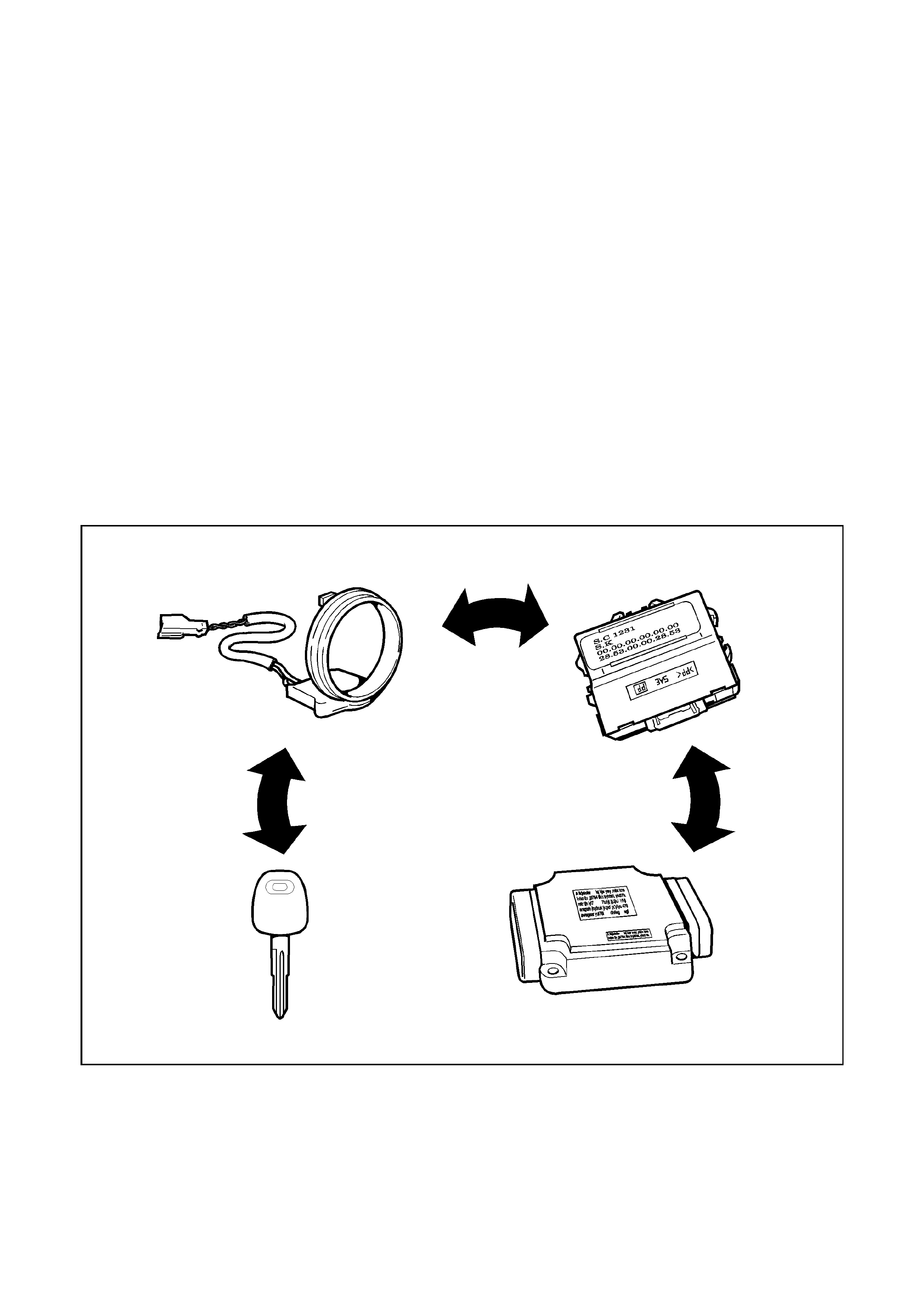
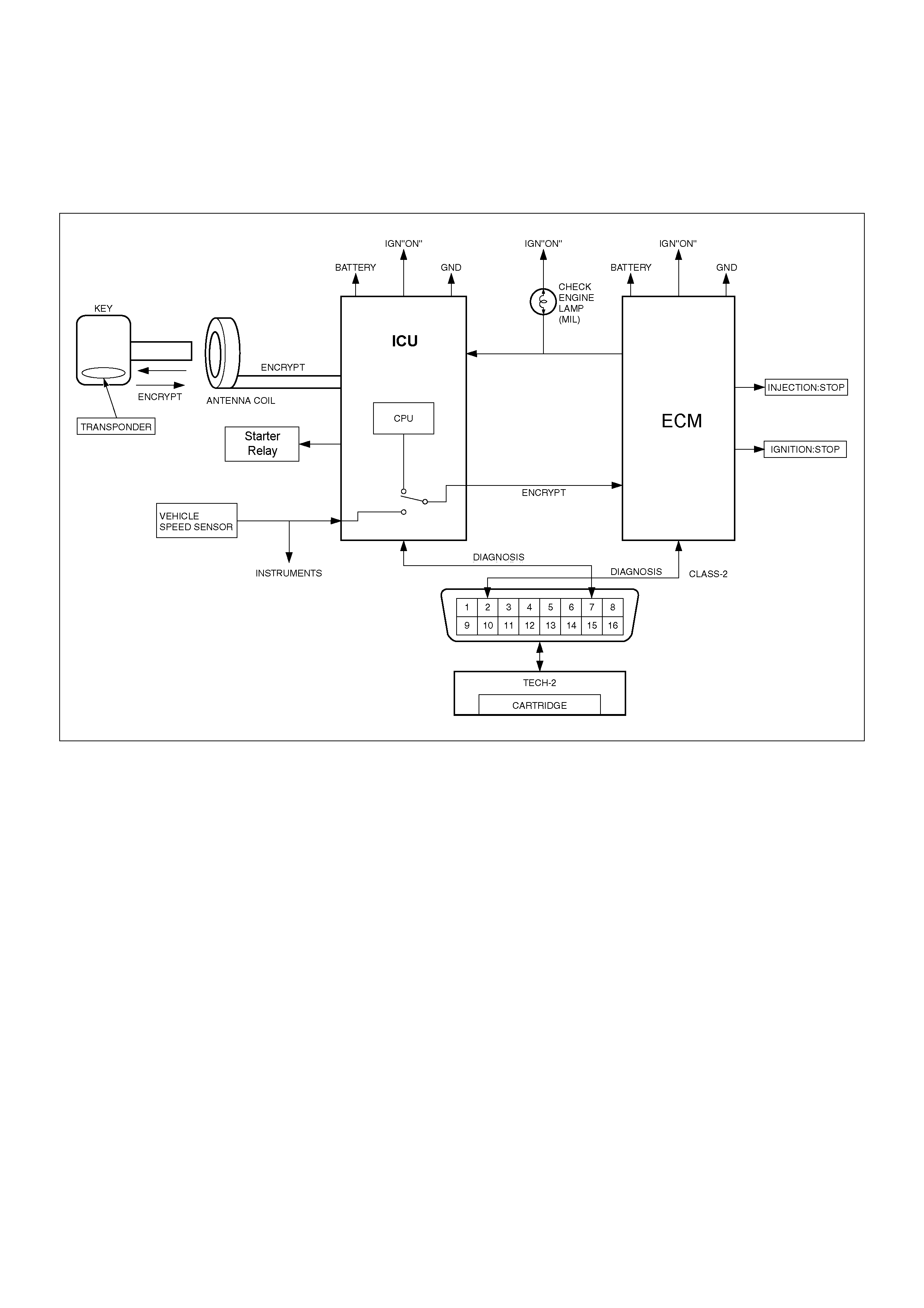
SYSTEM COMPONENTS
The main system components are:
• Transponder Ke y
• Coil Antenna
• I m mob ilis er C on t r ol U n it (IC U )
• Coil Antenna
• Starter Relay
• Eng ine Control Modu le ECM
• Assoc iated wiring harnesses, connectors and fuses
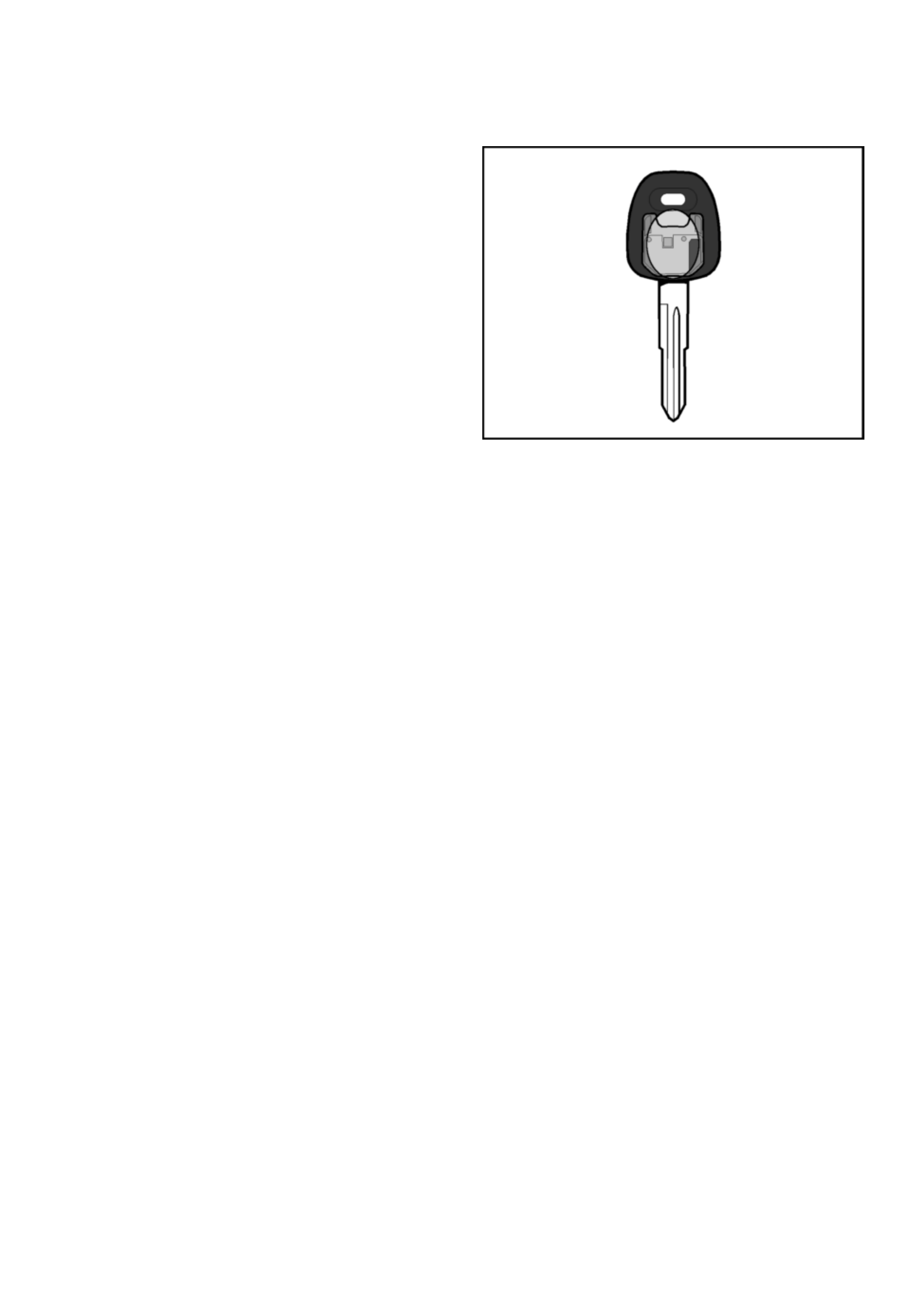
Transp on der Key
The system uses a conventional mechanical-cut ignition
key containing a minature transponder (transmitter/
responder) embedded in the plastic hand le.
Each transponder is programmed with it’s own specific
ID code during manufacture. Up to 1018 codes are
available with this system, making code duplication
almo s t impo ss ible .
The transponder circuit in the key does not require
batteries - the operating signal is provided cordlessly by
the ICU supplying a high frequency (133 kHz) AC
voltage signal to the coil antenna.
Encapsulated by the hard plastic of the key head, the
transponder is the most durable part of the ignition key.
The module is initially programmed with two
transponder codes, corresponding to the two keys
supplied with the vehicle. Should a key be lost, or an
additional key required, uncoded keys may be
programmed into the system with the aid of TECH 2. A
maximum of 5 transponder codes can be stored in the
ICU.
Due to the complex nature of the coded signals
transmitted between the it is recommended to replace
existing ignition keys when the ICU is replaced.

Coil Antenna
A non-contact radio frequency is used to transfer
information between the transponder key and the
Immobiliser Control Unit. Surrounding the ignition lock is
a dipole antenna, which is connected to the ICU by a
wiring harness.
The antenna is designed to have a very limited range,
ensuring that only the key in the ignition lock can
communicate with the ICU. This excludes the possible
interference from othe r transponder keys in the vehicle.
The antenna is accessed by removing the steering
column shroud. Apart from a continuity test on the coil
winding, subs titution with a kno wn good part is the o nly
applicable diagnostic procedure.
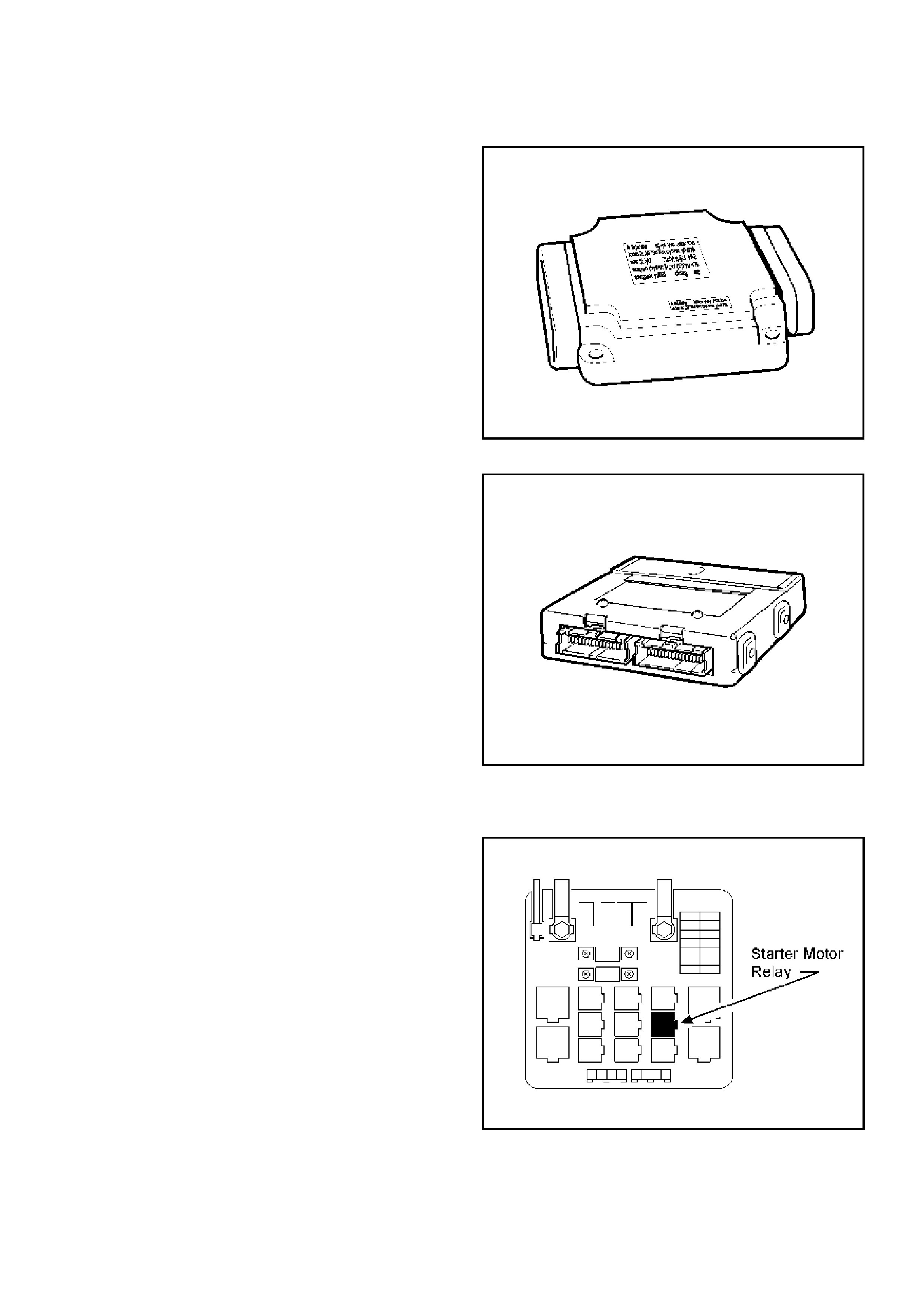
Immobiliser Control Unit (ICU)
The Immobiliser Contol Unit (ICU) is located bolted to
the cross-beam behind the RH lower instrument panel.
The ICU is powered at all times from Fuse C-2 (Horn)
and receives an ignition ‘ON’ signal from Fuse C-3
(Engine).
Communication from the ICU to the ECM is on the
Vehicle Speed Sensor (VSS) si g nal wir e :
• 6VD1 - ICU pin 8 to ECM pin B32
• C22NE - ICU pin 8 to ECM pin J1-E7
Communication from the ECM to the ICU takes place on
the ‘CHECK ENGINE’ Lam p (CEL) control circuit:
• 6VD1 - ECM pin B18 to ICU pin 3
• C22NE - ECM pin J2-B4 to ICU pin 3
NOTE: I f the I CU and ECM are replac ed at the sam e
time, the ICU MUST be programmed BEFORE the
Immobiliser function of the ECM can be activated.
NOTE: Th e petrol engine ICU differs from that fitted
to diesel engined vehicles. When installing a new
ICU, ensure that the correct part is fitted to the
vehicle. Refer to the latest parts listing for ICU part
number identification.
Engine Control Module (ECM)
• 6VD1 - The Hitachi ECM to is bolted to the top of the
common chamber (intake manifold). The intake
manifold acts as a heat-sink for the ECM and also
provides a ground path for the ECM circuit board.
When refitting the ECM, ensure the mating surfaces
are clean and free from corrosion.
• C22NE - The Delphi ECM is located immediately
below the centre of the instrument panel and is
accessed by removing the protective plastic cover.
Both the Hitachi and the Delphi ECM’s perform the
same function as regards Immobiliser operation - if the
the transponder key rolling code does not match the
ECM’s calculated code, the ECM will immobilise the
engine by disabling the fuel and ignition systems.
When installing a new ECM, ensure that the correct
ECM is fitted to the vehicle. Refer to the latest parts
listing for ECM part number identification.
Note: A replacement ECM must be programmed. Refer
to Section 0C-1 - Service Programming System. Once
programmed, the ICU and the ECM must be linked for
correct operation. Refer to System Programming in this
section.
Starter Motor Relay
The starter motor relay is located in the engine
compartment Main Fuse & Relay Box. One side of the
relay solenoid windings are connected ICU pin B1. Pin
B2 of the ICU is connected to ground.
When the ignition key is in the crank position, and the
correct signals hav e been received by the both ICU and
the ECM, the ICU will provide the path to ground
energising the relay windings.
ENGINE START SEQUENCE
Before the system will allow engine operation, the following sequence of data transfer and code evaluation must take
place:
1. When the ignition is turned ON, ICU supplies a high frequency (133kHz) AC voltage signal to the key via the
antenna.
2. The transponder code is transmitted to the ICU.
3. T he ICU checks the transpond er code and enables the Starter Motor Relay.
4. The ECM generates and transmits a RANDOM code to the ICU.
5. The ICU receives the RANDOM code from the ECM and transmits the code to the transponder.
6. T he transpond er calculate s a ROLLING code based on th e RANDOM code.
7. T he transpond er transmi ts the ROLLING code to the ECM via the ICU
8. T he ECM com p ar es the tra nsf er r ed ro lling code wi th its cal c u lat e d rolling cod e.
9. If both the calculated and transferred codes match, the ECM enabl e the fuel and ignition systems.
10. T he engine cannot be started during the data transfer and code evaluation process. If any of the above steps are
unsucces sfu l, all releva nt engine functions rema in disabled .

SYSTEM PROGRAMMING
Programm ing of the Immobiliser sy stem is performed with TEC H-2 w hen:
• The Imm obiliser Control Unit is replaced.
• The Imm obiliser Control Unit is reset.
• The ECM is replaced.
• Additional ignition keys are required.
• An ignition key has been lost.
Prior to commencing the programming sequen ce , the technician will require:
• The Vehicle Identification Number.
• The vehicle sec urity code from Holden TAS
• The mechanical key number.
To enable the complet ion of the program mi ng seq uenc e, the technician will r equi re:
• Perm ission from TIS 2000
Security Data
The following codes/data are stored in the ICU reference memory during vehicle production:
• The Vehicle Identification Number.
• The vehicle sec urity code.
• The mechanical key number.
• Engine type
• T ransponder code/s
The sec urity co de cannot be delet ed or al tered with TECH-2. Th e tran sponder c ode/s and engine type are proces sed
internally onl y and are not di splayed o n TECH-2. The Vehicle Id entification Number an d mechanical key number are
stored as further information for vehicle identification and can be displayed on TECH-2.
Security Code
The 4-digit security code prevents unauthorised programming and access to the data in the ICU via TECH-2. The
security code is programmed into the ICU.
Program m i ng th e Securi t y C ode
New Immobiliser Control Units do not contain a programmed security code. If the ICU is replaced, the security code for
that vehicle must be obtained, and then programmed into the ICU with TECH-2.
Replacem en t of the Imm obiliser Control Unit(ICU)
Due to the complex nature of the coded signals transmitted between the key and the ICU, it is necessary to replace
both existing ignition keys when the ICU is replaced.
Resettin g of the Immob ilise r Contro l U nit (ICU)
Resetting of the ICU may necess itate replacement of either or both ex isting ignition keys. This situation is most likely
to occur if the ICU is swapped from one vehicle to another.

Replacement of the ECM
Once programmed to the vehicle Immobiliser system, the ECM cannot be removed and used in another vehicle
without first re-programming the ECM using the Service Programming System (SPS). Refer to Section 0C-1
Loss of a Transponder Key
If a transponder key is lost, all transponder codes in the Immobiliser Control Unit must be erased to prevent
un auth oris ed us e. Th is w ill e nsur e tha t, wh ilst the 'lost' key w ill a llow a cce ss t o th e veh icl e, it ca nn ot be used t o star t
the vehicle.
After erasing all existing codes, the transponder codes of the remaining keys and the new transponder key can be
programmed.
NOTE:
• Programming Approval must be obtained from TIS, using the `Enable Programming" option, before either
control unit or transponder key programming is performed.
• Onc e Pro grammin g Ap proval has been obtained, TE CH-2 will allow five p rogrammin g operat ions. Onc e al l five
programming operations have been used, Programming Approval will then have to be obtained again.
• If the five programming operations are not used within 24hrs, they will be cleared from TECH-2, requiring
further Programm ing Approv al to be obtained.
TECH 2 OPERATION
W ith the lates t software loade d, connect TE CH 2 to the
vehicle, turn on TECH 2.
When the TECH 2 introduction screen appears, press
ENTER.
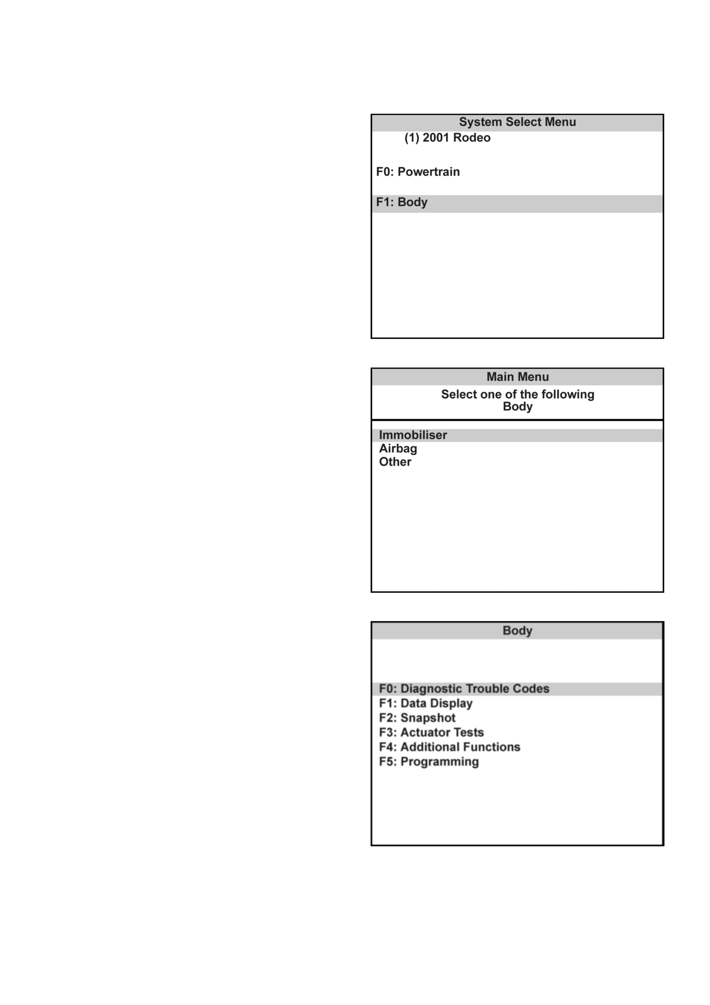
Select: Diagnostics / MY2001 / Rodeo/ F1: Body /
Immobiliser / Immobiliser (Isuzu)
The following modes and sub-mo des are now available:
F0: Diag nostic Trouble Codes
• F0: Read DTC Info Ordered By Priority
• F1: Read DTC Info As S tored By ECU
• F2: Clear DTC Information
F1: Data Display
F2: S napshot
F3: Actuator Test
• F0: Starter Relay Output Test
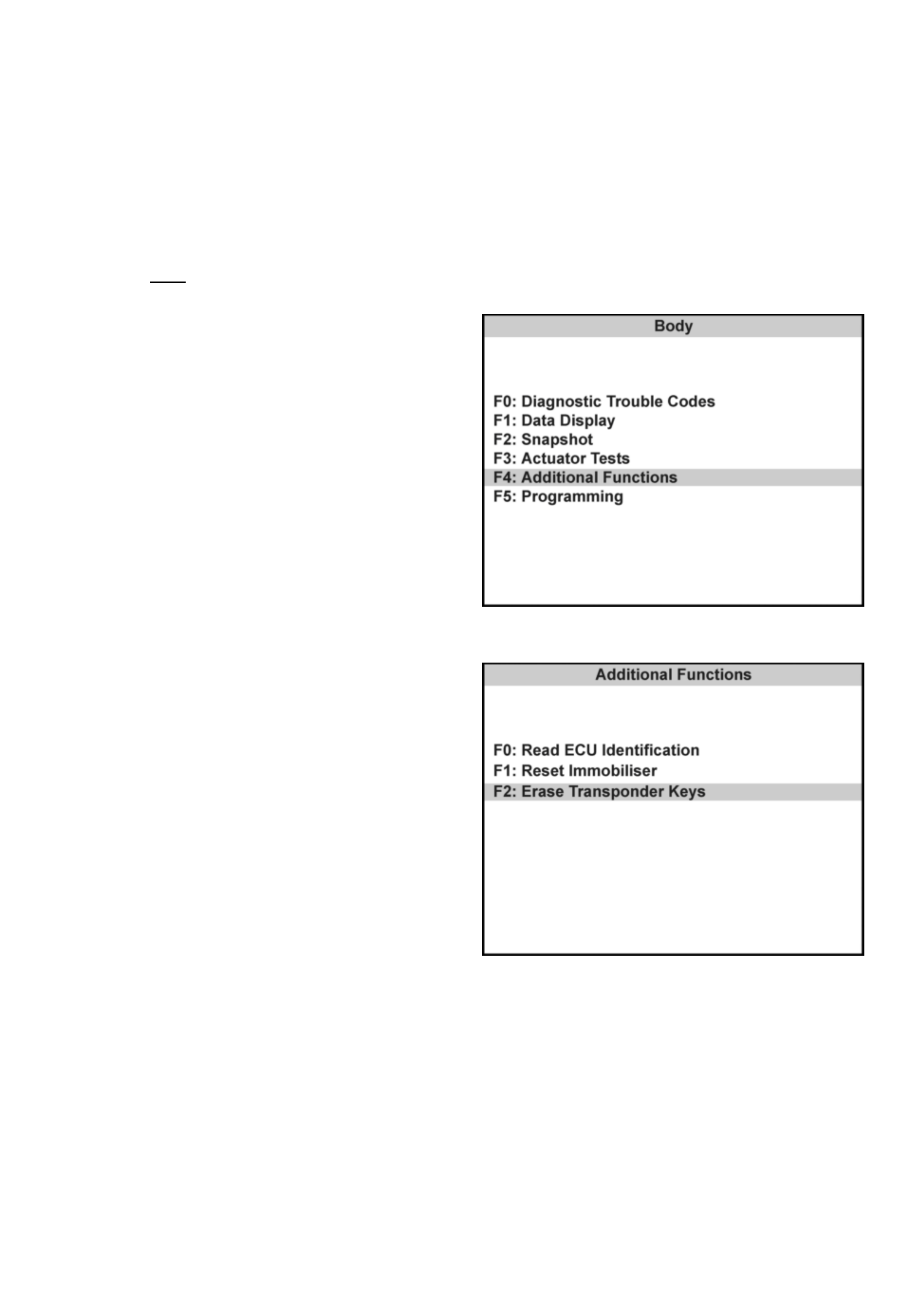
F4: Add i tiona l Functions
• F0: Read ECU Identification
• F 1 : Re s et Immobiliser
• F2: Reset Engine Cont rol Modu le
• F3: Erase Transponder - Keys
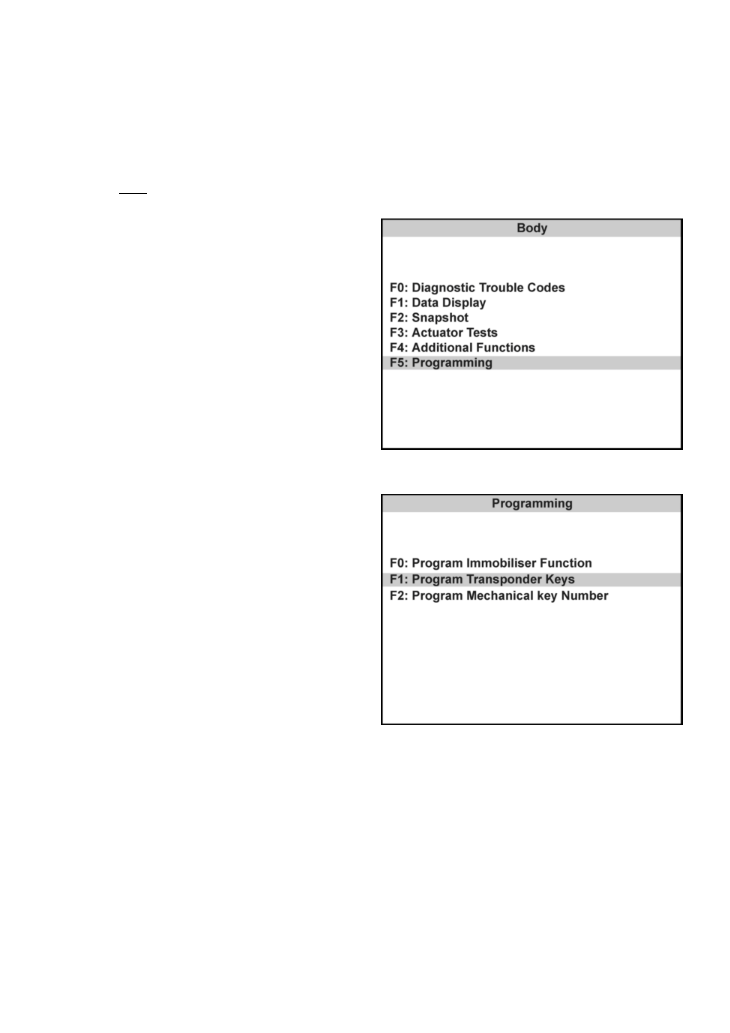
F5: P rogra m ming
• F0: Program Immobi liser Function
• F1: Program T ransponder - Keys
• F2: Program Mechanical key Number
TRANSPONDER-KEY PROGRAMMING
Programming Approval must be obtained from TIS 2000, using the "Enable Programming" option, during the
transponder key program sequen ce .
TECH 2 will requ est the Vehicle Secu rity Numb er during the program seq uence - this must be obtained fro m
Holden TAS prior to comm enc i ng t his ope rati on.
Connec t TECH 2 to the vehicle:
1. Select Diagnostics / MY2001 / Rodeo/ F1:
Body.
2. Select Immobiliser / Immobiliser (Isuzu)
3. Select F5: P rogramming.
4. Select F1: P rogram Tr ans ponde r - Key s.
5. Obta in programming approv al from TIS 2000 .
6. Retu rn to F1: Program Transpond er - Keys.
7. When the SECURITY CODE is requested, enter
the secu ri ty co de and pres s ENTER.
8. Insert a non-programmed Transponder key and
press CONFIRM.
9. 'Turn On Ignition Key' will be displayed if the
ignition is OFF.
10. The Transponder status will be displayed if the
status does not allow programm ing.
11. When Programming starts, 'Programming
Transponde r - key' is displayed.
12. Cycle the ignition key as instructed by the
display.
13. If the programming was successful, the screen
will display'Program More Keys?'
ERASING TRANSPONDER KEYS
If a transponder key is lost, all transponder codes in the Immobiliser Control Unit must be erased to prevent
unauthorised use. This will ensure that, whilst the 'lost' key will allow access to the vehicle, it cannot be used to start
the vehicle.
CAUTION: This sequence erases ALL transponder-keys. Transponder-Key programming will be required before the
vehicle can be restart ed.
TECH 2 will requ est the Vehicle Secu rity Numb er during the program seq uence - this must be obtained fro m
Holden TAS prior to comm enc i ng t his oper ation.
Connec t TECH 2 to the vehicle:
1. Select Diagnostics / MY2001 / Rodeo / F1:
Body.
2. Select Immobiliser / Immobiliser (Isuzu)
3. Select F4: Addit ional Func tions .
4. Select F2: Erase Transponder - Keys.
5. The screen will display 'See Checking
Procedure Be fore Program ming'.
6. Select CONFIRM to continue.
7. The screen will display 'CAUTION - All
Transponde r keys will be erased'
8. Select CONFIRM to continue.
9. A ll transponder-key s are now erased.
10. Program the new transponder key and any
remaining keys to the vehicle using the
'Transponde r-Key Prog ramming' sequenc e

PROGRAMMING THE IMMOBILISER CONTROL UNIT (ICU)
TECH 2 will requ est the Vehicle Secu rity Numb er during the program seq uence - this must be obtained fro m
Holden TAS prior to comm enc i ng t his ope rati on.
Connec t TECH 2 to the vehicle:
1. Select Diagnostics / MY2001 / Rodeo / F1:
Body.
2. Select Immobiliser / Immobiliser (Isuzu)
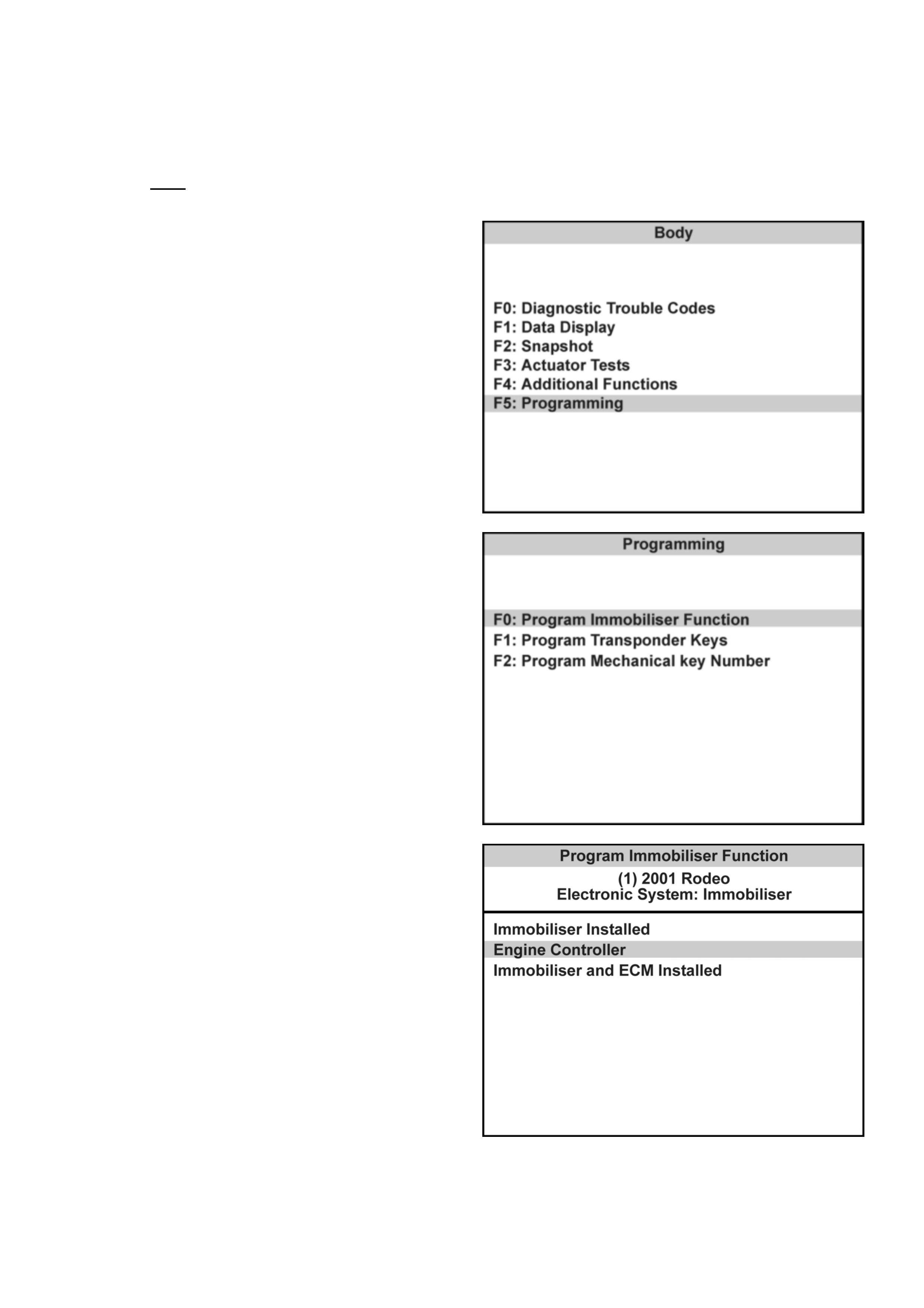
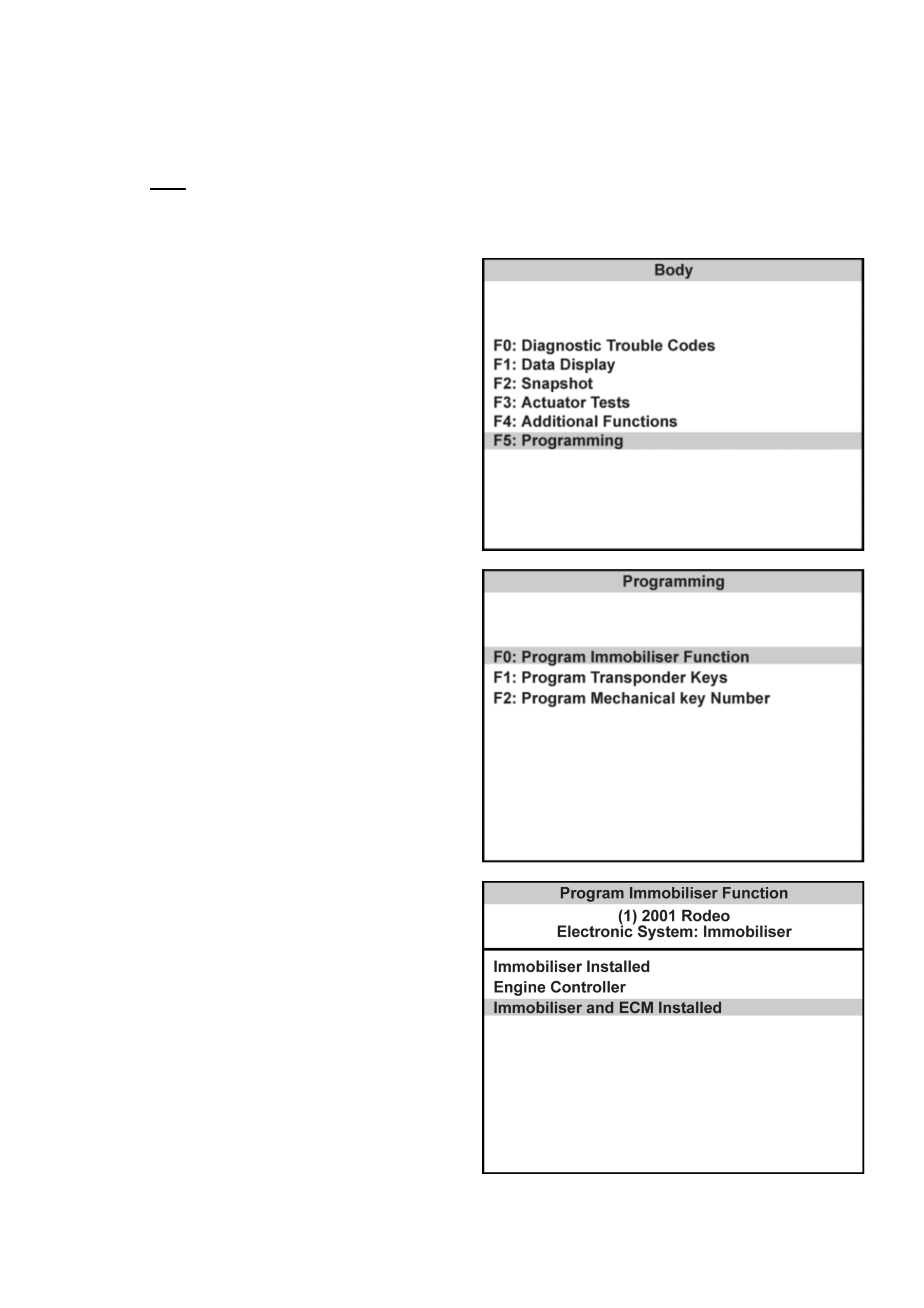
3. Select F5 : Progr am m ing.
4. Select F0: P rogram Im m obil iser Func t ion.
5. Select Immobiliser Insta lled
6. Obta in programmi ng approval from TIS 2000 .
7. Retu rn to F0: P rogram Im m o bi li ser Fu nction.
8. When the SECURITY CODE is requested, enter
the secu ri ty co de and pres s ENTER.
9. When the VIN is requested, enter the vehicle
identification number and pres s ENTER.
10. When the MECHANICAL KEY number is
requested, enter the key number and press
ENTER.
11 . Turn the ignition ON.
12. Select the engine type
13. Chec k the programm ing result
14. Program the transponder-keys to the ICU.
PROGRAMMING THE ECM
TECH 2 will requ est the Vehicle Secu rity Numb er during the program seq uence - this must be obtained fro m
Holden TAS prior to comm enc i ng t his ope rati on.
Connec t TECH 2 to the vehicle:
1. Select Diagnostics / MY2001 / Rodeo / F1:
Body.
2. Select Immobiliser / Immobiliser (Isuzu)
3. Select F5 : Progr am m ing.
4. Select F0: P rogram Im m obil iser Func t ion.
5. Select Engine Controller
6. Obta in programmi ng approval from TIS 2000 .
7. Retu rn to F0: P rogram Im m o bi li ser Fu nction.
8. When the SECURITY CODE is requested, enter
the secu ri ty co de and pres s ENTER.
9. When the VIN is requested, enter the vehicle
identification number and pres s ENTER.
10. When the MECHANICAL KEY number is
requested, enter the key number and press
ENTER.
11 . Turn the ignition ON.
12. Select the engine type
13. Chec k the programm ing result
PROGRAMMING THE ECM & ICU
TECH 2 will request the Vehicle Security Number during the program sequence - this must be obtained from
Holden TAS prior to commencing this operation.
When the ECM and ICU are replaced at the same time, the ICU MUST be programmed BEFORE the
Immobiliser function of the ECM can be activated.
Connec t TECH-2 to the vehicle:
Connec t TECH 2 to the vehicle:
1. Select Diagnostics / MY2001 / Rodeo / F1:
Body.
2. Select Immobiliser / Immobiliser (Isuzu)
3. Select F5 : Progr am m ing.
4. Select F0: P rogram Im m obil iser Func t ion.
5. Select Immobi liser and ECM In stalled
6. Obta in programmi ng approval from TIS 2000 .
7. Retu rn to F0: P rogram Im m o bi li ser Fu nction.
8. When the SECURITY CODE is requested, enter
the secu ri ty co de and pres s ENTER.
9. When the VIN is requested, enter the vehicle
identification number and pres s ENTER.
10. When the MECHANICAL KEY number is
requested, enter the key number and press
ENTER.
11 . Turn the ignition ON.
12. Select the engine type
13. Chec k the programm ing result
14. Program the transponder-keys to the ICU.
ENABLE PROGRAMMING - TIS 2000
'Enable Programming' (TIS Approval) is used in order to
prevent the unauthorised programming of the system
security functions.
TIS Approval is required to perform the following
functions on the UBS Immobiliser System:
• Programming the Immobiliser Control Unit
• Program m ing the transponde r keys
• Program m ing the ECM
After the TECH 2 security programming function has
been selected, TECH 2 will display - "Please get
programming approval from TIS'.
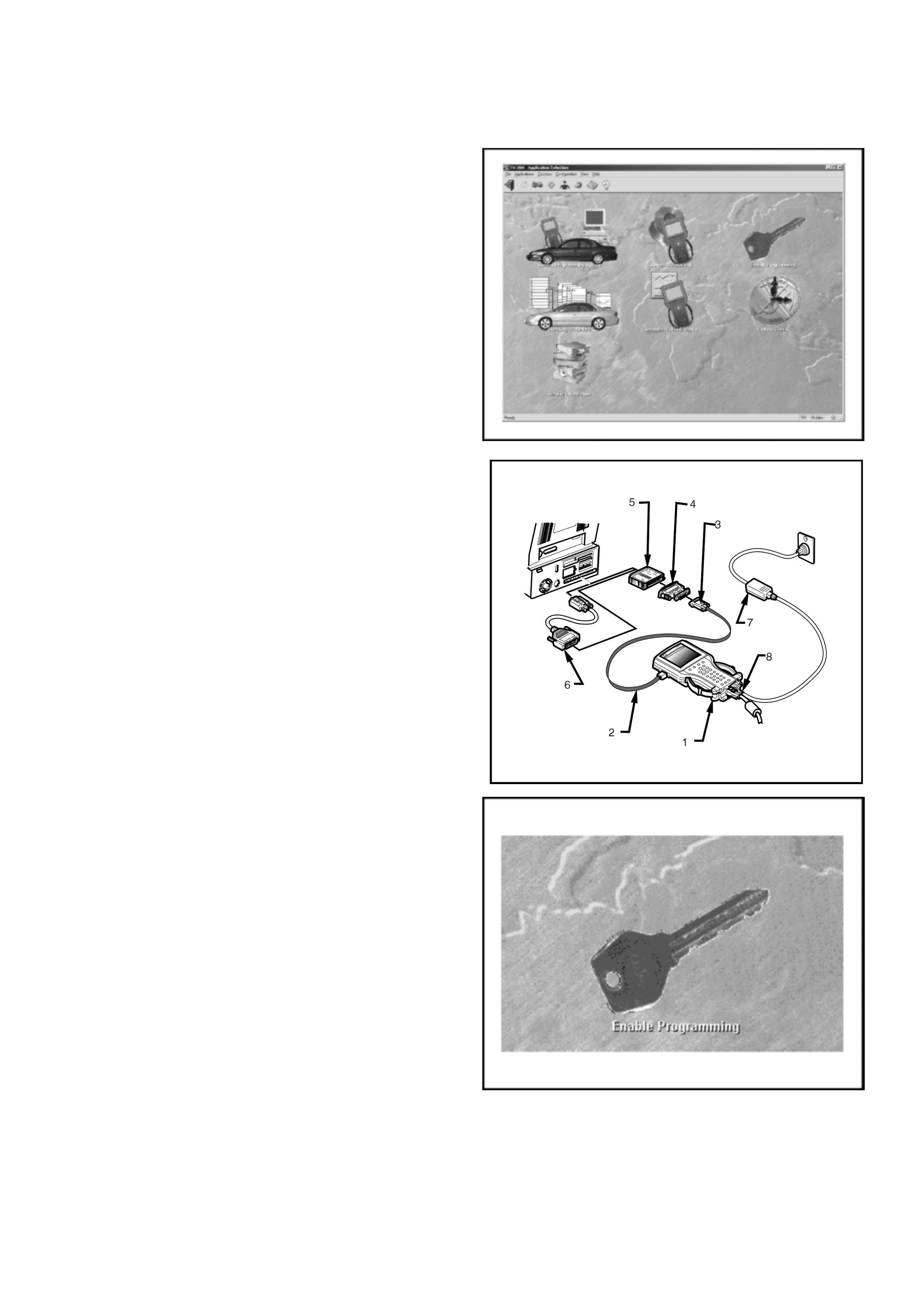
Enable Pr og r ammi ng Pro c e du r e
1. Connect the RS232C interface cable to the
TECH2 commu nicat ion port.
2. Connect the other end of the RS232C cable to
the hardware key using the 9 pin and 25 pin
adaptors.
3. Connect the hardware key to the serial port of
the TIS 2000 PC.
4. Connect the powe r su pply to th e TECH 2 p ower
jack.
5. Press the PWR button and allow TECH 2 to
boot to the start-up screen.
6. Click on the Enable Programming icon of the
TIS 2000 main screen.
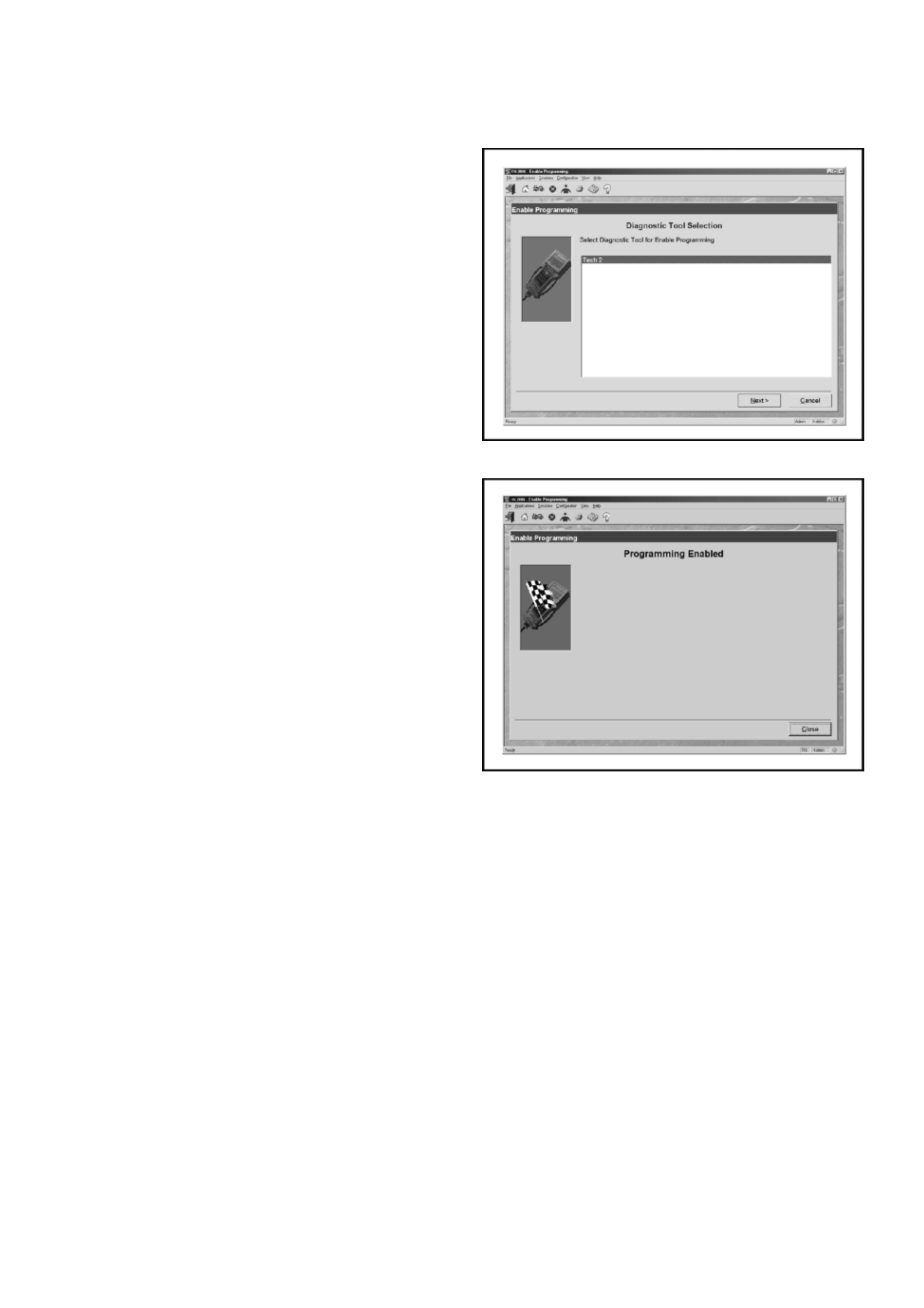
7. Select diagnostic tool (TECH 2) for Enable
Programming
8. Select Next to continue
9. When the process is completed, the
Program ming Ena bled screen will be displayed.
10. Click on the Close button to close the
application.
11. Reconnect TECH-2 to the vehicle DLC and
complete the programming function.

DIAGNOSTIC TROUBLE CODES
Current DTC's
The engine will not run when any current DTC is logged.
• The ECM disable s the fuel and ignition systems
• The ICU inhibits starter motor operation by disabling the starter motor relay.
History DTC's
W hen the fault has been repaired, the engine will oper ate nor m ally and the current DTC bec om es a History DTC.
History DTC's are stored in an EEPROM. This type of memory storage means the codes are not cleared when the
battery is disconnected.
• History codes may be cleared from the system memory by TECH 2.
• A History DTC will self-clear after 25 consecutive ignition cycles without the fault recurring.
NO DTC SET
ENGINE WILL NOT CRANK
DTC Description
B0011 T ransponder Key Problem
B0012 Wrong Transponder key
B0013 Immobi liser Not programmed
B0014 No Transponde r Key Programm ed
B0015 Vehicle Speed Signal Low
B0016 Vehicle Speed Signal High
B0017 No Engine Request Received
B0023 Antenna Coil Open Circuit
B0024 Wrong Transponder Response
B0025 Wrong Engine Reque st
B 005 5 EEP ROM Err or
060RA00003
Circuit Description
The Immobiliser Control Unit provdes the ground path
for the starter motor relay solenoid windings. A no-crank
condition will occur due to failure in either the Engine
Immobiliser System or starter motor circuit operation .
Condition for Setting the DTC
Not Applicable
Action Taken When the DTC sets
Not Applicable
Condition for Clearing the MIL/DTC
Not Applicable
Diagnostic Aids
Check for the following conditions:
• Poor connection at ECM and Immobiliser Control
Unit. Inspect harness connectors for backed out
terminals, improper mating, broken locks,
improperly formed or damaged terminals, and
poor terminal to wire connection.
• Damaged harness-Inspect the wiring harness for
damage, If the harness appears to be OK,
disconnect the ECM and Immobiliser, turn the
ignition “ON" and observe a voltmeter connected
to the suspect driver circuit at the ECM and
Immobiliser harness connector while moving
connectors and wiring harnesses relates to the
MIL. A change in voltage will indicate the location
of the fault.
ENGINE WILL NOT CRANK - NO DTC SET
Step Action Value(s) Yes No
• 1 Was the “On-Board Diagnostic (OBD) system Check"
performed? •— •Go to Step 2 • Go to OBD
system
check
• Refer to
Sect ion 6C1

• 2 Check the ECM and ICU harness and connecto rs for:
1. Backed out terminals, improper mating, broken
locks, improperly formed or damaged terminals,
and poor terminal to wire connection.
2. Dam aged harness - Inspect the wiring harnes s for
damage.
If a problem found, repair as necessary.
Was a problem found?
• • Verify repair • Go to Step 3
• 3 Turn the ignition ON, does the ‘CHECK ENGINE’
Lamp flash at 2Hz? • — • Go to St ep 4 • Check starter
motor circuit.
• Refer
Sect ion 6D
• 4 With the ignition ON, check the voltage at ICU pin 2.
Is the voltage in specified range?
• 11.6v -
12.7v •Go to St ep 6 •Go to Step 5
• 5 Check for continuity between Fuse C-3 & ICU pin 2.
If a problem found, repair as necessary.
Was a problem found?
• • Verify repair • Go to Step 6
• 6 Measure the resistance between ICU pin 7 and
ground.
Is the resistanc e less than the specified value?
•5 W•
•
•
•Go to Step 8
•Go to Step 7
• 7 Repair the ground circuit from ICU pin 7 to ground
Is the action complete?
• — • Verify repair • —
• 8. Replace the ICU and the existing ignition keys
Reprogram the system
• • Verify repair •
Step Action Value(s) Yes No

DTC B0011
TRANSPONDER KEY PROBLEM
060RA00003
Circuit Description
The Immobiliser Control Unit expects to recei ve a valid
transponder key signal when the ignition is turned ON.
Condition for Setting the DTC
A DTC B0011 will set if any of the following conditions
are present for at least 0.84 seconds during an
attemp ted start:
• No transponder-k ey signal is present
• The transpon der-ke y is defective
• The ke y is not a transp onder key
Action Taken When the DTC sets
• The engine will not crank
• The CHEC K ENGINE Lamp will flash at 4Hz
Condition for Clearing th e MIL /DTC
• Using TECH 2, select Clear DTC Information
• A History DTC B0011 will self-clear after 25
consecutive ignition cycles without the fault
recurring.
Diagnostic Aids
Check for the following conditions:
• Poor connection at ECM and Immobiliser Control
Unit. Inspect harness connectors for backed out
terminals, improper mating, broken locks,
improperly formed or damaged terminals, and
poor terminal to wire connection.
• Damaged harness-Inspect the wiring harness for
damage, If the harness appears to be OK,
disconnect the ECM and Immobiliser, turn the
ignition “ON" and observe a voltmeter connected
to the suspect driver circuit at the ECM and
Immobiliser harness connector while moving
connectors and wiring harnesses relates to the
MIL. A change in voltage will ind icate the lo cation
of the fault.

DTC B0011- TRANSPONDER KEY PROBLEM
Step Action Value(s) Yes No
• 1 Was the “On-Board Diagnostic (OBD) system Check"
performed? •— •Go to Step 2 • Go to OBD
system
check
• Refer to
Sect ion 6C1
• 2 Check the ECM and ICU harness and connecto rs for:
1. Backed out terminals, improper mating, broken
locks, improperly formed or damaged terminals,
and poor terminal to wire connection.
2. Dam aged harness - Inspect the wiring harnes s for
damage.
If a problem found, repair as necessary.
Was a problem found?
• • Verify repair • Go to Step 3
• 3 Turn the ignition ON, does the ‘CHECK ENGINE’
Lamp flash at 4Hz? • — • Go to Step 4 • —
• 4 Check for correct operation with the other transponder
key/s
Does the system operate correctly?
•— •Go to Step 5 •Go to Step 5
• 5 Reprogram the transponder key.
Was the programm ing successful?
• • Verify repair • Go to Step 6
• 6 Is a DTC B0023 set after the program attempt? • • Go to
Diagnostic
Chart
• DTC B0023 -
Antenna Coil
Open
•Go to Step 7
• 7 Replace the ICU and the existing ignition keys
Reprogram the system
• — • Verify repair • —
DTC B0012
WRONG TRANSPONDER KEY
060RA00003
Circuit Description
The Immobiliser Control Unit expects to recei ve a valid
transponder key signal when the ignition is turned ON.
Condition for Setting the DTC
A DTC B0012 will set if any of the following conditions
are present for at least 0.84 seconds during an
attemp ted start:
• The transponder-key signal is not programmed to
the EC U
• The transpon der read-out is interrupted
• The ke y is not a transp onder key
Action Taken When the DTC sets
• The engine will not crank
• The CHEC K ENGINE Lamp will flash at 4Hz
Condition for Clearing th e MIL /DTC
• Using TECH 2, select Clear DTC Information
• A History DTC B0012 will self-clear after 25
consecutive ignition cycles without the fault
recurring.
Diag nostic Ai ds
Check for the following conditions:
• Poor connection at ECM and Immobiliser Control
Unit. Inspect harness connectors for backed out
terminals, improper mating, broken locks,
improperly formed or damaged terminals, and
poor terminal to wire connection.
• Damaged harness-Inspect the wiring harness for
damage, If the harness appears to be OK,
disconnect the ECM and Immobiliser, turn the
ignition “ON" and observe a voltmeter connected
to the suspect driver circuit at the ECM and
Immobiliser harness connector while moving
connectors and wiring harnesses relates to the
MIL. A change in voltage will ind icate the lo cation
of the fault.

DTC B0012 - WRONG TRANSPONDER KEY
Step Action Value(s) Yes No
• 1 Check for correct operation with the other transponder
key/s
Does the system operate correctly?
•— •Go to Step 2 •Go to Step 4
• 2 Reprogram the transponder key.
Was the programm ing successful?
• • Verify repair • Go to Step 3
• 3 Replace the transponder key
Reprogram the system
• — • Verify repair • —
• 4 Replace the ICU and the existing ignition keys
Reprogram the system
• — • Verify repair • —

DTC B0013
IMMOBILISER NOT PROGRAMMED
060RA00003
Circuit Description
The Immobiliser Control Unit expects to recei ve a valid
transponder key signal when the ignition is turned ON.
Condition for Setting the DTC
A DTC B0 013 w ill set imm endi atel y upo n recogn ition If :
• The vehicle security code is not programmed into
the system .
Action Taken When the DTC sets
• The engine will not crank
• The CHEC K ENGINE Lamp will flash at 4Hz
Condition for Clearing th e MIL /DTC
• Using TECH 2, select Clear DTC Information
• A History DTC B0013 will self-clear after 25
consecutive ignition cycles without the fault
recurring.
Diagnostic Aids
Check for the following conditions:
• Poor connection at ECM and Immobiliser Control
Unit. Inspect harness connectors for backed out
terminals, improper mating, broken locks,
improperly formed or damaged terminals, and
poor terminal to wire connection.
• Damaged harness-Inspect the wiring harness for
damage, If the harness appears to be OK,
disconnect the ECM and Immobiliser, turn the
ignition “ON" and observe a voltmeter connected
to the suspect driver circuit at the ECM and
Immobiliser harness connector while moving
connectors and wiring harnesses relates to the
MIL. A change in voltage will ind icate the lo cation
of the fault.

DTC B0013 - IMMOBILISER NOT PROGRAMMED
Step Action Value(s) Yes No
• 1 Attempt to reprogram the security information
Was the programming successful?
• — • Verify repair • Go to Step 2
• 2 Was the “On-Board Diagnostic (OBD) system Check"
performed? •— •Go to Step 3 •Go to OBD
system
check
• Refer to
Sect ion 6C1
• 3 Check the ECM and ICU harness and connecto rs for:
1. Backed out terminals, improper mating, broken
locks, improperly formed or damaged terminals,
and poor terminal to wire connection.
2. Dam aged harness - Inspect the wiring harnes s for
damage.
If a problem found, repair as necessary.
Was a problem found?
• — • Verify repair • Go to Step 4
• 4 Replace the ICU and the existing ignition keys
Reprogram the system
• — • Verify repair • —

DTC B0014
NO TRANSPONDER KEY PROGRAMMED
060RA00003
Circuit Description
The Immobiliser Control Unit expects to recei ve a valid
transponder key signal when the ignition is turned ON.
Condition for Setting the DTC
A DTC B0 014 w ill set imm endi atel y upo n recogn ition If :
• No transponder keys are programmed into the
system.
Action Taken When the DTC sets
• The engine will not crank
• The CHEC K ENGINE Lamp will flash at 4Hz
Condition for Clearing th e MIL /DTC
• Using TECH 2, select Clear DTC Information
• A History DTC B0014 will self-clear after 25
consecutive ignition cycles without the fault
recurring.
Diagnostic Aids
Check for the following conditions:
• Poor connection at ECM and Immobiliser Control
Unit. Inspect harness connectors for backed out
terminals, improper mating, broken locks,
improperly formed or damaged terminals, and
poor terminal to wire connection.
• Damaged harness-Inspect the wiring harness for
damage, If the harness appears to be OK,
disconnect the ECM and Immobiliser, turn the
ignition “ON" and observe a voltmeter connected
to the suspect driver circuit at the ECM and
Immobiliser harness connector while moving
connectors and wiring harnesses relates to the
MIL. A change in voltage will ind icate the lo cation
of the fault.

DTC B0014 - NO TRANSPONDER KEY PROGRAMMED
Step Action Value(s) Yes No
• 1 Attempt to reprogram the transponder keys
Was the programming successful?
• — • Verify repair • Go to Step 2
• 2 Was the “On-Board Diagnostic (OBD) system Check"
performed? •— •Go to Step 3 •Go to OBD
system
check
• Refer to
Sect ion 6C1
• 3 Check the ECM and ICU harness and connecto rs for:
1. Backed out terminals, improper mating, broken
locks, improperly formed or damaged terminals,
and poor terminal to wire connection.
2. Dam aged harness - Inspect the wiring harnes s for
damage.
If a problem found, repair as necessary.
Was a problem found?
• — • Verify repair • Go to Step 4
• 4 Replace the ICU and the existing ignition keys
Reprogram the system
• — • Verify repair • —
DTC B0015
VEHICLE SPEED SIGNAL LOW (<2.5V)
060RA00003
Circuit Description
The Immobiliser Control Unit transmits a rolling code
signal to t he E CM when the ignition is turned ON, using
the ‘VSS Out’ circuit.
Condition for Setting the DTC
A DTC B0 015 w ill s et if:
• There is a sho rt to ground in the circuit from ICU
pin 8 to ECM pin B32 (6VD1) / J1-E7(C22NE).
Action Taken When the DTC sets
• The engine will not crank
• The CHEC K ENGINE Lamp will flash at 4Hz
Condition for Clearing th e MIL /DTC
• Using TECH 2, select Clear DTC Information
• A History DTC B0015 will self-clear after 25
consecutive ignition cycles without the fault
recurring.
Diagnostic Aids
Check for the following conditions:
• Poor connection at ECM and Immobiliser Control
Unit. Inspect harness connectors for backed out
terminals, improper mating, broken locks,
improperly formed or damaged terminals, and
poor terminal to wire connection.
• Damaged harness-Inspect the wiring harness for
damage, If the harness appears to be OK,
disconnect the ECM and Immobiliser, turn the
ignition “ON" and observe a voltmeter connected
to the suspect driver circuit at the ECM and
Immobiliser harness connector while moving
connectors and wiring harnesses relates to the
MIL. A change in voltage will ind icate the lo cation
of the fault.

DTC B0015 - VEHICLE SPEED SENSOR SIGNAL LOW (<2.5V)
Step Action Value(s) Yes No
• 1 Was the “On-Board Diagnostic (OBD) system Check"
performed? •— •Go to Step 2 • Go to OBD
system
check
• Refer to
Sect ion 6C1
• 2 Check for continuity between ICU pin 8 and ECM pin
B32 (6VD1) / J1-E7(C22NE).
If a problem found, repair as necessary.
Was a problem found?
• — • Verify repair • Go to Step 3
• 3 Check for continuity between ICU pin 7 and ground
If a problem found, repair as necessary.
Was a problem found?
• — • Verify repair • Go to Step 4
• 4 Clear the DTC using TECH 2
Did the DTC Clear?
• — • Verify repair • Go to Step 2

DTC B0016
VEHICLE SPEED SENSOR SIGNAL HIGH (>2.5 V)
060RA00003
Circuit Description
The Immobiliser Control Unit transmits a rolling code
signal to t he E CM when the ignition is turned ON, using
the ‘VSS Out’ circuit.
Condition for Setting the DTC
A DTC B0 016 w ill s et if:
• There is a short to power in the circuit from ICU
pin 8 to ECM pin B32 (6VD1) / J1-E7(C22NE).
Action Taken When the DTC sets
• The engine will not crank
• The CHEC K ENGINE Lamp will flash at 4Hz
Condition for Clearing th e MIL /DTC
• Using TECH 2, select Clear DTC Information
• A History DTC B0016 will self-clear after 25
consecutive ignition cycles without the fault
recurring.
Diagnostic Aids
Check for the following conditions:
• Poor connection at ECM and Immobiliser Control
Unit. Inspect harness connectors for backed out
terminals, improper mating, broken locks,
improperly formed or damaged terminals, and
poor terminal to wire connection.
• Damaged harness-Inspect the wiring harness for
damage, If the harness appears to be OK,
disconnect the ECM and Immobiliser, turn the
ignition “ON" and observe a voltmeter connected
to the suspect driver circuit at the ECM and
Immobiliser harness connector while moving
connectors and wiring harnesses relates to the
MIL. A change in voltage will ind icate the lo cation
of the fault.

DTC B0016 - VEHICLE SPEED SENSOR SIGNAL HIGH (>2.5V)
Step Action Value(s) Yes No
• 1 Was the “On-Board Diagnostic (OBD) system Check"
performed? •— •Go to Step 2 • Go to OBD
system
check
• Refer to
Sect ion 6C1
• 2 1. Disconnect the ICU and ECM harness
connectors.
2. Turn the ignition ON
3. Check for voltage at ICU harness connector pin 8
If a problem found, repair as necessary.
Was a problem found?
• — • Verify repair • Go to Step 3
• 3 Clear the DTC using TECH 2
Did the DTC Clear?
• — • Verify repair • Go to Step 2

DTC B0017
NO ENGINE REQUEST RECEIVED
060RA00003
Circuit Description
The ECM transmits an ‘Engine Request’ signal to the
ICU when the ignition is turned ON, using the ‘CHECK
ENGINE ’ Lamp circuit.
Condition for Setting the DTC
A DTC B0017 will set within 0.5 secs. of turning the
ignition ON if:
• ICU pin 3 does not receive an ‘Engine Request’
signal from the ECM.
Action Taken When the DTC sets
• The engine will not crank
• The CHEC K ENGINE Lamp will flash at 4Hz
Condition for Clearing th e MIL /DTC
• Using TECH 2, select Clear DTC Information
• A History DTC B0017 will self-clear after 25
consecutive ignition cycles without the fault
recurring.
Diagnostic Aids
Check for the following conditions:
• Poor connection at ECM and Immobiliser Control
Unit. Inspect harness connectors for backed out
terminals, improper mating, broken locks,
improperly formed or damaged terminals, and
poor terminal to wire connection.
• Damaged harness-Inspect the wiring harness for
damage, If the harness appears to be OK,
disconnect the ECM and Immobiliser, turn the
ignition “ON" and observe a voltmeter connected
to the suspect driver circuit at the ECM and
Immobiliser harness connector while moving
connectors and wiring harnesses relates to the
MIL. A change in voltage will ind icate the lo cation
of the fault.

DTC B0017 - NO ENGINE REQUEST RECEIVED
Step Action Value(s) Yes No
• 1 Was the “On-Board Diagnostic (OBD) system Check"
performed? •— •Go to Step 2 • Go to OBD
system
check
• Refer to
Section 6C1
• 2 Check for continuity between ICU pin 3 and ECM pin
B18 (6VD1) / J2-B4(C22NE).
If a problem found, repair as necessary.
Was a problem found?
• — • Verify repair • Go to Step 3
• 3 1. Disconnect the ECM connectors
2. Check for continuity between ICU pin 3 and
ground
If a continuity is found, repair as necessary.
Was continuity found?
• — • Verify repair • Go to Step 4
• 3 Replace the ECM (Internal circuit failure).
Important: The replacement ECM must be
programmed. Refer to Section 0C - Service
Programming System
Important: The ECM and ICU must be linked, refer to
this Section for the correct procedure.
Important: Ensure the latest software program is
downloaded to the ECM.
Is the action complete?
• — • Verify repair • —

DTC B0023
ANTENNA COIL OPEN
060RA00003
Circuit Description
The Immobiliser Control Unit expects to recei ve a valid
transponder key signal when the ignition is turned ON.
The ICU and transponder key communicate via the
antenna coil circuit.
Condition for Setting the DTC
A DTC B0 023 w ill set imm endi atel y upo n recogn ition If :
• The a ntenna coi l is not connected or there is a n
open in the antenna coil circuit.
Action Taken When the DTC sets
• The engine will not crank
• The CHEC K ENGINE Lamp will flash at 4Hz
Condition for Clearing th e MIL /DTC
• Using TECH 2, select Clear DTC Information
• A History DTC B0023 will self-clear after 25
consecutive ignition cycles without the fault
recurring.
Diagnostic Aids
Check for the following conditions:
• Poor connection at ECM and Immobiliser Control
Unit. Inspect harness connectors for backed out
terminals, improper mating, broken locks,
improperly formed or damaged terminals, and
poor terminal to wire connection.
• Damaged harness-Inspect the wiring harness for
damage, If the harness appears to be OK,
disconnect the ECM and Immobiliser, turn the
ignition “ON" and observe a voltmeter connected
to the suspect driver circuit at the ECM and
Immobiliser harness connector while moving
connectors and wiring harnesses relates to the
MIL. A change in voltage will ind icate the lo cation
of the fault.

DTC B0023 - ANTENNA COIL OPEN
Step Action Value(s) Yes No
• 1 Was the “On-Board Diagnostic (OBD) system Check"
performed? •— •Go to Step 2 •Go to OBD
system
check
• Refer to
Sect ion 6C1
• 2 Check for continuity between ICU harness connector
pin 6 and pin 13.
Was a problem found?
•— •Go to Step 3 •Go to Step 3
• 3 Check for continuity between ICU harness connector
pin 6 and antenna coil pin 1.
If a problem found, repair as necessary.
Was a problem found?
• — • Verify repair • Go to Step 4
• 4 Check for continuity between ICU harness connector
pin 13 and antenna coil pin 2.
If a problem found, repair as necessary.
Was a problem found?
• — • Verify repair • Go to Step 3
• 5 Replace the antenna c oil assem bly
Is the action complete?
• — • Verify repair • —

DTC B0024
WR ONG TRANSPONDER KEY RESPONSE
060RA00003
Circuit Description
The Immobiliser Control Unit expects to recei ve a valid
transponder key signal when the ignition is turned ON.
Condition for Setting the DTC
A DTC B0 024 w ill set imm endi atel y upo n recogn ition If :
• The transponder key reponse to the ICU signal is
incorrect.
Action Taken When the DTC sets
• The engine will not crank
• The CHEC K ENGINE Lamp will flash at 4Hz
Condition for Clearing th e MIL /DTC
• Using TECH 2, select Clear DTC Information
• A History DTC B0024 will self-clear after 25
consecutive ignition cycles without the fault
recurring.
Diagnostic Aids
Check for the following conditions:
• Poor connection at ECM and Immobiliser Control
Unit. Inspect harness connectors for backed out
terminals, improper mating, broken locks,
improperly formed or damaged terminals, and
poor terminal to wire connection.
• Damaged harness-Inspect the wiring harness for
damage, If the harness appears to be OK,
disconnect the ECM and Immobiliser, turn the
ignition “ON" and observe a voltmeter connected
to the suspect driver circuit at the ECM and
Immobiliser harness connector while moving
connectors and wiring harnesses relates to the
MIL. A change in voltage will ind icate the lo cation
of the fault.

DTC B0024 - WRONG TRANSPONDER KEY RESPONSE
Step Action Value(s) Yes No
• 1 Check for correct operation with the other transponder
key/s
Does the system operate correctly?
•— •Go to Step 2 •Go to Step 4
• 2 Reprogram the transponder key.
Was the programm ing successful?
• • Verify repair • Go to Step 3
• 3 Replace the transponder key
Reprogram the system
• — • Verify repair • —
• 4 Replace the ICU and the existing ignition keys
Reprogram the system
• — • Verify repair • —

DTC B0025
WRONG ENGINE RE QUEST SIGNAL
060RA00003
Circuit Description
The Immobiliser Control Unit expects to recei ve a valid
‘Eng ine Request’ signal when the ignition is turned ON.
Condition for Setting the DTC
A DTC B0025 will set within 0.5 secs. of turning the
ignition ON if:
• ICU pin 3 does not receive an valid ‘Engine
Request’ signal from the ECM.
Action Taken When the DTC sets
• The engine will not crank
• The CHEC K ENGINE Lamp will flash at 4Hz
Condition for Clearing th e MIL /DTC
• Using TECH 2, select Clear DTC Information
• A History DTC B0025 will self-clear after 25
consecutive ignition cycles without the fault
recurring.
Diagnostic Aids
Check for the following conditions:
• Poor connection at ECM and Immobiliser Control
Unit. Inspect harness connectors for backed out
terminals, improper mating, broken locks,
improperly formed or damaged terminals, and
poor terminal to wire connection.
• Damaged harness-Inspect the wiring harness for
damage, If the harness appears to be OK,
disconnect the ECM and Immobiliser, turn the
ignition “ON" and observe a voltmeter connected
to the suspect driver circuit at the ECM and
Immobiliser harness connector while moving
connectors and wiring harnesses relates to the
MIL. A change in voltage will ind icate the lo cation
of the fault.

DTC B0025 - WRONG ENGINE REQUEST SIGNAL
Step Action Value(s) Yes No
• 1 Was the “On-Board Diagnostic (OBD) system Check"
performed? •— •Go to Step 2 • Go to OBD
system
check
• Refer to
Section 6C1
• 2 Check for continuity between ICU pin 3 and ECM pin
B-18 (6VD1) / J2-B4(C22NE).
If a problem found, repair as necessary.
Was a problem found?
• — • Verify repair • Go to Step 3
• 3 1. Disconnect the ECM connectors
2. Check for continuity between ICU pin 3 and
ground
If a continuity is found, repair as necessary.
Was continuity found?
• — • Verify repair • Go to Step 4
• 4 Replace the ECM.
Important: The replacement ECM must be
programmed. Refer to Section 0C - Service
Programming System
Important: The ECM and ICU must be linked, refer to
this Section for the correct procedure.
Important: Ensure the latest software program is
downloaded to the ECM.
Is the action complete?
• — • Verify repair • —

DTC B0055
EEPROM ERROR
060RA00003
Circuit Description
The Immobiliser Control Unit generates signals based
on information received from the transponder key and
the EC M.
Condition for Setting the DTC
A DTC B0055 will set within 0.5 secs. of turning the
ignition ON if:
• The ICU’s EEPROM fails to produce a valid
signal. This is an internal ICU failure and cannot
be repaired.
Action Taken When the DTC sets
• The engine will not crank
• The CHEC K ENGINE Lamp will flash at 4Hz
Condition for Clearing th e MIL /DTC
• Using TECH 2, select Clear DTC Information
• A History DTC B0055 will self-clear after 25
consecutive ignition cycles without the fault
recurring.
Diagnostic Aids
Not Applicable

DTC B0055 - EEPROM ERROR
Step Action Value(s) Yes No
• 1 Replace the ICU and the existing ignition keys
Reprogram the system
• — • Verify repair • —
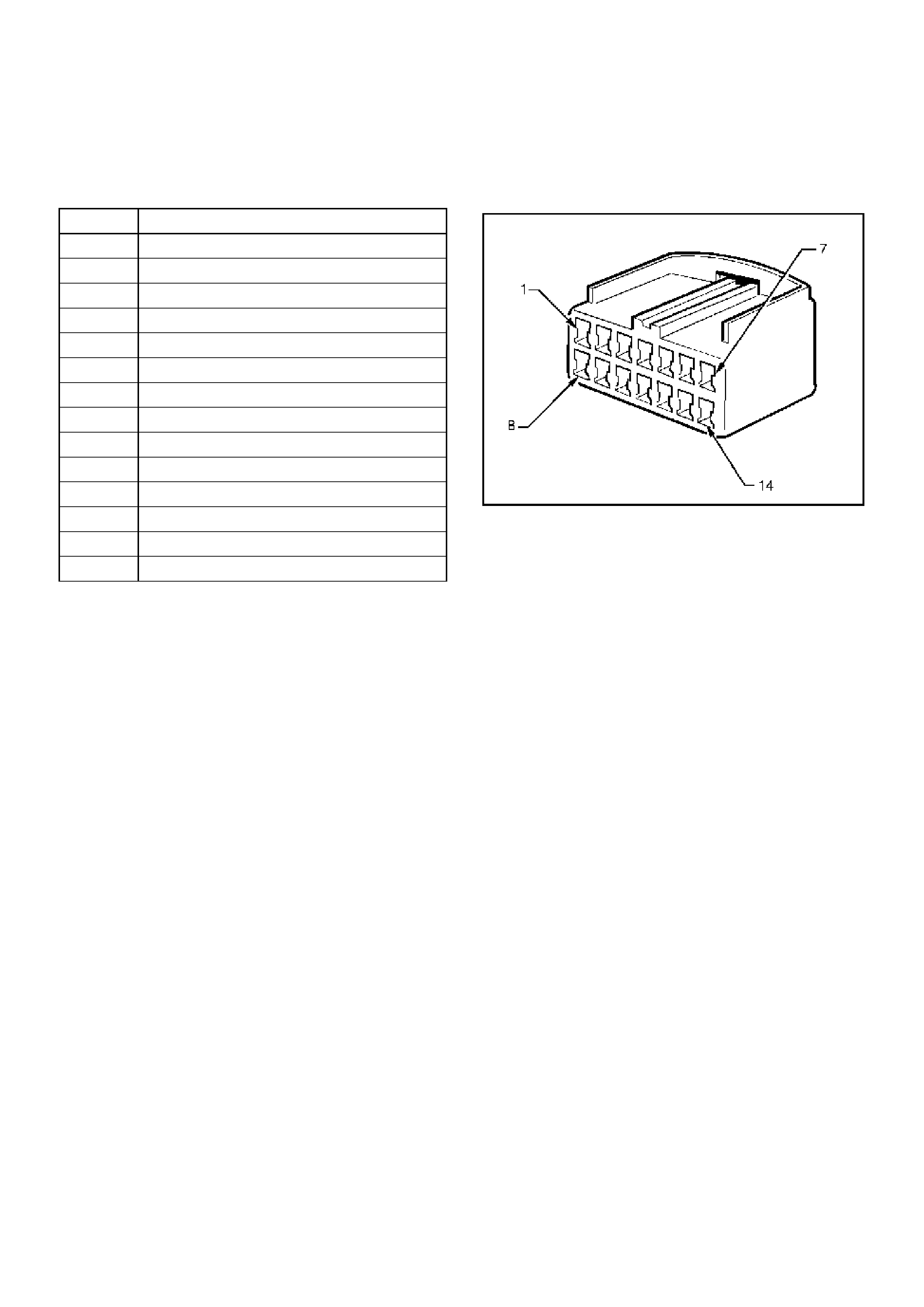
IMMOBILISER CONTROL UNIT
HARNESS CONNECTOR
Pin Circuit
1 Battery Power from Fuse C2 (10A Horn)
2 Ignition from Fuse C3 (15A Engine)
3 ECM to ICU Communication
4Not Used
5Not Used
6 Antenna Coil - Positive
7 Ground
8 ICU to ECM Communication
9 Diagnostic Link Connector Pin 7
10 Vehicle Speed Sensor (VSS) Input
11 Not Used
12 Not Used
13 A nt enna Coil - Negative
14 St arter Relay
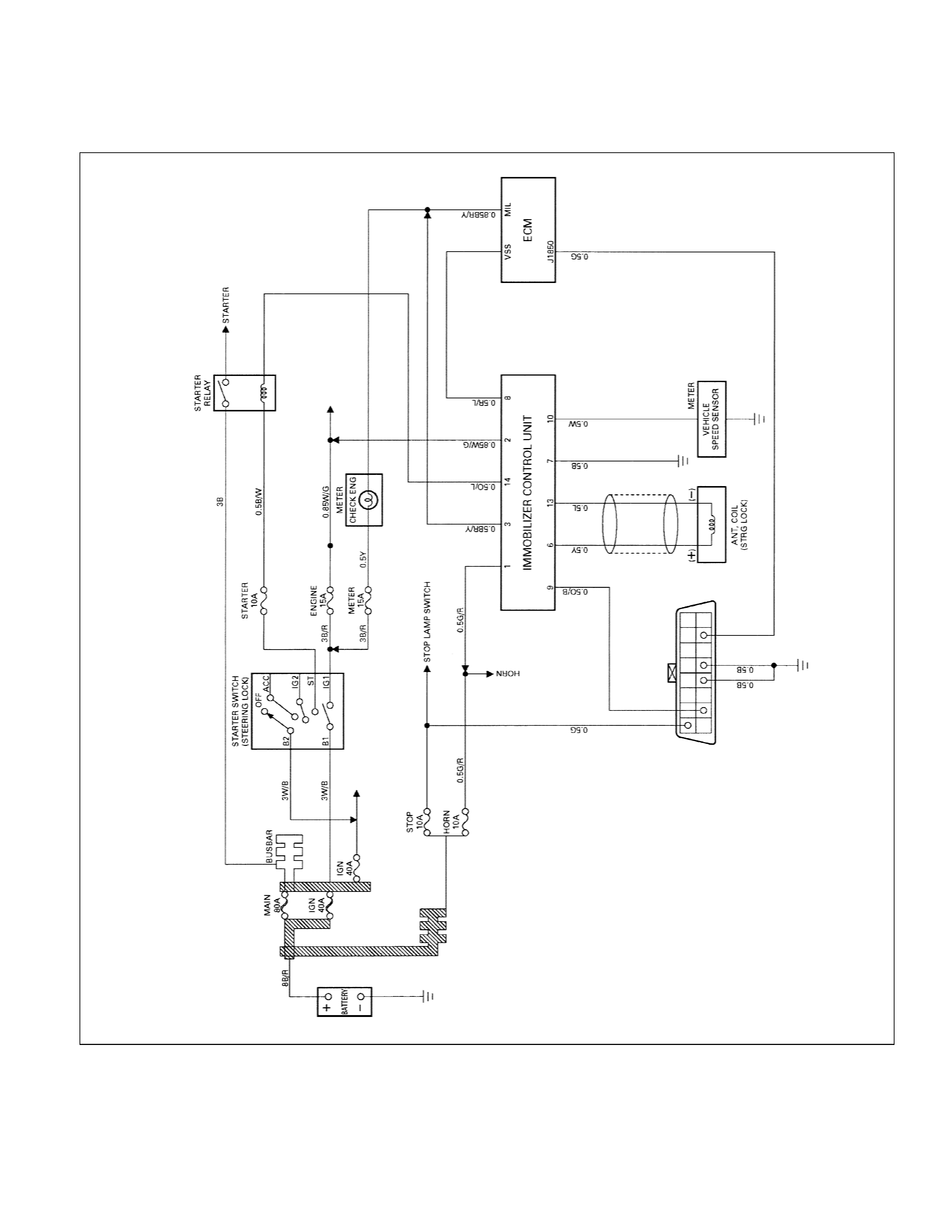
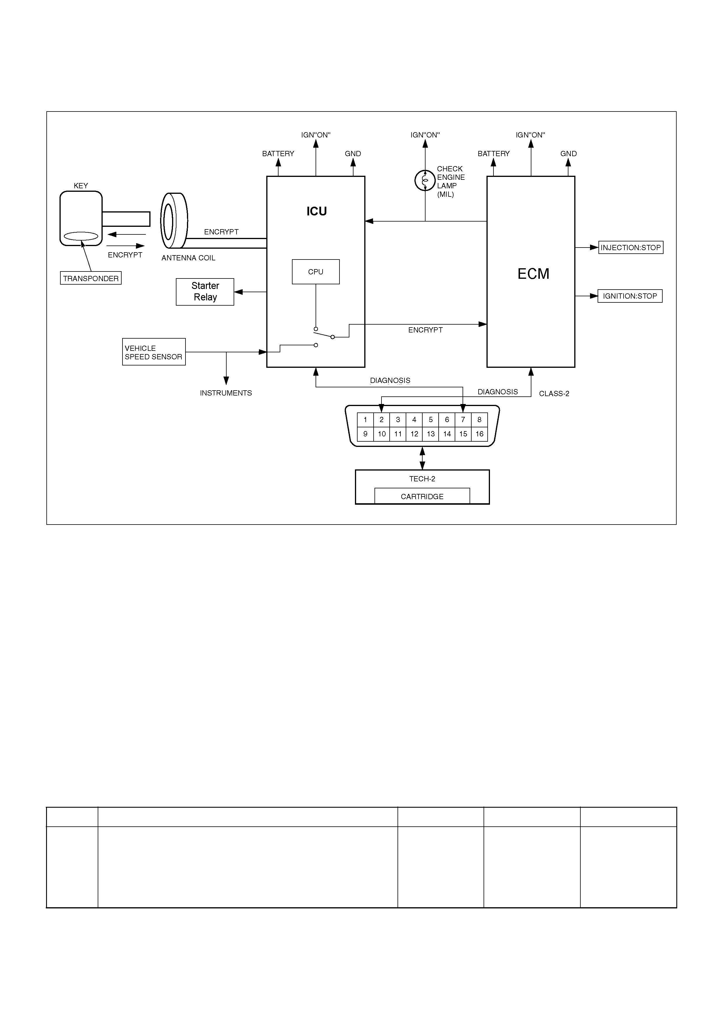
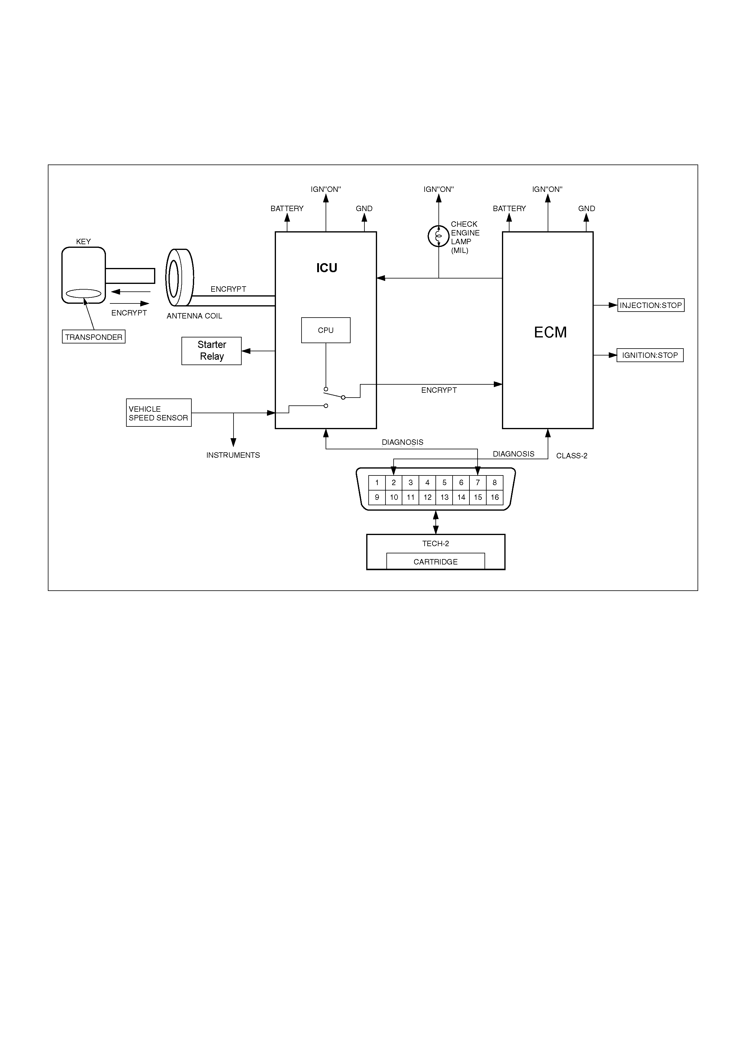
CIRCUIT DIAGRAM
Petrol Engine (C22NE, 6VD1)