
SECTION 11B - ENGINE IMMOBILISER SYSTEM
(4JB1-T DIESEL ENGINE)
General Information
System Comp one nts
Engine Start Sequence
System Progr am mi ng
TECH 2 Operation
Transponder-Key Programming
Erasing Transponder Keys
Programming The Immobiliser Control Unit (ICU)
Programming The Diesel Cut-off Solenoid (DDS-1)
Enable Programming - TIS 2000
Diagnosti c Tro uble Codes
Engine Will Not Crank No DTC Set
DTC B8011 Transponder Key Problem
DTC B8012 Wrong Transponder Key
DTC B8013 Immobiliser Not Programmed
DTC B8014 No Transponder Key Programmed
DTC B8015 Frequency Signal Low
DTC B8016 Frequency Signal High
DTC B8023 Antenna Coil Open
DTC B8024 Wrong Transponder Key Response
DTC B8055 EEPROM Error
Immobiliser Control Unit Harness Connector
Techline

Gene ra l Informat i on
The Engine Immobiliser System is designed to provide ‘Drive-away’ protection by electronically disabling the fuel
system and the starter motor relay. It is a passive system, requiring no action on the part of the driver other than
removing the ignition key from the switch.
When the i gnition s witch is turne d ‘ON’, a p rocess of data tra nsfer takes plac e between the transponde r type ignit ion
key, the Immobiliser Control Unit and the Diesel Cut-off Solenoid (DDS-1) Module.
If any transmitted data is incorrect or missing, the ICU prevents Immobiliser Relay operation - disabling the starter
motor, and th e DDS-1 Mod ule wi ll s hu t o ff the fu el supp ly to th e inj ec tor p ump . W he n t he eng ine ha s be en sh ut down
for more than twelve se conds, b oth the reques t and the im mobiliser signal cha nge on the ne xt ignition k ey cycle , the
complex data exchange taking place again.
If there is a malfunction - either an incorrect transponder signal or no communication between the components, engine
is disab led, the ‘C HECK ENG INE’ l amp in the instrume nt clus ter will bl ink rapi dly an d the rele vant Diagno st ic Trouble
Code (DTC) is stored in the ICU. It should be noted that the indication of an Immobiliser system fault is the only
function of the ‘CHECK ENGINE’ lamp on the 4JB1T system.
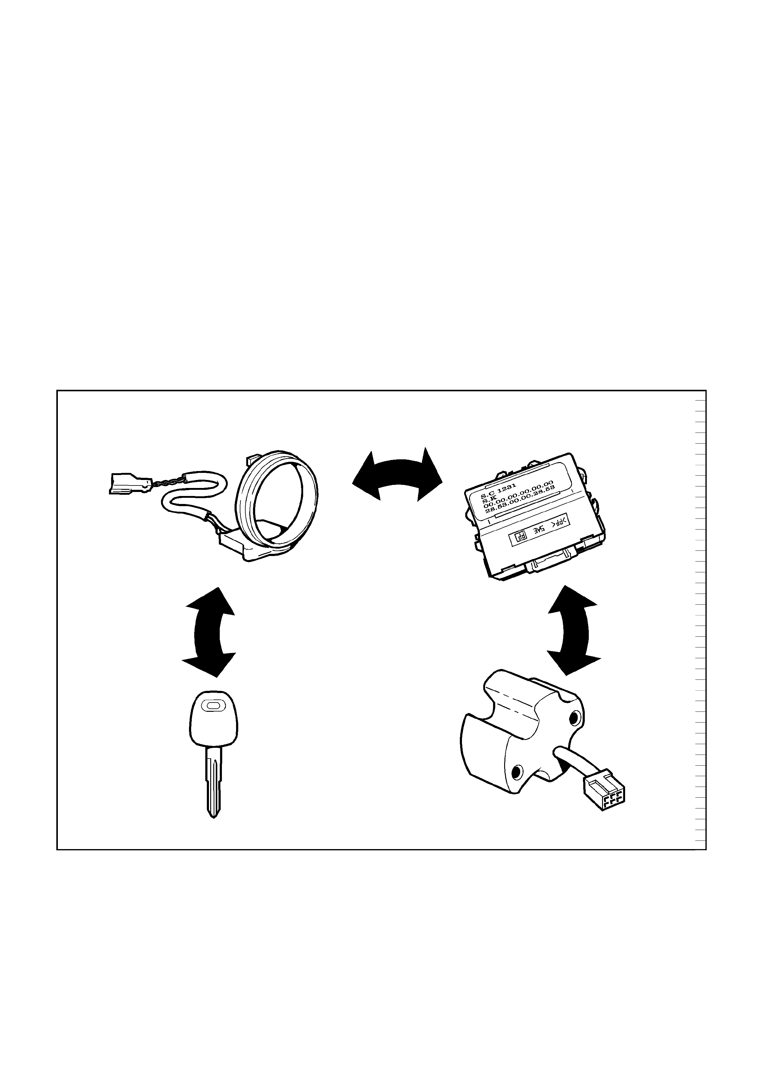
System Components
The main system components are:
• Transponder Key
• Coil Antenna
• Immobiliser Control Unit (ICU)
• Coil Antenna
• Immobiliser Relay
• DDS-1 Module & Fuel Cut Solenoid Valve
• Associated wiring harnesses, connectors and fuses
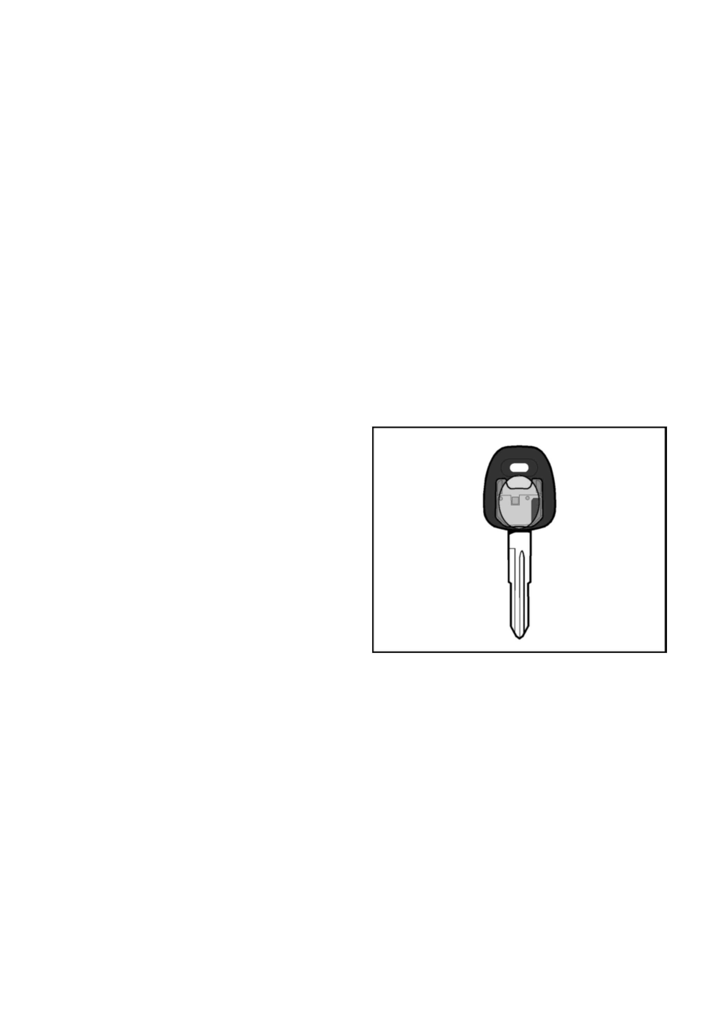
Transponder Key
The system uses a conventional mechanical-cut ignition
key containing a minature transponder (transmitter/
responder) embedded in the plastic handle.
Each transponder is programmed with it’s own specific
ID code during manufacture. Up to 10
18
codes are
available with this system, making code duplication
almost impossible.
The transponder circuit in the key does not require
batteries − the operating signal is provided cordlessly by
the ICU supplying a high frequency (133 kHz) AC
voltage signal to the coil antenna.
Encapsulated by the hard plastic of the key head, the
transponder is the most durable part of the ignition key.
The module is initially programmed with two
transponder codes, corresponding to the two keys
supplied with the vehicle. Should a key be lost, or an
additional key required, uncoded keys may be
programmed into the sy stem with the a id of TECH 2. A
maximum of 5 transponder codes can be stored in the
ICU.
Due to the complex nature of the coded signals
transmitted between the it is recommended to replace
existing ignition keys when the ICU is replaced.
NOTE: The Immobiliser Key for the 4JB1T diesel
engine differs INTERNALLY from that fitted to
MY2002 4JH 1-TC eng ined vehicles . When pro viding
a replacement or additional Immobiliser Key, refer
to the latest parts listing for correct part number
identification.
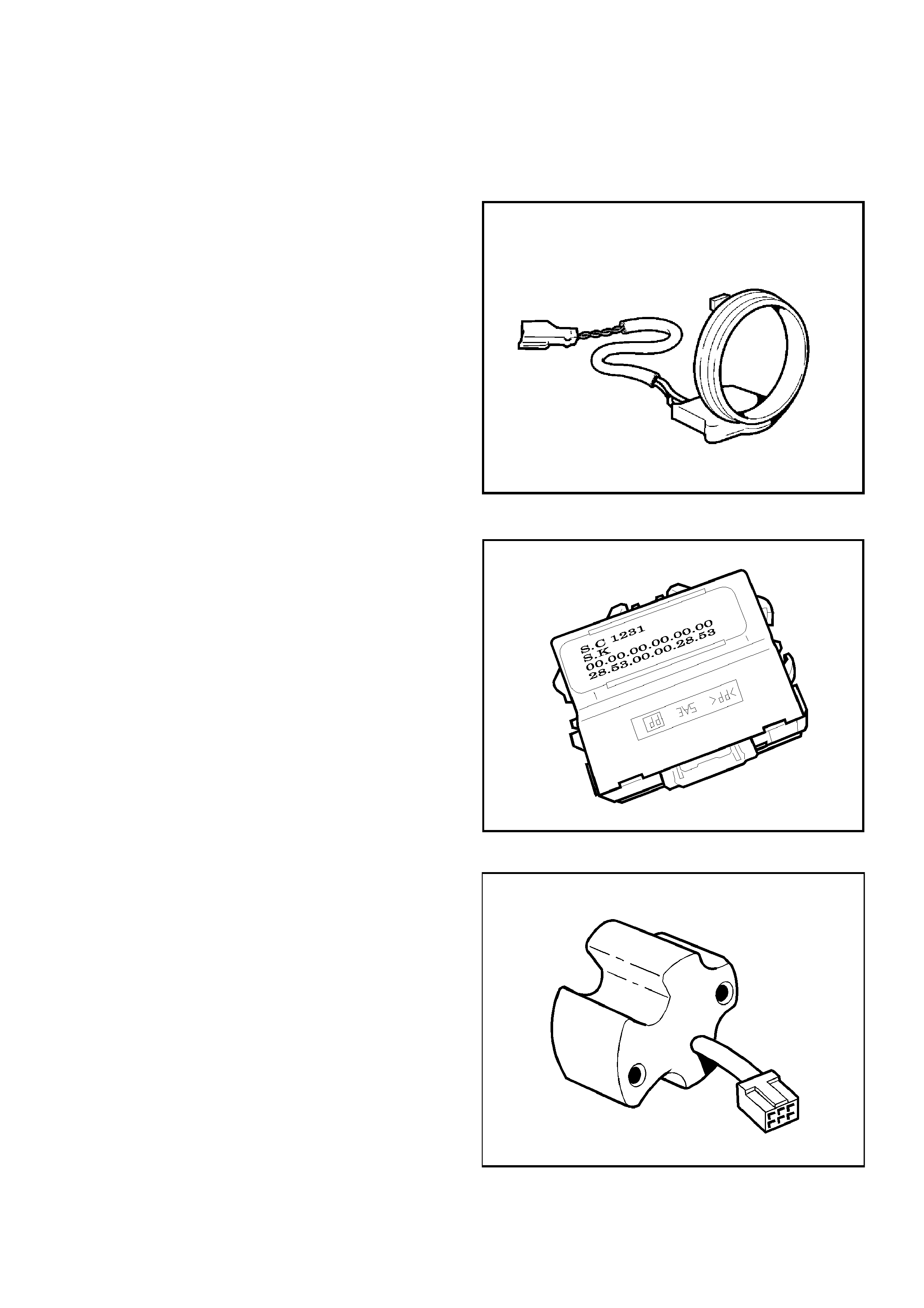
Coil Antenna
A non-contact radio frequency is used to transfer
information between the transponder key and the
Immobiliser Control Unit. Surrounding the ignition lock is
a dipole antenna, which is connected to the ICU by a
wiring harness.
The antenna is designed to have a very limited range,
ensuring that only the key in the ignition lock can
communicate with the ICU. This excludes the possible
interference from other transponder keys in the vehicle.
The antenna is accessed by removing the steering
column shroud. Apart from a continuity test on the coil
windin g, substitu tion with a known g ood part is the only
applicable diagnostic procedure.
Immobiliser Control Unit (ICU)
The Immobiliser Contol Unit (ICU) is located bolted to
the cross-beam behind the RH lower instrument panel.
The ICU is powered at all time s from Fuse EB-2 (Horn)
and receives an ignition ‘ON’ signal from Fuse CB-2
(Engine).
Communication from the ICU to the DDS-1 Module is on
the DDS-1 signal wire (ICU pin 10 to DDS-1 pin 1).
NOTE: If the ICU and DDS-1 are replaced at the
same time, the ICU MUST be programmed BEFORE
the Immobiliser function of the DDS-1 can be
activated.
NOTE: The 4JB1T diesel engine ICU differs from
that fitted to other Holden Light Commercial
Vehicles. When installing a new ICU, ensure that the
correct part is fitted to the vehicle. Refer to the
latest parts listing for ICU part number
identification.
DDS-1 Module
The DDS-1 Module is mounted on the rear of the
injector pump. The Mo dule trans mits a 10-volt signal to
the ICU. When the ignition is turned ON with a valid
transponder key, the ICU’s code generator will pulse the
10-volt signal to ground. The DDS-1 Module’s Signal
Comparator compare the coded signal generated by the
ICU to that pre-programmed into it’s memory. If both
codes are identical, the injector pump Fuel Cut Solenoid
Valve wi ll be e n ab l ed , a llowi ng f uel to fl o w to t h e in je ct or
pump.
A mis-match between the ICU generated code and the
DDS-1 Module code, or a failure occur in the
Immobiliser system, the Fuel Cut Solenoid Valve will
remain disabled, preventing the engine from running.
Note: A replacement DDS-1 must be linked to the ICU
for correct operation. Refer to System Programming in
this section.
Immobiliser Relay
The Immobiliser Relay is located in the engine
compartment Main Fuse & Relay Box. One side of the
relay solenoid windings is connected to power via the
Engine Fuse CB-2, and the other side connected ICU
pin 14. Pin 7 of the ICU is connected to ground.
When the ignition key is in the crank position, and the
ICU has received a valid transponder key signal, the
ICU will provi de th e path to groun d, ene rg ising the relay
windings.
When enabled by the ICU, the Immobiliser Relay allows
the starter motor relay to be energised.
Engine Start Sequence
Before the syst em will all ow engi ne oper ation, the foll owing sequ ence of d ata transfe r and code evalu ation mu st take
place:
1. When the ignition is turned ON, ICU supplies a high frequency (133kHz) AC voltage signal to the key via the
antenna.
2. The transponder code is transmitted to the ICU.
3. The ICU checks the transponder code and enables the Immobilser Relay.
4. The DDS-1 transmits a 10 volt signal from pin 1 to the ICU pin 10.
5. The ICU Code Generator will pulse the 10 volt signal to ground in a pre-programmed sequence.
6. The DDS-1 Module’s Signal Comparator compares the coded signal generated by the ICU to that programmed
into it’s memory.
7. If both co des are identical , the DDS-1 will enabl e the injecto r pump Fuel Cut Solenoi d Val ve, allowing fue l to flow
to the injector pump.

System Programming
Programming of the Immobiliser system is performed with TECH-2 when:
• The Immobiliser Control Unit is replaced.
• The Immobiliser Control Unit is reset.
• The DDS-1 is replaced.
• Addit ion al ign iti on ke ys are requi re d.
• An ignition key has been lost.
Prior to commencing the programming sequence, the technician will require:
• The Vehicle Identification Number.
• The vehicle security code from Holden TAS
• The mechanical key number.
To enable the completion of the programming sequence, the technician will require:
• Permission f rom TIS 2000
Security Data
The following codes/data are stored in the ICU reference memory during vehicle production:
• The Vehicle Identification Number.
• The vehicle security code.
• The mechanical key number.
• Engine type
• Transponder code/s
The secur ity c od e c an not b e d ele ted or al tered with TEC H-2. T he trans po nder cod e/s an d en gin e ty pe are p ro ce ssed
internal ly only and are n ot displ ayed on T ECH-2. T he Vehic le Identific ation Nu mber and m echanic al key n umber are
stored as further information for vehicle identification and can be displayed on TECH-2.
Security Code
The 4-digit security code prevents unauthorised programming and access to the data in the ICU via TECH-2. The
security code is programmed into the ICU.
Programming the Security Code
New Immobiliser Control Units do not contain a programmed security code. If the ICU is replaced, the security code for
that vehicle must be obtained, and then programmed into the ICU with TECH-2.
Replacement of the Immobiliser Control Unit(ICU)
Due to the comple x nature of the coded signals transmitted between the key and the ICU, it is necessary to repla ce
both existing ignition keys when the ICU is replaced.

Resetting of the Immobiliser Control Unit (ICU)
Resetting of the ICU m ay nece ssitate repla cemen t of e ither or both exi sting ignitio n key s. Th is s ituati on is most like ly
to occur if the ICU is swapped from one vehicle to another.
Loss of a Transponder Key
If a transponder key is lost, all transponder codes in the Immobiliser Control Unit must be erased to prevent
unauthori sed use. Thi s will ens ure that, whi lst the 'lost' key will allow acc ess to the v ehicle, i t cannot b e used to star t
the vehicle .
After erasing all existing codes, the transponder codes of the remaining keys and the new transponder key can be
programmed.
NOTE:
• Programming Approval must be obtained from TIS, using the `Enable Programming" option, before either
control unit or transponder key programming is performed.
• Once Pr og ra mming Approva l h as been obta in ed, TE CH- 2 will all ow f iv e prog ra mm ing ope ra tio ns . On ce al l fi ve
programming operations have been used, Programming Approval will then have to be obtained again.
• If the five programming operations are not used within 24hrs, they will be cleared from TECH-2, requiring
further Programming Approval to be obtained.

TECH 2 Operation
NOTE: Due to the constant evolution of TECH 2
software, the screens shown below may vary
slightly fro m t hose d ispla yed fo r the vehic le sys t em
being programmed.
With the lates t software loaded, co nnect TECH 2 to the
vehicle, turn on TECH 2.
When the TECH 2 introduction screen appears, press
ENTER.
Select: Diagnostics / MY2001 / TF (LUV) / F1: Body /
Immobiliser / Immobiliser (Isuzu)
The following modes and sub-modes are now available:
F0: Diagnostic Trouble Codes
• F0: Read DTC Info Ordered By Priority
• F1: Read DTC Info As Stored By ECU
• F2: Clear DTC Information
F1: Data Display
F2: Snapshot
F3: Actuator Test
• F0: Immobiliser Relay Output Test
F4: Additional Functions
• F0: Read ECU Identification
• F1: Reset Immobiliser
• F2: Erase Transponder - Keys
F5: Programming
• F0: Program Immobiliser Function
• F1: Program Transponder - Keys
• F2: Program Mechanical key Number
• F3: Program Diesel Cutoff Solenoid
System Select Menu
(1) 2001 TF (LUV)
F0: Powertrain
F1: Body
TFIMMO01
Main Menu
Select one of the following
Body
Immobiliser
Air Bag
Immobiliser
1/2
TFIMMO02
Body
F0: Diagnostic Trouble Codes
F1: Data Display
F2: Snapshot
F3: Actuator Tests
F4: Additional Functions
F5: Programming
1/6
TFIMMO03

Transponder-Key Programming
Programming Approval must be obtained from TIS 2000, using the "Enable Programming" option, during the
transponder key program sequence.
TECH 2 will request the Vehicle Security Code during the program sequence - this must be obtained from
Holden TAS prior to commencing this operation.
Connect TECH 2 to the vehicle:
1. Select Diagnostics / MY2001 / TF (LUV) / F1:
Body.
2. Select Immobiliser / Immobiliser (Isuzu).
3. Select F5: Programming.
4. Select F1: Program Transponder - Keys.
5. Obtain programming approval from TIS 2000.
6. Return to F1: Program Transponder - Keys.
7. When the SECURITY CODE is requested, enter
the security code and press ENTER.
8. Insert a non-programmed Transponder key and
press CONFIRM.
9. 'Turn On Ignition Key' will be displayed if the
ignition is OFF.
10. The Transponder status will be displayed if the
status does not allow programming.
11. When Programming starts, 'Programming
Transponder - key' is displayed.
12. Cycle the ignition key as instructed by the
display.
13. If the programming was successful, the screen
will display'Program More Keys?'
Body
F0: Diagnostic Trouble Codes
F1: Data Display
F2: Snapshot
F3: Actuator Tests
F4: Additional Functions
F5: Programming
6/6
TFIMMO04
(1) 2001 TF (Luv)
Electronic System: Immobiliser
Programming
F0: Program Immobiliser Function
F1: Program Transponder keys
F2: Program Mechanical Key Number
F3: Program Diesel Cutoff Solenoid
2/4
TFIMMO07

Erasing Transpond er Keys
If a transponder key is lost, all transponder codes in the Immobiliser Control Unit must be erased to prevent
unauthori sed use. Thi s will ens ure that, whi lst the 'lost' key will allow acc ess to the v ehicle, i t cannot b e used to star t
the vehicle .
CAUTION: This sequence erases ALL transponder-keys. Transponder-Key programming will be required before the
vehicle can be restarted.
TECH 2 will request the Vehicle Security Number during the program sequence - this must be obtained from
Holden TAS prior to commencing this operation.
Connect TECH 2 to the vehicle:
1. Select Diagnostics / MY2001 / TF (LUV) / F1:
Body.
2. Select Immobiliser / Immobiliser (Isuzu).
3. Select F4: Additional Functions.
4. Select F2: Erase Transponder - Keys.
5. The screen will display 'See Checking
Procedur e Bef or e Progr amm in g'.
6. Select CONFIRM to cont inu e.
7. The screen will display 'CAUTION - All
Transponder keys will be erased'
8. Select CONFIRM to cont inu e.
9. All transponder-keys are now erased.
10. Program the new transponder key and any
remaining keys to the vehicle using the
'Transponder -Ke y Progr am mi ng' sequen ce
Body
F0: Diagnostic Trouble Codes
F1: Data Display
F2: Snapshot
F3: Actuator Tests
F4: Additional Functions
F5: Programming
5/6
TFIMMO08
Additional Functions
F0: Read ECU Identification
F1: Reset Immobiliser
F2: Erase Transponder Keys
3/3
TFIMMO09
Programming The Immobiliser Control Unit (ICU)
TECH 2 will request the Vehicle Security Number during the program sequence - this must be obtained from
Holden TAS prior to commencing this operation.
Connect TECH 2 to the vehicle:
1. Select Diagnostics / MY2001 / TF (LUV) / F1:
Body.
2. Select Immobiliser / Immobiliser (Isuzu).
3. Select F5: Programming.
4. Select F0: Program Immobiliser Function.
5. Select Immobiliser Installed
6. Obtain programming approval from TIS 2000.
7. Return to F0: Program Immobiliser Function.
8. When the SECURITY CODE is requested, enter
the security code and press ENTER.
9. When the VIN is requested, enter the vehicle
identification number and press ENTER.
10. When the MECHANICAL KEY number is
requested, enter the key number and press
ENTER.
11. Turn the ignition ON.
12. Select the engine type
13. Check the programming result
14. Program the transponder-keys to the ICU.
Body
F0: Diagnostic Trouble Codes
F1: Data Display
F2: Snapshot
F3: Actuator Tests
F4: Additional Functions
F5: Programming
6/6
TFIMMO04
(1) 2001 TF (Luv)
Electronic System: Immobiliser
Programming
F0: Program Immobiliser Function
F1: Program Transponder keys
F2: Program Mechanical Key Number
F3: Program Diesel Cutoff Solenoid
1/4
TFIMMO05
(1) 2001 TF (Luv)
Electronic System: Immobiliser
Programming The Diesel Cut-off Solenoid (DDS-1)
When the DDS-1 and ICU are replaced at the same time, the ICU MUST be programmed
BEFORE the Immobiliser function of the DDS-1 can be activated.
Connect TECH 2 to the vehicle:
1. Select Diagnostics / MY2001 / TF (LUV) / F1:
Body.
2. Select Immobiliser / Immobiliser (Isuzu).
3. Select F5: Programming.
4. Select F3: Diesel Cutoff Solenoid.
5. Remove the 50A Glow Plug Fuse when
requested by TECH 2.
6. Cycle the ignition key as requested by TECH 2
7. TECH 2 will now ask: “Frequent Rattling Every
10 seconds?” - press the YES soft key.
8. Cycle the ignition key as requested by TECH 2
9. Replace the 50A Glow Plug Fuse when
instructe d by TE CH 2.
10. TECH 2 will now display “Start Engine !, Does
the Engine Run?” - Press the YES soft key to
confirm engine runs.
11. Should the engine not run at Step 10, press the
NO soft key and follow the TECH 2 on-screen
instructions
Body
F0: Diagnostic Trouble Codes
F1: Data Display
F2: Snapshot
F3: Actuator Tests
F4: Additional Functions
F5: Programming
6/6
TFIMMO04
(1) 2001 TF (Luv)
Electronic System: Immobiliser
Programming
F0: Program Immobiliser Function
F1: Program Transponder keys
F2: Program Mechanical Key Number
F3: Program Diesel Cutoff Solenoid
4/4
TFIMMO05a
(1) 2001 TF (Luv)
Electronic System: Immobiliser

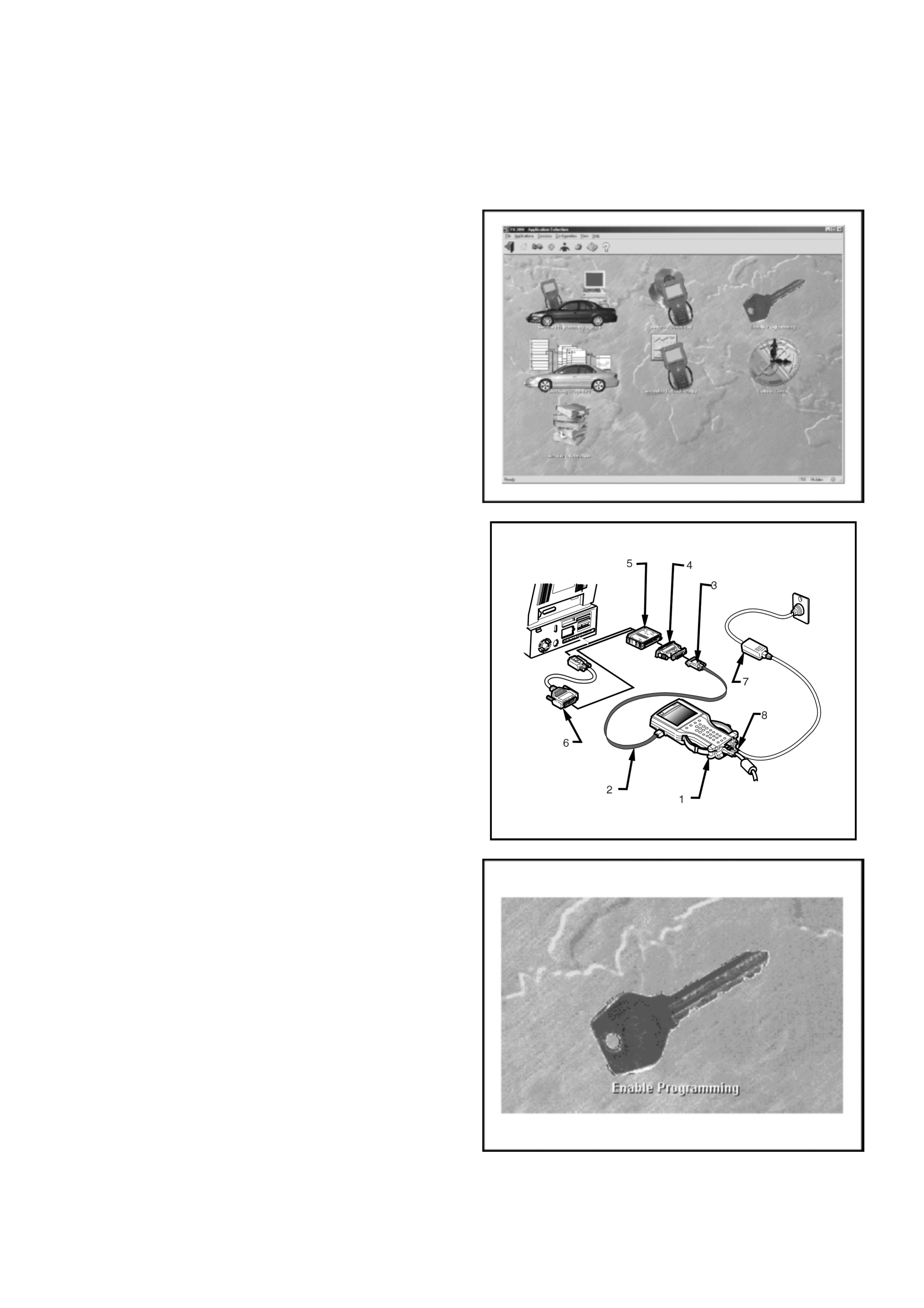
Enable Programming - TIS 2000
'Enable Programming' (TIS Approval) is used in order to
prevent the unauthorised programming of the system
security functions.
TIS Approval is required to perform the following
functions on the UBS Immobiliser System:
• Programming the Immobiliser Control Unit
• Programming the transponder keys
• Programming the ECM
After the TECH 2 security programming function has
been selected, TECH 2 will display - "Please get
programming approval from TIS'.
Enable Programming Procedure
1. Connect the RS232C interface cable to the
TECH2 communication port.
2. Connect the other end of the RS232C cable to
the hardware key using the 9 pin and 25 pin
adaptors.
3. Connect the hardware key to the serial port of
the TIS 2000 PC.
4. Connect t he p ower sup ply to the TECH 2 po wer
jack.
5. Press the PWR button and allow TECH 2 to
boot to the start-up screen.
6. Click on the Enable Programming icon of the
TIS 2000 main screen.
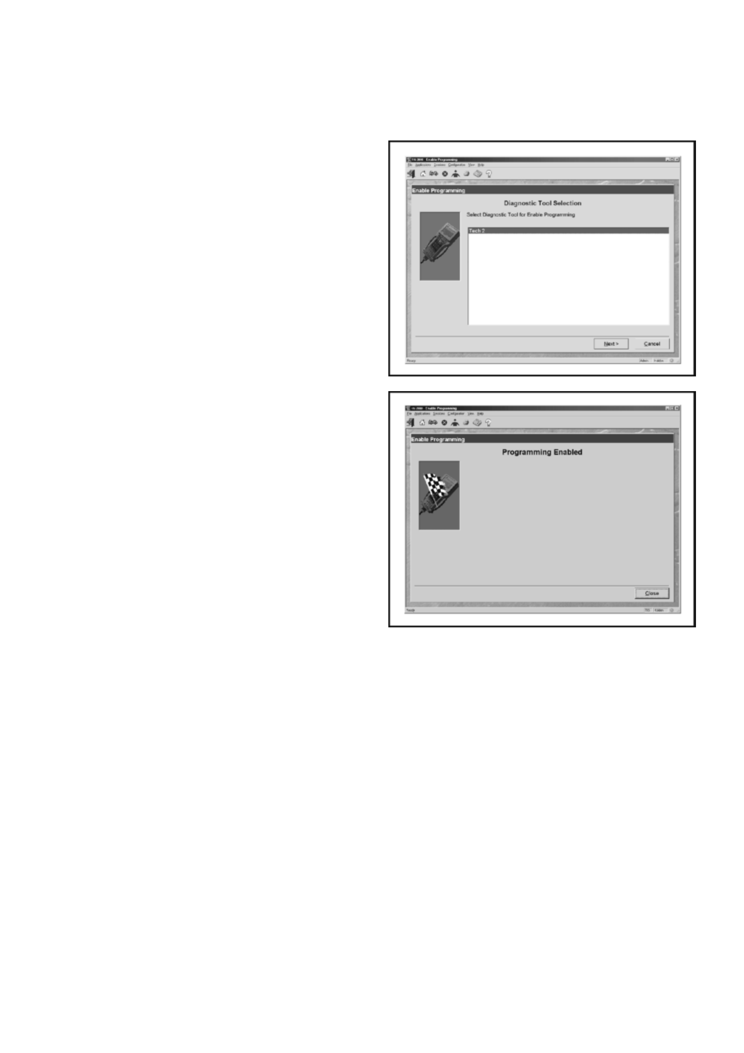
7. Select diagnostic tool (TECH 2) for Enable
Programming
8. Select Next to continue
9. When the process is completed, the
Programming Enabled screen will be displayed.
10. Click on the Close button to close the
application.
11. Reconnect TECH-2 to the vehicle DLC and
complete the programming function.

Diagnostic Trouble Codes
Current DTC's
The engine will not run when any current DTC is logged.
• The DDS-1 Module disables the fuel system.
• The ICU inhibits starter motor operation by disabling the Immobiliser relay.
History DTC's
When the fault has been repaired, the engine will operate normally and the current DTC becomes a History DTC.
History DTC's are stored in an EEPROM. This type of memory storage means the codes are not cleared when the
battery is disconnected.
• History codes may be cleared from the system memory by TECH 2.
• A History DTC will self-clear after 25 consecutive ignition cycles without the fault recurring.
DTC Description
B8011 Transponder Key Problem
B8012 Wrong Transponder key
B8013 Immobiliser Not programmed
B8014 No Transponder Key Programmed
B8015 Frequency Signal Low
B8016 Frequency Signal High
B8023 Antenna Coil Open Circuit
B8024 Wrong Transponder Response
B8055 EEPROM Error

Engine Will Not Crank No DTC Set
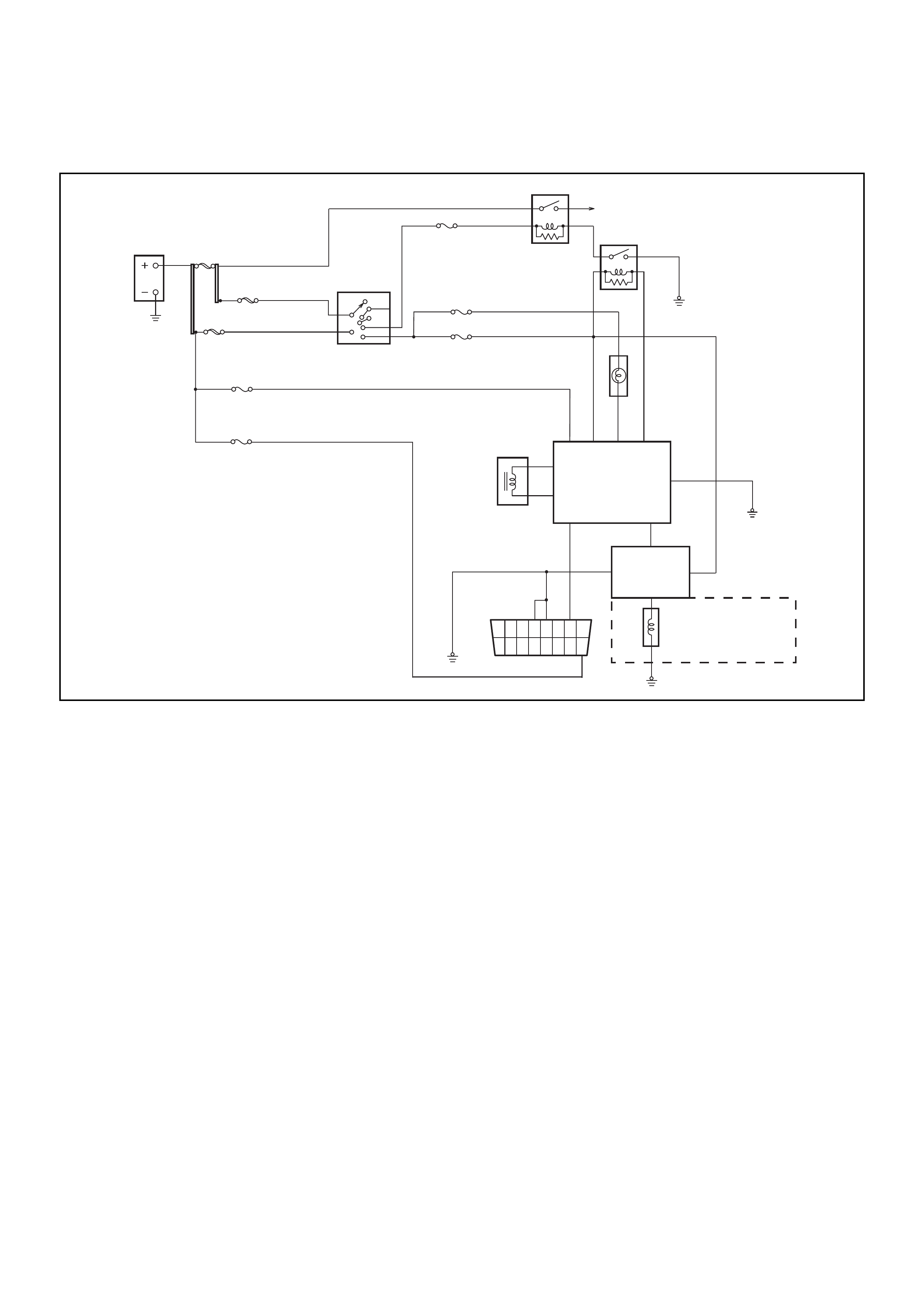
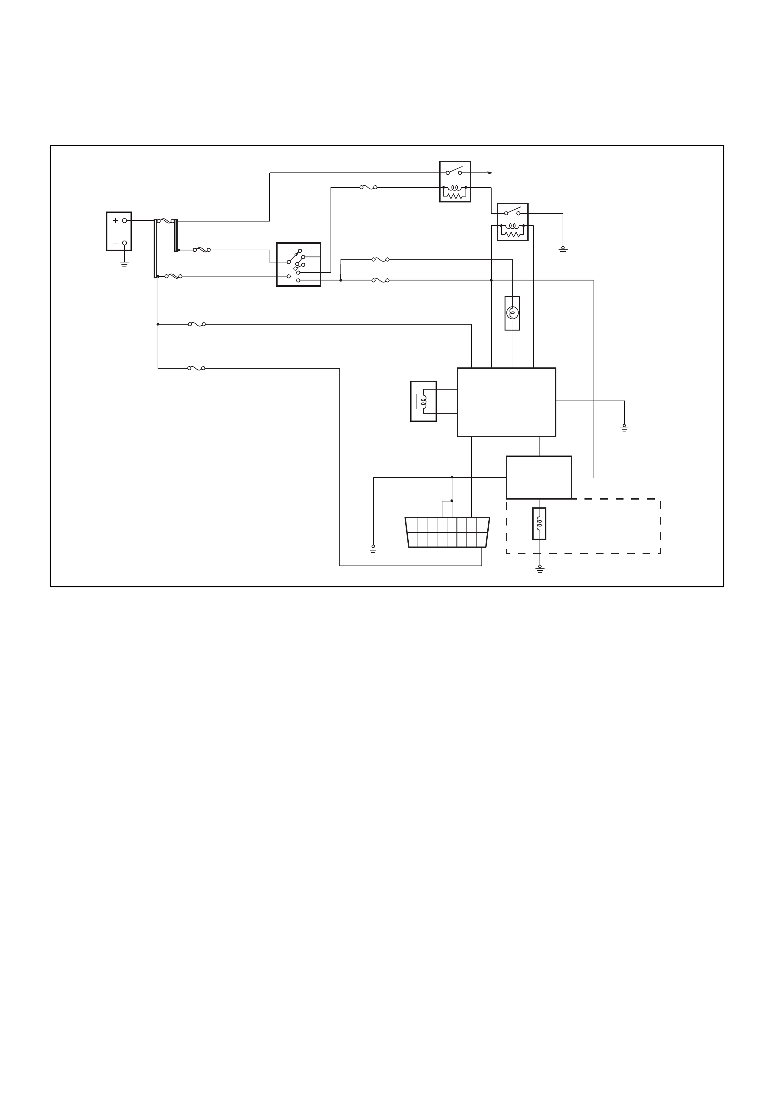
Circuit Description
The Immobiliser Control Unit provides the ground path for the starter motor relay solenoid windings via the immobiliser
relay. A no-crank condition will occur due to failure in either the Engine Immobiliser System or starter motor circuit
operation .
Condition for Setting the DTC
Not Applicable
Acti on Taken Wh en the DTC sets
Not Applicable
Condition for Clearing the MIL/DTC
Not Applicable
Diagnostic Aids
Check for the following conditions:
• Poor connection at DDS-1 and Immobiliser Control Unit. Inspect harness connectors for backed out terminals,
improper mating, broken locks, improperly formed or damaged terminals, and poor terminal to wire connection.
• Damag ed harnes s-Inspe ct the wiri ng harn ess for dam age, If the ha rness ap pears to be OK, disc onnect the DDS-1
and ICU, turn the ignition “ON" and observe a voltmeter connected to the suspect circuit at the DDS-1 and
Immobiliser harness connectors while moving connectors and wiring harnesses relates to the MIL. A change in
voltage will indicate the location of the fault.
ACC
B2
B1
OFF
IG2
ST
IG1
IGNITION
SWITCH
BATT
MAIN
EB- 1 6
100A
IGN
EB- 2 0
40A HORN
EB- 2
10A
ENGINE
CB- 2
15A
METER
CB-6
10A
STOP
EB- 3
10A
C.E.L.
6
3
1
DDS- 1
7
15
8
16
1
9
2
10
3
11
4
12
5
13
6
14
10
9
3
7
14
2
1
13
ANTENNA
COIL
STARTER
10A
STARTER
MOTOR
IMMOBILISER
CONTROL
UNIT
IMMOBILISER
RELAY
STARTER
RELAY
IGN
EB- 1 7
40A
2
FUEL CU T
SOLENOID FUEL
INJECTOR
PUMP

Engine Will Not Crank - No DTC Set
Step Action Value(s) Yes No
1 Check the DDS-1 and ICU harness and connectors
for:
1. Backed out terminals, improper mating, broken
locks, improperly formed or damaged terminals,
and poor terminal to wire connection.
2. Damaged ha rn es s - Ins pec t the wiring har ne ss for
damage.
If a problem found, repair as necessary.
Was a problem found? Verify repair Go to Step 2
2 Turn the ignition ON, does the ‘CHECK ENGINE’
Lamp flash at 2Hz?
— Go to Step 3
Check starter
motor circuit.
Refer Section
6D
3 With the ignition ON, check the voltage at ICU pin 2.
Is the voltage in specified range? 11.6v - 12.7v Go to Step 5 Go to Step 4
4 Check for continuity between Fuse C-3 & ICU pin 2.
If a problem found, repair as necessary.
Was a problem found? Verify repair Go to Step 5
5 Measure the resistance between ICU pin and ground.
Is the resistance less than the specified value? 5 ΩGo to Step 7 Go to Step 6
6 Repair the ground circuit from ICU pin 7 to ground
Is the action complete? — Verify repair —
7. Replace the ICU and the existing ignition keys
Reprogram the system Verify repair
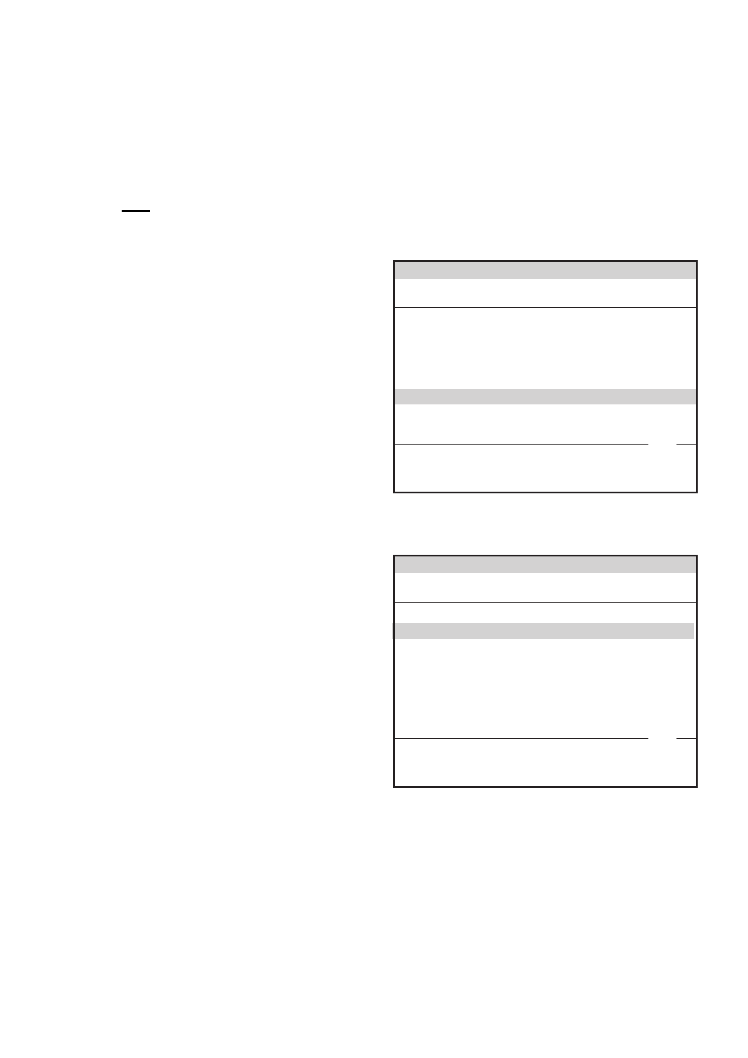
DTC B8011 Transponder Key Problem
060RA00003
Circuit Description
The Immobiliser Control Unit expects to receive a valid transponder key signal when the ignition is turned ON.
Condition for Setting the DTC
A DTC B8011 will set if any of the following conditions are present for at least 0.84 seconds during an attempted start:
• No transponder-key signal is present
• The transponder-key is defective
• The key is not a transponder key
Acti on Taken When the DTC sets
• The engine will not crank
• The CHECK ENGINE Lamp will flash at 4Hz
Condition for Clearing the MIL/DTC
• Using TECH 2, select Clear DTC Information
• A History DTC B8011 will self-clear after 25 consecutive ignition cycles without the fault recurring.
Diagnostic Aids
• Poor connection at DDS-1 and Immobiliser Control Unit. Inspect harness connectors for backed out terminals,
improper mating, broken locks, improperly formed or damaged terminals, and poor terminal to wire connection.
• Damag ed harnes s-Inspe ct the wiri ng harn ess for dam age, If the ha rness ap pears to be OK, disc onnect the DDS-1
and ICU, turn the ignition “ON" and observe a voltmeter connected to the suspect circuit at the DDS-1 and
Immobiliser harness connectors while moving connectors and wiring harnesses relates to the MIL. A change in
voltage will indicate the location of the fault.
ACC
B2
B1
OFF
IG2
ST
IG1
IGNITION
SWITCH
BATT
MAIN
EB- 1 6
100A
IGN
EB- 2 0
40A HORN
EB- 2
10A
ENGINE
CB- 2
15A
METER
CB-6
10A
STOP
EB- 3
10A
C.E.L.
6
3
1
DDS- 1
7
15
8
16
1
9
2
10
3
11
4
12
5
13
6
14
10
9
3
7
14
2
1
13
ANTENNA
COIL
STARTER
10A
STARTER
MOTOR
IMMOBILISER
CONTROL
UNIT
IMMOBILISER
RELAY
STARTER
RELAY
IGN
EB- 1 7
40A
2
FUEL CU T
SOLENOID FUEL
INJECTOR
PUMP

DTC B8011- Transponder Key Problem
Step Action Value(s) Yes No
1 Check the DDS-1 and ICU harness and connectors
for:
1. Backed out terminals, improper mating, broken
locks, improperly formed or damaged terminals,
and poor terminal to wire connection.
2. Damaged ha rn es s - Ins pec t the wiring har ne ss for
damage.
If a problem found, repair as necessary.
Was a problem found? Verify repair Go to Step 2
2 Turn the ignition ON, does the ‘CHECK ENGINE’
Lamp flash at 4Hz? — Go to Step 3 —
3 Check for correct operation with the other transponder
key/s
Does the system operate correctly? — Go to Step 4 Go to Step 4
4 Reprogram the transponder key.
Was the programming successful? Verify repair Go to Step 5
5 Is a DTC B8023 set after the program attempt? Go to
Diagnostic
Chart
DTC B8023 -
Antenna Coil
Open Go to Step 6
6 Replace the ICU and the existing ignition keys
Reprogram the system — Verify repair —

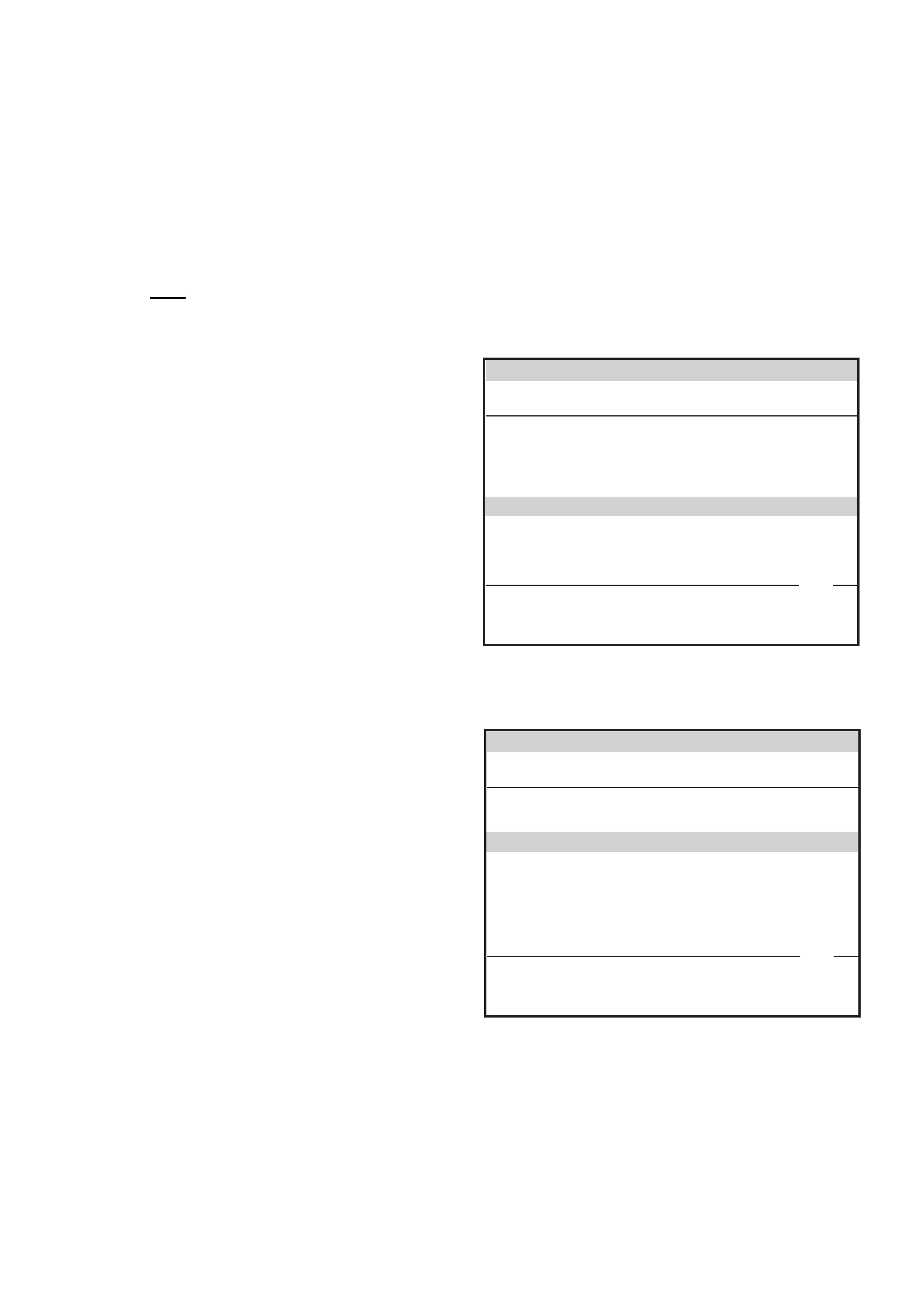
DTC B8012 Wrong Transponder Key
060RA00003
Circuit Description
The Immobiliser Control Unit expects to receive a valid transponder key signal when the ignition is turned ON.
Condition for Setting the DTC
A DTC B8012 will set if any of the following conditions are present for at least 0.84 seconds during an attempted start:
• The transponder-key signal is not programmed to the ECU.
• The transponder read-out is interrupted
• The key is not a transponder key
Acti on Taken When the DTC sets
• The engine will not crank
• The CHECK ENGINE Lamp will flash at 4Hz
Condition for Clearing the MIL/DTC
• Using TECH 2, select Clear DTC Information
• A History DTC B8012 will self-clear after 25 consecutive ignition cycles without the fault recurring.
ACC
B2
B1
OFF
IG2
ST
IG1
IGNITION
SWITCH
BATT
MAIN
EB- 1 6
100A
IGN
EB- 2 0
40A HORN
EB- 2
10A
ENGINE
CB- 2
15A
METER
CB-6
10A
STOP
EB- 3
10A
C.E.L.
6
3
1
DDS- 1
7
15
8
16
1
9
2
10
3
11
4
12
5
13
6
14
10
9
3
7
14
2
1
13
ANTENNA
COIL
STARTER
10A
STARTER
MOTOR
IMMOBILISER
CONTROL
UNIT
IMMOBILISER
RELAY
STARTER
RELAY
IGN
EB- 1 7
40A
2
FUEL CU T
SOLENOID FUEL
INJECTOR
PUMP

Diagnostic Aids
Check for the following conditions:
• Poor connection at DDS-1 and Immobiliser Control Unit. Inspect harness connectors for backed out terminals,
improper mating, broken locks, improperly formed or damaged terminals, and poor terminal to wire connection.
• Damag ed harnes s-Inspe ct the wiri ng harn ess for dam age, If the ha rness ap pears to be OK, disc onnect the DDS-1
and ICU, turn the ignition “ON" and observe a voltmeter connected to the suspect circuit at the DDS-1 and
Immobiliser harness connectors while moving connectors and wiring harnesses relates to the MIL. A change in
voltage will indicate the location of the fault.
DTC B8012 - Wron g Transponder Key
Step Action Value(s) Yes No
1 Check for correct operation with the other transponder
key/s
Does the system operate correctly? — Go to Step 2 Go to Step 4
2 Reprogram the transponder key.
Was the programming successful? Verify repair Go to Step 3
3 Replace the transponder key
Reprogram the system — Verify repair —
4 Replace the ICU and the existing ignition keys
Reprogram the system — Verify repair —

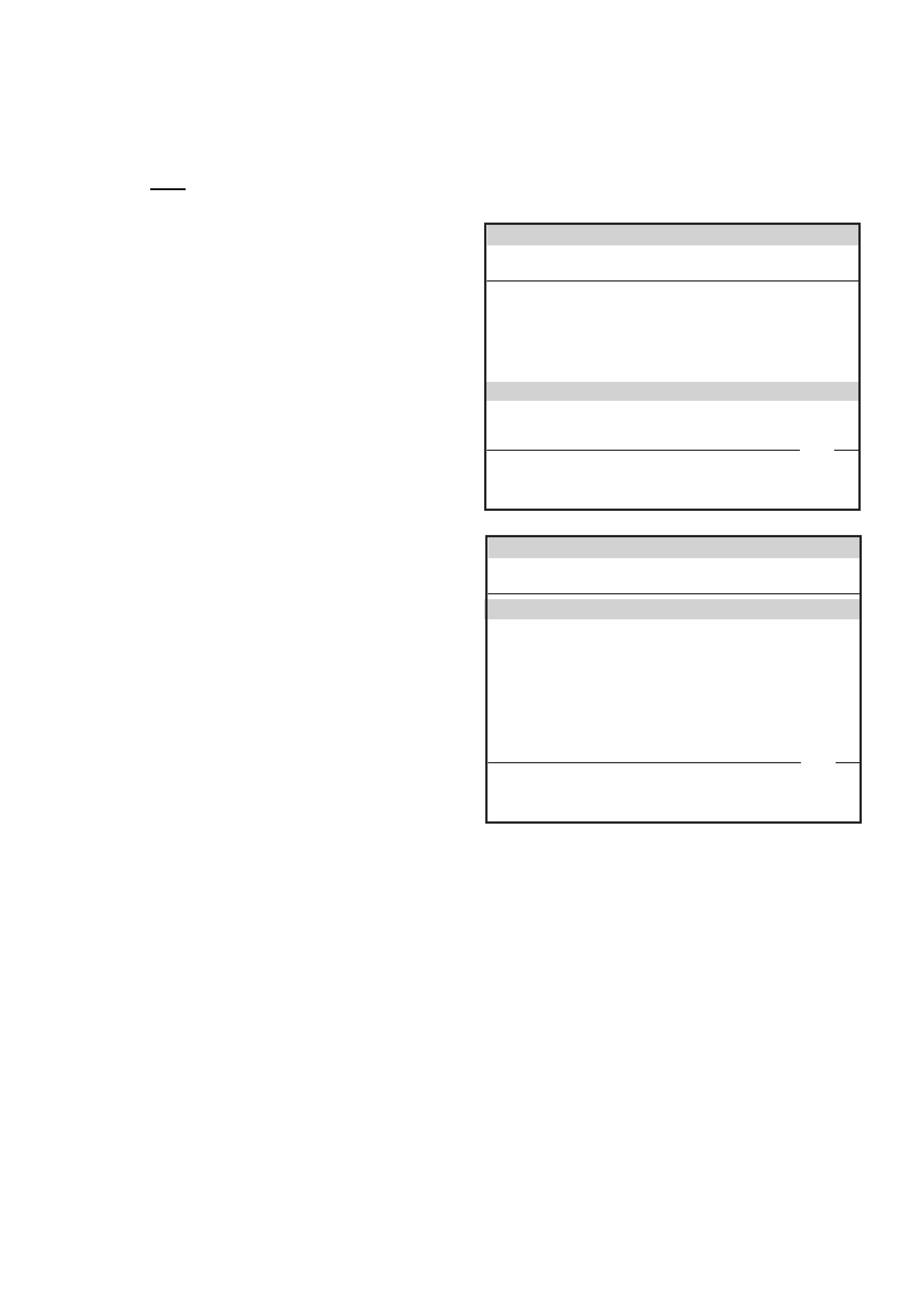
DTC B8013 Immobiliser Not Programmed
060RA00003
Circuit Description
The Immobiliser Control Unit expects to receive a valid transponder key signal when the ignition is turned ON.
Condition for Setting the DTC
A DTC B8013 will set immendiately upon recognition If :
• The vehicle security code is not programmed into the system.
Acti on Taken When the DTC sets
• The engine will not crank
• The CHECK ENGINE Lamp will flash at 4Hz
Condition for Clearing the MIL/DTC
• Using TECH 2, select Clear DTC Information
• A History DTC B8013 will self-clear after 25 consecutive ignition cycles without the fault recurring.
Diagnostic Aids
Check for the following conditions:
• Poor connection at DDS-1 and Immobiliser Control Unit. Inspect harness connectors for backed out terminals,
improper mating, broken locks, improperly formed or damaged terminals, and poor terminal to wire connection.
• Damag ed harnes s-Inspe ct the wiri ng harn ess for dam age, If the ha rness ap pears to be OK, disc onnect the DDS-1
and ICU, turn the ignition “ON" and observe a voltmeter connected to the suspect circuit at the DDS-1 and
Immobiliser harness connectors while moving connectors and wiring harnesses relates to the MIL. A change in
voltage will indicate the location of the fault.
ACC
B2
B1
OFF
IG2
ST
IG1
IGNITION
SWITCH
BATT
MAIN
EB- 1 6
100A
IGN
EB- 2 0
40A HORN
EB- 2
10A
ENGINE
CB- 2
15A
METER
CB-6
10A
STOP
EB- 3
10A
C.E.L.
6
3
1
DDS- 1
7
15
8
16
1
9
2
10
3
11
4
12
5
13
6
14
10
9
3
7
14
2
1
13
ANTENNA
COIL
STARTER
10A
STARTER
MOTOR
IMMOBILISER
CONTROL
UNIT
IMMOBILISER
RELAY
STARTER
RELAY
IGN
EB- 1 7
40A
2
FUEL CU T
SOLENOID FUEL
INJECTOR
PUMP

DTC B8013 - Immobiliser Not Programmed
Step Action Value(s) Yes No
1 Attempt to reprogram the security information
W as the programming successful? — Verify repair Go to Step 2
2 Check the DDS-1 and ICU harness and connectors
for:
1. Backed out terminals, improper mating, broken
locks, improperly formed or damaged terminals,
and poor terminal to wire connection.
2. Damaged ha rn es s - Ins pec t the wiring har ne ss for
damage.
If a problem found, repair as necessary.
Was a problem found? — Verify repair Go to Step 3
3 Replace the ICU and the existing ignition keys
Reprogram the system — Verify repair —
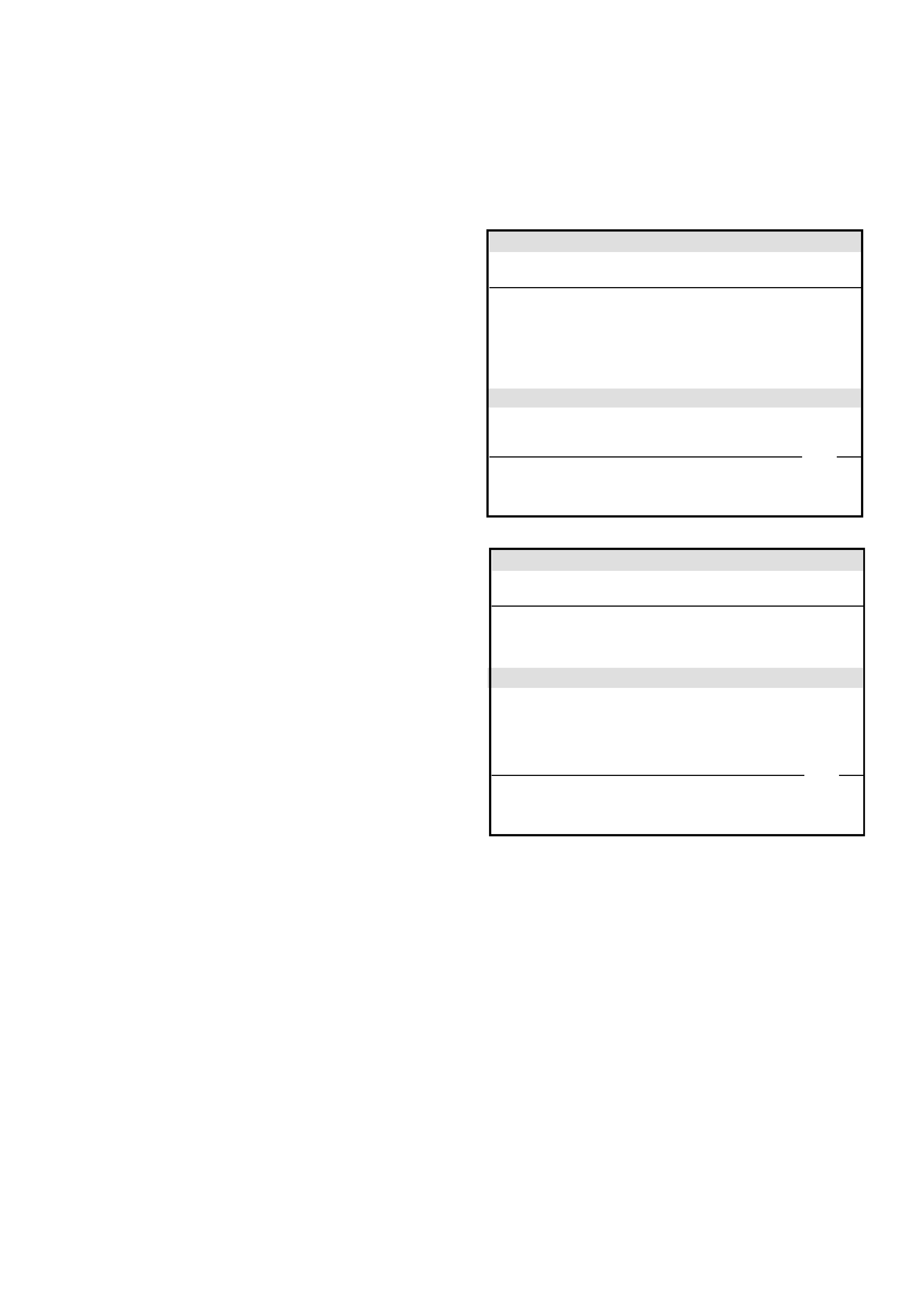
DTC B8014 No Transponder Key Programmed
060RA00003
Circuit Description
The Immobiliser Control Unit expects to receive a valid transponder key signal when the ignition is turned ON.
Condition for Setting the DTC
A DTC B8014 will set immendiately upon recognition If :
• No transponder keys are programmed into the system.
Acti on Taken When the DTC sets
• The engine will not crank
• The CHECK ENGINE Lamp will flash at 4Hz
Condition for Clearing the MIL/DTC
• Using TECH 2, select Clear DTC Information
• A History DTC B8014 will self-clear after 25 consecutive ignition cycles without the fault recurring.
Diagnostic Aids
Check for the following conditions:
• Poor connection at DDS-1 and Immobiliser Control Unit. Inspect harness connectors for backed out terminals,
improper mating, broken locks, improperly formed or damaged terminals, and poor terminal to wire connection.
• Damag ed harnes s-Inspe ct the wiri ng harn ess for dam age, If the ha rness ap pears to be OK, disc onnect the DDS-1
and ICU, turn the ignition “ON" and observe a voltmeter connected to the suspect circuit at the DDS-1 and
Immobiliser harness connectors while moving connectors and wiring harnesses relates to the MIL. A change in
voltage will indicate the location of the fault.
ACC
B2
B1
OFF
IG2
ST
IG1
IGNITION
SWITCH
BATT
MAIN
EB- 1 6
100A
IGN
EB- 2 0
40A HORN
EB- 2
10A
ENGINE
CB- 2
15A
METER
CB-6
10A
STOP
EB- 3
10A
C.E.L.
6
3
1
DDS- 1
7
15
8
16
1
9
2
10
3
11
4
12
5
13
6
14
10
9
3
7
14
2
1
13
ANTENNA
COIL
STARTER
10A
STARTER
MOTOR
IMMOBILISER
CONTROL
UNIT
IMMOBILISER
RELAY
STARTER
RELAY
IGN
EB- 1 7
40A
2
FUEL CU T
SOLENOID FUEL
INJECTOR
PUMP

DTC B8014 - No Transponder Key Programme d
Step Action Value(s) Yes No
1 Attempt to reprogram the transponder keys
W as the programming successful? — Verify repair Go to Step 2
2 Check the DDS-1 and ICU harness and connectors
for:
1. Backed out terminals, improper mating, broken
locks, improperly formed or damaged terminals,
and poor terminal to wire connection.
2. Damaged ha rn es s - Ins pec t the wiring har ne ss for
damage.
If a problem found, repair as necessary.
Was a problem found? — Verify repair Go to Step 3
3 Replace the ICU and the existing ignition keys
Reprogram the system — Verify repair —
DTC B8015 Frequency Signal Low
060RA00003
Circuit Description
The Immobiliser Control Unit generates a coded frequency signal based on the 10 volt signal from the DDS-1 Module.
.
Condition for Setting the DTC
A DTC B8015 will set if:
• There is a short to ground or an open circuit in the harness wire from ICU pin 10 to DDS-1 pin 1.(signal is low)
Acti on Taken When the DTC sets
• The engine will not crank
• The CHECK ENGINE Lamp will flash at 4Hz
Condition for Clearing the MIL/DTC
• Using TECH 2, select Clear DTC Information
• A History DTC B8015 will self-clear after 25 consecutive ignition cycles without the fault recurring.
Diagnostic Aids
Check for the following conditions:
• Poor connection at DDS-1 and Immobiliser Control Unit. Inspect harness connectors for backed out terminals,
improper mating, broken locks, improperly formed or damaged terminals, and poor terminal to wire connection.
• Damag ed harnes s-Inspe ct the wiri ng harn ess for dam age, If the ha rness ap pears to be OK, disc onnect the DDS-1
and ICU, turn the ignition “ON" and observe a voltmeter connected to the suspect circuit at the DDS-1 and
Immobiliser harness connectors while moving connectors and wiring harnesses relates to the MIL. A change in
voltage will indicate the location of the fault.
ACC
B2
B1
OFF
IG2
ST
IG1
IGNITION
SWITCH
BATT
MAIN
EB- 1 6
100A
IGN
EB- 2 0
40A HORN
EB- 2
10A
ENGINE
CB- 2
15A
METER
CB-6
10A
STOP
EB- 3
10A
C.E.L.
6
3
1
DDS- 1
7
15
8
16
1
9
2
10
3
11
4
12
5
13
6
14
10
9
3
7
14
2
1
13
ANTENNA
COIL
STARTER
10A
STARTER
MOTOR
IMMOBILISER
CONTROL
UNIT
IMMOBILISER
RELAY
STARTER
RELAY
IGN
EB- 1 7
40A
2
FUEL CU T
SOLENOID FUEL
INJECTOR
PUMP

DTC B8015 - Frequency Signal Low
Step Action Value(s) Yes No
1 Check for continuity between ICU pin 10 and DDS-1
pin 1.
If a problem found, repair as necessary.
W as a problem found? — Verify repair Go to Step 2
2 Check for continuity between ICU pin 10 and ground
If continuity is found, repair as necessary.
Was continuity found? — Verify repair Go to Step 3
3 Clear the DTC using T ECH 2
Did the DTC Clear? — Verify repair Go to Step 2

DTC B8016 Frequency Signal High
060RA00003
Circuit Description
The Immobiliser Control Unit generates a coded frequency signal based on the 10 volt signal from the DDS-1 Module.
.
Condition for Setting the DTC
A DTC B8016 will set if:
• There is a short to power in the harness wire from ICU pin 10 to DDS-1 pin 1.(signal is high)
Acti on Taken When the DTC sets
• The engine will not crank
• The CHECK ENGINE Lamp will flash at 4Hz
Condition for Clearing the MIL/DTC
• Using TECH 2, select Clear DTC Information
• A History DTC B8016 will self-clear after 25 consecutive ignition cycles without the fault recurring.
Diagnostic Aids
Check for the following conditions:
• Poor connection at DDS-1 and Immobiliser Control Unit. Inspect harness connectors for backed out terminals,
improper mating, broken locks, improperly formed or damaged terminals, and poor terminal to wire connection.
• Damag ed harnes s-Inspe ct the wiri ng harn ess for dam age, If the ha rness ap pears to be OK, disc onnect the DDS-1
and ICU, turn the ignition “ON" and observe a voltmeter connected to the suspect circuit at the DDS-1 and
Immobiliser harness connectors while moving connectors and wiring harnesses relates to the MIL. A change in
voltage will indicate the location of the fault.
ACC
B2
B1
OFF
IG2
ST
IG1
IGNITION
SWITCH
BATT
MAIN
EB- 1 6
100A
IGN
EB- 2 0
40A HORN
EB- 2
10A
ENGINE
CB- 2
15A
METER
CB-6
10A
STOP
EB- 3
10A
C.E.L.
6
3
1
DDS- 1
7
15
8
16
1
9
2
10
3
11
4
12
5
13
6
14
10
9
3
7
14
2
1
13
ANTENNA
COIL
STARTER
10A
STARTER
MOTOR
IMMOBILISER
CONTROL
UNIT
IMMOBILISER
RELAY
STARTER
RELAY
IGN
EB- 1 7
40A
2
FUEL CU T
SOLENOID FUEL
INJECTOR
PUMP

DTC B8016 - Frequency Signal High
Step Action Value(s) Yes No
1 1. Disconnect the ICU and DDS-1 harness
connectors.
2. Turn the ignition ON
3. Check for voltage at ICU harness connector pin 10
If voltage is found, repair as necessary.
Was voltage found? — Verify repair Go to Step 2
2 Clear the DTC using T ECH 2
Did the DTC Clear? — Verify repair Go to Step 1

DTC B8023 Antenna Coil Open
060RA00003
Circuit Description
The Immobiliser Control Unit expects to receive a valid transponder key signal when the ignition is turned ON. The
ICU and transponder key communicate via the antenna coil circuit.
Condition for Setting the DTC
A DTC B8023 will set immendiately upon recognition If :
• The antenna coil is not connected or there is an open in the antenna coil circuit.
Acti on Taken When the DTC sets
• The engine will not crank
• The CHECK ENGINE Lamp will flash at 4Hz
Condition for Clearing the MIL/DTC
• Using TECH 2, select Clear DTC Information
• A History DTC B8023 will self-clear after 25 consecutive ignition cycles without the fault recurring.
Diagnostic Aids
Check for the following conditions:
• Poor connection at DDS-1 and Immobiliser Control Unit. Inspect harness connectors for backed out terminals,
improper mating, broken locks, improperly formed or damaged terminals, and poor terminal to wire connection.
• Damag ed harnes s-Inspe ct the wiri ng harn ess for dam age, If the ha rness ap pears to be OK, disc onnect the DDS-1
and ICU, turn the ignition “ON" and observe a voltmeter connected to the suspect circuit at the DDS-1 and
Immobiliser harness connectors while moving connectors and wiring harnesses relates to the MIL. A change in
voltage will indicate the location of the fault.
ACC
B2
B1
OFF
IG2
ST
IG1
IGNITION
SWITCH
BATT
MAIN
EB- 1 6
100A
IGN
EB- 2 0
40A HORN
EB- 2
10A
ENGINE
CB- 2
15A
METER
CB-6
10A
STOP
EB- 3
10A
C.E.L.
6
3
1
DDS- 1
7
15
8
16
1
9
2
10
3
11
4
12
5
13
6
14
10
9
3
7
14
2
1
13
ANTENNA
COIL
STARTER
10A
STARTER
MOTOR
IMMOBILISER
CONTROL
UNIT
IMMOBILISER
RELAY
STARTER
RELAY
IGN
EB- 1 7
40A
2
FUEL CU T
SOLENOID FUEL
INJECTOR
PUMP

DTC B8023 - Antenna Coil Open
Step Action Value(s) Yes No
1 Check for continuity between ICU harness connector
pin 6 and pin 13.
Was a problem found? — Go to Step 2 Go to Step 2
2 Check for continuity between ICU harness connector
pin 6 and antenna coil pin 1.
If a problem found, repair as necessary.
W as a problem found? — Verify repair Go to Step 3
3 Check for continuity between ICU harness connector
pin 13 and antenna coil pin 2.
If a problem found, repair as necessary.
W as a problem found? — Verify repair Go to Step 2
4 Replace the antenna coil assembly
Is the action complete? — Verify repair —

DTC B8024 Wrong Transponder Key Response
060RA00003
Circuit Description
The Immobiliser Control Unit expects to receive a valid transponder key signal when the ignition is turned ON.
Condition for Setting the DTC
A DTC B8024 will set immendiately upon recognition If :
• The transponder key reponse to the ICU signal is incorrect.
Acti on Taken When the DTC sets
• The engine will not crank
• The CHECK ENGINE Lamp will flash at 4Hz
Condition for Clearing the MIL/DTC
• Using TECH 2, select Clear DTC Information
• A History DTC B8024 will self-clear after 25 consecutive ignition cycles without the fault recurring.
Diagnostic Aids
Check for the following conditions:
• Poor connection at DDS-1 and Immobiliser Control Unit. Inspect harness connectors for backed out terminals,
improper mating, broken locks, improperly formed or damaged terminals, and poor terminal to wire connection.
• Damag ed harnes s-Inspe ct the wiri ng harn ess for dam age, If the ha rness ap pears to be OK, disc onnect the DDS-1
and ICU, turn the ignition “ON" and observe a voltmeter connected to the suspect circuit at the DDS-1 and
Immobiliser harness connectors while moving connectors and wiring harnesses relates to the MIL. A change in
voltage will indicate the location of the fault.
ACC
B2
B1
OFF
IG2
ST
IG1
IGNITION
SWITCH
BATT
MAIN
EB- 1 6
100A
IGN
EB- 2 0
40A HORN
EB- 2
10A
ENGINE
CB- 2
15A
METER
CB-6
10A
STOP
EB- 3
10A
C.E.L.
6
3
1
DDS- 1
7
15
8
16
1
9
2
10
3
11
4
12
5
13
6
14
10
9
3
7
14
2
1
13
ANTENNA
COIL
STARTER
10A
STARTER
MOTOR
IMMOBILISER
CONTROL
UNIT
IMMOBILISER
RELAY
STARTER
RELAY
IGN
EB- 1 7
40A
2
FUEL CU T
SOLENOID FUEL
INJECTOR
PUMP

DTC B8024 - Wrong Transponder Key Response
Step Action Value(s) Yes No
1 Check for correct operation with the other transponder
key/s
Does the system operate correctly? — Go to Step 2 Go to Step 4
2 Reprogram the transponder key.
Was the programming successful? Verify repair Go to Step 3
3 Replace the transponder key
Reprogram the system — Verify repair —
4 Replace the ICU and the existing ignition keys
Reprogram the system — Verify repair —
DTC B8055 EEPROM Error
060RA00003
Circuit Description
The Immobiliser Control Unit generates signals based on information received from the transponder key.
Condition for Setting the DTC
A DTC B8055 will set within 0.5 secs. of turning the ignition ON if:
• The ICU’s EEPROM fails to produce a valid signal. This is an internal ICU failure and cannot be repaired.
Acti on Taken When the DTC sets
• The engine will not crank
• The CHECK ENGINE Lamp will flash at 4Hz
Condition for Clearing the MIL/DTC
• Using TECH 2, select Clear DTC Information
• A History DTC B8055 will self-clear after 25 consecutive ignition cycles without the fault recurring.
Diagnostic Aids
Not Applicable
DTC B8055 - EEPROM Error
Step Action Value(s) Yes No
1 Replace the ICU and the existing ignition keys
Reprogram the system — Verify repair —
ACC
B2
B1
OFF
IG2
ST
IG1
IGNITION
SWITCH
BATT
MAIN
EB- 1 6
100A
IGN
EB- 2 0
40A HORN
EB- 2
10A
ENGINE
CB- 2
15A
METER
CB-6
10A
STOP
EB- 3
10A
C.E.L.
6
3
1
DDS- 1
7
15
8
16
1
9
2
10
3
11
4
12
5
13
6
14
10
9
3
7
14
2
1
13
ANTENNA
COIL
STARTER
10A
STARTER
MOTOR
IMMOBILISER
CONTROL
UNIT
IMMOBILISER
RELAY
STARTER
RELAY
IGN
EB- 1 7
40A
2
FUEL CU T
SOLENOID FUEL
INJECTOR
PUMP

Immobiliser Control Unit Harness Connector
Pin Circuit
1 Battery Power from Fuse C2 (10A Horn)
2 Iginition from Fuse C3 (15A Engine)
3 “CHECK ENGINE” Lamp
4 Not Used
5 Not Used
6 Antenna Coil - Positive
7Ground
8 Not Used
9 Diagnostic Link Connector Pin 7
10 ICU to DDS-1 (pin 1) Communication
11 Not Used
12 Not Used
13 Antenna Coil - Negative
14 Imobiliser Relay