
SECTION 11C - ENGINE IMMOBILISER SYSTEM
4JH1-TC DIESEL ENGINE
General Informat ion
System Com ponent s
Engine Start Sequence
System Prog ramming
TECH 2 O peration
Trans ponder Key Programm ing
Erasing Tran sp onder Keys
Program m ing the Immobiliser Control Unit
Programming the Engine Control Unit
Programming the ICU & the ECU
Enable Programming - TIS 2000
Diagnostic Trouble Codes
Mu lt iple D TCs S e t
No DTC Set
DTC B0001
DTC B0002
DTC B0003
DTC B0004
DTC B0007
DTC B0009
DTC B0010
ICU Harness Connectors
Immobi liser Circuit Diagram
GENERAL INFORMAT ION
The Engine Immobiliser System is designed to provide ‘Drive-away’ protection by electronically disabling the fuel
system and the starter motor relay. It is a passive system, requiring no action on the part of the driver other than
removing the ignition key from the switch.
W hen the ignition is turned ‘ON’, a process of data transfer takes pl ace between the transponder type ignition key, th e
Immobiliser Control Unit (ICU) and the Engine Control Unit (ECU).
If any transmitted data is incorrect or missing, the ICU prevents Immobiliser Relay operation - disabling the starter
motor, and the ECU will disable the High Pressure Solenoid valve in the injector pump. When the engine has been
shut down for m ore t han t welve seco nds, both t he request an d t he imm obil iser signa l change on the next ignition key
cycle, the complex data exchange taking place again.
If there is a malfunction - either an incorrect transponder signal or no communication between the components, engine
is disabled, the ‘CHECK ENGI NE’ l amp in the instrument cluster will blink rapidly and the relevant Diagnost ic Trouble
Code/s (DTC/s) stored in the ICU and the ECU.
SYSTEM COMPONENTS
The main syste m components are:
NOTE: Transponde r Key
NOTE: Coi l Antenna
NOTE: Immobiliser Control Unit (ICU)
NOTE: Coi l Antenna
NOTE: Immobiliser Relay
NOTE: Engine Control Unit (ECU)
NOTE: Hi gh Pressure Solenoid valve
NOTE: Associated wiring harnesses, connectors and
fuses
Transpon der Key
The system uses a conventional mechanical-cut ignition
key containing a minature transponder (transmitter/
responder) embedded in the plastic hand le.
Each transponder is programmed with it’s own specific
ID code during manufacture. Up to 1018 codes are
available with this system, making code duplication
almost impossib le.
The transponder circuit in the key does not require
batteries - the operating signal is provided cordlessly by
the ICU supplying a high frequency (133 kHz) AC
voltage signal to the coil antenna.
Encapsulated by the hard plastic of the key head, the
transponder is the most durable part of the ignition key.
The module is initially programmed with two
transponder codes, corresponding to the two keys
supplied with the vehicle. Should a key be lost, or an
additional key required, uncoded keys may be
programmed into the system with the aid of TECH 2. A
maximum of 5 transponder codes can be stored in the
ICU.
Due to the complex nature of the coded signals
transmitted between the it is recommended to replace
existing ignition keys when the ICU is replaced.
Coil Antemnna
A non-contact radio frequency is used to transfer
information between the transponder key and the
Immobiliser Control Unit. Surrounding the ignition lock is
a dipole antenna, which is connected to the ICU by a
wiring harness.
The antenna is designed to have a very limited range,
ensuring that only the key in the ignition lock can
communicate with the ICU. This excludes the possible
interference from othe r transponder keys in the vehicle.
The antenna is accessed by removing the steering
column shroud. Apart from a continuity test on the coil
winding, subs titution with a kno wn good part is the o nly
applicable diagnostic procedure.
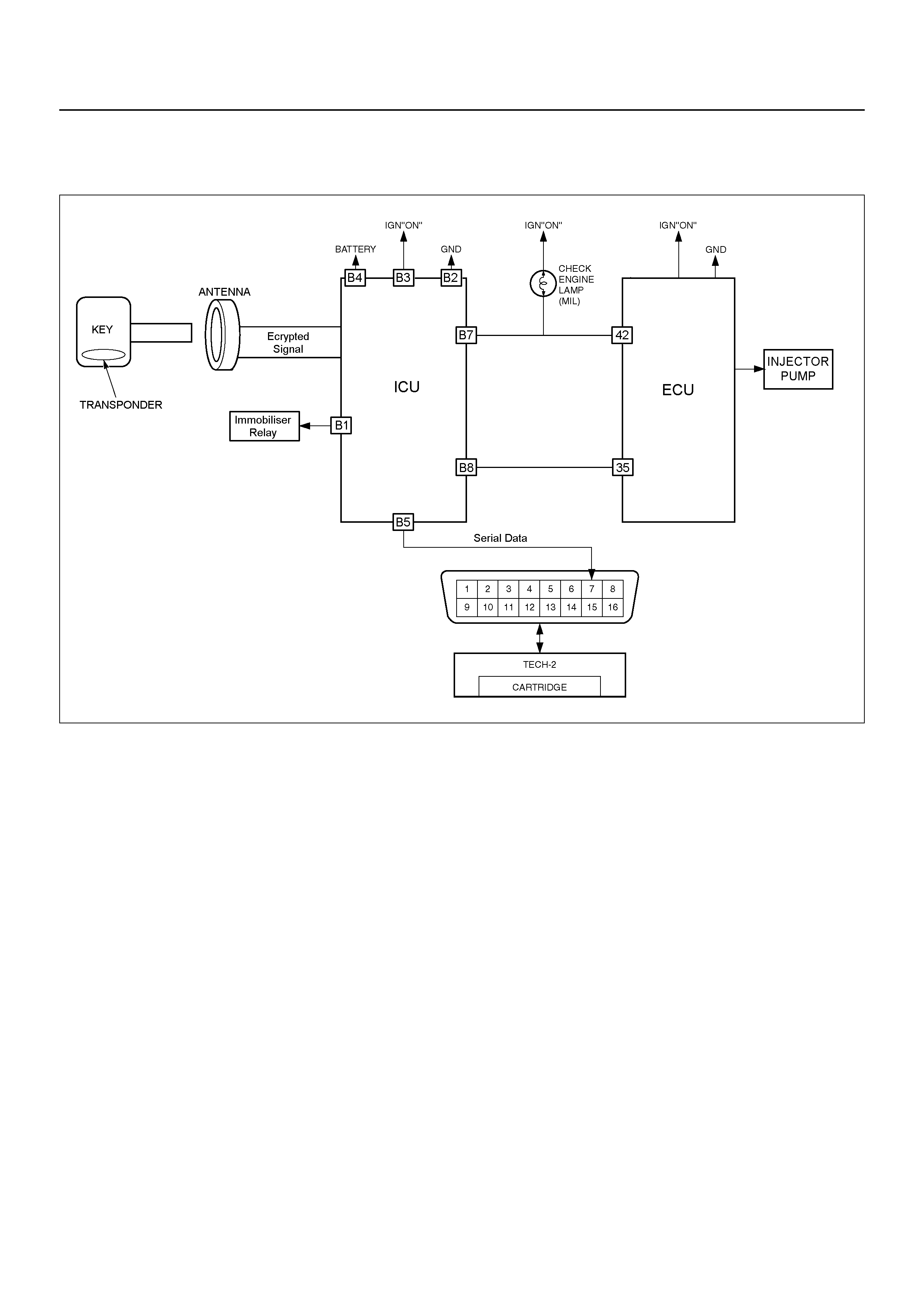
Immobilis er Control Unit (ICU)
The Immobiliser Contol Unit (ICU) is located bolted to
the cross-beam behind the RH lower instrument panel.
The ICU is powered at all times from the 10A Horn Fuse
and receives an ignition ‘ON’ signal from 10A Engine
Fuse.
Communication between the ICU and the ECU takes
place on the ISO-K signal wire (ICU pin B8 to ECU pin
35), and on the ‘CHECK ENGINE’ Lamp (CEL) control
circuit (ECU pin 42 to ICU pin B7 and Instrument Cluster
pin A6)
NOTE: If the ICU and ECU are replaced at the same
time, the ICU MUST be programmed BEFORE the
Immobiliser function of the ECU can be activated.
Engine Control Unit
The Bosch ECU is located immediately below the
centre of the instrument panel and is accessed by
removing the pr otective plastic cover.
If the the transponder key rolling code does not match
the ECU’s calculated code, the ECU will not transmit the
fuel request signal to the injector pump. This will result
in the High pressure Solenoid valve remaining closed,
preventing fuel flow to the injectors, and effectively
immobil ising the engine.
When installing a new ECU, ensure that the correct
ECU is fitted to the vehicle. Refer to the latest parts
listing for ECU part number identification.
Note: A replacemen t ECU must be linked to the ICU for
correct operation. Refer to System Programming in this
section.
Pump Control Unit
The Pump Control Unit (PCU) is screwed to the top of
the injector pump casing. From information received
from the ECU, the PCU will determine the operating
characteristics o f the Timing Control Valve and the Hig h
Pressure Solenoid valve.
If the the transponder key rolling code does not match
the ECU’s calculated code, the ECU will not transmit the
fuel request signal to the Pump Control Unit. This will
result in the High pressure Solenoid valve remaining
closed, preventing fuel flow to the injectors, and
effectively immobilising the engine.
Immobiliser Relay
The Immobiliser Relay is located in the engine
compartment Main Fuse & Relay Box. One side of the
relay solenoid windings is connected to power via the
Engi ne Fu se C-3, an d the ot her side connected ICU pi n
14. Pin 7 of the I CU is connected to ground.
When the ignition key is in the crank position, and the
ICU has received a valid transponder key signal, the
ICU will provide the path to ground, energi sing the re lay
windings.
When enabled by the ICU, the Immobiliser Relay allows
the starter motor relay to be energised .
ENGINE START SEQUENCE
Before the system will allow engine operation, the following sequ ence o f data transfer and code evaluation must take
place:
1. When the ignition is turned ON, ICU supplies a high frequency (133kHz) AC voltage signal to the key via the
antenna.
2. The transponder code is transmitted to the ICU.
3. The ICU checks the transponder code and enables the Immobiliser Relay in the underbonnet Fuse & Relay box.
4. T he ECU gene rates and transmits a RANDOM code to the ICU.
5. The ICU receives the RANDOM code from the ECU and transmits the code to the transponder.
6. T he transponder calculates a ROLLING code bas ed on the RANDO M code.
7. The transponder transmits the ROLLING code to the ECU via the ICU.
8. T he ECU com pares the transferred ROLLING code with it’s calculated ROLL ING code.
9. If both codes match, the ECU will transmit a fuel enable signal to the Pump Control Unit.
10. T he engine cannot be started during th e da ta transfe r and c ode evaluation process. If any o f the above steps are
unsucces sfu l, all rele va nt engine functions will remain disabled.

SYSTEM PROGRAMMING
Programm ing of the Immobiliser sy stem is performed with TECH -2 w hen:
• The Imm obiliser Control Unit is repla ced.
• The Imm obiliser Control Unit is reset .
• The Eng ine Control Unit is replaced.
• Additional ignition keys are required.
• An ignition key has been lost.
Prior to commencing the programming sequen ce , the technician will re quire:
• The Vehicle Identification Num ber.
• The vehicle sec urity code from Holden TAS
• The mechanical key number.
To enable t he complet ion of the program ming sequenc e, the technic ian will requi re :
• Perm ission from TIS 2000
Security Data
The following codes/data are stored in the ICU reference memory during vehicle production:
• The Vehicle Identification Num ber.
• The vehicle sec urity code.
• The mechanical key number.
• Engine type
• T ransponder code/s
The sec urity co de cannot be delet ed or al tered with TECH-2. Th e tran sponder c ode/s and engine type are proces sed
internally onl y and are not displayed o n TECH-2. T he Vehicle Identifi ca tion Number an d mechanical key number are
stored as further information for vehicle identification and can be displayed on TECH-2.
Security Code
The 4-digit security code prevents unauthorised programming and access to the data in the ICU via TECH-2. The
security code is programmed into the ICU.
Program m i ng th e Securi ty Code
New Immobiliser Control Units do not contain a programmed security code. If the ICU is replaced, the security code for
that vehicle must be obtained, and then programmed into the ICU with TECH-2.
Replacem en t of the Im m obiliser Control Unit (ICU)
Due to the complex nature of the coded signals transmitted between the key and the ICU, it is necessary to replace
both existing ignition keys when the ICU is replaced.
Resetting of the Immobiliser Contr ol Unit (IC U)
Resetting of the I CU may necessitate replacement of either or both existing ignition keys. T his si tuation is m ost likely
to occur if t he ICU is swapped from one vehicle to another.

System Programming
Loss of a Transponde r Key
If a transponder key is lost, all transponder codes in the Immobiliser Control Unit must be erased to prevent
un auth oris ed us e. Th is w ill e nsur e tha t, wh ilst the 'lost' key w ill a llow a cce ss t o th e veh icl e, it ca nn ot be used t o star t
the vehicle.
After erasing all existing codes, the transponder codes of the remaining keys and the new transponder key can be
programmed.
NOTE:
• Programming Approval must be obtained from TIS, using the `Enable Programming" option, before either
control unit or transponder key programming is performed.
• Onc e Pro grammin g Ap proval has been obtained, TE CH-2 will allow five pro grammin g operat ions. Onc e al l five
programming operations have been used, Programming Approval will then have to be obtained again.
• If the five programming operations are not used within 24hrs, they will be cleared from TECH-2, requiring
further Programm ing Approv al to be obtain ed.
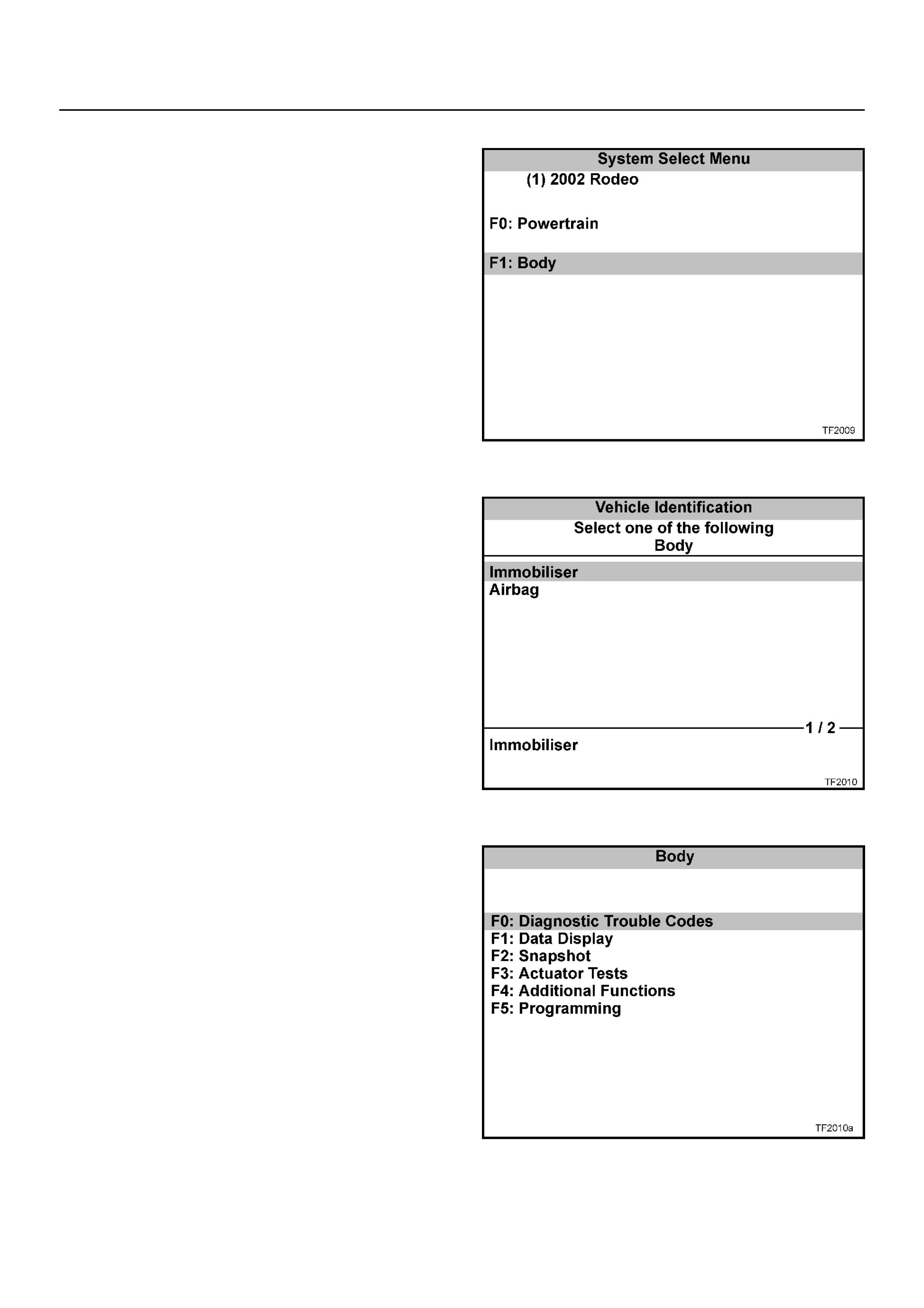
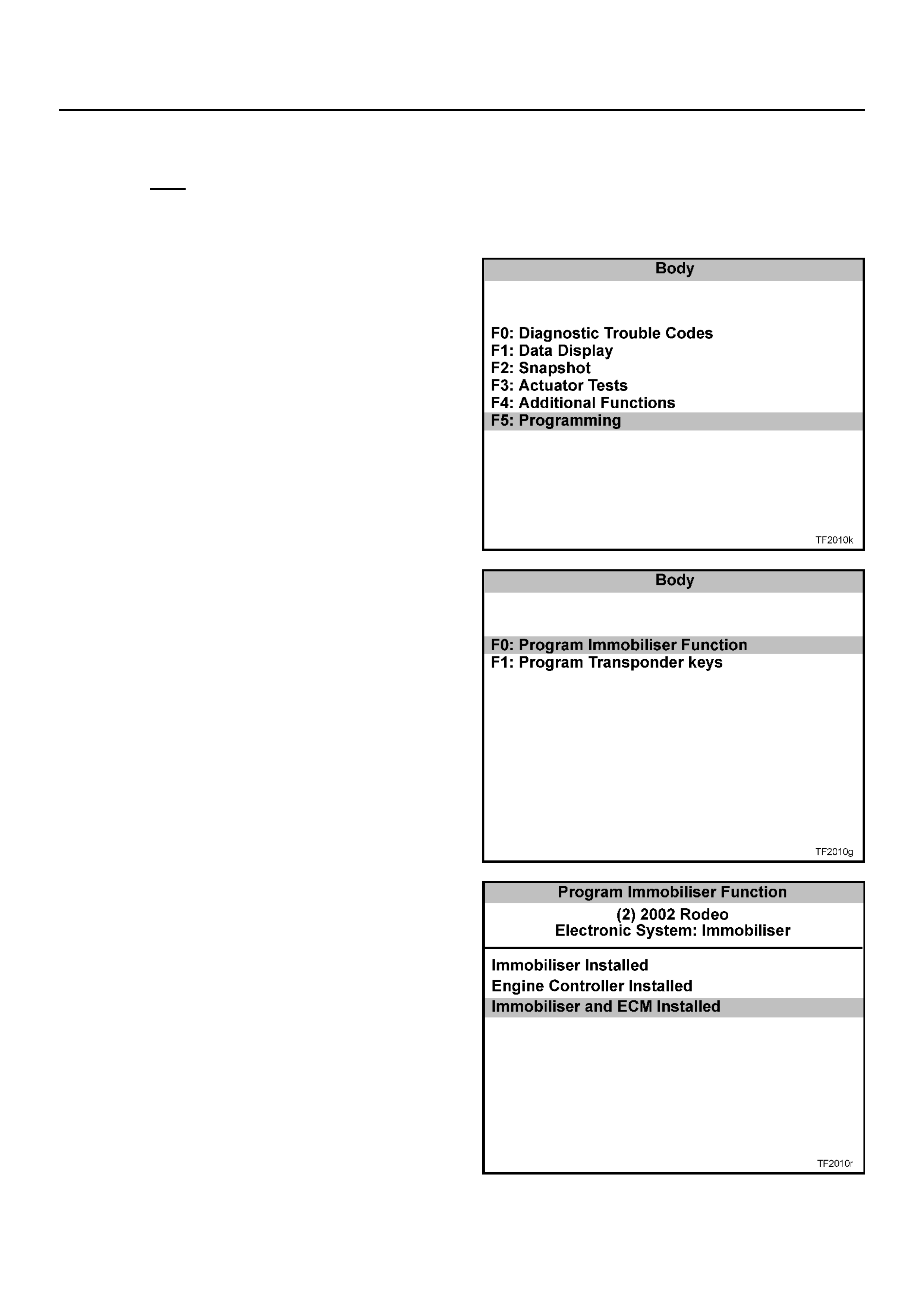
TECH 2 OPERATION
W ith the latest software loaded, con nect TECH 2 t o th e
vehicle, turn on TECH 2.
NOTE: Due to the constant evolution of TECH 2
software, the screens shown in this section may
differ slightly from those displayed for the vehicle
being tested.
When the TECH 2 introduction screen appears, press
ENTER.
Sele ct: Diagnostics / MY2002 / Rodeo / F1: Body /
Immobiliser
The following modes and sub-mo des are now available:
F0: Diagnostic Tr oub l e Codes
• F0: Read DTC Info Ordered By Priority
• F1: Read DTC Info As S tored By ECU
• F2: Clear DTC Information
F1: Data Display
F2: S napshot
F3: Actuator Test
• F0: Immobiliser Relay Output Test
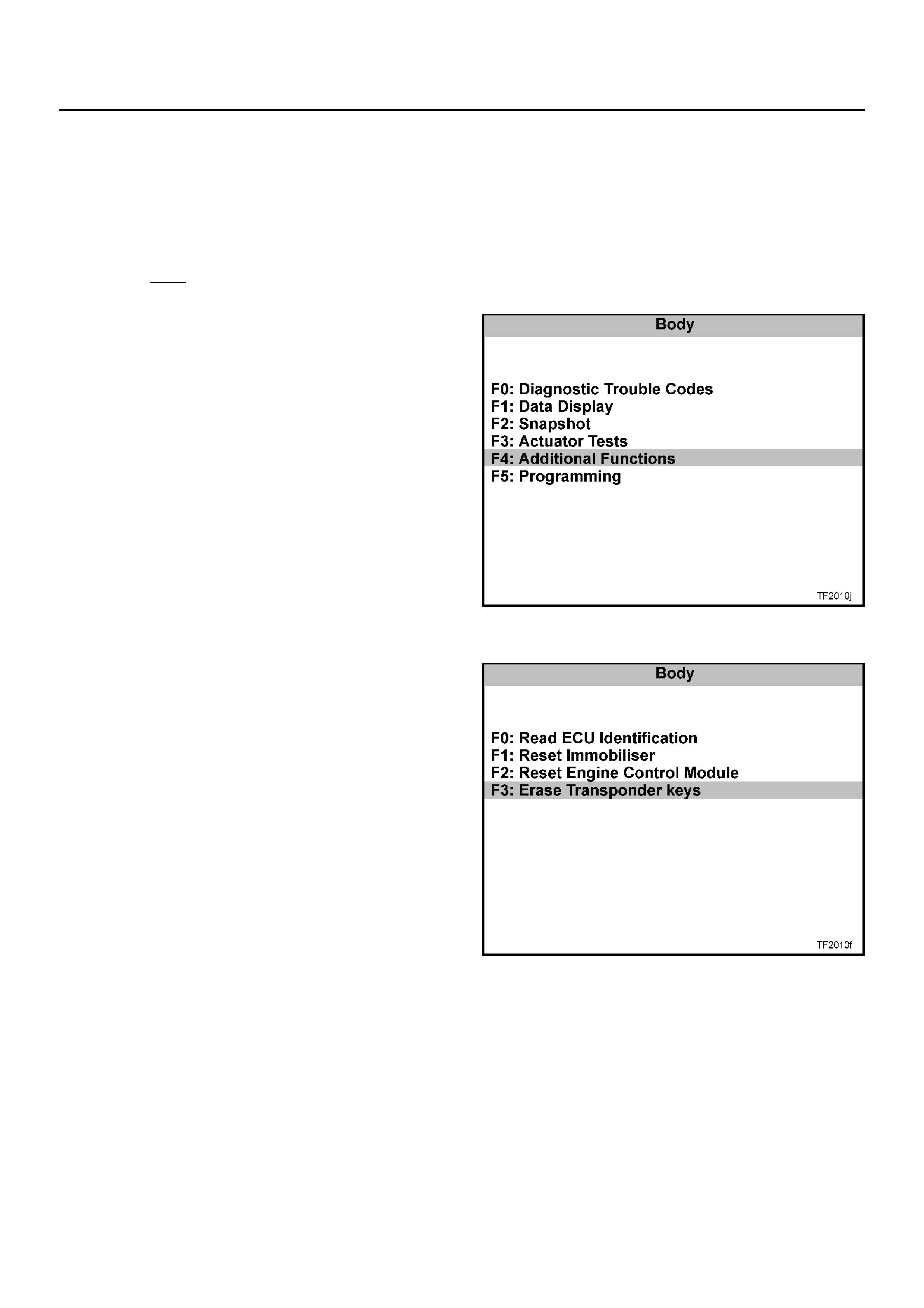
F4: Addi t ional Funct ions
• F0: Read ECU Identification
• F 1 : Re s et Immobilis e r
• F2: Reset Engine Cont rol Module
• F3: Erase Transponder - Keys
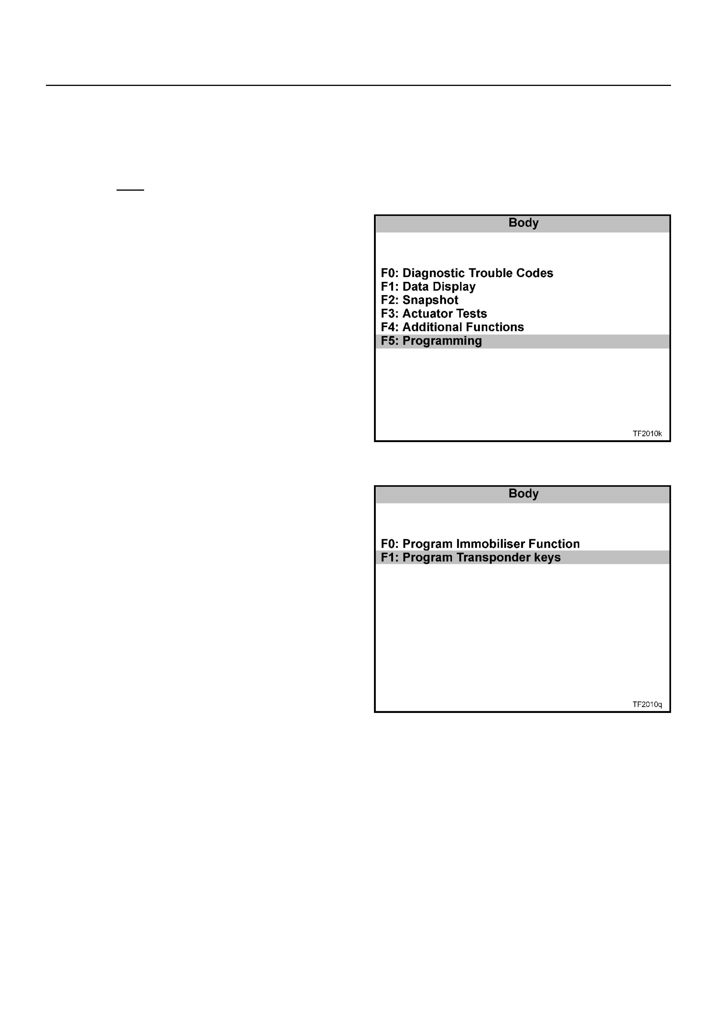
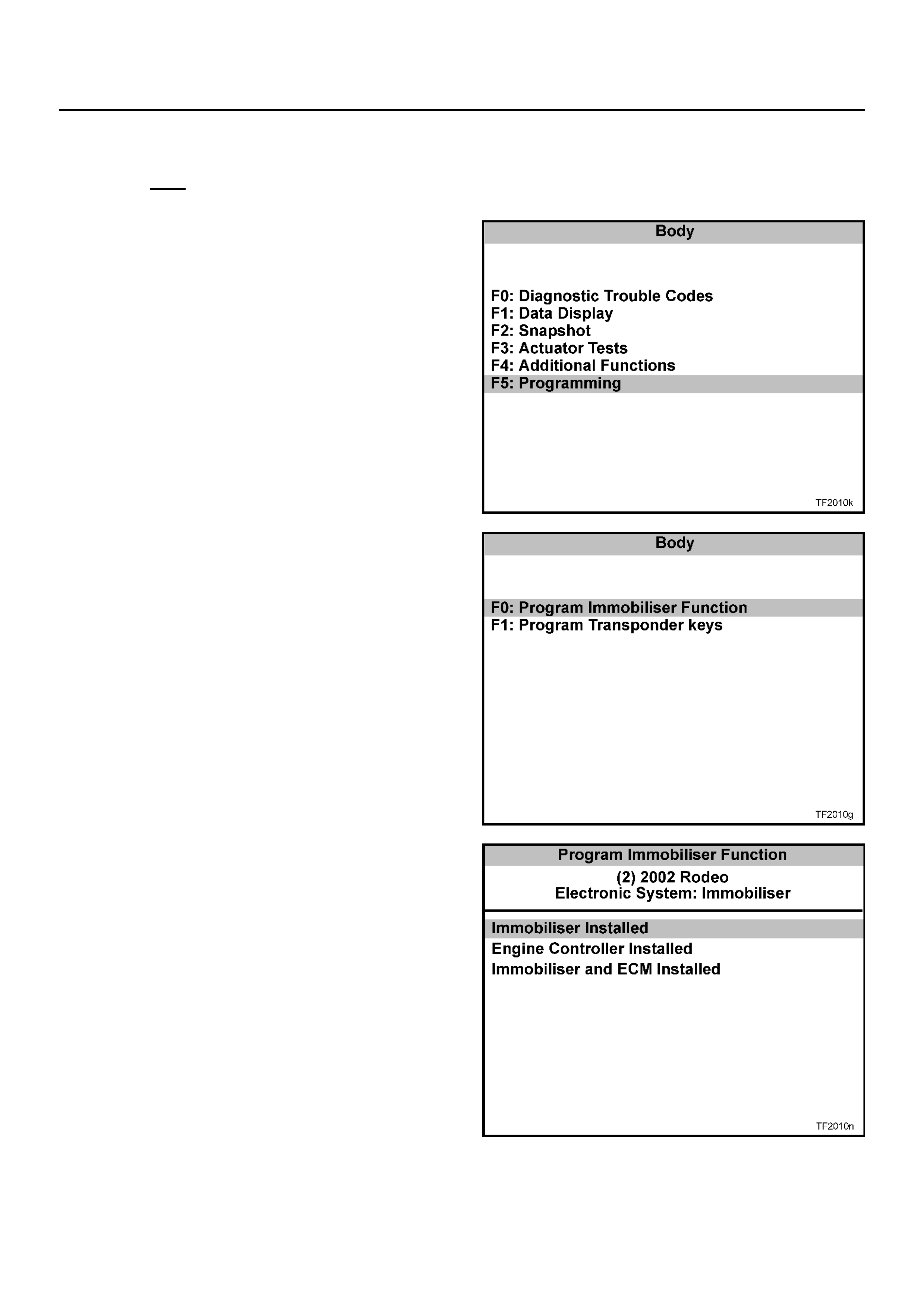
F5: P rogram ming
• F0: Program Immobi liser Function
• F1: Program T ransponder - Keys
TRANSPONDER-KEY PROGRAMMING
Programming Approval must be obtained from TIS 2000, using the "Enable Programming" option, during the
transponder key program sequen ce .
TECH 2 will requ est the Vehicle S ecurity Numb er during the progr am sequen ce - this m ust be obtained fro m
Holden TAS prior to comme nci ng this operation.
Connec t TECH 2 to th e vehic le:
1. Select Diagnostics / MY2002 / Rodeo / F1:
Body.
2. Select Immobili ser
3. Select F5: P rogramming .
4. Select F1: P rogram Transponde r - Keys.
5. Obtain programming approv al from TIS 2000 .
6. R e tu rn to F1: Program Transpo nd er - Keys.
7. When the SECURITY CODE is requested, enter
the secu ri ty co de and pres s ENTER.
8. Insert a non-programmed Transponder key and
press CONFIRM.
9. 'Turn On Ignition Key' will be displayed if the
ignition is OFF.
10. The Transponder status will be displayed if the
status does not allow programming.
11. When Programming starts, 'Programming
Transponder - key' is d isplayed.
12. Cycle the ignition key as instructed by the
display.
13. If the programming was successful, the screen
will display'Program More Keys?'
ERASING TRANSPONDER KEYS
If a transponder key is lost, all transponder codes in the Immobiliser Control Unit must be erased to prevent
unauthorised use. This will ensure that, whilst the 'lost' key will allow access to the vehicle, it cannot be used to start
the vehicle.
CAUTION: This sequence erases ALL transponder-keys. Transponder-Key programming will be required before the
vehicle can be restart ed.
TECH 2 will requ est the Vehicle S ecurity Numb er during the progr am sequen ce - this m ust be obtained fro m
Holden TAS prior to comme nci ng this operation.
Connec t TECH 2 to th e vehic le:
1. Select Diagnostics / MY2002 / Rodeo / F1:
Body.
2. Select Immobiliser
3. Select F4: A ddit ion al Fu nctions.
4. Select F2: Erase Transponder - Keys.
5. The screen will display 'See Checking
Procedure Be fore Program ming'.
6. Select CONFIRM to continue.
7. The screen will display 'CAUTION - All
Transponder keys will be erased'
8. Select CONFIRM to continue.
9. All transponder-keys are now erased.
10. Program the new transponder key and any
remaining keys to the vehicle using the
'Transponder-Key Prog ramm ing ' sequenc e
PROGRAMMING THE IMMOBILISER CONTROL UNIT (ICU)
TECH 2 will requ est the Vehicle S ecurity Numb er during the progr am sequen ce - this m ust be obtained fro m
Holden TAS prior to comme nci ng this operation.
Connec t TECH 2 to th e vehic le:
1. Select Diagnostics / MY2002 / Rodeo / F1:
Body.
2. Select Immobiliser
3. Select F5: Programming .
4. Select F0: P rogram Imm obili ser Funct ion .
5. Select Immobiliser Installed
6. Obtain programming approv al from TIS 2000 .
7. R e tu rn to F0: P rogram Imm obi li ser Fu nction.
8. When the SECURITY CODE is requested, enter
the secu ri ty co de and pres s ENTER.
9. When the VIN is requested, enter the vehicle
identification number and pres s ENTER.
10. When the MECHANICAL KEY number is
requested, enter the key number and press
ENTER.
11. Turn the ignition ON.
12. Select the engine type
13. Chec k the programm ing result
14. Program the transponder-keys to the ICU.

PROGRAMMING THE ENGINE CONTROLLER
TECH 2 will requ est the Vehicle S ecurity Numb er during the progr am sequen ce - this m ust be obtained fro m
Holden TAS prior to comme nci ng this operation.
Connec t TECH 2 to th e vehic le:
1. Select Diagnostics / MY2002 / Rodeo / F1:
Body.
2. Select Immobiliser
3. Select F5: Programming .
4. Select F0: P rogram Imm obili ser Funct ion .
5. Select Engine Controller Installed
6. Obtain programming approv al from TIS 2000 .
7. R e tu rn to F0: P rogram Imm obi li ser Fu nction.
8. When the SECURITY CODE is requested, enter
the secu ri ty co de and pres s ENTER.
9. When the VIN is requested, enter the vehicle
identification number and pres s ENTER.
10. When the MECHANICAL KEY number is
requested, enter the key number and press
ENTER.
11. Turn the ignition ON.
12. Select the engine type
13. Chec k the programm ing result
PROGRAMMING THE ICU AND THE ECU
TECH 2 will requ est the Vehicle S ecurity Numb er during the progr am sequen ce - this m ust be obtained fro m
Holden TAS prior to comme nci ng this operation.
When the DDS-1 and ICU are replaced at the same time, the ICU MUST be programmed BEFORE the
Immobiliser function of the DDS-1 can be activated.
Connec t TECH-2 to the vehicle:
Connec t TECH 2 to th e vehic le:
1. Select Diagnostics / MY2002 / Rodeo / F1:
Body.
2. Select Immobiliser
3. Select F5: Programming .
4. Select F0: P rogram Imm obili ser Funct ion .
5. Select Immobi liser and ECM Installed
6. Obtain programming approv al from TIS 2000 .
7. R e tu rn to F0: P rogram Imm obi li ser Fu nction.
8. When the SECURITY CODE is requested, enter
the secu ri ty co de and pres s ENTER.
9. When the VIN is requested, enter the vehicle
identification number and pres s ENTER.
10. When the MECHANICAL KEY number is
requested, enter the key number and press
ENTER.
11. Turn the ignition ON.
12. Select the engine type
13. Chec k the programm ing result
14. Program the transponder-keys to the ICU.
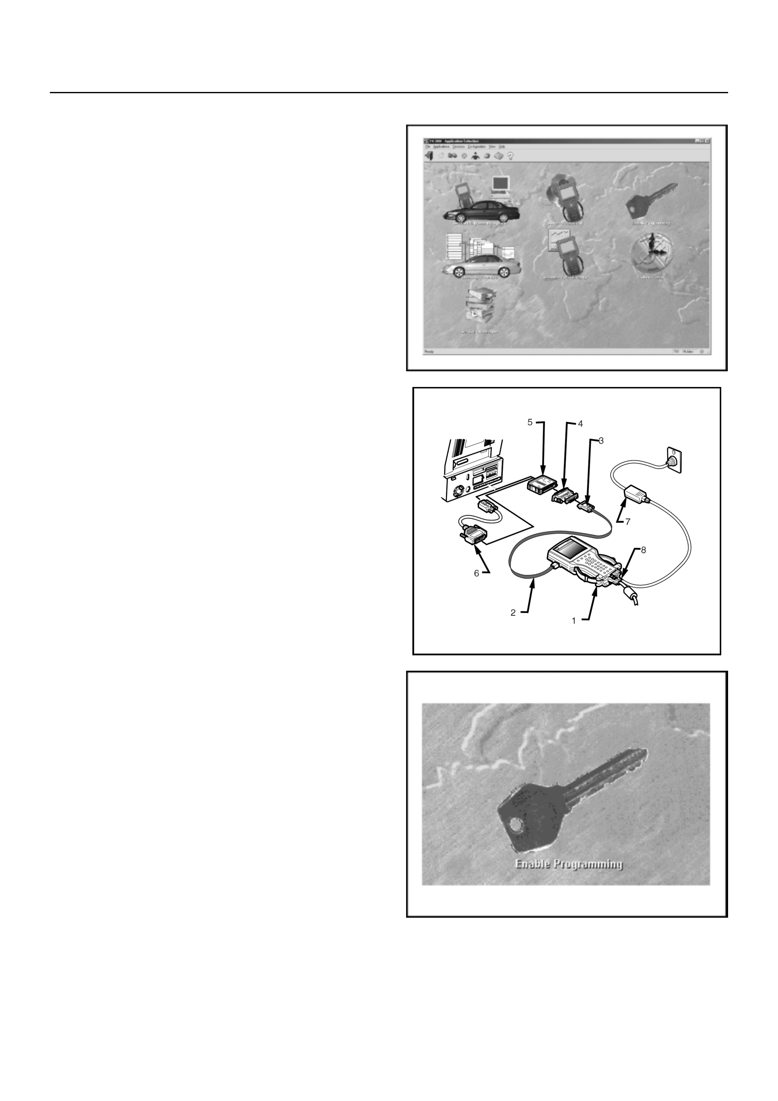
ENABLE PROGRAMMING - TIS 2000
'Enable Programming' (TIS Approval) is used in order to
prevent the unauthorised programming of the system
security functions.
TIS Approval is required to perform the following
functions on the UBS Immobiliser System:
• Programming the Immobiliser Control Unit
• Program m ing the transponde r keys
• Programming the ECU
After the TECH 2 security programming function has
been selected, TECH 2 will display - "Please get
programming approval from TIS'.
Enable Pr og r ammi ng Pro c e du r e
1. Connect the RS232C interface cable to the
TECH2 commu nicat ion port.
2. Connect the other end of the RS232C cable to
the hardware key using the 9 pin and 25 pin
adaptors.
3. Connect the hardware key to the serial port of
the TIS 2000 PC.
4. Connect the power supply t o the TE CH 2 p ower
jack.
5. Press the PWR button and allow TECH 2 to
boot to the start- up screen.
6. Click on the Enable Programming icon of the
TIS 2000 main screen.
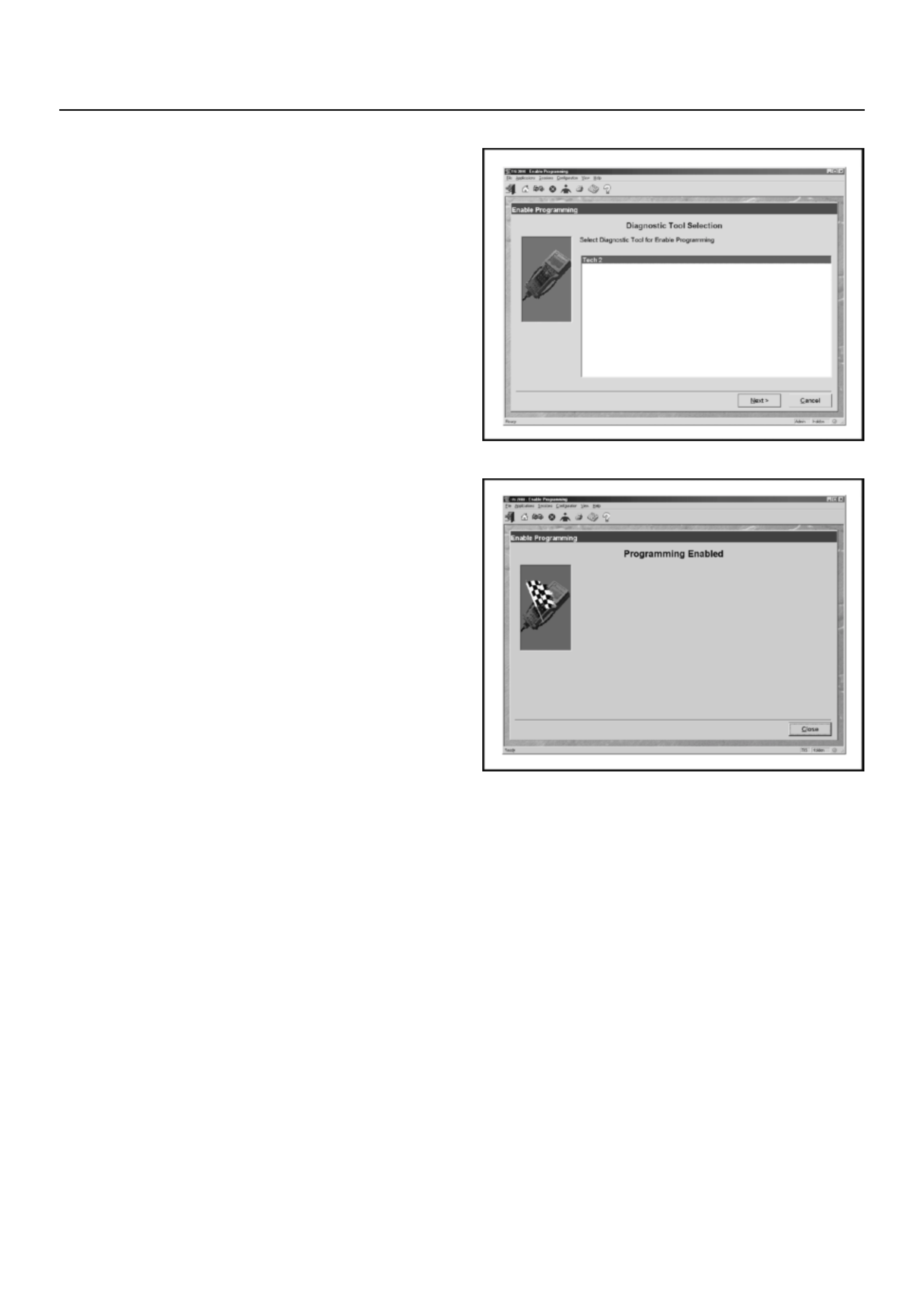
Enable Programming - TIS 2000
7. Select diagnostic tool (TECH 2) for Enable
Programming
8. Select Next to continue
9. When the process is completed, the
Program ming Ena bled screen will be displayed.
10. Click on the Close button to close the
application.
11. Reconnect TECH-2 to the vehicle DLC and
complete the programming function.

DIAGNOSTIC TROUBLE CODES
Current (Present) DTCs
The engine will not run when any cu rrent DTC is logged.
• The Eng ine Control Unit disables the fuel system.
• The ICU inhibits starter motor operation by disabling the Immobiliser relay.
History (Not Present) DTCs
When the fault has been repaired, the engine will operate normally and the current DTC becomes a History DTC.
T he s e D TC s w ill no rma lly c lea r o n the ne x t ig nit io n c yc le.
MULTIPLE DTCS
If multiple DTCs are displayed on Tech 2, c heck integrity of power and ground circuits first , then use the following chart
to isolate the possible cause:
DTC Description
B0001 Immobi liser Fault
B0002 Immobi liser Not Programmed
B0003 T ransponder Key Problem
B0004 Immobiliser Coil Circuit
B0007 No Engine Requ est Received
B0009 No Trans ponde r Key Programm ed
B0010 Unknown T ransponder Key
DTC Description
DTC Description
B0009 & B001 0 No Keys programmed
B0003 , B0004 & B0007 Immobi liser Coil Circuit open
B0002 , B0009 & B0010 Immobiliser not programm ed

No DTC Set
Engine Will Not Crank
060RA00003
Circuit Description
The Immobiliser Control Unit provdes the ground path
for the Immobiliser relay solenoid windings. A no-crank
condition will occur due to failure in either the Engine
Immobi liser System or starter motor circuit.
Condition for Setting the DTC
Not Applicable
Action Taken When the DTC sets
Not Applicable
Condition f or Clearing the CEL/DTC
Not Applicable
Diagnostic Aids
Check for the following conditions:
• Poor connection at ECU and Immobiliser Control
Unit. Inspect harness connectors for backed out
terminals, improper mating, broken locks,
improperly formed or damaged terminals, and
poor terminal to wire connection.
• Damaged harness-Inspect the wiring harness for
damage, If the harness appears to be OK,
disconnect the ECU and Immobiliser, turn the
ignition “ON" and observe a voltmeter connected
to the suspect driver circuit at the ECU and
Immobiliser harness connector while moving
connectors and wiring harnesses relates to the
CEL. A change in vo ltage will indicate the location
of the fault.

Engine Will Not Crank - No DTC Set
Step Action Value(s) Yes No
1 Was the “On-Board Diagnostic (OBD) system Check"
performed? — Go to Step 2 Go to OBD
system
check
Refe r to
Section 6C1
2 Check the ECU and ICU harness and connectors for:
1. Backed out terminals, improper mating, broken
locks, improperly formed or damaged terminals,
and poor terminal to wire connection.
2. Damaged ha rness - Inspec t the wiring harness for
damage.
If a problem found, repa ir as necessary.
Was a problem found?
Verify repair Go to St ep 3
3 Turn the ignition ON, does the ‘CHECK ENGINE’
Lamp flash at 2Hz? — Go to Step 4 C heck starter
motor circuit.
4 With the ignition ON, check the voltage at ICU pin B3.
Is the voltage in specified range?
11.6v -
12.7v Go to Step 6 Go to Step 5
5 Check for continuity between 15A En gine Fuse & ICU
pin B3.
If a problem found, repa ir as necessary.
Was a problem found?
Verify repair Go to St ep 6
6 Measure the resistance between ICU pin B2 and
ground.
Is the resista nc e less than the specified value?
5 W
Go to Step 8
Go to S tep 7
7 Repair the ground circuit from ICU pin B2 to ground
Is the action complete?
— Verify repair —
8. Replace the ICU and the existing ignition keys
Reprogra m the system
Verify repair

DTC B0001
Immobiliser Fault
060RA00003
Circuit Description
The Immobiliser Control Unit generates signals based
on information received from the transponder key and
the ECU.
Condition for Setting the DTC
A DTC B0001 will set within 0.5 secs. of turning the
ignition ON if:
• The ICU’s EEPROM fails to produce a valid
signal. This is an internal ICU failure and cannot
be repaired.
Action Taken When the DTC sets
• The engine will not crank
• The CHEC K ENGINE Lamp will flash at 4Hz
Condition f or Clearing the CEL/DTC
• Using TECH 2, select Clear DTC Information
• A History DTC B0001 will self-clear after 25
consecutive ignition cycles without the fault
recurring.
Diagnostic Aids
Not Applicable

DTC B0001 - Immobiliser Fault
Step Action Value(s) Yes No
1 Replace the ICU and the existing ignition keys
Reprogra m the system
— Verify repair —

DTC B0002
Immobiliser Not Programmed
060RA00003
Circuit Description
The Immobiliser Control Unit expects to recei ve a valid
transponder key signal when the ignition is turned ON.
Condition for Setting the DTC
A DTC B0 002 w ill set imm endi atel y upo n recogn ition If :
• The vehicle security code is not programmed into
the system .
Action Taken When the DTC sets
• The engine will not crank
• The CHEC K ENGINE Lamp will flash at 4Hz
Condition f or Clearing the CEL/DTC
• Using TECH 2, select Clear DTC Information
• A History DTC B0002 will self-clear after 25
consecutive ignition cycles without the fault
recurring.
Diagnostic Aids
Check for the following conditions:
• Poor connection at ECU and Immobiliser Control
Unit. Inspect harness connectors for backed out
terminals, improper mating, broken locks,
improperly formed or damaged terminals, and
poor terminal to wire connection.
• Damaged harness-Inspect the wiring harness for
damage, If the harness appears to be OK,
disconnect the ECU and Immobiliser, turn the
ignition “ON" and observe a voltmeter connected
to the suspect driver circuit at the ECU and
Immobiliser harness connector while moving
connectors and wiring harnesses relates to the
CEL. A change in vo ltage will indicate the location
of the fault.

DTC B0002 - Immobiliser Not Programmed
Step Action Value(s)
Yes No
1 Attempt to reprogram the security information
Was the programming successful?
— Verify repair Go to Step 2
2 Was the “On-Board Diagnostic (OBD) system Check"
performed? — Go to Step 3 Go to OBD
system
check
Refer to
Section 6C1
3 Check the ECU and ICU harness and connectors for:
1. Backed out terminals, improper mating, broken
locks, improperly formed or damaged terminals,
and poor terminal to wire connection.
2. Damaged ha rness - Inspec t the wiring harness for
damage.
If a problem found, repa ir as necessary.
Was a problem found?
— Verify repair Go to Step 4
4 Replace the ICU and the existing ignition keys
Reprogra m the system
— Verify repair —
DTC B0003
Transpond er Key Problem
060RA00003
Circuit Description
The Immobiliser Control Unit expects to recei ve a valid
transponder key signal when the ignition is turned ON.
Condition for Setting the DTC
A DTC B0003 will set if any of the following conditions
are present for at least 0.84 seconds during an
attemp ted start:
• No transponder-k ey signal is present
• The transpon der-ke y is defective
• The ke y is not a tran sp onder key
Action Taken When the DTC sets
• The engine will not crank
• The CHEC K ENGINE Lamp will flash at 4Hz
Condition f or Clearing the CEL/DTC
• Using TECH 2, select Clear DTC Information
• A History DTC B0003 will self-clear after 25
consecutive ignition cycles without the fault
recurring.
Diag nostic Ai ds
Check for the following conditions:
• Poor connection at ECU and Immobiliser Control
Unit. Inspect harness connectors for backed out
terminals, improper mating, broken locks,
improperly formed or damaged terminals, and
poor terminal to wire connection.
• Damaged harness-Inspect the wiring harness for
damage, If the harness appears to be OK,
disconnect the ECU and Immobiliser, turn the
ignition “ON" and observe a voltmeter connected
to the suspect driver circuit at the ECU and
Immobiliser harness connector while moving
connectors and wiring harnesses relates to the
CEL. A change in vo ltage will indicate the location
of the fault.

DTC B8003 - Transponder Key Problem
Step Action Value(s) Yes No
1 Was the “On-Board Diagnostic (OBD) system Check"
performed? — Go to Step 2 Go to OBD
system
check
Refe r to
Section 6C1
2 Check the ECU and ICU harness and connectors for:
1. Backed out terminals, improper mating, broken
locks, improperly formed or damaged terminals,
and poor terminal to wire connection.
2. Damaged ha rness - Inspec t the wiring harness for
damage.
If a problem found, repa ir as necessary.
Was a problem found?
Verify repair Go to St ep 3
3 Turn the ignition ON, does the ‘CHECK ENGINE’
Lamp flash at 4Hz? — Go to Step 4 —
4 Check for correct operation with the other transponder
key/s
Does the system operat e correctly?
— Go to Step 5 Go to Step 5
5 Reprogram the transponder key.
Was the program m ing successf ul?
Verify repair Go to St ep 6
6 Is a DTC B0004 set after t he program attempt? Go to
Diagnostic
Chart
DTC B0004 -
Immobiliser
Coil Circuit
Go to S tep 7
7 Replace the ICU and the existing ignition keys
Reprogra m the system
— Verify repair —

DTC B0004
Immobiliser Coil Circuit
060RA00003
Circuit Description
The Immobiliser Control Unit expects to recei ve a valid
transponder key signal when the ignition is turned ON.
The ICU and transponder key communicate via the
antenna coil circuit.
Condition for Setting the DTC
A DTC B0 004 w ill set imm endi atel y upo n recogn ition If :
• The a ntenna coil is not connected or there is an
open in the antenna coil circuit.
Action Taken When the DTC sets
• The engine will not crank
• The CHEC K ENGINE Lamp will flash at 4Hz
Condition f or Clearing the CEL/DTC
• Using TECH 2, select Clear DTC Information
• A History DTC B0004 will self-clear after 25
consecutive ignition cycles without the fault
recurring.
Diagnostic Aids
Check for the following conditions:
• Poor connection at ECU and Immobiliser Control
Unit. Inspect harness connectors for backed out
terminals, improper mating, broken locks,
improperly formed or damaged terminals, and
poor terminal to wire connection.
• Damaged harness-Inspect the wiring harness for
damage, If the harness appears to be OK,
disconnect the ECU and Immobiliser, turn the
ignition “ON" and observe a voltmeter connected
to the suspect driver circuit at the ECU and
Immobiliser harness connector while moving
connectors and wiring harnesses relates to the
CEL. A change in vo ltage will indicate the location
of the fault.

DTC B0004 - Immobiliser Coil Circuit
Step Action Value(s) Yes No
1 Was the “On-Board Diagnostic (OBD) system Check"
performed? — Go to Step 2 Go to OBD
system
check
Refe r to
Section 6C1
2 Check for continuity between ICU harness connector
‘A’ pin 1and pin 3.
Was a problem found?
—Go to Step 3 Go to Step 3
3 Check for continuity between ICU harness connector
‘A’ pin 1and antenna coil pin 1.
If a problem found, repa ir as necessary.
Was a problem found?
— Verify repair Go to Step 4
4 Check for continuity between ICU harness connector
‘A’ pin 3 and antenna coil pin 2.
If a problem found, repa ir as necessary.
Was a problem found?
— Verify repair Go to Step 3
5 Replac e the antenna coil assem bly
Is the action complete?
— Verify repair —

DTC B0007
No ECM Request
060RA00003
Circuit Description
The ECU t ransmits an ‘ECM Request’ signal to the ICU
when the ignition is turned ON.
Condition for Setting the DTC
A DTC B0007 will set within 0.5 secs. of turning the
ignition ON if:
• The ICU does not receive an ‘ECM Request’
signal from the ECU.
Action Taken When the DTC sets
• The engine will not crank
• The CHEC K ENGINE Lamp will flash at 4Hz
Condition f or Clearing the CEL/DTC
• Using TECH 2, select Clear DTC Information
• A History DTC B0007 will self-clear after 25
consecutive ignition cycles without the fault
recurring.
Diagnostic Aids
Check for the following conditions:
• Poor connection at ECU and Immobiliser Control
Unit. Inspect harness connectors for backed out
terminals, improper mating, broken locks,
improperly formed or damaged terminals, and
poor terminal to wire connection.
• Damaged harness-Inspect the wiring harness for
damage, If the harness appears to be OK,
disconnect the ECU and Immobiliser, turn the
ignition “ON" and observe a voltmeter connected
to the suspect driver circuit at the ECU and
Immobiliser harness connector while moving
connectors and wiring harnesses relates to the
CEL. A change in vo ltage will indicate the location
of the fault.

DTC B0007 - No ECM Request
Step Action Value(s) Yes No
1 Was the “On-Board Diagnostic (OBD) system Check"
performed? — Go to Step 2 Go to OBD
system
check
Refer to
Section 6C1
2 Check for an open circuit between ICU pin B7 and
ECU pin 42.
If a problem found, repair as necessary.
Was a problem found?
— Verify repair Go to Step 3
3 1. Disconnect the ECU connectors
2. Check for continuity between ICU pin B7 and
ground
If a continuity is found, repair as necessary.
Was continuity found?
— Verify repair Go to Step 4
4 Replace the ECU (Internal circuit failure).
Important: The ECU and ICU must be linked, refer to
this Section for the correct procedure.
Is the action complete?
— Verify repair —

DTC B0009
No Transponder Key Programmed
060RA00003
Circuit Description
The Immobiliser Control Unit expects to recei ve a valid
transponder key signal when the ignition is turned ON.
Condition for Setting the DTC
A DTC B0 009 w ill set imm endi atel y upo n recogn ition If :
• No transponder keys are programmed into the
system.
Action Taken When the DTC sets
• The engine will not crank
• The CHEC K ENGINE Lamp will flash at 4Hz
Condition f or Clearing the CEL/DTC
• Using TECH 2, select Clear DTC Information
• A History DTC B0009 will self-clear after 25
consecutive ignition cycles without the fault
recurring.
Diagnostic Aids
Check for the following conditions:
• Poor connection at ECU and Immobiliser Control
Unit. Inspect harness connectors for backed out
terminals, improper mating, broken locks,
improperly formed or damaged terminals, and
poor terminal to wire connection.
• Damaged harness-Inspect the wiring harness for
damage, If the harness appears to be OK,
disconnect the ECU and Immobiliser, turn the
ignition “ON" and observe a voltmeter connected
to the suspect driver circuit at the ECU and
Immobiliser harness connector while moving
connectors and wiring harnesses relates to the
CEL. A change in vo ltage will indicate the location
of the fault.

DTC B0009 - Transponder ID Table Empty
Step Action Value(s) Yes No
1 Attempt to reprogram the transponder keys
Was the programming successful?
— Verify repair Go to Step 2
2 Was the “On-Board Diagnostic (OBD) system Check"
performed? — Go to Step 3 Go to OBD
system
check
Refe r to
Section 6C1
3 Check the ECU and ICU harness and connectors for:
1. Backed out terminals, improper mating, broken
locks, improperly formed or damaged terminals,
and poor terminal to wire connection.
2. Damaged ha rness - Inspec t the wiring harness for
damage.
If a problem found, repa ir as necessary.
Was a problem found?
— Verify repair Go to Step 4
4 Replace the ICU and the existing ignition keys
Reprogra m the system
— Verify repair —

DTC B0010
Unknown Transponder Key
060RA00003
Circuit Description
The Immobiliser Control Unit expects to recei ve a valid
transponder key signal when the ignition is turned ON.
Condition for Setting the DTC
A DTC B0010 will set if any of the following conditions
are present for at least 0.84 seconds during an
attemp ted start:
• The transponder-key signal is not programmed to
the EC U
• The transpon der read-out is interrupted
• The ke y is not a tran sp onder key
Action Taken When the DTC sets
• The engine will not crank
• The CHEC K ENGINE Lamp will flash at 4Hz
Condition f or Clearing the CEL/DTC
• Using TECH 2, select Clear DTC Information
• A History DTC B0010 will self-clear after 25
consecutive ignition cycles without the fault
recurring.
Diag nostic Ai ds
Check for the following conditions:
• Poor connection at ECU and Immobiliser Control
Unit. Inspect harness connectors for backed out
terminals, improper mating, broken locks,
improperly formed or damaged terminals, and
poor terminal to wire connection.
• Damaged harness-Inspect the wiring harness for
damage, If the harness appears to be OK,
disconnect the ECU and Immobiliser, turn the
ignition “ON" and observe a voltmeter connected
to the suspect driver circuit at the ECU and
Immobiliser harness connector while moving
connectors and wiring harnesses relates to the
CEL. A change in vo ltage will indicate the location
of the fault.

DTC B0010 - Unknown Transponder Key
Step Action Value(s) Yes No
1 Check for correct operation with the other transponder
key/s
Does the system operat e correctly?
— Go to Step 2 Go to Step 4
2 Reprogram the transponder key.
Was the program m ing successf ul?
Verify repair Go to St ep 3
3 Replace the transponder key
Reprogra m the system
— Verify repair —
4 Replace the ICU and the existing ignition keys
Reprogra m the system
— Verify repair —
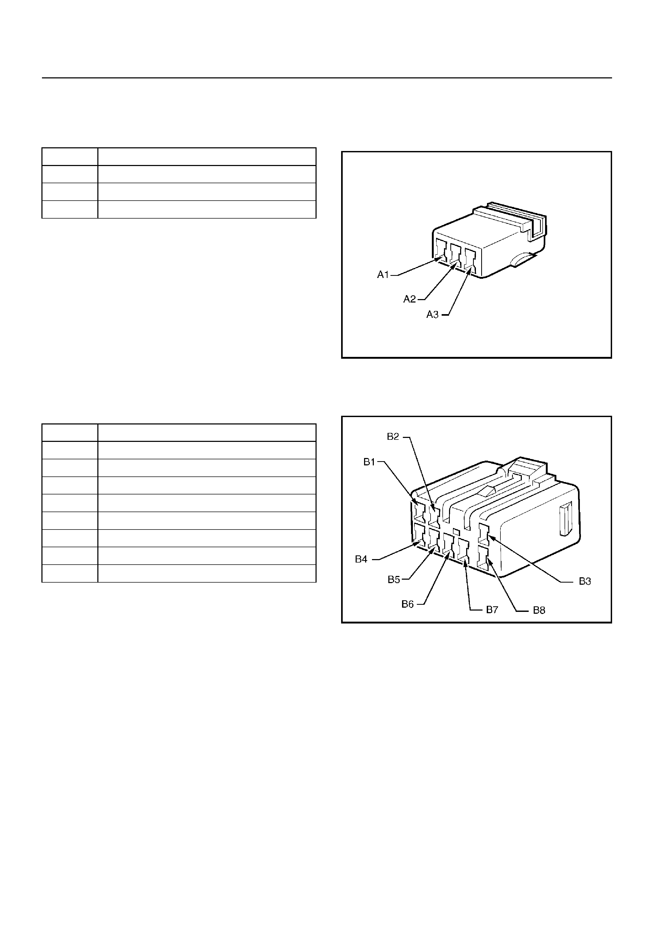
IMMOBILISER CONTROL UNIT
HARNESS CONNECTORS
Pin Circuit
A1 Antenna Coil - Positive
A2 Not Used
A3 Antenna Coil - Negative
Pin Circuit
B1 Immobi liser Relay
B2 Ground
B3 Ignition (15A Eng ine Fuse)
B4 Battery Positive (10A Horn Fuse)
B5 Diagnostic Link Connector Pin 7
B6 Not Used
B7 “CHECK ENGINE” Lamp
B8 ISO - K L in e
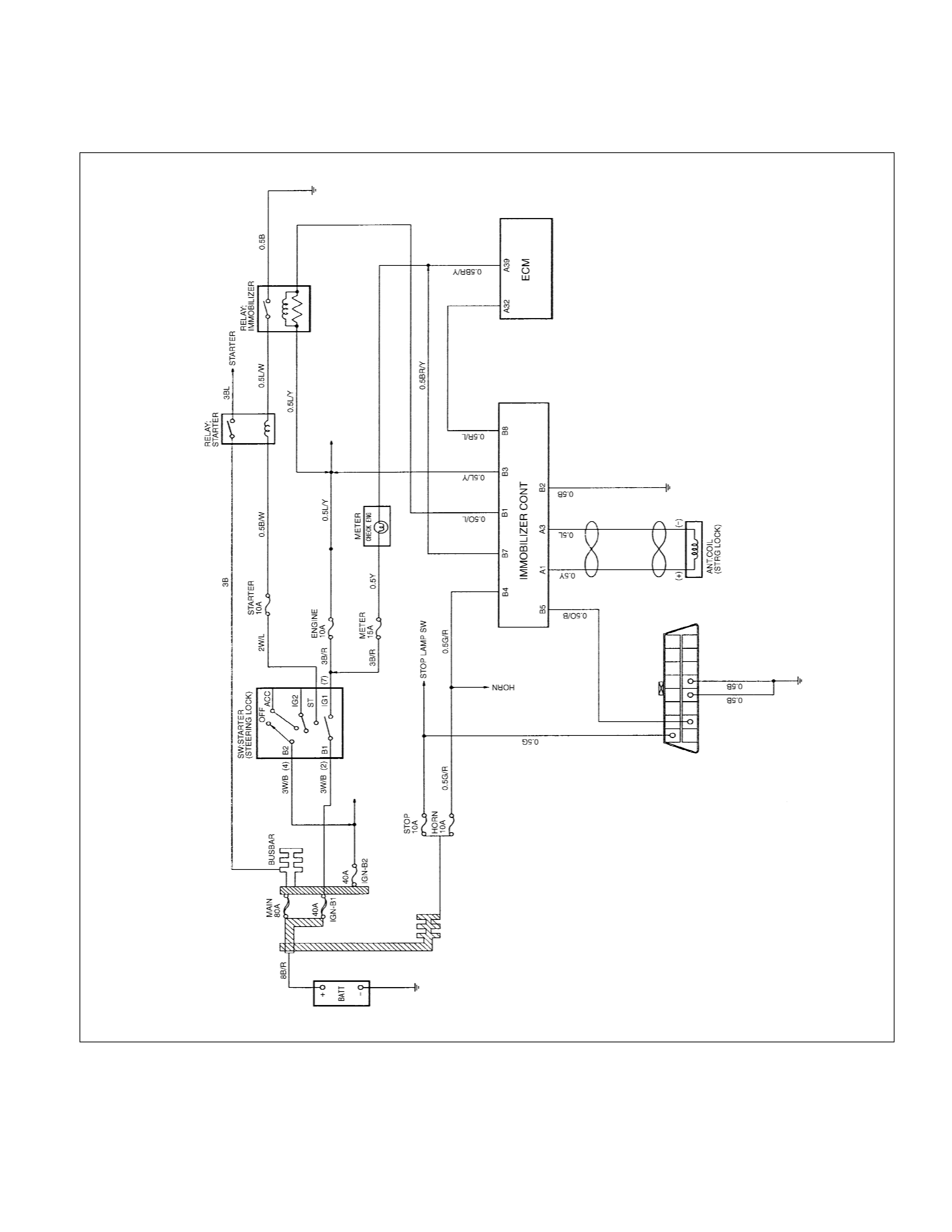
CIRCUIT DIAGRAM
Diesel Engine (4JH1-TC)