
SECTION 12B – ELECTRICAL - BODY & CHASSIS
General Information
Notes for Working on Electrical Items
Symbols and Abbreviations
Symbols
Abbreviations
Parts for Electrical Circuit
Wiring
Fuse
Fusible Link
Circuit Breaker
Relay
Diode
Connector
Battery
Reading the Circuit Diagram
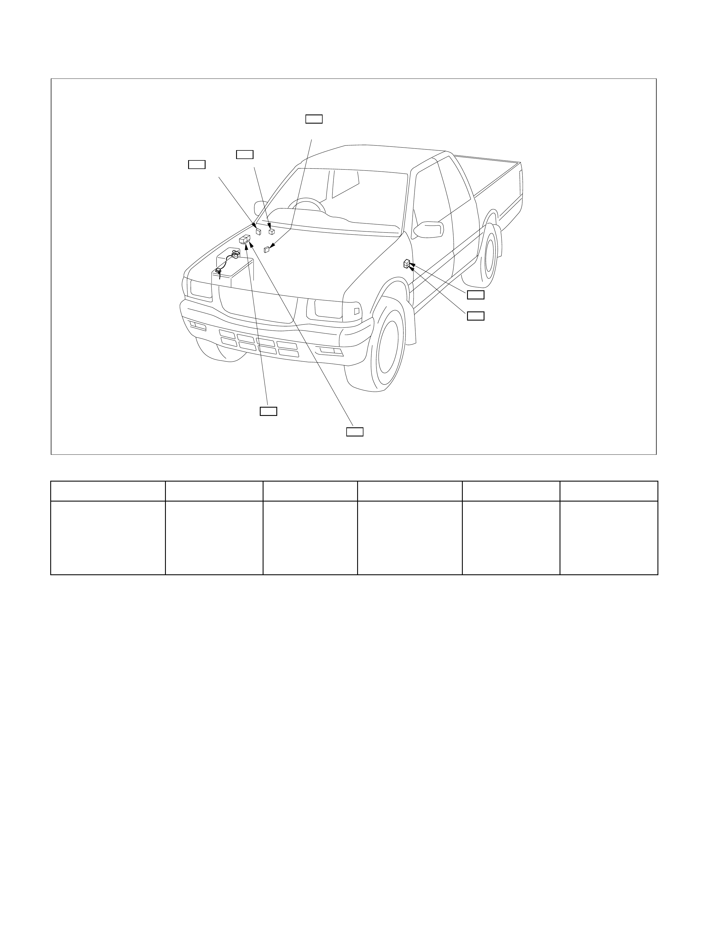
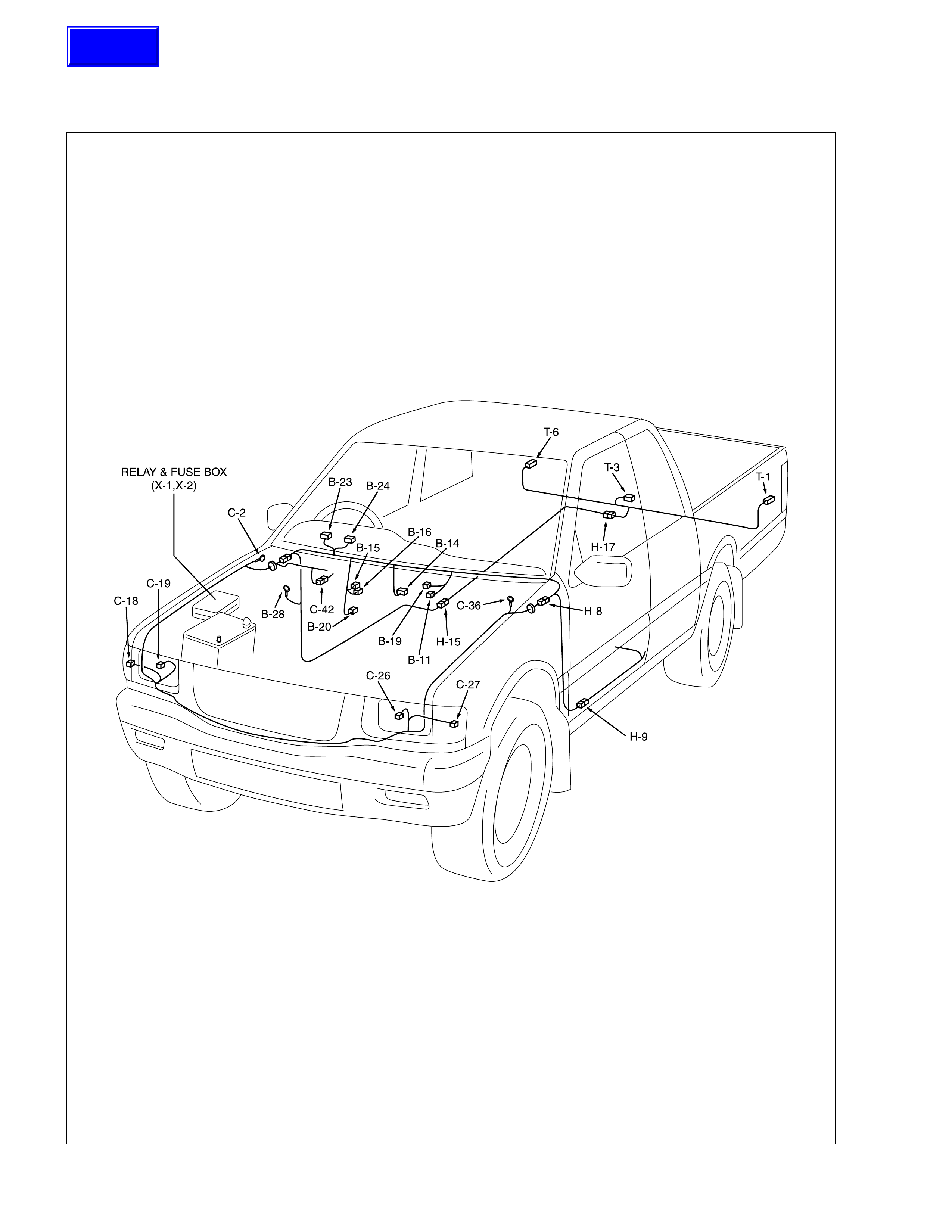
Parts Location
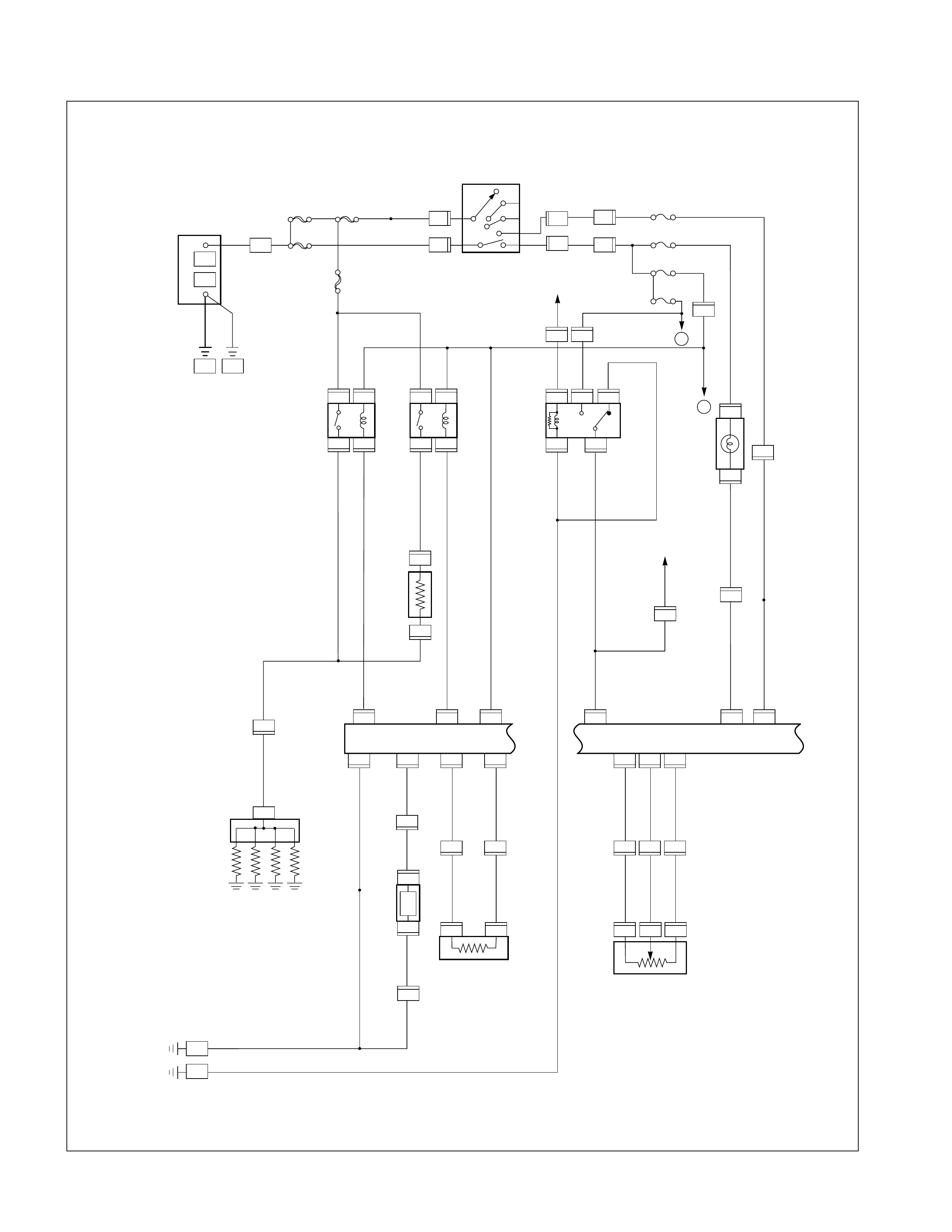
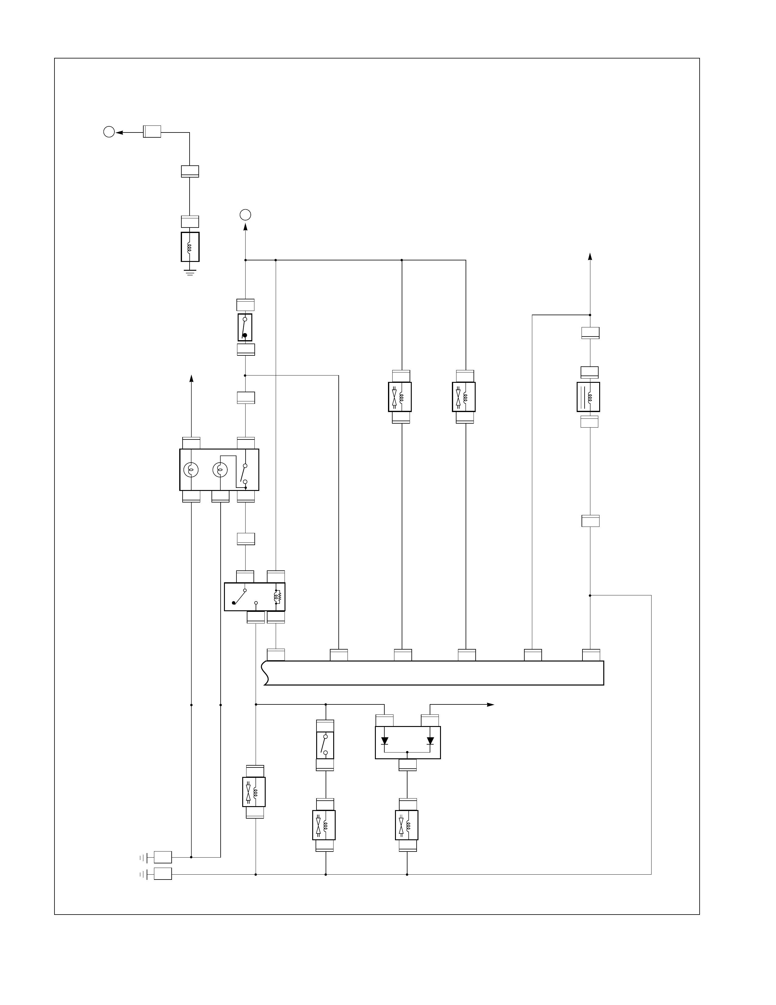
Circuit Diagram
Connector List
Main Data and Specifications
Bulb Specifications
Relay and Fuse
Relay and Fuse Box Location (C22NE / 4JB1T / 4JH1TC)
Relay and Fuse Box Location (6VD1-W)
Relay Location-1 (Relay and Fuse Box)
Relay Location-2 (Relay and Fuse Box)
Relay Location-3 (HEC C22NE)
Relay Location-4 (4JB1T / 4JH1TC)
Relay Location-5 (6VD1-W)
Fuse and Fusible Link Location (Relay and Fuse Box)
Fuse and Circuit Breaker Location (Fuse Box)
Diode Location
Fuse Block Circuit-1 (HEC C22NE)
Fuse Block Circuit-2 (4JB1T)
Fuse Block Circuit-3 (6VD1-W)
Fuse Block Circuit-4 (4JH1TC)
Reference Table of Fuse, Fusible Link and Circuit Breaker

Grounding Point
Reference Table
Location
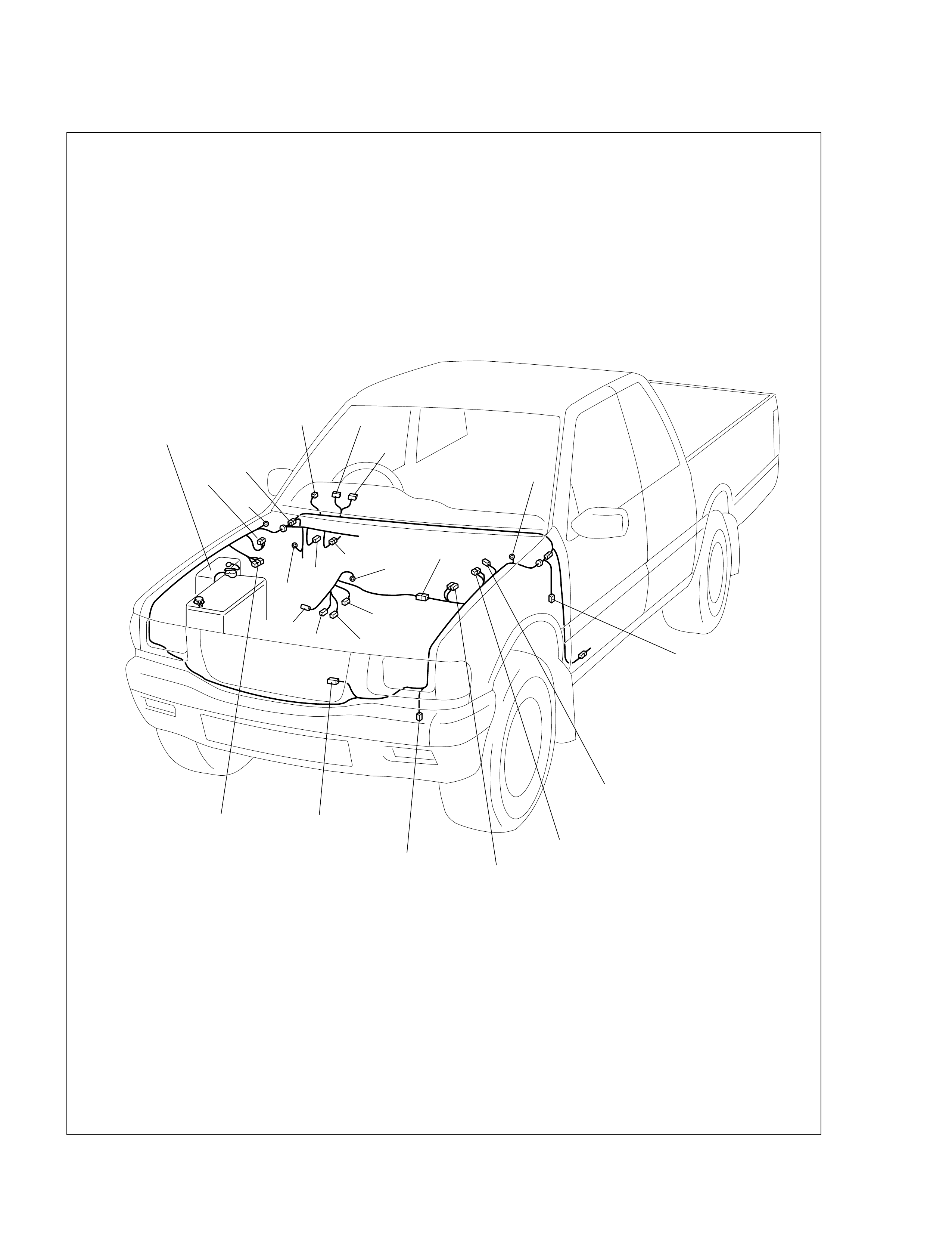
Main Cable Harness Routing
HEC C22NE - 1
HEC C22NE - 2
6VD1 - 1
6VD1 - 2
4J Engine - 1
4J Engine - 2
System Repair
Start and Charging
Engine Control Module (ECM)
QOS/EGR/QWS
Lighting
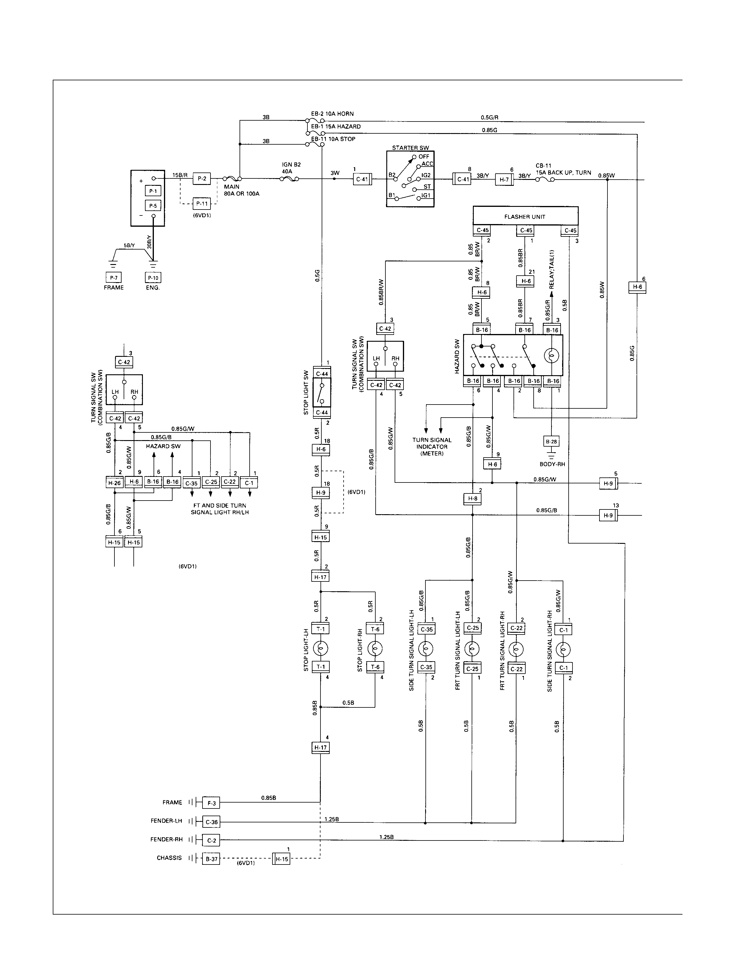
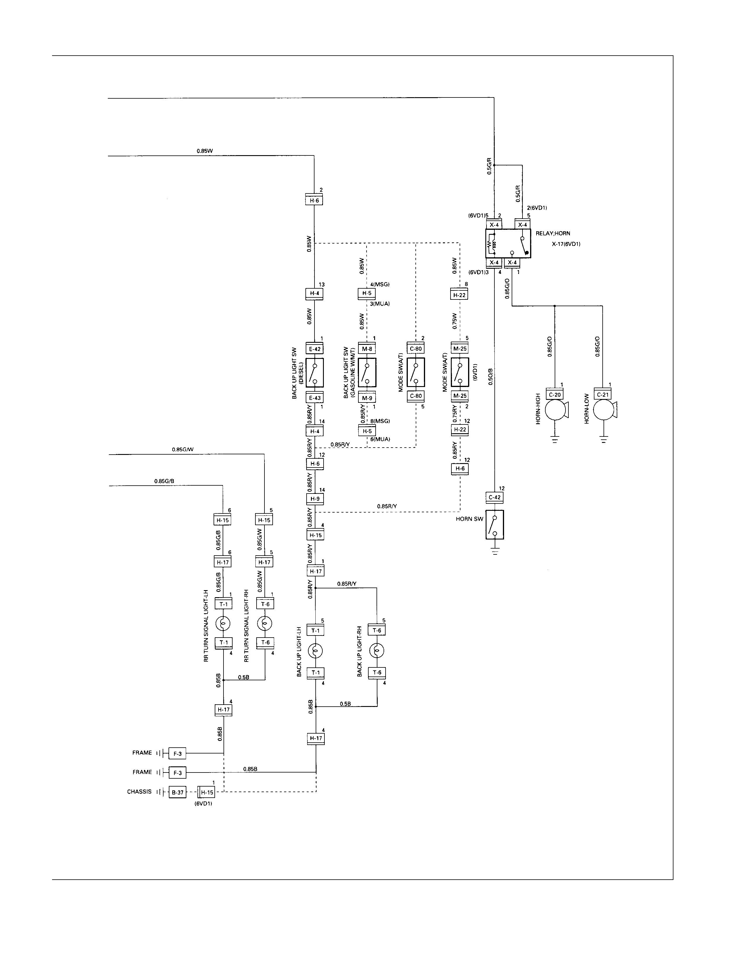
Hazard Warning Flasher, Turn Signal Light, Back Up Light, Horn and Stop Light
Dome Light, Spot Light and Warning Buzzer
Windshield Wiper and Washer
Overdrive Off (A/T)
Transmission Control Module (TCM)
Meter, Warning Light and Indicator Light
Heater and Air Conditioning
Pow er Door Lock
Pow er Window
Audio, Clock and Cigarette Lighter
Pow er Door Mirror
Rear Defogger
SRS-Air Bag
Shift On The Fly
Immobilizer
Connector List (HEC Engine Model)
Connector List (6VD1 Engine Model)
Connector List (4J Engine Model)

General Information
The body and chassis electrical system operates on a twelve-volt power supply wi th negative ground polarity.
The main harness consists of the engine harness, the instrument harness, the body harness, and the chassis harness.
The harnesses use a split corrugated tube to protect the wires from the elements.
Wire size is determined by current flow, circuit length, and voltage drop.
All wires have color-coded insulation.
Wire color-codes are shown in the circuit diagrams.
This makes it easier to trace circuits and to make the proper connections.
Each circuit consists of the following:
1. Power source - The battery and the alternator
2. Wires - To carry electrical current through the circuit
3. Fuses - To protect the circuit against current overload
4. Relays - To protect voltage drop between the battery and the circuit parts and to protect the switch points against
burning
5. Switches - To open and close the circuit
6. Load - Any device, such as a light or motor, which converts the electrical current into useful work
7. Ground - To allow the current to flow back to the power source
Notes For Working On Electrical Items
BATTERY CABLE
Disconnecting the Battery Cable
1. All switches should be "OFF" position.
2. Disconnect the battery ground cable.
3. Disconnect the battery positive cable.
CAUTION:
It is important that the ba ttery ground cable be
disconnected first.
Disconnecting the battery positive cable first can result in
a short circuit.
CONNECTING THE BATTERY CABLE
Follow the disconnecting procedure in the reverse order to
connect the battery cables.
CAUTION:
Clean the battery terminal and apply light coat of grease to
prevent terminal corrosion.
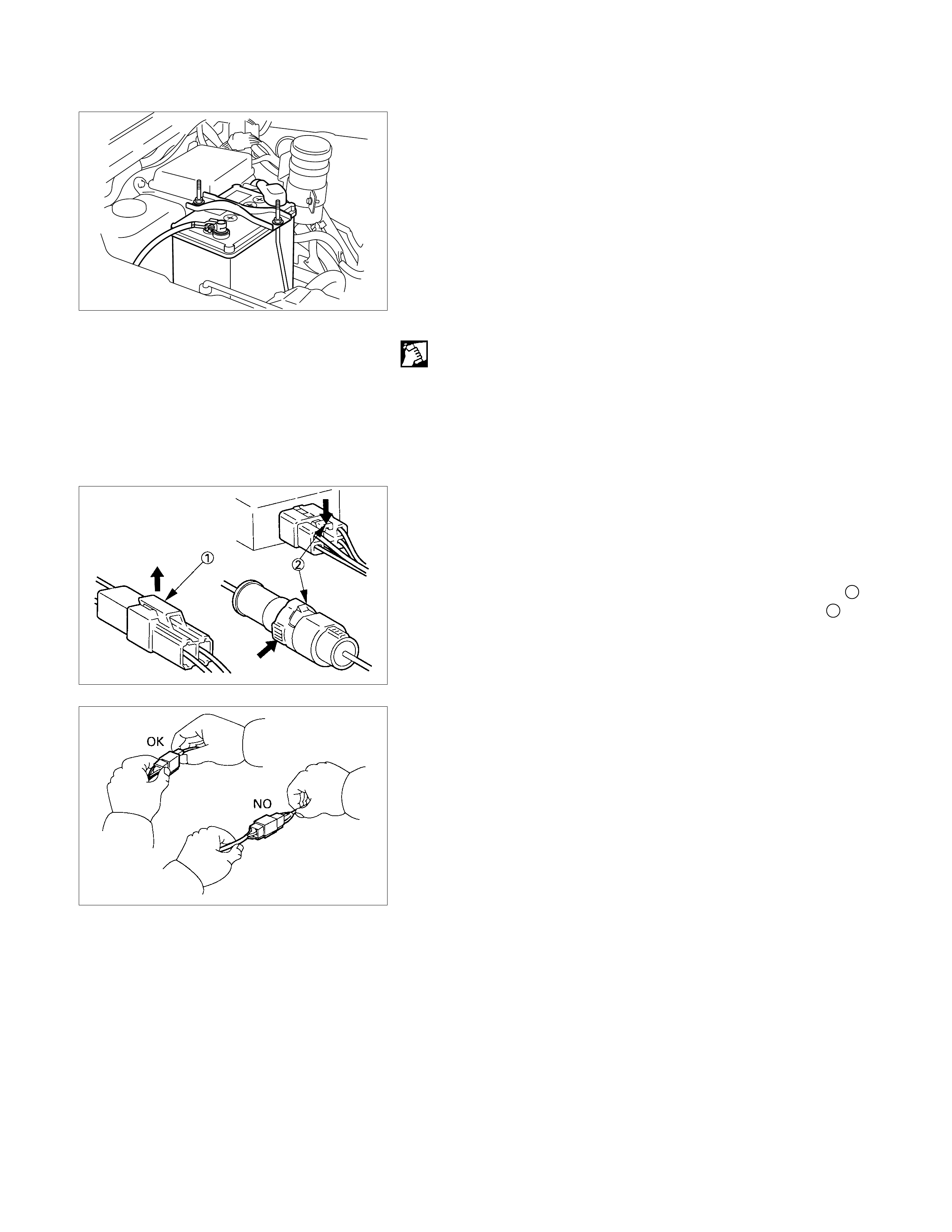
CONNECTOR HANDLING
DISCONNECTING THE CONNECTORS
Some connectors have a tang lock to hold the connectors
together during vehicle operation.
Some tang locks are released by pulling them towards you 1.
Other tang locks are released by pressing them forward 2.
Determine which type of tang lock is on the connector being
handled.
Firmly grasp both sides (male and female) of the connector.
Release the tang lock and carefully pull the two halves of the
connector apart.
Never pull on the wires to separate the connectors.
This will result in wire breakage.
CONNECTING THE CONNECTORS
Firmly grasp both sides (male and female) of the connector.
Be sure that the connector pins and pin holes match.
Be sure that both sides of the connector are aligned with each
other.
Firmly but carefully push the two sides of the connector
together until a distinct click is heard.
CONNECTOR INSPECTION
Use a circuit tester to check the connector for continuity.
Insert the test probes from the connector wire side.
CAUTION:
Never insert the circuit tester test probes into the
connector open side to test the c ontinuity.
Broken or open connector terminals will result.
WATERPROOF CO NNECTOR INSPECTION
It is not possible to insert the test probes into the connector
wire side of a waterproof connector.
Use one side of a connector 1 with its wires cut to make the
test.
Connect the test connector to the connector 2 to be tested.
Connect the test probes to the cut wires to check the connecto
r
continuity.
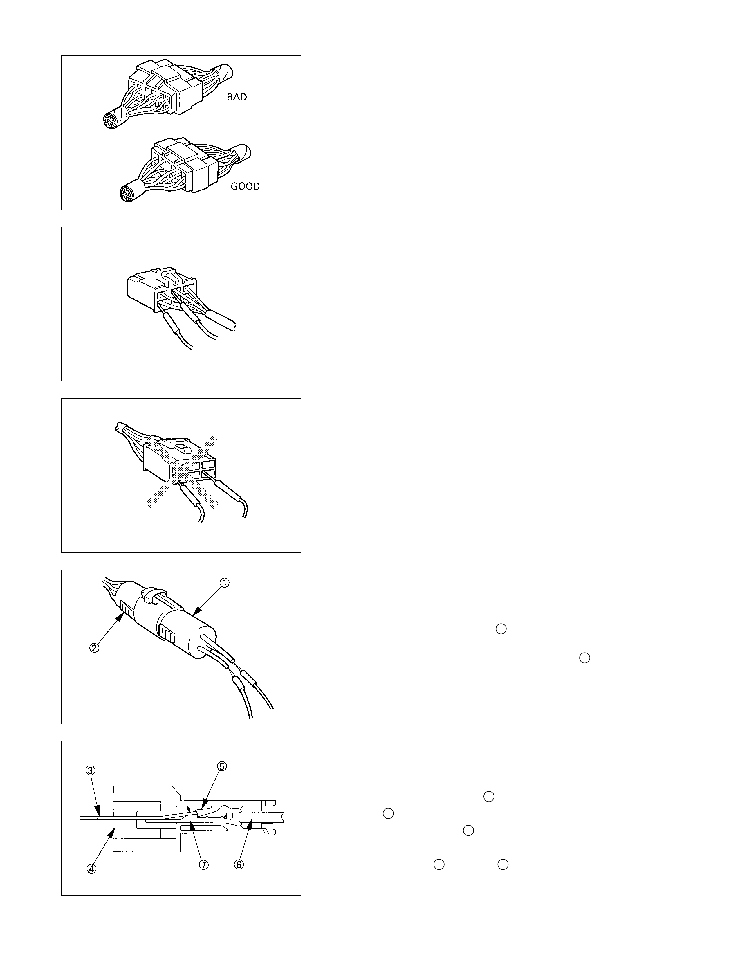
CONNECTOR PIN REMOVAL
CONNECTOR HOUSI NG TANG LOCK TYPE
1. Insert a slender shaft 3 into the connector housing open
end 4.
2. Push the tang lock 5 up (in the direction of the arr ow in the
illustration).
Pull the wire 6 with pin 7 free from the wire side of the
connector.
PIN TANG LOCK TYPE
1. Insert a slender shaft 3 into the connector housing open
end 4.
2. Push the tang lock 8 flat (toward the wire side of the
connector).
Pull the wire 6 with pin 7 free from the wire side of the
connector.
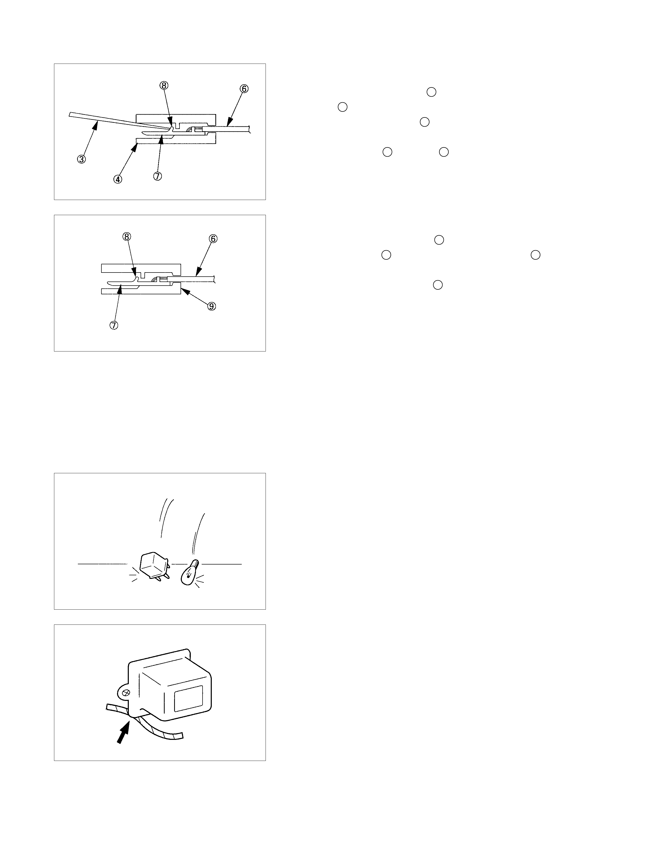
Connector Pin Insertion
1. Check that the tang lock 8 is fully up.
2. Insert the pin 7 from the connector wire side 9.
Push the pin in until the tang lock closes firmly.
3. Gently pull on the wires 6 to make sure that connector pin
is firmly set in place.
Fuse Replacement
The replacement fuse must have the same amperage
specification as the original fuse.
Never replace a burn out fuse with a fuse of a different
amperage specification.
Doing so can result in an electrical fire or other serious circuit
damage.
Parts Handling
Be careful for parts handling and any part should not be
dropped or thrown, otherwise short circuit or disorder may
result.
Wiring Harness
1. W hen as sem bling the parts, be caref ul not to bite or wedge
the wiring harness.
2. All electrical connections must be kept clean and tight.
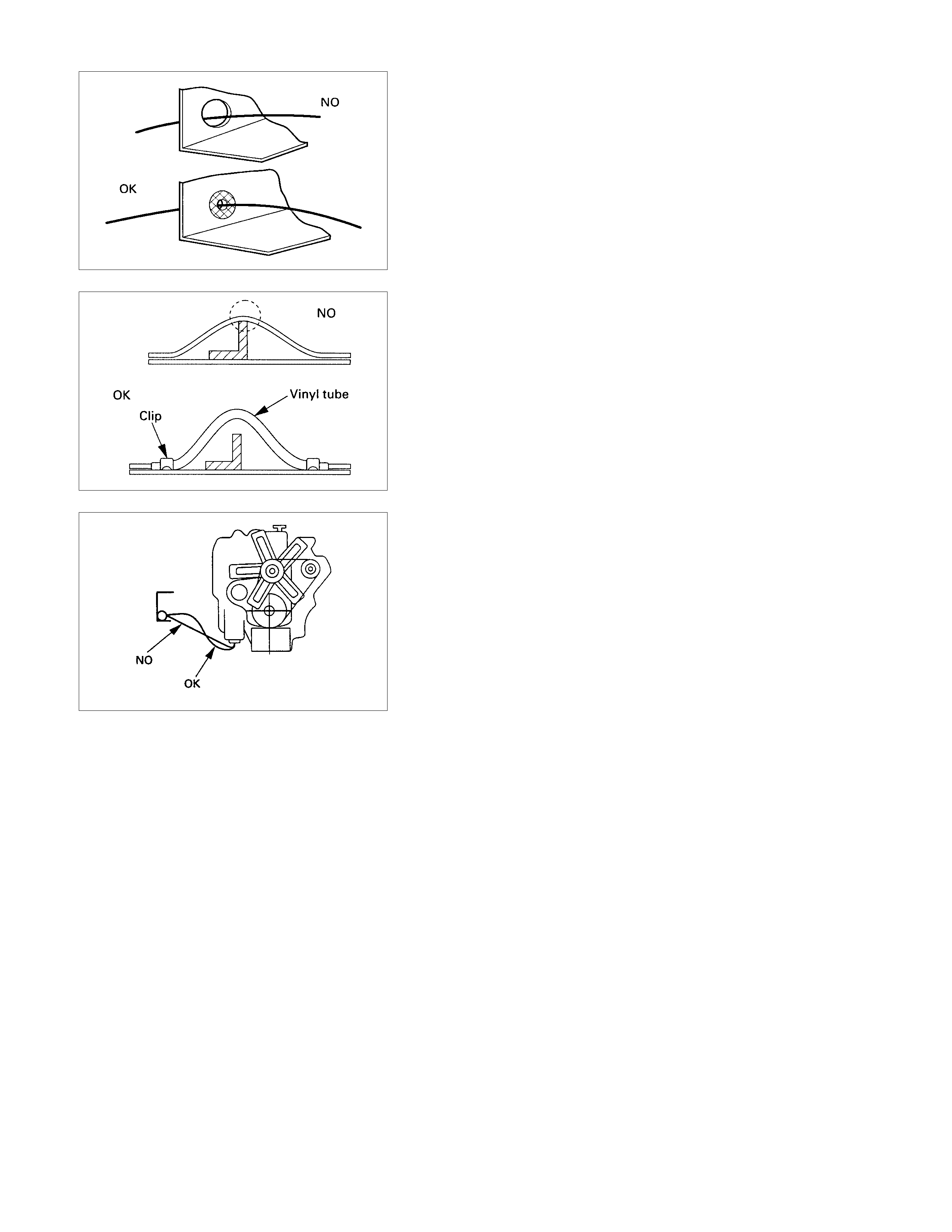
3. Use a grom met or guard tube to protect the wiring harness
from contacting a sharp edge or surface.
4. Position the wiring harness with enough clearance f rom the
other parts and guar d the wiring harness with a vinyl tube to
avoid direct contact.
5. The wiring harness between engine and chassis should be
long enough to prevent chafing or damage due to various
vibrations.
SPLICING WIRE
Open the Harness
If the harness is taped, remove the tape.
To avoid wire insulation damage, use a sewing "seam ripper"
(available from sewing supply stores) to cut open the harness.
If the harness has a black plastic conduit, simply pull out the
desired wire.
Cut the wire
Begin by cutting as little wire off the harness as possible.
You may need the extra length of wire later if you decide to cut
more wire off to change the location of a splice.
You may have to adjust splice locations to make certain that
each splice is at least 1-1/2" (40 mm) away from other splices,
harness branches, or connectors.
Strip the insulation
When replacing a wire, use a wire of the same size as the
original wire.
Check the stripped wire for nicks or cut strands.
If the wire is damaged, repeat the procedure on a new section
of wire.
The two stripped wire ends should be equal in length.
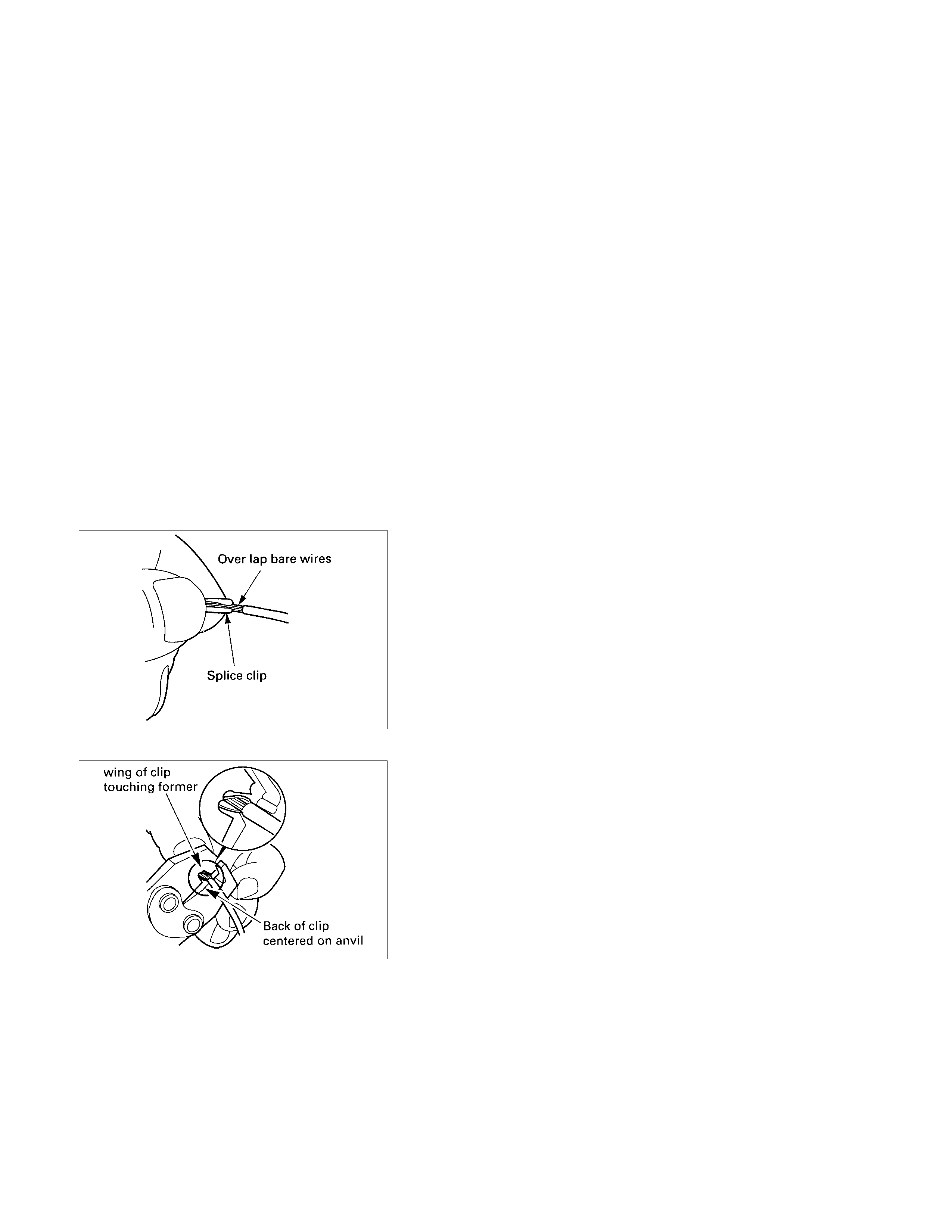
Crimp the Wires
Select the proper clip to secure the splice.
To determine the proper clip size for the wire being spliced,
follow the directions included with your clips.
Select the correct anvil on the crimper.
(On most crimpers your choice is limited to either a small or
large anvil.)
Overlap the two stripped wire ends and hold them between
your thumb and forefinger.
Then, enter the splice clip under the stripped wires and hold it
in place.
•Open the crim ping tool to its full width and rest one handle
on a firm flat surface.
•Center the back of the splice clip on the proper anvil and
close the crimping tool to the point where the back of the
splice clip touches the wings of the clip.
•Make sure that the clip and wires are still in the correct
position. Then, apply pressure until the crimping tool closes.

Before crimping the ends of the clip, be sure that:
•The wires extend beyond the clip in each direction.
•No strands of wire are cut loose.
•No insulation is caught under the clip.
Crimp the splice again, once on each end.
Do not let the crimping tool extend beyond the edge of the clip
or you may damage or nick the wires.
Solder
Apply 60/40 rosin core solder to the opening in the back of the
clip.
Follow the manufacturer's instructions for the solder equipment
you are using.
Tape the Splice
Center and roll the splicing tape.
The tape should cover the entire splice.
Roll on enough tape to duplicate the thickness of the insulation
on the existing wires.
Do not flag the tape.
Flagged tape may not provide enough insulation, and the
flagged ends will tangle with the other wires in the harness.
If the wire does not belong in a conduit or other harness
covering, tape the wire again.
Use a winding motion to cover the first piece of tape.
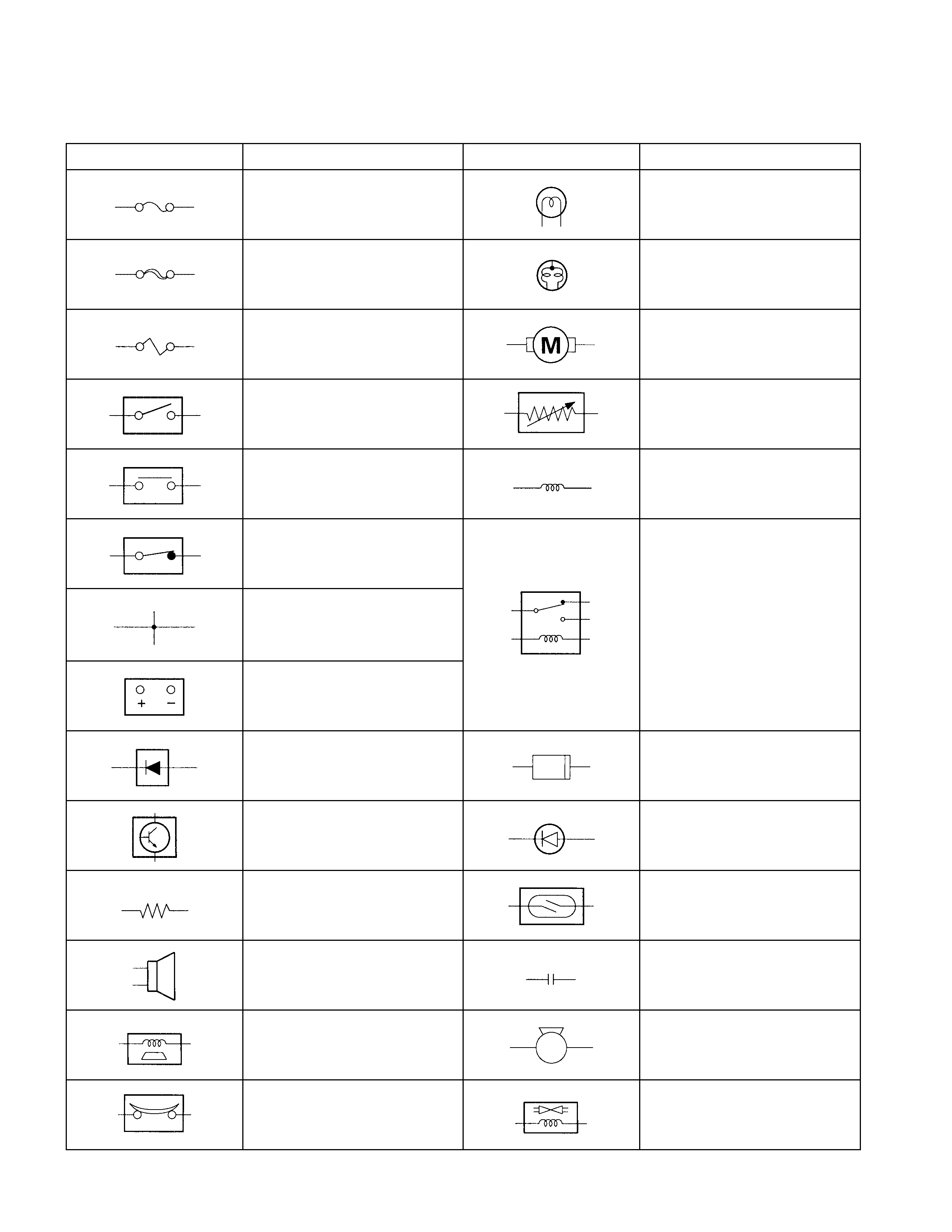
Symbols and Abbreviations
Symbols
Symbol Meaning of Symbol Symbol Meaning of Symbol
Fuse Bulb
Fusible link Double filament bulb
Fusible link wire Motor
Switch Variable resistor Rheostat
Switch Coil (inductor),solenoid,
magnetic valve
Switch (Normal close type)
Contact wiring Relay
Battery
Diode Connector
Electronic Parts Light emitting diode
Resistor Reed switch
Speaker Condenser
Buzzer Horn
Circuit breaker Vacuum switching valve

Abbreviations
Abbreviation Meaning of abbreviation Abbreviation Meaning of abbreviation
A Ampere(S) LH Left hand
ABS Anti-lock brake system LWB Long wheel base
ASM Assembly MPI Multiport fuel injection
AC Alternating current M/T Manual transmission
A/C Air conditioner QOS Quick On Start system
ACC Accessories RH Right hand
CARB Carburetor RR Rear
C/B Circuit breaker RWAL Rear wheel anti-lock brake system
CSD Cold start device SRS Supplemental restraint system
DIS Direct ignition system ST Start
EBCM Electronic brake control module STD Standard
ECGI Electronic control gasoline injection SW Switch
ECM Engine control module SWB Short wheel base
ECU Electronic control unit TCM Transmission control module
EFE Early fuel evaporation V Volt
4×2 Two-wheel drive VSV Vacuum switching valve
4×4 Four-wheel drive W Watt(S)
FL Fusible link WOT Wide open throttle
FRT Front W/ With
H/L Headlight W/O Without
IC Integrated circuit
IG Ignition
kW kilowatt
Parts For Electrical Circuit
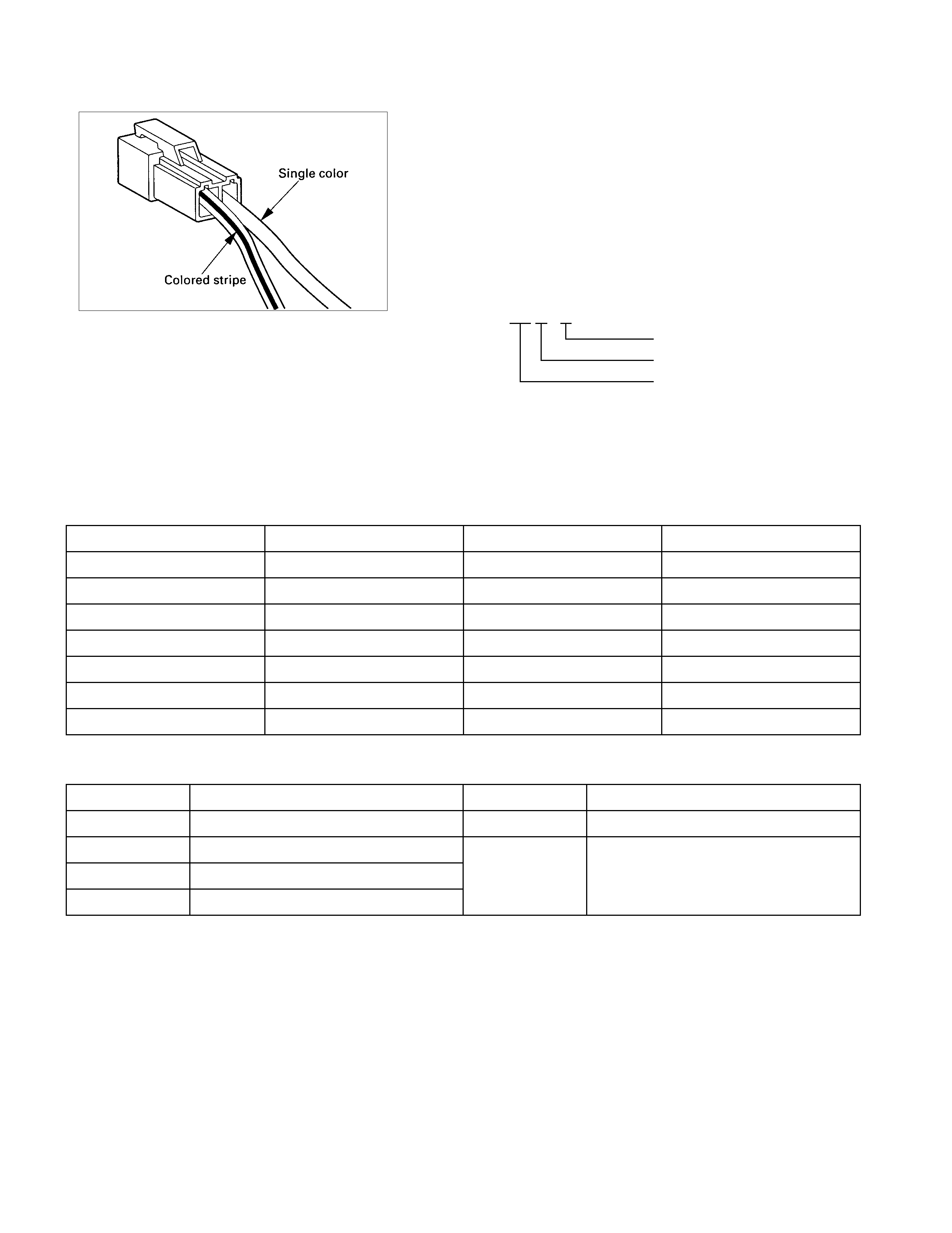
Wiring
WIRE CO LO R
All wires have color-coded insulation.
Wires belonging to system's main harness will have a single
color.
Wires belonging to a system's sub-circuits will have a colored
stripe.
Striped wires use the following code to show wire size and
colors.
Example: 0.5 G / R Red (Stripe color)
Green (Base color)
Wire size (0.5mm2)
Abbreviations are used to indicate wire color within a circuit
diagram.
Refer to the following table.
WIRE CO LOR-CODING
Color-Coding Meaning Color-Coding Meaning
B Black BR Brown
W White LG Light green
R Red GR Grey
G Green P Pink
Y Yellow LB Light blue
L Blue V Violet
O Orange
DISTINCTION OF CIRCUI T BY WI RE BASE COLOR
Base color Circuits Base color Circuits
B Starter circuit and grounding circuit Y Instrument circuit
W Charging circuit L, O, BR,
R Lighting circuit LG, GR, Other circuits
G Signal circuit P, LB, V
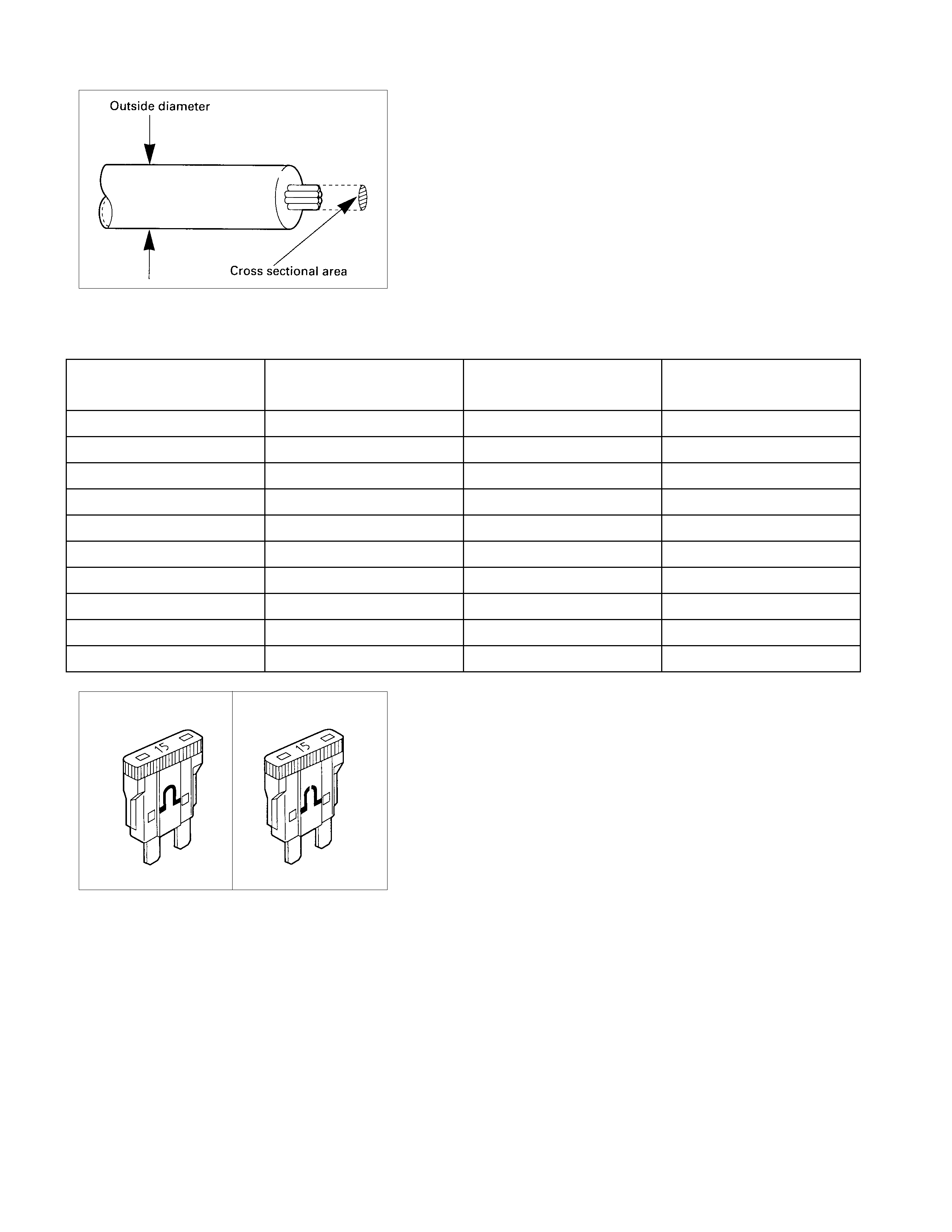
WIRE SIZE
Wire size is specified with the metric gauge system.
The metric gauge system gives the wire size in cross sectional
area measured in square millimeters.
WIRE SI ZE SPECI F ICATIONS
Normal size Cross sectional area
(mm2)Outside diameter
(mm) Allowable current
(A)
0.3 0.372 1.8 9
0.5 0.563 2.0 12
0.85 0.885 2.2 16
1.25 1.287 2.5 21
2 2.091 2.9 28
3 3.296 3.6 37.5
5 5.227 4.4 53
8 7.952 5.5 67
15 13.36 7.0 75
20 20.61 8.2 97
Normal Blown Fuse
Fuses are the most common form of circuit protection used in
vehicle wiring.
A fuse is a thin piece of wire or strip of metal encased in a
glass or plastic housing.
It is wired in series with the circuit it protects.
When there is an overload of current in a circuit, such as a
short of a ground, the wire or metal strip is designed to burn
out and interrupt the flow of current.
This prevents a surge of high current from reaching and
damaging other components in the circuit.
Determine the cause of the overloaded before replacing the
fuse.
Never replace a blown fuse with a fuse of a different amperage
specification.
Doing so can result in an electrical fire or other serious circuit
damage.
A blown fuse is easily identified.
Normal Blown Fusible Link
The fusible link is primarily used to protect circuits where high
amounts of current flow and where is would not be practical to
use a fuse.
For example, the starter circuit.
When a current overload occurs, the fusible link melts open
and interrupts the flow of current so as to prevent the rest of
the wiring harness from burning.
Determine the cause of the overload before replacing the
fusible link.
The replacement fusible link must have the same amperage
specification as the original fusible link.
Never replace a blown fusible link with fusible link of a different
amperage specification.
Doing so can result in an electrical fire or other serious circuit
damage.
A blown fusible link is easily identified.
FUSIBLE LINK SPECI F I CATIONS
Type Rating Case Color Maximum Circuit Current(A)
Connector 30A Pink 15
Connector 40A Green 20
Bolted 50A Red 25
Bolted 60A Yellow 30
Bolted 80A Black 40
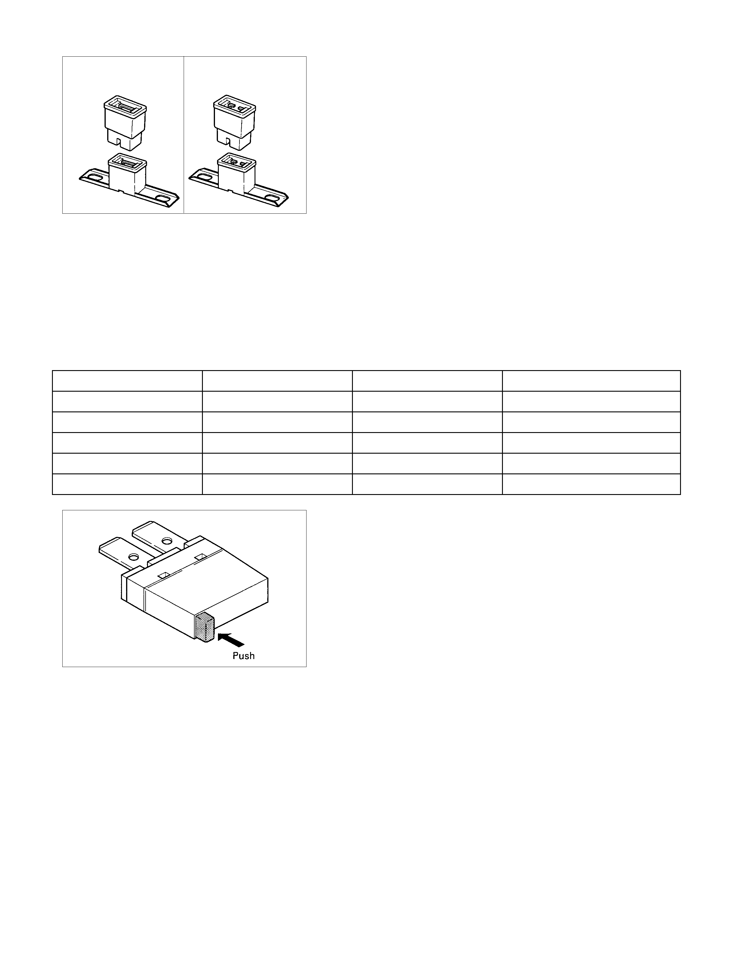
Circuit Breaker
The circuit breaker is a protective device designed to open the
circuit when a current load is in excess of rated breaker
capacity.
If there is a short or other type of overload condition in the
circuit, the excessive current will open the circuit between the
circuit breaker terminals.
The reset knob pops out when the circuit is open.
Push the reset knob in place to restore the circuit after
repairing it.

Relay
Battery and load location may require that a switch be placed
some distance from either component.
This means a longer wire and a higher voltage drop 1. The
installation of a relay between the battery and the load reduces
the voltage drop 2.
Because the switch controls the relay, amperage through the
switch can be reduced.
RELAY SPECIFICATIONS AND CONFIGURATIONS
Name/
Color
Rated
voltage/ Coil
resistance Internal circuit
1T
(MR5C)
/Black
12V
Approx. 90Ω
Minimum
operating
voltage:7V at
25°C (77°F)
1T
(MR5C)
/Brown
12V
Approx. 90Ω
Minimum
operating
voltage: 10.5V
at 25°C (77°F)
* Relay contact shown in the wiring diagram indicates condition before actuation.
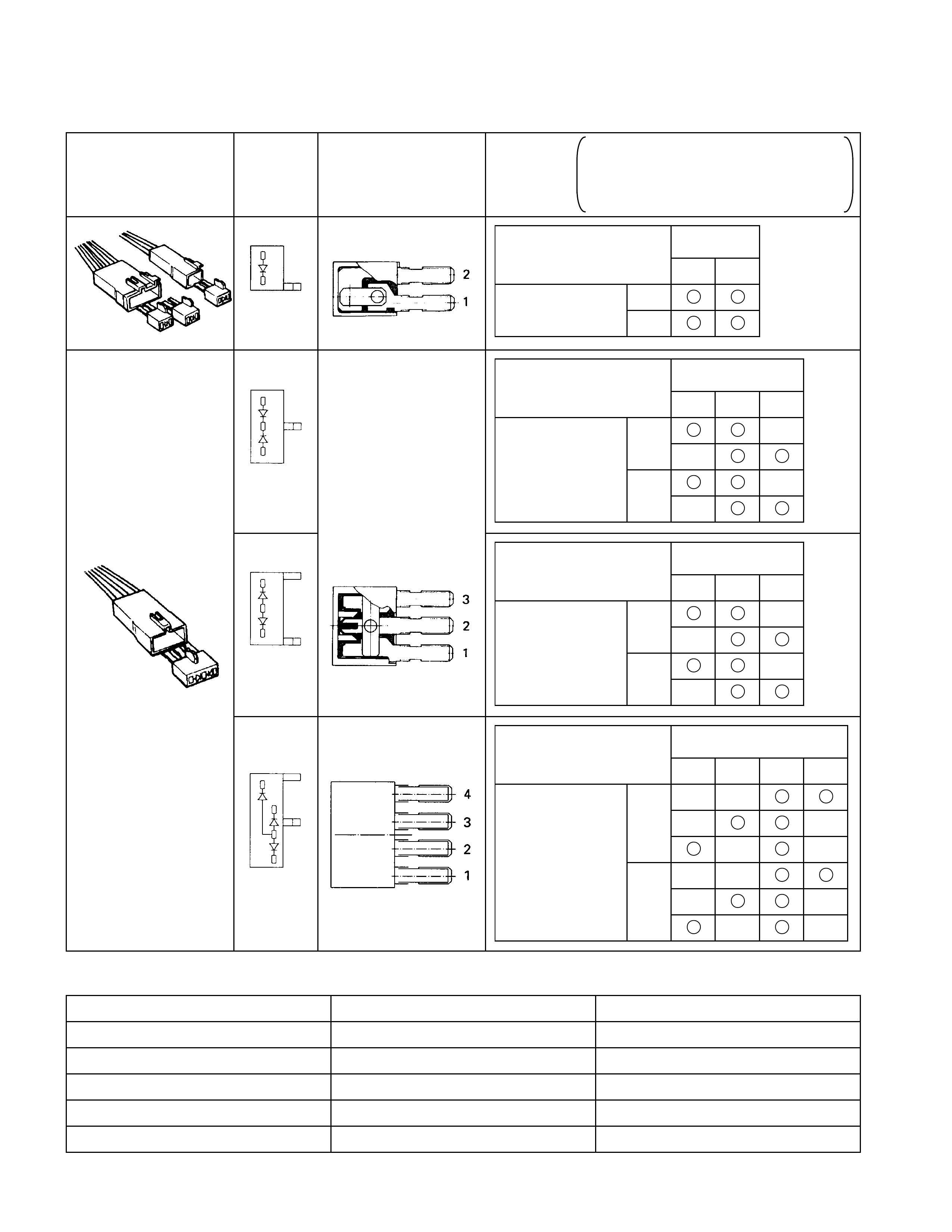
Diode
DIODE SPECI F ICATIONS AND CONFIG URATIONS
SHAPE MARK/
COLOR CONSTRUCTION CHECKING
THERE SHOULD BE CONTINUITY IN
EITHER A OR B WHEN A CIRCUIT
TESTER IS CONNECTED WITH
DIODE TERMINAL
BLACK
21
CONNECTION A + -
PATTERN B - +
TERMINAL NO.
BLACK
321
- +
CONNECTION + -
PATTERN + -
- +
B
A
TERMINAL NO.
BLACK
321
- +
CONNECTION + -
PATTERN + -
- +
B
A
TERMINAL NO.
BLACK
4321
+ -
A- +
CONNECTION - +
PATTERN - +
B+ -
+ -
TERMINAL NO.
Maximum Rating (Temp.=25°
°°
°C)
Items Rating Remarks
Peak reverse voltage 400V
Transient peak reverse voltage 500V
Average output current 1.5A Temp.=40°C
Working ambient temperature -30°C∼80°C
Storage temperature -40°C∼100ßC
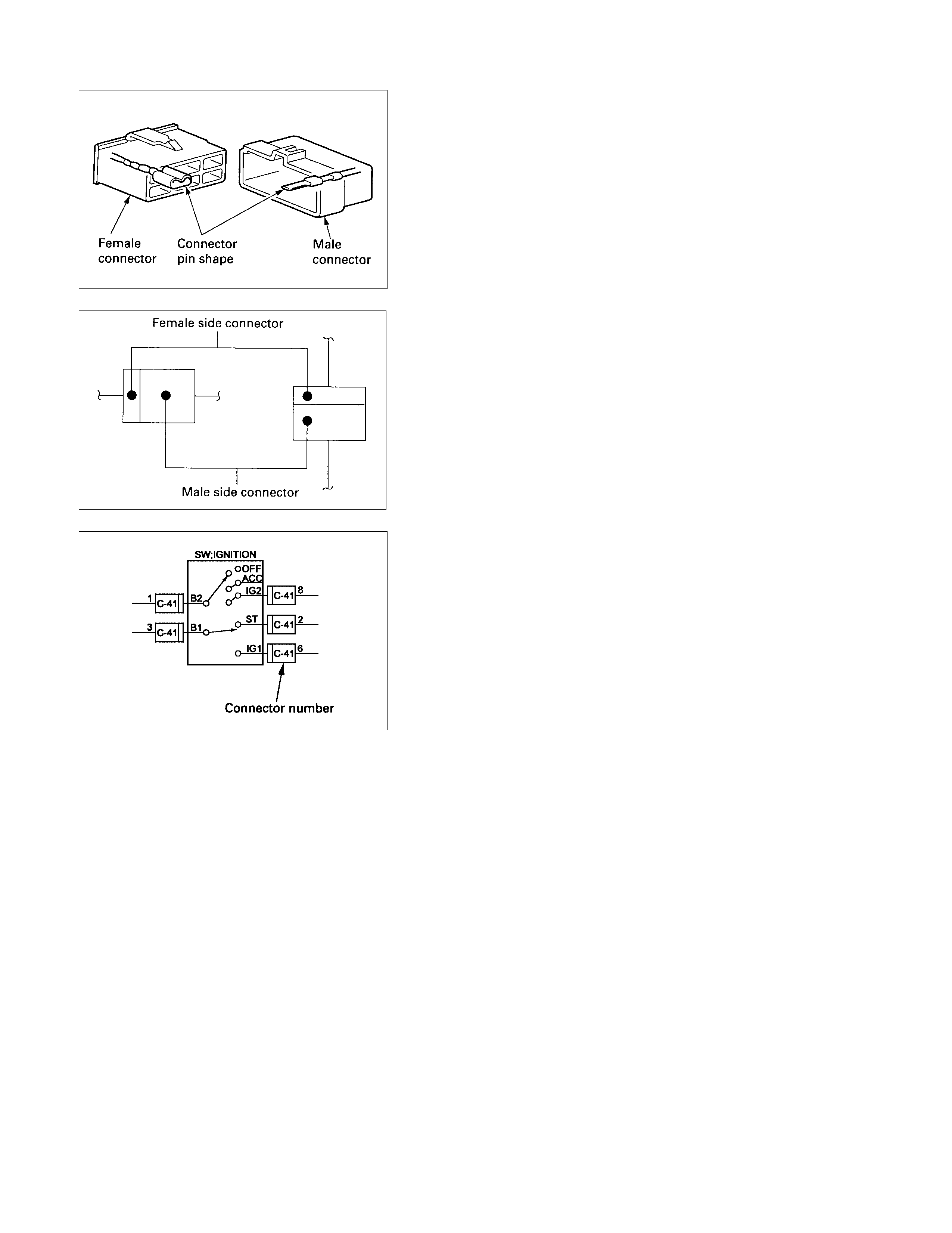
Connector
The connector pin shape determines whether the connector is
male or female.
The connector housing configuration does not determine
whether a connector is male or female.
The symbol illustrated in the figure is used as connector in the
circuit this section.
Connector is identified with a number.
The applicable terminal number is shown for each connector.
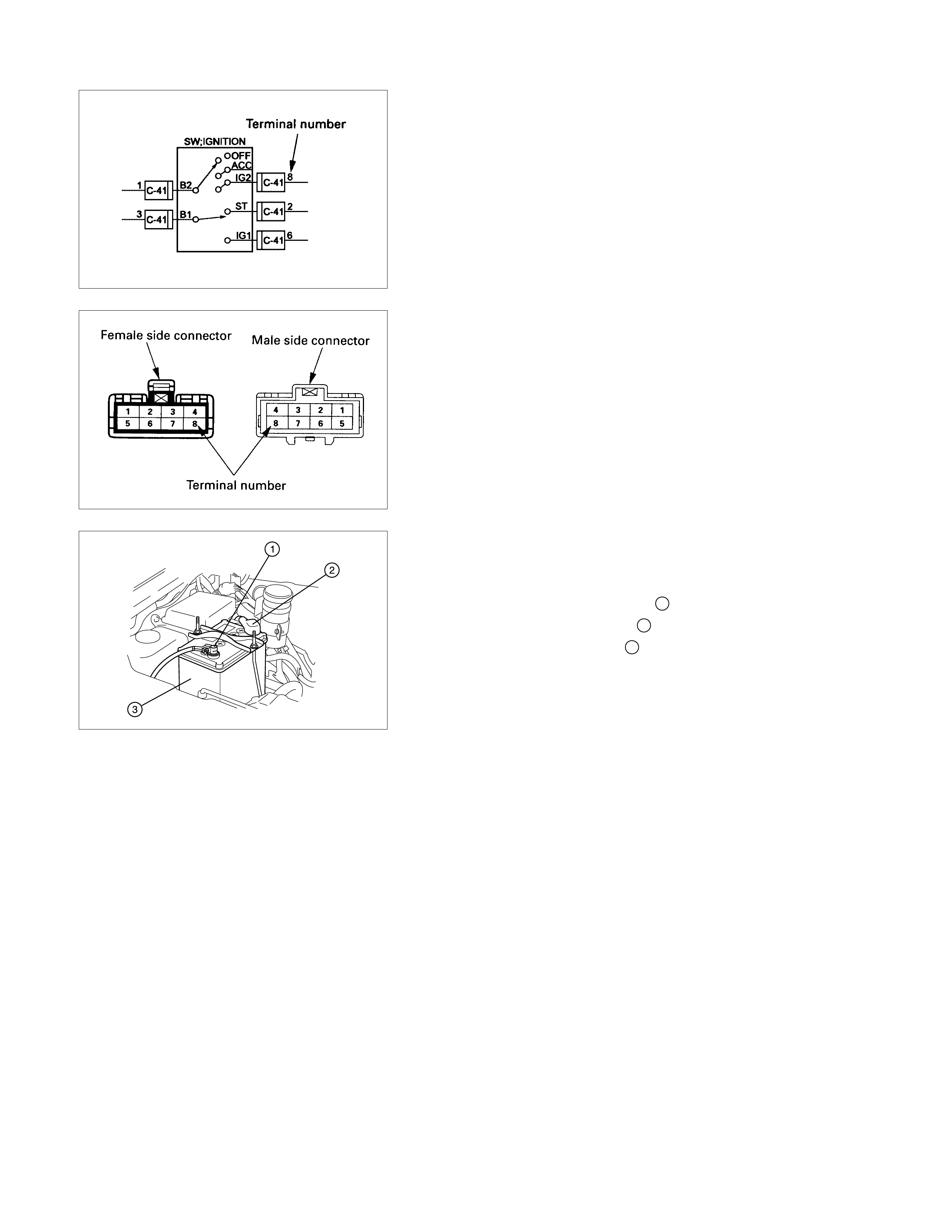
Connector terminal numbers are clearly shown.
Male side connector terminal numbers are in sequence from
upper right to lower left.
Female side connector terminal numbers are in sequence from
upper left to lower right.
NOTE:
For those conne ctors on which specific terminal numbers
on symbols are shown, the terminal numbers or symbols
are used in the circuit diagram, irrespective of the above
rule.
Battery
INSPECTION
1. Check the battery terminals 1 for corrosion.
2. Check the battery cables 2 for looseness.
3. Check the battery case 3 for cracks and other damage.
4. Check the battery electrolyte level.
If the electrolyte level is excessively low, the battery must
be replaced.
5. If the battery has a built-in hydrometer, perform the
following steps.
1) Carefully clean the battery upper surface.
2) Check the hydrometer.
The hydrometer design will vary with the battery
manufacturer.
Refer to the illustration shown on the battery.
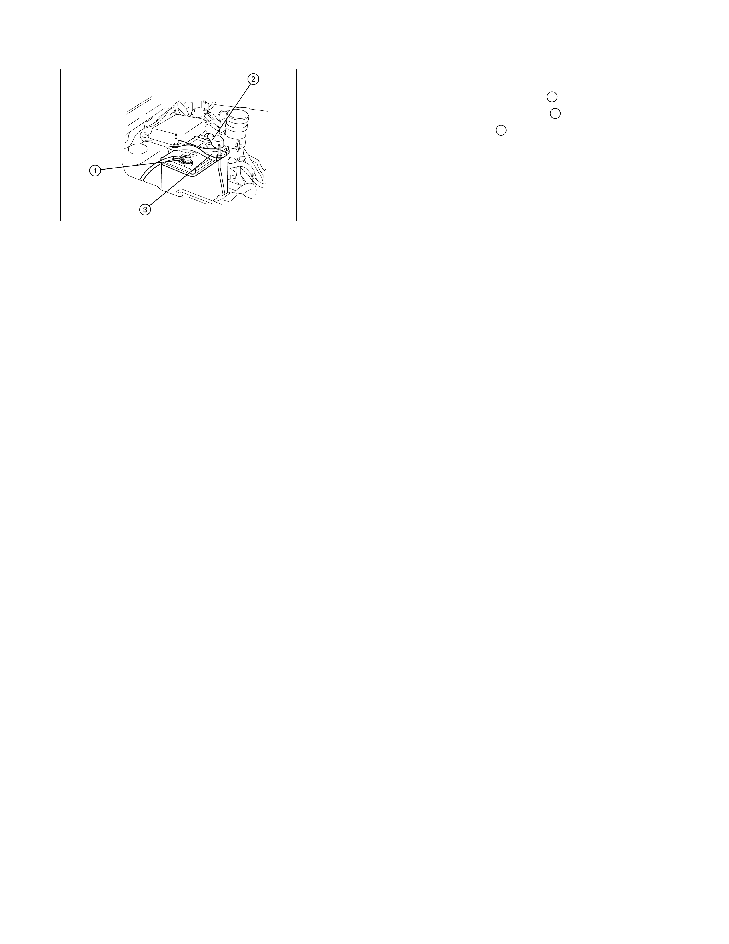
Battery Replacement
1. Disconnect the battery ground cable 1.
2. Disconnect the battery positive cable 2.
3. Remove the battery clamp 3.
4. Remove the battery
CAUTION:
It is important that the ba ttery ground cable be removed
first.
Removing the battery positive cable first can result in a
short circuit.
Jump Starting the Engine with a Booster Battery
The following description assumes that you are using a booster
battery mounted on a second vehicle.
The listed steps (with some minor modifications) are also
applicable if you are using a naked booster battery or special
battery charging equipment.
CAUTION:
Never push or tow the vehicle in an attempt to start it.
Extensive damage to the emission system and other
vehicle parts will result.
(only catalytic converter vehicle)
Treat both the discharged battery and the booster battery
with great care when using jumper cables.
Carefully follow the procedure outlined below.
Always be aware of the dangers of sparking.
Failure to follow the following procedure can result in:
a. Serious personal injury, specially to your eyes.
b. Extensive property damage from a battery explosion,
battery acid discharge, or electrical file.
c. Extensive damage to the electronic components o
f
both vehicles.
Do not use a 24 volt booste r battery.
Serious damage to the vehicle's electrical system and
electronic components will result.

Jump Starting Procedure
1.Set the parking brake on both vehicles.
2.If one or both vehicles is equipped with a manual
transmission, place the gear shift in the "NEUTRAL"
position.
3.Turn off the ignition on both vehicles.
4.Turn off all vehicle lights and accessories.
5.Check the built-in hydrometer on the discharged Battery (I
f
so equipped).
If there is no hydrometer indication abandon the jump start
procedure.
6.Be sure that the two vehicles are not touching.
Attach the end of one jumper cable to the booster battery
positive terminal.
7.Attach the other end of the same cable to the discharged
battery positive terminal.
8. Once again, check that the booster battery has a 12 volt
rating.
9.Attach one end of the remaining booster cable to the
booster battery negative terminal.
10.Attach the other end of the booster cable to a solid ground
(such as the air conditioner compressor mounting bracket
or the alternator mounting bracket) in the engine room o
f
the vehicle with the discharged battery.
Be sure that the ground connection is at least 500 mm (20
in) from the discharged battery.
CAUTION:
Do not attach the booster cable to the discharged battery
negative terminal.
11.Start the engine of the vehicle with the booster battery.
Check that all unnecessary electrical accessories are off.
12.Start the engine of the vehicle with the discharged battery.
13.Remove the jumper cables in the reverse order to which
they were attached.
CAUTION:
Be absolutely sure to remove the negative jumper cable
from the vehicle with the discharged battery first.
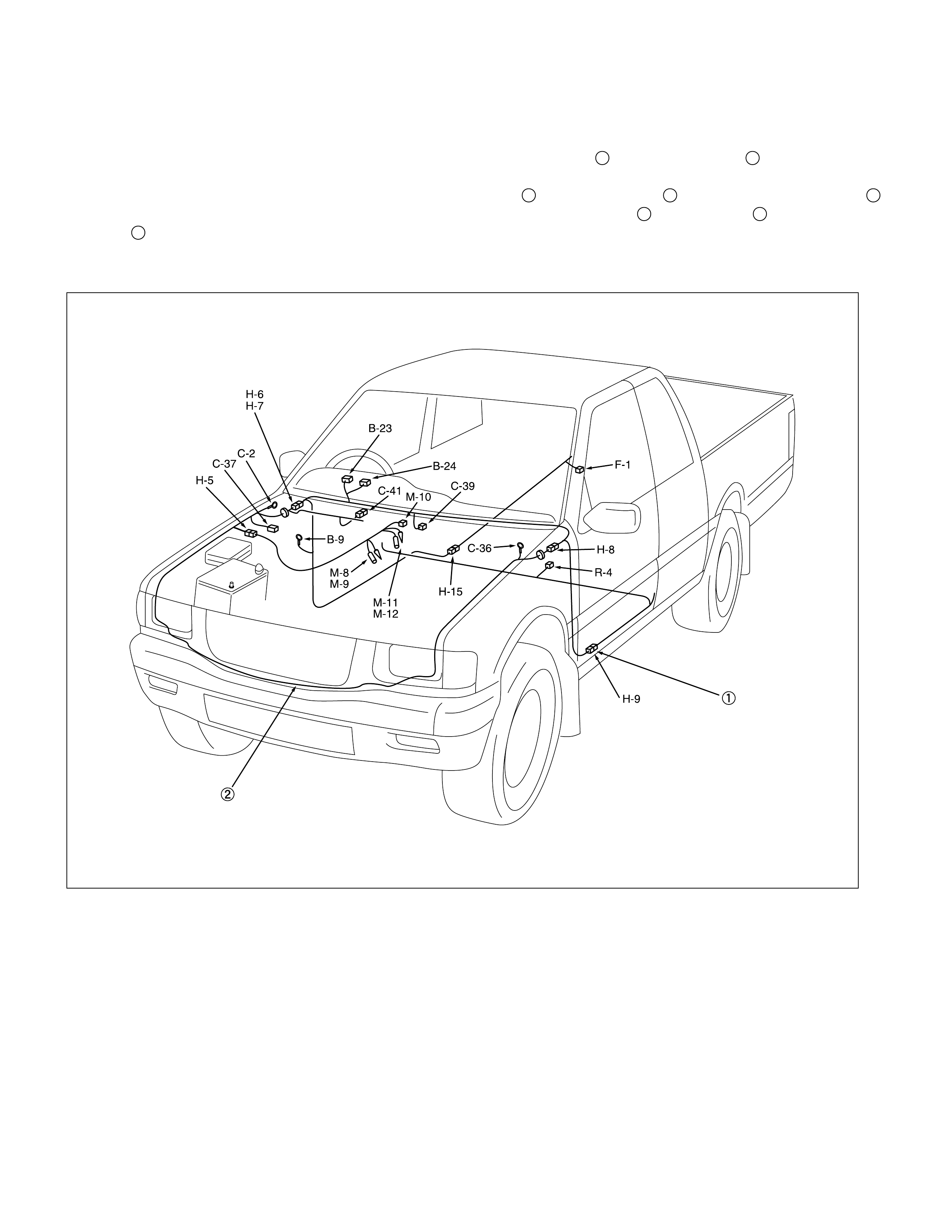
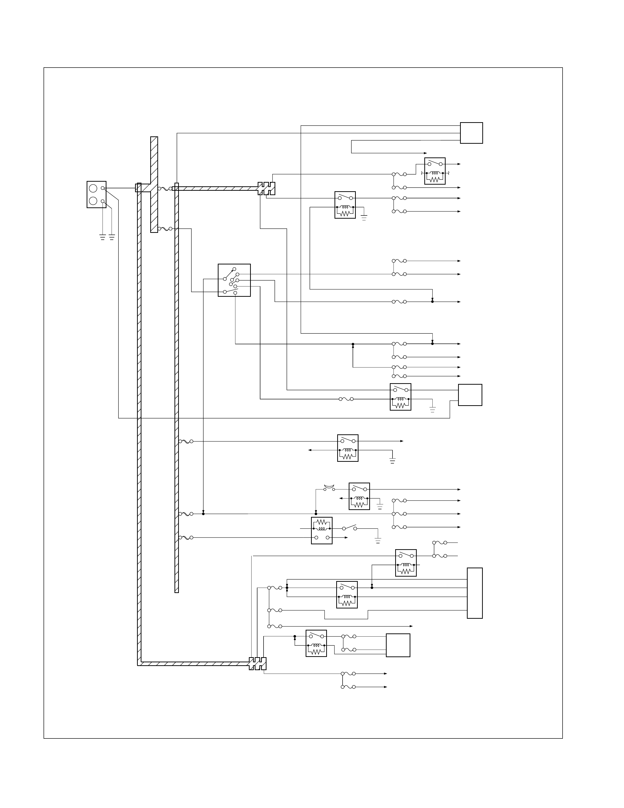
Reading The Cir c uit Diagra m
In this manual, each system has its own parts location illustration and circuit diagram.
And connector configurations used in the circuit diagram are shown at the end of this manual.
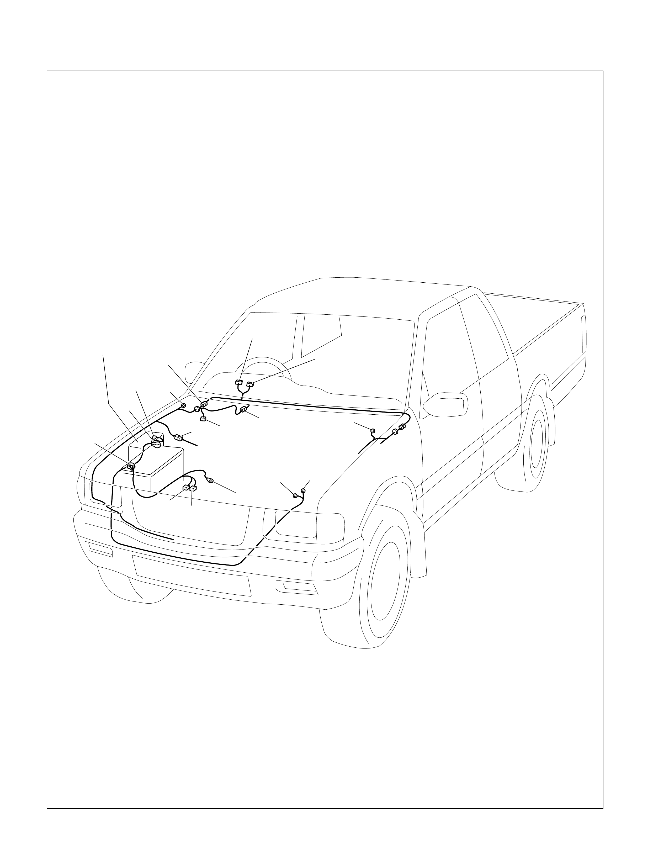
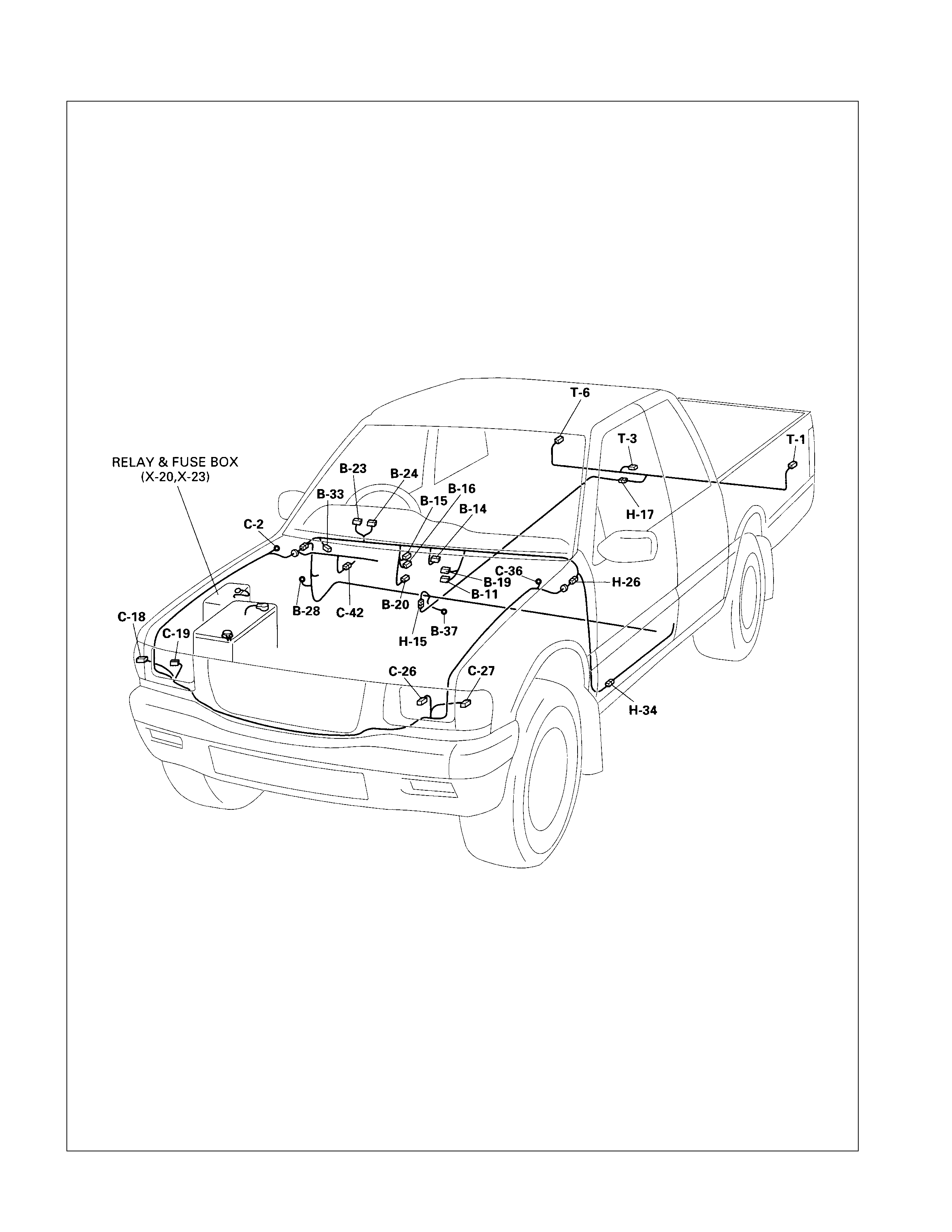
PARTS LOCATION: The parts location shows the location of the connectors 1 and the harnesses 2 used in the each
system.
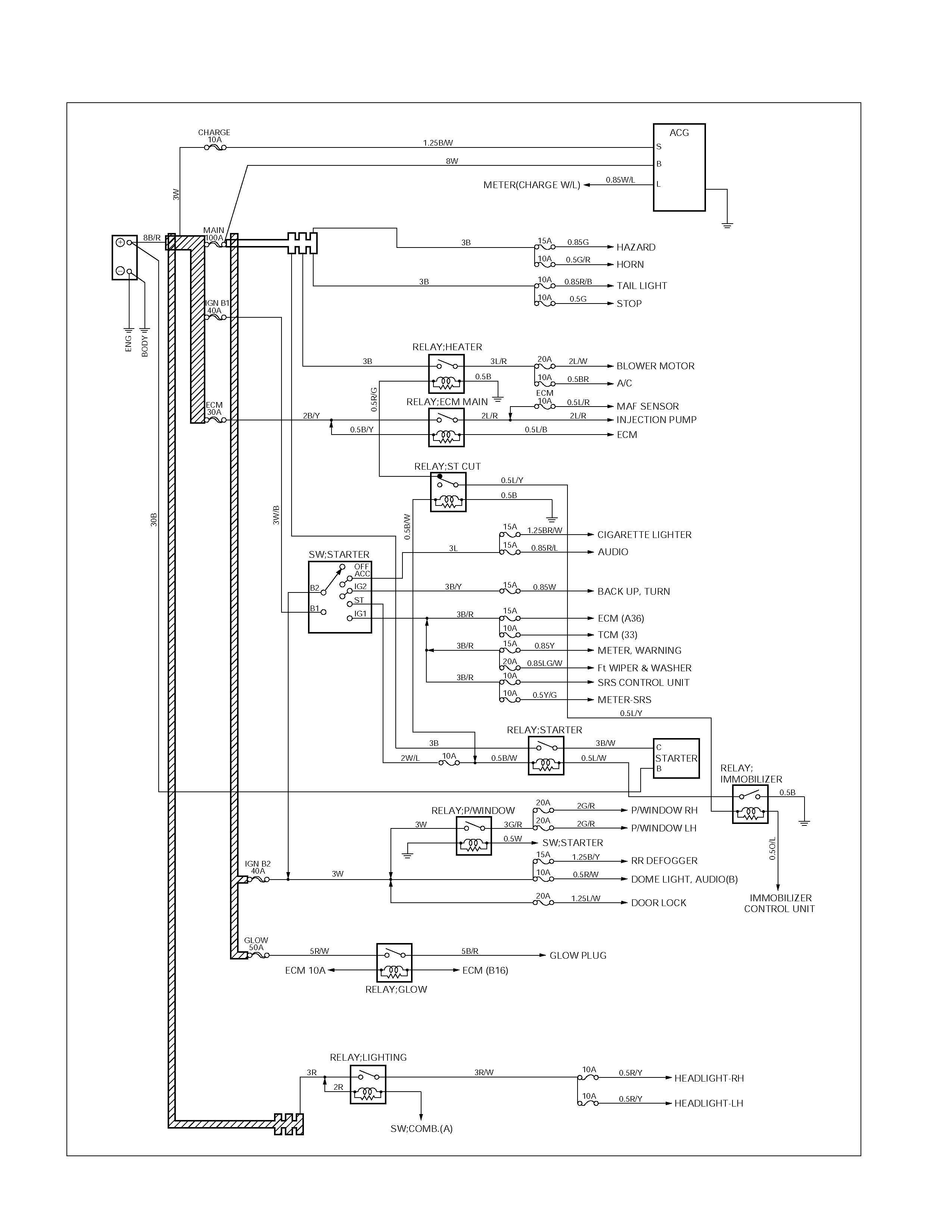
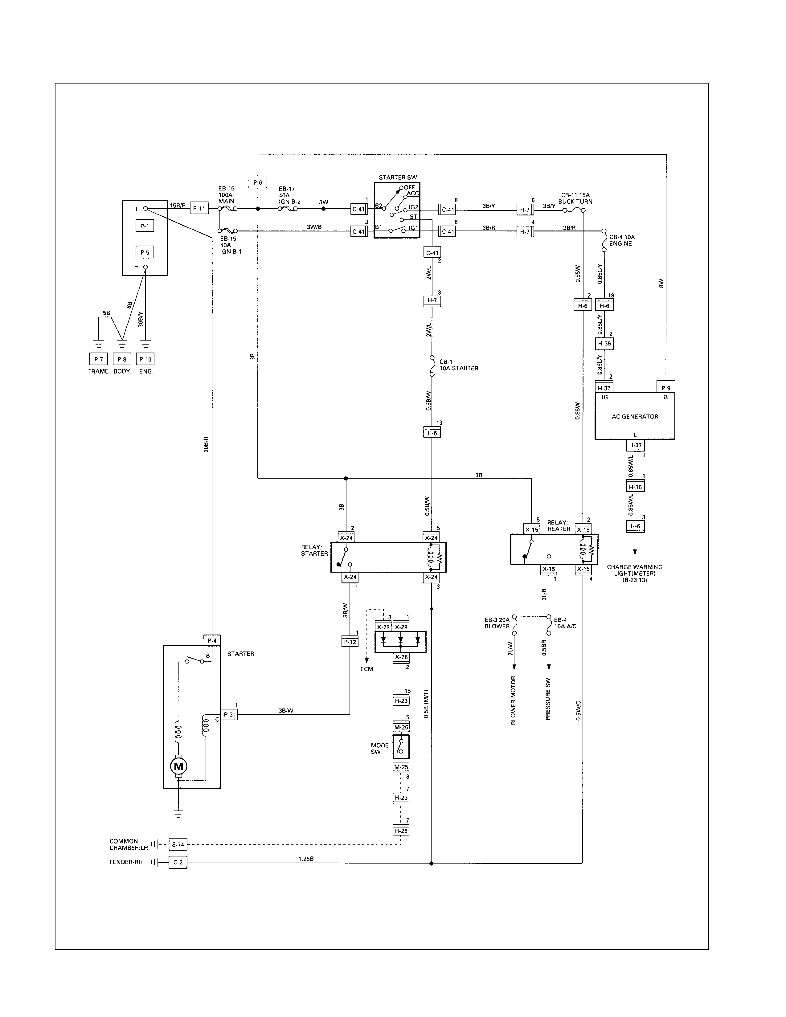
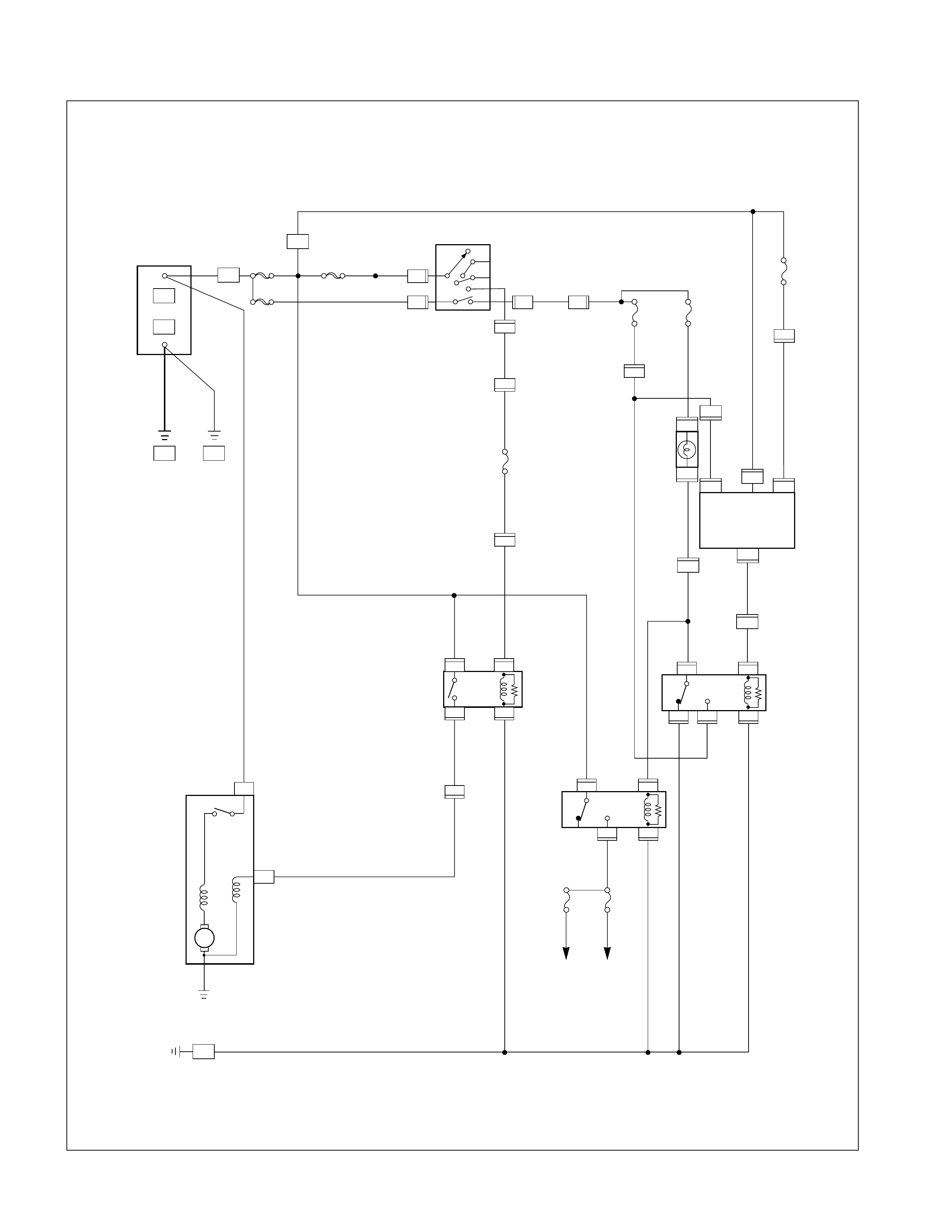
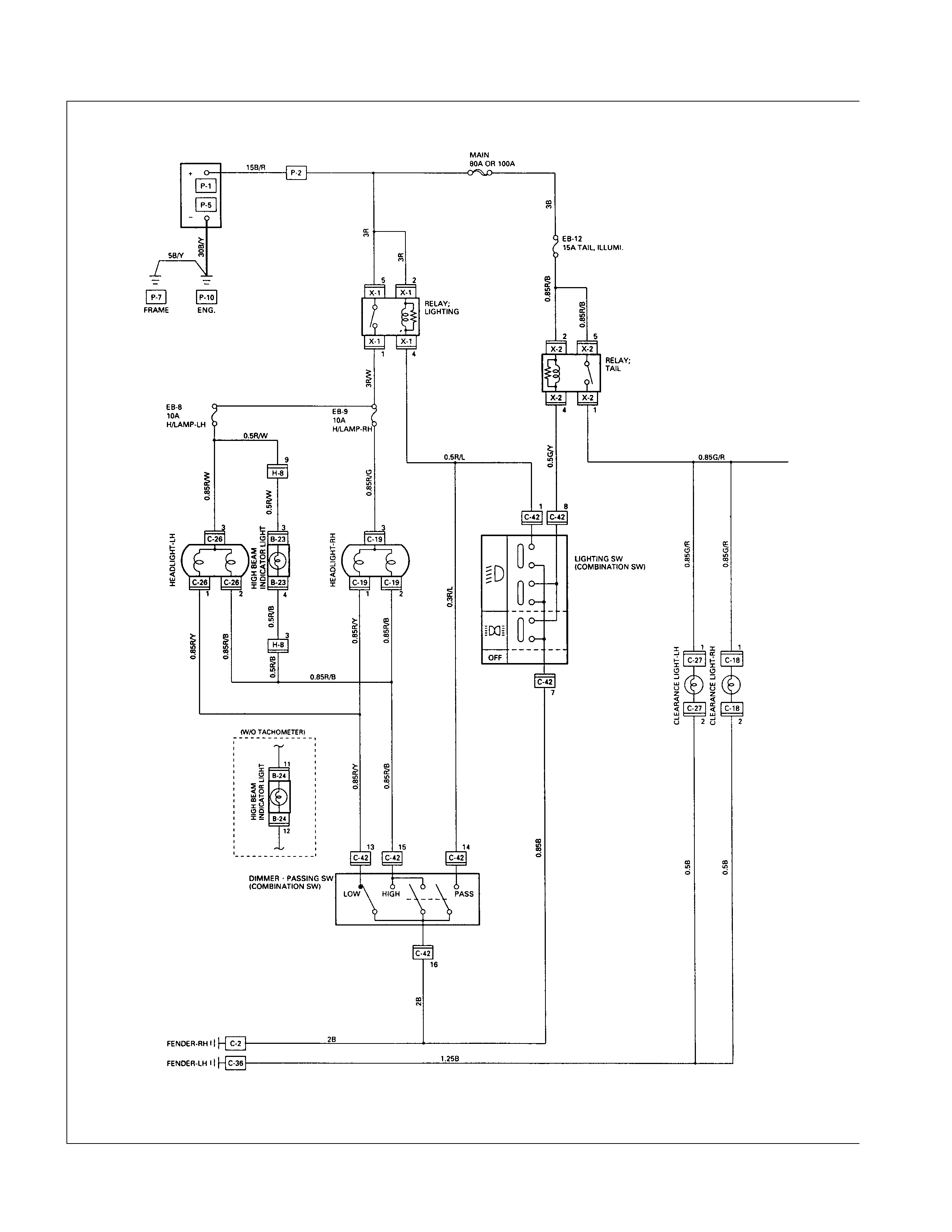
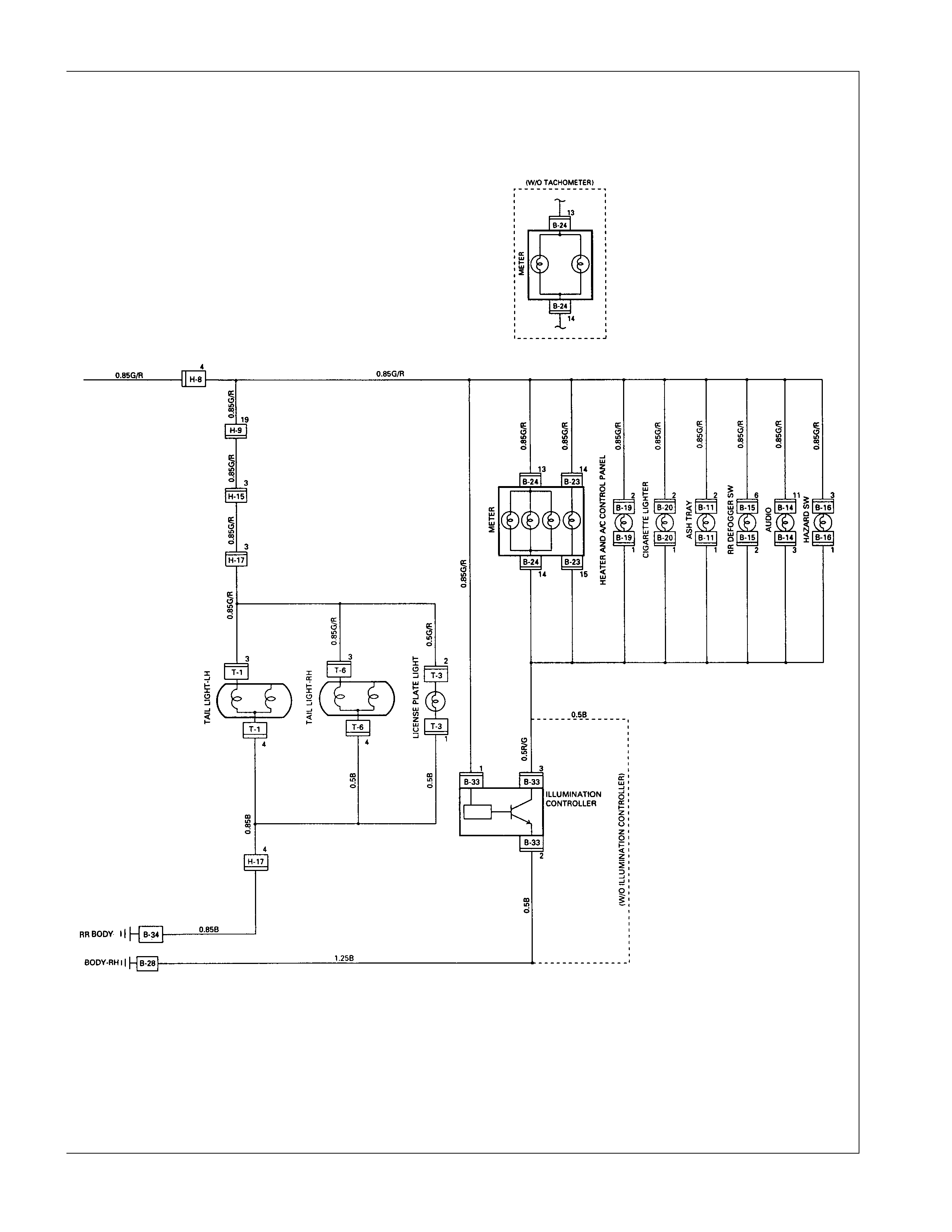
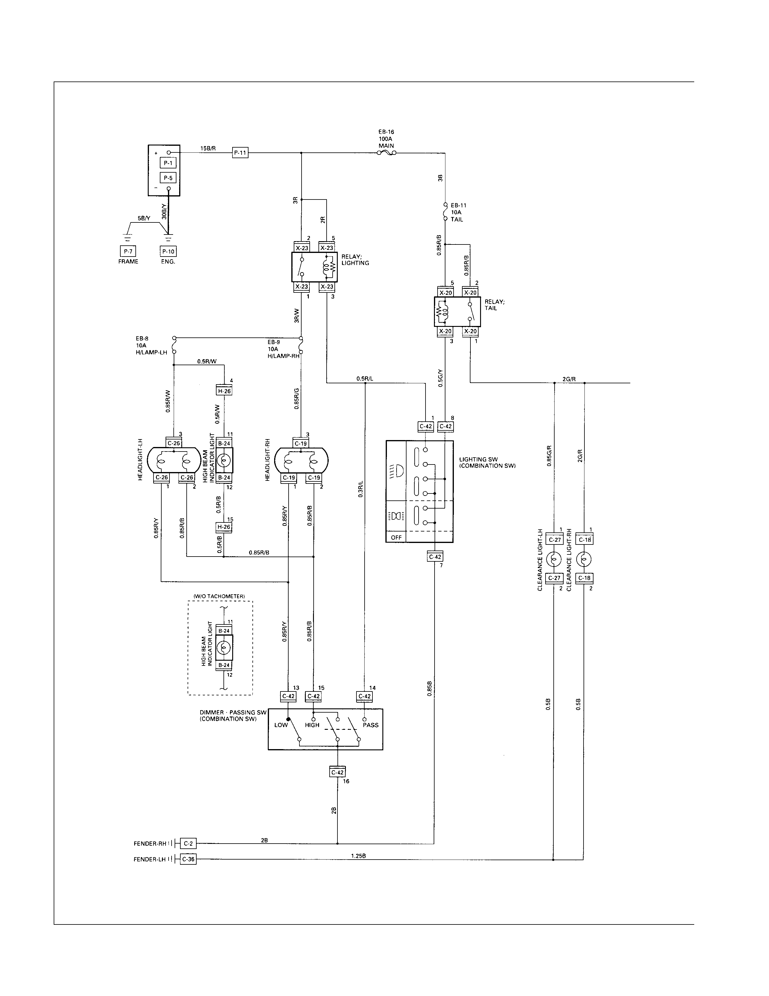
CIRCUIT DIAGRAM: The circuit diagram shows the power supply 3, the load or loads 4 and the grounding point(s) 5.
CONNECTOR LIST: The connector configuration shows each connector's number 6, configuration 7 and the pin
numbers 8.
Parts Location
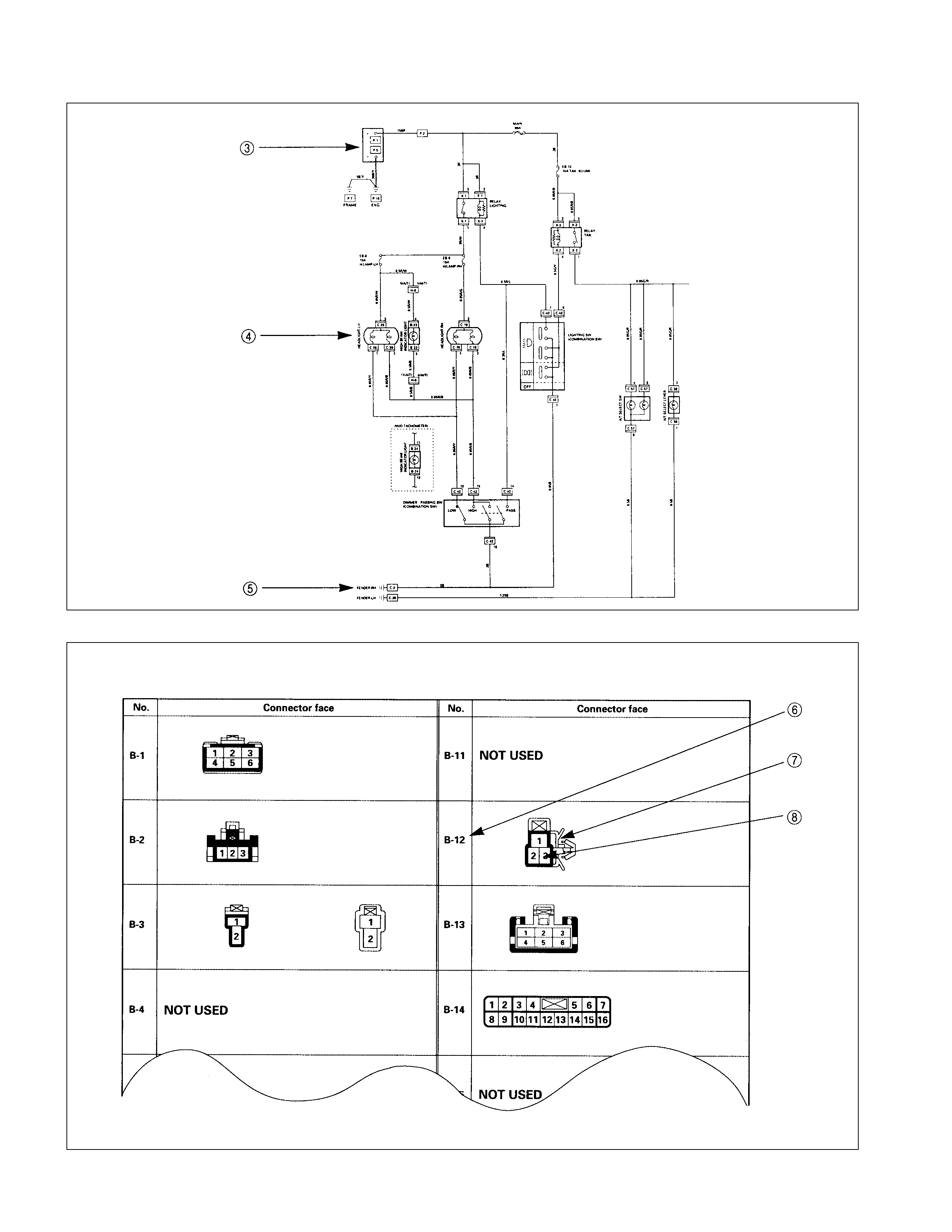
Circuit Diagram
Connector List
CONNECTOR LIST
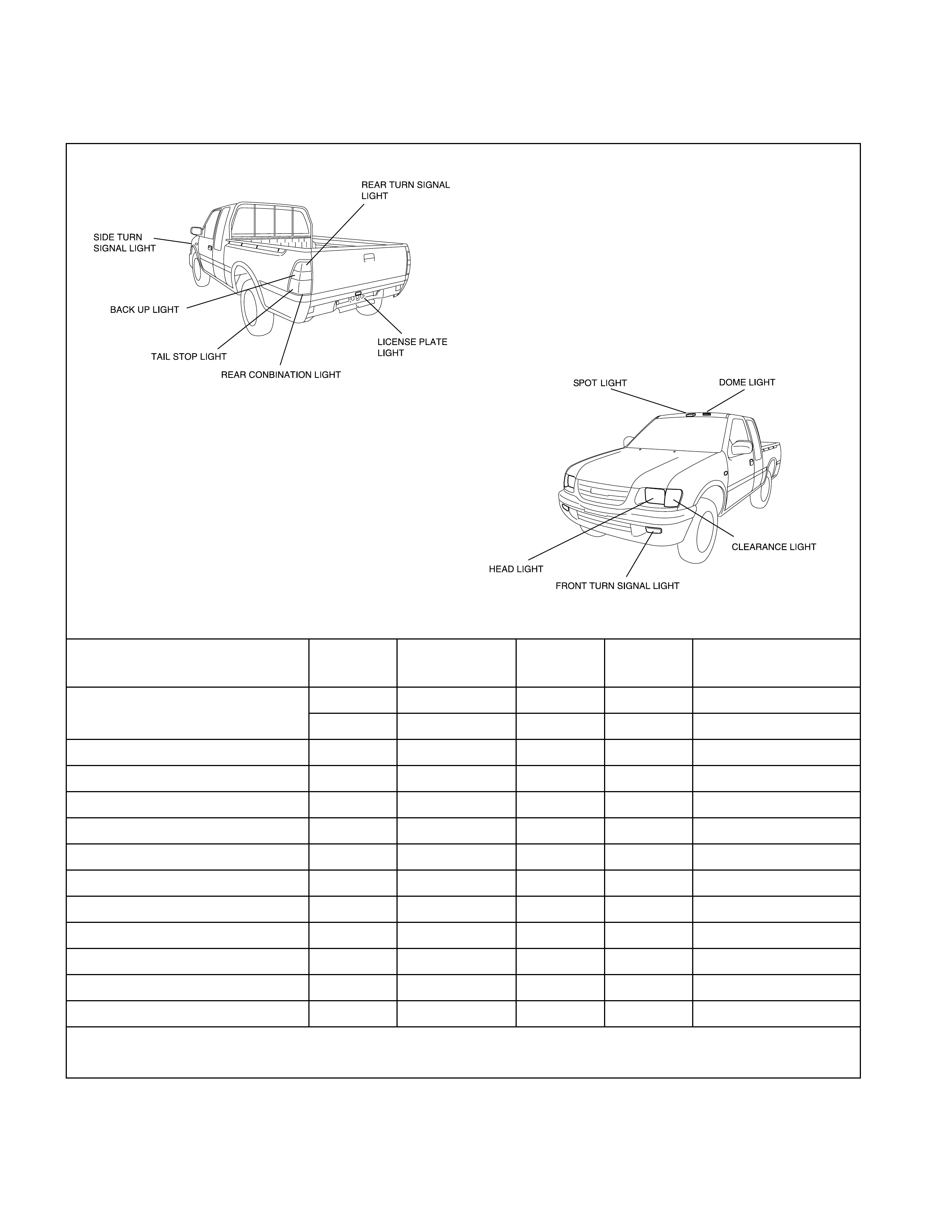
Main Data and Specifications
Bulb Specifications
This illustration based on LHD
Light Name Bulb No. Rated Power
V-W Number
of Bulbs Lens
Color Remarks
H4 12-60/55 2 White Halogen
R2 12-45/40 2 White
Front turn signal light - 12-23 2 Amber
Side turn signal light W5W 12-5 2 Amber
Rear turn signal light P21W 12-21 2 Amber
Tail and stop light P21/5W 12-21/5 2 Red
Back up light P21W 12-21 2 White
License plate light W5W 12-5 1 or 2 White
Clearance light W5W 12-5 2 White
A/C-Heater control light - 12-0.7 1 -
Dome light - 12-10 1 White
Spot light - 12-5 2 White
Inspection light - 12-5 1 White
Headlight
Light Name Bulb No. Rated Power
V-W Number
of Bulbs Lens
Color Remarks
Charging
system Petrol engine - 14-3.0 1 Red
Check engine 74 14-1.4 1 Red Petrol engine
Turn W/O Tachometer 158 14-3.4 2
signal W/Tachometer 74 14-1.4 2
High W/O Tachometer 158 14-3.4 1
beam W/Tachometer 74 14-1.4 1
Low W/O Tachometer - 14-3.0 1
fuel W/Tachometer 74 14-1.4 1
Indicator/ Oil pressure 74 14-1.4 1 Red
Warning Brake sy stem 74 14-1.4 1 Red
light W/O Tachometer 158 14-3.4 1
W/Tachometer 74 14-1.4 1
Seat belt - 14-2.0 1 Red
Oil temperature 74 14-1.4 1 Red
Green
Blue
Amber
4WD Green
Relay and Fuse
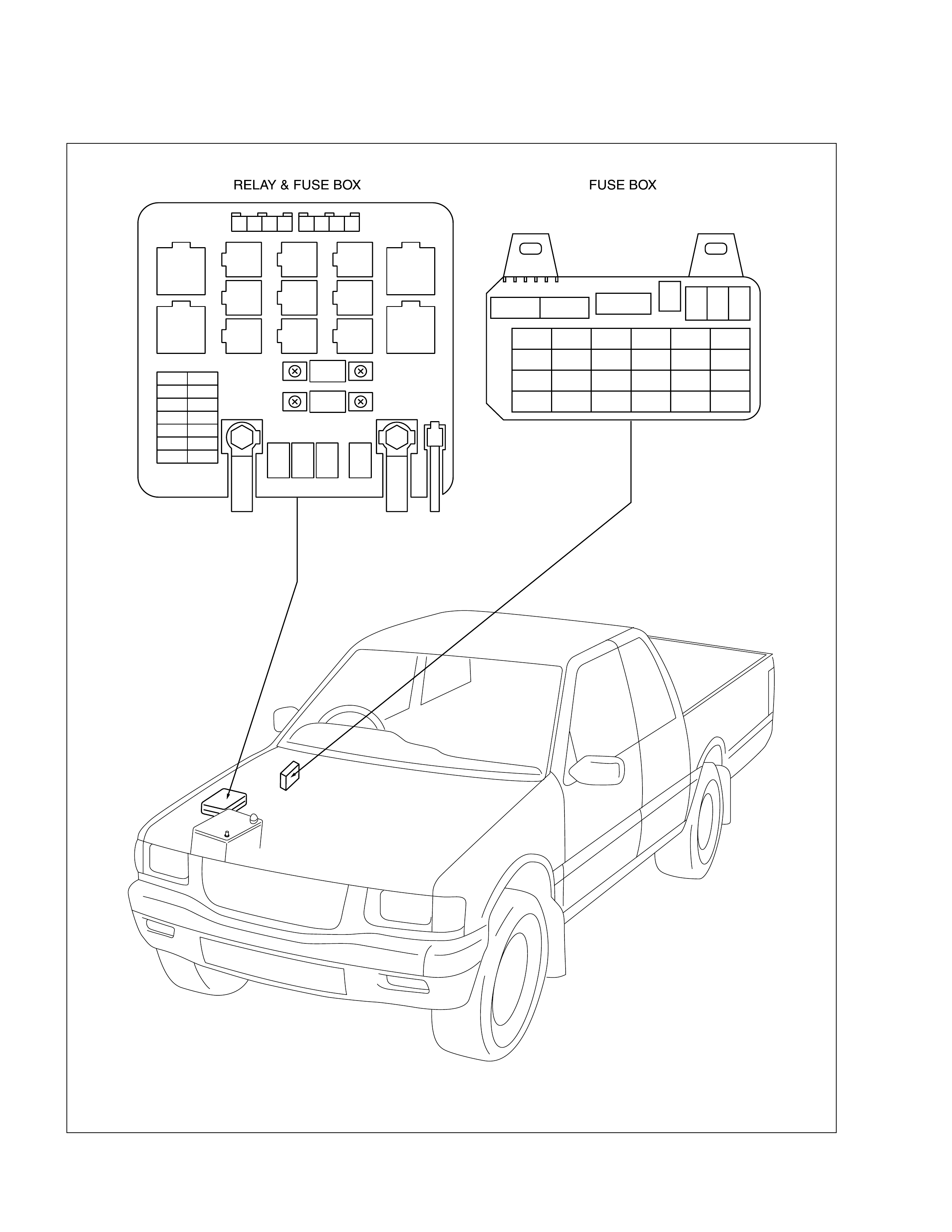
Relay and Fuse Box Location (C22NE / 4JB1T / 4JH1TC)
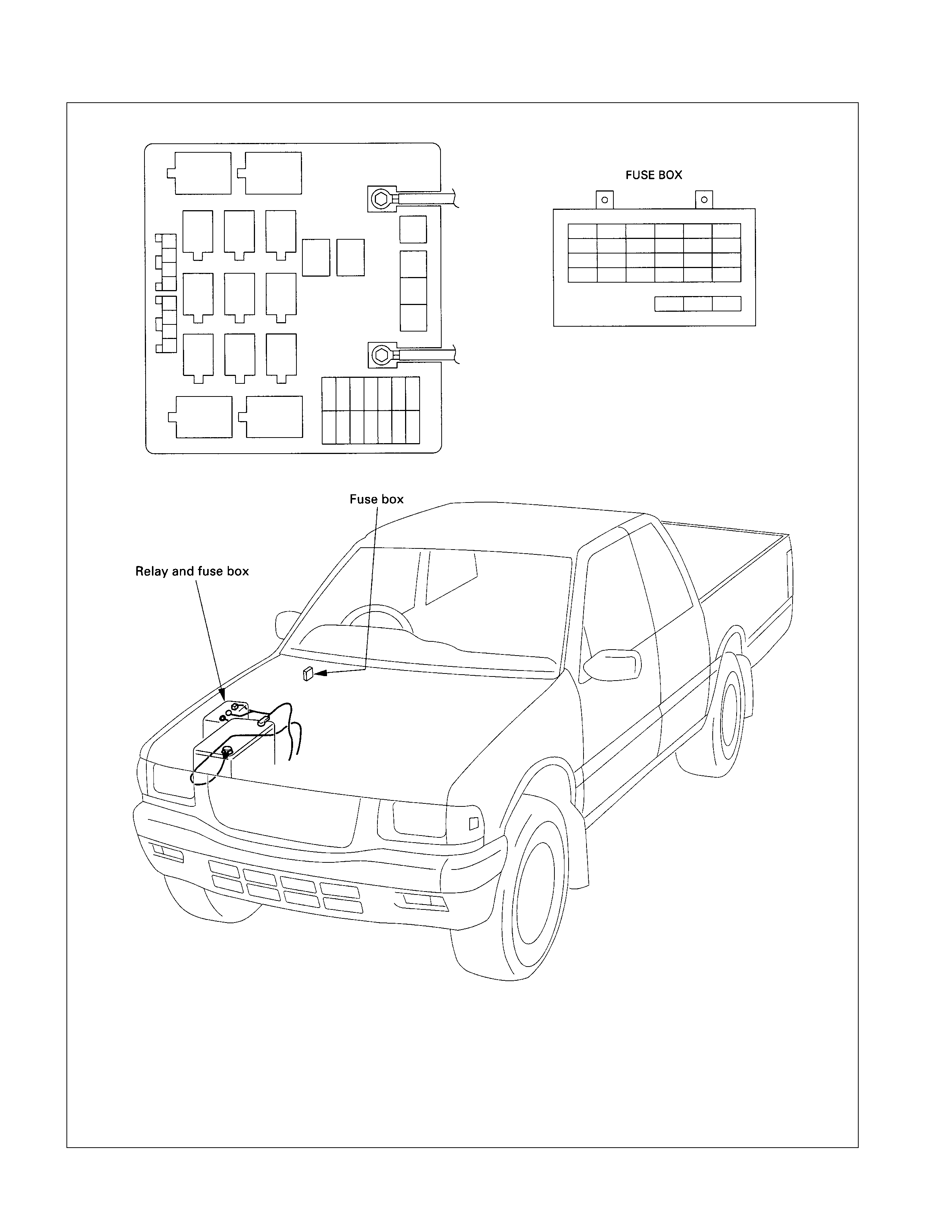
Relay and Fuse Box Location (6VD1-W)
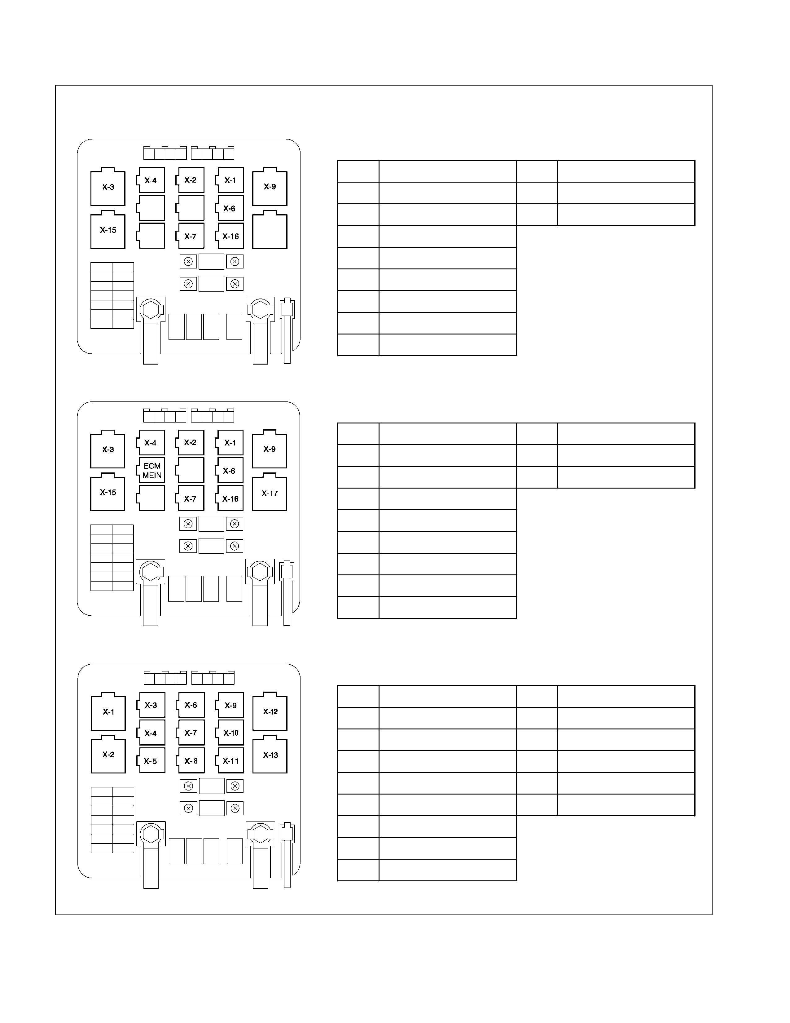
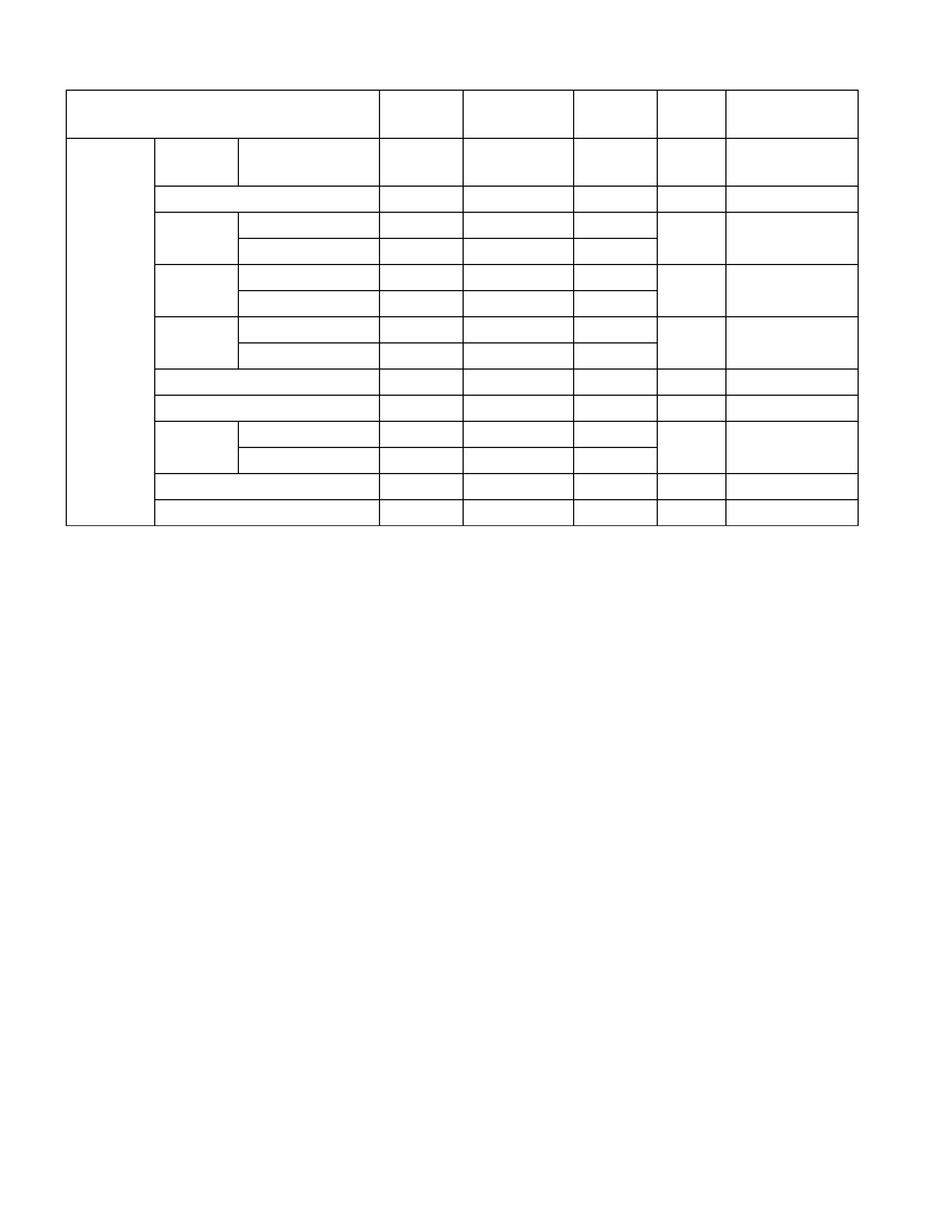
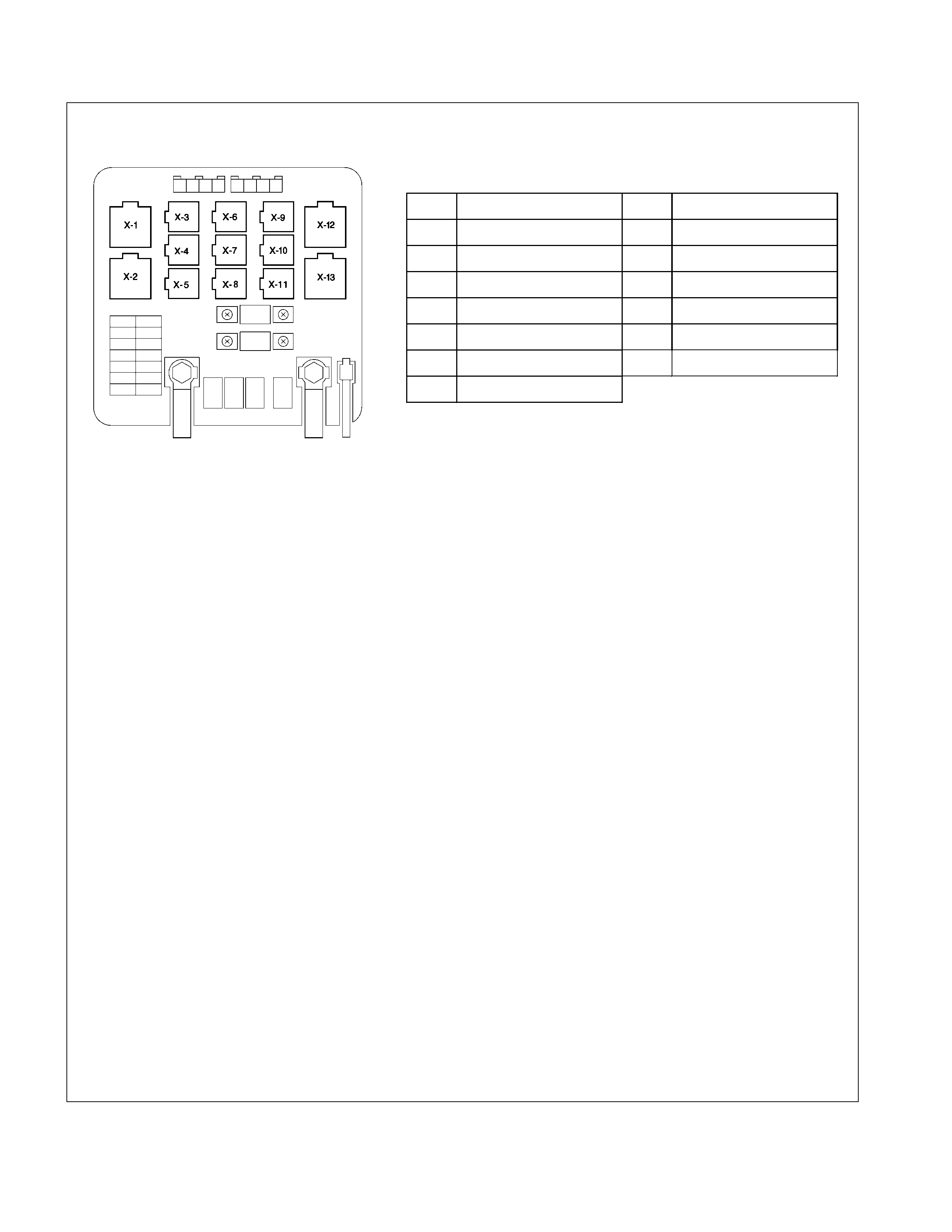
Relay Location-1 (Relay and Fuse Box)
RELAY & FUSE BOX
RELAY C22NE
NO. Relay name NO. Relay name
X-1 RELAY;HEAD LIGHT X-16 (RELAY;COND.FAN)
X-2 RELAY;TAIL LIGHT X-17 -
X-3 RELAY;HEATER
X-4 RELAY;HORN
X-6 RELAY;STARTER
X-7 (RELAY;THERMO)
X-9 RELAY;FUEL PUMP
X-15 (RELAY;A/C COMP)
RELAY 6VD1 -W
NO. Relay name NO. Relay name
X-1 RELAY;HEAD LIGHT X-16 RELAY;COND.FAN
X-2 RELAY;TAIL LIGHT X-17 -
X-3 RELAY;HEATER
X-4 RELAY;HORN
X-6 RELAY;STARTER
X-7 RELAY;THERMO
X-9 RELAY;FUEL PUMP
X-15 RELAY;A/C COMP
RELAY 4JB1T
NO. Relay name NO. Relay name
X-1 RELAY;HEATER X-9 RELAY;HEAD LIGHT
X-2 RELAY;CHARGE X-10 RELAY;QWS
X-3 RELAY;HORN X-11 -
X-4 - X-12 RELAY;DIMMER
X-5 RELAY;IMMOBILIZER X-13 RELAY;STARTER
X-6 RELAY;TAIL LIGHT
X-7 -
X-8 RELAY;THERMO
Relay Location-2 (Relay and Fuse Box)
RELAY & FUSE BOX
RELAY 4JH1TC
NO. Relay name NO. Relay name
X-1 RELAY;HEATER X-8 RELAY;A/C THERMO
X-2 RELAY;ST CUT X-9 RELAY;HEAD LIGHT
X-3 RELAY;HORN X-10 RELAY;A/C COMP.
X-4 RELAY;ECM MAIN X-11
X-5 RELAY;HATCH GATE X-12 RELAY;GLOW
X-6 RELAY;TAIL LIGHT X-13 RELAY;STARTER
X-7 RELAY;IMMOBILIZER

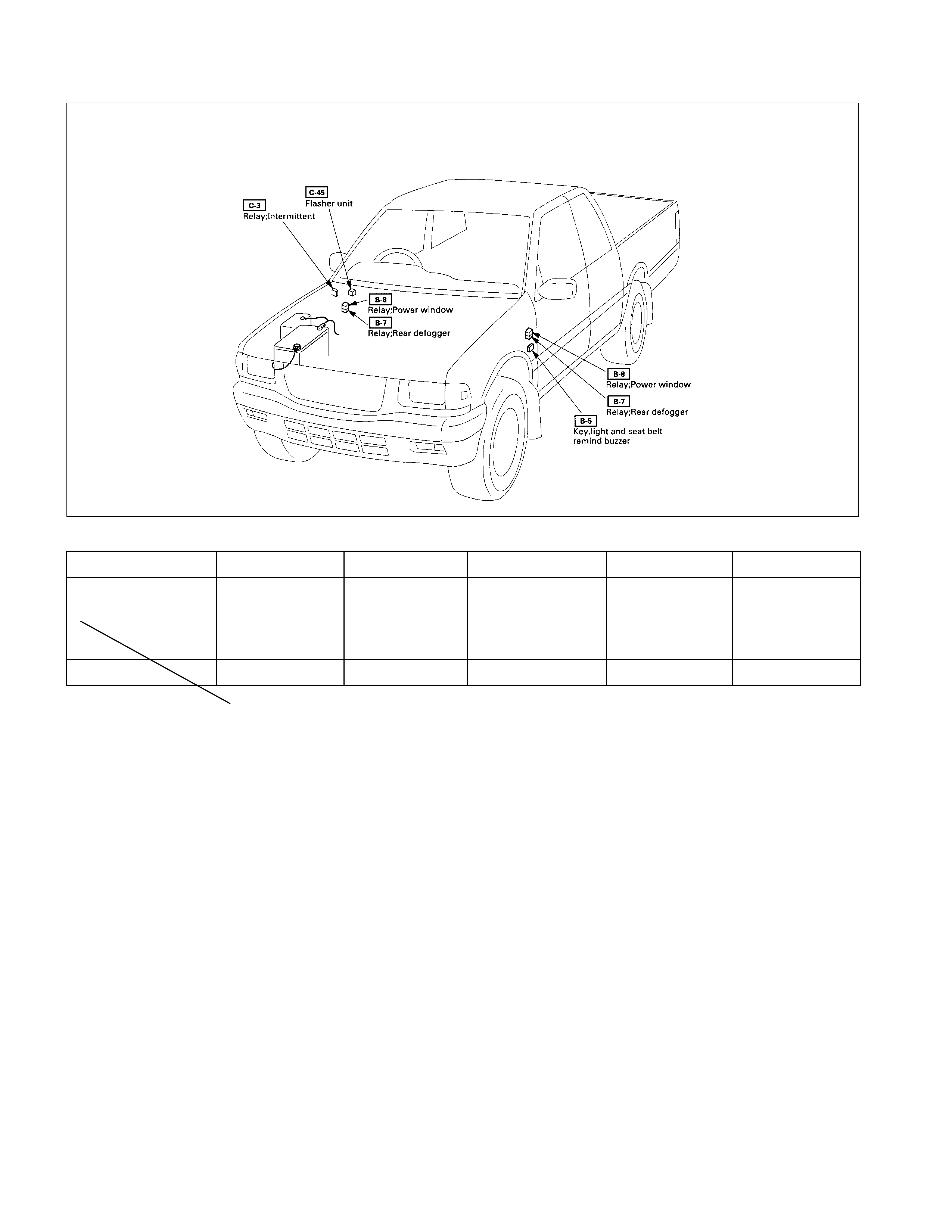
Relay Location-3 (HEC C22NE)
RELAY
Connector No. C-3 C-45 B-5 B-7 B-8
HEC Engine Series WINDSHIELD
INTERMITTENT FLASHER UNIT KEY, LIGHT AND
SEAT BELT
REMIND BUZZER
(For Gulf only)
REAR
DEFOGGER
(Except South
Africa & Chile)
POWER
WINDOW
Relay Location-4 (4JB1T / 4JH1TC)
C-45
C-3
Flasher unit
B-5
Key, light and seat belt
remind buzzer
Relay;Intermittent
Relay;Glow-1
Relay;Glow-2
C-49
C-50
Relay;Rear defogger
B-7
Relay;Power window
B-8
RELAY
Connector No. C-3 C-45 B-5 B-7 B-8
4J Engine Series WINDSHIELD
INTERMITTENT FLASHER UNIT KEY, LIGHT AND
SEAT BELT
REMIND
BUZZER
REAR
DEFOGGER POWER
WINDOW
Relay Location-5 (6VD1-W)
RELAY
Connector No. C-3 C-45 B-5 B-7 B-8
Relay
Engine model
WINDSHIELD
INTERMITTENT FLASHER UNIT KEY, LIGHT AND
SEAT BELT
REMIND BUZZER
REAR
DEFOGGER POWER
WINDOW
6VD1 ¡¡¡
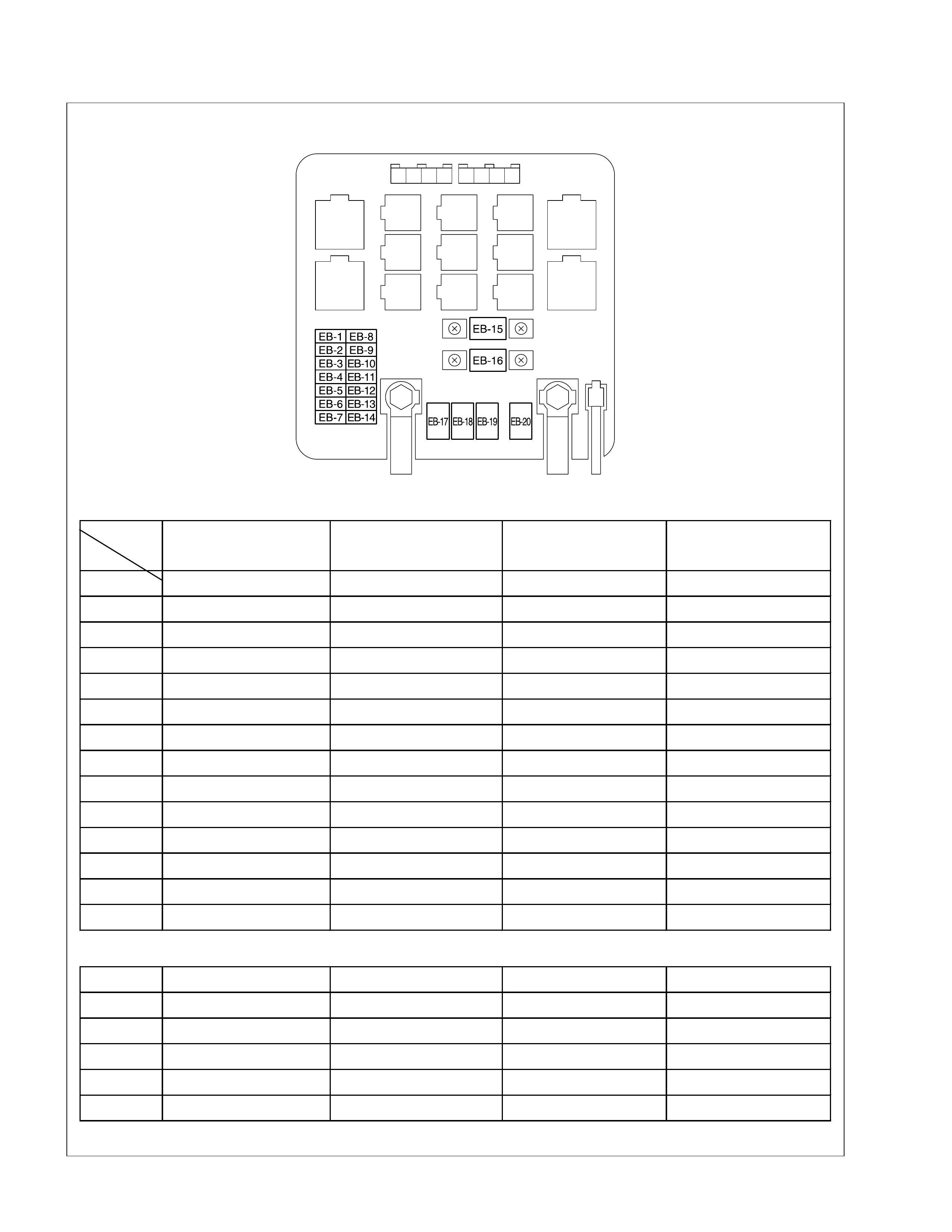
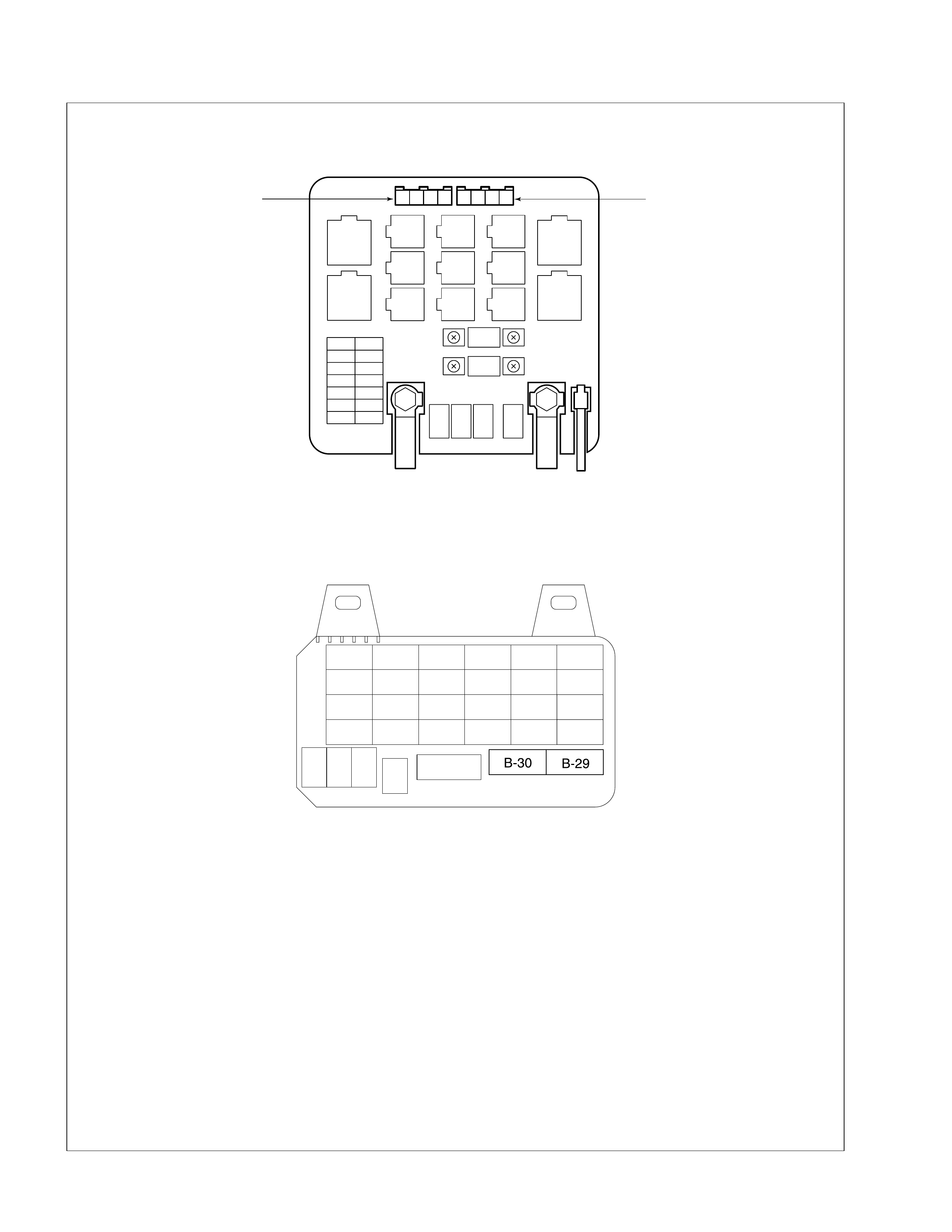
Fuse and Fusible Link Location (Relay and Fuse Box)
RELAY & FUSE BOX
FUSE
Engine
model
NO. HEC C22NE 4JB1T 4JH1TC 6VD1W
EB-1 15A HAZARD 15A HAZARD 15A HAZARD 15A HAZARD
EB-2 10A HORN 10A HORN 10A HORN 10A HORN
EB-3 20A BLOWER 10A STOP LIGHT 20A BLOWER 2 0 A BLOWER
EB-4 10A A/C 20A BLOWER 10A A/C 10A A/C
EB-5 20A INJECTOR 10A A/C
EB-6 15A FUEL 10A RR FOG LIGHT 15A FUEL PUMP
EB-7 10A O2 SENSOR 10A CHARGE 10A CHARGE 10A O2 SENSOR
EB-8 10A HEADLIGHT LH 10A H/LIGHT-RH (HI) 10A HEADLIGHT LH 10A H/LIGHT-LH
EB-9 10A HEADLIGHT RH 10A H/LIGHT-LH (HI) 10A HEADLIGHT RH 10A H/LIGHT-RH
EB-10 10A STOP LIGHT 10A H/LIGHT-RH (LO) 10A STOP LIGHT 10A STOP LIGHT
EB-11 10A TAIL LIGHT 10A H/LIGHT-LH (LO) 10A TAIL LIGHT 10A TAIL LIGHT
EB-12 10A TCM 10A TCM
EB-13 10A ALTERNATOR 10A TAIL LIGHT-RH 10A ECM
EB-14 15A ECM 10A TAIL LIGHT-LH 10A ECM 20A ECM
( ) ......IF EQ UI PPED
EB-15 40A IGN-B1 30A ECM
EB-16 100A MAIN 80A MAIN 100A MAIN 100A MAIN
EB-17 40A IGN-B2 40A IGN-B2 40A IGN-B2 40A IGN-B2
EB-18 30A RR DEM
EB-19 30A CONDENSE R F A N 50A GLOW 50A GLOW 30A COND. FAN
EB-20 40A IGN-B1 40A IGN-B1 40A IGN-B1
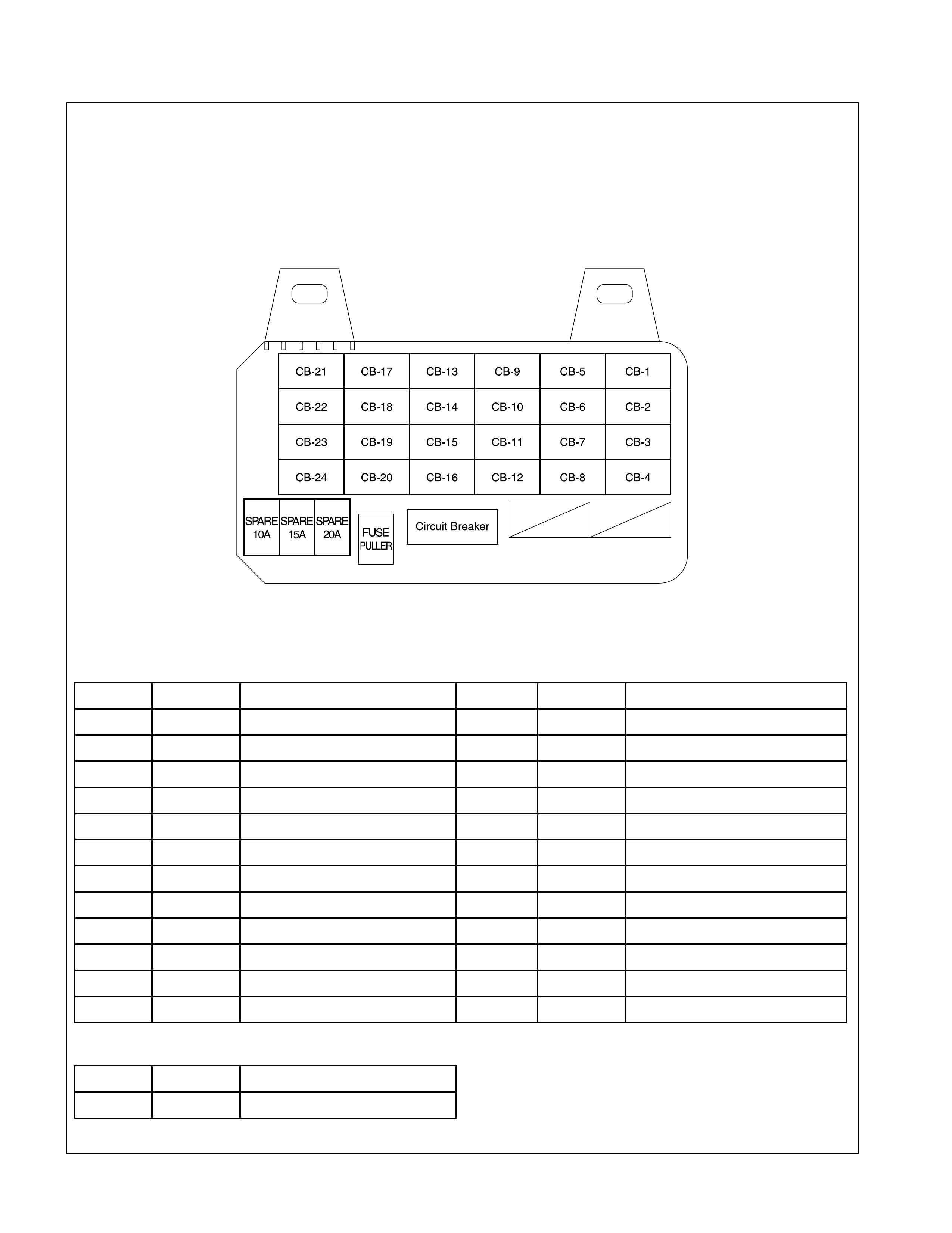
Fuse and Circuit Breaker Location (Fuse Box-)
FUSE
No. Capacity Indication on label No. Capacity Indication on label
CB-1 10A STARTER CB-13 15A (PR DEFOG.)
CB-2 - - CB-14 10A DOME LIGHT
CB-3 15A ENGINE-1 CB-15 20A (DOOR LOCK)
CB-4 10A ENGINE-2 CB-16 - -
CB-5 15A METER CB-17 - -
CB-6 20A FRONT WIPER CB-18 - -
CB-7 - - CB-19 15A AUDIO
CB-8 - - CB-20 15A CIGAR
CB-9 - - CB-21 20A (POWER WINDOW)
CB-10 - - CB-22 20A (POWER WINDOW)
CB-11 15A BACK UP, TURN CB-23 10A (SRS-2)
CB-12 - - CB-24 10A (SRS-1)
CIRCUIT BREAKER
No. Capacity Indication on label
B-31 30A (POWER WINDOW)
FUSE BOX
( )...........IF EQUIPPED
Diode Location
RELAY & FUSE BOX
X-15
X-14
FUSE BOX - INSTRUMENT PANEL
Fuse Block Circuit-1 (HEC C22NE)
MAIN
80A BUSBAR-4
BUSBAR-3
BUSBAR-1
8B/R
1.25B/W
8W
3B
0.85W/L
0.85R/W
ACG
RELAY;HEATER
RELAY;TAIL
RELAY;STARTER
RELAY=P/W
RELAY;FUEL
RELAY;H/LAMP
HEAD
LAMP
ECM
STARTER
S
OFF
ACC
IG2
IG1 ST
B1 B2
C
B
CHARGE W ARNING LIGHT
TAIL LAMP
10A
15A
20A HA
HA
SA
KA
EA
FA
3B/W3B
2W/L 0.5B/W
0.85Y
RA,VA
3L/R3B
3L
3B/Y
3B/R
3B/R 20A
ECM
15A
ACG
10A
HAZARD
HORN
20A
10A
15A
10A
10A
10A
AA
AA
AA
10A
10A
15A
15A
10A
3W/B
20B/R
20B/Y
2B
ENG
BODY
3W
15A
15A
15A
15A JA
DA
3W
3W
3W
3W
2W
3R 3RW
15A
20A
STOP LAMP
BLOWER MOTOR
A/C
CIGAR LIGHTER
AUDIO,MIRROR
BACK UP,TURN
ENGINE
(IG.COIL)
METER,WARNING
FT WIPER&W ASHER
P/WINDOW
RR DEFOG
DOOM LIGHT
AUDIO(B)
DOOR LOCK
O
2
SENSOR
INJECTOR
FUEL PUMP
B
L
IGN.
40A
IGN B-2
40A
JOINT
TO KA01
C/B
P/W
Fuse Block Circuit-2 (4JB1T)
SW ; CONB
15A BACK UP, TURN
ENGINE-2
(QOS CONTROL, V.S.V, GLOW RELAY)
ENGINE-1
(FUEL CUT, SOF CONTROL (4JG2))
METER, W ARNING
S/HEATER
AUDIO
CIGAR LIGHTER
10A
15A
15A
Ft WIPER&W ASHER
20A
SRS CONTROL UNIT
15A
10A
15A
15A
19B
8B
5B
ENG
BODY
FRAME
MAIN
100A
8B/R
IGN B1
40A
8W
3W
RELAY ; TAIL
3B 3G
3L/R
0.85W/L
0.85W/G
3L
3B/Y
10A ROOM LAMP
AUDIO (B)
DOOR LOCK
P/WINDOW LH
P/WINDOW RH
20A
20A
20A
3W
3B/R
3B/R
3B/R
3B
2W/L 5B/W
0.5B/W
OFF
ACC
IG2
ST
IG1
B2
B1
0.85W/G
SW ; COMB
SW ; COMB
RELAY ; HEATER
3W/R
3W/B
3W
3W
2B/W
2R/G
2R/W
5R/W
0.85W/L
30B
RELAY ; RR FOG
RR FOG LIGHT
15A TAIL LIGHT RH
0.5G/R
1.25B/W
0.85W/L
ACG
S
B
L
IG
TAIL LIGHT LH
0.5G/O
BLOWER MOTOR
2L/W
A/C
15A RR DEFOG
0.5R/B
0.5R/B
0.5R/Y
0.5R/Y
5B/R
CONT ; H/LAMP WASHER
GLOW PLUG
H/LAMP
RH (HI)
H/LAMP
LH (HI)
H/LAMP
RH (LO)
H/LAMP
LH (LO)
CHARGE W ARNING LIGHT
0.5BR
3B
3B
HORN
HAZARD
STOP
10A
20A
10A
10A
15A
10A
10A
10A
RELAY ; CHARGE
RELAY ; P/WINDOW
(4JG2)
SW ; IGNITION
RELAY ; GLOW
RELAY ; DIMMER
C
STARTER
B
10A
IGN B2
40A
H/L W ASHER
30A
GLOW
50A
RELAY ; STARTER
FUSE ;
ENGINE-2
RELAY ; H/LAMP
SW ; CONB
10A
10A
10A
10A
Fuse Block Circuit-3 (6VD1-W)
MAIN
100A
A/C GENERATOR
RELAY;HEATER
STARTER SW
RELAY STARTER
RELAY;COND.FAN
RELAY=P/W
RELAY;RR DEF
RR DEF RELAY;FUEL
RELAY;ECM
RELAY;LIGHT
HEAD
LIGHT
ECM
STARTER
IG
OFF
ACC
IG2
IG1
ST
B2
B1
C
B
CHARGE WARNING
TAIL LAMP
10A
10A
20A
20A
ECM
20A
ECM
10A
TCM
10A TCM
HAZARD
HORN
20A
10A
10A
10A
10A
10A
10A
10A
10A
15A
15A
15A
15A
15A
15A
15A
15A
STOP LAMP
BLOWER MOTOR
A/C
CIGAR LIGHTER
AUDIO,MIRROR
BACK UP,TURN
ENGINE
(IG.COIL)
METER,WARNING
FT WIPER&WASHER
P/WINDOW
RR DEFOG
ROOM LAMP
AUDIO(B)
DOOR LOCK
O
2
SENSOR
FUEL PUMP
CONDENSOR FAN
TRIPLE PRESSURE SW
B
L
IGN.
40A
COND
FAN
30A
ILGN.B
40A
RR DEF
30A
JOINT
TO KA01
C/B
P/W
Fuse Block Circuit-4 (4JH1TC)

Reference Table Of Fuse, Fusible Link and Circuit Breaker
FUSE - (Relay and Fuse Box)
Fuse No. Capacity Indication on lable Parts(Load)
EB-1 15A HAZARD Hazard SW, Flasher unit
EB-2 10A HORN Horn relay, Horn SW, Horn
EB-3 20A BLOWER Blower motor, Control lever, Blower resistor
20A BLOWER Blower motor, A/C thermo relay, Blower resistor (4JB1T,
4JH1TC)
10A A/C Pressure SW, A/C SW, Electronic thermostat, Fan SW,
Magnetic clutch, A/C thermo relay, A/C relay
20A INJECTOR Fuel rail, Injector, ECM (C22NE)
10A A/C Pressure SW, A/C SW, Electronic thermostat, Fan SW,
Magnetic clutch, FICD, A/C thermo relay
EB-6 15A FUEL Fuel pump
EB-7 10A O2 SENSOR Oxygen sensor
EB-8 10A HEADLIGHT LH Headlight-LH, High beam, Indicator light,
Dimmer⋅passing SW
EB-9 10A HEADLIGHT RH Headlight-RH, Dimmer⋅passing SW
EB-10 10A STOP LIGHT Stop light SW, Stop light, Highmount Stop light
EB-11 10A TAIL LIGHT Tail relay, Clearance light, Tail light, License plate light,
Illumination lights, Lighting SW, Meter Panel
10A TAIL LIGHT Tail relay, Clearance light, Tail light, License plate light,
Illumination lights, Lighting SW, Meter Panel
TCM TCM (6VD1, 4JH1TC)
EB-12 10A ECM ECM
ALTERNATOR ACG (C22NE)
TAIL LIGHT-RH Tail light-RH
EB-13 10A
ECM ECM Back Up (6VD1)
15A ECM Relay fuel pump, ECM (C22NE)
10A TAIL LIGHT-LH Tail light-LH
20A ECM ECM main relay, Fuel pump relay, ECM, Fuel injector,
Idle control valve (6VD1)
EB-14
10A ECM ECM, Glow relay (4JH1TC), A/C Compressor relay
(4JH1TC), Idle up resister (4JH1TC), MAF Sensor
(4JH1TC)
EB15 40A IGN-B1 -
EB16 100A MAIN -
EB17 40A IGN-B2 -
EB18 - - -
EB19 30A CONDENSER FAN -
EB20 - - -
EB-5
EB-4

FUSE
(Fuse Box)
Fuse No. Capacity Indication on lable Parts(Load)
CB-1 10A STARTER Starter relay, Starter, Starter cu t relay.
CB-2
CB-3 15A ENGINE-1 Ignition SW, Coil Module, ECM, Immobilizer relay
CB-4 10A ENGINE-2 ECM, TCM
CB-5 15A RHD METER Meter gauges. Indicator and warning lights,
Vehicle speed sensor
CB-6 20A RHD FRONT WIPER Windshield wiper&washer SW, Windshield wiper
motor, Windshield washer motor, Windshield
intermittent relay
CB-7 15A LHD METER Meter gauges. Indicator and warning lights, ECM
CB-8 20A LHD FRONT WIPER Windshield wiper&washer SW, Windshield wiper
motor, Windshield washer motor, Windshield
intermittent relay
CB-9
CB-10
CB-11 15A BACK UP, TURN Control unit, Hazard SW, Back up light
SW(M/T),Back up light
CB-12 10A LHD (SEAT HEATER)
CB-13 15A (RR DEFOG.) RR defog relay, RR defogger SW, RR defog
CB-14 10A DOME LIGHT Dome light, Spot light, Door SW, Audio Clock
CB-15 20A (DOOR LOCK) FRT power window&door lock SW-driver side,
Door lock SW-driver side, Door lock actuator
CB-16
CB-17
CB-18
CB-19 15A AUDIO Audio
CB-20 15A CIGAR Cigarette lighter, Clock
CB-21
CB-22
CB-23
CB-24
FUSIBLE LINK
(Relay and fuse box)
Fusible link No. Capacity Indication on label Remarks
40A IGN-B1 EB-15 30A ECM 4JH1TC
EB-16 80A MAIN
100A MAIN
EB-17 40A IGN-B2
EB-18 30A RR DEF 6VD1
30A CONDENSER FAN EB-19 50A GLOW 4JH1TC
EB-20 40A IGN-B1 4JH1TC
CIRCUIT BREAKER
(Fuse box)
Circuit breaker No. Capacity Indication on label Parts(Load)
B-31 30A (POWER WINDOW) Power window & door lock SW, Power
window motor, Power window relay
Grounding Poi nt
Reference Table
Connector No. Cable harness Location Parts (Load)
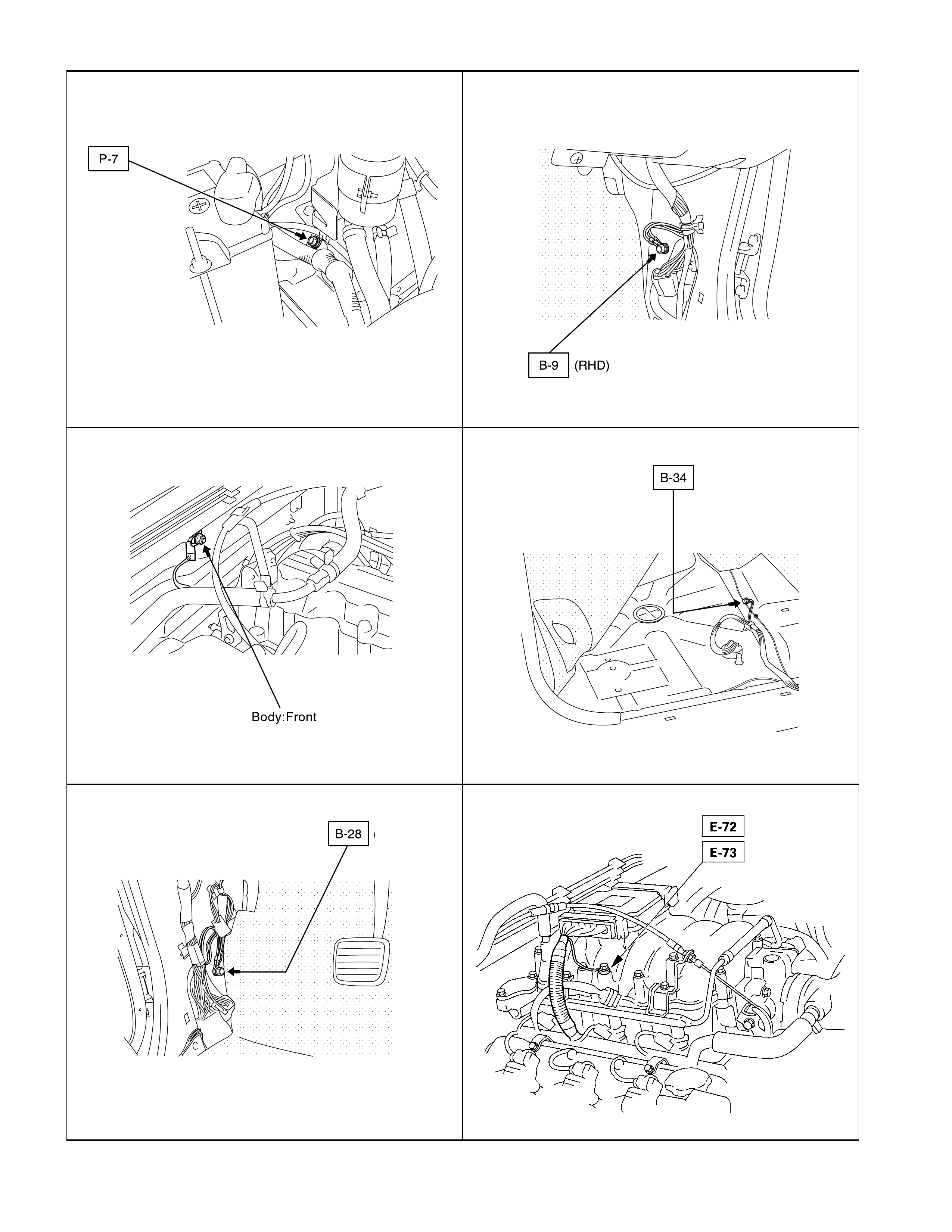
B-9 Body-LH Fan SW, FRT power window & door lock SW-
passenger side, RR power window SW, Key, light O/D
Off switch (4JH1-A/T)
B-28 Body harness Body-RH
Illumination light (meter, Heater & A/C control panel,
Cigarette lighter, Ashtray, RR defog SW, Audio, Hazard
SW), Turn signal indicator light, FRT power window &
door lock SW-driver side, Power window relay, Door
mirror control SW, RR defog, RR defog SW, Door lock
SW-driver side, Audio, Clock, Cigarette lighter
B-34 Body-RR Fuel tank unit, Tail light, License plate light, Fuel pump,
Stop light, RR turn signal light, Back up light
C-2 Fender-RH
Vehicle speed sensor, 4WD SW, Brake fluid level SW,
Heater relay, Dimmer⋅passing SW, Lighter SW, Starter
relay, Windshield intermittent relay, Windshield wiper
motor, Flasher unit, Side turn signal light-RH,
Condenser fan relay, ST cut relay, Idle up resister
(4JH1-TURBO)
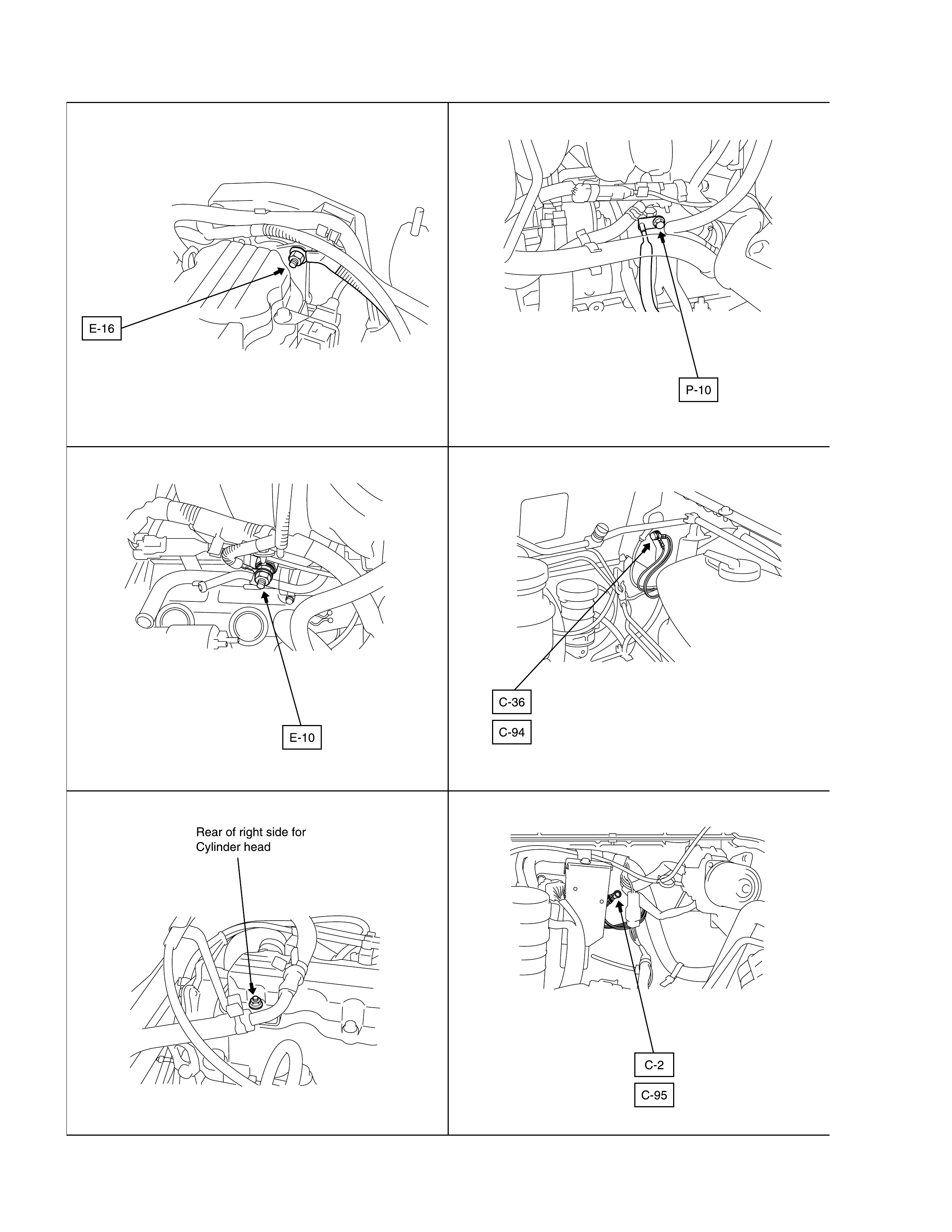
C-36 Engine room
harness Fender-LH Clearance light, Seat belt SW Windshield washer
motor, Side turn signal light-LH, FRT turn signal light,
ST cut relay, ECM (4JH1TC)
C-95 Engine-RH Condenser fan
C-94 Engine-LH Speedometer, Tachometor (W/Tachometer), Engine
coolant temperature gauge (W/Tachometer), Fuel
gauge
E-10 ECM (C22NE), Injection pump (4JH1TC), TCM
(4JH1TC)
E-16 Engine harness Engine ECM (C22NE)
E-72 Data link connector, ECM, Crank angle sensor
E-73 Engine harness
Common
chamber- RH Ignition coil, ECM
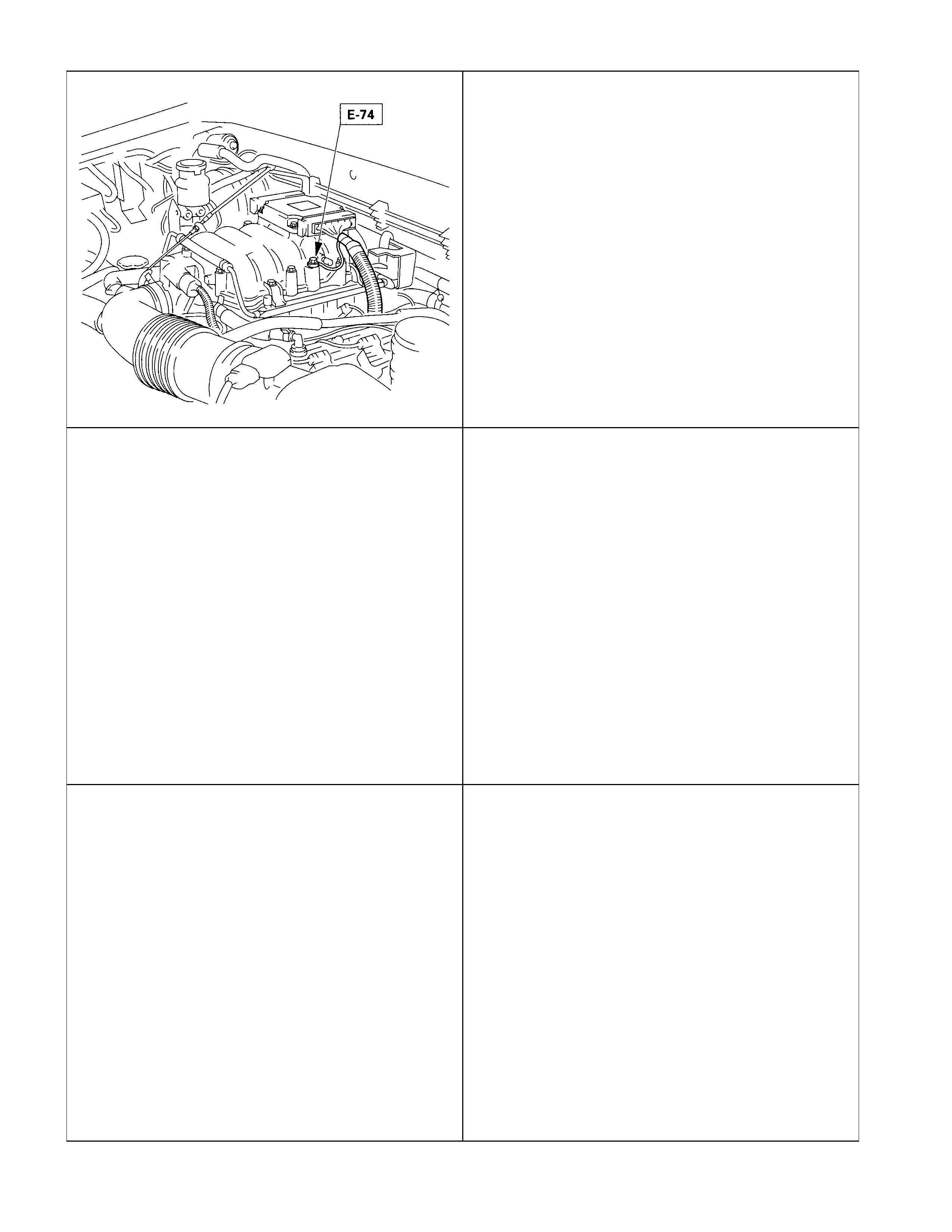
E-74 Common
chamber- LH Ignition coil, ECM, MAF sensor shield, Cam angle
sensor shield, Throttle position sensor shield
P-7 Body-RH Right side of body
P-10 Battery harness Body-RH Right side of Engine
Location
;;
;;
QQ
QQ
¢¢
¢¢
;;;;
;;;;
QQQQ
QQQQ
¢¢¢¢
¢¢¢¢
;;;
;;;
QQQ
QQQ
¢¢¢
¢¢¢
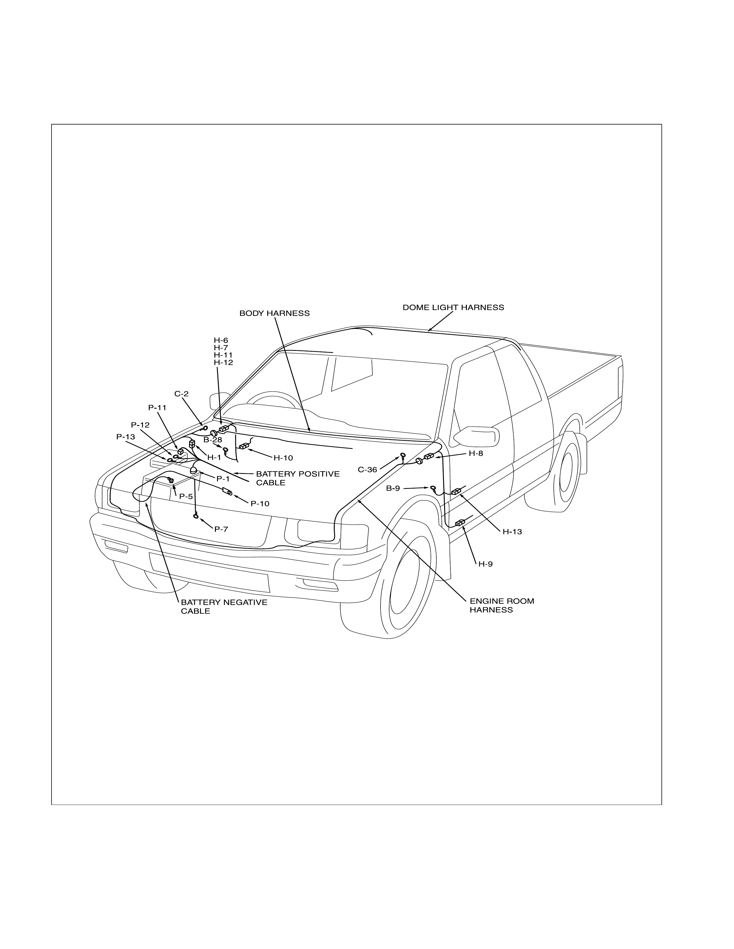
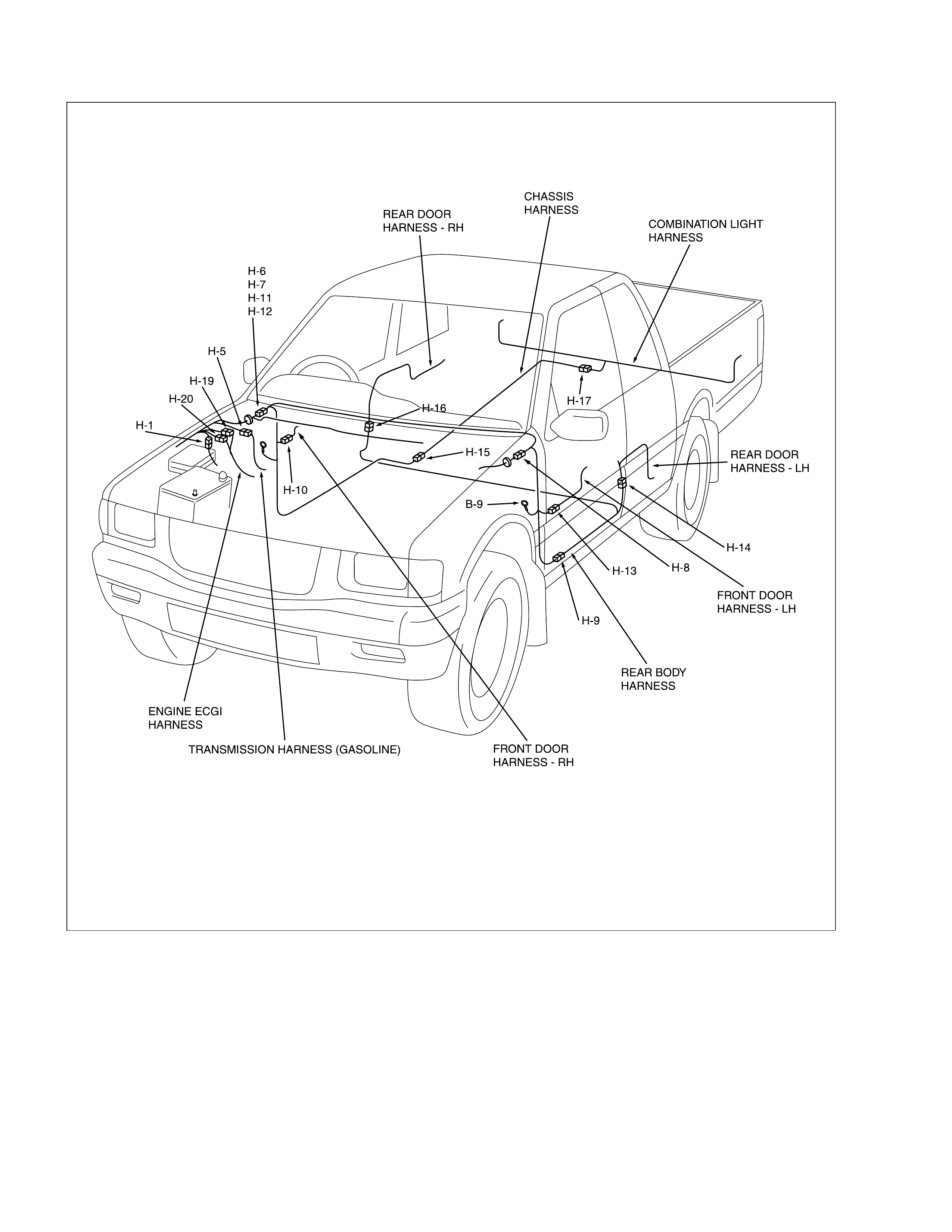
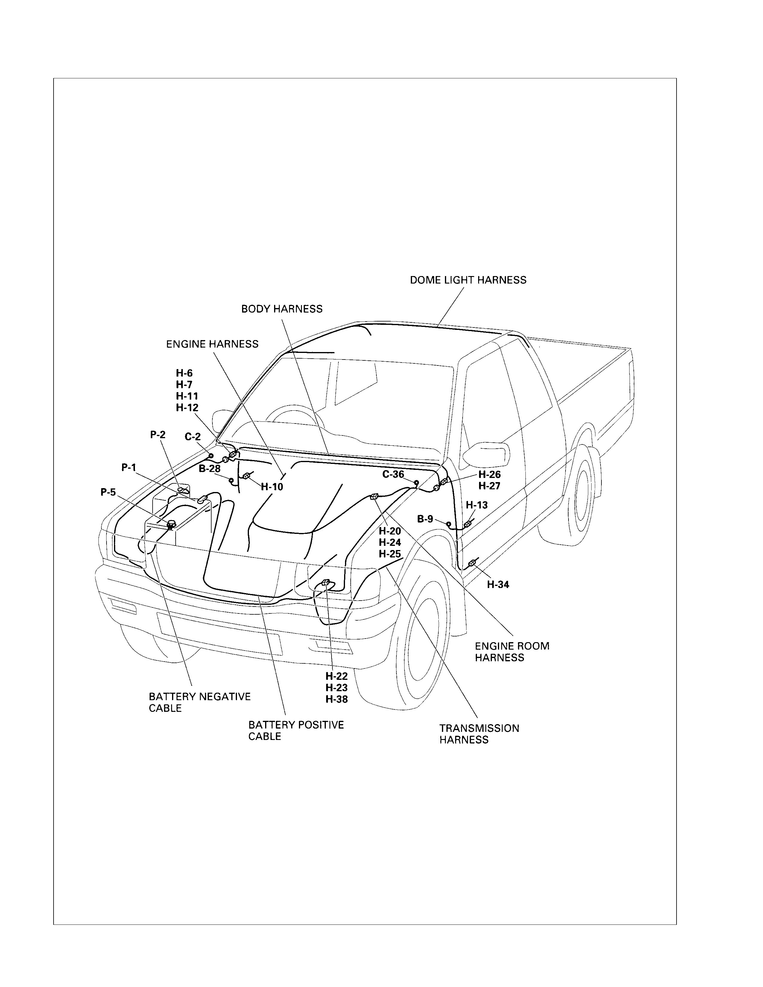
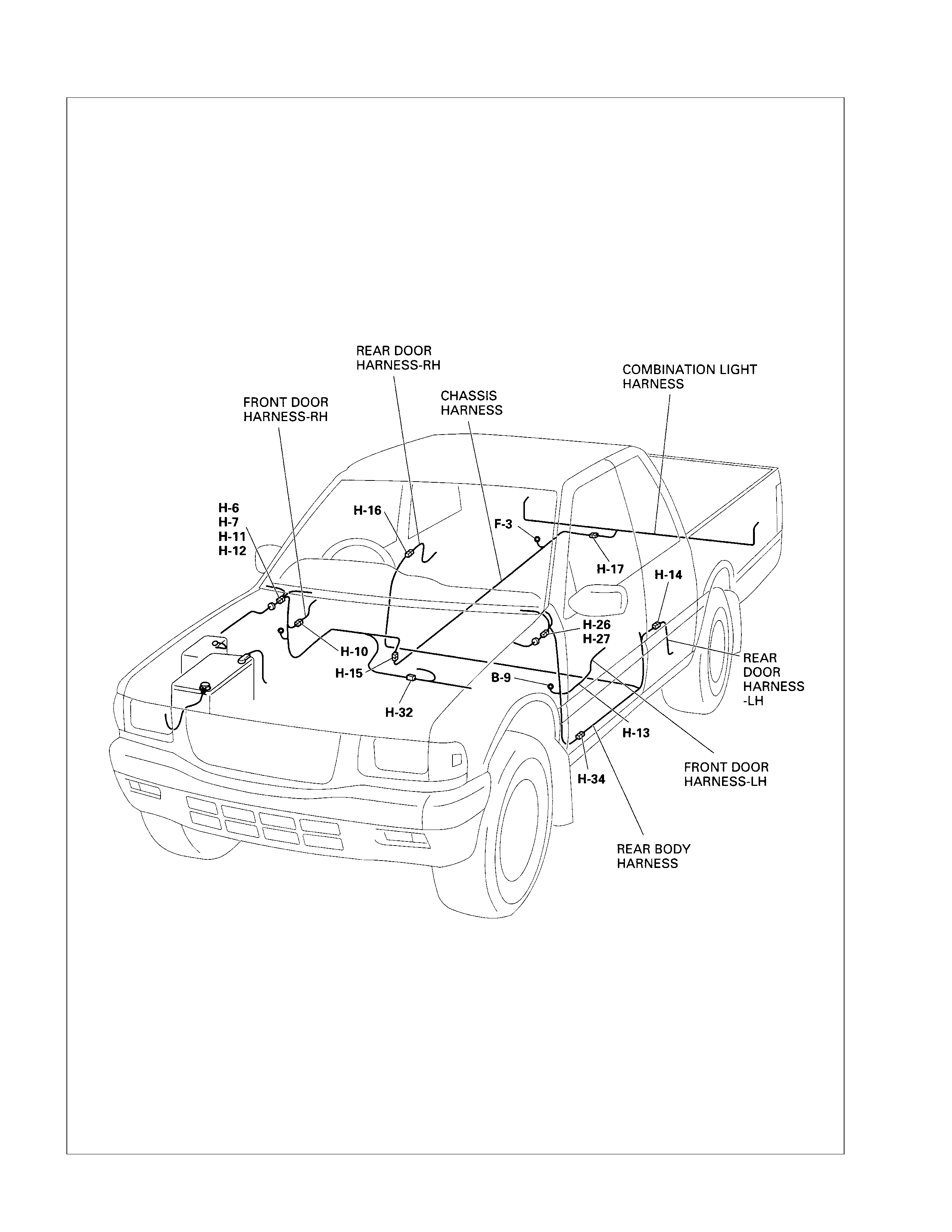
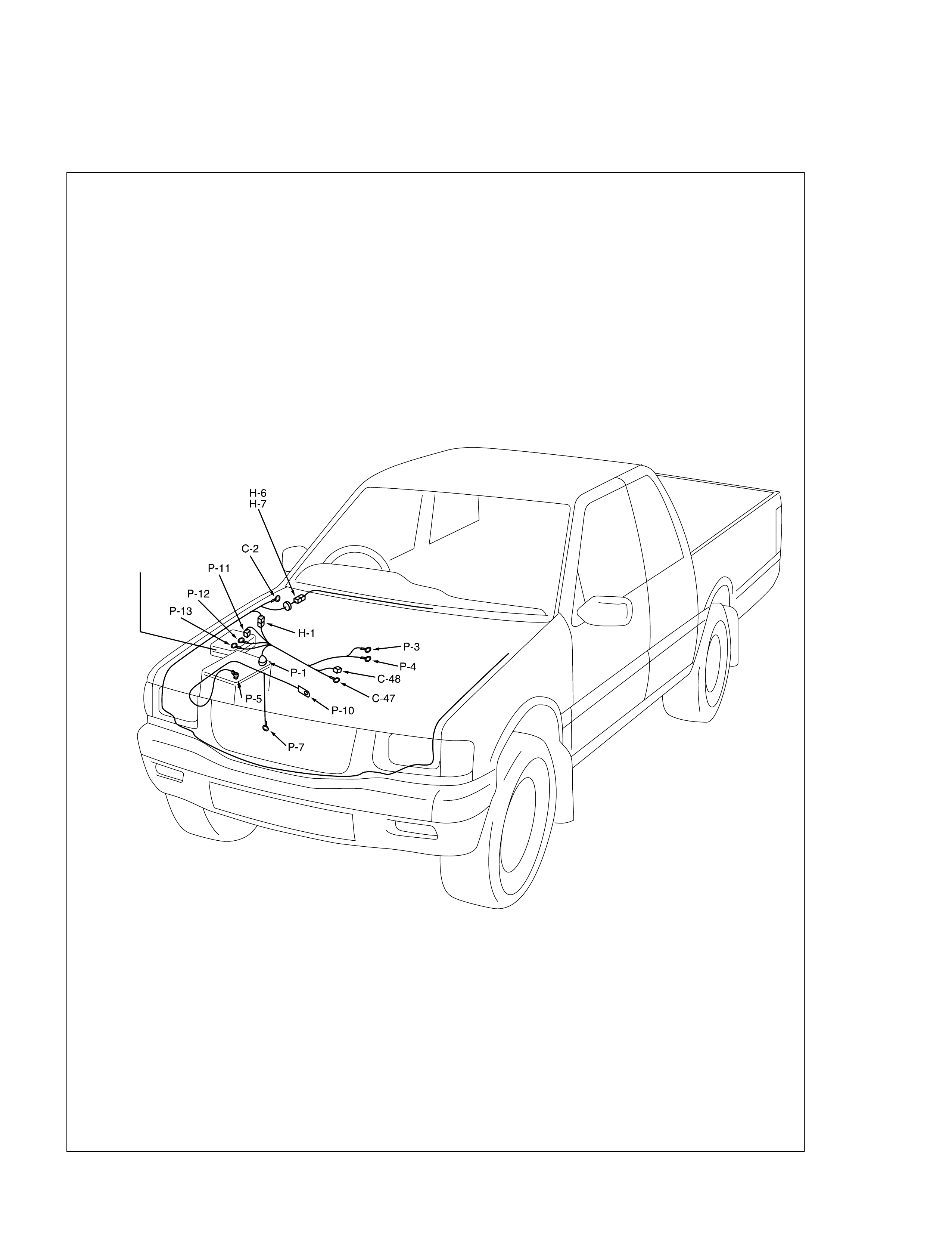
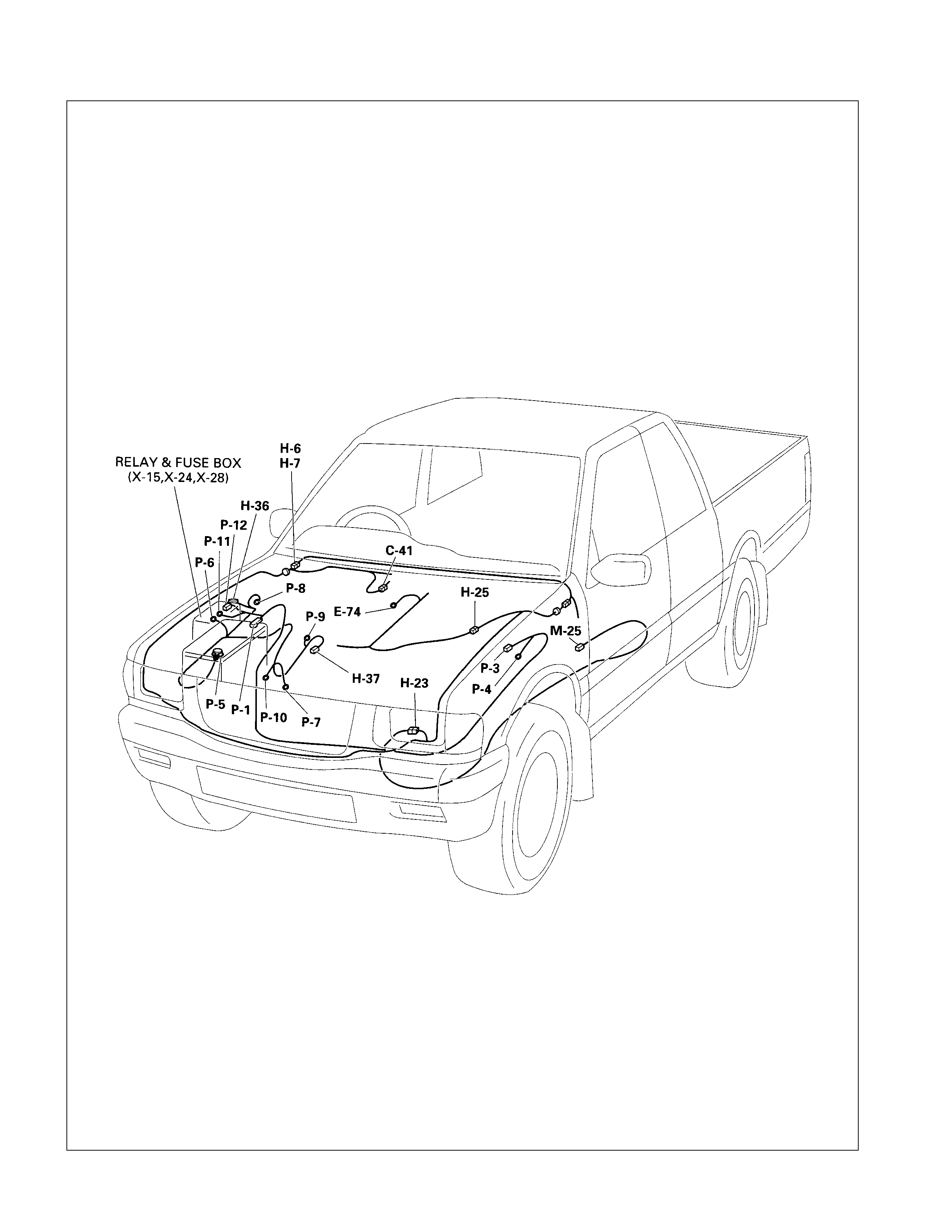
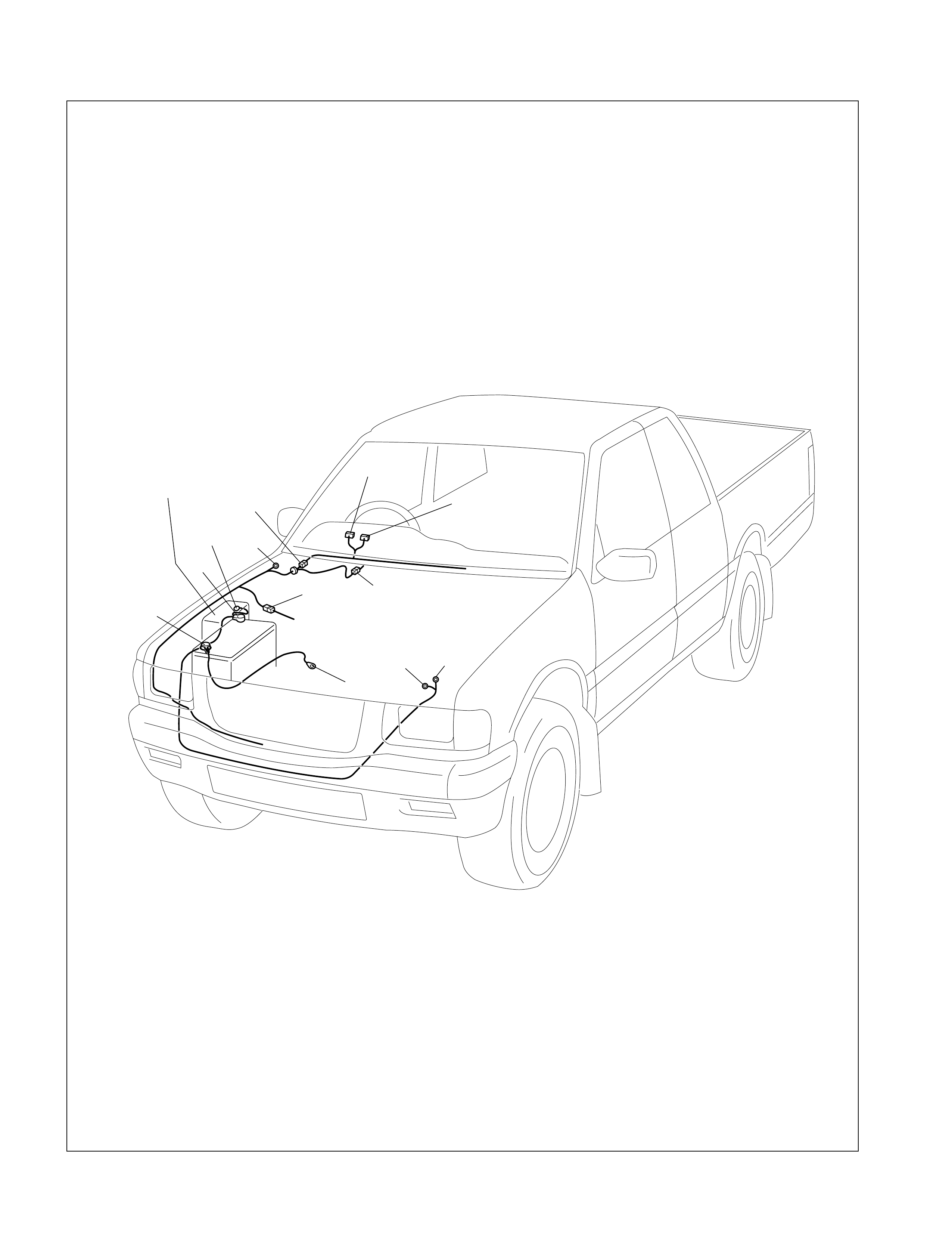
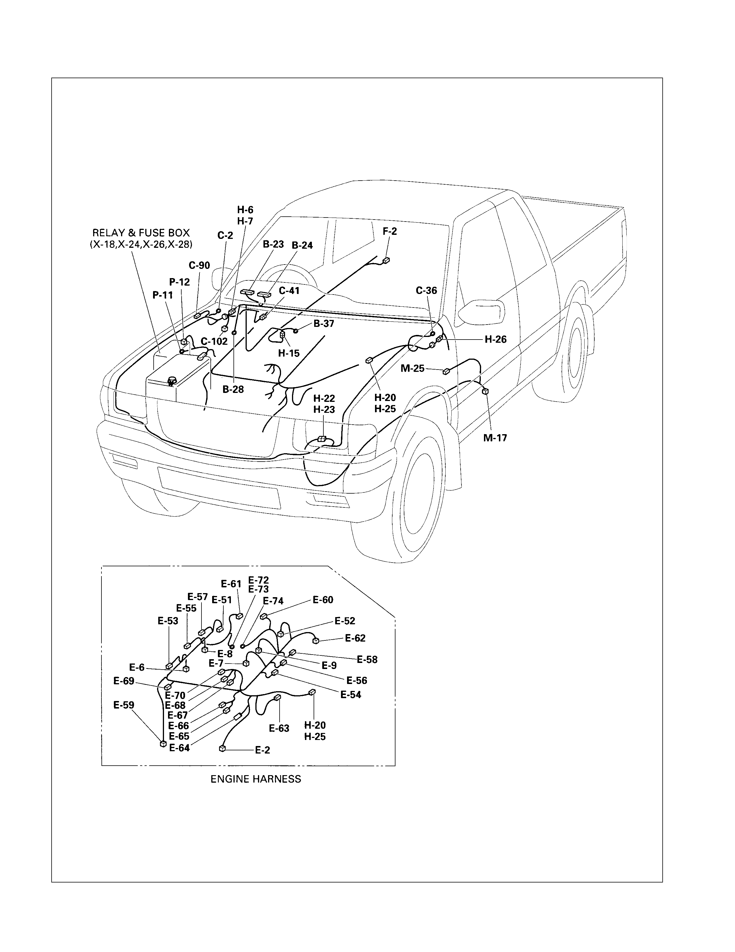
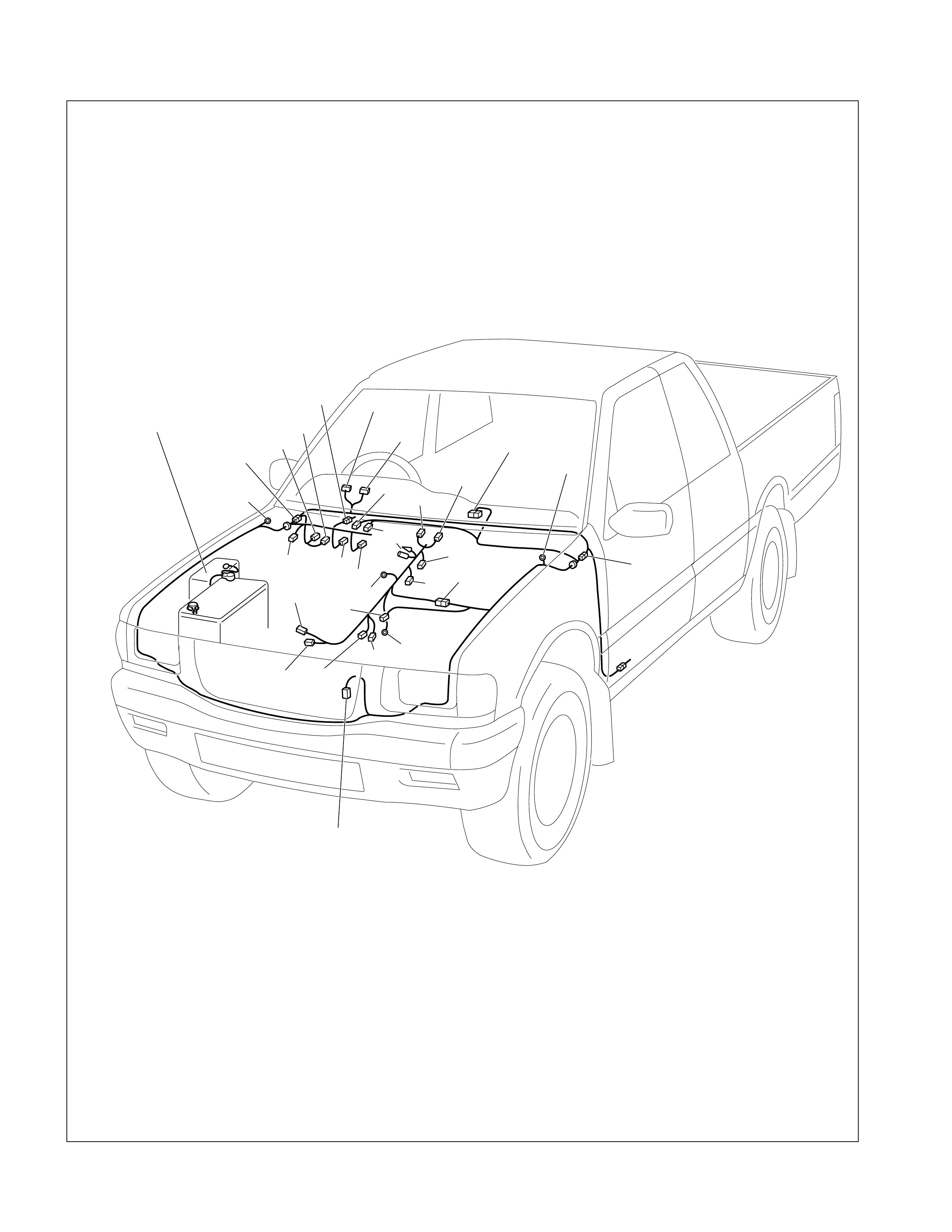
Main Cable Harness Routing
HEC C22NE - 1
HEC C22NE - 2
6VD1 - 1
6VD1 - 2
4J ENGINE - 1
BATTERY NEGATIVE
CABLE
BATTERY POSITIVE
CABLE
ENGINE ROOM
HARNESS
BODY HARNESS
DOME LIGHT HARNESS
ENGINE & TRANSMISSION
HARNESS
P-10
H-4
H-5
H-9
H-13
H-8
C-36
H-10
B-32
B-28
H-6
H-7
H-11
H-12
H-18
P-1
P-5
P-2
B-9
P-7
C-2
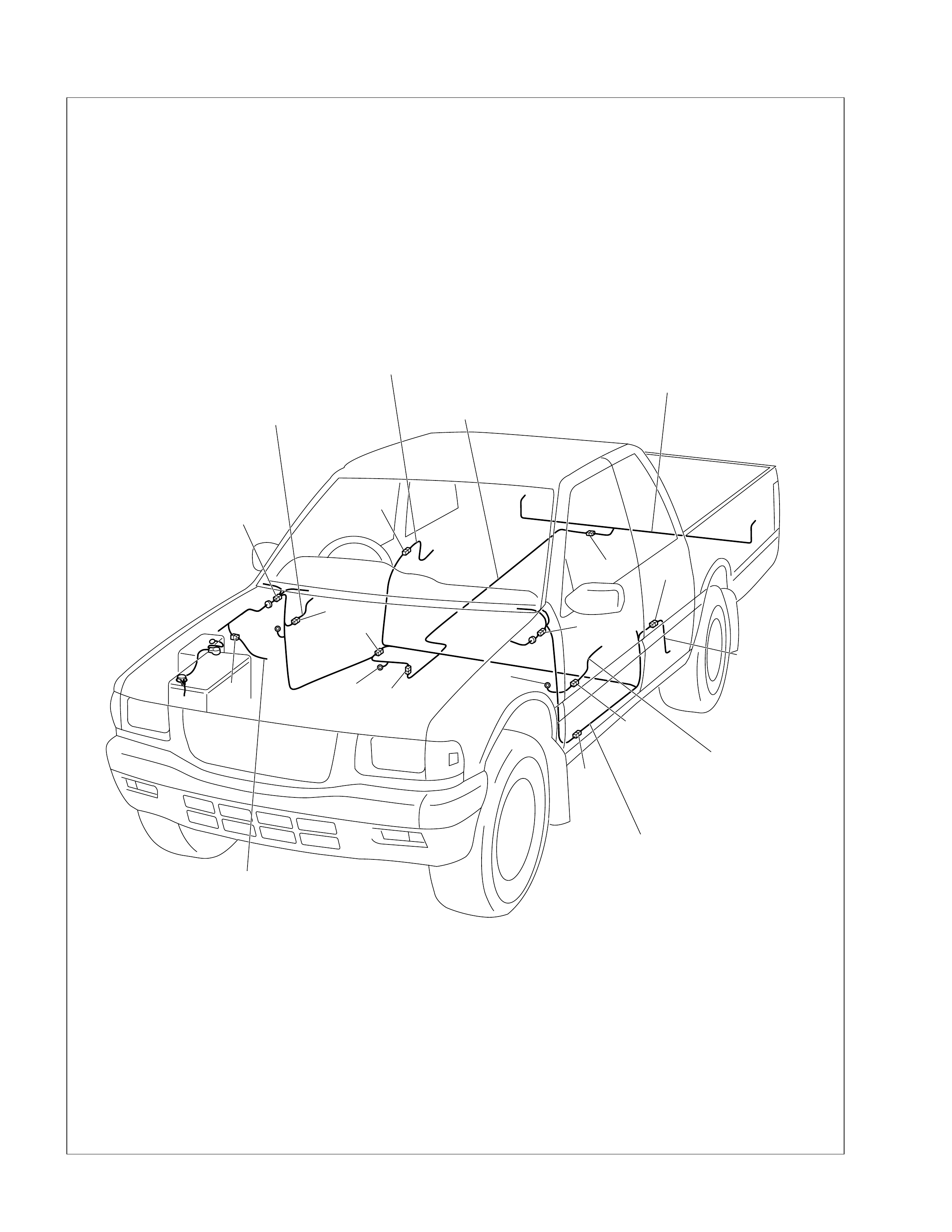
4J ENGINE - 2
REAR
DOOR
HARNESS
-LH
FRONT DOOR
HARNESS-LH
REAR BODY
HARNESS
COMBINATION LIGHT
HARNESS
CHASSIS
HARNESS
REAR DOOR
HARNESS-RH
BATTERY NEGATIVE
CABLE
FRONT DOOR
HARNESS-RH
H-9
H-6
H-7
H-11
H-12
H-18
H-10
H-15
H-19
B-34
H-3
H-16
H-17 H-14
H-8
H-13
B-9
System Repair
Start and Charging
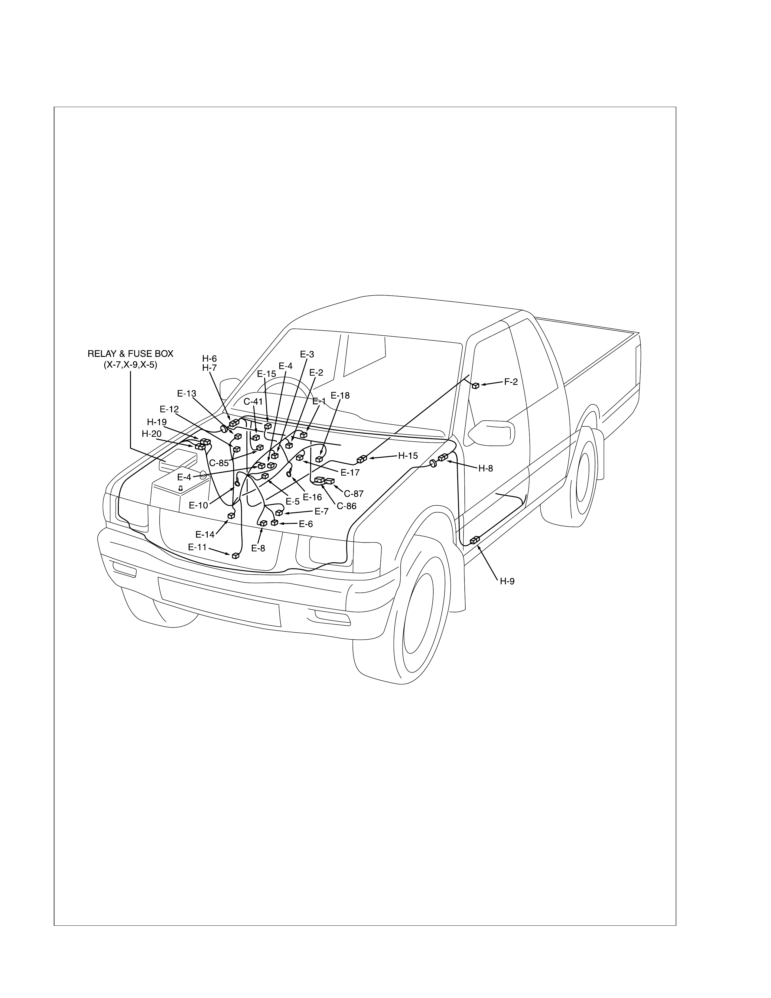
PARTS LOCATION - C22NE
RELAY & FUSE BOX
(X-3, X-6)
PARTS LOCATION ( 6 VD1)
PARTS LOCATION ( 4JB1T)
P-3 P-4
C-41
RELAY & FUSE BOX
(X-3,X-5,X-13,H-1) H-6
H-7
C-2
B-23
B-24
H-3
P-2
P-11
P-1
P-5
P-10
PARTS LOCATION ( 4JH1TC)
P-3
C-36
P-4
C-41
RELAY & FUSE BOX
(X-1,X-2,X-7,X-13) H-6
H-7
C-2
B-23
B-24
H-3
P-2
P-11
P-1
P-5
P-10
P-8 P-9
C-205
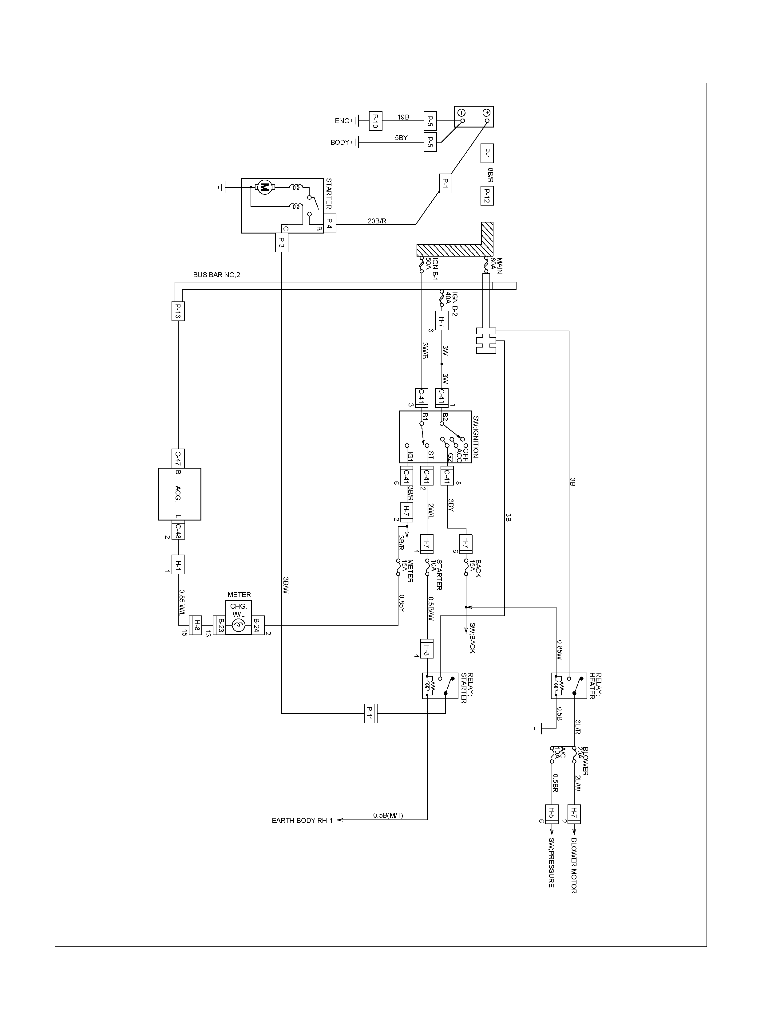
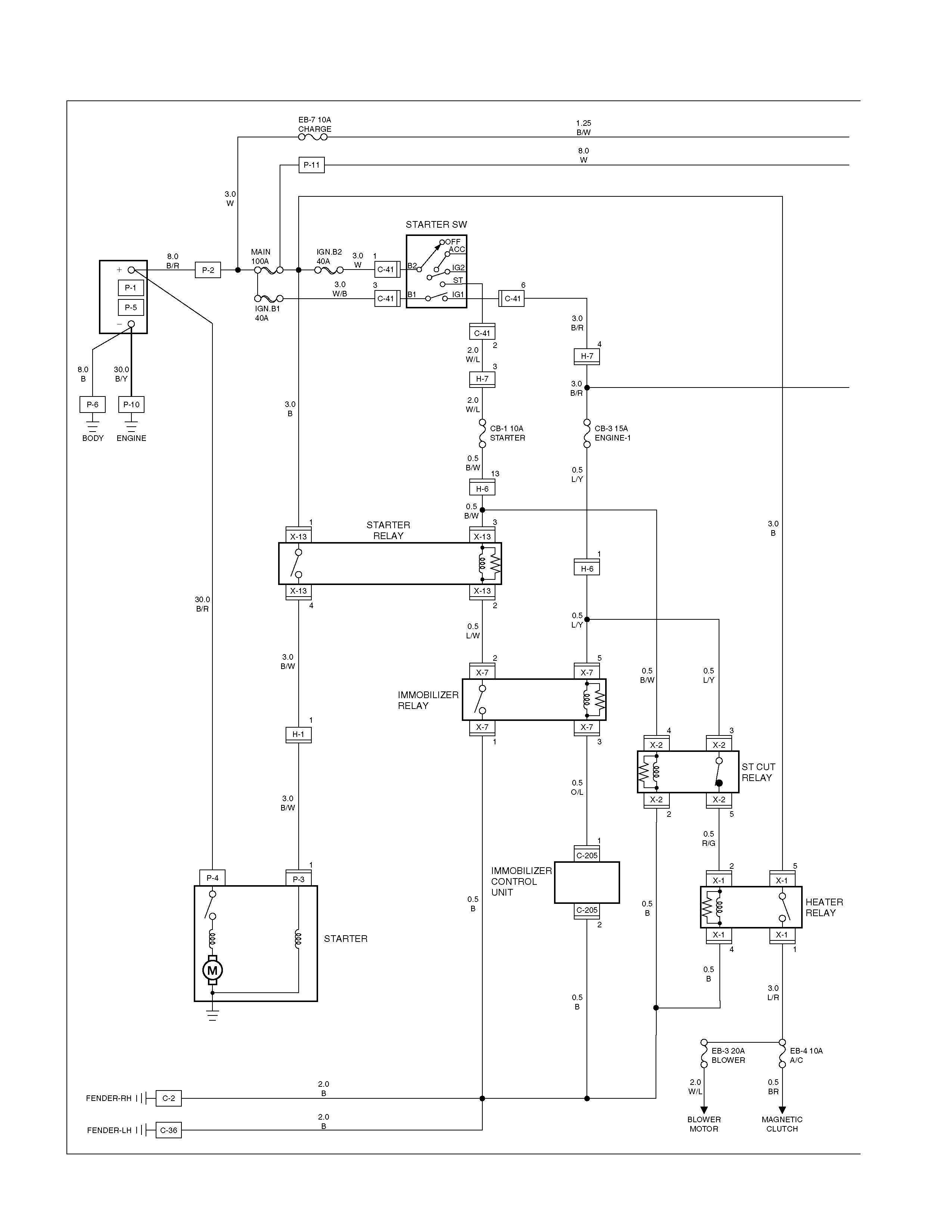
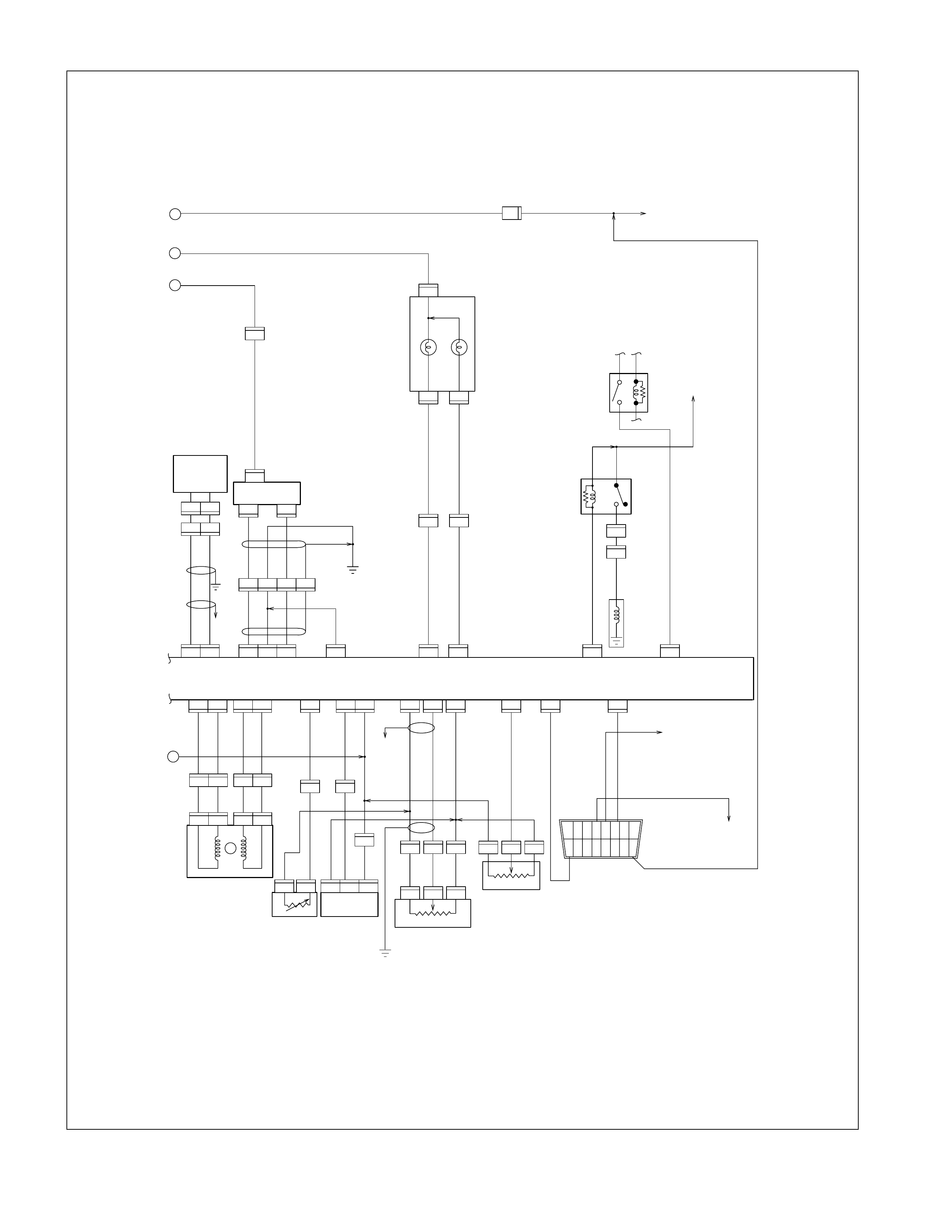
CIRCUIT DIAGRAM (C22NE)
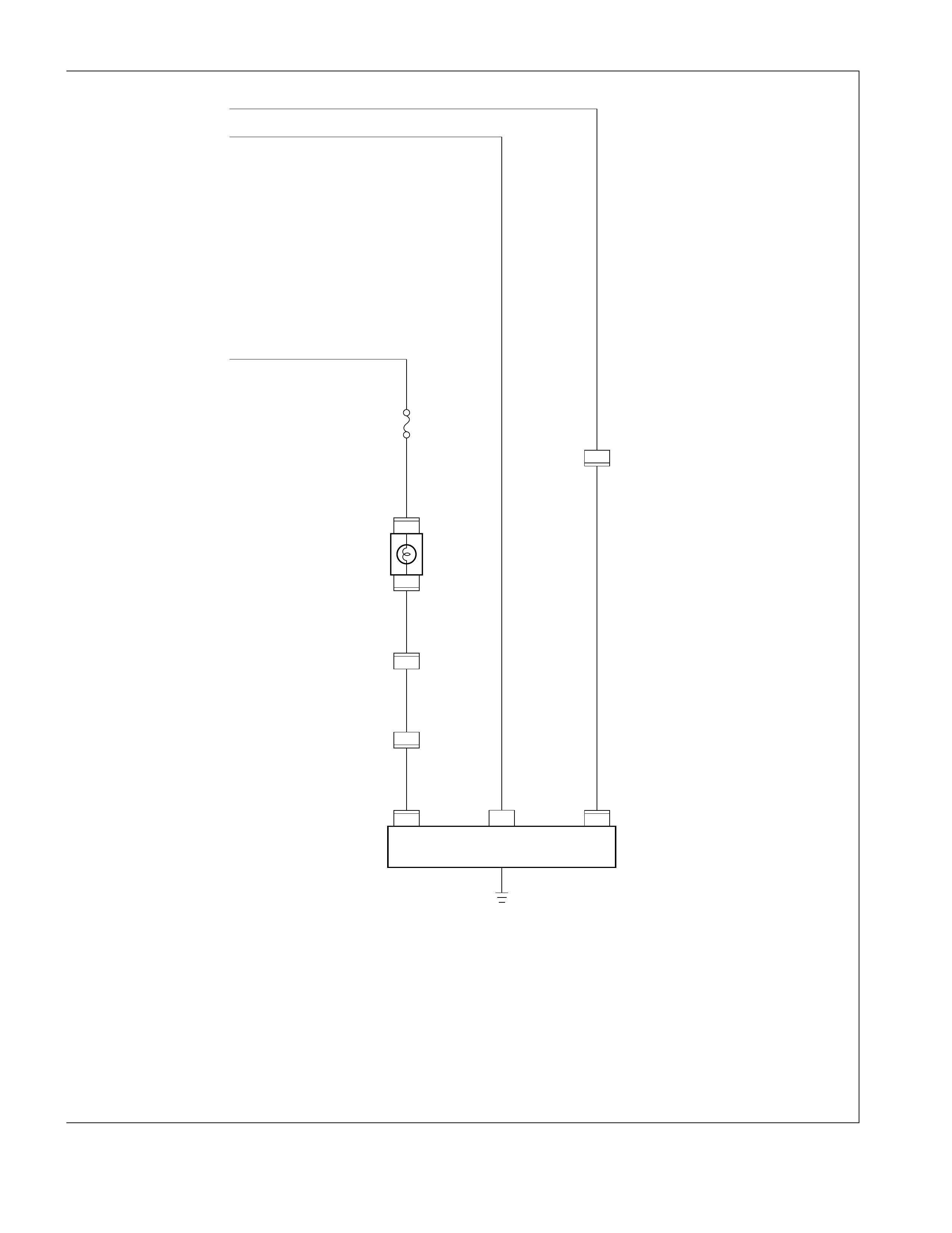
CIRCUIT DIAGRAM (6VD1)
CIRCUIT DIAGRAM (4JB1T)
+
_
M
2
1
P-9
P-1
P-5
P-6P-10
8B/R
1.25B
BODYENG.
30B/Y
8B
P-2
P-11
ACC
STARTER SW
IG2
IG1
ST
B2
C-41
1
3W
3W/B 3B/R 3B/R
CB-3 15A
ENGINE-1
CB-1
10A STARTER
EB-7 10A
CHARGE
3B/R
3W1.25B/W
MAIN
100A
IGN.B1
40A
IGN.B2
40A
OFF
B1
C-41
3
H-7
4
C-41
6
C-41
2
3
13
2W/L
0.85W/G
0.85Y
0.85W/G
2B/W
2W/L0.5B/W
H-6
1
H-6
H-7
2
H-3
8W
8W
0.85W/L0.85W/L0.85W/L
0.85W/L
3B/W
3B
3B
30B/R
3B
0.5B/W
0.5B
0.5B
0.5B
0.5B
0.85W/R0.85W/R
0.85W/G
0.85W/G
CHARGE WARNING
LIGHT(METER)
2
1
13
1
B-24
3
P-8 P-8
3
H-6
3
25
31 4
H-3
P-8
B-23
H-3
SB
L
IG
AC GENERATOR
X-5 X-5
X-5 X-5
RELAY;
CHARGE
X-5
X-13 X-13
X-13
RELAY;
STARTER
X-13
25
13
H-1
1
24
14
X-3 X-3
X-3
RELAY;
HEATER
EB-5
10A A/C
EB-4 20A
BLOWER
BLOWER MOTOR
PRESSURE SW
2L/W
0.5BR 3L/R
X-3
FENDER-RH C-2
P-3
B
C
STARTER
3B/W
P-4
CB-5 15A
METER
CIRCUIT DIAGRAM (4JH1TC)
2
B-24
P-9
1
P-8
2
SBL P-8
AC GENERATOR
CHARGE
WARNING
LIGHT
(METER)
0.85
Y
8.0
W
1.25
B/W
1.25
B/W
0.85
W/L
0.85
W/L
0.85
W/L
3.0
B/R
CB-5 15A
METER
1
H-3
2
H-3
13
B-23
3
H-6
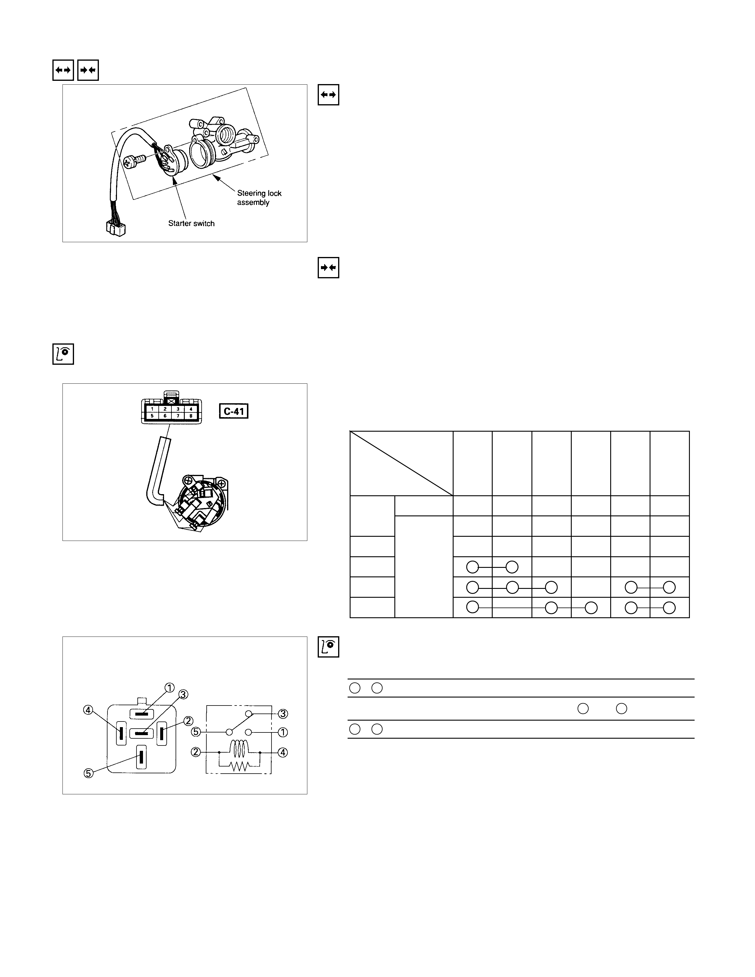
REMOVAL AND INSTALLATION
STARTER SWITCH
REMOVAL
1. Steering Lock Assembly
•Refer to "STEERING COLUMN" for steering lock
assembly removal st eps.
2. Starter Switch
INSTALLATION
Follow the removal procedure in the reverse order to install the
starter switch.
INSPECTION AND REPAIR
STARTER SWITCH
SWITCH CONNECTIO NS
Terminal No.
Starter
swit ch key
position
1
(B2) 4
(ACC) 8
(IG2) 2
(ST) 3
(B1) 6
(IG1)
Removed
OFF
ACC Inserted
ON
START
LOCK
STARTER RELAY, HEATER RELAY, ST CUT RELAY
Check continuity between the relay terminals.
1 - 5............................No continuity
(When battery voltage is applied between 2 and 4)
1 - 5............................Continuity
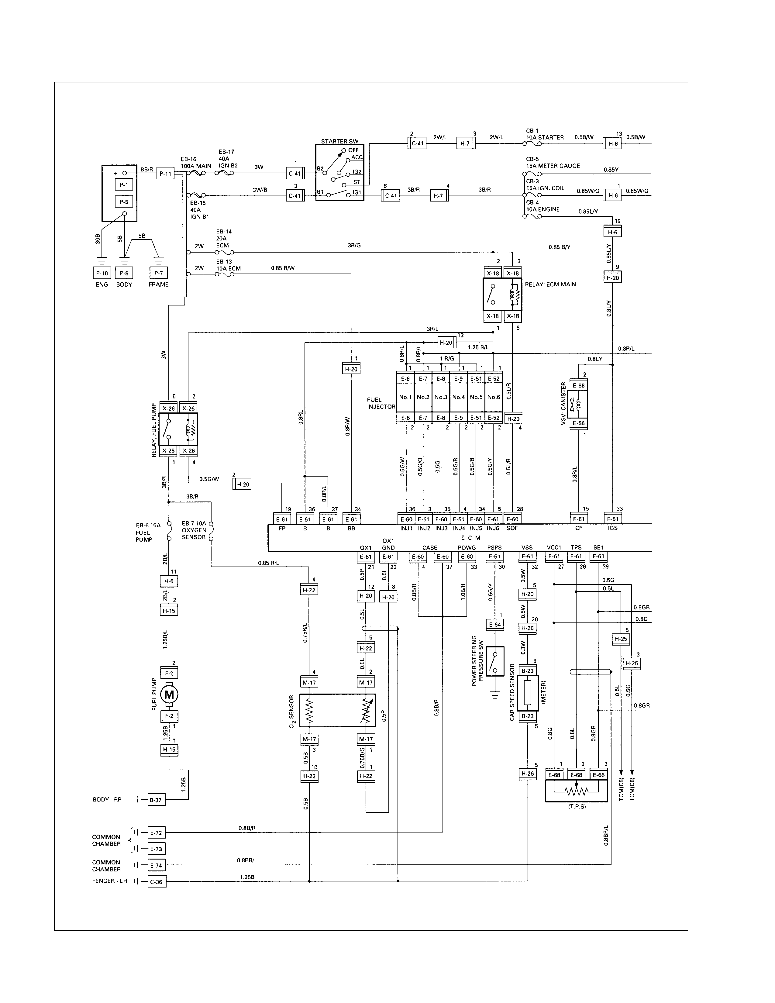
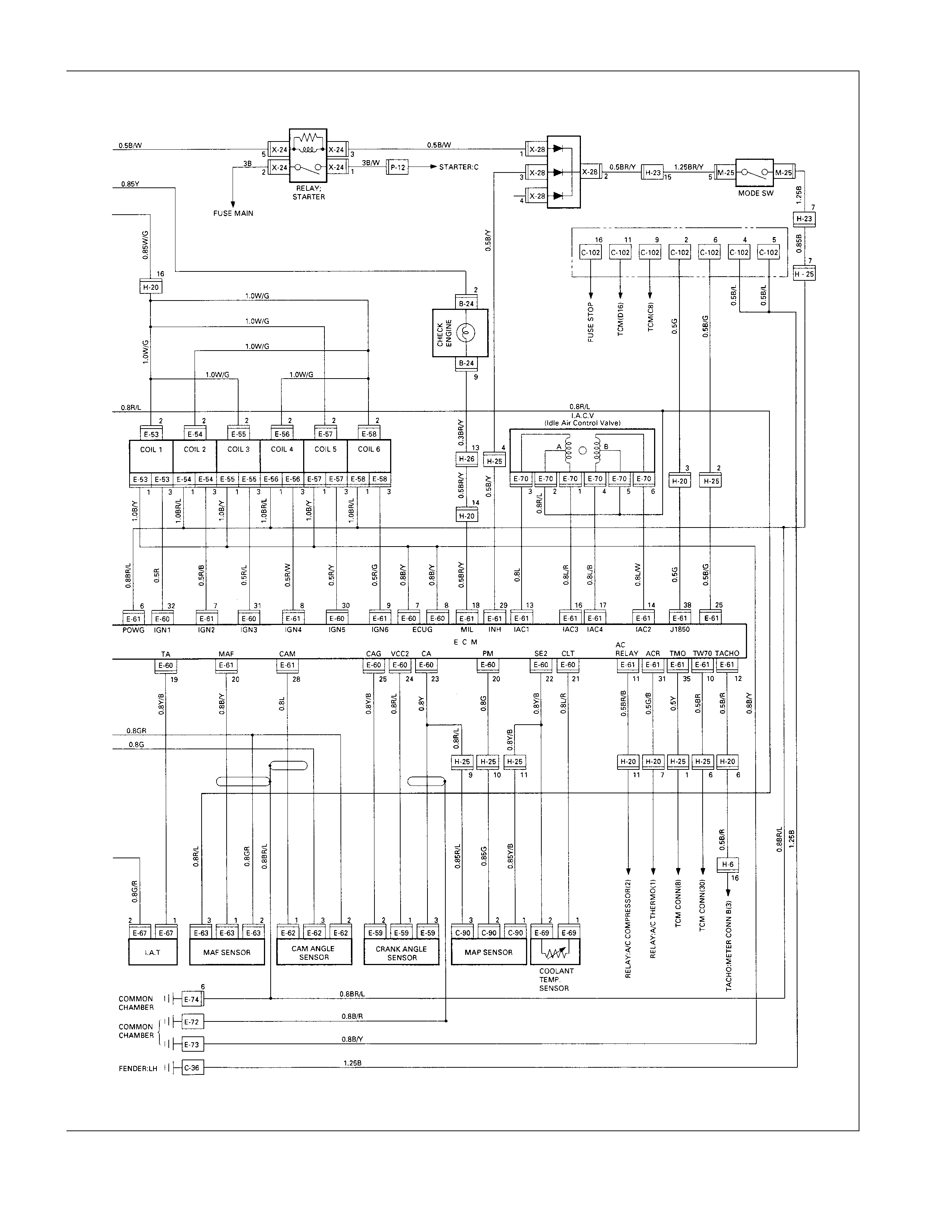
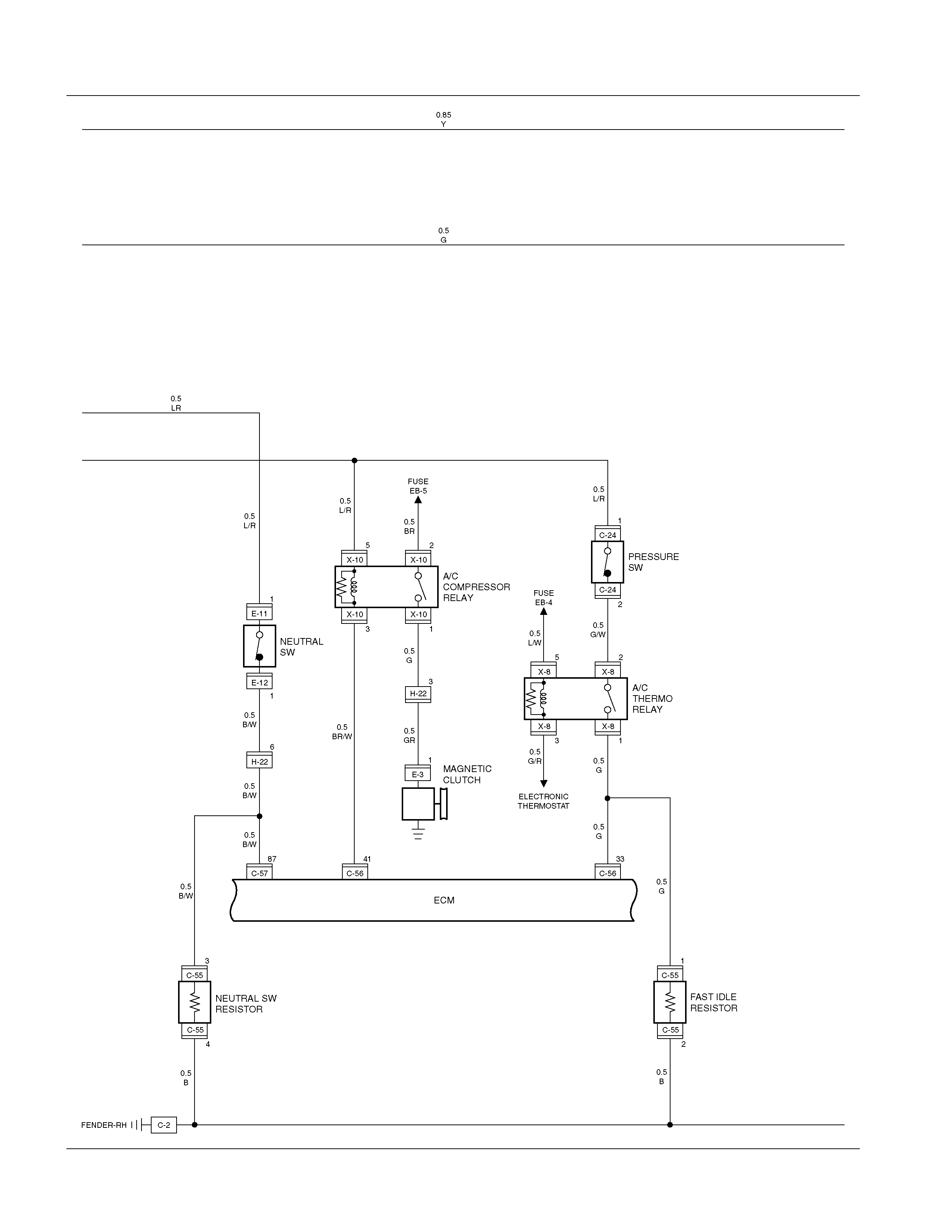
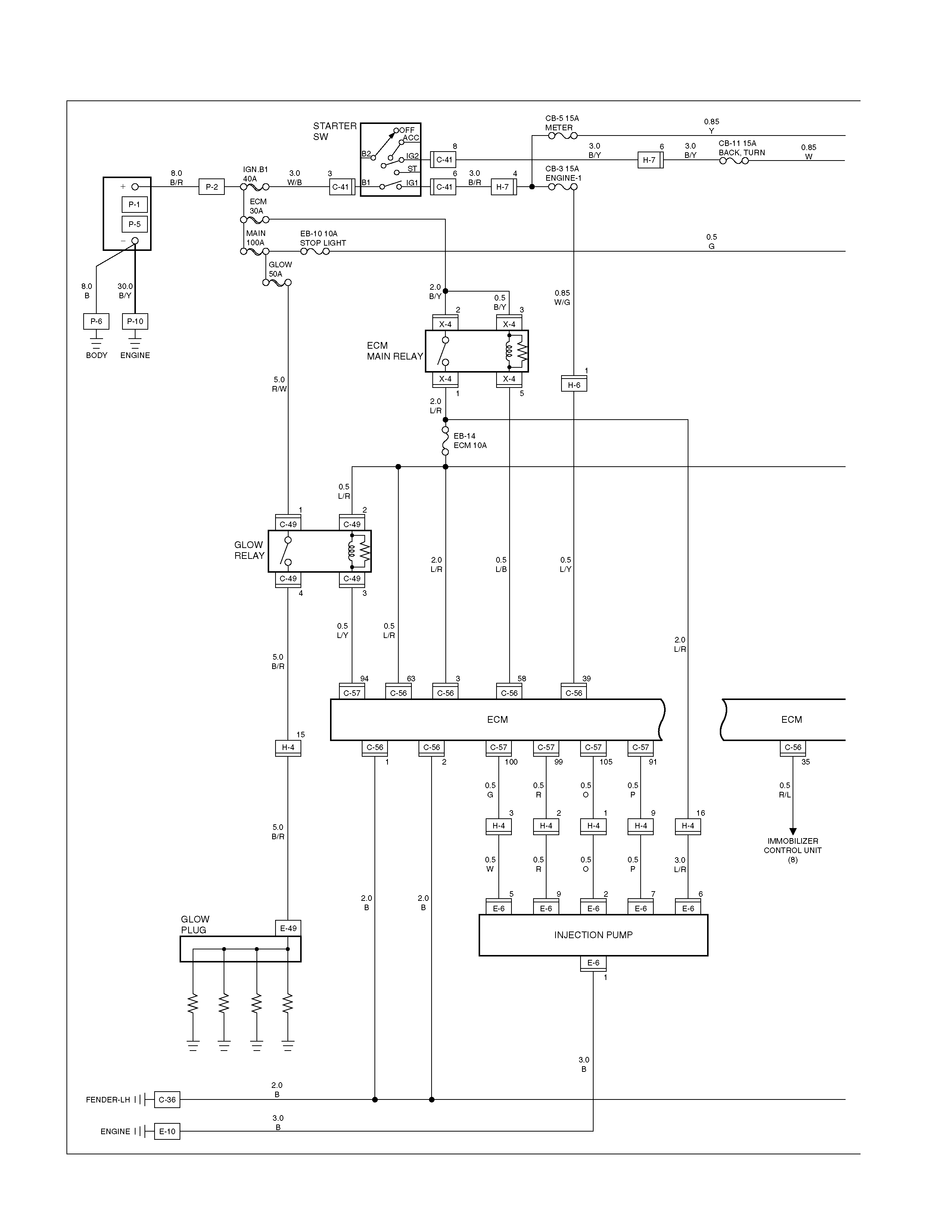
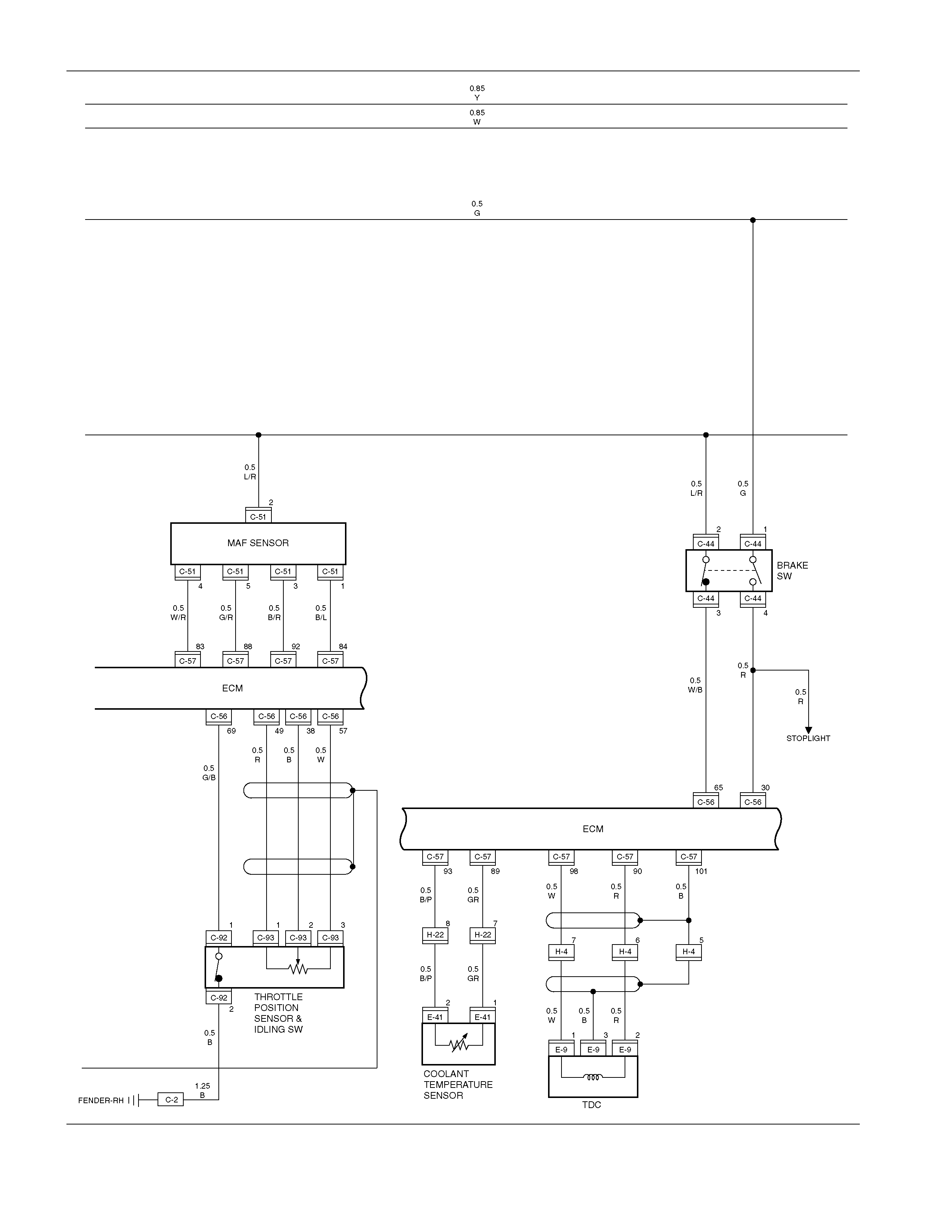
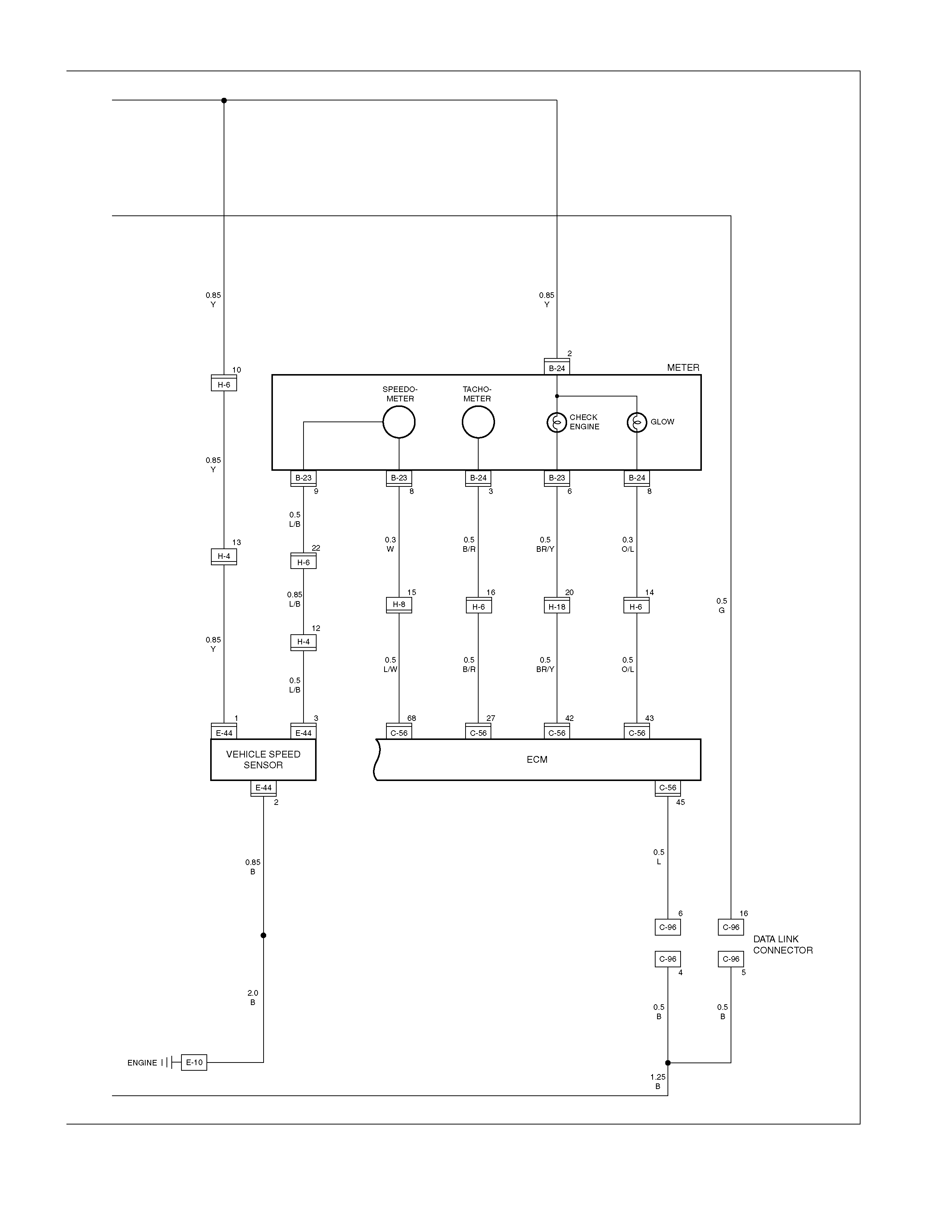
Engine Control Module (ECM)
PARTS LOCATION ( C22NE)
PARTS LOCATION ( 6 VD1)
PARTS LOCATION ( 4JH1TC)
B-24
C-36
H-8
B-23
C-94
C-95
C-41
RELAY & FUSE BOX
(X-4,X-10,X-12,X-14,X-15)
C-2
H-6
H-18
C-56
C-57
E-1 E-6 E-10
C-51
C-53
C-44 H-4
H-22
H-23
E-44
E-46 E-45
E-11
E-12
E-9
E-49
E-3
E-41
C-24
C-96
C-92
C-93
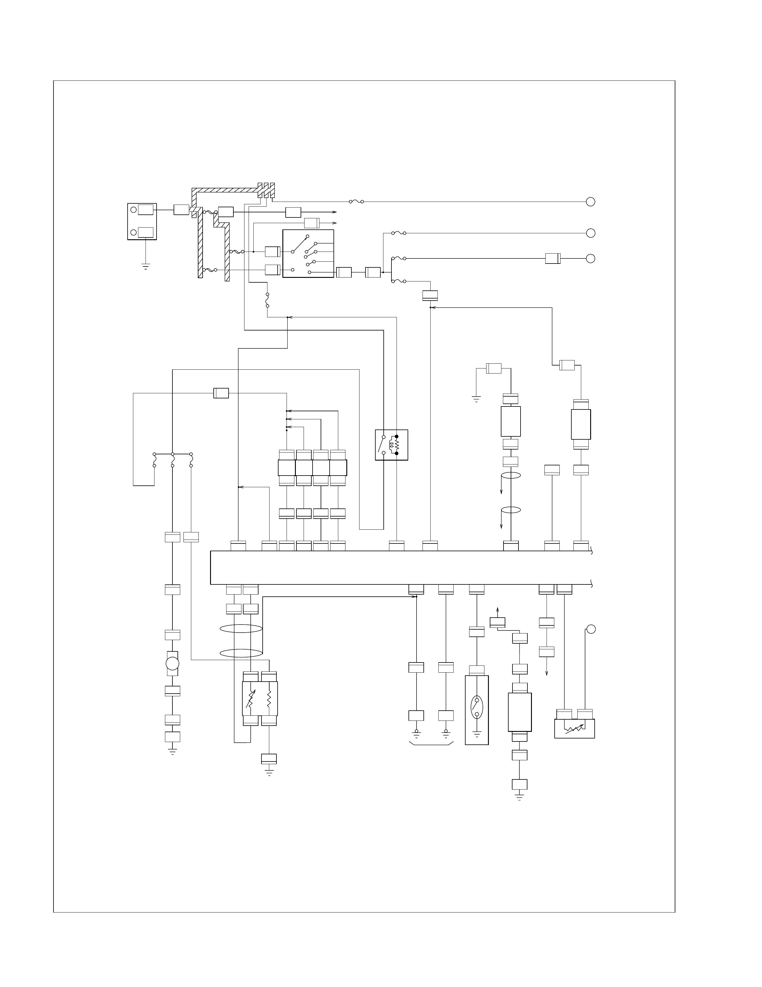
CIRCUIT DIAGRAM (C22NE)
SW:IGNITION
ACC
OFF
IG2
IG1
ST
B2
B1
3W
3W
2W
3W/B
0.5G
0.85L/Y
3B/R
0.85L/Y
0.85Y
2W/B
2W
0.5B/R
A1F12
A4 A7 A9 A8 A6 A13 E16 A14A12F8
F15
1.25B/R
0.5L/B
METER
METER
0.5G/Y0.5P/L
0.5Y/G
0.85B/Y
PRESSURE SW;P/STRG.
VENICLE SPEED
SENSOR
0.5G
0.5B
1.25B 2B/L2B/L1.25B/L
0.85R/G
3B/R
1.25R/W1.25R/W
INJECTIOR
20A
F/PUMP
20A
10A
O
2
SENSOR
2B/R
0.85G/W
1.25R/W
0.5G/W
2B/R
0.85R/W
0.85L/Y
0.5B/R 0.5Y
SENSOR; KNOCK
POWER
GROUND
POWER
GROUND
DUTY SOLENOID VALVE
0.5R/G
0.5R/L
0.85G/R
0.85G/B
0.85G
0.5L/P 0.5R/G
1.25R/G
0.5R/G
0.5R/G
0.5R/G
0.5L/B
0.5L/W
0.5L/Y
0.5B
O
2
SENSOR
( LAO ONLY )
0.5P
FUEL PUMP
0.5L
POWER
A2 F16 F10
1.25B/L
1.25R/G
1.25B/R
SENSOR
EARTH
EARTH
EARTH
EB
STOP
10A
DB-04
EIGINE
10A
ECM
15A
DB-05
IG.COIL
15A
DB-05
METER
15A
#1 #2 #3 #4
INJECTOR
(FUEL RAIL)
(ASS7)
ECM
IAT
SENSOR
ENGINE
BLOCK
12
C-86
24
C-87
16
C-87
6
C-86
8
C-86
9
C-86
A5
5
C-86
7
C-86
4
H-20
2
H-20
1
H-20
3
1
H-20
E-4
1
E-3
1
E-2
1
2222
E-1
E-4 E-3 E-2 E-1
19
H-6
9
26
C-87
E7
7
C-87
1
C-86
2
C-86
5
H-20
6
H-20
E-10 E-16
32
C-87
12
H-19
1
E-14
9
B-23
22
8
H-6
3
H-5
3
M-10
2
M-10
6
H-5
C-2
13
H-19
1
C-93
2
C-93
A
B
C
D
8B/R MAIN
80A
BATT
8W
3W
ACG (B)
FUSE BOX(CB-14)
IGZ
40A
IG.1
50A
J/C;A
P-12 C-47
H-7
3
P-13
C-41
1
C-41
3
C-41
6
H-7
2
H-7
5
3B/R
14
C-86
1
2
E-5
E-5
15
H-20
1
E-17
2
E-17
12
H-20
RELAY;
FUEL PUMP
13
C-86
11
H-6
2
H-15
28
C-87
10
H-5
9
H-5
31
C-87
2
F-2
1
F-2
3
C-91
4
C-91
1
C-91
2
C-91
11
H-5
1
H-15
B-34
12
H-5
P-1
P-5
H-19
M
0.5W0.3W
7
H-8
8
B-23
-
+
H-20
13
H-19
6
4
C-86
RELAY;A/C
COMPRESSOR
MAG.CLUTCH
(COMPRESSOR)
METER
2W/G
CHECK ENGINE
0.3BR/Y0.58R/Y
0.5B/R 0.5B/R
0.5BR
1.25BR
0.5GR/R
0.5BR/Y
RELAY;
THERMO
SW;AIRCON
SW;STOP LAMP
0.5G
2G/B
B16 B15 B13 B14 F14 B7 B2 B1 B8 A3
E5 E1 E2 E4 E3F1 A16 B10B4 B5
(ALDL)
E8
CD ADJUST
E12
(DIAG)
B11
(D) (C) (B) (A)
AB
ECM
POWER
GROUND
EARTH
COIL MODULE
1 . 4 2 . 3
HI LO HI LO
HIOUTLO
IDLE AIR
CONT.VALVE
(THROTTLE
VALE)
TEMP
SENSOR.
WATER
MAP
SENSOR T.P.S.
(THROTTLE VALVE)
SENSOR
GROUND
SENSOR
GROUND
V5RTN B V5RTN A V5B
12345678
9 10111213141516
0.5B/L
0.5B
SENSOR GROUND
EARTH
TACHO
4
E-13
3
E-13
2
E-13
16
H-20
7
H-20
5
0.5G
H-19
E-15E-15E-15E-7 E-7 1
E-12
3
E-12
2
E-12
6
H-19
14
H-19
8
H-20
4
C-85
1
21 1 2 3
E-13
1
H-19
2
H-19
3
H-19
4
H-19
17
C-87
2
B-24
9
B-24
3
B-24
13
H-8
16
H-6 14
H-20
1
E-6
5
C-87
2
C-87
4
C-87
3
C-87
20
C-86
21
C-86
16
C-86
26
C-86
1
C-87
2
E-9 E-18 E-18
7
H-19
15
H-19
8
H-19
16
H-19
1
E-9
10
H-20
11
H-20
32
C-86
31
C-86
29
C-86
30
C-87
30
C-86
23
C-86
17
C-86
24
C-86
3
C-86
18
C-86
9
H-20
2
31
E-18
A
B
C
D
C-44
1
0.5R
0.5G
1.25G
0.85B
0.85B
1.25B
1.25B
1.25L
0.85G
0.85L
0.5B
SENSOR
GROUND
0.5L
0.5L/W
0.5L/R
0.5L/B
0.5L/R0.85GR
0.5GR0.85GR/G
0.85B/L
0.75G
0.75L
0.5R
0.85B/6
0.85W/L
0.85L/O
0.5Y
0.5R
0.5B/W
0.5R
0.85GR/L
0.85GR/L
CD ADJUST
(LAO)
12
C-87
8
C-87
27
C-86
3
C-85
2
C-85
C-96
(1) (2)
(1)
(3)(4)
(2)
(4)(3)
SENSOR;
CRANK
ANGLE
CIRCUIT DIAGRAM (6VD1 )
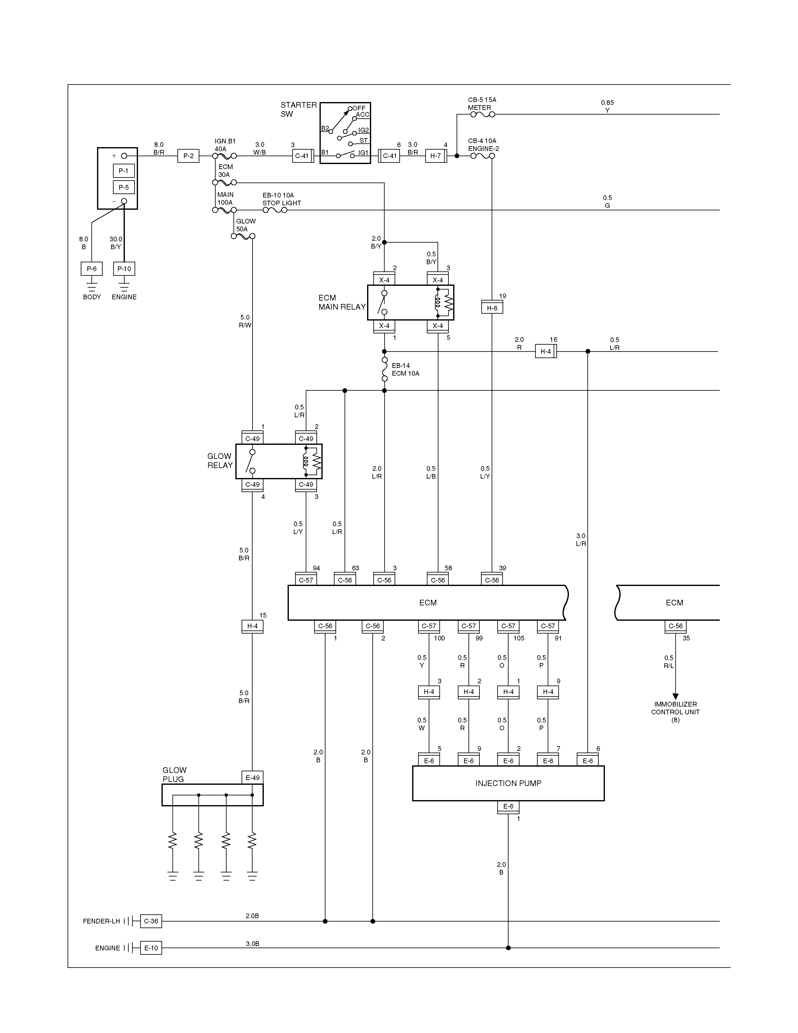
CIRCUIT DIAGRAM (4JH1-TURBO RHD-M/T)


CIRCUIT DIAGRAM (4JH1-TURBO RHD-A/T)


REMOVAL AND INSTALLATION
ECM (ENG INE CONTROL MODULE)
REMOVAL
1. Remove the ECM.
Refer to the "ENGINE" Section of this Manual.
2. Loosen the three screws.
3. Pull out the ECM.
4. Disconnect both red and tan connectors.
INSTALLATION
Follow the removal procedure in the reverse order to install the
ECM.
Pay close attention to the important points mentioned in the
following paragraphs.
CONNECTOR
Be absolutely sure that ECM is securely connected.
This will prevent a poor contact and open circuit.
FUEL PUMP
REMOVAL
1. Remove the fuel tank.
Refer to the "ENGINE" Section of this Manual.
2. Loosen the screws 1.
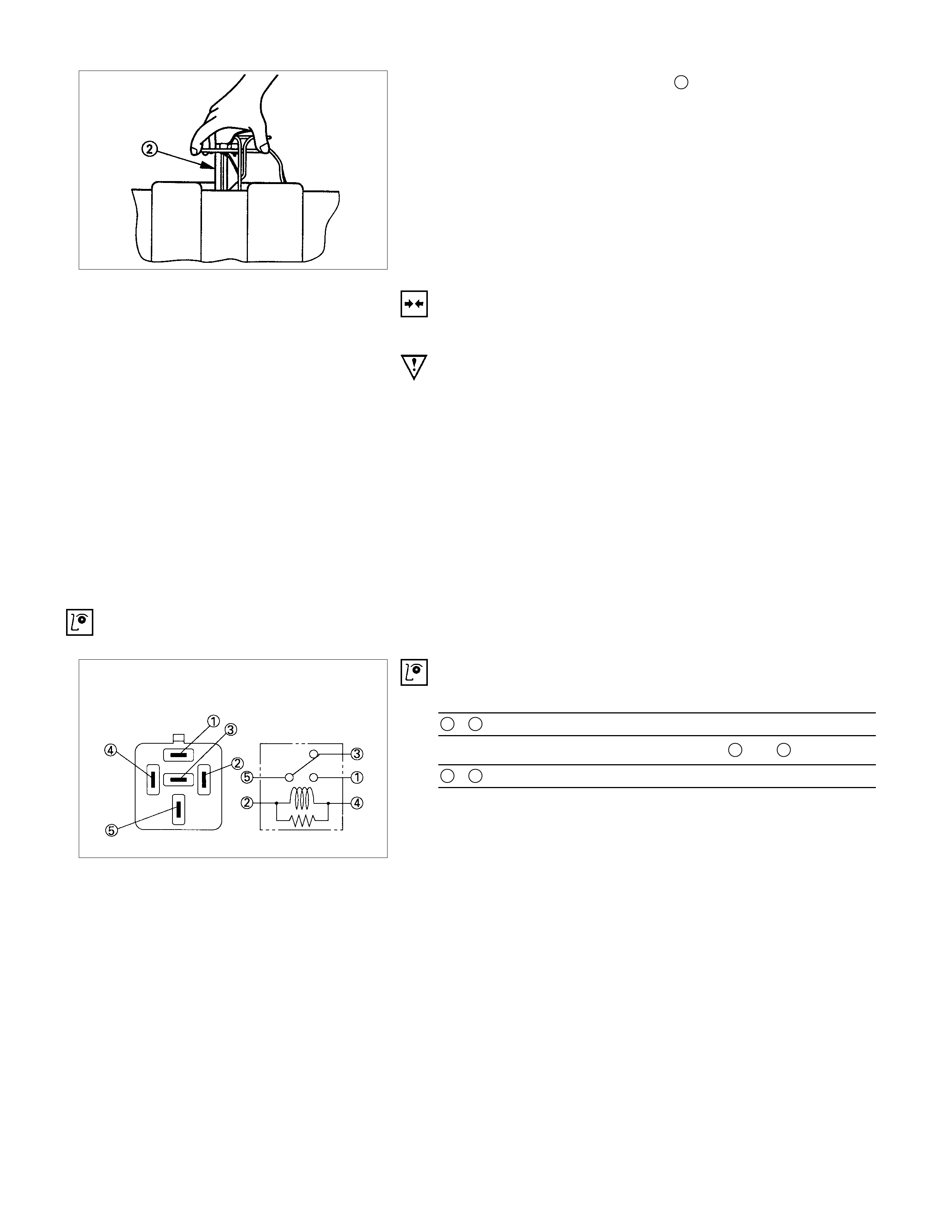
3. Raise the fuel pump assembly 2 from the fuel tank.
INSTALLATION
Follow the removal procedure in the reverse order to install the
fuel pump.
Pay close attention to the important points mentioned in the
following paragraphs.
RUBBER SEAL
Be absolutely sure that the fuel pump rubber seals correctly
seated.
CONNECTOR
Be absolutely sure that the fuel pump connector is securely
connected.
This will prevent a poor contact and an open circuit.
INSPECTION AND REPAIR
FUEL PUMP RELAY
Check continuity between the relay terminals.
1 - 5............................No continuity
(When battery voltage is applied between 2 and 4)
1 - 5............................Continuity
QOS / EGR / QWS
PARTS LOCATION (RHD)
C-13
C-14
C-15
(4JA1)
B-24
C-36
H-4
C-46
C-13
(4JG2)
C-14
C-15
(4JG2)
C-31
C-32
C-28
C-23
B-23
B-25
C-41
C-40
B-28
E-36
E-49
E-37
E-5
E-41
C-49
C-50
RELAY & FUSE BOX
(X-5,X-8,X-14)
C-2
H-6
H-7
CIRCUIT DIAGRAM (RHD)
B-23
5
C-2
C-36
FENDER-LH
GLOW
PLUG
FENDER-RH
C-46 C-46 C-46
918 5
0.5L/Y
0.85W/L
0.5B 0.85W/R
0.85W/G
0.5L/Y
0.5L/Y
0.5B
0.5L/Y0.5L/Y
0.85Y
0.5B/W
3B/R
1.25B
0.85W/L
5B/R5B/R
P-2
11
H-8
C-46
6
0.5B/G
5W/B
C-28
1
C-28
2
C-46
7
5B/R
0.5B/L
5B/R
0.3O/L
0.3O/L
E-5 E-5
13
C-46
2112
C-46 C-46
H-4
913 8
H-4 H-4
0.5R/G
0.5R/W
0.5Y/G
0.5R/G
0.5R/W
E-41 E-41
21
C-46
13 11
C-46
H-4
10 5
H-4
0.5Y/R
0.5Y
0.5Y/R
0.5Y
C-46
316
C-46
0.5W0.5W0.85B0.85B
0.5B1.25B
0.5Y/G
C-41
3
H-7
4
3
3
H-7
C-41
6
3W/B 3B/R 3B/R
CB-1 10A
STARTER
CB-5 15A
METER
CB-4 10A
ENGINE-2
W/L
2
W/L
8B/R
IGN.B1
40A
GLOW
50A
BODY
ENG.
C-41
1
3W
MAIN
80A
IGN.B2
40A
C-49
4
C-49
3
1 2
C-49 C-49
C-50
4
C-50
3
1 2
C-50 C-50
3
X-5
2 1
X-5 X-5
3 1
H-3 H-6
X-5 X-5
45
RELAY;
CHARGE
RELAY;
GLOW-2
RELAY;
GLOW-1
RESISTOR
CHARGE
WARNING
LIGHT
AC GENERATOR(L)
STARTER SW
OFF
IG1
IG2
ST
B2
B1
ACC
C-41
2
C-46
17
4
H-8
19
H-6
0.5B/W
QOS / EGR / QWS
CONTROL UNIT
QOS / EGR / QWS
CONTROL UNIT
THROTTLE POSITION
SENSOR
THERMO SENSOR
CAR SPEED
SENSOR
H-6
3
B-23
8
H-6
11
H-6
7
E-5
2
B-24
8
B-24
2
0.85W/G
0.5L/Y
5R/W
5R/W
GLOW
INDICATOR
LIGHT
(METER)
H-4
E-49
15
B
A
P-1
P-5
P-6
8B
+
_
+_
P-10
30B/Y
CB-3 15A
ENGINE-1
C-36
B-28
BODY-RH
FENDER-LH
C-46
10
0.5L/Y
H-6
16
H-6
14
C-23
1
0.5G/O 0.5G/Y
0.85G/R0.5B
0.5B
0.5G/Y 0.5L/Y
0.85W/G0.85W/G
0.5G/O
0.5W/R
0.5G/B
0.5O0.5O
0.5O 0.5O
2B
1.25B
0.5B
0.5G/O
0.5B
C-46
14
0.5B/R0.5B/R
12
H-4
0.5B0.5B0.5B
0.5B
7
H-4
C-46
4
0.5L/Y
0.5W/O
C-46
15
0.5B/R
QOS / EGR / QWS CONTROL UNIT
RELAY;
QWS
TACHO METER
TACHO
SENSOR
VSV;
EGR-1
VSV;
EGR-2
THERMO
SW
FUEL CUT
SOLENOID
DIODE
RELAY ; A/C THERMOSTAT (1)
VSV;
THROTTLE-1
(4JG2)
VSV;
EXHAUST-1
(4JA1) VSV;
THROTTLE-2
(4JG2)
VSV;
EXHAUST-2
(4JA1)
VSV; FICD
C-46
8
C-23
2
X-8
2
X-8
5
X-8
3
X-8
1
B-25
2
B-25
6
QWS SW
FUSE EB-12
B-25
3
B-25
5
B-25
4
ACCEL.
SW
C-46
20
1.25B
0.5G
0.5G/Y
0.5L/Y
C-31
1
C-31
2
C-13
2
C-13
1
0.5O/G
0.5B
C-40
2
C-14
1
C-40
1
C-32
1
C-32
2
E-36
2
E-36
1
X-14
1
X-14
3
2
C-15
2
C-14
2
C-15
1
A
B
E-37
1
H-4
6
X-14
1
H-6
PARTS LOCATION ( 6 VD1W )
CIRCUIT DIAGRAM
CIRCUIT DIAGRAM (6VD1W)
TROUBLE SHOOTING
HEADLIGHT
1. Both the headlights (high and low beam) do not light
Checkpoint Trouble Cause Countermeasure
Repair the wiringPoor ground point contact
NG
Repair open circuit or
connector contact
Repair open circuit
Repair or replace the
combination switch
Voltage between 1 C-42 -
ground Open circuit between lighting
relay and lighting switch
Open circuit between battery
positive terminal and lighting
relay
Combination switch continuity Poor switch contact or sw
faulty
Voltage between
5 X-1 - ground and
2 X-1 - ground
Reinstall or replace the
lighting relay
Lighting relay Poor relay contact or relay
faulty
NG
NG
NG
NG
OK
OK
OK
OK
Ground point contact (C-2)
Repair open circuit
Wiring continuity between
7 C-42 - C-2 and
16 C-42 - C-2 Open circuit
NG
OK
2. High or low beam does not light on both headlights
Checkpoint Trouble Cause Countermeasure
Repair or replace the
combination switch
Dimmer⋅passing switch
continuity Poor switch contact or switch
faulty
NG
Repair open circuit or
connector contact
Voltage between
13 C-42 - ground and
15 C-42 - ground
Open circuit between
headlight and dimmer⋅passing
switch
NG
OK
3. RH (or LH) high and low beam does not light
Replace the headlight bulbHeadlight connector continuity Blown filament or air leakage
NG
Repair or replace the wire
and/or connector
Wiring continuity between
connector 3 C-19 - fuse No.
EB-9 or 3 C-26 fuse No.
EB-8
Open circuit and/or poor
connector contact
NG
OK
Reinstall or replace fuse No.
EB-8 or No. EB-9
Fuse No. EB-8 (10A) or
No. EB-9 (10A) (Relay and
fuse box)
(No. EB-9 RH, No. EB-8: LH)
Poor installation or blown fuse
NG
OK
4. High or low beam does not light on one headlight (RH or LH)
Replace the headlight
assembly
Headlight connector continuity Blown filament
NG
Repair open circuit or
connector contact
Wiring continuity between
headlight and dimmer⋅passing
switch
Open circuit between
headlight and dimmer⋅passing
switch
NG
OK
5. Headlight does not go out
Checkpoint Trouble Cause Countermeasure
Replace the lighting relay
Lighting relay continuity
between connector 1 X-1
- 5 X-1 (Should be no
continuity)
Relay point fused
NG
Replay the combination switch
Lighting switch continuity
between connector 1 C-42
-7 C-42 when switch is
OFF(Should be no continuity)
point fused or faulty
NG
OK
OK
Repair or replace the
combination switch
Dimmer⋅passing switch con-
tinuity between connector
14 C-42 - 16 C-42 when
switch is not operating
(Should be no continuity)
Switch point fused or faulty
NG
Repair short circuit
between 4 X-1 - 1 C-42
and 4 X-1 - 14 C-42
Check if headlight goes out
when connector C-42 is
disconnected Short circuit
NG
OK
6. Insufficient headlight brightness
Replace the headlight bulbHeadlight bulb Bulb filament faulty
NG
Repair the wiring
Dimmer⋅passing switch
Wire continuity between con-
nector 16 C-42 - C-2 Poor ground point contact
NG
OK
Clean the light lens
Headlight lens Lens dirty
NG
OK
7. Passing light does not function when dimmer switch is operated
Checkpoint Trouble Cause Countermeasure
Repair or replace the dimmer
switch
Dimmer switch Poor switch point contact
NG
Repair open circuit between
4 X-1 - 14 C-42
Voltage between
14 C-42 - ground (Should
be battery voltage present) Open circuit
NG
OK
8. Headlight beam does not change when dimmer switch is operated
Repair or replace the dimmer
switch
Dimmer switch Loose beam lever or foreign
material in switch
NG
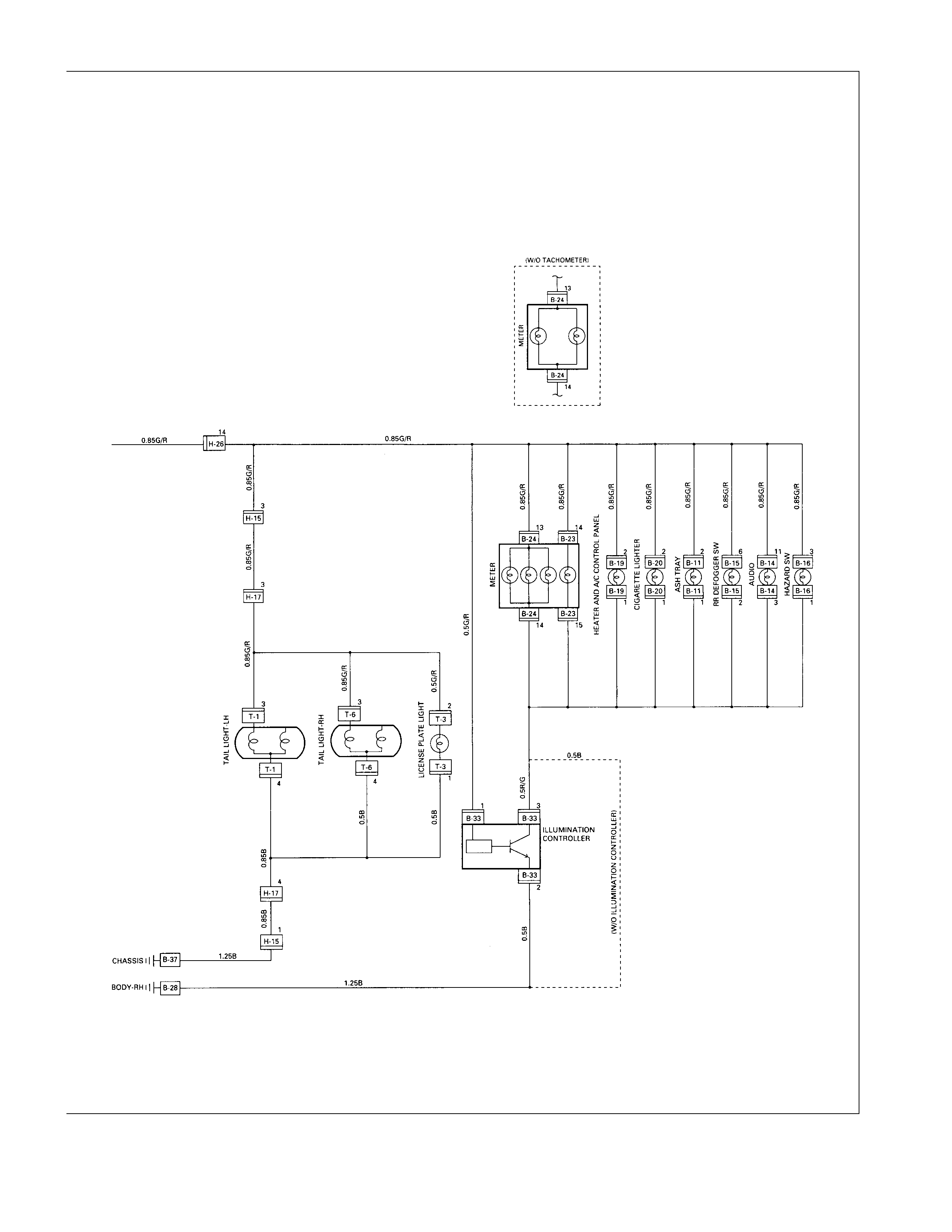
TAIL LIGHT, LICENSE PLATE LIGHT, CLEARANCE LIGHT AND ILLUMINATION CONTROLLER
1. All lights do not light
Checkpoint Trouble Cause Countermeasure
Repair or replace the
combination switch
Lighting switch continuity
between connector
8 C-42 - 7 C-42
Poor switch point or connector
contact
NG
Reinstall or replace the tail
relay
Tail relay Poor relay contact or relay
faulty
NG
OK
Reinstall or replace the fuse
No. EB-12
Fuse No. EB-12 (15A, Relay
and fuse box) Poor fuse contact or blown
NG
OK
2. Tail light does not light
Replace the bulb or repair
connector contact
Tail light bulb continuity Bulb burned out or poor
connector contact
NG
Repair open circuit or
connector contact
Continuity between connector
3 T-6 - 4 T-6 (RH)
or 3 T-1 - 4 T-1 (LH)
Open circuit or poor connector
contact
NG
OK
3. License plate light does not light
Checkpoint Trouble Cause Countermeasure
Repair open circuit or
connector contact
Continuity between
connector 1 T-3 - 2 T-3 Open circuit or poor connector
contact
NG
Replace the bulb or repair
connector contact
License plate light bulb
continuity Bulb burned out or poor
connector contact
NG
OK
4. Clearance light does not light
Replace the bulb or repair
connector contact
Clearance light bulb continuity Bulb burned out or poor
connector contact
NG
5. Illumination controller does not operate
Repair knob installation or
replace the controller
Turn the illumination controller
knob (Brightness should
change) Loose knob or faulty controller
NG
Repair short circuit or replace
the wire
Disconnect the illumination
controller connector (Light
should be dim) Short circuit
NG
OK
REMOVAL AND INSTALLATION
HEADLIGHT
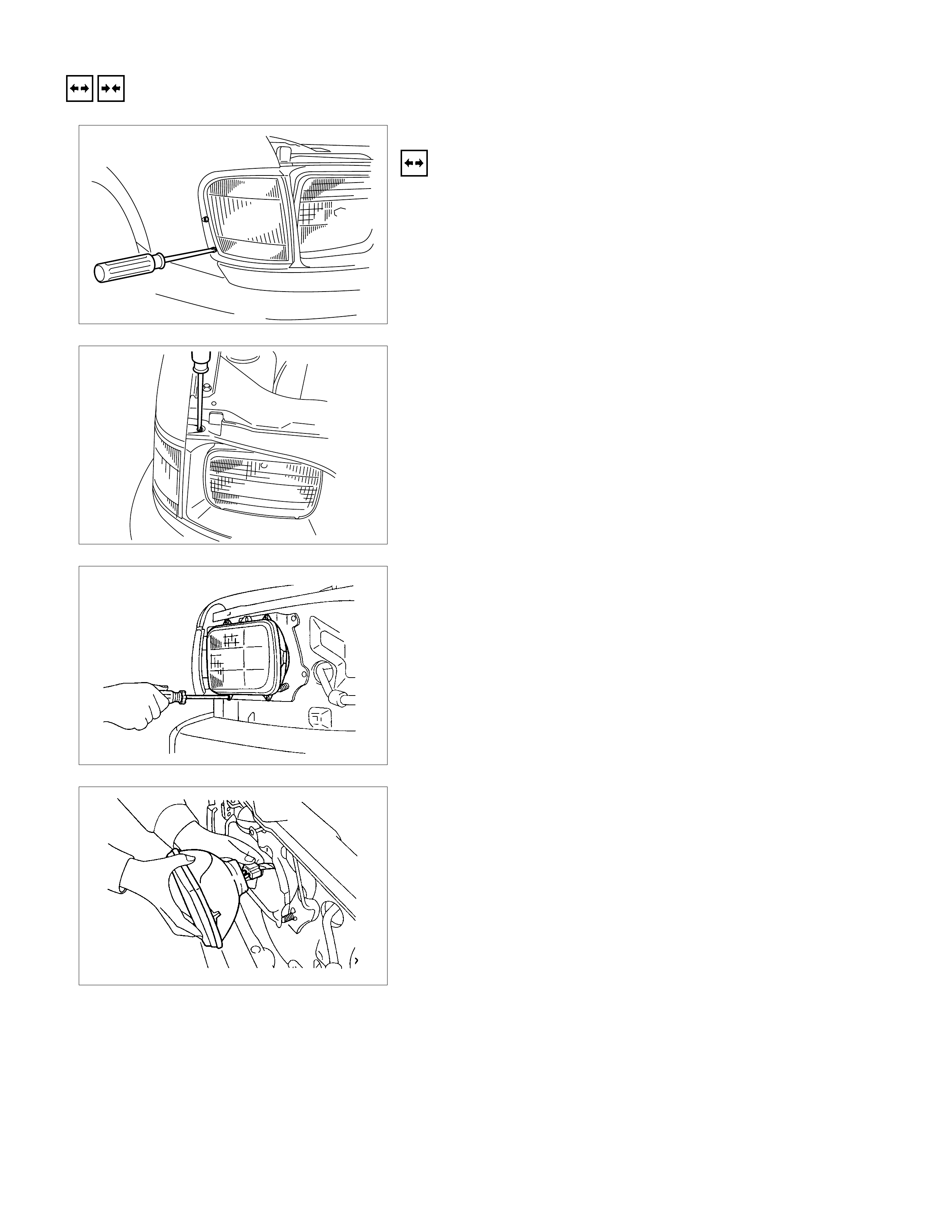
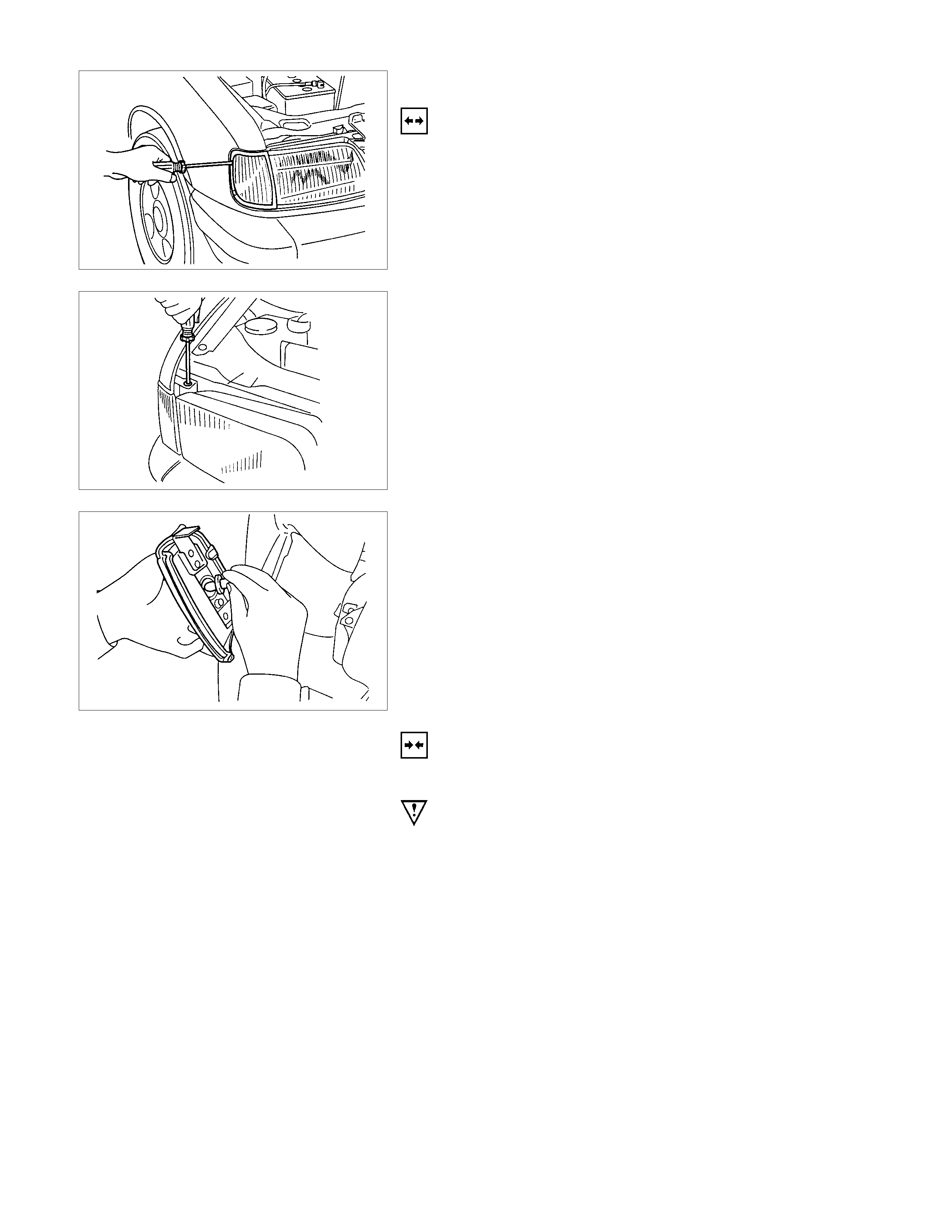
REMOVAL
1. Remove the radiator grille center bolt.
2. Use a screwdriver to raise the clip and release the lock.
Place a clean rag beneath the scr ewdriver tip to protec t the
body painted surfaces.
3. Remove the radiator grille.
4. Remove the headlight rim.
5. Disconnect the headlight connector.
6. Remove the headlight.
INSTALLATION
Follow the removal procedure in the reverse order to install the
headlight.
Pay close attention to the important points mentioned in the
following paragraphs.
CONNECTOR
Be absolutely sure that the headlight connector is securely
connected.
This will prevent a contact and an open circuit.
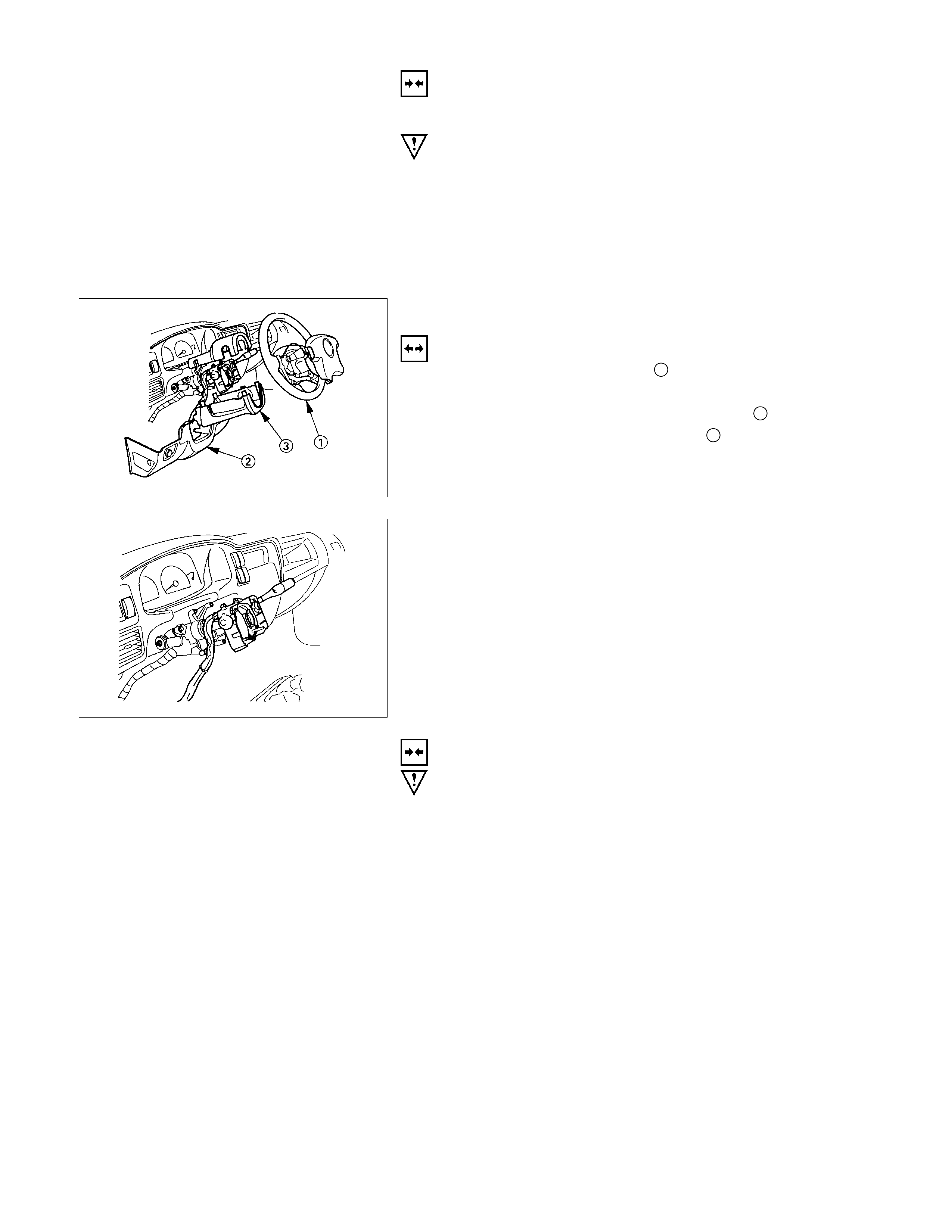
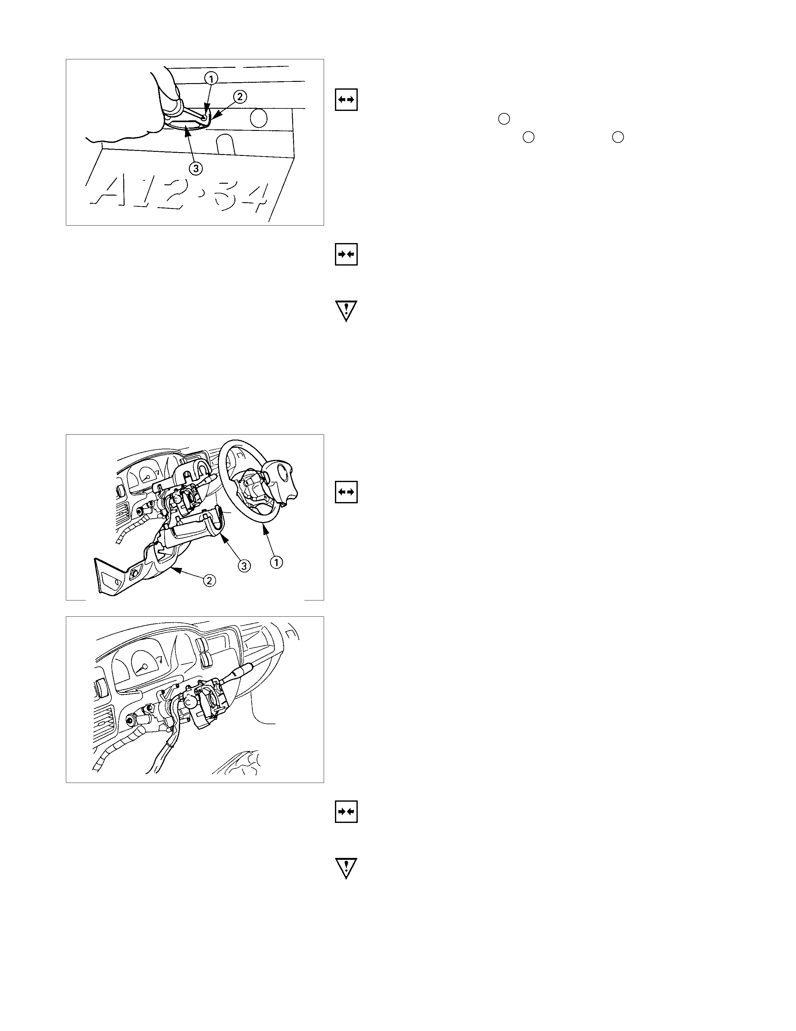
LIGHTING SWITCH
REMOVAL
1. Remove the steering wheel 1.
Refer to the “STEERING” Section of this manual.
2. Remove the Instrument panel lower cover 2.
3. Remove the steering column cover 3.
4. Disconnect the connector.
5. Remove the lighting switch from the steering shaft.
INSTALLATION
Follow the removal procedure in the reverse order to install the
lighting switch.
Pay close attention to the important points mentioned in the
following paragraphs.
Connector
Be absolutely sure that the lighting switch connector is securely
connected.
This will prevent a poor contact and an open circuit.
WIRE HARNESS
Do not pinch the wire harnesses between the cluster and the
meter hood during the cluster installation procedure.
Wire damage will result.
CLEARANCE LIGHT
REMOVAL
1. Remove the radiator grille.
(Refer to headlight removal procedure.)
2. Remove the side screws.
3. Remove the top screw.
4. Turn the socket counterclockwise to disconnect it from the
clearance light housing.
5. Pull the bulb from the socket.
INSTALLATION
Follow the removal procedure in the reverse order to install the
clearance light.
Pay close attention to the important points mentioned in the
following paragraphs.
CONNECTOR
Be absolutely sure that the clearance light connector is
securely connected.
This will prevent a poor contact and an open circuit.
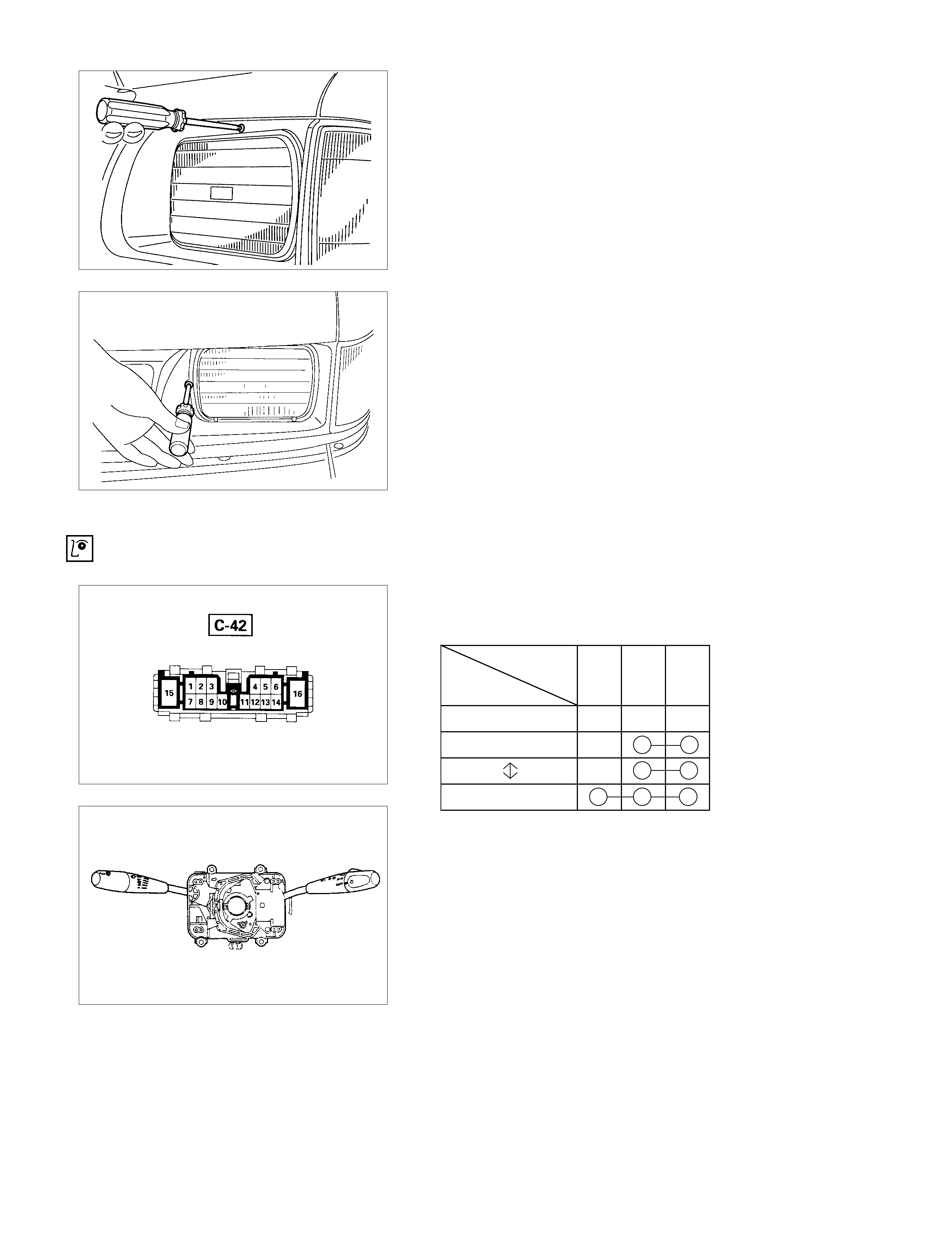
LICENSE PLATE LIGHT
REMOVAL
1. Loosen the screws 1.
2. Remove the lens cover 2 and the lens 3.
3. Pull the bulb to remove it.
INSTALLATION
Follow the removal procedure in the reverse order to install the
license plate light.
Pay close attention to the important points mentioned in the
following paragraphs.
BULB
Be absolutely sure that the license plate light bulb is correctly
installed.
This will prevent a poor contact and open circuit.
HEADLIGHT BEAM SWITCH (COMBINATION
SWITCH)
REMOVAL
1. Remove the screws on the lower part of the steering wheel.
2. Remove the horn pad.
3. Remove the wiring connector.
4. Remove the steering wheel fixing nuts.
5. Remove the steering wheel.
Refer to the "STEERING" Section of this manual.
6. Remove the Instrument panel lower cover.
7. Remove the steering column cover.
8. Disconnect the connector.
9. Remo ve the headlight beam switch ( lever) f rom the s teer ing
shaft (combination switch).
INSTALLATION
Follow the removal procedure in the reverse order to install the
headlight beam switch.
Pay close attention to the important points mentioned in the
following paragraphs.
CONNECTOR
Be absolutely sure that the headlight beam switch connector is
securely connected.
This will prevent a poor contact and an open circuit.
WIRE HARNESS
Do not pinch the wire harnesses between the cluster and the
meter hood during the cluster installation procedure.
Wire damage will result.
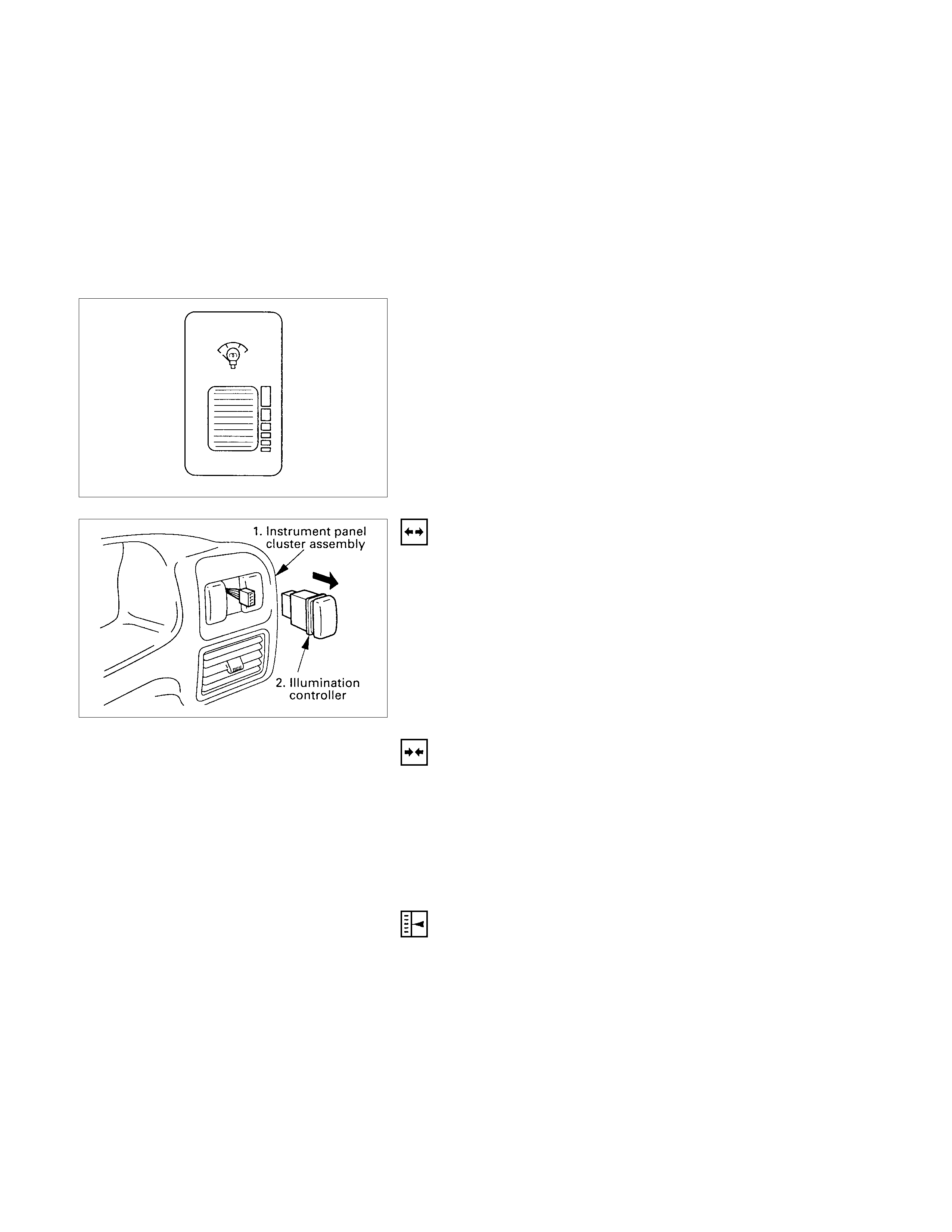
ILLUMI NATION CONTROLLER
Turning the illumination controller knob upward increases the
brightness of each illumination light, turning it downward
decreases its brightness.
REMOVAL
1. Instrument Panel Cluster Assembly
• Refer to Section 1C “BODY” for instrument panel cluste
r
assembly removal st eps.
2. Illumination Controller
•Disconnect the switch connector.
•To rem ove the switch, push the lock from the back side
of the cluster assembly.
INSTALLATION
To install, follow the removal procedure in the reverse order.
CONNECTOR
Be absolutely sure that the illumination controller connector is
securely connected.
This will prevent a poor contact and an open circuit.
AIMING OF HEADLIGHT
Check and adjust the inflation pressures, clean the headlight,
park the vehicle on a level surface and insure that vehicle is at
curb weight.
VERTICAL ADJUSTMENT
Use a screwdriver for vertical adjustment.
HORIZO NTAL ADJUSTMENT
Use a screwdriver horizontal adjustment.
INSPECTION AND REPAIR
Switch side
LIGHTING SWITCH
LIGHTING SWITCH CONNECTIONS
Terminal
SW No.
position 178
OFF
Tail
Headlight
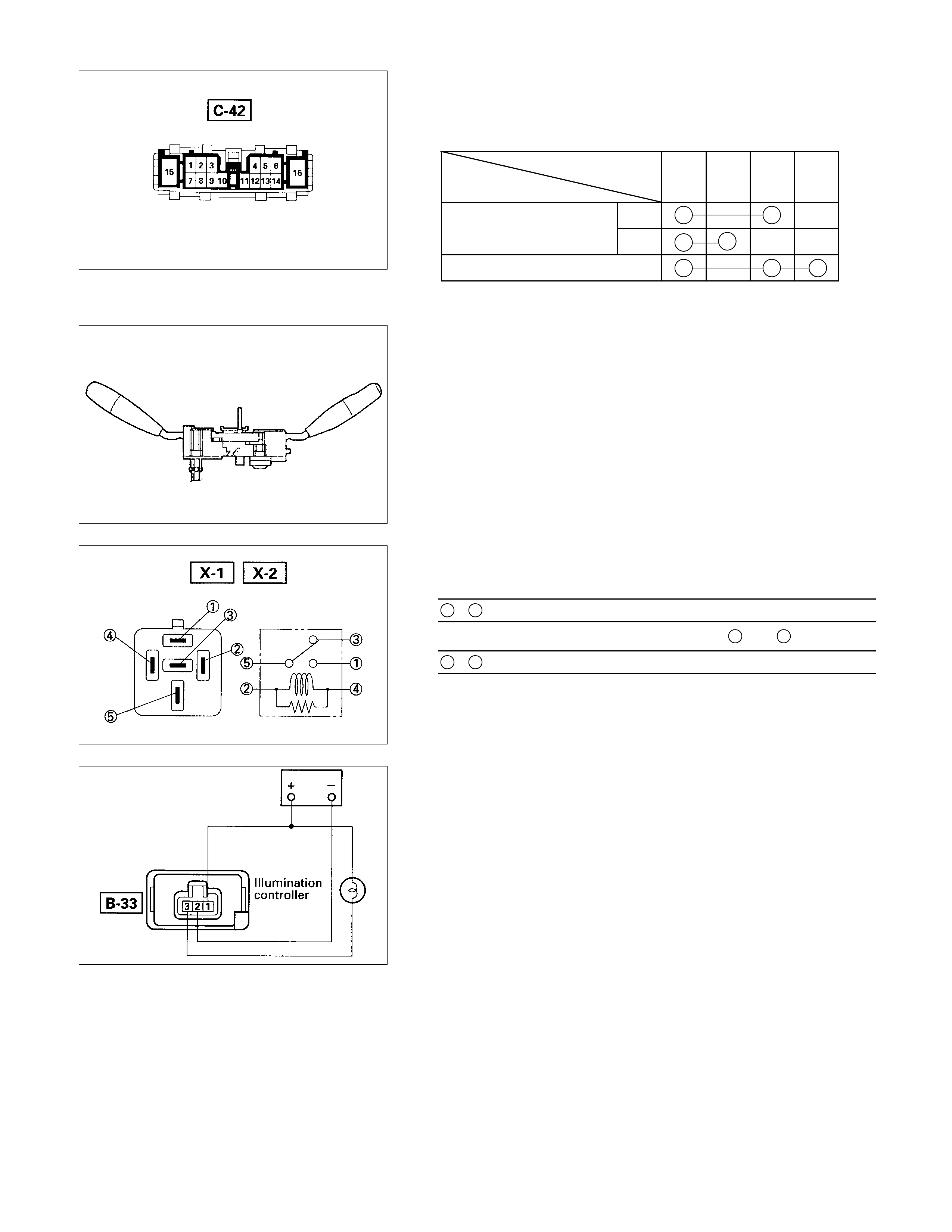
Switch side
HEADLIGHT BEAM SWITCH
HEADLIGHT BEAM AND PASSING SWI TCH
CONNECTIONS
Terminal NO.
SW position 16 13 15 14
HI
LO
At “Passing” Position
At “Dimmer” position
LIGHTING RELAY, TAIL RELAY
Check continuity between the relay terminals.
1 - 5............................No continuity
(When battery voltage is applied between 2 and 4)
1 - 5............................Continuity
ILLUMI NATION CONTROLLER
CONTROLLER INSPECTIO N
Check the illumination controller function.
Hazard Warning, Turn Signal, Back Up, Horn, Stop Light
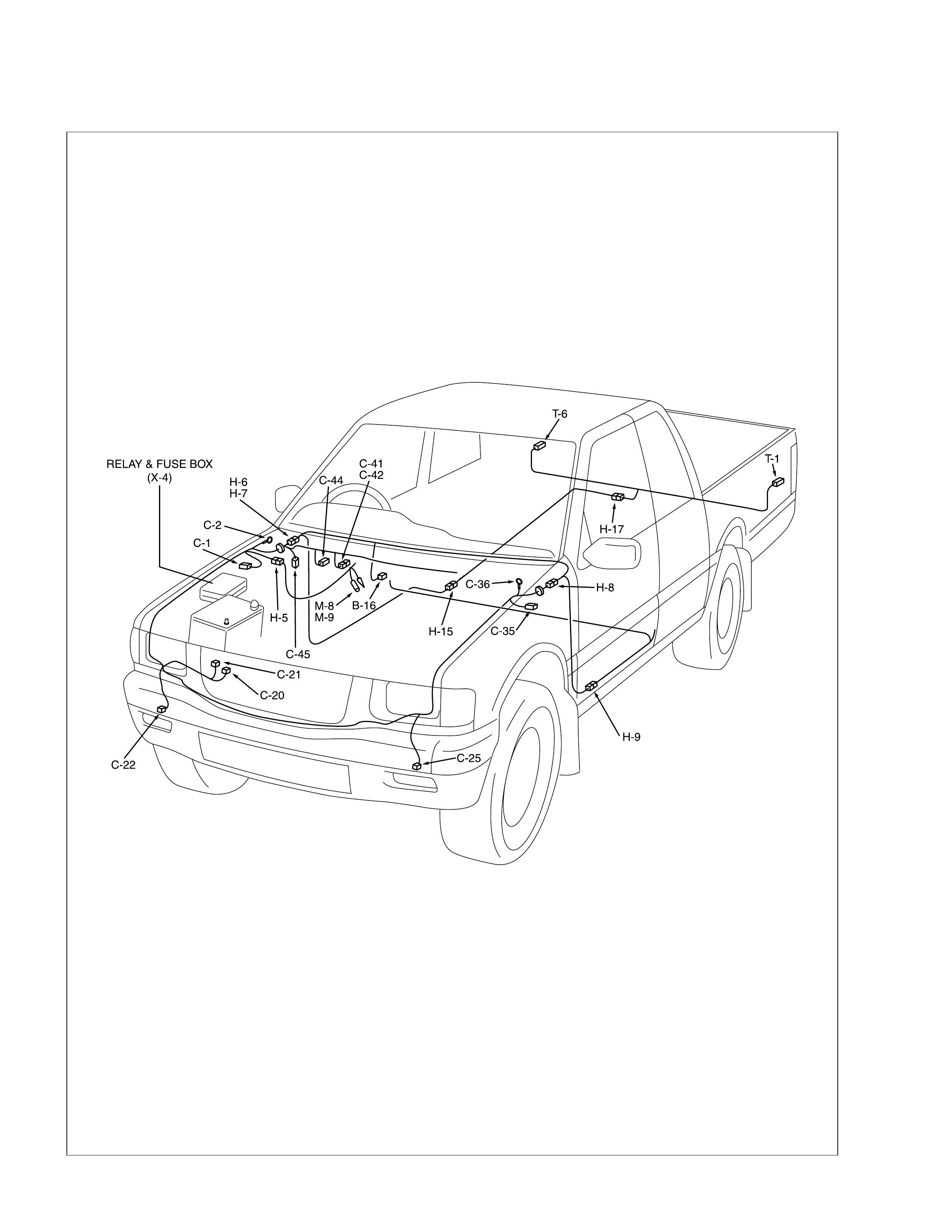
PARTS LOCATION
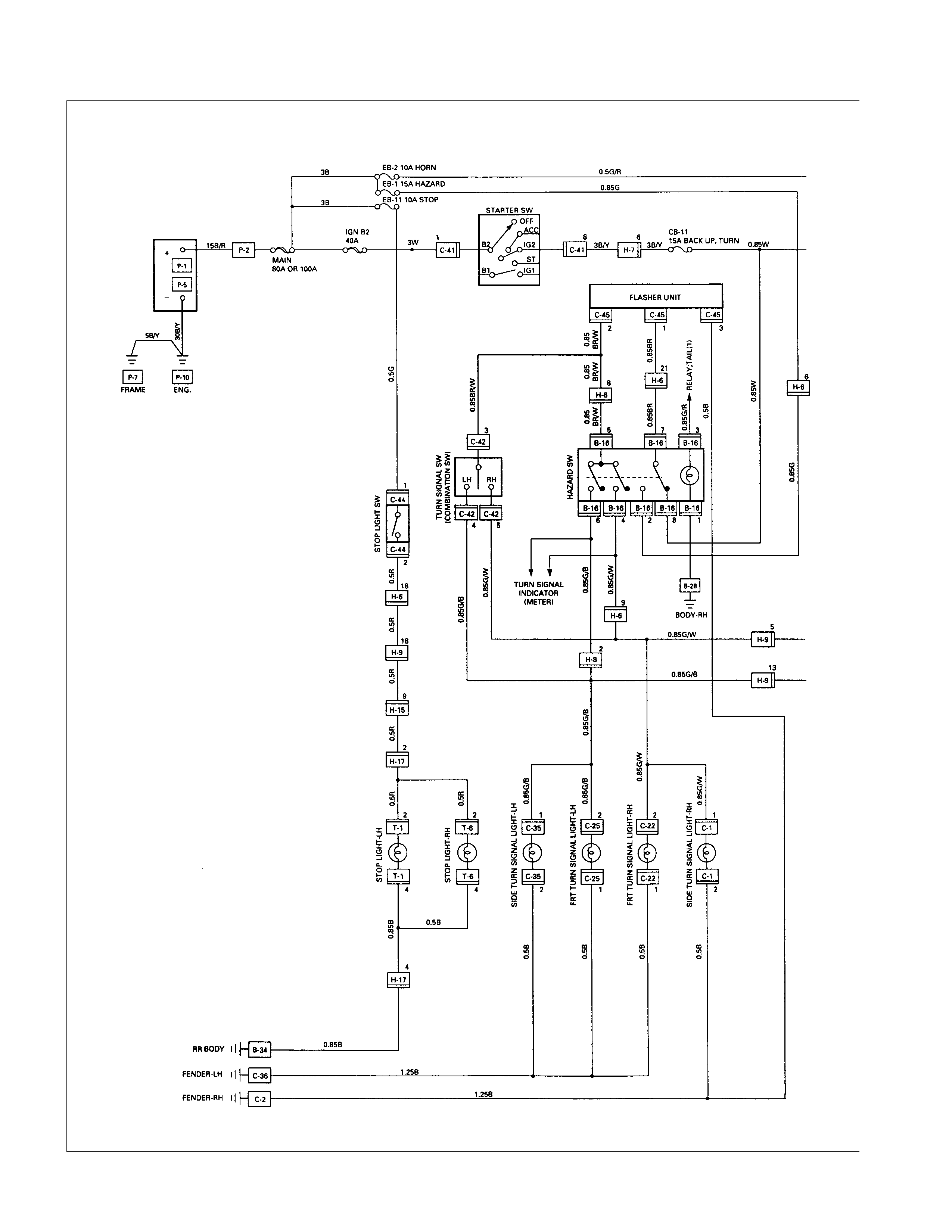
CIRCUIT DIAGRAM
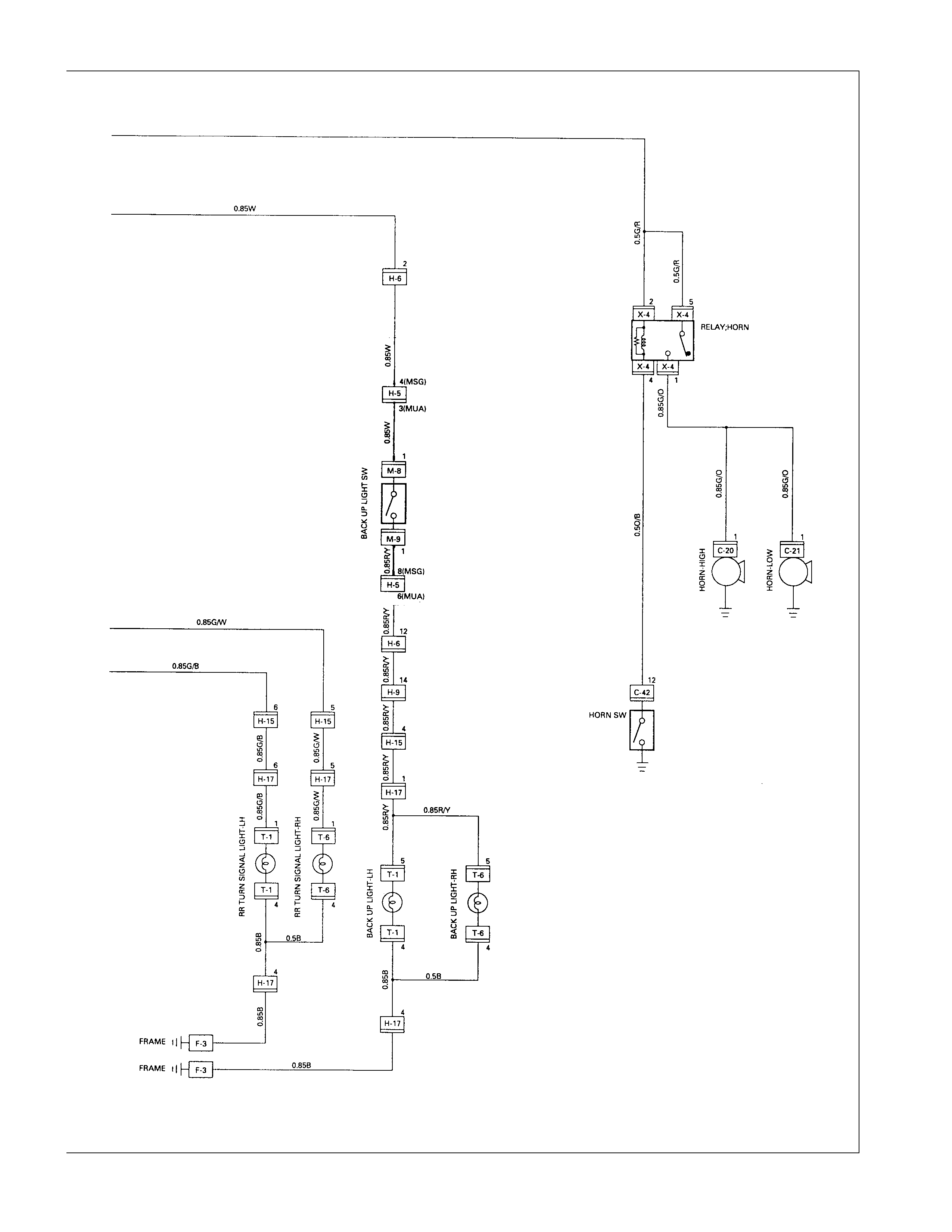
CIRCUIT DIAGRAM (6VD1W)
TROUBLESHOOTING
STOPLIGHT AND HIGH MOUNTED STOPLIGHT
1. One side of stoplight does not light
Checkpoint Trouble Cause Countermeasure
Replace the bulb or repair
connector contact
Burned out bulb or poor
connector contact
NG
Repair open circuit or
connector contact
Repair open circuit or
connector contact
Open circuit or poor connector
contact
LHD:
Continuity between
8 H-8 - 2 T-1 (LH) (or
2 T-6 (RH))
RHD:
Continuity between
18 H-6 - 2 T-1 (LH) (or
2 T-6 (RH))
Open circuit or poor connector
contact
Continuity between
B-34 - 4 T-1 (LH) (or
4 T-6 (RH))
NG
NG
OK
OK
Stoplight bulb continuity
2. Both sides of stoplight do not light
Adjust the switch instal lation
position
Stop light switch (or brake
switch) function Incorrect the switch installation
or adjustment
NG
Repair open circuit or
connector contact
Voltage between 2 T-1
ground or 2 T-6 - ground
with brake pedal depressed
(Should be battery voltage
present)
Open circuit or poor connector
contact between stoplight
switch (or brake switch) and
stoplight
NG
OK
Reinstall or replace fuse No.
EB-11 (10A)
Fuse No. EB-11 (10A, Fuse
and Relay box) Poor fuse contact or blown
NG
OK
3. High mounted stoplight does not light
Checkpoint Trouble Cause Countermeasure
Repair or replace the high
mounted stoplight
Continuity between 1 L-5 -
1 L-6 High mounted stoplight
malfunction
NG
Repair an open circuit or
connector contact between
1 L-5 - 8 H-8
Voltage between 1 L-5 -
ground with brake pedal
depressed
(Should be battery voltage
present)
Open circuit or poor connector
contact
NG
OK
Repair grounding point
(B-28 ) contact
Grounding point ( B-28 )Poor grounding point contact
NG
OK
TURN SIGNAL LIG HT AND HAZARD WARNING LIG HT
1. Turn signal light does not light on both sides (RH and LH)
Checkpoint Trouble Cause Countermeasure
Replace the flasher unitFlasher unit malfunction
NG
Repair or replace the
combination switch
Turn signal switch continuity
between connector
3 C-42 - 4 C-42 and
3 C-42 - 5 C-42 when
turn signal switch operates
Short circuit between
connector 1 C-45 - 2 C-45
when turn signal switch
operates with starter switch
in “ON” position (Turn
signal light should be ON)
Poor switch point contact or
faulty switch
NG
OK
Reinstall or replace fuse No.
CB-11 (15A)
Fuse No. CB-11 (15A, Fuse
box) Poor fuse contact or blown
fuse
NG
OK
OK
Repair open circuit or
connector contact
Continuity between
connector 3 C-45 -ground
(Should be continuity)
Open circuit or poor connector
contact
NG
2. Turn signal light does not light on one side (RH or LH)
Checkpoint Trouble Cause Countermeasure
Repair open circuit or
connector contact
Open circuit or poor connector
contact
NG
(LH)
Continuity between
2 C-25 - 4 C-42 (FRT),
1 C-1 - 4 C-42 (SIDE)
1 T-6 - 4 C-42 (RR)
(RH)
Continuity between
2 C-22 - 5 C-42 (FRT),
1 C-1 - 5 C-42 (SIDE)
1 T-6 - 5 C-42 (RR)
Repair or replace the
combination switch
Turn signal switch continuity Poor switch point contact or
faulty switch
NG
OK
OK
Repair open circuit or
connector contact
Open circuit or poor connector
contact
NG
3. Hazard warning light does not light
Repair or replace the hazard
SW.
Hazard SW. malfunction
NG
Voltage between 2 B-16 -
ground (Should be battery
voltage present)
Hazard SW. continuity
Reinstall or replace the fuse
No. EB-1 (15A)
Fuse No. EB-1 (15A, Relay
and fuse box) Poor fuse contact or blown
fuse
NG
OK
OK
Repair open circuit or
connector contact
Open circuit or poor
connector contact between
fuse No. EB-1 (15A) -
2 B-16
NG
4. Flashing rate too fast (One side)
Replace the bulb or repair
open circuit
Inspect bulb Burned out bulb
NG
BACKUP LIGHT
1. Backup light does not light on one side (RH or LH)
Checkpoint Trouble Cause Countermeasure
Repair grounding point contactPoor ground contact
NG
Grounding point
Replace the bulb or repair
connector contact
Backup light bulb continuity Burned out bulb or poor
connector contact
NG
OK
2. Backup light does not light on both sides
Repair or replace the switch
Poor switch point contact of
faulty switch
NG
Voltage between 5 T-1
(5 T-6 ) - ground with
starter switch ON and shift
lever into reverse position
(Should be battery voltage
present)
Back up light switch (mode
switch) continuity
Reinstall or replace fuse No.
CB-11 (15A)
Fuse No. CB-11 (15A, Fuse
box) Poor fuse contact or blown
fuse
NG
OK
OK
Repair open circuit or
connector contact
Open circuit or poor connector
contact
NG
HORN
1. Both sides of horn do not sound
Checkpoint Trouble Cause Countermeasure
Repair the grounding pointPoor ground contact
NG
Horn relay
Grounding point
Reinstall or replace fuse No.
EB-2 (10A)
Fuse No EB-2 (10A, Relay
and fuse box) Poor fuse contact or blown
fuse
NG
OK
OK
Reinstall or replace the horn
relay
Poor relay contact or faulty
horn relay
NG
Voltage between connector
2 X-4 - ground or 5 X-4
- ground (Should be battery
voltage present)
OK
Repair open circuit or
reconnect the connector
Open circuit or poor connector
contact between fuse No. EB-
2 (10A) and horn relay
NG
Remove steering pad and
steering wheel
OK
Horn switch continuity
OK
Repair or replace the horn
switch
Poor switch point contact or
faulty switch
NG
Continuity between
4 X-4 - 12 C-42
1 X-4 - 1 C-20 (1 C-21 )
OK
Repair open circuit or
connector contact
Open circuit or poor connector
contact
NG
2. One side of horn does not blow
Checkpoint Trouble Cause Countermeasure
Repair open circuit or
reconnect the connector
Open circuit or poor connector
contact
NG
Voltage between 1 C-20
(1 C-21 ) - ground with
horn switch depressed
(Should be battery voltage
present)
Replace the horn assembly
Horn continuity between
connectors Faulty horn assembly
NG
OK
3. Insufficient horn volume
Clfean and/or remove the
foreign material
Stain foreign material in the
horn
NG
Horn
Recharge or replace the
battery
Battery condition Discharged battery
NG
OK
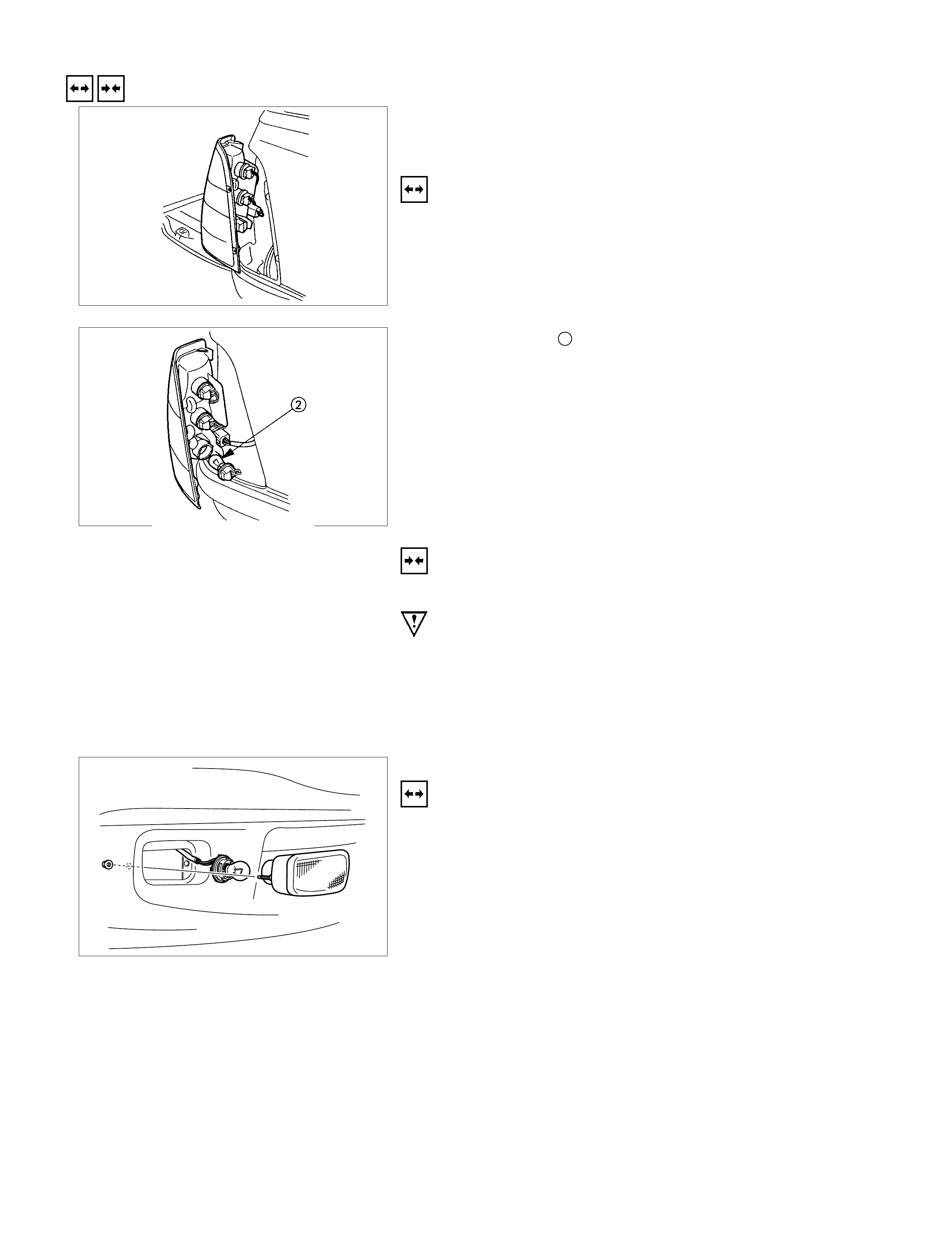
REMOVAL AND INSTALLATION
REAR COMBINATION LIGHT
STOPLIGHT
REMOVAL
1. Open the rear gate.
2. Remove the screws of rear combination light.
3. Remove the rear combination light assembly.
4. Turn the bulb 2 counterclockwise to remove it.
INSTALLATION
Follow the removal procedure in the reverse order to install the
rear combination light.
Pay close attention to the important points mentioned in the
following paragraphs.
BULB
Be absolutely sure that each bulb is correctly installed.
This will prevent a poor contact and an open circuit.
FRONT TURN LIGHT
REMOVAL
1. Remove the screws of the front turn light.
2. Pull out the light housing for front turn light from bumper.
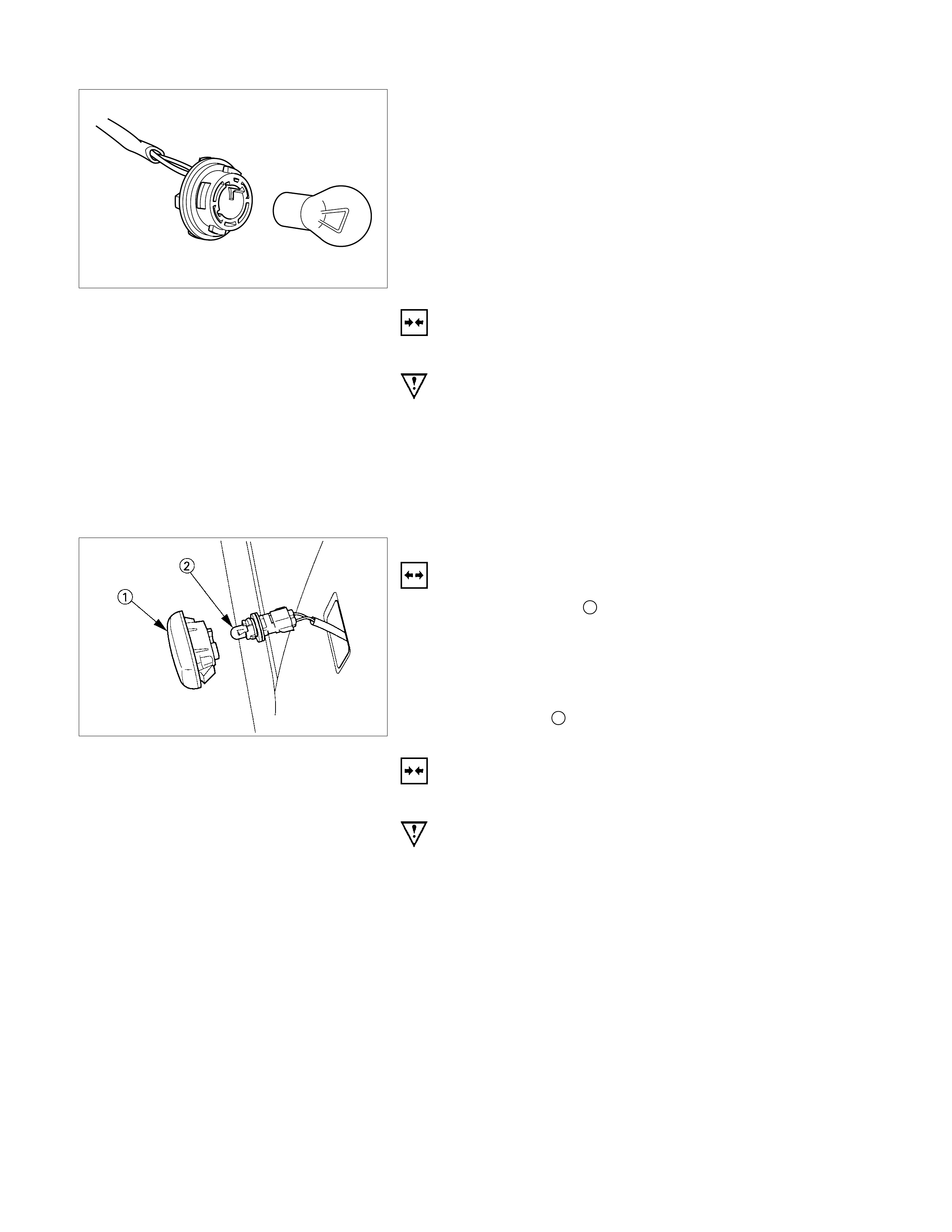
3. Push the bulb in and turn it counterclockwise to remove it
from the light housing.
INSTALLATION
Follow the removal procedure in the reverse order to install the
front turn light.
Pay close attention to the important points mentioned in the
following paragraphs.
BULB
Be absolutely sure that the front turn light bulb is correctly
installed.
This will prevent a poor contact and an open circuit.
SIDE TURN LIGHT
REMOVAL
1. Remove the lens 1.
•Pull the light/bulb toward you while pushing the light
housing in the rear direction of the vehicle to release its
lock.
•Remove the socket by turning it counterclockwise.
2. Pull the bulb 2 to remove it.
INSTALLATION
Follow the removal procedure in the reverse order to install the
side turn light.
Pay close attention to the important points mentioned in the
following paragraphs.
BULB
Be absolutely sure that the side turn light bulb is correctly
installed.
This will prevent a poor contact and an open circuit.
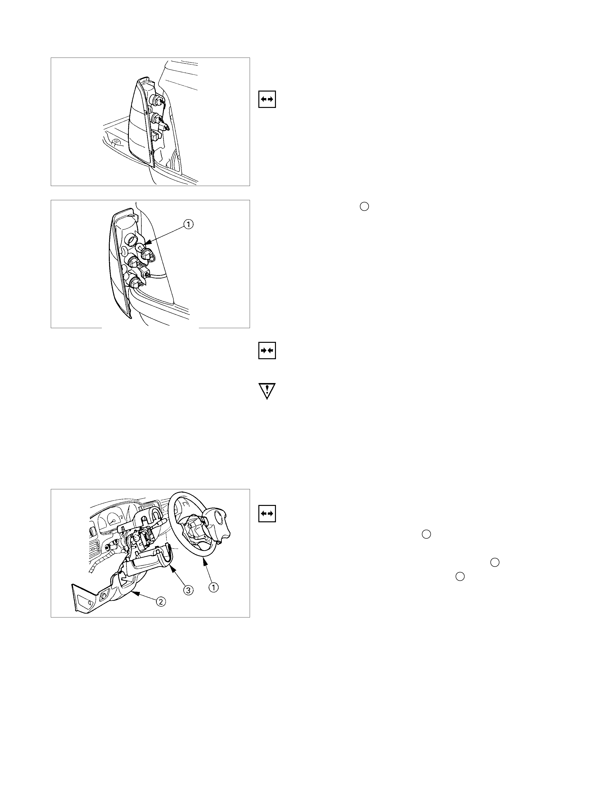
REAR COMBINATION LIGHT
TURN SIGNAL LIGHT
REMOVAL
1. Open the rear gate.
2. Remove the screws.
3. Remove the rear combination light assembly.
4. Turn the bulb 1 counterclockwise to remove it.
INSTALLATION
Follow the removal procedure in the reverse order to install the
rear combination light.
Pay close attention to the important points mentioned in the
following paragraphs.
BULB
Be absolutely sure that the rear combination light bulb is
correctly in stalled.
This will prevent a poor contact and an open circuit.
TURN SIGNAL SWITCH
REMOVAL
1. Remove the steering wheel 1.
Refer to the “STEERING” Section of this Manual.
2. Remove the instruments panel lower cover 2.
3. Remove the steering column cover 3.
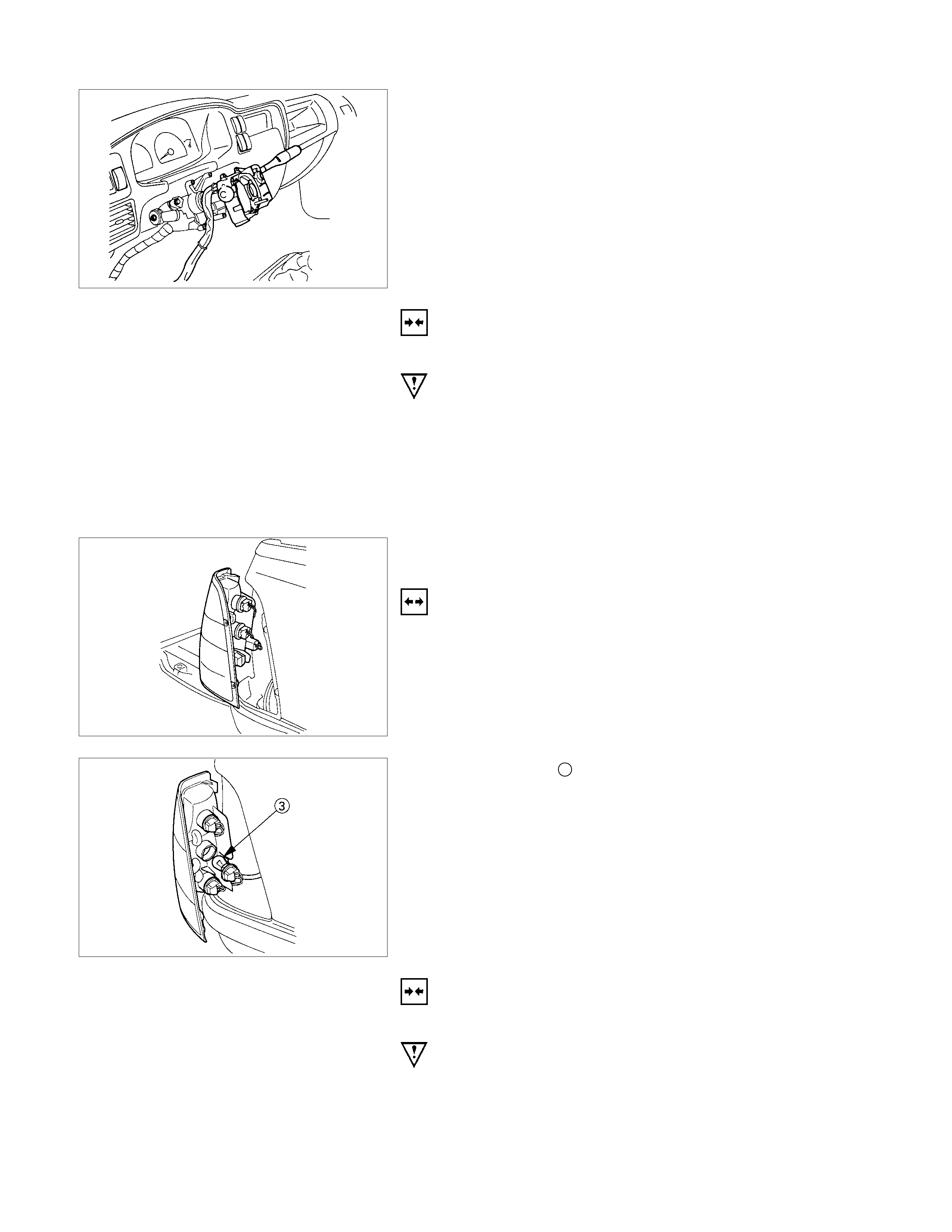
4. Disconnect the connector.
5. Remove the turn signal switch from the steering shaft.
INSTALLATION
Follow the removal procedure in the reverse order to install the
turn signal switch (lever).
Pay close attention to the important points mentioned in the
following paragraphs.
CONNECTOR
Be absolutely sure that the turn signal switch connector is
securely connected.
This will prevent a poor contact and at an open circuit.
REAR COMBINATION LIGHT
BACK UP LIGHT
REMOVAL
1. Open the rear gate.
2. Remove the screws.
3. Remove the rear combination light assembly.
4. Turn the bulb 3 counterclockwise to remove it.
INSTALLATION
Follow the removal procedure in the reverse order to install the
rear combination light.
Pay close attention to the important points mentioned in the
following paragraphs.
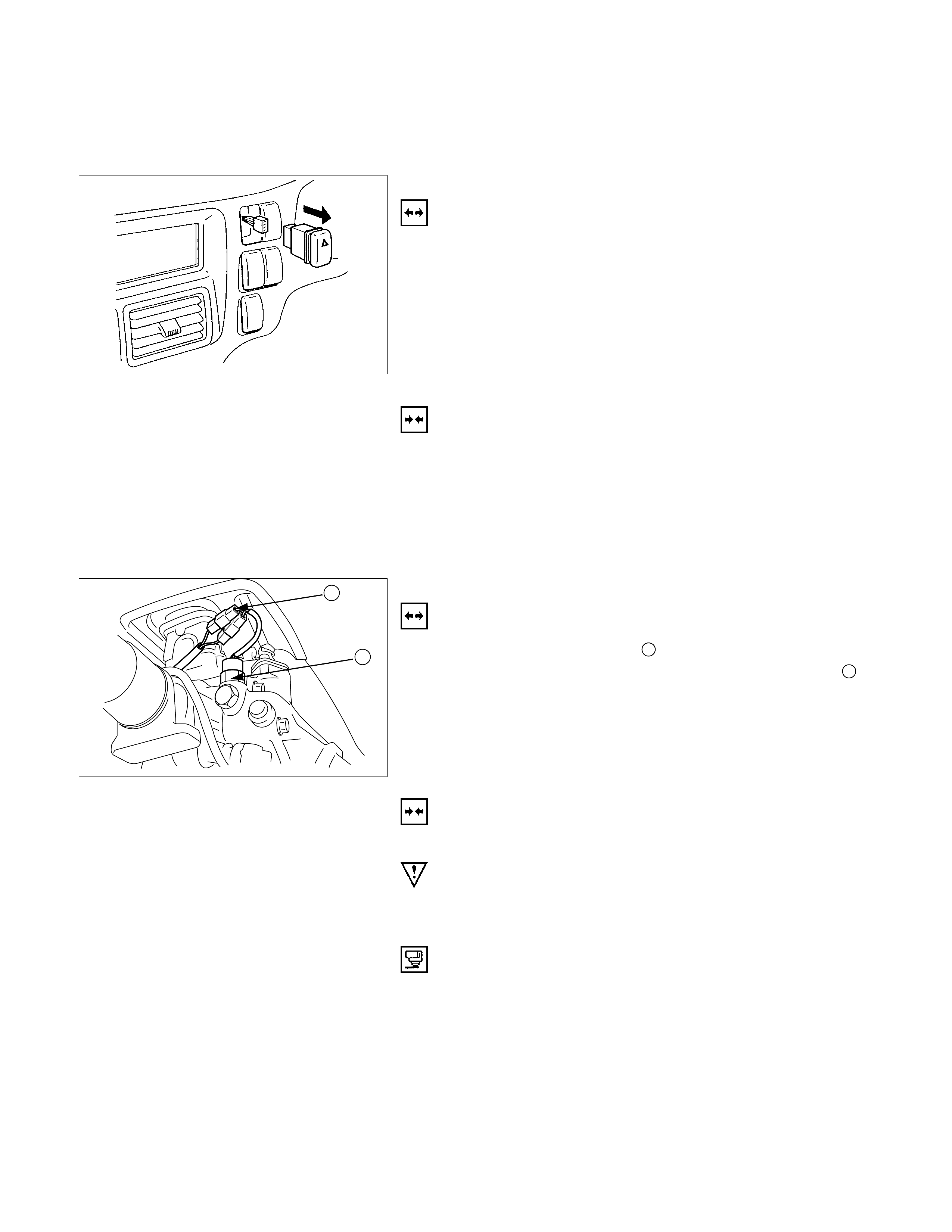
BULBS
Be absolutely sure that each bulb is correctly installed.
This will prevent a poor contact and an open circuit.
HAZARD WARNING FLASHER SWITCH
REMOVAL
1. Instrument Panel Cluster Assembly
• Refer to Section 1C “BODY” for instrument panel
cluster assembly removal st eps.
2. Hazard Warning Switch
•Disconnect the switch connector.
•To rem ove the switch, push the lock from the back side
of the cluster assembly.
INSTALLATION
To install, follow the removal procedure in the reverse order.
CONNECTOR
Be absolutely sure that the hazard warning flasher switch
connector is securely connected.
This will prevent a poor contact and an open circuit.
1
2
BACK UP LIGHT SWITCH
REMOVAL
1. Disconnect the connector 1.
2. Remove the back up light switch from the transmission 2.
INSTALLATION
Follow the removal procedure in the reverse order to install the
back up light switch.
Pay close attention to the important points mentioned in the
following paragraphs.
BACK UP LIGHT SWITCH THREADS
Apply liquid gasket to the threaded portion and install the back
up light switch.
CONNECTOR
Be absolutely sure that the back up light connector is securely
connected.
This will prevent a poor contact and an open circuit.
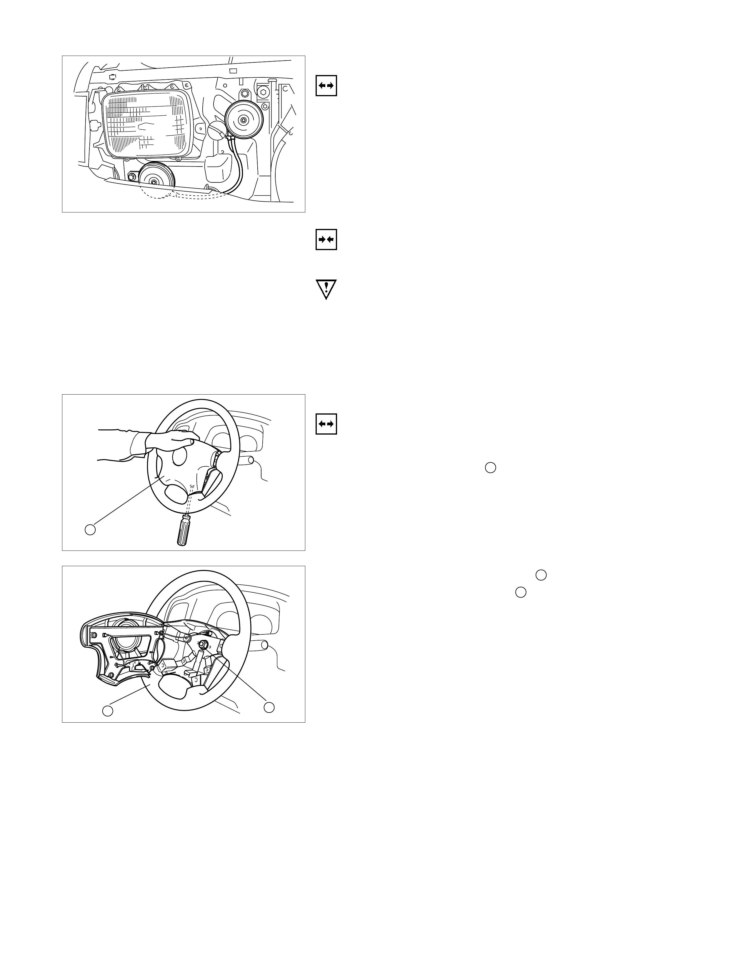
HORN
REMOVAL
1. Remove the radiator grille.
Refer to the “HEADLIGHT” removal procedure.
2. Loosen the horn bolt.
3. Disconnect the horn connector.
INSTALLATION
Follow the removal procedure in the reverse order to install the
horn.
Pay close attention to the important point mentioned in the
following paragraphs.
CONNECTOR
Be absolutely sure the horn connector is securely connected.
This will prevent a poor contact and open circuit.
1
HORN SWI TCH
REMOVAL
1. Remove the screws on the lower part of the steering wheel.
2. Remove the horn pad 1.
3. Remove the horn wiring connector.
32
4. Remove the steering wheel nut 2.
5. Remove the steering wheel 3.
6. Remove the connector.
7. Remove the horn switch (combination switch).
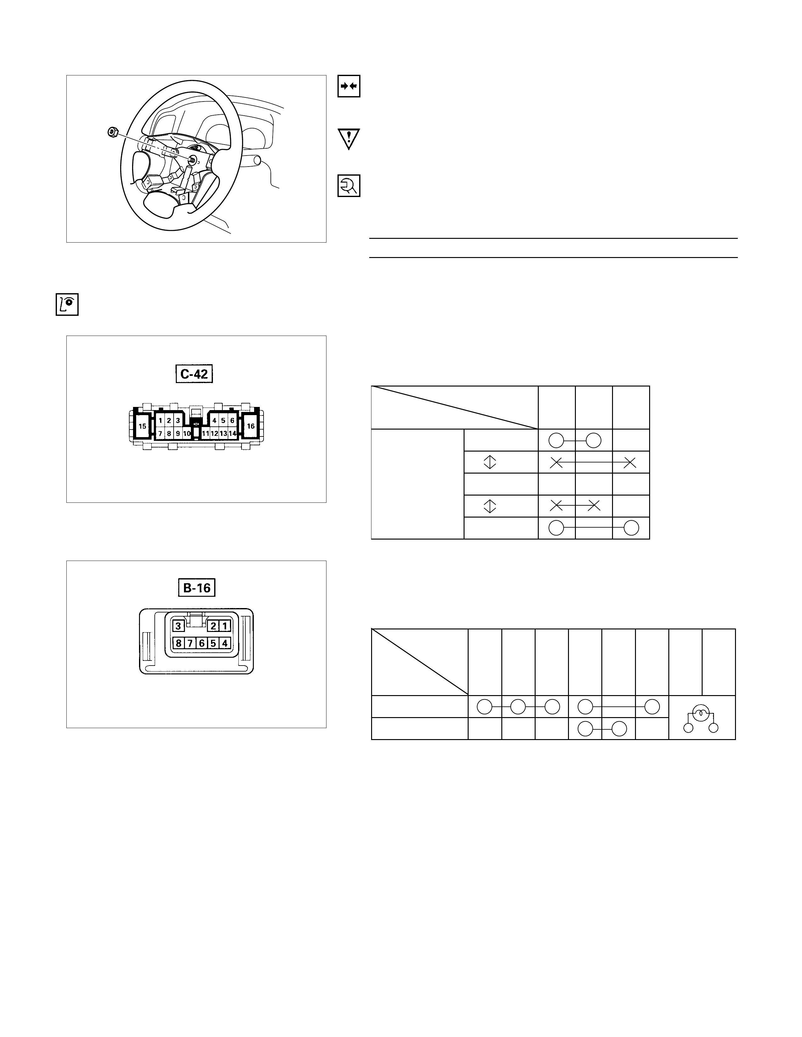
INSTALLATION
Follow the removal procedure in the reverse order to install the
horn switch.
Pay close attention to the important points mentioned in the
following paragraphs.
STEERING WHEEL NUT
Tighten the nut to the specified torque.
Steering Wheel Nut Torque N⋅m (kgf⋅m/lb⋅ft)
34.3±4.9 (3.5±0.5 / 25±3.6)
INSPECTION AND REPAIR
Switch side
TURN SIGNAL SWITCH
LIGHTING SWITCH CONNECTIONS
Terminal No.
SW position 345
Left
Neutral
Right
Turning
direction
Switch side
HAZARD WARNING FLASHER SWITCH
HAZARD WARNING FLASHER SWITCH
CONNECTIONS
Terminal
No.
SW position
45678213
ON
OFF
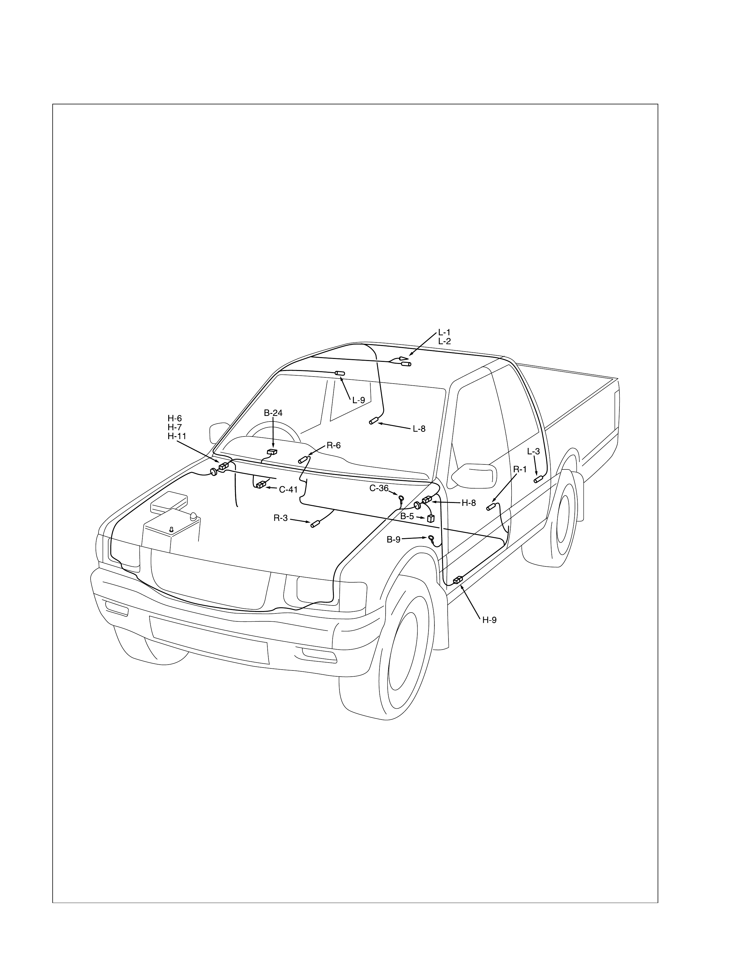
Dome Light, Spot Light and Warning Buzzer
PARTS LOCATION
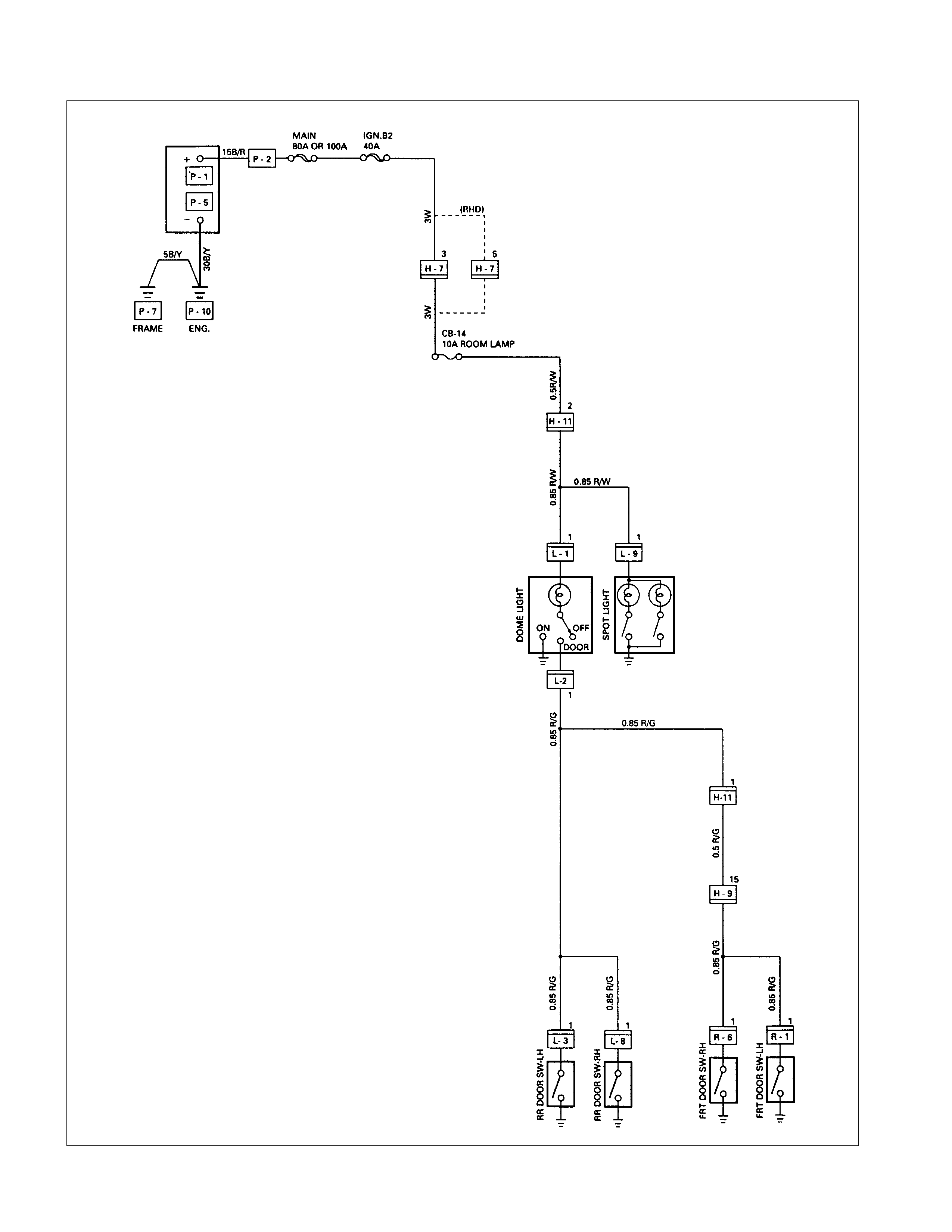
CIRCUIT DIAGRAM
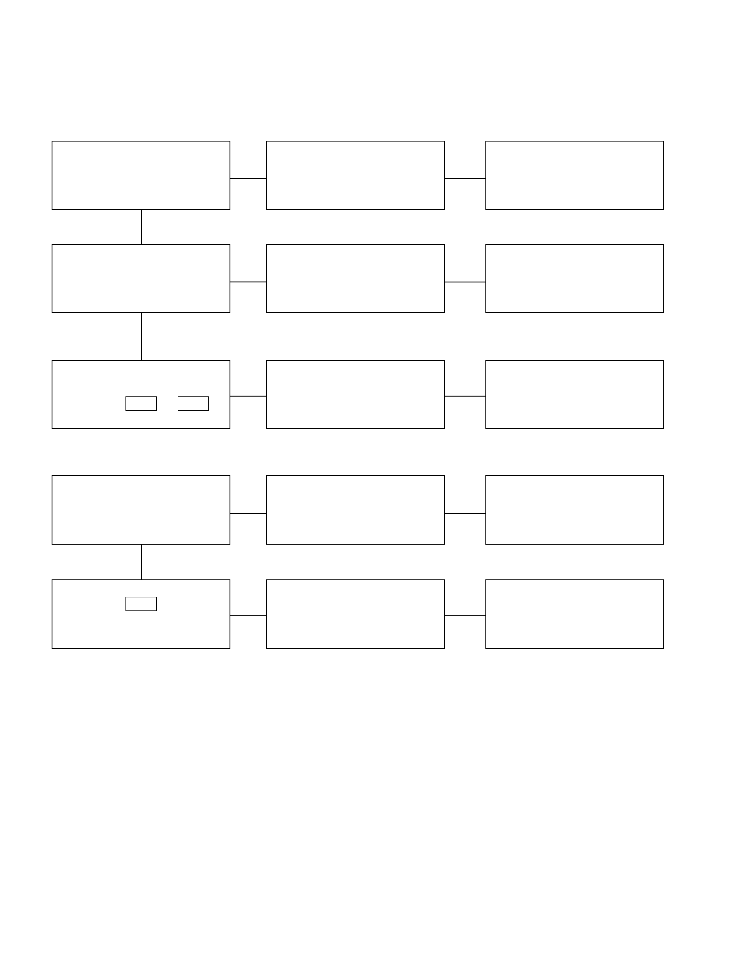
TROUBLESHOOTING
1. Dome light dose not light
Checkpoint Trouble Cause Countermeasure
Replace the dome light bulb
Burned out the bulb
NG
Repair or replace the dome
light assembly
Dome light switch function
Switch malfunction
Repair open circuit or
connector contact
Continuity between
connector 2 H-11 - 1 L-1
Open circuit or poor connector
contact
NG
NG
OK
OK
Dome light bulb continuity
2. Dome light does not go out
Repair or replace the door
switch
Switch malfunction or foreign
material switch
NG
Repair short circuit or
connector contact
Continuity between
connector 1 L-2 -ground
when shutting the door
(Should be no continuity)
Short circuit
NG
OK
Door switch function (Both
side)
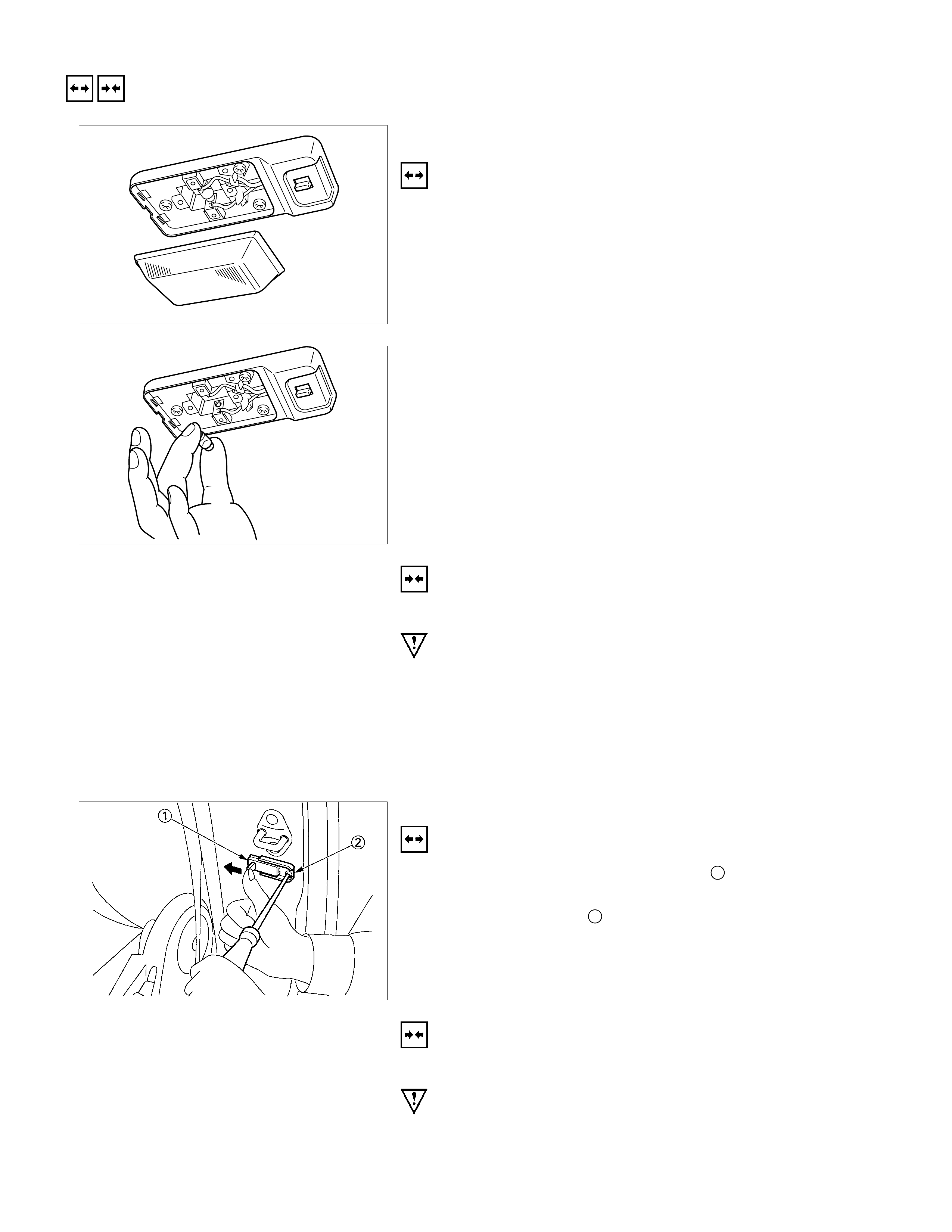
REMOVAL AND INSTALLATION
DOME LIGHT
REMOVAL
1. Remove the dome light lens free.
2. Remove three dome light fixing screws.
3. Remove the wiring connector.
4. Remove the dome light.
5. Pull the bulb to remove it.
INSTALLATION
Follow the removal procedure in the reverse order to install the
dome light.
Pay close attention to the important points mentioned in the
following paragraphs.
BULB
Be absolutely sure that the dome light bulb is correctly
installed.
This will prevent a poor contact and an open circuit.
DOOR SWITCH
REMOVAL
1. Push the door switch sliding por tion 1 in the direc tion of the
arrow in the illustration.
2. Loosen the screw 2.
3. Pull the switch free to remove it.
4. Disconnect the door switch connector.
INSTALLATION
Follow the removal procedure in the reverse order to install the
spot light.
Pay close attention to the important points mentioned in the
following paragraphs.
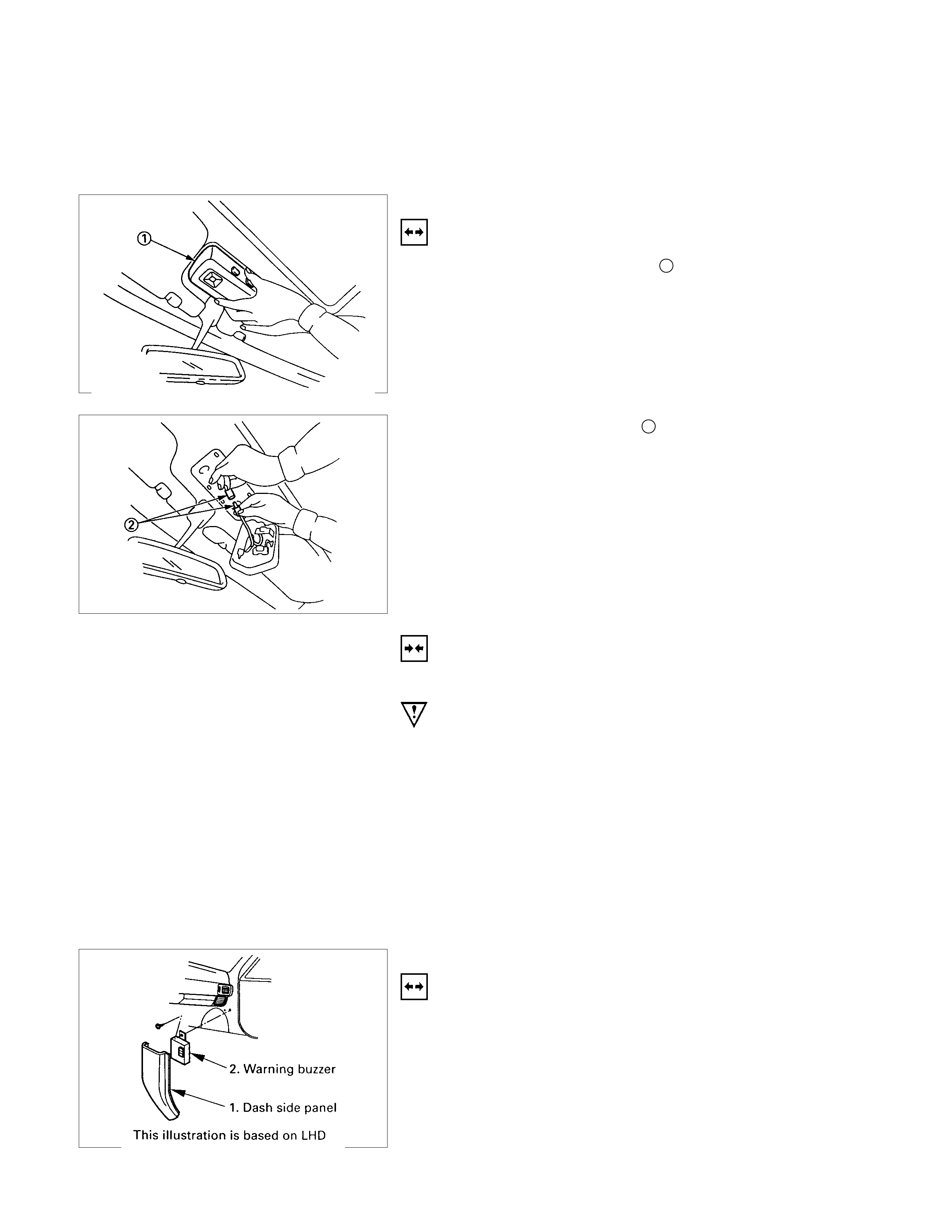
CONNECTOR
Be absolutely sure that the door switch connector is securely
connected.
This will prevent a poor contact and an open circuit.
SPOT LIGHT
REMOVAL
1. Grasp the spot light housing 1 with both hands.
Pull the housing straight down.
This will release the clip.
2. Disconnect the connector 2.
3. Push the bulb in and turn it counterclockwise to remove it.
INSTALLATION
Follow the removal procedure in the reverse order to install the
spot light.
Pay close attention to the important points mentioned in the
following paragraphs.
CONNECTOR
Be absolutely sure that the spot light connector is securely
connected.
This will prevent a poor contact and an open circuit.
BULB
Be absolutely sure that the spot light bulb is correctly installed.
This will prevent a poor contact and an open circuit.
WARNING BUZZER
REMOVAL
1. Dash Side Panel
2. Warning Buzzer
•Disconnect the connector.
•Remove the screw.
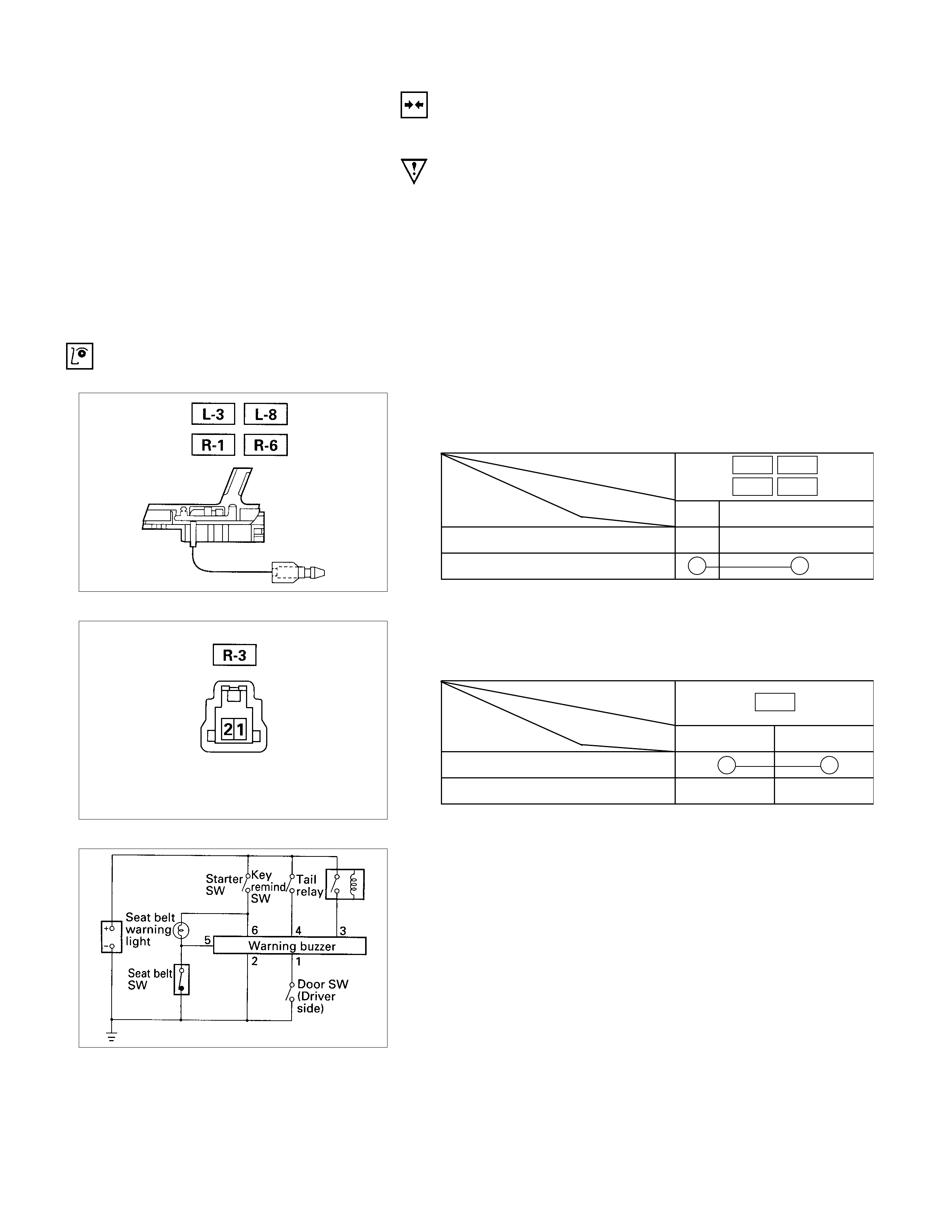
INSTALLATION
Follow the removal procedure in the reverse order to install the
warning buzzer.
Pay close attention to the important points mentioned in the
following paragraphs.
CONNECTOR
Be absolutely sure that the warning buzzer connector is
securely connected.
This will prevent a poor contact and an open circuit.
INSPECTION AND REPAIR
DOOR SWITCH
DOOR SW ITCH CONNECTIONS
Connector
SW No. L-3 L-8
R-1 R-6
position Terminal No. 1 Body Ground
PUSHED
RELEASED
Switch side
SEAT BELT SWITCH
SEAT BELT SWITCH CONNECTIONS
Connector
SW No. R-3
position Terminal No. 12
ON (Belt tongue removed)
OFF (Belt tongue inserted)
WARNING BUZZER
1. Warning Buzzer Circuit
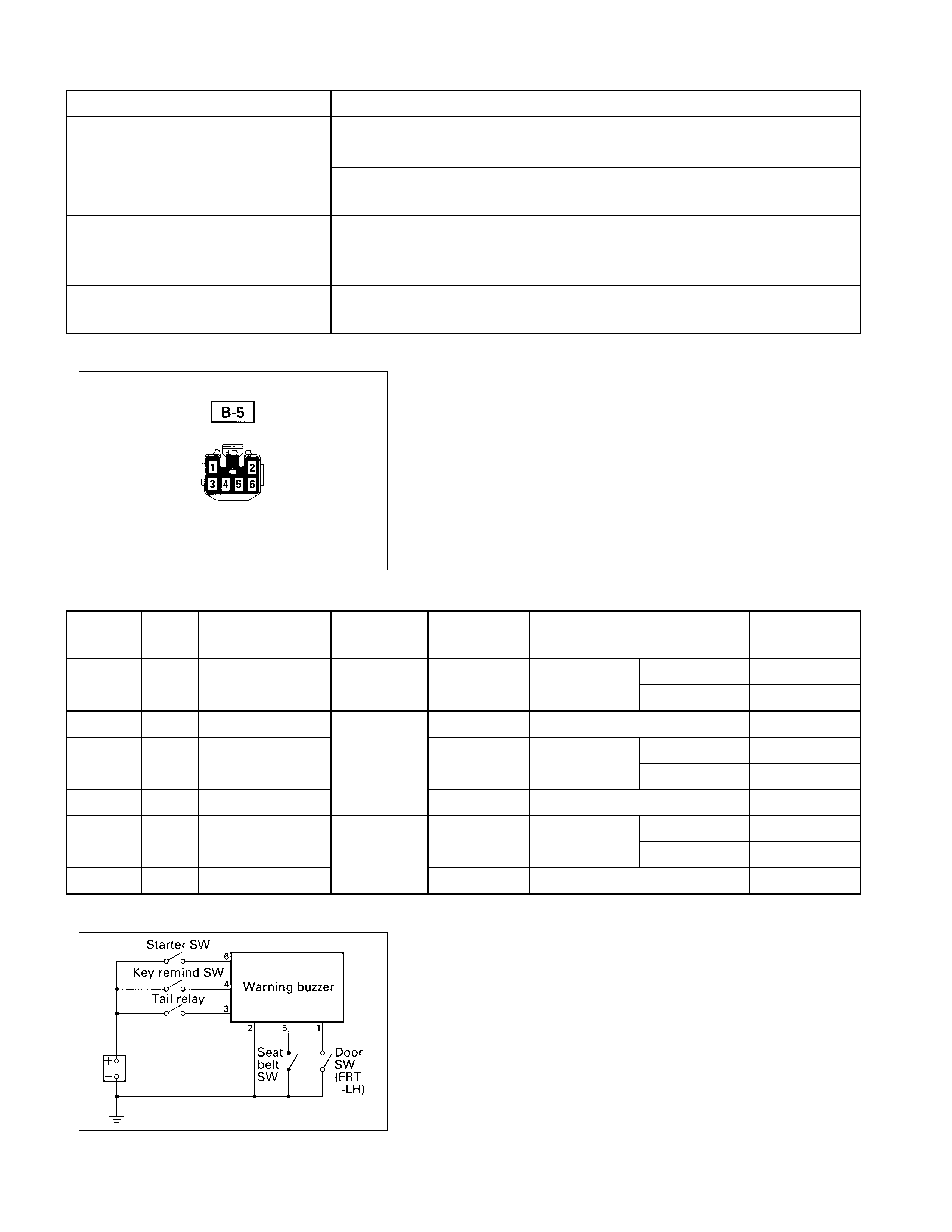
Warning function Operational conditions
The warning light meter assembly turned about 6 seconds from the
moment the starter switch is turned on.
The buzzer sounds for about 6 seconds when the starter switch is turned
on with the seat belt switch on (when the seat belt is not used).
Key left in starter switch The buzzer sounds when both the key remind switch and the FRT door
switch-LH are turned on.
To stop the sound of the buzzer, turn on the starter switch.
Tail lights left on The buzzer sounds when the starter switch is turned from the “on” to “off”
position while the taillights are on.
Harness side
2. Warning Buzzer Harness Side Connector Circuit
Disconnect the warning buzzer connector and check
continuity and voltage between the warning buzzer harness
side connector terminals.
Terminal
NO. Wire
color Connecting to Check item Connecting
terminal Check condition Standard
Seat Unfasten Continuity
belt Fasten No continuity
3 G/Y Tail relay 3-Ground Light SW “ON” Approx. 12V
Key remind SW Insert Approx. 12V
(Starter SW) Remove 0V
6 Y Fuse CB-7 6-Ground Starter SW “ON” Approx. 12V
Door SW Open Continuity
(FRT-LH) Continuity Close No continuity
2 B Ground 2-Ground - Continuity
WARNING BUZZER
1. Warning Buzzer Circuit
Fasten the seat belt
5-GroundContinuitySeat belt SWG/Y5
Key4-GroundVoltageR/B4
FRT door-LH1-GroundB/W1
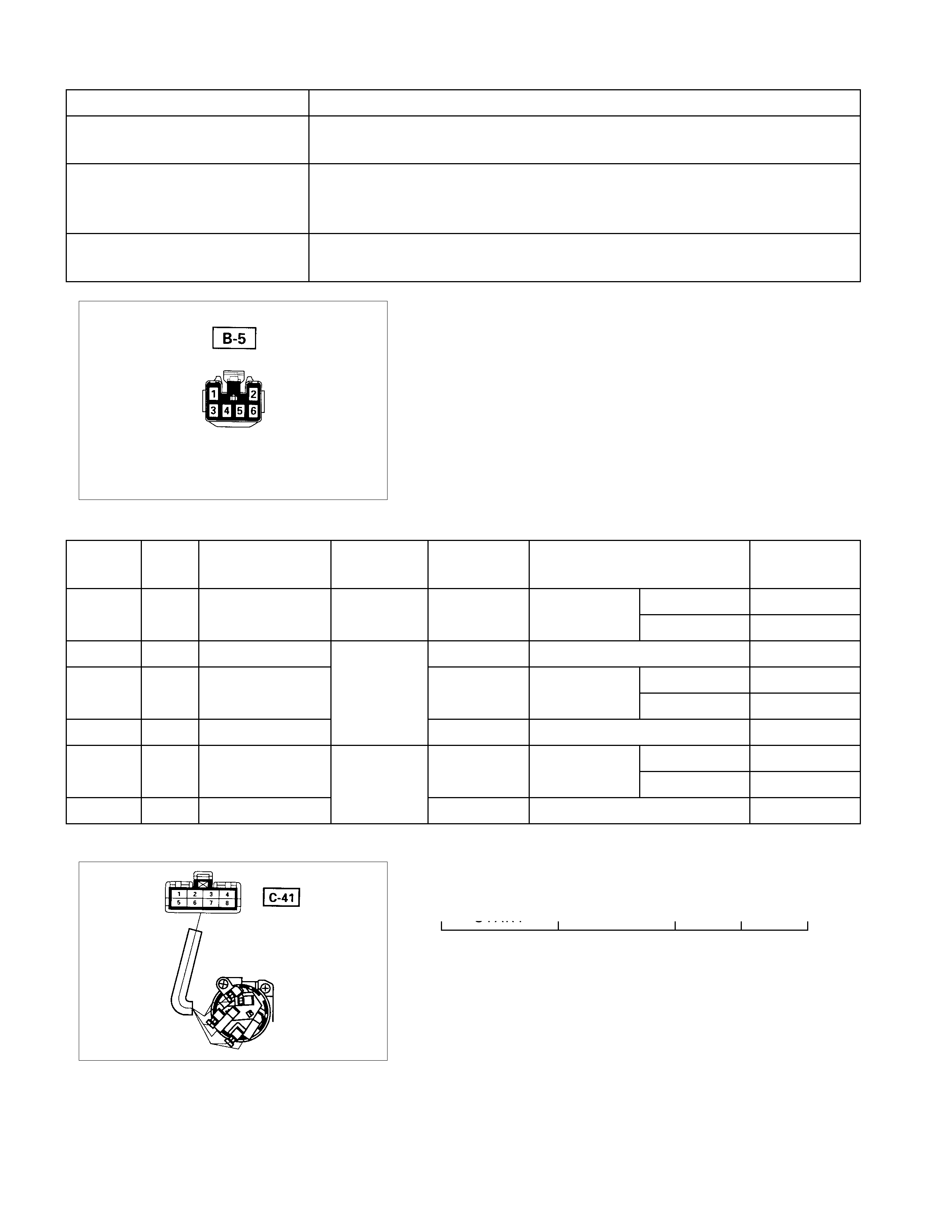
Warning function Operational conditions
Fasten the seat belt The buzzer sounds when the starter switch is turned on with the seat belt
switch on (when the seat belt is not used)
Key left in starter switch The buzzer sounds when both the key remind switch and the FRT door
switch-LH are turned on.
To stop the sound of the buzzer, turn on the starter switch.
Taillights left on The buzzer sounds when the starter switch is turned from the “on” to “off “
position while the taillights are on.
Harness side
2. Warning Buzzer Harness Side Connector Circuit
Disconnect the warning buzzer connector and check
continuity and voltage between the warning buzzer harness
side connector terminals.
Terminal
NO. Wire
color Connecting to Check item Connecting
terminal Check condition Standard
Seat Unfasten Continuity
belt Fasten No continuity
3 G/R Tail relay 3-Ground Lighting SW “ON” Approx. 12V
Key remind SW Insert Approx. 12V
(Starter SW) Remove 0V
6 Y Fuse CB-5 6-Ground Starter SW “ON” Approx. 12V
Door SW Open Continuity
(FRT-LH) Continuity Close No continuity
2 B Ground 2-Ground - Continuity
KEY REMIND SW ITCH (STARTER SWITCH)
SWITCH CONNECTIO NS
START
5-Ground
ContinuitySeat belt SWG/Y5
Key
4-Ground
4R/B Voltage
FRT door-LH1-Ground
1B/W
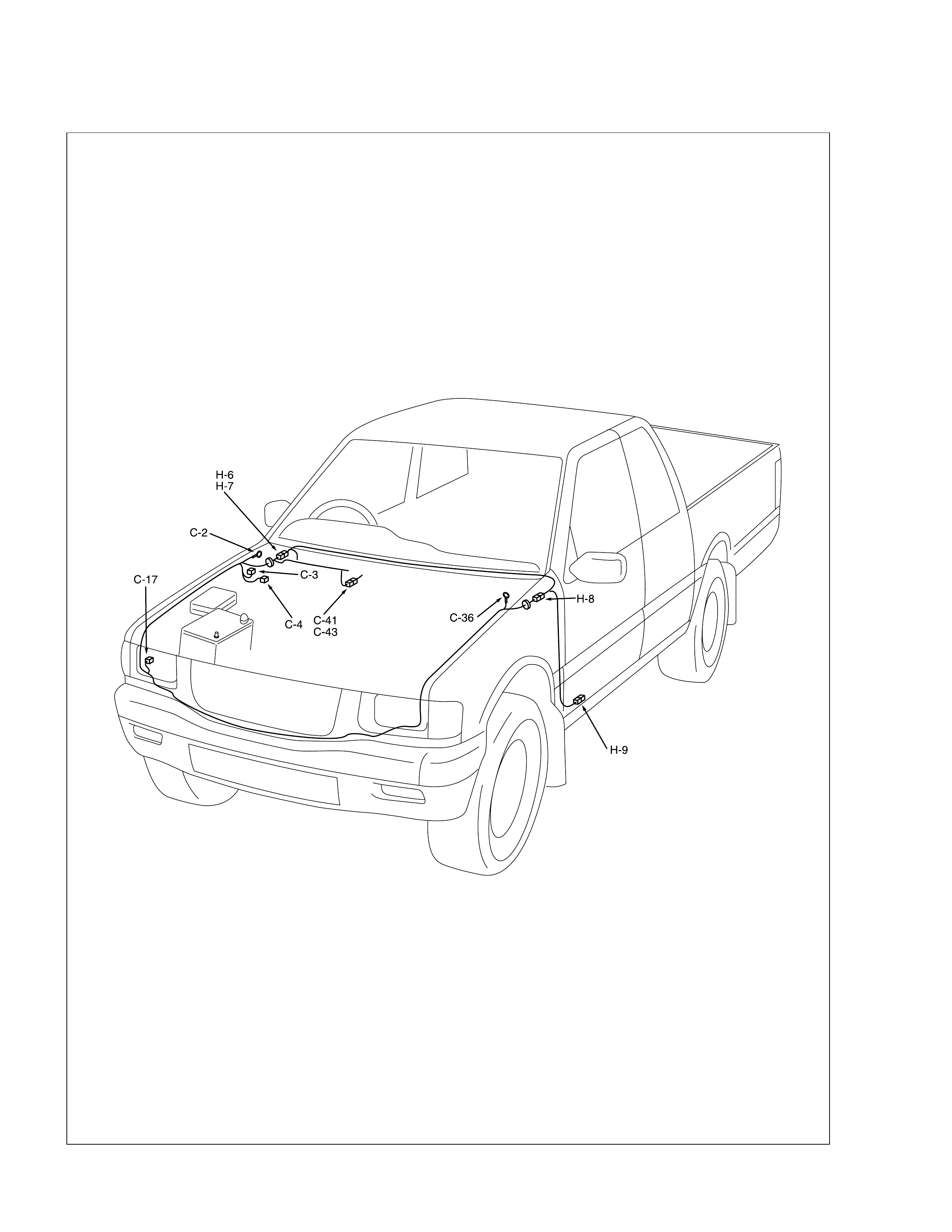
Windshield Wiper and Washer
PARTS LOCATION
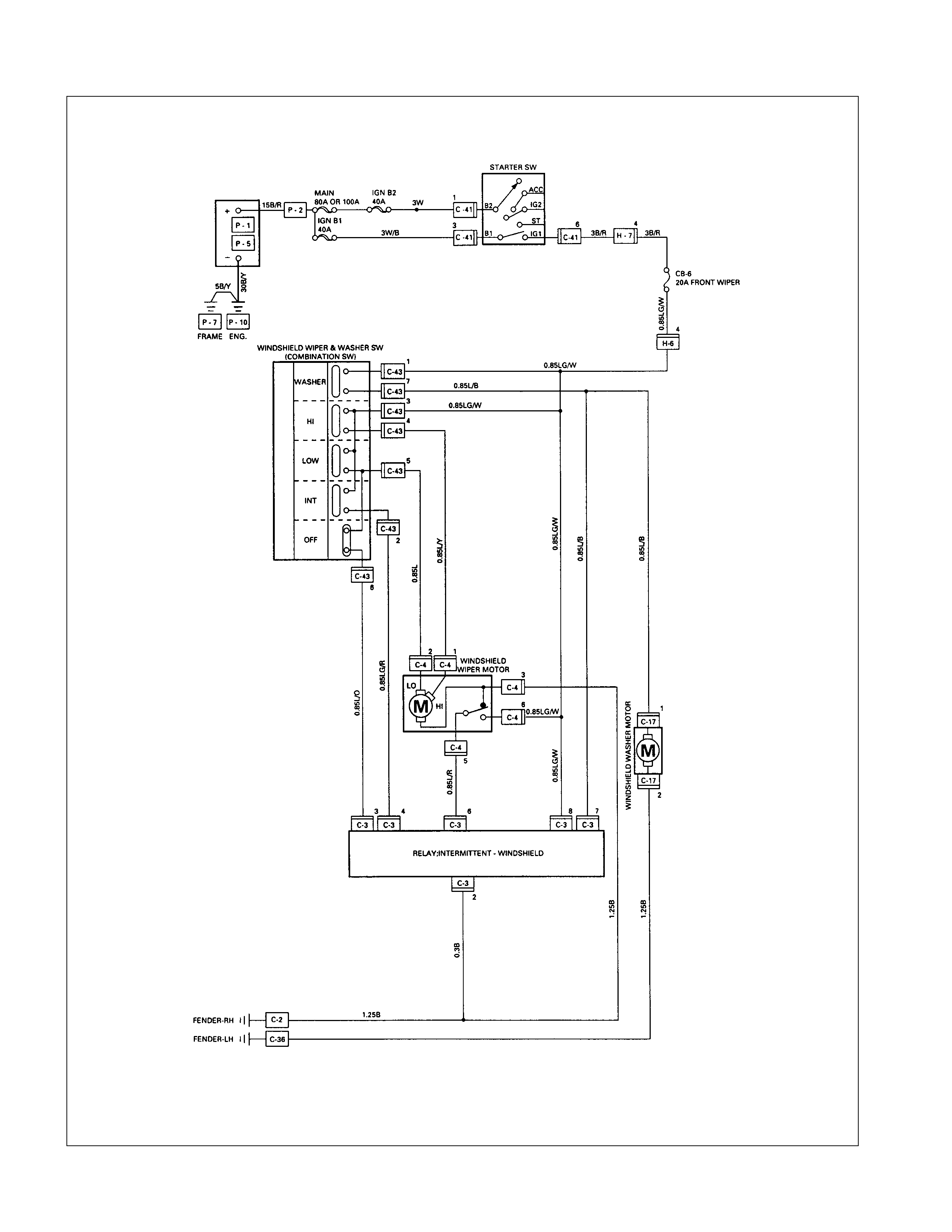
CIRCUIT DIAGRAM
TROUBLESHOOTING
WINDSHI ELD W IPER
1. Wiper dose not operate at any switch position
Checkpoint Trouble Cause Countermeasure
Reinstall or replace the fuse
No. CB-8 (20A) (RHD: CB-6
(20A) )
Poor fuse contact or blown
NG
Repair open circuit or
connector contact
1. Wiper motor function when
connecting the motor
connector 2 C-4 to the
battery (+) terminal, and 3
C-4 to the (-) terminal
(Should the wiper motor
rotate at a low speed)
2. Wiper motor function when
connecting the motor
connector 1 C-4 to the
battery (+) terminal , 3 C-4
to the (-) terminal (Should
the wiper motor rotate at a
high speed)
Voltage between 3 C-43 and
the ground (Should be battery
voltage present)
Open circuit or poor connector
contact
Replace the wiper & washer
SW.
Continuity in the wiper &
washer SW. SW. malfunction
NG
NG
OK
OK
LHD:
Fuse No. CB-8 (20A)
RHD:
Fuse No. CB-6 (20A)
Repair grounding point
(C-2 ) contact
Grounding point ( C-2 )Poor grounding point contact
NG
OK
OK
Replace the wiper motorWiper motor malfunction
NG
Repair open circuit or
connector contact
Continuity between 3 C-4
and C-2 Open circuit or poor connector
contact
NG
OK

2. Wiper dose not operate at “ INT “ position
Checkpoint Trouble Cause Countermeasure
Replace the wiper & washer
SW.
SW. malfunction
NG
Repair grounding point contact
Grounding point C-2
Poor grounding point contact
Repair open circuit or
connector contact
Voltage between the
intermittent relay harness side
connector terminal 4 C-3
and the ground at the “INT”
position (Should be battery
voltage present)
Open circuit or poor connector
contact
NG
NG
OK
OK
Continuity between the wiper
& washer SW connector
terminals 3 C-43 and 2 C-43
at the “ INT “ position
Replace the intermittent relay
Intermittent relay function
Relay malfunction
NG
OK
3. Wiper does not operate at “LO” position
Replace the wiper motor
Wiper motor function
1. Disconnect the wiper &
washer SW. connector
2. Turn the starter SW. on
3. Short-circuit between the
wiper & washer SW.
harness side connector
terminals.
3. C-43 and 5 C-43
4. Check to see if the wiper
motor rotates at a low
speed
Wiper motor malfunction
NG
Replace the wiper & Washer
SW.
Wiper & washer SW. function SW. malfunction
NG
OK
4. Wiper does not operate at “HI” position
Checkpoint Trouble Cause Countermeasure
Repair open circuit or
connector contact
Open circuit or poor connector
contact
NG
Replace the wiper motor
Wiper motor function when
connecting the motor
connector1 C-4 to the
battery (+) terminal, and 3
C-4 to the (-) terminal
(Should the wiper motor rotate
at a high speed)
Wiper motor malfunction
NG
OK
Continuity between the wiper
& washer SW. connector
terminals 3 C-43 and 4 C-43
at the “HI” position
Repair open circuit or
connector contact
Continuity between 4 C-43
and1 C-4 Open circuit or poor connector
contact
NG
OK
5. Rotation of the wiper motor does not stop
Replace the wiper & washer
SW.
SW. malfunction
NG
OK
Continuity in the wiper &
washer SW.
Replace the wiper motorWiper motor function Wiper motor malfunction
NG
6. Auto-stop function of the wiper motor does not operate
Checkpoint Trouble Cause Countermeasure
Repair open circuit or
connector contact
Open circuit or poor connector
contact
NG
Repair open circuit or
connector contact
Open circuit or poor connector
contact
NG
Continuity between the
intermittent relay harness side
connector 6 C-3 and the
wiper motor harness side
connector 5 C-4
Replace the intermittent relayRelay malfunction
NG
Intermittent relay function
Wiper motor function
1. Disconnect the wiper motor
connector
2. Connect the motor
connector 2 C-4 to the
battery (+) terminal and 3
C-4 to the (-) terminal,
and then change the
connection of the battery (+)
terminal to the connector 6
C-4 while the motor
rotating at a low speed
3. Check to see if the wiper
motor stops at the auto stop
position when connecting
the connector terminals 2
C-4 and 5 C-4 in this
condition
Continuity between the wiper
& washer SW. connector
terminals 5 C-43 and 6 C-43
at the “OFF” position
OK
Replace the wiper motorWiper motor malfunction
NG
Repair an open circuit or a
poor connection of the
connectors between the fuse
No. CB-8 (20A) (RHD: CB-6
(20A) ) and 6 C-4
Voltage between the wiper
motor harness side connector
terminal 6 C-4 and the
ground (Should be battery
voltage present)
Open circuit or poor connector
contact
NG
OK
OK
OK
WASHER
1. Washer motor does not operate
Checkpoint Trouble Cause Countermeasure
Reinstall or repla ce the fuse
No. CB-8 (20A) (RHD: CB-6
(20A) )
Poor fuse contac t or blown
NG
Repair or an open circuit or a
poor connection of the
connectors betwee n 1 C-17
and 7 C-43
Open circui t or po or connector
contact
NG
Voltag e betwe en the washer
motor harness side connec tor
terminal 1 C-17 and the
ground when the washer
button is de pressed (Should
be batte ry v oltage pres ent)
Repair groundin g point
(C-36 ) contact
Poor grounding po int contact
NG
Ground ing poin t ( C-36 )
Replace th e washer motor
Motor malfunction
NG
Washer motor function when
connecting the motor side
connector 1 C-17 to the
battery (+) terminal, and the
connector 2 C-17 to the (-)
terminal (Should the washer
motor rotate)
OK
Repair open circuit or
connector contact
Open circui t or po or connector
contact
NG
Continuity between 2 C-17
and C-36
OK
Continuity between t he wiper
& washer SW. side connector
terminals C-43 and 7 C-43
when th e washer button is
depressed
LHD:
Fuse No. CB-8 (20A)
RHD:
Fuse No. CB-6 (20A)
OK
Replace the wip er & washer
SW.
SW. m alfunction
NG
Repair or an open circuit or a
poor connection of the
connectors betwee n the fuse
No. CB-8 (20A) (RHD: CB-6
(20A) )and 1 C-43
Voltag e betwe en the wiper &
wa sher S W. harness side
connector terminal 1 C-43
and the ground (Should be
battery voltage preset)
Open circui t or po or connector
contact
NG
OK
OK
OK
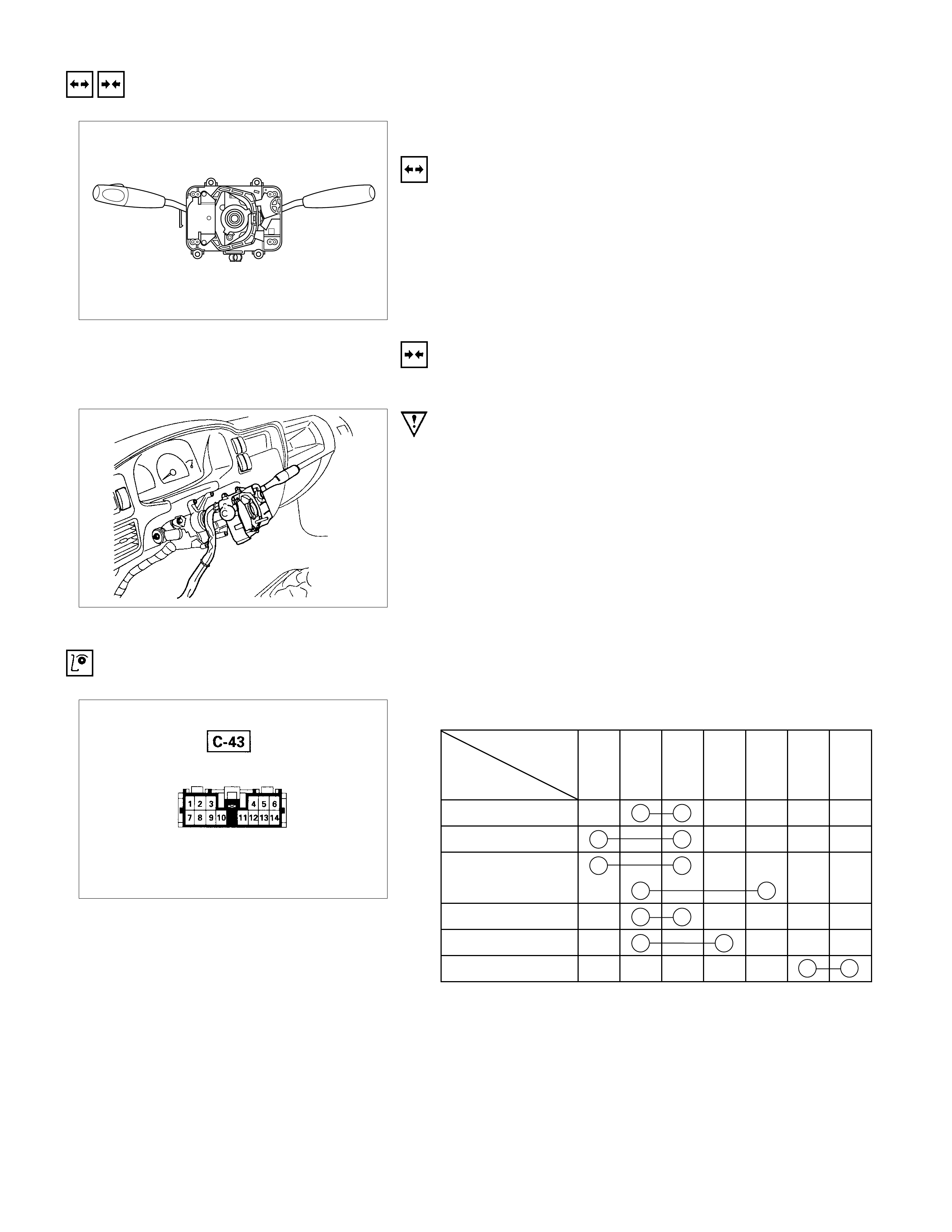
REMOVAL AND INSTALLATION
WIPER AND WASHER SWITCH
REMOVAL
Refer to the removal steps of the LIGHTING SWITCH
(COMBINATION SWITCH) in “LIGHTING“ of this section.
INSTALLATION
Follow the removal procedure in the reverse order to install the
wiper and washer switch.
Pay close attention to the important points mentioned in the
following paragraphs.
CONNECTOR
Be absolutely sure that the wiper and washer switch connector
is securely connected.
This will prevent a poor contact and an open circuit.
INSPECTION AND REPAIR
Switch side
CONTROL SWI TCH CONNECTIONS
Terminal
No.
SW position 6354217
Mist
Off
INT
Lo
Hi
Wash
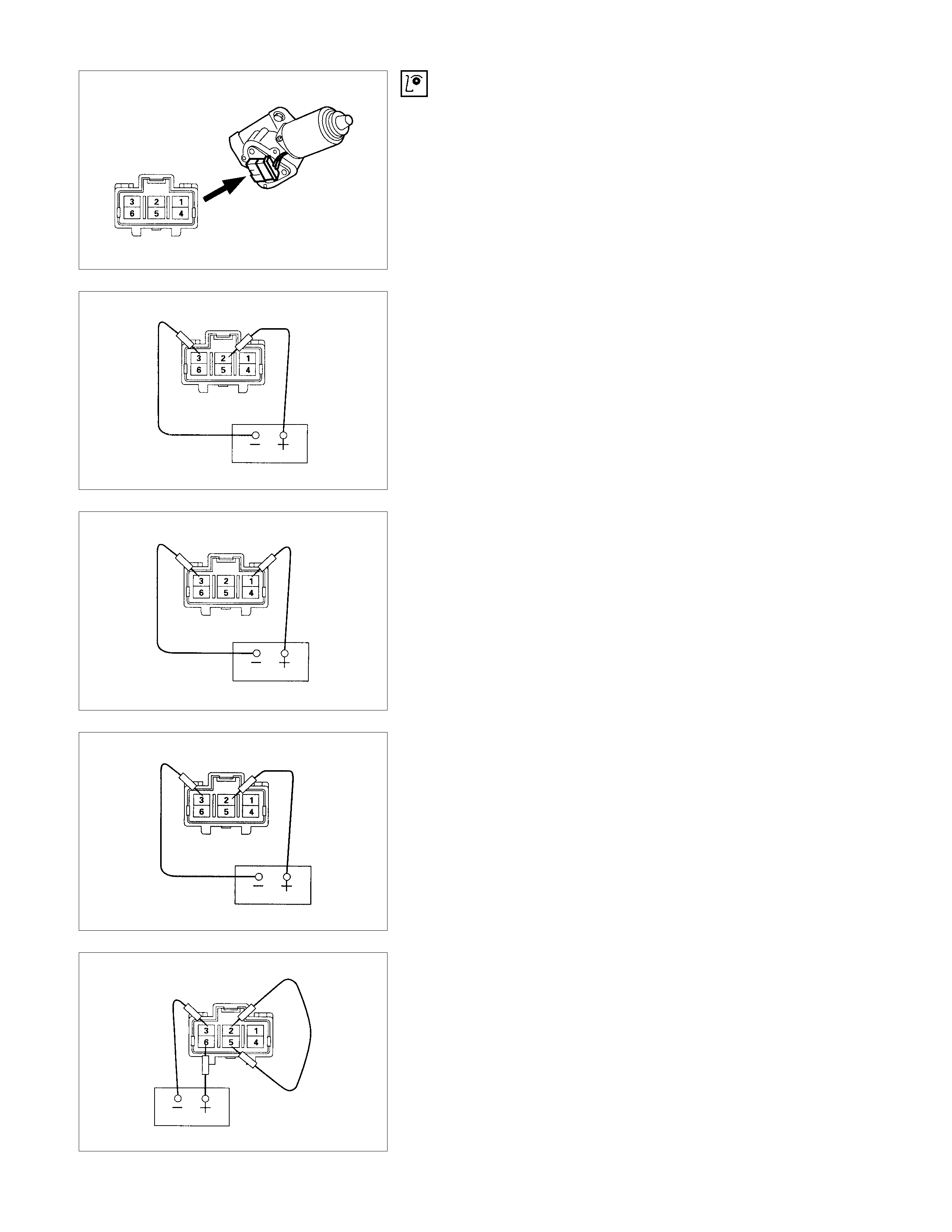
WIPER M OTOR INSPECTION
CONNECTOR
LOW SPEED INSPECTION
1. Clamp the wiper motor in a vise.
The moving parts must be clear of the vise.
2. Connect the connector terminals to the battery.
Refer to the illustration.
3. Check the wiper motor low speed operation.
HIGH SPEED I NSPECTION
1. Clamp the wiper motor in a vise.
The moving parts must be clear of the vise.
2. Connect the connector terminals to the battery.
Refer to the illustration.
3. Check the wiper motor high speed operation.
AUTO-STOP INSPECTION
1. Clamp the wiper motor in a vise.
The moving parts must be clear of the vise.
2. Connect the connector terminals to the battery.
Refer to the illustration.
3. Check the wiper motor low speed operation.
4. Disconnect the positive battery terminal.
This will stop the motor.
5. Connect the connector terminals No. 2 and No. 5 with a
lead wire.
Refer to the illustration.
6. Reconnect the positive battery terminal to connecto
r
terminal No. 6.
This will restart the motor.
Refer to the illustration.
7. Check the auto-stop operation.
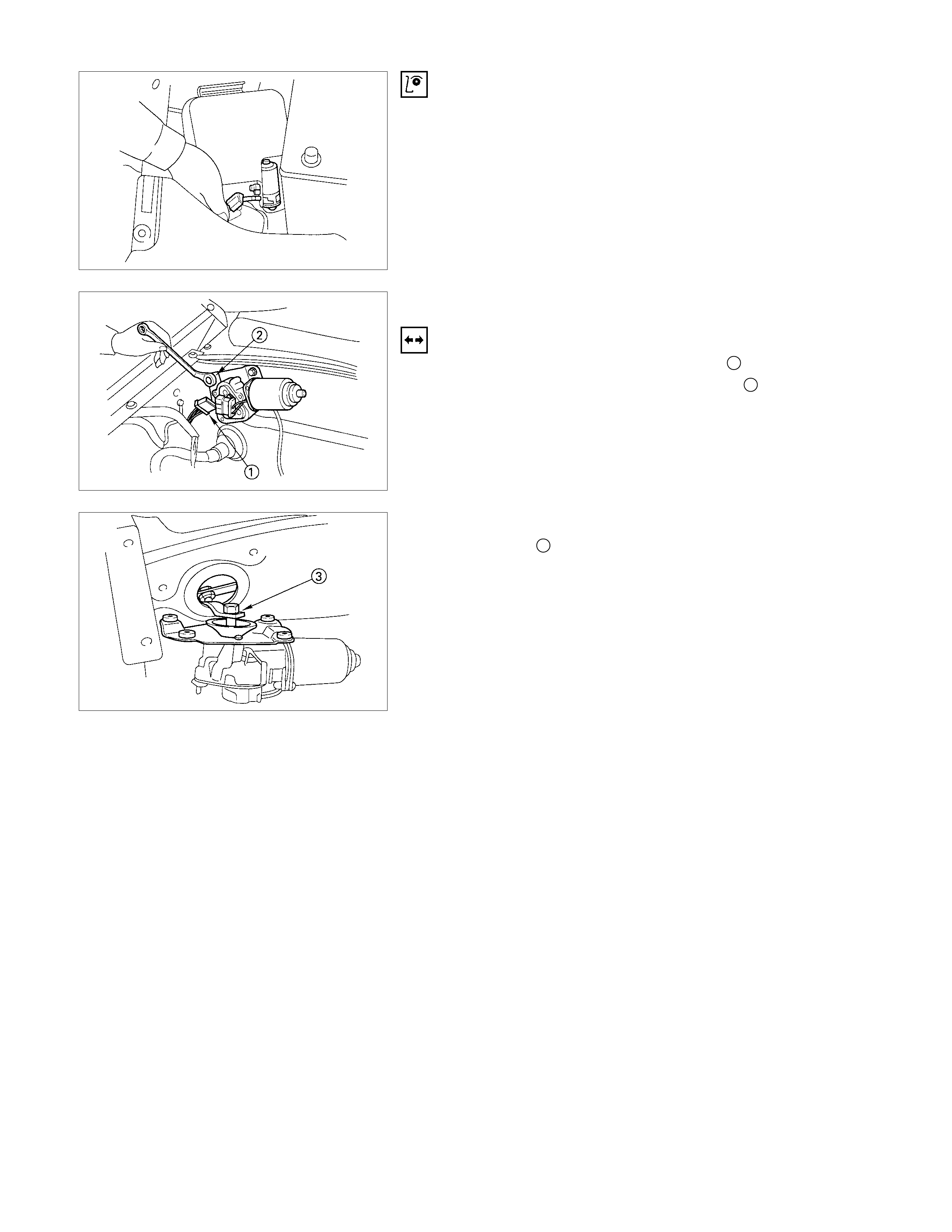
WASHER MOTOR INSPECTION
1. Fill the washer tank with washing solution.
2. Disconnect the motor connector.
3. Apply battery voltage to the washer motor connector.
4. Check the washer motor operation.
WIPER M O TO R AND LINKAGE
REMOVAL
1. Disconnect the wiper motor connector 1.
2. Remove the wiper motor bracket screws 2.
3. Disconnect the wiper motor from the wiper linkage at the
crank arm 3.
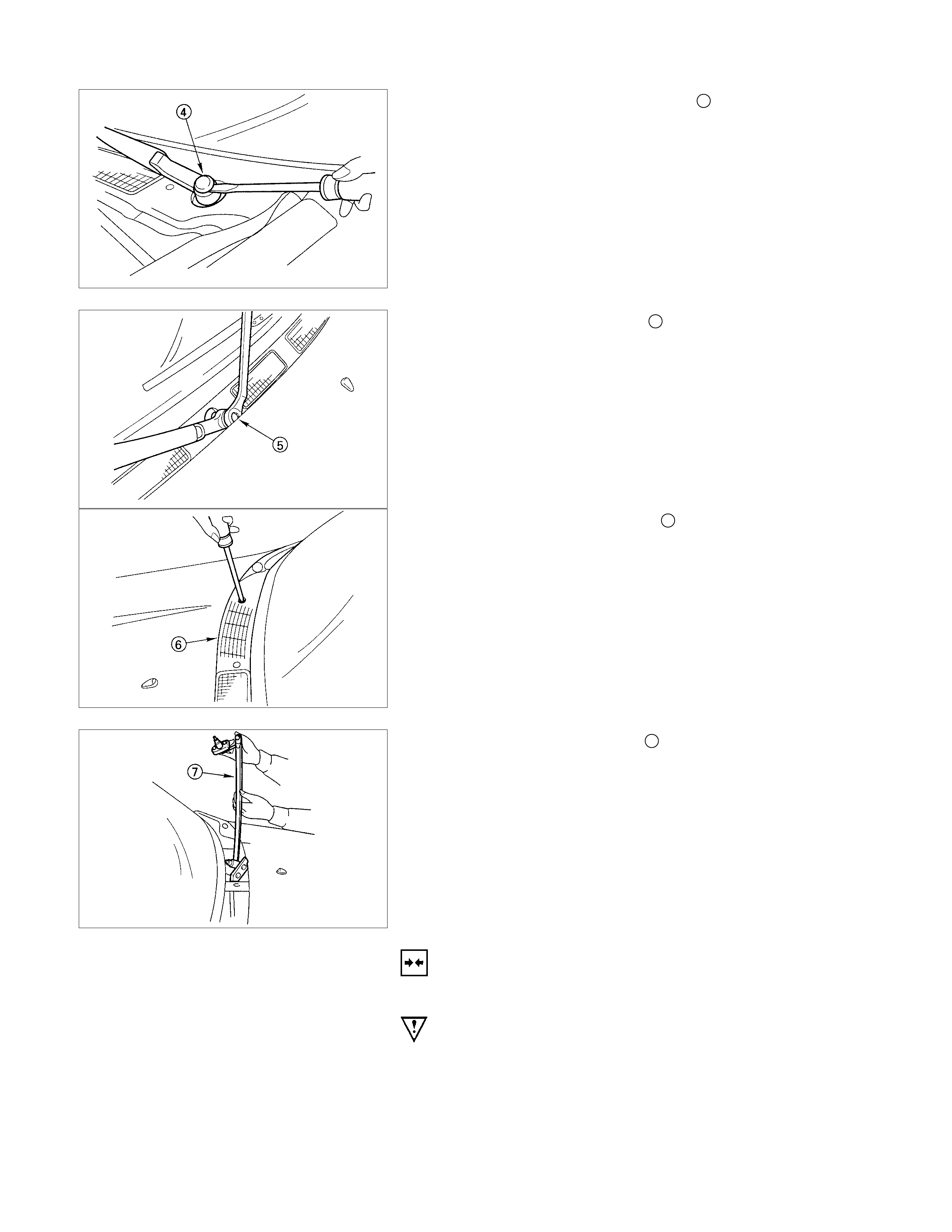
4. Disconnect the wiper arm nut cap 4.
5. Remove the wiper arm nut 5.
6. Remove the wiper arm with blade.
7. Remove the vent cowl cover 6.
8. Remove the wiper linkage 7 from the access hole.
INSTALLATION
Follow the removal procedure in the reverse order to install the
wiper motor and linkage.
Pay close attention to the important points mentioned in the
following paragraphs.
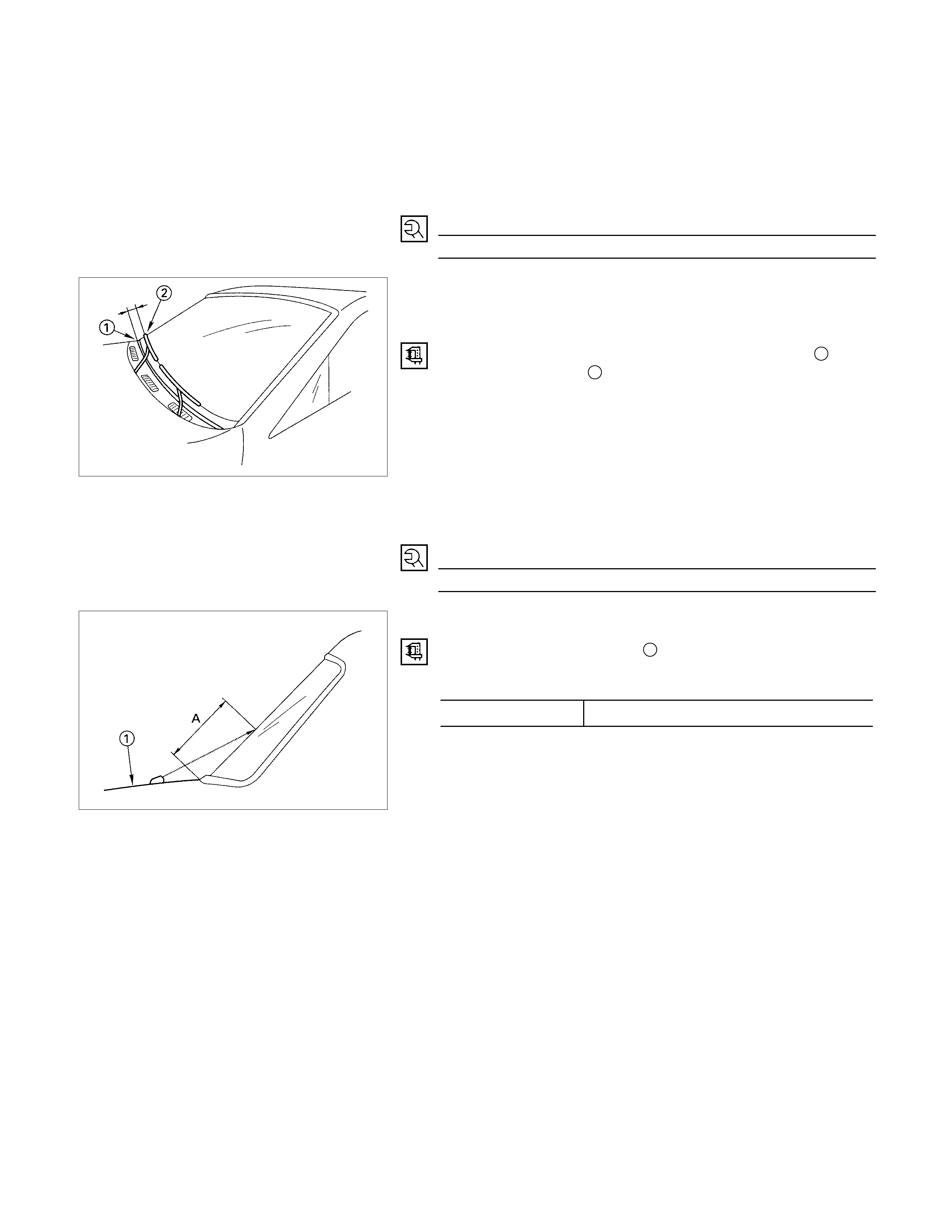
WIPER LI NKAGE
Take care not to scratch the painted surfaces of the body when
installing the wiper linkage to the body.
In case crank arm of wiper motor is removed, confirm the
position of auto stop prior to reinstall the crank arm to the wiper
motor.
Crank Arm Nut Torque N⋅m (kgf⋅m/lb⋅ft
)
13.7 ± 2.0 (1.4 ± 0.2/10 ± 1.4)
WIPER BLADE POSITION
Confirm the auto stop position of wiper motor prior to the
installation of the wiper blade and arm.
The distance between the vent cowl cover rubber seal 1 and
the wiper blade edge 2 is about 45 mm(1.8 in).
WIPER ARM NUT
Tighten the wiper arm nut to the specified torque.
Wiper Arm Nut Torque N⋅m (kgf⋅m/lb⋅ft)
13.7 ± 2.0 (1.4 ± 0.2/10 ± 1.4)
WINDSHI ELD W ASHER SPRAY
Be sure that the engine hood 1 is completely closed before
checking the windshield washer spray adjustment.
Windshield Washer Spray Position mm(in)
A Approximately 300 (11.8)
CONNECTOR
Be absolutely sure that the wiper motor connector is securely
connected.
This will prevent a poor contact and an open circuit.
Note:
Windshield wiper arm and blade assembly configurations
are different for the right-hand and left-hand side of the
vehicle.
Be care ful not to confuse the right-hand and left-hand side
assemblies.
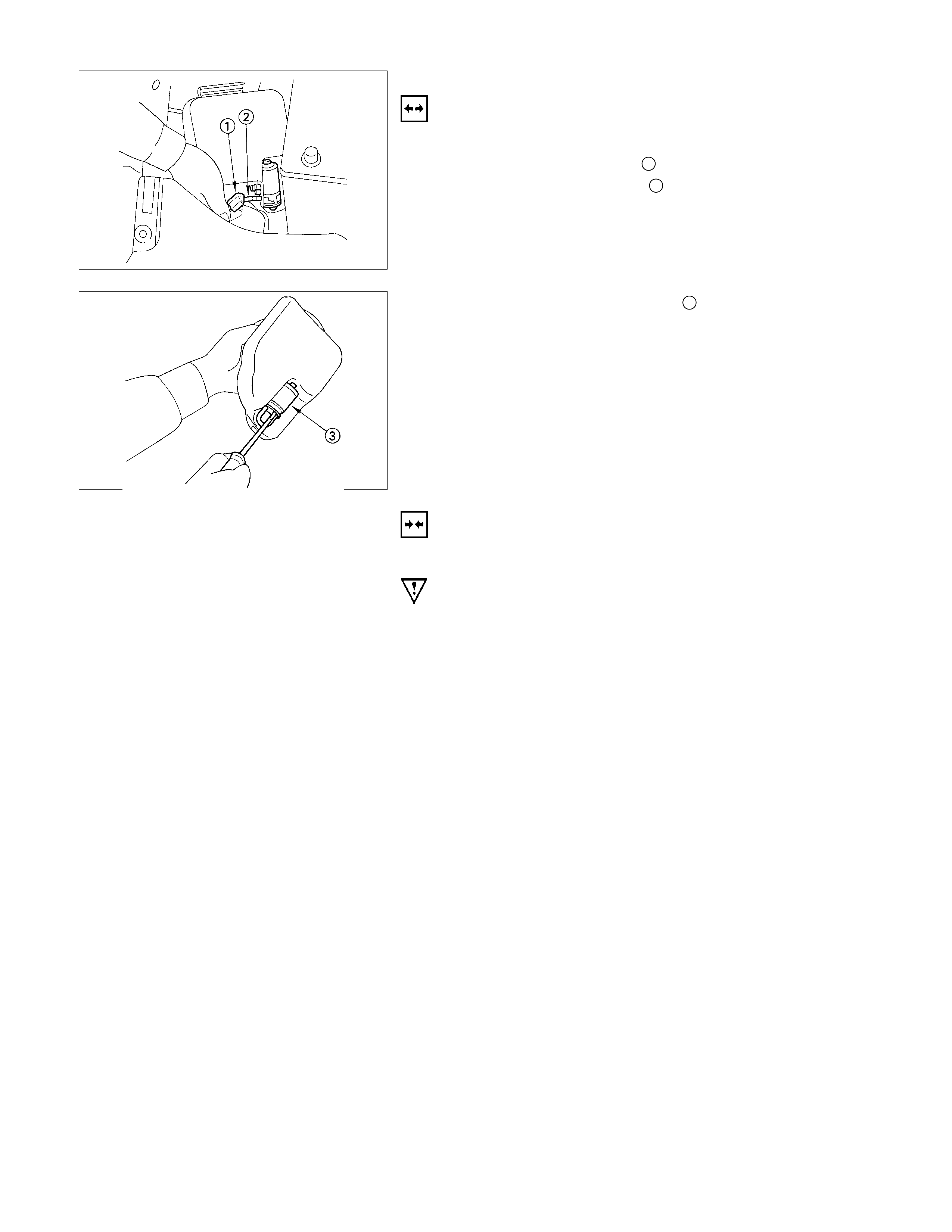
WASHER TANK MOTOR
REMOVAL
1. Remove the washer tank bolts.
2. Disconnect the connector 1.
3. Disconnect the water hose 2.
4. Remove the washer tank motor 3.
INSTALLATION
Follow the removal procedure in the reverse order to install the
washer tank motor.
Pay close attention to the important points mentioned in the
following paragraphs.
CONNECTOR
Be absolutely sure that the washer tank motor connector is
securely connected.
This will prevent a poor contact and an open circuit.
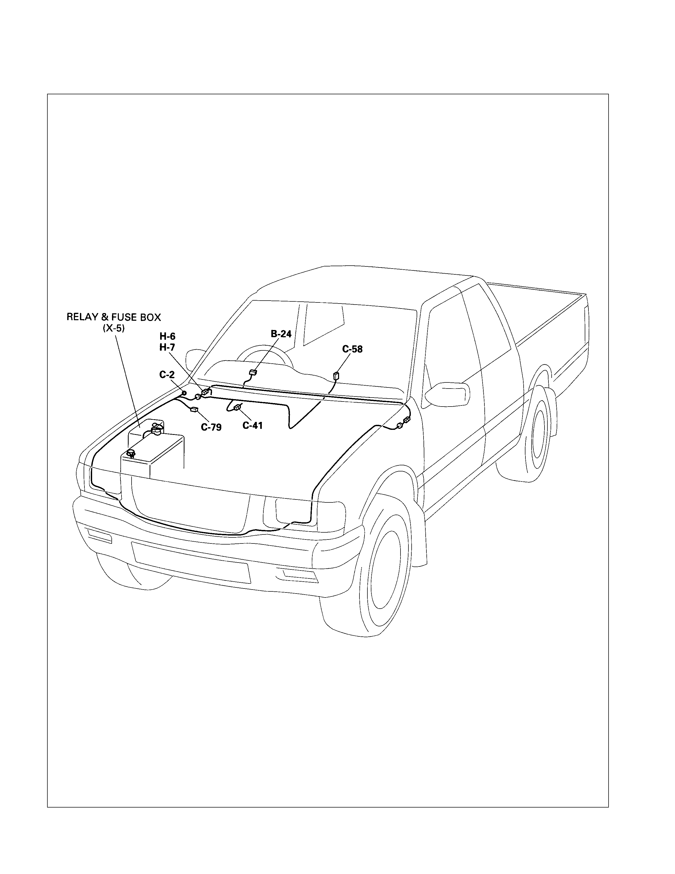
Overdrive Off (A/T)
PARTS LOCATION
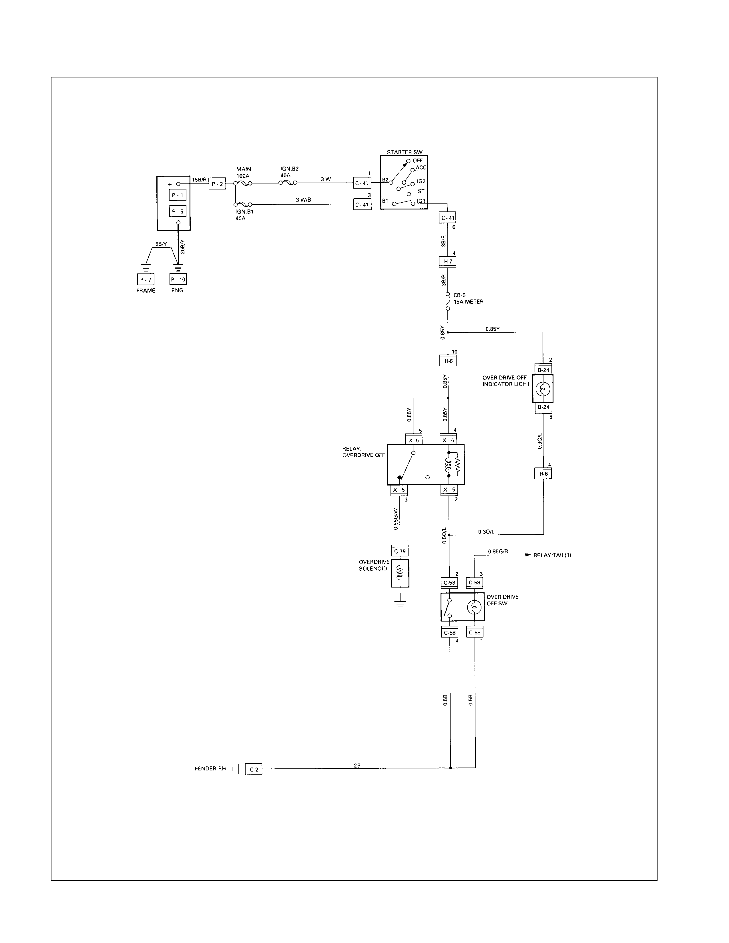
CIRCUIT DIAGRAM
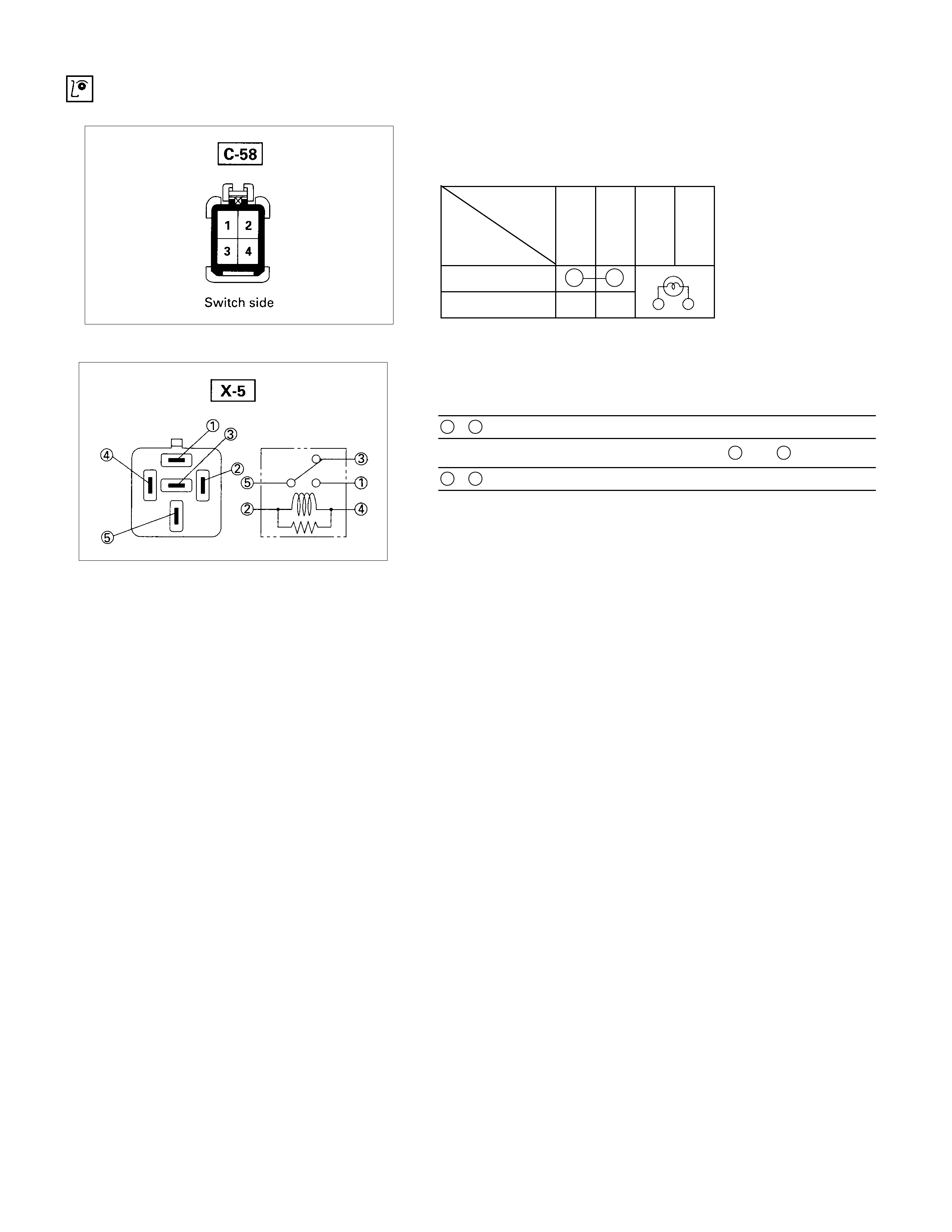
INSPECTION AND REPAIR
OVERDRIVE O FF SW ITCH
OVERDRIVE O FF SWITCH CONNECTIONS
Terminal
No.
SW position
2413
ON
OFF
OVERDRIVE O FF RELAY
Check continuity between the relay terminals.
3 - 5............................Continuity
(When battery voltage is applied between 2 and 4)
3 - 5............................No continuity
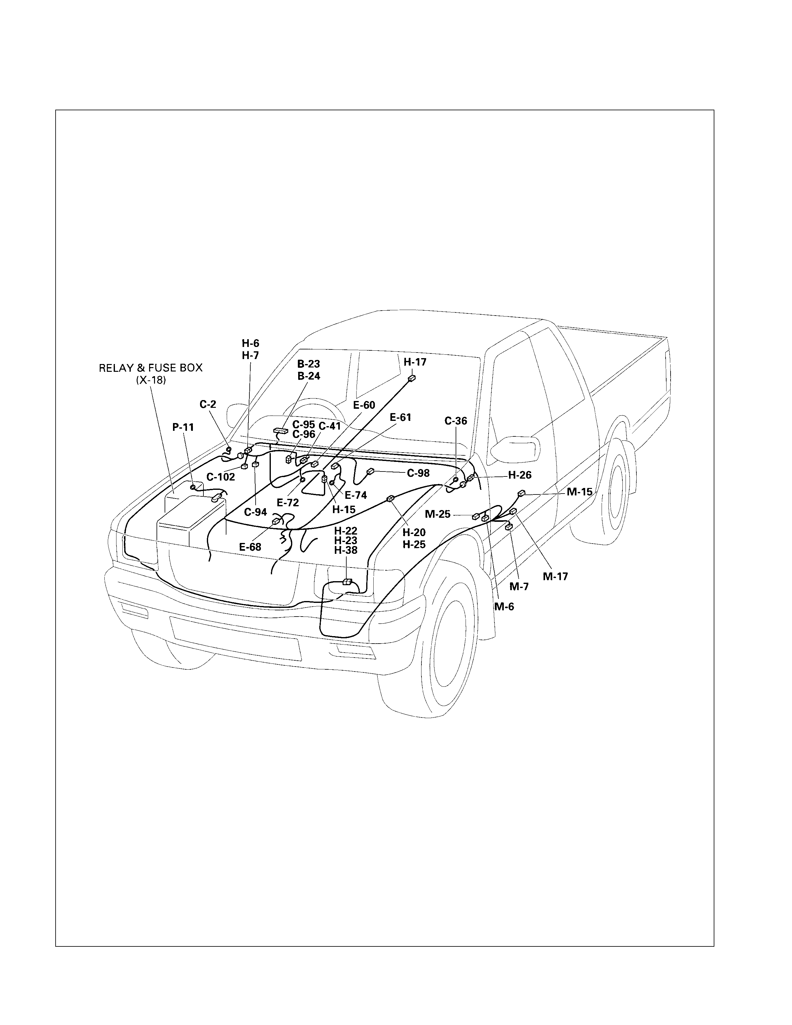
Transmission Control Module (TCM)
PARTS LOCATION ( 6 VD1W )
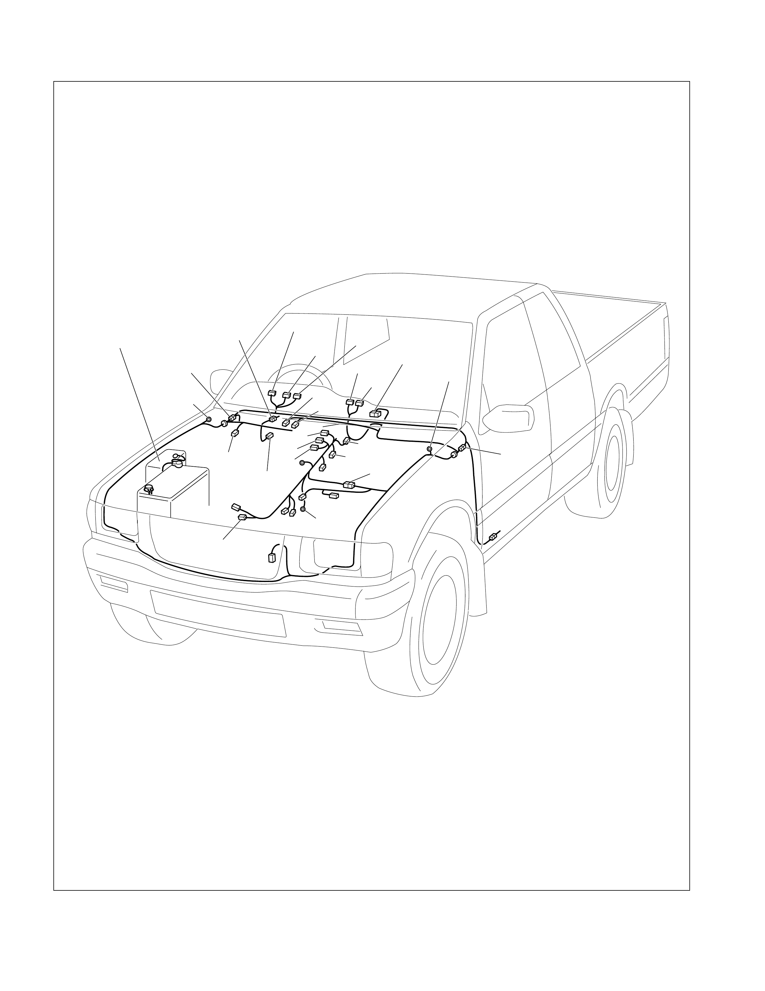
PARTS LOCATION ( 4JH1TC)
B-24
C-36
H-8
B-23
B-94
B-95
C-206
C-207
B-39
C-41
RELAY & FUSE BOX
(X-15)
C-2
H-6
H-18
C-56
C-57
E-10
C-44 H-4
E-51
E-55
E-41
E-52
E-53 E-54
C-96
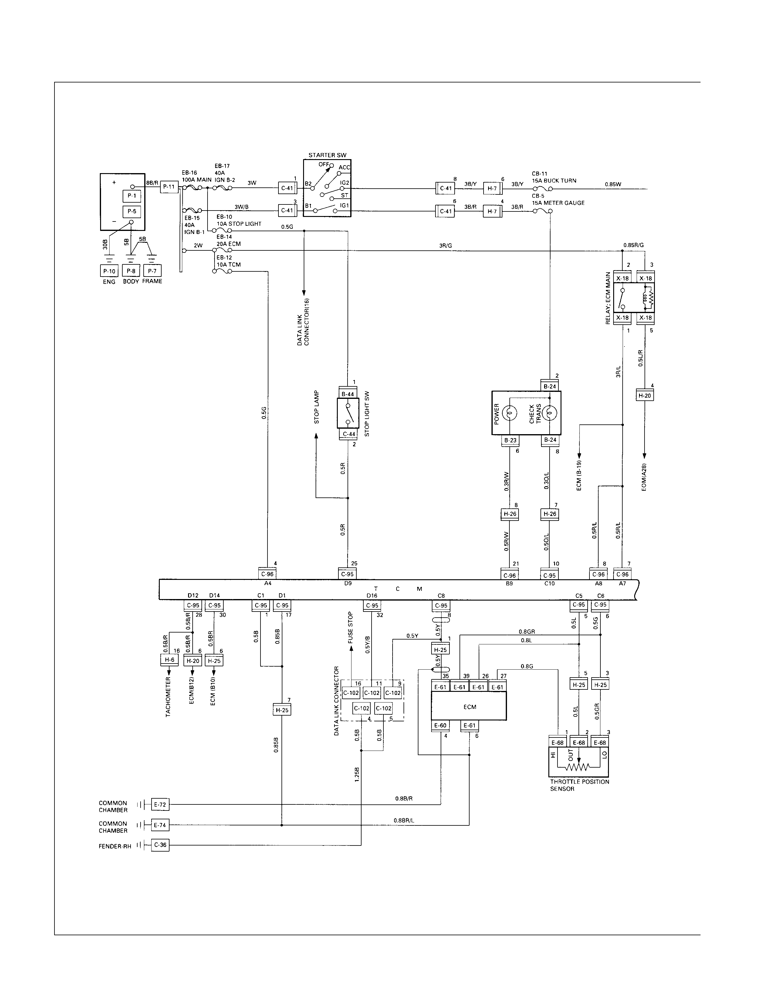
CIRCUIT DIAGRAM (6VD1W)
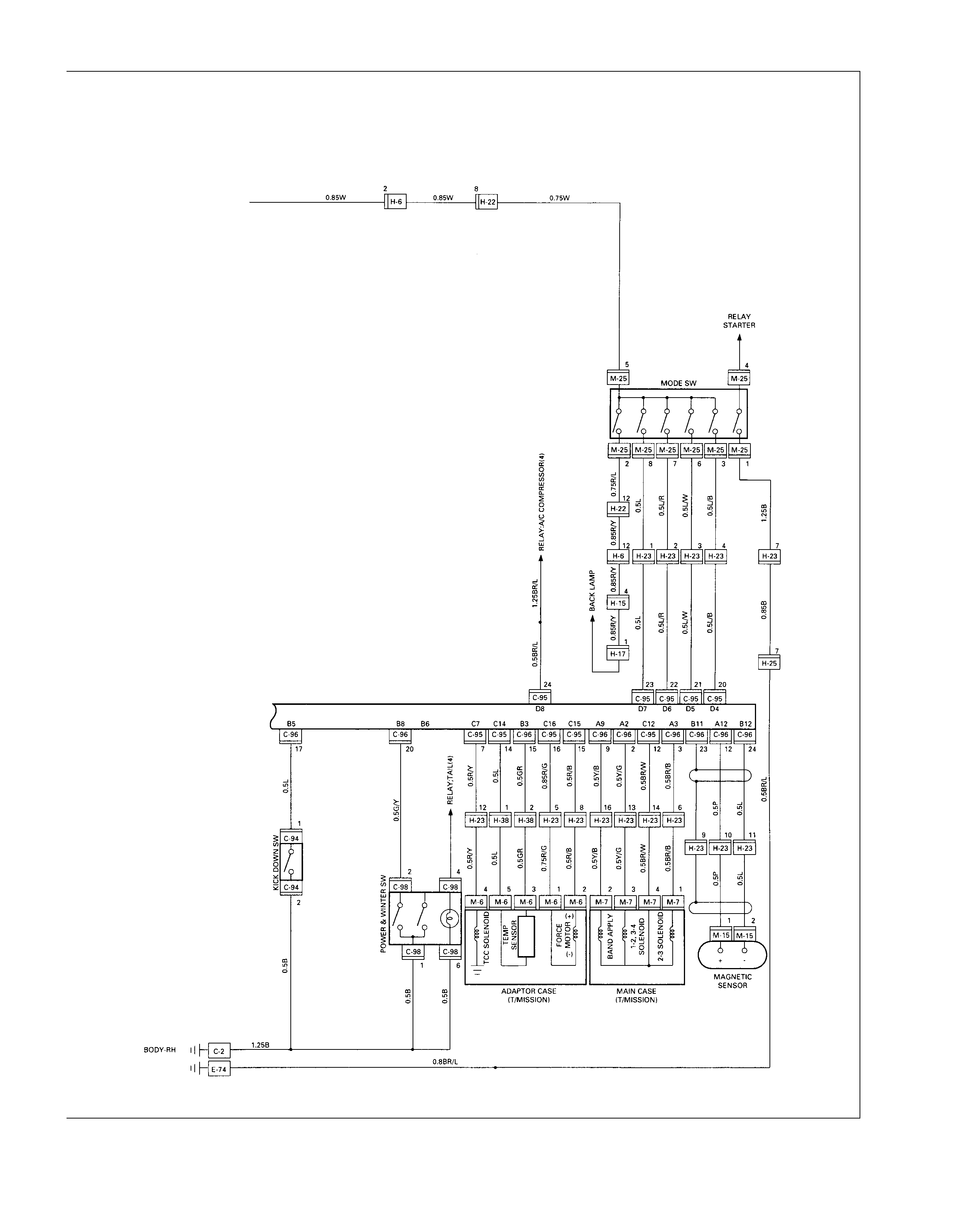
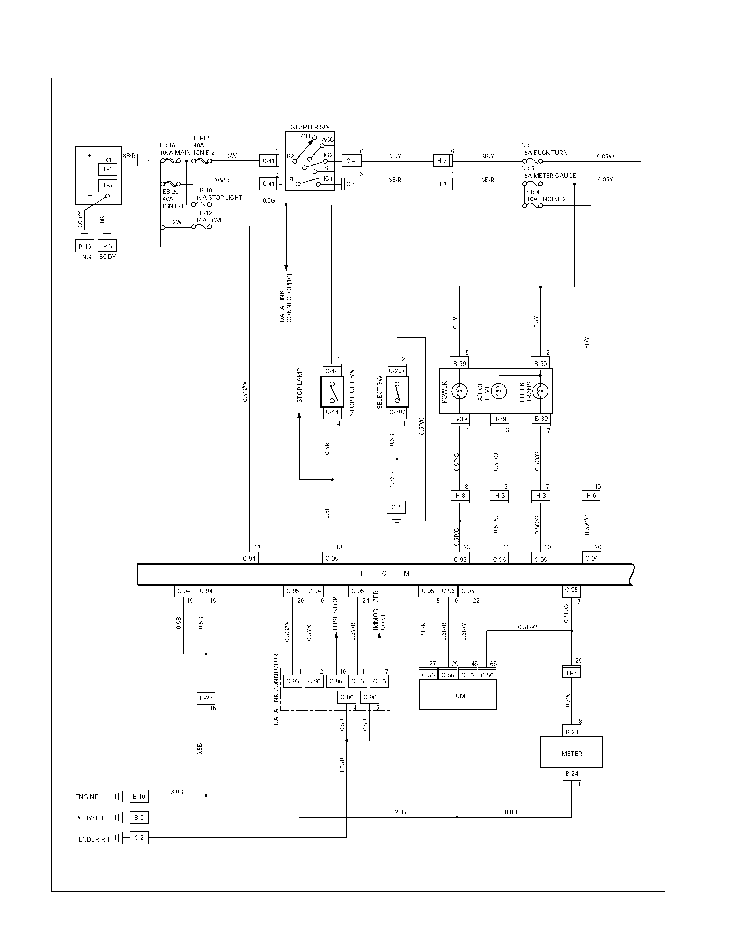
CIRCUIT DIAGRAM (4JH1TC)
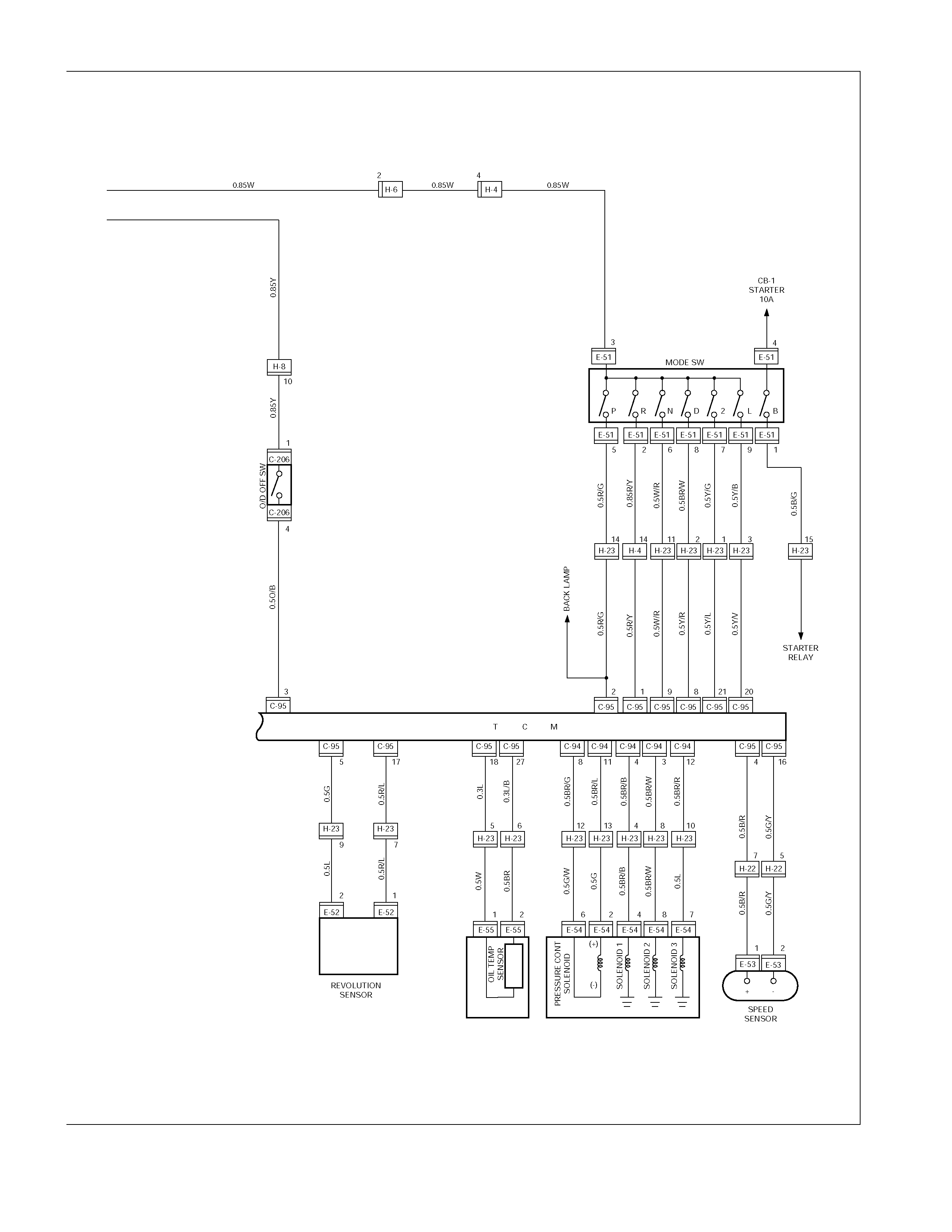
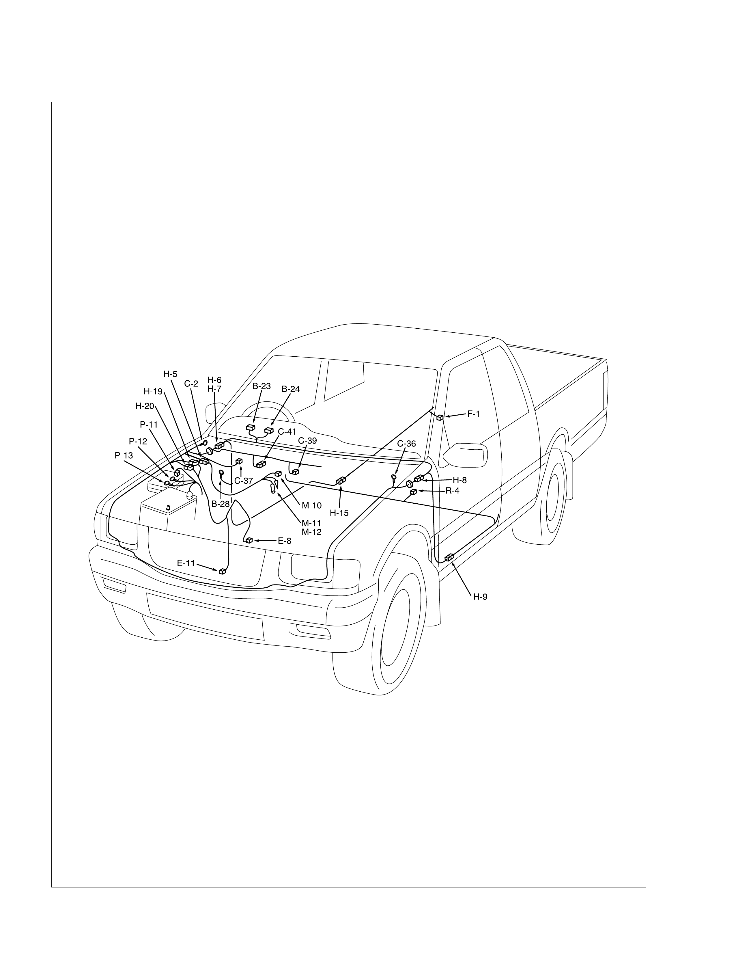
Meter, Warning Light and Indicator Light
PARTS LOCATION
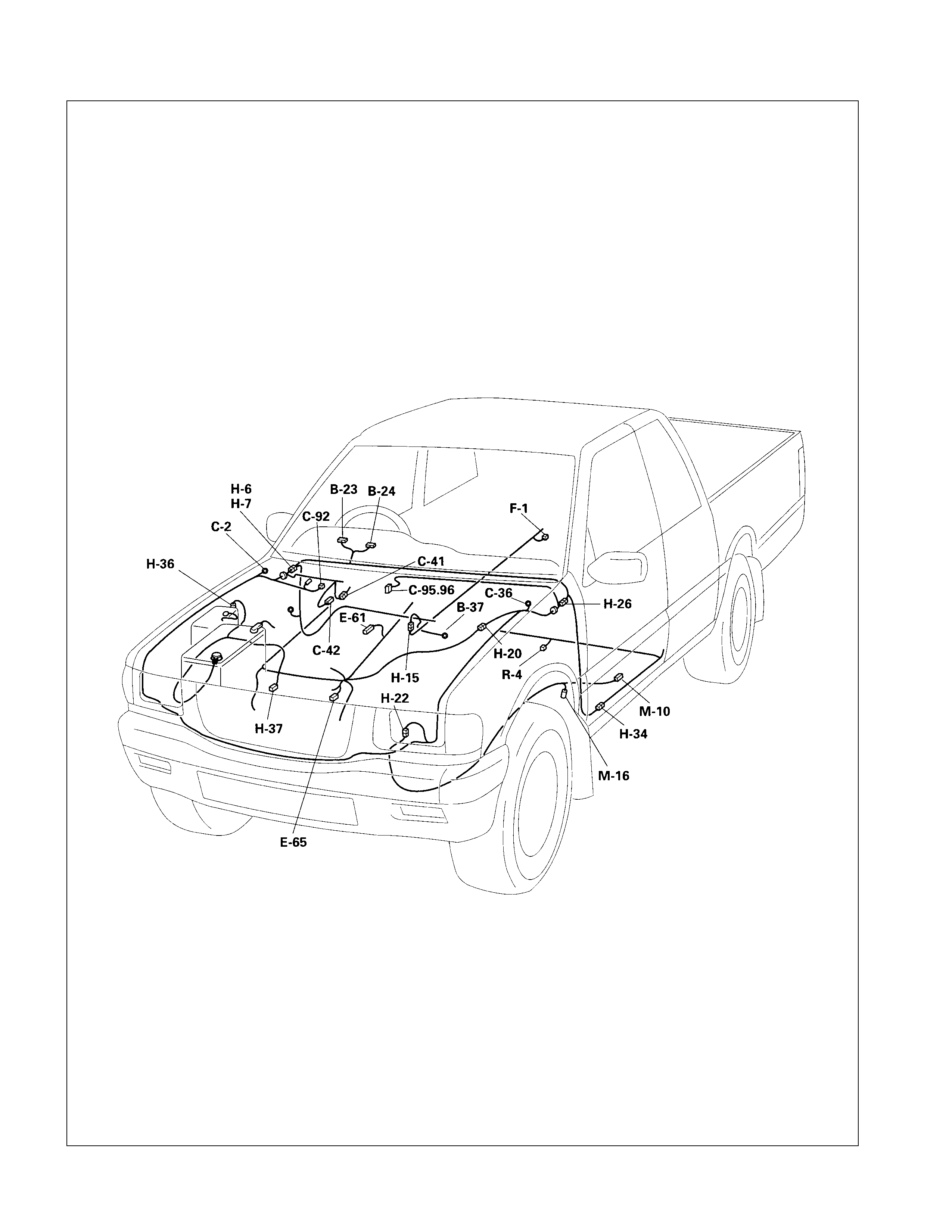
PARTS LOCATION ( 6 VD1W )

PARTS LOCATION ( 4JH1TC)
H-15
R-4
F-1
C-56
C-57
B-34
E-10
H-9
B-9
H-8
C-36
C-208
C-41
E-19
E-1
C-2
H-19
B-23 B-24
B-39
C-39
E-44
E-45
E-46
C-37
C-38
H-6
H-7
H-18
H-3
H-4
H-22
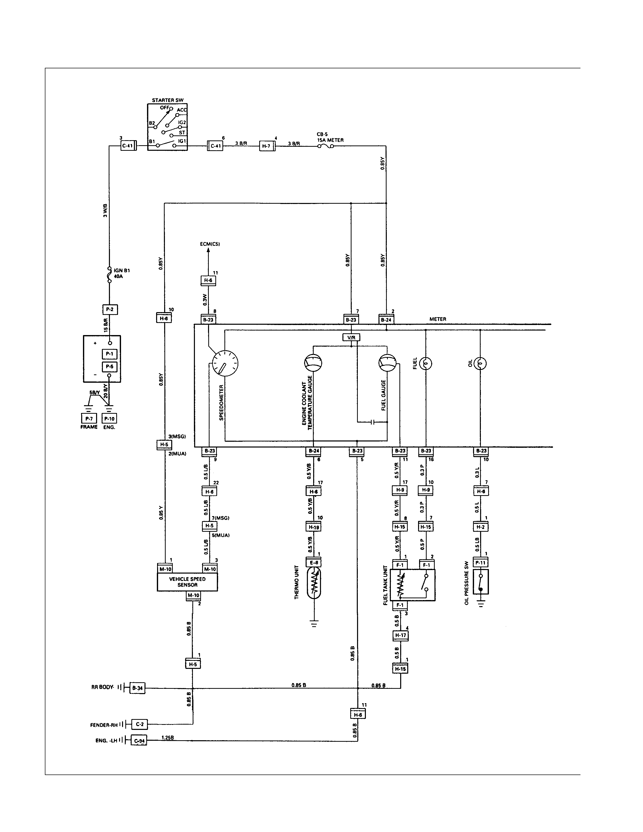
CIRCUIT DIAGRAM (W/ O TACHOMETER)
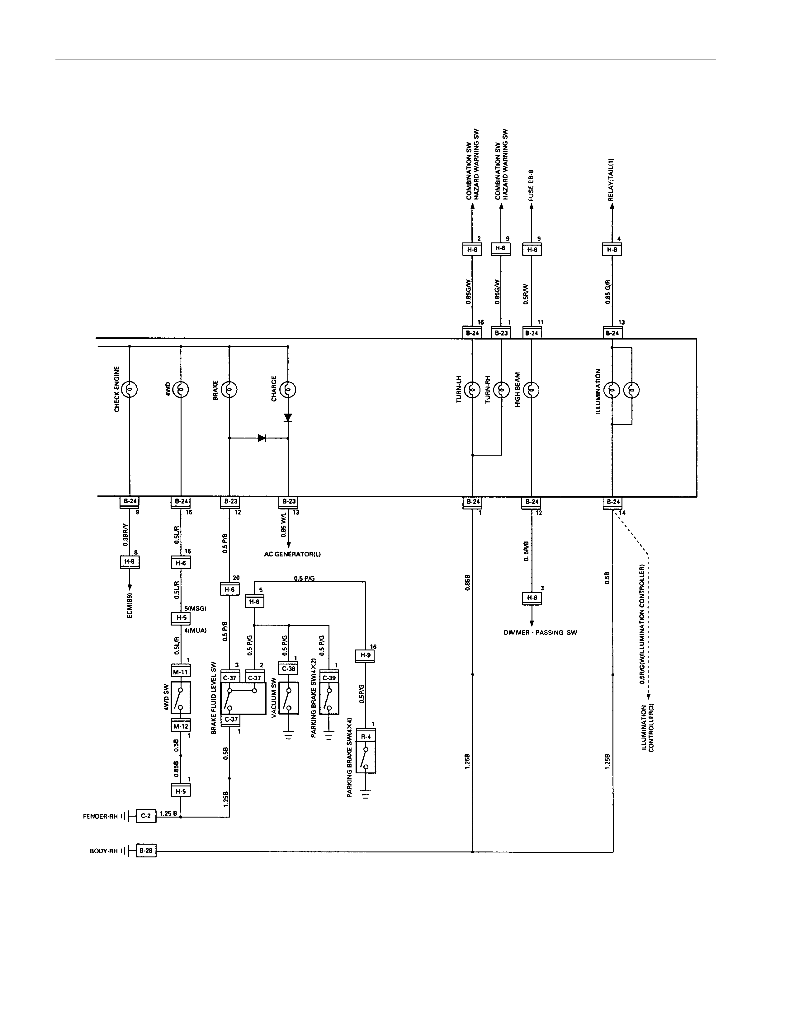
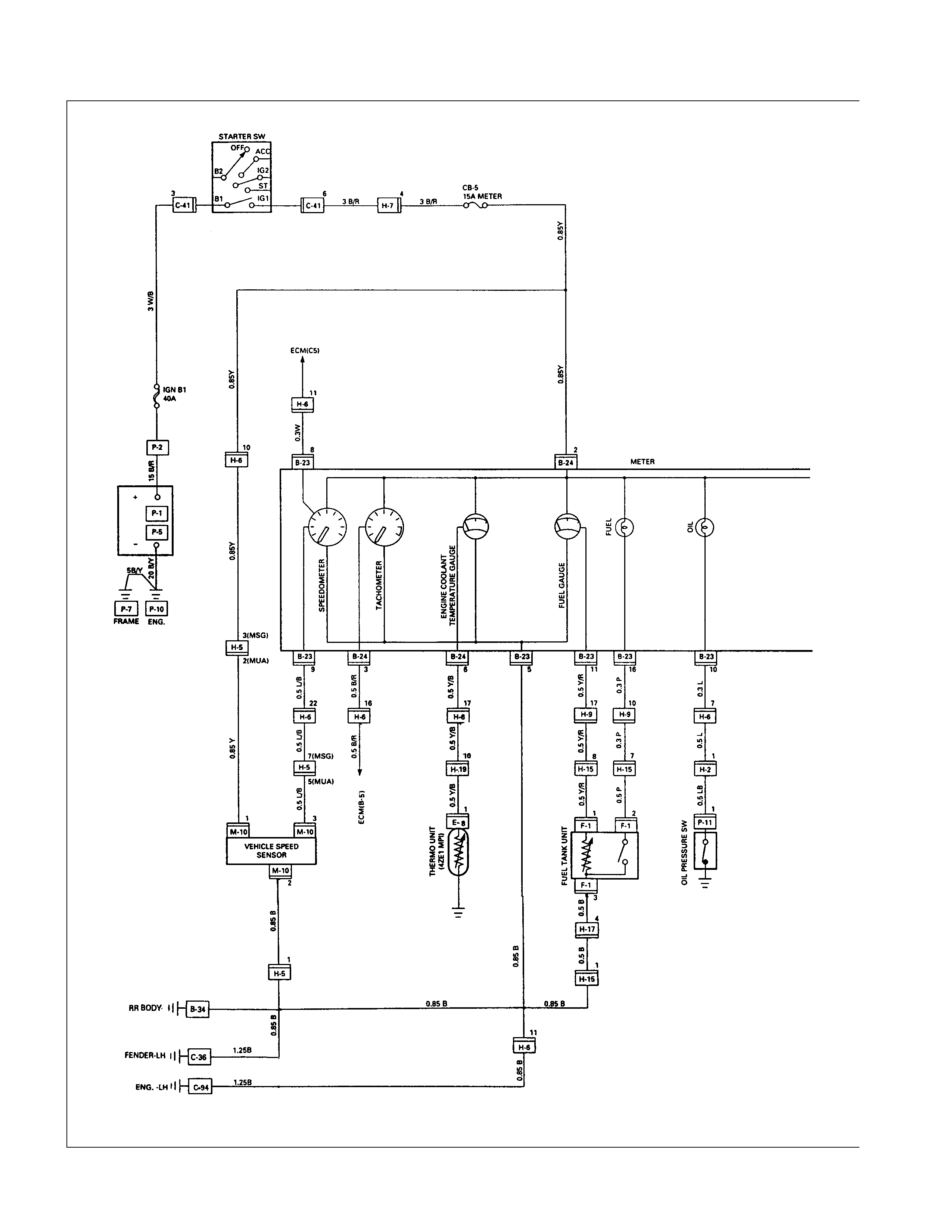
CIRCUIT DIAGRAM (W/ TACHOMETER)
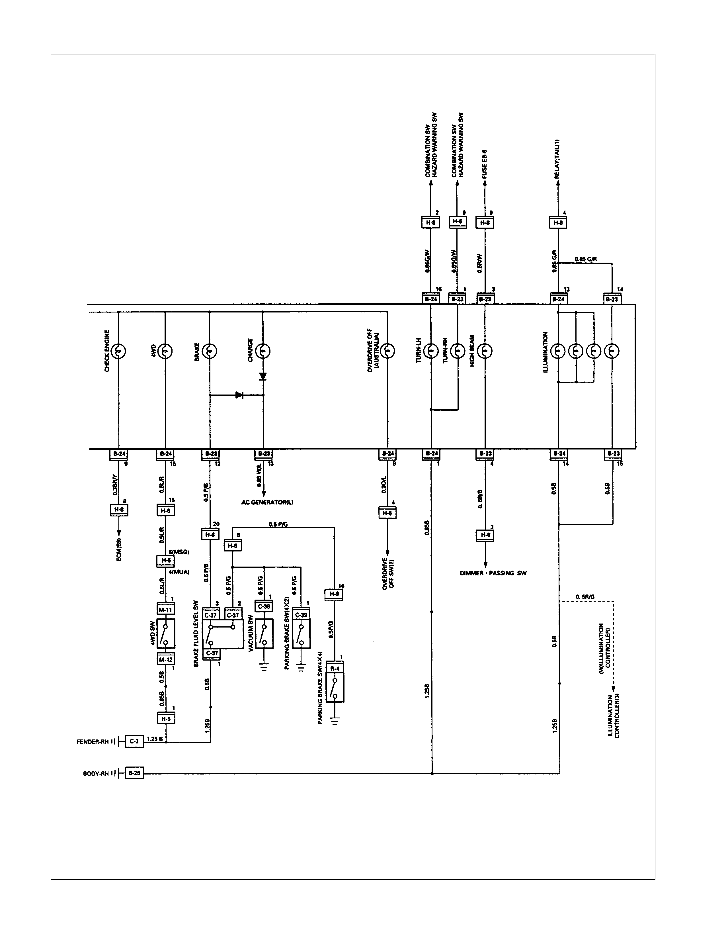
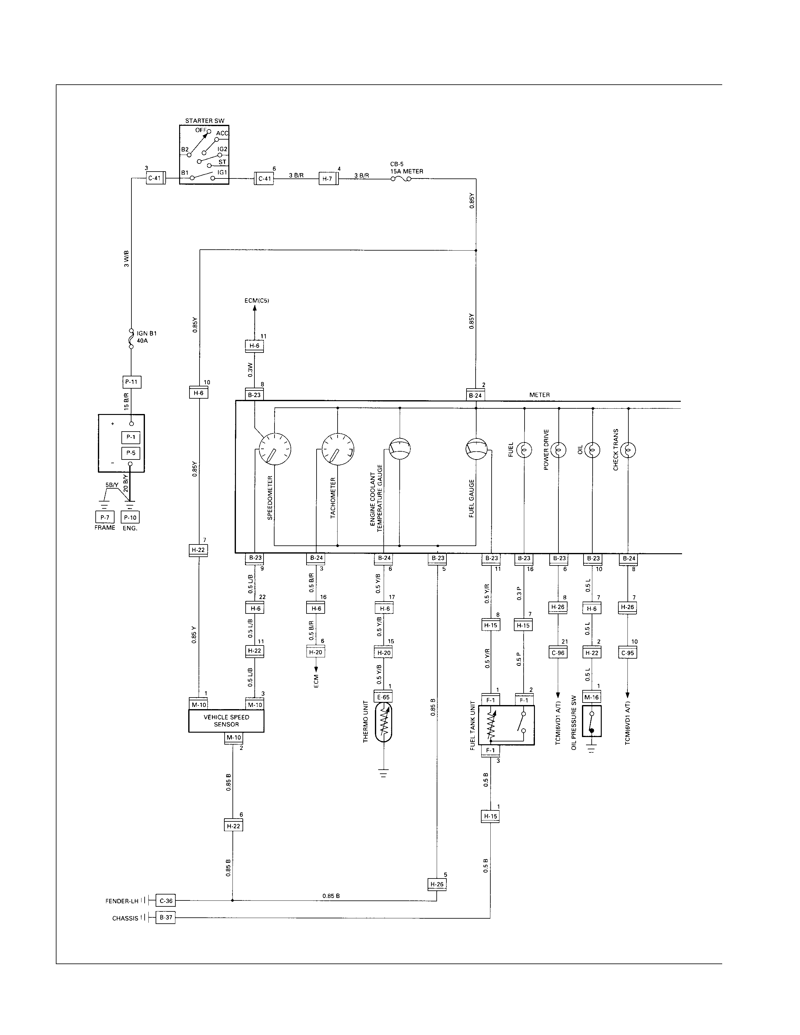
CIRCUIT DIAGRAM (W/ TACHOMETER 6VD1W)
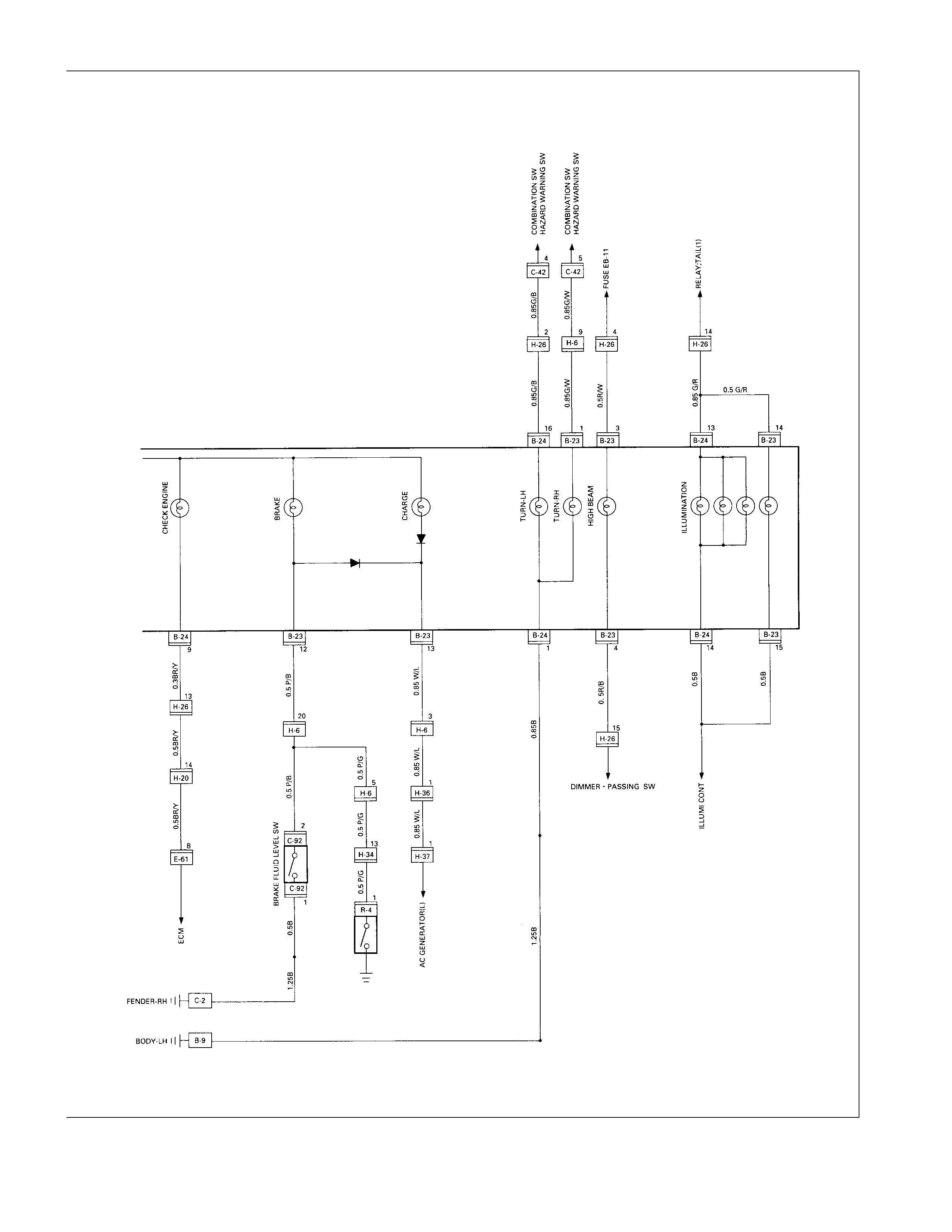
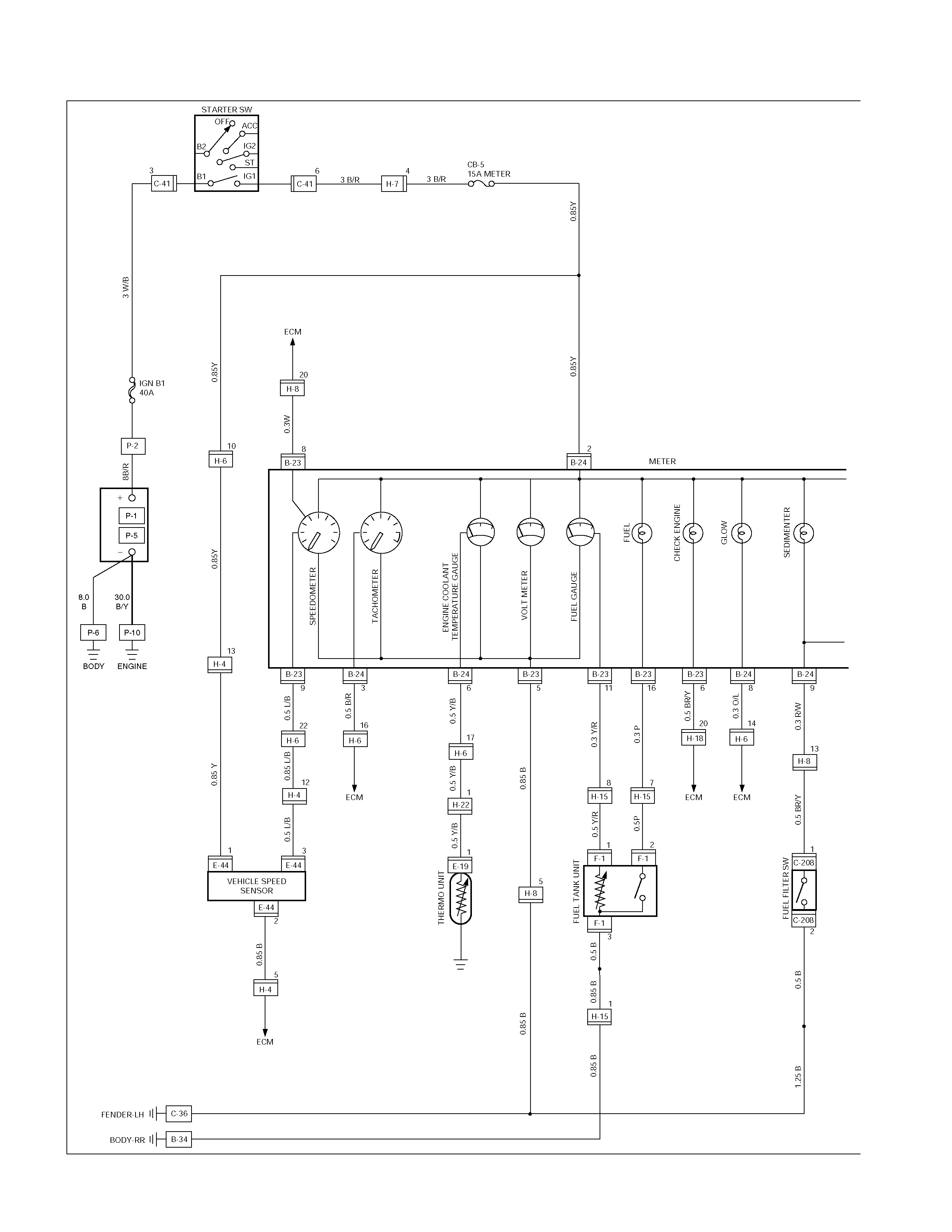
CIRCUIT DIAGRAM (4JH1TC M/T)
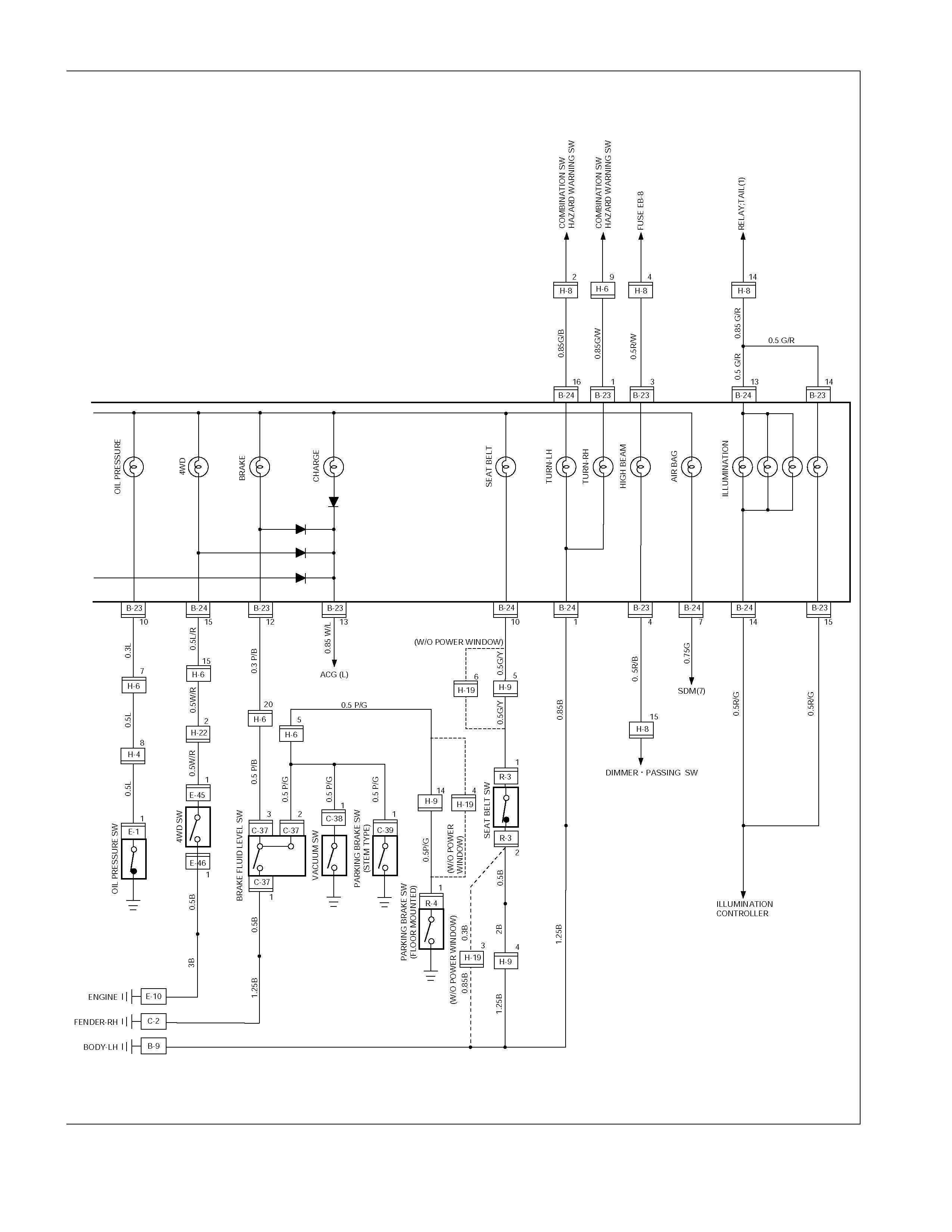
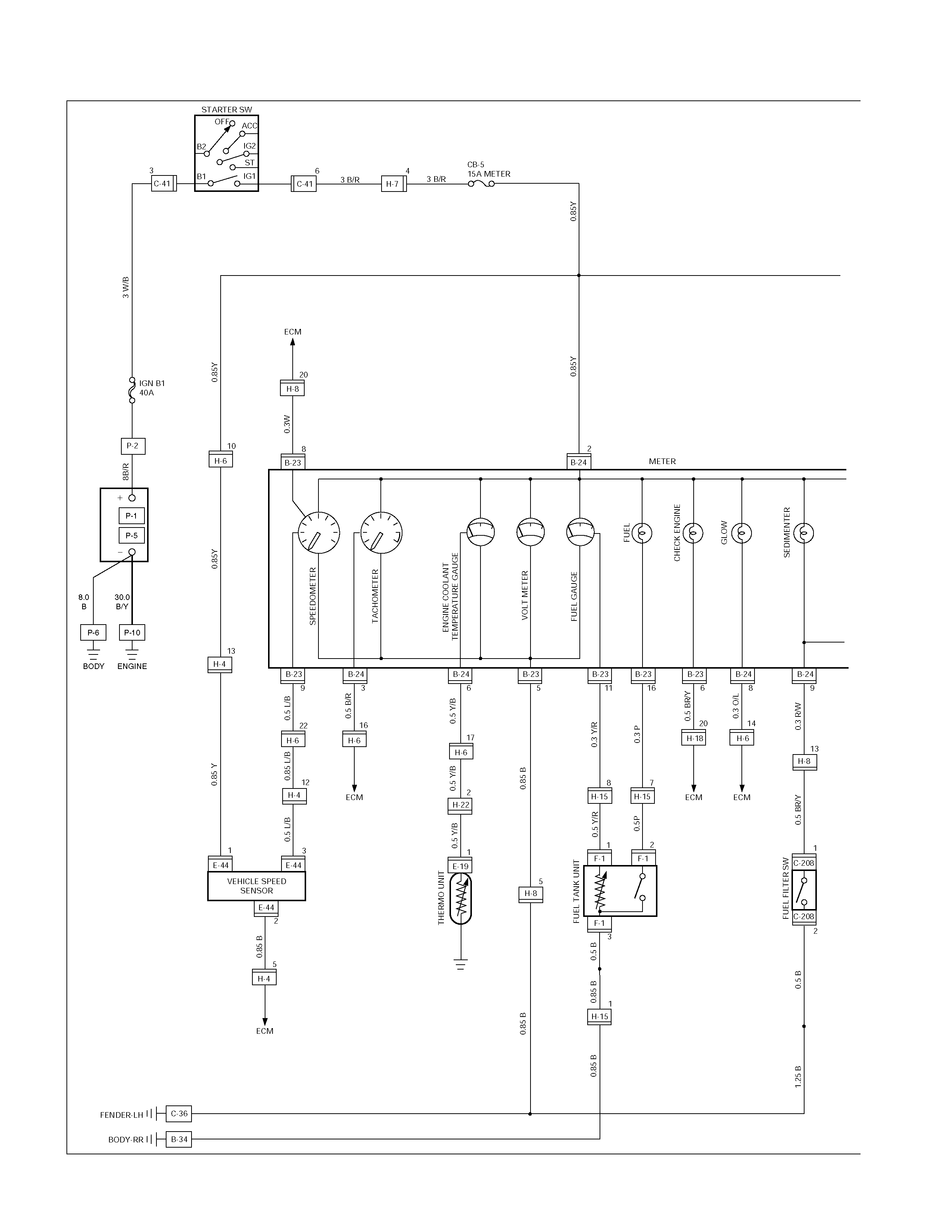
CIRCUIT DIAGRAM (4JH1TC A/T)
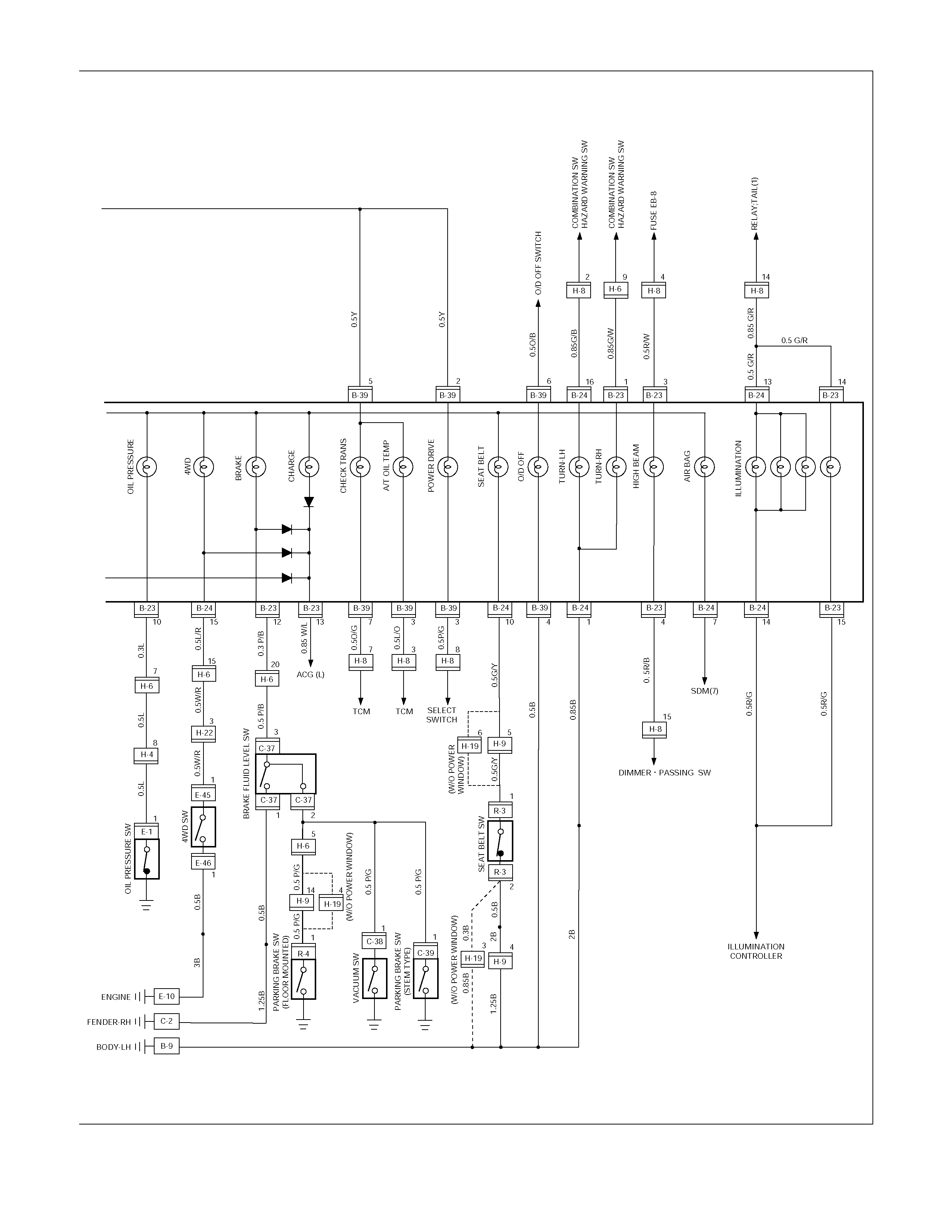
TROUBLESHOOTING
SPEEDOMETER
1. Speedometer and odometer do not function
Checkpoint Trouble Cause Countermeasure
Replace the vehicle speed
sensor
Vehicle speed sensor
malfunction
NG
Repair an open circuit in the
circuit or a poor connection at
the connectors
Continuity between the vehicle
speed sensor and the meter,
or the fuse (LHD: CB-7
(15A)/RHD: CB-5 (15A)) and
the ground
Open circuit or poor connector
contact
Replace the speedometer
Use a meter tester to check
the speedometer function Speedometer malfunction
NG
NG
OK
OK
Check the vehicle speed
sensor output
(4 pulses/1 rotation)
2. Speedometer needle fluctuates
(May be wide fluctuation)
Replace the vehicle speed
sensor, or repair an open
circuit in the circuit or a
connectors
Vehicle speed sensor
malfunction, or open circuit or
poor connector contact
NG
Replace the speedometer
Use a meter tester to check
the speedometer function Speedometer malfunction
NG
OK
Check the speed sensor
output by using the
oscilloscope
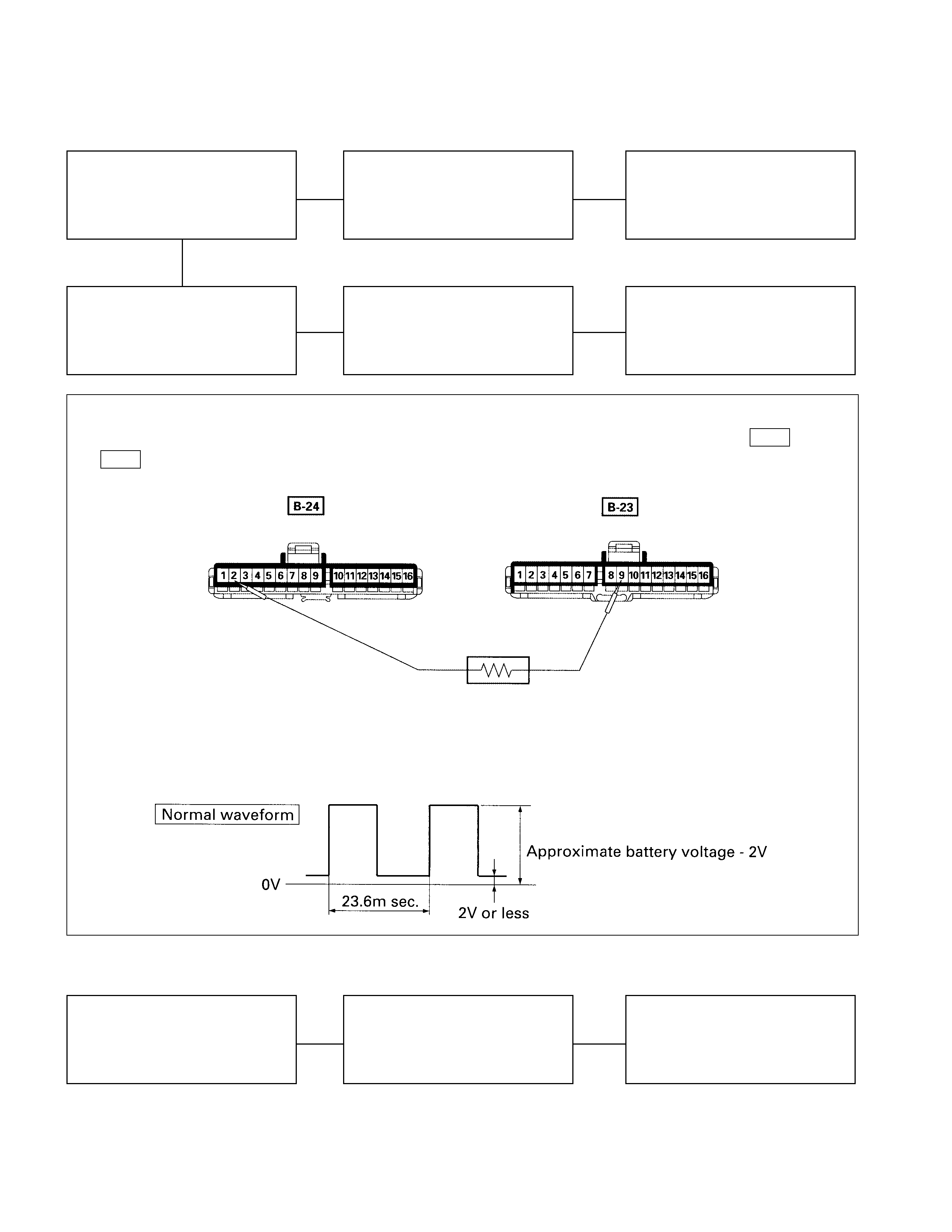
3. Speedometer needle jumps erratically
Checkpoint Trouble Cause Countermeasure
Replace the vehicle speed
sensor, or repair an open
circuit in the circuit or a poor
connection at the connectors
Vehicle speed sensor
malfunction, or open circuit or
poor connector contact
NG
Replace the speedometer
Use meter tester to check the
speedometer function Speedometer malfunction
NG
OK
Check the vehicle speed
sensor output by using the
oscilloscope
Inspection of a waveform by oscilloscope
1. Connect a resistance of 1.3 to 5k ohm (1.4W or more) between the harness side connectors 2 B-24 and 9
B-23 of the meter.
2. Install a speedometer tester.
2. Turn on the starter SW.
3. Check the waveform at the time when the vehicle speed is at 60km/h.
4. Trip odometer does not reset
Replace the speedometer
Faulty reset mechanism or
worn gear
NG
Check at other kilometer
figures given by meter tester
(Reset should be made to
zero kilometer)
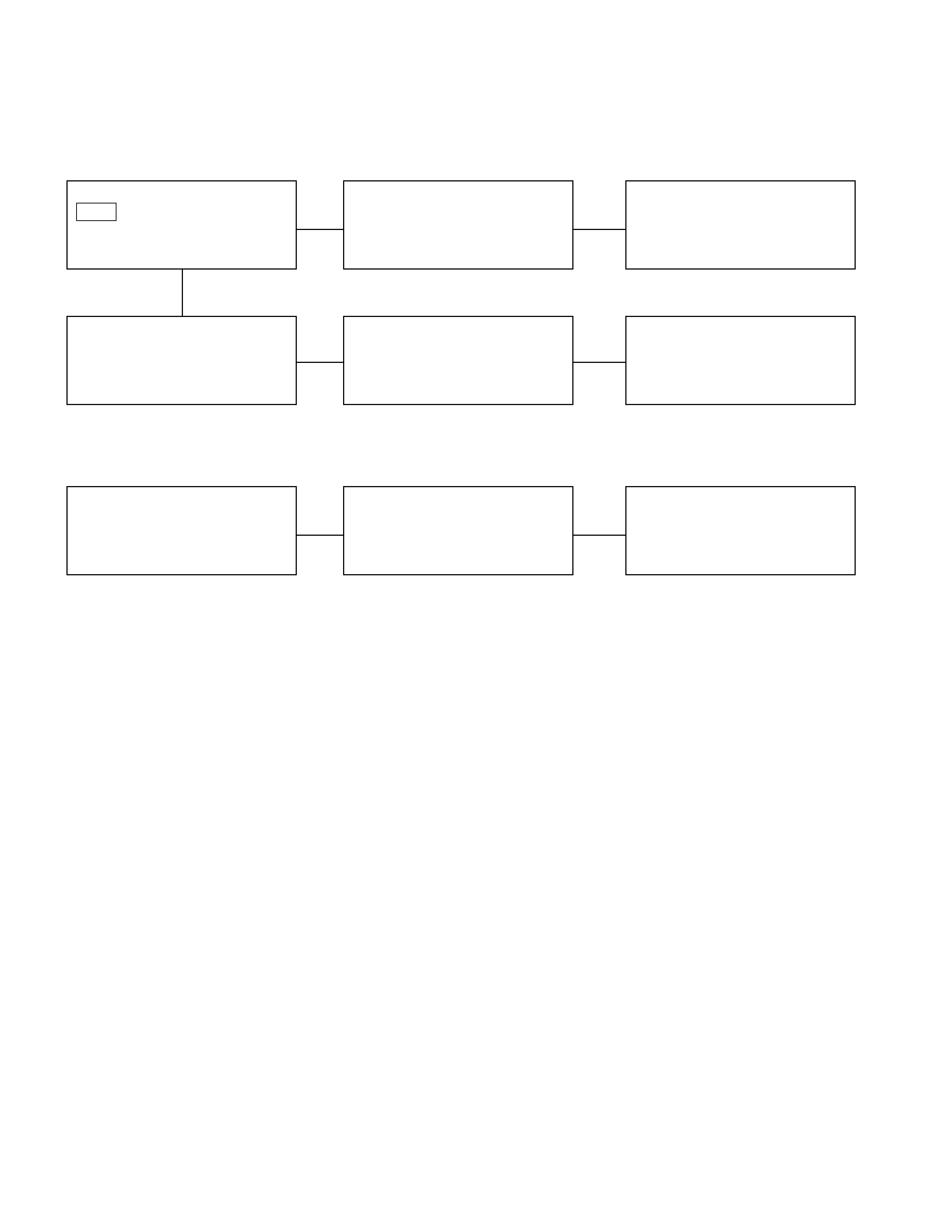
TACHOMETER
1. Tachometer does not function when engine is running
Checkpoint Trouble Cause Countermeasure
Replace the tacho sensor, or
repair open circuit or
connector contact
Tacho sensor malfunction, or
open circuit or poor connector
contact
NG
Replace the tachometerTachometer function Tachometer malfunction
NG
OK
Pulse between connector
B-24 and the ground when
engine is running (Should be
pulse present)
2. Meter needle fluctuates
(May be wide fluctuation)
Replace the tachometerTachometer malfunction
NG
Use a meter tester to check
the tachometer function
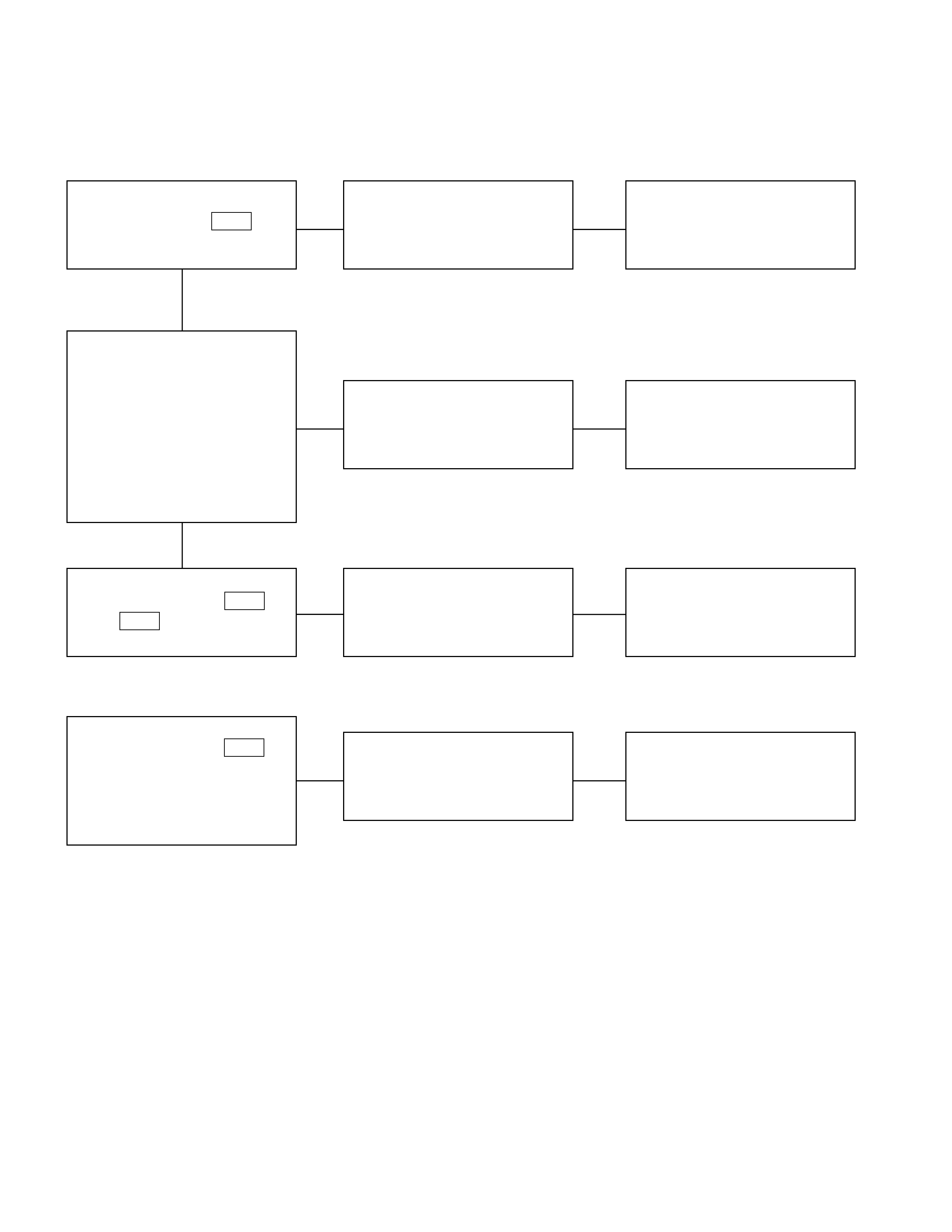
TEMPERATURE GAUGE AND THERMO UNIT
1. No temperature indicates at all
Checkpoint Trouble Cause Countermeasure
Replace the thermo unitThermo unit malfunction
NG
Replace the temperature
gauge
Gauge function
1. Disconnect the unit
connector then connect
3.4W bulb to wire harness
side with ground
2. Check indicating point
when starter SW. is ON
position (Temperature
should indicate)
Gauge malfunction
Repair open circuit or
connector contact
Continuity between 1 E-8
and 6 B-24 Open circuit or poor connector
contact
NG
NG
OK
OK
Thermo unit continuity
between connector E-8 and
the ground
2. Temperature gauge incorrect readings in all ranges
Replace the thermo unitThermo unit malfunction
NG
Thermo unit resistance
between connector 1 E-8
and the ground when
disconnecting the connector
(Specified resistance should
indicate)
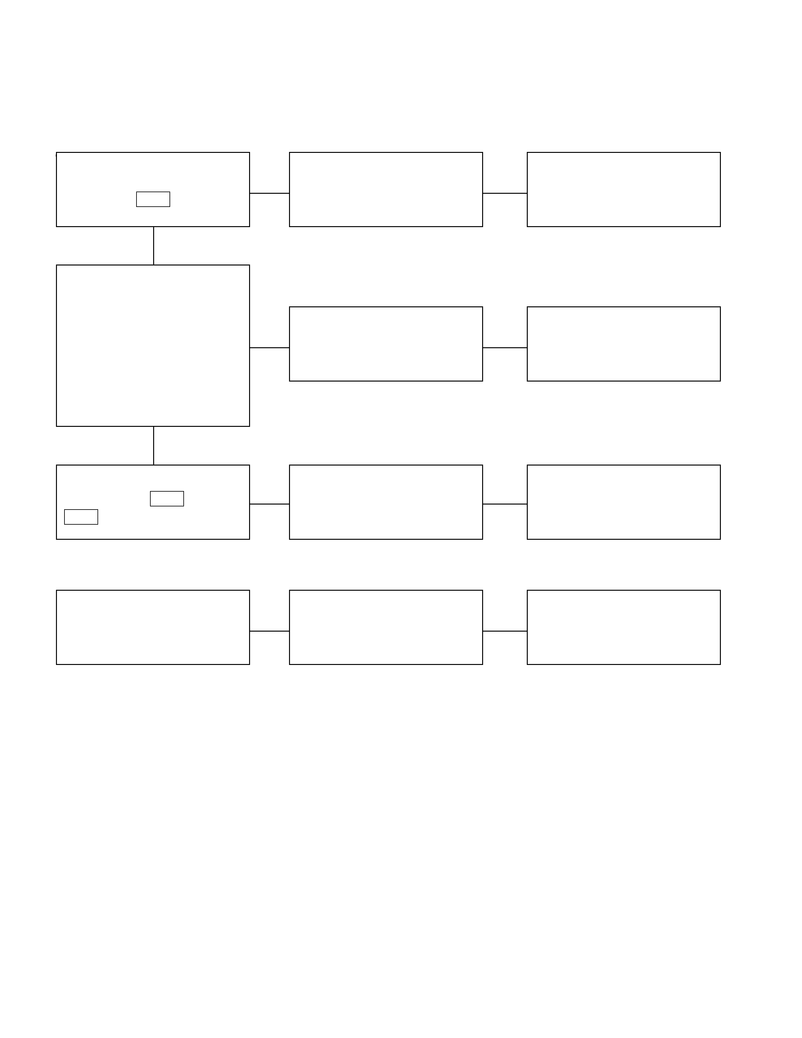
FUEL GAUGE AND FUEL TANK UNIT
1. No fuel level indicates at all
Checkpoint Trouble Cause Countermeasure
Replace the tank unit
Open circuit inside the tank
unit
NG
Thermo unit malfunction
Replace the fuel gauge
Fuel gauge function
1. Disconnect the tank unit
connector then connect
3.4W bulb to wire harness
side
2. Check indicating point
when starter SW. is ON
position (Fuel level should
indicate)
Gauge malfunction
Repair open circuit or
connector contact
Continuity between
connectors 11 B-23 and 1
F-1
Open circuit or poor connector
contact
NG
NG
OK
OK
Tank unit continuity between
connector 1 F-1 and ground
2. Fuel gauge gives incorrect readings in all ranges
Replace the tank unitTank unit malfunction
NG
Tank unit resistance position
with the float at checking
points (Specified resistance
should indicate)
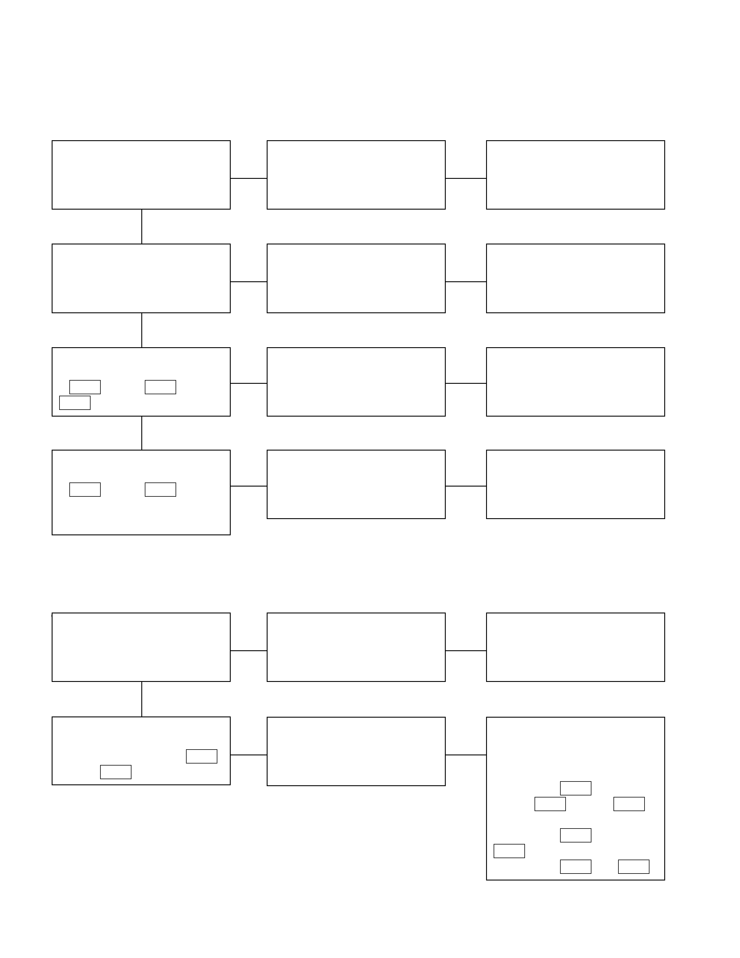
WARNING AND INCIDATOR LIGHT
1. When the parking brake lever is pulled, the indicator light does not light up
Checkpoint Trouble Cause Countermeasure
Replace or reinstall the bulb
Bulb burned out or loose
contact
NG
Adjust or replace the parking
brake SW.
Parking brake SW. installation
position and function Incorrect SW. adjustment or
poor SW. point contact
Repair open circuit or
connector contact
Continuity between the
parking brake SW. connector
1 C-39 (4×4: 1 R-4 ) and 12
B-23
Open circuit or poor connector
contact
NG
NG
OK
OK
Brake indicator light bulb
continuity
Replace the parking brake
SW.
Continuity between the
parking brake SW. connector
1 C-39 (4×4: 1 R-4 ) and
the ground when the parking
brake is operated
Parking brake SW.
malfunction
NG
OK
2. Even when the parking brake lever is pulled, the indicator light does not go off
Checkpoint Trouble Cause Countermeasure
Adjust the SW. installation
position or replace the parking
brake SW.
Incorrect the parking brake
SW. adjustment or brake SW.
faulty
NG
Thermo unit malfunction
Replace the brake fluid level
SW., or vacuum SW., or
repair a short circuit between
the parking brake SW.
connector 1 C-39
(4×4: 1 R-4 ) and 12 B-23
or the brake fluid level SW.
connector 3 C-37 and 12
B-23 , or the vacuum SW.
connector 1 C-38 and B-23
Check to see if the indicator
light goes off when the parking
brake SW. connector 1 C-39
(4×4: 1 R-4 ) is disconnected
Brake fluid level SW. or
vacuum SW. faulty or short
circuit
NG
OK
Parking brake SW. installation
position and function
3. Oil pressure warning light does not go off while engine is running
Refer to ENGINE SectionRefer to ENGINE Section
NG
Thermo unit malfunction
Repair a short circuit between
1 P-11 and 10 B-23
Check to see the warning light
goes off when the oil pressure
SW. connector
1 P-11 is disconnected Short circuit
Replace the oil pressure unit
(or the oil pressure SW.)
Continuity between the oil
pressure SW. connector
1 P-11 and the body ground
when the engine is operating
Oil pressure unit (or oil
pressure SW) faulty
NG
NG
OK
OK
Engine oil pressure
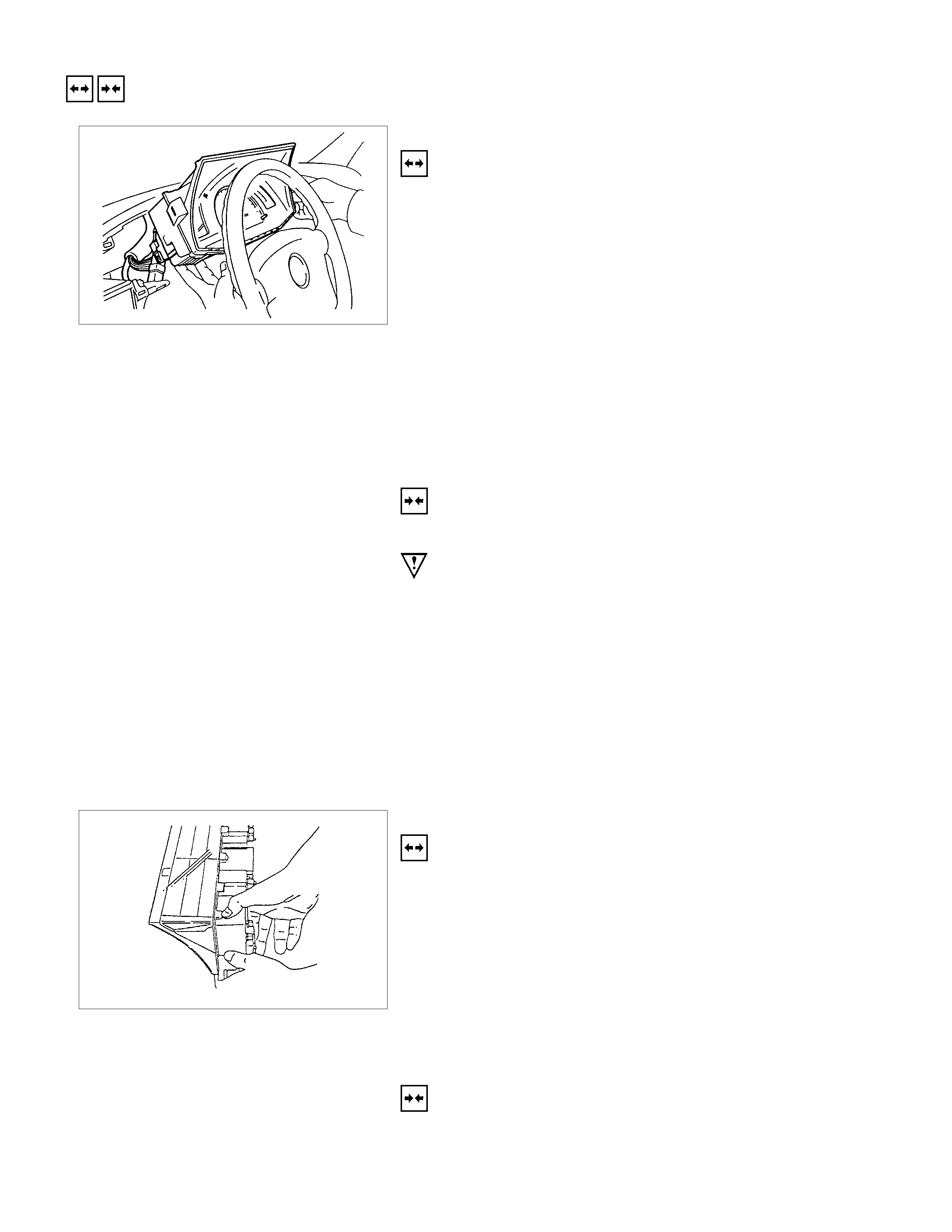
REMOVAL AND INSTALLATION
METER ASSEMBLY
REMOVAL
1. Instrument Panel Driver Lower Cover
•Refer to the removal steps of “INSTRUMENT PANEL”
in Section 1C “CAB”.
2. Lower Cluster Assembly
•Refer to the removal steps of “INSTRUMENT PANEL”
in Section 1C “CAB”.
3. Instrument Panel Cluster Assembly
•Refer to the removal steps of “INSTRUMENT PANEL”
in Section 1C “CAB”
4. Meter Assembly
•Remove four screws of the meter assembly.
•Disconnect the meter connectors.
INSTALLATION
Follow the removal procedure in the reverse order to install the
meter.
Pay close attention to the important points mentioned in the
following paragraphs.
Connector
Be absolutely sure that the meter connectors are securely
connected.
This will prevent a poor contact and an open circuit.
Wire Harness
Do not pinch the wire harness between the cluster and the
meter hood during the meter assembly installation procedure.
Wire damage will result.
METERS AND GAUGES
REMOVAL
1. Meter Assembly
•Refer to “METER ASSEMBLY” removal steps in this
system.
2. Meter Glass
3. Meter Needless
•Pull out the needles of speedometer and tachometer
4. Meter Board
•Loosen four fixing screws.
5. Meters and Gauges
INSTALLATION
To Install, follow the removal steps in the reverse order.
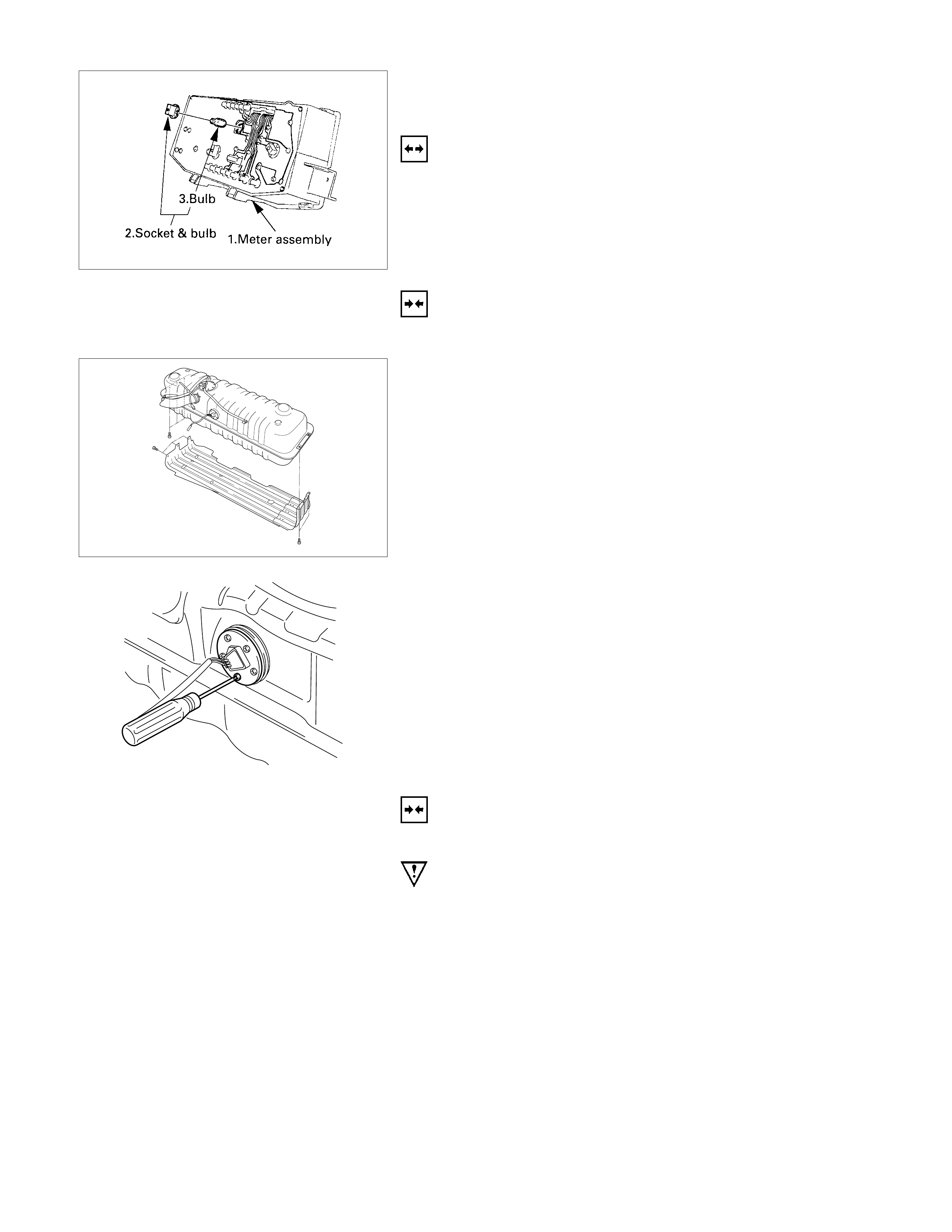
WARNING LI GHT BULB, INDI CATOR LIGHT BULB
AND ILLUMINATION LIGHT BULB
REMOVAL
Turn the bulb socket counterclockwise and pull the bulb out.
INSTALLATION
To Install, follow the removal steps in the reverse order.
FUEL TANK UNIT
REMOVAL
Dismount the fuel tank first, then remove the fuel tank unit.
1. Disconnect the fuel tank unit connector.
2. Loosen the screws.
3. Remove the fuel tank unit from the fuel tank.
INSTALLATION
Follow the removal procedure in the reverse order to install the
fuel tank unit.
Pay close attention to the important points mentioned in the
following paragraphs.
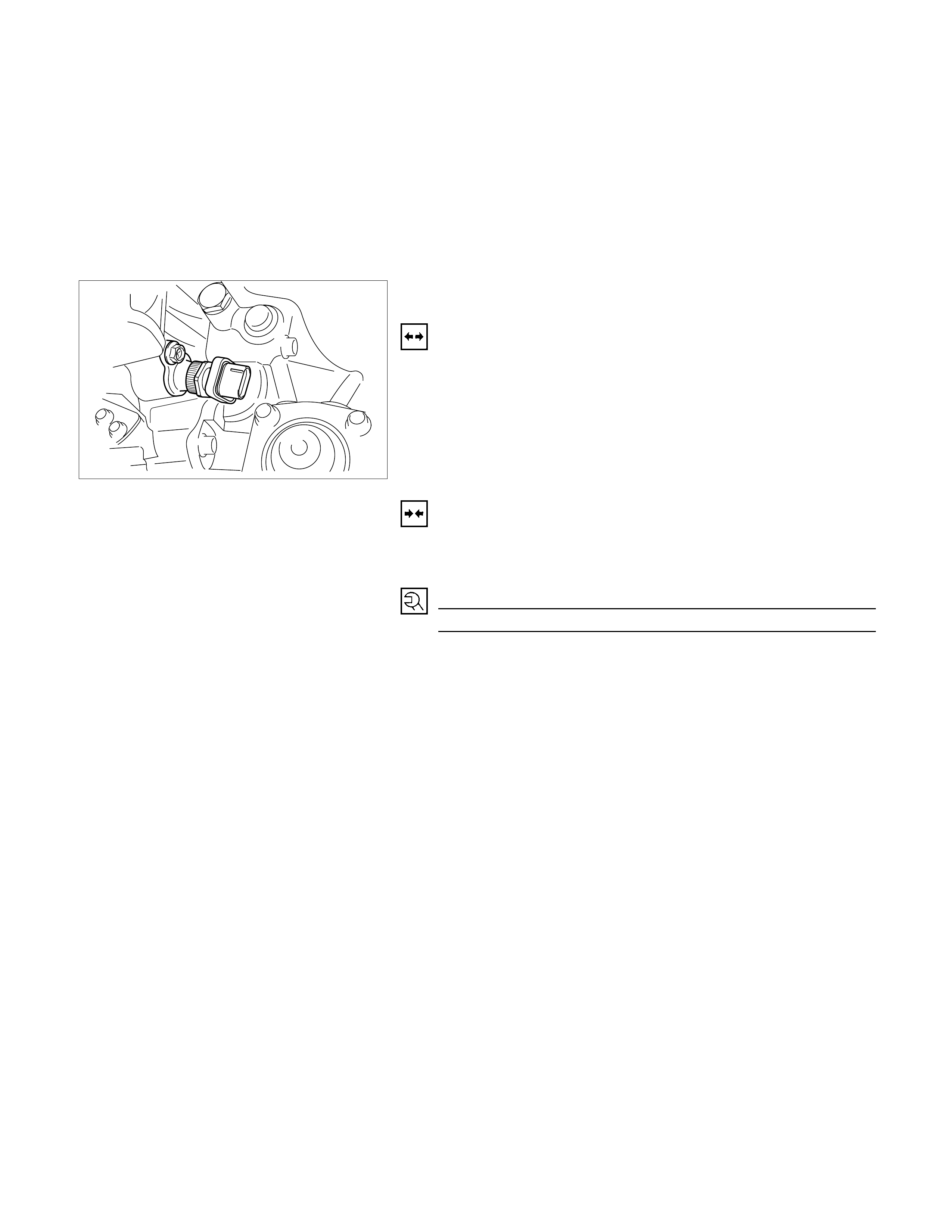
RUBBER SEAL
Be absolutely sure that the fuel tank unit rubber seal is
correctly seated.
CONNECTOR
Be absolutely sure that the fuel tank unit connector is securely
connected.
This will prevent a poor contact and an open circuit.
VEHICLE SPEED SENSOR ( INSTALLED ON THE
TRANSMISSION)
REMOVAL
1. Disconnect the connector.
2. Remove the vehicle speed sensor body by rotating it.
INSTALLATION
To Install, follow the removal steps in the reverse order, noting
the following point.
Tighten the vehicle speed sensor to the specified torque.
Vehicle Speed Sensor Tightening Torque N⋅m (kgf⋅m/lb.ft)
25 ± 4.9 (2.5 ± 0.5/18 ± 3.6)
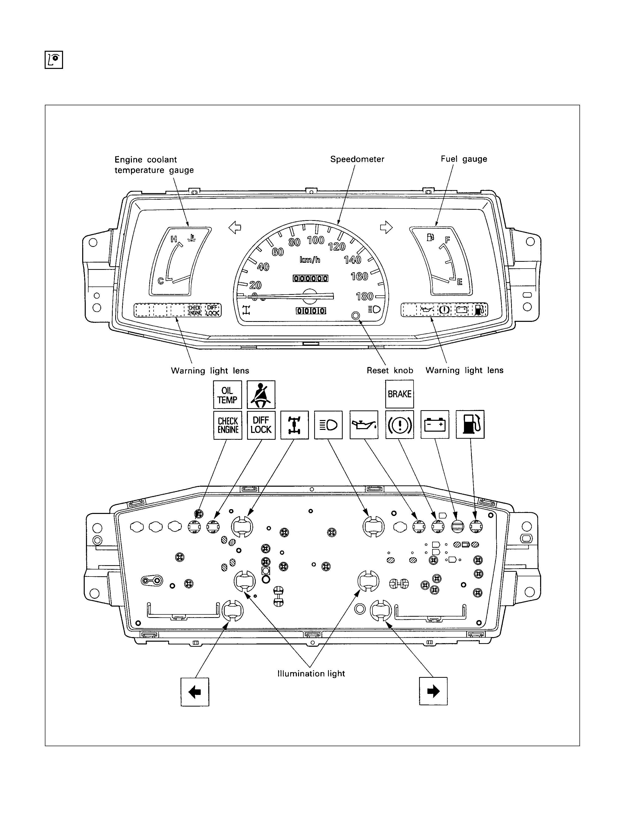
INSPECTION AND REPAIR
WARNING, INDICATOR AND ILLUMINATION LIGHT POSITION W/O TACHOMETER
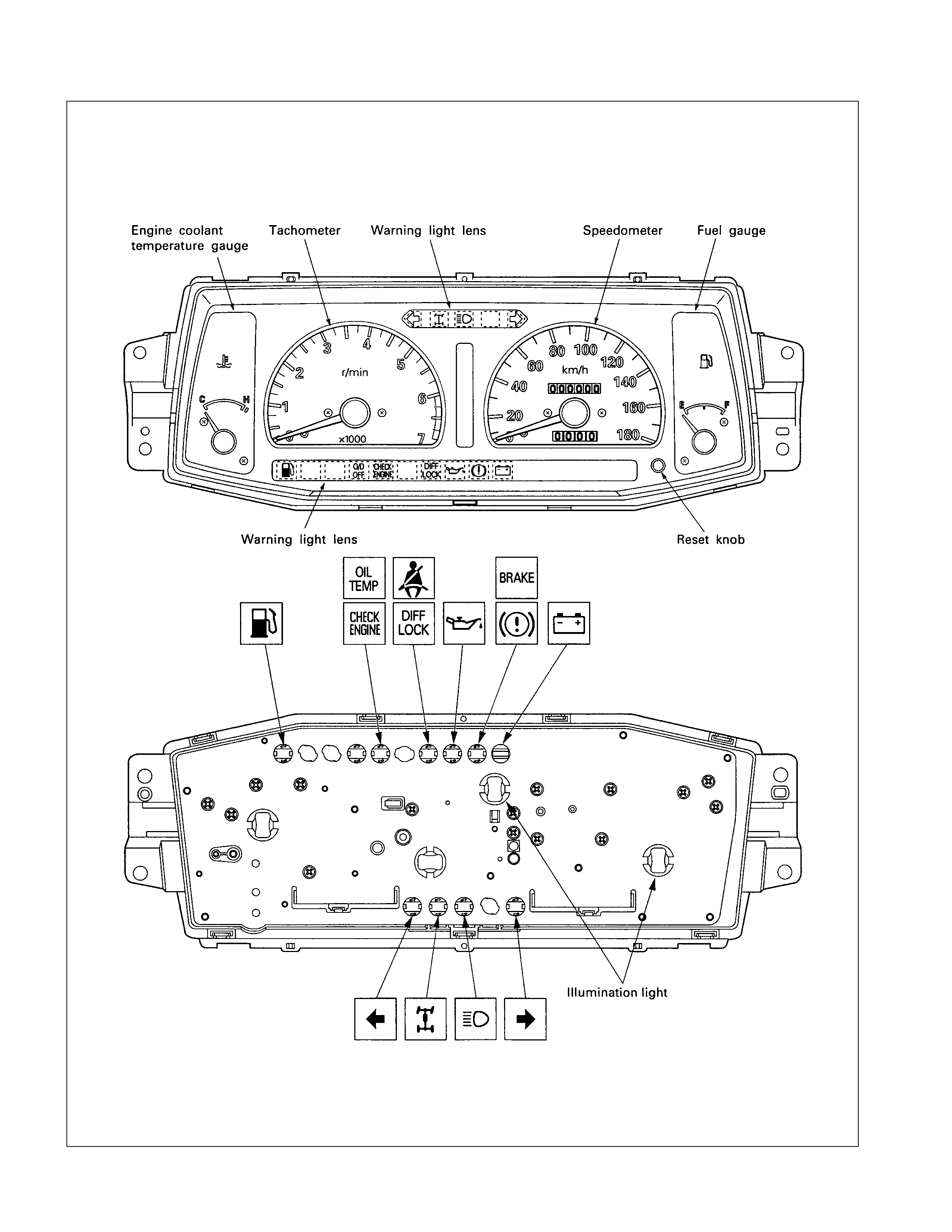
W/ TACHOMETER- 1
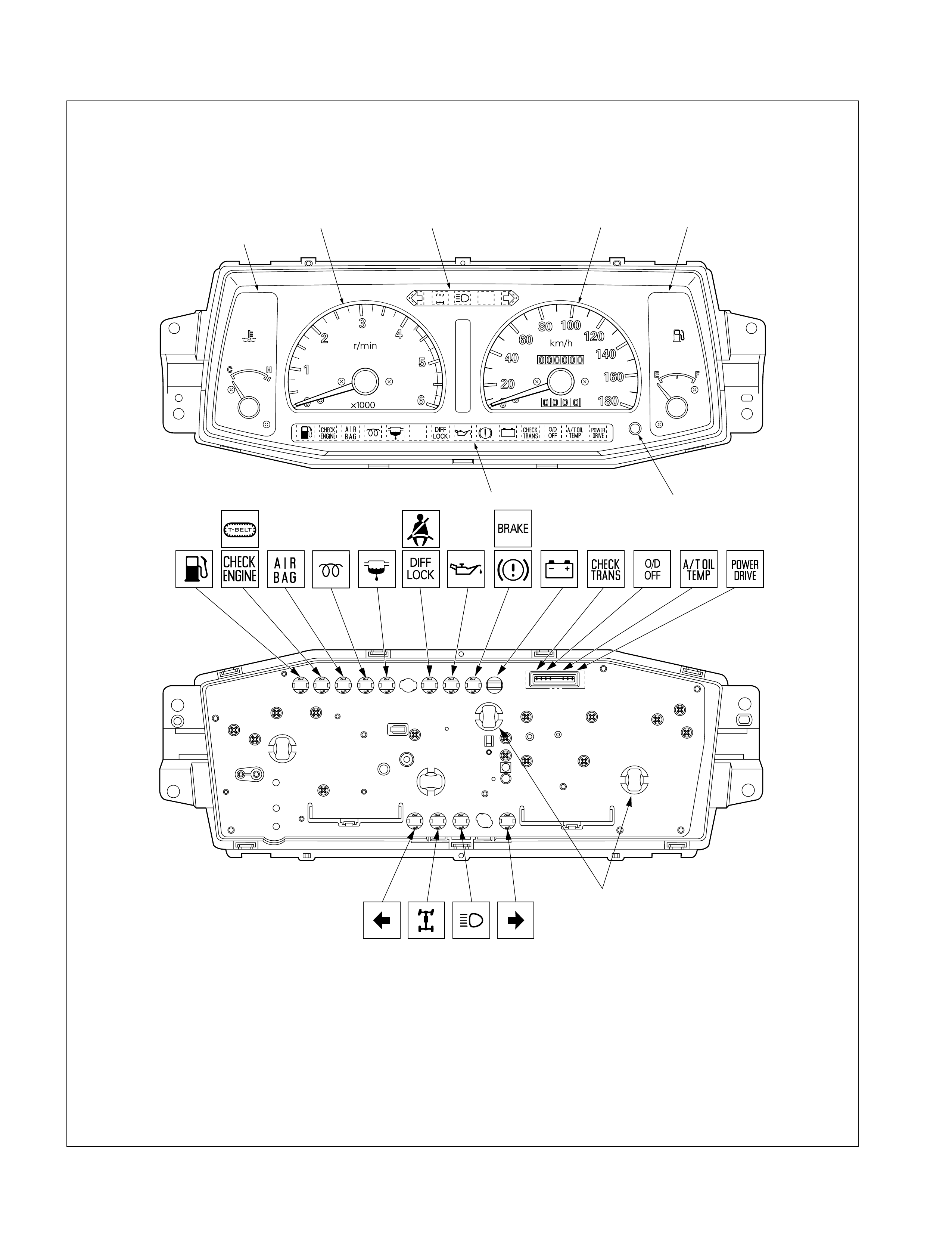
W/ TACHOMETER- 2
Illumination light
Reset knobWarning light lens
Warning light lensTachometerEngine coolant
temperature gauge Fuel gaugeSpeedometer
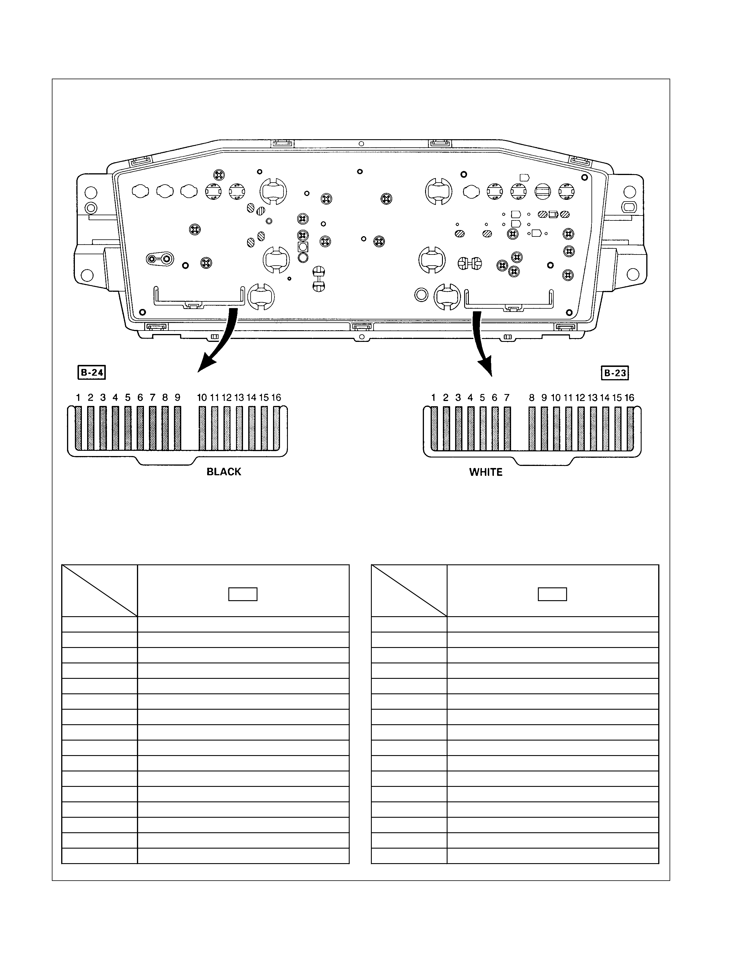
METER CONNECTOR PIN ARRANGEMENT W/O TACHOMETER-1
Connector
Ter- No.
minal No. B-24
1 Ground
2 Ignition
3-
4-
5-
6 Engine coolant temperature gauge
7-
8-
9 Check engine warning light
10 -
11 High-beam indicator light (+)
12 High-beam indicator light (-)
13 Illumination light (+)
14 Illumination light (-)
15 4WD indicator light
16 Turn signal indicator light (left)
Connector
Ter- No.
minal No. B-23
1 Turn signal indicator light (right)
2-
3-
4-
5 Ground
6-
7 Ignition
8 Speedometer
9 Speedometer
10 Oil pressure warning light
11 Fuel gauge
12 Brake warning light
13 Charge warning light
14 -
15 -
16 Fuel warning light (Except Chile)
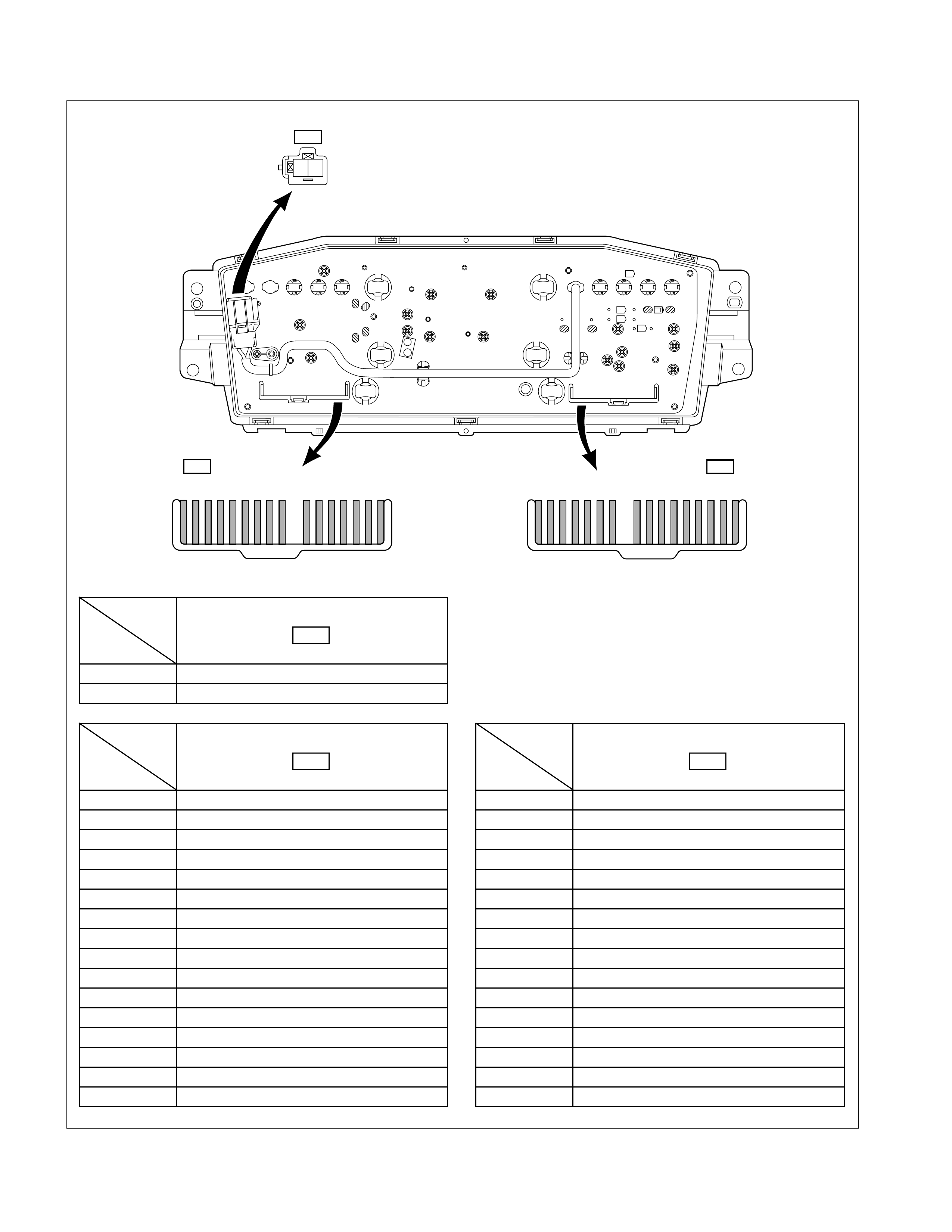
W/O TACHOMETER-2
123456789 10111213141516 1234567 8910111213141516
BLACK
YELLOW
B-24
B-37
B-23
WHITE
2 1
Connector
Ter- No.
minal No. B-24
1 Turn signal indicator light
2 Ignition
3-
4-
5-
6 Engine coolant temperature gauge
7 Seat belt warning light
8 Glow indicator light
9 Water sedimenter warning light
10 Rear fog light indicator light
11 High-beam indicator light (+)
12 High-beam indicator light (-)
13 Illumination light (+)
14 Illumination light (-)
15 4WD indicator light
16 Turn signal indicator light (left)
Connector
Ter- No.
minal No. B-23
1 Turn signal indicator light (right)
2-
3-
4-
5 Ground
6-
7 Ignition
8 Speedometer
9 Speedometer
10 Oil pressure warning light
11 Fuel gauge
12 Brake warning light
13 Charge warning light
14 -
15 -
16 Fuel warning light
Connector
Ter- No.
minal No. B-37
1 Air bag Warning light
2 Air bag Warning light
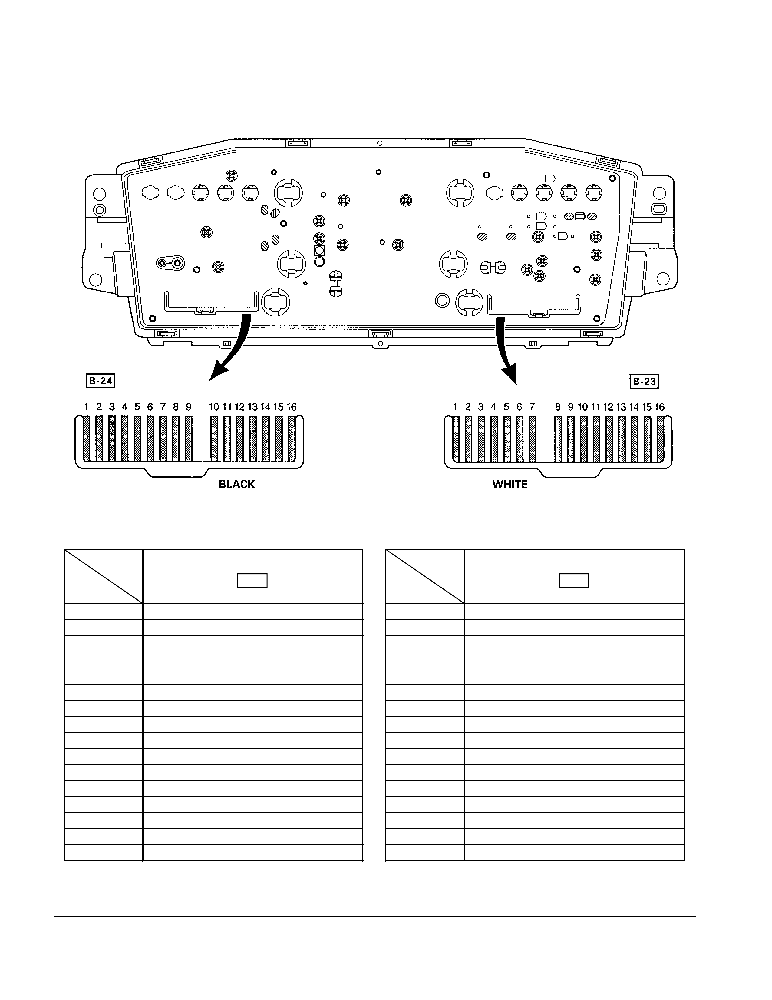
W/ TACHOMETER- 1
Connector
Ter- No.
minal No. B-24
1 Ground
2 Ignition
3 Tachometer
4-
5-
6 Engine coolant temperature gauge
7-
8-
9 Check engine warning light
10 -
11 -
12 -
13 Illumination light (+)
14 Illumination light (-)
15 4WD indicator light
16 Turn signal indicator light (left)
Connector
Ter- No.
minal No. B-23
1 Turn signal indicator light (right)
2-
3 High-beam indicator light (+)
4 High-beam indicator light (-)
5 Ground
6-
7-
8 Speedometer
9 Speedometer
10 Oil pressure warning light
11 Fuel gauge
12 Brake warning light
13 Charge warning light
14 Illumination light (+)
15 Illumination light (-)
16 Fuel warning light (Except Chile)
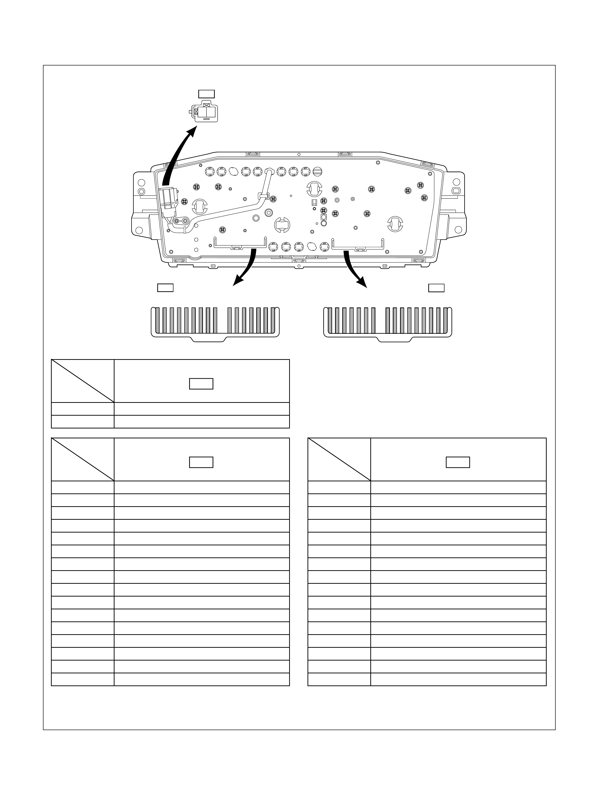
W/ TACHOMETER- 2
YELLOW
B-37
2 1
123456789 10111213141516 1234567 8910111213141516
BLACK
B-24 B-23
WHITE
Connector
Ter- No.
minal No. B-24
1 Turn signal indicator light
2 Ignition
3 Tachometer
4-
5-
6 Engine coolant temperature gauge
7 Seat belt warning light
8 Glow indicator light
9 Water sedimenter warning light
10 Rear fog light indicator light
11 -
12 -
13 Illumination light (+)
14 Illumination light (-)
15 4WD indicator light
16 Turn signal indicator light (left)
Connector
Ter- No.
minal No. B-23
1 Turn signal indicator light (right)
2-
3 High-beam indicator light (+)
4 High-beam indicator light (-)
5 Ground
6-
7-
8 Speedometer
9 Speedometer
10 Oil pressure warning light
11 Fuel gauge
12 Brake warning light
13 Charge warning light
14 Illumination light (+)
15 Illumination light (-)
16 Fuel warning light
Connector
Ter- No.
minal No. B-37
1 Air bag warning light
2 Air bag warning light

W/ TACHOMETER- 3
Connector
Ter- No.
minal No.
B-24
1 Turn signal indicator light
2 Ignition
3 Tachometer
4 -
5 -
6 Engine coolant temperature gauge
7 Air bag warning light
8 Glow indicator light
9 Water sedimenter warning light
10 Seat belt warning light
11 -
12 -
13 Illumination light (+)
14 Illumination light (-)
15 4WD indicator light
16 Turn signal indicator light (left)
Connector
Ter- No.
minal No.
B-23
1 Turn signal indicator light (right)
2 -
3 High-beam indicator light (+)
4 High-beam indicator light (-)
5 Ground
6 Check engine warning light
7 -
8 Speedometer
9 Speedometer
10 Oil pressure warning light
11 Fuel gauge
12 Brake warning light
13 Charge warning light
14 Illumination light (+)
15 Illumination light (-)
16 Fuel warning light
Connector
Ter- No.
minal No.
B-39
1 Power drive indicator light (-)
2 Power drive indicator light (+)
3 A/T Oil temperature warning light (-)
4 O/D OFF indicator light (-)
5 Check trans warning light (+)
6 O/D OFF indicator light (+)
7 Check trans warning light (-)
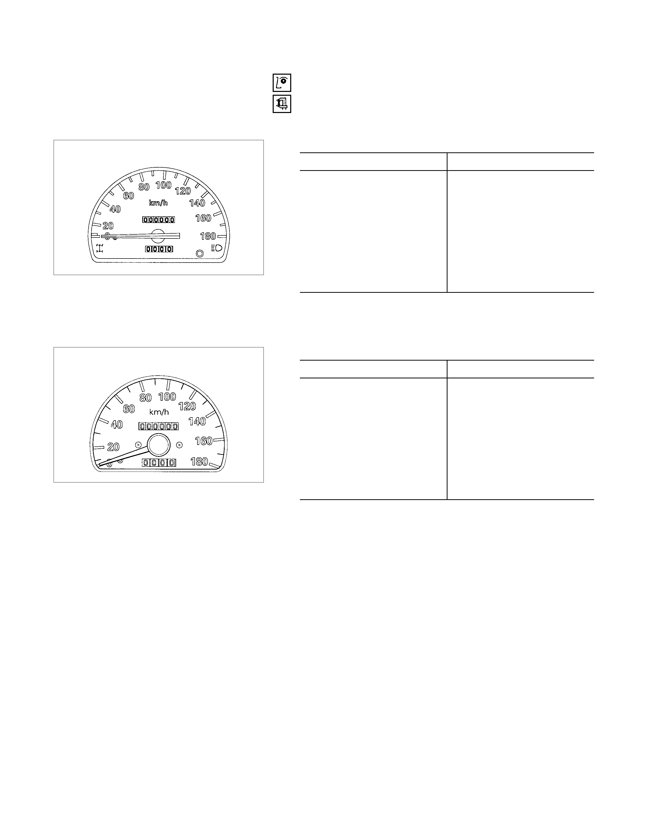
SPEEDOMETER AND TACHOMETER
SPEEDOMETER ON- VEHICLE INSPECTION
Check the speedometer accuracy with a speedometer tester.
Carefully follow the tester manufacturer’s instructions.
W/O Tachometer km/h
Indication Permissible Range
20 17.2-22.8
40 37.2-42.8
60 57.2-62.8
80 77.2-82.8
100 97.3-103.7
120 117.3-123.7
140 137.3-143.7
160 156.9-164.1
W/ Tachometer km/h
Indication Permissible Range
20 17.5-22.5
40 37.5-42.5
60 57.5-62.5
80 77.5-82.5
100 97.6-103.4
120 117.6-123.4
140 137.6-143.4
160 157.2-163.8
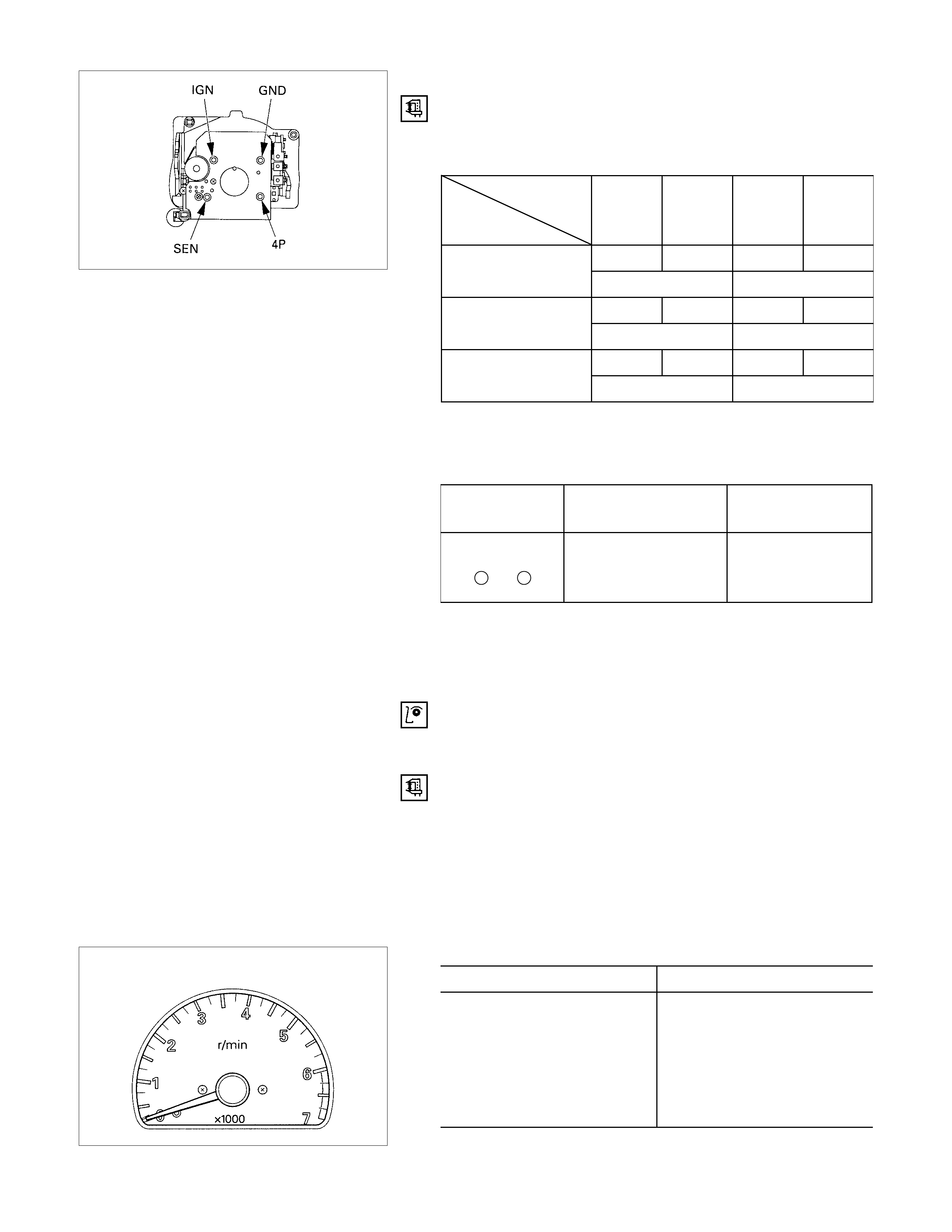
SPEEDOMETER OFF- VEHI CLE INSPECTION
Remove the speedometer from the meter assembly and
measure the resistance and the current consumption between
each terminal.
Speedometer Resistance
Tester
Terminal terminal
symbol Red (+) Black (-) Black (-) Red (+)
IGN GND IGN GND
∞30.6 - 37.4k
SEN GND SEN GND
28.8 - 35.2k ∞
4P GND 4P GND
13.5 - 16.5k ∞
4P - GND
SEN - GND
IGN - GND
Note: Use the analog type circuit tester (range: × 1k).
Speedometer Current Consumption
Terminal
symbol Current
consumption Remarks
IGN - GND
+ -
85 ± 15mA
(when 12 ± 1V
applied) No signal input
Note: 1. Use the analog type circuit tester.
2. Since the current consumption fluctuates when the
source voltage varies, check to be sure that the
voltage applied is 12V ± 1V.
TACHOMETER ON-VEHICLE INSPECTION
1. Attach a tune-up tester to the engine.
2. Start the engine.
3. Compare the tachometer reading and the tester reading.
If the tachometer indication is outside the permissible
range, the tachometer must be replaced.
4. Gradually increase and decrease the engine speed.
Note the movement of the tachometer needle.
If the needle movement is sluggish, the tachometer must be
replaced.
Gasoline engine rpm
Indication Permissible Range
1,000 940-1060
2,000 1875-2125
3,000 2850-3150
4,000 3820-4180
5,000 4820-5180
6,000 5820-6180

Gasoline engine (6VD1) Gasoline engine (6VD1) rpm
Indication Permissible Range
1,000 900-1060
2,000 1820-2070
3,000 2820-3120
4,000 3820-4180
5,000 4820-5180
6,000 5820-6180
7,000 6820-7180
Diesel engine Diesel engine rpm
Indication Permissible Range
750 690-810
2,000 1875-2125
3,000 2850-3150
4,000 3820-4180
5,000 4820-5180
TACHOMETER OFF-VEHICLE INSPECTION
Remove the tachometer from the meter assembly and
measure the resistance value and the current consumption
between each terminal.
Tachometer Resistance
Tester
Terminal terminal
symbol Red (+) Black (-) Black (-) Red (+)
IGN GND IGN GND
∞23 - 31k
PGNDPGND
28.8 - 35.2k ∞
P - GND
IGN - GND
Note: Use the analog type circuit tester (range: × 1k).
Tachometer Current Consumption
Terminal
symbol Current
consumption Remarks
IGN - GND
+ -
90 ± 15mA
(12 ± 1V when
voltage applied) No signal input
Note: 1. Use the analog type circuit tester.
2. Since the current consumption fluctuates as the source
voltage varies, check voltage applied is 12V ± 1V.
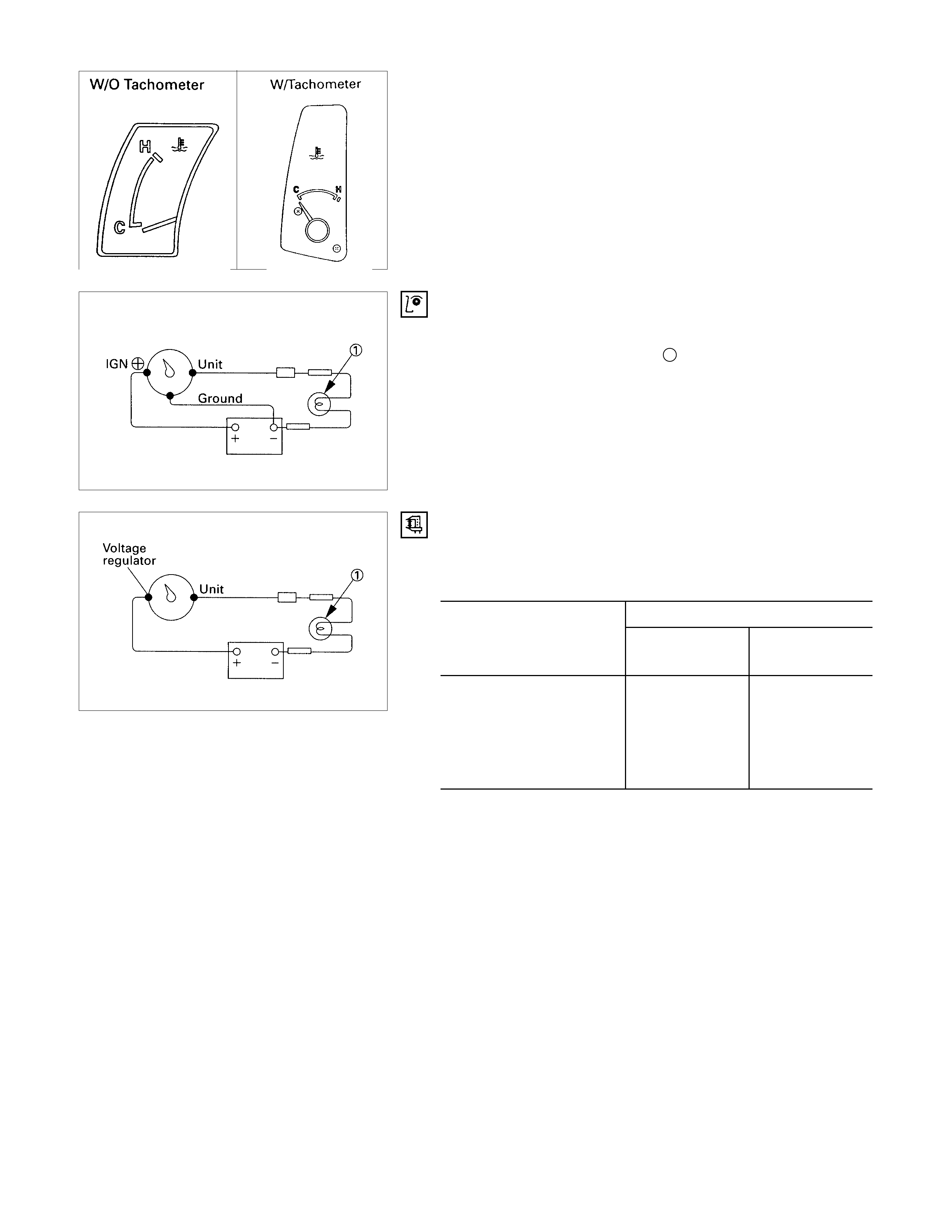
TEMPERATURE GAUGE AND THERMO UNIT
TEMPERATURE GAUGE ON-VEHICLE INSPECTION
1. Disconnect the temperature gauge wire connector.
2. Connect a 3.4 Watt test bulb 1 to the ground.
The gauge needle should move the middle part of the
gauge
TEMPERATURE GAUGE OFF-VEHICLE I NSPECTION
Use a circuit tester to measure the temperature gauge
resistance.
Temperature Gauge Resistance Ω
Standard
Measuring Point With
Tachometer Without
Tachometer
IGN (+) - Ground 130 -
IGN (+) - UNIT 82 -
UNIT - Ground 212 -
VOLTAGE
REGULATOR - UNIT - 25
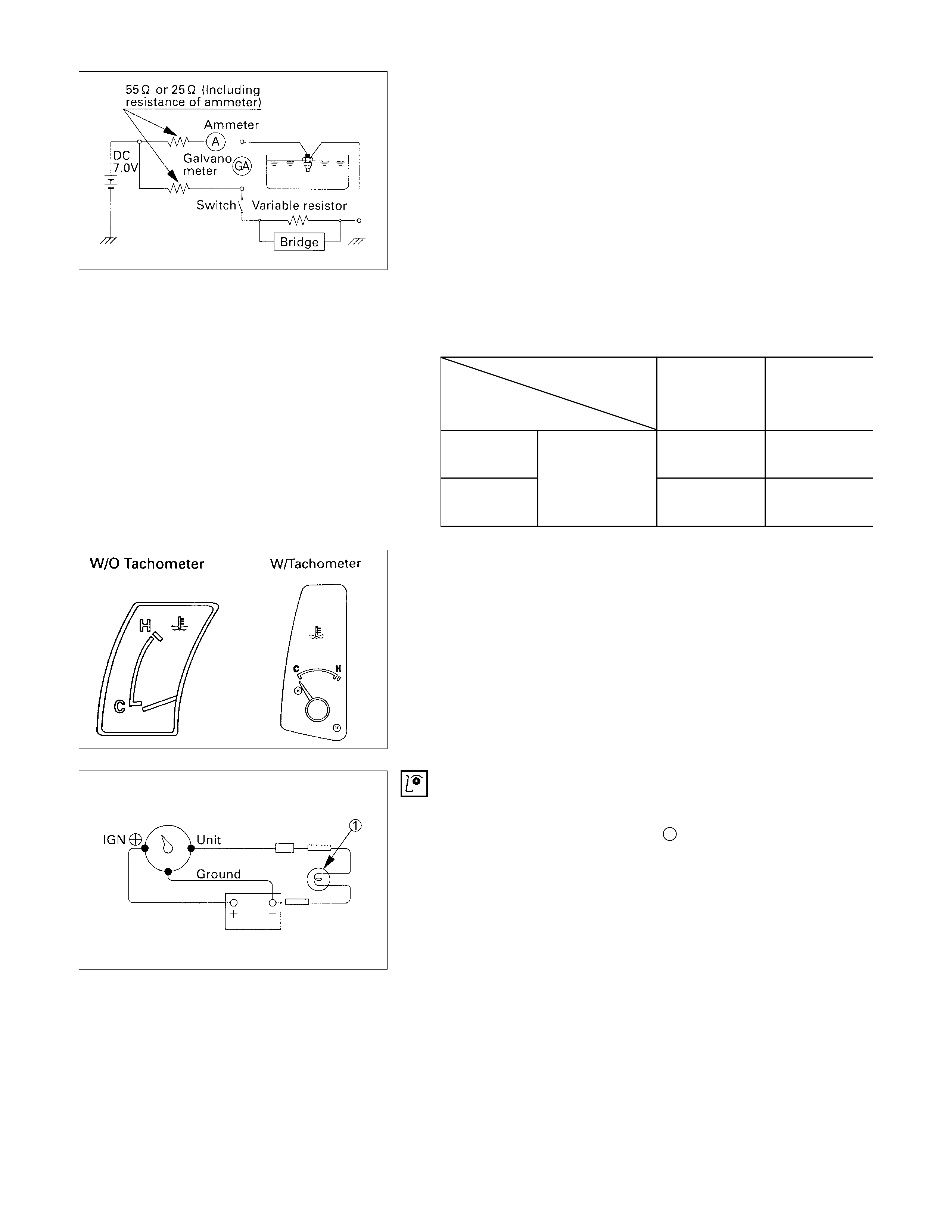
THERMO UNIT INSPECTION
The thermo unit is thermistor type and must be inspected
under the conditions as shown in the left chart.
1. Put the deviation of the galvanometer to 0 by using the
variable resistor, switch the thermo unit off and then
measure the resistance of the resistor through the bridge.
Confirm that the resistance is continuously variable in any
other points than those shown in the following table.
2. Dip the thermo unit into 80 - 90°C (176 - 194°F) water and
confirm that there is no bubble continuously coming out o
f
inside of the unit.
Replace the unit when the result of inspection is found
abnormal. Temperature
Check
condition
50°C
(122°F) 115°C
(239°F)
7V 55 Ω
Gauge Resistance +33.6
226.0 -36.6 +1.71
26.4 -2.21
7V 25 Ω
Gauge value (Ω)-+2.68
24.3 -3.68
FUEL GAUGE AND TANK UNIT
FUEL GAUGE ON- VEHICLE INSPECTION
1. Disconnect the fuel gauge wire connector.
2. Connect a 3.4 Watt test bulb 1 to the ground.
The gauge needle should more the middle part of the
gauge.
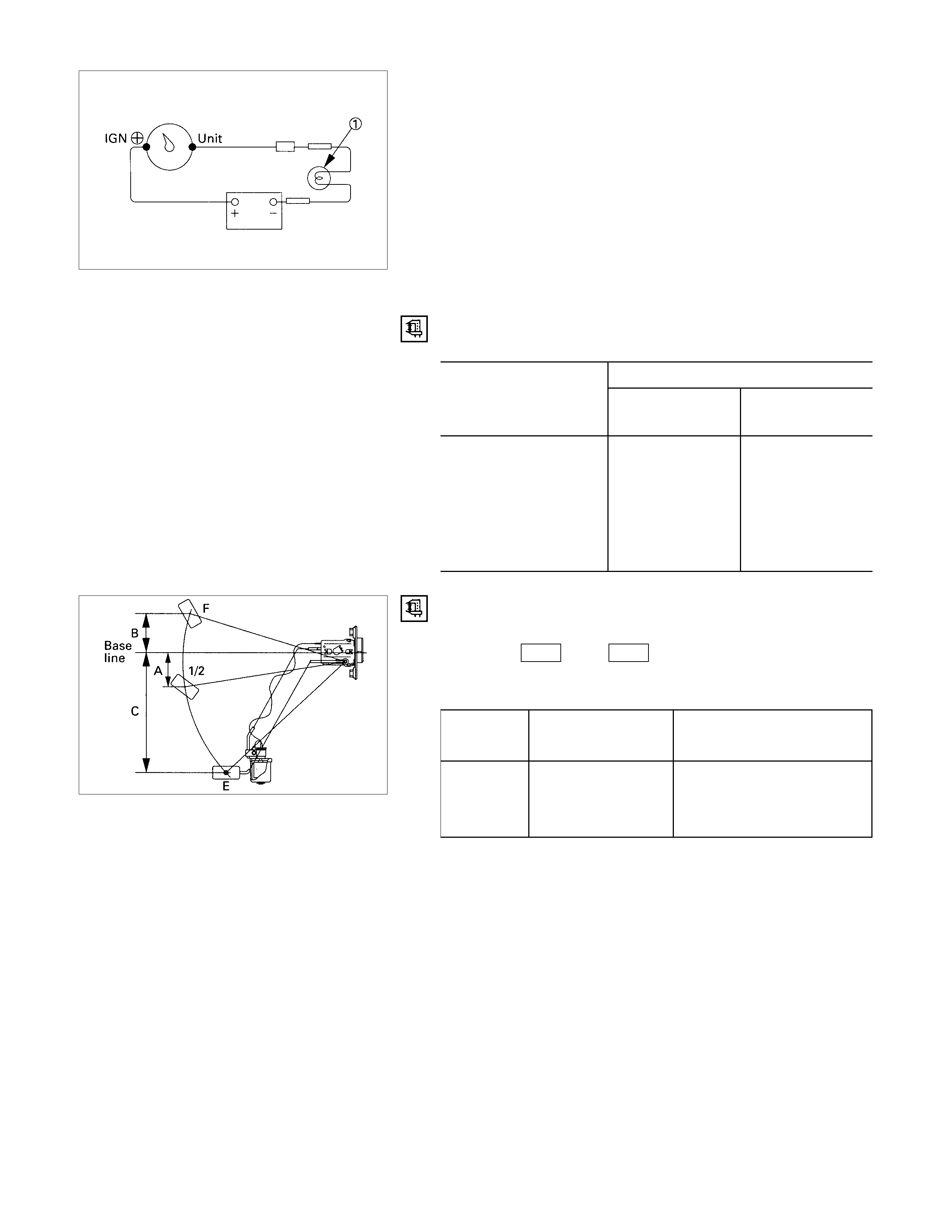
FUEL GAUGE OFF- VEHICLE INSPECTION
Use a circuit tester to measure the fuel gauge resistance.
Fuel Gauge Resistance Ω
Standard
Measuring Point With
Tachometer Without
Tachometer
IGN (+) - Ground 223 110
IGN (+) - 7V (0)
IGN (+) - UNIT 83 25
Ground - 7V 110
Ground - UNIT 140 135
7V - UNIT 25
FUEL TANK UNIT INSPECTION
Measure the fuel tank unit resistance between the connector
terminals 1 F-1 and 3 F-1 while shifting the float from “E”
to “F” point.
Fuel Tank Resistance
Level Float position
mm Standard resistance
Ω
F (B) 51.7 17 ± 2.1
1/2 (A) 49.4 45 ± 4.5
E (C) 166.9 120 ± 6.5
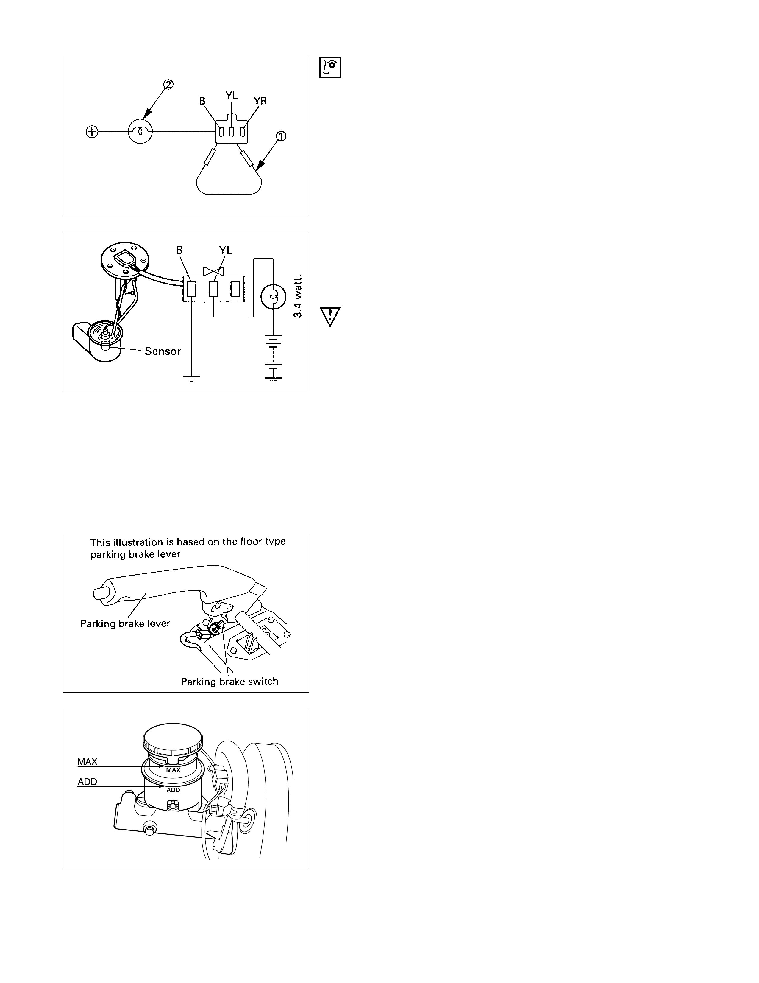
LOW FUEL I NDI CATOR LIGHT INSPECTION
1. Disconnect the fuel tank unit wire connector.
2. Connect between terminal (YL) and (B).
3. Turn the key switch on. Check that the bulb lights.
If operation is not correct, remove and check the bulb or circuit.
CHECK LEVEL SENSOR OPERATION
1. Remove the fuel tank unit.
2. Apply battery voltage between terminal (YL) and (B) through
a 3.4 watt bulb. Check that the bulb lights.
Note:
It will take a short time for the bulb light.
3. Submerge the sensor in fuel. Check that the bulb goes out.
If operation is not correct, replace the fuel tank unit.
BRAKE SYSTEM WARNING LIGHT
The brake system warning light comes on while the parking
brake is set and the starter key is ON position.
Note:
The parking brake indicator light circuit is designed to
prevent driving of the vehicle with the parking brake on.
It does not indicate the condition of the parking brake
system.
The parking brake switch is in parallel with the brake fluid
switch.
The brake system warning light also comes on when reservoir
brake fluid level falls below the specified limit with the parking
brake released and the starter switch is ON position.
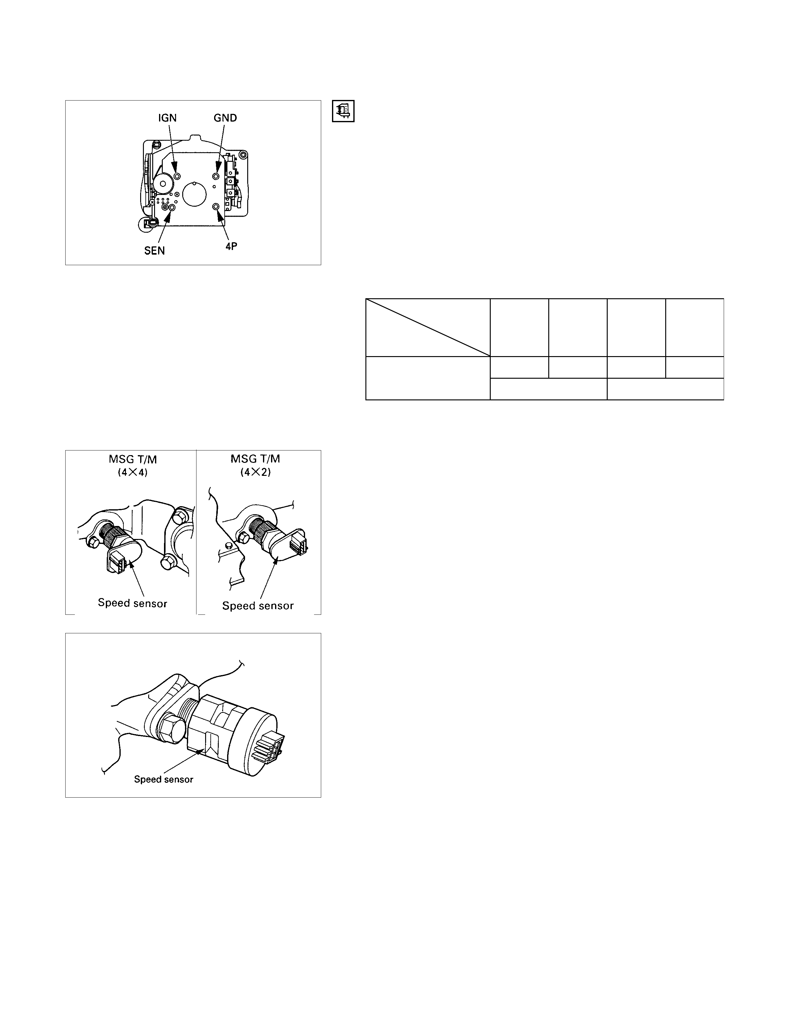
VEHICLE SPEED SENSOR ( INCORPORATED IN THE
SPEEDOMETER)
VEHICLE SPEED SENSOR I NSPECTION
Remove the speedometer from the meter assembly and
measure the resistance value between the terminals.
Speed Sensor Resistance
Tester
Terminal terminal
symbol Red (+) Black (-) Black (-) Red (+)
4P GND 4P GND
13.5 - 16.5k ∞
4P - GND
Note: Use the analog type circuit tester.
VEHICLE SPEED SENSOR ( INSTALLED ON THE
TRANSMISSION)
The speed sensor is installed on the rear portion of the
transmission.
The number of pulses generated is four pulses per one rotation
of the pinion shaft.
MUA T/M
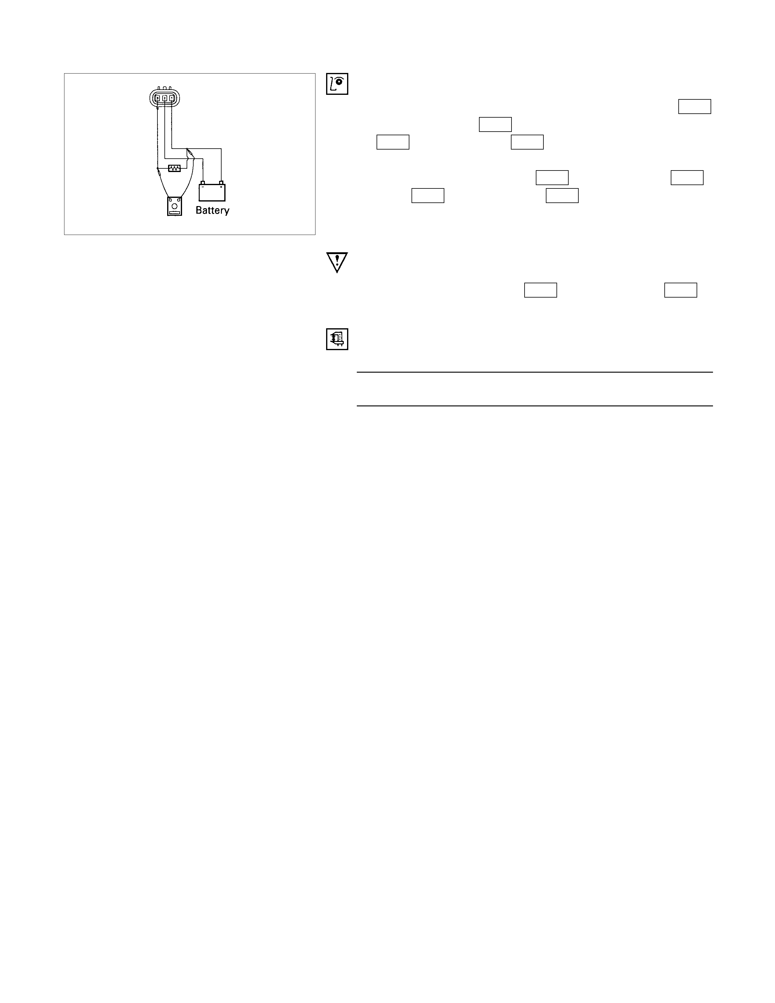
VEHICLE SPEED SENSOR I NSPECTION
1. Connect the vehicle speed sensor connector 1 M-10
(Diesel engine: 1 E-44 ) to the battery (+) terminal and 2
M-10 (Diesel engine: 2 E-44 ) to the (-) terminal.
2. Connect a resistance of 1.3K ohm to 5K ohm (1/4 W o
r
more) between connectors 1 M-10 . (Diesel engine: 1 E-44 )
and 3 M-10 (Diesel engine: 3 E-44 )
CAUTION:
Be extremely careful not to connect the battery (+)
terminal to the connector 3 M-10 (Diesel engine: 3 E-44 ).
This may damage the vehicle speed sensor.
3. Rotate the shaft of the vehicle speed sensor slowly and
measure the voltage at the both ends with a digital tester.
The voltage, with one rotation of shaft fluctuates four times in
the following range: 10 to 14V - 2V or less.
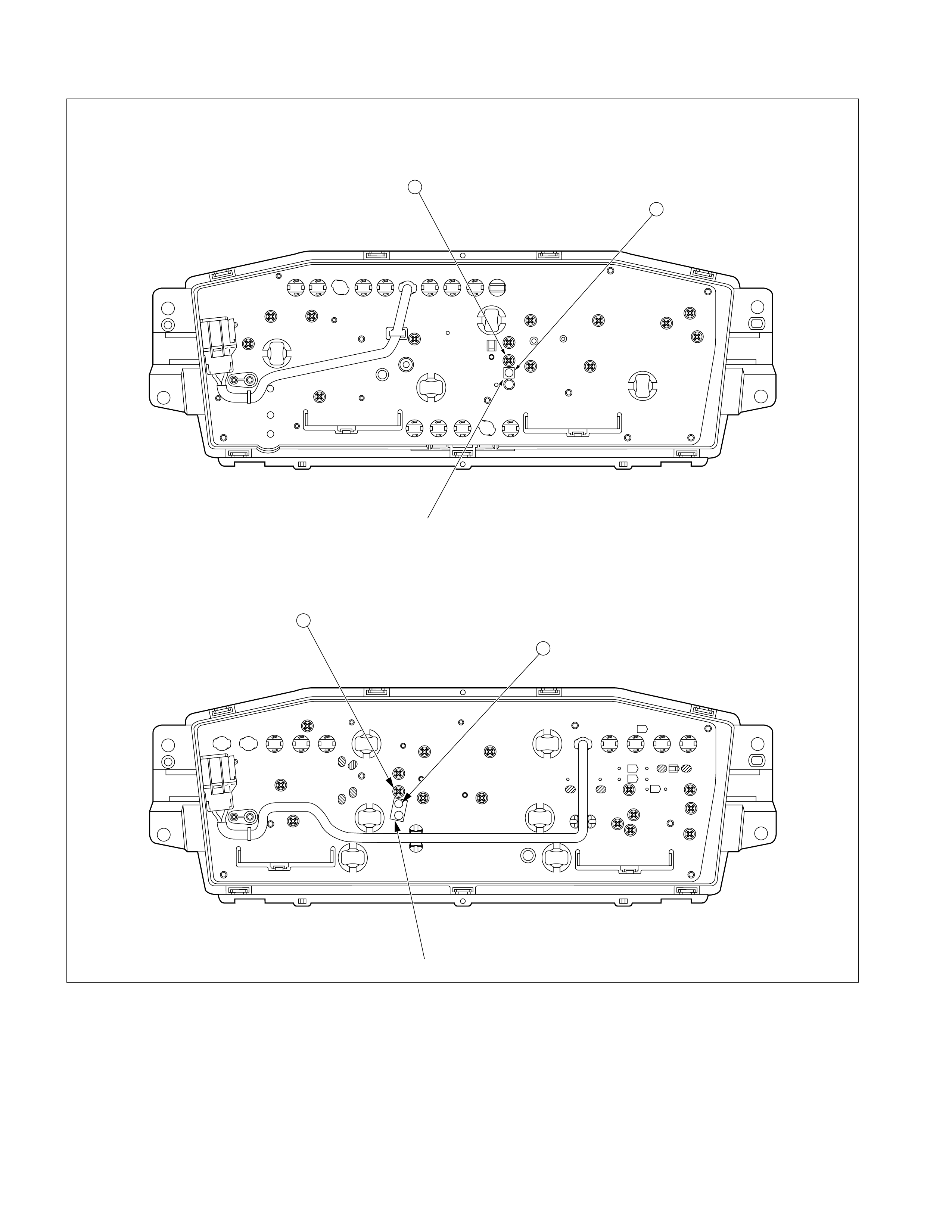
Timing Belt Indicator Light Reset Procedure (If Fitted)
Masking tape
A
B
W/ Tachometer
Masking tape
W/O Tachometer
A
B
Timing belt must be replaced after 100,000 km of vehicle operation.
When the odometer reading reaches 100,000 km, the timing belt indicator light will turn on to remind the driver to
change the timing belt.
After replacing the timing belt, the timing belt indicator light must be reset to remind the driver to replace the timing belt
after the next 100,000 km.

Timing Belt Indicator Light Reset Procedure
1. Remove the masking tape from the hole B.
2. Remove the s crew f rom the hole A and install it to the hole
B.
3. Apply new masking tape to the hole A.
Note:
The above procedure assumes that the timing belt is
being replaced for the first time (after 100,000 km).
For subsequent reset procedure (at next 100,000 km), hole
positions will be the opposite of the above procedure.
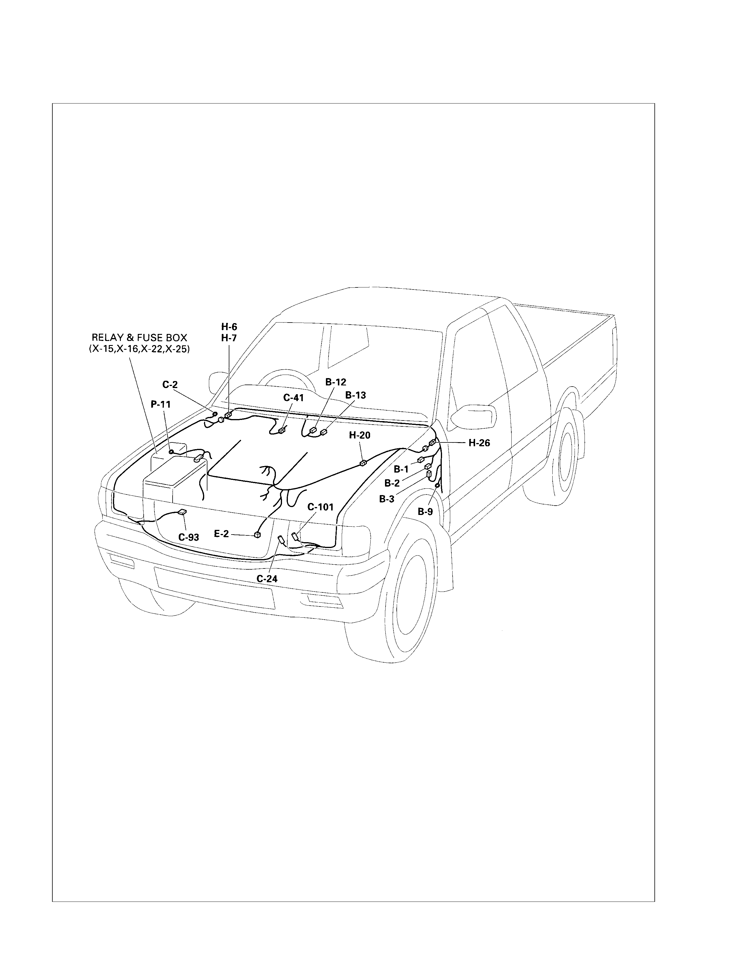
Heater and Air Conditioning
PARTS LOCATION ( 6 VD1)
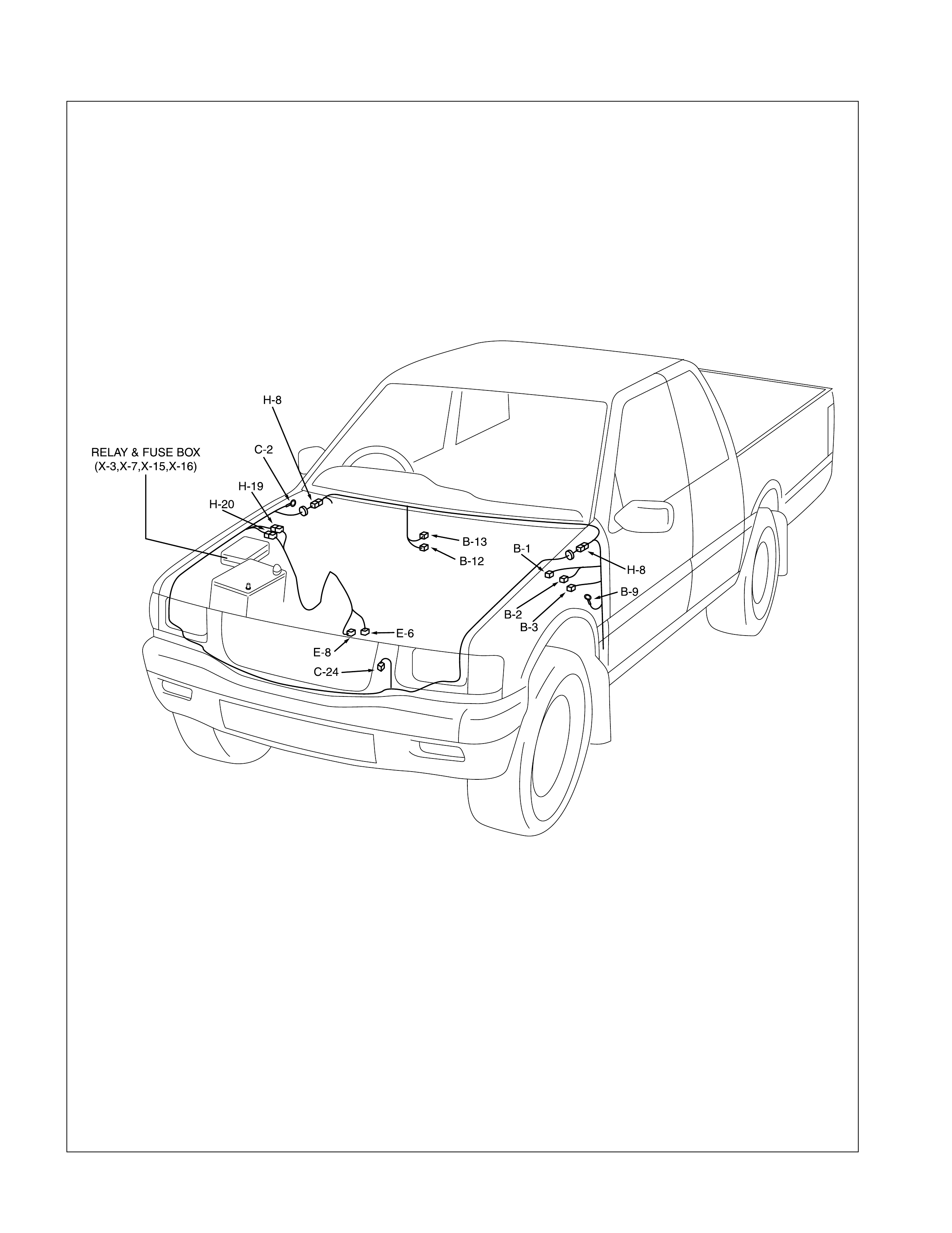
PARTS LOCATION
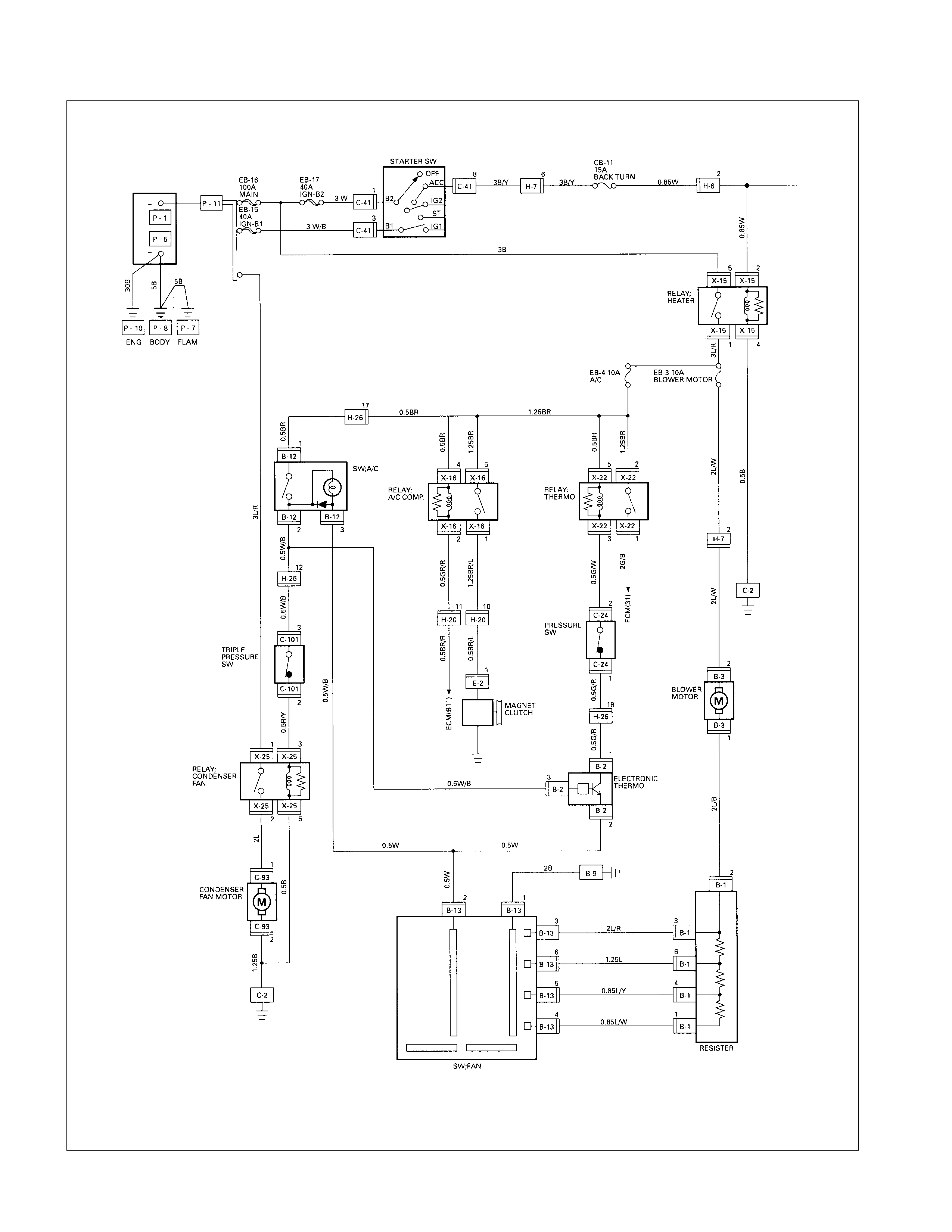
CIRCUIT DIAGRAM (6VD1)

CIRCUIT DIAGRAM
8B
20B
+
-
6V
5B
8BR
SW;IGNITION
OFF
IG1
ST
IG2
ACC BACK TURN
15A
EB-5
A/C
10A
EB-5
A/C
10A
CB-7
METER
15A
3W
3B 3L/R 1.25BR
2L/W
2L/B
0.5B
FRAME
ENG
BODY
0.85W
3W
3W/B
IGN
B-1
50A
IGN B-2
40A
MAIN
80A
5
H-7 C-41
1
C-41
8
H-7
6
H-8
8
B-24
2
B-23
3
H-6
3
H-1
1
H-5
3
C-41
6
H-7
2
C-41
3
3B/R
3B/Y 0.85W
0.85Y 0.85W/L
3B/R
FUSE;ENGINE
FUSE;CHARGE
SW;BACK UP
METER
CHARGE W/L
RELAY;
HEATER
RELAY;
CONDENSER
FAN
RELAY;
A/C COMP
RELAY;
THERMO
EARTH
H-7
2
B-13
4
B-3
2
B-3
1
M
B-1
2
OFF L M
3
M
2
H
CONTROL LEVER
B-13
5
B-13
6
B-13
3
C-2
B-13
1
B-13
2
2L/R
1.25L
0.85L/Y
0.85L/W
B-1
3
B-1
6
B-1
4
B-1
1
RESISTOR
2B
EARTH
B-2
20.5W
B-12
2
B-2
3
B-12
3
0.5W/B
SW;A/C
0.5W
0.5G/R
0.5G/W0.5BR
0.5GR/R
MAGNET
CLUTCH
1.25BR
BUS BAR NO.2
(MICRO ISO)
THERMO
B-2
1
C-24
1
H-8
13
C-24
4
H-8
13
C-24
2
C-24
3
C-92
1
C-92
2
C-95
C-95
SW;
PRESSURE
2G/B
TO ECM
(B10)
0.5BR
1.25BR 1.25BR/L
0.5BR
1.25BR
3L/R 2L 1.25B
0.5R/Y
0.5R/Y 0.5W/B
(MINI ISO)
TO ECM(A16)
H-20
14
EARTH
EARTH
CONDENSER
FAN
30A M
CONDENSER
FAN
0.5B
B2
B1
BLOWER
H-5
3
SW;
PRESSURE
E-6
1
E-6
2
P-10
P-10
P-1
P-5
P-7
B-28 C-36
P-12
Removal and Installation : Refer to “HEATING AND AIR CONDITIONING” Section of this manual.
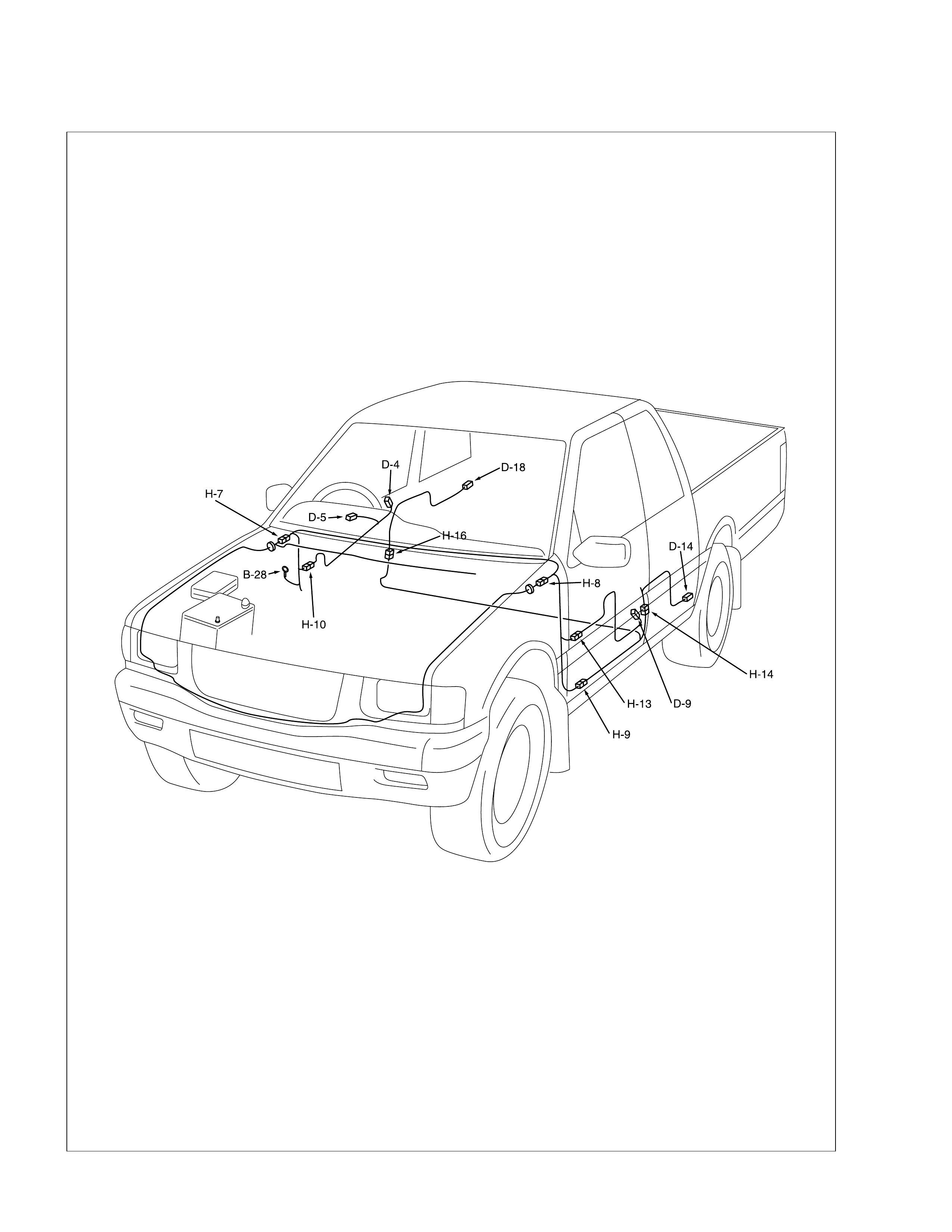
Pow e r Door Lock
PARTS LOCATION (RHD)
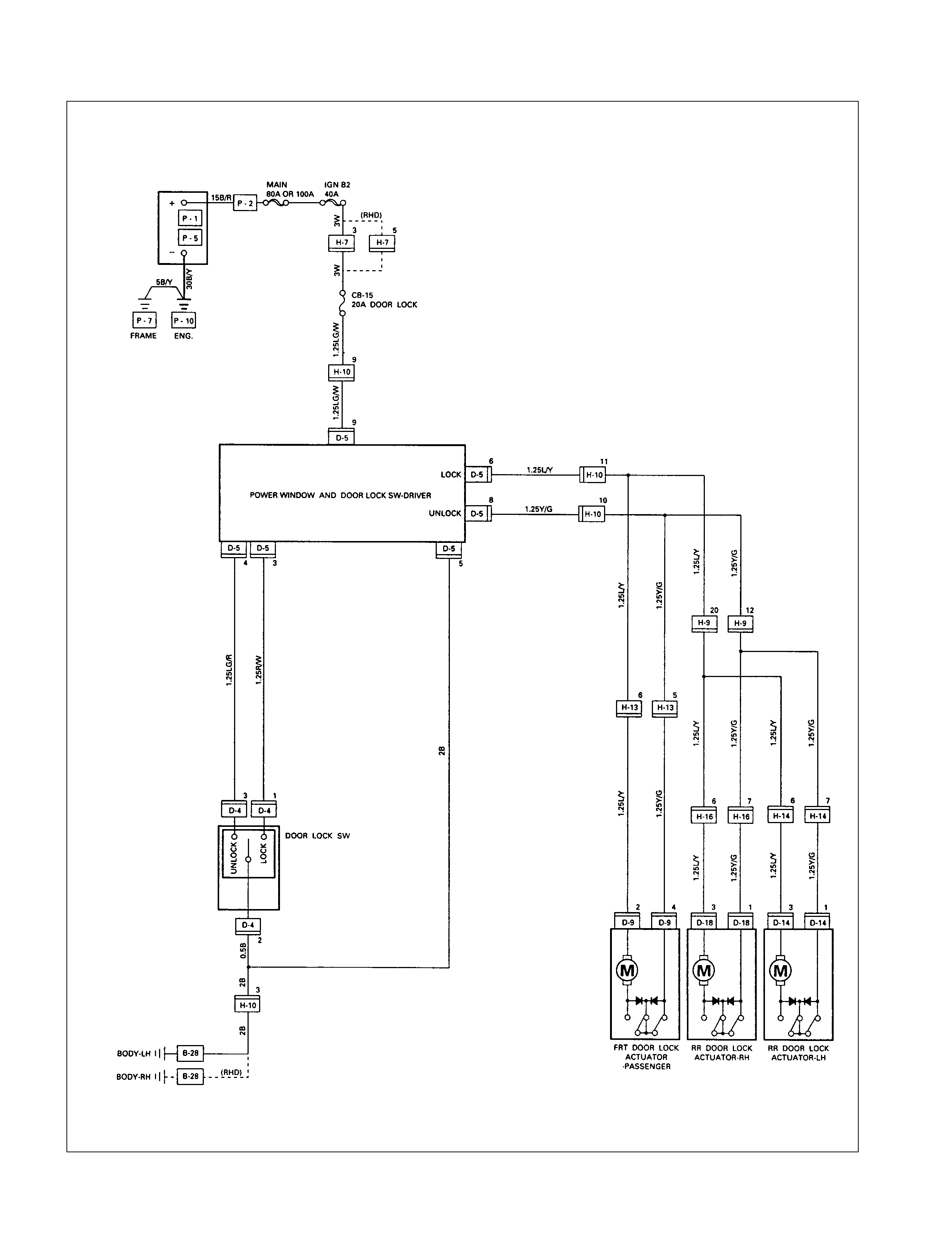
CIRCUIT DIAGRAM
TROUBLESHOOTING
QUICK CHART FOR CHECK POINTS
Check Points Fuse
CB-15
Power Window
& Door Lock
Switch
Door Lock
Switch Door Lock Actuator Cable
Trouble Mode (20A) Driver’s
side Driver’s
side Passenger’
s side RR-RH RR-LH Harnes
s
1. All the doors do not lock
and unlock
2. All the doors do not get
locked (or unlocked)
3. Driver’s side door does not
get locked (or unlocked)
4. FRT passenger’s side door
does not get locked (or
unlocked)
5. RR door-RH does not get
locked (or unlocked)
6. RR door-LH does not get
locked (or unlocked)
7. Door lock does not operate
when operating from the
driver’s seat side
1. All the doors do not lock and unlock
Checkpoint Trouble Cause Countermeasure
Reinstall or replace the fuse
No. CB-15 (20A)
Poor fuse contact or blown
NG
Repair grounding point
(B-28 ) contact
Grounding point ( B-28 )Poor grounding point contact
Repair open circuit or
connector contact
Voltage between the driver’s
side power window & door
lock SW harness side
connector terminal 9 D-5
and the ground (Should be
battery voltage present)
Open circuit or poor connector
contact
NG
NG
OK
OK
OK
Fuse No. CB-15 (20A, Fuse
box)
Repair open circuit or
connector contact
Open circuit or poor connector
contact
NG
Replace the driver’s side
power window & door lock
SW.
Driver’s side power window &
door lock SW. function SW. malfunction
NG
OK
Continuity between 5 D-5
and B-28
2. All the doors do not get locked (or unlocked)
Repair open circuit or
connector contact
Open circuit or poor connector
contact
NG
Replace the driver’s side
power window & door lock
SW.
Driver’s side power window &
door lock SW. function SW. malfunction
NG
OK
Continuity between the driver’s
side power window & door
lock SW harness side
connector terminals 6 D-5
and 8 D-5
3. Driver’s side door does not get locked (or unlocked)
Checkpoint Trouble Cause Countermeasure
Replace the door lock SW.Door lock SW. function SW. malfunction
NG
4. FRT passenger’s side door does not get locked (or unlocked)
Replace the FRT passenger’s
side door lock actuator
FRT passenger’s side door
lock actuator function Actuator malfunction
NG
5. RR door-RH does not get locked (or unlocked)
Replace the RR door lock
actuator-RH
RR door lock actuator-RH
function Actuator malfunction
NG
6. RR door-LH does not get locked (or unlocked)
Replace the RR door lock
actuator-LH
RR door lock actuator-LH
function Actuator malfunction
NG
7. Door lock does not operate when operated from the driver’s seat side
Repair grounding point
(B-28 ) contact
Poor grounding point contact
NG
Replace the door lock SW.
Continuity between the door
lock SW. side connector
terminals 1 D-4 and 2 D-4
when the SW is locked and
between is unlocked 3 D-4
and 2 D-4 when the SW.
SW. malfunction
NG
OK
Grounding point ( B-28 )

REMOVAL AND I NSTALLATION
DRIVER SEAT SIDE POWER W INDOW & DOOR
LOCK SWI TCH
REMOVAL
1. Remove the switch by pushing the spring with the tip of a
screwdriver.
2. Disconnect the connector.
INSTALLATION
To install, follow the removal steps in the reverse order.
DRIVER’S SI DE DOOR LO CK SW ITCH
REMOVAL
1. Door Lock ASM
• Refer to the removal steps of the DOORS in section 1C
“BODY”.
2. Door Lock Switch
INSTALLATION
To install, follow the removal steps in the reverse order.
FRT PASSENGER’S SIDE DOOR LOCK ACTUATOR
REMOVAL
1. Door Lock ASM
• Refer to the removal steps of the DOORS in Section 1C
“BODY”.
2. Door Lock Actuator
•Remover the actuator fixing bolts.
•Disconnect the door lock link rod.
•Disconnect the actuator connector.
INSTALLATION
To install, follow the removal steps in the reverse order.
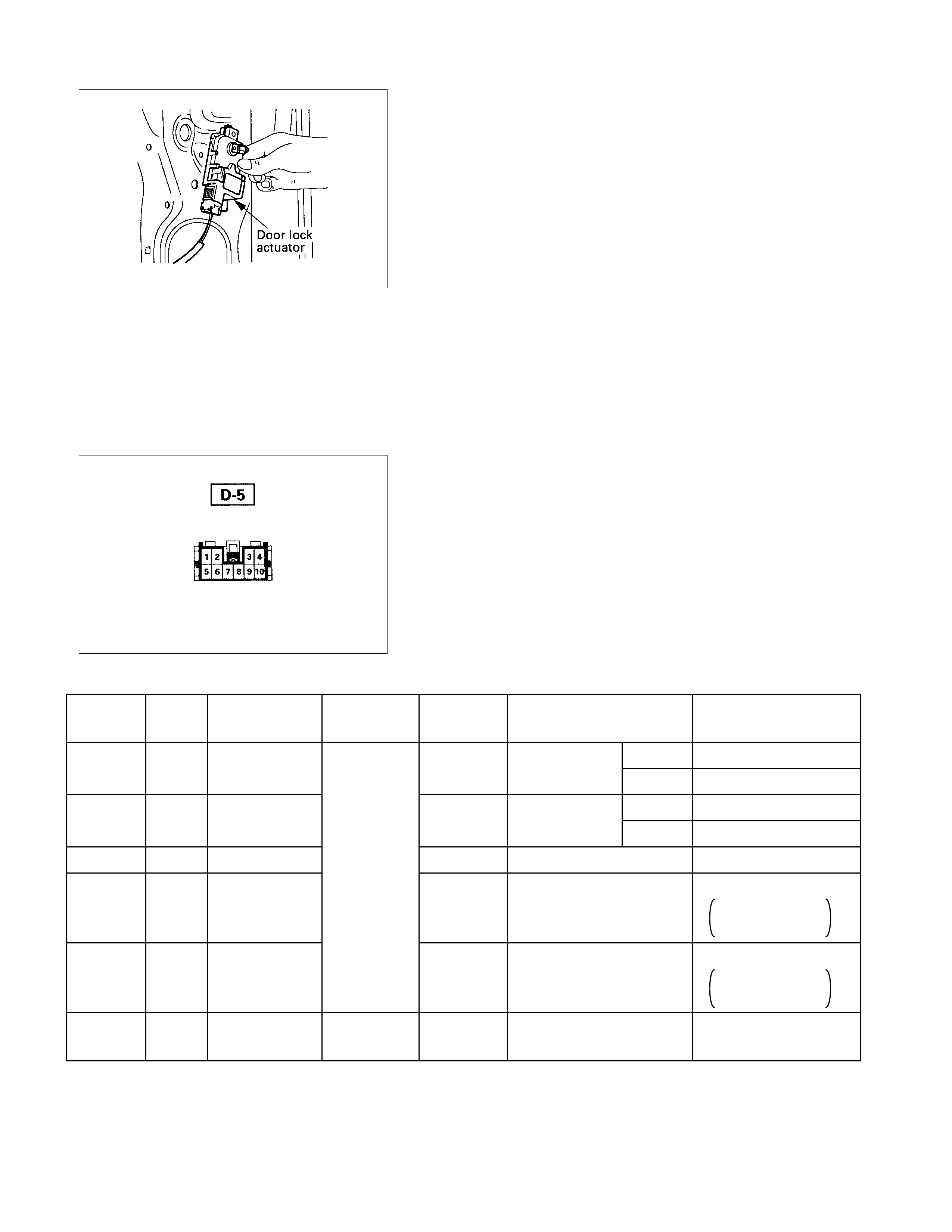
RR DOOR LO CK ACTUATOR- L H & RH
REMOVAL
1. Door Lock ASM
• Refer to the removal steps of the DOORS in section 1C
“BODY”.
2. Door Lock Actuator
•Remove the actuator fixing bolts.
•Disconnect the door lock link rod.
•Disconnect the actuator connector.
INSTALLATION
To install, follow the removal steps in the reverse order.
INSPECTION AND REPAIR
Harness side
DRIVER SEAT SIDE POWER W INDOW & DOOR
LOCK SWI TCH
1. Harness Side Connector Circuit
Check voltage and continuity between the switch harness
side connector terminals as shown in the following table.
Terminal
No. Wire
color Connecting to Check item Connecting
terminal Check condition Standard
Door lock SW Driver seat Lock Continuity
(Lock) side door Unlock No continuity
Door lock SW Driver seat Lock No continuity
(Unlock) side door Unlock Continuity
5 B Ground Continuity 5-Ground - Continuity
6L/Y
Door lock
actuator (Lock)
(Resistance
)6-8 - Continuity
There is some
resistance
8Y/G
Door lock
actuator
(Unlock) 8-6 - Continuity
There is some
resistance
9LG/W Fuse
CB-15 (20A) Voltage 9- Ground - Battery voltage
(Approx. 12V)
3-GroundR/W3
4-Ground
LG/R
4
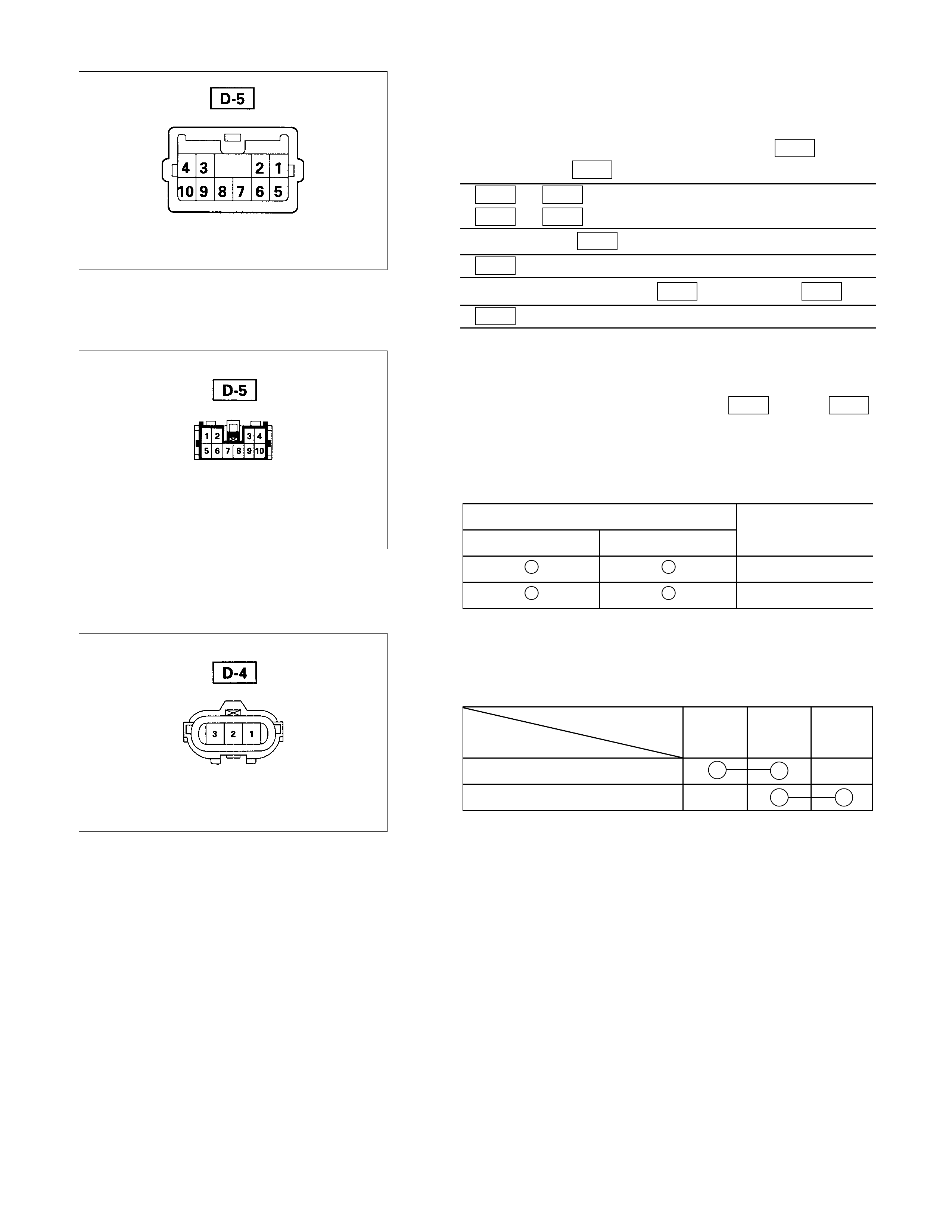
Switch side
2. Switch Side Connector Circuit
Remove the switch connector, and check continuity and
voltage between the switch connector terminals.
(Connect the (+) terminal of the battery to 9 D-5 and the
(-) terminal to 5 D-5 .)
5 D-5 - 6 D-5 ..................Continuity
5 D-5 - 8 D-5 ..................Continuity
(Then, ground 3 D-5 .)
6 D-5 ...........Current flow for approx. 1 second
(Disconnect the ground of 3 D-5 , and ground 4 D-5 .)
8 D-5 ...........Current flow for approx. 1 second
Harness side
3. Door Lock Operation Test
After confirming that there is continuity between the switch
harness side connector terminals 6 D-5 and 8 D-5 ,
apply the battery voltage to each of the terminals to conduc t
the operation test.
When the door lock will not operate, check the door lock
actuator for any trouble.
Connecting terminals
8 (Y/G) 6 (L/Y)
+ - Unlock
- + Lock
Operation
Switch side
DRIVER’S SI DE DOOR LO CK SW ITCH
1. Switch Side Connector Circuit
Check continuity between the switch connector terminals
Terminal No.
SW position 123
Lock
Unlock
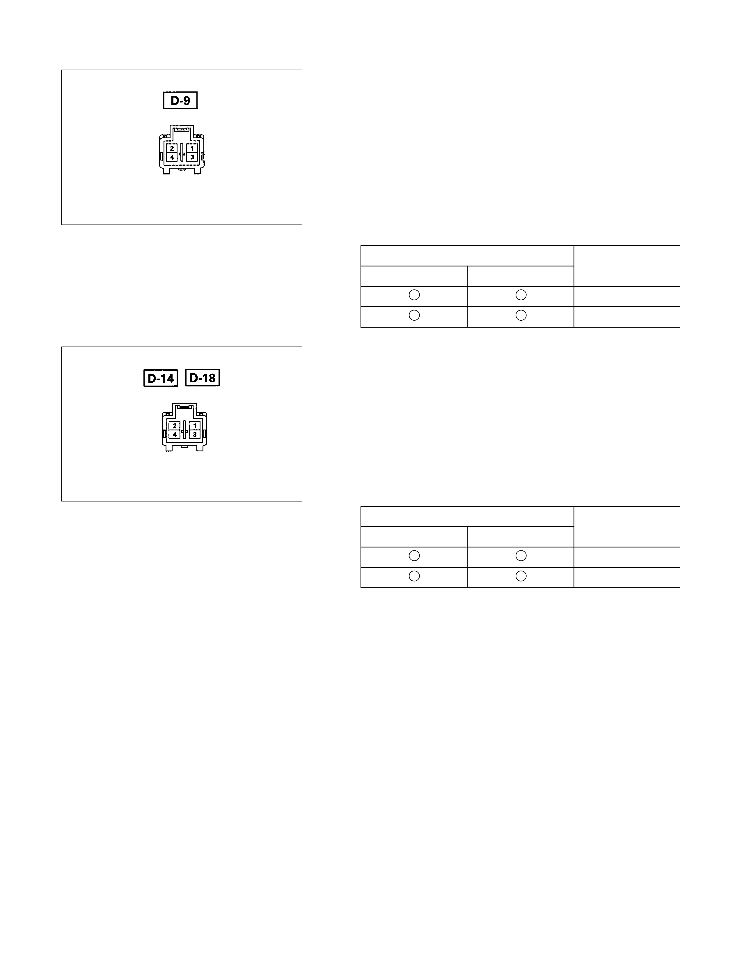
Actuator side
FRONT PASSENGER’S SIDE DOOR LOCK
ACTUATOR
1. Actuator Side Connector Circuit
A
pply the battery voltage to the actuator connecto
r
terminals to check the operation.
W hen the door lock actuator is checked on the vehicle and
there is no continuity, and when the door lock actuator itsel
f
is checked and no trouble is found, check the circuit
between the door lock actuator and the driver seat side
power window & door lock switch for any failure.
Connecting terminals
24
+ - Lock
- + Unlock
Operation
Actuator side
REAR DOOR LOCK ACTUATOR - LH & RH
1. Actuator Side Connector Circuit
A
pply the battery voltage to the actuator connecto
r
terminals to check the operation.
W hen the door lock actuator is checked on the vehicle and
there is no continuity, and when the door lock actuator itsel
f
is checked and no trouble is found, check the circuit
between the door lock actuator and the driver seat side
power window & door lock switch for any failure.
Connecting terminals
13
- + Lock
+ - Unlock
Operation
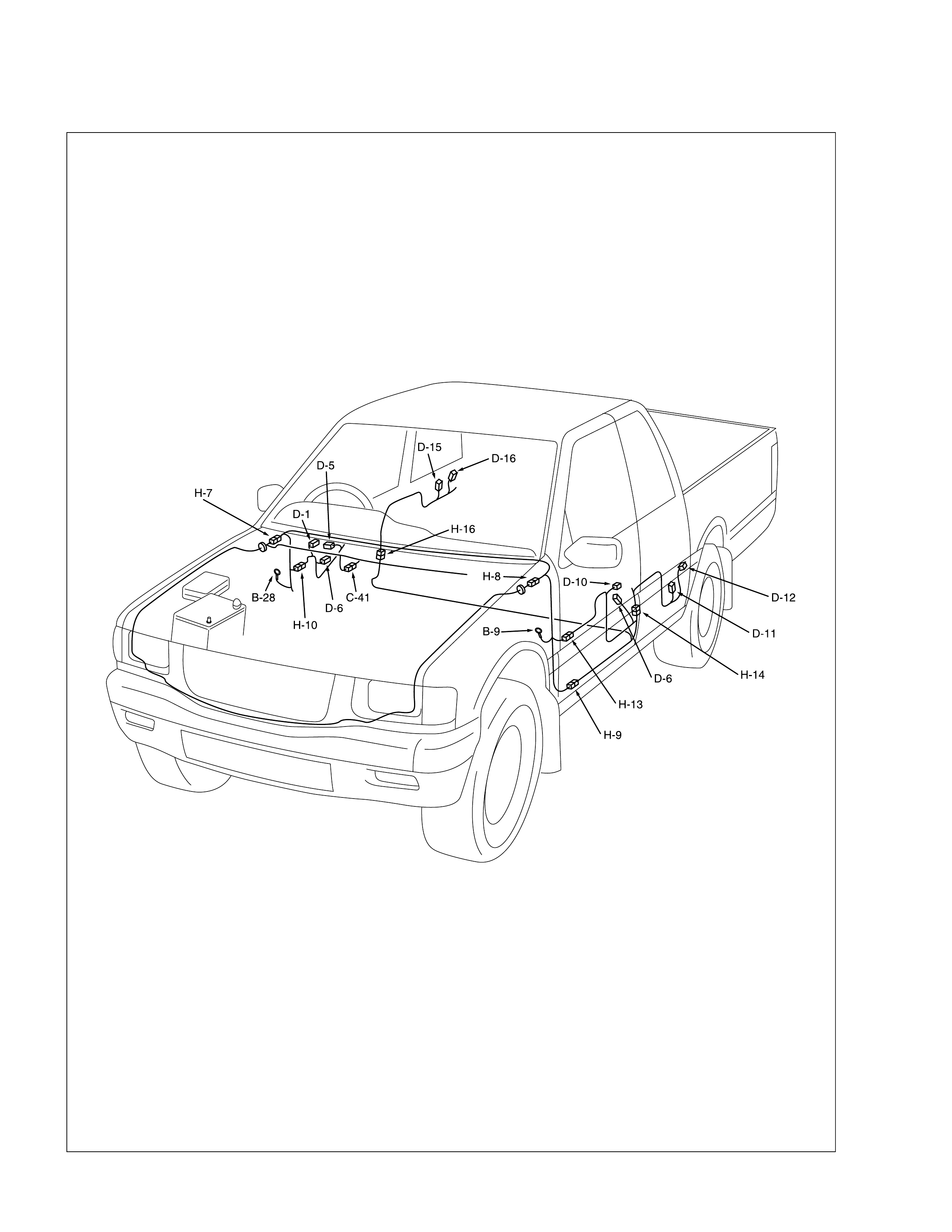
Pow er Window
PARTS LOCATION
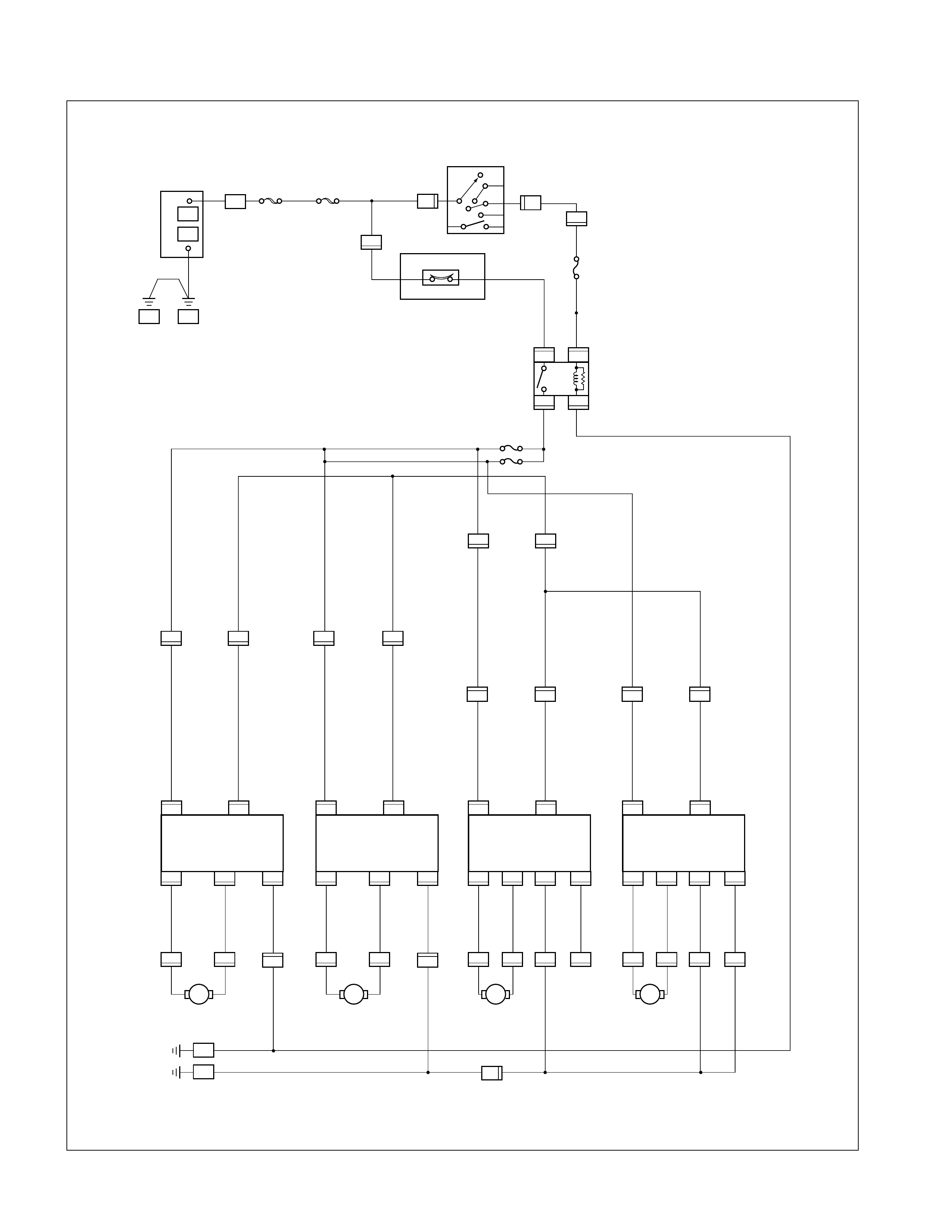
CIRCUIT DIAGRAM
P-1 P-2
P-5
P-10P-7
B-9
B-20
C-41
H-3
C-41
H-7
H-7
H-9 H-9
H-10
D-5 D-6 D-5
D-1 D-1
H-10 H-12 H-13
H-14
D-5 D-5
H-14 H-16 H-16
B-8
B-8 B-8
B-8
M
H-10
D-10 D-10 D-10
D-6 D-8
D-10 D-10
M
D-12
D-11
D-12
H-14
D-12
H-14
D-12
D-11 D-15 D-15
D-12 D-12
M
D-16 D-16
H-16
D-16
H-16
D-16
D-16 D-16
M
H-13
BODY-RH
BODY-LH
2B
2B
2B
2B
2B 2B
2L/R
2L/R
2L/R
2L/W
2L/W
2G/R 2G/R
2G/R
2G/R
2G/R 2G/R 2G/R
2G/R
2G/R
2G/R
0.5R/Y
0.5R/Y 0.5R/Y
0.5R/Y
0.5R/Y 0.5R/Y 0.5R/Y
0.5W 0.85W 3B/Y
3B/Y
2G/W3W
3W
15B/R
30B/Y
5B/Y
IGN.B2
FRAME ENG.
MAIN
BOA OR 100A
STARTFR SW
40A
3W
0.5R/Y 0.5R/Y
0.5R/Y
2L/R
0.5B
0.5B
0.5B
2B
2BR/W
2BR/W
2B
2B
0.5B
2B
21 1 11 11
1365136556610101
4
4
32
1
12
22424
6363
32
1
1
5
4
6
6
ACC
B2
B1
IG2
ET
IG1
OFF
6
2
291
2
2222
UP DOWNUP DOWNUPUP LOCK
RR POWER WINDOW
MOTOR-RH
RR POWER WINDOW
MOTOR-LH
RR POWER WINDOW
SW-LH
FAT POWER WINDOW
AND DOOR LOCK SW-PASSENGER
FAT POWER WINDOW
AND DOOR LOCK SW-DRIVER
RR POWER WINDOW
SW-RH
FAT POWER WINDOW
MOTOR-PASSENCER
FAT POWER WINDOW
MOTOR-DRIVER
DOWNDOWN
RELAY
POWER WINDO W
CB-11
15A BACK UP TURN
DIESEL and IGM GAS W/SRS with SRS
GAS medel only (IGM W/SRS except)
CIRCUIT BRAKER 30A
+
-
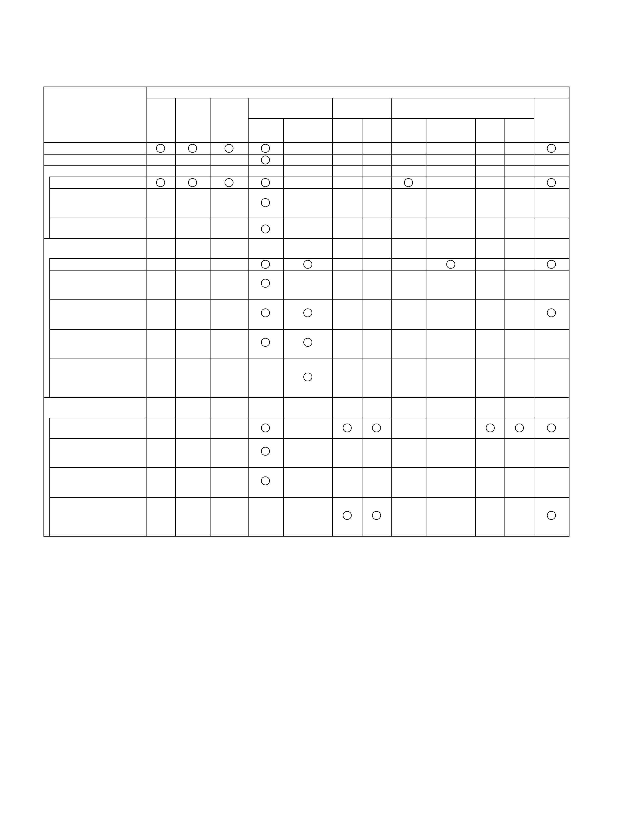
TROUBLESHOOTING
QUICK CHART FOR CHECK POINTS
Check Points
Trouble Mode Power Window & Door
Lock Switch Power Window
Switch Power Window Motor
Driver’s
Side Passenger’s
Side RR-LH RR-
RH
Driver’s
Side Passenger’s
Side RR-LH RR-
RH
All windows will not operate
Lock SW does not function
Driver’s Window:
Window does not operate
One-touch operation for
“DOWN” movement will not
operate
Window operates in only
one direction
Front window on passenger
seat side:
Window does not operate
Window does not operate
when operating the driver’s
SW
Window does not operate
when operating the
passenger’s SW
Window does operate in
only one direction when
operating the driver’s SW
Window does operate in
only one direction when
operating the passenger’s
seat side SW
Rear window on left (or right)
side:
Window on left (or right)
side does not operate
Window does not operate
when operating the driver’s
SW
Window does operate in
only one direction when
operating the driver’s SW
Window does operate in
only one direction when
operating the RR-LH (or
RH) side SW
Cable
Harness
Relay;
Power
Window
Circuit
Breaker
(30A)
Fuse
CB-11
(15A)
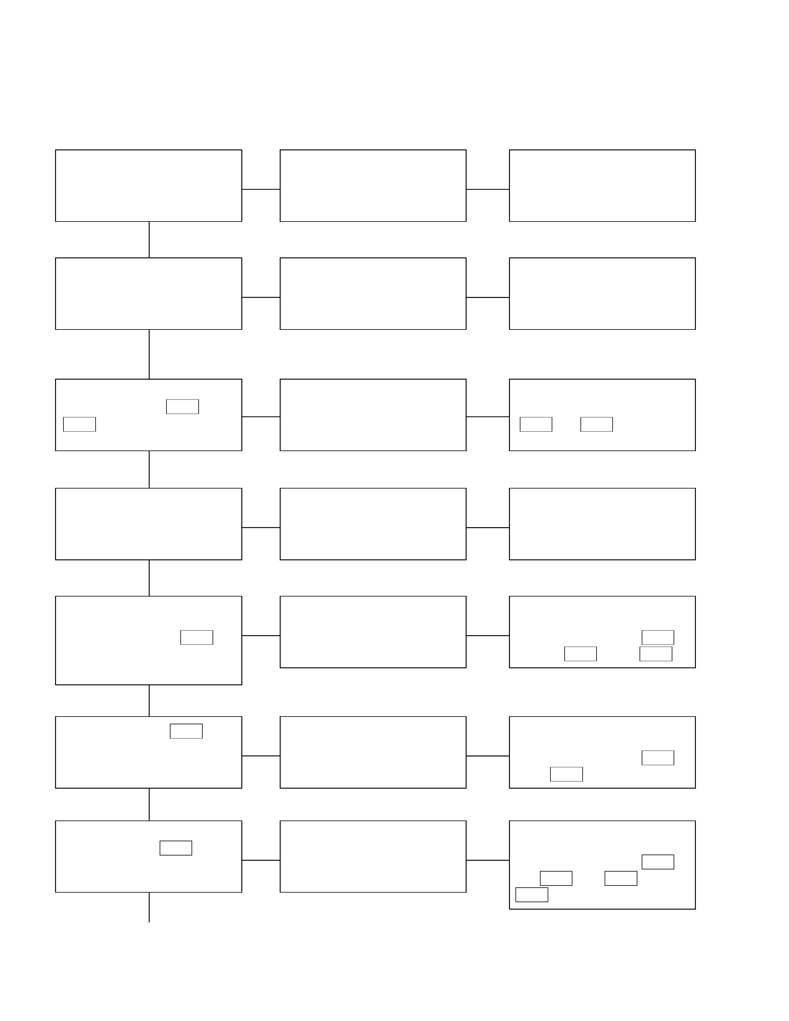
PETROL
1. All windows do not operate
Checkpoint Trouble Cause Countermeasure
Reinstall or replace the fuse
No. CB-11 (15A)
Poor fuse contact or blown
NG
Replace the circuit breaker
(30A)
Circuit breaker (30A, Fuse
box) function Circ uit breaker malfunction
Repair grounding points
(B-9 and B-28 ) contact
Grounding points ( B-9
B-28 )Poor grounding point contact
NG
NG
OK
OK
OK
Fuse CB-11 (15A, Fuse box )
Replace the power window
relay
Power win d ow relay
malfunction
NG
Repair an open circuit or a
poor connec tion of the
connectors between 3 H-7
(RHD: 5 H-7 ) and 5 B-8
Voltage between the power
window relay harness side
connector terminal 5 B-8
and the ground (Should be
battery voltage present)
Open circuit or poor connector
contact
NG
OK
Power window relay func tion
OK
Repair an open circuit or a
poor connec tion of the
connectors between 1 B-8
and 2 D-5
Open circuit or poor connector
contact
NG
Voltage between 2 D-5 and
the ground (Should be battery
voltage present)
OK
Repair an open circuit or a
poor connec tion of the
connectors between 5 D-5
and B-28 , or 4 B-8 and
B-28
Open circuit or poor connector
contact
NG
Continued on the next page
Voltage between B-28 and
the ground

Checkpoint Trouble Cause Countermeasure
Replace the driver seat side
power window & door lock
SW.
SW. malfunction
OK
NG
Driver seat side power window
& door lock SW. function
Continued from the previous page
2. Lock switch does not function
Checkpoint Trouble Cause Countermeasure
Replace the driver seat side
power window & door lock
SW.
SW. malfunction
NG
Driver seat side power window
& door lock SW. function
3. Window on the driver’s side does not operate
Checkpoint Trouble Cause Countermeasure
Replace the driver seat side
power window & door lock
SW.
SW. malfunction
NG
Replace the driver seat side
power window motor
Motor malfunction
NG
OK
Driver seat side power window
& door lock SW. function
OK
Repair open circuit or
connector contact
Open circuit or poor connector
contact
NG
Continuity between 1 D-5
and 2 D-1 , or 10 D-5 and
1 D-1
1. Driver seat side power
window motor function
when connection the motor
connector 2 D-1 to the
battery (+) terminal, and 1
D-1 to the (-) terminal
(Should the motor rotate in
the “UP” direction of the
window)
2. Driver seat side power
window motor function
when connecting the motor
connector 1 D-1 to the
battery (+) terminal, and 2
D-1 to the (-) terminal
(Should the motor rotate in
the “DOWN” direction of the
window)
DIESEL W/ SRS
1. RH SIDE windows do not operate
Checkpoint Trouble Cause Countermeasure
Reinstall or replace the fuse
No. CB-11 (15A)
Poor fuse contact or blown
NG
Reinstall or replace the fuse
No.CB-21, 24 (20A)
Fuse CB-24 (20A, FUSE
BOX) LH D
Fuse CB-21 (20A, FUSE
BOX) R HD
Circuit breaker malfunction
Repair grounding points
(B-9 and B-28 ) contact
Grounding points ( B-9
B-28 )Poor grounding point cont ac t
NG
NG
OK
OK
OK
Fuse CB-11 (15A, Fuse box)
Replac e the power window
relay
Power window relay
malfunction
NG
Repair an open circuit or a
poor connection of the
connectors between 3 H-7
(RHD: 5 H-7 ) and 5 B-8
Voltage between the power
window relay harness sid e
connec t or terminal 5 B-8
and the ground (Should be
battery voltage presen t)
Open circuit or poor connector
contact
NG
OK
Power window relay function
OK
Repair an open circuit or a
poor connection of the
connectors between 1 B-8
and 2 D-5
Open circuit or poor connector
contact
NG
Voltage between 2 D-5 and
the ground (Should be battery
voltage present)
OK
Repair an open circuit or a
poor connection of the
connectors between 5 D-5
and B-28 , or 4 B-8 and
B-28
Open circuit or poor connector
contact
NG
Continued on the next page
Voltage between B-28 and
the ground

Checkpoint Trouble Cause Countermeasure
Replace the driver seat side
power window & door lock
SW.
SW. malfunction
OK
NG
Driver seat side power window
& door lock SW. function
Continued from the previous page
2. Lock switch does not function
Checkpoint Trouble Cause Countermeasure
Replace the driver seat side
power window & door lock
SW.
SW. malfunction
NG
Driver seat side power window
& door lock SW. function
3. Window on the driver’s side does not operate
Checkpoint Trouble Cause Countermeasure
Replace the driver seat side
power window & door lock
SW.
SW. malfunction
NG
Replace the driver seat side
power window motor
Motor malfunction
NG
OK
Driver seat side power window
& door lock SW. function
OK
Repair open circuit or
connector contact
Open circuit or poor connector
contact
NG
Continuity between 1 D-5
and 2 D-1 , or 10 D-5 and
1 D-1
1. Driver seat side power
window motor function
when connection the motor
connector 2 D-1 to the
battery (+) terminal, and 1
D-1 to the (-) terminal
(Should the motor rotate in
the “UP” direction of the
window)
2. Driver seat side power
window motor function
when connecting the motor
connector 1 D-1 to the
battery (+) terminal, and 2
D-1 to the (-) terminal
(Should the motor rotate in
the “DOWN” direction of the
window)

DIESEL W/ SRS
1. LH SIDE windows do not operate
Checkpoint Trouble Cause Countermeasure
Reinstall or replace the fuse
No. CB-11 (15A)
Poor fuse contact or blown
NG
Reinstall or replace the fuse
No.CB-23 or 22 (20A)
Fuse CB-23 (20A, FUSE
BOX) LHD
Fuse CB-22 (20A, FUSE
BOX) RHD
Poor fuse contact or blown
Repair grounding points
(B-9 and B-28 ) contact
Grounding points ( B-9
B-28 )Poor grounding point contact
NG
NG
OK
OK
OK
Fuse CB-11 (15A, Fuse box)
Replace the power window
relay
Power win d ow relay
malfunction
NG
Repair an open circuit or a
poor connec tion of the
connectors between 3 H-7
(RHD: 5 H-7 ) and 5 B-8
Voltage between the power
window relay harness side
connector terminal 5 B-8
and the ground (Should be
battery voltage present)
Open circuit or poor connector
contact
NG
OK
Power window relay func tion
OK
Repair an open circuit or a
poor connec tion of the
connectors between 1 B-8
and 2 D-5
Open circuit or poor connector
contact
NG
Voltage between 2 D-5 and
the ground (Should be battery
voltage present)
OK
Repair an open circuit or a
poor connec tion of the
connectors between 5 D-5
and B-28 , or 4 B-8 and
B-28
Open circuit or poor connector
contact
NG
Continued on the next page
Voltage between B-28 and
the ground
Checkpoint Trouble Cause Countermeasure
Replace the driver seat side
power window & door lock
SW.
SW. malfunction
OK
NG
Driver seat side power window
& door lock SW. function
Continued from the previous page
2. Lock switch does not function
Checkpoint Trouble Cause Countermeasure
Replace the driver seat side
power window & door lock
SW.
SW. malfunction
NG
Driver seat side power window
& door lock SW. function
3. Window on the driver’s side does not operate
Checkpoint Trouble Cause Countermeasure
Replace the driver seat side
power window & door lock
SW.
SW. malfunction
NG
Replace the driver seat side
power window motor
Motor malfunction
NG
OK
Driver seat side power window
& door lock SW. function
OK
Repair open circuit or
connector contact
Open circuit or poor connector
contact
NG
Continuity between 1 D-5
and 2 D-1 , or 10 D-5 and
1 D-1
1. Driver seat side power
window motor function
when connection the motor
connector 2 D-1 to the
battery (+) terminal, and 1
D-1 to the (-) terminal
(Should the motor rotate in
the “UP” direction of the
window)
2. Driver seat side power
window motor function
when connecting the motor
connector 1 D-1 to the
battery (+) terminal, and 2
D-1 to the (-) terminal
(Should the motor rotate in
the “DOWN” direction of the
window)
4. Window on the front passenger’s side does not operate
Checkpoint Trouble Cause Countermeasure
Replace the front passenger’s
power window & door lock
SW.
SW. malfunction
NG
Replace the front passenger’s
power window motor
Motor malfunction
NG
OK
Driver seat side power window
& door lock SW. function
OK
Repair open circuit or
connector contact
Open circuit or poor connector
contact
NG
Continuity Between 6 D-10
and 2 D-6 , or 10 D-10 and
1 D-6
1. Front passenger’s power
window motor function
when connecting the motor
connector 2 D-6 to the
battery (+) terminal, and 1
D-6 to the (-) terminal
(Should the motor rotate in
the “UP” direction of the
window)
2. Front passenger’s power
window motor function
when connecting the motor
connector 1 D-6 to the
battery (+) terminal, and 2
D-6 to the (-) terminal.
(Should the motor rotate in
the “DOWN” direction of the
window)
Replace the driver seat side
power window & door lock
SW.
SW. malfunction
NG
OK
Front passenger’s window &
door lock SW. function
5. Rear window on the left (right) side does not opera te
Checkpoint Trouble Cause Countermeasure
Replace the driver seat side
power window & door lock
SW.
SW. malfunction
NG
Replace the rear power
window motor
Motor malfunction
NG
OK
Driver seat side power window
& door lock SW. function
OK
Repair open circuit or
connector contact
Open circuit or poor connector
contact
NG
Continuity between 5 D-12
and 2 D-11 (5 D-16 and 2 D-
15), or 6 D-12 and 1 D-11 (6
D-16 and1 D-15 )
1. Rear power window motor-
LH (RH) function when
connecting the motor
connector 2 D-11 (2
D-15 ) to the battery (+)
terminal, and 1 D-11 (1
D-15 ) to the (-) terminal
(Should the motor rotate in
the “UP” direction of the
window)
2. Rear power window motor-
LH (RH) function when
connecting the motor
connector 1 D-11 (1
D-15 ) to the battery (+)
terminal, and 2 D-11 (2
D-15 ) to the (-) terminal
(Should the motor rotate in
the “DOWN” direction of the
window)
Replace the rear power
window SW. -LH (RH)
SW. malfunction
NG
OK
Rear power window SW. LH
(RH) function
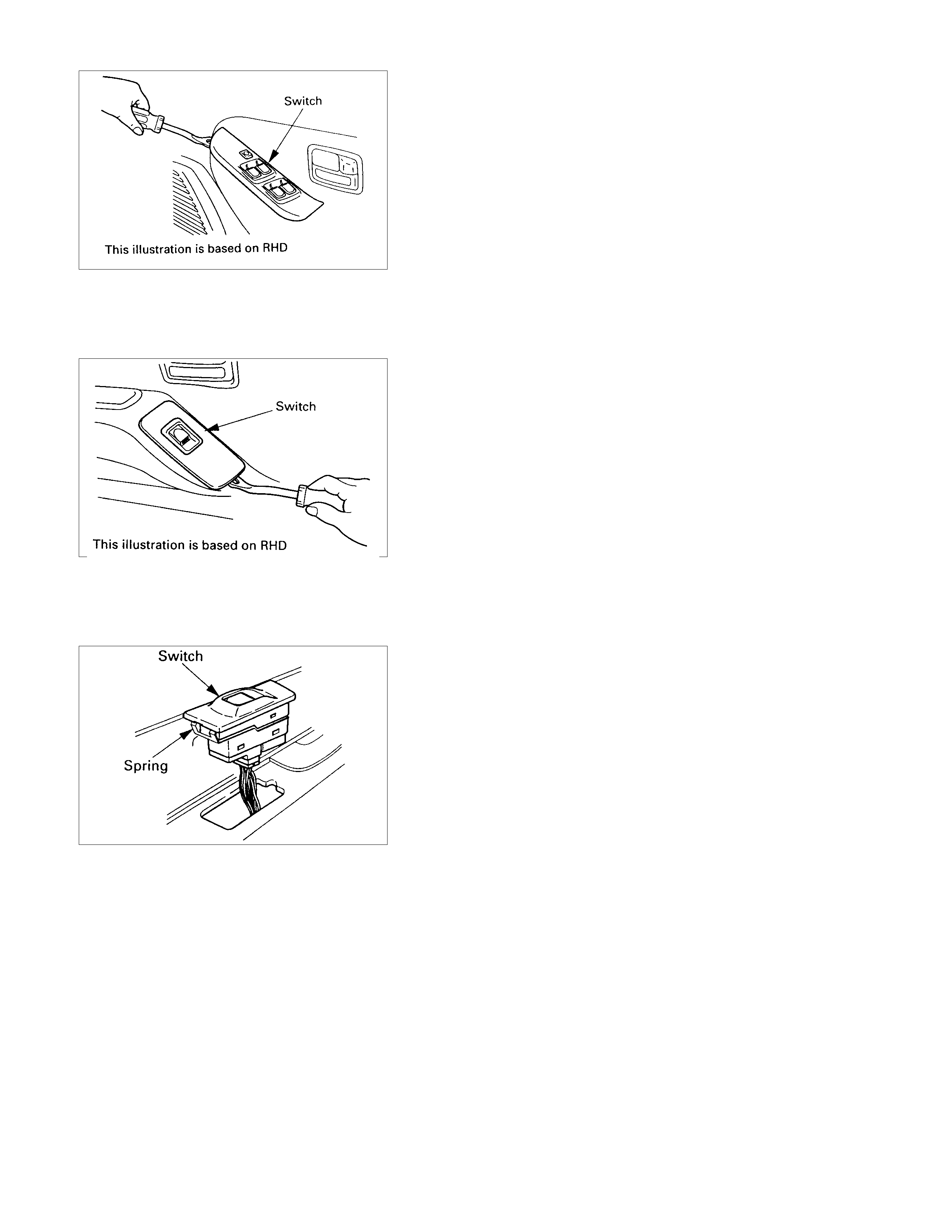
DRIVER SEAT SIDE POWER W INDOW & DOOR
LOCK SWI TCH
(4 DOORS MODEL)
REMOVAL
1. Remove the switch by pushing the spring with the tip of a
screwdriver.
2. Disconnect the connector.
INSTALLATION
To install, follow the removal steps in the reverse order.
FRONT PASSENGER’S POWER WINDO W & DOOR
LOCK SWI TCH
(4 DOORS MODEL)
REMOVAL
1. Remove the switch by pushing the spring with the tip of a
screwdriver.
2. Disconnect the connector.
INSTALLATION
To install, follow the removal steps in the reverse order.
REAR POWER WI NDOW & DOO R LOCK SWITCH-LH
& RH
REMOVAL
1. Remove the switch by pushing the spring with the tip of a
screwdriver.
2. Disconnect the connector.
INSTALLATION
To install, follow the removal steps in the reverse order.
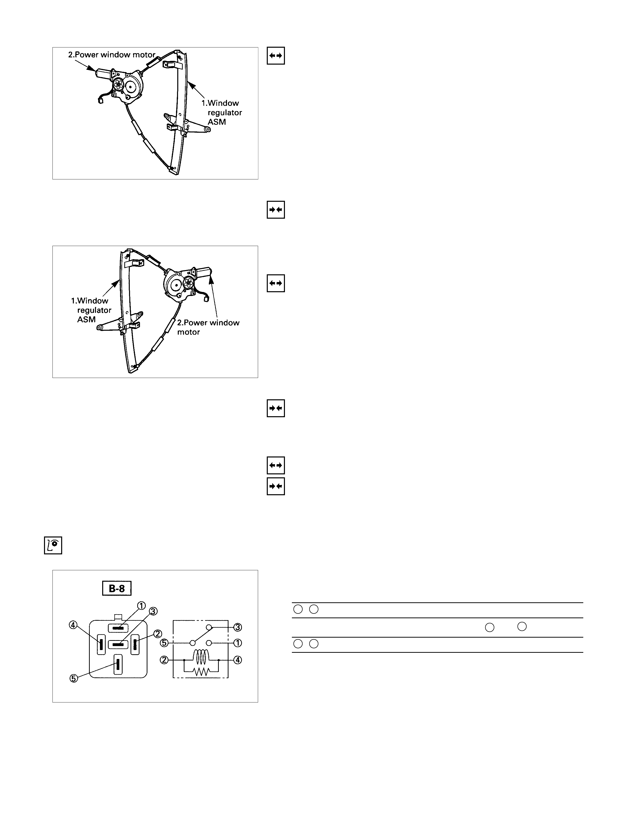
DRIVER SEAT SIDE POWER W INDOW MOTOR
REMOVAL
1. Window Regulator ASM
•Refer to the removal steps of the
WINDOW REGULATOR/POWER WINDOW MOTOR in
Section 1C “BODY”.
2. Power Window Motor
•Loosen the fixing bolts to remove the power windo
w
motor from the regulator.
INSTALLATION
To install, follow the removal steps in the reverse order.
FRONT PASSENGER’S POWER WINDO W MOTOR
REMOVAL
1. Window Regulator ASM
•Refer to the removal steps of the
WINDOW REGULATOR/POWER WINDOW MOTOR in
Section 1C “BODY”.
2. Power Window Motor
•Loosen the fixing bolts to remove the power windo
w
motor from the regulator.
INSTALLATION
To install, follow the removal steps in the reverse order.
REAR POWER WI NDOW MOTOR-LH & RH
REMOVAL AND I NSTALLATION
Refer to the “DRIVER SEAT SIDE POWER WINDOW
MOTOR” removal and installation steps in this section.
INSPECTION AND REPAIR
POWER WINDOW RELAY
Check continuity between the relay terminals.
1- 5........................No continuity
(When battery voltage is applied between 2 and 4)
1- 5........................Continuity
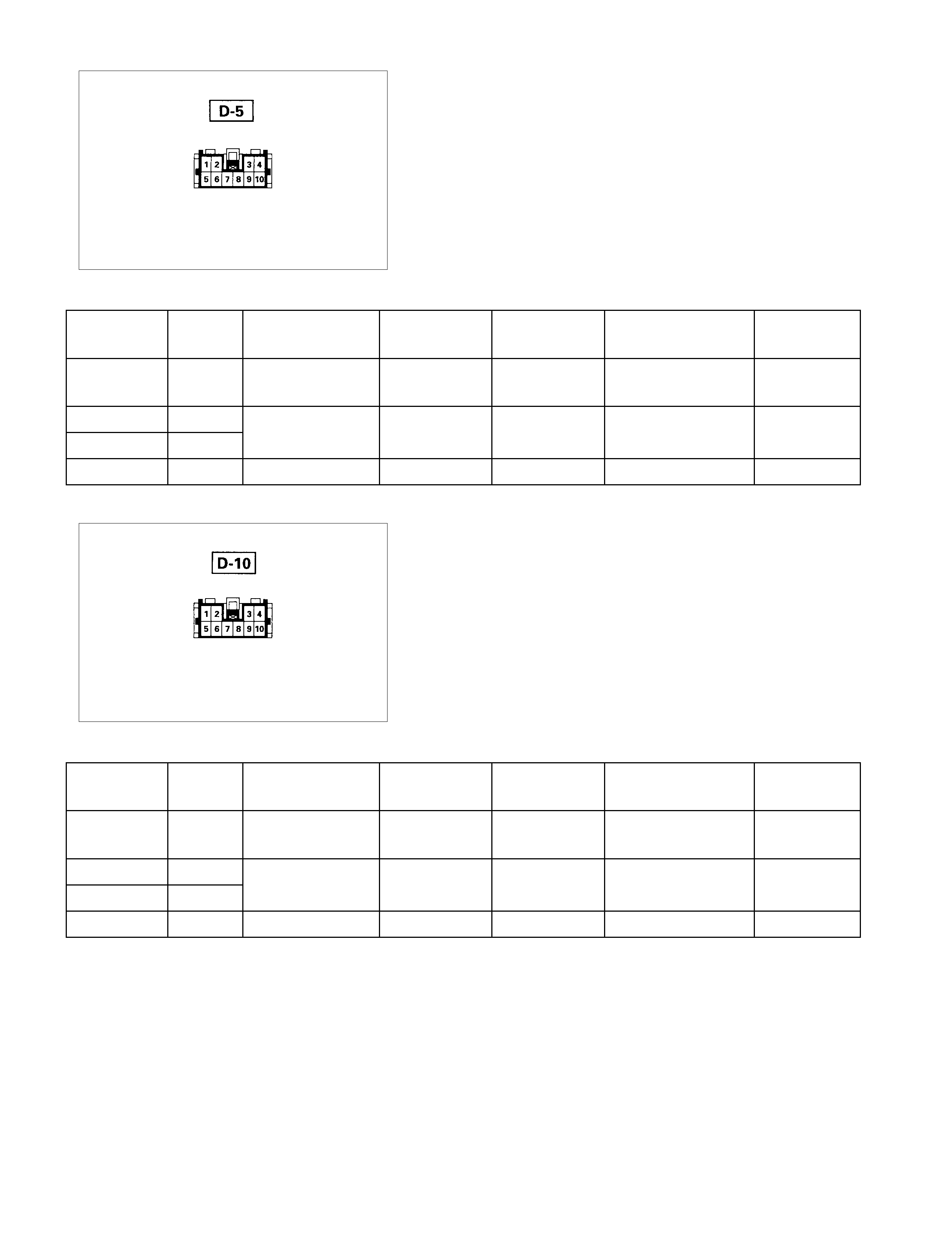
Harness side
DRIVER SEAT SIDE POWER W INDOW & DOOR
LOCK SWI TCH
1. Harness Side Connector Circuit
Disconnect the switch connector, and check voltage and
continuity between the harness s ide connector term inals as
shown in the following table.
Terminal
No. Wire
color Connecting to Check item Connectin
g terminal Check condition Standard
2G/R
Power window
relay Voltage 2-Ground Starter SW “ON” Approx.
12V
1L/R
Power window
10 L/W motor
5 B Ground Continuity 5-Ground - Continuity
Harness side
FRONT PASSENGER’S POWER WINDO W & DOOR
LOCK SWI TCH
1. Harness Side Connector Circuit
Disconnect the switch connector, and check voltage and
continuity between the harness s ide connector term inals as
shown in the following table.
Terminal
No. Wire
color Connecting to Check item Connectin
g terminal Check condition Standard
9G/R
Power window
relay Voltage 9-Ground Starter SW “ON” Approx.
12V
6L/R
Power window
10 L/W motor
5 B Ground Continuity 5-Ground - Continuity
Continuity
-
1-10Continuity
Continuity-6-10Continuity
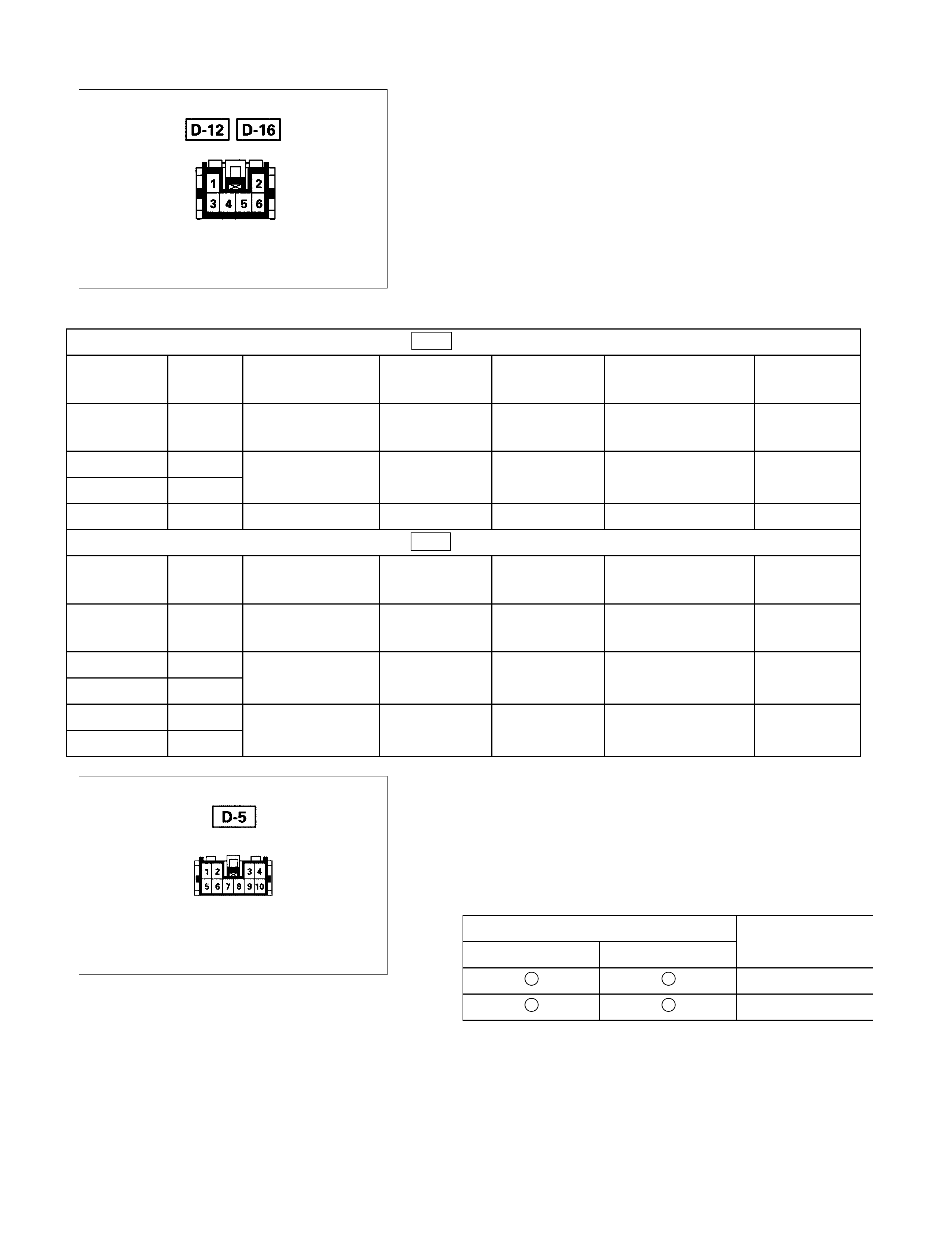
Harness side
REAR POWER WI NDOW SWI TCH-LH & RH
1. Harness Side Connector Circuit
Disconnect the switch connector, and check voltage and
continuity between the harness s ide connector term inals as
shown in the following tables.
D-12 (RR-LH)
Terminal
No. Wire
color Connecting to Check item Connectin
g terminal Check condition Standard
4G/R
Power window
relay Voltage 4-Ground Starter SW “ON” Approx.
12V
5L/R
Power window
6BR/W
motor
3 B Ground Continuity 3-Ground - Continuity
D-16 (RR-RH)
Terminal
No. Wire
color Connecting to Check item Connectin
g terminal Check condition Standard
4G/R
Power window
relay Voltage 4-Ground Starter SW “ON” Approx.
12V
5L/R
Power window
6BR/W
motor
3B
1B
Harness side
DRIVER SEAT SIDE POWER W INDOW MOTOR
1. Driver Seat Side Power Window & Door Lock Switch
Connector Circuit
Disconnect the switch connector, apply the battery voltage
(12V) to the harness side connector terminals and check
operation.
Connecting terminals Operation
1 (L/R) 10 (L/W) direction
- + DOWN
+ - UP
ContinuityContinuity 6-10 -
ContinuityContinuity 6-10 -
Ground Continuity 3-1 Continuity
-
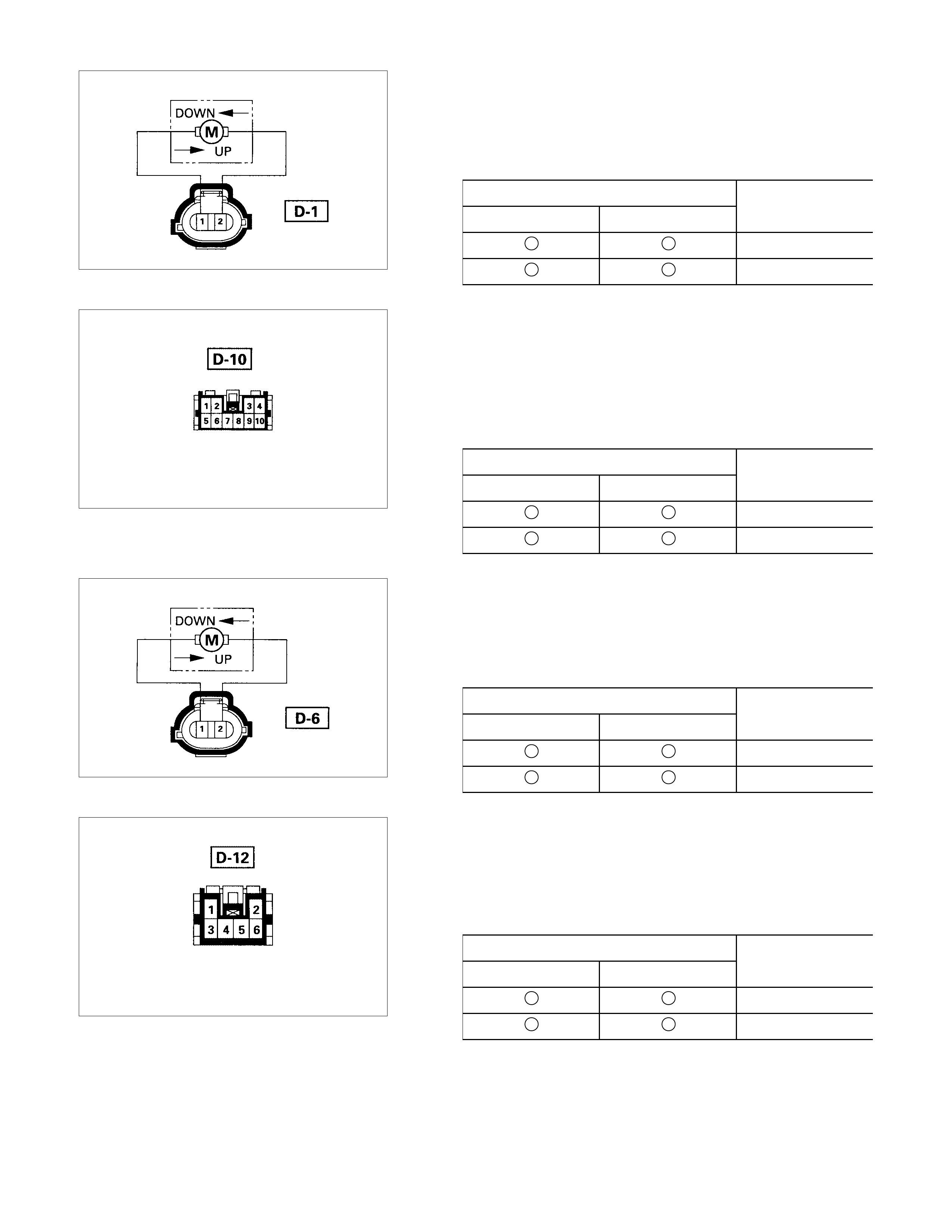
2. Driver Seat Side Power Window Motor Connecto
r
Circuit
Disconnect the switch connector, apply the battery voltage
(12V) to the motor side connector terminals and check
operation.
Connecting terminals Operation
12
direction
+ - DOWN
- + UP
Harness side
FRONT PASSENGER’S POWER WINDO W MOTOR
1. Front Passenger’s Power Window Switch & Door Lock
Switch Connector Circuit
Disconnect the motor connector, apply the battery voltage
(12V) to the harness side connector terminals and check
operation.
Connecting terminals Operation
6 (L/R) 10 (L/W) direction
- + DOWN
+ - UP
2. Front Passenger’s Power Window Motor Connecto
r
Circuit
Disconnect the switch connector, apply the battery voltage
(12V) to the motor side connector terminals and check
operation.
Connecting terminals Operation
12
direction
+ - DOWN
- + UP
Harness side
REAR PASSENGER’S POWER W INDOW MOTOR-LH
1. Rear Power Window Switch-LH Connector Circuit
Disconnect the motor connector, apply the battery voltage
(12V) to the harness side connector terminals and check
operation.
Connecting terminals Operation
5 (L/R) 6 (BR/W) direction
- + DOWN
+ - UP
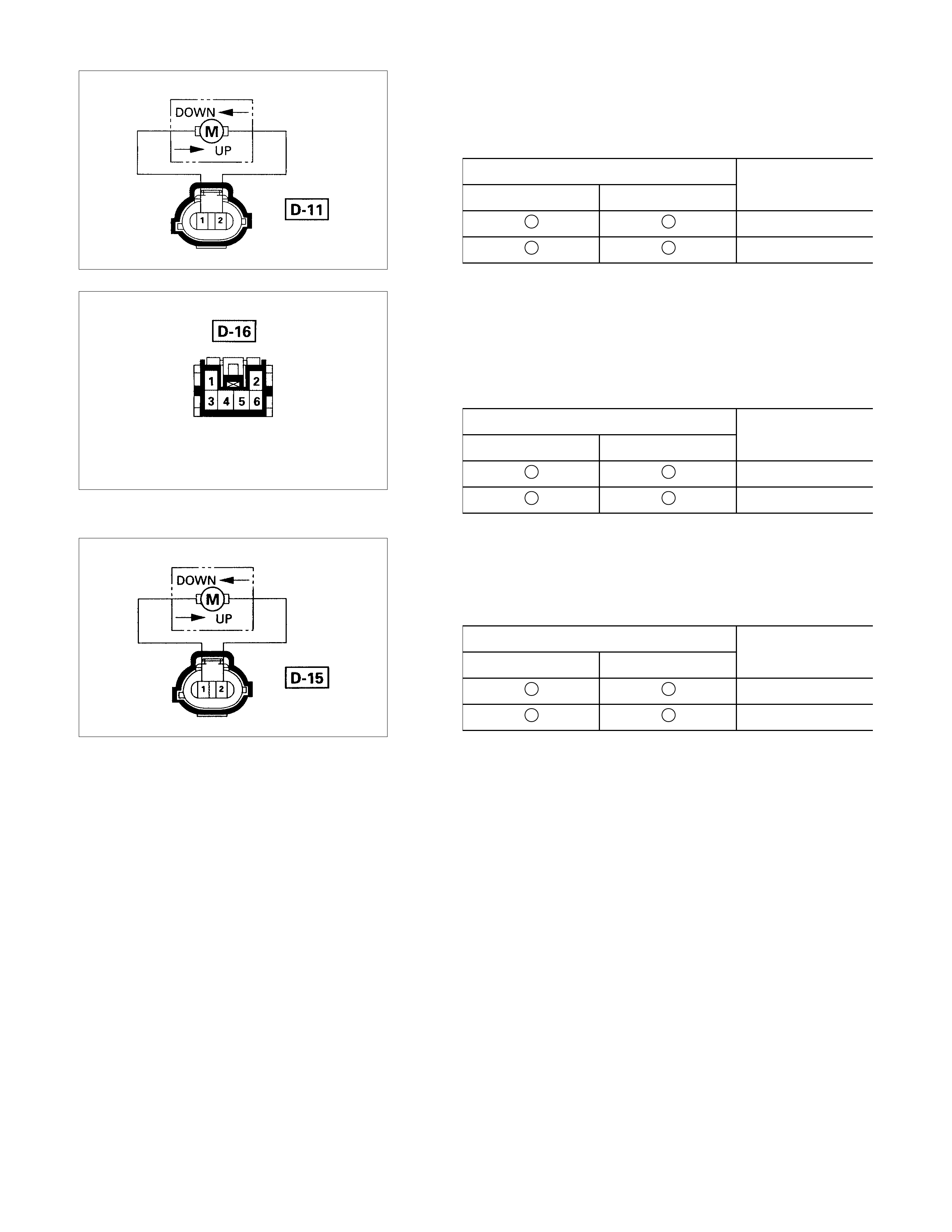
2. Rear Power Window Motor-LH Connector Circuit
Disconnect the switch connector, apply the battery voltage
(12V) to the motor side connector terminals and check
operation.
Connecting terminals Operation
12
direction
+ - DOWN
- + UP
Harness side
REAR POWER WI NDOW MOTOR-RH
1. Rear Power Window Switch-RH Connector Circuit
Disconnect the motor connector, apply the battery voltage
(12V) to the harness side connector terminals and check
operation.
Connecting terminals Operation
5 (L/R) 6 (BR/W) direction
- + DOWN
+ - UP
2. Rear Power Window Motor-RH Connector Circuit
Disconnect the switch connector, apply the battery voltage
(12V) to the motor side connector terminals and check
operation.
Connecting terminals Operation
12
direction
+ - DOWN
- + UP

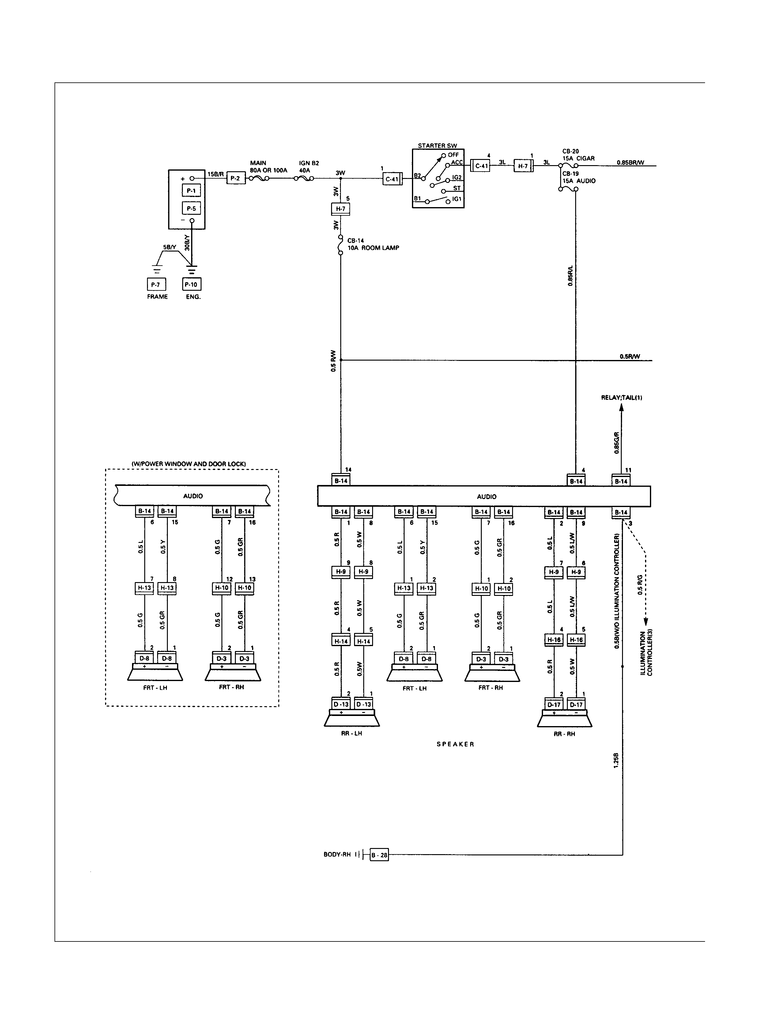
CIRCUIT DIAGRAM
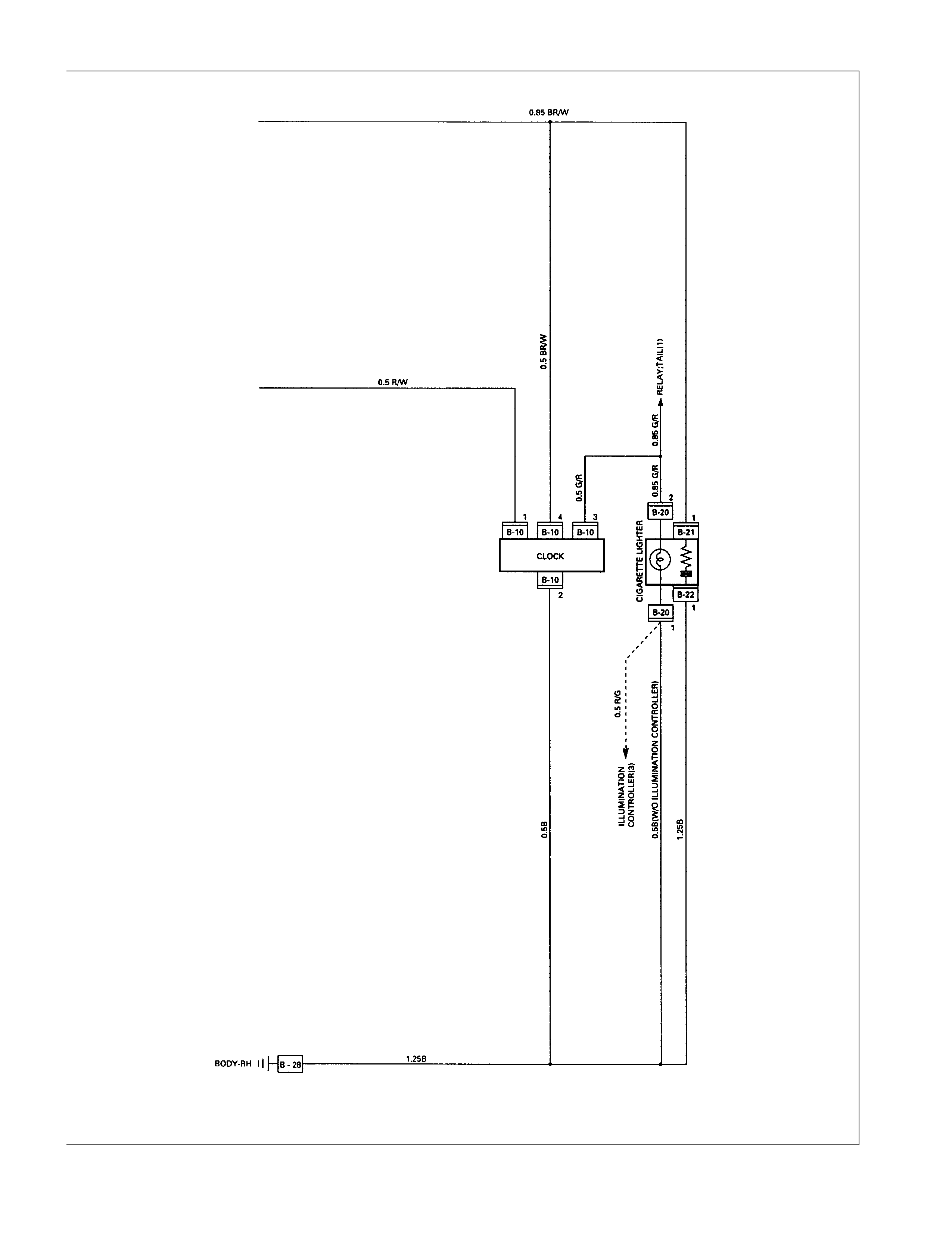
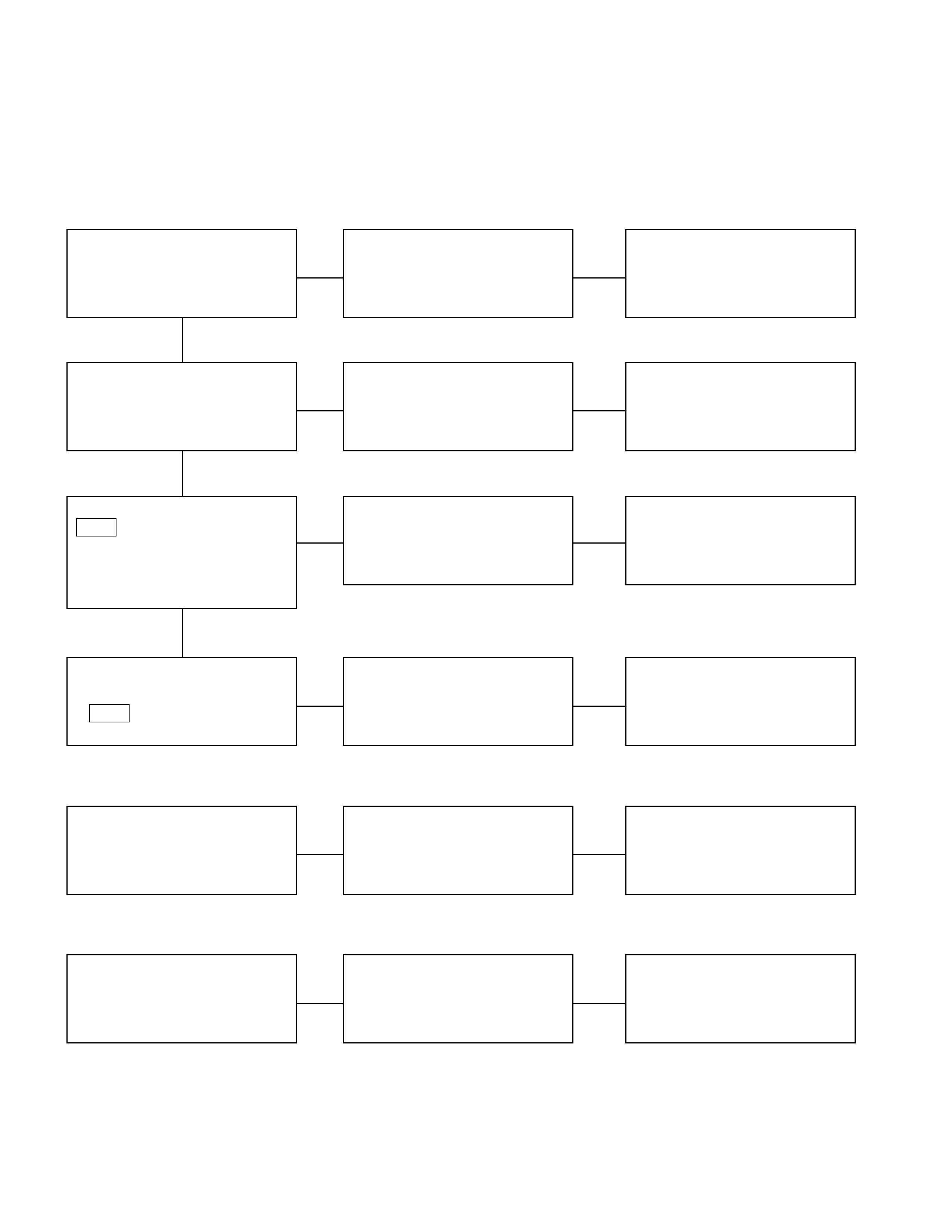
TROUBLESHOOTING
CIGARETTE LIGHTER
1. Lighter does not pop out after being pushed in. It does not become hot.
Checkpoint Trouble Cause Countermeasure
Reinstall or replace the fuse
No. CB-20 (15A)
Poor Fuse No. CB-20 (15A,
Fuse box) contact or blown
NG
Replace the lighter
Lighter continuity between
center part and outer area Open circuit or poor connector
contact
Repair open circuit or
connector contact
Voltage between connector 1
B-21 and the ground at
starter SW. is ACC position
(Should be battery voltage
present)
Open circuit or poor connector
contact
NG
NG
OK
OK
OK
Audio system (System should
receive power)
Repair open circuit or
connector contact
Open circuit or poor connector
contact
NG
Continuity between connector
1 B-22 and the ground
2. Lighter pops out prematurely before becoming hot
Repair or replace the lighter
and/or casing
Deformed lighter or casing
NG
Lighter and casing
3. Lighter becomes too hot
Repair or replace the lighter
and/or casing
Deformed lighter and casing
NG
Lighter and casing
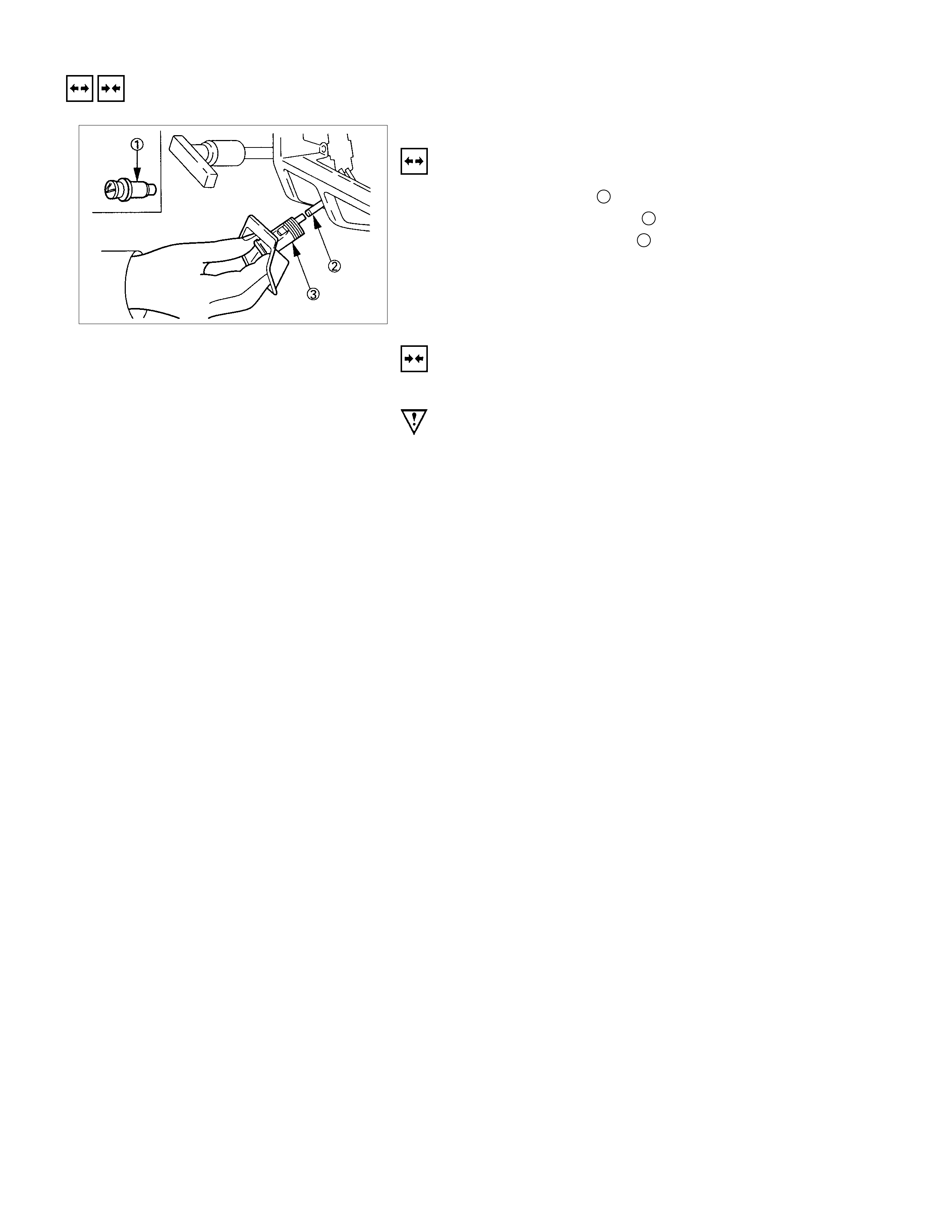
REMOVAL AND INSTALLATION
CIGARETTE LIGHTER
REMOVAL
1. Remove the lighter 1.
2. Disconnect the connector 2.
3. Loosen the lighter holder 3 nut at the back side.
4. Remove the holder from the bezel.
INSTALLATION
Follow the removal procedure in the reverse order to install the
lighter.
Pay close attention to the important points mentioned in the
following paragraphs.
CONNECTOR
Be absolutely sure that the lighter connector is securely
connected.
This will prevent a poor contact and an open circuit.
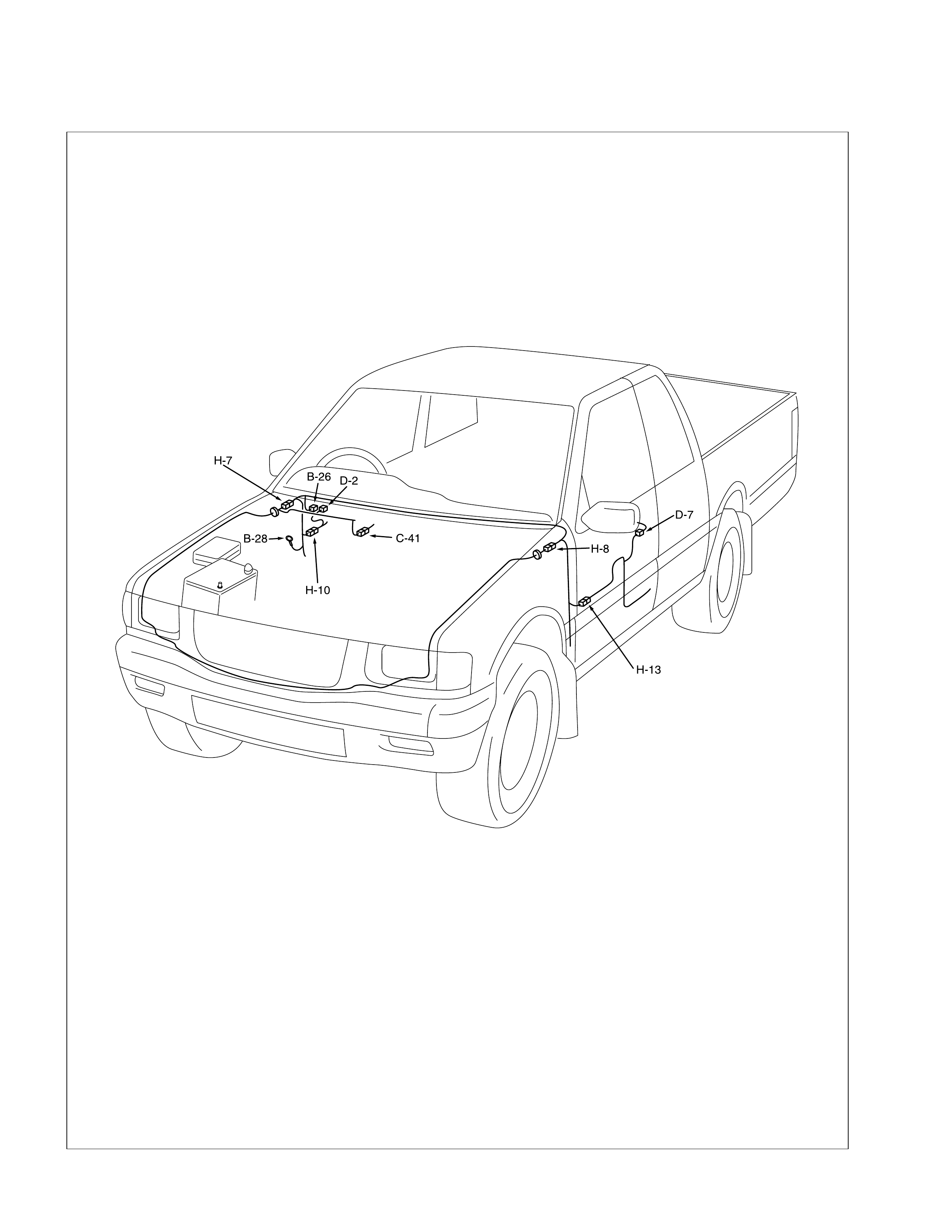
Pow er Door Mirror
PARTS LOCATION
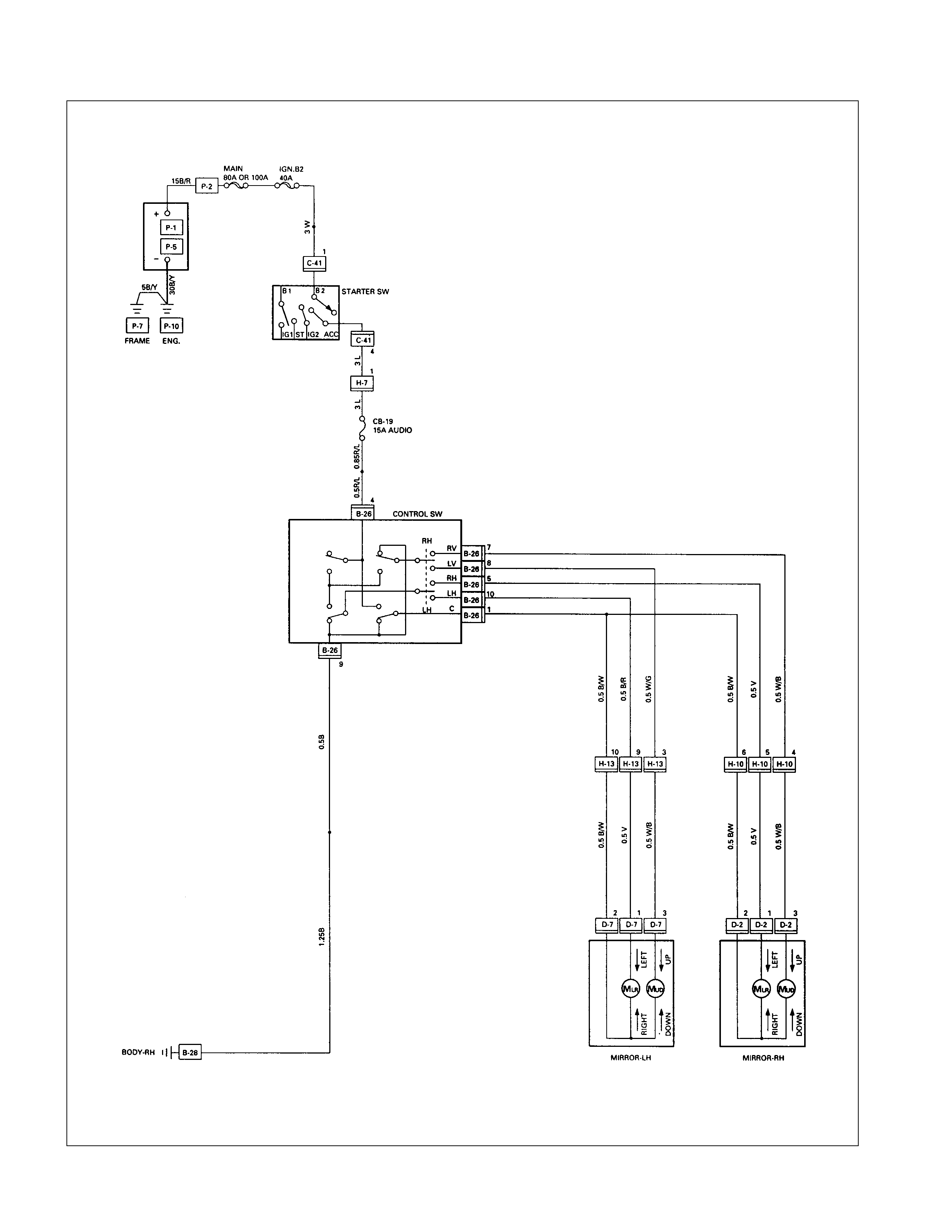
CIRCUIT DIAGRAM (RHD)
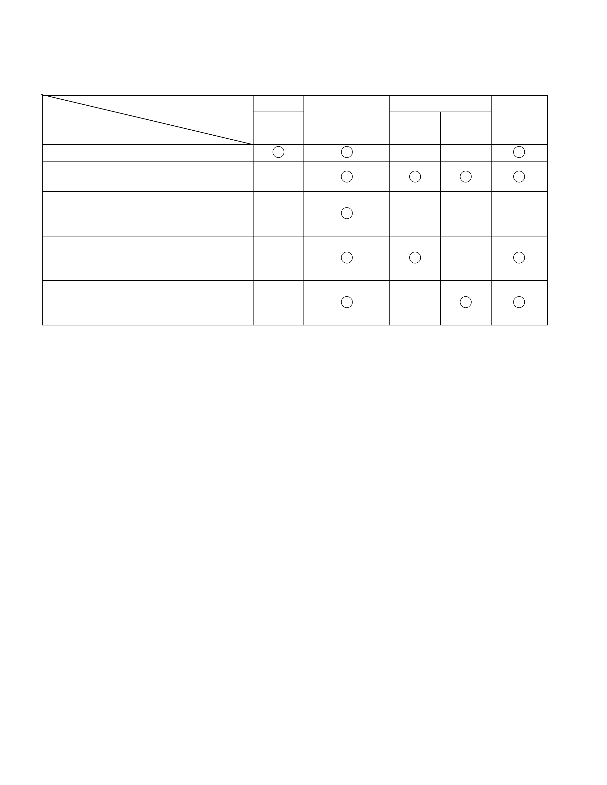
TROUBLESHOOTING
QUICK CHART FOR CHECK POINT
Check Point Fuse Door Mirror Door Mirror
Trouble Mode
CB-19
(15A)
Control
Switch LH RH
1. Mirrors on the both sides do not operate
2. Mirror on the left (or right) side does not
operate
3. Mirrors on the both sides operate only in
the vertical
(or horizontal) direction
4. Mirror on the left side operates only in
the vertical
(or horizontal)direction
5. Mirror on the right side operates only in
the vertical
(or horizontal) direction
Cable
Harness
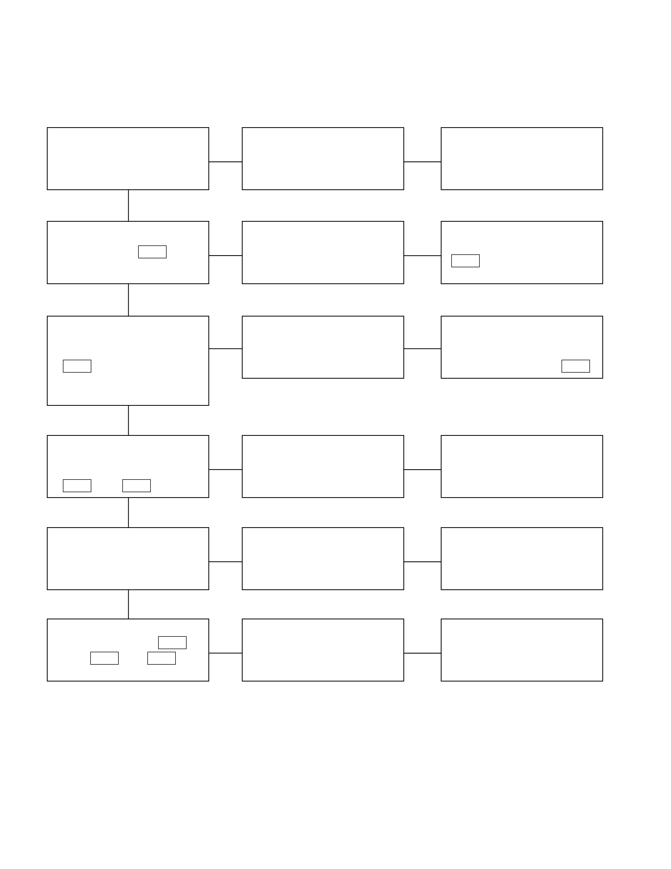
DOOR M IRROR CO NTROL SW ITCH
1. Mirrors on the both sides do not operate
Checkpoint Trouble Cause Countermeasure
Reinstall or replace the fuse
No. CB-19 (15A)
Poor fuse contact or blown
NG
Repair grounding point
(B-28 ) contact
Grounding point ( B-28 )
Poor grounding point contact
Repair an open circuit or a
poor connection of the
connectors between the fuse
No. CB-19 (15A) and 4 B-26
Voltage between the door
mirror control SW. harness
side connector terminal
4 B-26 and the ground
(Should be battery voltage
present)
Open circuit or poor connector
contact
NG
NG
OK
OK
OK
Fuse No. CB-19 (15A, Fuse
box)
Repair open circuit or
connector contact
Open circuit or poor connector
contact
NG
Continuity between the door
mirror control SW harness
side connector terminal
9 B-26 and ( B-28 )
Replace the door mirror
control SW.
Door mirror control SW.
function
SW. malfunction
NG
OK
Repair open circuit or
connector contact
Continuity between 1 B-26
and 10 H-13 (or 6 H-10 )
Open circuit or poor connector
contact
NG
OK
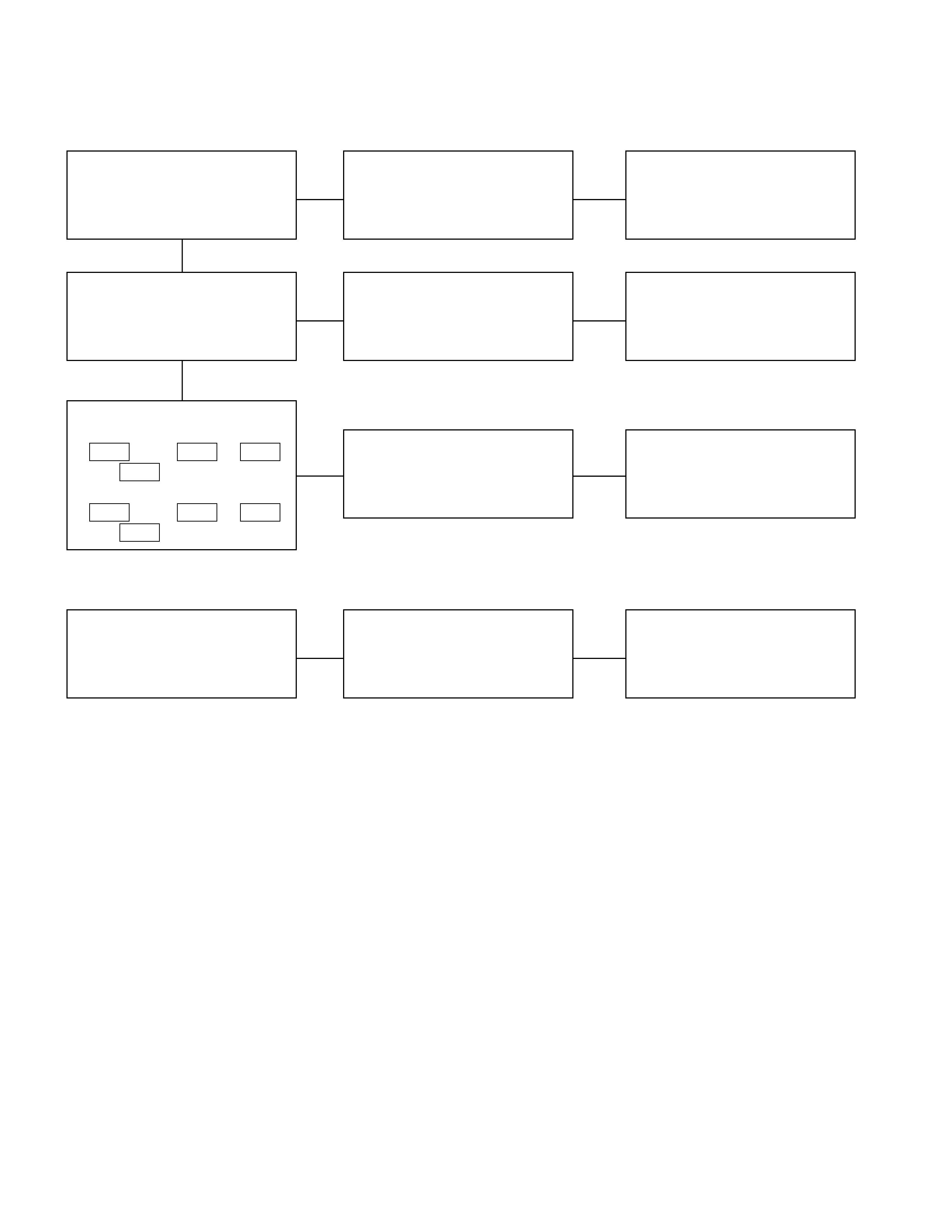
2. Mirror on the left (or right) side does not operate
Checkpoint Trouble Cause Countermeasure
Replace the door mirror
control SW.
SW. malfunction
NG
Repair or replace the door
mirror
Mirror function on the left (or
right) side Mirror malfunction on the left
(or right)
Repair open circuit or
connector contact
Continuity between
[LHD]
1 B-26 and 2 D-2 (1 B-26
and 2 D-7 )
[RHD]
1 B-26 and 2 D-7 (1 B-26
and 2 D-2 )
Open circuit or poor connector
contact
NG
NG
OK
OK
Door mirror control SW.
function
3. Mirrors on the both s ides operate only in the vertical (or horizontal) direction
Replace the door mirror
control SW.
SW. malfunction
NG
Door mirror control SW.
function
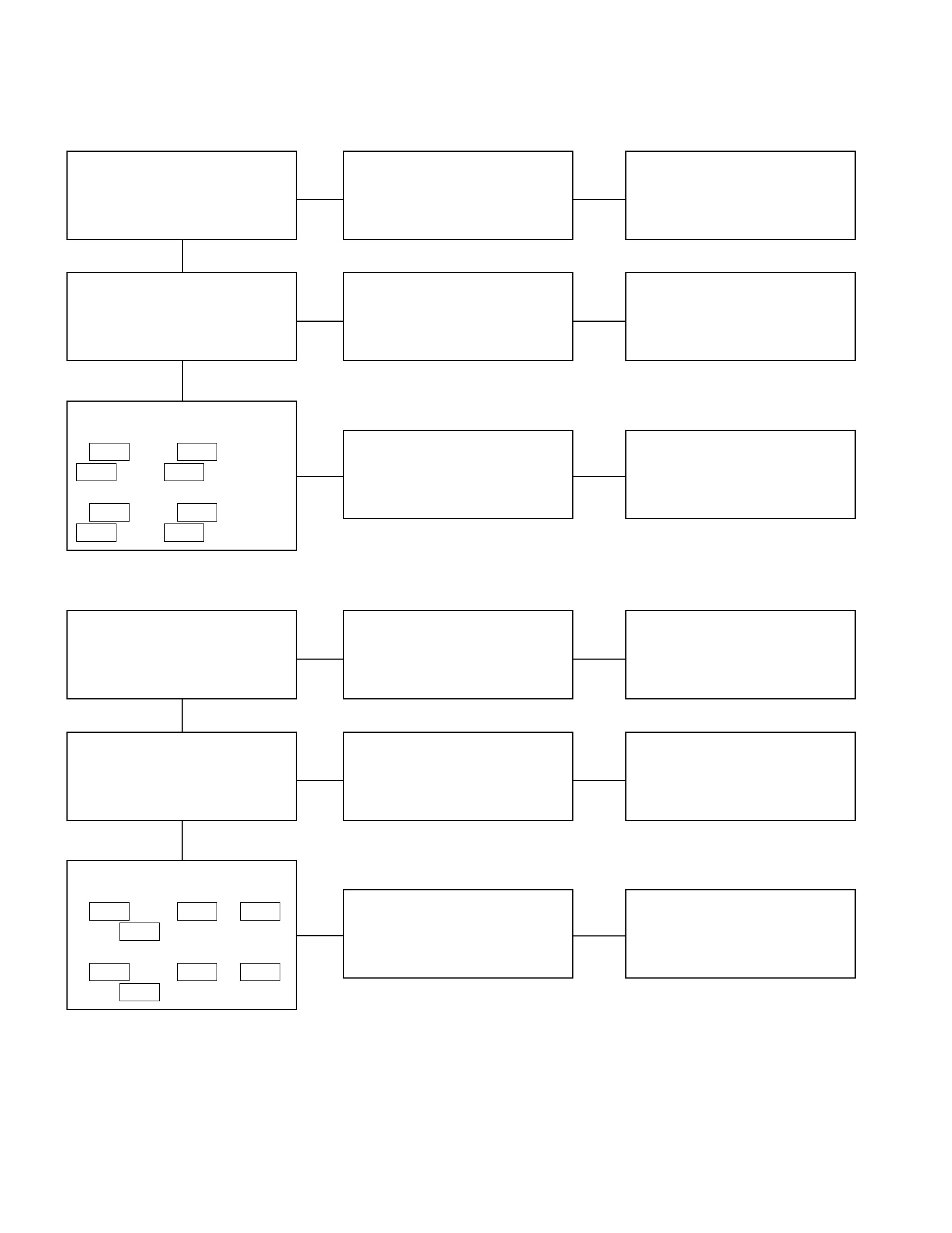
4. Mirror on the left side operates only in the vertic al (or horizontal) direction
Checkpoint Trouble Cause Countermeasure
Replace the door mirror
control SW.
SW. malfunction
NG
Repair or replace the door
mirror
Door mirror function Door mirror malfunction
Repair open circuit or
connector contact
Continuity between
[LHD]
8 B-26 and 3 D-2 (10
B-26 and 1 D-7 )
[RHD]
8 B-26 and 3 D-7 (10
B-26 and 1 D-2 )
Open circuit or poor connector
contact
NG
NG
OK
OK
Door mirror control SW.
function
5. Mirror on the right side operates only in the vertical (or horizontal) direction
Replace the door mirror
control SW.
Door mirror control
malfunction
NG
Repair or replace the door
mirror
Door mirror function Door mirror malfunction
Repair open circuit or
connector contact
Continuity between
[LHD]
7 B-26 and 3 D-7 (5 B-26
and 1 D-7 )
[RHD]
7 B-26 and 3 D-2 (5 B-26
and 1 D-2 )
Open circuit or poor connector
contact
NG
NG
OK
OK
Door mirror control SW.
function

REMOVAL AND INSTALLATION
DOOR M IRROR CO NTROL SW ITCH
REMOVAL
1. Instrument Panel Cluster Assembly
• Refer to Section 1C “BODY” for instrument panel
cluster assembly removal st eps.
2. Door Mirror Control Switch
•Disconnect the switch connector.
•To rem ove the switch, push the lock from the back side
of the cluster assembly.
INSTALLATION
To install, follow the removal steps in the reverse order.
DOOR MIRROR
REMOVAL AND I NSTALLATION
Refer to the DOOR MIRROR in section 10 “BODY”.
INSPECTION AND REPAIR
Switch side
DOOR M IRROR CO NTROL SW ITCH
1. Switch side Connector Circuit
Check continuity between the switch connector terminals
while operating the door mirror control switch as shown in
the following table.
Connector No.
Switch position 49181075
(Up)
(Down)
(Left)
(Right)
(Up)
(Down)
(Left)
(Right)
Door mirror (RH)
Door mirror (LH)
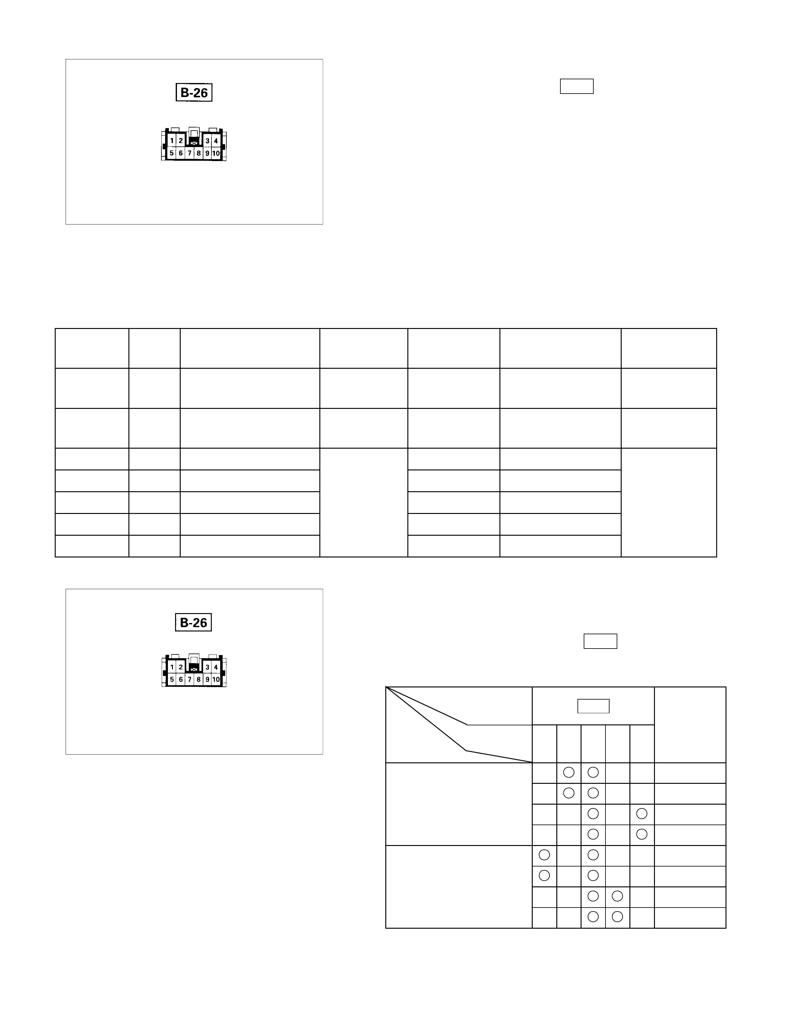
Harness side
2. Harness Side Connector Circuit
Remove the connector No. B-26 of the mirror control
switch and check voltage and c ontinuity of the harness side
connector.
•When there is no continuity at the terminal No. 5, 7, 8
and 10, it is considered that the circuit with term inal No.
1 (B/W) is defective.
•When there is no continuity at either one of the circuit
No, 5, 7, 8, or 10, the m otor in the m irror of the circuit o
r
the circuit itself is defective.
Terminal
No. Wire
color Connection to Check item Connecting
terminal Check condition Standard
1B/W
LH mirror & RH
mirror Continuity 1-Ground - No continuity
4 R/L Fuse CB-19 (15A) Voltage 4-Ground Starter SW “ACC”
position Approx.
12V
5 V RH mirror-LH/RH 5-1 -
7 W/B RH mirror-Up/Down 7-1 -
8 W/G LH mirror-Up/Down Continuity 8-1 - Continuity
9 B Ground 9-Ground -
10 B/R LH mirror-LH/RH 10-1 -
Harness side
DOOR MIRROR
1. Door Mirror Control Switch Connector Circuit
Disconnect the switch connector ( B-26 ), apply the battery
voltage to the harness side connector terminals and check
its function. Connector
No. B-26 Operating
Terminal
Mirror No. 10 5 1 8 7 direction
+ - Left
- + Right
- + Up
+ - Down
+ - Left
- + Right
- + Up
+ - Down
Left
Right
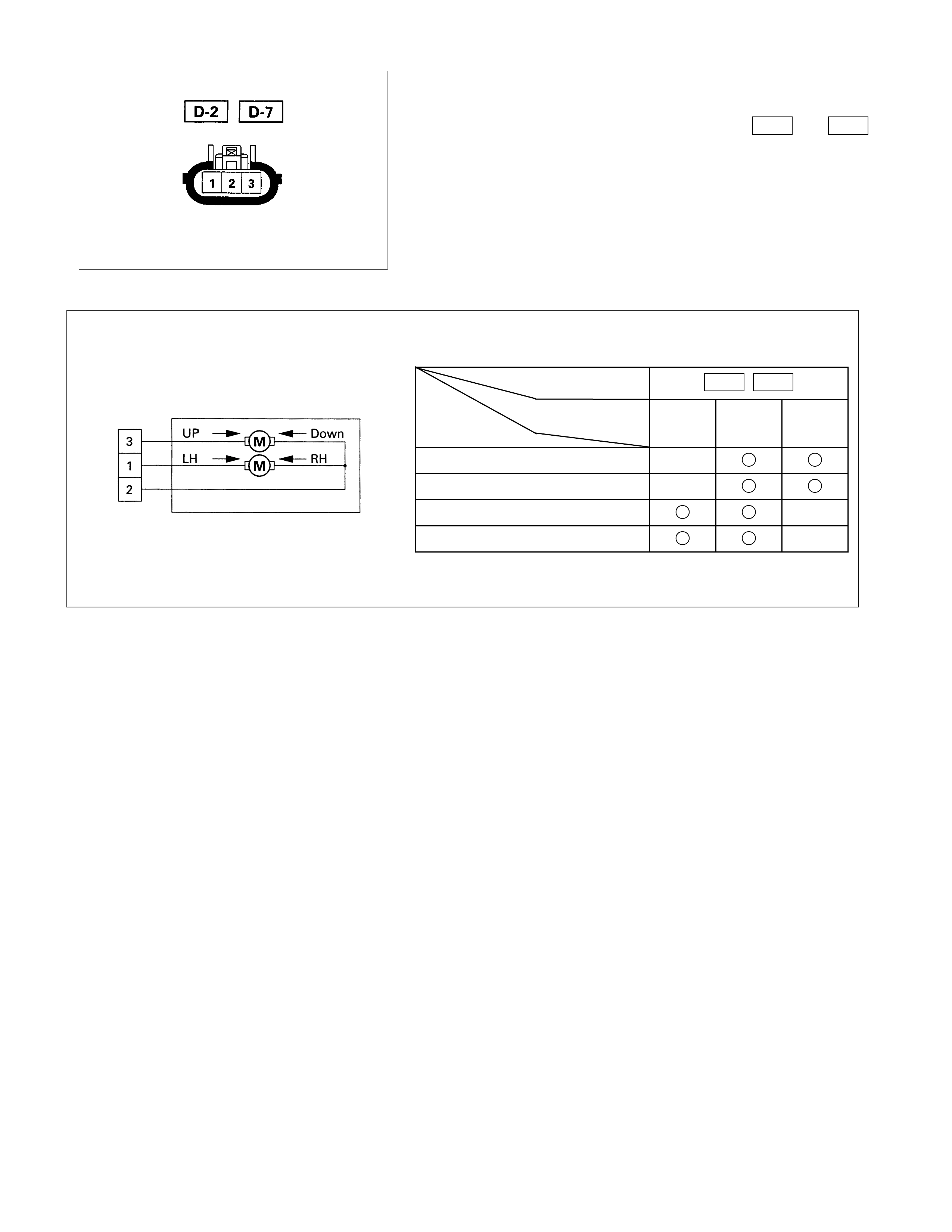
Door mirror side
2. Door Mirror Connector Circuit
Disconnect the door mirror connector, apply the battery
voltage to the door mirror s ide connector ( D-2 and D-7 )
terminals and check its function.
Connector No. D-2 D-7
Terminal No.
Operation 123
Up - +
Down + -
Left + -
Right - +
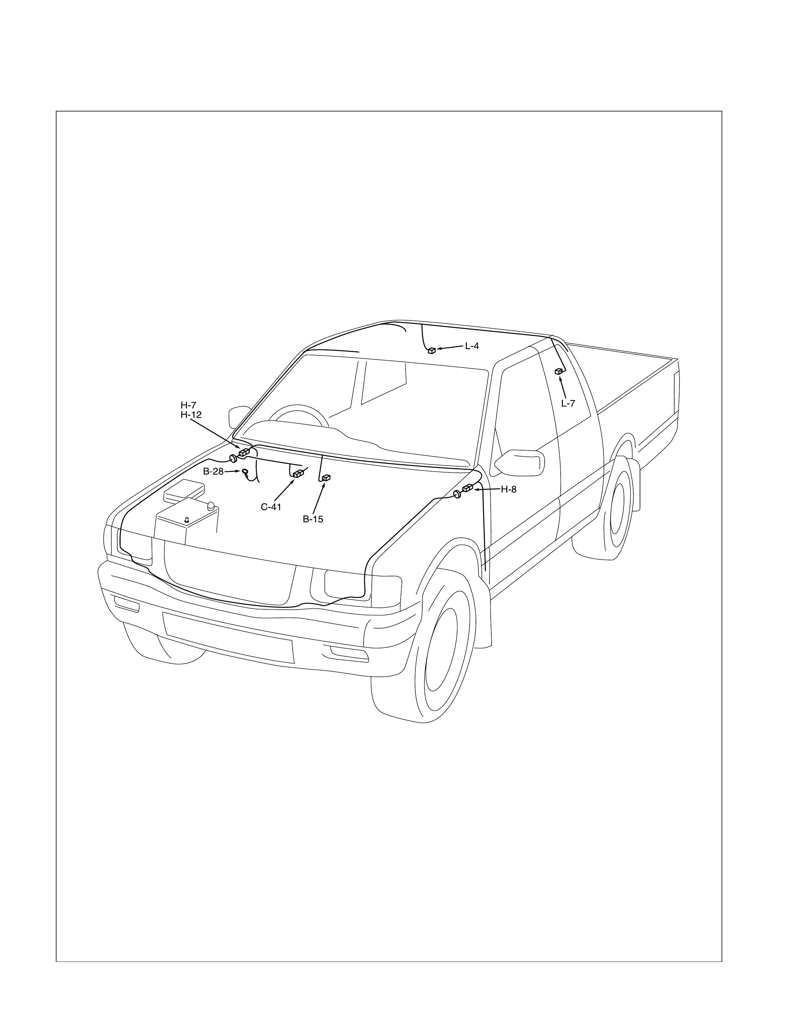
Rear Defogger
PARTS LOCATION
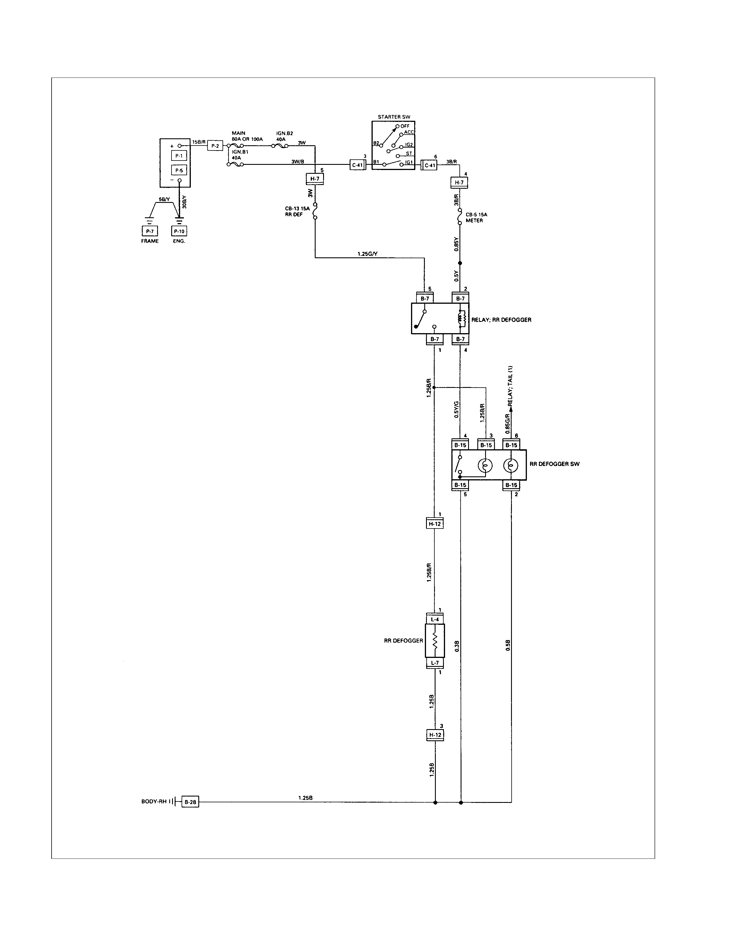
CIRCUIT DIAGRAM
TROUBLE SHOOTING
REAR DEFOGGER INOPERATIVE
Checkpoint Trouble Cause Countermeasure
Reinstall or replace the fuse
No. CB-7 (15A) (RHD: fuse
No. CB-5 (15A))
Poor fuse contact or blown
NG
Reinstall or replace the fuse
No. CB-13 (15A)
Fuse No. CB-13 (15A, Fuse
box) Poor fuse contact or blown
Replace the rear defogger
switch
Rear defogger switch function Switch malfunction
NG
NG
OK
OK
OK
LHD:
Fuse No. CB-7 (15A, Fuse
box)
RHD:
Fuse No. CB-5 (15A, Fuse
box)
Replace the rear defogger
relay
Relay malfunction
NG
Continued on the next page
Rear defogger relay function
Repair grounding point
(B-28 ) contact
Grounding point ( B-28 )Poor grounding point contact
NG
OK
Repair open circuit or poor
connector contact between
fuse No. CB-7 (15A) (RHD:
fuse No. CB-5 (15A)) and 2
B-7 , fuse No. CB-13 (15A)
and 5 B-7 , 1 B-7 and 1
L-4 , 4 B-7 and 4 B-15 or
5 B-15 and B-28
Voltage between 1 L-4 -
ground when the starter switch
and the rear defogger switch
are at on position (should be
battery voltage present)
Open circuit or poor connector
contact
NG
OK
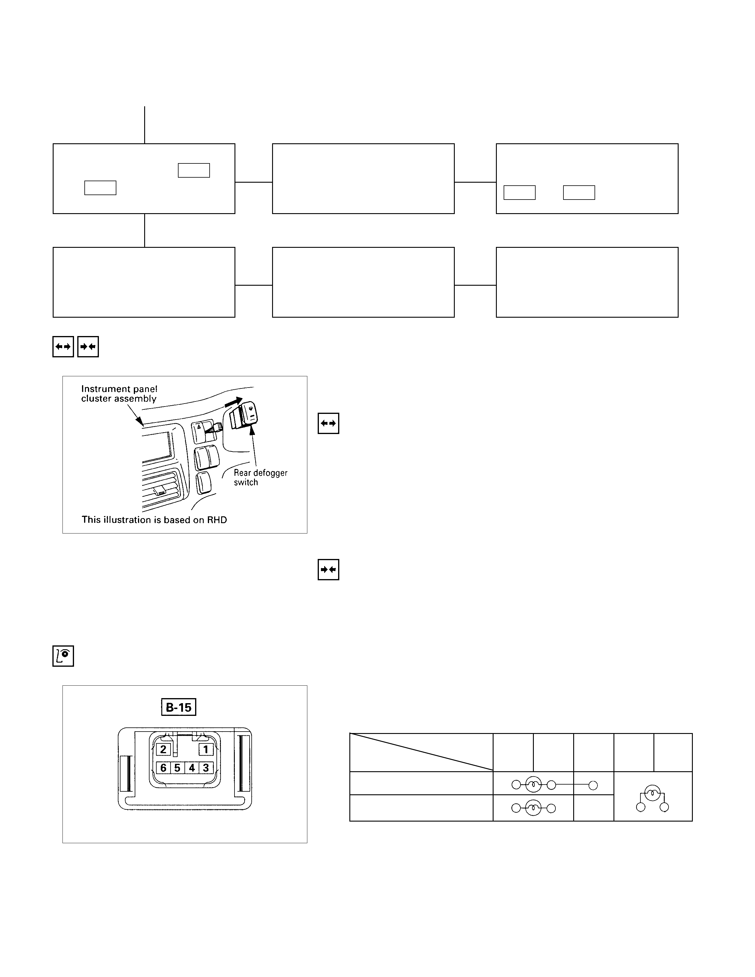
Checkpoint Trouble Cause Countermeasure
OK
Repair open circuit or
connector contact between 1
L-7 and B-28
Open circuit or poor connector
contact
NG
Continued from the previous page
Continuity between 1 L-7
and B-28
Repair heat wire
Continuity between rear
defogger terminals
Broken heat wire of rear
defogger
NG
OK
REMOVAL AND INSTALLATION
REAR DEFOG SWITCH
REMOVAL
1. Instrument Panel Cluster Assembly
• Refer to Section 1C “BODY” for instrument panel
cluster assembly removal st eps.
2. Rear Defogger Switch
•Disconnect the switch connector.
•To rem ove the switch, push the lock from the back side
of the cluster assembly.
INSTALLATION
Follow the removal procedure in the reverse order to install the
rear defogger switch.
INSPECTION AND REPAIR
Switch side
REAR DEFOG SWITCH
REAR DEFOG SWI TCH CO NNECTIONS
Terminal No.
SW position 35462
ON
OFF
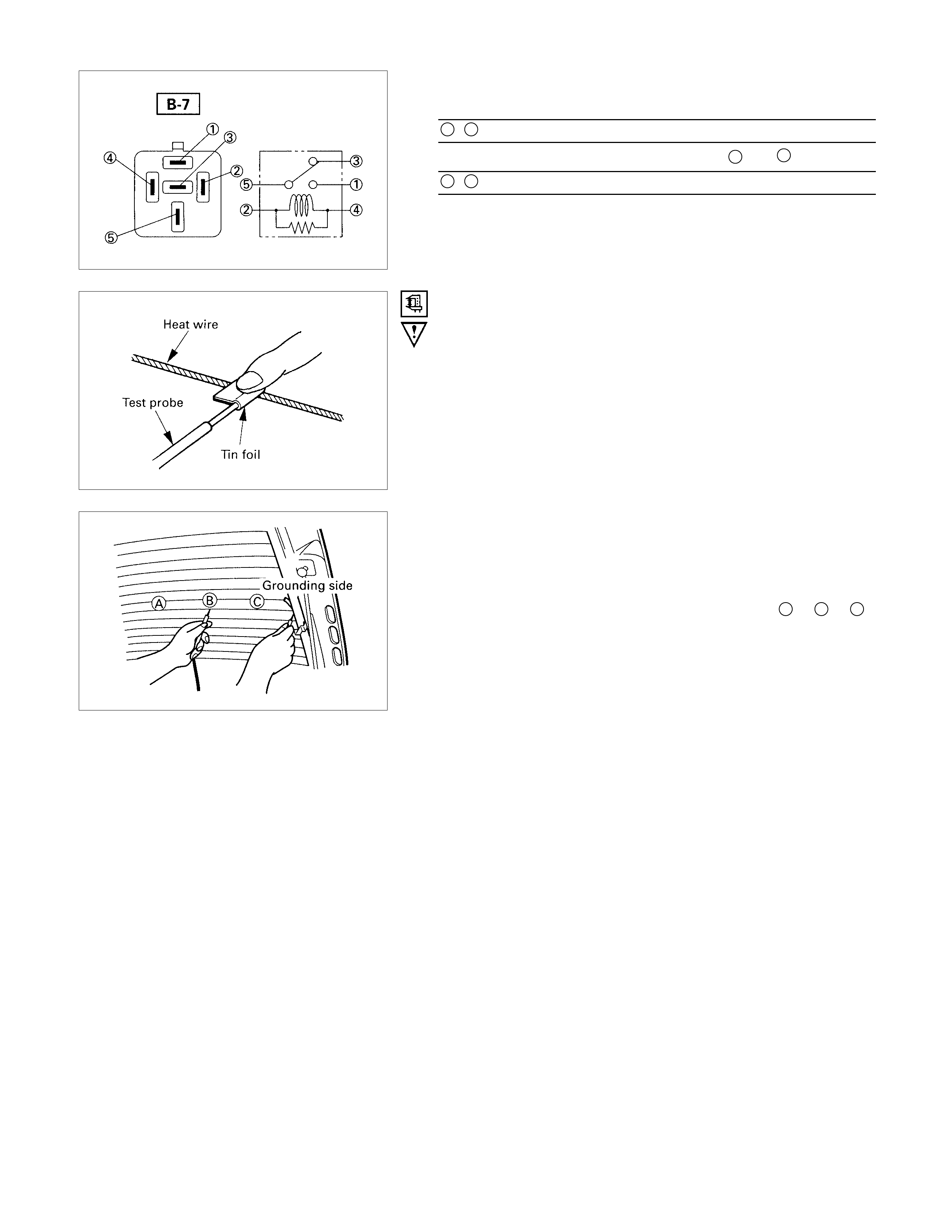
REAR DEFOG RELAY
Check continuity between the relay terminals.
1- 5........................No continuity
(When battery voltage is applied between 2 and 4)
1- 5........................Continuity
INSPECTION OF REAR DEFOG HEAT WIRE
•Heat wires are printed on the inner side of glass.
To clean, use a soft cloth and wipe horizontally along the
wires.
•Never use glass cleaner or equivalent.
•When m easuring voltage, wind a piece of tin f oil ar ound the
tip of the negative probe and press the foil against the wire
with your finger as shown.
(1)Turn the ignition switch on.
(2)Turn the defogger switch on.
(3)Measure the voltage between the three points on the heat
wire and the (-) terminal with a voltmeter.
(4)Check that the voltage becomes smaller from A to B to C.
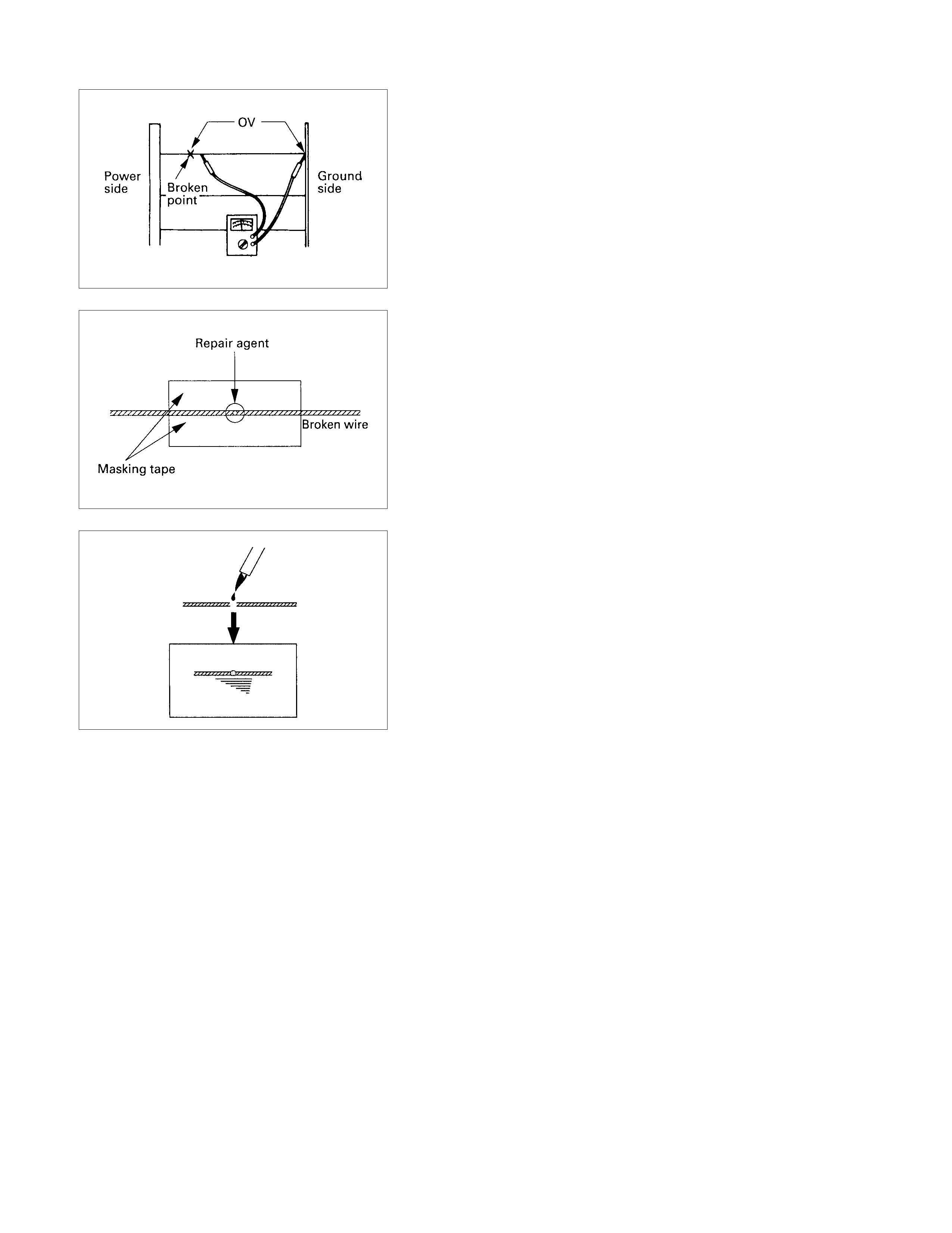
(5)If there is a place where the voltage suddenly changes to
0V, there is a broken wire between there and the powe
r
side.
(6)Move the tester probe from the position where the voltage
changes to 0V toward the power side and find where the
voltage suddenly increases.
REPAIR OF BRO KEN HEAT WIRE
(1)Clean broken wire tips with white gasoline.
(2)Place masking tape along both sides of wire to be repaired.
(3)T horoughly mix the repair agent (Dupont paste No. 4817 o
r
equivalent).
(4)Using a fine tip brush, apply a small amount to the wire.
(5)After a couple of minutes, remove the masking tape.
(6)Allow to stand at least 24 hours.
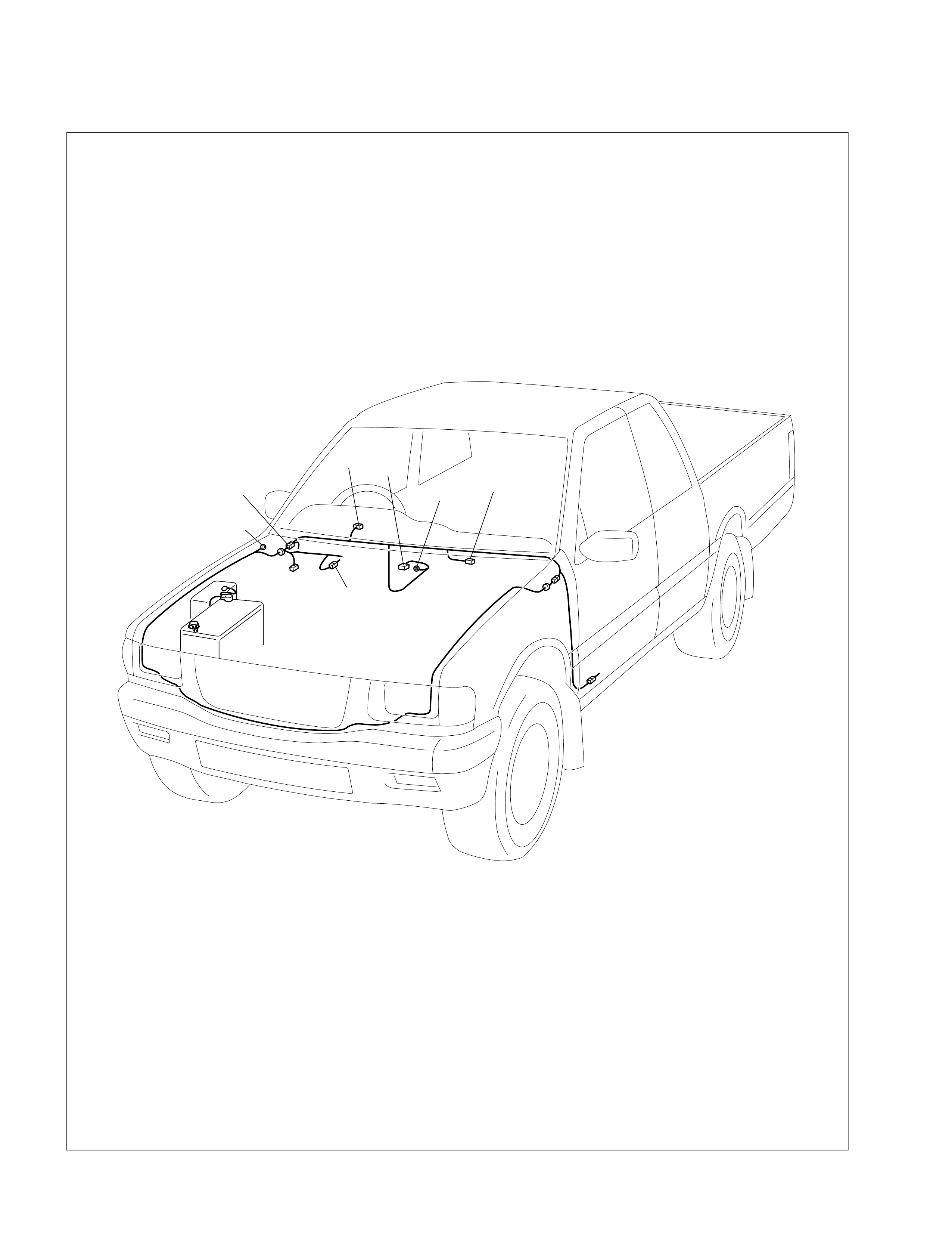
SRS-Air Bag
PARTS LOCATION
C-2
B-37 B-31
B-32
C-41
B-36
H-7
H-18 B-35
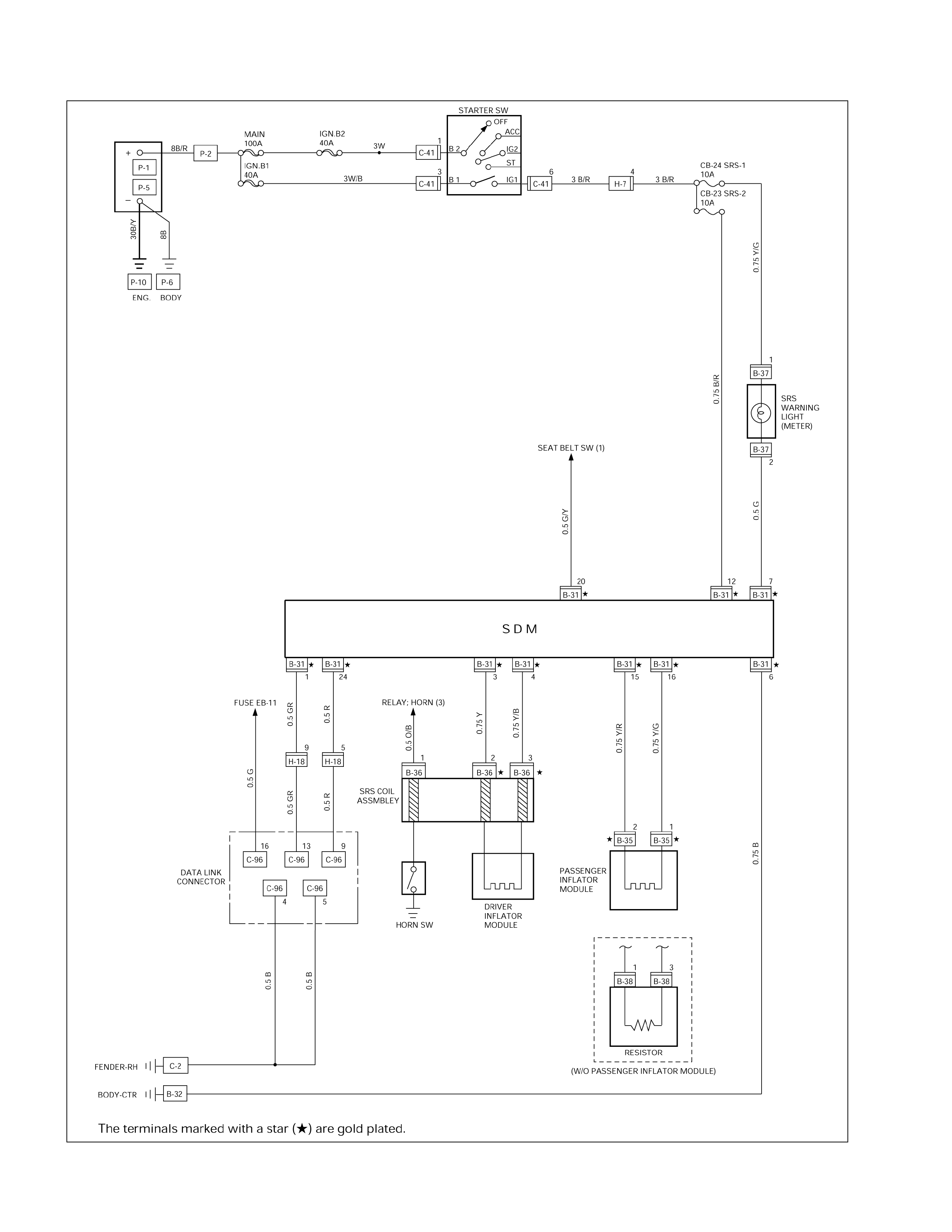
CIRCUIT DIAGRAM
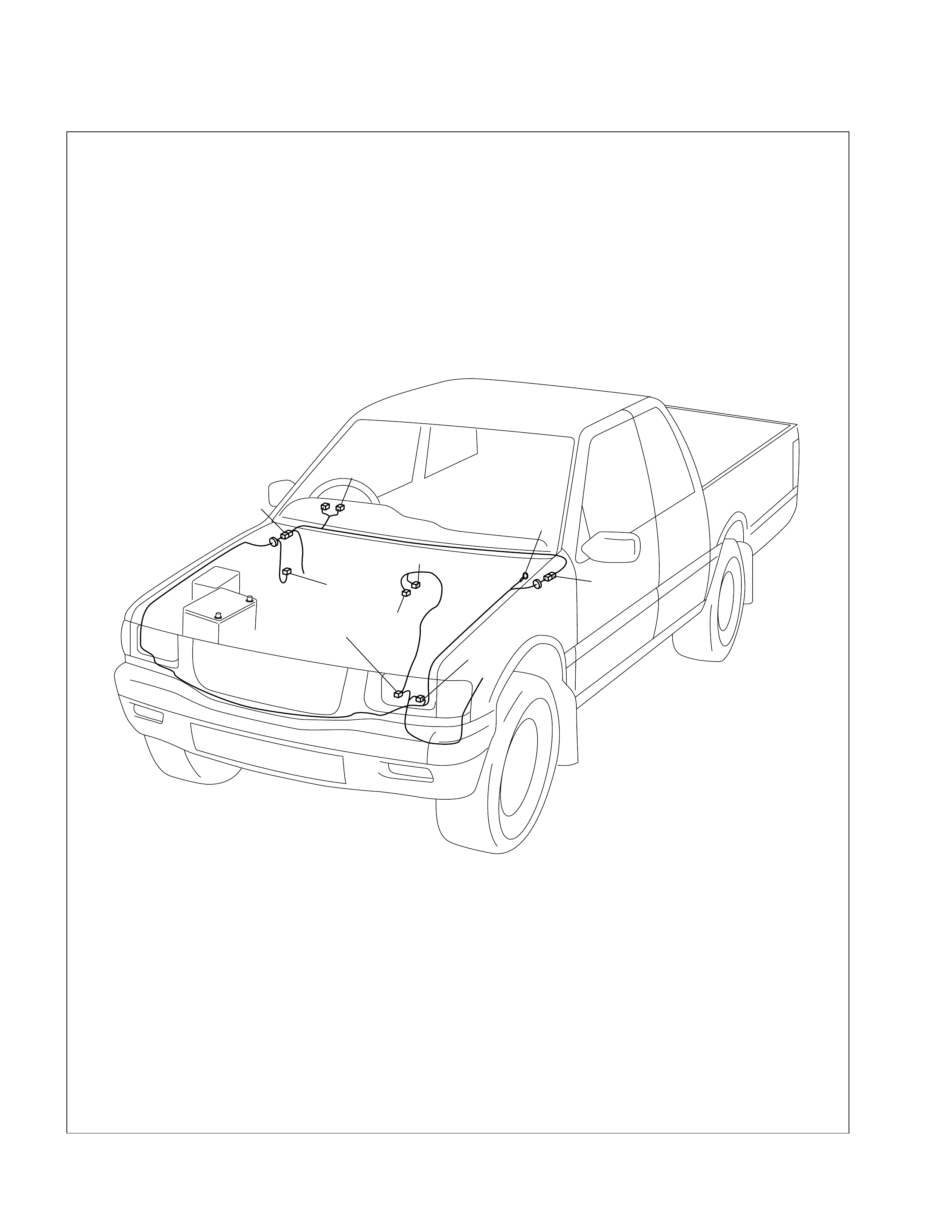
Shift On The Fly
PARTS LOCATION
C-36
C-110
B-24
H-6
H-7
E-46
H-8
E-45
P-21
H-22
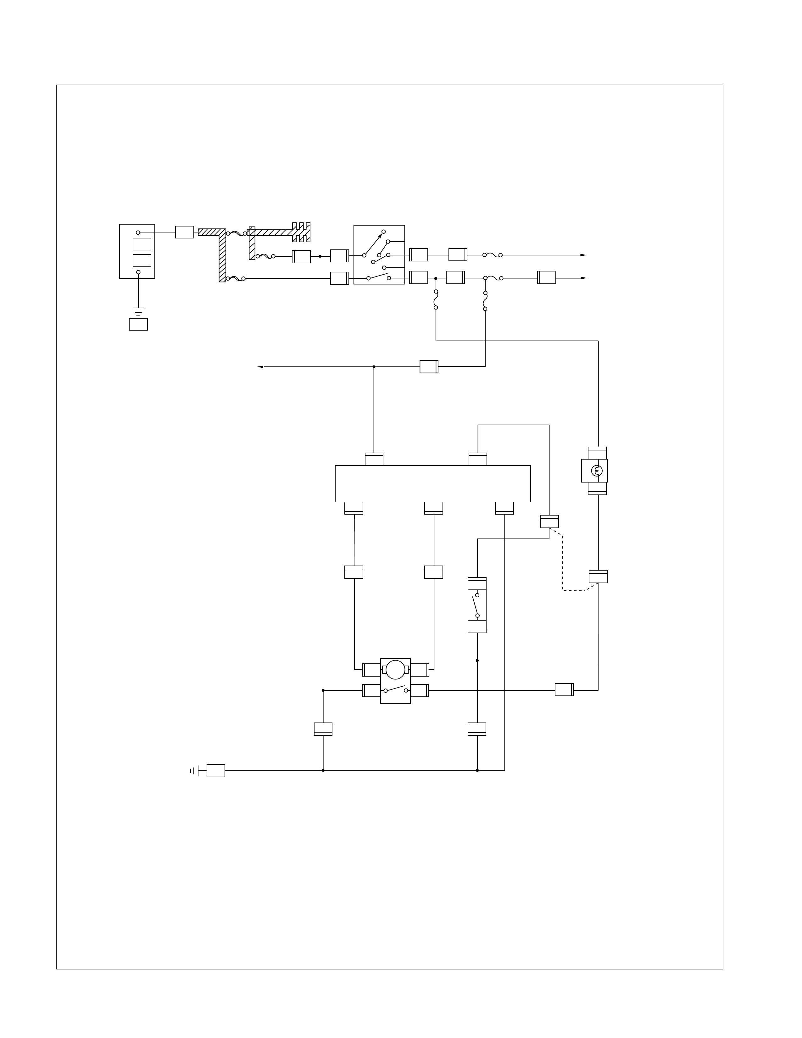
CIRCUIT DIAGRAM
H-22
E-45
B-24
C-110C-110
C-110 C-110
E-46
C-110
H-22 H-22
B-24
H-22
MP-21
P-21
C-41
H-7
C-41
H-7 C-41
P-1
P-2
P-5
C-36
P-10
+
–
BATT
ACC
IG2
ST
IG1
B
2
B
1
SW;IGNITION
(STEERING LOCK)
1
3
3W
3W/B
EB-18
IGN.B-2
40A
EB-16
MAIN
100A
EB-15
IGN.B-1
40A
8B/R
6
C-41
P-21
H-22
P-21
8
56
H-7 43B/R
3B/Y
0.85L/Y
CB-11
BACK TURN
15A 0.85W
4WD
METER
2
15
34
621 7
1
1
S.O.F CONT.
0.5L/R
0.5L/R
0.5L/W
3
4
12
0.85L/O
0.5L/Y
0.85L/Y
0.85Y/G0.85Y/G
3
H-22
14 10
2
0.5B
0.85B
0.5B
0.5B
0.5B
0.5B
1.25B
1
0.5L/W
4 X 4 ON
4 X 2 OFF
SW;TRANSFER
(MISSION)
BODY (LH)
SW ; HAZARD
CB-3
IG COIL
15A
0.85Y
ACT;SOF
3W
CB-4
ENGINE
10A
H-6 0.85L/Y
19
0.5L/R
H-6
0.5B
0.5B
15
HARNESS ; ENGINE ECGI
(W/O
FT AXLE
DISCONNECT)
0.5L/R
CB-5
METER
15A
HARNESS ; ENGINE ECGI
H-6
1
0.85W/G
3B/R
0.85Y
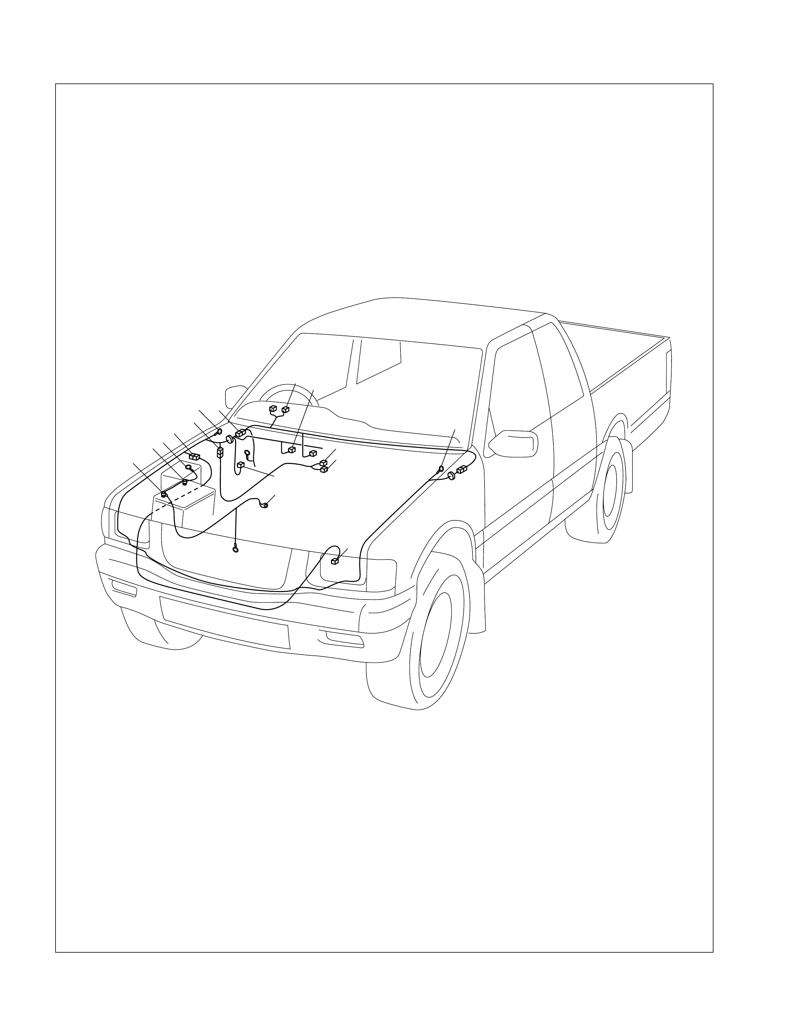
PARTS LOCATION ( 4JB1)
C-41
C-36
C-110
B-24
E-45
E-46
H-7
H-8
H-4
H-51
P-2
P-1
P-5
P-10
P-21
C-2
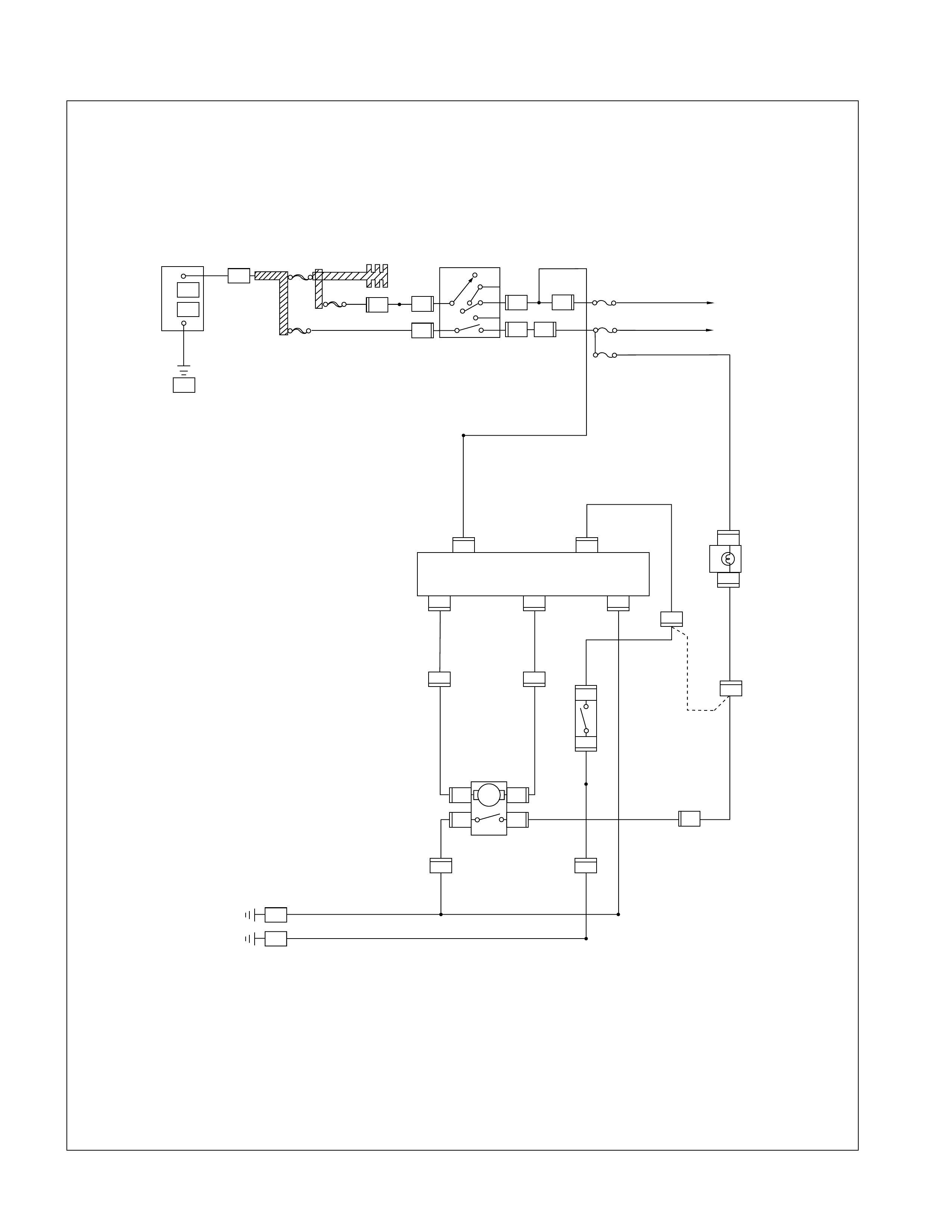
CIRCUIT DIAGRAM
H-4
E-45
B-24
C-110C-110
C-110 C-110
E-46
C-110
H-51 H-51
B-24
H-4
M
P-21
P-21
C-41
H-7
C-41
H-7 C-41
P-1
P-2
P-5
C-36
P-10
+
–
BATT
ACC
IG2
ST
IG1
B2
B1
SW;IGNITION
(STEERING LOCK)
1
3
3W
3W/B
EB-19
IGN.B-2
40A
EB-16
MAIN
80A
EB-15
IGN.B-1
40A
8B/R
6
C-41
P-21
H-51
P-21
8
56
H-7 43B/R
3B/Y
3B/Y
CB-11
BACK TURN
15A 0.85W
4WD
METER
2
15
34
621 1
1
1
S.O.F CONT.
0.5L/R
0.5L/R
0.5L/W
(W/O
FT AXLE
DISCONNECT)
C-2
3
4
12
0.85L/O
0.5L/Y
0.85L/O
0.85Y/G0.85Y/G
4
H-51
112
3
0.5B
0.85B
0.5B
0.5B
0.5B
1.25B
1.25B
1.25B
20.5L/W
4 X 4 ON
4 X 2 OFF
SW;TRANSFER
(MISSION)
BODY ( L H )
BODY ( R H )
SW ; HAZARD
CB-23
SRS2
15A
0.85Y
ACT;SOF
SRS CONT
0.75B/R
0.85Y
CB-5
METER
15A
0.5L/R
H-8
0.85B
15
3B/Y
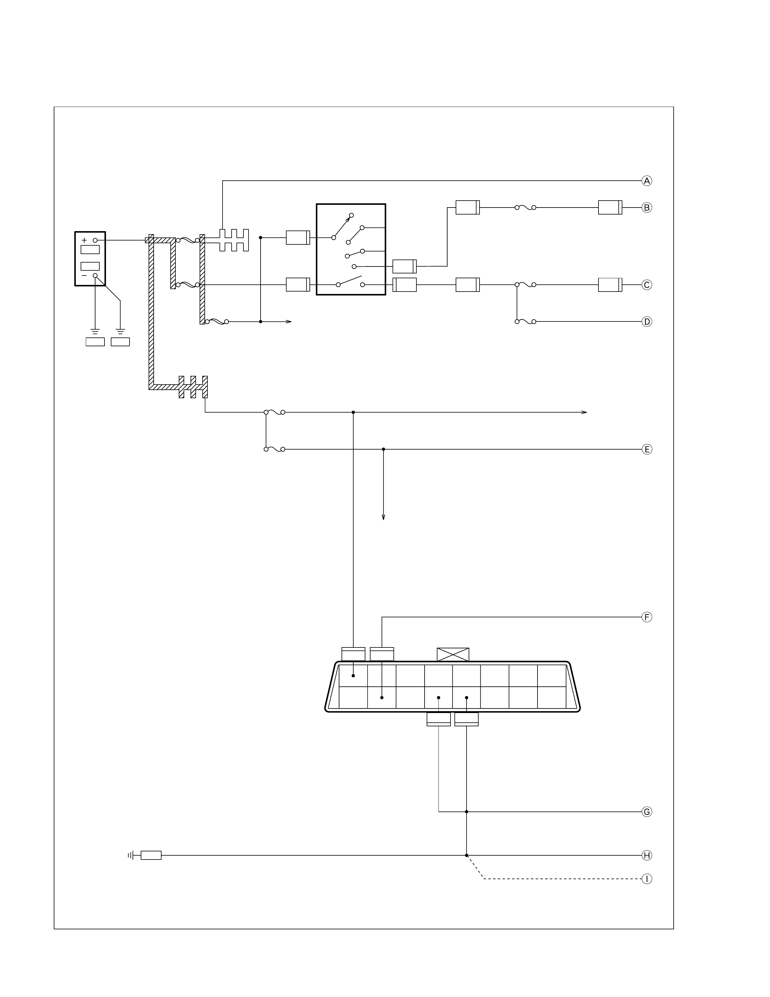
Immobilizer
CIRCUIT DIAGRAM - 4JB1T
B2
B1
ACC
OFF
IG2
ST
IG1
C-41
1
C-41 2
C-41
3
2W/L
3B/R 3B/R
2W/L
0.85W/G
0.85Y
0.5O/B
0.5B
0.5G/R0.5G/R
0.5G0.5G3B
0.5B/W
3B
C-41 6
SW ; STARTER
(STEERING LOCK)
P-5
BATT
P-1
P-10 P-8
ENG. BODY
30B/Y
8B
3W
3W/B
3W
3W
BODY H.CONN,LH
MAIN
EB-16
100A BUSBAR
8B/R
IGN-B1
EB-20
40A
IGN-B2
EB-17
40A
0.5B
0.5B
0.5B
0.5B
0.5G
STOP
EB-3
10A
HORN
EB-2
10A
ENGINE
CB-2
15A
STARTER
10A
METER
CB-6
10A
C-2
BODY-RH 1.25B
STOP LAMP SW
HORN RELAY
C-55
12
C-55
13
C-55
1
C-55
10
H-6 4
H-8 4
H-7 4
H-7 2
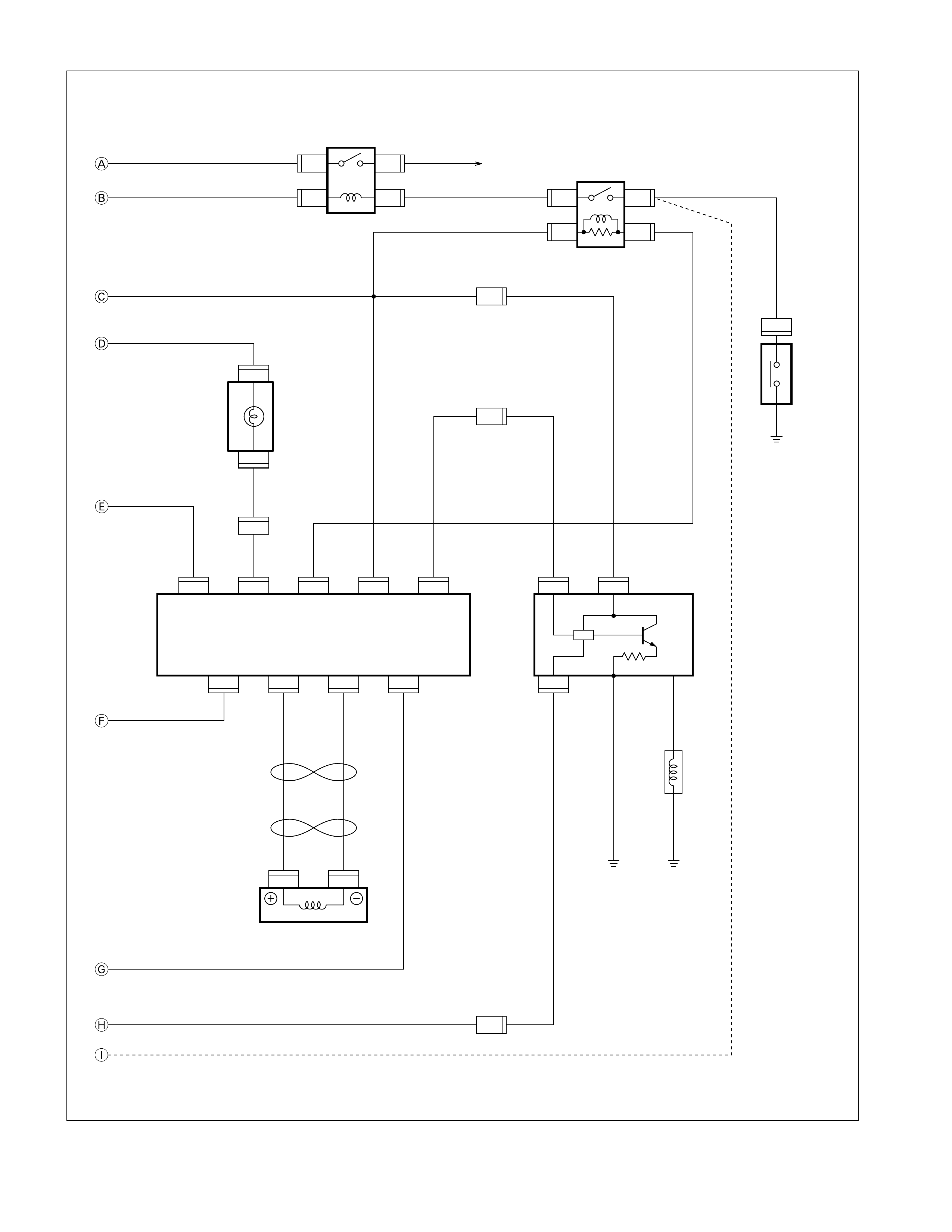
0.85W/G 0.85W/G
0.5L/W
0.85W/G
5B/W
0.85Y
0.5O/B
0.5G/R
0.5O/L
0.5B/W
3B
0.5Y
0.5BR/Y 0.5BR/Y
0.85W/G
0.85W/G
0.5B (M/T)
0.5W (A/T)
A/T MODE
(MISSION)
0.5O
0.5O
0.5L
0.5B
0.5B
METER
CHECK ENG
0.5B
0.5B
0.5B
ANT.COIL
(STRG LOCK)
C-205
9
C-205
6
C-205
13
C-205
7
C-205
1
C-205
3
B-23
2
B-24
2
C-54
1
H-25
20
C-205
14
C-205
2
C-205
8
C-204
1
C-204
2
X-13
4X-13 1
RELAY ;
STARTER
X-13
2X-13 3X-5
2X-5 1
RELAY ;
IMMOBILIZER
X-5
4X-5 3
STARTER (C)
H-4 6
H-5 6
H-5 4
E-100
3
E-100
2
E-100
1
IMMOBILIZER CONT
DDS-1 ; IMMOBILIZER
(ENGINE)
FUEL CUT VALVE
(INJ PUMP)
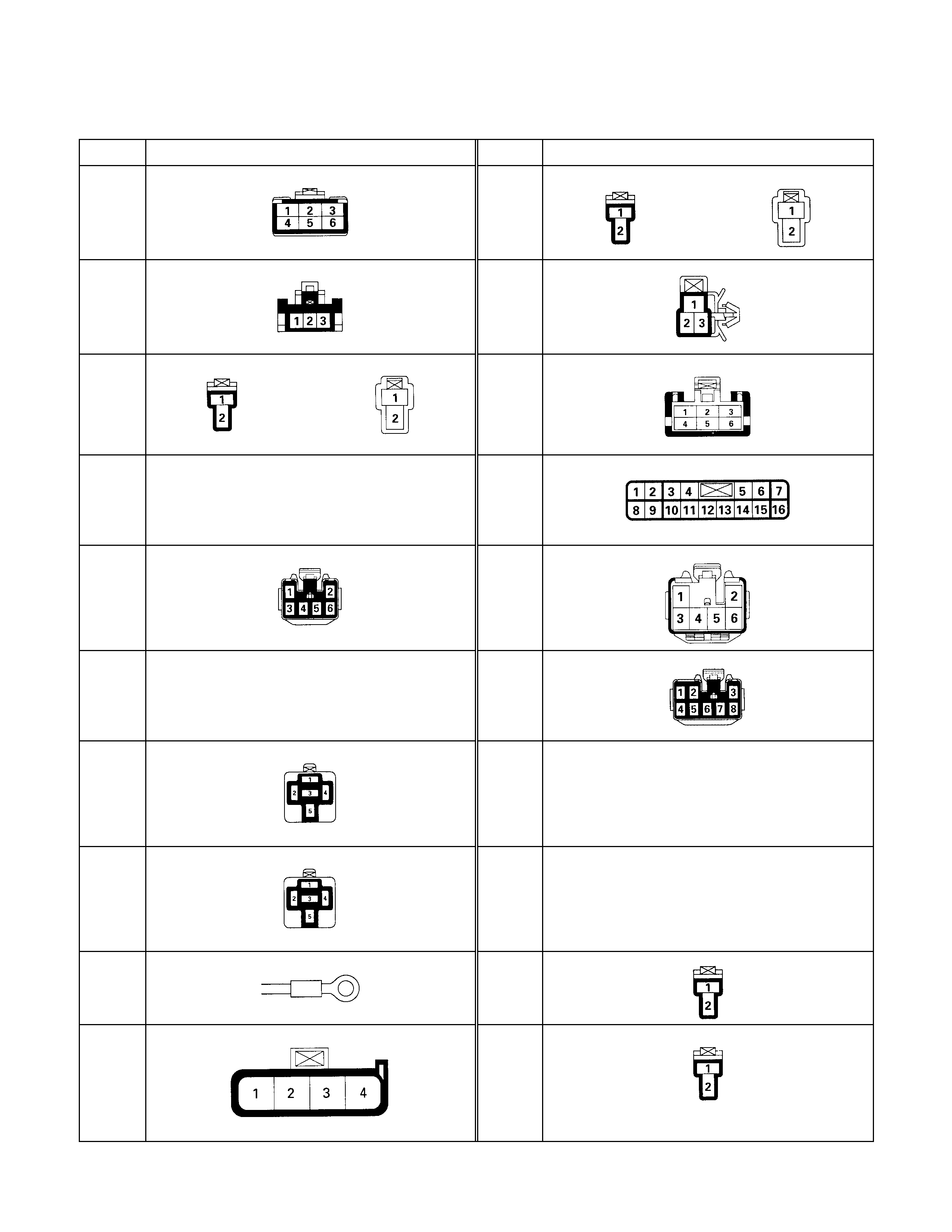
Connector List (HEC Engi ne Model )
No. Connector face No. Connector face
B-1 B-11
B-2 B-12
B-3 B-13
B-4
NOT USED
B-14
B-5 B-15
B-6
NOT USED
B-16
B-7 B-17
NOT USED
B-8 B-18
NOT USED
B-9 B-19
B-10 B-20
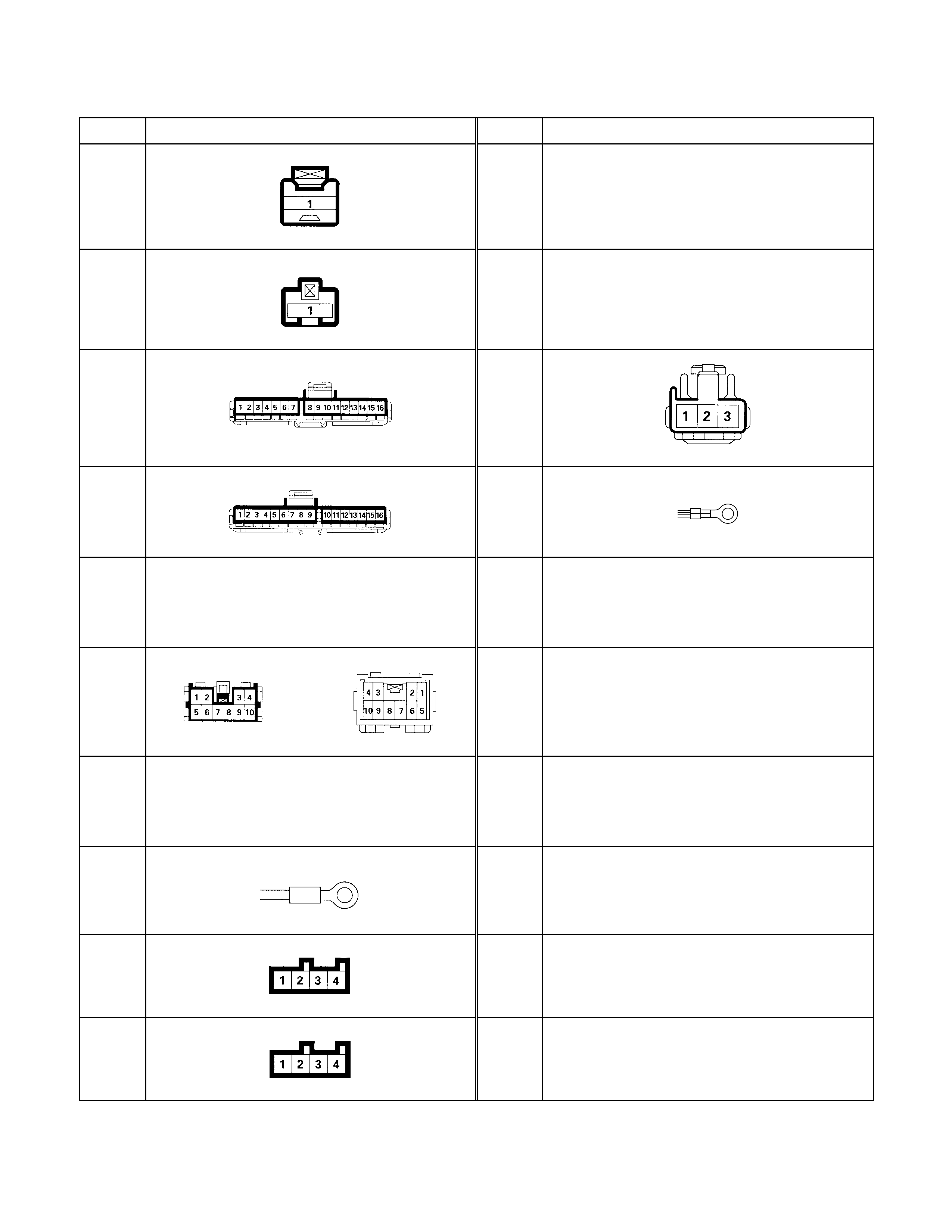
No. Connector face No. Connector face
B-21 B-31
NOT USED
B-22 B-32
NOT USED
B-23 B-33
(RHD)
B-24 B-34
B-25
NOT USED
B-26
B-27
NOT USED
B-28
B-29
B-30
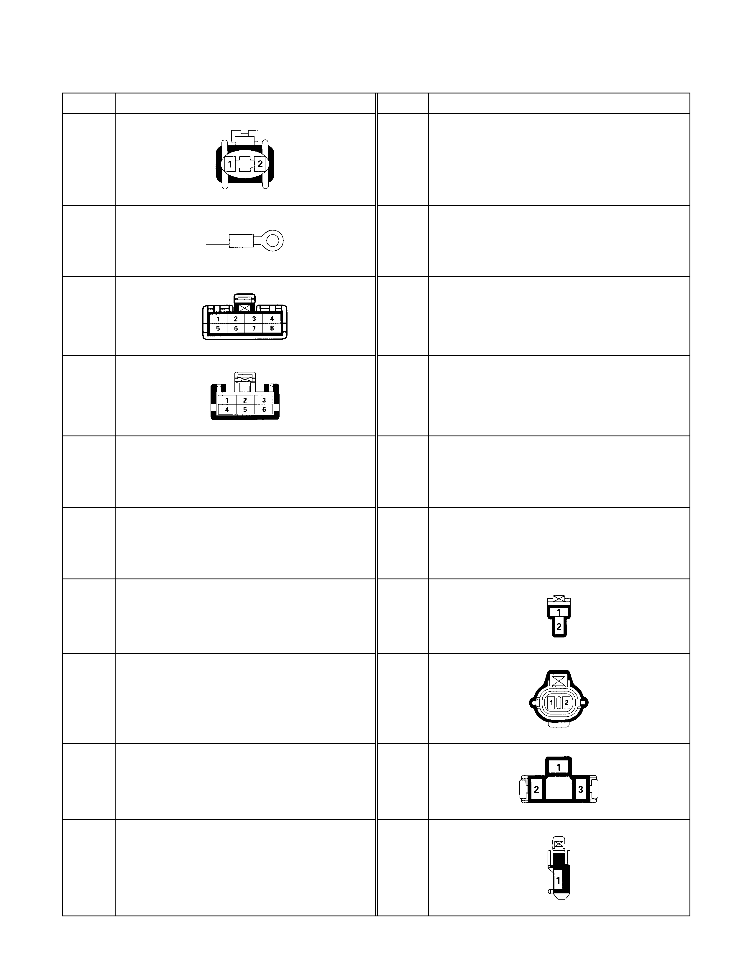
No. Connector face No. Connector face
C-1 C-11
NOT USED
C-2 C-12
NOT USED
C-3 C-13
NOT USED
C-4 C-14
NOT USED
C-5
NOT USED
C-15
NOT USED
C-6
NOT USED
C-16
NOT USED
C-7
NOT USED
C-17
C-8
NOT USED
C-18
C-9
NOT USED
C-19
C-10
NOT USED
C-20
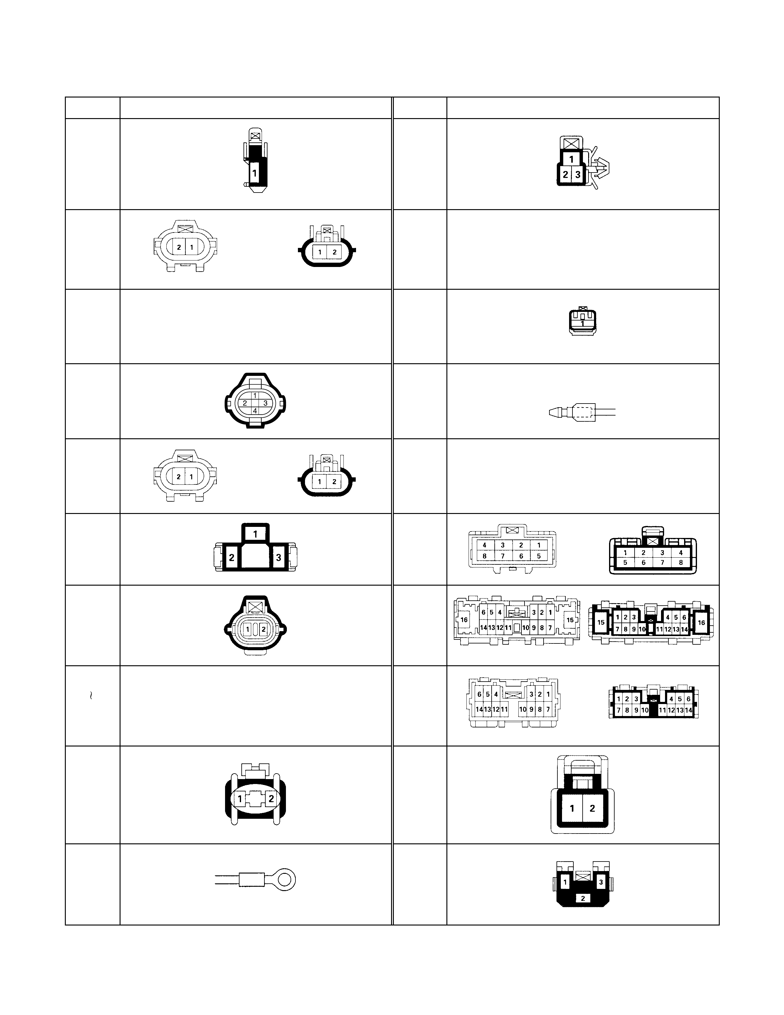
No. Connector face No. Connector face
C-21 C-37
C-22 C-38
NOT USED
C-23
NOT USED
C-39
(LHD
)
C-24 C-39
(RHD)
C-25 C-40
NOT USED
C-26 C-41
C-27 C-42
C-28
C-34 NOT USED
C-43
C-35 C-44
C-36 C-45
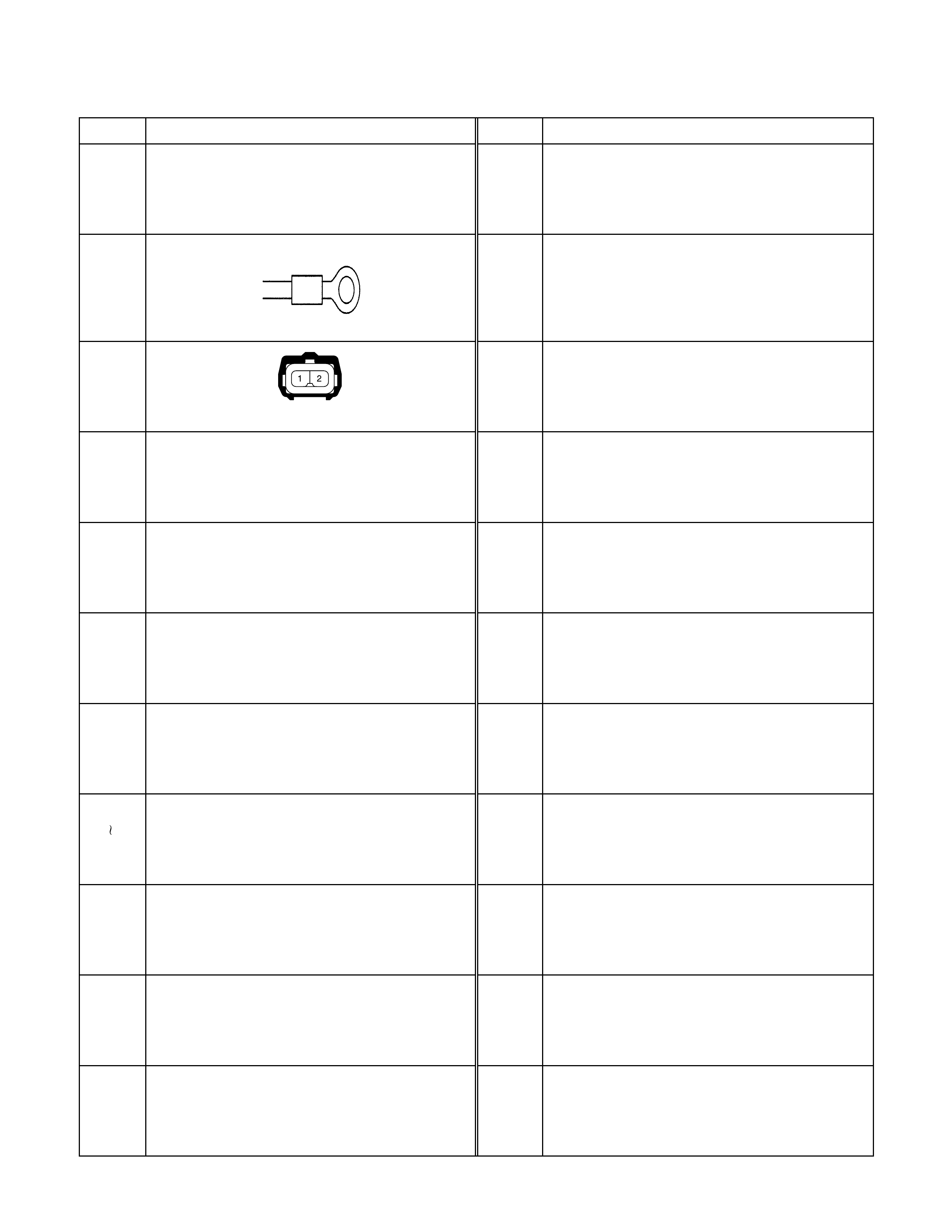
No. Connector face No. Connector face
C-46
NOT USED
C-60
NOT USED
C-47 C-61
NOT USED
C-48 C-62
NOT USED
C-49
NOT USED
C-63
NOT USED
C-50
NOT USED
C-64
NOT USED
C-51
NOT USED
C-65
NOT USED
C-52
NOT USED
C-66
NOT USED
C-53
C-57 NOT USED
C-67
NOT USED
C-58
NOT USED
C-68
NOT USED
C-59
NOT USED
C-69
NOT USED
C-70
NOT USED
C-80
NOT USED
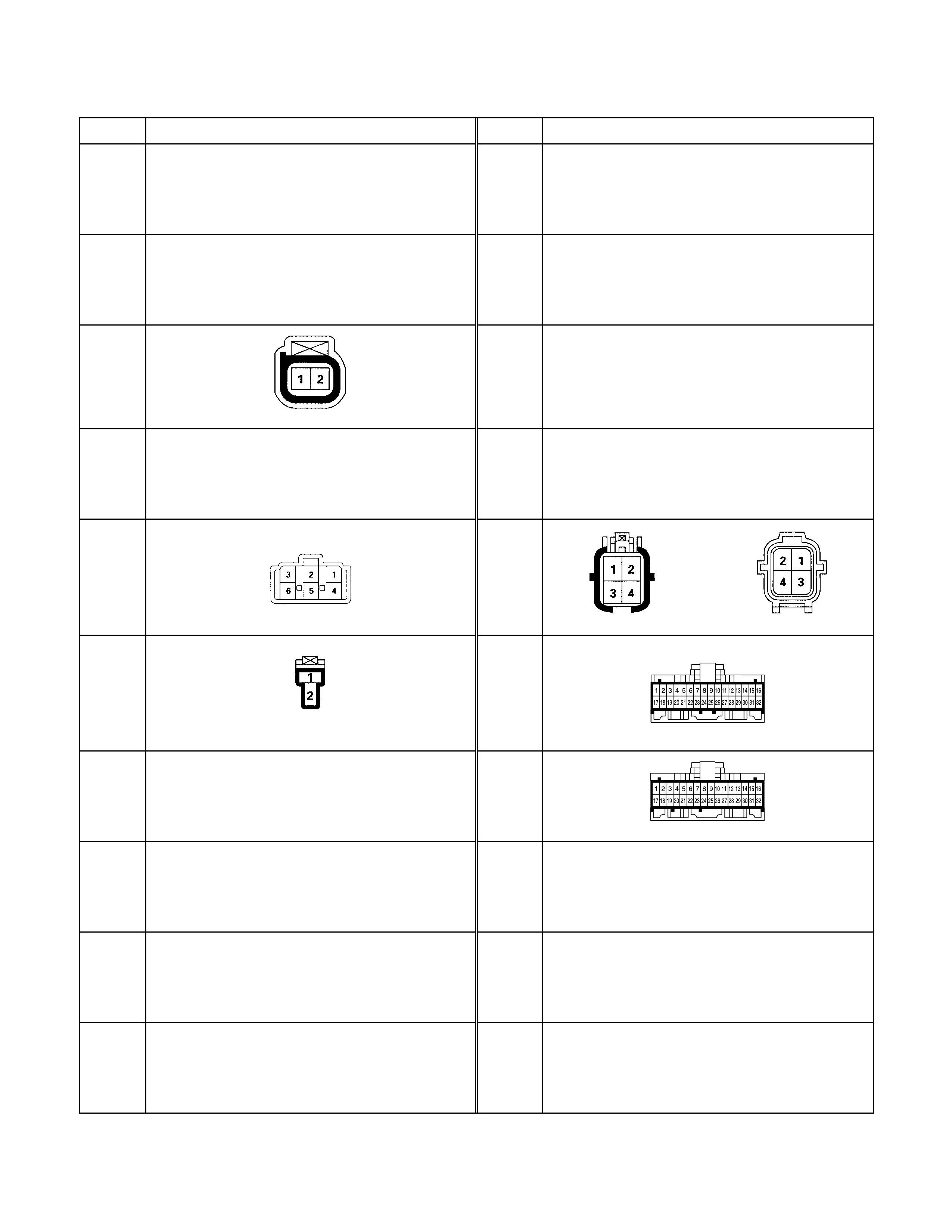
No. Connector face No. Connector face
C-71
NOT USED
C-81
NOT USED
C-72
NOT USED
C-82
NOT USED
C-73
(LHD) C-83
NOT USED
C-74
NOT USED
C-84
NOT USED
C-75
(LHD) C-85
C-76
(LHD) C-86
C-77
NOT USED
C-87
C-78
NOT USED
C-88
NOT USED
C-79
NOT USED
C-89
NOT USED
C-90
NOT USED

No. Connector face No. Connector face
C-91
NOT USED
C-92
C-93
C-94
C-95
C-96
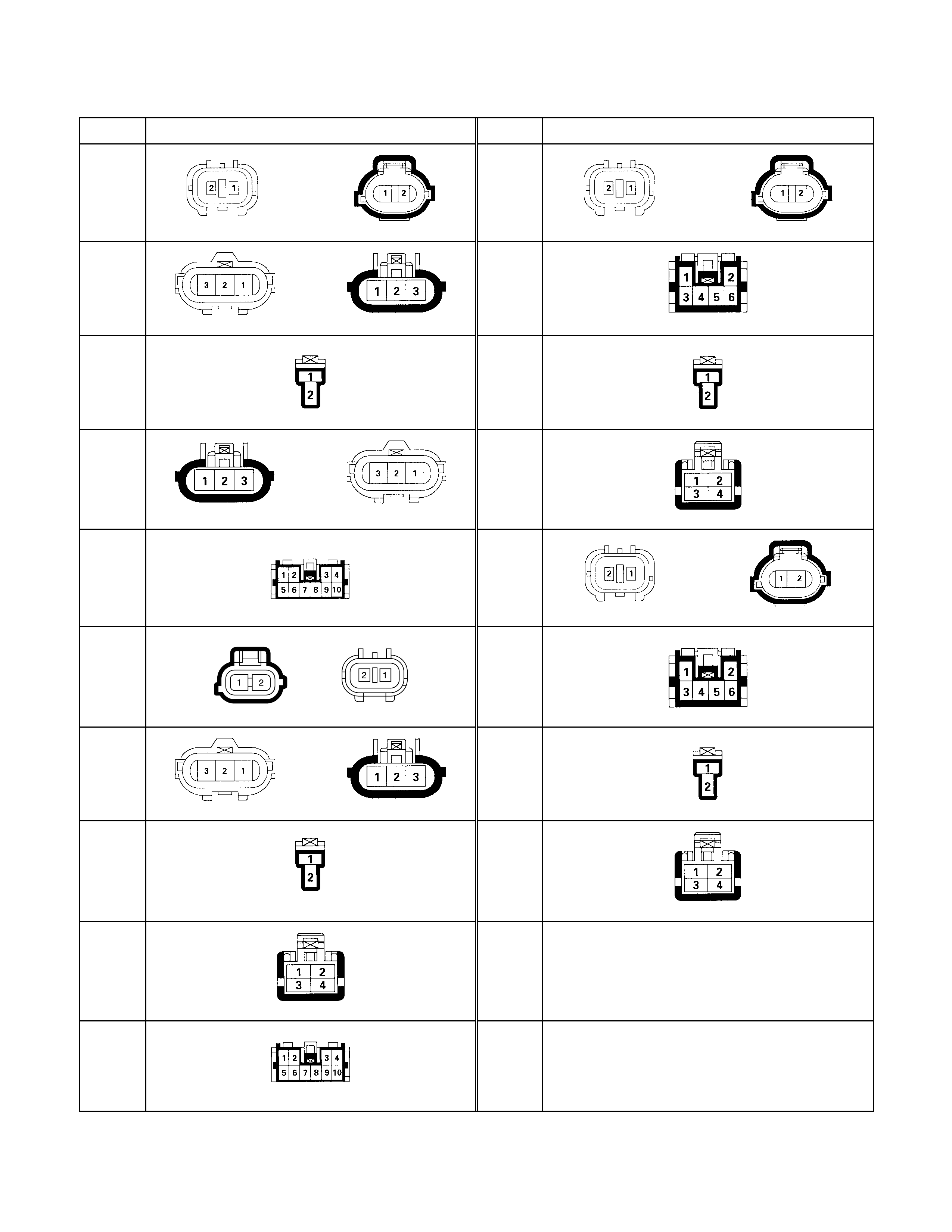
No. Connector face No. Connector face
D-1 D-11
D-2 D-12
D-3 D-13
D-4 D-14
D-5 D-15
D-6 D-16
D-7 D-17
D-8 D-18
D-9
D-10
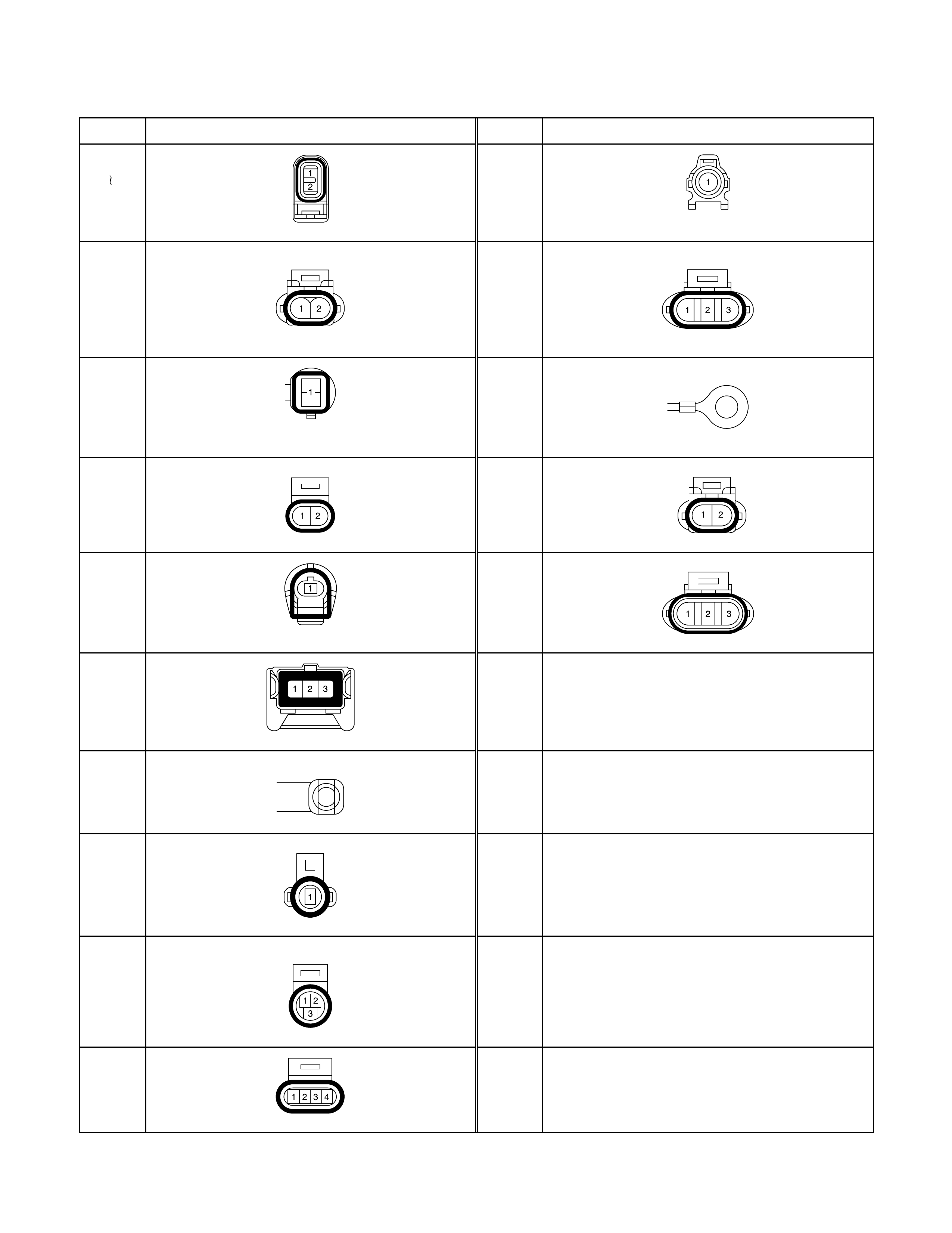
No. Connector face No. Connector face
E-1
E-4
E-14
E-5 E-15
E-6 E-16
E-7 E-17
E-8 E-18
E-9
E-10
E-11
E-12
E-13
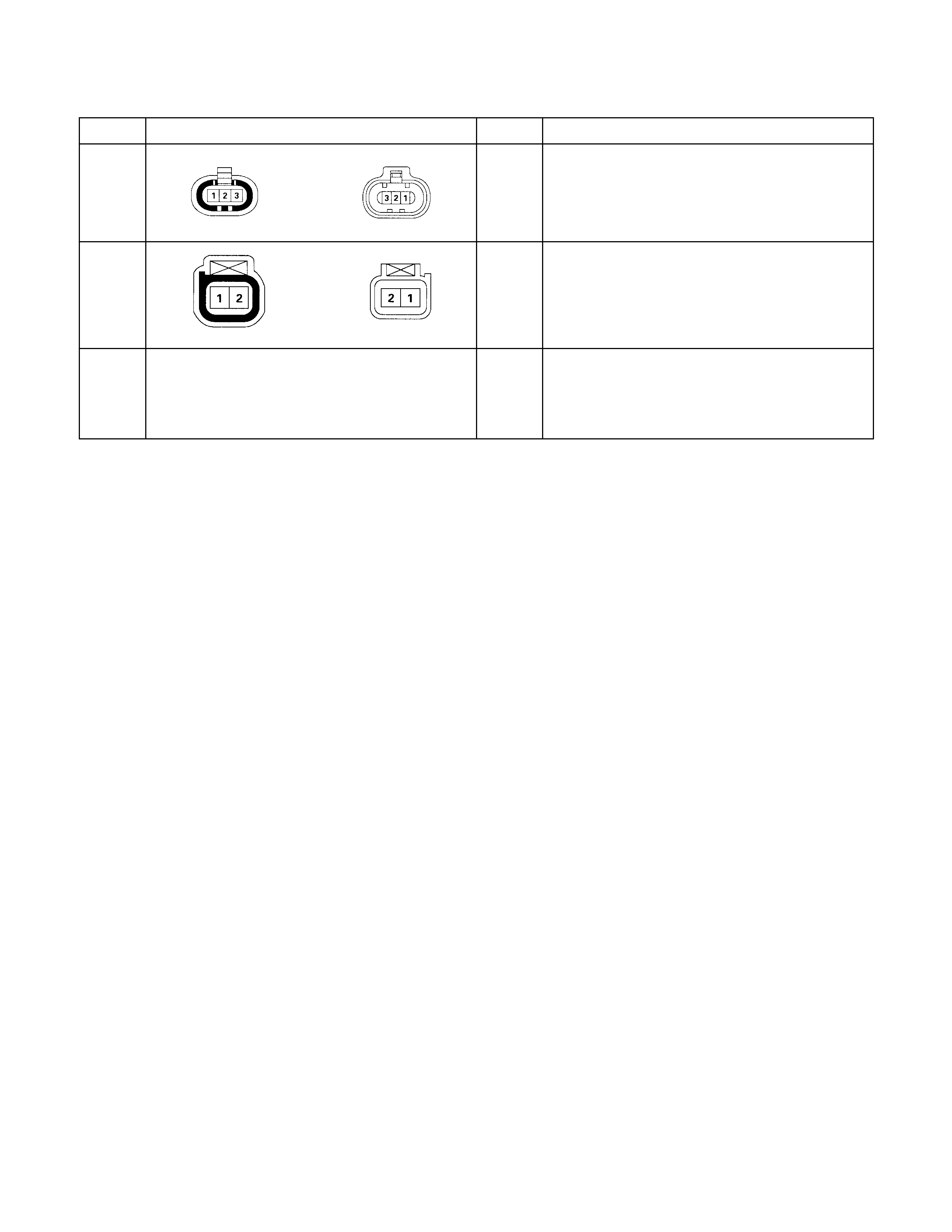
No. Connector face No. Connector face
F-1
F-2
F-3
NOT USED
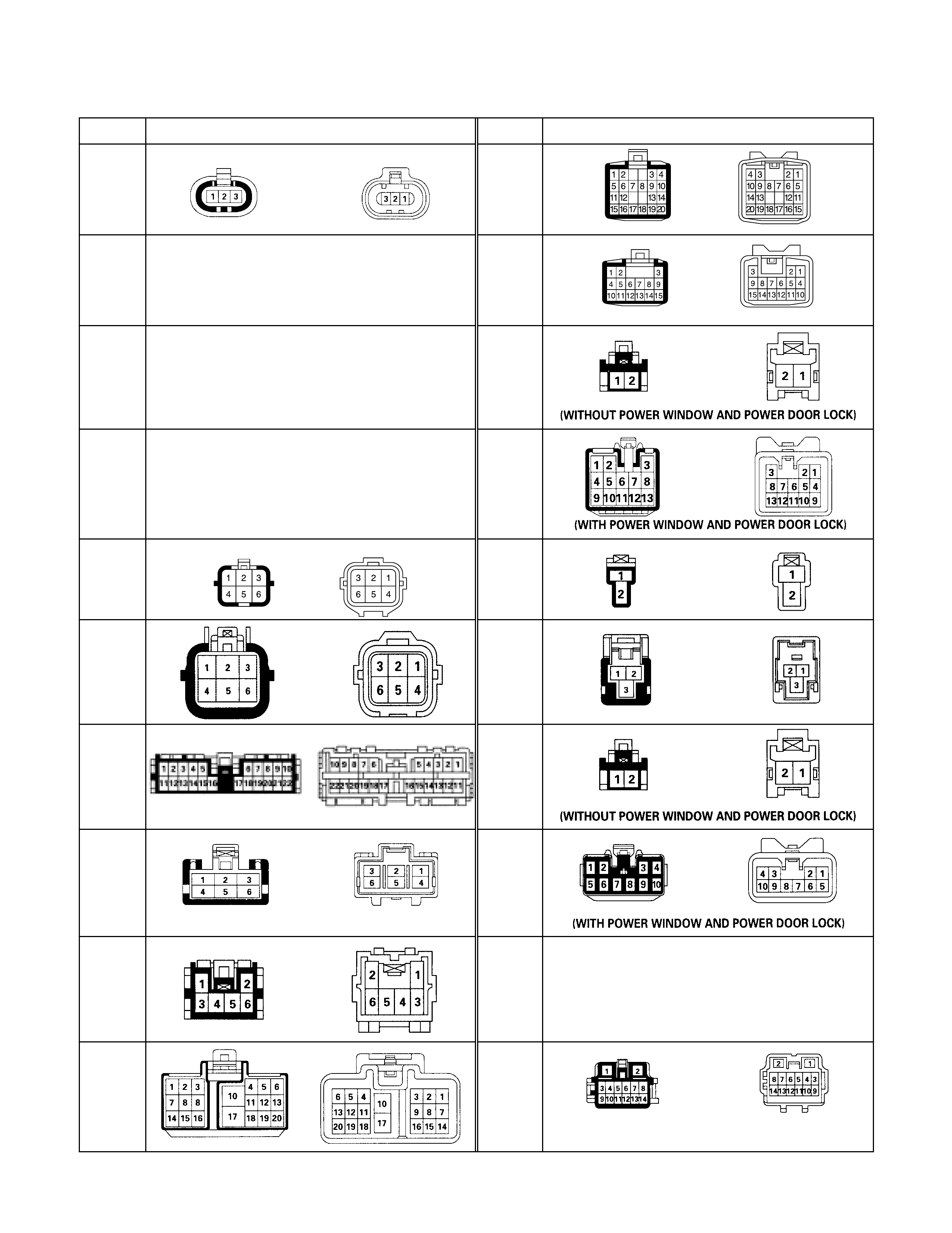
No. Connector face No. Connector face
H-1 H-8
(RHD)
H-2
NOT USED
H-9
H-3
NOT USED
H-10
H-4
NOT USED
H-10
H-5
(LHD) H-11
H-5 H-12
H-6 H-13
H-7
(LHD
)
H-13
H-7
(RHD) H-14
NOT USED
H-8
(LHD) H-15
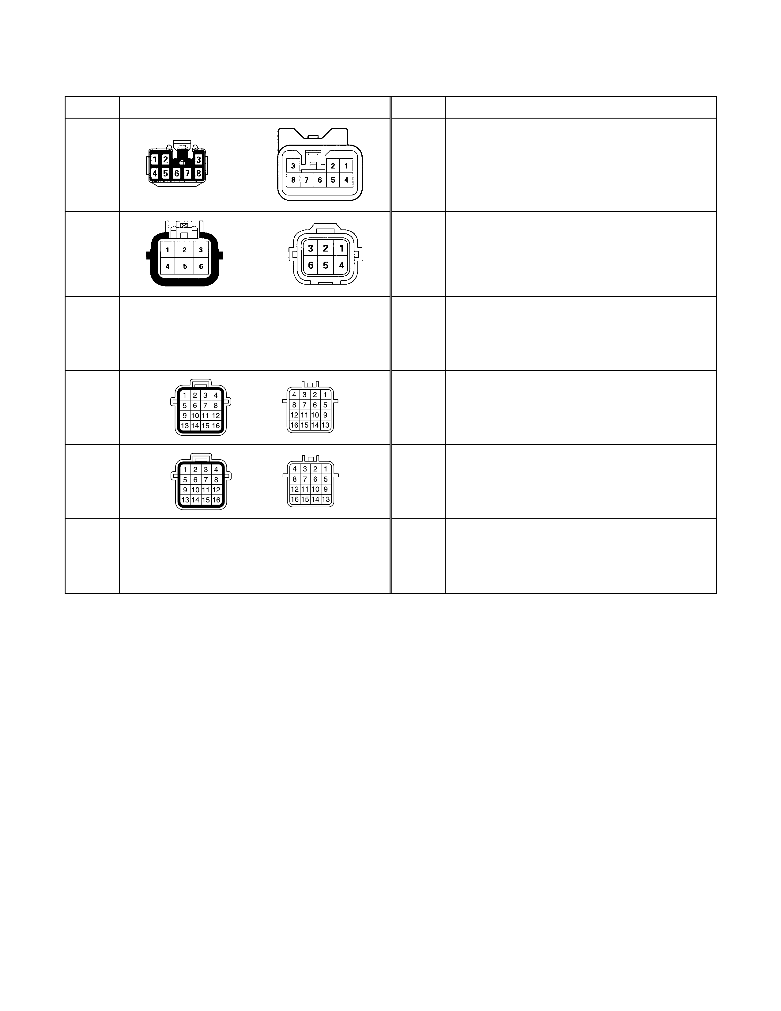
No. Connector face No. Connector face
H-16
H-17
H-18
NOT USED
H-19
H-20
H-21
NOT USED
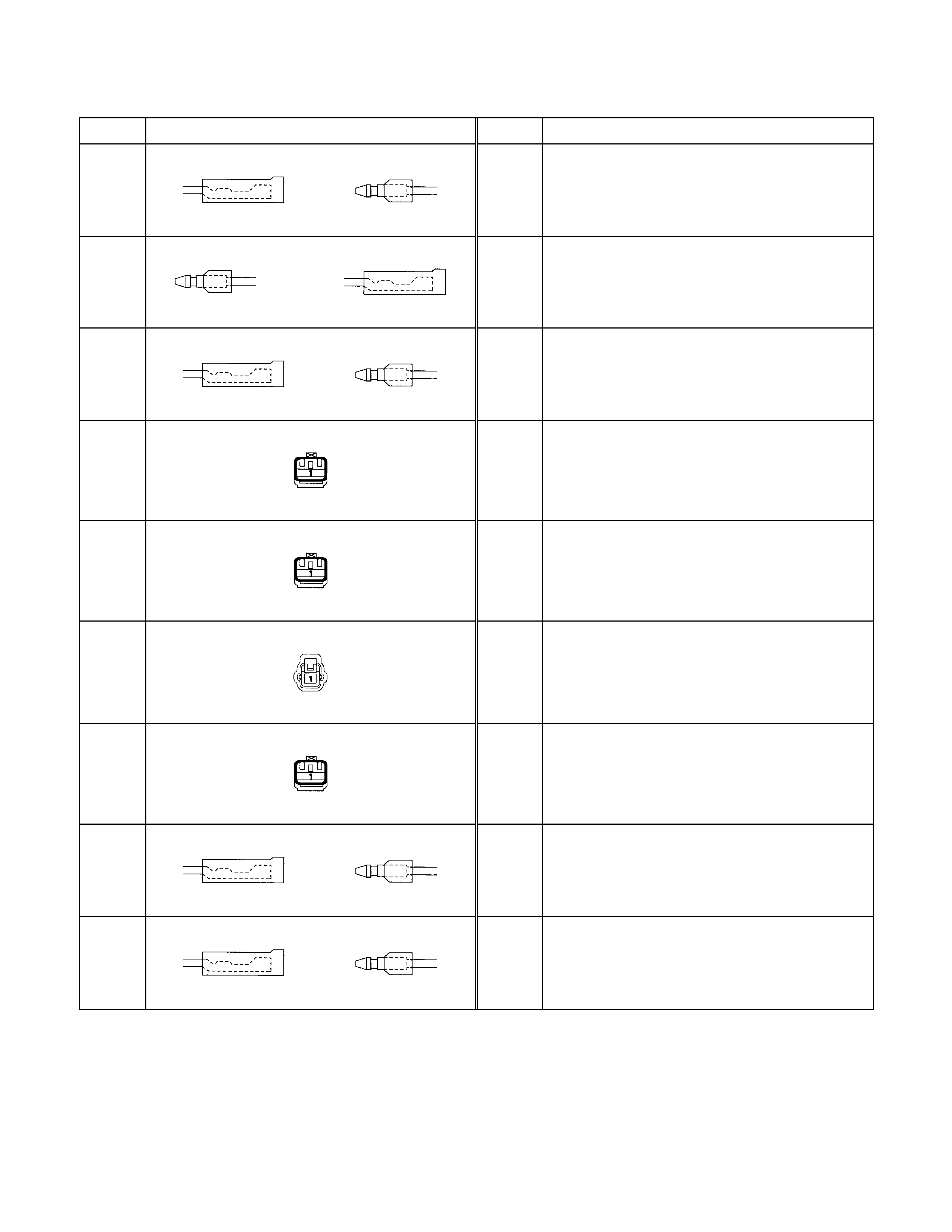
No. Connector face No. Connector face
L-1
L-2
L-3
L-4
L-5
L-6
L-7
L-8
L-9
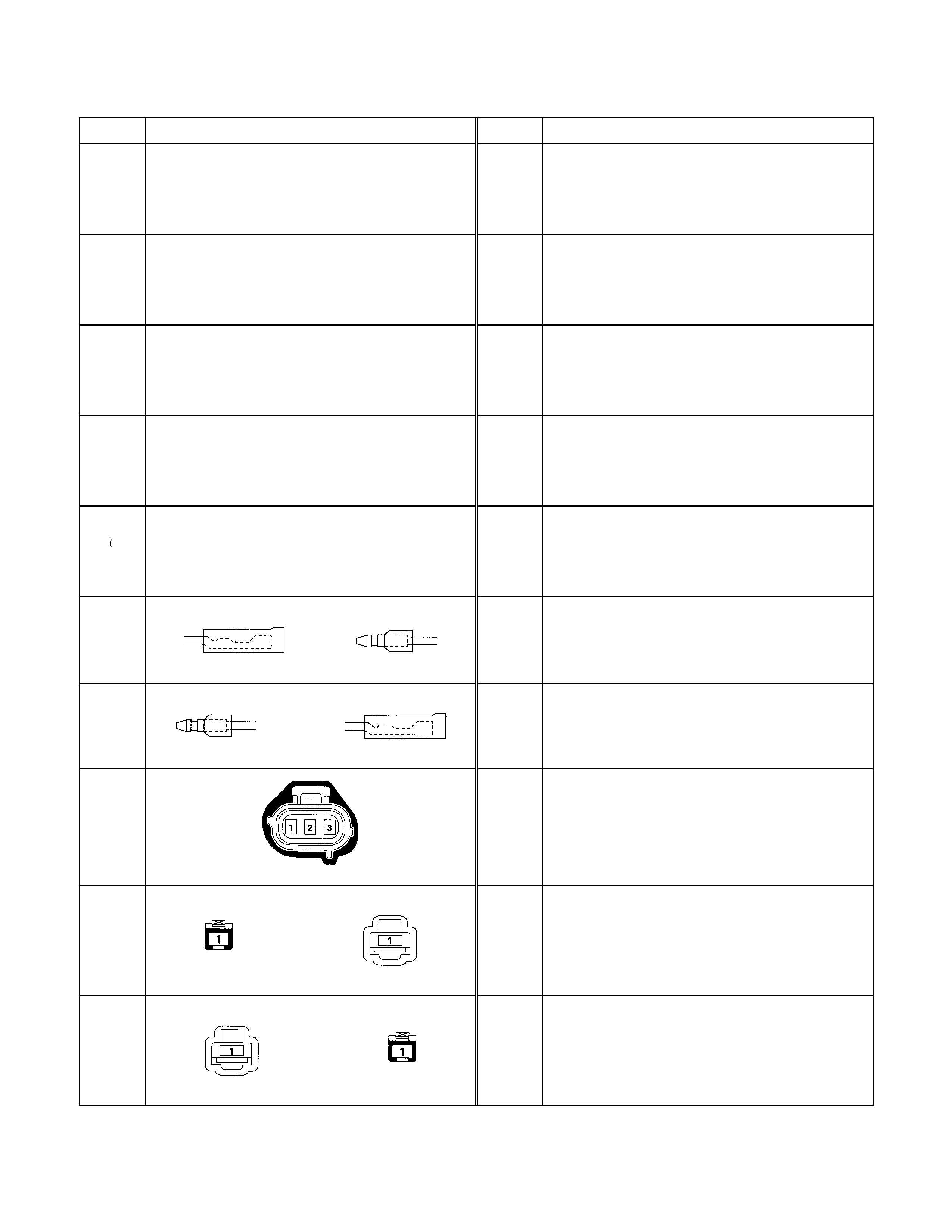
No. Connector face No. Connector face
M-1
NOT USED
M-13
NOT USED
M-2
NOT USED
M-14
NOT USED
M-3
NOT USED
M-4
NOT USED
M-5
M-7 NOT USED
M-8
M-9
M-10
M-11
M-12
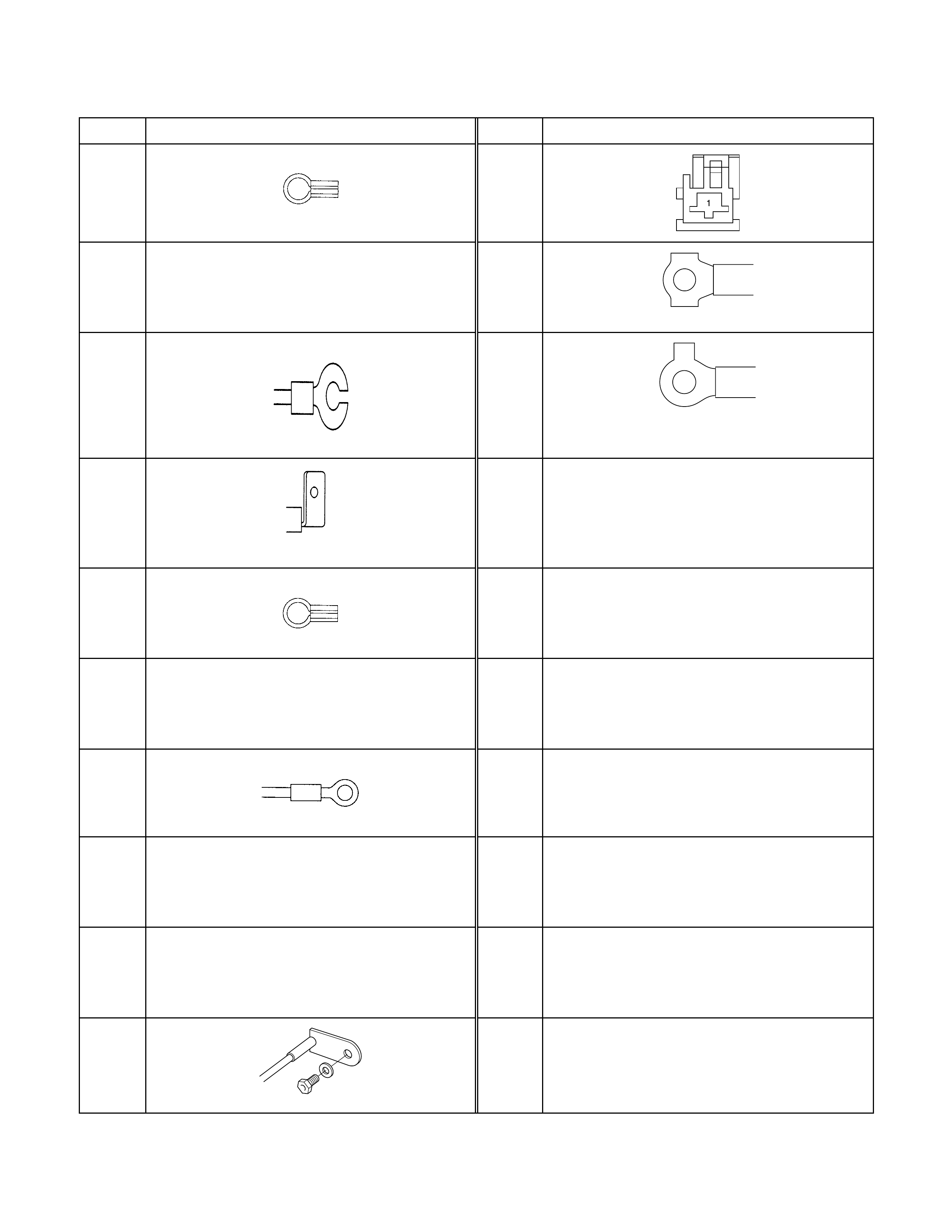
No. Connector face No. Connector face
P-1 P-11
P-2
NOT USED
P-12
P-3 P-13
P-4
P-5
P-6
NOT USED
P-7
P-8
NOT USED
P-9
NOT USED
P-10
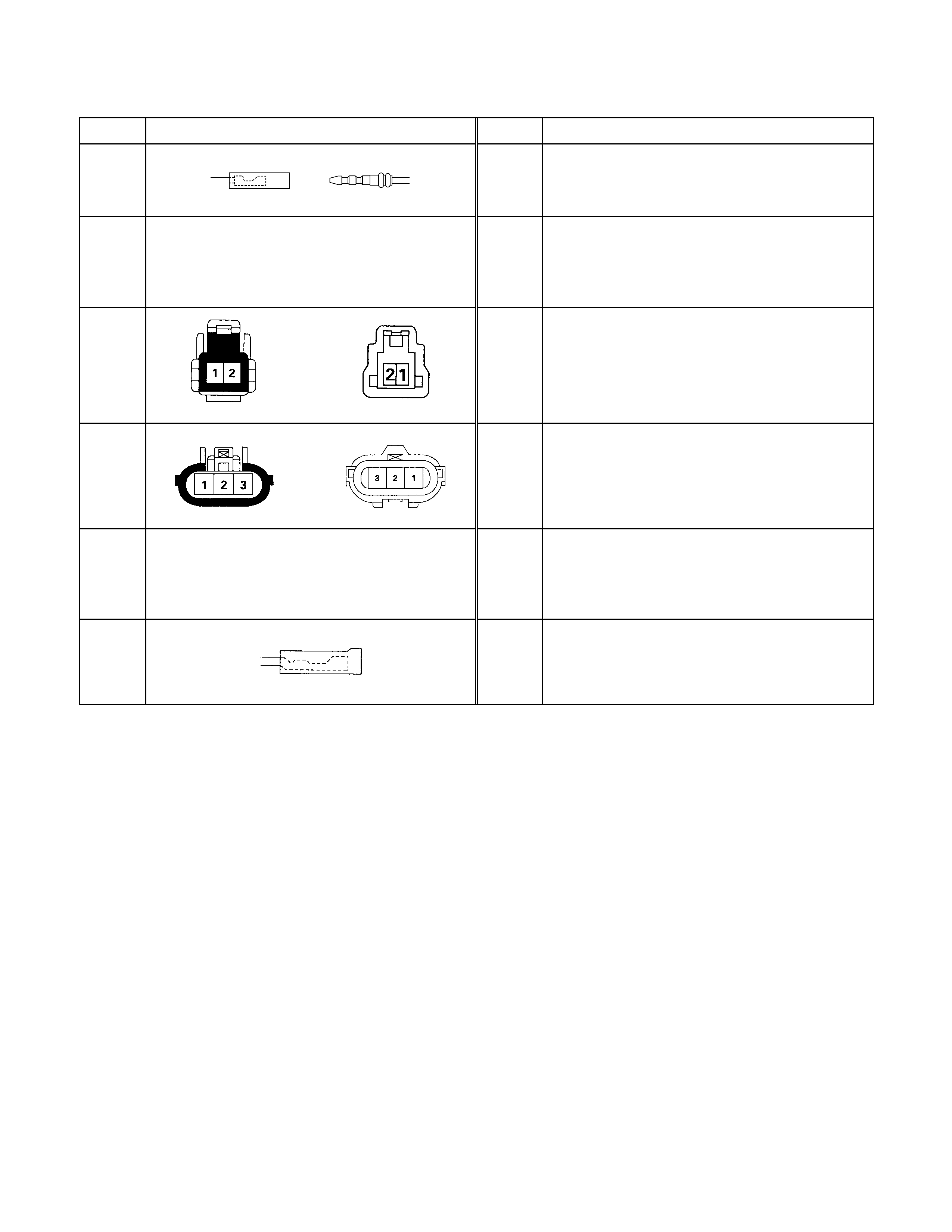
No. Connector face No. Connector face
R-1
R-2
NOT USED
R-3
R-4
R-5
NOT USED
R-6
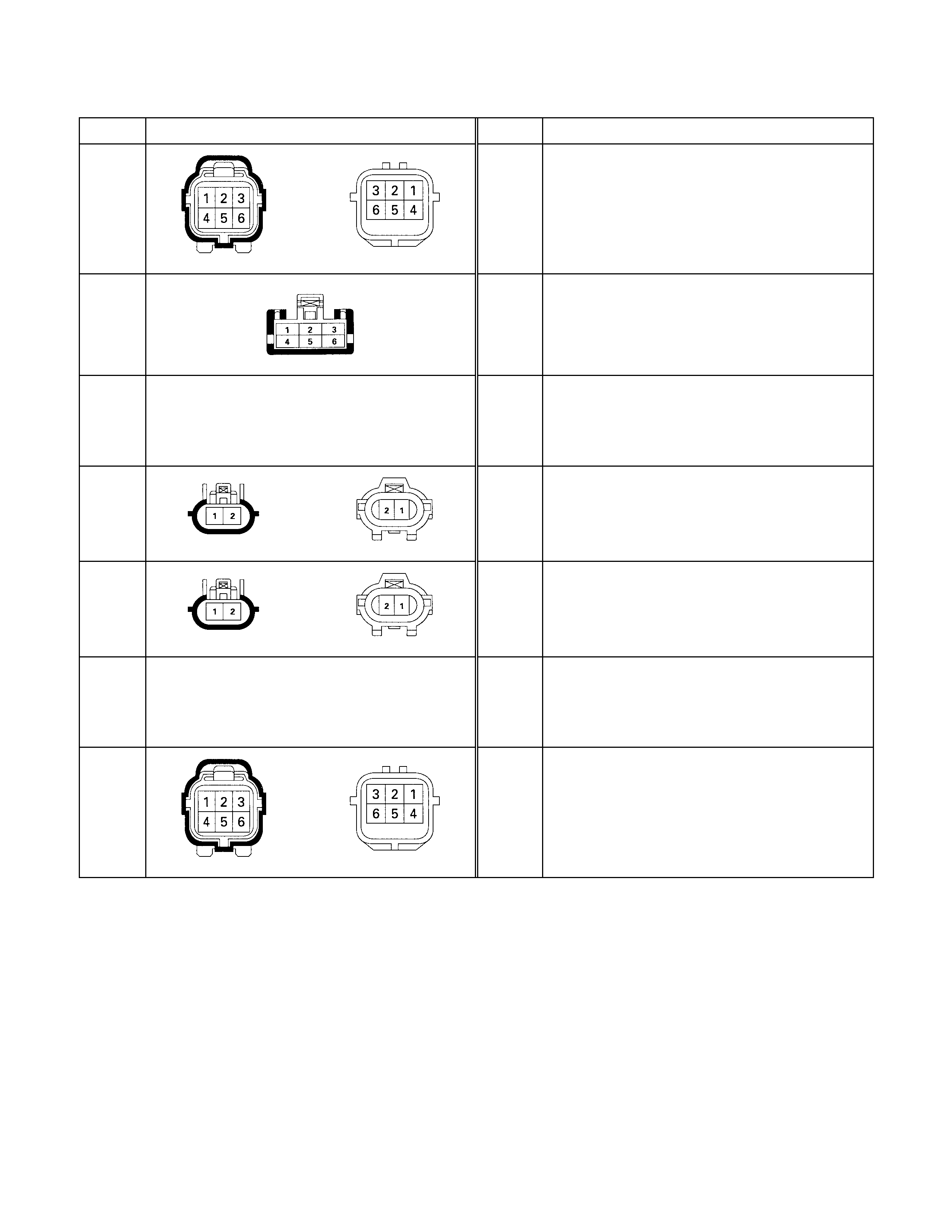
No. Connector face No. Connector face
T-1
T-1
T-2
NOT USED
T-3
T-4
T-5
NOT USED
T-6
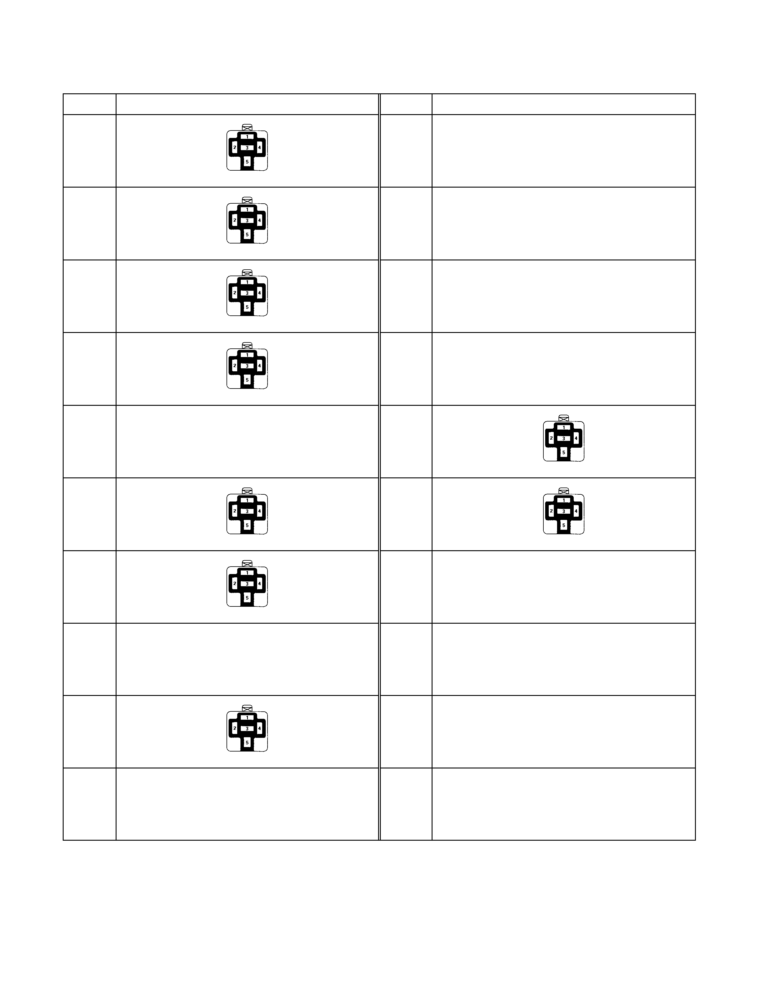
No. Connector face No. Connector face
X-1 X-11
NOT USED
X-2 X-12
NOT USED
X-3 X-13
NOT USED
X-4 X-14
NOT USED
X-5
NOT USED
X-15
X-6 X-16
X-7
X-8
NOT USED
X-9
X-10
NOT USED
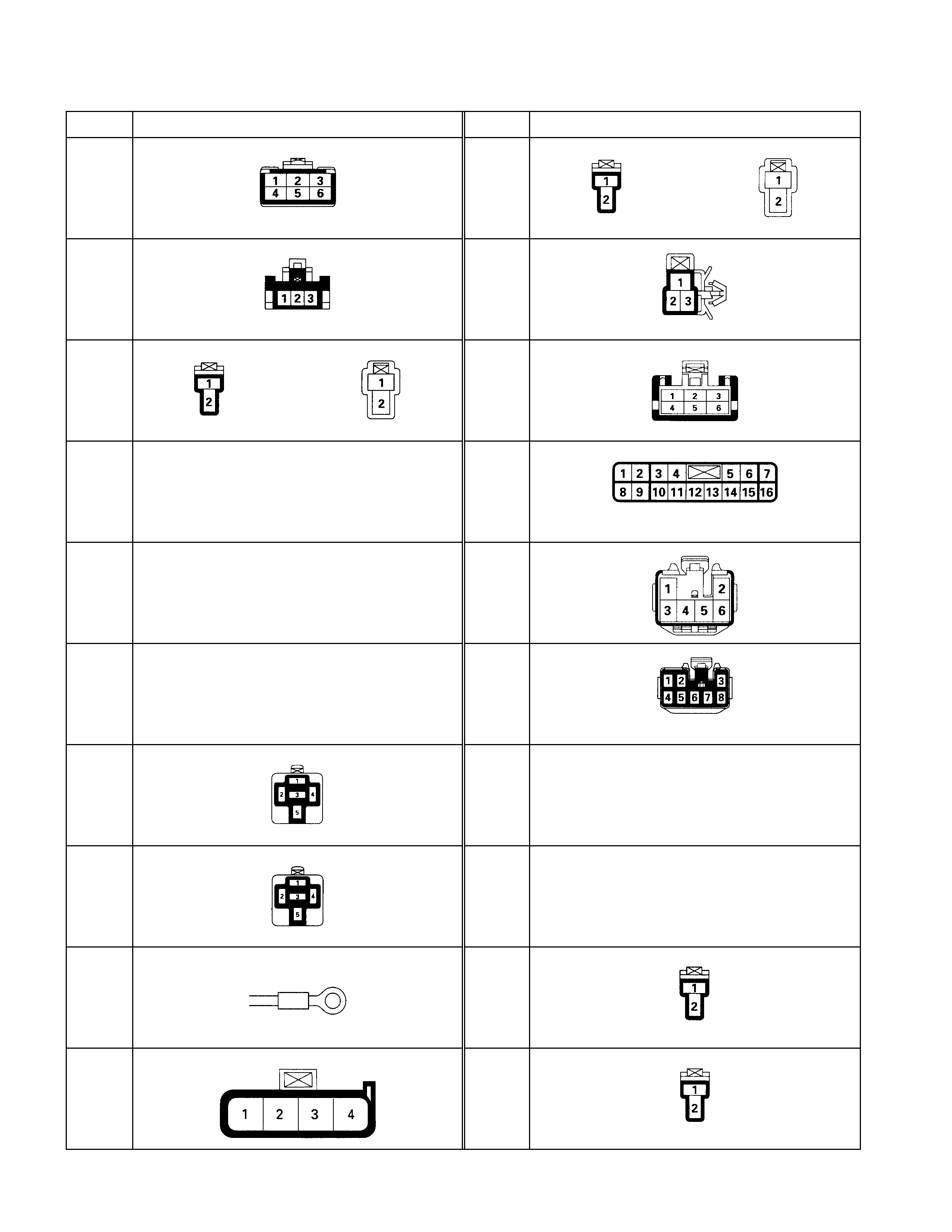
Connector List (6VD1 Engi ne Model)
No. Connector face No. Connector face
B-1 B-11
B-2 B-12
B-3 B-13
B-4
NOT USED
B-14
B-5
NOT USED
B-15
B-6
NOT USED
B-16
B-7 B-17
NOT USED
B-8 B-18
NOT USED
B-9 B-19
B-10 B-20
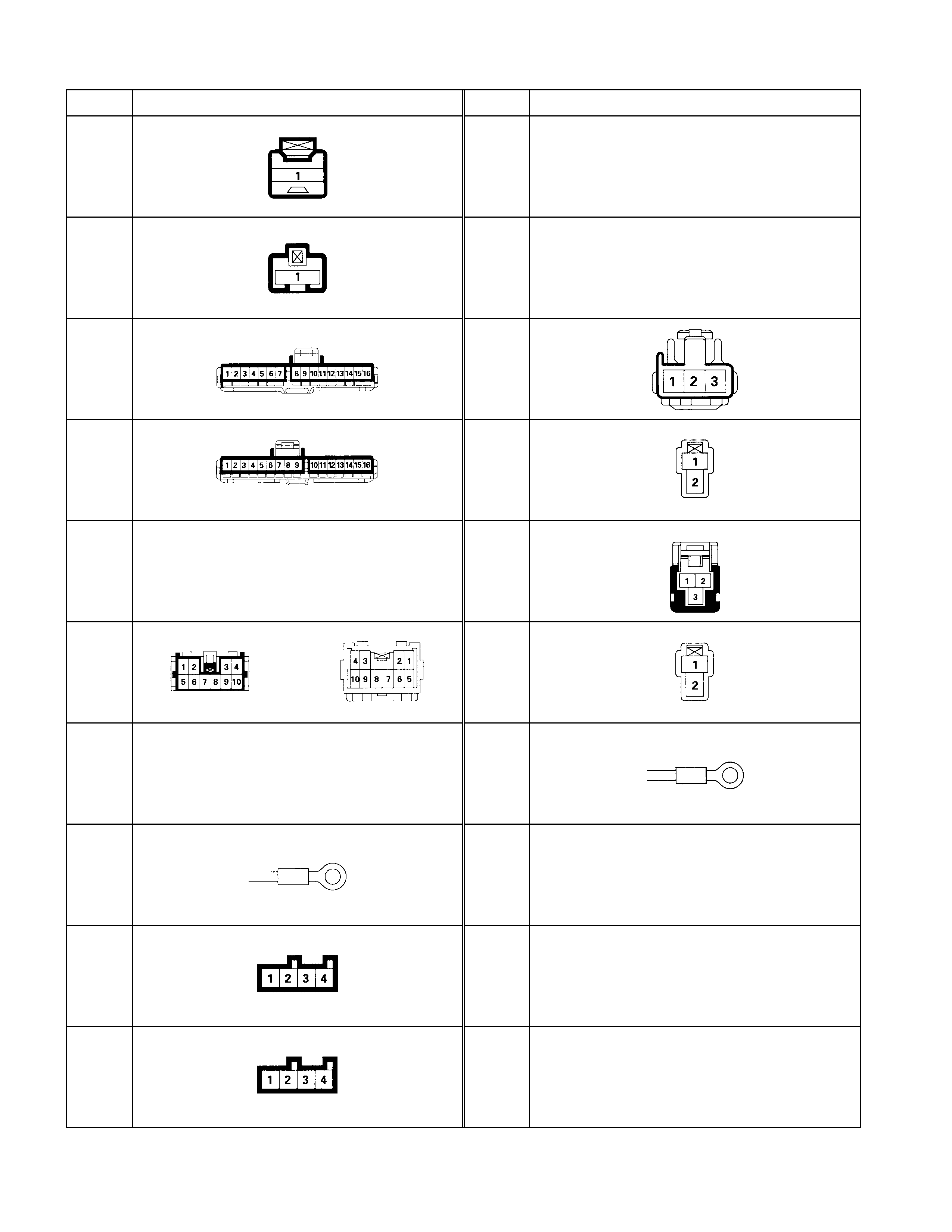
No. Connector face No. Connector face
B-21 B-31
-
B-22 B-32
NOT USED
B-23 B-33
(RHD)
B-24 B-34
B-25
NOT USED
B-35
B-26 B-36
B-27
NOT USED
B-37
B-28
B-29
B-30

No. Connector face No. Connector face
C-1 C-11
C-2 C-12
NOT USED
C-3 C-13
NOT USED
C-4 C-14
NOT USED
C-5 C-15
C-6 C-16
NOT USED
C-7 C-17
C-8
NOT USED
C-18
C-9
NOT USED
C-19
C-10 C-20
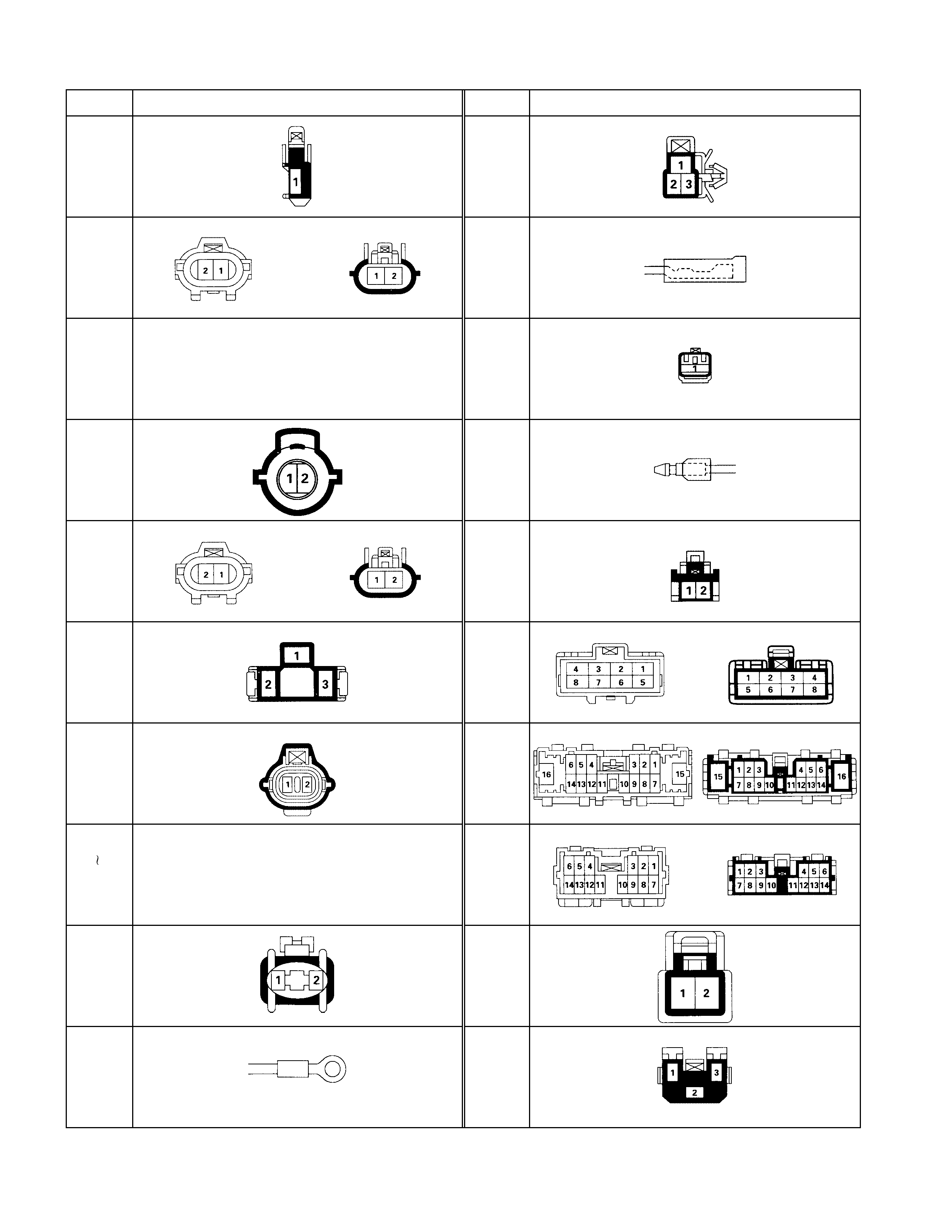
No. Connector face No. Connector face
C-21 C-37
C-22 C-38
C-23
NOT USED
C-39
(LHD
)
C-24 C-39
(RHD)
C-25 C-40
C-26 C-41
C-27 C-42
C-28
C-34 NOT USED
C-43
C-35 C-44
C-36 C-45
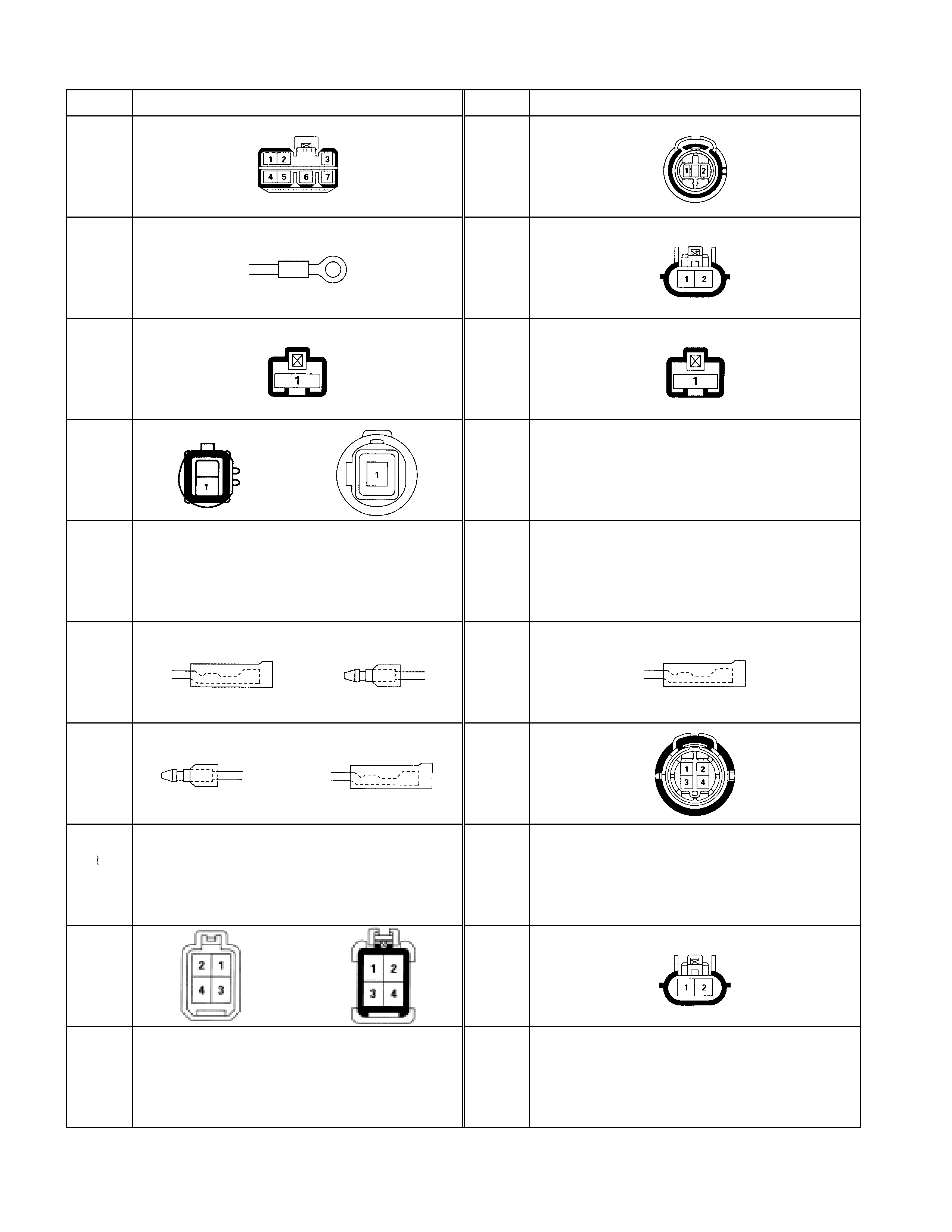
No. Connector face No. Connector face
C-46 C-60
C-47 C-61
C-48 C-62
C-49 C-63
NOT USED
C-50
NOT USED
C-64
NOT USED
C-51 C-65
C-52 C-66
C-53
C-57 NOT USED
C-67
NOT USED
C-58 C-68
C-59
NOT USED
C-69
NOT USED
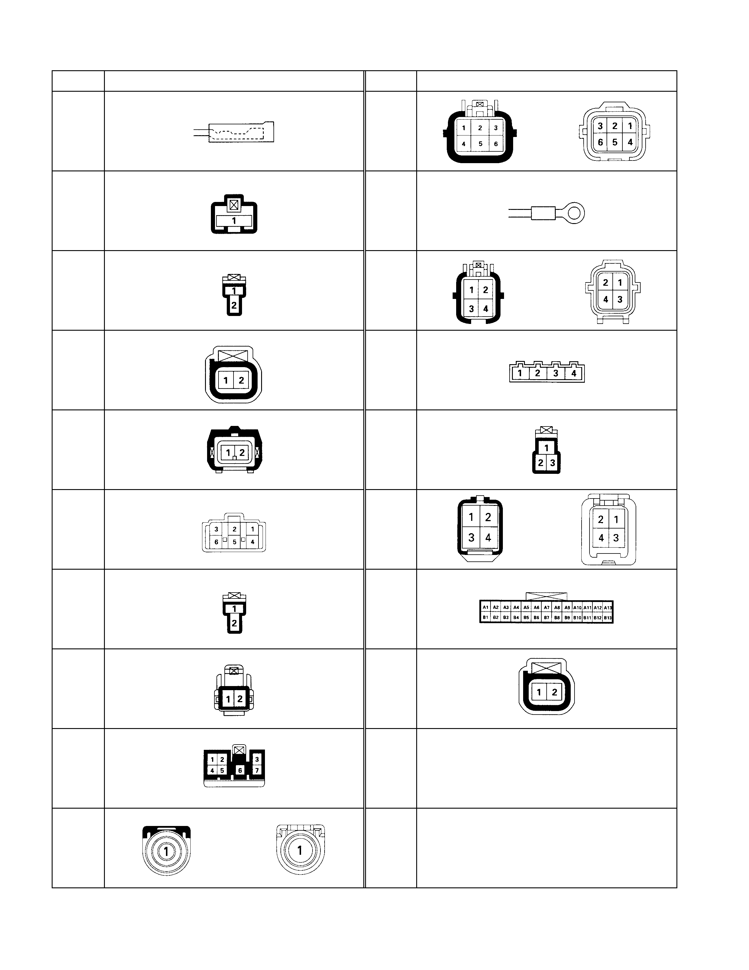
No. Connector face No. Connector face
C-70 C-80
C-71 C-81
C-72 C-82
C-73 C-83
C-74 C-84
C-75 C-85
C-76 C-86
C-77 C-87
C-78 C-88
NOT USED
C-79 C-89
NOT USED
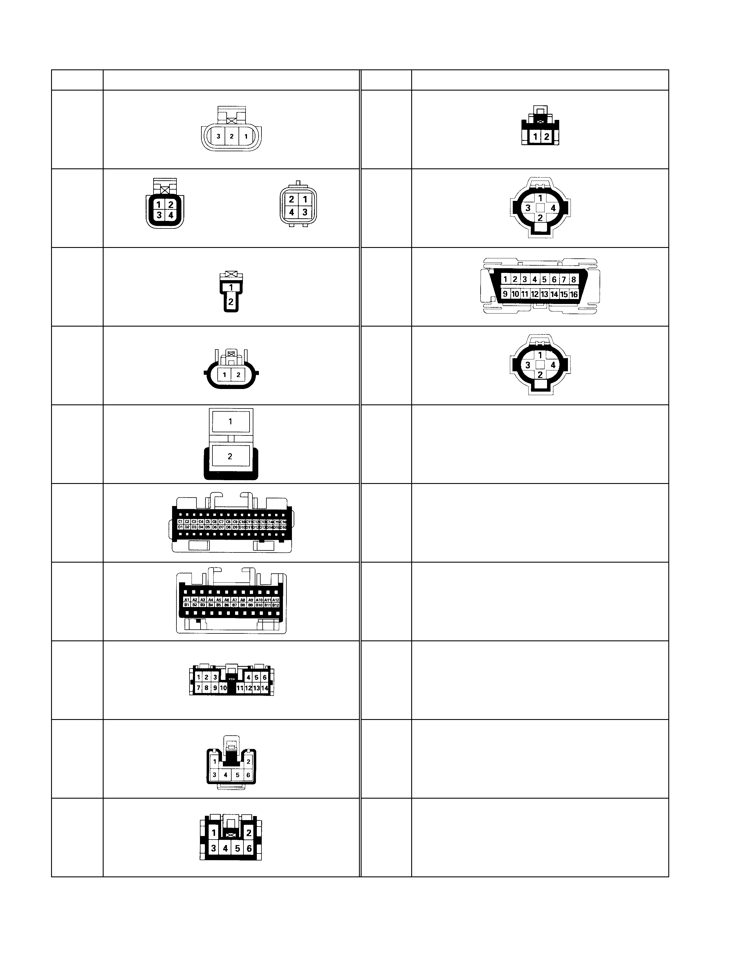
No. Connector face No. Connector face
C-90 C-100
C-91 C-101
C-92 C-102
C-93 C-103
C-94
C-95
C-96
C-97
C-98
C-99
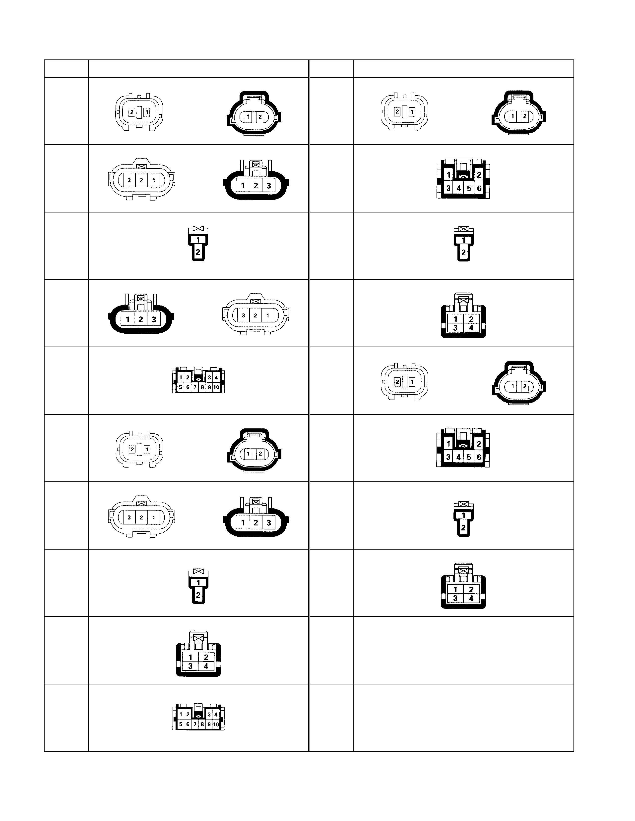
No. Connector face No. Connector face
D-1 D-11
D-2 D-12
D-3 D-13
D-4 D-14
D-5 D-15
D-6 D-16
D-7 D-17
D-8 D-18
D-9
D-10

No. Connector face No. Connector face
E-1 E-11
E-2 E-12
E-3 E-13
E-4 E-14
E-5 E-15
E-6 E-16
E-7 E-17
NOT USED
E-8 E-18
NOT USED
E-9 E-19
E-10 E-20
E-35 NOT USED
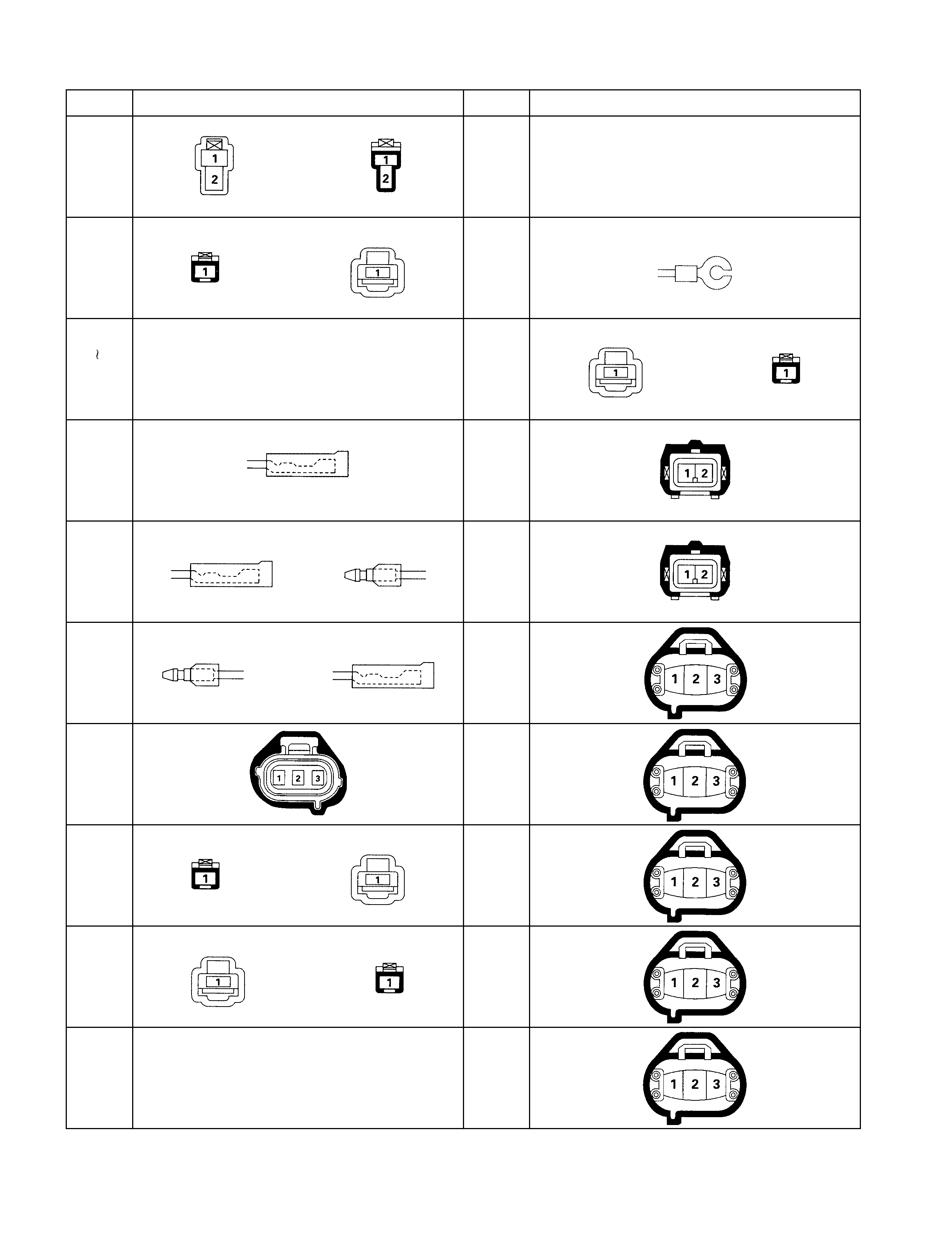
No. Connector face No. Connector face
E-36 E-48
NOT USED
E-37 E-49
E-38
E-40 NOT USED
E-50
E-41 E-51
E-42 E-52
E-43 E-53
E-44 E-54
E-45 E-55
E-46 E-56
E-47
NOT USED
E-57

No. Connector face No. Connector face
E-58 E-68
E-59 E-69
E-60 E-70
E-61 E-71
E-62 E-72
E-63 E-73
E-64 E-74
E-65
E-66
E-67
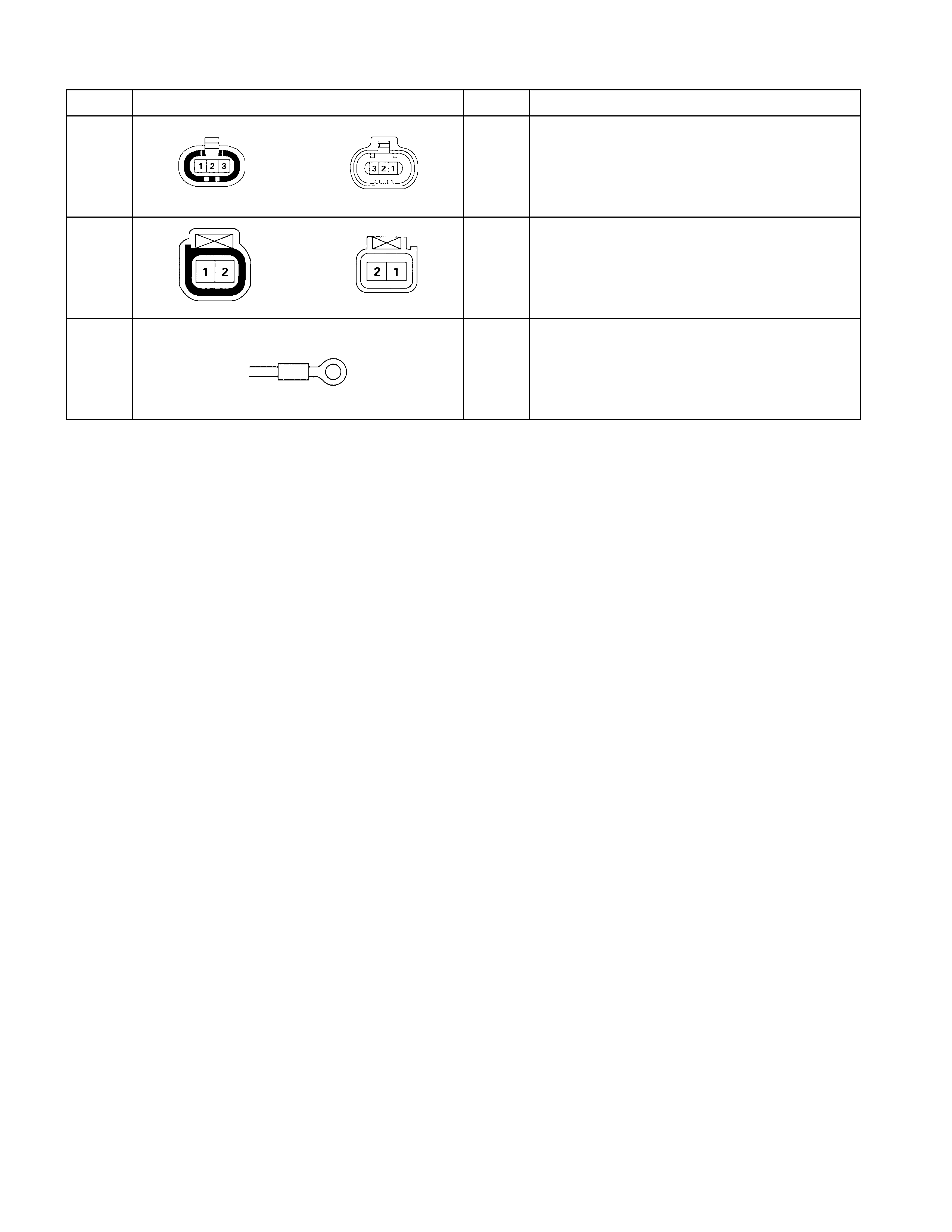
No. Connector face No. Connector face
F-1
F-2
F-3
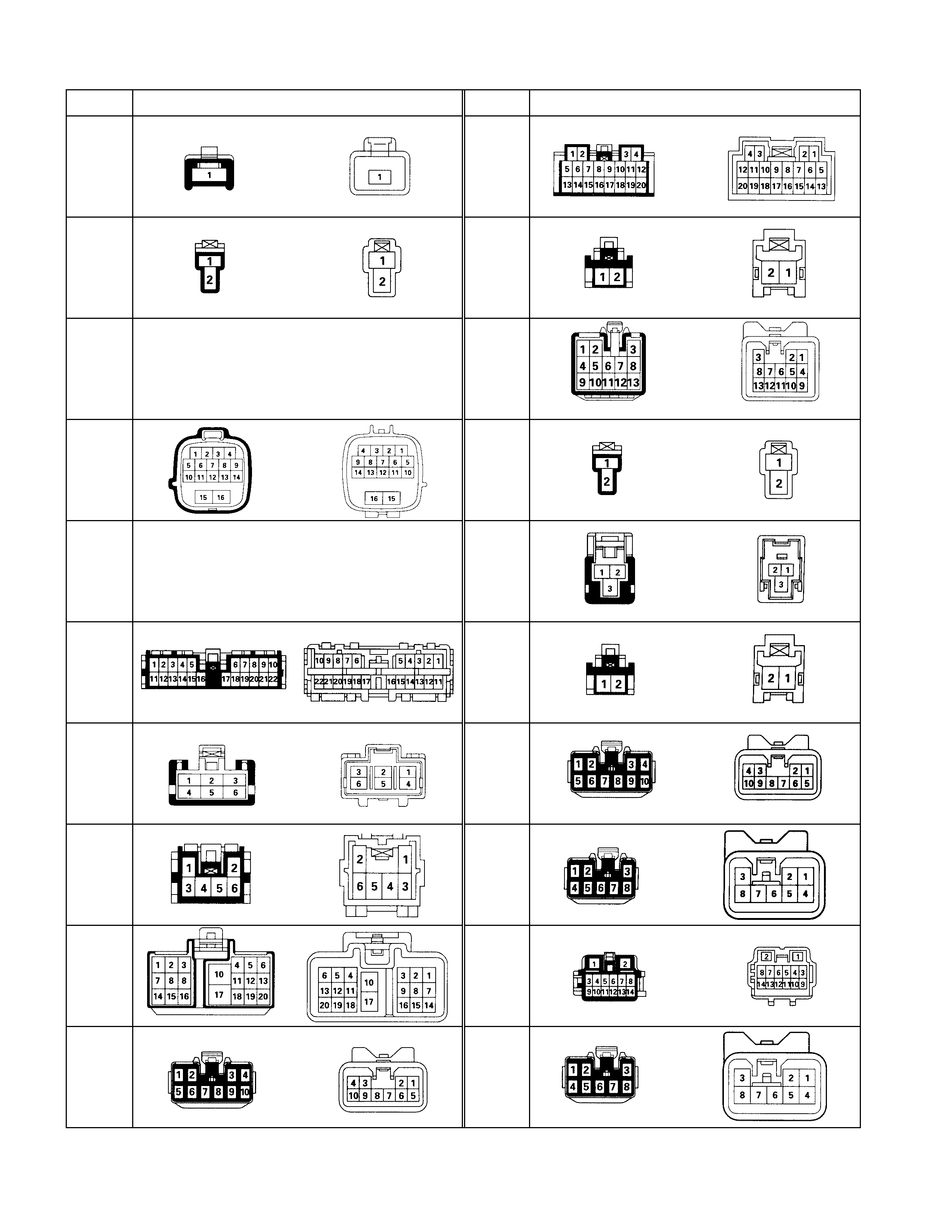
No. Connector face No. Connector face
H-1 H-9
H-2 H-10
(W ITHOUT PO WER WI NDO W AND P O WER DO O R LO CK)
H-3
NOT USED
H-10
(W ITHOUT PO WER WI NDO W AND P O WER DO O R LO CK)
H-4 H-11
H-5
NOT USED
H-12
H-6 H-13
(W ITHOUT PO WER WI NDO W AND P O WER DO O R LO CK)
H-7
(LHD
)
H-13
(W ITHOUT PO WER WI NDO W AND P O WER DO O R LO CK)
H-7
(RHD) H-14
H-8
(LHD) H-15
H-8
(RHD) H-16
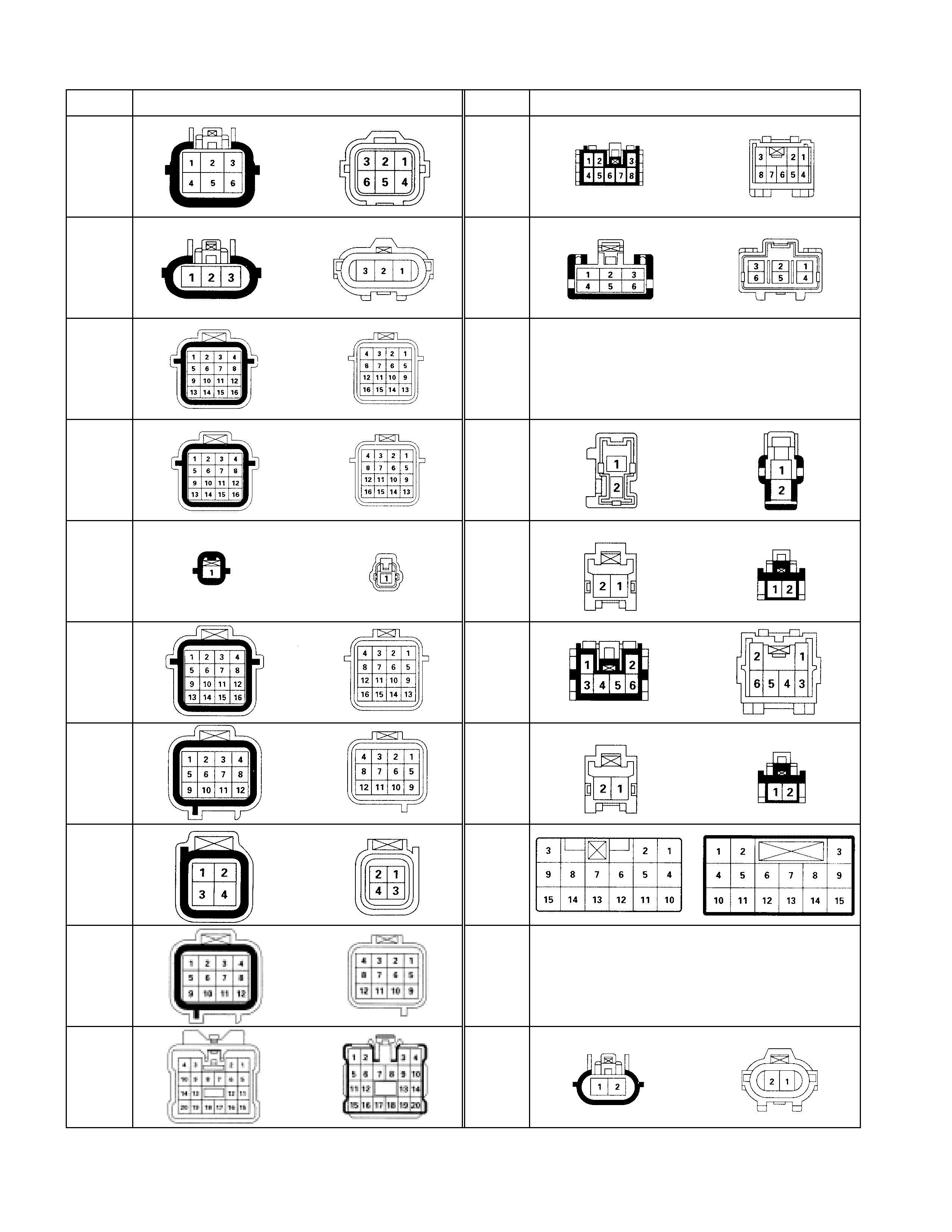
No. Connector face No. Connector face
H-17 H-27
H-18 H-28
H-19 H-29
NOT USED
H-20 H-30
H-21 H-31
H-22 H-32
H-23 H-33
H-24 H-34
H-25 H-35
NOT USED
H-26 H-36
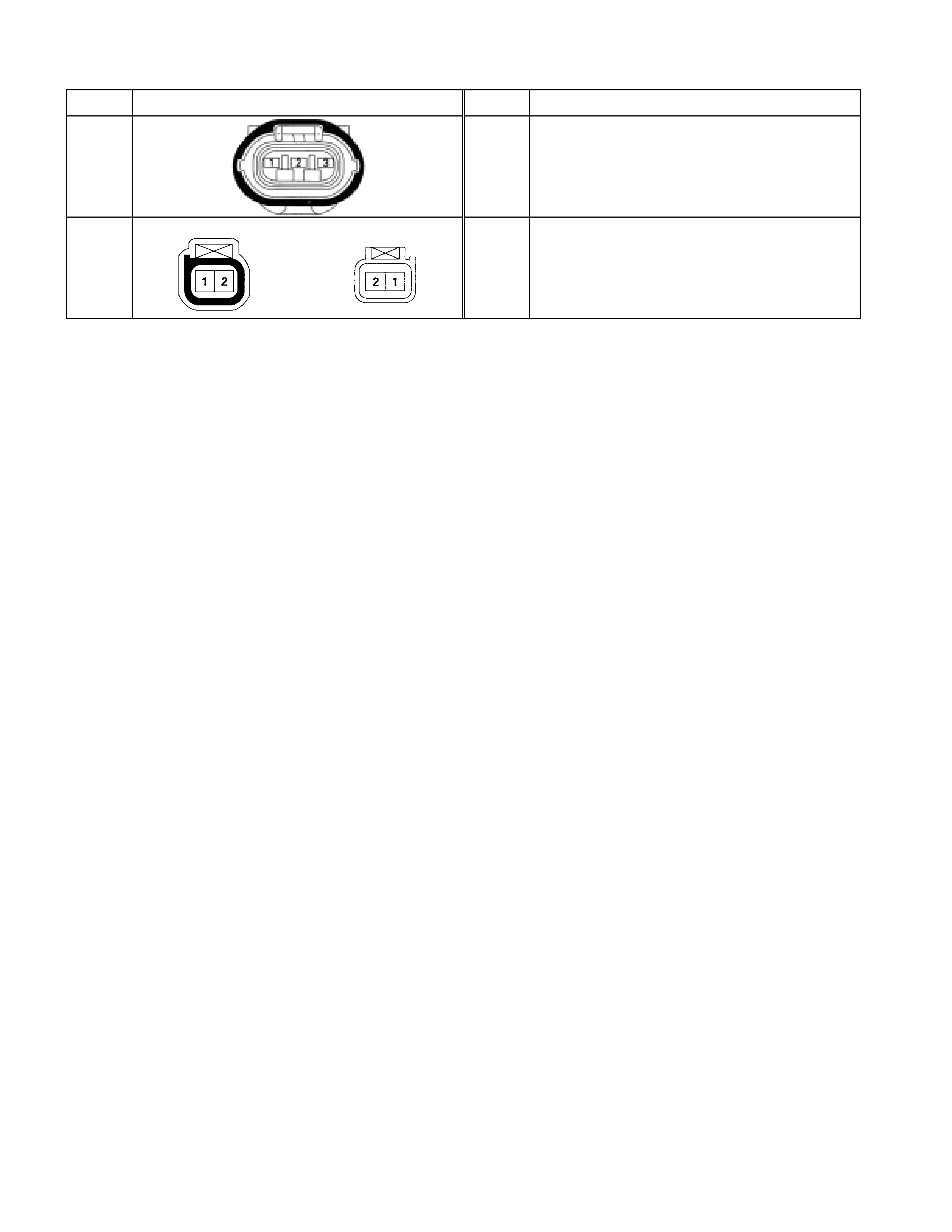
No. Connector face No. Connector face
H-37
H-38
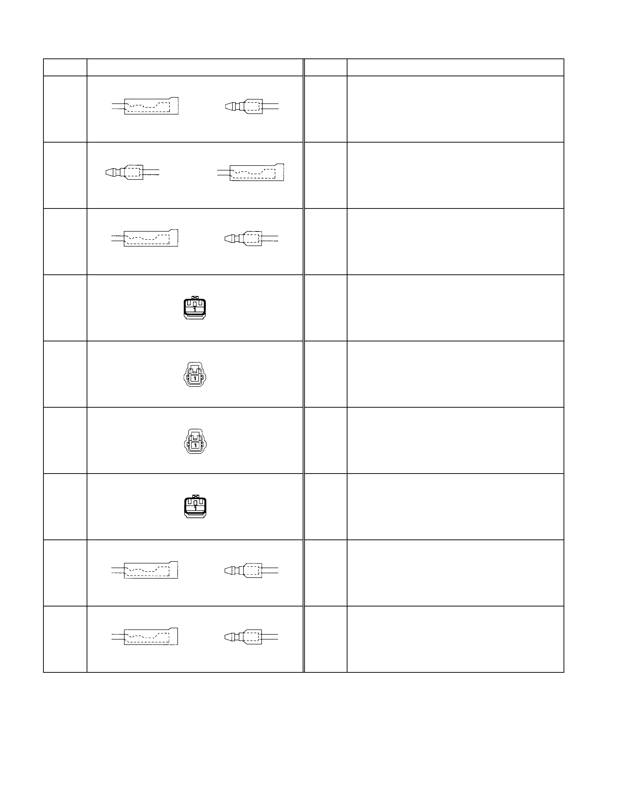
No. Connector face No. Connector face
L-1
L-2
L-3
L-4
L-5
L-6
L-7
L-8
L-9

No. Connector face No. Connector face
M-1 M-11
M-2 M-12
M-3 M-13
M-4 M-14
M-5
NOT USED
M-15
M-6 M-16
M-7 M-17
M-8 M-18
M-24 NOT USED
M-9 M-25
M-10
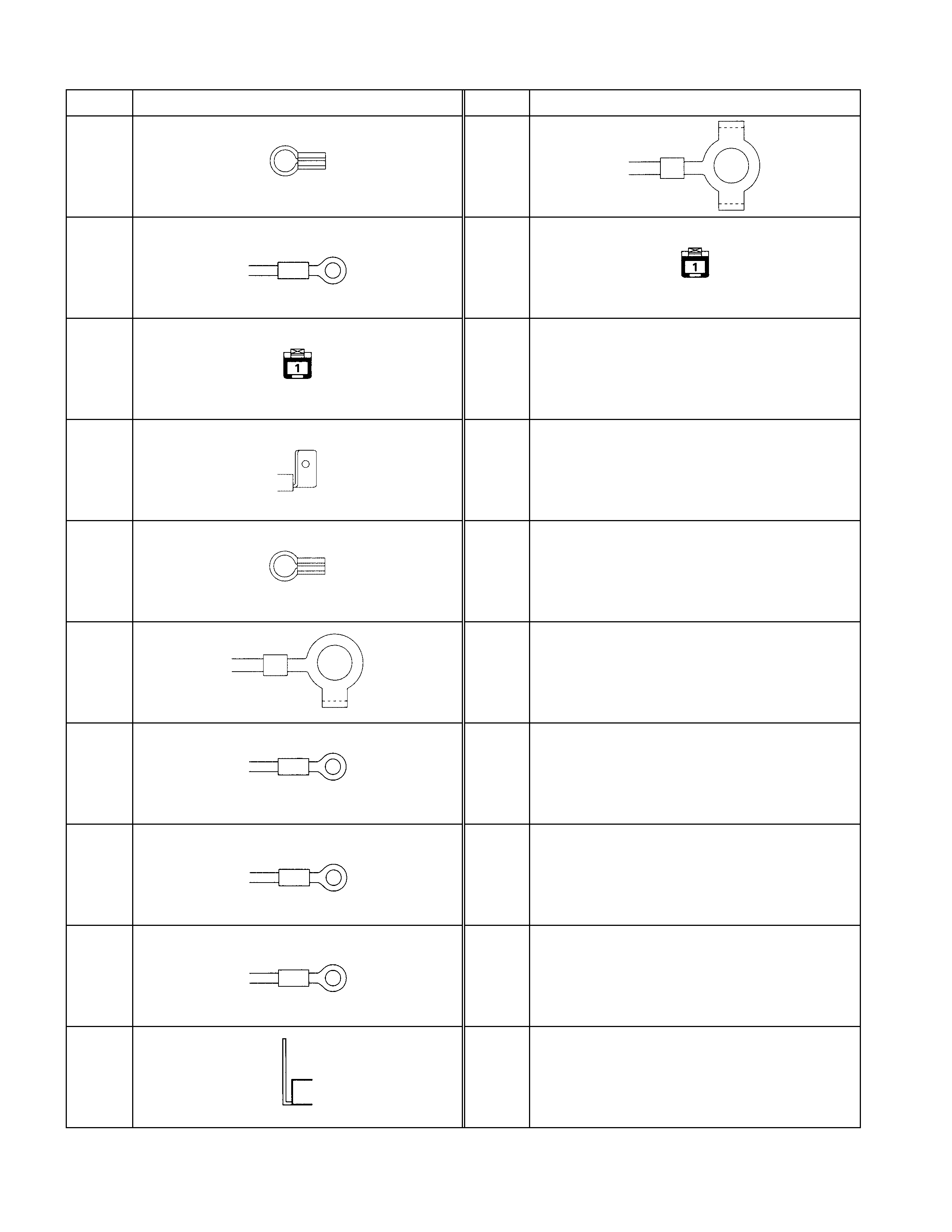
No. Connector face No. Connector face
P-1 P-11
P-2 P-12
P-3
P-4
P-5
P-6
P-7
P-8
P-9
P-10
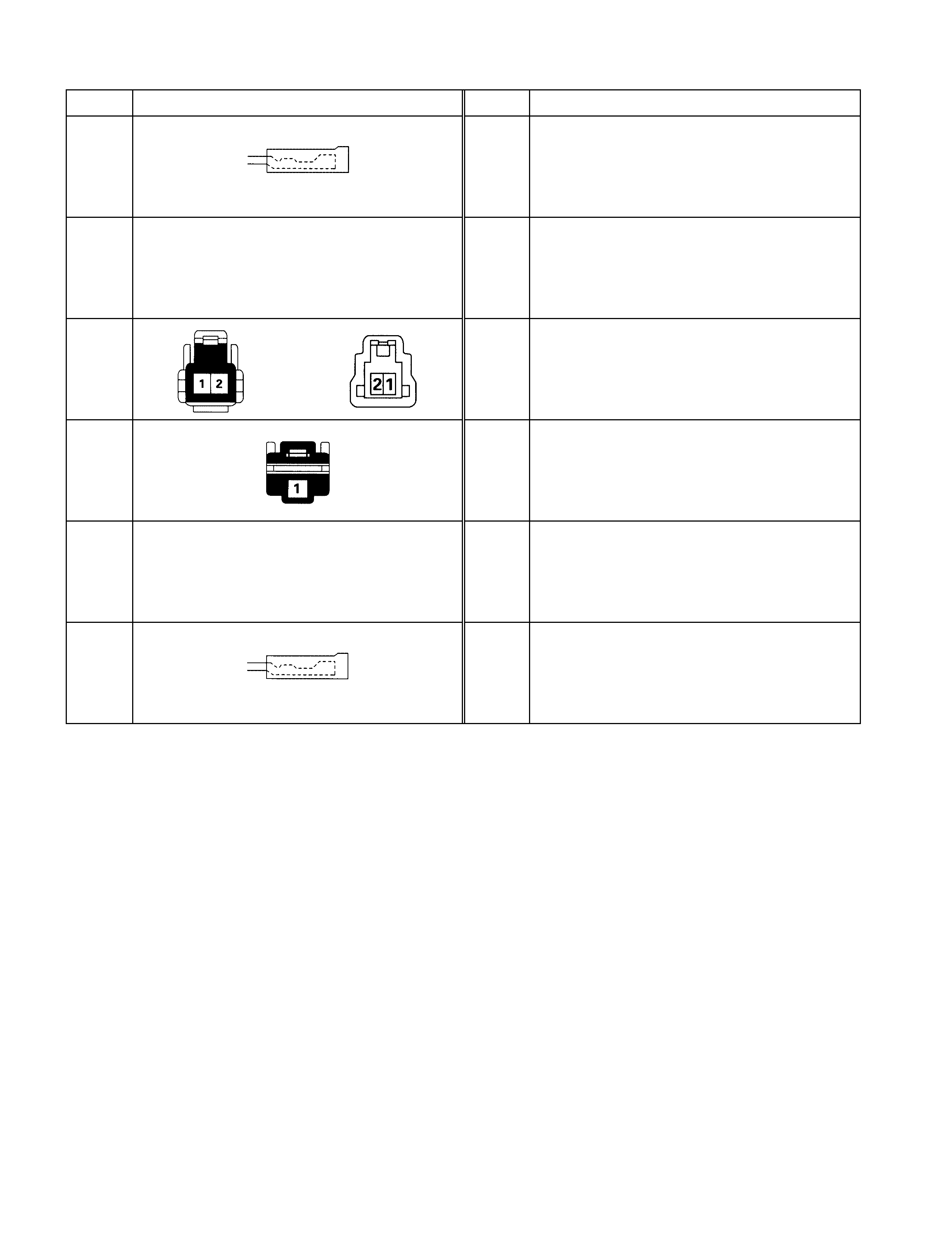
No. Connector face No. Connector face
R-1
R-2
NOT USED
R-3
R-4
R-5
NOT USED
R-6
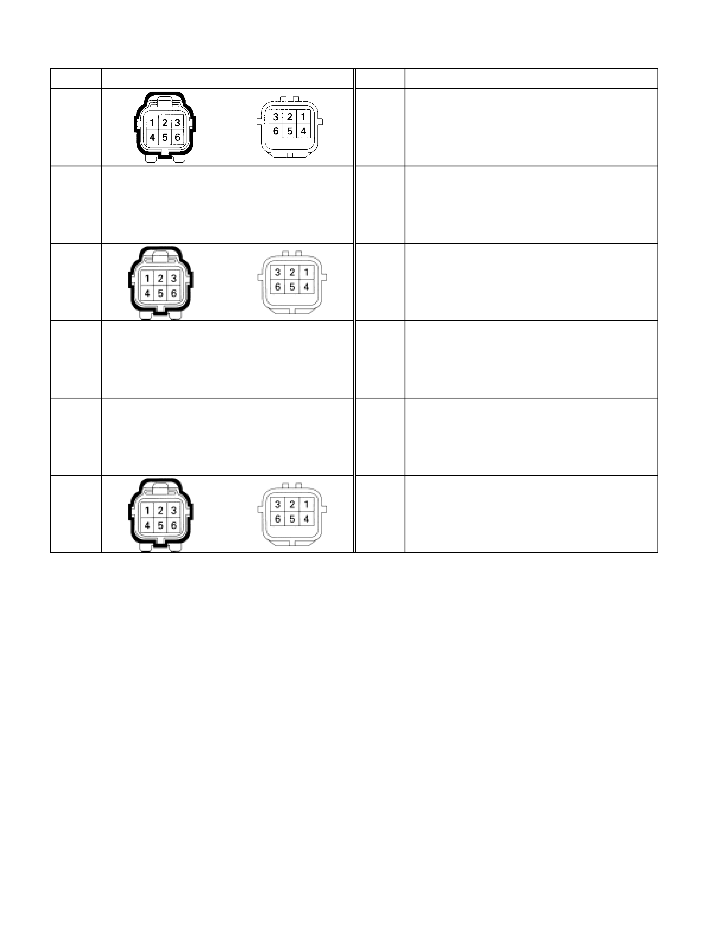
No. Connector face No. Connector face
T-1
T-2
NOT USED
T-3
T-4
NOT USED
T-5
NOT USED
T-6

No. Connector face No. Connector face
X-15 X-25
X-16 X-26
X-17 X-27
NOT USED
X-18 X-28
X-19
X-20
X-21
X-22
X-23
X-24
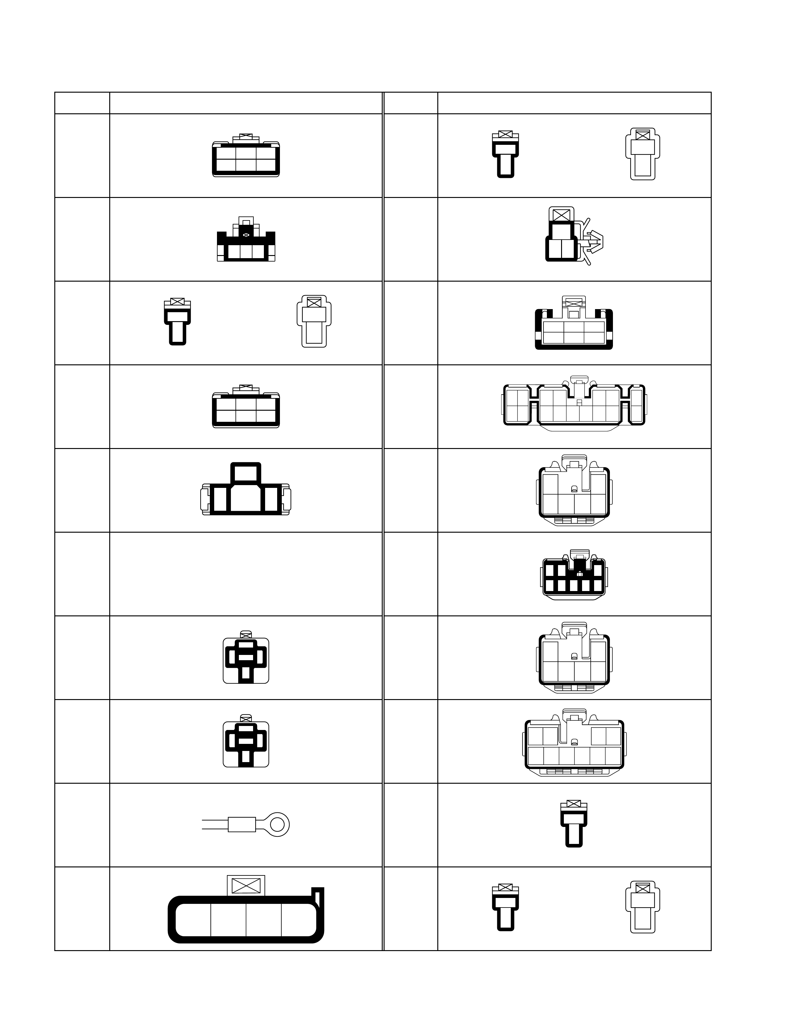
Connector List (4J Engi ne Model)
No. Connector face No. Connector face
B-1
1 2 3
4 5 6
B-11
1
2
1
2
B-2
123
B-12
23
1
B-3
1
2
1
2
B-13
123
45 6
B-4
1 2 3
4 5 6
B-14
12
89
34 56 7
10 11 12 13 14 15 16
B-5
1
2 3
B-15
1
3
2
645
B-6
NOT USED
B-16
3
5867
4
12
B-7
1
3
24
5
B-17
1
3
2
645
B-8
1
3
24
5
B-18
10
4
56789
12 3
B-9 B-19
1
2
B-10
3421
B-20
1
2
1
2
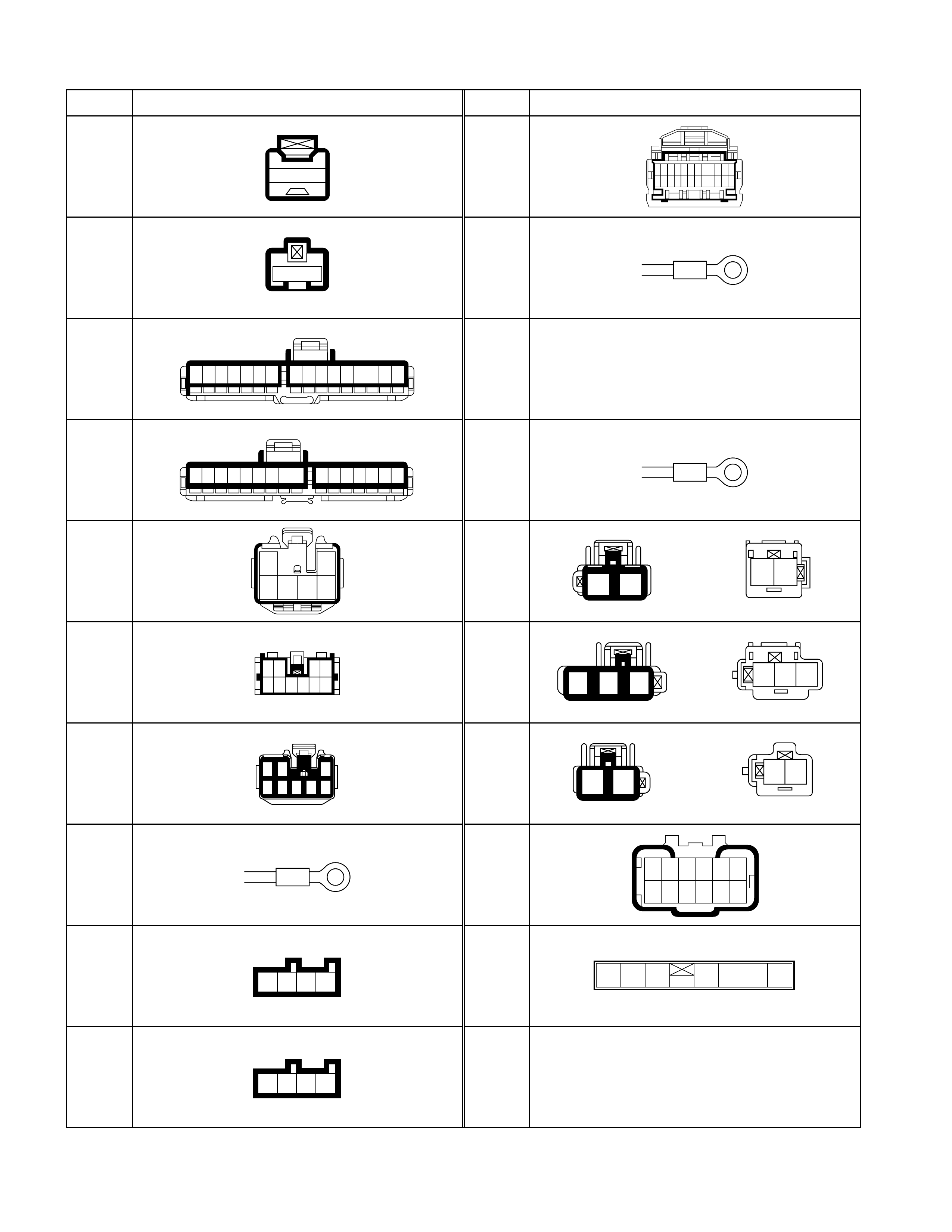
No. Connector face No. Connector face
B-21
1
B-31
123456789101112
13 14 15 16 17 18 19 20 21 22 23 24
B-22
1
B-32
B-23
16151413121110987654321
B-33
NOT USED
B-24
98765432116151413121110
B-34
B-25
1
3
2
645
B-35
12
12
B-26
1098765
4321
B-36
123
321
B-27
3
5867
4
12
B-37
21
2 1
B-28 B-38
121110987
654321
B-29
1 2 3 4
B-39
123 4567
B-30
1 2 3 4
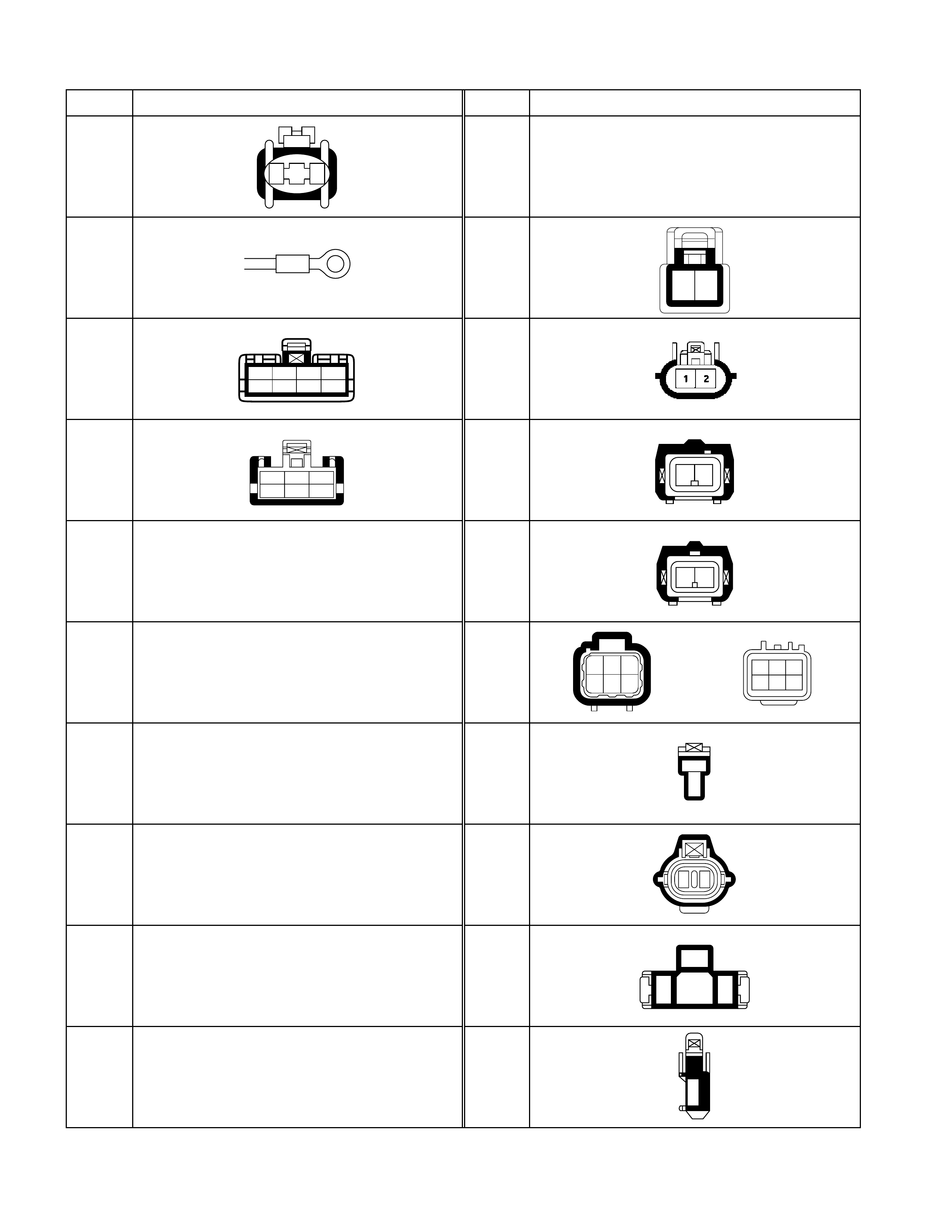
No. Connector face No. Connector face
C-1
1 2
C-11
NOT USED
C-2 C-12
12
C-3
1234
5678
C-13
C-4
123
45 6
C-14
12
C-5
NOT USED
C-15
12
C-6
NOT USED
C-16
123
456
321
654
C-7
NOT USED
C-17
1
2
C-8
NOT USED
C-18
21
C-9
NOT USED
C-19
1
2 3
C-10
NOT USED
C-20
1
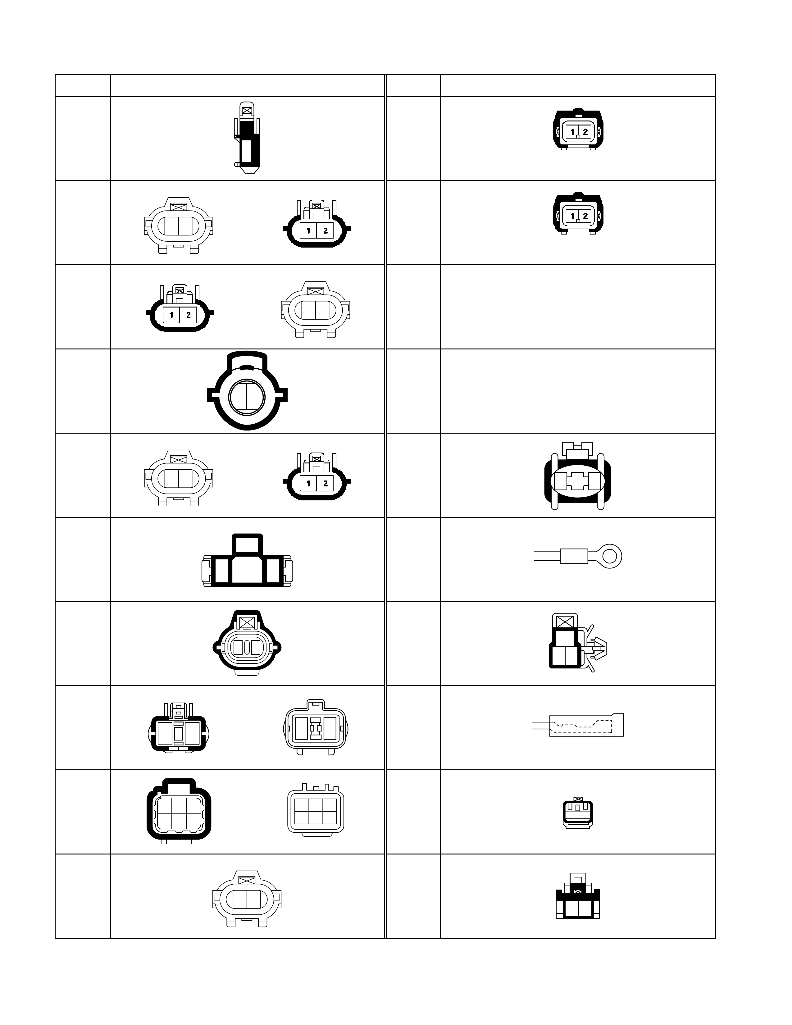
No. Connector face No. Connector face
C-21
1
C-31
(GRAY)
C-22
12
C-32
(BLUE)
C-23
12
C-33
NOT USED
C-24
12
C-34
NOT USED
C-25
12
C-35
1 2
C-26
1
2 3
C-36
C-27
21
C-37
23
1
C-28
1 2
2 1
C-38
C-29
123
456
321
654
C-39
1
C-30
12
C-40
12
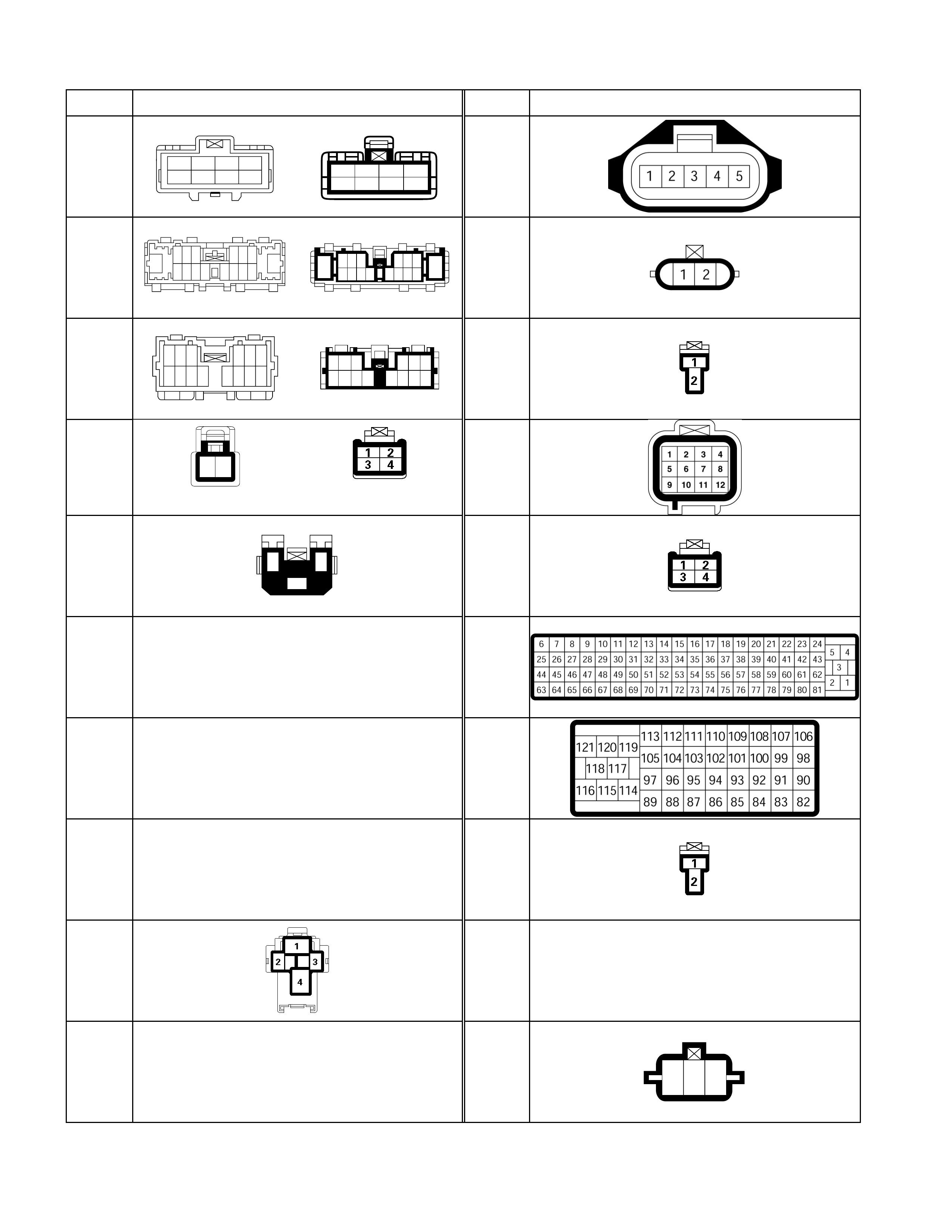
No. Connector face No. Connector face
C-41
1234
5678
1234
5678
C-51
C-42
16
654
14 13 12 11
321
98710
15
15
123
78910
16
456
12 13 1411
C-52
C-43
654
1413 12 11
321
98710
12 3
78 910 11
4
12
5
13
6
14
C-53
12
C-44
(4JH1-TURBO, 4JA1-TURBO)
C-54
C-45
13
2
C-55
C-46
NOT USED
C-56
C-47
NOT USED
C-57
C-48
NOT USED
C-58
C-49 C-59
~
C-91 NOT USED
C-50
NOT USED
C-92
123
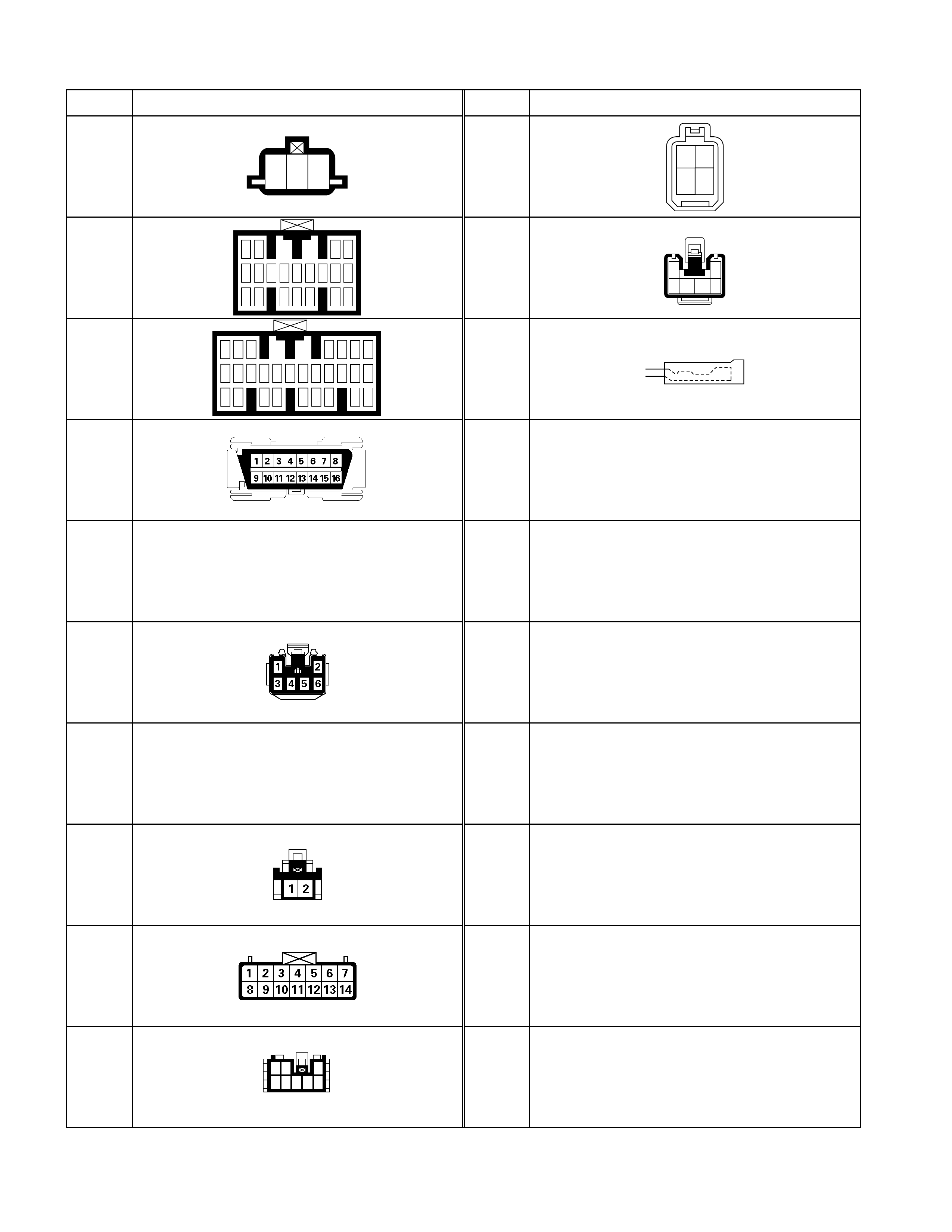
No. Connector face No. Connector face
C-93
123
C-207
2 1
4 3
C-94
12 34
5 6 12 1310 11
19 2014 15 181716
978
C-208
1
3456
2
C-95
123 456
12 1310 11 19
20
14 15 18
22 2321 25 26 27 2824
17169
7
8
C-209
C-96
C-97
~
C-109 NOT USED
C-110
C-111
~
C-203 NOT USED
C-204
C-205
C-206
12 3
8
4567
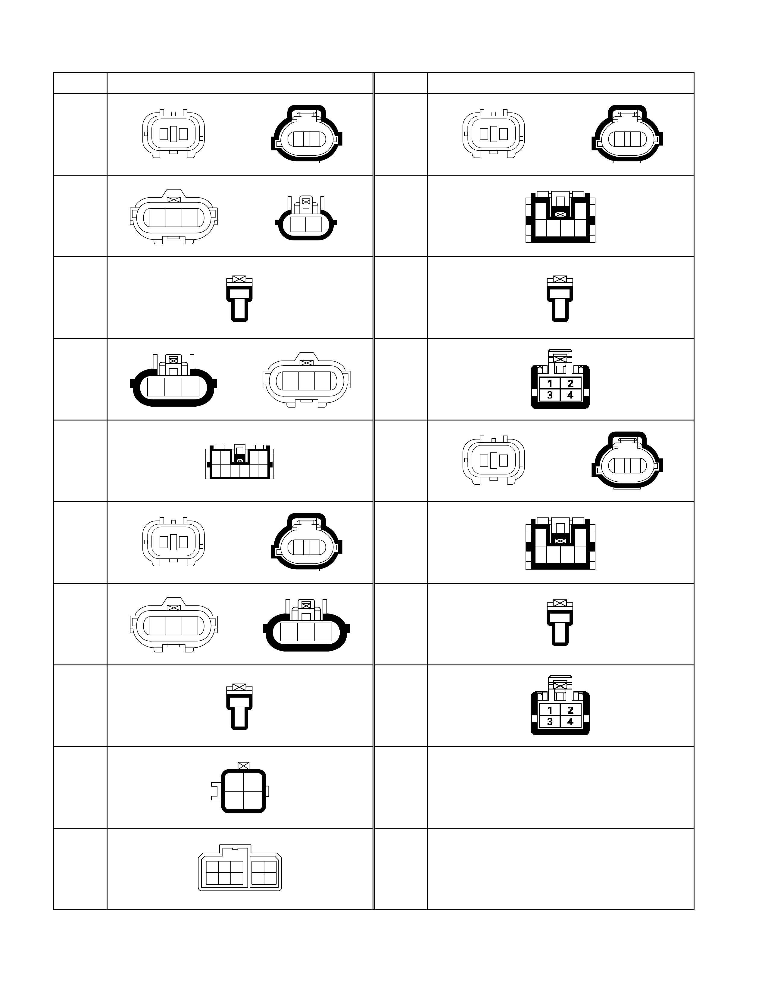
No. Connector face No. Connector face
D-1
21
1 2
D-11
21
1 2
D-2
321
12
D-12
1
3456
2
D-3
1
2
D-13
1
2
D-4
123
321
D-14
D-5
1098765
4321
D-15
21
1 2
D-6
21
1 2
D-16
1
3456
2
D-7
321
123
D-17
1
2
D-8
1
2
D-18
D-9
12
34
D-10
12
67
43
98
5
10
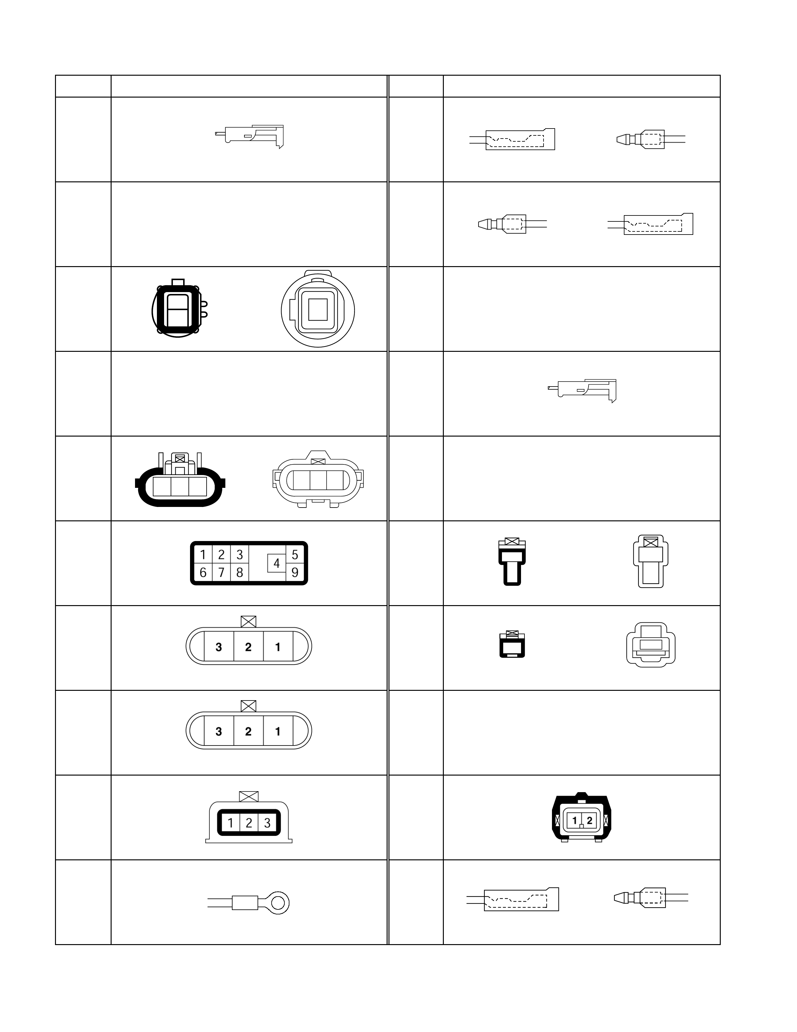
No. Connector face No. Connector face
E-1 E-11
E-2
NOT USED
E-12
E-3
1
1
E-13
~
E-18 NOT USED
E-4
NOT USED
E-19
E-5
123
321
E-20
~
E-35 NOT USED
E-6 E-36
1
2
1
2
E-7
(BROWN)
E-37
1
1
E-8
(GRAY)
E-38
~
E-40 NOT USED
E-9 E-41
E-10 E-42

No. Connector face No. Connector face
E-43 E-53
2
1
E-44
123
E-54
23
6758
14
E-45
1
1
E-55
21
E-46
1
1
E-56
~
E-99 NOT USED
E-47
NOT USED
E-100
123
E-48
NOT USED
E-49
E-50
NOT USED
E-51
56 7 8 9
1234
10
E-52
2
1
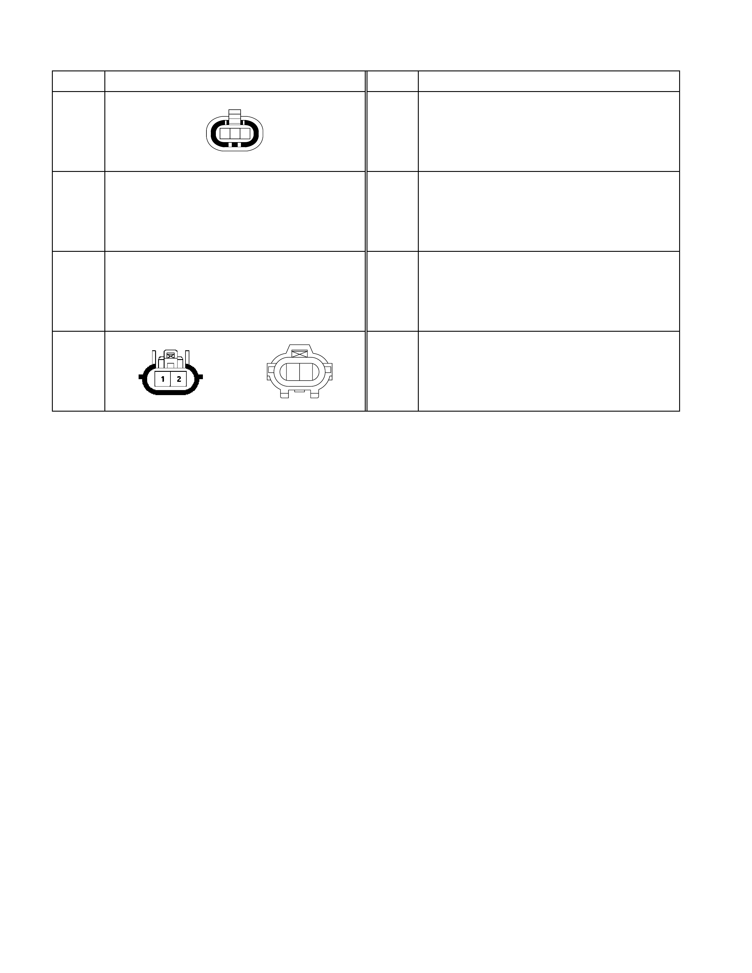
No. Connector face No. Connector face
F-1
1 2 3
F-2
NOT USED
F-3
NOT USED
F-4
12
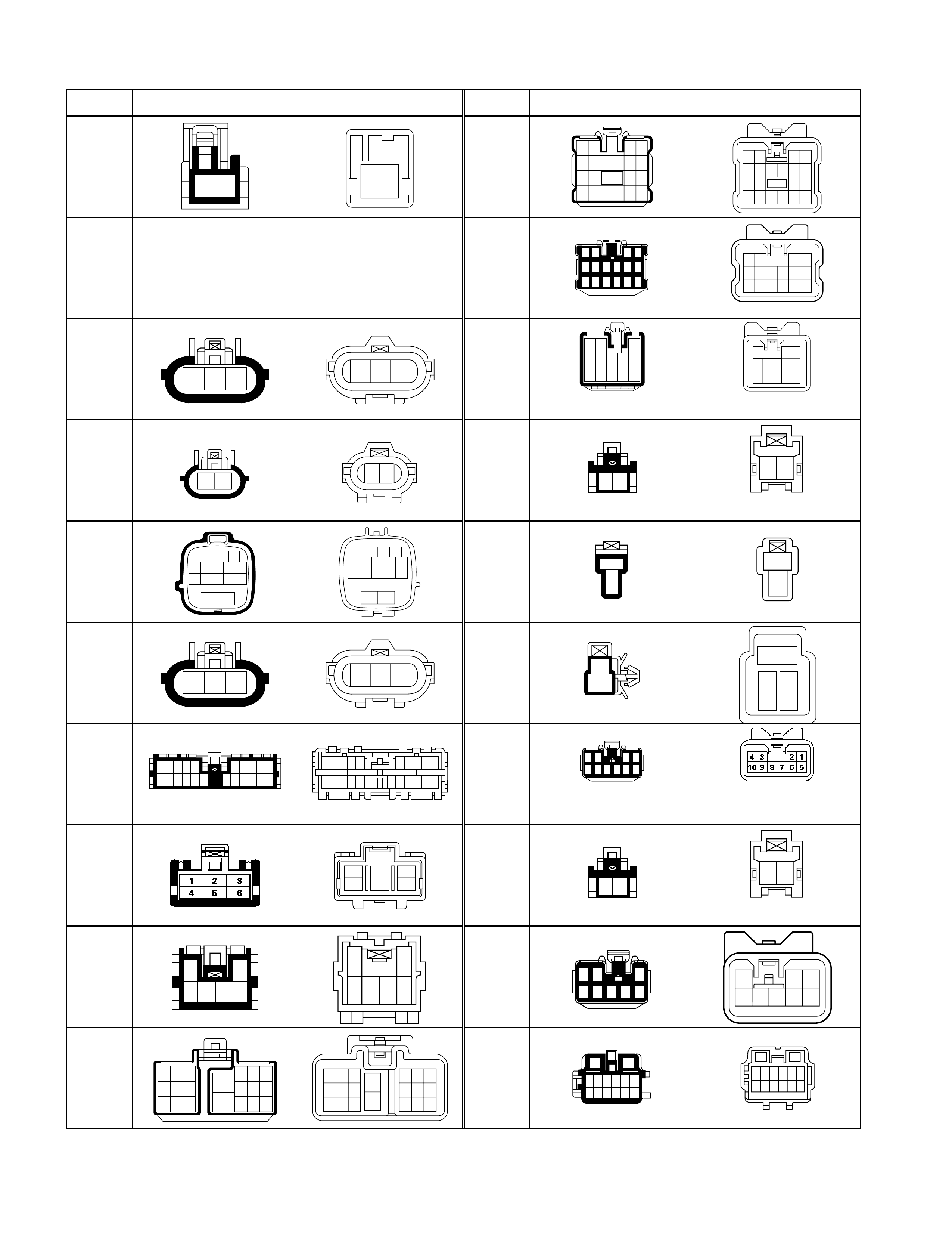
No. Connector face No. Connector face
H-1
1
1
H-8
(UK)
12 34
56 78910
11 12 13 14
15 16 17 18 19 20
1234
5678910
151617181920
11121314
H-2
NOT USED
H-9
12
78
34
56
13
14
910
11 12 15 16
8
43
10 9
1416 15
5
2
76
1113 12
1
H-3
123
321
H-10
1
4
9
2
5
10
6
11
7
12
3
8
13
1
4
9
2
5
10
6
11
7
12
3
8
13
(W/ POWER WINDOW)
H-3
(4JH1)
12
12
H-10
12
2 1
(W/O POWER WINDOW)
H-4
1234
56789
11 12 13 14
15 16
10
4321
98765
13 12 11 10
16 15
14
H-11
1
2
1
2
H-5
123
321
H-12
23
1
1
32
H-6
12345
111213 1415
678910
1819 20212216 17
10 9876 54321
2221 201918 151413121117 16
H-13
56
12
98
10
4
3
7
(W/ POWER WINDOW)
H-7
(LHD)
3
6
2
5
1
4
H-13
12
2 1
(W/O POWER WINDOW)
H-7
(UK)
1
3456
2
2
65 43
1
H-14
3
5867
4
12
321
85467
H-8
(LHD)
123
788
14 15 16
456
11
10
17
12 13
18 19 20
4
10
17
56
111213
181920
123
789
141516
H-15
1211
12
3456 7 8
910 1314
21
345678
91011121314
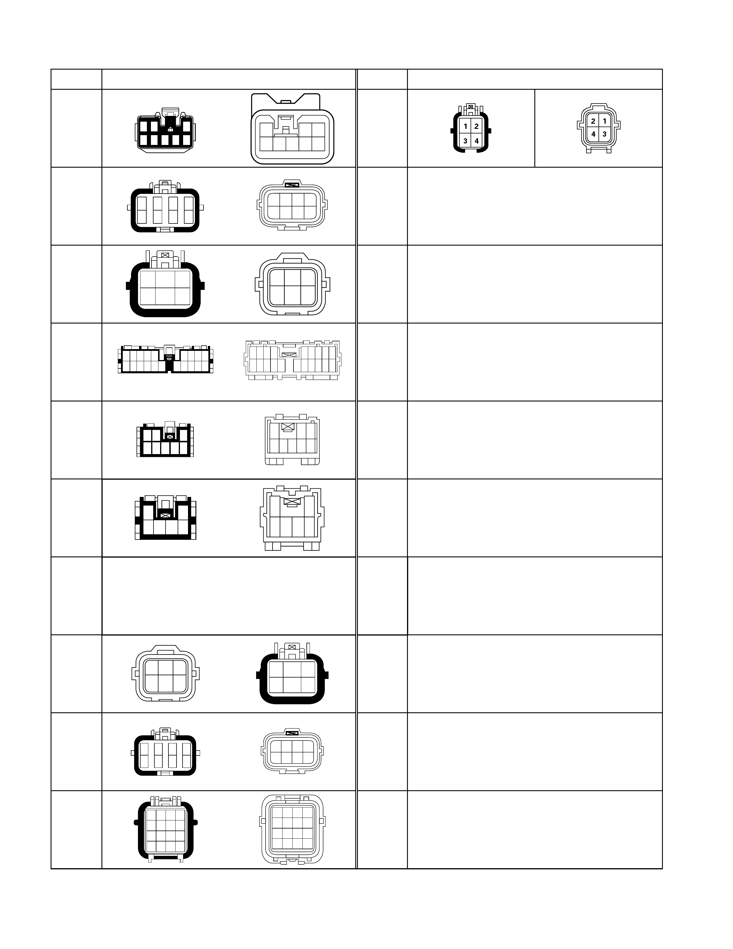
No. Connector face No. Connector face
H-16
3
5867
4
12
321
85467
H-51
H-17
(LHD)
1
5
2
6
3
7
4
8
1234
5678
H-17
(UK)
1
4
2
5
3
6
564
231
H-18
10 11 12 13 14 15
12345
17 18 19 20
6789
16
9876
20 19 18 17 16
5
1415
4
13
3
12
2
11
1
10
H-19
12 3
8
4567
123
84567
H-19
(4JH1)
1
3456
2
2
6543
1
H-20
~
H-21 NOT USED
H-22
(4JH1-
MT)
564
231
1
4
2
5
3
6
H-22
(4JH1-
A/T)
1
5
2
6
3
7
4
8
1234
5678
H-23
1234
5678
9101112
13 14 15 16
12
56
910
1314
1516
1112
78
34
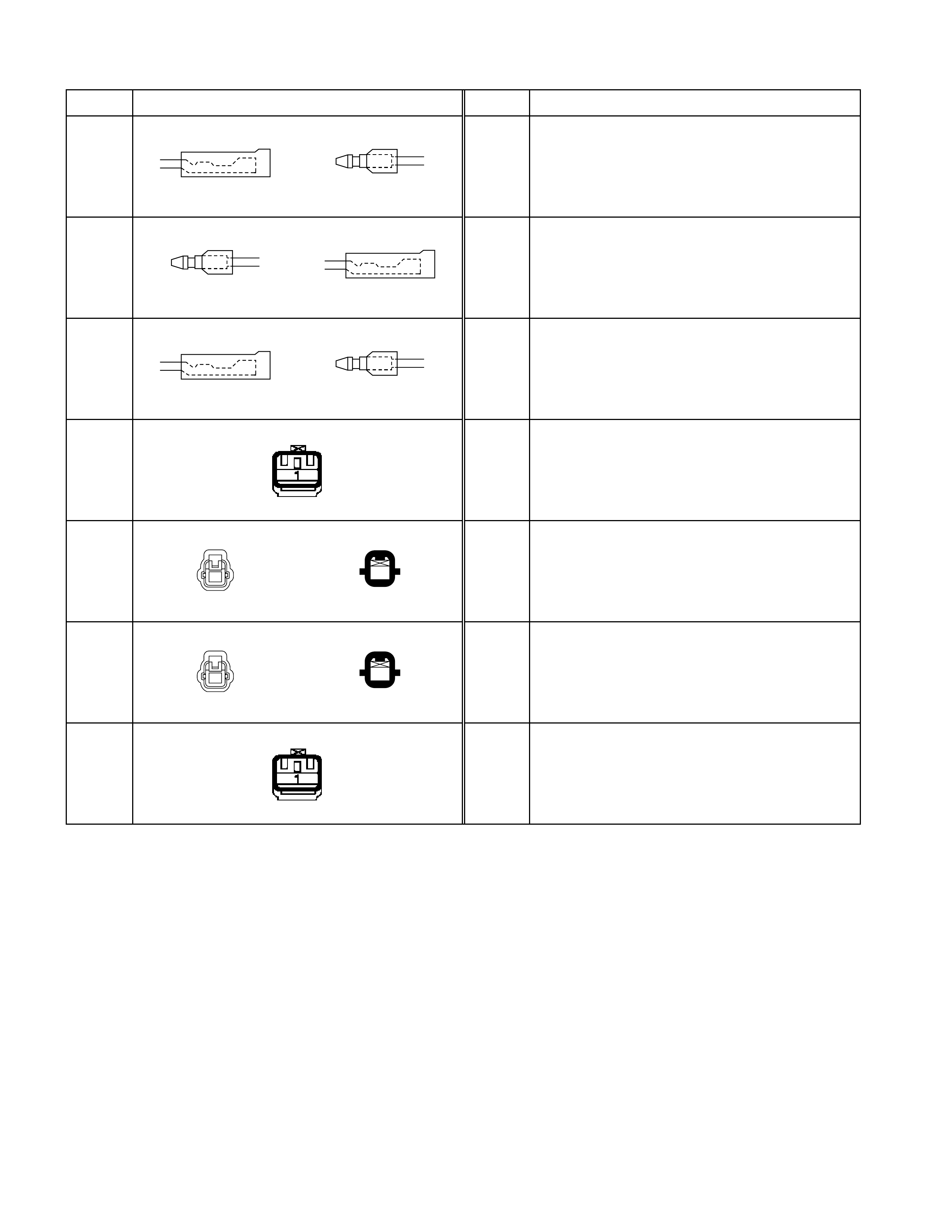
No. Connector face No. Connector face
L-1
L-2
L-3
L-4
L-5
1
1
L-6
1
1
L-7
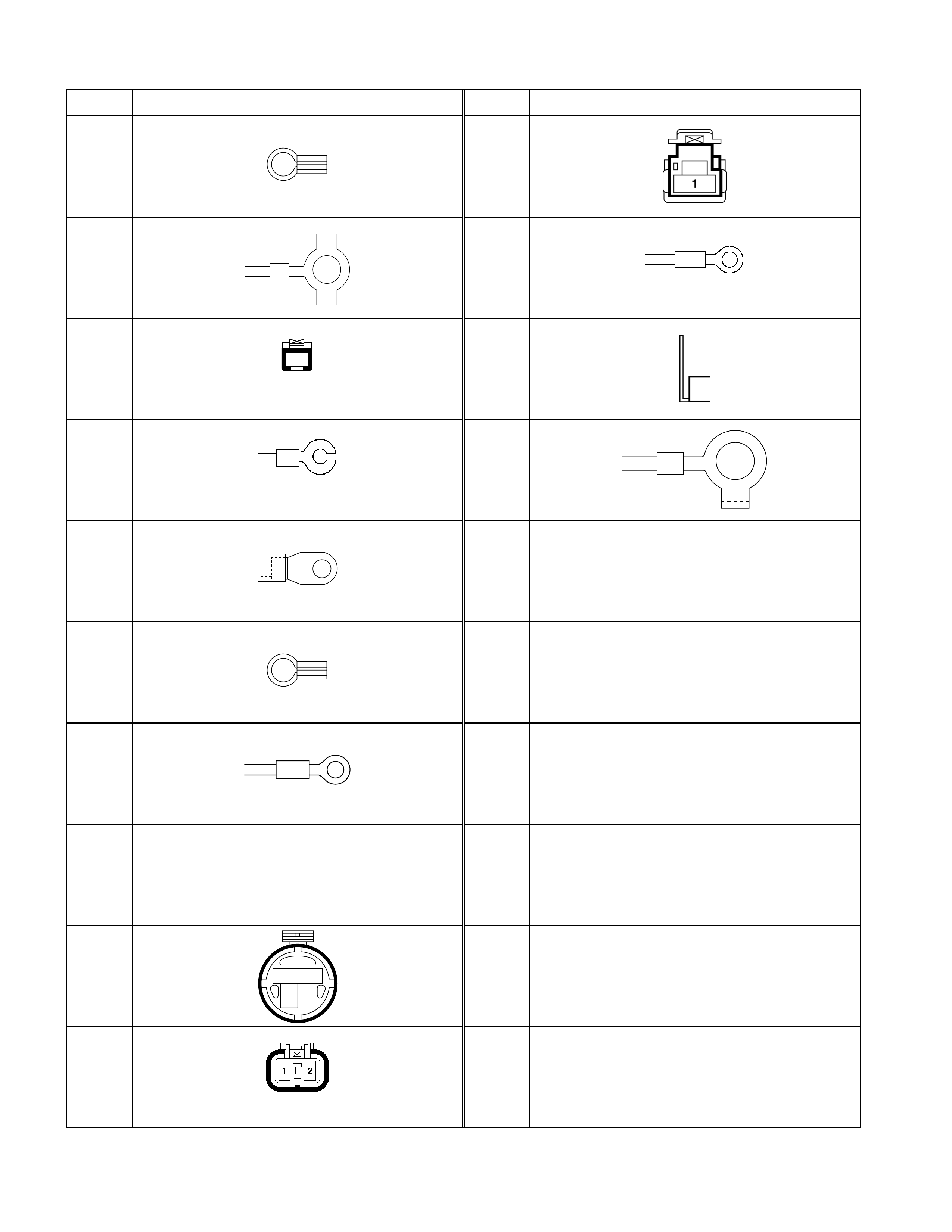
No. Connector face No. Connector face
P-1 P-9
P-2 P-9
(4JA1-TURBO)
P-3
1
(4JA1)
P-10
P-3
(4JG2)
P-11
P-4
P-5
P-6
P-7
NOT USED
P-8
21
43
P-8
(4JA1-TURBO)
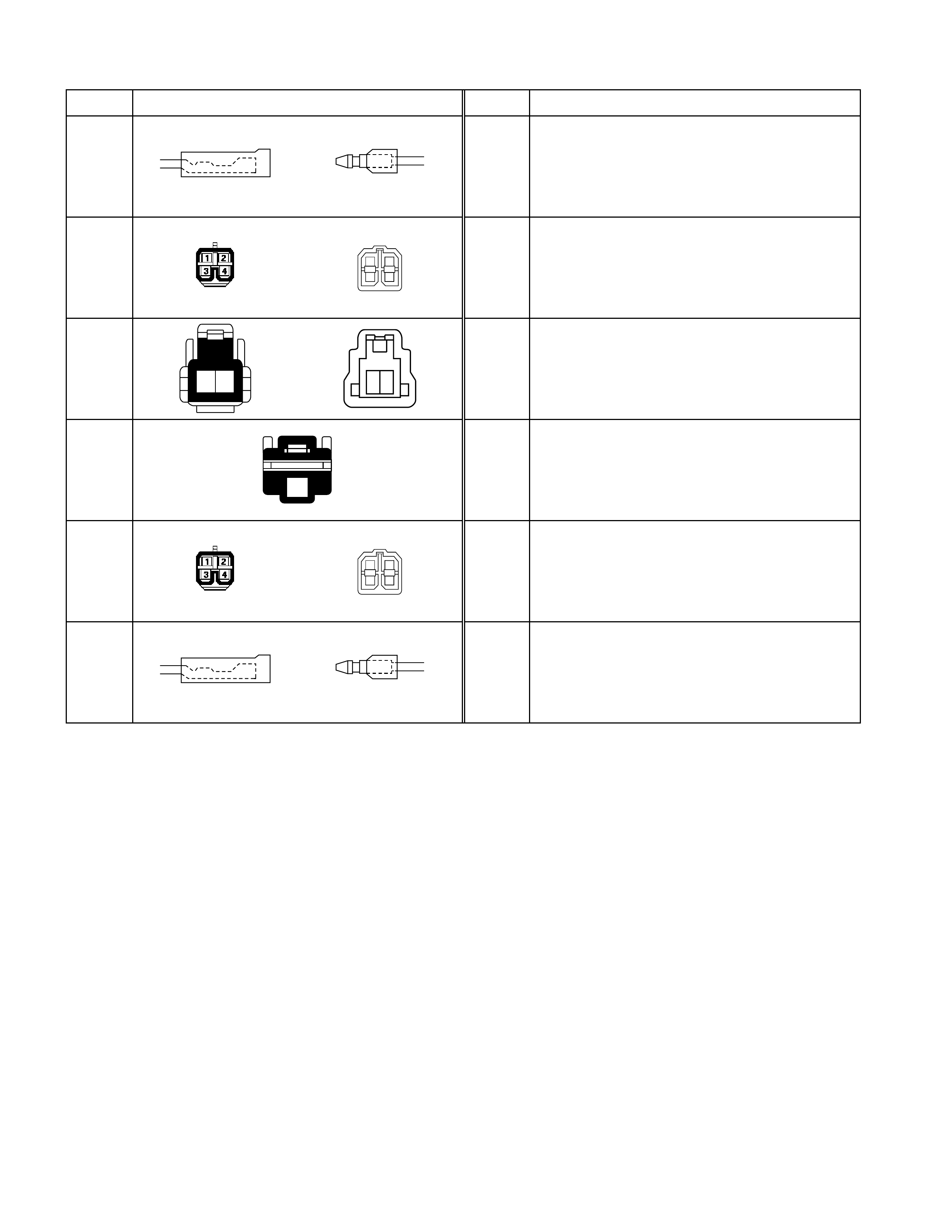
No. Connector face No. Connector face
R-1
R-2
2
4
1
3
R-3
12
12
R-4
1
R-5
2
4
1
3
R-6
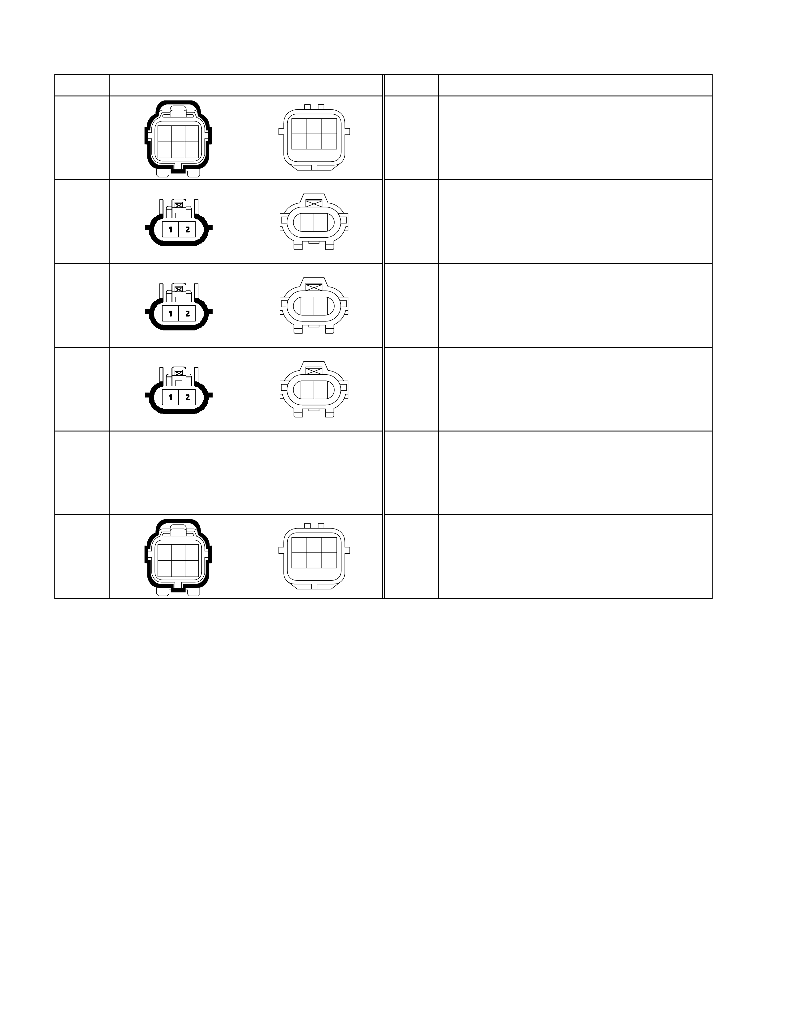
No. Connector face No. Connector face
T-1
123
456
321
654
T-2
12
T-3
12
T-4
12
T-5
NOT USED
T-6
123
456
321
654
No. Connector face No. Connector face
X-1 X-11
X-2 X-12
X-3 X-12
X-4 X-12
1
23
4
(4JX1-TURBO)
X-5 X-13
X-6 X-13
4JX1-TURBO)
X-7
X-8
X-9
X-10