
SECTION 12M2 - SEAT BELTS
Service Precaution
Diagnostic Information
System Schematic
SRS Diagnostic System Check
Chart A SDM Integrity Check
Chart B “AIR BAG" Warning Lamp Comes
“ON" Steady
Chart C “AIR BAG" Warning Lamp Does Not
Come “ON" Steady
DTC 15 Passenger Deployment Loop
Resistance High
DTC 16 Passenger Deployment loop
Resistance Low
DTC 17 Passenger Deployment Loop Open
DTC 18 Passenger Deployment Loop Short
To Ground
DTC 19 Passenger Deployment Loop Short
To Voltage
DTC 21 Driver Deployment Loop Resistance
High
DTC 22 Driver Deployment Loop Resistance
Low
DTC 24 Driver Deployment Loop Short To
Ground
DTC 25 Driver Deployment Loop Short To
Voltage
DTC 26 Driver Deployment Loop Open
DTC 51 Deployment Event Commanded
DTC 53 Deployment Commanded With
Deployment Loop Fault Or Energy Reserves
Out Of Range
DTC 61 Warning Lamp Circuit Failure
DTC 71 Internal SDM Fault
Service Precaution
WARNING: THIS VEHICLE HAS A SUPPLEMENTAL
RESTRAINT SYSTEM (SRS). REFER TO THE SRS
COMPONENT AND WIRING LOCATION VIEW IN
ORDER TO DETERMINE WHETHER YOU ARE
PERFORMING SERVICE ON OR NEAR THE SRS
COMPONENTS OR THE SRS WIRING. WHEN YOU
ARE PERFORMING SERVICE ON OR NEAR THE
SRS COMPONENTS OR THE SRS WIRING, REFER
TO THE SRS SERVICE INFORMATION. FAILURE TO
FOLLOW WARNINGS COULD RESULT IN POSSIBLE
AIR BAG DEPLOYMENT, PERSONAL INJURY, OR
OTHERWISE UNNEEDED SRS SYSTEM REPAIRS.
CAUTION: Always use the correct fastener in the
proper location. When you replace a fastener, use
ONLY the exact part number for that application.
ISUZU will call out those fasteners that require a
replacement after removal. ISUZU will also call out
the fasteners that require thread lockers or thread
sealant. UNLESS OTHERWISE SPECIFIED, do not
use supplemental coatings (Paints, greases, or
other corrosion inhibitors) on threaded fasteners or
fastener joint interfaces. Generally, such coatings
adversely affect the fastener torque and the joint
clamping f or ce, and may dama ge the fastener . Wh en
you install fasteners, use the correct tightening
sequence and specifications. Following these
instructions can help you avoid damage to parts
and systems.

Diagnostic Information
CAUTION: When fasteners are removed, always
reinstall them at the same location from which they
were removed. if a fastener needs to be replaced,
use the correct part number fastener for that
application. if the correct part number fastener is
not available, a fastener of equal size and strength
(or stronger) may be used. fasteners that are not
reused, and those requiring thread locking
compound will be called out. the correct torque
value must be used when installing fasteners that
require it. if the above conditions are not followed,
parts or system damage could result.
Diagnostic Procedures
WARNING: TO AVOID DEPLOYMENT WHEN
TROUBLESHOOTING THE SRS, DO NOT USE
ELECTRICAL TEST EQUIPMENT SUCH AS A
BATTERY–POWERED OR AC–POWERED
VOLTMETER, OHMMETER, ETC., OR ANY TYPE OF
ELECTRICAL EQUIPMENT OTHER THAN THAT
SPECIFIED IN THIS MANUAL. DO NOT USE A NON
POWERED, PROBE–TYPE TESTER.
INSTRUCTIONS IN THIS MANUAL MUST BE
FOLLOWED CAREFULLY, OTHERWISE PERSONAL
INJURY MAY RESULT.
The diagnostic procedures used in this section are
designed to aid in finding and repairing SRS problems.
Outlined below are the steps to find and repair SRS
problems quickly and effectively. Failure to carefully
follow these procedures may result in extended
diagnostic time, incorrect diagnosis and incorrect parts
replacement.
1.Perform The “SRS Diagnostic System Check".
The “SRS Diagnostic System Check" should always
be the starting point of any SRS diagnostics. The
“SRS Diagnostic System Check" checks for proper
“AIR BAG" warning lamp operation and checks for
SRS trouble codes using both “Flash Code" and
“Scan Tool" Methods.
2.Refer To The Proper Diagnostic Chart As
Directed By The “SRS Diagnostic System
Check".
The “SRS Diagnostic System Check" will lead you
to the correct chart to diagnose any SRS problems.
Bypassing these procedures may result in extended
diagnostic time, incorrect diagnosis and incorrect
parts replacement.
3.Repeat The “SRS Diagnostic System Check"
After Any Repair Or Diagnostic Procedures Have
Been Performed.
Preforming the “SRS Diagnostic System Check"
after all repair or diagnostic procedures will assure
that the repair has been made correctly and that no
other conditions exist.
Diagnostic Codes
The Sensing and Diagnostic Module (SDM) maintains a
history record of all diagnostic codes that have been
detected since the SRS codes were last cleared during
service.
1.Active Codes — Faults that are presently detected
this ignition cycle. Active codes are stored in RAM
(Random Access Memory).
2.History Codes — All faults detected since the last
time the history fault memory was cleared. History
codes are stored in EEPROM. (Electronically
Erasable Programmable Read only Memory)
How To Read Trouble Codes
All codes (Active and history) can be read (or cleared)
by using a scan tool or equivalent.
How To Clear Trouble Codes
Trouble codes can only be cleared by using a Scan
Tool. If a “scan tool" is not available then inform the
owner of the stored codes and suggest that the codes
are cleared upon the next visit to an Isuzu dealership.
Scan Tool Diagnostics
A scan tool can be used to read current and history
codes and to clear all history codes after a repair is
complete. The scan tool must be updated to
communicate with the SRS through a replaceable
cartridge or a manufacturer's update before it can be
used for SRS diagnostics. To use the scan tool,
connect it to the DLC connector and turn the ignition
switch “ON". Then follow the manufacturer's directions
for communication with the SRS. The scan tool reads
serial data from the SDM “Serial Data" output (terminal
24) to the DLC connector (terminal 9).
Basic Knowledge Required
Before using this section of the Service Manual, there is
some basic knowledge which will be required. Without
this knowledge, you will have trouble using the
diagnostic procedures in this section. Use care to
prevent harm or unwanted deployment. Read all
cautions in the service manual and on warning labels
attached to SRS components.
Basic Electrical Circuits
You should understand the basic theory of electricity
including series and parallel circuits, and understand
the voltage drops across series resistors. You should
know the meaning of voltage (volts), current (amps),
and resistance (ohms). You should understand what
happens in a circuit with an open or a shorted wire.
You should be able to read and understand a wiring
diagram.

“Flash Code" Diagnostics
Flash code diagnostics can be used to read active
codes and to determine if history codes are present
but cannot be used to clear codes or read history
codes. Flash c ode di agnos tics is enabled by groundin g
by terminal 4 shorting to terminal 13 of the DLC
connector with the ignition switch “ON". Grounding
terminal 4 of the DLC connector pulls the “Diagnostics
Request" input ( Termi nal 1) of the SDM low and signa ls
the SDM to enter the flash code diagnostic display
mode.
The SDM displays the trouble codes by flashing the
warni ng lamp. Each code t hat is disp layed will consist
of a number of fl ashes which repres ents the tens digi t,
a 1.2 second pause, following by a number of flashes
which repr es ent s t he o nes d igi t o f the code. Each c od e
is displayed one time before moving on to the next
code. After all of the codes have been displayed, the
entire code sequence will continually by repeated until
ground is removed from terminal 4 of the DLC
connector.
Two specia l code s exist when reading i n the flash code
mode (Flash Code 12 and Flash Code 13). “Flash
Code 12“ will always be the first code displayed when
the flash code mode is enable Code 12 is not an
indication of a SRS problem but an indication that the
flash code mode has been enabled. If there are no
active or history codes present, the SDM will display
code 12 until ground is removed from the DLC
connector at terminal 4. “flash Code 13" will be
displayed if history codes are present. To read the
history codes a scan tool must be used.
TECH 2 Tool Data
DISPLY on TECH 2 UNIT VALUE
IGNITION V 12.0
WARNING LAMP ON/OFF ON
DRIV. SENSELO V 2.5
PASS. SENSELO V 2.5
DRIVER RESIST OHMS 3.1
PASS. RESIST OHMS 3.1
DRIV. ENERGY V 22.3
PASS. ENERGY V 22.3
WARN LAMP ON HRS
WARNING LAMP
CYCLES ON
DRV LPS NOT PRES
PASS LPS PRESENCE
SYSTEM TYPE DRIV/PASS
WARNING LAMP ON
LAMP DRIVER FBK ON
DRIVER SEATBE LT BACKUPED
DRIVER SBELT FBK BACKUPED

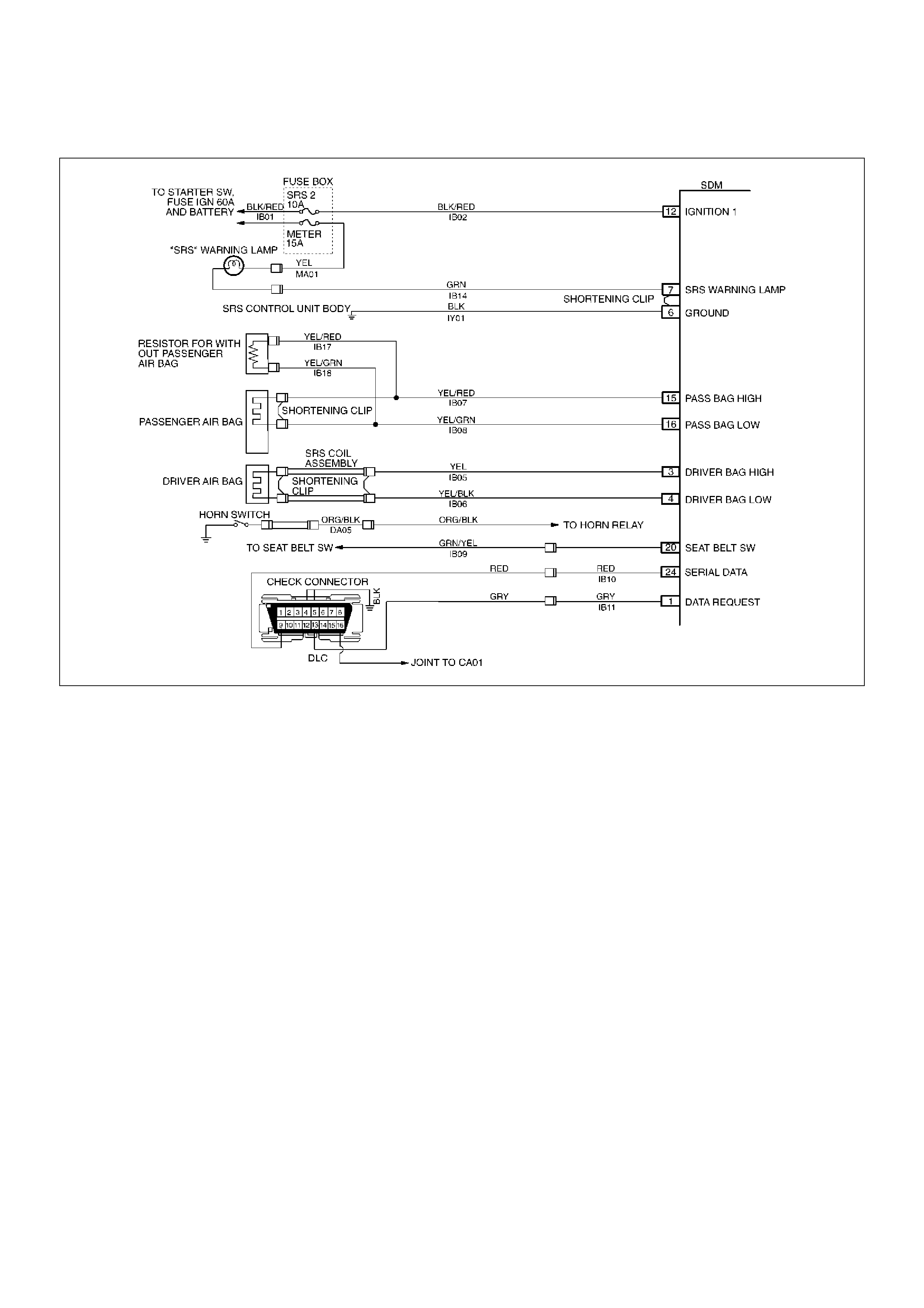
System Schematic
D09LX00001
SRS Diagnostic System Check
The diagnostic procedures used in this section are
designed to find and repair SRS m alfunctions. To ge t
the best results, it is important to use the diagnostic
charts and follow the sequence listed below:
A Perform the “SRS Diagnostic System Check."
The “SRS Diagnostic System Check" must be the
star ting point of any SRS diagnostics. The “SRS
Diagnostic System Check" checks for proper “AIR
BAG" warning lamp operation, the ability of the
SDM to c ommunicate through the “Seri al Data" line
and whether SRS diagnostic trouble codes exist.
B Refer to the proper diagnostic char t as directed by
the “SRS Diagnostic System Check."
The “SRS Diagnostic System Check" will lead you
to the correct chart to diagnose any SRS
malfunctions. Bypassing these procedures may
result in extended diagnostic time, incorrect
diagnosis and incorrect parts replacement.
C Repeat the “SRS Diagnostic System Check" after
any repair or diagnostic procedures have been
preformed.
Performing the “SRS Diagnostic System Check"
after al l repa ir or dia gnostic pro ce dures wi ll ensur e
that the repai r has been made co rrec tl y and tha t no
other malfunctions exist
Circuit De sc r i p t i o n
When t he i gn iti on switch is fi rst turne d “ O N", “ Ign iti on 1"
voltage is applied from the “SRS 2" fuse to the SDM at
the “Ignition 1" input terminals “12". The SDM
responds by flashing the “AIR BAG" warning lamp
seven times, while performing tests on the SRS.
Notes On Sy stem Che ck Chart:
1. The “AIR BAG" warning lamp should flash seven
times after ignition is first turned “ON".
2. After the “AIR BAG" warning lamp flashes seven
times, it should turn “OFF"
3. This test checks for the proper operation of the
“Serial Data" line. This test will also determine
whether hi stor y diagnosti c trouble codes ar e stored
and, if so, identify them.
4. Improper operation of the “AIR BAG" w arning lamp is
indicated. This test differentiates a warning lamp
stays “ON" condition from a warning lamp does not
come “ON" condition.
5. This test checks for proper operation of the “Serial
Data" line. This test will also identify the stored
diagnostic trouble codes and whether they are
current or history.

Diagnostic Aids:
The order in which diagnostic trouble codes are
diagnosed is very important. Failure to diagnose the
diagnostic trouble codes in the order specified may
result in extended diagnostic time, incorrect diagnosis
and incorrect parts replacement.
SRS Diagnostic System Check
Step Action Yes No
1 Note the “Air Bag" warning lamp as ignition switch is turned “ON."
Does the “AIR BAG" warning lamp flash seven (7) times? Go to Step 2 Go to Step 3
2 Note the “AIR BAG" warning lamp after it flashed 7 times.
Does the “AIR BAG" warning lamp go “OFF"? Go to Step 4 Go to Step 5
3 Note the “AIR BAG" warning lamp as ignition switch is turned
“ON".
Does the “AIR BAG" warning lamp come “ON" steady? Go to Chart B. Go to Chart C.
4 1. Note the “AIR BAG" warning lamp as that ignition switch is
tur n ed “ON."
Ignition switch “OFF."
2. Connect a scan tool to data link connector.
3. Follow direction given in the scan tool instruction manual.
Ignition switch “ON."
4. Request th e SRS dia gnostic tro uble cod e display, rec ode all
history diagnostic trouble code(s). specify as such, on repair
order
Is (are) diagnostic trouble code(s) displayed?
Ignition switch
“OFF."
When DTC 71 is
set, go to DTC 71
Chart.
For all other history
codes refer to
“Diagnostic Aids"
For that specific
DTC.
A history DTC
indicates the
malfunction has
been repaired or is
intermittent.
SRS is functional
and free of
malfuncitons, no
further diagnosis is
required.
If scan tool
indicated “NO
DA T A RECEIVED,"
refer to chassis
electrical section8.
5 1. Ignition switch “OFF."
2. Connect a scan tool to data link connector.
3. Follow directions as given in the scan tool instruction manual.
4. Ignition switch “ON."
5. Request the SRS diagnostic trouble code display, Recode all
diagnostic trouble code(s), specifying as current or history
on repair order.
Is (are) diagnostic trouble code (s) displayed?
Ignition switch
“OFF".
When DTC 53 is
set, go to DTC 53
chart.
When DTC 51 is
set, go to DTC 51
chart.
When DTC 19 is
set, go to DTC 19
chart.
When DTC 25 is
set, go to DTC 25
chart.
Diagnose
remaining current
DTCs from lowest
to highest.
When only his tory
DTCs e xist, refer to
“Diagnostics Aids"
for that specific
DTC.
A history DTC
indicates the
malfunction has
been repaired or is
intermittent.
If scan tool
indicates “No
Data Received,"
refer to chassis
electrical
section8.

Chart A SDM Integrity Check
D09LX00001
Circuit Description:
When the SDM recognizes “Ignition 1" voltage, applied
to terminals “12", is greater than 9 volts, the “AIR BAG"
warni ng lamp is flash ed 7 times to verify operation . At
this time the SDM performs “Turn–ON" tests followed
by “Conti nuous Monitor ing" tests. When a ma lfunctio n
is detected, the SDM sets a current diagnostic trouble
code and illuminates the “AIR BAG" warning lamp. The
SDM will clear current diagnostic trouble codes and
move them to a history file when the malfunction is no
longer detected and/or the ignition switch is cycled,
except for DTCs 19, 25, 51, 53 and 71. DTC 71 can
only be cleared using a scan tool “Clear Codes"
command. If DTCs 51, 53 are not indicated then DTC
71 is not existing. DTCs 51, 53 and 71 can not be
cleared after a “Clear Codes" command is issued.
Chart Test Descr iption:
Number(s) below refer to step number(s) on the
diagno sti c ch art:
1. This test confirms a current malfunction. If no
current malfunction is occurring (history DTC set)
the “Diagno stic Aid s" for the appropr iate dia gnostic
tr oub le code sh oul d be referenc ed. The SDM sh oul d
not be replaced for a history diagnostic trouble
code.
2. This test checks for a malfunction introduced into the
SRS during the diagnostic process. It is extremely
unlikely that a malfunctioning SDM would cause a
new malfunction to occur during the diagnostic
process.
3. When all circuitry outside the SDM has been f ound to
operate properly, as indicated by the appropriate
diagnostic chart, then and only then should the SDM
be replaced.

Chart A SDM Integrity Check
WARNING: DURING SERVICE PROCEDURES. BE VERY CAREFUL WHEN HANDLING A SENSING AND
DIAGNOSTIC MODULE (SDM). NEVER STRIKE OR JAR THE SDM. NEVER POWER UP THE SRS WHEN THE
SDM IS NOT RIGIDLY ATTACHED TO THE VEHICLE. ALL SDM AND MOUNTING BRACKET FASTENERS
MUST BE CAREFULLY TORQUED AND THE ARROW MUST BE POINTING TOWARD THE FRONT OF THE
VEHICLE TO ENSURE PROPER OPERATION OF THE SRS. THE SDM COULD BE ACTIVATED WHEN
POWERED WHILE NOT RIGIDLY ATTACHED TO THE VEHICLE WHICH COULD CAUSE DEPLOYMENT AND
RESULT IN PERSONAL INJURY.
Step Action Yes No
1 1. This chart assumes that the “SRS Diagnostic System
Check" and either a symptom chart or a diagnostic trouble
code chart diagnosis have been performed. When all
circuitry outside the SDM has been found to operate
properly, as indicated by the appropriate diagnostic chart,
and the symptom or DTC remains current, the following
2. Diagnosti c proce dures must be performed to verify the ne ed
for SDM replacement.
3. Ignition switch “OFF".
4. Reconnec t all SRS co mponen ts, ensure all comp onents are
properly mounted.
5. Ensure the ignition switch has been “OFF" for at least 15
seconds.
6. Note “AIR BAG" warning lamp as ignition switch is turned
“ON."
Does warning lamp flash 7 times then go “OFF"?
The symptom or
DTC is no longer
occurring.
Clear SRS
diagnostic trouble
codes.
Repeat “SRS
Diagnostic System
Check" Go to Step 2
2 Using a scan tool request diagnostic trouble code display.
Is the same symptom or DTC occurring as was when the “SRS
Diagnostic System Check " was first perf ormed?
Go to Step 3
Ignition switch
“OFF".
Go to the
appropriate chart
for the indicated
malfunction.
3 1. Clear “SRS Diagnostic Trouble Codes".
2. Ignition switch “OFF" for at least two minutes.
3. Note “AIR BAG" warning lamp as ignition switch is turned
“ON."
Does warning lamp flash 7 times then go “OFF"?
SRS is functional
and free of
malfunctions.
No further
diagnosis is
required.
Go to Step 4
Ignition switch
“OFF."
Replace SDM.
Go to Step 4
4 Reconnect all SRS components, ensure all components are
proper l y mou nted .
Was this step finished?
Repeat the “SRS
Diagnostic System
Check" Go to Step 4

Chart B “AIR BAG" Warning Lamp Comes “ON" Steady
D09LX00001
Circuit Description:
When the ignition switch is first turned “ON", voltage is
applied from the “METER" fuse to “AIR BAG", warnin g
lamp which is connected to “SRS Warning Lamp",
terminal “7". The “SRS 2" fuses apply system voltage
to the “Ignition 1" inputs, terminals “12". The SDM
responds by flashing the “AIR BAG" warning lamp 7
times. If “Ignit ion 1" i s less t han 9 volts, the “AIR BAG"
warning lamp will come “ON" solid with no DTCs set.
Chart Test Descr iption:
Number(s) below refer to step number(s) on the
diagno sti c ch art.
2. This t est checks for an open in the “Igniti on 1" c irc uit
to the SDM.
3. This test checks for the voltage of “IGNITION 1".
4. This test determines whether the malfunction is a
short to ground in circuit IB14–GRN.

Chart B “AIR BAG" warning lamp comes “ON" Steady
Step Action Yes No
1 1. When measurements are requested in this chart use 5–
8840–0285–0 DVM with correct terminal adapter from 5–
8840–0385 –0.
2. Ignition switch “OFF."
3. Connect scan tool to data link connector, follow directions as
given in the scan tool instruction MANUAL.
4. Ignition switch “ON."
5. Request SRS diagnostic trouble code displa y.
Dose scan tool indicate “No Data Received"? Go to Step 2 Go to Step 3
2 1. Ignition switch “OFF".
2. Inspect SDM harness connector connection to SDM.
Is it securely connected to the SDM? Ignition switch
“OFF."
Replace SDM .
Go to Step 5
Connect SDM
securely to de–
activate shorting
clip in SDM
harness connector.
Go to Step 5
3 Using scan tool, request SRS data list.
Is “ignition" more than 9 volts?
Go to Step 4
Ignition switch
“OFF."
Replace SDM.
Go to Step 5
4 1. Ignition switch “OFF."
2. Disconnect SRS coil and passenger air bag assemblies.
yellow 2–pin connector located at base of steering column
and behind the glove box assembly.
Disconnect SDM.
3. Disconnect the connector of “SRS Warning Lamp" of
instrument cluster.
4. Measure resistance from SDM harness connector terminal
“6" to ground.
Does 5–8840–0285–0 display “OL" (Infinite)? Go to Chart A
Replace SRS
harness.
Go to Step 5
5 Reconnect all SRS components, ensure all components are
proper l y mou nted .
Was this step finished?
Repeat the “SRS
Diagnostic System
Check" Go to Step 5

Chart C “AIR BAG" Warning Lamp Does Not Come “ON" Steady
D09LX00001
Circuit Description:
When the ignition switch is first turned “ON", voltage is
applied from the “METER" fuse to the “AIR BAG"
warning lamp which is connected to “SRS Warning
Lamp", terminal “7". The “SRS 2" fuse apply system
voltage to the “Ignition 1" inputs, terminals “12". The
SDM re sp on d s by flas hi ng t h e “A IR B AG" wa rning la mp
seven times. If “Ignition 1" is more than 16 volts, the
“AIR BAG" warning lamp will be still “OFF" solid with no
DTCs set.
Chart Test description:
Number(s) below refer to step number(s) on the
diagno sti c ch art:
1. This test decides whether power is available to SDM
warning lamp power feed circuit.
2. This test deter mines whether the voltage is present
in the warning lamp circuit.
3. This test determines if the malfunction is in the
instrument cluster.
4. This test checks for open in the warning lamp circuit.
5. This test isolates the IB14–GRN circuit and checks
for a short in the IB14–GRN circuit to B+.
8. This test checks for a short from the SDM warning
lamp power feed circuit to ground.
9. This test determines whether the short to ground is
due to a short in the wiring.

Chart C “AIR BAG" Warning Lamp Does Not Come “ON" Steady
Step Action Yes No
1 1. When measurements are requested in this chart, use 5–
8840–0285–0 DVM with correct terminal adapter from 5–
8840–0385 –0.
2. Ignition switch “OFF."
3. Remove and inspect “METER" fuse to the “AIR BAG"
warni ng lam p.
Is fuse good? Go to Step 2 Go to Step 7
2 1. Ignition switch “OFF."
2. Disconnect SRS coil and passenger air bag assemblies.
Yellow 2–pin connector located at base of steering column
and behind the glove box assembly.
3. Disconnect SDM.
4. Ignition switch “ON."
5. Measure voltage on SDM harness connector from terminal
“7" to terminal “6" (ground).
Is system voltage present on terminal “7"? Go to Step 4 Go to Step 3
3 1. Ignition switch “OFF."
2. Remove instrument meter cluster.
3. Check for proper connection to instrument cluster at IB14–
GRN terminal.
4. If ok, then remove and inspect “AIR BAG" bulb.
Is bulb good? Go to Step 5 Replac e bulb.
Go to Step 6
4 1. Ignition switch “OFF."
2. Disconnect instrument meter cluster harness connector.
3. Ignition switch “ON."
4. Measure voltage on SDM harness connector from terminal
“7" to terminal “6" (GROUND).
Is voltage 1 volt or less? Go to Chart A
Replace SRS
harness.
Go to Step 6
5 1. Install bulb.
2. Measure resistance from instrument meter cluster harness
connector IB14–GRN terminal to SDM harness connector
ter m inal “7".
Is resistance 5.0 ohms or less?
Service instrument
mete r clus ter.
Install ins tr ument
mete r clus ter.
Go to Step 6
Replace SRS
harness.
Go to Step 6
6 Reconnect all SRS components, ensure all components are
proper l y mou nted .
Was this step finished?
Repeat the “SRS
Diagnostic System
Check" Go to Step 6
7 Perform chart C.
Was this step finished? Go to Step 8 Go to Step 1
8 1. Replace “METER" fuse.
2. Ignition switch “ON" wait 10 Seconds then ignition switch
“Off. "
3. Remove and inspect “METER" fuse.
Is fuse good?
Install “METER"
fuse.
Go to Step 10 Go to Step 9

9 1. Disconnect SRS coil and passenger air bag assemblies.
Yellow 2–pin conn ectors located at base of steer ing column
and behind the glove box assembly.
2. Disconnect SDM.
3. Replace “SRS 2" fuse.
4. Ignition switch “ON" wait 10 seconds.
5. Ignition switch “OFF".
6. Remove and inspection “SRS 2" fuse.
Is fuse good?
Install “SRS 2"
fuse.
Go to Chart A
Replace SRS
harness.
Replace “SRS 2"
fuse.
Go to Step 10
10 Reconnect all SRS components, ensure all components are
proper l y mou nted .
Was this step finished?
Repeat the “SRS
Diagnostic System
Check" Go to Step 10
Step Action Yes No

DTC 15 Passenger Deployment Loop Resistance High
D09LX00001
Circuit Description:
When the ignition switch is turned “ON", the SDM will
perform tests to diagnose critical malfunctions within
itself. Upon passing these tests “Ignition 1", and
deployment loop voltages are measured to ensure they
are within their res pective nor mal voltage ranges. The
SDM then proc eeds with the “Re sistance Measu rement
Test". “Passenger B ag Low" ter minal “1 6" is grounded
through a resister and the passenger current source
connected to “Passenger Bag High" terminal “15"
allows a known amount of current to flow. By
monitoring the voltage difference between “Passenger
Bag High" and “Passenger Bag Low" the SDM
calculates the combined resistance of the passenger
air bag assembly, harness wiring circuits IB07–YEL/
RED and IB08–YEL/GRN connector terminal contact.
DTC Will Set When:
The combined resistance of the passenger air bag
assembly, harness wiring circuits IB07–YEL/RED and
IB08–YEL/GRN, and connector terminal contact is
above a specified value. This test is run once each
ignition cycle during the “Resistance Measurement
Test" when:
1. No “higher priority faults" are detected during “Turn–
ON",
2. “Ignition 1" voltage is in the specified value.
Action Taken:
SDM turns “ON" the “AIR BAG" war ning lamp and sets
a diagnostic trouble code.
DTC Will Clear When:
The ignition switch is turned “OFF."
DTC Chart Test Desc ription:
Number(s) below refer to step number(s) on the
diagno sti c ch art:
2. This test determines whether the malfunction is in the
SDM.
3. This test verifies proper connection of the yellow 2–
pin connector.
4. This test checks for proper contact and/or corrosion
of the yellow 2–pin connector terminals.
5. The test checks for a malfunctioning passenger air
bag assembly.
6. This test determines whether the malfunction is due
to high resistance in the wiring.
Diagnostic Aids:
An intermittent co ndition is likely to be caused by a poor
connection at the passenger air bag assembly harness

connector terminals “1" and “2", SDM terminal “15" and
“16", or a poor wire to terminal connection in circuits
IB07–YEL /RED and IB08–YEL/GRN. This test for this
diagnosti c trouble code is only run while the “ AIR BAG"
warning lamp is performing the bulb check, unless
DTC 17 or DTC 26 is detected. When a scan tool
“Clear Codes" c ommand i s issued and the malfunction
is st ill prese nt, the DTC wil l not reappear until the next
ignition cycle.
DTC 15 Passenger Deployment loop Resistance High
Step Action Yes No
1 Was the “SRS Diagnostic System Check" Performed?
Go to Step 2
Go to The “SRS
Diagnostic System
Check"
2 1. When measurements are requested in this chart use 5–
8840–0285–0 DVM with correct terminal adapter from 5–
8840–0385 –0.
2. Use scan tool data list function, read and record the
passenger deployment loop resistance.
Is passenger resist. more than 2.9 ohms? Go to Step 3 Go to Chart A
3 1. Ignition switch “Off."
2. Make sure the passenger air bag assembly yellow 2–pin
connector located behind the glove box assembly is seated
properly.
Is the yellow 2–pin connector connected properly? Go to Step 4
Seat passenger Air
Bag asse mbly
yellow 2–pin
connector properly.
Go to Step 7
4 1. Disconnect and inspect the passenger air bag assembly
yellow 2–pin connector located behind the glove box
assembly.
2. If ok, reconnect the passenger air bag assembly 2–pin
connector.
3. Ignition switch “ON."
Is DTC 15 current? Go to Step 5 Go to Step 7
5 1. Ignition switch “Off."
2. Disconnect SRS coil and passenger air bag assembly, yello w
2–pin connector located at the base of the steering column
and behind the glove box assembly.
3. Connect 5–8840–2421–0 SRS driver / passenger load tool
and appro priate ad apte rs to S RS c oi l and passe nger air bag
assembly harness connectors.
4. Ignition switch “ON."
Is DTC 15 Current? Go to Step 6
Ignition switch
“Off."
Replace the
passenge r air b ag
assembly.
Go to Step 7
6 1. Ignition switch “Off."
2. There has been an incr ease in the total circuit res istance of
the passenger inflator deployment loop.
3. Use the high resolution ohmmeter mode of the DVM while
checking circuits IB07–YEL/RED and IB08–YEL/GRN, and
SDM connector terminal “15" and “16" to locate the root
cause.
Was a fault found?
Replace SRS
harness.
Go to Step 7 Go to Chart A
7 1. Reconnect all components ensure all component are
properly mounted.
2. Clear diagnostic trouble codes.
Was This step finished?
Repeat the “SRS
Diagnostic System
Check" Go to Step 7
DTC 16 Passenger Deployment loop Resistance Low
D09LX00001
Circuit Description:
When the ignition switch is turned “ON", the SDM will
perform tests to diagnose critical malfunctions within
itself. Upon passing these tests “Ignition 1", and
deployment loop voltages are measured to ensure they
are within their res pective nor mal voltage ranges. The
SDM then proc eeds with the “Re sistance Measu rement
Test". “Passenger B ag Low" ter minal “1 6" is grounded
through a resistor and the passenger current source
connected to “P assenger Bag High" terminal “15" allows
a known amount of current to flow. By monitoring the
voltage difference between “Passenger Bag High" and
“Passenger Bag Low", the SDM calculates the
combined resistance of the passenger air bag
assembly, harness wiring circuits IB07–YEL/RED and
IB08–YEL/GRN connector terminal contact.
DTC Will Set When:
The combined resistance of the passenger air bag
assembly, harness wiring circuits IB07–YEL/RED and
IB08–YEL/GRN, and connector terminal contact is
above a specified value. This test is run once each
ignition cycle during the “Resistance Measurement
Test" when:
1. No “higher priority faults" are detected during “Turn–
ON",
2. “Ignition 1" voltage is in the specified value.
Action Taken:
SDM turns “ON" the “AIR BAG" war ning lamp and sets
a diagnostic trouble code.
DTC Will Clear When:
The ignition switch is turned “OFF."
DTC Chart Test Desc ription:
Number(s) below refer to step number(s) on the
diagno sti c ch art:
2. This test determines whether the malfunction is in the
SDM.
3. This test verifies connection of the yellow 2–pin
connector.
4. This test cheeks for proper operation of the shor ting
clip in the yellow 2–pin connector.
5. The test checks for a malfunction passenger air bag
assembly.
6. This test determines whether the malfunctioning is
due to shortening in the wiring.
Diagnostic Aids:
An intermittent condition is likely to be caused by a short
between circuits IB07–YEL/RED and IB08–YEL/GRN,

or a malfunctioning shorting clip on the passenger air
bag assembly which would require replacement of the
air bag assembly. The test for this diagnostic trouble
code is only run while “AIR BAG" warning lamp is
perfor ming the bulb check, unle ss DTC 17 or DTC 26 is
detected. When a scan tool “Clear Codes" command is
issued and the malfunction is still present, the DTC will
not reappear until the next ignition cycle.
DTC 16 Passenger Deployment loop Resistance Low
Step Action Yes No
1 Was the “SRS Diagnostic System Check" performed?
Go to Step 2
Repeat the “SRS
Diagnostic System
Check"
2 1. When measurements are requested in this chart use 5–
8840–0285–0 DVM with correct terminal adapter from 5–
8840–0385 –0.
2. Using scan tool data list function, read and record the
passenger deployment loop resistance.
Is passenger resist. less than 1.4 ohms? Go to Step 3 Go to Chart A
3 1. Ignition switch “Off."
2. Make sure the passenger air bag assembly yellow 2–pin
connector located behind the glove box assembly is seated
properly.
Is the yellow 2–pin connector connected properly? Go to Step 4
Seat passenger air
bag assembly
yellow 2–pin
connector properly.
Go to Step 7
4 1. Disconnect and inspect the passenger air bag assembly
yellow 2–pin connector located behind the glove box
assembly.
2. If ok, reconnect the passenger air bag assembly 2–pin
connector.
3. Ignition switch “ON."
Is DTC 16 Current? Go to Step 5 Go to Step 7
5 1. Ignition switch “Off."
2. Disconnect SRS coil and passenger air bag assembly, yello w
2–pin connector located at the base of the steering column
and behind the glove box assembly.
3. Connect 5–8840–2421–0 SRS driver/passenger load tool
and appro priate ad apte rs to SR S c oil and pas se nger ai r bag
assembly harness connectors.
4. Ignition switch “ON."
Is DTC 16 current? Go to Step 6
Ignition switch
“Off."
Replace the
passenge r air b ag
assembly.
Go to Step 7
6 1. Ignition switch “Off."
2. There has been a decrease in the total circuit resistance of
the passenger inflator deployment loop.
3. Use the high resolution ohmmeter mode of the DVM while
checking circuits IB07–YEL/RED and IB08–YEL/GRN, and
SDM connector terminal “15" and “16" to locate the root
cause.
Was a fault found?
Replace SRS
harness.
Go to Step 7 Go to Chart A
7 1. Reconnect all components, ensure all component are
properly mounted.
2. Clear diagnostic trouble codes.
Was this step finished?
Repeat the “SRS
Diagnostic System
Check" Go to Step 7

DTC 17 Passenger Deployment Loop Open
D09LX00001
Circuit Description:
When the ignition switch is turned “ON", the SDM will
perform tests to diagnose critical malfunctions within
itself. Upon passing these tests, “Ignition 1", and
deployment loop voltages are measured to ensure they
are within their respective normal voltage ranges.
During “Continuous Monitoring" diagnostics, a fixed
amount of current is flowing in the deployment loop.
This produces proportional voltage drops in the loop.
By monitoring the voltage difference between
“Passenger Bag High" and “Passenger Bag Low", the
SDM calculates the combined resistance of the
passenger air bag assembly, harness wiring circuits
IB07–YEL/RED AND IB08–YEL/GRN, and connector
terminal contact.
DTC Will Set When:
The voltage difference between “Passenger Bag High"
terminal “15" and “Passenger Bag Low" terminal “16" is
above or equal to a specified value for 500 milliseconds
during “Continuous Monitoring".
Action Taken:
SDM tur ns “ON" the “AIR B AG" war ning lamp and sets
a diagnostic trouble code.
DTC Will Clear When:
The voltage difference between “Passenger Bag High"
terminal “15" and “Passenger Bag Low" terminal “16" is
below a specified value for 500 milliseconds during
“Continuous Monitoring".
DTC Chart Test Desc ription:
Number(s) below refer to step number(s) on the
diagno sti c ch art:
2. This test determines whether the malfunction is in the
SDM.
3. This test verifies proper connection of the yellow 2–
pin connector.
4. This test cheeks for proper contact and/or corrosion
of the shorting clip in the yellow 2–pin connector
terminals.
5. The test checks for a malfunctioning passenger air
bag assembly.
6. This test determines whether the open in the wiring.
Diagnostic Aids:
An intermittent co ndition is likely to be caused by a poor
connec tion at the passeng er air bag assem bly har ness
connector terminals“1" and “2", SDM terminals “15"
and “16", or an open in circuits IB07–YEL/RED and
IB08–YEL/GRN.

DTC 17 Passenger Deployment Loop Open
Step Action Yes No
1 Was the “SRS Diagnostic System Check" performed?
Go to Step 2
Go to the “SRS
Diagnostic System
Check"
2 1. When measurements are requested in this chart use 5–
8840–0285–0 DVM with correct terminal adapter from 5–
8840–0385–0.
2. Using scan tool data list function, read and record the
passenger differential voltage.
Is passenger VDIF 0.4 volts or more? Go to Step 3 Go to Chart A
3 1. Ignition switch “OFF".
2. Make sure the passenger air bag assembly yellow 2–pin
connector located behind the glove box assembly is seated
properly.
Is the yellow 2–pin connector connected properly? Go to Step 4
Seat passenger air
bag assembly
yellow 2–pin
connector properly.
Go to Step 7
4 1. Disconnect and inspect the passenger air bag assembly
yellow 2–pin connector located behind the glove box
assembly.
2. If ok, reconnect the passenger air bag assembly 2–pin
connector.
3. Ignition switch “ON".
Is DTC 17 current? Go to Step 5 Go to Step 7
5 1. Ignition switch “Off."
2. Disconnect SRS coil and passenger air bag assembly, yello w
2–pin connector located at the base of the steering column
and behind the glove box assembly.
3. Connect 5–8840–2421–0 SRS driver / passenger load tool
and appro priate ad apte rs to SR S c oil and pas se nger ai r bag
assembly harness connectors.
4. Ignition switch “ON."
Is DTC 17 current? Go to Step 6
Ignition switch
“Off."
Replace the
passenge r air b ag
assembly.
Go to Step 7
6 1. Ignition switch “Off."
2. There has be en an open circuit resis tance in the passe nger
deployment loop.
3. Use the high resolution ohmmeter mode of the DVM while
checking circuits IB07–YEL/RED and IB08–YEL/GRN, and
SDM connector terminal “15" and “16" to locate the root
cause.
Was a fault found?
Replace SRS
harness.
Go to Step 7 Go to Chart A
7 1. Reconnect all components ensure all component are
properly mounted.
2. Clear diagnostic trouble codes.
Was this step finished?
Go to the “SRS
Diagnostic System
Check" Go to Step 7

DTC 18 Passenger Deployment Loop Short To Ground
D09LX00001
Circuit Description:
When the ignition switch is turned “ON", the SDM will
perform tests to diagnose critical malfunctions within
itself. Upon passing these tests, “Ignition 1", and
deployment loop voltages are measured to ens ure they
are within their respective normal voltage ranges.
The SDM monitors the voltages at “Driver Bag Low"
ter m ina l “4" and “ Passenger B ag Low" term in al “ 16" t o
detect short to ground in the air bag assembly circuits.
DTC Will Set When:
Neither of the two air bag assemblies is open.
“Ignitio n 1" is with in the normal op erating voltage range.
Once these conditions are met and the voltage at
“Passenger Bag Low" is below a specified value, DTC
18 will set. This test is run once each ignition cycle and
“Continuous Monitoring".
Action Taken:
SDM tur ns “ON" the “AIR B AG" war ning lamp and sets
a diagnostic trouble code.
DTC Will Clear When:
This malfu nction is no longer occurr ing and the ig nition
switch is turned “OFF".
DTC Chart Test Desc ription:
Number(s) below refer to circled number(s) on the
diagno sti c ch art.
2. This test determines whether the SDM is
malfunctioning.
3. This test isolates the malfunction to one side of the
passenger air bag assembly y ellow 2–pin connector
behind glove box compartment.
4. This test determines whether the malfunction is in
circuit IB07–YEL/RED.
5. This test determines whether the malfunction is in
CKT IB08–YEL/GRN.
Diagnostic Aids:
An intermittent condition is likely to be caused by a short
to ground in the passenger air bag assembly circuit.
Inspect circuits IB07–YEL/RED and IB08–YEL/GRN
carefully for cutting or chafing. If the wiring pigtail of the
passenger air bag assembly is damaged, the
component must be replaced.

DTC 18 Passenger Deployment Loop Short To Ground
Step Action Yes No
1 Was the “SRS Diagnostic System Check" performed?
Go to Step 2
Go to the “SRS
Diagnostic System
Check"
2 1. When measurements are requested in this chart use 5–
8840–0285–0 DVM with correct terminal adapter from 5–
8840–0385–0.
2. Ignition switch “OFF."
3. Connect scan tool data link connector. follow directions as
given in the scan tool operator's MANUAL.
4. Ignition switch “ON."
5. Read passenger sense LO.
Is passenger sense LO less than 1.5 volts? Go to Step 3 Go to Chart A
3 1. Ignition switch “OFF."
2. Disconnect passenger air bag assembly yellow 2–pin
connector behind the glove box assembly.
3. Leave driver air bag assembly connected.
4. Connect SRS driver / passenger load tool 5–8840–2421–0
and appropriate adapter to passenger air bag assembly
harness connector.
5. Ignition switch “ON."
Is DTC 18 current? Go to Step 4
Ignition switch
“OFF."
Replace
passenge r air bag
assembly .
Go to Step 6
4 1. Ignition switch “OFF".
2. Disconnect SRS driver / passenger load tool
3. Measure resistance on SDM harness connector from
terminal “15" to terminal “16" (ground).
Does 5–8840–0285–0 display “OL" (Infinite)? Go to Step 5
Replace SRS
Harness.
Go to Step 6
5 Measure resistance on SDM harness connector from terminal
“16" to terminal “6" (ground).
Does 5–8840–0285–0 display “OL" (Infinite)? Go to Chart A
Replace SRS
Harness.
Go to Step 6
6 1. Reconnect all components and ensure all component are
properly mounted.
2. Clear diagnostic trouble codes.
Was this step finished?
Go to the “SRS
Diagnostic system
Check" Go to Step 6

DTC 19 Passenger Deployment Loop Short To Voltage
D09LX00001
Circuit Description:
When the ignition switch is turned “ON", the SDM will
perform tests to diagnose critical malfunctions within
itself. Upon passing these tests, “Ignition 1", and
deployment loop voltages are measured to ens ure they
are within their respective normal voltage ranges.
The SDM monitors the voltages at “Driver Bag Low"
ter m ina l “4" and “ Passenger B ag Low" term in al “ 16" t o
detect short to B+ in the air bag assembly circuits.
DTC Will Set When:
“Ignitio n 1" is with in the normal op erating voltage range.
Once these conditions are met and the voltage at
“Passenger Bag Low" is above a specified value, DTC
19 will set. This test is run once each ignition cycle and
“Continuous Monitoring".
Action Taken:
SDM tur ns “ON" the “AIR B AG" war ning lamp and sets
DTC 19 and also DTC 71.
DTC Will Clear When:
The SDM is replaced.
DTC Chart Test Desc ription:
Number(s) below refer to step number(s) on the
diagno sti c ch art:
2. This test determines whether the malfunction is in the
SDM.
3. This test isolates the malfunction to one side of the
passenger air bag assembly y ellow 2–pin connector
behind glove box assembly.
4. This test determines whether the malfunction is in
circuit IB07–YEL/RED.
5. This test determines whether the malfunction is in
circuit IB08–YEL/GRN.
Diagnostic Aids:
An intermittent condition is likely to be caused by a short
to B+ in the passenger air bag assembly circuit.
Inspect circuits IB07–YEL/RED and IB08–YEL/GRN
carefully for cutting or chafing. If the wiring pigtail of
the passenger air bag assembly is damaged, the
component must be replaced. A careful inspecti on of
circuits IB07–YEL/RED and IB08–YEL/GRN, including
the passenger air bag assembly pigtail is essential to
ensure that the replacement SDM will not be
damaged.

DTC 19 Passenger Deployment Loop Short To Voltage
CAUTION: When DTC 19 has been set, it is necessary to replace the SDM. Setting DTC 19 will also cause
DTC 71 to set. When a scan tool “CLEAR CODES" command is issued and the malfunction is no longer
present, DTC 71 will remain curre nt. Ensure that the shor t to voltage condition is repaired prior to installing
a replacement SDM to avoid damaging the SDM.
Step Action Yes No
1 Perform the “SRS Diagnostic System Check"
Was the “SRS Diagnostic System Check" performed? Go to Step 2
Repeat the “SRS
Diagnostic System
Check"
2 1. When measurements are requested in this chart use 5–
8840–0285–0 DVM With correct terminal adapter from 5–
8840–0385–0.
2. Ignition switch “OFF."
3. Connect scan tool data link connector. follow directions as
given in the scan tool operator's manual.
4. Ignition switch “ON."
5. Read passenger sense LO.
Is passenger sense LO more than 3.5 volts? Go to Step 3 Go to Chart A
3 1. Ignition switch “OFF".
2. Disconnect passenger air bag assembly yellow 2–pin
connector behind the glove box assembly.
3. Leave driver air bag assembly connected.
4. Connect SRS driver / passenger load tool 5–8840–2421–0
and appropriate adapter to passenger air bag assembly
harness connector.
5. Ignition switch “ON."
Is passenger sense LO more than 3.5 volts? Go to Step 4
Ignition switch
“OFF."
Replace
passenge r air bag
assembly.
Go to Step 6
4 1. Ignition switch “OFF."
2. Disconnect SDM.
3. Disconnect SRS driver / passenger load tool.
4. Measure resistance on SDM harness connector from
terminal “15" to terminal “12" (ignition).
Does 5–8840–0285–0 display “OL" (infinite)? Go to Step 5
Replace SRS
harness.
Go to Step 6.
5 Measure resistance on SDM harness connector from terminal
“16" and terminal “12" (ignition).
Does 5–8840–0285–0 display “OL" (infinite)? Go to Chart A
replace SRS
harness.
Go to Step 6
6 1. Reconnect all components ensure all component are
properly mounted.
2. Ignition switch “ON".
Is passenger senslo less than 3.5 volts?
Ignition switch
“OFF."
Replace SDM .
Go to Step 7 Go to Chart A
7 1. Reconnect all components ensure all component are
properly mounted.
2. Clear diagnostic trouble codes.
Was this step finished?
Repeat the “SRS
Diagnostic System
Check" Go to Step 7

DTC 21 Driver Deployment Loop Resistance High
D09LX00001
Circuit Description:
When the ignition switch is turned “ON", the SDM will
perform tests to diagnose critical malfunctions within
itself. Upon passing these tests, “Ignition 1", and
deployment loop voltages are measured to ens ure they
are within their respective normal voltage ranges.
The SDM then proceeds with the “Resistance
Measurement Test" “Driver Bag Low" terminal “4" is
grounded through a current sink and the driver current
source connected to “Driver Bag High" terminal “3"
allows a known amount of current to flow. By
monitoring the voltage difference between “Driver Bag
High" and “Driver Bag Low", the SDM calculates the
combined resistance of the driver air bag assembly,
SRS coil assembly, harness wiring circuits IB05–YEL
and IB06–YEL/BLK, and connector terminal contact.
DTC Will Set When:
The combined resistance of the driver air bag assembly,
SRS Coil assembly, har ness wiring circuits IB05–YEL
and IB06–YEL/BLK, and connector terminal contact is
above a specified value. This test run once each
ignition cycle during the “Resistance Measurement
Test" when:
1. No “higher priority faults" are detected during “Turn–
ON"
2. “Ignition 1" voltage is in the specified value.
Action Taken:
SDM turns “ON" the “AIR BAG" war ning lamp and sets
DTC 21 .
DTC Will Clear When:
The ignition switch is turned “OFF".
DTC Chart Test Desc ription:
Number(s) below refer to step number(s) on the
diagno sti c ch art:
2. This test determines whether the malfunction is in the
SDM.
3. This test verifies proper connection of the yellow 2–
pin connector at the base of the steering column.
4. This test checks for proper contact and/or corrosion
of the 2–pin connector terminals at the base of
steering column.
5. This test isolate the malfunction to one side of the
SRS coil assembly yellow 2– pin connector located
at the base of the steering column.
6. This test determines whether the malfunction is due
to high resistance in the wiring.
7. This test determines whether the malfunction is in the
SRS coil assembly or the driver air bag assembly.

Diagnostic Aids:
An intermittent condition is likely to be caused by a poor
connection at terminals “1" and “2" of the SRS coil 2–
pin connector at the base of the steering column,
terminal “1" and “2" of the driver air bag assembly 2–pin
connector at the top of the steering column, SDM
terminals “3" and “4" or a poor wire to terminal
connection in circuit IB05–YEL or IB06–YEL/BLK. The
test for this diagnostic trouble code is only run while the
“AIR BAG" warnin g lamp is p erform ing the bulb check,
unless DTC 17 or DTC 26 is detected. When a scan
tool “Clear Codes" command is issued and the
malfunction is still present, the DTC will not reappear
until the next ignition cycle.
DTC 21 Driver Deployment Loop Resistance High
Step Action Yes No
1 Perform the “SRS Diagnostic System Check".
Was the “SRS Diagnostic System Check" performed? Go to Step 2
Repeat the “SRS
Diagnostic System
Check"
2 1. When measurements are requested in this chart use 5–
8840–0285–0 DVM with correct terminal adapter from 5–
8840–0385–0.
2. Use scan tool data list function, read and record the driver
deployment loop resis tan ce.
Is driver resistance more than 3.7 ohms? Go to Step 3 Go to Chart A
3 1. Ignition switch “OFF."
2. Disconnect SRS coil assembly yellow 2–pin connector
located at base of steering column is seated properly.
Is the 2–pin connector connected properly? Go to Step 4
Seat SRS coi l
assembly 2–pin
connector properly.
Go to Step 8
4 1. Disconnect and inspect the SRS coil assembly yellow 2–Pin
connector located base of steering column.
2. If ok, reconnect the SRS coil assembly yellow 2–pin
connector.
3. Ignition switch “ON."
Is DTC 21 current? Go to Step 5 Go to Step 8
5 1. Ignition switch “OFF."
2. Disconnect SRS coil and passenger air bag assembly, yello w
2–pin connector loc ated at the base of steer ing column a nd
behind the glove box assembly.
3. Connect SRS driver / passenger load tool 5–8840–2421–0
and appr opr iat e adapt er to S RS c oil and pa ssen ger air bag
assembly harness connectors.
4. Ignition switch “ON."
Is DTC 21 current? Go to Step 6 Go to Step 7
6 1. Ignition switch “Off. "
2. There has been a increase in the total circuit resistance of
the driver deployment loop.
3. Use the high resolution ohmmeter mode of the DVM while
checking circuits IB05–YEL and IB06–YEL/BLK, and SDM
connector terminal “3" and “4" to locate the root cause.
Was a fault found?
Replace SRS
harness.
Go to Step 8 Go to Chart A

7 1. Ignition switch “OFF."
2. Disconnect SRS driver / passenger load tool from SRS coil
assembly harness connector.
3. Connect SRS driver / passenger load tool 5–8840–2421–0
on the top of steering column.
4. Reconnect SRS coil assembly harness connector as the
base of steering column.
5. Ignition switch “ON."
Is DTC 21 current?
Ignition switch
“OFF."
Replace SRS coil
assembly.
Go to Step 8
Ignition switch
“OFF."
Replace driver air
bag assembly.
Go to Step 8
8 1. Reconnect all components ensure all component are
properly mounted.
2. Clear diagnostic trouble codes.
Was this step finished?
Repeat the “SRS
Diagnostic System
Check" Go to Step 8
Step Action Yes No

DTC 22 Driver Deployment Loop Resistance Low
D09LX00001
Circuit Description:
When the ignition switch is turned “ON", the SDM will
perform tests to diagnose critical malfunctions within
itself. Upon passing these tests “Ignition 1", and
deployment loop voltages are measured to ensure they
are within their respective normal voltage ranges.
The SDM then proceeds with the “Resistance
Measurement Test" “Driver Bag Low" terminal “4" is
grounded through a current sink and the driver current
source connected to “Driver Bag High" terminal “3"
allows a known amount of current to flow. By
monitoring the voltage difference between “Driver Bag
High" and “Driver Bag Low" the SDM calculates the
combined resistance of the driver air bag assembly,
SRS coil assembly, harness wiring circuits IB05–YEL
and IB06–YEL/BLK and connector terminal contact.
DTC Will Set When:
The combined resistance of the driver air bag assembly,
SRS Coil assembly, har ness wiring circuits IB05–YEL
and IB06–YEL/BLK and connector terminal contact is
above a specified value. This test is run once each
ignition cycle during the “Resistance Measurement
Test" when:
1. No “higher priority faults" are detected during “Turn–
ON"
2. “Ignition 1" voltage is in the specified value.
Action Taken:
SDM turns “ON" the “AIR BAG" war ning lamp and sets
DTC 22 .
DTC Will Clear When:
The ignition switch is turned “OFF."
DTC Chart Test Desc ription:
Number(s) below refer to circled number(s) on the
diagno sti c ch art:
2. This test determines whether the malfunction is in the
SDM.
3. This test verifies proper connection of the yellow 2–
pin connector at the base of the steering column.
4. This test checks for proper operation of the shor ting
clip in the yellow 2–pin connector.
5. This test isolate the malfunction to one side of the
SRS coil assembly yellow 2–pin connector located
at the base of steering column.
6. This test determines whether the malfunction is due
to shortening in the wiring.
7. This test determines whether the malfunction is in the
SRS coil assembly or the driver air bag assembly.

Diagnostic Aids:
An intermittent condition is lik ely to be caused by a short
between circuit IB05–YEL or IB06–YEL/BLK or a
malfunctioning shorting clip on the driver air bag
assembly or SRS coil assembly which would require
replacement of the component. The test for this
diagno stic trouble c ode is o nly r un while the “AIR B AG"
warning lamp is performing the bulb check, unless
DTC 17 or DTC 26 is detected. When a scan tool
“Clear Codes" c ommand i s issued and the malfunct ion
is st ill prese nt, the DTC wil l not reappe ar until the next
ignition cycle.
DTC 22 Driver Deployment Loop Resistance Low
Step Action Yes No
1 Perform the “SRS Diagnostic System Check."
WAS THE “SRS Diagnostic System Check" performed? Go to Step 2
Go to the “SRS
Diagnostic System
Check"
2 1. When measurements are requested in this chart use 5–
8840–0285–0 DVM with correct terminal adapter from 5–
8840–0385–0.
2. Use scan tool data list function, read and record the driver
deployment loop resis tan ce.
Is driver deployment loop resistance less than 1.7 OHMS? Go to Step 3 Go to Chart A
3 1. Ignition switch “OFF."
2. Make sure the SRS coil assembly yellow 2–pin connector
located at the base of steering column is seated properly.
Is the 2–pin connector connected properly? Go to Step 4
Seat driver air bag
assembly 2–pin
connector properly.
Go to Step 8
4 1. Disconnect and inspect the SRS coil assembly yellow 2–pin
connector located base of steering column.
2. If ok, reconnect the SRS coil assembly yellow 2–pin
connector.
3. Ignition switch “ON."
Is DTC 22 current? Go to Step 5 Go to Step 8
5 1. Ignition switch “OFF."
2. Disconn ect SR S coi l an d pass eng er air bag as s embly, yellow
2–pin connector located at the base of steering column and
behind the glove box assembly.
3. Connect SRS driver / passenger load tool 5–8840–2421–0
and appropriate adapter to SRS coil and passenger air bag
assembly harness connectors.
4. Ignition switch “ON."
Is DTC 22 current? Go to Step 6 Go to Step 7
6 1. Ignition switch “OFF."
2. There has been a decrease in the total circuit resistance of
the driver deployment loop.
3. Use the high resolution ohmmeter mode of the DVM while
checking circuits IB05–YEL and IB06–YEL/BLK, and SDM
connector terminal “3" and “4" to locate the root cause.
Was a f ault found?
Replace SRS
harness.
Go to Step 8 Go to Chart A
7 1. Ignition switch “OFF."
2. Disconnect SRS driver / passenger load tool from driver air
bag assembly harness connector.
3. Connect SRS driver / passenger load tool 5–8840–2421–0
to the top of steering column 2–pin connector.
4. Reconnect SRS coil assembly harness connector as the
base of steering column.
5. Ignition switch “ON."
Is DTC 22 current?
Ignition switch “off."
Replace SRS coil
assembly.
Go to Step 8
Ignition switch
“OFF."
Replace driver
air bag
assembly.
Go to Step 8

8 1. Reconnect all components, ensure all component are
properly mounted.
2. Clear diagnostic trouble codes.
Was this step finished?
Go to the “SRS
Diagnostic System
Check" Go to Step 8
Step Action Yes No

DTC 24 Driver Deployment Loop Short To Ground
D09LX00001
Circuit Description:
When the ignition switch is turned “ON", the SDM will
perform tests to diagnose critical malfunctions within
itself. Upon passing these tests, “Ignition 1", and
deployment loop voltages are measured to ensure they
are within their respective normal voltage ranges.
The SDM monitors the voltage at “Driver Bag Low"
ter mina l “4" an d “pass enger Bag Low" ter m inal “16 " to
detect shorts to ground in the air bag assembly circuits.
DTC Will Set When:
Neither of the two air bag assemblies is open.
“Ignitio n 1" is with in the normal op erating voltage range.
This test is run once each ignition cycle and
“Continuous Monitoring". Once these conditions are
met and the voltage at “Driver Bag Low" is below a
specified value, DTC 24 will set.
Action Taken:
SDM tur ns “ON" the “AIR B AG" war ning lamp and sets
a diagnostic trouble code.
DTC Will Clear When:
The malfunction is no longer occurring and the ignition
is turned “OFF".
DTC Chart Test Desc ription:
Number(s) below refer to step number(s) on the
diagno sti c ch art:
2. This test determines whether the SDM is
malfunctioning
3. This test isolates the malfunction to one side of the
SRS coil assembly yellow 2–pin connector at the
base of the steering column.
4. This test determines whether the malfunction is in
circuit IB05–YEL.
5. This test determines whether the malfunction is in
circuit IB06–YEL/BLK.
6. This test determines whether the malfunction is in the
SRS coil assembly or the driver air bag assembly.
Diagnostic Aids:
An intermittent condition is likely to be caused by a short
to ground in the driver air bag assembly circuit. Inspect
circuits IB05–YEL and IB06–YEL/BLK carefully for
cutting or chafing.

DTC 24 Driver Deployment Loop Short To Ground
Step Action Yes No
1 Was the “SRS Diagnostic System Check" performed?
Go to Step 2
Go to the “SRS
Diagnostic System
Check"
2 1. When measurements are requested in this chart use 5–
8840–0285–0 DVM with correct terminal adapter from 5–
8840–0385–0.
2. Ignition switch “OFF."
3. Connect scan tool data link connector. follow directions as
given in the scan tool operator's manual.
4. Ignition switch “ON."
5. Read driver sense LO.
Is driver sense LO less than 1.5 volts? Go to Step 3 Go to Chart A
3 1. Ignition switch “OFF."
2. Disconnect SRS coil assembly yellow 2–pin connector
located at base of the steering column. leave passenger air
bag assembly connected.
3. Connect SRS driver / passenger load tool 5–8840–2421–0
and appropriate adapter to SRS coil assembly harness
connector.
4. ignition switch “ON."
Is DTC 24 current? Go to Step 4 Go to Step 6
4 1. Ignition switch “OFF."
2. Disconnect SDM.
3. Disconnect SRS driver / passenger load tool.
4. Measure resistance on SDM harness connector “3" to
terminal “6" (ground).
Does 5–8840–0285–0 display “OL" (infinite)? Go to Step 5
Replace SRS
harness.
Go to Step 7
5 measure resistance on SDM harness connector from terminal
“4" to terminal “6" (ground).
Does 5–8840–0285–0 display “OL" (infinite)? Go to Chart A
Replace SRS
harness.
Go to Step 7
6 1. Ignition switch “OFF."
2. Disconn ect SRS dr i ver / passenger load t ool 5–8840– 2421–
0 from SRS coil assembly harness connector.
3. connect SRS driver / passenger load tool 5–8840–2421–0
and appropriate adapter 5–8840–0385–0 to driver air bag
assembly harness connector. located top of the steering
column 2–pin connector.
4. Reconnect SRS coil assembly harness connector as the
base of steering column.
5. Ignition switch “ON."
Is DTC 24 current?
Ignition switch
“OFF."
Replace SRS coil
assembly.
Go to Step 7
Ignition switch
“OFF."
Replace driver air
bag assembly.
Go to Step 7
7 1. Reconnect all components ensure all component are
properly mounted.
2. Clear diagnostic trouble codes.
Was this step finished?
Go to the “SRS
Diagnostic System
Check" Go to Step 7

DTC 25 Driver Deployment Loop Short To Voltage
D09LX00001
Circuit Description:
When the ignition switch is turned “ON", the SDM will
perform tests to diagnose critical malfunctions within
itself. Upon passing these tests, “Ignition 1", and
deployment loop voltages are measured to ensure they
are within their respective normal voltage ranges.
The SDM monitors the voltage at “Driver Bag Low"
ter m ina l “4" and “ Passenger B ag Low" term in al “ 16" t o
detect shorts to B+ in the air bag assembly circuits.
DTC Will Set When:
“Ignition 1" is in the normal operating voltage range.
This test is run once each ignition cycle and
“Continuous monitoring". Once these conditions are
met and the voltage at “Driver Bag Low" is above a
specified value, DTC 25 will set.
Action Taken:
SDM tur ns “ON" the “AIR B AG" war ning lamp and sets
DTC 25 and also DTC 71
DTC Will Clear When:
The SDM is replaced.
DTC Chart Test Desc ription:
Number(s) below refer to step number(s) on the
diagno sti c ch art:
2. This test determines whether the SDM is
malfunctioning.
3. This test isolates the malfunction to one side of the
driver air bag assembly yellow 2–pin connector at
the base of steering column.
4. This test determines whether the malfunction is in
circuit IB05–YEL.
5. This test determines whether the malfunction is in
circuit IB06–YEL/BLK.
6. This test determines whether the malfunction is in the
SRS coil assembly or the driver air bag assembly.
Diagnostic Aids:
An intermittent condition is likely to be caused by a short
to B+ in the driver air bag assembly circuit. Inspect
circuits IB05–YEL and IB06–YEL/BLK carefully for
cutting or chafing. If the wiring pigtail of the driver air
bag ass embly and SRS c oil assembly i s damaged , the
compon ents must b e replac ed. A careful inspec tion of
circuits IB05–YEL and IB06–YEL/BLK, including the
SRS coil assembly and driver air bag assembly is
essential to ensure that the replacement SDM will not
be damaged.

DTC 25 Driver Deployment Loop Short To Ignition
CAUTION: When DTC 25 has been set, it is necessary to replace the SDM. Setting DTC 25 will also cause
DTC 71 to set. When a scan tool “CLEAR CODES" command is issued and the malfunction is no longer
present, DTC 71 will remai n current. Ensure that the shor t to voltage condition is repaired prior to installing
a replacement SDM to avoid damaging the SDM.
Step Action Yes No
1 Was the “SRS Diagnostic System Check" performed?
Go to Step 2
Go to the “SRS
Diagnostic System
Check"
2 1. When measurements are requested in this chart use 5–
8840–0285–0 DVM with correct terminal adapter from 5–
8840–0385–0.
Ignition switch “OFF."
Connect scan tool data link connector. follow directions as
given in the scan tool operator's manual.
2. Ignition switch “ON."
3. Read driver sense LO .
Is driver sense LO more than 3.5 volts? Go to Step 3 Go to Chart A
3 1. Ignition switch “OFF."
2. Disconnect SRS coil assembly yellow 2–pin connector at the
base of the steering column. leave passenger air bag
assembly connected.
3. Connect SRS driver /passenger load tool 5–8840–2421–0
and appropriate adapter to SRS coil assembly harness
connector.
4. Ignition switch “ON."
Is driver sense LO more than 3.5 volts? Go to Step 4 Go to Step 6
4 1. Ignition switch “OFF."
2. Disconnect SDM.
3. Disconnect SRS driver /passenger load tool.
4. Measure resistance on SDM harness connector “3" to
terminal “12" (ignition).
Does 5–8840–0285–0 display “OL" (infinite)? Go to Step 5
Replace SRS
harness.
Go to Step 7
5 Measure resistance on SDM harness connector from terminal
“4" to terminal “12" (ignition).
Does 5–8840–0285–0 display “OL" (infinite)? Go to Chart A
Replace SRS
harness.
Go to Step 7
6 1. Ignition switch “OFF."
2. Disconn ect SRS dr i ver / passenger load t ool 5–8840– 2421–
0 and ap propriat e adapter 5–8840–0385– 0 to dr iver air b ag
assembly harness 2-pin connector located at top of the
steering column.
3. Reconnect SRS coil assembly harness connector as the
base of steering column.
4. Ignition switch “ON."
Is driver sense LO more than 3.5 volts?
Ignition switch
“OFF."
Replace SRS coil
assembly.
Go to Step 7
Ignition switch
“OFF."
Replace driver air
bag assembly.
Go to Step 7
7 1. Reconnect all components, ensure all component are
properly mounted.
2. Ignition switch “ON."
Is passenger sense Lo less than 3.5 volts?
Ignition switch
“OFF."
Replace SDM .
Go to Step 8 Go to Chart A

8 1. Reconnect all components ensure all component are
properly mounted.
2. Clear diagnostic trouble codes.
Was this step finished?
Go to the “SRS
Diagnostic System
Check" Go to Step 8
Step Action Yes No

DTC 26 Driver Deployment Loop Open
D09LX00001
Circuit Description:
When the ignition switch is turned “ON", the SDM will
perform tests to diagnose critical malfunctions within
itself. Upon passing these tests, “Ignition 1", and
deployment loop voltages are measured to ens ure they
are within their respective normal voltage ranges.
During “Continuous Monitoring" diagnostics, a fixed
amount of current is following in the deployment loop.
This produces proportional voltage drops in the loop.
By monitoring the voltage difference between “Driver
Bag High" and “Driver Bag Low", the SDM calculates
the combine d re si sta nc e of the driver air bag assem bly,
SRS coil assembly, harness wiring circuits IB05–YEL
and IB06–YEL/BLK, and connector terminal contact.
DTC Will Set When:
The voltage difference between “Driver Bag High"
terminal “3" and “Driver Bag Low" terminal “4" is above
or equal to a specified v alue f or 500 milliseconds during
“Continuous Monitoring".
Action Taken:
SDM tur ns “ON" the “AIR B AG" war ning lamp and sets
a diagnostic trouble code.
DTC Will Clear When:
The voltage difference between “Driver Bag High"
terminal “3" and “Driver Bag Low" terminal “4" is below
a specified value for 500 milliseconds during
“Continuous Monitoring".
DTC Chart Test Desc ription:
Number(s) below refer to step number(s) on the
diagno sti c ch art:
2. This test determines whether the malfunction is in the
SDM.
3. This test verifies proper connection of the yellow 2–
pin connector at the base of the steering column.
4. This test checks for proper contact and/or corrosion
of the yellow 2–pin connector at the base of the
steering column.
5. This test isolates the malfunction to one side of the
SRS coil assembly yellow 2–pin connector located
at the base of steering column.
6. This test determines whether the open is in the
wiring.
7. This test determines whether the malfunction is in the
SRS coil assembly or the driver air bag assembly.
Diagnostic Aids:
An intermittent co ndition is likely to be caused by a poor
connection at the driver air bag assembly harness 2–
pin connector terminals “1" and “2" at the top of the

steering column, SRS coil assembly harness 2–pin
connection terminals “1" and “2", SDM terminals “3" and “4", or an open in circuits IB05–YEL and IB06–
YEL/BLK.
DTC 26 Driver Deployment Loop Open
Step Action Yes No
1 Was the “SRS Diagnostic System Check" performed?
Go to Step 2.
Go to the “SRS
Diagnostic System
Check"
2 1. When measurements are requested in this chart use 5–
8840–0285–0 DVM with correct terminal adapter from 5–
8840–0385–0.
2. use scan tool data list function, read and record the driver
diff erential voltage.
Is driver VDIF more than 4 volts? Go to Step 3 Go to Chart A
3 1. Ignition switch “OFF."
2. Make sure the SRS coil assembly yellow 2–pin connector
located at the base of steering column is seated properly.
Is the yellow 2–pin connector connected properly? Go to Step 4
Seat driver air bag
assembly 2–pin
connector.
Go to Step 8
4 1. Disconn ect and inspect the SR S coil assembly yellow 2–pin
connector located base of steering column.
2. If ok, reconnect the SRS coil assembly yellow 2–pin
connector.
3. Ignition switch “ON."
Is DTC 26 current? Go to Step 5 Go to Step 8
5 1. Ignition switch “OFF".
2. Disconnect SRS coil and passenger air bag assembly, yello w
2–pin connectors located at the base of steering column and
behind the glove box assembly.
3. Connect SRS driver/passenger load tool 5–8840–2421–0
and appr opr iat e adapt er to S RS c oil a nd pas senger air b ag
assembly harness connectors.
4. Ignition switch “ON."
Is DTC 26 current? Go to Step 6 Go to Step 7
6 1. Ignition switch “OFF."
2. there has been an open circuit in the driver inflator
deployment loop.
3. use the high resolution ohmmeter mode of the DVM while
checking circuits IB05–YEL and IB06–YEL/BLK, and SDM
connector terminal “3" and “4" to locate the root cause.
Was a fault found?
Replace SRS
harness.
Go to Step 8 Go to Chart A
7 1. Ignition switch “OFF."
2. Disconnect SRS driver / passenger load tool from SRS coil
assembly harness connector.
3. connect SRS driver / passenger load tool 5–8840–2421–0 on
steering column 2–pin connector.
4. Reconnect SRS coil assembly harness connector at the
base of steering column.
5. Ignition switch “ON."
IS DTC 26 CURRENT?
Ignition switch
“OFF."
Replace SRS coil
assembly.
Go to Step 8
Ignition switch
“OFF."
Replace driver air
bag assembly.
Go to Step 8.
8 1. Reconnect all components ensure all component are
properly mounted.
2. Clear diagnostic trouble codes.
Was this step finished?
Repeat the “SRS
Diagnostic System
Check" Go to Step 8

DTC 51 Deployment Event Commanded
D09LX00001
Circuit Description:
The SDM contains a sensing device which converts
vehicle velocity changes to an electrical signal. The
electrical signal generated is processed by the SDM
and then compared to a value stored in memory. When
the generated signal exceeds the stored value, the
SDM will cause current to flow through the air bag
assembly deploying the air bags and causing DTC 51
to set.
DTC Will Set When:
The SDM detects a frontal crash, up to 30 degrees off
the centerline of the vehicle, of sufficient force to
warrant deployment of the air bags.
Action Taken:
SDM turns “ON" the “AIR BAG" warning lamp records
“Crash Data", and sets a diagnostic trouble code.
DTC Will Clear When:
The SDM is replaced.
DTC Chart Test Desc ription:
Number(s) below refer to step number(s) on the
diagno sti c ch art:
2. If air bag assemb ly (s) has not deploy ed, DTC 51 may
have falsely set.
3. If DTC 51 has set with no si gns of frontal impact, the
diagnostic trouble code has falsely set.

DTC 51 Deployment Event Commanded
WARNING: DURING SERVICE PROCEDURES. BE VERY CAREFUL WHEN HANDLING A SENSING AND
DIAGNOSTIC MODULE (SDM). NEVER STRIKE OR JAR THE SDM. NEVER POWER UP THE SRS WHEN THE
SDM IS NOT RIGIDLY ATTACHED TO THE VEHICLE. ALL SDM AND MOUNTING BRACKET FASTENERS MUST
BE CAREFULLY TORQUED AND THE ARROW MUST BE POINTING TOWARD THE FRONT OF THE VEHICLE
TO ENSURE PROPER OPERATION OF THE SRS. THE SDM COULD BE ACTIVATED WHEN POWERED WHILE
NOT RIGIDLY ATTACHED TO THE VEHICLE WHICH COULD CAUSE DEPLOYMENT AND RESULT IN
PERSONA L INJURY.
Step Action Yes No
1 Was the “SRS Diagnostic System Check" performed?
Go to Step 2.
Go to the “SRS
Diagnostic System
Check"
2 Ignition switch “OFF."
Have air bag assemblies deployed? Replace
components and
perform
inspections as
directed in “repairs
and inspections
required after an
accident" in this
section.
clear diagnostic
trouble codes.
Repeat “SRS
Diagnostic System
Check" Go to Step 3
3 Inspect front of vehicle and undercarriage for sings of impact.
Were signs of impact found? Replace
components and
perform
inspections as
directed in
“Repairs and
Inspections
Required After An
Acci den t" in thi s
section.
Clear diagnostic
trouble codes.
Repeat “SRS
Diagnostic System
Check"
Ignition switch
“OFF".
Replace SDM.
Reconnect all SRS
system
components,
ensure all
components are
properly mounted.
Repeat “SRS
Diagnostic System
Check"
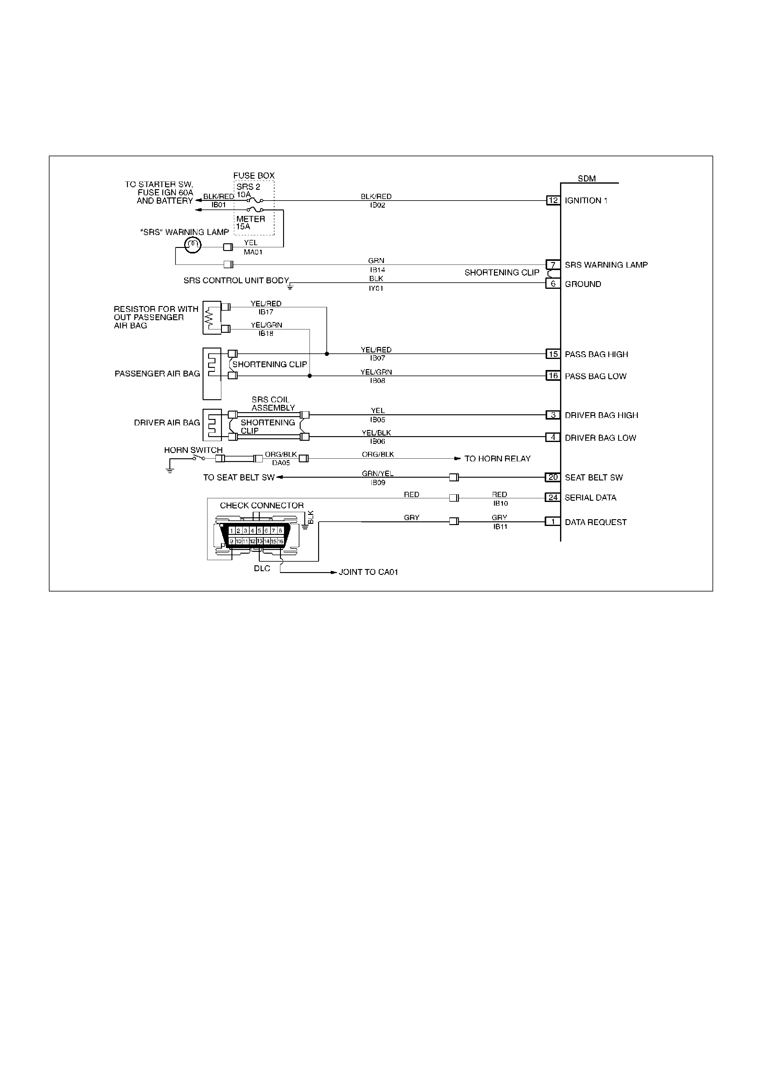
DTC 53Deployment Commanded With Deployment Loop Fault Or Energy
Reserves Out Of Range
D09LX00001
Circuit Description:
The SDM contains a sensing drive which converts
vehicle velocity changes to an electrical signal. The
electrical signal generated is processed by the SDM
and then compared to a value stored in memory.
When the generated signal exceeds the stored value,
the SDM will cause current to flow through the ai r bag
assembly deploying the air bags. DTC 53 is set
accompa nying with D TC 51 w hen a deployment occurs
while an air bag assembly circuit fault is present that
could possible result in a no deployment situation in
one or both air bag assemblies.
DTC Will Set When:
The SDM detects a frontal crash, up to 30 degrees off
the centerline of the vehicle, of sufficient force to
warrant deployment of the air bags and an inflator
circuit fault is present..
Action Taken:
SDM turns “ON" the “AIR BAG" warning lamp records
“Crash Data", and sets a diagnostic trouble code.
DTC Will Clear When:
The SDM is replaced. If DTC 53 is set, one or more
DTCs will be s et in ad dit ion to DTC 53 . Mal fun ction (s)
setting DTC(s) (other than DTC 71) must be repaired
so that DTC(s) will not be set when a new SDM is
installed.
DTC Chart Test Desc ription:
Number(s) below refer to step number(s) on the
diagno sti c ch art:
2. If air bag assembly have not deployed, DTC 53 may
have falsely set.
3. If DTC 53 has set with no si gns of frontal impact, the
diagnostic trouble code has falsely set.

DTC53Deployment Commanded WITH Deployment Loop Fault Or Energy Reserves
Out Of Range
WARNING: DURING SERVICE PROCEDURES. BE VERY CAREFUL WHEN HANDLING A SENSING AND
DIAGNOSTIC MODULE (SDM). NEVER STRIKE OR JAR THE SDM. NEVER POWER UP THE SRS WHEN THE
SDM IS NOT RIGIDLY ATTACHED TO THE VEHICLE. ALL SDM AND MOUNTING BRACKET FASTENERS MUST
BE CAREFULLY TORQUED AND THE ARROW MUS T BE POINTING TOWARD THE FRONT OF THE VEHICLE
TO ENSURE PROPER OPERATION OF THE SRS. THE SDM COULD BE ACTIVATED WHEN POWERED WHILE
NOT RIGIDLY ATTACHED TO THE VEHICLE WHICH COULD CAUSE DEPLOYMENT AND RESULT IN
PERSONA L INJURY.
Step Action Yes No
1 Was the “SRS Diagnostic System Check" performed?
Go to Step 2
Go to the “SRS
Diagnostic System
Check"
2 Ignition switch “OFF."
Have air bag assembles deployed? Replace
components and
perform
inspections as
directed in
“Repairs And
Inspections
Required After An
Acci den t" in thi s
section.
Clear diagnostic
trouble codes.
Repeat the “SRS
Diagnostic System
Check" Go to Step 3
3 Inspect front of vehicle and undercarriage for signs of impact.
Were signs of impact found? Replace
components and
perform
inspections as
directed in
“Repairs And
Inspections
Required After An
Acci den t" in thi s
section.
Clear diagnostic
trouble codes.
Repeat “SRS
Diagnostic System
Check"
Ignition switch
“OFF."
Replace SDM.
Reconnect all SRS
system
components,
ensure all
components are
properly mounted.
Repeat the “SRS
Diagnostic System
Check"

DTC 61 Warning Lamp Circuit Failure
D09LX00001
Circuit Description:
When the i gniti on switch is tur n ed “ON" , battery voltage
is applied to the “AIR BAG" warning lamp and to the
“Ignition 1" input terminal “12". The SDM responds by
flashing the “AIR BAG" warning lamp seven times. The
SDM monito rs the lamp dr iver output by compar ing th e
output stat e at “ S RS War ni ng L amp " terminal “ 7" to th e
microprocessor commanded state. When “Ignition 1"
is in the specified value, and the output state does not
match the co mmanded sta te of the lamp dri ver for 500
milliseconds, DTC 61 is set.
DTC Will Set When:
“Ignition 1" voltage is in the specified value and the
output state at the “SRS Warning Lamp" terminal does
not match the commanded state of the lamp driver for
500 milliseconds. This test is run every 100
milliseconds during “Continuous Monitoring" tests and
once per each ignition cycle at the beginning.
Action Taken:
SDM attempts to turn “ON" the “AIR BAG" warning lamp
and sets a diagnostic trouble code.
DTC Will Clear When:
The ignition switch is turned “OFF."
Diagnostic Aids:
Refer to Charts B and C to diagnose warning lamp
circuit malfunctions.

DTC 61 Warning Lamp Circuit Failure
Step Action Yes No
1 Was the “SRS Diagnostic System Check" performed?
Go to Step 2
Go to the “SRS
Diagnostic System
Check"
2 1. Malfunctions within the “AIR BAG" warning lamp circuitry will
set this diagnostic trouble code.
2. These malfunctions are addressed in the “SRS Diagnostic
System Check" via Chart B and Chart C.
3. Failure to properly perform the “SRS Diagnostic System
Check" m ay result in misdiagnosis.
4. Ignition switch “ON."
5. Clear SRS diagnostic trouble codes.
IS DTC 61 set?
Ignition switch
“OFF."
Go to Chart A
Repeat the “SRS
Diagnostic System
Check"
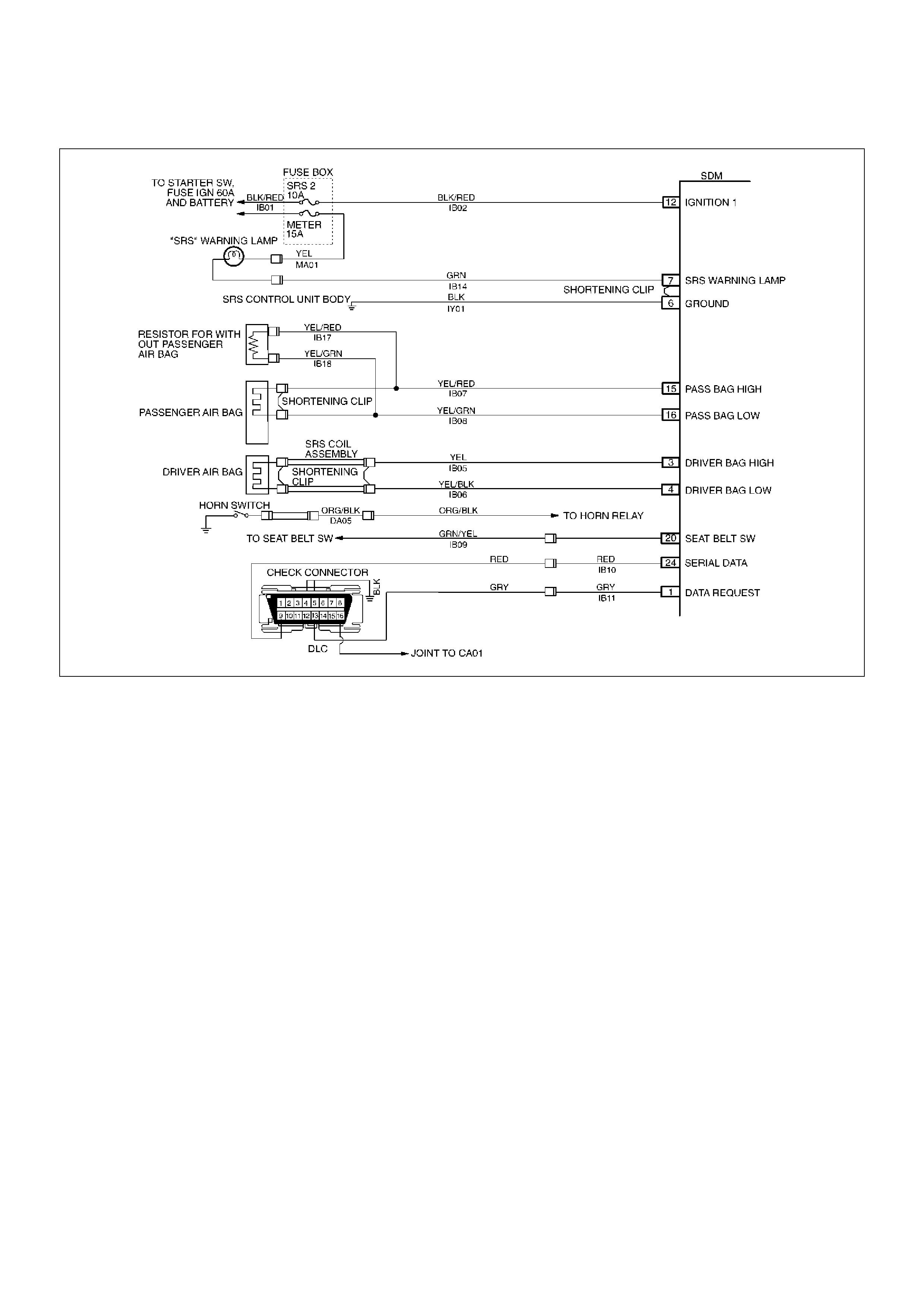
DTC 71 Internal SDM Fault
D09LX00001
Circuit Description:
DTC 71 is an indication of a potential internal SDM
malfunction and will set if any of the following
conditions are detected:
1) Deployment or microprocessor energy reserve
failure.
2) EEPROM failure.
3) ROM failure.
4) RAM failure.
5) Calibration check sum failure.
6) Deployment switch faults.
7) Accelerometer fault.
8) Arming sensor fault.
9) Diagnostic current faults.
10) DTC 19
11) DTC 25
12) DTC 51
13) DTC 53
DTC Will Set When:
Any of the above indicated malfunctions are detected by
the SDM. The malfunctions described above are
tested mainly during “Continuous Monitoring" and
some ones run each ignition cycle.
Action Taken:
SDM turns “ON" the “AIR BAG" war ning lamp and sets
a diagnostic trouble code.
DTC Will Clear When:
A scan tool “Clear Codes" commanded is received by
the SD M. Some of th e indicate d malfunc tions w ill only
allow the “AIR BA G" warning lamp to go out.
But when DTC 19, 25, 51, 53 are also set, SDM is
replaced.

DTC 71 Internal SDM Fault
WARNING: DURING SERVICE PROCEDURES. BE VERY CAREFUL WHEN HANDLING A SENSING AND
DIAGNOSTIC MODULE (SDM). NEVER STRIKE OR JAR THE SDM. NEVER POWER UP THE SRS WHEN THE
SDM IS NOT RIGIDLY ATTACHED TO THE VEHICLE. ALL SDM AND MOUNTING BRACKET FASTENERS MUST
BE CAREFULLY TORQUED AND THE ARROW MUST BE POINTING TOWARD THE FRONT OF THE VEHICLE
TO ENSURE PROPER OPERATION OF THE SRS. THE SDM COULD BE ACTIVATED WHEN POWERED WHILE
NOT RIGIDLY ATTACHED TO THE VEHICLE WHICH COULD CAUSE DEPLOYMENT AND RESULT IN
PERSONAL INJURY.
CAUTION: When DTC 19 or 25 has been set, it is necessary to replace the SDM. Setting DTC 19 and 25 or 51
or 53 will also cause DTC 71 to set. When a scan tool “CLEAR CODES" command is issued and the
malfunction is no longer present, DTC 51 or 53 and DTC 71 will remain current. Ensure that the short to
volta ge condition DTC 19, 25 is repaired prior to installing a replacement SDM to avoid damaging the SDM.
Step Action Yes No
1 Was the “SRS Diagnostic System Check" performed?
Go to Step 2
Go to the “SRS
Diagnostic System
Check"
2 Note SRS “Diagnostic System Check."
IS DTC 19 OR 25 OR 51 OR 53 ALSO SET (CURRENT OR
HISTORY)? (REFER TO CAUTION ABOVE.)
Go to DTC 19 if
DTC 19 is set.
Go to DTC 25 if
DTC 25 is set.
Go to DTC 51 if
DTC 51 is set.
Go to DTC 53 if
DTC 53 is set.
Ignition switch
“OFF."
Replace SDM.
Repeat the “SRS
Diagnostic System
Check"