
SECTION 2A - HEATER AND AIR CONDITIONING
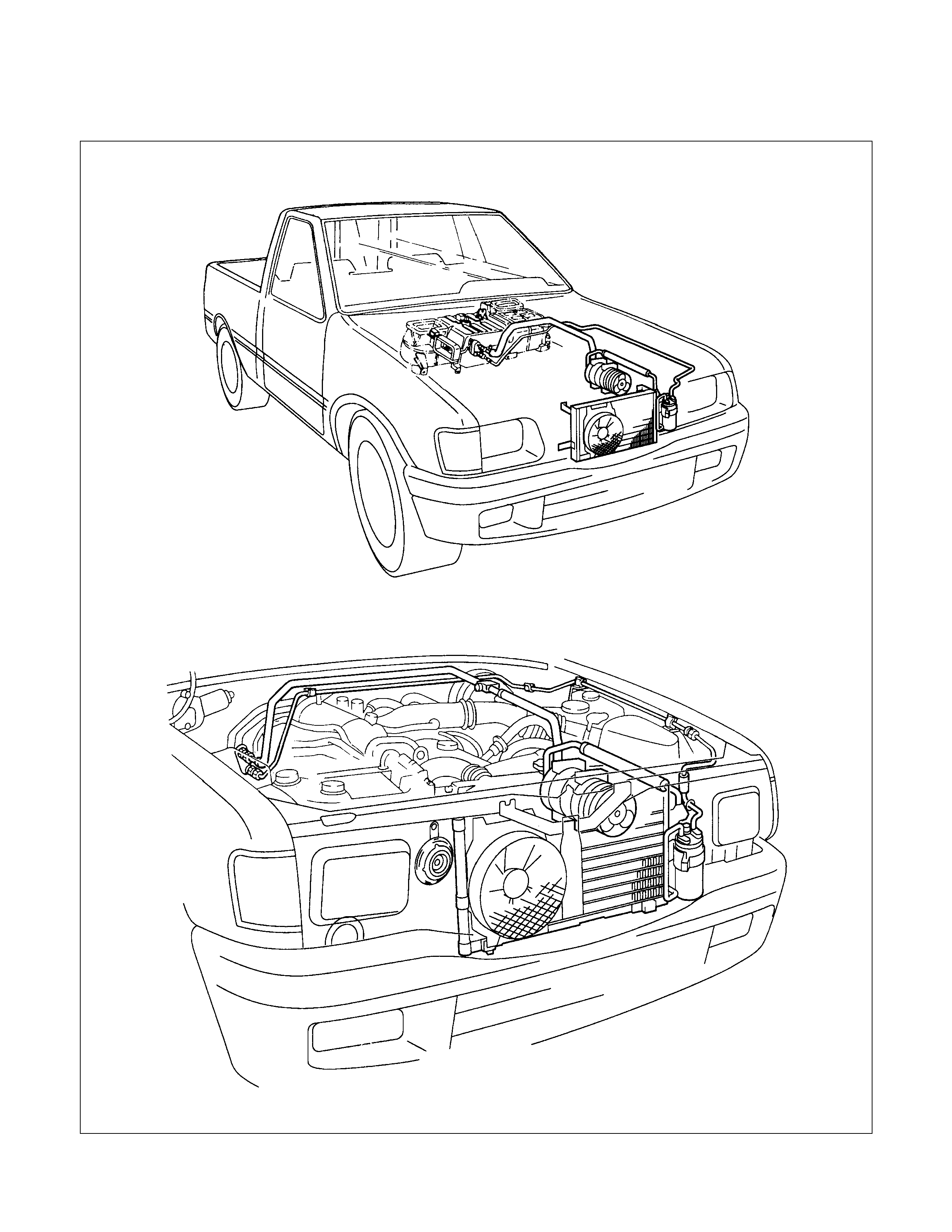
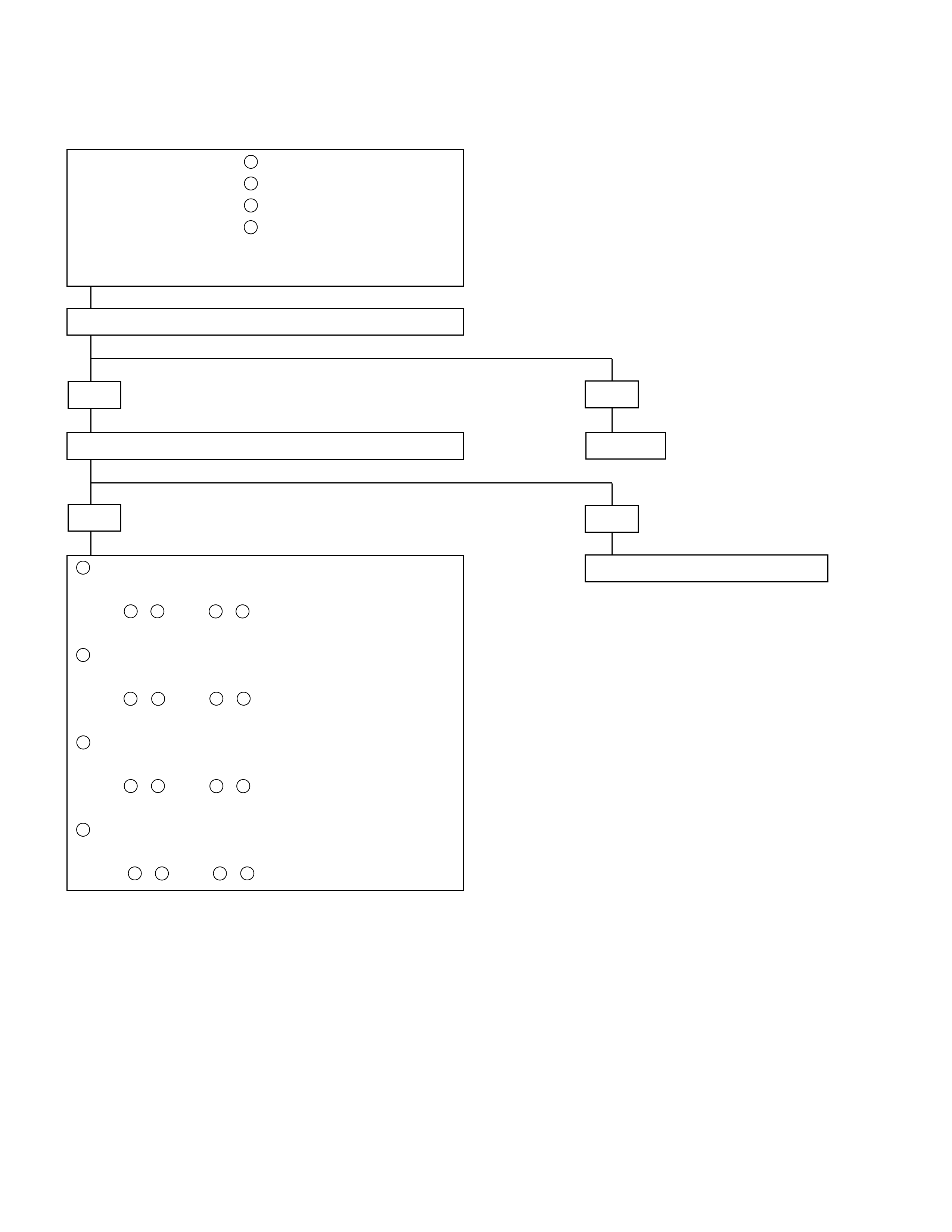
GENERAL DESCRIPTION
SYSTEM COMPONENTS
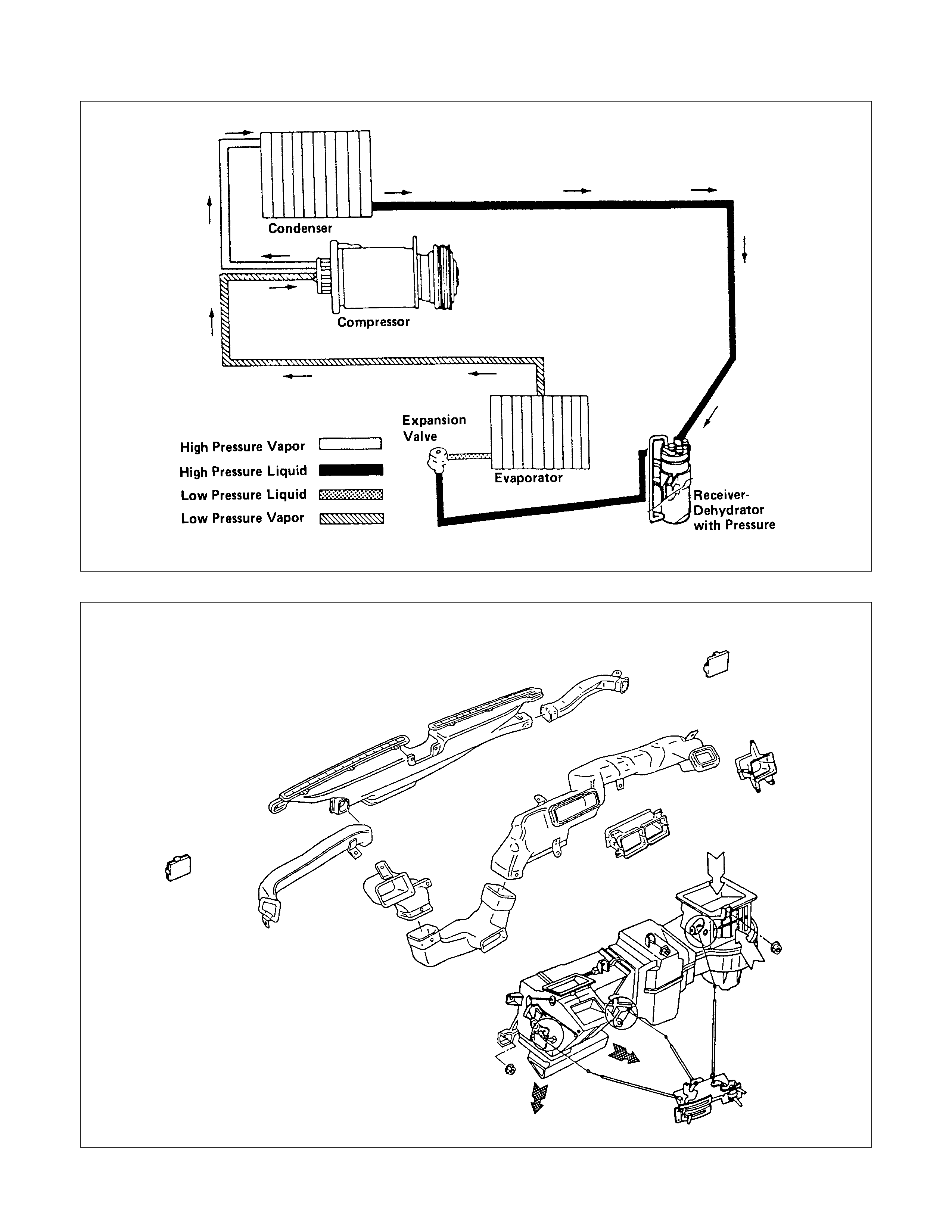
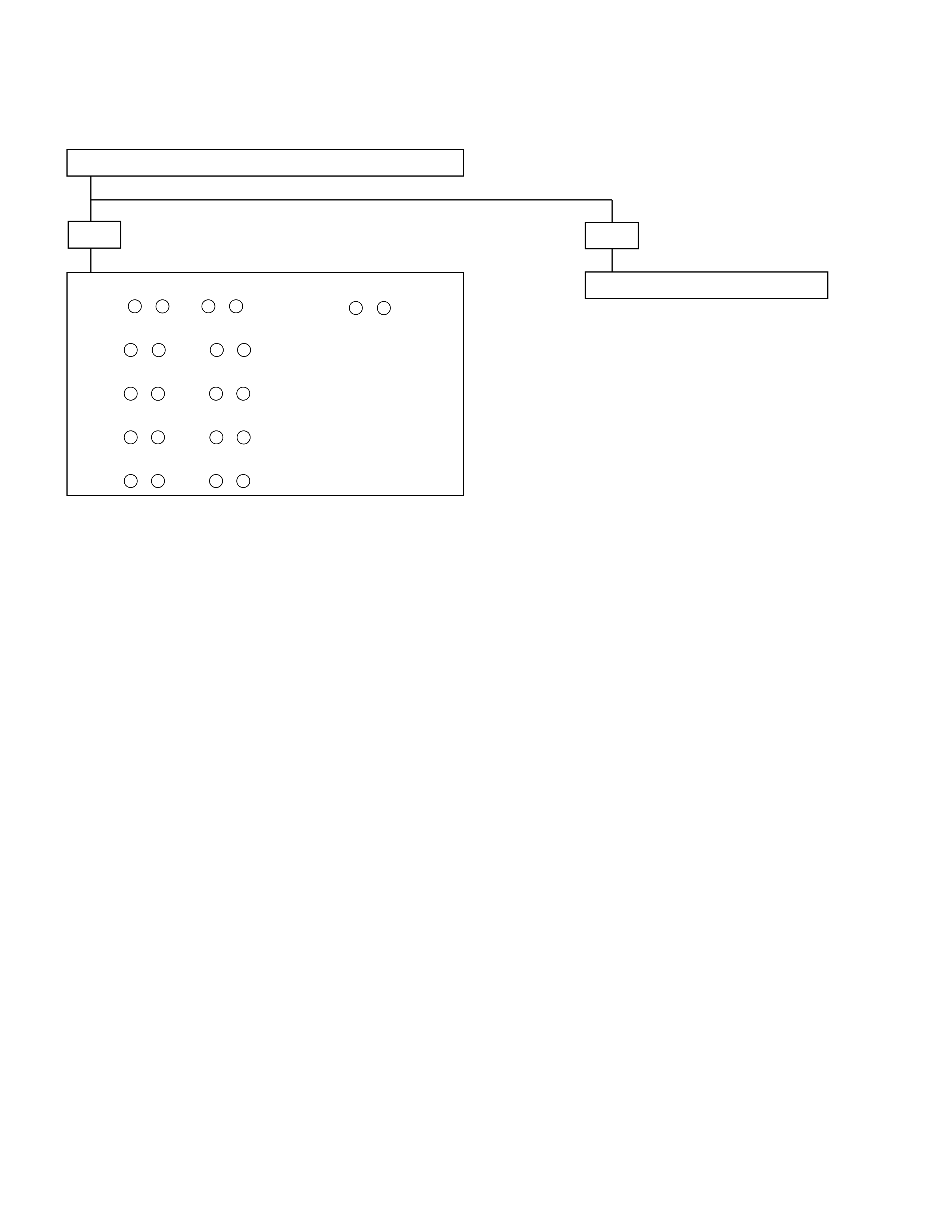
SYSTEM COOLING LINE
UNIT
WIRING DIAGRAM
WIRING HARNESS TERMINAL POSTIONS
VENTILATION
MAIN DATA AND SPECIFICATIONS
SPECIAL PARTS FIXING NUTS AND BOLTS
COMPRESSOR ASSEMBLY
REFRIGERATION SYSTEM (RHD MODEL)
SERVICING
PRECAUTIONS FOR REFRIGERANT - 134A (R-134A) AIR CONDITIONING SYSTEM
REPAIR OF REFRIGERANT LEAKS
LEAK AT REFRIGERANT LINE CONNECTIONS
LEAK IN THE HOSE
COMPRESSOR LEAKS
REPLACEMENT OF COMPONENT PARTS
RECOVERY, RECYCLING, EV ACUATION AND CHARGING
REFRIGERANT RECOVERY
REFRIGERANT RECYCLING
EVACUATION OF THE REFRIGERANT SYSTEM
CHARGING THE REFRIGERANT SYSTEM
CHARGING P ROCE DURE
CONDENSER
REMOVAL AND INSTALLATION
RECEIVER DE HYDRATOR
REMOVAL AND INSTALLATION
Techline
Techline
Techline
Techline
Techline
Techline
Techline
Techline
Techline

COMPRESSOR
REMOVAL AND INSTALLATION
GENERAL REPAIR PROCEDURE
DISASSEMBLY
REASSEMBLY
HEATER UNIT
REMOVAL AND INSTALLATION
DISASSEMBLY AND REASSEMBLY
EVAPORATOR
REMOVAL AND INSTALLATION
DISASSEMBLY AND REASSEMBLY
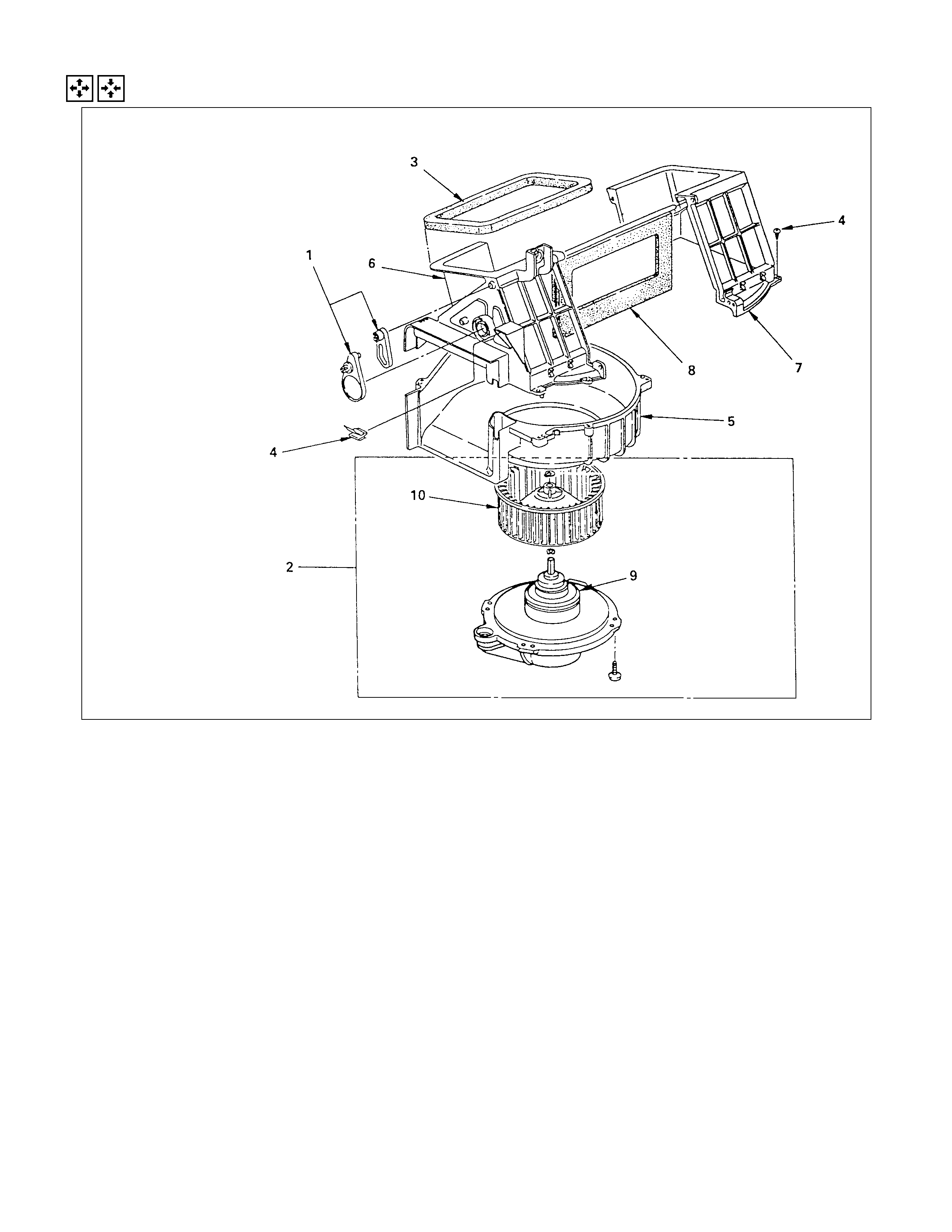
BLOWER UNIT ASSEMBLY
REMOVAL AND INSTALLATION
DISASSEMBLY AND REASSEMBLY
CONTROL LEVER ASSEMBLY
REMOVAL AND INSTALLATION
INSPECTION AND REPAIR
CONDENSER FAN MOTOR
REMOVAL
INSTALLATION
TROUBLESHOOTING
SPECIAL SERVICE TOOL
GENERAL DESCRI PTION
SYSTEM COMPO NENTS
These illustrations are based on the LHD model.
SYSTEM COOLI NG LINE
UNIT
This illustration is based on the LHD model.
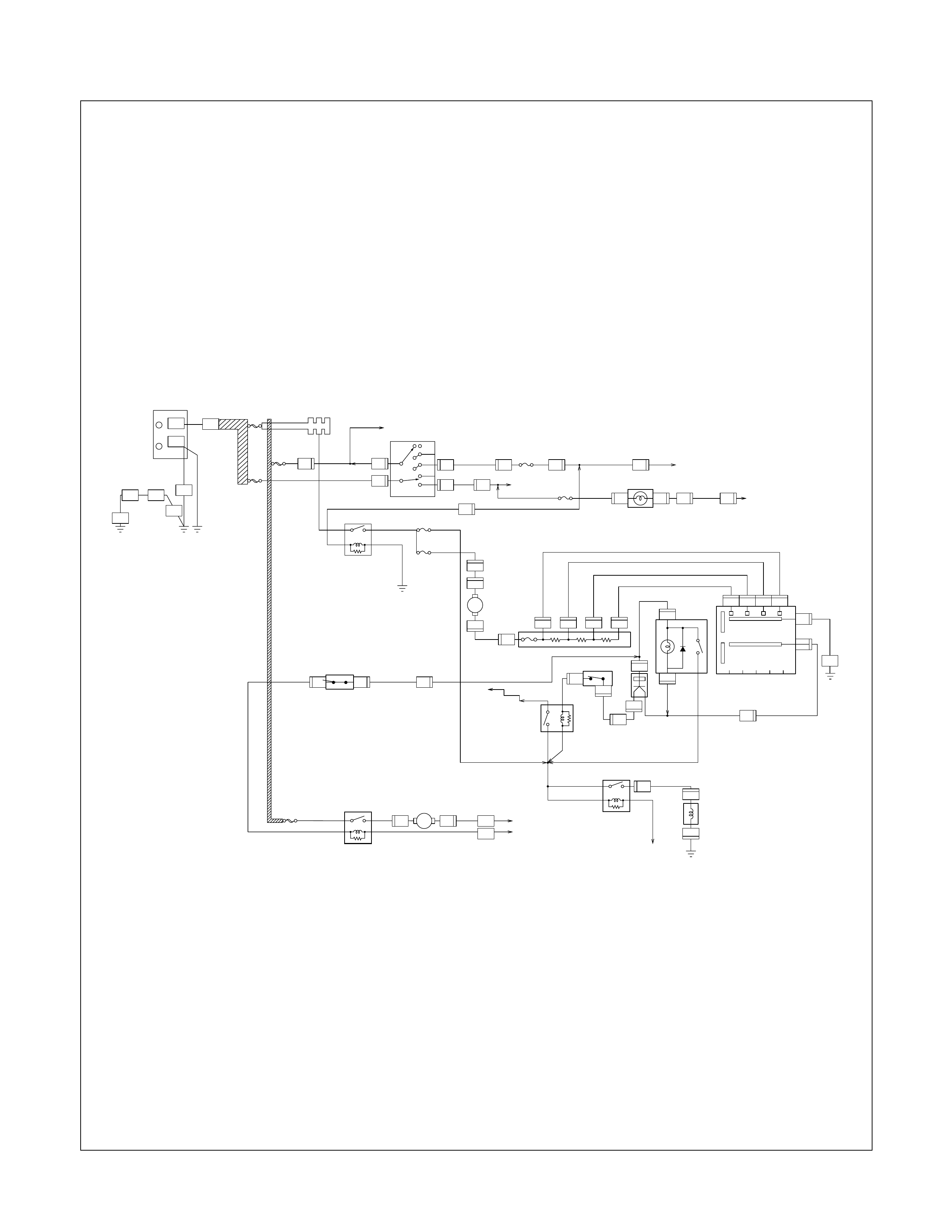
WIRI NG DIAGRAM
8B
20B
+
-
6V
2B
8BR
SW;IGNITION
OFF
IG1
ST
IG2
ACC BACK TURN
15A
EB-5
A/C
10A
EB-5
A/C
10A
CB-7
METER
15A
3W
3B 3L/R 1.25BR
2L/W
2L/B
0.5B
FRAME
ENG
BODY
0.85W
3W
3W/B
IGN
B-1
50A
IGN B-2
40A
MAIN
80A
3
H-7 C-41
1
C-41
8
H-7
6
H-8
8
B-24
2
B-23
13
H-8
15
H-1
1
H-5
3
C-41
6
H-7
2
C-41
3
3B/R
3B/Y 0.85W
0.85Y 0.85W/L
3B/R
FUSE;ENGINE
FUSE;CHARGE
SW;BACK UP
METER
CHARGE W/L
RELAY;
HEATER
RELAY;
CONDENSER
FAN
RELAY;
A/C COMP
RELAY;
THERMO
EARTH
H-8
10
B-13
4
B-3
1
B-3
2
M
B-1
2
OFF L M3M2H
CONTROL LEVER
B-13
5
B-13
6
B-13
3
C-2
B-13
1
B-13
2
2L/R
1.25L
0.85L/Y
0.85L/W
B-1
3
B-1
6
B-1
4
B-1
1
RESISTOR
2B
EARTH
B-2
20.5W
B-12
2
B-2
3
B-12
3
0.5W/B
SW;A/C
0.5W
0.5G/R
0.5G/W0.5BR
0.5GR/R
MAGNET
CLUTCH
1.25BR
BUS BAR NO.2
(MICRO ISO)
THERMO
B-2
1
C-24
1
H-8
13
C-24
4
H-6
19
C-24
2
C-24
3
C-92
1
C-92
2
C-95
C-95
SW;
PRESSURE
2G/B
TO ECM
(B10)
0.5BR
1.25BR 1.25BR/L
0.5BR
1.25BR
3L/R 2L 1.25B
0.5R/Y
0.5R/Y 0.5W/B
(MINI ISO)
TO ECM(A16)
H-20
14
EARTH
EARTH
CONDENSER
FAN
30A
M
CONDENSER
FAN
0.5B
B2
B1
BLOWER
H-5
3
SW;
PRESSURE
E-6
1
E-6
2
P-10
P-10
P-1
P-5
P-7
B-28 C-95
P-12
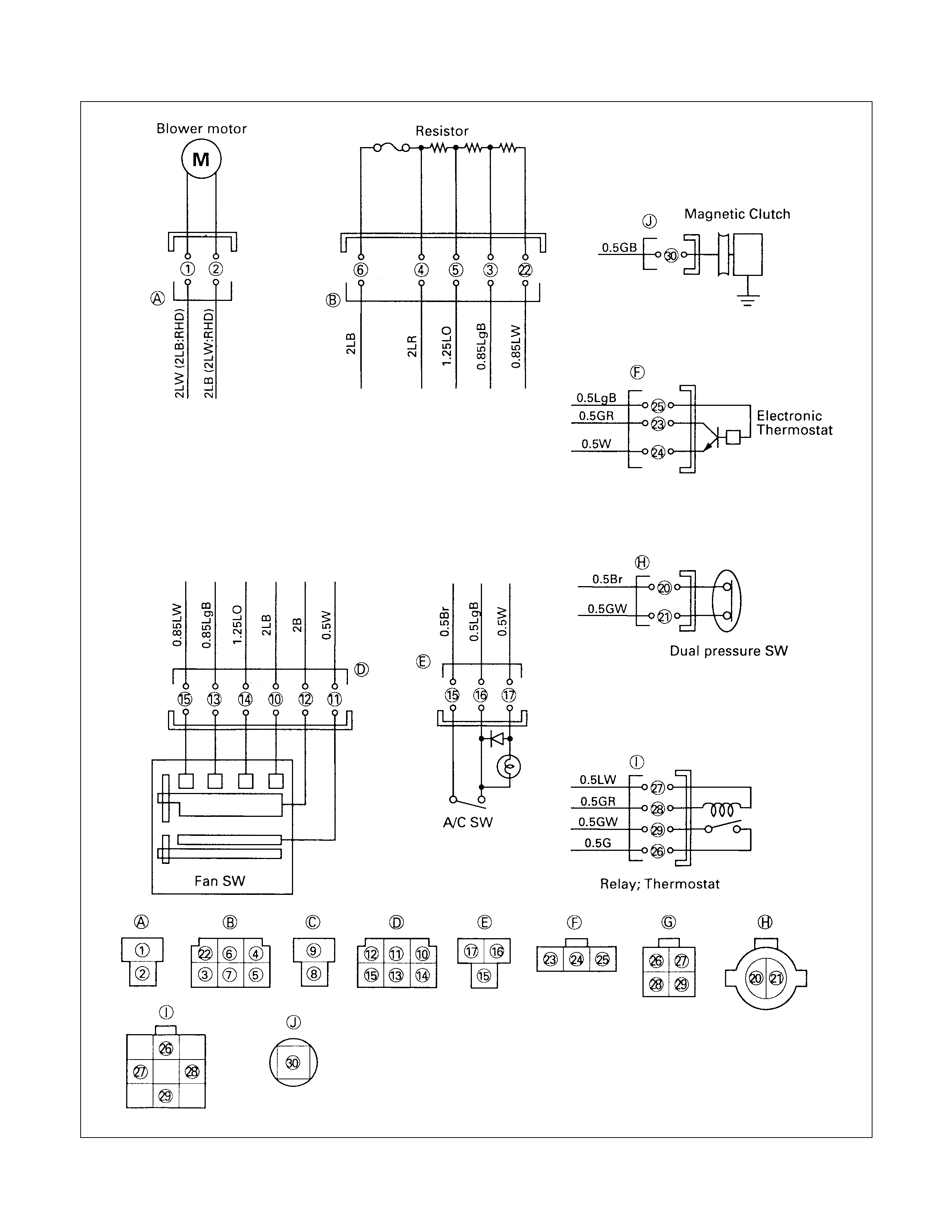
WIRI NG HARNESS TERMINAL POSITIONS
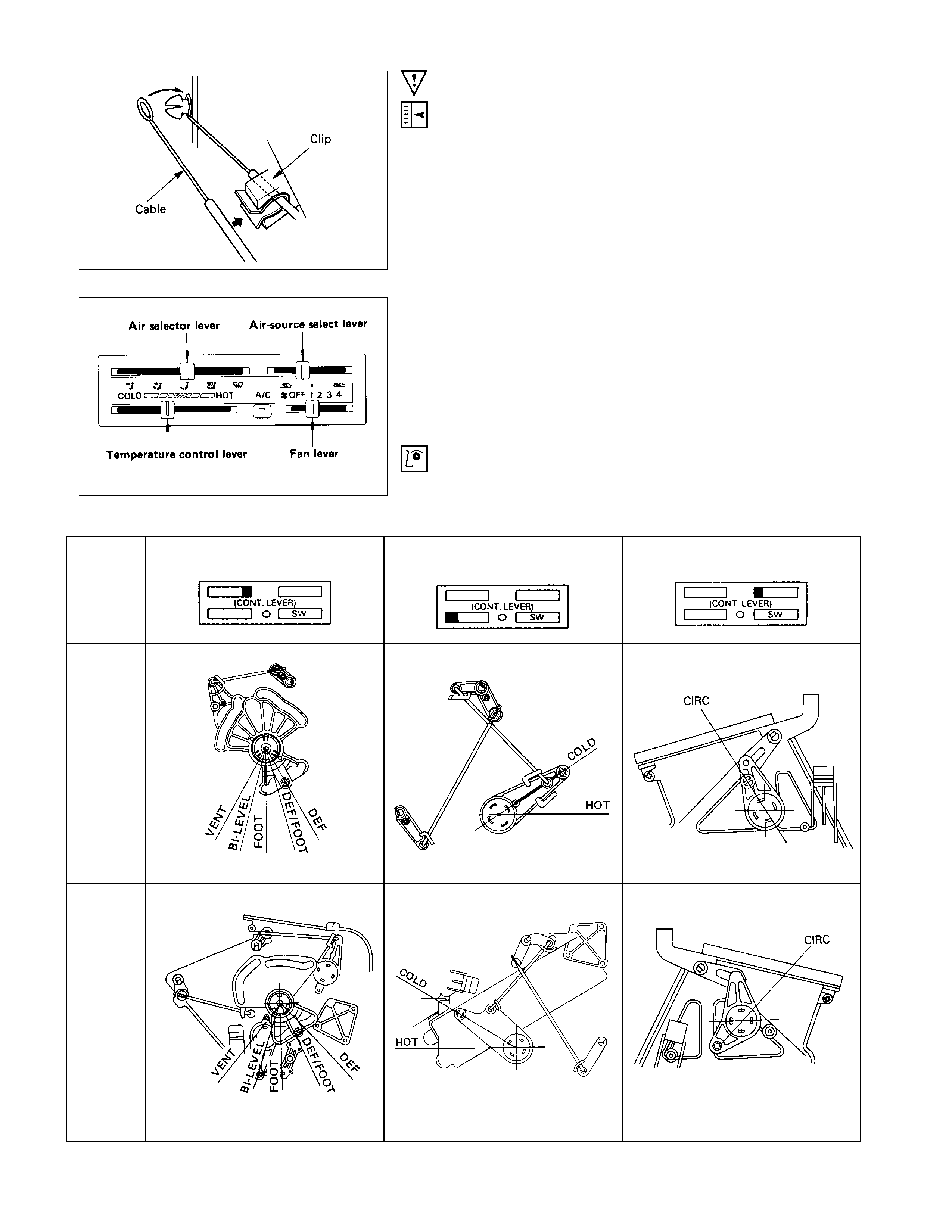
VENTILATION
VENT MODE BI⋅LEVEL MODE FOOT MODE
DEF/FOOT MODE DEF MODE

MAIN DATA AND SPECIFICATIONS
AIR COMPRESSOR
Type 6 cylinder swash plate type
Displacement cc (lmp fl oz) 147 (4.2)
Oil type ZXL-100PG
(ISUZU PART NO. 8-97101-338-0)
Oil capacity cc (lmp fl oz) 150 (4.2)
Magnetic clutch Type: Dry double disc dia. 135 mm (5.3 in.) (Gasoline)
125 mm (4.9 in.) (4J engine)
HEATING UNIT
Type Air mix type
Core dimension mm (in.) (L×H×W) 161 (6.34) ×163 (6.42) ×45 (1.77)
Capacity (kcal./hr.) 3700 kcal./hr. (280 m3/hr.)
BLOWER UNIT
Type Sirocco fan type
COOLING UNIT
Type Fin and tube evaporator
Evaporator element dimensions mm (in.) (L×H×W) 235 (9.25) ×224 (8.82) ×74 (2.91)
Evaporator capacity (kcal./hr.) 4200 kcal./hr. (470 m3/hr.)
CONDENSER
Type Aluminium louvered fins
Capacity (kcal./hr.) 9400 kcal./hr.
RECEIVER-DEHYDRATOR Assembly includes sight glass
and temperature sensitive device
REFRIGERANT Type: R-134a Capacity: 0.65 kg (1.43 lbs.)
IDLE SPEED-UP CONTROL Idle speed controlled by solenoid switch
SPECIAL PARTS FIXING NUTS AND BOLTS
COMPRESSO R ASSEMBLY
N⋅
⋅⋅⋅m (kgf⋅
⋅⋅⋅m/lb⋅
⋅⋅⋅ft)
REFRIGERATION SYSTEM ( RHD MODEL)
N⋅
⋅⋅⋅m (kgf⋅
⋅⋅⋅m/lb⋅
⋅⋅⋅ft)
H/U
EVAPO
ENG.ENG.
20-29 (2.0-3.0/14-22) 10-20 (1.0-2.0/7.2-14)
10-20 (1.0-2.0/7.2-14)
27-34 (2.8-3.5/20-25)
4-8 (0.4-0.8/3-6)
SERVICING
This illustration is based on the LHD
model.
PRECAUTIO NS FO R REFRIGERANT-134A (R-134A)
AIR CONDITIONING SYSTEM
Vehicles that use Refrigerant-134a (R-134a) in the air
conditioning system have a caution plate fixed to the rear wall
of the engine compartment. Also, components designed solely
for use with R-134a are so marked, to distinguish them from
components designed solely for use with Refrigerant-12 (R-
12).
R-12 and R-134a systems require different types of lubricating
oil. components designed solely for use with one refrigerant
and oil type must never by interchange with components
designed solely for use with another refrigerant and oil type.
R-134A REFRIGERANT:
•R-134a differs entirely from R-12 in its composition and,
therefore, the two should never by mixed. Always charge
the specified amount of R-134a.
•The pressure characteristics of R-134a differ from those o
f
R-12. The low pressure is lower, and the high pressure is
higher.
R-134A COMPRESSO R OIL:
•The R-134a s ystem requires a synthetic (PAG) com presso
r
oil whereas the R-12 system requir es a mineral compr ess o
r
oil. The two oils must never be mixed.
•Compressor (PAG) oil varies according to compresso
r
model. Be sure to use oil specified for the model o
f
compressor.
Oil Specification ZXL-100PG
(ISUZU PART NO. 8-97101-338-0)
Techline
Techline
•The PAG compressor oil for the R-134a system tends to
absorb moisture more quickly than mineral oil. When ai
r
conditioning parts are removed for servicing, all the open
ends of parts and com ponents must be s ealed with caps to
keep out contaminants.
•The PAG compressor oil must be stored in metal
containers, not in plastic containers.
R-134a
SERVICE CHARGE VALVE:
•The diameter of the service charge valve for the R-134a
system is made larger than that for the R-12 system to
prevent cross-contamination. In addition, the screw-in type
joint of the R-12 sys tem Is replaced with a quick joint type in
the R-134a system.
•To pr event refrigerant f rom esc aping during installation and
removal of charging hoses from the service charge valves,
quick-joint type fittings are used.
Connection: Push on firmly until locked (a "click" will be
heard).
Removal : Hold the grip-ring and pull to remove.
•
A
ir conditioning m anifold gauges , charging hoses and othe
r
service tools designed exclusively for the R-134a system
must be used with this vehicle.
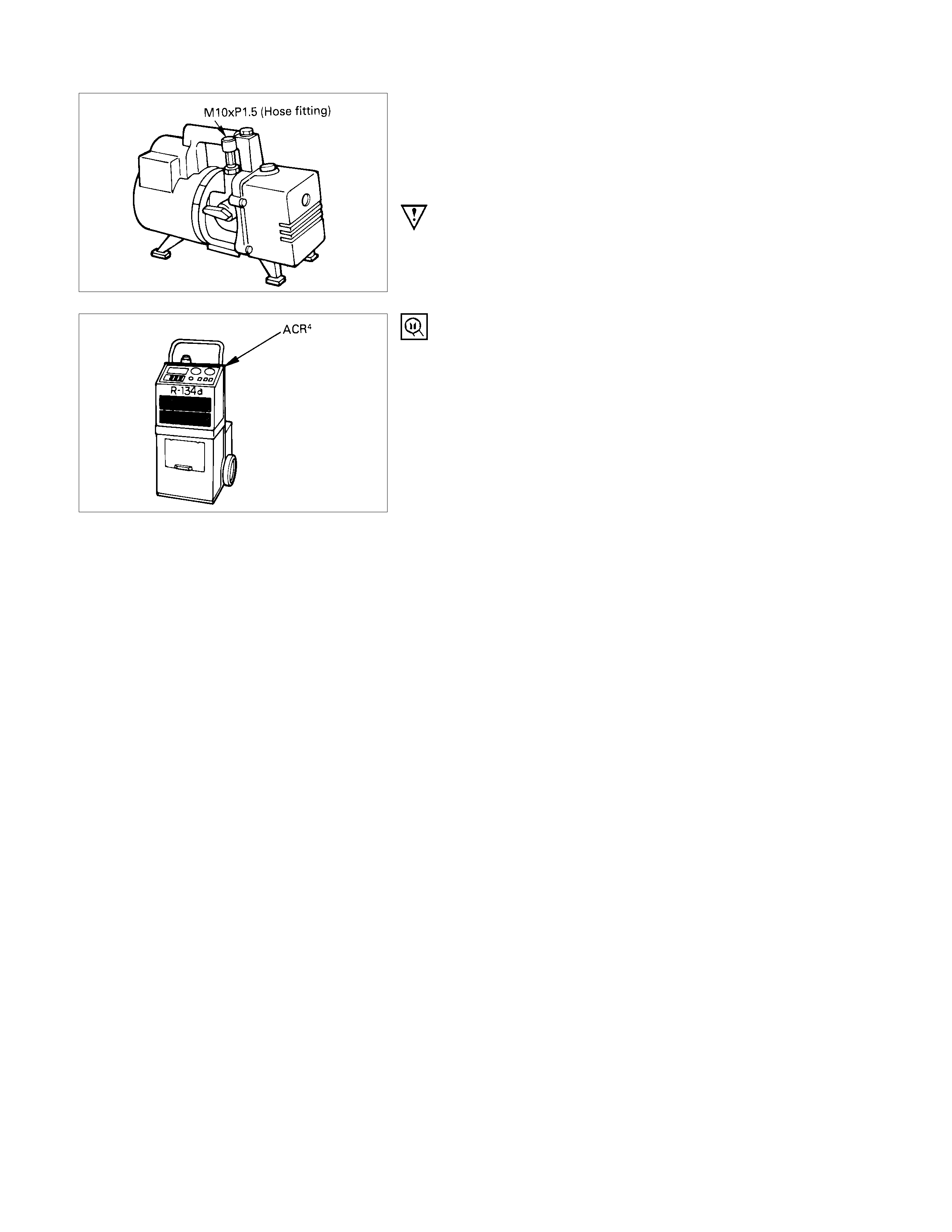
•Do not use the same vacuum pump for evacuating the R-
134a and R-12 systems interchangeably (The vacuum
pump hose fitting is a M10×1.5).
•R-134a vacuum pumps must have a positive shutoff valve.
CAUTION:
Never use the same vacuum pump for both R-134a and R-
12 systems, as cross contamination of compressor oil
may occur.
REFRIGERANT RECOVERY, RECYCLING AND
CHARGING
•R Avoid releasing the R-134a into the atmosphere.
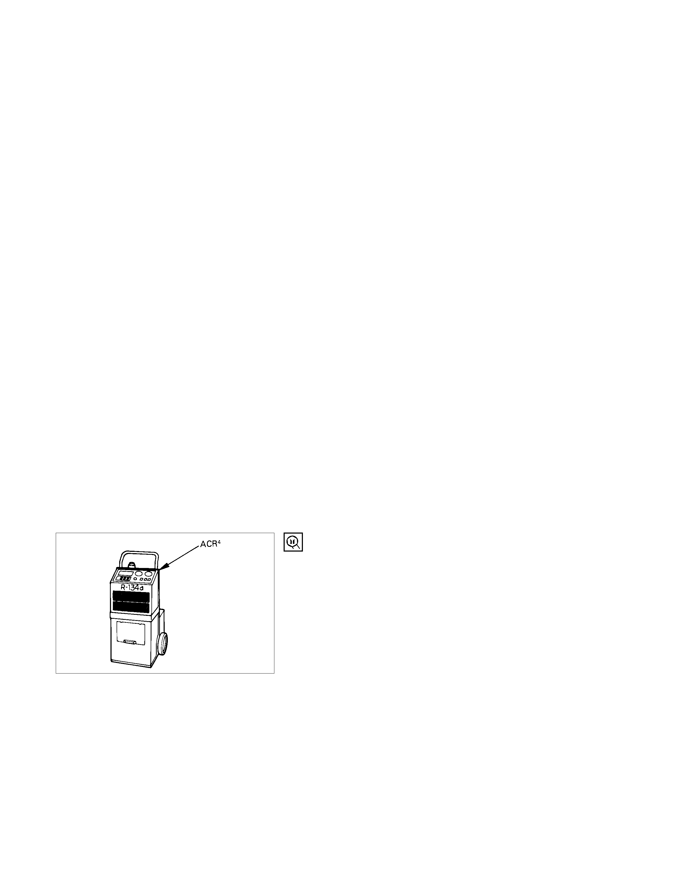
Use the ACR4 (R-134a Refrigerant Recovery/Recycling/
Recharging/System) or equivalent to r ec over and r ec ycle R-
134a. Note that the ACR4 (or equivalent) is not
interchangeable between the R-134a and R-12 systems.
ACR4 (115V 60 Hz) : 5-8840-0629-0 (J-39500-A)
ACR4 (220-240V 50/60 Hz)
: 5-8840-0630-0 (J-39500-220A)
ACR4 (220-240V 50/60 Hz Australian model)
: 5-8840-0631-0 (J-39500-220ANZ)
REFRIGERANT LEAK INSPECTION
•The flame type gas leak detector for the R-12 system
cannot be used with the R-134a system.
•The electric leak detector for the R-12 cannot be used with
the R-134a system as the R-134a particles are far smalle
r
than the R-12 molec ules and, therefore, m ay not be always
detected. Use leak detectors designed exclusively for the
R-134a system.
Refrigerant liquid line
Pressure switch
Refrigerant discharge line
Refrigerant suction line
Evaporator
Compressor
Receiver/drier
Condenser
PRECAUTIO NS FOR REPLACEMENT OR REPAIR OF
R-134A AIR CONDITIONING PARTS
There are certain procedures, practices and precautions that
should be followed when servicing air conditioning systems:
•Keep your work area clean.
•Always wear safety goggle and protective gloves when
working on refrigerant systems.
•Beware of the danger of c ar bon monoxide f umes caus ed by
running the engine.
•Beware of discharged refrigerant in enclosed or improperly
ventilated garages.
•Always disconnect the negative battery cable and discharge
and recover the refrigerant whenever repairing the ai
r
conditioning system.
•When discharging and recovering the refrigerant, do not
allow refrigerant to discharge too fast; it will dra
w
compressor oil out of the system.
•Keep moisture and contaminants out of the system. W hen
disconnecting or removing any lines or parts, use plugs o
r
caps to close the fittings immediately.
Never remove the caps or plugs until the lines o
r
reconnecting the lines, use two wrenches to s upport the line
fitting, to prevent from twisting or other damage.
•Always install new O-rings whenever a connection is
disassembled.
•Before connecting any hoses or lines, apply new specified
compressor oil to the O-rings.
•When removing and replacing any parts which require
discharging the refrigerant circuit, the operations described
in this section must be performed in the following sequence:
1) Using the ACR4 (R-134a Refrigerant Recovery/
Recycling/Recharging/System) or equivalent to
thoroughly discharge and recover the refrigerant.
ACR4 (220-240V 50/60Hz Australian model)
: 5-8840-0631-0 (J-39500-220ANZ)
2) Remove and replace the defective part.
3) After evac uation, charge the air conditioning s ystem and
check for leaks.
REPAIR OF REFRIGERANT LEAKS
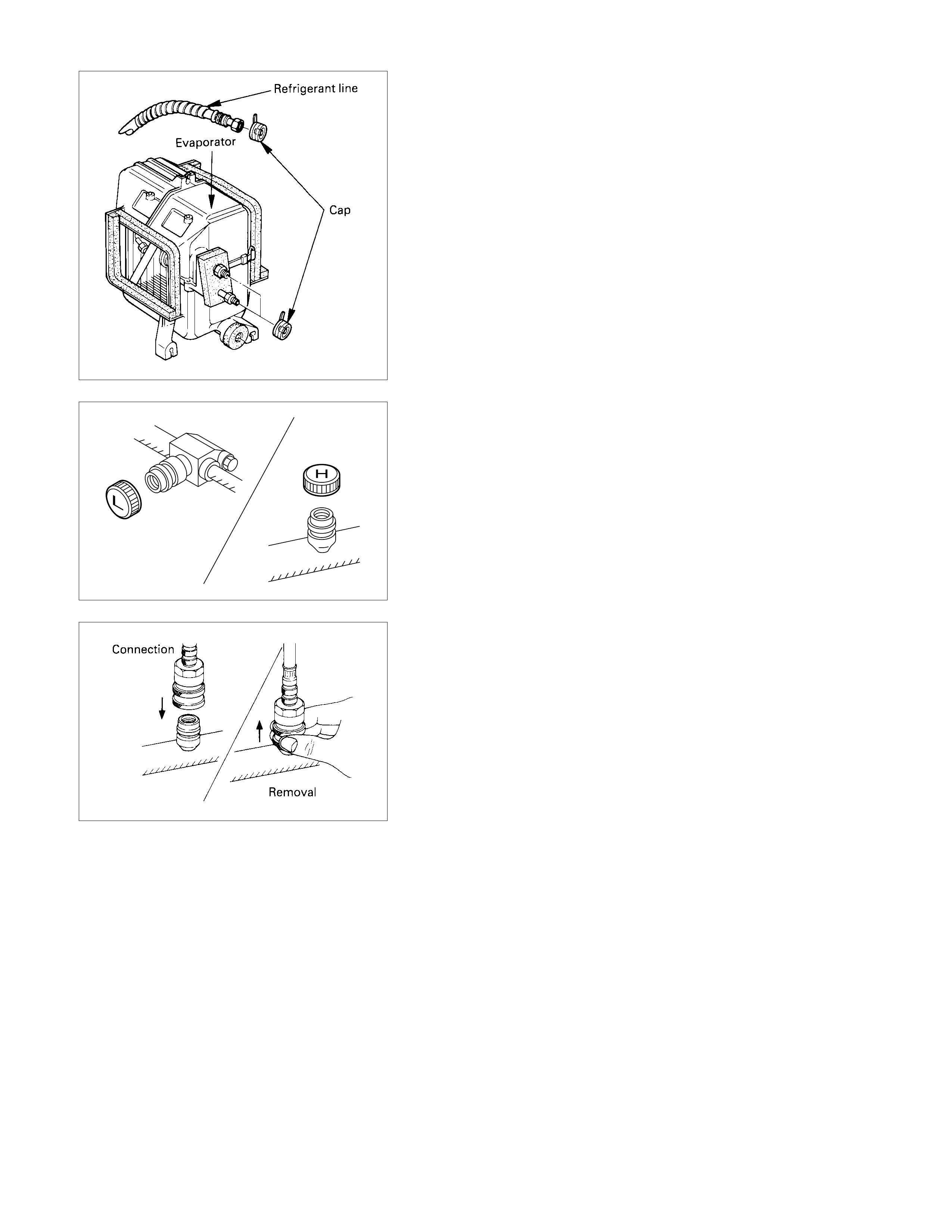
REFRIGERANT LINE CONNECTIONS
Install new O-ring, if required. When disconnecting or
connecting lines, use two wrenches to prevent the connecting
portion from twisting or becoming damaged.
O-ring
Block joint
When connecting the refrigerant line at the block joint, securely
insert the projecting portion of the joint portion into the
connecting hole on the unit side and secure with a bolt.
Apply specified compressor oil to the O-rings prior to
connecting.
CAUTION:
Compressor (PAG) oil to be used varies according to
compressor model. Be sure to apply oil specified for the
model of compressor.
O-rings must be fitted in the groove (1) of refrigerant line.
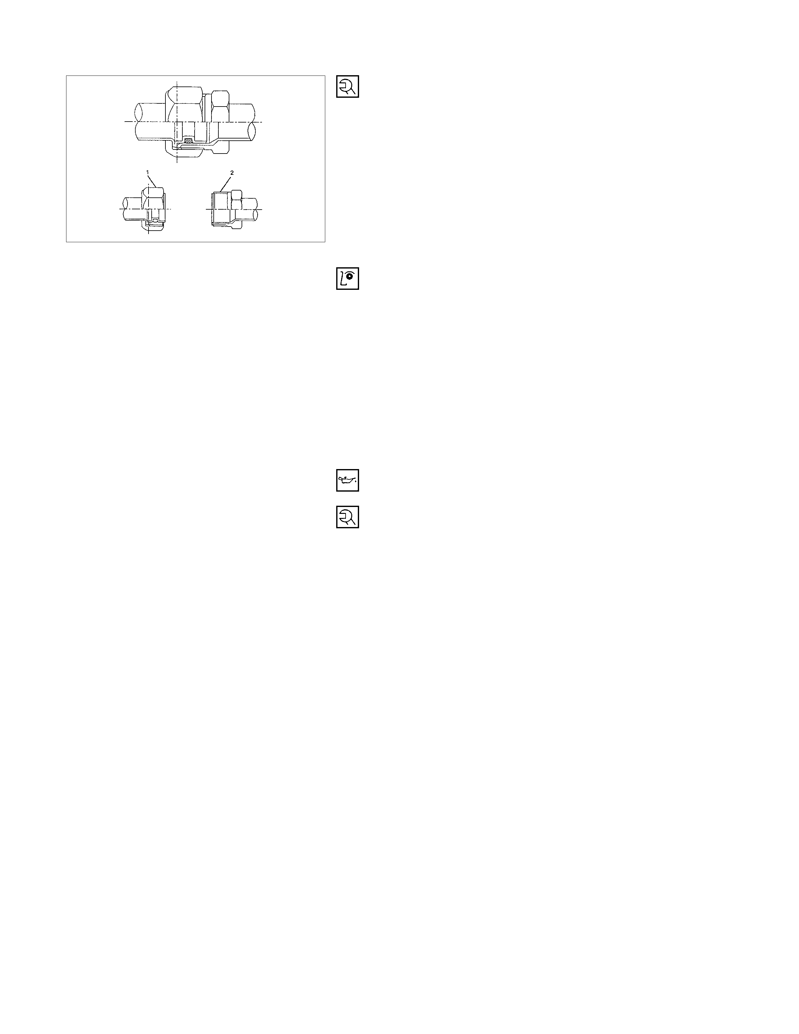
Insert the nut into union. First tighten nut by hand as much as
possible. Then, tighten nut to specified torque.
(Refer to "Special Parts Fixing Nuts and Bolts" in this
section)
LEAK AT REFRIGERANT LINE CONNECTIONS
1) Check the torque on the refrigerant line fitting and, if too
loose, tighten to the specified torque.
•Use two wrenches to prevent twisting and damage to the
line.
•Do not over tighten.
2) Perform a leak test on the refrigerant line fitting.
3) If the leak is still present, discharge and recover the
refrigerant from the system.
4) Replace the O-rings.
•O-rings cannot be reused. Always replace with ne
w
ones.
•Be sure to apply specified compressor oil to the new O-
rings.
5) Retighten the refrigerant line fitting to the specified torque.
•Use two wrenches to prevent twisting and damage to the
line.
6) Evacuate, charge and retest the system.
LEAK IN THE HOSE
If the compressor inlet or outlet hose is leaking, the entire hose
must be replaced. Refrigerant hose must not be cut or spliced
for repair.
1) Locate the leak.
2) Discharge and recover the refrigerant.
3) Remove the hose assembly.
•cap the open connections at once.
4) Connect the new hose assembly.
•Use two wrenches to prevent twisting or damage to the
hose fitting.

•Tighten the hose fitting to the specified torque.
5) Evacuate, charge and test the system.
COMPRESSO R LEAKS
If leaks are located around the compressor shaft seal or shell,
replace the compressor.
REPLACEM ENT O F COMPONENT PARTS
When replacing system component parts, supply the following
amount of oil to the component parts to be installed.
cc (lmp fl oz)
Component parts to be installed Amount of oil
Evaporator 50 (1.4)
Condenser 30 (0.8)
Receiver /drier 30 (0.8)
Refrigerant line (one piece) 10 (0.3)
RECOVERY, RECYCLI NG, EVACUATION AND
CHARGING
HANDLING REFRIG ERANT 134A
Air conditioning systems contain R-134a.
This is a chemical mixture which requires special handling
procedures to avoid personal injury.
•Always wear safety goggles and protective gloves.
•Always work in a well-ventilated area. Do not weld or steam
clean on or near any vehicle-installed air conditioning lines
or components.
•If R-134a s hould come in contac t with any part of the body,
flush the exposed area with cold water and immediately
seek medical help.
•If it is necessary to transport or carry any container of R-
134a in a vehicle, do not carry it in the passenge
r
compartment.
•If it is necessary to a fill a small R-134a container from a
large one, never f ill the container c ompletely. Space s hould
always be allowed above the liquid for expansion.
•R-134a and R-12 should never by mixed as thei
r
compositions are not the same.
•R-134a PAG oil tends to absor b m oisture m or e quick ly than
R-12 mineral oil and, therefore, should be handled more
carefully.
•Keep R-134a containers stored below 40°C (100°F).
WARNING:
•
••
•SHOULD R-134a CONTACT YOUR EYE(S), CONSULT A
DOCTOR IMMEDIATELY.
•
••
•DO NOT RUB THE AFFECTED EYE(S). INSTEAD,
SPLASH QUANTITIES OF FRESH COLD WATER OVER
THE AFFECTED AREA TO GRADUALLY RAISE THE
TEMPERATURE OF THE REFRIGERANT ABOVE THE
FREEZING POINT.
•
••
•OBTAIN PROPER MEDICAL TREATMENT AS SOON AS
POSSIBLE. SHOULD THE R-134a TOUCH THE SKIN,
THE INJURY MUST BE TREATED THE SAME AS SKIN
WHICH HAS BEEN FROSTBITTEN OR FROZEN.
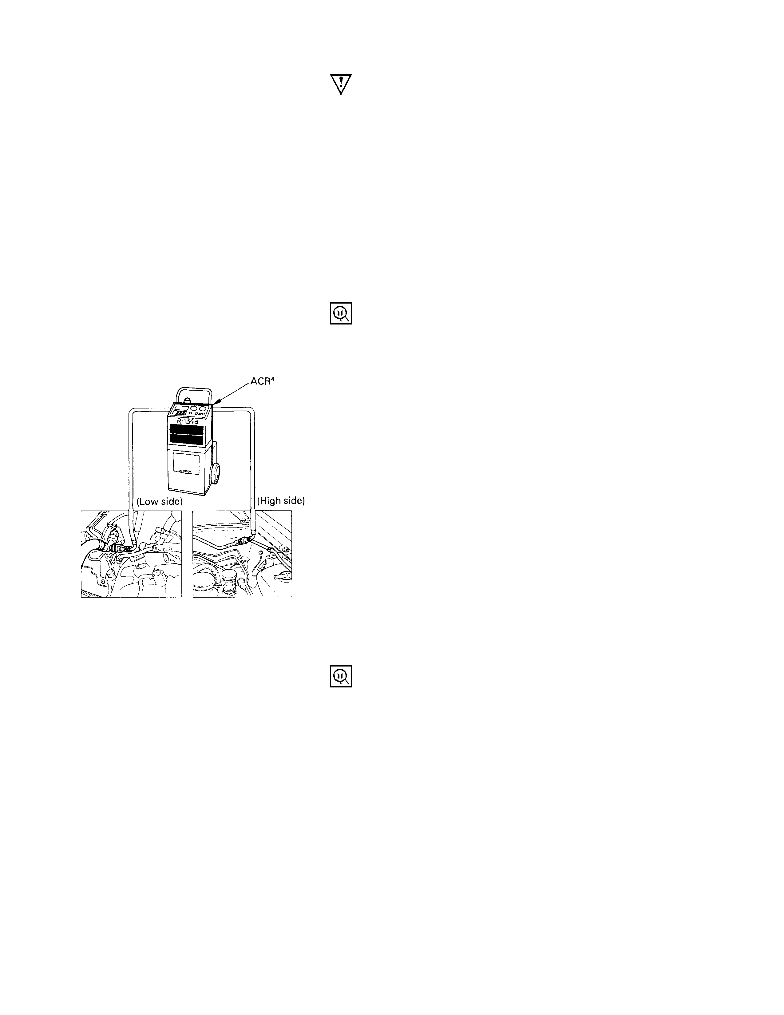
REFRIGERANT RECOVERY
The refrigerant must be discharged and recovered by using the
ACR4 (R-134a Refrigerant Recovery/Recycling/Recharging/
System) or equivalent before removing or installing air
conditioning parts.
ACR4 (220-240V 50/60Hz Australian model)
: 5-8840-0631-0 (J-39500-220ANZ)
1) Connect the high and low charging hoses of the ACR4(o
r
equivalent) as shown.
2) Recover the refrigerant by following the ACR4
Manufacturer's Instructions.
3) When a part is removed, put a cap or a plug on the
connecting portion so that dust, dirt or moisture cannot get
into it.
REFRIGERANT RECYCLING
Recycle the refrigerant recovered by the ACR4 or equivalent.
For the details of the actual operation, follow the steps in the
ACR4 Manufacturer's Instructions.
ACR4 (220-240V 50/60Hz Australian model)
: 5-8840-0631-0 (J-39500-220ANZ)
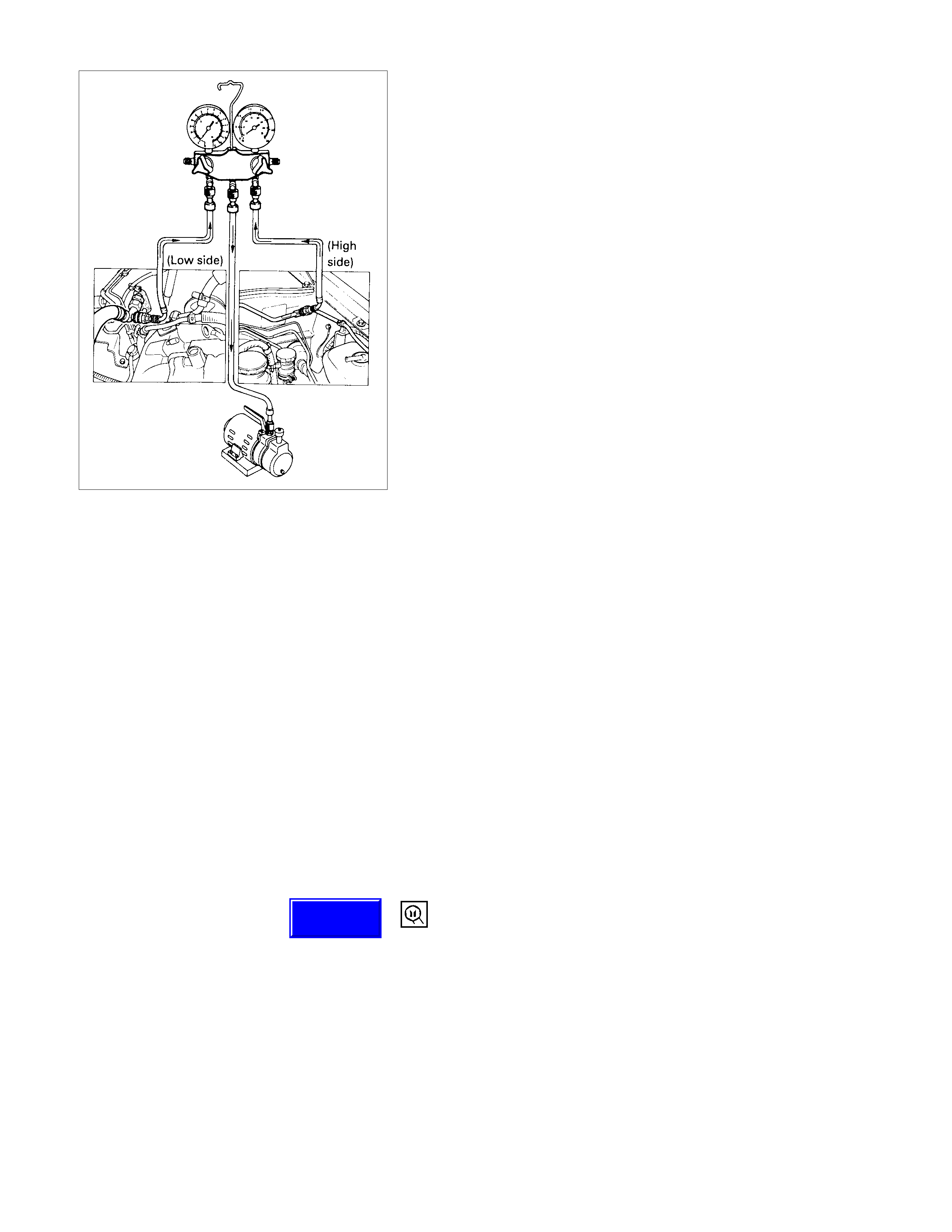
EVACUATION OF THE REFRIGERANT SYSTEM
Note:
Explained below is a method using a vacuum pump. Refer
to the ACR4 (or equivalent) Manufacturer's Instructions
when evacuating the system with ACR4 (or equivalent).
Air and moisture in the refrigerant will cause problems in the air
conditioning system.
Therefore, before charging the refrigerant, be sure to evacuate
air and moisture thoroughly from the system.
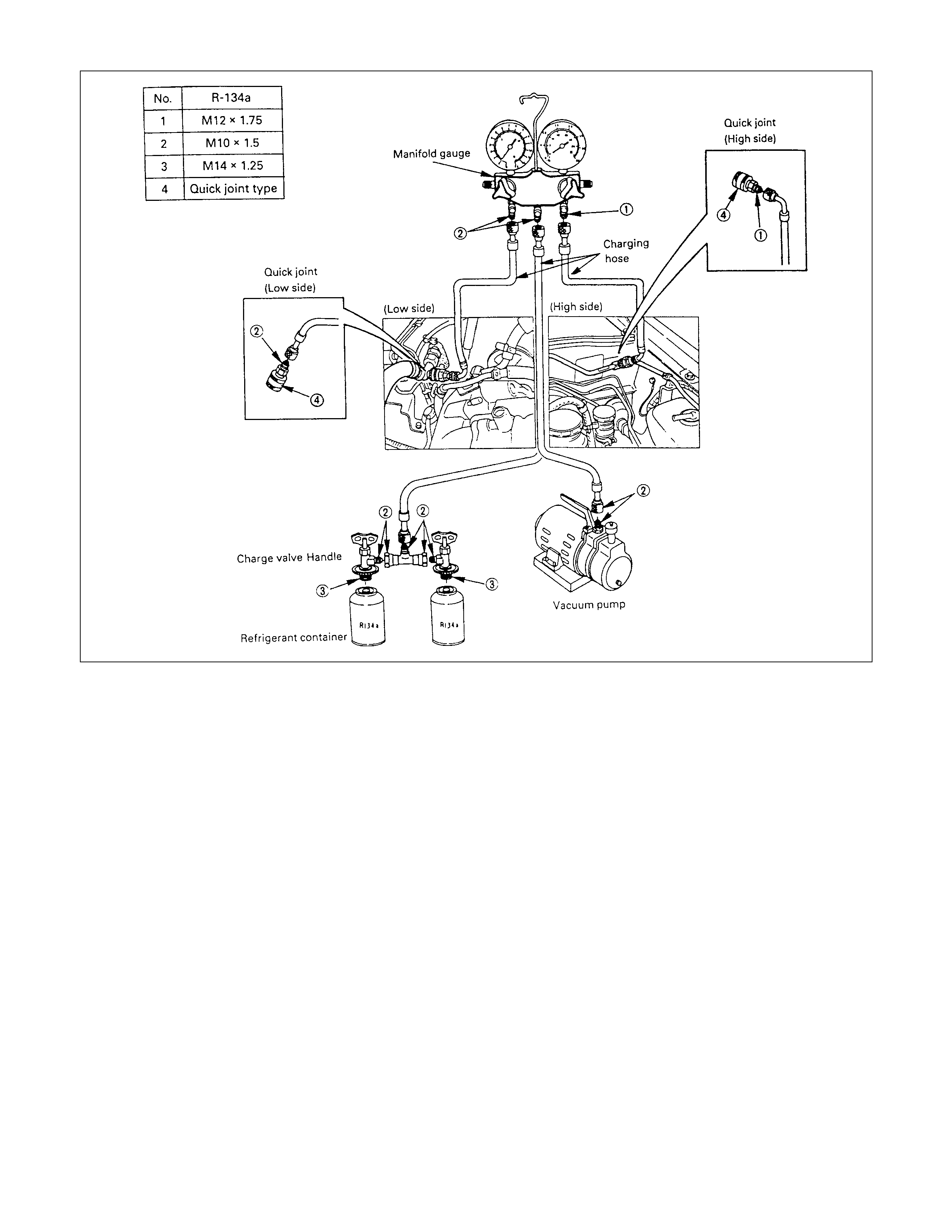
1) Connect the gauge manifold.
•
••
•High-pressure valve (HIGH)-Discharge-side
•
••
•Low-pressure valve (LOW)-Suction-side
2) Discharge and recover the refrigerant.
3) Connect the center hose of the gauge manifold set to the
vacuum pump inlet.
4) Operate the vacuum pump, open shutoff valve and then
open both hand valves.
5) W hen the low-pressure gauge indicates approx. 750 m m Hg
(30 ln.Hg), continue the evacuation for 5 minutes or more.
6) Close both hand valves and stop the vacuum pump.
7) Check to ensur e that the pres s ure does not c hange af ter 10
minutes or more.
•
••
•If the pressure changes, check the system for leaks.
•
••
•If leaks occur, retighten the refrigerant line connections
and repeat the evacuation steps.
8) If no leaks are found, again operate the vacuum pump fo
r
20 minutes or more. After confirming that the gauge
manifold pressure is at 750 mmHG (30 ln.Hg), close both
hand valves.
9) Close positive shutoff valve.
Stop the vacuum pump and disconnect the center hose
from the vacuum pump.
CHARGING THE REFRIGERANT SYSTEM
There are various methods of charging refrigerant into the air
conditioning system.
These include using the ACR4 (R-134a Refrigerant Recovery/
Recycling/Recharging/System) or equivalent and direct
charging with a manifold gauge charging station.
ACR4 (220-240V 50/60Hz Australian model)
: 5-8840-0631-0 (J-39500-220ANZ)
Techline
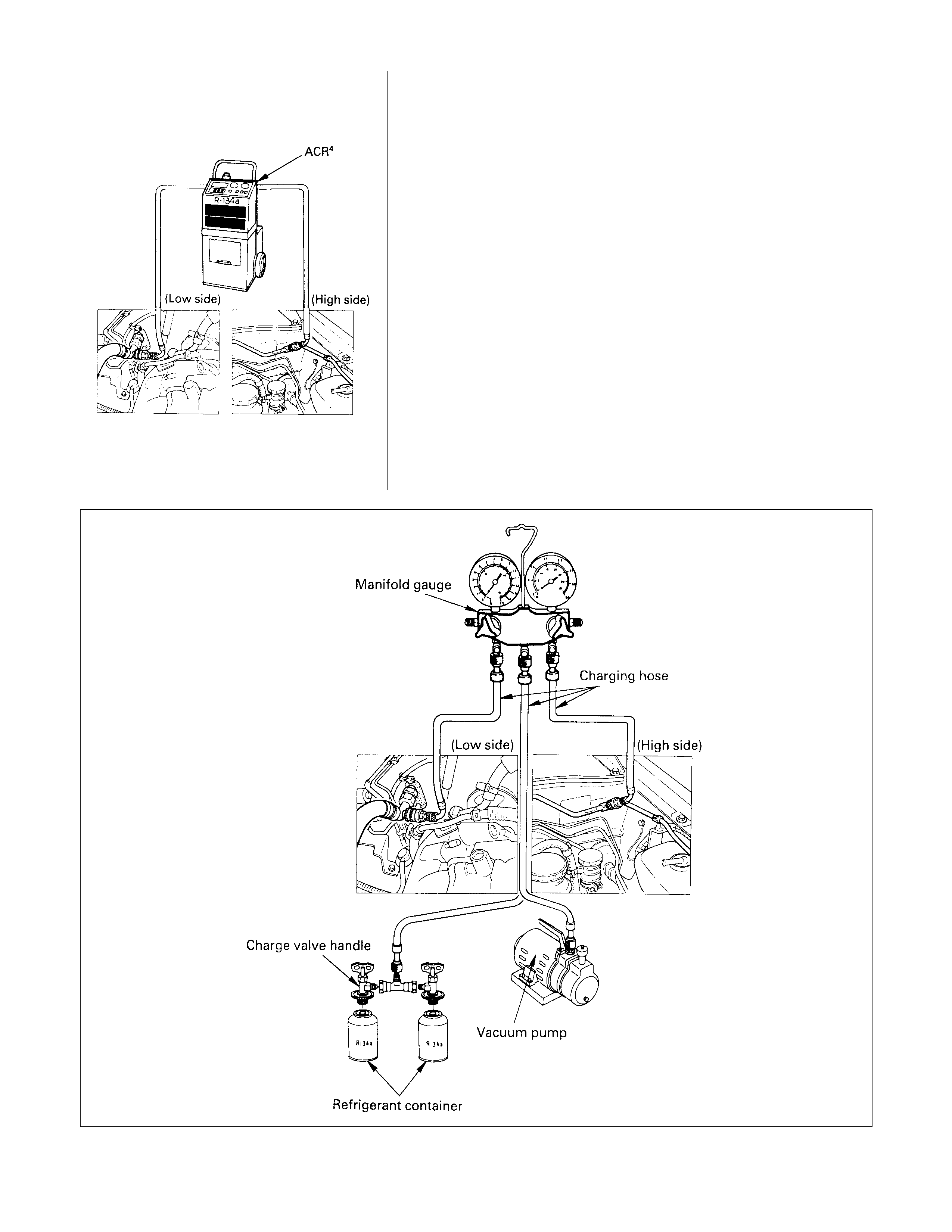
CHARGING PROCEDURE
•
••
•ACR4 (or equivalent) method
For the charging of refrigerant recovered by ACR4, follow the
Manufacturer's Instruction.
•
••
•Direct charging with a manifold gauge charging
station method.
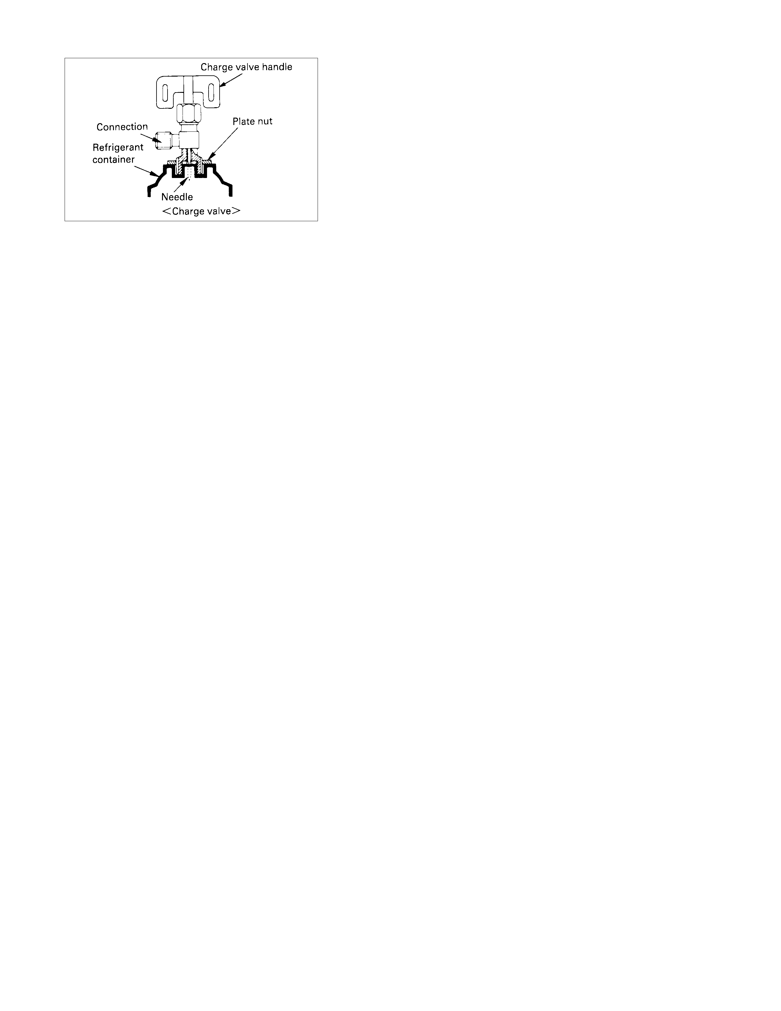
Handling the charge valve handle when installing refrigerant
container.
1) Before attaching the charge valve to the refrigerant
container, turn the charge valve handle counterclockwise
until the needle is fully retracted.
2) Turn the plate nut counterclockwise until it reaches its
highest position relative to the charge valve.
3) Install the charge valve onto the refrigerant container.
4) Turn the plate nut clockwise and connec t the c enter hos e o
f
the manifold gauge to the charge valve.
5) Tighten the plate nut sufficiently by hand. Then turn the
charge valve handle cloc kwise to lower the needle and bor e
a hole in the refrigerant container.
6) Turn the charge valve handle counterclockwise to raise the
needle. The refrigerant in the refrigerant container is
charged into the air c onditioning sys tem by the operation o
f
the manifold gauge.
•
••
•Be absolutely sure not to reuse the emptied refrigerant
container.
1) Make sure the evacuation process is correctly completed.
2) Connect the center-hose of the manifold gauge to the
refrigerant container.
•
••
•Turn the charge valve handle counterclock wise to purge
to charging line and purge any air exiting in the center-
hose of the manifold gauge.
3) Open the low-pressure hand valve and charge the
refrigerant about 200 g (0.44 lbs.).
•
••
•Make sure the high-pressure hand valve is closed.
•
••
•Avoid charging the refrigerant by turning the refrigerant
container upside down.
4) Close the low-pressure hand valve of the manifold gauge.
•
••
•Check to ensure that the degree of pressure does not
change.
5) Check the refrigerant leaks by using a R-134a leak
detector.
•
••
•If a leak occurs, repair the leak connection, and start all
over again from the first step of evacuation.
6) If no leaks are found, open the low-pressure hand valve o
f
the manifold gauge. Then continue charging refrigerant to
the system.
•
••
•When charging the system becomes difficult:
(1) Run the engine at 1,300∼1,500 rpm and open the all
vehicle doors.
(2)A/C switch is "ON".
(3) Set the fan control knob (fan switch) to its highest
position.

WARNING:
BE ABSOLUTELY SURE NOT TO OPEN THE HIGH-
PRESSURE HAND VALVE. SHOULD THE HIGH-
PRESSURE HAND VALVE BE OPENED, THE HIGH-
PRESSURE REFRIGERANT GAS WOULD FLOW
BACKWARD, AND THIS MAY CAUSE THE REFRIGERANT
CONTAINER TO BURST.
7) W hen the refr igerant container is em ptied, use the f ollowing
procedure to replace it with a new refrigerant container.
(1) Close the low-pressure hand valve.
(2) Raise the needle upward and remove the charge valve.
(3) Reinstall the charge valve to the new refrigerant
container.
(4) Purge any air exis ting in the center hose of the m anifold
gauge.
8) Charge the system to the specified amount and then close
the low-pressure hand valve.
Refrigerant Specified Amount g(lbs.)
650 (1.43)
•
••
•A fully charged system is indicated by the sight glass on
the receiver/drier being free of any bubbles (Refer to
"Reading Sight Glass").
•
••
•Check the high and low pressure value of the manifold
gauge.
•
••
•Check for refrigerant leaks by using a R-134a leak
detector.
Immediately after charging refrigerant, both high and low
pressures are slightly high and to the left of the gauge, but they
settle down to the guide pressure valves as shown below:
•
••
•Ambient temperature; 30∼35°C (86∼95°F)
•
••
•Guide pressure
High-pressure side;
Approx. 1373∼167 kPa (14∼17 kg⋅cm2/199∼242 PSI)
Low-pressure side;
Approx. 127∼245 kPa (1.3∼2.5 kg⋅cm2/18∼36 PSI)
9)Close the low pressur e hand valve and charge valve of the
refrigerant container.
10)Stop the air conditioning and the engine.
11)Disconnect the high and low pressure hoses from the
manifold gauge fittings.
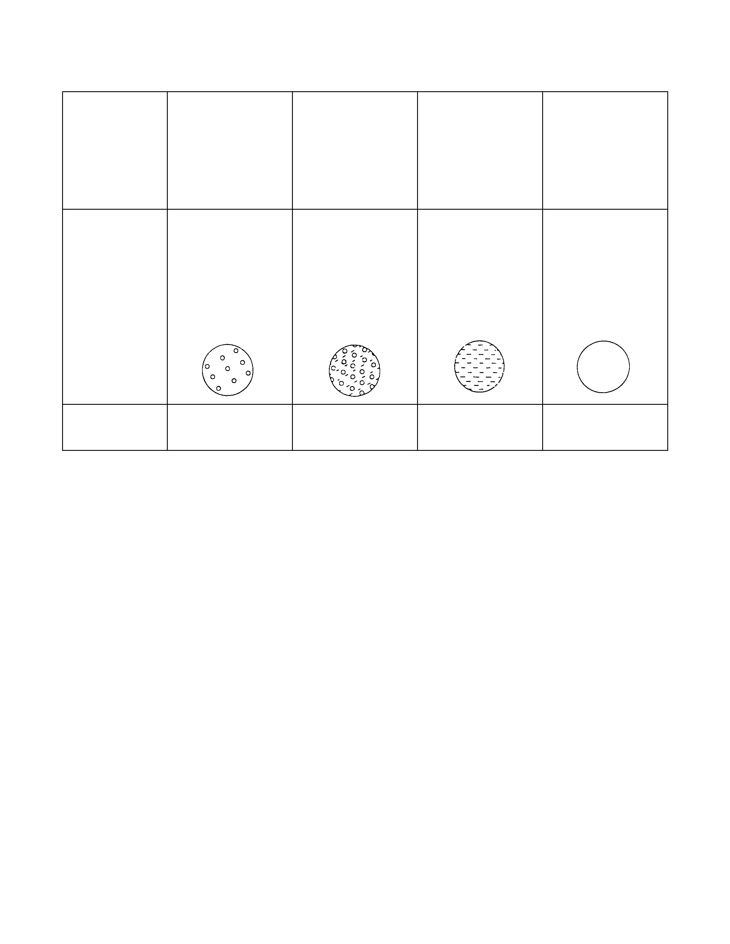
READING SIGHT GLASS
High and low
pressure pipe
temperature
The high pressure
pipe is hot and the
low pressure pipe
is cold. There is a
distinct difference
in temperature
between them.
The high pressure
pipe is warm and
the low pressure
pipe is cool. There
is no great
difference in
temperature
between them.
There is little
difference in
temperature
between the high
pressure pipe and
the low pressure
pipe.
The high pressure
pipe is hot and the
low pressure pipe
is slightly warm.
There is a
difference in
temperature
between them.
Sight glass
condition Almost transparent.
A flow of bubbles
can be seen, but
they disappear
when the throttle is
opened.
A flow of bubbles
always can be
seen. It appears
sometimes
transparent, and
sometimes frothy.
Something like fog
faintly can be seen. Evan at idle with
the fan at "HI" (with
the window fully
open), the bubbles
cannot be seen.
Air conditioning
cycle condition OK NG
(Not enough
refrigerant)
NG
(Almost no
refrigerant)
NG
(Too much
refrigerant)
The sight glass provides accurate diagnosis only under the following conditions.
If the vehicle can be tested under these conditions, check the sight glass appearance and compare to the chart
* Engine speed 1,500 RPM
* A/C switch "ON"
* Blower fan operating at highest speed
* Air source selector lever at "RECIRC"
* Temperature control lever at coldest position
* Ambient temperature below 35°C (95°F) and humidity below 70% (See NOTE 1)
* High side pressure less than 1667 kPa (17 kg⋅cm2/242 PSI) (See NOTE 2)
NOTE 1
If the vehicle cannot be moved to a testing location that meets these specifications, then the sight glass cannot be used
for diagnosis. You must discharge and recover the refrigerant, then recharge the system with the specified amount of
refrigerant.
Then continue checking the system performance.
NOTE 2
If the high side pressure is greater than stated, the sight glass cannot be used for diagnosis. You must discharge and
recover the refrigerant, then recharge the system with the specified amount of refrigerant.
Then continue checking system performance.
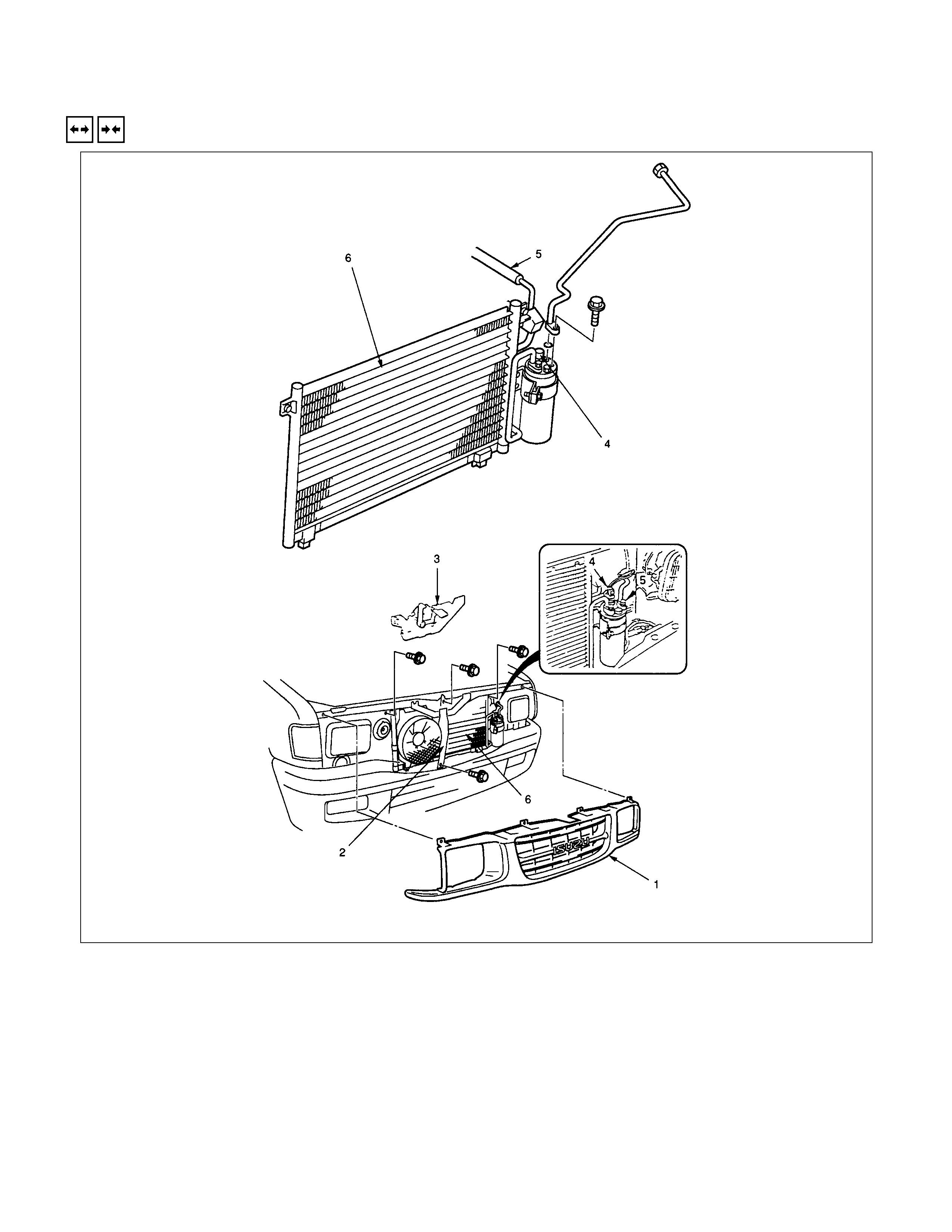
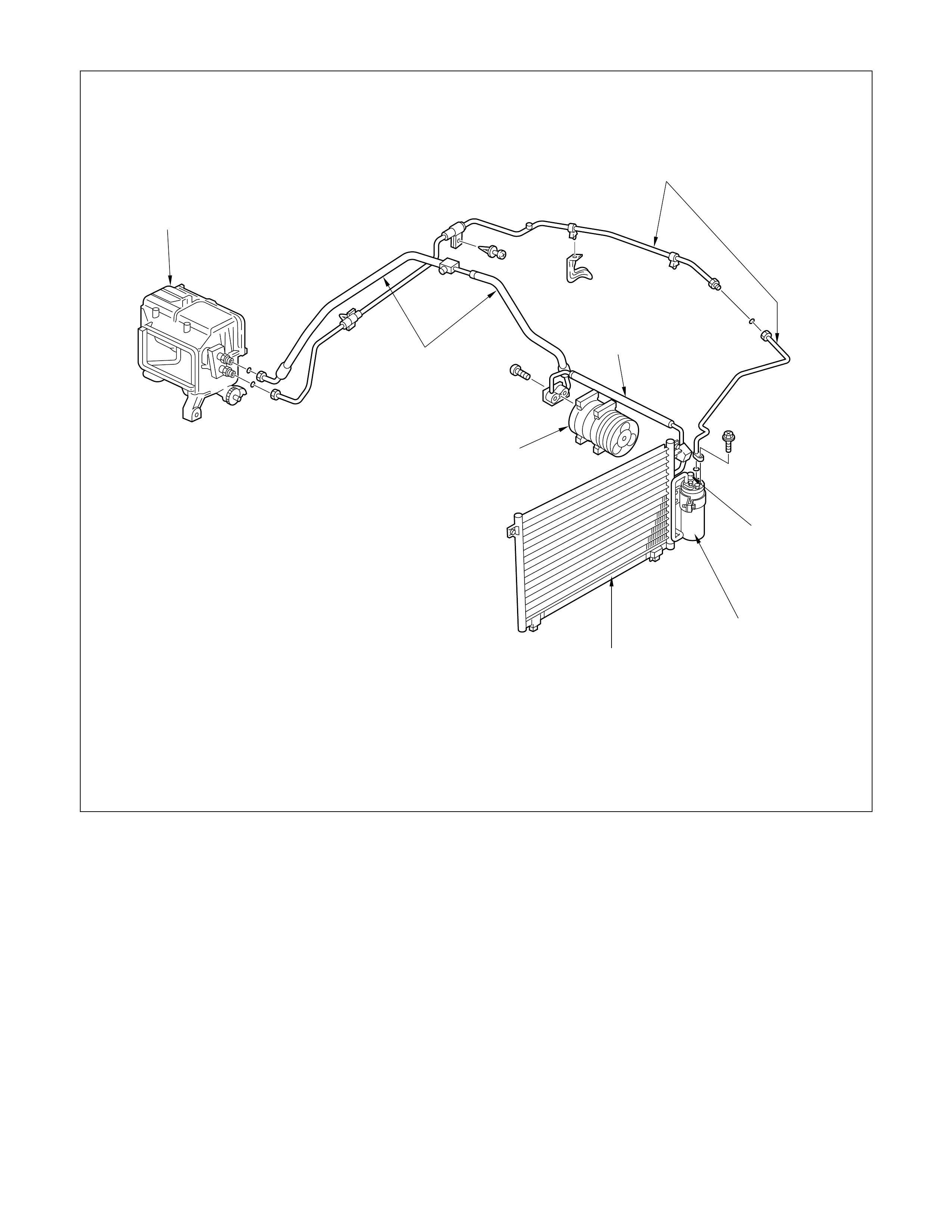
CONDENSER
REMOVAL AND INSTALLATION
REMOVAL STEPS
1. Radiator grille
2. Engine hood front end stay
3. Engine hood lock
4. Pressure switch connector
5. Refrigerant line
6. Condenser
INSTALLATION STEPS
To install, follow the removal procedure in
reverse order.
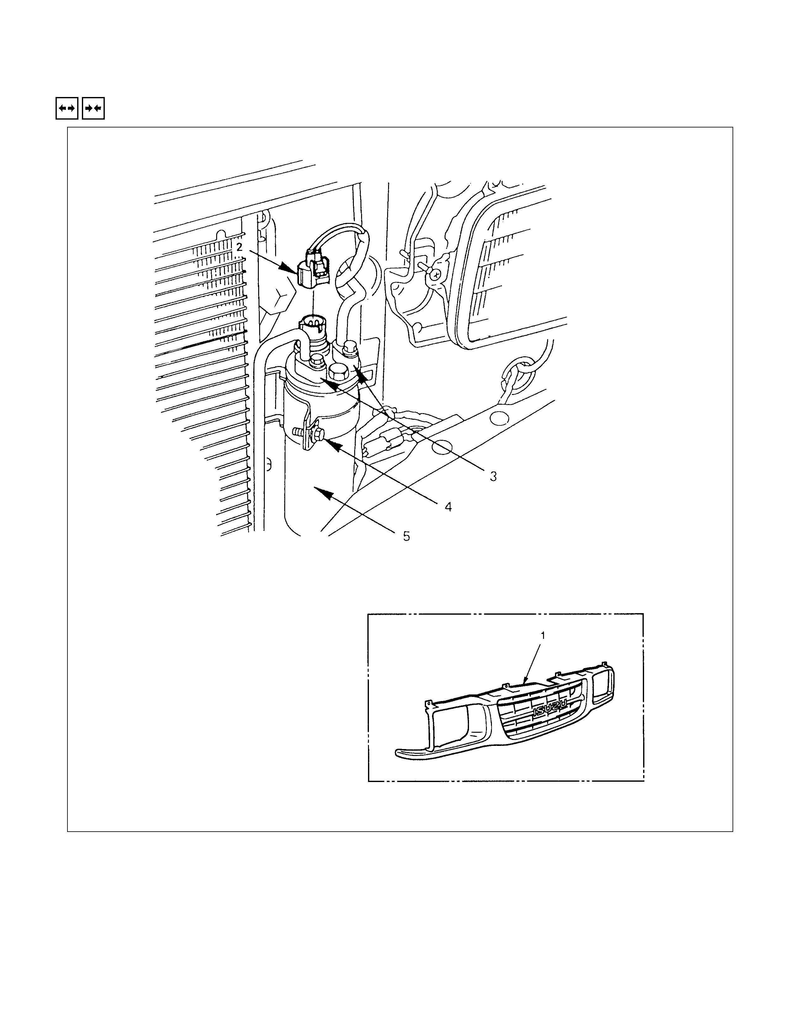
RECEIVER DEHYDRATOR
REMOVAL AND INSTALLATION
REMOVAL STEPS
1. Radiator grille
2. Dual pressure switch connector
3. Refrigerant line
4. Bracket bolt
5. Receiver dehydrator
INSTALLATION STEPS
To install, follow the removal procedure in
reverse order.
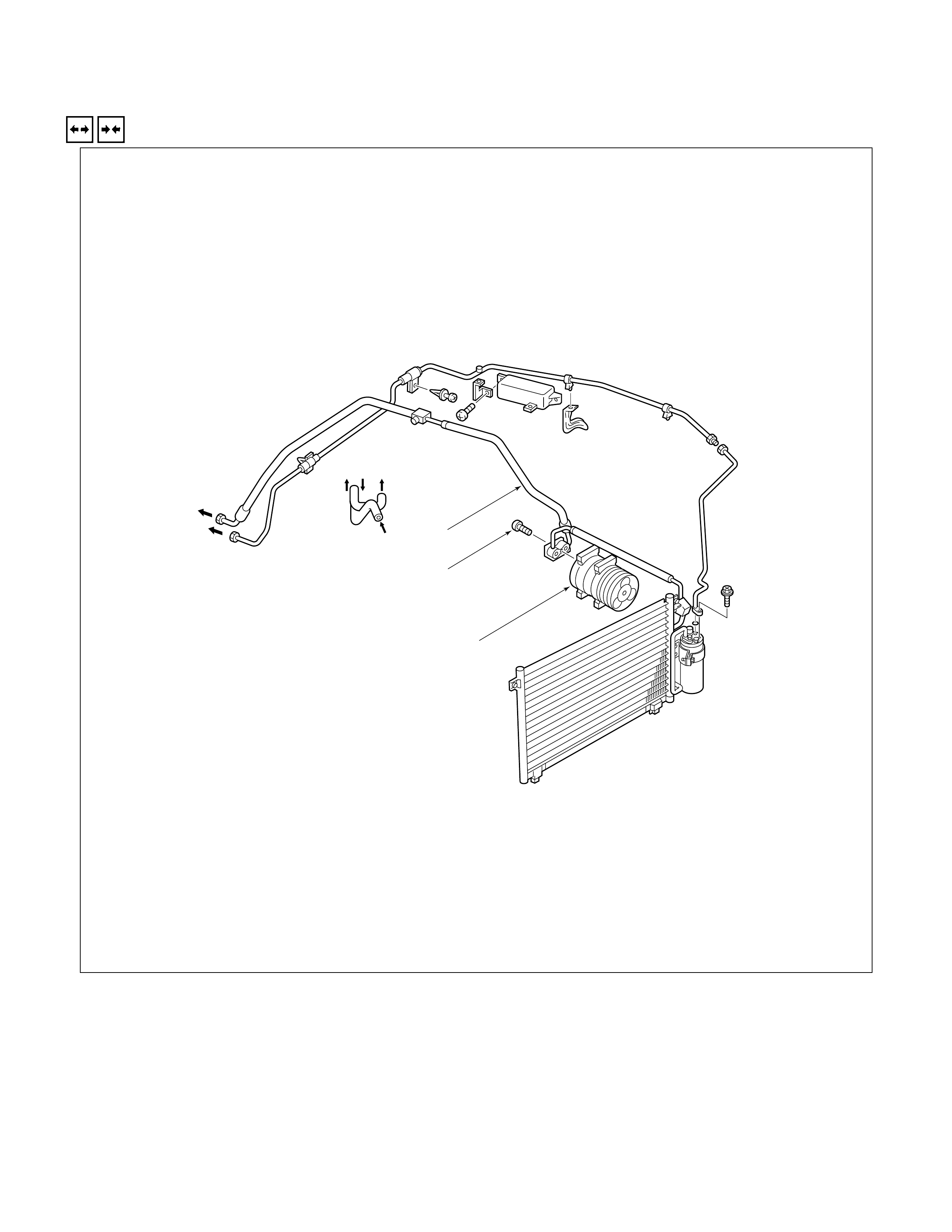
COMPRESSOR
REMOVAL AND INSTALLATION
EVAPO
H/U
ENG.
This illustration is based on the LHD gasoline engine model.
ENG.
1
2
3
REMOVAL STEPS
1. Compressor flex/hose
2. Bolt; compressor to bracket
3. Compressor assembly
INSTALLATION STEPS
3. Compressor assembly
▲2. Bolt; compressor to bracket
▲1. Compressor flex/hose
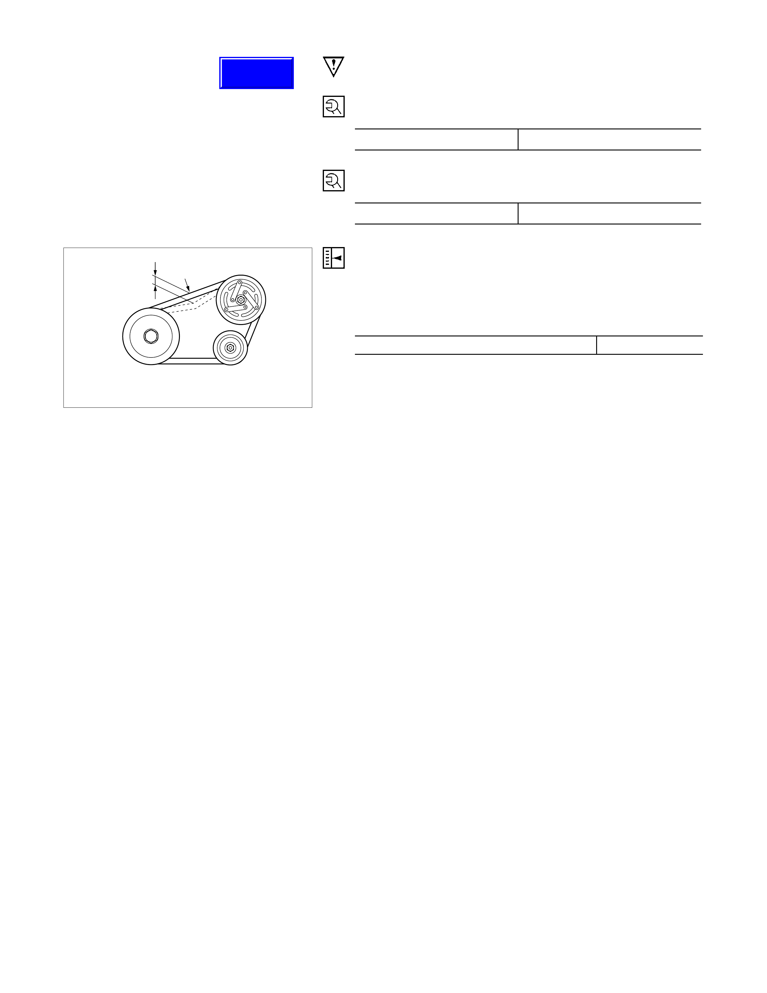
IMPORTANT OPERATIONS - INSTALLATION
2. Bolt; Compressor to Bracket N⋅m (kgf⋅m/lb⋅ft)
Torque 54-64 (5.5-6.5/40-47)
1. Compressor Flex/Hose N⋅m (kgf⋅m/lb⋅ft)
Torque 27-34 (2.8-3.5/20-25)
Compressor pulley
Crank pulley
10mm(0.4in)
Idler pulley
Compressor Belt
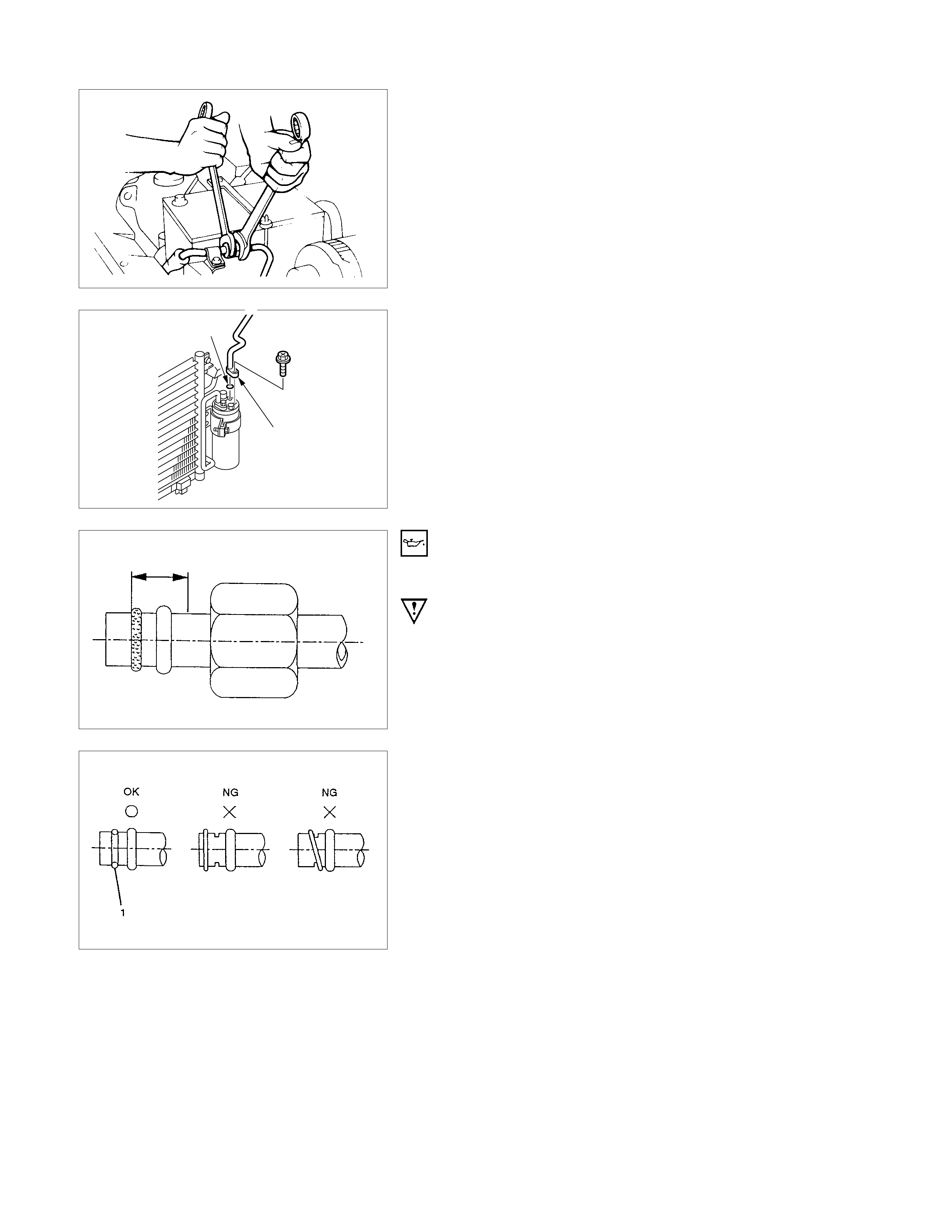
Check the drive belt tension.
Depress the drive belt mid-portion with a 98N (10kg/22Ib)
force.
Gasoline Engine mm(in.)
Standard deflection 10 (0.4)
Techline

GENERAL REPAIR PROCEDURE
OIL SPECIFICATION
•The R-134a system requires a synthetic (PAG)
compressor oil
•Compressor (PAG) oil varies according to compresso
r
model. Be sure to use oil specified for the model o
f
compressor.
Specified Compressor Oil
ZXL-100PG
(ISUZU PART NO.8-97101-338-0)
HANDLING OF OIL
•The oil should be free from moisture, dust, metal powder,
etc.
•Do not mix with other oil.
•The water content in the oil incr eases when exposed to the
air. After use, seal oil from air immediately.
(R-134a PAG Com pressor Oil absorbs m oisture ver y easily
than R-12.)
•The compressor oil must be stored in steel containers, not
in plastic containers.
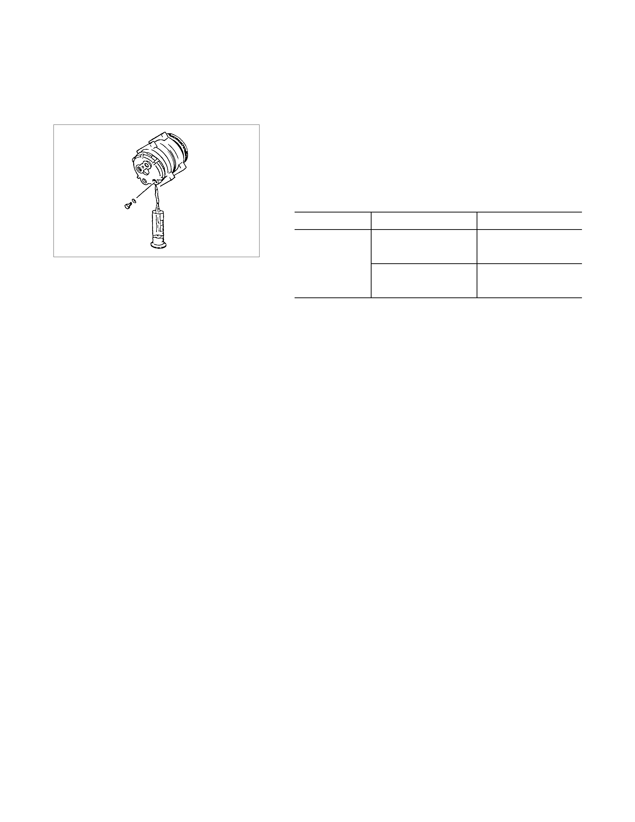
COMPRESSOR OIL CHECK
The Oil used to lubricate the compressor is circulating with the
refrigerant.
Whenever replacing any component of the system or a large
amount of gas leakage occurs, add oil to maintain the original
amount of. oil.
Oil Capacity
Capacity total in
system DKS 15 CH 150 cc (5.0 fl.oz.)
Compressor
(Service parts)
charging amount DKS 15 CH 150 cc (5.0 fl.oz.)
CHECKING AND ADJUSTING FOR USED
COMPRESSOR
(1)Perform Oil return operation.
(Refer to "Oil Return Operation" in this section.)
(2)Discharge refrigerant and remove the compressor.
(3)Drain the compressor oil and measure the extracted oil with
a measuring cylinder.
(4)Check the compressor oil for contamination.
(Refer to "Contamination of Compressor Oil" in this
section.)
(5)Adjust oil level following the procedure below.
Type Collected Amount Charging Amount
more than 90 cc
(3.0 fl.oz.) same as collected
amount
less than 90 cc
(3.0 fl.oz.) 90 cc (3.0 fl.oz.)
DKS-15 CH
(6)Install the com pressor, then evacuate, charge and perform
oil return operation.
(7)Check system operation.
When it is impossible to pe rform oil return operation, the
compressor oil should be checked in the following order:
(1)Discharge refrigerant and remove the compressor.
(2)Drain the compressor oil and measure the extracted oil with
a measuring cylinder.
(3)Check the oil for contamination.
(4)If more than 90 cc (3.0 fl.oz.) for DKS-15 CH type is
extracted from the compressor, supply same amount of oil
to the compressor to be installed.
If the amount of oil extracted is less than 90 cc (3.0 fl.oz.)
for DKS-15 CH type recheck the compressor oil in the
following order:
(5)Supply 90 cc (3.0 fl.oz.) for DKS-15 CH type oil to the
compressor and install it onto the vehicle.
(6)Perform oil return operation.
(7)Remove the compressor and recheck the amount of oil.
(8)Adjust the compressor oil.

CHECKING AND ADJUSTING FOR COMPRESSOR
REPLACEMENT
150 cc (5.0 fl.oz.) for DKS-15 CH type of oil is charged in
compressor (serv ice parts).
So it is necessary to drain the proper amount of oil from new
compressor.
(1)Perform oil return operation.
(2)Recover refrigerant and remove the compressor.
(3)Drain the compressor oil and measure the extracted oil with
a measuring cylinder.
(4)Check the compressor oil for contamination.
(5)Adjust oil level following the procedure below.
Type Collected Amount Charging Amount
more than 90 cc
(3.0 fl.oz.) same as collected
amount
less than 90 cc
(3.0 fl.oz.) 90 cc (3.0 fl.oz.)
DKS-15 CH
(6)Evacuate, charge and perform oil return operation.
(7)Check system operation.
CONTAMINATION OF COMPRESSOR OIL
Unlike engine oil, no cleaning agent is added to the
compressor oil. Even is the compressor runs for a long period
of time (approximately 1 season), the oil never becomes
contaminated as long as there is nothing wrong with the
compressor or its method of use.
Inspect the extracted oil for any of the following
conditions:
•The capacity of the oil has increased.
•The oil has changed color to red.
•Foreign substances, metal powder, etc., are present in the
oil.
If any of these conditions exists, compressor oil is
contaminated. Whenever contaminated compressor oil is
discovered, the receiver/drier must be replaced.
OIL RETURN OPERATION
There is close affinity betw een the oil and the refrigerant.
During normal operation, part of the oil recirculates with the
refrigerant in the system.
When checking the amount of oil in the system, or replacing
any component of the system, the compressor must be run in
advance for oil return operation. The procedure is as follows:
(1)Open the all doors and engine hood.
(2)Start the engine and A/C switch is "ON" and Set the fan
control knob at its highest position.
(3) Run the compressor for more than 20 minutes between
800 and 1,000 rpm in order to operate the system.
(4)Stop the engine.
REPLACEM ENT O F COMPONENT PARTS
When replacing system component parts, supply the following
amount of oil to the component parts to be installed.
Component parts to be installed Amount of oil
Evaporator 50 cc (1.7 fl.oz.)
Condenser 30 cc (1.0 fl.oz.)
Receiver/drier 30 cc (1.0 fl.oz.)
Refrigerant line (One piece) 10 cc (0.3 fl.oz.)
Refrigeration oil must be replenished if more than two parts
are removed at the same time. After installing these
components, check compressor oil.
DISASSEMBLY
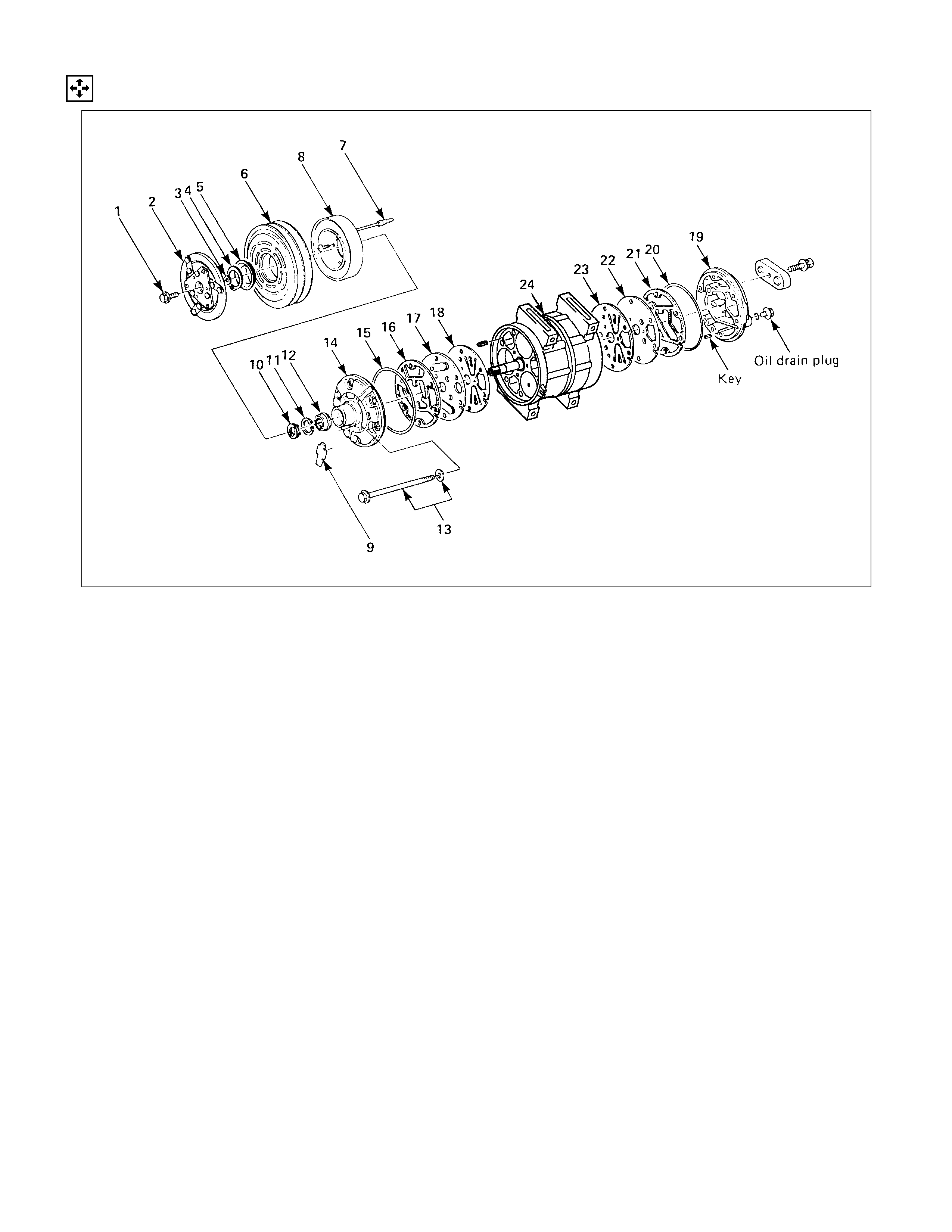
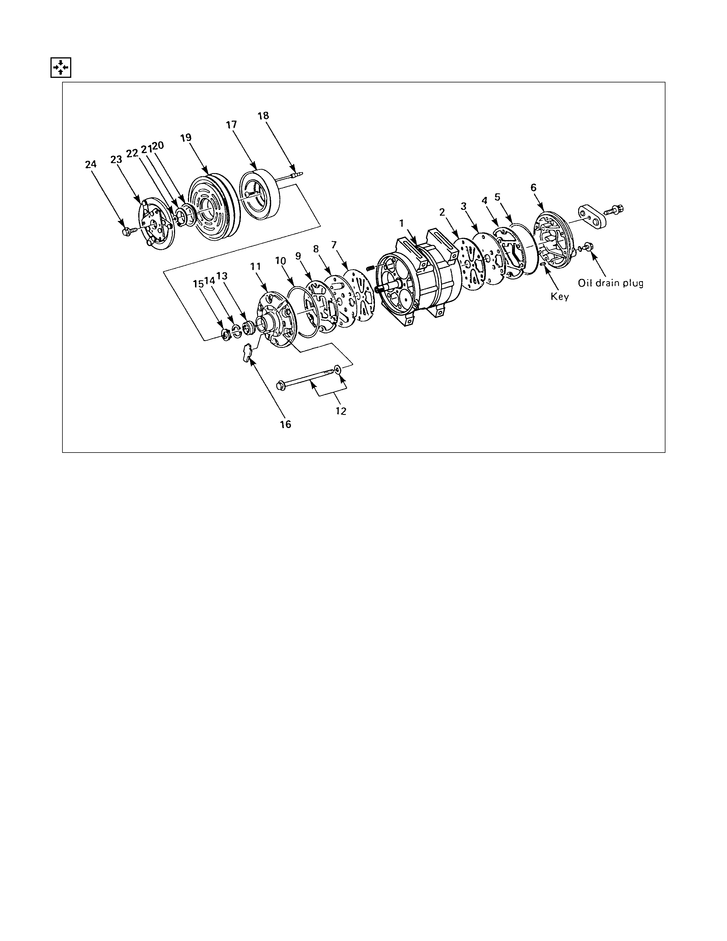
DISASSEMBLY STEPS
1. Drive plate bolt
2. Drive plate
3. Shim(s)
4. Snap ring
5. Cover (If so equipped)
6. Pulley assembly
7. Lead wire connector
8. Field coil
9. Felt (If so equipped)
10. Shaft seal cover (If so equipped)
11. Snap ring
12. Shaft seal assembly
13. Through bolt with gasket
14. Front cylinder head
15. O-ring
16. Gasket
17. Front valve plate
18. Front suction valve
19. Rear cylinder head
20. O-ring
21. Gasket
22. Rear valve plate
23. Rear suction valve
24. Cylinder and shaft assembly
IMPO RTANT OPERATIONS - DI SSASSEMBLY
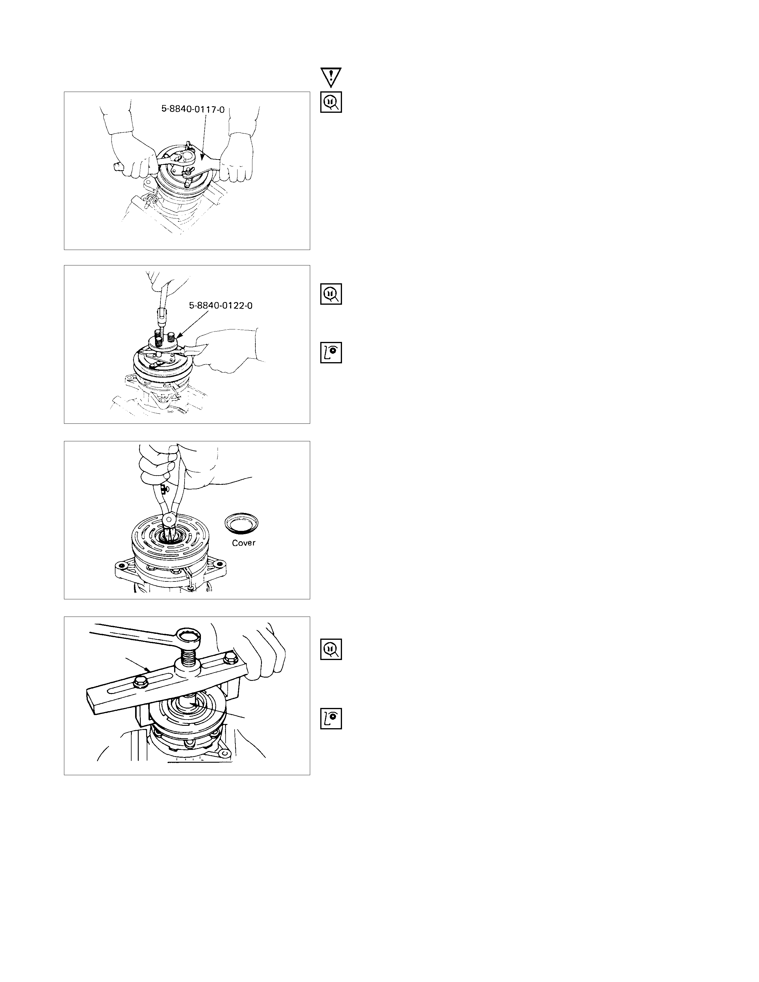
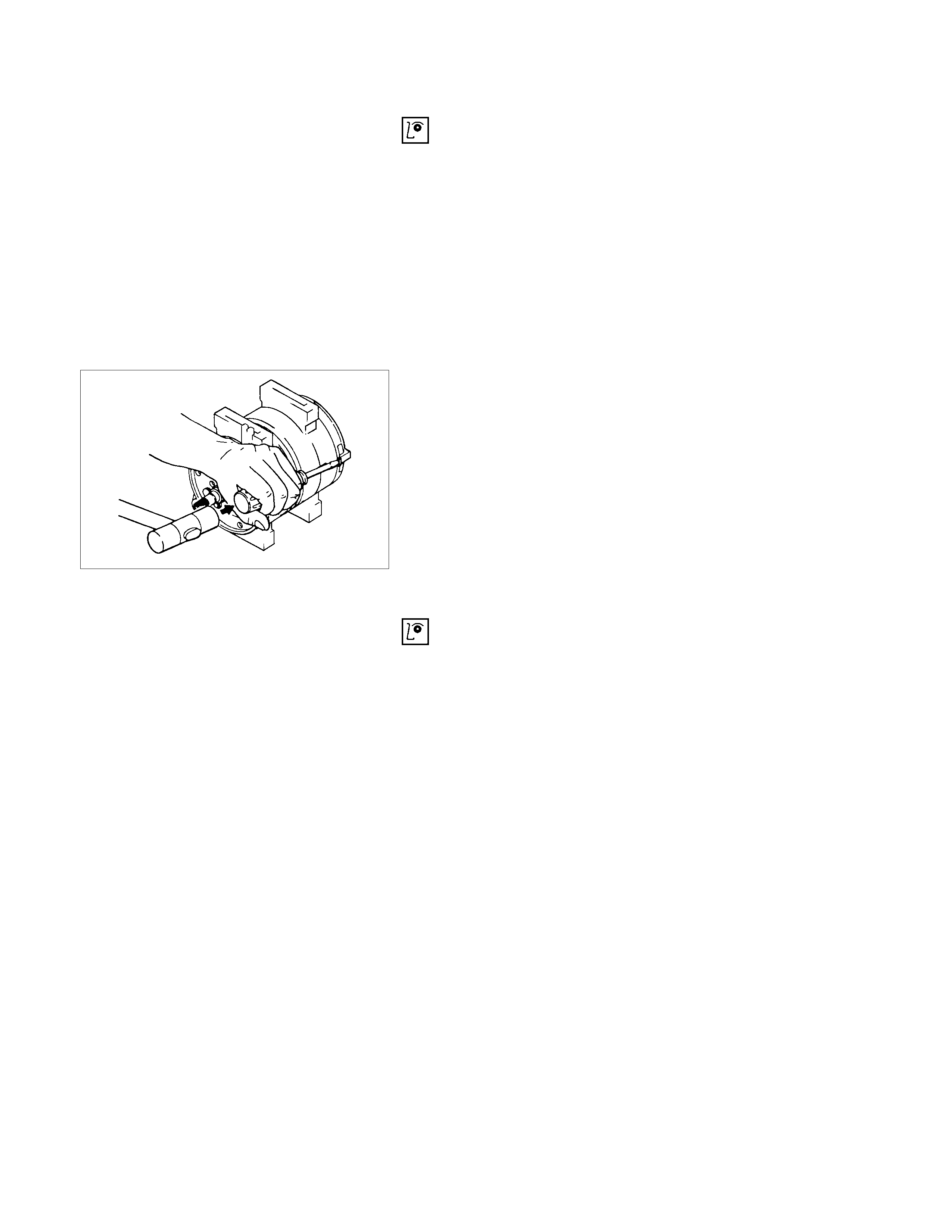
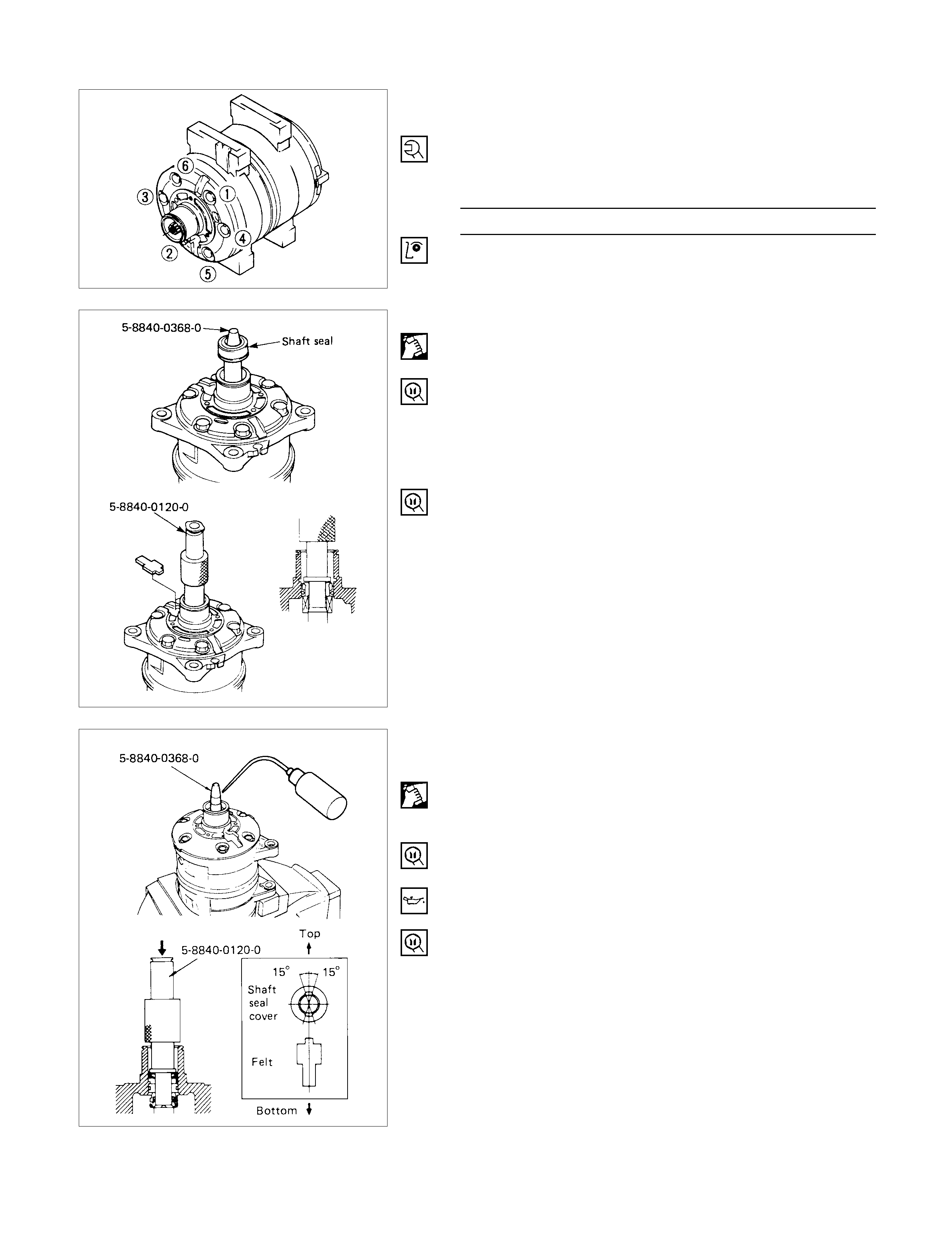
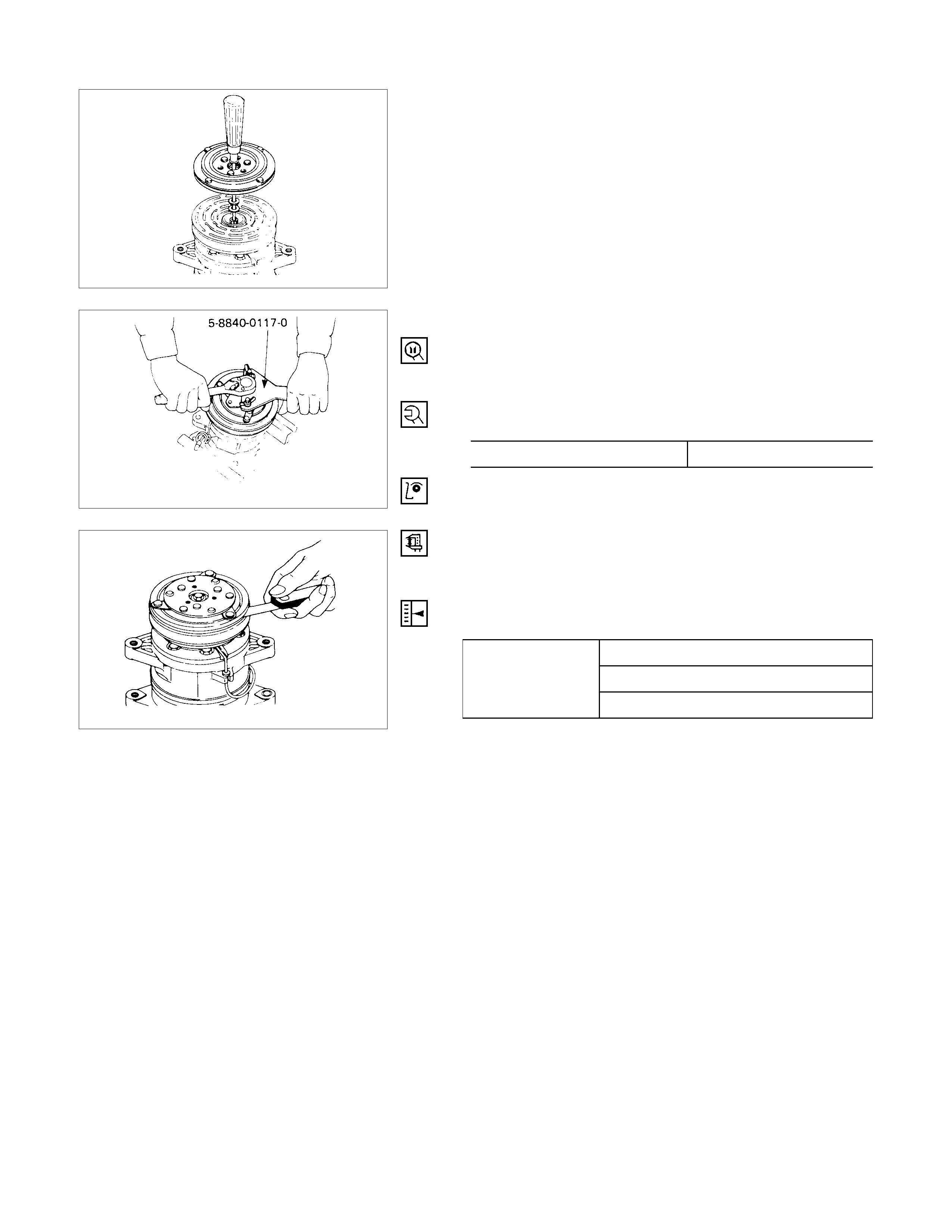
1. Drive Plate Bolt
Using drive plate holder to prevent the drive plate from
rotating, then remove the bolt.
Drive Plate Holder: 5-8840-0117-0 (J-33939)
2. Drive Plate
Using drive plate puller and forcing screw to remove the
drive plate.
Drive Plate Puller: 5-8840-0122-0 (J-33944-A)
If the frictional surface shows signs of damage due to
excessive heat, the drive plate and pulley should be
replaced.
5. Cover (If so equipped)
Using snap ring pliers to remove the snap ring.
5-8840-0111-0
5-8840-0121-0
6. Pulley Assembly
Using pulley puller pilot and pulley puller to remove the
pulley assembly.
Pulley Puller Pilot: 5-8840-0121-0 (J-33943)
Pulley Puller: 5-8840-0111-0 (J-8433)
Check the appearance of the pulley assembly. If the
frictional surface of the pulley shows signs of excessive
grooving due to slippage, both the pulley and drive plate
should be replaced. The frictional surfaces of the pulley
assembly should be cleaned with a suitable solvent before
reinstallation.
8.Field Coil
Loosen three screws and remove the field coil with lead
wire.
Check coil for loose connector or cracked insulation.
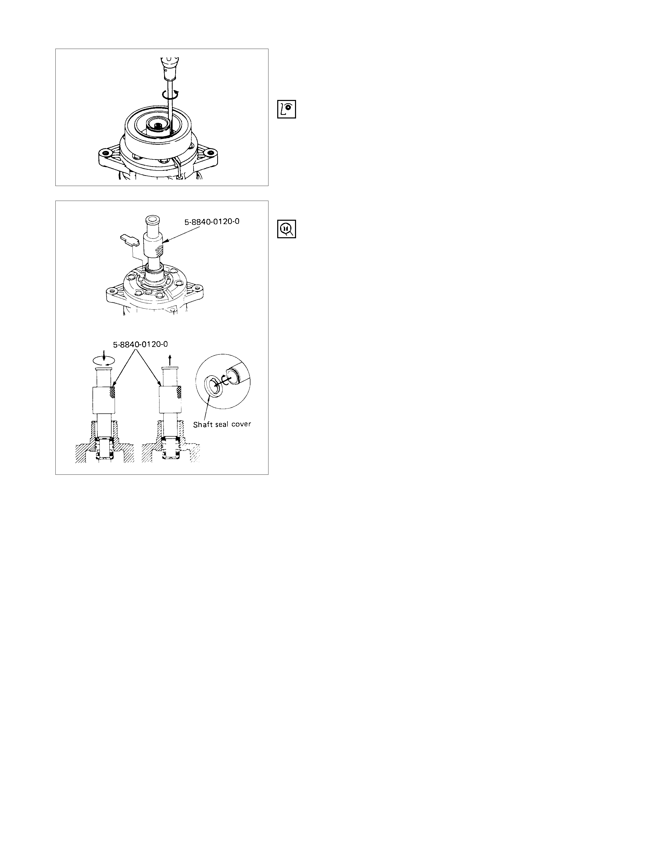
10.Shaft Seal Cover (If so equipped)
Using shaft seal remover to remove the shaft seal cover.
Engage the remover hook with the shaft seal cover groove
and slowly draw the shaft seal cover out.
Shaft Seal Remover: 5-8840-0120-0 (J-33942)
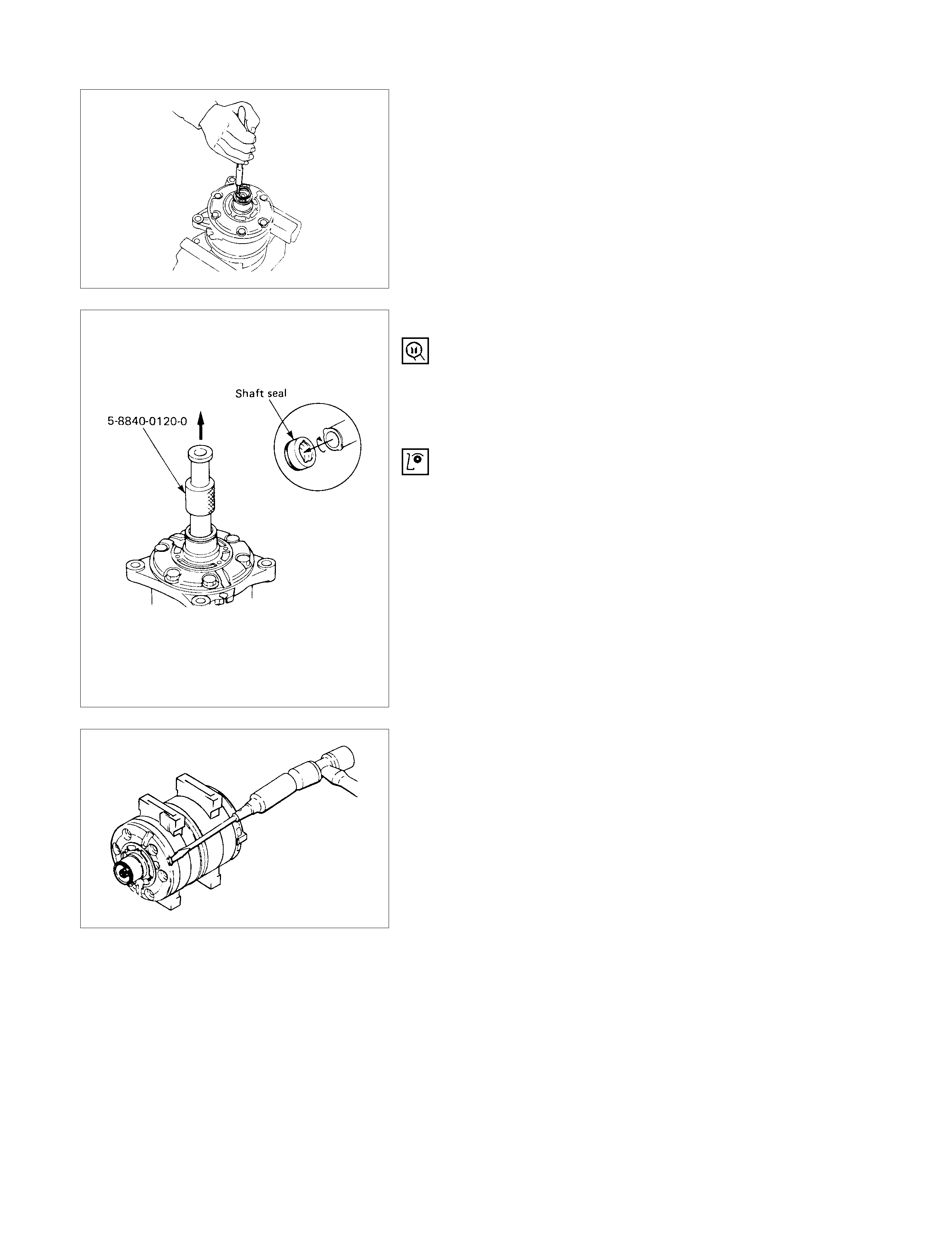
11.Snap Ring
Using snap ring pliers to remove the snap ring.
12.Shaft Seal Assembly
Using shaft seal remover to remove the shaft seal
assembly.
Engage the remover hook with the shaft seal assembly
groove and slowly draw the shaft seal assembly out.
Shaft Seal Remover: 5-8840-0120-0 (J-33942)
The shaft seal is precision-machined and its critical parts
are finished to extremely close tolerances. The assembly
must be handled with great care, it slips face demanding
particularly careful handling.
The shaft seal can not be reused. Install a new shaft seal
at reassembly.
Take care not to scratch or otherwise damage the shaft
seal face.
Keep the shaft seal free from lint and dirt.
14.Front Cy linder Head
15.O-ring
Alternately tap the projections on the circumference of the
front cylinder head with a screwdriver and a plastic hamme
r
to remove the front cylinder head.
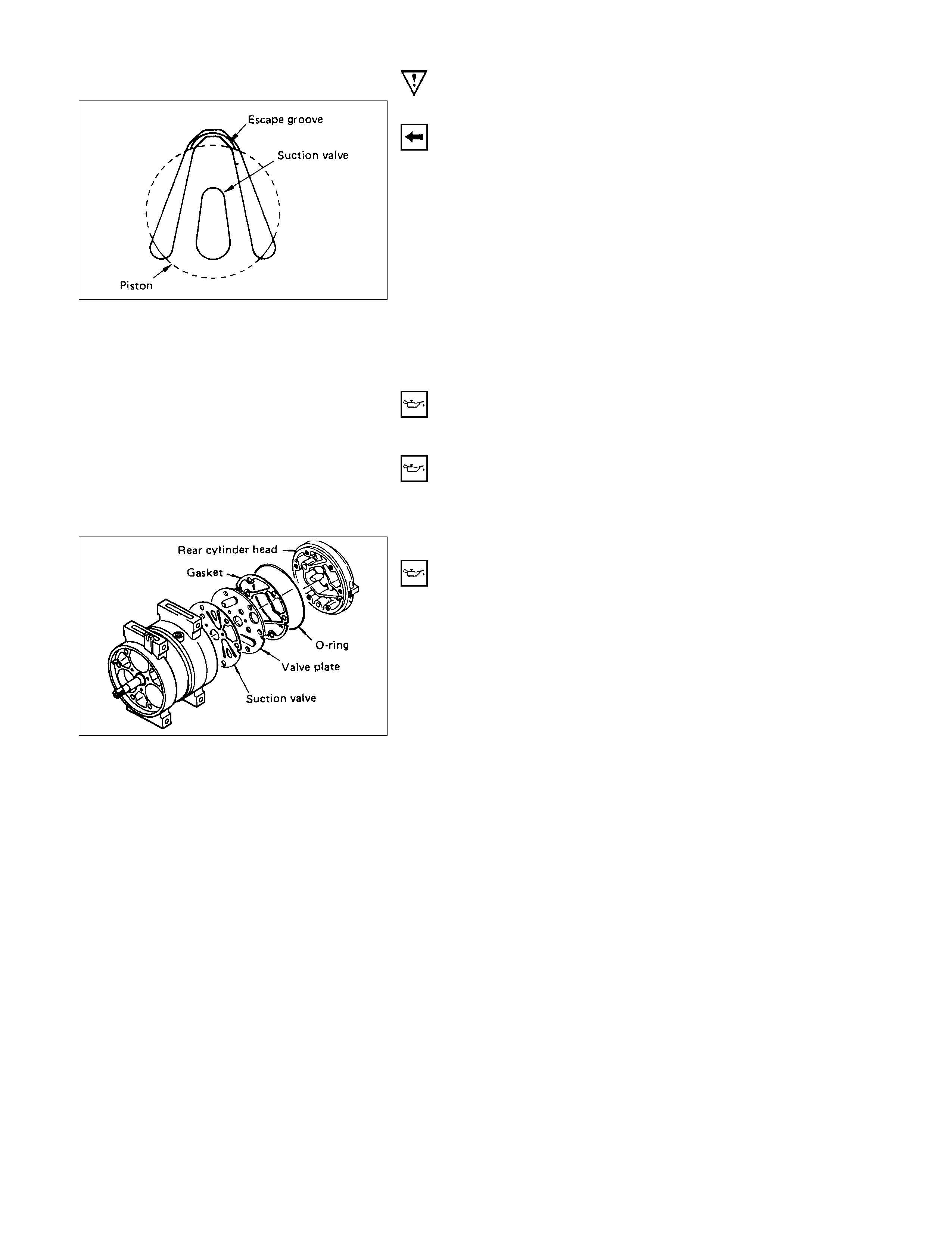
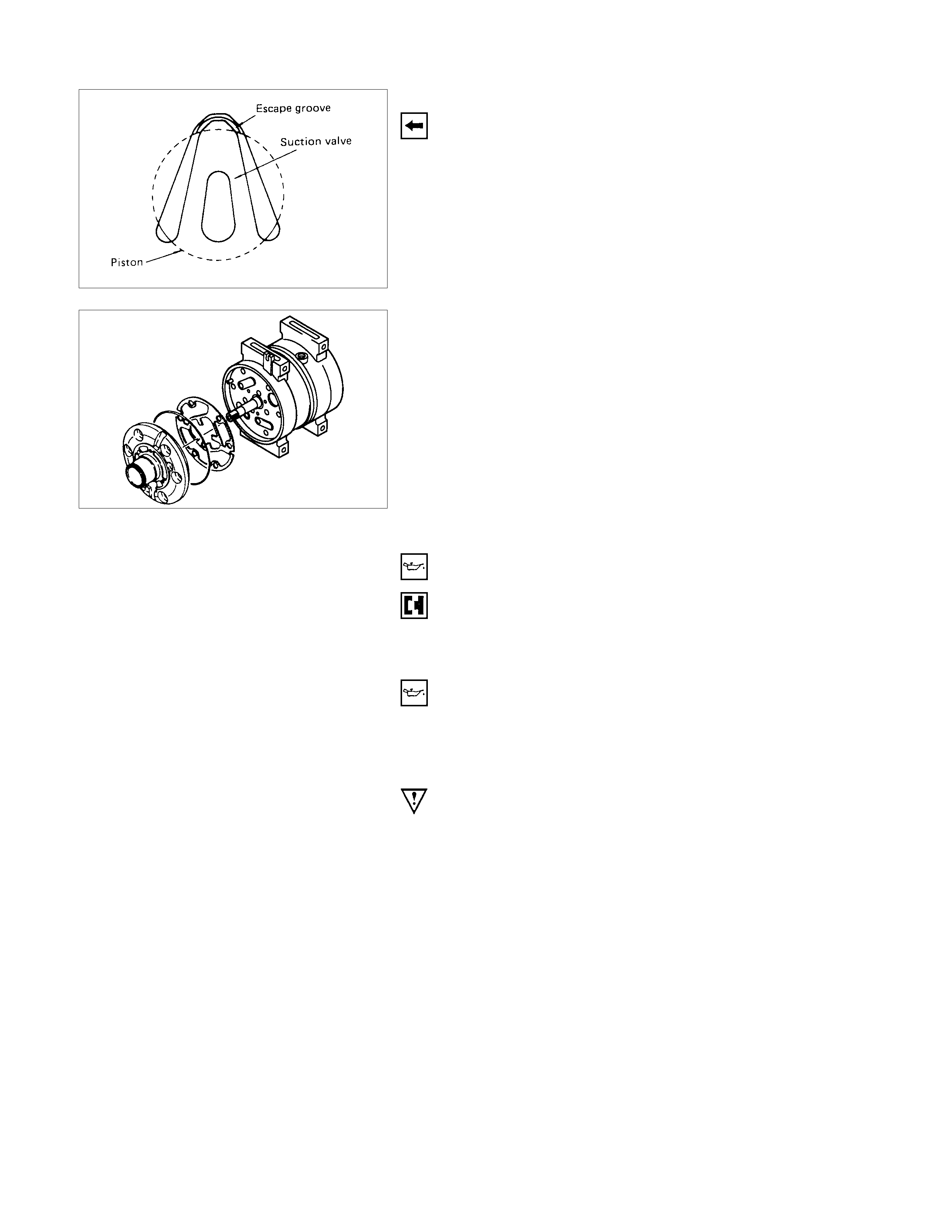
18.Front Suction Valve
Check the front valve plate for scratching and bending.
Check the front valve plate and the front cylinder head fo
r
nicks and burrs on the sealing surface.
Buff or replace the valve plate and cylinder head if nicks
and burrs are present.
Check that the front valve plate passage is free from
obstructions.
Check the front valve plate and the cylinder head fo
r
cracks.
Replace the valve plate and cylinder head if cracks are
present.
19.Rear Cylinder Head
20.O-ring
Alternately tap the projections on the circumference of the
rear cylinder head with a sc rewdriver and a plastic ham m e
r
to remove the rear cylinder head.
24.Cylinder and shaft assembly
Check the rear valve plate for scratching and bending.
Check the rear valve plate and the rear cylinder head fo
r
nicks and burrs on the sealing surface.
Buff or replace the valve plate and cylinder head if nicks
and burrs are present.
Check that the rear valve plate passage is free from
obstructions.
Check the rear valve plate and the cylinder head for cracks.
Replace the valve plate and cylinder head if cracks are
present.
REASSEM BLY
REASSEM BLY STEPS
1. Cylinder and shaft assembly
2. Rear suction valve
3. Rear valve plate
4. Gasket
5. O-ring
6. Rear cylinder head
7. Front suction valve
8. Front valve plate
9. Gasket
10. O-ring
11. Front cylinder head
12. Through bolt with gasket
13. Shaft seal assembly
14. Snap ring
15. Shaft seal cover (If so equipped)
16. Felt (If so equipped)
17. Field coil
18. Lead wire connector
19. Pulley assembly
20. Cover (If so equipped)
21. Snap ring
22. Shim(s)
23. Drive plate
24. Drive plate bolt
IMPO RTANT OPERATION - RESASSEMBLY
1. Cylinder and Shaft Assembly
Clamp the cylinder shaft assem bly in a vise. The rear side
of the cylinder shaft assembly must be facing up.
2. Rear Suction Valve
Install the suction valve by aligning it with the spring pin and
the cylinder valve relief grooves.
3. Rear Valve Plate
Install the valve plate to the suction valve by aligning it with
the spring pin.
Note:
Do not mix up the front and rear valve plates.
4. Gasket
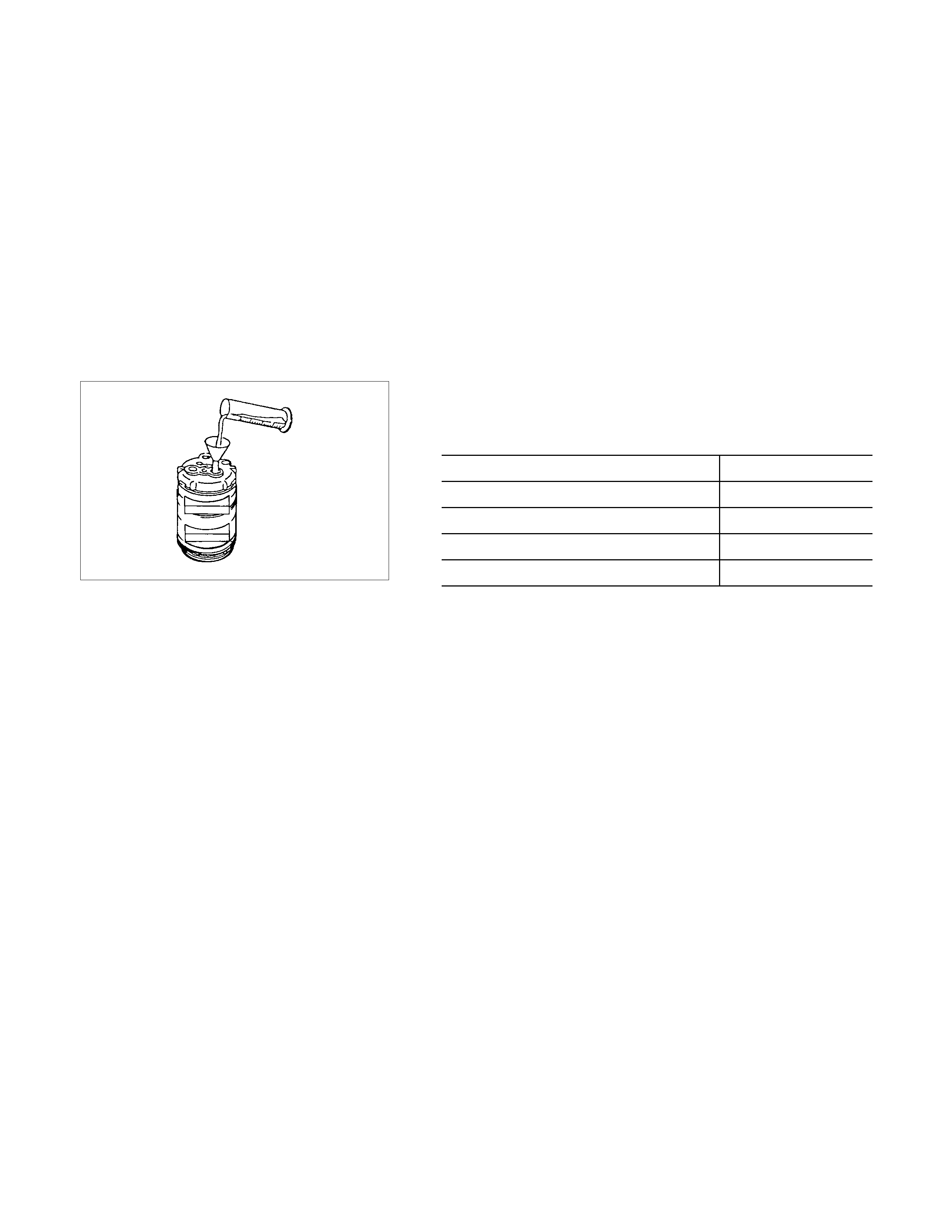
1) Apply a coat of new compressor oil to the new gasket.
2) Install the gasket to the valve plate.
5. O-ring
6. Rear Cylinder Head
1) Apply a coat of new compressor oil to the new O-ring.
2) Install the O-ring to the rear cylinder head.
3) Install the rear cylinder head.
Tap the rear cylinder head into place with a plastic
hammer.
7. Front Suction Valve
Set the cylinder shaft assembly with the front side facing up.
Install the suction valve by aligning it with the spring pin and
the cylinder valve relief grooves.
8. Front Valve Plate
Install the valve plate to the suction valve by aligning it with
the spring pin.
Note:
Do not mix up the front and rear valve plates.
9. Gasket
Apply new compressor oil to the new gasket.
Install the gasket to the valve plate by aligning it with the
spring pin.
10.O-ring
11.Front Cy linder Head
Apply a coat of new compressor oil to the new O-ring.
Install the O-ring to the front cylinder head.
Install the front cylinder head.
Tap the front cylinder head into place with a plastic
hammer.
Note:
When installing the cylinder head, be careful that the
end of the drive shaft does not damage the shaft seal
assembly surface in the cylinder head.
12.Through Bolt with Gasket
Gaskets cannot reused. Always replace new ones.
Tighten the bolts to the specified torque a little at a time in
the sequence shown in the illustration.
Through Bolt Torque N⋅m (kg⋅m/lb⋅ft)
22 (2.2/16)
Rotate the compressor drive shaft two or three times to
make sure that it moves smoothly.
13.Shaft Seal Assembly
1) Clean the sealing portion of the compressor and shaft
seal.
2) Install the shaft seal guide onto the end of the drive
shaft.
3) Shaft Seal Guide: 5-8840-0368-0 (J-34614)
4) Apply new compressor oil to the shaft seal guide.
5) Install the shaft seal onto the compressor drive shaft
head by using shaft seal installer.
Shaft Seal Installer: 5-8840-0120-0 (J-33942)
15.Shaft Seal Cover (If so equipped)
16.Felt (If so equipped)
Clean the sealing portion of the compressor and shaft seal
cover.
Install the shaft seal guide onto the end of the drive shaft.
Shaft Seal Guide: 5-8840-0368-0 (J-34614)
Apply new compressor oil to the shaft seal guide.
Install the shaft seal cover onto the drive shaft by using
shaft seal installer.
The installation position of the shaft seal cover is shown in
the illustration.
Shaft Seal Installer: 5-8840-0120-0 (J-33942)
17.Field Coil
18.Lead Wire Connector
Install the field coil to the compressor.
Lead wire must be facing up.
Tighten the field coil fixing screws to the specified torque.
N⋅m (kgf⋅m/Ib⋅ft)
Torque 5.0 (0.5/3.6)
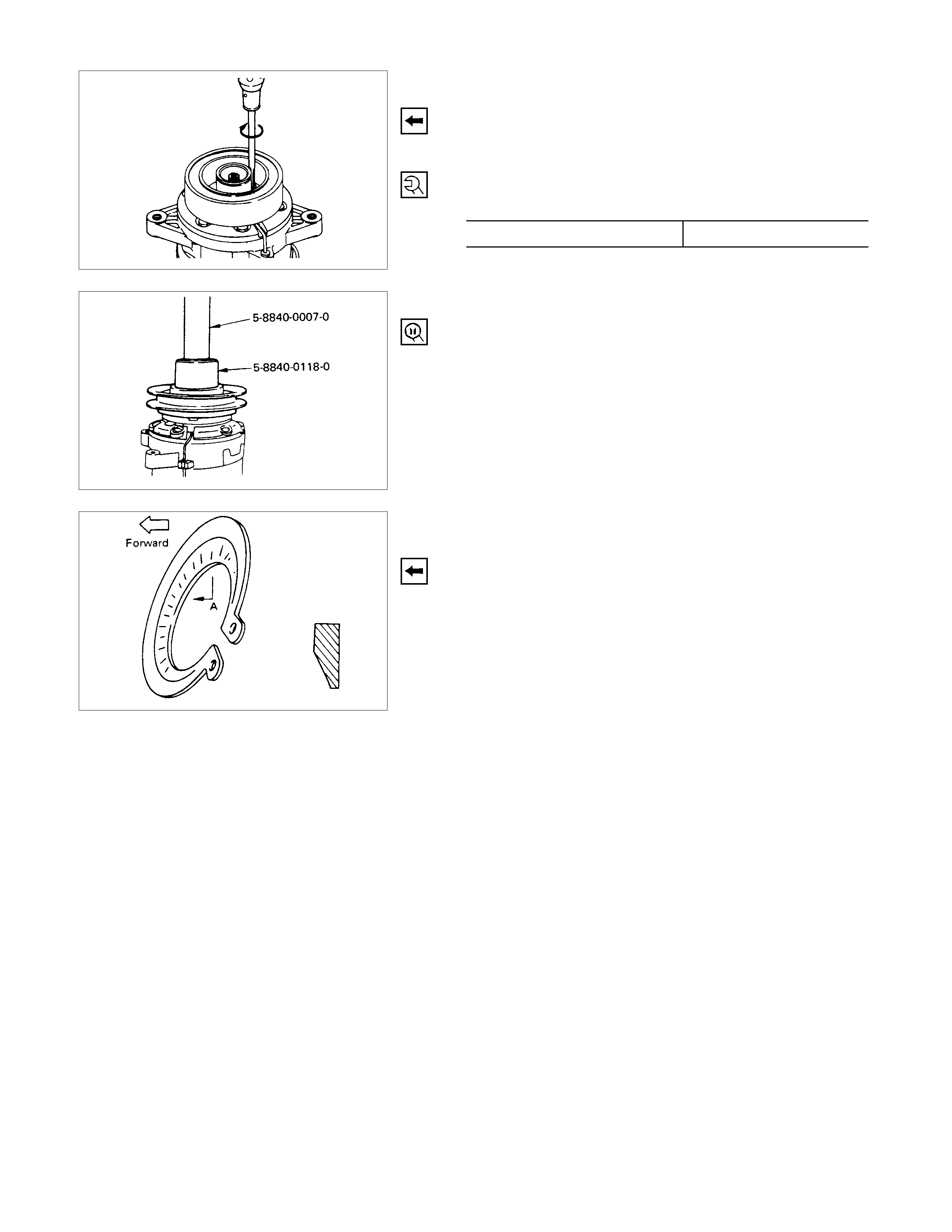
19.Pulley Asssembly
Using pulley installer and drive handle to install the pulley
assembly.
Pulley Installer: 5-8840-0118-0 (J-33940)
Drive Handle: 5-8840-0007-0 (J-8092)
20.Cover (If so equipped)
21.Snap Ring
Install the snap ring with the inside indented portion facing
out.
22.Shim(s)
23.Drive Plate
Install the drive plate to the com pres sor drive shaf t togethe
r
with the original shim(s).
Press the drive plate by hand.
24.Drive Plate Bolt
Using drive plate holder to prevent the drive plate from
rotating.
Drive Plate Holder: 5-8840-0117-0 (J-33939)
Tighten the bolt to the specified torque. N⋅m (kgf⋅m/Ib⋅ft)
Torque 15 (1.5/11)
After tightening the bolt, c heck to be s ure the pulley rotates
smoothly.
Check to be sure that the clutch clearance is between 0.3 -
0.6 mm (0.01 - 0.02 in).
If necessary, install adjusting shim(s).
Adjusting shims are available in the following thickness.
0.1 mm (0.0039 in)
Thickness 0.3 mm (0.0118 in)
0.5 mm (0.0197 in)
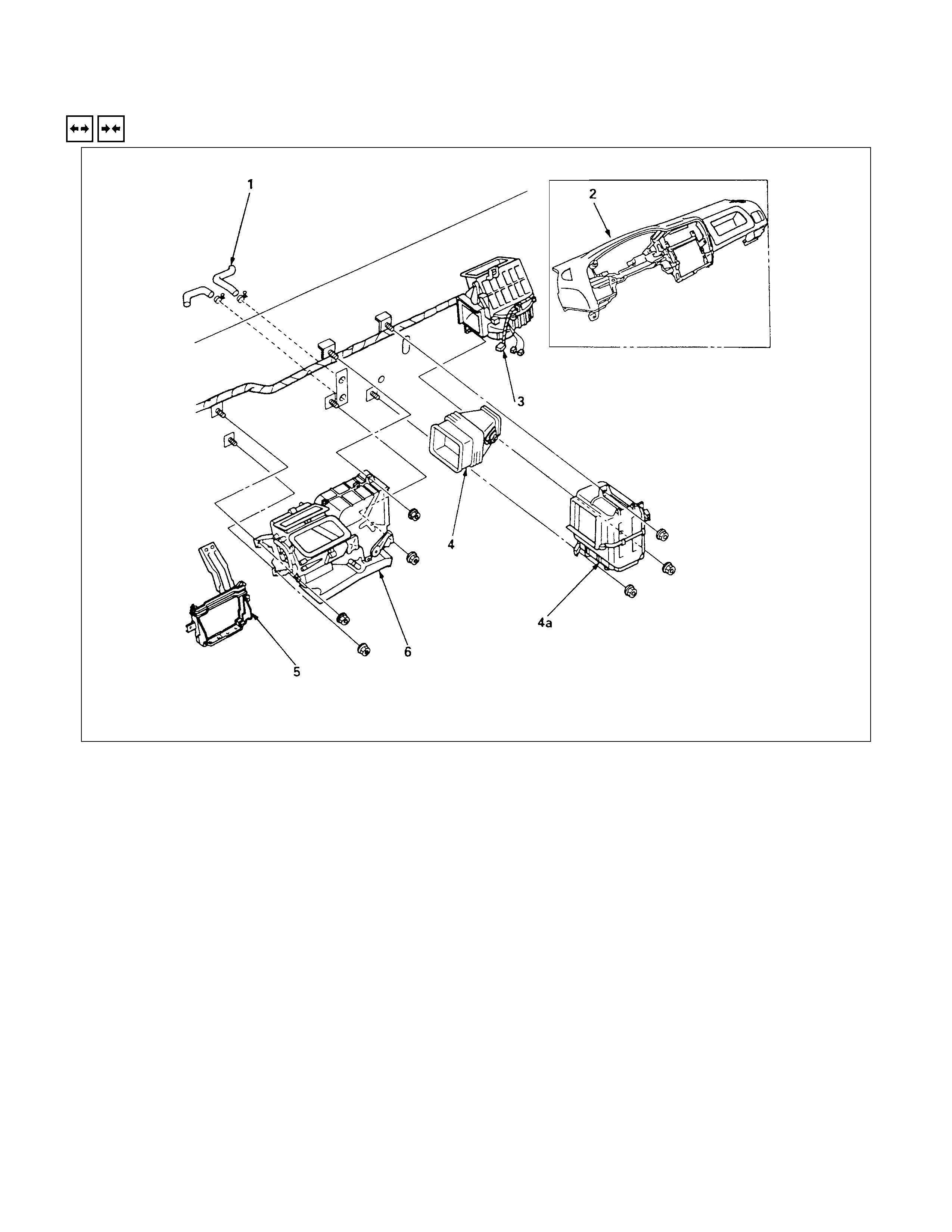
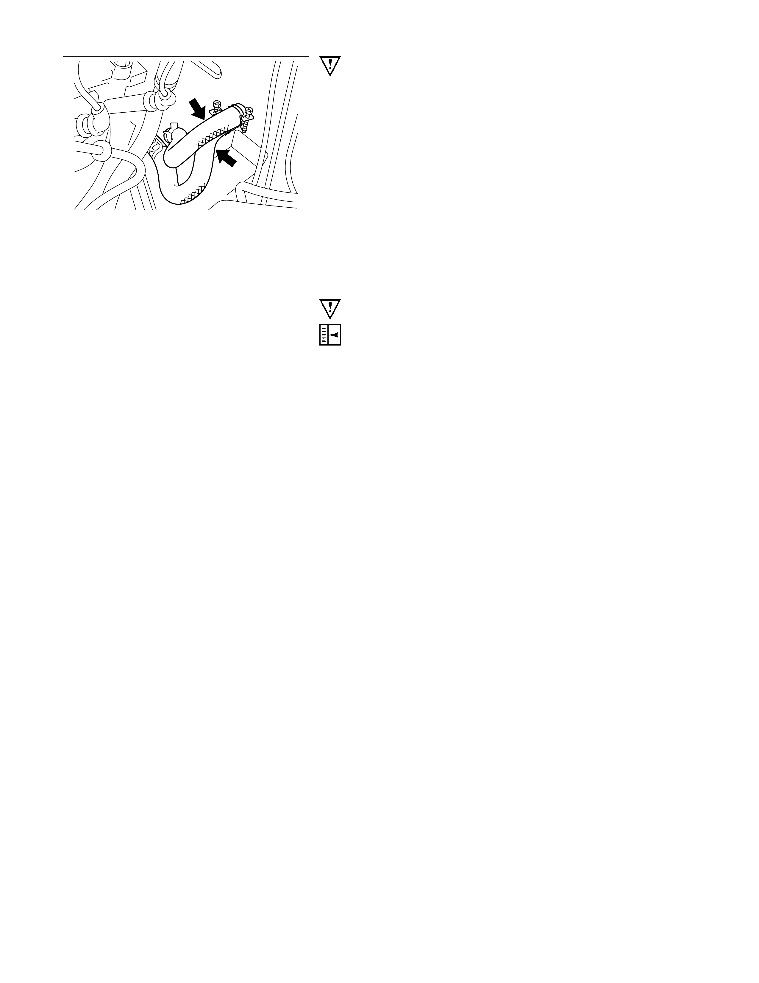
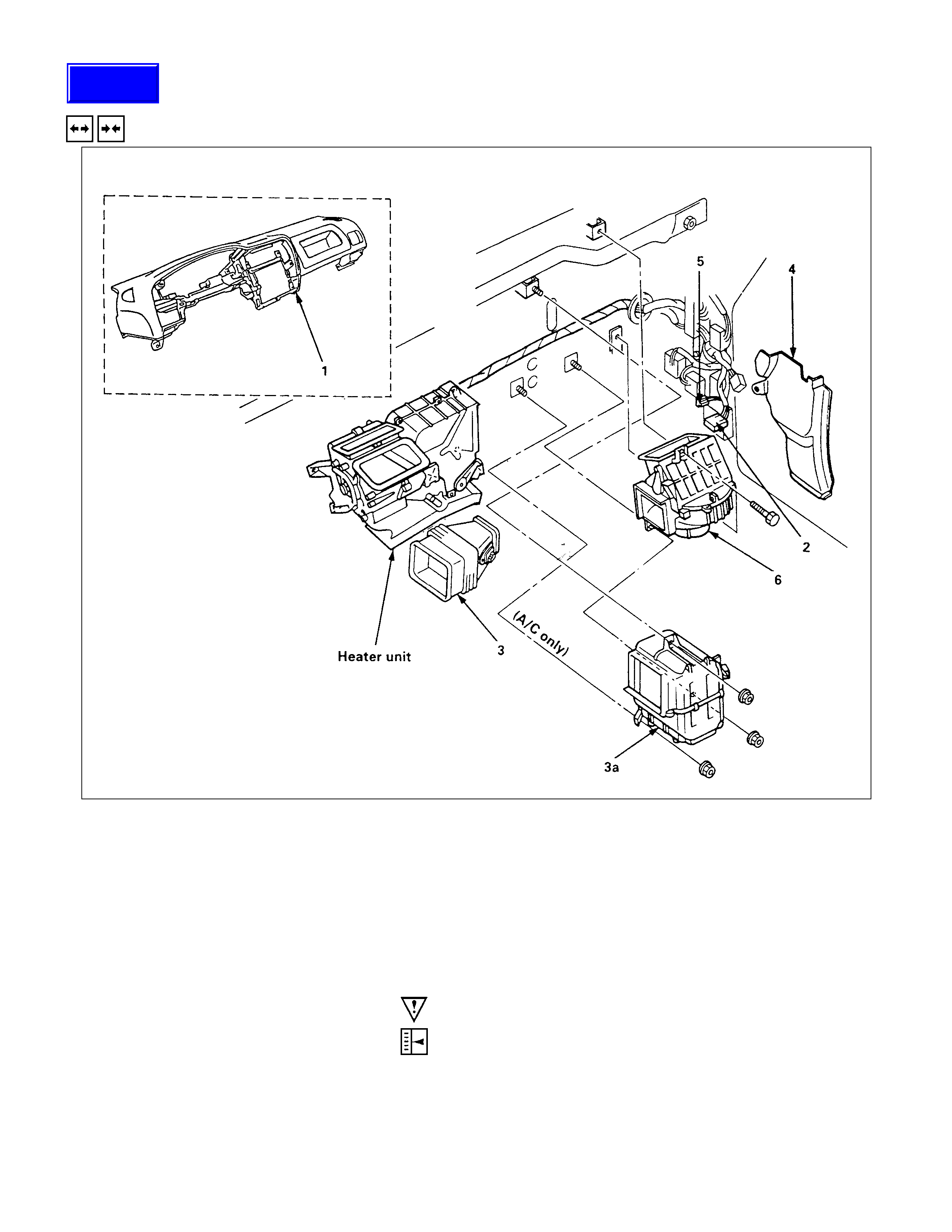
HEATER UNI T
REMOVAL AND INSTALLATION
This illustration is based on LHD model
REMOVAL STEPS
▲1. Heater hose
▲2. Instrument panel assembly
3. Resistor connector
4. Duct
4a. Evaporator (A/C only)
5. Instrument panel stay
6. Heater unit
INSTALLATION STEPS
6. Heater unit
5. Instrument panel stay
4a. Evaporator (A/C only)
4. Duct
3. Resistor connector
▲2. Instrument panel assembly
1. Heater hose
IMPO RTANT OPERATIONS - REM OVAL
1. Heater Hose
Disconnect the heater hoses at heater unit.
Place the drain pan under the vehicle.
2. Instrument Panel Assembly
Refer to section 1C "BODY" for instrument panel removal
procedure.
IMPORTANT OPERATION - INSTALLATION
2. Instrument Panel Assembly
Adjust the heater control cables.
Refer to "CONTROL LEVER ASSEMBLY" in this section.
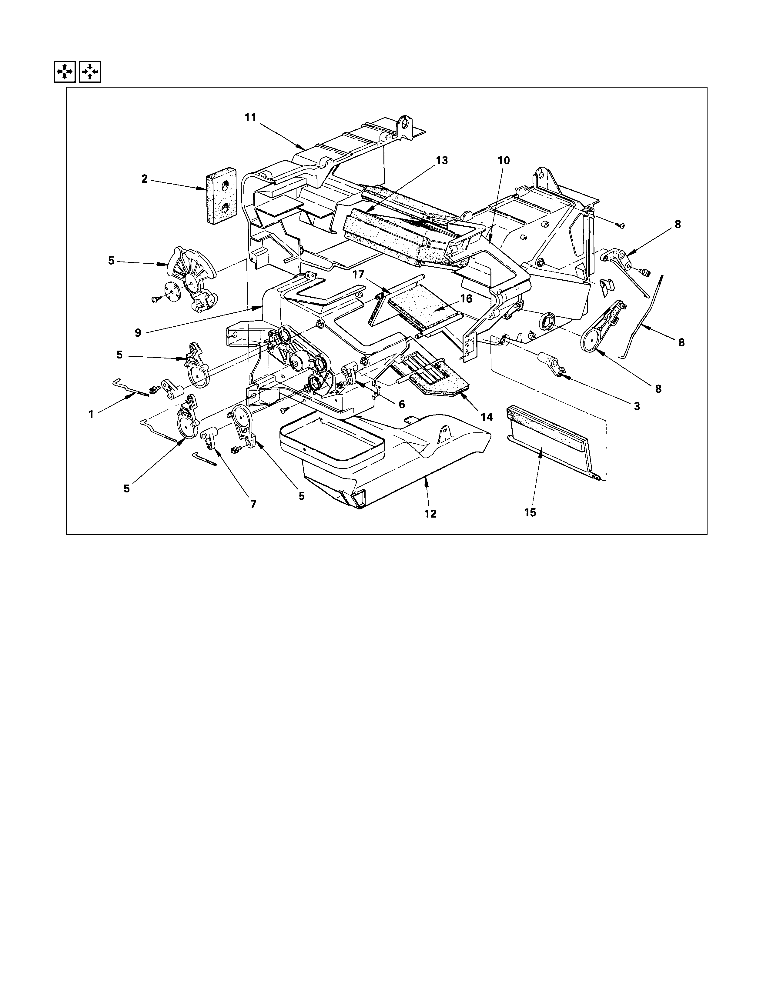
DISASSEMBLY AND REASSEMBLY
This illustration is based on the LHD model.
DISASSEMBLY STEPS
1. Rod and lever; defroster door
2. Plate and seal
3. Lever; mix door
4. Link; main model control
5. Relay link
6. Lever; vent door
7. Lever; heater door
8. Relay link mix door
9. Case; LH
10. Case; RH
11. Case; back
12. Duct
13. Core assembly
14. Door; heat foot
15. Door; heat mix
16. Door; side vent
17. Door; defroster
REASSEM BLY STEPS
To reassemble, follow the disassembly
procedure in reverse order.
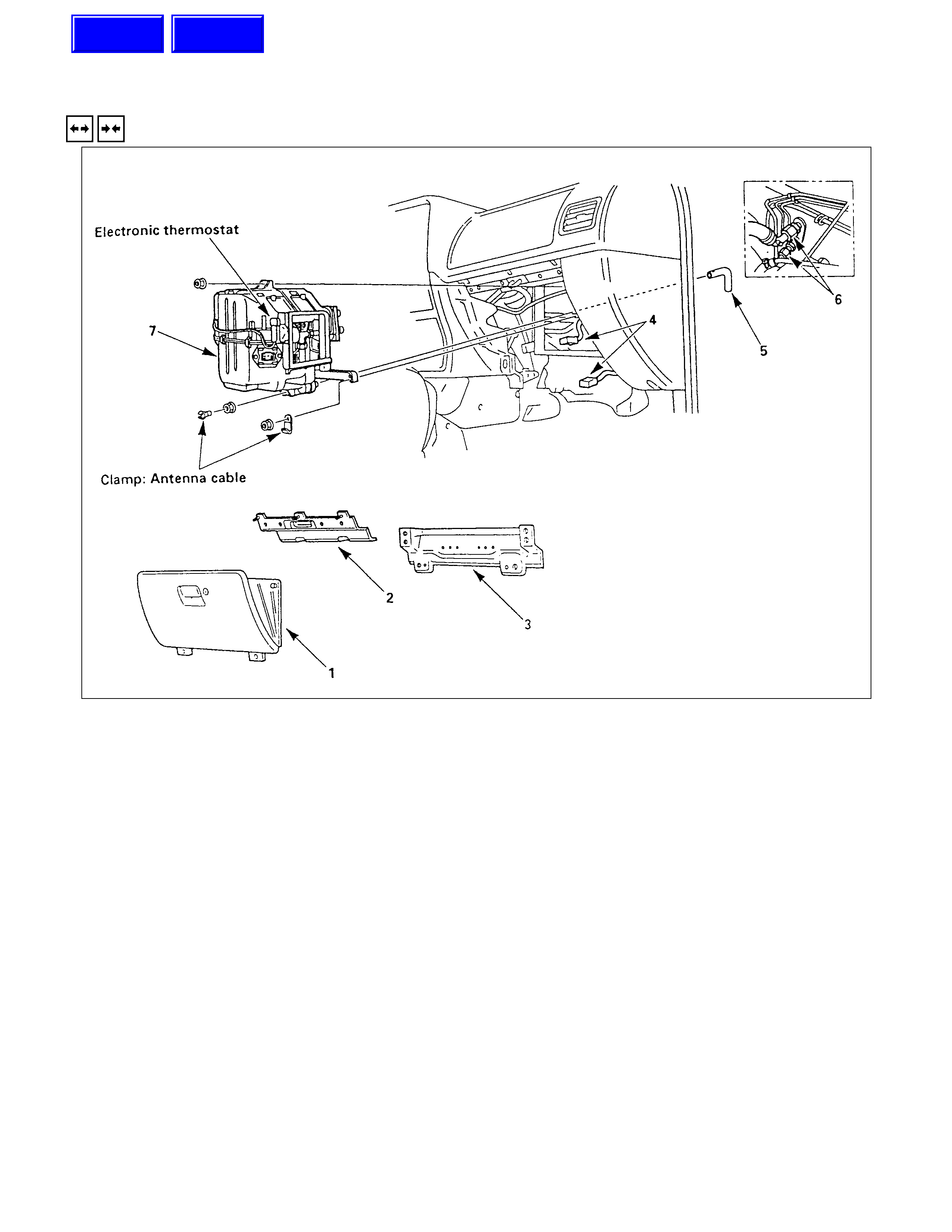
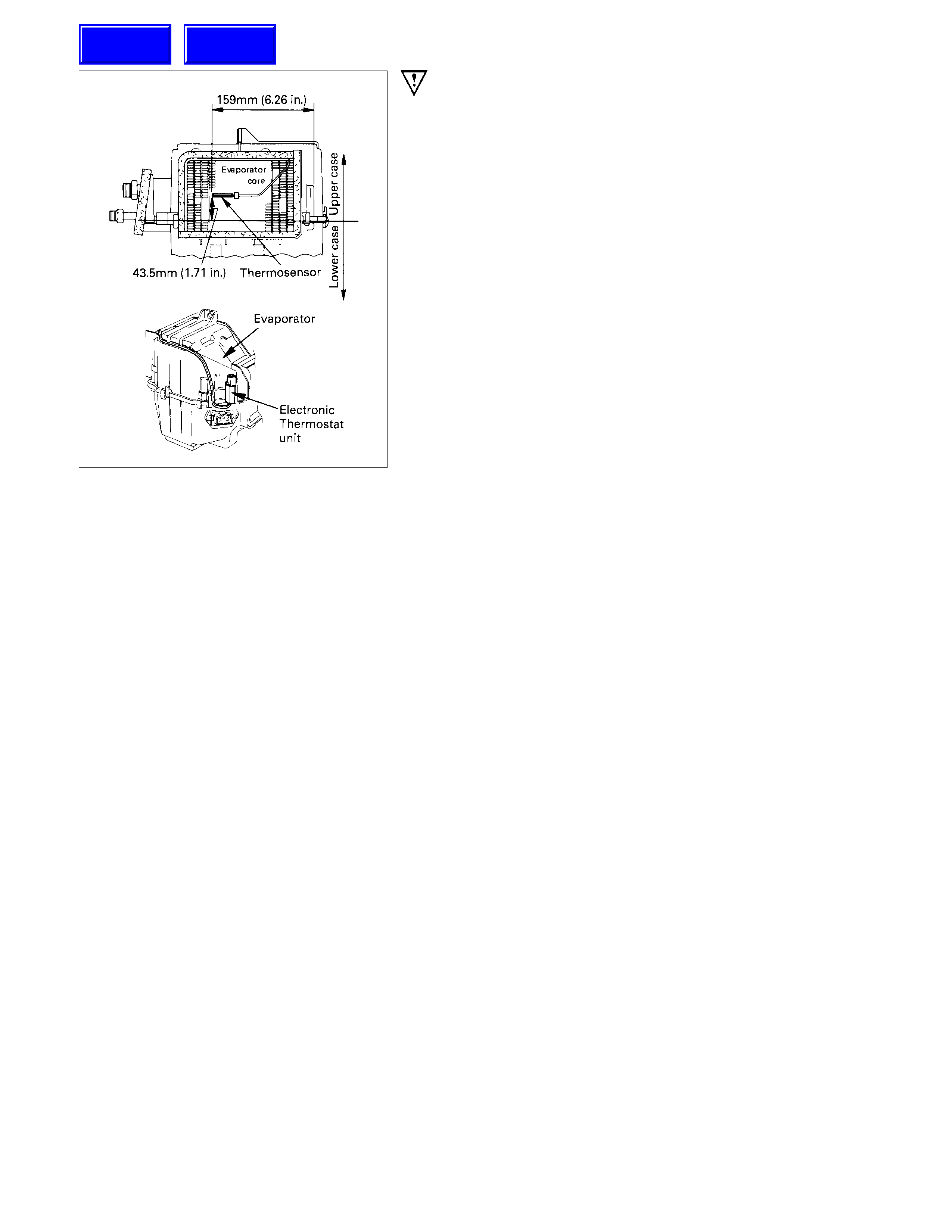
EVAPORATOR
REMOVAL AND INSTALLATION
This illustration is based on LHD model.
REMOVAL STEPS
1. Glove box
2. Glove box cover
3. Passenger knee bolster reintorcement
4. Resister and electronic thermostat
connector
5. Drain hose
6. Refrigerant line
7. Evaporator assembly
INSTALLATION STEPS
To install, follow the removal procedure in
reverse order.
Techline
Techline
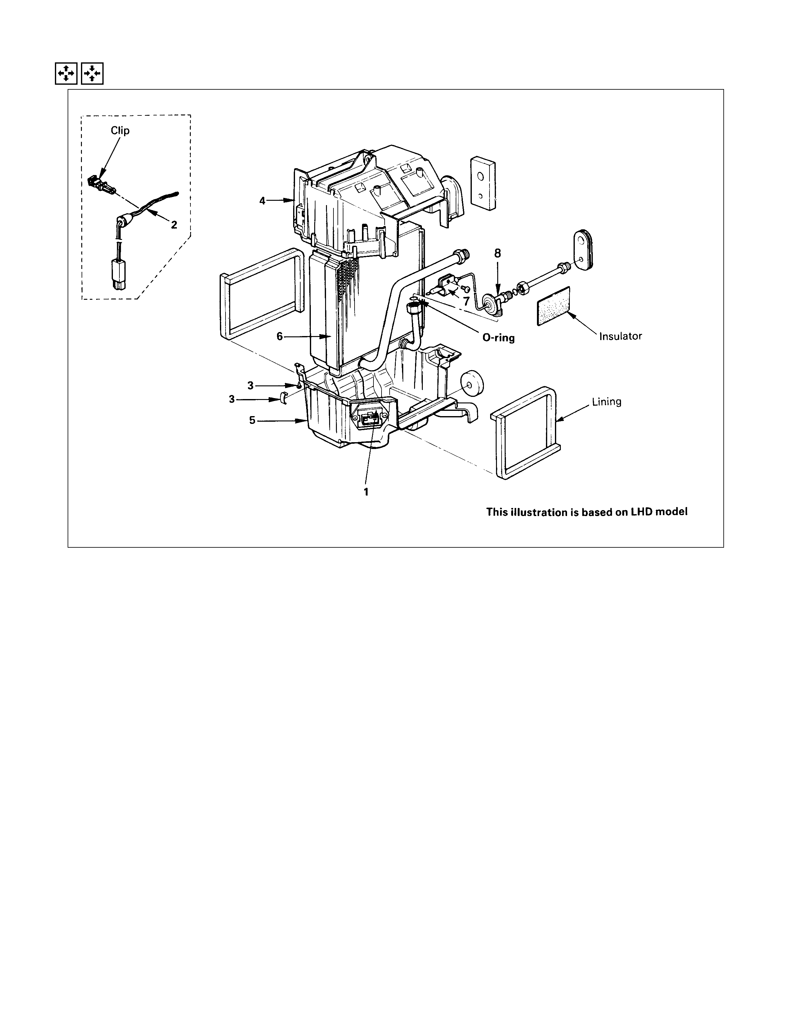
DISASSEMBLY AND REASSEMBLY
DISASSEMBLY STEPS
1. Resistor
2. Electronic thermostat (Clip type)
3. Attaching parts
4. Case; upper
5. Case; lower
6. Core assembly
7. Clip; sensing tube
8. Expansion valve assembly
REASSEM BLY STEPS
8. Expansion valve assembly
7. Clip; sensing tube
6. Core assembly
5. Case; lower
4. Case; upper
3. Attaching parts
▲2. Electronic thermostat (Clip type)
1. Resistor
BLOWER UNIT ASSEMBLY
REMOVAL AND INSTALLATION
This illustration is based on LHD model.
REMOVAL STEPS
1. Instrument panel assembly
2. Resistor connector
3. Duct
3a. Evaporator (A/C only)
4. Dash side trim panel
5. Blower motor connector
6. Blower unit assembly
INSTALLATION STEPS
6. Blower unit assembly
5. Blower motor connector
4. Dash side trim panel
3a. Evaporator (A/C only)
3. Duct
2. Resistor connector
▲1. Instrument panel assembly
IMPORTANT OPERATION - INSTALLATION
1. Instrument Panel Assembly
Adjust the blower control cable.
Refer to "CONTROL LEVER ASSEMBLY" in this section.
Techline
DISASSEMBLY AND REASSEMBLY
This illustration is
based on LHD model.
DISASSEMBLY STEPS
1. Lever; door
2. Blower motor assembly
3. Seal
4. Attaching parts
5. Case; lower
6. Case; LH
7. Case; RH
8. Door, blower unit
9. Fan; blower motor
10. Blower motor
REASSEM BLY STEPS
10. Blower motor
9. Fan; blower motor
8. Door, blower unit
7. Case; RH
6. Case; LH
5. Case; lower
4. Attaching parts
3. Seal
2. Blower motor assembly
1. Lever; door
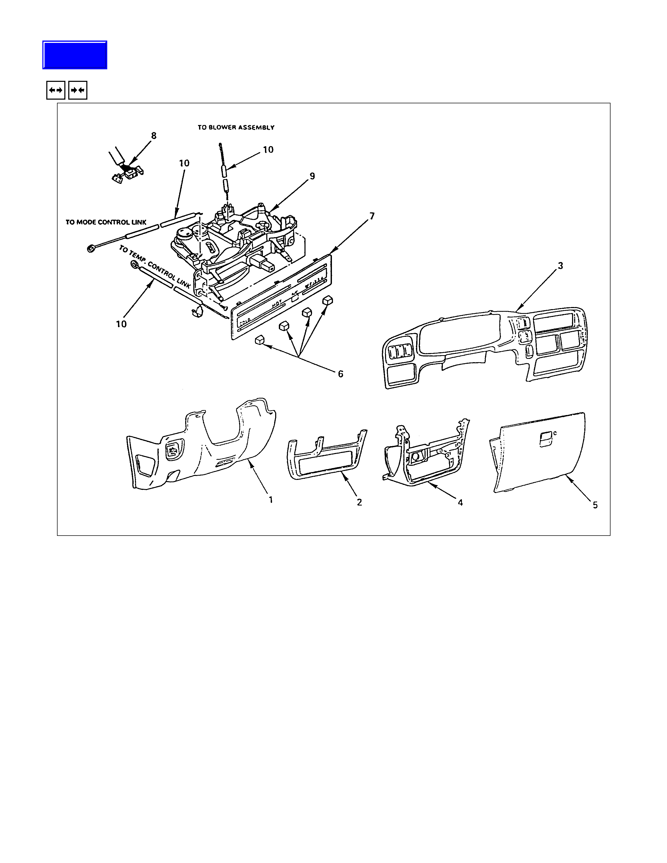
CONTROL LEVER ASSEMBLY
REMOVAL AND INSTALLATION
REMOVAL STEPS
1. Instrument panel driver lower
2. Lower cluster assembly
3. Meter cluster assembly
4. Instrument panel lower center cover
assembly
5. Glove box
6. Knobs
▲7. Heater bezel
▲8. Fan control lever and / or A/C switch
connector
9. Control lever assembly
▲10. Cables cover assembly
INSTALLATION STEPS
10. Cables
9. Control lever assembly
8. Fan control lever and / or A/C switch connector
7. Heater bezel
▲6. Knobs
5. Glove box
4. Instrument panel lower center cover assembly
3. Meter cluster assembly
2. Lower cluster assembly
1. Instrument panel driver lower
Techline
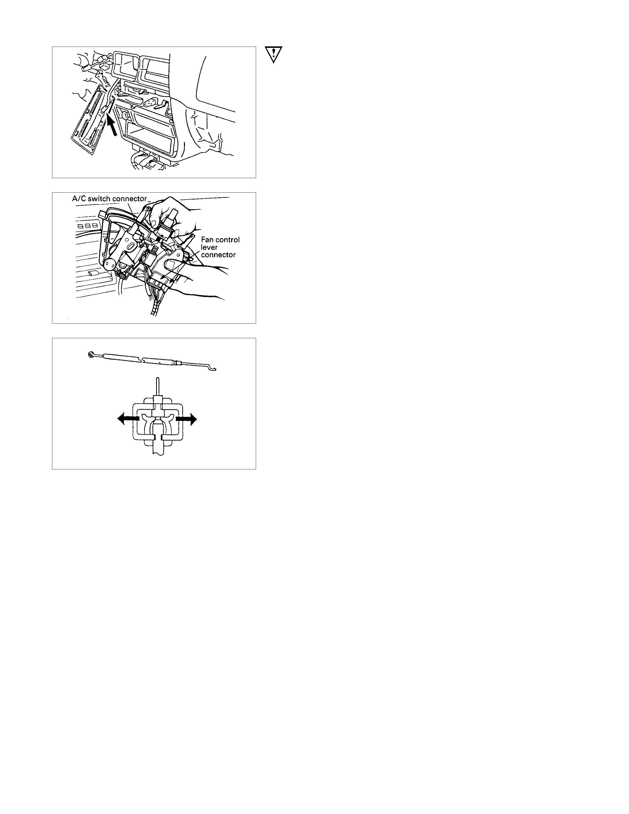
IMPORTANT OPERATION - REMOVAL
7. Heater Bezel
8. Fan and A/C Switch Connector
Pull the control lever assembly out and disconnect the
connectors.
10.Cables
IMPORTANT OPERATION - INSTALLATION
6. Control Lever Assembly
Adjust the control cables.
Air source control cable (Blower unit)
(1)Slide the control lever to the left.
(2)Connect the control cable at the "CIRC" position and fix it
with the clip.
Temperature control cable (Heater unit)
(1)Slide the control lever to the left.
(2)Connect the control cable at the "COLD" position and fix it
with the clip.
Air select control cable (Heater unit)
(1)Slide the control lever to the right.
(2)Connect the control cable at the "DEFROST" position and
fix it with the clip.
Check operation.
BEZEL
(AIR SELECTOR CABLE) (TEMPERATURE CONTROL
CABLE) (AIR SOURCE SELECT CABLE)
LHD
RHD
INSPECTION AND REPAIR
RESISTOR
As for air-conditioning model, fixed on right side of the
evaporator unit.
As for heater only model, fixed on right side of the duct placed
between blower unit and heater unit.
Replace the resistor with a new on if the coil is found to be
open or if the resistance value deviates from the specified
range.
Terminal Resistance
a - b 2.40Ω
b - d 0.90Ω
b - e 0.28Ω
b - c -
BLOWER MOTOR
Check blower motor for smooth rotation.
Connect the battery positive terminal to the No.1 (No.2: RHD)
terminal of the blower motor and negative to the No.2 (No.1:
RHD).
Be sure to check to see if the blower motor operates correctly.
FAN SW ITCH AND A/C SWITCH
Check for continuity between switch connector terminals.
Connector
No. FAN SW FAN
SW A/C
SW
SW Position 12345612123
OFF
1¡¡ ¡
2¡¡ ¡
3¡¡ ¡
4¡¡¡
OFF ¡¡
ON ¡¡¡
A/C
Blower
motor
THERMO SWITCH
(1)Remove the thermosensor from the evaporator.
(2)A/C is "ON".
(3) Set the atmospheric temperature of the thermosensor to
the following condition.
(4)Confirm that the thermo switch relay is activated when the
condition is met.
Ambient Temperature Thermo switch relay
Below 3.5±0.5°C (38.3±0.9°F) OFF
Above 5.0±0.5°C (41.0±0.9°F) ON
PRESSURE SWITCH
Check for continuity between pressure switch side connector
terminals.
1. Disconnect the connector and check f or continuity between
pressure switch side connector terminals (1).
2 Reconnect the connector to activate the A/C switch, and
check to see if there is continuity between the chassis side
connector terminals (3) and (4) and the fan operates.
IT RELAY
HEATER AND THERMO SWI TCH RELAY.
Check for continuity between relay side connector terminals.
IT RELAY:
Rated voltage/Coil resistance
12V/Approx. 90Ω
Minimum operating voltage : 7V at 25°C (77°F)
There is continuity betw een the relay side connector terminals
(5) and (1) when the relay connects between terminals (2) and
(4).
CM RELAY
CM RELAY
Rated voltage/Coil resistance
12V/Approx. 130Ω
Minimum operating voltage : 7V at 25°C (77°F)
There is continuity betw een the relay side connector terminals
(2) and (1) when the relay connects between terminals (4) and
(3).
CONDENSER FAN MOTOR
1
2
3
4
5
6
REMOVAL
Preparation: Battery ground cable
1. Radiator grille
2. Condenser fan assembly
•Disconnect the fan motor connector and
remove the 4 fixing bolts.
3. Cover
•Remove the 4 fixing screws.
4. Shroud
•Remove the 3 fixing nuts.
•Loosen the condenser fixing nut and
remove the fan motor connector from
bracket.
5. Fan
•Remove the fan fixing nut.
6. Condenser fan motor
•Disconnect the condenser connectors.
INSTALLATION
To install, follow the removal steps in the reverse order, noting
the following point.
1. Route the fan m otor har ness in its previous pos ition, and f ix
it securely with clip and bracket.

TROUBLESHOOTING
1. Trouble of Fan Control System
1-A Blower motor would not rotate totally.
1-B Blower motor does not rotate in certain position.
1-C Blower motor does no stop at "OFF" position.
2. Trouble of Air-Conditioning System
2-A Magnetic clutch would not engage.
2-B Refrigeration system defective.
1-A BLOWER MOTOR WO ULD NOT ROTATE TOTALLY
(REFER TO "WIRING HARNESS TERMINAL POSITIONS" IN THIS SECTION.)
Replace
YES
•Is heater fuse (20A) OK?
•Is heater relay OK?
YES
•Is resistor OK?
YES
•Is fan control knob (Fan switch) OK?
YES
YES
•Check to see if battery voltage is present at chassis
side connector terminal No.A - 1 (No.A - 2; RHD)
•Turn the ignition switch "ON" (Engine is running)
•Fan control knob (Fan switch) "ON"
•Is blower motor OK?
YES
Poor ground or open circuit either between chassis
side connector terminal No.A - 2 (No.A - 1; RHD)
and No.B - 6 or No.D - 12 and body ground
NO
Replace
NO
Replace
NO
NO
Replace control lever assembly
Replace
NO
NO
Open circuit between heater
fuse (20A) and No.A - 1 (No.A
- 2; RHD)
1-B BLOWER MOTOR DO ES NOT ROTATE IN CERTAIN POSI TION
(REFER TO "WIRING HARNESS TERMINAL POSITIONS" IN THIS SECTION.)
A1: (Low)
Blower motor does not B2: (Medium Low) Position
run at C3: (Medium Hi)
D4: (High)
* Checking is performed only when in the malfunction
mode.
•Is resistor OK?
YES
•Is fan control knob (Fan switch) OK?
YES
A Condition:
•Open circuit between chassis side connector terminal
No.B - 22 or No.D - 15
B Condition :
•Open circuit between chassis side connector terminal
No.B - 3 or No. D - 1
3
C Condition:
•Open circuit between chassis side connector terminal
No. B - 5 or No.D - 14
D Condition:
•Open circuit between chassis side connector terminal
No. B - 4 or No.D - 10
Replace
NO
NO
Replace control lever assembly
1-C BLOWER MOTOR DO ES NO T STOP AT "OFF" POSITION
(REFER TO "WIRING HARNESS TERMINAL POSITIONS" IN THIS SECTION.)
•Is fan control knob (Fan switch) OK?
YES
Short circuit between chassis side connector terminal
•No. A - 2 (No.A - 1; RHD) and No.B - 6
(or)
•No. B - 4 or No. D - 1
0
(or)
•No. B - 5 or No. D - 14
(or)
•No. B - 3 or No. D - 13
(or)
•No. B - 22 or No. D - 15
NO
Replace control lever assembly
2-A MAG NETIC CLUTCH WO ULD NOT ENGAGE
(REFER TO "WIRING HARNESS TERMINAL POSITIONS" IN THIS SECTION.)
Magnetic clutch deffective
NO
•Are A/C (10A) and heater (20A) fuses OK?
•Stop the engine
YES
•Are heater and thermo switch relays OK?
YES
•Is pressure switch (Dual pressure switch ) OK?
YES
YES
Check the A/C related harness and repair it as necessary
•Is thermo switch OK?
•Are A/C switch and fan control knob (Fan switch)
YES
Replace
NO
Replace
NO
NO
Switch defective or insufficient
refrigerant
Replace
NO
•Check to see if continuity between chassis side
connector terminal D - 12and ground
•Check to see if battery voltage is present at
magnetic clutch chassis side connector terminal
•Turn the ignition switch "ON" (Engine is running)
•A/C switch and fan switch "ON"
YES
YES
Replace
NO
Poor ground or open circuit
NO
2-B REFRIGERATION SYSTEM DEFECTIVE
Checkpoint Trouble Cause Countermeasure
Clean or replac e the
expansion v alv e
Clean or replac e the pipe line
Purge air from the
refrigeration system
Adjust the refriger ant gas
quantity
Expansion valve is c logged
Pipe line is c logged
Air exists in the system
The system is over-charged
Clean or replac e the
condenser
Charge the system with
ref r iger ant gas
Condenser is fouled or
clogged
The system is charged
unsufficiently
(Turn t he A /C swit c h on again)
Check to see if the pres s ur e
of high pr es s ur e s ide is 16
kg/cm2 (228 psi/ 15.7×10²kPa)
or lower.
Check to see if bubbles c om e
out wit hin 5 seconds aft er
turning the A/C switch off from
5 minut es r unning
Continue d on the nex t page
NG
NG
NG
NG
NG
NG
OK
OK
Sight glas s for being clear or
not
First , tur n engine ( with engine
speed of about 1000 rpm) and
A/C s witch on, and set fan
switch to be at 1-4 position
Checkpoint Trouble Cause Countermeasure
Replace the expansion valveExpansion valve is defective
Repair or replace the
compressor
Compressor is faulty
Continued from the previous
page
NG
NG
OK
Check to see if the pressure
of low pressure side is about
2.1 kg/cm2 (30 psi/2.1 ×
102kPa)
SPECIAL SERVICE TOOL
ITEM NO. ILLUSTRATION PART NO. PART NAME
5-8840-0629-0
(J-39500-A)
5-8840-0630-0
(J-39500-220A)
5-8840-0631-0
(J-39500-220ANZ)
ACL-2 5-8840-0117-0
(J-33939) Clutch hub holder
ACL-3 5-8840-0122-0
(J-33944-A) Clutch plate remover
ACL-4 5-8840-0121-0
(J-33943) Clutch pulley puller pilot
ITEM NO. ILLUSTRATION PART NO. PART NAME
ACL-5 5-8840-0111-0
(J-8433) Clutch pulley puller
ACL-6 5-8840-0120-0
(J-33942) Shaft seal cover remover
and installer
ACL-9 5-8840-0368-0
(J-34614) Shaft seal guide
CDL-10 5-8840-0118-0
(J-33940) Clutch pulley installer
OTL-1 5-8840-0007-0
(J-8092) Driver handle