
ALIGNMENT
•Tire pressure and abnormal wear
•Front hub bearings for axial play
•Ball joints on steering linkage for
play
•Suspension ball joint
•Operation of shock absorber
•Tightness of suspension parts
INSPECTION OF WHEEL ALIGNMENT
The points listed in table at left must be checked prior to
inspecting front wheel alignment.
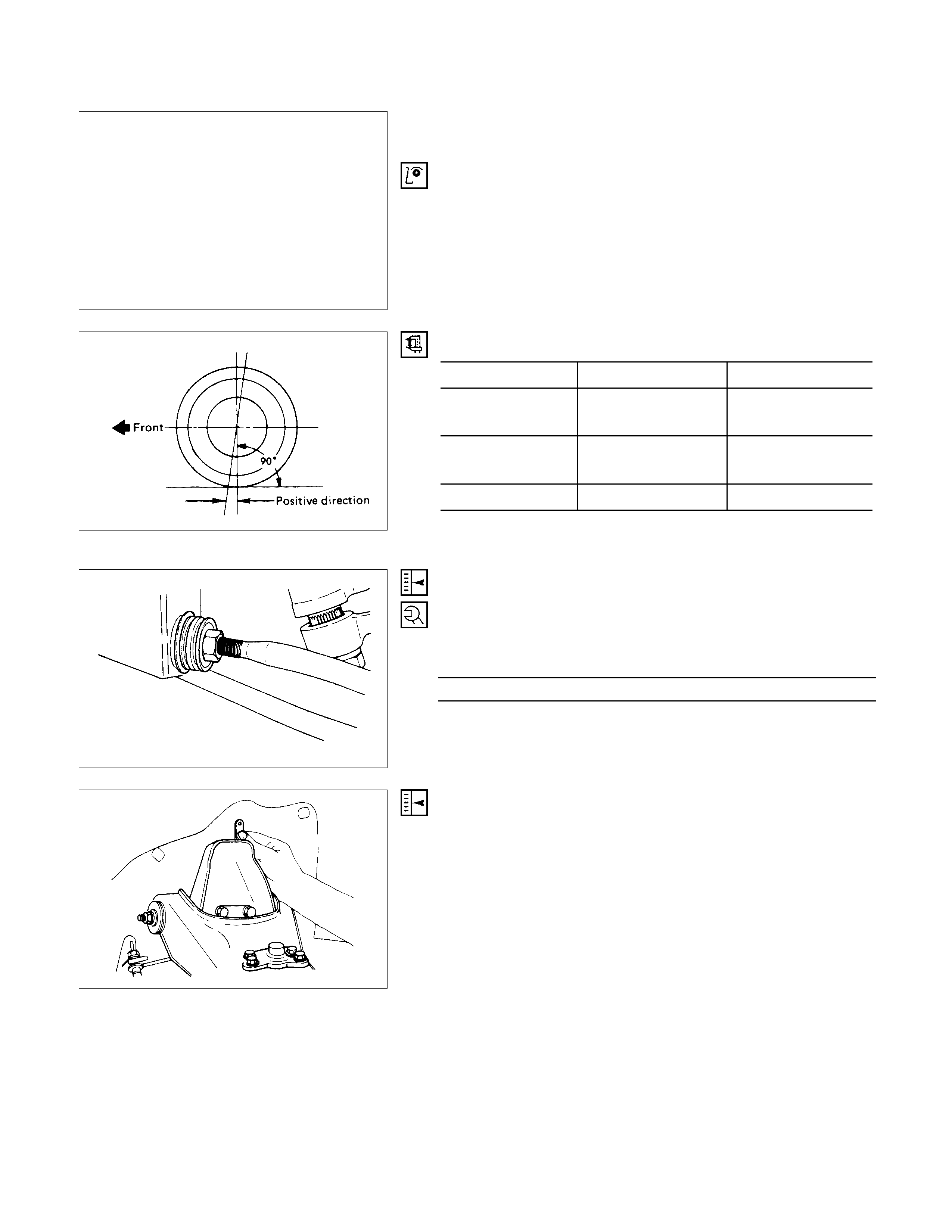
CASTER
Short wheel base Long wheel base
4×2 model
(except TFR25) 1°35'±45' 1°50'±45'
4×4 model and
TFR25 1°55'±45' 2°10'±45'
4×2 Flat Deck - 1°10'±45'
Note:
Left and right side to be equal within 35'.
[4×
××
×2 MODEL (EXCEPT TFR25)]
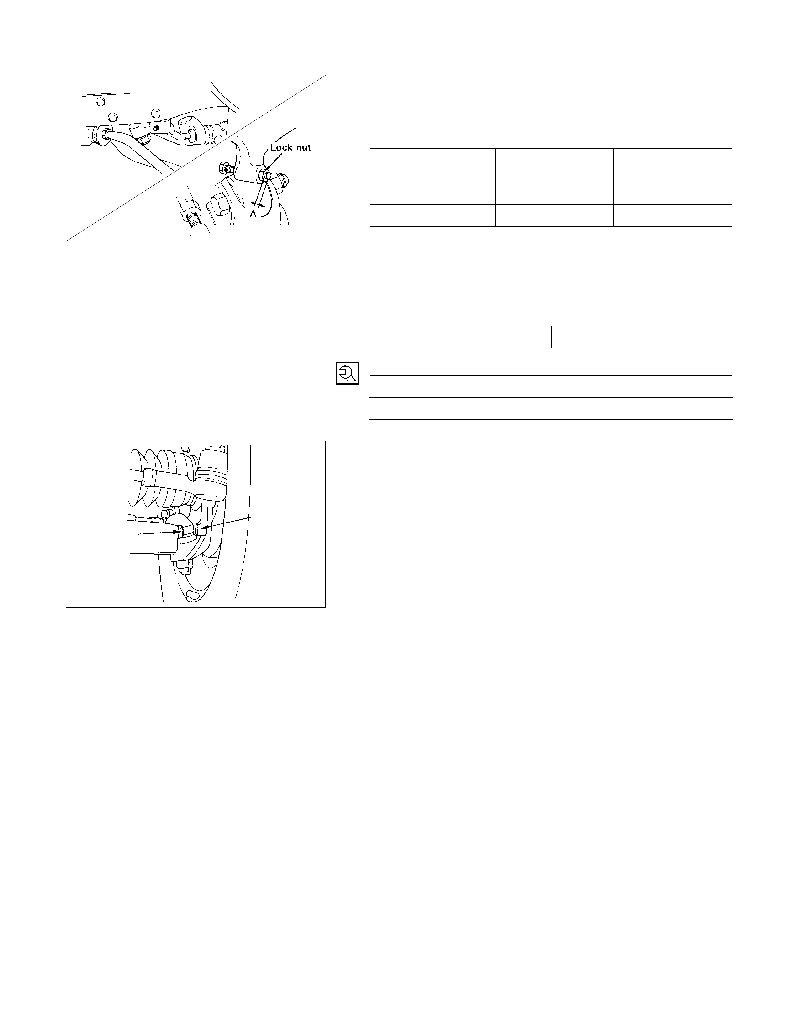
The caster angle can be adjusted by varying length of the strut
bar (adjust with lock nut) and shims should not be used for
adjustment.
Lock Nut Torque N⋅m
127.5±12.8
[4×
××
×4 MODEL AND TFR25]
The caster angle can be adjusted by means of the caster
shims installed in position between the chassis frame and
fulcrum pins.
Note:
Difference of the caster shim front/rear thickness shall be
3.2 mm (0.126 in) or less. Overall thickness of caster shim
and camber shim shall be 10.8 mm (0.426 in) or less.
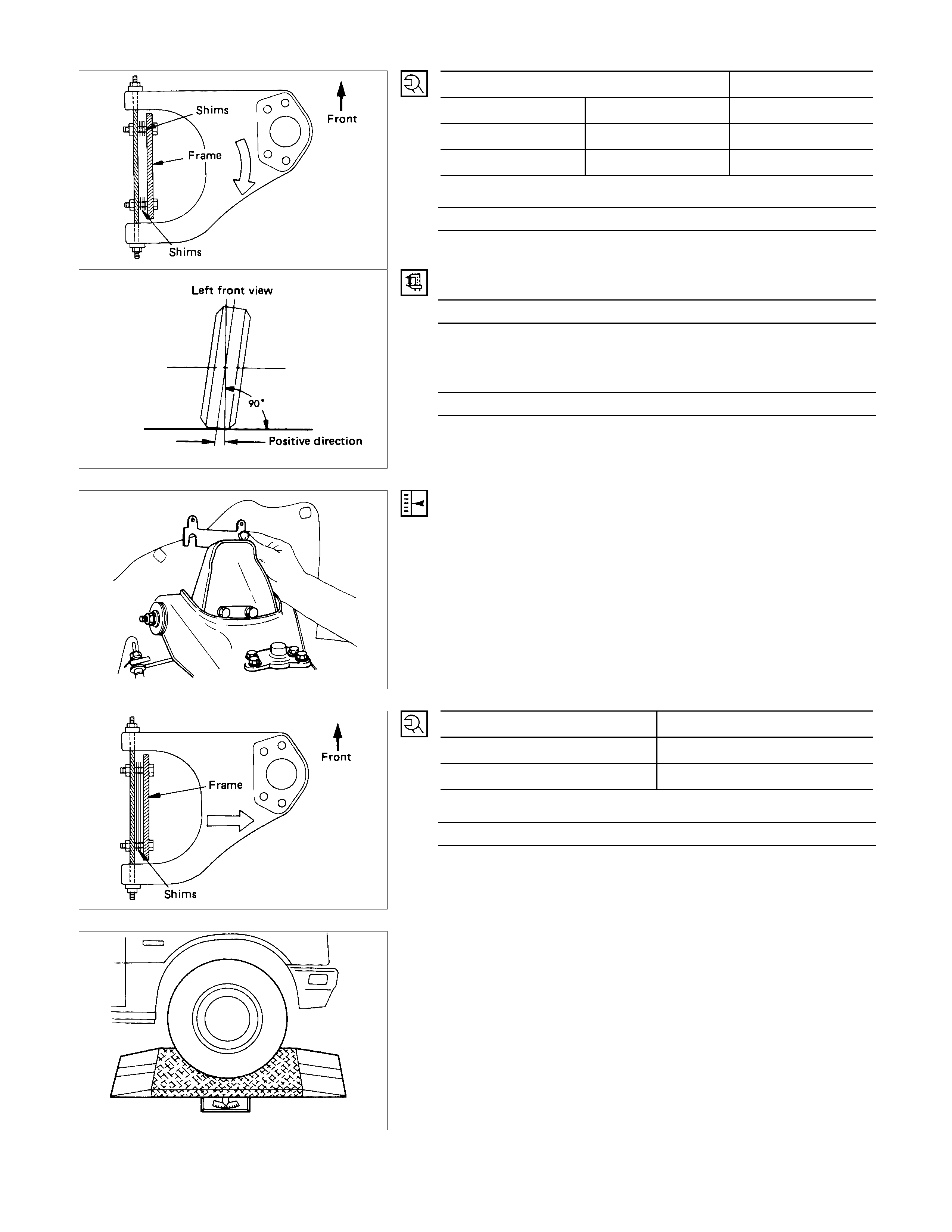
Position of shims Caster angle
Front side Rear side
When added When removed Decreases
When removed When added Increases
Fulcrum Pin Bolt Torque N⋅m
152.0±14.7
CAMBER
30'±60’
Note:
Left and right side to be equal within 45'.
KING PIN INCLINATION 10°±60'
[4×
××
×4 MODEL AND TFR25 ONLY]
The camber angle can be adjusted by means of the camber
shims installed in position between the chassis frame and
fulcrum pins.
Note:
Overall thickness of caster shim and chamber shim shall
be 10.8 mm (0.425 in) or less.
Position of shims Camber angle
When added Decreases
When removed Increases
Fulcrum Pin Bolt Torque N⋅m
152.0±14.7
MEASUREMENT OF SIDE SLIPPAGE
When inspection and adjustments of toe-in, camber, caster
and kingpin inclination are completed, check for side slippage
using a side slip tester.
Roll the wheels over the side tester as slowly as possible and
take reading on the tester. If the amount of side slippage is in
excess of 5 mm per 1 m, recheck the wheel alignment.

TOE-IN
Measurement should be taken with the vehicle on a surface
plate.
If a surface plate is not available, toe-in should be checked
with the vehicle parked on a level floor.
1. Set front wheels to straight ahead position.
2. Align the toe-in gauge with center height of each wheel at
front end.
3. Apply center marks to each wheel, then take measurement
of distance A between the center marks on each wheel.
4. Slowly move the vehicle rearward until the center marks
reach the rear end position.
5. Take measurement of distance B between the cente
r
marks at rear end.
The toe-in can be calculated with next formula.
Toe-in = B - A
Toe-in mm (in)
4×2 (except TFR25) 2±2 ( 0.08±0.08)
4×4 and TFR25 2±2 ( 0.08±0.08)
To adjust the toe-in angle, loosen the lock nut on the outer
track rod and turn the outer track rod with the same degree as
right and left.
Lock Nut Torque N⋅m
98.1±9.8
4×
××
×2 Model (except TFR25)
4×
××
×4 Model and TFR25
TRIM HEIGHT OR VEHICLE HEIGHT
Trim Height : at Curb Weight
Trim height (Z) = A - B
Front mm (in)
Model Z
4×2 (except TFR25) 56 (2.20)
4×4 and TFR25 130 (5.12)
Note:
Trim height and vehicle height measurements are
interchangeable.
Techline
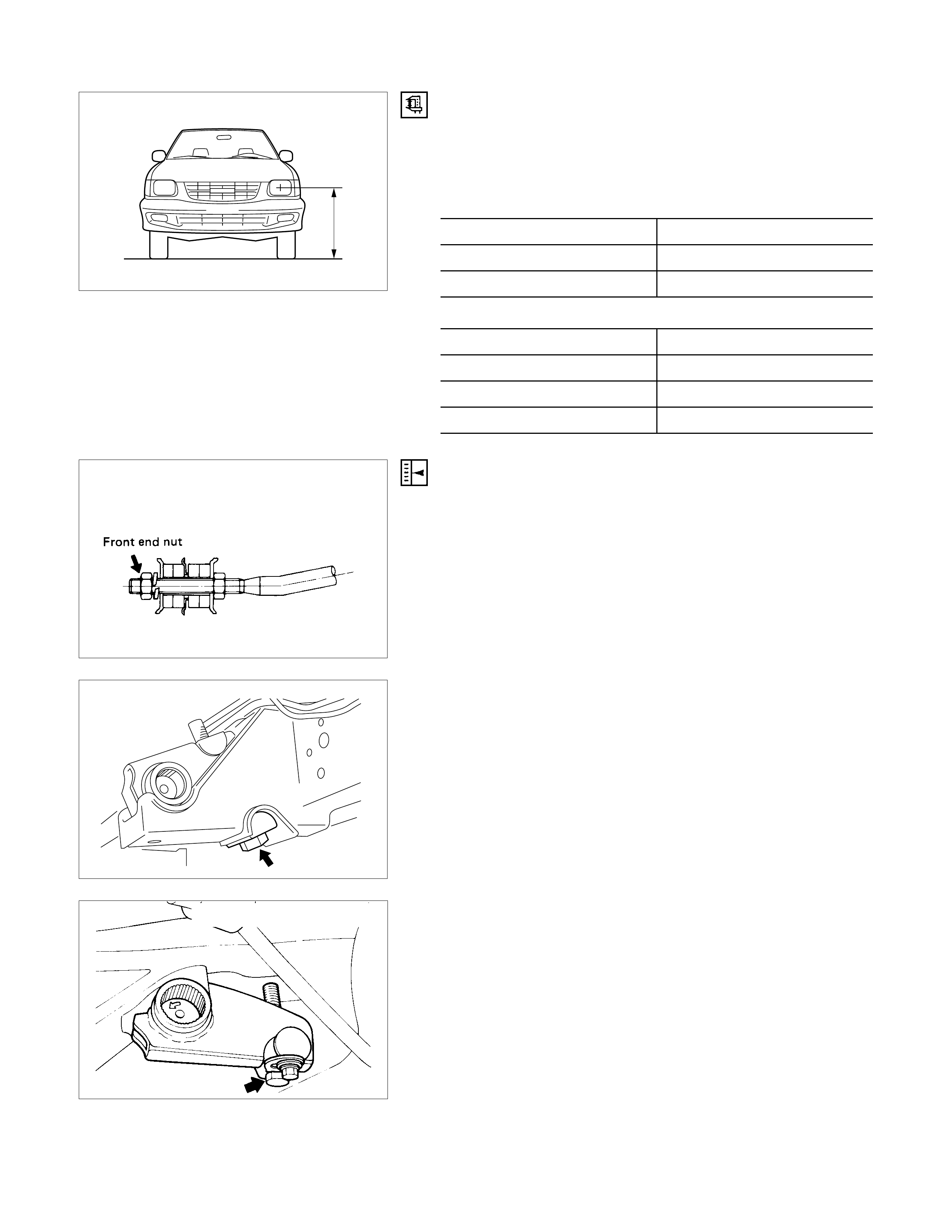
VEHICLE HEIGHT
Measure the height from the center of the headlights to the
ground. Height should be as specified; there must be no more
than 10 mm difference between the left-hand and right-hand
measurements.
2WD (except TFR25) mm (in
)
185R14 735 (28.9)
6.50-14 760 (29.9)
P205/75R14 740 (29.1)
4WD and TFR25 mm (in)
205R16 835 (32.9)
6.50-15 835 (32.9)
215R15 825 (32.5)
P225/75R15 823 (32.5)
4×
××
×2 Model (except TFR25)
ADJUSTMENT
Adjust the trim height by means of the adjusting bolt on the
height control arms.
1. Check and adjust the tire inflation pressures.
2. Park the vehicle on a level ground and move the f r ont of the
vehicle up and down several times to settle the suspension.
3. Loosen the nuts on the front end of the strut bar. (For 4×2
model (except TFR25) only ).
C22, C20 Series Engine Model
4. Make necessary adjustment with the adjusting bolt on the
height control arms.
4J Series, 6VD1 E ngine Model
Reference Data mm(in)
4×4 and TFR25
4JB1T & 6VD1
Engine model only
Standard 90 (3.54) 95 (3.74)
Heavy Duty
Sus. 90 (3.54) -
Flat Deck 65( 2.56) -
4×2
(except TFR25)
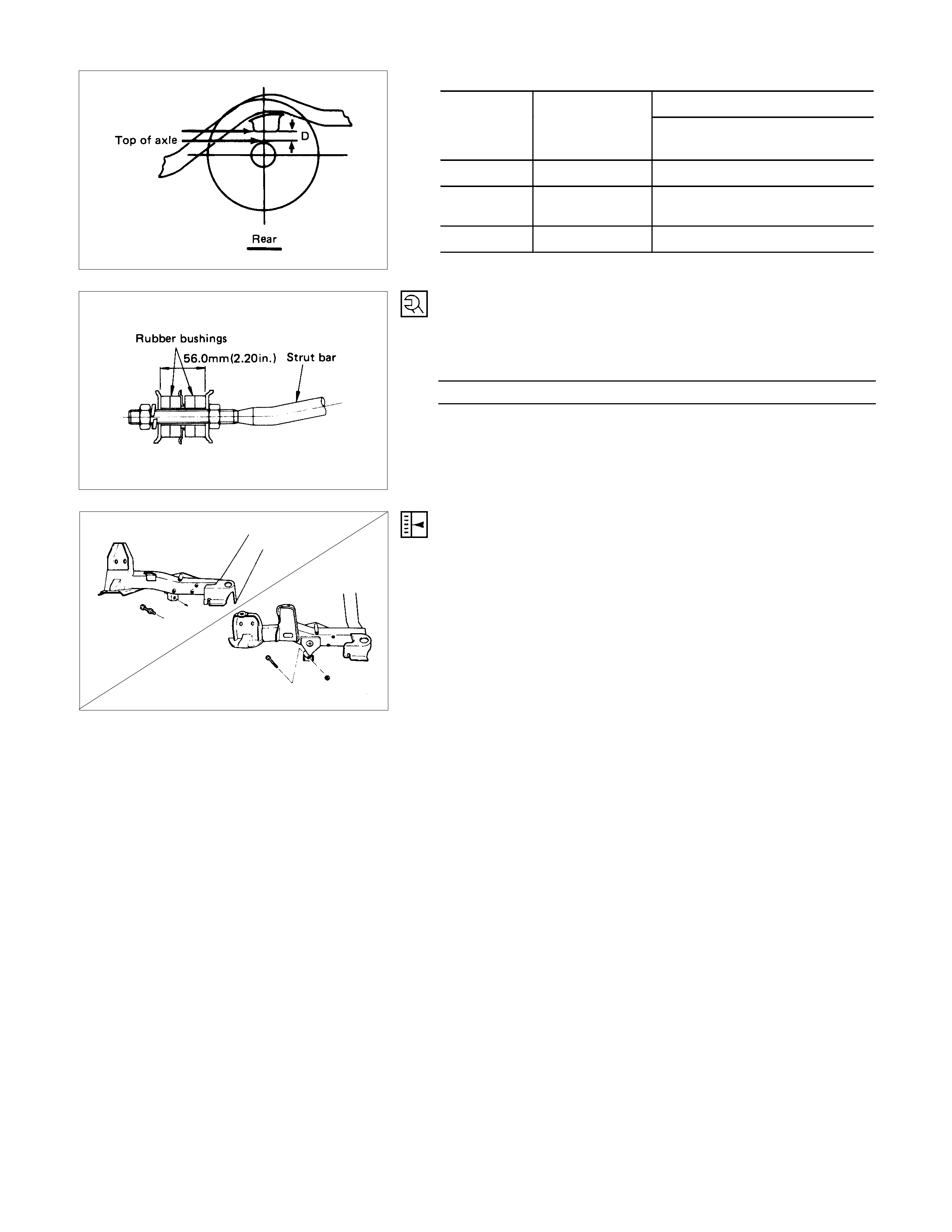
STRUT BAR
Securely Tighten the Strut Bar Nuts
(4×
××
×2 Model (except TFR25) Only)
Strut Bar Torque N⋅m
127.5±12.8
4×
××
×4 Model and TFR25
4×
××
×2 Model (except TFR25) MAXIM UM STEERING ANGLE ADJUSTMENT
The maximum steering angle of the front wheels can be
adjusted with the stopper bolts under the frame side members.
1. Position each front wheel on the turning radius gauge in a
straight-ahead position.
2. Set the parking brake firmly.
4×
××
×4 Model and TFR25
4×
××
×2 Model (except TFR25) 3.
A
djust the inside wheel angle of each side with the stoppe
r
bolts.
4. Similar ly adjust the inside wheel angle of the other side with
stopper bolt. 4×2
(except TFR25) 4×4 and TFR25
Outside wheel 33°33°
Inside wheel 37°+0°
-2°35°+0°
-2°
Note:
Maximum steering angles should be set after adjusting
front wheel alignment.
4×4 Model and TFR25 Only mm (in)
A 0 - 8.5 (0 - 0.33)
Stopper Bolt Lock Nut Torque N⋅m
4×2 (exc. TFR25) 44.1±9.8
4×4 and TFR25 22.5±2.9
Stoppe
r
Stopper
4×
××
×4 MODEL AND TFR25 ONLY
If the stopper (non-adjustable) between the lower link end and
the knuckle comes ahead of the stopper bolt, adjust the
stopper bolt so that the inner-side stopper bolt touches the
drop arm (relay lever).