
SECTION 3B - FRONT SUSPENSION
MAIN DATA AND SPECIFICATIONS
C22NE SERIES ENGINE MODEL
4J SERIES ENGINE MODEL
TORQUE SPECIFICATIONS
SPECIAL PARTS FIXING NUTS AND BOLTS
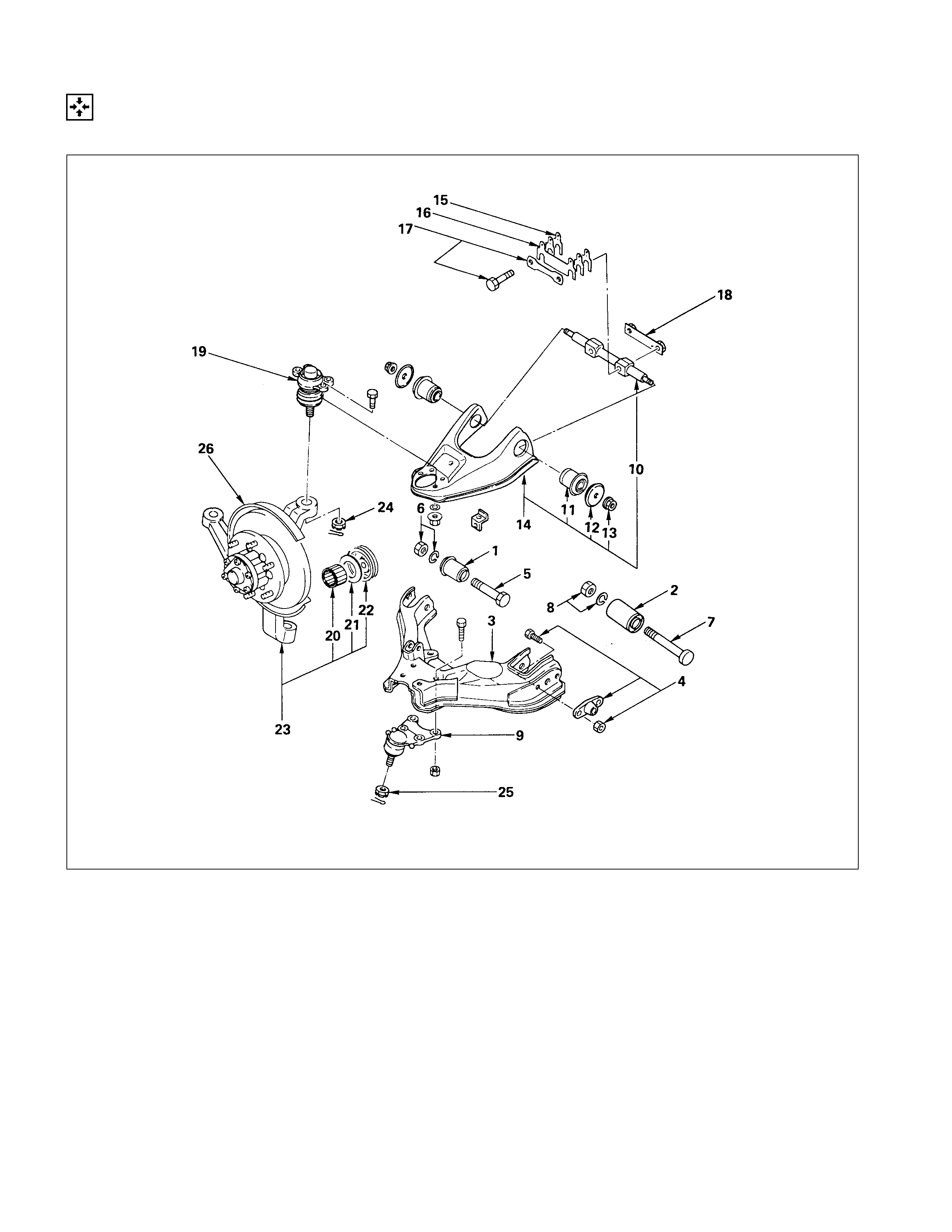
FRONT SUSPENSION
GENERAL DESCRIPTION
TORSION BAR, STRUT BAR, STABILIZER BAR AND SHOCK ABSORBER (4 ×
××
× 2 MODEL
EXCEPT V6 ENGINE)
DISASSEMBLY
INSPECTION AND REPAIR
REASSEMBLY
TORSION BAR, STABILIZER BAR AND SHOCK ABSORBE R (4 ×
××
× 4 AND 4 ×
××
× 2 V6 ENGINE)
DISASSEMBLY
INSPECTION AND REPAIR
REASSEMBLY
KNUCKLE, UPPER LINK AND LOWER LINK (4 ×
××
× 2 MODEL EXCEPT V6 ENGINE)
DISASSEMBLY
INSPECTION AND REPAIR
REASSEMBLY
KNUCKLE, UPPER LINK AND LOWER LINK (4 ×
××
× 4 AND 4 ×
××
× 2 V6 ENGINE)
DISASSEMBLY
INSPECTION AND REPAIR
REASSEMBLY
TROUBLESHOOTING
SPECIAL SERVICE TOOL (C22, C20 SERIES ENGINE MODEL)

MAIN DATA AND SPECIFICATIONS
C22NE SERIES ENGI NE MODEL
4×
××
×2 MODEL
Front Suspension Type Independent wishbone arms. torsion bar springs with
stabilizer bar
Except Tray Top Tray Top
Front wheel alignment
When not loaded
Tread mm(in) 1445 (56.88)
Camber 0°30'±60'
(Left and right side to be equal within 45')
Caster *1°50'±45' | *1°10'±45'
* Left and right side to be equal within 35'
Toe-in mm(in) 2±2 (0.08±0.08)
Kingpin inclination 10°±60'
Torsion Bar Spring Data
Length×diameter mm(in) 1006×24.4 (39.61×0.961)
Wheel Rate/Side N/mm (kg/mm/Ib/in) 25.0 (2.55/143)
Spring Constant N⋅m/deg (kg⋅m /deg/Ib⋅ft/deg) 48.06 (4.90/35.44)
Spring Capacity N (kg/lb) 4658 (475/1047), For Australia 5148 (525/1157)
Shock Absorber Data
Maximum Length mm(in) 328(12.91)
Minimum Length mm(in) 213 (8.39)
Stroke mm(in) 115 (4.53)
Damping Force
Rebound Side 215 kg at 0.3 m/sec.
(2108 N at 0.3 m/sec./474 lb. at 11.8 in/sec.)
Compression Side 118 kg at 0.3 m/sec.
(1157 N at 0.3 m/sec./26.0 lb. at 11.8 in/sec.)
4J SERIES ENGI NE M ODEL
4×
××
×2 MODEL
Front Suspension Type Independent wishbone arms. torsion bar springs with
stabilizer bar
Except Tray Top Tray Top
Front wheel alignment
When not loaded
Tread mm (in) 1445 (56.88)
Camber 0°30’±60’
(Left and right side to be equal within 45’)
Caster *1°50’±45’ *1°10’±45’
*Left and right side to be equal within 35’
Toe-in mm (in) 2±2 (0.08±0.08)
Kingpin inclination 10°±60’
Torsion Bar Spring Data
Length x Diameter mm (in) 1006 x 24.4 (39.61 x 0.961)
Wheel Rate/Side kg/mm (lb/in/N/mm) 2.55 (143/25.0)
Spring Constant kg⋅m/deg (lb.ft/deg/N⋅m/deg) 4.90 (35.44 / 48.06)
Shock Absorber Data
Maximum Length mm (in) 325 (12.80)
Minimum Length mm (in) 210 (8.27)
Stroke mm (in) 115 (4.53)
Damping Force
Rebound Side 135 kg at 0.3 m/sec.
(297 lb. at 11.8 in/sec./ 1324 N at 0.3 m/sec.)
Compression Side 34 kg at 0.3 m/sec.
(74.9 lb. at 11.8 in/sec./333 N at 0.3 m/sec.)
Shock Absorber Data (Gas-sealed)
Maximum Length mm (in) 328 (12.91)
Minimum Length mm (in) 213 (8.39)
Stroke mm (in) 115 (4.53)
Damping Force
Rebound Side 215 kg at 0.3 m/sec.
(474 lb. at 11.8 in/sec./ 2108 N at 0.3 m/sec.)
Compression Side 118 kg at 0.3 m/sec.
(260 lb. at 11.8 in/sec./ 1157 N at 0.3 m/sec.)
4×
××
×4 MODEL & 4X2 V6 ENG I NE
Front Suspension Type Independent wishbone arms. torsion bar springs with
stabilizer bar
Short wheel base Long wheel base
Front wheel alignment
When not loaded
Tread mm(in) 1438 (56.61)
Camber 0°30' ± 60'
(Left and right side to be equal within 45')
Caster *1°55' ± 45' | *2°10' ± 45'
* Left and right side to be equal within 35'
Toe-in mm(in) 2 ± 2 (0.08±0.08)
Kingpin inclination 10° ± 60'
Torsion Bar Spring Data
Length × diameter mm(in) 998×23.4 (39.29×0.321)
Wheel Rate/Side N/mm (kg/mm/lb/in) 32.6 (3.33/186)
Spring Constant N⋅m/deg (kg⋅m/deg/lb⋅ft) 41.2 (4.20/30.4)
Spring Capacity N (kg/lb) Gasoline engine 490 (500/1102)
Shock Absorber Data
Type Hydraulic double acting, telescopic
Maximum Length mm(in) 375 (14.76)
Minimum Length mm(in) 235 (9.25)
Stroke mm(in) 140 (5.51)
Damping Force
Rebound Side 110 kg at 0.3 m/sec.
(1079 N at 0.3 m/sec./243 lb. at 11.8 in/sec.)
Compression Side 32 kg at 0.3 m/sec.
(313 N at 0.3 m/sec./70.5 lb. at 11.8 in/sec.)
Shock Absorber Data (For Australia)
Type Gas-sealed, hydraulic double acting telescopic
Maximum Length mm(in) 377 (14.84)
Minimum Length mm(in) 237 (9.33)
Stroke mm(in) 140(5.51)
Damping Force
Rebound Side 200 kg at 0.3 m/sec.
(1961 N at 0.3 m/sec./441 lb. at 11.8 in/sec.)
Compression Side 138 kg at 0.3 m/sec.
(1353 N at 0.3 m/sec./304 lb. at 11.8 in/sec.)
Shock Absorber Data (TFS25)
Type Gas-sealed, hydraulic double acting telescopic
Maximum Length mm(in) 377 (14.84)
Minimum Length mm(in) 237 (9.33)
Stroke mm(in) 140(5.51)
Damping Force
Rebound Side 199 kg at 0.3 m/sec.
(439 lb. at 11.8 in/sec./1952 N at 0.3 m/sec.)
Compression Side 126 kg at 0.3 m/sec.
(278 lb. at 11.8 in/sec./1236 N at 0.3 m/sec.)
TORQUE SPECIFICATIONS
SPECIAL PARTS FI XING NUTS AND BOLTS
4×
××
×2 MODEL ( EXCEPT V6 ENGI NE M ODEL) N⋅
⋅⋅⋅m (kgf⋅
⋅⋅⋅m/lb⋅
⋅⋅⋅ft)
147.1±9.8(15.0±1.0/108±7.2)
68.7±6.9(7.0±0.7/50.6±5.1)
126.5±12.8(12.9±1.3/93.3±9.4)
68.7±6.9(7.0±0.7/50.6±5.1)
107.9±9.8(10.0±1.0/79.7±7.2)
107.9±14.1(11.0±1.5/79.6±10.8)
32.4±2.9(3.3±0.3/23.9±2.2)
107.9±14.7(11.0±1.5/79.6±10.8)
107.9±14.7(11.0±1.5/79.6±10.8)
4×
××
×2 MODEL ( EXCEPT V6 ENGI NE M ODEL) N⋅
⋅⋅⋅m (kgf⋅
⋅⋅⋅m/lb⋅
⋅⋅⋅ft)
68.7±6.9 (7.0±0.7 / 50.6±5.1)
18.6±4.9 (1.9±0.5 / 13.7±3.6)
24.5±4.9 (2.5±0.5 / 18.1±3.6)
82.4±7.8 (8.4±0.8 / 60.8±5.8)
127.5±12.8
(13.0±1.3 / 94.0±9.4)
9.8 (1.0 / 7.2)
19.6±4.9 (2.0±0.5 / 14.5±3.6)
4×
××
×4 AND 4×
××
×2 V6 ENGINE M O DEL N⋅
⋅⋅⋅m (kgf⋅
⋅⋅⋅m/lb⋅
⋅⋅⋅ft)
107.9±14.7
(11.0±1. 5 / 79. 6±10.8)
156.9±19.6 ( 16±2. 0 / 115.7±14.5)
115.7±9.8 ( 11. 8±1. 0 / 85. 3±7.2)
103.0±9.8 ( 10. 5±1. 0 / 75. 9±7.2)
196.1±19.6 ( 20±2. 0 / 144.7±14.5)
127.5±9.8 ( 13. 0±1. 0 / 94. 0±7.2)
98.1±9.8 ( 10. 0±1. 0 / 72. 3±7.2)
32.4±2.9 ( 3. 3±0. 3 / 23. 9±2.2)
107.9±14.7 ( 11. 0±1. 5 / 79. 6±10.8)
152.0±14.7 ( 15. 5±1. 5 / 112. 1±10.8)
4×
××
×4 AND 4×
××
×2 ENGINE M O DEL N⋅
⋅⋅⋅m (kgf⋅
⋅⋅⋅m/lb⋅
⋅⋅⋅ft)
82.4±7. 8 ( 8.4±0.8/60.8±5.8)
9.8 (1.0/7.2)
40.2±5. 9 ( 4.1±0.6/29.7±4.3)
19.6±4. 9 ( 2.0±0.5/14.5±3.6)
27.5±6. 9 ( 2.8±0.7/20.3±5.1)
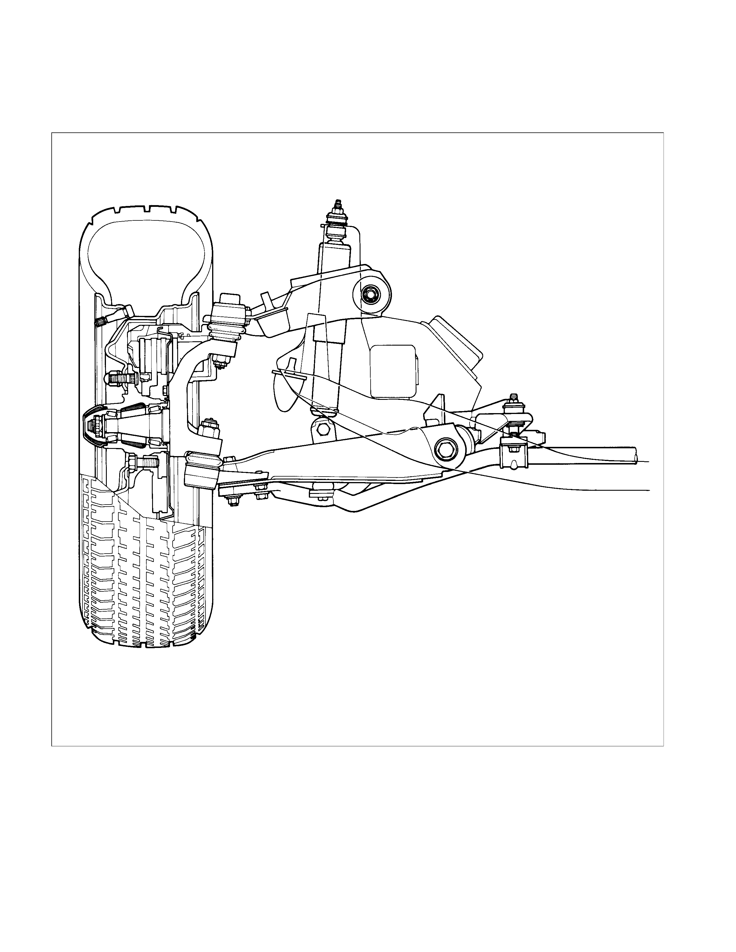
FRONT SUSPENSION
GENERAL DESCRI PTION
4×
××
×2 MODEL ( EXCEPT V6 ENGI NE M ODEL)
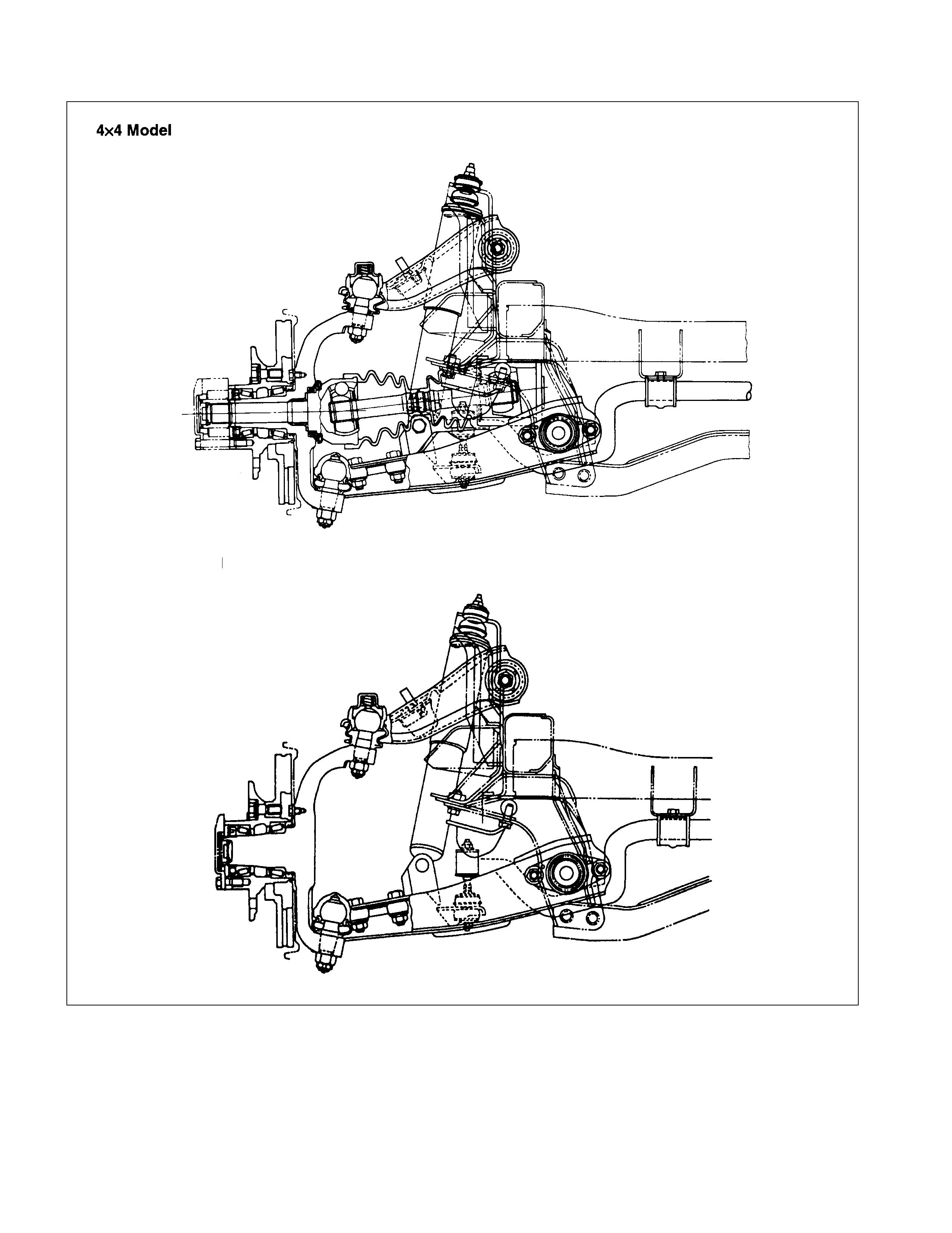
4×
××
×4 AND 4×
××
×2 V6 ENGINE M O DEL
The links attach to the vehicle with bolts and bushings at their inner pivot points and to the steering knuckle, which is
part of the front wheel spindle, at their outer points.
The knuckle is mounted to the upper and lower links, each of which has a ball joint to permit pivoting of the knuckle for
steering operations. The hub is supported in position on the knuckle spindle by means of the two bearings and the rotor
is mounted to the hub.
The front suspension is an independent type utilizing torsion bar springs. The torsion bar spring has splines on each
end. Height control is provided on the third crossmember. Both the upper and lower links are pressed steel and the
torsion bar is supported at the ends by lower link in front and by height control arm in rear.
4x2 V6 Engine
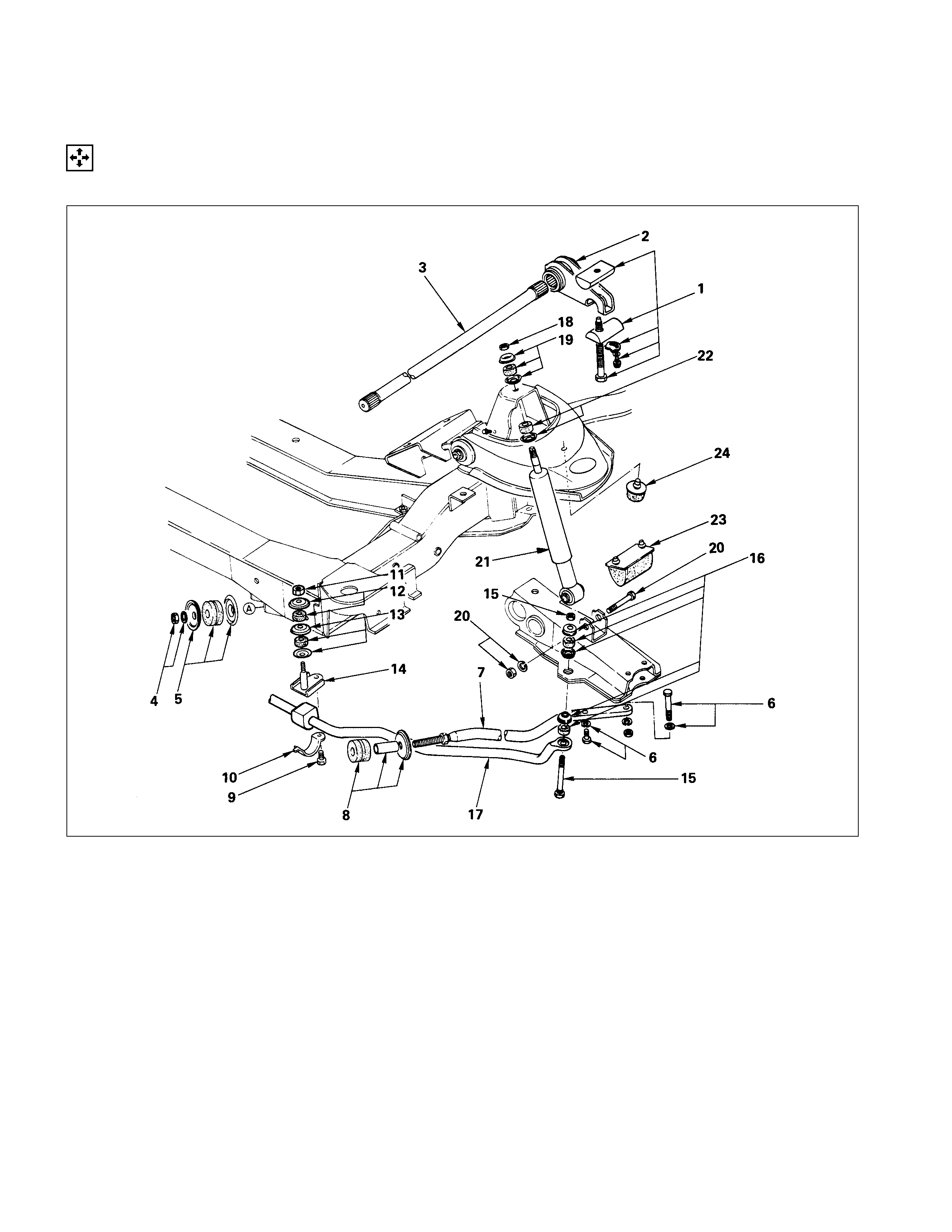
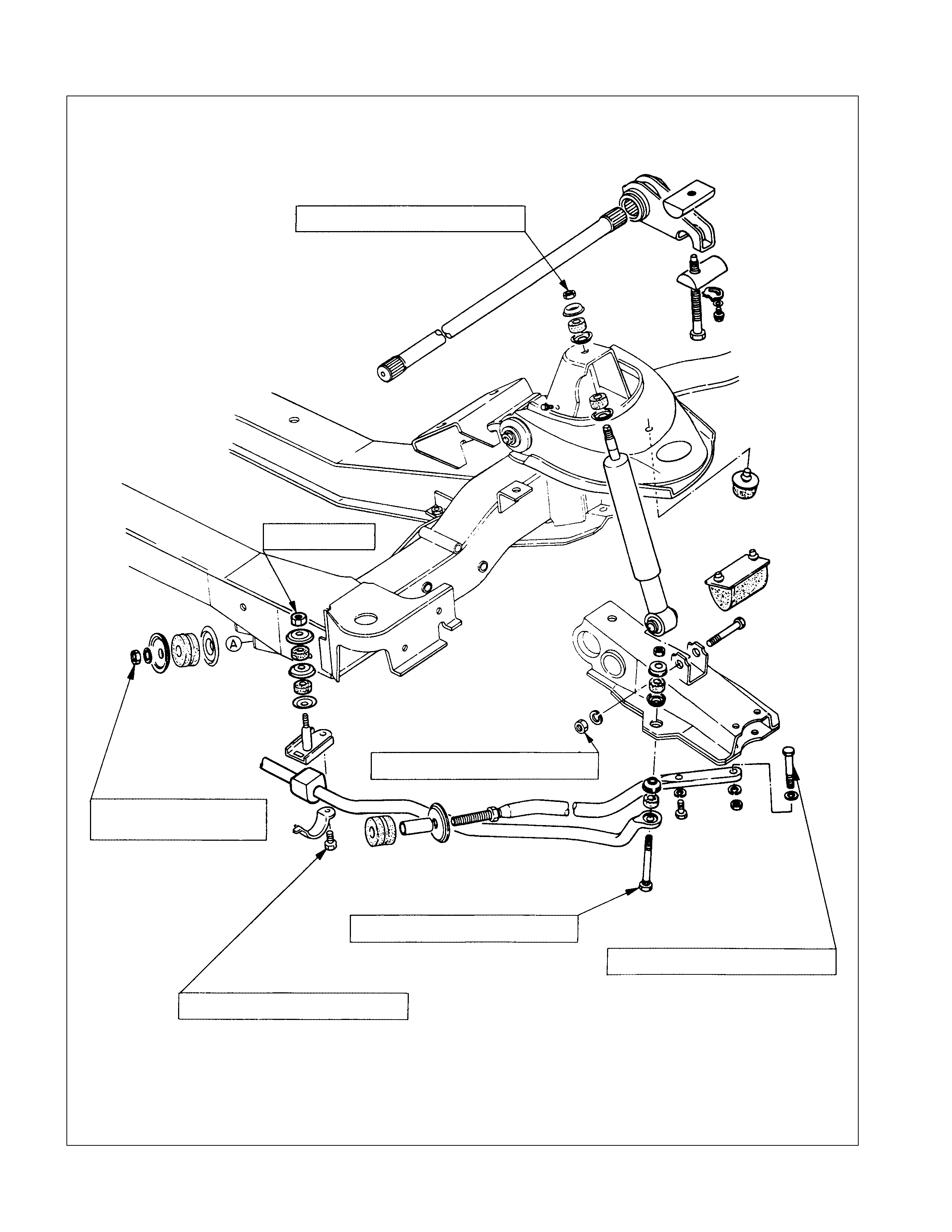
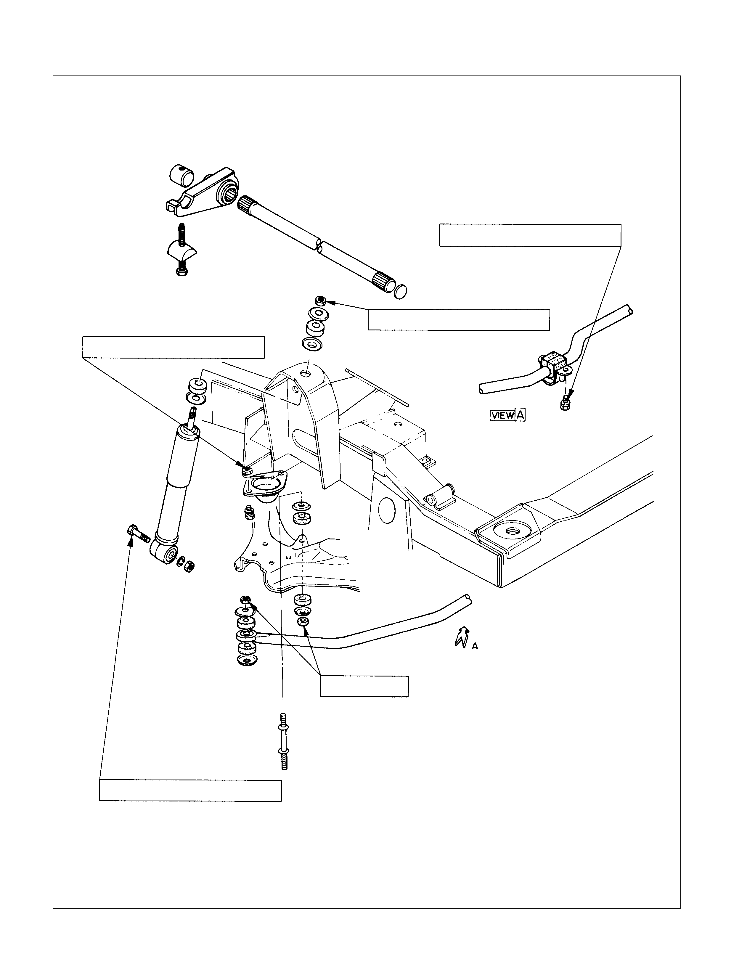
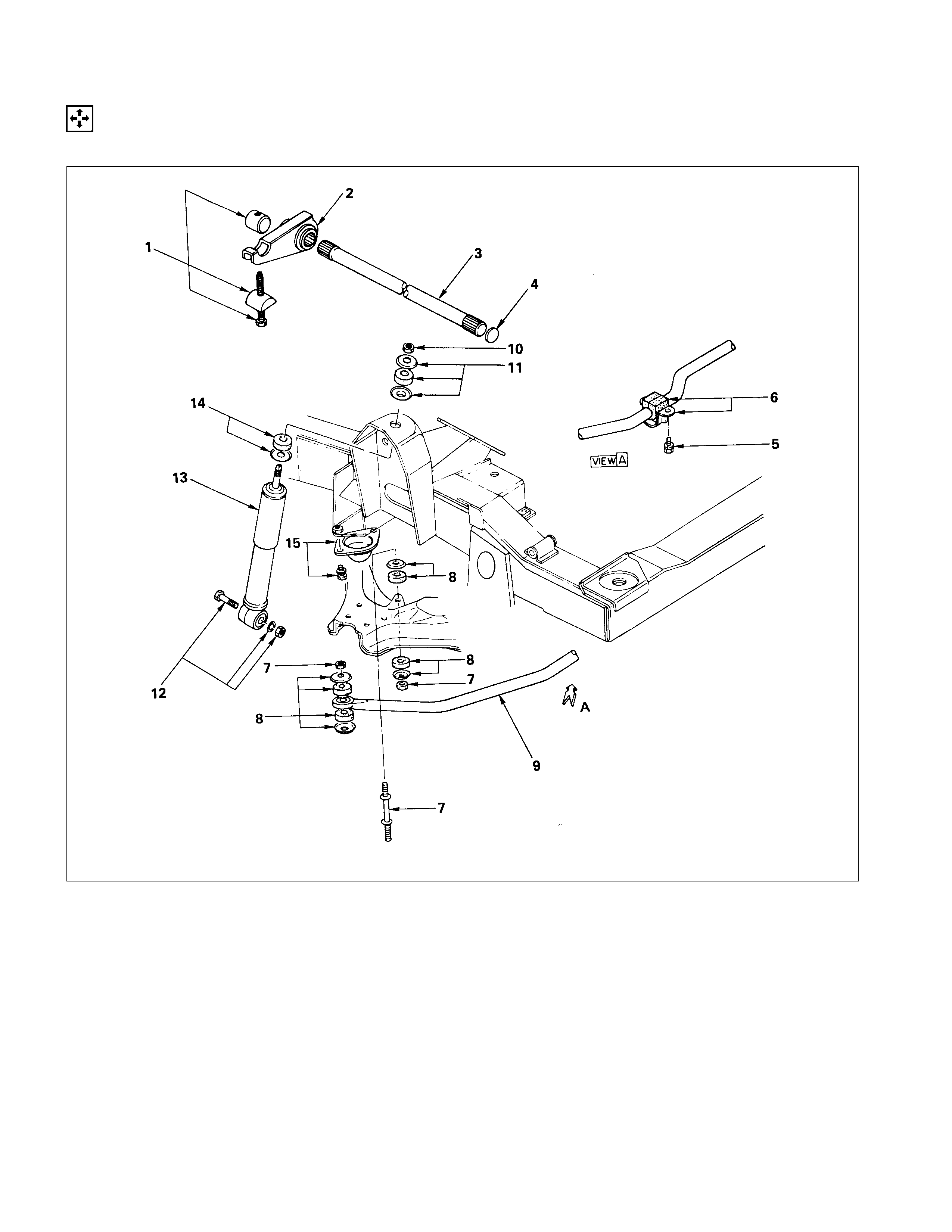
TORSION BAR, STRUT BAR, STABILIZ ER BAR AND SHOCK ABSO RBER
(4×
××
×2 MODEL EXCEPT V6 ENGI NE)
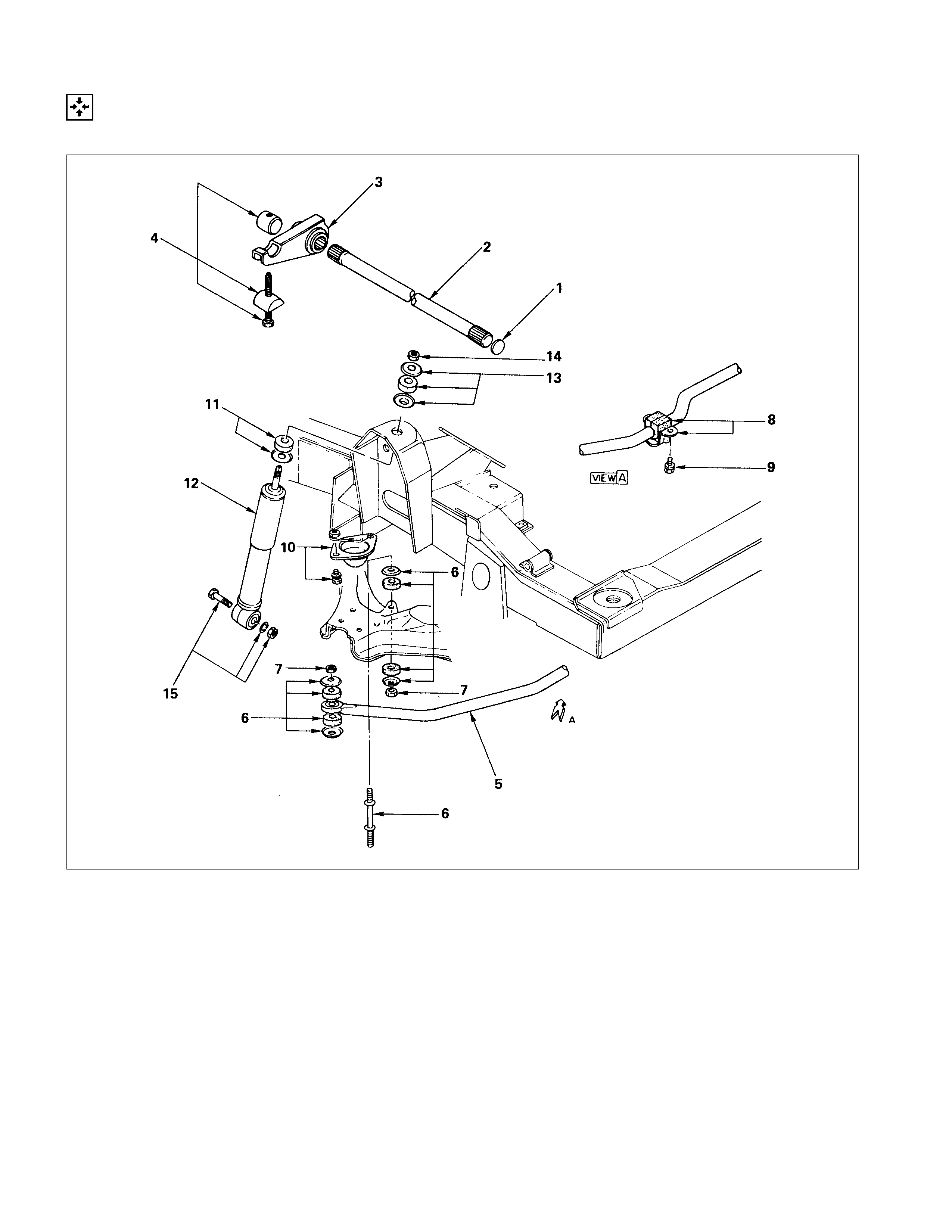
DISASSEMBLY
DISASSEM BLY STEPS
TORSION BAR
▲1. Adjust bolt, seat, lock plate
and bolt
▲2. Height control arm
▲3. Torsion bar
STRUT BAR
4. Nut and washer
5. Rubber bushing and washer
6. Bolt and washer
7. Strut bar
8. Rubber bushing, washer and
tube
STABILIZER BAR
9. Bolt
10. Bracket
11. Nut
12. Rubber bushing and washer
13. Rubber bushing and washer
14. Bracket
15. Bolt and nut
16. Rubber bushing and washer
17. Stabilizer bar
SHOCK ABSO RBER
18. Nut
19. Rubber bushing and washer
20. Bolt, nut, and washer
▲21. Shock absorber
22. Rubber bushing and washer
23. Lower link bumper
24. Upper link bumper
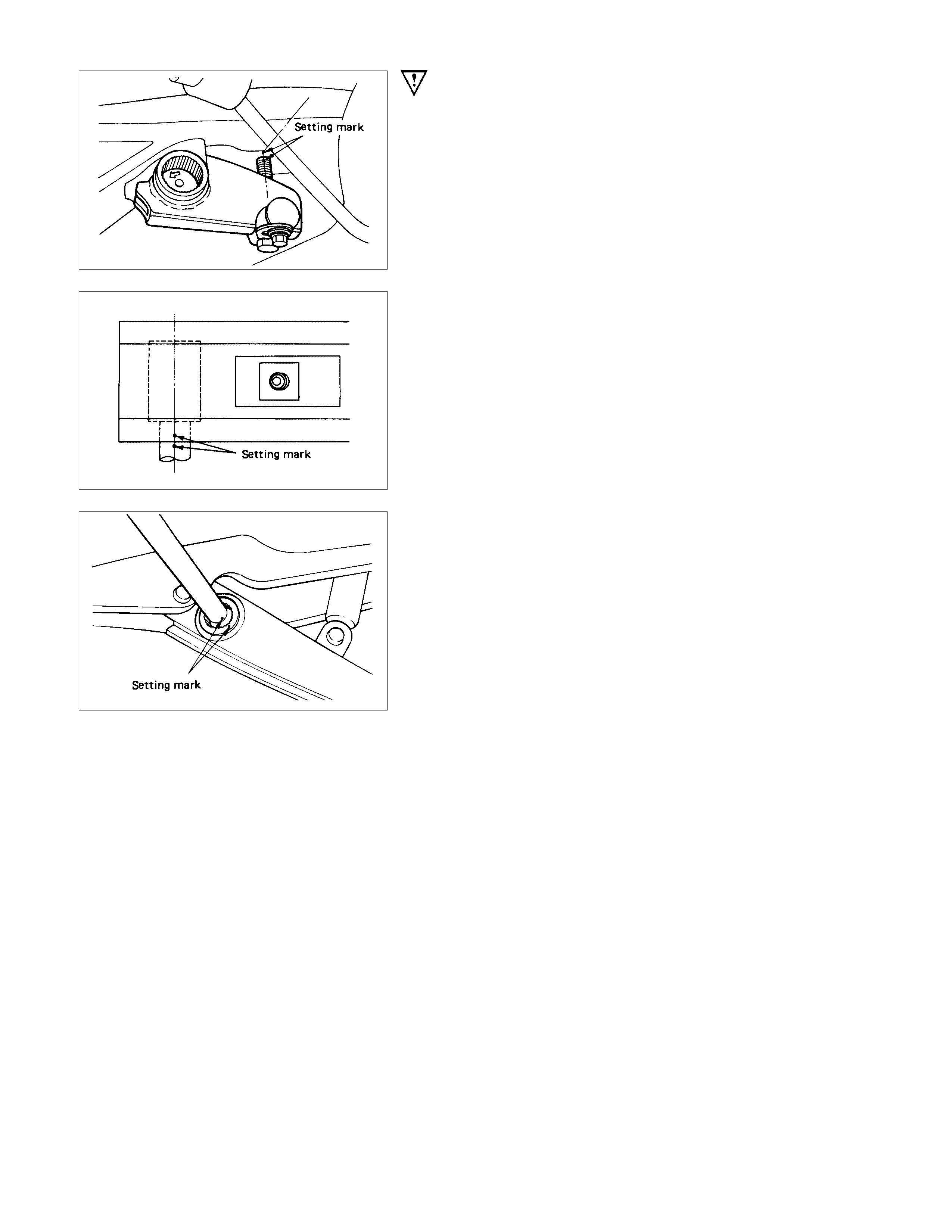
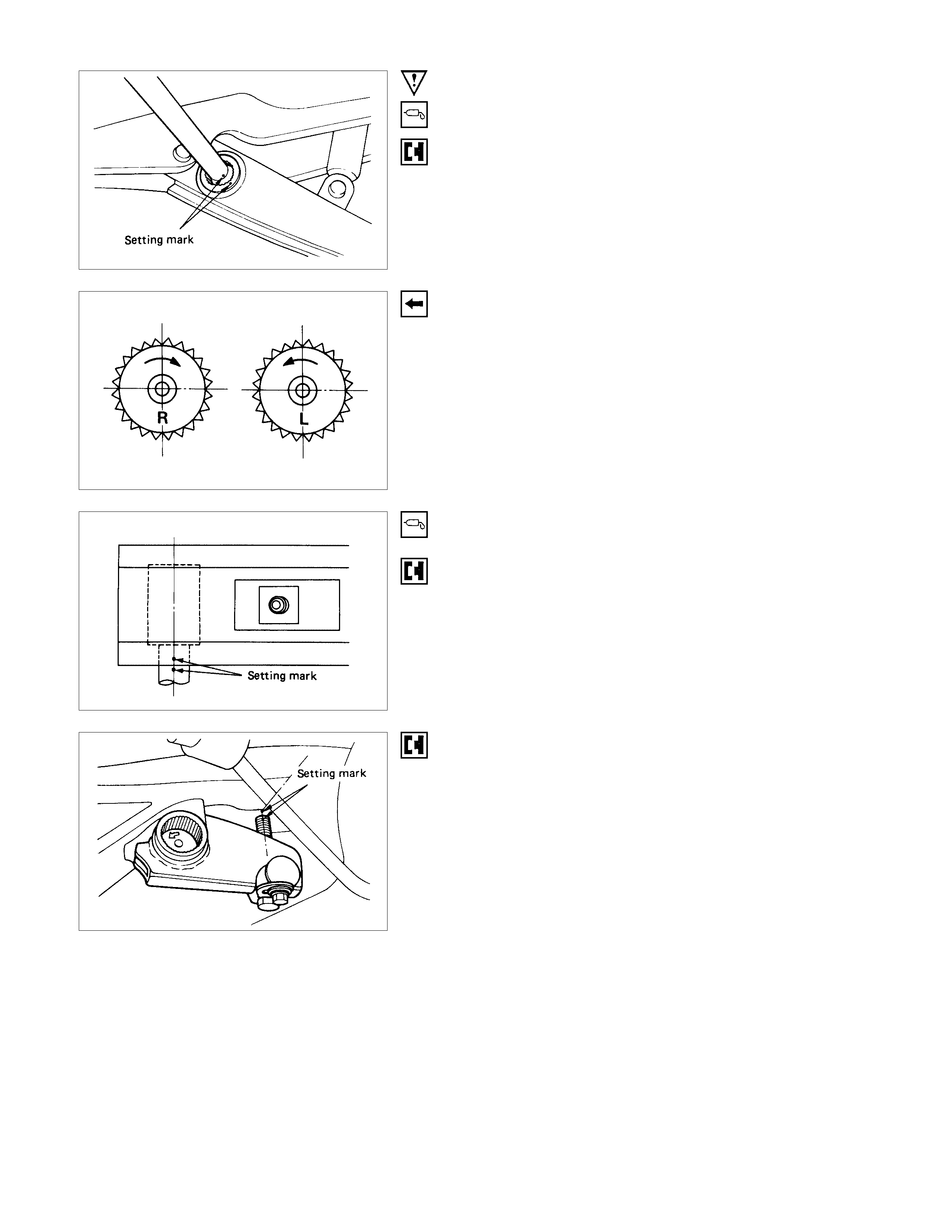
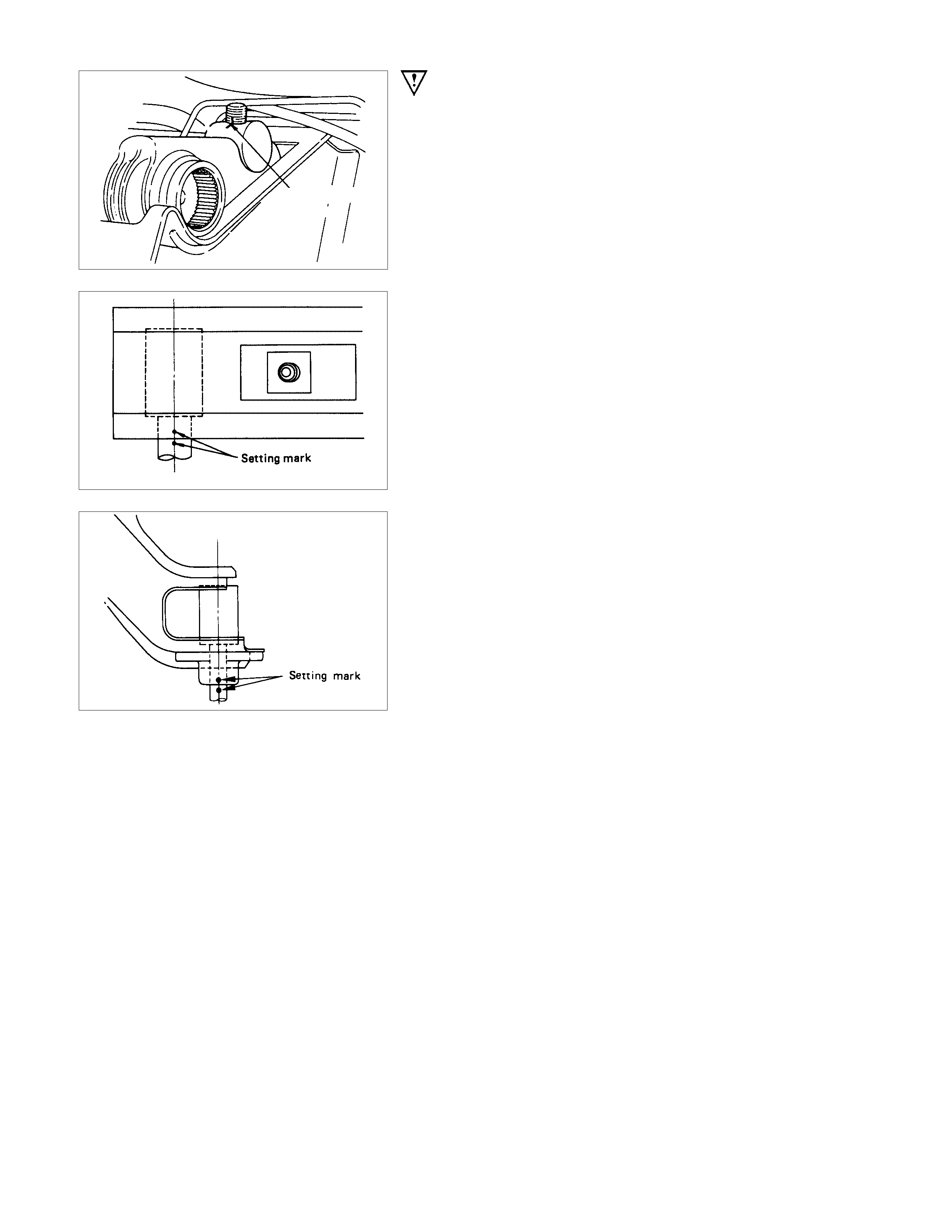
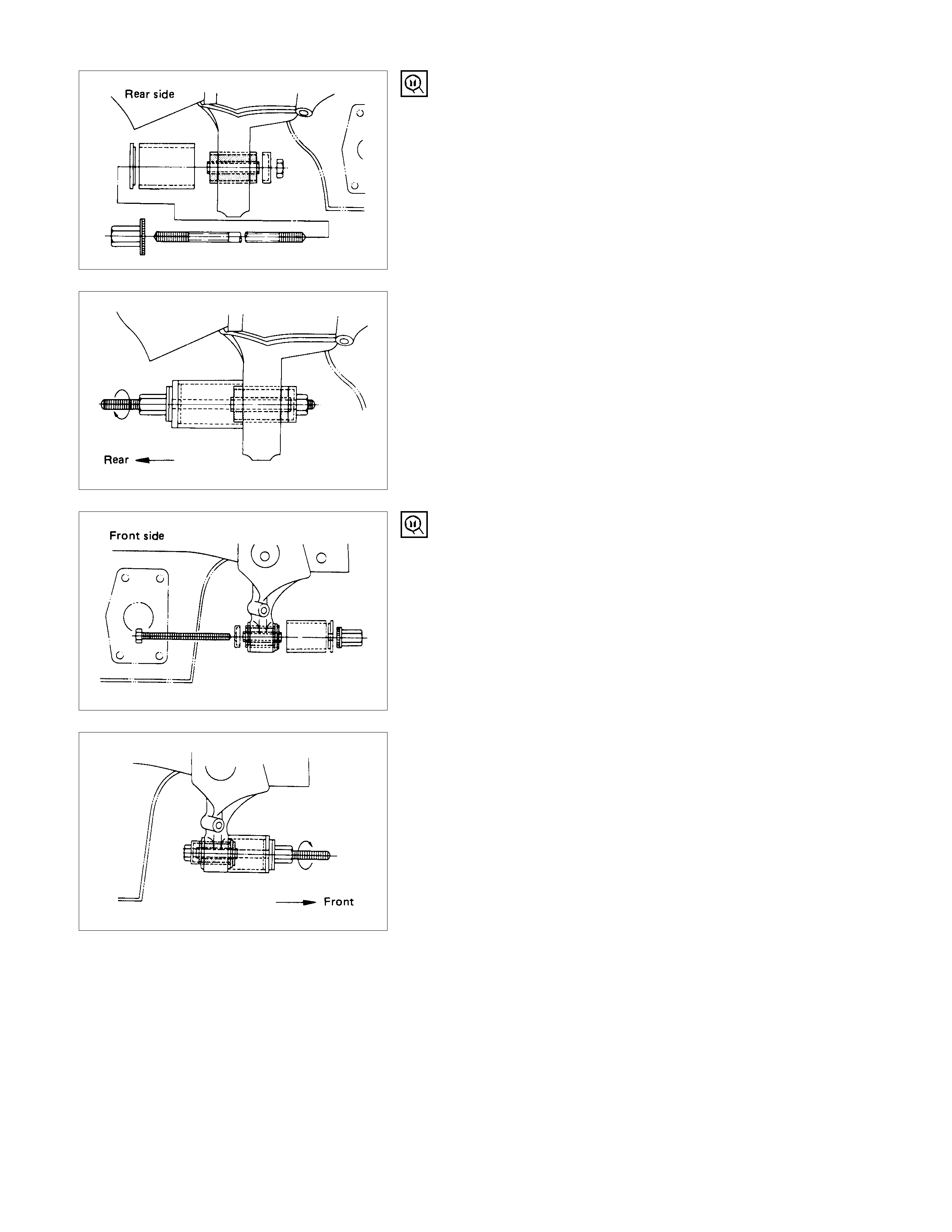
IMPORTANT OPERATIONS
1. Adjust Bolt
Apply the setting marks to the adjust bolt and height control
arm.
2. Height Control Arm
Apply the setting marks to the height control arm and torsion
bar.
3. Torsion Bar
Apply the setting marks to the torsion bar and lower link.
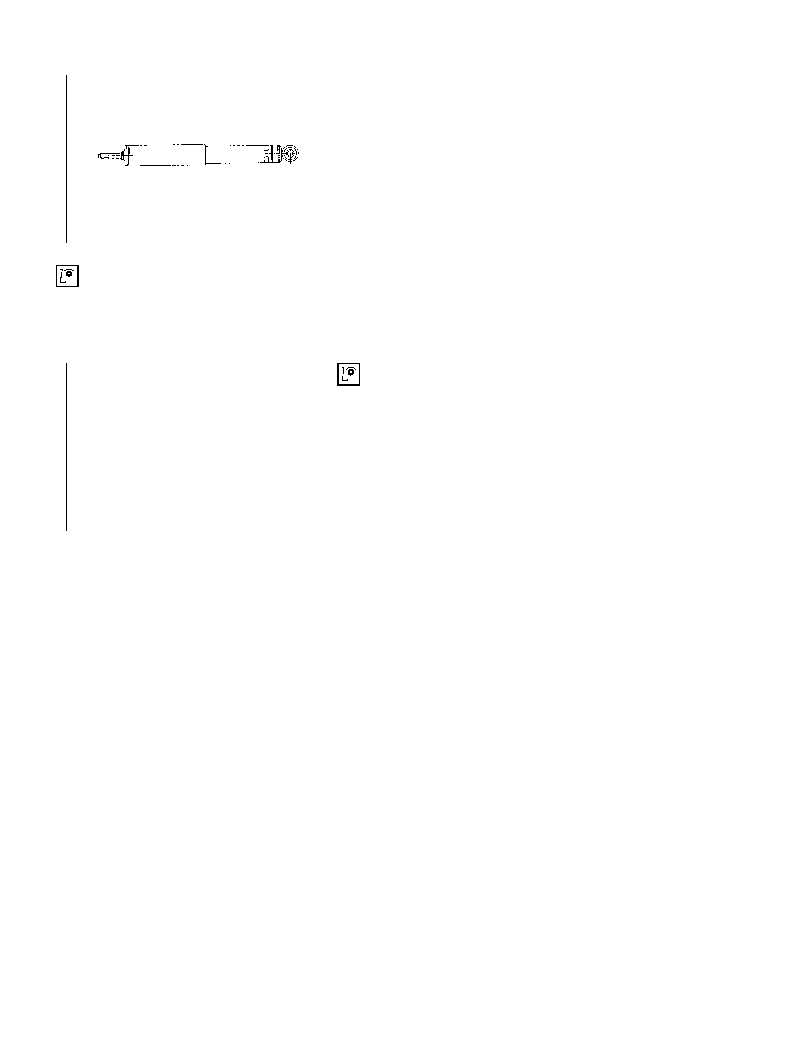
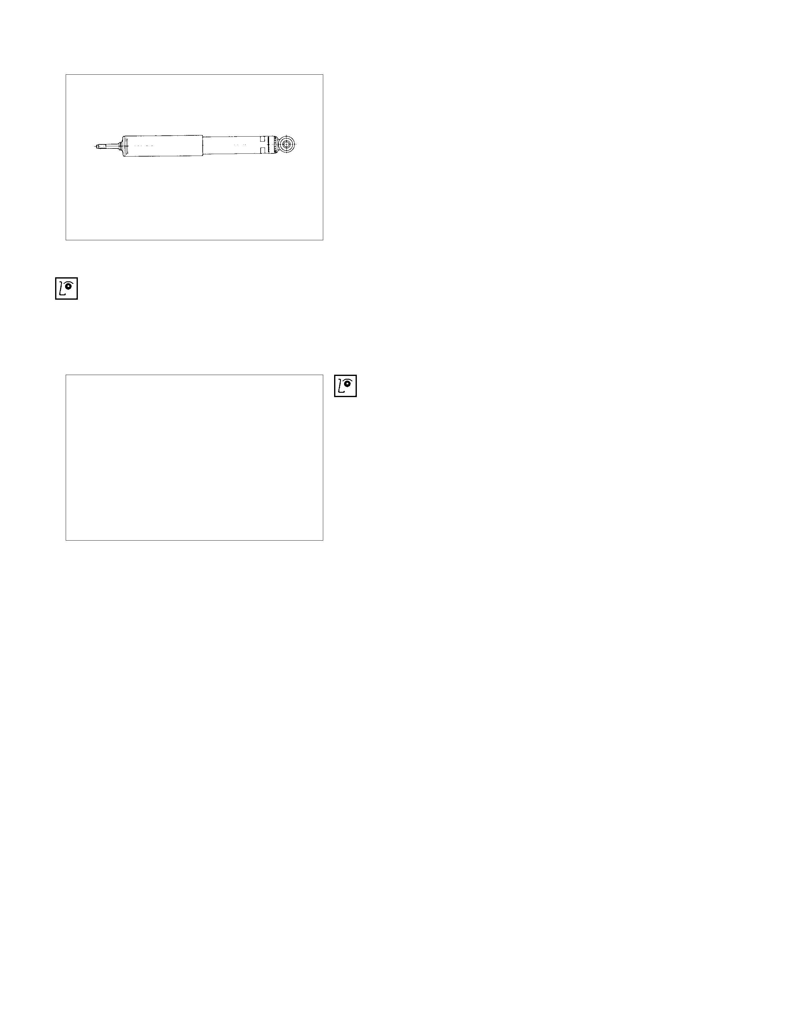
21.Shock Absorber (Gas-sealed type)
CAUTION:
The shock absorbers have been charged with gas at the
factory. Exposure to high temperatures or an open flame
can result in a dangerous explosion.
Keep the shock absorbers away from high temperatures
and open flames.
INSPECTION AND REPAIR
Make all necessary adjustments, repairs, and part replacements if wear, damage, or other problems are discovered
during inspections.
• Torsion bar, height cont rol arm
• Strut bar
• Stabiliz er bar
• Shock abs or ber
• Rubber bushing
VISUAL CHECK
Inspect the following parts for wear, damage or other abnormal
conditions.
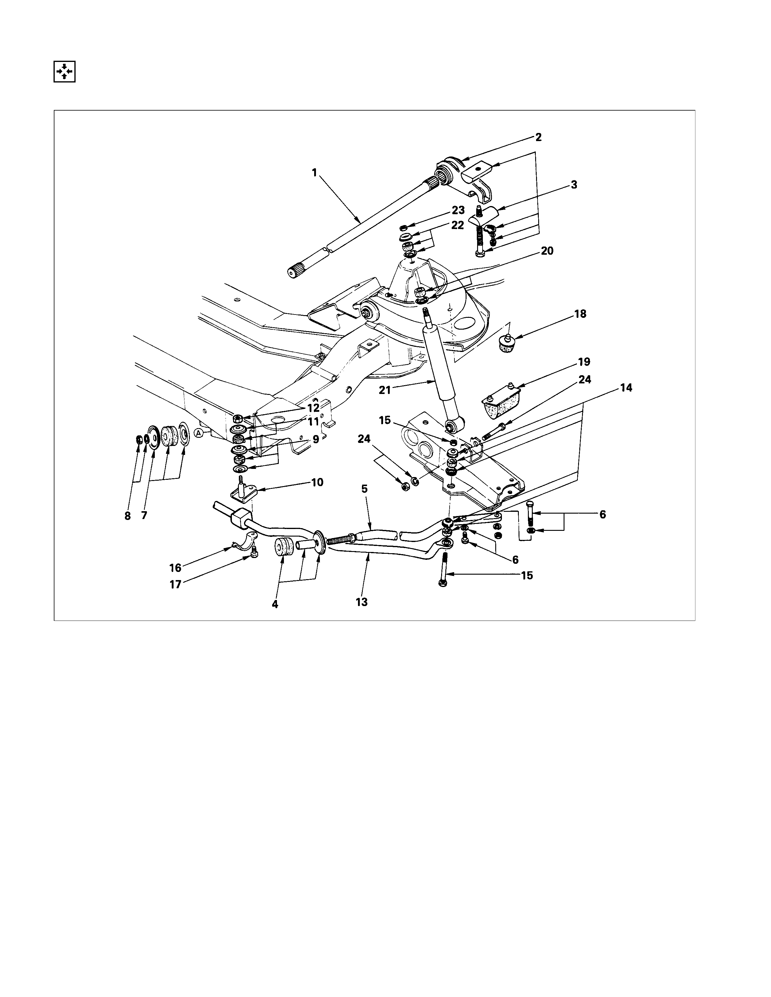
REASSEMBLY
REASSEMBLY STEPS
TORSION BAR
▲1. Torsion Bar
▲2. Height control arm
▲3. Adjust bolt, seat, lock plate
and bolt
STRUT BAR
4. Rubber bushing and washer
▲5. Strut bar
▲6. Bolt and washer
7. Rubber bushing, washer and
tube
▲8. Nut and washer
STABILIZER BAR
9. Rubber bushing and washer
10. Bracket
11. Rubber bushing and washer
12. Nut
13. Stabilizer bar
14. Rubber bushing and washer
▲15. Bolt and nut
16. Bracket
17. Bolt
SHOCK ABSO RBER
18. Upper link bumper
19. Lower link bumper
20. Rubber bushing and washer
21. Shock absorber
22. Rubber bushing and washer
▲23. Nut
▲24. Bolt, nut, and washer
IMPORTANT OPERATIONS
1. Torsion Bar
(1)Apply grease to the serrated portions.
(2)Align the scribe marks.
(3)Note the embossed mark on the end of the torsion bar.
R : Right side
L : Left side
2. Height Control Arm
(1)Apply grease to the portion that fits into the bracket.
(2)Align the scribe marks.
3. Adjust Bolt, Seat, Lock Plate and Bolt
(1)Turn in the adjustment bolt to location marked upon
disassembly.
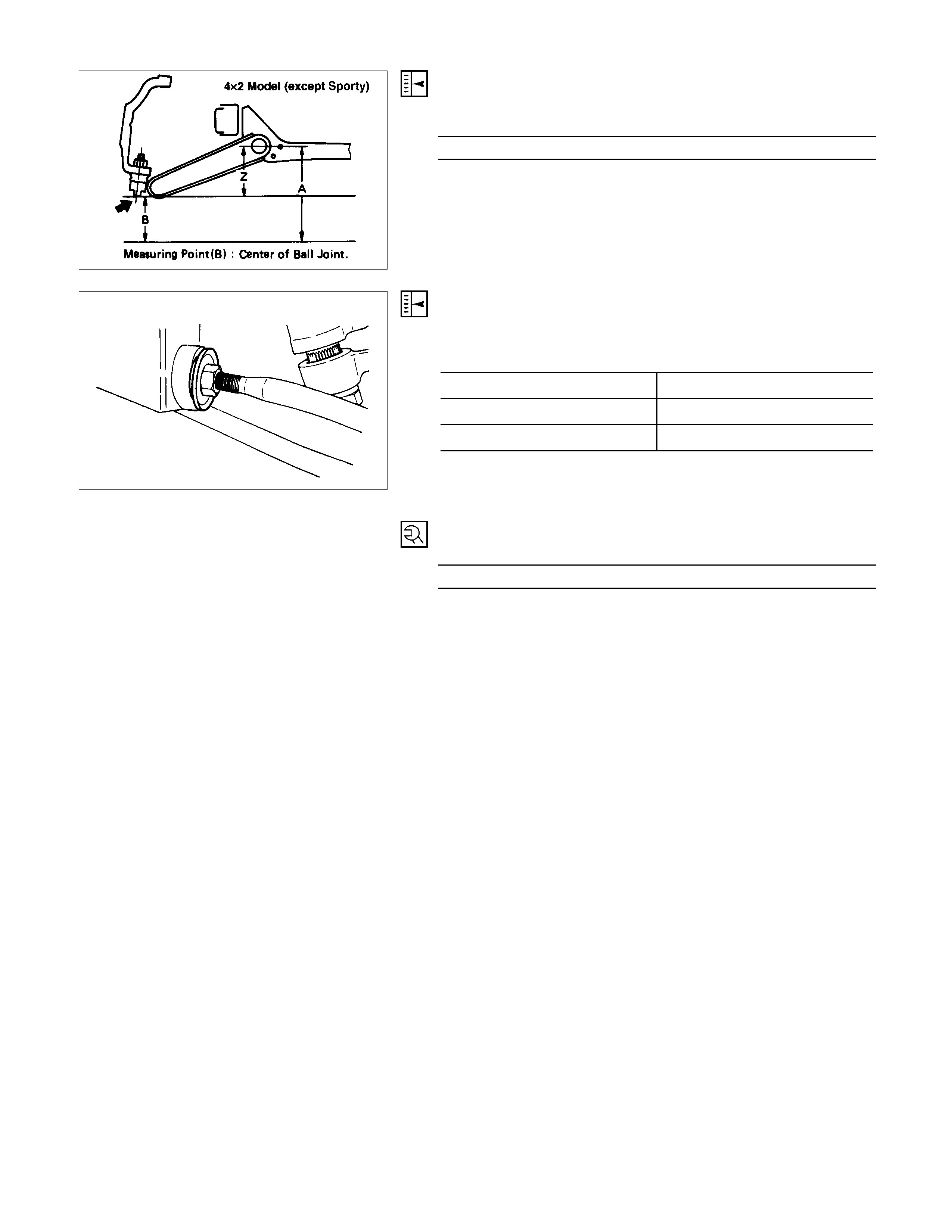
(2)Check the vehicle trim height.
Trim Height (Z) = A - B
Trim Height mm(in)
56 (2.20)
5. Strut Bar
Adjust the caster angle by varying length of the strut bar (adjust
with lock nut).
Caster
Short Wheel Base 1°35' ± 45'
Long (Except Flat Deck) 1°50' ± 45'
Long (Flat Deck) 1°10' ± 45'
Note :
No more than 35' side to side variation.
6. Bolt, Nut and Washer
Strut Bar Bolt Torque N⋅m (kgf⋅m/lb⋅ft)
68.7 ± 6.9 (7.0 ± 0.7/50.6 ± 5.1)
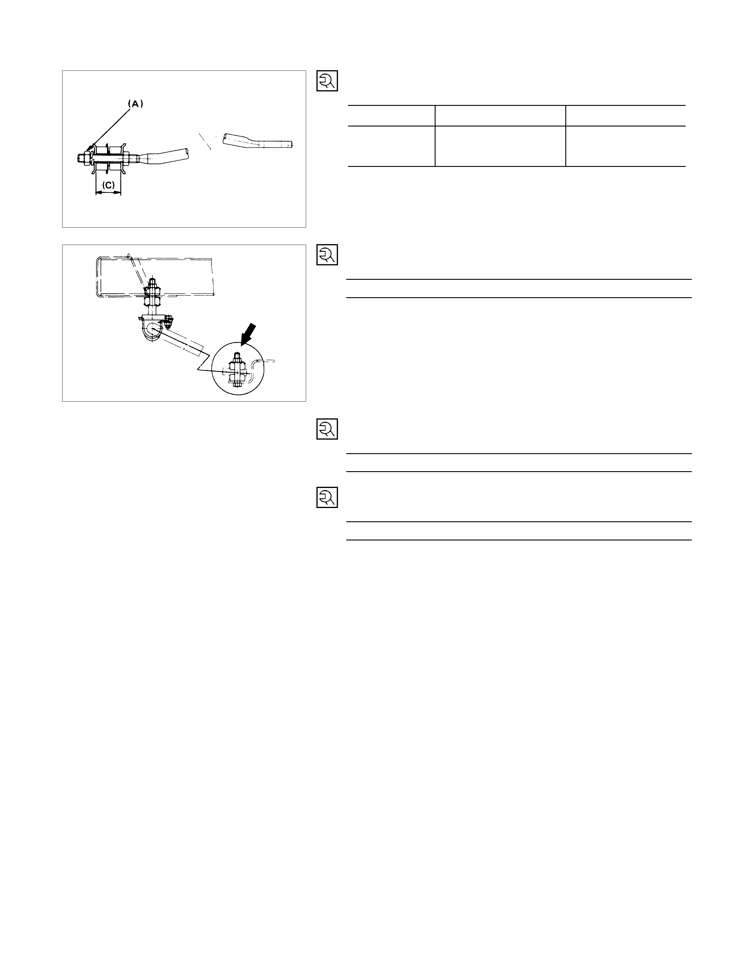
8. Nut and Washer
Strut Bar Nu t Torque
Model N⋅m (kgf⋅m/lb⋅
⋅⋅⋅ft) Distance (C) mm(in)
127.5 ± 12.8 56.0
(13.0 ± 1.3/94.0 ± 9.4) (63.3)
4 × 2
(except Sporty )
15.Bolt and Nut
Stabilizer Bar Bolt Torque N⋅m (kgf⋅m/lb⋅ft)
24.5 ± 4.9 (2.5 ± 0.5/18.1 ± 3.6)
23.Nut
Shock Absorber Nut Torque N⋅m (kgf⋅m/lb⋅ft
)
19.6 ± 4.9 (2.0 ± 0.5/14.5 ± 3.6)
24.Bolt, Nut and Washer
Shock Absorber Bolt Torque N⋅m (kgf⋅m/lb⋅ft)
82.4 ± 7.8 (8.4 ± 0.8/60.8 ± 5.8)
TORSION BAR, STABILIZER BAR (4×
××
×4 AND 4×
××
×2 V6 ENGINE MODEL)
DISASSEM BLY
DISASSEM BLY STEPS
TORSION BAR
▲1. Adjust bolt, seat
▲2. Height control arm
▲3. Torsion Bar
4. Rubber seat
STABILIZER BAR
5. Bolt
6. Bracket and rubber bushing
7. Bolt, nut, and washer
8. Rubber bushing and washer
9. Stabilizer bar
SHOCK ABSO RBER
10. Nut
11. Rubber bushing and washer
12. Bolt, nut, and washer
13. Shock absorber
14. Rubber bushing and washer
15. Lower link bumper
Setting mark
IMPORTANT OPERATIONS
1. Adjust Bolt
Apply the setting marks to the adjust bolt and height control
arm.
2. Height Control Arm
Apply the setting marks to the height control arm and torsion
bar.
3. Torsion Bar
Apply the setting marks to the torsion bar and lower link.
13.Shock Absorber
CAUTION:
The shock absorbers have been charged with gas at the
factory. Exposure to high temperatures or an open flame
can result in a dangerous explosion.
Keep the shock absorbers away from high temperatures
and open flames.
INSPECTION AND REPAIR
Make all necessary adjustments, repairs, and part replacements if wear, damage, or other problems are discovered
during inspection.
• Torsion bar, height control arm
• Strut bar
• Stabilizer bar
• Shock absorber
• Rubber bushing
VISUAL CHECK
Inspect the following parts for wear, damage or other abnormal
conditions.
REASSEMBLY
REASSEMBLY STEPS
TORSION BAR
1. Rubber seat
▲2. Torsion Bar
▲3. Height control arm
▲4. Adjust bolt, seat
STABILIZER BAR
5. Stabilizer bar
6. Rubber bushing and washer
▲7. Nut
8. Bracket
9. Bolt
SHOCK ABSO RBER
10. Lower link bumper
11. Rubber bushing and washer
12. Shock absorber
13. Rubber bushing and washer
▲14. Nut
▲15. Bolt, nut, and washer
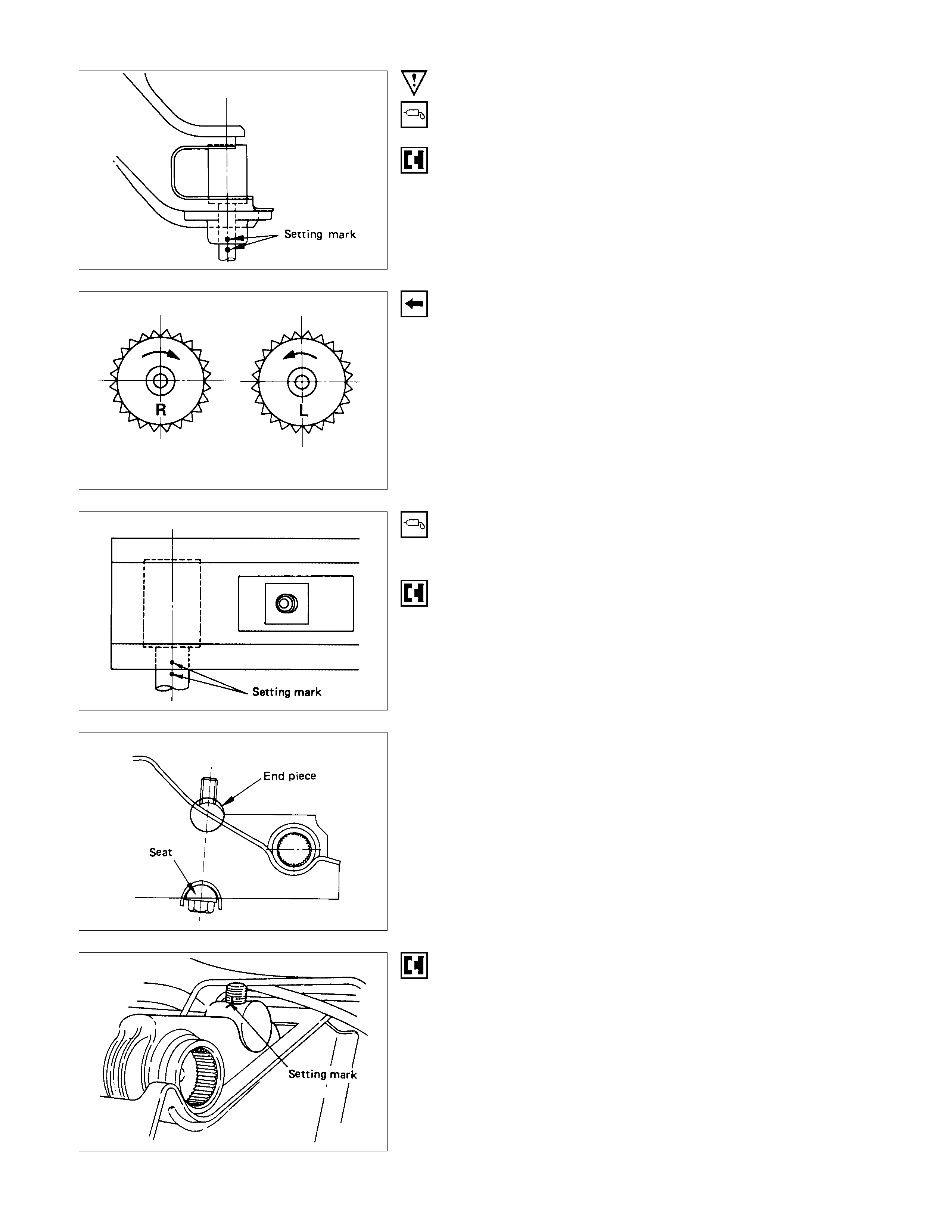
IMPORTANT OPERATIONS
2. Torsion Bar
(1)Apply grease to the serrated portions.
(2)Align the setting marks.
(3)Note the emboss mark on its side face.
R : Right side
L : Left side
3. Height Control Arm
(1)Apply grease to the portion that fits into the bracket.
(2)Align the setting marks.
(3)Apply grease to the bolt portion of the end piece.
(4) Apply grease to the portion of the seat that fits in to the
bracket.
4. Adjust Bolt
(1)Turn in the adjust bolt to location marked during
disassembly.
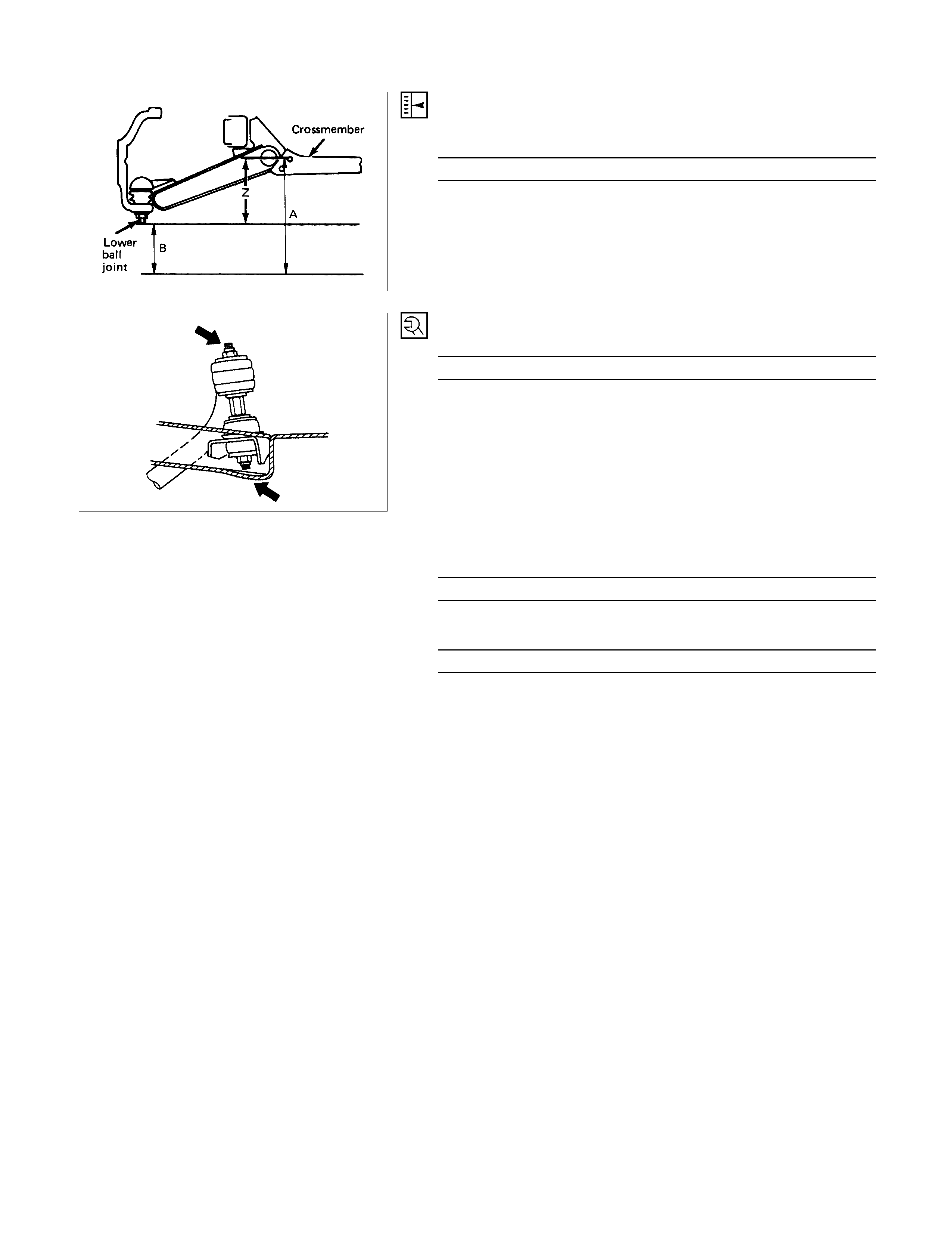
(2)Check the vehicle trim height.
Trim height (Z) = A - B
Trim Height mm(in)
130 (5.12)
7. Bolt
Stabilizer bar Bolt Torque N⋅m (kgf⋅m/lb⋅ft)
9.8 (1.0/7.2)
14.Nut
Shock Absorber Nut Torque N⋅m (kgf⋅m/lb⋅ft)
19.6 ± 4.9 (2.0 ± 0.5/14.5 ± 3.6)
15.Bolt
Shock Absorber Bolt Torque N⋅m (kgf⋅m/lb⋅ft)
82.4 ± 7.8 (8.4 ± 0.8/60.8 ± 5.8)
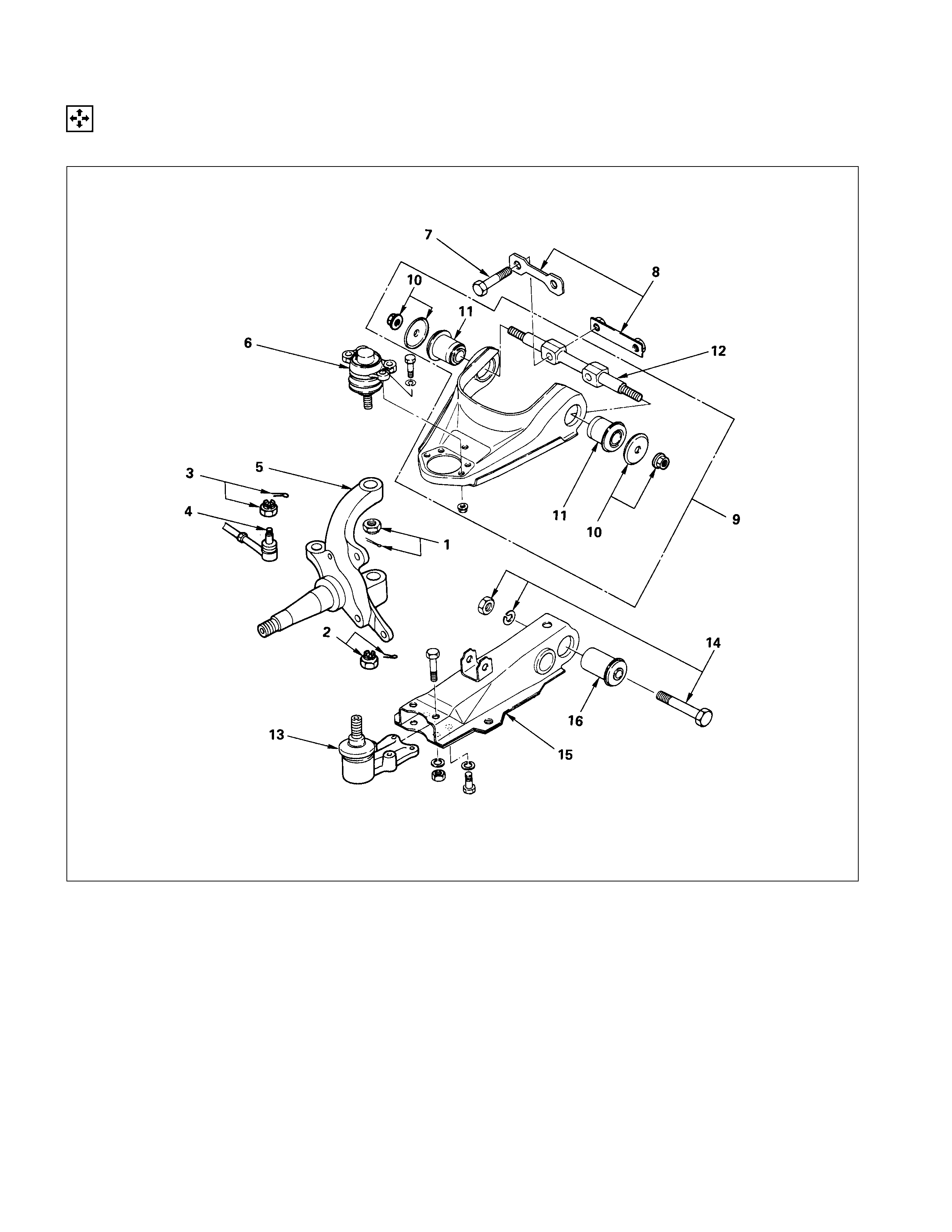
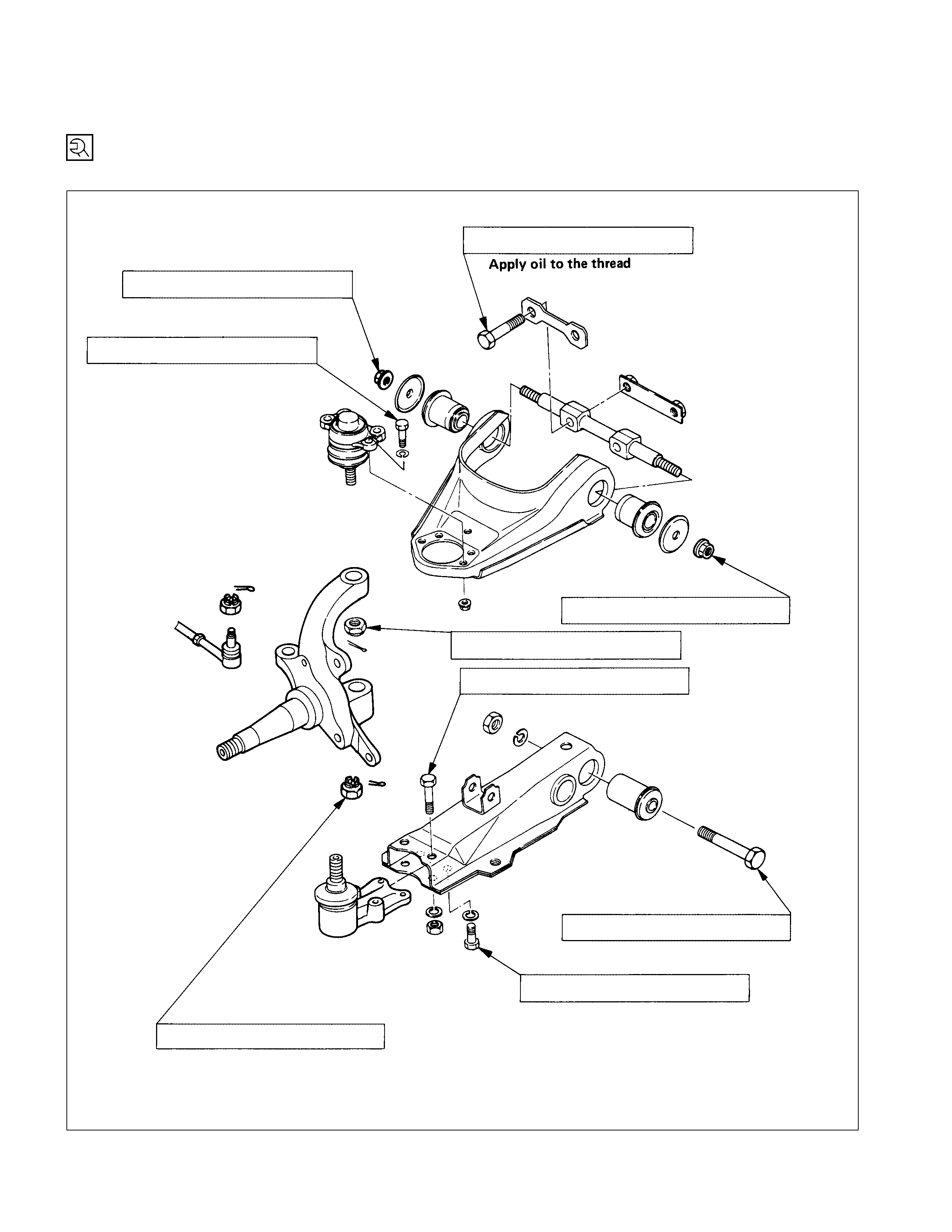
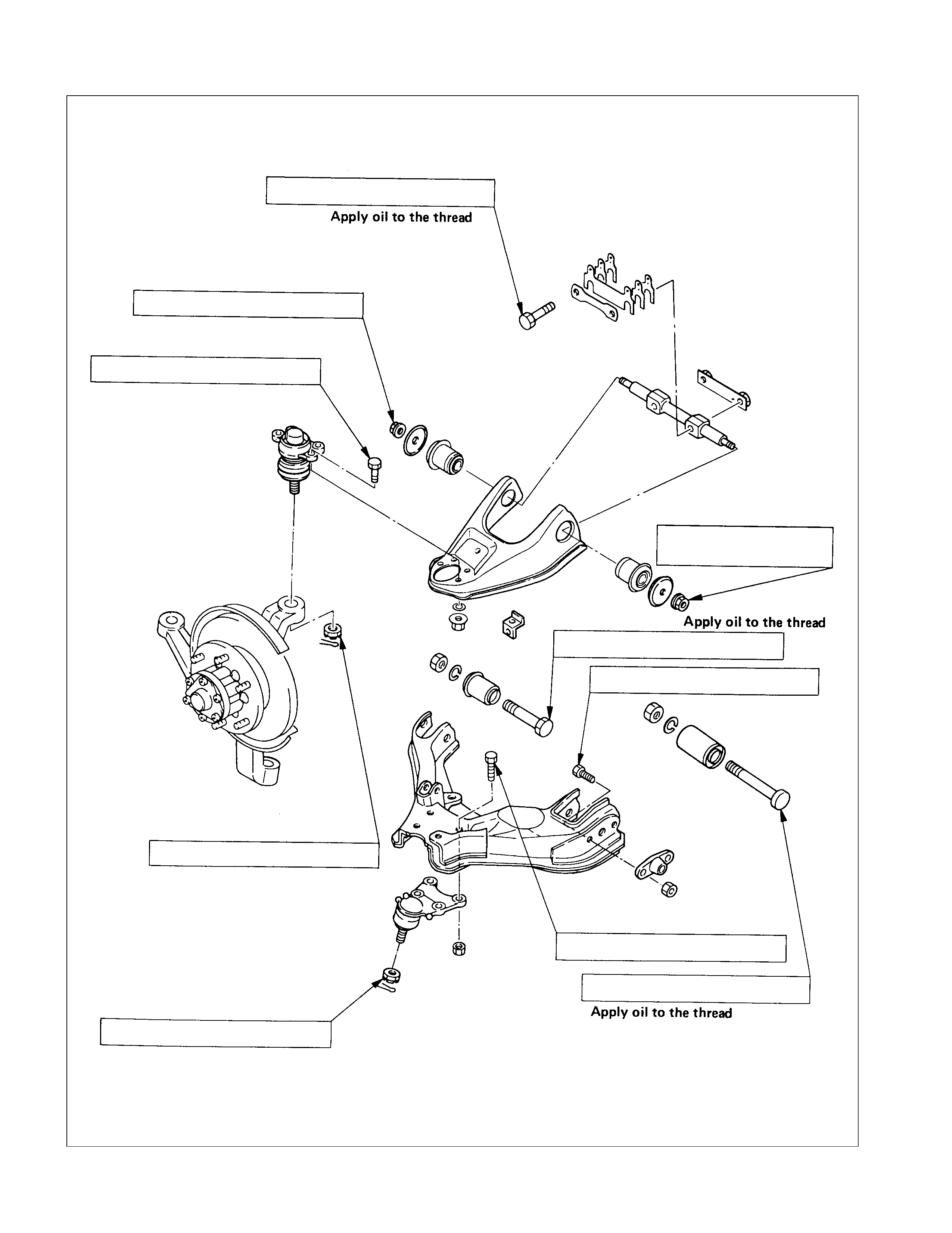
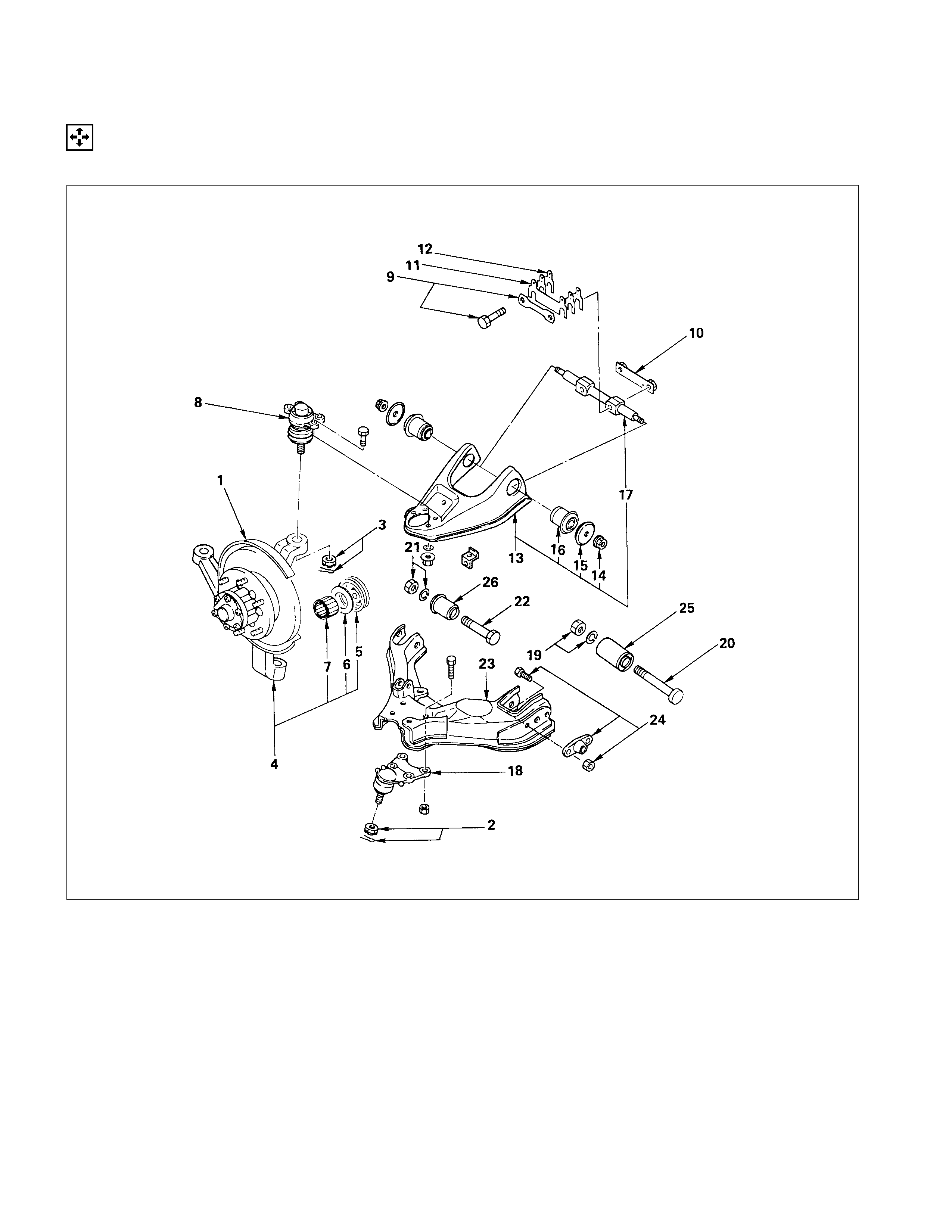
KNUCKLE, UPPER LINK AND LOWER LINK (4×
××
×2 MODEL EXCEPT V6 ENGI NE)
DISASSEM BLY
DISASSEM BLY STEPS
KNUCKLE
1. Nut and cotter pin
2. Nut and cotter pin
3. Nut and cotter pin
4. Steering link end
5. Knuckle
UPPER LINK
6. Upper end
7. Bolt and washer
8. Nut Assembly
9. Upper link assembly
10. Nut and plate
▲11. Bushing
12. Fulcrum pin
LOWER LINK
13. Lower end
14. Bolt, nut and washer
▲15. Lower link assembly
▲16. Bushing
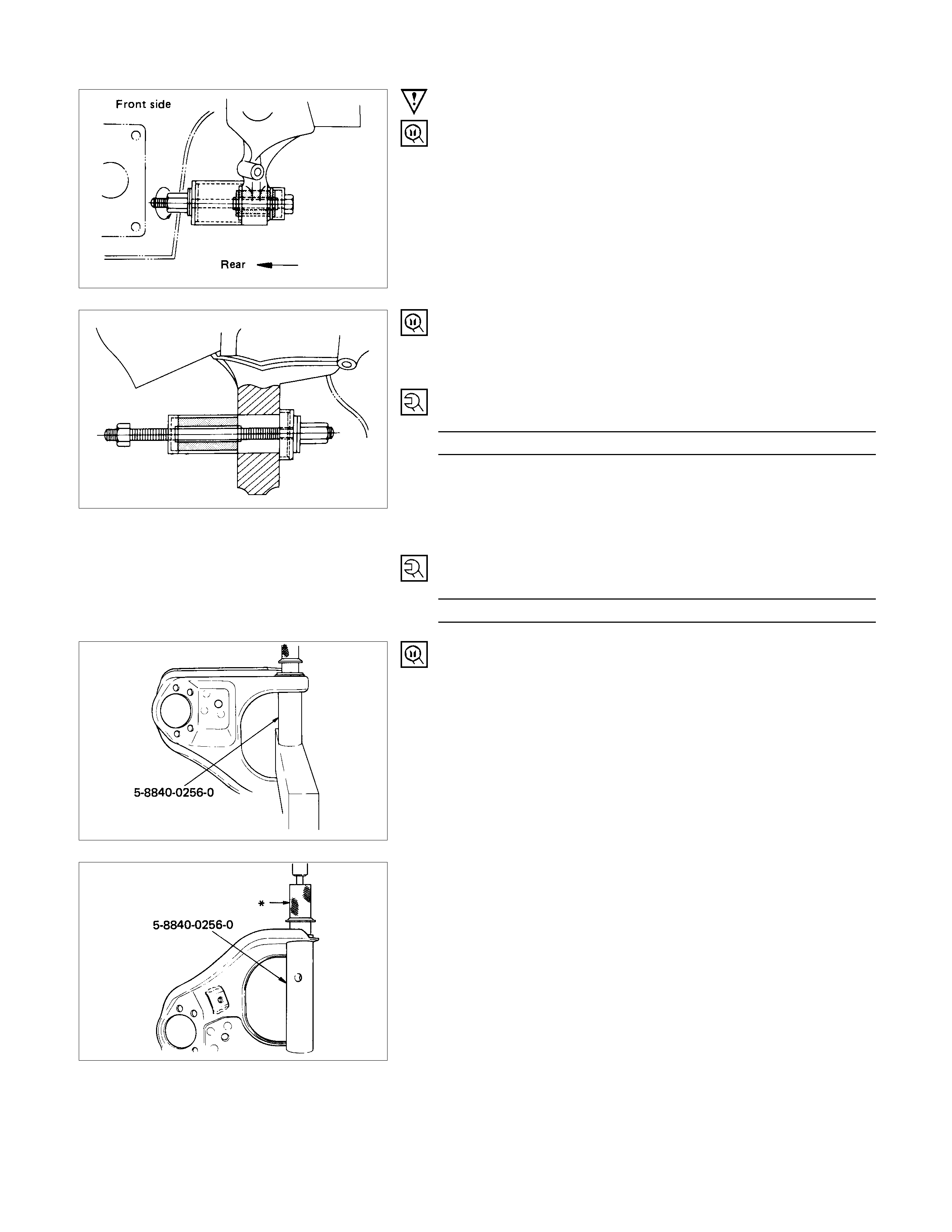
IMPORTANT OPERATIONS
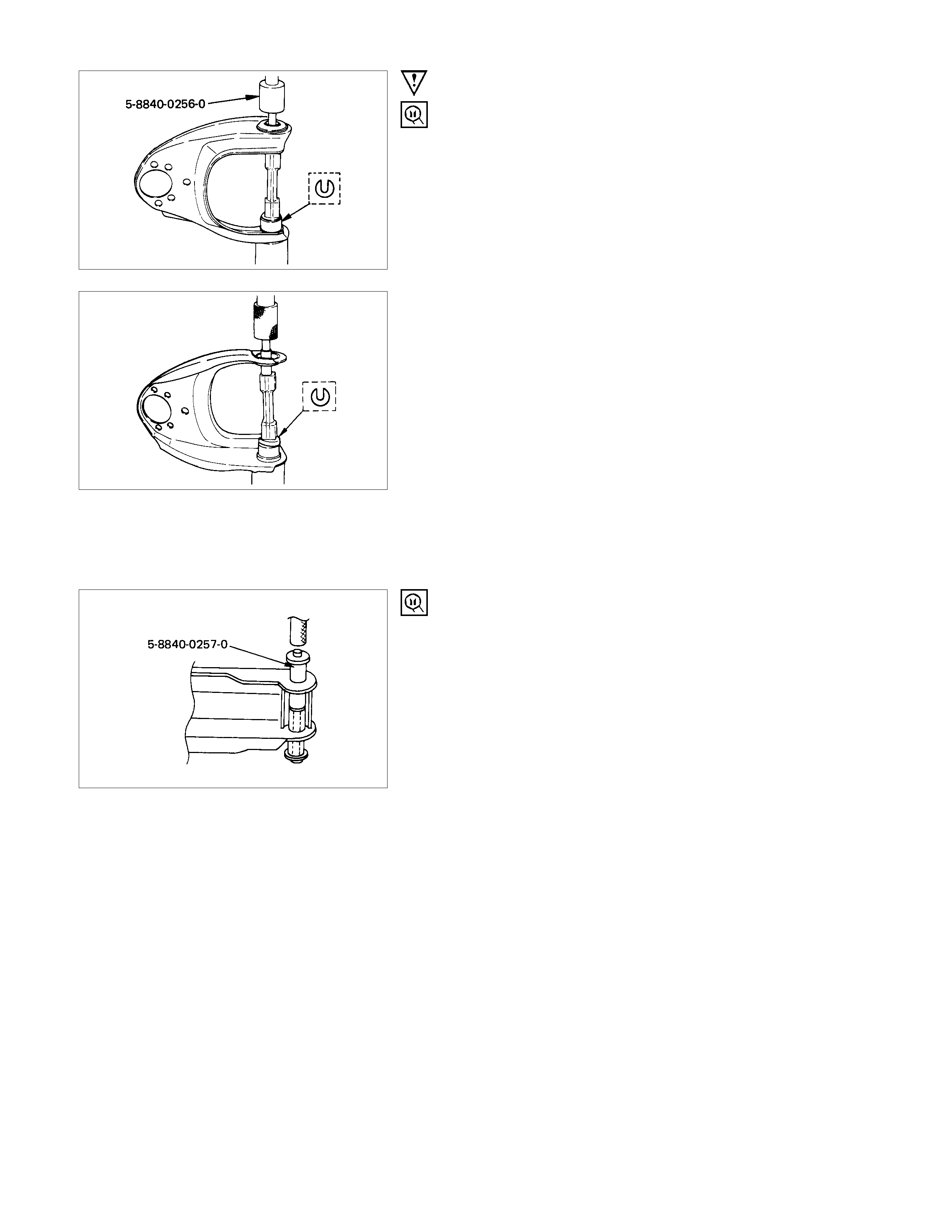
11.Bushing
Remover and installer : 5-8840-0256-0
(J-29755)
15.Lower Link Assembly
Before removal, remove the torsion bar, strut bar, stabilizer bar
and shock absorber.
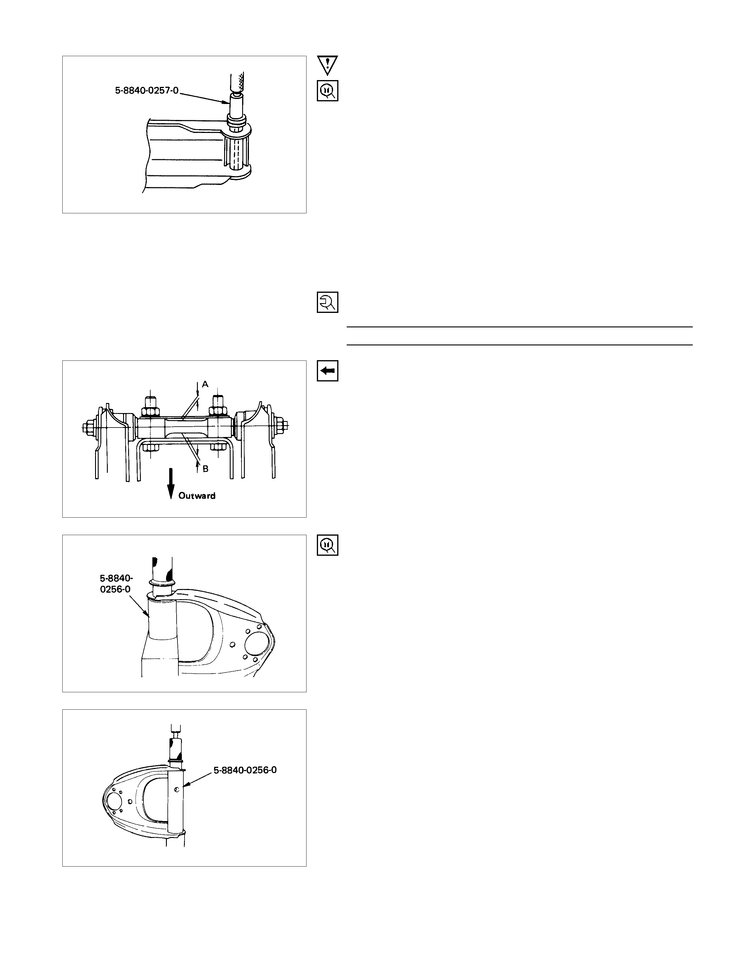
16.Bushing
Remover and installer : 5-8840-0257-0
(J-29756)
INSPECTION AND REPAIR
Make necessary correction or parts replacement if wear, damage or any other abnormal conditions are found through
inspection.
• Knuckle, Knuckle arm
• Upper link, lower link, bushing
• Upper end, lower end, boot
• Fulcrum pin
VISUAL CHECK
Inspect the following parts for wear, damage or other abnormal
conditions.
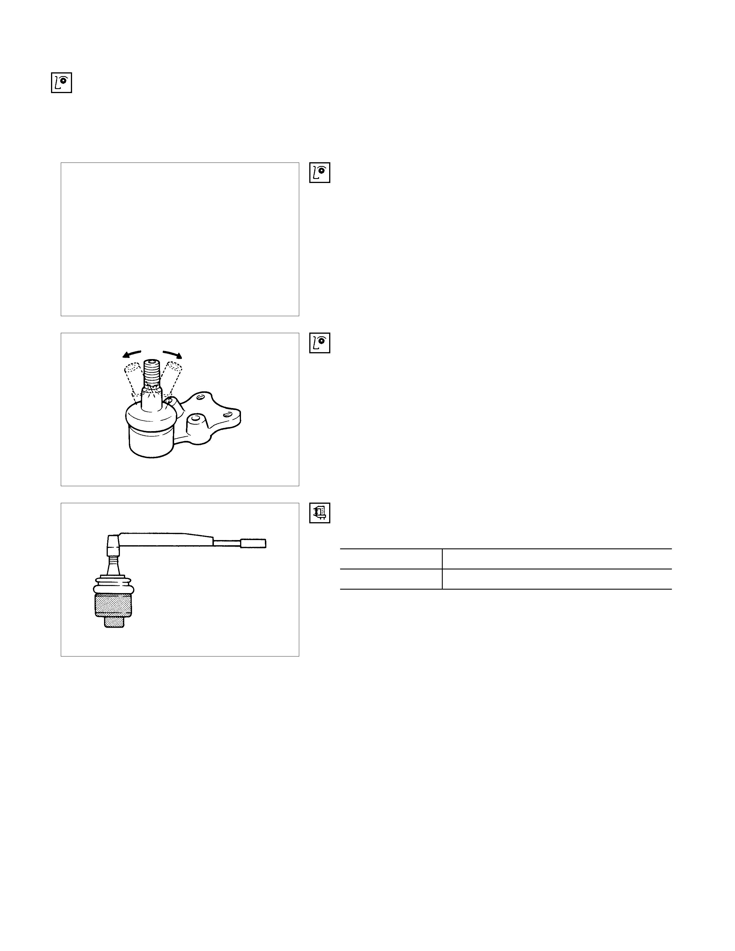
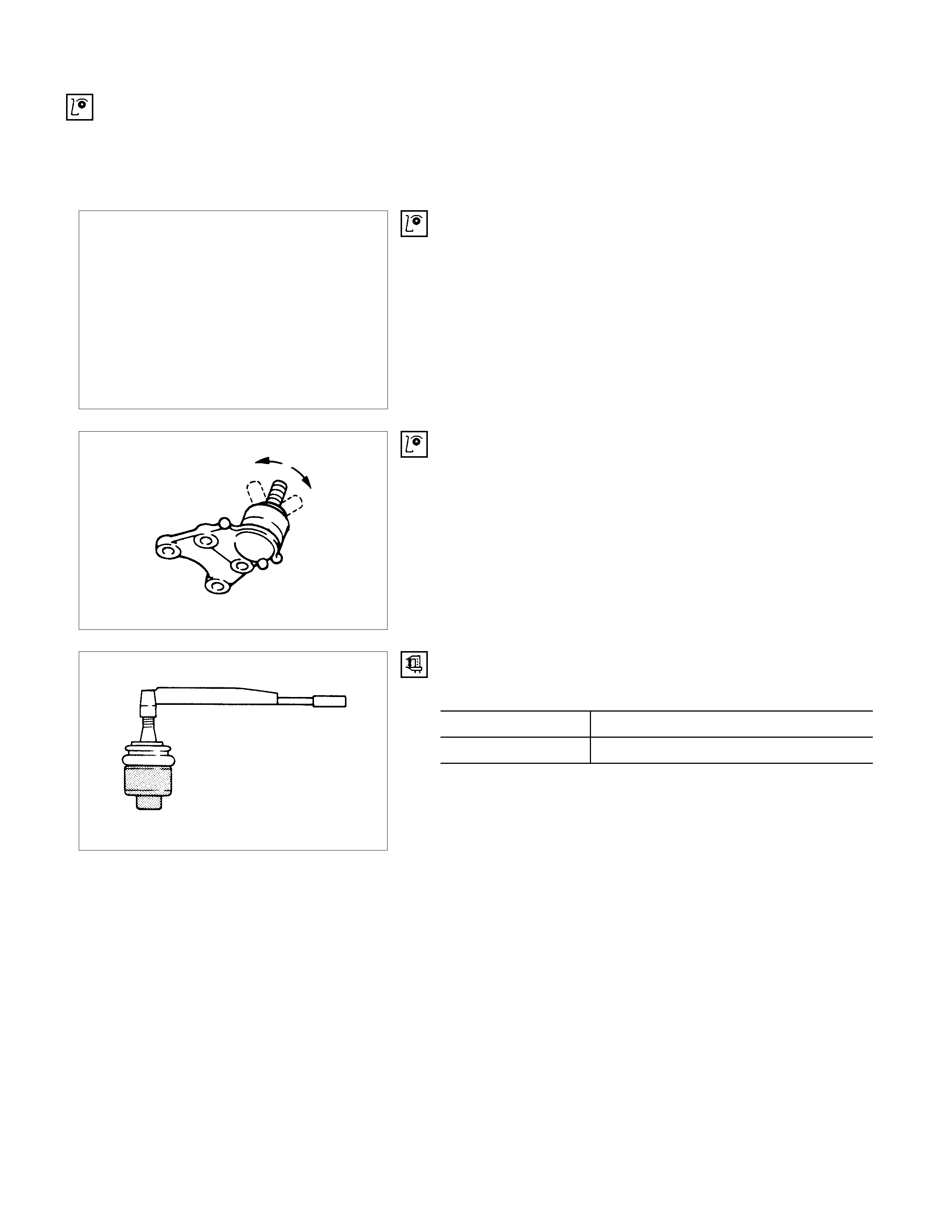
UPPER LINK END AND LO WER LINK END
Inspect the upper and lower link end boot for damage or
grease leak.
Move the Ball Joint as shown in the illustration, then confirm its
normal movement.
Inspect screw/taper area of Ball Joint for defects.
If any defects are found by the above inspections, replace the
end assembly w ith new one.
After moving the Ball Joint 4 or 5 times, attach nuts then
measure the preload.
Preload N⋅m (kgf⋅m/lb⋅ft)
Upper link end 0.9 - 3.2 (0.1 - 0.33/0.7 - 2.4)
Lower link end 0.5 - 3.4 (0.05 - 0.35/0.35 - 2.5)
If above limits specified are exceeded, replace the end
assembly.

REASSEMBLY
REASSEMBLY STEPS
LOWER LINK
▲1. Bushing
2. Lower link assembly
▲3. Bolt, nut, and washer
▲4. Lower end
UPPER LINK
▲5. Fulcrum pin
▲6. Bushing
▲7. Plate and nut
8. Upper link assembly
9. Nut Assembly
▲10. Bolt and washer
▲11. Upper end
KNUCKLE
12. Knuckle
▲13. Nut and cotter pin
▲14. Nut and cotter pin
15. Steering link end
▲16. Nut and cotter pin
IMPORTANT OPERATIONS
1. Bushing
Remover and Installer : 5-8840-0257-0
(J-29756)
3. Bolt, Nut and Washer
Tighten lower link nut finger-tight.
Perform the secure tightening after adjusting buffer clearance.
4. Lower End
Lower End Bolt Torque N⋅m (kgf⋅m/lb⋅ft)
68.7 ± 6.9 (7.0 ± 0.7/50.6 ± 5.1)
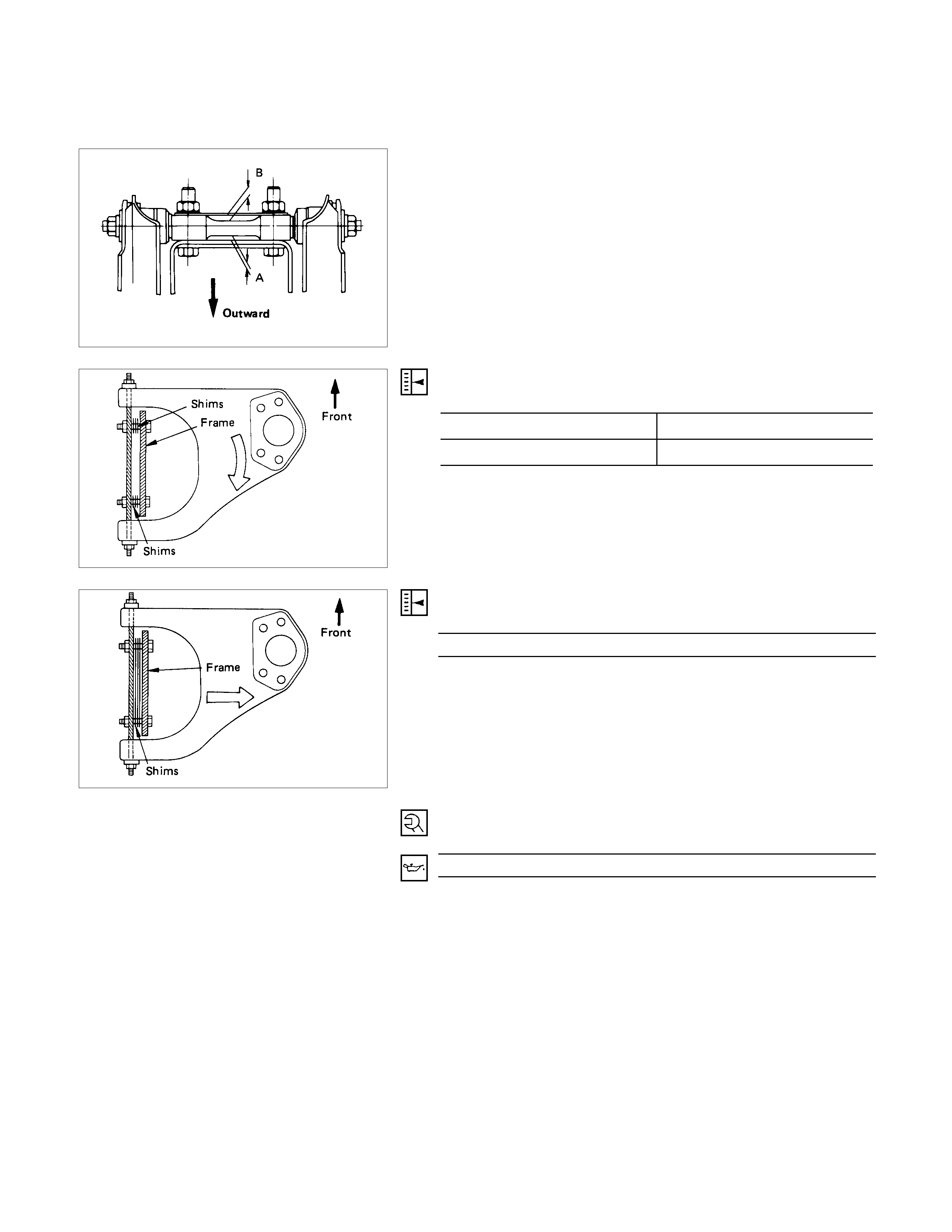
5. Fulcrum Pin
Install the smaller clearance A to be inside and larger
clearance B outside of vehicle.
6 Bushing
Remover and Installer : 5-8840-0256-0
(J-29755)
7. Plate and Nut
Tighten fulcrum pin nut finger-tight.
Perform the secure tightening after adjusting buffer clearance.
10.Bolt
Fulcrum Pin Bolt Torque N⋅m (kgf⋅m/lb⋅ft)
152.0 ± 14.7 (15.5 ± 1.5/112.1 ± 10.8)
11.Upper End
Upper End Torque N⋅m (kgf⋅m/lb⋅ft)
32.4 ± 2.9 (3.3 ± 0.3/23.9 ± 2.2)
13.14. 16. Nut
Knuckle Nut Torque N⋅m (kgf⋅m/lb⋅ft)
Lower End 147.1 ± 9.8 (15.0 ± 1.0/108.5 ± 7.2)
Upper End 107.9 ± 9.8 (10.0 ± 1.0/79.7 ± 7.2)
Steering Link End 107.9 ± 9.8 (10.0 ± 1.0/79.7 ± 7.2)
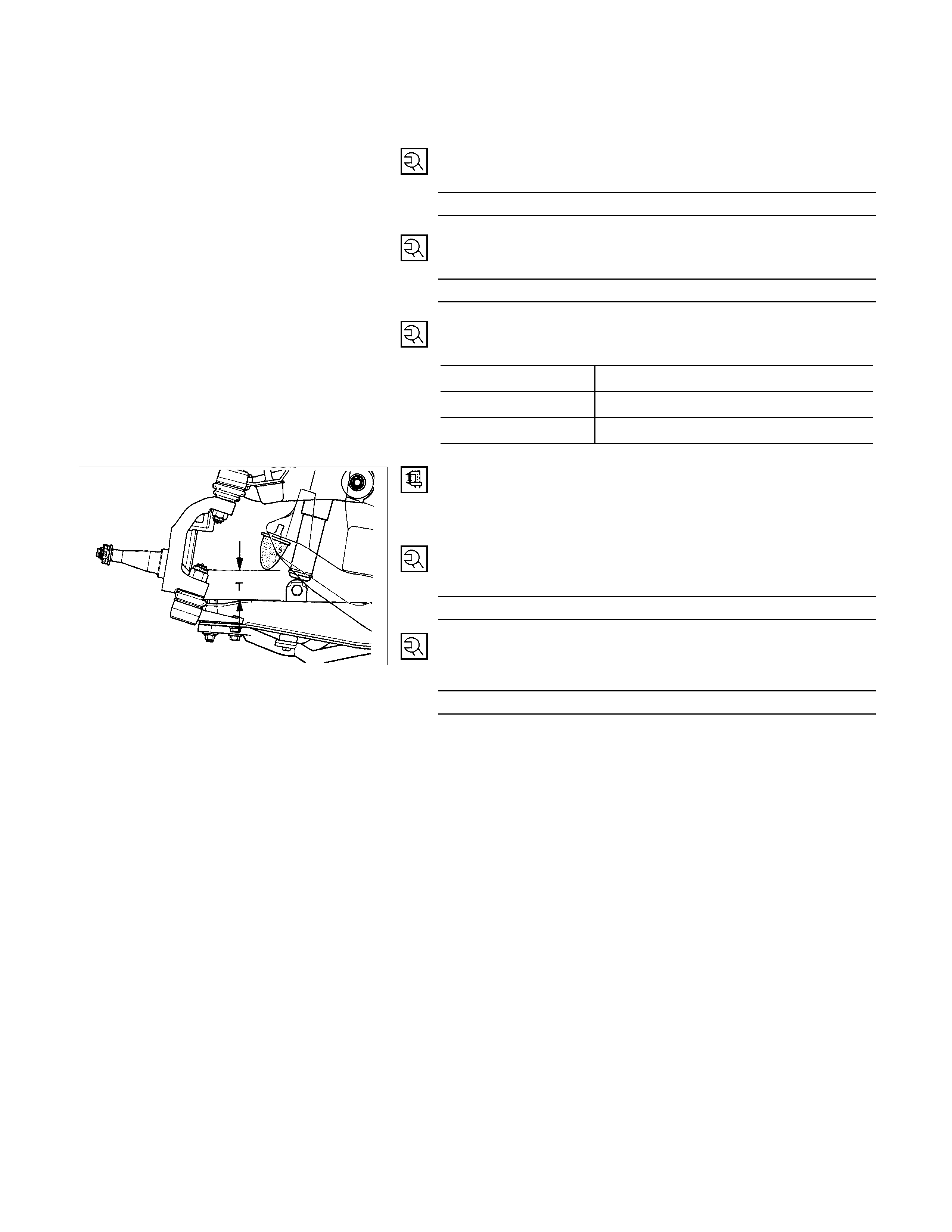
Fasten the bushing nut, and keep the buffer clearance as
shown on the left diagram.
T = 53 mm (2.09 in)
LOWER LI NK NUT
Lower Link Nut Torque N⋅m (kgf⋅m/lb⋅ft)
126.5 ± 12.8 (12.9 ± 1.3/93.3 ± 9.4)
UPPER LINK NUT
Upper Link Nut Torque N⋅m (kgf⋅m/lb⋅ft)
107.9 ± 14.7 (11.0 ± 1.5/79.6 ± 10.8)
KNUCKLE, UPPER LINK AND LOWER LINK (4×
××
×4 AND 4×
××
×2 V6 ENGINE)
DISASSEM BLY
DISASSEM BLY STEPS
KNUCKLE
1. Back plate and hub
2. Nut and cotter pin
3. Nut and cotter pin
4. Knuckle
5. Oil Seal (4×4 model)
6. Washer (4×4 model)
▲7. Needle bearing (4×4 model)
UPPER LINK
8. Upper end
9. Bolt and plate
10. Nut Assembly
▲11. Camber shims
▲12. Caster shims
13. Upper link assembly
14. Nut
15. Plate
▲16. Bushing
17. Fulcrum pin
LOWER LINK
18. Lower end
19. Nut and washer
20. Bolt
21. Nut and washer
22. Bolt
▲23. Lower link assembly
24. Torsion bar arm
▲25. Bushing
▲26. Bushing
IMPORTANT OPERATIONS
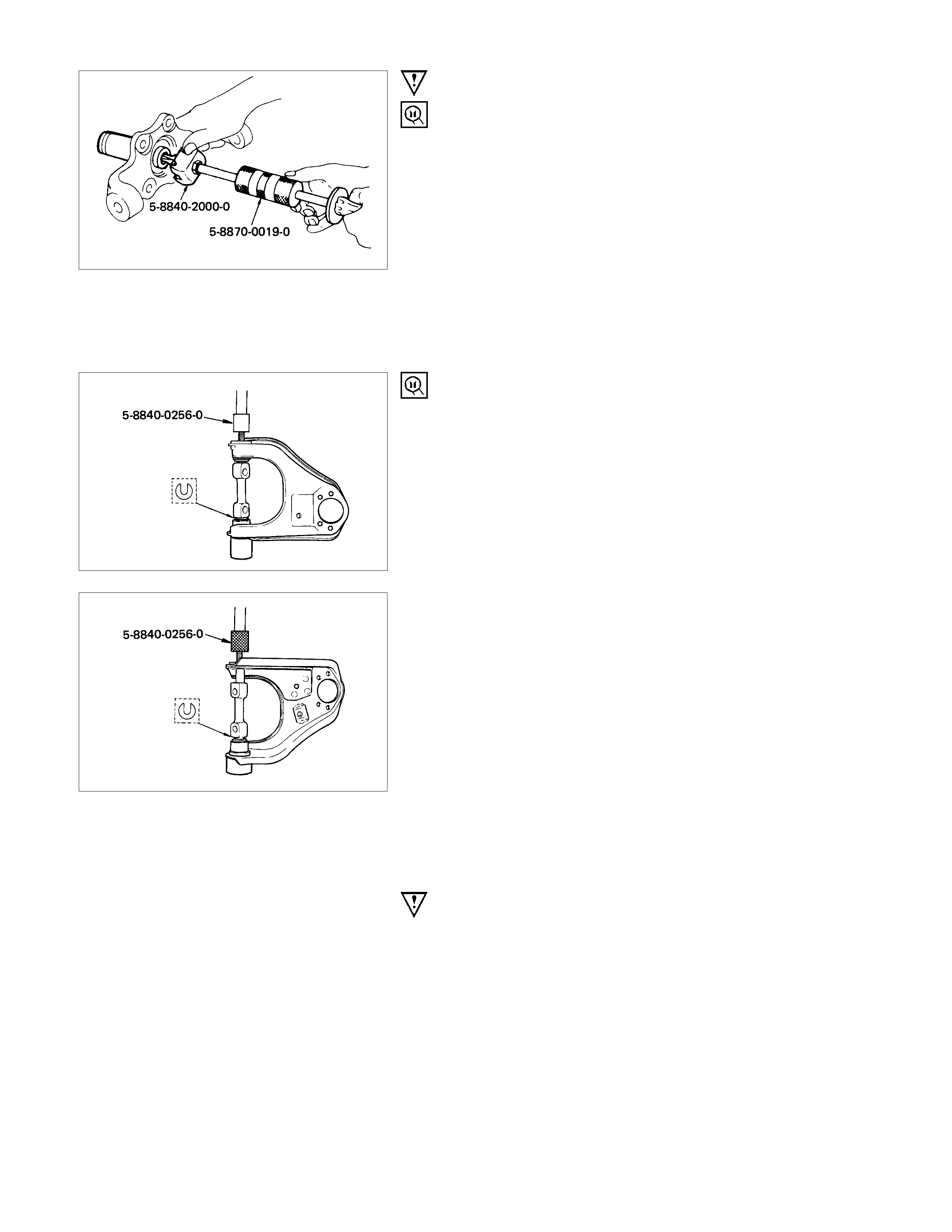
7. Needle Bearing (4×
××
×4 model)
Remover : 5-8840-2000-0
(J-5822)
Sliding hammer : 5-8840-0019-0
(J-23907)
11.Camber Shims
12.Caster Shims
Note the positions and number of shims.
16.Bushing
Remover and installer : 5-8840-0256-0
(J-29755)
23.Lower Link Assembly
Before removal, remove the torsion bar, stabilizer bar and
shock absorber.
Brake hoses should be removed before disassembly and
installed after reassembly to avoid serious damage.
25.Bushing : Rear Side
Remover and Installer : 5-8840-2124-0
(J-36834)
26.Bushing : Front Side
Remover and Installer : 5-8840-2123-0
(J-36833)
INSPECTION AND REPAIR
Make necessary correction or parts replacement if wear, damage or any other abnormal conditions are found through
inspection.
• Knuckle, Knuckle arm
• Needle bearing, oil seal (4×4 model)
• Upper link, lower link, bushing
• Upper end, lower end, boot
• Fulcrum pin
• Thrust washer
VISUAL CHECK
Inspect the following parts for wear, damage or other abnormal
conditions.
UPPER LINK END AND LO WER LINK END
Inspect the upper and lower link end boot for damage or
grease leak.
Move the Ball Joint as shown in the illustration, then confirm its
normal movement.
Inspect screw/taper area of Ball Joint for defects.
If any defects are found by the above inspections, replace the
end assembly w ith new one.
After moving the Ball Joint 4 or 5 times, attach nuts then
measure the preload.
Preload N⋅m (kgf⋅m/lb⋅ft)
Upper link end 0.9 - 3.2 (0.1 - 0.33/0.7 - 2.4)
Lower link end 0.06 - 0.64 (0.07 - 0.65/0.15 - 1.43)
If above limits specified are exceeded, replace the end
assembly.
REASSEMBLY
REASSEMBLY STEPS
LOWER LINK
▲1. Bushing ; front
▲2. Bushing ; rear
3. Lower link assembly
▲4. Torsion bar arm
5. Bolt
▲6. Nut and washer
7. Bolt
▲8. Nut and washer
▲9. Lower End
UPPER LINK
10. Fulcrum pin
▲11. Bushing
12. Plate
▲13. Nut
▲14. Upper link assembly
▲15. Caster shims
▲16. Caster shims
▲17. Bolt and plate
18. Nut assembly
▲19. Upper end
KNUCKLE
▲20. Needle bearing (4×4 model)
21. Washer (4×4 model)
▲22. Oil seal (4×4 model)
23. Knuckle
▲24. Nut and cotter pin
▲25. Nut and cotter pin
26. Back plate
IMPORTANT OPERATIONS
1. Bushing ; Front S ide
Remover and Installer : 5-8840-2123-0
(J-36833)
2. Bushing ; Rear Side
Remove and Installer : 5-8840-2124-0
(J-36834)
4. Torsion Bar Arm
Torsion Bar Arm Torque N⋅m (kgf⋅m/lb⋅ft)
115.7 ± 9.8 (11.8 ± 1.0/85.3 ± 7.2)
6. 8. Nut and Washer
Tighten Lower Link Nut finger-tight.
Perform the secure tightening after adjusting buffer clearance.
9. Lower End
Lower End Bolt Torque N⋅m (kgf⋅m/lb⋅ft)
103.0 ± 9.8 (10.5 ± 1.0/75.9 ± 7.2)
11.Bushing
Remover and Installer : 5-8840-0256-0
(J-29755)
Apply a suitable socket to (*) portion.
13.Nut
Tighten fulcrum pin nut finger-tight.
Perform the secure tightening after adjusting buffer clearance.
14.Upper Link Assembly
Install the smaller clearance A outside and larger clearance B
inside of vehicle.
15.Caster Shims
Caster angle
Short Wheel Base Long Wheel Base
1°55' ± 45' 2°10' ± 45'
Note :
No more than 35' side to side variation.
16.Camber Shims
Camber angle 30' ± 60'
Note :
No more than 45' side to side variation.
17.Bolt and Plate
Fulcrum Pin Bolt Torque N⋅m (kgf⋅m/lb⋅ft)
152.0 ± 14.7 (15.5 ± 1.5/112.1 ± 10.8)
Apply oil to the thread.
19.Upper End
Upper End Bolt Torque N⋅m (kgf⋅m/lb⋅ft)
32.4 ± 2.9 (3.3 ± 0.3/23.9 ± 2.2)
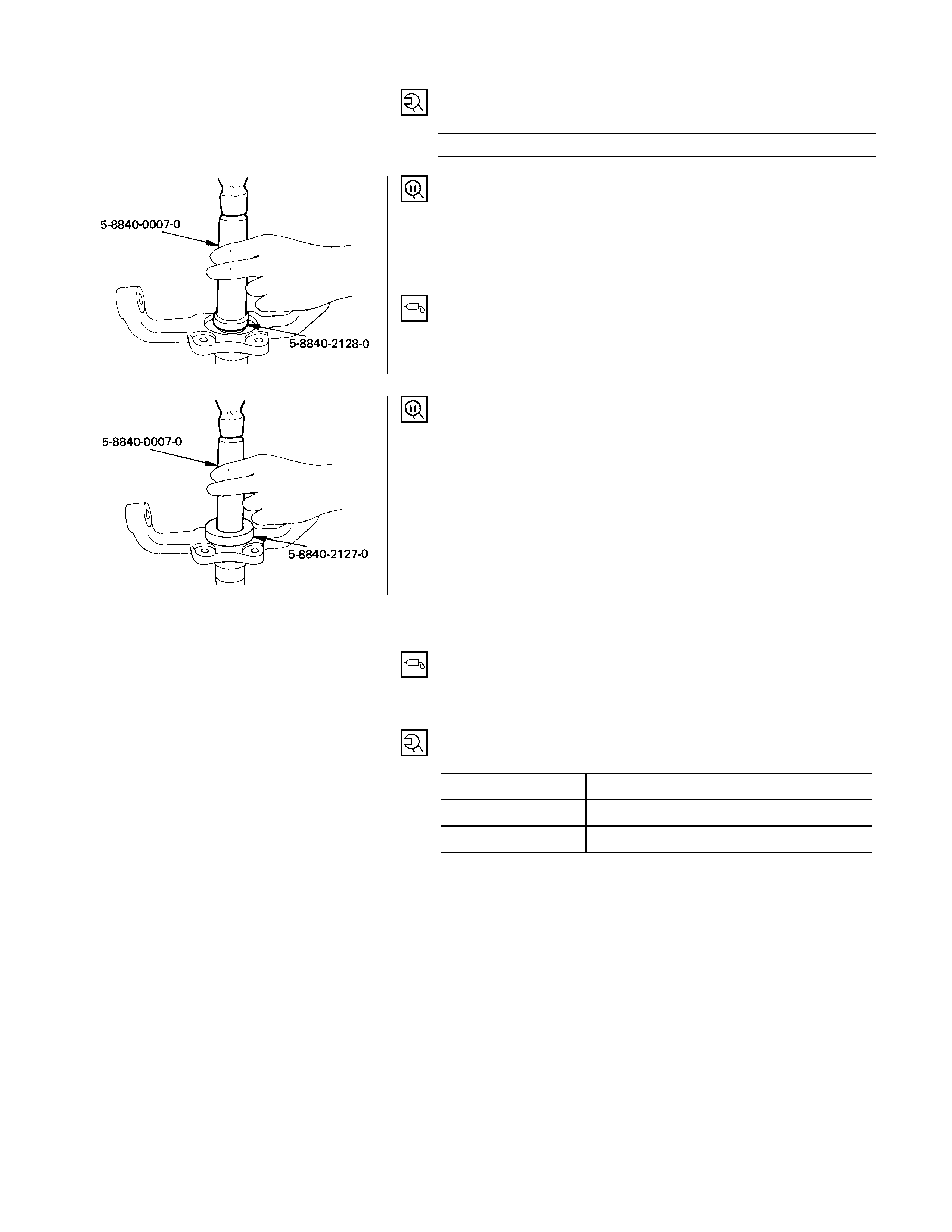
20.Needle Bearing (4×
××
×4 model)
Installer : 5-8840-2128-0
(J-36838)
Grip : 5-8840-0007-0
(J-8092)
Before installation, apply the appropriate amount of specified
grease (Besco L2 or equivalent) to the bearing (Approx. 15g).
22.Oil Seal (4×
××
×4 model)
Installer : 5-8840-2127-0
(J-36837)
Grip : 5-8840-0007-0
(J-8092)
•Insert the thrust washer into the knuckle.
• After fitting the oil seal to the setting tool; installer, drive it to
the knuckle using a hammer or bench press until the tool
front face contacts with the thrust washer.
•Apply the specified grease to the thrust washer, and install
after turning the place where there is a chamfer to the
spindle.
•Use a new oil seal, and apply the specified grease (Besco
L2 or equivalent) to the place surrounded by the lip (Approx.
15g).
24.25. Nut and Cotter Pin
Torque N⋅m (kgf⋅m/lb⋅ft)
Upper Link End 98.1 ± 9.8 (10.0 ± 1.0/72.3 ± 7.2)
Lower Link End 127.5 ± 9.8 (13.0 ± 1.0/94.0 ± 7.2)
Track Rod End 107.9 ± 9.8 (11.0 ± 1.0/79.6 ± 7.2)
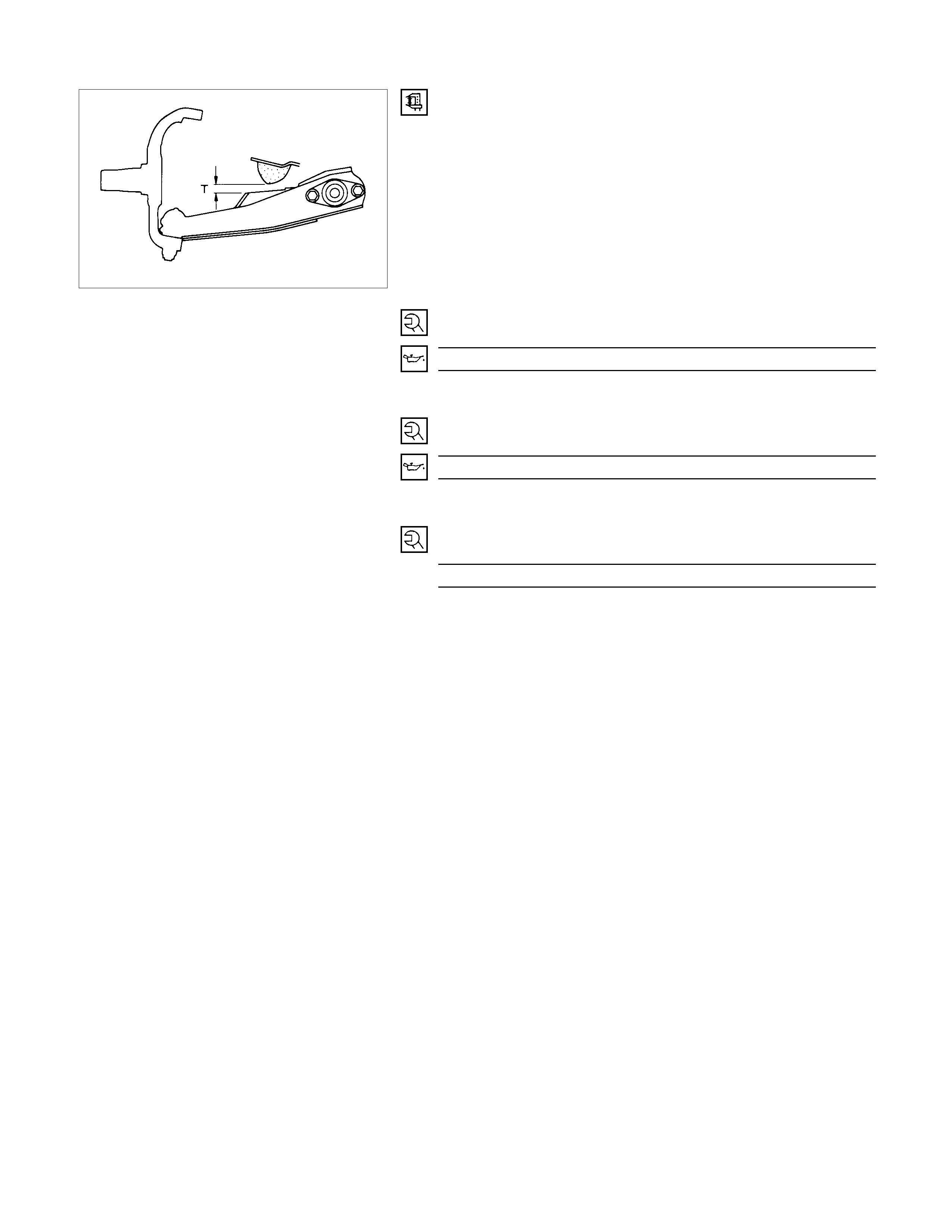
Fasten the bushing nut and keep the buffer clearance as
shown on the left diagram.
T = 15 mm (0.59 in)
Nut and Washer
Front Lower Link Nut Torque N⋅m (kgf⋅m/lb⋅ft)
156.9 ± 19.6 (16.0 ± 2.0/115.7 ± 14.5)
Apply oil to the thread.
Nut and Washer
Rear Lower Link Nut Torque N⋅m (kgf⋅m/lb⋅ft)
196.1 ± 19.6 (20.0 ± 2.0/144.7 ± 14.5)
Apply oil to the thread.
Nut
Fulcrum Pin Nut Torque N⋅m (kgf⋅m/lb⋅ft)
152.0 ± 14.7 (11.0 ± 1.5/112.1 ± 10.8)
Apply oil to the thread.
TROUBLESHOOTING
1. VIBRATION, SHOCK, AND SHIMMY OF STEERING WHEEL
Checkpoint Trouble Cause Countermeasure
Check front axle
Check wheel alignment
Check suspension ball joint
Check shock absorber or
attaching nut and bolt
Check tires and wheels
Adjust
Replace
Replace or retighten
Check steering unit and
linkage
Faulty
Worn
Malfunction or loose
Check upper and lower link
bushings Replace
Adjust
Worn
Incorrect
OK
OK
OK
NG
NG
NG
NG
NG
NG
OK
OK
Check vehicle trim height
•Improperly adjusted or worn fron
t
wheel bearing.
•Worn or incorrectly adjusted wheel
bearing.
Replace; refer to Section 4b "Front
Wheel Drive"
•Insufficiently tightened steering
gear housing.
•Wear of steering linkage.
•Excessive backlash due to
improper adjustment of the steering
gear box.
•Worn column bearing weakened
column bearing spring, or loose
clamp.
Replace; refer to Section 9
"Steering"
•Improper tire pressure.
•Imbalance and deformation of frond
wheel.
•Unevenly worn tire or insufficient
tightening of wheel nuts.
Replace; refer to Section 10 "Wheel
and Tires"

"Steering"

2. VEHICLE PULLS TO RIGHT OR LEFT
Checkpoint Trouble Cause Countermeasure
Steering linkage, and upper
and lower link and strut bar
Rubber bushing for upper and
lower link, and strut bar
Wheel alignment
Vehicle trim height
Front wheel bearing
Replace
Adjust
Adjust
Deformed Replace
Worn
Incorrect
Incorrect
Brake adjustment (binding) Adjust
Replace
Incorrect
Collapsed or twisted
Continued on the next page
OK
OK
OK
OK
NG
NG
NG
NG
NG
NG
OK
OK
Torsion bar
Front wheel bearing Adjust or replace
Incorrect adjustment or
abrasion
NG

Checkpoint Trouble Cause Countermeasure
Tire tread (right and left) Replace (tire)Difference in wear and tear
Adjust or tighten
Improper or instufficient
tightening
NG
NG
OK
Tire pressure or wheel nuts
Continued from the previous page
3. INSTABILITY OF VEHICLE
Checkpoint Trouble Cause Countermeasure
Tire pressure
Steering gear (back lash and
worm bearing preload)
Wheel alignment
Rubber bushings for upper
and lower links. and strut bar
(4 × 2)
Adjust
Adjust
Adjust
Replace
Incorrect
Incorrect
Incorrect
Worn
Steering linkage and upper
and lower links Replace
Adjust
Worn or deformed
Incorrect
OK
OK
OK
OK
NG
NG
NG
NG
NG
NG
OK
OK
Vehicle trim height
Road wheel AdjustDeformed or unbalanced
NG

4. STIFF STEERING WHEEL
Checkpoint Trouble Cause Countermeasure
Steering gear box or steering
linkage
Steering linkage
Steering gear
Wheel alignment
Replace the part
Replace
Replace
Adjust
Insufficient lubricants or
impurities present; or
excessively worn
Deformed
Worn or damaged
Incorrect
Steering gear (Back lash) Adjust
Replace
Incorrect
Stiff or damaged or lack of
grease
OK
OK
OK
OK
OK
NG
NG
NG
NG
NG
NG
OK
OK
Upper and ball joint
Steering column with turn
signal switch ReplaceInterference abrasion
NG
Tire pressure AdjustImproper
NG
5. NOISES
Checkpoint Trouble Cause Countermeasure
Lubricating oil and grease for
upper and lower ball joint
Shock absorber
Stabilizer fixing nuts and bolts
Upper and lower links and
strut bar bushings
Replace
Replace
Retighten
Replace
Insufficient
Faulty
Loose
Worn
Shock absorber fixing nut and
bolt Retighten
Replace
Loose
Broken
Continued on the next page
OK
OK
OK
OK
NG
NG
NG
NG
NG
NG
OK
OK
Strut bar (4 × 2)
Upper and lower ball joint ReplaceDamaged
NG

Checkpoint Trouble Cause Countermeasure
Steering linkage and steering
gear ReplaceWorn
AdjustImproper
OK
NG
NG
OK
Tire pressure
Continued from the previous page
Steering unit fixing bolts and
linkage RetightenLoose
Adjust or replace
Incorrect adjustment or
abrasion
OK
NG
NG
OK
Front wheel bearing
Lubricating oil and grease to
steering linkage ReplaceInsufficient
NG
OK
6. EXCESSIVE STEERING W HEEL PLAY
Checkpoint Trouble Cause Countermeasure
Front wheel bearing
Steering linkage
Adjust or replace
Replace
Incorrect adjustment or
abrasion
Worn
Adjusted gear housing Adjust
Replace
Incorrectly
Worn
OK
NG
NG
NG
NG
OK
OK
Upper, and lower links, and
strut bar bushing (4 × 2)

7. GRATING TIRE NOISE
Checkpoint Trouble Cause Countermeasure
Tire pressure
Knuckle spindle and steering
linkage
Adjust
Replace
Improper
Deformed
Suspension fixing bolt Replace
Adjust
Loose
Incorrect
OK
NG
NG
NG
NG
OK
OK
Wheel alignment
8. EXCESSIVELY O R PARTIALLY WO RN TIRE
Checkpoint Trouble Cause Countermeasure
Brake adjustment
Wheel alignment
Adjust
Adjust
Incorrect
Incorrect
Front wheel bearing Replace
Adjust
Faulty
Improper
OK
NG
NG
NG
NG
OK
OK
Tire pressure
Tire rotation Rotate tires at recomended
intervals
Not rotated
OK
NG
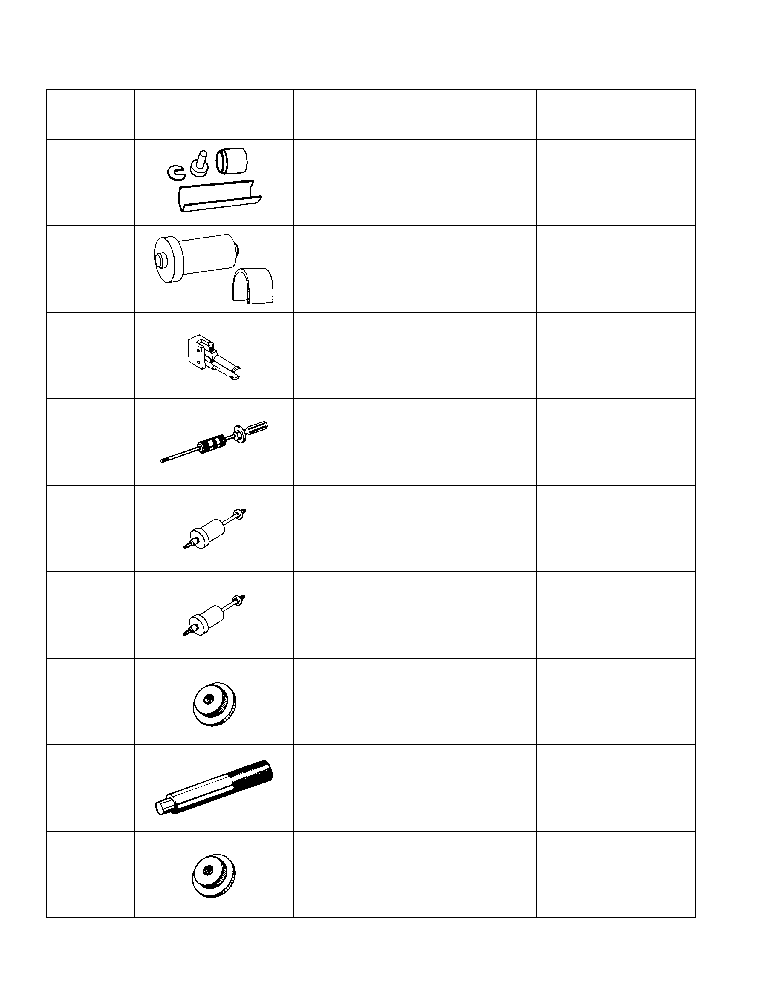
SPECIAL SERVICE TOOL (C22, C20 SERIES ENGINE MO DEL)
ITEM NO. ILLUSTRATION PART NO. PART NAME
SUL-1 5-8840-0256-0
(J-29755) Upper link bushing
remover & installer
SUL-6 5-8840-0257-0
(J-29756) Lower link bushing
remover & installer
SUL-3 5-8840-2000-0
(J-5822) Knuckle needle bearing
remover
OTL-2 5-8840-0019-0
(J-23907) Sliding hammer (small)
SUL-5 5-8840-2124-0
(J-36384) Rear lower link bushing
remover & installer kit
SUL-4 5-8840-2123-0
(J-36833) Front lower link bushing
remover & installer kit
SUL-10 5-8840-2128-0
(J-36838) knuckle needle bearing
installer
OTL-1 5-8840-0007-0
(J-8092) Driver handle
SUL-9 5-8840-2127-0
(J-36838) Knuckle oil seal installer