
MAIN DATA AND SPECIFICATIONS
Models Standard Have-duty
Suspension Flat Deck
Items 4 × 2
(except
Sporty) 4 × 4 4 × 2
Sporty
4 × 2
(except
Sporty)
4 × 4
and
4 × 2
Sporty
4 × 24 × 4
Type Semi-elliptic, rubber bushed, leaf type springs and direct
double acting shock absorbers.
Main spring
No. of leaves 4 6 4
Leaf thickness - Numbered 7(0.276); No.1-2 7(0.276)
; No.1 7(0.276); No.1-4 8(0.315); No.1-2
(Top to bottom) mm(in) 6 (0.236); No. 3 6(0.236)
;No.2-3 7 (0.709); No. 3
15(0.591); No.4 12(0.472); No.5-6 18(0.709); No.4
Spring eye type Berlin eye type
Bushing outside dia. mm(in) Front; 40 (1.575), Rear; 30 (1.181)
Length mm(in) 1200 (47.244)
Width mm(in) 60 (2.362)
Rate - Unclamped kg/mm 2.61/7.96 2.23/
8.13 3.91/8.34 3.95/12.8
(lb/in) (146.0/445.4) (124.8/
454.9) (218.8/466.7) (221.0/716.2)
Clamped kg/mm 2.87/8.75 2.47/8.72 4.30/9.17 4.37/14.2
(lb/in) (160.6/489.6) (138.3/487.9
)
(240.6/513.1) (244.5/794.6)
Rear spring capacity N(kg/Ib) 768 763 701 760 755 715 720
(7532/1693) (7483/1682) (1545/6877) (7423/1676) (7404/1664) (7012/1576) (7061/1587)
Weight N(kg/lb) 153 (15.6/34.4) 16.2
(35.7/
158.9) 196 (20.0/44.1) 180 (18.4/40.6)
Rear shock absorbers
Type Hydraulic, double acting, telescopic
Gas-sealed Hydraulic, double acting telescopic
(For Australia)
Mean stroke mm(in) 245 (9.65)
Compressed length mm(in) 353 (13.90)
Extended length mm(in) 598 (23.54)
Bump rubber
Height mm(in) 69 (2.72) 84 (3.31) 69 (2.72) 84 (3.31) 84 (3.31) 84 (3.31)
For Australia mm(in) 69 (2.72) 99 (3.90) 69 (2.72) 99 (3.90) - -
TORQUE SPECIFICATIONS
SPECIAL PARTS FI XING NUTS AND BOLTS
REAR SUSPENSIO N N⋅
⋅⋅⋅m(kgf⋅
⋅⋅⋅m/lb⋅
⋅⋅⋅ft)
29.4±1.96(3.0±0.2/21.7±1.4)
152.0±14.7(15.5±15/112.1±10.8
98.0±19.6(10.0±2.0/72.3±14.4)
65.7±5.8(6.7±0.6/48.5±4.3)
39.2±1.9(4.0±0.2/28.9±1.4)
14.7(1.5/10.8)
39.2±4.9(4.0±0.5/28.9±3.6)
37.2±8.8(3.8±0.9/27.5±6.5)
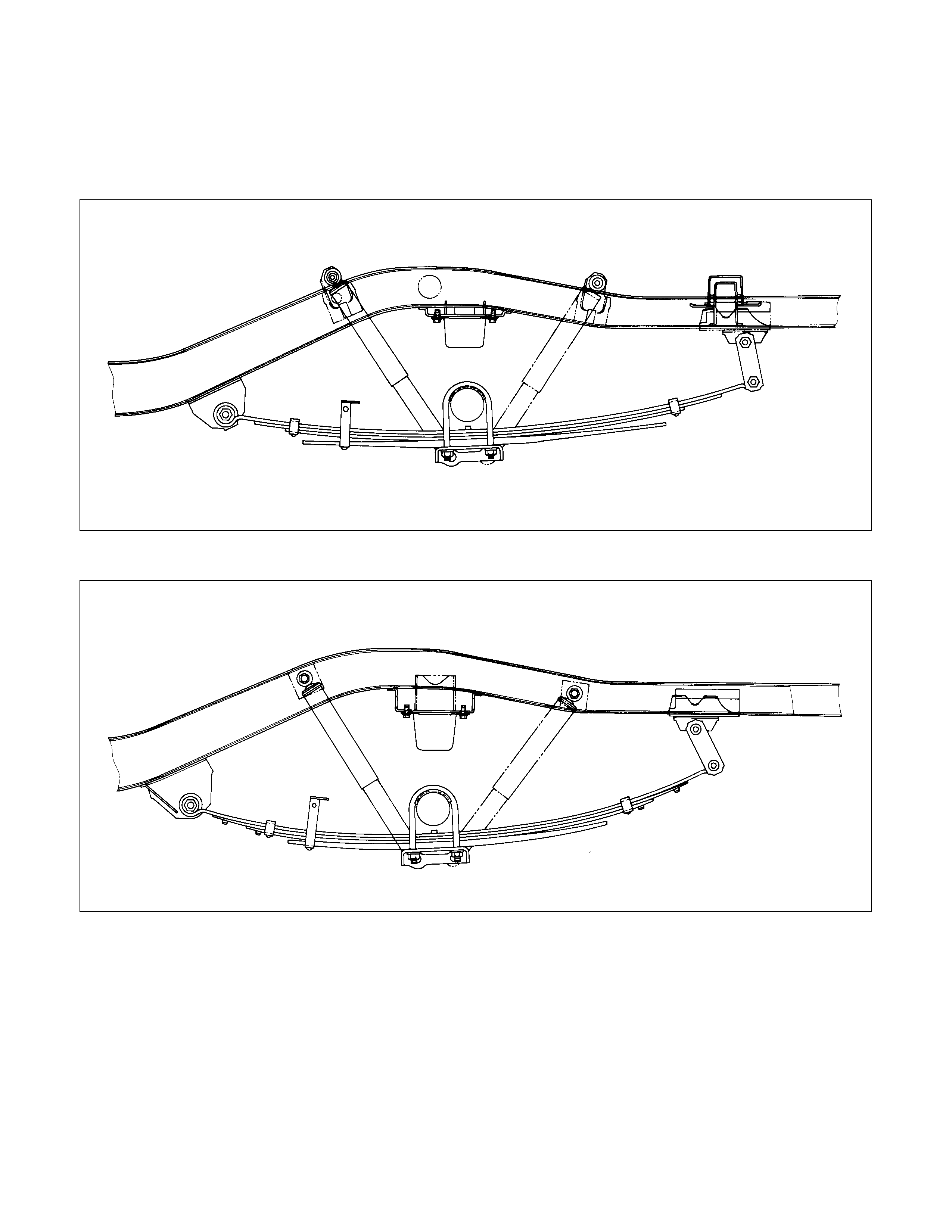
REAR SUSPENSION
GENERAL DESCRI PTION
4×
××
×2 MODEL ( EXCEPT SPORTY)
4×
××
×4 AND 4×
××
×2 SPORTY MODEL
Rear suspension absorbs vibration from the road surface thus preventing vehicle damage, as well as providing a
good ride.
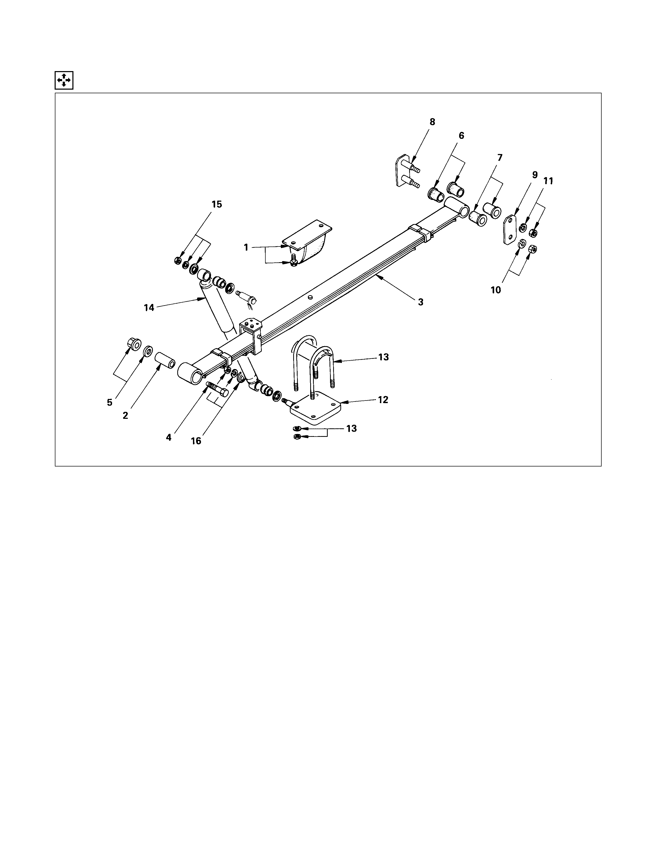
COMPONENTS PARTS
•Spring between the body and the axle case
•Spring shackle connecting the spring to the body
•Clamp and U-bolt fixing the axle case to the spring
•Shock absorber as a countermeasure for vibration
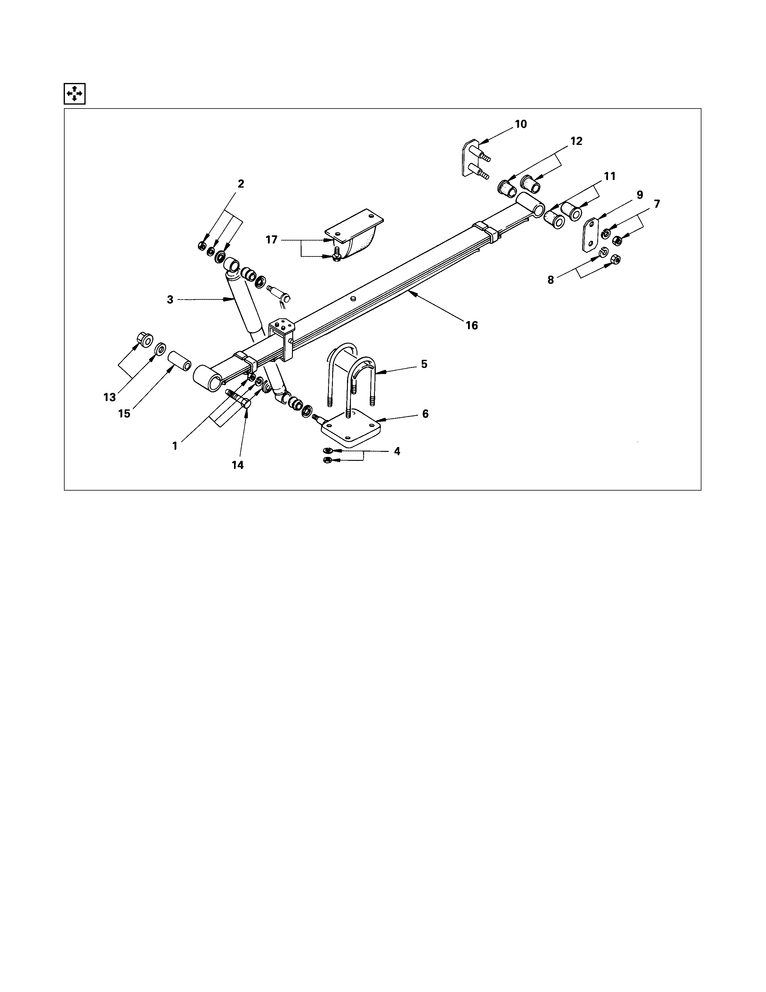
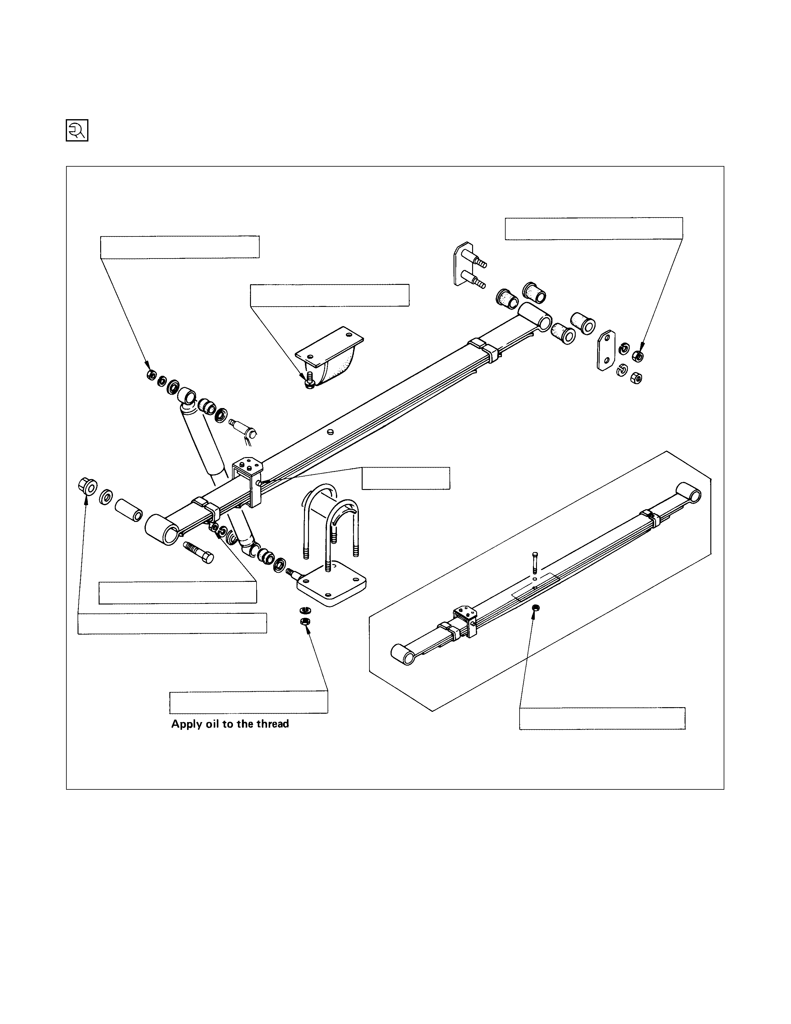
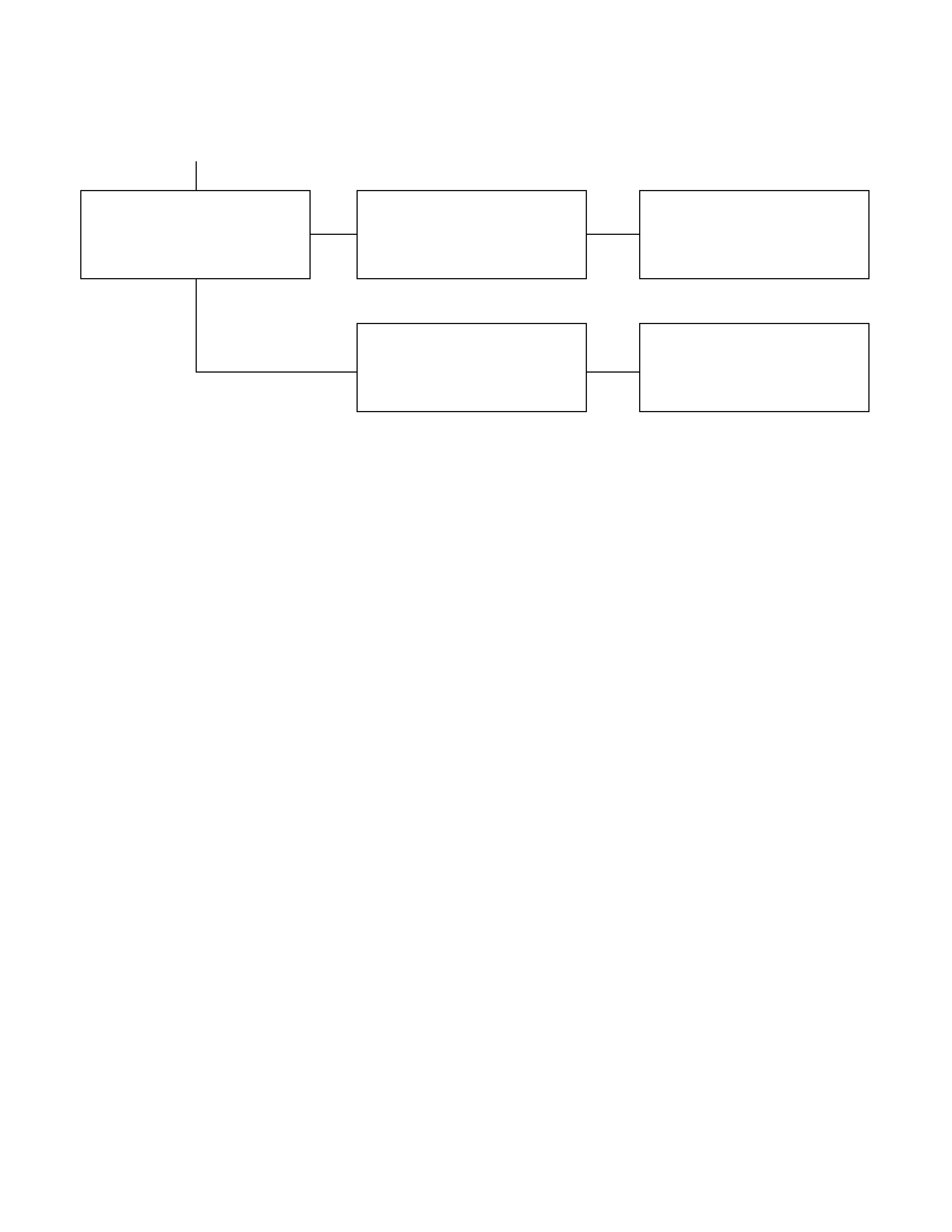
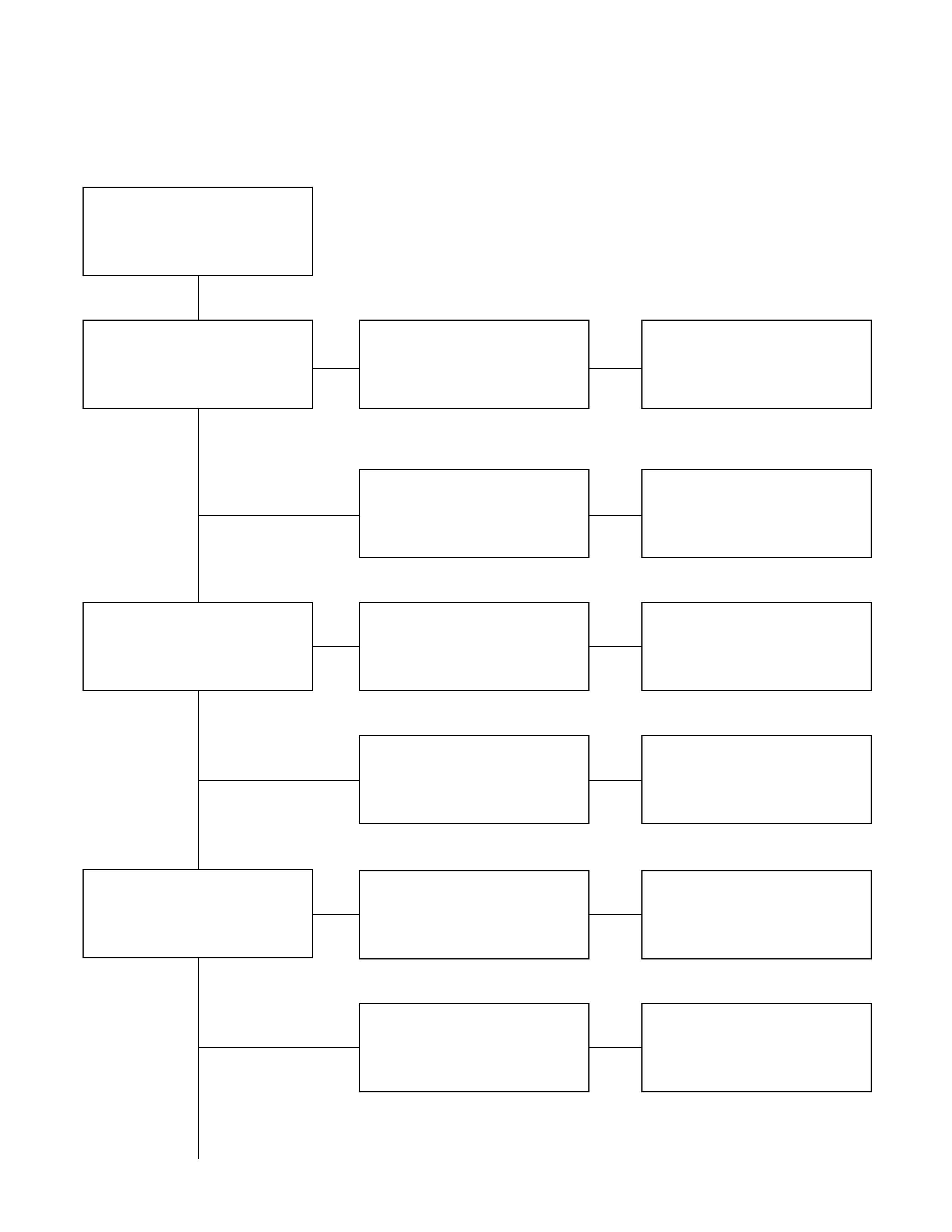
DISASSEM BLY
DISASSEM BLY STEPS
▲1. Nut and washer
▲2. Nut and washer
3. Shock absorber
▲4. Nut and washer
▲5. U-bolt
6. Lower clamp
▲7. Nut and washer
▲8. Nut and washer
▲9. Shackle plate
▲10. Shackle
11. Rubber bushing
12. Rubber bushing
▲13. Nut and washer
▲14. Bolt, washer and spring pin
▲15. Bushing
16. Leaf spring assembly
17. Bolt and dump rubber
IMPORTANT OPERATIONS
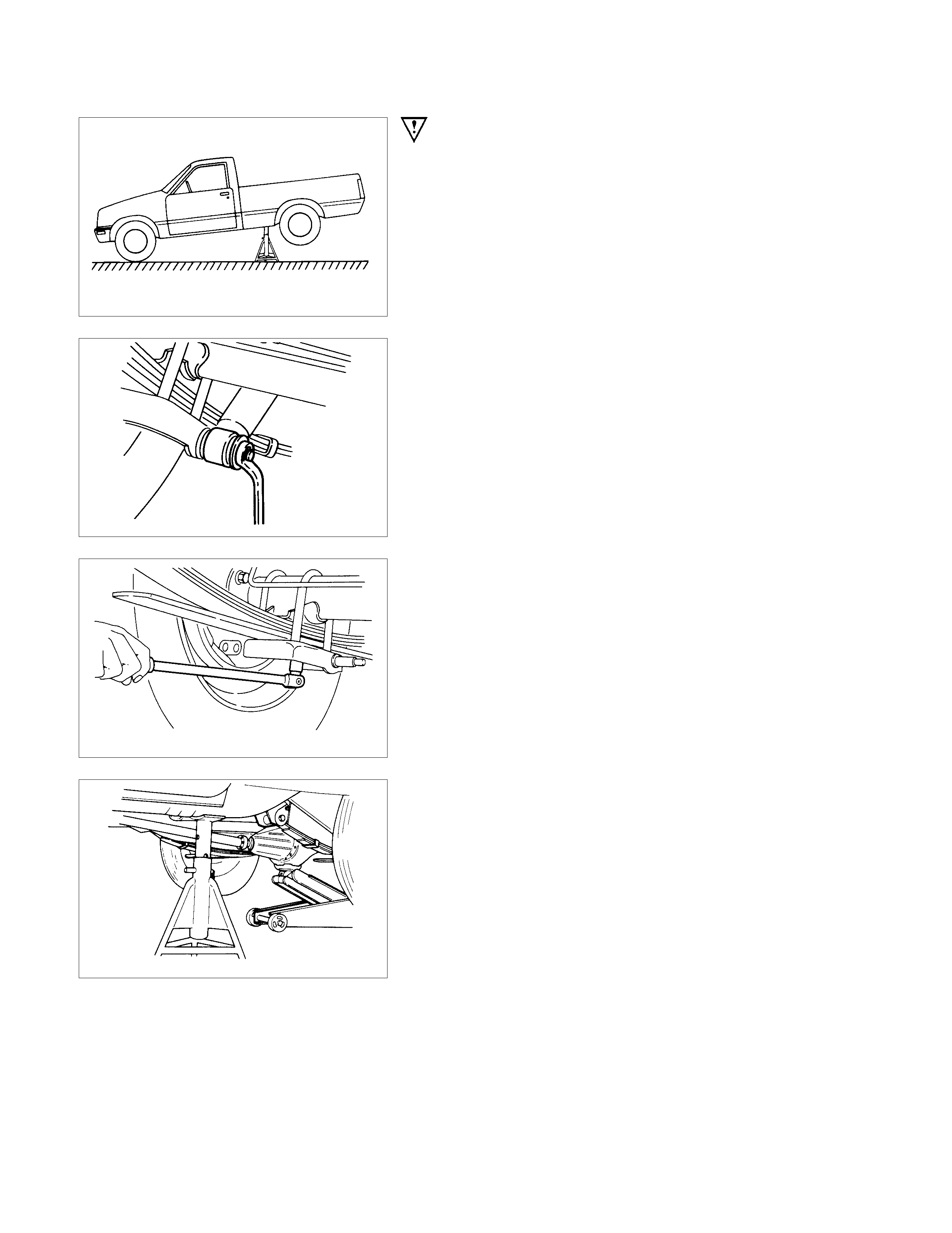
Jack up the rear axle and place chassis stands under the
frame near the front end of the rear spring brackets.
1. 2. Nut and Washer
Caution (Australia only):
The shock absorbers have been charged with gas at the
factory. Exposure to high temperatures or an open flame
can result in a dangerous explosion.
Keep the shock absorbers away from high temperatures
and open flames.
4. Nut and Washer
5. U-bolt
Jack up the rear axle case slightly to separate it from the leaf
spring assemblies.
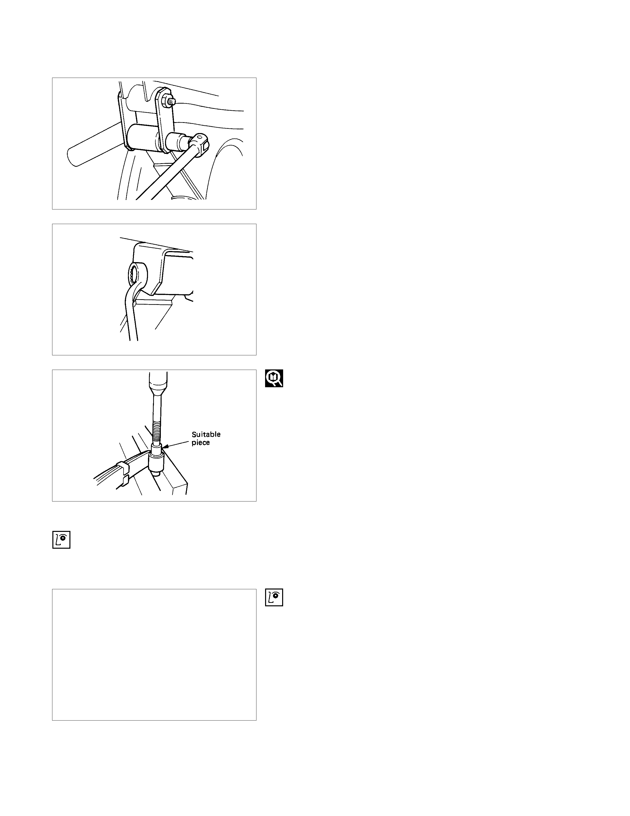
7. 8. Nut and Washer
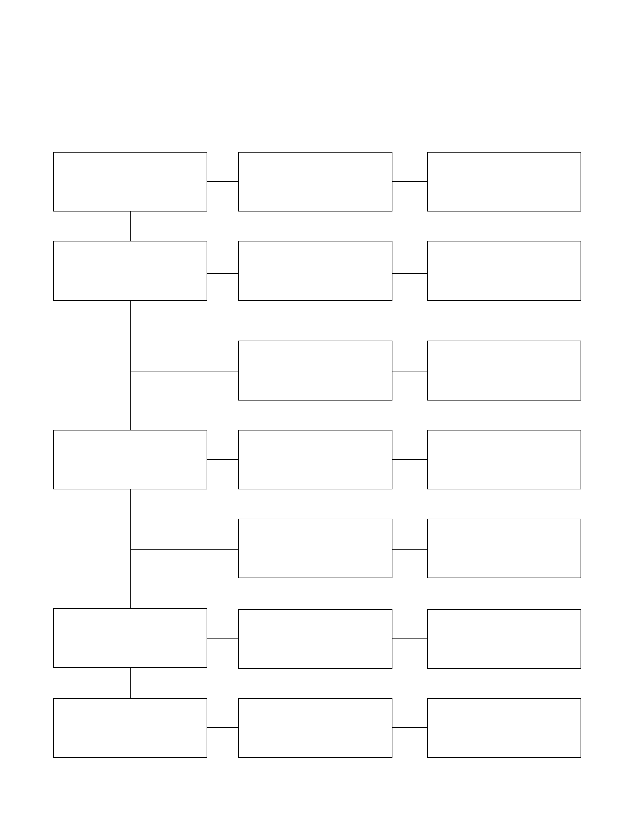
9. 10. Shackle
Remove the nut and drive out the shackle with a hammer using
a brass bar.
13.14. Nut, Washer, Bolt and Spring Pin
Remove the nut and drive out the spring pin with a hammer
using a brass drift.
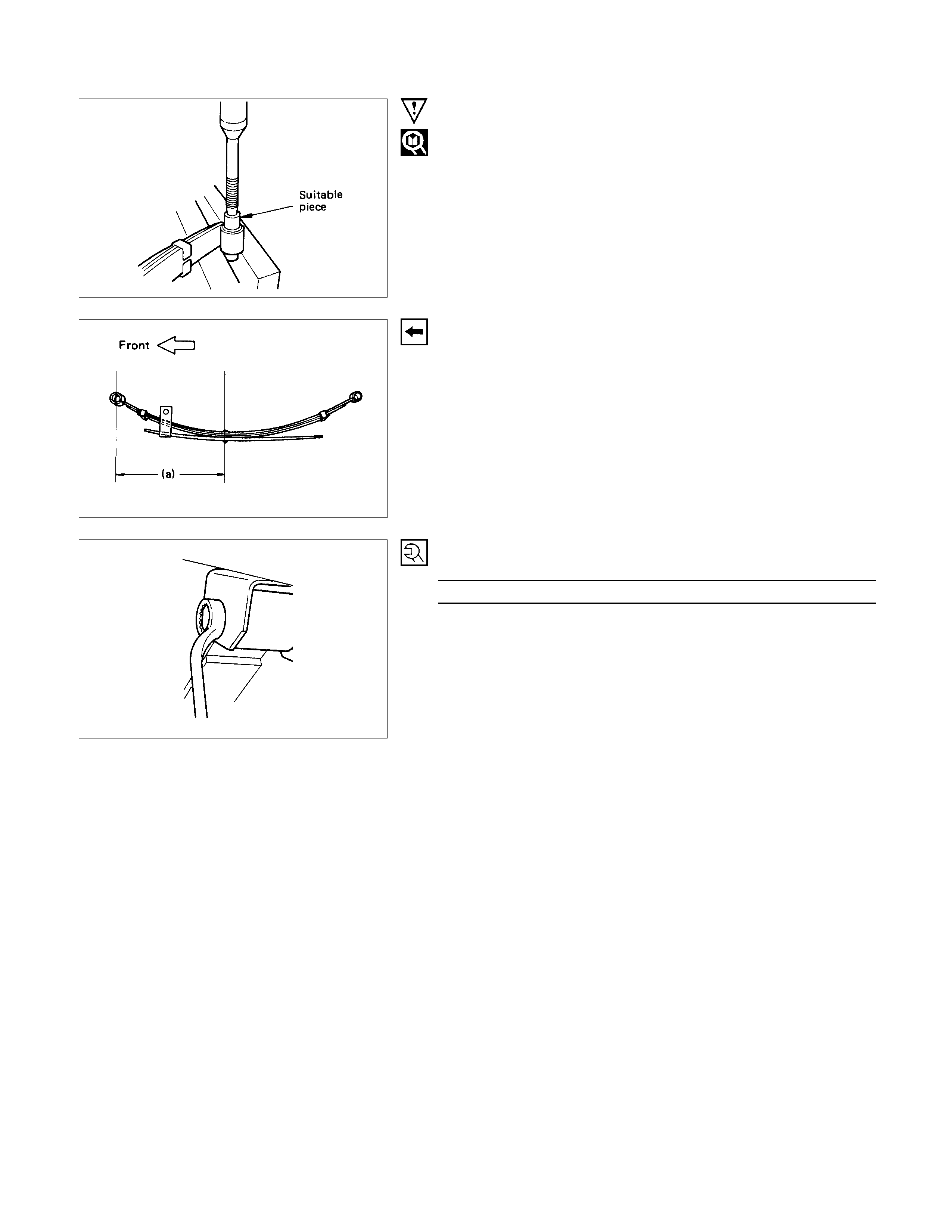
15.Bushing
Remove the bushing using a bench press.
INSPECTION AND REPAIR
Make correction or parts replacement if wear, damage or their abnormal conditions are found through inspection.
• Leaf spring assembly
• Clip
• Center bolt
• U-bolt
• Spring pin
• Shackle pin
• Shock absorber
• Bump rubber
• Rubber bushing
• Bump rubber seat
VISUAL CHECK
Inspect the following parts for wear, damage or other abnormal
conditions.
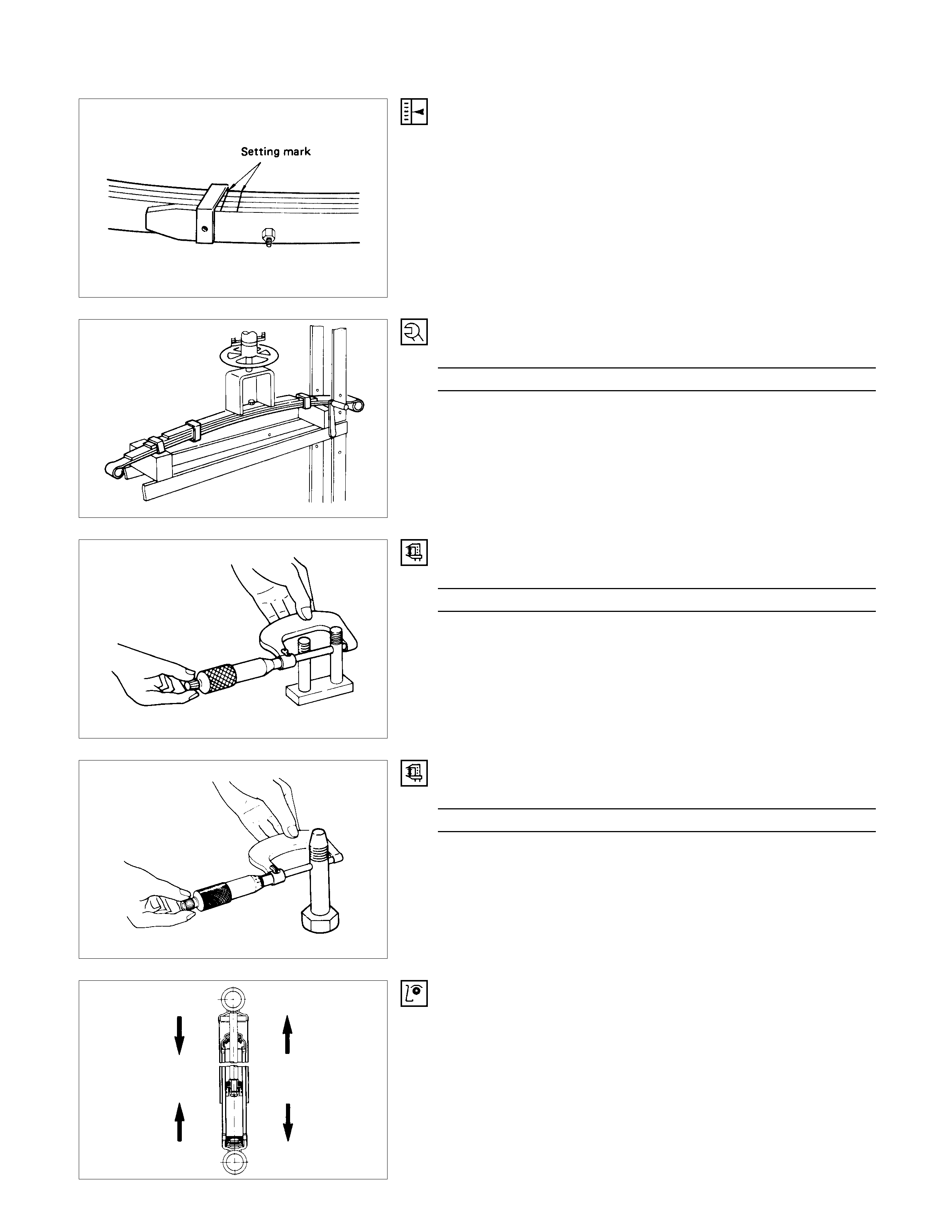
LEAF SPRING ASSEMBLY REPLACEMENT
•Apply a setting mark across the springs before
disassembling the leaf spring assembly.
•Apply grease to both faces of each leaf spring at assembly.
•Use a bench press for disassembly and reassembly.
•Discard center bolt and install a new one.
CENTER BOLT
Center Bolt Torque N⋅m(kgf⋅m/lb⋅ft)
29.4 ± 19.6 (3.0 ± 0.2 / 21.7 ± 1.4)
SHACKLE PIN
Shackle Pin diameter mm(in)
17.93 - 18.00 (0.706 - 0.709)
SPRING PIN
Spring Pin Diameter mm(in)
13.8 - 14.0 (0.543 - 0.551)
SHOCK ABSORBER
Inspection operation of shock absorber
If no resistance is felt while expanding the shock absorber, that
indicates the absorber is faulty.
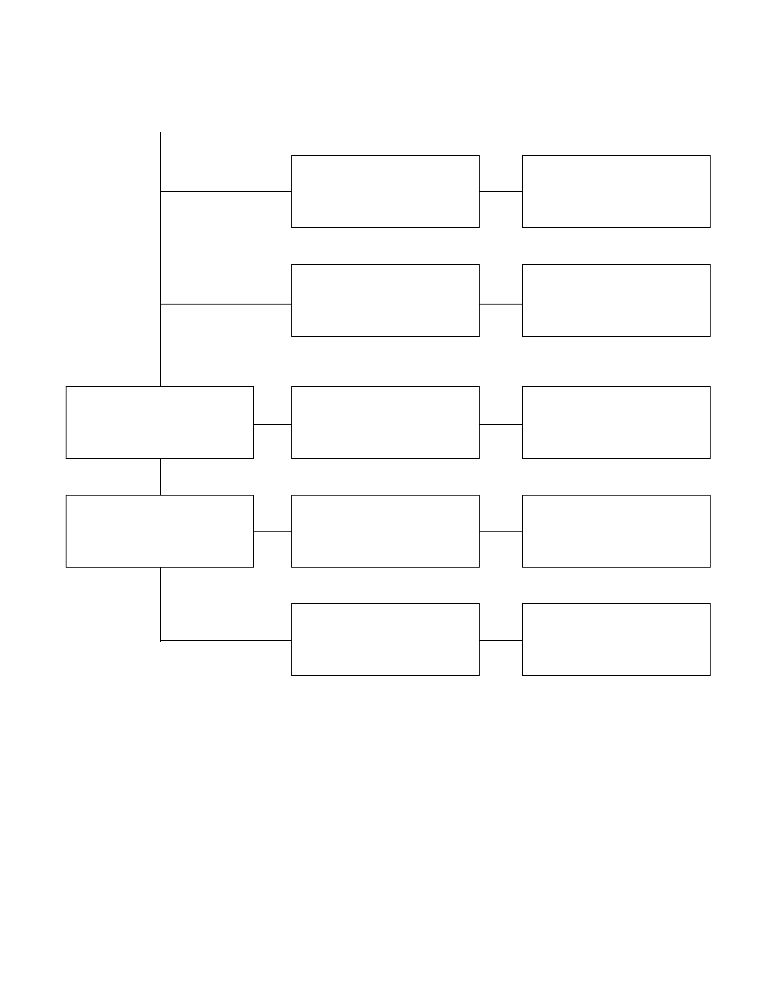
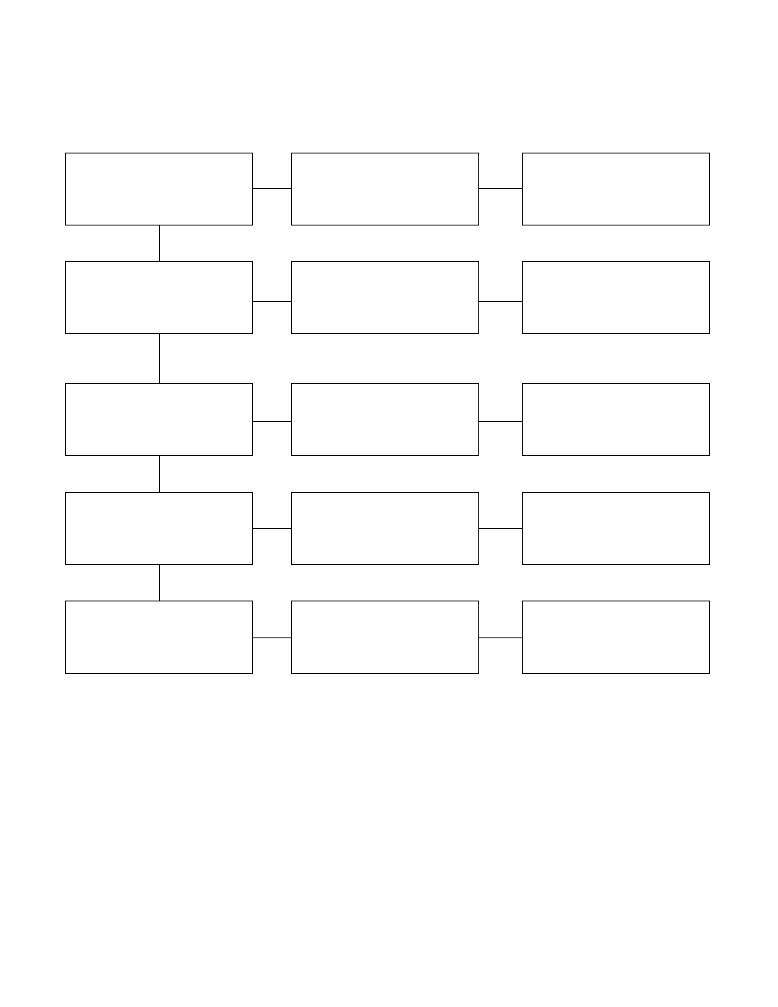
REASSEMBLY
REASSEMBLY STEPS
1. Bump rubber
▲2. Bushing
▲3. Leaf spring assembly
4. Spring pin, bolt and washer
▲5. Nut and washer
▲6. Rubber bushing
▲7. Rubber bushing
▲8. Shackle
▲9. Shackle plate
▲10. Nut and washer
▲11. Nut and washer
12. Lower clamp
▲13. U-bolt and nut
▲14. Shock absorber
▲15. Nut and washer
▲16. Nut and washer
IMPORTANT OPERATIONS
2. Bushing
Install the bushing using a bench press.
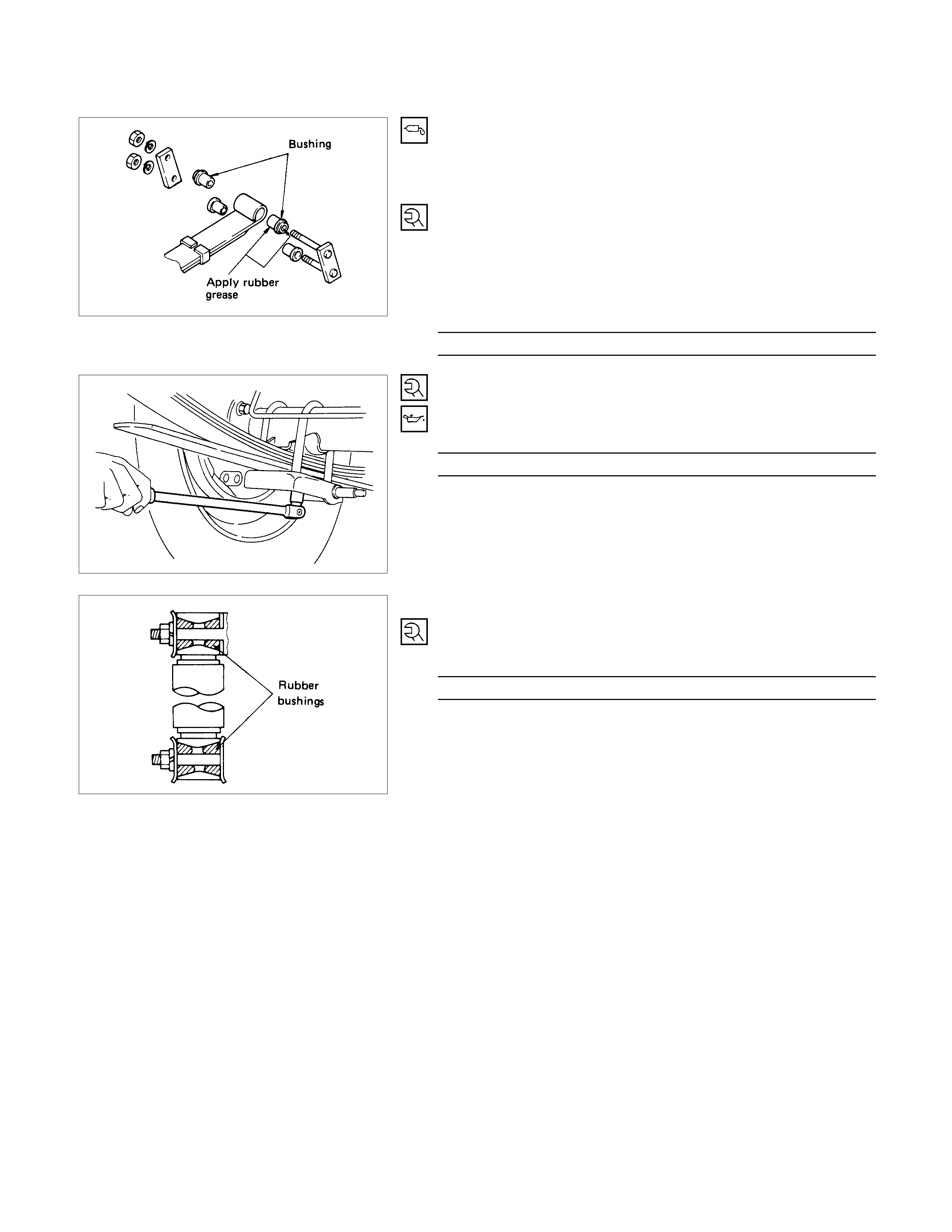
3. Leaf Spring Assembly
The leaf spring assembly should be installed so that the
shorter length (a) (distance between center bolt and center of
spring eye) is toward the front.
5. Nut and Washer
Spring Pin Torque N⋅m(kgf⋅m/lb⋅ft)
152.0 ± 14.7 (15.5 ± 1.5 / 112.1 ± 10.8)
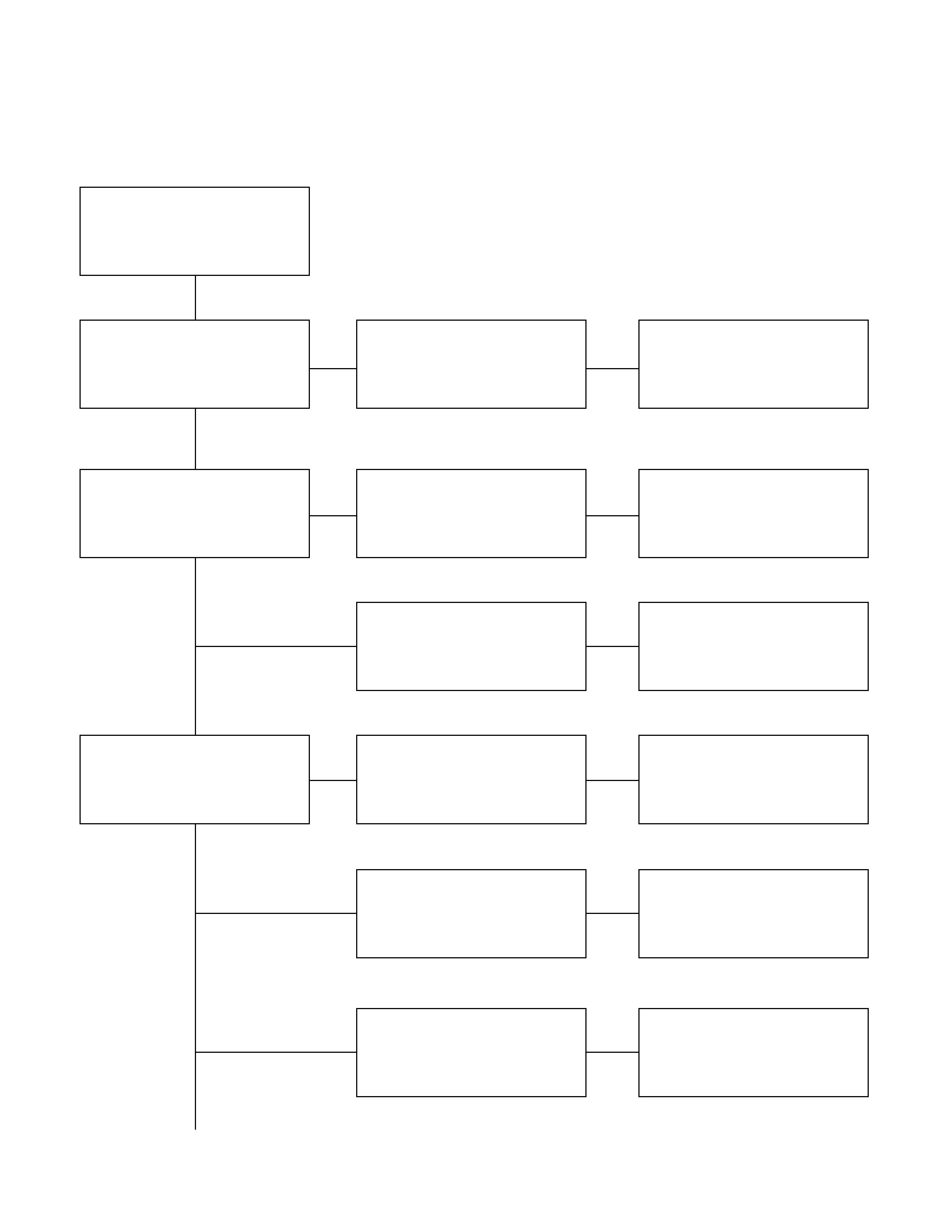
6. 7. Rubber Bushing
Apply rubber grease to inside and outside of the rubber
bushing.
8. 9. Shackle
10.11. Nut and Washer
Install bushing with collar on the leaf spring, then install and
tighten the nut.
Note :
Tighten the nuts to the specified torque with the vehicle
empty.
Shackle Nut Torque N⋅m(kgf⋅m/lb⋅ft
)
98.0 ± 19.6 (10.0 ± 2.0 / 72.3 ± 14.4)
13.U-bolt and Nut
When tightening the nuts apply oil as necessary to prevent
damaging the threads.
U-bolt Nut Torque N⋅m(kgf⋅m/lb⋅ft)
65.7 ± 5.8 (6.7 ± 0.6 / 48.5 ± 4.3)
14.Shock Absorber
15.16. Nut and Washer
Refer to the drawing for parts installation.
Shock Absorber Nut Torque N⋅m(kgf⋅m/lb⋅ft)
39.2 ± 4.9 (4.0 ± 0.5 / 28.9 ± 3.6)
TROUBLESHOOTING
1. BODY INCLINATION
Checkpoint Trouble Cause Countermeasure
Replace
Bushings worn or
disintegrated
NG
Mounting brackets
Shock absorbers
ReplaceDefective
Spring brackets and U-bolts
Shackle pins and bushings
Replace
Retighten
Replace
Cracked
Bolt loosened
Worn or disintegrated
Regrease
Replace
Poorly lubricated
Weak or broken
OK
OK
OK
NG
NG
NG
NG
NG
NG
OK
Spring
2. REDUCTION G ROUND CLEARANCE
Checkpoint Trouble Cause Countermeasure
Bushings
Leaf springs
Regrease
Replace
Retighten
Replace
Poorly lubricated
Deteriorated or disintegrated
Loosened
Broken
Springs clip bands ReplaceWorn or broken
Continued on the next page
OK
NG
NG
NG
NG
NG
OK
OK
Condition of load
Wipe off excess greaseOver lubricated
NG
Checkpoint Trouble Cause Countermeasure
ReplaceCracked or damaged
RetightenLoose
OK
NG
NG
Parts for looseness
Continued from the previous page
3. SPRING BREAKAGE
Checkpoint Trouble Cause Countermeasure
ReplaceOil leakage
NG
Shock absorber
ReplaceBushing worn
U-bolts
Shackle pins and pivot pins
Replace
Retighten
Retighten
Damaged
Bolts and nuts for loosening
Bolts and nuts for loosening
ReplaceWorn or damaged
OK
OK
NG
NG
NG
NG
NG
OK
Condition of loading
Continued on the next page
Checkpoint Trouble Cause Countermeasure
Center bolts
Replace
Retighten
Replace
Damaged
Loosened
Defective
Spring bushing Replace
Replace
Worn or disintegrated
Brackets cracked
OK
NG
NG
NG
NG
NG
OK
Continued from the previous page
4. HARSHNESS
Checkpoint Trouble Cause Countermeasure
Bushings in suspension
system
Bushings in suspension
System
Tire inflation pressure
Retighten or replace
Replace
Adjust
Loosen or broken
Defective
Incorrect
Tires for out of balance Adjust or replace
Replace tires
Incorrect
Noise does not have any
specific pattern
OK
OK
NG
NG
NG
NG
NG
OK
OK
Road test vehicle(Noise has a
certain pattern)