

TROUBLESHOOTING
FRONT DRIVING AXLE
PROBLEMPOSSIBLE CAUSE CORRECTION
Oil Leak At Front
Axle 1. Worn or defective oil seal.
2. Front axle housing cracked. 1. Replace the oil seal.
2. Repair or replace.
Oil Leak At Pinion
Shaft 1. Too much gear oil.
2. Oil seal worn or defective.
3. Pinion flange loose or demaged.
1. Correct the oil level.
2. Replace the oil seal.
3. Tighten or replace.
Noises In Front Axle
Drive Shaft Joint Broken or worn drive shaft joints and
bellows (BJ and DOJ) Replace the drive shaft joints and
bellows.
"Clank" When
Accelerating From
"Coast"
1. Loose drive shaft joint to output shaft
bolts.
2. Damaged inner drive shaft joint.
1. Tighten.
2. Replace.
Shudder or
Vibration During
Acceleration
1. Excessive drive shaft joint angle.
2. Worn or damaged drive shaft joints.
3. Sticking spider assembly (inner drive
shaft joint).
4. Sticking joint assembly (outer drive
shaft joint).
1. Repair.
2. Replace.
3. Lubricate or replace.
4. Lubricate or replace.
Vibration At
Highway Speeds 1.Out of balance or out of round tyres.
2. Front end out of alignment. 1. Balance or replace.
2. Align.
Noises in Front Axle 1. Insufficient gear oil.
2. Wrong or poor grade gear oil.
3. Drive pinion to ring gear backlash
incorrect.
4. Worn or chipped ring gear, pinion
gear or side gear.
5. Pinion shaft bearing worn.
6. Wheel bearing worn.
7. Differential bearing loose worn.
1. Replenish the gear oil.
2. Replace the gear oil.
3. Adjust the backlash.
4. Replace the ring gear, pinion gear or
side gear.
5. Replace the pinion shaft bearing.
6. Replace the wheel bearing.
7. Tighten or replace.
Wanders and Pulls 1. Wheel bearing preload too tight.
2. Incorrect front alignment.
3. Steering linkage loose or worn.
4. Steering gear out of adjustment gear.
5.Tyres worn or improperly inflated.
6. Front or rear suspension parts loose
or broken.
1. Adjust the wheel bearing preload.
2. Adjust the front alignment.
3. Tighten or replace.
4. Adjust or replace the steering gear.
5. Adjust the inflation or replace.
6. Tighten or replace.
Front Wheel
Shimmy 1. Wheel bearing worn or improperly
adjusted.
2. Incorrect front alignment.
3. Worn ball joint or bush.
4. Steering linkage loose or worn.
5. Steering gear out of adjustment.
6.Tyres worn or improperly inflated.
7. Shock absorber worn.
1. Adjust or replace.
2. Adjust the front alignment.
3. Replace the ball joint or bush.
4. Tighten or replace.
5. Tighten or replace.
6. Replace or adjust the inflation.
7. Replace the shock absorber.

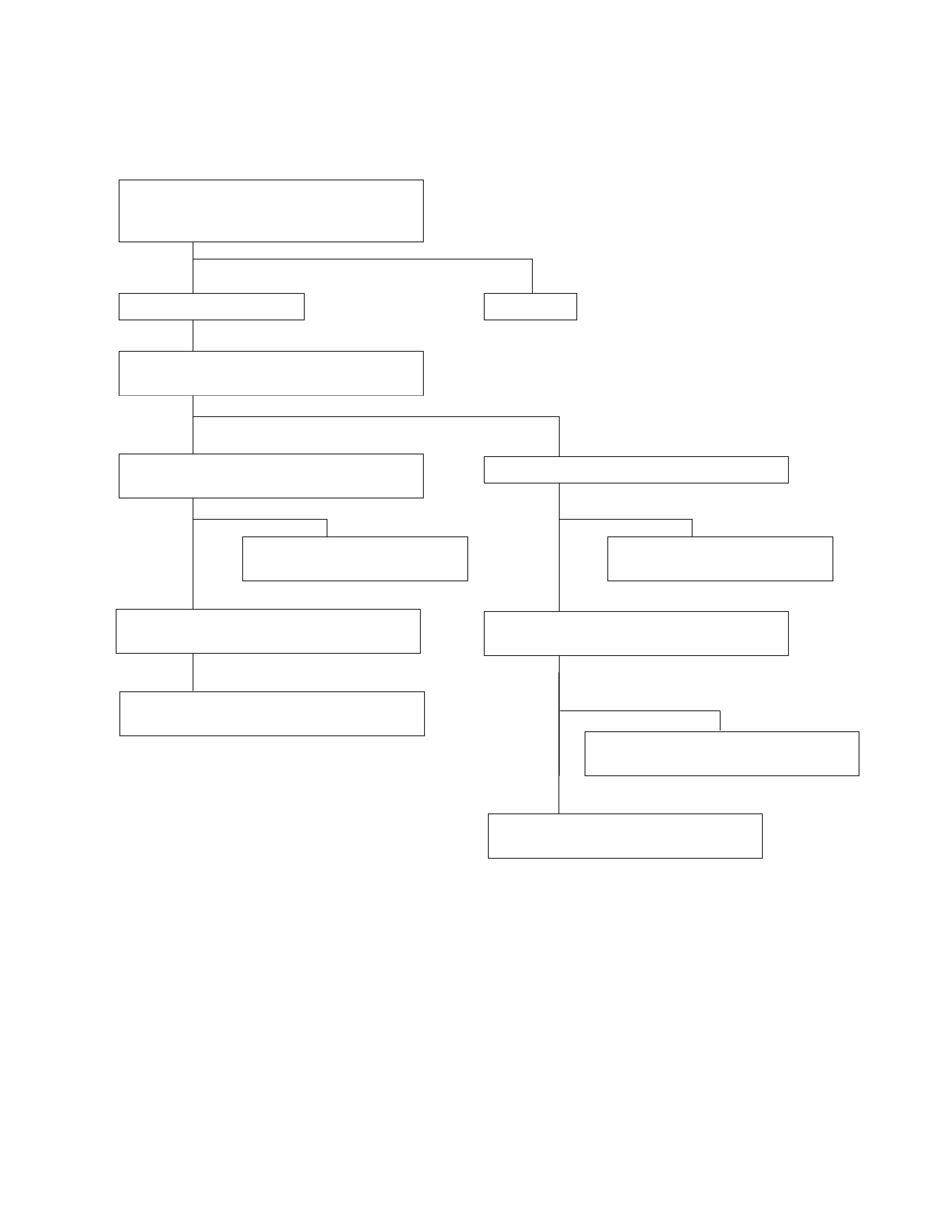
SHIFT ON THE FLY SYSTEM
•When the transfer lever is shifted from 4H to 2H, the 4WD indicator light does not go out.
Repair or replace the switch
Confirm correct operation.
Is SOF controlctly?
Yes
No
Yes
Yes
No
Yes
No
No
System OK
Repair or replace the SOF actuator switch
circuit. Confirm operation after repair.
Is the transfer case SOF actuator switch
Rotate the left side front wheel by hand,
Does the right side front wheel rotate?
Jack up the front axle
Stop the vehicle, then drive 100 - 200m at
about 5km/hr. Does the 4WD indicator light
go out?
operating correctly?
Is the transfer case SOF actuator switch
circuit operating correctly?
Replace the controller
Confirm correct operation.
Is the SOF Controller operating correctly?
Is the SOF Controller circuit operating
correctly?
Repair or replace the SOF Controller
circuit. Confirm operation after repair.
No
Yes
Repair or replace the SOF Actuator
Confirm operation after repair.
No
SHIFT ON THE FLY SYSTEM
•When the transfer lever is shifted from 2H to 4H, the 4WD indicator light does not illuminate.
Repair or replace the switch
Confirm correct operation.
Is SOF controlctly?
Yes
No
Yes
Yes
No
Yes
No
No
System OK
Repair or replace the SOF actuator switch
circuit. Confirm operation after repair.
Is the transfer case SOF actuator switch
Rotate the left side front wheel by hand,
Does the right side front wheel rotate?
Jack up the front axle
Stop the vehicle, then drive 100 - 200m at
about 5km/hr. Does the 4WD indicator light
illuminate?
operating correctly?
Is the transfer case SOF actuator switch
circuit operating correctly?
Replace the controller
Confirm correct operation.
Is the SOF Controller operating correctly?
Is the SOF Controller circuit operating
correctly?
Repair or replace the SOF Controller
circuit. Confirm operation after repair.
No
Yes
Repair or replace the SOF Actuator
Confirm operation after repair.
No

SERVICE STANDARD
ItemsService StandardService Limit
Thrust Washer wear limit mm(in) 1.3 (0.05)
Depth of the Differential Cage
(A-B) (See Text) mm (in)
(C) (See Text) mm (in) 80.58 (3.17)
10.58 (0.41)
Depth of the Differential Cage
(F-B) (See Text) mm (in)
(G) (See Text) mm (in) 82.03 (3.23)
12.03 (0.47)
Limited Slip Differential Starting Torque
N⋅m (kg⋅m/lb⋅ft) 64-98 (6.5-10.0/47-72)
FRONT DIFFERENTIAL
Pinion Bearing Starting Torque
New Bearing N⋅m (kg ⋅cm/lb⋅in)
Used Bearing N⋅m (kg⋅cm/lb⋅in) 0.7-1.1 (6.5-11.5/5.64-9.98)
0.4-0.5 (3.3-5.7/2.86-4.94)
Ring Gear Backlash mm (in) 0.155 (0.006)
Ring Gear Run-Out mm (in) 0.02 (0.001) 0.05 (0.002)
Clearance between the Differential
Pinion and the Cross Pin mm (in) 0.06-0.12 (0.002-0.005) 0.2 (0.008)
Clearance between the Side Gear and
the Differential Box mm (in) 0.03-0.10 (0.001-0.004) 0.15 (0.006)
Play in Splines between the Side Gear and
the Axle Shaft mm (in) 0.07-0.36 (0.003-0.014) 0.5 (0.02)
Backlash between the Side Gear and the
Pinion Gear mm (in) 0.03-0.08 (0.001-0.003)
SHIFT ON THE FLY SYSTEM
Inner shaft Deflection mm (in) 0.5 (0.02)
Sleeve center Groove mm (in) 7.1 (0.28)
Clutch Gear Out side diameter mm (in) 36.98 (1.46)
FRONT HUB
Front Hub Bearing Preload
New Bearing and New Oil Seal N (kg/lb)
Reused Bearing and New Oil Seal N (kg/lb) 20-25 (2-2.5/4.4-5.5)
12-18 (1.2-1.8/2.6-4.0)
FRONT HUB
Clearance between the Free Wheeling
Hub Body and the Snap Ring mm (in) 0-0.3 (0-0.01)
MANUAL LOCKING HUB GREASE AMOUNT
Hub g (oz)
Outer Bearing g (oz)
Inner Bearing g (oz)
35 (1.23)
10 (0.35)
15 (0.53)
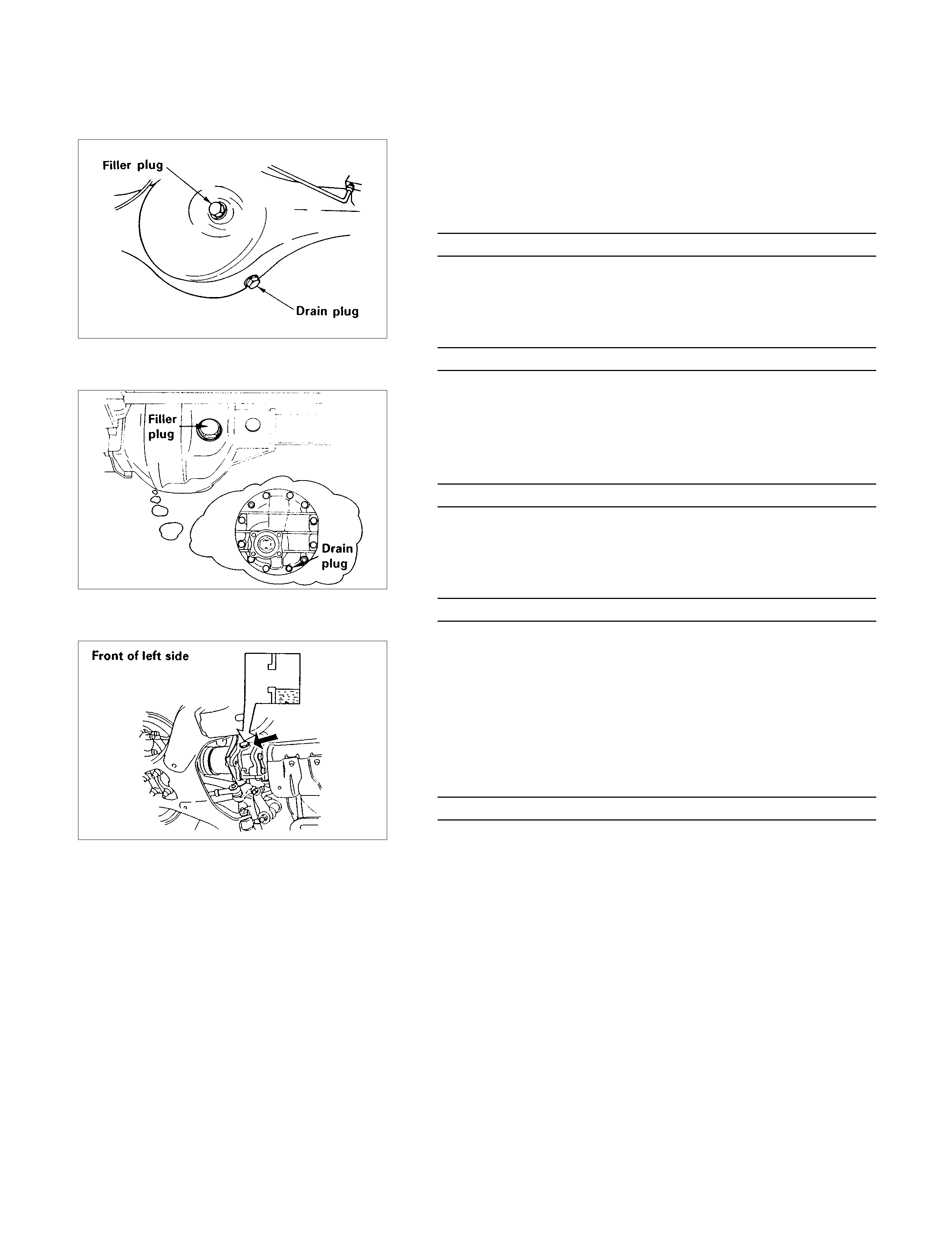
SERVICING
CHANGE THE REAR DIFFERENTIAL GEAR OIL
1. Remove the drain plug and filler plug and, drain the gear oil.
2. Tighten the drain plug to specified torque.
Drain Plug Torgue N⋅m (kg⋅m/lb⋅ft)
78 (8/58)
3. Fill the rear axle case with hypoid gear lubricant, to just
below the filler hole.
4. Tighten the filler plug to specified torque.
Filler Plug Torque N⋅m (kg⋅m/lb⋅ft)
78 (8/58)
CHANGE THE FRONT DIFFERENTIAL GEAR OIL
1. Remove the drain plug and filler plug, and drain the gear oil.
2. Tighten the drain plug to specified torque.
Drain Plug Torque N⋅m (kg⋅m/lb⋅ft)
25 (2.6/19)
3. Fill the rear axle case with hypoid gear lubricant, to just
below the filler hole.
4. Tighten the filler plug to specified torque.
Filler Plug Torque N⋅m (kg⋅m/lb⋅ft)
78 (8/58)
INSPECTION OF SHIFT ON THE FLY SYSTEM
GEAR OIL
1. Open filler plug and make sure that the oil up to the plug
port.
If the oil is short, replenish with gear oil GL-5 grade.
2. Tighten the filler plug to specified torque.
Filler Plug Torque N⋅m (kg⋅m/lb⋅ft)
78 (8/58)
Front Drive Axle N⋅m (kg⋅m/lb⋅ft)
Shift On The Fly System N⋅m (kg⋅m/lb⋅ft)
Fixing TorqueN⋅m (kg⋅m/lb⋅ft)
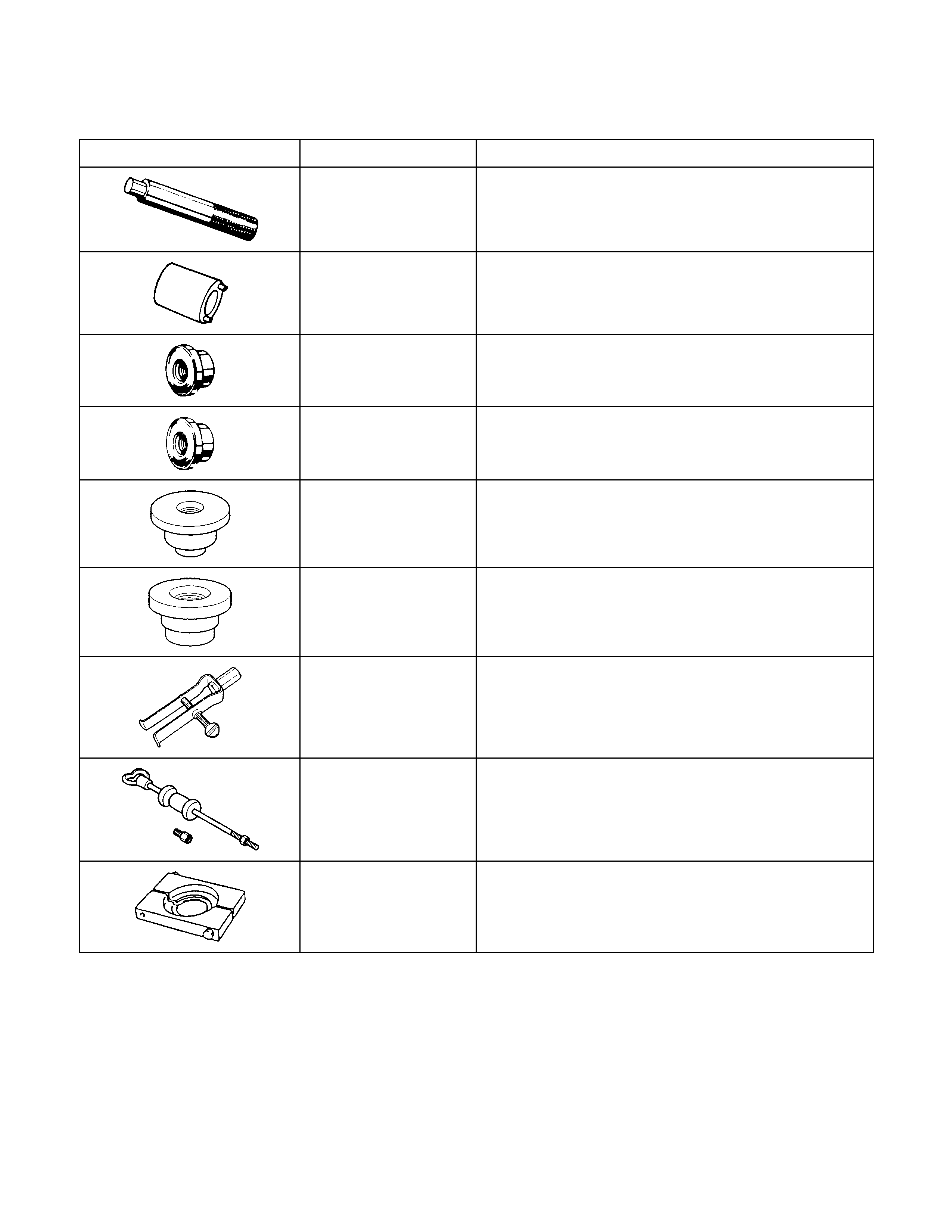
SPECIAL TOOLS
ILLUSTRATION PARTS NO. PARTS NAME
5-8840-0007-0
(J-8092) Grip
5-8840-2117-0
(J-36827) Wrench: Hub nut
5-8840-2119-0
(J-36829) Installer: Inner bearing outer race
5-8522-0054-0
(J-29015) Installer: Outer bearing outer race
5-8840-2407-0
(J-41693) Installer: Oil seal
5-8840-2408-0
(J-41694) Installer: Bearing needle
5-8840-0027-0
(J-26941) Remover: Bearing needle
5-8840-0084-0
(J-2619-01) Hammer: Sliding
5-8840-2197-0
(J-37452) Remover: Bearing inner shaft
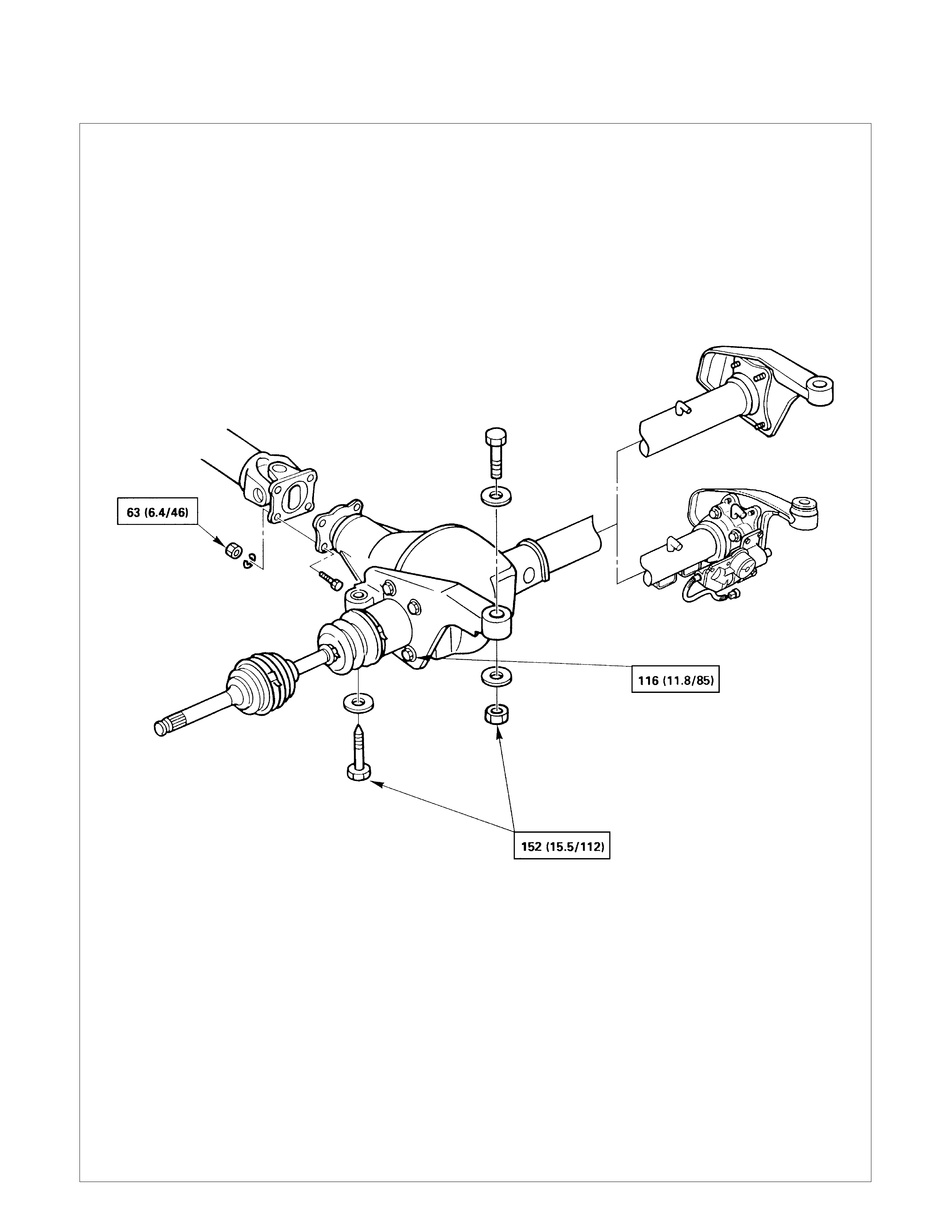
UNIT REPAIR
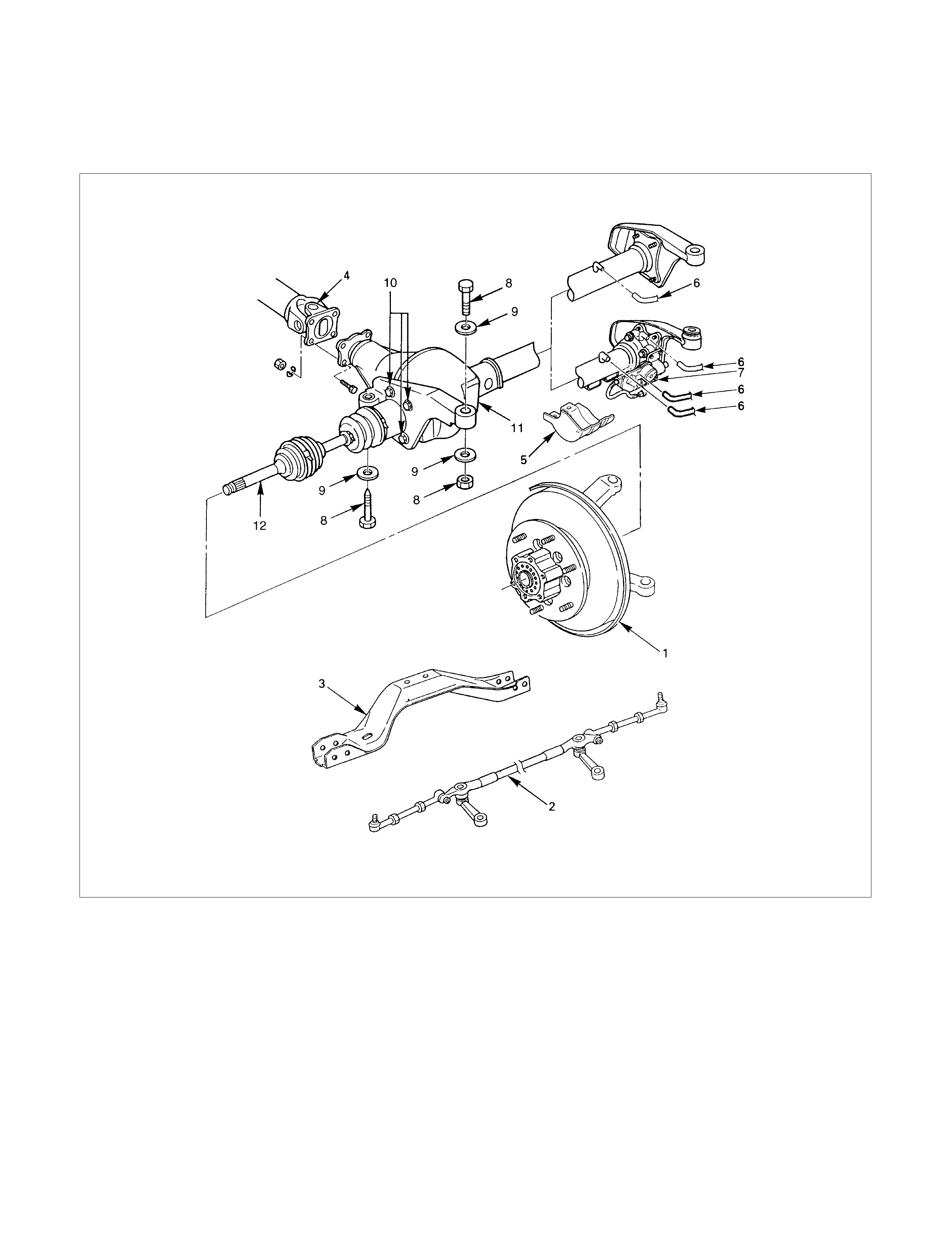
FRONT DRIVE AXLE ASSEMBLY
Disassembly Steps
1. Hub assembly (Disc, back plate and knuckle)
2. Steering link and arm assembly
3. Suspension crossmember
4. Propeller shaft
5. Protector (w/shift on the fly system)
6. Breather hose
7. Actuator connector (w/shift on the fly system)
8. Mounting bolt and nut
9. Washer and spacer
10.Bolt
11.Front axle case assembly and front drive shaft
assembly (LH side)
12.Front drive shaft assembly (RH side)
Reassembly Steps
To reassemble, follow the disassembly steps in the
reverse order.

DISASSEMBLY
WARNING:
DURING THE WORK, BE SURE THAT THE DIFF CASE IS
SUPPORTED BY THE JACK.
Preparations:
•Jack up the vehicle and support it using jack stands.
•Remove the tire and wheel.
•Remove the drain bolt to drain differential oil.
•Remove the brake caliper fixing bolt and hang the caliper.
Refer to Section 5A "BRAKES".
1.Hub Assembly (Disc, Back Plate and Knuckle)
•Remove the locking hub. Refer to this Section "FRONT
HUB AND DISC".
•Disconnect the knuckle and the suspension arm. Refer to
Section 3B "FRONT SUSPENSION".
2.Steering Link and Arm Assembly
Refer to Section 9 "POWER STEERING".
3.Suspension Crossmember
4.Propeller Shaft
Refer to Section 4B "FRONT AXLE & PROPELLER SHAFT".
5.Protector (w/shift on the fly system)
6.Breater Hose
•Disconnect breather hose from front drive axle.
7.Connector (w/shift on the fly system)
•Disconnect actuator connector.
•Disconnect shift detective switch connector.
8.Mounting Bolt and Nut
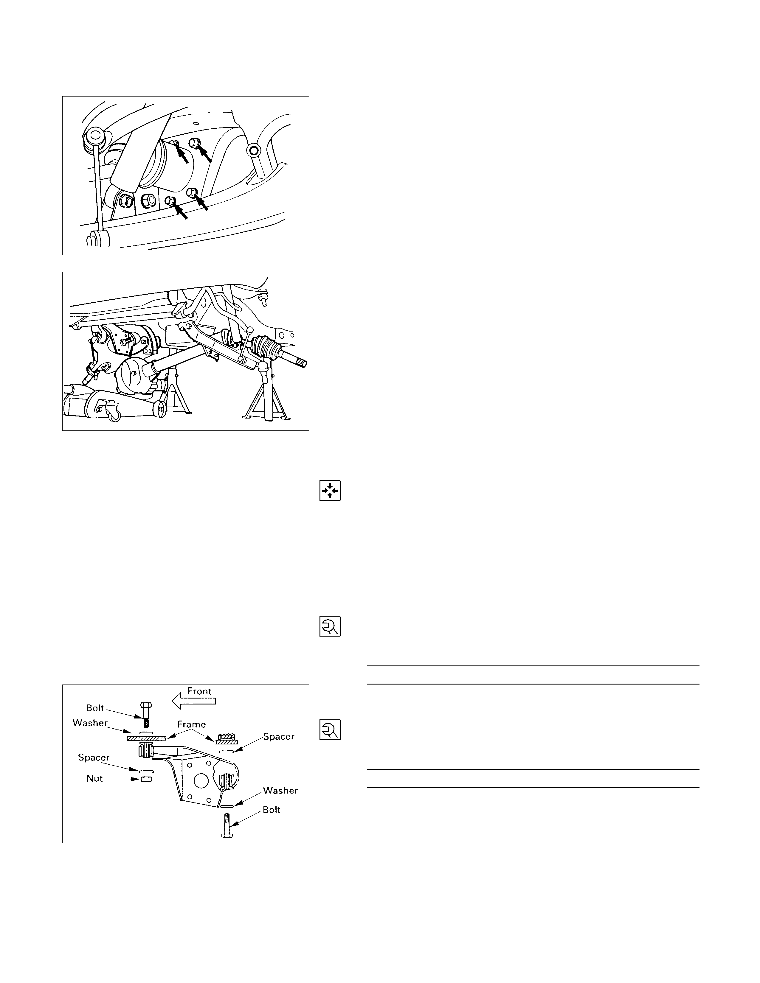
9.Washer and Spacer
10.Bolt
Remove the mounting bracket fixing bolt.
11.Front Axle Case Assembly and Front Drive Shaft
Assembly (LH side).
Lower the vehicle and disconnect the RH front drive shaft
assembly, and then remove the front axle case assembly
and front drive shaft assembly (LH).
12.Front Drive Shaft Assembly (RH side)
REASSEMBLY
12.Front Drive Shaft Assembly (RH side)
Lay the assembly on the lower arm.
11.Front Axle Case Assembly and Front Drive Shaft
Assembly (LH side)
Place the axle case on the jack, connect to the front drive
shaft assembly (RH) before installing to the vehicle.
10.Bolt
Tighten the mounting bracket fixing bolt to the specified
torque.
Mounting Bracket Fixing Bolt Torque N⋅m (kg⋅m/lb⋅ft)
116 (11.8/85)
9.Washer and Spacer
8.Mounting Bolt and Nut
Tighten the mounting bolt and nut to the specified torque.
Front Drive Axle Case Mounting
Bolt and Nut Torque N⋅m (kg⋅m/lb⋅ft)
152 (15.5/112)

7.Connector (W/Shift on the fly system)
Fit actuator connector.
6.Breather Hose
NOTE:
Be careful not to permit the entry of dust into the hose and
connector.
5.Protector (w/shift on the fly system)
Tighten bolts to specified torque.
Bolt TorqueN⋅m (kg⋅m/lb⋅ft)
26 (2.7/20)
4.Propeller Shaft
Refer to Section 4B "FRONT AXLE & PROPELLER SHAFT".
3.Suspension Crossmember
2.Steering Link and Arm Assembly
Refer to Section 9 "POWER STEERING".
1.Hub Assembly (Disc, Back Plate and Knuckle)
Refer to Section 5A "BRAKES"
and Section 3B "FRONT SUSPENSION".
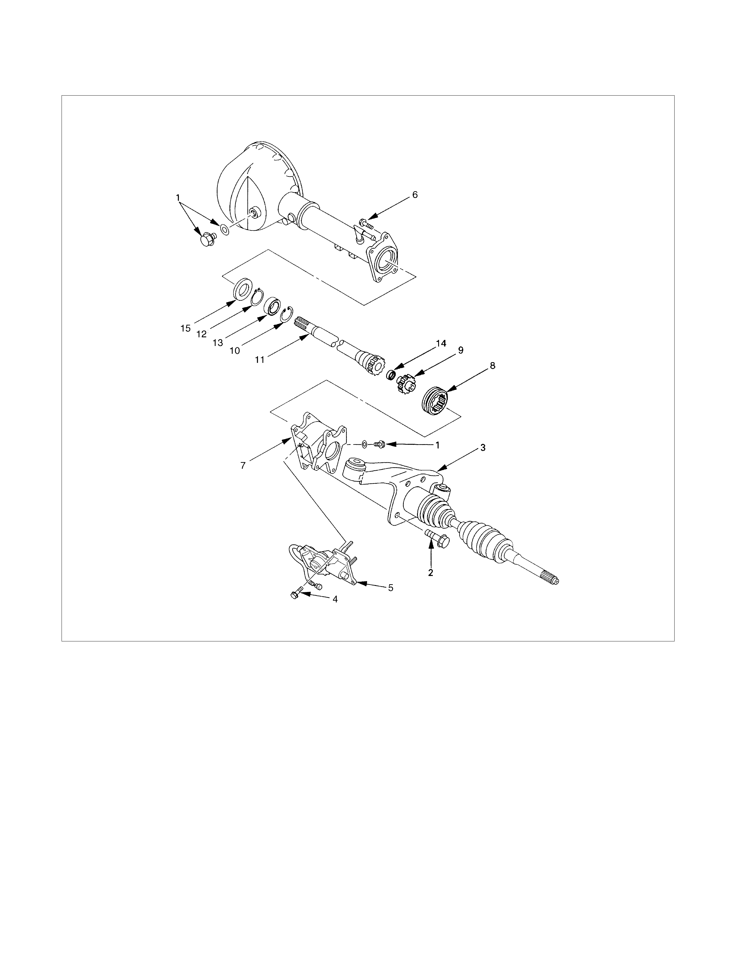
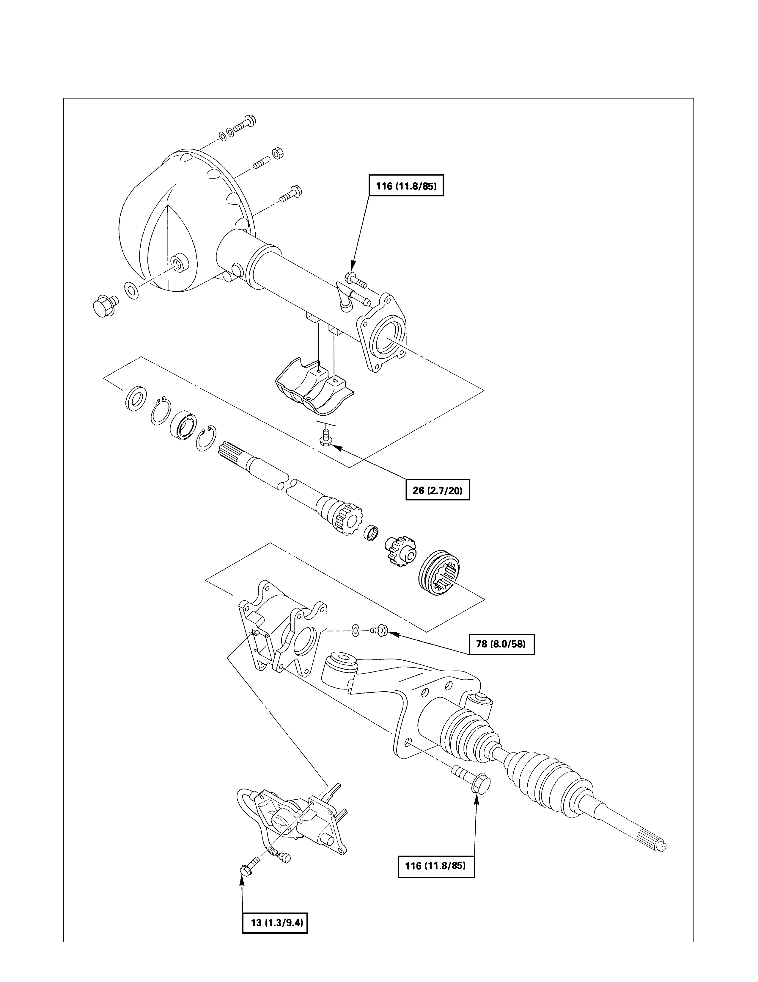
SHIFT ON THE FLY SYSTEM
Disassembly steps
1.Filler plug
2.Bolt
3.Front axle drive shaft (LH side)
4.Bolt
5.Actuator assembly
6.Bolt
7.Housing
8.Sleeve
9.Clutch gear
10.Snap ring
11.Inner shaft
12.Snap ring
13.Inner shaft bearing
14.Needle bearing
15.Oil seal
Reassembly steps
To reassemble, follow the disassembly steps in
the reverse order.
DISASSEMBLY
1.Filler Plug
Remove filler plug and packing and drain oil.
2.Bolt
Loosen mounting bracket fitting bolts and remove front axle
drive shaft from front axle case.
3.Front Axle Drive Shaft (LH side)
4.Bolt
Loosen actuator ASM fitting bolts.
5.Actuator Assembly
Draw out actuator ASM.
6.Bolt
Remove housing fitting bolts.
7.Housing
8.Sleeve
9.Clutch Gear
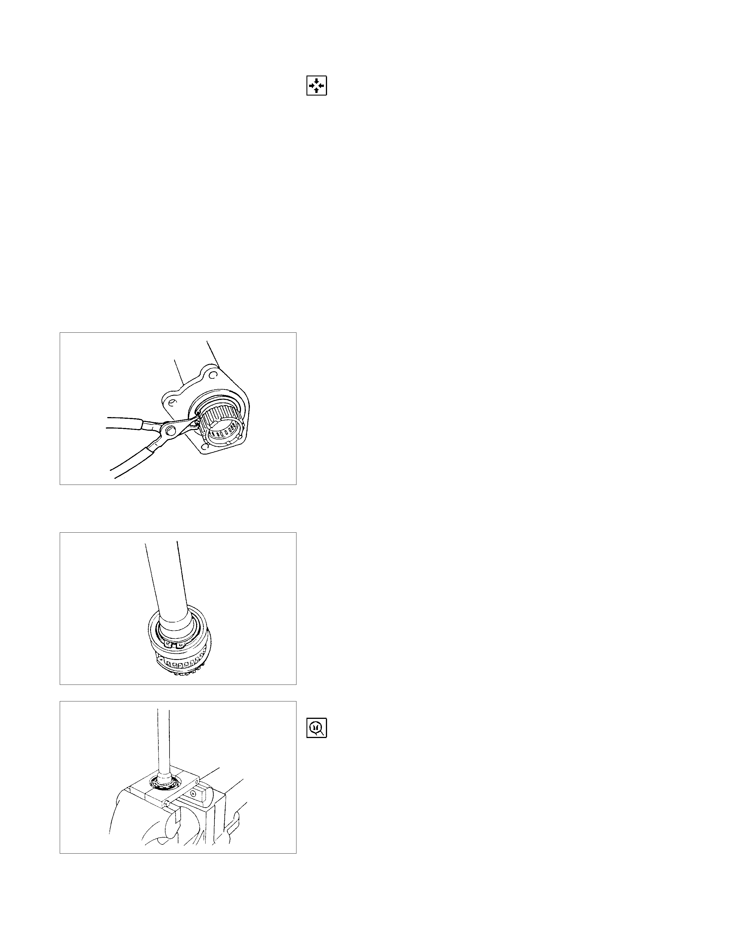
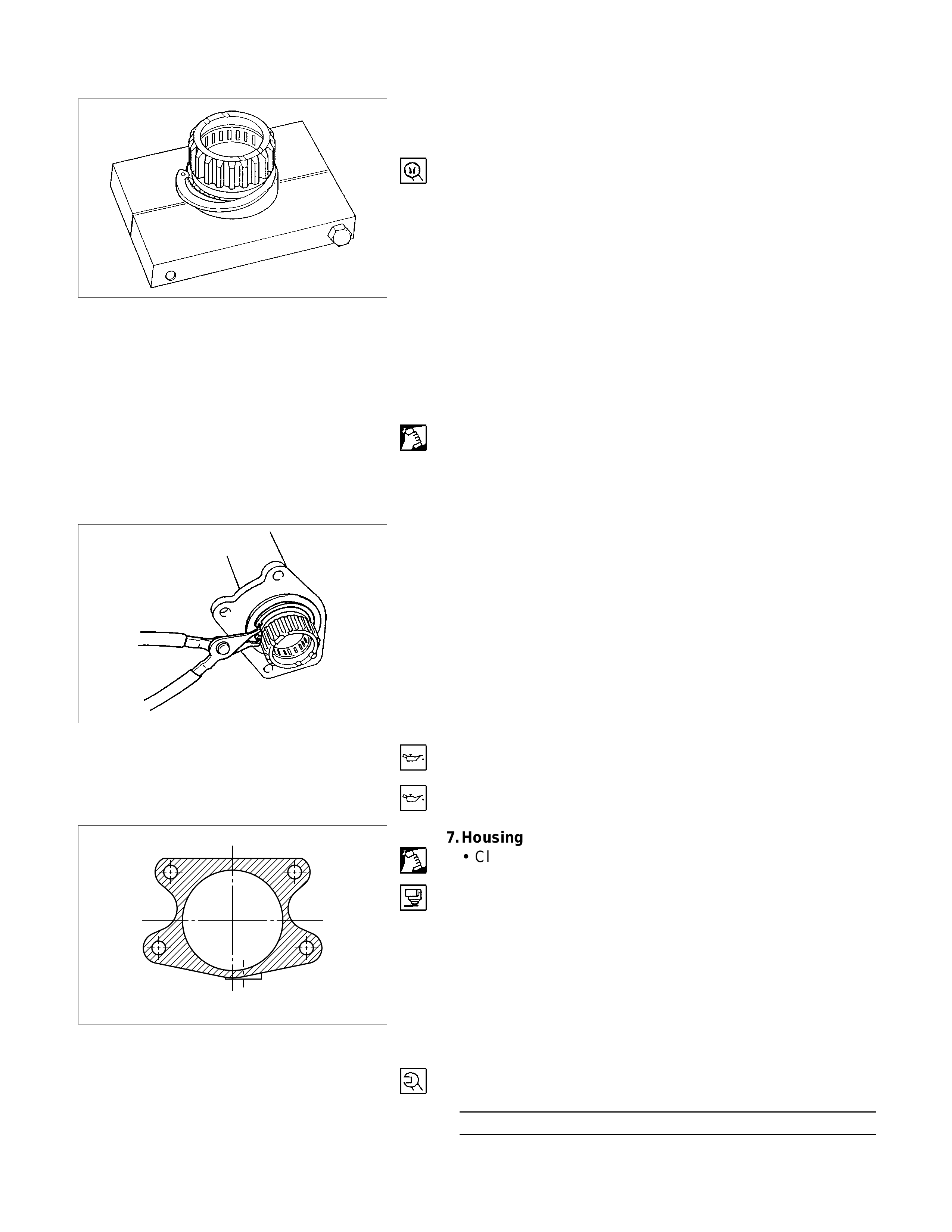
10.Snap Ring
Remove snap ring from front axle case by using a snap ring
plier.
11.Inner Shaft
Take out inner shaft from front axle case.
12.Snap Ring
Remove snap ring from inner shaft by using a snap ring
plier.
13.Inner Shaft Bearing
Remove inner shaft bearing by using a special tool and
press.
Remover : 5-8840-2197-0 (J-37452)
NOTE:
Be careful not to damage the shaft.
14.Needle Bearing
Remove needle bearing from inner shaft by using a special
tool.
Remover : 5-8840-0027-0 (J-26941)
Sliding hammer : 5-8840-0084-0 (J-2619-01)
NOTE:
Be careful not to damage the shaft.
15.Oil Seal
Remove oil seal from front axle case.
NOTE:
Be careful not to damage the front axle case.
INSPECTION AND REPAIR
Inspect the removed parts. If there are abnormalities such as
wear and damage, take corrective action or replace.
Visual Check
•Check and see if the inner shaft has such abnormalities
as wear and damage.
•When inspecting the inner shaft, be sure to check and
see if its splined part is twisted, worn, or cracked. If so,
replace with a new shaft. In case such an abnormality in
its gear part (a slide with sleeve), replace the shaft.
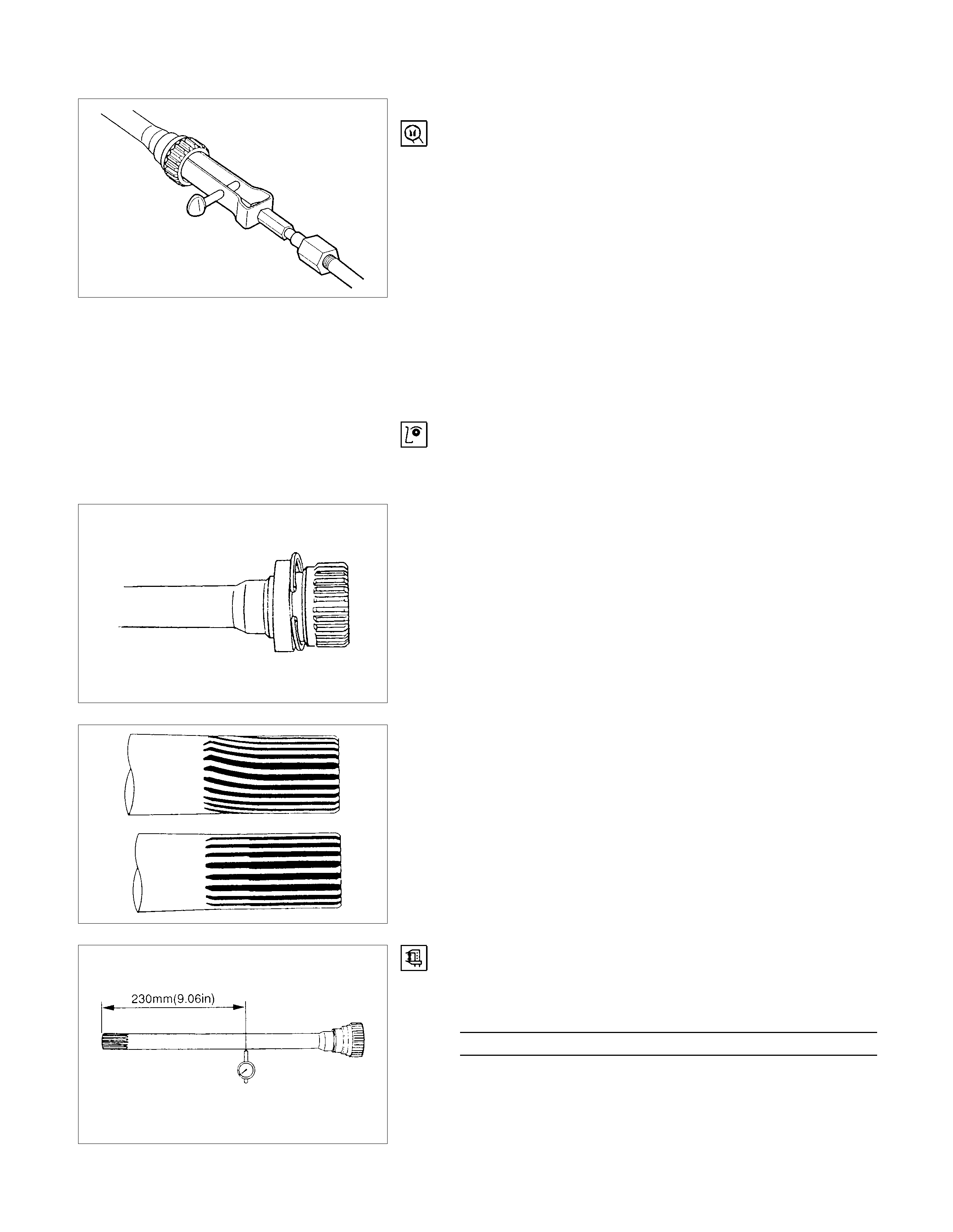
Inner Shaft Run-Out
With both end centers supported, rotate the shaft slowly and
measure deflection with a dial gauge.
Inner Shaft Run-Out (Limit) mm (in)
0.5 (0.02)
NOTE:
Do not heat the shaft to correct its bend.
Inner Shaft Bearing
Inspect the state of inner shaft bearing. If any abnormality
such as smoothlessness is found, replace with a new inner
shaft bearing.
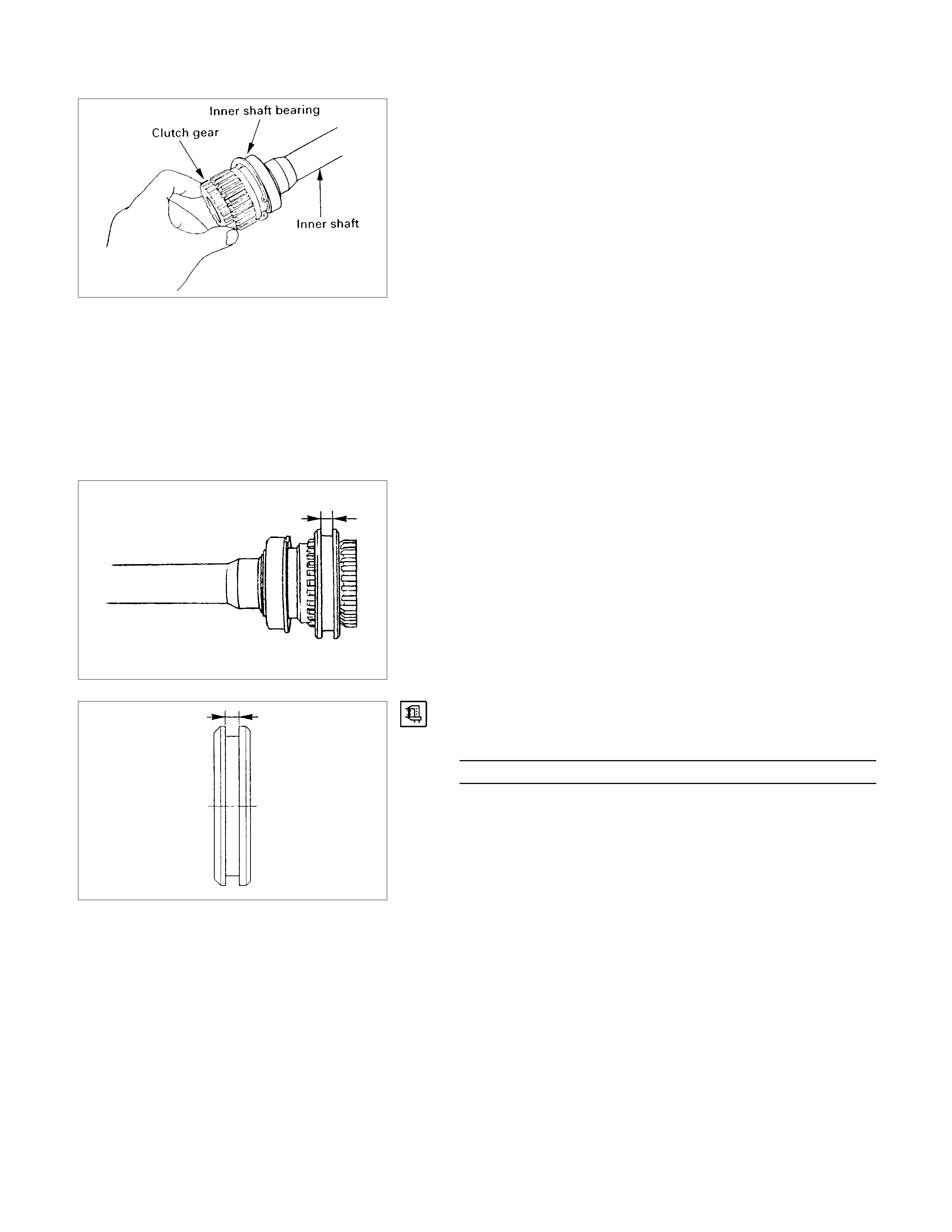
Insert a clutch gear and check the state of needle bearing.
If there is an abnormality such as smoothlessness, replace
the needle bearing.
Sleeve
Visual Check
Check and see that there is not wear, damage, or cracking
in the sleeve.
NOTE:
Close inspection of the groove and inner gear are required
because those are important parts.
Functional Check
Operate the sleeve with the inner shaft combined with the
clutch gear.
If smoothlessness is felt, replace the sleeve.
NOTE:
Gear oil should be applied to the contact surface of gear.
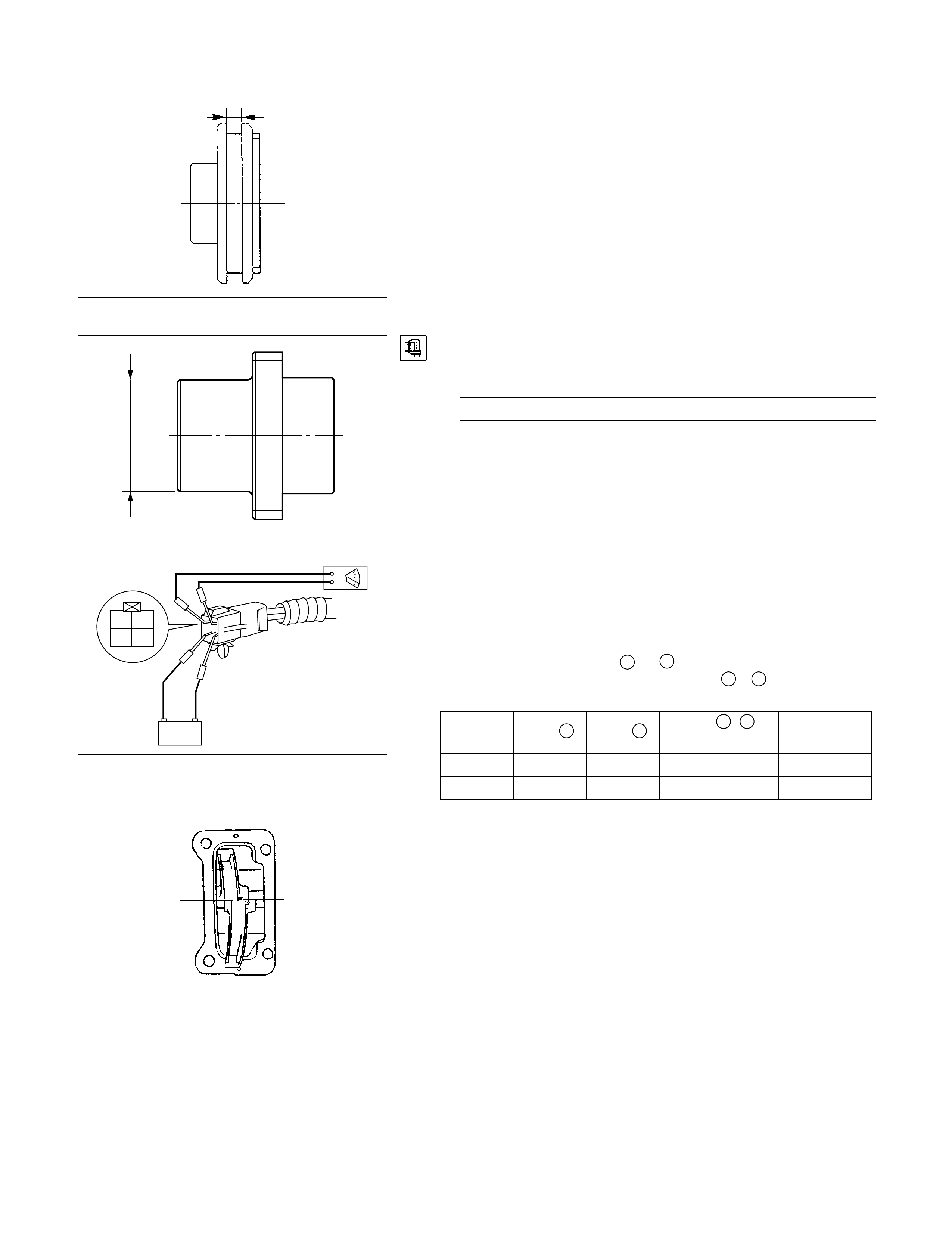
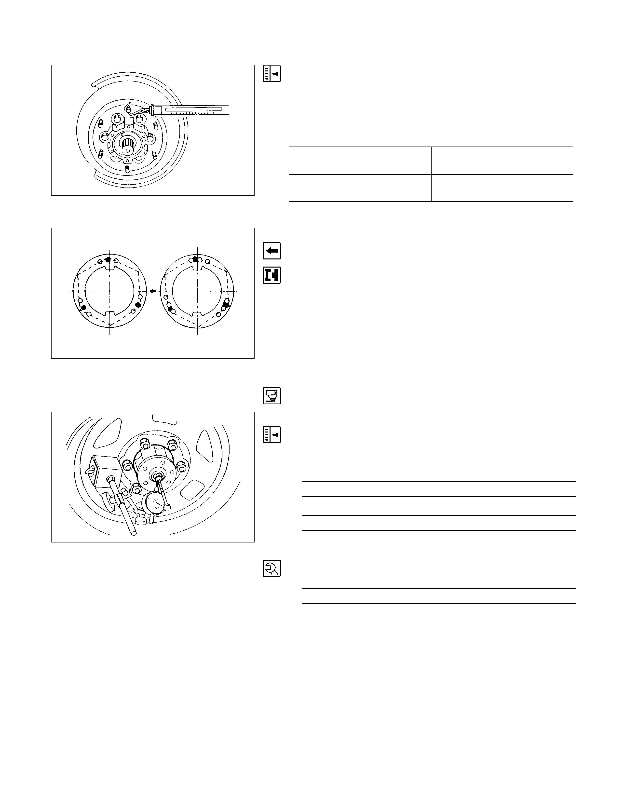
Dimensional Check
Check the width of sleeve center groove.
Sleeve Center Groove (Limit) mm (in)
7.1 (0.28)
Clutch Gear
Visual Check
Check and see that there is not wear, damage, crack, or
any other abnormality in the clutch gear.
Functional Check
If there is an abnormality such as smoothlessness when
operated in combination with sleeve, replace the clutch
gear.
NOTE:
When inspecting, gear oil should be applied to the contact
surface of gear.
Dimensional Inspection
Make sure of the size illustrated.
Clutch Gear Out Side Diameter (Limit) mm (in)
36.98 (1.46)
Battery
1
34
2
Actuator
Visual Check
Check and see that there is no damage, cracking, or other
abnormality.
Functional Check
Apply 12V to terminals3
Connect a voltmeter across terminals 1& 2 .
Compare the results with those in the table below.
State Term.
3Term. 4Term. 1, 2
DMM reading Function
A+
B−+
STATE B
STATE AIf there is any abnormality, replace the actuator as an
assembly.
& 4 as shown in the table below.
No voltage D
Voltage C
−
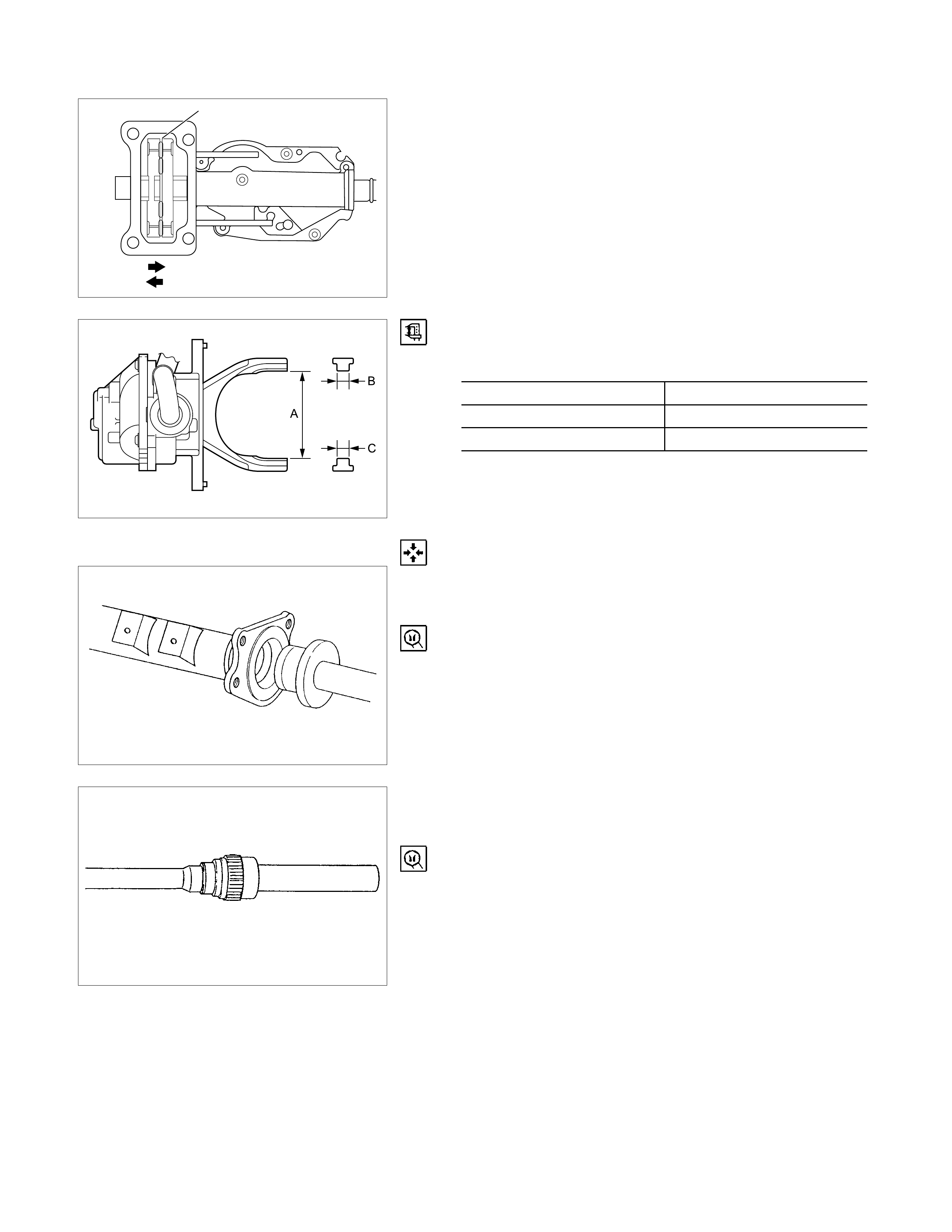
Shift Drum
Function D Function C
Dimensional Check
Measure illustrated sizes A, B, and C.
Limit mm (in)
A 64.1 (2.52)
B 6.7 (0.26)
C 0.7 (0.03)
REASSEMBLY
15.Oil Seal
Install the new oil seal which has been immersed in
differential gear oil, by using an oil seal installer.
Installer : 5-8840-2407-0 (J-41693)
Grip : 5-8840-0007-0 (J-8092)
14.Needle Bearing
Force a new needle bearing into inner shaft by using a
special tool.
Installer : 5-8840-2408-0 (J-41694)
Grip : 5-8840-0007-0 (J-8092)
13.Inner Shaft Bearing
•Place a new snap ring in inner shaft.
•Force a new inner shaft bearing into the inner shaft.
Installer : 5-8840-2197-0 (J-37452)
12.Snap Ring
NOTE:
Be careful not to damage the inner shaft.
11.Inner Shaft
•Clean the housing contact surface of the front axle case.
•Insert inner shaft assembly into the front axle case.
NOTE:
Be careful not to damage oil seal.
10.Snap Ring
Install snap ring in the groove of front axle case.
NOTE:
Be sure to install the snap ring properly.
9.Clutch Gear
Apply differential gear oil to clutch oil.
8.Sleeve
Apply differential gear oil to sleeve.
,,
,,
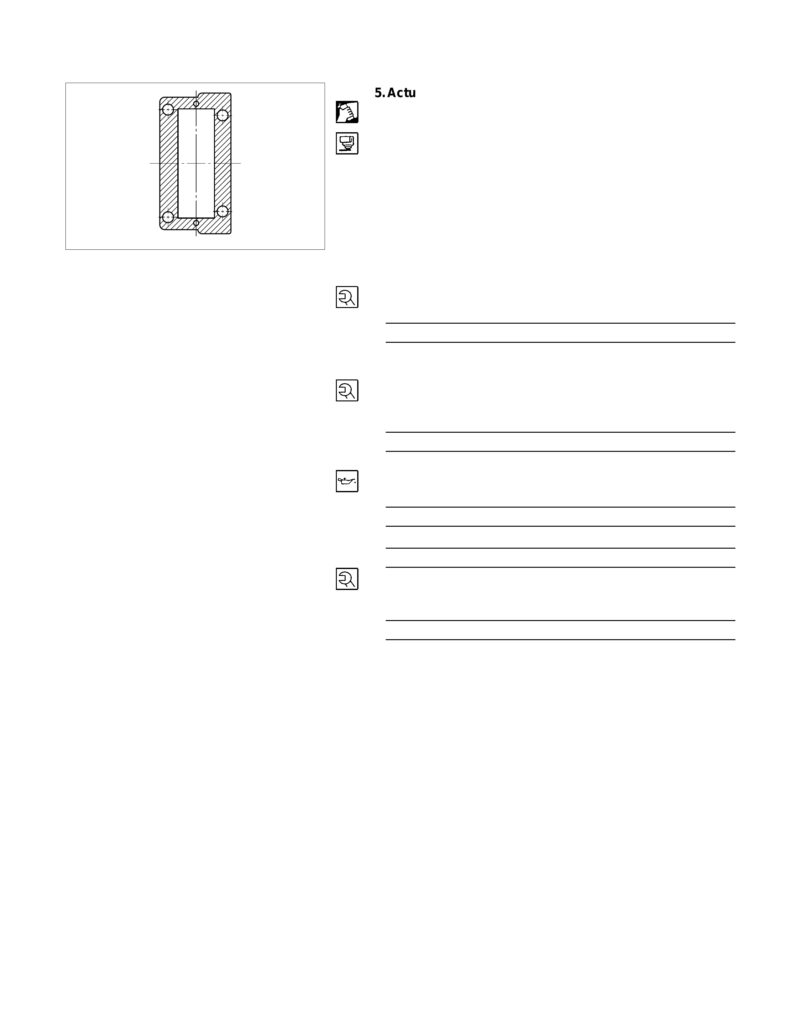
7.Housing
•Clean contact surface with the front axle and actuator
mounting surface.
•Apply liquid gasket to the contact surface on the front axle
case and install in the housing.
6.Bolt
Tighten bolts to specified tightening torque.
Housing Bolt Torque N⋅m (kg⋅m/lb⋅ft)
116 (11.8/85)
,
,
5.Actuator
•Clean the actuator contact surface with the housing.
•Apply liquid gasket to the contact surface on the actuator
side.
•Align shift arm with the groove of sleeve and install the
actuator.
4.Bolt
Tighten bolts to specified torque.
Actuator Bolt Torque N⋅m (kg⋅m/lb⋅in)
13 (1.3/113)
3.Front Axle Drive shaft (LH side)
2.Bolt
•Install front axle drive shaft and mounting bracket.
•Tighten fitting bolts to specified tightening torque.
Bolt Torque N⋅m (kg⋅m/lb⋅ft)
116 (11.8/85)
1.Filler Plug
•Pour specified amount of differential gear oil.
Front Differential Oil Capacity lit (Impq+/USqt)
1.5 (1.32/1.59)
Actuator Housing Oil Capacity lit (Impq+/USqt)
0.12 (0.11/0.13)
•Install filler plug through packing and tighten to specified
torque.
Filler Plug Torque N⋅m (kg⋅m/lb⋅ft)
7.8 (8.0/58)
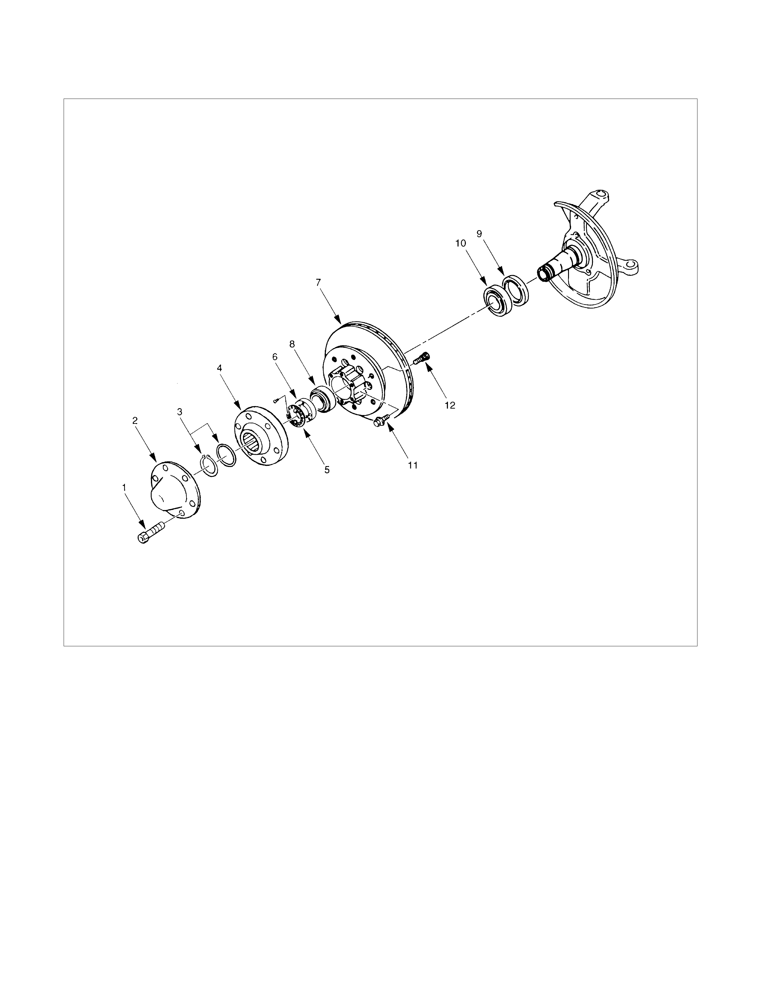
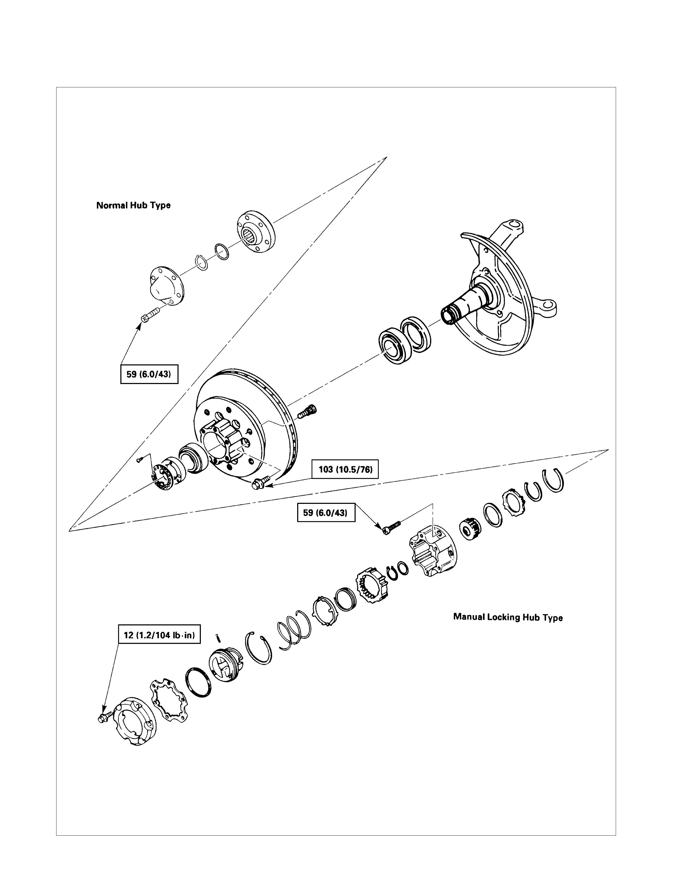
FRONT HUB AND DISC (4WD Model Normal Hub)
Disassembly Steps
1.Bolt
2.Hub cap
3.Snap ring and shim
4.Hub flange
5.Lock washer and lock screw
6.Hub nut
7.Hub and disc assembly
8.Outer bearing outer race
9.Oil seal
10.Inner bearing outer race
11.Bolt
12.Wheel pin
Reassembly Steps
12.Wheel pin
11.Bolt
10.Inner bearing outer race
9.Oil seal
8.Outer bearing outer race
7.Hub nad disc assembly
6.Hub nut
5.Lock washer and lock screw
4.Hub flange
3.Snap ring and shim
2.Hub cap
1.Bolt
DISASSEMBLY
•Before disassembly, jack up the front of vehicle and
support frame with jack stands.
•Remove the disc brake caliper assembly and hang it on
the frame with wires (Refer to Section 5A "BRAKES")
1.Bolt
Before removal, shift transfer lever into "2H" position.
2.Hub cap
3.Snap Ring and Shim
4.Hub flange
5.Lock Washer and Lock Screw
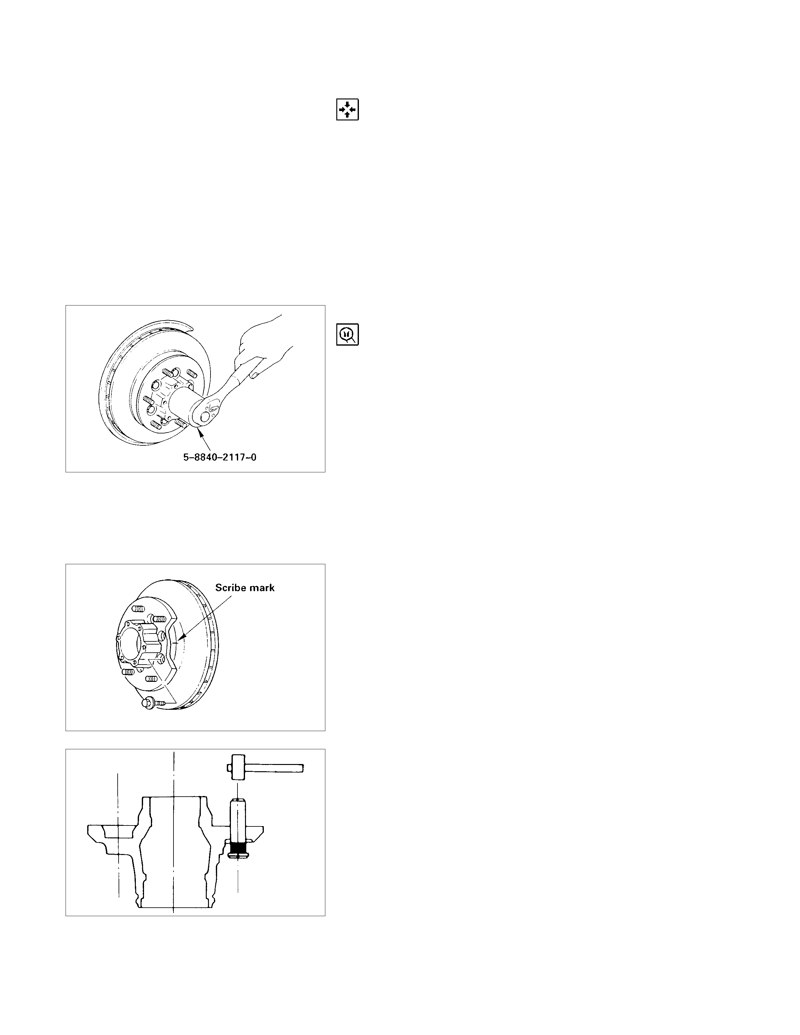
6.Hub nut
Wrench: 5-8840-2117-0 (J-36827)
7.Hub and Disc Assembly
8.Outer Bearing Outer Race
9.Oil Seal
10.Inner Bearing Outer Race
11.Bolt
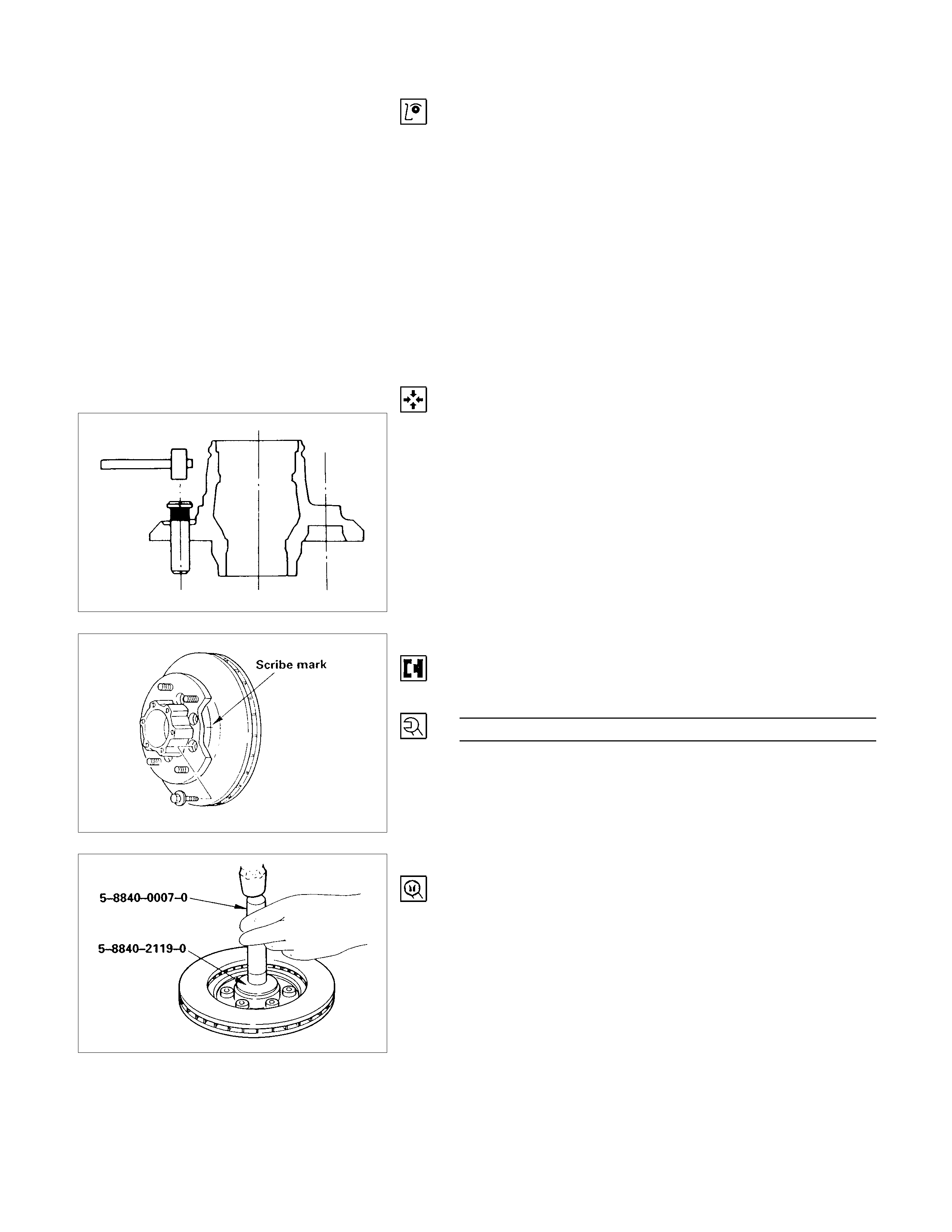
If necessary, replace the wheel pin in the following manner.
1) Apply a scribe mark to disc to hub.
2) Clamp the hub and disc assembly in a vise, using
protective pads. Remove the 6 disc-to-hub retaining
bolts.
12.Wheel Pin
Place hub on a suitable work surface and remove the wheel
studs, as required, using a hammer.
INSPECTION AND REPAIR
Make necessary correction or parts replacement if wear,
damage, corrosion or any other abnormal condition are found
through inspection.
Check the following parts.
•Hub
•Hub bearing oil seal
•Knuckle spindle
•Disc
•Caliper
•Shift on the fly system parts (Cap, Hab flange, Shim,
Snap ring)
For inspection and servicing of disc caliper and related parts,
refer to Section 5A "BRAKES".
REASSEMBLY
12.Wheel Pin
1) Place the hub on a wood workbench or a block of wood
approx. 6 "by 6" to protect the wheel stud ends and
threads.
2) Insert a wheel stud using a hammer.
Be sure the wheel stud is started squarely and seats
completely.
11.Bolt
Align scribe marks and attach the hub to the disc.
Tighten the bolts to the specified torque.
Hub Bolt Torque N⋅m (kg⋅m/lb⋅ft)
103 (10.5/76)
10.Inner Bearing Outer Race
Install the outer race; inner bearing by driving it into the hub.
Installer : 5-8840-2119-0 (J-36829)
Grip : 5-8840-0007-0 (J-8092)
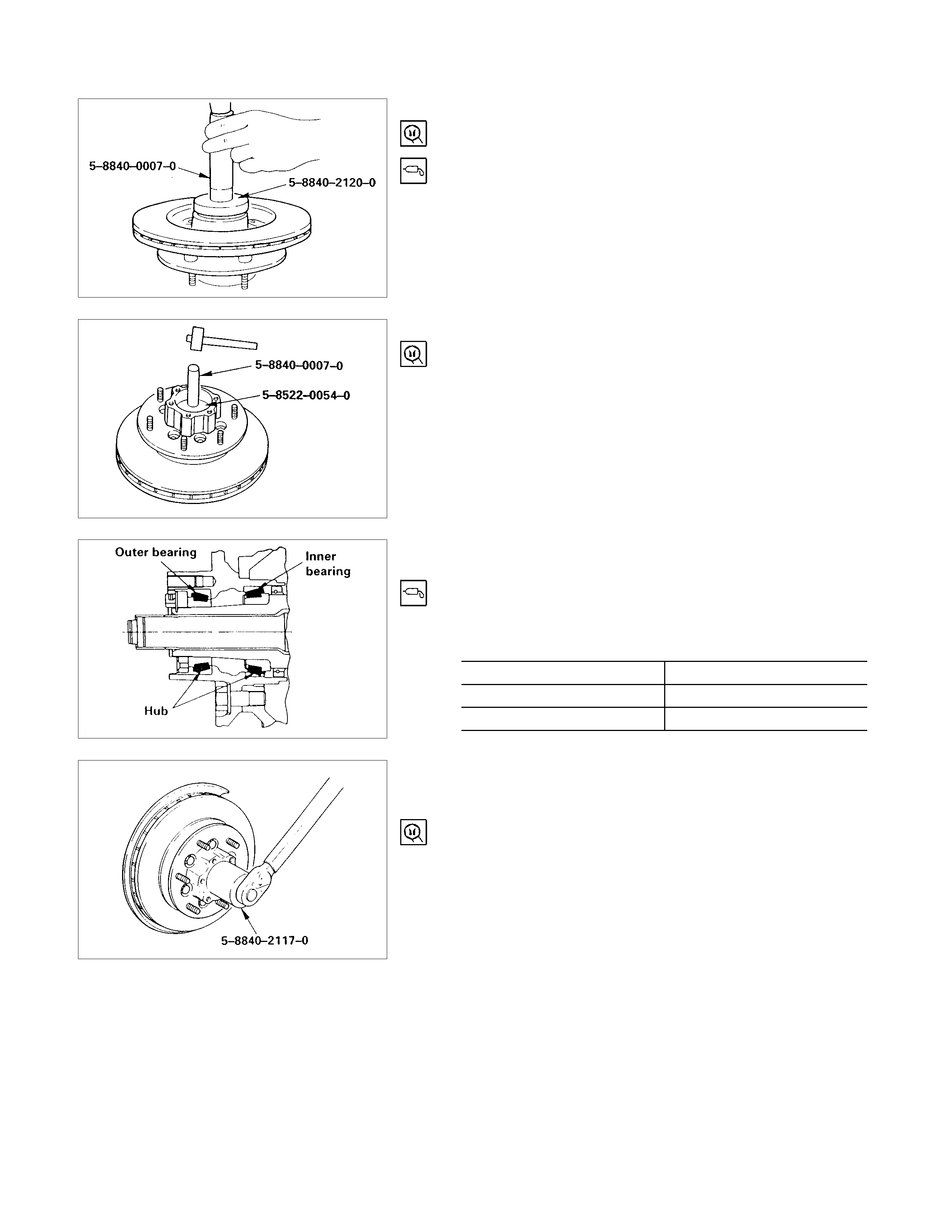
9.Oil Seal
Installer : 5-8840-2120-0 (J-36830)
Grip : 5-8840-0007-0 (J-8092)
Apply grease (Besco L-2 or equivalent) to the lip portion.
8.Outer Bearing Outer Race
Install the outer race; outer bearing by driving it into the hub.
Installer : 5-8522-0054-0 (J-29015)
Grip : 5-8840-0007-0 (J-8092)
7.Hub and Disc Assembly
1) Apply grease in the hub.
2) Apply wheel bearing type grease NLGI No.2 or
equivalent to the other and inner bearing.
Grease Amount g (oz)
Hub 35 (1.23)
Outer bearing 10 (0.35)
Inner bearing 15 (0.53)
6.Hub Nut
1) Turn the place where there is a chamfer in the tapped
hole to the outer side, and attach the nut.
Wrench: 5-8840-2117-0 (J-36827)
Preload Adjustment
Tighten the hub nut to 29 N⋅m (3.0 kg⋅m/22 lb⋅ft), then fully
loosen the nut.
Tighten the hub nut to the value given below, using a spring
scale on the wheel pin.
Bearing Preload N (kg/lb)
New bearing and
New oil seal 20-25 (2-2.5/4.4-5.5)
Used bearing and
New oil seal 12-18 (1.2-1.8/2.6-4.0)
If the measured bearing preload is outside the specifications,
adjust it by loosening or tightening the bearing nut.
5.Lock Washer and Lock Screw
Turn the side with larger diameter of the tapered bore to the
vehicle outer side, and attach the washer.
If the bolt holes in the lock plate are not aligned with the
corresponding holes in the nut, reverse the lock plate.
If the bolt holes are still out of alignment, turn in the nut just
enough to obtain alignment.
Screw is to be fastened tightly so its head may come lower
than the surface of the washer.
4.Hub flange
•Apply adhesive (LOCTITE 515 or equivalent) to both
joining faces.
3.Snap Ring and Shim
Adjust the clearance between the free wheeling hub body
and the snap ring.
Clearance between the Free Wheeling
Hub Body and the Snap Ring mm (in)
0-0.3 (0-0.012)
Adjust Shims Available mm (in)
0.2, 0.3, 0.5, 1.0 (0.008, 0.012, 0.020, 0.039)
2.Hub cap
1.Bolt
Tighten the bolts to the specified torque.
Cover Bolt Torque N⋅m (kg⋅m/lb⋅ft)
59 (6.0/43)
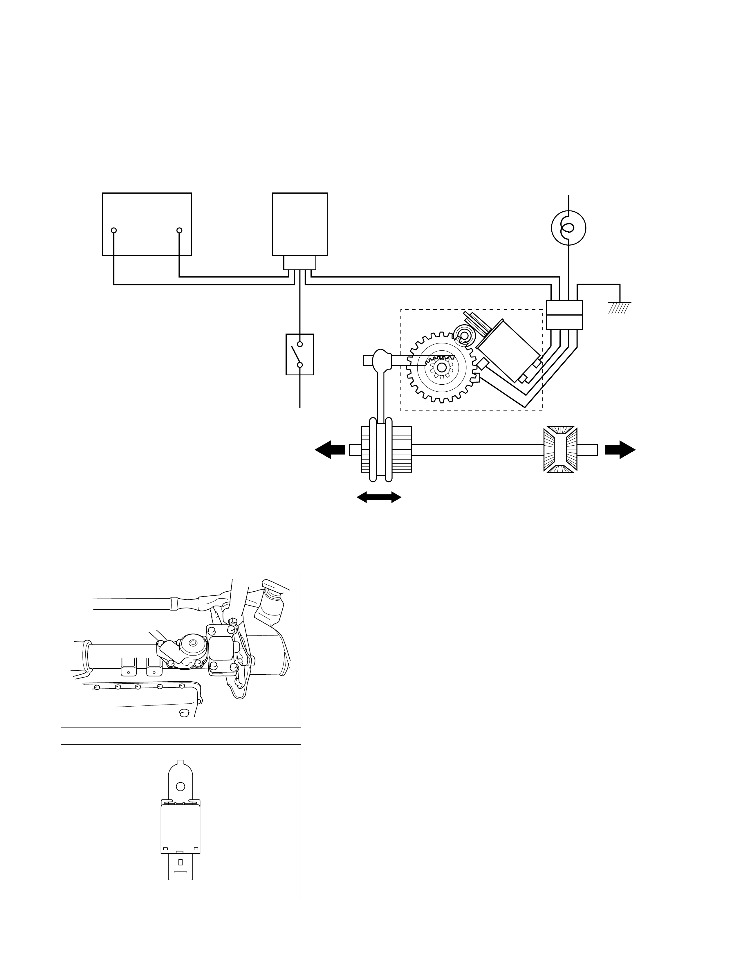
SHIFT ON THE FLY SYSTEM ELECTRIC EQUIPMENT
DIAGRAM
LH RH
Battery Axle Disconnect
Controller 4WD
Indicator
Axle Motor
Actuator
4x4
4WD
SW
4x2
ACTUATOR ASSEMBLY
Axle Disconnect Controller
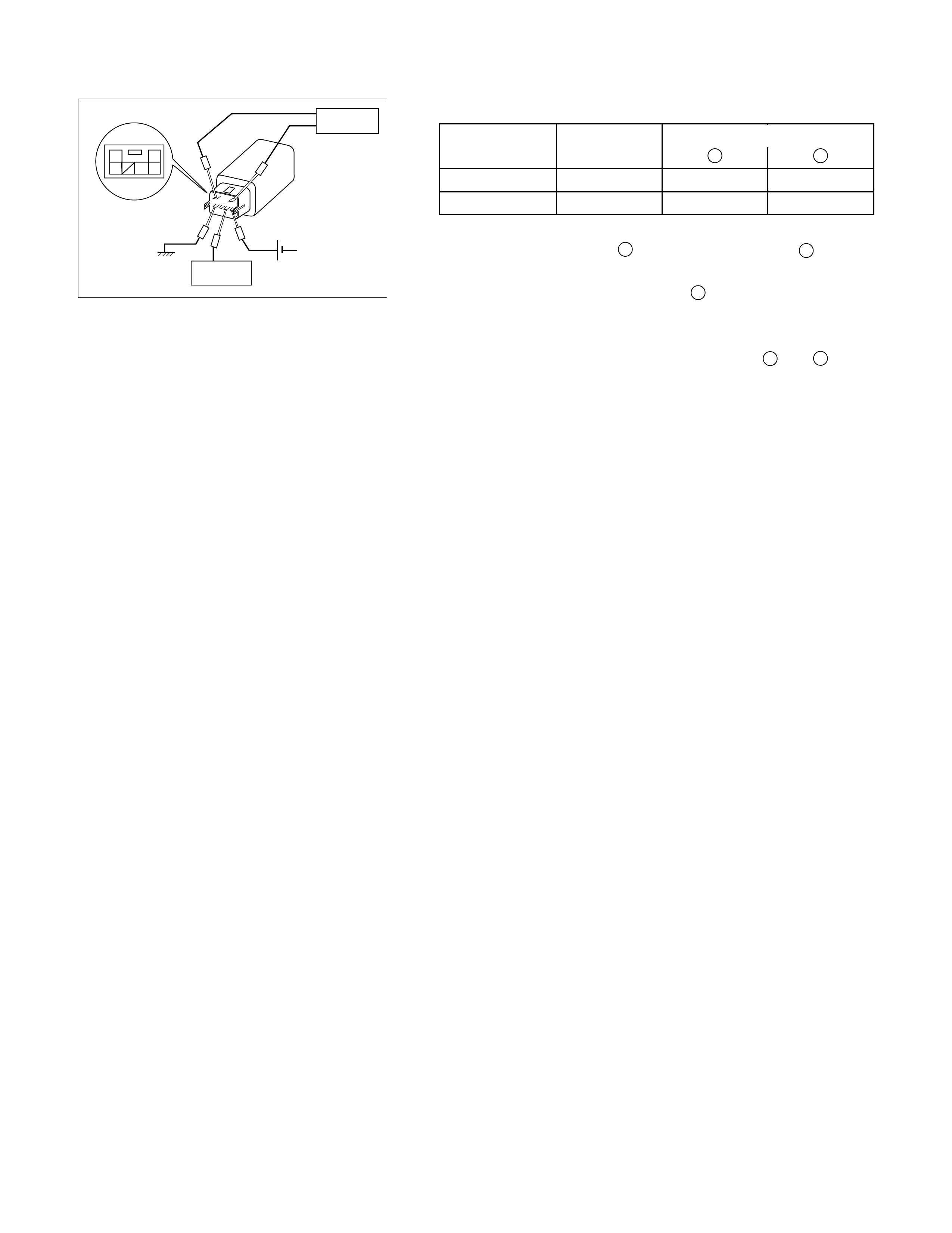
2
65 43
1
Terminal Arrangement
of Connector
Out signal
Input signal
GND 12V
SOF Controller test procedure.
Input signal 1 2
2WD→4WD Hi 0V 12V
4WD→2WD Lo 12V 0V
Output signal
1. Apply 12v. to terminal 3, and connect terminal 6 to
ground (GND).
2.Apply the input signal to terminal 4.
2WD→4WD More than 9.0V
4WD→2WD Less than 1.5V
3.Make sure the output signal from terminals 1 and 2
is present for 2 seconds.