
SECTION 4B - FRONT AXLE & PROPELLER SHAFT
MAIN DATA AND SPECIFICATIONS
SPECIAL PARTS FIXING NUTS AND BOLTS
RECOMMENDED LIQUID GASKET
RECOMMENDED THREAD LOCKING AGENTS
SERVICING
GENERAL DESCRIPTION
FRONT DRIVE AXLE ASSEMBLY
REMOVAL AND INSTALLATION
DISASSEMBLY
INSPECTION AND REPAIR
REASSEMBLY
DIFFERENTIAL
DISASSEMBLY
MAJOR COMP ONENTS
MINOR COMPONENTS
INSPECTION AND REPAIR
REASSEMBLY
MINOR COMPONENTS
MAJOR COMP ONENTS
FRONT HUB AND DISC (4×
××
×2 MODEL)
DISASSEMBLY
INSPECTION AND REPAIR
REASSEMBLY
Techline

MAIN DATA AND SPECIFICATIONS
FRONT AXLE AND DI FFERENTIAL
Type one piece cast iron housing and steel axle tubes.
Gear type Hypoid
Gear ratio
6VD1 Manual 4x2 4.300 : 1
6VD1 Automatic 4x2 4.555 : 1
6VD1 Manual 4x4 4.555 : 1
6VD1 Automatic 4x4 4.555 : 1
4JB1T Manual 4x2 4.300 : 1
4JB1T Manual 4x4 4.555 : 1
C22NE Manual 4x2 4.555 : 1
Differential type Two pinion
Oil capacity 1.4 litres
Axle shaft type Constant velocity joint (Birfield joint type and double offset joint).
Hub locking type Manual locking & SOF free wheel hubs.
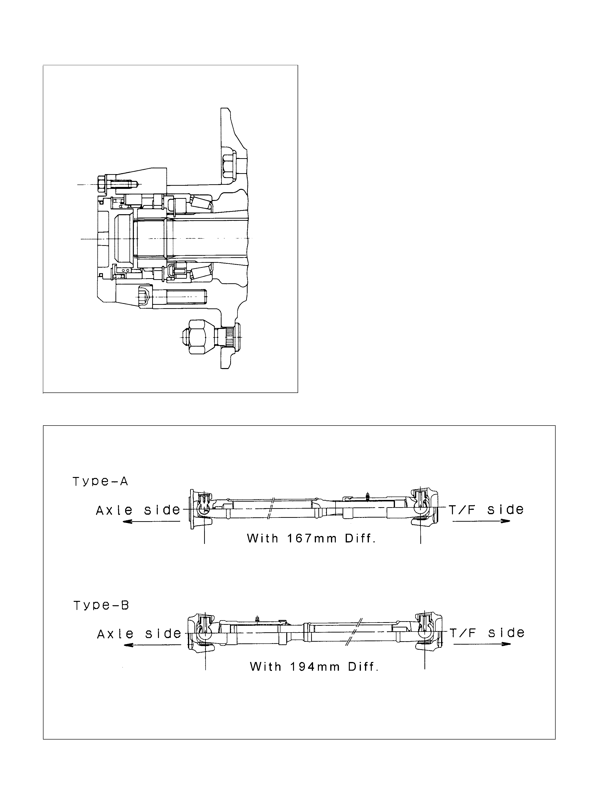
FRONT PROPELLER SHAFT mm(in)
Engine Model 4JA1 4JB1 4JG2
Transmission Type 5M/T ←←←4A/T 5M/T 4A/T
(MSG) ←(MUA) ←(MUA)
Rear Axle 167mm 194mm ←←←←←
Type Type-A Type-B Type-B Type-B Type-B Type-B Type-B
Outside Diameter mm 40.0 40.0 40.0 40.0 40.0 40.0 40.0
(in) (1.57) (1.57) (1.57) (1.57) (1.57) (1.57) (1.57)
Inside Diameter mm 33 32 32 32 32 32 32
(in) (1.30) (1.26) (1.26) (1.26) (1.26) (1.26) (1.26)
Length mm 545 517 421 421 627 421 627
(in) (21.46) (20.35) (16.57) (16.57) (24.69) (16.57) (24.69)
Spline Outside mm 31.67 36.67 36.67 36.67 36.67 36.67 36.67
Diameter (in) (1.25) (1.44) (1.44) (1.44) (1.44) (1.44) (1.44)
Fix Bolt Size M8 M8 M10 M10 M10 M10 M10
Engine Model X22SE 6VD1
Transmission Type 5M/T ←←←4A/T
(MSG) ←(MUA) ←
Rear Axle 194mm 167mm 194mm ←←
Type Type-B Type-A Type-B Type-B Type-B
Outside Diameter mm 40.0 40.0 40.0 40.0 40.0
(in) (1.57) (1.57) (1.57) (1.57) (1.57)
Inside Diameter mm 32 33 32 32 32
(in) (1.26) (1.30) (1.26) (1.26) (1.26)
Length mm 471 505 376 393 559
(in) (18.54) (19.88) (14.80) (15.47) (22.01)
Spline Outside mm 36.67 31.67 36.67 36.67 36.67
Diameter (in) (1.44) (1.25) (1.44) (1.44) (1.44)
Fix Bolt Size M8 M8 M10 M10 M10
SPECIAL PARTS FI XING NUTS AND BOLTS
FRONT DRIVE AXLE AND PROPELLER SHAFT N⋅m (kgf⋅m/lb⋅ft)
FRONT DIFFERENTIAL N⋅m (kgf⋅m/lb⋅ft)

FREE WHEELING HUB N⋅m (kgf⋅m/lb⋅ft)
11.8±2.0 (1.2±0.2/8.7±1.4)
58.9±5 (6±0.5/43.4±3.6)
103±5 (10.5±1/75.9±7.2)
58.9±5 (6±0.5/43.4±3.6)
RECOMMENDED LI QUI D GASKET
Type Brand Name Manufacture Remarks
RTV*
Silicon Base
ThreeBond 1207B
ThreeBond 1207C
ThreeBond 1215
Three Bond
Three Bond
Three Bond
For Engine Repairs
For Axle Case
Repairs, T/M
Water Base ThreeBond 1141E Three Bond For Engine Repairs
Solvent
ThreeBond 1104
BelcoBond 4
BelcoBond 401
BelcoBond 402
Three bond
Isuzu
Isuzu
Isuzu
For Engine Repairs
Anerobic LOCTITE 515
LOCTITE 518 Loctite
Loctite All
* RTV : Room Temperature Vulcanizer
Note :
1. It is very important that the liquid gaskets listed above or their exact equivalent be used on the vehicle.
2. Be careful to use the specified amount of liquid gasket.
Follow the manufacture's instructions at all times.
3. Be absolutely sure to remo ve all lubricants and mo isture from the conn ecting surfaces before ap plying the
liquid gasket.
The connecting surfaces must be perfectly dry.
4. LOCTITE 515 and LOCTITE 518 harden upon contact with a metal surface.
Do not apply LOCTITE 515 or LOCTIT E 518 between tw o metal surfaces having a clearance of greater than
0.25 mm (0.01 in). Poor adhesion will result.
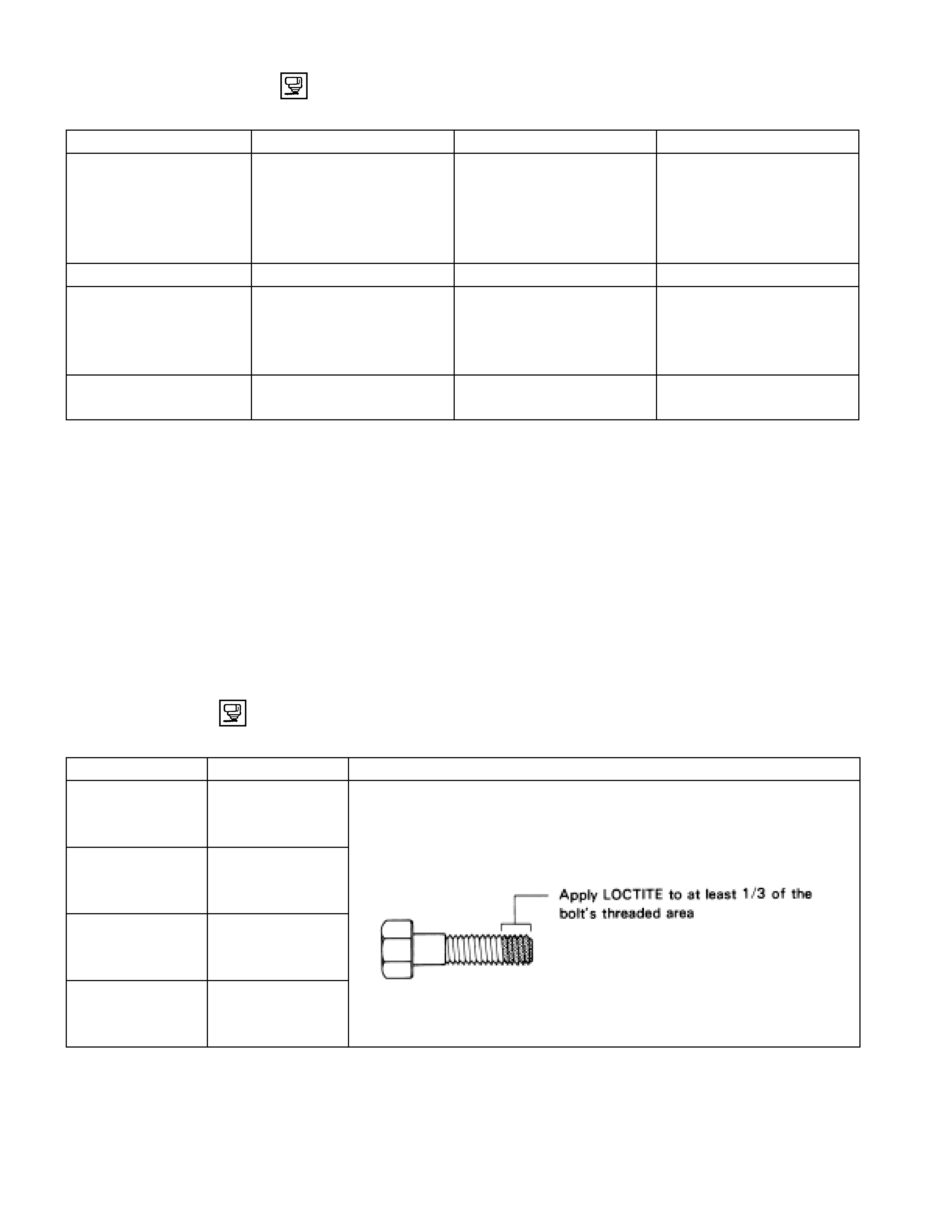
RECOMMENDED THREAD LOCKING AGENTS
LOCTITE Type LOCTITE Color Application Steps
LOCTITE 242 Blue 1. Completely remove all lubricant and moisture from the bolts and
the female threaded surfaces of the parts to be joined.
The surfaces must be perfectly dry.
LOCTITE 262 Red 2. Apply LOCTITE to the bolts.
LOCTITE 270 Green
LOCTITE 271 Red 3. Tighten the bolts to the specified torque.
4. Wait at least on hour before continuing the installation procedure.

SERVICING
HUB BEARING PRELOAD AT THE WHEEL PIN
4×4 Model kg(lb
)
New bearing and New oil seal 2 - 2.5 (4.4 - 5.5)
Reuse bearing and New oil seal 1.2 - 1.8 (2.6 - 4.0)
4×2 Model kg(lb)
New bearing and New oil seal 0.8 - 1.0 (1.8 - 2.2)
Reuse bearing and New oil seal 0.8 - 1.0 (1.8 - 2.2)
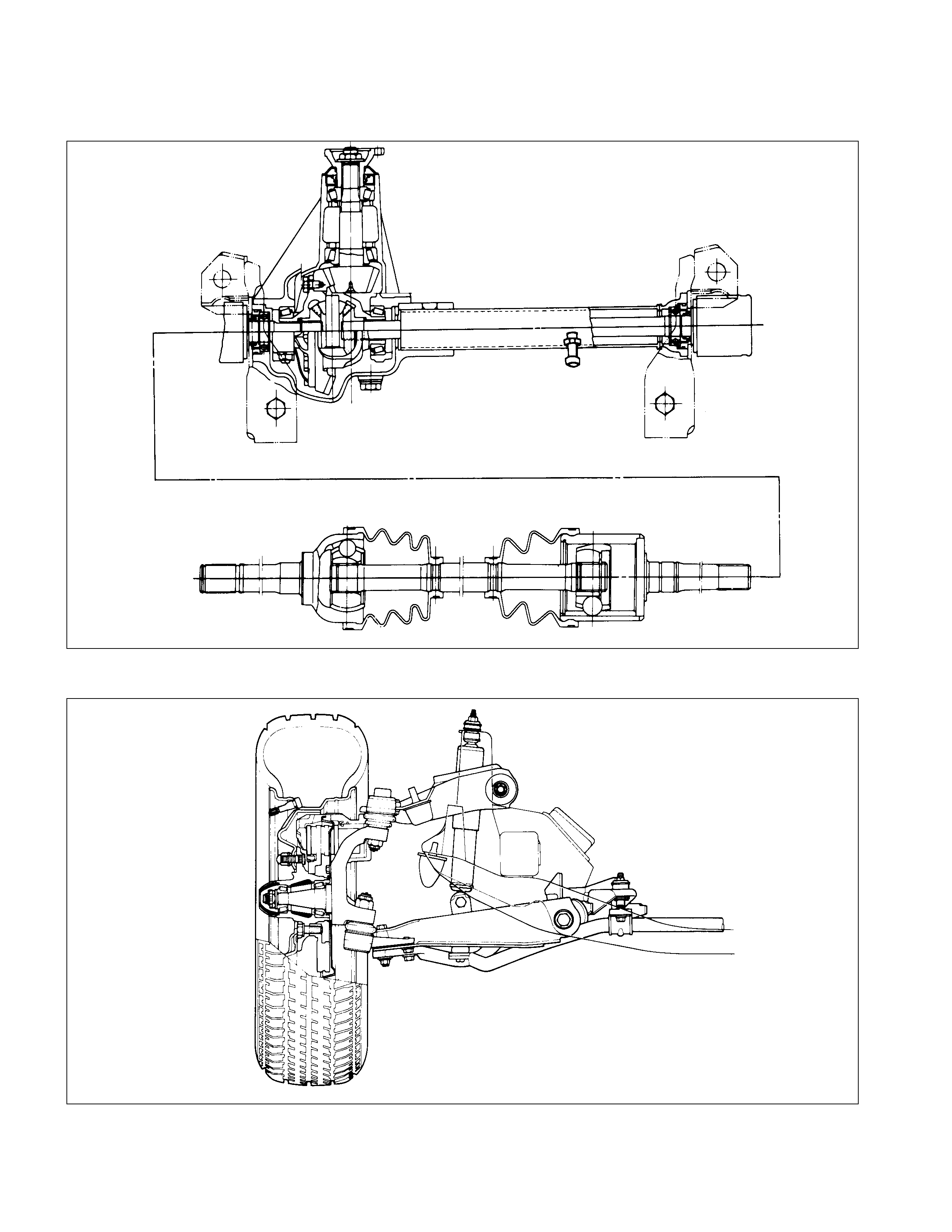
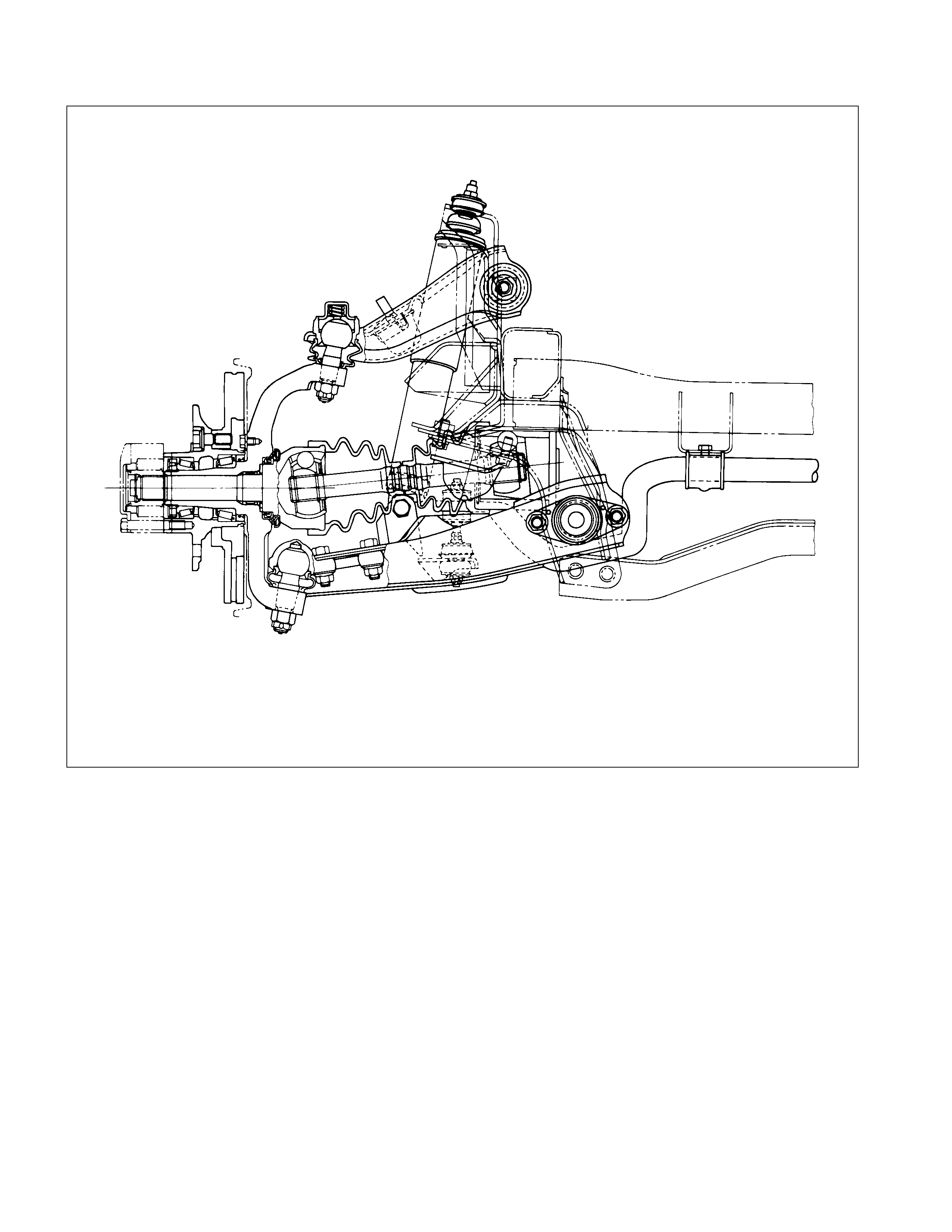
GENERAL DESCRIPTI O N
FRONT DRIVE AXLE
FRONT HUB AND DISC (4×
××
×2 MODEL)
FRONT HUB AND DISC (4×
××
×4 MODEL)
LOCKING HUB
MANUAL TYPE
FRONT PROPELLER SHAFT
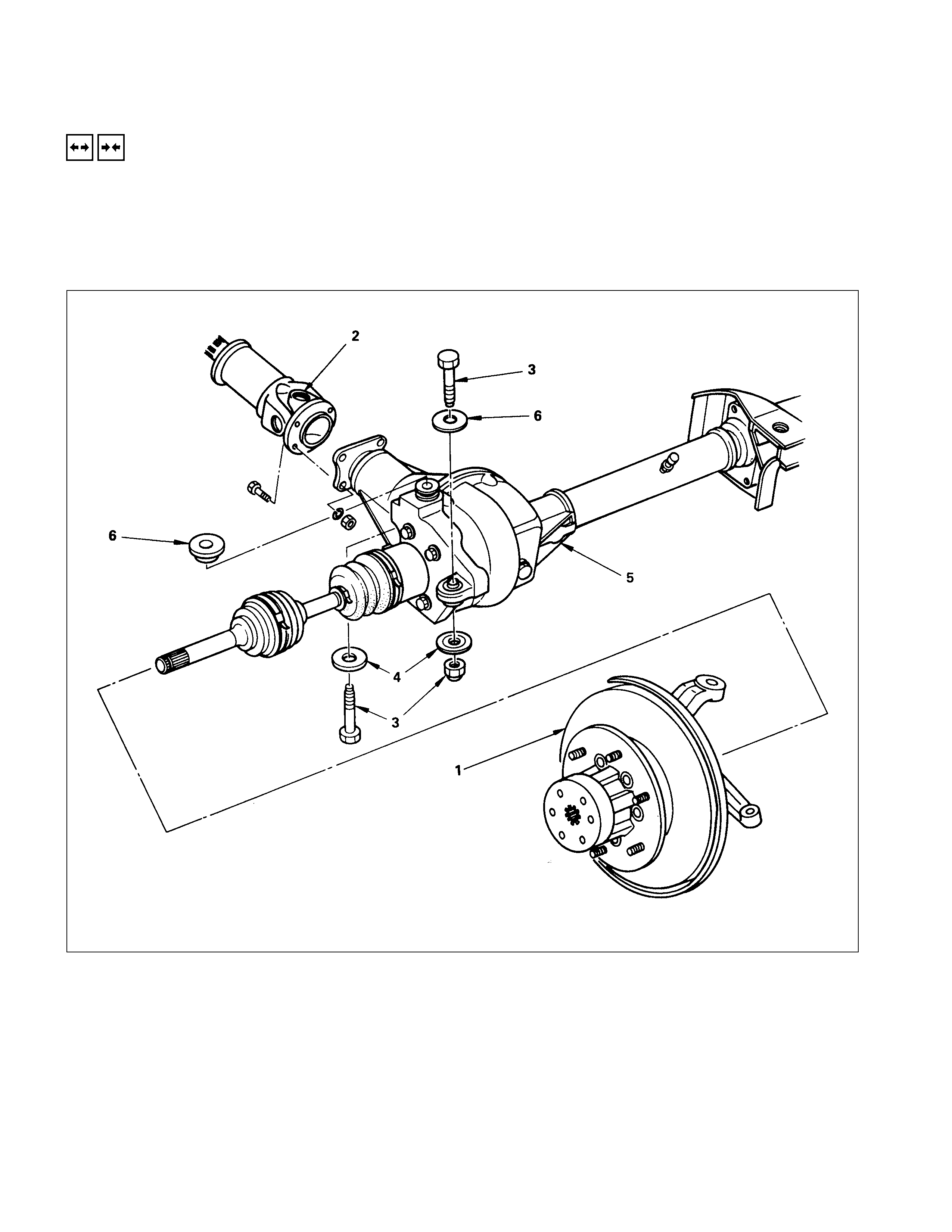
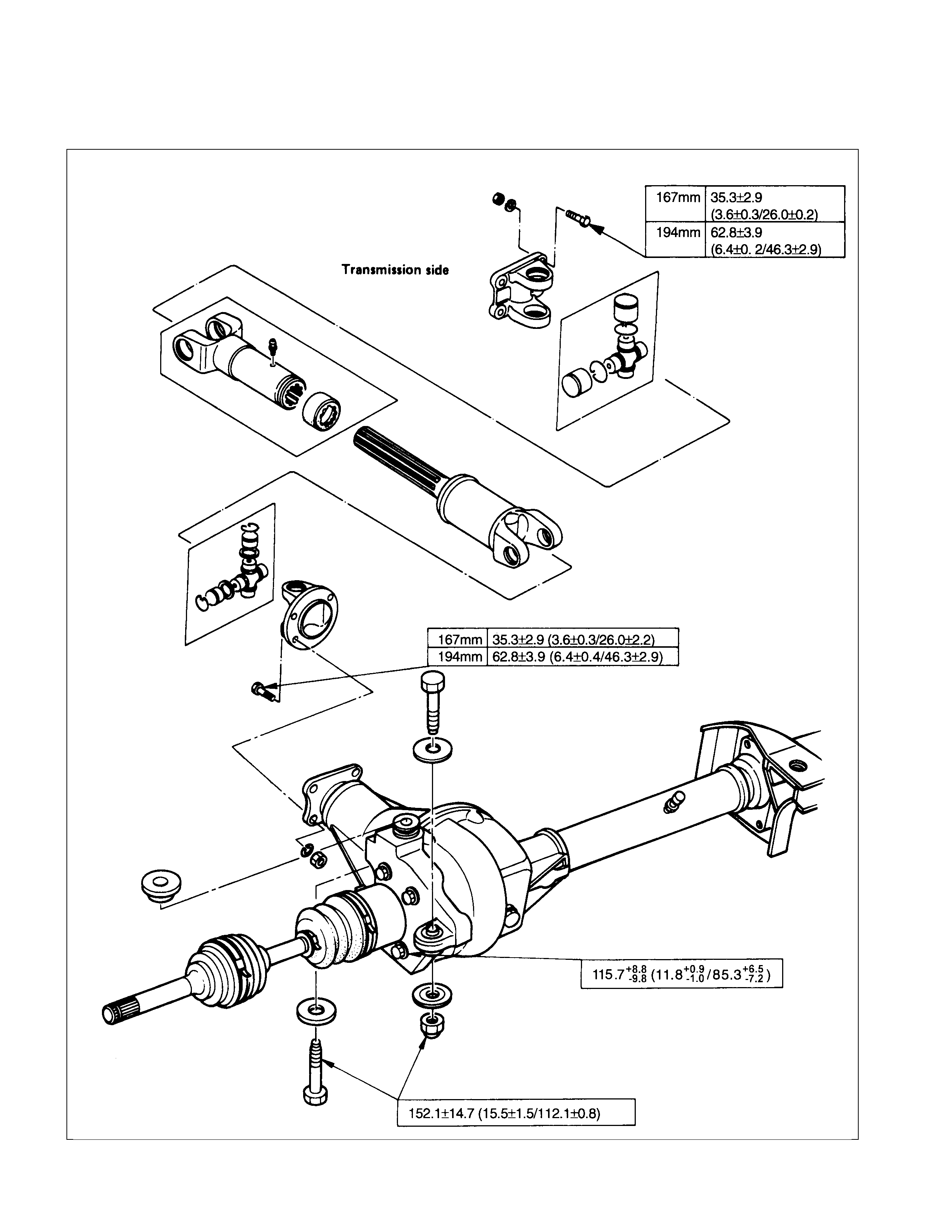
FRONT DRIVE AXLE ASSEMBLY
REMOVAL AND INSTALLATION
1. Refer to SECTION 10 “WHEEL AND TIRES” for road wheel Disassembly and Reassembly procedure.
2. Refer to SECTION 5 “BRAKES” for disc brake caliper removal and installation procedure.
3. Refer to SECTION 9 “STEERING” for Steering linkage removal and installation procedure.
REMOVAL STEPS
▲1. Assembly of hub and disc, back plate,
knuckle, knuckle arm, and lower end.
▲2. Propeller shaft
3. Nut and bolt
4. Washer
▲5. Front drive axle assembly
6. Washer
INSTALLATION STEPS
6. Washer
▲5. Front drive axle assembly
4. Washer
▲3. Nut and bolt
▲2. Propeller shaft
1. Assembly of hub and disc, back plate,
knuckle, knuckle arm, and lower end.
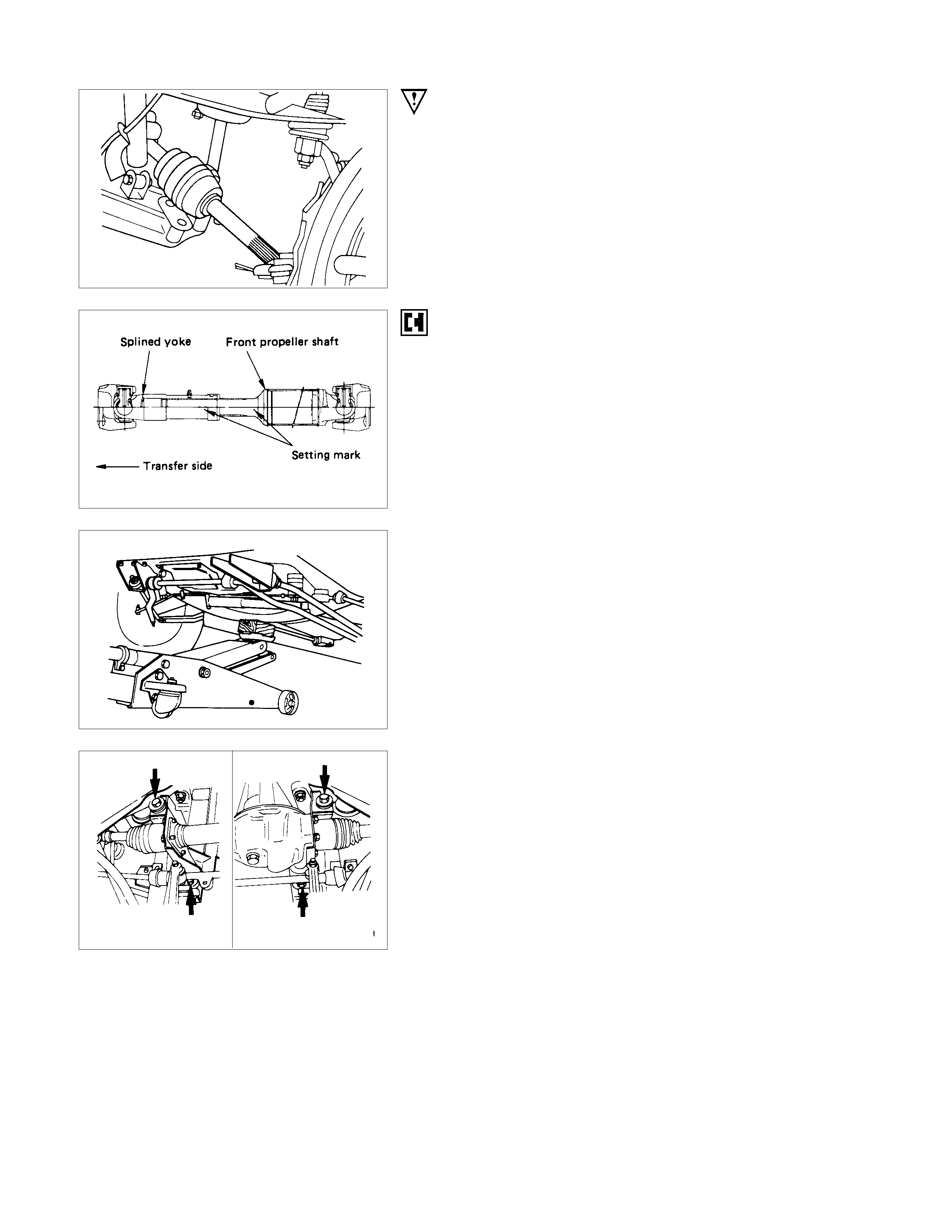
IMPO RTANT OPERATIONS - REMOVAL
1. Assembly of hub and disc, back plate, knuckle, knuckle
arm, and lower end.
Before removal, jack up the front of vehicle and support the
frame with jack stands.
2. Propeller Shaft
Apply the setting marks.
5. Front Drive Axle Assembly
(1)Put the lifting jack under the center part of the front.
(2)Remove four bolts fixing axle case mounting brackets to the
frame.
Note :
Be careful not to damage birfield joints or double off-set
joints when supporting axle shaft assembly.
(3)Lower the f r ont axle assembly and roll it out toward the front
of the vehicle.
Take care not to damage the birfield joints or the double off-
set joints.
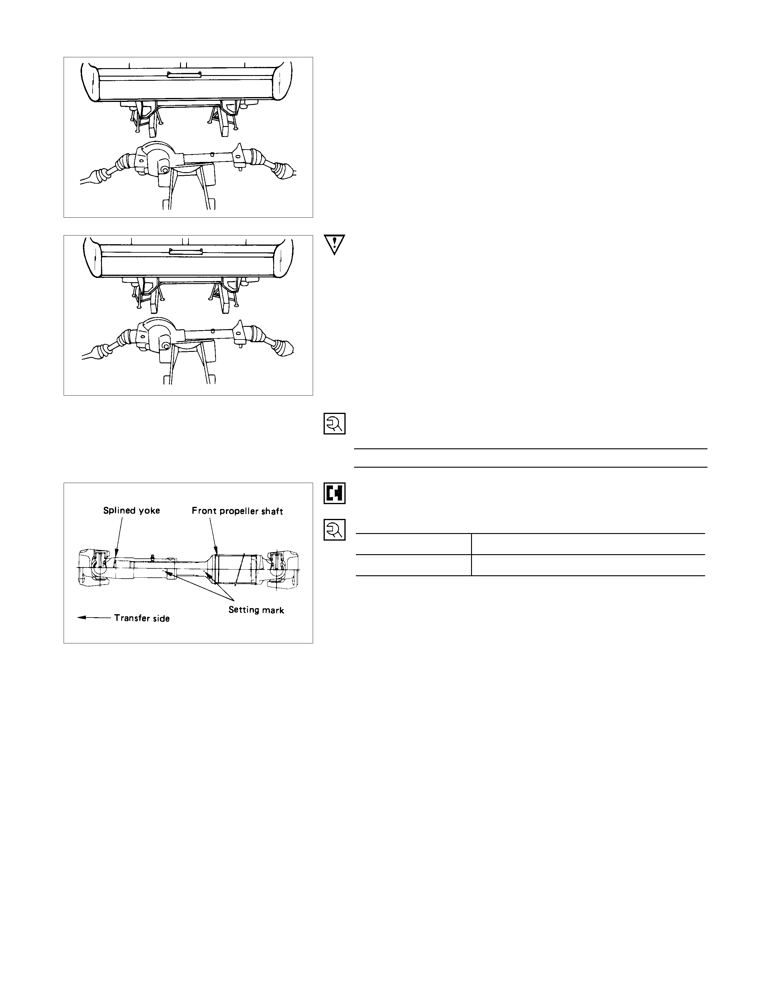
IMPORTANT OPERATIONS - INSTALLATION
5. Front Drive Axle Assembly
Place the front axle assembly in position under the vehicle
using a lifting jack.
3. Nut
Front Axle Mounting Nut Torque N⋅m (kgf⋅m/lb⋅ft)
152.1 ± 14.7 (15.5 ± 1.5/112.1 ± 10.8)
2. Propeller Shaft
Align the setting marks applied the removal.
Bolt Torque N⋅m (kgf⋅m/lb⋅ft)
167 mm 35.3 ± 2.9 (3.6 ± 0.3/26.0 ± 2.2)
194 mm 62.8 ± 3.9 (6.4 ± 0.4/46.3 ± 2.9)
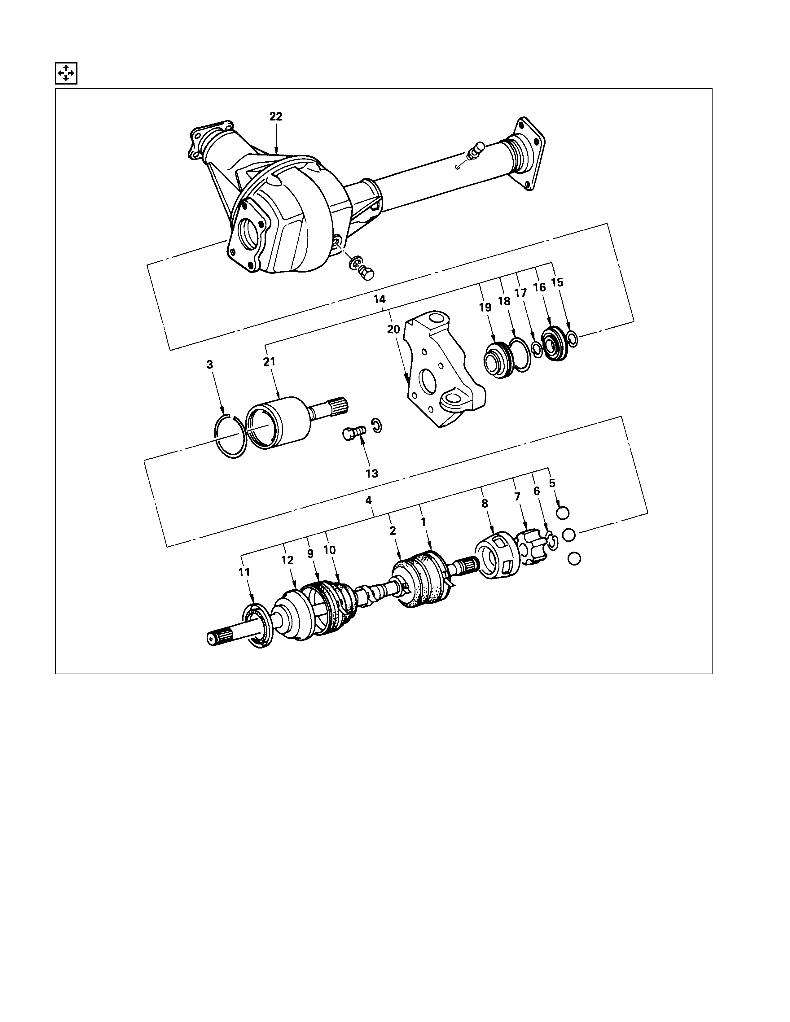
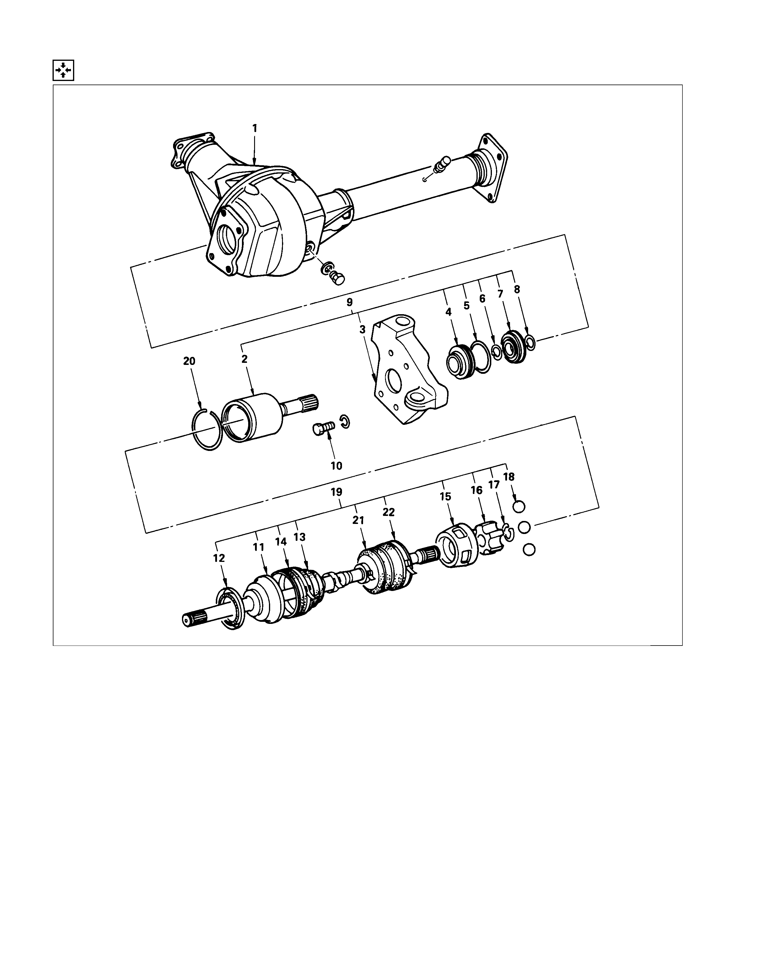
DISASSEM BLY
DISASSEM BLY STEPS
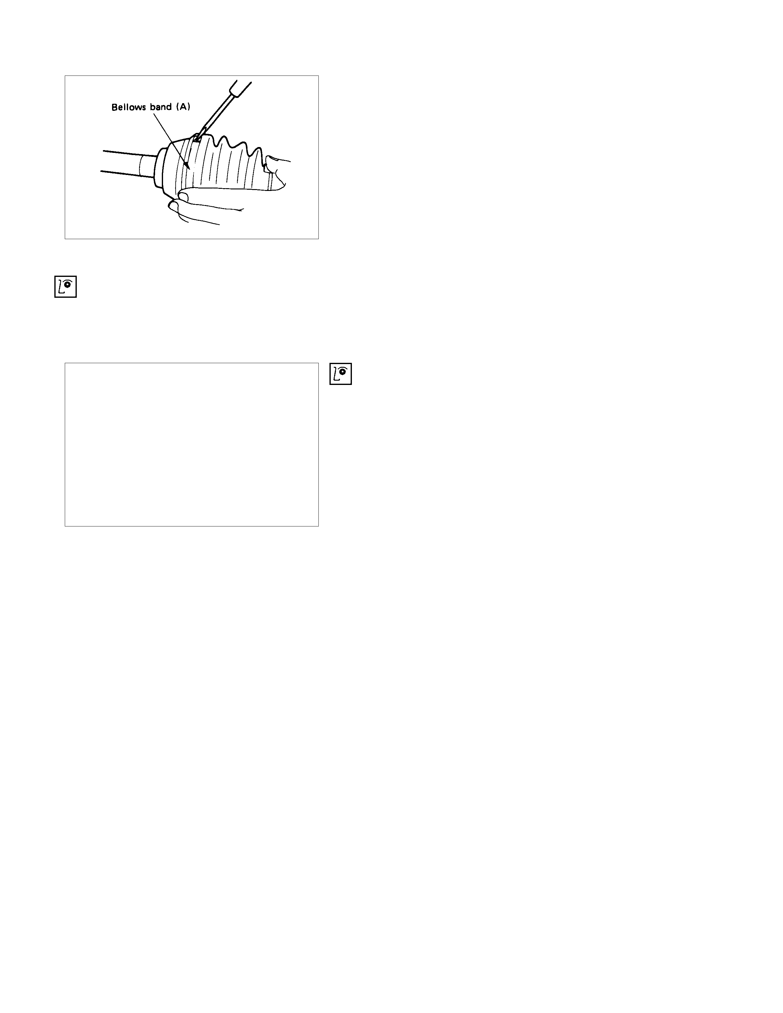
▲1. Band
2. Bellows
▲3. Circlip
4. BJ shaft assembly
▲5. Ball
▲6. Snap ring
7. Ball retainer
8. Ball guide
▲9. Band
10. Bellows
11. Dust seal
12. BJ shaft
13. Bolt
14. DOJ case assembly
15. Snap ring
16. Bearing
17. Snap ring
18. O-ring
19. Oil seal
20. Bracket
21. DOJ case
22. Axle case and differential
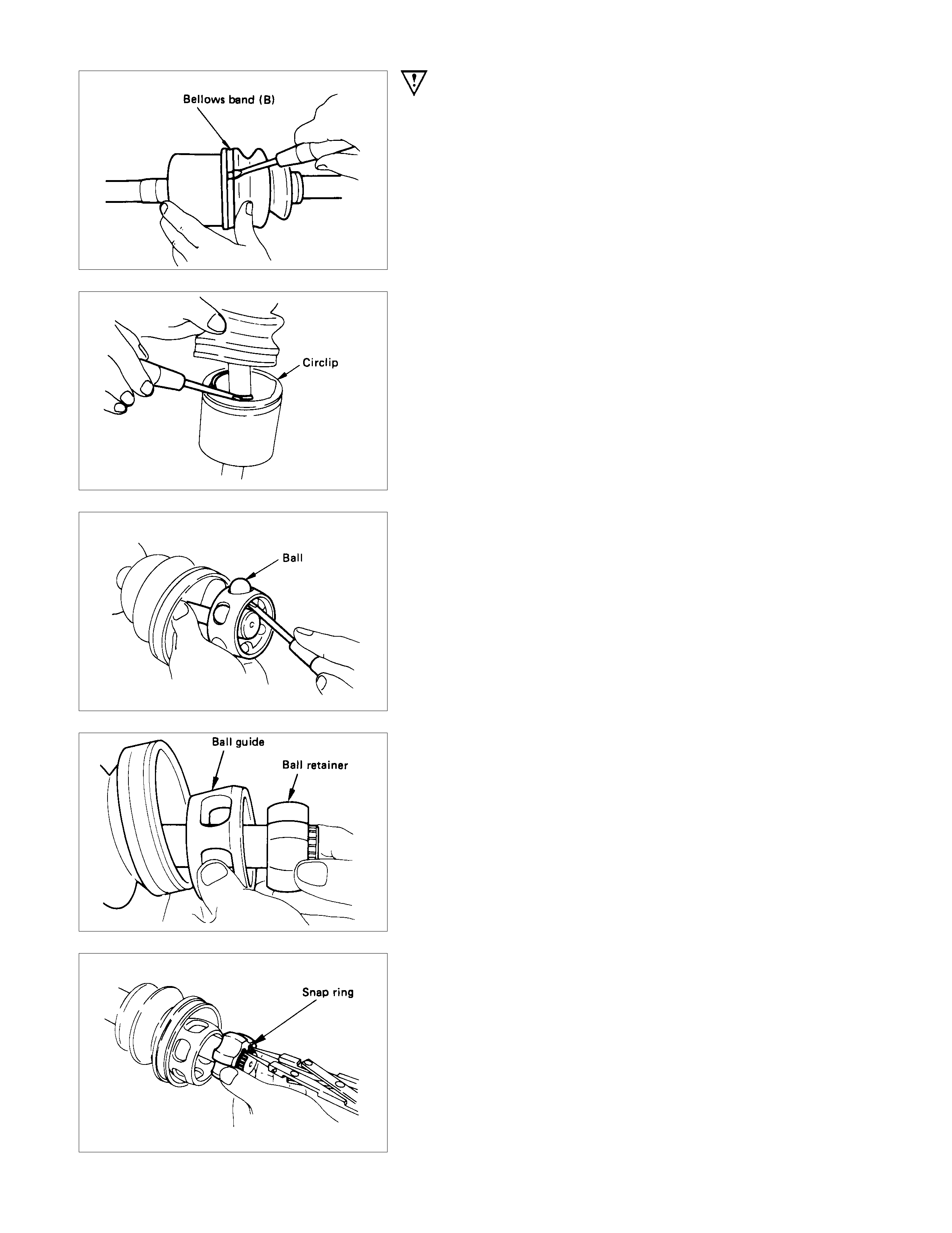
IMPORTANT OPERATIONS
1. Band
Raise the hooked end of the band with a screwdriver or
equivalent.
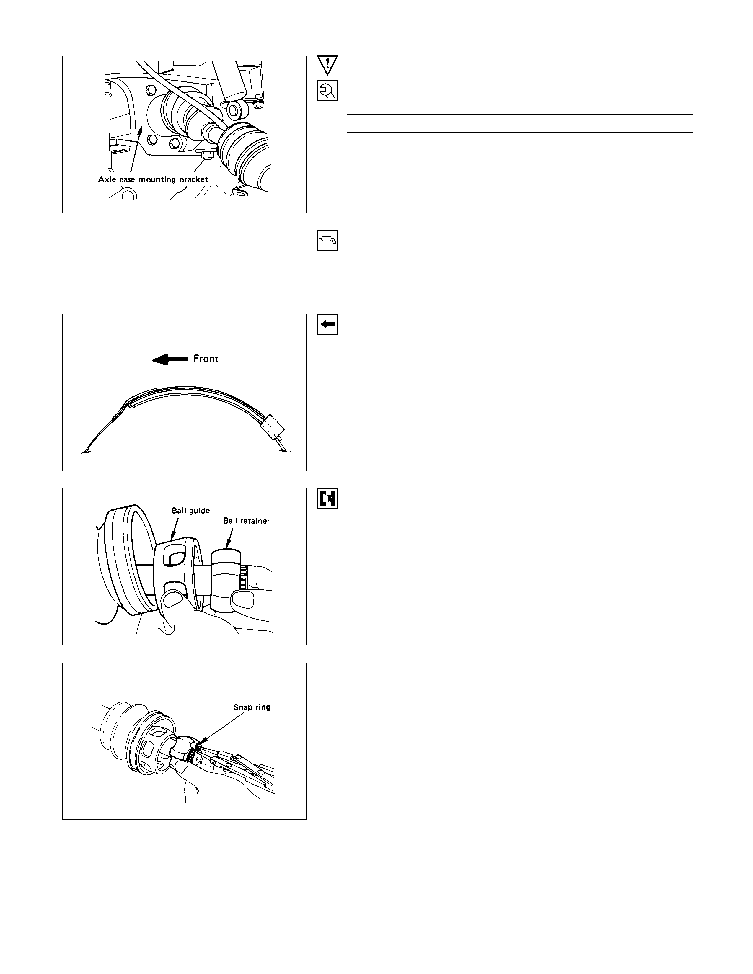
3. Circlip
Pry off with a screwdriver or equivalent.
5. Ball
Remove the six balls with a screwdriver or equivalent.
Rotate the case half a pitch to align the ball guide on the case
with the projected portion of the ball retainer, then slide the
case toward the bellows. The case can not be removed in the
reverse direction.
6. Snap Ring
Remove the snap ring fastening the ball retainer to the center
shaft.
8. Band
Raise the hooked end of the band with a screwdriver or
equivalent.
INSPECTION AND REPAIR
Make all necessary adjustments, repairs, and part replacements if wear, damage, or other problems are discovered
during inspection.
• BJ assembly
• DOJ case, ball, ball guide, ball retainer
• Bellows
• Bearing
• Dust seal, oil seal
VISUAL CHECK
Inspect the following parts for wear, damage, or other
abnormal conditions.
REASSEMBLY
REASSEMBLY STEPS
1. Axle case and differential
2. DOJ case
3. Bracket
4. Oil seal
5. O-ring
6. Snap ring
7. Bearing
8. Snap ring
9. DOJ case assembly
▲10. Bolt
11. BJ shaft
12. Dust seal
▲13. Bellows
▲14. Band
▲15. Ball guide
▲16. Ball retainer
▲17. Snap ring
▲18. Ball
▲19. BJ shaft assembly
▲20. Circlip
▲21. Bellows
▲22. Band
IMPORTANT OPERATIONS
10.Bolt
Bolt Torque N⋅m (kgf⋅m/lb⋅ft)
115.7 +8.8
−9.8 (11.8 +0.9
−1.0 /85.3 +6.5
−7.2 )
13.Bellows
(1)Apply a thin coat of grease to the shaft for smooth
installation.
(2)Apply specified grease to the ½ space of the bellows.
14.Band
Note the setting direction.
After installation, check that the bellows is free from distortion.
15.Ball Guide
16.Ball Retainer
Install the ball guide with the smaller diameter side ahead onto
the shaft.
17.Snap Ring
Install the snap ring securing the ball retainer to the shaft.
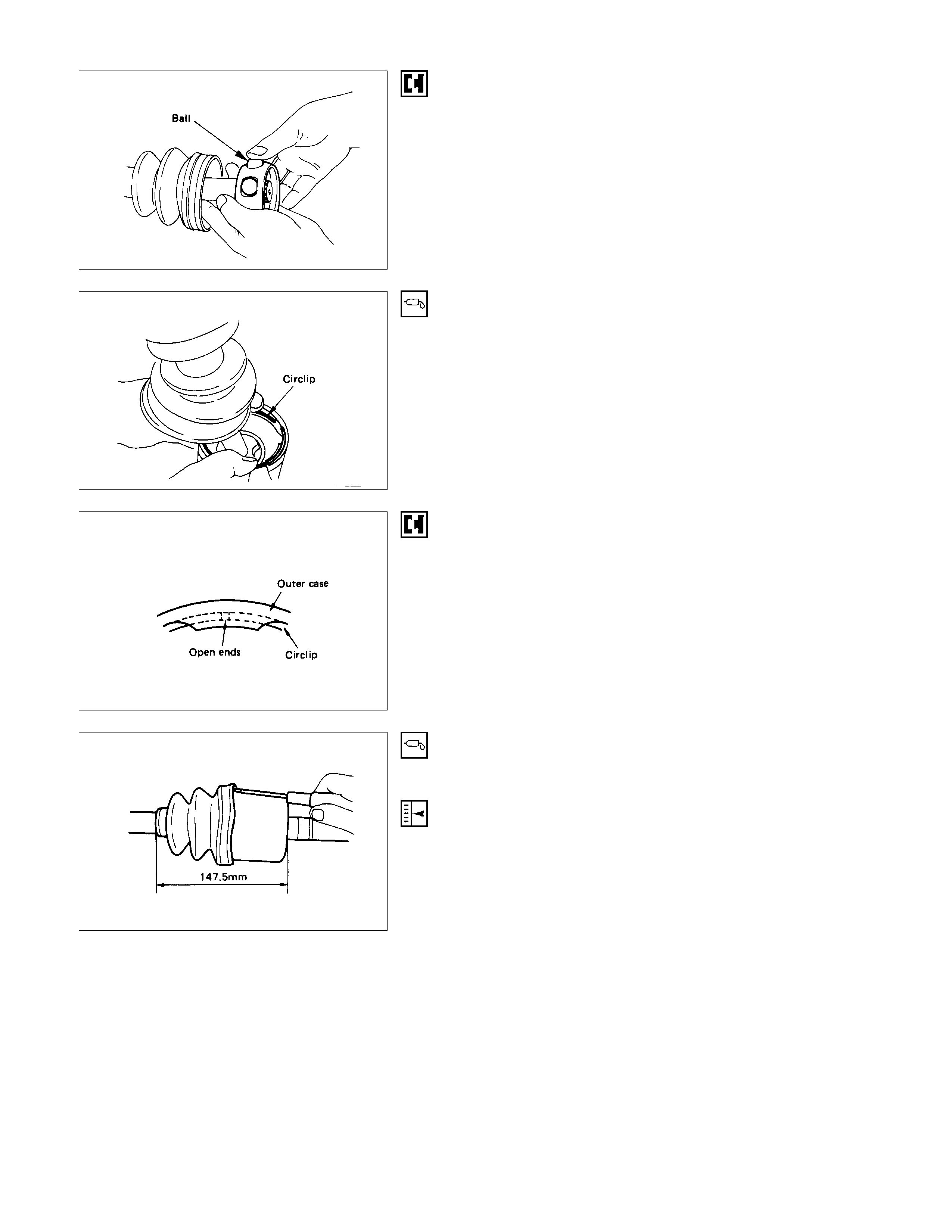
18.Ball
Bring the ball guide of the cage into alignment with the
projected portion of the ring on the ball retainer, then turn the
cage ½ pitch. Align the track on the ball retainer with the
window in the cage and install the six balls into position.
19.BJ Shaft Assembly
Apply specified grease to the half of the space of the DOJ case
(Approx. 50g (1.8 oz)).
20.Circlip
Install the circlip so that open ends are positioned away from
the ball groove.
21.Bellows
(1)Before installation, insert the appropriate amount o
f
specified grease into the DOJ case.
(2)Adjust the air pressure within the bellows by inserting a
screwdriver or equivalent, so that it equals atmospheric
pressure.
22.Band
After installation, check that the bellows is free from distortion.
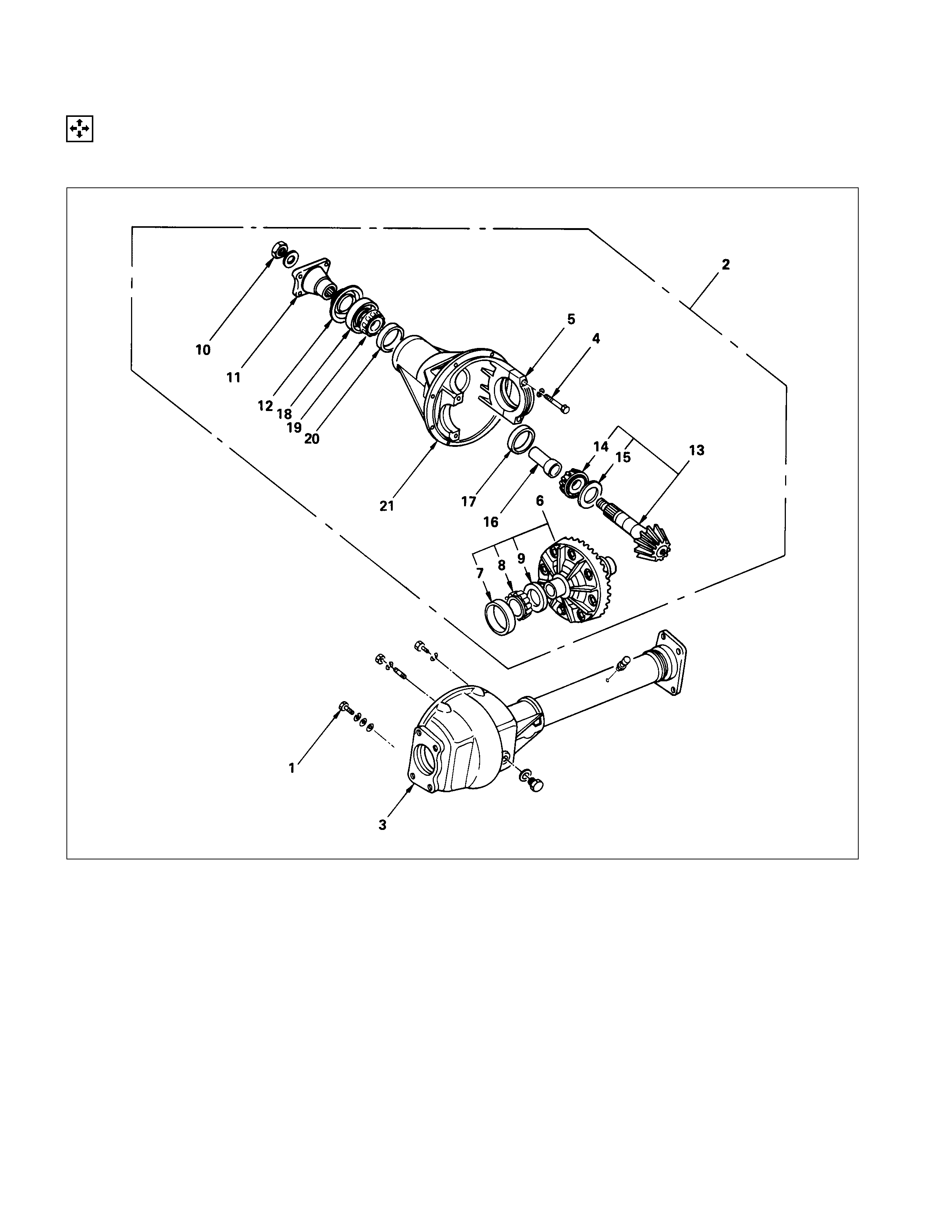
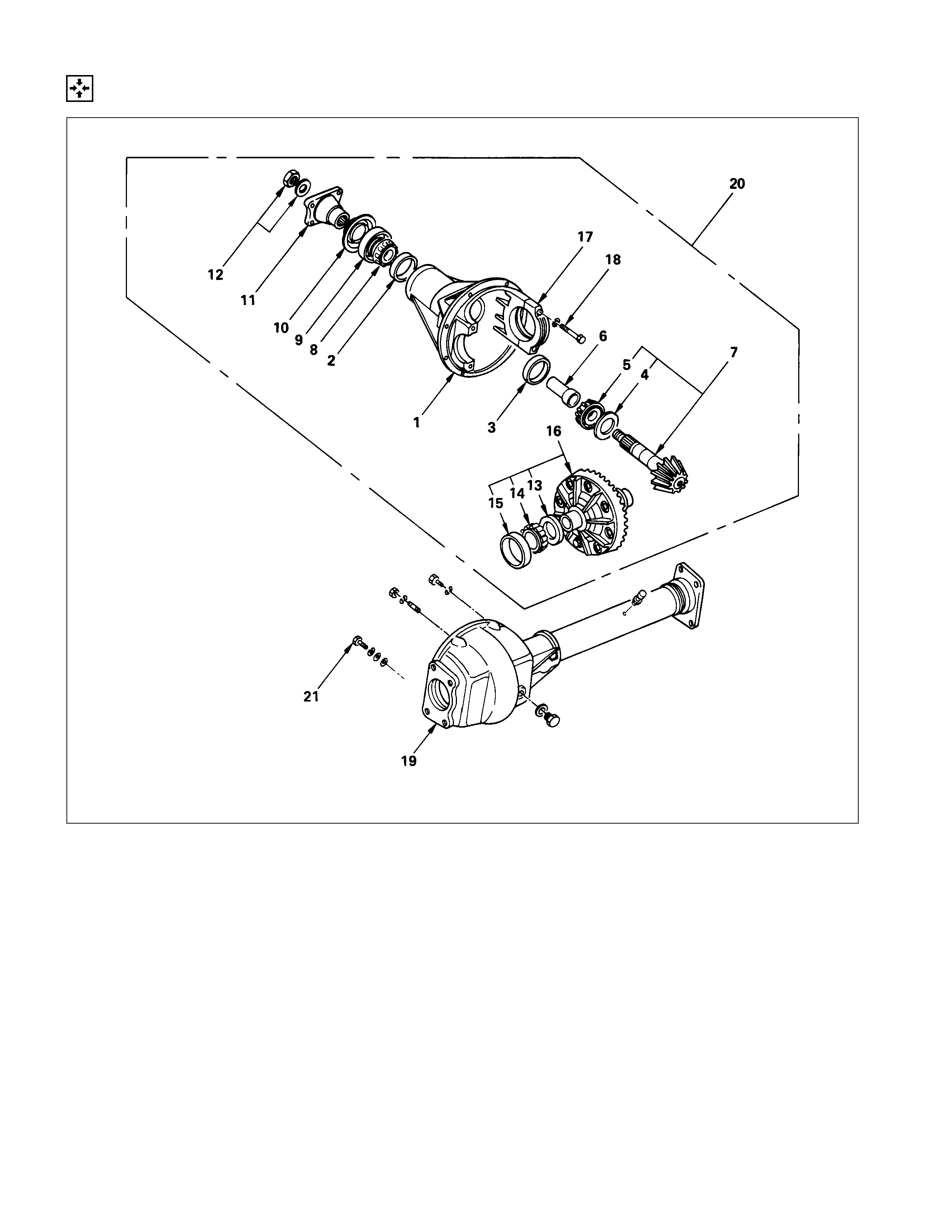
DIFFERENTIAL
DISASSEM BLY
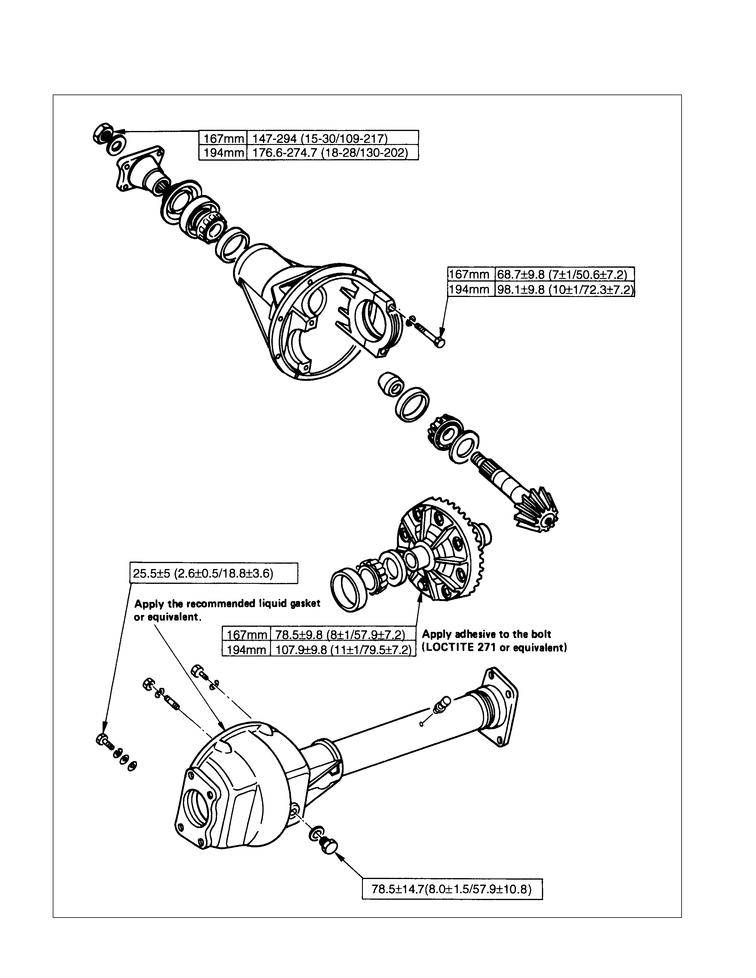
MAJO R COMPONENTS
DISASSEM BLY STEPS
1. Bolt
2. Differential assembly
3. Axle case
4. Bolt
▲5. Bearing cap
6. Diff. cage assembly
▲7. Side bearing outer race
▲8. Side bearing
▲9. A djust shims
▲10. Flange nut
11. Flange
12. Dust cover
▲13. Pinion gear
▲14. Inner bearing
15. Adjust shim
16. Collapsible spacer
▲17. Inner bearing outer race
18. Oil seal
19. Outer bearing
▲20. Outer bearing outer race
21. Diff. carrier
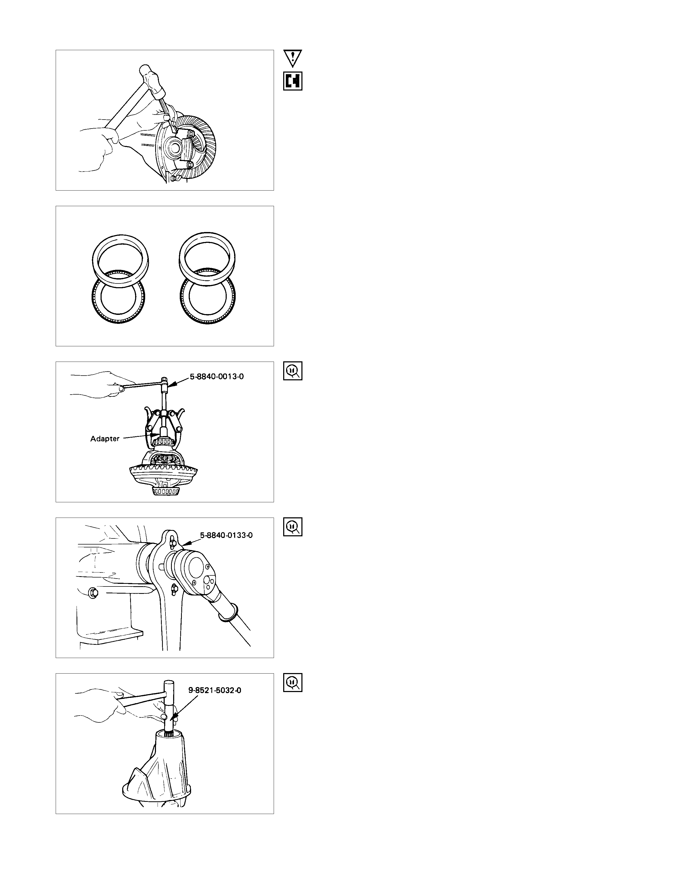
IMPORTANT OPERATIONS
5. Bearing Cap
Apply a setting mark to the side bearing cap and the differential
carrier.
7. Side Bearing Outer Race
After removal, keep the right and left-hand side bearing
assemblies separate to maintain inner and outer race
combinations.
8. Side Bearing
Remover : 5-8840-0013-0
(J-22888)
Adapter : 5-8521-0019-0 167 mm)
9-8521-1743-0 (194 mm)
(J-8107-2)
9. Adjust Shims
Note the thickness and position of the shims removed.
10.Flange Nut
Holding wrench : 5-8840-0133-0 (167 mm and 194 mm)
(J-8614-01)
13.Pinion Gear
Remove the drive pinion assembly using a soft metal rod and a
hammer.
Spindle : 9-8521-5032-0
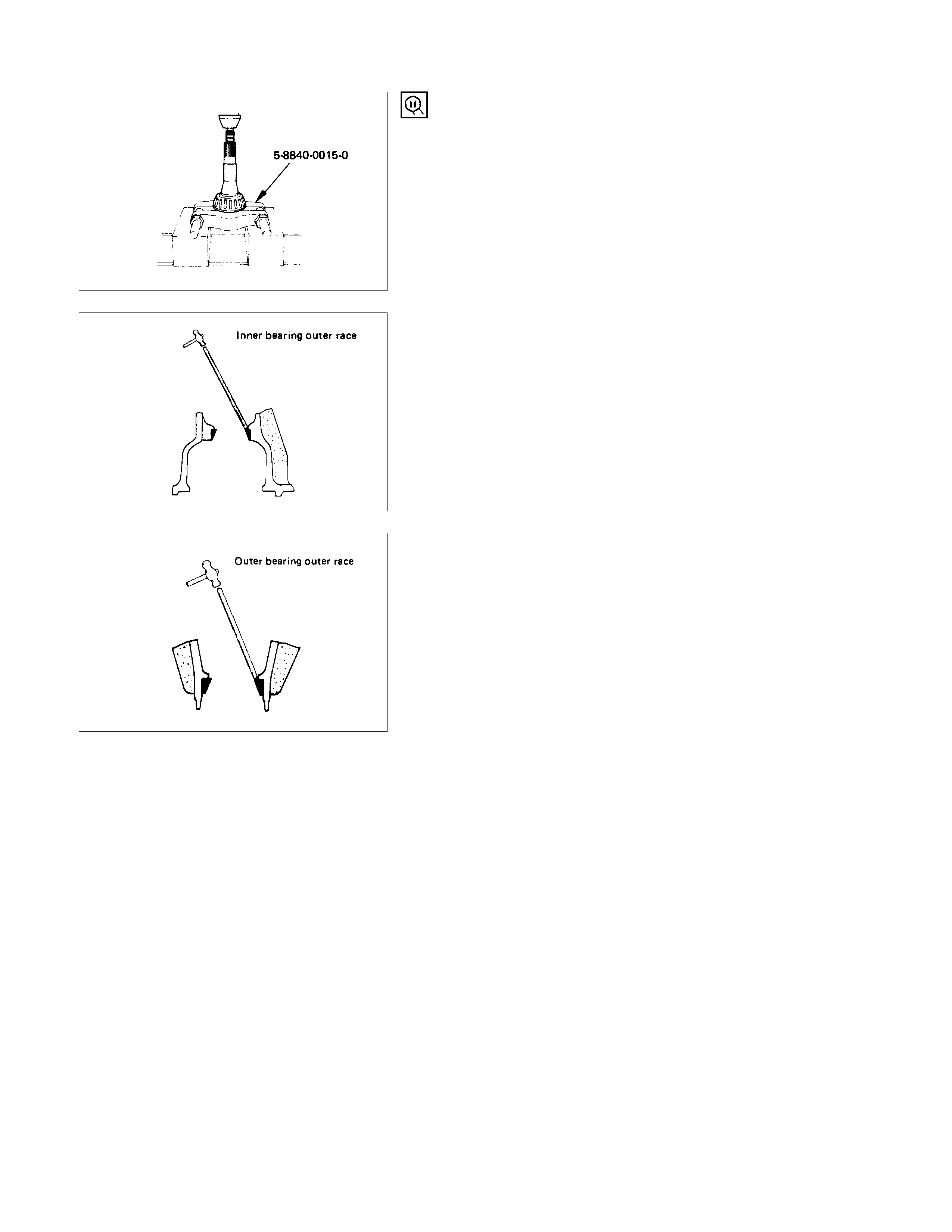
14.Inner Bearing
Remove the inner bearing using a separator and a press.
Separator : 5-8840-0015-0
(J-22912-01)
17.Inner Bearing Outer Race
20.Outer Bearing Outer Race
Remove the inner bearing outer race and the outer bearing
outer race by using a brass bar and a hammer.
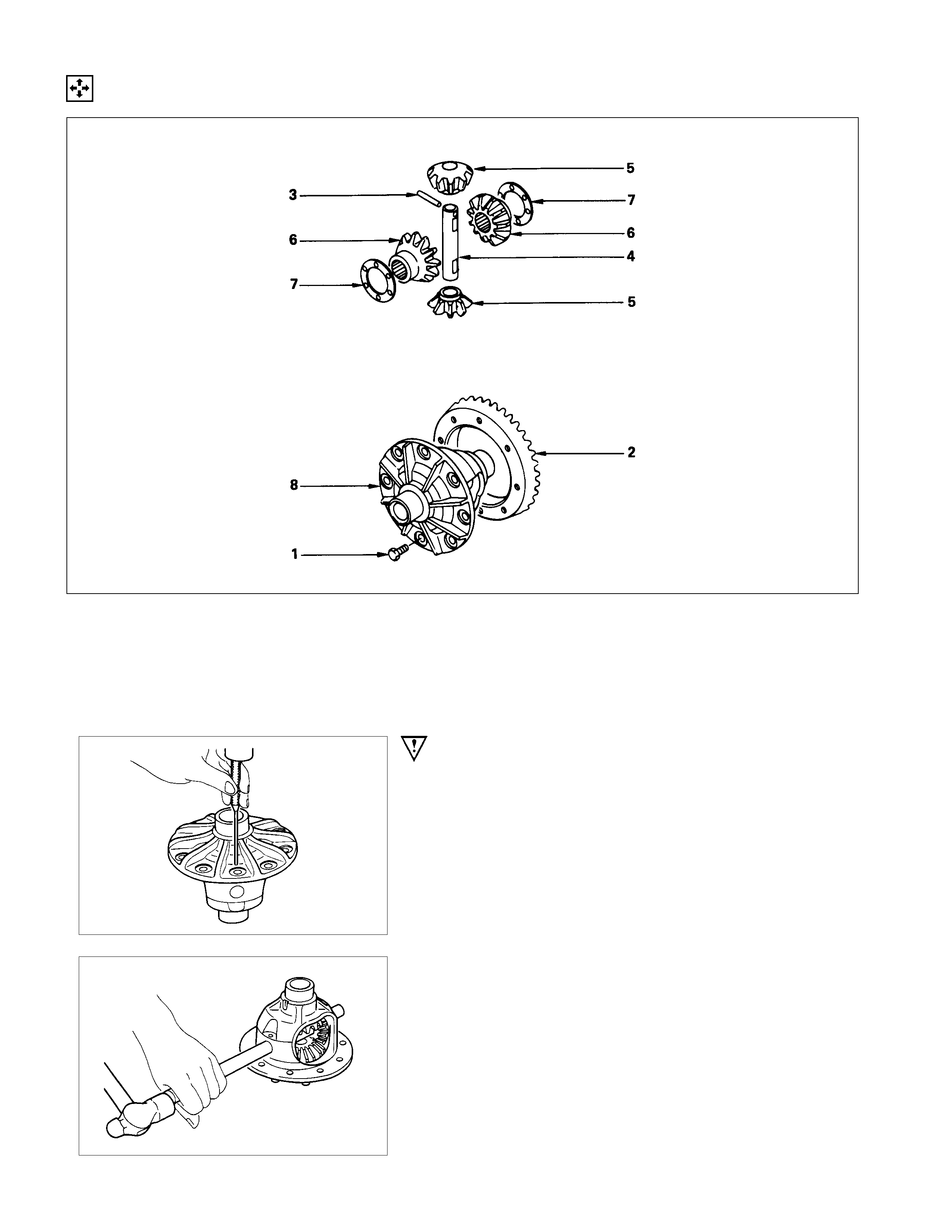
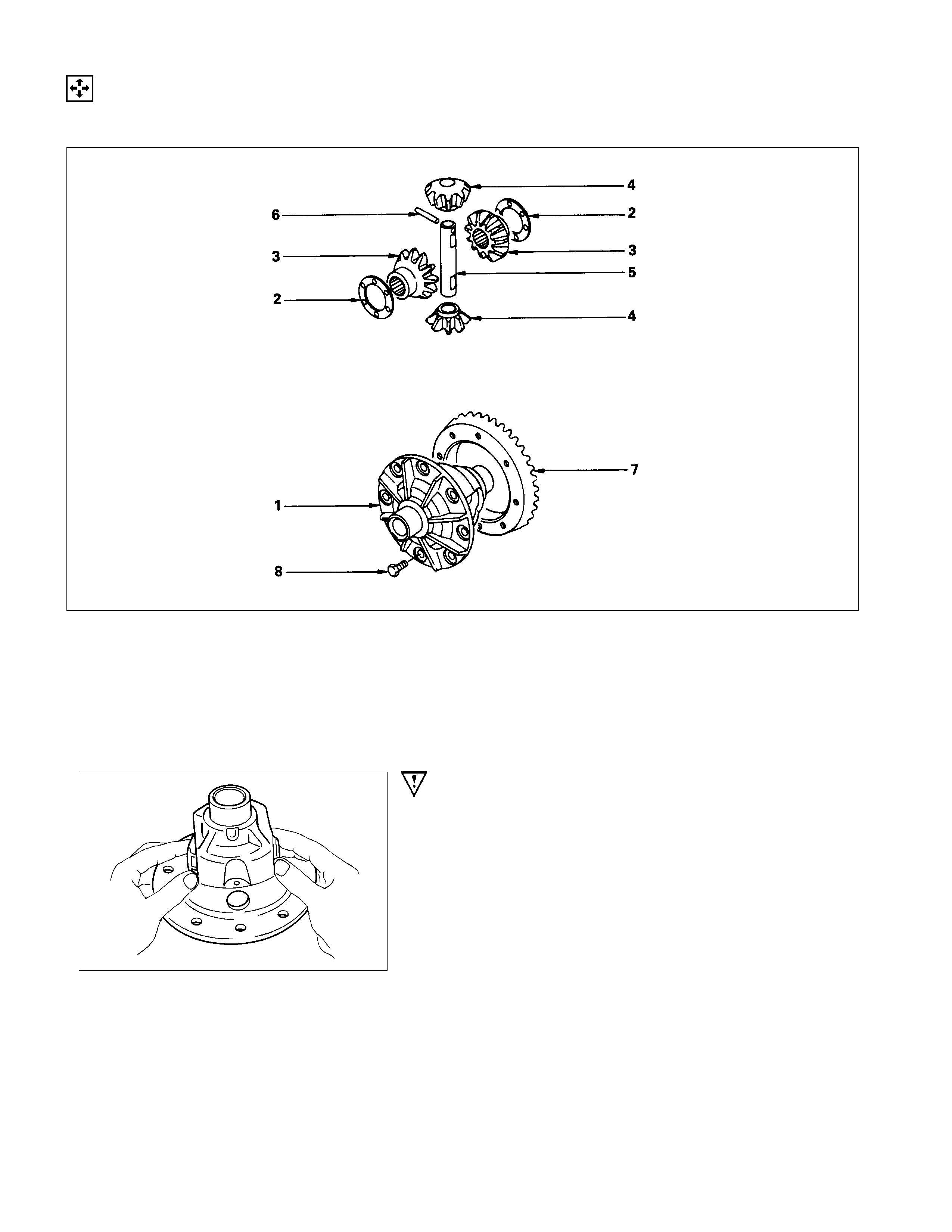
MINOR COMPONENTS
DISASSEM BLY STEPS
1. Bolt
2. Ring gear
▲3. Lock pin
▲4. Cross pin
5. Pinion gear
6. Side gear
7. Thrust washer
8. Differential cage
IMPORTANT OPERATIONS
3. Lock Pin
Break staking on the lock pin using a 5 mm (0.20 in.) diameter
drill.
4. Cross Pin
Remove the cross pin using a soft metal rod and a hammer.
INSPECTION AND REPAIR
Make all necessary adjustments, repairs, and part replacements if wear, damage, or other problems are discovered
during inspection.
• Ring gear, pinion gear
• Bearing
• Side gear, pinion gear, cross pin
• Differential cage, carrier
• Thrust washer
• Oil seal
VISUAL CHECK
Inspect the following parts for wear, damage, or other
abnormal conditions.
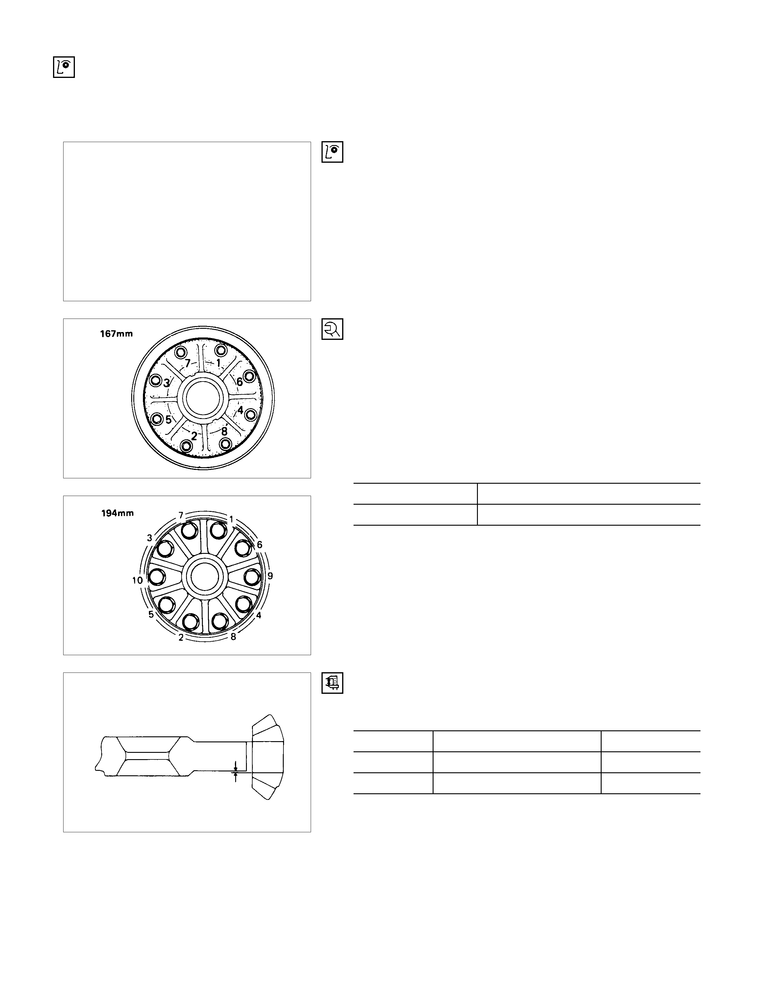
RING G EAR REPLACEMENT
(1)The ring gear should always be replaced with the drive
pinion as a set.
(2)When installing the ring gear, apply LOCTITE 271 o
r
equivalent to the threaded hole and bolt.
(3)Tighten the fixing bolts in a diagonal sequence as
illustrated.
(4)Discard used bolts and install new ones.
Bolt Torque N⋅m (kgf⋅m/lb⋅ft)
167 mm 78.5 ± 9.8 (8 ± 1/57.9 ± 7.2)
194 mm 107.9 ± 9.8 (11 ± 1/79.6 ± 7.2)
FOR 167 mm
Note that all bolts have a left hand thread.
CLEARANCE BETWEEN THE DIFFERENTIAL PINION
AND THE CROSS PIN mm(in)
Standard Limit
167 mm 0.06 - 0.12 (0.002 - 0.005) 0.2 (0.008)
194 mm 0.05 - 0.10 (0.002 - 0.004) 0.2 (0.008)

CLEARANCE BETWEEN THE SIDE G EAR AND THE
DIFFERENTIAL BO X mm(in)
Standard Limit
167 mm 0.03 - 0.11 (0.001 - 0.004) 0.15 (0.006)
194 mm 0.03 - 0.10 (0.001 - 0.004) 0.15 (0.006)
PLAY IN SPLI NES BETWEEN THE SIDE G EAR AND
THE AXLE SHAFT mm(in)
Standard Limit
167 mm 0.11 - 0.38 (0.004 - 0.015) 0.30 (0.012)
194 mm 0.07 - 0.36 (0.003 - 0.014) 0.25 (0.010)
REASSEMBLY
MINOR COMPONENTS
REASSEMBLY STEPS
1. Differential cage
2. Thrust washer
3. Side gear
▲4. Pinion gear
▲5. Cross pin
▲6. Lock pin
▲7. Ring gear
▲8. Bolt
IMPORTANT OPERATIONS
4. Pinion Gear
Install the pinion gear by engaging it with the side gears while
turning both pinion gears simultaneously in the same direction.
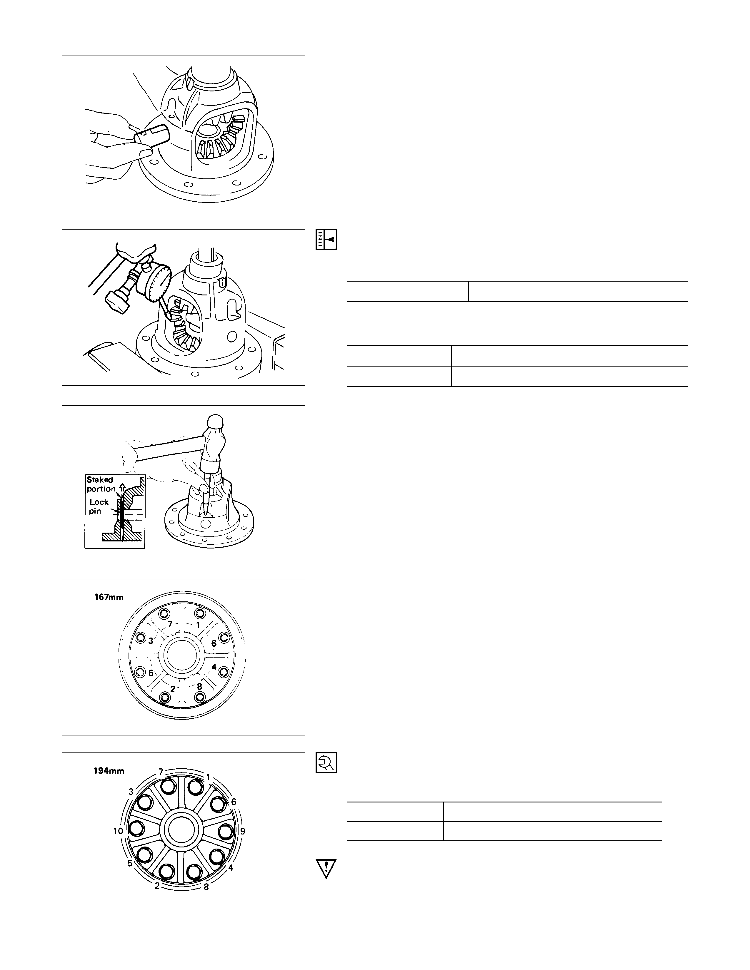
5. Cross Pin
(1)Be sure to ins tall the cross pin so that it is in alignm ent with
the lock pin hole in the differential cage.
(2)Adjust the backlash between the side gear and the pinion
gear. mm(in)
Backlash 0.10 - 0.20 (0.004 - 0.008)
Thickness of thrust washers available mm(in)
167 mm 1.05, 1.15, 1.25 (0.041, 0.043, 0.049)
194 mm 1.00, 1.05, 1.10 (0.039, 0.041, 0.043)
6. Lock Pin
After lock pin installation, stake the cage to prevent discharge
of the lock pin.
7. Ring Gear
When installing the ring gear, apply LOCTITE 271 or
equivalent to the threaded hole and bolt.
8. Bolt
Tighten the bolts in diagonal sequence as illustrated.
Bolt Torque N⋅m (kgf⋅m/lb⋅ft)
167 mm 78.5 ± 9.8 (8 ± 1/57. 9 ± 7.2)
194 mm 107.9 ± 9.8 (11 ± 1/79.6 ± 7.2)
Note :
Discard used bolts and install new ones.
For 167 mm
Note that all bolts have a left hand thread.
MAJO R COMPONENTS
REASSEMBLY STEPS
1. Diff. carrier
▲2. Outer bearing outer race
▲3. Inner bearing outer race
▲4. A djust shim
▲5. Inner bearing
▲6. Collapsible spacer
7. Pinion gear
8. Outer bearing
▲9. Oil seal
10. Dust cover
11. Flange
▲12. Flange nut and washer
▲13. Adjust shim
▲14. Side bearing
15. Bearing outer race
16. Diff. cage assembly
▲17. Bearing cap
▲18. Bolt
19. Axle case
▲20. Differential assembly
21. Bolt
IMPORTANT OPERATIONS
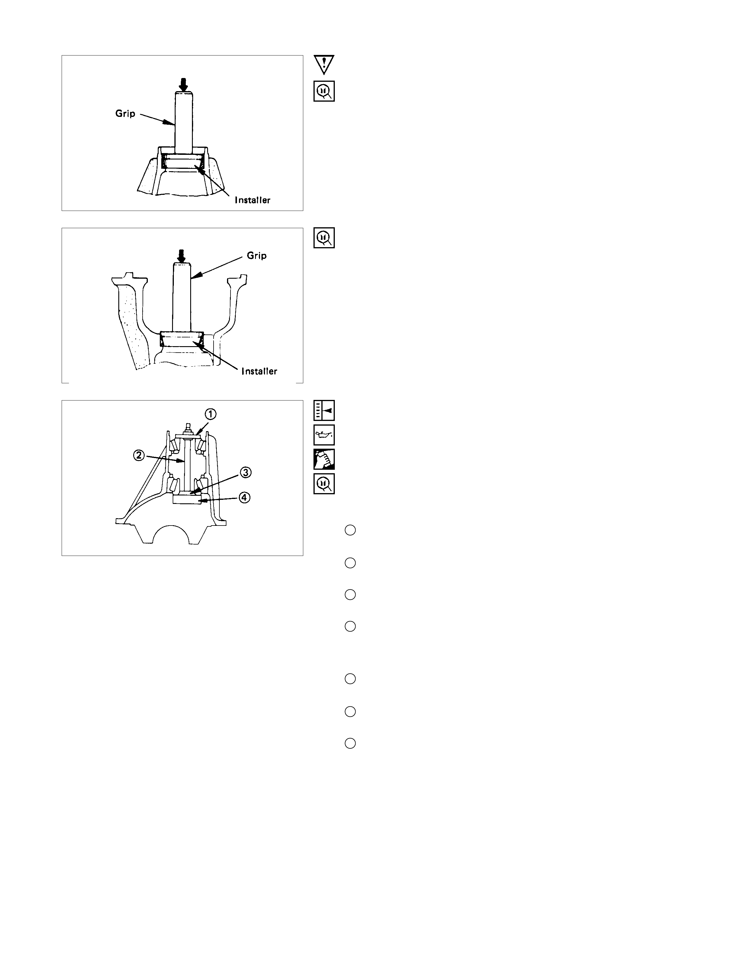
2. Outer Bearing Outer Race
Installer : 5-8522-0048-0 (167 mm)
(J-29038)
9-8522-1141-0 (194 mm)
(J-24256)
Grip : 5-8840-0007-0
(J-8092)
3. Inner Bearing Outer Race
Installer : 5-8522-0049-0 (167 mm)
(J-29039)
9-8522-1274-0 (194 mm)
Grip : 5-8840-0007-0
(J-8092)
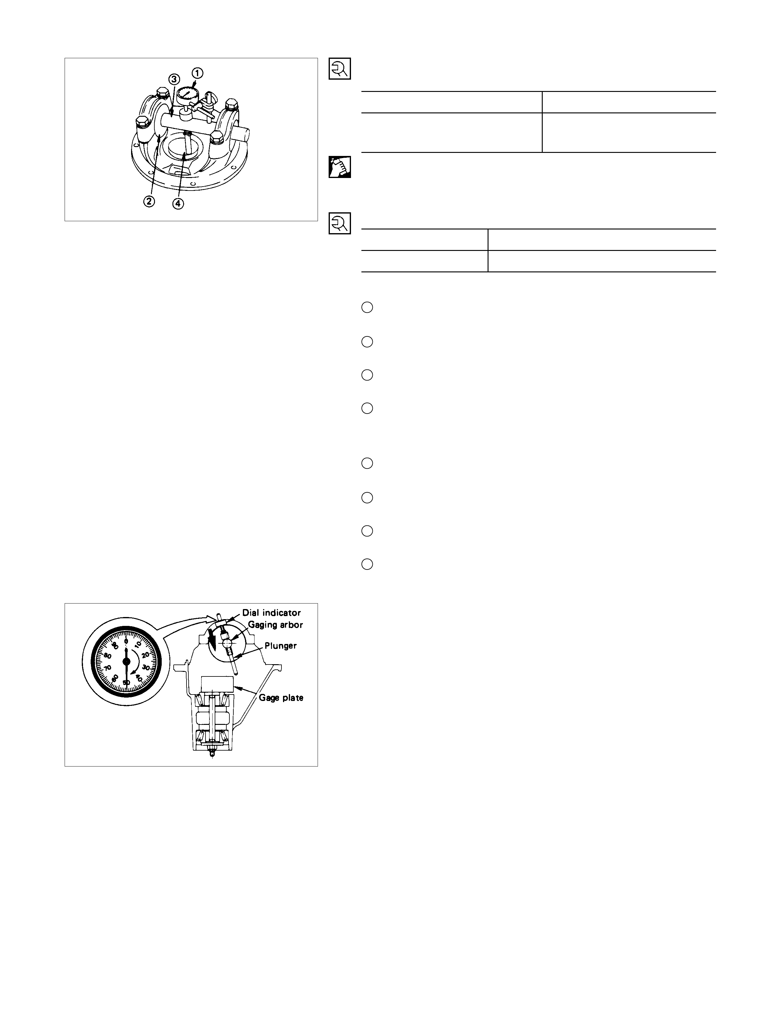
4. Adjust Shim
Adjustment of drive pinion mounting distance
(1)Apply gear oil to the inner and outer drive pinion bearing.
Clean the pinion setting gage set.
Then install the gage set together with the inner and oute
r
bearings.
For 167 mm
1Pilot : 5-8840-2092-0
(J-23597-28)
2Nut and bolt : 5-8840-0127-0
(J-21777-43)
3Rear pilot : 5-8840-02091-0
(J-23597-27)
4Gage plate : 5-8840-2090-0
(J-23597-26)
For 194 mm
1Pilot : 5-8840-2085-0
(J-21777-42)
2Nut and bolt : 5-8840-2089-0
(J-23597-9)
4Gage plate : 5-8840-2087-0
(J-23597-7)
Tighten the nut to the specified torque. N⋅m (kgf⋅m/lb⋅ft)
New bearing 2.26 (23/20)
Used bearing 0.98 - 1.18
(10 - 12/8.7 - 10.4)
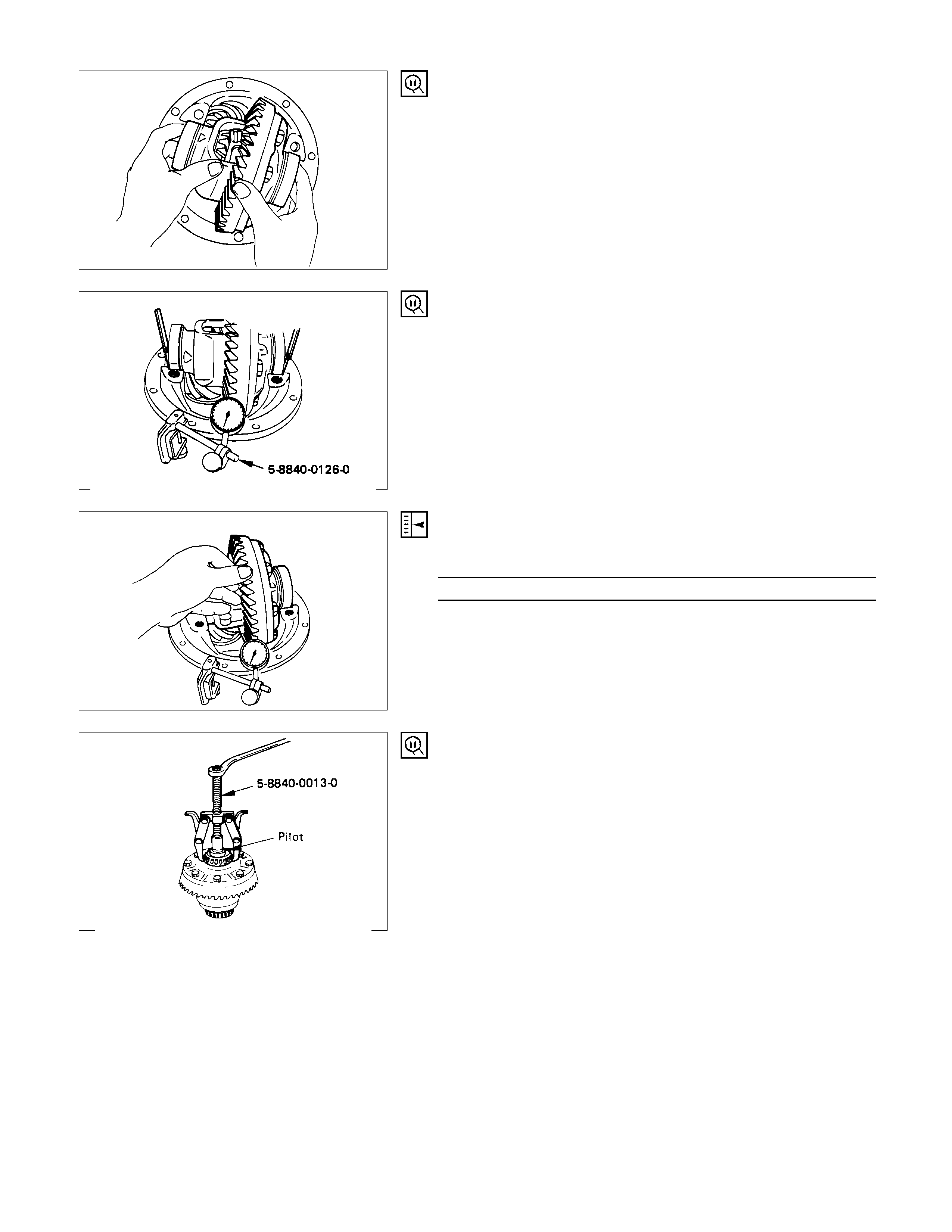
(2)Clean the side bearing bores. Install the dial indicator with
the discs and Arbor. Install and tighten the bearing caps to
the specified torque.
Torque N⋅m (kgf⋅m/lb⋅ft)
167 mm 68.7 ± 9.8 (7.0 ± 1.0/50.6 ± 7.2)
194 mm 98.1 ± 9.8 (10.0 ± 1.0/72.3 ± 7.2)
For 167 mm
1Dial indicator: 5-8840-0126-0
(J-8001)
2Disc (2 pcs.) : 5-8840-2086-0
(J-23597-4)
3Arbor : 5-8840-0128-0
(J-23597-1)
4Gage plate : 5-8840-2090-0
(J-23597-26)
For 194 mm
1Dial indicator: 5-8840-0126-0
(J-8001)
2Disc (2 pcs.) : 5-8840-2088-0
(J-23597-8)
3Arbor : 5-8840-0128-0
(J-23597-1)
4Gage plate : 5-8840-2087-0
(J-23597-7)
(3)Set the dial indicator to “0”. Place it on the mounting post o
f
the gauging arbor with the contact button touching the
indicator pad. Force the dial indicator downward until the
needle has made a half turn clockwise. Tighten down the
dial indicator in this position.
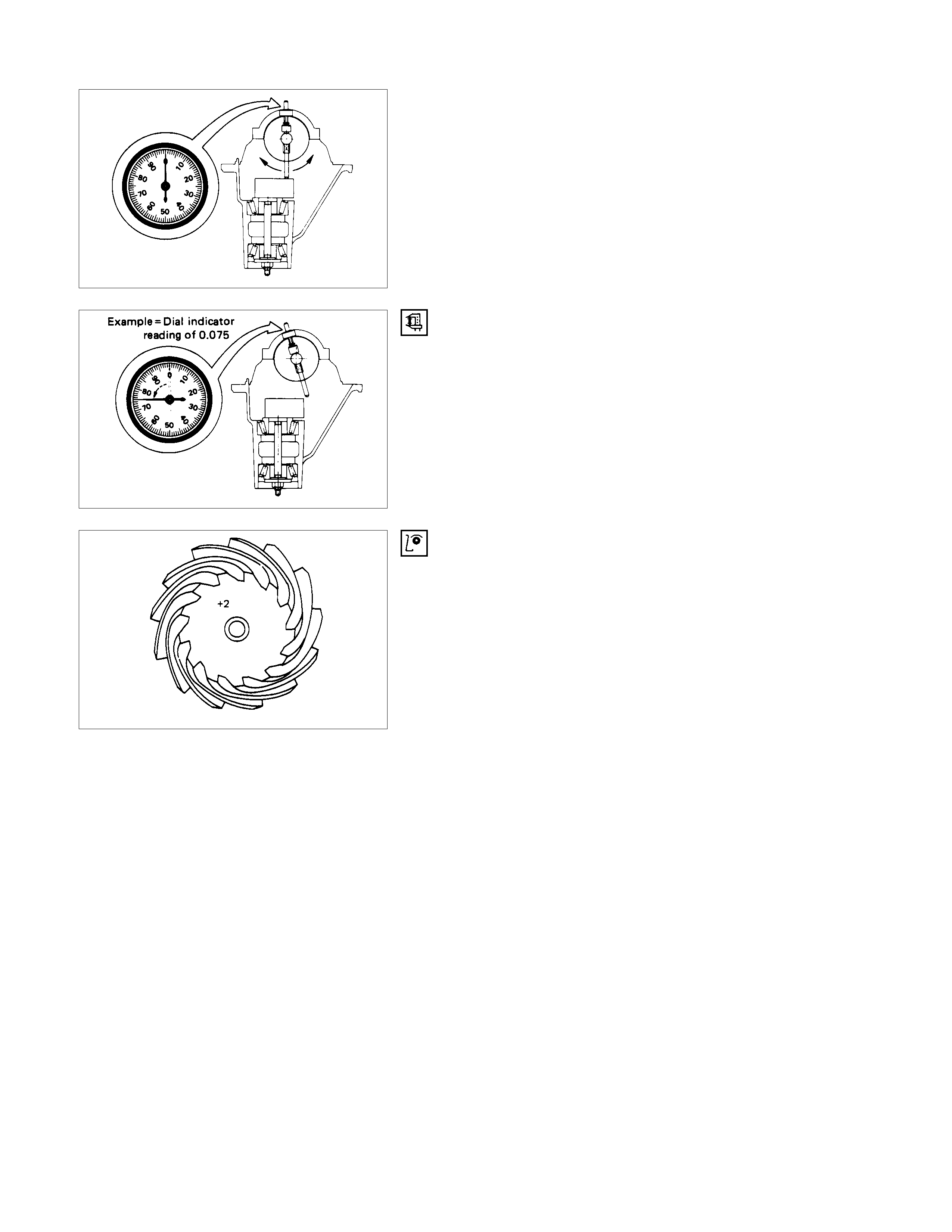
(4)Position the plunger on the gage plate. Move the gauging
arbor slowly back and for th and locate the position at which
the dial indicator shows the greatest deflection. At this
point, once again set the dial indicator to “0”.
Repeat the procedure to verify the “0” setting.
(5)
A
fter the ZERO setting is obtained, rotate the gauging arbo
r
until the dial indicator rod does not touch the gauging plate.
Record the number the dial indicator needle points to.
(6) Record the pinion depth code on the head of the drive
pinion.
The number indicates a necessary change in the pinion
mounting distanc e. A plus number indic ates the need for a
greater mounting distance (which can be achieved by
decreasing the s him thick ness). A m inus num ber indicates
the need for a smaller mounting distance (which can be
achieved by increasing the shim thickness). If examination
reveals pinion depth code “0”, the pinion is “nominal”.

(7)Select the shim using the chart:
For 167 mm mm(in)
Pinion
marking +6 +4 +2 +0 -2 -4 -6
Dial indicator
reading (inches)
0.052 1.39 (0.0547)
0.053 1.39 (0.0547) 1.41 (0.0555)
0.054 1.39 (0.0547) 1.41 (0.0555) 1.43 (0.0563)
0.055 1.39 (0.0547) 1.41 (0.0555) 1.43 (0.0563) 1.45 (0.0571)
0.056 1.39 (0.0547) 1.41 (0.0555) 1.43 (0.0563) 1.45 (0.0571) 1.47 (0.0579) 1.49 (0.0587)
0.057 1.39 (0.0547) 1.41 (0.0555) 1.43 (0.0563) 1.45 (0.0571) 1.47 (0.0579) 1.49 (0.0587) 1.51 (0.0594)
0.058 1.41 (0.0555) 1.43 (0.0563) 1.45 (0.0571) 1.47 (0.0579) 1.49 (0.0587) 1.51 (0.0594) 1.53 (0.0602)
0.059 1.43 (0.0563) 1.45 (0.0571) 1.47 (0.0579) 1.49 (0.0587) 1.51 (0.0594) 1.53 (0.0602) 1.55 (0.0610)
0.060 1.47 (0.0579) 1.49 (0.0587) 1.51 (0.0594) 1.53 (0.0602) 1.55 (0.0610) 1.57 (0.0618) 1.59 (0.0626)
0.061 1.49 (0.0587) 1.51 (0.0594) 1.53 (0.0602) 1.55 (0.0610) 1.57 (0.0618) 1.59 (0.0626) 1.61 (0.0634)
0.062 1.51 (0.0594) 1.53 (0.0602) 1.55 (0.0610) 1.57 (0.0618) 1.59 (0.0626) 1.61 (0.0634) 1.63 (0.0642)
0.063 1.55 (0.0610) 1.57 (0.0618) 1.59 (0.0626) 1.61 (0.0634) 1.63 (0.0642) 1.65 (0.0650) 1.67 (0.0657)
0.064 1.57 (0.0618) 1.59 (0.0626) 1.61 (0.0634) 1.63 (0.0642) 1.65 (0.0650) 1.67 (0.0657) 1.69 (0.0665)
0.065 1.59 (0.0626) 1.61 (0.0634) 1.63 (0.0642) 1.65 (0.0650) 1.67 (0.0657) 1.69 (0.0665) 1.71 (0.0673)
0.066 1.61 (0.0634) 1.63 (0.0642) 1.65 (0.0650) 1.67 (0.0657) 1.69 (0.0665) 1.71 (0.0673) 1.73 (0.0681)
0.067 1.65 (0.0650) 1.67 (0.0657) 1.69 (0.0665) 1.71 (0.0673) 1.73 (0.0681) 1.75 (0.0689) 1.77 (0.0697)
0.068 1.67 (0.0657) 1.69 (0.0665) 1.71 (0.0673) 1.73 (0.0681) 1.75 (0.0689) 1.77 (0.0697)
0.069 1.69 (0.0665) 1.71 (0.0673) 1.73 (0.0681) 1.75 (0.0689) 1.77 (0.0697)
0.070 1.71 (0.0673) 1.73 (0.0681) 1.75 (0.0689) 1.77 (0.0697)
0.071 1.75 (0.0689) 1.77 (0.0697)
0.072 1.77 (0.0697)
For 194 mm mm (in)
Pinion
marking +10 +8 +6 +4 +2 0 -2 -4 -6 -8 -10
Dial indicator
reading (inches)
0.081 2.18 (0.0858)
0.082 2.18 (0.0858) 2.20 (0.0866)
0.083 2.18 (0.0858) 2.20 (0.0866) 2.24 (0.0882)
0.084 2.18 (0.0858) 2.20 (0.0866) 2.24 (0.0882) 2.26 (0.0890)
0.085 2.18 (0.0858) 2.20 (0.0866) 2.24 (0.0882) 2.26 (0.0890) 2.28 (0.0898)
0.086 2.18 (0.0858) 2.20 (0.0866) 2.24 (0.0882) 2.26 (0.0890) 2.28 (0.0898) 2.32 (0.0914)
0.087 2.18 (0.0858) 2.20 (0.0866) 2.24 (0.0882) 2.26 (0.0890) 2.28 (0.0898) 2.32 (0.0914) 2.34 (0.0921)
0.088 2.18 (0.0858) 2.20 (0.0866) 2.24 (0.0882) 2.26 (0.0890) 2.28 (0.0898) 2.32 (0.0914) 2.34 (0.0921) 2.36 (0.0929)
0.089 2.18 (0.0858) 2.20 (0.0866) 2.24 (0.0882) 2.26 (0.0890) 2.28 (0.0898) 2.32 (0.0914) 2.34 (0.0921) 2.36 (0.0929) 2.38 (0.0937)
0.090 2.18 (0.0858) 2.20 (0.0866) 2.24 (0.0882) 2.26 (0.0890) 2.28 (0.0898) 2.32 (0.0914) 2.34 (0.0921) 2.36 (0.0929) 2.38 (0.0937) 2.42 (0.0953)
0.091 2.18 (0.0858) 2.20 (0.0866) 2.24 (0.0882) 2.26 (0.0890) 2.28 (0.0898) 2.32 (0.0914) 2.34 (0.0921) 2.36 (0.0929) 2.38 (0.0937) 2.42 (0.0953) 2.44 (0.0961)
0.092 2.20 (0.0866) 2.24 (0.0882) 2.26 (0.0890) 2.28 (0.0898) 2.32 (0.0914) 2.34 (0.0921) 2.36 (0.0929) 2.38 (0.0937) 2.42 (0.0953) 2.44 (0.0961) 2.46 (0.0969)
0.093 2.24 (0.0882) 2.26 (0.0890) 2.28 (0.0898) 2.32 (0.0914) 2.34 (0.0921) 2.36 (0.0929) 2.38 (0.0937) 2.42 (0.0953) 2.44 (0.0961) 2.46 (0.0969) 2.48 (0.0977)
0.094 2.26 (0.0890) 2.28 (0.0898) 2.32 (0.0914) 2.34 (0.0921) 2.36 (0.0929) 2.38 (0.0937) 2.42 (0.0953) 2.44 (0.0961) 2.46 (0.0969) 2.48 (0.0977) 2.52 (0.0992)
0.095 2.28 (0.0898) 2.32 (0.0914) 2.34 (0.0921) 2.36 (0.0929) 2.38 (0.0937) 2.42 (0.0953) 2.44 (0.0961) 2.46 (0.0969) 2.48 (0.0977) 2.52 (0.0992) 2.54 (0.1000)
0.096 2.32 (0.0914) 2.34 (0.0921) 2.36 (0.0929) 2.38 (0.0937) 2.42 (0.0953) 2.44 (0.0961) 2.46 (0.0969) 2.48 (0.0977) 2.52 (0.0992) 2.54 (0.1000) 2.56 (0.1008)
0.097 2.34 (0.0921) 2.36 (0.0929) 2.38 (0.0937) 2.42 (0.0953) 2.44 (0.0961) 2.46 (0.0969) 2.48 (0.0977) 2.52 (0.0992) 2.54 (0.1000) 2.56 (0.1008)
0.098 2.36 (0.0929) 2.38 (0.0937) 2.42 (0.0953) 2.44 (0.0961) 2.46 (0.0969) 2.48 (0.0977) 2.52 (0.0992) 2.54 (0.1000) 2.56 (0.1008)
0.099 2.38 (0.0937) 2.42 (0.0953) 2.44 (0.0961) 2.46 (0.0969) 2.48 (0.0977) 2.52 (0.0992) 2.54 (0.1000) 2.56 (0.1008)
0 2.42 (0.0953) 2.44 (0.0961) 2.46 (0.0969) 2.48 (0.0977) 2.52 (0.0992) 2.54 (0.1000) 2.56 (0.1008)
0.001 2.44 (0.0961) 2.46 (0.0969) 2.48 (0.0977) 2.52 (0.0992) 2.54 (0.1000) 2.56 (0.1008)
0.002 2.46 (0.0969) 2.48 (0.0977) 2.52 (0.0992) 2.54 (0.1000) 2.56 (0.1008)
0.003 2.48 (0.0977) 2.52 (0.0992) 2.54 (0.1000) 2.56 (0.1008)
0.004 2.52 (0.0992) 2.54 (0.1000) 2.56 (0.1008)
0.005 2.54 (0.1000) 2.56 (0.1008)
0.006 2.56 (0.1008)
Note:
When ordering shims, find the part number in the Parts Catalog by using the thickness of the shims listed in
the above table.

5. Inner Bearing
Place the shim on the drive pinion, with the chamfered side
turned towards the pinion head then install the inner bearing on
to the pinion using an installer and a press.
Installer : 9-8522-1165-0 (J-6133-01)
Note:
Do not apply pressure to the roller cage.
Apply pressure only to the inner race.
6. Collapsible Spacer
Discard the used collapsible spacer and install a new one.
9. Oil Seal
Use oil seal installer to install a new oil seal that has been
soaked in rear axle lubricant.
Installer : 5-8522-0046-0 (J-26234) (For 167 mm)
9-8522-1275-0 (J-24250) (For 194 mm)
Note :
Take care not to use a rear differential oil seal instead of
the front differential oil seal.
12.Flange Nut and Washer
For 194 mm
(1)Apply lubricant to the pinion threads.
(2)Tighten the nut to the specified torque using the pinion
flange holder.
Pinion flange holder : 5-8840-0133-0
(J-8614-01)
Torque N⋅m (kgf⋅m/lb⋅ft
)
176.6 - 274.7 (18 - 28/130 - 202)
Discard used flange nut and install new one.
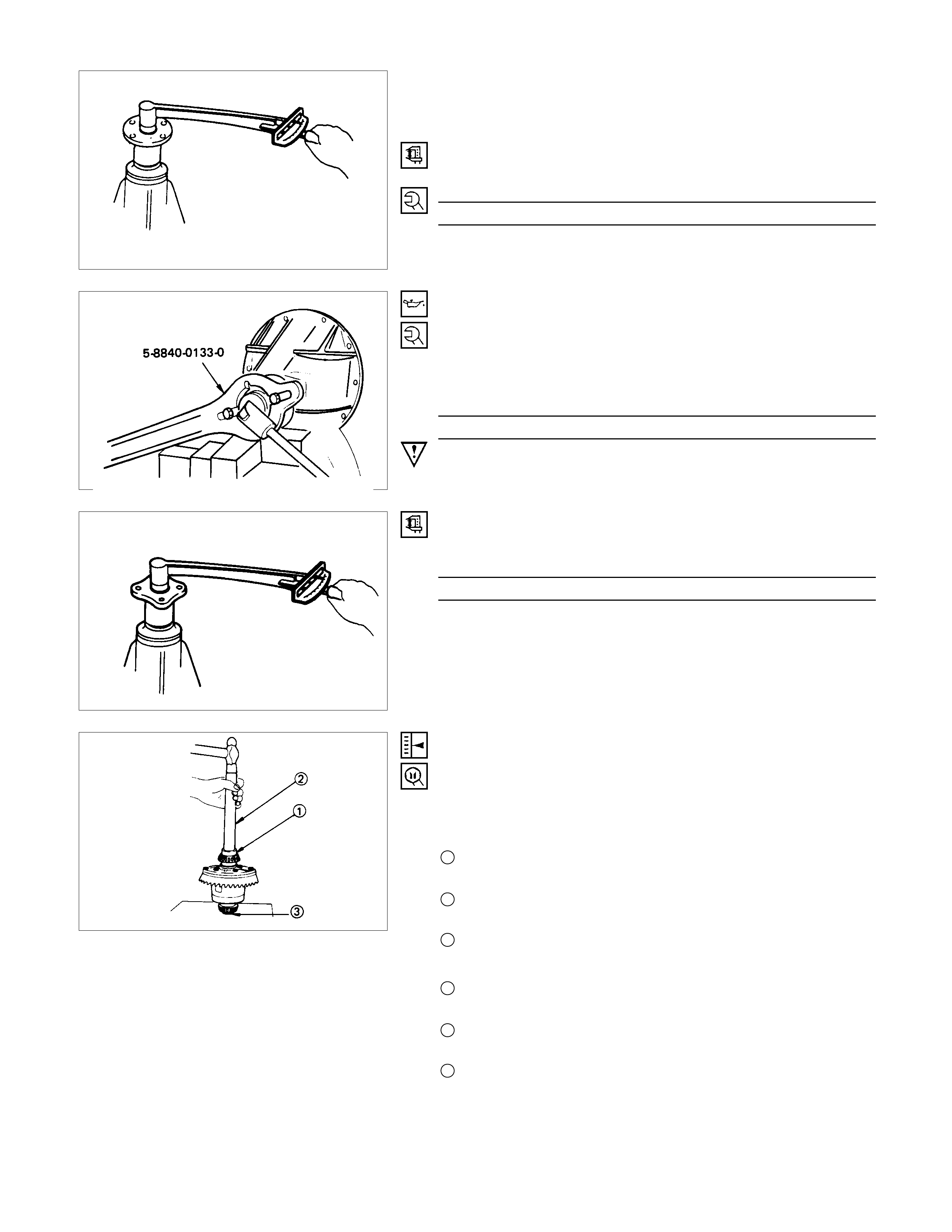
(3)Pinion bearing preload
(a)Measure the bearing preload by using a torque meter . Note
the scale reading required to rotate the flange.
(b)Continue tightening until the specified starting torque is
obtained.
Starting Torque N⋅m (kgf⋅cm/lb⋅in
)
0.63 - 1.13 (6.5 - 11.5/5.7 - 9.9)
For 167 mm
(1)Apply lubricant to the pinion threads.
(2)Tighten the nut to the specified torque using the pinion
flange holder.
Pinion flange holder : 5-8840-0133-0 (J-8614-01)
Torque N⋅m (kgf⋅m/lb⋅ft)
117 - 127 (12 - 13/87 - 94)
Discard used flange nut and install new one.
(3)Continue tightening until the specified starting torque is
obtained.
Starting Torque N⋅m (kgf⋅cm/lb⋅in)
0.59 - 1.0 (6 - 11/5.2 - 9.5)
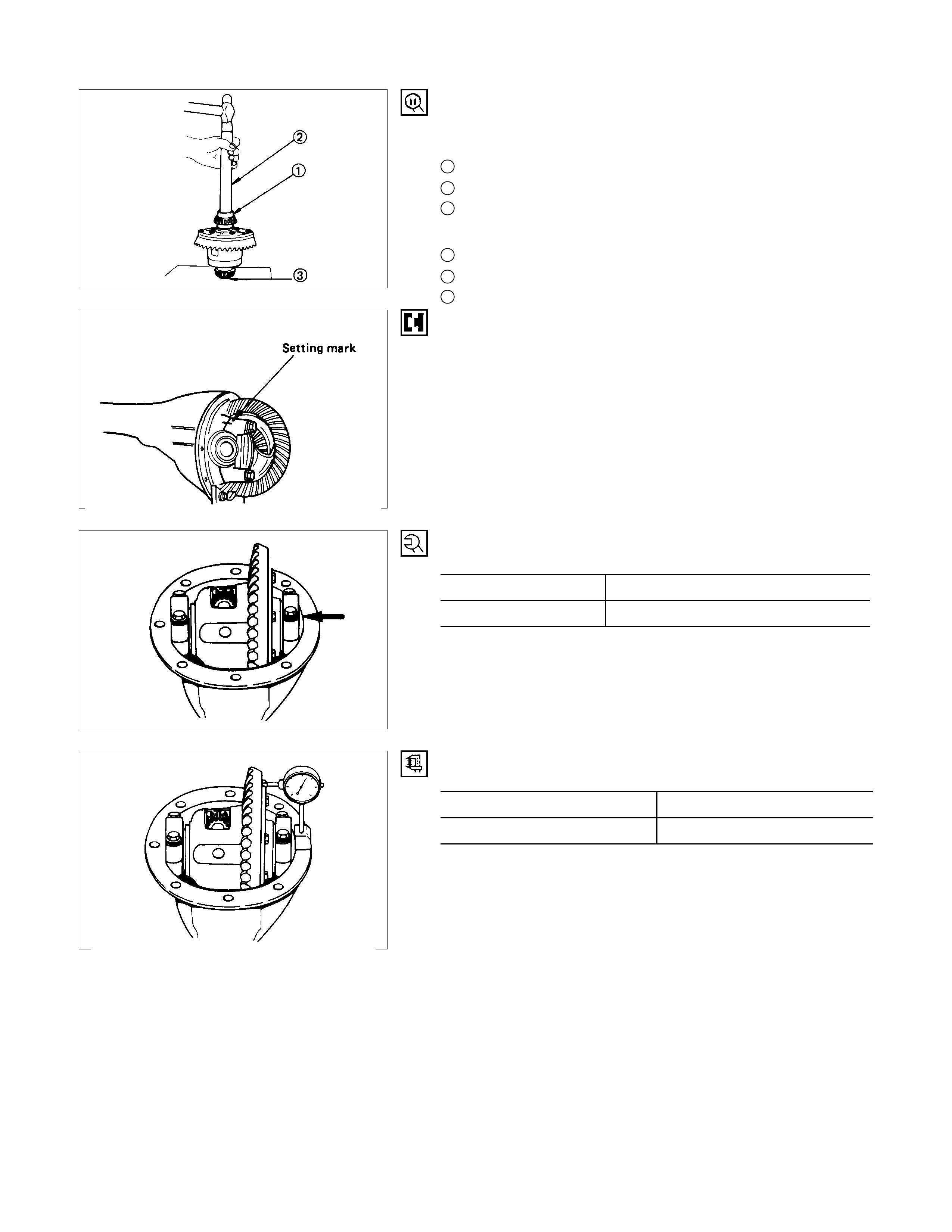
13.Adjust Shim
(1)Attach the side bearing to the differential assembly without
shims. Support the opposite side using a pilot to prevent
bearing damage.
For 167 mm
1Installer : 5-8840-0138-0
(J-29036)
2Drive handle : 5-8840-0007-0
(J-8092)
3Pilot : 5-8521-0019-0
For 194 mm
1Installer : 9-8521-1164-0
(J-24244)
2Drive handle : 5-8840-0007-0
(J-8092)
3Pilot : 9-8521-1743-0
(J-8107-2)
(2)Insert the differential cage assembly with bearing oute
r
races into the side bearing bores of the carrier.
(3) Using two sets of feeler gauges, insert a feeler stock o
f
sufficient thickness between each bearing outer race and
the carrier to remove all end plat. Make certain the feele
r
stock is pushed to the bottom of the bearing bores.
Mount the dial indicator on the carrier so that the indicato
r
stem is at right angles to a tooth on the ring gear.
Dial indicator : 5884-0126-0
(J-8001)
(4) Adjust feeler gauge thickness from side to side until ring
gear backlash is in the specified range.
Backlash mm(in)
0.13 - 0.18 (0.005 - 0.007)
With zero end play and correct backlash established,
remove the feeler gauge packs, determine the thickness o
f
the shims required and add 0.05 mm (0.002 in) to each
shim pack to provide side bearing preload. Always use ne
w
shims.
(5)Remove side bearing
Remover : 5-8840-0013-0
(J-22888)
Pilot : 5-8521-0019-0 (167 mm)
9-8521-1743-0 (194 mm)
(J-8107-2)
14.Side Bearing
Install the side bearings together with the selected shims.
For 167 mm
1Installer : 5-8840-0138-0 (J-29036)
2Drive handle : 5-8840-0007-0 (J-8092)
3Pilot : 5-8521-0019-0
For 194 mm
1Installer : 9-8521-1164-0 (J-24244)
2Drive handle : 5-8840-0007-0 (J-8092)
3Pilot : 9-8521-1743-0 (J-8107-2)
17.Bearing Cap
Align the setting marks applied at disassembly.
18.Bolt
Bolt Torque N⋅m (kgf⋅m/lb⋅ft
)
167 mm 68.7 ± 9.8 (7.0 ± 1.0/50.6 ± 7.2)
194 mm 98.1 ± 9.8 (10.0 ± 1.0/72.3 ± 7.2)
Measure the amount of run-out of the ring gear at its rear face.
mm(in)
Standard Limit
0.02 (0.001) 0.05 (0.002)
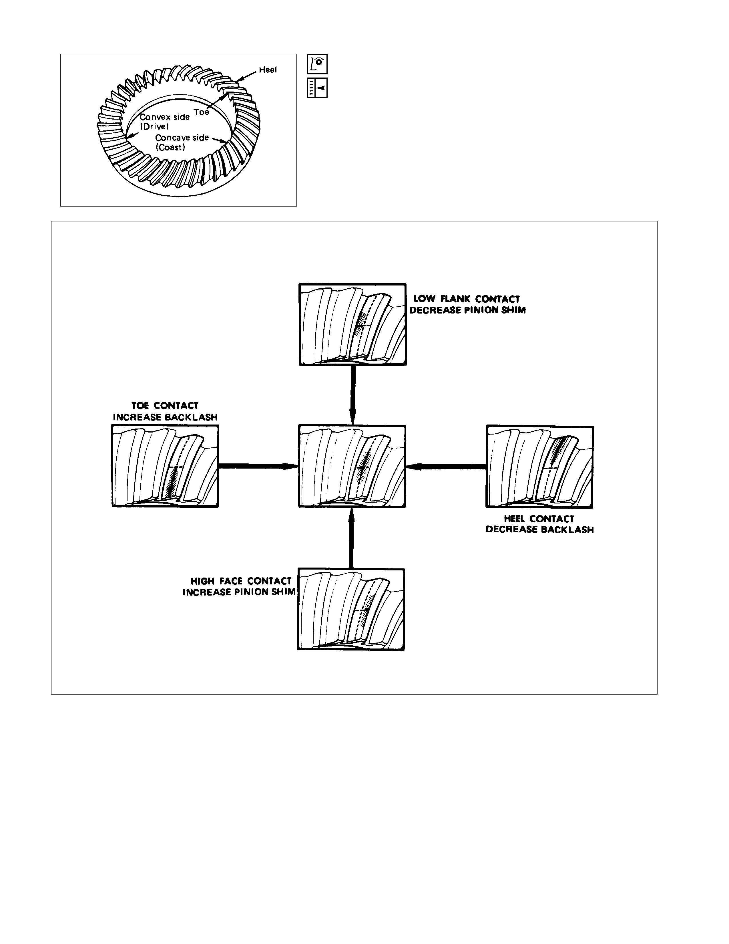
Gear Tooth Contact Pattern Check and Adjustment
Apply a thin coat of Prussian blue or equivalent to the faces of
the 7 - 8 teeth of the ring gear. Check the impression of
contact on the ring gear teeth and make necessary adjustment
as described below if the contact is abnormal.
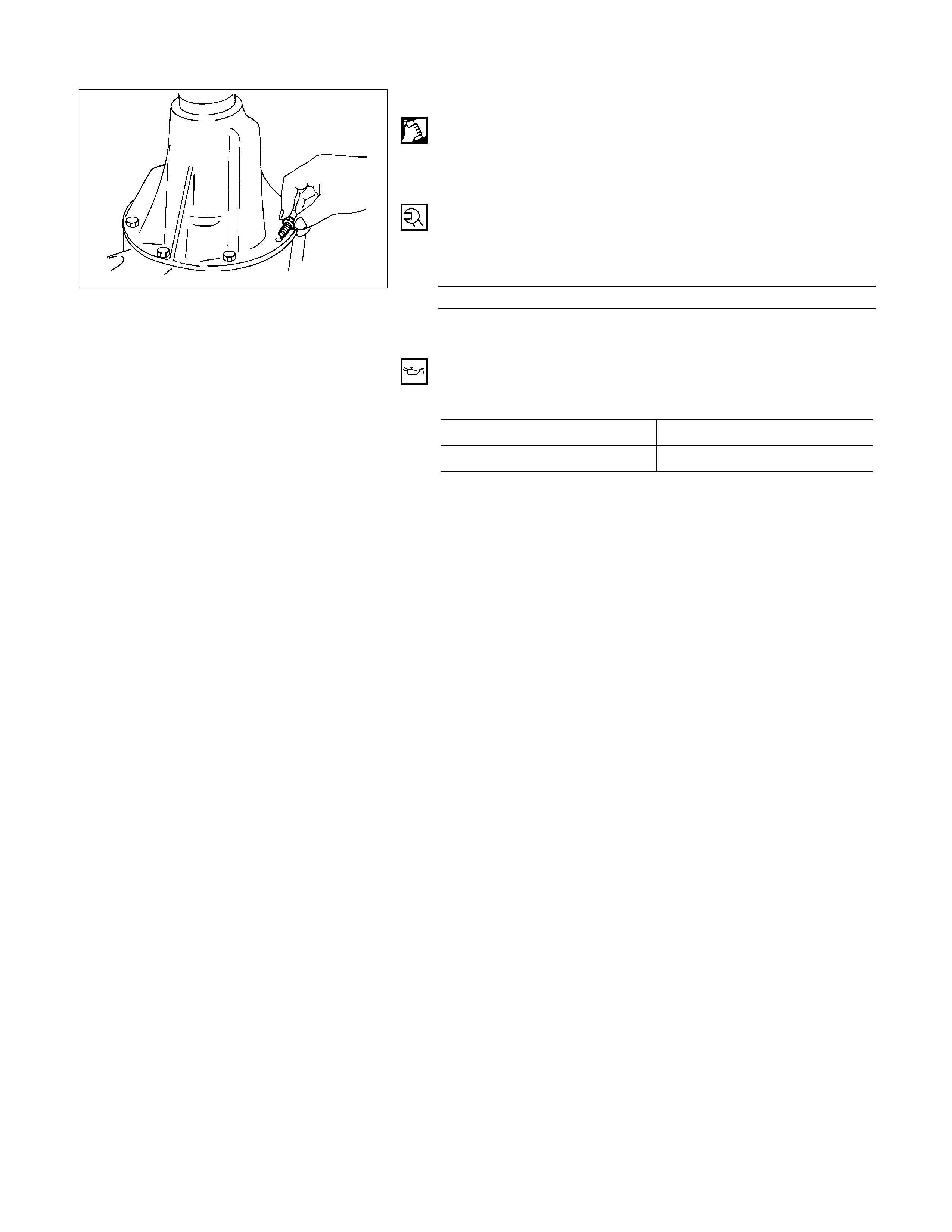
20.Differential Assembly
(1)Clean the faces of the front axle case and differential
carrier.
Apply the recommended liquid gasket or its equivalent to
the sealing side of the axle case and the carrier.
(2)Attach the differential case and the carrier assembly to the
front axle case and tighten the nuts and bolts. The axle
case bolt is used for drainage.
Torque N⋅m (kgf⋅m/lb⋅ft)
25.5 ± 5 (2.6 ± 0.5/18.8 ± 3.6)
(3)Install the axle shaft assem blies as instructed earlier in this
section under “Axle Shaft Replacement”.
(4)Fill the axle case with hypoid gear lubricant, to just belo
w
the filler hole.
Lubricant capacity liter (US/UK gal)
167 mm 1.0 (0.26/0.22)
194 mm 1.4 (0.37/0.31)
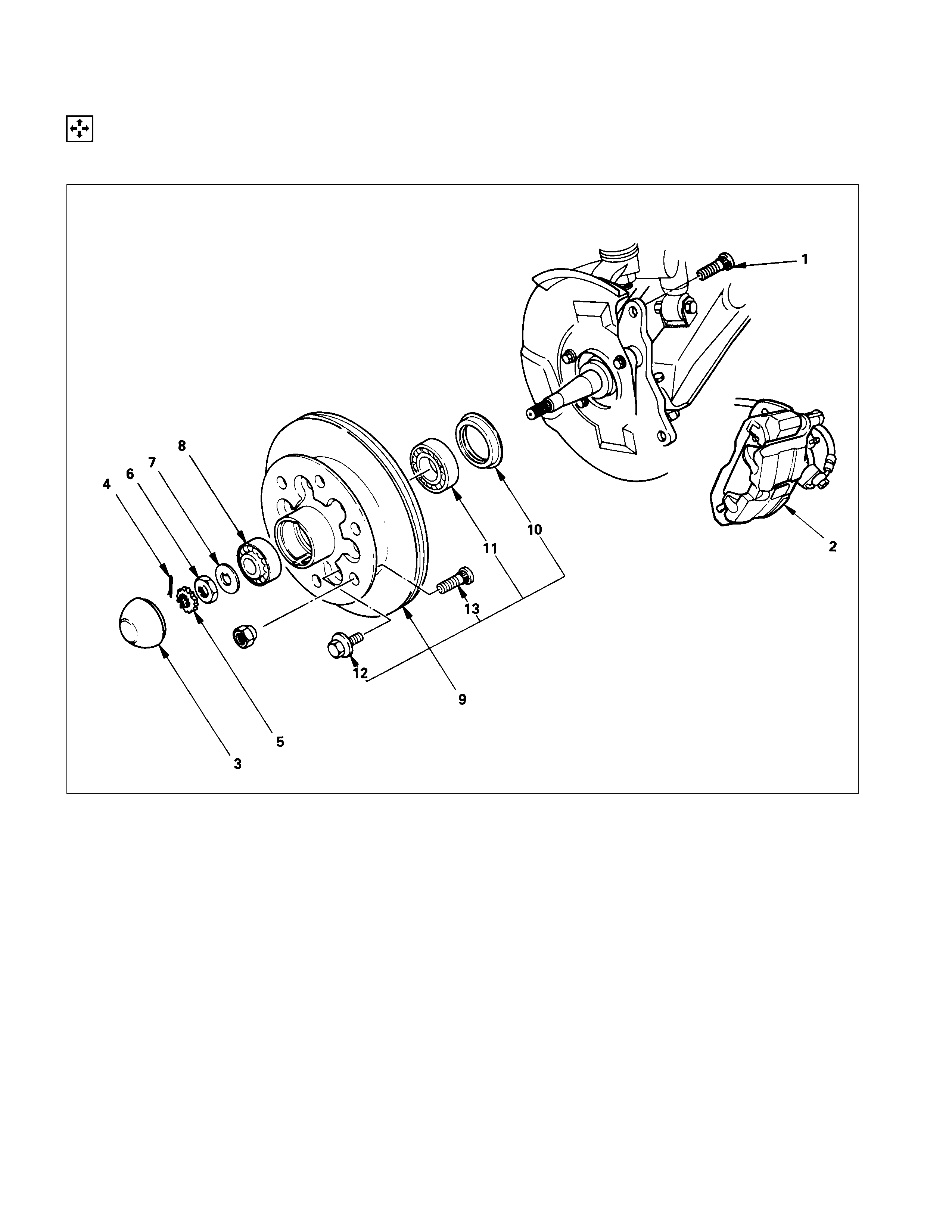
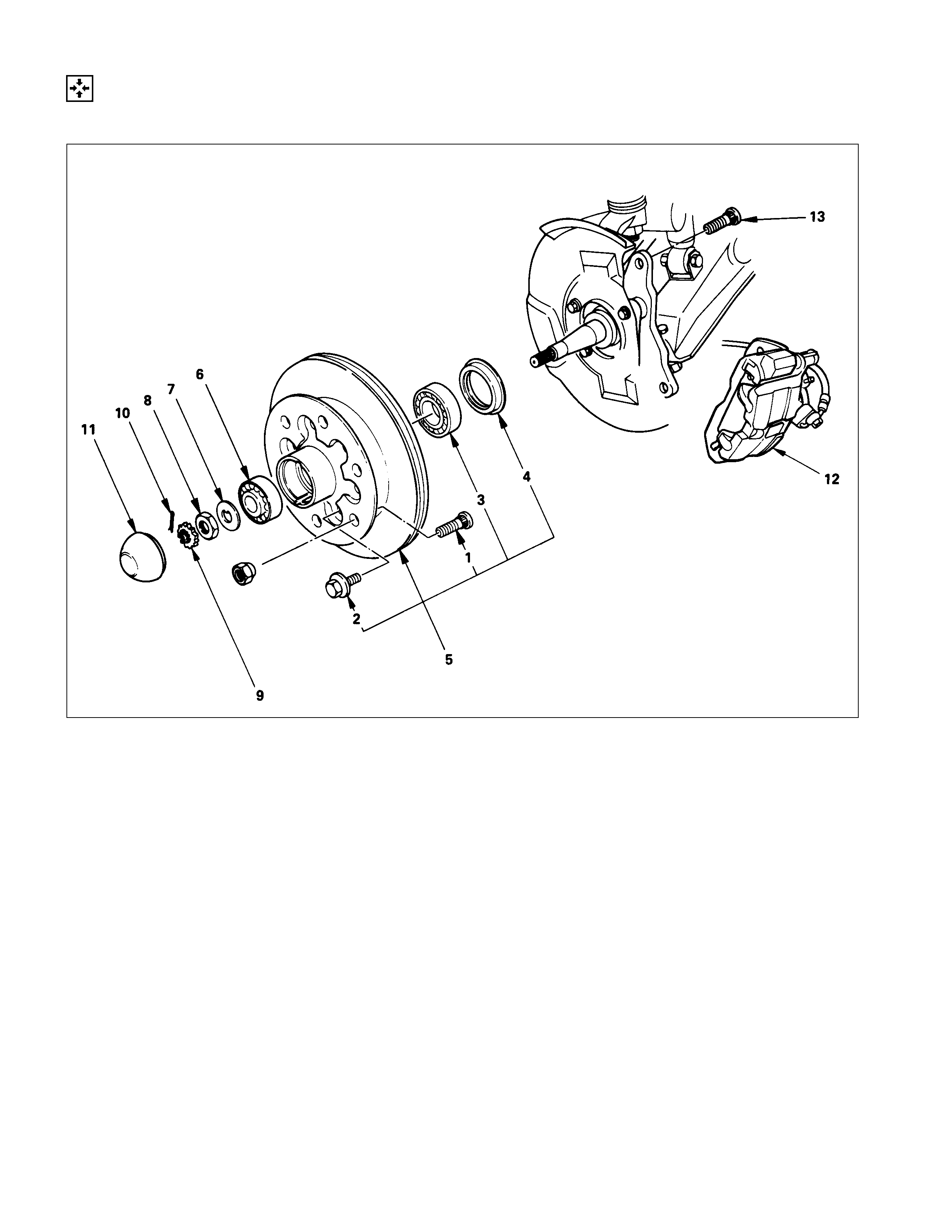
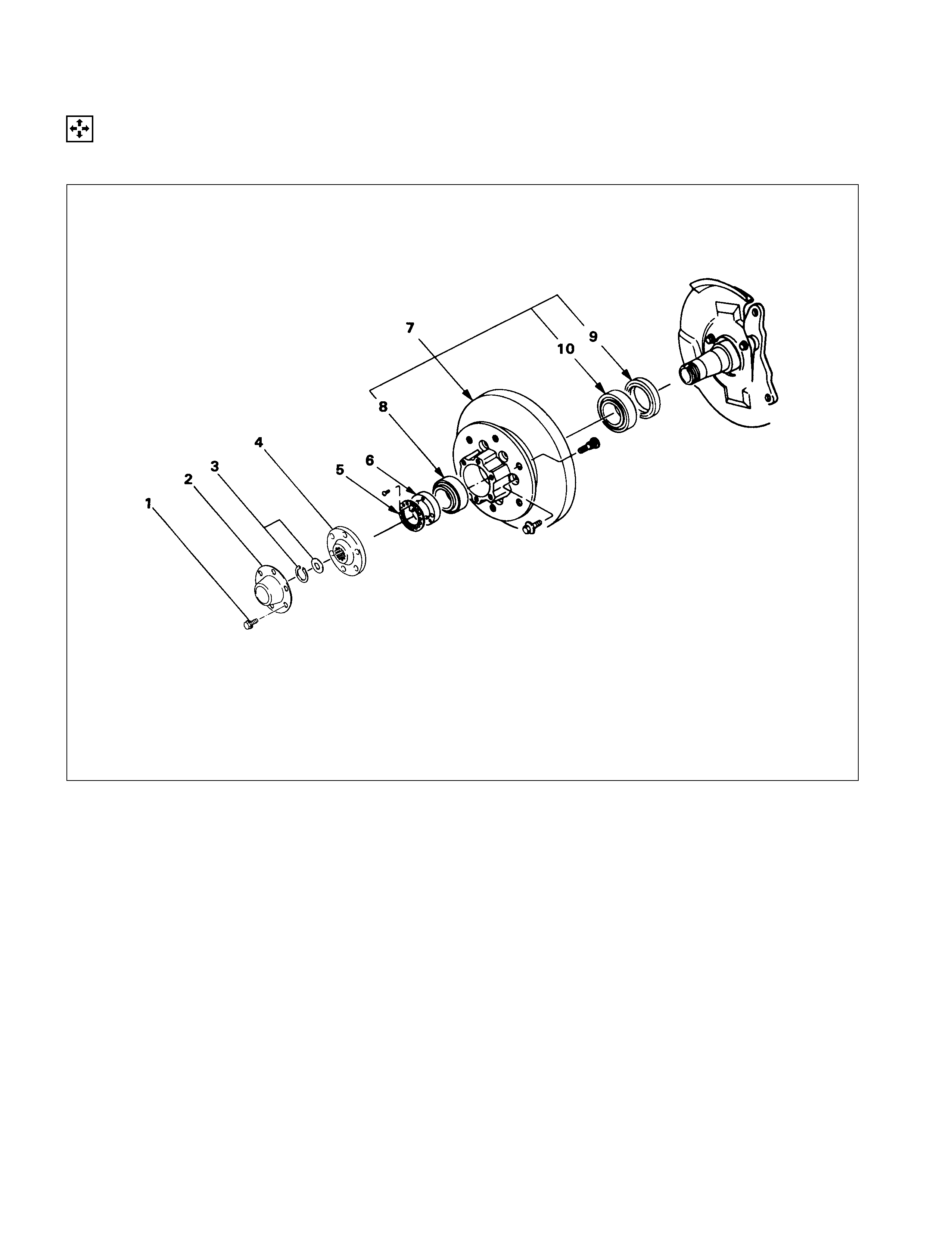
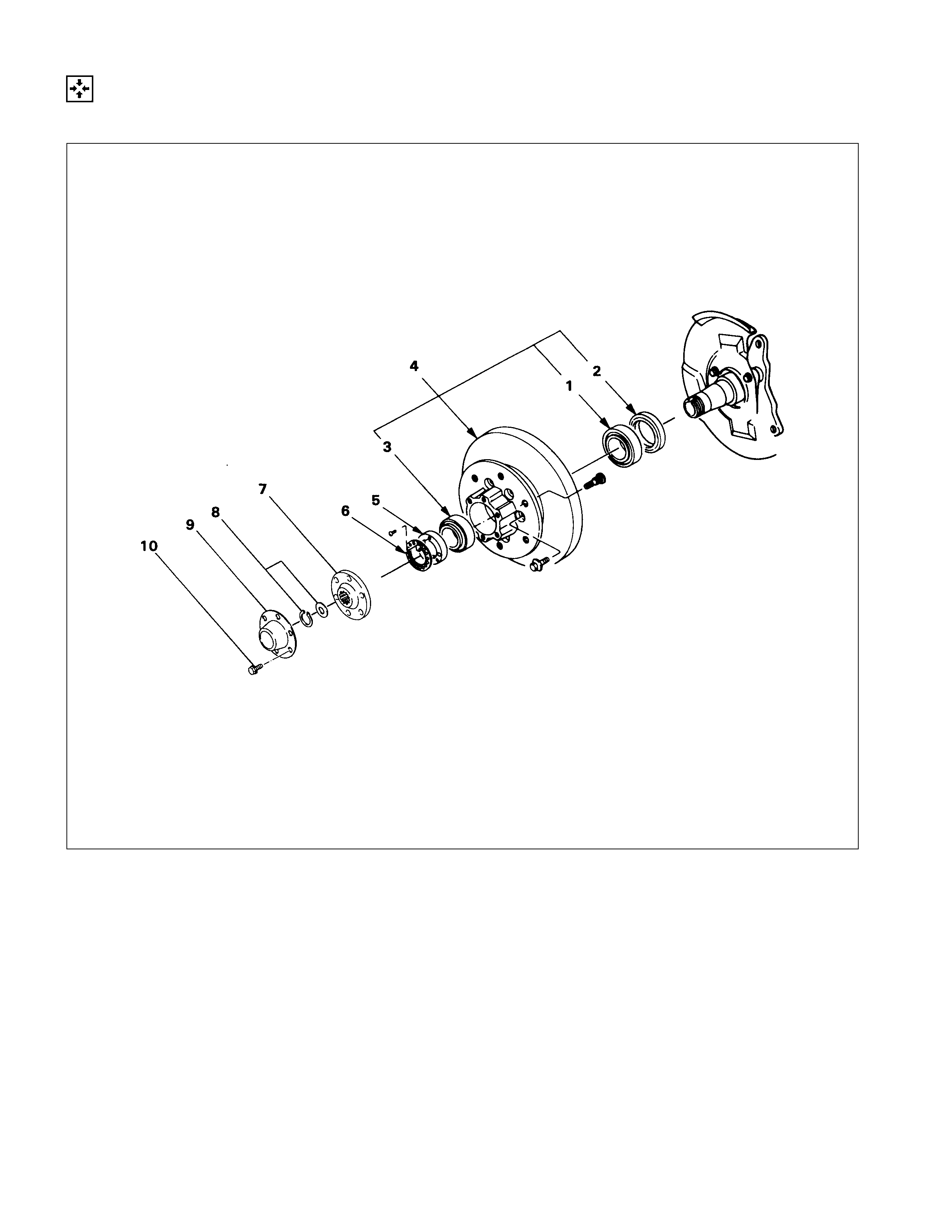
FRONT HUB AND DISC (4×
××
×2 MODEL)
DISASSEM BLY
Refer to SECTION 10 “WHEEL AND TIRE” for wheel removal procedure.
DISASSEM BLY STEPS
1. Bolt
▲2. Brake caliper
▲3. Hub cap
4. Split pin
5. Nut retainer
6. Hub nut
7. Lock washer
8. Outer bearing
▲9. Hub and disc assembly
10. Oil seal
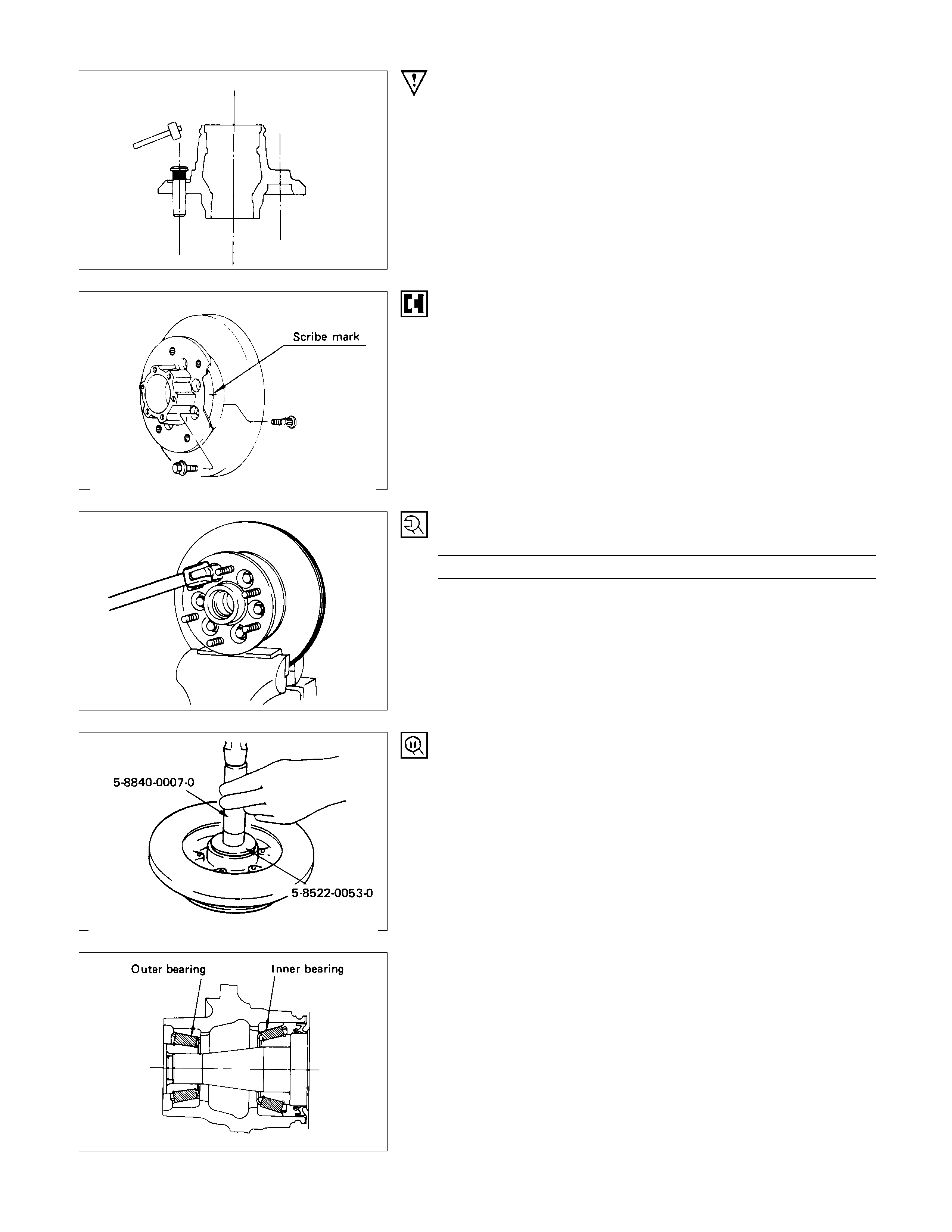
11. Inner bearing and outer race
▲12. Bolt
▲13. Wheel pin
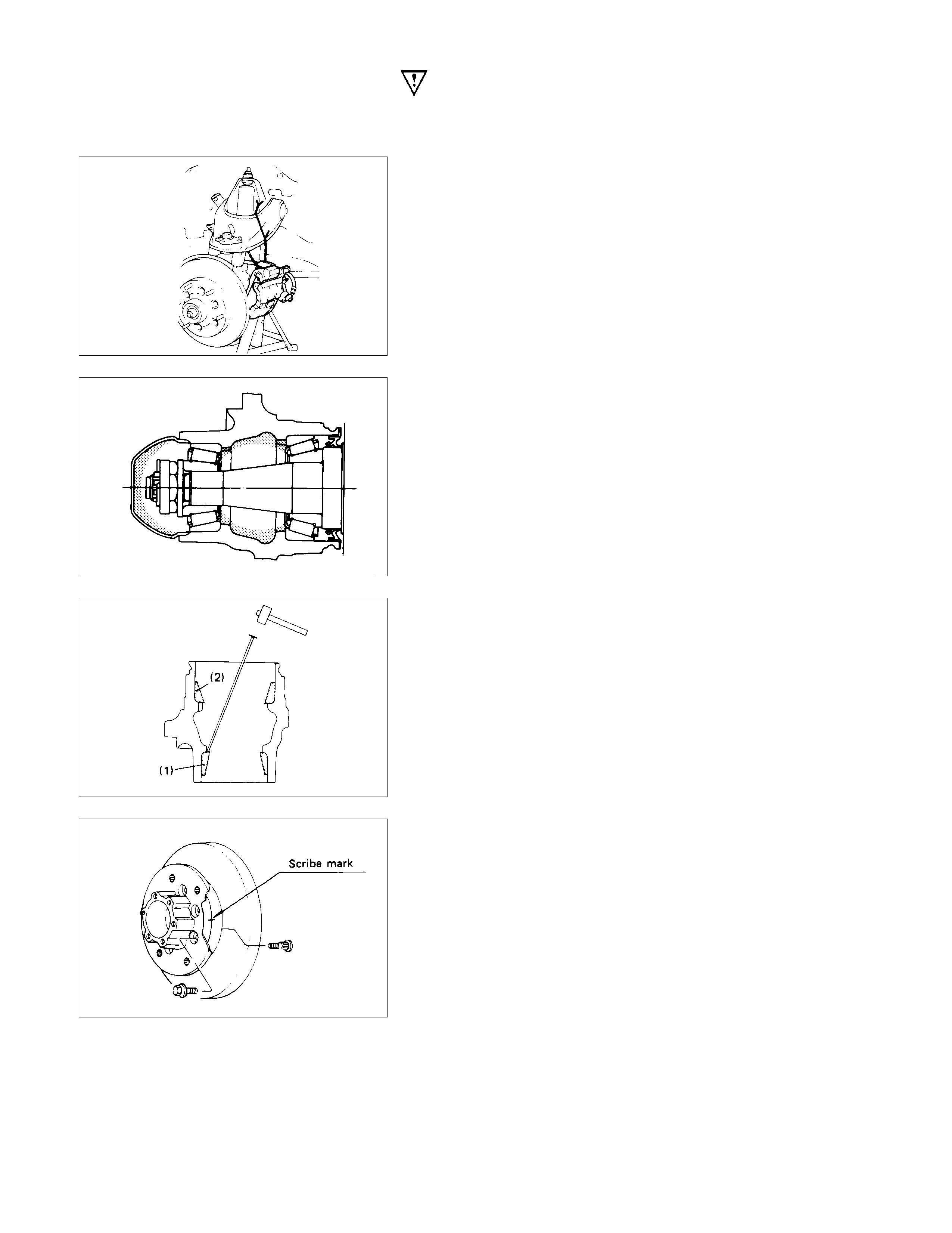
IMPORTANT OPERATIONS
Before removal, jack up the front of vehicle and support frame
with jack stands.
2. Brake Caliper
(1)Remove the two bolts from the rear side of the knuckle arm,
and then remove the brake caliper, with the brake hose
attached.
(2)Use a wire etc., for attaching the brake caliper to the uppe
r
link.
3. Hub Cap
When removing hub cap, exercise care so as not to scratch or
distort hub fitting face.
9. Hub and Disc Assembly
Using a brass bar to remove the outer bearing outer race (1),
oil seal, inner bearing and inner bearing outer race (2) from the
hug.
If necessary, replace the wheel pin in the following manner.
12.Bolt
13.Wheel Pin ; Front Hub
(1)Scribe mark on hub to disc before disassembly to insure
proper assembly.
(2)Clam p hub and disc ass embly in vise using protective pads
and remove six (6) disc to hub retaining bolts.
(3) Place hub on a suitable work surface and remove wheel
studs, as required, using a hammer.
INSPECTION AND REPAIR
Make necessary correction or parts replacement if wear, damage or any other abnormal conditions are found through
inspection.
• Hub
• Hub bearing
• Bearing outer race
• Disc
• Oil seal
VISUAL CHECK
Check the following parts for wear, damage or other abnormal
conditions.
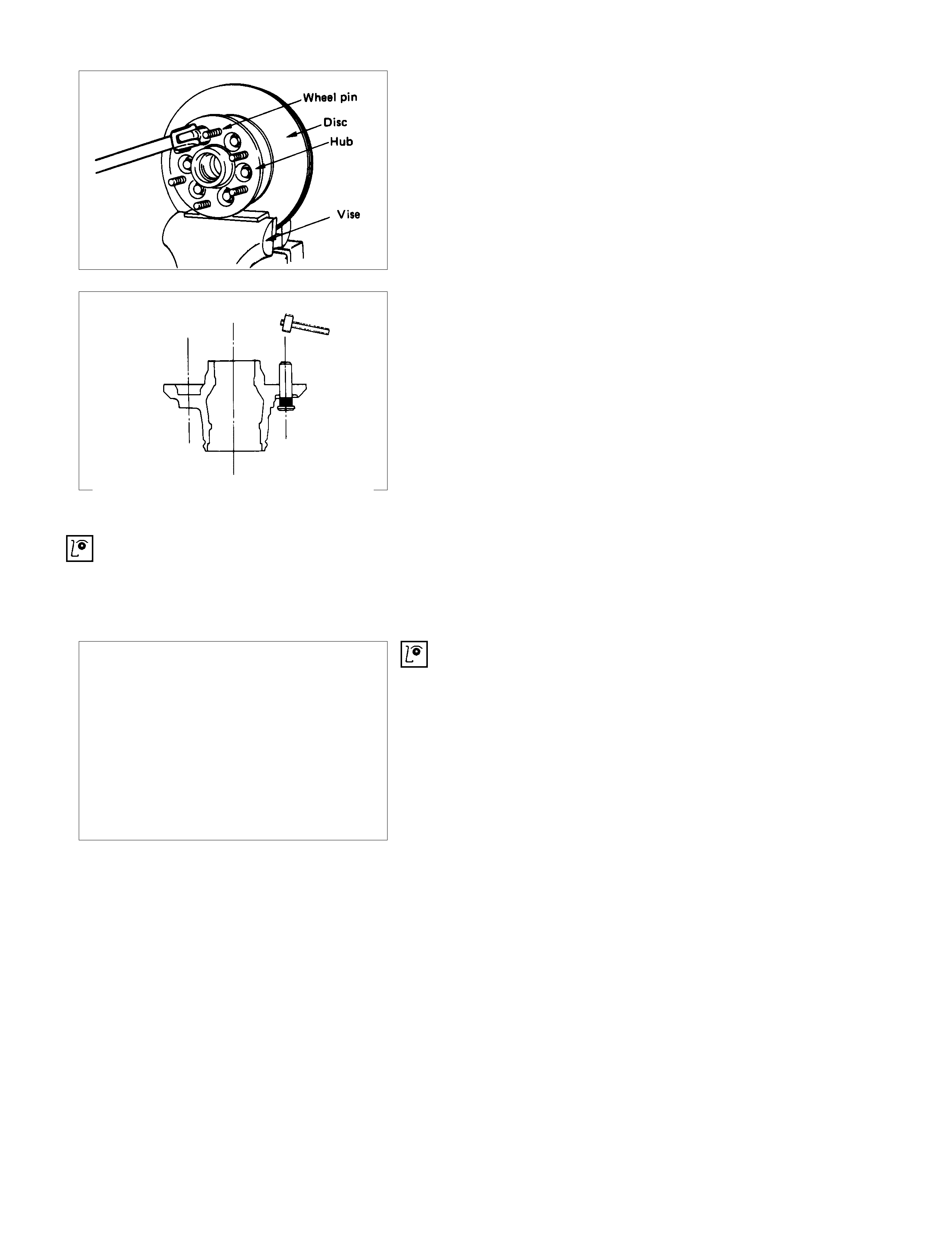
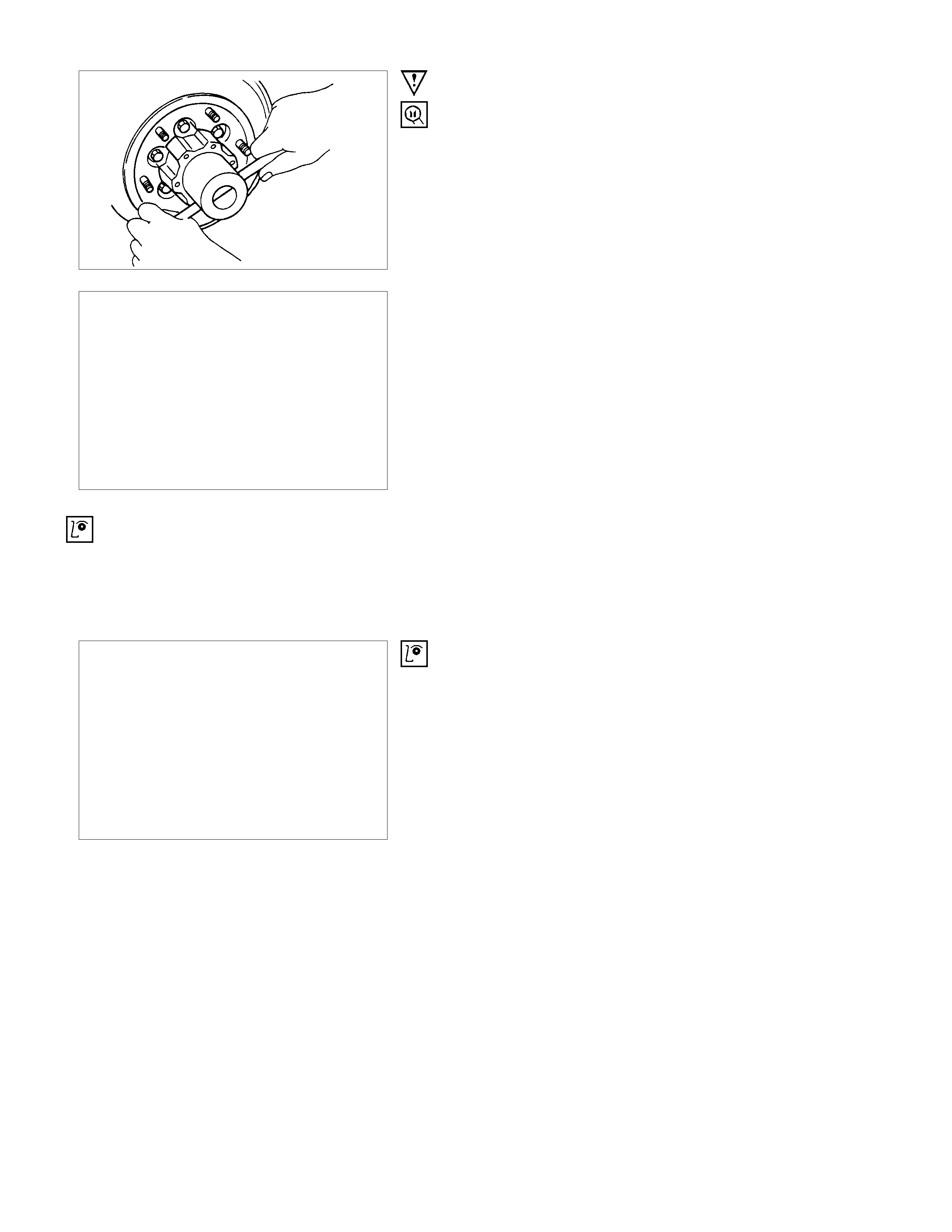
IMPORTANT OPERATIONS
1. Wheel Pin
(1)Place hub on a wood workbench or a block of wood,
approx. 6” by 6” to protect the wheel stud ends and threads.
(2)Install wheel stud using a hammer.
Be sure wheel stud is started squarely and seats
completely.
(3)Align index marks and install hub to disc.
2. Bolt
Torque N⋅m (kgf⋅m/lb⋅ft)
103 ± 5 (10.5 ± 1/75.9 ± 7.2)
3. Inner Be aring and Outer Race
4. Oil Seal
▲Outer Bearing Outer Race
(1)Install the bearing outer race by driving into the hub.
Installer (Outer) : 5-8822-0053-0 (J-29016)
Installer (Inner) : 5-8822-0054-0 (J-29015)
Drive handle : 5-8840-0007-0 (J-8092)
(2)Install the outer and inner bearing into the hub with fingers.
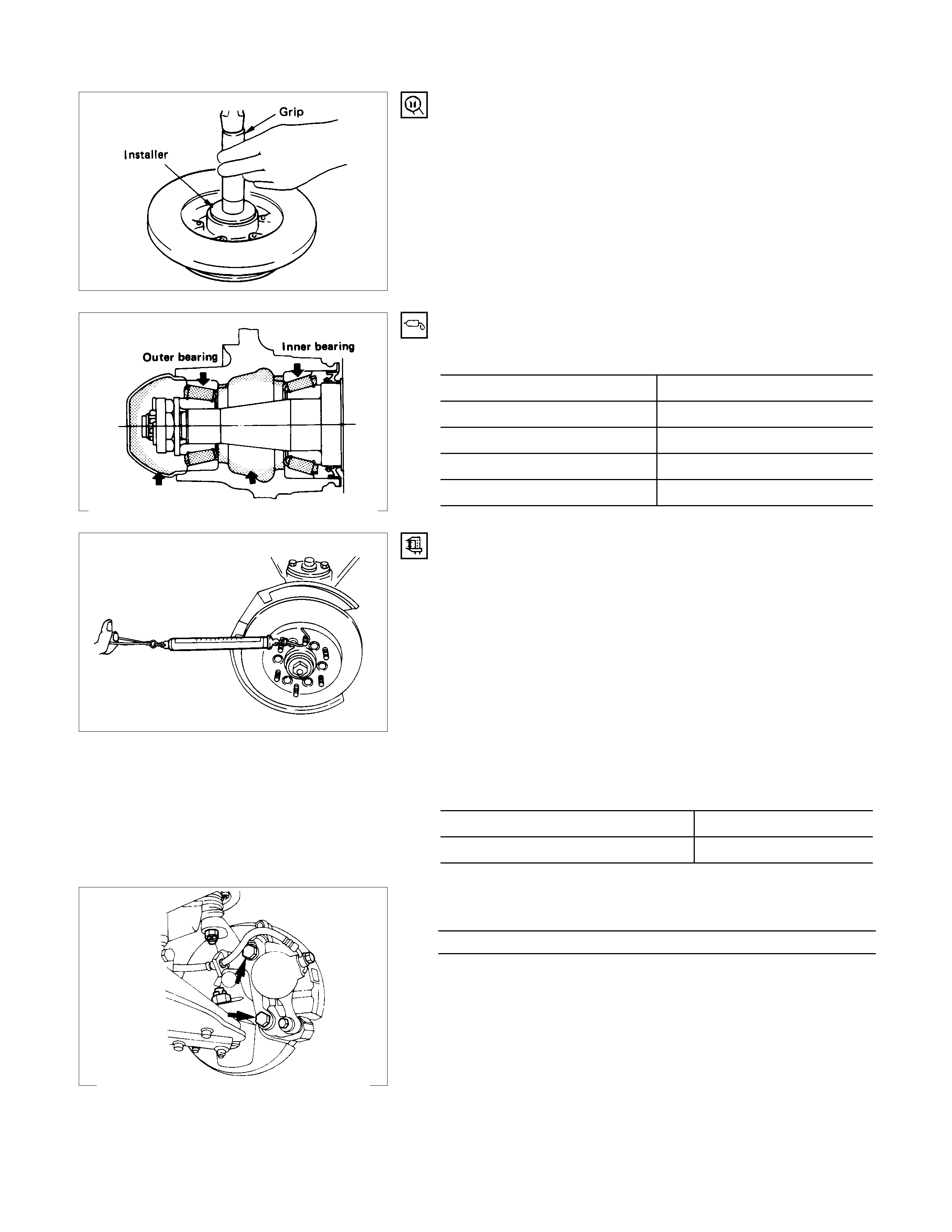
(3)Install oil seal using special tools.
Installer : 5-8522-0051-0
(J-33161)
Grip : 5-8840-0007-0
(J-8092)
5. Hub and Disc Assembly
11. Hub Cap
Apply grease in the hub and hub cap.
Description Amount g(oz)
Hub 50 (1.76)
Hub cap 20 (0.70)
Outer bearing 6.5 (0.23)
Inner bearing 12 (0.42)
8. Hub nut
Adjustment of front wheel hub bearing preload
1. Tighten spindle nut to 3.0 kg⋅m (21.7 lb.ft/29.4 N⋅m) torque.
2. Turn the hub 2-3 turns and loosen the nut just enough so
that it can be turned with the fingers.
3. Turn the nut all the way in with the fingers and check to be
sure the hub has no free play.
4. Measure the bearing preload by pulling one of the wheel hub
studs with a spring scale.
5. Tighten the spindle nut until specified bearing preload Is
obtained.
After reassembling, install the disc brake caliper assembly.
Bearing Preload kg(lb)
New bearing and New oil seal 0.8 - 1.0(1.8 - 2.2)
Reuse bearing and New oil seal 0.8 - 1.0 (1.8 - 2.2)
13.Bolt
Torque N⋅m (kgf⋅m/lb⋅ft)
155 ± 15.7 (15.8 ± 1.6/114.3 ± 11.6)
IMPORTANT OPERATIONS
6. Hub nut
Wrench : 5-8840-2117-0
(J-36827)
Refer to Section 5 “Brake” for disc brake
caliper removal procedure.
7. Hub and disc assembly
Before disassembly, remove the disc brake caliper assembly
and hang it on the frame with wires.
INSPECTION AND REPAIR
Make necessary correction or parts replacement if wear, damage or any other abnormal conditions are found through
inspection.
For inspection and servicing of disc caliper, and relative parts, refer to Section 5 “Brakes”.
• Hub
• Hub bearing, oil seal
• Knuckle spindle
• Disc
• Caliper
• Free wheeling hub parts
(Option)
• Clutch, knob, follower, inner, ring and
spring
VISUAL CHECK
Check the following parts for wear, damage or other abnormal
conditions.
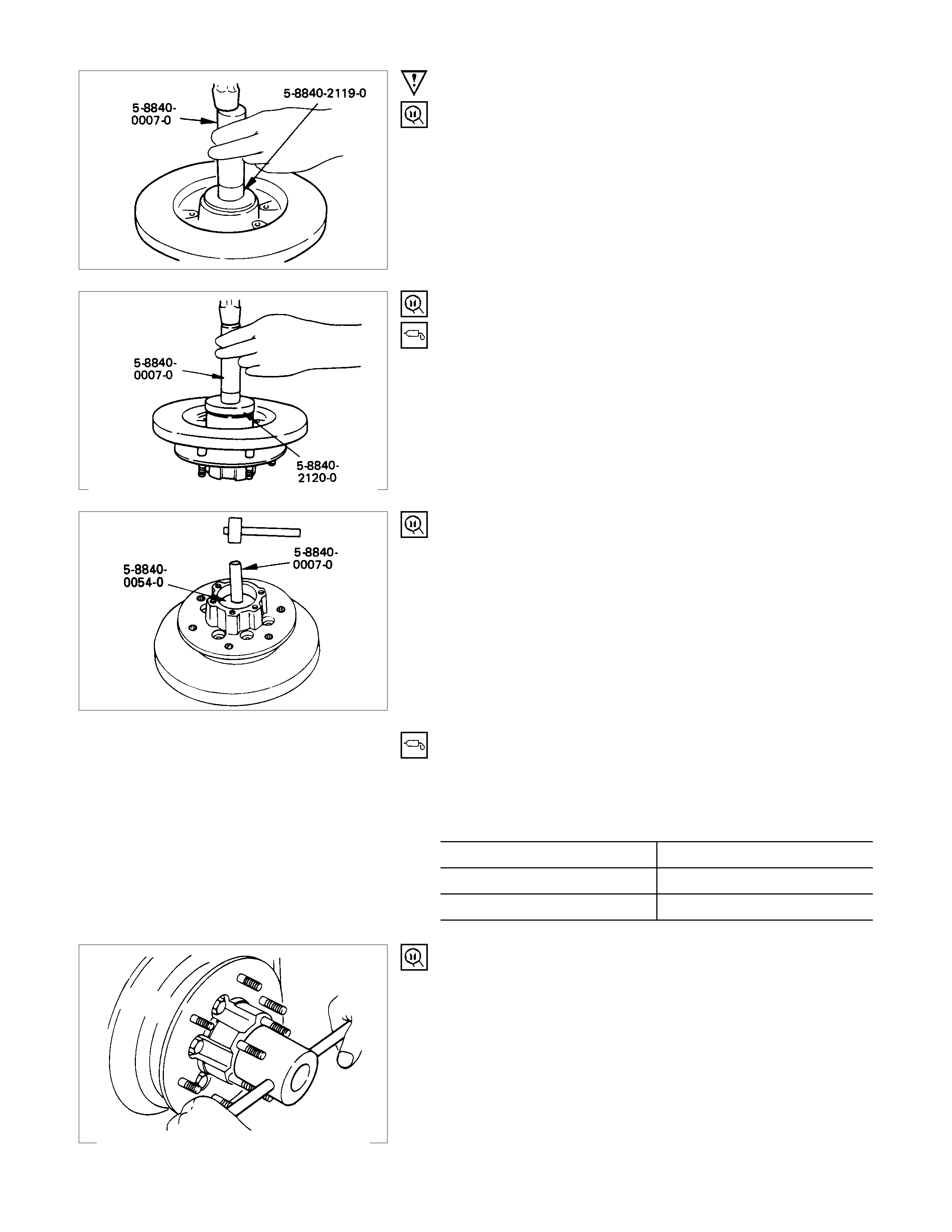
IMPORTANT OPERATIONS
1. Inner Bearing
Outer race ; outer bearing
Install the outer race by driving it into the hub.
Installer : 5-8840-2119-0
(J-36829)
Grip : 5-8840-0007-0
(J-8092)
2. Oil Seal
Installer : 5-8840-2120-0
(J-36830)
Grip : 5-8840-0007-0
(J-8092)
Apply grease (Besco L-2 or equivalent) to the lip portion.
3. Outer bearing
Outer race ; outer bearing
Install the outer race by driving it into the hub.
Installer : 5-8840-0054-0
(J-29015)
Grip : 5-8840-0007-0
(J-8092)
4. Hub and Disc Assembly
(1)Apply grease in the hub.
(2) Apply grease (Besco L-2 or equivalent) to the outer and
inner bearing. g(oz)
Hub 35 (1.23)
Outer bearing 10 (0.35)
Inner bearing 15 (0.53)
5. Hub Nut
(1)Turn the place where there is a cham fer in the tapped hole
to the outer side, and attach the nut.
Wrench : 5-8840-2117-0
(J-36827)
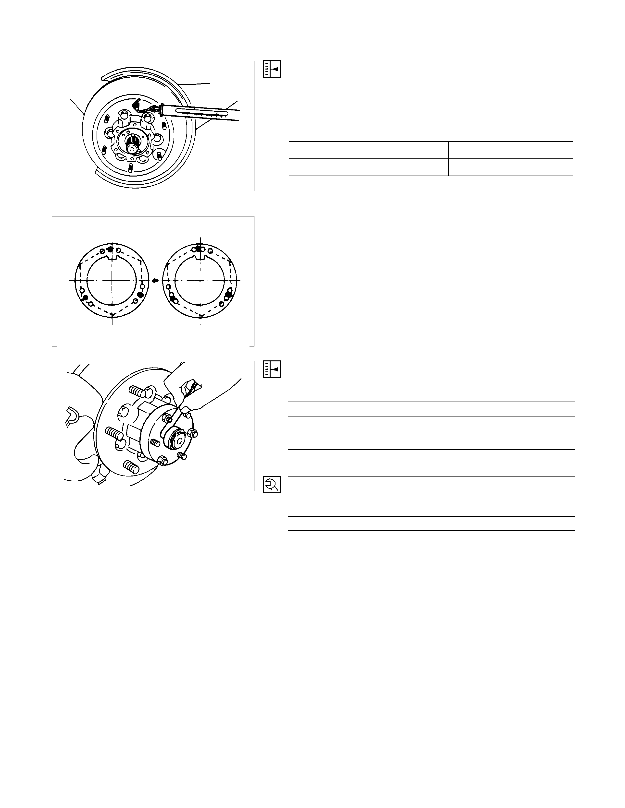
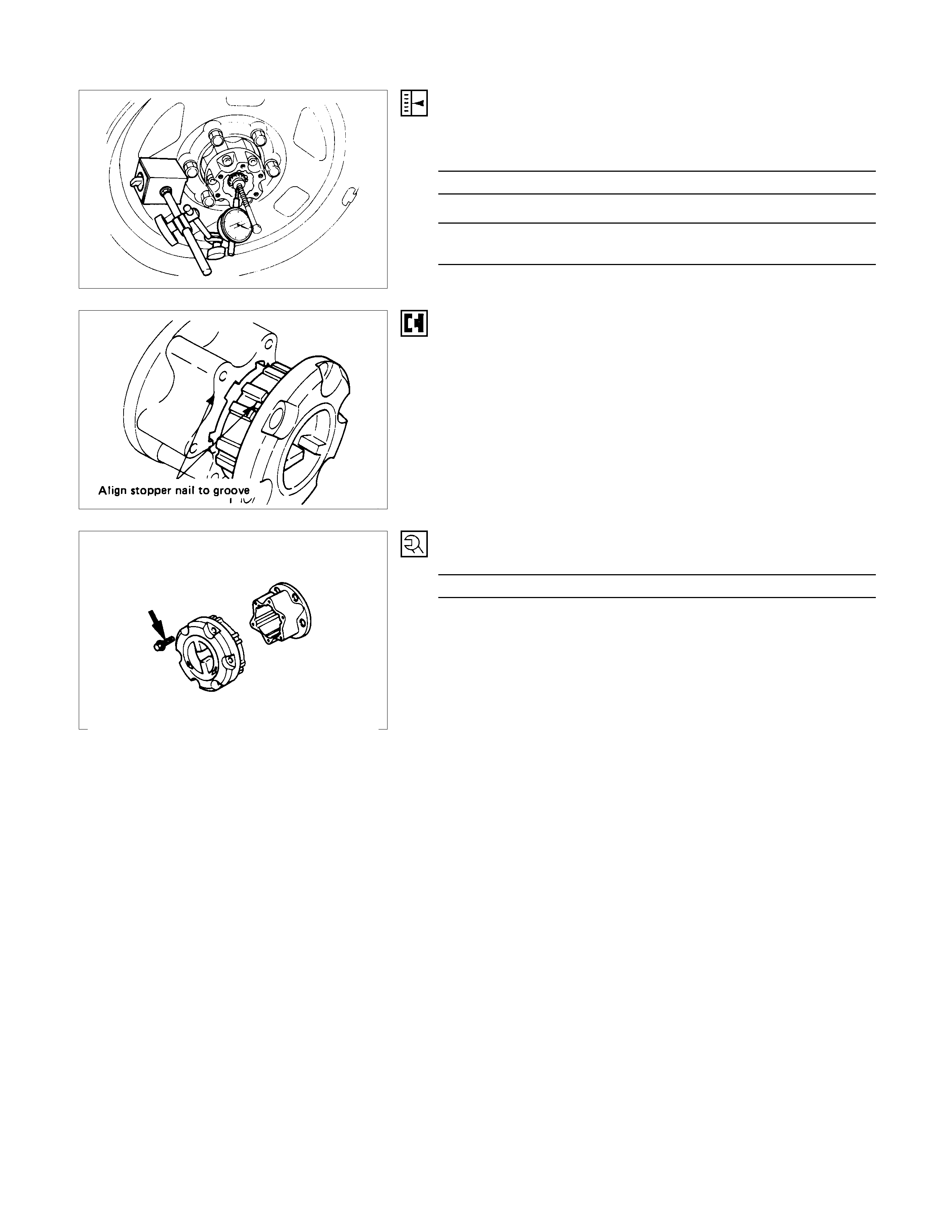
PRELOAD ADJUSTM ENT
Tighten the hub nut at 29.4 N⋅m (3 kgf⋅m / 21.716 lb.ft), then
loosen the nut to the full.
Tighten the hub nut at the value given below, using a spring
scale on the wheel pin.
Bearing Preload kg(lb)
New bearing and New oil seal 2 -2.5 (4.4 - 5.5)
Used bearing and New oil seal 1.2 - 1.8 (2.68 - 4.0)
If the measured bearing preload is outside the specifications,
adjust it by loosening or tightening the bearing nut.
6. Lock Washer
Turn the side with larger diameter of the tapered bore to the
vehicle outer side, and attach the washer.
If the bolt holes in the lock plate are not aligned with the
corresponding holes in the nut, reverse the lock plate.
If the bolt holes are still out of alignment, turn in the nut just
enough to obtain alignment,. Screw is to be fastened tightly so
its head may come lower than the surface of the washer.
8. Snap ring, shims
Adjust the clearance between the collar and the snap ring.
Clearance mm(in)
0 - 0.3 (0 - 0.01)
Adjust shims available mm(in)
0.2, 0.3, 0.5, 1.0
(0.008, 0.011, 0.020, 0.039)
10.bolt
Torque N⋅m (kgf⋅m/lb⋅ft
)
10 - 14 (1.0 - 1.4 / 7 - 10)

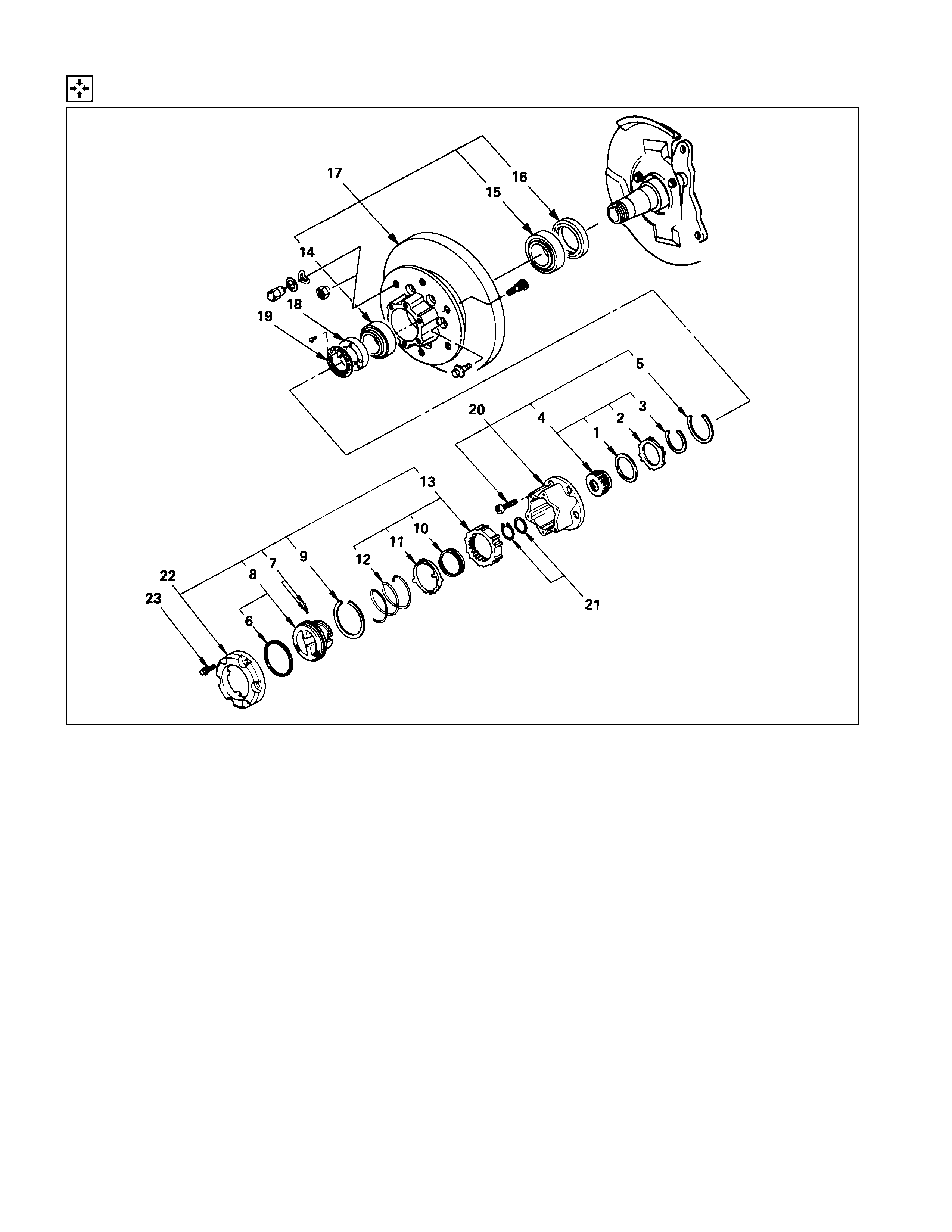
FRONT HUB AND DISC (MANUAL LOCKING HUB)
DISASSEM BLY
DISASSEM BLY STEPS
▲1. Bolt
2. Housing assembly
3. Snap ring and shim
4. Body assembly
5. Lock washer
▲6. Hub nut
▲7. Hub and disc assembly
8. Outer bearing
9. Oil seal
10. Inner bearing
▲11. Clutch assembly
12. Snap ring
13. Knob
14. Compression spring
15. Follower
▲16. Retaining spring
17. Detent ball and spring
18. X-ring
19. Snap ring
20. Inner assembly
21. Snap ring
22. Ring
23. Spacer
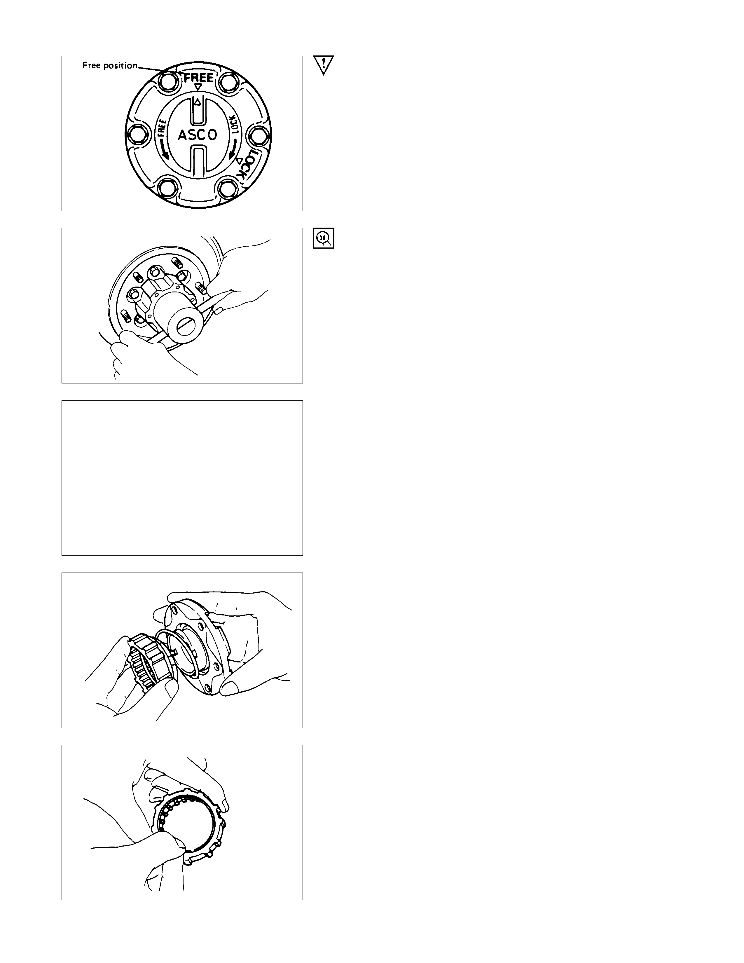
IMPORTANT OPERATIONS
1. Bolt
Before removal, shift transfer lever into “2H” position and set
free wheeling hub knob into “FREE” position.
6. Hub Nut
Wrench : 5-8840-2117-0
(J-36827)
Refer to Section 5 “Brake” for disc brake
caliper removal procedure.
7. Hub and Disc Assembly
Before disassembly, remove the disc brake caliper assembly
and hang it on the frame with wires.
11.Clutch Assembly
While pushing follower knob, turn clutch assembly clockwise
and then remove clutch assembly from knob.
16.Retaining Spring
Remove retaining spring from clutch assembly by turning it
counterclockwise.

INSPECTION AND REPAIR
Make necessary correction or parts replacement if wear, damage or any other abnormal conditions are found through
inspection.
For inspection and servicing of disc caliper, and relative parts, refer to Section 5 “Brakes”.
• Hub
• Hub bearing, oil seal
• Knuckle spindle
• Disc
• Caliper
• Free wheeling hub parts
(Option)
• Clutch, knob, follower, inner, ring and
spring
VISUAL CHECK
Check the following parts for wear, damage or other abnormal
conditions.
REASSEMBLY
REASSEMBLY STEPS
▲1. Spacer
2. Ring
3. Snap ring
▲4. Inner assembly
5. Snap ring
6. X-ring
7. Detent ball and spring
▲8. Knob
▲9. Snap ring
▲10. Retaining spring
▲11. Follower
▲12. Compression spring
▲13. Clutch assembly
▲14. Outer bearing
▲15. Inner bearing
▲16. Oil seal
▲17. Hub and disc assembly
▲18. Hub nut
▲19. Lock washer
▲20. Body assembly
▲21. Snap ring and shims
▲22. Cover assembly
▲23. Bolt
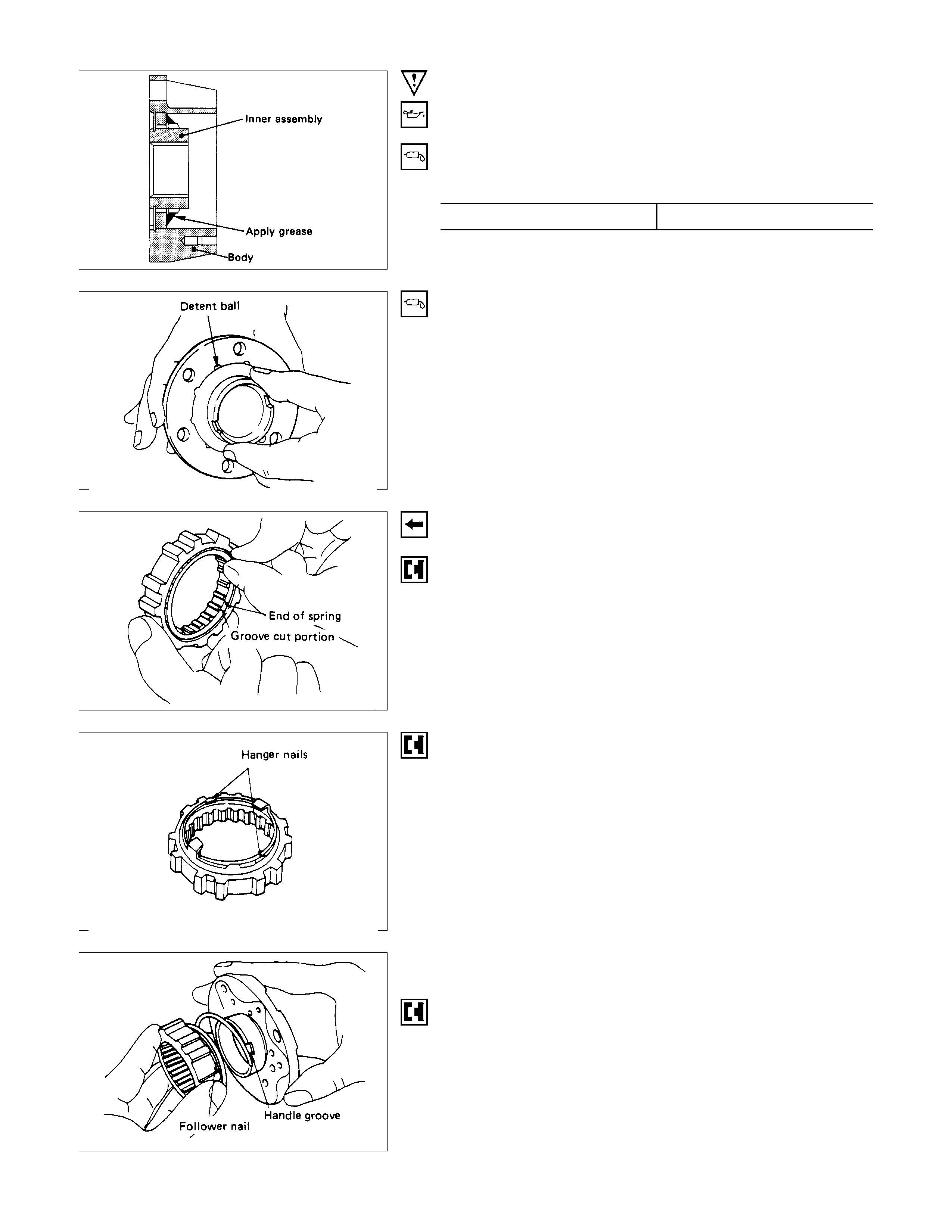
IMPORTANT OPERATIONS
1. Spacer
Apply grease to both faces of spacer.
4. Inner Assembly
Apply grease wheel bearing to inside face of ring. g(oz)
Amount of grease 3 (0.10)
8. Knob
(1)Apply greas e Wheel bear ing to outer c irc umf er ence of k nob
and inner circumference of cover.
(2)Align detent ball to either groove of cover.
9.Snap Ring
Turn the smoother face to knob side.
10.Retaining Spring
Align the end of spring to the end of cut portion of clutch spring
groove.
11.Follower
Install follower to clutch so that follower nail will come closer to
the bent portion of retaining spring by aligning follower stopper
nail to outer teeth of clutch. Then, hook retaining spring onto
upper portion of hanger nails of follower.
12.Compression Spring
Turn the smaller diameter side to follower.
13.Clutch Assembly
Align follower nail to handle groove, and then assemble clutch
with knob by pushing and turning clutch counterclockwise to
knob.
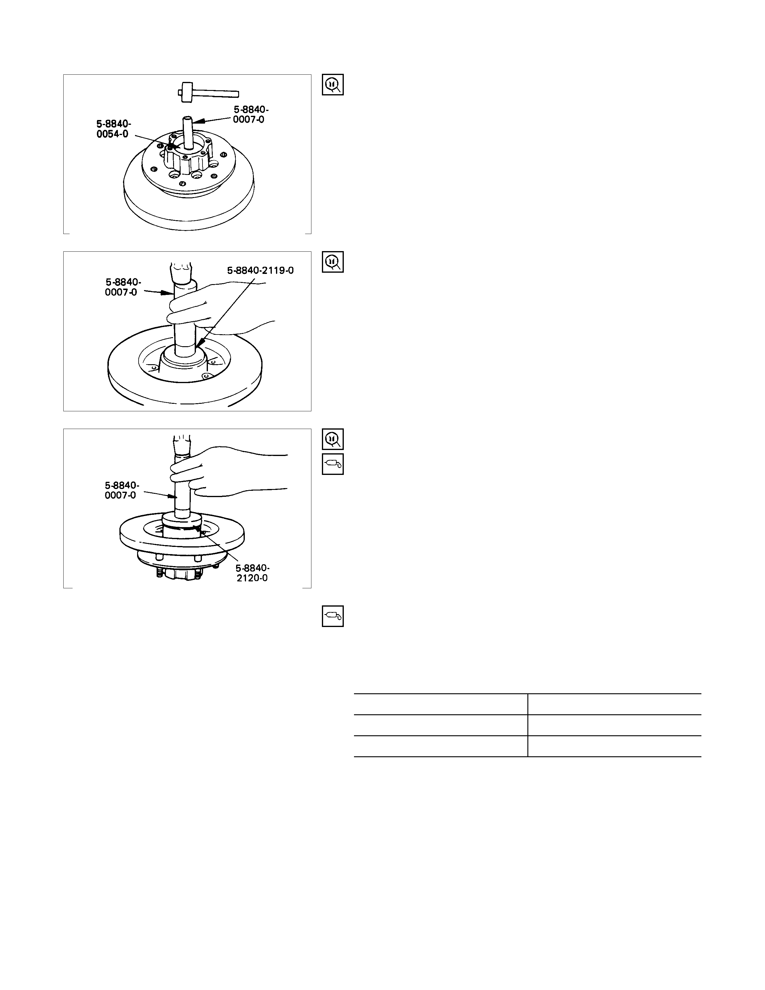
14.Outer Bearing
Outer race ; outer bearing
Install the outer race by driving it into the hub.
Installer : 5-8840-0054-0
(J-29015)
Grip : 5-8840-0007-0
(J-8092)
15.Inner Bearing
Outer race ; inner bearing
Install the outer race by driving it into the hub.
Installer : 5-880-2119-0
(J-36829)
Grip : 5-8840-0007-0
(J-8092)
16.Oil Seal
Installer : 5-8840-2120-0
(J-36830)
Grip : 5-8840-0007-0
(J-8092)
17.Hub and Disc Assembly
(1)Apply grease in the hub.
(2) Apply grease (Besco L-2 or equivalent) to the outer and
inner bearing. g(oz)
Hub 35 (1.23)
Outer bearing 10 (0.35)
Inner bearing 15 (0.53)
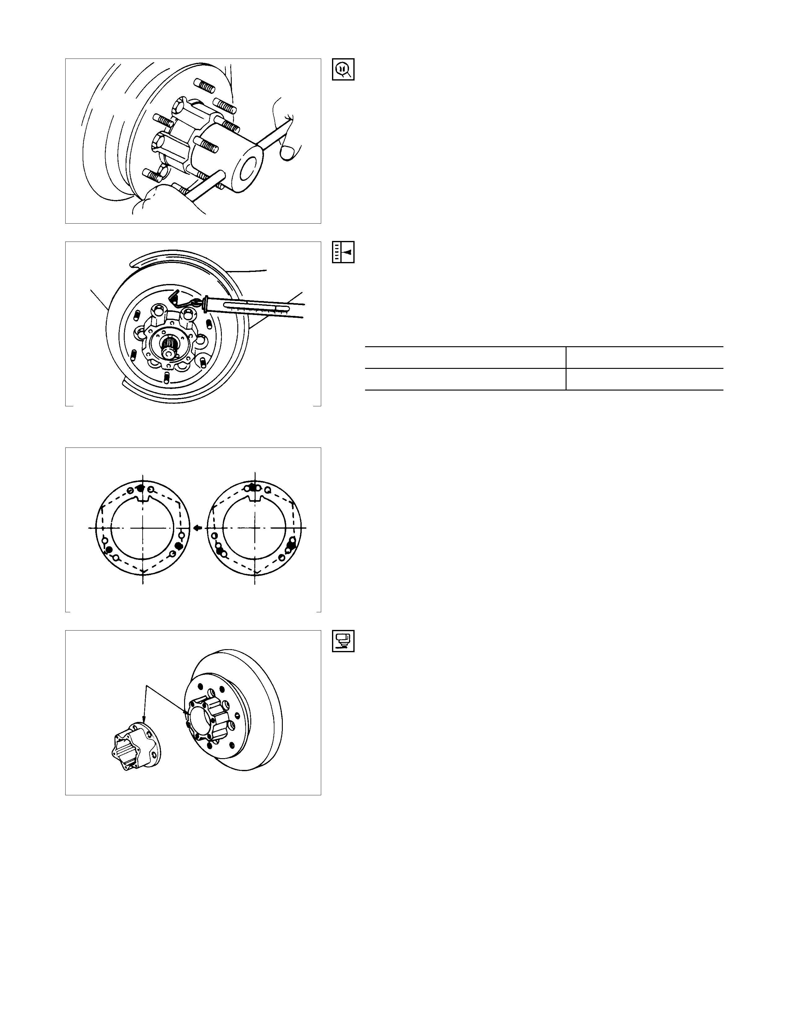
18.Hub Nut
(1)Turn the place where there is a cham fer in the tapped hole
to the outer side, and attach the nut.
Wrench : 5-8840-2117-0
(J-36827)
PRELOAD ADJUSTM ENT
Tighten the hub nut at 29.4 N⋅m (3 kgf⋅m / 21.716 lb⋅ft), then
loosen the nut to the full.
Tighten the hub nut at the value given below, using a spring
scale on the wheel pin.
Bearing Preload kg(lb)
New bearing and New oil seal 2 -2.5 (4.4 - 5.5)
Used bearing and New oil seal 1.2 - 1.8 (2.6 - 4.0)
If the measured bearing preload is outside the specifications,
adjust it by loosening or tightening the bearing nut.
19.Lock Washer
Turn the side with larger diameter of the tapered bore to the
vehicle outer side, and attach the washer.
If the bolt holes in the lock plate are not aligned with the
corresponding holes in the nut, reverse the lock plate.
If the bolt holes are still out of alignment, turn in the nut just
enough to obtain alignment,. Screw is to be fastened tightly so
its head may come lower than the surface of the washer.
20.Body Assembly
Apply adhesive (Loctite 15 or equivalent) to the both joining
faces.
21.Snap Ring and Shims
Adjust the clearance between the free wheeling hub body and
the snap ring.
Clearance mm(in)
0 - 0.3 (0 - 0.01)
Adjust Shims Available mm(in)
0.2, 0.3, 0.5, 1.0
(0.008, 0.011, 0.020, 0.039)
22.Cover Assembly
Align stopper nails to grooves of body.
23.Bolt
Torque N⋅m (kgf⋅m/lb⋅ft)
11.8 ± 2.0 (1.2 ± 0.2 / 8.7 ± 1.4)

FRONT PROPELLER SHAFT
REMOVAL AND INSTALLATION
Since the propeller shaft assembly is carefully
balanced, a setting mark should be applied to
the flange before removal to indicate correct
position.
Install the parts by aligning the setting marks
made at removal.
REMOVAL STEPS
1. Nut ; differential side
2. Bolt ; transfer side
3. Propeller shaft assembly ; rear side
4. Propeller shaft assembly ; front side
INSTALLATION STEPS
4. Propeller shaft assembly ; front side
▲3. Propeller shaft assembly ; rear side
▲2. Bolt ; transfer side
▲1. Nut ; differential side

IMPORTANT OPERATION - INSTALLATION
3. Propeller Shaft Assembly ; Rear Side
Align the indexing marks (about 3 mm dia. punched mark) on
the propeller shaft end and the splined yoke.
2. Bolt ; Transfer Side
Torque N⋅m (kgf⋅m/lb⋅ft)
Bolt size M10 62.8 ± 3.9 (6.4 ± 0.4/46.3 ± 2.9)
1. Bolt ; Differential Side
Torque N⋅m (kgf⋅m/lb⋅ft)
Bolt size M8 35.3 ± 2.9 (3.6 ± 0.3 / 26 ± 2.2)
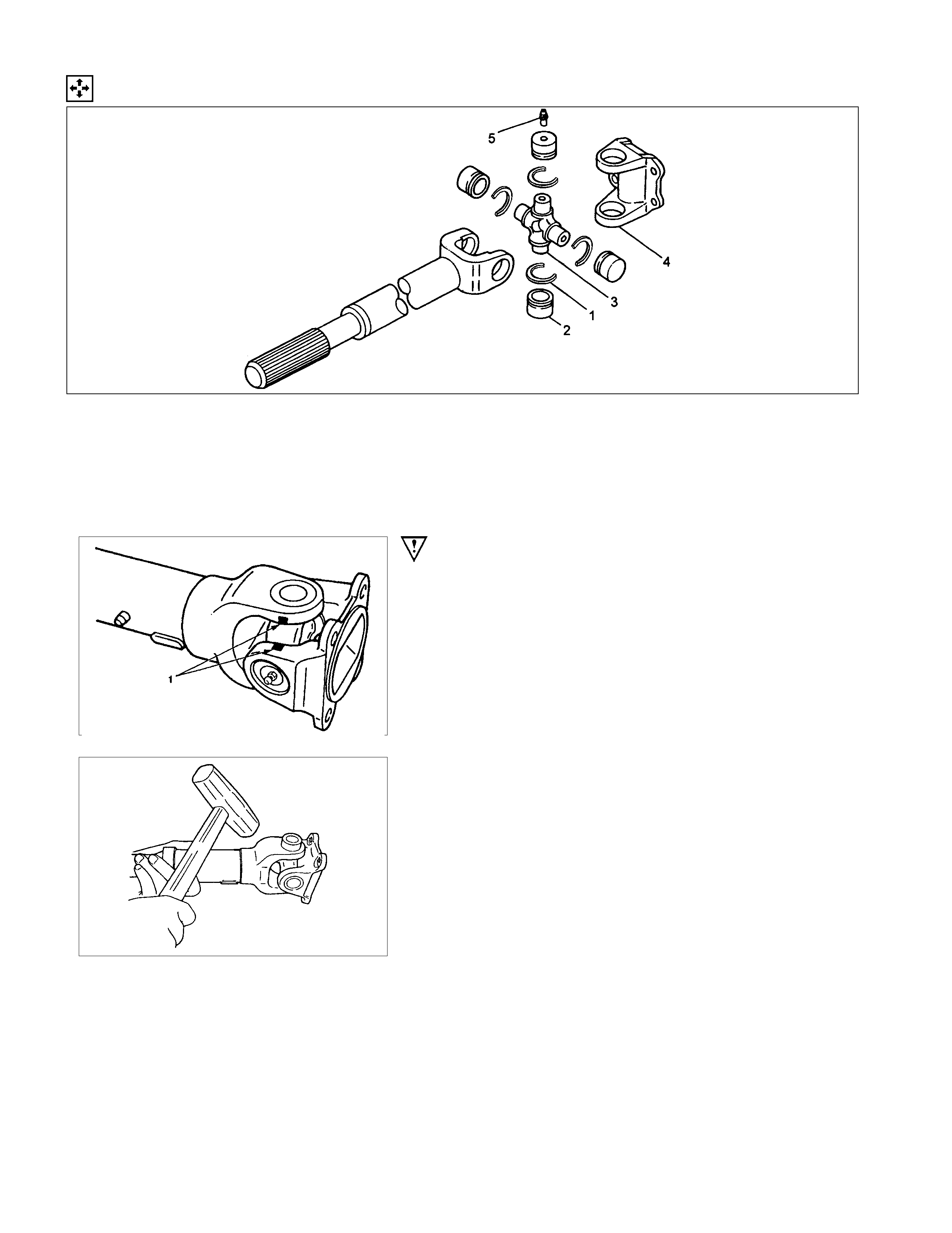
DISASSEM BLY
DISASSEM BLY STEPS
1. Snap Ring
▲2. Needle Roller Bearing
3. Spider
4. Flange Yoke
5. Grease Fitting
IMPORTANT OPERATION
2. Needle Roller Bearing
(1) Apply alignment marks (1) on the yokes of the universal
joint, then remove snap ring.
(2)Tap out the needle roller bearing by gently striking the
shoulder of the yoke, using a mallet or a copper hammer.
INSPECTION AND REPAIR
Make necessary correction or parts replacement if wear, damage or any other abnormal conditions are found through
inspection.
Spider
Needle roller bearing
Yoke
Flange
Center bearing
Cushioning rubber
Bracket
VISUAL CHECK
Check the following parts for wear, damage or other abnormal
conditions.
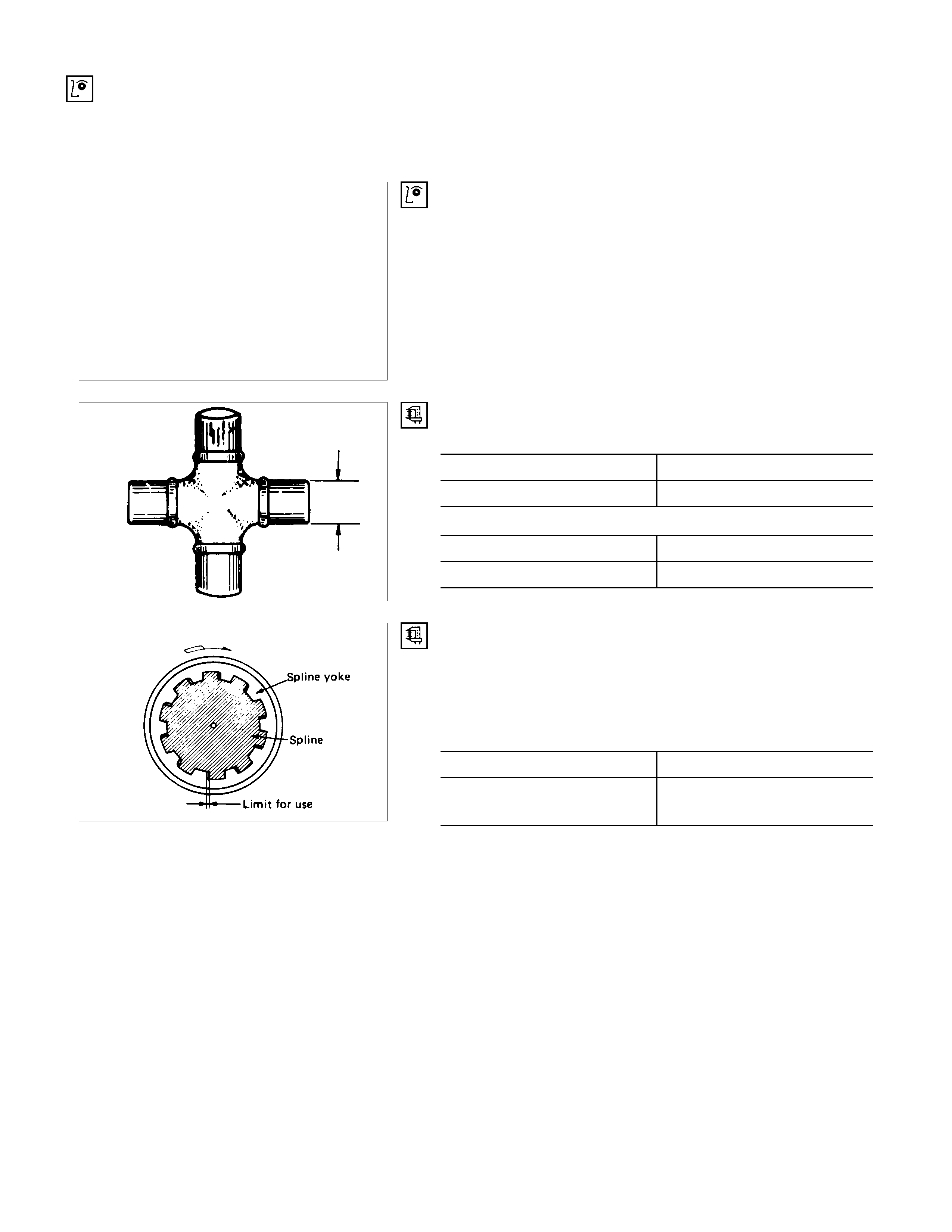
OUTSIDE DIAMETER OF SPIDER PINS
TF Side for Type - A and B mm(in)
Standard Limit
17.000 (0.669) 16.90 (0.665)
Axle Side for Type - A mm(in)
Standard Limit
14.724 (0.580) 14.624 (0.576)
PLAY IN SPLINES IN NORMAL DIRECTION OF
ROTATION
Check the amount of play in the sleeve yoke and propeller
shaft splines in the direction of rotation, using a pointed feeler
gauge. mm(in)
Standard Limit
0.074 - 0.156
(0.003 - 0.006) 0.3 (0.012)
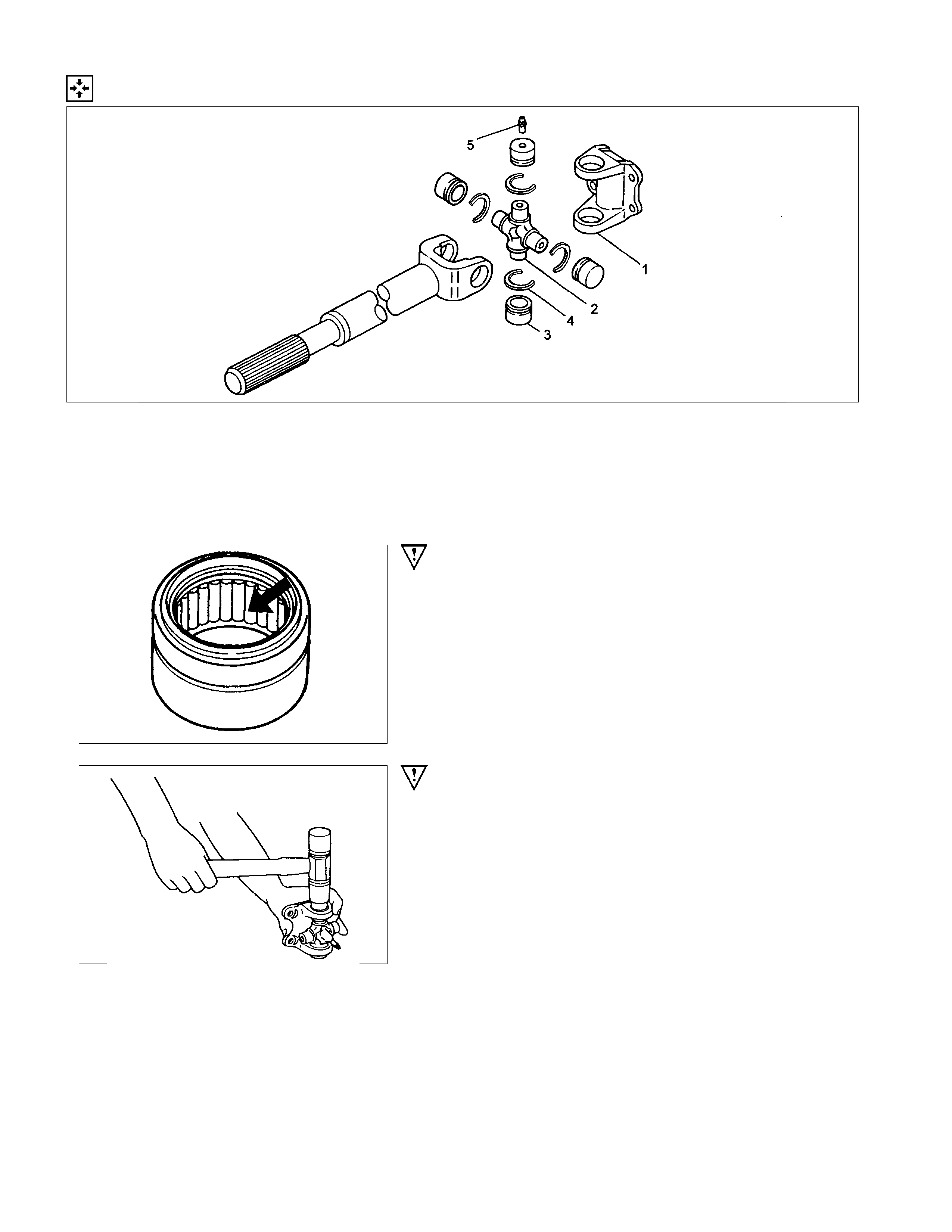
REASSEMBLY
REASSEMBLY STEPS
1. Flange yoke
2. Spider
▲3. Needle roller bearing
4. Snap ring
5. Grease Fitting
IMPORTANT OPERATIONS
3. Needle roller bearing
(1)Install spider to flange yok e. Be sure to install the spider by
aligning the setting marks made during disassembly.
(2) Apply molybdenum-disulfide grease or multi-purpose type
grease NLGI No.2 to inside of the bearing cap.
Grease Amount: Approx. 1.2g (0.042 oz)
(3)Using either mallet (or copper hammer) or a press, install
the needle roller bearing into the yoke so that the snap ring
can be installed in its groove.
CAUTION:
The needle roller bearing cannot be installed smoothly if it
is set at an incorrect angle with the flange and excessive
hammering will damage the needle roller bearing.

(4)Align setting marks (1) and join the yokes.
(5)Install snap ring.
NOTE:
Discard used snap rings and install new ones.
When the bearing cap is in position, select and attach a snap
ring of suitable thickness so that the end play of the spider pin
is held within 0.1mm (0.004 in).
T/F side for Type - A and B
Snap ring thickness and Identification color
1.5mm (0.059 in); Blue
1.53mm (0.060 in); White
1.59mm (0.063 in); Yellow
1.62mm (0.064 in); Green
1.68mm (0.066 in); Not colored
Axle side for Type - A
1.44mm (0.057 in); Not colored
1.49mm (0.059 in); Not colored
1.54mm (0.061 in); Not colored
NOTE:
Be sure to use snap rings of the same thickness on both sides.