
SECTION 4C - REAR AXLE
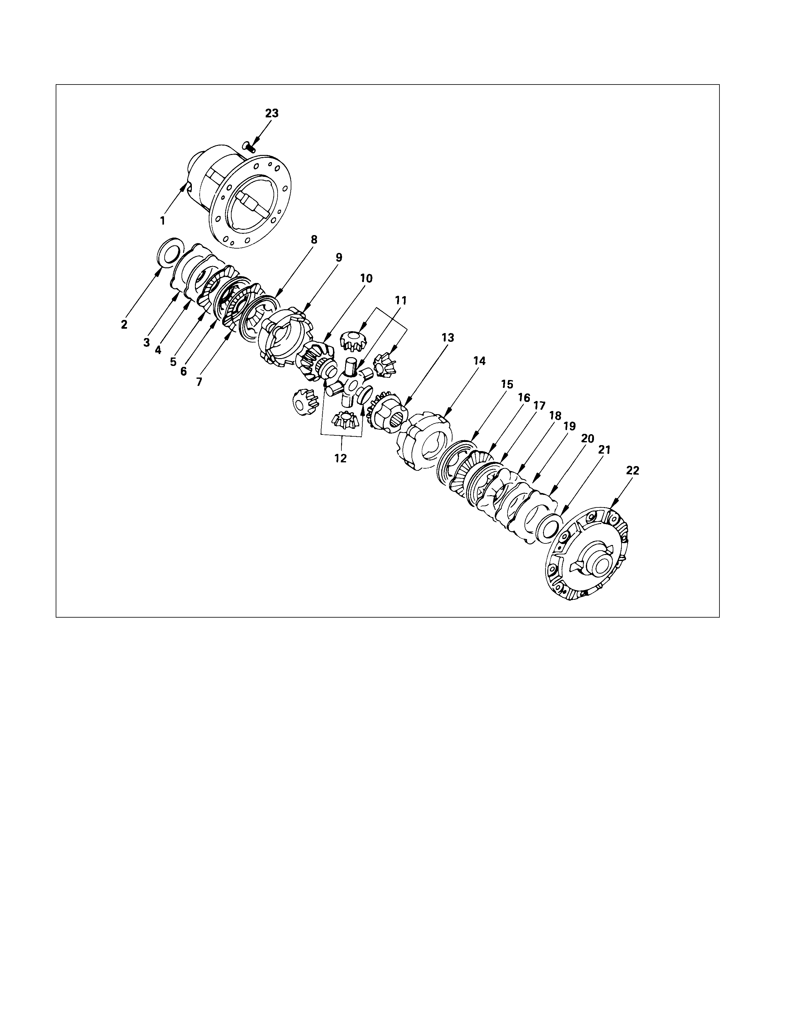
MAIN DATA AND SPECIFICATIONS
SPECIAL PARTS FIXING NUT AND BOLT
RECOMMENDED LIQUID GASKET
RECOMMENDED THREAD LOCKING AGENTS
REAR AXLE ASSEMBLY
GENERAL DESCRIPTION
SERVICING
AXLE SHAFT
DISASSEMBLY
INSPECTION AND REPAIR
REASSEMBLY
DIFFERENTIAL
REMOVAL AND INSTALLATION
DISASSEMBLY
MAJOR COMP ONENTS
MINOR COMPONENTS
STANDARD DIFFERENTIAL
LIMITED SLIP DIFFERENTIAL (LSD)
INSPECTION AND REPAIR
REASSEMBLY
MINOR COMPONENTS
LIMITED SLIP DIFFERENTIAL
STANDARD DIFFERENTIAL
MAJOR COMP ONENTS
TROUBLESHOOTING
SPECIAL SERVICE TOOLS
Techline
Techline
Techline
MAIN DATA AND SPECIFICATIONS
REAR AXLE
Ring gear size mm 194 220
Rear axle type Banjo, semi-floating
Rear axle capacity N 16475
Rear axle case
Axle tube section
Outside diameter mm 75
Thickness mm 4.5
Final drive type Single speed
Final gear type Hypoid
Drive pinion bearing preload kg-cm
Starting torque (At drive pinion flange nut) 6.5-11.5 7-13
Preload adjusting method Collapsible
Final gear backlash mm 0.13-0.18 0.15-0.20
Differential carrier assembly
Weight (Dry) N 208 284
Amount of hub grease g 80
(one wheel)
Lubrication
Specified gear oil (APL grade) GL-5
Oil capacity lit 1.5 1.8
SPECIAL PARTS FI XING NUT AND BOLT
REAR AXLE AND DIFFERENTIAL
194 mm N⋅m (kgf⋅m/lb⋅ft)

220 mm N⋅m (kgf⋅m/lb⋅ft)
RECOMMENDED LI QUI D GASKET
Type Brand Name Manufacture Remarks
RTV*
Silicon Base
ThreeBond 1207B
ThreeBond 1207C
ThreeBond 1215
Three Bond
Three Bond
Three Bond
For Engine Repairs
For Axle Case
Repairs, T/M
Water Base ThreeBond 1141E Three Bond For Engine Repairs
Solvent
ThreeBond 1104
BelcoBond 4
BelcoBond 401
BelcoBond 402
Three bond
Isuzu
Isuzu
Isuzu
For Engine Repairs
Anerobic LOCTITE 515
LOCTITE 518 Loctite
Loctite All
* RTV : Room Temperature Vulcanizer
Note:
1. It is very important that the liquid gaskets listed above or their exact equivalent be used on the vehicle.
2. Be careful to use the specified amount of liquid gasket.
Follow the manufacture's instructions at all times.
3. Be absolutely sure to remove all lubricants and moisture from the connecting surfaces before applying
the liquid gasket.
The connecting surfaces must be perfectly dry.
4. LOCTITE 515 and LOCTITE 518 harden upon contact with a metal surface.
Do not apply LOCTITE 515 or LOCTITE 518 between two metal surfaces having a clearance of greater
than 0.25 mm (0.01 in). Poor adhesion will result.
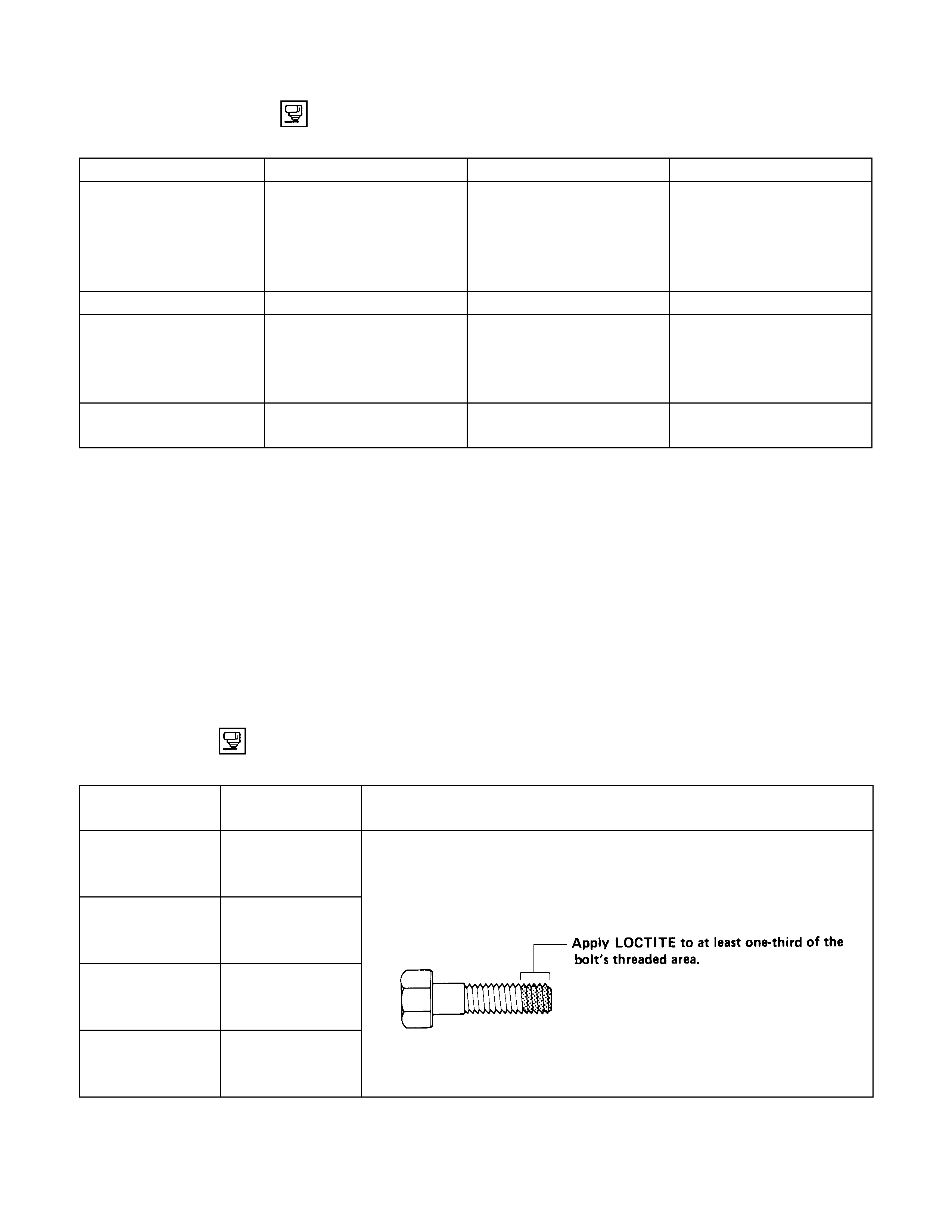
RECOMMENDED THREAD LOCKING AGENTS
LOCTITE Type LOCTITE
Colour Application Steps
LOCTITE 242 Blue 1. Completely remove all lubricant and moisture from the bolts and
the female threaded surfaces of the parts to be joined.
The surfaces must be perfectly dry.
LOCTITE 262 Red 2. Apply LOCTITE to the bolts.
LOCTITE 270 Green
LOCTITE 271 Red 3. Tighten the bolts to the specified torque.
4. Wait at least one hour before continuing the installation procedure.
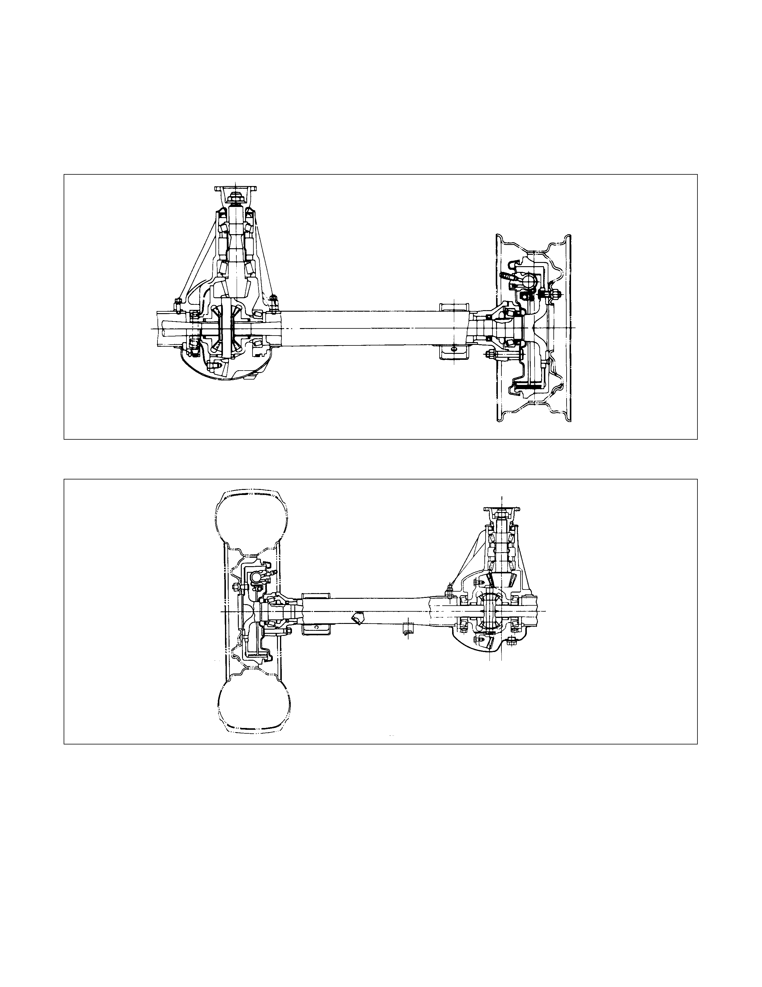
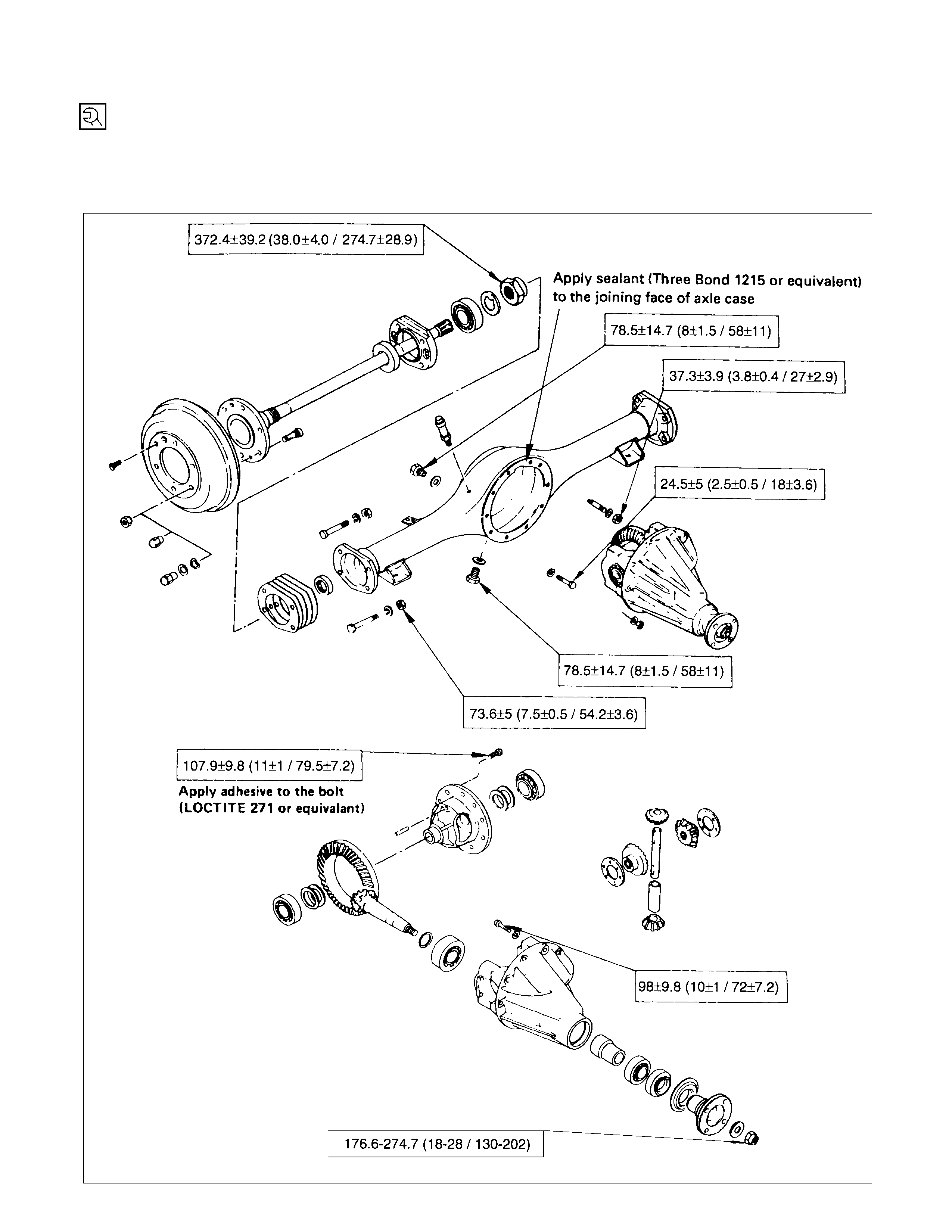
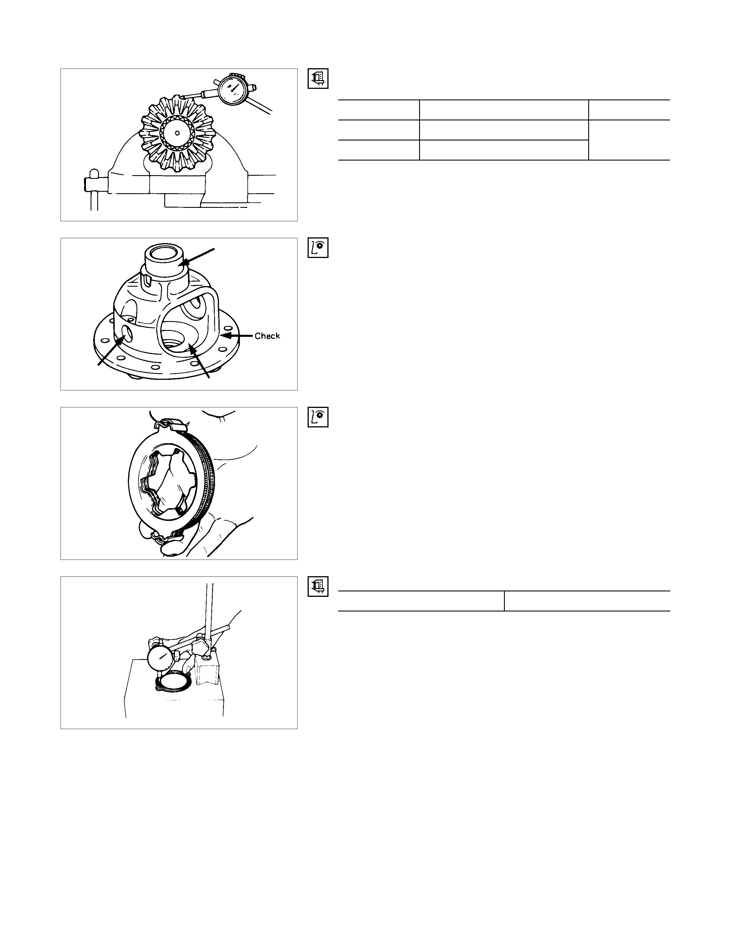
REAR AXLE ASSEMBLY
GENERAL DESCRI PTION
194 mm (7.6 in)
220 mm (8.6 in)
The rear axle assembly consists of the rear axle case, the differential carrier assembly, the rear hub assembly, and
the rear axle shaft.
The rear axle assembly supports the greater part of the vehicle weight including the load. It receives the engine
torque through the clutch, the transmission, and the propeller shaft, magnifies the torque at the final gear, and
delivers the torque at a right angle to the rear axle shaft.
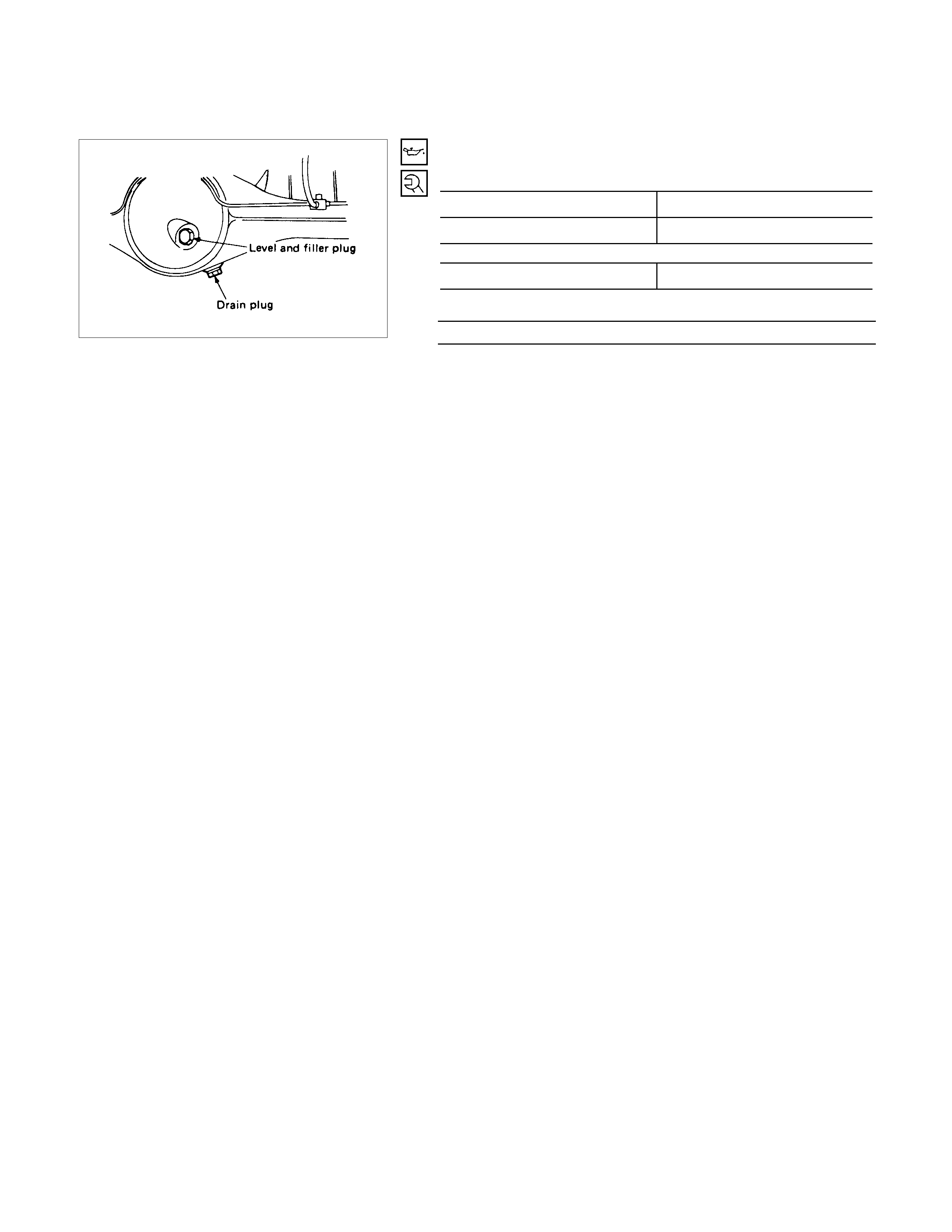
SERVICING
REAR AXLE OIL REPLACEMENT
Oil Capacity litres (US/UK gal.
)
194 mm 1.5 (0.4/0.33)
220 mm 1.8 (0.48/0.4)
Specified gear oil GL-5 (API grade)
Filler Plug and Drain Plug Torque N⋅m (kgf⋅m/lb⋅ft)
78.5 ± 14.7 (8 ± 1.5/58 ± 11)
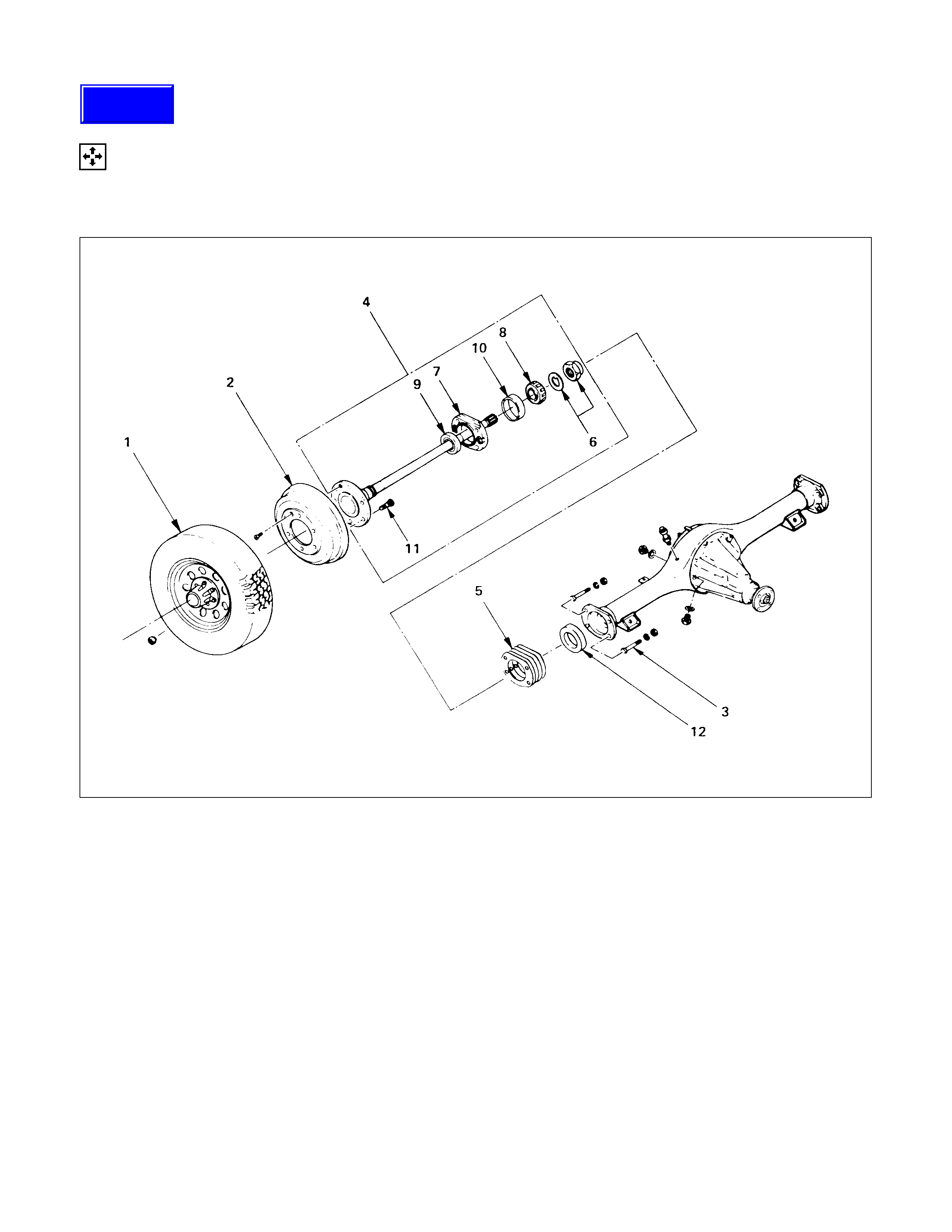
AXLE SHAFT
DISASSEM BLY
1. Refer to Section 10 "WHEEL and TYRE" for road wheel Disassembly procedure.
2. Refer to Section 5 "BRAKE" for rear brake removal procedure.
DISASSEM BLY STEPS
▲1. Wheel and tire
2. Brake drum
3. Bolt and nut
4. Axle shaft assembly
5. Shim
▲6. Bearing nut and lock washer
▲7. Bearing holder
8. Bearing
9. Oil seal
▲10. Bearing outer race
▲11. Wheel pin
12. Oil seal
Techline
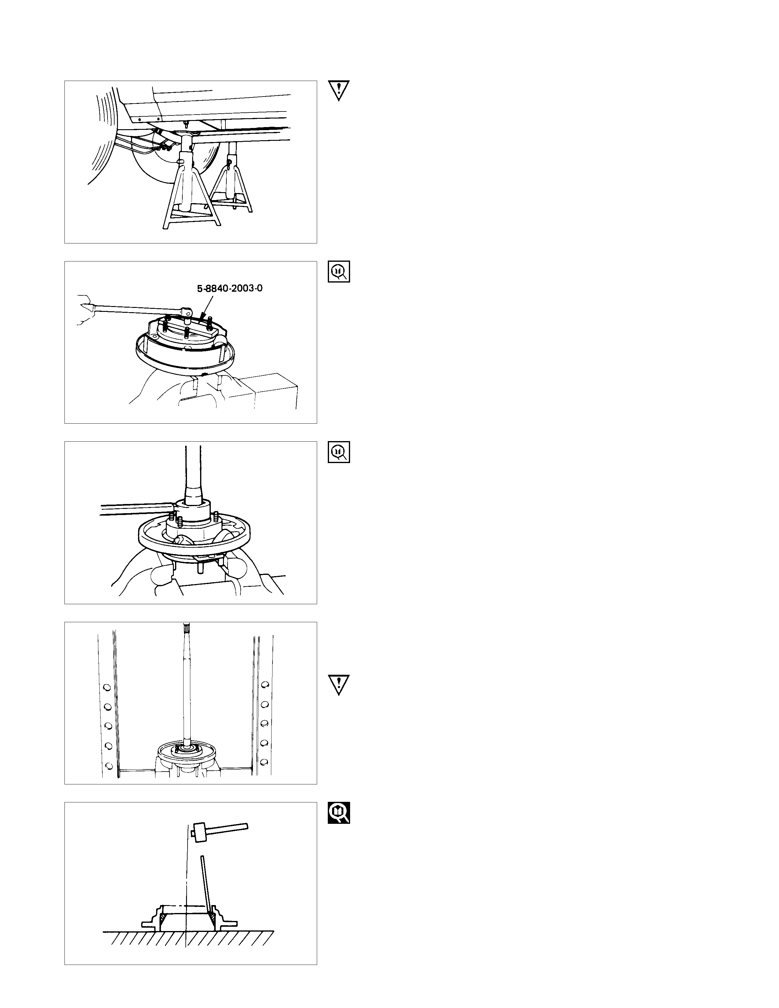
IMPORTANT OPERATIONS
1. Wheel and Tire
Raise vehicle to the working level.
Support the axle assembly with the proper jack and chassis
stands.
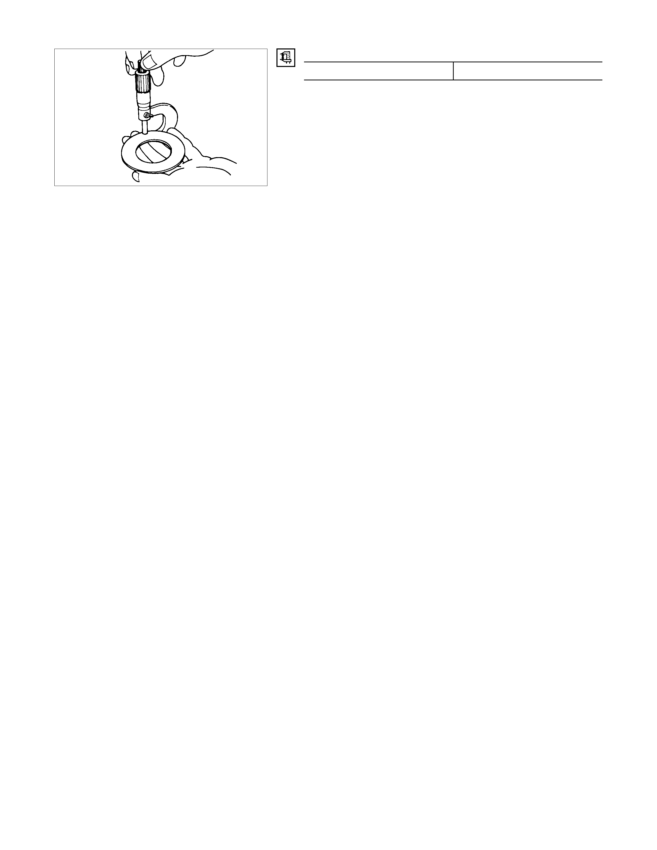
6. Bearing Nut and Washer
<Standard Type Axle Shaft>
(1)Remove the stake from the lock nut.
(2)Mount axle shaft into vice, clamping vice jaws around the
lock nut.
Vice should not be tightened excessively on lock nut.
(3)Install special tool onto flange studs, lock into position with
two wheel nuts, and turn axle shaft loose from lock nut.
Remover and installer : 58840-2003-0 (J-24246)
<Heavy-Duty Type Axle Shaft>
(1)Remove the stake from the lock nut.
(2)Install special tool onto lock nut, and remove the lock nut.
Remover and installer : 5-8840-2329-0
7. Bearing Holder
Remove the bearing holder and bearing from the axle shaft by
means of a press.
NOTE :
Only a slight amount of pressure from the press is
required to separate the bearing from the shaft. Be sure
to support the backing plate solidly, and to hold onto the
axle shaft to prevent it from falling to the floor.
10.Bearing Outer Race
Drive off the bearing outer race using a brass drift.
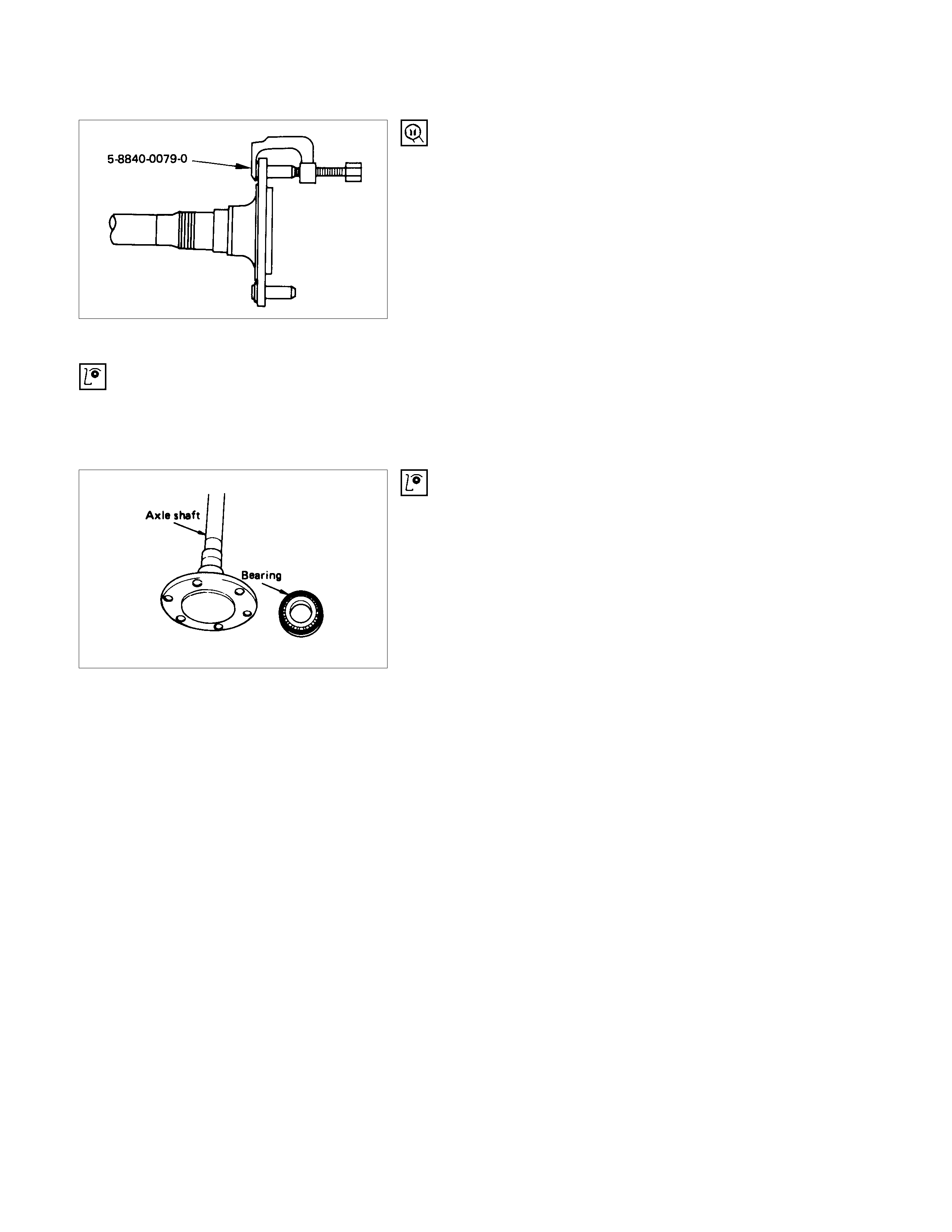
11.Wheel Pin
Remove the wheel pins from the axle shaft flange.
Remover : 5-8840-0079-0
(J-6627-A)
INSPECTION AND REPAIR
Make all necessary adjustments, repairs, and part replacements if wear, damage, or other problems are discovered
during inspections.
VISUAL CHECK
Inspect the following parts for wear, damage or other abnormal
conditions.
AXLE S HAFT
When checking the axle shaft, pay special attention to the
splined portions and replace the shaft if distortion or step wear
is noticeable. Correct slight step wear with a pencil grinder.
AXLE SHAFT RUN-OUT
Check the shafts for bending with the use of a dial indicator in
contact with the shaft. Rotate the shaft slowly and observe the
dial indicator.
Limit mm(in)
1.0 (0.039)
NOTE :
Never use heat to correct bending.
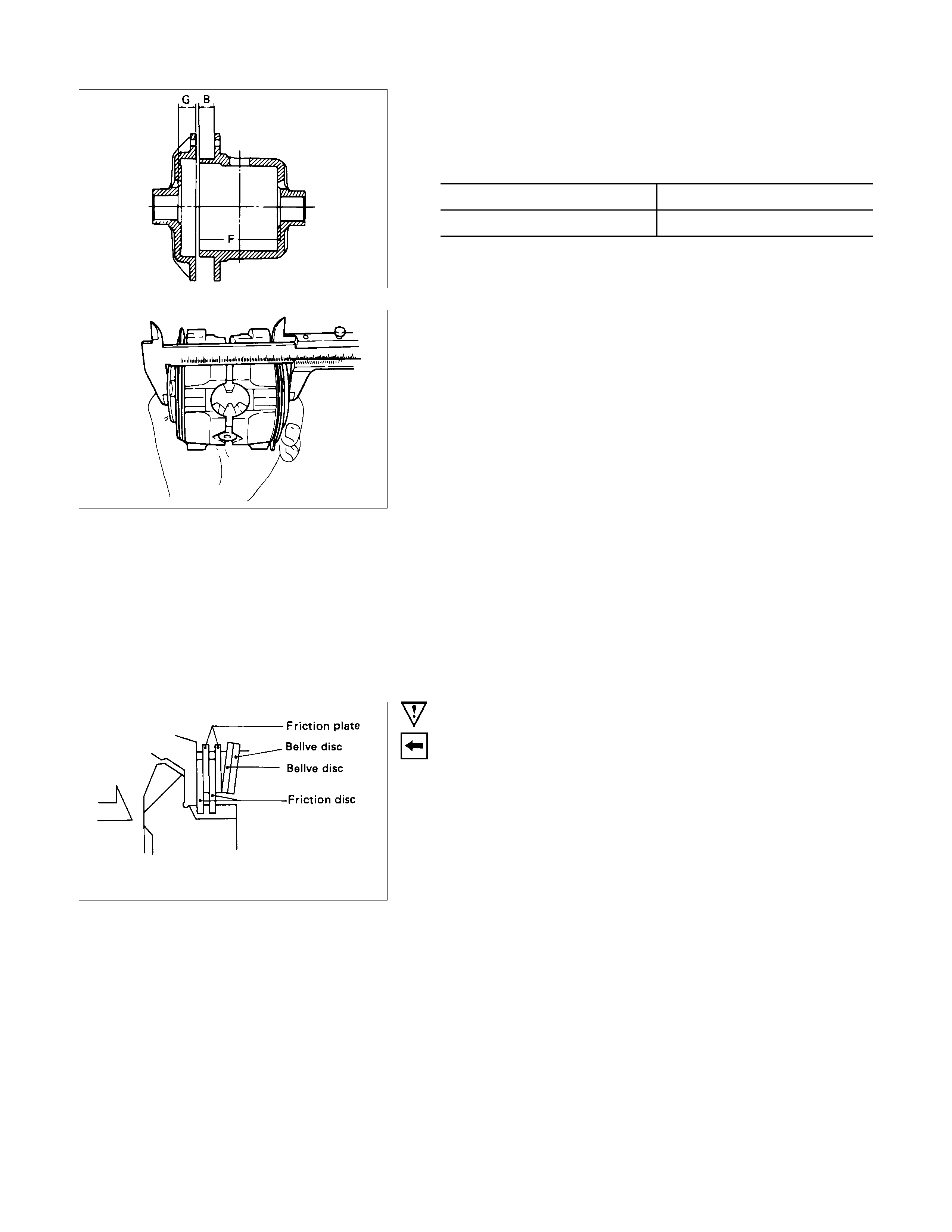
AXLE SHAFT FLANGE RUN-OUT
Check the axle shaft flange for run-out. Hold the probe of a
dial indicator in contact with the flange. Rotate the shaft slowly
and observe the dial.
Limit mm(in)
0.08 (0.003)
REASSEMBLY
1. Refer to Section 10 "WHEEL and TIRE" for road wheel reassembly procedure.
2. Refer to Section 5 "BRAKE" for rear brake installation procedure.
REASSEMBLY STEPS
1. Wheel pin
▲2. Bearing outer race
▲3. Oil seal
4. Bearing holder
▲5. Bearing
▲6. Axle shaft assembly
▲7. Bearing nut and lock washer
▲8. Oil seal
▲9. Shim
▲10. Bolt and nut
11. Brake drum
▲12. Wheel and tire
IMPORTANT OPERATIONS
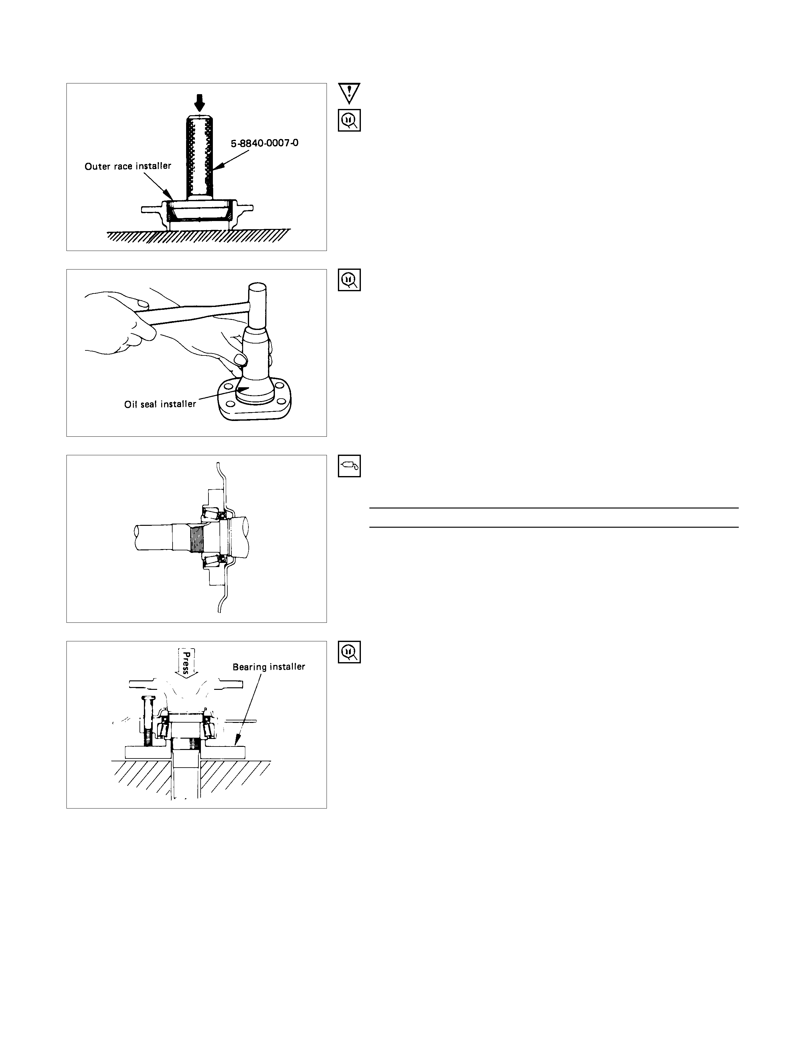
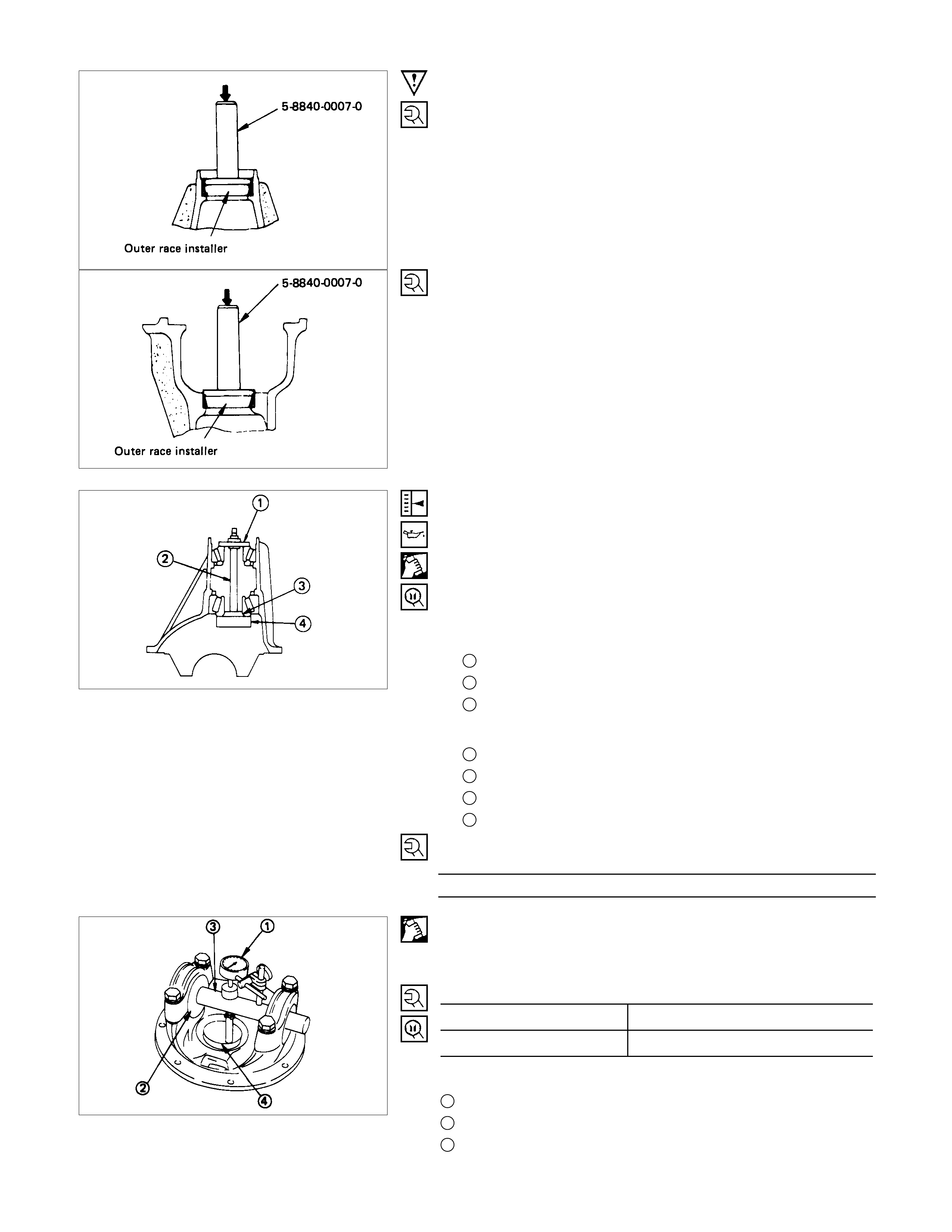
2. Bearing Outer Race
Installer : 5-8522-1268-0
(194 mm standard suspension)
(J-24259)
: 5-8840-2201-0
(194 mm heavy-duty suspension and 220 mm)
Grip : 5-8840-0007-0 (J-8092)
3. Oil Seal ; Bearing Holder
Installer : 9-8522-1269-0
(194 mm standard suspension)
(J-24255)
: 5-8840-2202-0(194 mm H/D, 220 mm)
5. Bearing
Apply a generous amount of grease to the bearing inner race.
g(oz)
Approx. 30 (1)
6. Axle Shaft Assembly
7. Bearing Nut and Lock Washer
(1)Insert four through-bolts into the back plate.
(2)Install bearing holder to the back plate.
(3)Install the above parts onto the axle shaft.
(4)Install bearing over axle shaft and press it into bearing
holder.
Axle shaft bearing Installer : 9-8522-1271-0 (J-8609-01)
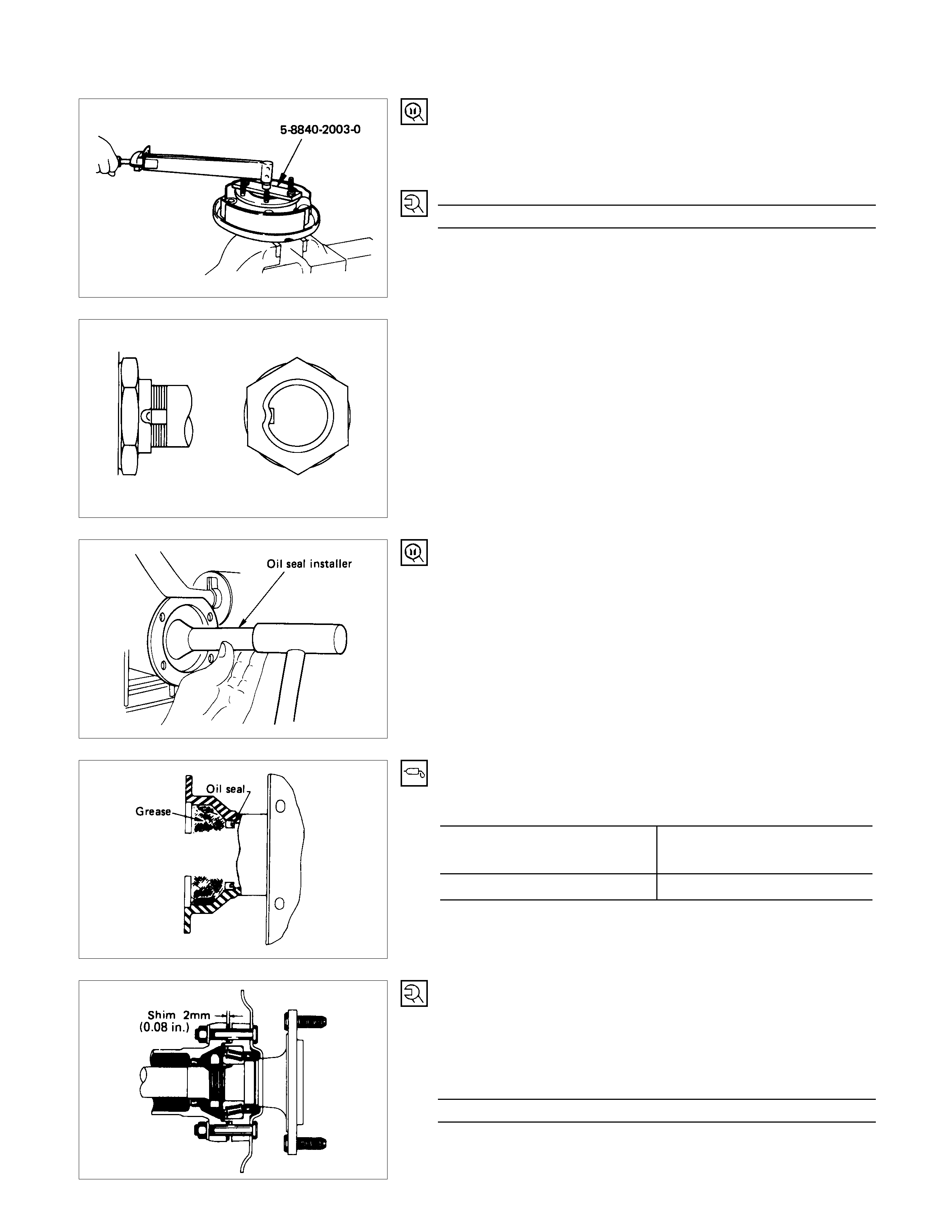
(5)Install the bearing nut into position by using a vice and the
special tool.
Installer : 5-8840-2003-0
(J-24246)
Torque N⋅m (kgf⋅m/lb⋅ft)
372.4 ± 39.2 (38.0 ± 4.0/274.7 ± 28.9)
(6)Position the chisel perpendicular to the centre of the lock
nut groove.
Stake the lock nut.
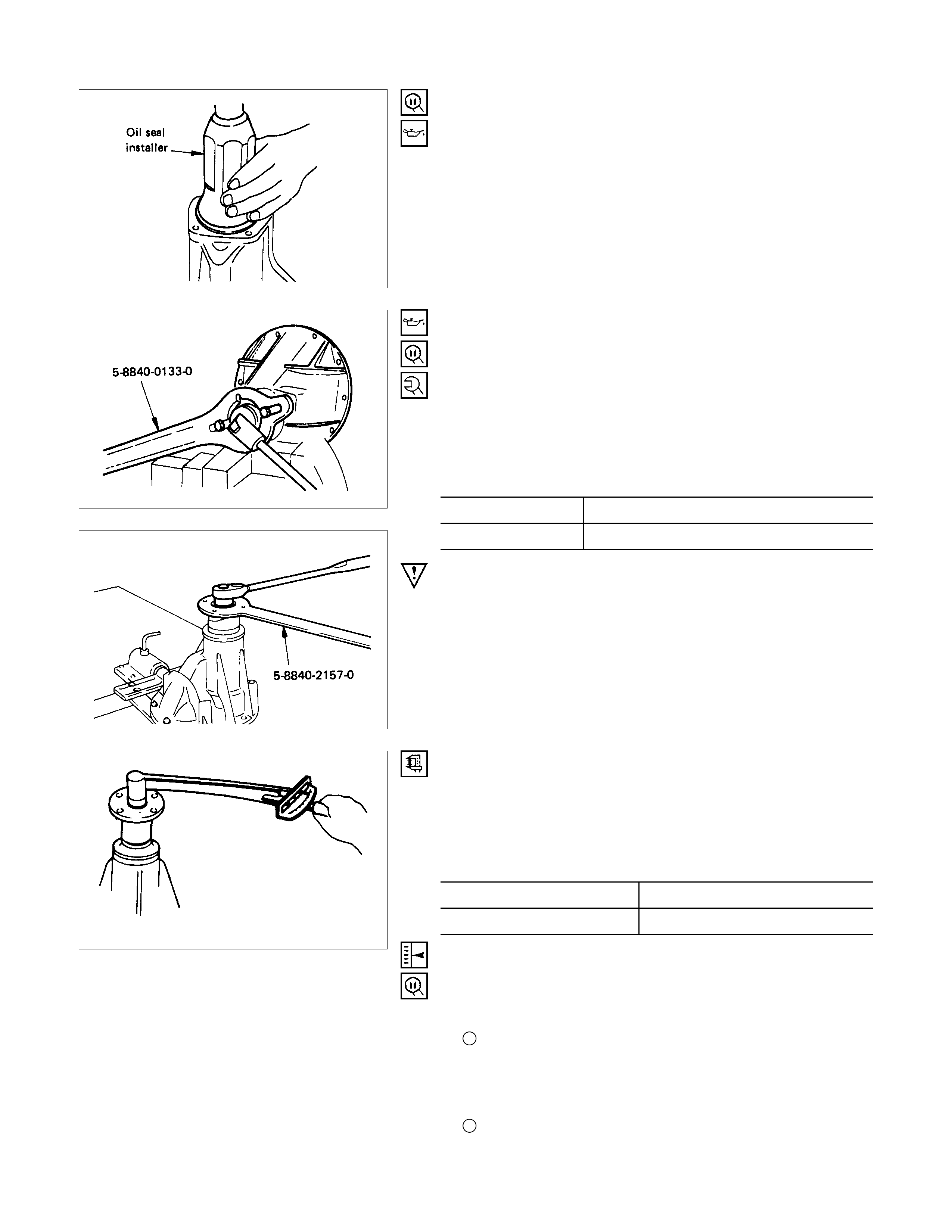
8. Oil Seal ; Axle Case
Oil seal installer : 9-8522-1272-0 (J-24254)
(1)Apply m easured am ount of good quality grease to the inne
r
face of the rear axle case. g(oz)
Type of grease Wheel bearing grease or
Multipurpose type grease
Amount of grease required 80 (2.8)
9. Shim
Install the axle shaft assembly to the axle case with a 2 mm
(0.08 in) thick shim fit into position between the bearing holder
and axle case flange. Install and tighten the bolts evenly in
progression.
Torque N⋅m (kg⋅m/lb⋅ft)
74 ± 5 (7.5 ± 0.5/54 ± 3.6)
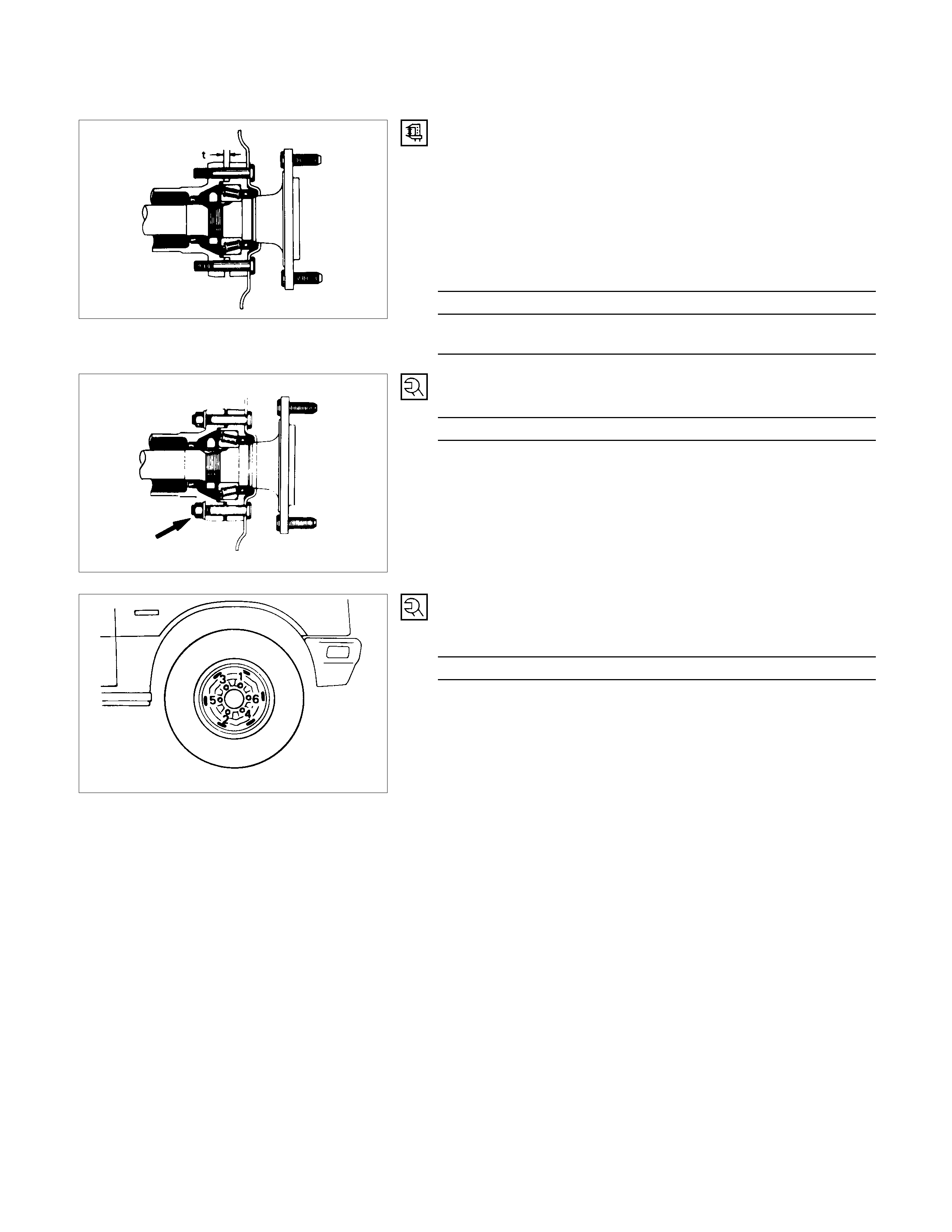
Install the axle shaft assembly on the opposite side and push it
in until it fits against the differential thrust block. Then,
measure the clearance (t) between the bearing holder and the
axle case flange and determine the thickness of the shim to be
installed by the following formula :
Measured clearance (t) + 0.3 mm (0.012 in) = thickness of
shim to be installed. mm(in)
thickness of shims available
1.0, 0.5, 0.13, 0.076, 0.05
(0.036, 0.026, 0.005, 0.003, 0.002)
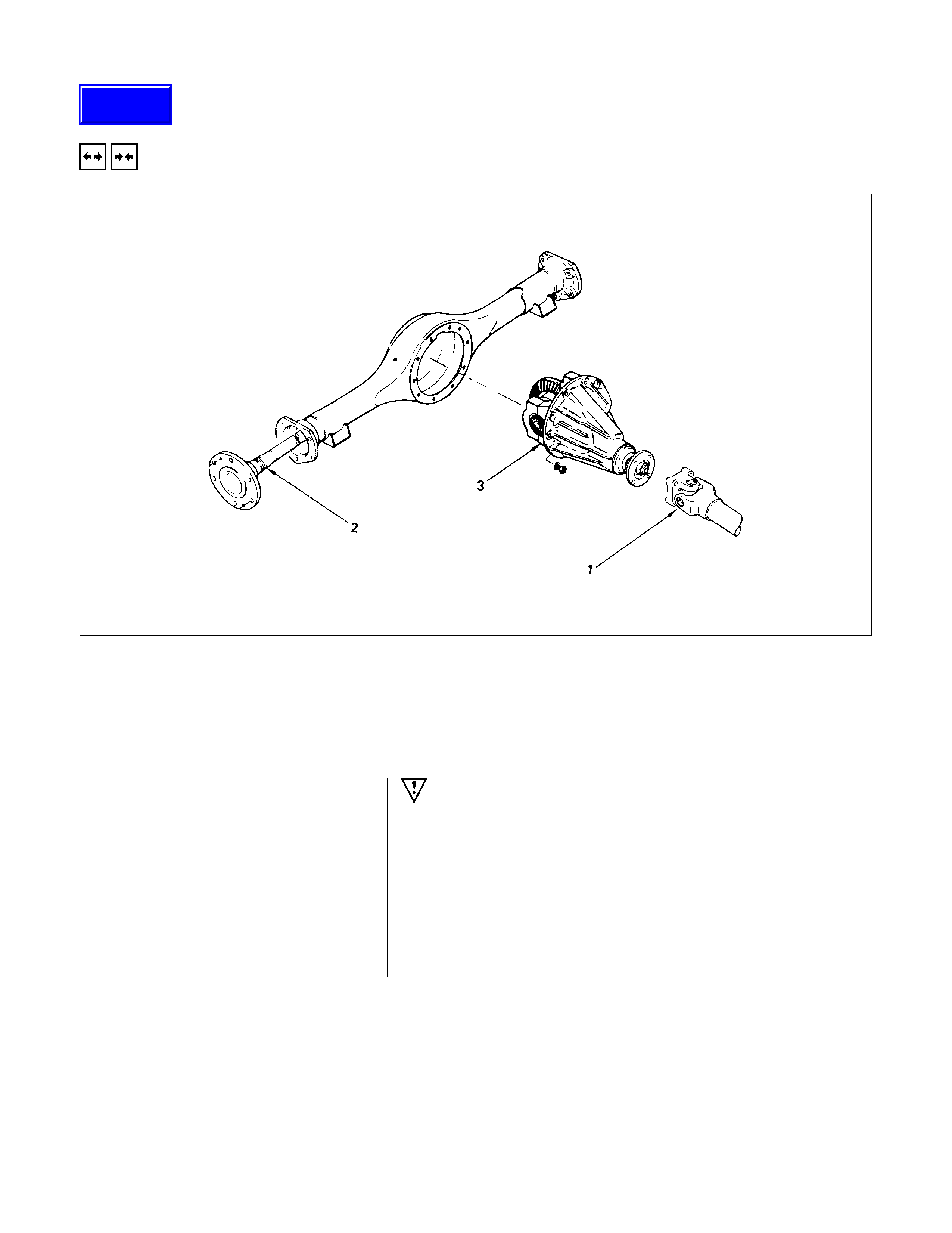
10.Bolt and Nut
Torque N⋅m (kgf⋅m/lb⋅ft)
74 ± 5 (7.5 ± 0.5 / 54 ± 3.6)
•Connect the brake lines to wheel cylinder.
•Connect the parking brake rear cable.
•Brake air bleeding; refer to servicing to Section 5 brake.
Note :
To install the axle shaft assembly, follow the reassembly
procedure outline under the "BRAKE".
12.Wheel and Tire
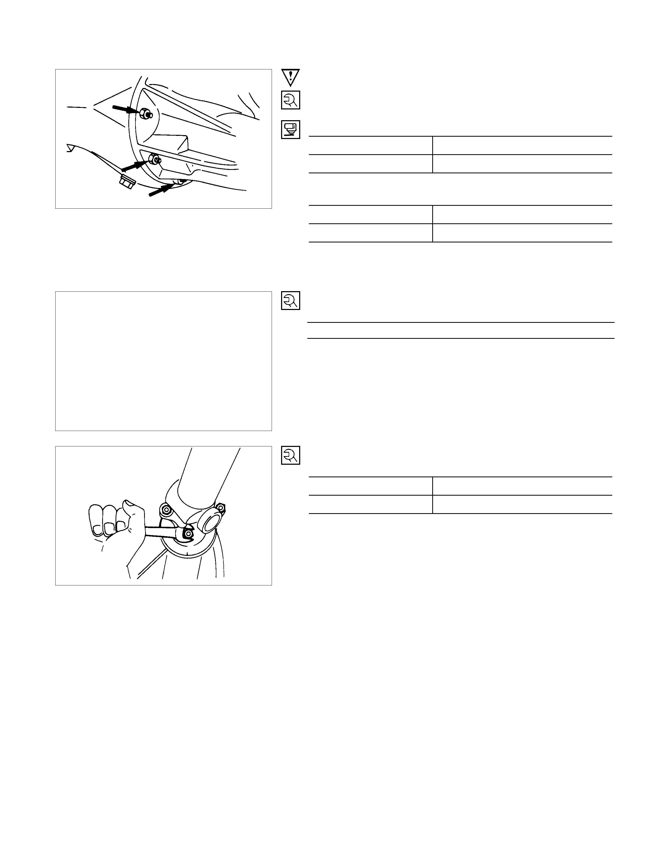
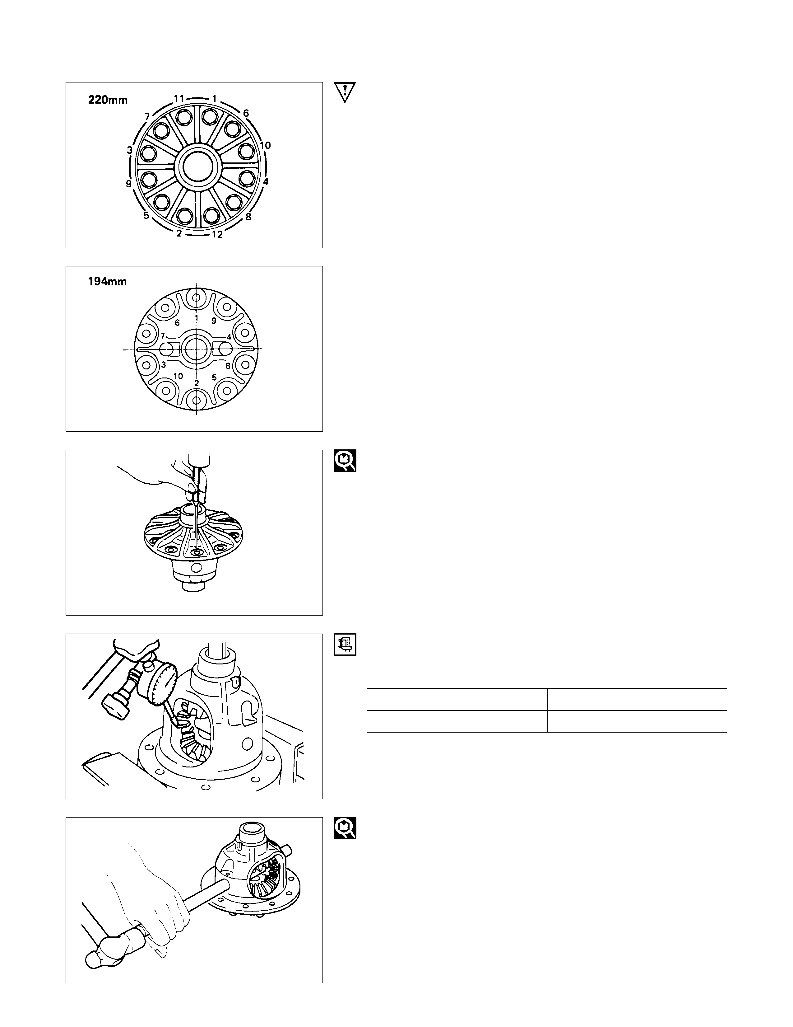
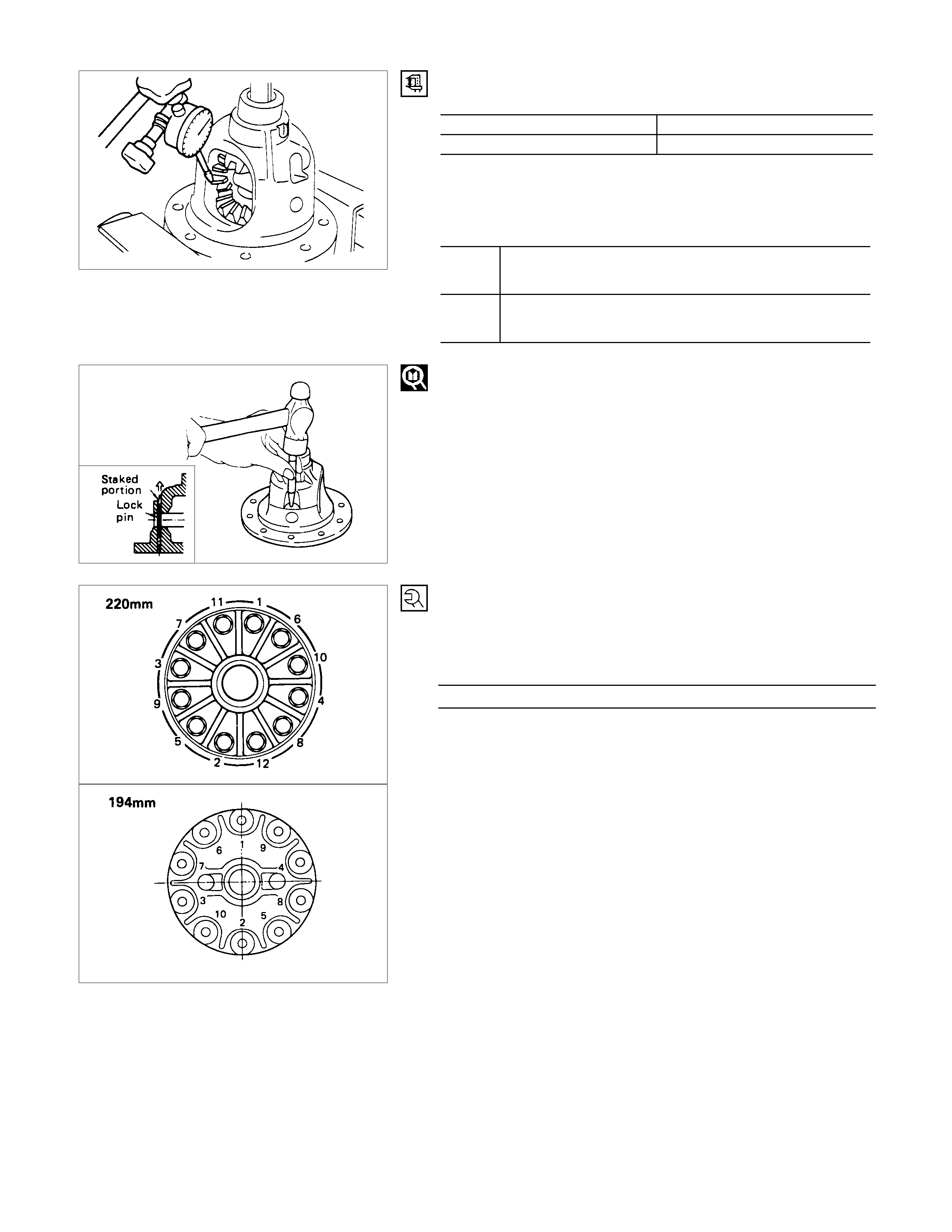
Tighten the wheel nut in numerical order.
Torque N⋅m (kgf⋅m/lb⋅ft)
117.7 ± 9.8 (12 ± 1/86.8 ± 7.2)
DIFFERENTIAL
REMOVAL AND INSTALLATION
REMOVAL STEPS
1. Propeller shaft
▲2. Axle shaft
3. Differential assembly
INSTALLATION STEPS
▲3. Differential assembly
▲2. Axle shaft
▲1. Propeller shaft
To remove the axle shaft assembly,
follow the disassembly procedure outline
in this Section “Axle shaft”
IMPORTANT OPERATION - REMOVAL
2. Axle Shaft
Disengage the axle shafts from the carrier assembly and
partially withdraw the shafts from the axle tube.
It is not necessary to completely remove the axle shafts.
Move them only enough to allow the differential to be removed.
To remove the axle shaft assembly, follow the disassembly
procedure outline in this Section "Axle shaft".
Techline
IMPORTANT OPERATIONS - INSTALLATION
3. Differential Assembly
(194 mm)
Torque N⋅m (kgf⋅m/lb⋅ft)
NUT 37.3 ± 3.9 (3.8 ± 0.4/27 ± 2.9)
BOLT 24.5 ± 5 (2.5 ± 0.5/18 ± 3.6)
(220 mm)
Torque N⋅m (kgf⋅m/lb⋅ft)
NUT 44 ± 14.7 (4.5 ± 1.5/32.5 ± 10.8)
BOLT 63.8 ± 5 (6.5 ± 0.5/47 ± 3.6)
Apply the recommended liquid gasket or its equivalent to the
sealing side of the axle case and the carrier.
To install the axle shaft assembly, follow
the reassembly procedure outline in the
“Rear axle shaft” section.
2. Axle Shaft
Torque N⋅m (kgf⋅m/lb⋅ft)
73.6 ± 5 (7.5 ± 0.5/54.2 ± 3.6)
1. Propeller Shaft
Torque N⋅m (kgf⋅m/lb⋅ft)
194 mm 35.3 ± 2.9 (3.6 ± 0.3/26 ± 2.2)
220 mm 62.8 ± 3.9 (6.4 ± 0.4/46.3 ± 2.9)
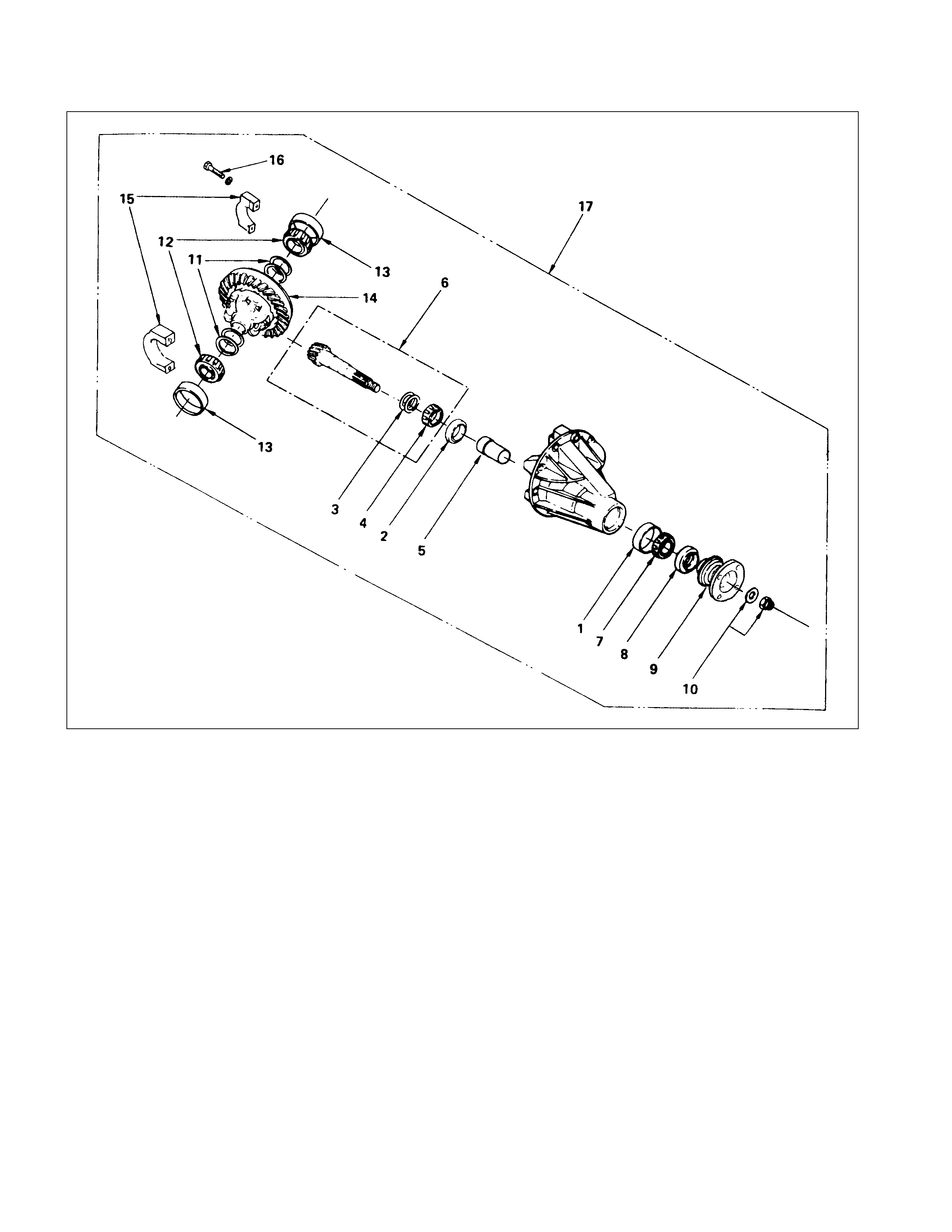
DISASSEM BLY
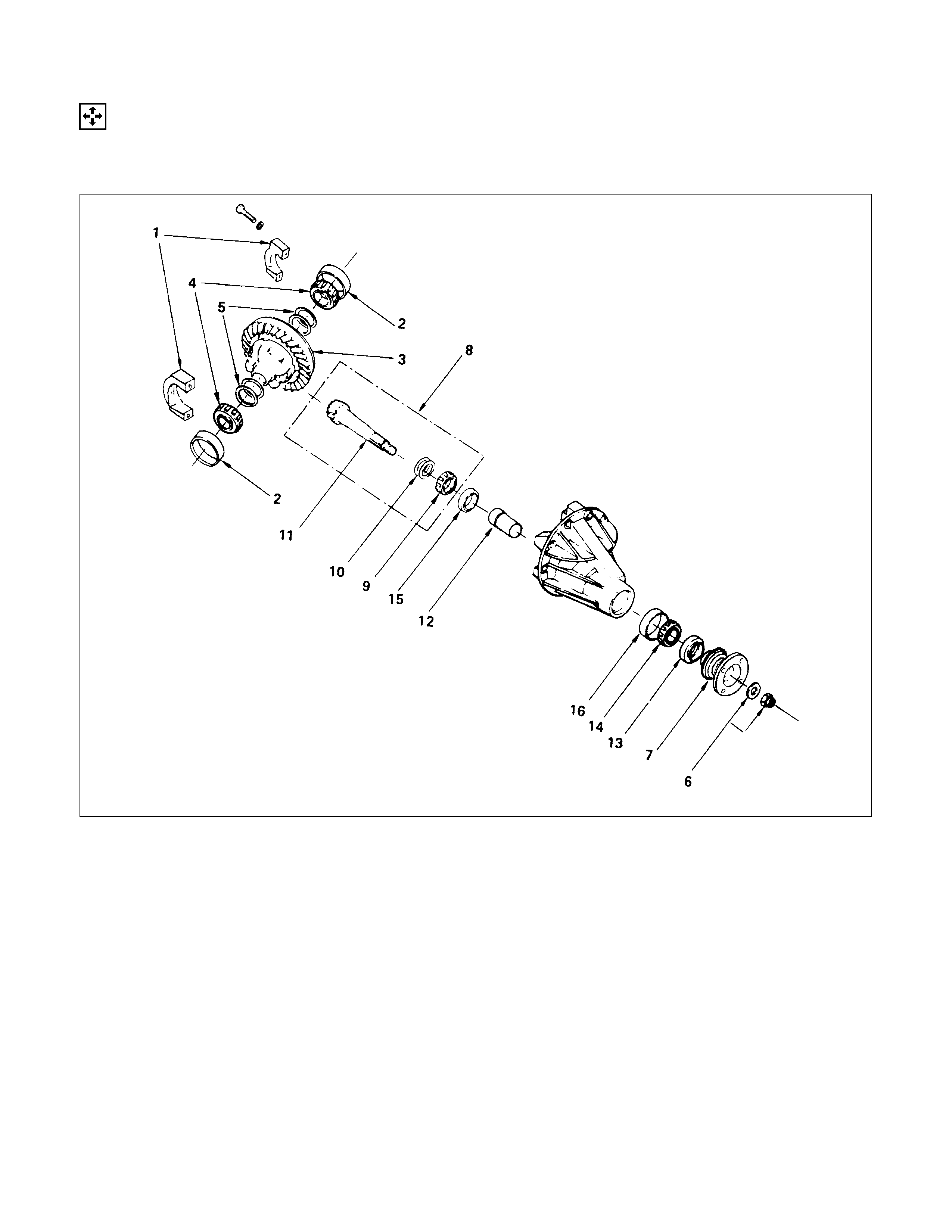
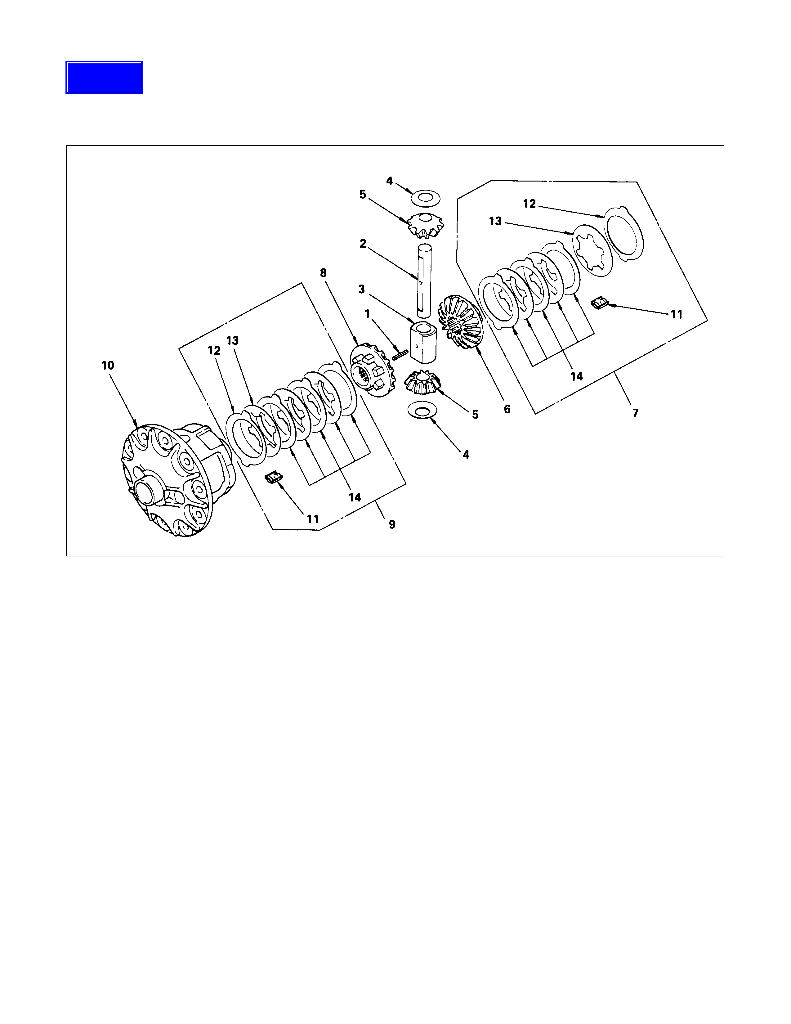
MAJO R COMPONENTS
DISASSEM BLY STEPS
▲1. Side bearing cap
▲2. Side bearing outer race
3. Differential cage assembly and ring gear
▲4. Side bearing
▲5. Backlash and side bearing preload
adjusting shim
▲6. Flange nut and washer
7. Flange assembly
▲8. Drive pinion shaft assembly
▲9. Inner bearing
10. Pinion depth adjusting shim
11. Drive pinion shaft
12. Collapsible spacer
13. Oil seal
14. Outer bearing
▲15. Inner bearing outer race
▲16. Outer bearing outer race
IMPORTANT OPERATIONS
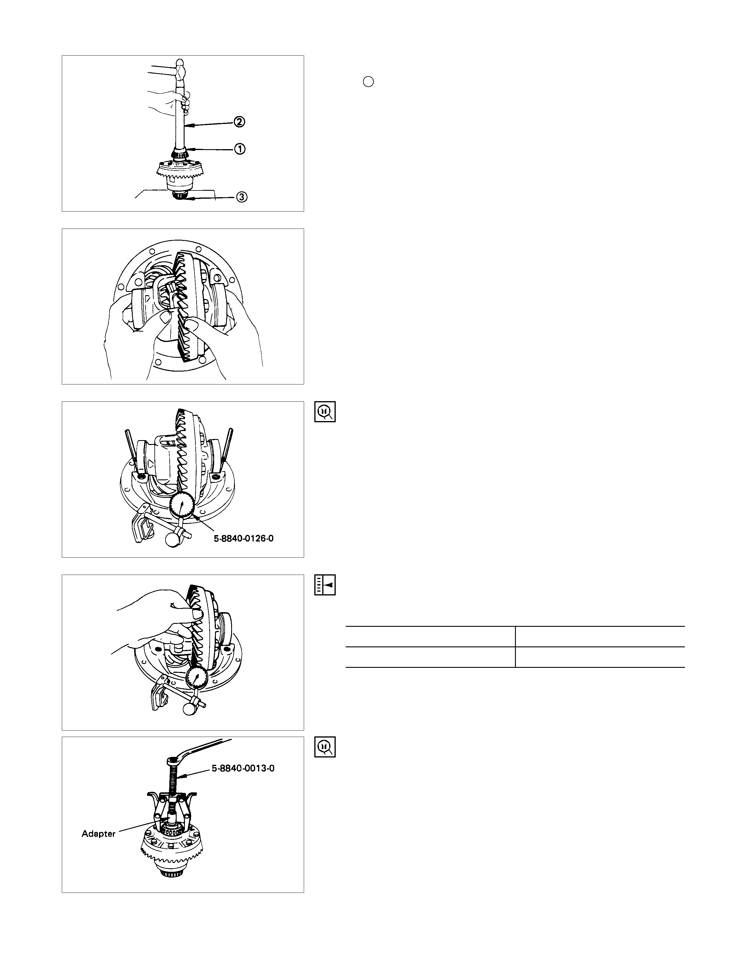
Before disassembling, make a pattern check using the method
described later in this section under "Gear Tooth Contact
Pattern Check and Adjustments". This check will help
determine what service should be performed on the differential
components.
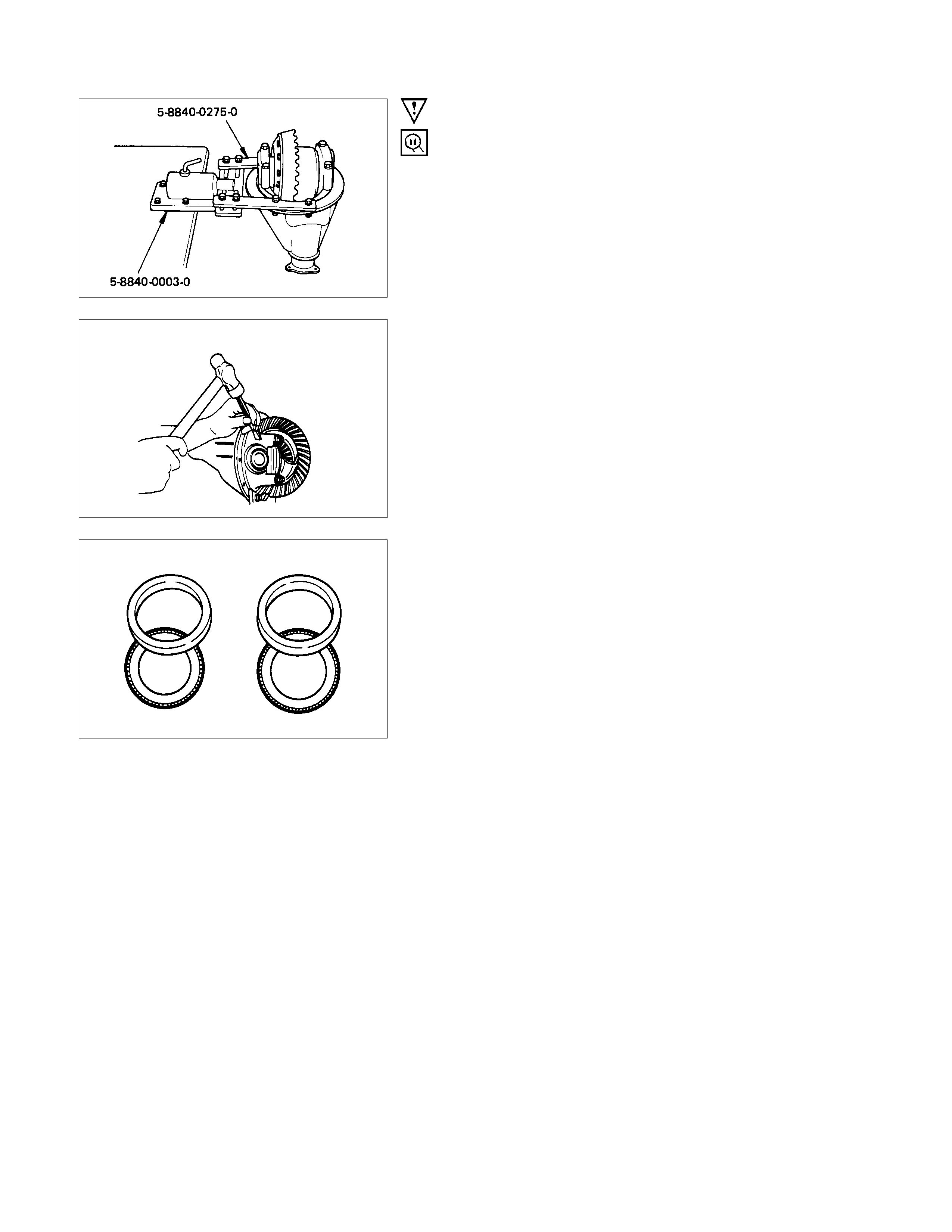
On some bench operations, it may be advantageous to use a
holding fixture and a holding fixture base.
Tool 5-8840-0275-0 (J-37264) and 5-8840-0003-0 (J-3289-20)
are available tools that work well for this purpose.
1. Bearing Cap
Apply an alignment mark to the side bearing cap and
differential carrier.
2. Side Bearing Outer Race
After removal, keep the right and left side bearing assemblies
separate to maintain inner and outer race combinations.
4. Side Bearing
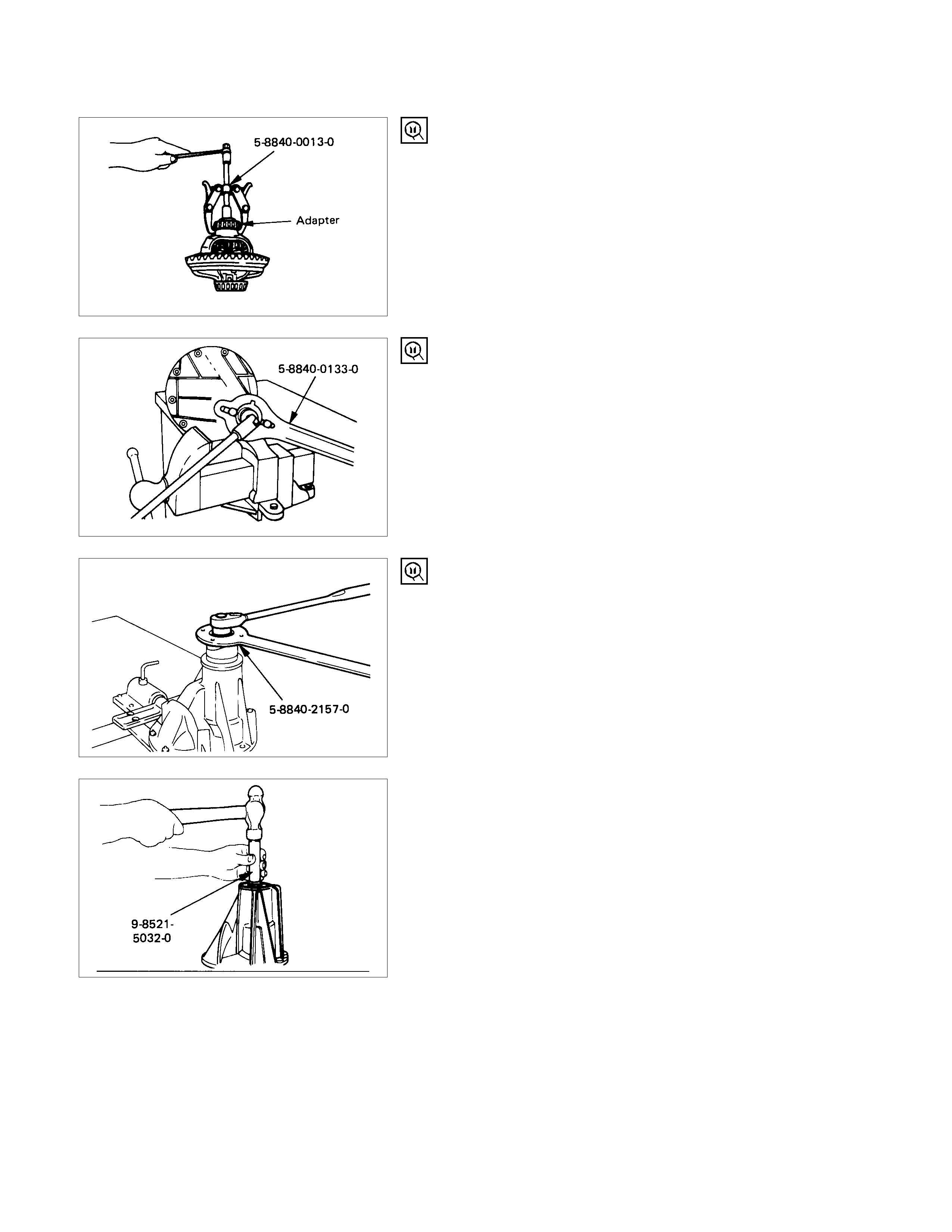
5. Backlash and Side Bearing Preload Adjusting Shim
Remover : 5-8840-0013-0 (J-22888)
Adaptor : 9-8521-1743-0 (J-8107-2) (194 mm)
5-8840-2196-0 (J-8107-4) (220 mm)
Carefully record the thickness of each side bearing and each
shim pack. Keep them separated and in order for later
reassembly.
6. Flange nut and washer (194 mm)
Holder : 5-8840-0133-0
(J-8614-01)
FLANGE NUT AND WASHER (220 MM)
Holder : 5-8840-2157-0
(J-37221)
8. Drive Pinion Shaft Assembly
Hold a soft metal rod against the end of the drive pinion. Drive
out the pinion from the carrier by tapping the hammer against
the metal rod.
Installer : 9-8521-5032-0
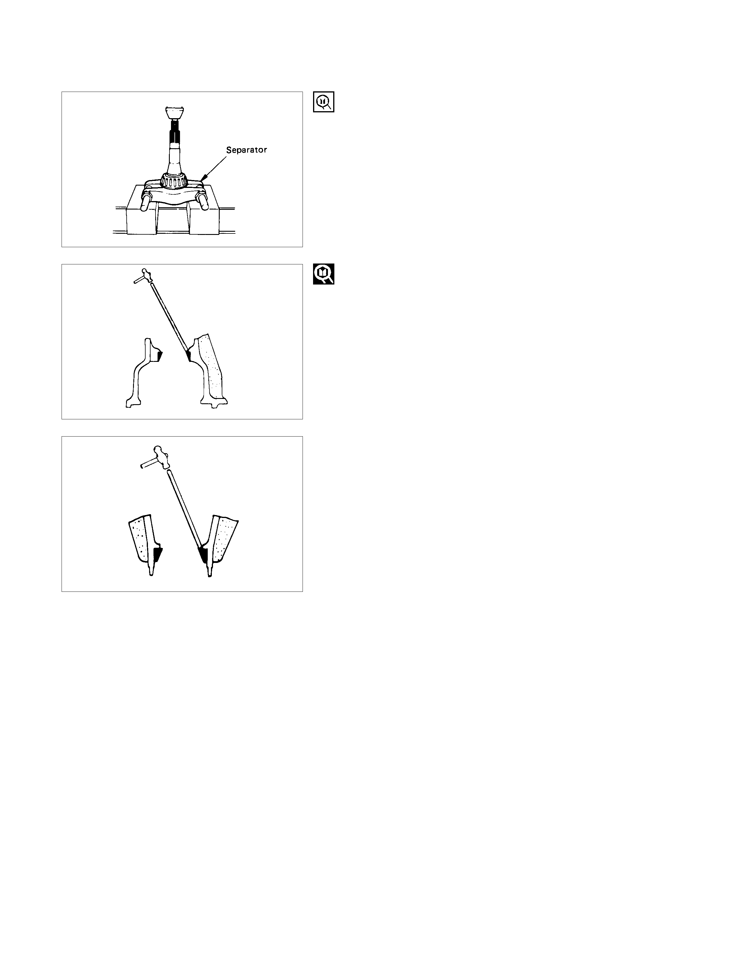
9. Inner Bearing
Remove the pinion bearing using a separator and a press.
Separator : 5-8840-0015-0 (194 mm)
(J-22912-01)
: 5-8840-2197-0 (220 mm)
(J-37452)
Inner bearing oute
r
race 15.Inner Bearing Outer Race
16.Outer Bearing Outer Race
Remove the inner bearing outer race and the outer bearing
outer race by using a brass bar and a hammer.
Other bearing oute
r
race
MINOR COMPONENTS
STANDARD DIFFERENTIAL
DISASSEM BLY STEPS
▲1. Ring gear
▲2. Lock pin
▲3. Cross pin
4. Pinion gear
5. Thrust block
6. Side gear
7. Thrust washer
8. Differential cage
IMPORTANT OPERATIONS
1. Ring Gear
Take care not to damage the ring gear or the differential case
when removing the ring gear. Never try to wedge a tool
between the two faces.
2. Lock Pin
Drive out the pinion shaft lock pin with a long drift punch. It
may be necessary to first remove the stakes in the lock pin
with a 5-mm drill.
3. Cross Pin
(1)Check the amount of backlash before removal.
Backlash mm(in
)
194 mm 0.10 - 0.20 (0.004 - 0.008)
220 mm 0.13 - 0.18 (0.005 - 0.007)
(2)Rem ove the cross pin with a brass dr ift punc h, and take out
the pinion gears, side gears, thrust block and thrust
washers from the differential cage.
LIMI TED SLIP DI FFERENTIAL (LSD)
(FOR RING SIZE 194 mm)
DISASSEM BLY STEPS
1. Spring pin
2. Pinion spider
3. Thrust block
▲4. Pinion washer
▲5. Pinion gear
6. Side gear
7. Friction disc and plate assembly
8. Side gear
9. Friction disc and plate assembly
10. Differential cage
11. Sleeve
12. Spring plate
13. D isc spring
14. Disc and plate
Techline

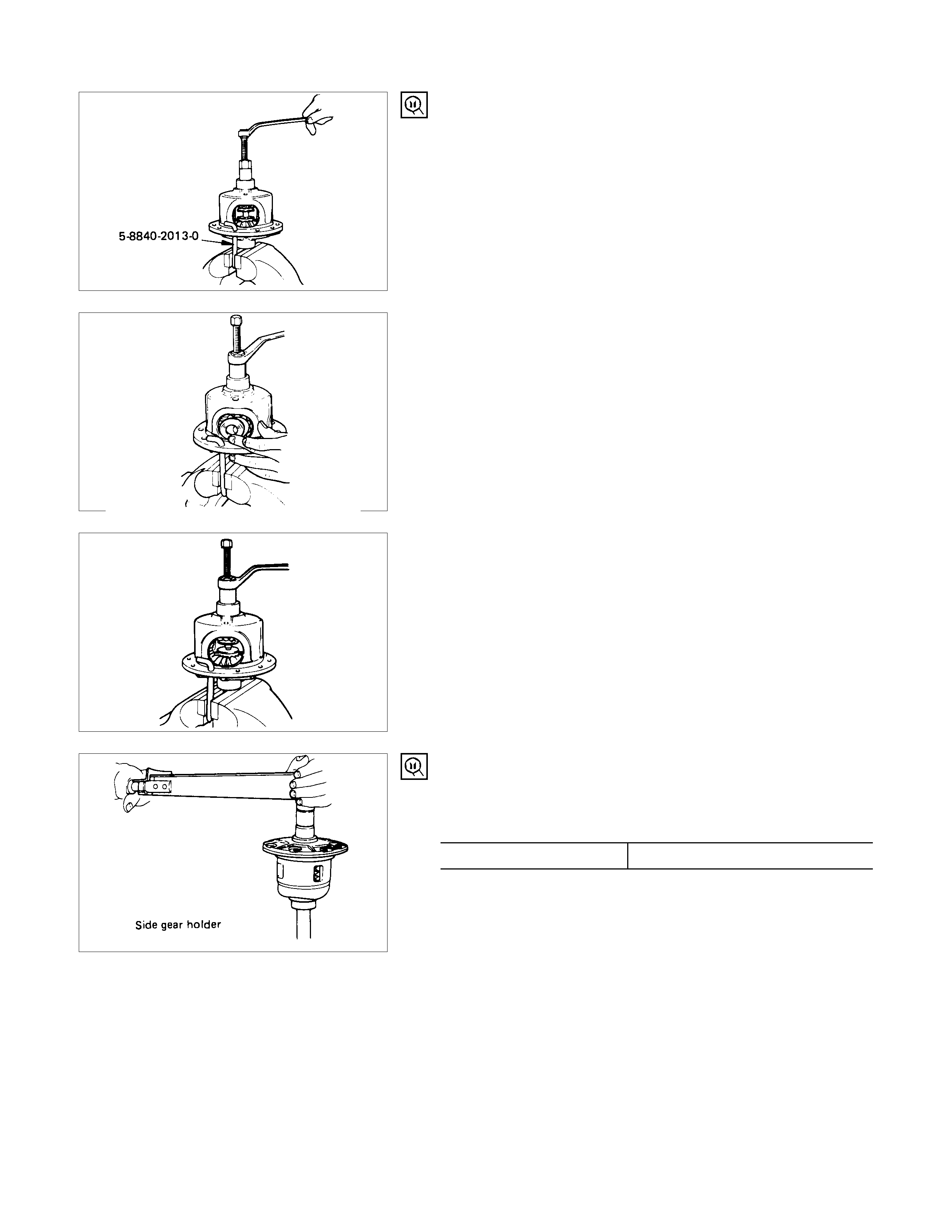
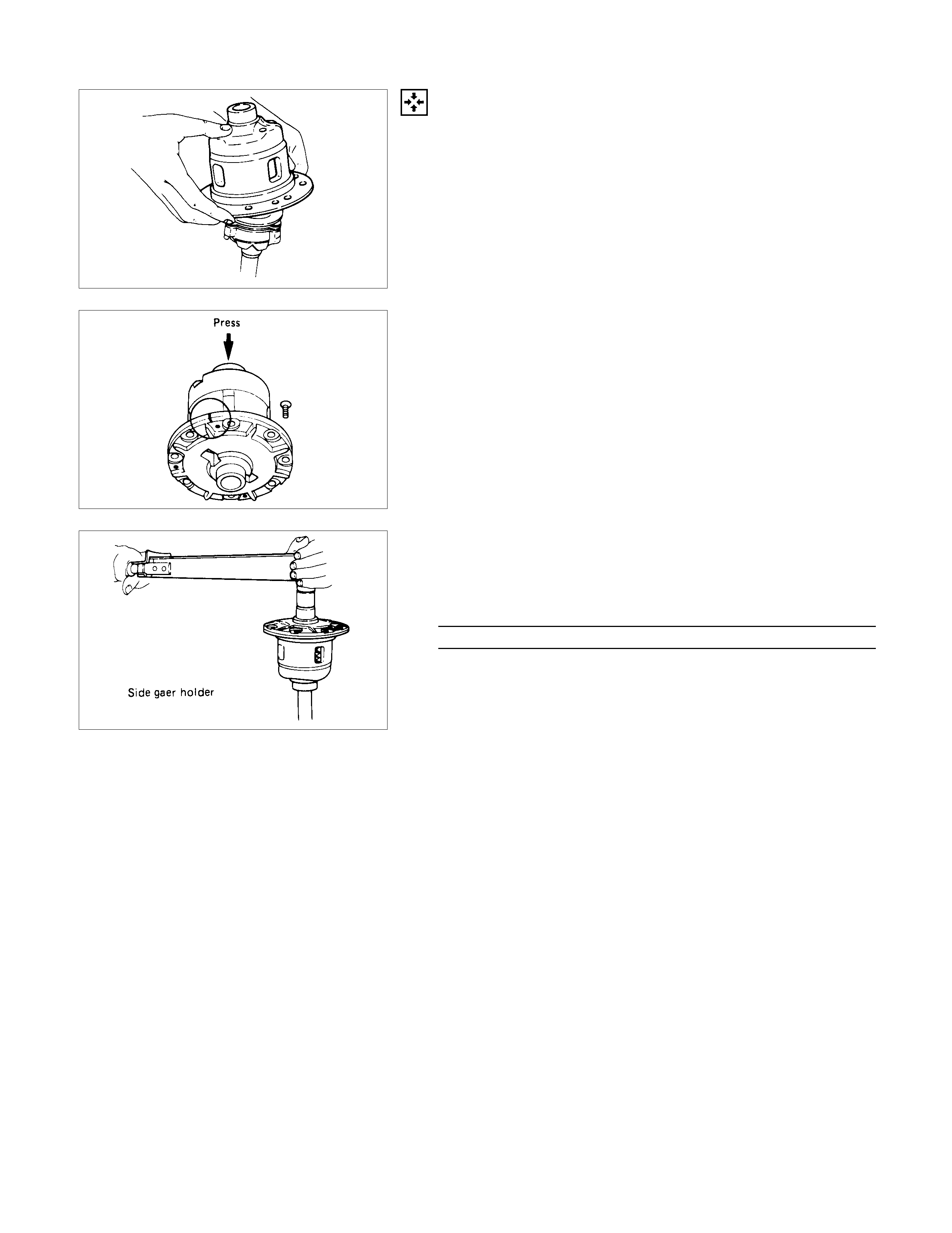
IMPORTANT OPERATIONS
4. Pinion washer
5. Pinion gear
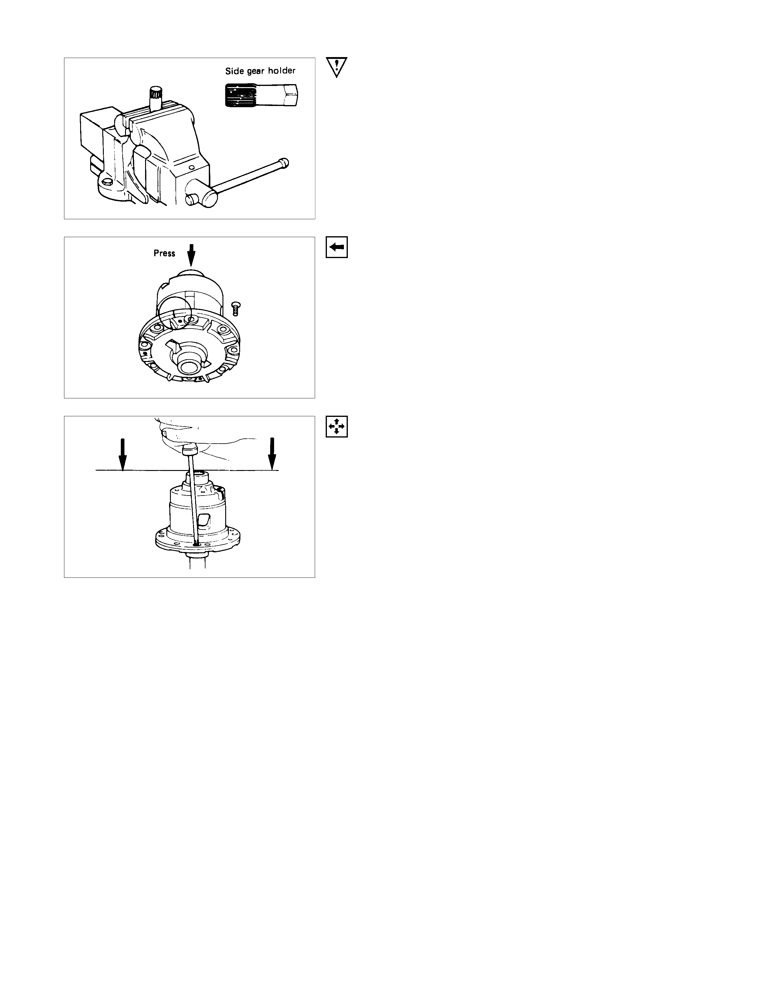
(1)Clamp special tool (side gear holder) into a vice. Set the
LSD assembly.
Holder : 5-8840-2010-0
(J-36563)
(2)Set special tools (side pinion expanders and pinion rotator)
to the LSD.
Expander : 5-8840-2011-0
(J-36564)
Rotor : 5-8840-2012-0
(J-36565)
(3)Set special tool (cage lock bar) through a ring gear fixing
hole to a vice.
Then rotate s ide pinion ex panders with a wrench one half to
one full turn to provide backlash between the side and
pinion gears.
Bar : 5-8840-2013-0
(J-36566)
(4)W ith a wrench, rotate special tool ( pinion rotator) to rem ove
the pinion gear and the pinion washer.

(FOR RING SIZE 220 mm)
DISASSEM BLY STEPS
▲1. Bolt
2. Differential cage cover
3. Thrust washer
4. Bellville disc
5. Bellville disc
6. Friction plate
7. Friction disc
8. Friction plate
9. Friction disc
10. Pressure ring
11. Side gear
12. Thrust block
13. Pinion gear and pinion spider
14. Side gear
15. Pressure ring
16. Friction disc
17. Friction plate
18. Friction disc
19. Friction plate
20. Bellville disc
21. Bellville disc
22. Thrust washer
23. Thrust washer
IMPORTANT OPERATIONS
•Prepare a side gear holder (An axle shaft m ust be used) as
shown in the left f igure, clam p it with a stock vice, and s et a
differential.
1. Bolt
Apply a setting mark to the differential cage cover and
differential cage a remove the bolt using the press.
•W hen the differential cage is pressed down with the press,
loosen the four bolts fixing the differential cage evenly and
remove them, and then disconnect the differential cage.
INSPECTION AND REPAIR
Make all necessary adjustments, repairs, and part replacements if wear, damage, or other problems are discovered
during inspection.
• Gear
• Bearing
• Differential box
• Drive pinion
VISUAL CHECK
Inspect the following parts for wear, damage or other abnormal
conditions.
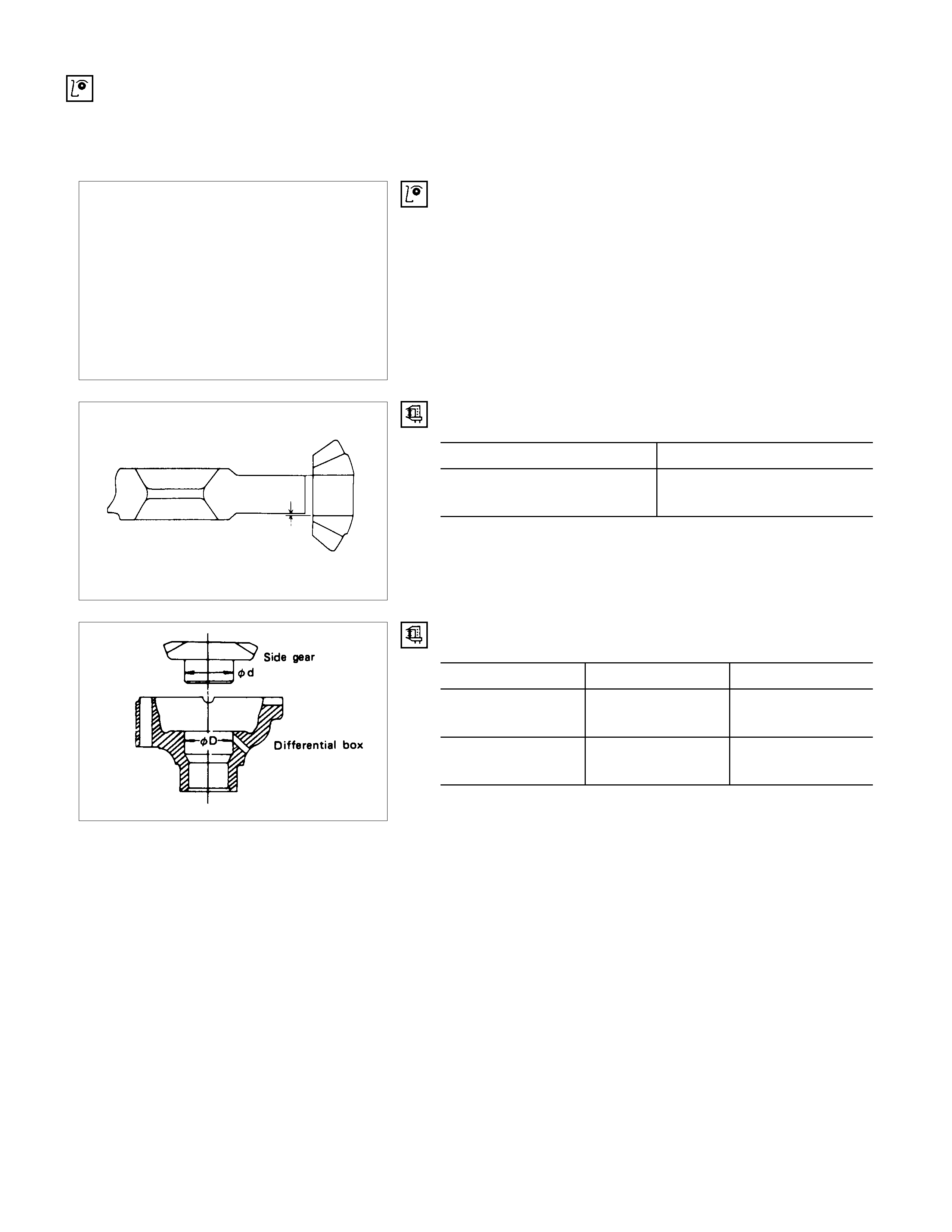
Clearance between pinion gear and cross pin:
194 mm and 220 mm mm(in)
Standard Limit
0.06 - 0.12
(0.002 - 0.005) 0.2 (0.008)
Clearance between side gear and differential cage. mm(in)
Standard Limit
194 mm 0.03 - 0.10
(0.001 - 0.004) 0.15 (0.006)
220 mm 0.05 - 0.11
(0.002 - 0.004) 0.15 (0.006)
Play in splines between the side gear and axle shafts. mm(in)
Standard Limit
194 mm 0.08 - 0.36 (0.003 - 0.014)
220 mm 0.08 - 0.38 (0.003 - 0.015) 0.5 (0.02)
DIFFERENTIAL CAGE
Check the ring gear the side gear fitting faces and the cross
pin hole for scores or roughness. Correct as necessary. Slight
scores or roughness may be corrected with an oil stone or fine
sand paper.
<LSD FOR 194 mm>
Friction disc and plate assembly.
Check the parts for damage or other abnormal conditions.
Check the friction plate for distortion.
Limit mm(in) 0.07 (0.0027)
Check the friction plate for wear.
Limit (A - B) mm(in) 0.1 (0.0039)
Note : A = Non-sliding face thickness
B = Sliding face thickness
Check the friction disc for distortion.
Limit mm(in) 0.07 (0.0027)
Check the friction disc for wear.
Limit (A - B) 0.1 (0.0039)
Note : A = Non-sliding face thickness
B = Sliding face thickness
SLIDE GEAR AND SLEEVE
Check the parts for damage or other abnormal conditions.
PINION SHAFT AND PINION GEAR
Check the parts for damage or other abnormal conditions.
<LSD FOR 220 mm>
PRESSURE RING
Check the parts for damage or other abnormal conditions.
1Sliding part for a pinion
2Sliding part for a disc
3Sliding part for a gear
4V-shape groove for the pinion spider
5Fitting protrusion for a case
6Fitting part for the inner surface of a case
7Sliding part for a side gear or a case
FRICTION DISC AND PLATE ASSEMBLY
Check the parts for damage or other abnormal conditions.
1Sliding part
2Protrusion
Check the friction plate for distortion.
Limit mm(in) 0.08 (0.0031)
Check the friction plate for wear.
Limit (A - B) mm(in). 0.1 (0.0039)
Note :
A = Non-sliding face thickness
B = Sliding face thickness
Check the friction disc for distortion.
Limit mm(in) 0.08 (0.0031)
Check the friction plate for wear.
Limit (A - B) mm(in). 0.1 (0.0039)
Note :
A = Non-sliding face thickness
B = Sliding face thickness
Check the Thrust Washer mm(in)
Limit 1.3 (0.051)

REASSEMBLY
MINOR COMPONENTS
LIMI TED SLIP DI FFERENTIAL (LSD)
<FOR RING SI ZE 194 mm>
REASSEMBLY STEPS
▲1. Friction disc and plate
▲2. Disc spring
3. Spring plate
4. Sleeve
5. Differential cage
6. Friction disc and plate assembly
7. Side gear
8. Friction disc and plate assembly
9. Side gear
▲10. Pinion gear
▲11. Pinion washer
12. Thrust block
13. Pinion shaft
14. Spring pin

IMPORTANT OPERATIONS
1. Friction disc and plate
Measure the thickness of disc and plate pack (A). mm(in)
Thickness (A) 7 ± 0.1 (0.27 ± 0.004)
If the thickness (A) is beyond the limits, adjust with a friction
disc of selected thickness.
Thickness of friction discs available mm(in)
1.4 (0.055), 1.5 (0.059)
Apply molybdenum disulphide grease to the friction discs and
plates.
3. Spring plate
Install the spring plate with dished side turned side turned to
the differential cage side.
10.Pinion gear
11.Pinion washer
(1)Clamp special tool (side gear holder) into a vise. Set the
LSD assembly.
Holder : 5-8840-2010-0
(J-36563)
(2)Set special tools (side pinion expanders and side pinion
rotator) to the LSD.
Expander : 5-8840-2011-0
(J-36564)
Rotator : 5-8840-2012-0
(J-36565)
(3)Set special tool (cage lock bar) through a ring gear fixing
hole to a vice.
Then rotate s ide pinion ex panders with a wrench one half to
one full turn to pr ovide proper clearanc e to install the pinion
gears.
Bar : 5-8840-2013-0
(J-36566)
(4)Attach the pinion gears and washers in the proper order to
the left and right hand side of the differential cage.
(5)W ith a wrench, turn special tool (pinion rotator) to align the
pinion gear and washer holes with the pinion shaf t holes on
the differential cage.
CONFIRMATION OF OPERATION
Using the side gear holder, measure the starting of the side
gear.
Starting Torque N⋅m (kgf⋅m/lb⋅ft)
Standard 147-225 (15 - 23/108 - 166)
Side gear holder : 5-8840-2010-0
(J-36563)
Side gear rotor : 5-8840-2012-0
(J-36565)
<FOR RING SI ZE 220 mm>
REASSEMBLY STEPS
1. Differential cage
2. Thrust washer
▲3. Bellville disc
▲4. Bellville disc
5. Friction plate
6. Friction disc
7. Friction plate
8. Friction disc
▲9. Pressure ring
10. Side gear
11. Pinion gear and pinion spider
12. Thrust block
13. Side gear
14. Pressure ring
15. Friction disc
16. Friction plate
17. Friction disc
18. Friction plate
▲19. Bellville disc
▲20. Bellville disc
21. Thrust washer
22. Differential cage cover
▲23. Bolt
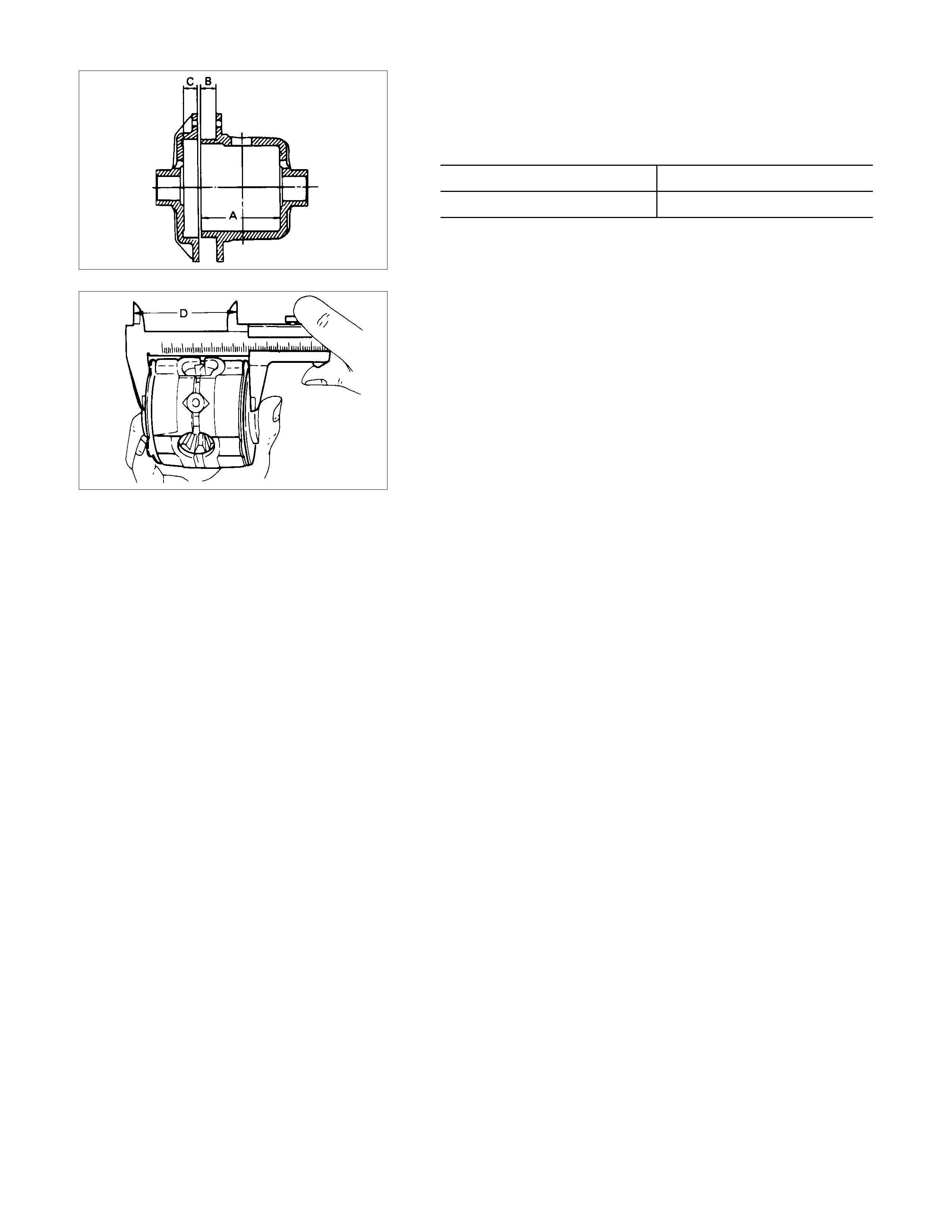
ADJUSTMENT OF CLEARANCE BETW EEN FRICTION
DISC AND PLATE
1) Measuring depth of differential case mm(in)
Standard (A-B) 80.58 (3.17)
(C) 10.58 (0.41)
2) Measuring overall length of pressure ring, friction disc and
plate assembly
•Assembly pinion shaft with pressure ring, then friction
disc and plate.
•Measure length between plates at both ends over V-
shape groove. (D)
3) After A, B, C and D dimensions are measured, perform
adjustment with the following procedure.
•Measure disc spring :
1.75 mm (0.69 in) × 2 pcs (E)
•Measure thickness of plate spring
Standard dimension :
1.75 mm (0.069 in) × 2 pcs (F)
4) Select a friction disc or plate so that ((A-B+C) - (D+E+F) =
0.06 to 0.20 mm ( 0.002 to 0.008 in.) and also the dif fer ence
in total dimension of f riction dis c and plate, plate spring and
disc spr ing (left/r ight side) does not ex ceed 0.05 m m (0.002
in.).
Thickness : 1.75, 1.85 mm
ADJUSTING BACKLASH OF SIDE GEAR IN AXIAL
DIRECTION
1) Measuring depth of differential case mm(in.)
Standard (F-B) 82.03 (3.23)
(G) 12.03 (0.47)
2) Measuring dimension between thrust washers at both ends.
•Eliminate clearance by pushing pressure ring against the
pinion shaft in axial direction.
•Eliminate backlash by connecting side gear to the
pinion.
•Measure dimension between thrust washers at both
ends. (H)
3) After eac h dimension is measur ed, perform adj us tment with
the following procedure.
Adjust s o that ((F-B) + G -H) = 0.05 to 0.2 m m. Also, s elect
a proper thrust washer so that the dimension difference
from back face of the pressure ring to thrust washe
r
(left/right side) does not exceed 0.05 mm.
Thickness : 1.5, 1.6, 1.7 mm
IMPORTANT OPERATIONS
3. 19. Bellville disc
4. 18. Bellville disc
Install the Bellville disc with dished side turned to the
differential cage side.
9. Pressure Ring
1) Fit two side gears in two pressure rings, one from under a
ring and the other from above a ring.
2) Fit two pairs of a f riction disc and a fric tion plate under it on
and under these two pressure rings. Also, fit disc springs
and plate springs for the discs and plates.
23.Bolt
Align the setting marks on the box and box cover and install
the bolts using the press.
CONFIRMATION OF OPERATION
•Using the side gear holder, measure the starting torque o
f
the side gear.
Starting torque N⋅m (kgf⋅m/lb⋅ft)
64 - 147 (6.5 - 15/47-108)
STANDARD DIFFERENTIAL
REASSEMBLY STEPS
1. Differential cage
2. Thrust washer
3. Side gear
▲4. Pinion gear
5. Thrust block
▲6. Cross pin
▲7. Lock pin
▲8. Ring gear
IMPORTANT OPERATIONS
4. Pinion Gear
Install the pinion gear by engaging it with the side gears while
turning both pinion gears simultaneously in the same direction.
6. Cross Pin
(1)Be sure to ins tall the cross pin s o that it is in alignm ent with
the lock pin hole in the differential cage.
(2)Backlash between the side gear and the pinion gear.
Backlash mm(in)
194 mm 0.10 - 0.20 (0.004 - 0.008)
220 mm 0.13 - 0.18 (0.005 - 0.007)
If the backlash is beyond the limits, adjust with a thrust washer
of selected thickness.
Thicknesses of thrust washers available. mm(in)
194 mm 1.00
(0.039) 1.05
(0.041) 1.10
(0.043)
220 mm 0.80
(0.031) 0.90
(0.035) 1.00
(0.039) 1.10
(0.043) 1.20
(0.047) 1.30
(0.051)
7. Lock Pin
After lock pin installation, stake the cage to prevent the lock pin
from falling out.
8. Ring Gear
Discard used bolts and install new ones.
When installing the ring gear, apply the LOCTITE 271 or
equivalent to the threaded holes and bolts after applying.
Ring Gear Bolt Torque N⋅m (kgf⋅m/lb⋅ft
)
107.9 ± 9.8 (11 ± 1/79.5 ± 7.2)
MAJO R COMPONENTS
REASSEMBLY STEPS
▲1. Outer bearing outer race
▲2. Inner bearing outer race
▲3. Pinion depth adjusting ; shim
▲4. Inner bearing
▲5. Collapsible spacer
6. Friction disc
7. Outer bearing
▲8. Oil seal
9. Pinion flange assembly
▲10. Flange nut and washer
▲11. Backlash and pre-load adjusting shim
▲12. Side bearings
13. Side bearing outer race
14. Differential cage assembly and ring gear
▲15. Bearing cap
▲16. Bolt
▲17. Differential assembly
IMPORTANT OPERATIONS
1. Outer Bearing Outer Race
Installer : 9-8522-1141-0 (194 mm)
(J-24256)
5-8840-2164-0 (220 mm)
(J-8092)
Grip : 5-8840-0007-0
(J-8092)
2. Inner Bearing Outer Race
Installer : 9-8522-1274-0 (194 mm)
(J-24252)
5-8840-2163-0 (220 mm)
(J-37261)
Grip : 5-8840-0007-0
(J-8092)
3. Pinion Depth Adjusting ; Shim
Adjustment of drive pinion mounting distance.
(1)Apply gear oil to the drive pinion bearing, inner and outer.
Clean all of the pinion setting gage sets.
Then install the gage set together with the inner and oute
r
bearings.
For 194 mm
1Pilot : 5-8840-2085-0 (J-21777-42)
2Stud and nut : 5-8840-2089-0 (J-23597-9)
4Gauge plate : 5-8840-2087-0 (J-23597-7)
For 220 mm
1Front pilot : 5-8840-2085-0 (J-21777-42)
2Stud and nut : 5-8840-0127-0 (J-21777-43)
3Rear pilot : 5-8840-0129-0 (J-23597-12)
4Gage plate : 5-8840-2166-0 (J-23597-42)
Tighten the nut to the specified torque.
194 mm and 220 mm kg⋅cm(lb.in)
23 (20)
(2)Clean the side bearing bores. Install a dial indicator with
discs and arbor. Then install and tighten the bearing caps
to the specified torque.
Torque N⋅m (kgf⋅m/lb⋅ft)
194 mm 98.1 ± 9.8 (10 ± 1/72 ± 7.2)
220 mm 107.9 ± 9.8 (11 ± 1/79.6 ± 7.2)
For 194 mm
1Dial indicator: 5-8840-0126-0 (J-8001)
2Disc (2 pcs.) : 5-8840-2088-0 (J-23597-8)
3Arbor : 5-8840-0128-0 (J-23597-1)
4Gage plate : 5-8840-2087-0 (J-23597-7)
For 220 mm
1Dial indicator: 5-8840-0126-0 (J-8001)
2Disc (2 pcs.) : 5-8840-2167-0 (J-21777-86)
3Arbor : 5-8840-0128-0 (J-23597-1)
4Gage plate : 5-8840-2166-0 (J-23597-42)
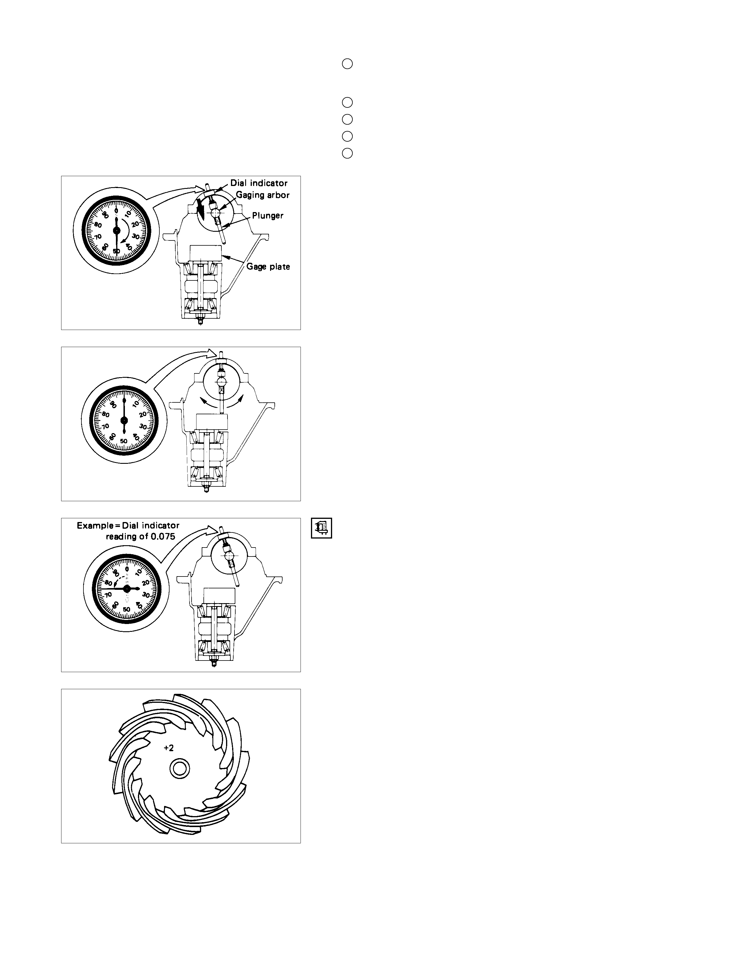
(3)Set the dial indicator to "0". Place it on the mounting post o
f
the gauging arbor with the contact button touching the
indicator pad. Force the dial indicator downward until the
needle has made a half turn clockwise. Tighten down the
dial indicator in this position.
(4)Position the plunger on the gage plate. Move the gauging
arbor slowly back and for th and locate the position at which
the dial indicator shows the greatest deflection. At this point,
once again set the dial indicator to "0".
Repeat the procedure to verify the "0" setting.
(5)
A
fter the ZERO setting is obtained, rotate the gauging arbo
r
until the dial indicator rod does not touch the gauging plate.
Record the number the dial indicator needle points to.
(6)Record the pinion depth code on the head of the drive
pinion.
The number indicates a necessary change in the pinion
mounting distance. A plus number indicates the need for a
greater mounting distance (which can be achieved by
decreasing the shim thickness). A minus number indicates
the need for a smaller mounting distance (which can be
achieved by increasing the shim thickness). If examination
reveals pinion depth code "0", the pinion is "nominal".
(7)Select the shim using table below.
[194 mm] mm(in)
Pinion
marking +10 +8 +6 +4 +2 0 -2 -4 -6 -8 -10
Dial indicator
reading (inches)
0.081 2.18 (0.0858)
0.082 2.18 (0.0858) 2.20 (0.0866)
0.083 2.18 (0.0858) 2.20 (0.0866) 2.24 (0.0882)
0.084 2.18 (0.0858) 2.20 (0.0866) 2.24 (0.0882) 2.26 (0.0890)
0.085 2.18 (0.0858) 2.20 (0.0866) 2.24 (0.0882) 2.26 (0.0890) 2.28 (0.0898)
0.086 2.18 (0.0858) 2.20 (0.0866) 2.24 (0.0882) 2.26 (0.0890) 2.28 (0.0898) 2.32 (0.0914)
0.087 2.18 (0.0858) 2.20 (0.0866) 2.24 (0.0882) 2.26 (0.0890) 2.28 (0.0898) 2.32 (0.0914) 2.34 (0.0921)
0.088 2.18 (0.0858) 2.20 (0.0866) 2.24 (0.0882) 2.26 (0.0890) 2.28 (0.0898) 2.32 (0.0914) 2.34 (0.0921) 2.36 (0.0929)
0.089 2.18 (0.0858) 2.20 (0.0866) 2.24 (0.0882) 2.26 (0.0890) 2.28 (0.0898) 2.32 (0.0914) 2.34 (0.0921) 2.36 (0.0929) 2.38 (0.0937)
0.090 2.18 (0.0858) 2.20 (0.0866) 2.24 (0.0882) 2.26 (0.0890) 2.28 (0.0898) 2.32 (0.0914) 2.34 (0.0921) 2.36 (0.0929) 2.38 (0.0937) 2.42 (0.0953)
0.091 2.18 (0.0858) 2.20 (0.0866) 2.24 (0.0882) 2.26 (0.0890) 2.28 (0.0898) 2.32 (0.0914) 2.34 (0.0921) 2.36 (0.0929) 2.38 (0.0937) 2.42 (0.0953) 2.44 (0.0961)
0.092 2.20 (0.0866) 2.24 (0.0882) 2.26 (0.0890) 2.28 (0.0898) 2.32 (0.0914) 2.34 (0.0921) 2.36 (0.0929) 2.38 (0.0937) 2.42 (0.0953) 2.44 (0.0961) 2.46 (0.0969)
0.093 2.24 (0.0882) 2.26 (0.0890) 2.28 (0.0898) 2.32 (0.0914) 2.34 (0.0921) 2.36 (0.0929) 2.38 (0.0937) 2.42 (0.0953) 2.44 (0.0961) 2.46 (0.0969) 2.48 (0.0977)
0.094 2.26 (0.0890) 2.28 (0.0898) 2.32 (0.0914) 2.34 (0.0921) 2.36 (0.0929) 2.38 (0.0937) 2.42 (0.0953) 2.44 (0.0961) 2.46 (0.0969) 2.48 (0.0977) 2.52 (0.0992)
0.095 2.28 (0.0898) 2.32 (0.0914) 2.34 (0.0921) 2.36 (0.0929) 2.38 (0.0937) 2.42 (0.0953) 2.44 (0.0961) 2.46 (0.0969) 2.48 (0.0977) 2.52 (0.0992) 2.54 (0.1000)
0.096 2.32 (0.0914) 2.34 (0.0921) 2.36 (0.0929) 2.38 (0.0937) 2.42 (0.0953) 2.44 (0.0961) 2.46 (0.0969) 2.48 (0.0977) 2.52 (0.0992) 2.54 (0.1000) 2.56 (0.1008)
0.097 2.34 (0.0921) 2.36 (0.0929) 2.38 (0.0937) 2.42 (0.0953) 2.44 (0.0961) 2.46 (0.0969) 2.48 (0.0977) 2.52 (0.0992) 2.54 (0.1000) 2.56 (0.1008)
0.098 2.36 (0.0929) 2.38 (0.0937) 2.42 (0.0953) 2.44 (0.0961) 2.46 (0.0969) 2.48 (0.0977) 2.52 (0.0992) 2.54 (0.1000) 2.56 (0.1008)
0.099 2.38 (0.0937) 2.42 (0.0953) 2.44 (0.0961) 2.46 (0.0969) 2.48 (0.0977) 2.52 (0.0992) 2.54 (0.1000) 2.56 (0.1008)
0.000 2.42 (0.0953) 2.44 (0.0961) 2.46 (0.0969) 2.48 (0.0977) 2.52 (0.0992) 2.54 (0.1000) 2.56 (0.1008)
0.001 2.44 (0.0961) 2.46 (0.0969) 2.48 (0.0977) 2.52 (0.0992) 2.54 (0.1000) 2.56 (0.1008)
0.002 2.46 (0.0969) 2.48 (0.0977) 2.52 (0.0992) 2.54 (0.1000) 2.56 (0.1008)
0.003 2.48 (0.0977) 2.52 (0.0992) 2.54 (0.1000) 2.56 (0.1008)
0.004 2.52 (0.0992) 2.54 (0.1000) 2.56 (0.1008)
0.005 2.54 (0.1000) 2.56 (0.1008)
0.006 2.56 (0.1008)
[220 mm] mm(in)
Pinion
marking +10 +8 +6 +4 +2 0 -2 -4 -6 -8 -10
Dial indicator
reading (inches)
0.073 1.94 (0.0764) 1.96 (0.0772)
0.074 1.94 (0.0764) 1.96 (0.0772) 1.98 (0.0779)
0.075 1.94 (0.0764) 1.96 (0.0772) 1.98 (0.0779) 2.00 (0.0787)
0.076 1.94 (0.0764) 1.96 (0.0772) 1.98 (0.0779) 2.00 (0.0787) 2.02 (0.0795) 2.04 (0.0803)
0.077 1.96 (0.0772) 1.98 (0.0779) 2.00 (0.0787) 2.02 (0.0787) 2.04 (0.0803) 2.06 (0.0811)
0.078 1.94 (0.0764) 1.96 (0.0772) 1.98 (0.0779) 2.00 (0.0787) 2.02 (0.0787) 2.04 (0.0803) 2.06 (0.0811) 2.08 (0.0819)
0.079 1.94 (0.0764) 1.96 (0.0772) 1.98 (0.0779) 2.00 (0.0787) 2.02 (0.0787) 2.04 (0.0803) 2.06 (0.0811) 2.08 (0.0819) 2.10 (0.0827)
0.080 1.94 (0.0764) 1.96 (0.0772) 1.98 (0.0779) 2.00 (0.0787) 2.02 (0.0787) 2.04 (0.0803) 2.06 (0.0811) 2.08 (0.0819) 2.10 (0.0827) 2.12 (0.0835) 2.14 (0.0842)
0.081 1.96 (0.0772) 1.98 (0.0779) 2.00 (0.0787) 2.02 (0.0787) 2.04 (0.0803) 2.06 (0.0811) 2.08 (0.0819) 2.10 (0.0827) 2.12 (0.0835) 2.14 (0.0842) 2.16 (0.0850)
0.082 1.98 (0.0779) 2.00 (0.0787) 2.02 (0.0787) 2.04 (0.0803) 2.06 (0.0811) 2.08 (0.0819) 2.10 (0.0827) 2.12 (0.0835) 2.14 (0.0842) 2.16 (0.0850) 2.18 (0.0858)
0.083 2.00 (0.0787) 2.02 (0.0787) 2.04 (0.0803) 2.06 (0.0811) 2.08 (0.0819) 2.10 (0.0827) 2.12 (0.0835) 2.14 (0.0842) 2.16 (0.0850) 2.18 (0.0858) 2.20 (0.0866)
0.084 2.04 (0.0803) 2.06 (0.0811) 2.08 (0.0819) 2.10 (0.0827) 2.12 (0.0835) 2.14 (0.0842) 2.16 (0.0850) 2.18 (0.0858) 2.20 (0.0866) 2.22 (0.0874) 2.24 (0.0882)
0.085 2.06 (0.0811) 2.08 (0.0819) 2.10 (0.0827) 2.12 (0.0835) 2.14 (0.0842) 2.16 (0.0850) 2.18 (0.0858) 2.20 (0.0866) 2.22 (0.0874) 2.24 (0.0882) 2.26 (0.0890)
0.086 2.08 (0.0819) 2.10 (0.0827) 2.12 (0.0835) 2.14 (0.0842) 2.16 (0.0850) 2.18 (0.0858) 2.20 (0.0866) 2.22 (0.0874) 2.24 (0.0882) 2.26 (0.0890) 2.28 (0.0898)
0.087 2.12 (0.0835) 2.14 (0.0842) 2.16 (0.0850) 2.18 (0.0858) 2.20 (0.0866) 2.22 (0.0874) 2.24 (0.0882) 2.26 (0.0890) 2.28 (0.0898) 2.30 (0.0906) 2.32 (0.0913)
0.088 2.14 (0.0842) 2.16 (0.0850) 2.18 (0.0858) 2.20 (0.0866) 2.22 (0.0874) 2.24 (0.0882) 2.26 (0.0890) 2.28 (0.0898) 2.30 (0.0906) 2.32 (0.0913) 2.34 (0.0921)
0.089 2.16 (0.0850) 2.18 (0.0858) 2.20 (0.0866) 2.22 (0.0874) 2.24 (0.0882) 2.26 (0.0890) 2.28 (0.0898) 2.30 (0.0906) 2.32 (0.0913) 2.34 (0.0921) 2.36 (0.0929)
0.090 2.18 (0.0858) 2.20 (0.0866) 2.22 (0.0874) 2.24 (0.0882) 2.26 (0.0890) 2.28 (0.0898) 2.30 (0.0906) 2.32 (0.0913) 2.34 (0.0921) 2.36 (0.0929)
0.091 2.22 (0.0874) 2.24 (0.0882) 2.26 (0.0890) 2.28 (0.0898) 2.30 (0.0906) 2.32 (0.0913) 2.34 (0.0921) 2.36 (0.0929)
0.092 2.24 (0.0882) 2.26 (0.0890) 2.28 (0.0898) 2.30 (0.0906) 2.32 (0.0913) 2.34 (0.0921) 2.36 (0.0929)
0.093 2.26 (0.0890) 2.28 (0.0898) 2.30 (0.0906) 2.32 (0.0913) 2.34 (0.0921) 2.36 (0.0929)
0.094 2.28 (0.0898) 2.30 (0.0906) 2.32 (0.0913) 2.34 (0.0921) 2.36 (0.0929)
0.095 2.32 (0.0913) 2.34 (0.0921) 2.36 (0.0929)
0.096 2.34 (0.0921) 2.36 (0.0929)
0.097 2.36 (0.0929)
Note :
When ordering shims, find the part number in the Parts Catalog by using the thickness of the shims listed in
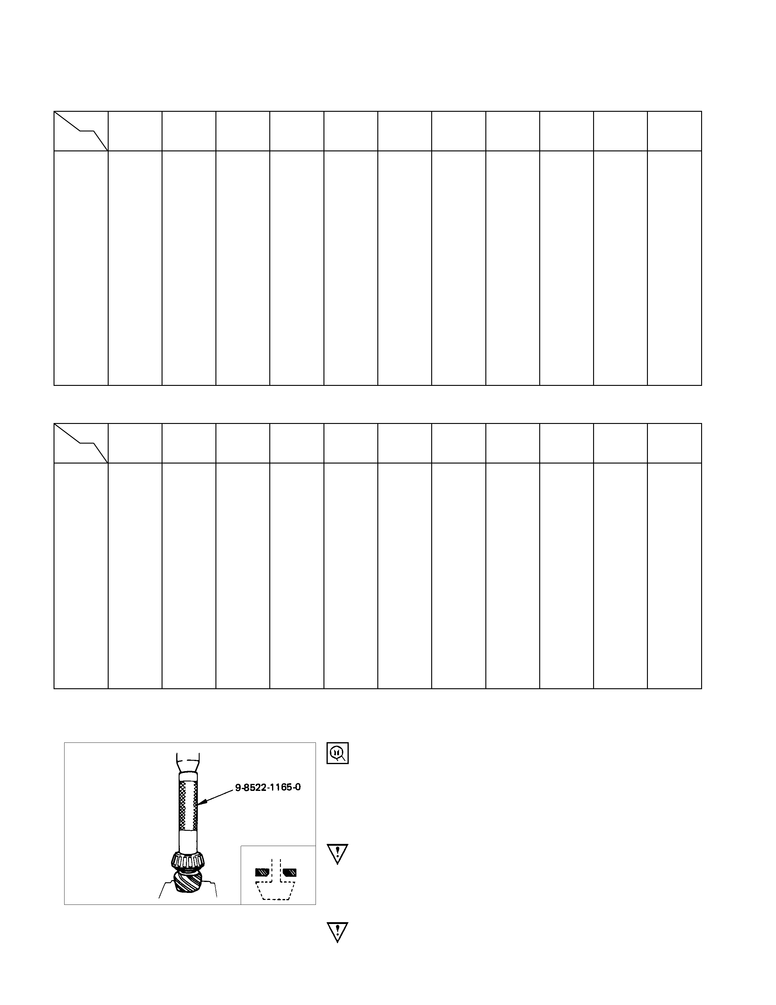
the above table. 4. Inner Bearing
Place the shim on the drive pinion with the chamfered side
turned toward the pinion head, then attach the inner bearing to
the pinion using an installer and a press.
Installer : 9-8522-1165-0
(J-6133-01)
NOTE :
Do not press on the roller cage.
Press only on the inner race.
5. Collapsible Spacer
Discard the used collapsible spacer and install a new one.
8. Oil Seal
Use the oil seal installer to install a new oil seal that has been
soaked in rear axle lubricant.
Installer : 9-8522-1275-0 (194 mm)
(J-24250)
: 5-8840-2165-0 (220 mm)
(J-37263)
10.Flange Nut and Washer
(1)Apply lubricant to pinion threads.
(2)Tighten the nut to the specified torque using the pinion
flange holder.
Pinion flange holder : 5-8840-0133-0 (194 mm)
(J-8614-01)
5-8840-2157-0 (220 mm)
(J-37221)
Flange Nut Torque N⋅m (kgf⋅m/lb⋅ft)
194 mm 176.6 - 274.7 (18 - 28/130 - 202)
220 mm 245.3 - 294.3 (25 - 30/181 - 217)
Discard used flange nuts and install new ones.
(3)Pinion bearing preload.
(a) Measure the bearing preload by using a torque wrench.
Note the scale reading required to rotate the flange.
(b) Continue tightening until the specified starting torque is
obtained.
Pinion Bearing Preload Starting Torque N⋅m (kgf⋅m/lb⋅ft)
194 mm 64 - 113 (6.5 - 11.5/47 - 72)
220 mm 69 - 127 (7 - 13/51 - 94)
11.Backlash and Pre-load Adjusting Shim
(1)Attach the side bearing to the differential assembly without
shims. Support the opposite side using a pilot to prevent
bearing damage.
1Installer : 9-8522-1164-0 (194 mm)
(J-24244)
: 5-8840-2162-0 (220 mm)
(J-37257)
2Drive handle : 5-8840-0007-0
(J-8092)
3Pilot : 9-8521-1743-0
(J-8107-2)
(2)Position the differential cage assembly with the bearing
outer races to the side bearing bores of the carrier.
(3) Using two sets of feeler gauges, insert a feeler stock o
f
sufficient thickness between each bearing outer race and
the carrier to remove all end play. Make certain the feele
r
stock is pushed to the bottom of the bearing bores.
Mount the dial indicator on the carrier so that the indicato
r
stem is at right angles to a tooth on the ring gear.
Dial indicator : 5-8840-0126-0
(J-8001)
(4)Adjust the f eeler gauge thick ness fr om s ide to side until the
ring gear backlash is in the specified range.
Backlash mm(in)
194 mm 0.13 - 0.18 (0.005 - 0.007)
220 mm 0.15 - 0.20 (0.006 - 0.008)
With zero end play and correct backlash established, remove
feeler gauge packs, determine the thickness of shims required
and add 0.05 mm (0.002 in.) to each shim pack to provide side
bearing preload. Always use new shims.
(5)Remove side bearing
Remover : 5-8840-0013-0
(J-22888)
Adapter : 9-8521-1743-0 (194 mm)
(J-8107-2)
: 5-8840-2196-0 (220 mm)
(J-8107-4)
12.Side Bearing
Install side bearings together with selected shims.
1Installer : 9-8522-1164-0 (194 mm)
(J-24244)
: 5-8840-2162-0 (220 mm)
(J-37257)
2Drive handle : 5-8840-0007-0 (J-8092)
3Pilot : 9-8521-1743-0 (J-8107-2)
15.Bearing Cap
Align the setting marks applied at the time of disassembly.
16.Bolt
Cap Bolt Torque N⋅m (kgf⋅m/lb⋅ft
)
194 mm 98.1 ± 9.8 (10 ± 1/72 ± 7.2)
220 mm 107.9 ± 9.8 (11 ± 1/79.5 ± 7.2)
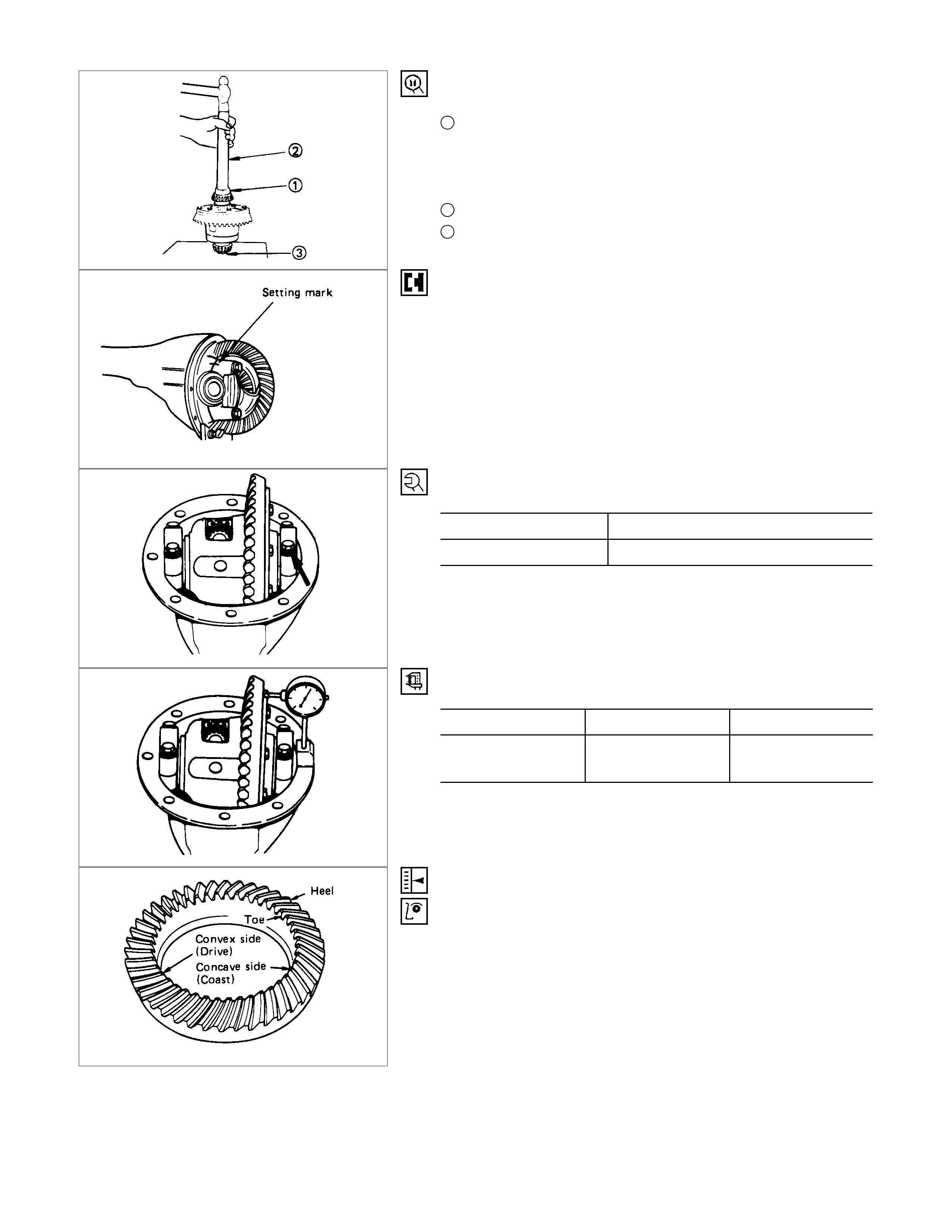
Measure the amount of run-out of the ring gear at its rear face.
Run-Out mm(in
)
Standard Limit
194 mm
220 mm 0.02 ( 0.001) 0.05 ( 0.002)
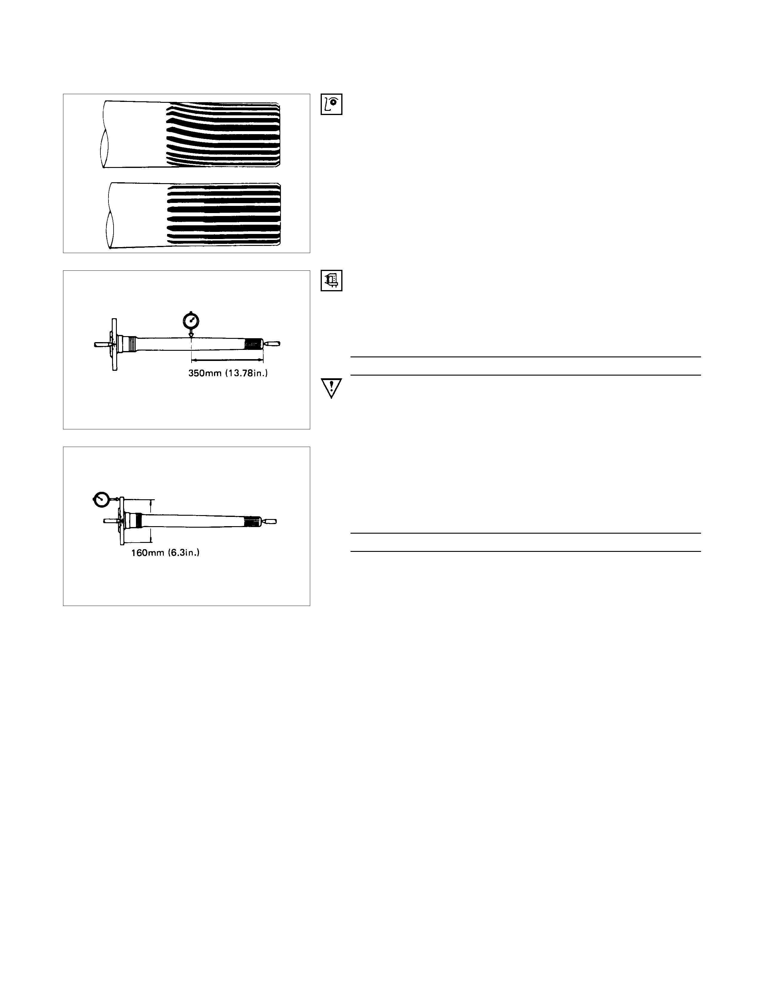
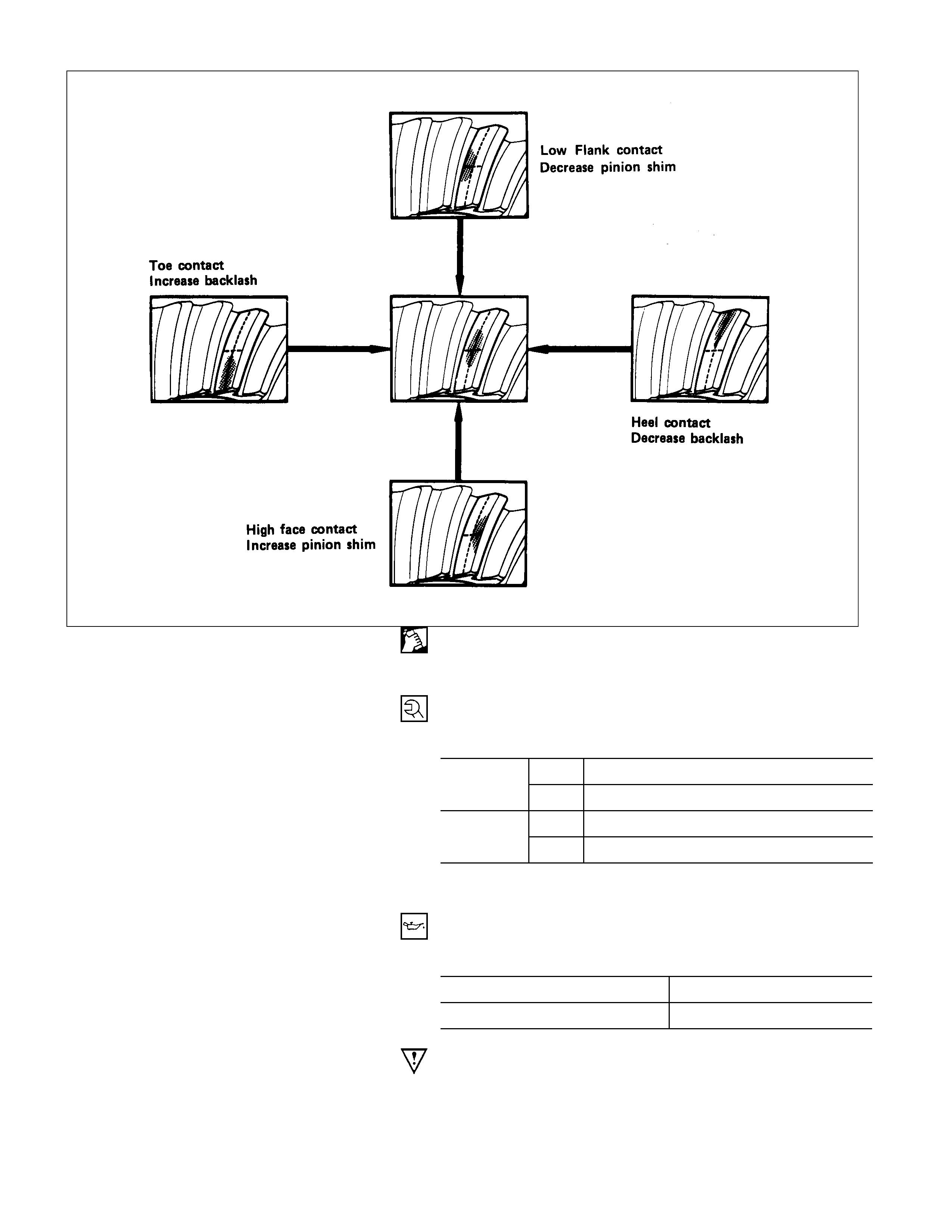
GEAR TOOTH CONTACT PATTERN CHECK AND
ADJUSTMENT
Apply a thin coat of Prussian blue or equivalent to the faces of
7 - 8 teeth of the ring gear. Check the impression of contact
obtained on the ring gear teeth and make necessary
adjustment as described below if the contact is abnormal.
17.Differential Assembly
(1)Clean the fac es of the rear axle cas e and diff erential carr ie
r
and apply the recommended liquid gasket or its equivalent.
(2)Mount the differential case and the carrier assembly to the
rear axle case and tighten the nuts and bolts.
Torque N⋅m (kgf⋅m/lb⋅ft)
Nut 37.3 ± 3.9 (3.8 ± 0.4/27 ± 2.9)
bolt 24.5 ± 5 (2.5 ± 0.5/18 ± 3.6)
Nut 44 ± 14.7 (4.5 ± 1.5/32.5 ± 10.8)
Bolt 68.5 ± 5 (6.5 ± 0.5/47 ± 3.6)
220 mm
194 mm
(3)Install the axle shaft assem blies as instructed earlier in this
section under "Axle Shaft Reassembly".
(4)Fill the axle case with hypoid gear lubricant to j ust below the
filler hole.
Lubricant Capacity liter (US/UK gal.)
194 mm 1.5 (0.4/0.33)
220 mm 1.8 (0.48/0.4)
Check owner's manual for correct type and viscosity of gear
lubricant required.

TROUBLESHOOTING
Refer to this Section to quickly diagnose and repair rear axle problems.
Each troubleshooting chart has three headings arranged from left to right.
(1) Checkpoint (2) Trouble Cause (3) Countermeasure
This Section is divided into five sub-sections:
1. Abnormal Rear Axle Noise
1) Noise when the engine is driving the vehicle
2) Noise when the vehicle is coasting
3) Intermittent noise
4) Noise when the vehicle is turning
5) Constant noise
2. Vibration
3. Oil Leakage
1) Differential carrier leakage
2) Axle case leakage
3) Axle case to inside hub leakage
4) Axle case to inside brake drum leakage
4. Power Not Being Transmitted to the Wheels (Propeller Shaft Operation is Normal)

1. ABNO RMAL REAR AXLE NOISE
1) Noise when the Engine is Driving the Vehicle
Checkpoint Trouble Cause Countermeasure
Replenish the gear oilInsufficient gear oil
NG
Differential side bearing Adjust the differential side
bearing preload
Replace the drive pinion
bearings
Adjust the drive pinion bearing
preload
Replace the gear oil
Loose differential side
bearings
Worn drive pinion bearings
Loose drive pinion bearings
Wrong or poor grade gear oil
Drive pinion to ring gear
backlash
Drive pinion end play
Adjust the backlashToo much or too little backlash
Continued on the next page
OK
OK
NG
NG
NG
NG
NG
OK
OK
Rear axle gear oil
Replace the differential side
bearings
Worn differential side bearings
NG
Checkpoint Trouble Cause Countermeasure
Replace the drive pinion and
the ring gear as a set
Excessive ring gear run-out
Replace the drive pinion and
the ring gear as a set
Drive pinion and/or ring gear
damage
NG
NG
Drive pinion and ring gear
Continued from the previous page
Replace the drive pinion and
the ring gear as a set
Worn drive pinion and ring
gear
NG
2) Noise when the Vehicle is Coasting
Checkpoint Trouble Cause Countermeasure
Replace the ring gear and the
pinion as a set
Ring gear damaged
Adjust the backlashInsufficient backlash
OK
Ring gear NG
NG
Drive pinion and ring gear
backlash
3) Intermittent Noise
Checkpoint Trouble Cause Countermeasure
Axle case inside
Ring gear
Remove the foreign material
Replace the drive pinion and
the ring gear as a set
Foreign material in the axle
case
Warped ring gear
Differential cage Tighten the differential cage
bolts
Replace the shaft
Loose differential cage bolts
Too much spline play
OK
NG
NG
NG
NO
OK
OK
Axle shaft

4) Noise when the Vehicle is Turning
Checkpoint Trouble Cause Countermeasure
Differential cross pin
Side gear
Replace the differential cross
pin
Replace the side gear
Worn differential cross pin
Worn side gear
Differential pinion Replace the differential pinion
Replace the rear axle shaft
Worn differential pinion
Worn rear axle shaft splines
OK
NG
NG
NG
NO
OK
OK
Rear axle shaft
5) Constant Noise
Checkpoint Trouble Cause Countermeasure
Replace the rear axle shaftBent rear axle shaft
NG
Replace the side bearing
Replace the drive pinion
bearing
Replace the drive pinion and
the ring gear as a set
Replace the drive pinion and
the ring gear as a set
Flat spot on the side bearing
oil seal
Bearing Flat spot on the drive pinion
Flat spot on the gear teeth
pilot bearing wear
Drive pinion Flat spot on the drive pinion
gear teeth
Ring gear
Replace the drive pinion and
the ring gear as a set
Worn pinion splines oil seal
NG
NG
NG
NG
NG
OK
OK
OK
Rear axle shaft
2. VIBRATION
Checkpoint Trouble Cause Countermeasure
Replace the rear axle shaftBent rear axle shaft
Replace the rear hub bearingWorn rear hub bearing
OK
Rear axle shaft NG
NG
Rear hub bearing
3. OIL LEAKAGE
1) Differential Carrier Leakage
Checkpoint Trouble Cause Countermeasure
Correct the oil levelToo much gear oil
NG
Reapply the liquid gasket
and/or tighten the lock nut to
the specified torque
Reapply the liquid gasket
Tighten the bolts to the
specified torque
Replace the oil seal
Ring gear thrust bolt Loose lock nut and/or liquid
Liquid gasket seal bed
Loose bolts
Oil seal Worn or defective oil seal
Differential carrier
Clean the air breatherAir breather Clogged air breather
NG
NG
NG
NG
NG
OK
OK
OK
OK
Gear oil level
2) Axle Case Leakage
Checkpoint Trouble Cause Countermeasure
Tighten the drain plug and/or
replace the gasket(s)
Loose drain plug and/or
defective gasket(s)
NG
Reapply the liquid gasket
Tighten the bolts to the
specified torque
Clean the air breather
Liquid gasket seal bad
Loose bolts
Air breather Clogged air breather
Differential carrier
Replace the axle caseAxle case Cracked axle case
NG
NG
NG
NG
OK
OK
OK
Oil filler and drain plug

3) Axle Case to Inside Brake Drum Leakage
Checkpoint Trouble Cause Countermeasure
Replace the oil sealWorn or defective oil seal
NG
Oil seal
4. POWER NOT BEING TRANSMITTED TO THE WH EEL S
(PROPELLER SHAFT OPERATION IS NORMAL)
Checkpoint Trouble Cause Countermeasure
Replace the rear axle shaftBroken rear axle shaft
NG
Replace the drive pinion and
the ring gear as a set
Drive pinion and ring gear Broken drive pinion and/or ring
gear
Replace the differential gears
and/or the spider
Differential cage gears Broken differential cage gears
and/or spider
NG
NG
OK
OK
Rear axle shaft
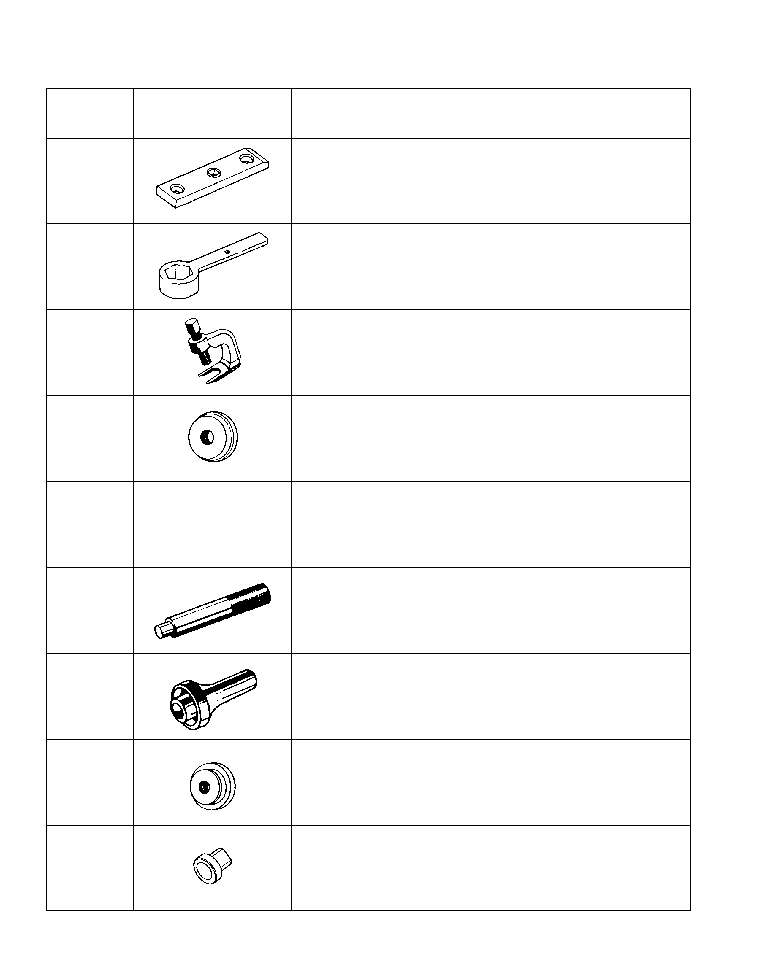
SPECIAL SERVICE TOOL
ITEM NO. ILLUSTRATION PART NO. PART NAME
RAL-1 5-8840-2003-0
(J-24246) Axle shaft bearing nut
remover & installer
RAL-2 5-8840-2329-0 Axle shaft bearing nut
remover & installer
(Heavy-Duty type)
RAL-3 5-8840-0079-0
(J-6627-A) Wheel pin remover
RAL-4 5-8522-1268-0
(J-24259) Axle shaft bearing outer
race installer (for 194mm)
5-8840-2201-0 194mm (H/D), 220mm
OTL-1 5-8840-0007-0
(J-8092) Driver handle
RAL-35 9-8522-1269-0
(J-24255) Bearing holder oil seal
installer (for 194mm)
RAL-11 5-8840-2202-0 Bearing holder oil seal
installer (for 194mm H/D,
220mm)
RAL-6 9-8522-1271-0
(J-8609-01) Axle shaft bearing installer
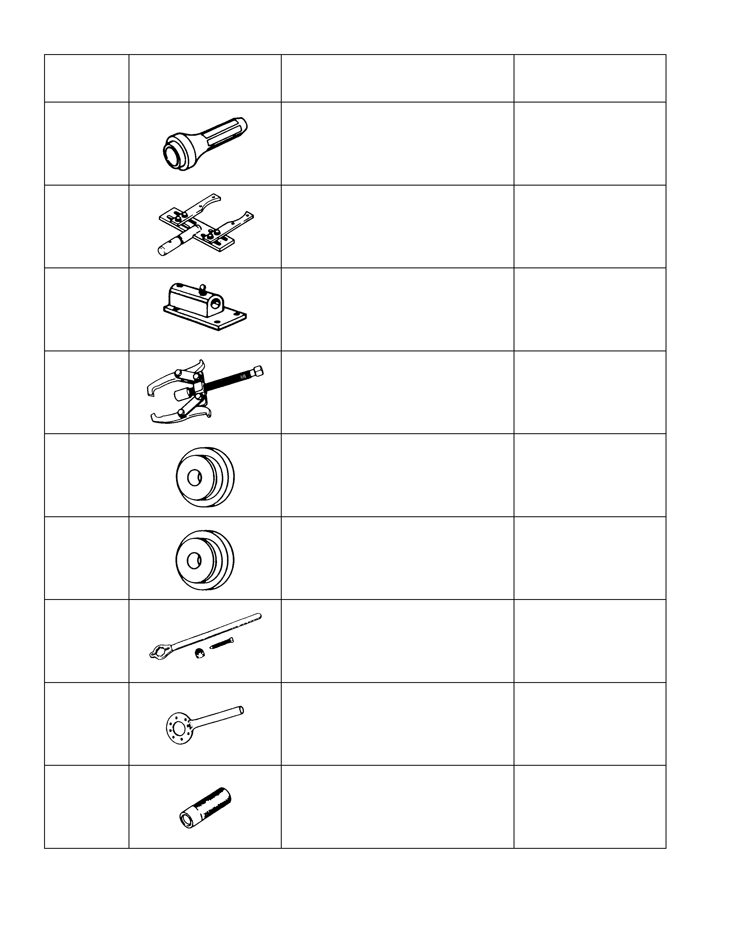
ITEM NO. ILLUSTRATION PART NO. PART NAME
RAL-34 9-8522-1272-0
(J-24254) Axle case oil seal installer
(for 194mm)
RAL-41 5-8840-0275-0
(J-37264) Differential holding fixture
RAL-40 5-8840-0003-0
(J-3289-20) Holding fixture base
RAL-44 5-8840-0013-0
(J-22888) Side bearing puller
RAL-9 9-8521-1743-0
(J-8107-2) Side bearing plug adapter
(for 194mm)
RAL-10 5-8840-2196-0
(J-8107-4) Side bearing plug adapter
(for 220mm)
RAL-50 5-8840-0133-0
(J-8614-01) Pinion flange holder
(for 194mm)
RAL-51 5-8840-2157-0
(J-37211) Pinion flange holder
(for 220mm)
RAL-53 9-8521-5032-0 Final pinion spindle
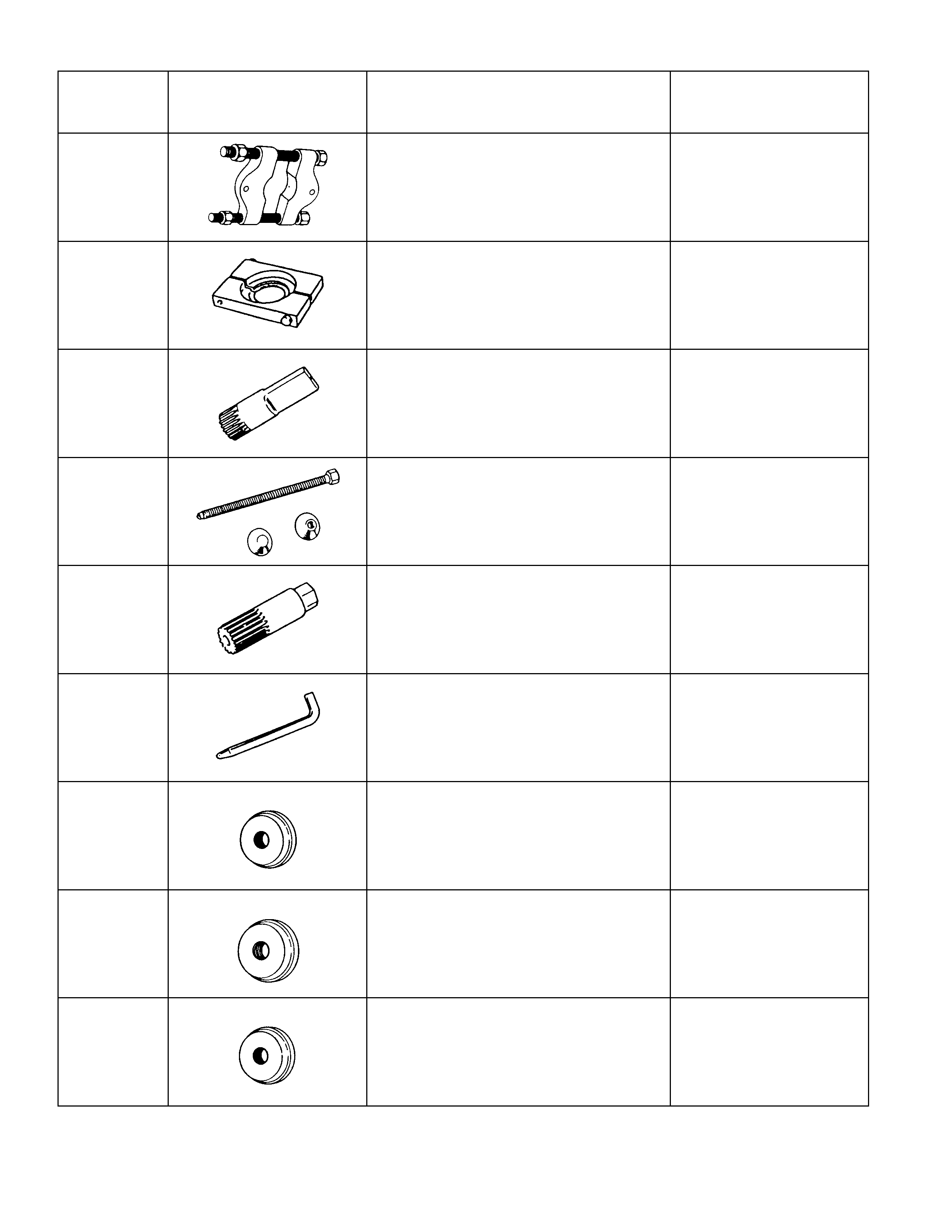
ITEM NO. ILLUSTRATION PART NO. PART NAME
RAL-56 5-8840-0015-0
(J-22912-01) Separator (for 194mm)
RAL-57 5-8840-2197-0
(J-37452) Separator (for 220mm)
RAL-54 5-8840-2010-0
(J-36563) Side gear holder
(194mm L.S.D only)
RAL-59 5-8840-2011-0
(J-36564) Side gear expander
(194mm L.S.D only)
RAL-55 5-8840-2012-0
(J-36565)
Side gear rotor
(194mm L.S.D only)
RAL-70 5-8840-2013-0
(J-36566) Diff. Cage lock bar
(194mm L.S.D only)
RAL-12 9-8522-1141-0
(J-24256) Outer bearing outer race
installer (for 194mm)
RAL-13 5-8840-2164-0
(J-37262) Outer bearing outer race
installer (for 220mm)
RAL-14 9-8522-1274-0
(J-24252) Outer bearing outer race
installer (for 194mm)
ITEM NO. ILLUSTRATION PART NO. PART NAME
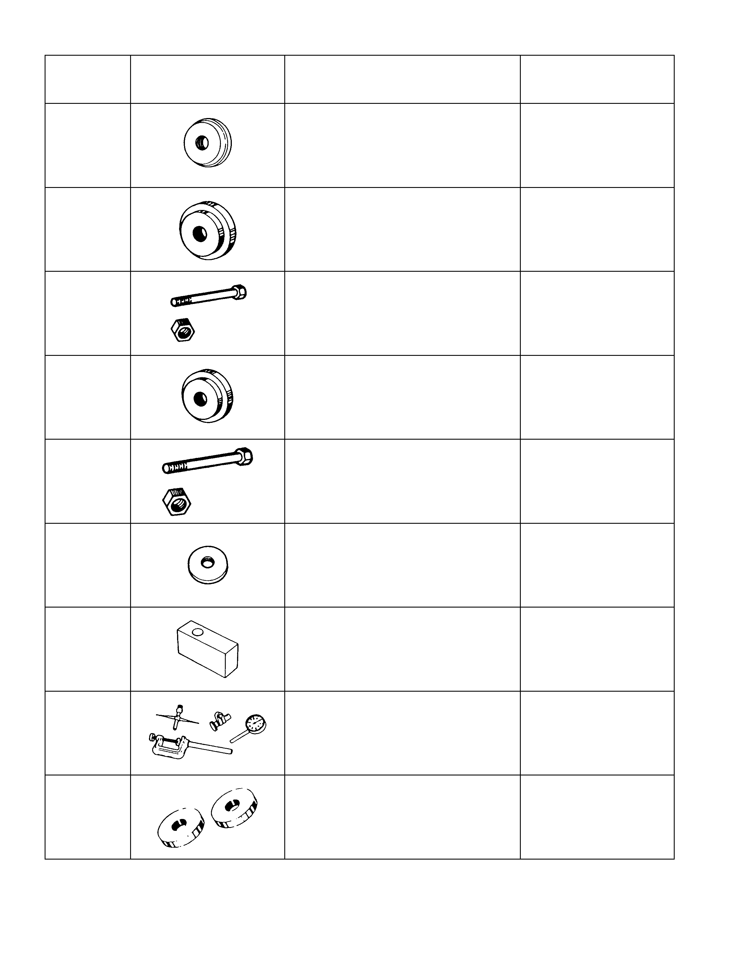
RAL-15 5-8840-2163-0
(J-37261) Inner bearing outer race
installer (for 220mm)
RAL-60 5-8840-2085-0
(J-21777-42) Pilot (for 194mm, 220mm)
RAL-67 5-8840-2089-0
(J-23597-9) Bolt & nut (for 194mm)
RAL-63 5-8840-2087-0
(J-23597-7) Gauge plate (for 194mm)
RAL-66 5-8840-0127-0
(J-21777-43) Bolt & nut (for 220mm)
RAL-61 5-8840-0129-0
(J-23597-12) Pilot (for 220mm)
RAL-62 5-8840-2166-0
(J-23597-42) Gauge plate (for 220mm)
RAL-68 5-8840-0126-0
(J-8001) Dial gauge set
(for 194mm, 220mm)
RAL-65 5-8840-2088-0
(J-23597-8) Disc (2 pcs. Required)
(for 194mm)

ITEM NO. ILLUSTRATION PART NO. PART NAME
RAL-69 5-8840-0128-0
(J-23597-1) Arbor
(for 194mm, 220mm)
RAL-64 5-8840-2167-0
(J-21777-86) Disc (2 pcs. Required)
(for 220mm)
RAL-27 9-8522-1165-0
(J-6133-01) Inner bearing installer
RAL-36 9-8522-1275-0
(J-24250) Pinion oil seal installer
(for 194mm)
RAL-37 5-8840-2165-0
(J-37263) Oil seal installer
(for 220mm)
RAL-29 9-8522-1164-0
(J-24244) Side bearing installer
(for 194mm)
RAL-28 5-8840-2162-0
(J-37257) Side bearing installer
(for 220mm)