
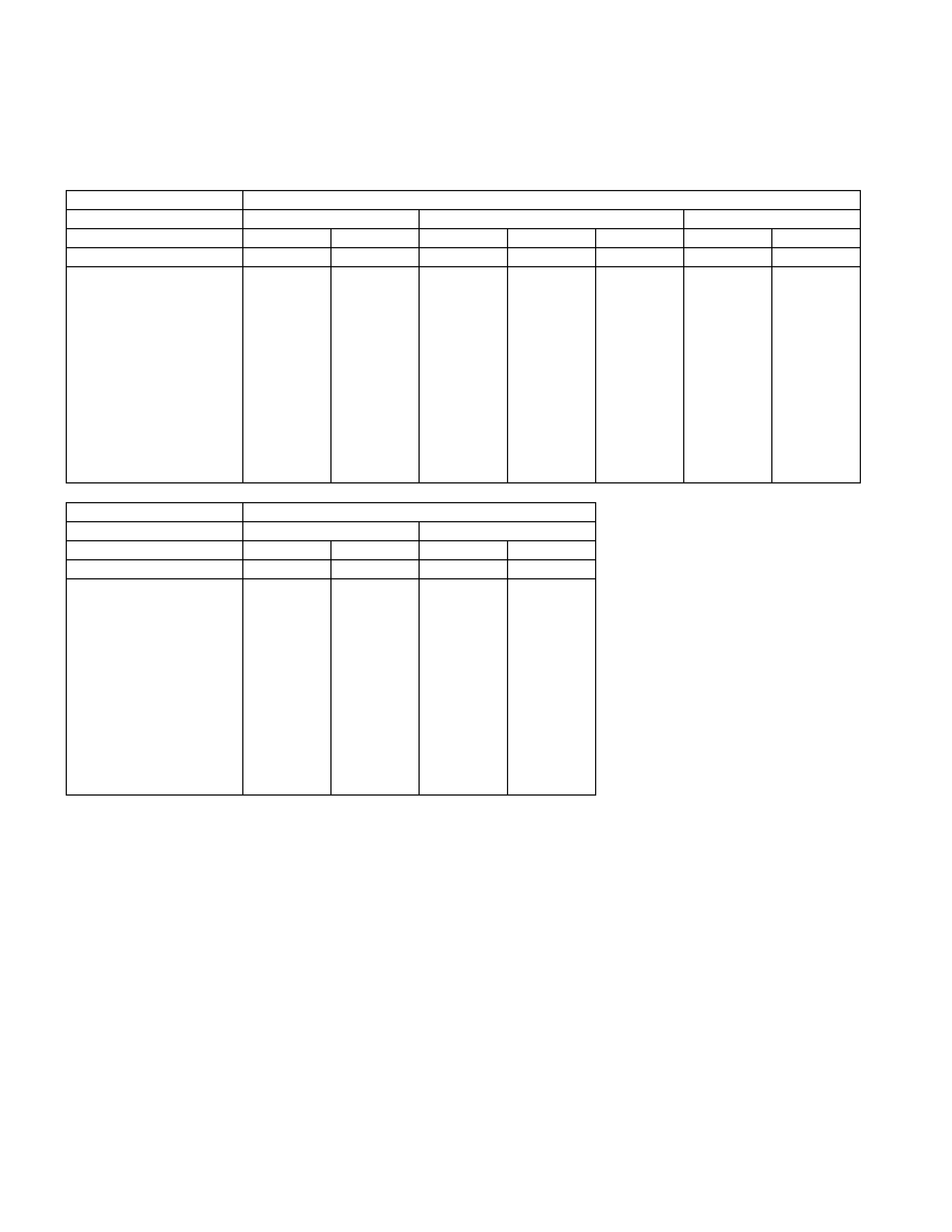
MAIN DATA AND SPECIFICATION
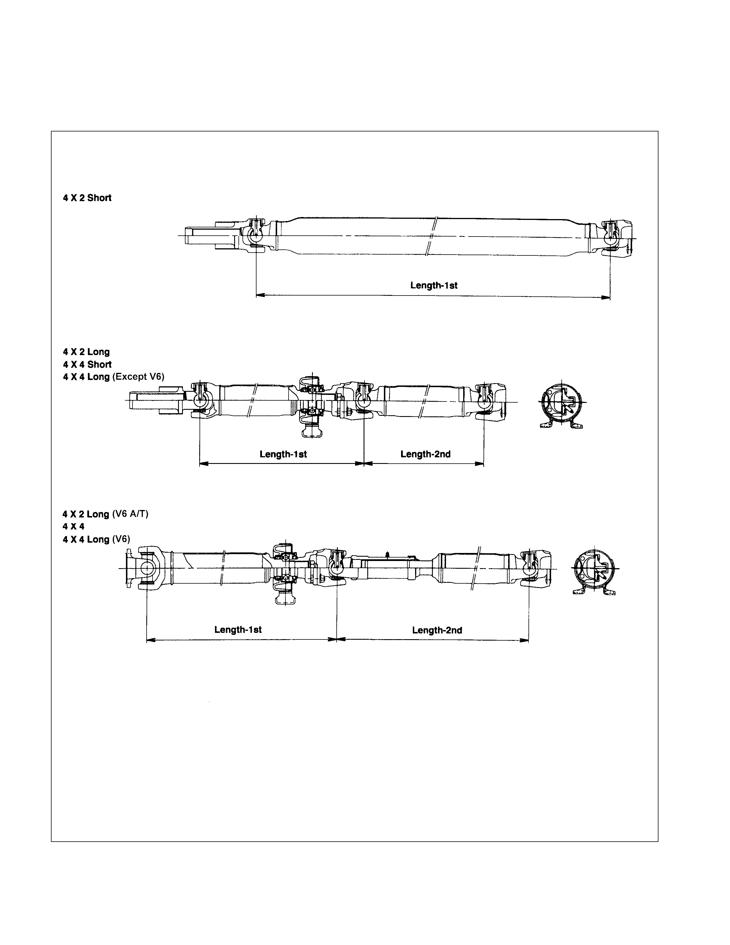
REAR PROPELLER SHAFT
4 ×
××
× 2 MODEL Long Wheel Base
Engine Model 4JA1 4JB1 4JG2
Transmission Type 5M/T ←←←4A/T 5M/T 4A/T
Rear Axle 194mm 220mm 194mm 220mm ←←←
Type OBS ←←←←←←
Outside Diameter mm 63.5 68.9 63.5 68.9 68.9 68.9 68.9
Inside Diameter mm 60.3 64.9 60.3 64.9 64.9 64.9 64.9
Length 1st mm 675.5 675.5 675.5 675.5 593.5 675.5 593.5
2nd mm 949 924 949 924 924 924 924
Spline Outside mm 29.87 29.87 29.87 29.87 30.48 29.87 30.48
Diameter
Fix Bolt Size M8 M10 M8 M10 M10 M10 M10
Long Wheel Base
Engine Model C22NE 6VD1
Transmission Type 5M/T ←←4A/T
Rear Axle 194mm 220mm ←←
Type OBS ←←IBS
Outside Diameter mm 63.5 68.9 68.9 68.9
Inside Diameter mm 60.3 64.9 64.9 64.9
Length 1st mm 720.5 720.5 695.5 737.5
2nd mm 949 924 924 924
Spline Outside mm 29.87 29.87 29.87 36.67
Diameter
Fix Bolt Size M8 M10 M10 M10
* OBS - Outboard Slip (Spline Engagement To T/M)
IBS - Inboard Slip (Spline Travel at Joint Center)
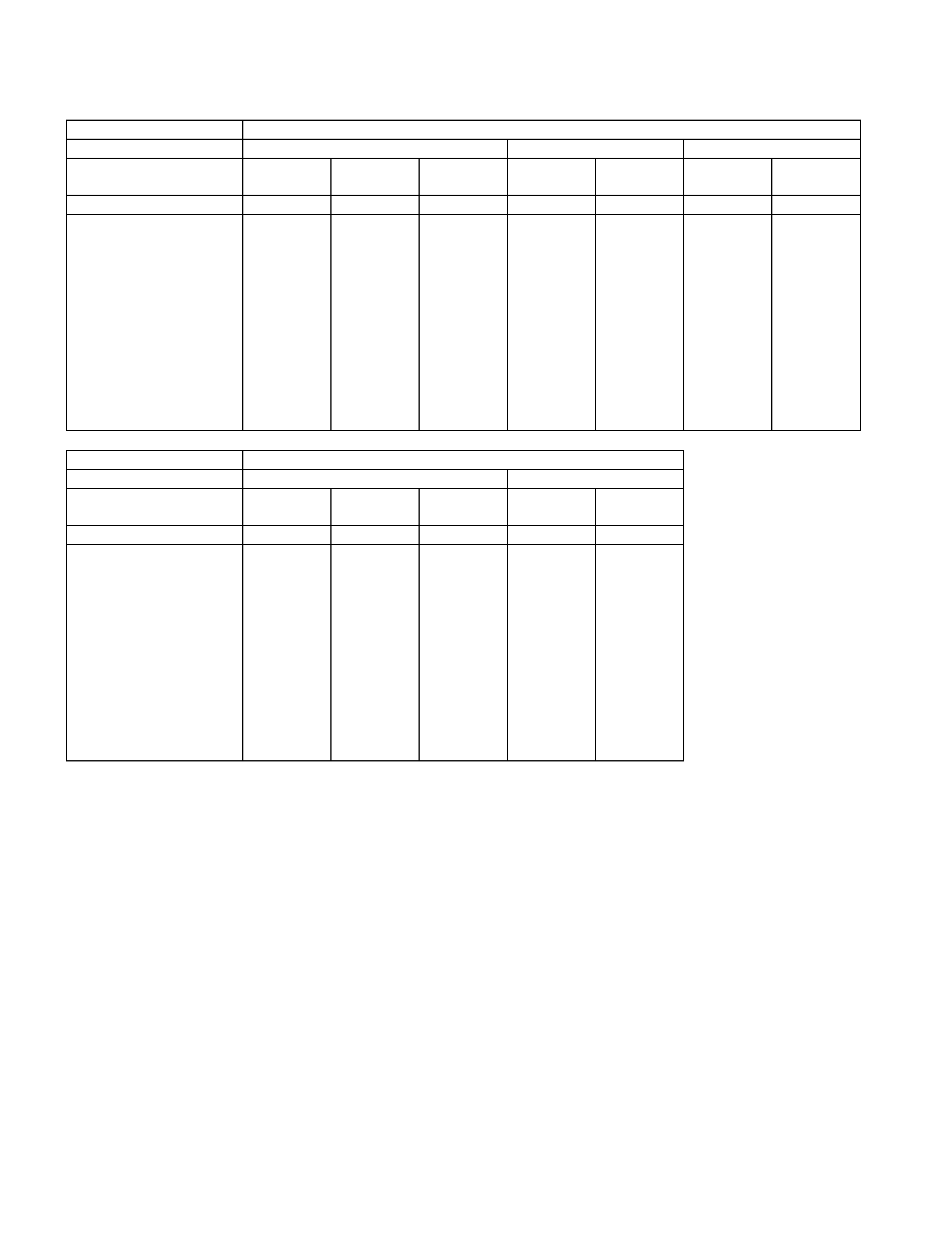
4 ×
××
× 4 MODEL
Long Wheel Base
Engine Model 4JA1 4JB1 4JG2
Transmission Type 5M/T ←←←4A/T 5M/T 4A/T
(MSG) ←(MUA) ←(MUA)
Rear Axle 194mm 220mm 220mm ←←←←
Type OBS ←←←IBS OBS IBS
Outside Diameter mm 63.5 68.9 68.9 68.9 68.9 68.9 68.9
Inside Diameter mm 60.3 64.9 64.9 64.9 64.9 64.9 64.9
Length 1st mm 541.5 541.5 482.5 482.5 627.5 482.5 627.5
2nd mm 949 924 924 924 670 924 670
Spline Outside mm 29.87 29.87 29.87 29.87 36.67 29.87 36.67
Diameter
Fix Bolt Size M8 M10 M10 M10 M10 M10 M10
Long Wheel Base
Engine Model C22NE 6VD1
Transmission Type 5M/T ←←←4A/T
(MSG) ←(MUA) ←
Rear Axle 194mm 220mm ←←←
Type OBS ←←←IBS
Outside Diameter mm 63.5 68.9 68.9 68.9 68.9
Inside Diameter mm 60.3 64.9 64.9 64.9 64.9
Length 1st mm 581.5 581.5 527.5 607.5 437.5
2nd mm 949 924 924 924 924
Spline Outside mm 29.87 29.87 29.87 36.67 36.67
Diameter
Fix Bolt Size M8 M10 M10 M10 M10
* OBS - Outboard Slip (Spline Engagement To T/M)
IBS - Inboard Slip (Spline Travel at Joint Center)
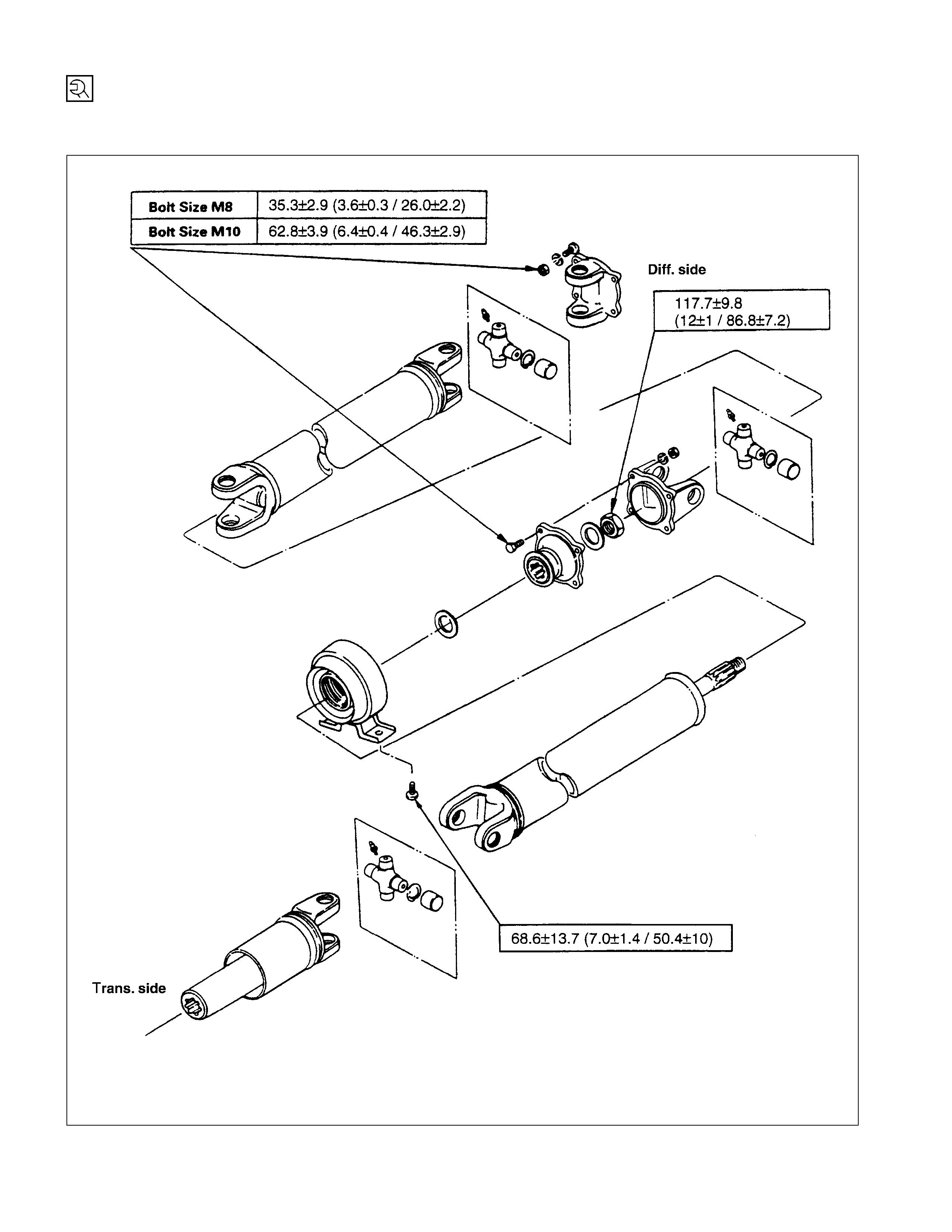
SPECIAL PARTS FI XING NUT AND BOLT
REAR PROPELLER SHAFT ( LONG WHEEL BASE MODEL) N⋅m (kgf⋅m/lb⋅ft)
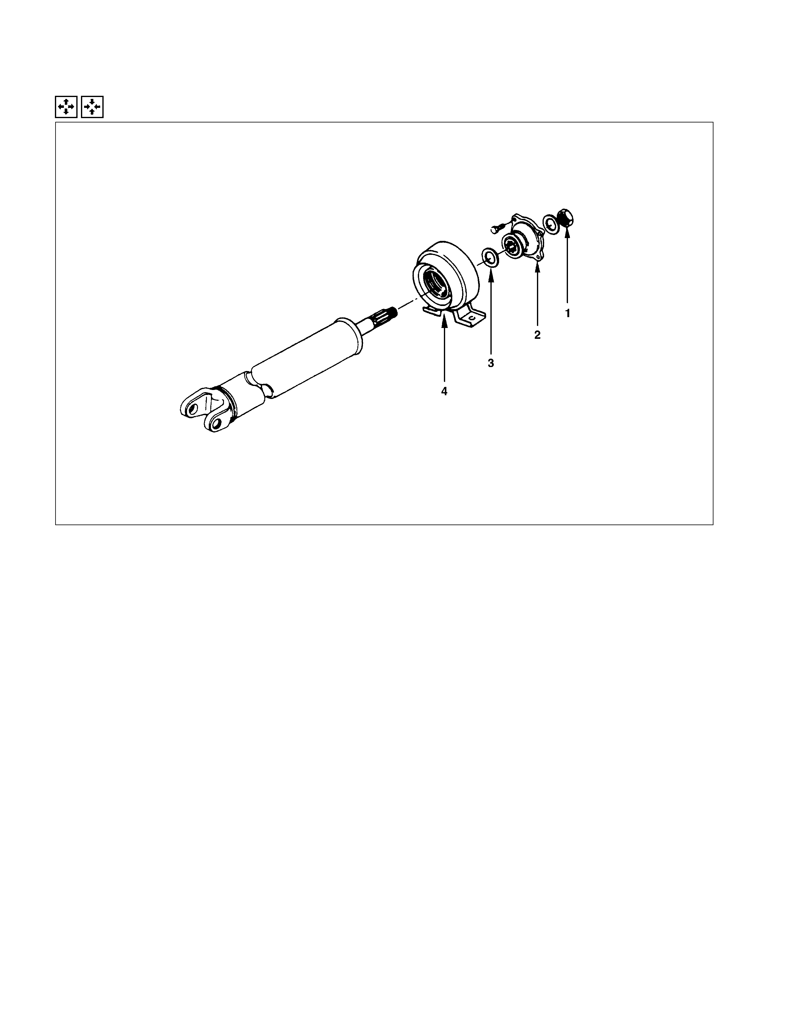
PROPELLER SHAFT ASSEMBLY
GENERAL DESCRI PTION
REAR PROPELLER SHAFT
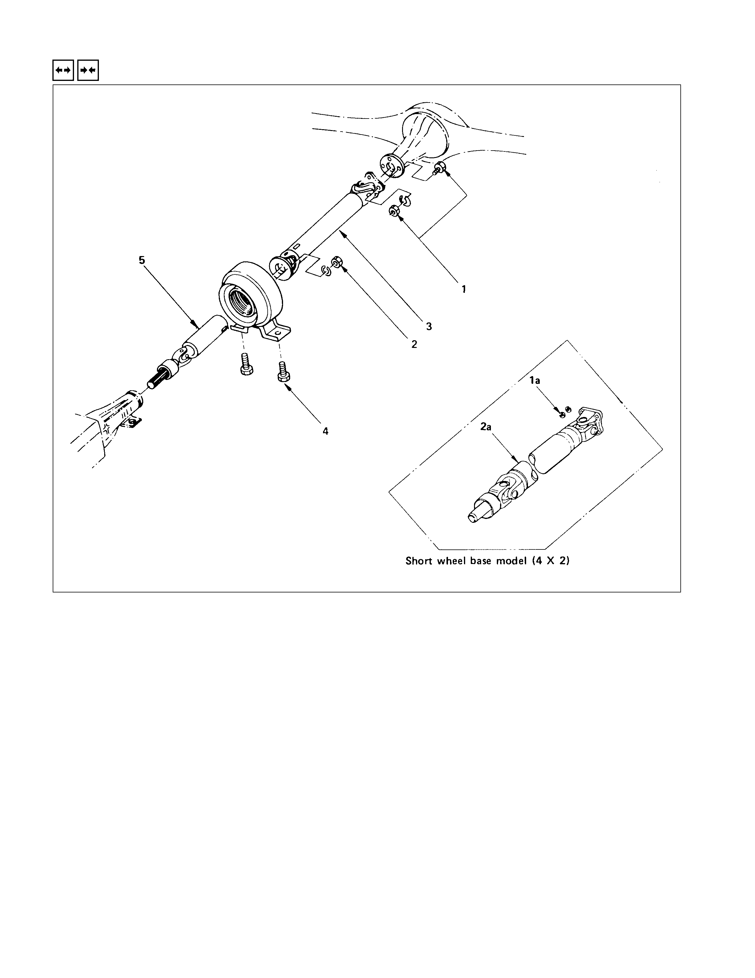
REMOVAL AND INSTALLATION
Since the propeller shaft assembly is carefully
balanced, a scribe mark should be made on
the flange before removal.
Install the parts by aligning scribe marks made
during removal.
REMOVAL STEPS
1. 1a. Bolt ; differential side
2. Bolt ; flange
▲2a. Propeller shaft assembly
3. Propeller shaft assembly ; 2nd
4. Bolt ; center bearing bracket
▲5. Propeller shaft assembly ; 1st
INSTALLATION STEPS
5. Propeller assembly ; 1st
▲4. Bolt ; center bearing bracket
3. Propeller shaft assembly ; 2nd
▲2. Bolt ; flange
2a. Propeller shaft assembly
▲1. 1a. Bolt ; differential side
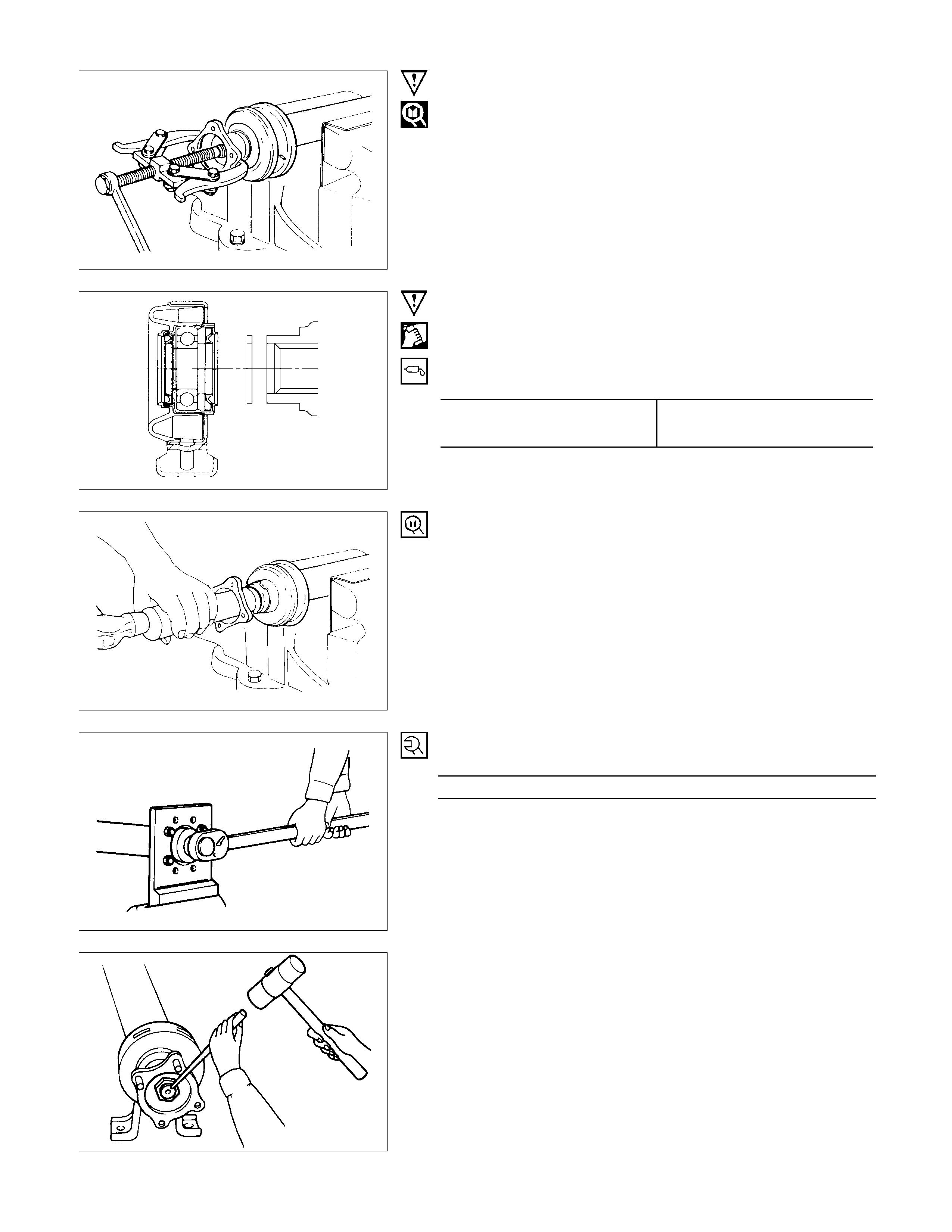
IMPO RTANT OPERATIONS - REMOVAL
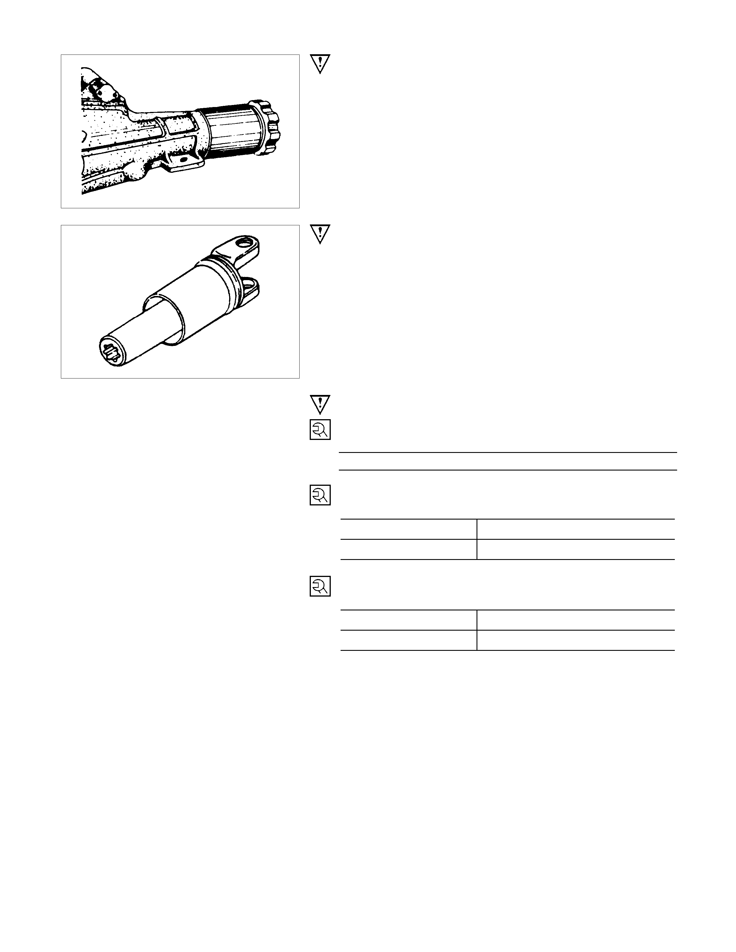
2a.Propeller Shaft Assembly
5. Propellers Shaft Assembly ; 1st
Install a plug at the transmission rear cover to prevent loss of
the transmission oil.
CAUTION:
Cover the slip yoke with cloth to avoid damage to the oil
seal contact surface, when
removing propeller shaft from transmission. Do not
damage the oil seal contact surface of
slip yoke with other parts at removal and installation.
IMPORTANT OPERATIONS - INSTALLATION
4. Bolt ; Center Bearing Bracket
Bolt Torque N⋅m (kgf⋅m/lb⋅ft)
68.6 ± 13.7 (7.0 ± 1.4 / 50.4 ± 10)
2. Bolt ; Flange
Bolt Torque N⋅m (kgf⋅m/lb⋅ft)
Bolt size M10 62.8 ± 3.9 (6.4 ± 0.4/46.3 ± 2.9)
Bolt size M8 35.3 ± 2.9 (3.6 ± 0.3/26 ± 2.2)
1. 1a. Bolt ; differential side
Bolt Torque N⋅m (kgf⋅m/lb⋅ft)
Bolt size M10 62.8 ± 3.9 (6.4 ± 0.4/46.3 ± 2.9)
Bolt size M8 35.3 ± 2.9 (3.6 ± 0.3/26 ± 2.2)
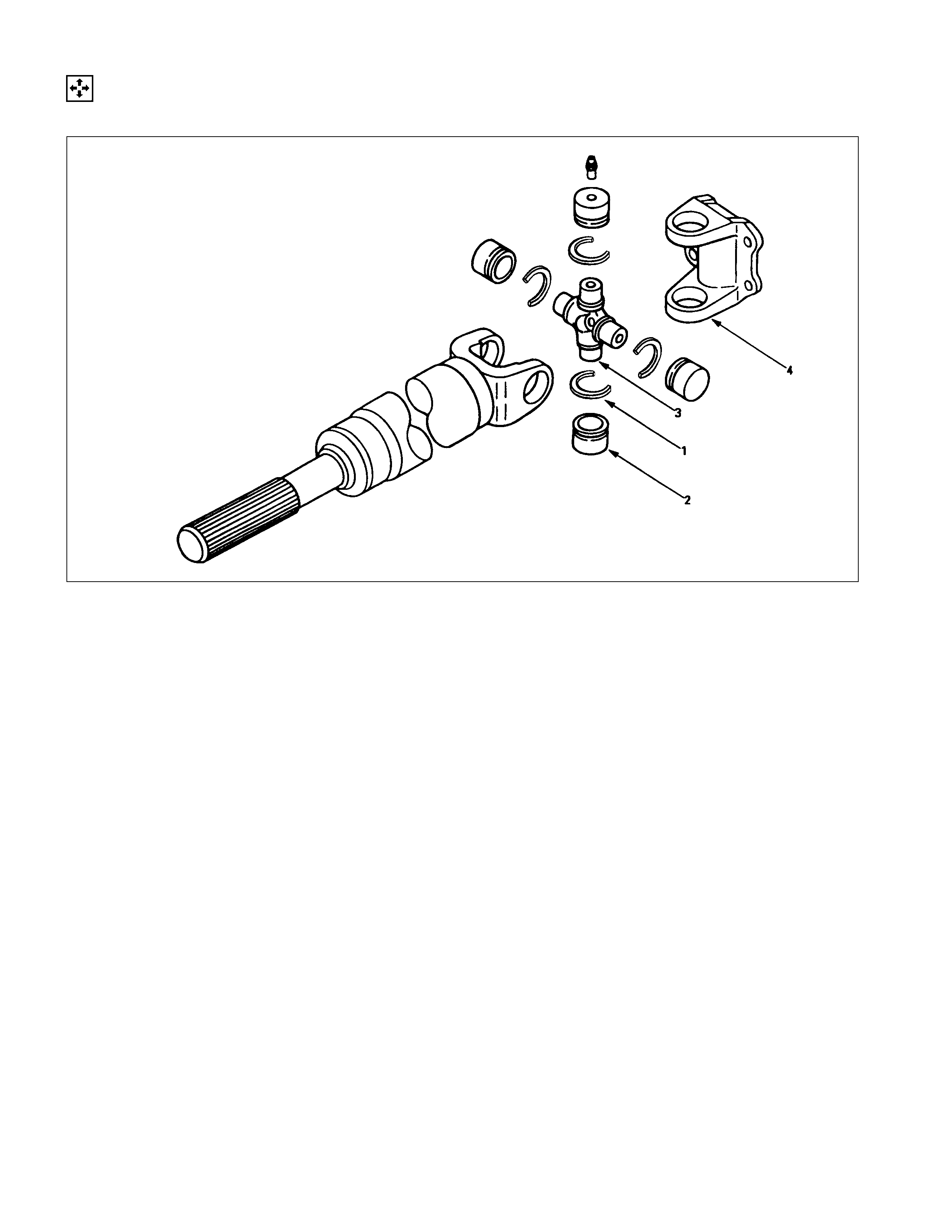
DISASSEM BLY
UNIVERSAL JO INT
DISASSEM BLY STEPS
1. Snap ring
2. Needle roller bearing
3. Spider
4. Flange yoke
REASSEMBLY STEPS
To reassemble, follow the disassembly steps
in the reverse order.
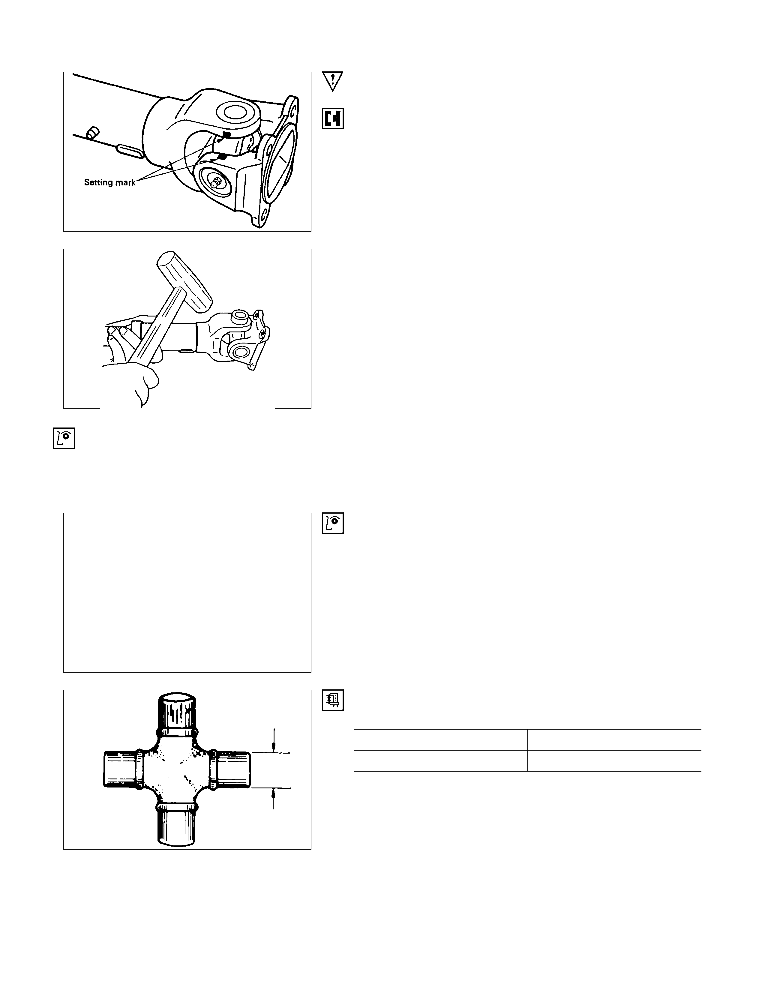
IMPORTANT OPERATION
1. Snap ring
•Apply alignment marks on the yokes of the universal
joint.
2. Needle roller bearing
•Tap out the bearing by gently strik ing the shoulder of the
yoke, using a mallet or a copper hammer.
3. Spider
•Make sure of proper position for reinstallation by
applying setting marks.
4. Flange Yoke
INSPECTION AND REPAIR
Make all necessary adjustment, repairs, and part replacements if wear, damage, or other problems are discovered
during inspection.
Spider
Needle roller bearing
Yoke
Flange
Center bearing
Cushioning rubber
Bracket
VISUAL CHECK
Inspect following parts for wear, damage, or other abnormal
conditions.
OUTSIDE DIAMETER OF SPIDER PINS mm(in)
Standard Limit
17 (0.67) 16.90 (0.665)
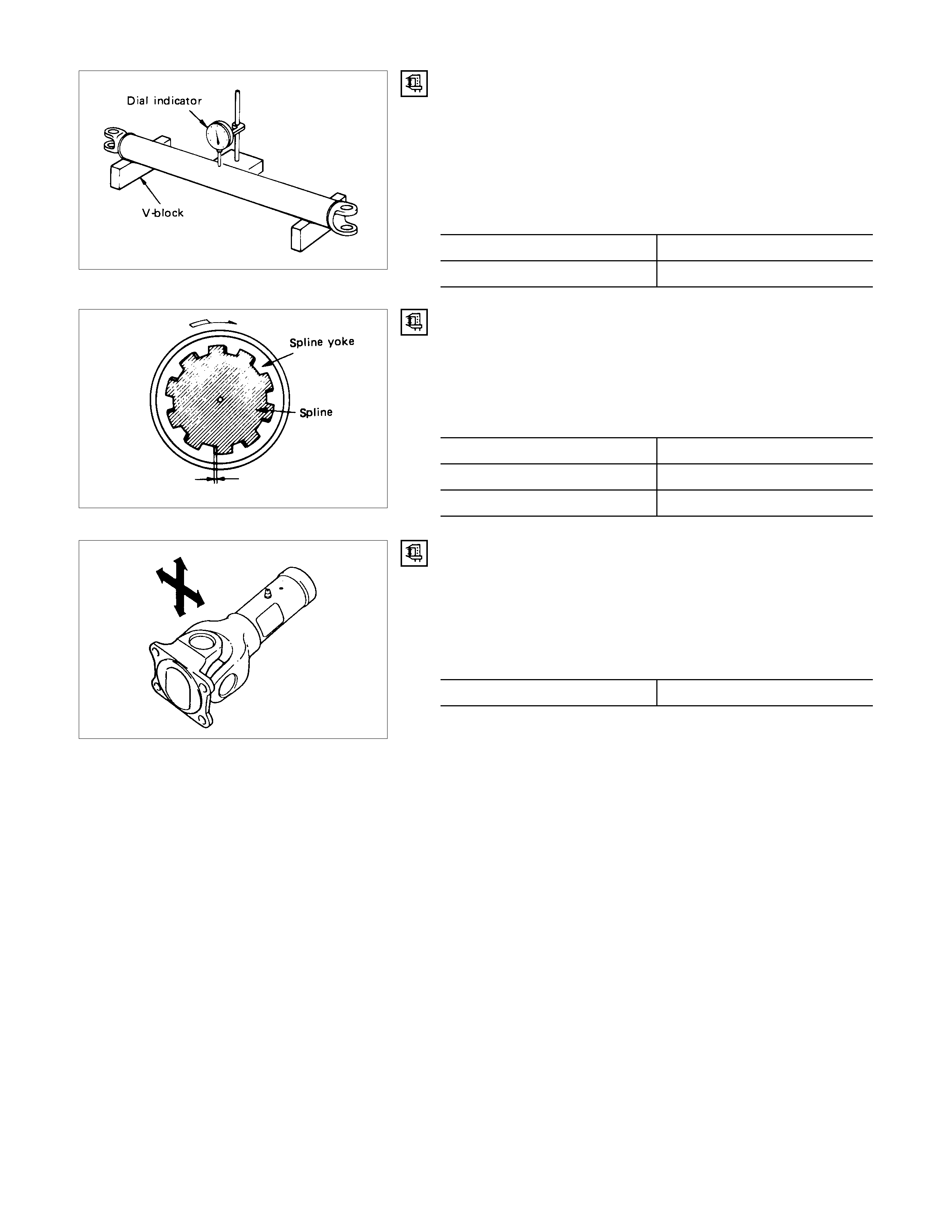
PROPELLER SHAFT RUN-OUT
Support the ends of the propeller shaft on V-blocks and check
for run-out by holding the probe of a dial indicator in contact
with the center part of the shaft.
If the amount of run-out is beyond the standard value for
assembly, correct with a bench press or replace the shaft with
a new one. mm(in)
Standard Limit
0.5 (0.02) 1.0 (0.04)
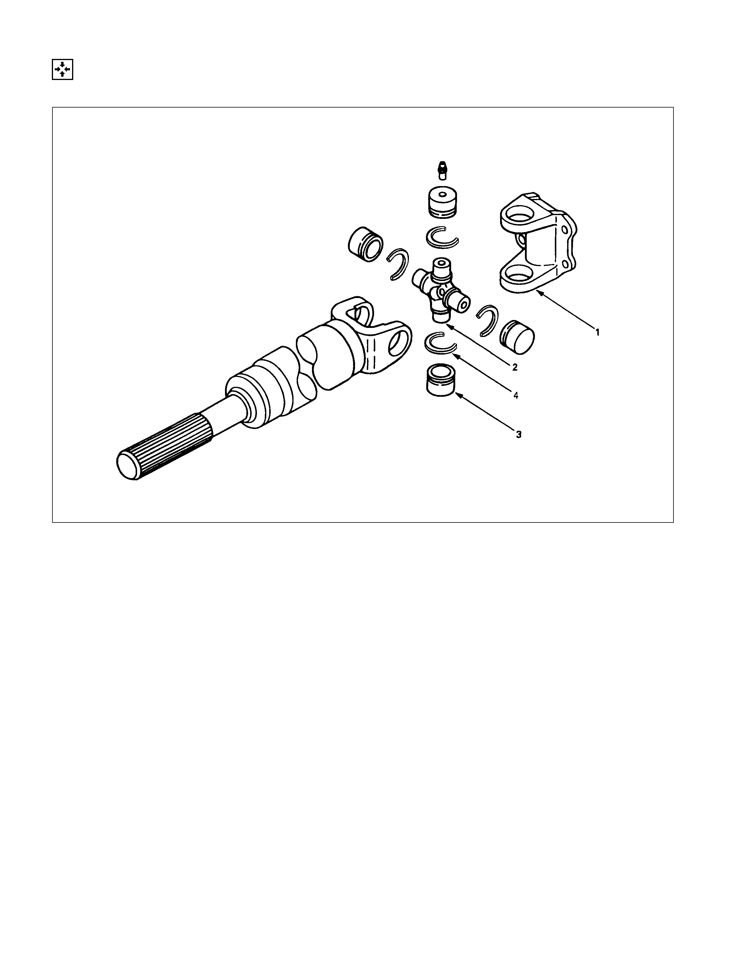
PLAY IN THE SPLINES IN THE NORMAL DIRECTION
OF ROTATION
Check the amount of play in the sleeve yoke and the propeller
shaft splines in the direction of rotation using a pointed feeler
gauge. mm(in)
Standard Limit
0.06 - 0.14 0.3 (0.012)
(0.002 - 0.006)
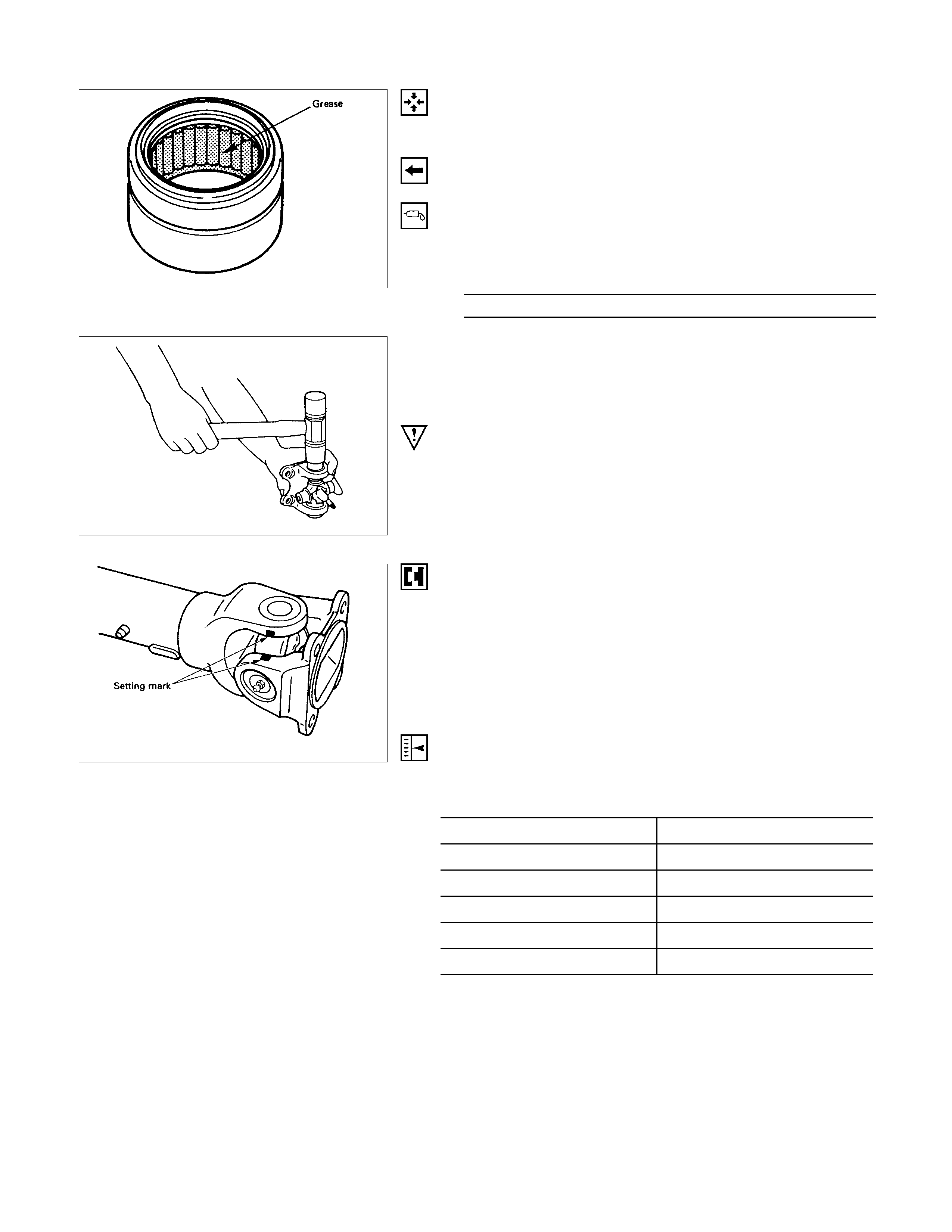
PLAY IN SPIDER BEARING
(1)Check the spider bearings for wear or damage.
(2)Check the amount of axial and radial play in spider bearing
by moving the yoke back and forth on the spider axes and
shaft axis. mm(in)
Limit 0.5 (0.02)
If the limit is exceeded, replace the shaft assembly.
REASSEMBLY
UNIVERSAL JO INT
DISASSEM BLY STEPS
1. Flange yoke
2. Spider
3. Needle roller bearing
4. Snap ring
REASSEMBLY STEPS
To reassemble, follow the disassembly steps
in the reverse order.
REASSEMBLY
1. Flange yoke
2. Spider
•Be sure to install the spider by aligning the setting marks
made during disassembly.
3. Needle Roller Bearing
1) Apply a molybdenum-disulfide grease or a multi-purpose.
type grease NLGI No.2 to inside of the bearing cap.
Grease Amount g(oz)
Approx. 1.2 (0.042)
2) Using either a mallet (or copper ham mer ) or a press, ins tall
the needle roller bearing into the yoke s o that snap ring c an
be installed in its groove.
CAUTION:
•
••
•The needle roller bearing cannot be installed smoothly
if it is set at an incorrect angle with the flange.
•
••
•Excessive hammering will damage the needle rolle
r
bearing.
3) Align setting marks and join the yokes.
NOTE:
Assemble the spider and spline yoke so that their grease
fittings are arranged on the same side.
4. Snap ring
NOTE:
Discard used snap rings and install new ones.
When the bearing cap is in position, select and attach a snap
ring of suitable thickness so that the end play of the spider pin
is held within 0.1mm (0.004in). mm(in)
Snap ring thickness Identification color
1.5 (0.059) Blue
1.53 (0.060) White
1.59 (0.063) Yellow
1.62 (0.064) Green
1.68 (0.066) Not colored
NOTE:
Be sure to use snap rings of the same thickness on both sides.
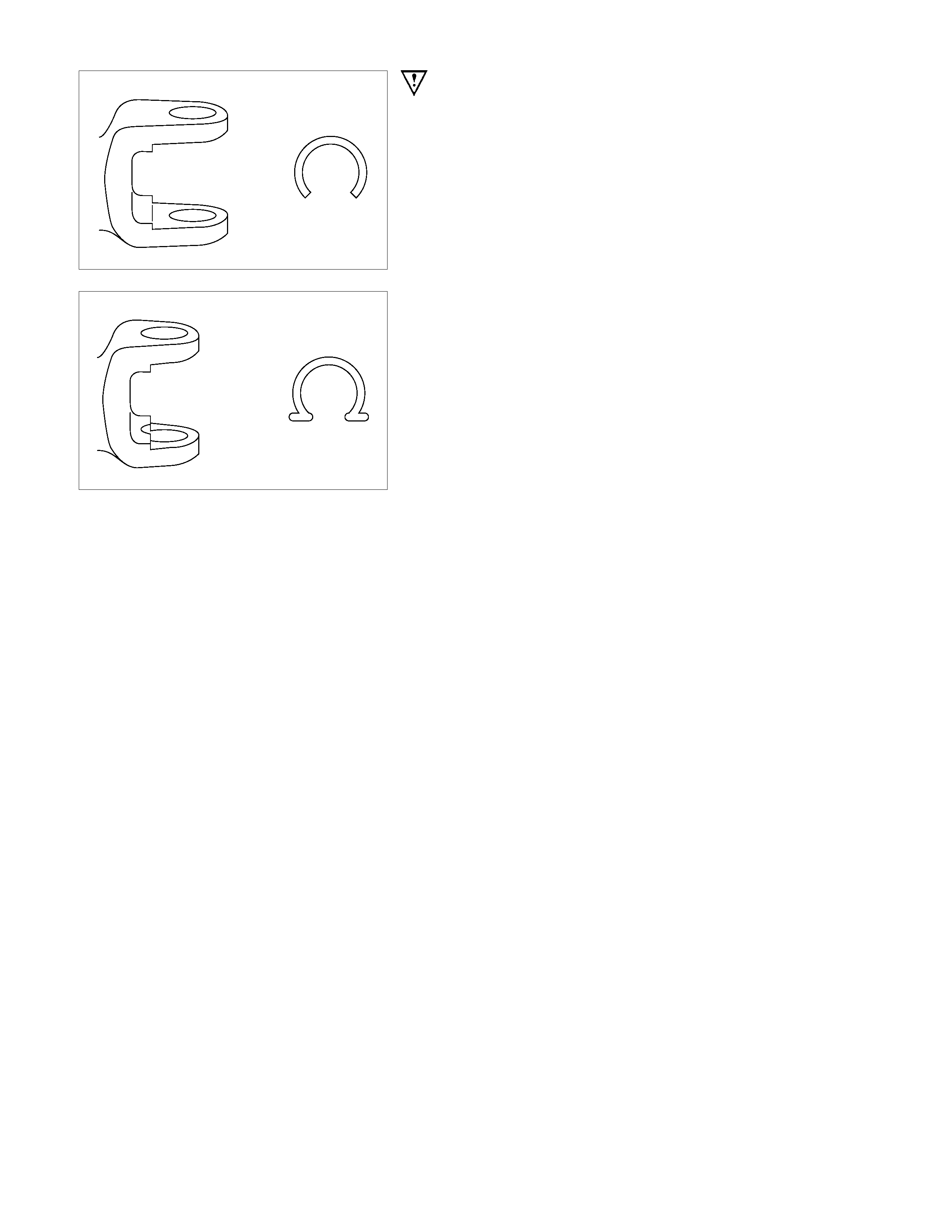
CAUTION:
There are two types of flange yoke and snap rings. There
is no interchangeability between
them, so be sure not to misassemble them.
CENTER BEARING
DISASSEM BLY AND REASSEMBLY
DISASSEM BLY STEPS
1. Lock nut
▲2. Flange
3. Washer
4. Bearing assembly
REASSEMBLY STEPS
▲4. Bearing assembly
3. Washer
▲2. Flange
▲1. Lock nut
IMPO RTANT OPERATIONS - DISASSEMBLY
2. Flange
Use a suitable remover.
IMPO RTANT OPERATIONS - REASSEMBLY
3. Bearing assembly
Clean the bearing fitting face.
Repack the grease and apply a grease to the both sides of
washer.
Amount of grease
required g(oz) Approx. 12 (0.42)
2. Flange
Installer : 58522-0034-0
(J-6403-C)
1. Lock nut
Lock nut Torque N⋅m (kgf⋅m/lb⋅ft)
117.7 (12/86.8)
(1)Discard the flange nut and install a new one.
(2)Stake the outer f ace of the f lange nut against the slot in the
shaft.
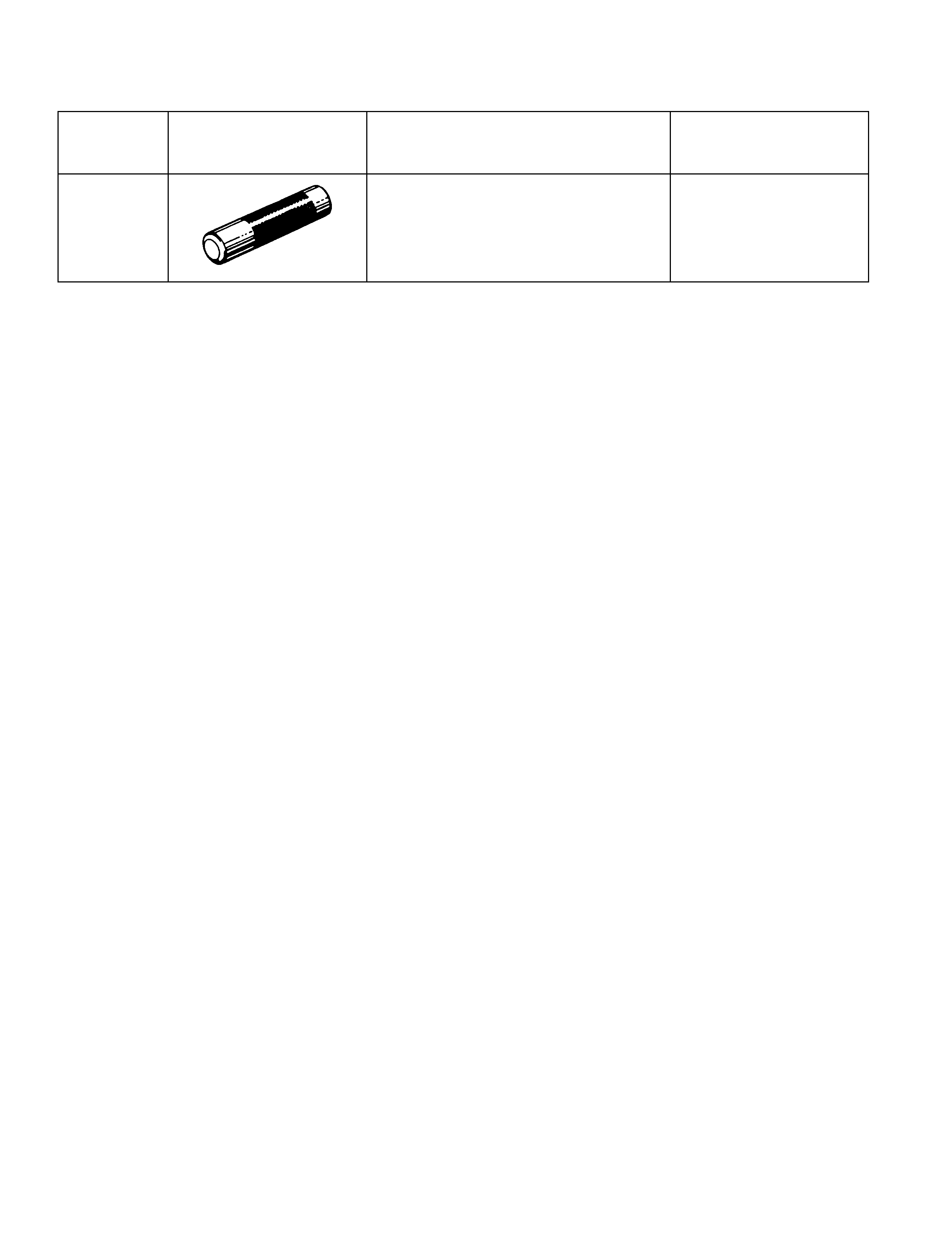
SPECIAL SERVICE TOOL
ITEM NO. ILLUSTRATION PART NO. PART NAME
PSL-1 5-8522-0034-0
(J-6403-C) Pinion flange installer