
SECTION 5 - BRAKES
General Description
Main Data and Specifications
Special Parts Fixing Nut and Bolt
Load Sensing Proportioning Valve (LSPV)
Front Brake Assembly
Removal and Installation
Removal and installation of Disc Pad
Disassembly
Inspection and Repair
Reassembly
Rear Drum Brake Assembly
Disassembly
Inspection and Repair
Reassembly
Brake Control
Removal and Installation
Master Cylinder
Removal and Installation
Disassembly
Inspection and Repair
Reassembly
Vacuum Servo
Removal and Installation
Parking Brake (Stem Type)
Removal and installation
Disassembly and Reassembly
Inspection and Repair
Parking Brake (Floor Mount Type)
Techline
Techline
Techline

GENERAL DESCRIPTION
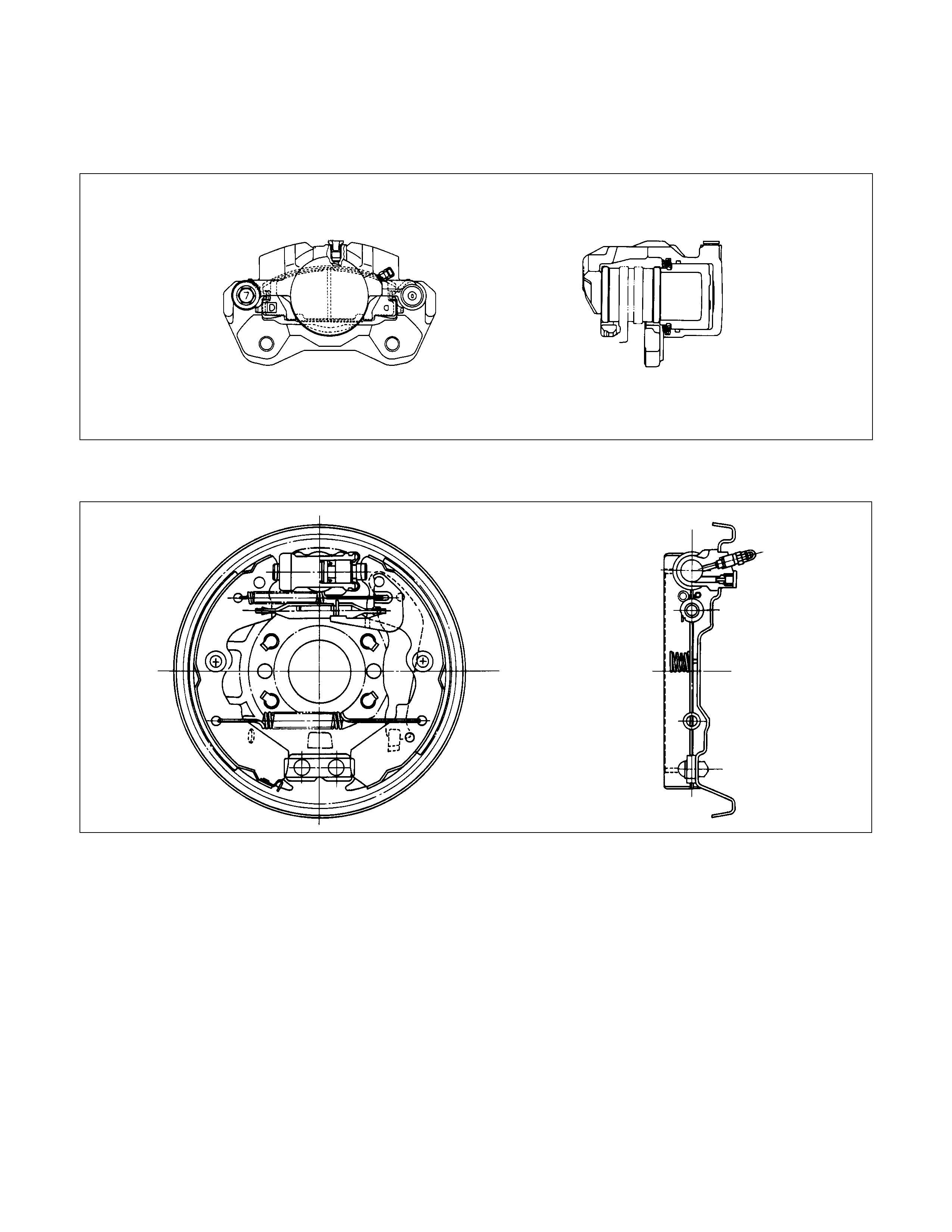
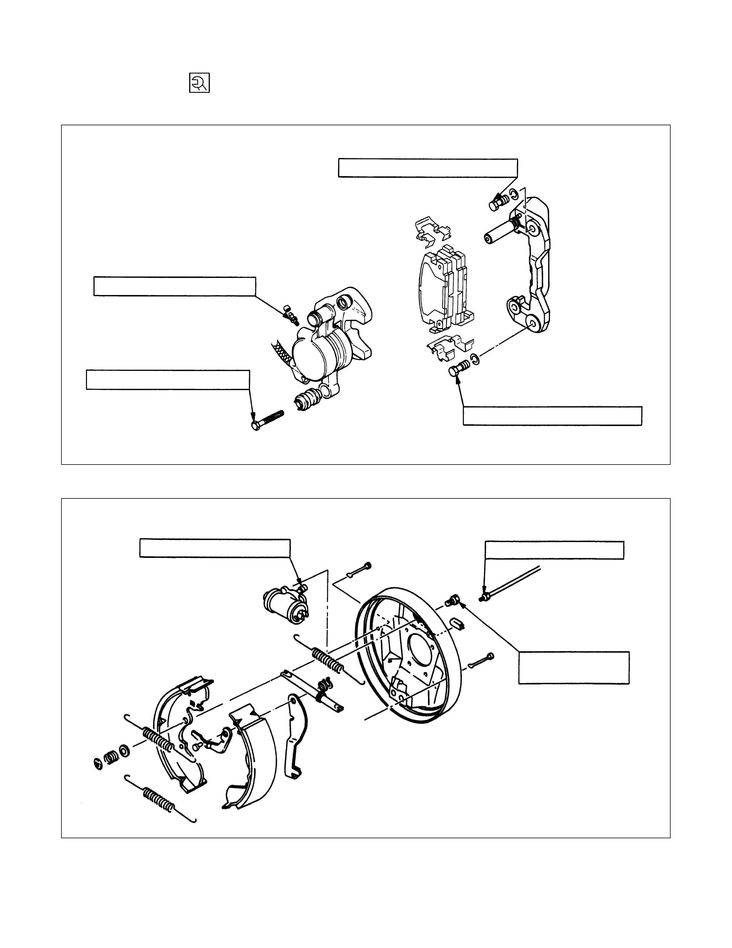
FRONT DISC BRAKE
REAR DRUM BRAKE
REAR WHEEL CYLINDER
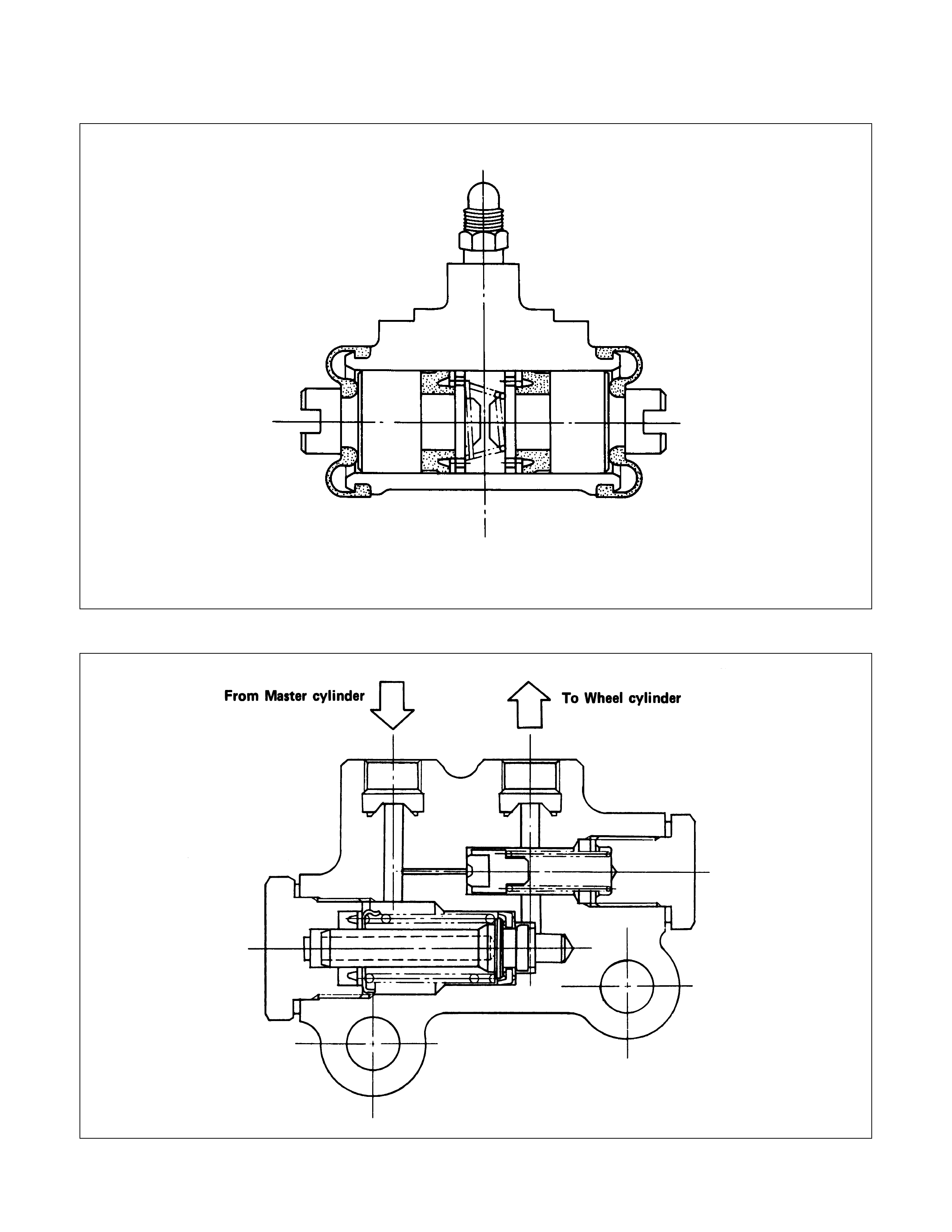
BLEND PROPORTIONING VALVE
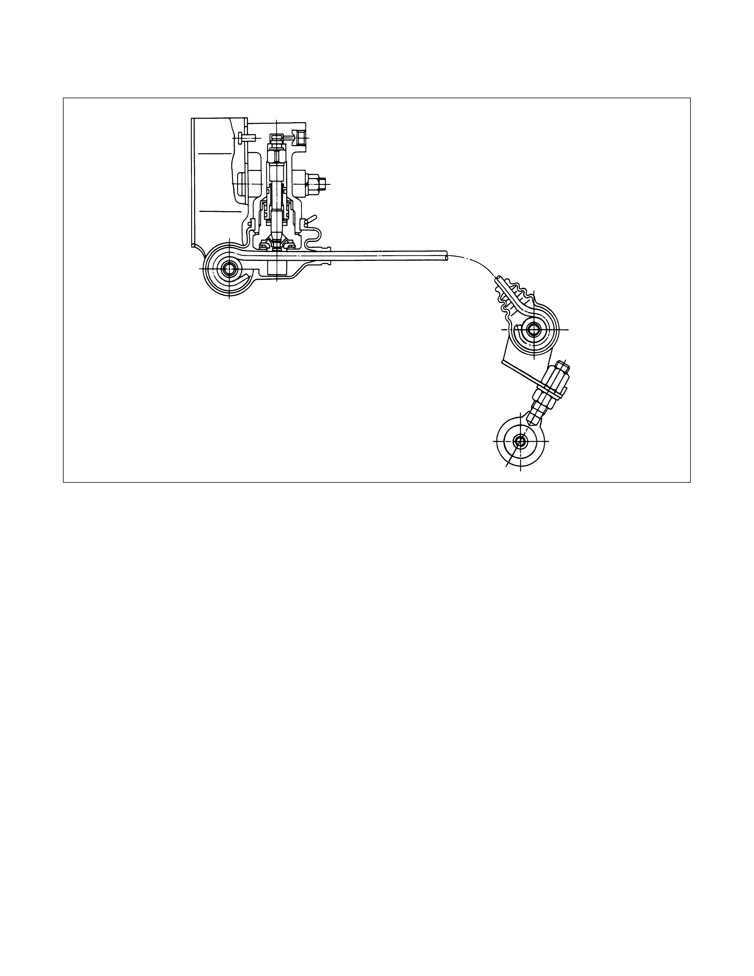
LOAD SENSING PROPORTIONING VALVE (LSPV)
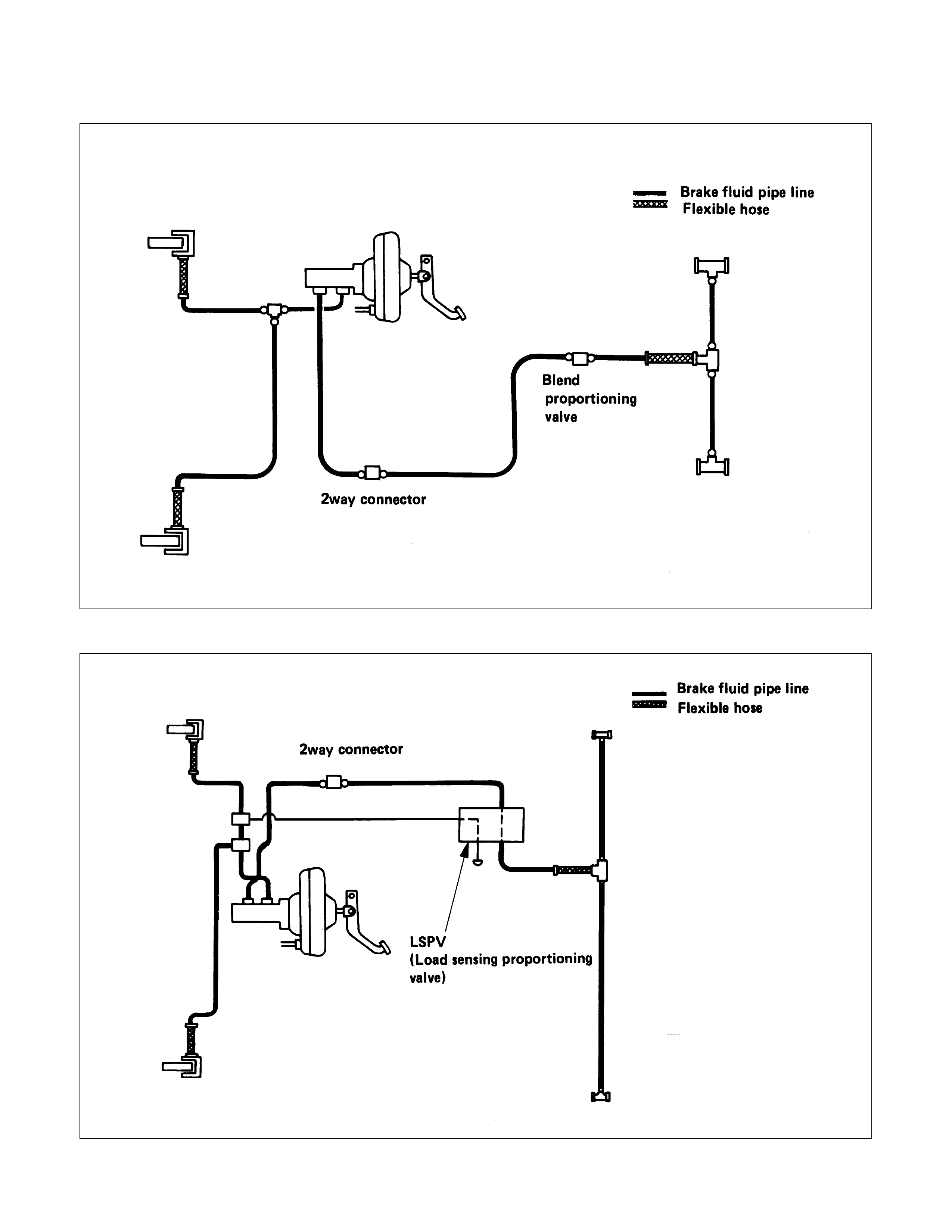
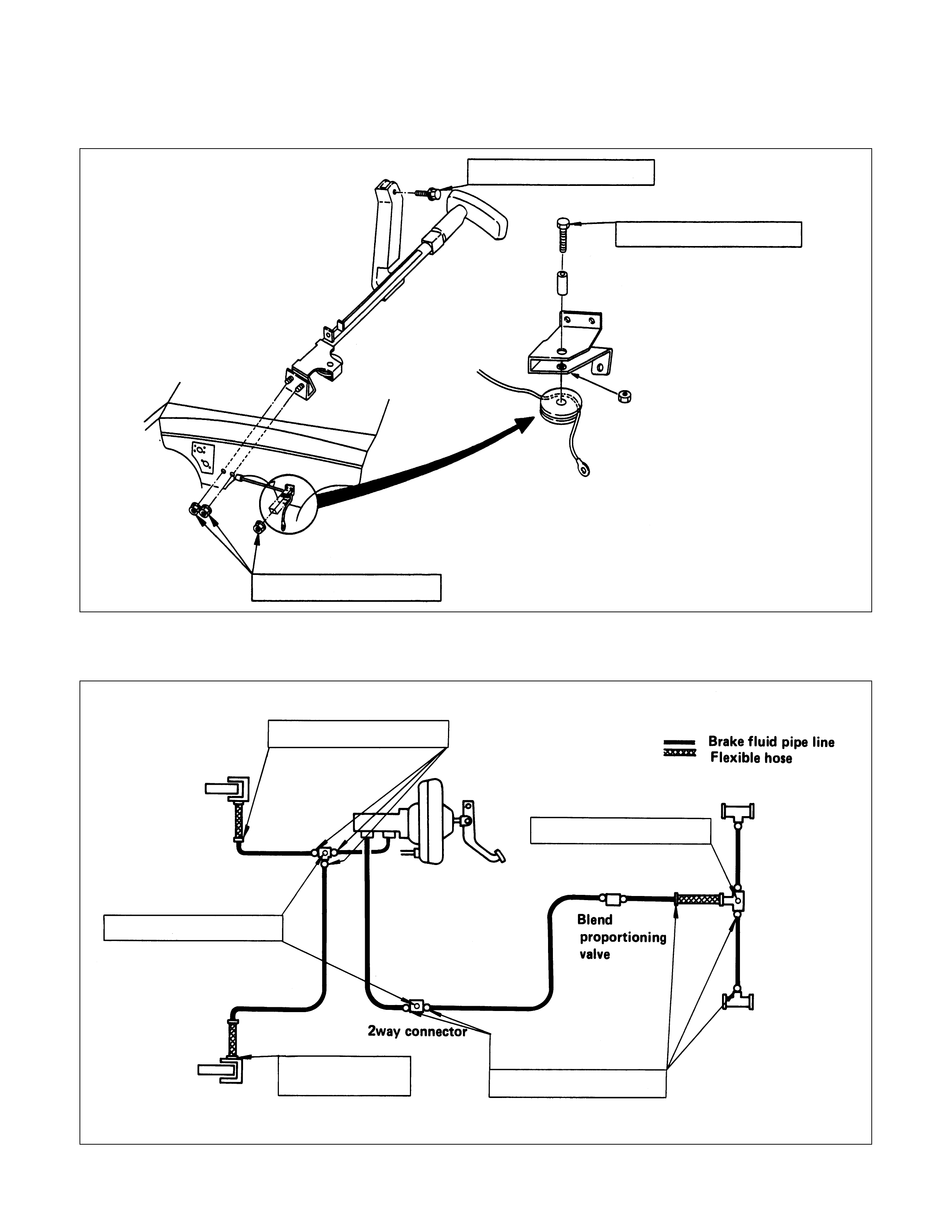
PIPING DIAGRAM (MODEL WITH BLEND PROPORTIONING VALVE)
PIPING DIAGRAM (MODEL WITH LSPV)
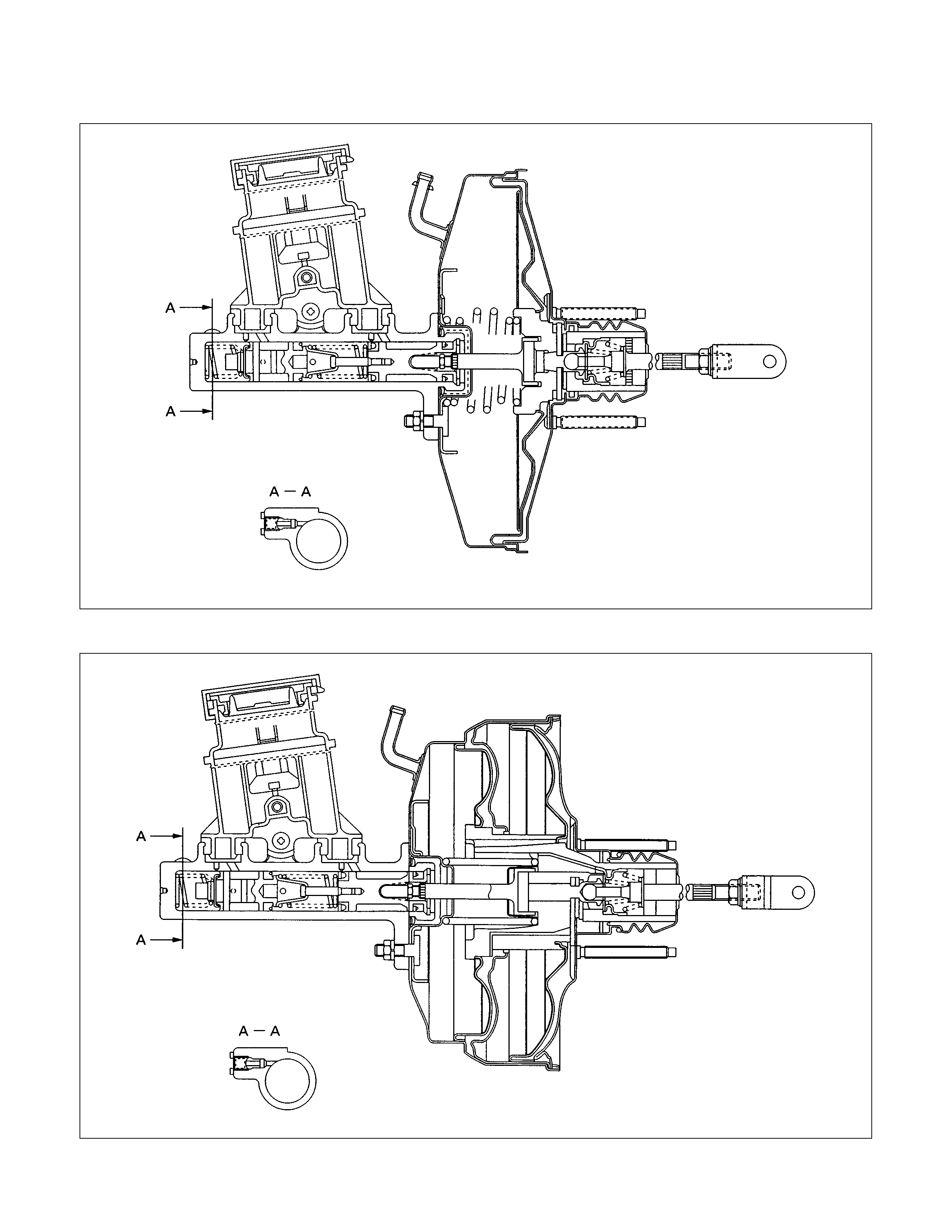
VACUUM SERVO WITH MASTER CYLINDER (Except Australia)
VACUUM SERVO WITH MASTER CYLINDER (For Australia)

MAIN DATA AND SPECIFICATIONS
FRONT DISC BRAKE mm(in.)
Caliper type Pin slide
Disc outside diameter 257 (10.118)
Disc thickness 22 (0.866)
Piston diameter 60.33 (2.375)
Adjustment method Self-adjusting
REAR DRUM BRAKE mm(in.) 4 × 24 × 4
Type Leading and Trailing
Drum inside diameter 254(10.008) 295 (11.614)
Brake lining dimension 221 × 50 × 5 283 × 45 × 4
(Length × Width × Thickness) (8.71 × 1.97 × 0.20) (11.14 × 1.77 × 0.16)
Adjustment method Self-adjusting
WHEEL CYLINDER mm(in.)
Inside diameter : rear
Europe and South Africa 25.40 (1.000)
Others 22.22 (0.875)
MASTER CYLINDER mm(in.)
Type Split
Bore diameter 23.81 (0.938)
Piston stroke (Primary + Secondary) 19 + 12 (0.75 + 0.47)
VACUUM SERVO mm(in.)
Diaphragm diameter
Except Australia 230 (9.055)
For Australia 180 (7.087) + 205 (8.077)
Power cylinder stroke 32.5 (1.281)
PEDAL RATIO 4.04
BALANCE
Type Blend proportioning valve/Load sensing proportioning
valve
SPECIAL PARTS FIXING NUT AND BOLT
FRONT WHEEL BRAKE N⋅m(kgf⋅m/lb⋅ft)
27-37 (2.8-3.8/20-27)
139-171 (14.2-17.4/103-126)
139-171 (14.2-17.4/103-126)
5.9-8.8 (0.6-0.9/4.3-6.5)
REAR WHEEL DRUM BRAKE N⋅m(kgf⋅m/lb⋅ft)
11-15
(1.1-1.5/8-11)
13-19 (1.3-1.9/9-14)
6.9-11.8 (0.7-1.2/5.1-8.7)
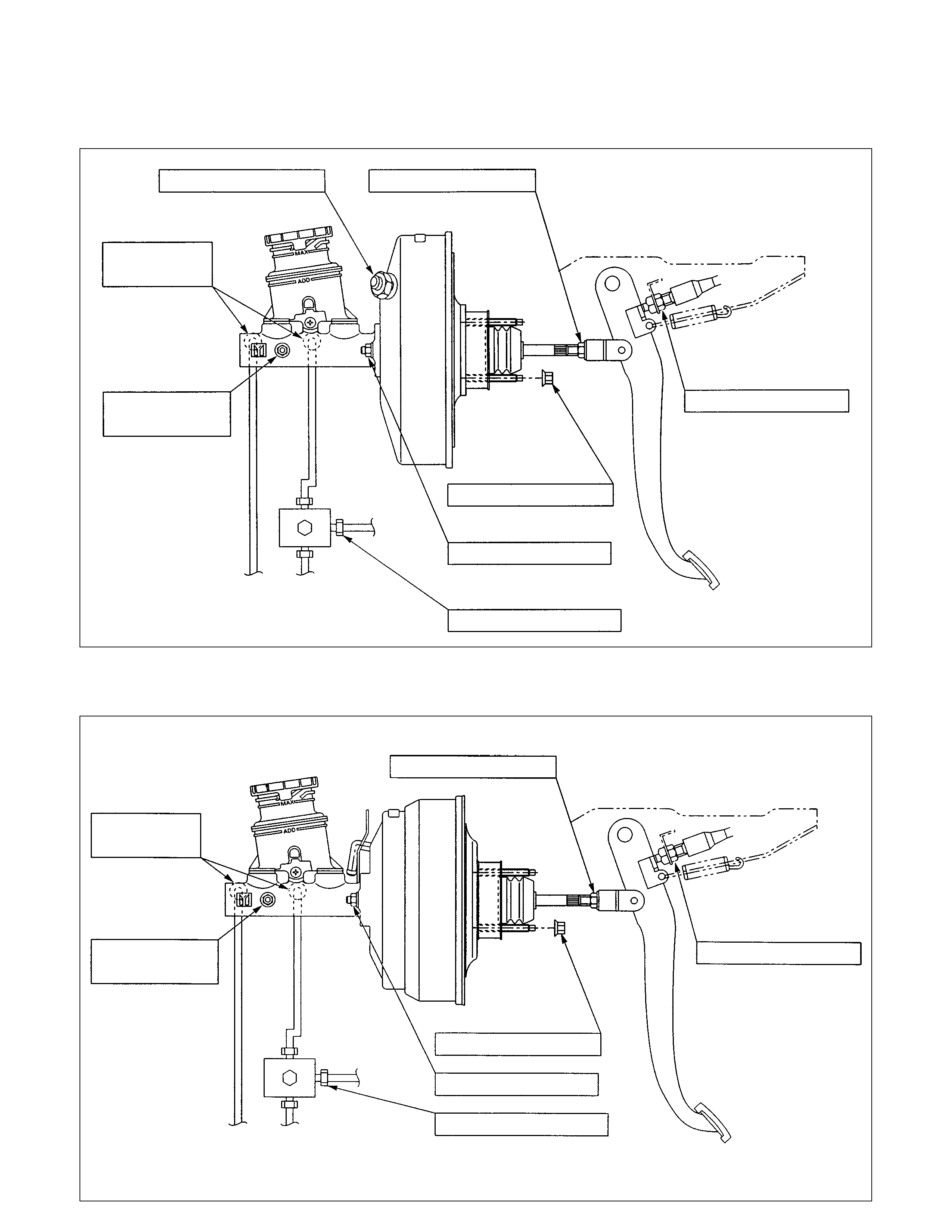
VACUUM SERVO WITH MASTER CYLINDER AND BRAKE PEDAL
(Except Australia) N⋅m(kgf⋅m/lb⋅ft)
6.9-8.8
(0.7-0.9 / 5.1-6.5) 15-25 (1.5-2.5 / 11-18)
13-19 (1.3-1.9 / 9.4-14)
9.8-16 (1.0-1.6 / 7-12)
18-24 (1.8-2.4 / 13-17)
15-25 (1.5-2.5 / 11-18)
20-25 (2.0-2.5 / 14-18)
9-15
(0.9-1.5 / 6.5-11)
VACUUM SERVO WITH MASTER CYLINDER AND BRAKE PEDAL
(For Australia only) N⋅m(kgf⋅m/lb⋅ft)
6.9-8.8
(0.7-0.9 / 5.1-6.5)
9-15
(0.9-1.5 / 6.5-11)
13-19 (1.3-1.9 / 9.4-14)
9.8-16 (1.0-1.6 / 7-12)
18-24 (1.8-2.4 / 13-17)
15-25 (1.5-2.5 / 11-18)
15-25 (1.5-2.5 / 11-18)
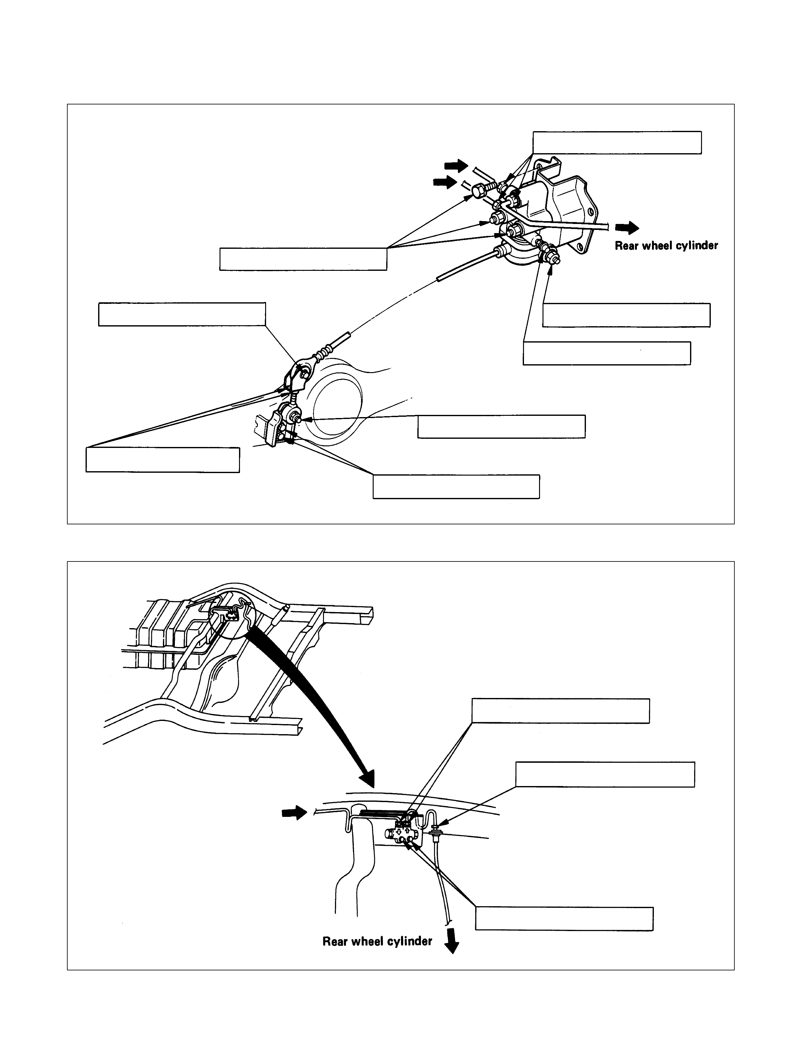
LOAD SENSING PROPORTIONING VALVE N⋅m(kgf⋅m/lb⋅ft)
Primary Master Cylinder
Secondary Master Cylinder
19-30 (1.9-3.1/14-22)
14-24 (1.4-2.4/10-17)
10-16 (1.0-1.6/7-12)
7-10 (0.7-1.0/5-7)
15-22 (1.5-2.2/11-16)
13-19 (1.3-1.9/9.4-14)
15-22 (1.5-2.2/11-16)
14-24 (1.4-2.4/10-17)
BLEND PROPORTIONING VALVE N⋅m(kgf⋅m/lb⋅ft)
14-24 (1.4-2.4/10-17)
13-19 (1.3-1.9/9.4-14)
13-19 (1.3-1.9/9.4-14)
Secondary master cylinder
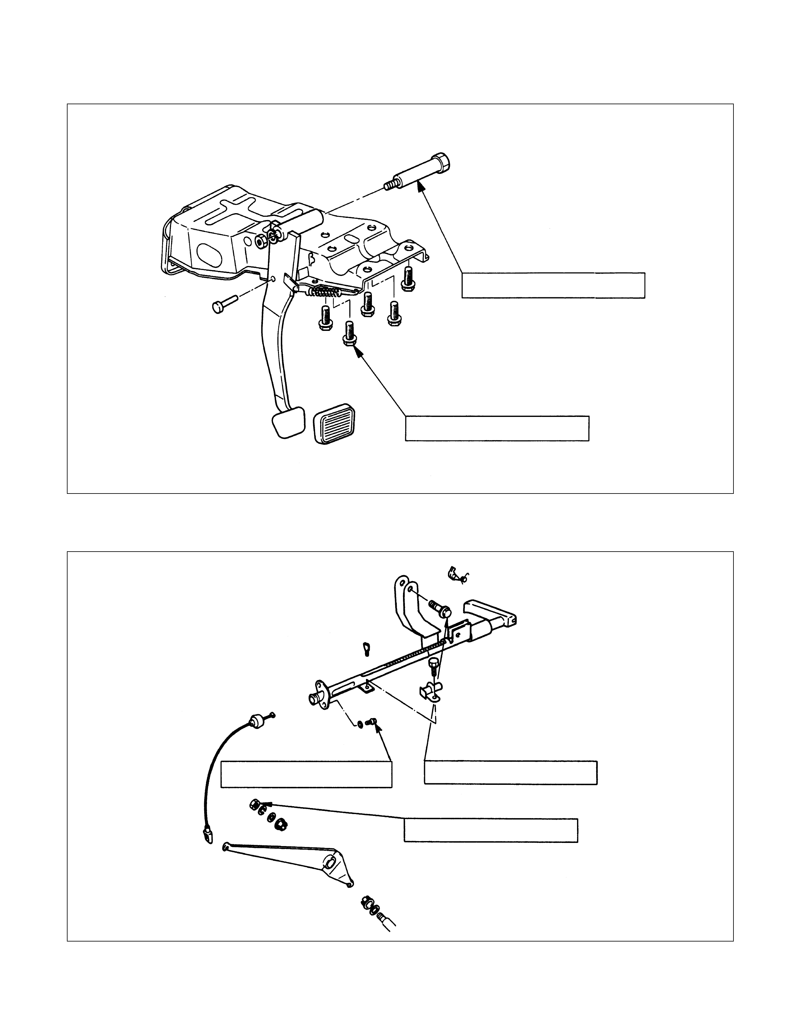
BRAKE PEDAL ASSEMBLY N⋅m(kgf⋅m/lb⋅ft)
This illustration is besed on the LHD model
11-20 (1.1-2.0/8-14
29-39 (3.0-4.0/22-29)
PARKING BRAKE STEM ASSEMBLY
(STEM TYPE, LEFT HAND DRIVE MODEL) N⋅m(kgf⋅m/lb⋅ft)
21-34 (2.1-3.5/15-25)
11-20 (1.1-2.0/8-14) 14-25 (1.4-2.5/10-18)
PARKING BRAKE STEM ASSEMBLY
(STEM TYPE, RIGHT HAND DRIVE MODEL) N⋅m(kgf⋅m/lb⋅ft)
18-24 (1.8-2.4/13-17)
11-20 (1.1-2.0/8-14)
14-25 (1.4-2.5/10-18)
BRAKE LINES (HOSES AND PIPES)
(MODEL WITH BLEND PROPORTIONING VALVE) N⋅m(kgf⋅m/lb⋅ft)
29-39
(3.0-4.0/22-29) 13-19 (1.3-1.9/9.4-14)
11-20 (1.1-2.2/8-14)
7.8-18 (0.8-1.8/5.8-13)
13-19 (1.3-1.9/9.4-14)
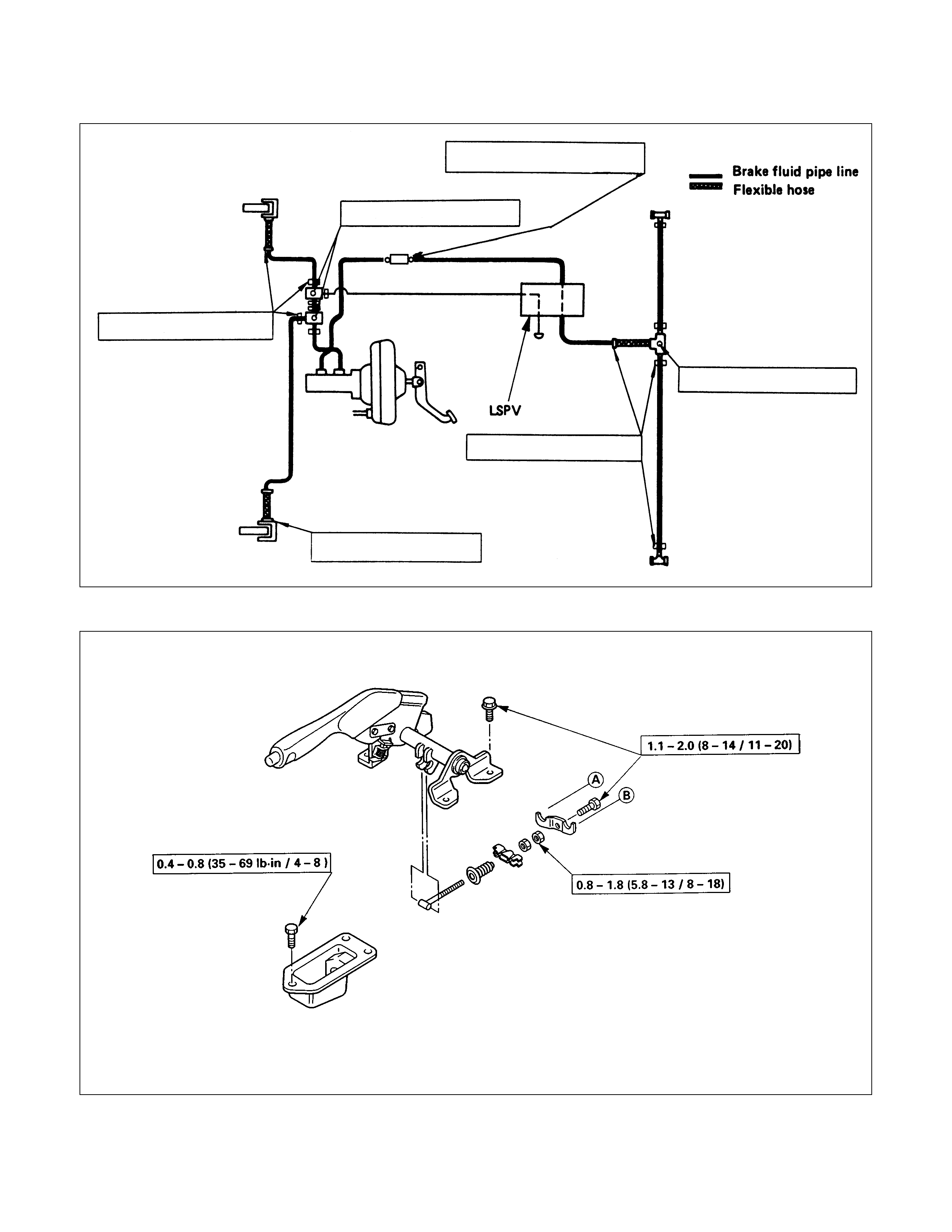
BRAKE LINES (HOSES AND PIPES) (MODEL WITH LSPV) N⋅m(kgf⋅m/lb⋅ft)
29-39 (3.0-4.0/22-29)
13-19 (1.3-1.9/9.4-14)
11-20 (1.1-2.0/8-14)
13-19 (1.3-1.9/9.4-14)
7.8-18 (0.8-1.8/5.8-13)
13-19 (1.3-1.9/9.4-14)
PARKING BRAKE LEVER ASSEMBLY (FLOOR MOUNT TYPE) N⋅m(kgf⋅m/lb⋅ft)
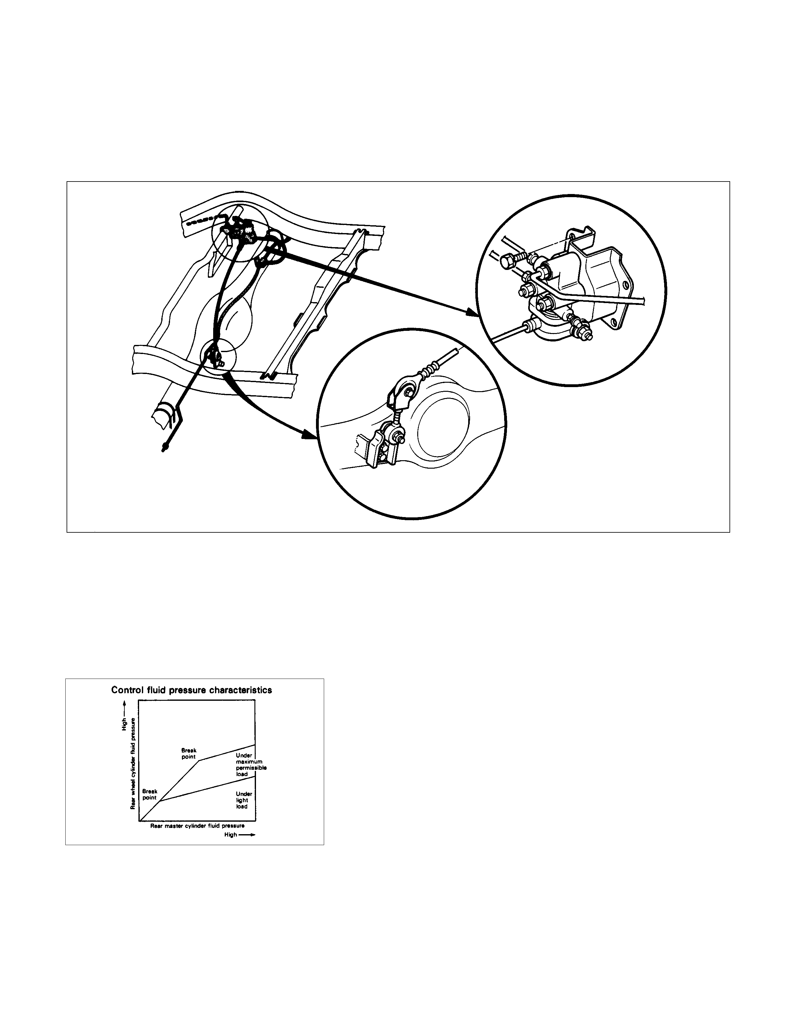
LOAD SENSING PROPORTIONING VALVE (LSPV)
Location of LSPV
Structure and Operation
The following is an explanation of the structure and operation
of the linkage type load sensing device.
This device controls the fluid pressure to the rear brakes in
accordance with changes in rear axle load (vertical
displacements of the rear axle springs).
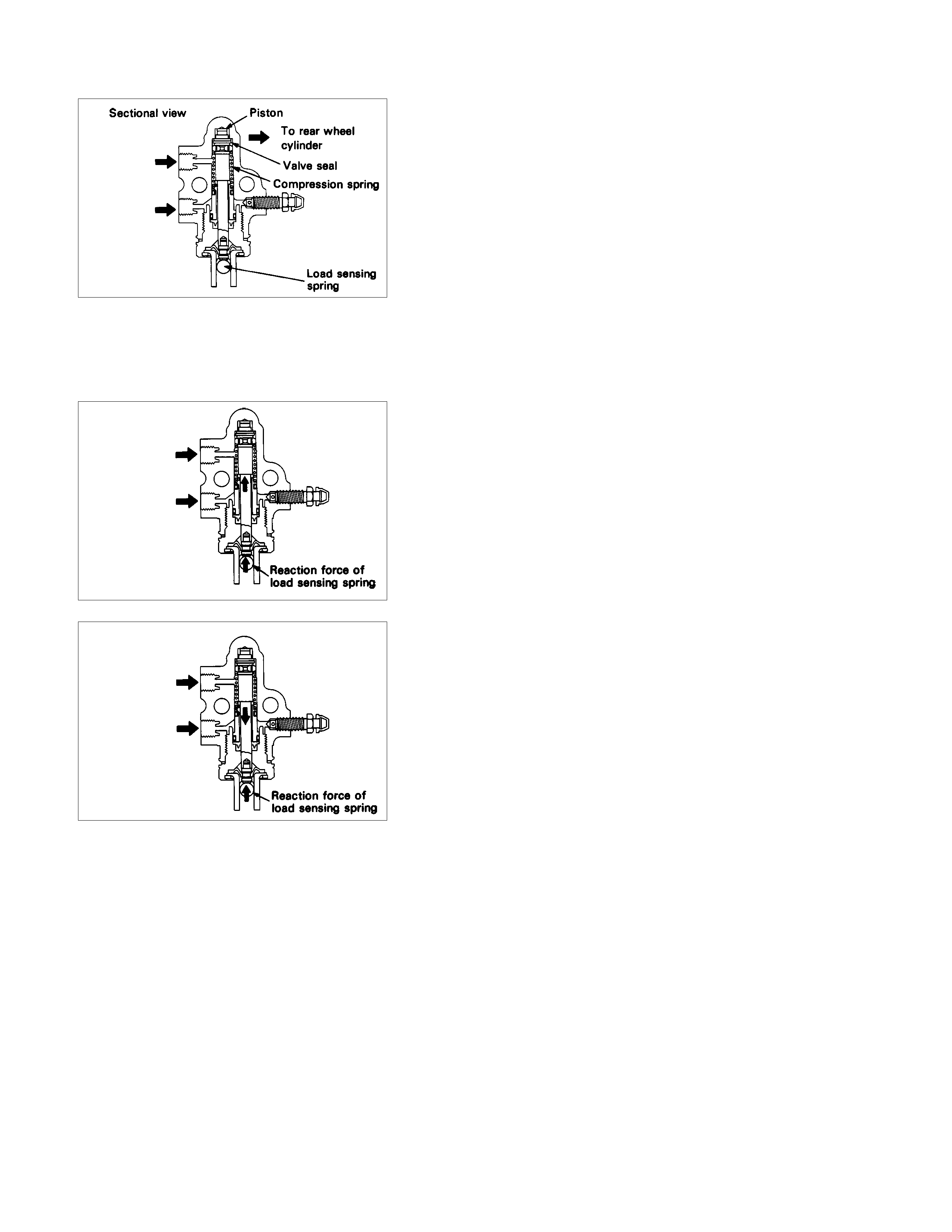
•Structure
This device consists of a load sensing spring (bending bar)
and a valve.
The valve is mounted through a bracket to the frame.
One end of the load sensing spring is fixed to the valve at
the frame and the other end to the rear axle housing
through a shackle.
From
primary
master cy linder
From
Secondary
master cy linder
•Operation
1) Outline
When the L.S.P.V.(Load Sensing Proportioning Valve)
detects a change in load weight, the load sensing spring
deflects.
Its reaction force is transmitted to the bottom of the load
sensing valve to secure an optimum rear wheel cylinder
fluid pressure break point in proportion to the actual load
weight.
Besides, if the front brake system should fail, the device is
designed to prevent the master cylinder fluid pressure from
decreasing and to apply it directly to the rear wheel cylinder
to obtain a sufficient braking performance.
Primary master
cy linder fluid
pressure
Secondary master
cy linder fluid
pressure
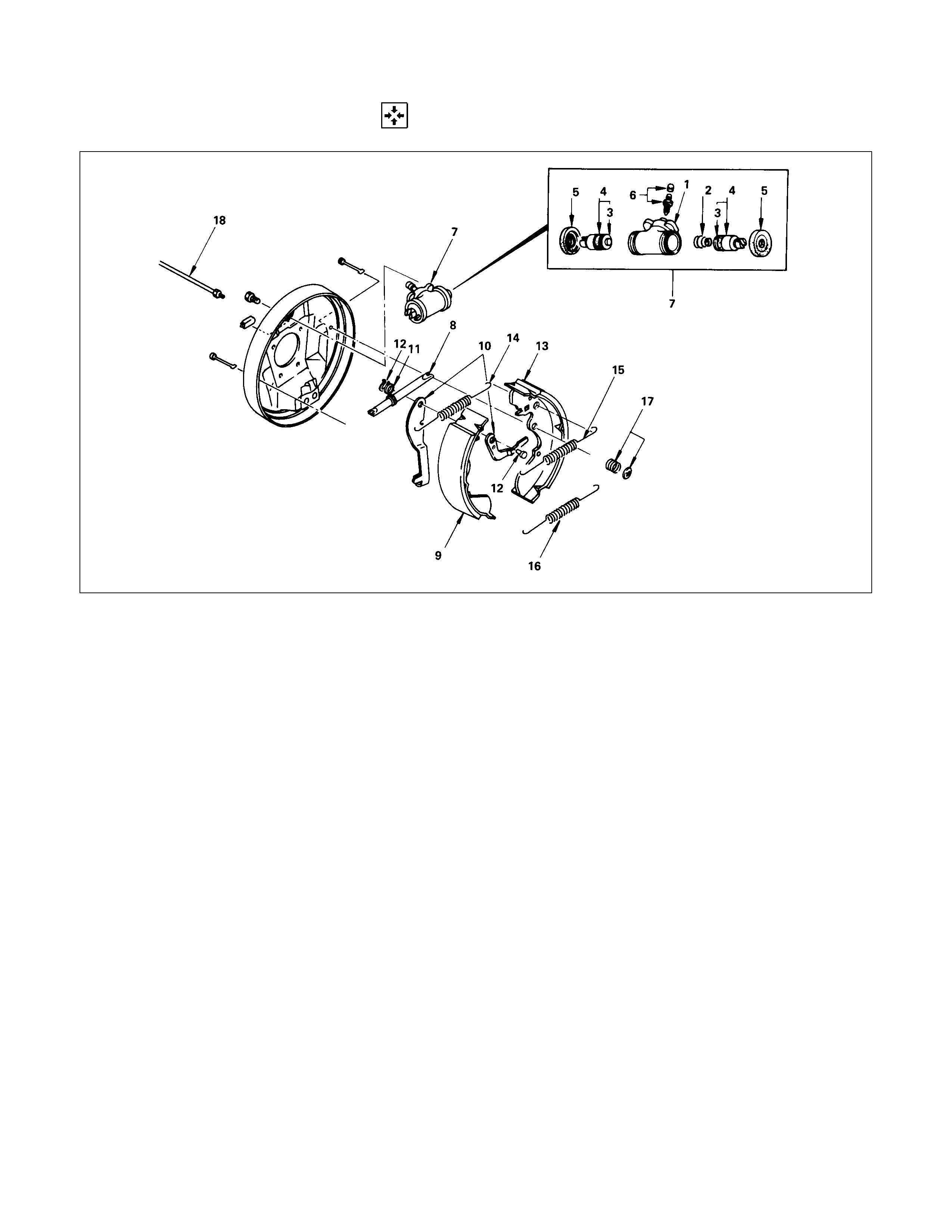
2) Operation
(1)When the fluid pressure is under the break point.
The fluid pressure of the rear master cylinder passes
through a clearance between the valve seal and the piston
and acts on the rear wheel cylinder.
At this moment, a downward force is applied to the piston.
However, the compression spring force and reaction force
of the load sensing spring keep the piston in the upper
position by pushing upwards. (See the left figure.)
Primary master
cy linder fluid
pressure
Secondary master
cy linder fluid
pressure
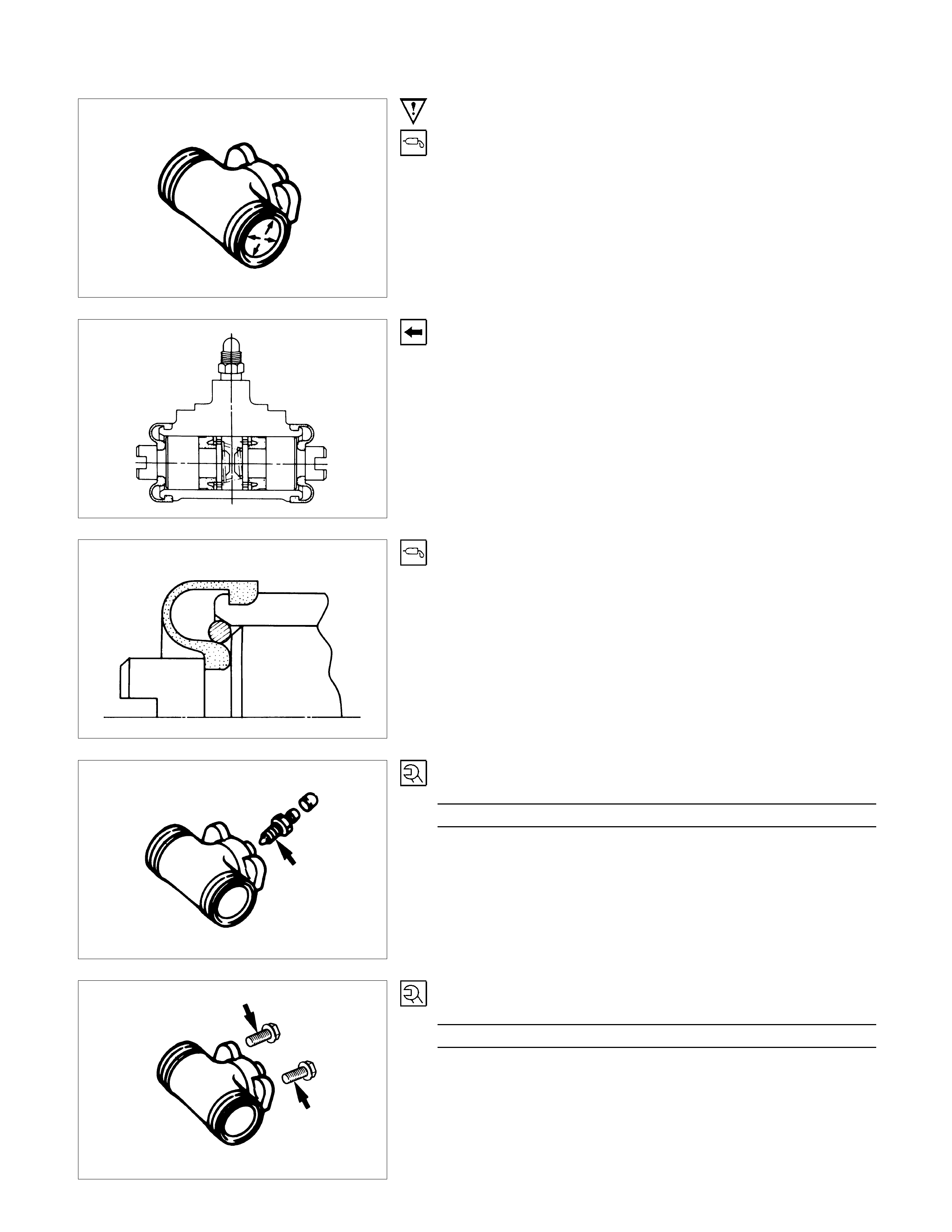
(2)When the fluid pressure is equal to the break point.
As the rear wheel cylinder pressure increases, it surpasses
the compression spring force and reaction force of the load
sensing spring, causing the piston to move downwards, so
that the piston butts against the valve seal to shut off the
fluid line between the master cylinder and rear wheel
cylinder. (See the left figure.)
(3)When the fluid pressure is over the break point.
When the fluid press ur e incr eas es further, the piston moves
upwards.
The moment the piston comes apart from the valve seal,
fluid pressure is applied to the rear wheel cylinder and the
piston moves downwards so that the fluid line is shut off
again.
This process goes on repeatedly to control the fluid
pressure to the rear wheel cylinder.
Secondary master
cy linder fluid
pressure
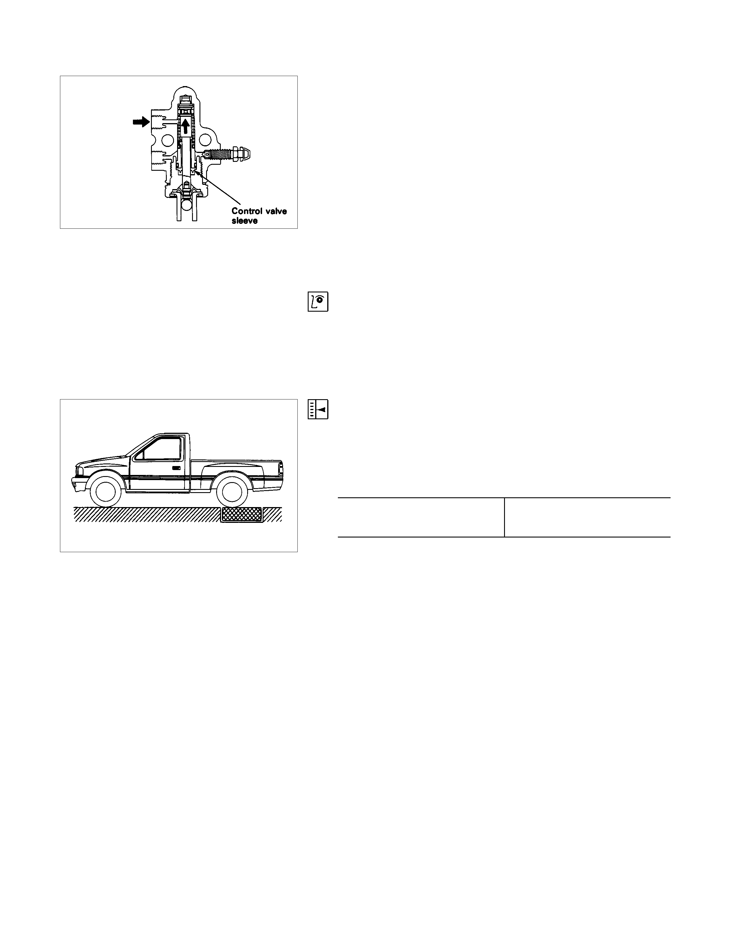
(4)When the front brake system fails.
When there is a failure in the front brake system, the fluid
pressure from the front master cylinder decreases.
As a result, the balance between the front and rear brake
side fluid pressures are lost at the control valve sleeve so
that the control valve sleeve moves upwards.
The control valve sleeve strikes against the piston, thereby
pushing the piston upwards.
Accordingly, the fluid pressure of the rear mater cylinder is
not decreased and is applied directly to the rear wheel
cylinder to secure a sufficient braking performance of the
rear brakes. (See the left figure.)
Valve Maintenance
In the case of fluid lead or other a abnormalities, faulty valve
should be replaced.
Note:
The load sensing proportioning valve is not repairable and
must be replaced as a completed assembly.
ADJUSTMENT PROCEDURE OF LSPV
This adjustment should be performed with the battery voltage
applied to the valve.
1. Adjust the rear axle weight by loading the rear body as
necessary.
Rear axle weight kg (lbs)
TFR 750(1.654)
TFS 900(1.985)
Note:
The rear axle weight should be adjusted to the specified
value with a man seated in the driver seat.
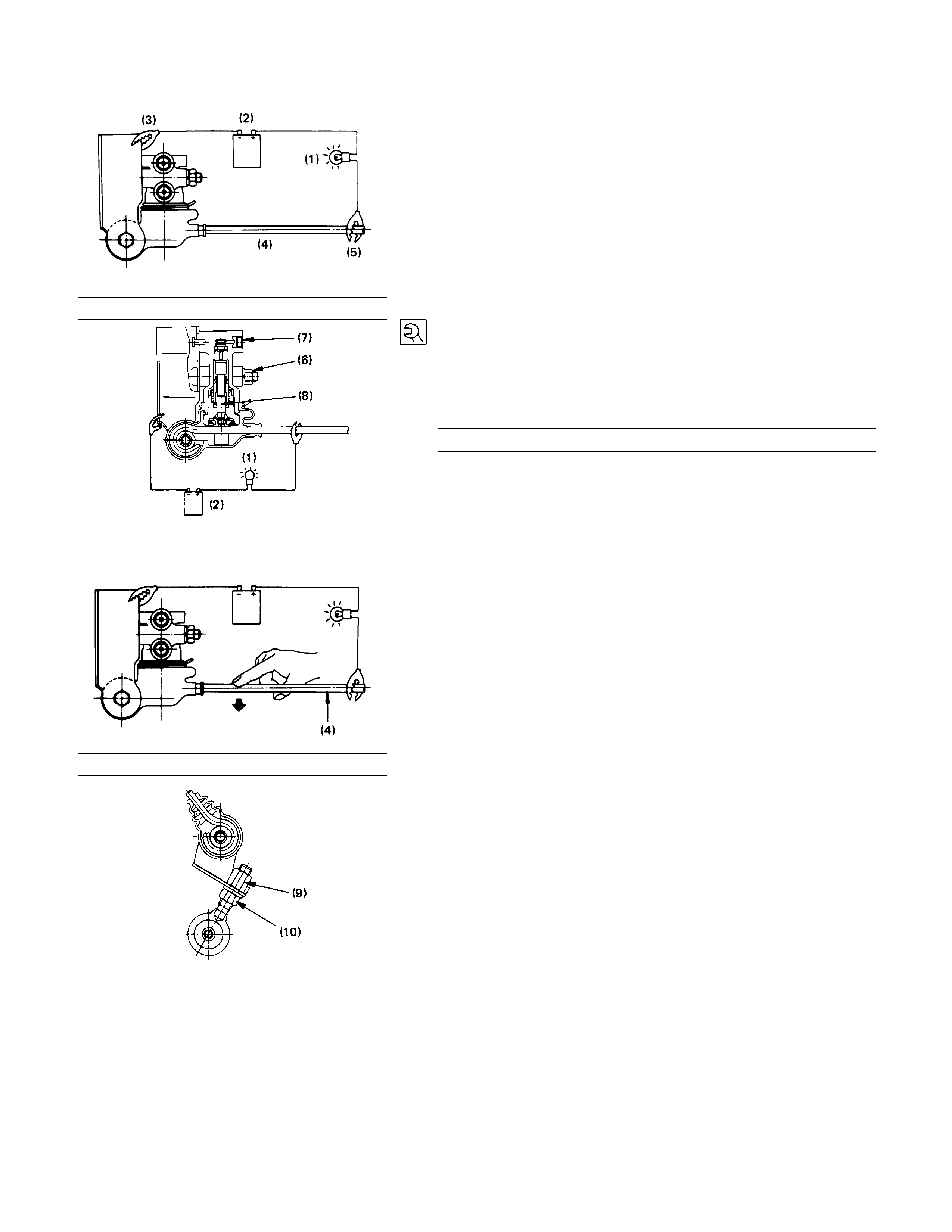
2. Connect the wiring with miniature lam p (1) and a battery (2)
between valve bracket (3) and linkage (4) with each end of
wiring clipped.
This wiring is necessary to find the mom ent at which piston
within the valve assembly is brought into connect with the
linkage.
Note:
As the linkage is coated with insulation material, turn the
clip (5) with 2 or 3 turns to break insulation.
3. Loosen the nut (6) and raise the valve assembly (7) all the
way.
Then lower the valve as se mbly gradually and tighten the nut
(6) when miniature lamp (1) turns on.
Torque N⋅m(kgf⋅m/lb⋅ft)
17(1.7/12)
Note:
If the miniature lamp (1) goes out as the nut (6) is
tightened, lower the valve assembly (7) slightly with the
nut loosened, then retighten the nut(6).
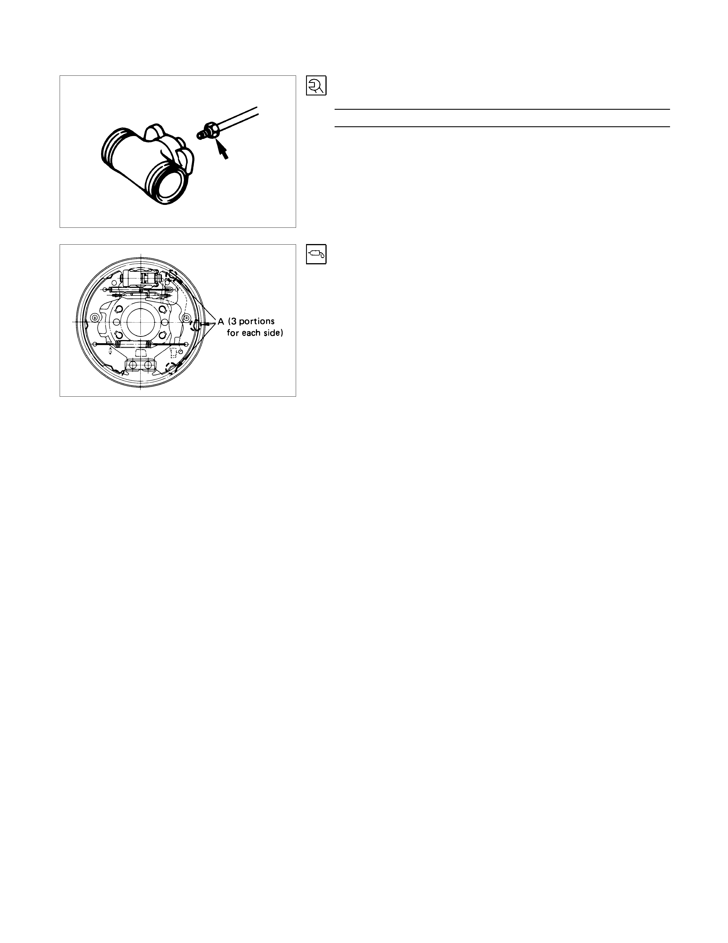
4. Depress the linkage (4) near the valve assembly slightly
downward with finger (test pressue:0.5-0.8kg) and check to
see if the miniature lamp (1) goes out.
Lamp goes out : OK Adjustment is completed.
Lamp remains on : NG Repeat adjustment operation
outline under paragraph 3.
Excessive force is exerted on
linkage by piston (8) within the
valve assembly.
Note:
Adjustment can also be made by means of nuts (9) and
(10) on shackle at rear axle case side.
However, shackle nut is not normally used for adjustment
as it is for making fine adjustment.
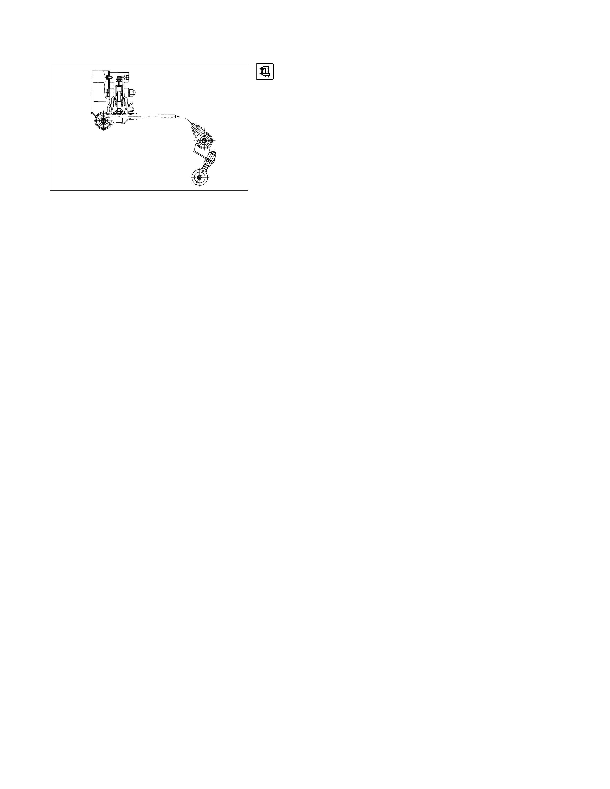
5. Inspection of brake fluid pressure (Reference value)
1) Adjust the rear axle weight as specified under the
paragraph 1.
2) Install the pressure gauge on bleeder screws on the
front and rear brakes.
3) Depress the brake pedal and take reading of the
pressure gauges.
The brake f luid pr es sur e is nor mal if the pr ess ur e of fluid
within the rear wheel cylinders is within the range of 34.4
±5.5 kg/c m2 when press ure of fluid within the front wheel
cylinders reaches 50 kg/cm2.
Note:
The brake pedal should be depressed gradually until
specified pressure is reached without pumping or
adjusting foot pressure.
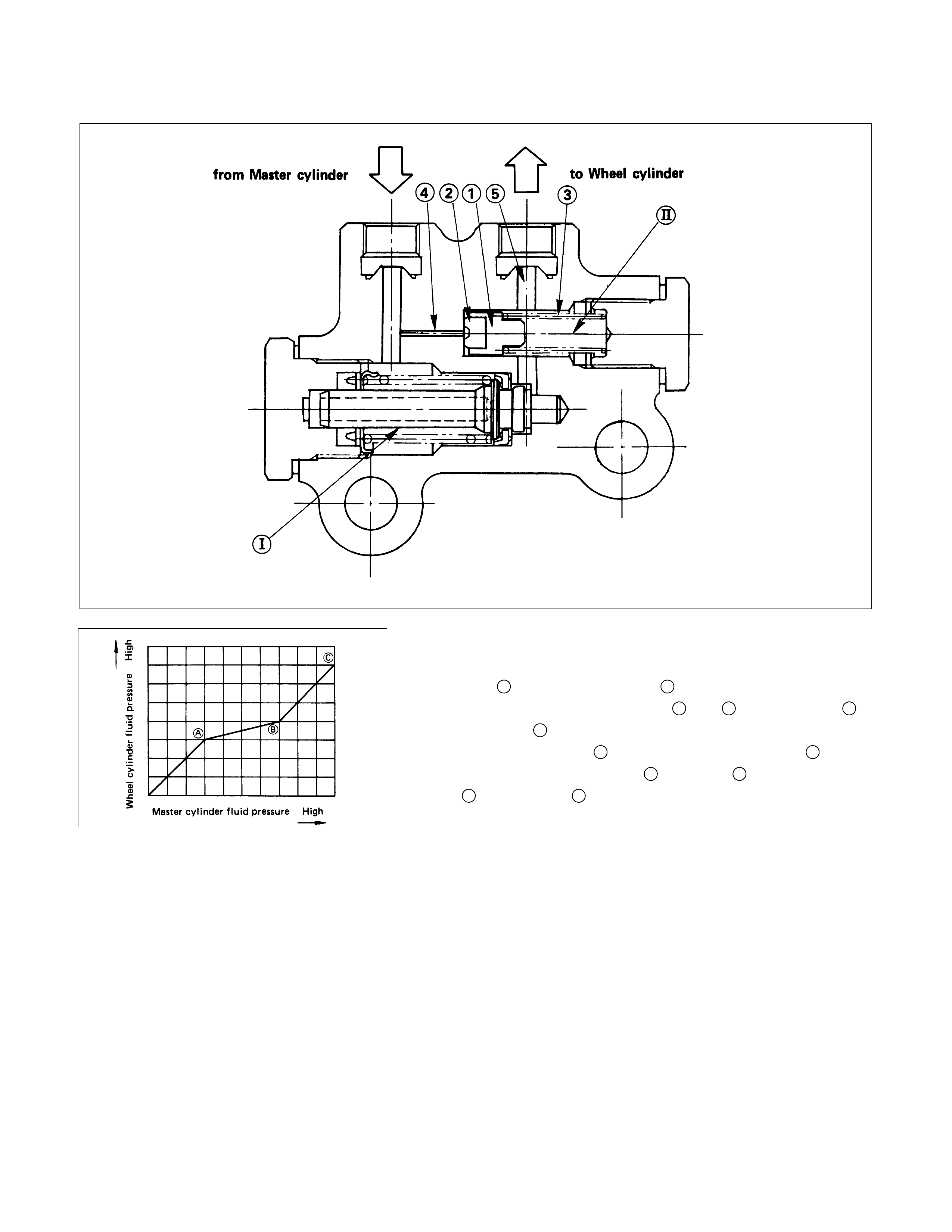
BLEND PROPORTIONING VALVE (IF SO EQUIPPED)
Structure and Operation
•Structure
Side I shows P-valve ; side II shows bypass valve.
Bypass valve s eals the routes 4 and 5 using the seal 2 at
the piston 1 end.
In addition, spring 3 presses against the piston 1, and in
order to seal out the route 4 and route 5 sufficiently, spring
3 presses seal 2 against cylinder end surface.
The left figure is a characteristic curve diagram.
•Operation
The operation of the P-valve by the master cylinder
pressure is unchanged up to the brake points A and B.
If master cylinder fluid pressure penetrates into the second
break point B, the fluid pressure pressing against the seal
2, (which isolated route 4 and route 5), passing the route
4 of the master cylinder side, overcomes the operating
force of the spring 3 + fluid pressur e af fecting the s eal 2 of
the wheel cylinder, and presses the piston 1 to the right
side, resulting in the opening of the routes 4 and 5, and
canceling of the P-valve operation.
Then, because the master cylinder fluid pressure and the
wheel cylinder fluid pressure, up to the point C, operate on
the identical surface of the seal 2, both have identical
ascending ratio.
However, because of the operation of s pring 3 in the wheel
cylinder side, wheel cylinder fluid pressure operate to
preserve the balance against the master cylinder fluid
pressure on the lower level with the difference in pressure
resulting from this spring.
Valve Maintenance
In the case of fluid leak or other abnormalities, faulty valve
should be replaced.
The valve is set up at the right hand side of the 5th
crossmember near the rear axle.
Note:
The blend proportioning valve is not repairable and must
be replaced as a complete assembly.
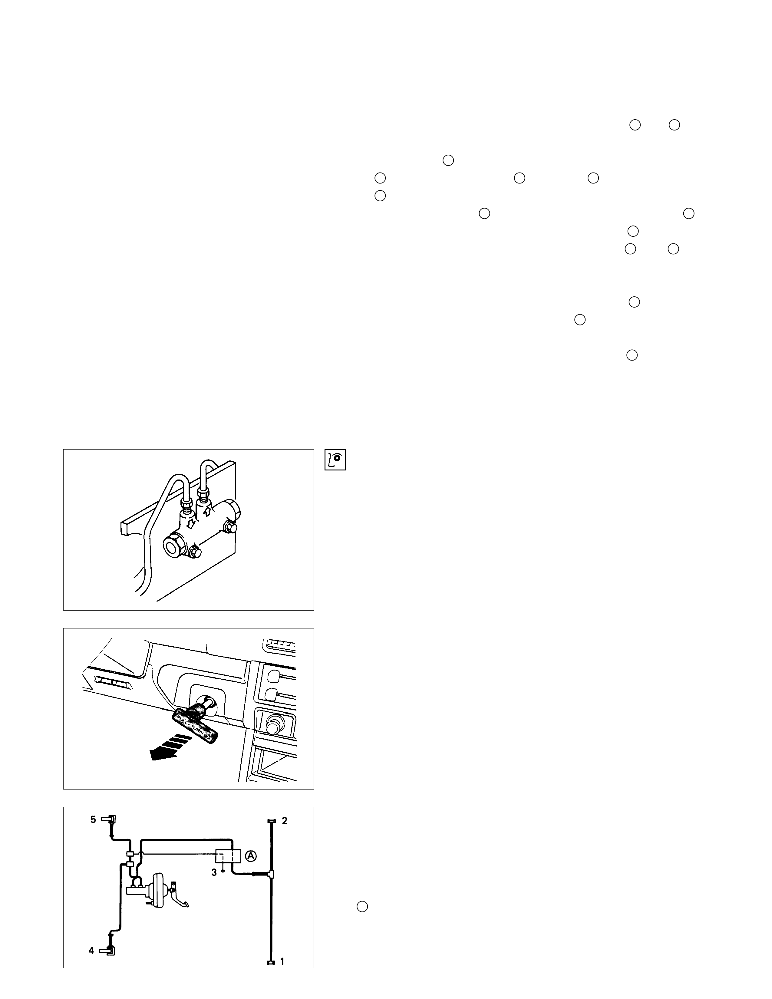
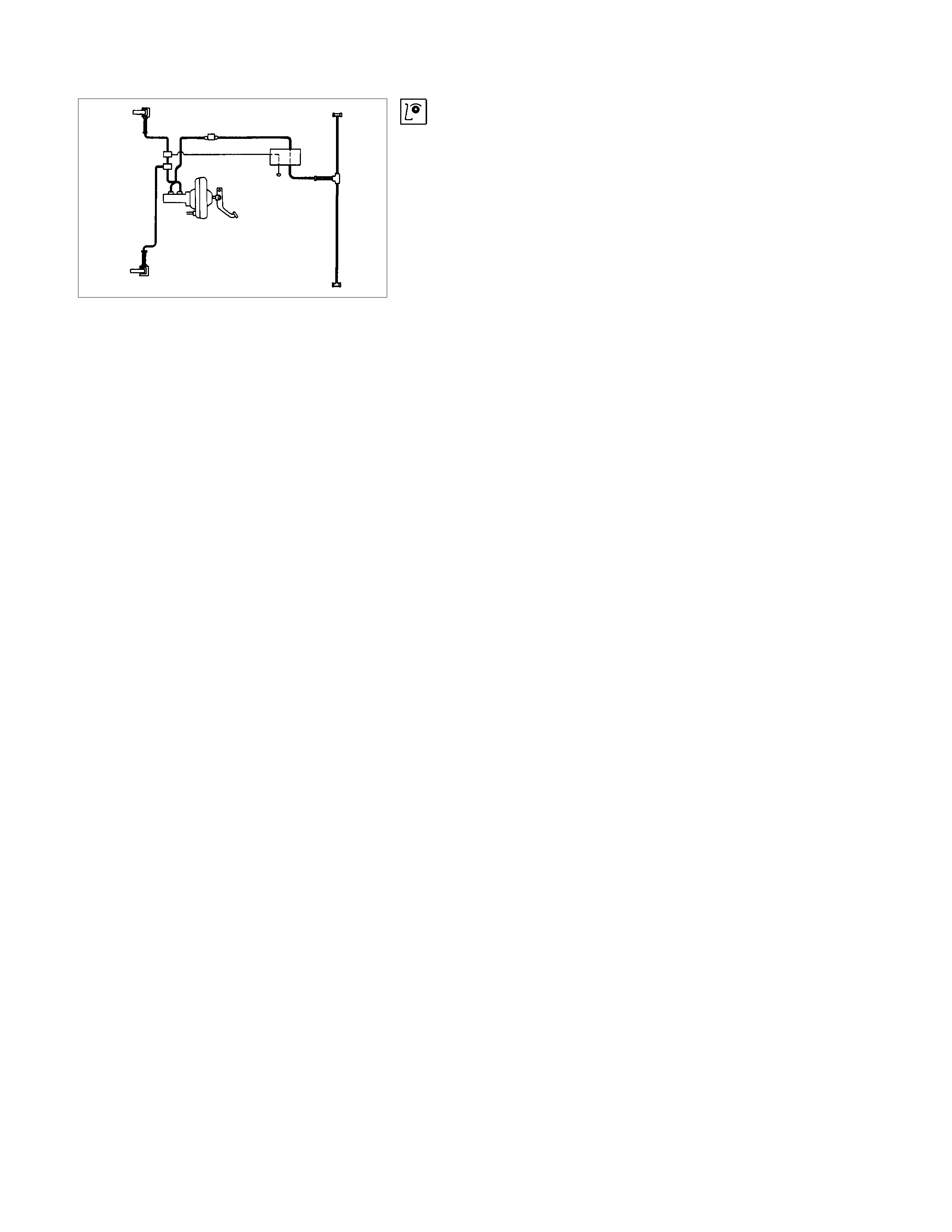
BLEEDING OF THE BRAKE HYDRAULIC
CIRCUIT
If air enters the bake lines, it will cause poor brake action.
Therefore, bleeding should be performed if the brakes have
been used with the level of brake fluid in the reservoir
excessively low or if brake pipes have been disconnected in
the course of brake servicing.
Bleeding operation calls for co-operative action of 2 persons.
•Set the parking brake firmly while bleeding.
•Perform bleeding operation with ENGINE RUNNING, to
prevent damage to push rod seal.
Make sure exhaust is suitably ventilated.
•Bleed the hydraulic system with the fluid reservoir filled to
the specified level.
•Bleed the system starting with the rear wheel cylinder
farthest from the master cylinder.
A : Load sensing proportioning valve (If so equipped).
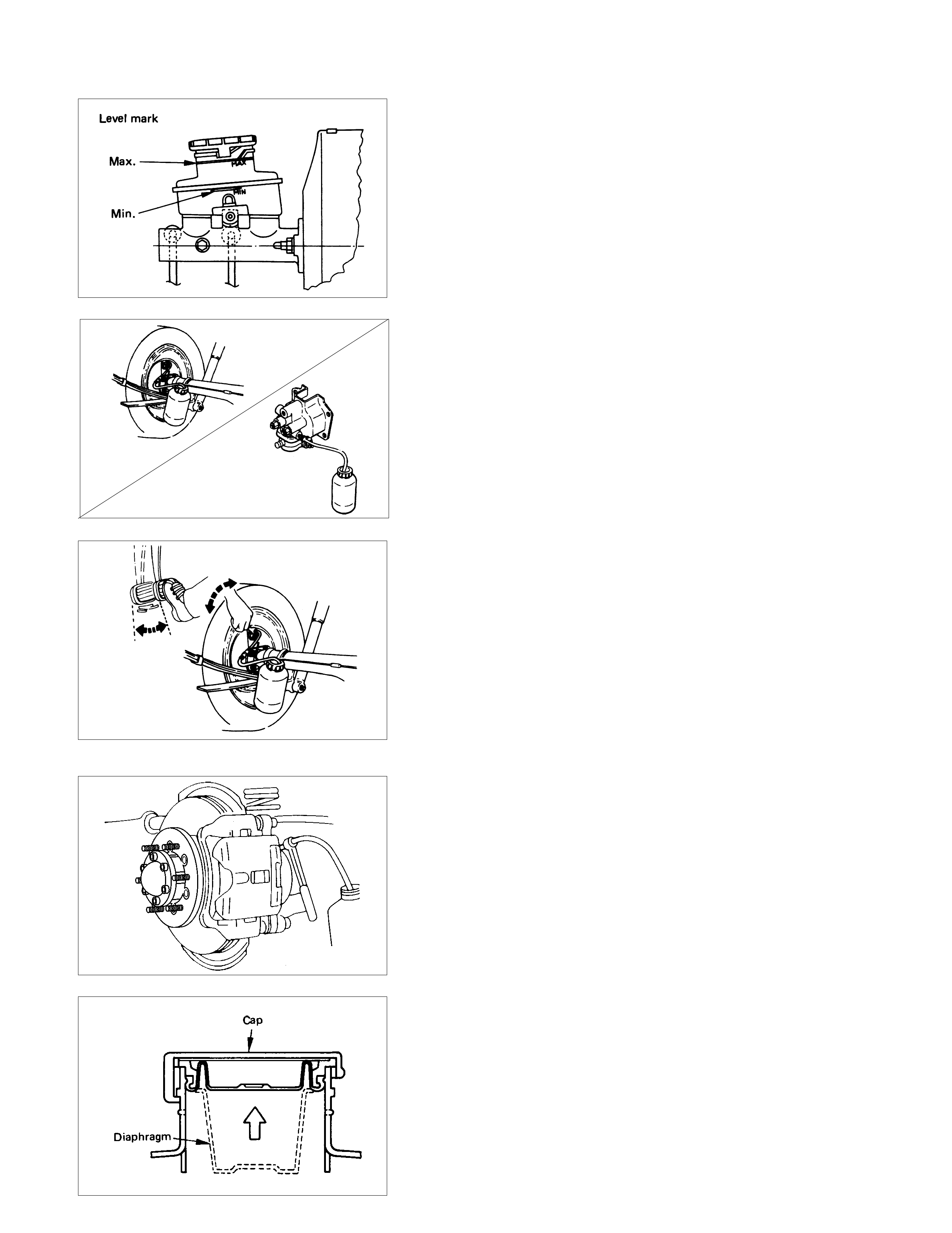
1. Fill the brake fluid reservoir with brake fluid.
Handle the brake with reasonable care to avoid spillage as it
is damaging to paint.
Note:
Take care to prevent foreign matter from entry, when
replenishing or replacing brake fluid.
When pouring brake fluid, if diaphragm in the oil tank cap
is stretched, be sure to place it into original position,
(fasten it), and then cap it.
2. Connect a vinyl pipe to the bleeder screw on the wheel
cylinder, caliper bode or LSPV and the other end of the pipe
in a transparent container.
3. Pump the brake pedal several times and hold it depressed.
Loosen the bleed screw to release brake f luid together with
air bubbles.
Tighten the bleeder screw before pressure is released
completely.
4. Repeat the step in paragraph 3 above until the air bubbles
disappear completely.
Securely tighten the bleeder screw when the air bubbles
disappear completely.
5. Repeat the step in paragraph 4 above on the remaining
wheel cylinders.
Bleed the system starting with rear side farthest from the
brake fluid reservoir.
6. Fill the brake fluid reservoir to the specified level.
Pour brake fluid carefully so as not to produce air bubbles.
7. If the cap diaphragm is s tretched, f asten the diaphr agm and
the sure to cap it after it is placed to the original position.
Note:
Never reuse the old brake fluid.
BRAKE LINE (HOSES AND PIPES)
•Inspect all hoses and pipes for wear, bending, chafing,
cracks, dents, or any other damage.
Make necessary correction or parts replacement if these
abnormal conditions are found through inspection.
•All hoses, pipes and joints can be damaged easily.
Do not allow the hose to become excessively twisted and
bent when working with then, and pay special attention to all
the brake lines not to damage them when repairing or
replacing other parts (axle, suspension, etc).
•Inspection for leakage should be performed by depressing
the brake pedal fully.
If leakage is apparent at the circumference of joints,
retighten or replace these parts.
This procedure must be performed whenever brake lines
are installed.
•After disconnecting the hoses and pipes, cap or tape the
openings to prevent entry of foreign material.
ADJUSTMENT PROCEDURE OF SERVICE AND PARKING BRAKE
Stem type
All brakes are self-adjusting.
Brake are adjusted by repeated stepping on the brake pedal.
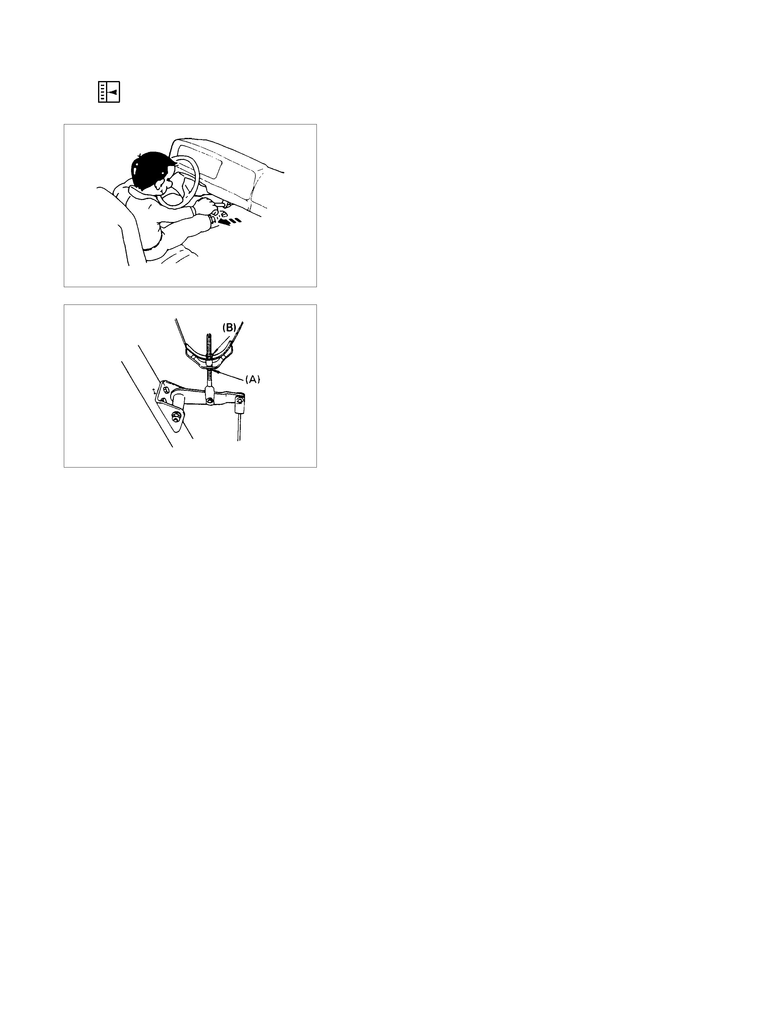
The parking brake adjustment should be performed as follows:
1. Release the parking brake lever fully.
2. Loosen the lock nut (A).
3. Repeat stepping the brak e pedal firm ly and releasing it until
the rear brake auto-adjuster completes the function.
4. Rotate the adjust nut (B) until all slack disappears from the
cable.
5. Set the lock nut.
The parking brake lever travel is normal when the lever comes
out 9 to 11 notches when pulled with a force of 30 kg (66 lbs.).
Floor mount type
All brakes are self-adjusting.
Brakes are adjusted by repeated stepping on the brake pedal.
(After stepping on the pedal and releasing it, the rear auto-
adjuster, in the rear brake, produces a clicking sound.
the same operation should be repeated until the sound
disappears.)
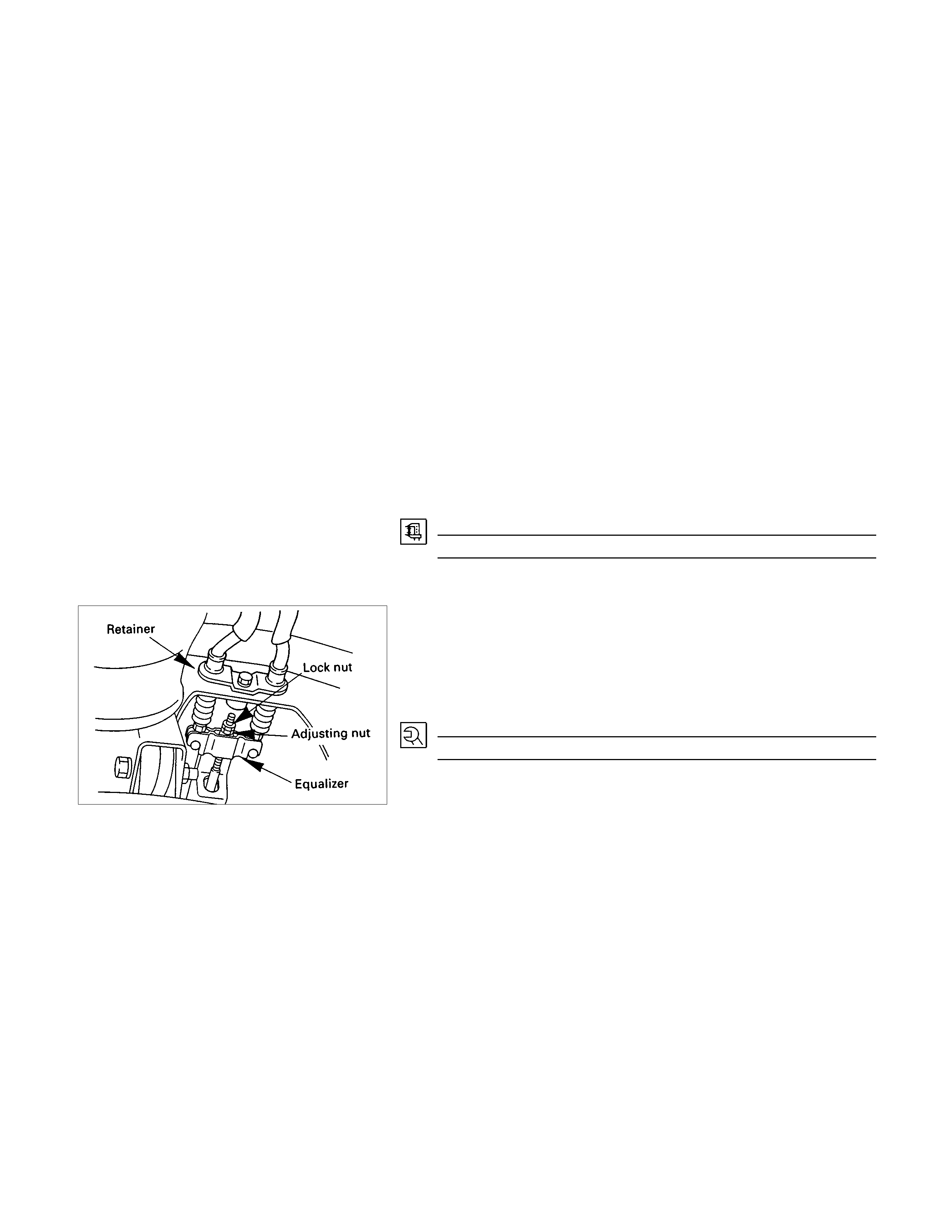
Take the following steps after overhauling the rear brake
assembly.
1. Move the parking brake lever to its fully released position.
2. Parking cable must be loosened sufficiently.
(Loosen the adjust nut and the lock nut.)
3. Repeat stepping on the brake pedal firmly, and releasing it
until the clicking sound can no longer be heard.
If the dif ference between the brake dr um inside diam eter of
the brake shoes is adjusted to be 0.5 mm, the number of
times for depressing the brake pedal can be reduced.
4. Remove the drum.
Measure the brake drum inside diameter and diameter and
diameter of the brake shoes.
Shoe Clearance mm(in)
0.25 - 0.40 (0.0098 - 0.0157)
If incorrect, check the brake auto-adjusting system.
5. Turn the equalizer nut so that the parking brake lever
travels 6 or 7 notches when pulled up with a force 30 k g (66
lbs.).
6. Make sure ther e is not brak e dragging and tighten the c able
lock nut.
Torque N⋅m(kgf⋅m/lb⋅ft)
8 - 18 (0.8 - 1.8 / 5.8 - 13)
ADJUSTMENT PROCEDURE OF BRAKE PEDAL
The push rod serves as the brake pedal stopper when the
pedal is fully released.
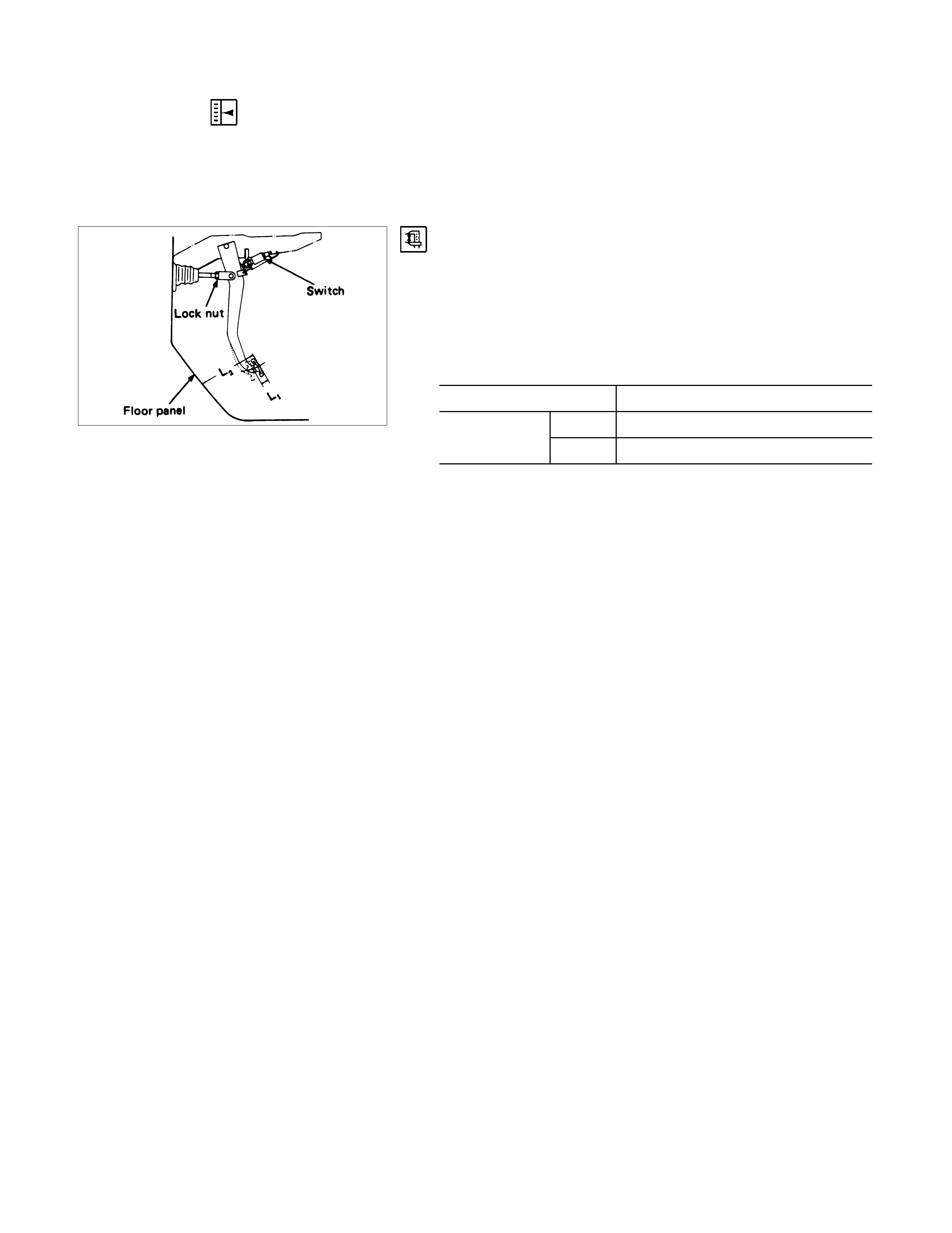
Brake pedal height adjustment should be performed as follows.
Brake Pedal - Height
Measure the brake pedal height after making sure the pedal is
fully returned by the pedal return spring.
Note:
Pedal height (L2) must be measured after starting the
engine and increasing the revolution several times by
stepping on the accelerator pedal. mm(in)
Pedal free play (L1) 6-10 (0.23 - 0.39)
LHD 174-184 (6.85-7.24)
RHD 193-203 (7.60 7.99)
Height (L2)
Note:
Pedal free play must be measured after turning off the
engine and stepping on the brake pedal firmly five times or
more.
If the measured value deviates from the above range, adjust
the brake pedal as follows:
a) Disconnect the stop lamp switch.
b) Loosen the lock nut on the push rod.
c) Adjust the brak e pedal to the s pec if ied height by rotating the
push rod in the appropriate direction.
Lock Nut Torque N⋅m(kgf⋅m/lb⋅ft)
15- 25 (1.5 - 2.5 / 11 - 18)
d) Install the stop lamp switch.
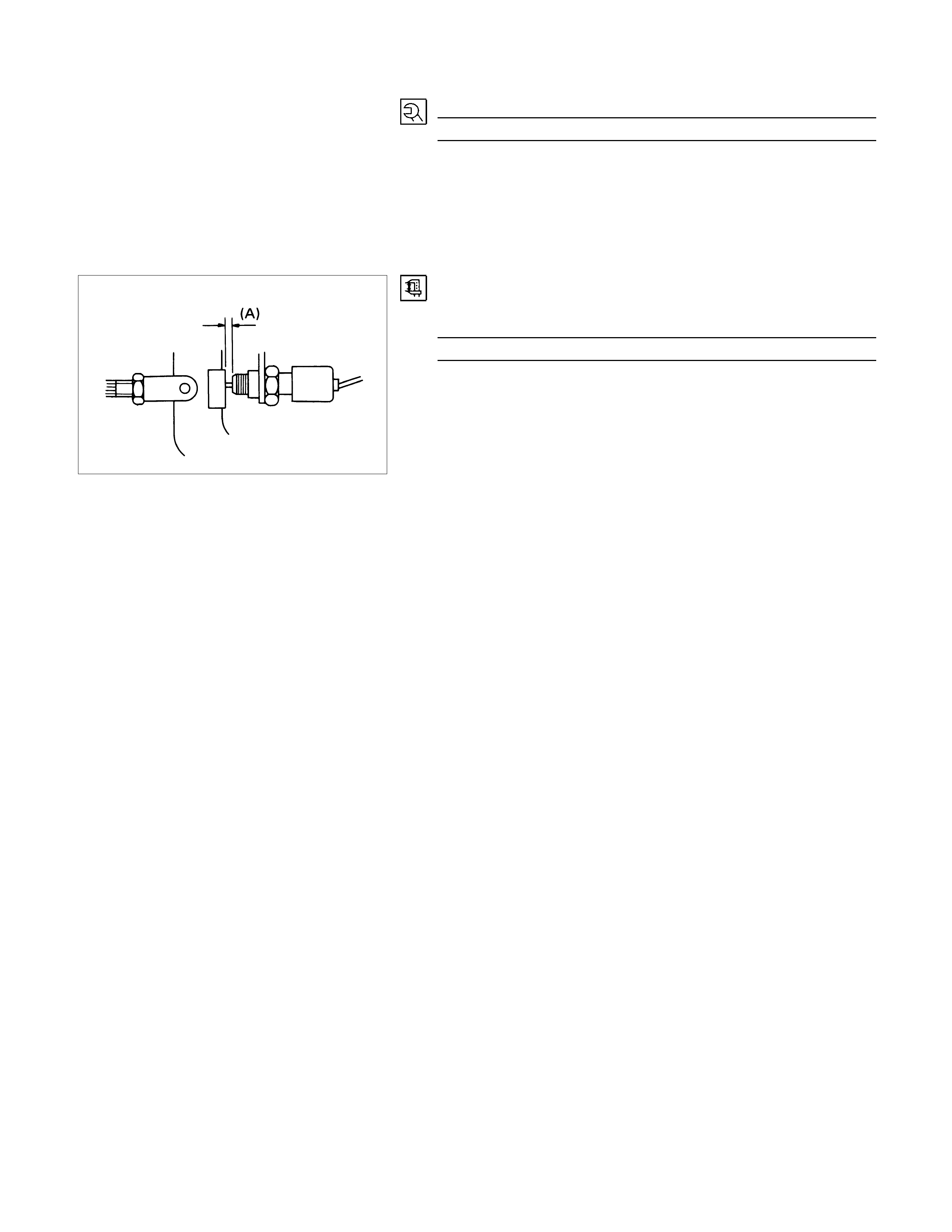
Note:
Pedal height (L2) must be 95 mm (3.7 in.) or more when
applying about 50 kg (110.25 lbs.) of stepping force.
Clearance
Between the Switch Housing and the Brake Pedal (A). mm(in)
0.5 - 1.0 (0.02 - 0.04)
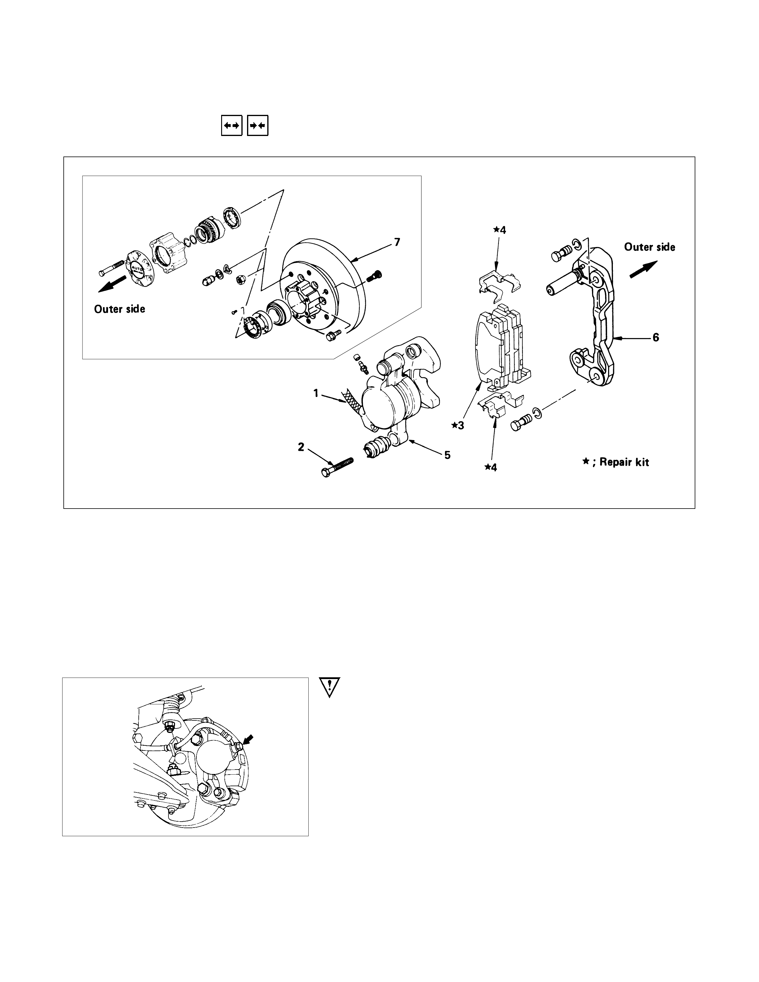
FRONT BRAKE ASSEMBLY
REMOVAL AND INSTALLATION
Removal Steps
▲1. Brake flexible hose
▲2. Lock bolt
▲3. Pad assembly with shim
4. Clip ; pad
5. Caliper assembly
▲6. Support bracket
▲7. Front hub and disc assembly
Installation Steps
▲7. Front hub and disc assembly
▲6. Support bracket
5. Caliper assembly
▲4. Clip ; pad
3. Pad assembly with shim
▲2. Lock bolt
▲1. Brake flexible hose
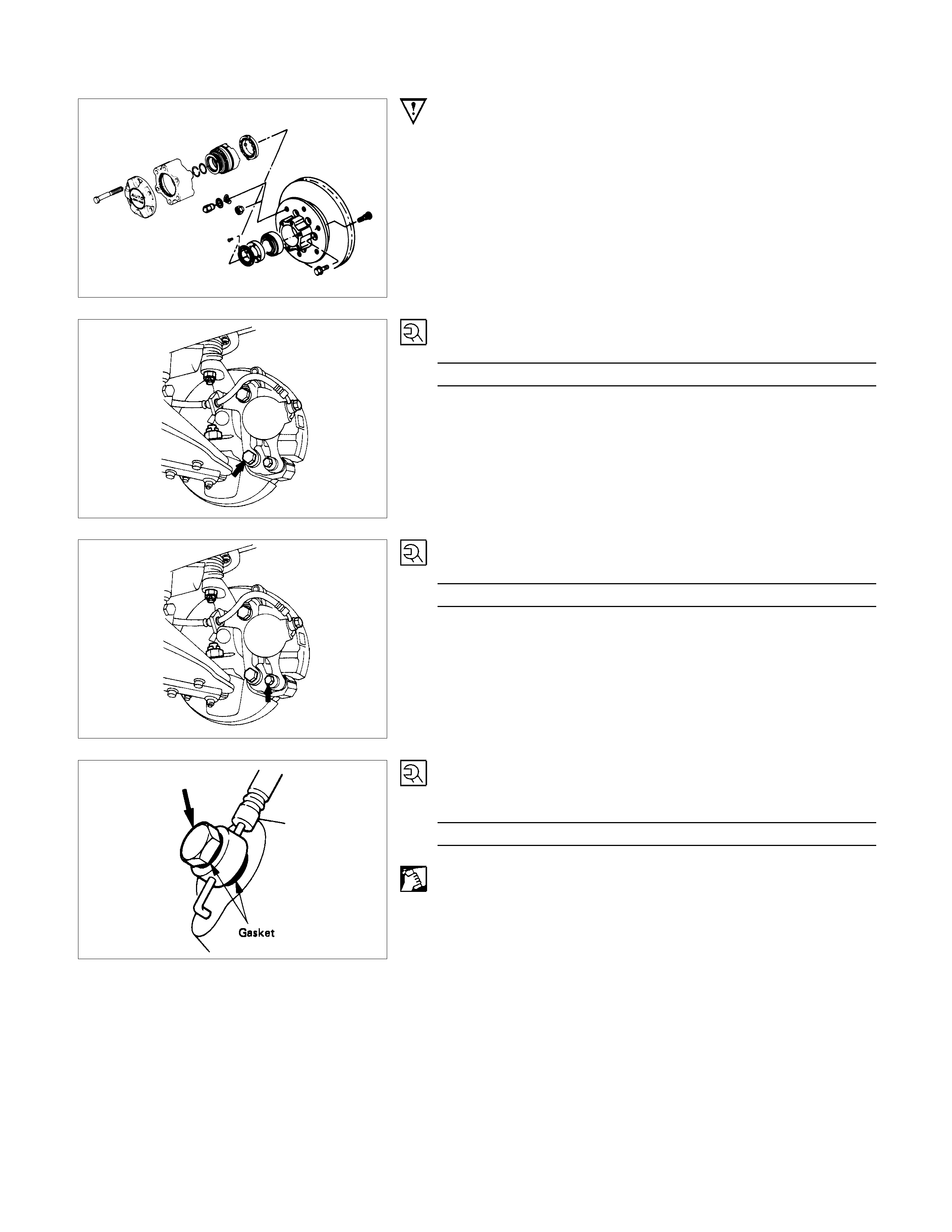
Important Operations - Removal
1. Brake Flexible hose
Remove the bolt and gasket and disconnect the brake flexible
hose from the caliper.
After disconnecting the flexible hose, cap or tape the openings
to prevent entry of foreign material.

2.Lock Bolt
Remove the lock bolt from the caliper.
3.Pad Assembly with Shim
Rotate the caliper upward.
Mark the lining locations if they are to be reinstalled.
6.Support Bracket
Take care not to damage the flexible brake hose when
removing the support bracket.
7.Front Hub and Disc Assembly
For the removal procedure, refer to Section 4B "FRONT
AXLE & PROPELLER SHAFT".
Important Operations - Installation
7.Front Hub and Disc Assembly
For the installation procedure, refer to the front hub and disc
reassembly procedure in Section 4B "FRONT AXLE".
6. Support Bracket
Torque N⋅m(kgf⋅m/lb⋅ft)
139 - 171 (14.2 - 17.4 / 103 - 126)
Set up the clip and pad before installation of the support racket.
4. Clip ; Pad
Install new parts if necessary.
2. Lock Bolt
Torque N⋅m(kgf⋅m/lb⋅ft)
27 - 37 (2.8 - 3.8 / 20 - 27)
1. Brake Flexible Hose
Attach the bolt and new gasket
Torque N⋅m(kgf⋅m/lb⋅ft)
29 -39 (3.0 - 4.0 / 22 - 29)
After installation, bleeding and replenishing procedure must be
performed.
Wipe the circumference of the hose clean.
Note:
•Always use new gaskets.
•Be sure to put the hooked edge of the f lexible hose end
into the anti-rotation cavity.
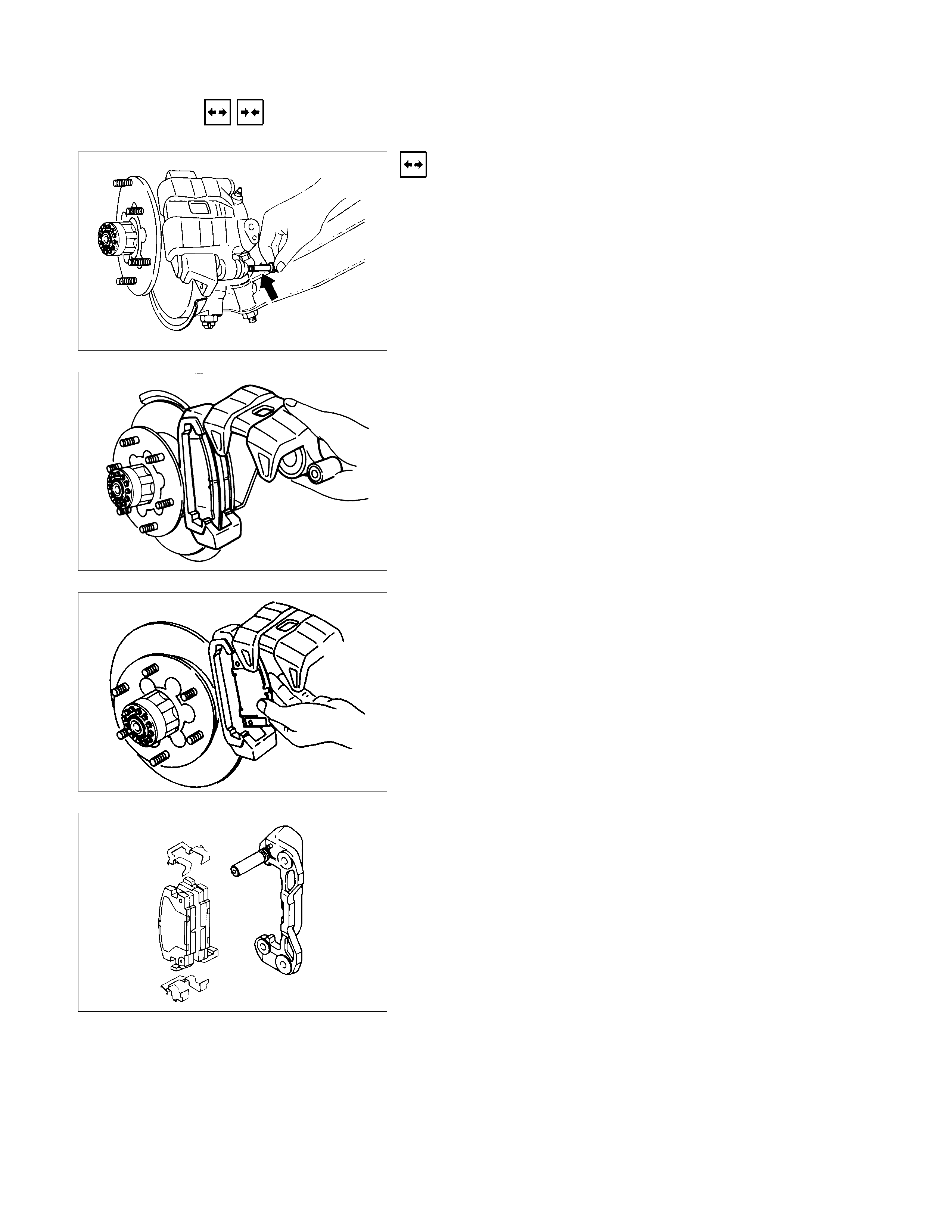
REMOVAL AND INSTALLATION OF DISC PAD
Removal Steps
1. Lock Bolt
Remove the lock bolt from the caliper.
Note:
Don't remove the brake hose from caliper when replacing
pads.
2. Rotate the Caliper Upward
Remove the caliper from the support bracket and ire the caliper
to the upper link or the frame.
Note:
While caliper is removed from support bracket, never step
on the brake pedal or the piston will protrude rapidly.
3. Pad Assembly with Shim
Remove the pad assembly with the shim.
Mark the pad locations if they are to be reinstalled.
4. Clip ; Pad
Discard the used clip and install a new one.
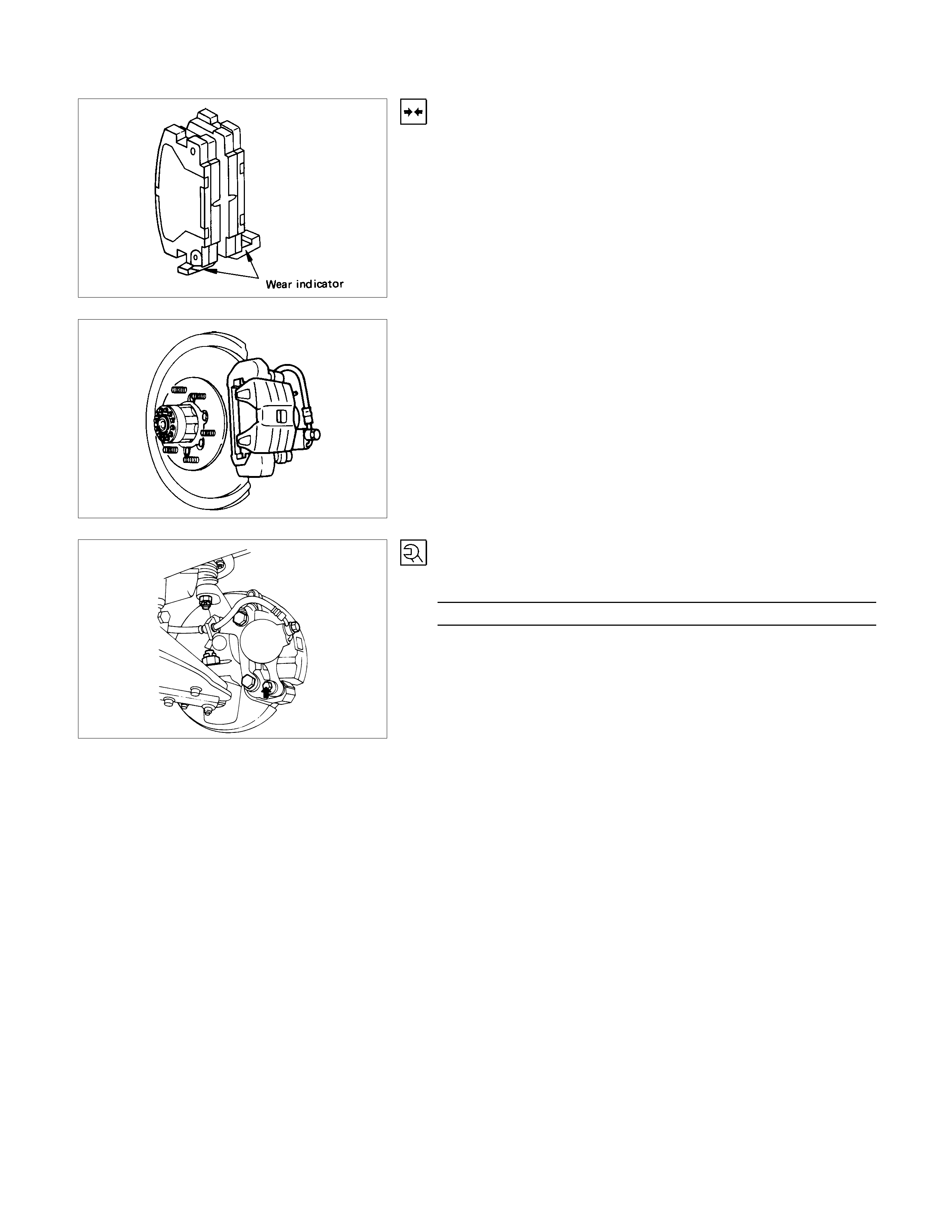
Installation Steps
1. Clip ; Pad
2. Pad Assembly with Shim
After attaching the pad assembly with the shim to the support
bracket, position the wear indicator to the lower side of the pad.
3. Caliper Assembly
Lower the caliper into its original position.
Do not damage the flexible hose by twisting or pulling it.
4. Lock Bolt
Attach the lock bolt to the caliper.
Torque N⋅m(kgf⋅m/lb⋅ft)
27 - 37 (2.8 - 3.8 / 20 - 27)
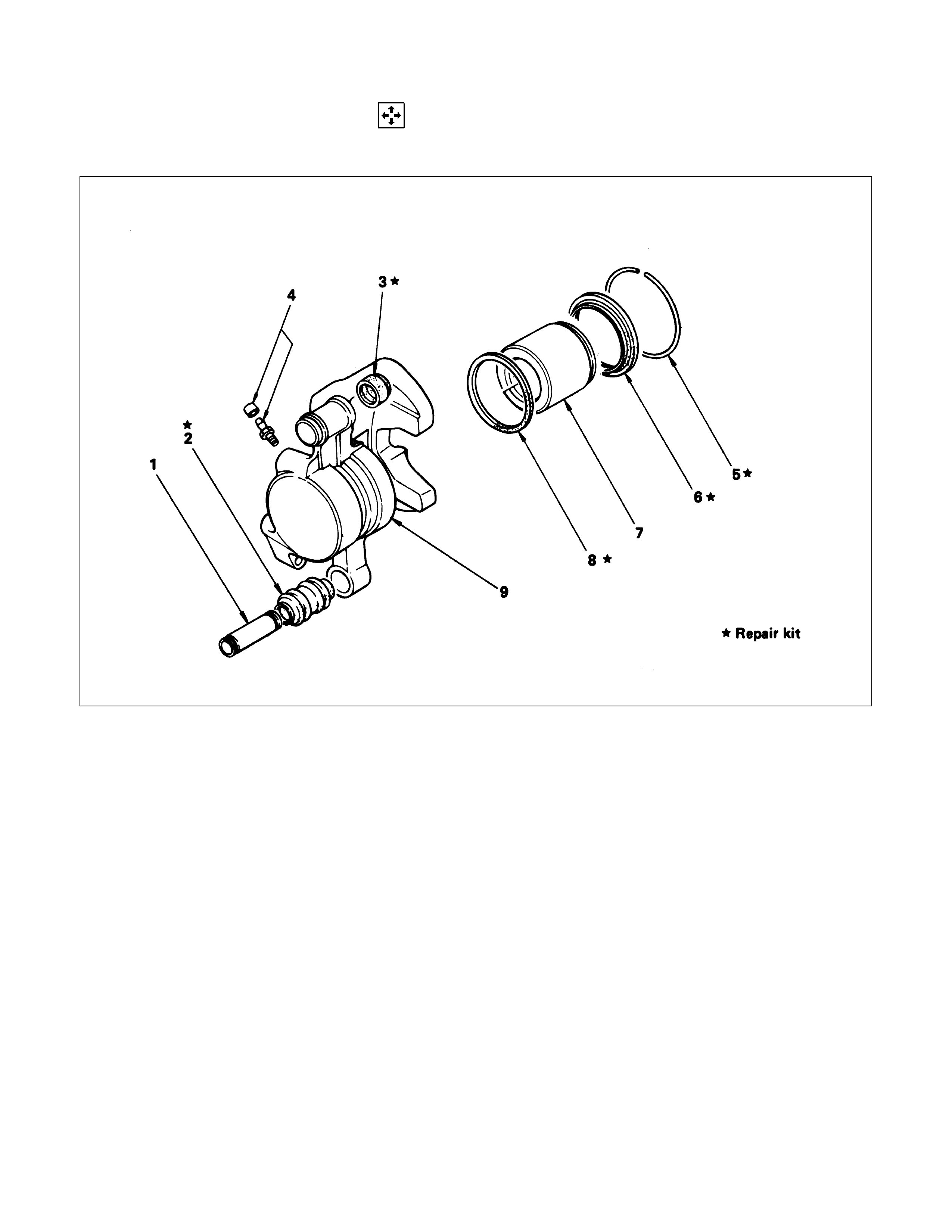
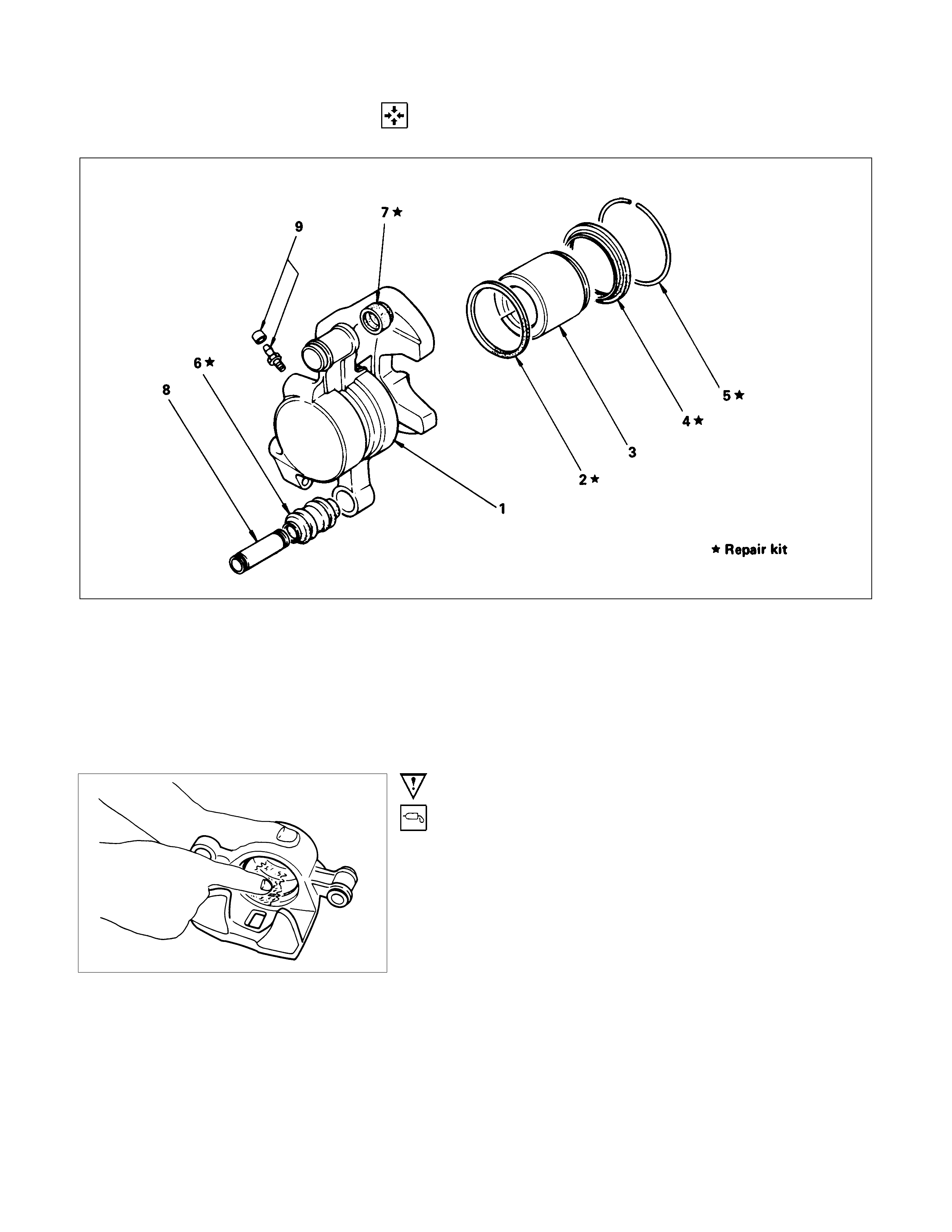
DISASSEMBLY
CALIPER ASSEMBLY
Disassembly Steps
1. Sleeve
2. Dust boot ; sleeve
3. Dust boot ; guide pin
4. Bleeder with cap
▲5. Dust seal ring
6. Dust seal ; piston
▲7. Piston (with seal ring)
8. Ring seal
9. Body ; caliper
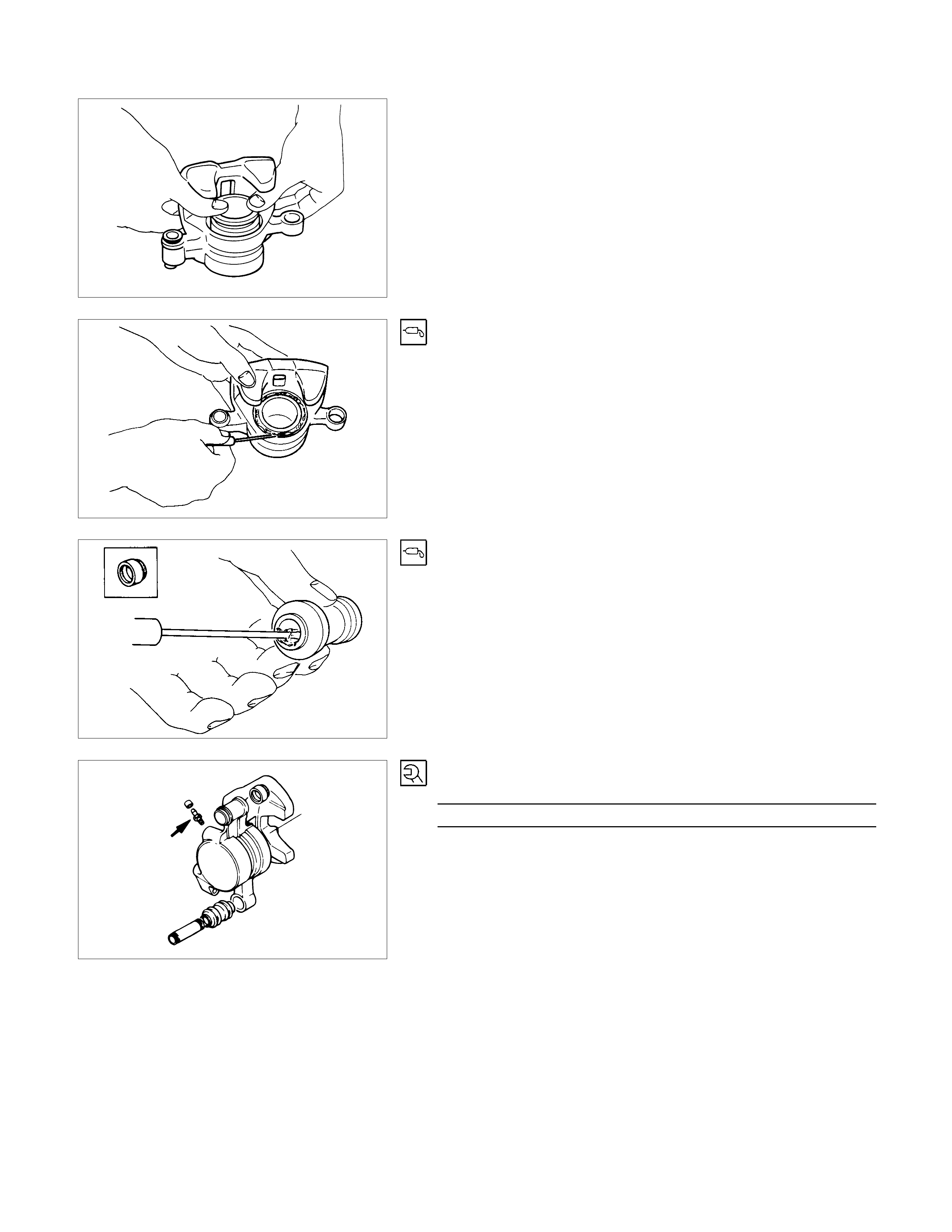
Important Operations
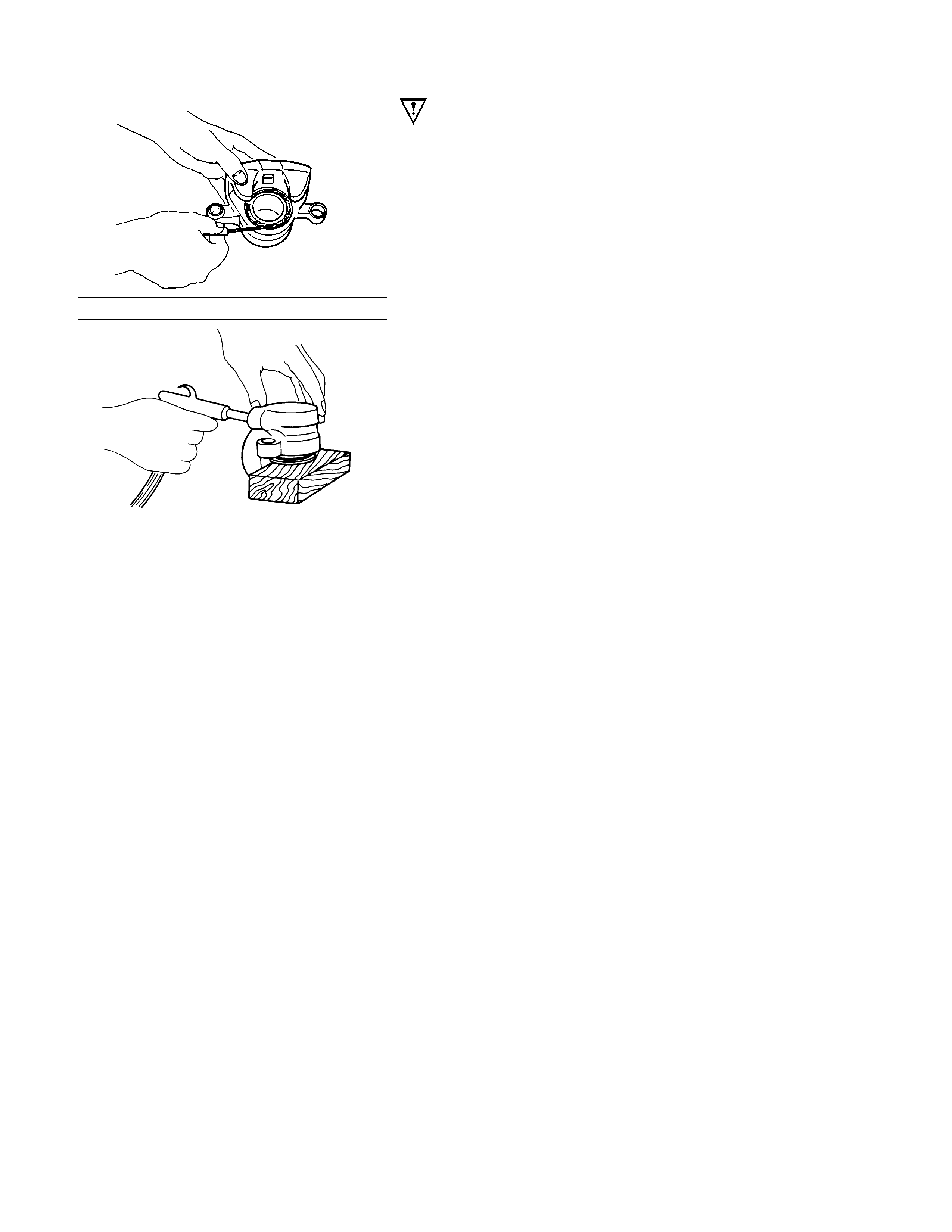
5.Dust Seal Ring
Using a small screwdriver, remove the dust boot.
7.Piston (with Ring Seal)
Insert a block of wood into the caliper and force out the piston
by blowing compressed air into the caliper at the flexible hose
attachment.
This procedure must be done prior tor removal of dust seal.
CAUTION:
Do not place your fingers in front of the piston in an
attempt to catch or protect it when applying compressed
air.
INSPECTION AND REPAIR
Make necessary correction or parts replacement if wear damage or any other abnormal conditions are found
through inspection.
• Rotor
• Caliper body
• Cylinder bore
• Piston
• Support bracket
• Lock bolt
• Guide pin
Visual Check
Inspect the following parts for wear, bending, distortion,
cracking, corrosion, or other abnormal conditions.
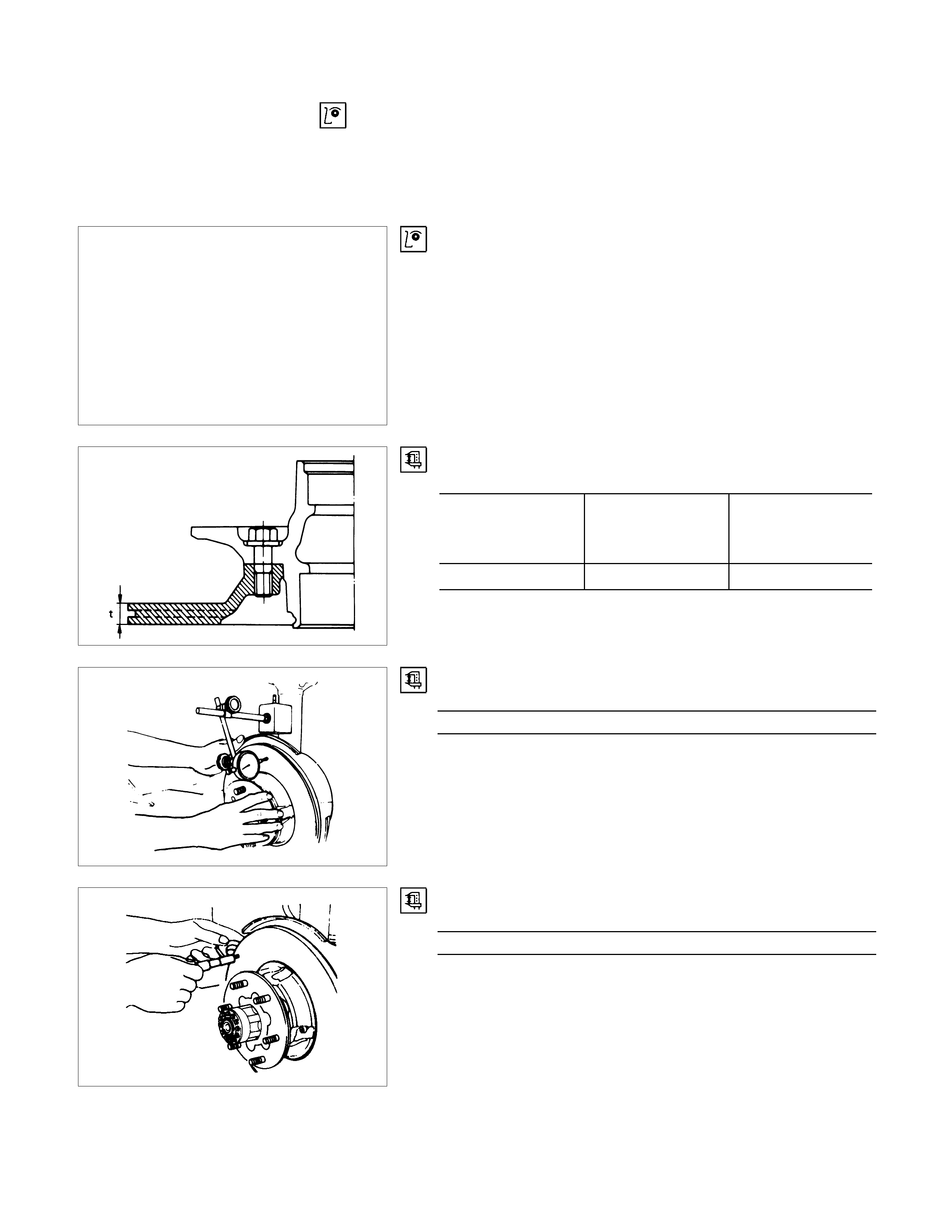
Rotor
•Thickness (t) mm(in)
Standard Minimum
thickness after
refinishing
Replacement
thickness
(Discard)
22.0(0.866) 20.97(0.826) 20.6(0.811)
•Run out
Limit mm(in)
0.13 (0.005)
Before inspection, adjust the wheel bearing correctly.
Using a dial gauge, measure the run out at the center of disc
pad contact surface.
•Parallelism (Total circumferential thickness variation)
Limit mm(in)
0.15 (0.0006)
Contact surface must be within 0.015 mm at the circumference
of 203 mm dia. Circle.
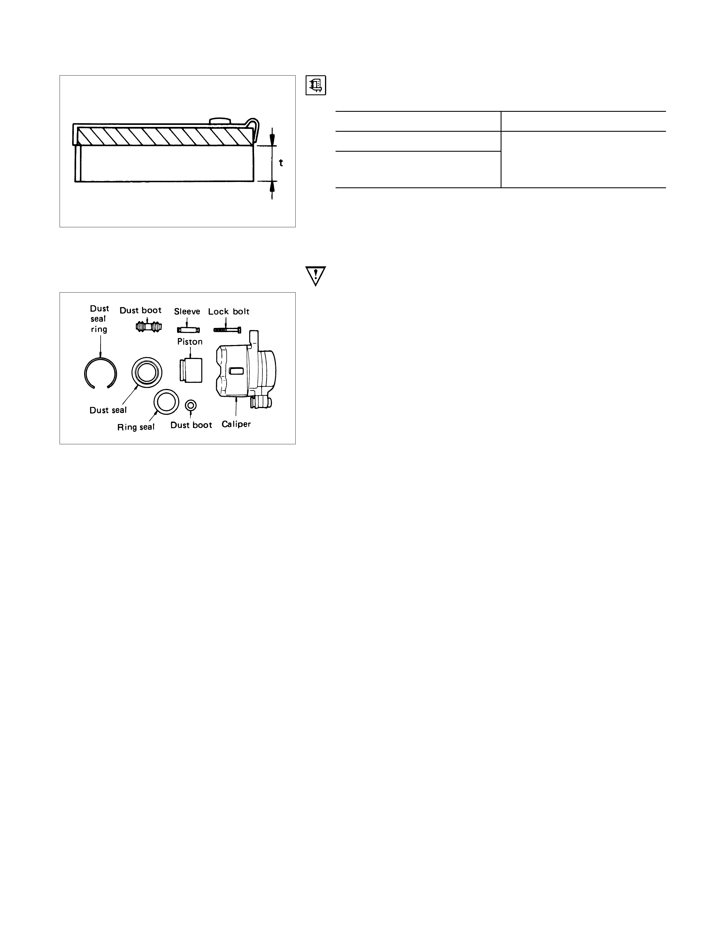
Thickness of Disc Pad
Thickness (t) mm(in)
Standard Limit
10.5 (0.413)
9.5 (0.374)
(For Australia only) 1.0 (0.039)
Replace the front disc pad whenever the pad wear indicator
makes a squeaking noise or when the pad is worn to within 1
mm of the shoe table.
All four brake pads should be replaced together.
Seal and Boot
The dust seal, dust boot and ring seal are to be replaced each
time the caliper is overhauled.
Discard thee used rubber parts.
REASSEMBLY
CALIPER ASSEMBLY
Disassembly Steps
▲1. Body ; caliper
▲2. Ring seal
▲3. Piston
▲4. Dust seal ; piston
▲5. Dust seal ring
▲6. Dust boot ; sleeve
▲7. Dust boot ; guide pin
8. Sleeve
▲9. Bleeder with cap
Important Operations
1. Body ; Caliper
2. Ring Seal
Apply special grease to the ring seal and cylinder wall, then
insert the ring seal into the cylinder.
The special grease is included in the repair kit.
3. Piston
When inserting the piston into the cylinder, use finger pressure
only.
Do not use a mallet or other impact tools, since damage to the
cylinder wall or ring seal can result.
4. Dust Seal ; Piston
5. Dust Seal Ring
Apply special grease (Approx. 1g) to the piston and attach the
dust seal to the piston and caliper.
Insert the dust seal ring into the dust seal.
6. Dust Boot ; Sleeve
7. Dust Boot ; Guide Pin
Install the sleeve dust boot on the caliper after applying special
grease (Approx. 1g) into the sleeve and guide pin boot, then
insert the sleeve into the dust boot.
9. Bleeder with Cap
Torque N⋅m(kgf⋅m/Ib⋅ft)
5.9-8.8 (0.6 - 0.9 / 4.3 - 6.5)
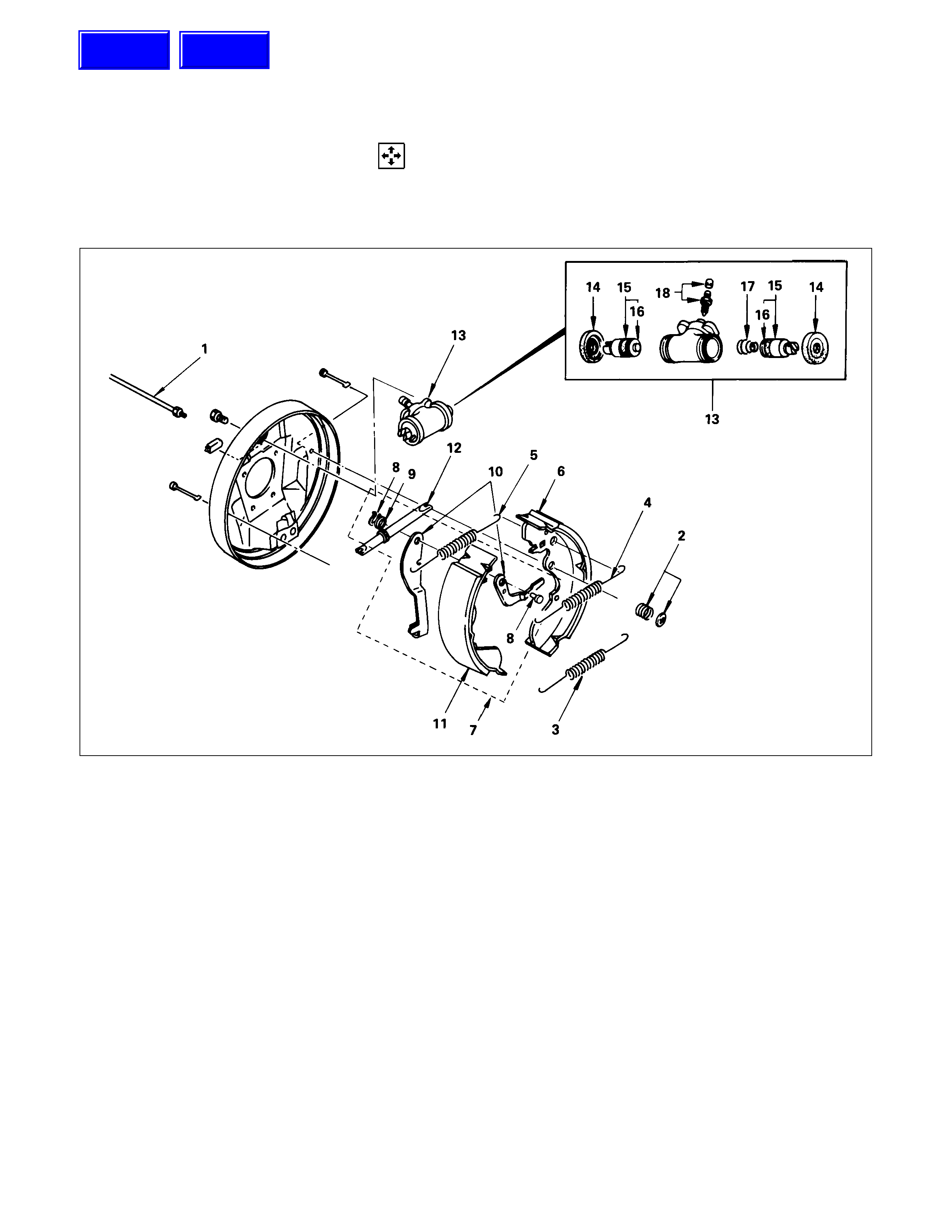
REAR DRUM BRAKE ASSEMBLY
DISASSEMBLY
First, disassemble the brake drum. Then disassemble the rear brake assembly.
Refer to the “REAR AXLE” section for the brake drum disassembly procedure.
MAJOR COMPONENTS
Disassembly Steps
1. Brake line
2. Holding spring and cups
▲3. Return spring ; lower
4. Return Spring ; upper
(shoe to adjust lever)
5. Return spring ; upper
(shoe to shoe)
6. Shoe assembly (primary)
7. Shoe assembly with lever
8. Retainer with pin
9. Washer ; wave
10. Lever ; auto adjust
11. Shoe assembly (secondary)
12. Adjuster assembly
13. Wheel cylinder assembly
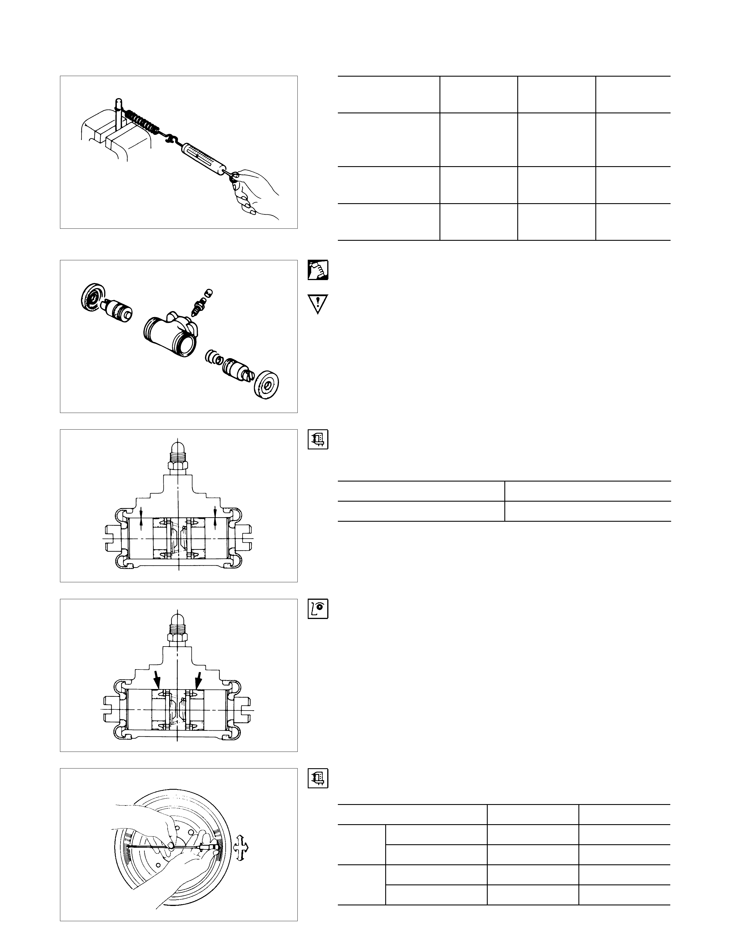
MINOR COMPONENTS
Disassembly Steps
Wheel Cylinder Assembly (13)
14. Boot ; wheel cylinder
15. Piston assembly
16. Cup ; piston
17. Return spring ; piston
18. Bleeder ; wheel cylinder
Techline
Techline
Important Operations
3. Return Spring ; Lower
INSPECTION AND REPAIR
Make necessary correction or parts replacement if wear damage or any other abnormal conditions are found
through inspection.
• Brake drum
• Back plate
• Brake lining
• Wheel cylinder body
• Piston
• Piston cup
• Return spring
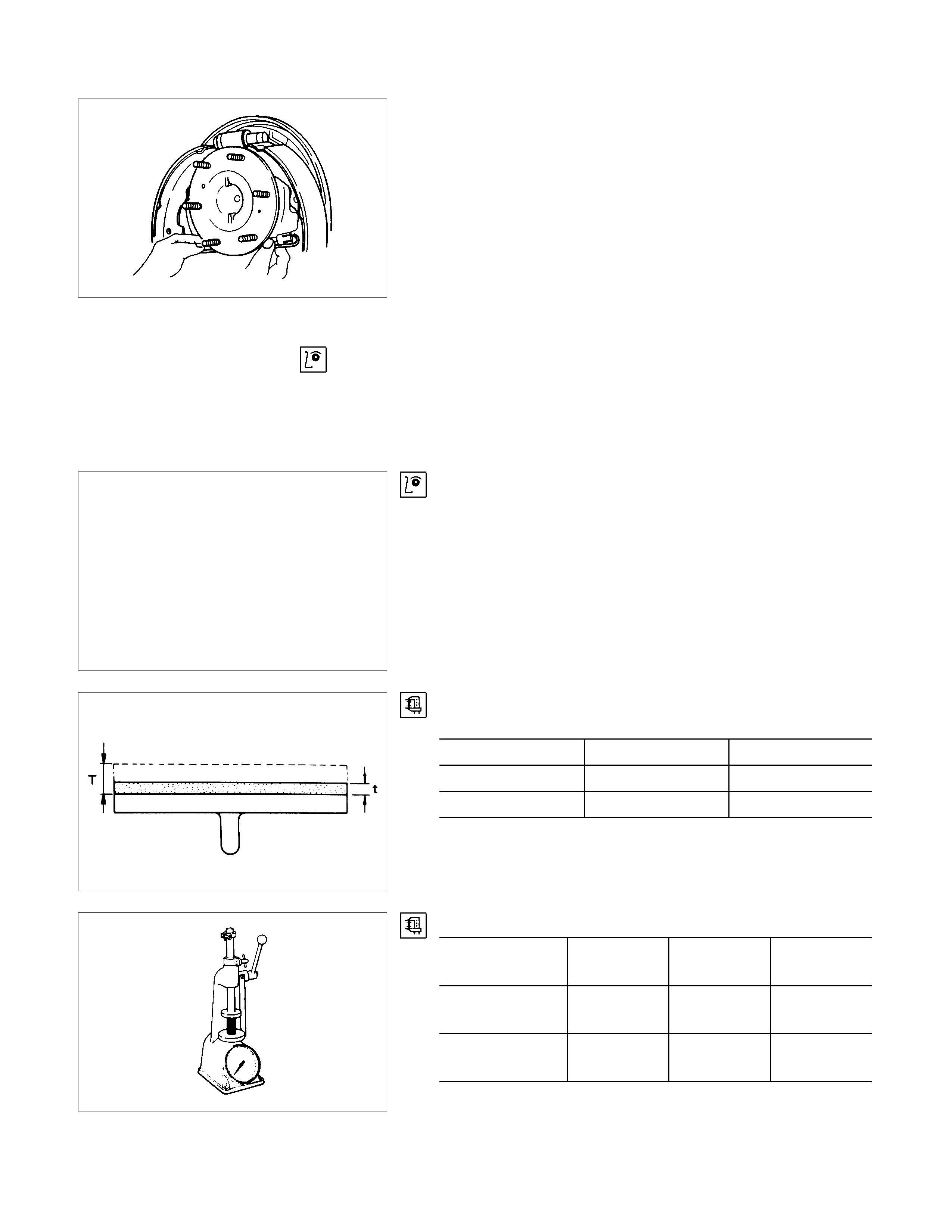
Visual check
Inspect the following parts for wear scuffs, scratches,
corrosion, stains, deterioration, or other abnormal conditions.
Thickness of the Brake Lining
Thickness mm(in)
standard (T) Limit (t)
TFR 5.0 (0.197) 1.0 (0.039)
TFS 4.0 (0.157) 1.9 (0.039)
Inspection of the Return Spring
Free length
mm(in.) Set length
mm(in.) Set load
kg (Ibs.)
Holding spring 15.0 (0.591) 11.2 (0.441) 10.0±1.0
(22.3±2.2)
Wheel cylinder
spring 37.4 (1.472) 8.0 (0.315) 1.0±0.1
(2.2±0.2)
Free length
mm(in.) Set length
mm(in.) Set load
kg(lbs.)
Return spring :
upper
(adjust lever)
124.9
(4.917) 134.9
(5.311) 7±0.7
(15.4±1.6)
Shoe return
spring : upper 112.4
(4.425) 121.5
(4.783) 2±0.2
(4.4±0.4)
Shoe return
spring : lower 167.2
(6.583) 190.2
(7.488) 28.0±2.8
(61.7±6.4)
Clean wheel Cylinder Parts
Always use clean brake fluid to clean wheel cylinder parts.
Note:
Do not use mineral-vase cleaning solvents such as
gasoline, kerosene, acetone, paint thinner, or carbon
tetrachloride.
Clearance Between the Wheel Cylinder
and the Piston mm(in)
Standard Limit
0.02 - 0.1(0.001 - 0.004) 0.15(0.006)
Piston Cups
Inspect the piston cups for wear, distortion, fatigue, fatigue or
other abnormal conditions.
Measuring the Brake Drum mm(in)
Standard Limit
Inside diameter 254(10.000) 255.5(10.059)
Run out 0.05(0.002) 0.15(0.006)
Inside diameter 295(11.614) 296.5(11.673)
Run out 0.05(0.02) 0.15(0.006)
TFS
TFR
REASSEMBLY
MINOR COMPONENTS
Reassembly Steps
Wheel cylinder Assembly (7)
▲1. Bode ; wheel cylinder
2. Return spring ; piston
3. Cup ; piston
▲4. Piston assembly
5. Boot ; wheel cylinder
▲6. Bleeder ; wheel cylinder
MAJOR COMPONENTS
Reassembly Steps
▲7. Wheel cylinder assembly
8. Adjuster assembly
9. Shoe assembly (secondary)
10. Lever ; auto adjuster
11. Washer ; wave
12. Retainer with pin
13. Shoe assembly (primary)
14. Return spring ; upper
(shoe to shoe)
15. Return spring ; upper
(shoe to adjust lever)
16. Return spring ; lower
17. Holding spring and cups
▲18. Brake line
Important Operations
1. Bode ; Wheel Cylinder
Lubricate the cylinder bore with clean rubber grease.
4. Piston Assembly
Install new piston cups on each piston so that the flared end of
the cups are turned to the inboard side of the pistons.
Attach the return spring and the boot to the piston.
Apply DELCO silicone lube No.5459912 (or equivalent) to the
piston and the inner face of the boots.
6. Bleeder ; Wheel Cylinder
Torque N⋅m(kgf⋅m/Ib⋅ft)
6.9 - 11.8 (0.7 - 1.2 / 5.1 - 8.7)
7. Wheel Cylinder Assembly
Torque N⋅m(kgf⋅m/Ib⋅ft)
11 - 15 (1.1 - 1.5 / 8 - 11)
18.Brake Line
Torque N⋅m(kgf⋅m/Ib⋅ft)
13 - 19 (1.3 - 1.9 / 9 - 14)
Apply grease lightly to back plate A.
BRAKE CONTROL
REMOVAL AND INSTALLATION
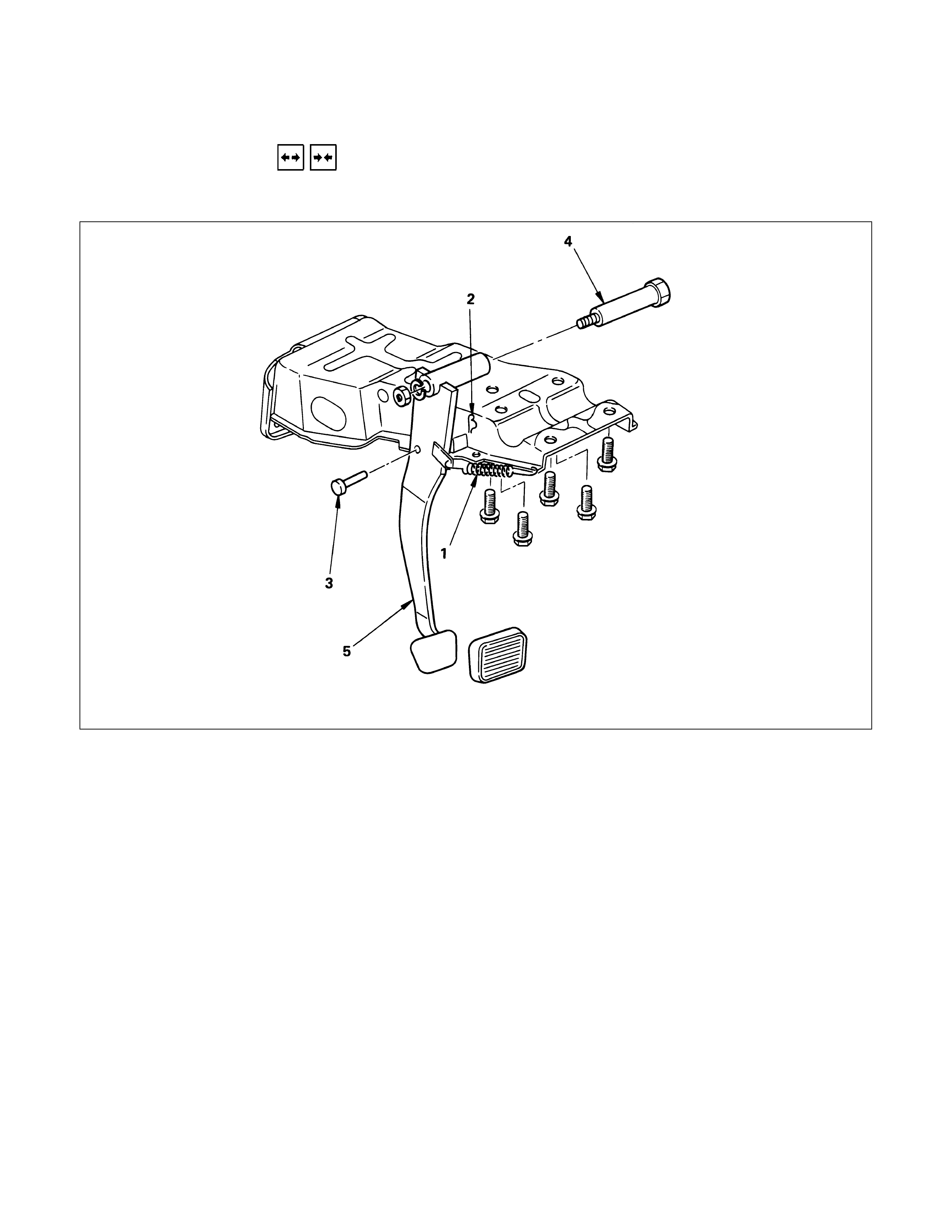
BRAKE PEDAL ASSEMBLY
This illustration based on the LHD model
Removal Steps
1. Return spring
2. Snap pin
3. Pin ; push rod to pedal
4. Pin ; fulcrum, pedal to bracket
5. Pedal assembly with bush
Installation steps
To install, follow the removal procedure in
reverse order.
Before installation, appyl grease to the entire
circumference of the fulcrum pin (4) and push
rod pin (3).
Refer to "SERVICING" in this section for
adjustment procedure of brake pedal.
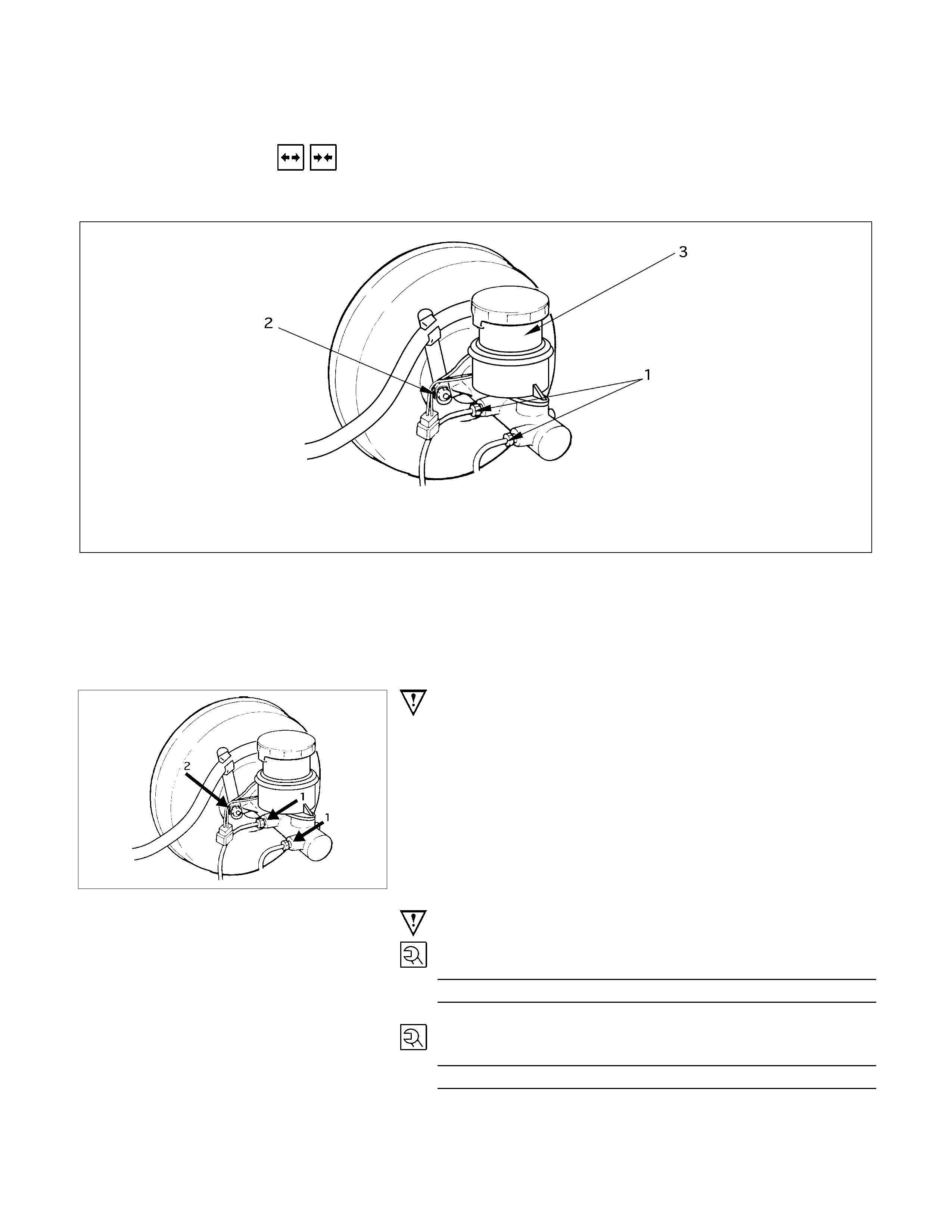
MASTER CYLINDER
REMOVAL AND INSTALLATION
BRAKE PEDAL ASSEMBLY
This illustration based on the LHD model.
Removal Steps
▲1. Brake line
2. Nut ; master cylinder to vacuum servo
3. Master cylinder assembly
Installation Steps
3. Master cylinder assembly
▲2. Nut ; master cylinder to vacuum servo
▲1. Brake line
Important Operation - Removal
1. Brake Line
Be very careful not to spill brake fluid on the painted surface.
Damage to the painted surface will result.
Important Operation - Installation
2. Nut ; Master Cylinder to Vacuum Servo
Torque N⋅m (kgf⋅m/lb⋅ft)
1.0 - 1.6 (7 - 12 / 9.8 - 16)
1. Brake Line
Torque N⋅m (kgf⋅m/lb⋅ft)
0.9 - 1.5 (6.5 - 11 / 8.8 - 15)
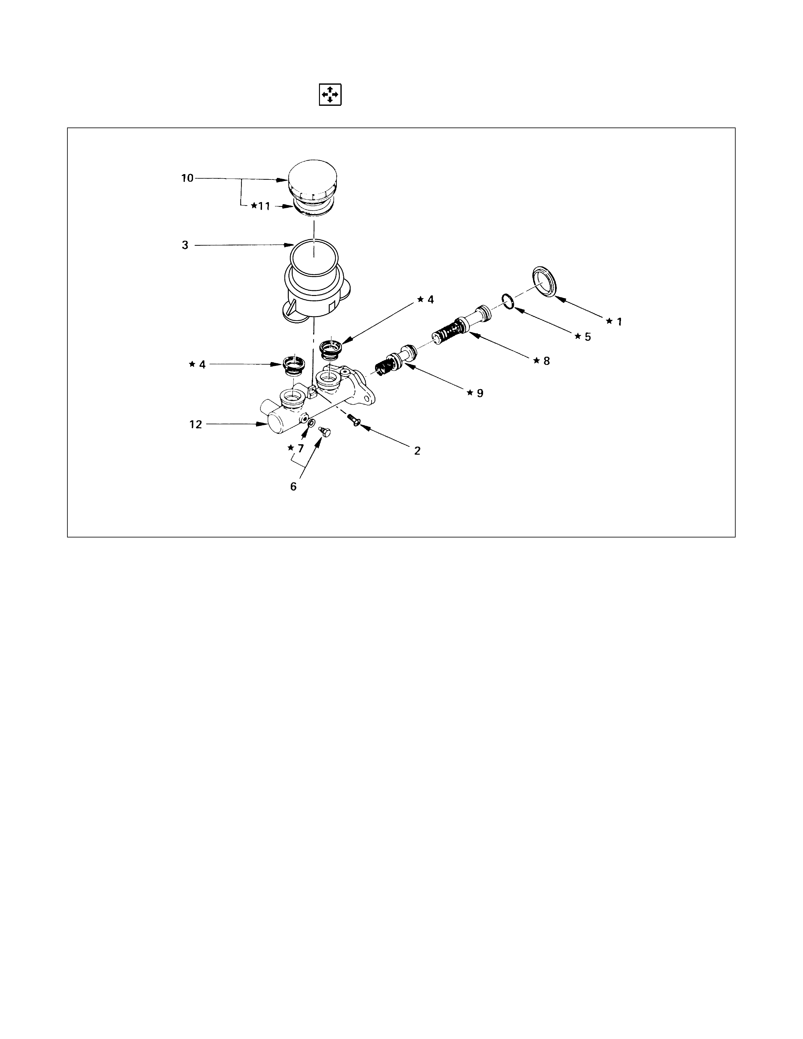
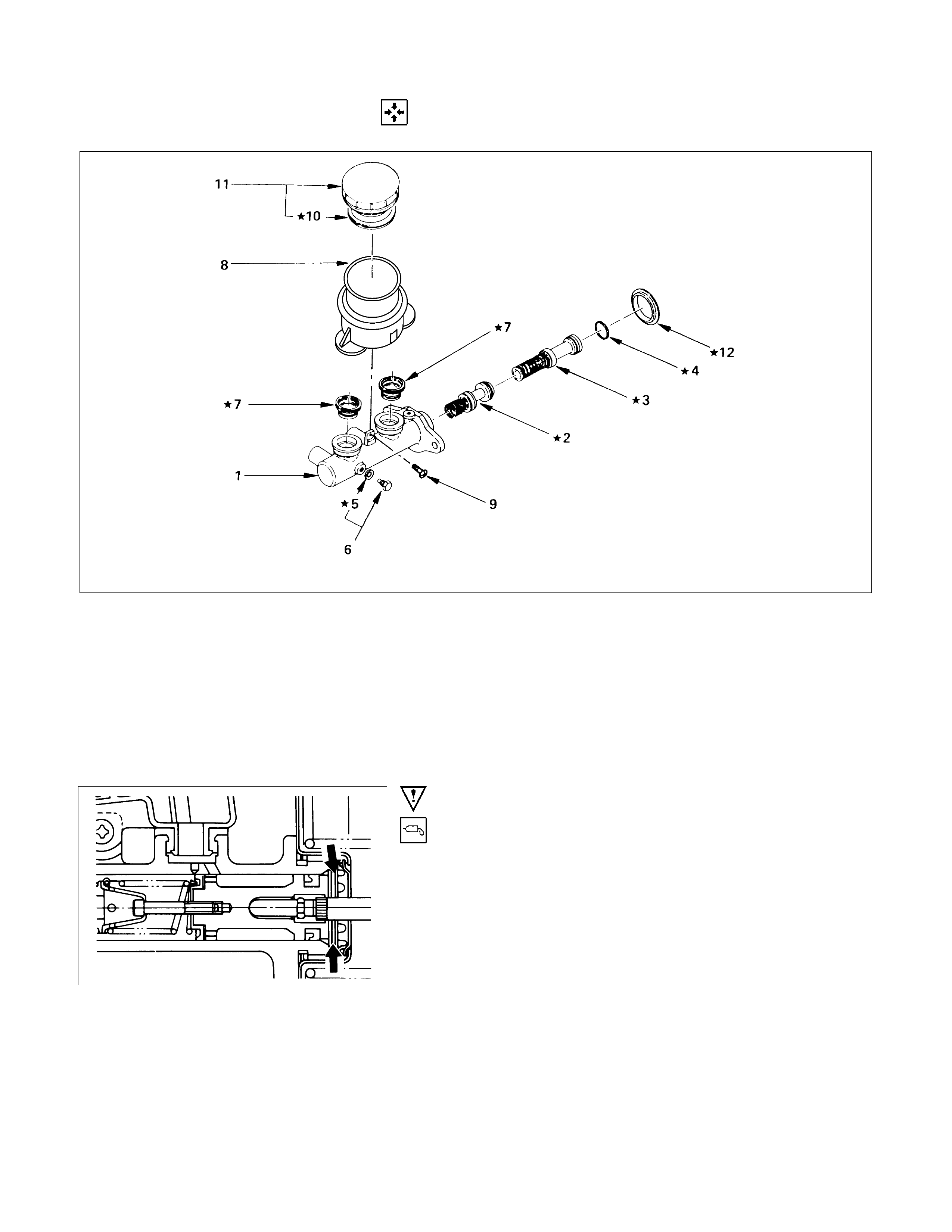
DISASSEMBLY
Disassembly Steps
1. Dust seal
2. Screw
3. Reservoir ; fluid, brake
4. Grommet
▲5. Ring ; snap
▲6. Bolt ; stopper
7. Gasket
▲8. Piston assembly ; primary and spring
▲9. Piston assembly ; secondary and spring
10. Cover ; fluid reservoir
11. Seal
12. Cylinder assembly ; brake, master
Important Operations
When disassembling, inspecting or reassembling the master
cylinder assembly, take care not to bring the parts into contact
with mineral oil or dust. Wash the piston cups only with brake
fluid. Do not use gasoline or other mineral-base cleaning
solvents.
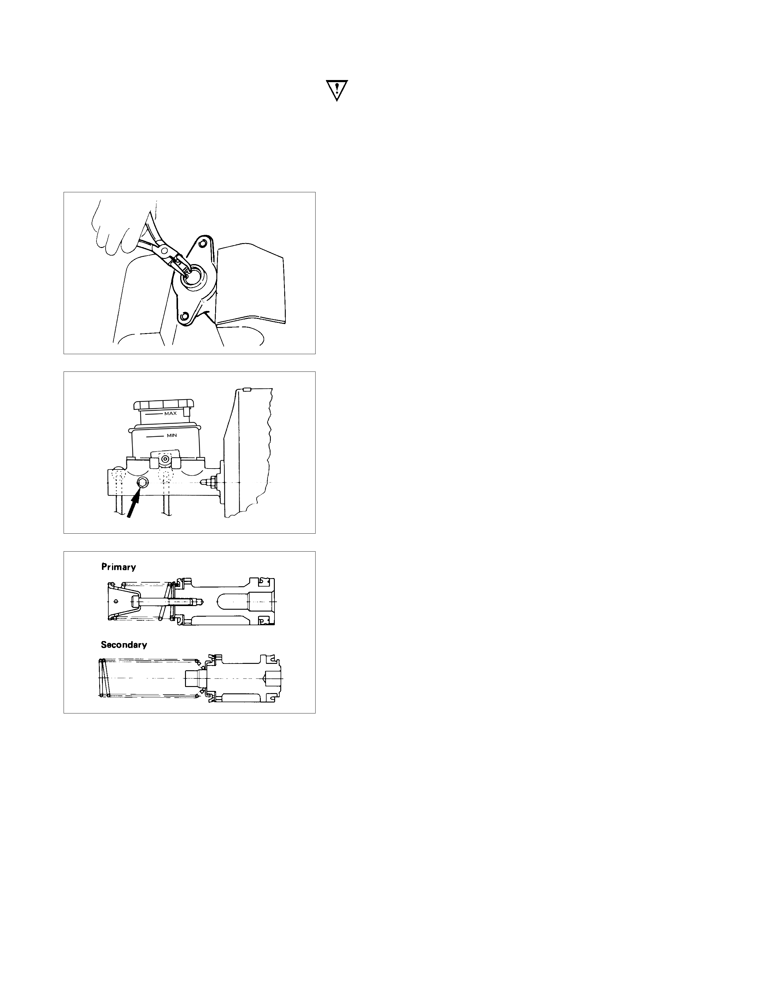
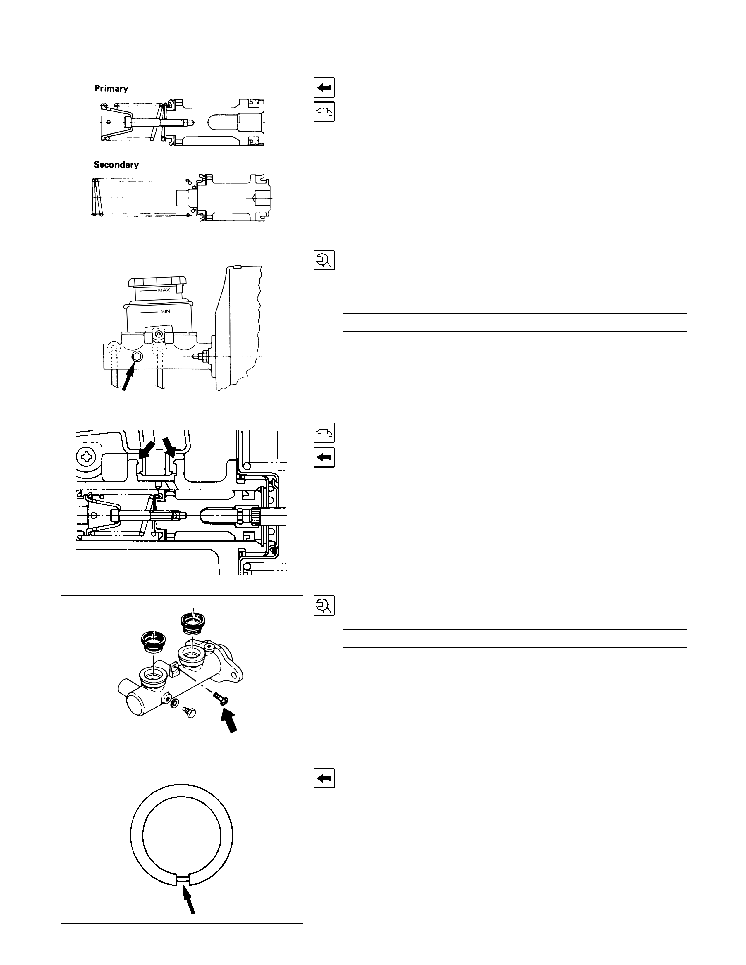
5. Ring ; Snap
Remove the snap ring from the cylinder body with pushing in
the primary and secondary pistons.
6. Bolt ; Stopper
Push in the primary and secondary pistons and remove the
stopper bolt completery from the cylinder body, then remove
the primary and secondary piston assemblies.
8. Piston Assembly ; Primary and Spring
9. Piston Assembly ; Secondary and Spring
Don’t remove the spring from the piston.
INSPECTION AND REPAIR
Make necessary correction or parts replacement if wear damage or any other abnormal conditions are found
through inspection.
• Cylinder inside face
• Piston
• Piston cap
• Piston cap spacer
• Return port
• Return spring
Visual Check
Inspect the following parts for wear, distortion, cuts, nicks,
corrosion, or other abnormal conditions.
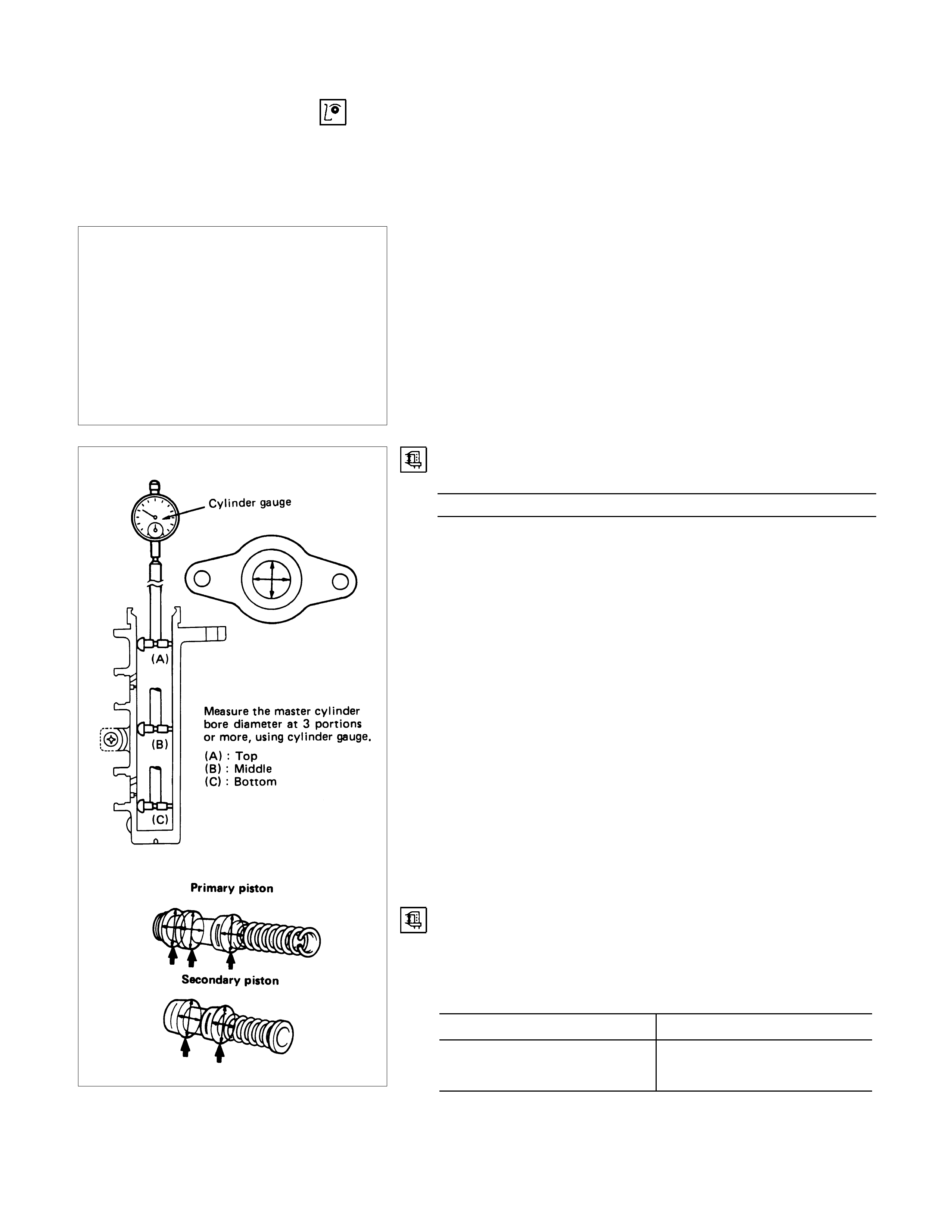
Master Cylinder Bore Diameter
Standard mm(in)
23.81 (0.938)
Clearance between the Master Cylinder
and the Piston
Measure the outer diameter of the piston assembly at the
portions shown in the left figure. mm(in)
Standard Limit
0.04 - 0.125
(0.00158 - 0.00493) 0.15 (0.00591)
Note:
If the clearance deviates from the range shown above,
replace the master cylinder and the piston assembly
together.

Return Port
Check the return port for obstructions and if necessary, clean
with a tag wire.
Blow away foreign matter with compressed air.
Primary Piston
After reassembly, push in the primary piston to see that returns
smoothly.
Repeat the test two or three times to see that brake fluid is
forced out from the front and rear outlets.
REASSEMBLY
★; Repair Kit
Reassembly Steps
▲1. Cylinder assembly ; brake, master
▲2. Piston assembly ; secondary and spring
▲3. Piston assembly ; primary and spring
4. Ring ; snap
5. Gasket
▲6. Bolt ; stopper
▲7. Grommet
8. Reservoir ; fluid, brake
▲9. Screw
10. Seal
11. Cover ; fluid reservoir
▲12. Dust seal
Important Operations
1. Cylinder Assembly ; Brake, Master
Lubricate the master cylinder bore with clean rubber
grease.(arrowed portion)
2. Piston Assembly ; Secondary and Spring
3. Piston Assembly ; Primary and Spring
Lubricate the piston cups on the primary piston assemblies with
rubber grease.
Take care not to scratch the piston cup when installing the
piston assemblies.
Note:
Don't remove the spring from the piston.
6. Bolt ; Stopper
Depress the primary piston and install the piston stopper bolt
with a new gasket.
Torque N⋅m(kgf⋅m/lb⋅ft)
6.9 - 8.8 (0.7 - 0.9 / 5.1 - 6.5)
7. Grommet
Lubricate the new grommets with clean rubber grease.
Insert the grommets, with the flared side up, into the cylinder
body.
Apply rubber grease to the dust seal portion.
(The portion indicated by the arrows in the left diagram.)
9. Screw
Torque N⋅m(kgf⋅m/lb⋅ft)
1.0 - 2.0 (0.01 - 0.20 / 0.7 - 1.5)
12.Dust Seal
Install the dust seal so that its groove faces downward.

VACUUM SERVO
REMOVAL AND INSTALLATION
Removal Steps
1. Clamp ; vacuum hose
2. Vacuum hose
▲3. Brake line
4. Return spring ; brake pedal
5. Snap pin
6. Pin ; push rod to brake pedal
7. Vacuum servo to dash panel and pedal
mounting bracket
8. Maser cylinder assembly
9. Vacuum servo assembly
Installation Steps
9. Vacuum servo assembly
▲8. Maser cylinder assembly
▲7. Vacuum servo to dash panel and pedal
mounting bracket
6. Pin ; push rod to brake pedal
5. Snap pin
4. Return spring ; brake pedal
▲3. Brake line
▲2. Vacuum hose
1. Clamp ; vacuum hose
Important Operation - Removal
3. Brake Line
When handling, be careful not to spill brake fluid over the
painted surfaces, as damage to the paint finish will result.
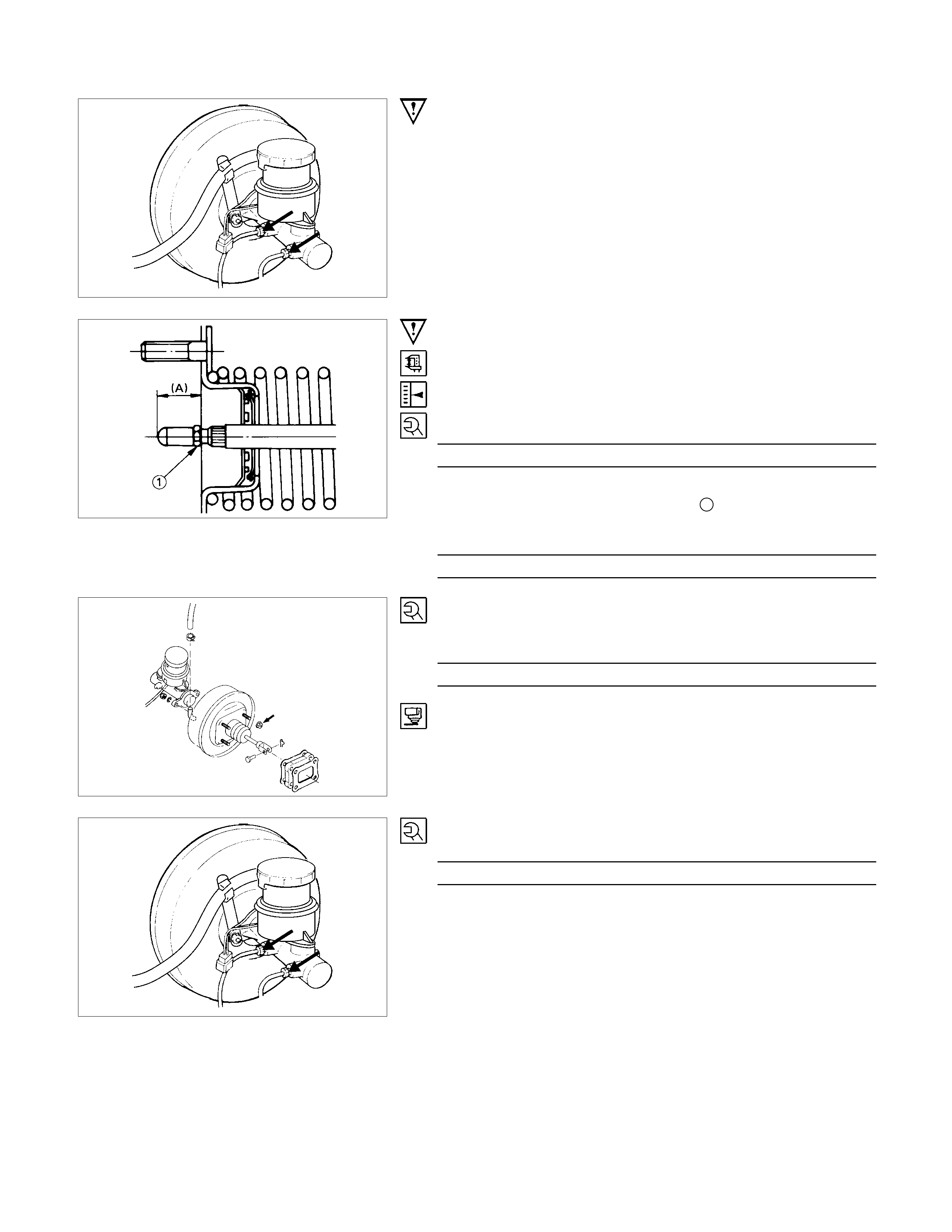
Important Operation - Installation
8. Master Cylinder Assembly
Check the distance from the flange face of the vacuum servo
to the end of the push rod before installation of the master
cylinder.
Projection (A) mm(in)
18.0 - 18.2 (0.709 - 0.717)
If the measured distance deviates from the specified range,
make an adjustment with the lock nut 1 at the end of the push
rod.
Torque N⋅m(kgf⋅m/lb⋅ft)
15 - 25 (1.5 - 2.5 / 11 - 18)
7. Vacuum Servo to Dash Panel and Pedal Mounting
Bracket
Torque N⋅m(kgf⋅m/lb⋅ft)
22 - 31 (2.2 - 3.2 / 16 - 23)
Apply sealer to the dashboard fitting face.
3. Brake Line
Torque N⋅m(kgf⋅m/lb⋅ft)
9 - 15 (0.9 - 1.5 / 6.5 - 11)
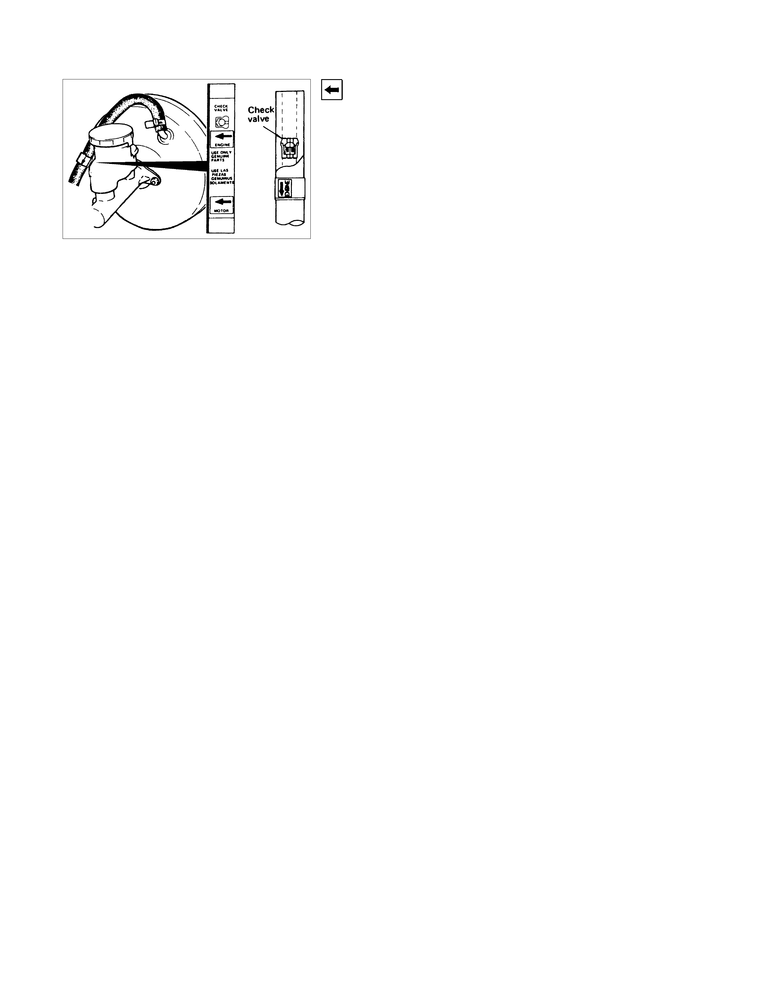
2. Vacuum Hose
1) When removing or replacing the vacuum hose make sure
that the arrow on the label of the hose is facing the engine.
2) Also confirm that the check valve is facing the engine.
PARKING BRAKE (STEM TYPE)
REMOVAL AND INSTALLATION
PARKING BRAKE STEM ASSEMBLY (LEFT HAND DRIVE MODEL)
Removal Steps
1. Cable front, relay lever side
2. Bolt ; bracket to dash
3. Bolt ; bracket to cross beam
4. Parking brake stem assembly
Installation Steps
To install, follow the removal procedure in
reverse order.
PARKING BRAKE STEM ASSEMBLY (RIGHT HAND DRIVE MODEL)
Removal Steps
1. Bolt and nut
2. Collar
3. Roller
4. Cable front, relay lever side
5. Nuts ; bracket to dash
6. Bolt ; bracket to cross beam
7. Parking brake stem assembly
8. Nuts
9. Bracket ; roller
Installation Steps
To install, follow the removal procedure in
reverse order.
Before installation, apply chassis grease to the
roller (3)'s contact surface to the collar (2) and
cable (4).
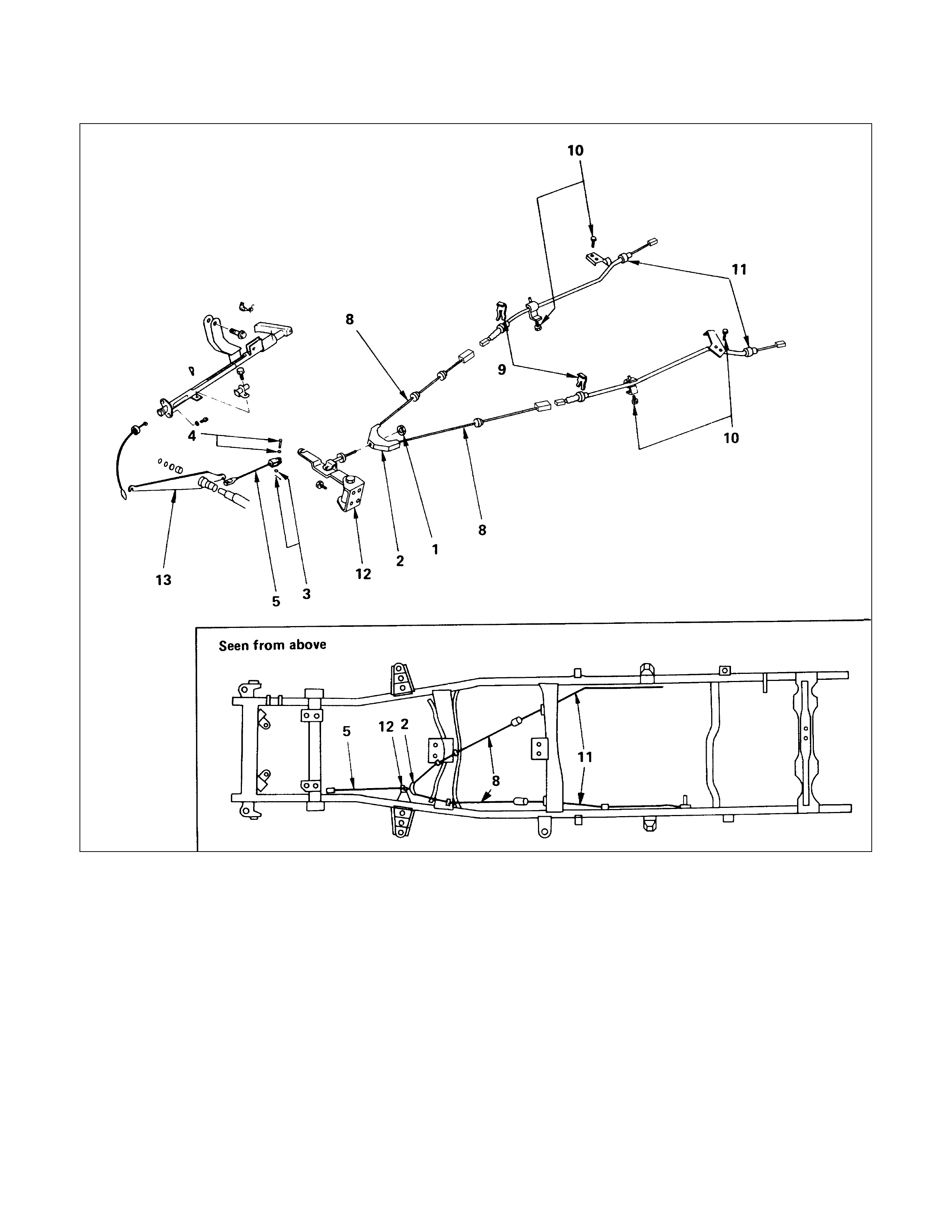
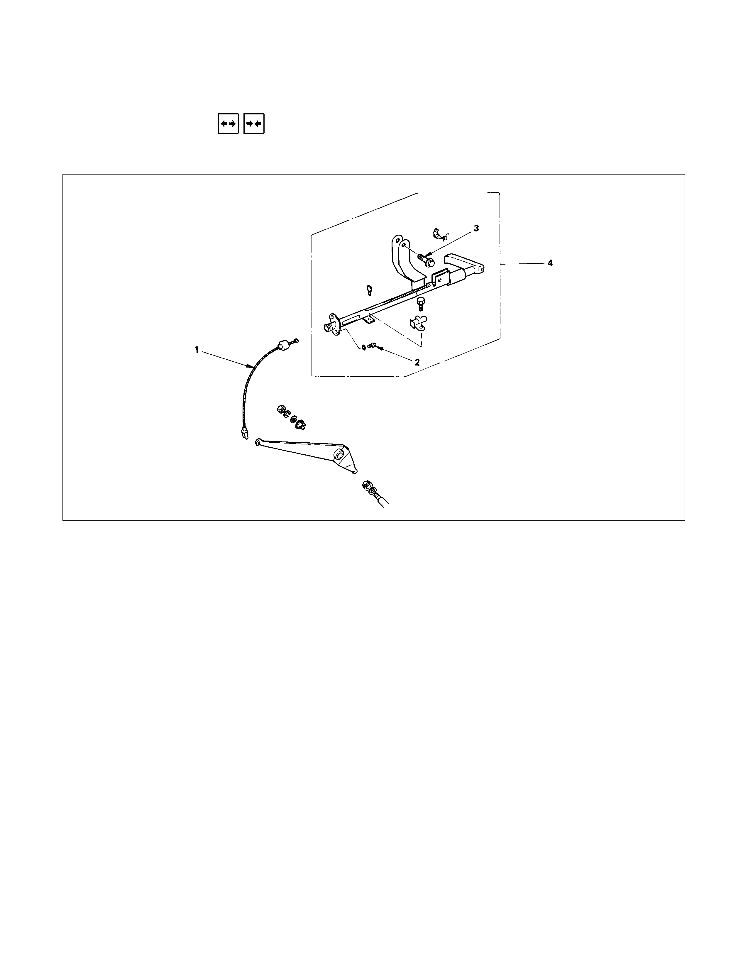
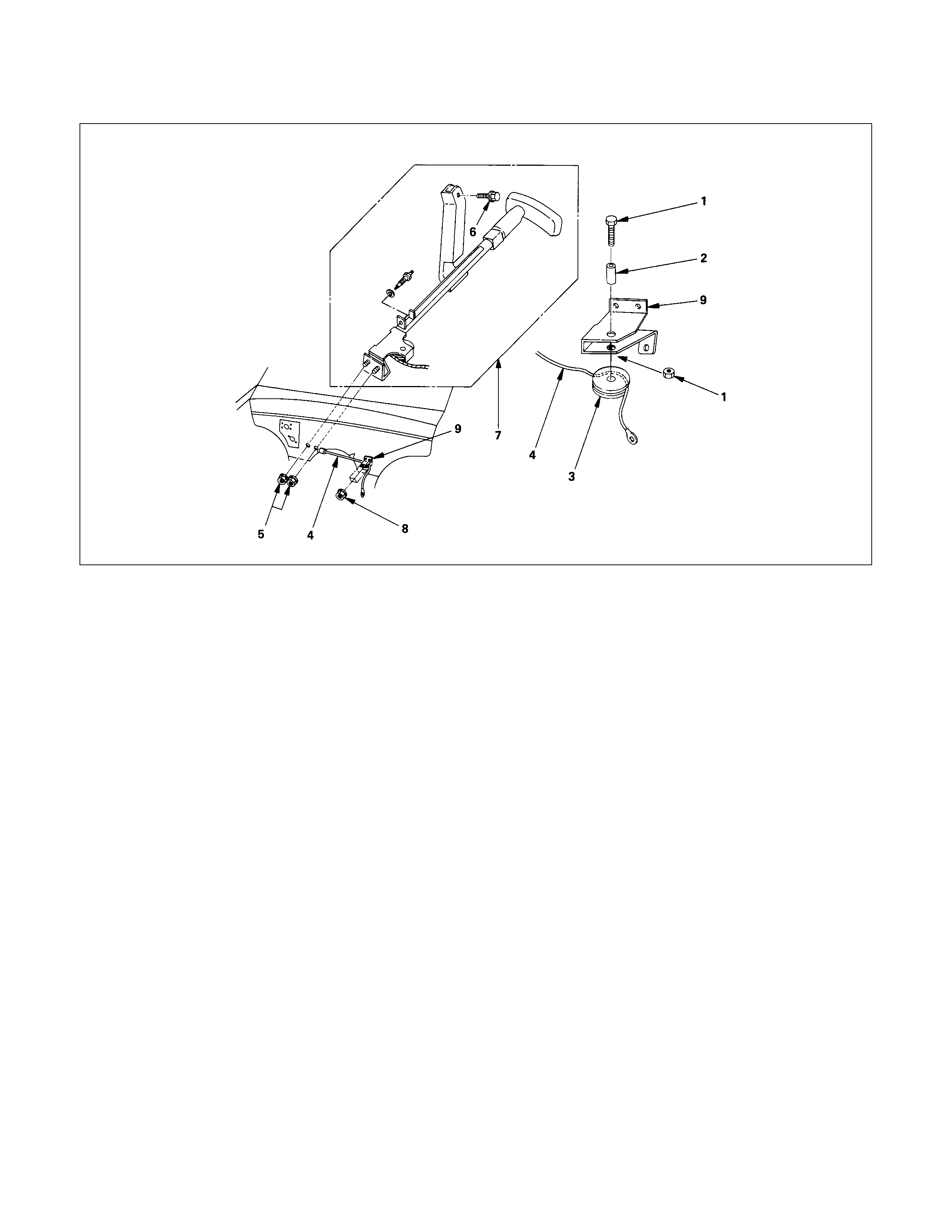
FRONT AND REAR CABLE ASSEMBLY
Removal Steps
1. Nut
2. Equalizer bracket
3. Snap pin, with plan washer
4. Pin with curved washer
5. Cable ; front lower
6. Pin with curved washer
7. Parking brake stem assembly
8. Nuts
9. Clip
10. Clip ; fixing bracket
▲11. Cable assembly ; rear
12. 2nd relay lever assembly with return
spring
13. 1st relay lever assembly
Installation Steps
▲13. 1st relay lever assembly
▲12. 2nd relay lever assembly with return
spring
11. Cable assembly ; rear
10. Clip ; fixing bracket
9. Clip
▲8. Nuts
▲7. Parking brake stem assembly
▲6. Pin with curved washer
5. Cable ; front lower
4. Pin with curved washer
▲3. Snap pin, with plan washer
2. Equalizer bracket
1. Nut
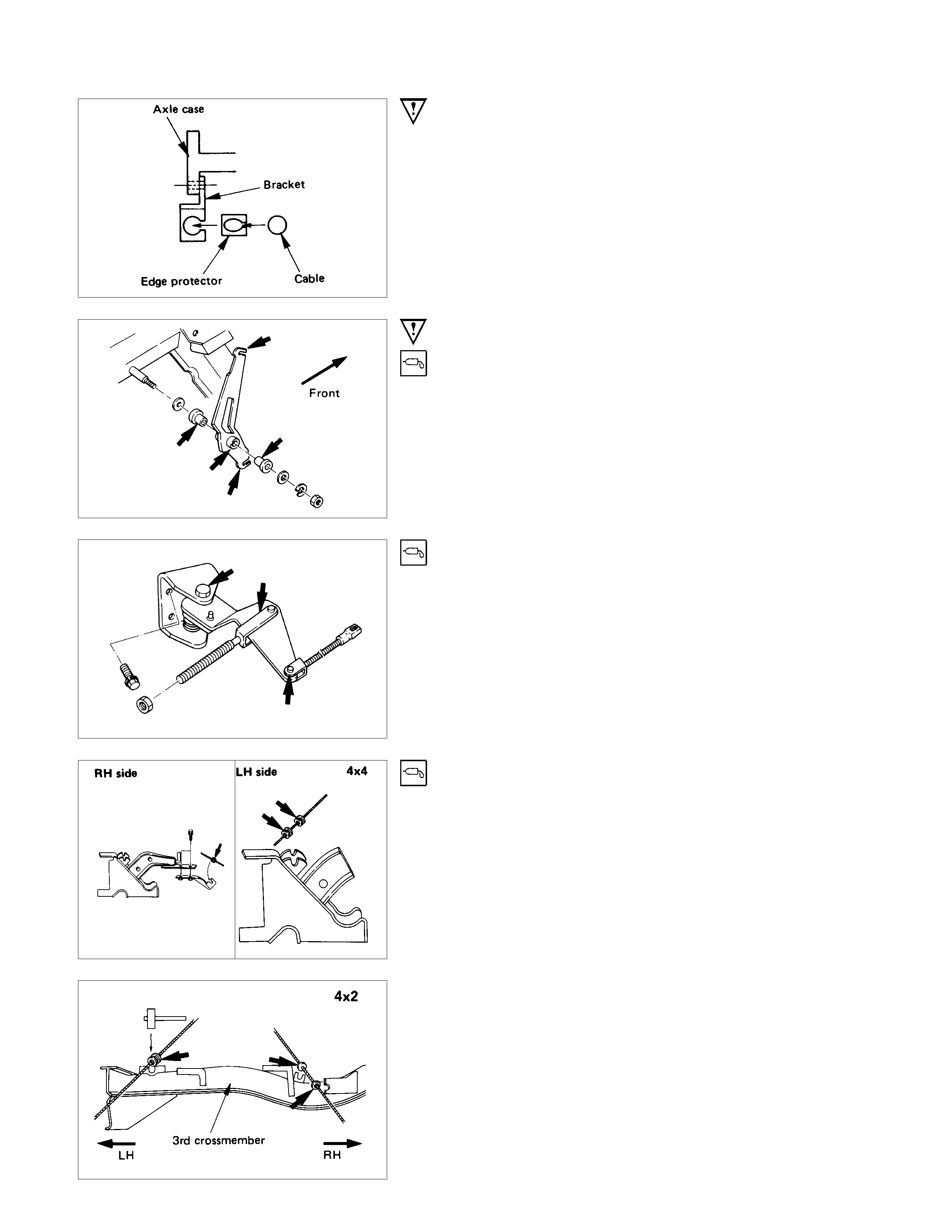
Important Operations - Removal
11.Cable Assembly ; Rear
When abrasion or wear is evident on edge protector, in must
be replaced with new one.
Important Operations - Installation
13.1st Relay Lever Assembly
Apply grease (BESCO L-2 or equivalent) to the inner and outer
surface of the bushes and cable connecting portions.
12.2nd Relay Lever Assembly with Return Spring
Apply grease (BESCO L-2 or equivalent) to the arrowed portion
in the left figure.
8. Intermediate Cable
After applying grease (BESCO L-2 or equivalent) to the cable
guide, set it to the bracket by striking lightly with a mallet.
Apply grease (BESCO L-2 or equivalent) to the arrowed portion
in the left figure.
7. Pin with Curved Washer
Apply grease (BESCO L-2 or equivalent) to the circumference
of the pin and joint.
6. Snap pin, with Plain Washer
3. Snap pin, with Plain Washer
Discard the used snap pins and use new parts.
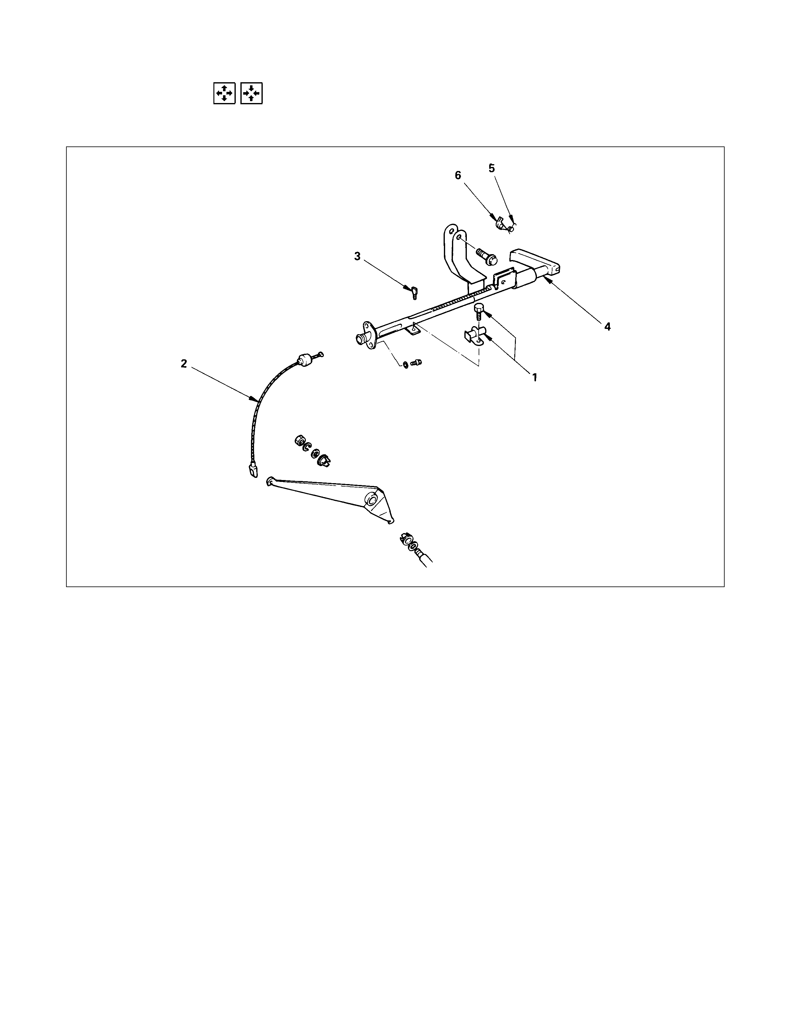
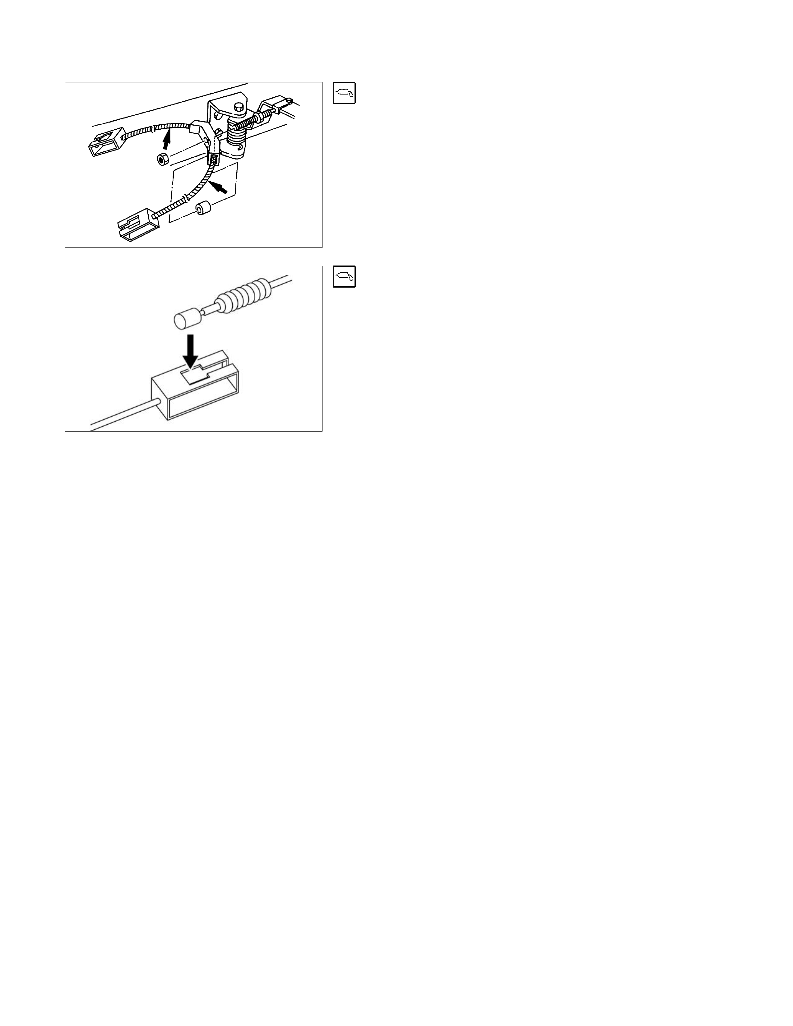
DISASSEMBLY AND REASSEMBLY
PARKING BRAKE STEM ASSEMBLY
This illustration is based on the LHD model
Disassembly Steps
1. Switch ; parking brake and bolt
▲2. Cable ; front
▲3. Switch actuating pin
4. Stem
5. Spring
6. Pole
Reassembly Steps
▲6. Pole
5. Spring
▲4. Stem
3. Switch actuating pin
▲2. Cable ; front
1. Switch ; parking brake and bolt
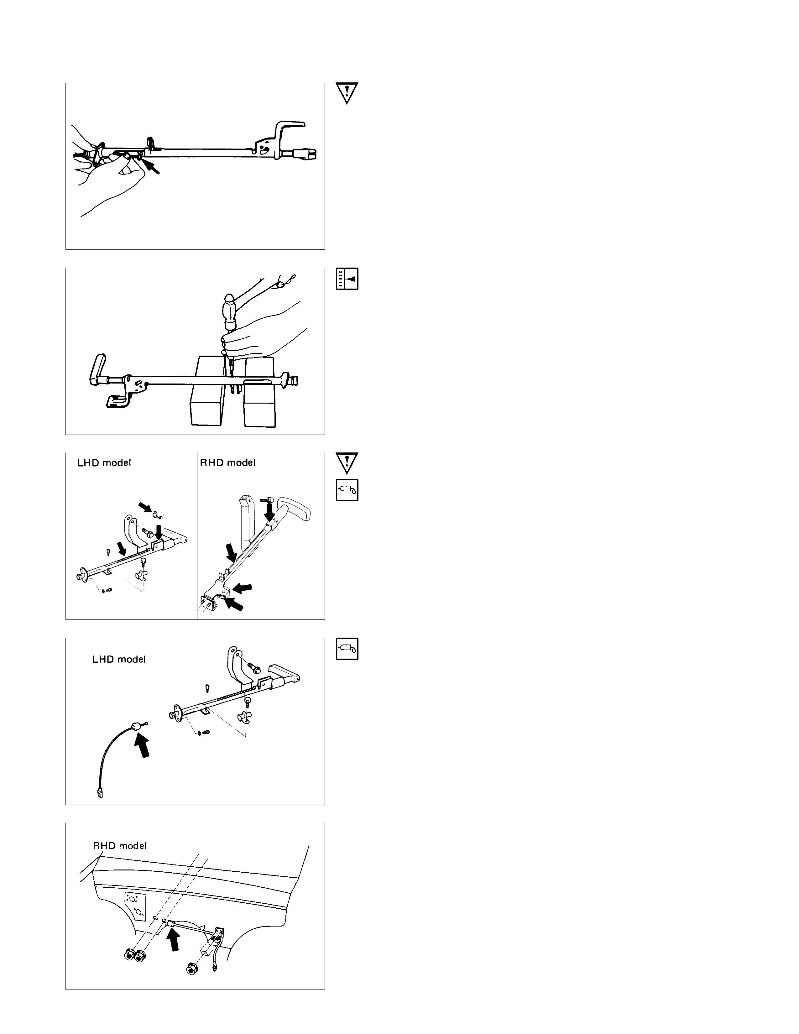
Important Operations - Disassembly
2. Cable ; Front
Manually release the lever ratchet and depress the stem until
the cable attachment at the lower end of the stem is visible.
Remove the cable from the stem lower end.
3. Switch Actuating Pin
Align the parking brake switch actuating pin with the hole in the
housing.
Using a flat head punch, drive out the pin.
Important Operations - Reassembly
6. Pole
4. Stem
Before reassembly, apply chassis grease to the arrowed
portion in the left figures.
2. Cable ; Front
Before reassembly, apply chassis grease to the entire inside
surface of the cable boot (arrowed in the left figure)fully.

INSPECTION AND REPAIR
Make necessary adjustments, repairs, and parts replacements if wear, damage or other problems are discovered
during inspection.
Refer to "SERVICING" in this section for
adjustment procedure of parking brake.
Adjustment Procedure of Parking Brake
•Parking brake
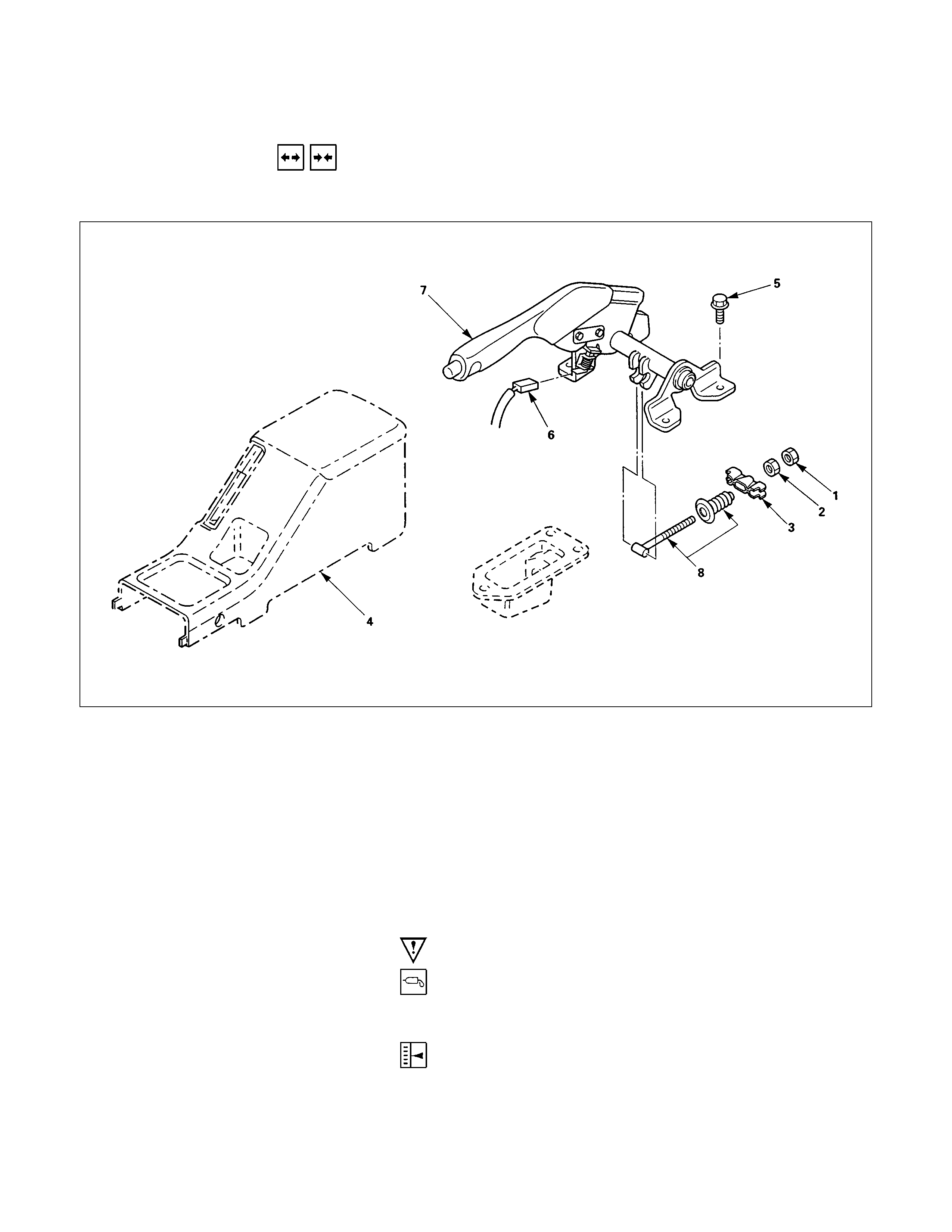
PARKING BRAKE (FLOOR MOUNT TYPE)
REMOVAL AND INSTALLATION
PARKING BRAKE LEVER AND FRONT CABLE ASSEMBLY
Removal Steps
1. Lock nut
2. Adjust nut
3. Equalizer
4. Center console
5. Bolt
6. Switch connector
7. Parking brake lever
8. Parking brake front cable
Installation Steps
▲8. Parking brake front cable
7. Parking brake lever
6. Switch connector
▲5. Bolt
4. Center console
3. Equalizer
2. Adjust nut
1. Lock nut
Important Operation - Installation
8.Parking Brake Front Cable
Apply grease (BESCO L-2 or equivalent) to the front cable
before installation.
•After installation, be sure to adjust the parking brake.
Refer to "SERVICING" of this section.
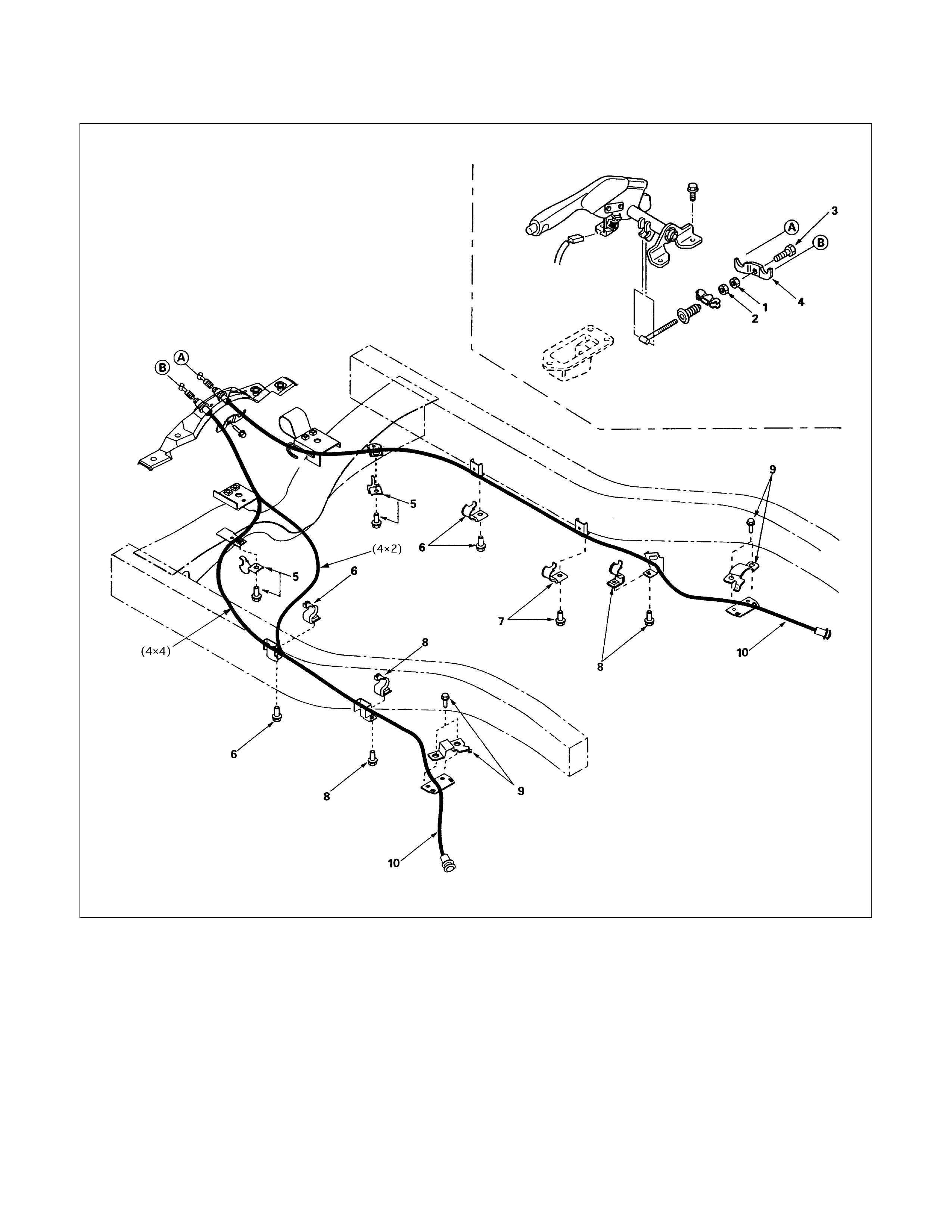
REAR CABLE ASSEMBLY
Removal Steps
▲1. Lock nut
▲2. Adjusting nut
▲3. Bolt
▲4. Retainer
5. Clip and bolt ; crossmember
6. Clip and bolt ; side member
7. Clip and bolt ; side member
8. Clip and bolt ; spring eye
9. Clip and bolt ; leaf spring
10. Hand brake rear cable
Installation Steps
▲10. Hand brake rear cable
▲9. Clip and bolt ; leaf spring
▲8. Clip and bolt ; spring eye
▲7. Clip and bolt ; side member
▲6. Clip and bolt ; side member
▲5. Clip and bolt ; crossmember
▲4. Retainer
▲3. Bolt
▲2. Adjusting nut
▲1. Lock nut
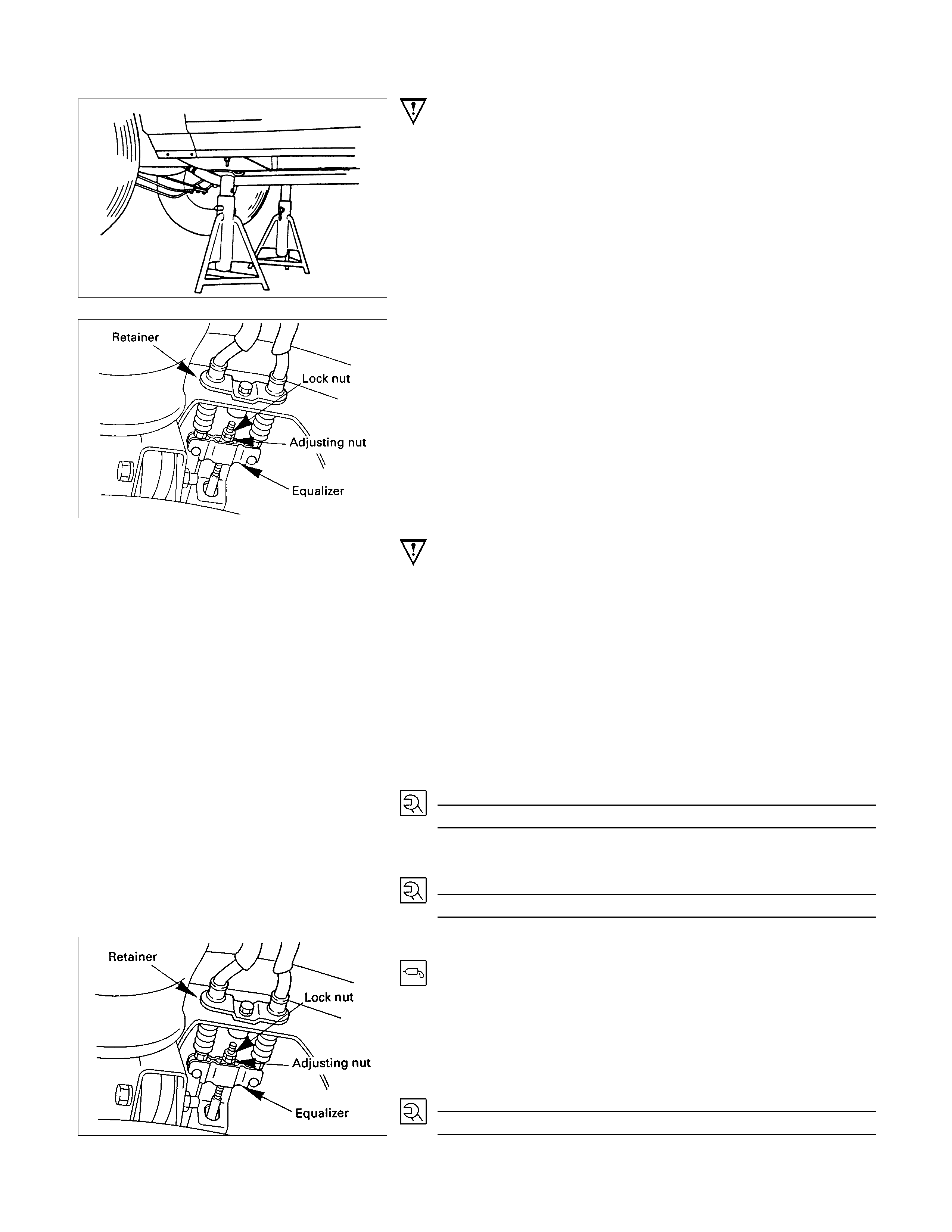
Important Operations - Removal
Preparation
•Raise vehicle to the working level.
Support the axle assembly with the proper jack and chassis
stands.
•Remove the tire and wheel.
•Remove the brake drum.
1.Lock Nut
2.Adjusting Nut
3.Bolt
4.Retainer
•Loosen lock nut and adjusting nut, then disconnect rear
cable from the equalizer.
•Remove bolt and retainer.
Important Operations - Installation
10.Hand Brake Rear Cable
•Apply grease (BESCO L-2 or equivalent) to the
circumference of the pin and joint.
•Apply grease (BESCO L-2 or equivalent) to the equalizer
joint portion.
9.Clip and Bolt; Leaf Spring
8.Clip and Bolt; Spring Eye
7.Clip and Bolt; Side Member
6.Clip and Bolt; Side Member
5.Clip and Bolt; Crossmember
TorqueN⋅m (kgf⋅m/lb⋅ft)
6 (0.6 / 4.3)
4.Retainer
3.Bolt
TorqueN⋅m(kgf⋅m/lb⋅ft)
16 (0.6 / 4.3)
2.Adjusting Nut
1.Lock Nut
•Apply grease (BESCO L-2 or equivalent) to the front cable
contact portion.
•Connect rear cable to the equalizer, then adjust the parking
brake. Refer to "SERVICING".
•Tighten lock nut to the specified torque.
Torque N⋅m(kgf⋅m/lb⋅ft)
16 (0.6 / 4.3)

TROUBLESHOOTING
Condition and Cause Correction
Poor Brake Action
Master cylinder faulty Correct or replace
Power cylinder faulty Correct or replace
Level of brake fluid in reservoir too low Replenish and bleed
Air in hydraulic circuit Bleed
Front disc brake caliper faulty Clean or replace
Rear brake wheel cylinder faulty Clean or replace
Water or oil on brake pads or linings Clean or replace
Brake pads or linings hardened Replace
Brake pads or linings in poor contact with rotor or brake drum Correct
Brake pads or linings worn Replace
Brake disc or drum rusted Grind or replace
Check valve in vacuum hose faulty Correct or replace
Brake Squeak
Brake pads or linings worn Replace
Brake pads or linings hardened Replace
Brake pads or linings in poor contact with rotor or brake drum Correct
Brake disc(s) warped, worn or damaged Grind or replace
Disc brake anti-squeak shims fatigued Replace
Front hub bearings loose or preload is incorrect Adjust or replace
Brake disc or drum rusted Grind or replace
Brake Pull
Tire inflation pressures unequal Adjust
Front wheel alignment incorrect Adjust
Water or oil on brake pads or linings Clean or replace
Brake pads or linings hardened Replace
Brake pads or linings worn excessively Replace
Brake drum or rotor worn or scored Grind or replace
Front or rear wheel cylinder or disc brake caliper malfunctioning Clean or replace
Front hub bearing preload incorrect Adjust or replace
Brake pad or lining clearances unequal Adjust or replace
Brake Drag
Parking brake maladjusted Adjust
Brake pad or lining clearance insufficient Adjust
Brake pedal free play insufficient Adjust brake pedal height or power cylinder operating rod
Piston in master cylinder sticking Clean or replace
Pistons in disc brake caliper sticking Replace piston seals
Pistons in rear brake wheel cylinders sticking Clean or replace
Brake pads sticking in caliper Clean
Return springs weakened Replace
Parking brake binding Overhaul rear brakes
Front hub bearing preload incorrect Adjust or replace
Rear brake shoes not returning Correct or replace brake back plate, check automatic adjuster and
replace as necessary
Obstructions in hydraulic circuit Clean
Rotor warped excessively Grind or replace
Rear brake drum distorted Grind or replace
Piston cups swollen Replace brake fluid and piston cups
Check valve ; vacuum hose faulty Replace
Parking cable sticking Clean or replace
Rear disc brake over adjust Adjust or overhaul rear brakes
Excessive Brake Pedal Travel
Air in hydraulic circuit Bleed hydraulic circuit
Level of brake fluid in reservoir too low Replenish brake fluid reservoir to specified level and bleed hydraulic
circuit as necessary.
Master cylinder push rod clearance excessive Adjust
Leakage in hydraulic system Correct or replace defective parts
Rear disc brake autoadjuster malfunction Overhaul rear brakes