
SECTION 6A - ENGINE MECHANICAL (4JB1T MODELS)
MAIN DATA AND SPECIFICATIONS
TORQUE SPECIFICATIONS
STANDARD BOLTS
SPECIAL PARTS FIXING NUTS AND BOLTS
CYLINDER HEAD COVER, CYLINDER HEAD, AND ROCKER ARM SHAFT BRACKET
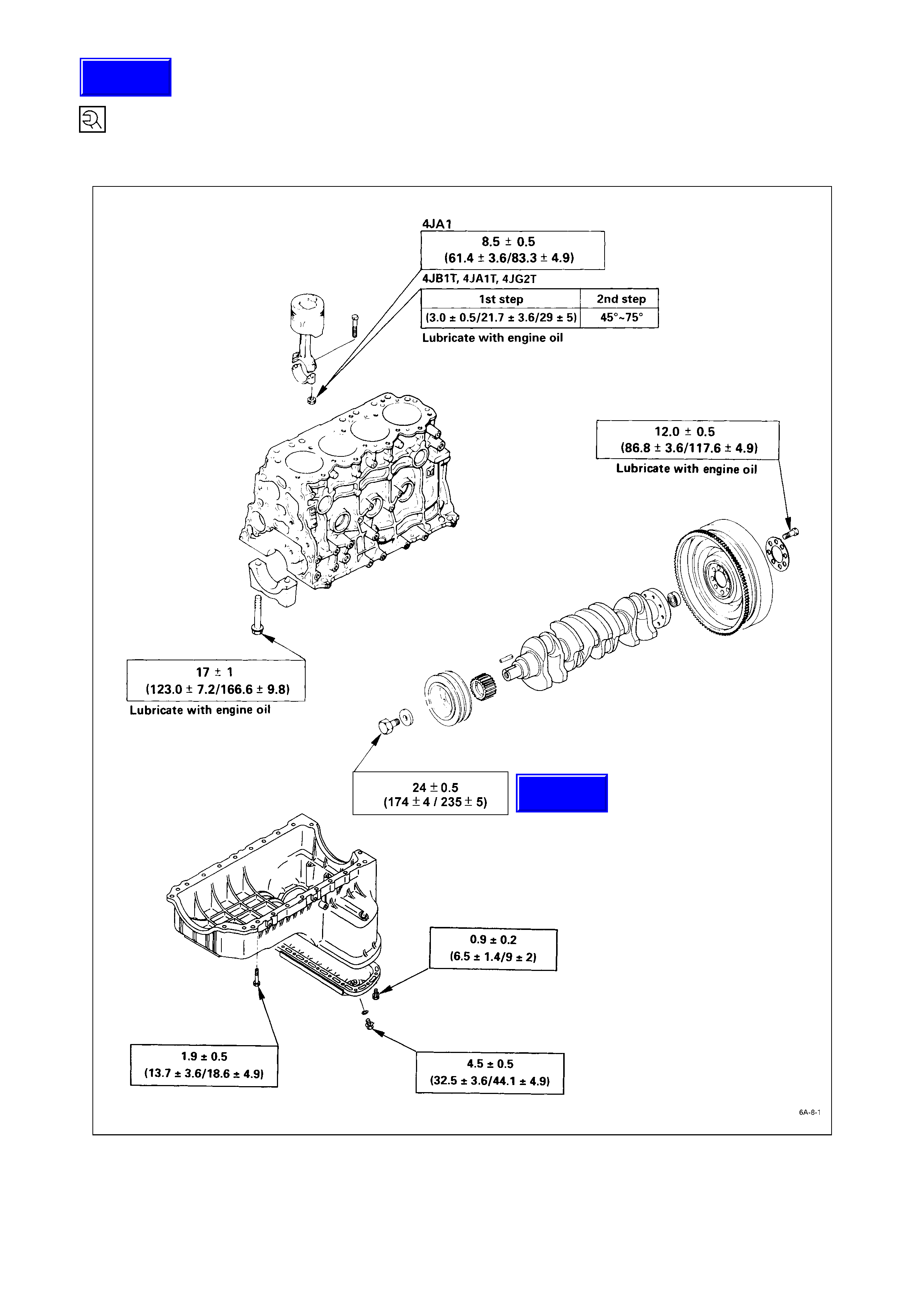
CRANKSHAFT BEARING CAP, CONNECTING ROD BEARING CAP,CRANKSHAFT DAMPER PULLEY,
FLYWHEEL, AND OIL PAN
TIMING GEAR CASE, PULLEY HOUSING, TIMING GEAR, AND CAMSHAFT
COOLING AND LUBRICATING SYSTEM
INTAKE MANIFOLD, EXHAUST MANIFOLD, AND TURBOCHARGER
ENGINE ELECTRICA LS
FUEL INJECTION SYSTEM
ENGINE MOUNTING BRACKET
RECOMMENDED LIQUID GASKET
LOCTITE APPLICATION PROCEDURE
SERVICING
LUBRICATING SYSTEM
FUEL SYSTEM
COOLING SYSTEM
ENGINE CONTROL
ACCELERA TOR CONTROL
PRE-HEATING SYSTEM
GENERAL DESCRIPTION
REMOVAL AND INSTALLATION
BATTERY
ENGINE HOOD
FUEL FILTER AND WATER SEPARATOR
AIR CLEANER
COOLANT
GEAR SHIFT LEVER
TRANSFER CHANGE LEVER (FOR 4 × 4)
RADIATOR
SUPPORTING THE VEHICLE
ENGINE OIL DRAINING
TRANSFER CASE PROTECTOR (4 × 4 MODEL)
TRANSMISSION OIL DRAINING
CONTROL CABLES OR RODS
EXHAUST PIPE
REAR PROPELLER SHAFT
FRONT PROPELLER SHAFT (FOR 4 × 4)
TRANSMISSION
ENGINE
TRANSMISSION
Techline
Techline
Techline
Techline
Techline

EXHAUST PIPE
FRONT PROPELLER SHAFT (FOR 4 × 4)
REAR PROPELLER SHAFT
TRANSFER CASE PROTECTOR (FOR 4 × 4)
GEAR SHIFT LEVER
TRANSFER CHANGE LEVER (FOR 4 × 4)
RADIATOR
LOWERING THE VEHICLE
COOLANT REPLENISHMENT
ENGINE OIL REPLENISHMENT
ENGINE HOOD
BATTERY
ENGINE WARM-UP
ENGINE REPAIR KIT
ENGINE OVERHAUL
REMOVAL
EXTERNAL PARTS
INTERNAL PARTS
MAJOR COMPONENTS
MINOR COMPONENTS
ROCKER ARM SHAFT AND ROCKER ARM
CYLINDER HEAD
PISTON AND CONNECTING ROD
INSPECTION AND REPAIR
CYLINDER HEAD
VALVE GUIDE
VALVE AND VALVE SEAT INSERT
CYLINDER BODY
ROCKER ARM SHAFT AND ROCKER ARM
VALVE SPRING
TAPPET AND PUSH ROD
CAMSHAFT
CRANKSHAFT AND BEARING
CRANKSHA FT BEARING SELECTION
FLYWHEEL AND RING GEAR
PISTON
PISTON RING
PISTON PIN
CYLINDER HEAD GASKET SELECTION
CONNECTING ROD
TIMING PULLEY HOUSING
IDLER GEAR SHAFT AND IDLER GEAR (GEAR DRIVE MODEL)
TIMING GEAR CASE COVER

REASSEMBLY
INTERNAL PARTS
MINOR COMPONENTS
ROCKER ARM SHAFT AND ROCKER ARM
CYLINDER HEAD
PISTON AND CONNECTING ROD
MAJOR COMPONENTS
INSTALLATION
EXTERNAL PARTS
LUBRICATING SYSTEM
MAIN DATA AND SPECIFICATIONS
GENERAL DESCRIPTION
LUBRICATING OIL FLOW
OIL PUMP AND OIL FILTER
OIL PUMP
DISASSEMBLY
INSPECTION AND REPAIR
REASSEMBLY
OIL FILTER AND OIL COOLER
DISASSEMBLY
INSPECTION AND REPAIR
REASSEMBLY
SPECIAL TOOLS
MAIN DATA AND SPECIFICATIONS
Engine model
Item 4JB1T
Engine type
Combustion chamber type
Cylinder liner type
Timing gear train system
Four-cycle, overhead valve, water cooled
Direct injection
Dry type, chrome plated, stainless steel tube
Gear drive
No. of cylinders-bore × stroke mm (in) 4 – 93 × 102 (3.66 × 4.02)
No. of piston rings Compression ring: 2 / Oil ring: 1
Total piston displacement cm3 (in3)
Compression ratio
2,771 (169.0)
18.1:1
Compression pressure kg/cm2 (psi/kPa) 31 (441/3) – 200 rpm
Engine weight kg (lb) Approximately 250 (550)
Fuel injection order 1 – 3 – 4 - 2
Fuel injection timing BTDC deg 11
Specified fuel type
Idling speed rpm
Valve clearances (At cold): Intake mm (in)
Exhaust mm (in)
Intake valves Open at (BTDC) deg
Close at (ABDC) deg
Exhaust valves Open at (BBDC) deg
Close at (ATDC) deg
Fuel system
Injection pump type
SAE No. 2 diesel fuel
750
0.4 (0.016)
0.4 (0.016)
24.5
55.5
54.0
26.0
BOSCH distributor VE type
Governor type Mechanical (Limit speed)
Injection nozzle type
Injection nozzle opening pressure
(Design value) kg/cm2 (psi/kPa)
Single spring type
Main fuel filter type
Lubricating system
Lubricating method
Hole with 5 orifices
185 (2,631/18,143)
Cartridge paper element and water separator
Pressu re circulation
Specified engine oil (API grade) CD / CG4
Oil pump type
Oil filter type
Oil capacity (engine dry) litres (US/UK gal))
Oil cooler type
Gear
Cartridge paper element
6.5 (1.7/1.43)
Water cooled
4JB1T : 4JB1 Engine with turbocharger.

Engine model
Item 4JB1T
Cooling system
Water pump type
Thermostat ty pe
Air cleaner type
Battery type/voltage × No. of units
Centrifugal
Wax pellet with jiggle valve
Dry paper element
95D31R-12 × 1
Generator capacity V-A (Kw) 12 – 50 (600)
Starter motor output V-Kw 12 – 2.0 or 12 – 2.8
Turbocharger model
Turbine type
Compressor type
Maximum permissible speed rpm
*IHI RHF4H
Radial-inflow
Radial-outflow
172,000
*IHI : Ishikawajima-Harima Heavy Industries., Ltd.
TORQUE SPECIFICATION
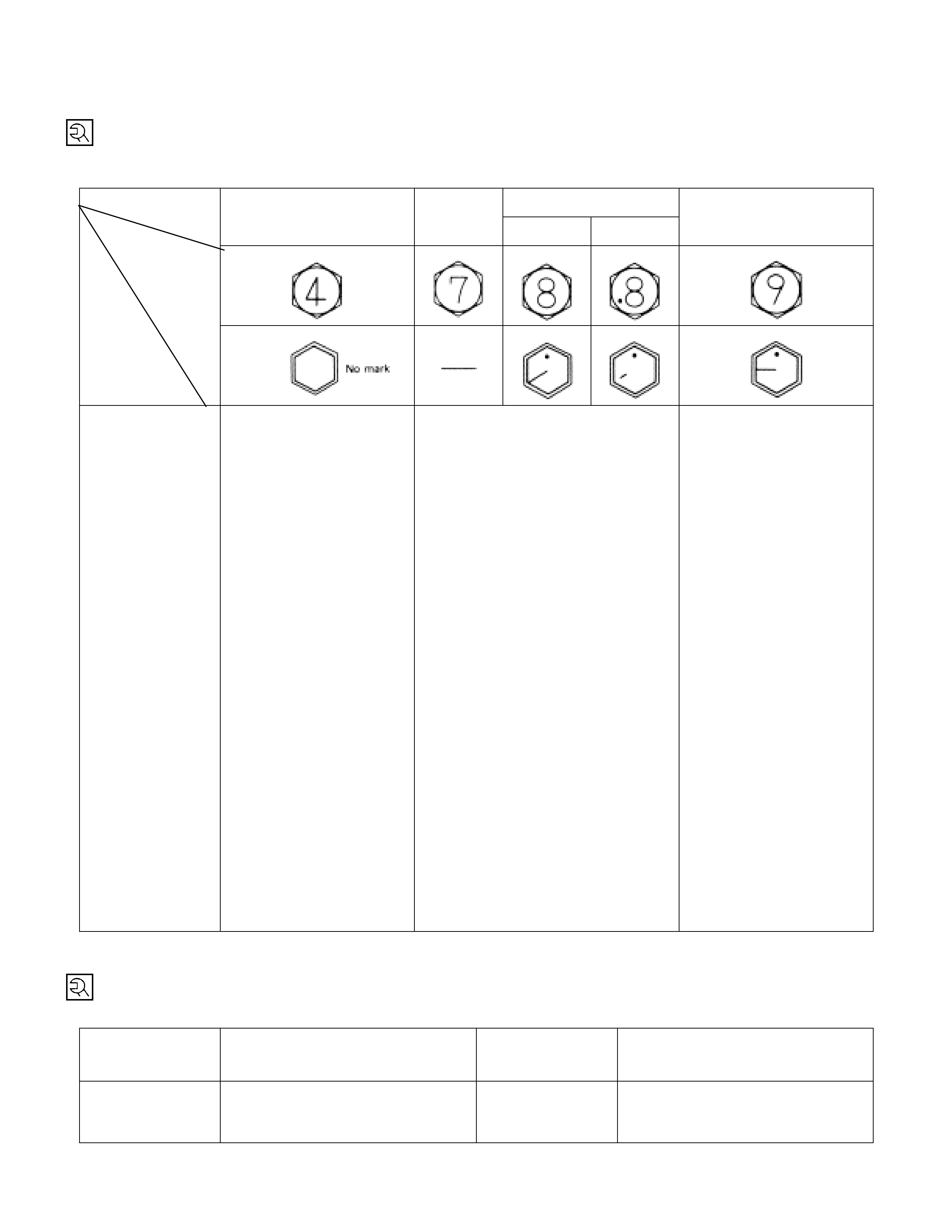
STANDARD BOLTS
The torque values given in the following table should be applied whenever a particular torque is not specified.
kg·m (lb·ft/N·m)
8.8
4.8 (4T) (7T) Refined Non-Refined 9.8 (9T)
Strength
Class
Bolt
Identification
Bolt
Diameter ×
Pitch (mm)
M6×
××
×1.0
M8×
××
×1.25
M10 ×
××
×1.25
M12 ×
××
×1.25
M14 ×
××
×1.5
M16 ×
××
×1.5
M18 ×
××
×1.5
M20 ×
××
×1.5
M22 ×
××
×1.5
M24 ×
××
×2.0
*M10×
××
×1.5
*M12×
××
×1.5
*M14×
××
×2.0
*M16×
××
×2.0
0.60 ± 0.20
(4.33 ± 1.44/5.88 ± 1.96)
1.30 ± 0.50
(9.40 ± 3.62/12.74 ± 4.90)
2.80 ± 0.70
(20.25 ± 5.06/27.44 ± 6.86)
6.25 ± 1.25
(45.21 ± 9.04/61.25 ± 12.25)
9.75 ± 1.95
(70.52 ± 14.10/95.55 ± 19.11)
13.30 ± 2.70
(96.20 ± 19.53/130.34 ± 26.46)
19.20 ± 3.80
(138.87 ± 27.49/188.16 ± 37.24)
26.30 ± 5.30
(190.23 ± 38.33/257.74 ± 51.94)
33.90 ± 8.30
(245.20 ± 60.03/332.22 ± 81.34)
45.80 ± 9.20
(331.27 ± 66.54/448.84 ± 90.16)
2.70 ± 0.70
(19.53 ± 5.06/26.46 ± 6.86)
5.80 ± 1.20
(41.95 ± 8.68/56.84 ± 11.76)
9.10 ± 1.80
(65.82 ± 13.02/89.18 ± 17.64)
12.70 ± 2.50
(91.86 ± 18.08/124.46 ± 24.50)
0.75 ± 0.25
(5.43 ± 1.80/7.35 ± 2.45)
1.75 ± 0.55
(12.66 ± 4.00/17.15 ± 5.39)
3.75 ± 0.95
(27.12 ± 6.87/36.75 ± 9.31)
7.75 ± 1.55
(56.06 ± 11.21/75.95 ± 15.19)
11.85 ± 2.35
(85.71 ± 17.00/116.13 ± 23.03)
17.30 ± 3.50
(125.13 ± 25.32/169.54 ± 34.30)
24.90 ± 5.00
(180.10 ± 36.17/244.02 ± 49.00)
34.40 ± 6.90
(248.82 ± 49.41/337.12 ± 67.62)
46.25 ± 9.25
(334.53 ± 66.91/453.25 ± 90.65)
58.20 ± 14.30
(420.96 ± 103.43/570.36 ± 140.14)
3.70 ± 0.90
(26.76 ± 6.50/36.26 ± 8.82)
7.20 ± 1.40
(52.08 ± 10.13/70.56 ± 13.72)
11.20 ± 2.20
(81.01 ± 15.91/109.76 ± 21.56)
16.50 ± 3.30
(119.34 ± 23.87/161.70 ± 32.34)
-
2.40 ± 0.70
(17.36 ± 5.06/23.52 ± 6.86)
5.10 ± 1.30
(36.89 ± 9.40/49.98 ± 12.74)
9.65 ± 1.95
(69.80 ± 14.10/94.57 ± 19.11)
14.50 ± 2.90
(104.88 ± 21.00/142.10 ± 28.42)
20.40 ± 4.10
(147.55 ± 29.66/199.92 ± 40.18)
29.30 ± 5.90
(211.93 ± 42.67/287.14 ± 57.82)
40.40 ± 8.10
(292.21 ± 58.59/395.92 ± 79.38)
54.10 ± 10.80
(391.30 ± 78.12/530.18 ± 105.84)
70.60 ± 14.10
(510.65
±
101.99/691.88
±
138.18)
4.90 ± 1.20
(35.44 ± 8.68/48.02 ± 11.76)
9.10 ± 1.80
(65.82 ± 13.02/89.18 ± 17.64)
13.60 ± 2.70
(98.37 ± 19.53/133.28 ± 26.46)
19.50 ± 3.90
(141.04 ± 28.21/191.10 ± 38.22)
An asterisk (*) indicates that the bolts are used for female threaded parts that are made of soft materials such
as casting. Those shown in parentheses in the strength class indicate the classification by the old standard.
FLARE NUTS kg·m (lb·ft/N·m)
Pipe diam eter m m
(in) Torque Pipe diam eter m m
(in) Torque
4.76 (0.187)
6.35 (0.250)
8.00 (0.315)
1.55 ± 0.25 (11.2 ± 1.8/15. 2 ± 2.45)
2.70 ± 0.30 (19.5 ± 2.1/26. 48 ± 2.94)
4.50 ± 0.50 (32.5 ± 3.6/44. 14 ± 4.90)
10.00 (0.394)
12.00 (0.472)
15.00 (0.591)
5.50 ± 0.5 (39.7 ± 3.6/53. 95 ± 4.90)
9.00 ± 1.0 (65.0 ± 7.2/88. 29 ± 9.80)
10.75 ± 1.25 (77.7 ± 9.0/105. 45 ± 12.26)
SPECIAL PARTS FI XING NUTS AND BO LTS
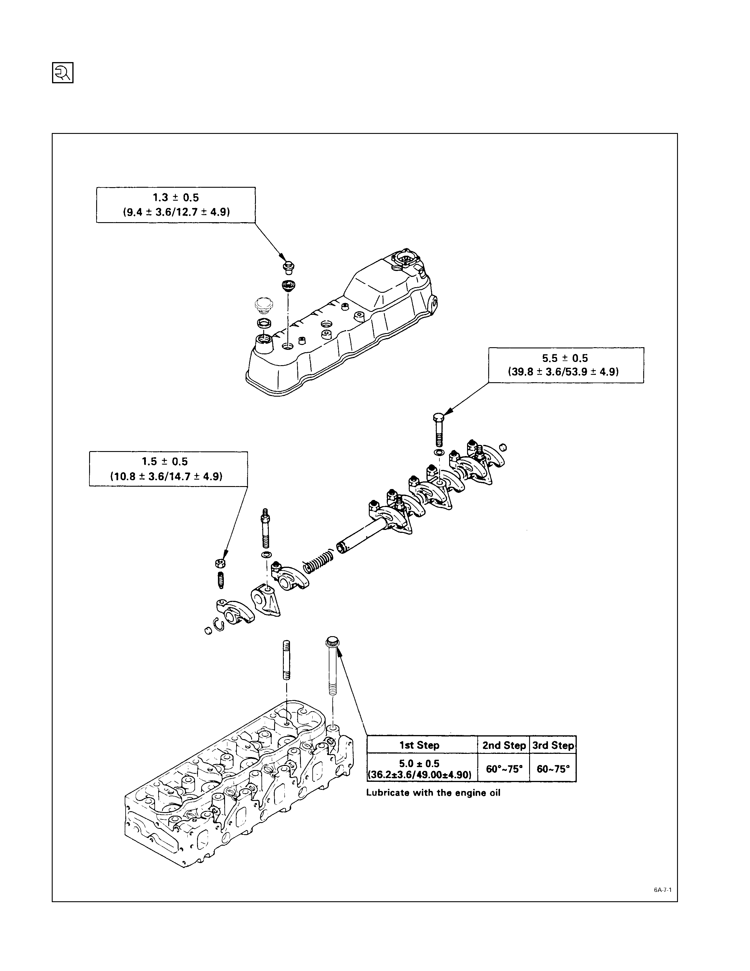
CYLINDER HEAD CO VER, CYLINDER HEAD, AND ROCKER ARM SHAFT BRACKET
kg·m (lb·ft/N·m)
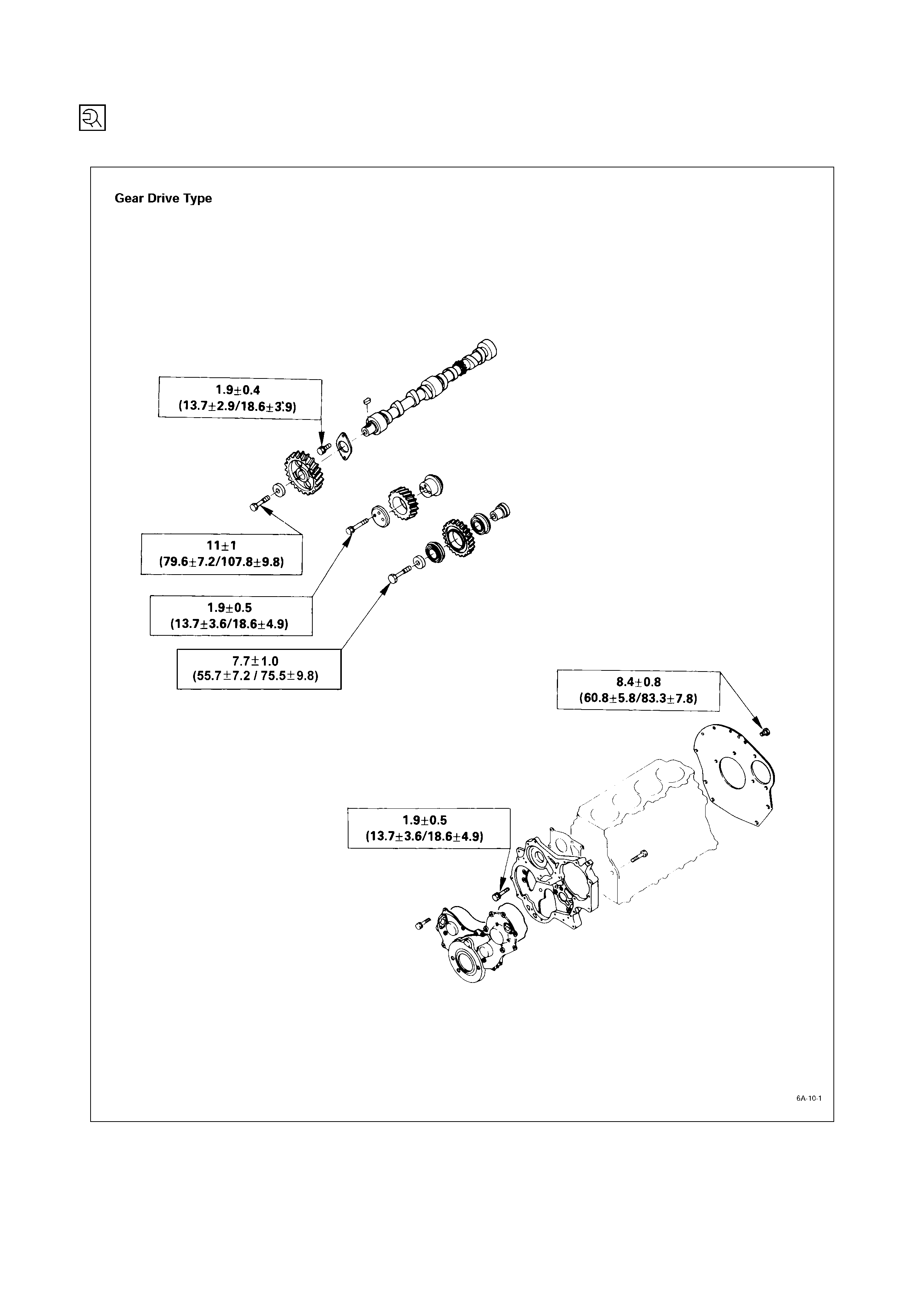
TIMING GEAR CASE, PULLEY HOUSING, TIMING GEAR, AND CAMSHAFT
kg m (lb ft / N.m)
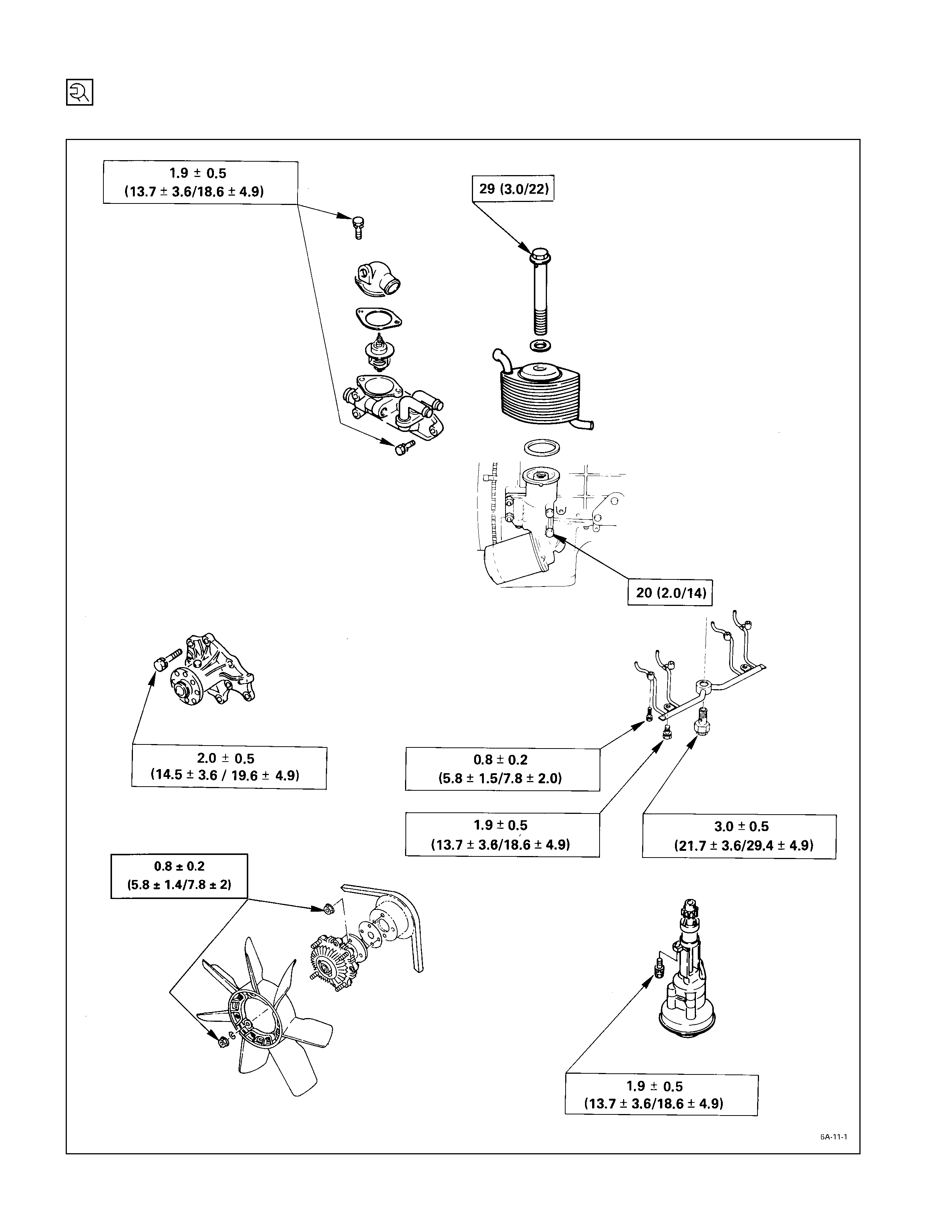
COOLING AND LUBRICATING SYSTEM
kg·m (lb·ft/N·m)
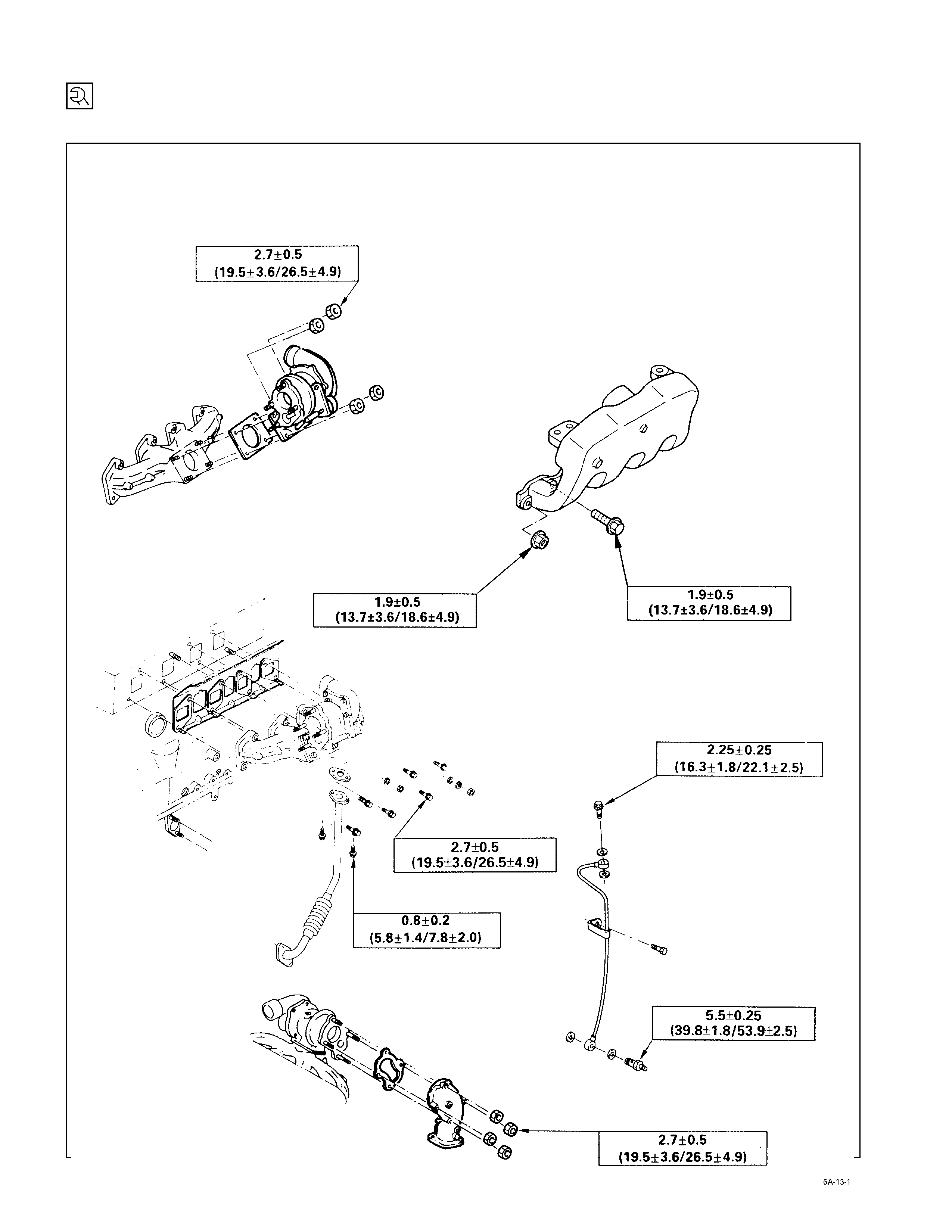
INTAKE MANIFOLD, EXHAUST MANIFOLD, AND TURBOCHARGER
kg·m (lb·ft/N·m)
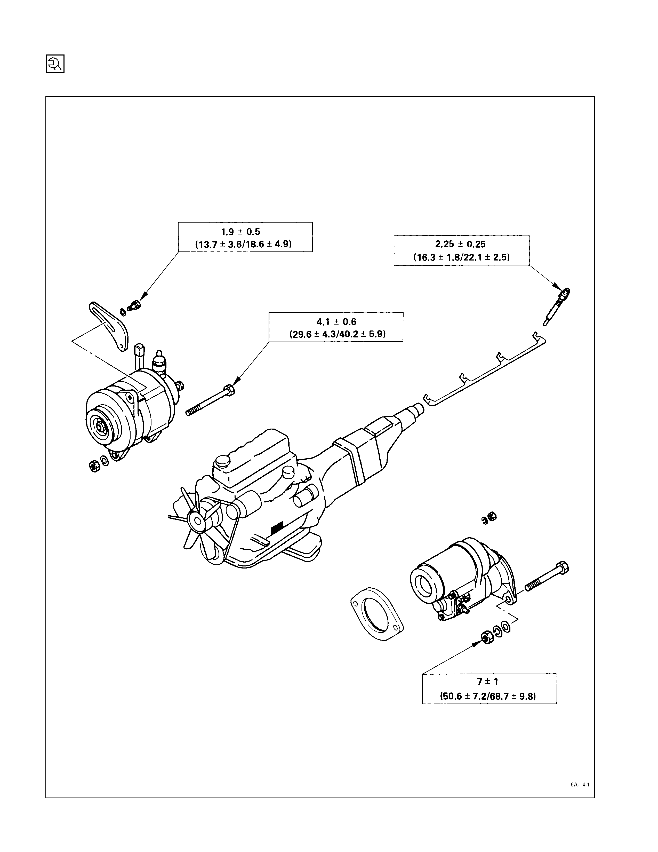
ENGINE ELECTRICALS
kg·m (lb·ft/N·m)
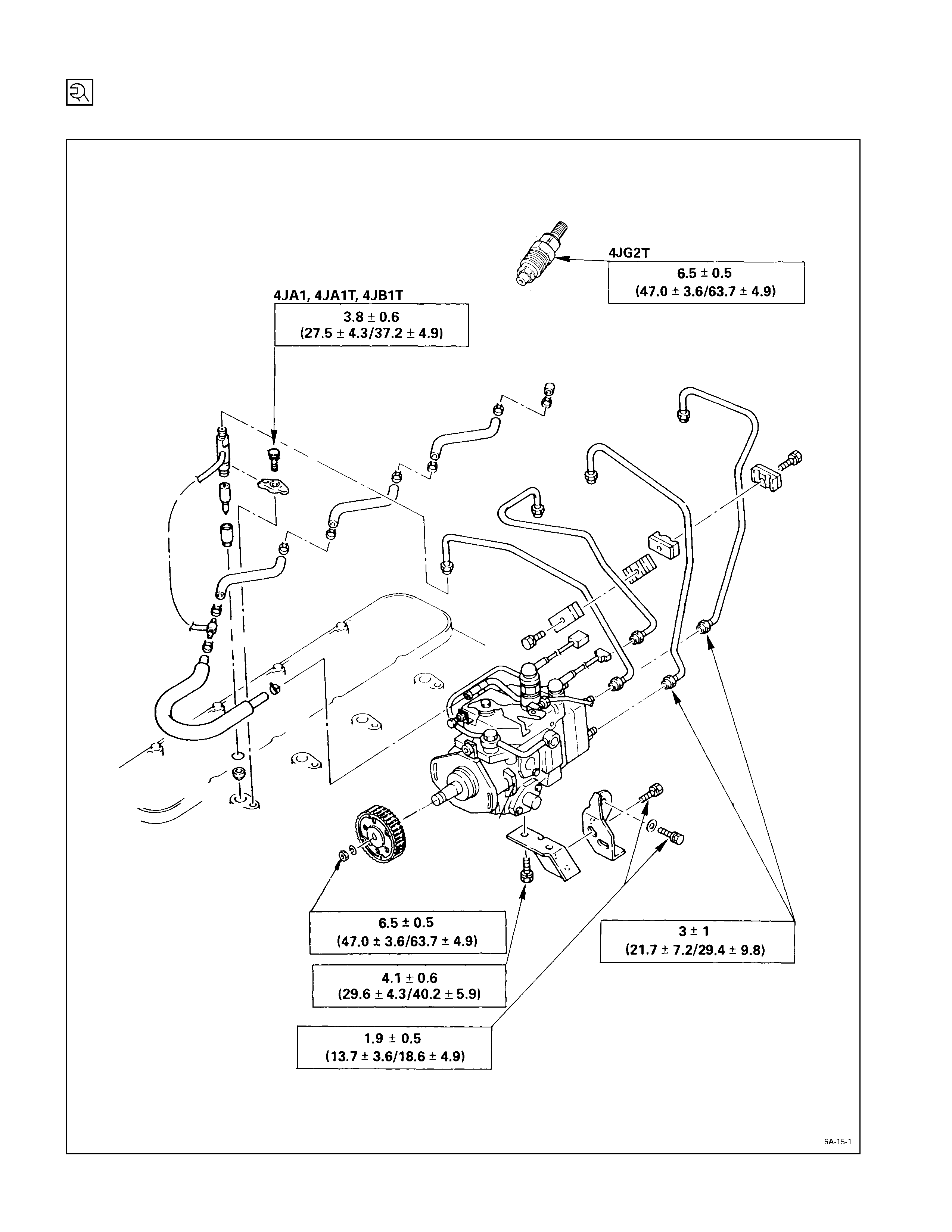
FUEL INJECTION SYSTEM
kg·m (lb·ft/N·m)
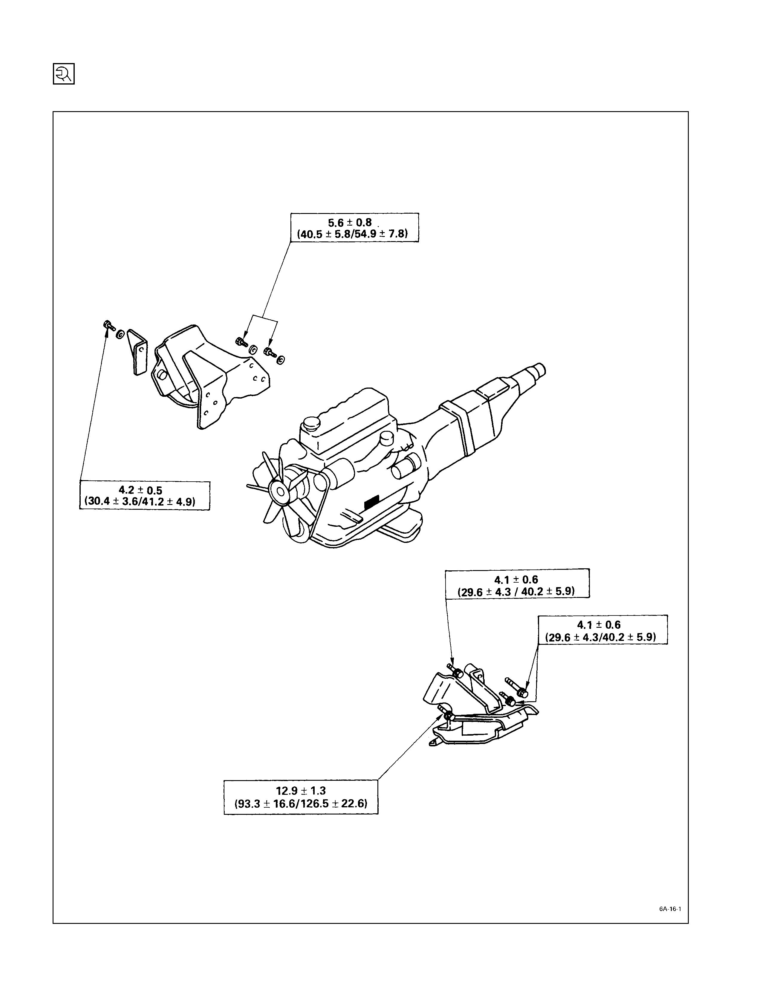
ENGINE M OUNTING BRACKET
kg·m (lb·ft/N·m)
RECOMMENDED LI QUID GASKET
Type Brand Name Manufacturer Remarks
RTV*
Silicon Base ThreeBond 1207B
ThreeBond 1207C Three Bond
Three Bond
Water Base ThreeBond 1141E Three Bond
Solvent ThreeBond 1104
BelcoBond 4
BelcoBond 401
BelcoBond 402
Three Bond
Isuzu
Isuzu
Isuzu
Anaerobic LOCTITE 515
LOCTITE 518 Loctite
Loctite Recommended for
transaxle repairs
* RTV : Room Temperature Vulcanizer
Note:
1. It is very important that the liquid gaskets listed above or their exact equivalent be used on the vehicle.
2. Be careful to use the specified amount of liquid gasket.
Follow the manufacturer’s instructions at all times.
3. Be absolutely sure to remove all lubricants and moisture from the connecting surfaces before applying
the liquid gasket.
The connecting surfaces must be perfectly dry.
4. LOCTITE 515 and LOCTITE 518 harden upon contact with a metal surface.
Do not apply LOCTITE 515 or LOCTITE 518 between two metal surfaces having a clearance of greater
than 0.25 mm (0.01 in). Poor adhesion will result.
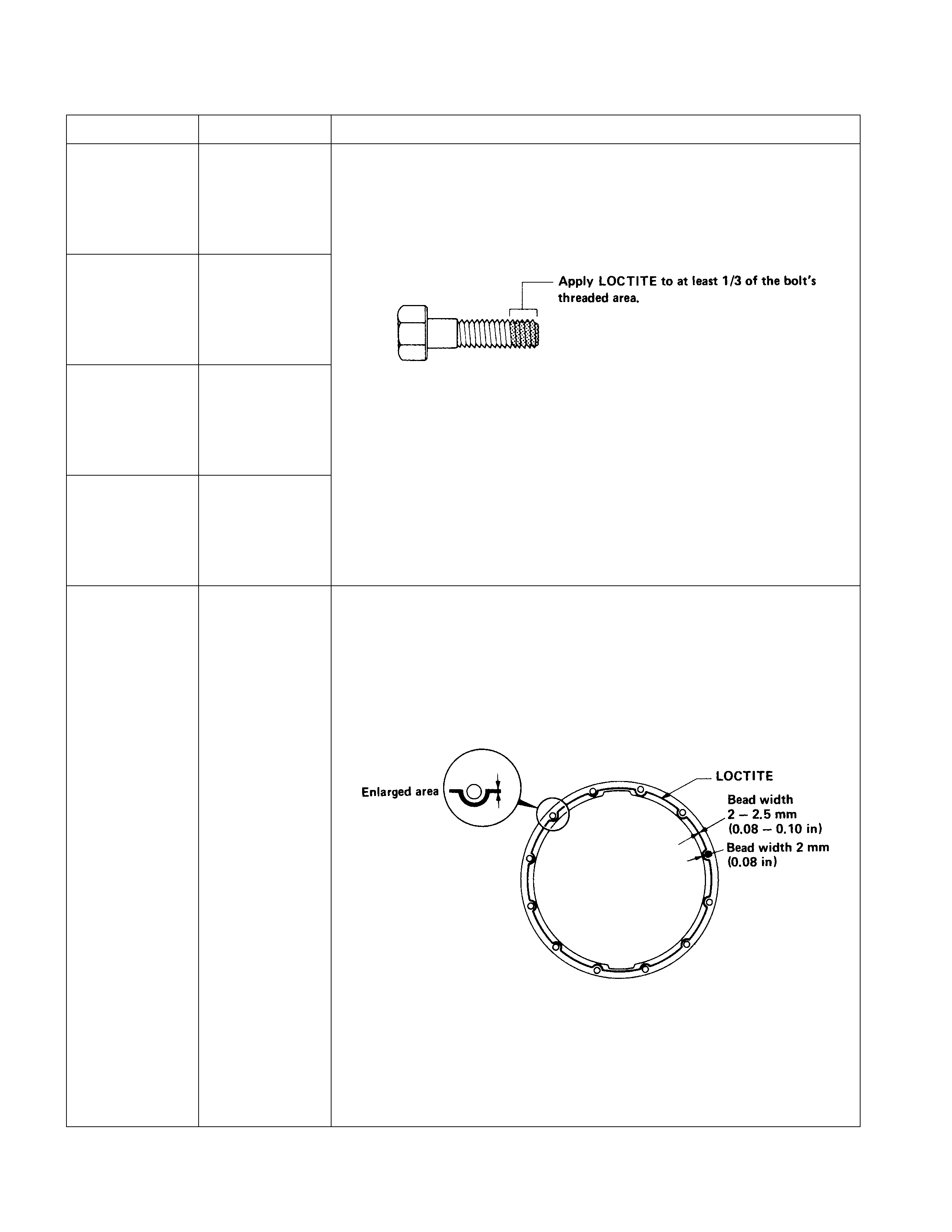
LOCTITE APPLI CATION PROCEDURE
LOCTITE Type LOCTITE Color Application Steps
LOCTITE 242 Blue
LOCTITE 262 Red
LOCTITE 270 Green
LOCTITE 271 Red
1. Completely remove all lubricant and moisture from the bolts and the
female threaded surfaces of the parts to be joined.
The surfaces must be perfectly dry.
2. Apply LOCTITE to the bolts.
3. Tighten the bolts to the specified torque.
4. Wait at least one hour before continuing the installation procedure.
LOCTITE 515 Violet
1. Completely remove lubricant and moisture from the connecting
surfaces.
The surfaces must be perfectly dry.
2. Apply a 2.0 – 2.5 mm bead of LOCTITE to one of the connecting
surfaces.
There must be no gaps in the bead.
3. Tighten the bolts to the specified torque.
4. Let the joined parts set for at least thirty minutes.
SERVICING
Servicing refers to general maintenance procedures to be performed by qualified service personnel.
MODEL IDENTIFICATION
ENGINE SERI AL NUMBER
The engine number is stamped on the front left hand side
of the cylinder body.
AIR CLEANER
Element cleaning procedures will vary according to the
condition of the element.
OIL W ETTED (VISCOUS) TYPE PAPER ELEM ENT
The air cleaner has an oil wetted paper element. No
servicing is required until the replacement interval is
reached. Never attempt to clean the element, no matter
how dirty may appear. The element is designed to provide
normal filtering efficiency until it becomes due for
replacement. Refer to the Item “Service and Maintenance”
in the Owner’s and Driver’s Manual for general service
information.
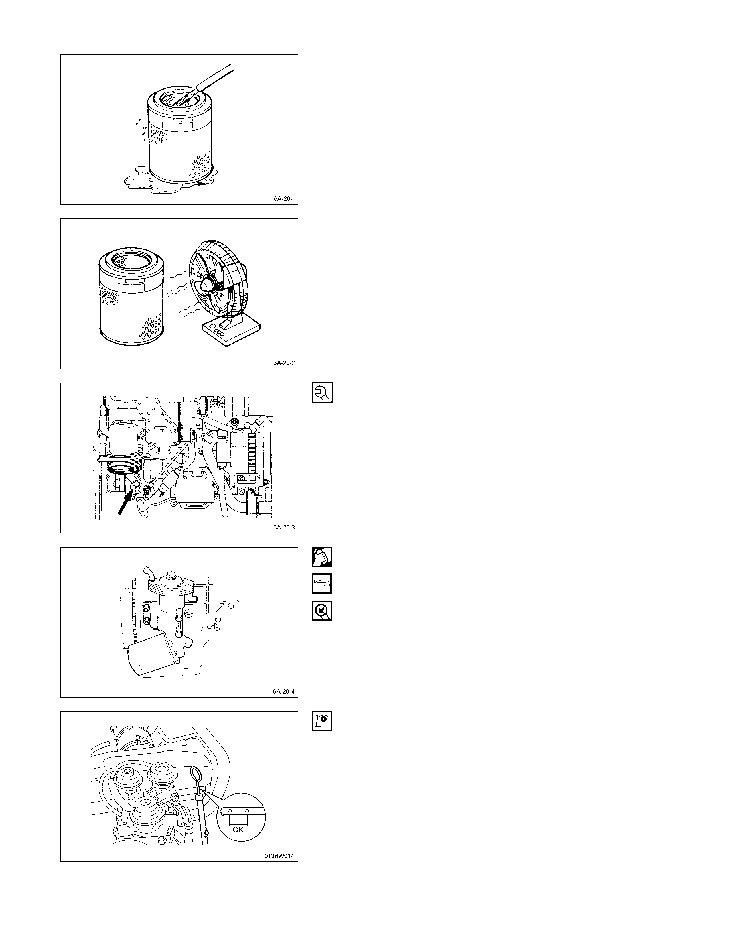
DUST FOULED ELEMENT
Rotate the element with your hand while applying
compressed air to the inside of the element. This will blow
the dust free.
Compressed air pressure must not exceed 7 kg/cm2 (99.6
psi/686 kPa).
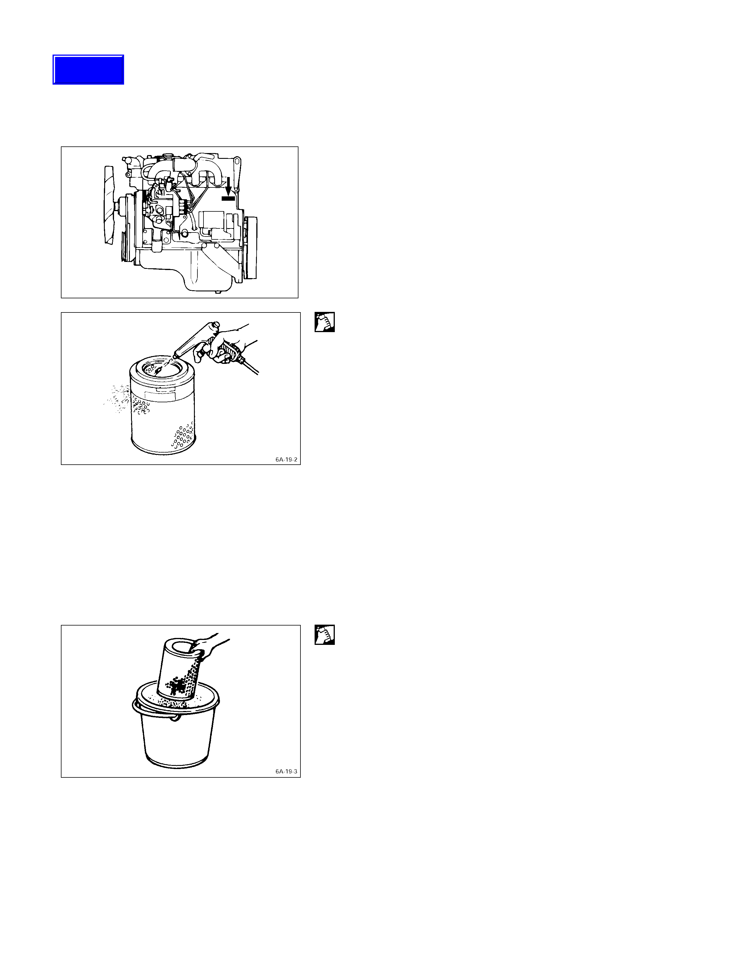
CARBON AND DUST FO ULED ELEMENT
1. Prepare a cleaning solution of Isuzu Genuine Element
Cleaner (Donaldson D1400) diluted with water.
2. Submerge the element in the solution for twenty
minutes.
Techline
3. Remove the element from the solution and rinse it well
with running water.
Water pressure must not exceed 2.8 kg/cm2 (39.8
psi/274 kPa).
4. Dry the element in a well ventilated area.
An electric fan will hasten drying.
Note:
Do not use compressed air or an open flame to dry the
element quickly. Damage to the element will result.
It will usually take two or three days for the element to
dry completely. Therefore, it is a good idea to have a
spare on hand to use in the interim.
LUBRICATING SYSTEM
MAIN OIL FILTER (CARTRIDGE TYPE PAPER
ELEMENT) REPLACEM ENT PROCEDURE
1. Loosen the drain plug to drain the engine oil.
2. Wait a few minutes and then retighten the drain plug.
3. Loosen the used oil filter by turning it counterclockwise
with a filter wrench.
4. Clean the oil cooler fitting face. This will allow the new
oil filter to seat properly.
5. Apply a light coat of engine oil to the O-ring.
6. Turn in the new oil filter until the filter O-ring is fitted
against the sealing face.
7. Use the filter wrench to turn in the filter an additional 1
and 1/8 turns.
Filter Wrench: 5-8840-0200-0
8. Check the engine oil level and replenish to the
specified level if required.
Replenished Engine Oil 6.5 lit
9. Start the engine and check for oil leakage from the
main oil filter.
FUEL SYSTEM
FUEL FILTER REPLACEMENT PROCEDURE
1. Place the end of the vinyl hose (beneath the drain
plug) in a container.
2. Open the drain plug.
3. Operate the priming pump several times to drain water
from the fuel filter.
4. Close the drain plug.
5. Operate the priming pump and check for fuel leakage.
6. Check that the water level warning light is off.
FUEL FILTER REPLACEMENT PROCEDURE
1. Remove the fuel filter by turning it counterclockwise
with a filter wrench.
Filter Wrench: 5-8840-0253-0 (J-22700)
2. Remove the level sensor from the filter by turning it
counterclockwise with a wrench.
3. Install the level sensor to the water separator body
with wrench.
Level Sensor Torque kg·m (lb.ft/N·m)
1.3 (9.4/12.7)
4. Clean the water separator cover fitting faces.
This will allow the new fuel filter to seat properly.
5. Apply a light coat of engine oil to the O-ring.
6. Turn in the fuel filter until the sealing face comes in
contact with the O-ring.
7. Turn in the fuel filter an additional 2/3 of a turn with a
filter wrench.
Filter Wrench : 5-8840-0253-0 (J-22700)
8. Loosen the bleeder plug Q on the priming pump body.
9. Operate the priming pump until fuel begins to flow
from the fuel filter.
10. Retighten the bleeder plug Q.
11. Operate the priming pump several times and check for
fuel leakage.
Note:
The use of an HOLDEN genuine fuel filter is strongly
recommended.
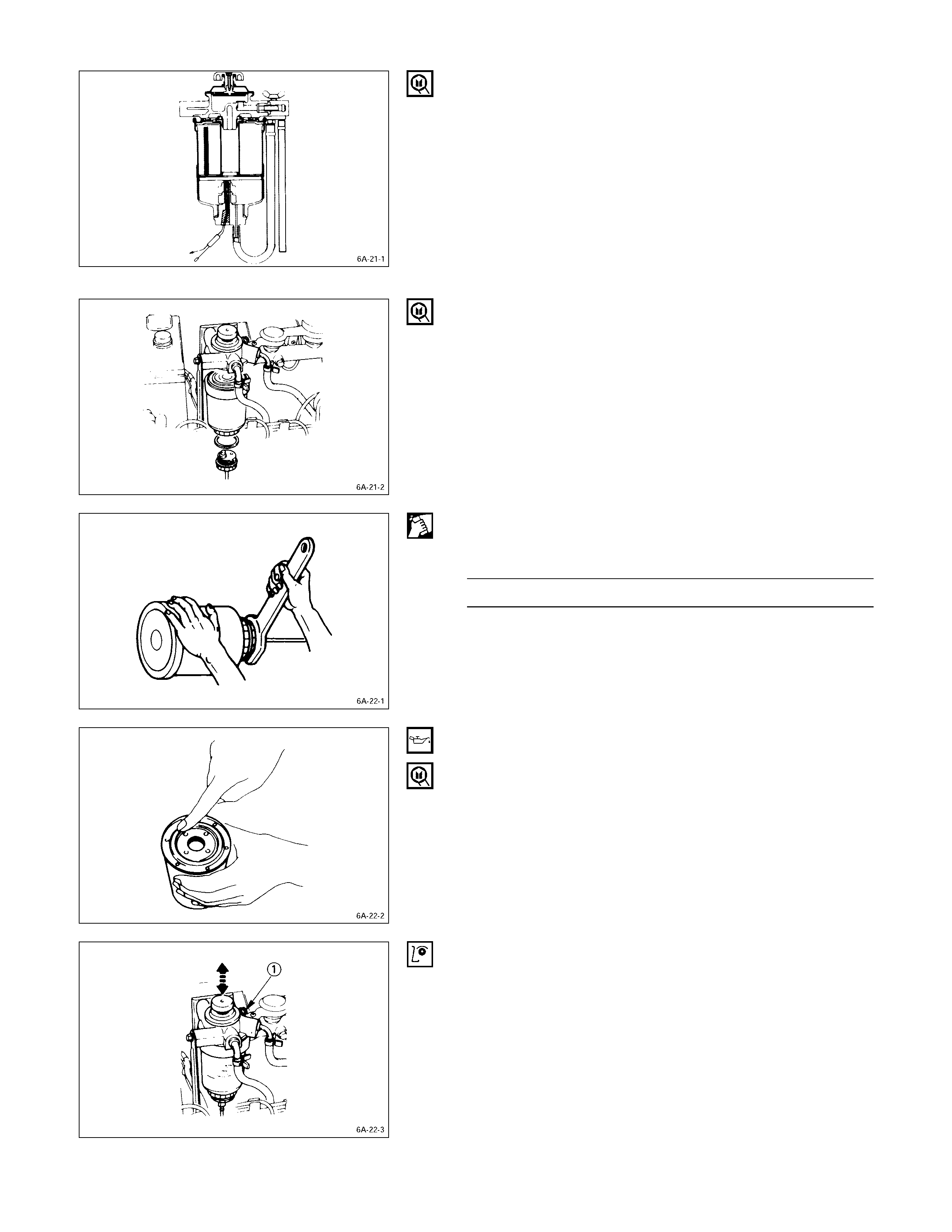
DRAINING PRO CEDURE
The indicator light will come on when the water level in the
water separator exceeds the specified level.
Drain the water and foreign material from the water
separator with the following procedure.
1. Place the end of the vinyl hose (beneath the drain
plug) in a container.
2. Loosen the drain plug Q.
3. Operate the priming pump R several times to drain
the water.
4. After draining the water, tighten the drain plug Q .
5. Operate the priming pump several times and check for
fuel leakage.
6. Check the water separator indicator light. It should be
off.
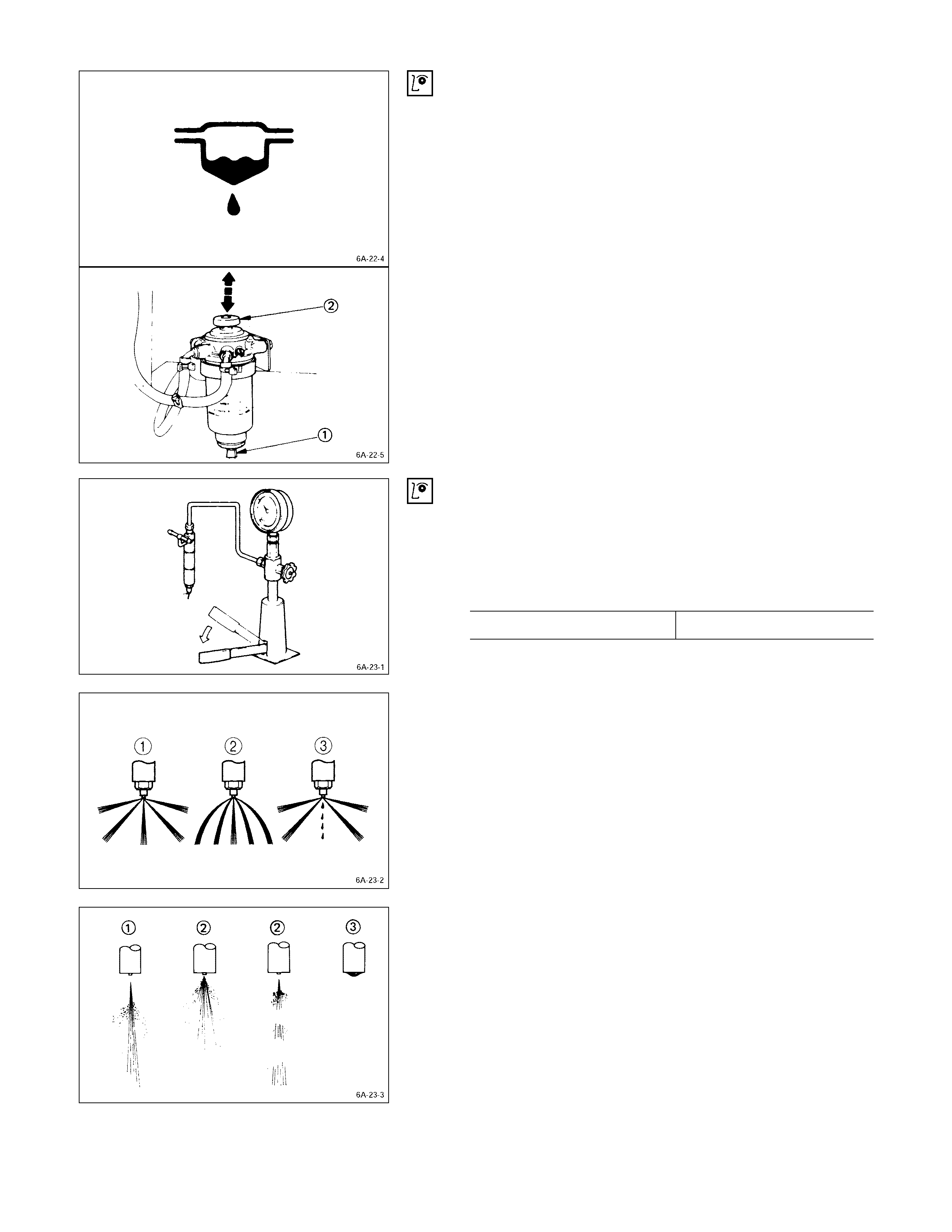
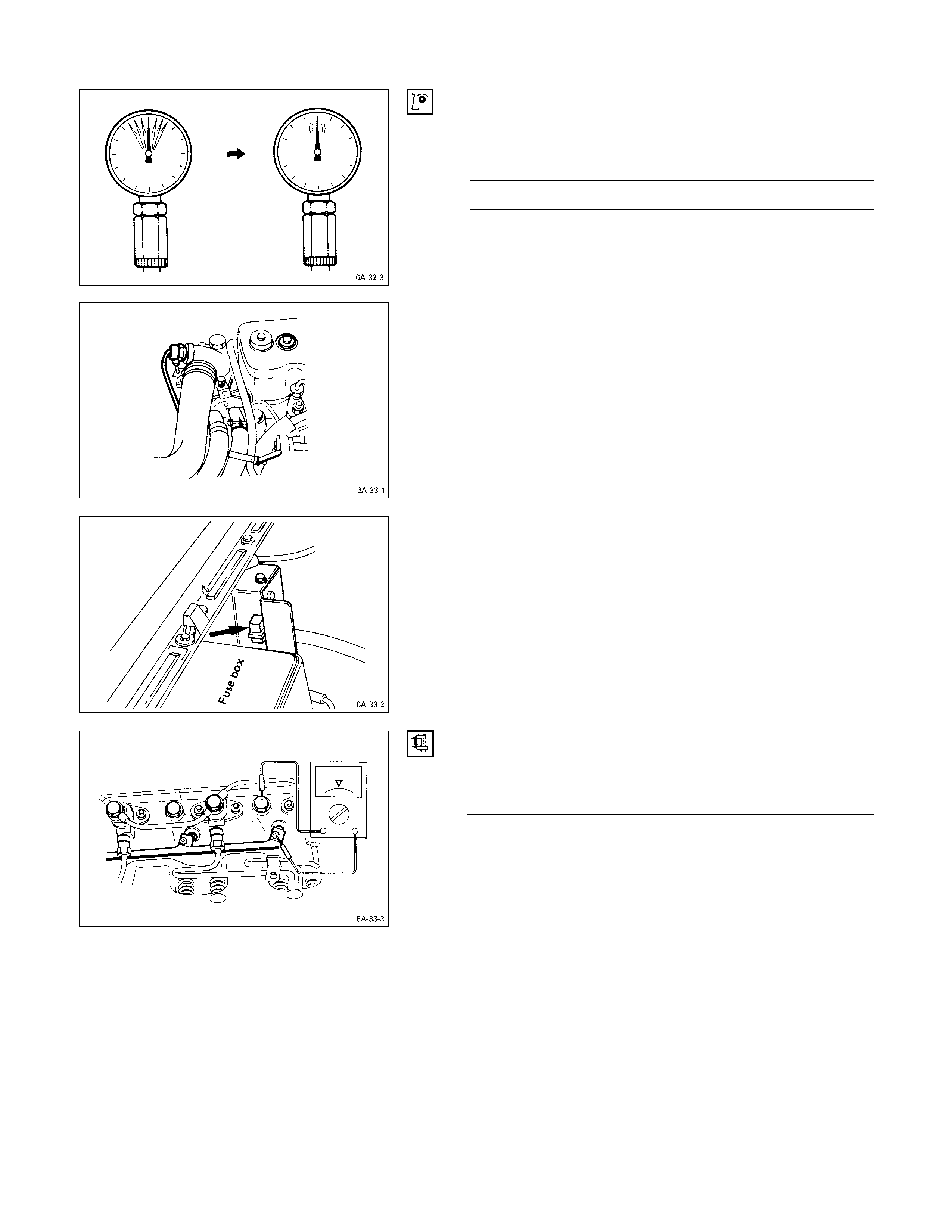
INJECTION NOZZLE INSPECTION
Use a nozzle tester to check the injection nozzle opening
pressure and the spray condition.
If the opening pressure is above or below the specified
value, the injection nozzle must be replaced or adjusted.
Injection Nozzle Opening Pressure kg/cm2 (psi/kPa)
4JB1T 185 (2,631/18,143)
If the spray condition is bad, the injection nozzle must be
replaced or repaired.
Spray Condition
QCorrect
R Incorrect (Restrictions in orifice)
SIncorrect (Dripping)
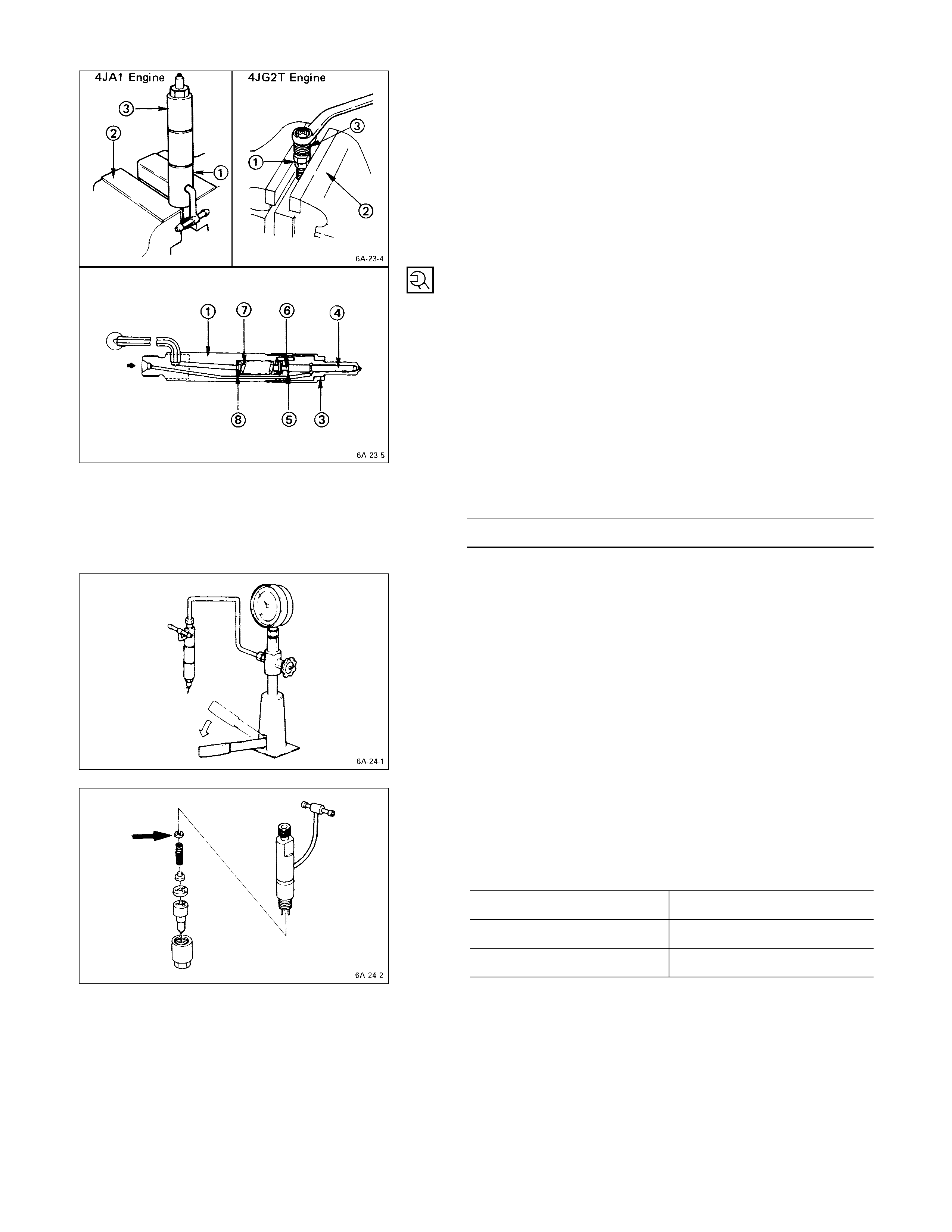
INJECTION NOZZLE ADJUSTMENT
1. Clamp the injection nozzle holder Q in a vise R.
2. Use a wrench to remove the injection nozzle retaining
nut S.
3. Remove the injection nozzle holder from the vise.
4. Remove the injection nozzle T, the spacer U, the
spring seat V, the spring W and the adjusting shim
X.
5. Install the new adjusting shim, the spring, the spring
seat, the spacer, the injection nozzle, and the retaining
nut.
6. Clamp the injection nozzle holder in the vise.
7. Tighten the injection nozz le holder retaining nut to the
specified torque.
Injection Nozzle Holder Retaining Nut
Torque kg·m (ft.lbs/N·m)
3.5 ± 0.5 (25.3 ± 3.6/34.3 ± 4.9)
8. Remove the injection nozzle holder from the vise.
9. Attach the injection nozzle holder to the injection
nozzle tester.
10. Apply pressure to the nozzle tester to check that the
injection nozzle opens at the specified pressure.
If the injection nozzle does not open at the specified
pressure, install or remove the appropriate number of
adjusting shims to adjust it.
(Reference)
Removing or installing one shim will increase or decrease
the nozzle opening pressure approximately 3.77 kg/cm2
(53.6 psi/370 kPa)
Adjusting Shim Availability mm (in)
Range 0.5 – 1.5 (0.02 – 0.06)
Increment 0.025 (0.001)
Total No. of Shims 41
Warning:
Test fluid from the injection nozzle tester will spray
out under great pressure. It can easily puncture a
person’s skin. Keep your hands away from the
injection nozzle holder tip at a ll times.
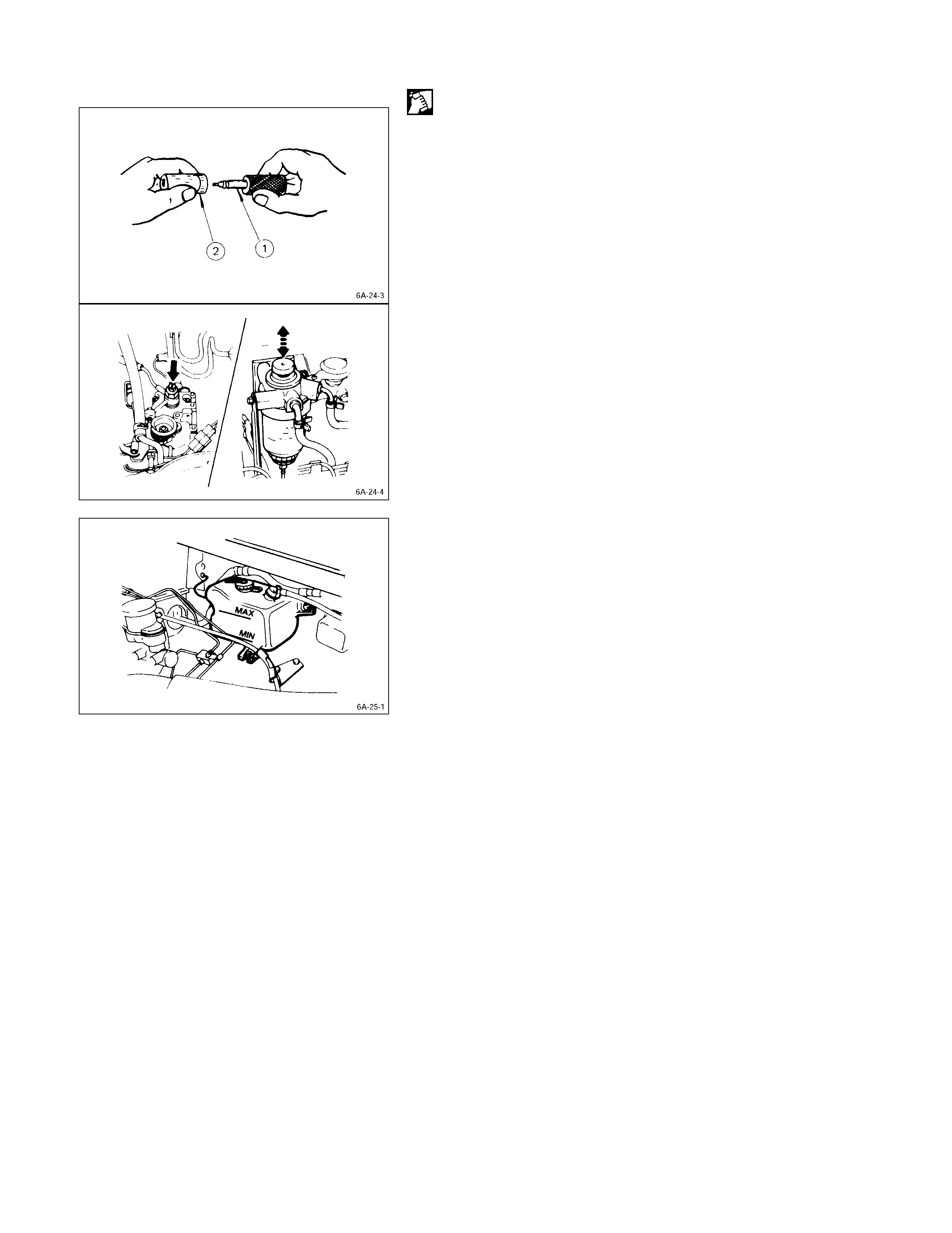
NOZZLE LAPPI NG PROCEDURE
1. Lap the nozzle needle Q and the nozzl e body R by
applying a compound of oxidized chrome and animal
oil.
Note:
Do not apply an excessive amount of the oxidized
chrome and animal oil compound to the injection
needle valve seat area.
2. Carefully wash the needle valve and the nozzle body in
clean diesel fuel after lapping.
AIR BLEEDING
1. Loosen the bleeder screw on the injection pump
overflow valve.
2. Operate the priming pump until fuel mixed with foam
flows from the bleeder screw.
3. Tighten the bleeder screw.
4. Operate the priming pump several times and check for
fuel leakage.
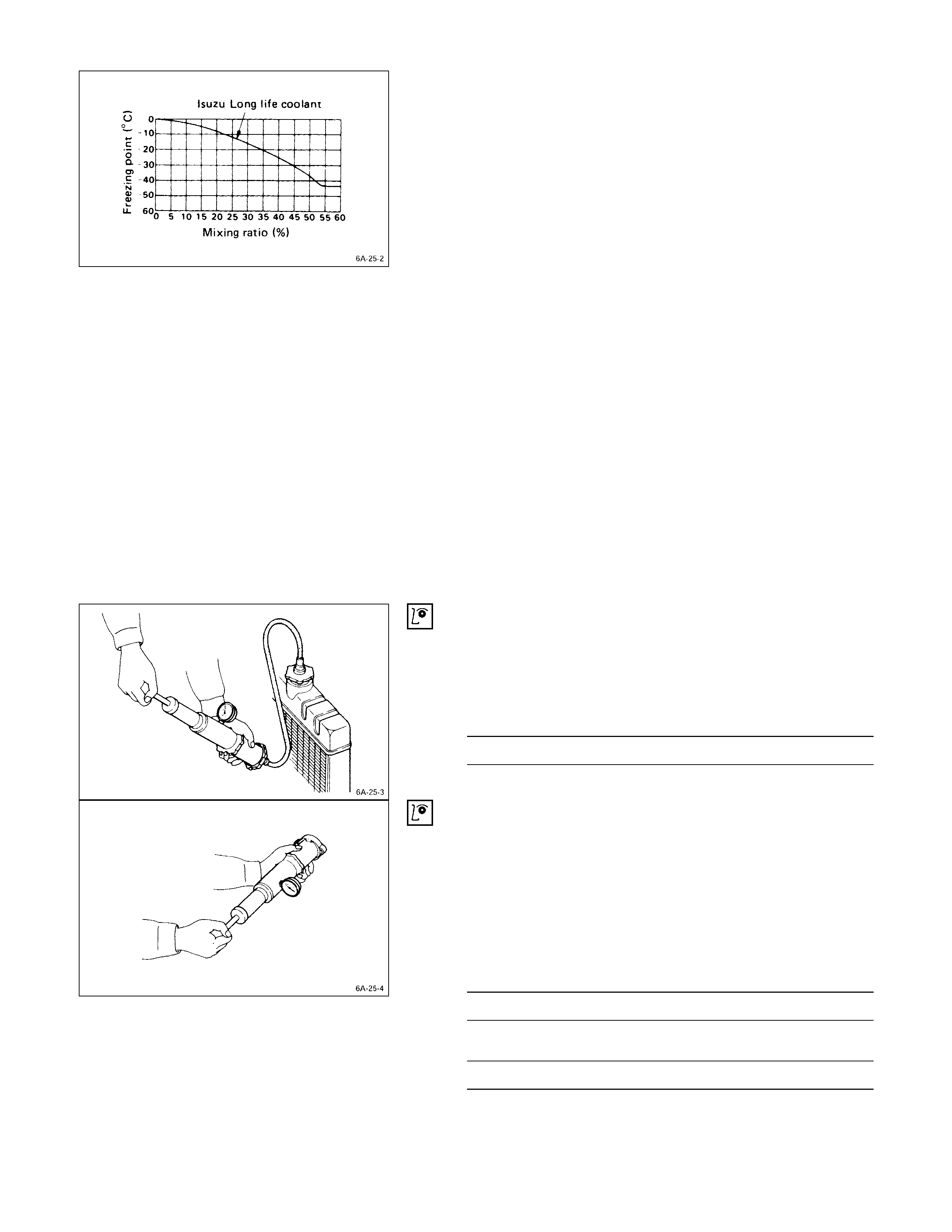
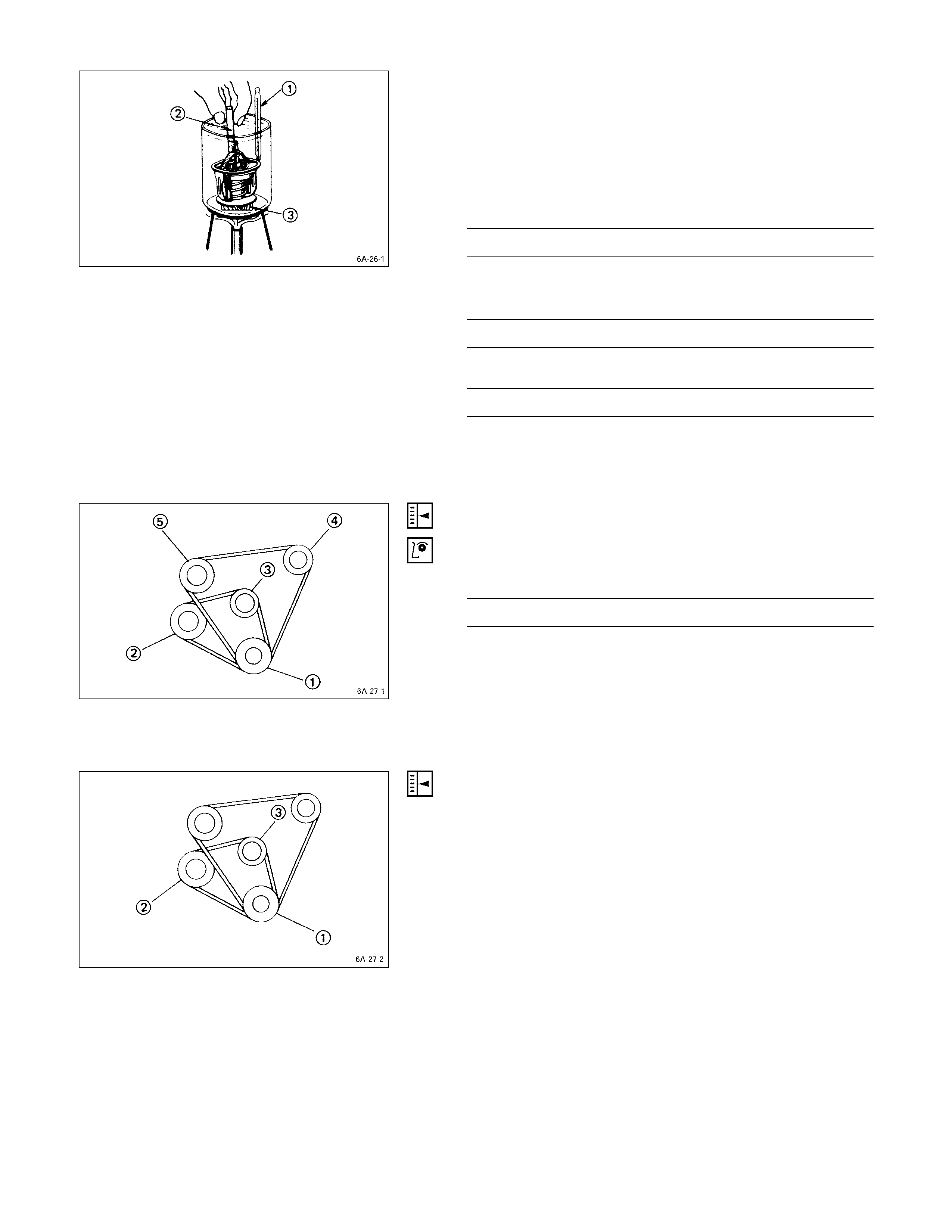
COOLING SYSTEM
COOLANT LEVEL
Check the coolant level and replenish the radiator reserve
tank as necessary.
If the coolant level falls below the “MIN” line, carefully
check the cooling system for leakage. Then add enough
coolant to bring the level up to the “MAX” line.
ENGINE CO OLANT FILLI NG UP PROCEDURE
1. Make sure that the engine is cool
Warning:
When the coolant is heated to a high temperature, be
sure not to loosen or remove the rediator cap.
Otherwise you might get scalded by hot vapor or
boiling water.
To open the radiator cap, put a piece of thick cloth on
the cap and loosen the cap slowly to reduce the
pressure when the coolant has become cooler.
2. Open rediator cap pour coolant up to filler neck
3. Pour coolant into reservoir tank up to “MAX” line
4. Tighten radiator cap and start the engine. After idling
for 2 to 3 minutes, stop the engine and reopen radiator
cap. If the water level is lower, replenish.
5. After replenish the coolant tighten radiator cap, warm
up the engine at about 2000 rpm. Set heater
adjustment to the highest temperature position, and let
the coolant circulate also intoheater water system.
6. Chech to see the thermometer, continuously idling 5
minutes and stop the engine.
7. When the engine has been cooled, check filler neck
for water level and replenish if required. Should
extreme shortage of coolant is found, check the
coolant system and reservoir tank hosefor leakage.
8. Pour coolant into the reservoir tank up to “MAX” line.
COOLING SYSTEM INSPECTION
Install a radiator filler cap tester to the radiator. Apply
testing pressure to the cooling system to check for
leakage. The testing pressure must not exceed the
specified pressure.
Testing Pressure kg/cm2 (psi/kPa)
2 (28.45/196)
RADIATOR CAP INSPECTION
The radiator filler cap is designed to maintain coolant
pressure in the cooling system at 1.05 kg/cm2 (15 psi/103
kPa).
Check the radiator filler cap with a radiator filler cap tester.
The radiator filler cap must be replaced if it fails to hold the
specified pressure during the test procedure.
Radiator Filler Cap Pressure
Pressu re Valve kg/cm2 (psi/kPa)
0.9 – 1.2 (12.8 – 17.1/88.2 – 117.6)
Negative Valve (Reference) kg/cm2 (psi/kPa)
0.01 – 0.04 (0.14 – 0.57/0.98 – 3.92)
THERMOSTAT OPERATING TEST
1. Completely submerge the thermostat in water.
2. Heat the water.
Stir the water constantly to avoid direct heat being
applied to the thermostat.
3. Check the thermostat initial opening temperature.
Thermostat Initial Opening Temperature °C (°F)
82 (180)
4. Check the thermostat full opening temperature.
Thermostat Full Opening Temperature °C (°F)
95 (203)
Valve Lift at Fully Open position mm (in)
9.5 (0.37)
QThermometer
RAgitating rod
SWooden piece
DRIVE BELT ADJUSTMENT
Depress the drive belt mid-portion with a 10 kg (22 lb/98N)
force.
Drive Belt Deflection mm (in)
10 (0.39)
Check the drive belt for cracking and other damage.
QCrankshaft damper pulley
RGenerator pulley
SCooling fan pulley
TOil pump pulley or idler pulley
UCompressor pulley or idler pulley
COOLING FAN PULLEY DRIVE BELT
Fan belt tension is adjusted by moving the generator.
Depress the drive belt mid-portion with a 10 kg (22 lb/98N)
force.
QCrankshaft damper pulley
RGenerator pulley
SCooling fan pulley
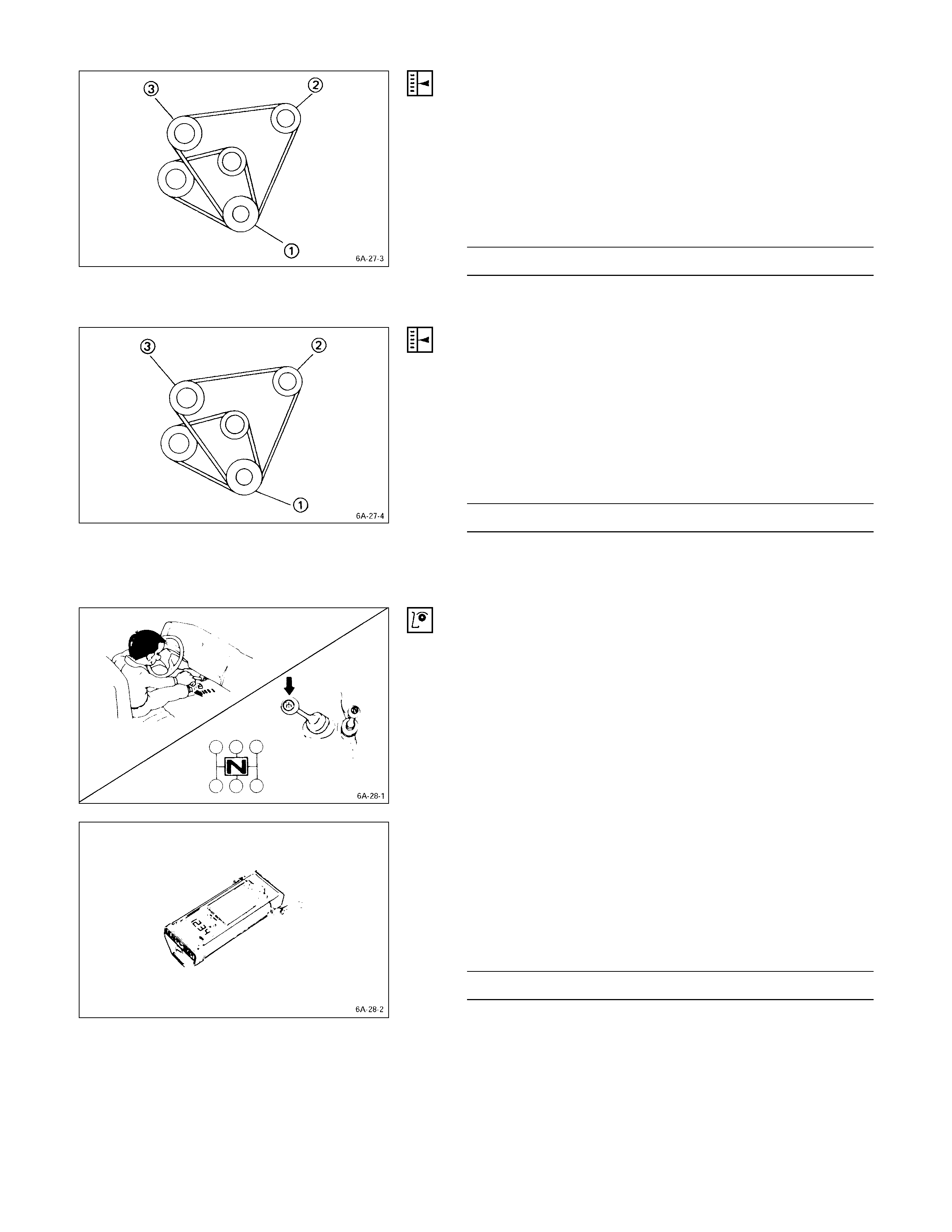
COMPRESSO R PULLEY DRIVE BELT
Move the idler pulley as required to adjust the compressor
drive belt tension.
If the vehicle is equipped with power steering, move the oil
pump as required
Depress the drive belt mid-portion with a 10 kg (22 lb/98
N) force.
Belt Deflection mm (in)
12 – 15 (0.47 – 0.59)
QCrankshaft damper pulley
ROil pump pulley or idler pulley
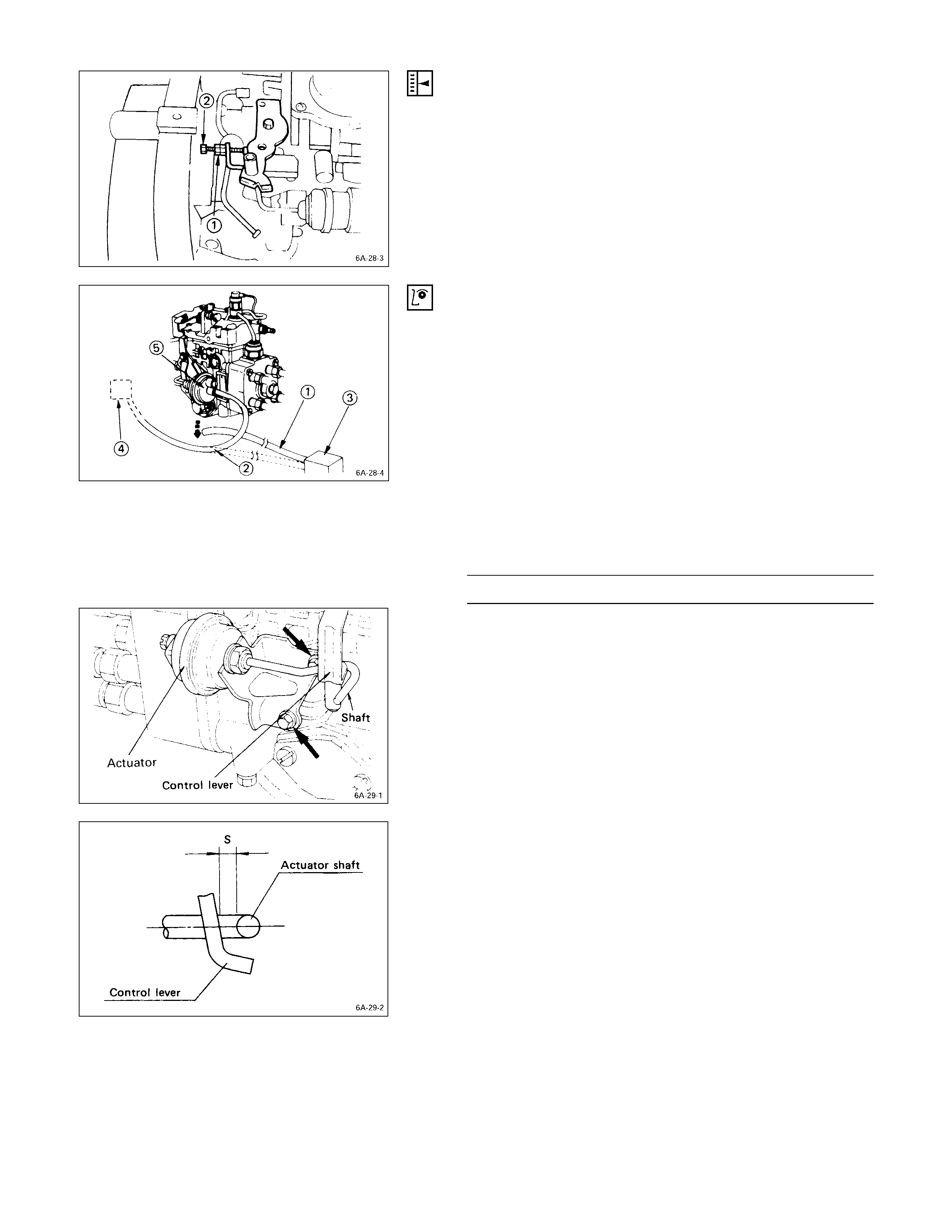
POWER STEERING OIL PUM P PULLEY DRIVE BELT
Move the oil pump as required to adjust the oil pump drive
belt tension.
On air conditioner equipped models, both drive belts pulley
must always be replaced as a set.
Depress the drive belt mid-portion with a 10 kg (22 lb/98
N) force.
Belt Deflection mm (in)
14 - 17 (0.55 – 0.67)
QCrankshaft damper pulley
ROil pump pulley
SCompressor pulley or idler pulley
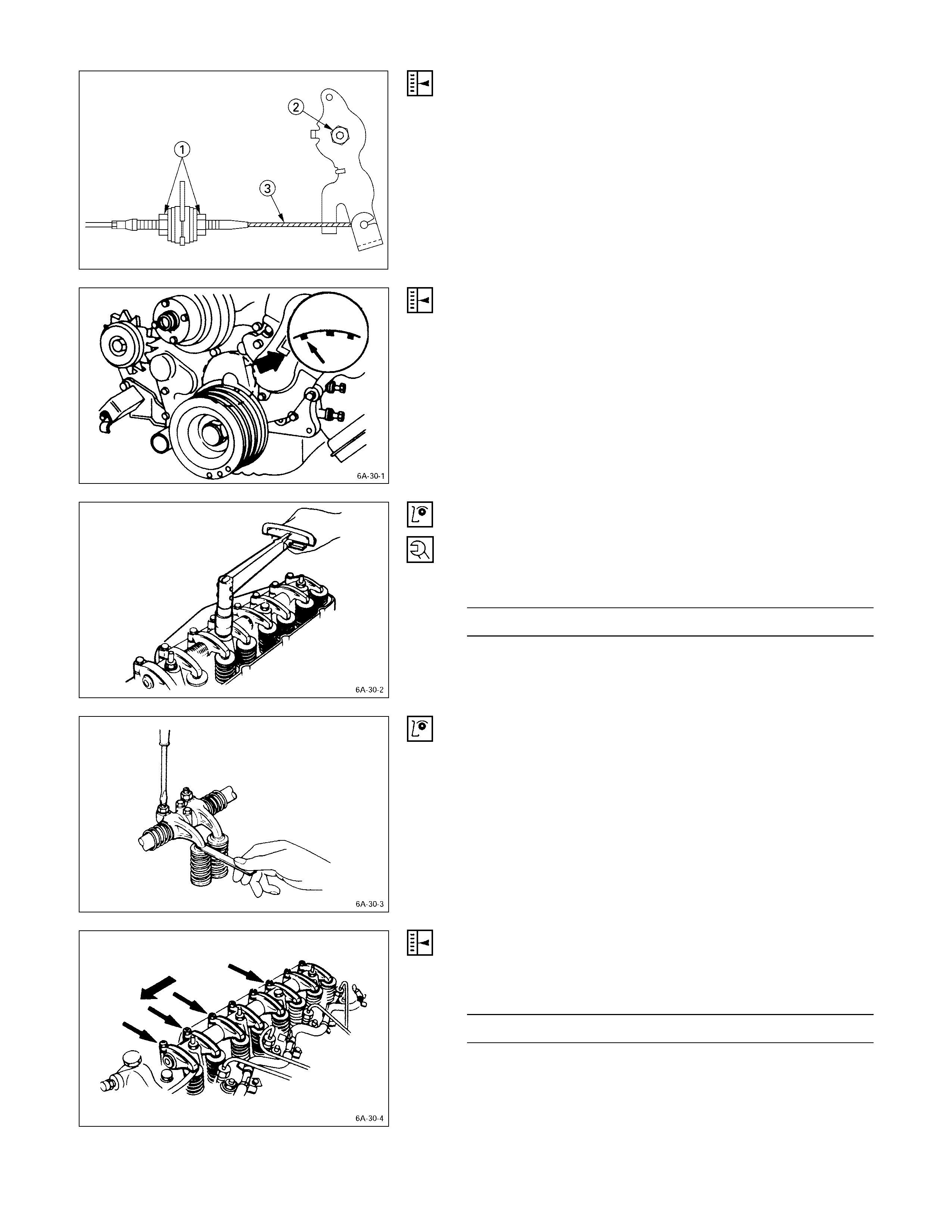
ENGINE CONTROL
IDLING SPEED ADJUSTM ENT
1. Set the vehicle parking brake and chock the drive
wheels.
2. Place the transmission in neutral.
3. Start the engine and allow it to idle until the coolant
temperature reaches 70 - 80°C (158 - 176°F).
4. Disconnect the engine control cable from the control
lever.
5. Set a tachometer to the engine.
6. Check the engine idling speed.
If the engine idling speed is outside the specified
range, it must be adjusted.
Engine Idling Speed rpm
750 ± 50
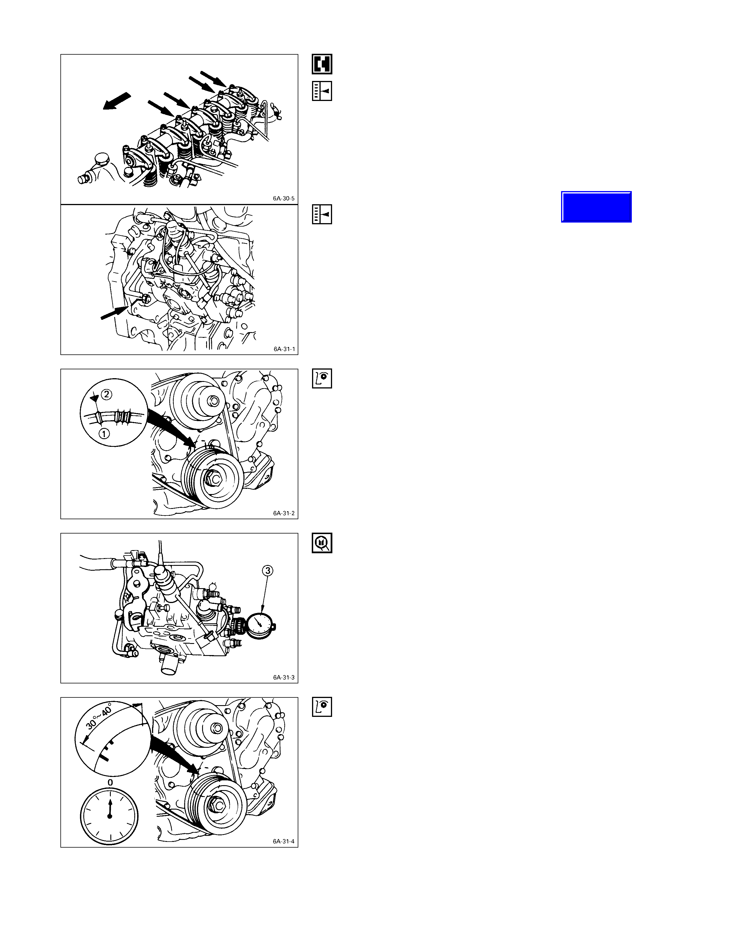
IDLING SPEED ADJUSTM ENT
1. Loosen the idling set screw lock nut Q on the injection
pump idling set bolt.
2. Adjust the idling speed to the specified range by
turning the idling set bolt R.
3. Lock the engine set bolt with the idling set screw lock
nut.
4. Check that the idling control cable is tight (free of
slack). If required, remove the slack from the cable.
FAST IDLING SPEED I NSPECTION
1. Set tachometer to the engine.
2. Disconnect the vacuum hose Q from the fast idle
actuator U on the injection pump.
3. Disconnect the other vacuum hose R from the
vacuum switching valve S and connect it to the fast
idle actuator U.
The vacuum line will now be connected directly from
the vacuum pump T to the fast idle actuator.
4. Check the engine fast idling speed.
If the engine idling speed is outside the specified
range, it must be adjusted.
Fast Idling Speed rpm
850 - 950
FAST IDLING SPEED ADJUSTM ENT
1. Loosen the fast idle actuator bracket bolts.
2. Adjust the fast idling speed by moving the actuator
bracket, so that the clearance “S” can be 1 ~ 2 mm
(0.04 ~ 0.08 in.).
3. Tighten the bracket bolts.
ACCELERATOR CONTROL
ACCELERATOR CO NTROL CABLE ADJUSTMENT
1. Loosen the accelerator cable clamp bolt Q.
2. Check that the idling control knob is in the engine
idling position.
3. Hold the accelerator lever R in the fully closed
position and stretch the control cable S in the
direction indicated by the arrow to remove any slack.
VALVE CLEARANCE ADJUSTMENT
1. Bring the piston in either the No. 1 cylinder or the No. 4
cylinder to TDC on the compression stroke by turning
the crankshaft until the crankshaft damper pulley TDC
line is aligned with the timing pointer.
2. Check the rocker arm shaft bracket nuts for
looseness.
Tighten any loose rocker arm shaft bracket nuts
before adjusting the valve clearance.
Rocker Arm Shaft Bracket Nut Torque kg·m (lb·ft/N·m)
5.5 ± 0.5 (39.8 ± 3.6/53.9 ± 4.9)
3. Check for play in the No. 1 intake and exhaust valve
push rods.
If the No. 1 cylinder intake and exhaust valve push
rods have play, the No. 1 piston is at TDC on the
compression stroke.
If the No. 1 cylinder intake and exhaust valve push
rods are depressed, the No. 4 piston is at TDC on the
compression stroke.
Adjust the No.1 or the No. 4 cylinder valve clearances
while their respective cy linders are at TDC on the
compression stroke.
Valve Clearance (At Cold) mm (in)
0.4 (0.016)
4. Loosen each valve clearance adjusting screw as
shown in the illustration.
5. Insert a feeler gauge of the appropriate thickness
between the rocker arm and the valve stem end.
6. Turn the valve clearance adjusting screw until a slight
drag can be felt on the feeler gauge.
7. Tighten the lock nut securely.
8. Rotate the crankshaft 360°.
9. Realign the crankshaft damper pulley TDC notched
line with the timing pointer.
10 Adjust the clearances for the remaining valves as
shown in the illustration.
INJECTION TIMING ADJUSTMENT
1. Check that the notched line on the injection pump
flange is aligned with the front plate or the timing gear
case notched line.
2. Bring the piston in the No. 1 cylinder to TDC Q on the
compression stroke by turning the crankshaft until the
crankshaft pulley TDC line is aligned with the timing
mark R.
Note:
Check for play in the No. 1 intake and exhaust valve
push rods.
If the No. 1 cylinder intake and exhaust valve push
rods have play, the No. 1 piston is at TDC on the
compression stroke.
3. Disconnect the injection pipe from the injection pump
4. Remove one bolt from the distributor head.
5. Insert a screwdriver into a hole in the fast idle lever
and turn the lever to release the W-C.S.D. function. (if
so equipped)
6. Install the static timing gauge S.
The probe of the gauge should be depressed inward
approximately 2 mm (0.079 in).
Static Timing Gauge: 5-8840-0145-0 (J-28827)
7. Rotate the crankshaft to bring the piston in the No. 1
cylinder to a point 30 - 40° BTDC.
8. Set the timing gauge needle to zero.
9. Move the crankshaft pulley slightly in both directions to
check that the gauge indication is stable.
Techline
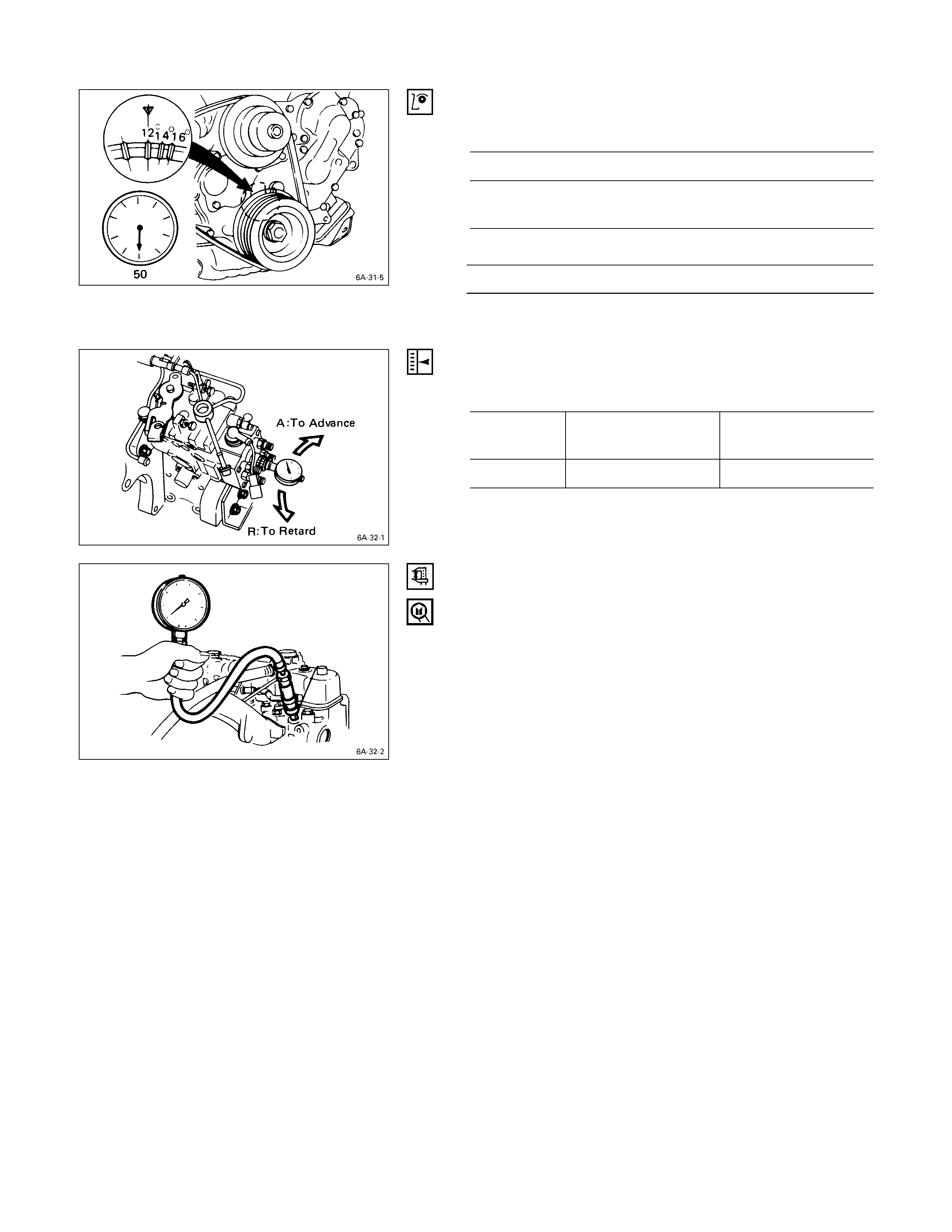
10. Turn the crankshaft clockwise and read the gauge
indication when the crankshaft pulley timing mark
11° (4JB1T) on pulley is aligned with the pointer.
4JB1T
BTDC
11 ± 2°
Standard Reading mm (in)
0.5 (0.02)
If the injection timing is outside the specified range,
continue with the following steps.
11. Loosen the injection pump fixing nuts and bracket
bolts.
12. Adjust the injection pump setting angle.
When large than
standard value When smaller than
standard value
Gear drive R A
A: Move the injection pump toward the engine.
R: Move the injection pump away from the engine.
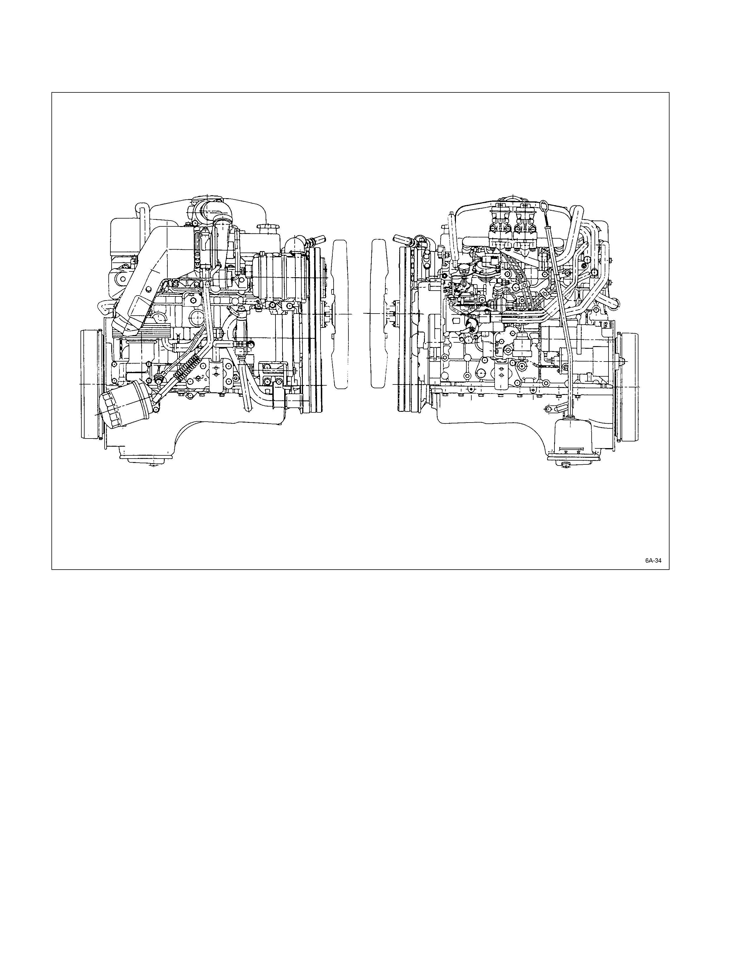
COMPRESSI ON PRESSURE MEASUREMENT
1. Start the engine and allow it to idle until the coolant
temperature reaches 70 – 80 °C (158 – 176 °F).
2. Remove the following parts.
•Glow plugs
•Fuel cut solenoid connector
3. Set the adapter and compression gauge to the No. 1
cylinder glow plug hole.
Compression Gauge: 5-8840-2675-0
Adapter; Compression Gauge: 5-8531-7001-0
4. Turn the engine over with the starter motor and take
the compression gauge reading.
Compression Pressure kg/cm2 (psi/kPa) at 200 rpm
Standard Limit
31 (441/3,038) 22 (313/2,156)
5. Repeat the procedure (Steps 3 and 4) for the
remaining cylinders.
If the measured value is less than the specified limit,
refer to “Troubleshooting” in this Manual.
PRE-HEATING SYSTEM
SYSTEM INSPECTION PRO CEDURE
1. Disconnect the thermo-switch on the thermostat outlet
pipe.
2. Turn the starter switch to the “ON” position.
If the Pre-heating System is operating properly, the
glow relay will make a clicking sound about seven
seconds after the starter switch is turned on.
3. Measure the glow plug terminal voltage with a circuit
tester immediately after turning the starter switch to
the “ON” position.
Glow Plug Terminal Voltage V
Approx. 11
GENERAL DESCRIPTI O N
The 4J series automotive diesel engine has SPECIAL DESIGNED combustion chambers in the piston. This design
provides superior fuel economy over a wi de range of driving conditions.
The model 4JG2 diesel engine has swirl type combustion chambers.
Auto-thermatic pistons with cast steel struts are used to reduce thermal expansion and resulting engine noise when the
engine is cold.
Chrome plated dry type cylinder liners provide the highest durability .
The laminated steel sheet cylinder head gasket is very durable and, to increase the head gasket reliability.
The crankshaft has been tufftrided to provide a longer service life. Because the crankshaft is tufftrided, it cannot be
reground.
The engines are equipped with the VE-Type distributor injection pump.
The 4JG2T, 4JB1T and 4JA1T engines are turbocharger equipped.
REMO VAL AND INSTALLATI ON
Read this Section carefully before performing any removal and installation procedure. This Section gives you important
points as well as the order of operation. Be sure that you understand everything in this Section before you begin.
IMPO RTANT OPERATI ONS – REMO VAL
J
Carefully remove the piping, hoses, wiring harness
connectors, engine control cables, and control rods
from the engine.
J
Remove the clutch sleeve cylinder, the back up light
switch connector, and the speedometer cable from the
transmission.
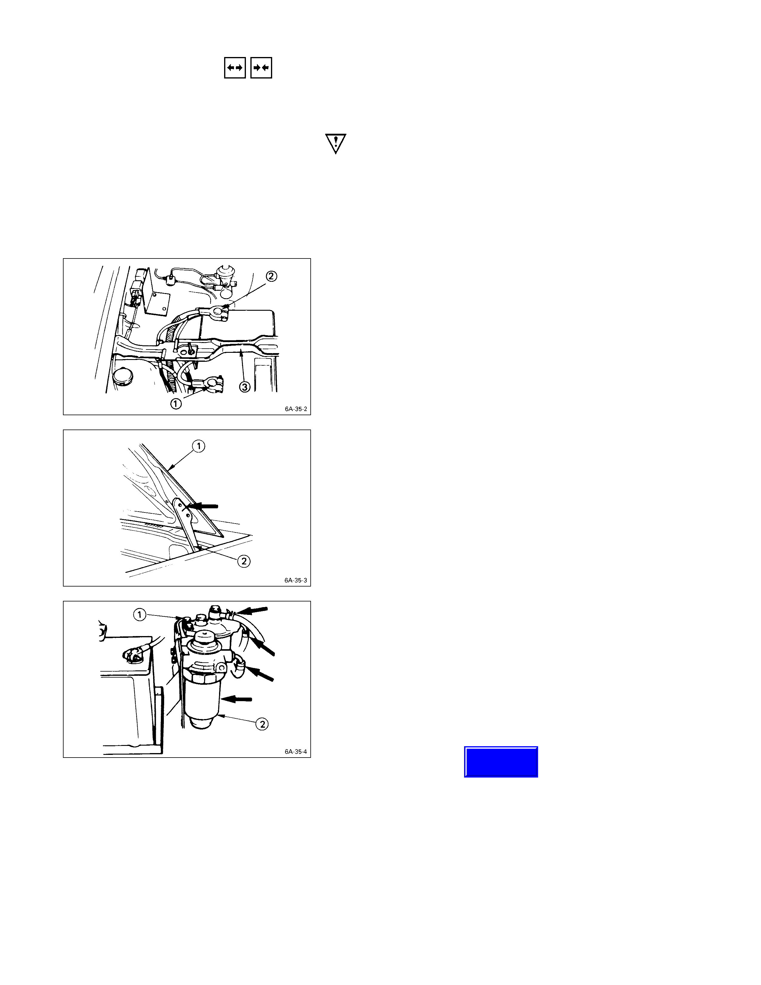
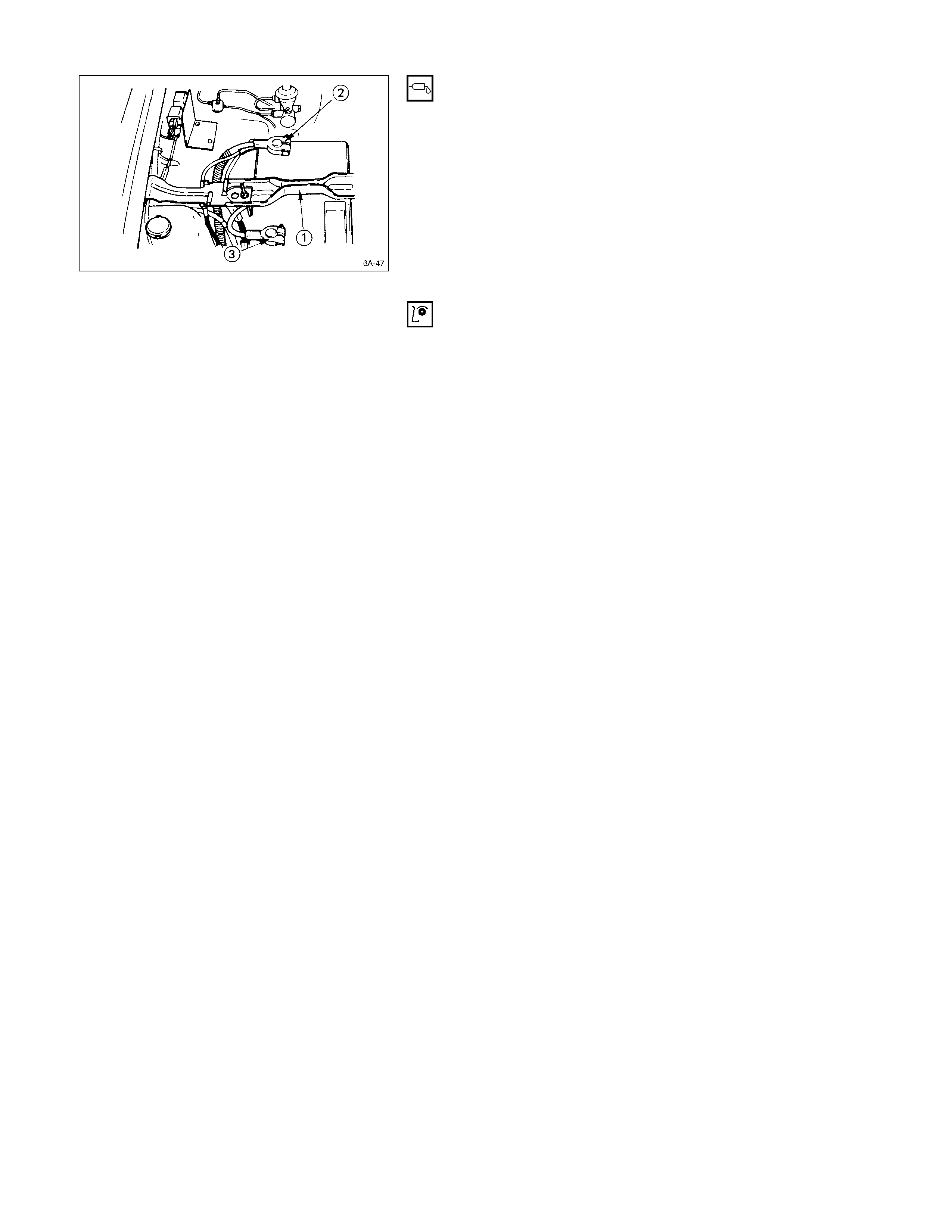
BATTERY
1. Disconnect the battery cable Q and the grounding
cable R from the battery terminals.
2. Remove the battery clamp S.
Take care not to accidentally short the battery with the
spanner or some other tool.
3. Remove the battery.
4. Disconnect the battery cable at the starter motor and
the ground cable at the cylinder body.
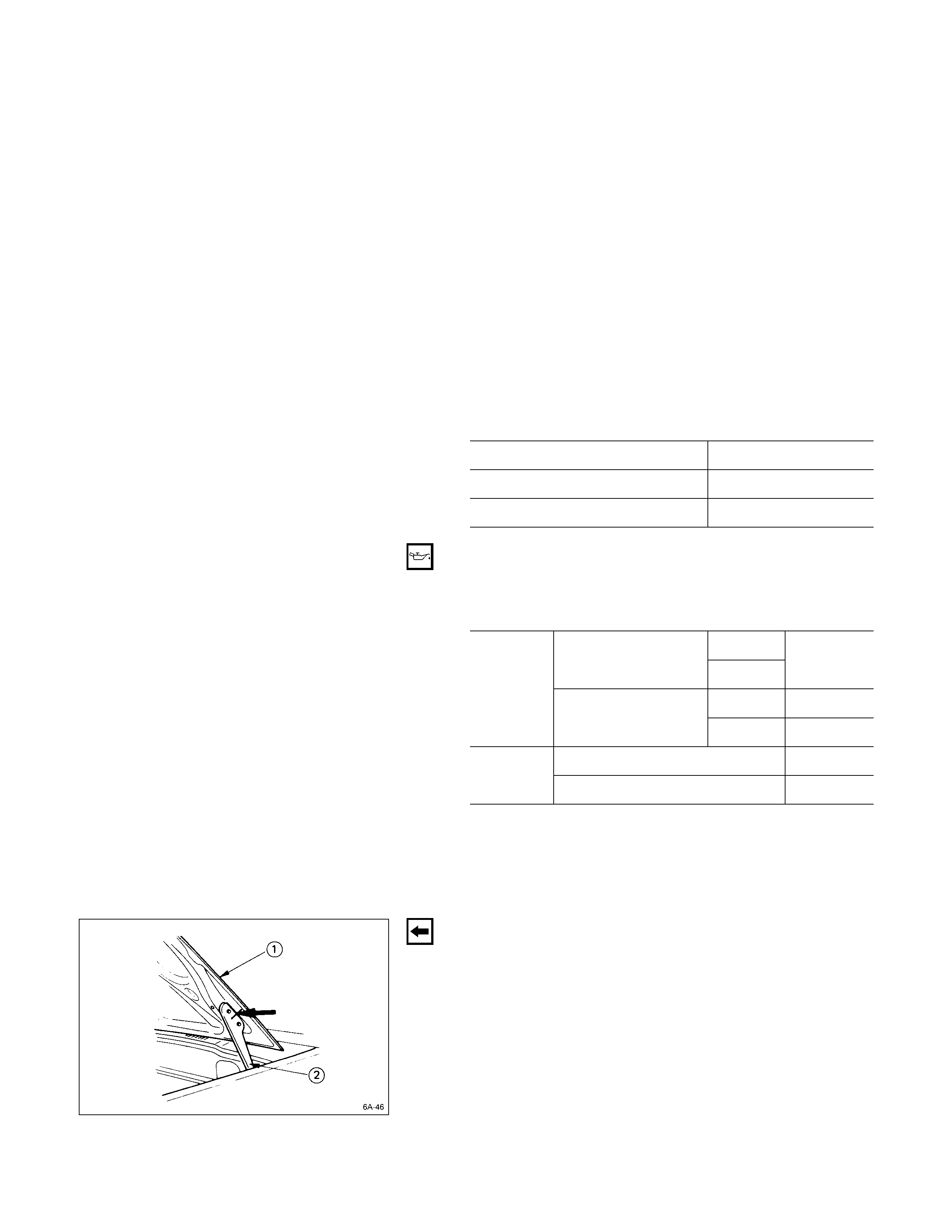
ENGINE HOOD
Apply setting marks to the engine hood Q and the engine
hood hinges R before removing the engine hood.
This will facilitate reinstallation of the engine hood to its
original position.
FUEL FILTER AND WATER SEPARATOR
1. Pull the fuel hose from the fuel filter Q and the water
separator R.
2. Plug the fuel hose to prevent fuel leakage.
3. Remove the fuel filter and the water separator.
AIR CLEANER
Remove the air cleaner duct from the engine.
Techline
COOLANT
Remove the coolant drain plug (at the lower left of the
engine) and the radiator drain plug.
Allow the engine coolant to drain completely.
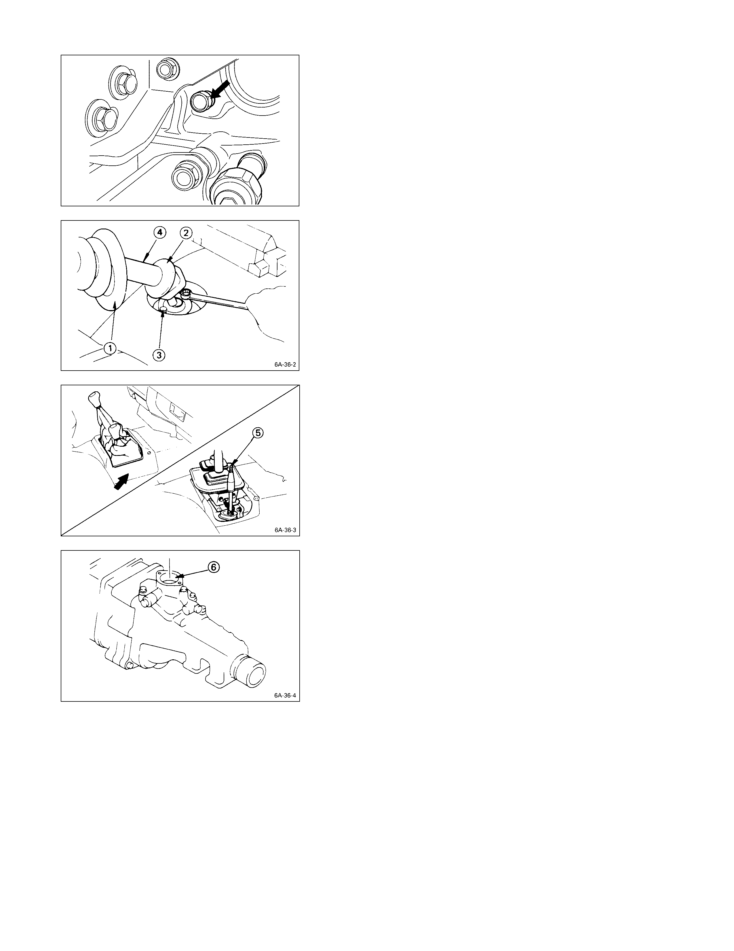
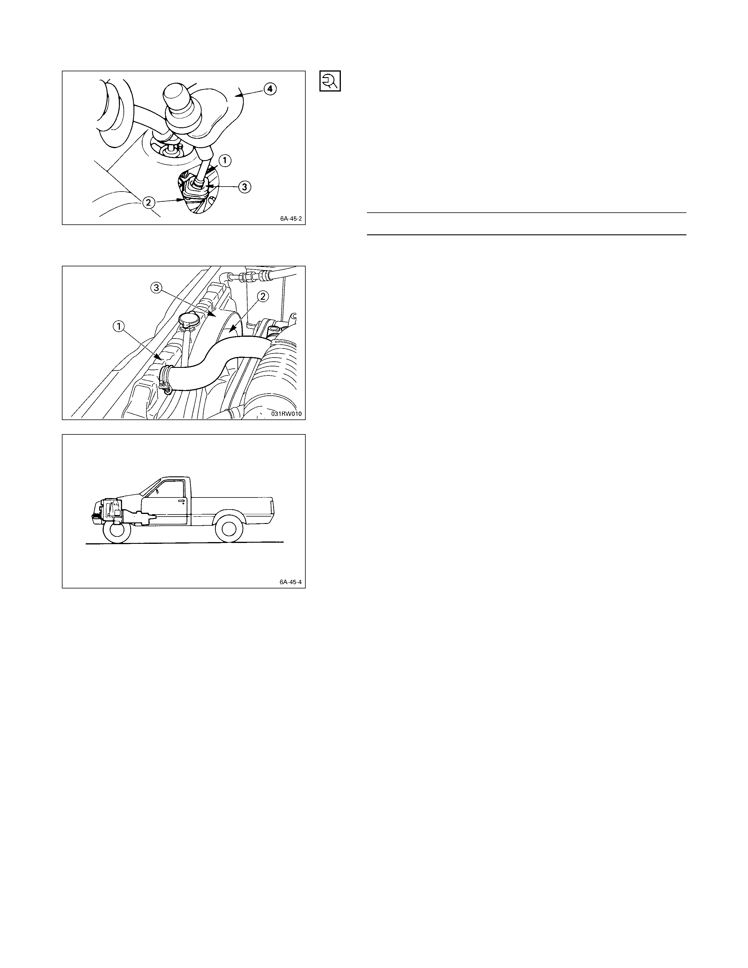
GEAR SHI FT LEVER
1. Place the gear shift lever in the neutral position.
2. Remove the front console from the floor panel.
3. Pull the gear shift lever grommet Q and the dust
cover R to the top of the gear shift lever.
4. Remove the gear shift lever cover bolt S.
5. Remove the gear shift lever T.
6. Remove the gear shift lever hole cover U or the
center console from the floor.
7. Remove the quadrant box V from the transmission
rear cover.
Note:
Cover the quadrant box hole to prevent the entry of
foreign material into the transmission.
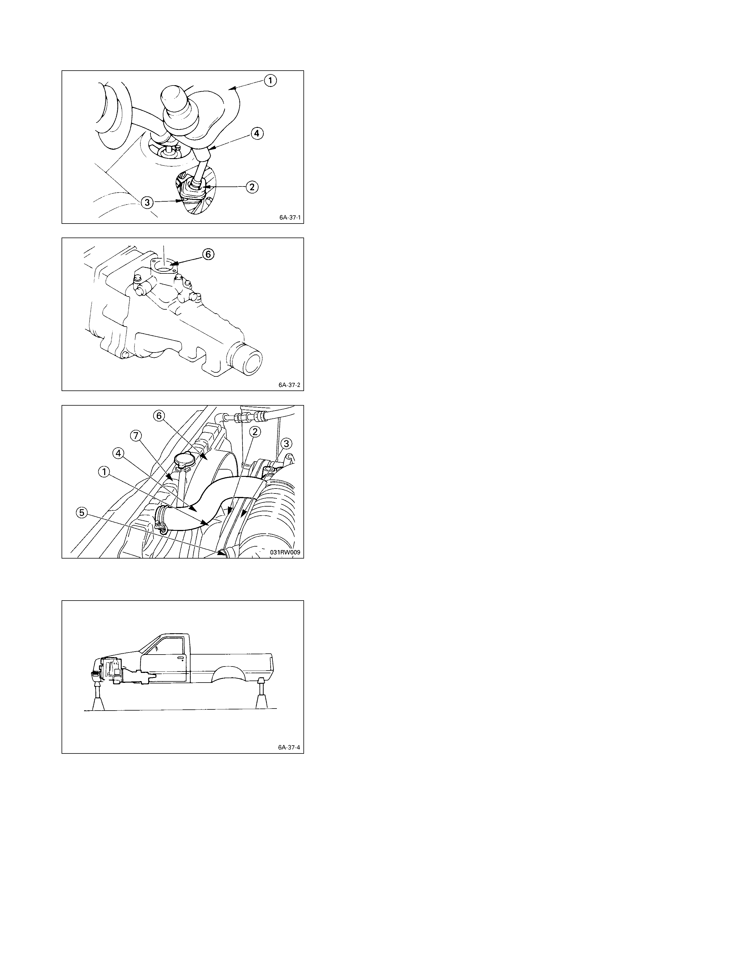
TRANSFER CHANGE LEVER (F OR 4 ×
××
× 4)
Perform this procedure after removing the gear shift lever.
1. Place the transfer change lever in the “H” position.
2. Pull the transfer change lever grommet Q and the
dust cover R to the top of the transfer change lever.
3. Remove the retainer bolts S.
4. Remove the transfer change lever T along with the
retainer and the ball seat cover.
5. Remove the change lever hole cover U or the center
console from the floor.
6. Remove the quadrant box V from the transfer case
adapter.
Note:
Cover the quadrant box hole and the change lever
hole to prevent the entry of foreign mater ial into the
transmission.
RADIATOR
1. Remove the cooling fan Q, the pulley R, and the belt
S.
2. Disconnect the radiator upper hose T and the
radiator lower hose U from the engine.
3. Remove the radiator shroud V.
4. Remove the radiator grille from the deflector panel.
5. Remove the radiator W.
Take care not to damage the radiator core.
6. Remove the radiator undercover from the chassis
frome.
SUPPORTING THE VEHICLE
1. Jack up the vehicle.
2. Place chassis stands at the front and the rear of the
vehicle.
3. Remove the wheels from the vehicle.
ENGINE OIL DRAINING
Remove the oil pan drain plug to drain the engine oil.
Do this while the engine is hot.
Do not forget to reinstall the drain plug after draining the
engine oil.
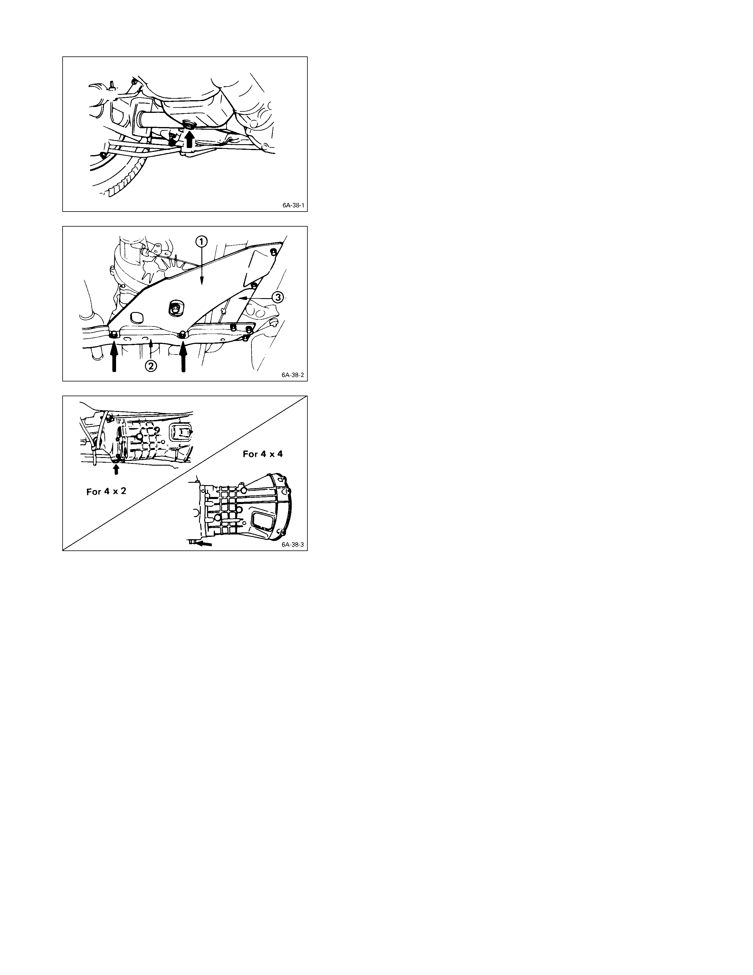
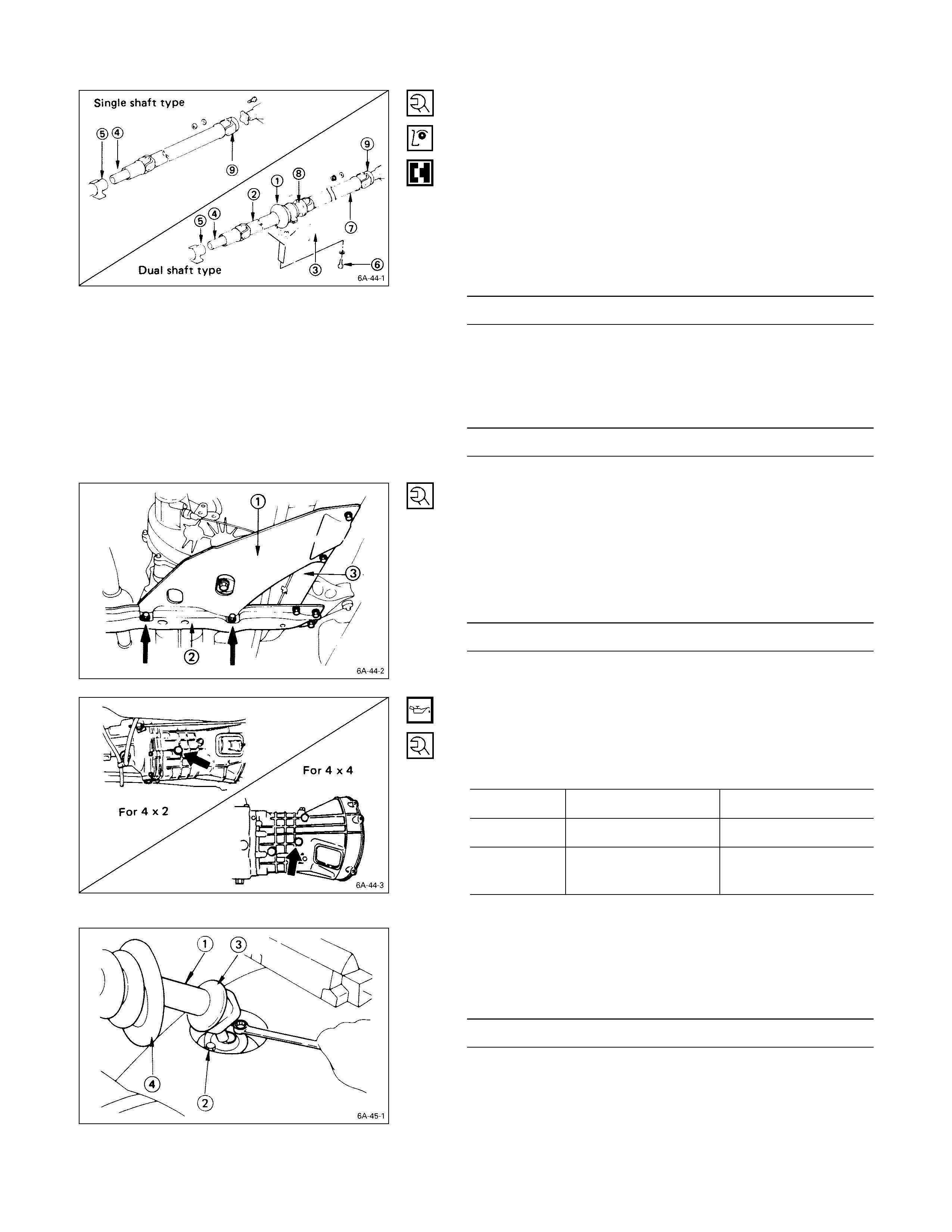
TRANSFER CASE PROTECTOR (4 ×
××
× 4 MODEL)
Remove the transfer case protector Q from the
transmission mounting member R and the side menber
S.
TRANSMISSION OIL DRAINING
1. Remove the transmission oil drain plug.
2. Replace the drain plug after draining the oil.
CONTROL CABLES O R RODS
1. Disconnect the clutch control cable or the hydraulic
cylinder from the transmission.
2. Disconnect the parking brake control cable from the
rear wheel brake back plate.
3. Disconnect the speedometer drive cable from the
transmission.
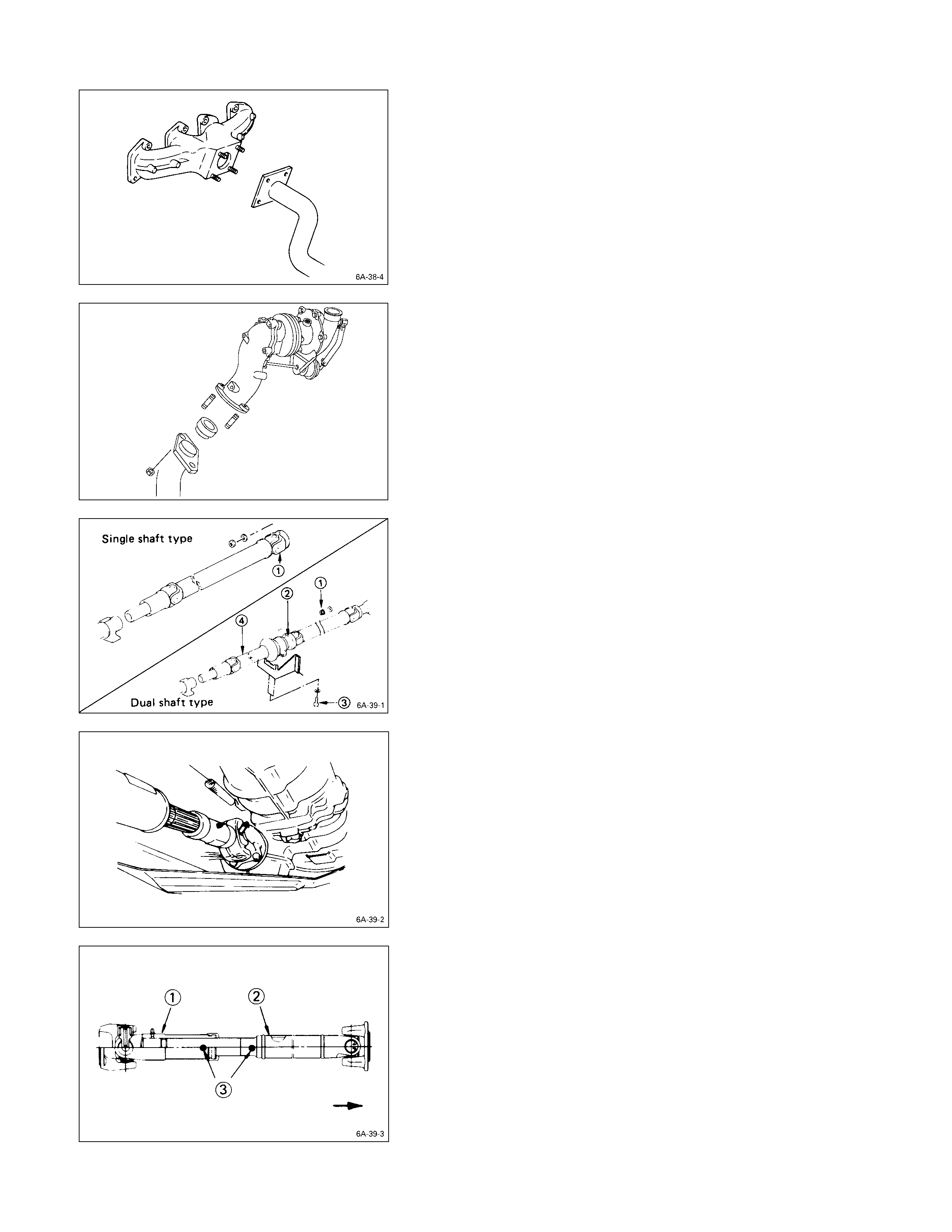
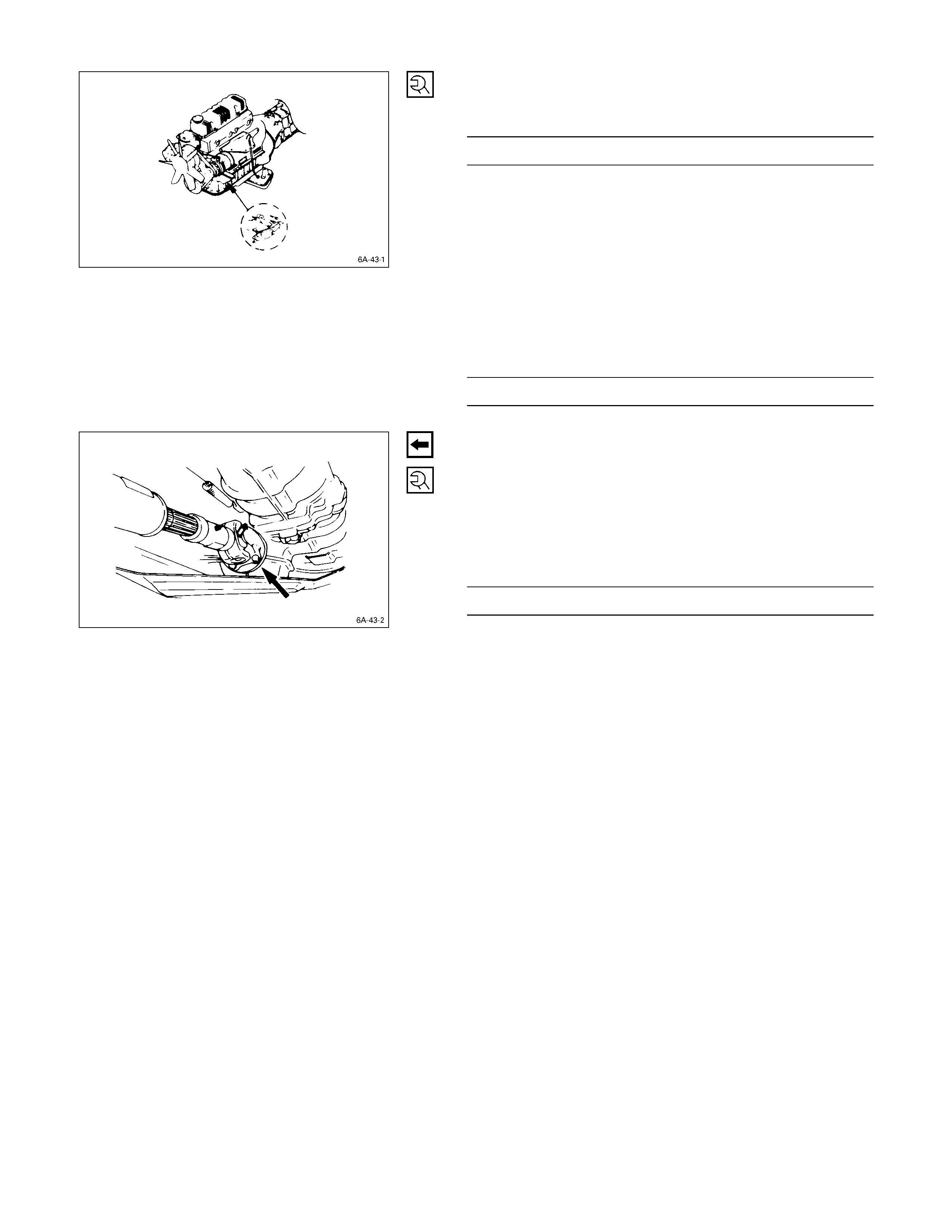
EXHAUST PIPE
1. Disconnect the exhaust pipe from the exhaust
manifold.
REAR PROPELLER SHAFT
1. Remove the propeller shaft flange yoke at the drive
pinion Q.
2. Remove the 2nd propeller shaft flange yoke bolts R
at the center bearing.
3. Remove the center bearing retainer bolts S.
4. Remove the 1st propeller shaft T together with the
center bearing from the transmission mainshaft spline.
FRONT PROPELLER SHAFT (FOR 4 ×
××
× 4)
Remove the splined yoke flange bolt at the transfer output
shaft.
Do not allow the splined yoke to fall away from the front
propeller shaft.
If the splined yoke should fall away from the front propeller
shaft, align the setting marks S on the splined yoke Q
and the propeller shaft R to reassemble the two parts.
The setting marks are puncked circles approximately S
mm (0.12 in) in diameter.
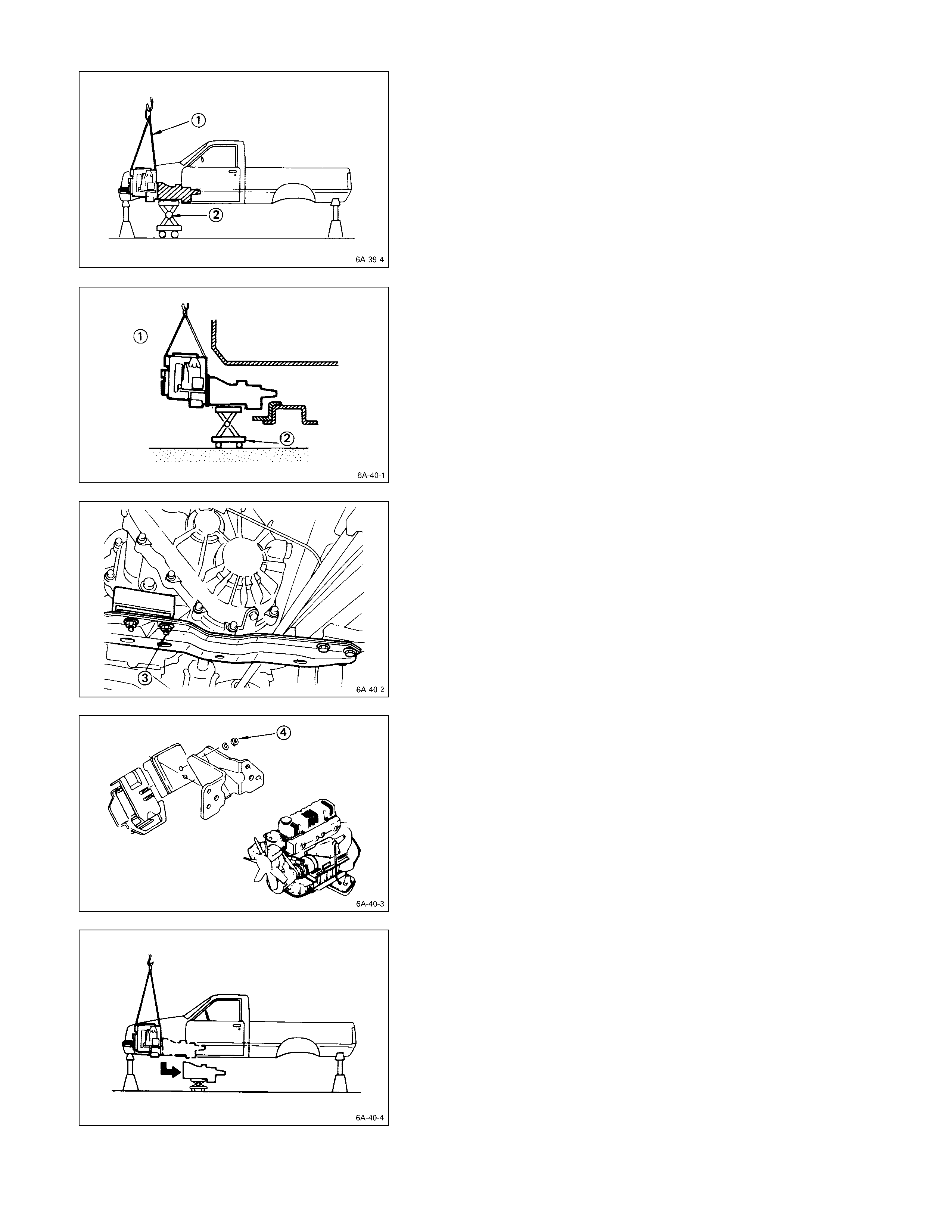
TRANSMISSION
1. Check that the lifting wires Q are securely attached.
2. Operate the hoist to slightly raise the engine.
Warning:
Take care not to lift the chassis from the chassis
stands.
If you do accidentally raise the chassis from the
chassis stands, make absolutely certain that the
chassis stands are correctly positioned before
lowering the chassis.
3. Place the jack R beneath the transmission case.
4. Operate the jack to slightly raise the transmission.
5. Remove the transmission member lower mounting
bolts S fixing the transmission member to the chassis
frame rail.
6. Loosen the engine mounting nuts T at the rubber
mountings.
7. Use the jack to slightly lower the transmission.
8. Remove the remaining transmission coupling bolts.
9. Separate the transmission from the engine.
Take care not to damage the transmission, the
engine, and their related parts.
10. Use the jack to lower the transmission together with
the mounting member to the floor.

11. Remove the engine mounting bolts U from the
chassis frame.
12. Use the hoist to lift the engine from the engine
compartment.
IMPORTANT OPERATIONS – INSTALLATION
Follow the removal procedure in the reverse order to
perform the installation procedure. Pay careful attention to
the important points during the installation procedure.
ENGINE
1. Attach a lifting wire to the engine lifting hanger.
2. Operate the hoist to position the engine above the
engine compertment.
Hold the front of the engine slightly higher than the
rear.
3. Slowly lower the engine into the engine compartment.
Be careful not to damage the brake pipes, the fuel
pipes, and other exposed parts.
4. Support the oil pan with a jack.
5. Temporarily tighten the engine front mounting rubber
nuts.
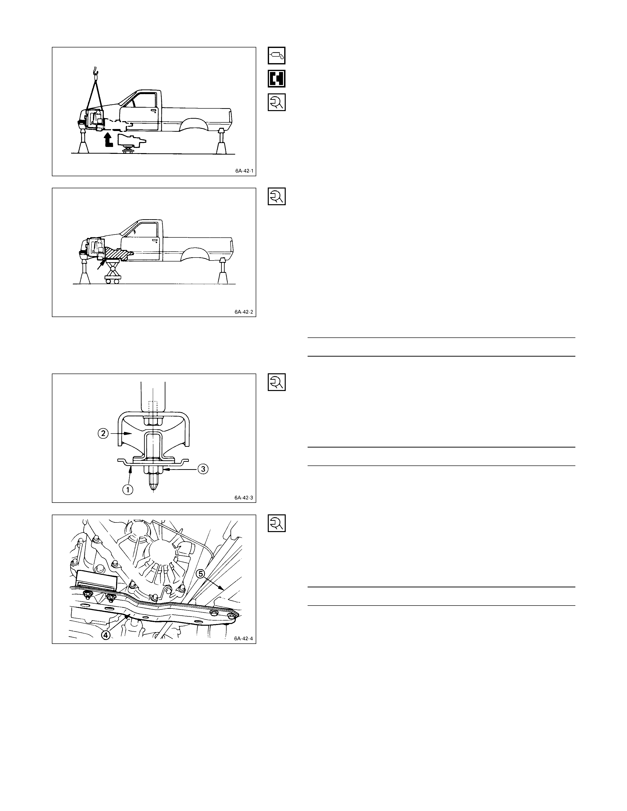
TRANSMISSION
1. Apply a thin coat of molybdenum disulfide grease to
the top gear shaft spline.
2. Place the transmission with the mounting rubbers on a
transmission jack.
3. Carefully move the transmission jack and
transmission into position behind the cab.
4. Slowly raise the transmission jack until the front of the
transmission is aligned with the engine flywheel.
The slope of the engine and the transmission must be
the same.
5. Align the top gear shaft spline with the clutch driven
plate internal spline.
6. Install the transmission to the engine.
Tighten the transmission coupling nuts and bolts to
the specified torque.
Transmission Coupling Nut and Bolt
Torque kg·m (lb.ft/N·m)
3.8 ± 0.8 (27.5 ± 5.8/37.2 ± 7.8)
7. Install the mounting member Q to the mounting
rubber R.
8. Tighten the mounting member nuts S to the specified
torque.
Mounting Rubber Nut Torque kg·m (lb.ft/N·m)
4.2 ± 0.5 (30.4 ± 3.6/41.2 ± 4.9)
9. Install the mounting member T to the sidemembers
U.
10. Tighten the mounting member bolts to the specified
torque.
Mounting Member Bolt Torque kg·m (lb.ft/N·m)
7.8 ± 1.6 (56.1 ± 11.2/76.0 ± 15.2)
11. Tighten the engine mounting rubber nuts to the
specified torque.
Engine Mounting Rubber Nut Torque kg·m (lb.ft/N·m)
4.2 ± 0.5 (30.4 ± 3.6/41.2 ± 4.9)
EXHAUST PIPE
Connect the exhaust pipe to the exhaust manifold.
Torque kg·m (lb.ft/N·m)
7.8 ± 0.5 (49 ± 3.6/67 ± 5)
FRONT PROPELLER SHAFT (FOR 4 ×
××
× 4)
1. Connect the propeller shaft flange yoke to the
matching flange.
2. Tighten the propeller shaft flange yoke bolt to the
specified torque.
Propeller Shaft Flange Yoke Bolt
Torque kg·m (lb.ft/N·m)
3.6 ± 0.3 (26.1 ± 2.2/35.3 ± 3.0)
Note:
If the splined yoke and the front propeller shaft have
accidentally separated, align their setting marks and
recouple them.
Refer to “FRONT PROPELLER SHAFT REMOVAL.”
REAR PROPELLER SHAFT
1. Place the center bearing and retainer Q together with
the 1st propeller shaft R on the No. 4 crossmember
S.
2. Insert the splined yoke T into the transmission main
shaft spline U.
3. Tighten the center bearing retainer bolts V to the
specified torque.
Center Bearing Retainer Bolt Torque kg·m (lb.ft/N·m)
6.2 ± 0.2 (44.8 ± 1.5/60.8 ± 2.0)
4. Connect the 2nd propeller shaft W center coupling
side X and drive pinion side Y.
Propeller Shaft Flange Yoke Bolt
Torque kg·m (lb.ft/N·m)
3.6 ± 0.3 (26.0 ± 2.2/35.3 ± 2.9)
TRANSFER CASE PROTECTOR (FO R 4 ×
××
× 4)
1. Install the transfer case protector Q to the mounting
member R and the sidemembers S.
2. Tighten the transfer case protector bolts to the
specified torque.
Transfer Case Protector Bolt Torque kg·m (lb.ft/N·m)
3.7 ± 1.0 (26.8 ± 7.2/36.3 ± 9.8)
GEAR SHI FT LEVER
1. Replenish the transmission case and the transfer case
with the specified engine oil.
Transmission and Transfer Case Oil lit (US/UK gal)
4 × 24 × 4
MSG 1.55 (0.41/0.34) 4.40 (1.16/0.97)
MUA 2.95 (0.65/0.54) 2.95 (T/M)
1.45 (Transter)
2. Install the quadrant box to the transmission rear cover.
3. Install the gear shift lever Q to the transmission case.
4. Tighten the gear shift lever cover R bolts to the
specified torque.
Shift Lever Cover Bolt Torque kg·m (lb.ft/N·m)
2.0 ± 0.2 (14.5 ± 1.5/19.6 ± 2.0)
5. Install the dust cover S and the grommet T.
TRANSFER CHANGE LEVER (F OR 4 ×
××
× 4)
1. Insert the transfer change lever Q into the transfer
side case.
2. Install the ball seat cover along with the change lever
retainer R.
3. Tighten the change lever retainer bolts to the specified
torque.
Change Lever Retainer Bolt Torque kg·m (lb.ft/N·m)
2.0 ± 0.2 (14.5 ± 1.5/19.6 ± 2.0)
4. Install the dust cover S and the grommet T.
RADIATOR
1. Install the radiator Q.
Be careful not to damage the radiator core.
2. Install the cooling fan R and the fan shroud S.
3. Connect the radiator upper and lower hoses.
4. Install the radiator undercover to the chassis frame.
5. Install the radiator grill to the deflector panel.
LOWERI NG THE VEHICLE
1. Install the wheels to the vehicle.
2. Place a jack beneath the vehicle.
3. Raise the jack to remove the chassis stands.
4. Lower the vehicle to the ground.
COOLANT REPLENISHMENT
Replenish the cooling system with coolant.
When radiator is emptied (for coolant change, etc.):
After filling with coolant up to the inlet port level, put the
radiator cap on and idle the engine for 5 to 6 consecutive
minute. Then remove the radiator cap and check and see
the coolant level. If the coolant is short, add to the radiator
as well as to the reserve tank.
If the reserve tank coolant level is lower than MIN,
replenish coolant to the reserve tank only.
In case there is no coolant in the reserve tank, make sure
of a drop in coolant temperature and add coolant through
the radiator inlet port. Then remove the cap and check the
coolant level after idling the engine for 5 to 6 consecutive
minutes.
Then add coolant into reserve tank fill up to full level.
Coolant Capacity lit (US/UK gal)
4JA1, 4JA1T 7.0 (1.8/1.5)
4JB1 with turbo engine 9.5 (2.5/2.1)
4JG2T 8.6 (2.3/1.9)
ENGINE O IL REPLENISHM ENT
1. Fill the engine through the filler port with new engine
oil of the specified grade.
Engine Oil Capacity and Grade lit (US/UK gal)
4 × 2
4JA1, 4JA1T, 4JB1T 4 × 4 6.5
4 × 2 6.5
Capacity
4JG2T 4 × 4 7.3
For 4JA1 CC or CD
Grade For 4JB1T, 4JG2T, 4JA1T CD
2. Start the engine and allow it to idle for several
minutes.
3. Stop the engine and wait five minutes for the oil to
settle.
4. Recheck the oil level and replenish if necessary.
ENGINE HOOD
Align the setting marks (applied at removal) on the engine
hood Q and the engine hood hinges R to install the
engine hood.
BATTERY
1. Check the battery fluid level and the specific gravity.
2. Secure the battery with the battery clamp.
Do not overtighten the battery clamp.
3. Connect the battery cable R and the ground cable S
to the battery.
4. Connect the battery cable to the starter motor and the
ground cable to the cylinder body.
5. Apply grease to the battery terminals.
ENGINE WARM-UP
After completing the required maintenance procedures,
start the engine and allow it to idle until it is warm.
Check the following:
1. Engine idling speed
Refer to “SERVICING” for the idle speed adjustment
procedure.
2. Engine noise level.
3. Engine lubricating system and cooling system
Carefully check for oil and coolant leakage.
4. Engine control cable operation
5. Clutch engagement
6. Indicator warning light operation
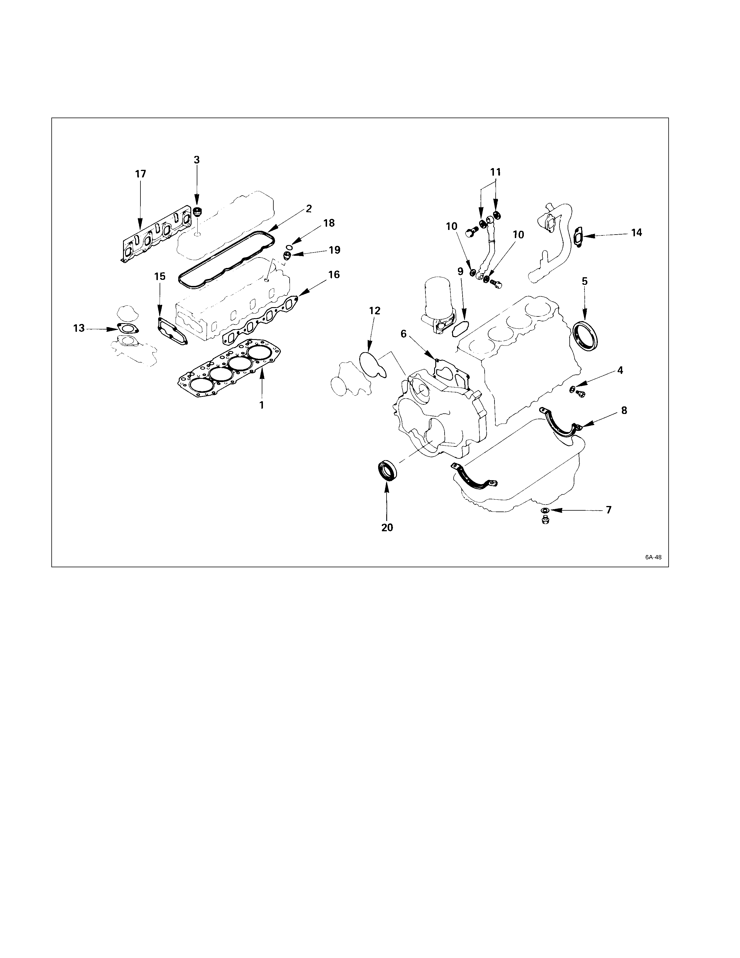
ENGINE REPAIR KIT
All of the numbered parts listed below are included in the Engine Repair Kit.
The gaskets marked with an asterisk (*) are also included in the Top Overhaul Kit.
* 1. Cy linder head gasket 11. Vacuum pump gasket
* 2. Head cover gasket 12. Water pump O-ring
* 3. Head cover cap nut gasket * 13. Water outlet pipe gasket
4. Drain cock gasket * 14. Intake pipe gasket
5. Crankshaft rear oil seal 15. Thermostat housing gasket
6. Gear case gasket * 16. Intake manifold gasket
7. Oil pan drain plug gasket * 17. Exhaust manifold gasket
8. Oil pan gasket * 18. Nozzle holder O-ring
9. Oil filter gasket * 19. Nozzle holder gasket
10. Joint bolt gasket 20. Crankshaft front oil seal
ENGINE OVERHAUL
REMOVAL
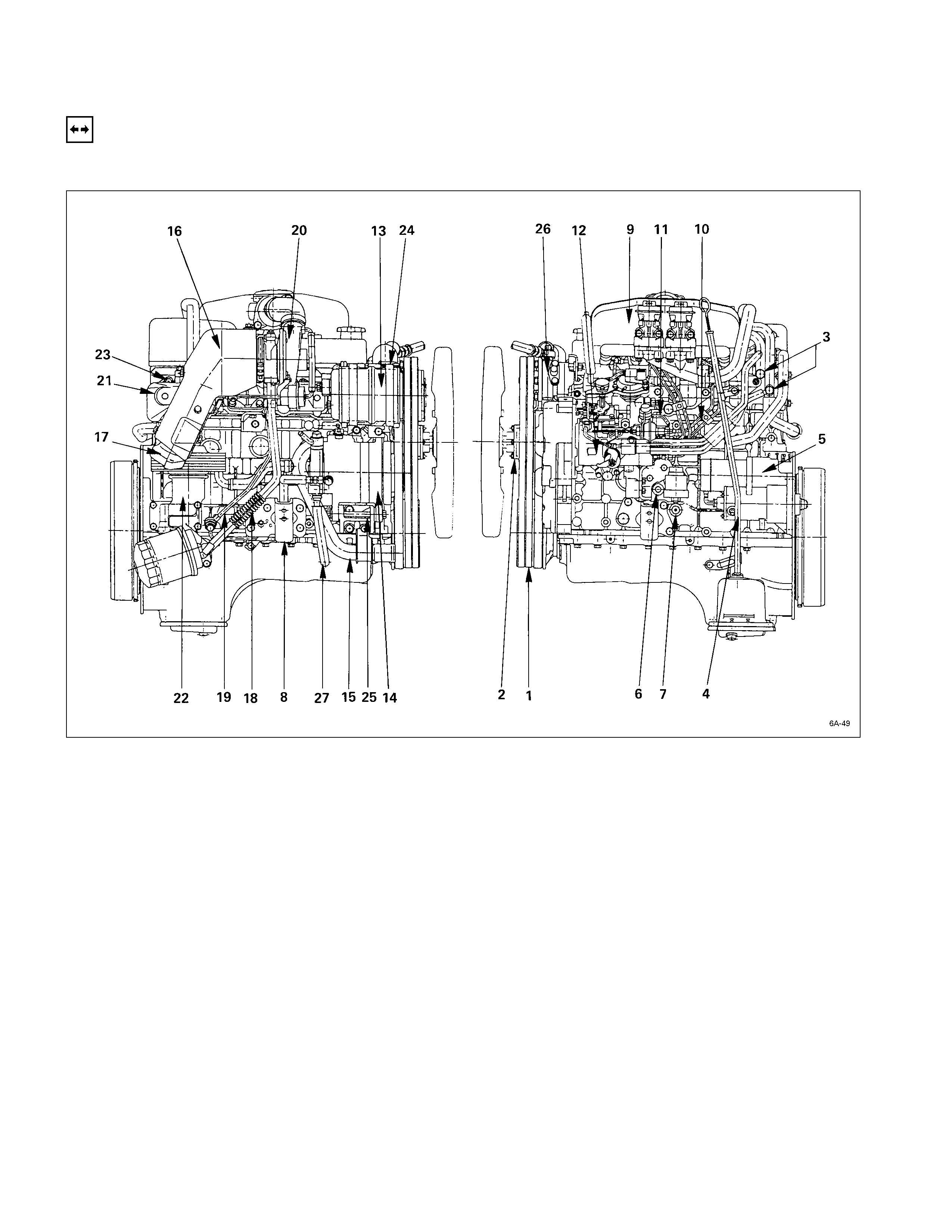
EXTERNAL PARTS
REMOVAL STEPS
1. Cooling fan drive belt 16. Turbocharger heat protector
2. Cooling fan pulley 17. Exhaust adaptor
3. Heater pipe (rear side) 18. Turbocharger oil return pipe
4. Oil level gauge and guide tube 19. Turbocharger oil feed pipe
5. Starter motor
J
20. Turbocharger
6. Water drain cock 21. Exhaust manifold heat protector
7. Oil pressure warning switch and 22. Oil cooler with Oil filter
nipple 23. Exhaust manifold
8. Engine mounting bracket 24. Compressor bracket
J
9. Intake manifold 25. Generator bracket
J
10. Fuel injection pipe with clip 26. Power steering oil pump
11. Fuel leak off pipe 27. Vacuum pipe
12. Injection pump
13. Compressor
14. Generator and adjusting plate
15. Water inlet pipe
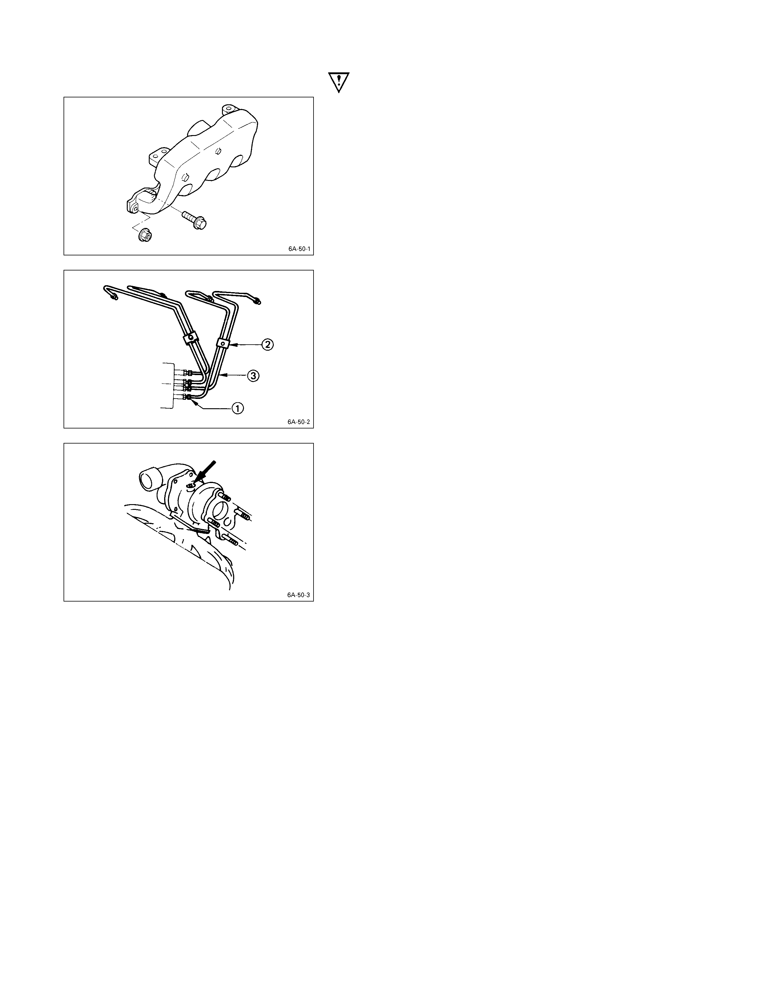
IMPORTANT OPERATIONS
9. Intake Manifold
1) Disconnect the PCV hose from the cylinder head
cover.
2) Disconnect the intake duct and intake rubber hose
from the turbocharger.
3) Remove the upper intake manifold the lower intake
manifold with intake duct, and the PCV hose.
10. Fuel Injection Pipe with Clip
1) Loosen the injection pipe sleeve nuts at the delivery
valve side Q and injection nozzle side.
Do not apply excessive force to the injection pipes.
2) Loosen the injection pipe clips R.
3) Remove the injection pipes S.
Note:
Plug the delivery holder ports with the shipping caps
to prevent the entry of foreign material.
20. Turbocharger
Plug the turbocharger body oil ports after removing the
turbocharger assembly to prevent the entry of foreign
material.
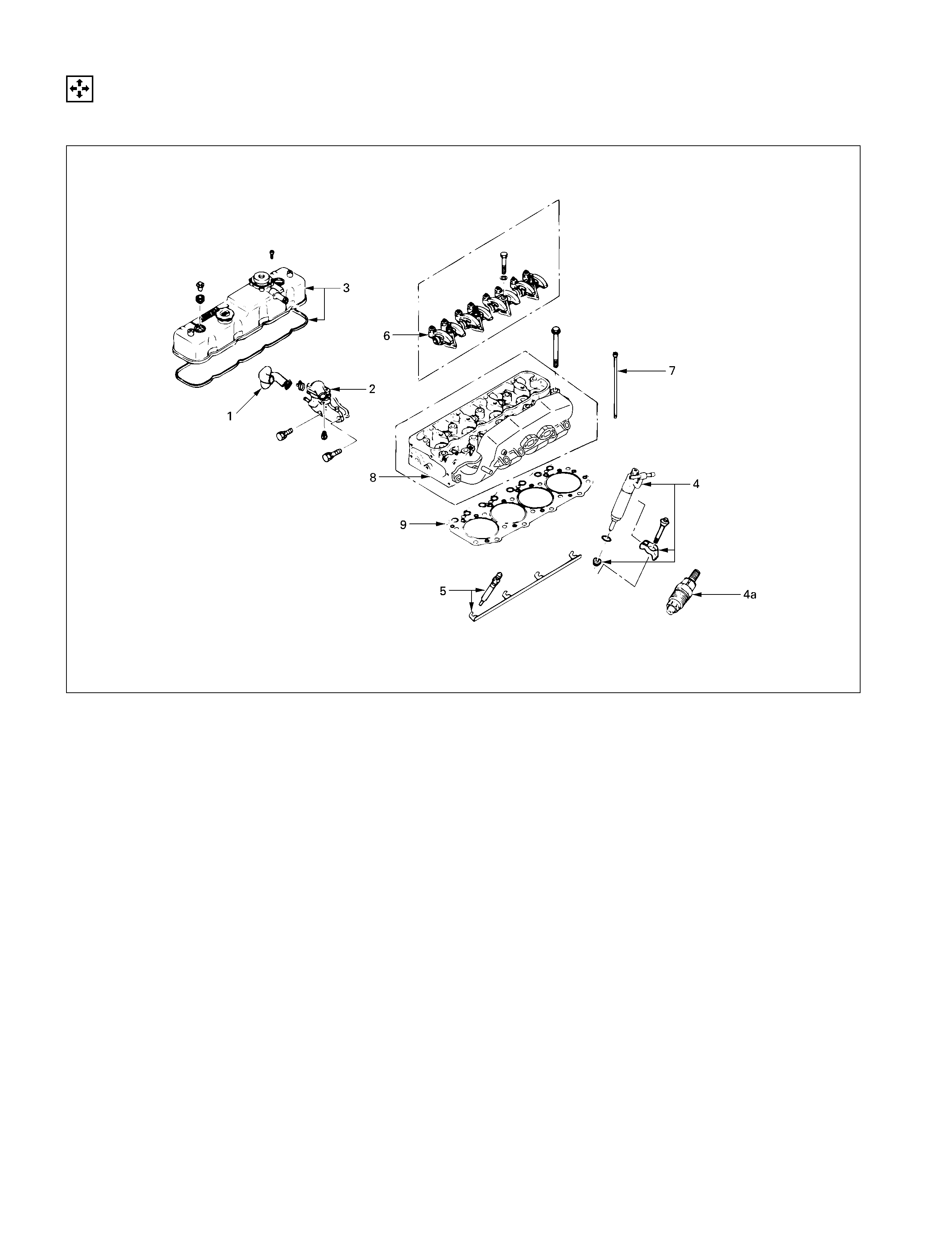
INTERNAL PARTS
MAJO R COMPONENTS
DISASSEM BLY STEPS-1
1. Water bypass pipe
J
6. Rocker arm shaft and rocker
2. Thermostat housing with thermo arm
switch 7. Push rod
3. Cylinder head cover
J
8. Cylinder head
J
4. Injection nozzle and Injection 9. Cylinder head gasket
nozzle holder
4a. Injection nozzle (4JG2T)
5. Glow plug and glow plug
connector
025RY00009
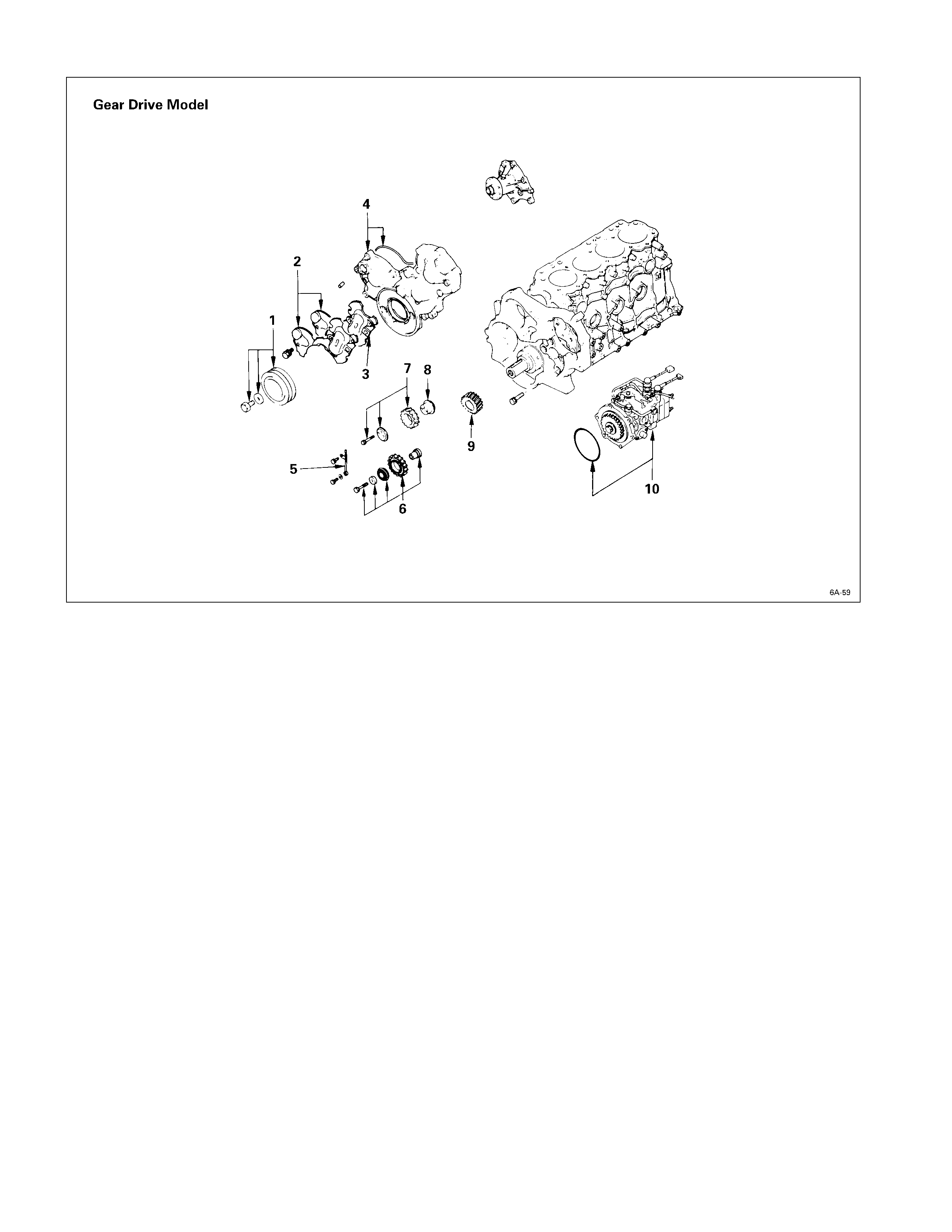
DISASSEM BLY STEPS-2
J
1. Crankshaft damper pulley
2. Gear case upper cover and
lower cover
3. Space rubber
4. Timing gear case cover
5. Timing gear oil pipe
6. Idler gear “B” and shaft
J
7. Idler gear “A”
8. Idler gear shaft
9. Crankshaft timing gear
J
10. Injection pump
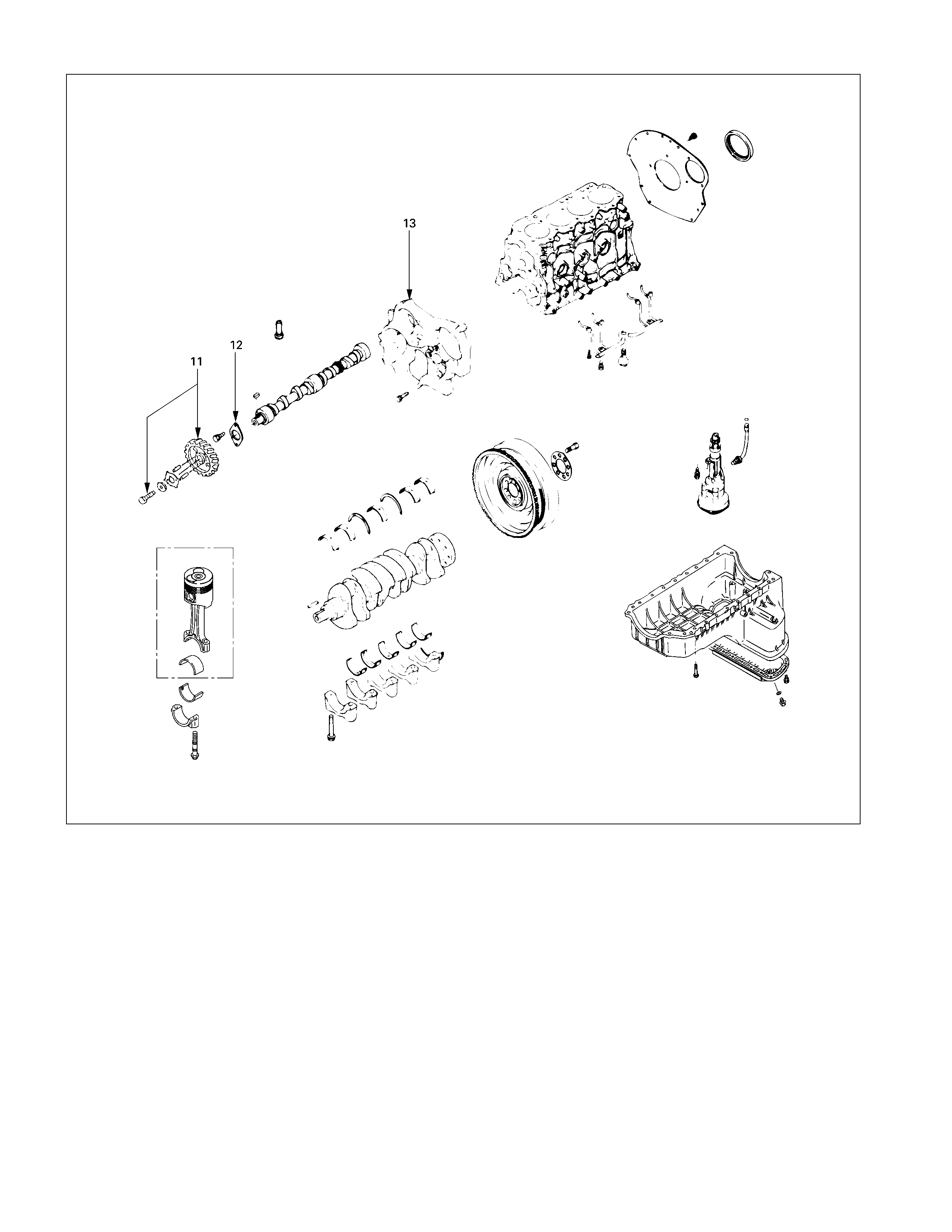
DISASSEM BLY STEPS-3
J
11. Camshaft timing gear
12. Camshaft thrust plate
13. Timing gear case
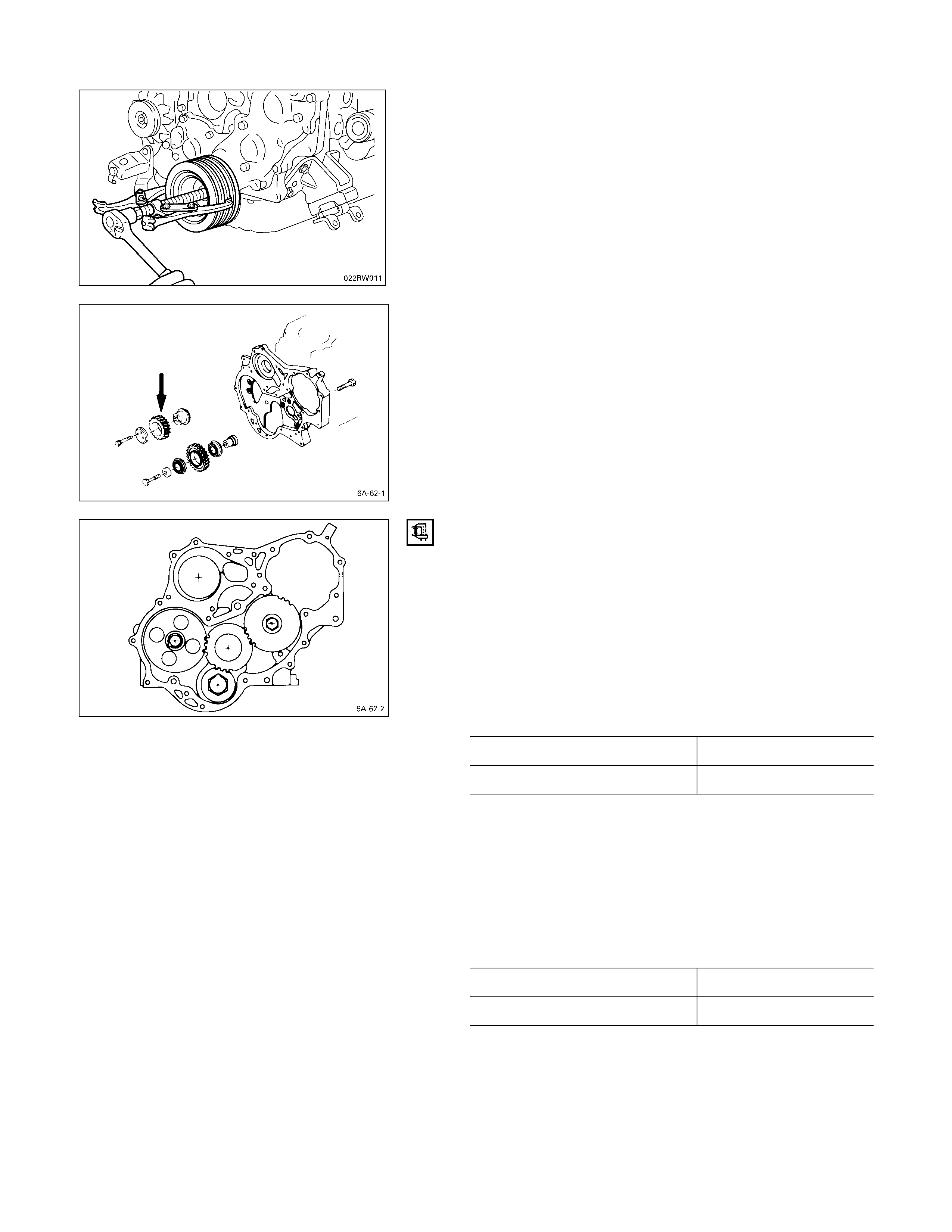
1. Crankshaft Damper Pulley
Use the remover to remove the damper pulley
NOTE:
Hold the flywheel ring gear stationary to prevent the
crankshaft from turning when removing the
crankshaft pulley.
7. Idler Gear “A”
1. Measure the camshaft timing gear backlash and the
crankshaft timing gear backlash before removing the
idler gear.
2. Measure the idler gear end play before removing the
idler gear.
Note:
Refer to the following items for details on the
backlash and end play measurement procedures.
TIMING GEAR BACKLASH MEASUREMENT
1) Set a dial indicator to the timing gear to measured.
Hold both the gear to be checked and the adjusting
gear stationary.
2) Move the gear to be checked as far as possible to
both the right and the left.
Take the dial indicator reading.
If the measured value exceeds the specified limit, the
timing gear must be replaced.
Timing Gear Backlash mm (in)
Standard Limit
0.10 – 0.17 (0.0039 – 0.0067) 0.30 (0.012)
IDLER GEAR “A” END PLAY MEASUREMENT
Insert a feeler gauge between the idler gear and the thrust
collar to measure the gap and determine the idler gear
end play.
If the measured value exceeds the specified limit, the
thrust collar must be replaced.
Idler Gear End Play mm (in)
Standard Limit
0.07 (0.0028) 0.2 (0.0079)
10. Injection Pump
1. Remove the six injection pump backet bolts Q from
the timing gear case.
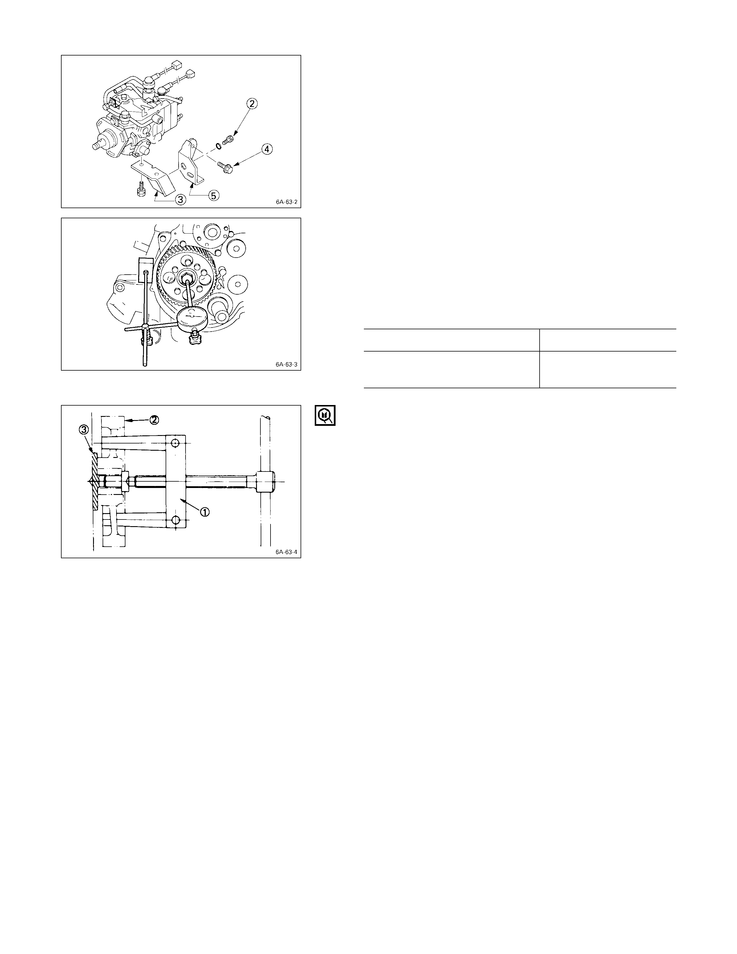
2 Remove the injection pump rear bracket bolts R from
the injection pump bracket S.
3. Remove the injection pump rear bracket bolts T and
the bracket U from the cylinder body.
4. Pull the injection pump along with the injection pump
timing gear free toward the rear of the engine.
Note:
Plug the injection pump delivery holder ports with the
shipping caps (or the equivalent) to prevent the entry
of foreign material.
11. Camshaft Timing Gear
1. Use a dial indicator to measure the camshaft end play.
This must be done before removing the camshaft
gear.
If the camshaft end play exceeds the specified limit,
the thrust plate must be replaced.
Camshaft End Play mm (in)
Standard Limit
0.050 – 0.114
(0.002 – 0.0044) 0.20
(0.008)
2. Remove the camshaft timing gear bolt from the
camshaft.
Note:
Hold the camshaft stationary to prevent the camshaft
from turning.
3. Use the universal puller Q to pull out the camshaft
timing gear R.
Universal Puller: 5-8521-0002-0
4. Remove the thrust plate S.
MINOR COMP ONENTS
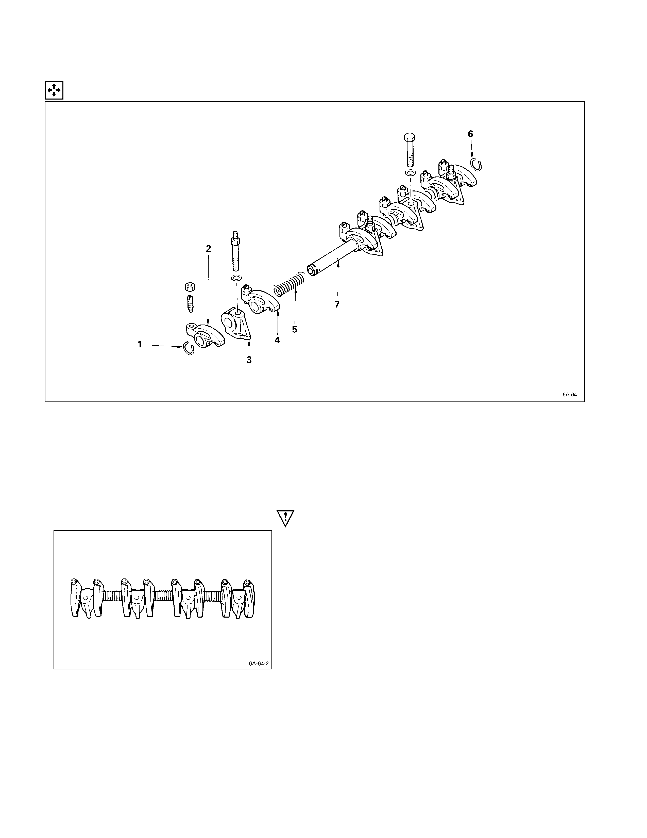
ROCKER ARM SHAFT AND ROCKER ARM
DISASSEM BLY STEPS
J
1. Rocker arm shaft snap ring 5. Rocker arm shaft spring
J
2. Rocker arm 6. Rocker arm shaft snap ring
J
3. Rocker arm shaft bracket 7. Rocker arm shaft
4. Rocker arm
IMPORTANT OPERATIONS
1. Rocker Arm Shaft Snap Ring
2. Rocker Arm
3. Rocker Arm Shaft Bracket
1) Use a pair of pliers to remove the snap rings.
2) Remove the rocker arms.
3) Remove the rocker arm shaft brackets.
If the rocker arms and rocker arm shaft brackets are
to be reinstalled, mark their installation positions by
tagging each rocker arm and rocker arm shaft bracket
with the cylinder number from which it was removed.
CYLINDER HEAD
DISASSEM BLY STEPS
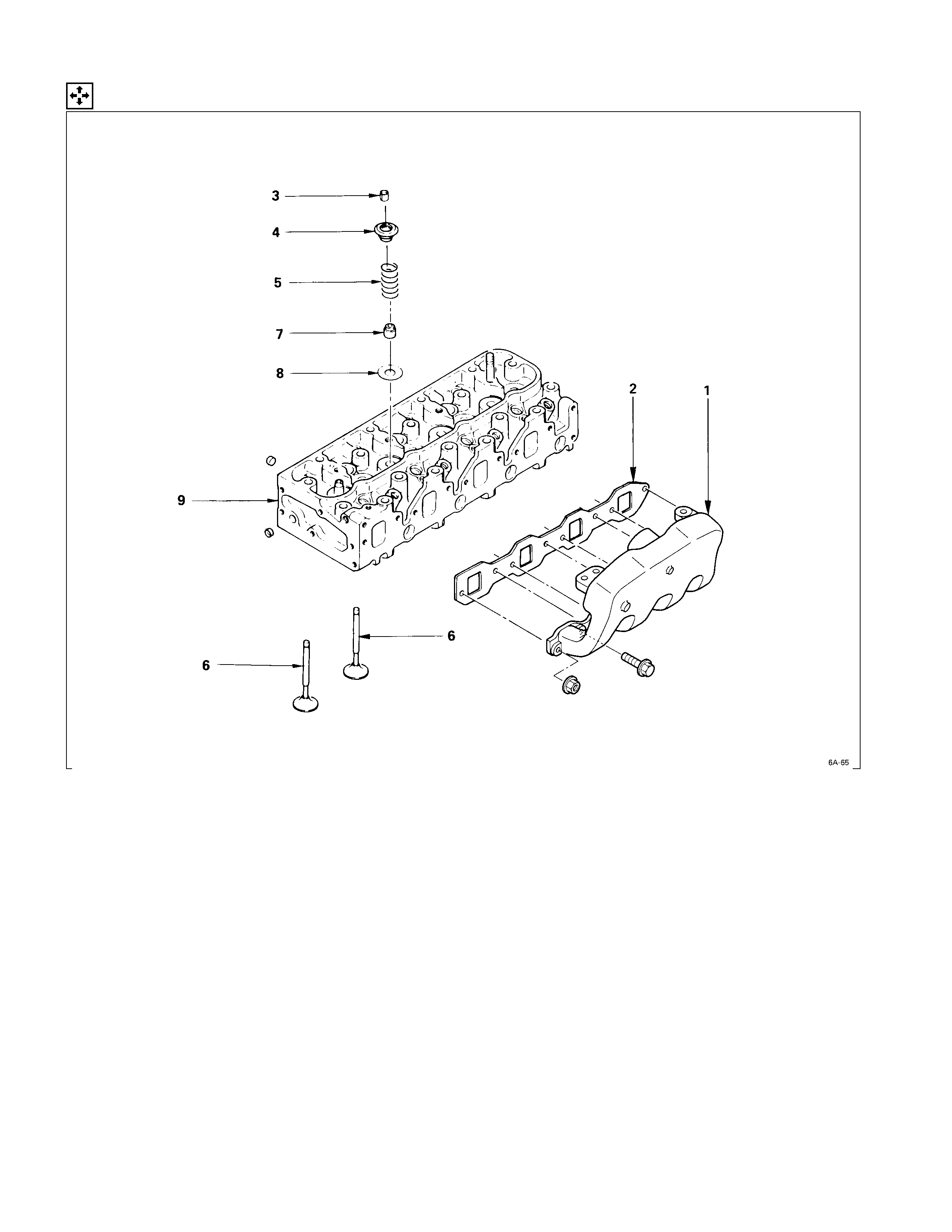
1. Intake manifold
J
6. Intake and exhaust valve
2. Intake manifold gasket 7. Valve stem oil seal
J
3. Split collar 8. Valve spring lower seat
4. Valve spring upper seat 9. Cylinder head
5. Valve spring
IMPORTANT OPERATIONS
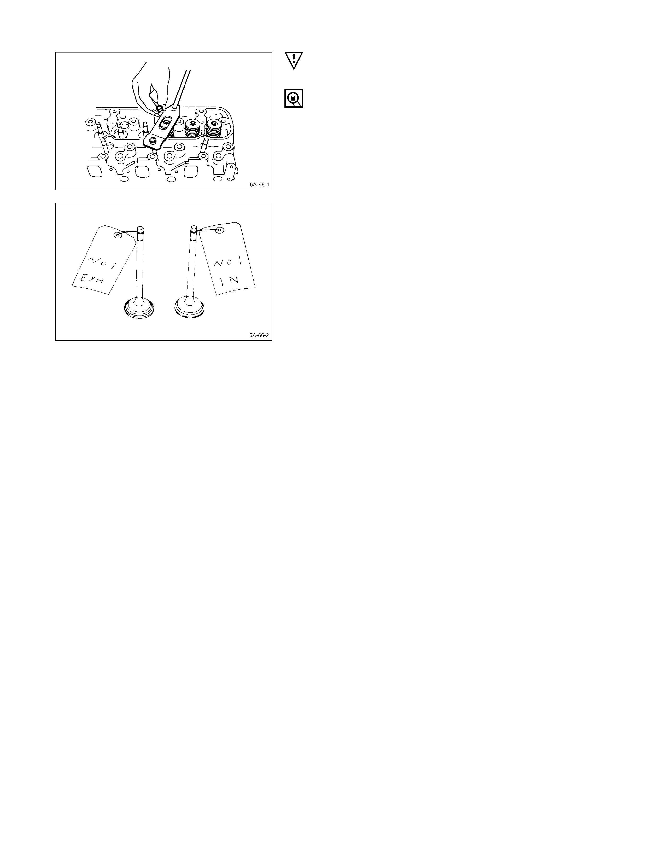
3. Split Collar
1) Place the cylinder head on a flat wooden surface.
2) Use the spring compressor to remove the split collars.
Do not allow the valve to fall from the cylinder head.
Spring Compressor: 9-8523-1423-0 (J-29760)
4. Intake and Exhaust Valve
If the intake and exhaust valves are to be reinstalled, mark
their installation positions by tagging each valve with the
cylinder number from which it was removed.
If the intake and exhaust valves are to be replaced, the
valve guides must also be replaced.
PISTON AND CONNECTING RO D
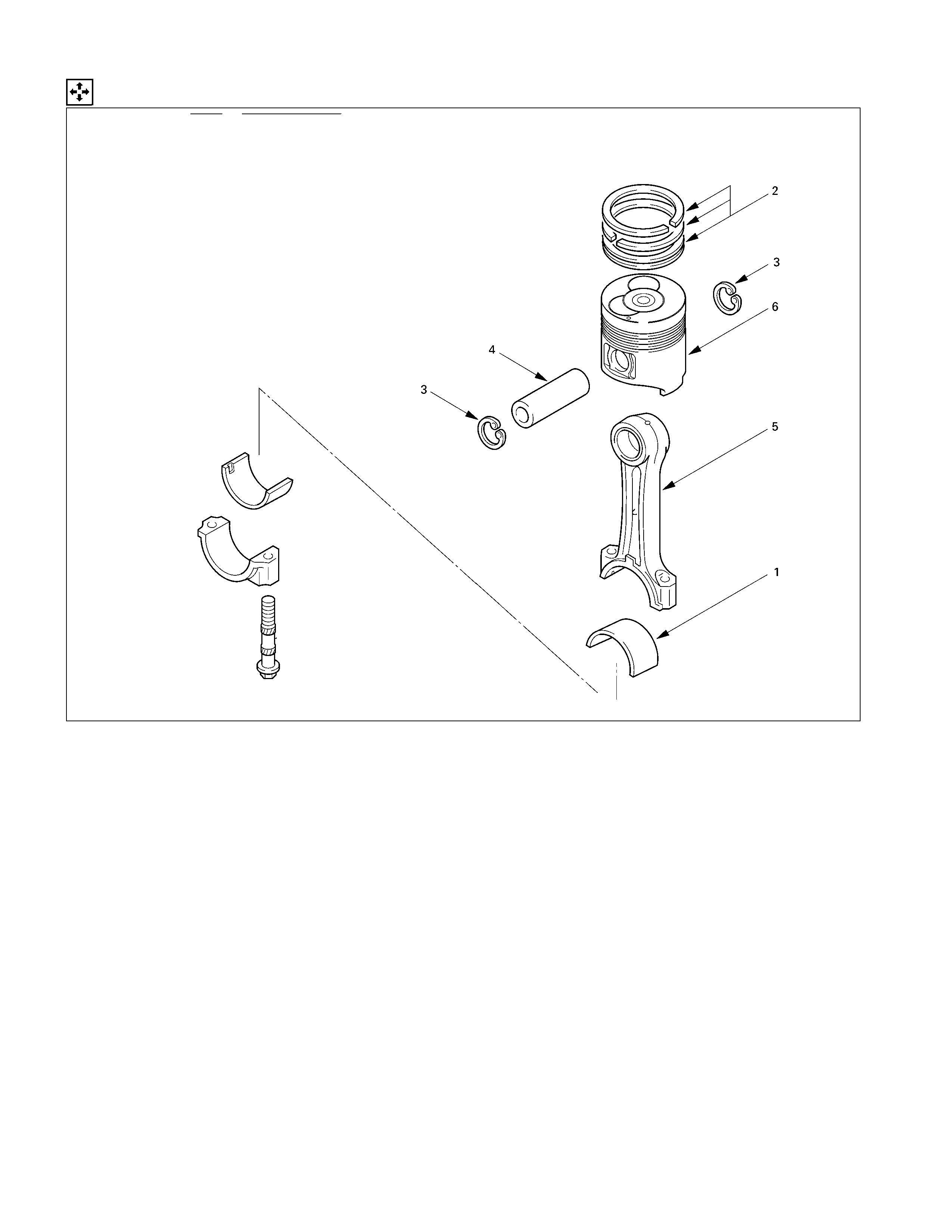
DISASSEM BLY STEPS
J
1. Connecting rod bearing
J
4. Piston pin
J
2. Piston ring 5. Connecting rod
J
3. Piston pin snap ring
J
6. Piston
IMPORTANT OPERATIONS
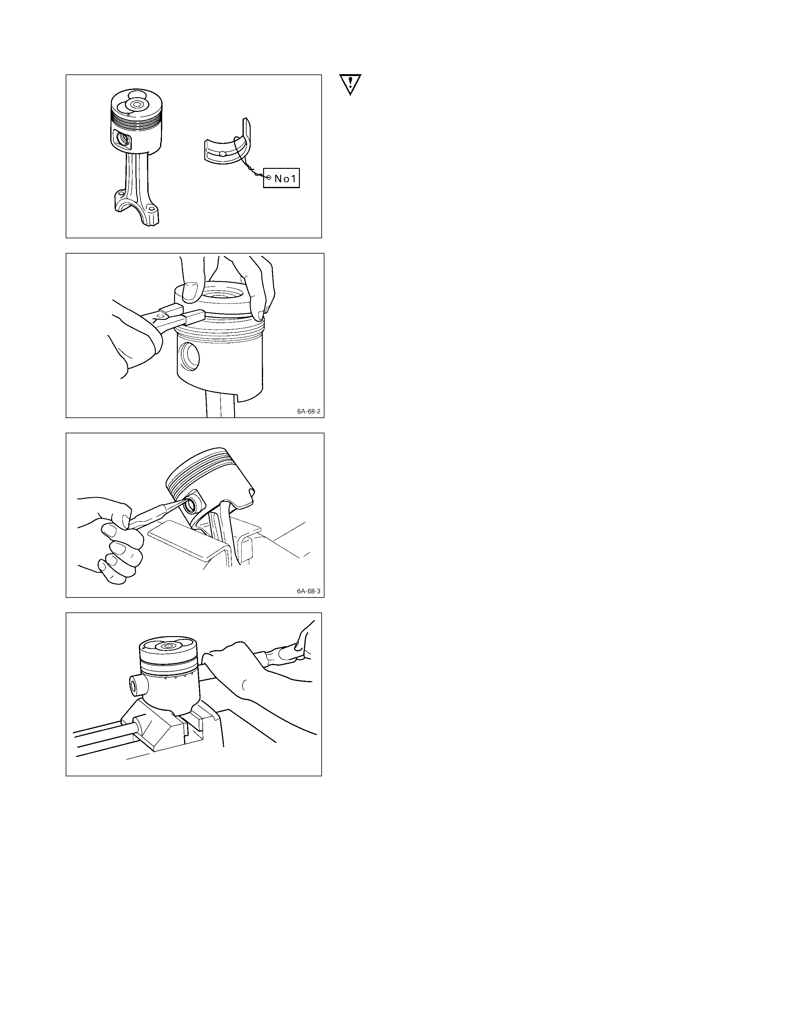
1. Connecting Rod Bearing
If the connecting rod bearings are to be reinstalled, mark
their fitting positions by tagging each bearing with the
cylinder number from which it was removed.
2. Piston Ring
1) Clamp the connecting rod in a vise.
Take care not to damage the connecting rod.
2) Use a piston ring replacer to remove the piston rings.
Piston Ring Replacer
Do not attempt to use some other tool to remove the
piston rings. Piston ring stretching will result in
reduced piston ring tension.
3. Piston Pin Snap Ring
Use a pair of pliers to remove the piston pin snap rings.
4. Piston Pin
6. Piston
Tap the piston pin out with a hammer and a brass bar.
If the pistons and piston pins are to be reinstalled, mark
their installation positions by tagging each piston and
piston pin with the cylinder number from which it was
removed.
INSPECTION AND REPAIR
Make the necessary adjustments, repairs, and part replacements if excessive wear or damage is discovered during
inspection.
CYLINDER HEAD
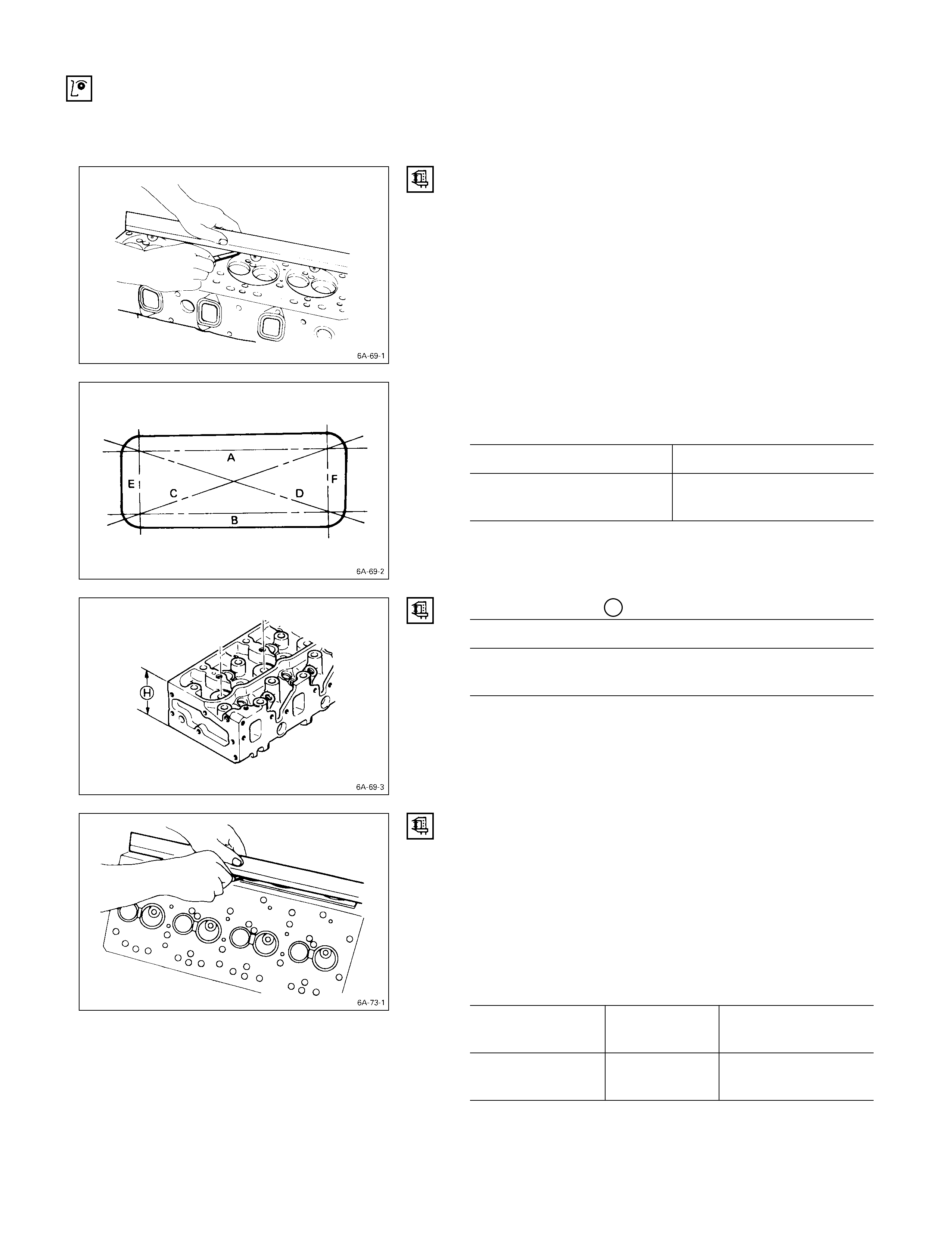
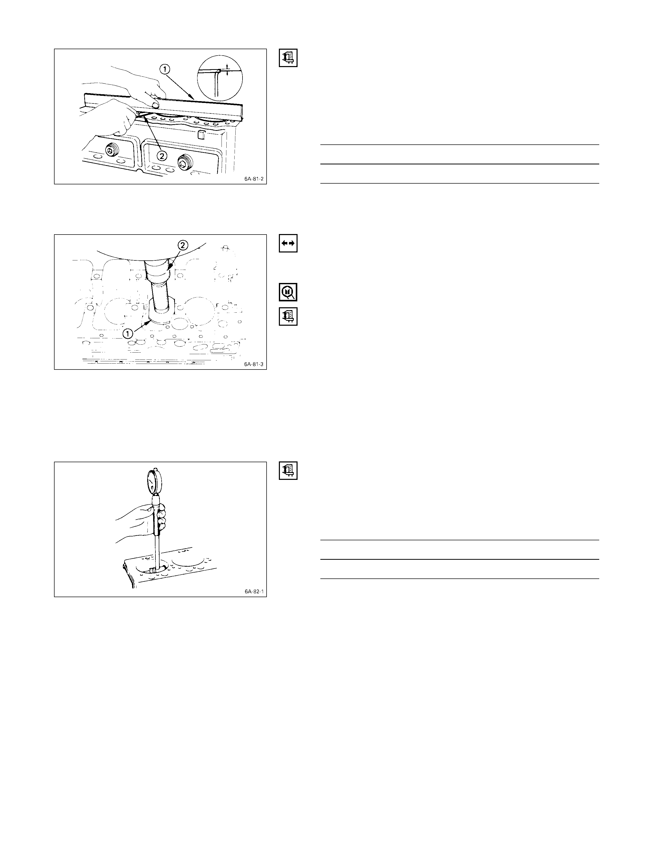
CYLINDER HEAD LO W ER FACE WARPAGE
1. Use a straight edge and a feeler gauge to measure
the four sides and the two diagonals of the cylinder
head lower face.
If the measured values exceed the limit, the cylinder head
must be replaced.
Cylinder Head Lower Face Warpage mm (in)
Standard Limit
0.05
(0.002) or less 0.20
(0.008)
Note:
The cylinder head lower face cannot be reground.
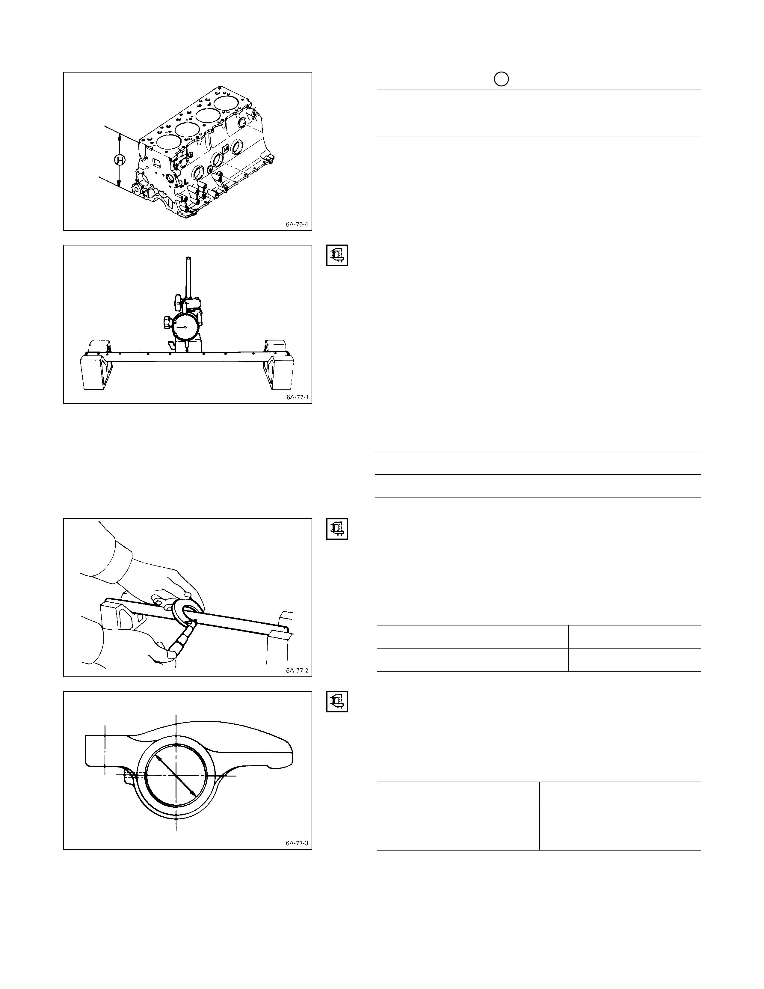
Cylinder Head Height H (Reference) mm (in)
Standard
91.95 – 92.05
(3.620 – 3.624)
MANIFOLD FITTING FACE WARPAGE
Use a straight edge and a feeler gauge to measure the
manifold cylinder head fitting face warpage.
Regrind the manifold cylinder head fitting surfaces if the
measured values are greater than the specified limit but
less than the maximum grinding allowance.
If the measured values exceed the maximum grinding
allowance, the cylinder head must be replaced.
Manifold Fitting Face Warpage mm (in)
Standard Limit Maximum Grinding
Allowance
0.05
(0.002) or less 0.20
(0.008) 0.40
(0.016)
EXHAUST MANI FO LD WARPAGE
Use a straight edge and a feeler gauge to measure the
manifold cylinder head fitting face warpage.
If the measured values exceed the specified limit, the
manifold must be replaced.
Exhaust Manifold Warpage mm (in)
Standard Limit
0.05 (0.002) or less 0.20 (0.008)
VALVE GUIDE
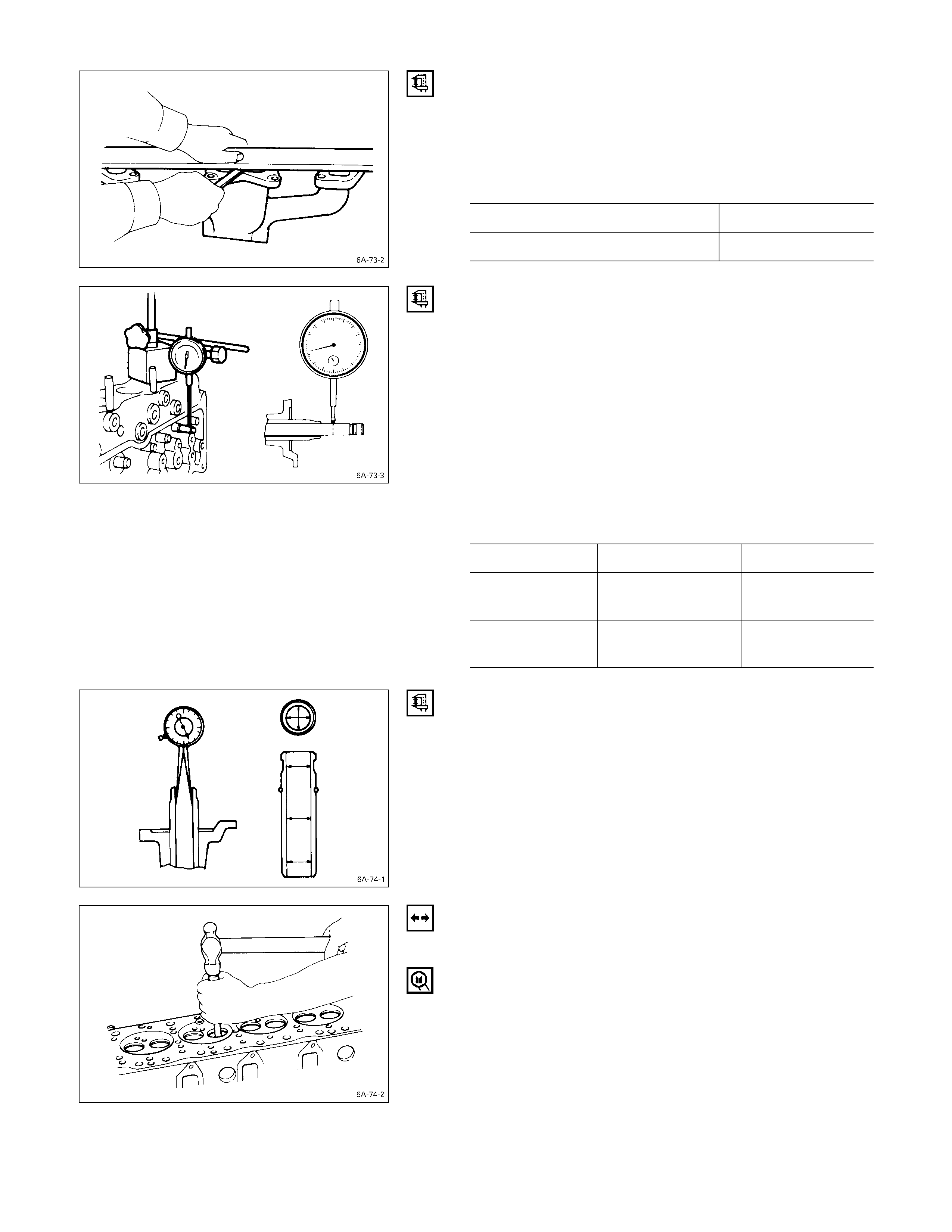
VALVE STEM AND VALVE GUIDE CLEARANCE
Measuring Method-I
1. With the valve stem inserted in the valve guide, set
the dial indicator needle to “0”.
2. Move the valve head from side to side.
Read the dial indicator.
Note the highest dial indication.
If the measured values exceed the specified limit, the
valve and the valve guide must be replaced as a set.
Valve Stem Clearance mm (in)
Standard Limit
Intake Valve 0.039 – 0.069
(0.0015 – 0.0027) 0.200
(0.008)
Exhaust Valve 0.064 – 0.093
(0.0025 – 0.0037) 0.250
(0.0098)
Measuring Method-II
1. Measure the valve stem outside diameter.
Refer to the Item “Valve Stem Outside Diameter”.
2. Use a caliper calibrator or a telescoping gauge to
measure the valve guide inside diameter.
VALVE GUI DE REPLACEMENT
Valve Guide Removal
Use a hammer and the valve guide replacer to drive out
the valve guide from the cylinder head lower face.
Valve Guide Replacer: 9-8523-1212-0
Valve Guide Installation
1. Apply engine oil to the valve guide outer
circumference.
2. Attach the valve guide installer to the valve guide.
3. Use a hammer to drive the valve guide into position
from the cylinder head upper face.
Valve Guide Replacer: 9-8523-1212-0
4. Measure the height of the valve guide upper end from
the upper face of the cylinder head.
Valve Guide Upper End Height H (Reference) mm (in)
13 (0.51)
Note:
If the valve guide has been removed, both the valve
and the valve guide must be replaced as a set.
VALVE AND VALVE SEAT INSERT
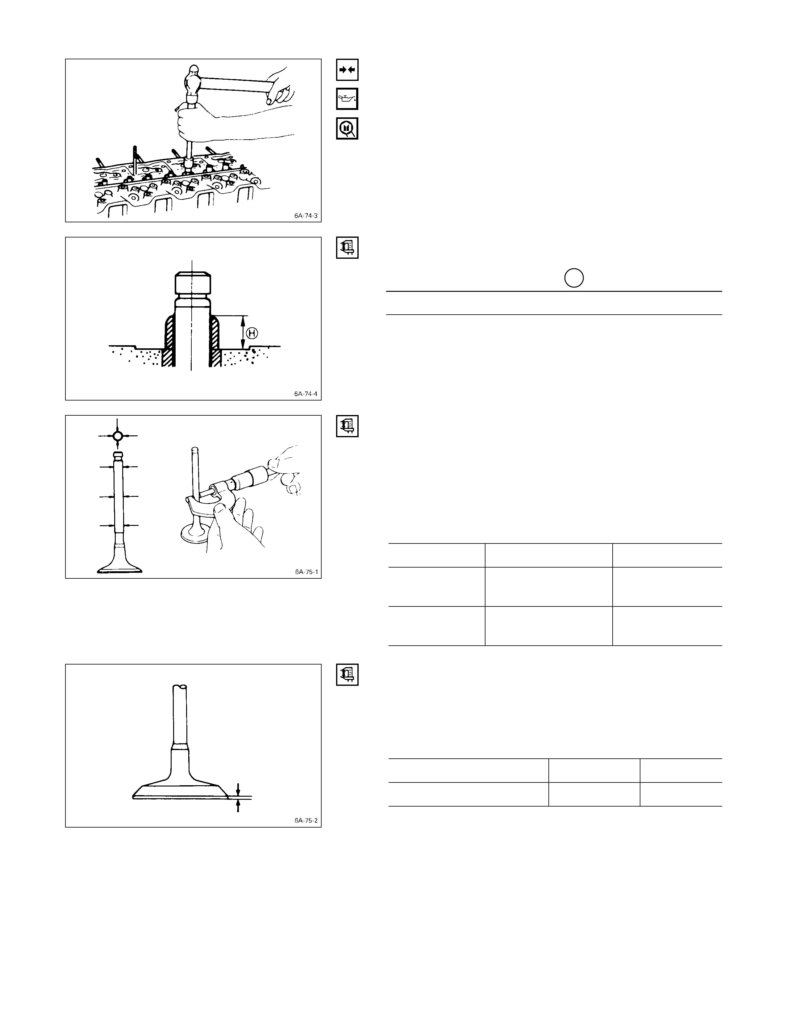
VALVE STEM OUTSIDE DI AMETER
Measure the valve stem diameter at three points.
If the measured value is less than the specified limit, the
valve and the valve guide must be replaced as a set.
Valve Stem Outside Diameter mm (in)
Standard Limit
Intake Valve 7.946 – 7.961
(0.3128 – 0.3134) 7.880
(0.3102)
Exhaust Valve 7.921 – 7.936
(0.3119 – 0.3124) 7.850
(0.3090)
VALVE THICKNESS
Measure the valve thickness.
If the measured value is less than the specified limit, the
valve and the valve guide must be replaced as a set.
Intake and Exhaust Valve Thickness mm (in)
Standard Limit
4JB1T 1.8 (0.07) 1.5 (0.06)
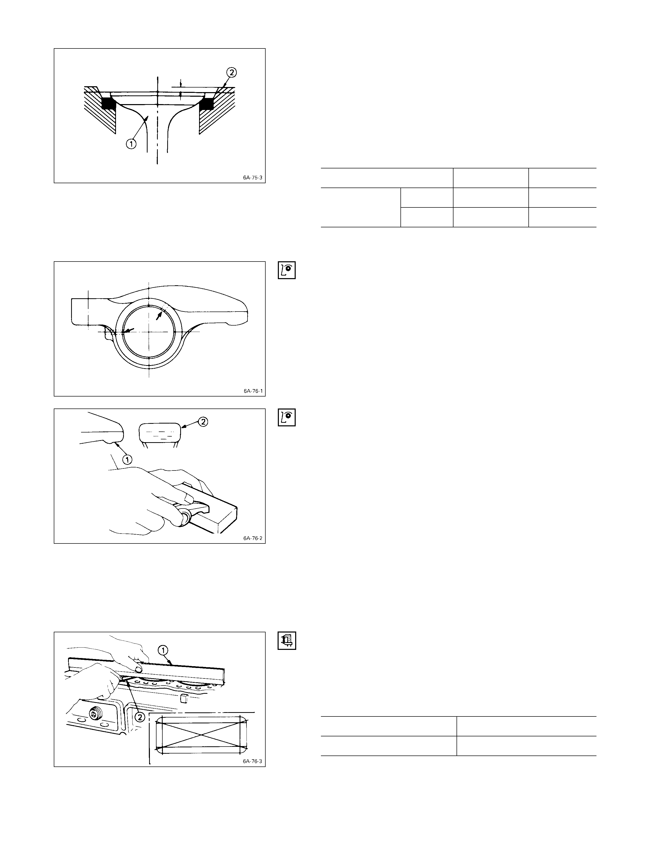
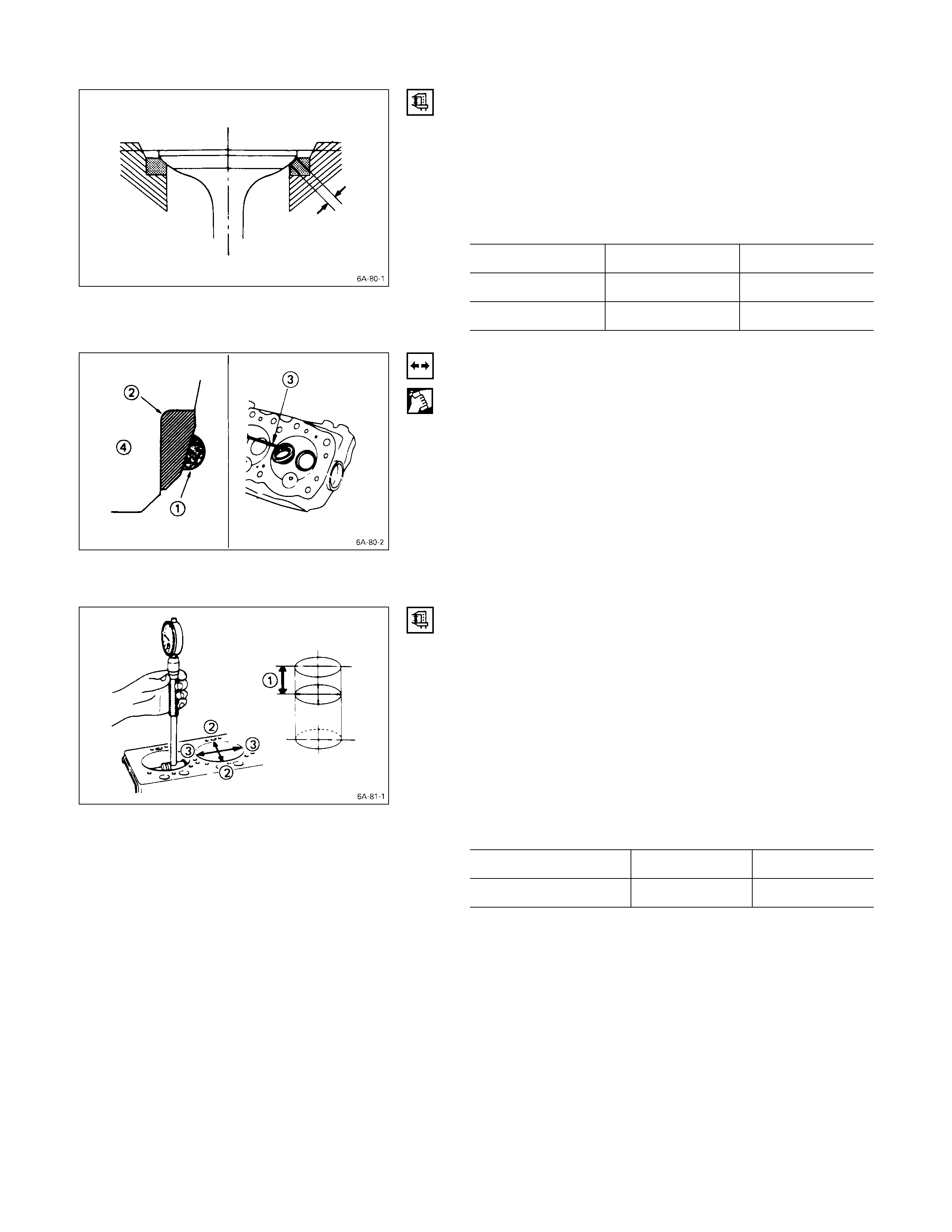
VALVE DEPRESSIO N
1. Install the valve Q to the cylinder head R.
2. Use a depth gauge or a straight edge with steel rule to
measure the valve depression from the cylinder head
lower surface.
If the measured value exceeds the specified limit, the
valve seat insert must be replaced.
Valve Depression mm (in)
Standard Limit
Intake 0.73 (0.029) 1.28 (0.050)
4JB1T Exhaust 0.70 (0.028) 1.20 (0.047)
3. Check that the rocker arm oil port is free of
obstructions.
If necessary, use compressed air to clean the rocker
arm oil port.
ROCKER ARM CORRECTIO N
Inspect the rocker arm valve stem contact surfaces for
step wear Q and scoring R.
If the contact surfaces have light step wear or scoring,
they may be honed with an oil stone.
If the step wear or scoring is severe, the rocker arm must
be replaced.
CYLINDER BODY
CYLINDER BODY UPPER FACE WARPAGE
1. Remove the cylinder body dowel.
2. Remove the cylinder liner.
Refer to “Cylinder Liner Replacement”.
3. Use a straight edge Q and a feeler gauge R to
measure the four sides and the two diagonals of the
cylinder body upper face.
If the measured values exceeds the limit, the cylinder
body must be replaced.
Cylinder Body Upper Face Warpage mm (in)
Standard Limit
0.05 (0.002) or less 0.20 (0.008)
Cylinder Body Height H (Reference) mm (in)
Standard
4JB1T 269.945 – 270.055 (10.6277 – 10.6320)
5. Reinstall the cylinder liner.
Refer to “Cylinder Liner Replacement”.
6. Reinstall the cylinder body dowel.
ROCKER ARM SHAFT AND ROCKER ARM
ROCKER ARM SHAFT RUN-O UT
1. Place the rocker arm shaft on a V-block.
2. Use a dial indicator to measure the rocker arm shaft
central portion run-out.
If the run-out is very slight, correct the rocker arm
shaft run-out with a bench press. The rocker arm must
be at cold condition.
If the measured rocker arm shaft run-out exceeds the
specified limit, the rocker arm shaft must be replaced.
Rocker Arm Shaft Run-Out mm (in)
Limit
0.3 (0.012)
ROCKER ARM SHAFT OUTSIDE DIAMETER
Use a micrometer to measure the rocker arm fitting
portion outside diameter.
If the measured value is less than the specified limit, the
rocker arm shaft must be replaced.
Rocker Arm Shaft Outside Diameter mm (in)
Standard Limit
18.98 – 19.00 (0.747 – 0.748) 18.90 (0.744)
ROCKER ARM SHAFT AND ROCKER ARM
CLEARANCE
1. Use either a vernier caliper or a dial indicator to
measure the rocker arm inside diameter.
Rocker Arm Inside Diameter mm (in)
Standard Limit
19.010 – 19.030
(0.748 – 0.749) 19.100 (0.752)
2. Measure the rocker arm shaft outside diameter.
If the measured value exceeds the specified limit,
replace either the rocker arm or the rocker arm shaft.
Rocker Arm Shaft and Rocker Arm
Clearance mm (in)
Standard Limit
0.01 – 0.05
(0.0004 – 0.0020) 0.20 (0.008)
VALVE SPRING
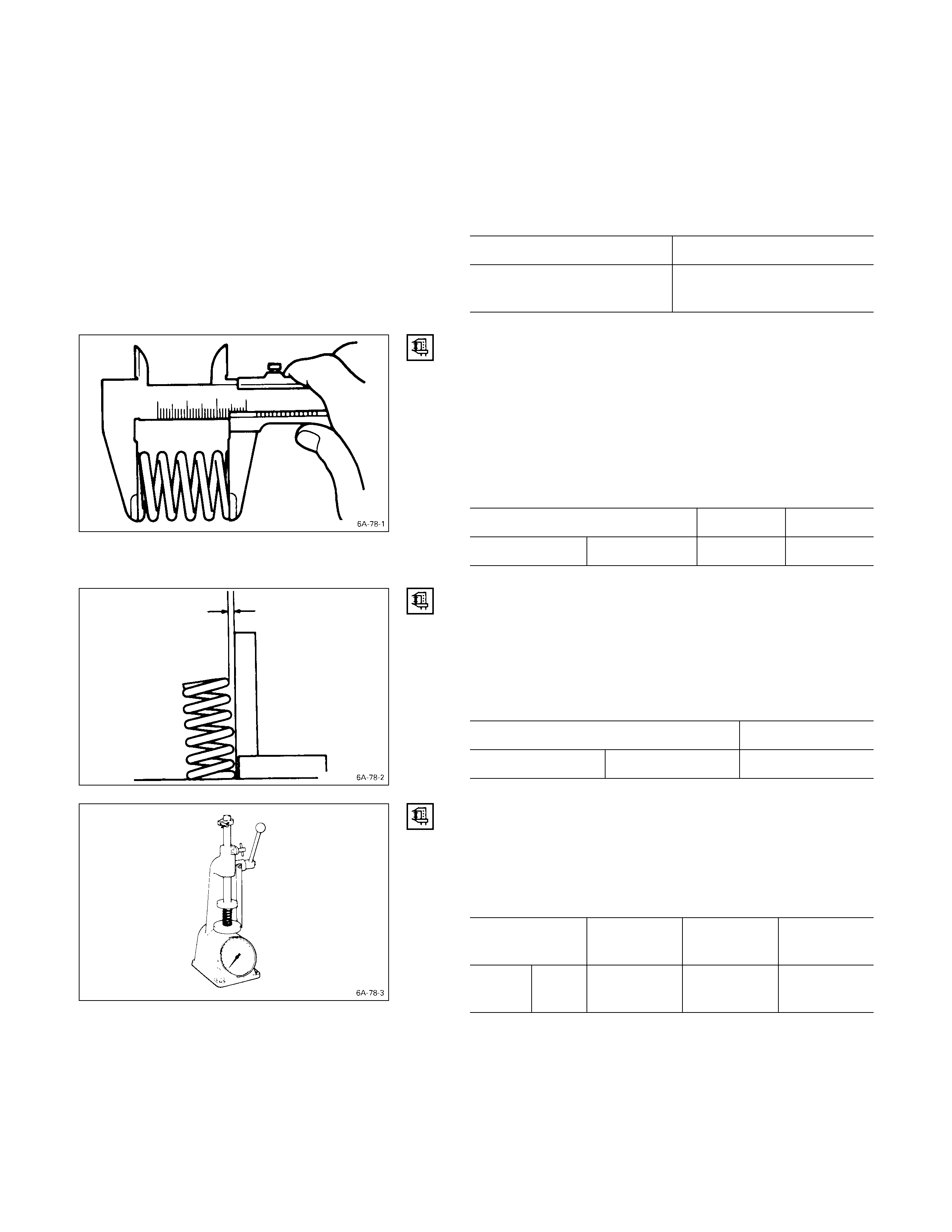
VALVE SPRING FREE HEIGHT
Use a vernier caliper to measure the valve spring free
height.
If the measured value is less than the specified limit, the
valve spring must be replaced.
Inner and Outer Spring Free Height mm (in)
Standard Limit
4JB1T Single spring 48.0 (1.89) 47.1 (1.85)
VALVE SPRING SQUARENESS
Use a surface plate and a square to measure the valve
spring squareness.
If the measured value exceeds the specified limit, the
valve spring must be replaced.
Inner and Outer Spring Squareness mm (in)
Limit
4JB1T Single Spring 1.7 (0.07)
VALVE SPRING TENSION
Use a spring tester to measure the valve spring tension.
If the measured value is less than the specified limit, the
valve spring must be replaced.
Valve Spring Tension kg (lb/N)
Compressed
Height Standard Limit
4JB1T Single
Spring 38.9 mm
(1.53 in) 30.2
(66.4/296.0) 26.3
(57.9/257.7)
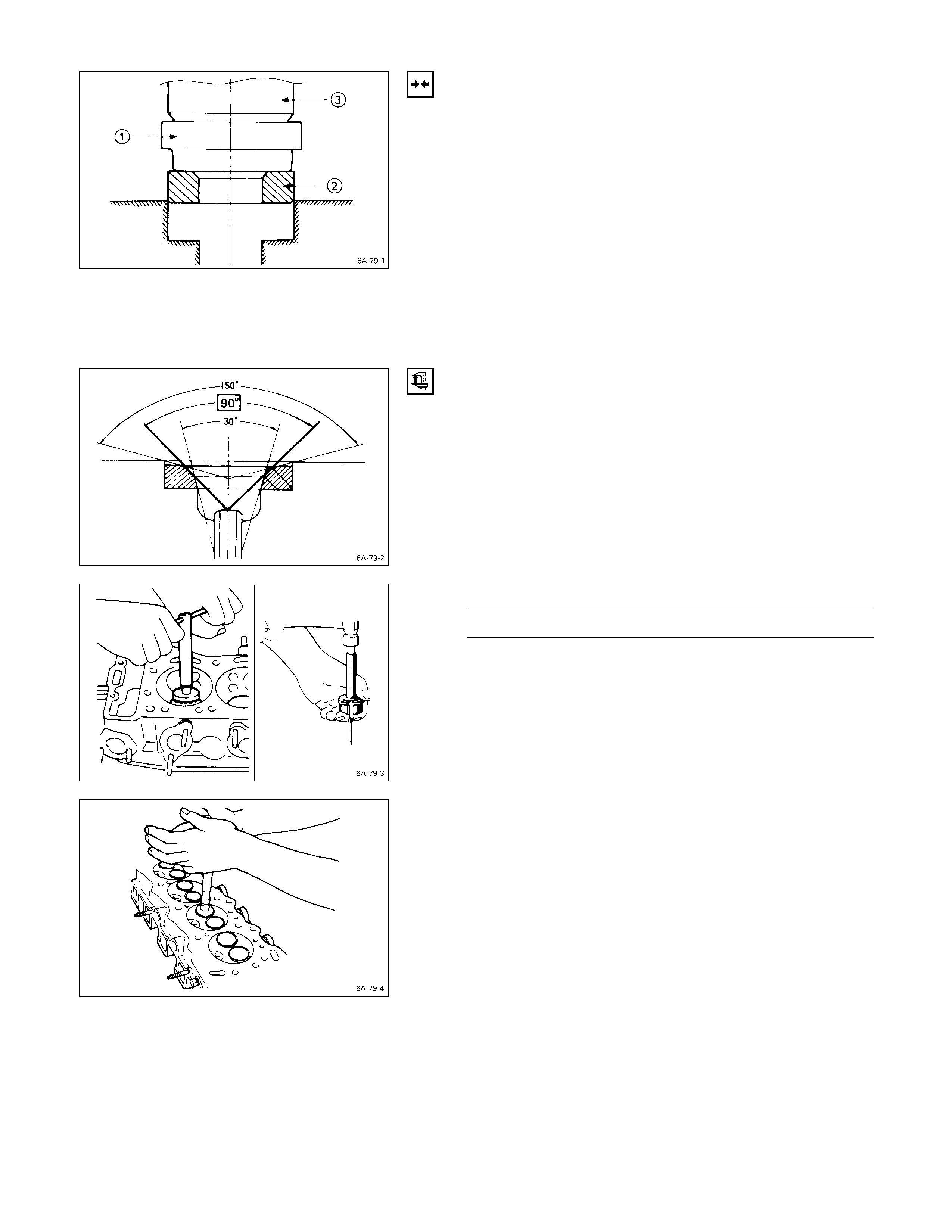
VALVE SEAT INSERT INSTALLATION
1. Carefully place the attachment Q (having a smaller
outside diameter than the valve seat insert) on the
valve seat insert R.
Note:
The smooth side of the attachment must contact the
valve seat insert.
2. Use a bench press S to gradually apply pressure to
the attachment and press the valve seat insert into
place.
Note:
Do not apply an excessive amount of pressure with
the bench press. Damage to the valve seat insert will
result.
VALVE SEAT INSERT CORRECTIO N
1. Remove the carbon from the valve seat insert surface.
2. Use a valve cutter (15°, 45°, and 75° blades) to
minimize scratches and other rough areas. This will
bring the contact width back to the standard value.
Remove only the scratches and rough areas. Do not
cut away too much. Take care not to cut away
unblemished areas of the valve seat surface.
Valve Seat Angle degree
45
Note:
Use an adjustable valve cutter pilot.
Do not allow the valve cutter pilot to wobble inside the
valve guide.
3. Apply abrasive compound to the valve seat insert
surface.
4. Insert the valve into the valve guide.
5. Turn the valve while tapping it to fit the valve seat
insert.
6. Check that the valve contact width is correct.
7. Check that the valve seat insert surface is in contact
with the entire circumference of the valve.
VALVE CONTACT WI DTH
1. Check the valve contact faces for roughness and
unevenness. Make smooth the valve contact surfaces.
2. Measure the valve contact width.
If the measured value exceeds the specified limit, the
valve seat insert must be replaced.
Valve Contact Width mm (in)
Standard Limit
Intake 1.7 (0.067) 2.2 (0.087)
Exhaust 2.0 (0.079) 2.5 (0.078)
VALVE SEAT INSERT REPLACEM ENT
VALVE SEAT INSERT REMO VAL
1. Arc weld the entire inside circumference Q of the
valve seat insert R.
2. Allow the valve seat insert to cool for a few minutes.
This will invite contraction and make removal of the
valve seat insert easier.
3. Use a screwdriver S to pry the valve seat insert free.
Take care not to damage the cylinder head T.
4. Carefully remove carbon and other foreign material
from the cylinder head insert bore.
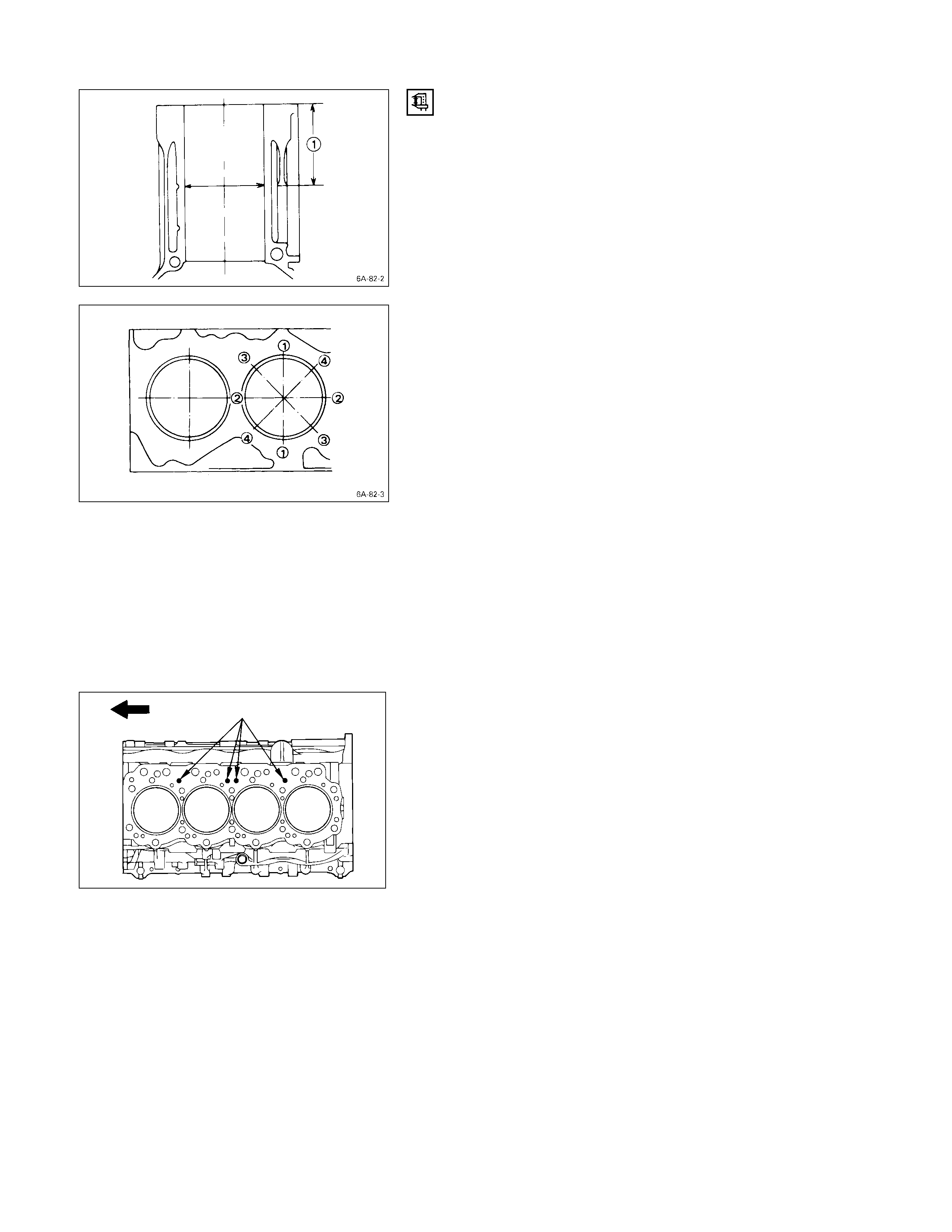
CYLINDER LINER BO RE MEASUREM ENT
Use a cylinder indicator to measure the cylinder bore at
measuring point Q in the thrust R-R and axial S-S
directions of the crankshaft.
Measuring Point Q 20 mm (0.79 in)
If the measured value exceeds the specified limit, the
cylinder liner must be replaced.
Cylinder Liner Bore mm (in)
Standard Limit
4JB1T 93.021 (3.662) 93.100 (3.665)
Note:
The inside of the dry type cylinder liner is chrome
plated. It cannot be rebored or honed.
If the inside of the cylinder liner is scored or
scorched, the cylinder liner must be replaced.
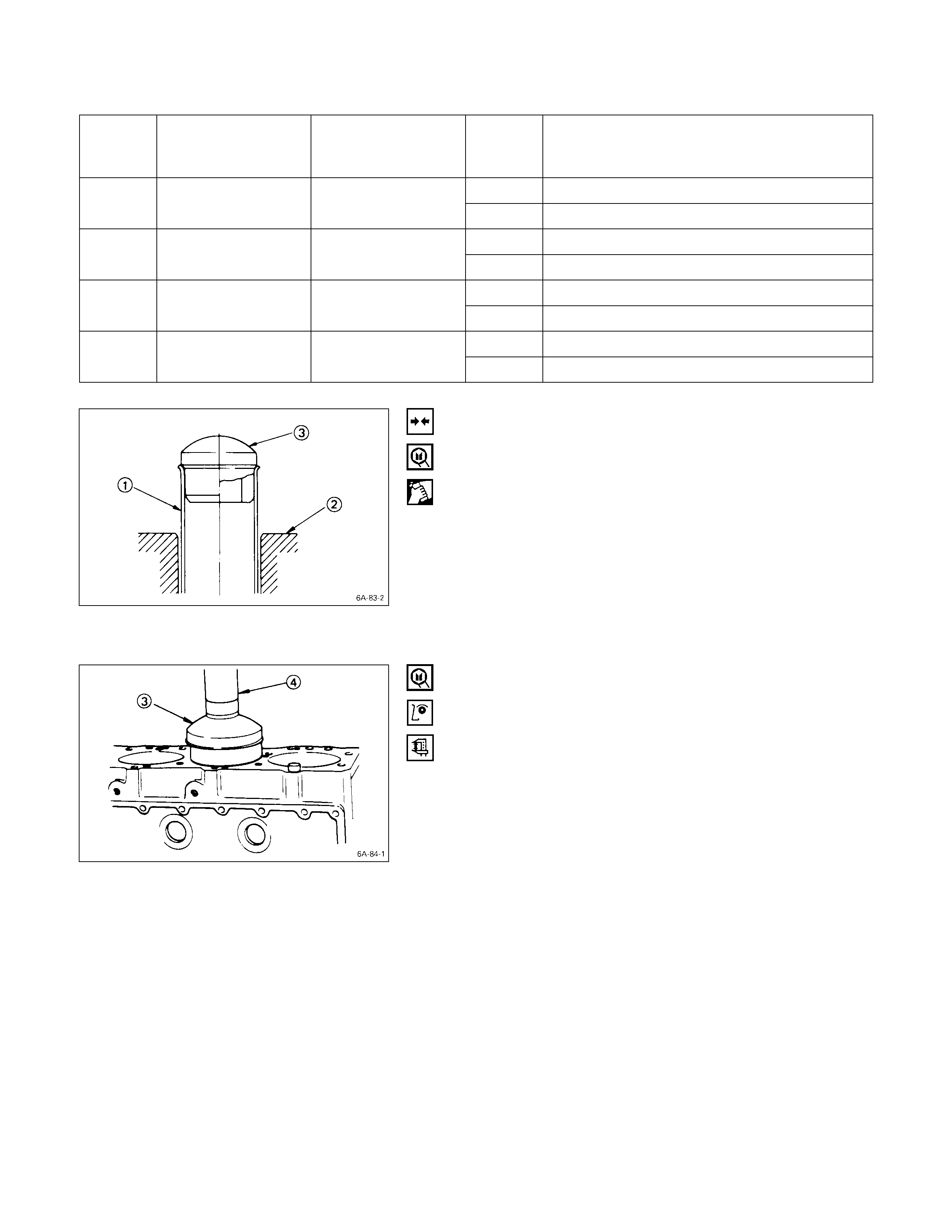
CYLINDER LINER PRO J ECTION INSPECTION
1. Hold a straight edge Q along the top edge of the
cylinder liner to be measured.
2. Use a feeler gauge R to measure each cylinder liner
projection.
Cylinder Liner Projection mm (in)
Standard
0 – 0.1 (0 – 0.004)
The difference in the cylinder liner projection height
between any two adjacent cylinders must not exceed
0.03 mm (0.0012 in).
CYLINDER LINER REPLACEMENT
CYLINDER LINER REM OVAL
1. Insert the cylinder liner remover Q into the cylinder
body (from the lower side of the cylinder body) until it
makes firm contact with the cy linder liner.
Cylinder Liner Remover:
5-8840-2039-0
5-8840-2304-0: 4JG2T Engine
2. Use a bench press R to slowly force the cylinder liner
from the cylinder body.
Note:
Take care not to damage the cylinder body upper face
during the cylinder liner removal procedure.
3. Measure the cylinder body upper face warpage.
Refer to “Cylinder Body Upper Face Warpage”.
CYLINDER LINER G RADE SELECTION
Subtract the average cylinder body bore from the average
cylinder liner outside diameter to obtain the fitting
interference.
Fitting Interference mm (in)
Standard
– 0.0010* – 0.019 (– 0.00004* – 0.0007)
* A minus (–) value indicates that the cylinder body bore
is smaller than the liner outside diameter.
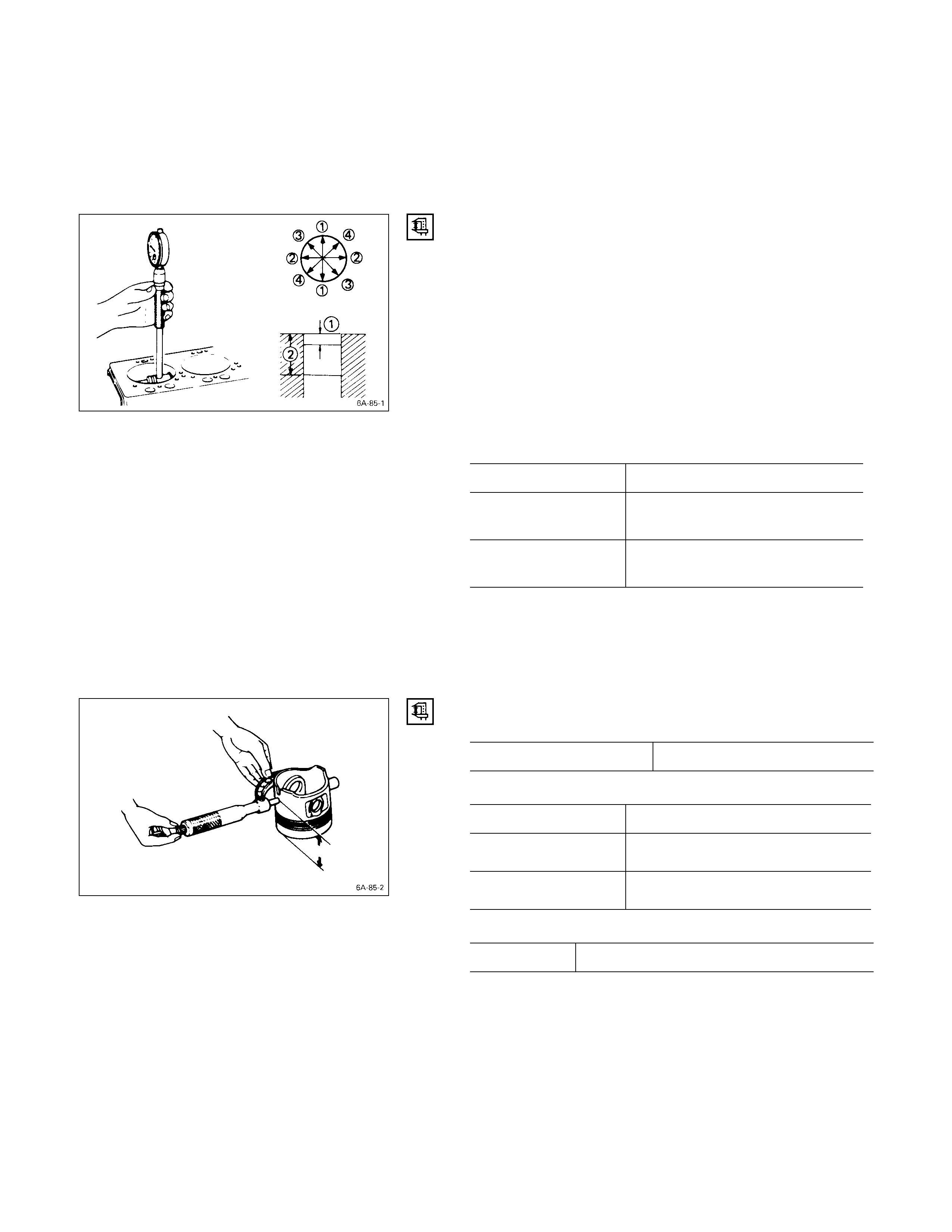
CYLINDER BODY BORE MEASUREMENT
1. Take measurements at measuring point Q across
positions Q-Q, R-R, S-S, and T-T.
Measuring Point Q 98 mm (3.86 in)
2. Calculate the average value of the four measurements
to determine the correct cylinder grade.
3. Consult the following table with the resultant diameter
for the correct liner application.
CYLINDER LINER G RADE SELECTION AND
STANDARD FITTING INTERFERENCE
Accurately measured fitting interference and proper
cylinder liner grade selection are extremely important.
If the cylinder liner fitting interference is too small, engine
cooling efficiency will be adversely affected.
If the cylinder liner fitting interference is too large, it will be
difficult to insert the cylinder liner into the cylinder body.
A mark was stamped on the upper of the cylinder block
during production to indicate the correct liner.
The liner grade (i.e.1.2.3.4) is indicated in metal stamp.
Cylinder Liner Grade mm (in)
Liner
Outside
Grade Cylinder Body
Bore Diameter Liner Outside
Diameter Liner
Bore
Grade Service Liner Bore Measurement
AX 93.035 – 93.050 (3.6628 – 3.6634)
195.001 – 95.010
(3.7402 – 3.7405) 95.011 – 95.020
(3.7406 – 3.7409) CX 93.051 – 93.066 (3.6634 – 3.6640)
AX 93.035 – 93.050 (3.6628 – 3.6634)
295.011 – 95.020
(3.7406 – 3.7409) 95.021 – 95.030
(3.7410 – 3.7413) CX 93.051 – 93.066 (3.6634 – 3.6640)
AX 93.035 – 93.050 (3.6628 – 3.6634)
395.021 – 95.030
(3.7410 – 3.7413) 95.031 – 95.040
(3.7414 – 3.7417) CX 93.051 – 93.066 (3.6634 – 3.6640)
AX 93.035 – 93.050 (3.6628 – 3.6634)
495.031 – 95.040
(3.7414 – 3.7417) 95.041 – 95.050
(3.7418 – 3.7421) CX 93.051 – 93.066 (3.6634 – 3.6640)
CYLINDER LINER I NSTALLATI ON
1. Cylinder Liner Installation Using The Special Tool
1) Use new kerosene or diesel oil to thoroughly clean
the cylinder liners and bores.
2) Use compressed air to blow-dry the cylinder liner
and bore surfaces.
Note:
All foreign material must be carefully removed from
the cy linder liner and the cylinder bore before
installation.
3) Insert the cylinder liner Q into the cylinder body R
from the top of the cylinder body.
4) Set the cylinder liner installer S to the top of the
cylinder liner.
Cylinder Liner Installer: 5-8840-2040-0
5-8840-2313-0 (4JG2T)
5) S is directly beneath the bench press shaft center
T.
Note:
Check that the cylinder liner is set perpendicular to
the bench press and that there is no wobble.
6) Use the bench press to apply a seating force of
500 kg (1,100 lb/4,900 N) to the cylinder liner.
7) Apply a force of 2,500 kg (5,500 lb/24,500 N) to
fully seat the cylinder liner.
8) After installing the cylinder liner, measure the
cylinder liner projection.
Refer to “Cylinder Liner Projection Inspection”.
2. Cylinder Liner Installation Using Dry Ice
Cylinder liner is a chrome plated dry type, it is
advisable to use dry ice during the installation
procedure.
Cooling the cylinder liner with dry ice will cause the
cylinder liner to contract, thus making installation
easier.
Note:
It is important that the cylinder liner be inserted to the
cylinder body immediately after it has been cooled.
Warning:
Dry ice must be used with great care. Careless
handling of dry ice can result in severe frostbite.
PISTON GRADE SELECTION
Measure the cylinder liner bore after installing the cylinder
liner. Then select the appropriate piston grade for the
installed cylinder liner.
1. Measure the cylinder liner bore.
Refer to “Cylinder Liner Bore Measurement”
Measuring Points Q20 mm (0.8 in) for 4JA1 and 4JB1T
R140 mm (5.5 in) for 4JA1
R160 mm (6.3 in) for 4JB1T
R165 mm (6.49 in) for 4JG2T
Cylinder Liner Bore (Service Part) mm (in)
Grade
AX 93.035 – 93.050
(3.6628 – 3.6634)
CX 93.051 – 93.066
(3.6634 – 3.6640)
Note:
It is most important that the correct piston grade be
used. Failure to select the correct piston grade will
result in engine failure. Always measure the cylinder
bore and select the correct piston grade.
2. Measure the piston diameter.
Piston Measuring Point mm (in)
4JB1T 74 (2.91)
Piston Grade (Service Part) mm (in)
Grade 4JB1T
AX 92.974 – 92.989
(3.6604 – 3.6610)
CX 92.990 – 93.005
(3.6610 – 3.6616)
Cylinder Liner and Piston Clearance mm (in)
4JB1T 0.046 – 0.076 (0.0018 – 0.0030)
Note:
Cylinder liner kit clearances are preset. However, the
cylinder liner installation procedure may result in
slight decreases in cylinder liner clearances. Always
measure the cylinder liner clearance after installation
to be sure that it is correct.
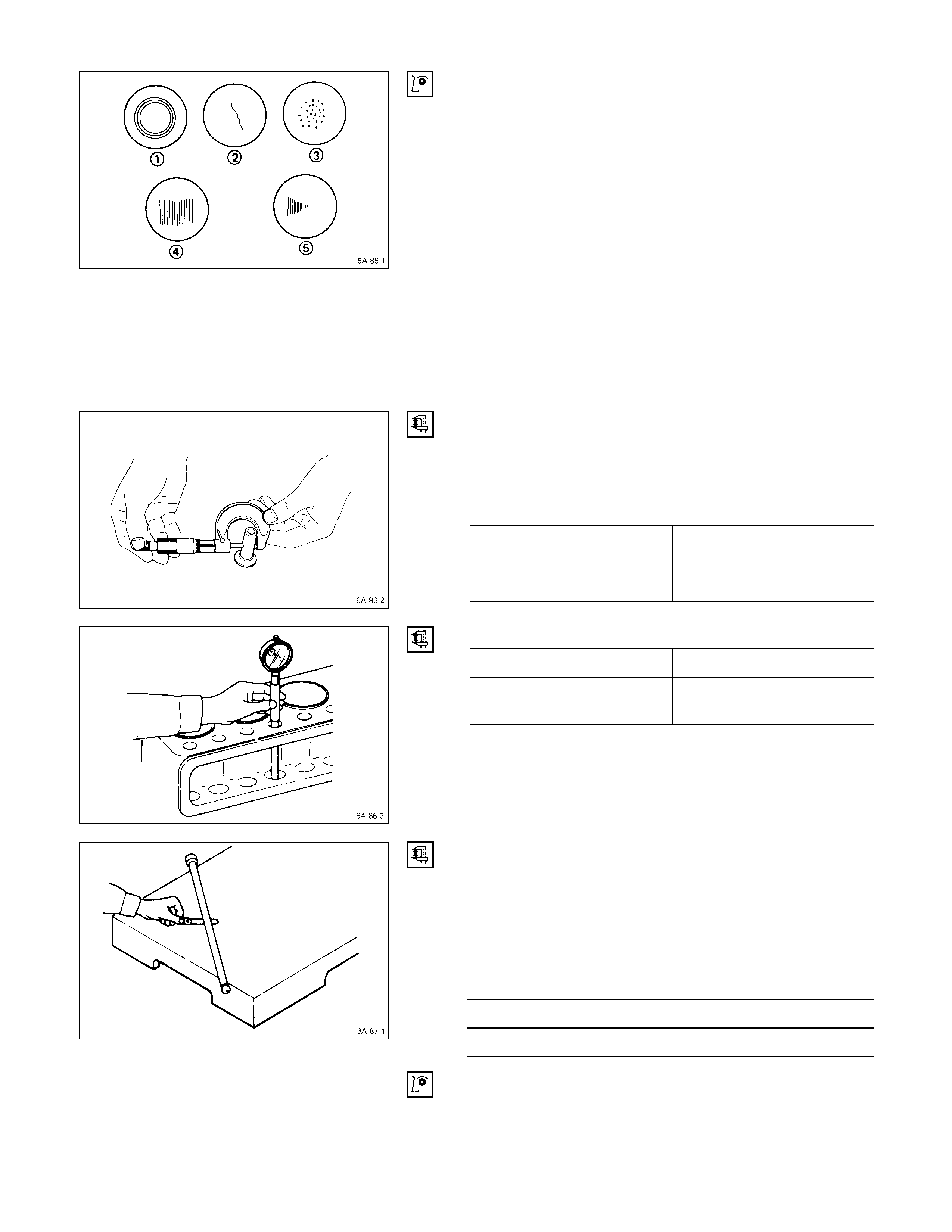
TAPPET AND PUSH ROD
Visually inspect the tappet contact surfaces for pitting,
cracking, and other abnormal conditions. The tappet must
be replaced if any of these conditions are present.
Refer to the illustration at the left.
QNormal contact
RCracking
SPitting
TIrregular contact Uneven contact
UIrregular contact One-sided contact
Note:
The tappet surfaces are spherical. Do not attempt to
grind them with an oil stone or similar tool in an effort
to repair the tappet. If the tappet is damaged, it must
be replaced.
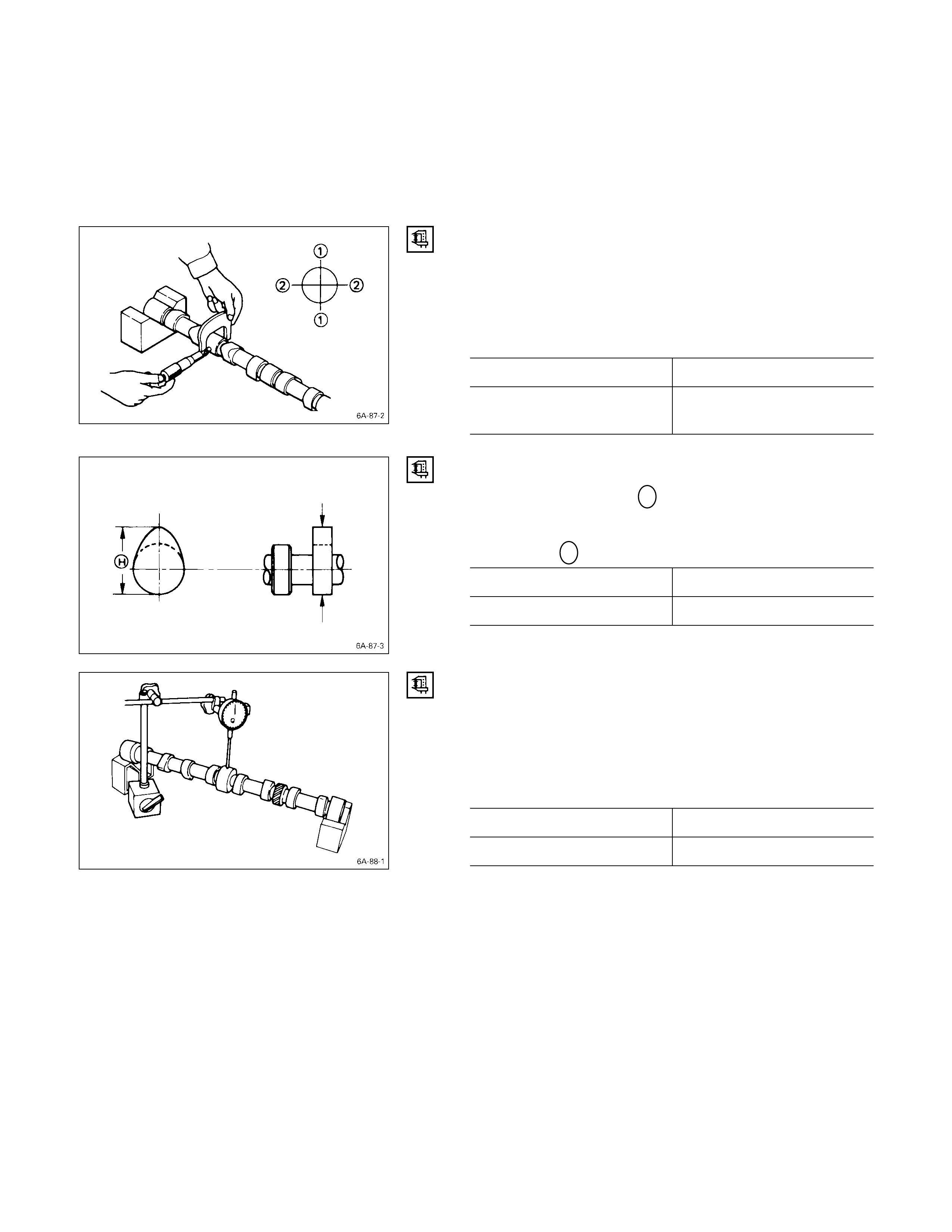
TAPPET OUTSIDE DIAM ETER
Measure the tappet outside diameter with a micrometer.
If the measured value is less than the specified limit, the
tappet must be replaced.
Tappet Outside Diameter mm (in)
Standard Limit
12.97 – 12.99
(0.510 – 0.511) 12.95 (0.510)
Tappet and Cylinder Body Clearance mm (in)
Standard Limit
0.01 – 0.046
(0.0004 – 0.0018) 0.10 (0.004)
PUSH ROD CURVATURE
1. Lay the push rod on a surface plate.
2. Roll the push rod along the surface plate and measure
the push rod curvature with a thickness gauge.
If the measured value exceeds the specified limit, the
push rod must be replaced.
Pushrod Curvature mm (in)
Limit
0.3 (0.012)
3. Visually inspect both ends of the push rod for
excessive wear and damage. The push rod must be
replaced if these conditions are discovered during
inspection.
CAMSHAFT
Visually inspect the journals, the cams, the oil pump drive
gear, and the camshaft bearings for excessive wear and
damage. The camshaft and the camshaft bearings must
be replaced if these conditions are discovered during
inspection.
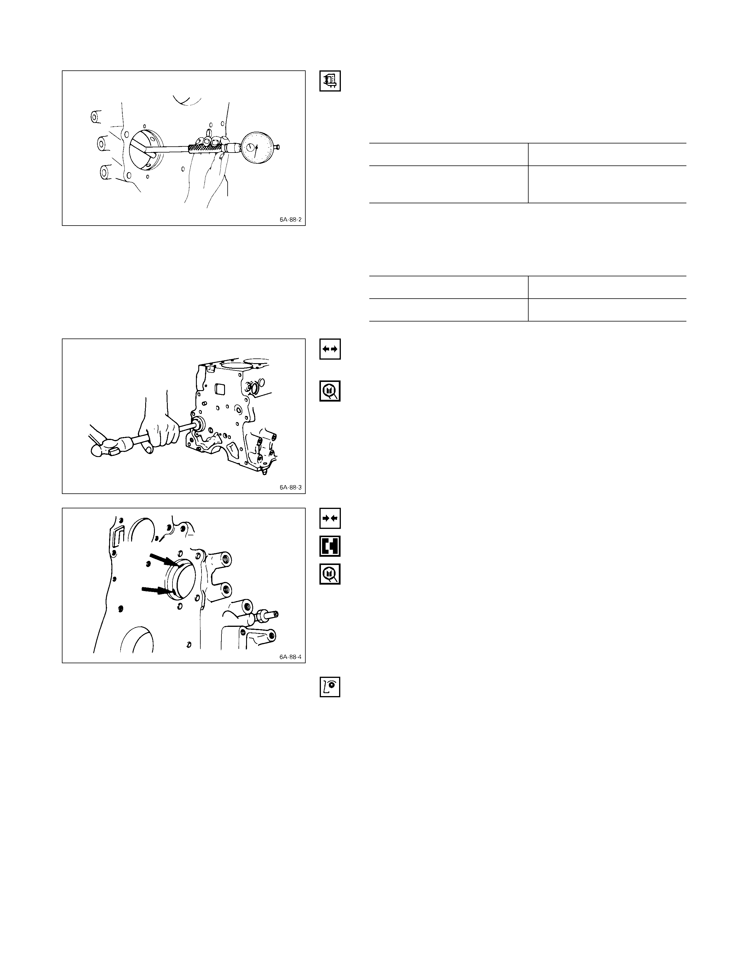
CAMSHAFT JO URNAL DIAMETER
Use a micrometer to measure each camshaft journal
diameter in two directions (Q and R). If the measured
value is less than the specified limit, the camshaft must be
replaced.
Camshaft Journal Diameter mm (in)
Standard Limit
49.945 – 49.975
(1.9663 – 1.9675) 49.60 (1.953)
CAM HEI GHT
Measure the cam height H with a micrometer. If the
measured value is less than the specified limit, the
camshaft must be replaced.
Cam Height Hmm (in)
Standard Limit
42.08 (1.657) 41.65 (1.640)
CAMSHAFT RUN- OUT
1. Mount the camshaft on V-blocks.
2. Measure the run-out with a dial indicator.
If the measured value exceeds the specified limit, the
camshaft must be replaced.
Camshaft Run-Out mm (in)
Standard Limit
0.02 (0.0008) 0.10 (0.004)
CAMSHAFT AND CAMSHAFT BEARING CLEARANCE
Use an inside dial indicator to measure the camshaft
bearing inside diameter.
Crankshaft Bearing Inside Diameter mm (in)
Standard Limit
50.00 – 50.03
(1.968 – 1.970) 50.08 (1.972)
If the clearance between the camshaft bearing inside
diameter and the journal exceeds the specified limit, the
camshaft bearing must be replaced.
Camshaft Bearing Clearance mm (in)
Standard Limit
0.05 (0.002) 0.12 (0.005)
CAMSHAFT BEARING REPLACEMENT
CAMSHAFT BEARING REMOVAL
1. Remove the cylinder body plug plate.
2. Use the bearing replacer to remove the camshaft
bearing.
Bearing Replacer: 5-8840-2038-0
CAMSHAFT BEARING INSTALLATION
1. Align the bearing oil holes with the cylinder body oil
holes.
2. Use the replacer to install the camshaft bearing.
Bearing Replacer: 5-8840-2038-0
CRANKSHAFT AND BEARING
Inspect the surface of the crankshaft journals and
crankpins for excessive wear and damage.
Inspect the oil seal fitting surfaces for excessive wear and
damage.
Inspect the oil ports for obstructions.
Note:
To increase crankshaft strength, tufftriding (Nitrizing
Treatment) has been applied. Because of this, it is not
possible to regrind the crankshaft surfaces.
Therefore, under size bearing are not available .
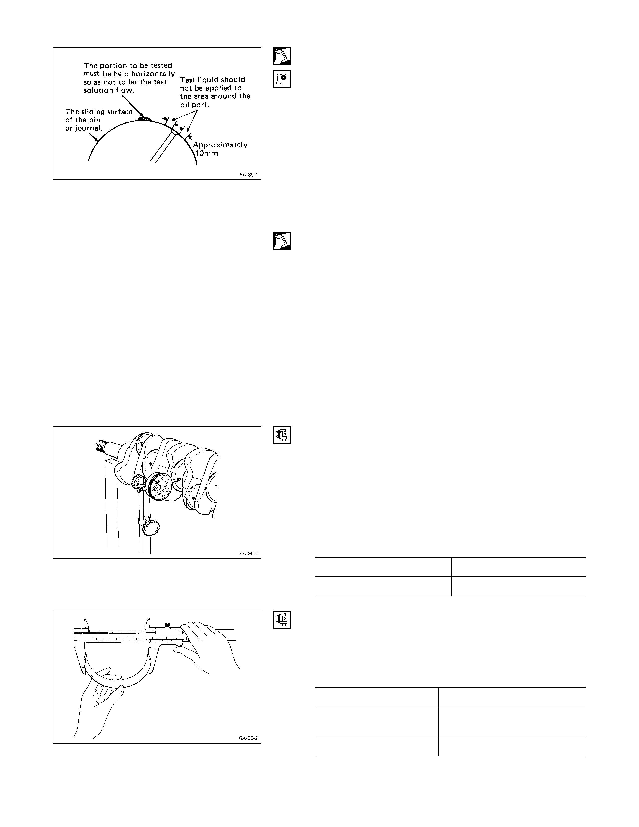
CRANKSHAFT TUFFTRIDING I NSPECTION
1. Use an organic cleaner to thoroughly clean the
crankshaft. There must be no traces of oil on the
surfaces to be inspected.
2. Prepare a 5 – 10% solution of ammonium cuprous
chloride (dissolved in distilled water).
3. Use a syringe to apply the solution to the surface to be
inspected.
Hold the surface to be inspected perfectly horizontal to
prevent the solution from running.
Note:
Do not allow the solution to come in contact with the
oil ports and their surrounding area.
JUDGMENT
1. Wait for thirty to forty seconds.
If there is no discoloration after thirty or forty seconds,
the crankshaft is usable.
If discoloration appears (the surface being tested will
become the color of copper), the crankshaft must be
replaced.
2. Steam clean the crankshaft surface immediately after
completing the test.
Note:
The ammonium cuprous chloride solution is highly
corrosive. Because of this, it is imperative that the
surfaces being tested be cleaned immediately after
completing the test.
CRANKSHAFT RUN-OUT
1. Set a dial indicator to the center of the crankshaft
journal.
2. Gently turn the crankshaft in the normal direction of
rotation.
Read the dial indicator as you turn the crankshaft.
If the measured value exceeds the specified limit, the
crankshaft must be replaced.
Crankshaft Run-Out mm (in)
Standard Limit
0.05 (0.002) or less 0.08 (0.003)
BEARING SPREAD
Use a vernier caliper to measure the bearing spread.
If the measured value is less than the specified limit, the
bearing must be replaced.
Bearing Spread mm (in)
Limit
Crankshaft Bearing 74.5 (2.93)
Connecting Rod Bearing 56.5 (2.22)
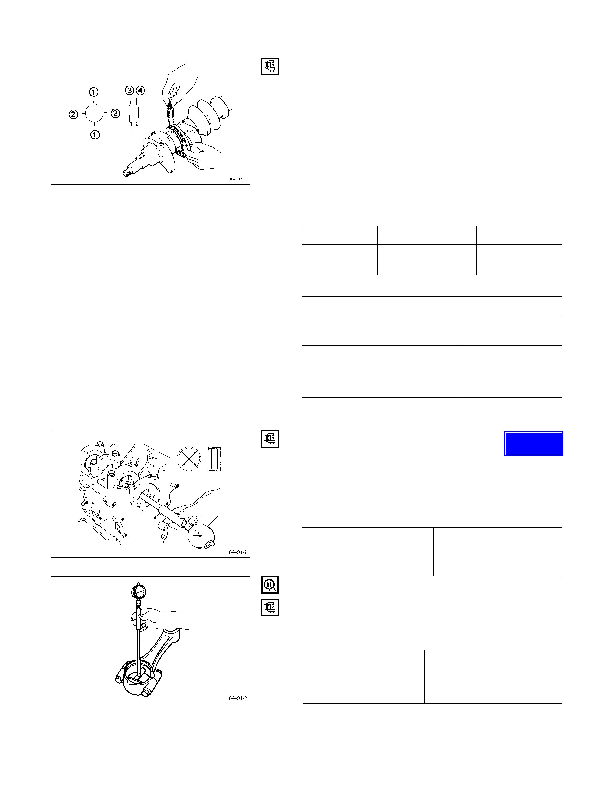
CRANKSHAFT JOURNAL AND CRANKPIN
DIAMETER
1. Use a micrometer to measure the crankshaft journal
diameter across points Q - Q and R - R.
2. Use the micrometer to measure the crankshaft journal
diameter at the two points (S and T).
3. Repeat Steps
Q and R to measure the crankpin
diameter.
If the measured values are less than the specified
limit, the crankshaft must be replaced.
Crankshaft Journal Diameter mm (in)
Standard Limit
4JB1T 69.92 – 69.93
(2.7527 – 2.7531) 69.91 (2.7524)
Crankpin Diameter mm (in)
Standard Limit
52.92 – 52.93
(2.0833 – 2.0839) 52.90 (2.083)
Crankshaft Journal and Crankpin
Uneven Wear mm (in)
Standard Limit
0.05 (0.002) or less 0.08 (0.003)
CRANKSHAFT JOURNAL AND BEARING
CLEARANCE
If the clearance between the measured bearing inside
diameter and the crankshaft journal diameter exceeds the
specified limit, the bearing and/or the crankshaft must be
replaced.
Crankshaft Journal and Bearing Clearance mm (in)
Standard Limit
0.031 – 0.064
(0.0012 – 0.0025) 0.110 (0.0043)
CONNECTING ROD BEARI NG INSI DE DIAMETER
1. Install the bearing to the connecting rod big end.
2. Tighten the bearing cap to the specified torque.
Connecting Rod Bearing Cap Bolt
Torque kg·m (lb.ft/N·m)
4JB1T 1st step ; 3.0(22/29)
2nd step ; 45degrees
3. Use an inside dial indicator to measure the connecting
rod bearing inside diameter.
Techline
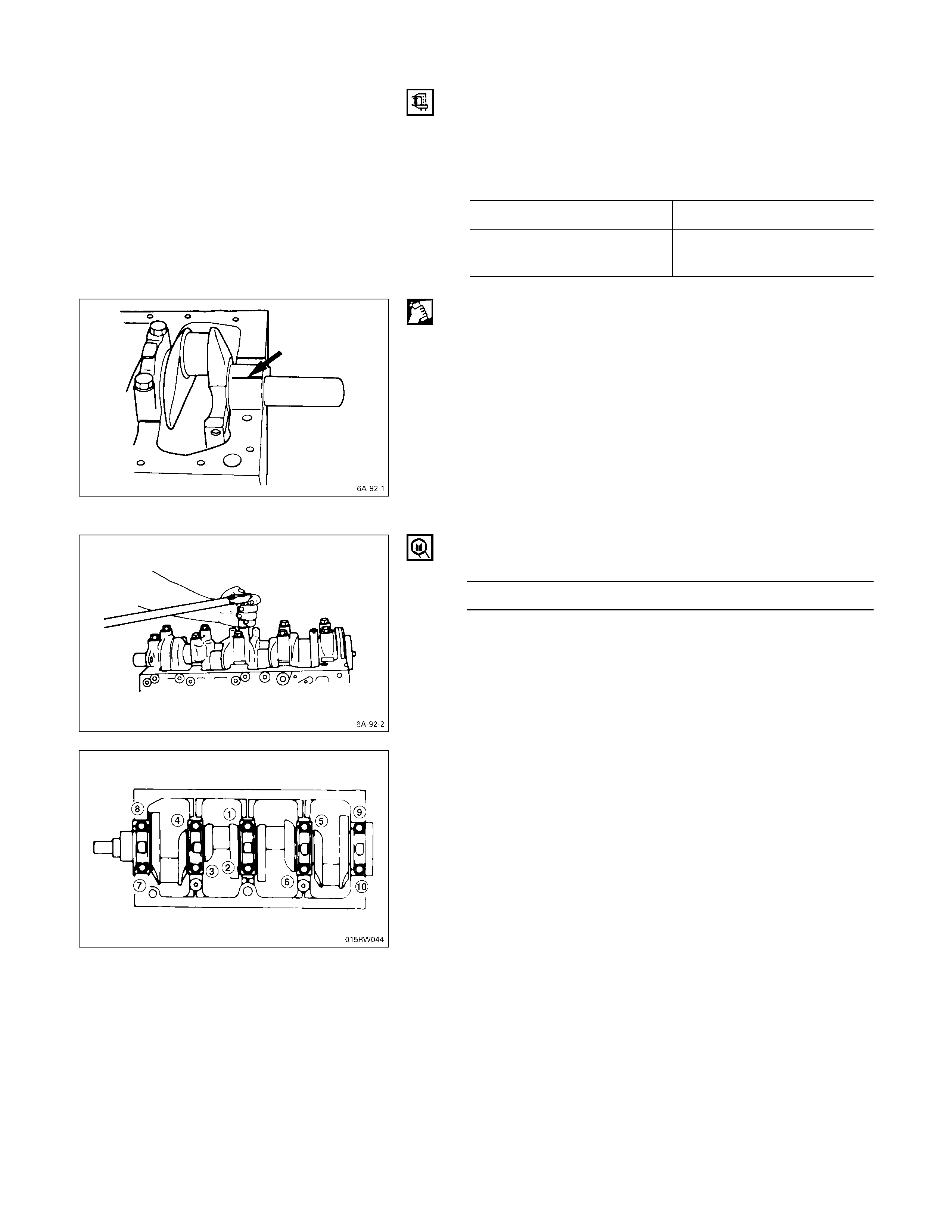
CRANKPIN AND BEARING CLEARANCE
If the clearance between the measured bearing inside
diameter and the crankpin exceeds the specified limit, the
bearing and/or the crankshaft must be replaced.
Crankpin and Bearing Clearance mm (in)
Standard Limit
0.029 – 0.066
(0.0011 – 0.0026) 0.100 (0.0039)
CLEARANCE M EASUREMENTS (WITH PLASTIGAGE)
Crankshaft Journal and Bearing Clearance
1. Clean the cylinder body, the journal bearing fitting
surface, the bearing caps, and the bearings.
2. Install the bearings to the cylinder body.
3. Carefully place the crankshaft on the bearings.
4. Rotate the crankshaft approximately 30° to seat the
bearing.
5. Place the Plastigage (arrow) over the crankshaft
journal across the full width of the bearing.
6. Install the bearing caps with the bearing.
7. Tighten the bearing caps to the specified torque.
Crankshaft Bearing Cap Bolt Torque kg·m (lb.ft/N·m)
17 ± 1 (123.0 ± 7.2/166.7 ± 9.8)
Do not allow the crankshaft to turn during bearing cap
installation and tightening.
8. Remove the bearing cap.
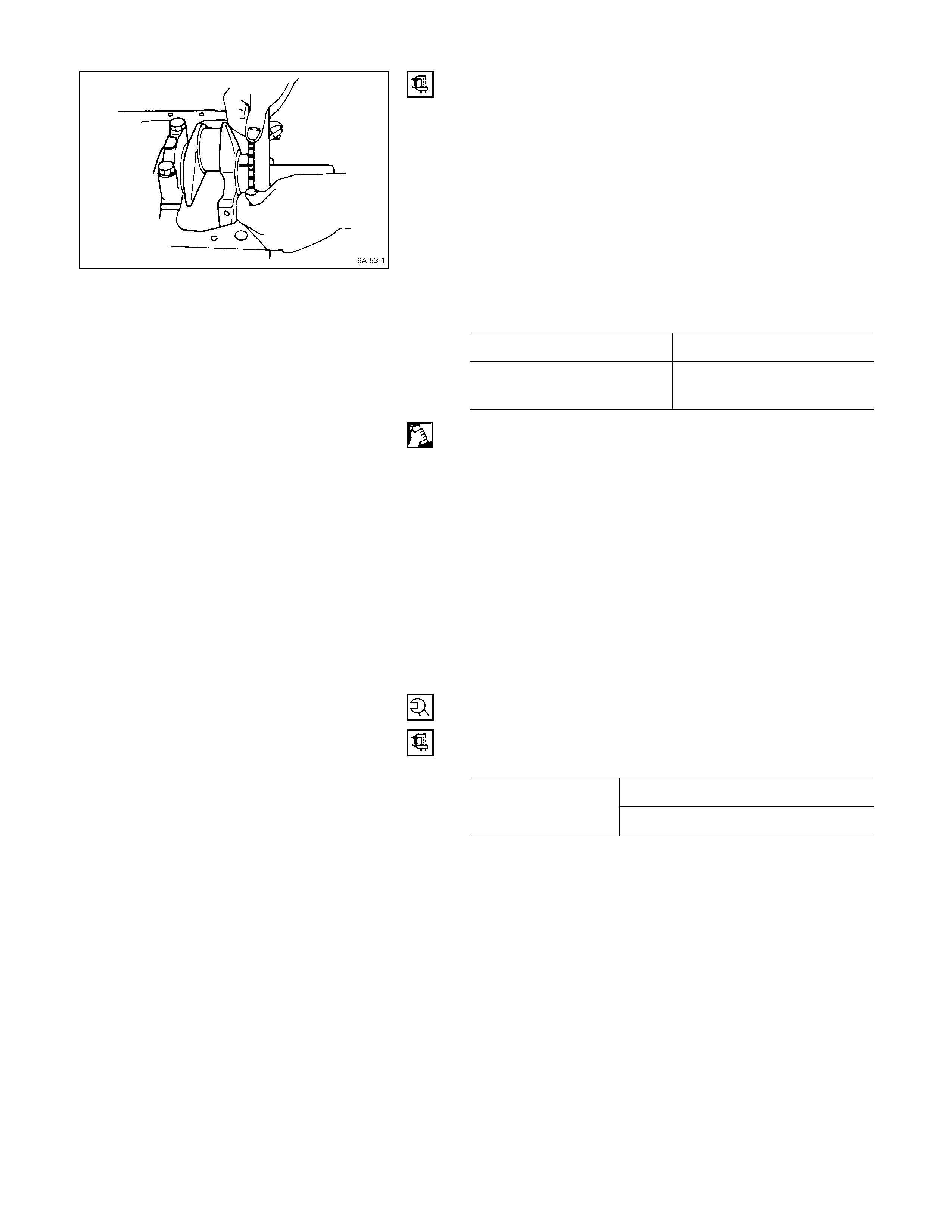
9. Compare the width of the Plastigage attached to either
the crankshaft or the bearing against the scale printed
on the Plastigage container.
If the measured value exceeds the limit, perform the
following additional steps.
1) Use a micrometer to measure the crankshaft
outside diameter.
2) Use an inside dial indicator to measure the
bearing inside diameter.
If the crankshaft journal and bearing clearance
exceeds the limit, the crankshaft and/or the
bearing must be replaced.
Crankshaft Journal and Bearing Clearance mm (in)
Standard Limit
0.031 – 0.064
(0.0012 – 0.0025) 0.110 (0.0043)
CRANKPIN AND BEARING CLEARANCE
1. Clean the crankshaft, the connecting rod, the bearing
cap, and the bearings.
2. Install the bearing to the connecting rod and the
bearing cap.
Do not allow the crankshaft to move when installing
the bearing cap.
3. Prevent the connecting rod from moving.
4. Attach the Plastigage to the crankpin.
Apply engine oil to the Plastigage to keep it from
falling.
5. Install the bearing cap and tighten it to the specified
torque.
Do not allow the connecting rod to move when
installing and tightening the bearing cap.
Connecting Rod Bearing Cap Bolt
Torque kg·m (lb.ft/N·m)
1st step; 3.0 (22/29)
4JB1T Engine 2nd step; 45° ~ 75°
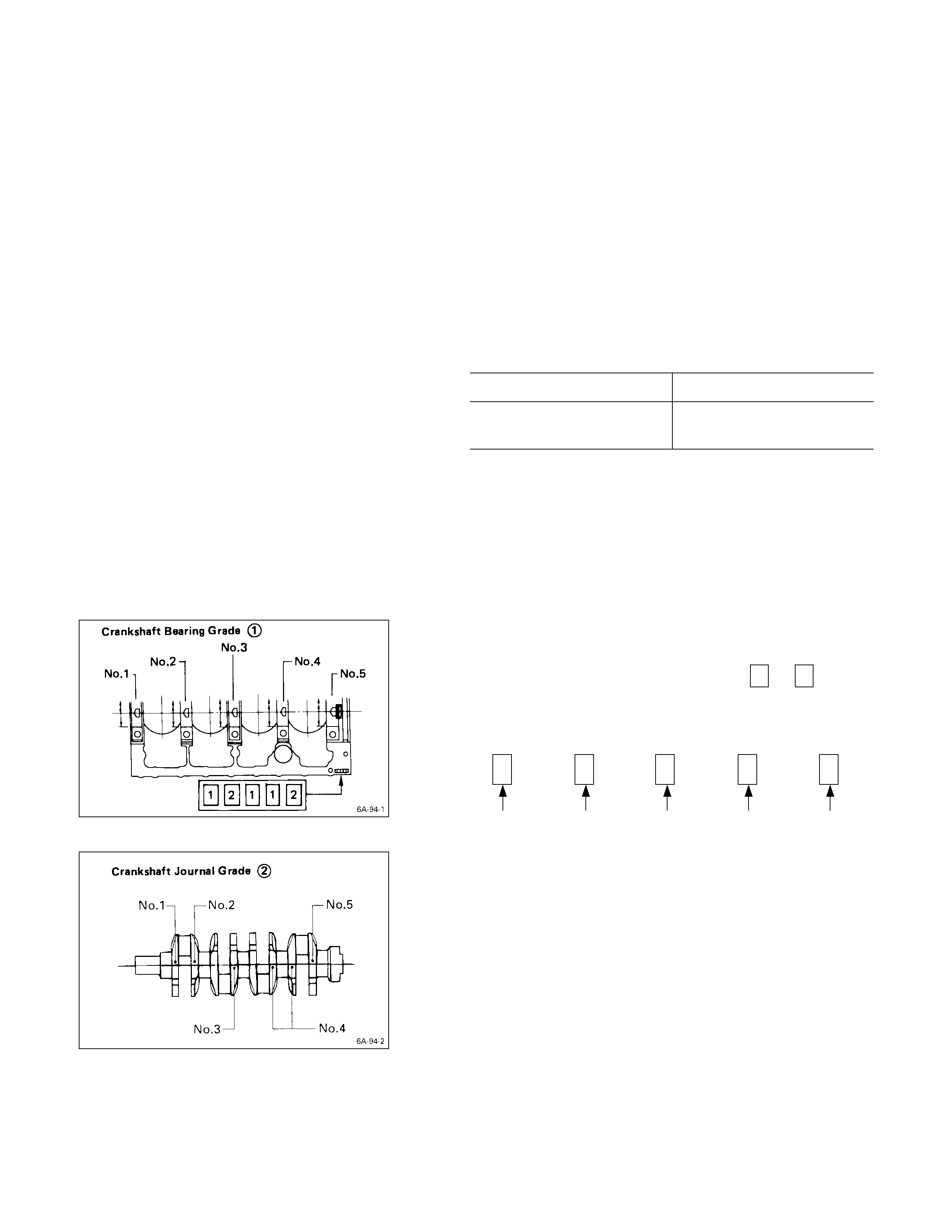
6. Remove the bearing cap.
7. Compare the width of the Plastigage attached to either
the crankshaft or the bearing against the scale printed
on the Plastigage container.
If the measured value exceeds the specified limit,
perform the following additional steps.
1) Use a micrometer to measure the crankpin
outside diameter.
2) Use an inside dial indicator to measure the
bearing inside diameter.
If the crank pin and bearing clearance exceeds the
specified limit, the crankshaft and/or the bearing
must be replaced.
Crankpin and Bearing Clearance mm (in)
Standard Limit
0.029 – 0.066
(0.0011 – 0.0026) 0.100 (0.0039)
CRANKSHAFT BEARI NG SELECTION
Crankshaft bearing selection is based on the measured
diameters of the crankshaft journals and the bearing
inserts.
Match the crankshaft bearing housing grade marks and
the crankshaft journal grade marks in the table below to
determine the correct crankshaft bearing size.
CRANKSHAFT BEARING HOUSING G RADE MARK
POSITION
Crankshaft bearing housing grade marks 1 or 2 are
stamped on the rear right hand side of the cylinder body.
Example:
12112
No. 1 Bearing
Housing No. 2 Bearing
Housing No. 3 Bearing
Housing No. 4 Bearing
Housing No. 5 Bearing
Housing
CRANKSHAFT JOURNAL GRADE MARK PO SITION
The crankshaft journal grade marks (1 or -) are stamped
on each crankshaft journal web.
The crankshaft journal and bearing clearance must be the
same for each position after installation of the crankshaft
and the crankshaft bearings.
Note:
The crankshaft journal mark No. 4 is stamped on
crankshaft No. 4 journal web front side or rear side.
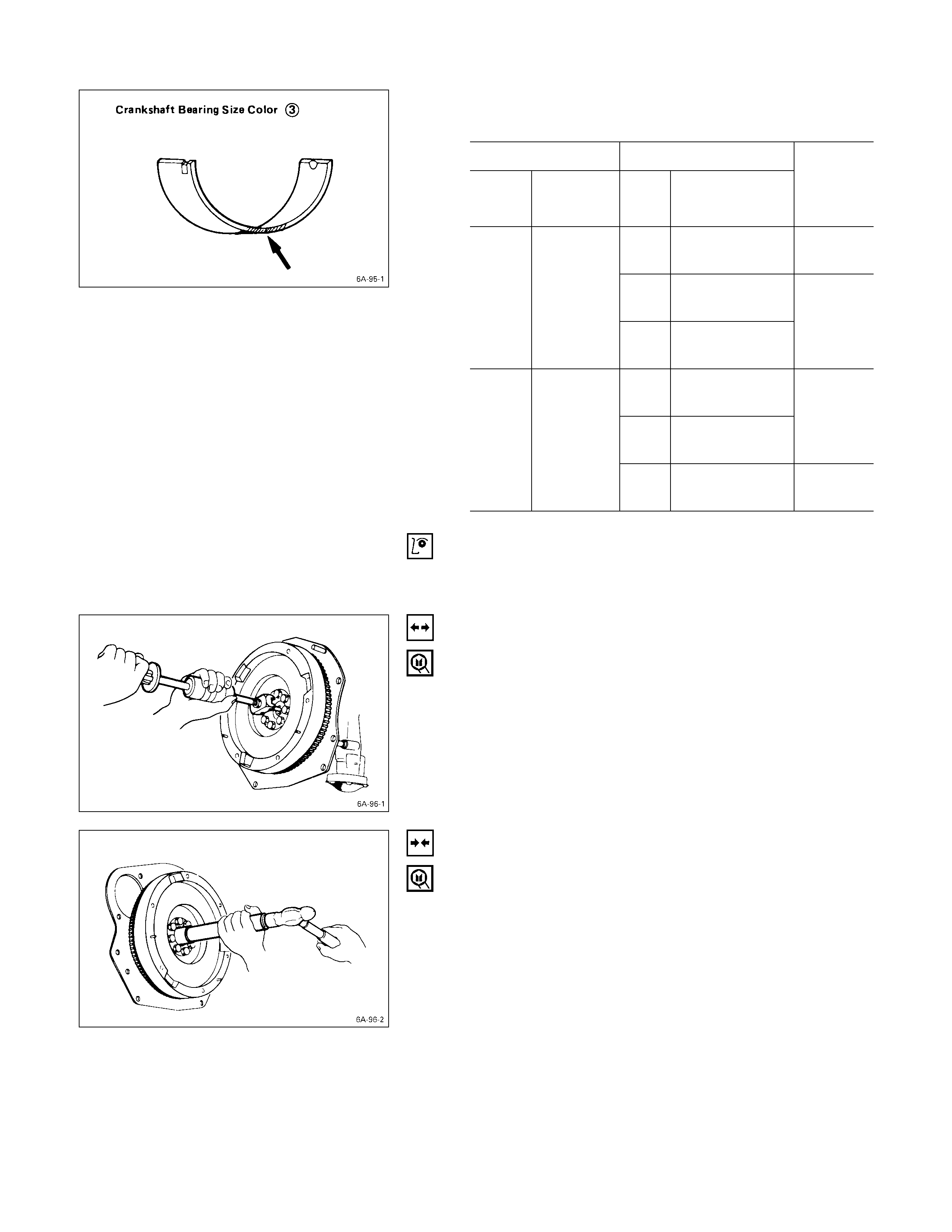
REFERENCE mm (in)
Crankshaft BearingQCrankshaft Journal R
Grade
Mark Diameter Grade
Mark Diameter
Crankshaft
Bearing
Size Color
Code S
1 or
-69.927 – 69.932
(2.7530 – 2.7532) Black
2 or
- - 69.922 – 69.927
(2.7528 – 2.7530)
1
73.987 –
74.000
(2.9129 –
2.9134) 3 or
- - - 69.917 – 69.922
(2.7556 – 2.7528)
Blue
1 or
-69.927 – 69.932
(2.7530 – 2.7532)
2 or
- - 69.922 – 69.927
(2.7528 – 2.7530)
Green
2
73.975 –
73.987
(2.9124 –
2.9129) 3 or
- - - 69.917 – 69.922
(2.7556 – 2.7528) Black
CRANKSHAFT PILO T BEARING
Check the crankshaft pilot bearing for excessive wear and
damage and replace it if necessary.
CRANKSHAFT PILO T BEARING REPLACEMENT
CRANKSHAFT PILO T BEARING REMOVAL
Use the pilot bearing remover to remove the crankshaft
pilot bearing.
Pilot Bearing Remover: 5-8840-2000-0
Sliding Hammer: 5-8840-0019-0 (J-23907)
CRANKSHAFT PILO T BEARI NG INSTALLATION
1. Place the crankshaft pilot bearing right angle across
the crankshaft bearing installation hole.
2. Tap around the edges of the crankshaft pilot bearing
outer races with a brass hammer to drive the bearing
into the crankshaft bearing installation hole.
Pilot Bearing Installer: 5-8522-0024-0
Note:
Strike only the crankshaft pilot bearing outer race with
the hammer. Do not strike the bearing inner race.
Bearing damage and reduced bearing service life will
result.
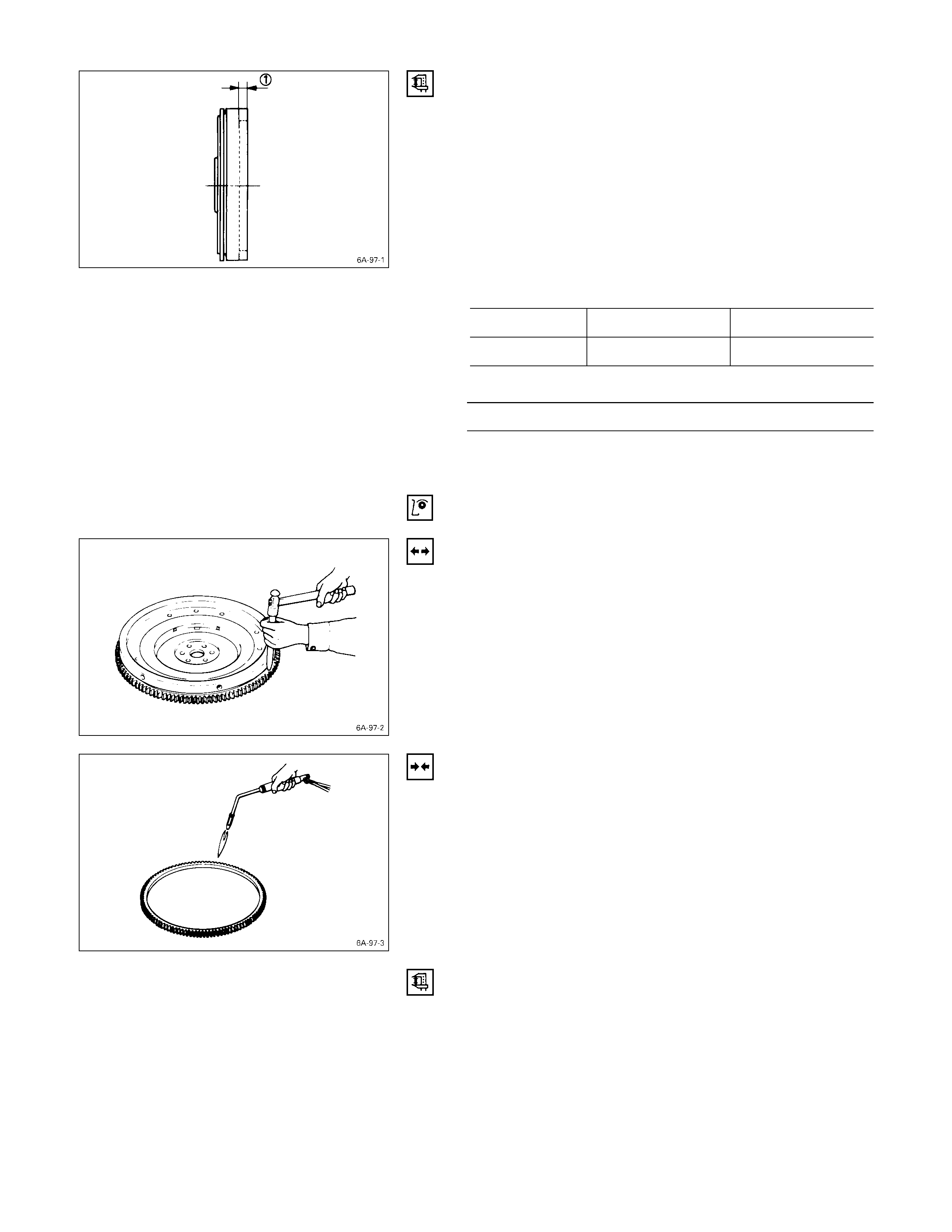
FLYWHEEL AND RI NG GEAR
FLYWHEEL
1. Inspect the flywheel friction surface for excessive wear
and heat cracks.
2. Measure the flywheel friction surface depth.
If the measured value is within the specified limit, the
flywheel may be reground.
If the measured value exceeds the specified limit, the
flywheel must be replaced.
Flywheel Friction Surface Depth Qmm (in)
Standard Limit
4JB1T 14 (0.551) 15 (0.591)
Flywheel Friction Surface Roughness mm (in)
Less than 0.006 (0.00024)
RING GEAR
Inspect the ring gear.
If the ring gear teeth are broken or excessively worn, the
ring gear must be replaced.
RING G EAR REPLACEMENT
RING GEAR REM O VAL
Strike around the edges of the ring gear with a hammer
and chisel to remove it.
RING GEAR INSTALLATION
1. Heat the ring gear evenly with a gas burner to invite
thermal expansion.
Do not allow the temperature of the gas burner to
exceed 200°C (390°F).
2. Install the ring gear when it is sufficiently heated.
The ring gear must be installed with the chamfer
facing the clutch.
PISTON
PISTON GRADE SELECTI ON AND CYLI NDER BO RE
MEASUREMENT
Refer to the Section “CYLINDER BODY”, Item “Cylinder
Liner Bore Measurement” for details on piston grade
selection and cylinder liner bore measurement.
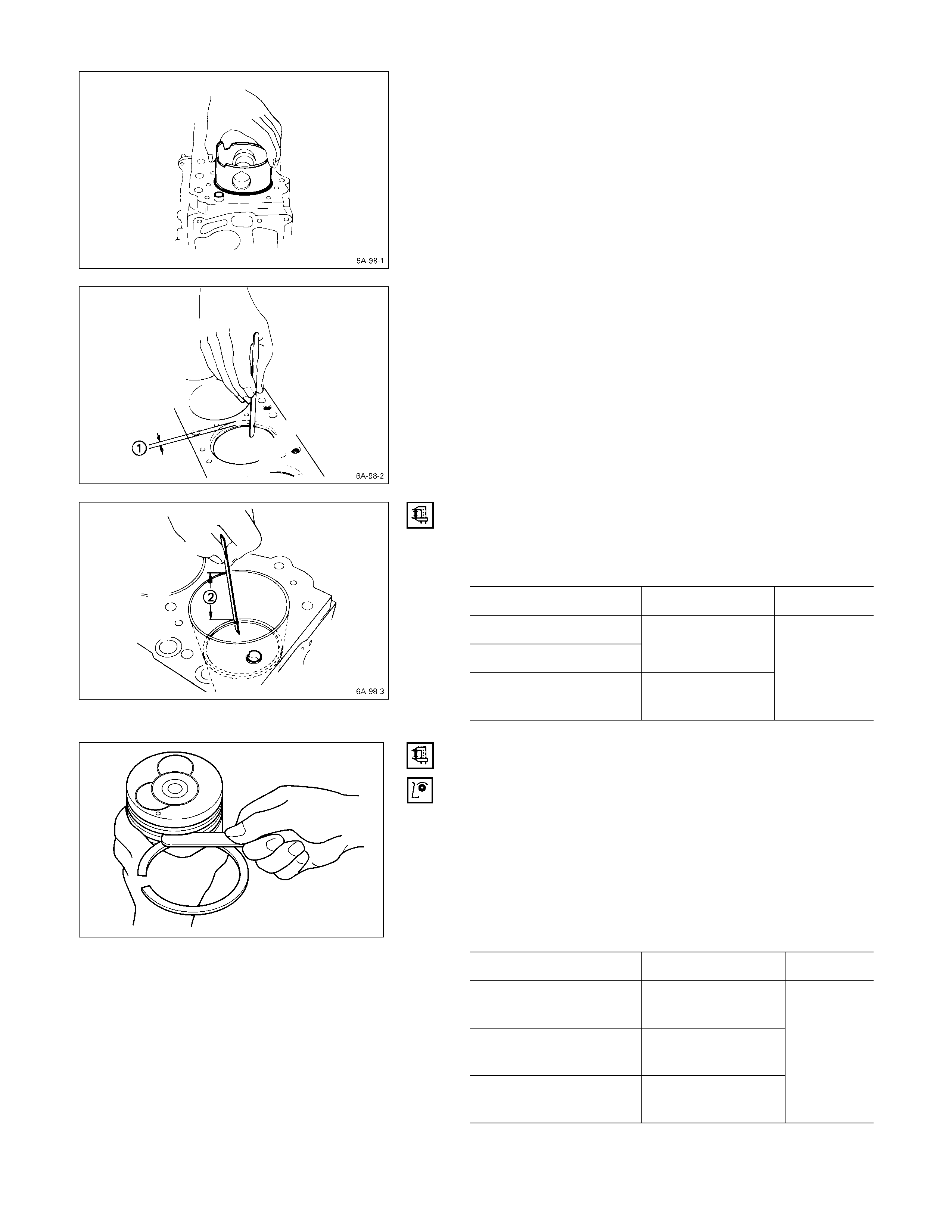
PISTON RING
PISTON RING GAP
1. Insert the piston ring horizontally (in the position it
would assume if it were installed to the piston) into the
cylinder liner.
2. Push the piston ring into the cylinder bore until it
reaches the measuring point Q or R where the
cylinder liner bore is the smallest.
Do not allow the piston ring to slant to one side or the
other. It must be perfectly horizontal.
Measuring Point Q10 mm (0.4 in)
or
Measuring Point R120 mm (4.7 in)
3. Use a feeler gauge to measure the piston ring gap.
If the measured value exceeds the specified limit, the
piston ring must be replaced.
Piston Ring Gap mm (in)
Standard Limit
1st Compression Ring
2nd Compression Ring 0.2 – 0.4
(0.008 – 0.016)
Oil Ring 0.1 – 0.3
(0.004 – 0.012)
1.5
(0.059)
PISTON RING AND PISTON RING GROOVE
CLEARANCE
Use a feeler gauge to measure the clearance between the
piston ring and the piston ring groove at several points
around the piston.
If the clearance between the piston ring and the piston ring
groove exceeds the specified limit, the piston ring must be
replaced.
Piston Ring and Piston Ring Groove
Clearance mm (in)
Standard Limit
1st Compression Ring 0.09 – 0.125
(0.0035 – 0.0049)
2nd Compression Ring 0.05 – 0.075
(0.002 – 0.003)
Oil Ring 0.03 – 0.070
(0.0012 – 0.0028)
0.150
(0.006)
015RY00029
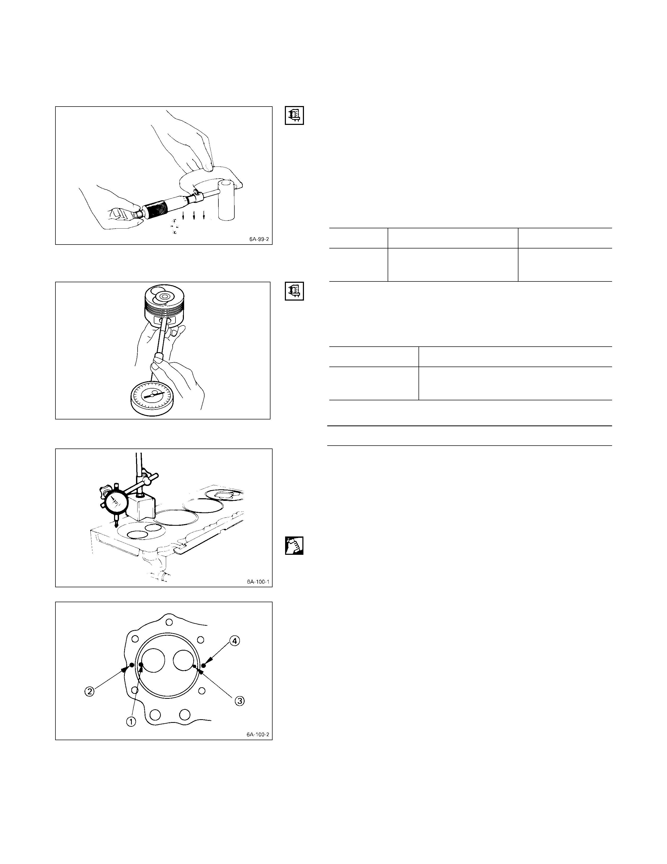
4. Visually inspect the piston rings.
If a piston ring groove is damaged or distorted, the
piston must be replaced.
PISTON PIN
PISTON PIN DI AMETER
Use a micrometer to measure the piston pin diameter at
several points.
If the measured value is less than the specified limit, the
piston pin must be replaced.
Piston Pin Diameter mm (in)
Standard Limit
4JB1T 33.994 – 34.000
(1.3383 – 1.3386) 33.97 (1.337)
PISTON PIN AND PISTON CLEARANCE
Use and inside dial indicator to measure the piston pin
hole (in the piston).
Piston Pin Hold mm (in)
Standard
4JB1T 34.002 – 34.010 (1.3387 – 1.3390)
(1.3383 – 1.3386)
Piston Pin and Piston Pin Hole Clearance mm (in)
0.002 – 0.015 (0.00008 – 0.0006)
CYLINDER HEAD G ASKET SELECTION
Cylinder head gasket is determined by the piston head
projection from the cylinder body upper surface, in order to
improve engine performance.
Three types of gasket are provided by the difference of
thickness. Select the adequet one out of three grades of
gasket, according to the following procedure.
Before measurement, clear off carbon from the piston
head and cylinder body surface and also clean the place
where a gasket was installed.
PISTON HEAD PROJECTION MEASURING POINT
1. Use a dial indicator to measure the piston projection
amount.
2. Refer to the illustration for the piston head projection
measuring positions.
All measuring positions should be as close as possible
to the cylinder liner.
015RY00030
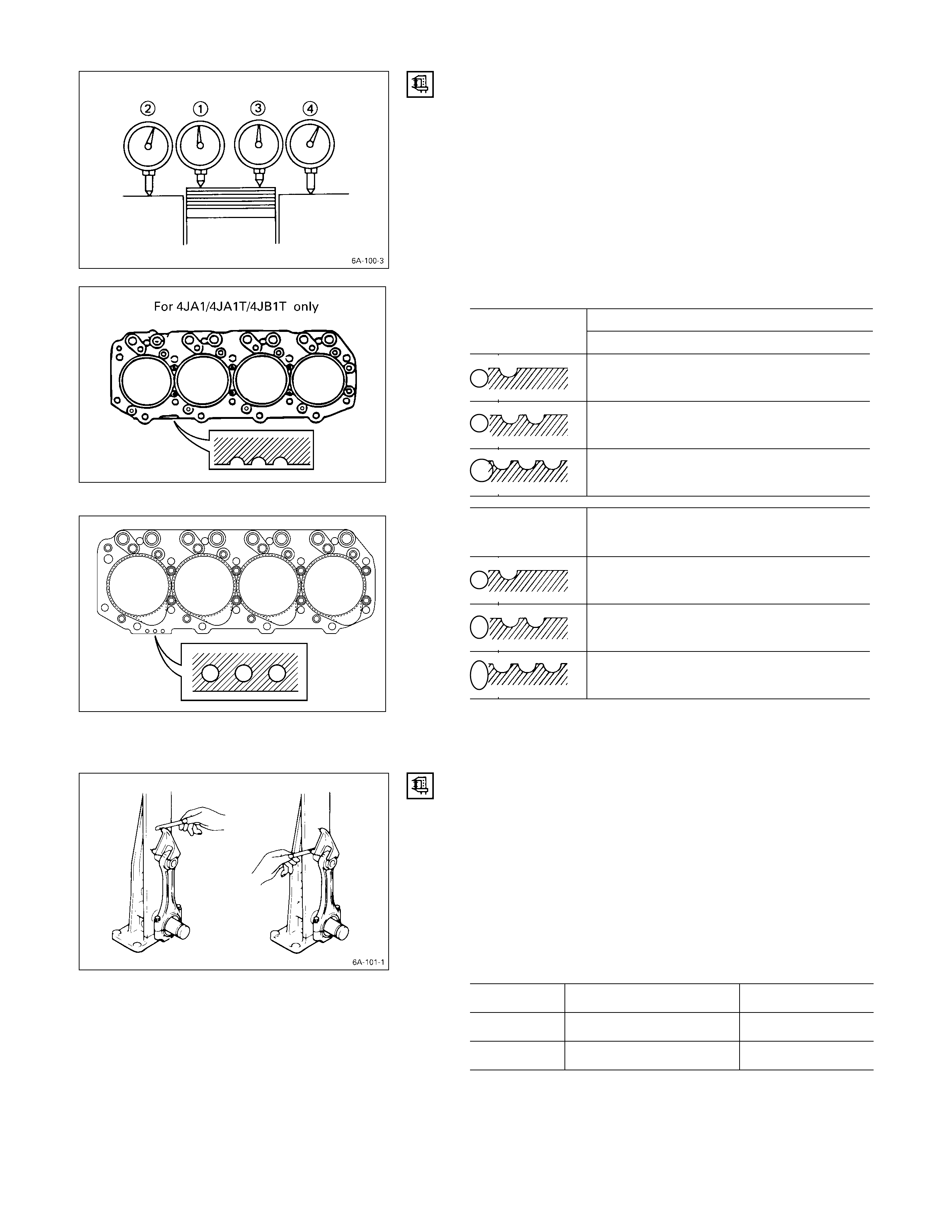
3. Measure the points Q R S T and obtain two
differences Q–R and S–T on each cylinder.
Calculate the average value of the piston head
projection on each cylinder.
4. Obtain the maximum value in the four cylinders.
5. Determine the gasket grade required to the maximum
value described above in accordance with the
following table.
Cylinder Head Gasket Combination mm (in)
Piston ProjectionGasket Grade
Mark 4JB1T
A0.758 – 0.813
(0.0298 – 0.0320)
B0.813 – 0.859
(0.0320 – 0.0338)
C0.859 – 0.914
(0.0338 – 0.0360)
Gasket Grade
Mark Gasket Thickness
(Reference)
A1.6
(0.0630)
B1.65
(0.0650)
C1.70
(0.0669)
Note:
Difference of the each piston projection and must be
equal or within 0.1 mm (0.004 in).
CONNECTING ROD
CONNECTING ROD ALIGNM ENT
Use a connecting rod aligner to measure the distortion and
the parallelism between the connecting rod big end hole
and the connecting rod small end hole.
If either the measured distortion or parallelism exceed the
specified limit, the connecting rod must be replaced.
Connecting Rod Alignment
Per Length of 100 mm (3.94 in) mm (in)
Standard Limit
Distortion 0.08 or Less (0.003) 0.20 (0.008)
Parallelism 0.05 or Less (0.002) 0.15 (0.006)
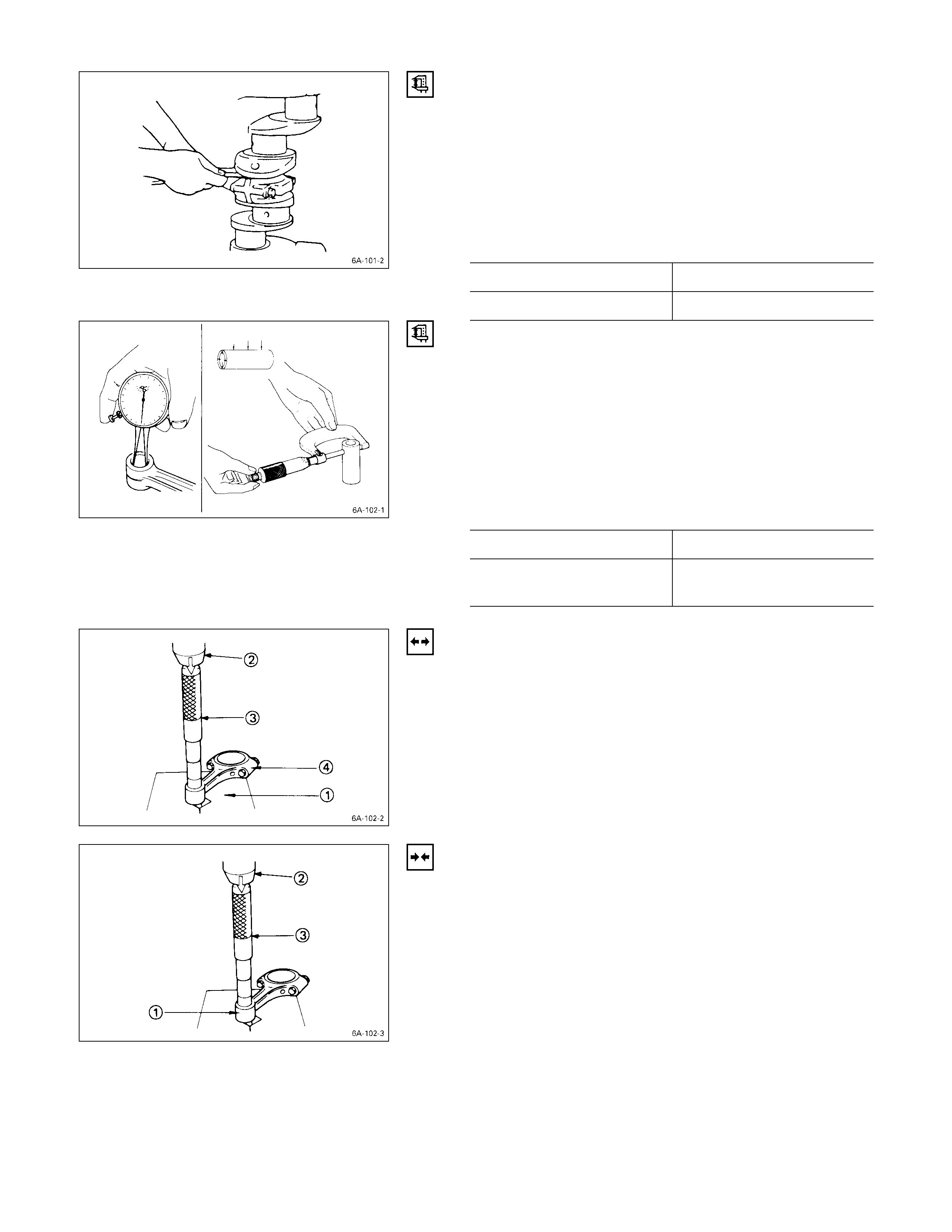
CONNECTING RO D SIDE FACE CLEARANCE
1. Install the connecting rod to the crankpin.
2. Use a feeler gauge to measure the clearance between
the connecting rod big end side face and the crankpin
side face.
If the measured value exceeds the specified limit, the
connecting rod must be replaced.
Connecting Rod Big End and Crankpin Side
Face Clearance mm (in)
Standard Limit
0.23 (0.009) 0.35 (0.014)
PISTON PIN AND CONNECTING ROD SMALL END
BUSHING CLEARANCE
Use a caliper calibrator and a dial indicator to measure the
piston pin and connecting rod small end bushing
clearance.
If the clearance between the piston pin and the connecting
rod small end bushing exceeds the specified limit, replace
the piston pin and/or the connecting rod bushing.
Piston Pin and Connecting Rod Small End
Bushing Clearance mm (in)
Standard Limit
0.008 – 0.020
(0.0003 – 0.0008) 0.050 (0.002)
CONNECTING ROD BUSHING REPLACEMENT
CONNECTING ROD BUSHING REMOVAL
1. Set the connecting rod small end to the bench press
V-block Q.
2. Use the bench press R and the bar S to slowly force
the bushing from the connecting rod T.
Note:
Take care not to damage the connecting rod with the
bar when removing the bushing.
CONNECTING RO D BUSHING I NSTALLATION
1. Set the connecting rod small end Q to the bench
press V-block.
The connecting rod must be perfectly horizontal.
2. Use the bench press R and the bar S to slowly force
the bushing with oil hole into position.
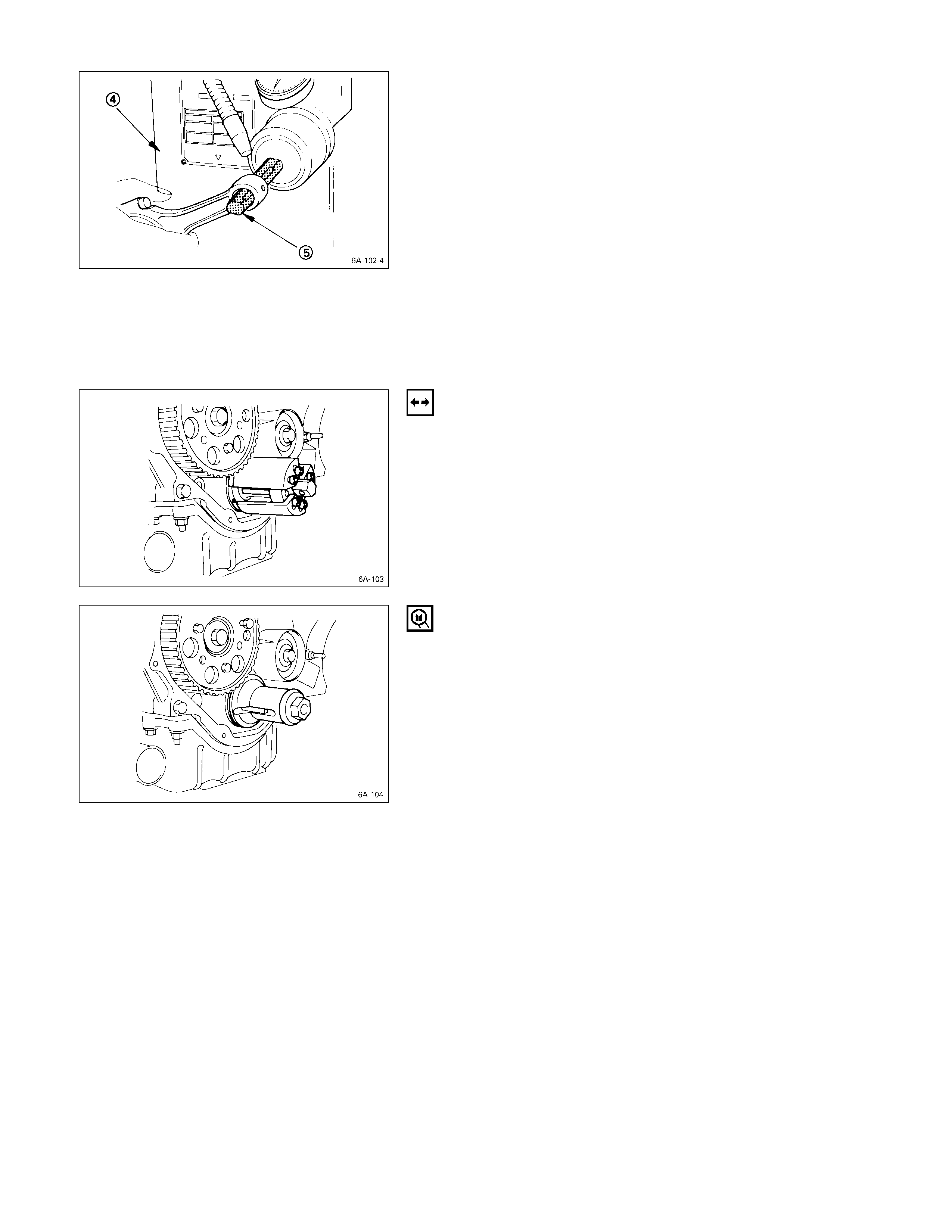
3. Use a pin hole grinder T fitted with a reamer U to
ream the piston pin hole.
TIMING PULLEY HOUSING
Replace the crankshaft front oil seal if it is worn or
damaged.
Take care not to damage the oil seal fitting surfaces.
CRANKSHAFT FRONT OI L SEAL REPLACEMENT
OIL SEAL REMOVAL
With the oil seal pushed in deep, install the special tool as
shown in the illustration and remove the oil seal.
Oil Seal Remover: 5-8840-2362-0
Note:
Take care not to damage sealing surface of front plate
and crankshaft when removing oil seal.
OIL SEAL INSTALLATION
Use the special tool to install the oil seal.
1. With the oil seal attached to the sleeve, insert it into
the front end section of the crankshaft.
2. With the oil seal end section attached securely to the
crankshaft, tighten up the center bolt until the sleeve
hits the front end reference plane of the crankshaft
securely.
3. Remove the sleeve.
4. With the seal pressed in, check the dimension of the
oil seal section.
Standard Dimension = 0.9 ± 0.3 mm
Note:
Install the oil seal after assembling the timing pulley
housing. The oil seal lip section is applied with oil.
Take notice of the press-in direction of the oil seal.
Front Oil Seal Installer: 5-8840-2361-0
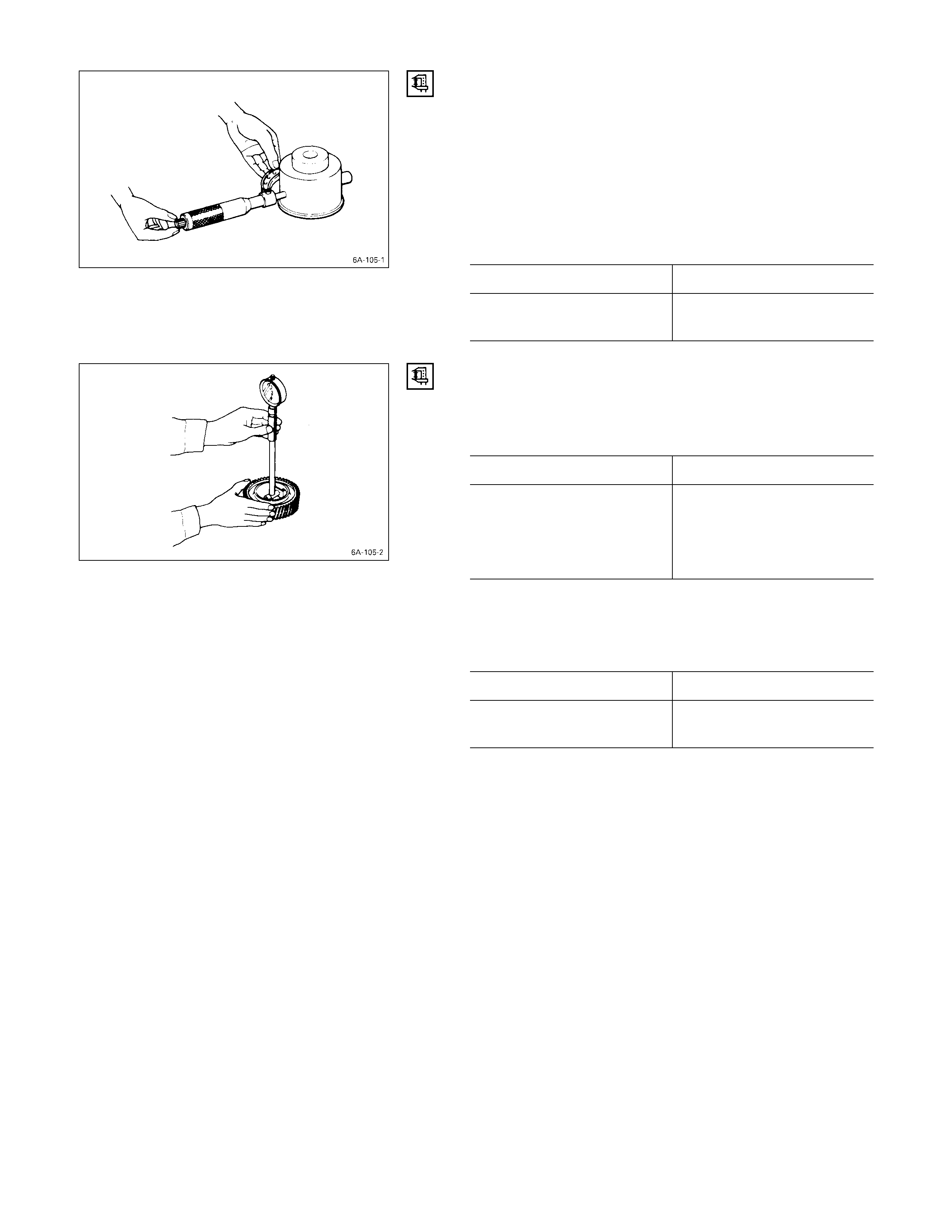
IDLER GEAR SHAFT AND IDLER GEAR
(GEAR DRIVE MODEL)
IDLER GEAR “A” SHAFT OUTSIDE DIAMETER
Use a micrometer to measure the idler gear shaft outside
diameter.
If the measured value is less than the specified limit, the
idler gear shaft must be replaced.
Idler Gear “A” Shaft Outside Diameter mm (in)
Standard Limit
44.945 – 44.975
(1.769 – 1.770) 44.845 (1.766)
IDLER GEAR “A” SHAFT INSIDE DIAMETER
1. Use an inside dial indicator or an inside micrometer to
measure the idler gear inside diameter.
Idler Gear Inside Diameter mm (in)
Standard Limit
45.0 – 45.03
(1.7717 – 1.7718) 45.10 (1.7756)
If the clearance between the idler gear shaft outside
diameter and the idler gear inside diameter exceeds the
limit, the idler gear must be replaced.
Idler Gear Shaft and Idler Gear Clearance mm (in)
Standard Limit
0.025 – 0.085
(0.0010 – 0.0033) 0.200 (0.008)
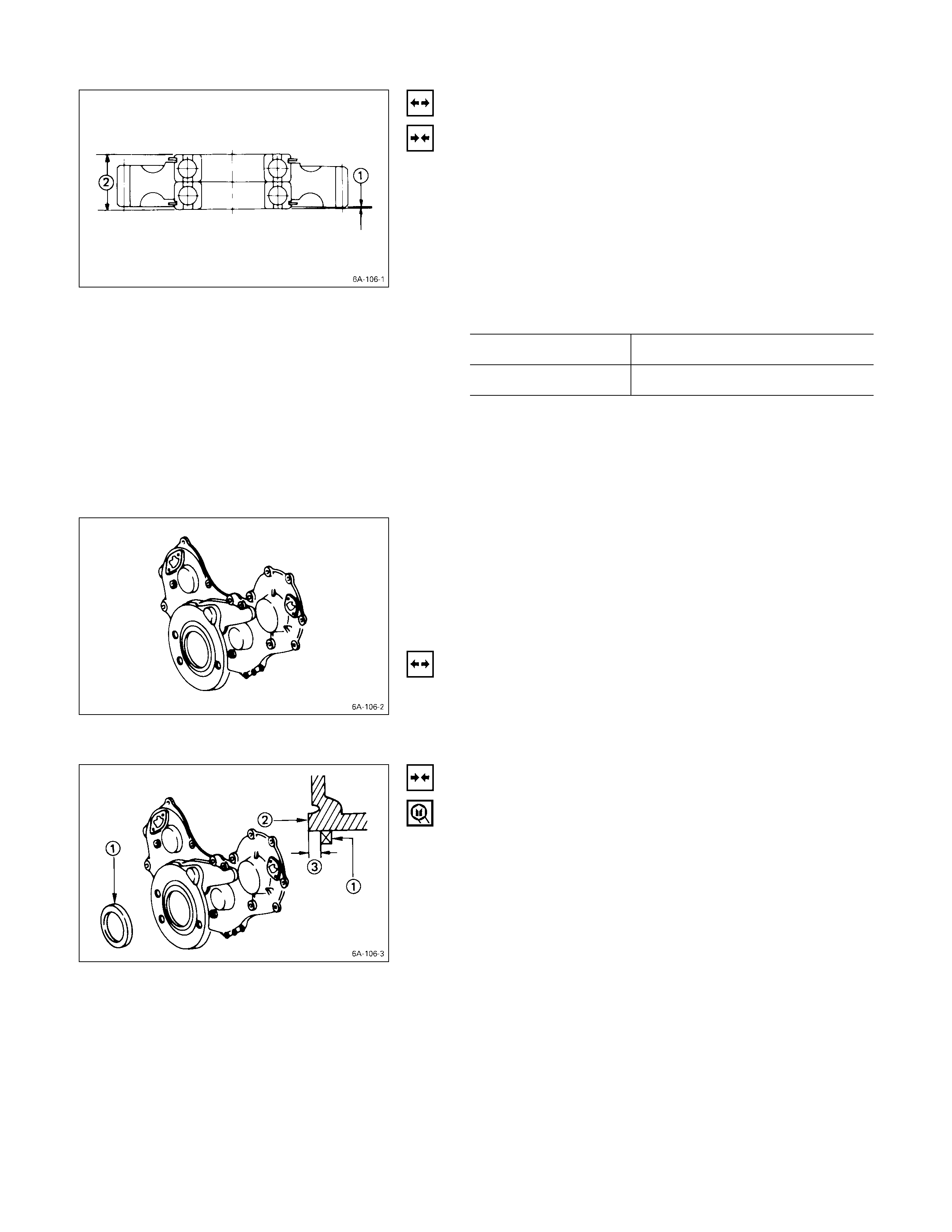
IDLER GEAR “B”
BEARING REPLACEMENT
BEARING REMOVAL
Use a bench press or a hammer and a bar to remove the
bearing from the idler gear.
BEARING INSTALLATION
Use a bench press and bar to install the bearing into the
idler gear.
Bearing Projection and Height mm (in)
Projection Q0.4 – 0.6 (0.016 – 0.024)
Height R23.7 – 24.0 (0.933 – 0.945)
Note:
The bench press and bar should make contact only
with the bearing outer races. Do not allow them to
make contact with the bearing inner races.
Bearing damage and reduced bearing service life will
result.
TIMING GEAR CASE COVER
Replace the crankshaft front oil seal if it is excessively
worn or damaged.
CRANKSHAFT FRONT OI L SEAL REPLACEMENT
OIL SEAL REMOVAL
Use a plastic hammer and a screwdriver to tap around the
oil seal to free it from the gear case cover.
Take care not to damage the oil seal lip surfaces.
OIL SEAL INSTALLATION
Use the installer to install the front oil seal Q to the gear
case cover R.
Oil Seal Installer: 5-8840-2061-0
Note the oil seal installation depth S shown in the
illustration.
Depth S = 1 mm (0.039 in.)
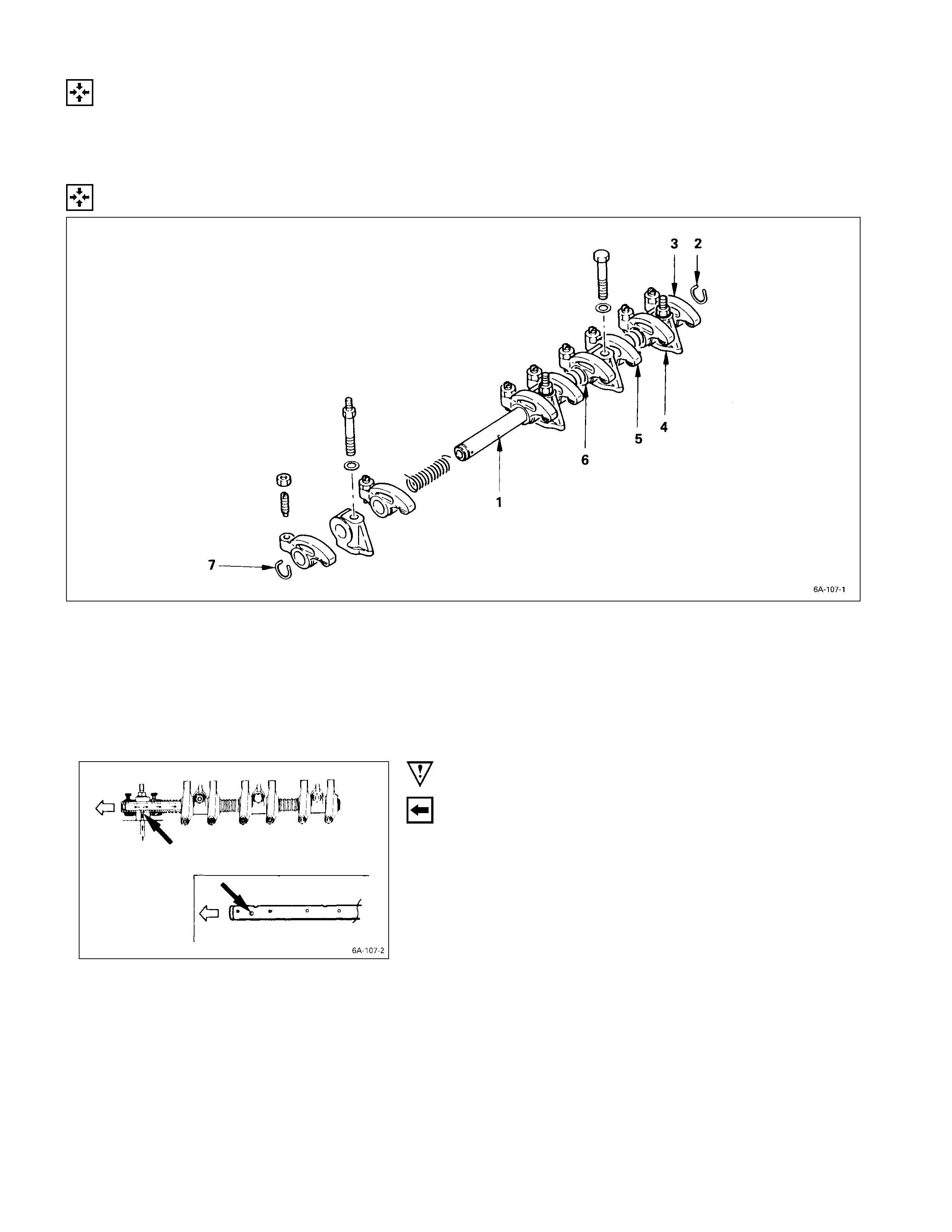
REASSEMBLY
INTERNAL PARTS
MINOR COMP ONENTS
ROCKER ARM SHAFT AND ROCKER ARM
REASSEMBLY STEPS
J
1. Rocker arm shaft 5. Rocker arm
2. Rocker arm shaft snap ring 6. Rocker arm shaft spring
3. Rocker arm 7. Rocker arm shaft snap ring
4. Rocker arm shaft bracket
IMPORTANT OPERATIONS
1. Rocker Arm Shaft
1) Position the rocker arm shaft with the large oil hole
(4φ) facing the front of the engine.
2) Install the rocker arm shaft together with the rocker
arm, the rocker arm shaft bracket, and the spring.
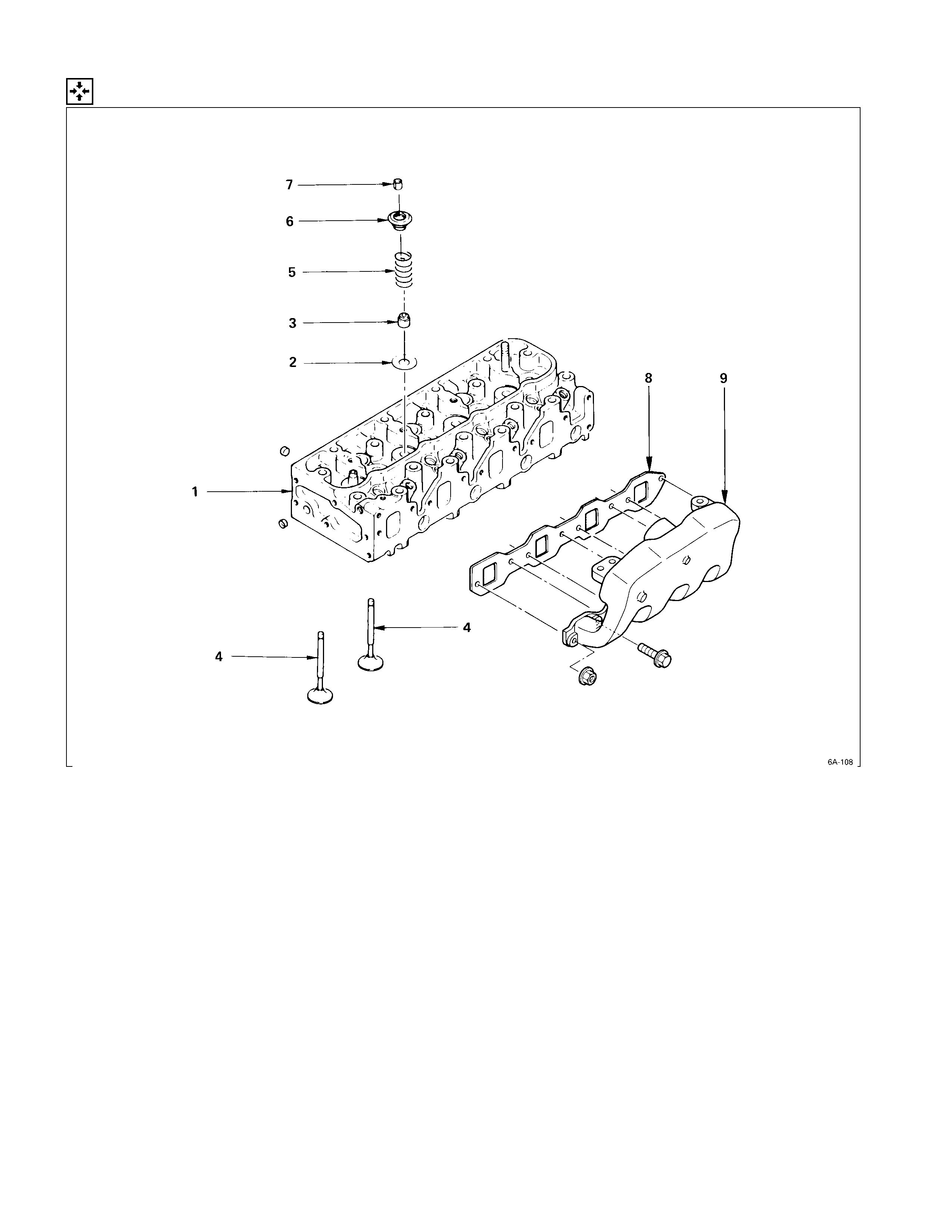
CYLINDER HEAD
REASSEMBLY STEPS
1. Cylinder head 6. Valve spring upper seat
2. Valve spring lower seat
J
7. Split collar
J
3. Valve stem oil seal
J
8. Intake manifold gasket
J
4. Intake and exhaust valve
J
9. Intake manifold
J
5. Valve spring
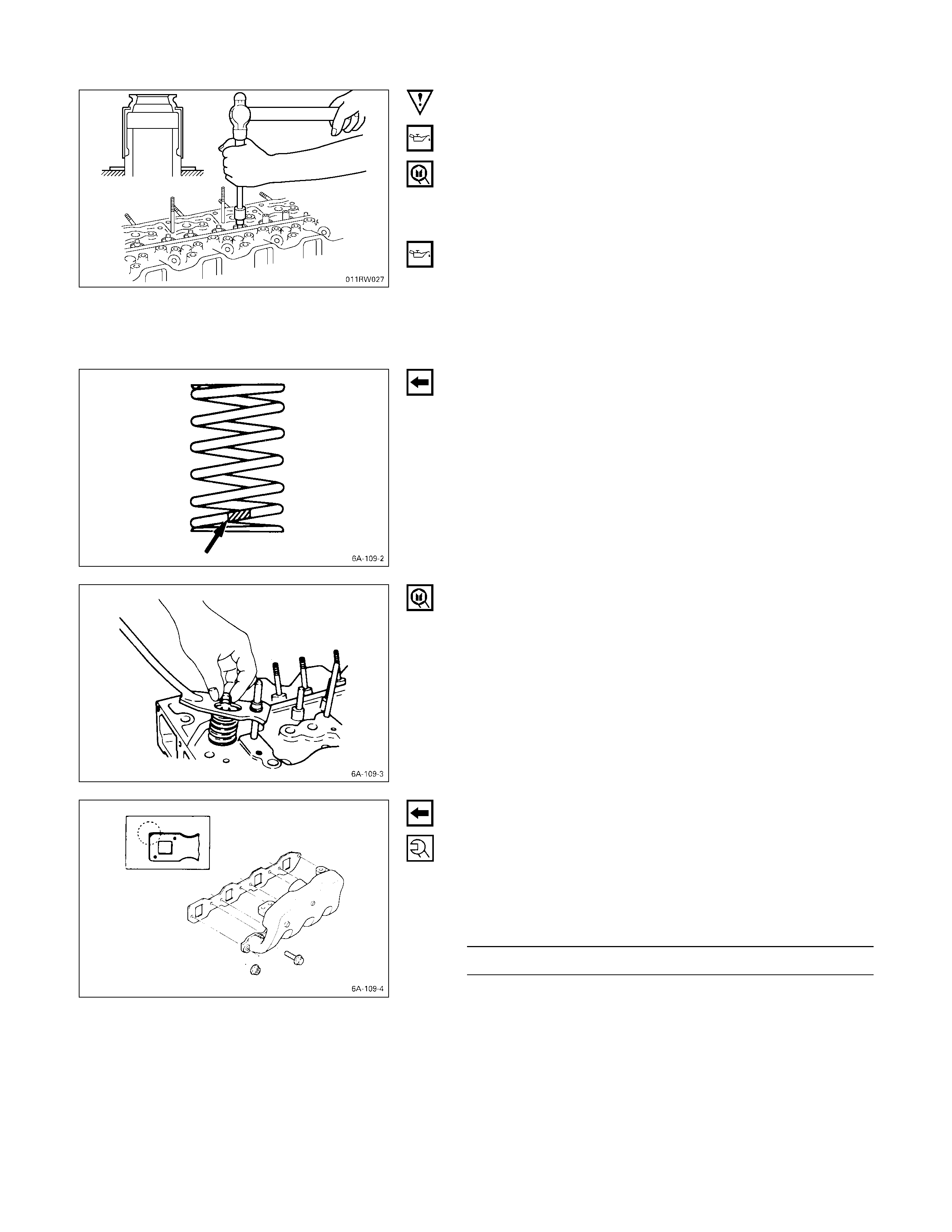
IMPORTANT OPERATIONS
3. Valve Stem Oil Seal
1) Apply a coat of engine oil to the oil seal inner face.
2) Use an oil seal installer to install the oil seal to the
valve guide.
Oil Seal Installer: 5-8840-2033-0
4. Intake and Exhaust Valve
1) Apply a coat of engine oil to each valve stem before
installation.
2) Install the intake and exhaust valves.
3) Turn the cylinder head up to install the valve springs.
Take care not to allow the installed valves to fall free.
5. Valve Spring
Install the valve spring with their fine pitched end (painted)
facing down.
7. Split Collar
1) Use the spring compressor to compress the valve
spring into position.
Spring Compressor: 9-8523-1423-0 (J-29760)
2) Install the split collars to the valve stem.
3) Set the split collars by tapping around the head of the
collar with a rubber hammer.
8. Intake Manifold Gasket
9. Intake Manifold
1) Install the manifold gasket with the end having the
sharp corners facing the front of the engine.
2) Install the intake manifold to the cylinder head.
3) Tighten the manifold bolts to the specified torque.
Manifold Bolt Torque kg·m (lb.ft/N·m)
1.9 ± 0.5 (13.7 ± 3.6/18.62 ± 4.90)
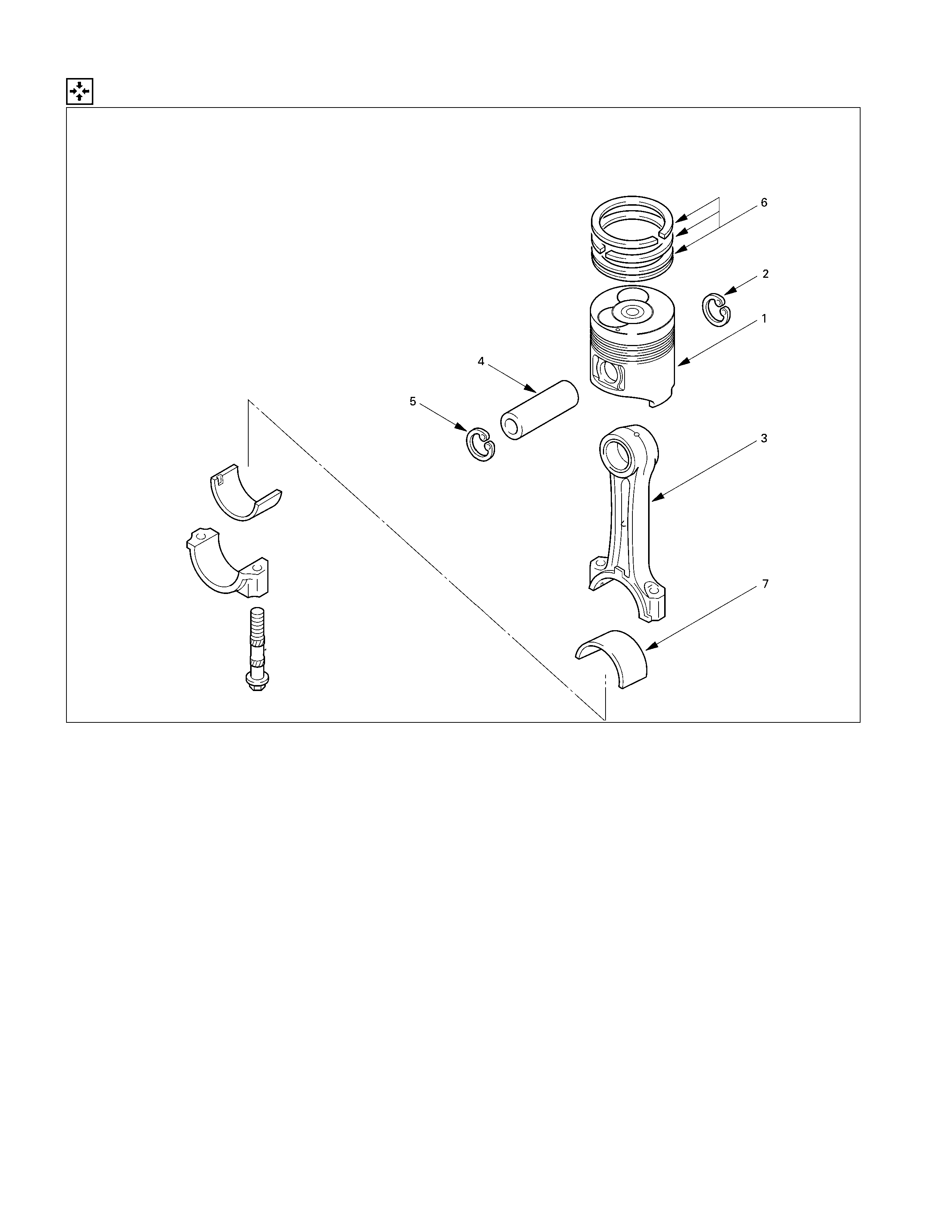
PISTON AND CONNECTING RO D
REASSEMBLY STEPS
J
1. Piston
J
5. Piston pin snap ring
J
2. Piston pin snap ring
J
6. Piston ring
J
3. Connecting rod
J
7. Connecting rod bearing
J
4. Piston pin
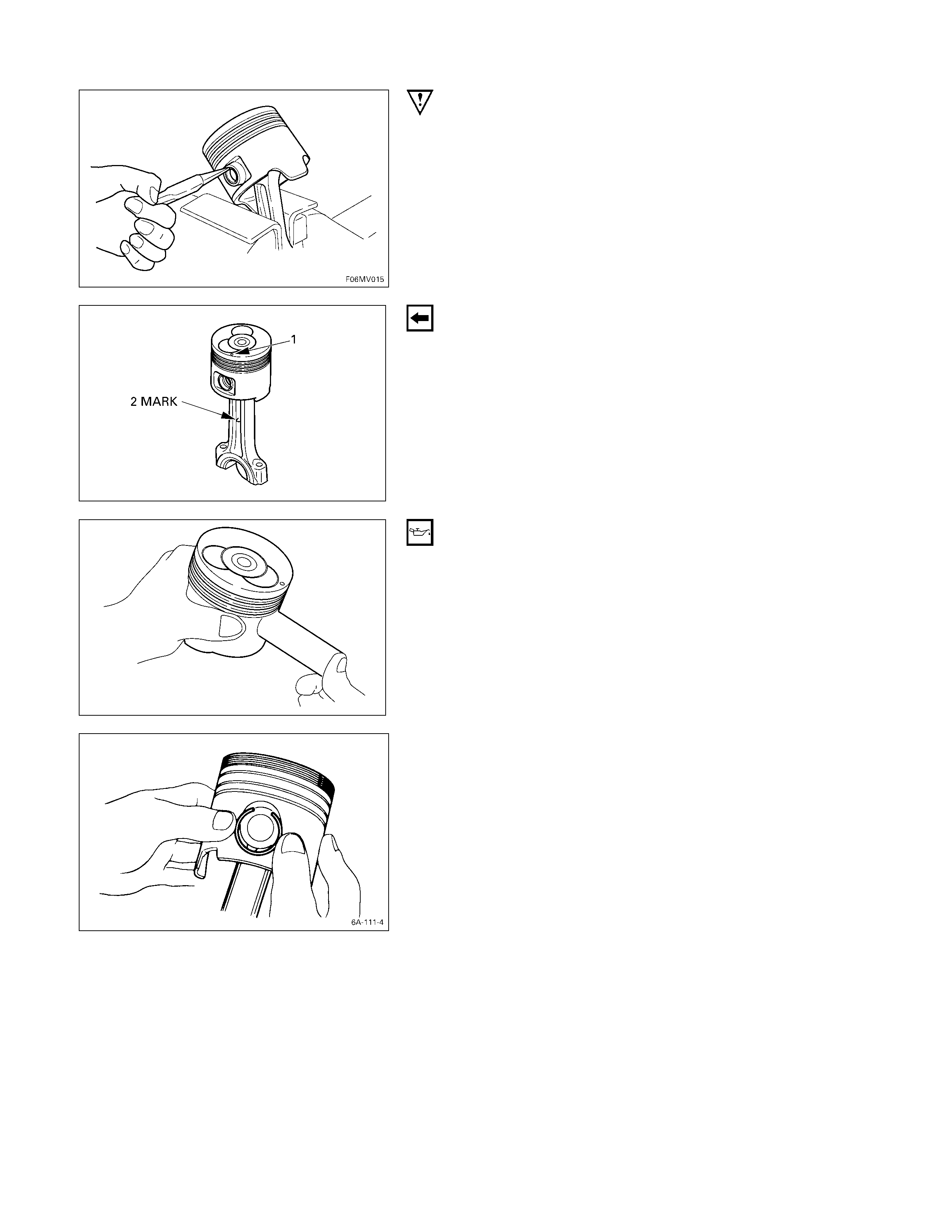
IMPORTANT OPERATIONS
1. Piston
2. Piston Pin Snap Ring
3. Connecting Rod
1) Clamp the connecting rod in a vise.
Take care not to damage the connecting rod.
2) Use a pair of pliers to install the piston pin snap ring to
the piston.
Install the piston to the connecting rod so that the piston
head front mark Q and the connecting rod “ISUZU”
casting mark R are facing in the same direction.
4. Piston Pin
1) Apply a coat of engine oil to the piston pin and the
piston pin hole.
2) Use your fingers to force the piston pin into the piston
until it makes contact with the snap ring.
5. Piston Pin Snap Ring
3) Use your fingers to force the piston pin snap ring into
the piston snap ring groove.
4) Check that the connecting rod moves smoothly on the
piston pin.
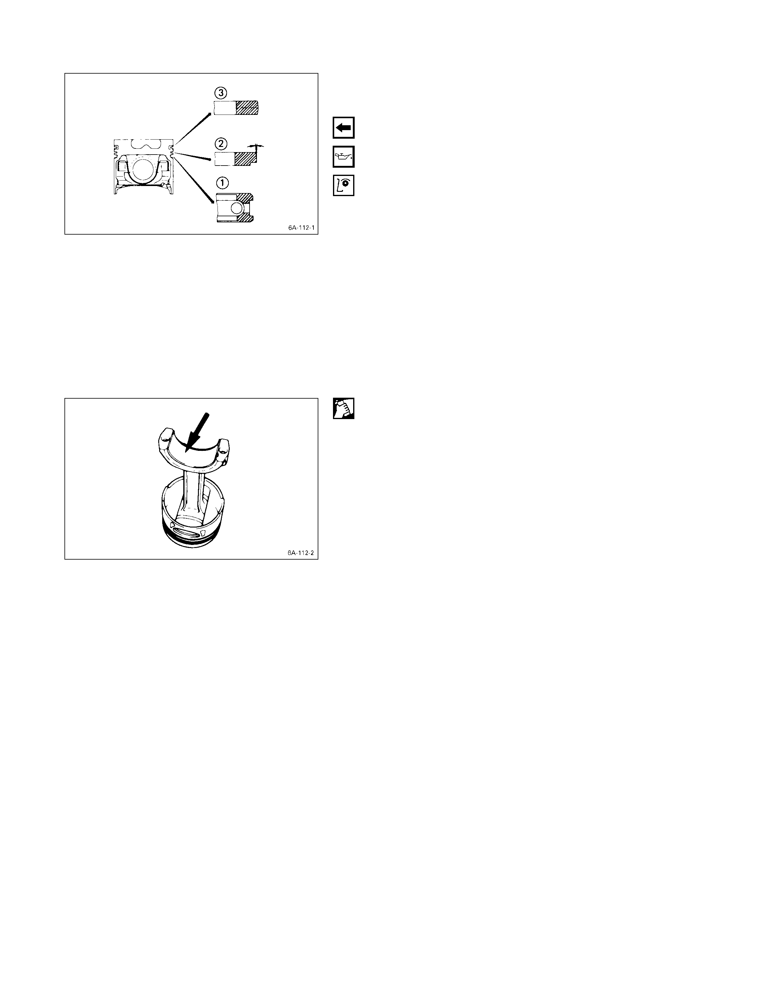
6. Piston Ring
1) Use a piston ring replacer to install the three piston
rings.
Piston Ring Replacer
Install the piston rings in the order shown in the
illustration.
QOil ring
R 2nd compression ring
S 1st compression ring
Note:
Install the compression rings with the stamped side
facing up.
Insert the expander coil into the oil ring groove so that
there is no gap on either side of the expander coil
before installing the oil ring.
2) Apply engine oil to the piston ring surfaces.
3) Check that the piston rings rotate smoothly in the
piston ring grooves.
7. Connecting Rod Bearing
Carefully wipe any oil or other foreign material from the
connecting rod bearing back face and the connecting rod
bearing fitting surface.
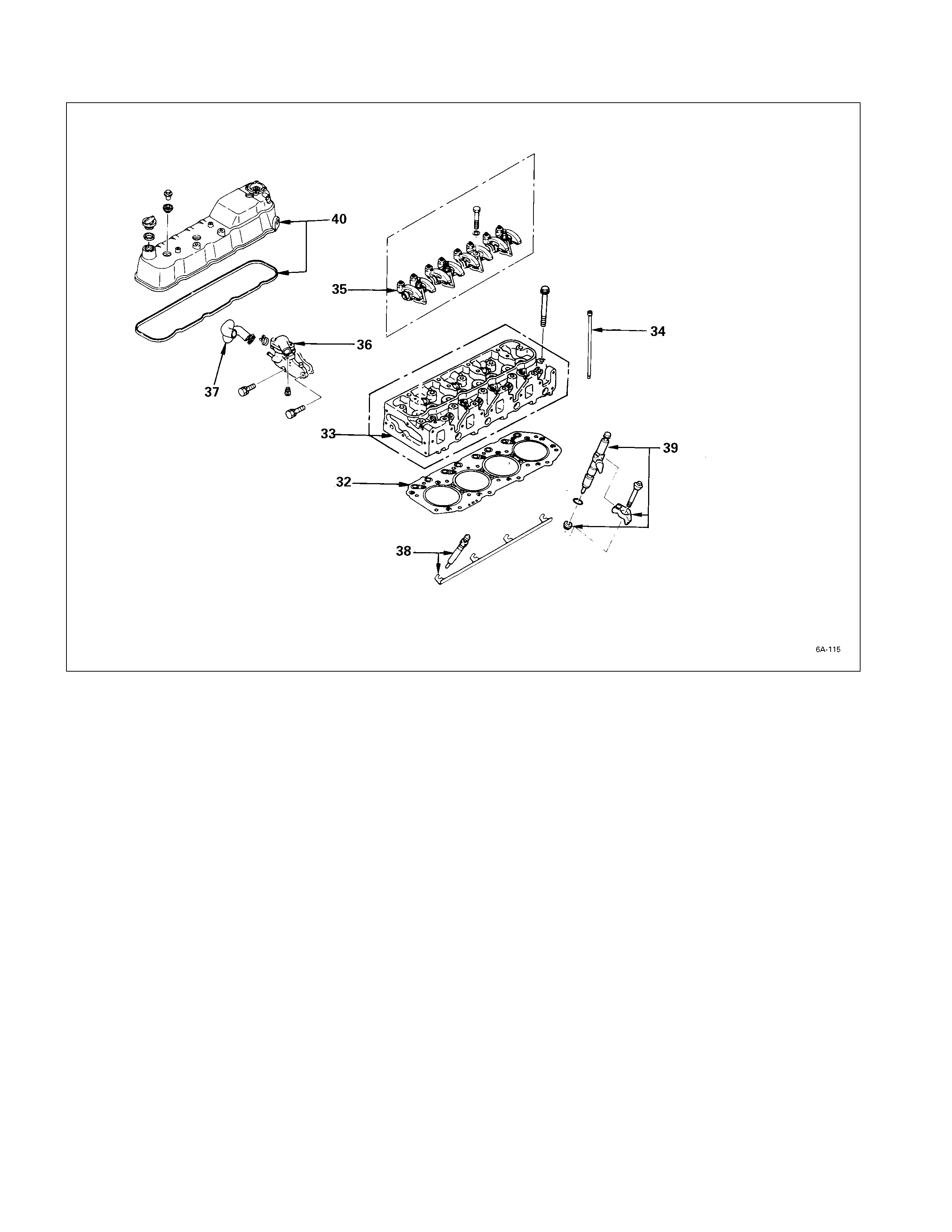
MAJO R COMPONENTS
REASSEMBLY STEPS-3
J
32. Cylinder head gasket 37. Water by-pass hose
J
33. Cylinder head
J
38. Glow plug and glow plug
34. Push rod connector
J
35. Rocker arm shaft and rocker
arm
J
39. Injection nozz le and Injection
nozzle holder
J
36. Thermostat housing with thermo
J
40. Cylinder head cover
switch
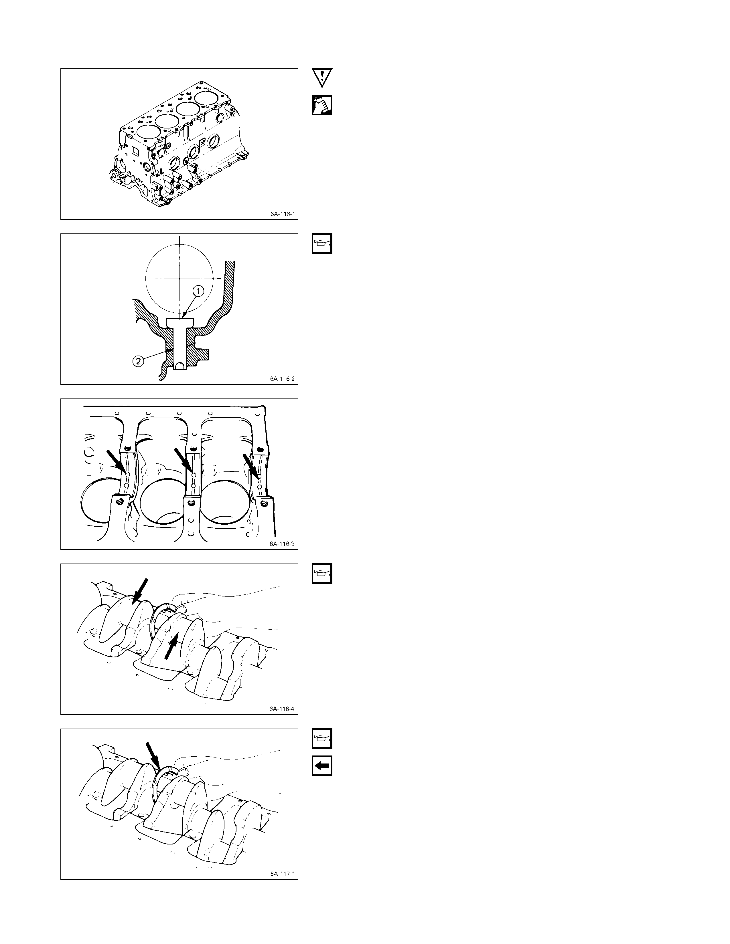
IMPORTANT OPERATIONS
1. Cylinder Body
Use compressed air to thoroughly clean the inside and
outside surfaces of the cylinder body, the oil holes, and the
water jackets.
2. Tappet
1) Apply a coat of engine oil to the tappet Q and the
cylinder body tappet insert holes R.
2) Locate the position mark applied at disassembly (if the
tappet is to be reused).
Note:
The tappet must be installed before the camshaft
installation.
3. Crankshaft Upper Bearing
The crankshaft upper bearings have an oil hole and an oil
groove. The lower bearings do not.
1) Carefully wipe any foreign material from the upper
bearing.
Note:
Do not apply engine oil to the bearing back faces and
the cylinder body bearing fitting surfaces.
2) Locate the position mark applied at disassembly if the
removed upper bearings are to be reused.
4. Crankshaft
Apply an ample coat of engine oil to the crankshaft
journals and the crankshaft bearing surfaces before
installing the crankshaft.
5. Crankshaft Thrust Bearing
Apply an ample coat of engine oil to the thrust bearings
before installation.
Install the thrust bearings to the crankshaft center journal.
The thrust bearing oil grooves must be facing the sliding
faces.

6. Crankshaft Bearing Cap With Lower Bearing
Before the crankshaft bearing installation, select the
appropriate bearings in accordance with the description in
CRANK BEARING SELECTION of INSPECTION AND
REPAIR.
1) Apply the recommended liquid gasket or its equivalent
to the No. 5 crankshaft bearing cap Q as shown in the
illustration.
2) Install the arch gasket R to the No. 5 bearing cap.
Use your fingers to push the arch gasket into the
bearing cap groove.
Take care not to scratch the arch gasket outer
surface.
3) Apply the recommended liquid gasket or its equivalent
to the No. 5 crankshaft bearing cap cylinder body
fitting surfaces at the points (T) shown in the
illustration.
Note:
Be sure that the bearing cap fitting surface is
completely free of oil before applying the liquid
gasket.
Do not allow the liquid gasket to obstruct the cylinder
thread holes and bearings.
4) Install the bearing caps with the bearing cap head
arrow mark facing the front of the engine.
The bearing cap numbers must be facing up.
5) Apply engine oil to the crankshaft bearing cap bolts.
6) Temporarily tighten the bearing cap bolts.
The bolts will be tightened to the specified torque after
the crankshaft rear oil seal is installed.
1) Tighten the adapter to the crankshaft rear end section
with 2 bolts.
2) Insert the oil seal into the peripheral section of the
adapter.
3) Insert the sleeve into the adapter section, and 1)
tighten it with a bolt (M12 × 1.75L = 70) until the
adapter section hits the sleeve.
4) Remove the adapter and the sleeve.
5) With the seal pressed in, check the dimension of the
oil seal section.
Standard Dimension = 12.5 ± 0.3 mm
Oil Seal Installer: 5-8840-2359-0
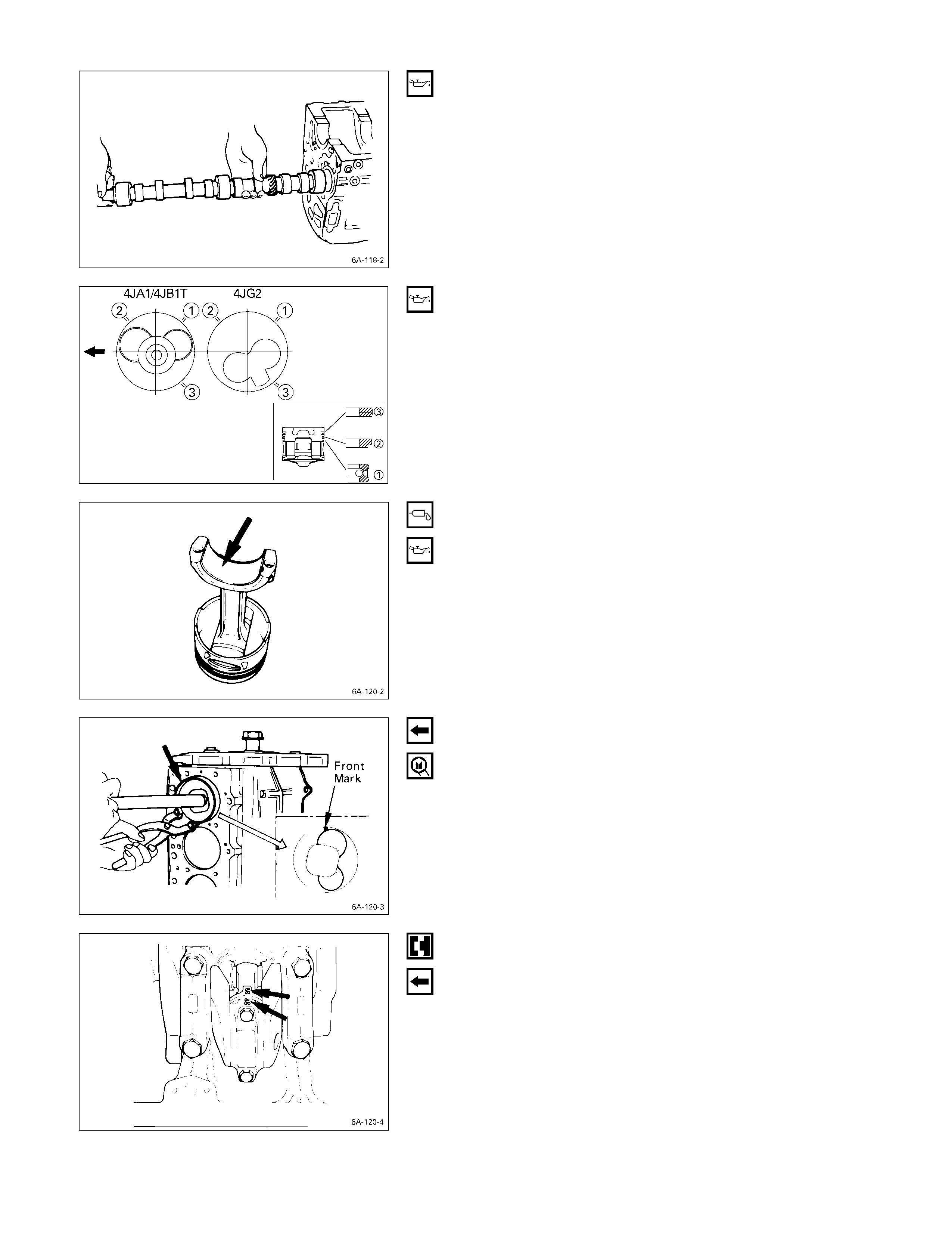
8. Camshaft
1) Apply a coat of engine oil to the camshaft and the
camshaft bearings.
Install the camshaft to the cylinder body.
Take care not to damage the camshaft bearings.
9. Piston and Connecting Rod with Upper Bearing
10. Connecting Rod Bearing Cap with Lower Bearing
1) Apply a coat of engine oil to the circumference of each
piston ring and piston.
2) Position the piston ring gaps as shown in the
illustration.
QOil ring
R 2nd compression ring
S 1st compression ring
3) Apply a coat of molybdenum disulfide grease to the
two piston skirts.
This will facilitate smooth break-in when the engine is
first started after reassembly.
4) Apply a coat of engine oil to the upper bearing
surfaces.
5) Apply a coat of engine oil to the cylinder wall.
6) Position the piston head front mark so that it is facing
the front of the engine.
7) Use the piston ring compressor to compress the
piston rings.
Piston Ring Compressor: 5-8840-9018-0 (J-8037)
8) Use a hammer grip to push the piston in until the
connecting rod makes contact with the crankpin.
At the same time, rotate the crankshaft until the
crankpin is at BDC.
9) Align the bearing cap cylinder number marks and the
connecting rod cylinder number marks.
The cylinder number marks must be turned toward the
exhaust manifold.
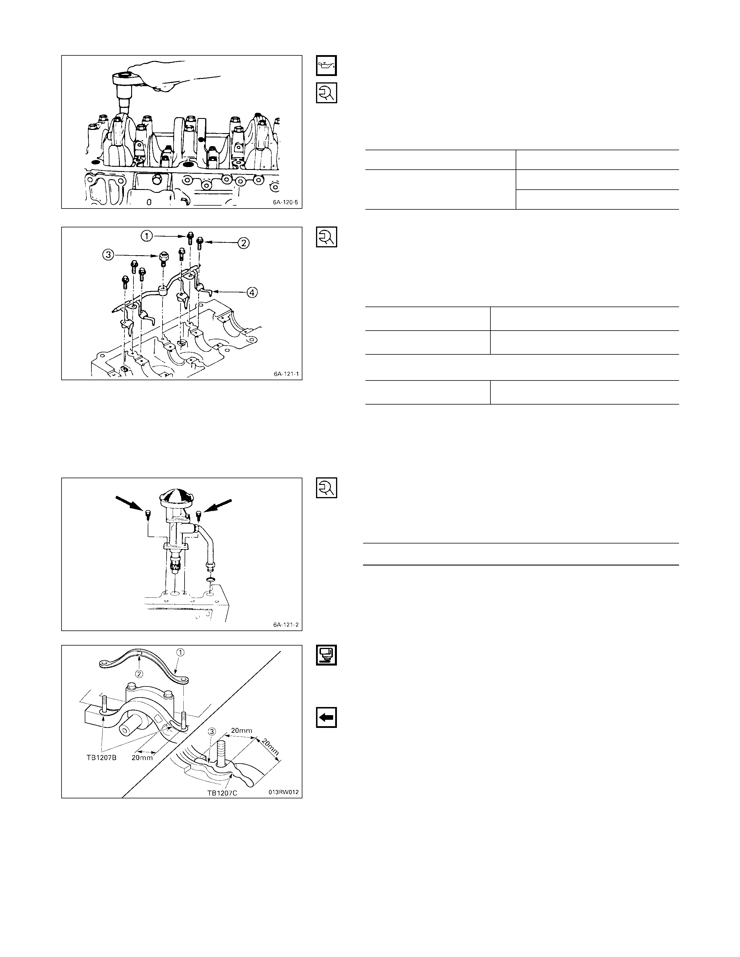
10) Apply a coat of engine oil to the threads and setting
faces of each connecting rod cap bolt.
11) Tighten the connecting rod caps to the specified
torque.
Connecting Rod Bearing Cap Bolt
Torque kg·m (lb.ft/N·m)
4JA1/4JA1T engine 8.5 ± 0.5 (61 ± 3.6/83 ± 5)
1st step; 3.0 (22/29)
4JB1T/4JG2T engine 2nd step; 45 degrees
11. Pis ton Cooling Oil Pipe
1) Install the piston cooling oil pipe to the cylinder body.
2) Tighten the oil pipe bolts and relief valve to the
specified torque.
Oil Pipe Bolt Torque kg·m (lb.ft/N·m)
Q M8 × 1.25 1.9 ± 0.5 (13.7 ± 3.6/14.7 ± 4.9)
R M6 × 1.00 0.8 ± 0.2 (5.1 ± 1.4/7.8 ± 2.0)
Relief valve Torque kg·m (lb.ft/N·m)
S M16 × 1.5 3.0 ± 0.5 (21.7 ± 3.6/29.4 ± 4.9)
Note:
Check that there is no interference between the piston
and the oiling jet pipe T
TT
T by slowly rotating the
crankshaft.
12. Oil Pump with Oil Pipe
Install the oil pump with the oil pipe and tighten the bolts to
the specified torque.
Oil Pump Bolt Torque kg·m (lb.ft/N·m)
1.9 ± 0.5 (13.7 ± 3.6/18.6 ± 4.9)
Note:
Take care not to damage the O-rings when tightening
the oil pipe bolts.
13. Oil Pan
1) Apply the recommended liquid gasket (three bond
TB1207 & TB1207C) or its equivalent to arch gasket
fitting surface as shown in the illustration.
2) Install the crank case front gasket 1 to the timing gear
case ar ches.
The gasket projection 2 must be facing forward.
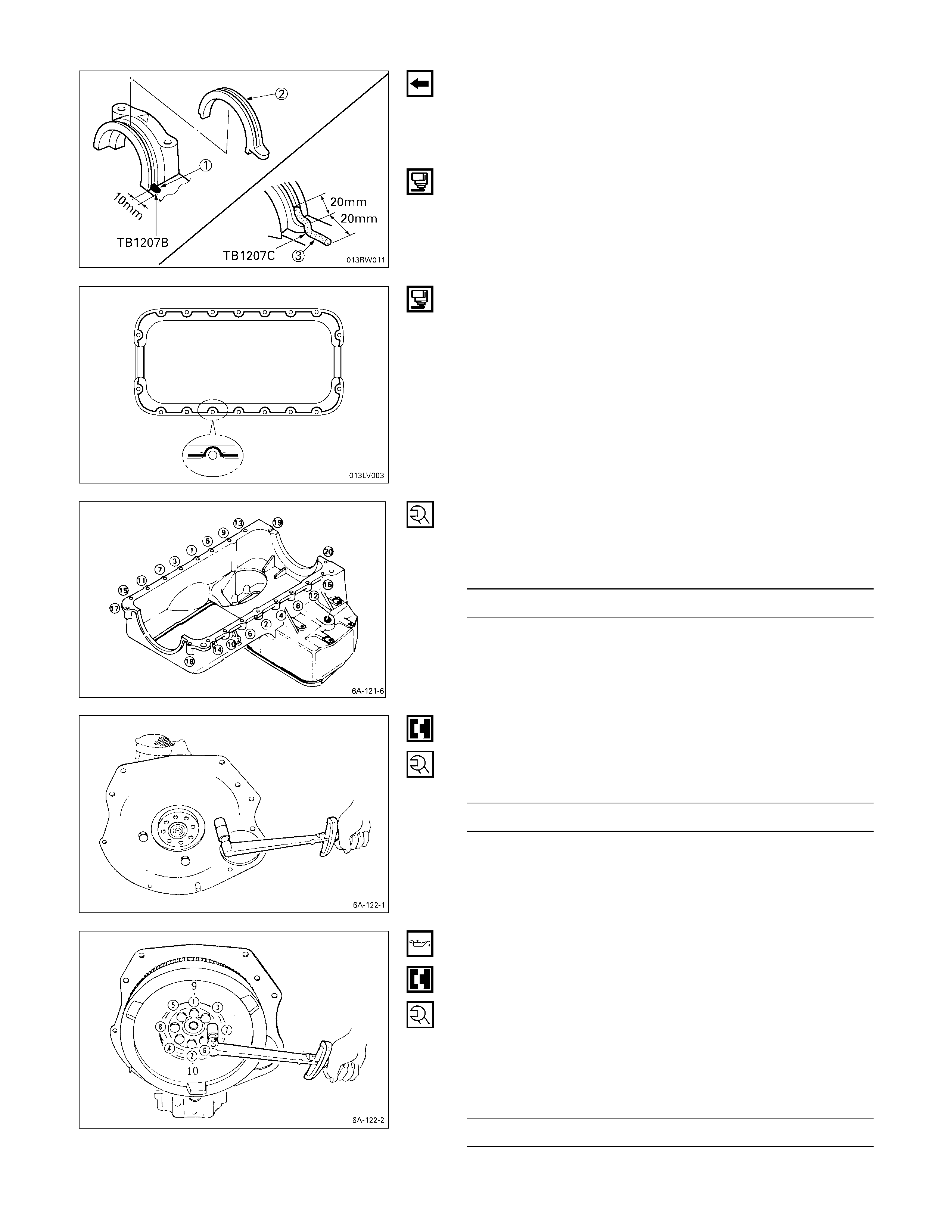
3) Install the rear arch gasket 2 to the No. 5 bearing cap.
Use your fingers to push the arch gasket into the
bearing cap groove.
Take care not to scratch the arch gasket outer
surface.
Also apply the recommended liquid gasket (TB1207B
& TB1207C) or its equivalent to arch gasket fitting
area as indicated in the illustration.
4) Apply the recommended liquid gasket or its equivalent
to groove of the crank case fitting surface as shown in
the illustration.
Note:
Be sure that the crank case fitting surface is
completely free of oil and dust before applying the
liquid gasket.
5) Install the crank case to the cylinder body.
6) Tighten the crank case bolts to the specified torque a
little at a time in the sequence shown in the illustration.
Crank Case Bolt Torque kg·m (lb.ft/N·m)
1.9 ± 0.5 (13.7 ± 3.6/18.6 ± 4.9)
14. Cylinder Body Rear Plate
1) Align the rear plate with the cylinder body knock pins.
2) Tighten the rear plate to the specified torque.
Rear Plate Torque kg·m (lb.ft/N·m)
8.4 ± 0.8 (60.7 ± 5.8/82.3 ± 7.8)
15. Flywheel
1) Block the crankshaft with a piece of hard wood to
prevent the flywheel from turning.
2) Apply a coat of engine oil to the threads of the flywheel
bolts.
3) Align the flywheel with the crankshaft dowel pin.
4) Tighten the flywheel bolts to the specified torque in the
numerical order shown in the illustration.
Flywheel Bolt Torque kg·m (lb.ft/N·m)
12.0 ± 0.5 (86.8 ± 3.6/117.6 ± 4.9)
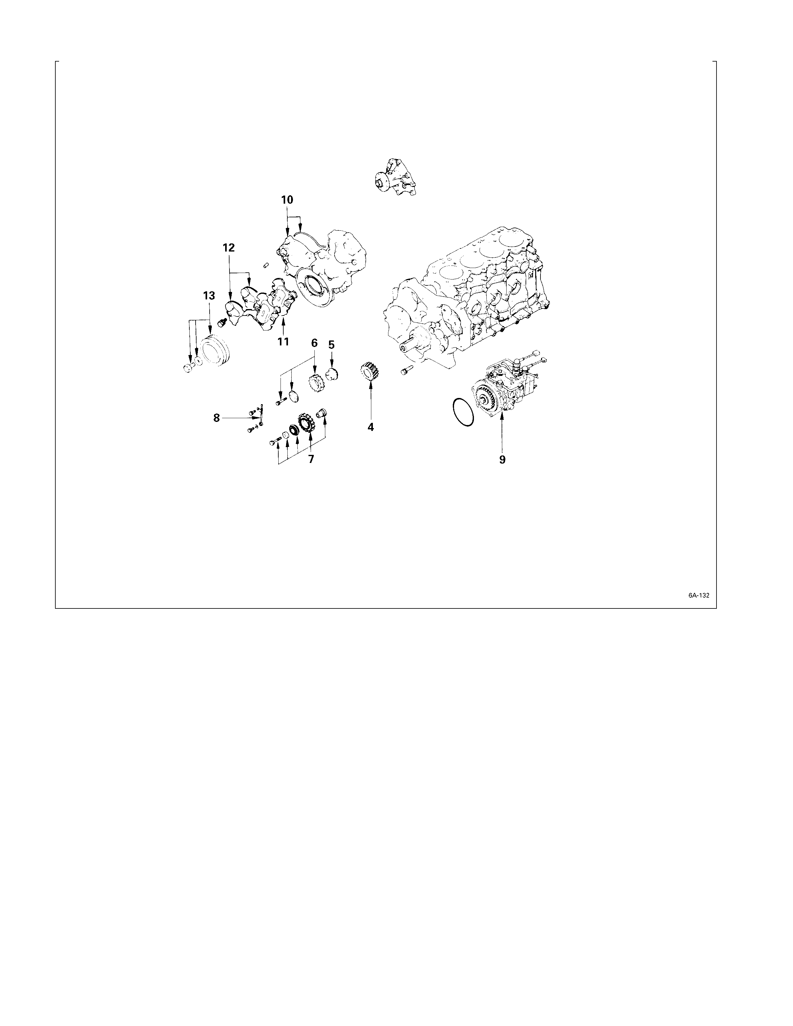
REASSEMBLY STEPS-2
J
4. Crankshaft timing gear 12. Gear case cover upper cover
J
5. Idler gear shaft and lower cover
J
6. Idler gear “A”
J
13. Crankshaft damper pulley
J
7. Idler gear “B” and shaft
J
8. Timing gear oil pipe
J
9. Injection pump
J
10. Timing gear case cover
11. Space rubber
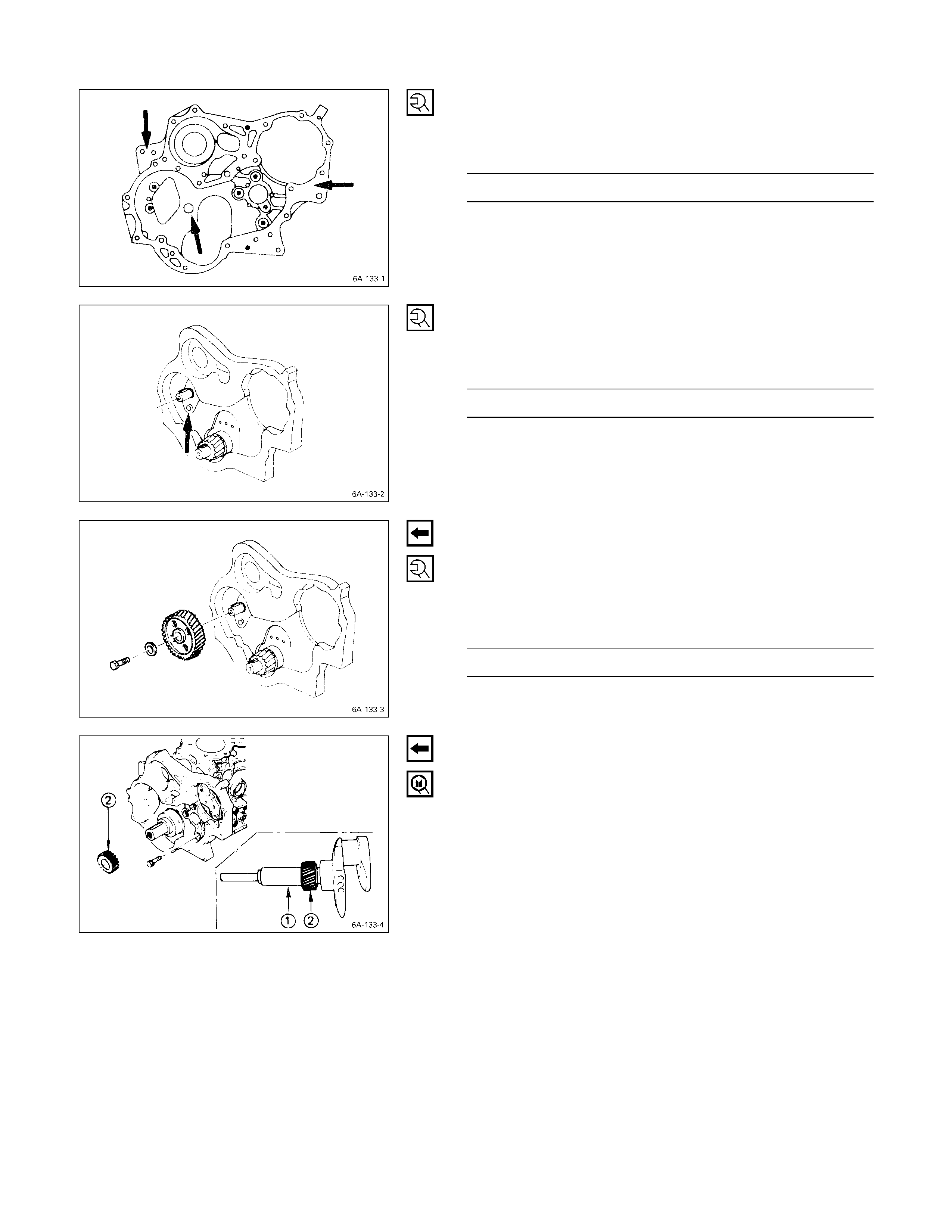
1. Timing Gear Case
1) Tighten the timing gear case with timing gear case
gasket to the specified torque.
Timing Gear Case Bolt Torque kg·m (lb.ft/N·m)
1.9 ± 0.5 (13.7 ± 3.6/18.6 ± 4.9)
2. Camshaft Thrust Plate
Install the thrust plate to the cylinder body and tighten the
thrust plate bolts to the specified torque.
Thrust Plate Bolt Torque kg·m (lb.ft/N·m)
1.8 ± 0.5 (13.0 ± 3.6/17.6 ± 4.9)
3. Camshaft Timing Gear
1) Install the camshaft timing gear to the camshaft.
The timing gear mark (“Y – Y”) must be facing
outward.
2) Tighten the timing gear to the specified torque.
Timing Gear Bolt Torque kg·m (lb.ft/N·m)
11.0 ± 1 (79.6 ± 7.2/107.8 ± 9.8)
4. Crankshaft Timing Gear
Use the crankshaft timing gear installer Q to install the
crankshaft timing gear R.
The crankshaft timing gear setting mark (“X – X”) must be
facing outward.
Crankshaft Timing Gear Installer: 9-8522-0020-0
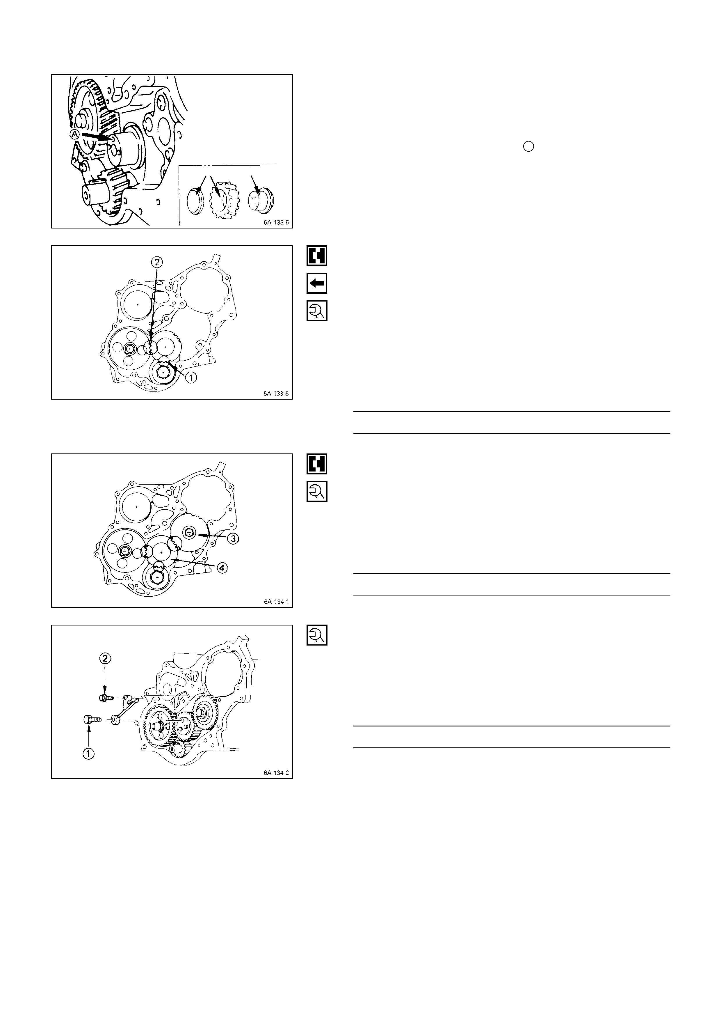
5. Idler Gear Shaft
6. Idler Gear “A”
1) Apply engine oil to the idler gear and the idler gear
shaft.
The idler gear shaft oil hole A must be facing up.
2) Position the idler gear setting marks “X” and “Y” so
that they are facing the front of the engine.
3) Align the idler gear “X” setting mark with the
crankshaft timing gear c “X – X” setting mark.
4) Align the idler gear “Y” setting mark with the camshaft
timing gear d “Y – Y” setting mark.
5) Install the thrust collar and bolts to the cylinder bo dy
through the shaft.
The thrust collar oil hole must be faci ng up, and the
thrust collar chamfered must be outward.
6) Tighten the idler gear bolt to the specified torque.
Idler Gear “A” Bolt Torque kg·m (lb.ft/N·m)
1.9 ± 0.5 (13.7 ± 3.6/18.6 ± 4.9)
7. Idler Gear “B” and Shaft
1) Apply engine oil to the idler gear and the idler gear
shaft.
2) Align the idler gear “B” e “Z” setting mark with the
idler gear “A” f “Z – Z” sett ing mark.
3) Tighten the idler gear bolt to the specified torque.
Idler Gear “B” Bolt Torque kg·m (lb.ft/N·m)
7.7 ± 1.0 (55.7 ± 7.2/75.5 ± 9.8)
8. Timing Gear Oil Pipe
1) Install the oil pipe to the timing gear case and idler
gear “A”.
2) Tighten the oil pipe eye bolt c and bolt d to the
specified torque.
Eye Joint and Bolt Torque kg·m (lb.ft/N·m)
1.25 ± 0.25 (9.0 ± 1.8/12.3 ± 2.5)
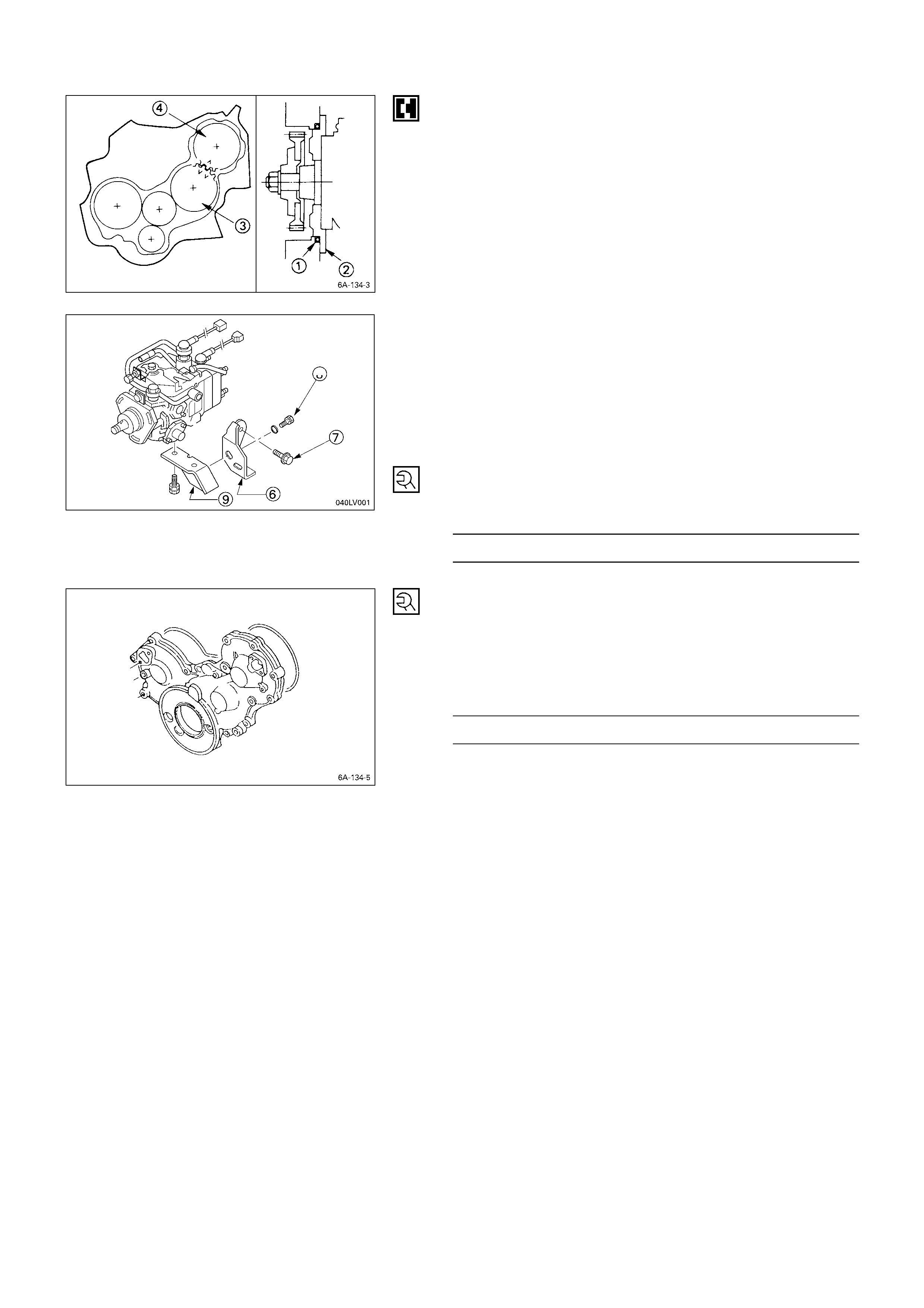
9. Injection Pump
1) Install the O-ring c to the injection pump flange d.
2) Install the injection pump to the timing gear case.
Align the idler gear “B” e “V – V” mark with the
injection pump timing gear f “V” mark.
3) Install the injection pump rear bracket h and the re ar
bracket bolts i to the cylinder body.
4) Install the rear bracket bolt s j to the injection pump
bracket k.
5) Tighten the injection pump bracket bolts to the
specified torque.
Injection Pump Bracket Bolt Torque kg·m (lb.ft/N·m)
1.9 ± 0.5 (13.7 ± 3.6/18.6 ± 4.9)
10. Timing Gear Case Cov er
1) Align the gear case with the timing gear case knock
pin and then install the timing gear case cover.
2) Tighten the gear case cover bolts to the specified
torque.
Gear Case cover Bolt Torque kg·m (lb.ft/N·m)
1.9 ± 0.5 (13.7 ± 3.6/18.6 ± 4.9)
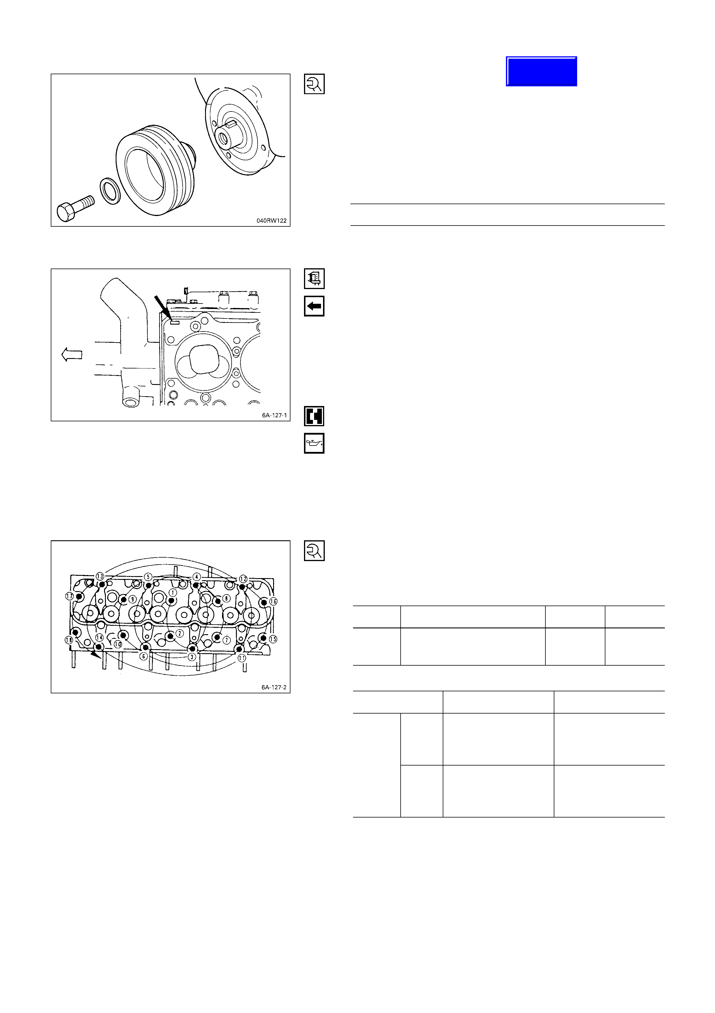
11. Crankshaft Damper Pulley
Tighten the crankshaft damper pulley bolt to the specif ied
torque.
Note:
Hold the flywheel ring gear stationary to prevent the
crankshaft from turning when tightening the damper
pulley.
Crankshaft Damper Pulley Bolt Torque kg·m (lb.ft/N·m)
24 ± 0.5 (174 ± 4.5 / 235 ± 5)
Take care not to damage th e crankshaft damper pulley
boss.
12. Cylinder Hea d Gasket
The cylinder head gasket “TOP” mark must be facing up.
Note:
Before the gasket installation, measure the piston
head projection and select the appropriate head
gasket.
Refer to “INSPECTION AND REPAIR”, “Cylinder Head
Gasket Selection”.
13. Cylinder Head
1) Align the cylinder body dowels and the cylinder head
dowel holes.
Carefully place the cylinder head on the cylinder head
gasket.
2) Apply a coat of engine oil to the cylinder head bolt
threads and setting faces.
3) Tighten the cylinder head bolts in two steps.
Follow the numerical sequence shown in the
illustration.
Cylinder Head Bolt Torque kg·m (lb.ft/N·m)
1st Step 2nd Step 3rd Step
4JG2T
4JB1T 5.0 ± 0.5
(36.2 ± 3.6/49.00 ± 4.90) 60° ~ 75°60° ~ 75°
Cylinder Head Bolt Torque kg·m (lb.ft/N·m)
1st Step 2nd Step
New
bolt
5.0 ± 0.5
(36.2 ± 3.6/
83.3 ± 4.9)
8.7 ± 0.5
(62.9 ± 3.6/
85.26 ± 4.90)
4JA1T
4JA1 Reuse
bolt
8.5 ± 0.5
(61.4 ± 3.6/
83.3 ± 4.9)
10.5 ± 0.5
(75.9 ± 3.6/
102.90 ± 4.90)
Techline
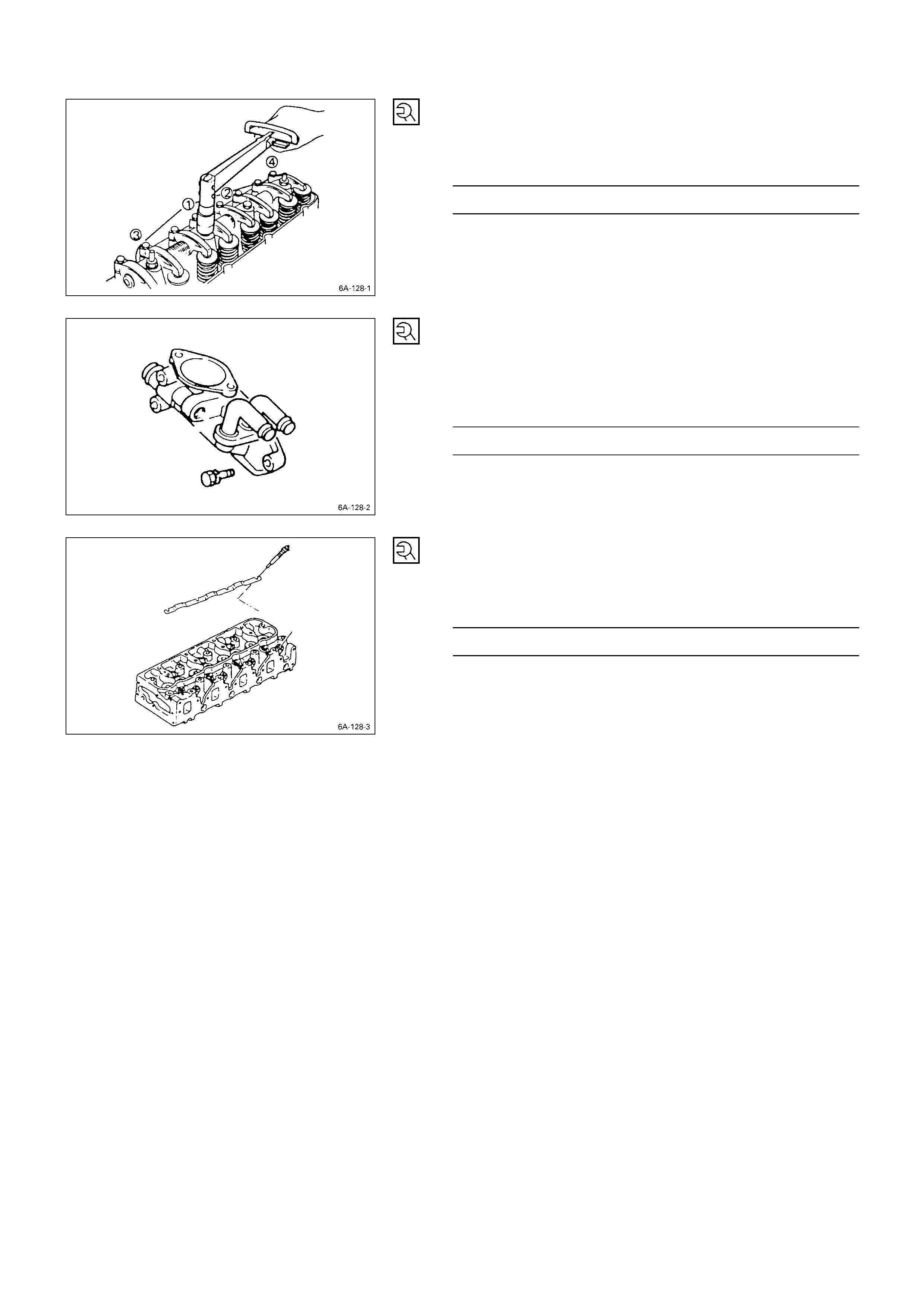
14. Rocker Arm Shaft and Rocker Arm
Tighten the rocker arm shaft bracket bolts in the num erical
order shown in the illustration.
Rocker Arm Shaft Bracket Bolt Torque kg·m (lb.ft/N·m)
5.5 ± 0.5 (39.8 ± 3.6/54.0 ± 4.9)
15. Thermostat Housing
1) Install the thermostat housi ng.
2) Tighten the thermostat housing bolts to the specified
torque.
Thermostat Housing Bolt Torque kg·m (lb.ft/N·m)
1.9 ± 0.5 (13.7 ± 3.6/18.6 ± 4.9)
16. Glow Plug and Glow Plug Connector
1) Install the glow plugs to the cylinder head.
2) Tighten the glow plugs to the specified torque.
Glow Plug Torque kg·m (lb.ft/N·m)
2.25 ± 0.25 (16.3 ± 1.8/22.1 ± 2.5)
3) Install the glow plug connector.
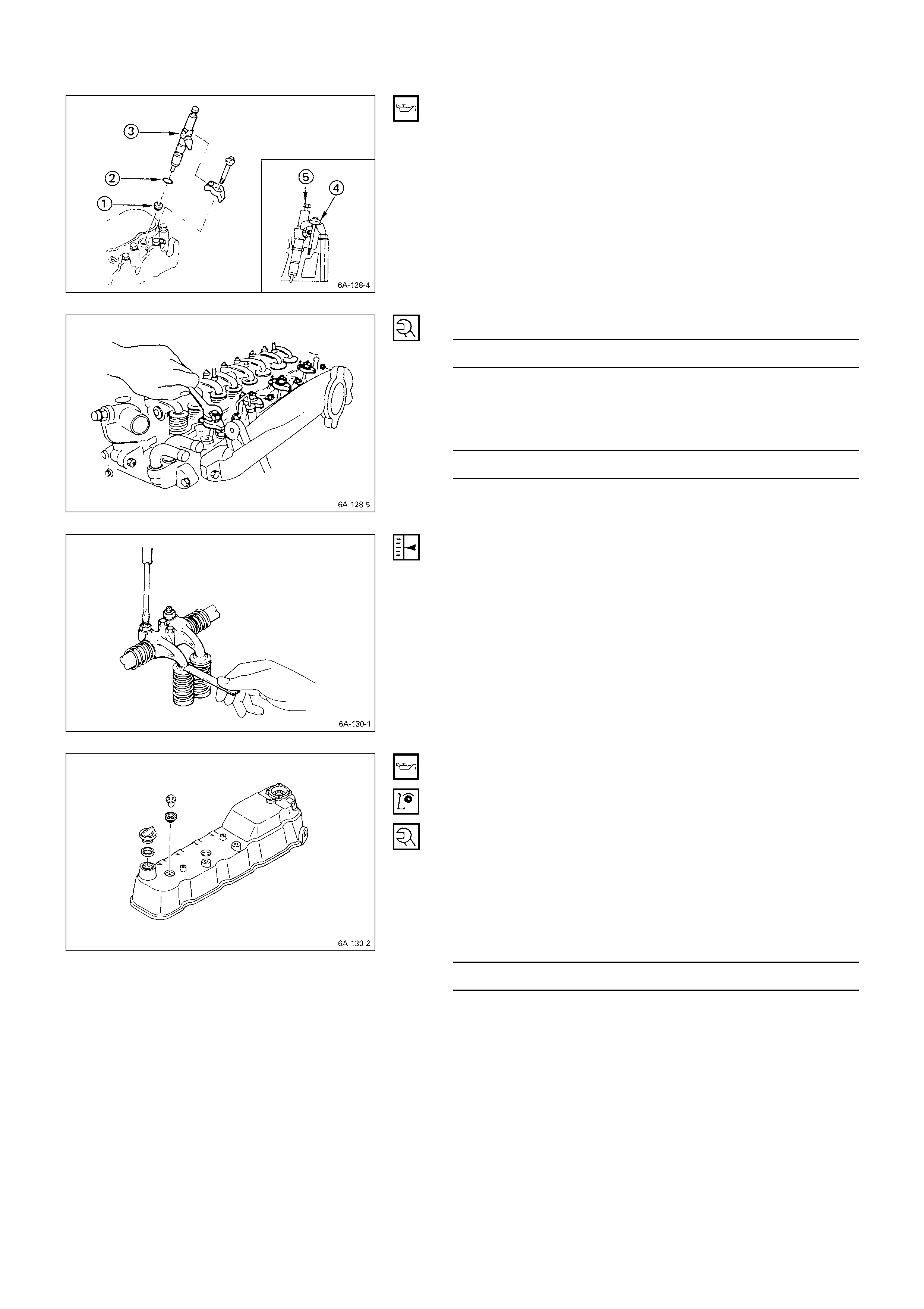
17. Injection Nozzle Holder
1) Install the injection nozzle gasket c and the O-ri ng d
to the injection nozzle holder e.
Be sure that the O-ring fits snugly in the injection
nozzle groove.
2) Install the nozzle holder toghther with the nozzle
holder bracket f to the cylinder head.
Nozzle Holder Bracket Bolt Torque kg·m (lb.ft/N·m)
3.8 ± 0.6 (27.5 ± 4.3/37.2 ± 5.9)
3) Tighten the holder nut with washer g to the specified
torque.
Injection Nozzle Holder Nut Torque kg·m (lb.ft/N·m)
3.8 ± 0.6 (26.0 ± 4.3/37.2 ± 5.9)
NOTE ON VALVE CLE ARANCE ADJUSTMENT
Valve clearances must be adjusted before the cylind er
head cover is reinstalled.
Refer to “Valve Clearance Adjustment ” in the “Servicing”
Section of this Manual.
18. Cylinder Hea d Cover
1) Apply engine oil to the rocker arm and the valve
spring.
2) Install the cylinder head cover gasket to the head
cover.
Check to see that the head cover gasket has n o loose
areas.
3) Tighten the cylinder head cover nuts in the nume rical
order shown in the illustration.
Cylinder Head Cover Bolt Torque kg·m (lb.ft/N·m)
1.3 ± 0.5 (9.4 ± 3.6/12.7 ± 4.9)
4) Connect the PCV hose to the cylinder head cover.
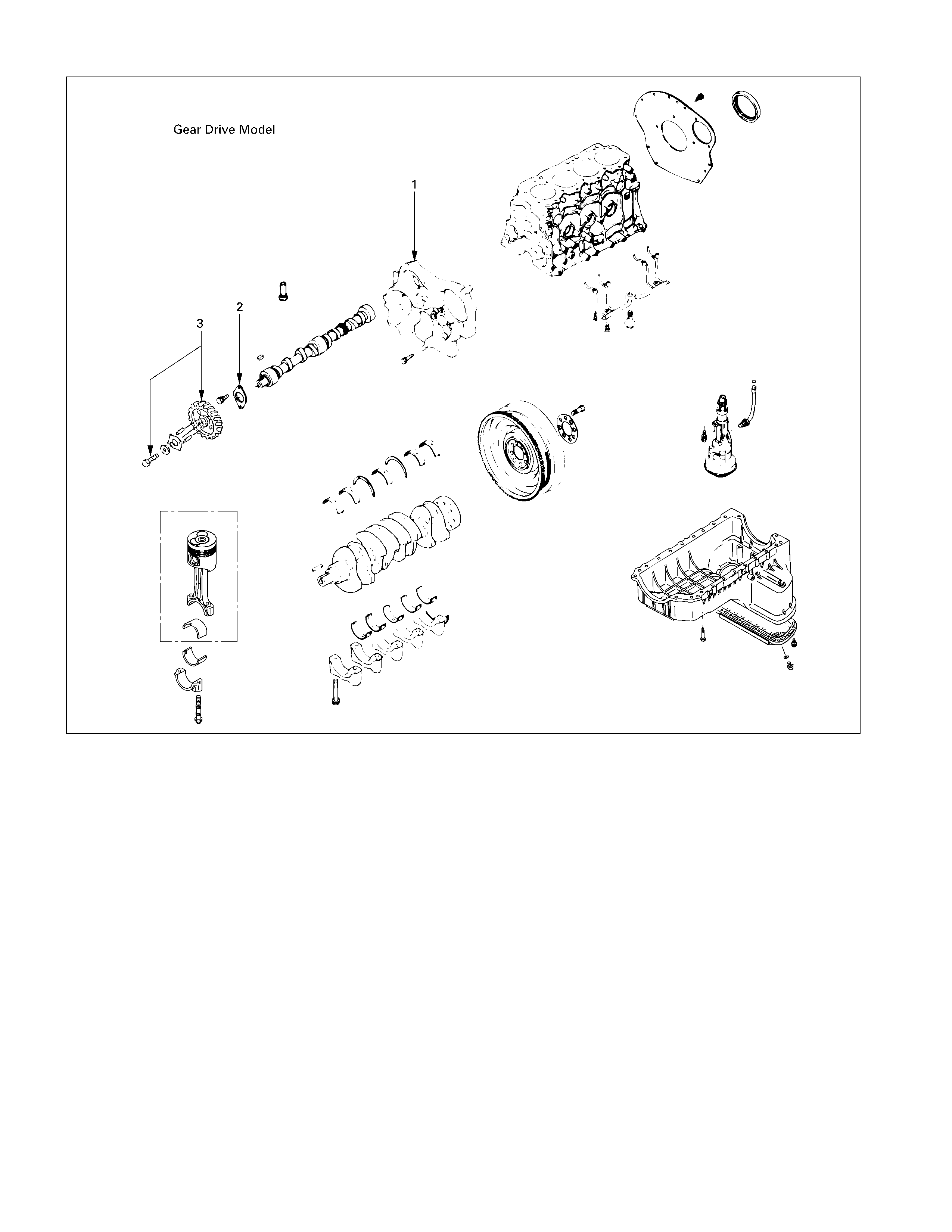
5
REASSEMBLY STEPS-1
J
1. Timing gear case
J
2. Camshaft thrust plate
J
3. Camshaft timing gear
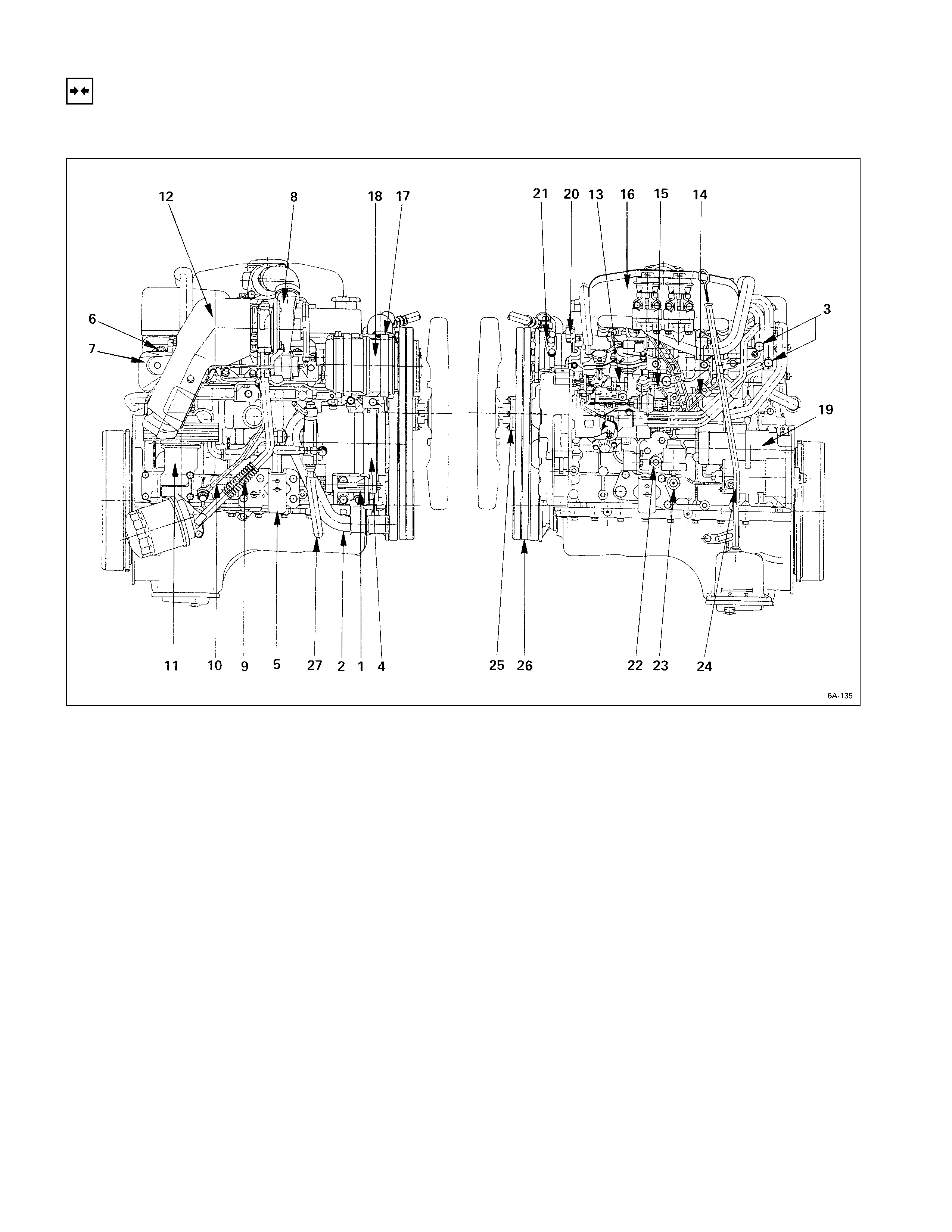
INSTALLATION
EXTERNAL PARTS
These installation steps are based on the 4JB1T engine.
INSTALLATION STEPS
J
1. Generator bracket
J
16. Intake manifold
J
2. Water inlet pipe
J
17. Compressor bracket
J
3. Heater pipe (Rear side)
J
18. Compressor
J
4. Generator and adjusting plate
J
19. Starter motor
J
5. Engine mounting bracket
J
20. Power steering oil pump bracket
J
6. Exhaust manifold
J
21. Power steering oil pump
7. Exhaust manifold heat protector 22. Water drain cock
J
8. Turbocharger 23. Oil pressure warning switch and
J
9. Turbocharger oil return pipe nipple
J
10. Turbocharger oil feed pipe 24. Oil level gauge guide tube
J
11. Oil cooler with Oil filter 25. Cooling fan pulley
12. Turbocharger heat protector 26. Cooling fan drive belt
13. Injection pump 27. Vacuum pipe
J
14. Fuel injection pipe with clip
15. Fuel leak off pipe
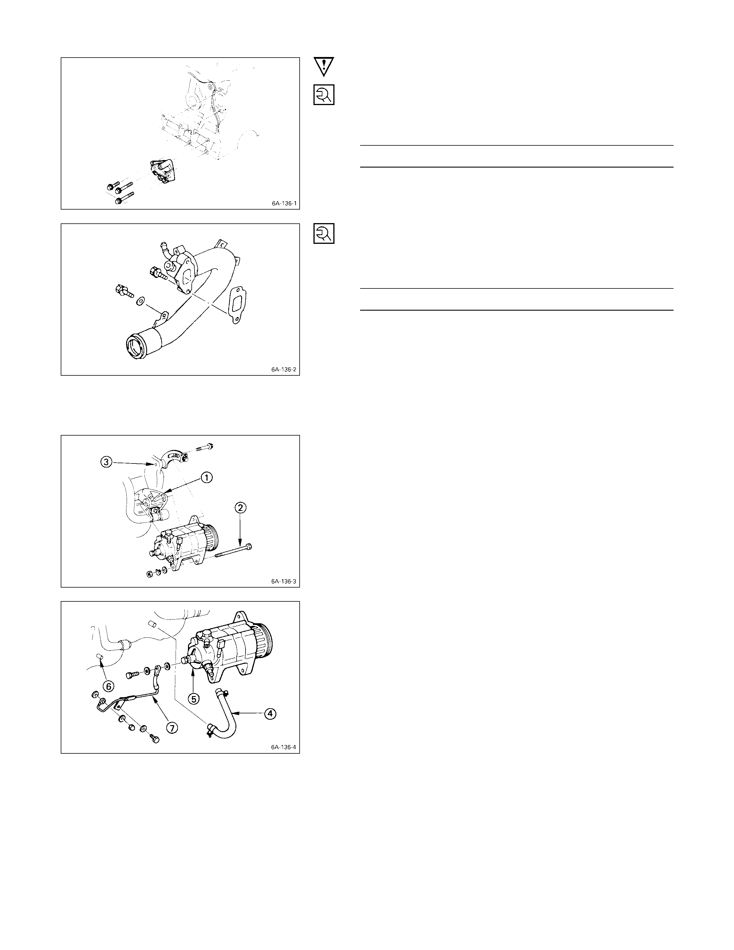
IMPORTANT OPERATIONS
1. Generator Bracket
Install the generator bracket to the cylinder body and
tighten the bracket bolts to the specified torque.
Bracket Bolt Torque kg·m (lb.ft/N·m)
4.1 ± 0.6 (29.7 ± 4.3/40.2 ± 5.9)
2. Water Inlet Pipe
1) Tighten the water inlet pipe bolts to the specified
torque.
Suction Pipe Bolt Torque kg·m (lb.ft/N·m)
1.9 ± 0.5 (13.7 ± 3.6/18.6 ± 4.9)
3. Heater Pipe (Rear Side)
1) Install the heater pipe to the cylinder head.
2) Connect the oil cooler return hose and feed hose to
the oil cooler.
3) Connect the water rubber hose to the heater pipe.
4. Generator and Adjusting Plate
1) Install the generator to the bracket Q.
2) Temporarily tighten the generator bolt R and
adjusting plate bolts S.
The bolts will be finally tightened after installation of
the cooling fan drive belt.
3) Connect the vacuum pump rubber hose T to the
vacuum pump U, and the oil pan V.
4) Connect the vacuum oil pipe W to the vacuum pump,
and the cylinder body.
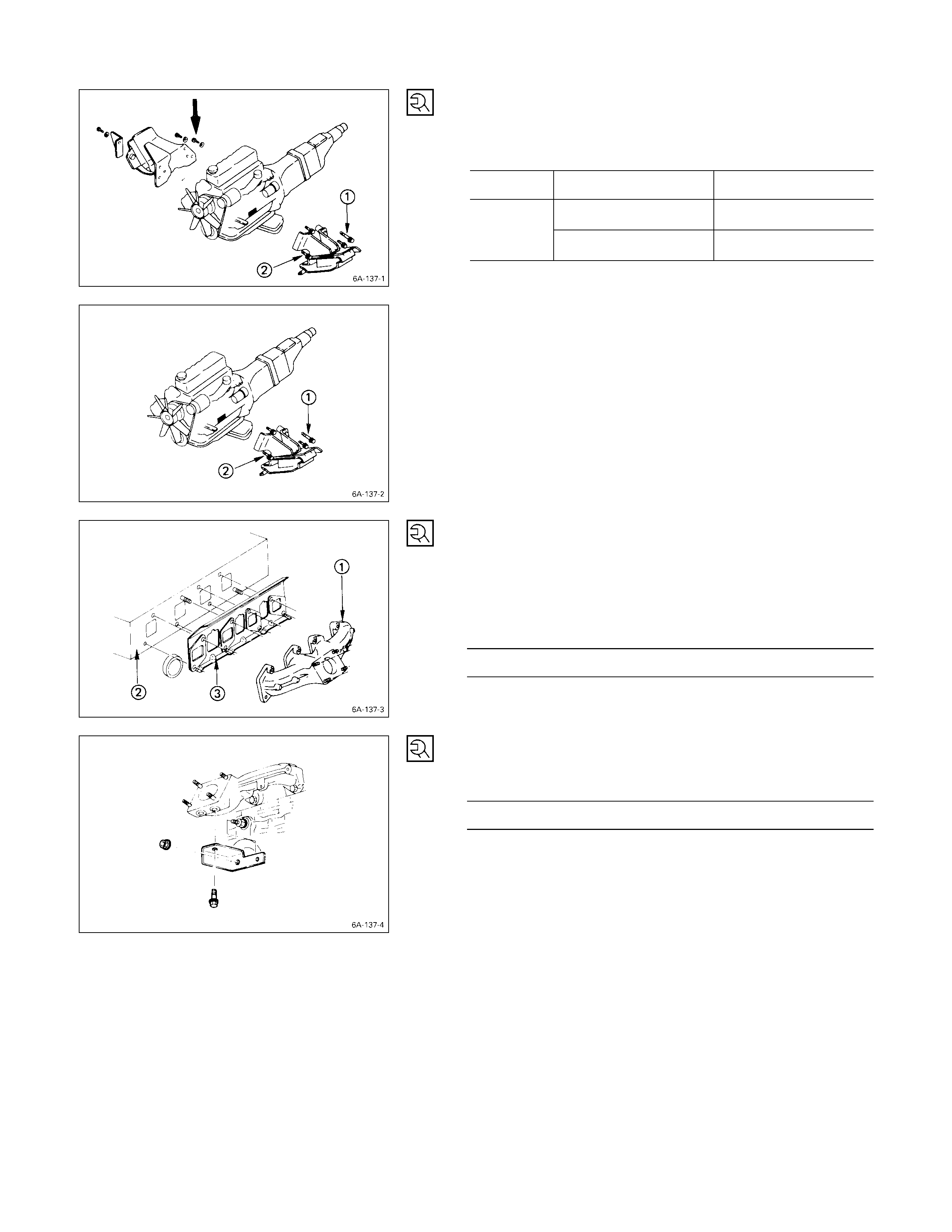
5. Engine Mounting Bracket
Install the engine mounting bracket to the cylinder body
and tighten the bracket bolts to the specified torque.
Mounting Bracket Bolt Torque kg·m (lb.ft/N·m)
Right Side M10 × 1.25 (9T) 5.6 (40.5/54.9)
RM10 × 1.25 (7T) 4.1 (30/40)
Left Side RM14 × 1.50 (7T) 12 (86.7/118)
6. Exhaust Manifold
1) Install the exhaust manifold Q to the cylinder head R
with the manifold gasket S.
2) Tighten the exhaust manifold bolts to the specified
torque a little at a time.
Exhaust Manifold Bolt Torque kg·m (lb.ft/N·m)
2.7 ± 0.5 (19.5 ± 3.6/26.5 ± 4.9)
3) Install the exhaust manifold bracket to the manifold
and the cylinder body.
Manifold Bracket Bolt Torque kg·m (lb.ft/N·m)
1.9 ± 0.5 (13.7 ± 3.6/18.6 ± 4.9)
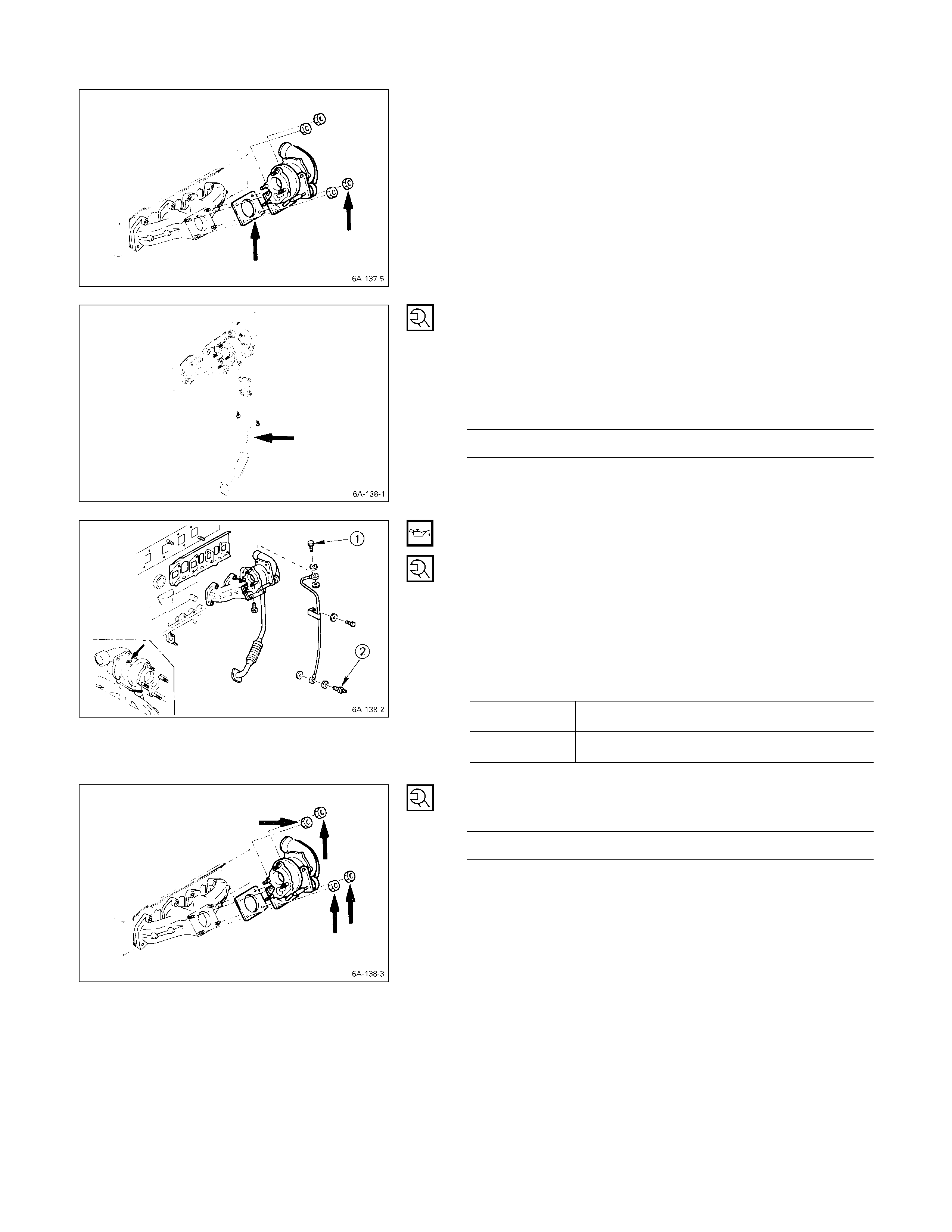
8. Turbocharger
1) Install the turbocharger and the gasket.
2) Temporarily tighten the turbocharger nuts at this time.
They will be fully tightened after the installation of the
turbocharger oil pipe.
Always install new nuts and new gasket.
9. Turbocharger Oil Return Pipe
1) Install the oil return pipe with gasket to the
turbocharger.
2) Tighten the turbocharger oil return pipe to the
specified torque.
Turbocharger Oil Reutrn Pipe Torque kg·m (lb.ft/N·m)
0.8 ± 0.2 (5.8 ± 1.4/7.8 ± 2.0)
10. Turbocharger Oil Feed Pipe
1) Before installing the oil feed pipe, supply 10 – 20 cc of
clean engine oil to the turbocharger center housing
through the oil feed opening.
2) Turn the rotating assembly with your hand to
thoroughly lubricate the internal parts.
3) Tighten the oil feed pipe to the specified torque.
Turbocharger Oil Feed Pipe Joint
Bolt Torque kg·m (lb.ft/N·m)
QM10 × 1.5 2.25 ± 0.25 (16.3 ± 1.8/22.05 ± 2.45)
RM14 × 1.5 5.5 ± 1.0 (40 ± 7.2/54 ± 10)
4) Tighten the turbocharger nut to the specified torque.
Turbocharger Nut Torque kg·m (lb.ft/N·m)
2.7 ± 0.5 (19.5 ± 3.6/26.5 ± 4.9)
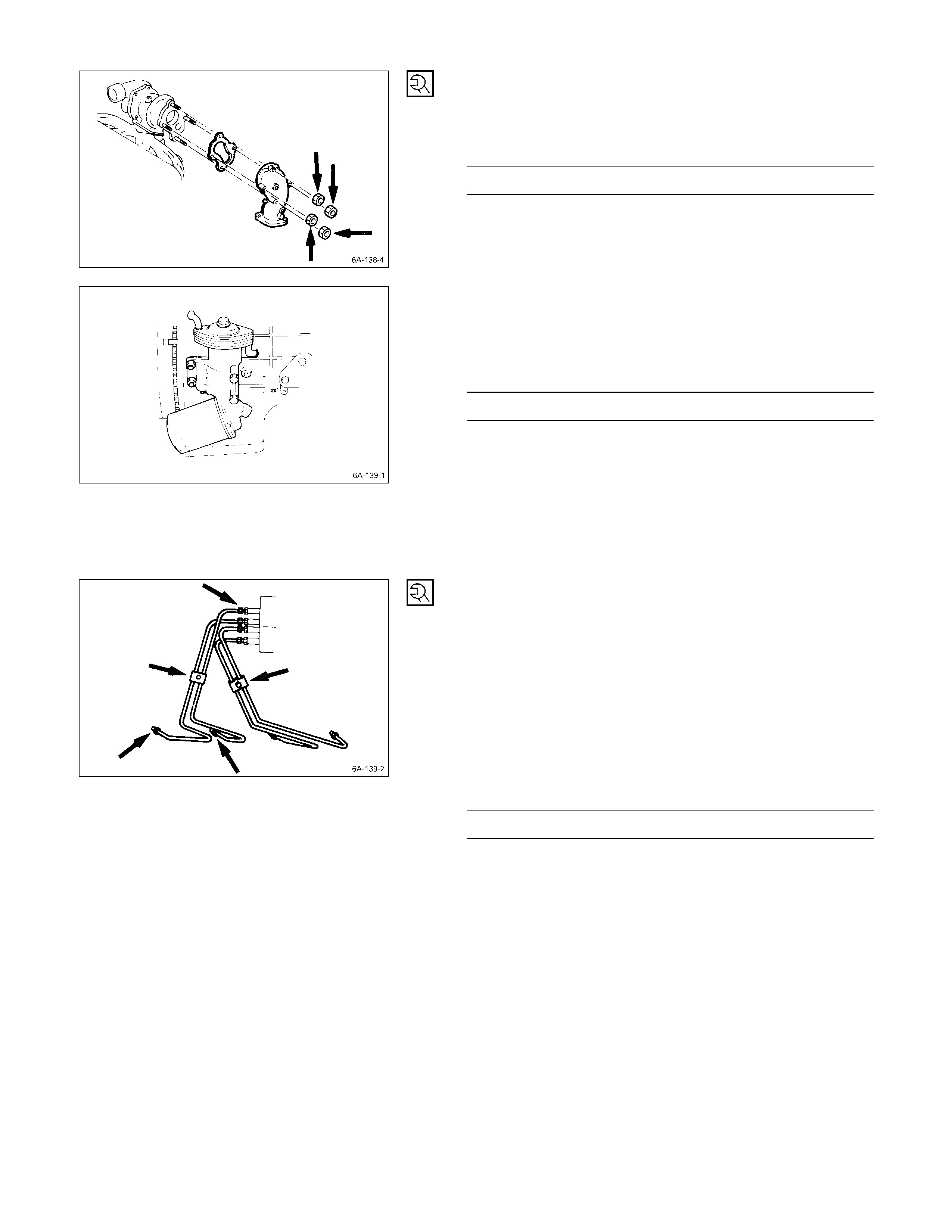
EXHAUST ADAPTER
Install the exhaust adapter with gasket and tighten the
adapter nut to the specified torque.
Adapter Nut Torque kg·m (lb.ft/N·m)
2.7 ± 0.5 (19.5 ± 3.6/26.5 ± 4.9)
11. Oil Cooler with Oil Filter
1) Install the O-ring to the oil filter flange groove.
2) Tighten the oil filter and oil cooler to the specified
torque.
Oil Filter Flange Bolt Torque kg·m (lb.ft/N·m)
1.9 ± 0.5 (13.7 ± 3.6/18.6 ± 4.9)
3) Lightly oil the O-ring of oil filter cartridge.
4) Turn in the new oil filter cartridge by hand until the
sealing face is fitted again the O-ring.
5) Use the filter wrench to turn in the oil filter and
additional one and 1·1/8 turns.
6) Start the engine and check for oil leakage from oil
filter.
13. Fuel Injection Pipe with Clip
1) Temporarily tighten the injection pipe sleeve nut.
2) Set the clip in the illustrated position.
Note:
Make absolutely sure that the clip is correctly
positioned.
An improperly positioned clip will result in injection
pipe breakage and fuel pulsing noise.
3) Tighten the injection pipe sleeve nut to the specified
torque.
Injection Pipe Sleeve Nut Torque kg·m (lb.ft/N·m)
3 ± 1 (21.7 ± 7.2/29.4 ± 9.8)
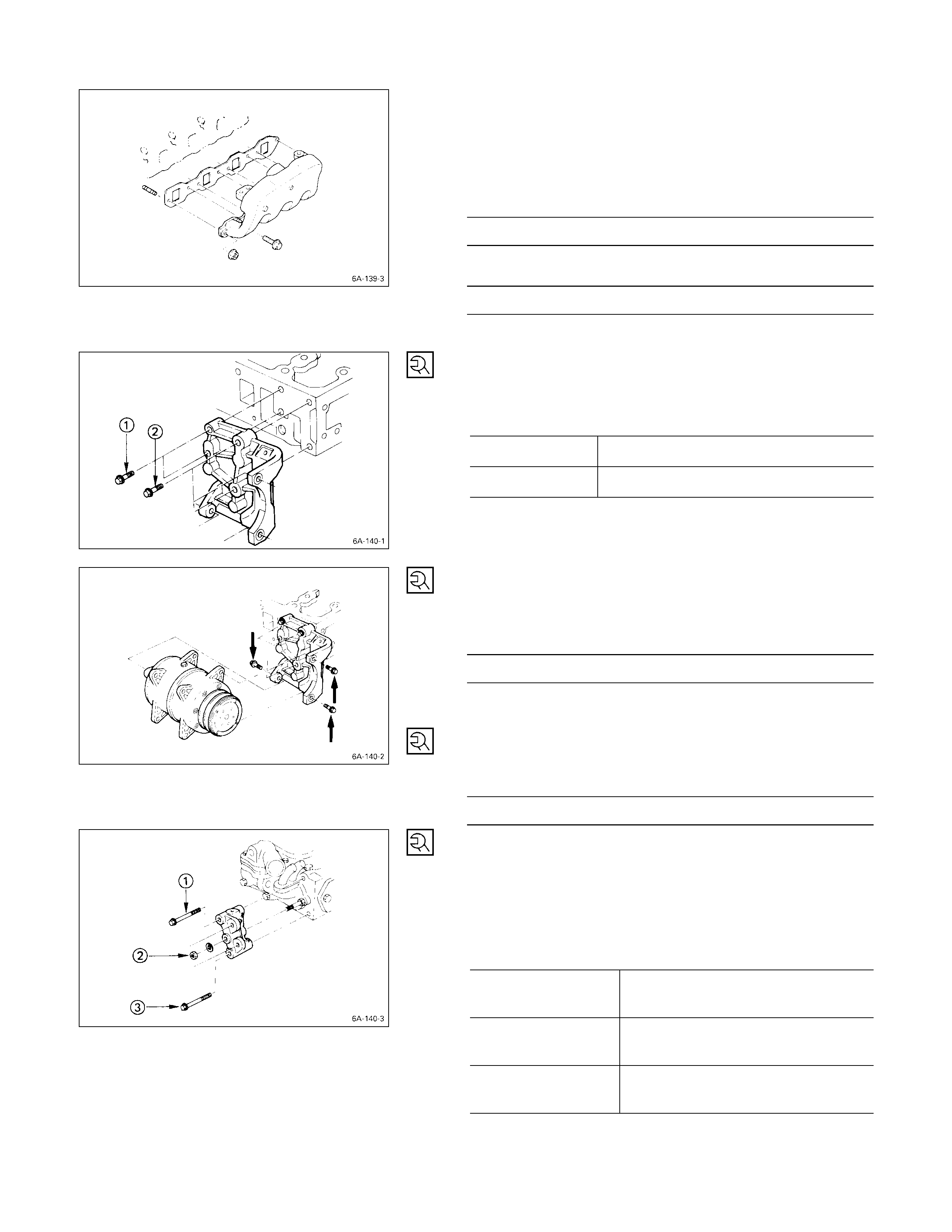
16. Intake Manifold
1) Install the manifold gasket to the intake manifold.
2) Connect the intake rubber hose to the intake duct.
3) Tighten the intake manifold bolts and the flange nuts
to the specified torque.
Intake Manifold Bolt Torque kg·m (lb.ft/N·m)
1.9 ± 0.5 (14 ± 3.6/19 ± 5)
Intake Manifold Flange Nut Torque kg·m (lb.ft/N·m)
1.9 ± 0.5 (14 ± 3.6/19 ± 5)
4) Connect the PCV hose to the cylinder head cover.
17. Compressor Bracket
1) Install the compressor bracket to the cylinder head.
2) Tighten the bracket bolts to the specified torque.
Bracket Bolt Torque kg·m (lb.ft/N·m)
QM 8 × 1.25 1.9 ± 0.5 (13.7 ± 3.6/18.6 ± 4.9)
RM10 × 1.25 4.1 ± 0.6 (30 ± 7.2/40 ± 6)
18. Compressor
1) Install the compressor to the compressor bracket.
2) Tighten the compressor bolts to the specified torque.
Compressor Bolt Torque kg·m (lb.ft/N·m)
3.8 ± 1.0 (27.5 ± 7.2/37.2 ± 9.8)
19. Starter Motor
Tighten the starter motor bolts to the specified torque.
Starter Motor Bolt Torque kg·m (lb.ft/N·m)
7.0 ± 1.0 (50.6 ± 7.2/68.6 ± 9.8)
20. Power Steering Oil Pump Bracket
21. Power Steering Oil Pump
1) Install the oil pump bracket to the cy linder head.
2) Tighten the pump bracket nut and bolts to the
specified torque.
Oil Pump Bracket Nut and Bolt
Torque kg·m (lb.ft/N·m)
QM10 × 1.25 (7T) 3.75 ± 0.95
(27.1 ± 6.9/36.75 ± 9.31)
RM 8 × 1.25 (7T) 1.75 ± 0.55
(12.7 ± 4.0/17.75 ± 5.39)
SM 8 × 1.25 (4T) 1.30 ± 0.50
(9.4 ± 3.6/12.74 ± 4.90)
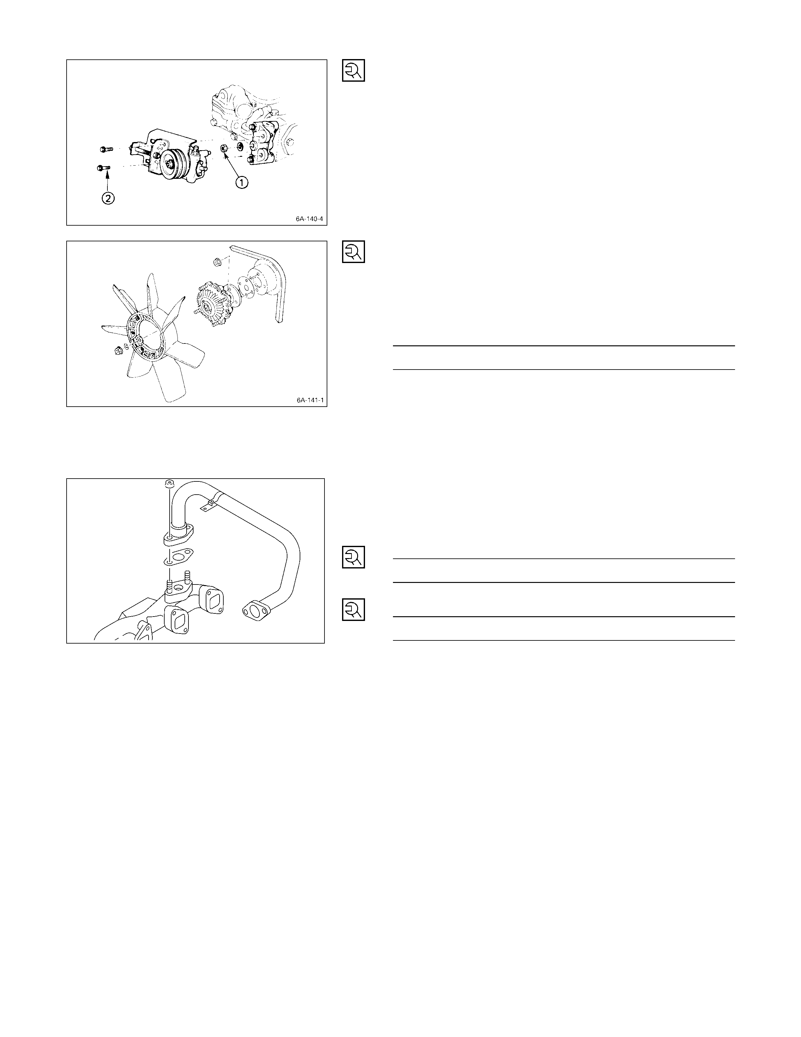
3) Install the oil pump to the bracket.
4) Temporarily tighten the oil pump nut Q and bolts R.
The nut and bolts will be finally tightened after
installation of the drive belt.
25. Cooling Fan Pulley
1) Install the cooling fan pulley to the water pump with
spacer.
2) Tighten the cooling fan pulley bolts to the specified
torque.
Cooling Fan Pulley Bolt Torque kg·m (lb.ft/N·m)
0.8 ± 0.2 (5.8 ± 1.4/7.8 ± 2.0)
26. Cooling Fan Drive Belt
Install the fan drive belt and adjust the belt tension
referring SERVICING of this section.
EGR PIPE
Install EGR pipe and tighten fixing bolt and nuts to the
specified torque.
Bolt and Nut N·m (Kg·m/lb·ft)
26 (2.7/20)
Nuts N·m (Kg·m/lb·ft)
24 (2.4/17)
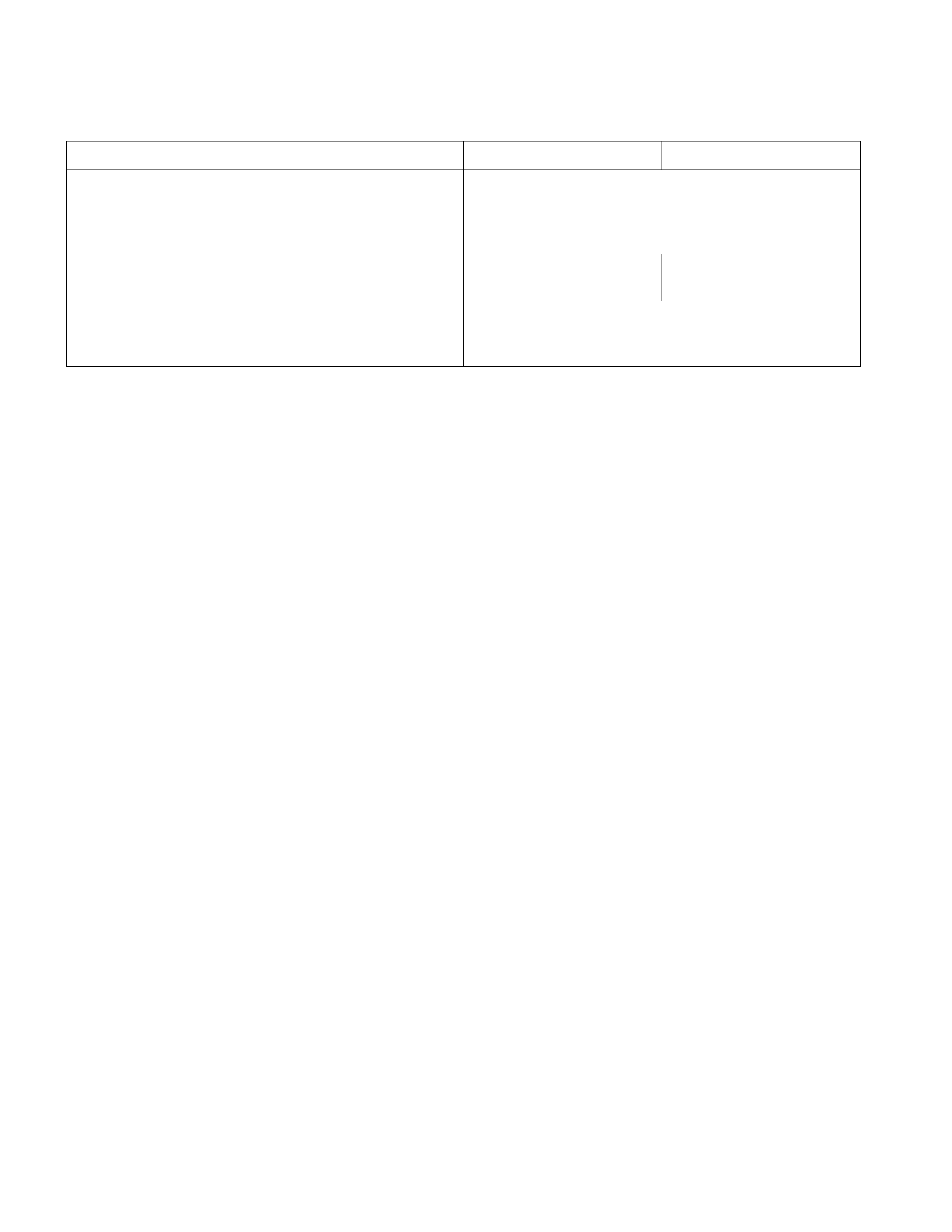
LUBRICATI NG SYSTEM
MAI N DATA AND SPECIFICATIONS
Engine Model 4JA1, 4JA1T 4JB1T, 4JG2T
Oil pump type
Oil pressure switch operating pressure kg/cm2 (psi/kPa)
Oil filter type
Gear
0.2 – 0.5 (2.8 – 7.1/19.6 – 49.0)
Full flow with cartridge paper element
Relief valve opening pressure kg/cm2 (psi/kPa) 4.3 – 4.7
(61.1 – 66.8/421.4 – 460.6) 5.7 – 6.3
(82.5 – 89.5/558.6 – 617.4)
Safety valve opening pressure kg/cm2 (psi/kPa)
Oil cooler type
Safety valve opening pressure kg/cm2 (psi/kPa)
0.8 – 1.2 (11.38 – 17.07/78.9 – 117.6)
Water-cooled
2.3 – 2.7 (32.7 – 38.4/225.4 – 264.6)
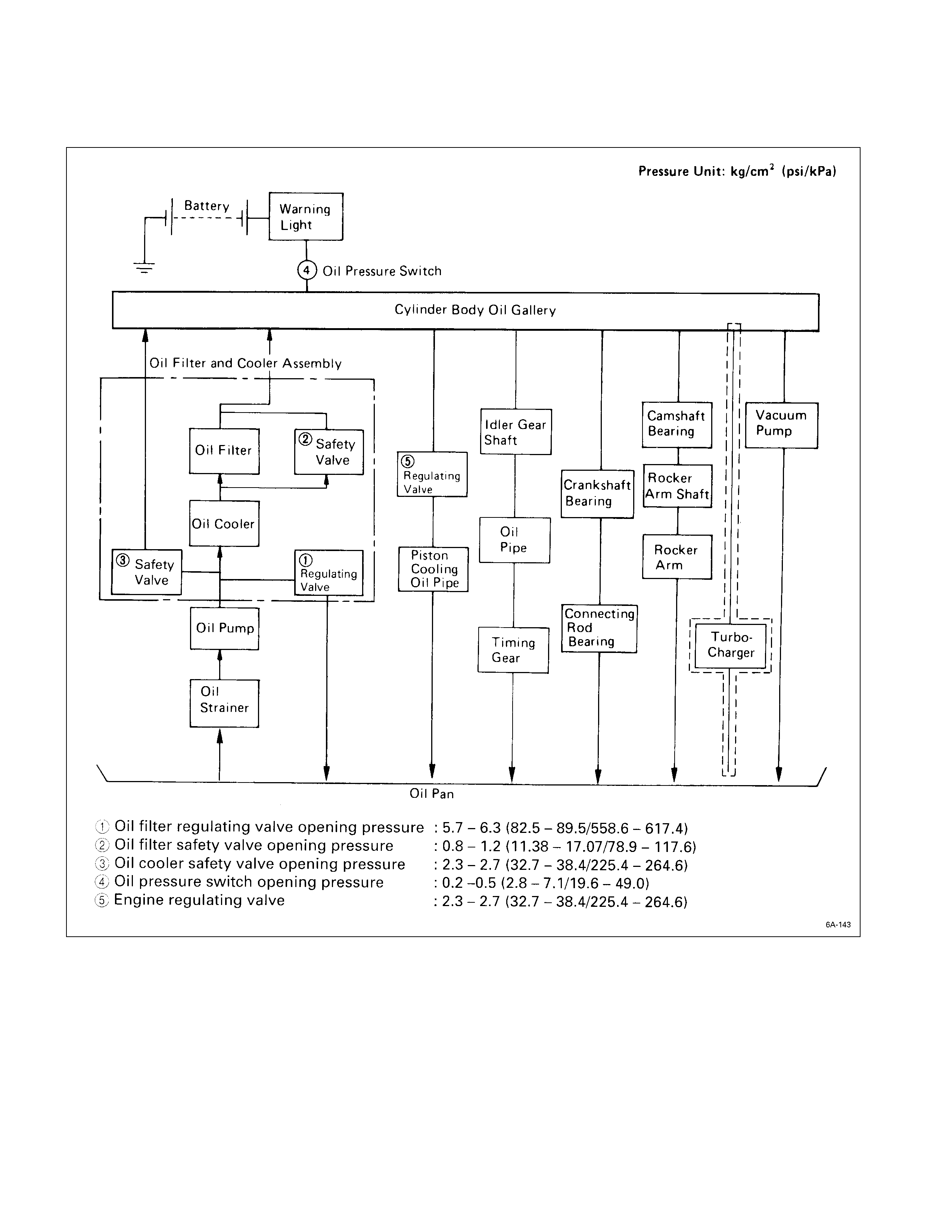
GENERAL DESCRI PTION
LUBRICATING OIL FLO W
The 4J series engine has a full flow type lubricating system.
Lubricating oil is pumped from the oil pump to the cylinder body oil gallery through the oil cooler and the oil filter. It is
then delivered to the vital parts of the engine from the cylinder body oil gallery.
Oiling jets installed on the cylinder body spray engine oil to the piston backside faces to achieve maximum piston
cooling effect.
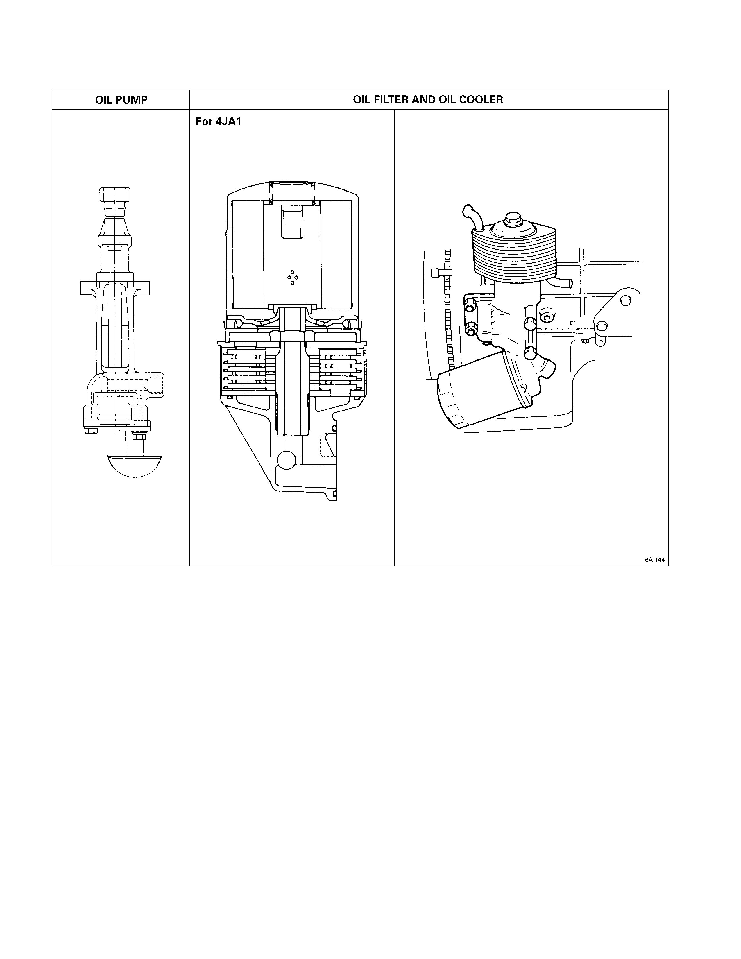
OIL PUMP AND OIL FILTER
The 4J series engine is equipped with a gear type oil pump.
The oil filter and the water cooled oil cooler integrated a single unit to increase the cooling effect.
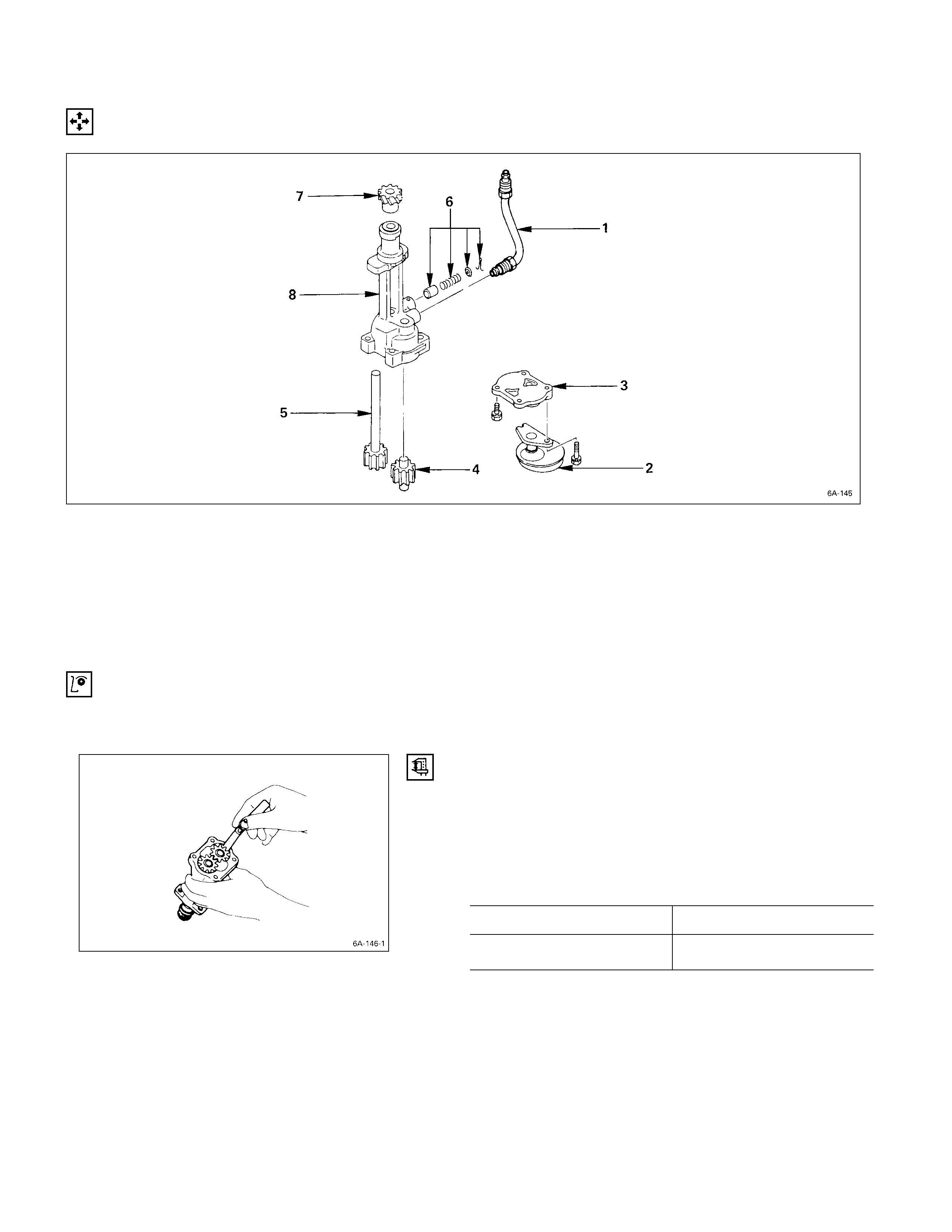
OIL PUMP
DISASSEM BLY
DISASSEM BLY STEPS
1. Oil pipe 6. Relief valve asm.
2. Strainer 7. Pinion gear
3. Pump cover 8. Oil pump body
4. Driven gear with bush
5. Driven gear
INSPECTION AND REPAIR
Make the necessary adjustments, repairs, and part replacements if excessive wear or damage is discovered during
inspection. G EAR TEETH AND BODY INNER WALL CLEARANCE
Use a feeler gauge to measure the clearance between the
gear teeth and the body inner wall.
If the clearance between the gear teeth and the body inner
wall exceeds the specified limit, either the gear or the body
must be replaced.
Gear Teeth and Body Inner Wall Clearance mm (in)
Standard Limit
0.14 (0.0055) 0.20 (0.0079)
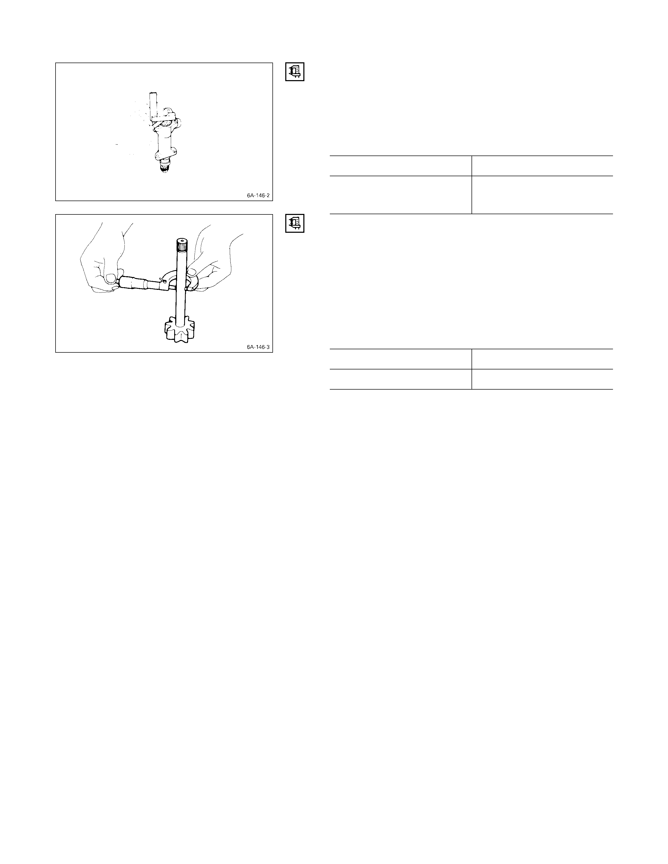
GEAR AND BODY CLEARANCE
Use a feeler gauge to measure the clearance between the
body and the gear.
If the clearance between the gear and the body exceeds
the specified limit, the body must be replaced.
Gear and Body Clearance mm (in)
Standard Limit
0.06 (0.024) 0.15 (0.0059)
DRIVE SHAFT AND OIL PUMP BODY CLEARANCE
Use a micrometer to measure the drive shaft outside
diameter.
Use an inside dial indicator to measure the pump body
inside diameter.
If the clearance between the drive shaft and the oil pump
body exceeds the specified limit, the oil pump assembly
must be replaced.
Drive Shaft and Oil Pump Body Clearance mm (in)
Standard Limit
0.04 (0.0016) 0.20 (0.0079)
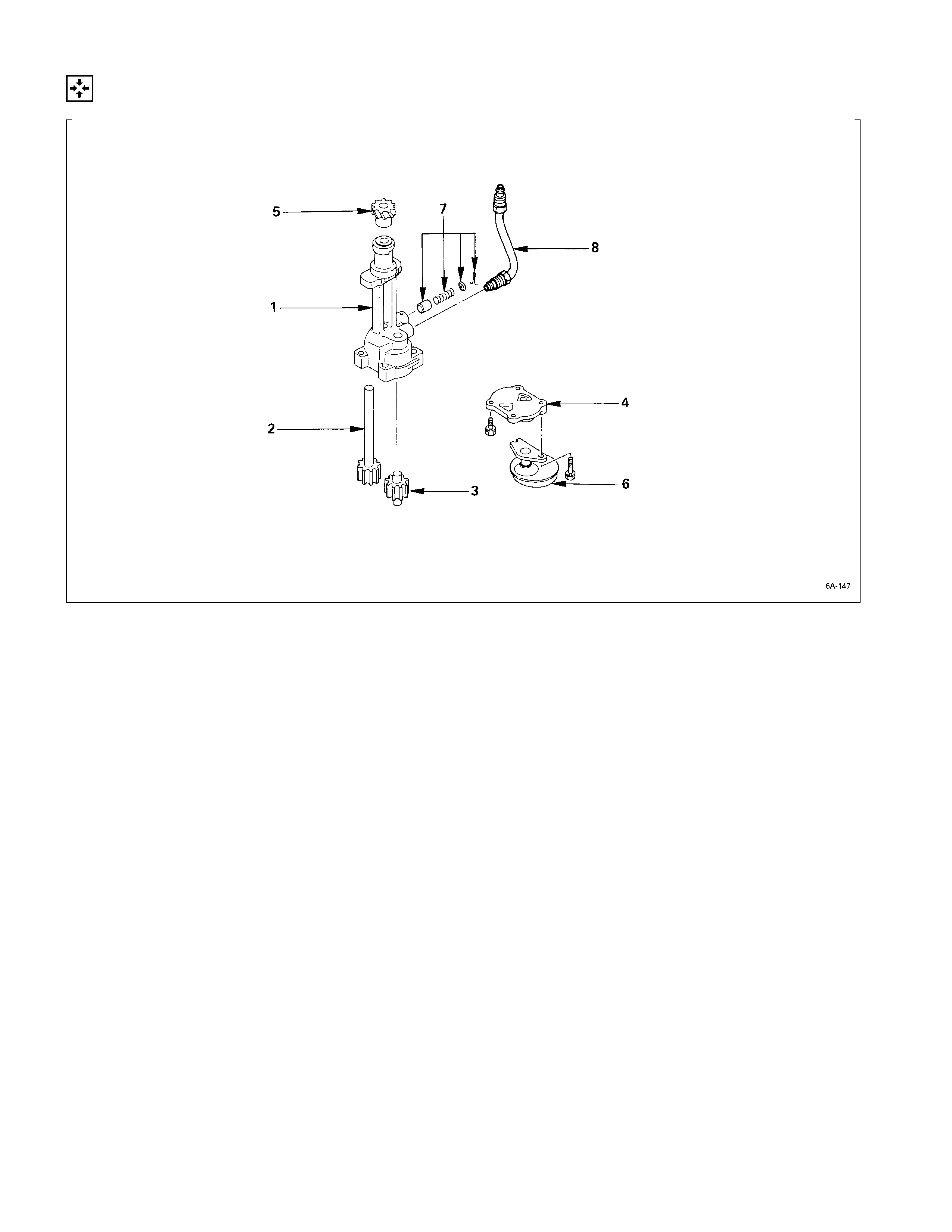
REASSEMBLY
REASSEMBLY STEPS
1. Oil pump body 5. Pinion gear
2. Drive gear 6. Strainer
3. Driven gear 7. Relief valve asm.
4. Pump cover 8. Oil pipe
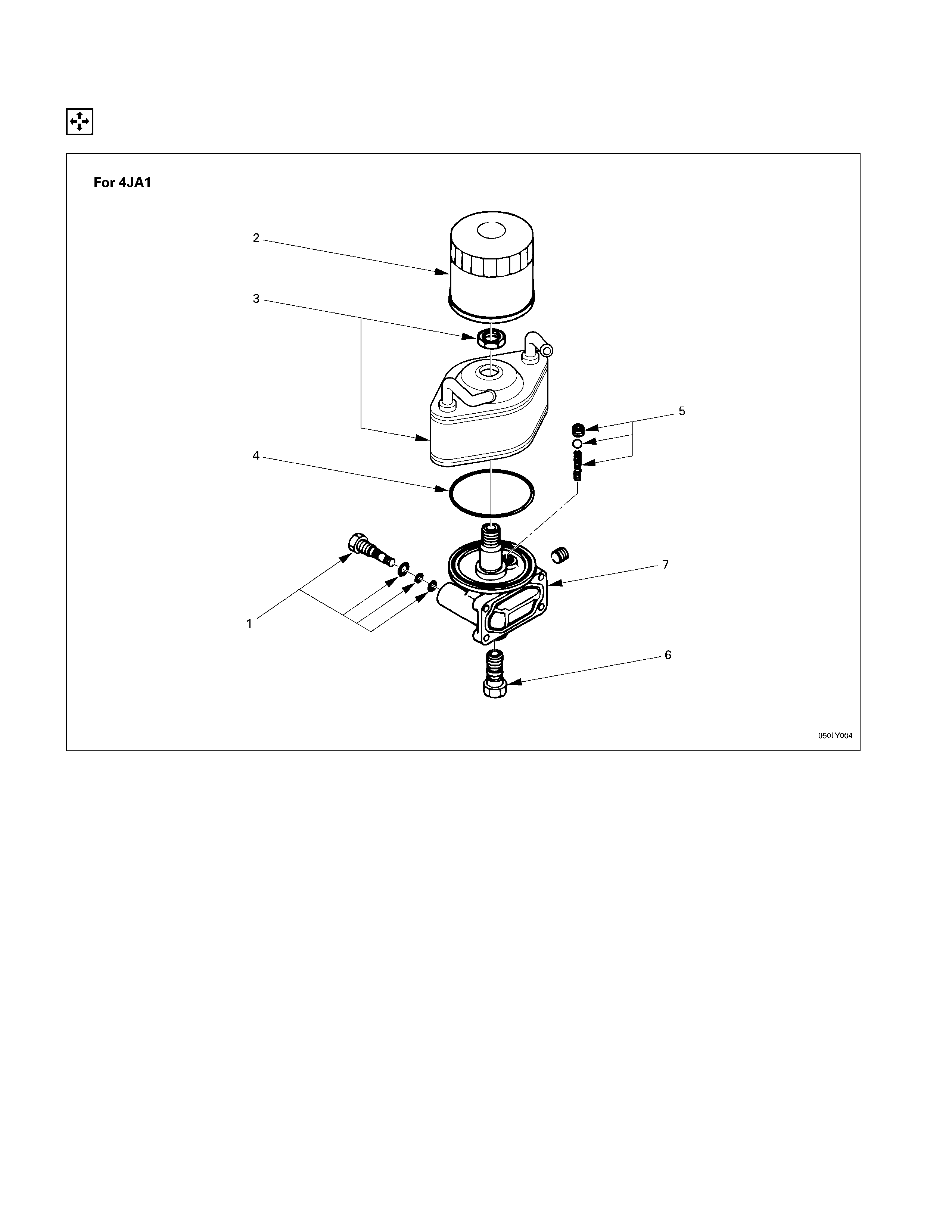
OIL FILTER AND OIL COOLER
DISASSEM BLY
DISASSEM BLY STEPS
1. Drain plug 5. Safety valve
2. Cartridge oil filter 6. Relief valve
3. Oil cooler 7. Oil filter body
4. O-ring
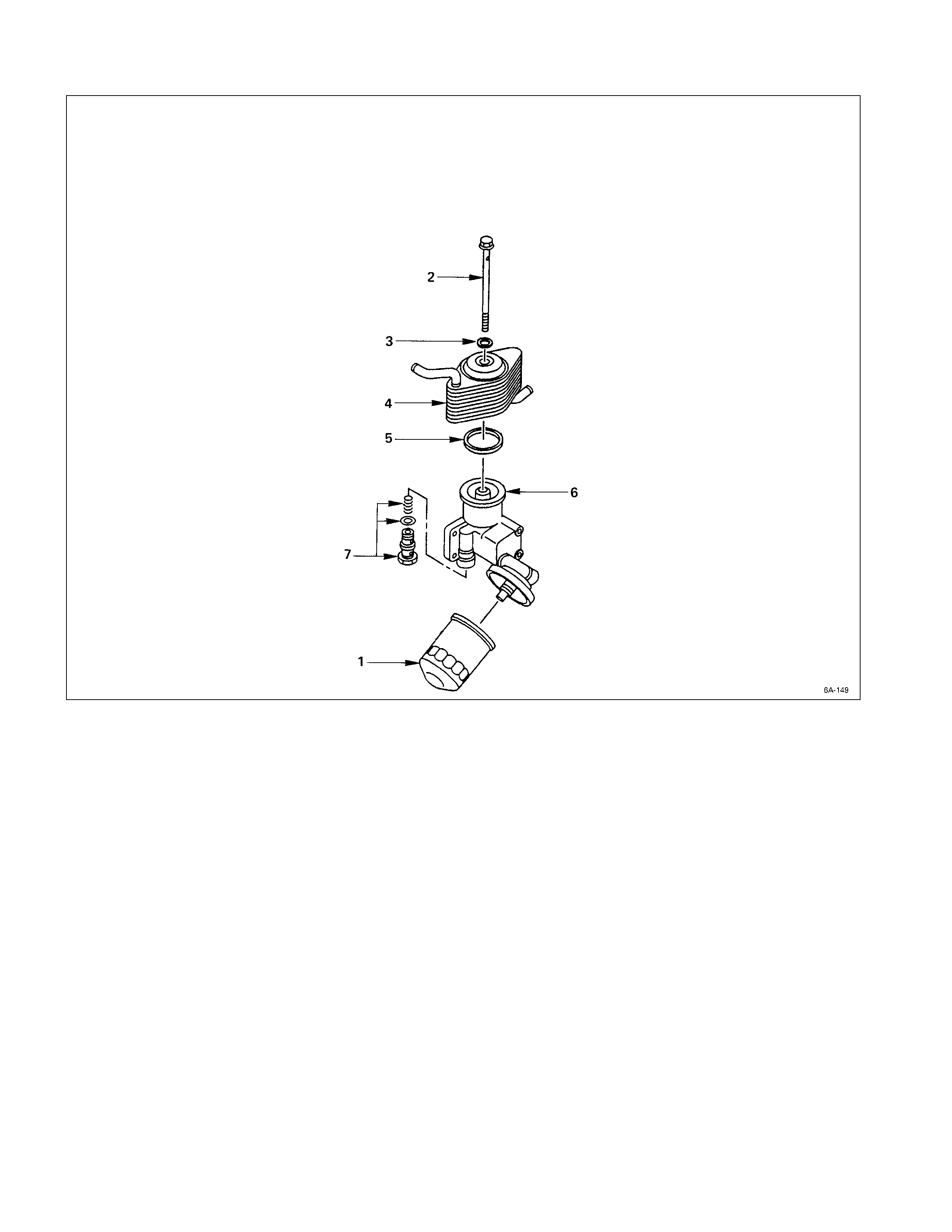
DISASSEM BLY STEPS
1. Oil filter cartridge 5. Gasket
2. Bolt 6. Body
3. Gasket 7. Relief valve
4. Oil cooler
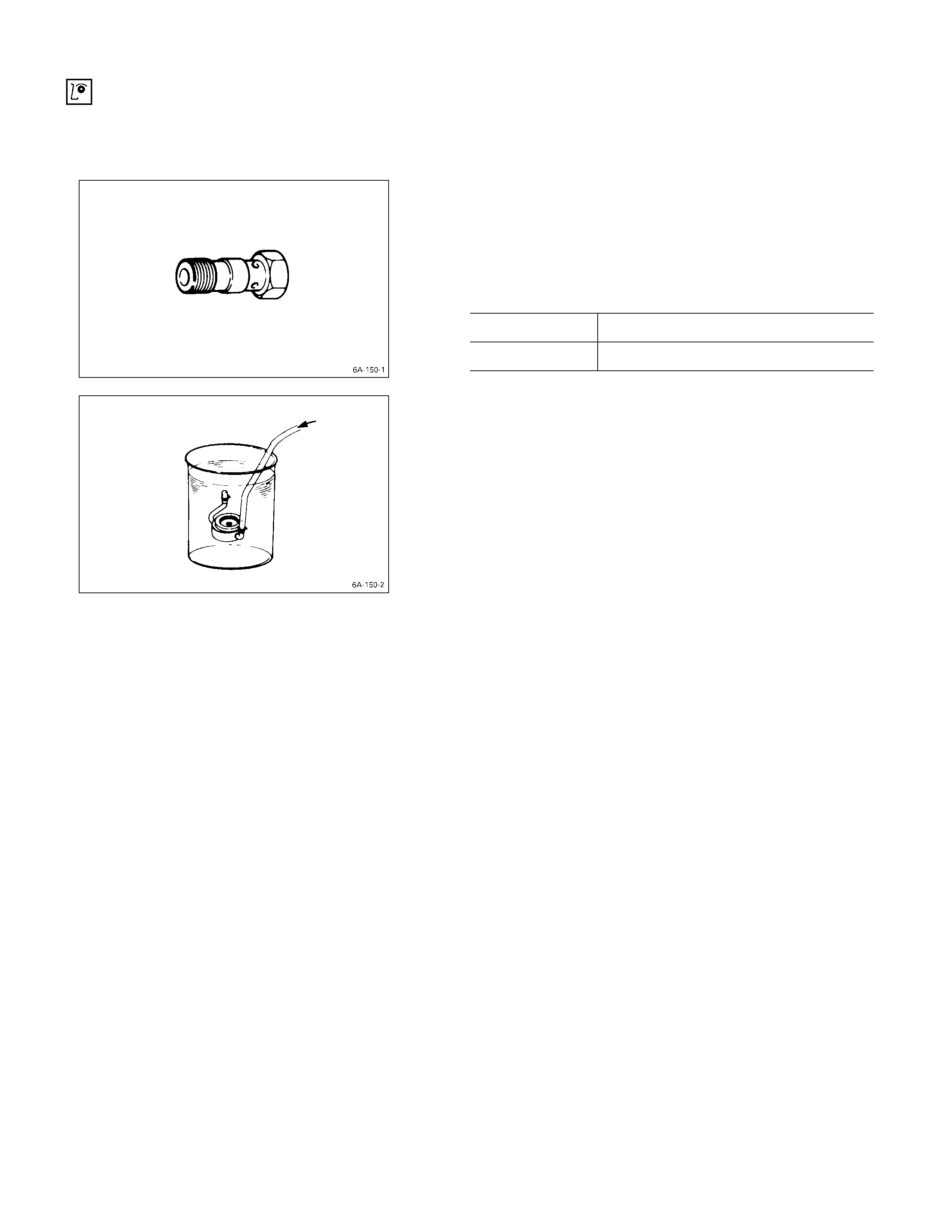
INSPECTION AND REPAIR
Make the necessary adjustments, repairs, and part replacements if excessive wear or damage is discovered during
inspection.
RELIEF VALVE
1. Attach an oil pressure gauge to the oil gallery near the
oil filter.
2. Start the engine to check the relief valve opening
pressure.
Relief Valve Opening Pressure kg/cm2 (psi/kPa)
4JA1, 4JA1T 4.3 – 4.7 (61.1 – 66.8/421.4 – 460.6)
4JB1T, 4JG2T 5.7 – 6.3 (82.5 – 89.5/558.6 – 617.4)
OIL COOLER
Water Leakage at Water Passage
1. Plug one side of the oil cooler water passage.
2. Submerge the oil cooler in water.
3. Apply compressed air (2 kg/cm2 (28 psi/200 kPa)) to
the other side of the oil cooler water passage.
If air bubbles rise to the surface, there is water leakage.
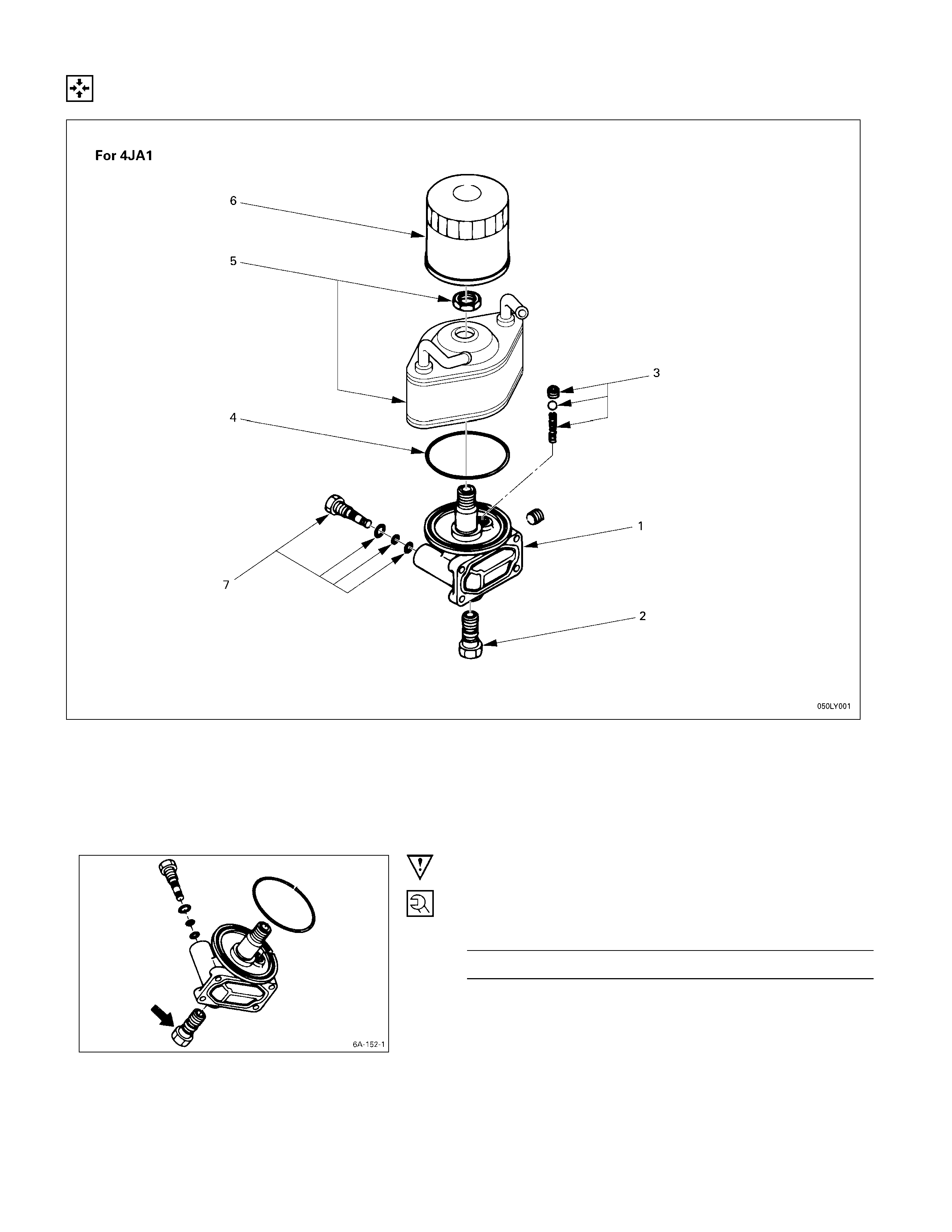
REASSEMBLY
REASSEMBLY STEPS
1. Oil filter body
J
5. Oil cooler
J
2. Relief valve
J
6. Oil filter cartridge
3. Safety valve
J
7. Drain plug
4. O-ring
IMPORTANT OPERATIONS
2. Relief Valve
Tighten the relief valve to the specified torque.
Relief Valve Torque kg·m (lb.ft/N·m)
3.0 ± 0.5 (21.7 ± 3.6/29.4 ± 4.9)
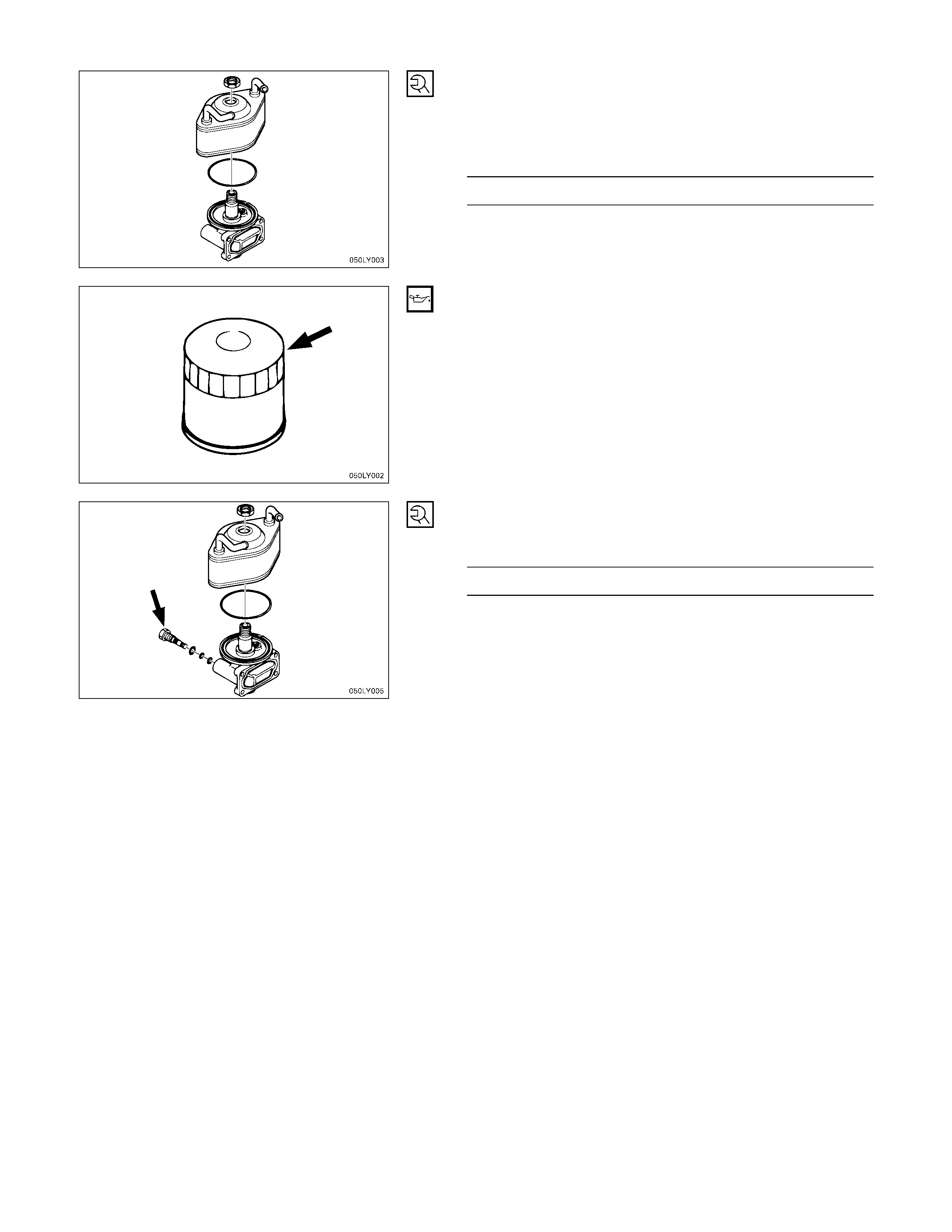
5. Oil Cooler
1) Align the oil filter holes with the body knock pins at
installation.
2) Tighten the oil cooler nut to the specified torque.
Oil Cooler Nut Torque kg·m (lb.ft/N·m)
3.0 ± 0.5 (21.7 ± 3.6/29.4 ± 4.9)
6. Oil Filter Cartridge
1) Apply engine oil to the O-ring.
2) Turn in the cartridge oil filter until the filter sealing face
makes contact with the O-ring.
3) Turn in the cartridge oil filter an additional one and 1/8
of a turn.
7. Drain Plug
Tighten the drain plug to the specified torque.
Drain Plug Torque kg·m (lb.ft/N·m)
2.5 ± 0.5 (18.1 ± 3.6/24.5 ± 4.9)
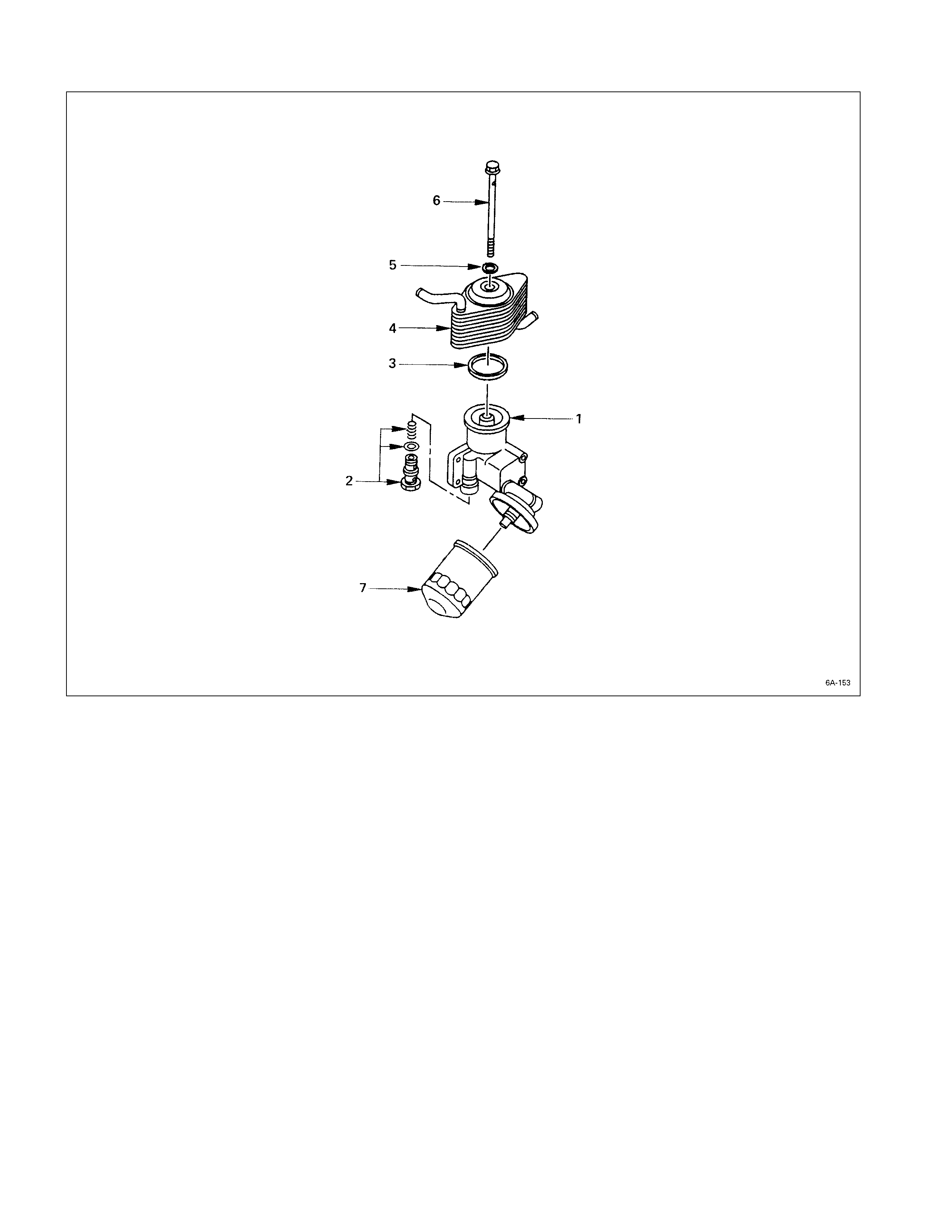
REASSEMBLY STEPS
1. Body 5. Gasket
J
2. Relief valve
J
6. Bolt
3. Gasket
J
7. Oil filter cartridge
J
4. Oil cooler
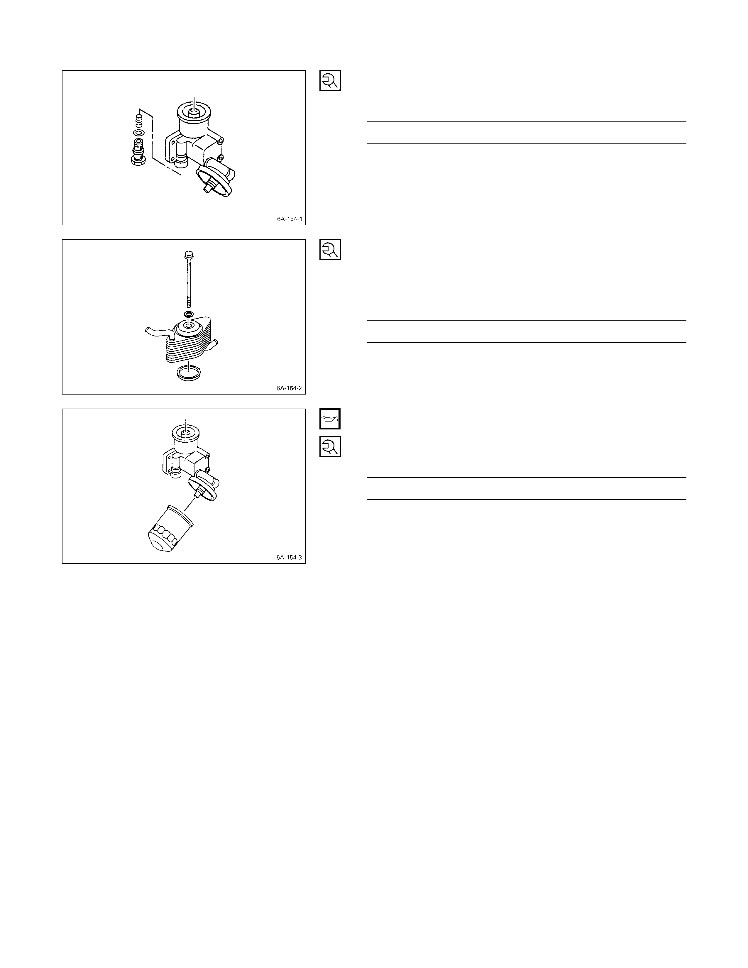
2. Relief Valve
Tighten the safety valve to the specified torque.
Safety Valve Torque kg·m (lb.ft/N·m)
0.3 ± 00.5 (4.3 ± 0.7/29.4 ± 4.9)
4. Oil Cooler
6. Bolt
Tighten Bolt with gaskets and oil cooler to the specified
torque.
Bolt Torque kg·m (lb.ft/N·m)
3.0 ± 0.5 (21.7 ± 3.6/29.4 ± 4.9)
7. Oil Filter Cartridge
1) Apply engine oil to the O-ring.
2) Tighten the oil filter cartridge to the specified torque.
Oil Filter Cartridge Torque kg·m (lb.ft/N·m)
0.2 ± 0.02 (2.8 ± 0.28/19.6 ± 2.0)
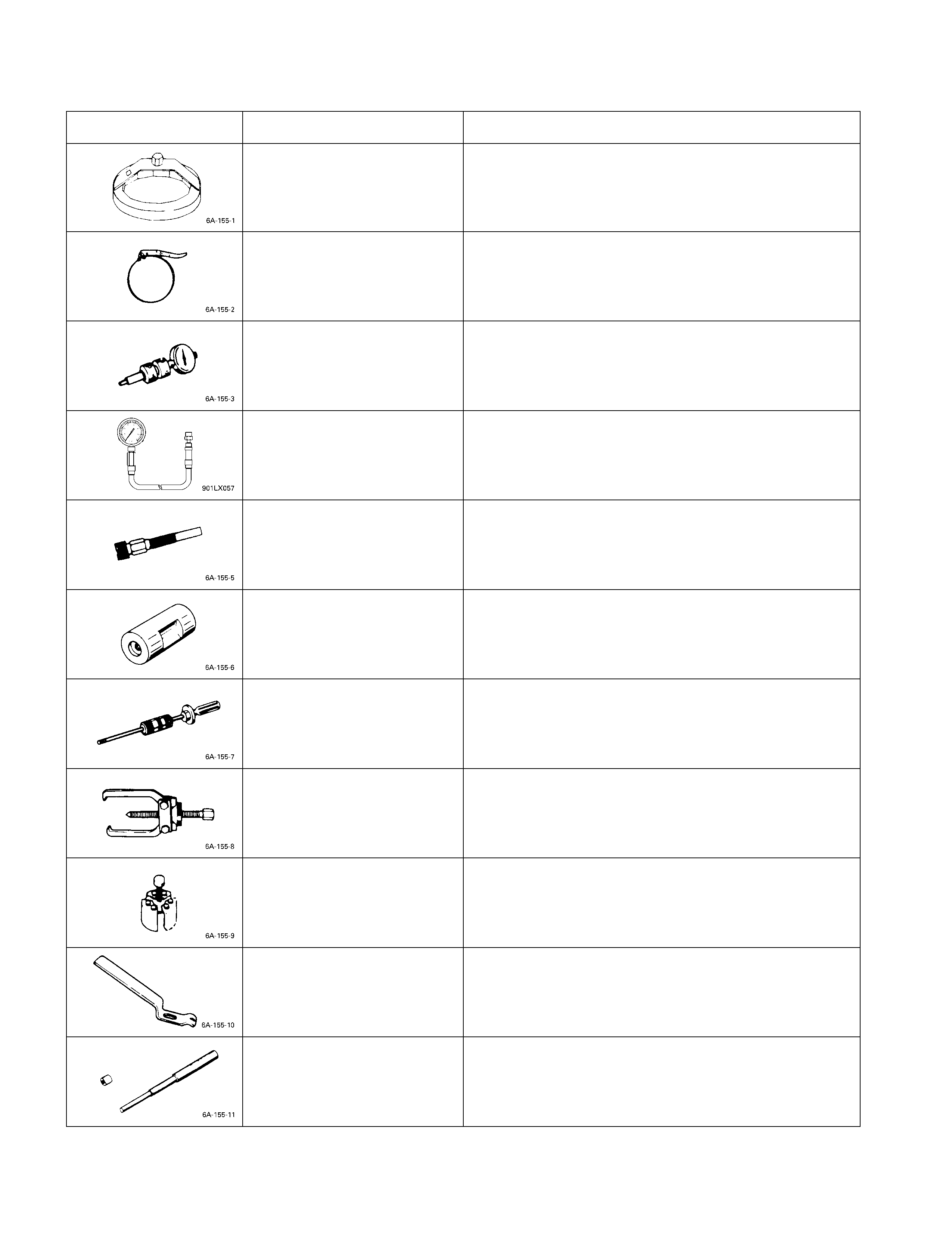
SPECIAL TOOLS
Illustration Tool Number Tool Name
5-8840-0200-0 Filter Wrench
5-8840-0253-0
(J-22700) Filter Wrench
5-8840-0145-0
(J-28827) Static Timing Gauge
5-8840-2675-0 Compression Gauge
5-8531-7001-0 Adapter; Compression Gauge
5-8840-2034-0 Nozzle Holder Remover
5-8840-0019-0
(J-23907) Sliding Hammer
5-8521-0002-0 Universal Puller
5-8840-2360-0 Oil Seal Remover
9-8523-1423-0
(J-29760) Spring Compressor
9-8523-1212-0 Valve Guide Replacer
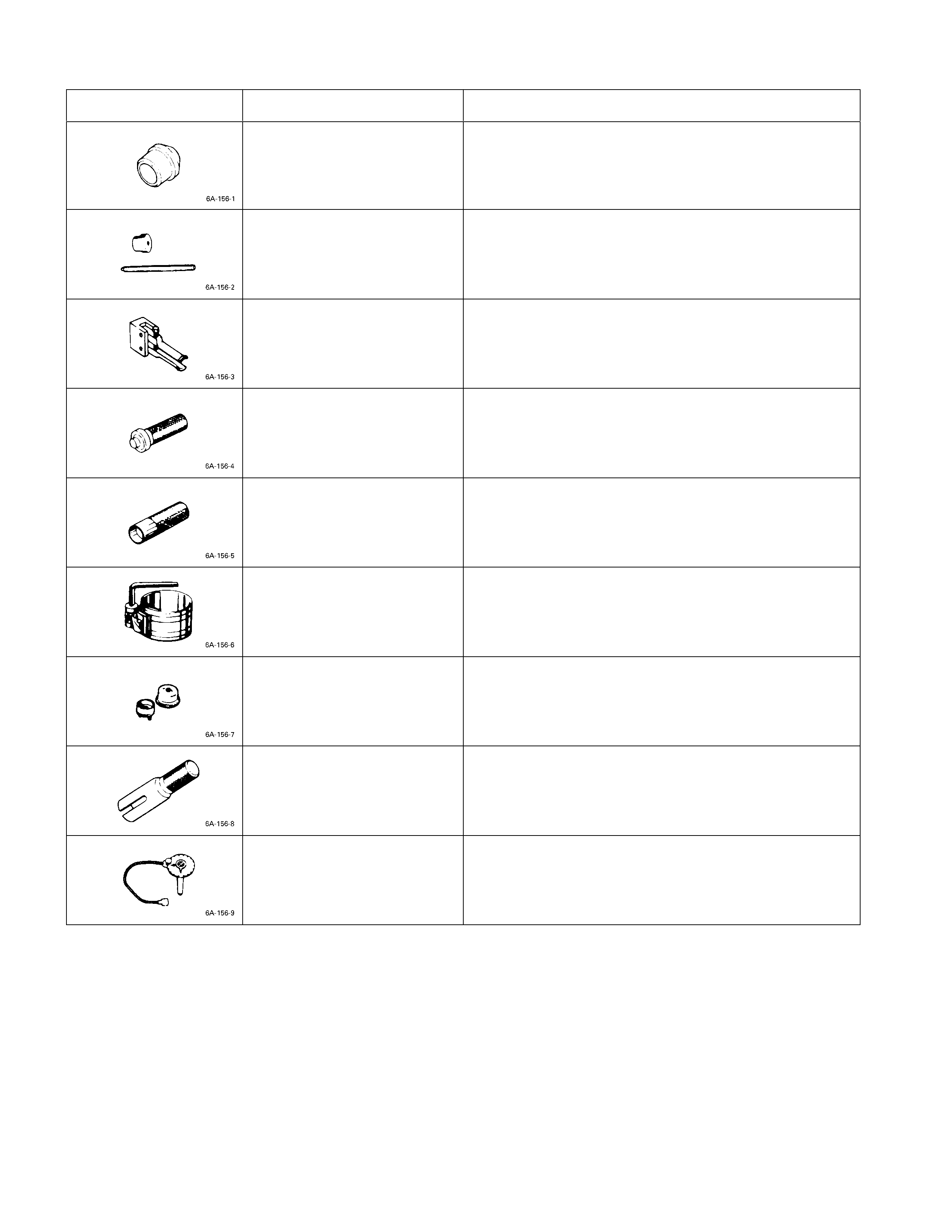
Illustration Tool Number Tool Name
5-8840-2040-0 Cylinder Liner Installer
5-8840-2038-0 Bearing Replacer; Camshaft
5-8840-2000-0 Pilot Bearing Remover
5-8522-0024-0 Pilot Bearing Installer
5-8840-2033-0 Oil Seal Installer
5-8840-9018-0
(J-8037) Piston Ring Compressor
5-8840-2359-0 Oil Seal Installer
9-8522-0020-0 Crankshaft Timing Gear Installer
5-8840-0266-0 Angle Gauge