

MAIN DATA AND SPECIFICATIONS
Item Description
Water pump type
Pump to crankshaft speed ratio (To 1)
Delivery volume lit (gal)/min
Pump speed at 3000 rpm
Water temperature at 30°C (86°F)
Pump bearing ty pe
Thermostat type
Valve initial opening temperature °C (°F)
Valve full opening temperature °C (°F)
Valve lift at fully open position mm (in)
Centrifugal
1.1
100 (22.2)
Double row shaft
Wax pellet with jiggle valve
82 (180)
95 (203)
9.5 (0.37)
GENERAL DESCRIPTI O N
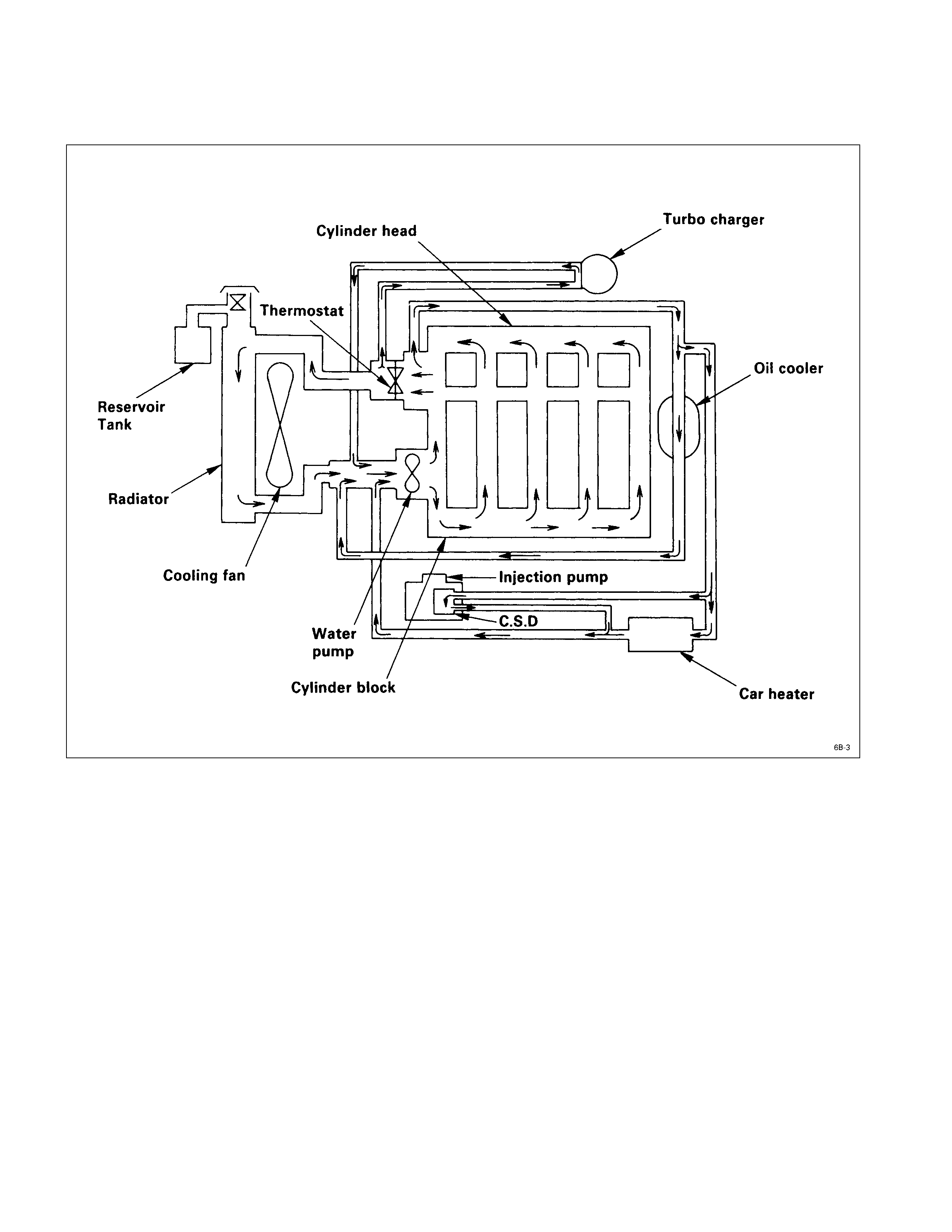
COOLANT FLOW
The engine cooling system consists of the radiator, the water pump, the cooling fan, and the thermostat.
To quickly increase cold engine coolant temperature for smooth engine operation, the coolant is circulated by the water
pump and thermostat through the bypass hose and back to the cylinder body. The coolant does not circulate through
the radiator.
When the coolant temperature reaches specified value, the thermostat will begin to open and a gradually increasing
amount of coolant will circulate through the radiator.
The thermostat will be fully open when the coolant temperature reaches specified value. All of the coolant is now
circulating through the radiator for effective engine cooling.
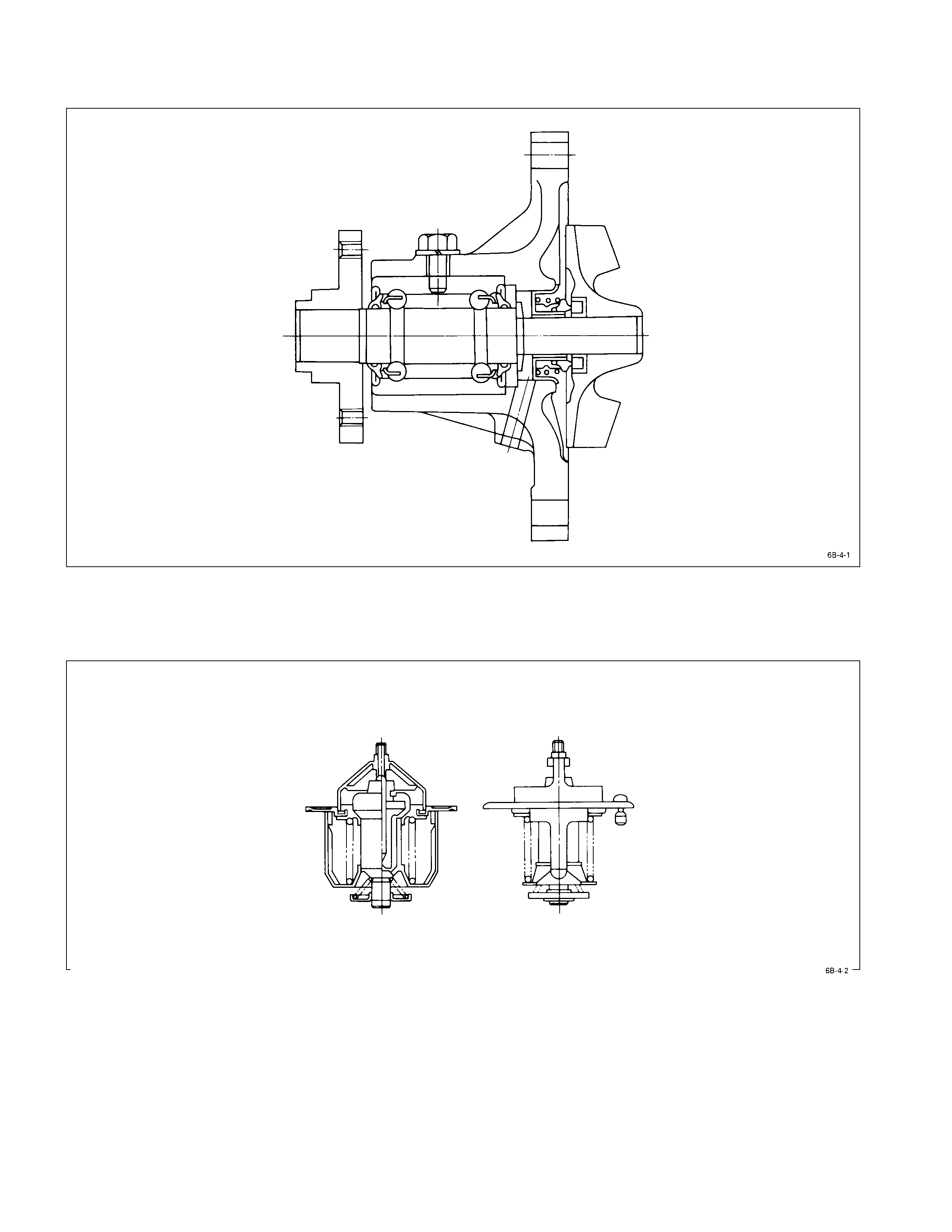
WATER PUMP
A centrifugal type water pump forcefully circulates the coolant through the cooling system.
The water pump is not disassembled type.
THERMOSTAT
A wax pellet type thermostat is used.
The jiggle valve accelerates engine warm-up.
WATER PUMP
REMOVAL AND INSTALLATION
Read this Section carefully before performing any removal and installation procedure. This Section gives you important
points as well as the order of operation. Be sure that you understand everything in this Section before you begin.
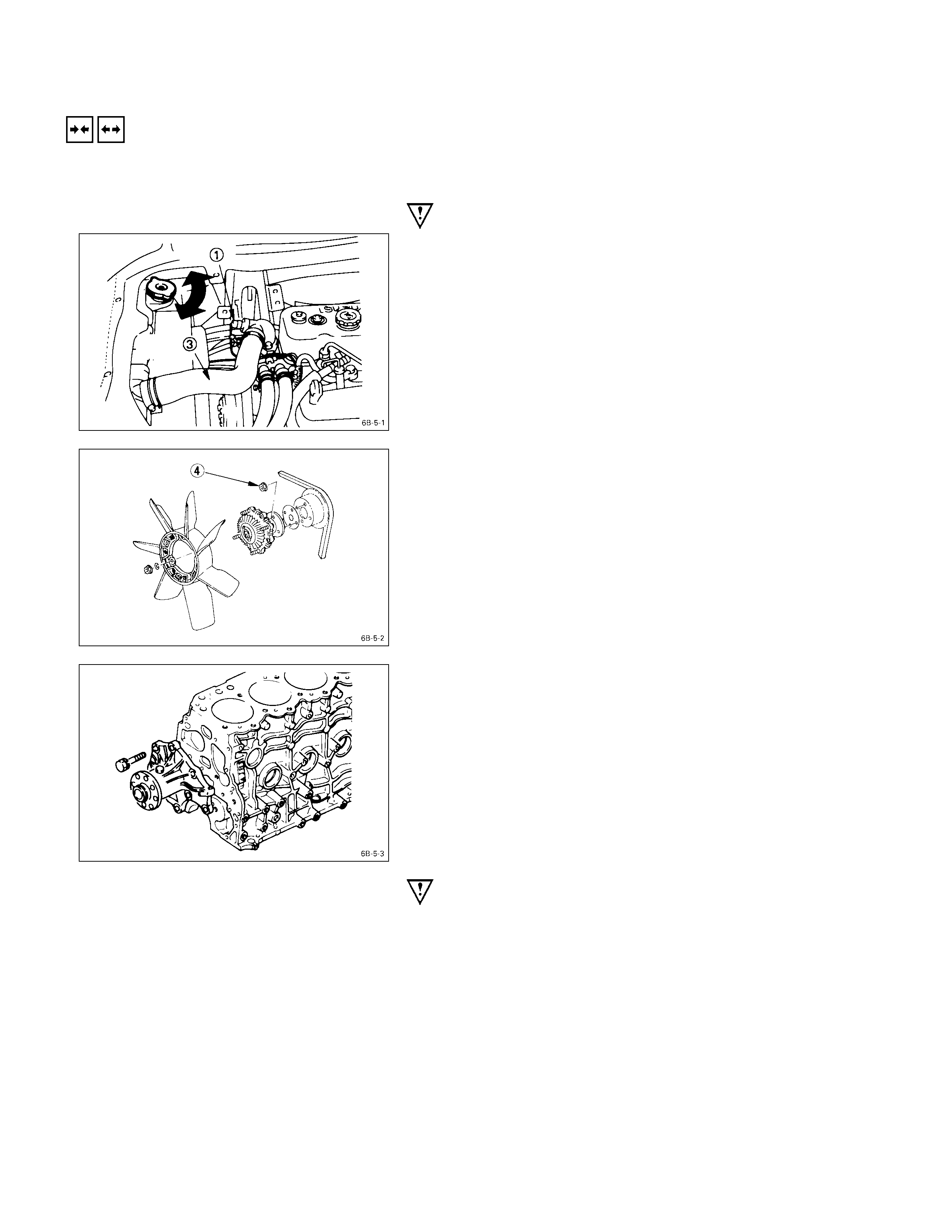
IMPO RTANT OPERATIONS - REMOVAL
RADIATOR UPPER HOSE
1. Disconnect the wiring harness Q.
2. Partially drain the engine coolant.
3. Remove the radiator upper hose S.
FAN AND FAN CLUTCH
1. Loosen the fan clutch nuts T.
2. Remove the fan together with the fan clutch.
Take care not to damage the radiator core.
WATER PUMP
1. Remove the water pump bolts.
2. Remove the water pump.
IMPORTANT OPERATIONS – INSTALLATION
Follow the removal procedure in the reverse order to
perform the installation procedure. Pay careful attention to
the important points during the installation procedure.
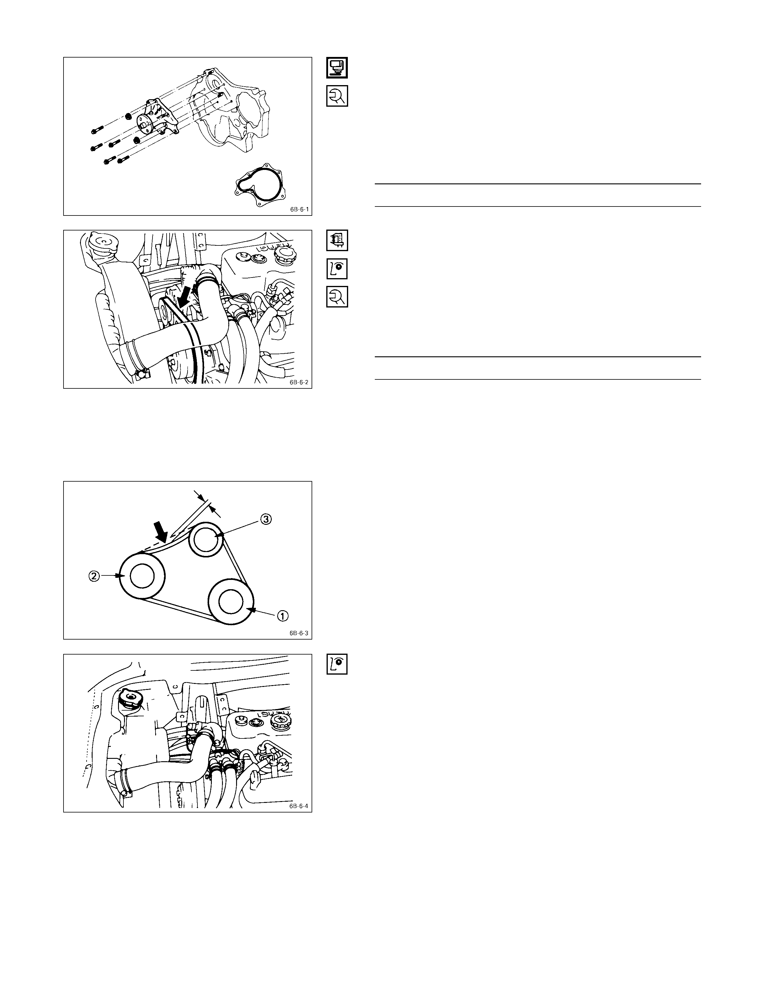
WATER PUMP
1) Apply the recommended liquid gasket or its equivalent
to the water pump at the position shown in the
illustration.
Do not apply an excessive amount of liquid gasket.
2) Tighten the water pump bolts to the specified torque.
Water Pump Bolt Torque kg·m (lb.ft/N·m)
2.0 ± 0.5 (14.5 ± 3.6/19.6 ± 4.9)
COOLING FAN DRI VE BELT
1. Install the cooling fan drive belt.
2. Apply tension to the cooling fan drive belt by moving
the generator .
3. Apply a force of 10 kg (22 lb/98 N) to the drive belt
mid-portion to check the drive belt deflection.
Cooling Fan Drive Belt Deflection mm (in)
10 (0.4)
QCrankshaft damper pulley
RGenerator pulley
S Cooling fan drive pulley
4. Tighten the remaining water pump bolt to the specified
torque.
RADIATOR UPPER HOSE
1. Connect the radiator upper hose to the water outlet
pipe.
2. Replenish the engine coolant.
3. Make sure the wiring harness is properly connected.
4. Start the engine and allow it to warm up.
5. Check the temperature gauge operation.
THERMOSTAT
REMOVAL AND INSTALLATION
Read this Section carefully before performing any removal and installation procedure. This Section gives you important
points as well as the order of operation. Be sure that you understand everything in this Section before you begin.
IMPO RTANT OPERATIONS – REMO VAL
RADIATOR UPPER HOSE
1. Disconnect the wiring harness Q.
2. Partially drain the engine coolant.
3. Disconnect the radiator upper hose R.
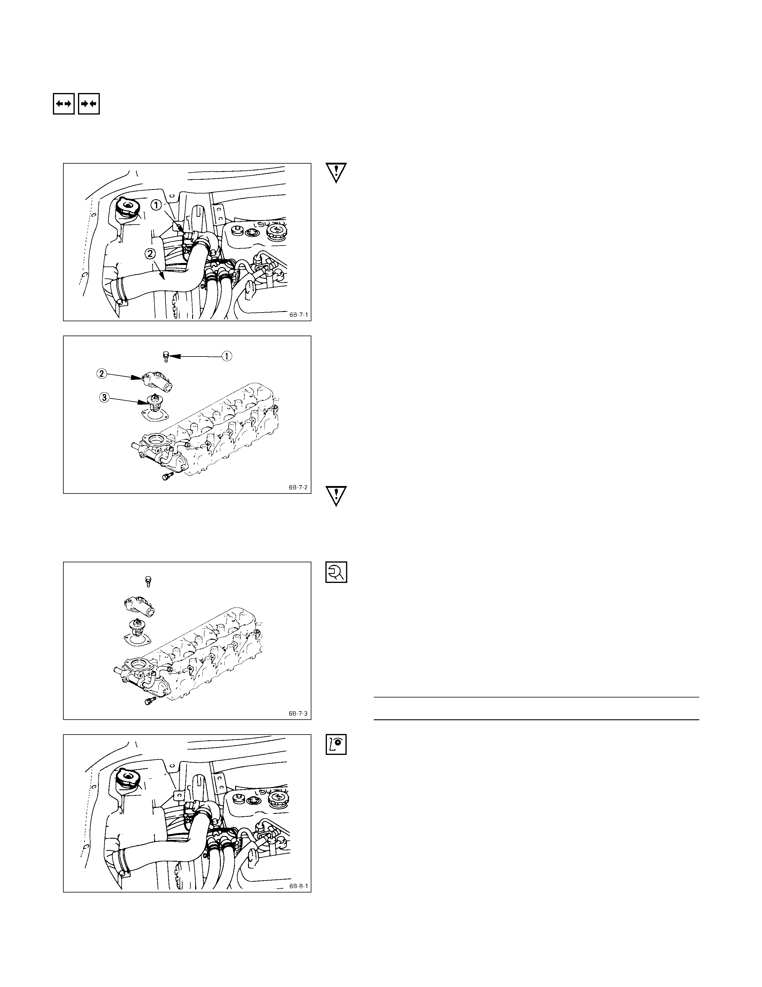
WATER OUTLET PIPE
THERMOSTAT
1. Loosen the water outlet pipe bolt Q.
2. Remove the water outlet pipe R.
3. Remove the thermostat S from the thermostat
housing.
Take care not to damage the thermostat.
IMPORTANT OPERATIONS – INSTALLATION
Follow the removal procedure in the reverse order to
perform the installation procedure. Pay careful attention to
the important points during the installation procedure.
THERMOSTAT
WATER OUTLET PIPE
1. Install the thermostat to the thermostat housing.
2. Install the water outlet pipe with the gasket to the
thermostat housing.
3. Tighten the outlet pipe to the specified torque.
Outlet Pipe Bolt Torque kg·m (lb.ft/N·m)
1.9 ± 0.5 (13.7 ± 3.6/18.6 ± 4.9)
RADIATOR UPPER HOSE
1. Connect the radiator upper hose to the water outlet
pipe.
2. Replenish the engine coolant.
3. Make sure the wiring harness is properly connected.
4. Start the engine and allow it to warm up.
5. Check the temperature gauge operation.
INSPECTION AND REPAIR
Make the necessary adjustments, repairs, and part replacements if excessive wear or damage is discovered during
inspection.
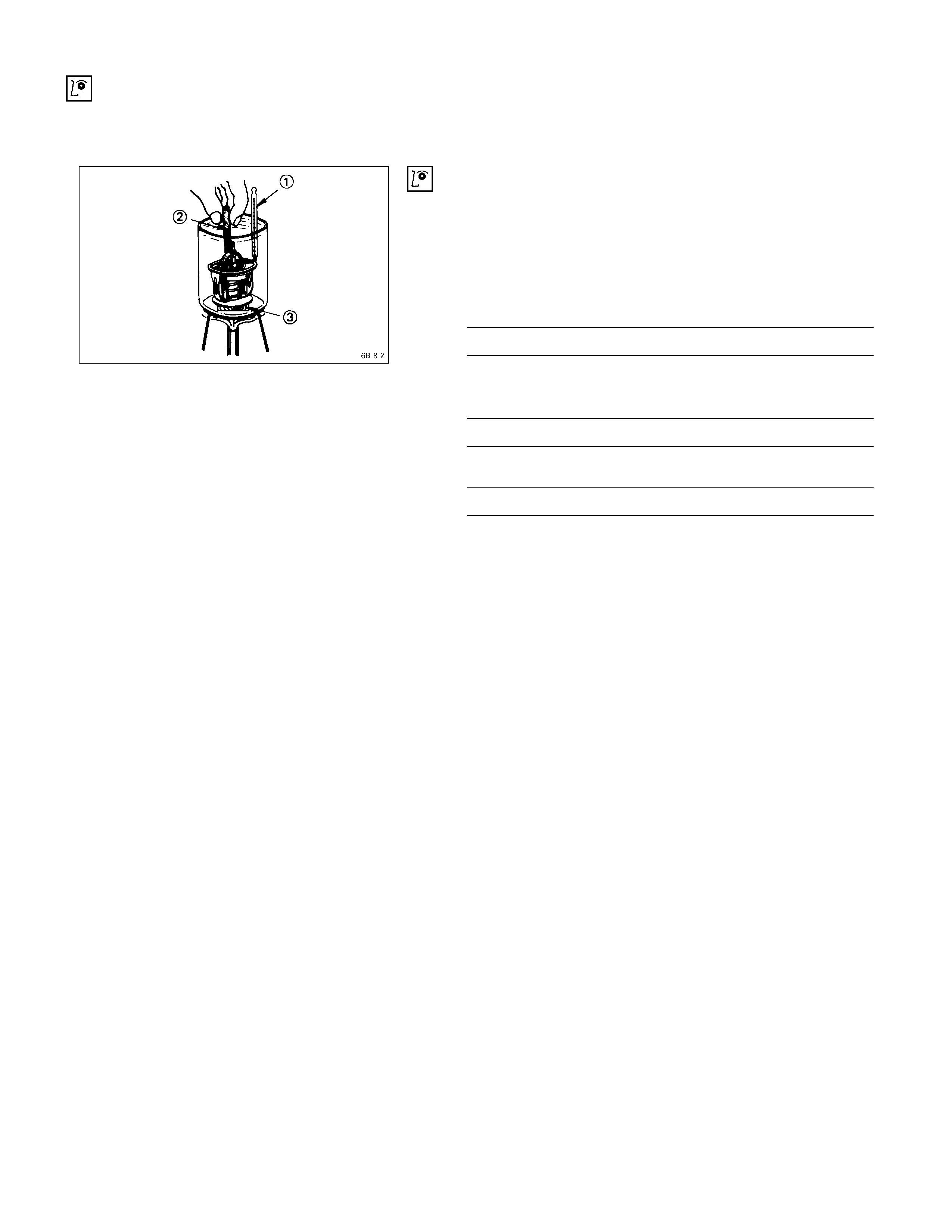
OPERATING TEST
1. Completely submerge the thermostat in water.
2. Heat the water.
Stir the water constantly to avoid direct heat being
applied to the thermostat.
3. Check the thermostat initial opening temperature.
Thermostat Initial Opening Temperature °C (°F)
82 (180)
4. Check the thermostat full opening temperature.
Thermostat Full Opening Temperature °C (°F)
95 (203)
Valve Lift At Fully Open Position mm (in)
9.5 (0.37)
QThermometer
RAgitating rod
SWooden piece
FAN CLUTCH WITH COOLING FAN
INSPECTION AND REPAIR
Make necessary correction or parts replacement if wear, damage or any other abnormal condition are found through
inspection.
Visually inspect for damage, leak (sillicon grease) or other
abnormal conditions.
1. Inspection (on-vehicle)
1) Turn the fan clutch by hand when in a low temperature
condition before starting the engine, and confirm that it
can be turned readily.
2) Start the engine to warm it up until the temperature at
the fan clutch portion gets to around 80°C. Then stop
the engine and confirm that the fan clutch can be
turned with considerable effort (clutch torque) when
turned by hand.
If the fan clutch rotates more readily, however, this
indicates that the silicone grease is leaking internally.
Replace the fan clutch with a new one.
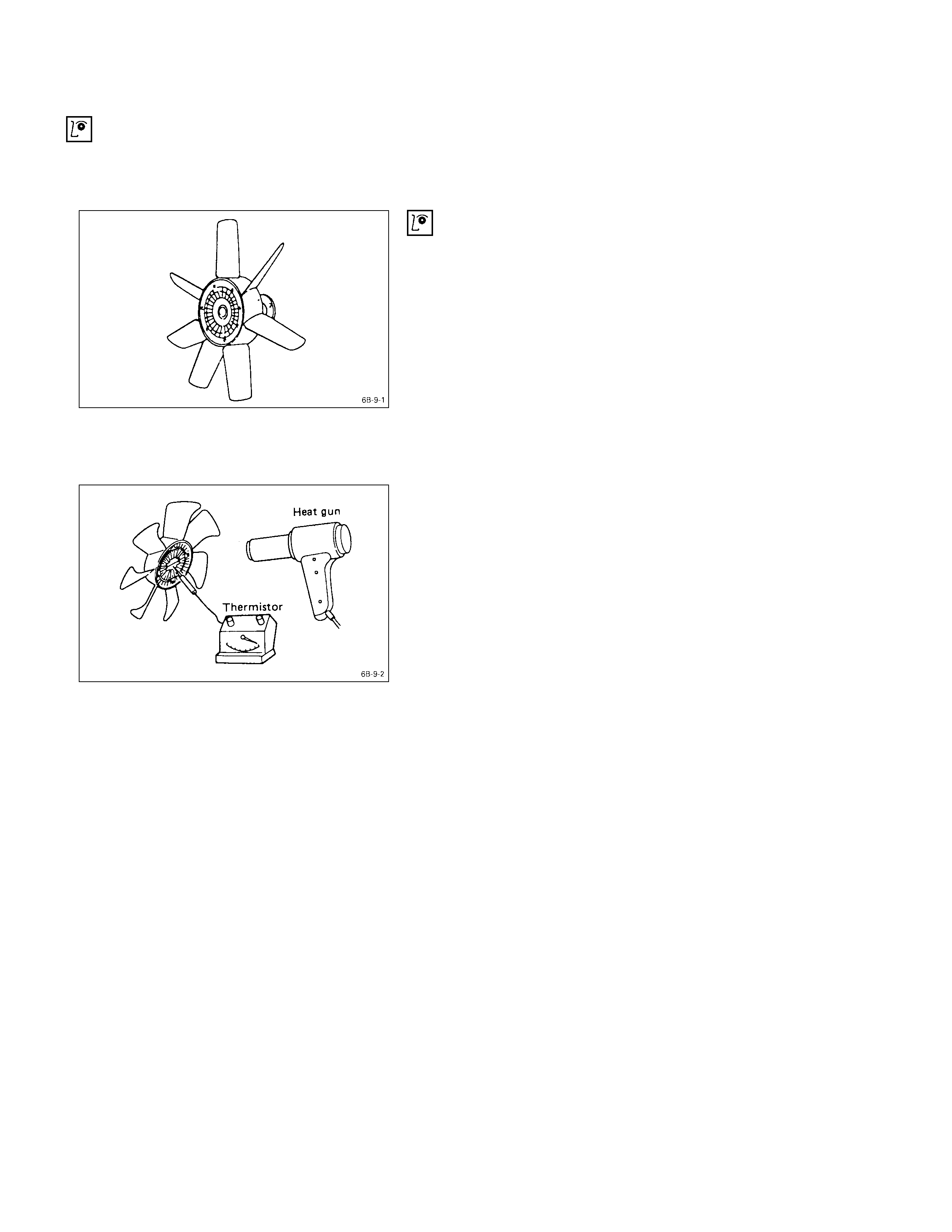
2. Inspection (in unit)
Warm up the bimetal of the fan clutch by using the heat
gun until the temperature gets to about 80°C when
measured with the thermistor. Then confirm that the fan
clutch can be turned with considerable effort (clutch
torque).
If the fan clutch retates more readily at this time, this
indicates that the silicone grease is leaking internally.
Replace the fan clutch with a new one.