
SECTION 6C1 - 4JH1-TC ENGINE DRIVEABILITY AND
EMISSIONS
Abbreviation Charts
Component Locator
Engine Component Locator Table
ECM Circuit Diagram
Ground Loc ati on
Cable Harness & Connector Location (4JH1-TC
RHD)
Connector List
Relay And Fuse
Relay And Fuse Box Location
Relay & Fuse Location
ECM Wiring Diagram
ECM Connector Pin Assignment & Output
Signal (4JH1-TC)
PSG Connector Pin Assignment & Output
Signal (4JH1-TC)
General Description For ECM And Sensors
Engine Control Module (ECM)
Pump Control Unit (PSG) & Data Exchange Between
Control Module
Mass Air Flow (MAF) Sensor & Intake Air
Temperature (IAT) Sensor
Pedal/throttle Position Sensor (TPS)
Crankshaft Position (CKP) Sensor
Engine Coolant Temperature (ECT) Sensor
Vehicle Speed Sensor (VSS)
General Description - Injection Pump
Outline
Charac ter isti c Of VP44 Inj ec tion System
Cross - se cti on View
Low Pressure Fuel Circuit
High Pressure Fuel Circuit
Timing Control
Start Of Injection
Strategy Based Diagnostics
Overview
Diagnostic Thought Process
1. Verify The Complaint
2. Perform Preliminary Checks
3. Check Bulletins And Troubleshooting Hints
4. Perform Service Manual Diagnostic Checks
5a And 5b. Perform Service Manual Diagnostic
Procedures
5c. Technician Self Diagnoses
5d. Intermittent Diagnosis
5e. Vehicle Operates As Designed
6. Re-examine The Complaint
7. Repair And Verify Fix
General Service Information
Serviceability Issues
Visual/Physical Engine Compartment Inspection
Basic Knowledge of Tools Required
On-Board Diagnostic (OBD)
On Board Diagnostic (Self Diagnosis System) Tests
The Diagnostic Executive
Diagnostic Information
Check Engine Lamp
Verifying Vehicle Repair
Reading Flash Diagnostic Trouble Codes
Reading Diagnostic Trouble Codes Using a Tech 2
Clearing Diagnostic Trouble Codes
Diagnosis With Tech 2
Tech 2 Connection
Typical Scan Data & Definitions 4JH1-TC (Engine Data)
Miscellaneous Test
Plotting Snapshot Graph
Plotting Graph Flow Chart (Plotting graph after
obtaining vehicle information)
Flow Chart‘ for Snapshot Replay (Plotting Graph)
Snapshot Display With TIS2000
Display of Graphs on one screen (Max. 6 graphs):
Service Programming System (SPS)
How To Use Breaker Box
On Board Diagnostic (OBD) System Check
No Check Engine Lamp (MIL)
Check Engine Lamp (MIL) “On” Steady
ECM Diagnostic Trouble Codes
Diagnostic T rouble Code (DTC) P0100 (Symptom Code
7) (Flash Code 65) Mass Air Flow (MAF) Sensor
Voltage Supply Circuit High Input
Diagnostic T rouble Code (DTC) P0100 (Symptom Code
9) (Flash Code 65) Mass Air Flow (MAF) Sensor
Voltage Supply Circuit Low Input
Diagnostic T rouble Code (DTC) P0100 (Symptom Code
B) (Flash Code 65) Mass Air Flow (MAF) Sensor
Output Cir cuit Low Inpu t
Diagnostic T rouble Code (DTC) P0100 (Symptom Code
C) (Flash Code 65) Mass Air Flow (MAF) Sensor
Output Cir cuit Hig h Input
Diagnostic Trouble Code (DTC) P0110 (Symptom Code
1) Flash Code 23) Intake Air T emperature (IA T) Sensor
Circuit High Input
Diagnostic Trouble Code (DTC) P0110 (Symptom Code
2) (Flash Code 23) Intake Air Temperature (IAT)
Sensor Circuit Low Input
Techline
Techline
Techline

Diagnostic T rouble Code (DTC) P0115 (Symptom Code
1) (Flash Code 14) Engine Coolant Temperature
Sensor Circuit High Input
Diagnostic T rouble Code (DTC) P0115 (Symptom Code
2) Flash Code 14) Engine Coolant Temperature
Sensor Circ uit Low Input
Diagnostic T rouble Code (DTC) P0180 (Symptom Code
B) (Flash Code 15) Fuel Temperature Sensor Circuit
Range/performance
Diagnostic T rouble Code (DTC) P0215 (Symptom Code
A) (Flash Code 52) Fuel Cutoff Solenoid Valve
Malfunction
Diagnostic T rouble Code (DTC) P0215 (Symptom Code
B) (Flash Code 52) Fuel Cutoff Solenoid Valve Circuit
High Input
Diagnostic T rouble Code (DTC) P0215 (Symptom Code
C) (Flash Code 52) Fuel Cutoff Solenoid V alve Always
Active
Diagnostic T rouble Code (DTC) P0215 (Symptom Code
D) (Flash Code 52) Fuel Cutoff Solenoid Valve
Malfunction
Diagnostic T rouble Code (DTC) P0216 (Symptom Code
A) (Flash Code 54) Injection Timing Control Circuit
Malfunction (Timer Deviation)
Diagnostic T rouble Code (DTC) P0216 (Symptom Code
B) (Flash Code 54) Injection Timing Control Circuit
Malfunction (Timer Fluctuation )
Diagnostic T rouble Code (DTC) P0251 (Symptom Code
6) (Flash Code 53) Injection Pump Malfunction
Diagnostic T rouble Code (DTC) P0251 (Symptom Code
7) (Flash Code 53) Injection Pump Malfunction
Diagnostic T rouble Code (DTC) P0251 (Symptom Code
9) (Flash Code 53) Injection Pump Malfunction
Diagnostic T rouble Code (DTC) P0251 (Symptom Code
A) (Flash Code 53) Injection Pump Malfunction
Diagnostic T rouble Code (DTC) P0251 (Symptom Code
B) (Flash Code 53) Injection Pump Malfunction
Diagnostic T rouble Code (DTC) P0251 (Symptom Code
D) (Flash Code 53) Injection Pump Malfunction
Diagnostic T rouble Code (DTC) P0251 (Symptom Code
E) (Flash Code 53) Injection Pump Malfunction
Diagnostic T rouble Code (DTC) P0335 (Symptom Code
B) (Flash Code 43)crankshaft Position Sensor Circuit
Malfunction
Diagnostic T rouble Code (DTC) P0335 (Symptom Code
D) (Flash Code 43) Crankshaft Position Sensor
Malfunction
Diagnostic T rouble Code (DTC) P0335 (Symptom Code
E) (Flash Code 43) Engine S peed Input Circuit Range/
performance
Diagnostic T rouble Code (DTC) P0380 (Symptom Code
4) (Flash Code 66) Glow Relay Circuit Voltage Low
Diagnostic T rouble Code (DTC) P0380 (Symptom Code
8) Flash Code 66) Glow Relay Circuit Voltage High
Diagnostic Trouble Code (DTC) P0381 (Sub Code 4)
(Flash Code 67) Glow Plug Indicator Circuit Voltage
Low
Diagnostic Trouble Code (DTC) P0381 (Sub Code 8)
(Flash Code 67) Glow Plug Indicator Circuit Voltage
High
Diagnostic T rouble Code (DTC) P0500 (Symptom Code
1) (Flash Code 24) V ehicle Speed Sensor Circuit High
Input
Diagnostic T rouble Code (DTC) P0500 (Symptom Code
A) (Flash Code 24) V ehicle Speed Sensor Input Signal
Frequency Too High
Diagnostic T rouble Code (DTC) P0500 (Symptom Code
B) (Flash Code 24) Vehicle Speed Sensor Incorrect
Signal
Diagnostic T rouble Code (DTC) P0560 (Symptom Code
1) (Flash Code 35) System Voltage Too High
Diagnostic T rouble Code (DTC) P0560 (Symptom Code
2) (Flash Code 35) System Voltage Too Low
Diagnostic T rouble Code (DTC) P0560 (Symptom Code
A) (Flash Code 35) System V oltage Malfunction (PSG)
Diagnostic T rouble Code (DTC) P0561 (Symptom Code
A) (Flash Code 18) System V oltage Circuit Malfunction
Diagnostic T rouble Code (DTC) P0561 (Symptom Code
B) (Flash Code 18) System V oltage Circuit Malfunction
Diagnostic Trouble Code (DTC) P0602 ECU
Programming Error
Diagnostic T rouble Code (DTC) P0606 (Symptom Code
A) (Flash Code 28) ECU Malfunction
Diagnostic T rouble Code (DTC) P0606 (Symptom Code
B) (Flash Code 28) ECU Malfunction
Diagnostic T rouble Code (DTC) P0645 (Symptom Code
4) (Flash Code 46) A/C Compressor Relay Circuit
Voltage Low
Diagnostic T rouble Code (DTC) P0645 (Symptom Code
8) (Flash Code 46) A/C Compressor Relay Circuit
Voltage High
Diagnostic T rouble Code (DTC) P0703 (Symptom Code
A) (Flash Code 25) Brake Switch Malfunction
Diagnostic T rouble Code (DTC) P0703 (Symptom Code
B) (Flash Code 25) Brake Switch Malfunction
Diagnostic T rouble Code (DTC) P0704 (Symptom Code
6) (Flash Code 57) Clutch Switch Circuit Malfunction
Diagnostic Trouble Code (DTC) P1105 (Symptom Code
1) (Flash Code 86) Barometric Pressure Sensor Circuit
High Input
Diagnostic Trouble Code (DTC) P1105 (Symptom Code
2) (Flash Code 86) Barometric Pressure Sensor Circuit
Low Input
Diagnostic Trouble Code (DTC) P1120 (Symptom Code
1) (Flash Code 21) Pedal/throttle Position Sensor
Circuit High Input
Diagnostic Trouble Code (DTC) P1120 (Symptom Code
7) (Flash Code 21) Pedal/throttle Position Sensor
Voltage Supply Circuit High Input
Diagnostic Trouble Code (DTC) P1120 (Symptom Code
9) (Flash Code 21) Pedal/throttle Position Sensor
Voltage Supply Circuit Low Input
Diagnostic Trouble Code (DTC) P1120 (Symptom Code
D) (Flash Code 21) Pedal/throttle Position Sensor
Brake Switch Error
Diagnostic Trouble Code (DTC) P1120 (Symptom Code
E) (Flash Code 21) Pedal/throttle Position Sensor Idle
Position Switch Error

Diagnostic T rouble Code (DTC) P1173 (Symptom Code
3) (Flash Code 22) Fuel Reduction Caused By High
Coolant Temperature
Diagnostic T rouble Code (DTC) P1173 (Symptom Code
7) (Flash Code 22) Fuel Reduction Caused By High
Fuel Temperature
Diagnostic T rouble Code (DTC) P1173 (Symptom Code
A) (Flash Code 22) Fuel Reduction Caused By Low
Temperature
Diagnostic T rouble Code (DTC) P1335 (Symptom Code
A) (Flash Code 43) Engine Speed Output Circuit
Malfunction
Diagnostic T rouble Code (DTC) P1345 (Symptom Code
A) (Flash Code 45) Camshaft Speed Malfunction
Diagnostic T rouble Code (DTC) P1520 (Symptom Code
A) (Flash Code 47) Neutral Switch On Error
Diagnostic T rouble Code (DTC) P1520 (Symptom Code
B) (Flash Code 47) Neutral Switch Off Error
Diagnostic T rouble Code (DTC) P1576 (Symptom Code
4) (Flash Code 71) Exhaust Throttle VSV 1 Circuit
Voltage Low
Diagnostic T rouble Code (DTC) P1576 (Symptom Code
8) (Flash Code 71) Exhaust Throttle VSV 1 Circuit
Voltage High
Diagnostic T rouble Code (DTC) P1577 (Symptom Code
4) (Flash Code 71) Exhaust Throttle VSV 2 Circuit
Voltage Low
Diagnostic T rouble Code (DTC) P1577 (Symptom Code
8) (Flash Code 71) Exhaust Throttle VSV 2 Circuit
Voltage High
Diagnostic T rouble Code (DTC) P1605 (Symptom Code
D) (Flash Code 55) Eeprom Defect
Diagnostic T rouble Code (DTC) P1605 (Symptom Code
E) (Flash Code 55) Eeprom Defect
Diagnostic T rouble Code (DTC) P1610 (Symptom Code
A) (Flash Code 56) Security Key And Security Code
Not Programmed
Diagnostic T rouble Code (DTC) P1611 (Symptom Code
A) (Flash Code 56) Wrong Security Code Entered
Diagnostic T rouble Code (DTC) P1612 (Symptom Code
A) (Flash Code 56) Immobiliser No Or Wrong Signal
Diagnostic T rouble Code (DTC) P1613 (Symptom Code
A) (Flash Code 56) Immobiliser No Or Wrong Signal
Diagnostic T rouble Code (DTC) P1614 (Symptom Code
A) (Flash Code 56) Wrong Transponder Key
Diagnostic T rouble Code (DTC) P1625 (Symptom Code
A) (F lash Code 76 ) ECM Main Relay Swit ched Of f Too
Early
Diagnostic T rouble Code (DTC) P1625 (Symptom Code
B) (F lash Code 76 ) ECM Main Relay Swit ched Of f Too
Late
Diagnostic T rouble Code (DTC) P1630 (Symptom Code
A) (Flash Code 51) Fuel Injection Quantity Circuit
Malfunction
Diagnostic T rouble Code (DTC) P1630 (Symptom Code
B) (Flash Code 51) Fuel Injection Quantity Circuit
Malfunction
Diagnostic T rouble Code (DTC) P1650 (Symptom Code
A) (Flash Code 44) Can Device Offline
Diagnostic T rouble Code (DTC) P1650 (Symptom Code
B) (Flash Code 44) Can Device Hang-up
Diagnostic T rouble Code (DTC) P1651 (Symptom Code
A) (Flash Code 45) Can Malfunction (PSG)
Diagnostic T rouble Code (DTC) P1651 (Symptom Code
B) (Flash Code 45) Can Received Error
Diagnostic T rouble Code (DTC) P1690 (Symptom Code
4) (Flash Code 77) Check Engine Lamp (MIL) Circuit
Voltage Low
Diagnostic T rouble Code (DTC) P1690 (Symptom Code
8) (Flash Code 77) Check Engine Lamp (MIL) Circuit
Voltage High
Symptom Diagnosis
Preliminary Checks
Visual/physical Check
Intermittent
Engine Cranks But Will Not Run
Hard Start Symptom
Rough, Unstable, Or Incorrect Idle, Stalling
Symptom
Surges And/or Chugs Symptom
Hesitation, Sag, Stumble Symptom
Cuts Out, Misses Symptom
Lack Of Power, Sluggish Or Spongy Symptom
Poor Fuel Economy Symptom
Excessive White Smoke
Excessive Black Smoke
On-vehicle Service Procedure
Engine Cont ro l Modu le (ECM)
Crankshaft Position (CKP) Sensor
Engine Coolant Temperature (ECT) Sensor
Mass Air Flow (MAF) & Intake Air Temperature (IAT)
Sensor
Pedal (Throttle) Position Sensor (TPS)
Special Service Tools

Abbreviation Charts
Abbreviations Appellation
A/C Air conditioner
A/T Automati c transmi ssio n
ACC Accessory
BLK Black
BLU Blue
BRN Brown
CAN Controller Area Network
CEL Check engine lamp
CKP Crankshaft position sensor
DLC Data link connector
DTC Diagnosis trouble code
DVM Digital voltage meter
ECM Engine co ntr ol module
ECT Engine co ola nt temperature
EEPROM Electrically erasable & programmable read only memory
EGR Exhaust gas recirculation
EVRV Electric vacuum regulating valve
GND Ground
GRY Gray
IAT Intake air temperature
IG Ignition
M/T Manual transmission
MAB High pressure solenoid valve cutoff (German abbreviation)
MAF Mass air flow
MIL Malfunction indicator lamp
OBD On-board diagnostic
ORN Orange
PNK Pink
RED Red
PSG Pump control unit (German abbreviation)
SW Switch
TCM Transmission control module
TCV Timing control valve
TDC Top dead center
TPS Throttle position sensor
VIO Violet
VSS Vehicle speed sensor
WHT White
YEL Yellow
Component Locator
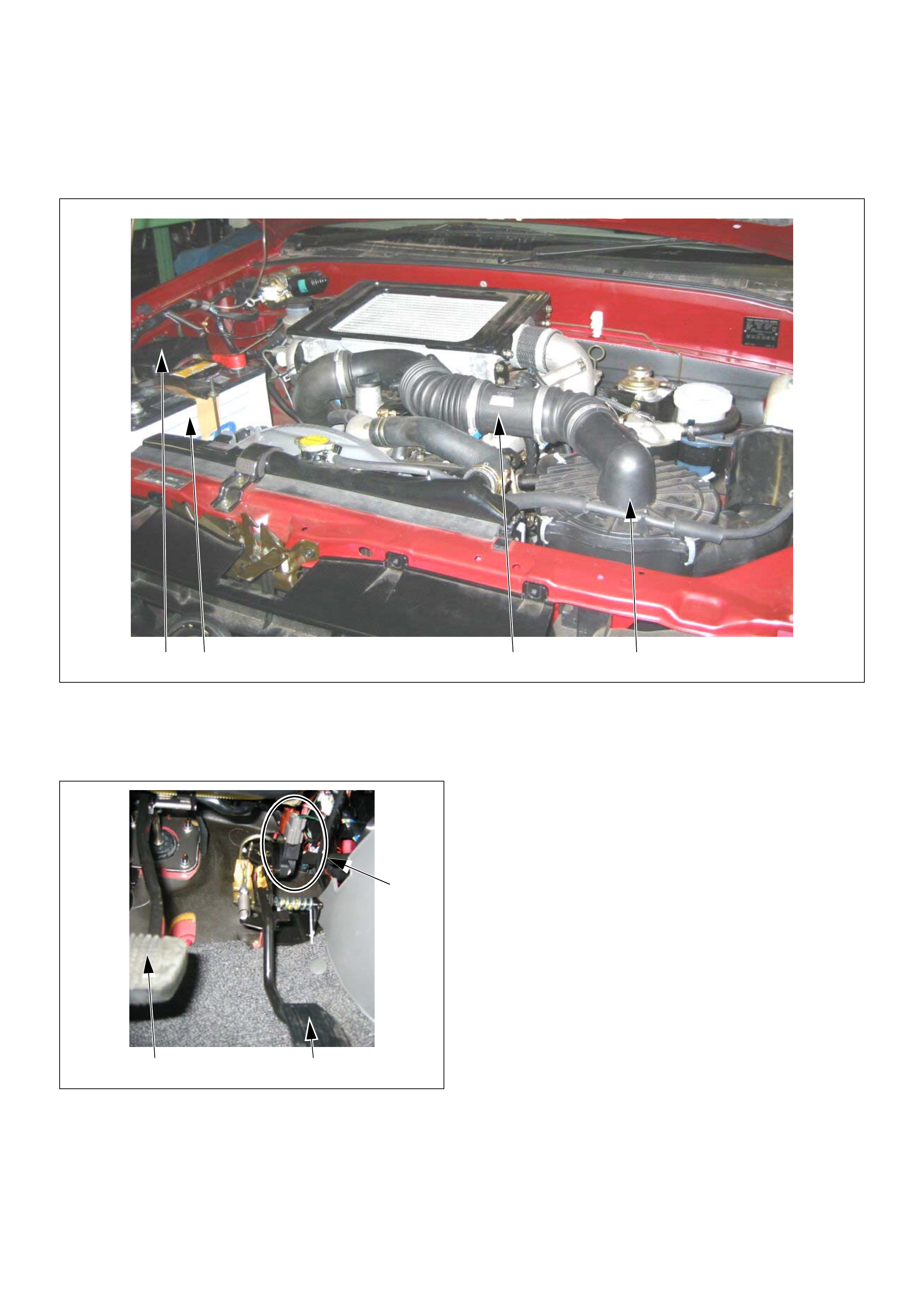
Engine Component Locator Table
4 3 1 2
4JH1-TC
(1) Mass Air Flow (MAF) & Intake Air Temperature
(IAT) Sensor Assembly
(2) Air Cleaner Case
(3) Battery
(4) Relay & Fuse Box
4JH1-TC
(1) Pedal/Throttle Position Sensor (TPS)
(2) A cc el erator Pedal
(3) Brake Pedal
1
3 2
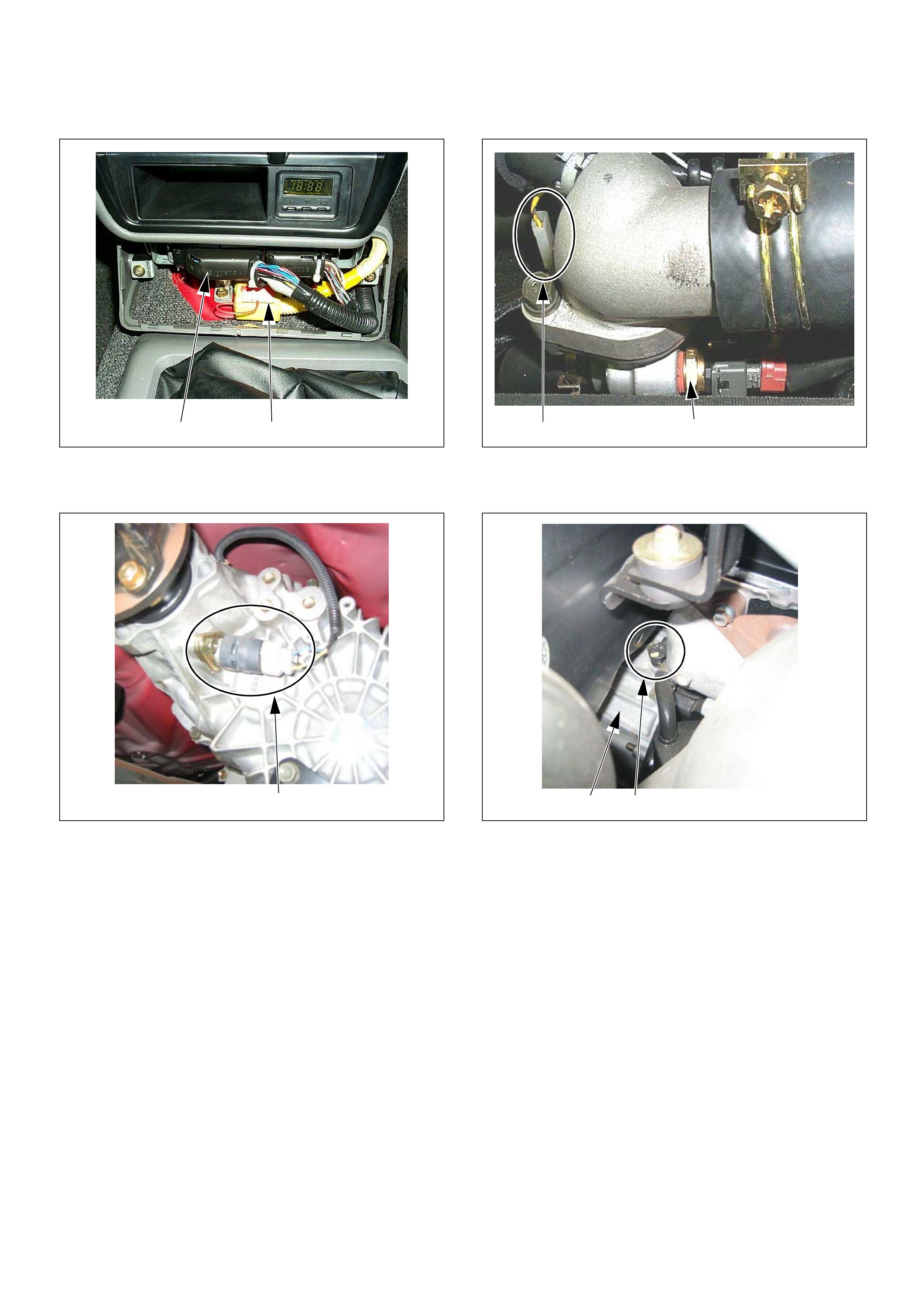
(1) Engine Control Module (ECM)
(2) S RS Cont ro l Modu le
(1) Vehicle Speed Sensor (VSS)
21
1
(1) Engine Coolant Temperature (ECT) Sensor
(2) Thermo Unit for Water Temperature Gauge
(1) Crankshaft Position (CKP) Sensor
(2) Clutch Housing
21
2 1
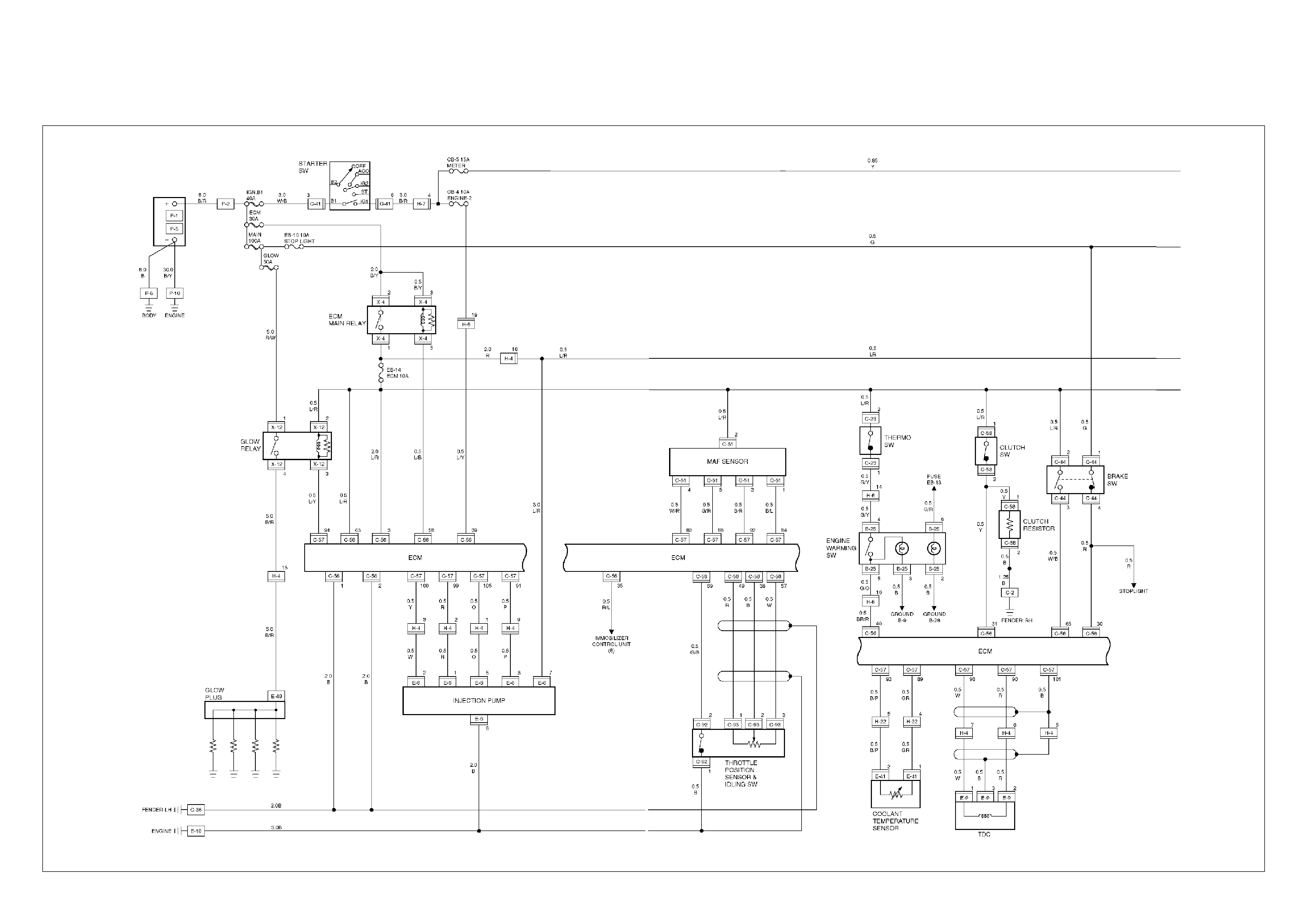
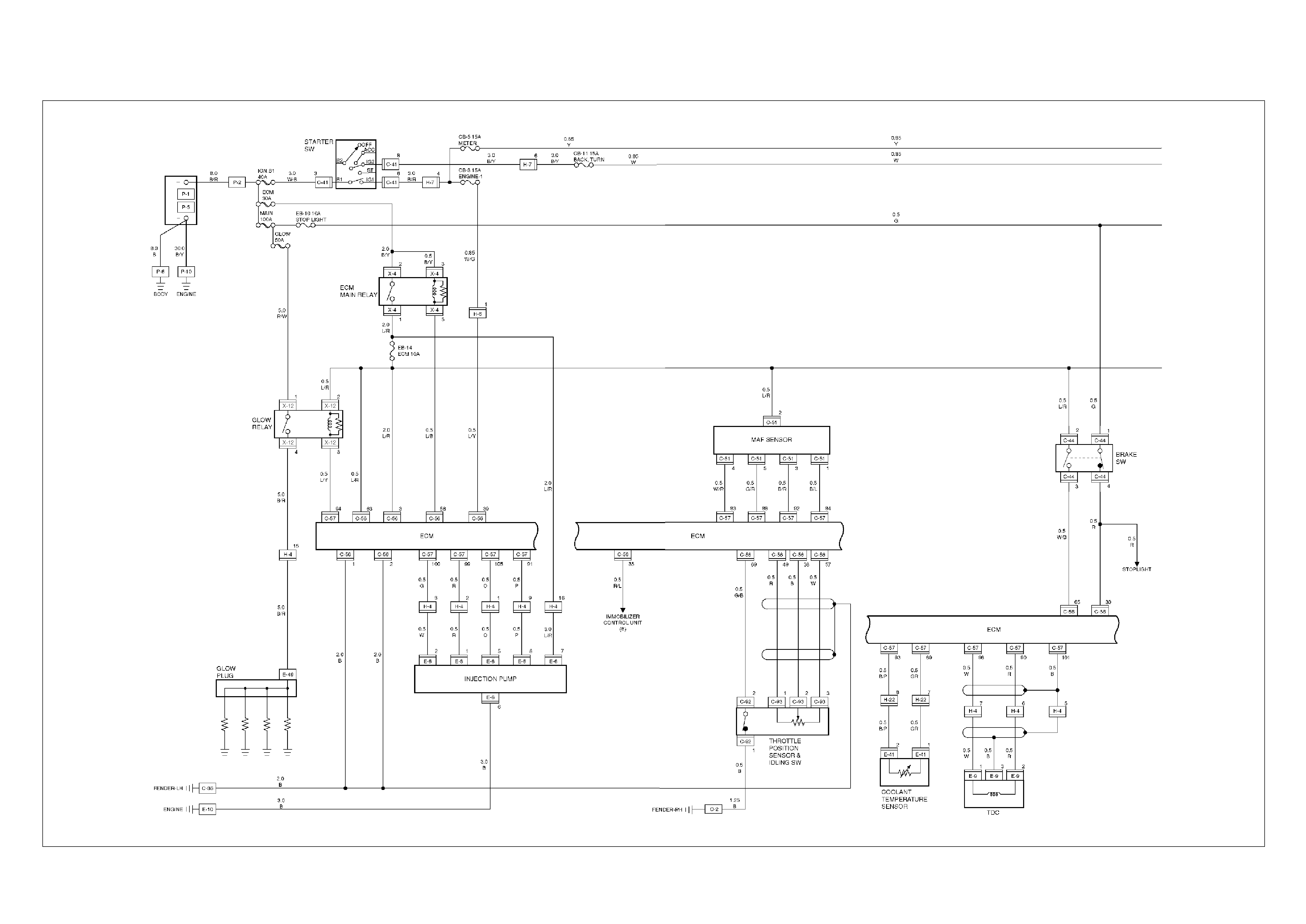
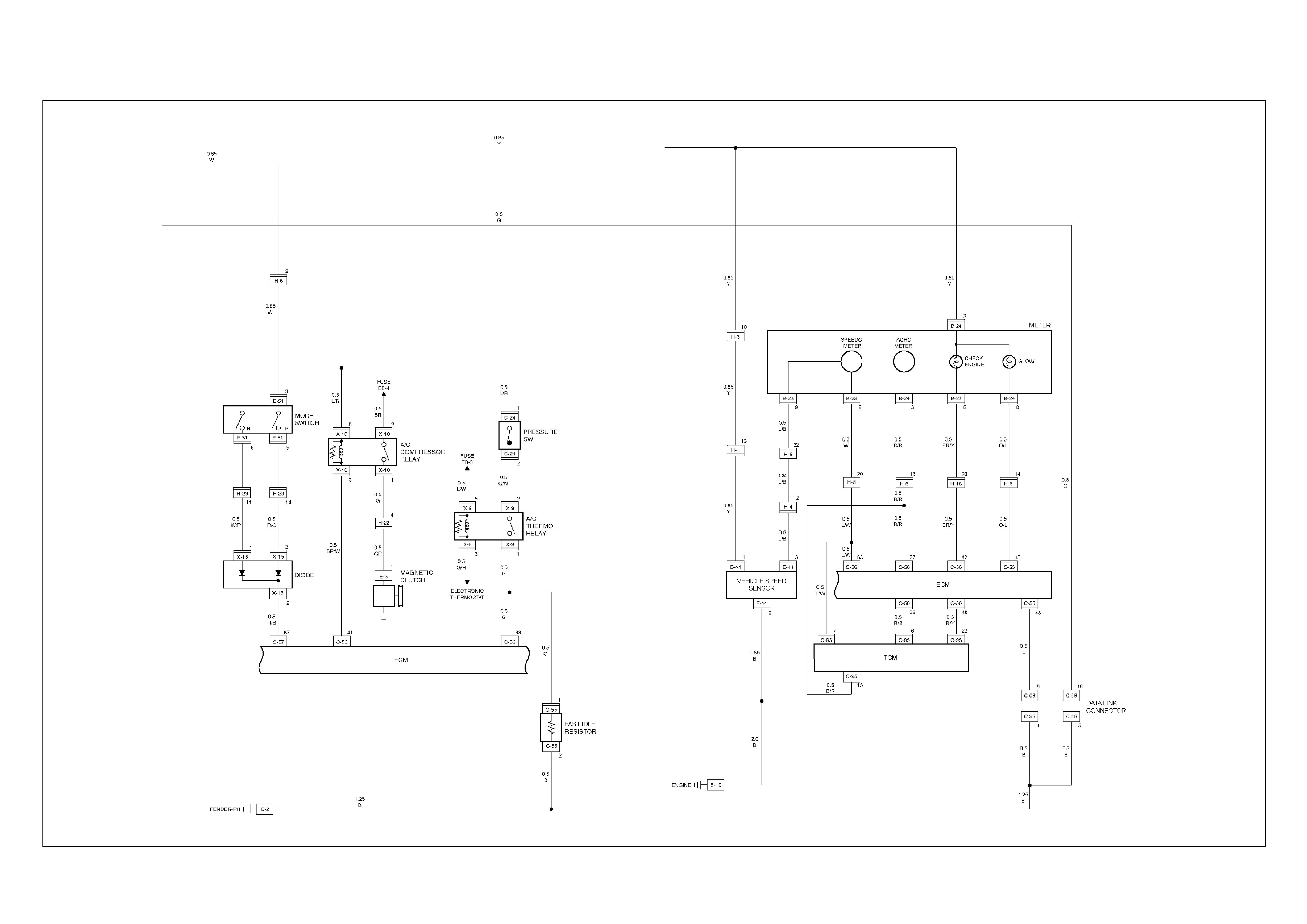
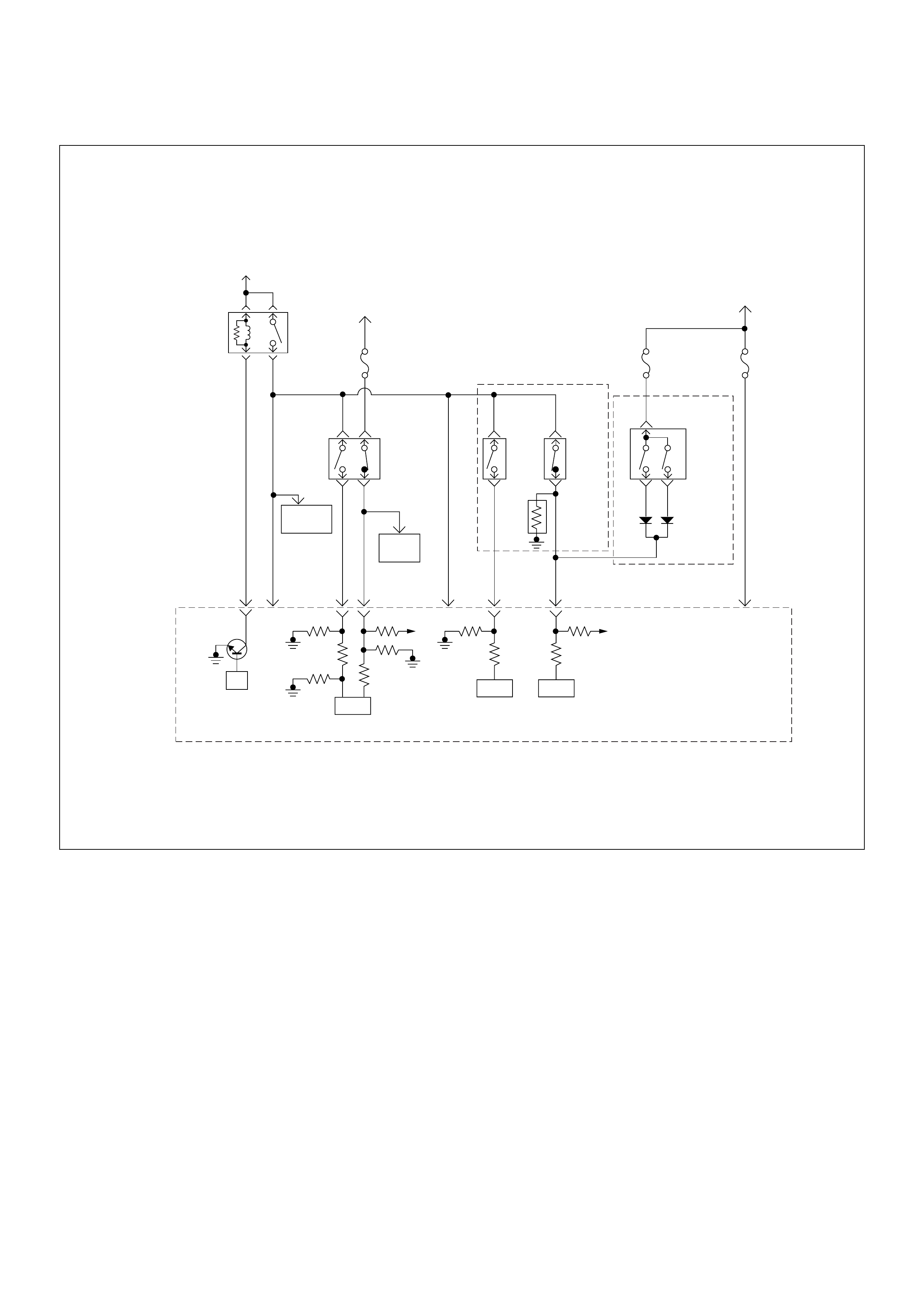
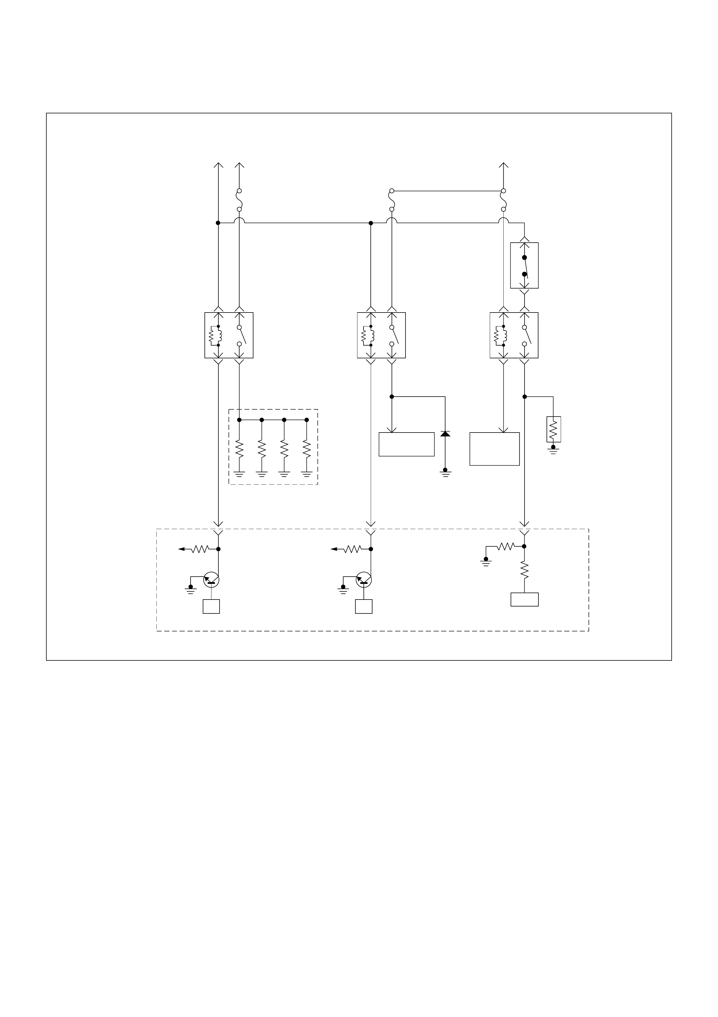
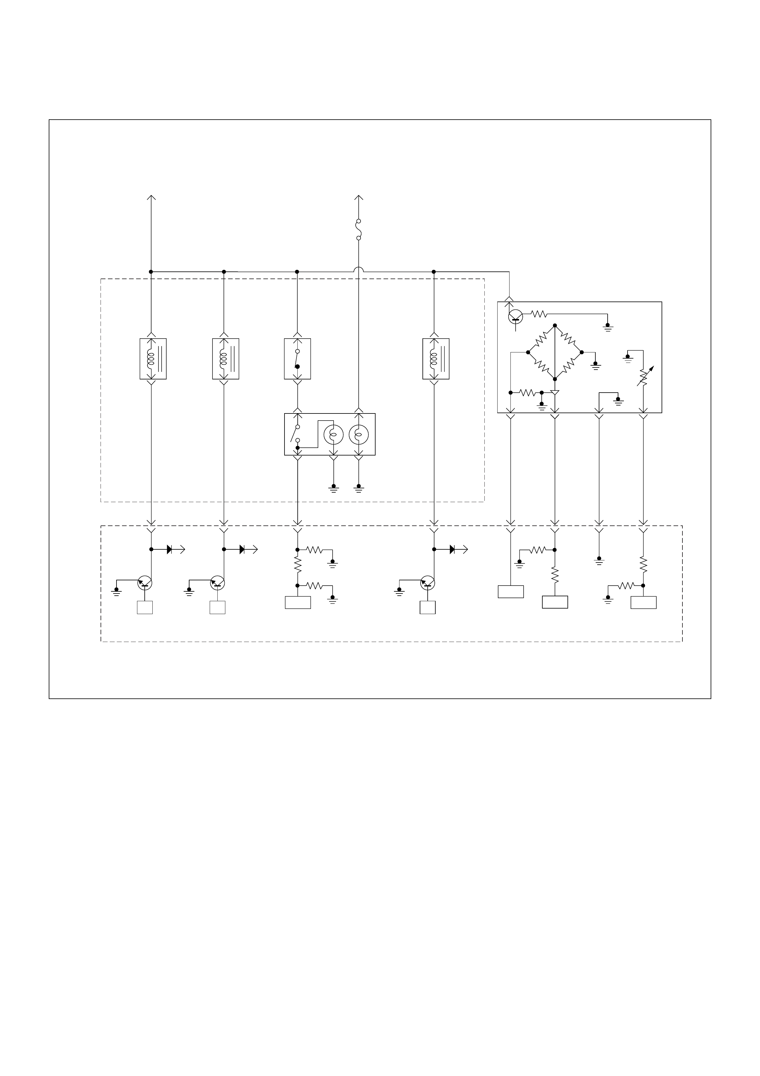
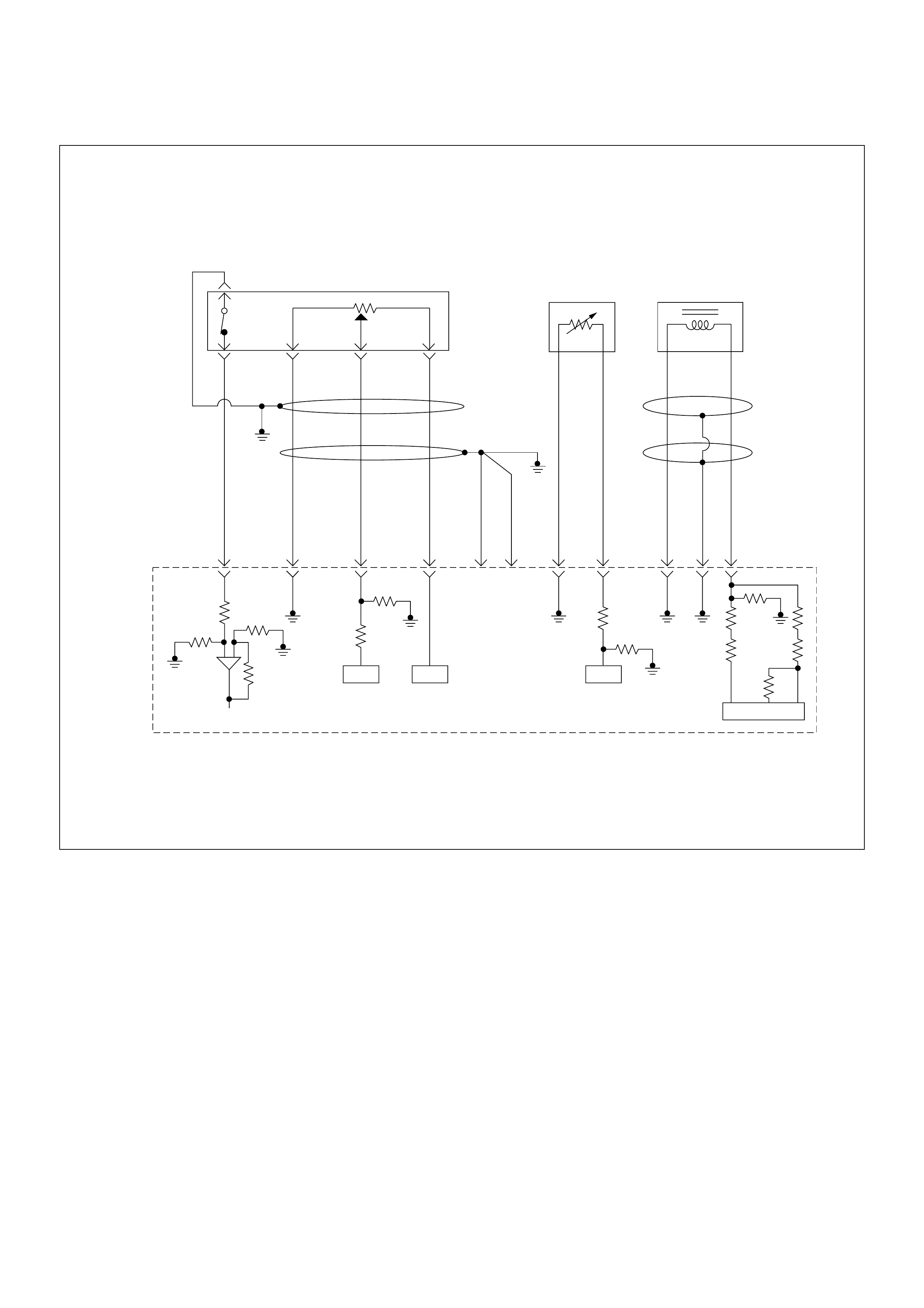
ECM Circuit Diagram
ECM CIRCUIT DIAGRAM (4JH1-TC RHD M/T) (1 /2)
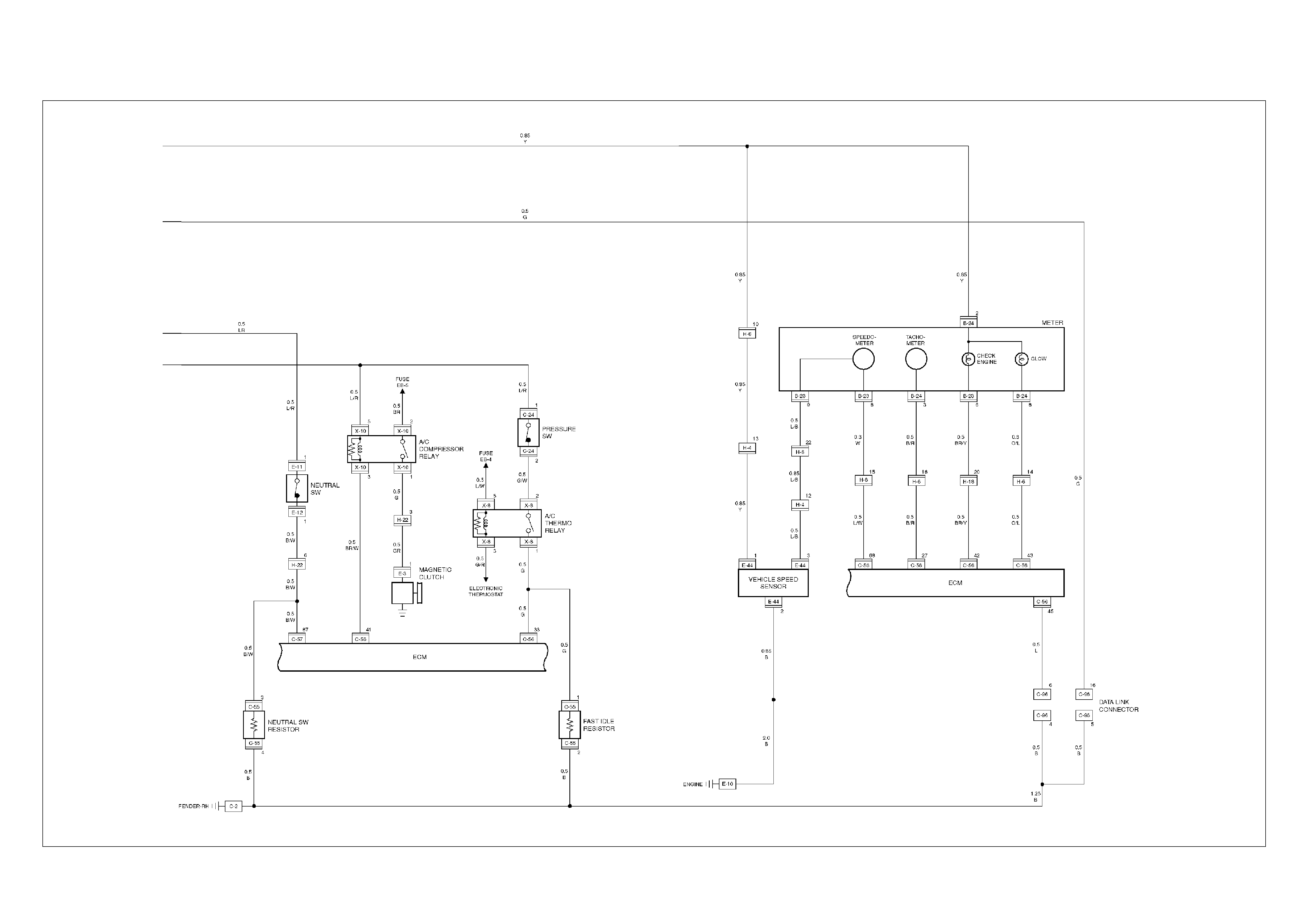
ECM CIRCUIT DIAGRAM (4JH1-TC RHD M/T) (2 /2)
ECM CIRCUIT DIAGRAM (4JH1-TC RHD A/T) (1 /2)
ECM CIRCUIT DIAGRAM (4JH1-TC RHD A/T) (2 /2)
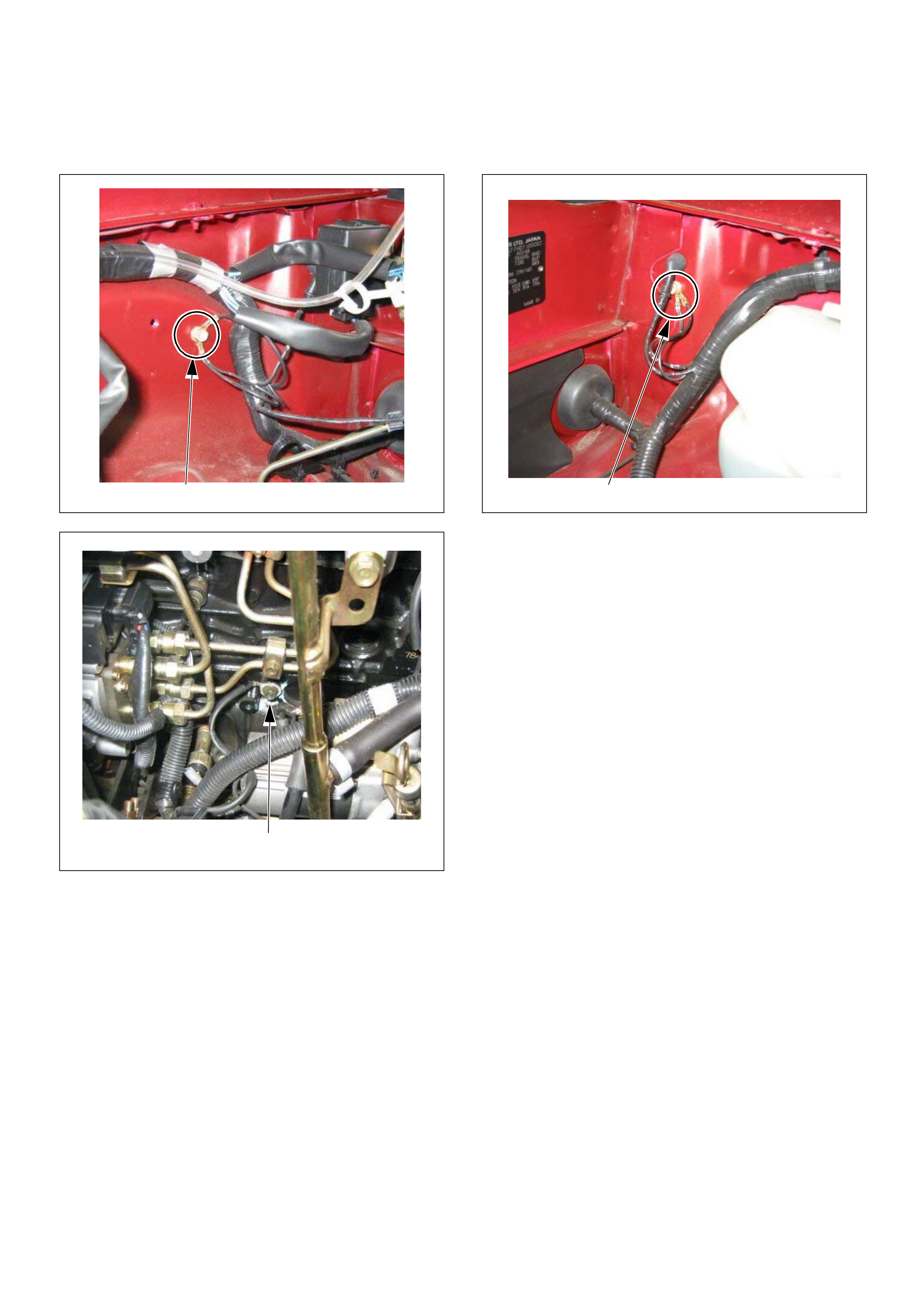
GROUND LOCATION
C2
E10
C36
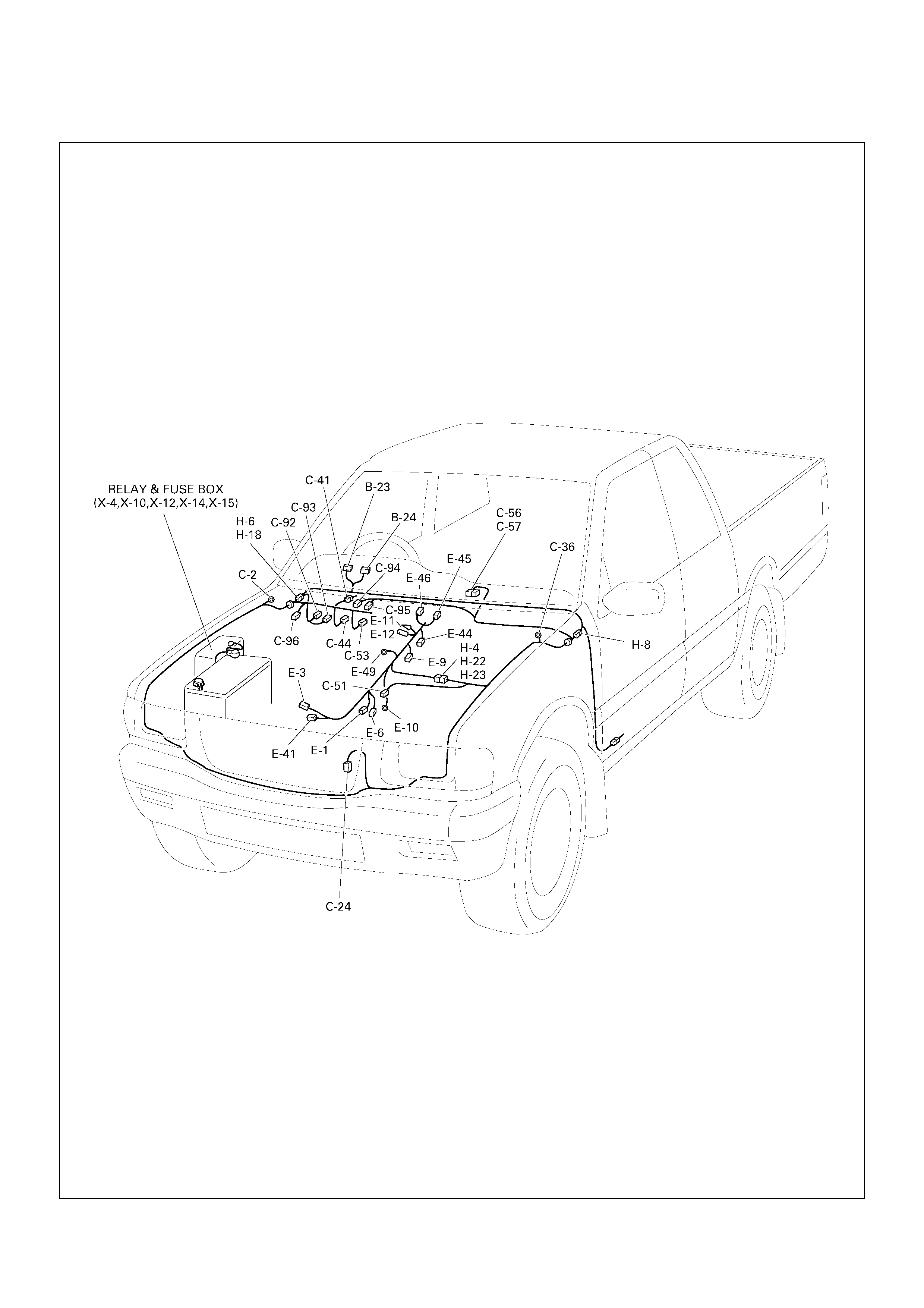
CABLE HARNESS & CONNECTOR LOCATION (4JH1-TC RHD)
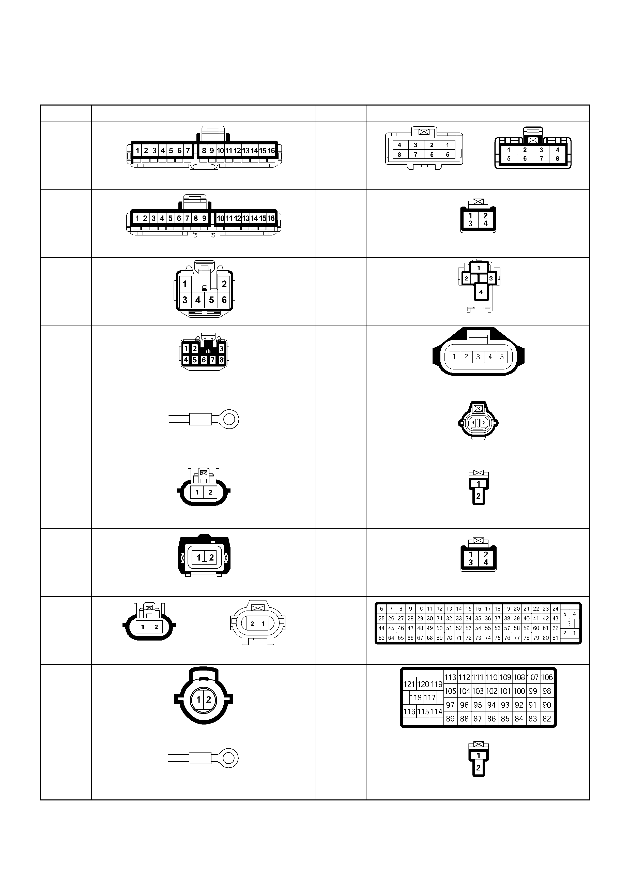
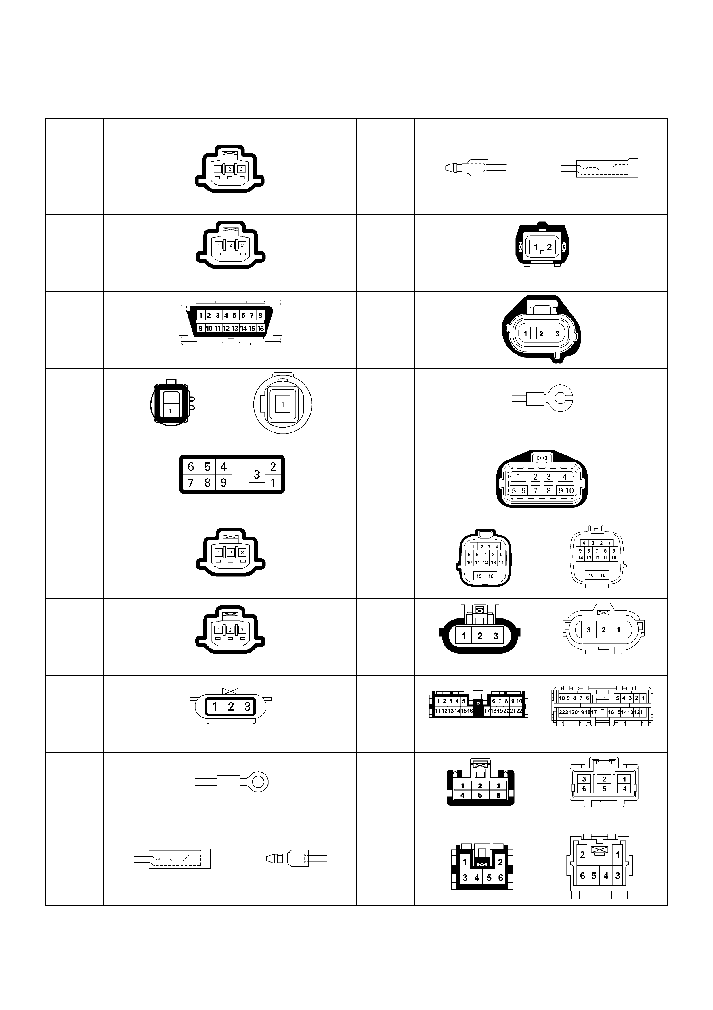
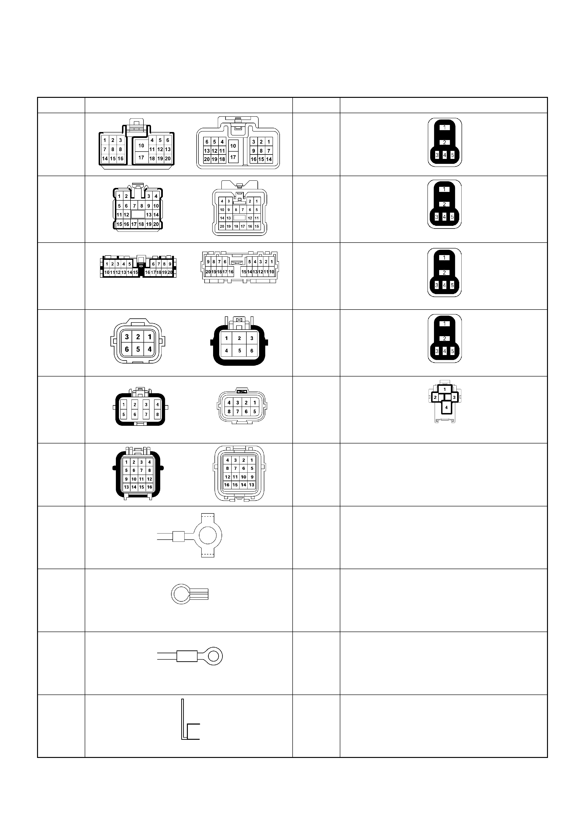
Connector List
NO. CONNECTOR FACE NO. CONNECTOR FACE
B-23 C-41
B-24 C-44
B-25 C-49
B-68
IMMOBILISER
C-51
C-2 C-52
EVRV
C-13 C-53
C-14 C-55
C-23 C-56
C-24 C-57
C-36 C-58
NO. CONNECTOR FACE NO. CONNECTOR FACE
C-92 E-12
C-93
TPS 1 MAIN
E-41
C-96 E-44
E-3 E-49
E-6 E-51
E-7
TPS 1 MAIN
H-4
E-8
IDLE SW
H-5
E-9 H-6
E-10 H-7
(LHD)
E-11 H-7
(RHD)
NO. CONNECTOR FACE NO. CONNECTOR FACE
H-8
(LHD) X-4
ECM
MAIN
H-8
(RHD) X-5
A/C
COMPR
ESSOR
(4JA1)
H-18 X-8
A/C
THERM
O
H-22
(4JH1-
MT)
X-10
A/C
COMPR
ESSOR
(4JH1)
H-22
(4JH1-
A/T)
X-12
GLOW
(4JH1)
H-23
P-2
P-5
P-6
P-10
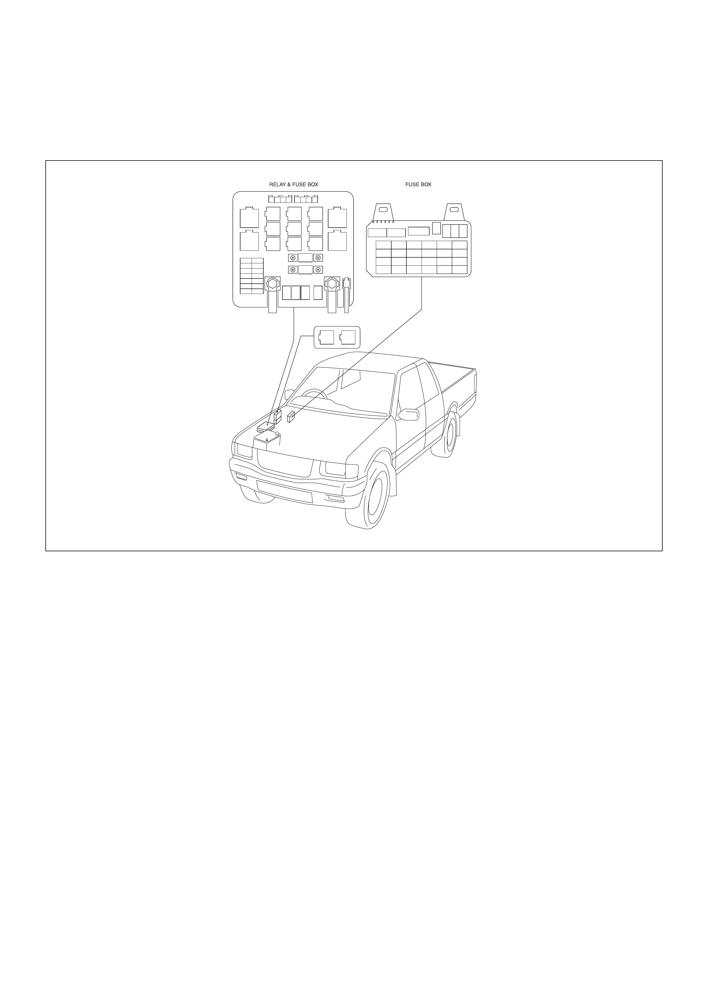
Relay And Fuse
Relay And Fuse Box Location
(Engine Room) (Cabin)
OPTION BOX (Engine Room) (4JA1-TC Only)
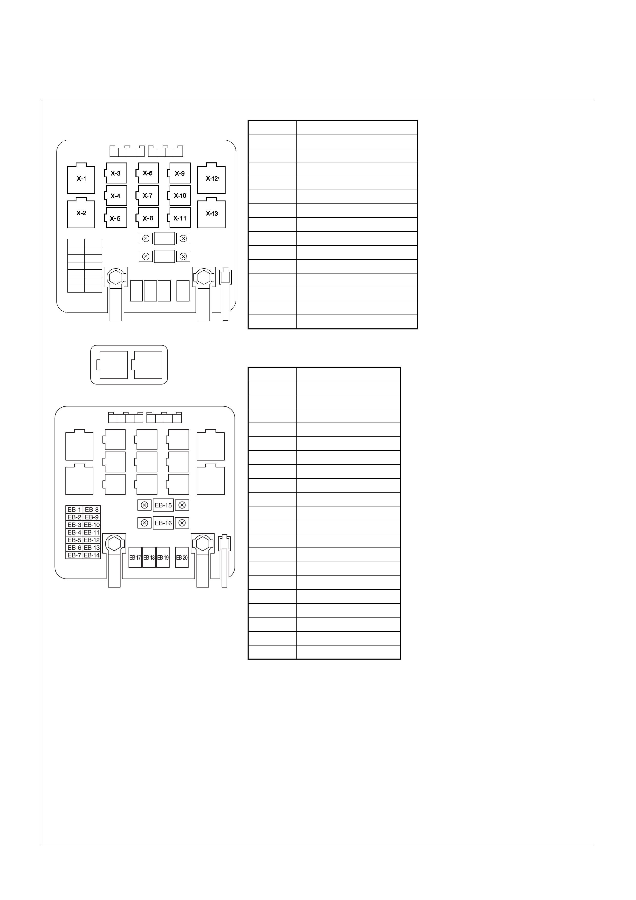
Relay & Fuse Location
C-49
RELAY 4JH1-TC
X-1 RELAY; HEATER
X-2 RELAY; ST CUT
X-3 RELAY; HONE
X-4 RELAY; ECM MAIN
X-5 RELAY; HATCH GATE
X-6 RELAY; TAIL LI GH T
X-7 RELAY; IMMOBILISER
X-8 RELAY; A/C TH ERM O
X-9 RELAY; HEAD LIGHT
X-10 RELAY; A/C COMP.
X-11 —
X-12 REL AY; GL OW
X-13 REL AY; STARTER
C-49 —
FUSE 4JH1-TC
EB-1 15A HAZARD
EB-2 10A HORN
EB-3 20A BLOWER
EB-4 10A A/C
EB-5 —
EB-6 —
EB-7 10A CHARGE
EB-8 10A H/LIGHT-LH
EB-9 10A H/LIGHT-RH
EB-10 10A STOP LIGHT
EB-11 10A TAIL LIGHT
EB-12 10A TCM
EB-13 —
EB-14 10A ECM
EB-15 30A ECM
EB-16 100A MAIN
EB-17 40A IGN-B2
EB-18 —
EB-19 50A GLOW
EB-20 40A IGN-B1
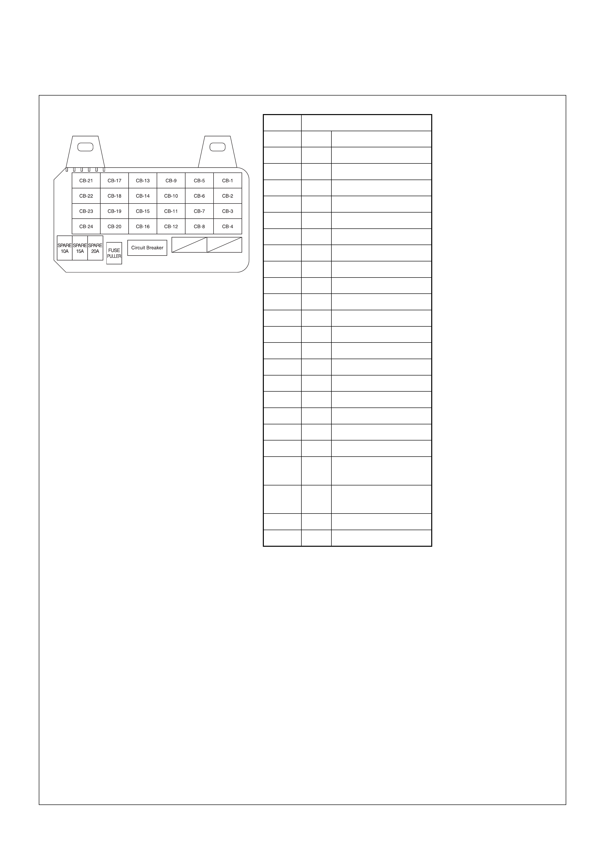
Relay & Fuse Location
(RHD)
FUSE
CB-1 10A STARTER
CB-2 — —
CB-3 15A ENGINE-1
CB-4 10A ENGINE-2
CB-5 15A METER
CB-6 20A FRONT WIPER
CB-7 — —
CB-8 — —
CB-9 — —
CB-10 — —
CB-11 15A BACK UP, TURN
CB-12 — —
CB-13 15A (RR DEFOG.)
CB-14 10A DOME LIGHT
CB-15 20A (DOOR LOCK)
CB-16 — —
CB-17 — —
CB-18 — —
CB-19 15A AUDIO
CB-20 15A CIGAR
CB-21 20A (POWER
WINDOW)
CB-22 20A (POWER
WINDOW)
CB-23 10A (SRS-2)
CB-24 10A (SRS-1)
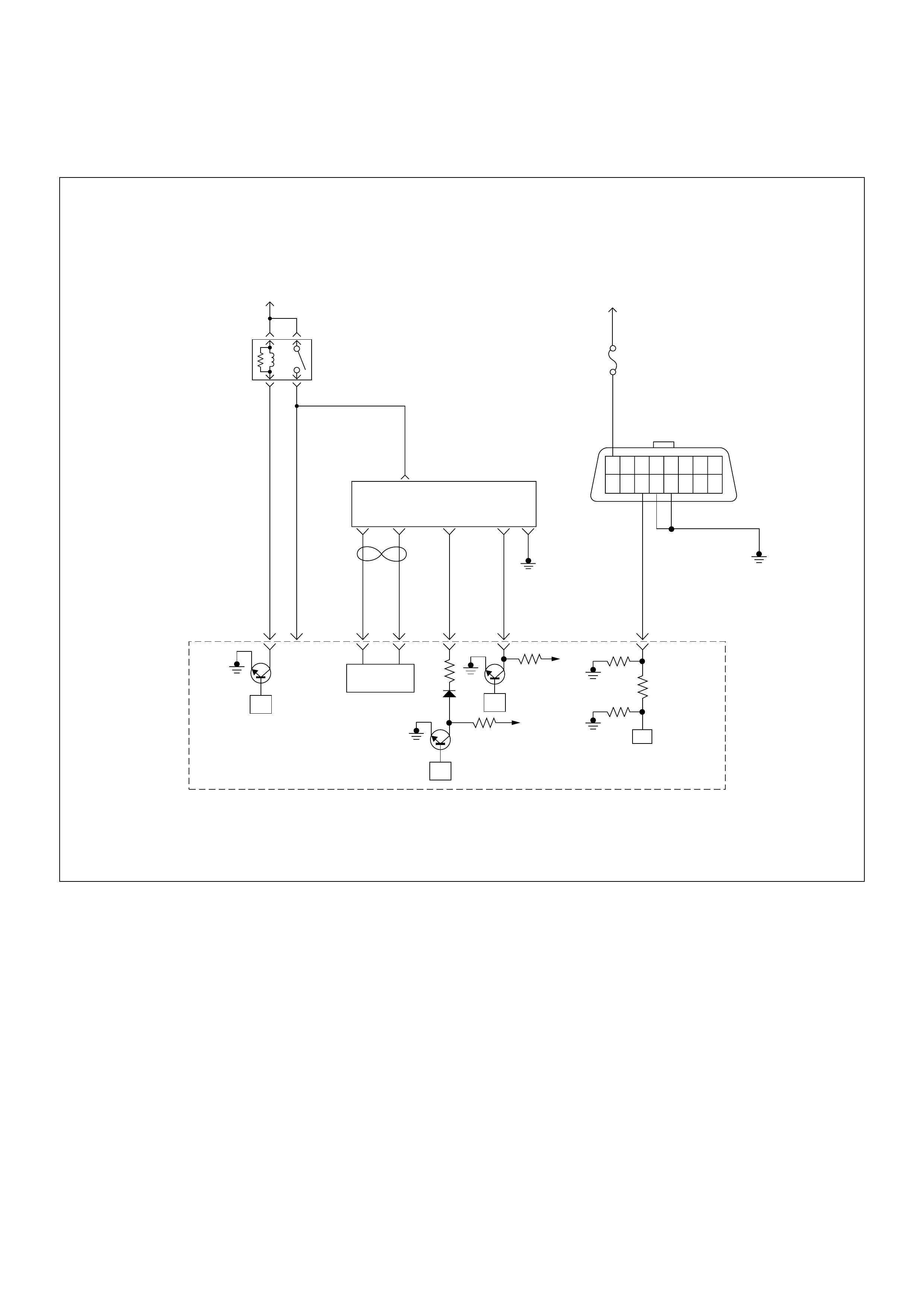
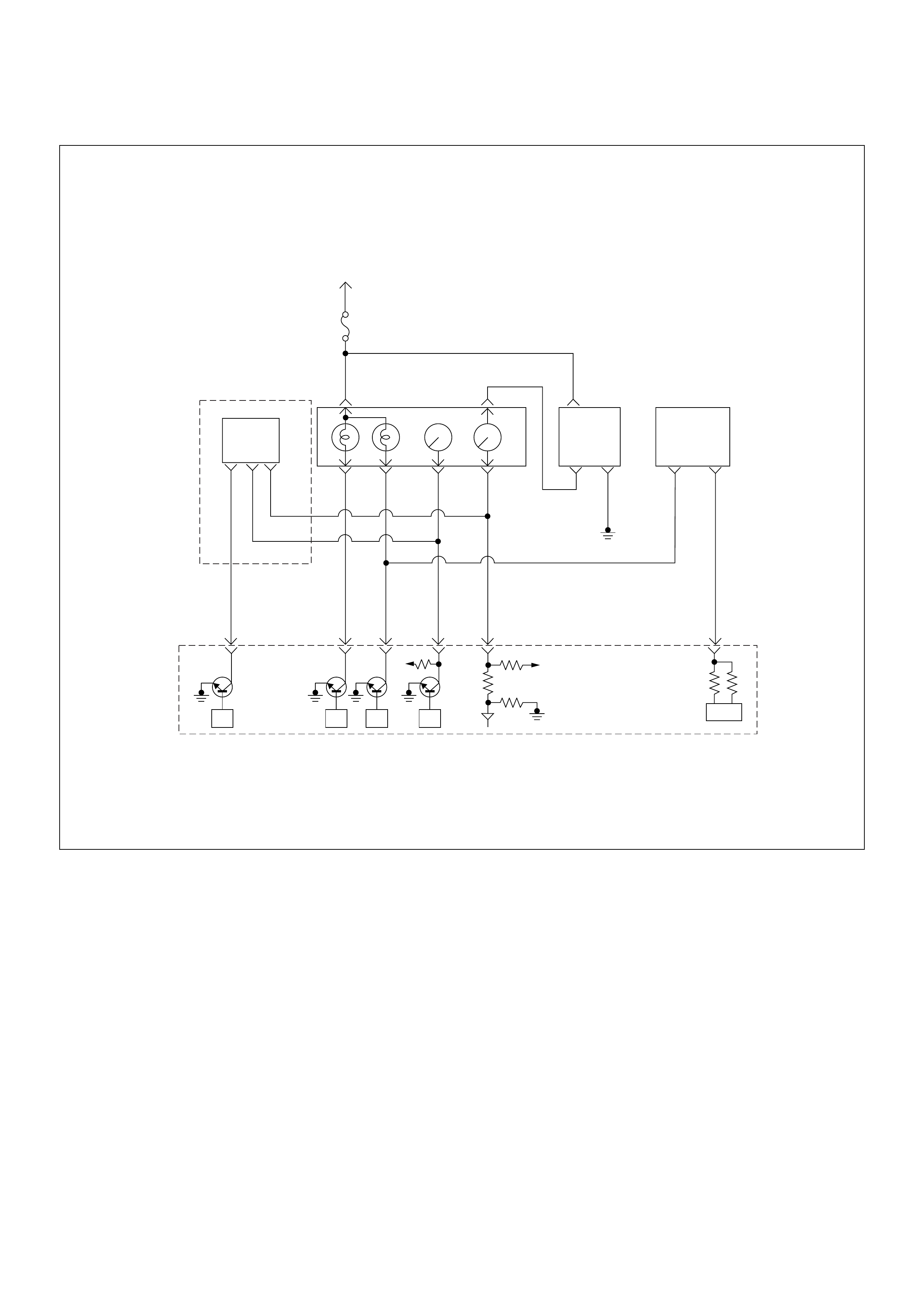
ECM Wiring Diagram
ECM Wiring Diagram (1/7)
45
16151413121110 9
87654321
Battery
Voltage Battery
Voltage
0.5
RED/
YEL
2.0
BLU/
RED
7
PSG(Pump Control Unit) Injection
Pump
21 5 8
0.5
WHT
2.0
BLU/
RED
0.5
BLU/
BLK
0.5
RED 0.5
ORG
100358 99 105 91
0.5
PNK
62.0
BLK
µP
CAN
Controller
Batt
Batt
IC
µP
0.5
BLU
Stop
Light
10A
1.25
BLK
µP
Engine
Control
Module
(ECM)
ECM
Main Relay
ECM Wiring Diagram (2/7)
Ignition
SW
Meter
15A
615 7
Batt
Batt
0.5
RED/
WHT
29
0.5
ORG/
BLU
43
0.5
BRN/
YEL
42
0.5
BLK/
RED
27
0.5
BLU/
WHT
0.5 BLU/BLK
68
0.5
WHT
2.0
BLK
35
VSS
0.85
YEL
Imnobiliser
Control Unit
78
0.5
BRN/
YEL
IC
0.85
YEL
Glow
Check
Engine
Tacho
Meter
Speed
Meter
A/T
TCM
µPµPµPµP
Engine
Control
Module
(ECM)
ECM Wiring Diagram (3/7)
Battery
Voltage
Battery
Voltage
ECM
Main Relay
Stop
Light
10A
Injection
Pump Stop
Lamp
IC IC CPU
0.5
BLU/
BLK
58
2.0
BLU/
RED
0.5
BLU/
RED
3
0.5
WHT/
BLK
65
0.85
RED
0.85
RED
0.85
GRN
30
0.5
BLU/
RED
63
0.5
YEL
31
0.5
RED/
BLK
0.5
BLU/
RED
0.5
BLU/
RED
0.85
WHT
0.5
WHT/
RED
0.5
RED/
GRN
Clutch
SW
Resister
Neutral
SW
87
0.5
BLU/
YEL
39
Brake
SW
M/T A/T
Inhibitor
SW
Ignition
SW
Back,
Turn
15A Engine
15A
µP
NP
Engine
Control
Module
(ECM) Batt Batt
ECM Wiring Diagram (4/7)
Resister
A/C
Compressor
ECM
Main Relay Battery
Voltage
Glow
80A
Glow
Relay
Glow
Plug
0.5
BLU/
RED
0.5
BLK/
BLU
94
0.5
BRN/
RED
0.5
BLK
41
0.5
GRN
33
5.0
RED/
WHT
0.5
BLU/
RED
0.5
GRY
0.5
GRN 0.5
GRN
0.5
BRN
0.5
GRY/
YEL
A/C
10A
Heater
Relay
Blower
20A
A/C
Compressor
Relay
A/C
Thermo
Relay
Pressure
SW
5.0
BLK/
RED
Electronic
Thermostat
µP
Batt
µP
Batt
IC
Engine
Control
Module
(ECM)
ECM Wiring Diagram (5/7)
Batt
µP
Batt
µP
Batt
µP
0.5
BLK/
URG
0.5
BRN/
RED
0.5
BLU/
RED
0.5
BLU/
RED
4JA1-TC
0.5
GRY/
YEL
974661
0.5
WHT/
RED
83
0.5
GRN/
RED
88
0.5
BLK/
RED
92
0.5
BLK/
BLU
84
IAT
Sensor MAF &
IAT
Sensor
Rr Fog
Light
10A
EGR-
EVRV
0.5
WHT/
BLK
0.5
BLU/
RED
0.5
WHT/
BLU
0.5
BLU/
RED
0.5
GRN/
RED
0.5
BLU/
RED
Exhaust
Throttle
VSV2
Exhaust
Throttle
VSV1
Engine
Warming Up
SW
Thermo
SW
2
4531
Battery
Voltage
ECM
Main Relay
IC ICIC CPU
Engine
Control
Module
(ECM)
40
ECM Wiring Diagram (6/7)
0.5
BLK
0.5
GRN/
BLK
69
0.5
RED/
GRN
49
0.5
GRN/
ORG
38
0.5
BLK/
GRN
57
2.0
BLK
1
2.0
BLK
2
0.5
BLK/
PNK
93
0.5
GRY
ECT
Sensor
TPS &
Idle SW
89
0.5
WHT
98 101
0.5
GRN/
RED
CKP
Sensor
90
ICIC IC
IC
Engine
Control
Module
(ECM)
ECM Wiring Diagram (7/7)
µP
1.25
BLK
16151413121110 9
87654321
0.5
RED/
YEL
0.5
WHT 0.5
BLU
35 45
0.5
BRN/
YEL
42
IC
Stop
Light
10A
Meter
15A
Ignition
SW
Check
Engine
Lamp Imnobiliser
Control Unit
Butery
Voltage
78
Engine
Control
Module
(ECM)

ECM Connector Pin Assignment & Output Signal (4JH1-TC)
View Looking Into ECM Case
PIN
NO. B/BOX
NO. PIN FUNCTION WIRE
COLOR
SIGNAL OR CONTINUITY ECM
CONNECTI
ON
TEST ER PO SITION
KEY SW OFF KEY SW
ON ENGINE
IDLE ENGINE
2000RPM RANG
E(+) (-)
11
ECM Grou nd
BLK CONTINUITY
WITH
GROUND
- - - DISCONNE
CT Ω1GND
22
ECM Grou nd
BLK CONTINUITY
WITH
GROUND
- - - DISCONNE
CT Ω2GND
33
Battery Power
Supply
BLU/RED L ES S THAN
1V BATTERY VOLTAGE CONNECT DC V 3 GND
25 25
No Connection
---------
26 26
No Connection
---------
27 27
Engine Speed
Output (To Tacho
Meter)
BLU/RED - - APPROX.
23HZ BY
WAVE
FORM OR
APPROX.
7.2V
APPROX.
68HZ BY
WAVE
FORM OR
APPROX.
7.5V
CONNECT AC V 27 GND
28 28
No Connection
---------
29 29
Throttle Position
Signal (AT Only)
BLK/RED - APPROX . 140HZ BY WAVE FORM
(IDLE: OFF DUTY 10% WOT: OFF
DUTY 90%)
----
30 30
Brake Switch 1
Signal
RED LESS THAN
1V BATTERY VOLTAGE WHEN PEDAL
IS STEP PE D ON CONNECT DC V 30 GND
31 31
Clutch Switch
Signal (MT Only)
YEL LESS THAN
1V BATTERY VOLTAGE WHEN PEDAL
IS NOT STEPPED ON CONNECT DC V 31 GND
32 32
No Connection
---------
33 33
A/C Thermo Relay
GRN LESS THAN
1V BATT ERY VOLTAGE WHEN A/C
REQUEST SWITCH IS TURNED ON CONNECT DC V 33 GND
34 34
No Connection
---------
35 35
Immobiliser
Control Unit (ICU
B8)
RED/BLU - WAVE FOR M - - - -
36 36
No Connection
---------
37 37
No Connection
---------
38 38
Throttle Position
Sensor (TPS)
Output Si gna l
GRN/
ORG LESS THAN
1V LESS THAN 1V APPROX.
1V CONNECT DC V 38 49
39 39
Key Switch Input
Signal Via Engine
Fuse
BLU/Y E L LESS THAN
1V BATTERY VOLTAGE CONNECT DC V 39 G ND

40 40
No Connection
WHT/BLK - - - - - - - -
41 41
A/C Compressor
Relay
BRN/RED LES S THAN
1V BATTERY
VOLTAGE BATTE R Y VO LTAG E
WHEN A/ C
COMPRESSOR IS
NOT ACTI VATED
CONNECT DC V 41 GND
42 42
Check Engine
Lamp
RED/YE L LESS TH AN
1V BATTERY VOLTAGE WHEN LAMP
IS TURNED OFF CONNECT DC V 42 GND
43 43
Glow Lamp
ORG/ BLU L ES S THAN
1V BATTERY VOLTAGE WHEN LAMP
IS TURNED OFF CONNECT DC V 43 GND
44 44
No Connection
---------
45 45
Data Link
Connector (No. 6)
BLU LESS THAN
1V BATTERY VOLTAGE CONNECT DC V 45 G ND
46 46
No Connection
BRN/RED - - - - - - - -
47 47
No Connection
---------
48 48
No Connection
---------
49 49
Throttle Position
Sensor (TPS)
Ground
RED/GRN IDLE:
APPROX.
0.4KΩ/
WOT:
APPROX.
3.8KΩ
- - - DISCONNE
CT Ω38 49
50 50
No Connection
---------
51 51
No Connection
---------
52 52
No Connection
---------
53 53
No Connection
---------
54 54
No Connection
---------
55 55
No Connection
---------
56 56
No Connection
---------
57 57
Throttle Position
Sensor (TPS)
Power Supply
BLK/GRN LESS THAN
1V APPROX. 5V CONNECT DC V 57 49
58 58
ECM Main Relay
BLU/BLK BATTERY
VOLTAGE LESS THAN 1V CONNECT DC V 58 GND
59 59
No Connection
---------
60 60
No Connection
---------
61 61
No Connection
---------
62 62
No Connection
---------
63 63
ECM Power
Supply
BLU/RED L ES S THAN
1V BATTERY VOLTAGE CONNECT DC V 63 G ND
64 64
No Connection
---------
65 65
Brake Switch 2
Signal
WHT/BLK LESS THAN
1V BATTERY VOLTAGE WHEN PEDAL
IS NOT STEPPED ON CONNECT DC V 65 GND
66 66
No Connection
---------
67 67
No Connection
---------
68 68
Vehicle Speed
Sensor (VSS) Via
Speed Meter
BLU/WHT - APPROX. 15HZ BY WAVE FORM
OR APPRO X. 6.4V AT VEHICLE
SPEED 20KM/H
CONNECT AC V 68 GND
69 69
Idle Switch
GRN/B L K LESS TH AN
1V APPROX . 5V WHEN PE D AL IS
STEPPED ON CONNECT DC V 69 GND
PIN
NO. B/BOX
NO. PIN FUNCTION WIRE
COLOR
SIGNAL OR CONTINUITY ECM
CONNECTI
ON
TEST ER PO SITION
KEY SW OFF KEY SW
ON ENGINE
IDLE ENGINE
2000RPM RANG
E(+) (-)

70 70
No Connection
---------
71 71
No Connection
---------
72 72
No Connection
---------
73 73
No Connection
---------
74 74
No Connection
---------
75 75
No Connection
---------
76 76
No Connection
---------
77 77
No Connection
---------
78 78
No Connection
---------
79 79
No Connection
---------
80 80
No Connection
---------
81 81
No Connection
---------
82 82
No Connection
---------
83 83
Mass Air Flow
(MAF) Sensor
Power Supply
WHT/ RED LESS THAN
1V APPROX. 5V CONNECT DC V 83 92
84 84
Intake Air
Temperature (IAT)
Sensor Signal
BLK/BLU LESS THAN
1V APPROX. 2.5V AT IAT 25°C CONNECT DC V 84 92
85 85
No Connection
---------
86 86
No Connection
---------
87 87
Neutral Switch
BLK/ WHT LESS TH AN
1V BATTERY VOLTAGE AT OTHER
THAN NEUTRAL (MT) / BATTERY
VOLTAGE IN P OR N (AT)
CONNECT DC V 87 GND
88 88
Mass Air Flow
(MAF) Sensor
Signal
GRN/R E D LESS THAN
1V APPROX.
1V APPROX.
2V APPROX.
3V CONNECT DC V 88 92
89 89
Engine Coolant
Temperature
(ECT) Sensor
Signal
GRY L ES S THAN
1V APPROX. 1.3V AT ECT 80°C CONNECT DC V 89 93
90 90
TDC Sensor
Signal
RED - - APPROX.
47HZ BY
WAVE
FORM OR
APPROX.
0.7 V AT
700RPM
APPROX.
133HZ BY
WAVE
FORM OR
APPROX.
1.0V
CONNECT AC V 90 98
91 91
TDC Sensor
Output To Pump
Control Unit (PSG)
No.8
PNK - - APPROX.
47HZ BY
WAVE
FORM
APPROX.
133HZ BY
WAVE
FORM
----
92 92
Mass Air Flow
(MAF) Sensor
Ground
BLK/RED CONTINUITY
WITH
GROUND
- - - CONNECT Ω92 GND
93 93
Engine Coolant
Temperature
(ECT) Sensor
Ground
BLK/PNK CONTINUITY
WITH
GROUND
- - - CONNECT Ω93 GND
PIN
NO. B/BOX
NO. PIN FUNCTION WIRE
COLOR
SIGNAL OR CONTINUITY ECM
CONNECTI
ON
TEST ER PO SITION
KEY SW OFF KEY SW
ON ENGINE
IDLE ENGINE
2000RPM RANG
E(+) (-)

94 94
Glow Relay
BLK/BLU LESS THAN
1V BATTERY VOLTAGE WHEN GLOW
SYST EM IS NOT ACTIVATED CONNECT DC V 94 GND
95 95
No Connection
---------
96 96
No Connection
---------
97 97
EGR EVRV
BLK/ORG - APPROX. 140HZ BY
WAVE FORM WHEN
EVRV IS ACTIVATED
----
98 98
TDC Sensor
Ground
WHT CONTINUITY
WITH
GROUND
- - - CONNECT Ω98 GND
99 99
CAN (Controller
Area Network) to
PSG No.1
RED - - - - - - - -
100 100
CAN (Controller
Area Network) to
PSG No.2
WHT - - - - - - - -
101 101
TDC Sensor
Shield Line
- CONTINUITY
WITH
GROUND
- - - CONNECT Ω101 GND
102 102
No Connection
---------
103 103
No Connection
---------
104 104
No Connection
---------
105 105
Soleno id Valve
Shut Off (MAB)
Output Si gna l to
PSG No.5
ORG - WAVE FORM - - - -
PIN
NO. B/BOX
NO. PIN FUNCTION WIRE
COLOR
SIGNAL OR CONTINUITY ECM
CONNECTI
ON
TEST ER PO SITION
KEY SW OFF KEY SW
ON ENGINE
IDLE ENGINE
2000RPM RANG
E(+) (-)

PSG Connector Pin Assignment & Output Signal (4JH1-TC)
View Looking Into PSG Case
PIN
NO. B/BOX
NO. PIN FUNCTION WIRE
COLOR
SIGNAL OR CONTINUITY PSG
CONNECTION
TESTER POSITION
KEY SW OFF KEY SW ON ENGINE
IDLE ENGINE
2000RPM RANGE (+) (-)
199
CAN (Controller
Area Network) to
ECM No.99
RED CONTINUITY
BETWEEN
ECM & PSG
- - - DISCONNECT Ω199
2 100
CAN (Controller
Area Network) to
ECM No.100
WHT CONTINUITY
BETWEEN
ECM & PSG
- - - DISCONNECT Ω2 100
3-
No Connectio n
-- --- ----
4-
No Connectio n
-- --- ----
5 105
Solenoid Valve
Shut Off (MAB)
Output Signal to
ECM No.105
ORG CONTINUITY
BETWEEN
ECM & PSG
- - - DISCONNECT Ω5 105
6-
Ground
BLK CONTINUITY
WITH GROUND - - - DISCONNECT Ω6GND
73
Battery Power
Supply
BLU/RED CONTINUITY
BETWEEN
ECM & PSG
- - - DISCONNECT Ω73
891
TDC Sensor
Output ECM
No.91 To Pump
Control Unit
(PSG)
PNK CONTINUITY
BETWEEN
ECM & PSG
- - - DISCONNECT Ω891
9-
No Connectio n
-- --- ----
General Description For ECM And
Sensors
Engine Control Module (ECM)
The engine control module (ECM) is located on the
transmission tunnel.
The fuel quantity and injection timing related functions
are controlled by the pump control unit (PSG).
The engine control module (ECM) performs the
following functions.
• Control of the quick on start (QOS) glow control
system
• Control of the A/C compressor
• Execution of the immobiliser function
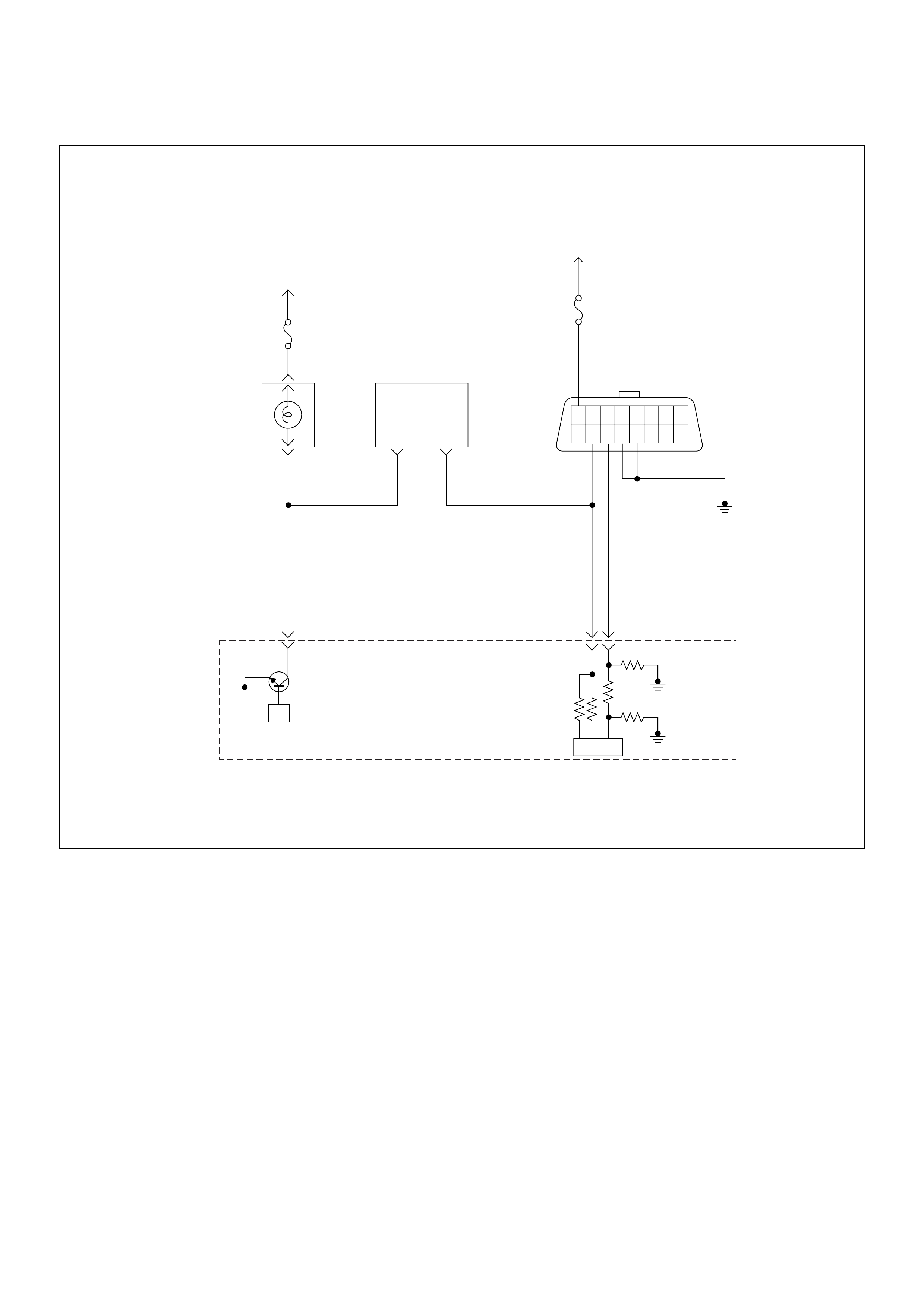
Pump Control Unit (PSG) & Data Exchange
Between Control Module
The radial plunger distributor type injection pump uses
two control modules to execute full control of the engine
management system.
• Engine Control Module (ECM)
• Pump Control Unit (PSG) = Pumpen Steuer Great
(German)
The pump control unit (PSG) receives signals from the
sensors inside the pump to determine the cam ring
rotation angle, the pump speed and the fuel
temper atur e .
These values are then compared to the desired values
sent by the engine control module (ECM) such as the
desired injection timing and the desired fuel injection
quantity.
The engi ne control module ( ECM) processes al l engine
data and data regarding the surrounding environment
received from external sensors to perform any engine
side adjustments.
Maps for both are encoded in both control units. The
control units input circuit process sensor data.
A Microprocessor then determines the operating
conditions and calculates set values for optimum
running.
The interchange of data between the engine control
module (ECM) and the pump control unit (PSG) is
perfumed via a CAN-bus system. The abbreviation CAN
stands for Controller Area Network. By having two
separate control modules, the high pressure solenoid
valve. This prevents the discharge of any disturbing
signals.
The following signals are exchanged via the CAN-bus:
From ECM to PSG
• Desired injection quantity
• Desired injection timing
• Engine speed
From PSG to ECM
• Fuel temperature
• Pump speed
• Cyli nde r identi fie r
• Control pulse (actual injection quantity + actual
inje cti on tim ing )
• PSG status
Self Diagnosis / Interface / Signal
To High Pressure Solenoid
Engine Speed
Injection Timing
Accelerator Pedal
Injection Quantity
Intake Air Tem perature
Response Signal
Mass Air Flow
Additional Signal
Others
Additional Operations To Timing Control Valve (TCV)
Engine
Control
Module
(ECM)
Cam Ring Rotational Angle
Fuel Temperature
High Pressure
Solenoid Valve
Pump
Control Fuel Injection
Unit (Mechanical)
(PSG)
Timing Device
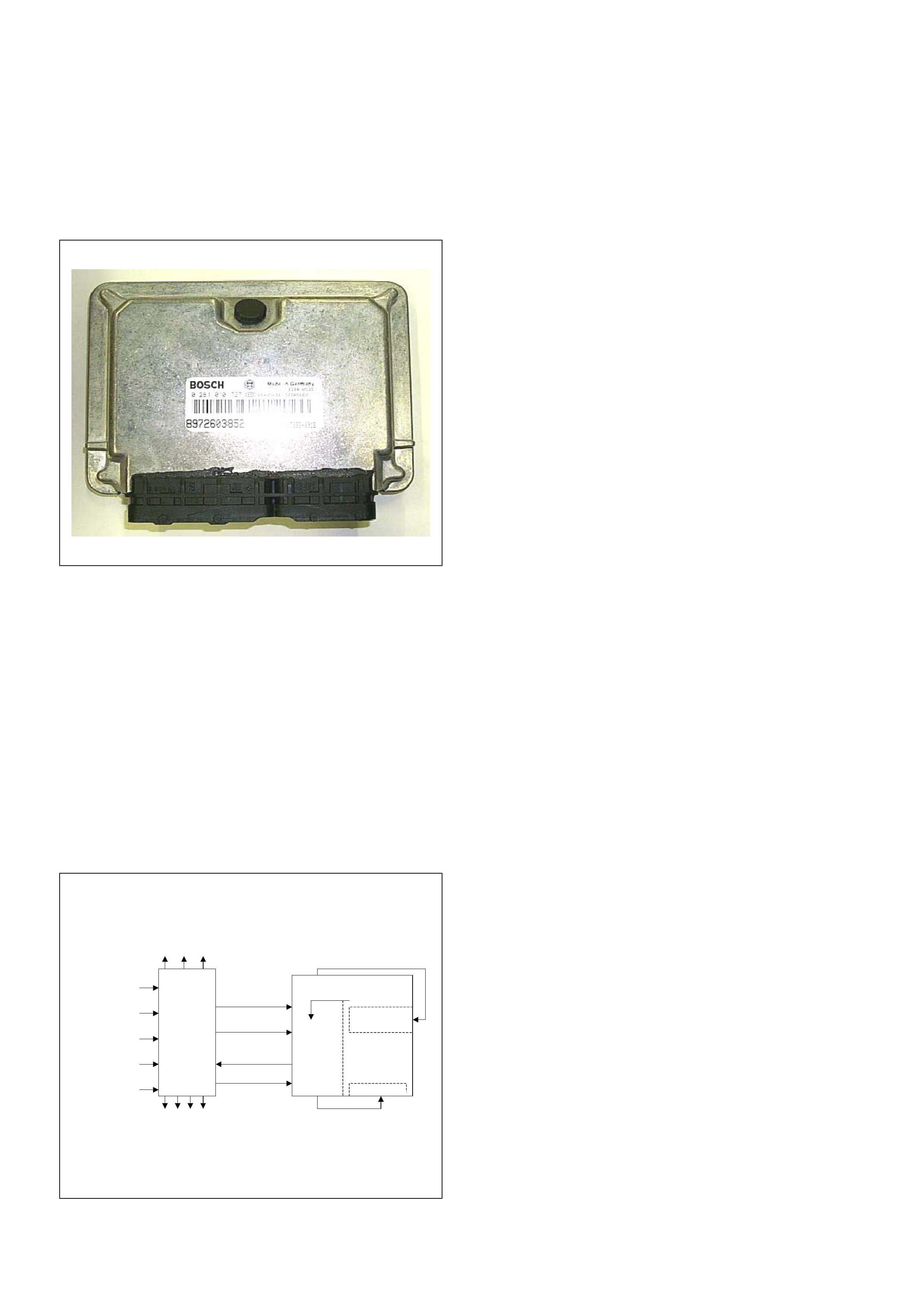
Mass Air Flow (MAF) Sensor & Intake Air
Temperature (IAT) Sensor
The mas s air flo w (MAF) sensor is part of the intake air
system.
It is fitted betw een the air cleaner and turboc harge r and
measure the mass air flowing into the engine.
The mass air flow (MAF) sensor uses a hot film element
to determine the amount of air flowing into the engine.
The mass air flow (MAF) sensor assembly consist of a
mass air flow (MAF) sensor element and an intake air
temperature sensor that are both exposed to the air flow
to be measured.
The mass air flow (MAF) sensor element measures the
partial air mass through a measurement duct on the
sensor housing.
Using calibration, there is an extrapolation to the entire
mass air flow to the engine.
The IAT sensor is a thermistor. A temperat ure changes
the resistance value. And it changes voltage. In other
words it measures a temperature value. Low air
temperature produces a high resistance.
The ECM supplies 5 volts signal to the IAT sensor
through resisters in the ECM and measures the voltage.
The signal voltage will be high when the air temperature
is cold, and it will be low when the air temperature is
hot.
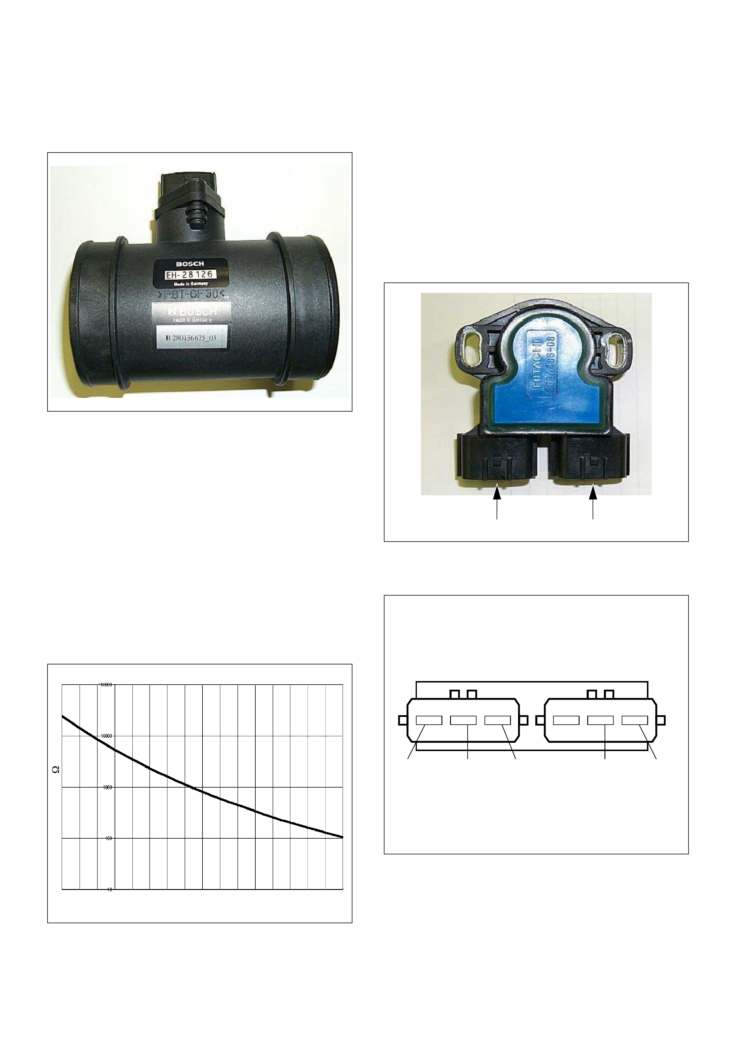
Pedal/Throttle Position Se nsor (TPS)
-30 -20 -10 0 10 20 30 40 50 60 70 80 90 100 110 120 130
Characteristic of IAT Sensor
Temperature (oC)
Resistance ( )
(1) Throttle Position Sensor (TPS)
(2) Idle Switch
1 2
+5V Output Ground +5VGround
The TPS is a potentiometer connected to throttle shaft
on the throttle body. It is installed to the main TPS and
idle switch.
The engine control module (ECM) monitors the voltage
on the signal line and calculates throttle position. As the
throttle valve angle is changed when accelerator pedal
moved. The TPS signal also changed at a moved
throttle valve. As the throttle valve opens, the output
increases so that the output voltage should be high.
The engine control module (ECM) calculates fuel
delivery based on throttle valve angle.
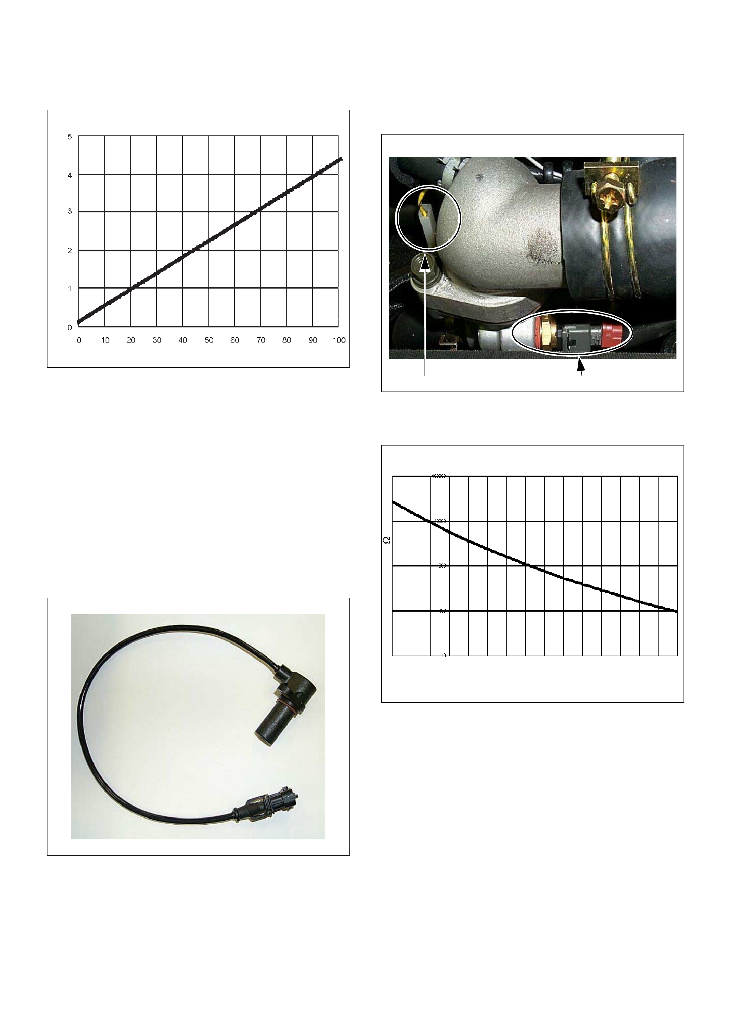
Crankshaft Position (CKP) Sensor
The CKP sensor is located on top of the flywheel
housing of the flywheel and fixed with a bolt.
The CKP sensor is of the magnet coil type. The
inductive pickup sensors four gaps in the flywheel
exciter ring and is used to determine the engine speed
and engine cylinder top dead center (TDC).
Engine Coolant Temperature (ECT) Sensor
The ECT sensor is a thermistor. A temperature changes
the resistance value. And it changes voltage. In other
words it measures a temperature value. It is installed on
the coolant stream. Low coolant temperature produces
a high resistance.
The ECM supplies 5 volts signal to the ECT sensor
through resisters in the ECM and measures the voltage.
The signal voltage will be high when the engine
temperature is cold, and it will be low when the engine
temper atur e is hot.
Characteristic of TPS
Throttle Angle (%)
Output V oltage (V)
(1) Engine Coolant Temperature (ECT) Sensor
(2) Thermo Unit for Water Temperature Gauge
21
-30 -20 -10 0 10 20 30 40 50 60 70 80 90 100 110 120
Characteristic of ECT Sensor
Temperature (deg. C)
Resistance ( )
Vehicle Speed Sensor (VSS)
The VSS is a magnet rotated by the transmission output
shaft. The VSS uses a hall ele ment. It in teracts with the
magnetic field treated by the r otating magnet. It out puts
pulse signal. The 12 volts operating supply from the
meter fuse.
The engine control module (ECM) calculates the vehicle
speed by VSS.

General De scription - Injection Pump
Outline
Instead of the previous face cam type, the radial plunger
distributor type injection pump utilizes a cam ring to
enable fuel injection at high-pressures, marking it
suitable for small, high-speed direct injection diesel
engines. T his pump was deve loped to provide the most
suitable fuel injection quantity and injection timing to
satisfy the demand fo r engine reli ability, driveabi lity, low
smoke, low noise, high output and clear exhaust
emissions.
Characteristic of VP44 Injection System
1. HIGH PRESSURE INJECTION
The radial plunger distributor type injection pump is
capable of generating pressure of 100 Mpa
(approximately 1000 Bar) demanded by small, high
speed direct injection diesel engines.
2. HIGH PRESSURE ATOMIZATION OF FUEL
INJECTED FROM THE NOZZLE
Through high pressure fuel injection, the fuel is
atomized at high pressure with a h igh pene trating force
(the fuel droplets penetrate further) and with greater
dispersion and distribution (mixing with air is improved)
and results in better combustion. This contributes to
cleaner emissions.
3. OPTIMUM FUEL INJECTION
High speed control of fuel injection quantity and fuel
injection timing, is performed by the control unit,
enabling lower fuel cost and high output.
4. IMPROVED DURABILITY
The com pon ents used i n the pump are very resis tant to
high pressure, ensuring improved durability.
5. IMPROVED ENGINE MATCHING
As fuel injection is controlled by cylinder selective
adaptation, smooth running is improved.
6. IMPROVED RELIABILITY
As a control unit system with both an engine control
module (ECM) and a pump control unit (PSG) is used,
the control system is extremely reliable.
7. IMPROVED POWER PERFORMANCE
As the control unit controls the optimum fuel injection
quantify corresponding to accelerator position,
increased torque in low accelerator pedal positions is
possible, enabling improved power performance.
8. DECREASED SMOKE AT ACCELERATION
When the amount of injected fuel is increased, to
increase engine power at acceleration, the excess fuel
usually generates smoke. The VP44 fuel injection
pump , accur ately co ntrol s fuel inject ion quan tity ev en in
this range to prevent the generation of smoke without
adversely affecting acceleration.
9. ADDITIONAL DEVICES ARE UNNECESSARY
Such additional devices as the boost compensator and
the aneroid compensator are unnecessary, as the
control unit compensates, based on signals from each
sensor. This results in less “clutter” injection pump.
10. SELF DIAGNOSIS FUNCTION
The system includes a self-diagnosis function, which
displays error codes to facilitate the diagnosis of
malfunctions.
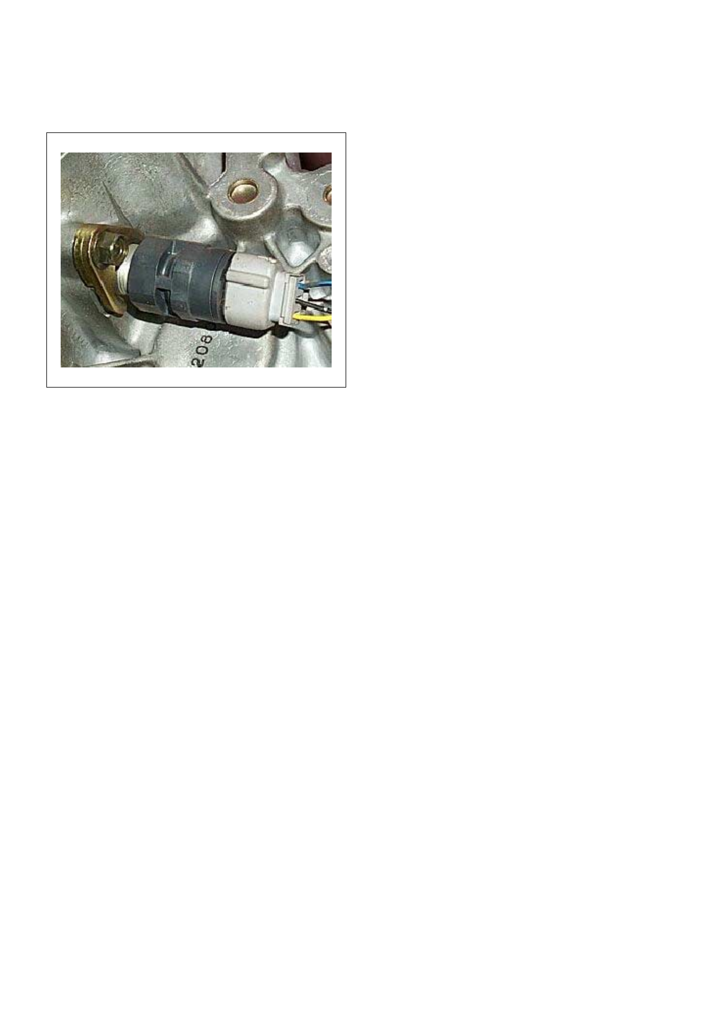
(1) Drive Shaft
(2) Feed Pump
(3) Pump Camshaft Speed Sensor
(4) Pump Control Unit (PSG)
(5) Distributor Head
(6) Constant Pressure Valve (CPV) Holder
(7) High Pressure Solenoid Valve
(8) Constant Pressure Valve (CPV)
(9) Timing Control Valve (TCV)
(10) Timer
(11) Radial Plunger High Pressure Pump
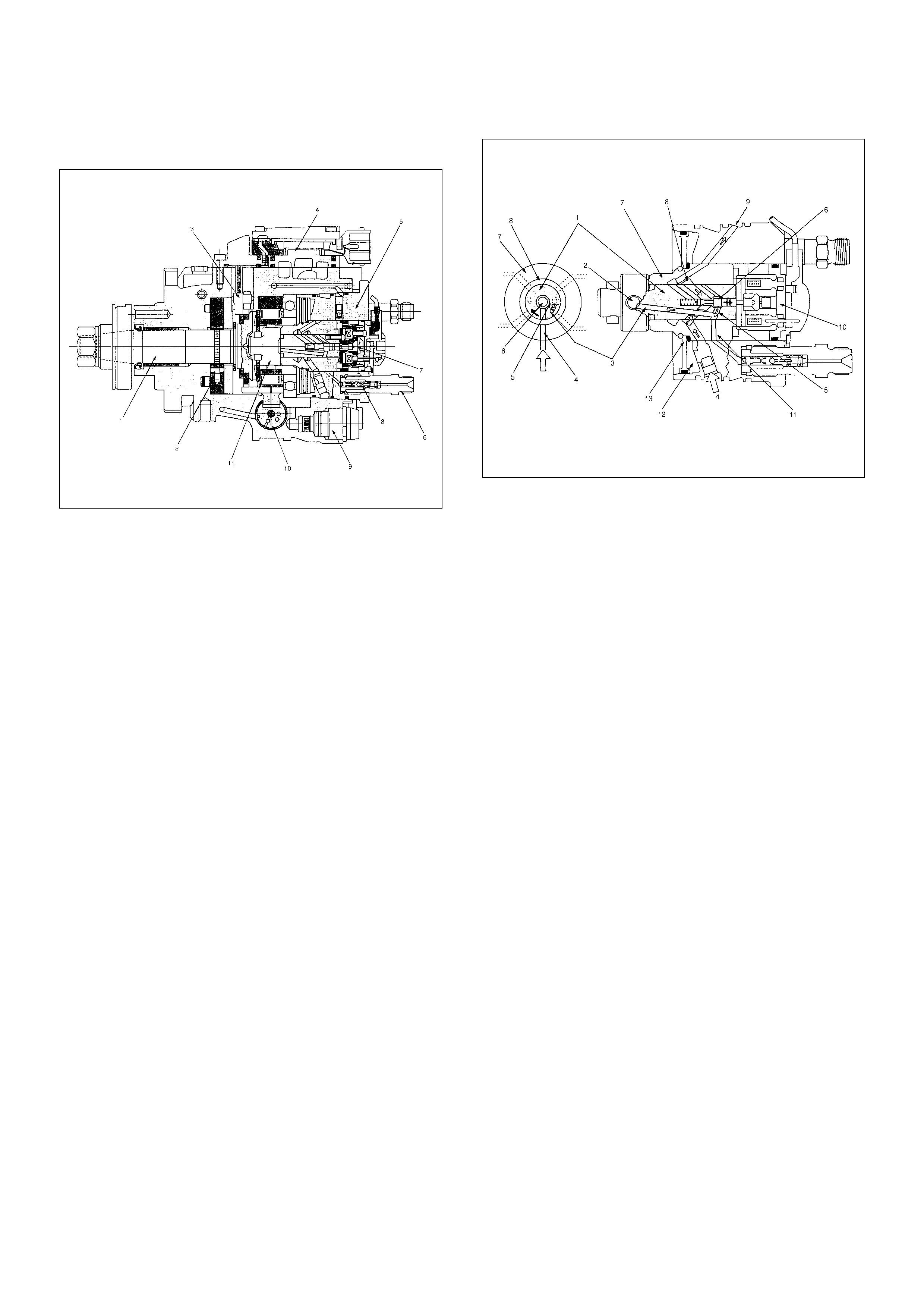
Cross-section View
(1) Drive Shaft
(2) Feed Pump
(3) Pump Camshaft Speed Sensor
(4) Pump Control Unit (PSG)
(5) Distributor Head
(6) Constant Pressure Valve (CPV) Holder
(7) High Pressure Solenoid Valve
(8) Constant Pressure Valve (CPV)
(9) Timing Control Valve (TCV)
(10) Timer
(11) Radial Plunger High Pressure Pump
(1) Rotor Shaft
(2) Radial Plunger
(3) High Pressure Passage
(4) Low Pressure Inlet
(5) Distributor Slit
(6) Valve Needle
(7) Barrel
(8) Annular Passage
(9) Fuel Return
(10) High Pressure Solenoid Valve
(11) High Pressure Outlet
(12) Diaphram Chamber
(13) Accumulator Diaphram
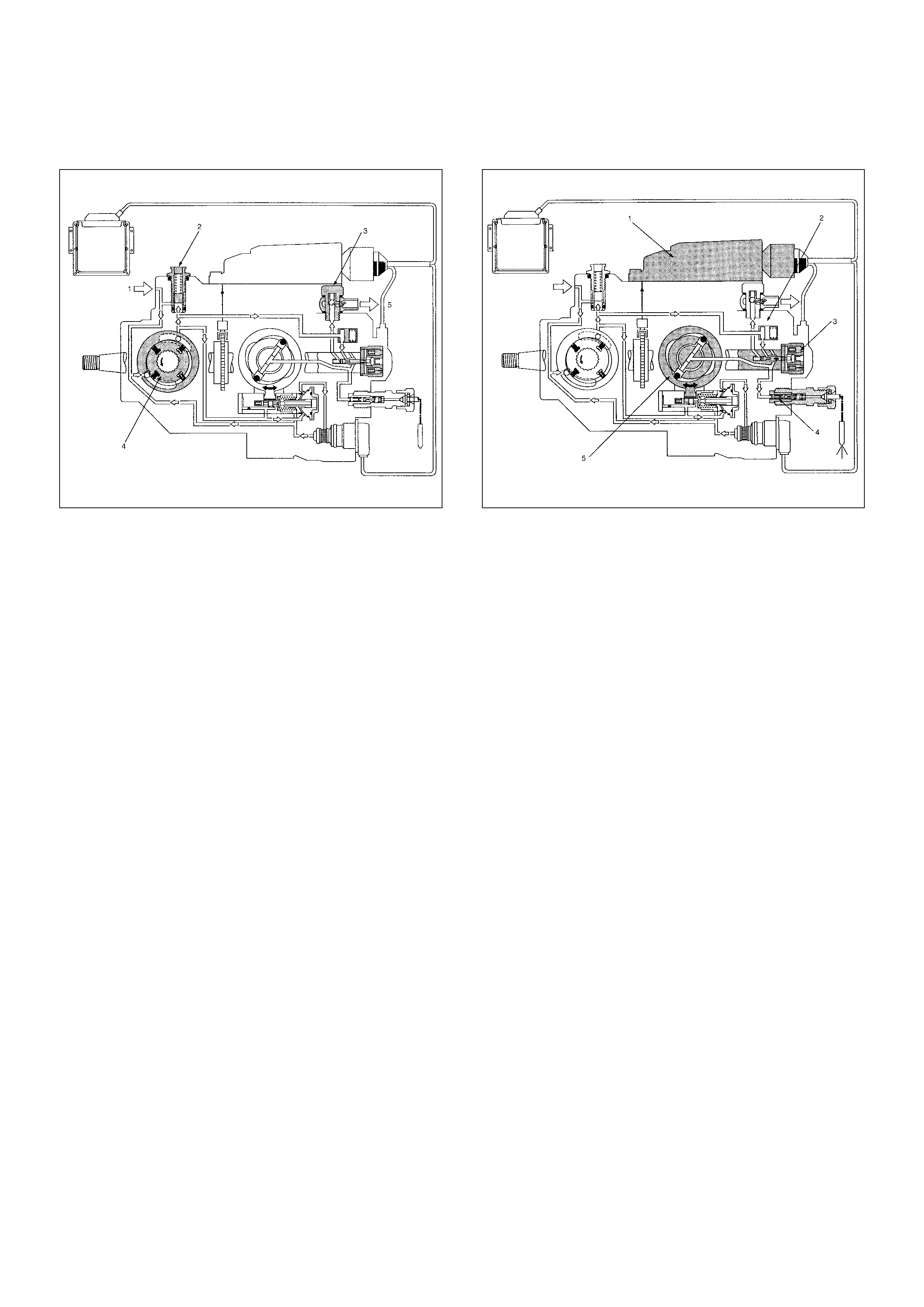
Low Pressure Fuel Circuit
The low pressure fuel circuit must supply sufficient fuel
to the high pressure fuel circuit. The main components
are the feed pump, the regulating valve and the
overflow valve.
High Pressure Fuel Circuit
In addition high pressure generating device, the high
press ure c irc uit als o c on sists of fu el p iping , and d ev ices
to set the beginning of injection and fuel injection
quantity.
The main components are as follows.
• High pressure generation: Radial Plunger High
Pressure Pump
• Fuel distribution: Distributor Head
• Beginning of injection timing: Timing Device
• Prevention of secondary injection: Constant Pressure
Valve (CPV)
(1) Fuel Suction
(2) Re gul ati ng Valve
(3) Overflow Valve
(4) Feed Pump
(5) To Fuel Tank
(1) Pump Control Unit (PSG)
(2) Distributor Head
(3) High Pressure Solenoid Valve
(4) Constant Pressure Valve (CPV)
(5) Radial Plunger High Pressure Pump
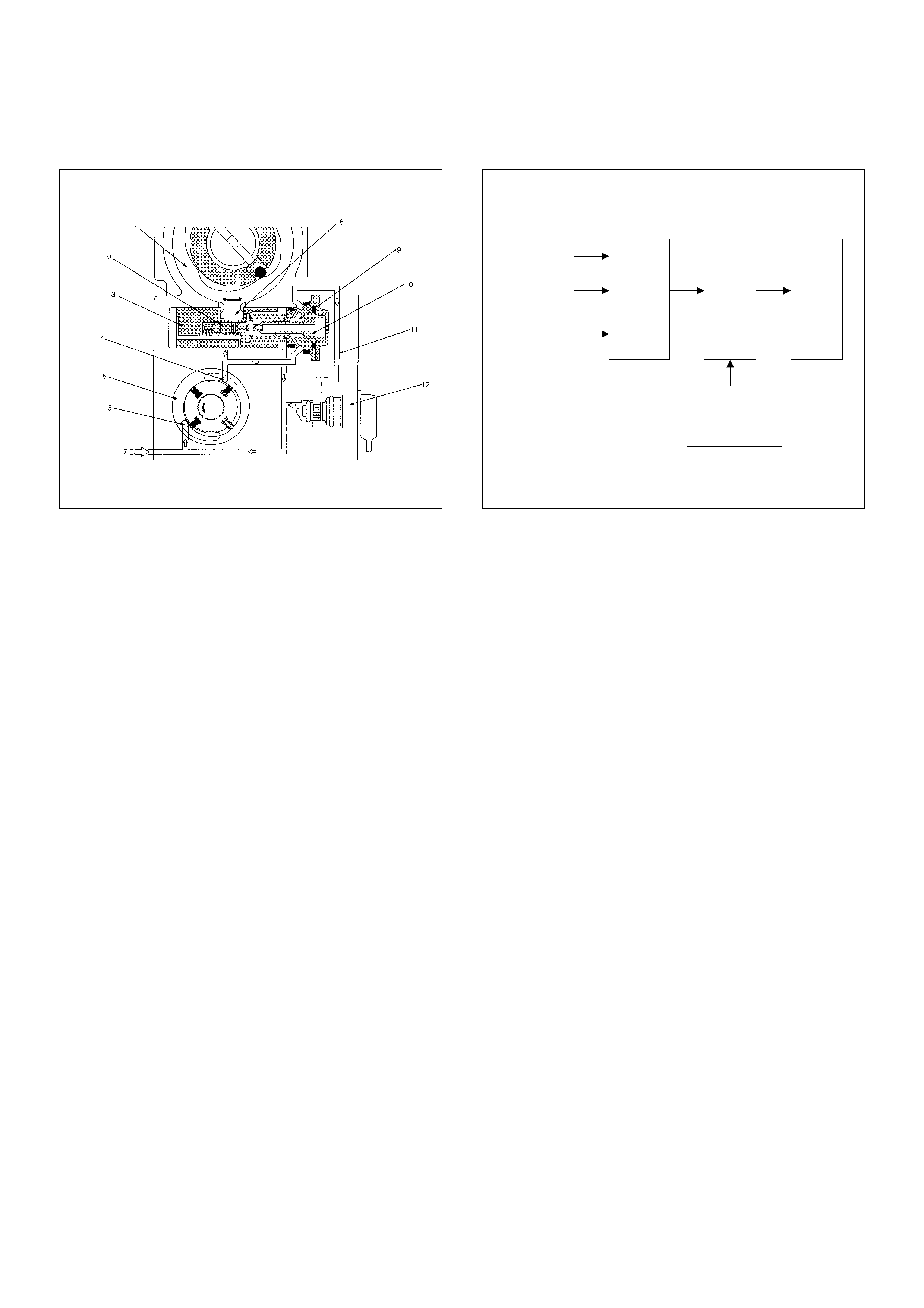
Timing Control
The timing device determines the optimum injection
timing against variations in engine speed.
The pressure of the fuel fed from the feed pump is
adjusted in accordance with speed by the regulating
valve. This delivery pressure acts on the hydraulic
stopper's annular chamber as control pressure.
The chamber pressure of the annular chamber is
controlled by the timing control valve (TCV).
The timing plunger is connected to the cam ring by a
ball pin. Axial movement of the timing plunger is
transferred to the cam ring in the form of rotational
movement. Movement to the right of the timing plunger
(to the spring side) advances injection timing.
The main components are timing plunger, the timing
control valve (TCV) and pump camshaft speed sensor.
St art of Injection
The engine control module (ECM) contains
characteristic maps of the beginning of injection,
corresponding to engine operating conditions (engine
load, engine speed and engine coolant temperature).
The pump control unit (PSG) is constantly comparing
the set beginning of injection timing and the actual
beginning of injection timing.
If the re is a differen ce, the tim ing contr ol valve ( TCV) is
controlled by the duty ratio. (The actual beginning of
injection timing is determined from the pump camshaft
speed sensor.)
(1) Cam Ring
(2) Servo Valve
(3) Timer Piston
(4) Outlet
(5) Feed Pump
(6) Inlet
(7) Fuel Suction
(8) Ball Pin
(9) Annular Chamber
(10) Hydraulic Stopper
(11) Return Passage
(12) Timing Control Valve (TCV)
Engine Load
Engine Speed
Engine Coolant
Temperature
Engine
Control
Module
(ECM)
Pump
Control
Unit
(PSG)
Pump
Camshaft
Speed Sensor
Timing
Control
Valve
(TCV)
Strategy Based Diagnostics
Overview
As a retail service technician, you are part of the
HOLDEN s ervice tea m. Th e team goal is FIX I T RIGHT
THE FIRST TIME for the satisfaction of every customer.
You are a very important member of the team as you
diagnose and repair customer vehicles.
You have maximum efficiency in diagnosis when you
have an effective, organized plan for your work.
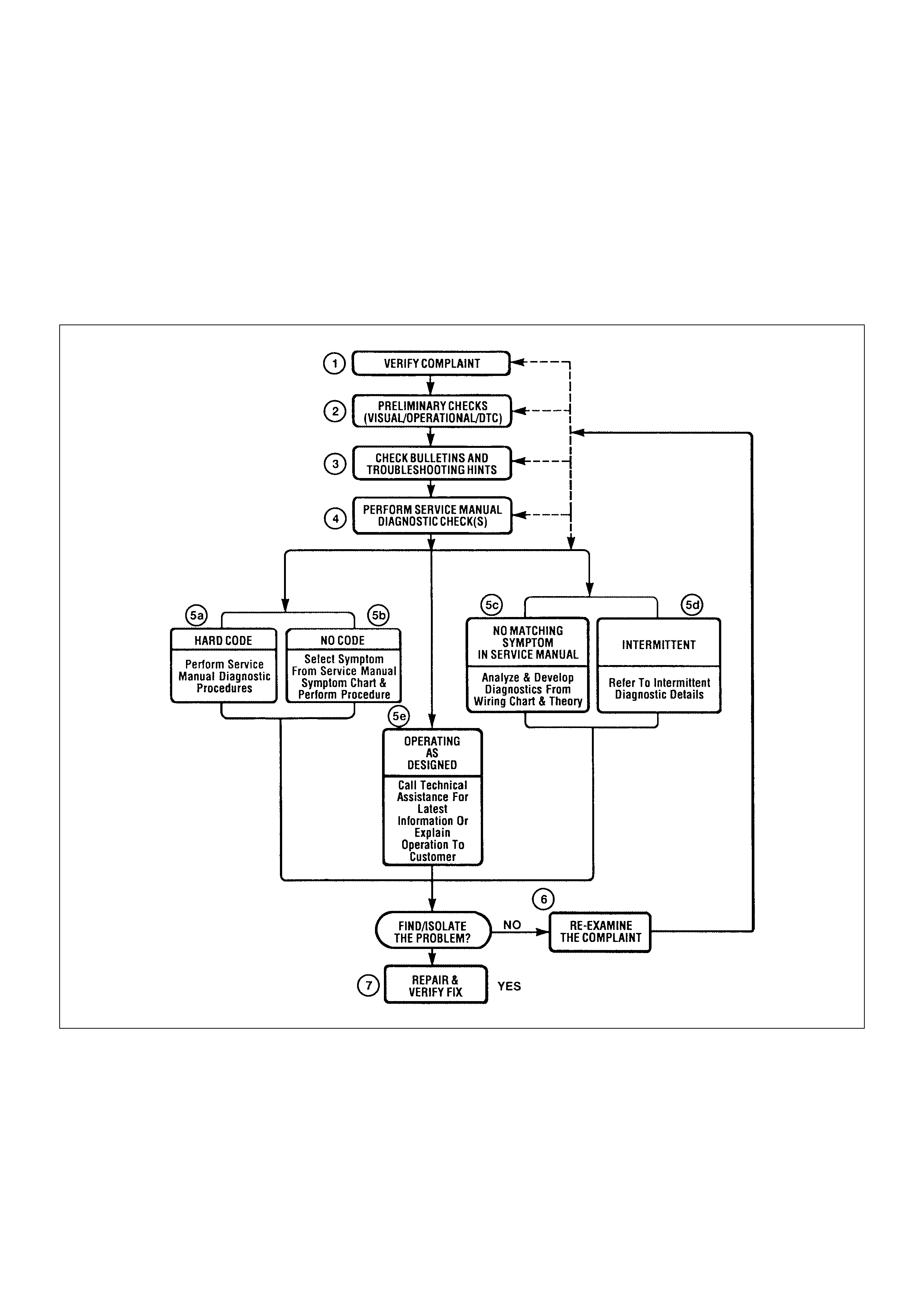
Str ategy Based Diagnostic s (refer to Figu re 1) provid es
you with guidance as you create and follow a plan of
action for each specific diagnostic situation.
Strategy Based Diagnostics Chart

Diagnostic Thought Process
As you follow a diagnostic plan, every box on the
Strategy Based Diagnostics chart requires you to use
the diagnos tic thought pr ocess. Thi s method of think ing
optimize s your diagno sis in the following ways:
• Improves your understanding and definition of the
customer complaint
• Sav es tim e by avo iding tes tin g a nd/o r repla ci ng goo d
parts
• Allows you to look at the problem from different
perspectives
• Gui des you to dete rmine what level of unders tanding
about system operation is needed:
– Owner’s manual level
– Service manual level
– In-depth (engineering) level
– O wn er’s manual level
– Service manual level
– In-depth (engineering) level
1. Verify the Complaint
What you should do
To verify the custo mer complai nt, you need to know th e
correct (normal) operating behavior of the system and
verify that the customer complaint is a valid failure of the
system.
The following information will help you verify the
complaint:
• WHAT the vehicle model/options are
• WHAT aftermarket and dealer-installed accessories
exist
• WHAT related system(s) operate properly
• WHEN the problem occurs
• WHERE the problem occurs
• HOW the problem occurs
• HOW LONG the condition has existed (and if the
system ever worked correctly)
• HOW OFTEN the problem occurs
• Whether the severity of the problem has increased,
decreased or stayed the same
What resources you should use
Whenever possible, you should use the following
resources to assist you in verifying the complaint:
• Service manual Theory or Circuit Description
sections
• Service manual “System Performance Check”
• Owner manual operational description
• Techni ci an exper ie nc e
• Identical vehicle for comparison
• Circuit testing tools
• Veh ic le ro ad tes ts
• Complaint check sheet
• Contact with the customer
2. Perform Preliminary Checks
NOTE: An estimated 10 percent of successful vehicle
repairs are diagnosed with this step!
What you should do
You perform preliminary checks for several reasons:
• To detect if the cause of the complaint is VISUALLY
OBVIOUS
• To identify parts of the system that work correctly
• To accumulate enough data to correctly and
accurately search for a ISUZU Service Bulletin on
ISUZU Web site.
The initial checks may vary depending on the
compl exity of the system and ma y include the fol lowing
actions:
• Operate the suspect system
• Make a visual inspection of harness routing and
accessible/visible power and ground circuits
• Check for blown fuses
• Make a visual inspection for separated connectors
• Make a visual inspection of connectors (includes
checking terminals for damage and tightness)
• Check for any DTCs stored by the on-board
computers
• Sense unusual noises, smells, vibrations or
movements
• Investigate the vehicle service history (call other
dealerships, if appropriate)

What resources you should use
Whenever appropriate, you should use the following
resources for assistance in performing preliminary
checks:
• Tech II or other technical equipment for viewing DTCs
• Service manual information:
– Component locations
– Harness routing
– Wiring schematics
– Procedures for viewing DTCs
• Dealership service history file
• Vehicle road test
• Identical vehicle or system for comparison
3. Check Bulletins and Troubleshooting
Hints
NOTE: As estimated 30 percent of successful vehicle
repairs are diagnosed with this step!
What you should do
You should have enough information gained from
preliminary checks to accurately search for a bulletin
and other related service information. Some service
manual sections provide troubleshooting hints that
match symptoms with specific complaints.
What resources you should use
You should use the following resources for assistance in
checking for bulletins and troubleshooting hints:
• Printed bulletins
• Access ISUZU Bulletin W eb s ite, ht tps: //www.ein et.isuzu .
co.jp//
• Videotapes
• Service manual
4. Perform Service Manual Diagnostic
Checks
What you should do
The “System Checks” in most service manual sections
and in most cells of section 8A (electrical) provide you
with:
• A systematic approach to narrowing down the
possible causes of a system fault
• Direction to specific diagnostic procedures in the
service manual
• Assistance to identify what systems work correctly
What resources you should use
Whenever possible, you should use the following
resources to perform service manual checks:
• Service manual
• Technical equipment (for viewing DTCs and
analyzing data)
• Digital multimeter and circuit testing tools
• Other tools as needed
5a and 5b. Perform Service Manual
Diagnostic Procedures
NOTE: An estimated 40 percent of successful vehicle
repairs are diagnosed with these steps!
What you should do
When directed by service manual diagnostic checks,
you must then carefully and accurately perform the
steps of diagnostic procedures to locate the fault related
to the customer complaint.
What resources you should use
Whenever appropriate, you should use the following
resources to perform service manual diagnostic
procedures:
• Service manual
• Technical equipment (for analyzing diagnostic data)
• Digital multimeter and circuit testing tools
• Essential and special tools
5c. Technician Self Diagnoses
When there is no DTC stored and no matching
symptom for the condition identified in the service
manual , you must b egin with a thorough understanding
of how the system(s) operates. Efficient use of the
service manual combined with you experience and a
good process of elimination will result in accurate
diagnosis of the condition.
What you should do
Step 1: Identify and understand the suspect
circuit(s)
Having completed steps 1 through 4 of the Strategy
Based Diagnostics chart, you should have enough
information to identify the system(s) or sub-system(s)
involved. Using the service manual, you should
determine and investigate the following circuit
characteristics:

• Electrical:
– How is the circuit powered (power distribution
charts and/or fuse block details)?
– How is the circuit grounded (ground distribution
charts)?
– How is the circuit controlled or sensed (theory of
operation):
– If it is a switched circuit, is it normally open or
normally closed?
– Is the power switched or is the ground
switched?
– Is it a variable resistance circuit (ECT sensor
or TP sensor, for example)?
– I s it a sign al gener ating device (M AF se nsor of
VSS, for example)?
– Does it rely on some mechanical/vacuum
device to operate?
• Physical:
– Where are the circuit components (component
locators and wire harness routing diagrams):
– Are there areas where wires could be chafed
or pinched (brackets or frames)?
– Are there areas subjected to extreme
temperatures?
– Are there areas subjected to vibration or
movement (engine, transmission or
suspension)?
– A re the re areas ex posed to moisture, r oad salt
or other corrosives (battery acid, oil or other
fluids)?
– Are there common mounting areas with other
systems/components?
– Have previous repairs been performed to wiring,
connectors, components or mounting areas
(causing pinched wires between panels and
drivetrain or suspension components without
causing and immediate problem)?
– Does the vehicle have aftermarket or dealer-
installed equipment (radios, telephone, etc.)
Step 2: Isolate the problem
At this point, you should have a good idea of what could
cause th e presen t cond ition, as well a s could not ca use
the condition. Actions to take include the following:
• Divide (and separate, where possible) the system or
circuit into smaller sections
• Confine the problem to a smaller area of the vehicle
(start with main harness connections while rem oving
panels and trim as necessary in order to eliminate
large vehicle sections from further investigation)
• For two or more circuits that do not share a common
power or ground, concentrate on areas where
harnesses are routed together or connectors are
shared (refer to the following hints)
Hints
Though the symptoms may vary, basic electrical failures
are generally caused by:
• Loose connections:
– Open/high resistance in terminals, splices,
connectors or grounds
• Incorrect connector/harness routing (usually in new
vehicles or after a repair has been made):
– Open/high resistance in terminals, splices,
connectors of grounds
• Corrosion and wire damage:
– Open/high resistance in terminals, splices,
connectors of grounds
• Compon ent fai lure:
– Opens/short and high resistance in relays,
modules, switches or loads
• Aftermarket equipment affecting normal operation of
other systems
You may isolate circuits by:
• Unplugging connectors or removing a fuse to
separate one part of the circuit from another part
• Operating shared circuits and eliminating those that
function normally from the suspect circuit
• If only one component fails to operate, begin testing
at the component
• If a number of components do no operate, begin tests
at the area of commonality (such as power sources,
ground circuits, switches or major connectors)
What resources you should use
Whenever appropriate, you should use the following
resources to assist in the diagnostic process:
• Service manual
• Technical equipment (for data analysis)
• Experience
• Technical Assistance
• Circuit testing tools
5d. Intermittent Diagnosis
By definition, an intermittent problem is one that does
not occur continuously and will occur when certain
conditions are met. All these conditions, however, may
not be obvious or currently known. Generally,
intermittents are caused by:
• Faulty electrical connections and wiring
• Malfunctioning components (such as sticking relays,
solenoids, etc.)
• EMI/RFI (Electromagnetic/radio frequency
interference)
• Aftermarket equipment

Intermittent diagnosis requires careful analysis ofsuspected systems to help prevent replacing goodparts. This may involve using creativity and ingenuity tointerpret customer complaints and simulating allexternal and internal system conditions to duplicate theproblem.
What you should do
Step 1: Acquire informationA thorough and comprehensive customer check sheetis critical to intermittent problem diagnosis. You shouldrequire this, since it will dictate the diagnostic startingpoint. The vehicle service history file is anothersource for accumulating information about thecomplaint.
Step 2: Analyze the intermittent problemAnalyze the customer check sheet and service historyfile to determine conditions relevant to the suspectsystem(s).Using service manual information, you must identify,trace and locate all electrical circuits related to themalfunctioning system(s). If there is more than onesystem failure, you should identify, trace and locateareas of commonality shared by the suspect circuits.
Step 3: Simulate the symptom and isolate the
problemSimulate the symptom and isolate the system byreproducing all possible conditions suggested in Step 1while monitoring suspected circuits/components/systems to isolate the problem symptom. Begin with themost logical circuit/component.Isolate the circuit by dividing the suspect system intosimpler circuits. Next, confine the problem into a smallerarea of the system. Begin at the most logical point (orpoint of easiest access) and thoroughly check theisolated circuit for the fault, using basic circuit tests.
HintsYou can isolate a circuit by:• Unplugging connectors or removing a fuse toseparate one part of the circuit from another• If only component fails to operate, begin testing thecomponent• If a number of components do not operate, begin testat areas of commonality (such as power sources,ground circuits, switches, main connectors or majorcomponents)• Substitute a known good part from the partsdepartment or the vehicle system• Try the suspect part in a known good vehicleSee Symptom Simulation Tests on the next page for
problem simulation procedures. Refer to service manualsections 6E and 8A for information about intermittentdiagnosis. Follow procedures for basic circuit testing in
service manual section 8A.
What resources you should use
Whenever appropriate, you should use the following
resources to assist in the diagnostic process:
• Service manual
• Bulletins
• Digital multimeter (with a MIN/MAX feature)
• Tech II and Tech II upload function
• Circuit testing tools (including connector kits/
harnesses and jumper wires)
• Experience
• Intermittent problem solving simulation methods
• Customer complaint check sheet
Symptom Simulation Tests
1. Vibration
This method is useful when the customer complaint
analysis indicates that the problem occurs when the
vehicle/system undergoes some form of vibration.
For connectors and wire harness, slightly shake
vertically and horizontally. Inspect the connector joint
and body for damage. Also, tapping lightly along a
suspected circuit may be helpful.
For parts and sensors, apply slight vibration to the part
with a l ig ht tap of the fin ger whi le mo nit oring the s ystem
for a malfunction.
2. Heat
This method is important when the complaint suggests
that th e problem occur s in a heat ed en vironm ent. App ly
moderate heat to the component with a hair drier or
similar tool while monitoring the system for a
malfunction.
CAUTION: Care must be take to avoid overheating
the compone nt.
3. Water and Moisture
This method may be used when the complaint suggests
that the malfunction occurs on a rainy day or under
conditions of high humidity . In this case, apply water in a
light spray on the vehicle to duplicate the problem.
CAUTION: Care must be take to avoid directly
exposing electrical connections to water.
4. Electrical loads
This method involves turning systems ON (such as the
blower, lights o r rear windo w defogger) to create a load
on the vehicle electrical system at the same time you
are monitoring the suspect circuit/component.

5e. Vehicle Operates as Design ed
This condition refers to instances where a system
operatin g as des igned i s perceiv ed to be unsatis factory
or undesirable. In general, this is due to:
• A lack of understanding by the customer
• A conflict between customer expectations and
vehicle des ig n inten t
• A system performance that is unacceptable to the
customer
What you should do
You can verify that a system is operating as designed
by:
• Reviewing service manual functional/diagnostic
checks
• Exa mining bul letins a nd other ser vice informati on for
supplementary information
• Co mpare sys tem oper a tio n to an identic al vehicl e
If the condition is due to a customer misunderstanding
or a con flict between c ustomer expec tation an d system
operation, you should explain the system operation to
the custo mer.
If the complaint is due to a case of unsatisfactory
system performance, you should contact Technical
Assistance for the latest information.
What resources you should use
Whenever possible, you should use the following
resour ce s to faci li tate the diagno sti c pr oces s:
• Vehicle service information (service manual, etc.)
• ISUZU field support
• Experience
• Identical vehicle or system for comparison
6. Re-examine the complaint
When you do not successfully find/isolate the problem
after executing a diagnostic path, you should re-
examine the complaint.
What you should do
In this case, you will need to backtrack and review
information accumulated from step 1 through 4 of
Strategy Based Diagnostics. You also should repeat any
procedures that require additional attention.
A previous path may be eliminated from consideration
only if you are certain that all steps were executed as
directed. You must then select another diagnostic path
(step 5a, 5 b, 5c or 5d ). I f all po ss ib le o pti ons ha ve b een
explored, you may call or seek ISUZU field support.
What resources you should use
Whenever possible, you should use the following
resources to facilitate the diagnostic process:
• Service manual
• Accumulated information form a previous diagnostic
path
• Service information and publications
• ISUZU field support
7. Repair and Verify Fix
What you should do
After you have located the cause of the problem, you
must execute a repair by following recommended
service manual procedures.
When the repair is completed, you should verify the fix
by performing the system checks under the conditions
listed in the customer complaint.
If applic able, you should ca rry out prev entive me asures
to avoid a repeat complaint.
What resources you should use
Whenever possible, you should use the following
resources to facilitate the repair process:
• Electrical repair procedures
• Service manual information and publications

General Service Information
Serviceability Issues
Non-OEM Parts
All of the OBD diagnostics have been calibrated to run
with OEM parts. Accordingly, if commercially sold
sensor or switch is installed, it makes a wrong diagnosis
and turns on the check engine lamp.
Aftermarket electronics, such as cellular phones,
stereos, and anti-theft devices, may radiate EMI into the
control system if they are improperly installed. This may
cause a false sensor reading and turn on the check
engine lamp.
Poor Vehicle Maintenance
The sens itivity of OBD dia gnostics will c ause the check
engine lamp to turn on if the vehicle is not maintained
properly. Restricted oil filters, fuel filters, and crankcase
deposits due to lack of oil changes or improper oil
viscosity can trigger actual vehicle faults that were not
previously monitored prior to OBD. Poor vehicle
maintenance can not be classified as a “non-vehicle
fault”, but with the sensitivity of OBD diagnostics,
vehicle maintenance schedules must be more closely
followed.
Related System Faults
Many of the OBD system diagnostics will not run if the
ECM detects a fault on a related system or component.
Visual/Physical Engine Compartment
Inspection
Perform a careful visual and physical engine
compartment inspection when performing any
diagnostic procedure or diagnosing the cause of an
emission te st failure. T his can often lead to repairing a
problem without further steps. Use the following
guidelines when performing a visual/physical
inspection:
• Inspect all vacuum hoses for punches, cuts,
disconnects, and correct routing.
• Inspect hoses that are difficult to see behind other
components.
• Inspect all wires in the engine compartment for
proper c onnection s, burned or chafed spots, pi nched
wires, contact with sharp edges or contact with hot
exhaust manifolds or pipes.
Basic Knowledge of Tools Required
NOTE: Lack of basic knowledge of this powertrain
when performing diagnostic procedures could result in
an incorrect diagnosis or damage to powertrain
components. Do not attempt to diagnose a powertrain
problem without this basic knowledge.
A basic understanding of hand tools is necessary to
effectively use this section of the Service Manual.
On-Board Diagnostic (OBD)
On-Board Diagnostic (Self Diagnosis
System) Tests
A diagno stic test is a serie s of steps, the re sult of whi ch
is a pass or fail reported to the diagnostic executive.
When a diagnostic test reports a pass result, the
diagno sti c ex ec utive re co rd s the foll owi ng data:
• The diagnostic test has been completed since the
last ignition cycle.
• The diagnostic test has passed during the current
ignition cycle.
• The fault identified by the diagnostic test is not
currently active.
When a diagnostic test reports a fail result, the
diagno sti c ex ec utive re co rd s the foll owi ng data:
• The diagnostic test has been completed since the
last ignition cycle.
• The fault identified by the diagnostic test is currently
active.
• The fault has been active during this ignition cycle.
• The operating conditions at the time of the failure.
The Diagnostic Executive
The Diagnostic Executive is a unique segment of
software which is designed to coordin ate and prioritize
the diagn os tic proc edu res as wel l as defi ne the protoc ol
for recording and displaying their results. The main
respo ns ibil ities of the Di agn os tic Ex ec uti ve ar e li st ed as
follows:
• Commanding the check engine lamp on and off
• DTC logging and clearing
• Current status information on each diagnostic
Diagnostic Information
The diagnostic charts and functional checks are
desig ned to loc ate a faul ty c ircu it or c omp onen t th rough
a proce ss of logica l decis ions . The charts are prepared
with the requirement that the vehicle functioned
correc tly at the time of assembl y and that there are not
multiple faults present.
There is a continuous self-diagnosis on certain control
functions. This diagnostic capability is complemented
by the diagnostic procedures contained in this manual.
The language of communicating the source of the
malfunction is a system of diagnostic trouble codes.
When a malfunction is detected by the control module, a
diagnostic trouble code is set and the check engine
lamp is illuminated.

Malfunction Indicator Lamp
The malfunction indicator lamp (MIL) is located in the
instrument pane l clus ter. The MIL will di splay the follow ing
symbol when commanded ‘ON’.
The MIL indicate s that an emissio n relate d fault ha s occurred
and vehicle service is required. The following is a list of the
modes of operation for the MIL:
• The MIL illuminates for about 2.6 seconds when the
ignition switch is turned ‘ON’, with the engine ‘OFF’. This is
a bulb test to ensu re th at the MIL is able to illu mina te.
• The MIL turns ’OFF’ after the engine is started, if a
diagnostic fault i s not present.
• The MIL remains illuminated after the engine is started, i
f
the engine control module (ECM) detects a fault.
A
diagnostic trouble code (DTC) is stored any time the ECM
illumina tes the MIL due to an emi ssion re lated fau l t.
Data Link Conne ctor (DLC)
The provision for communication with the control module is the
Data Link Connector (DLC). It is located behind the lower front
instrument pane l. The DLC is used to connect to a Tech2 .
Some common uses of the Tech2 are listed below:
• Identifying stored Diagnosti c Trou ble Codes (D TCs).
• Clearing DTCs.
• Reading serial data.
• Connect the SAE 16/19 adap ter (3 ) to the da ta lin k
connector of the vehicle.
• Connect the DLC ca ble (4 ) to the Tech 2 (5 ).
• Connect the SAE 16/19 adap ter (3 ) to the da ta lin k
connector (DLC) of the vehicle.
Verifying Vehicle Repair
Verifica tion of ve hi cle rep ai r w ill be mo re comprehensi ve fo r
vehicles with OBD system diagnostic. Following a repair, the
technician shoul d perfo rm the following steps:
1. Review and record the Fail Records for the DTC which
has been diagnosed .
2. Clear DTC(s).
3. Operate the vehicle within conditions noted in the Fail
Records.
4. Monitor the DTC status information for the specific DTC
which has been diagnosed until the diagnostic test
associated with that DTC runs.
Following these steps is very important in verifyin
g
repairs on OBD systems. Failure to follow these step
s
could result in unnecess ary re pairs.
On-Board Diagnosis (Self-Diagnosis)
The Tech 2 Scan Tool
The Tech 2 scan tool is used to electrically diagnose and
check the vehicle electronic systems. The Tech 2 enhances
the diagnosis efficiency, even though the troubleshooting can
be done without the Tech 2.
1. Tech 2 Components:
• Tech 2 scan tool kit (No. 70 000 86), Tech 2 scan tool
(No. 7000057) a nd DLC cable (No . 3000095).
• SAE 16/19 adapter (No. 3000098) (3), RS232 loop
back connector (No. 3000112 ) (2) and PCMCIA card
(No. 3000117) (1).
Legend
(1) PCMCIA Card
(2) Loop Back Conn ector
(3) SAE 16/19 Pin Adaptor
(4) DLC Cable
(5) Tec h 2 S ca n To ol
2. Connecting Tech 2 to the Vehicle:
• Check the ignition switch is turned OFF.
• Insert the PCMCIA card (1) into th e Te ch 2 (5). Note
that the PCMCIA card must be installed in the slot
closest to the Tech 2 screen.
NOTE: Check that power is not supplied to the Tech 2
when installing or remo vin g the PCMC IA card.
• Turn th e igni tion switch of the veh ic le to ON an d p ress
the "PWR" key of the Tech 2.
• Check the Tech 2 display.
Reading Flash Diagnostic Trouble Codes
The provision for communicating with the Engine Control
Module (ECM) is the Data Link Connector (DLC). The DLC is
located in the position shown next. It is used in the assembl
y
plant to receive information, checking that the engine is
operating properly before it leaves the plant.
The diagnostic trouble code(s) (DTCs) stored in the ECM
memory can be read either through a hand-held diagnosti
c
scanner plugged into the DLC or by counting the number o
f
flashes of the malfunction indicator lamp (MIL) when the
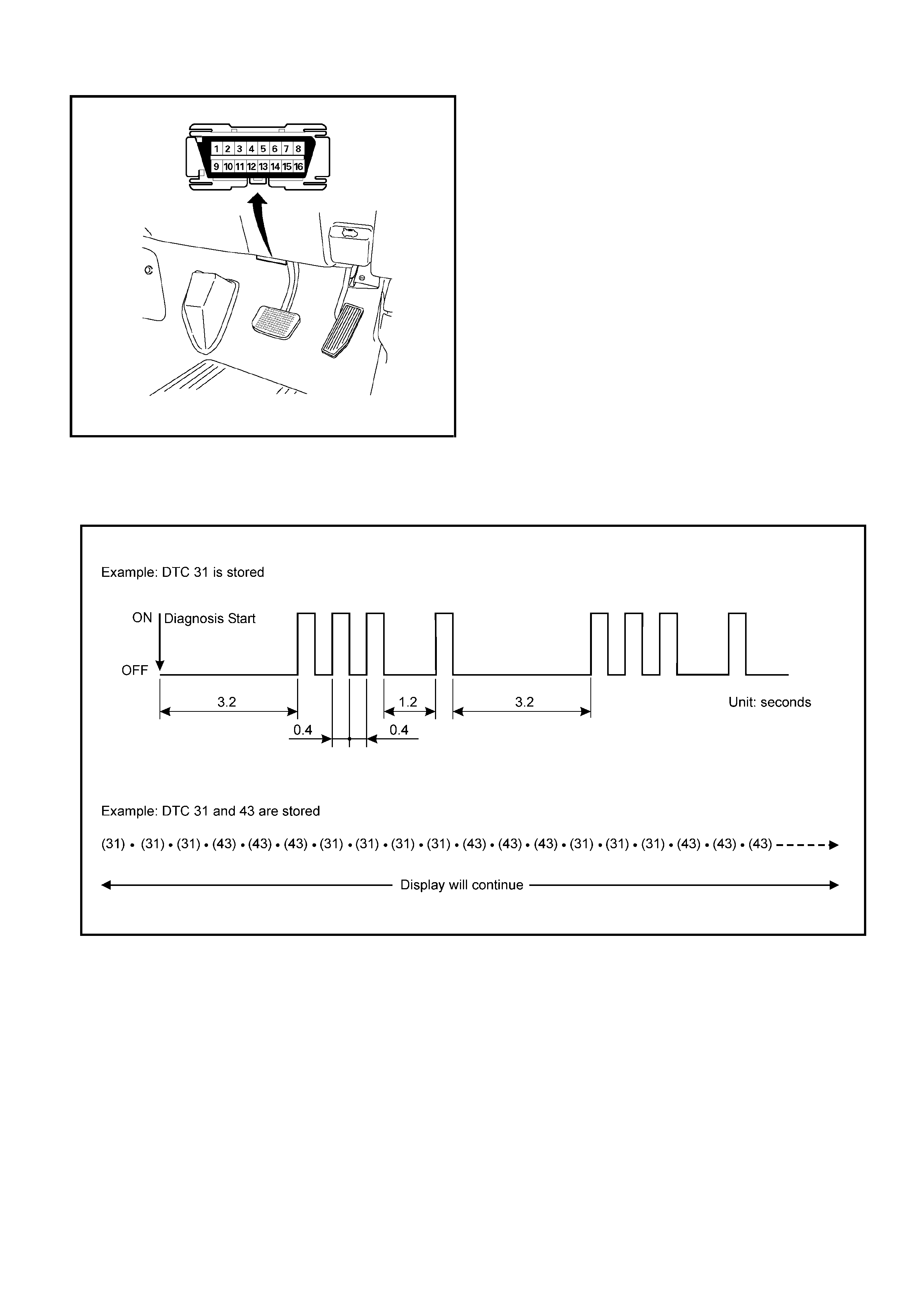
diagnostic test terminal of the DLC is grounded.
The DLC terminal "6" (diagnostic request) is pulled "Low"
(grounded) by jumping to DLC terminal '4’ or ‘5’, which are
ground circui ts.
This will signal the ECM that you want to "flash" DTCs), if an
y
are present. Once terminals '4’ or ‘5’ and ‘6’ have been
connected, the ignition switch must be turned to the ‘ON’
position, with the engine not running .
The check engine lamp will in di cate a DTC thre e times if a DTC
is present. If more than one DTC has been stored in the ECM
memory, the DTC(s) will be displayed from the lowest to the
highest, with each DTC being disp layed three times.
Shown is the patt ern that a DTC ‘31’ ge nerates and the pattern
of events, when both a DTC ‘31’ and ‘43’ are stored in the
ECM.
The DTC display will continue as long as the DLC is shorted
and the ignition is in the ON position.
Reading Diagnostic Trouble Codes With Tech 2
The preferred method for reading diagnostic trouble code(s) is
to use a Tech2 scan tool. When reading DTC(s), follo
w
instructions supplied by the Tech 2 manufacturer.
Clearing Diagnostic Trouble Codes
To clear Diagnostic Trouble Codes (DTCs), use the Tech2
"clear DTCs" or "clear information" function. When clearing
DTCs follow instructions supplied by the Tech2 manufacturer.
Flash Code Displays
Diagnosis With Tech 2
If No Codes are Set:
• Refe r to Fl: Data D isplay and iden ti fy the ele ctri cal faul ts
that are not indicated by a trouble code.
• Refer to "SYMPTOM DIAGNOSIS".
If codes are set:
1. Record all tr oubl e co des dis pla yed b y Tec h 2 and c heck i
f
the codes are intermittent.
2. Clear the codes.
3. Road test the vehicle to reproduce the faulty status.
4. Check trouble codes again using the Tech 2.
5. If no codes is displayed by test driving, the fault is
inte rmi t ten t. In th is ca se , re fe r to "DIAGNOSIS AIDS".
6. If a code is present, refer to DTC Chart for diagnosis.
7. Check trouble codes again using the Tech 2.

TECH 2 Operating Flow Cart (Start Up)
Select “4JA1-TC Bosch” or “4JH1-TC Bosch” in Vehicle Identification menu and the following table is shown in the
Tech 2 screen.
Main Menu
F0: Diagnostic
F1: Service Programming System (SPS)
F2: View Capture Data
F3: Tool Optio n
F4: Download/ Upload Help
Press “ENTER” key.
Vehicle Identification
(3) 2003
(2) 2002
(1) 2001
(Y) 2000
(X) 1999
(W) 1998
Select “F0: Diagnostic”.
Select “(2) 2002”or later.
Press (ENTER) to Continue
System Selection Menu
F0: Powertrain
F1: Chassis
F3: Body
Select “(TF/UC)”.
Vehicle Identification
4JH1-TC Bosch
4JA1-TC Bosc h
4JH1-T Denso
3.5L V6 6VE1 Hitachi
AW30-40LE
AT JR405E
Select “F0: Powertrain”.
Select “4JH1-TC Bosch”.
Vehicle Identification
(UB) Trooper, Bighorn
(UE) Rodeo,/Amigo, Wizard/Mu
(TF/UC) LUV, Frontier, LAO-Rodeo
(TBR)
(N*) ELF, NPR, NQR
or “4JH1-TC Bosch”.

F0: Diagnostic Trouble Code
The pur pose of the “D iag nosti c Trouble Codes” m ode is
to display stored trouble code in the ECM.
When “Clear DTC Information” is selected, a “Clear
DTC Information”, warning screen appears.
This screen informs you that by cleaning DTC's “all
stored DTC information in the ECM will be erased”.
After clearing codes, confirm system operation by test
driving the vehicle.
Symptom Code:
This number or alphabet means identification of the
malfunc tion. Ea ch DTC inc ludes plural symptom s, such
as DTC P0 100 has fou r kinds of sy mptom code (7), (9),
(B) and (C). DTC chart (check procedure) is separated
depending on the symptom code.
F1: Data Display
The purpose of the “Data Display” mode is to
continuously monitor data parameters.
The current actual values of all important sensors and
signals in the system are display through F1 mode.
See the “Typical Scan Data” section.
F2: Snapshot
“Snapsho t” allows you to focus on maki ng the condit ion
occur, rather than trying to view all of the data in
anticipation of the fault.
The snapshot will collect parameter information around
a trigger point that you select.
F3: Miscellaneous Test:
The purpose of “Miscellaneous Test” mode is to check
for correct operation of electronic system actuators.
F4: Programming (Factory Use Only)
The pu rpose o f “Prog ramming ” is to progr am VI N in the
ECM and lock the programmed data.
F0: Diagnostic Trouble Codes
F0: Read DTC Infor As Stored By ECU
F1: Clear DTC Information
F1: Data Display
F2: Snapshot
F3: Misc ell an eou s Test
F0: Lamps
F0: Check Light
F1: Glow Time Telltale Test
F1: Relays
F0: Glow Time Relay Test
F2: Engine Speed (RPM) Control
F4: Program mi ng
F0: Program VIN
F1: Lock ECU
Read DTC Infor As Stored By ECU
P0100 Present
(7) Mass Air Flow (MAF) Sensor
Voltage Supply Circuit High Input
DTC No.
Symp tom Code

Typical Scan Data & Definitions 4JH1-TC (Engine Data)
Use the Typical Values Table only after the On-Board Diagnostic System Check has been completed, no DTC(s) were
noted, and you have determined that the on-board diagnostics are functioning properly. Tech 2 values from a
properly-running engine may be used for comparison with the engine you are diagnosing.
Condition : Vehicle s topp in g, en gin e runn ing , air con ditioning off & after warm- up (Co olant tempera ture a ppr ox im ate ly
80 deg.)
Tech 2 Parameter Units Idle 1500rpm 2000rpm Description
1 Engine Speed rpm 675 - 725 1475 - 1525 1975 - 2025 The engine speed is measured by ECM from the CKP
sensor.
2 Vehicle Speed km/h 0 0 0 This displays vehicle speed. The vehicle speed is
measured by ECM from the vehicle speed sensor.
3 Pump Speed rpm 335 - 375 725 - 775 975 - 1025 This displays injection pump speed. The injection speed
is measured by ECM from the pump cam sensor.
4 Accelerator
Position Signal
Value of ( ) shows
AT model
% 0
(0) 3 - 6
(4 - 7) 5 - 8
(8 - 11) Throttle position operating angle is measured by the
ECM from throttle position output voltage. This should
display 0% at idle and 99 - 100% at full throttle.
5 Idle Switch Active/ Inactive Active Active Inactive This displays operating status of the idle switch. This
should display “Active” when the idle condition.
6 Mass Air Flow
Sensor
Value of ( ) shows
AT model
mg/strk 410 - 490
(730 - 785) 380 - 450
(700 - 780) 4 0 0 - 4 8 0
(780 - 830) This displays intake air amount. The mass air flow is
measured by ECM from the MAF sensor output voltage.
7 Barometric
Pressure hpa 990 - 1015 990 - 1015 990 - 1015 The barometric pressure is measured by ECM from the
sensor in the ECM. This data is changing by altitude.
8 Desired Injection
Quantity
Value of ( ) shows
AT model
mg/st k 5 - 8
(10 - 16) 5 - 9
(8 - 12) 6 - 10
(9 - 13) This displays commanded value from the ECM. The
ECM compensates for fuel rate to basic rate.
9 Injection Quantity
Value of ( ) shows
AT model
mg/st k 6 - 8
(10 - 16) 6 - 9
(8 - 12) 7 - 10
(9 - 13) This displays actual fuel quantity. The PSG controls high
pressure solenoid valve to meet commanded value from
the ECM.
10 Desired Fuel
Injection S tart °CA 1 - 3 2 - 4 3 - 6 This displays commanded value from the ECM. The
ECM compensates for fuel injection timing by throttle
position and various sensor signal.
11 Actual Injection
Start °CA 1 - 3 2 - 4 3 - 6 This displays actual injection timing value controlled by
the TCV. The TCV controls duty ratio to meet
commanded value from the PSG.
12 Coolant
Temperature °C 80 - 85 80 - 85 80 - 85 The ECT is measured by ECM from ECT sensor output
voltage. This data is changing by coolant temperature.
When the engine is normally warm upped, this data
displays approximately 80 deg.
13 Fuel Temperature °C 25 - 50 25 - 50 25 - 50 The FT is measured by PSG from FT sensor. This data is
changing by fuel temperature.
14 Intake Ai r
Temperature °C 25 - 50 25 - 50 25 - 50 The IAT is measured by ECM from IAT sensor output
voltage. This data is changing by intake air temperature.
15 Ignition Status On12V/ Off0V On 12V On 12V On 12V This displays the key s witch s tatus indicat ed by the ECM
with key switch signal. This should display “Off 0V” at key
OFF and “On12V” at key ON.
16 Brake Switch 1 Active/ Inactive I nactive Inactive Inactive This displays operating status of the brake switch 1. This
should display “Active” when the brake pedal is stepped
on.
17 Brake Switch 2 Act ive/ Inactive Inactive I nactive Inactive This displays operating status of the brake switch 2. This
should display “Active” when the brake pedal is stepped
on.
1 8 C l u t c h S w i t c h
Value of ( ) shows
AT model
Active/ Inactive Inactive
( - ) Inactive
( - ) Inactive
( - ) This displays operating status of the clutch switch. This
should display “Active” when the c lutch pedal is stepped
on.

Miscellaneous Test
The state of each circuit can be tested by using
miscellaneous test menus. Especially when DTC
cannot be detected, a faulty circuit can be diagnosed by
testing each circuit by means of these menus.
Even DTC has been detected, the circuit tests using
these menus could help discriminate between a
mechanical trouble and an electrical trouble.
Connect Tech 2 and select “Powertrain”, “4JH1-TC
Bosch” & “Miscellaneous Test”.
F0: Lamps
F0: Check Light
When the Tech 2 is operated, “Malfunction Indicator
Lamp (Check Engine Lamp)” is turned on or off.
The circuit is normal if the “Malfunction Indicator Lamp
(Check E ngine Lamp) ” in the i nstr ument panel is turne d
on or off in accordance with this operation.
F1: Glow Time Te lltale Test
When the Tech 2 is operated, “Glow Indicator Lamp” is
turned on or off.
The ci rcuit is normal if th e “Glow Indicator L amp” in the
instrument panel is turned on or off in accordance with
this operation.
F1: Relays
F0: Glow Time Relay Test
When the Tech 2 is operated, glow relay signal turns
ON or OFF.
The circuit is normal if glow system is activated/
deacti vated in acco rdance with thi s operation when k ey
switch is turned ON.
19 Neutral Switch On/Off On On On This displays operating status of the neutral switch. This
should display “On” when the gear position is neutral.
20 A/C Information
Switch Active 12V/
Inactive 0V Inactive 0V Inactive 0V Inactive 0V This displays the air conditioner request signal. This
should display “Active 12V” when the air conditioner
switch is switched on.
21 Diagnostic
Request Activ e 0V/
Inactive 12V Inactive
12V Inactive
12V Inactive
12V This displays the diagnostic request signal. This should
display “Inactive 12V” when the Tech 2 is connected.
22 System Voltage V 10 -14 10 -14 10 -14 This displays the system voltage measured by the ECM
at ignition feed.
23 Main Relay Active/ Inactive Active Active Active This displays operating status for the ECM main relay.
This should display “I nactive” at key O FF and “Active” a t
key ON.
24 Glow Time Relay Active 0V/
Inactive12V Inactive
12V Inactive
12V Inactive
12V This displays operating status for the glow relay. This
should display “Inactive 12V” when the engine is warm
upped.
25 Check Engine
Lamp On/Off Off Off Off This displays operating status for the Check Engine
Lamp. This should display “On” when the Check Engine
Lamp is turned on.
26 Glow T ime Telltale On/Off Off Off Off This displays operating status for the glow indicator lamp.
This should display “On” when the glow lamp is turned
on.
27 Desired Engine
Idle Speed rpm 700 700 700 The desired engine idle speed that the ECM
commanding. The ECM compensates for various engine
loads based on engine coolant temperature.
28 Start of Delivery °CA 1 8 - 22 20 - 25 2 2 - 26 This displays commanded value from the ECM when
engine start.
29 A/C Request Active 0V/
Inactive 12V Inactive
12V Inactive
12V Inactive
12V This displays operating status of the A/C compressor.
This should display “Active 0V” when the compressor
relay is operated.
30 Immobiliser Active/ Inactive Inactive Inactive Inactive This should display “Inactive” when the immobiliser is
normal.
31 Immobiliser Signal Received/
Not Received Not
Received Not
Received Not
Received This should display “Not Received” when the immobiliser
is not activated.
32 Immobiliser
Function
Programmed
Yes/No Yes Yes Yes This should display “Yes” when the immobiliser is
programmed.
Tech 2 Parameter Units Idle 1500rpm 2000rpm Description

F2: Engine Speed (RPM) Control
When the Tech 2 is operated, “Desired Idle Speed”
increases 50rpm-by-50rpm up to 1200rpm.
The circuit is normal if engine speed is changed in
accordance with this operation.
• Press “Increase” key.
Then, Desired Idle speed i ncreas es 5 0rpm-by- 50rpm
up to 1200rpm. Engine speed is also changed by this
operation.
• Press “Quit” Key.
Plotting Snapshot Graph
This test selects several necessary items from the data
list to plot graphs and makes data comparison on a long
term basis. It is an effective test particularly in emission
related evaluations.
For trouble diagnosis, you can collect graphic data
(snap shot) directly from the vehicle.
You can replay the snapshot data as needed. Therefore,
accura te diagno sis is possi ble, eve n thoug h the ve hicle
is not available.
Engine Speed (RPM) Control
Engine Speed 850 RPM
Desired Idle Speed 850 RPM
Injection Quantity 7.5mg/strk
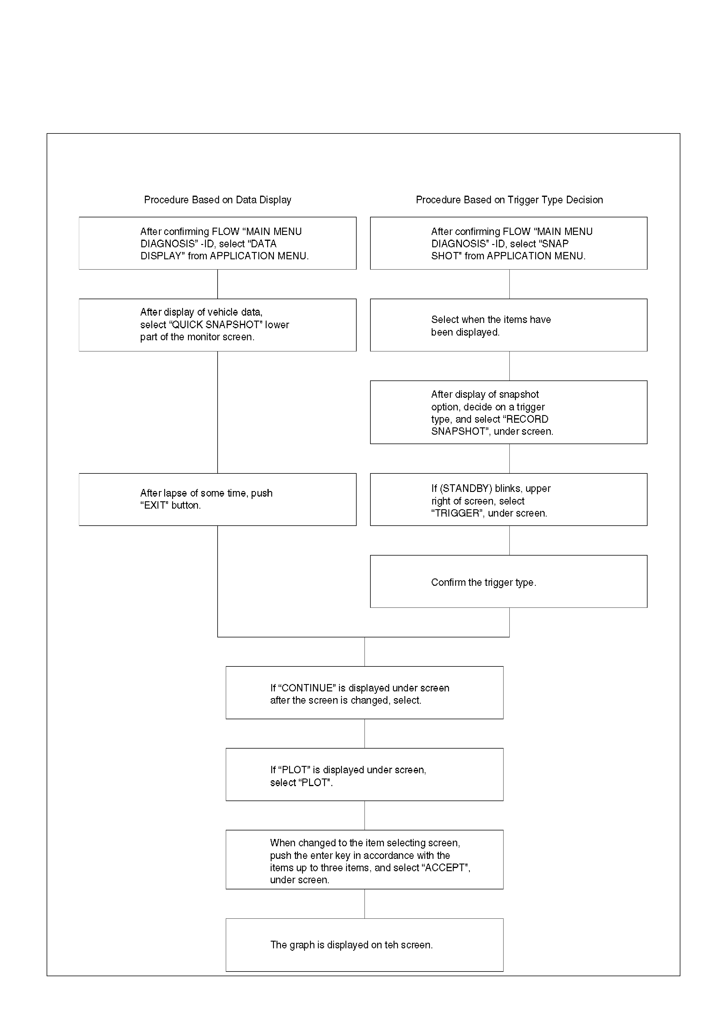
Plotting Graph Flow Chart (Plotting graph after obtaining vehicle information)
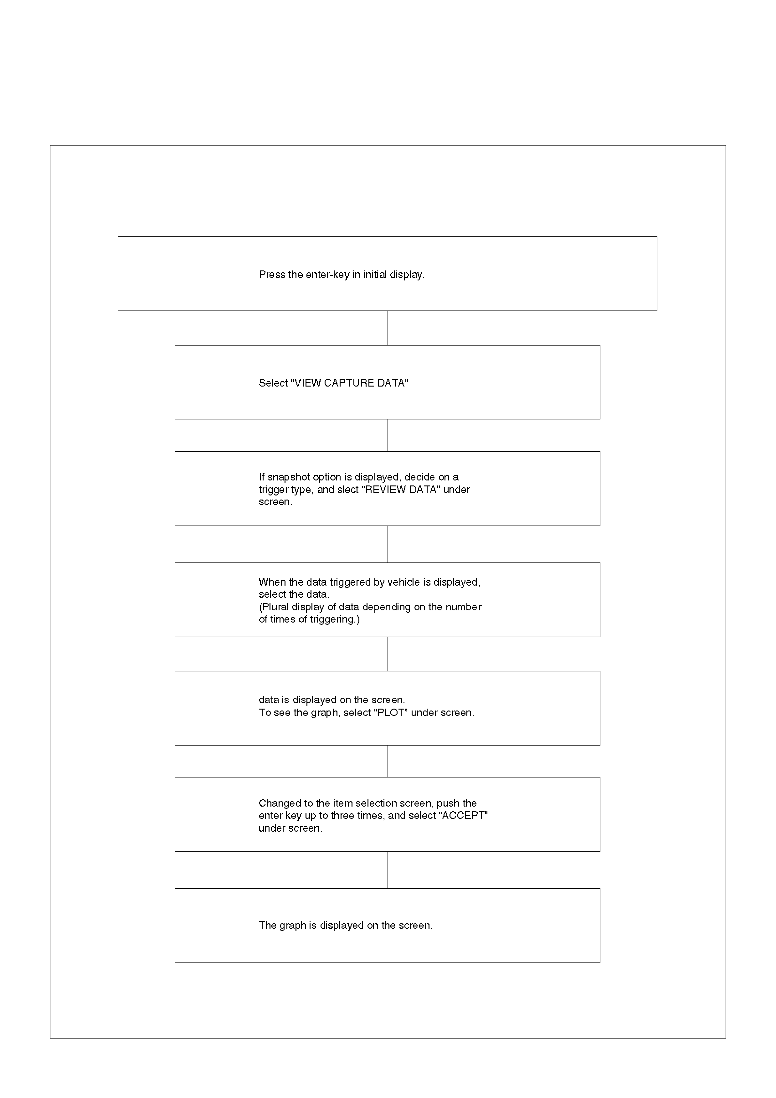
Flow Chart‘ for Snapshot Replay (Plotting Graph)
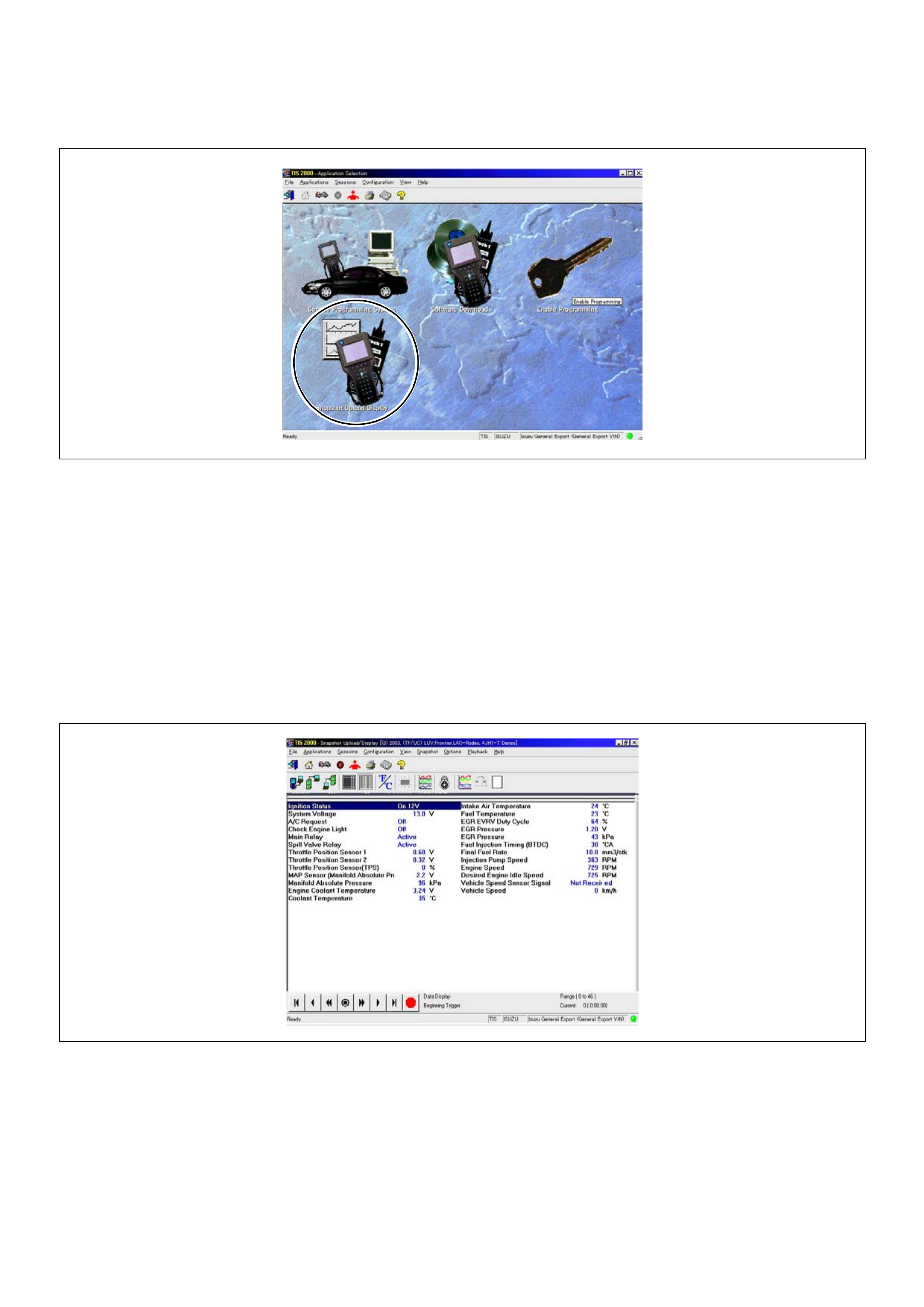
Snapshot Display With TIS2000
Procedures for transferring and displaying Tech2
snapshot data by using TIS2000 [Snapshot Upload]
function is described below.
Snapshot data can be displayed with [Snapshot Upload]
function included in TIS2000.
By analyzing these data in various methods, trouble
conditions can be checked.
Snapshot data is displayed by executing the three steps
below shown:
1. Record the snapshot data, in Tech2.
2. Transfer the snapshot data to PC.
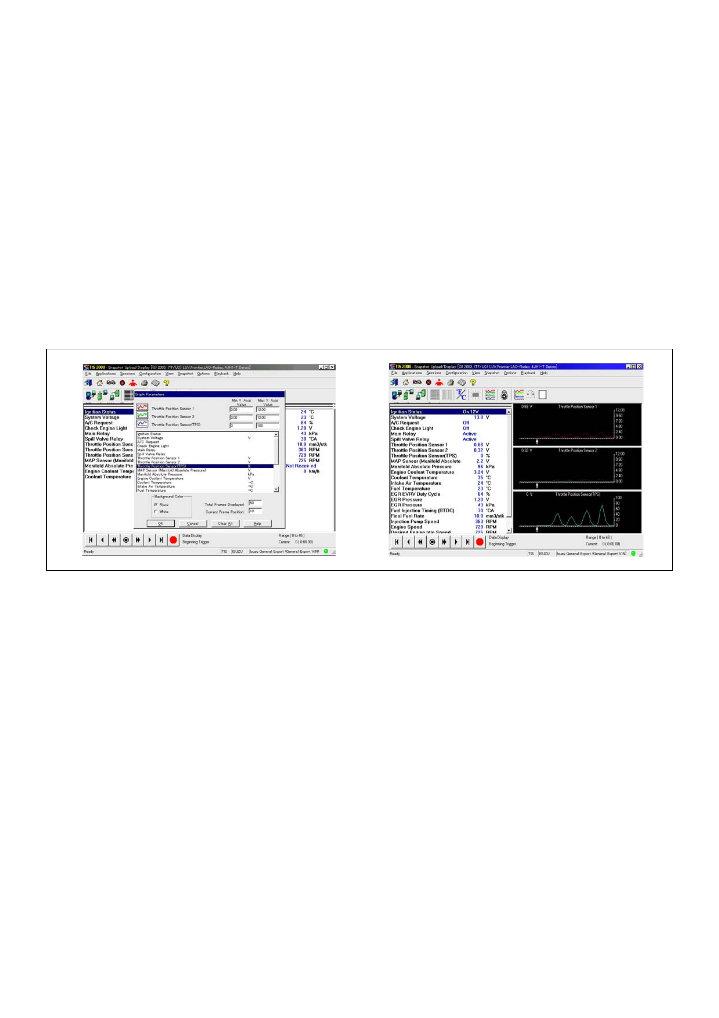
After recordin g the sn apshot in Tech2, transfe r the data
from Tech2 to PC by the below procedures.
1. Start TIS2000.
2. Select [Snapshot Upload] on the TIS2000 start
screen.
3. Select [Upload from trouble diagnosis tool (transfer
from diagnosis tester)] or click the corresponding
icon of the tool bar.
4. Select Tech2, and transfer the recorded snapshot
information.
5. Select the transferred snapshot.
6. After ending transfer of the snapshot, data
parameter list is displayed on the screen.
3. Snapshot data is displayed with TIS2000
[Snapshot Upload] function.
Snapshot is stored in the PC hard disk or floppy disk,
and can be displayed any time.
Stored snapshot can be displayed by the below
procedures.
1. Start TIS2000.
2. Select [Snapshot Upload] on the TIS2000 start
screen.
3. Select [Open the existing files] or click the
corresponding icon of the tool bar.
4. Select the transferred snapshot.
5. Open the snapshot, to display the data parameter
list on the screen.
Graph display Values and graphs (Max. 3 graphs):
1. Click th e icon for graph display. [G raph Par ameter]
window opens.
2. Click the first graph icon of the window upper part,
and select one parameter from the list of the window
lower part. Se lected param eter is displa yed nest to
the graph icon. Graph division can be selected in
the field on the parameter right side.
3. Repeat the same procedures with the 2nd and 3rd
icons.
4. After selecti ng all paramet ers to be displ ayed (Max.
3 parameters), click [OK] button.
5. Parameter selected is displayed in graph form on
the right of the data parameter on the screen.
6. Graph display can be moved with the navigation
icon.
7. For displaying another parameter by graph, click the
parameter o f the list, drug the mouse to th e display
screen while pressing the mouse button and release
the mouse button. New parameter is displayed at
the position of the previous parameter. For
displaying the graph display screen in full size,
move the cursor upward on the screen. When the
cursor is changed to the magnifying glass form, click
the screen. Graph screen is displayed on the whole
screen.
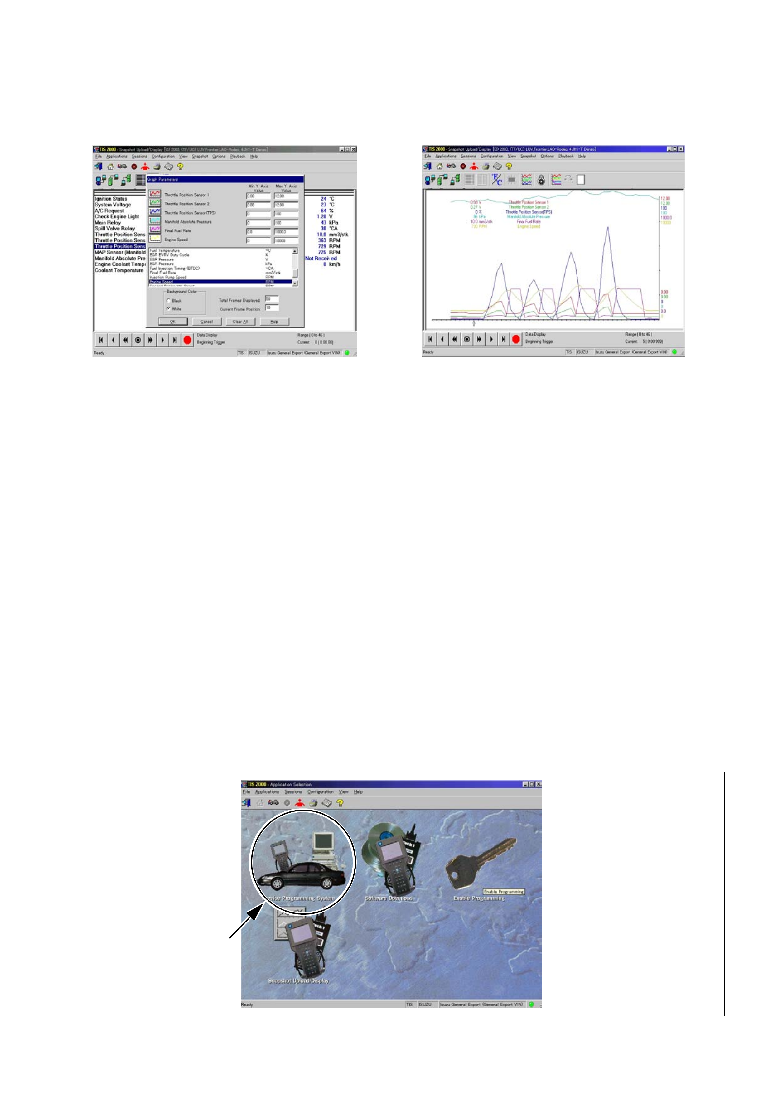
Display of graphs on one screen (Max. 6 graphs):
1. Click the 6 graph icon. [Graph Parameter] window
opens.
2. Click the graph icon, select the parameter to be
displayed from the list and change divisions
according to necessity.
3. Repeat the same procedures with the graph icons,
from the 2nd to 6th.
4. Click the [OK] button to display.
5. In this case, parameters are displayed only in graph
form. All parameters are displayed in one graph.
6. The graph display screen can be moved with the
navigation icon.
Service Programming System (SPS)
The procedure to program the control unit by using the
Service Programming System (SPS) software contained
in TIS2000 is explained below.
NOTE:
• If the Engine Control Module (ECM) was
programmed, the Immobiliser System must be linked
to the ECM: Refer to section 11 “Immobiliser System-
ECM replacement” for the ECM/Immobiliser linking
procedure.
Important: Perform the following checks before
attempting to program the control unit:
• The Tech2 PCMCIA card is programmed with The
latest software release.
• The latest release of TIS2000 is loaded on the PC.
• The vehicle battery is fully charged.
• The control unit to be programmed is connected to
the vehicle.
1. Preparations of TIS 2000
1. Connect Tech 2 to P/C.
2. Check to see if Hardware Key is plugged into Port.
3. Activate TIS 2000 by P/C.
4. On the activating screen of TIS2000, choose
“Service Programming System”
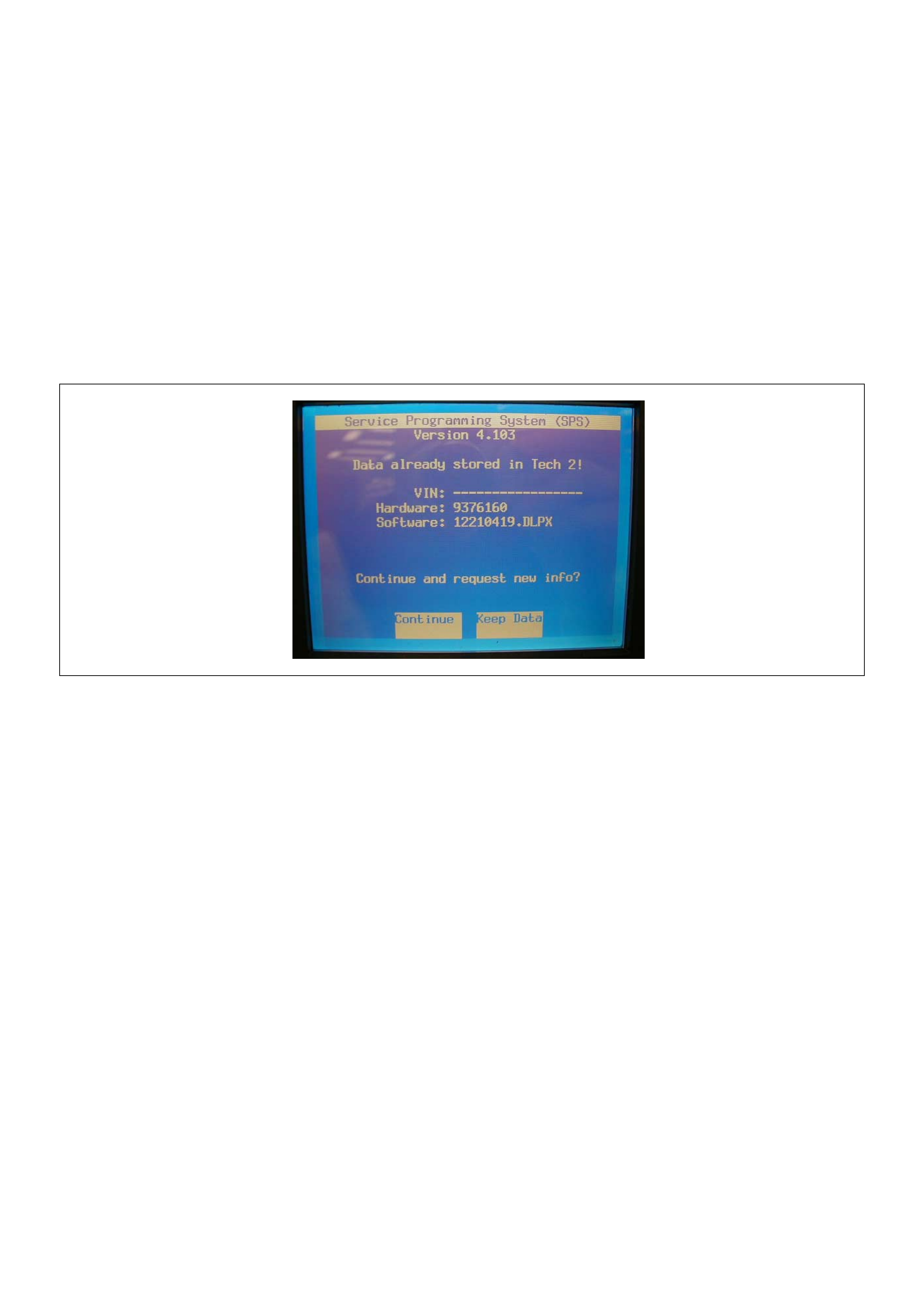
5. On the sc reen of “Diag nostic Te ster a nd Proces sing
Program Selection”, choose the one that will comply
with the following .
• Diagnostic tester in use
• New pr ogrammi ng by t he existi ng mod ule or ne w
programming by the replaced/new module.
• Fixing position of the control unit.
6. Upon completion of the selection, push the button of
“Continue”.
2. Demand of Data
1. Connect Tech-2 to the vehicle. When activated by
turning on the power of Tech-2, push the “Enter”
switch.
2. Turn on the ignition switch (without starting the
engine)
3. In the main menu of Diagnostic Tester, push “F1:
Service Programming System (SPS)”.
4. Push “F0: Request Info” of Tech-2.
5. Where ve hic le data has be en a lr ea dy sa ve d in Tech
2, the existing data come on display. In this
instance, as Tech-2 starts asking whether to keep
the data or to continue obtaining anew data from the
control unit, choose either of them.
6. If you select “continue”, you have to select “Model
Year”, “Vehicle Type”, “Controller Type (Engine)”.
7. After that. then push button and turn Ignition switch
tuned on, off, on following Tech-2 display. Tech-2
will read information from controller after this
procedure.
8. During obtaining information, Tech-2 is receiving
information from the control unit chosen. In
replacing the control unit, please be sure to
undertake “Obtaining Information” from the new
unit. With VIN not being programmed into the new
control unit at the time of shipment, “obtaining
information” is not complete (because the vehicle
model, engine model and model year are specified
from VIN). For the procedure get additional
information on vehicles, instruction will be provided
in dialog form, when TIS2000 is in operation.
9. Following instructions by Tech-2, push the “Exit”
switch of Tech-2, turn off the ignition of the vehicle
and turn off the power of Tech-2, thereby removing
from the vehicle.
3. Data Exchange
1. Conne ct Tech-2 t o P/C, turn on the p ower and click
the “Next” button of P/C.
2. Check VIN of the vehi cle and ch oos e “Next” .
3. When a lack of data is asked from among the
following menu, enter accordingly.
Select following Menu
• Model Year
• Model
• Engine type
• Transmission type
• Destination code (vehicles for general export)*1
• Immobiliser
* 1: How to read the destination code
Destination code can be read from ID Plate affixed on
vehicles, while on VIN plate the destination code is
described at the right-hand edge of Body Type line. In
Fig.-3, the destination code can be read as “EK4
(Europe)”.
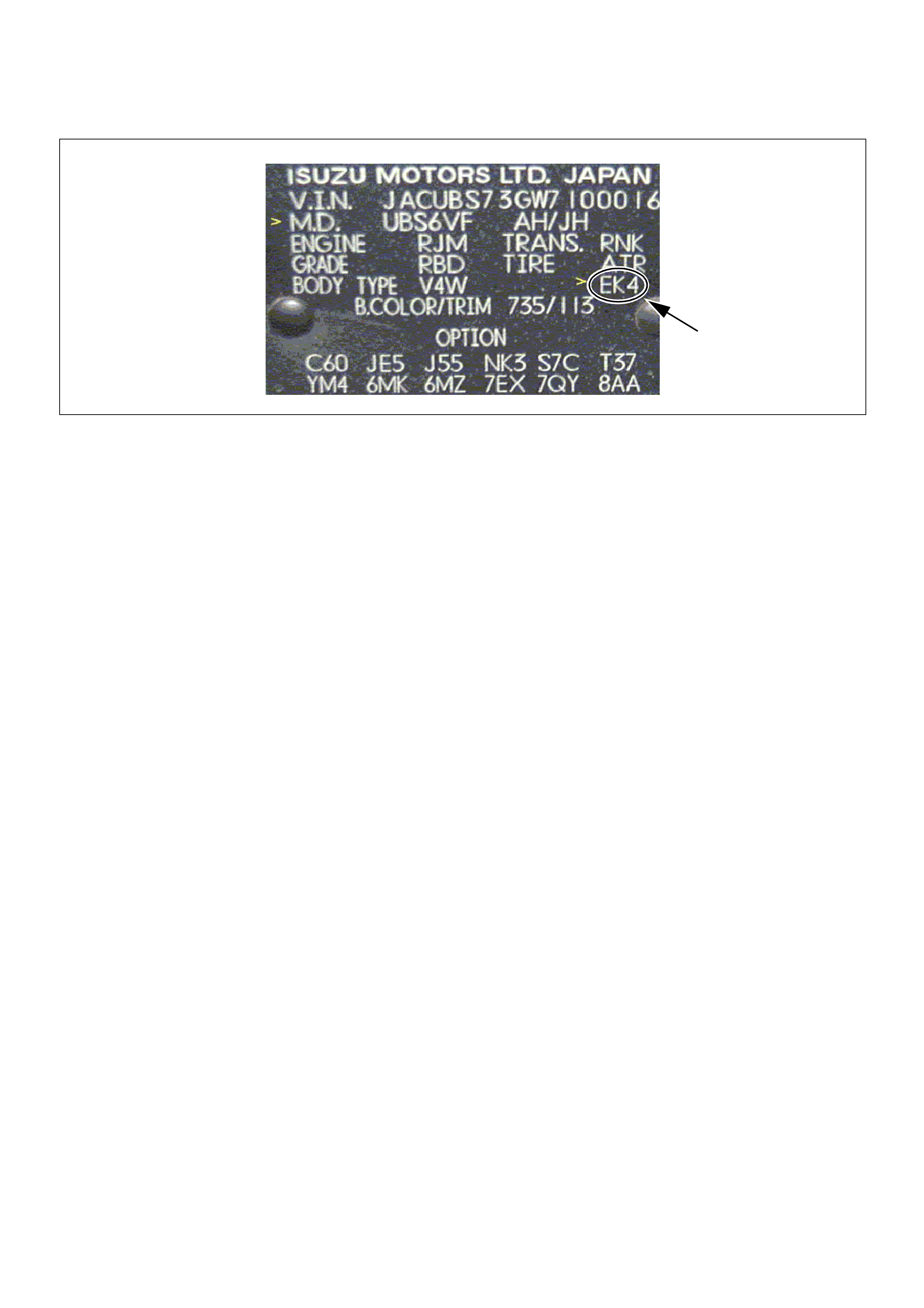
4. After choosing the data, click the “Next” button.
5. When all the necessary information is entered, the
“details” of software within the database that match
the entered data will appear for confirmation. Click
the “Program” switch and then download the new
software onto Tech-2.
6. “Data Transfer” comes on display. The progress of
downloading will be displayed on the screen in the
form of bar graph.
7. Upon finishing the data transfer, turn off the power
of Tech-2, removing from P/C.
4. Programming of ECM
1. Check to see if batteries are fully charged, while
ABS connectors shall be removed from the vehicle.
2. Connect Tech-2 to Vehicle Diagnostic Connectors.
3. Turn on the power of Tech-2 and the title screen
comes on display.
4. Turn on the ignition (without allowing the engine to
start)
5. On the title screen of Tech-2, push the “Enter”
button.
6. Choose “F: Service Programming System” on the
main screen and then choose “Fl: Programming”.
7. While data is being transferred, “Downloading” will
be displayed on the Tech-2 screen.
8. Upon finishing the data transfer, Tech-2 will display
“Reprogramming Successful”. Push the “Exit”
button to bring program to completion.
9. Following “Procedure 2: Demand of Data”, try over
again “Information Obtaining” and check to confirm
if the data has been correctly re-loaded.
10. Upon finishing confirmation, turn off the ignition of
the vehicle and then turn off the power of Tech-2,
removing from the vehicle.
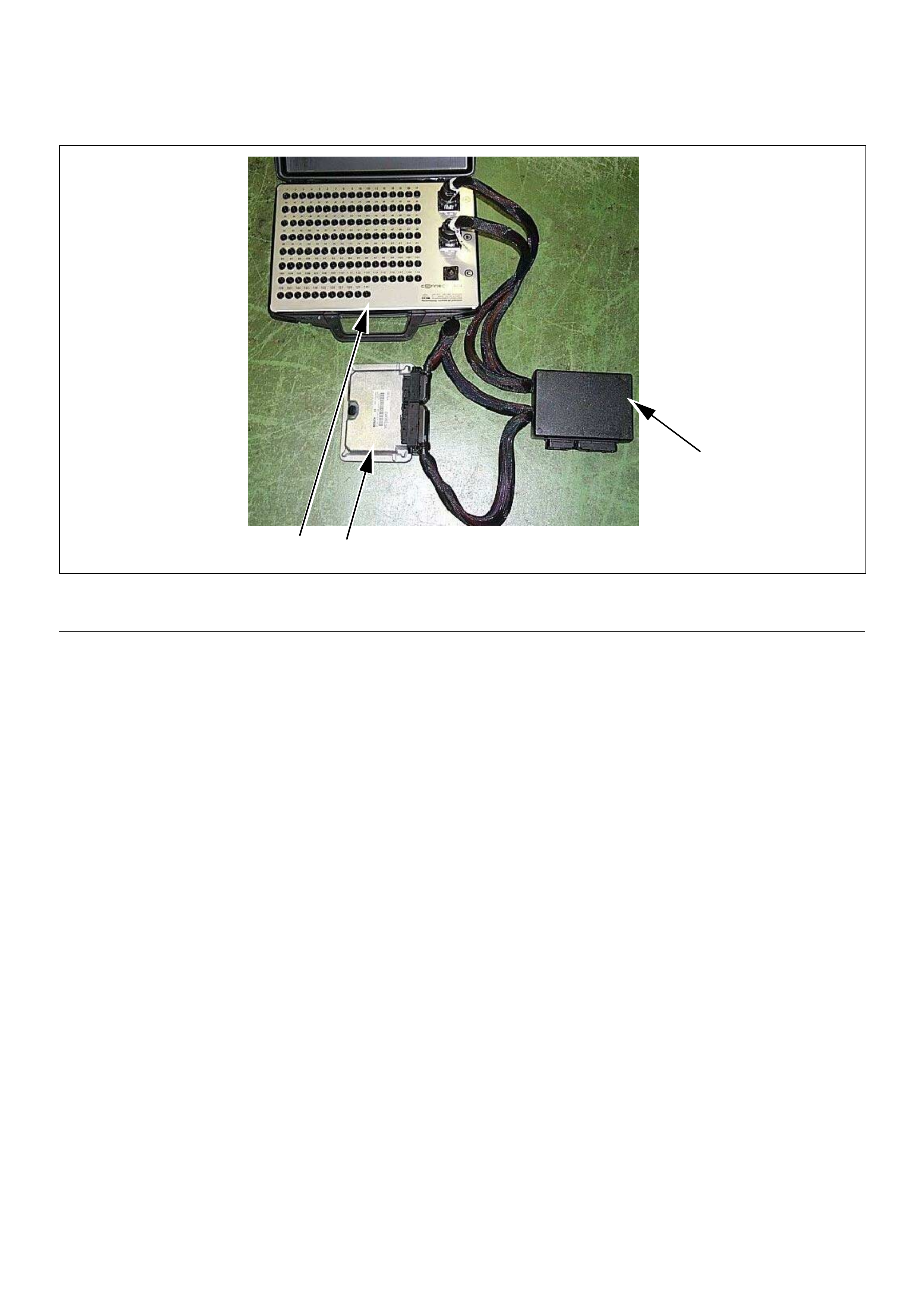
How To Use Breaker Box
The engine control module (ECM) and other connectors
have water proo f connector and special termina l. Water
proof terminal does not allow to use back prove. In
addition, the engine control module (ECM) special
terminal can not let regular digital voltage meter prove
to access, because terminal shape is very fin pin type.
In order to prevent damage of female terminal and
connector itself, the breaker box and adapter is the
most suitable special tool.
3 1
2
(1) Engine Control Module (ECM)
(2) Harness Adapter (3) Breaker Box
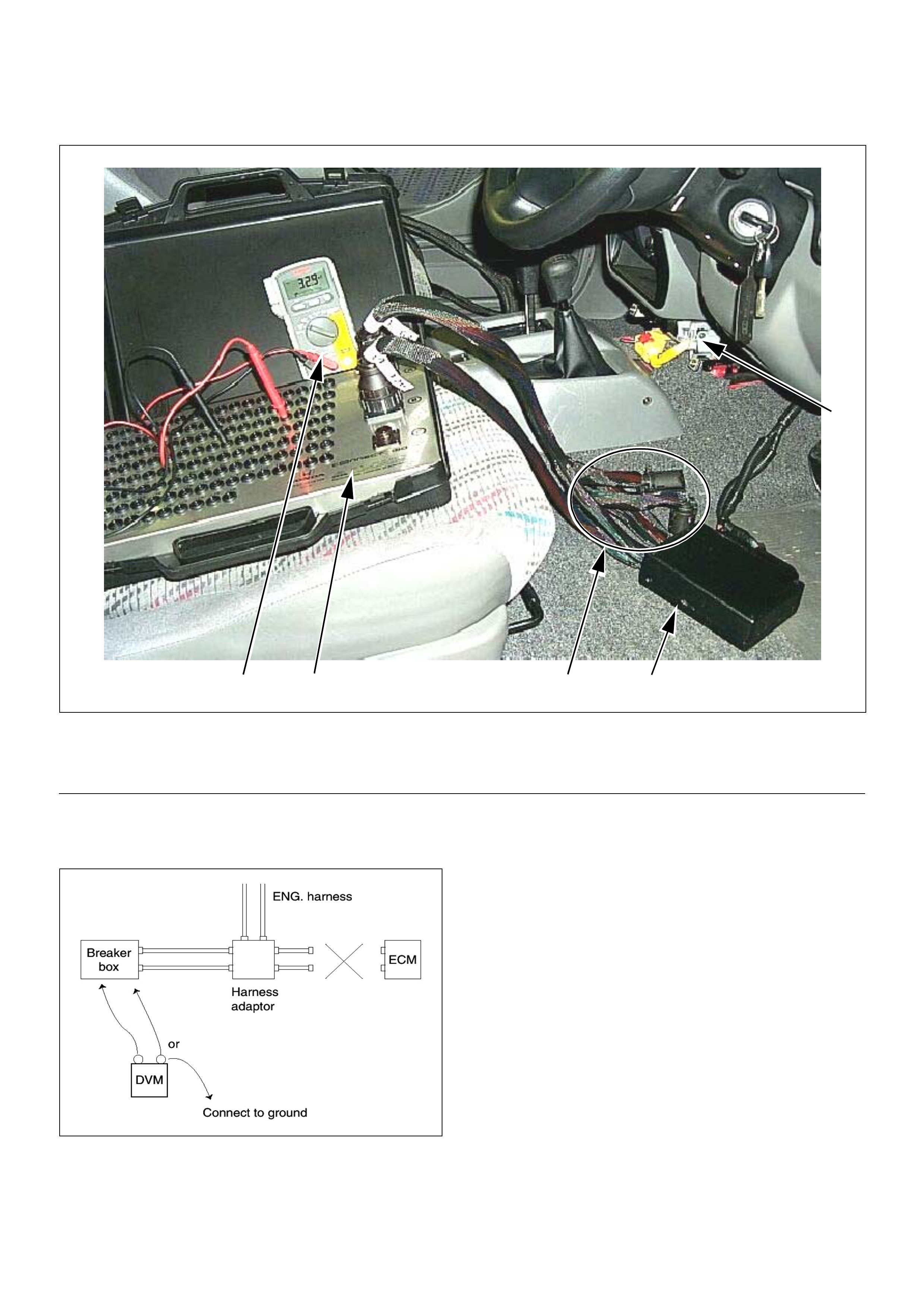
Breake r Box Connection Type A
Breake r box conne ction type A, check for “o pen circuit”
and “short to ground circuit”.
4 3 25
1
(1) Engine Control Module (ECM)
(2) Harness Adapter
(3) Breaker Box
(4) Digital Voltage Meter
(5) ECM - Harness Adapter Disconnection
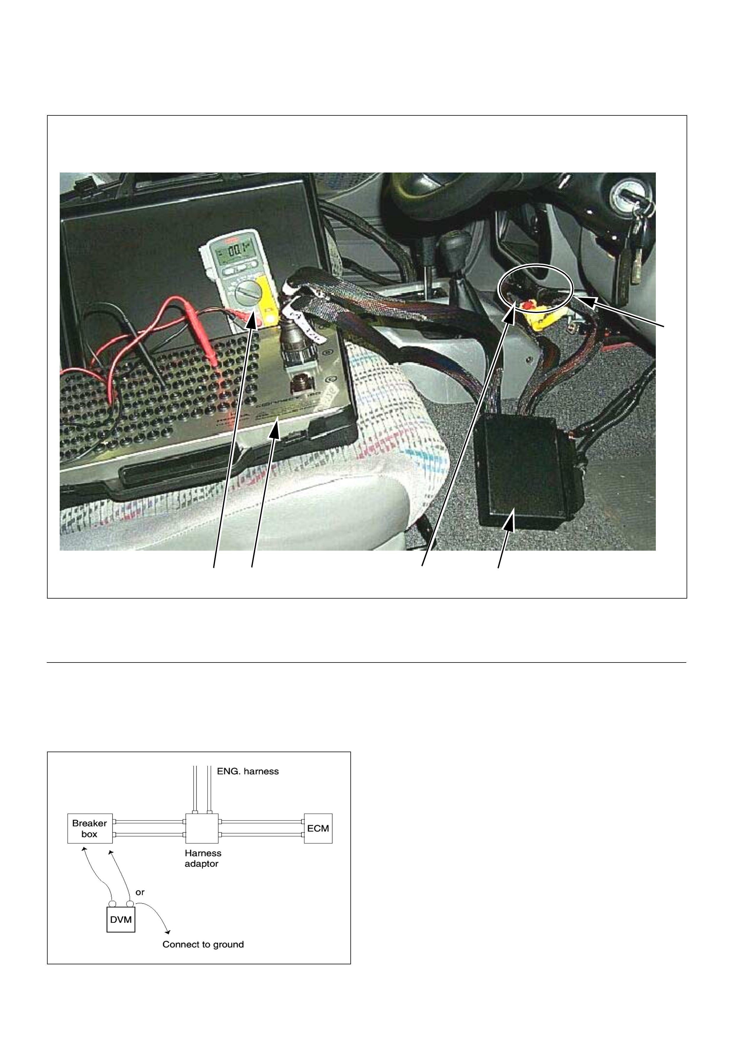
Breake r Box Connection Type B
Breaker box connection type B, check for “short to
power supply circuit” and “power, signal voltage check”
between the engine control module (ECM) and
electrical components.
4 3 52
1
(1) Engine Control Module (ECM)
(2) Harness Adapter
(3) Breaker Box
(4) Digital Voltage Meter
(5) ECM - Harness Adapter Connection
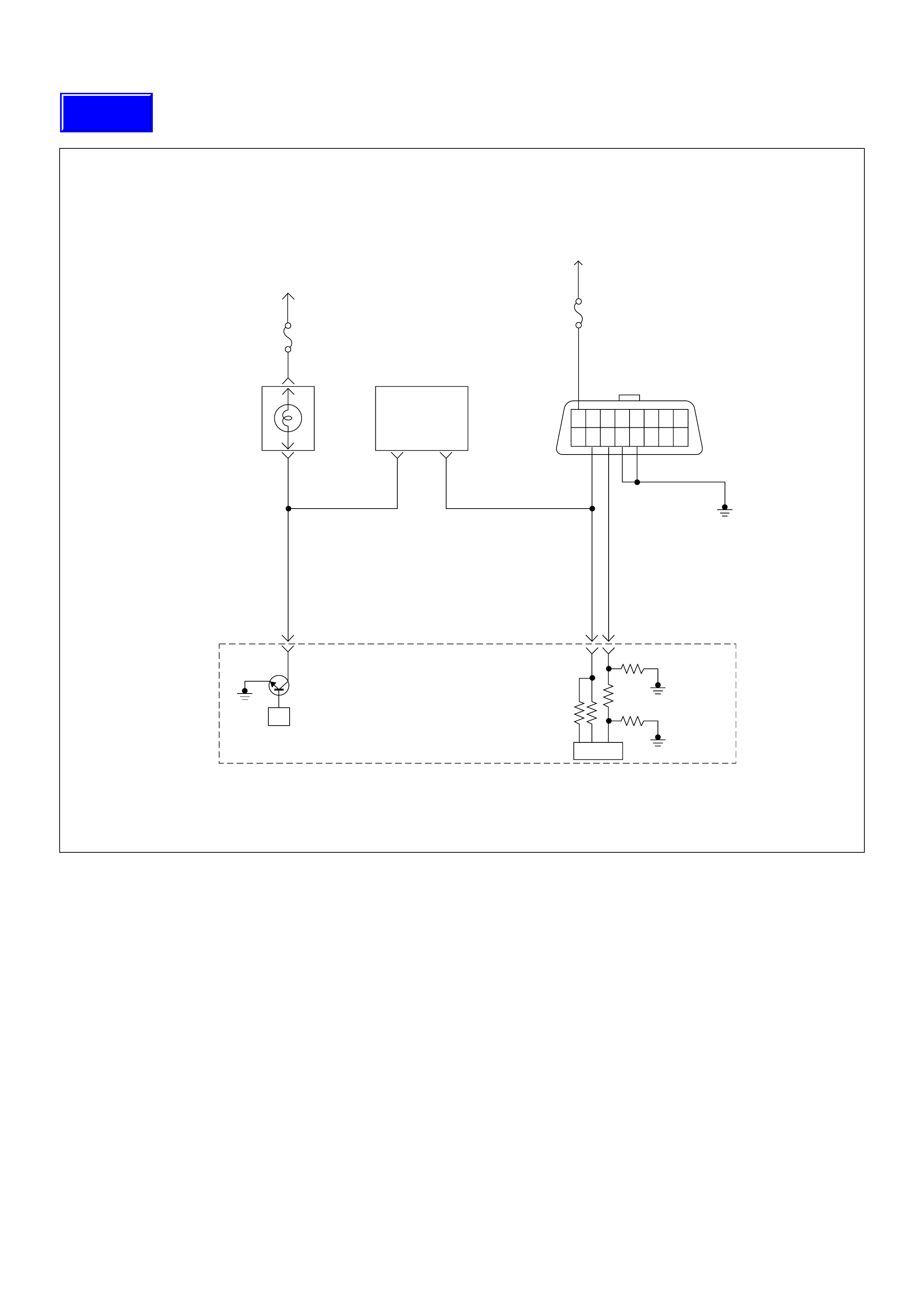
On-Board Diagnostic (OBD) System Check
Circuit Description
The on-board diagnostic system check is the starting
point for any driveability complaint diagnosis. Before
using this procedure, perform a careful visual/physical
check of the ECM and engine grounds for cleanliness
and tightness.
The on-board diagnostic system check is an organized
approach to identifying a problem created by an
electronic engine control system malfunction.
Diagnostic Aids
An intermittent may be caused by a poor connection,
rubbed-through wire insulation or a wire broken inside
the insulation. Check for poor connections or a
damaged harness. Inspect the ECM harness and
connector for improper mating, broken locks, improperly
formed or damaged terminals, poor terminal-to-wire
connection, and damaged harness.
Test Description
Number(s) below refer the step number(s) on the
Diagnostic Chart:
1. The Check Engi ne Lamp (M IL) shoul d be ON stea dy
with the ignition “On”, engine “Off”. If not, “No Check
Engine Lamp (M IL)” chart s hould be used to isol ate the
malfunction.
2. Check s the Class 2 data ci rcuit an d ensures that the
ECM is able to transmit serial data.
3. This test ensures that the ECM is capable of
controlling the Check Engine Lamp (MIL) and the Check
Engine Lamp (MIL) driver circuit is not shorted to
ground circuit.
4. If the engine will not start, “Engine Cranks But Will
Not Run” chart should be used to diagnose the fault.
6. Th e Tech2 parameter s which is not within the typical
range m ay help to iso late the area wh ich is caus ing the
problem.
µP
1.25
BLK
16151413121110 9
87654321
0.5
RED/
YEL
0.5
WHT 0.5
BLU
35 45
0.5
BRN/
YEL
42
IC
Stop
Light
10A
Meter
15A
Ignition
SW
Check
Engine
Lamp Imnobiliser
Control Unit
Butery
Voltage
78
Engine
Control
Module
(ECM)
Techline
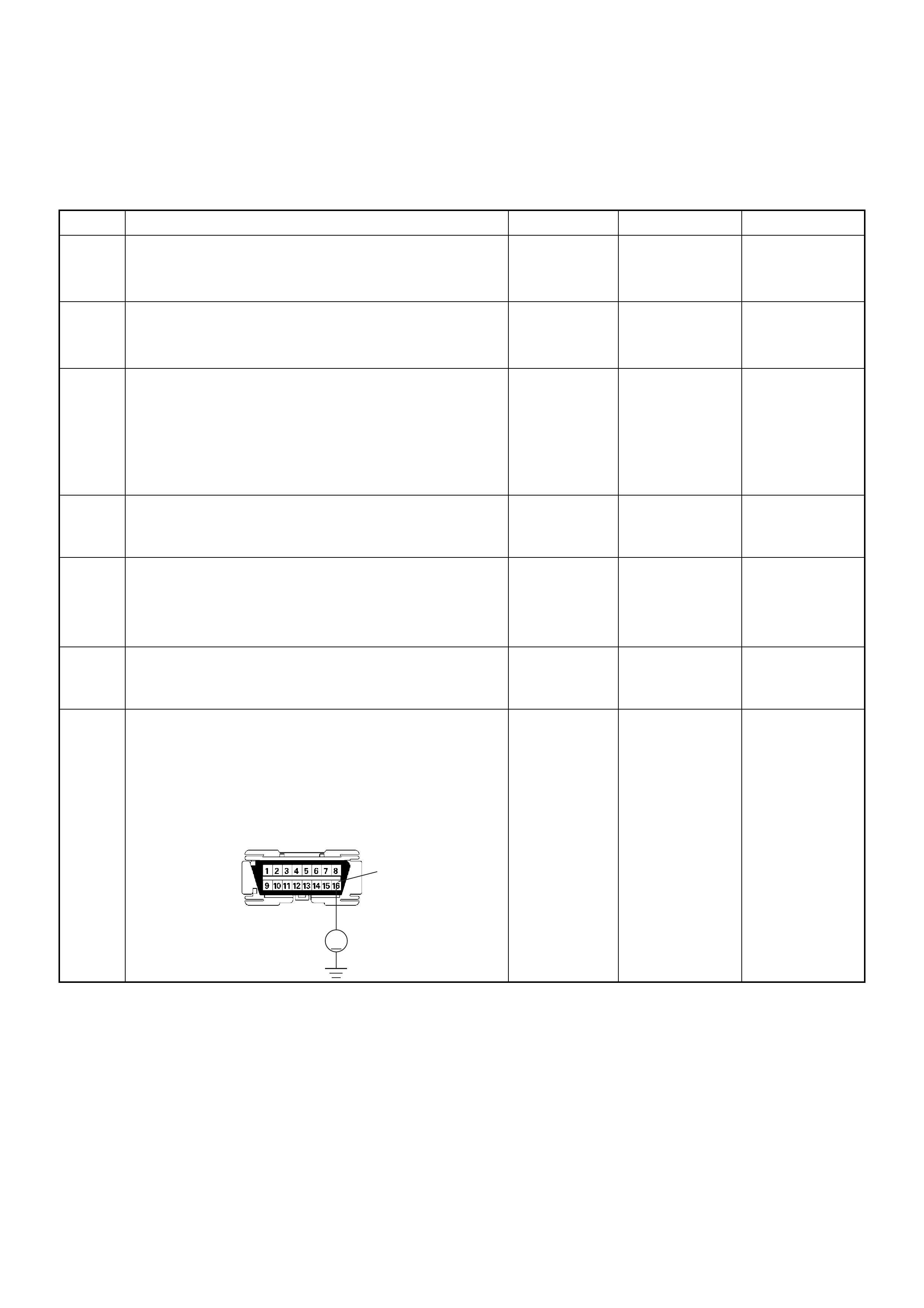
12. This vehic le is equip ped wit h ECM w hic h util izes a n
electrically erasable programmable read only memory (EEPROM).
On-Board Diagnostic (OBD) System Check
Step Action Value(s) Yes No
11. Ignition “On”, engine “Off”.
2. Check the “CHECK ENGINE” lamp (MIL).
Does the “CHECK ENGINE” lamp turn “On”? — Go to Step 2
Go to No
CHECK
ENGINE Lamp
21. Using the Tech 2, ignition “On” and engine “Off”.
2. Attempt to display “Data Display” with the Tech 2.
Does the Tech 2 display engine data? — Go to Step 3 Go to Step 7
31. Using the Tech 2, ignition “On” and engine “Off”.
2. Select the “Miscellaneous Test” and perform the
“Check Light” in “Lamps”.
3. Opera te the Tech 2 in ac cord ance with the Tech 2
instru ctions.
Does the “CHECK ENGINE” lamp turn “Off”? — Go to Step 4
Go to CHECK
ENGINE LAMP
On Steady
4Attempt to start the engine.
Does the engine start and continue to “Run”? —Go to Step 5
Go to Engine
Cranks But Will
Not Run
51. Using the Tech 2, ignition “On” and engine “Off”.
2. Select the “Read DTC Info r As Stored B y ECU” in
“Diagnostic Trouble Code”.
3. Are any DTCs stored? — Go to DTC
Chart Go to Step 6
6Compare typical scan data values displayed on the
Tech 2 “Data Display”.
Are the displayed values within the range? —
Refer to
SYMPTOM
DIAGNOSIS
Refer to
TYPICAL
SCAN DATA
7Using the DVM and check the data link connector
power supply circuit.
1. Ignition “Off”, engine “Off”.
2. Check the circuit for open circuit.
Was the problem found?
—
Repair faulty
harness and
verify repair Go to Step 8
V
16
C-96
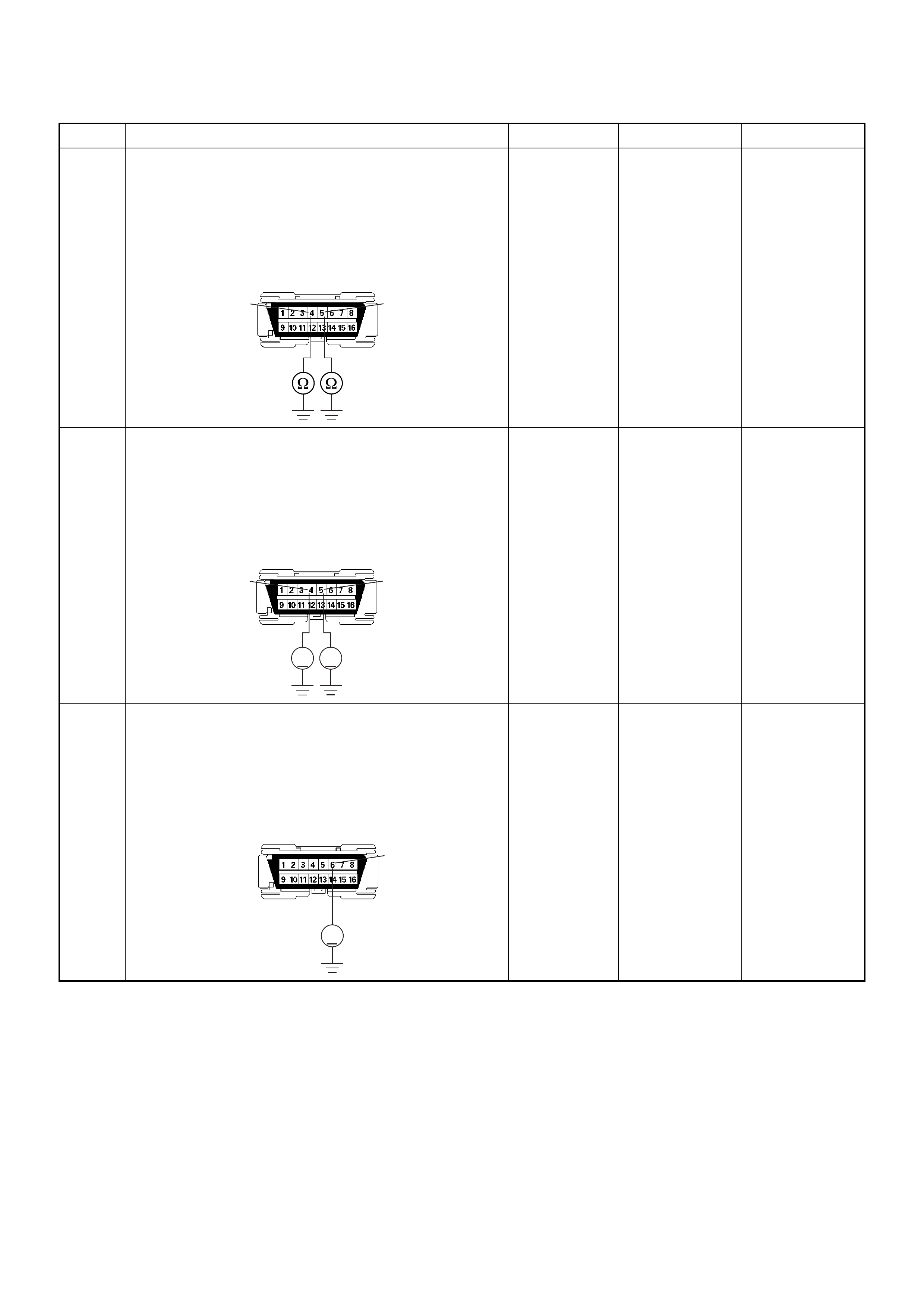
8Using the DVM and check the data link connector
ground circuit.
1. Ignition “Off”, engine “Off”.
2. Check the circuit for open circuit.
Was the problem found?
—
Repair faulty
harness and
verify repair Go to Step 9
9Using the DVM and check the data link connector
ground circuit.
1. Ignition “On”, engine “Off”.
2. Check the circuit for short to power supply circuit.
Was the DVM indicated specified value?
Less than 1V Go to Step 10
Repair faulty
harness and
verify repair
10 Using the DVM and check the data link connector
communicati on ci rcui t.
1. Ignition “On”, engine “Off”.
2. Check the circuit for short to power supply circuit.
Was the DVM indicated battery voltage?
—
Repair faulty
harness and
verify repair Go to Step 11
Step Action Value(s) Yes No
54
C-96
VV
54
C-96
V
6
C-96
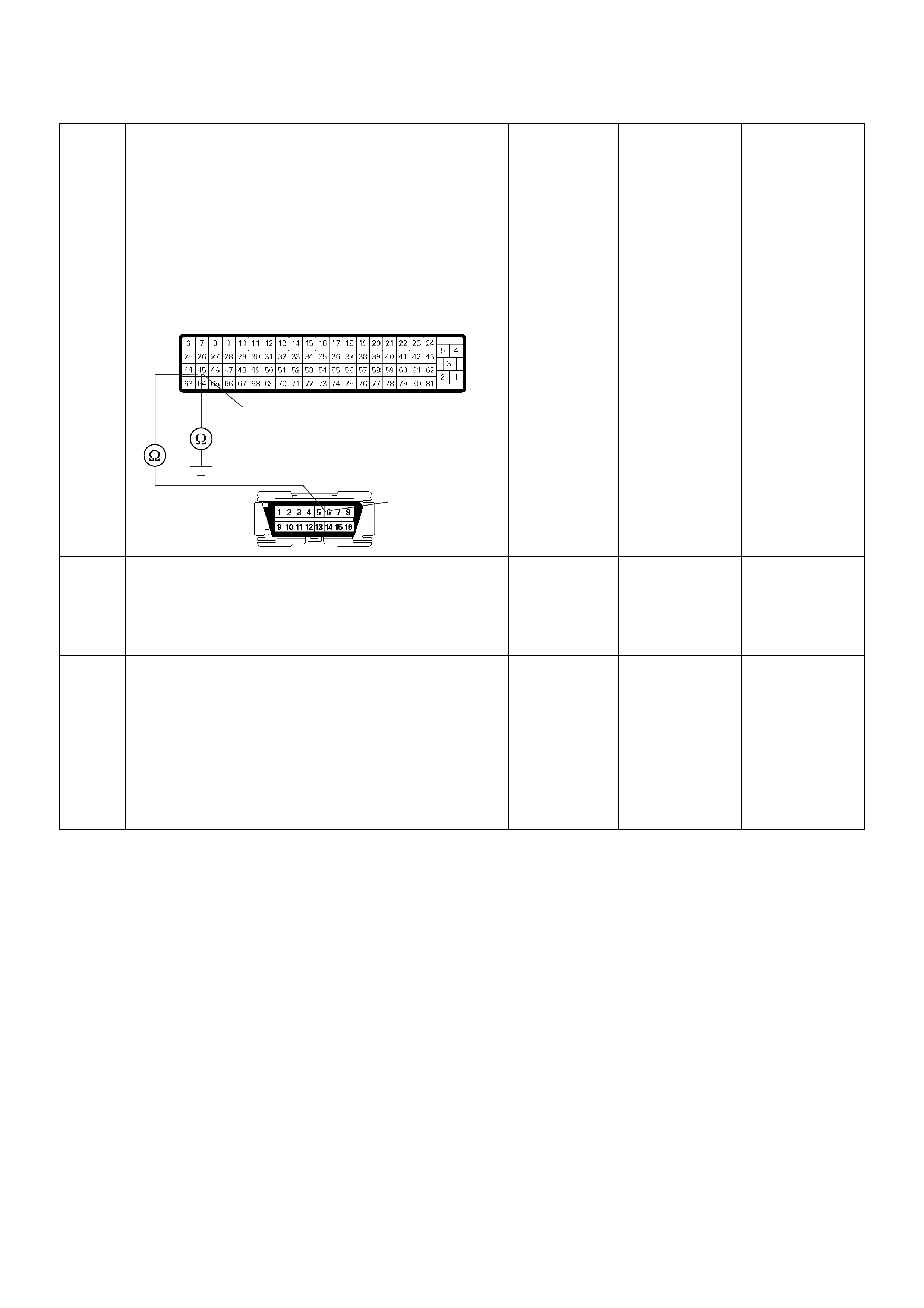
11 Using the DVM and check the data link connector
communicati on ci rcui t.
1. Ignition “Off”, engine “Off”.
2. Disconnect the ECM connector.
3. Check the circuit for open or short to ground
circuit.
Was the problem found?
—
Repair faulty
harness and
verify repair Go to Step 12
12 Is the ECM programmed with the latest software
release?
If not, downlo ad the latest software to the ECM using
the “SPS (Service Programming System)”.
Was the problem solved? — Verify repair Go to Step 13
13 Replace the ECM.
Is the action complete?
IMPORTANT: The replacement ECM must be
programmed. Refer to section of the Service
Programming System (SPS) in this manual.
Foll owing ECM pr ogramming, the immobi liser system
(if equipped) must be linked to the ECM. Refer to
section 11 “Immobiliser System-ECM replacement” for
the ECM/Immobiliser linking procedure. — Verify repair —
Step Action Value(s) Yes No
6
45
C-96
C-56
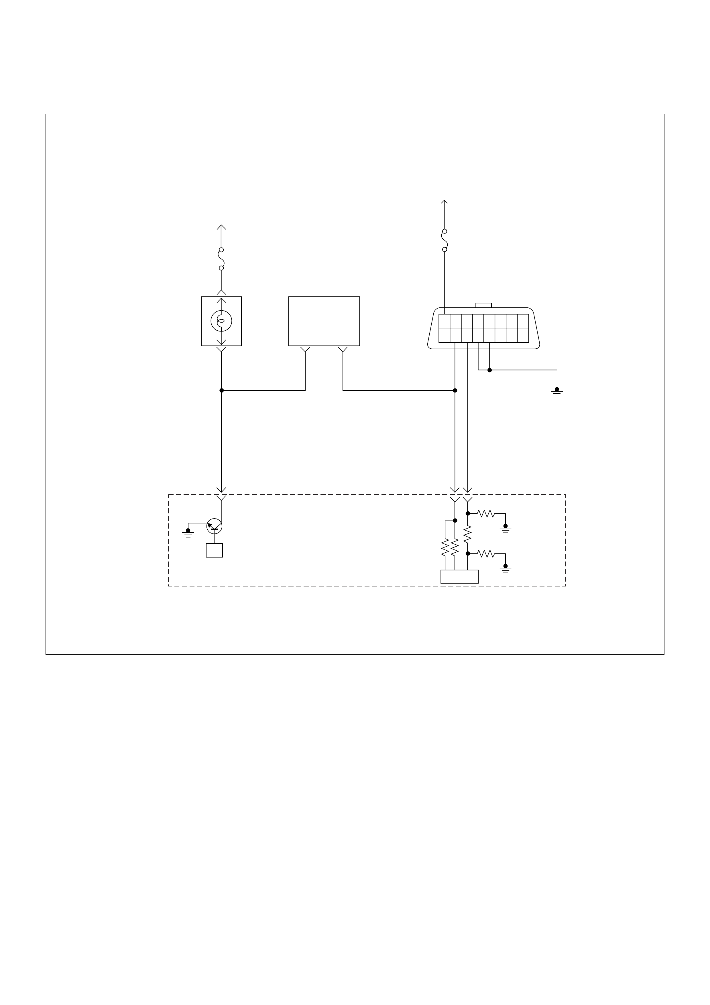
No Check Engine Lamp (MIL)
Circuit Description
The check engine lamp should be illuminated and
steady fo r abou t five se co nds wi th t he i gniti on “ ON” an d
the engi ne s topped. Ig nition feed voltage i s s upplied to
the check engine lamp bulb through the meter fuse.
The Engine Control Module (ECM) turns the check
engine lamp “ON” by grounding the check eng ine lamp
driver circuit.
Diagnostic Aids
An intermittent check engine lamp may be cased by a
poor connection, rubbed-through wire insulation, or a
wire broken inside the insulation. Check for the
followi ng ite ms :
• Inspect the ECM harness and connections for
improper mating, broken locks, improp erly formed or
damaged terminals, poor terminal-to-wire connection,
and damaged harness.
• If the engine runs OK, check for a faulty light bulb, an
open in the check engine lamp driver circuit, or an
open in the instrument cluster ignition feed.
• If the engine cranks but will not run, check for an
open ECM i gnition or batt ery feed, or a p oor ECM to
engine ground.
µP
1.25
BLK
16151413121110 9
87654321
0.5
RED/
YEL
0.5
WHT 0.5
BLU
35 45
0.5
BRN/
YEL
42
IC
Stop
Light
10A
Meter
15A
Ignition
SW
Check
Engine
Lamp Imnobiliser
Control Unit
Butery
Voltage
78
Engine
Control
Module
(ECM)
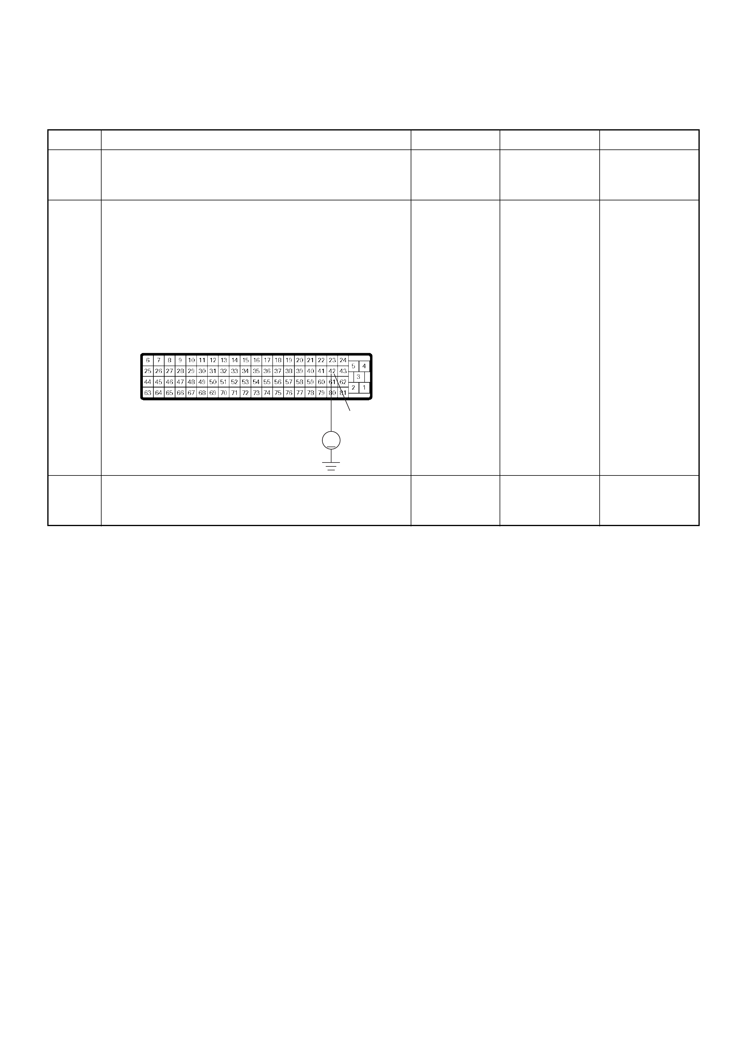
No Check Engine Lamp (MIL)
Step Action Value(s) Yes No
1 C h eck the mete r fuse (15A) .
If the fuse is burnt out, repair as necessary.
Was the problem found? — Verify repair Go to Step 2
2 Using the DVM and check the “CHECK ENGINE”
lamp circuit.
1. Ignition “Off”, engine “Off”.
2. Disconnect the ECM connector.
3. Ignition “On”.
4. Check the circuit for open circuit.
Was the DVM indicated specified value?
Battery
voltage Go to Step 5 Go to Step 3
3 Check the “CHECK ENGINE” lamp bulb.
If the bulb is burnt out, repair as necessary.
Was the problem found? — Verify repair Go to Step 4
V
42
C-56
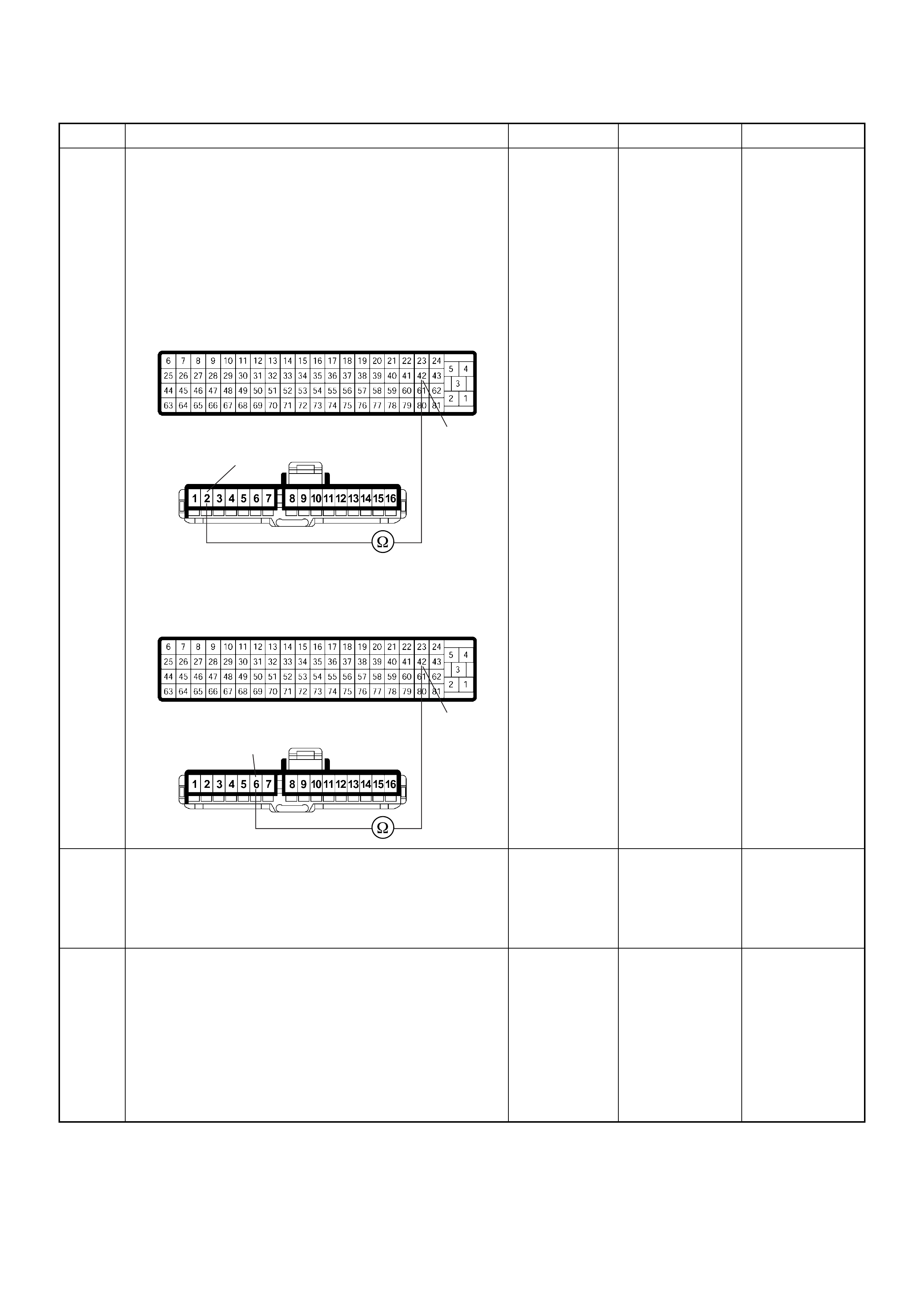
4 Using the DVM and check the “CHECK ENGINE”
lamp circuit.
1. Ignition “Off”, engine “Off”.
2. Disconnect the meter connector and ECM
connector.
3. Check the circuit for open circuit.
Was the problem found?
— Verify repair Go to Step 5
5 Is the ECM programmed with the latest software
release?
If not, downlo ad the latest software to the ECM using
the “SPS (Service Programming System)”.
Was the problem solved? — Verify repair Go to Step 6
6 Replace the ECM.
Is the action complete?
IMPORTANT: The replacement ECM must be
programmed. Refer to section of the Service
Programming System (SPS) in this manual.
Foll owing ECM pr ogramming, the immobi liser system
(if equipped) must be linked to the ECM. Refer to
section 11 “Immobiliser System-ECM replacement” for
the ECM/Immobiliser linking procedure. — Verify repair —
Step Action Value(s) Yes No
42
2
42
6
B-23
C-56
4JA1-TC
B-23
C-56
4JH1-TC
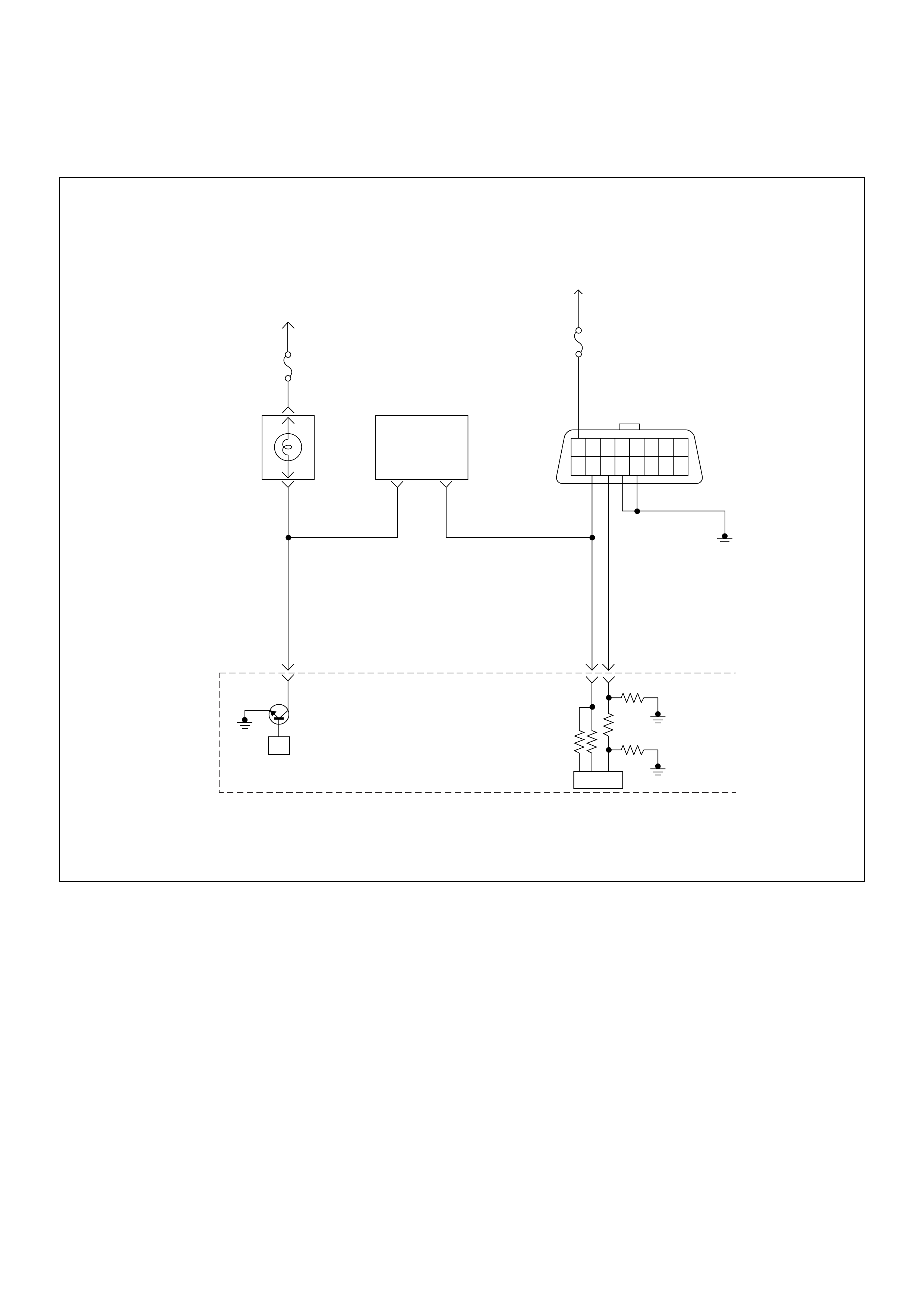
Check Engine Lamp (MIL) “On” Steady
Circuit Description
The check engine lamp should always be illuminated
and steady for about five seconds with ignition “ON” and
the engine stopped. Ignition feed voltage is supplied
directl y to the ch eck en gine lam p indic ator. The Engin e
Control Module (ECM) turns the check engine lamp
“ON” by grounding the check engine lamp driver circuit.
The check engine lamp should not remain “ON” with the
engine running and no DTC(s) set. A steady check
engine lamp with the engine running and no DTC(s)
suggests a short to ground in the check engine lamp
driver circuit.
Diagnostic Aids
An intermittent may be caused by a poor connection,
rubbed-through wire insulation, or a wire broken inside
the insulation. Check for the following items:
• Poor connection or damaged harness – Inspect the
ECM harness and connectors for improper mating,
broken locks, improperly formed or damaged
terminals, poor terminal-to-wire connection, and
damaged harness.
µP
1.25
BLK
16151413121110 9
87654321
0.5
RED/
YEL
0.5
WHT 0.5
BLU
35 45
0.5
BRN/
YEL
42
IC
Stop
Light
10A
Meter
15A
Ignition
SW
Check
Engine
Lamp Imnobiliser
Control Unit
Butery
Voltage
78
Engine
Control
Module
(ECM)
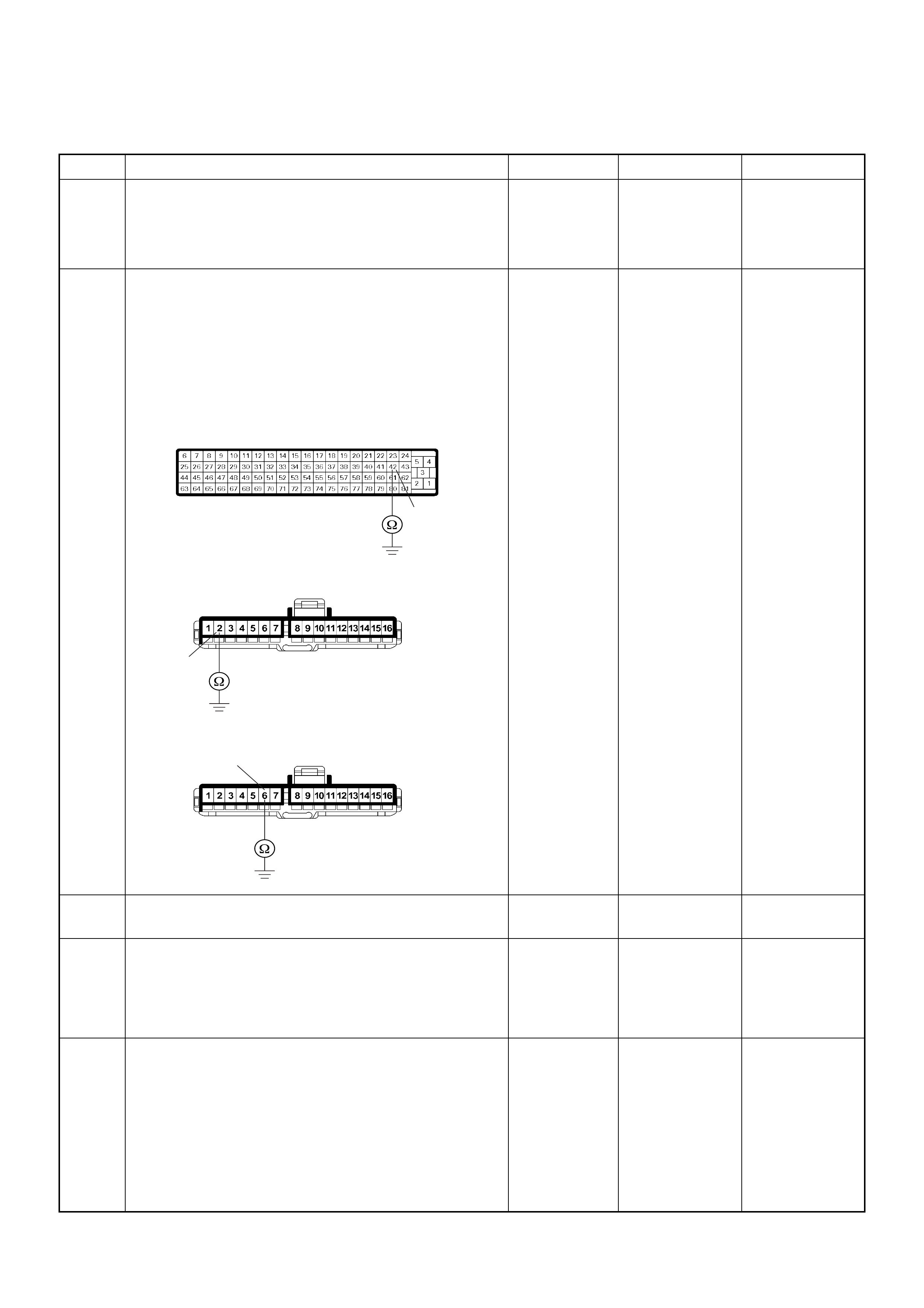
Check Engine Lamp (MIL) On Steady
Step Action Value(s) Yes No
1 1. Ignition “Off”, engine “Off”.
2. Disconnect the ECM connector.
3. Ignition “On”.
Was the “CHECK ENGINE” lamp turned on? — Go to Step 2 Go to Step 4
2 Using the DVM and check the “CHECK ENGINE”
lamp circuit.
1. Ignition “Off”, engine “Off”.
2. Disconnect the meter connector and ECM
connector.
3. Check the circuit for short to ground circuit.
Was the problem found?
— Verify repair Go to Step 3
3 Replace the meter assembly.
Is the action complete? — Verify repair —
4 Is the ECM programmed with the latest software
release?
If not, downlo ad the latest software to the ECM using
the “SPS (Service Programming System)”.
Was the problem solved? — Verify repair Go to Step 5
5 Replace the ECM.
Is the action complete?
IMPORTANT: The replacement ECM must be
programmed. Refer to section of the Service
Programming System (SPS) in this manual.
Foll owing ECM pr ogramming, the immobi liser system
(if equipped) must be linked to the ECM. Refer to
section 11 “Immobiliser System-ECM replacement” for
the ECM/Immobiliser linking procedure. — Verify repair —
42
2
6
B-23
C-56
4JA1-TC
B-23
4JH1-TC

ECM Diagnostic Trouble Codes
Flash
Code Code Symptom
Code MIL DTC Name DTC Setting Condition Fail-Safe (Back Up) Recovery Condition Related Failure Parts Related
ECM Pin
No.
Related
Multiple
DTC
4JA1
- T C
(MT)
4JH1
-TC
(MT)
4JH1
-TC
(AT)
65 P0100 7 ON Mass Air Flow (MAF) Sensor
Voltage Supply Circuit High Input MAF sensor power supply
voltage is more than 5.2V. ECM uses mass air flow
1600mg/strk & EGR 10%
(4JA1-TC only) condition(s)
as substitute.
MAF sensor power supply voltage
is below 5.2V. 1. Sensor power supply circuit
short to battery voltage circuit.
2. MAF sensor malfunction.
3. E CM malfunction.
83 -
9 ON Mass Air Flow (MAF) Sensor
Voltage Supply Circuit Low Input MAF sensor power supply
voltage is below 4.6V. MAF sensor power supply voltage
is more than 4.6V. 1. Sensor power supply circuit
short to ground circuit.
2. MAF sensor malfunction.
3. E CM malfunction.
83 -
B ON Mass Air Flow (MAF) Sensor
Output Circuit Low Input 1. Engine spe ed is between
600rpm and 5000rpm.
2. MAF sensor ou tput is below
-33.7mg/strk.
MAF sensor output is more than -
27.4mg/strk. 1. Sensor power supply circuit
open circuit.
2. Sensor signal circuit open or
short to ground circuit.
3. Sensor heater harness open
circuit.
4. Poor connector connection.
5. MAF sensor malfunction.
6. E CM malfunction.
83/88 P0110(1)
C ON Mass Air Flow (MAF) Sensor
Output Circuit High Input 1. Engine spe ed is between
600rpm and 5000rpm.
2. MAF sensor output is more
than 1784mg/strk.
MAF sensor output is below
1784mg/strk. 1. Sensor signal circuit short to
voltage circ ui t.
2. Sensor ground circuit open or
short to voltage circuit.
3. MAF sensor malfunction.
4. E CM malfunction.
88/ 92 P0110(1)
23 P0110 1 ON Intake Air Temperature (IAT)
Sensor Circuit High Input IAT sensor output voltage is
more than 4.7V. ECM use 0°C conditions as
substitute. IAT sensor output voltage is below
4.7V. 1. Sensor signal circuit open or
short to voltage circuit.
2. Sensor ground circuit open or
short to voltage circuit.
3. Poor connector connection
4. IAT sensor malfunction.
5. E CM malfunction.
84/92 P0100(B)/
P0100(C)
2 ON Intake Air Temperature (IAT)
Sensor Circuit Low Input IAT sensor output voltage is
below 0.3V. IAT sensor output voltage is more
than 0.3V. 1. Sensor signal circuit short to
ground circuit.
2. IAT sensor malfunction.
3. E CM malfunction.
84 -
14 P0115 1 ON Engine Coolant Temperature
(ECT ) Sensor Circuit High Input ECT sensor output voltage is
more than 4.7V. 1. ECM uses fuel
temperatur e as substitute.
2. ECM uses 60°C condition
for injec tion timing con tr ol.
3. ECM uses -1 5°C co ndit io n
for glow time control.
ECT sensor output voltage is below
4.7V. 1. Sensor signal circuit open or
short to voltage circuit.
2. Sensor ground circuit open or
short to voltage circuit.
3. Poor connector connection
4. ECT sensor malfunction.
5. E CM malfunction.
89/93 -
2 ON Engine Coolant Temperature
(ECT ) Sensor Circuit Low Input ECT sensor output voltage is
below 0.3V. ECT sensor output voltage is more
than 0.3V. 1. Sensor signal circuit short to
ground circuit.
2. ECT sensor malfunction.
3. E CM malfunction.
89 -

15 P0180 B ON Fuel Temperature Sensor Circuit
Range/Performance FT sens or output is high
temper atur e (mor e than
150°C) or low temperature
(below -40°C).
The ECM use 75°C
conditions as substitute. FT sensor output is correct
temperature range between 150°C
and -40°C.
1. E CM malfunction.
2. PSG (pump control unit)
malfunction.
--
52 P0215 A ON at
next
ignitio
n
cycle
Fuel Cutoff Solenoid Valve
Malfunction 1. Ignition key switch off.
2. Engine spe ed is below
1500rpm.
3. Vehicle speed is below
1.5km/h.
4. PSG ( pump control unit)
recognizes MAB (fuel cutoff
solenoid valve) signal from the
ECM, but the MAB could not
operate.
1. MAB (fuel cutoff solenoid
valve) is operated.
2. Desired injection quantity
becomes 0mg/strk.
No reco very until conditio n match in
the next ign iti on ke y cy cl e. 1. PSG (pump control unit)
malfunction.
2. MAB (fuel cutoff solenoid
valve) malfunction.
--
B ON Fuel Cutoff Solenoid V alve Circuit
High Input ECM does not command MAB
(fuel cutoff solenoid valve)
signal to the PSG (pump
control unit), but PSG
detected MAB signal line
circuit is high level.
Engine does not start. No recovery. 1. MAB (fuel cutoff solenoid
valve) signal circuit short to
voltage circ ui t.
2. PSG (pump control unit)
malfunction.
105 -
C ON Fuel Cutoff Solenoid Valve
Always Active 1. Ignition key switch off.
2. Engine spe ed is below
1500rpm.
3. Vehicle speed is below
1.5km/h.
4. PSG ( pump control unit)
does not recognize MAB (fuel
cutoff solenoid valve) signal
from the ECM.
1. MAB (fuel cutoff solenoid
valve) is operated.
2. Desired injection quantity
becomes 0mg/strk.
No reco very until conditio n match in
the next ign iti on ke y cy cl e. 1. MAB (fuel cutoff solenoid
valve) signal circuit open or short
to ground circuit.
2. PSG (pump control unit)
malfunction.
105 -
D ON Fuel Cutoff Solenoid Valve
Malfunction 1. Ignition key switch off.
2. CAN controller does not
operate Bus-off.
No fail-safe function. 1. ECM malfunction.
2. PSG (pump control unit)
malfunction.
--
54 P0216 A ON Inje ction Timing Control Circuit
Malfunction (Timer Deviation) 1. Engine speed is more than
700rpm.
2. Fuel injection quantity is
more than 4mg/stk.
3. Deviation of actual injection
timing and desired injection
timing is more than +3°CA or
-6°CA for 8 seconds.
Fuel injection quantity is
reduced. Deviation of actual injection timing
and desired injection timing is
below +3°CA or -6°CA for 8
seconds.
1. Timing control valve
malfunction.
2. Timer piston sticking.
3. Pump camshaft speed sensor
malfunction.
--
B ON Injection Timing Control Circuit
Malfunction (Timer Fluctuation) 1. Engine speed is more than
2014rpm.
2. Fluctuation of actual
injection timing is more than
±5.2°CA.
1. Engine speed is more than
2014rpm.
2. Fluctuation of actual injection
timing is below ±5.2°CA.
1. Insufficient air bleeding of fuel
line.
2. Fuel filter clogging.
3. Timing control valve
malfunction.
4. Pump camshaft speed sensor
malfunction.
--
Flash
Code Code Symptom
Code MIL DTC Name DTC Setting Condition Fail-Safe (Back Up) Recovery Condition Related Failure Parts Related
ECM Pin
No.
Related
Multiple
DTC
4JA1
- T C
(MT)
4JH1
-TC
(MT)
4JH1
-TC
(AT)

53 P0251 6 ON Injection Pump Malfunction 1. No pump camshaft speed
sensor error.
2. High pressure solenoid
valve control pulse width does
not match with desired fuel
injection quantity.
1. MAB (fuel cutoff solenoid
valve) is operated.
2. Desired injection quantity
becomes 0mg/strk.
No reco very until conditio n match in
the next ign iti on ke y cy cl e. 1. PSG (pump control unit)
malfunction.
2. Pump camshaft speed sensor
malfunction.
--
7 ON Injection Pump Malfunction 1. No pump camshaft speed
sensor error.
2. No CKP sensor error.
3. Difference of engine speed
and doub le d pump cam sh aft
speed is more than 720rpm
(4JA1-TC) or 690rpm (4JH1-
TC).
1. No pump camshaft speed sensor
error.
2. No CKP sensor error.
3. Difference of engine speed and
doubled pump camshaft speed is
below 720rpm (4JA1-TC) or
690rpm (4 JH1 -TC) .
No recovery until in the next ignition
key cycle.
1. Missing CKP sensor pulses.
2. Electrical interference.
3. Magnetic interference.
4. PSG (pump control unit)
malfunction.
91 -
9 ON Injection Pump Malfunction No pump map programmed in
the PSG (pump control unit) or
PSG malfunc ti on.
No reco very until conditio n match in
the next ign iti on ke y cy cl e. PSG (pump control unit)
malfunction. --
A ON Injection Pump Malfunction EEPROM or A/D converter
malfunction in the PSG (pump
contr ol uni t).
Fuel injection quantity is
reduced. EEPROM or A/D converter no
malfunction in the PSG (pump
control unit).
No recovery until in the next ignition
key cycle.
PSG (pump control unit)
malfunction. --
B ON Injection Pump Malfunction PSG (pump control unit)
recognized high pressure
solenoid valve drive circuit
error.
No fail-safe function. No recovery until condition match in
the next ign iti on ke y cy cl e. PSG (pump control unit)
malfunction. --
D ON Injection Pump Malfunction PSG (pump control unit) could
not measure the high pressure
solenoid valve drive voltage.
PSG (pump control unit)
malfunction. --
E ON Injection Pump Malfunction ECM could not accept PSG
(pump control unit) message. 1. MAB (fuel cutoff solenoid
valve) is operated.
2. Desired injection quantity
becomes 0mg/strk.
ECM accepts PSG (pump control
unit) message. 1. CAN high circuit open, short to
ground or short to voltage circuit.
2. CAN low circuit open, short to
ground or short to voltage circuit.
3. E CM malfunction.
4. PSG (pump control unit)
malfunction.
99/100 P1650(A)/
P1651(B)
Flash
Code Code Symptom
Code MIL DTC Name DTC Setting Condition Fail-Safe (Back Up) Recovery Condition Related Failure Parts Related
ECM Pin
No.
Related
Multiple
DTC
4JA1
- T C
(MT)
4JH1
-TC
(MT)
4JH1
-TC
(AT)

43 P0335 B ON Crankshaft Position Sensor
Circuit Malfunction 1. Engine speed is more than
665rpm.
2. CKP sensor pulse width
error.
When pump camshaft speed
sensor is OK:
ECM uses doubled pump
camshaft speed as substitute
engine speed.
When pump camshaft speed
sensor is not OK :
1. MAB (fuel cutoff solenoid
valve) is operated.
2. Desired injection quantity
becomes 0mg/strk.
ECM detects correct CKP pulse
width. During engine run:
1. CKP sensor harness open
circuit, short to ground or short to
voltage circ ui t.
2. Poor connector connection.
3. CKP sensor malfunction.
4. Pulse sensing gap incorrect.
5. Pulser malfunction.
6. Electrical interference.
7. Magnetic interference.
8. E CM malfunction.
90/ 98/
101 P1335 (A)
D ON Crankshaft Position Sens or
Circuit Malfunction 1. No pump camshaft speed
sensor error.
2. “Crankshaft Position Sensor
Circuit Mal fun cti on (Sy mpto m
Code B)” is not stored.
3. Engine spe ed is 0rpm .
4. Doubled pump camshaft
speed is more than 50rpm.
When pump camshaft speed
sensor is OK:
ECM uses doubled pump
camshaft speed as substitute
engine speed.
Other than pump camshaft
speed sensor is OK:
Fuel injection quantity is
reduced.
1. Engine speed is more than 0rpm.
2. Doubled pump camshaft speed is
below 100rpm.
During engine crank:
1. CKP sensor harness open
circuit, short to ground or short to
voltage circ ui t.
2. Poor connector connection.
3. CKP sensor malfunction.
4. Pulse sensing gap incorrect.
5. Pulser malfunction.
6. Electrical interference.
7. Magnetic interference.
8. E CM malfunction.
90/ 98/
101 P1135 (A)
E ON Engine Speed Input Circuit
Range/Performance Engine speed is more than
5700rpm. When intermittent
malfunction:
1. MAB (fuel cutoff solenoid
valve) is operated.
2. Desired injection quantity
becomes 0mg/strk.
When preliminary
malfunction:
ECM uses doubled pump
camshaft speed as substitute
engine speed.
Engine speed is below 5700rpm. 1. Engine over-running.
2. CKP sensor malfunction.
3. Pulser malfunction.
4. E CM malfunction.
90/ 98/
101 -
66 P0380 4 ON Glow Relay Circuit Voltage Low Glow relay circuit open or
short to ground circuit. No fail-safe function. Glow relay circuit is correct
condition. 1. Glow relay circuit open or short
to ground circuit.
2. Glow relay malfunction.
3. E CM malfunction.
94 -
8 ON Glow Relay Circuit Voltage High Glow relay circuit short to
voltage circuit. ECM malfunction. - -
67 P0381 4 ON Glow Plug Indicator Circuit
Voltage Low Glow plug indicator circuit
open or short to ground circuit. No fail-safe function. Glow plug indicator circuit is correct
condition. 1. Glow plug indicator circuit
open or short to ground circuit.
2. Glow plug indicator lamp
malfunction.
3. E CM malfunction.
43 -
8 ON Glow Plug Indicator Circuit
Voltage High Glow plug indicator circuit
short to voltage circuit. ECM malfunction. - -
Flash
Code Code Symptom
Code MIL DTC Name DTC Setting Condition Fail-Safe (Back Up) Recovery Condition Related Failure Parts Related
ECM Pin
No.
Related
Multiple
DTC
4JA1
- T C
(MT)
4JH1
-TC
(MT)
4JH1
-TC
(AT)

32 P0400 3 ON Exhaust Gas Recirculation Flow
Excessive Detected 1. Intake air temperature is
between 15°C and 100°C.
2. Engine coolant temperature
is between 55°C and 100°C.
3. Barometric pressure is
between 850hpa and
1100hpa.
4. Small amount of mass air
flow. (Desired mass air flow -
mass air flow is more than
150mg/strk)
Fuel injection quantity is
reduced. 1. Engine speed is between
1500rpm and 3100rpm.
2. Injection quantity is between
8mg/str k and 32mg/s tr k.
3. Correct amount of mass air flow.
1. EGR valve is stuck at open
position.
2. EGR EVRV malfunction.
3. Air intake is obstructed.
4. Air intake is leaking.
5. MAF sensor malfunction.
6. E CM malfunction.
88/97 - - -
4 ON Exhaust Gas Recirculation Circuit
Short to Ground or Open Circuit EGR EVRV circuit open or
short to ground circuit. Fuel injection quantity is
reduced and EGR EVRV
10% conditions as substitute.
EGR EVRV circuit is correct
condition. 1. EGR EVRV circuit open or
short to ground circuit.
2. EGR EVRV malfunction.
3. E CM malfunction.
97 - - -
5 ON Exhaust Gas Recirculation Flow
Insufficient Detected 1. Intake air temperature is
between 15°C and 100°C.
2. Engine coolant temperature
is between 55°C and 100°C.
3. Barometric pressure is
between 850hpa and
1100hpa.
4. Large mount of mass air
flow. (Desired mass air flow -
mass air flow is below 150 mg/
strk)
Fuel injection quantity is
reduced. 1. Engine speed is between
1500rpm and 3100rpm.
2. Injection quantity is between
8mg/str k and 32mg/s tr k.
3. Correct amount of mass air flow.
1. EGR valve is stuck at close
position.
2. EGR valve operating vacuum
hose is clogged or disconnected.
3. EGR EVRV malfunction.
4. MAF sensor signal circuit short
to voltage circuit.
5. MAF sensor malfunction.
6. E CM malfunction.
88/97 - - -
8 ON Exhaust Gas Recirculation Circuit
Short to Battery EGR EVRV circuit short to
voltage circuit. Fuel injection quantity is
reduced & EGR EVRV 10%
conditions as substitute.
EGR EVRV circuit is correct
condition. 1. EGR EVRV circuit short to
voltage circ ui t.
2. EGR EVRV malfunction.
3. E CM malfunction.
97 - - -
24 P0500 1 ON at
next
ignitio
n
cycle
Vehicle Speed Sensor Circuit
High Input Vehicle speed is more than
200km/h. ECM uses vehicle speed
5km/h condition as
substitute.
Vehicle speed is below 200km/h. 1. VSS signal circuit open, short
to ground or short to voltage
circuit.
2. VSS malfunction.
3. Speed meter malfunction.
4. E CM malfunction.
68 -
AON at
next
ignitio
n
cycle
Vehicle Speed Sensor Input
Signal Frequency Too High Input signal frequency is too
high. ECM uses vehicle speed
5km/h condition as
substitute.
Correct vehic le sp eed si gna l
frequency. 1. VSS malfunction.
2. Speed meter malfunction.
3. Electrical interference.
4. Magnetic interference.
5. E CM malfunction.
68 -
BON at
next
ignitio
n
cycle
Vehicle Speed Sensor Incorrect
Signal 1. Engine speed is more than
3600rpm.
2. Fuel injection quantity is
more than 41mg/stk.
3. Vehicle speed is below
1.5km/h.
Fuel injection quantity is
reduced. Vehicle speed is more than 1.5km/
h. 1. VSS open circuit, short to
ground or short to voltage.
2. Poor connector connection.
3. VSS malfunction.
4. Speed meter malfunction.
5. E CM malfunction.
68 - -
Flash
Code Code Symptom
Code MIL DTC Name DTC Setting Condition Fail-Safe (Back Up) Recovery Condition Related Failure Parts Related
ECM Pin
No.
Related
Multiple
DTC
4JA1
- T C
(MT)
4JH1
-TC
(MT)
4JH1
-TC
(AT)

35 P0560 1 OFF System Voltage Too High System voltage is more than
20V. ECM uses 9V conditions as
substitute. System voltage is below 20V. 1. Charge system malfunction.
2. Battery jump start cable
misconnect.
3. E CM malfunction.
3/39 -
2 OFF System Voltage Too Low System voltage is below 7V. System voltage is more than 7V. 1. Battery power feed harness
open circuit or short to ground
circuit.
2. ECM ground harness open or
poor connection.
3. Poor connector connection.
4. Battery malfunction.
5. Charge system malfunction.
6. E CM malfunction.
3/39 -
A OFF System Voltage Malfunction
(PSG) System voltage of PSG (pump
control unit) is below 4.5V or
more than 27V.
PSG uses default voltage as
substitute. System voltage of PSG is between
4.5V and 27V. 1. Battery power feed harness
open circuit or short to ground
circuit.
2. PSG (pump control unit)
ground harness open or poor
connection.
3. Poor connector connection.
4. Battery malfunction.
5. Charge system malfunction.
6. Battery jump start cable
misconnect.
7. PSG (pump control unit)
malfunction.
--
18 P0561 A OFF System Voltage Circuit
Malfunction The ECM recognized ignition
switch turn off signal during
ECM is activated.
ECM stops engine. No recovery until condition match in
the next ign iti on ke y cy cl e. 1. Ignition switch circuit open or
short to ground circuit.
2. Poor connector connection.
3. Ignition switch malfunction.
4. E CM malfunction.
39 -
B ON System Voltage Circuit
Malfunction Ignition switch circuit is
malfunction. 1. Ignition switch circuit open or
short to ground circuit.
2. Poor connector connection.
3. Ignition switch malfunction.
4. E CM malfunction.
39 -
- P0602 - ECU Programming Error ECM memory area error. Engine control disabled. Memory are is OK. ECM is not programmed. - -
28 P0606 A ON ECU Malfunction Gate Array communication
error. 1. MAB (fuel cutoff solenoid
valve) is operated.
2. Desired injection quantity
becomes 0mg/strk.
No recove ry. ECM malf unc tion. - -
B ON ECU Malfunction 1. Throttle position is below
1%.
2. Desired injection quantity is
more than 0mg/strk.
3. Engine speed is more than
2000rpm.
MAB (fuel cutoff solenoid
valve) is operated. Desired injection quantity is below
0mg/strk. 1. E CM malfunction.
2. PSG (pump control unit)
malfunction.
--
Flash
Code Code Symptom
Code MIL DTC Name DTC Setting Condition Fail-Safe (Back Up) Recovery Condition Related Failure Parts Related
ECM Pin
No.
Related
Multiple
DTC
4JA1
- T C
(MT)
4JH1
-TC
(MT)
4JH1
-TC
(AT)

46 P0645 4 ON A/C Compressor Relay Circuit
Voltage Low A/C compressor rela y circuit
open or short to ground circuit. No fail-safe function. A/C compressor relay circuit is
correct cond ition. 1. A/C compressor relay circuit
open or short to ground circuit.
2. Poor connector connection.
3. A/C compressor rel ay
malfunction.
4. E CM malfunction.
41 -
8 ON A/C Compressor Relay Circuit
Voltage High A/C compressor rela y circuit
short to voltage circuit. ECM malfunction. - -
25 P0703 A ON Brake Switch Malfunction 1. Throttle position is more
than 0%.
2. Engine speed is more than
693rpm (4JA1-TC) or 665rpm
(4JH1-TC).
3. Vehicle speed is more than
0km/h.
4. Brake switch 1 signal and
brake switch 2 signal are
differently inputted to the ECM
since the ignition switch was
turned on.
No fail-safe function. Brake switch 1 signal and brake
switch 2 signal are correctly
inputted to the ECM.
1. Brake switch 1 circuit open,
short to ground or short to
voltage circ ui t.
2. Poor connector connection.
3. Brake switch 1 malfunction.
4. E CM malfunction.
30 -
B ON Brake Switch Malfunction 1. Throttle position is more
than 0%.
2. Engine speed is more than
693rpm (4JA1-TC) or 665rpm
(4JH1-TC).
3. Vehicle speed is more than
0km/h.
4. Brake switch 1 signal and
brake switch 2 signal are
differently inputted to the
ECM.
1. Brake switch 2 circuit open or
short to ground circuit.
2. Poor connector connection.
3. Brake switch 2 malfunction.
4. E CM malfunction.
65 -
57 P0704 6 ON Clutch Switch Input Circuit
Malfunction Clutch signal does not change
between vehicle speed 1.5km/
h and 80km/h since ignition
switch was tuned on.
No fail-safe function. Clutch signal correctly changes. 1. Clutch switch circuit open,
short to ground or short to
voltage circ ui t.
2. Poor connector connection.
3. Clutch switch malfunction.
4. E CM malfunction.
31 - -
86 P1105 1 ON Barometric Pressure Sensor
Circuit High Input Barometric pressure sensor
output voltage is more than
4.4V.
ECM uses 1013hpa condition
as substitute. Barometric pressure sensor output
voltage is below 4.4V. ECM malfunction. - -
2 ON Barometric Pressure Sensor
Circuit Low Input Barometric pressure sensor
output voltage is below 1.5V. Barometric pressure sensor output
voltage is more than 1.5V. ECM malfunction. - -
Flash
Code Code Symptom
Code MIL DTC Name DTC Setting Condition Fail-Safe (Back Up) Recovery Condition Related Failure Parts Related
ECM Pin
No.
Related
Multiple
DTC
4JA1
- T C
(MT)
4JH1
-TC
(MT)
4JH1
-TC
(AT)

21 P1120 1 ON Pedal/Throttle Position Sensor
Circuit High Input Throt tle pos ition se nsor out put
voltage is more than 4.5V. ECM increases idle speed up
to 1400rpm. Throttle position sensor output
voltage is below 4.5V. 1. Sensor power supply circuit
short to voltage circuit.
2. Sensor signal circuit short to
voltage circ ui t.
3. Sensor ground circuit open or
short to voltage circuit.
4. Poor connector connection.
5. TPS malfunction.
6. E CM malfunction.
38/ 49/ 57 -
7 ON Pedal/Throttle Position Sensor
Voltage Supply Circuit High Input Throttle position sensor power
supply voltage is more than
5.2V.
Throttle position sensor power
supply voltage is below 5.2V. 1. Sensor power supply circuit
short to battery voltage circuit.
2. TPS malfunction.
3. E CM malfunction.
57 -
9 ON Pedal/Throttle Position Sensor
Voltage Supply Circuit Low Input Throttle position sensor power
supply voltage is below 4.6V. Throttle position sensor power
supply voltage is more than 4.6V. 1. Sensor power supply circuit
short to ground circuit.
2. TPS malfunction.
3. E CM malfunction.
57 -
D ON Pedal/Throttle Position Sensor
Brake Switch Error 1. Engine speed is more than
1700rpm.
2. Throttle position sensor is
more than 8.7%.
3. When brake pedal is
depressed during accelerator
pedal is depressing.
Throttle position is more than 20%
or brake pedal is released (switch is
inactive).
1. Throttle sticking.
2. TPS incorrect adjusting.
3. TPS malfunction.
4. Brake switch malfunction.
5. E CM malfunction.
30/ 38/ 65 -
E ON Pedal/Throttle Position Sensor
Idle Position Switch Error 1. When idle switch is turned
off, throttle position sensor
was below 0.35%.
or
2. When idle switch is tuned
on, throttle position sensor
was more than 7.8%.
1. When throttle position sensor is
100%, idle switch turns off.
2. When throttle position sensor is
0%, idle switch turns on.
1. TPS malfunction.
2. Idle switch malfunction.
3. E CM malfunction.
38/ 69 -
22 P1173 3 OFF Fuel Reduction Caused By High
Coolant Temperature Excessive high engine coolant
temp eratur e is detected. No fail-safe function. Engine coolant temperature is
normal range. 1. Engine overheat.
2. ECT sensor malfunction.
3. E CM malfunction.
89 -
7 OFF Fuel Reduction Caused By High
Fuel Temperature Fuel temperature is more than
100°C.PSG (pump control unit)
controls fuel injection
quantity based on engine
speed and fuel temperature.
Fuel temperature is below 100°C.1. ECM malfunction.
2. PSG (pump control unit)
malfunction.
--
A OFF Fuel Reduction Caused By Low
Fuel Temperature Excessive low fuel
temp eratur e is detected. No fail-safe function. Fuel temperature is normal range. 1. ECM malfunction.
2. PSG (pump control unit)
malfunction.
--
Flash
Code Code Symptom
Code MIL DTC Name DTC Setting Condition Fail-Safe (Back Up) Recovery Condition Related Failure Parts Related
ECM Pin
No.
Related
Multiple
DTC
4JA1
- T C
(MT)
4JH1
-TC
(MT)
4JH1
-TC
(AT)

43 P1335 A ON Engine Speed Output Circuit
Malfunction The PSG (pump control unit)
is recognized defective engine
speed signal form the ECM.
Fuel injection quantity is
reduced. Correct engine speed signal. 1. CKP sensor harness open
circuit, short to ground or short to
voltage.
2. CKP sensor output harness
open circuit, short to ground or
short to voltage.
3. Poor connector connection.
4. CKP sensor malfunction.
5. Pulse sensing gap incorrect.
6. Pulser malfunction.
7. Electrical interference.
8. Magnetic interference.
9. E CM malfunction.
10. PSG (pump control unit)
malfunction.
90/91/98/
101 P0335(B)/
P0335(D)
45 P1345 A ON Camshaft Speed Malfunction The PSG (pump control unit)
is recognized incorrect
camshaft speed signal.
No fail-safe function. Correct camshaft speed. 1. Pump camshaft speed sensor
malfunction.
2. Pulse sensing gap incorrect.
3. Pulser malfunction.
4. Electrical interference.
5. Magnetic interference.
5. E CM malfunction.
6. PSG (pump control unit)
malfunction.
--
47 P1520 A ON Neutral Switch ON Error Neutral switch signal is
inputted “On” three times
conse cu t ivel y under driving
conditions.
No fail-safe function. Correct neutral switch signal is
inputted two times consecutively
under driving conditions.
1. Neutral switch circuit short to
voltage circ ui t.
2. Neutral switch malfunction.
3. E CM malfunction.
87 - - -
B ON Neutral Switch OFF Error Neutral switch signal is
inputted “Off” three times
conse cu t ivel y under driving
conditions.
1. Neutral switch circuit open,
short to ground circuit.
2. Poor connector connection.
3. Neutral switch malfunction.
4. E CM malfunction.
87 - - -
71 P1576 4 ON Exhaust Throttle VSV 1 Circuit
Voltage Low Exhaust throttle VSV 1 circuit
open or short to ground circuit. No fail-safe function. Exhaust throttle VSV 1 circuit is
correct cond ition. 1. Exhaust throttle VSV 1 circuit
open or short to ground circuit.
2. Poor connector connection.
3. Exhaust throttle VSV 1
malfunction.
4. E CM malfunction.
40 - - -
8 ON Exhaust Throttle VSV 1 Circuit
Voltage High Exhaust throttle VSV 1 circuit
short to voltage circuit.
ECM malfunction.
-- --
71 P1577 4 ON Exhaust Throttle VSV 2 Circuit
Voltage Low Exhaust throttle VSV 2 circuit
open or short to ground circuit. No fail-safe function. Exhaust throttle VSV 2 circuit is
correct cond ition. 1. Exhaust throttle VSV 2 circuit
open or short to ground circuit.
2. Poor connector connection.
3. Exhaust throttle VSV 2
malfunction.
4. E CM malfunction.
61 - - -
8 ON Exhaust Throttle VSV 2 Circuit
Voltage High Exhaust throttle VSV 2 circuit
short to voltage circuit. ECM malfunction.
--
--
Flash
Code Code Symptom
Code MIL DTC Name DTC Setting Condition Fail-Safe (Back Up) Recovery Condition Related Failure Parts Related
ECM Pin
No.
Related
Multiple
DTC
4JA1
- T C
(MT)
4JH1
-TC
(MT)
4JH1
-TC
(AT)

55 P1605 D ON EEPROM Defect Write and read from the
EEPROM are failed during
initialization of the ECM.
ECM uses default values
from the EPROM. Write and read from the EEPROM
are correct during initialization of
the ECM.
ECM malfunction. - -
E ON EEPROM D efect EEPROM checks um doe s not
match with the read che ck
sum during initialization of the
ECM.
EEPROM checksum match with the
read check sum during initialization
of the ECM.
ECM malfunction. - -
56 P1610 A - Security Key and Security Code
not Programmed Immobiliser functions are not
programmed in the ECM. 1. Engine does not start.
2. Check engine lamp flash. No recove ry. ECM malfunc ti on. - B****
56 P1611 A - Wrong Security Code Entered Received security code is not
correct. 1. Engine does not start.
2. Check engine lamp flash. No recovery. 1. ECM malfunction.
2. Immobili ser contr ol uni t
malfunction.
3. Transponder key malfunction.
- B****
56 P1612 A - Immobiliser No or Wrong Signal Received challenge signal is
not correct or not received. 1. Engine does not start.
2. Check engine lamp flash. No recovery. 1. ECM and immobiliser control
unit communication circuit open
circuit, short to ground circuit or
short to voltage circuit.
2. E CM malfunction.
3. Immobili ser contr ol uni t
malfunction.
4. Transponder key malfunction.
27/35 B****
56 P1613 A - Immobiliser No or Wrong Signal Received response signal is
not correct or not received. 1. Engine does not start.
2. Check engine lamp flash. No recovery. 1. ECM and immobiliser control
unit communication circuit open
circuit, short to ground circuit or
short to voltage circuit.
2. E CM malfunction.
3. Immobili ser contr ol uni t
malfunction.
4. Transponder key malfunction.
27/35 B****
56 P1614 A - Wrong Transponder Key Received response signal is
not correct from the
transponder key.
1. Engine does not start.
2. Check engine lamp flash. No recovery. 1. ECM malfunction.
2. Immobili ser contr ol uni t
malfunction.
3. Transponder key malfunction.
- B****
76 P1625 A OFF ECM Main Relay Switched Off
Too Early When ignition switch was
turned off, timing of the ECM
main relay turning off is too
early.
No fail-safe func ti on. No reco ve ry. ECM malfunc tion. 3/58 -
B OFF ECM Main Relay Switched Off
Too Late When ignition switch was
turned off, timing of the ECM
main relay turning off is too
late or does not off.
No recovery. 1. ECM main relay malfunction.
2. E CM malfunction. 3/58 -
Flash
Code Code Symptom
Code MIL DTC Name DTC Setting Condition Fail-Safe (Back Up) Recovery Condition Related Failure Parts Related
ECM Pin
No.
Related
Multiple
DTC
4JA1
- T C
(MT)
4JH1
-TC
(MT)
4JH1
-TC
(AT)

51 P1630 A ON Fuel Injection Quantity Circuit
Malfunction The PSG (pump control unit)
detects high pressure solenoid
valve control circuit
malfunction due to high
current.
Fuel injection quantity is
reduced. The PSG (pump control unit)
detects correct high pressure
solenoid valve control circuit.
PSG (pump control unit)
malfunction. --
B ON Fuel Injection Quantity Circuit
Malfunction The PSG (pump control unit)
detects high pressure solenoid
valve control circuit
malfunction due to continuous
current.
1. MAB (fuel cutoff solenoid
valve) is operated.
2. Desired injection quantity
becomes 0mg/strk.
No recovery. PSG (pump control unit)
malfunction. --
44 P1650 A ON CAN Device Offline CAN controller detects Bus-off
or canc eli ng. MAB (fuel cutoff solenoid
valve) is operated. CAN controller detects correct Bus
signal. 1. CAN high circuit open, short to
ground or short to voltage circuit.
2. CAN low circuit open, short to
ground or short to voltage circuit.
3. Poor connector connection.
4. Electrical interference.
5. E CM malfunction.
6. PSG (pump control unit)
malfunction.
99/100 P1651(B)
B ON CAN Device Hang-up CAN controller does not react
under eng ine running. CAN controller reacts correctly
under engine running. 1. ECM malfunction.
2. PSG (pump control unit)
malfunction.
--
45 P1651 A ON CAN Malfunction (PSG) The PSG (pump control unit)
does not recognize CAN
signal from the CAN controller.
1. MAB (fuel cutoff solenoid
valve) is operated.
2. Desired injection quantity
becomes 0mg/strk.
The PSG (pump control unit)
recognizes CAN signal from the
CAN controller.
1. E CM malfunction.
2. PSG (pump control unit)
malfunction.
--
B ON CAN Receives Error The ECM does not read CAN
signal from the PSG (pump
contr ol uni t).
The ECM reads CAN signal from
the PSG (pump control unit). 1. CAN high circuit open, short to
ground or short to voltage circuit.
2. CAN low circuit open, short to
ground or short to voltage circuit.
3. Poor connector connection.
4. Electrical interference.
5. E CM malfunction.
6. PSG (pump control unit)
malfunction.
99/100 P1650(A)
77 P1690 4 OFF Check Engine Lamp (MIL) Circuit
Voltage Low Check engine lamp circuit
open or short to ground circuit. No fail-safe function. Check engine lamp circuit is correct
condition. 1. Check engine lamp circuit
open or short to ground circuit.
2. Check engine lamp
malfunction.
3. E CM malfunction.
42 B****
8 OFF Check Engine Lamp (MIL) Circuit
Voltage High Check engine lamp circuit
short to voltage circuit. ECM malfunction. - -
Flash
Code Code Symptom
Code MIL DTC Name DTC Setting Condition Fail-Safe (Back Up) Recovery Condition Related Failure Parts Related
ECM Pin
No.
Related
Multiple
DTC
4JA1
- T C
(MT)
4JH1
-TC
(MT)
4JH1
-TC
(AT)
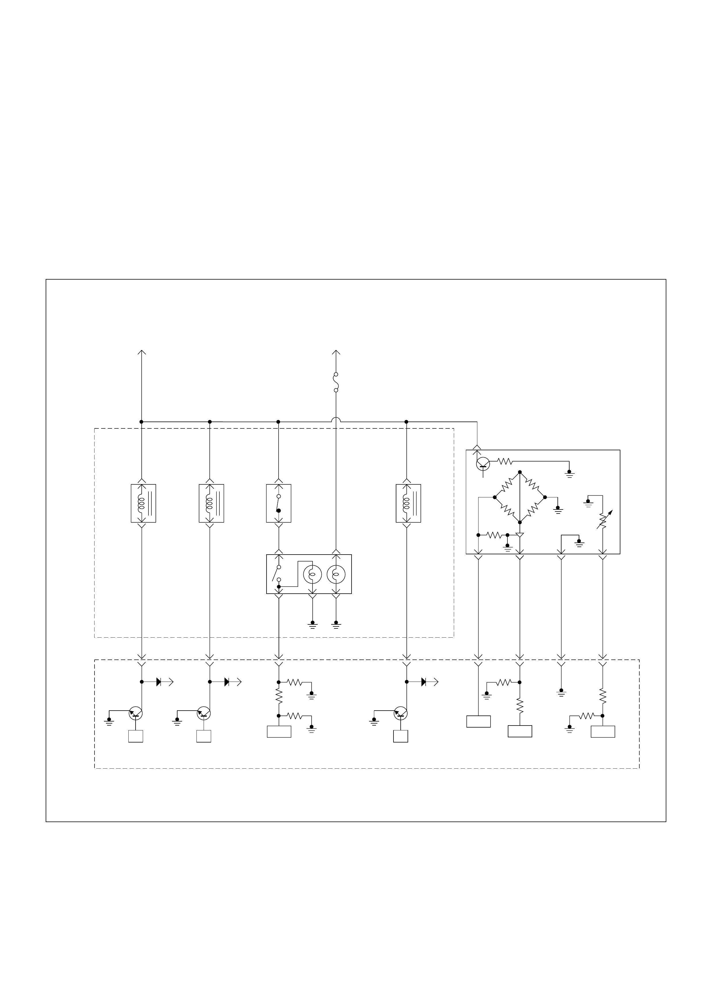
Diagnostic Trouble Code (Dtc) P0100 (Symptom Code 7)
(Flash Code 65) Mass Air Flow (MAF) Sensor Volt age Supply Circuit High Input
Diagnostic Trouble Code (DTC) P0100 (Symptom Code 9)
(Flash Code 65) Mass Air Flow (MAF) Sensor Voltage Supply Circuit Low Input
Diagnostic Trouble Code (DTC) P0100 (Symptom Code B)
(Flash Code 65) Mass Air Flow (MAF) Sensor Output Circuit Low Input
Diagnostic Trouble Code (DTC) P0100 (Symptom Code C)
(Flash Code 65) Mass Air Flow (MAF) Sensor Output Circuit High Input
Batt
µP
Batt
µP
Batt
µP
0.5
BLK/
URG
0.5
BRN/
RED
0.5
BLU/
RED
0.5
BLU/
RED
4JA1-TC
0.5
GRY/
YEL
974661
0.5
WHT/
RED
83
0.5
GRN/
RED
88
0.5
BLK/
RED
92
0.5
BLK/
BLU
84
IAT
Sensor MAF &
IAT
Sensor
Rr Fog
Light
10A
EGR-
EVRV
0.5
WHT/
BLK
0.5
BLU/
RED
0.5
WHT/
BLU
0.5
BLU/
RED
0.5
GRN/
RED
0.5
BLU/
RED
Exhaust
Throttle
VSV2
Exhaust
Throttle
VSV1
Engine
Warming Up
SW
Thermo
SW
2
4531
Battery
Voltage
ECM
Main Relay
IC ICIC CPU
Engine
Control
Module
(ECM)
40

Condition for setting the DTC and action taken when the DTC sets
Circuit Desc rip tio n
The mas s air flo w (MAF) sensor is part of the intake air
system. It is fitted between the air cleaner and
turbocha rger a nd mea sure th e mas s air flo win g into th e
engine.
The mass air flow (MAF) sensor element measures the
partial air mass through a measurement duct on the
sensor housing.
The ECM monitors the MAF sensor s upply voltage an d
MAF sensor output voltage. If fhe supply voltage is out
of range, DTC P0100 (Symptom Code 7) or P0100
(Symptom Code 9) will be stored. If the output voltage
excessively high or low, DTC P0100 (Symptom Code B)
or P0100 (Symptom Code C) will be stored.
Diagnostic Aids
An intermittent may be caused by the following:
• Poor connections.
• Misrouted harness.
• Rubbed through wire insulation.
• Broken wire inside the insulation.
Check for the following conditions:
• Poor con nection at ECM-I nspect harnes s connectors
for backed out terminals, improper mating, broken
locks, improperly formed or damaged terminals, and
poor terminal to wire connection.
• Damaged harness-Inspect the wiring harness for
damage. If the harness appears to be OK, observe
the “Mass Air Flow” display on the Tech2 while
moving connectors and wiring harness related to the
sensor.
Flash
Code Code Symptom
Code MIL DTC Name DTC Setting Condition F ail-Safe (Back Up)
65 P0100 7 ON Mass Air Flow (MAF) Sensor
Voltage Supply Circuit High
Input
MAF sensor power supply
voltage is more than 5.2V. ECM uses mass air flow
1600mg/strk & EGR 10%
(4JA1-TC only) condition(s) as
substitute.
9 ON M ass Air Flow (M AF ) Sensor
Voltage Supply Circuit Low
Input
MAF sensor power supply
voltage is below 4.6V.
B ON M ass Air Flow (M AF ) Sensor
Output Circuit Low Input 1.Engine speed is between
600rpm and 5000rpm.
2. MAF sensor output is
below -33.7mg/strk.
C ON Mass Air Flow (MAF) Sensor
Output Circuit High Input 1. Engine speed is between
600rpm and 5000rpm.
2. MAF sensor output is more
than 1784mg/strk.
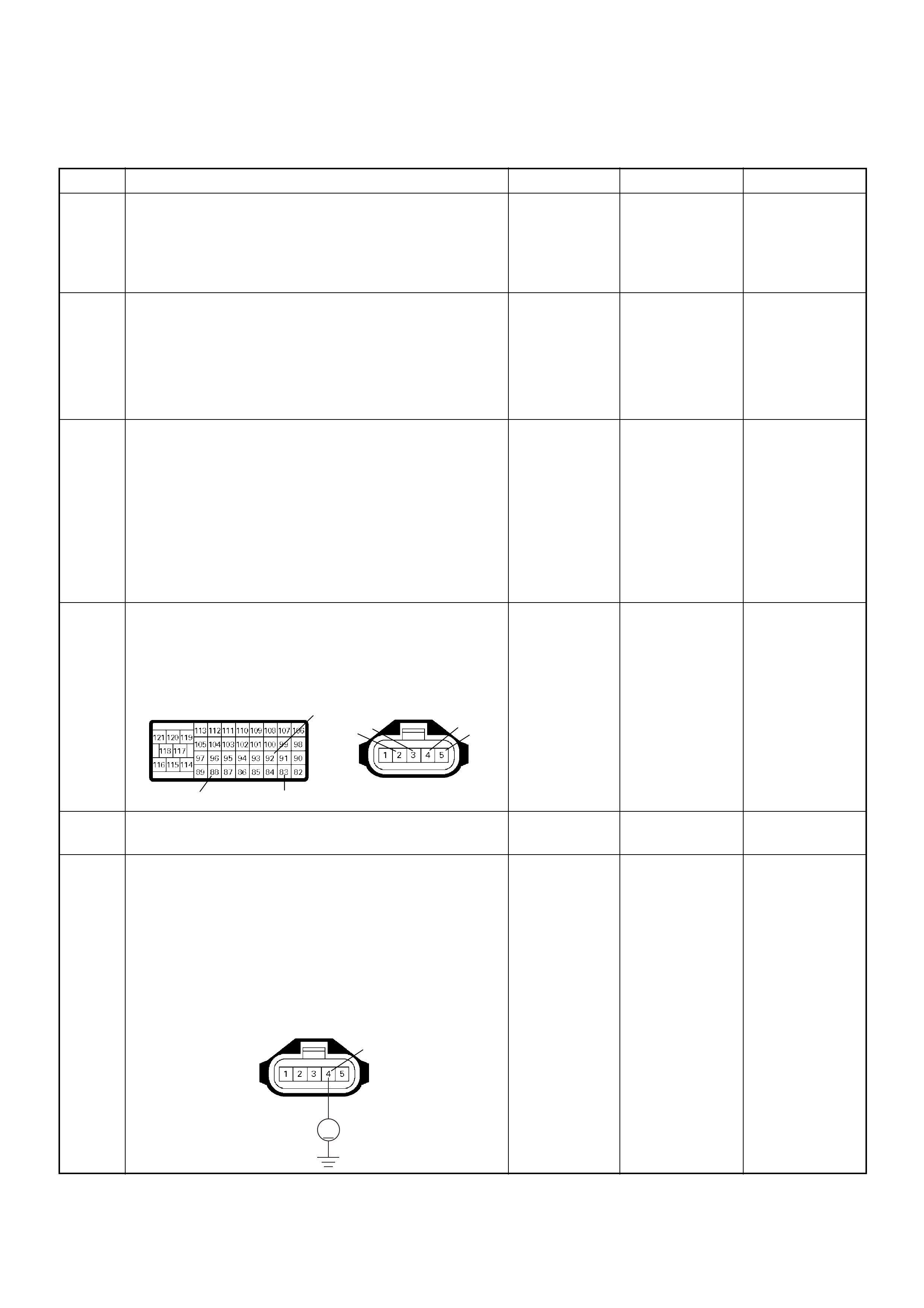
Diagnostic Trouble Code (DTC) P0100 (Symptom Code 7) (Flash Code 65)
Mass Air Flow (MAF) Sensor Voltage Supply Circuit High Input
Step Action Value(s) Yes No
1 Was the “On-Board Diagnostic (OBD) System Check”
performed?
—Go to Step 2
Go to On
Board
Diagnostic
(OBD) System
Check
2 1. Connect the Tech 2.
2. Review and record the failure information.
3. Select “F0: Read DTC Infor As Stored By ECU” in
“F0: Diagnostic Trouble Codes”.
Is the DTC P0100 (Symptom Code 7) stored as
“Present Failure”? — Go to Step 3
Refer to
Diagnostic
Aids and Go to
Step 3
3 1. Using the Tech 2, ignition “On” and engine “Off”.
2. Select “F1: Clear DTC Information” in “F0:
Diagnostic Trouble Codes” with the Tech 2 and
clear the DTC information.
3. Operate the vehicle and monitor the “F0: Read
DTC Infor As Stored By ECU” in the “F0:
Diagnostic Trouble Codes”.
Was the DT C P0 100 (Sy mpt om Code 7) stor e d i n th is
ignition cycle? — Go to Step 4
Refer to
Diagnostic
Aids and Go to
Step 4
4 Check for poor/faulty connection at the MAF sensor or
ECM connector. If a poor/faulty connection is found,
repair as necessary.
Was the problem found?
— Verify repair Go to Step 5
5 Vis ual ly chec k the MA F sensor.
Was the problem found? — Go to Step 11 Go to Step 6
6 Using the DVM and check the MAF sensor power
supply circuit.
1. Ignition “On”, engine “Off”.
2. Disconnect the MAF & IAT sensor connector.
3. Check the circuit for short to battery voltage
circuit.
Was the DVM indicated specified value?
Approximately
5.0V Go to Step 11
Less than 1V:
Go to Step 7
More than
specified value:
Go to Step 8
92
88 83
2345
C-51C-57(B)
V
4
C-51
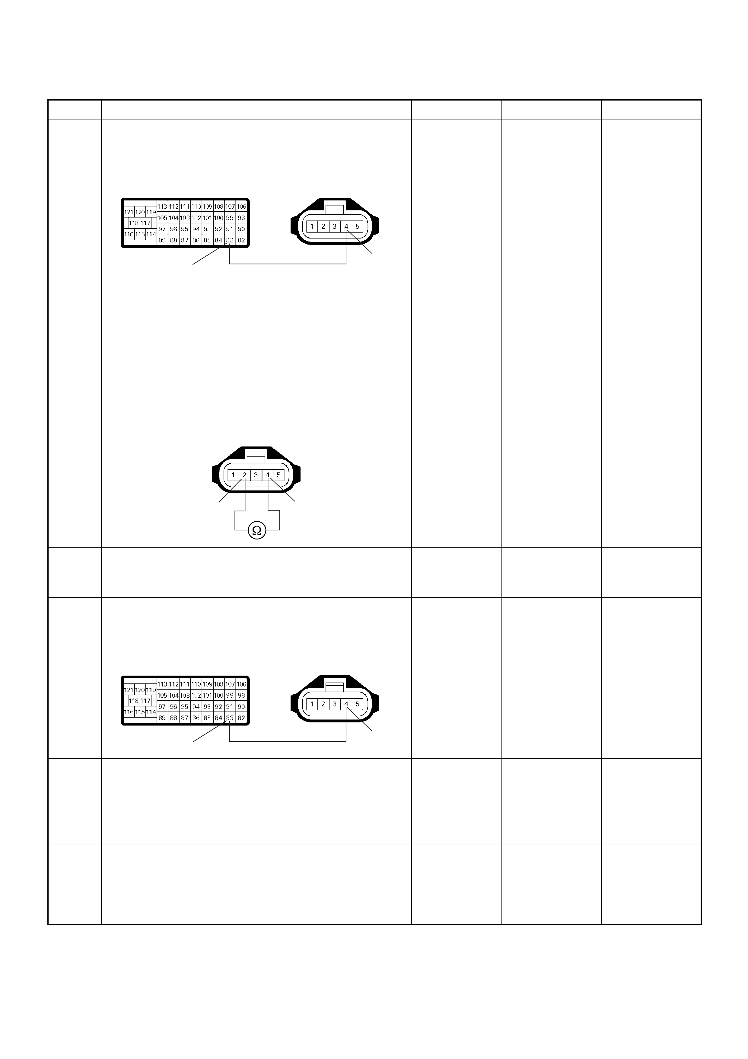
7 Repair the open circuit between the ECM and MAF
sensor.
Was the problem solved?
— Verify repair Go to Step 8
8 Using the DVM and check the MAF sensor power
supply circuit.
1. Ignition “Off”, engine “Off”.
2. Disconnect the MAF & IAT sensor connector and
ECM connector.
3. Check the circuit for short to MAF sensor heater
circuit.
Was the DVM indicated specified value?
No continuity Go to Step 10 Go to Step 9
9 Repair the circuit for short to MAF sensor heater
circuit.
Is the action complete? — Verify repair —
10 Re pair the short to battery v oltage circuit between the
ECM and MAF se ns or.
Was the problem solved?
— Verify repair Go to Step 13
11 Substitute a known good MAF & IAT sensor assembly
and recheck.
Was the problem solved? — Go to Step 12 Go to Step 13
12 Replace the MAF & IAT sensor assembly.
Is the action complete? — Verify repair —
13 Is the ECM programmed with the latest software
release?
If not, downlo ad the latest software to the ECM using
the “SPS (Service Programming System)”.
Was the problem solved? — Verify repair Go to Step 14
Step Action Value(s) Yes No
83 4
C-51C-57(B)
4
2
C-51
83 4
C-51C-57(B)

Diagnostic Trouble Code (DTC) P0100 (Symptom Code 9) (Flash Code 65)
Mass Air Flow (MAF) Sensor Voltage Supply Circuit Low Input
14 Replace the ECM.
Is the action complete?
IMPORTANT: The replacement ECM must be
programmed. Refer to section of the Service
Programming System (SPS) in this manual.
Following ECM programming, the immobiliser system
(if equipped) must be linked to the ECM. Refer to
section 11 “Immobiliser System-ECM replacement” for
the ECM/Immobiliser linking procedure. — Verify repair —
Step Action Value(s) Yes No
1 Was the “On-Board Diagnostic (OBD) System Check”
performed?
—Go to Step 2
Go to On
Board
Diagnostic
(OBD) System
Check
2 1. Connect the Tech 2.
2. Review and record the failure information.
3. Select “F0: Read DTC Infor As Stored By ECU” in
“F0: Diagnostic Trouble Codes”.
Is the DTC P0100 (Symptom Code 9) stored as
“Present Failure”? — Go to Step 3
Refer to
Diagnostic
Aids and Go to
Step 3
3 1. Using the Tech 2, ignition “On” and engine “Off”.
2. Select “F1: Clear DTC Information” in “F0:
Diagnostic Trouble Codes” with the Tech 2 and
clear the DTC information.
3. Operate the vehicle and monitor the “F0: Read
DTC Infor As Stored By ECU” in the “F0:
Diagnostic Trouble Codes”.
Was the DT C P0 100 (Sy mpt om Code 9) stor e d i n th is
ignition cycle? — Go to Step 4
Refer to
Diagnostic
Aids and Go to
Step 4
4 Check for poor/faulty connection at the MAF sensor or
ECM connector. If a poor/faulty connection is found,
repair as necessary.
Was the problem found?
— Verify repair Go to Step 5
5 Vis ual ly chec k the MA F sensor.
Was the problem found? — Go to Step 10 Go to Step 6
Step Action Value(s) Yes No
92
88 83
2345
C-51C-57(B)
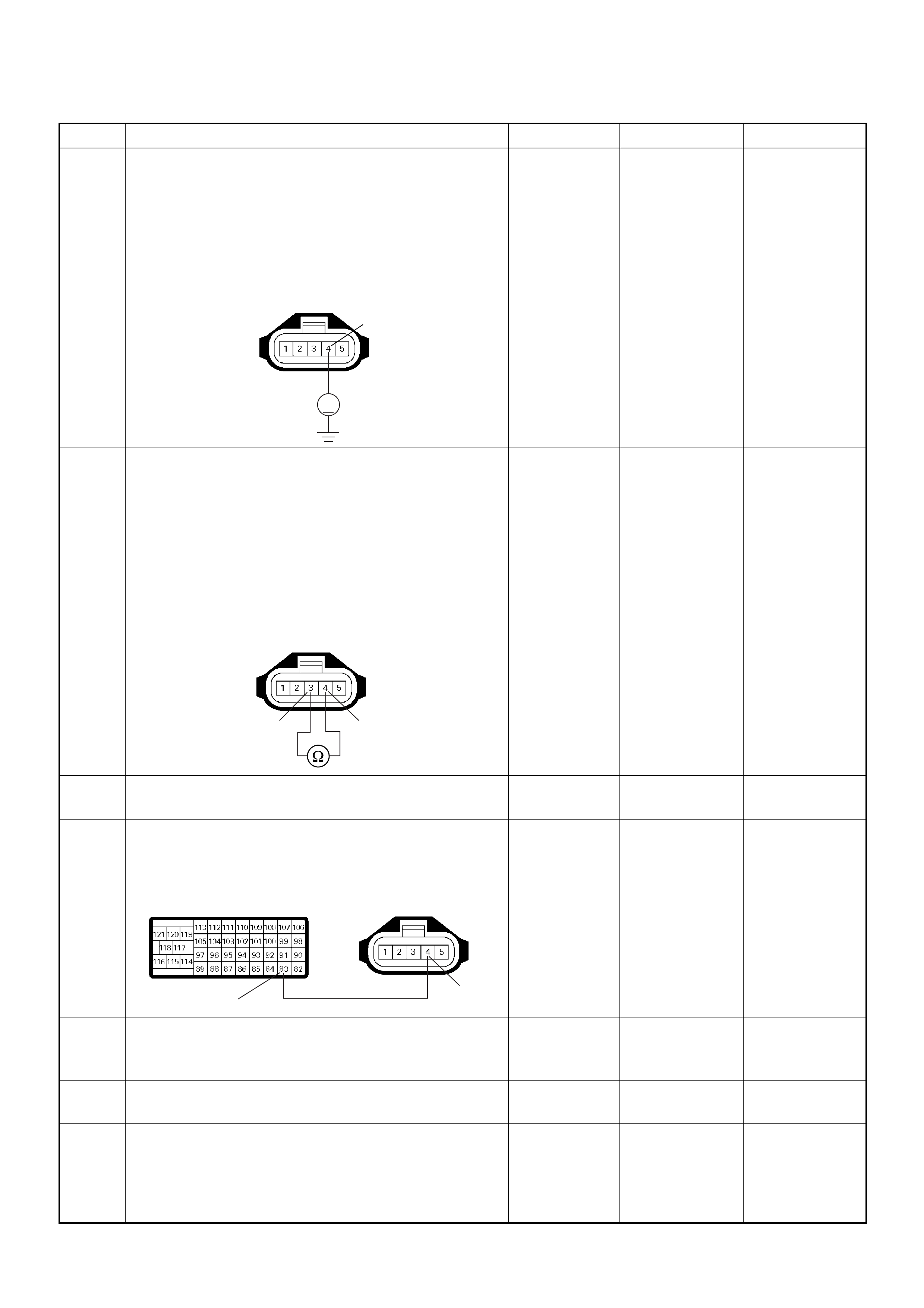
6 Using the DVM and check the MAF sensor power
supply circuit.
1. Ignition “On”, engine “Off”.
2. Disconnect the MAF & IAT sensor connector.
3. Check the circuit for short to ground circuit.
Was the DVM indicated specified value?
Approximately
5.0V Go to Step 10 Go to Step 7
7 Using the DVM and check the MAF sensor power
supply circuit.
1. Ignition “Off”, engine “Off”.
2. Disconnect the MAF & IAT sensor connector and
ECM connector.
3. Check the circuit for short to MAF sensor ground
circuit.
Was the DVM indicated specified value?
No continuity Go to Step 9 Go to Step 8
8 Repair the circuit for short to MAF sensor ground.
Is the action complete? — Verify repair —
9 Repair the short to ground circuit between the ECM
and MAF sensor.
Was the problem solved?
— Verify repair Go to Step 12
10 Substitute a known good MAF & IAT sensor assembly
and recheck.
Was the problem solved? — Go to Step 11 Go to Step 12
11 Replace the MAF & IAT sensor assembly.
Is the action complete? — Verify repair —
12 Is the ECM programmed with the latest software
release?
If not, downlo ad the latest software to the ECM using
the “SPS (Service Programming System)”.
Was the problem solved? — Verify repair Go to Step 13
Step Action Value(s) Yes No
V
4
C-51
4
3
C-51
83 4
C-51C-57(B)
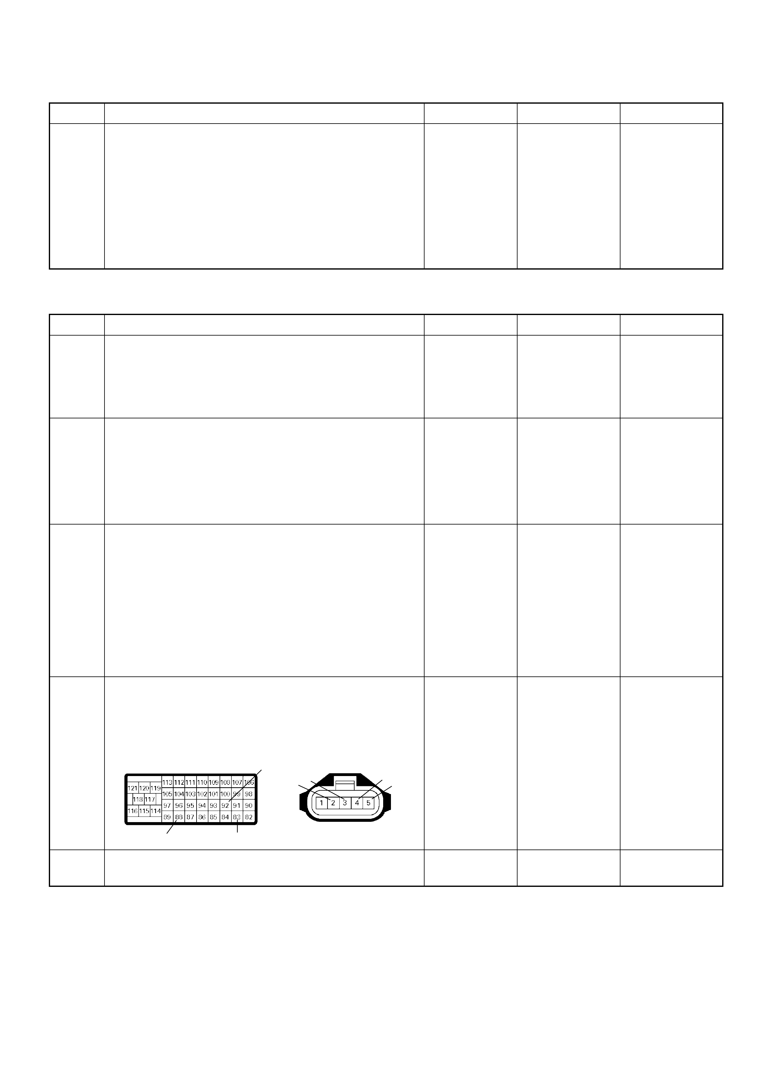
Diagnostic Trouble Code (DTC) P0100 (Symptom Code B) (Flash Code 65)
Mass Air Flow (MAF) Sensor Output Circuit Low Input
13 Replace the ECM.
Is the action complete?
IMPORTANT: The replacement ECM must be
programmed. Refer to section of the Service
Programming System (SPS) in this manual.
Foll owing ECM pr ogramming, the immobi liser system
(if equipped) must be linked to the ECM. Refer to
section 11 “Immobiliser System-ECM replacement” for
the ECM/Immobiliser linking procedure. — Verify repair —
Step Action Value(s) Yes No
1 Was the “On- Board Diagnos tic (OBD) Sy stem Check”
performed?
—Go to Step 2
Go to On
Board
Diagnostic
(OBD) System
Check
2 1. Connect the Tech 2.
2. Review and record the failure information.
3. S elect “F0: Read DTC I nfor As Stored B y ECU” in
“F0: Diagnostic Trouble Codes”.
Is the DTC P0100 (Symptom Code B) stored as
“Present Failure”? — Go to Step 3
Refer to
Diagnostic
Aids and Go to
Step 3
3 1. Using the Tech 2, ignition “On” and engine “Off”.
2. Select “F1: Clear DTC Information” in “F0:
Diagnostic Trouble Codes” with the Tech 2 and
clear the DTC information.
3. Operate the vehicle and monitor the “F0: Read
DTC Infor As Stored By ECU” in the “F0:
Diagnostic Trouble Codes”.
Was the DTC P0100 (Symptom Code B) stored in this
ignition cycle? — Go to Step 4
Refer to
Diagnostic
Aids and Go to
Step 4
4 Check for poor/faulty connection at the MAF sensor or
ECM connector. If a poor/faulty connection is found,
repair as necessary.
Was the problem found?
— Verify repair Go to Step 5
5 Vis ual ly chec k the MA F sensor.
Was the problem found? — Go to Step 11 Go to Step 6
Step Action Value(s) Yes No
92
88 83
2345
C-51C-57(B)
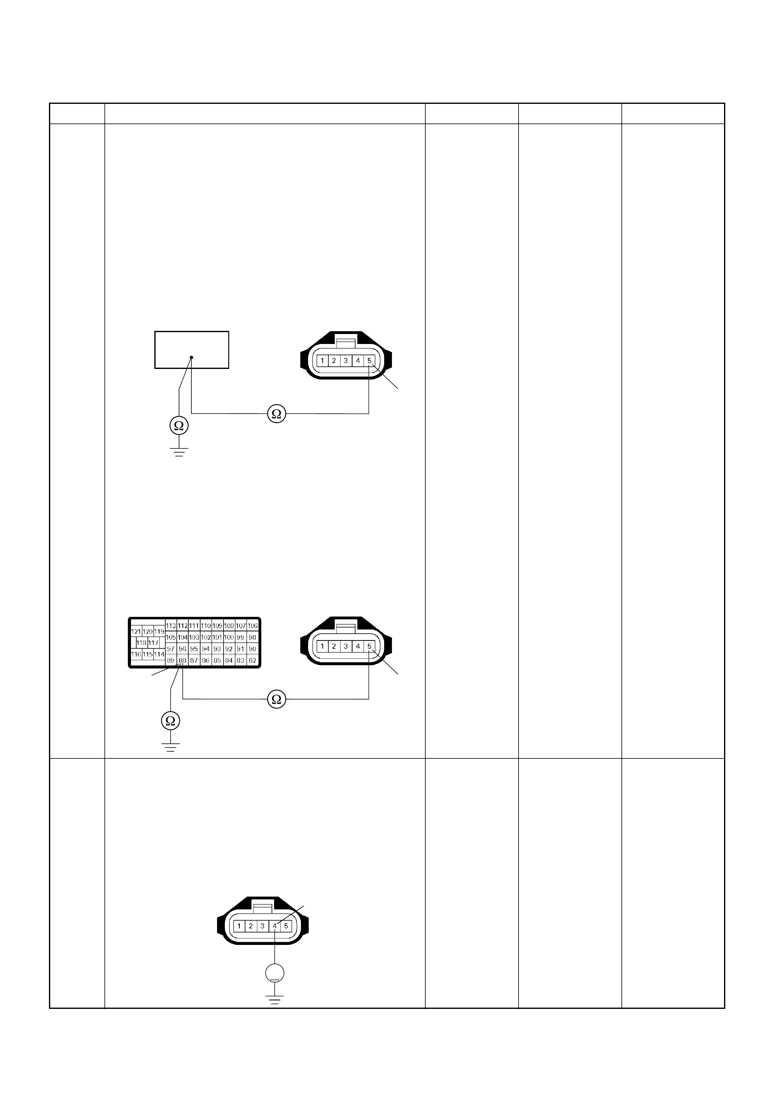
6 Using the DVM and check the MAF sensor signal
circuit.
Breaker box is available:
1. Ignition “Off”, engine “Off”.
2. Install the breaker box as type A. (ECM
disconnected) Ref. Page 6E-81
3. Disconnect the MAF & IAT sensor connector.
4. Check th e circuit for open, short to sensor gr ound
or short to ground circuit.
Was the problem found?
Breaker box is not available:
1. Ignition “Off”, engine “Off”.
2. Disconnect the MAF & IAT sensor connector and
ECM connector.
3. Check th e circuit for open, short to sensor gr ound
or short to ground circuit.
Was the problem found?
—
Repair faulty
harnes s and
verify repair G o to Step 7
7 Using the DVM and check the MAF sensor power
supply circuit.
1. Ignition “On”, engine “Off”.
2. Disconnect the MAF & IAT sensor connector.
3. Check the circuit for open circuit.
Was the DVM indicated specified value?
Approximately
5.0V Go to Step 9 Go to Step 8
Step Action Value(s) Yes No
88
5
C-51
5
88
C-51
C-57(B)
V
4
C-51
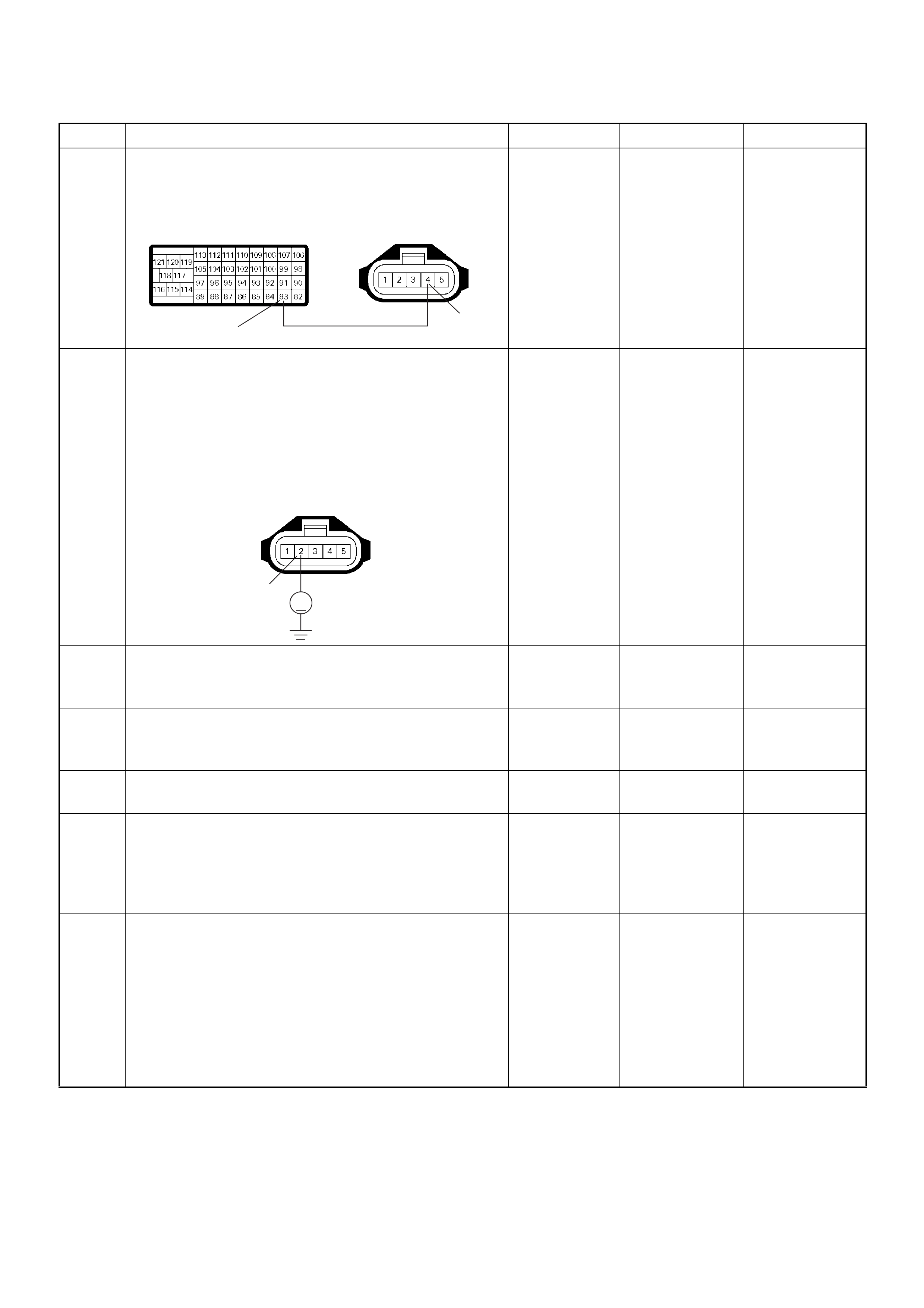
8 Repair the open circuit between the ECM and MAF
sensor.
Was the problem solved?
— Verify repair Go to Step 13
9 Using the DVM and check the MAF sensor heater
circuit.
1. Ignition “On”, engine “Off”.
2. Disconnect the MAF & IAT sensor connector.
3. Check the circuit for open circuit.
Was the DVM indicated specified value?
Battery
voltage Go to Step 11 Go to Step 10
10 Repair the open circuit between the ECM main relay
and MAF sensor.
Was the problem solved? — Verify repair Go to Step 11
11 Substitute a known good MAF & IAT sensor assembly
and recheck.
Was the problem solved? — Go to Step 12 Go to Step 13
12 Replace the MAF & IAT sensor assembly.
Is the action complete? — Verify repair —
13 Is the ECM programmed with the latest software
release?
If not, downlo ad the latest software to the ECM using
the “SPS (Service Programming System)”.
Was the problem solved? — Verify repair Go to Step 14
14 Replace the ECM.
Is the action complete?
IMPORTANT: The replacement ECM must be
programmed. Refer to section of the Service
Programming System (SPS) in this manual.
Foll owing ECM pr ogramming, the immobi liser system
(if equipped) must be linked to the ECM. Refer to
section 11 “Immobiliser System-ECM replacement” for
the ECM/Immobiliser linking procedure. — Verify repair —
Step Action Value(s) Yes No
83 4
C-51C-57(B)
2
V
C-51

Diagnostic Trouble Code (DTC) P0100 (Symptom Code C) (Flash Code 65)
Mass Air Flow (MAF) Sensor Output Circuit High Input
Step Action Value(s) Yes No
1 Was the “On-Board Diagnostic (OBD) System Check”
performed?
—Go to Step 2
Go to On
Board
Diagnostic
(OBD) System
Check
2 1. Connect the Tech 2.
2. Review and record the failure information.
3. Select “F0: Read DTC Infor As Stored By ECU” in
“F0: Diagnostic Trouble Codes”.
Is the DTC P0100 (Symptom Code C) stored as
“Present Failure”? — Go to Step 3
Refer to
Diagnostic
Aids and Go to
Step 3
3 1. Using the Tech 2, ignition “On” and engine “Off”.
2. Select “F1: Clear DTC Information” in “F0:
Diagnostic Trouble Codes” with the Tech 2 and
clear the DTC information.
3. Operate the vehicle and monitor the “F0: Read
DTC Infor As Stored By ECU” in the “F0:
Diagnostic Trouble Codes”.
Was the DTC P0100 (Symptom Code C) stored in this
ignition cycle? — Go to Step 4
Refer to
Diagnostic
Aids and Go to
Step 4
4 Check for poor/faulty connection at the MAF sensor or
ECM connector. If a poor/faulty connection is found,
repair as necessary.
Was the problem found?
— Verify repair Go to Step 5
5 Vis ual ly chec k the MA F sensor.
Was the problem found? — Go to Step 11 Go to Step 6
92
88 83
2345
C-51C-57(B)
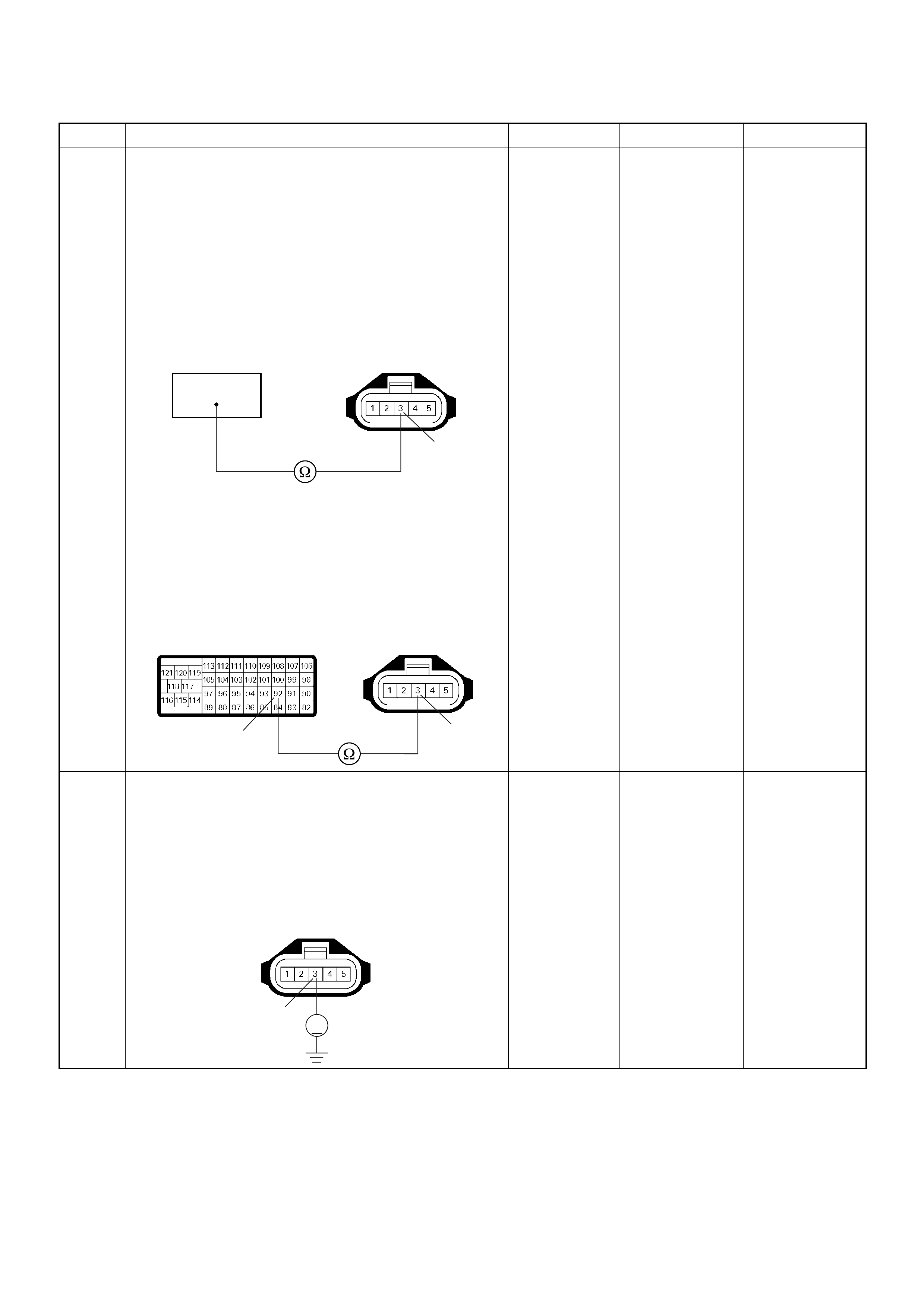
6 Using the DVM and check the MAF sensor ground
circuit.
Breaker box is available:
1. Ignition “Off”, engine “Off”.
2. Install the breaker box as type A. (ECM
disconnected) Ref. Page 6E-81
3. Disconnect the MAF sensor connector.
4. Check the circuit for open circuit.
Was the problem found?
Breaker box is not available:
1. Ignition “Off”, engine “Off”.
2. Disconnect the MAF sensor connector and ECM
connector.
3. Check the circuit for open circuit.
Was the problem found?
—
Repair faulty
harnes s and
verify repair G o to Step 7
7 Using the DVM and check the MAF sensor ground
circuit.
1. Ignition “On”, engine “Off”.
2. Disconnect the MAF sensor connector .
3. Check the circuit for short to power supply circuit.
Was the DVM indicated specified value?
Less than 1V Go to Step 8
Repair faulty
harness and
verify repair
Step Action Value(s) Yes No
92
3
C-51
3
92
C-51
C-57
3
V
C-51

8 Using the DVM and check the MAF sensor signal
circuit.
1. Ignition “On”, engine “Off”.
2. Disconnect the MAF sensor connector.
3. Check the circuit for short to power supply circuit.
Was the DVM indicated specified value?
Less than 1V Go to Step 9
Repair faulty
harness and
verify repair
9 Substitute a known good MAF & IAT sensor assembly
and recheck.
Was the problem solved? — Go to Step 10 Go to Step 11
10 Replace the MAF & IAT sensor assembly.
Is the action complete? — Verify repair —
11 Is the ECM programmed with the latest software
release?
If not, downlo ad the latest software to the ECM using
the “SPS (Service Programming System)”.
Was the problem solved? — Verify repair Go to Step 12
12 Replace the ECM.
Is the action complete?
IMPORTANT: The replacement ECM must be
programmed. Refer to section of the Service
Programming System (SPS) in this manual.
Foll owing ECM pr ogramming, the immobi liser system
(if equipped) must be linked to the ECM. Refer to
section 11 “Immobiliser System-ECM replacement” for
the ECM/Immobiliser linking procedure. — Verify repair —
Step Action Value(s) Yes No
5
V
C-51
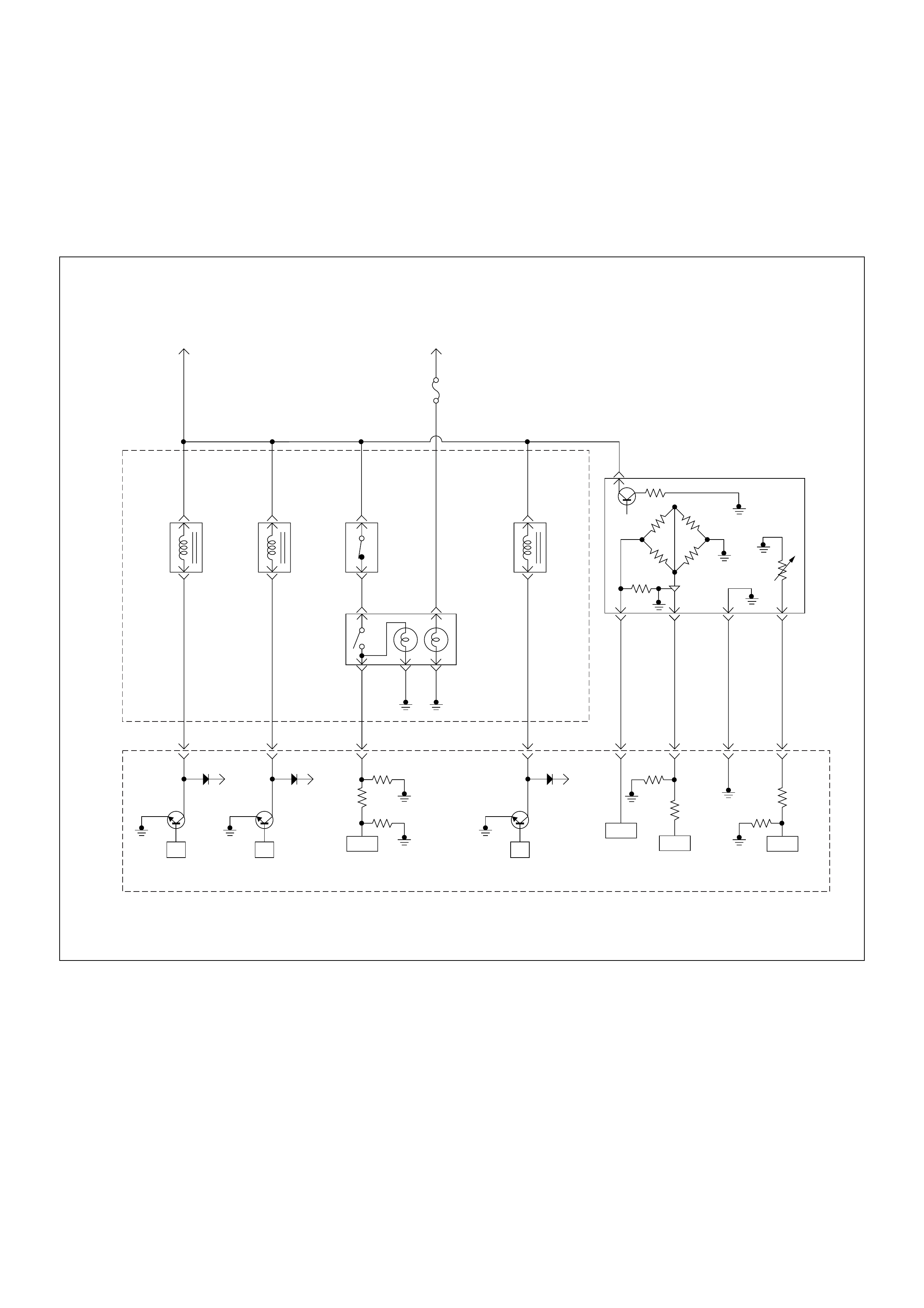
Diagnostic Trouble Code (DTC) P0110 (Symptom Code 1)
(Flash Code 23) Intake Air Temperature (IAT) Sensor Circuit High Input
Diagnostic Trouble Code (DTC) P0110 (Symptom Code 2)
(Flash Code 23) Intake Air Temperature (IAT) Sensor Circuit Low Input
Batt
µP
Batt
µP
Batt
µP
0.5
BLK/
URG
0.5
BRN/
RED
0.5
BLU/
RED
0.5
BLU/
RED
4JA1-TC
0.5
GRY/
YEL
974661
0.5
WHT/
RED
83
0.5
GRN/
RED
88
0.5
BLK/
RED
92
0.5
BLK/
BLU
84
IAT
Sensor MAF &
IAT
Sensor
Rr Fog
Light
10A
EGR-
EVRV
0.5
WHT/
BLK
0.5
BLU/
RED
0.5
WHT/
BLU
0.5
BLU/
RED
0.5
GRN/
RED
0.5
BLU/
RED
Exhaust
Throttle
VSV2
Exhaust
Throttle
VSV1
Engine
Warming Up
SW
Thermo
SW
2
4531
Battery
Voltage
ECM
Main Relay
IC ICIC CPU
Engine
Control
Module
(ECM)
40

Condition for setting the DTC and action taken when the DTC sets
Circuit Desc rip tio n
The IAT sensor is a thermistor. A temperature changes
the resistance value. And it changes voltage. In other
words it measures a temperature value. Low air
temperature produces a high resistance.
The ECM supplies 5 volts signal to the IAT sensor
through resisters in the ECM and measures the voltage.
The signal voltage will be high when the air temperature
is cold, and it will be low when the air temperature is
hot.
If the output voltage excessively high or low, DTC P01 10
(Symptom Code 1) or P0110 (Symptom Code 2) will be
stored.
Diagnostic Aids
An intermittent may be caused by the following:
• Poor connections.
• Misrouted harness.
• Rubbed through wire insulation.
• Broken wire inside the insulation.
Check for the following conditions:
• Poor con nection at ECM-I nspect harnes s connectors
for backed out terminals, improper mating, broken
locks, improperly formed or damaged terminals, and
poor terminal to wire connection.
• Damaged harness-Inspect the wiring harness for
damage. If the harness appears to be OK, observe
the “Intake Air Temperature” display on the Tech2
while moving connectors and wiring harness related
to the sensor.
Flash
Code Code Symptom
Code MIL DTC Name DTC Setting Condition F ail-Safe (Back Up)
23 P0110 1 ON Intake Air Temperature (IAT)
Sensor Circuit High Input IAT sensor output voltage is
more than 4.7V. ECM use 0°C conditions as
substitute.
2 ON Intake Air Temperature (IAT)
Sensor Circuit Low Input IAT sensor output voltage is
below 0.3V.
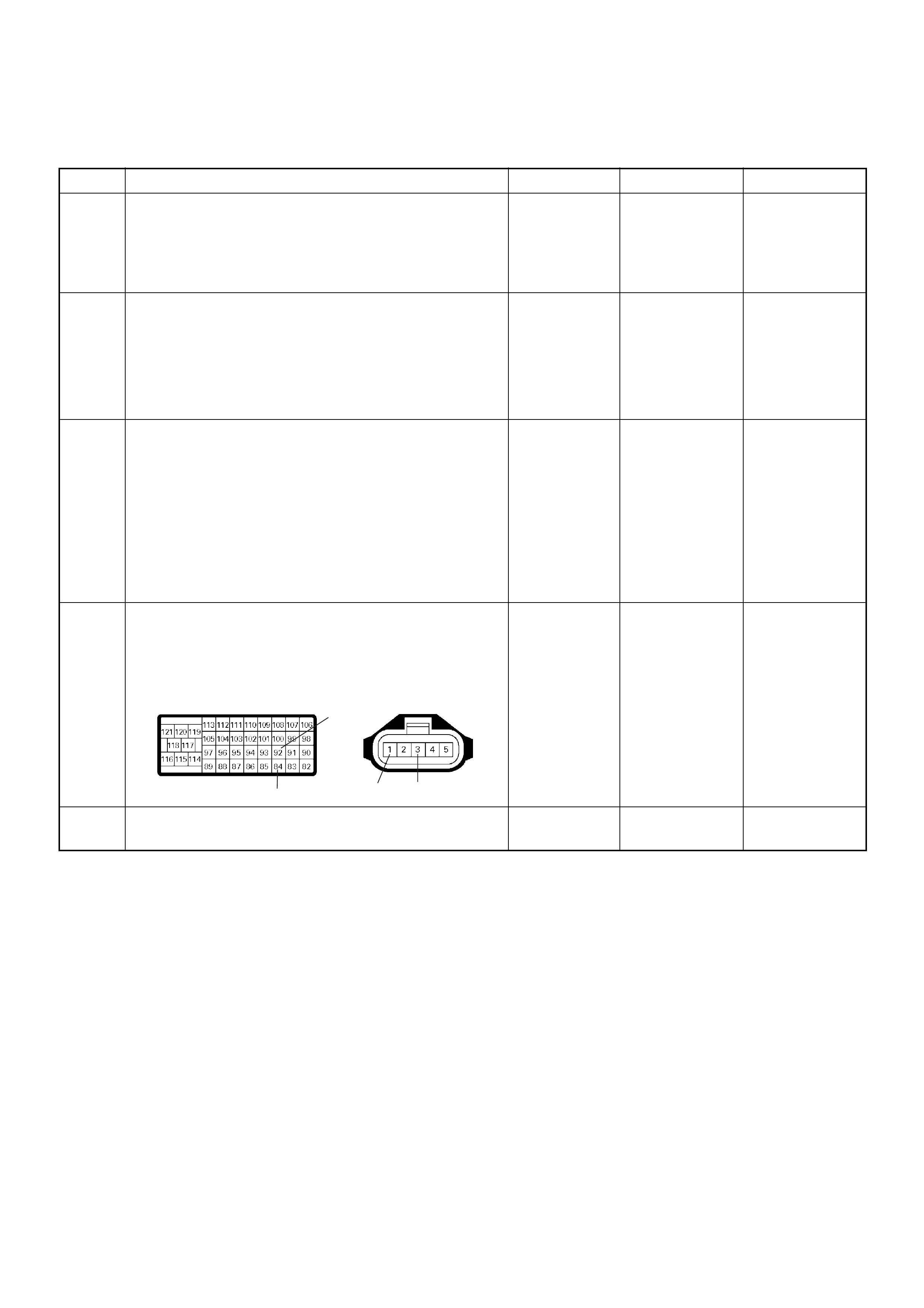
Diagnostic Trouble Code (DTC) P0110 (Symptom Code 1) (Flash Code 23)
Intake Air Temperature (IAT) Sensor Circuit High Input
Step Action Value(s) Yes No
1 Was the “On-Board Diagnostic (OBD) System Check”
performed?
—Go to Step 2
Go to On
Board
Diagnostic
(OBD) System
Check
2 1. Connect the Tech 2.
2. Review and record the failure information.
3. Select “F0: Read DTC Infor As Stored By ECU” in
“F0: Diagnostic Trouble Codes”.
Is the DTC P0110 (Symptom Code 1) stored as
“Present Failure”? — Go to Step 3
Refer to
Diagnostic
Aids and Go to
Step 3
3 1. Using the Tech 2, ignition “On” and engine “Off”.
2. Select “F1: Clear DTC Information” in “F0:
Diagnostic Trouble Codes” with the Tech 2 and
clear the DTC information.
3. Operate the vehicle and monitor the “F0: Read
DTC Infor As Stored By ECU” in the “F0:
Diagnostic Trouble Codes”.
Was the DT C P0110 (Sym ptom Cod e 1) stor ed in th is
ignition cycle? — Go to Step 4
Refer to
Diagnostic
Aids and Go to
Step 4
4 Check for poor/faulty connection at the IAT sensor or
ECM connector. If a poor/faulty connection is found,
repair as necessary.
Was the problem found?
— Verify repair Go to Step 5
5 Vis ually check the IAT sensor.
Was the problem found? — Go to Step 12 Go to Step 6
92
84 13
C-51
C-57(B)

6 Using the DVM and check the IAT sensor.
1. Ignition “Off”, engine “Off”.
2. Disconnect MAF & IAT sensor connector.
3. Measure the resistance of IAT sensor.
Does the tester indicate standard resistance as shown
in the following table?
Standard
resistance Go to Step 7 Go to Step 12
7 Using the DVM and check the IAT sensor signal
circuit.
1. Ignition “On”, engine “Off”.
2. Disconnect the MAF & IAT sensor connector.
3. Check the circuit for open circuit.
Was the DVM indicated specified value?
Approximately
5.0V Go to Step 10
Less than 1V:
Go to Step 8
More than
specified value:
Go to Step 9
8 Repair the open circuit between the ECM and IAT
sensor.
Was the problem solved?
— Verify repair Go to Step 14
Step Action Value(s) Yes No
Temperat ure (°C) Resistance (Ω) (Approximately)
-20 14210
0 5402
20 2343
40 1131
60 596
80 338
100 203
1235 4
13
IAT Sensor
1
V
C-51
1
84
C-51
C-57(B)
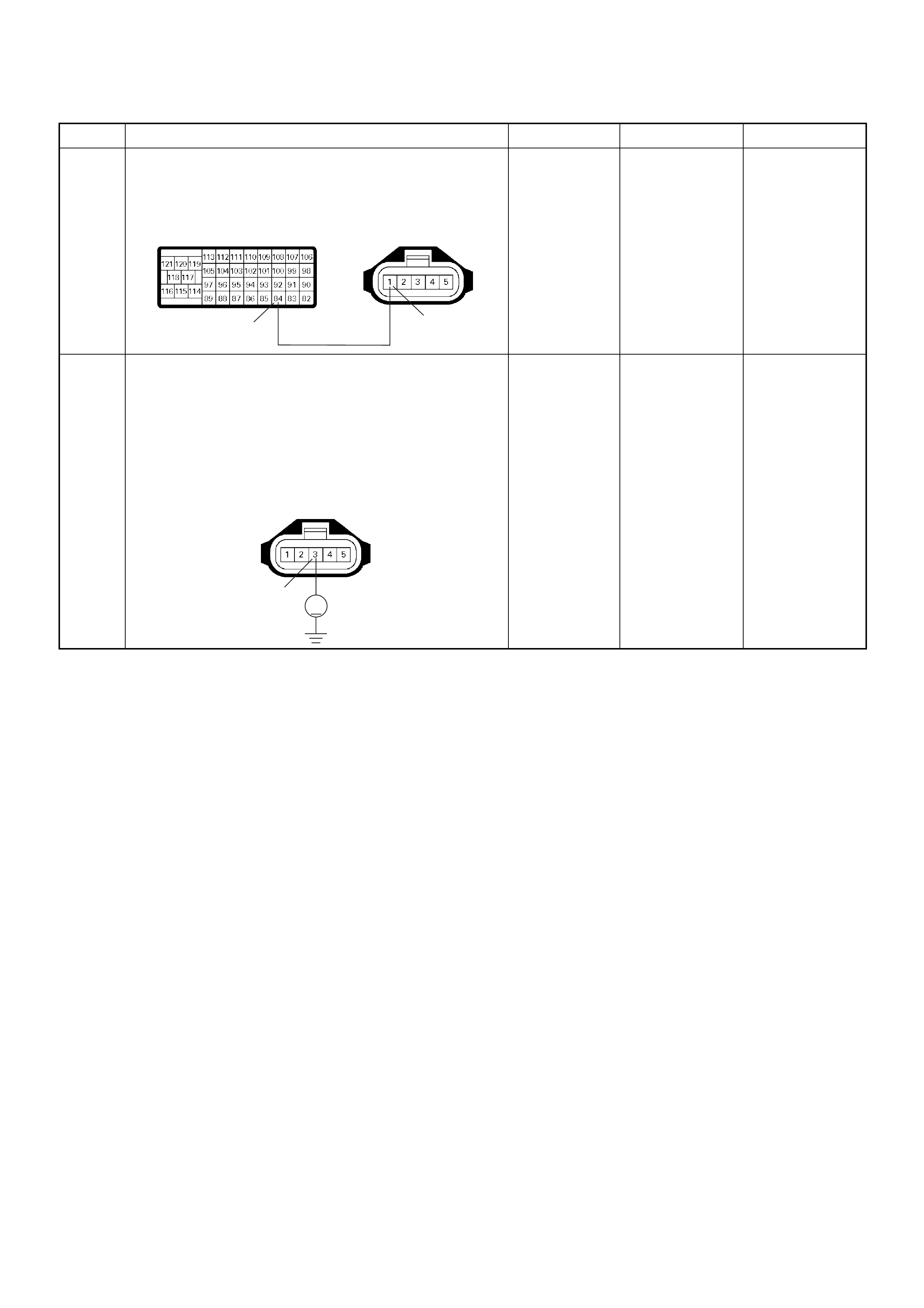
9 Repair the short to voltage circuit between the ECM
and IAT sensor.
Was the problem solved?
— Verify repair Go to Step 14
10 Using the DVM and check the IAT sensor ground
circuit.
1. Ignition “On”, engine “Off”.
2. Disconnect the MAF & IAT sensor connector.
3. Check the circuit for short to power supply circuit.
Was the DVM indicated specified value?
Less than 1V Go to Step 11
Repair faulty
harness and
verify repair
Step Action Value(s) Yes No
1
84
C-51
C-57(B)
3
V
C-51
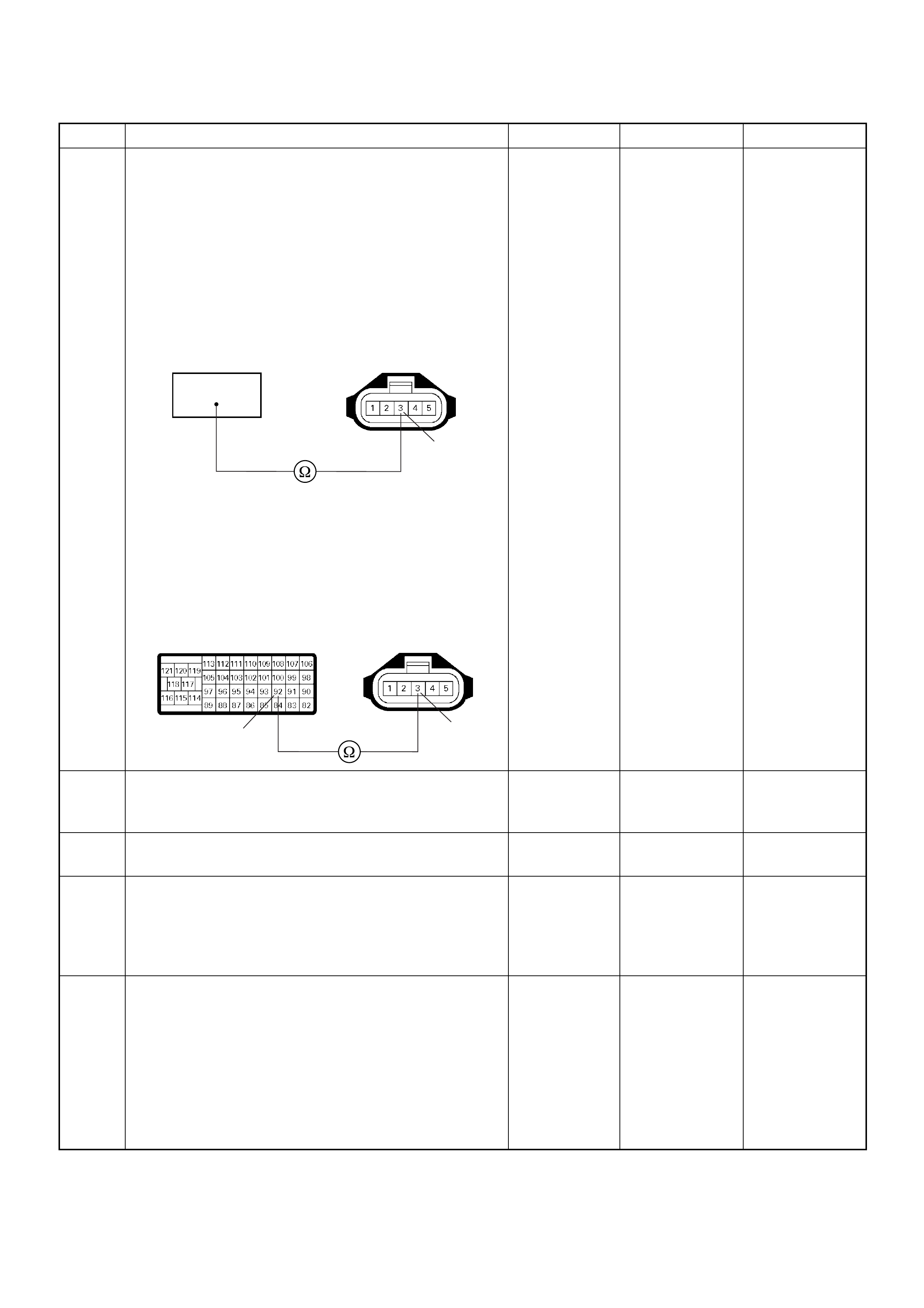
11 Using the DVM and check the IAT sensor ground
circuit.
Breaker box is available:
1. Ignition “Off”, engine “Off”.
2. Install the breaker box as type A. (ECM
disconnected) Ref. Page 6E-81
3. Disconnect the MAF & IAT sensor connector.
4. Check the circuit for open circuit.
Was the problem found?
Breaker box is not available:
1. Ignition “Off”, engine “Off”.
2. Disconnect the MAF & IAT sensor connector and
ECM connector.
3. Check the circuit for open circuit.
Was the problem found?
—
Repair faulty
harnes s and
verify repair Go to Step 14
12 Substitute a known good MAF & IAT sensor assembly
and recheck.
Was the problem solved? — Go to Step 13 Go to Step 14
13 Replace the MAF & IAT sensor assembly.
Is the action complete? — Verify repair —
14 Is the ECM programmed with the latest software
release?
If not, downlo ad the latest software to the ECM using
the “SPS (Service Programming System)”.
Was the problem solved? — Verify repair Go to Step 15
15 Replace the ECM.
Is the action complete?
IMPORTANT: The replacement ECM must be
programmed. Refer to section of the Service
Programming System (SPS) in this manual.
Foll owing ECM pr ogramming, the immobi liser system
(if equipped) must be linked to the ECM. Refer to
section 11 “Immobiliser System-ECM replacement” for
the ECM/Immobiliser linking procedure. — Verify repair —
Step Action Value(s) Yes No
92
3
C-51
3
92
C-51
C-57(B)
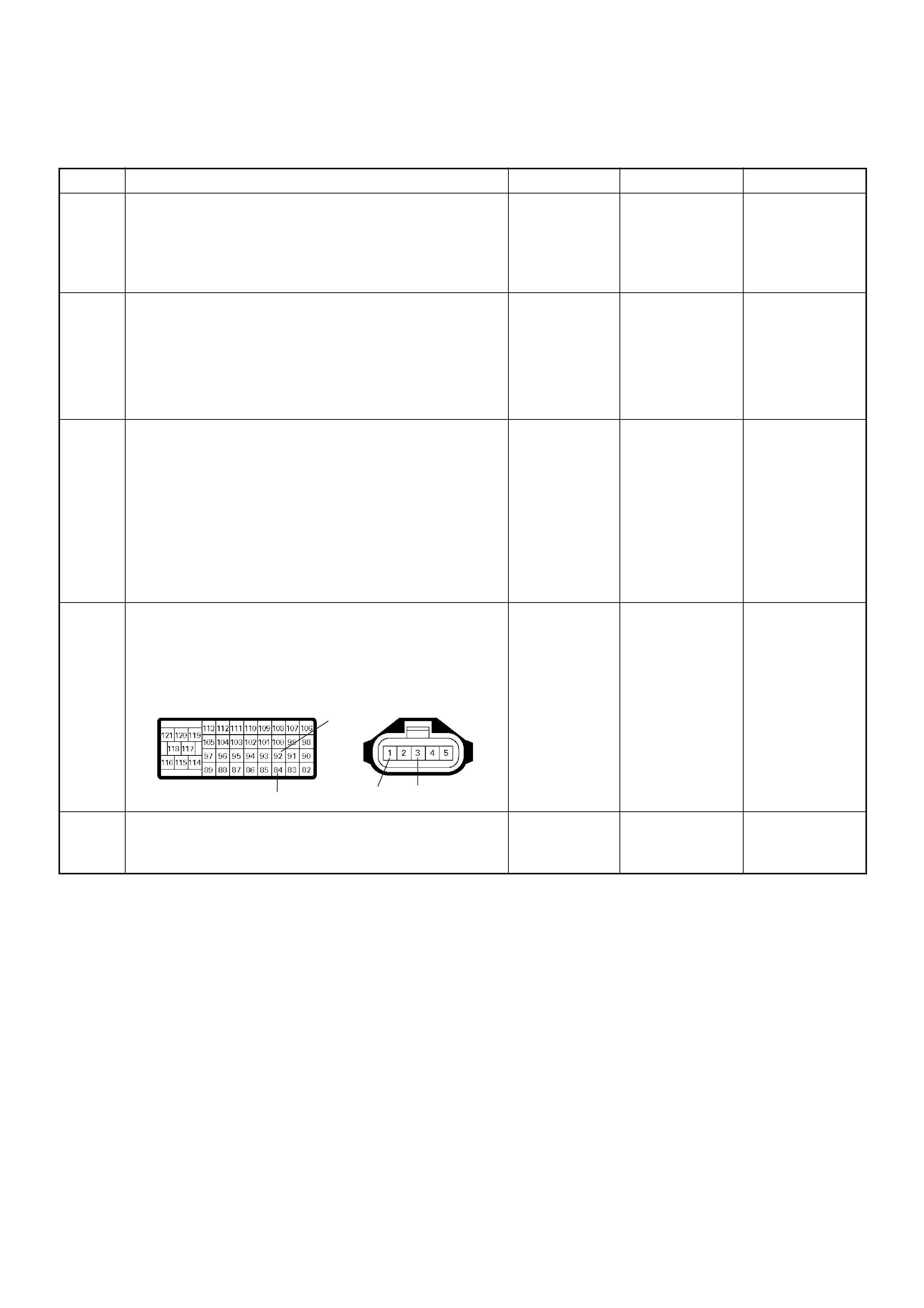
Diagnostic Trouble Code (DTC) P0110 (Symptom Code 2) (Flash Code 23)
Intake Air Temperature (IAT) Sensor Circuit Low Input
Step Action Value(s) Yes No
1 Was the “On-Board Diagnostic (OBD) System Check”
performed?
—Go to Step 2
Go to On
Board
Diagnostic
(OBD) System
Check
2 1. Connect the Tech 2.
2. Review and record the failure information.
3. Select “F0: Read DTC Infor As Stored By ECU” in
“F0: Diagnostic Trouble Codes”.
Is the DTC P0110 (Symptom Code 2) stored as
“Present Failure”? — Go to Step 3
Refer to
Diagnostic
Aids and Go to
Step 3
3 1. Using the Tech 2, ignition “On” and engine “Off”.
2. Select “F1: Clear DTC Information” in “F0:
Diagnostic Trouble Codes” with the Tech 2 and
clear the DTC information.
3. Operate the vehicle and monitor the “F0: Read
DTC Infor As Stored By ECU” in the “F0:
Diagnostic Trouble Codes”.
Was the DTC P0110 (Symptom Code 2) stored in this
ignition cycle? — Go to Step 4
Refer to
Diagnostic
Aids and Go to
Step 4
4 Check for poor/faulty connection at the IAT sensor or
ECM connector. If a poor/faulty connection is found,
repair as necessary.
Was the problem found?
— Verify repair Go to Step 5
5 R emov e the MAF & IAT sensor asse mbly and visually
check.
Was the problem found? — Go to Step 8 Go to Step 6
92
84 13
C-51
C-57(B)
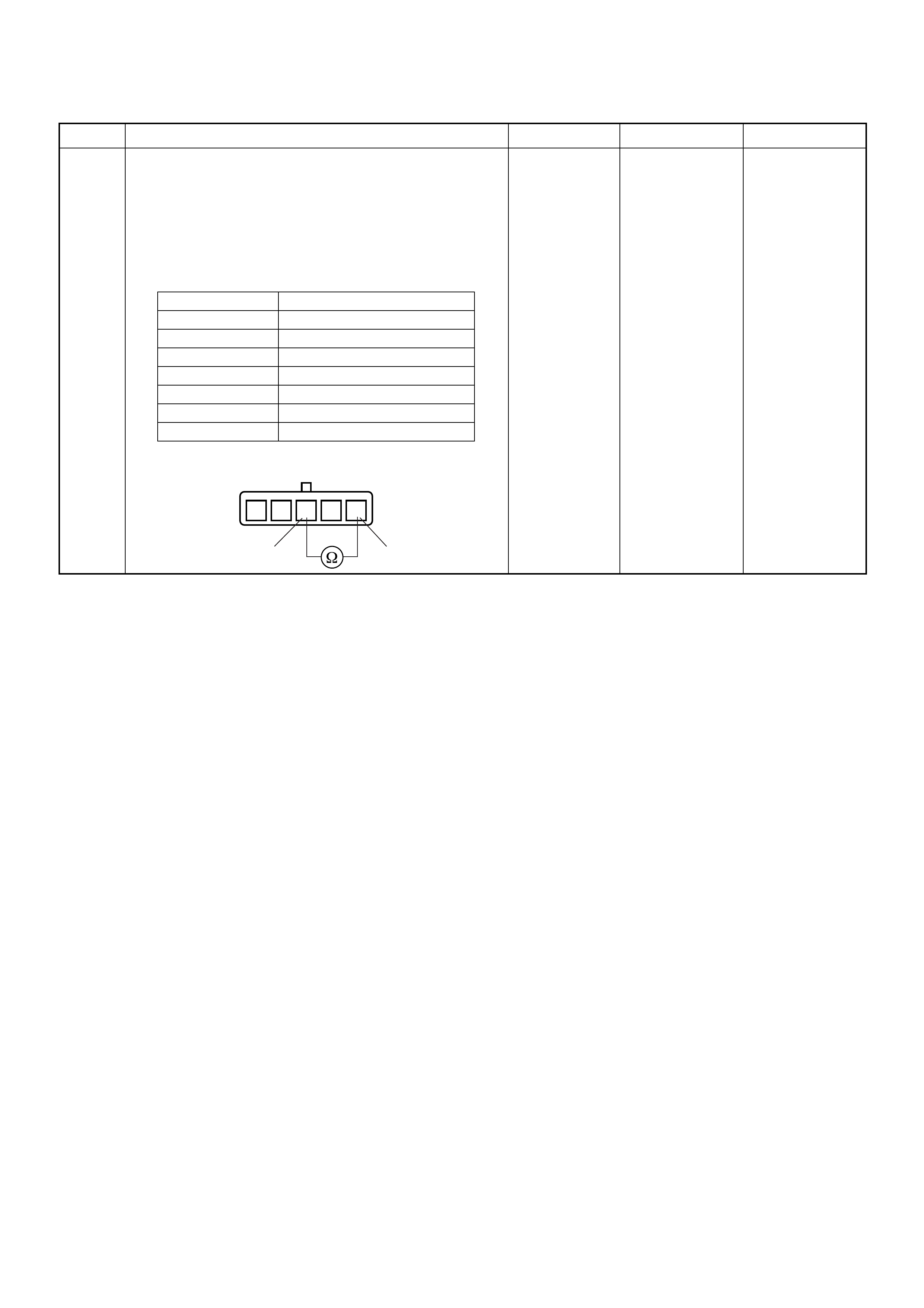
6 Using the DVM and check the IAT sensor.
1. Ignition “Off”, engine “Off”.
2. Disconnect MAF & IAT sensor connector.
3. Measure the resistance of IAT sensor.
Does the tester indicate standard resistance as shown
in the following table?
Standard
resistance Go to Step 7 Go to Step 8
Step Action Value(s) Yes No
Temperat ure (°C) Resistance (Ω) (Approximately)
-20 14210
0 5402
20 2343
40 1131
60 596
80 338
100 203
1235 4
13
IAT Sensor
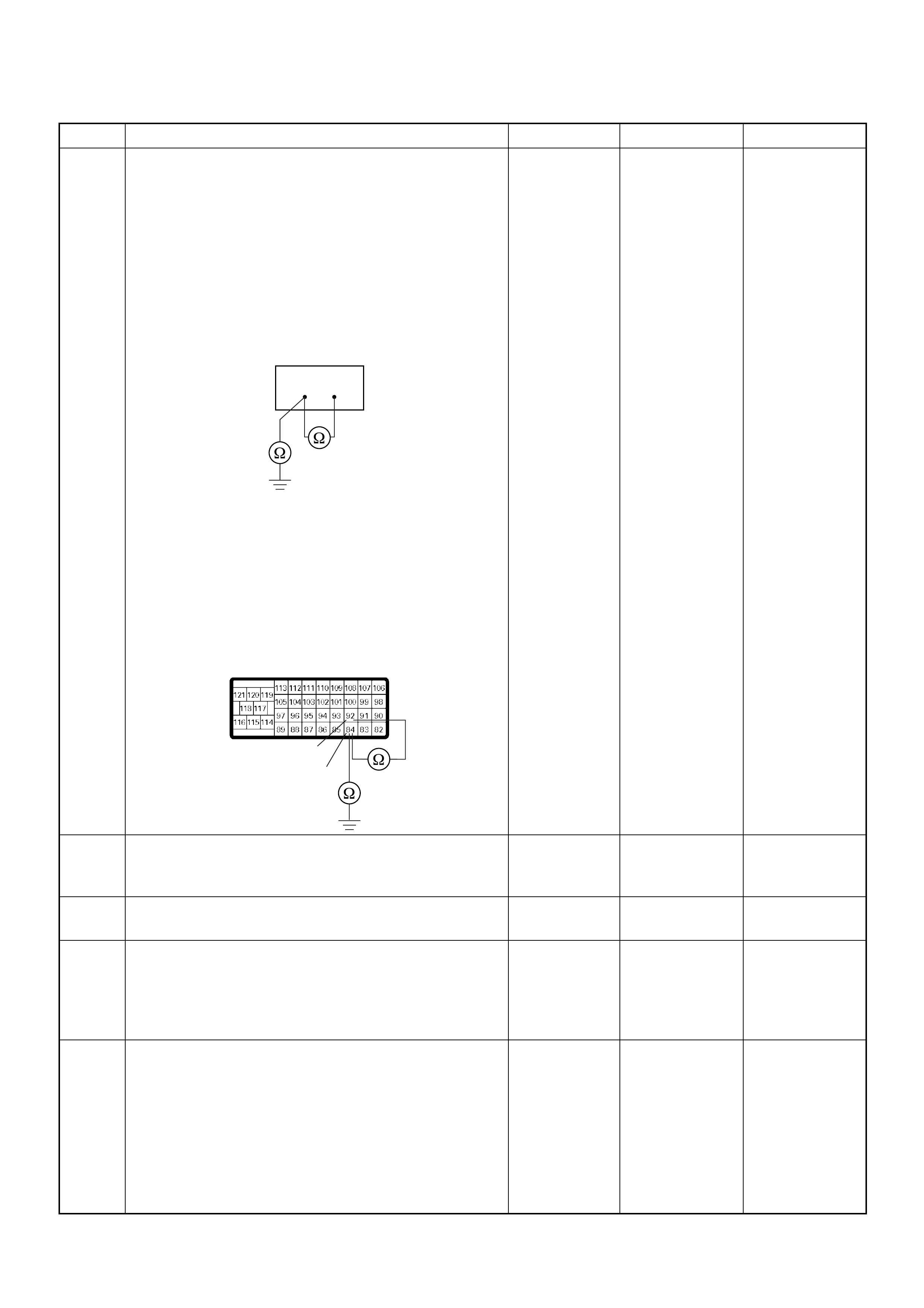
7 Using the DVM and check the IAT sensor signal
circuit.
Breaker box is available:
1. Ignition “Off”, engine “Off”.
2. Install the breaker box as type A. (ECM
disconnected) Ref. Page 6E-81
3. Disconnect the MAF & IAT sensor connector.
4. Check the circuit for short to sensor ground or
ground ci rcui t.
Was the problem found?
Breaker box is not available:
1. Ignition “Off”, engine “Off”.
2. Disconnect the MAF & IAT sensor connector and
ECM connector.
3. Check the circuit for short to sensor ground or
ground ci rcui t.
Was the problem found?
—
Repair faulty
harnes s and
verify repair Go to Step 10
8 Substitute a known good MAF & IAT sensor assembly
and recheck.
Was the problem solved? — Go to Step 9 Go to Step 10
9 Replace the MAF & IAT sensor assembly.
Is the action complete? — Verify repair —
10 Is the ECM programmed with the latest software
release?
If not, downlo ad the latest software to the ECM using
the “SPS (Service Programming System)”.
Was the problem solved? — Verify repair Go to Step 11
11 Replace the ECM.
Is the action complete?
IMPORTANT: The replacement ECM must be
programmed. Refer to section of the Service
Programming System (SPS) in this manual.
Foll owing ECM pr ogramming, the immobi liser system
(if equipped) must be linked to the ECM. Refer to
section 11 “Immobiliser System-ECM replacement” for
the ECM/Immobiliser linking procedure. — Verify repair —
Step Action Value(s) Yes No
84 92
92
84
C-57(B)
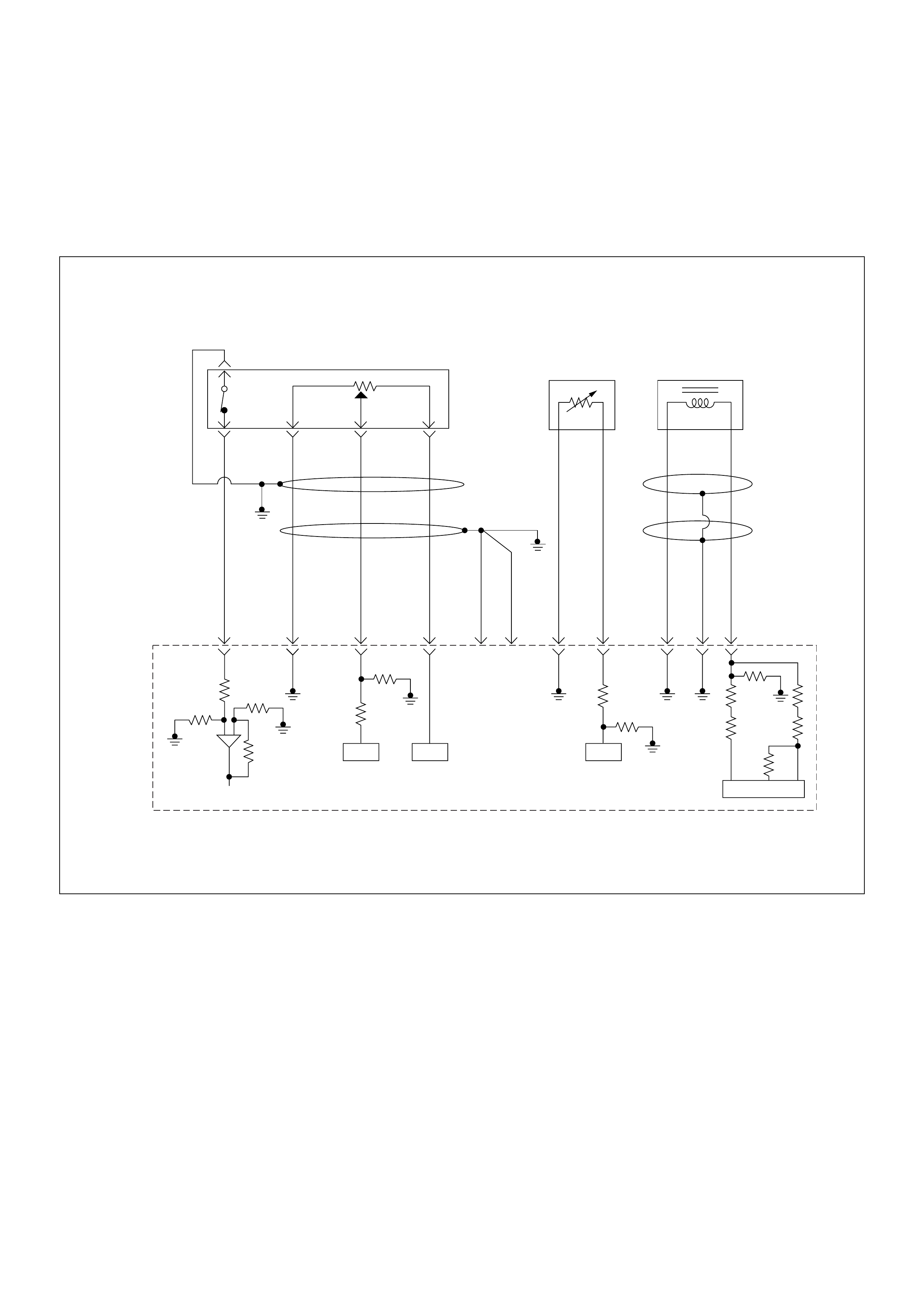
Diagnostic Trouble Code (DTC) P0115 (Symptom Code 1)
(Flash Code 14) Engine Coolant Temperature Sensor Circuit High Input
Diagnostic Trouble Code (DTC) P0115 (Symptom Code 2)
(Flash Code 14) Engine Coolant Temperature Sensor Circuit Low Input
0.5
BLK
0.5
GRN/
BLK
69
0.5
RED/
GRN
49
0.5
GRN/
ORG
38
0.5
BLK/
GRN
57
2.0
BLK
1
2.0
BLK
2
0.5
BLK/
PNK
93
0.5
GRY
ECT
Sensor
TPS &
Idle SW
89
0.5
WHT
98 101
0.5
GRN/
RED
CKP
Sensor
90
ICIC IC
IC
Engine
Control
Module
(ECM)

Condition for setting the DTC and action taken when the DTC sets
Circuit Desc rip tio n
The ECT sensor is a thermistor. A temperature changes
the resistance value. And it changes voltage. In other
words it measures a temperature value. It is installed on
the coolant stream. Low coolant temperature produces
a high resistance.
The ECM supplies 5 volts signal to the ECT sensor
through resisters in the ECM and measures the voltage.
The signal voltage will be high when the engine
temperature is cold, and it will be low when the engine
temperature is hot.
If the output voltage excessively high or low, DTC P01 15
(Symptom Code 1) or P0115 (Symptom Code 2) will be
stored.
Diagnostic Aids
An intermittent may be caused by the following:
• Poor connections.
• Misrouted harness.
• Rubbed through wire insulation.
• Broken wire inside the insulation.
Check for the following conditions:
• Poor con nection at ECM-I nspect harnes s connectors
for backed out terminals, improper mating, broken
locks, improperly formed or damaged terminals, and
poor terminal to wire connection.
• Damaged harness-Inspect the wiring harness for
damage. If the harness appears to be OK, observe
the “Coolant Temperature” display on the Tech2 while
moving connectors and wiring harness related to the
sensor.
Flash
Code Code Symptom
Code MIL DTC Name DTC Setting Condition F ail-Safe (Back Up)
14 P0115 1 ON Engine Coolant Temperat ure
(ECT) Sensor Circuit High
Input
ECT sensor output voltage is
more than 4.7V. 1. ECM uses fuel temperature
as substitute.
2. ECM uses 60°C condition for
injection timing control.
3. ECM uses -15°C condition
for glow time control.
2 ON Engine Coolant Te mperature
(ECT) Sensor Circuit Low
Input
ECT sensor output voltage is
below 0.3V.
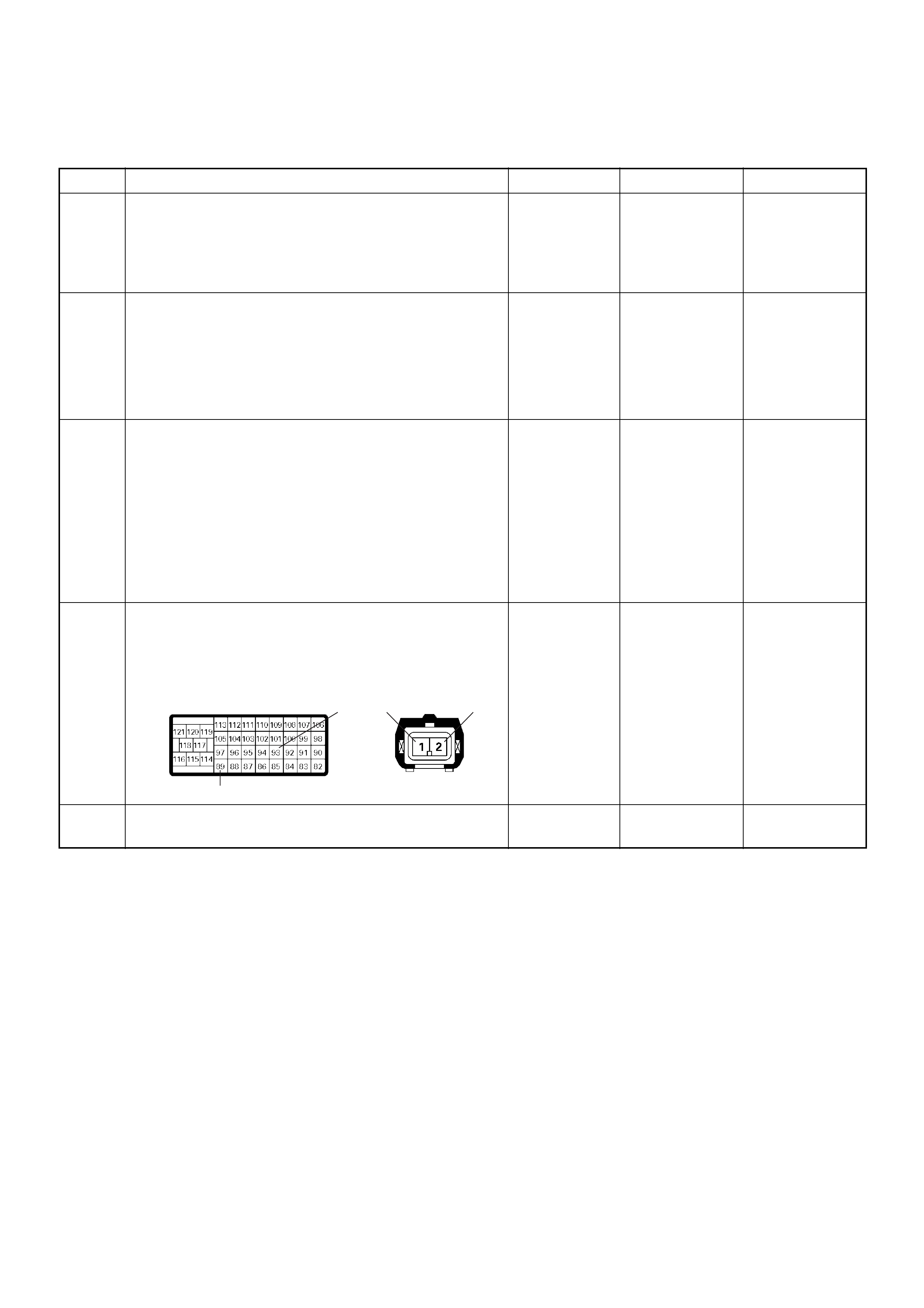
Diagnostic Trouble Code (DTC) P0115 (Symptom Code 1) (Flash Code 14)
Engine Coolant Temperature Sensor Circuit High Input
Step Action Value(s) Yes No
1 Was the “On-Board Diagnostic (OBD) System Check”
performed?
—Go to Step 2
Go to On
Board
Diagnostic
(OBD) System
Check
2 1. Connect the Tech 2.
2. Review and record the failure information.
3. Select “F0: Read DTC Infor As Stored By ECU” in
“F0: Diagnostic Trouble Codes”.
Is the DTC P0115 (Symptom Code 1) stored as
“Present Failure”? — Go to Step 3
Refer to
Diagnostic
Aids and Go to
Step 3
3 1. Using the Tech 2, ignition “On” and engine “Off”.
2. Select “F1: Clear DTC Information” in “F0:
Diagnostic Trouble Codes” with the Tech 2 and
clear the DTC information.
3. Operate the vehicle and monitor the “F0: Read
DTC Infor As Stored By ECU” in the “F0:
Diagnostic Trouble Codes”.
Was the DT C P0115 (Sym ptom Cod e 1) stor ed in th is
ignition cycle? — Go to Step 4
Refer to
Diagnostic
Aids and Go to
Step 4
4 Check for poor/faulty connection at the ECT sensor or
ECM connector. If a poor/faulty connection is found,
repair as necessary.
Was the problem found?
— Verify repair Go to Step 5
5 Vis ually check the ECT sen so r.
Was the problem found? — Go to Step 12 Go to Step 6
93 21
89
E-41C-57(B)

6 Using the DVM and check the ECT sensor.
1. Ignition “Off”, engine “Off”.
2. Disconnect ECT sensor connector.
3. Measure the resistance of ECT sensor.
Does the tester indicate standard resistance as shown
in the following table?
Standard
resistance Go to Step 7 Go to Step 12
7 Using the DVM and check the ECT sensor signal
circuit.
1. Ignition “On”, engine “Off”.
2. Disconnect the ECT sensor connector.
3. Check the circuit for open circuit.
Was the DVM indicated specified value?
Approximately
5.0V Go to Step 10
Less than 1V:
Go to Step 8
More than
specified value:
Go to Step 9
8 Repair the open circuit between the ECM and ECT
sensor.
Was the problem solved?
— Verify repair Go to Step 14
Step Action Value(s) Yes No
Temperat ure (°C) Resistance (Ω) (Approximately)
-30 27500
-20 16100
0 5760
20 2370
40 1080
60 537
80 290
100 161
120 95
12
ECT Sensor 12
V
1
E-41
89 1
E-41C-57(B)
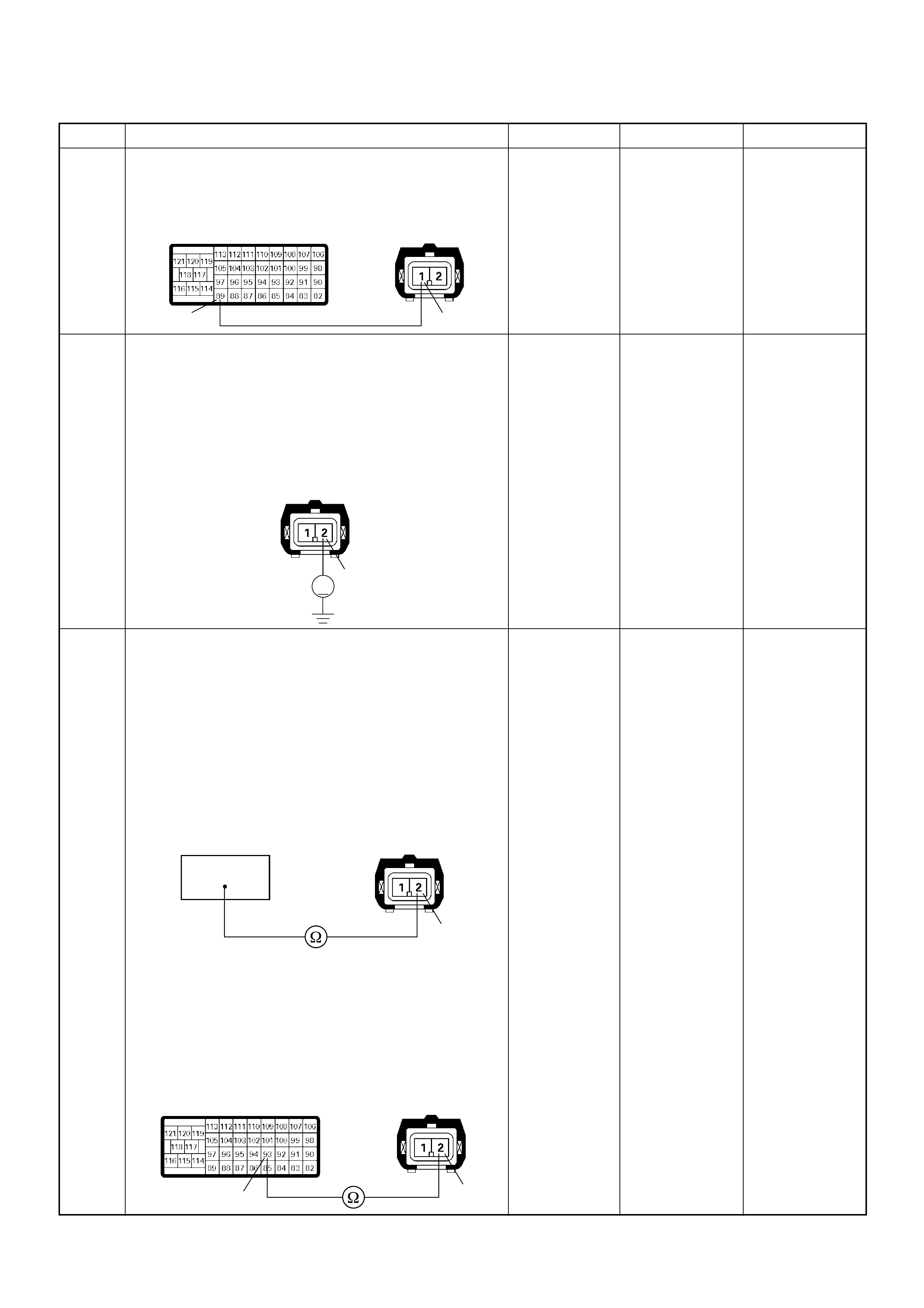
9 Repair the short to voltage circuit between the ECM
and ECT sensor.
Was the problem solved?
— Verify repair Go to Step 14
10 Using the DVM and check the ECT sensor ground
circuit.
1. Ignition “On”, engine “Off”.
2. Disconnect the ECT sensor connector.
3. Check the circuit for short to power supply circuit.
Was the DVM indicated specified value?
Less than 1V Go to Step 11
Repair faulty
harness and
verify repair
11 Using the DVM and check the ECT sensor ground
circuit.
Breaker box is available:
1. Ignition “Off”, engine “Off”.
2. Install the breaker box as type A. (ECM
disconnected) Ref. Page 6E-81
3. Disconnect the ECT sensor connector.
4. Check the circuit for open circuit.
Was the problem found?
Breaker box is not available:
1. Ignition “Off”, engine “Off”.
2. Disconnect the ECT sensor connector ECM
connector.
3. Check the circuit for open circuit.
Was the problem found?
—
Repair faulty
harnes s and
verify repair Go to Step 14
Step Action Value(s) Yes No
89 1
E-41C-57(B)
2
V
E-41
93
2
E-41
2
93
E-41
C-57

12 Substitute a known good ECT sensor assembly and
recheck.
Was the problem solved? — Go to Step 13 Go to Step 14
13 Replace the ECT sensor.
Is the action complete? — Verify repair —
14 Is the ECM programmed with the latest software
release?
If not, downlo ad the latest software to the ECM using
the “SPS (Service Programming System)”.
Was the problem solved? — Verify repair Go to Step 15
15 Replace the ECM.
Is the action complete?
IMPORTANT: The replacement ECM must be
programmed. Refer to section of the Service
Programming System (SPS) in this manual.
Foll owing ECM pr ogramming, the immobi liser system
(if equipped) must be linked to the ECM. Refer to
section 11 “Immobiliser System-ECM replacement” for
the ECM/Immobiliser linking procedure. — Verify repair —
Step Action Value(s) Yes No

Diagnostic Trouble Code (DTC) P0115 (Symptom Code 2) (Flash Code 14)
Engine Coolant Temperature Sensor Circuit Low Input
Step Action Value(s) Yes No
1 Was the “On-Board Diagnostic (OBD) System Check”
performed?
—Go to Step 2
Go to On
Board
Diagnostic
(OBD) System
Check
2 1. Connect the Tech 2.
2. Review and record the failure information.
3. Select “F0: Read DTC Infor As Stored By ECU” in
“F0: Diagnostic Trouble Codes”.
Is the DTC P0115 (Symptom Code 2) stored as
“Present Failure”? — Go to Step 3
Refer to
Diagnostic
Aids and Go to
Step 3
3 1. Using the Tech 2, ignition “On” and engine “Off”.
2. Select “F1: Clear DTC Information” in “F0:
Diagnostic Trouble Codes” with the Tech 2 and
clear the DTC information.
3. Operate the vehicle and monitor the “F0: Read
DTC Infor As Stored By ECU” in the “F0:
Diagnostic Trouble Codes”.
Was the DT C P0115 (Sym ptom Cod e 2) stor ed in th is
ignition cycle? — Go to Step 4
Refer to
Diagnostic
Aids and Go to
Step 4
4 Check for poor/faulty connection at the ECT sensor or
ECM connector. If a poor/faulty connection is found,
repair as necessary.
Was the problem found?
— Verify repair Go to Step 5
5 Vis ually check the ECT sen so r.
Was the problem found? — Go to Step 8 Go to Step 6
93 21
89
E-41C-57(B)
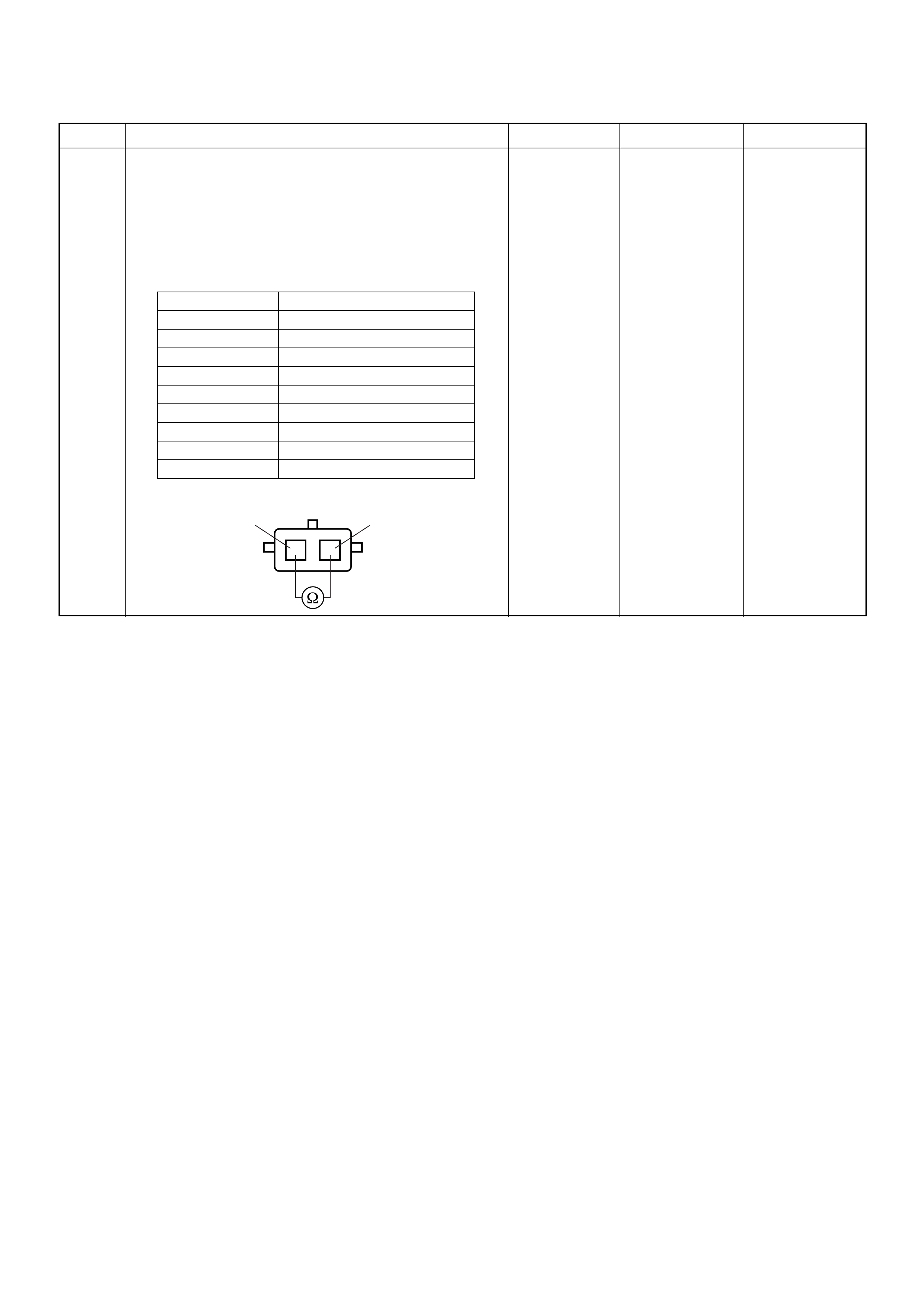
6 Using the DVM and check the ECT sensor.
1. Ignition “Off”, engine “Off”.
2. Disconnect ECT sensor connector.
3. Measure the resistance of ECT sensor.
Does the tester indicate standard resistance as shown
in the following table?
Standard
resistance Go to Step 7 Go to Step 8
Step Action Value(s) Yes No
Temperat ure (°C) Resistance (Ω) (Approximately)
-30 27500
-20 16100
0 5760
20 2370
40 1080
60 537
80 290
100 161
120 95
12
ECT Sensor 12
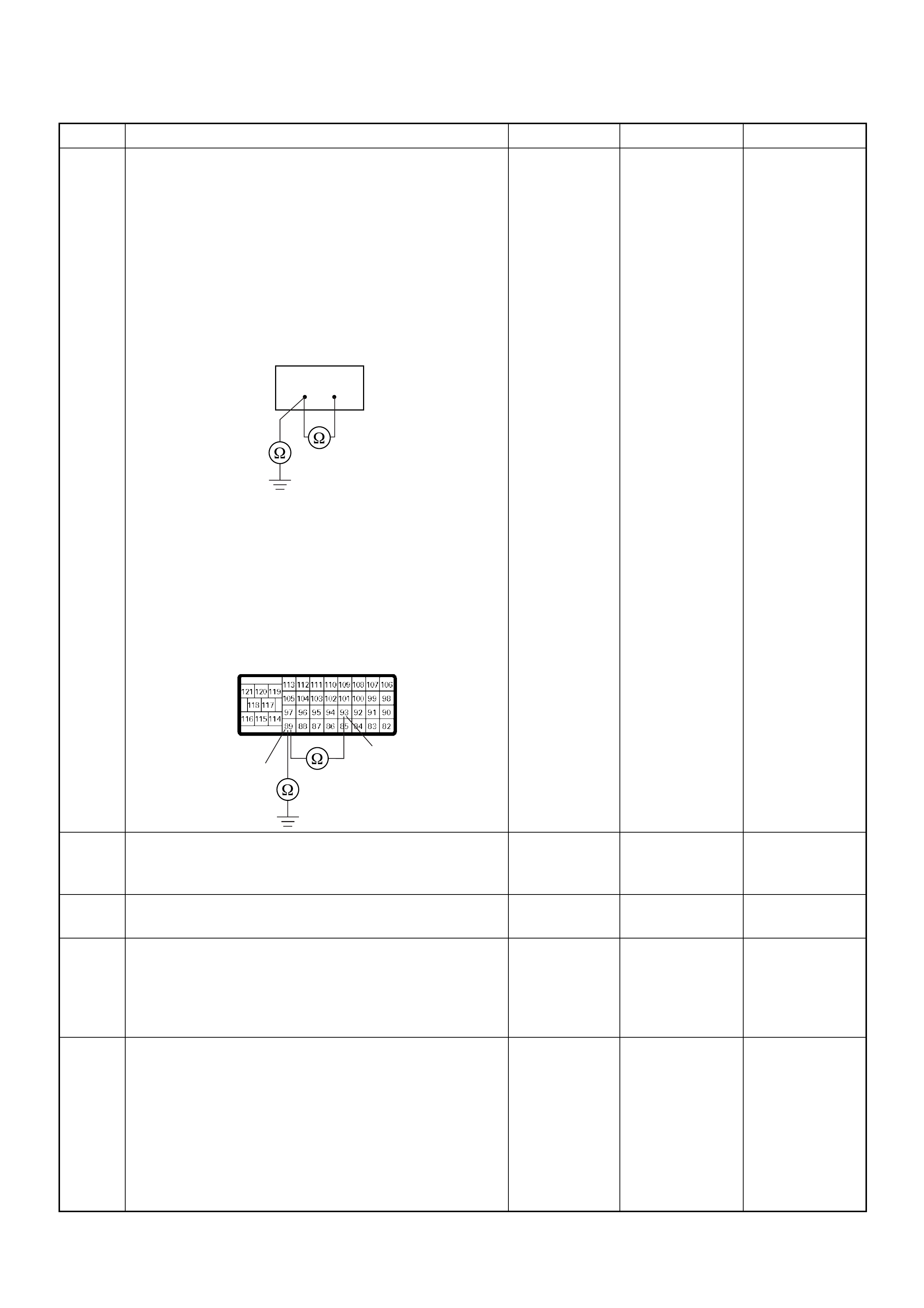
7 Using the DVM and check the ECT sensor signal
circuit.
Breaker box is available:
1. Ignition “Off”, engine “Off”.
2. Install the breaker box as type A. (ECM
disconnected) Ref. Page 6E-81
3. Disconnect the ECT sensor connector.
4. Check the circuit for short to sensor ground or
ground ci rcui t.
Was the problem found?
Breaker box is not available:
1. Ignition “Off”, engine “Off”.
2. Disconnect the ECT sensor connector and ECM
connector.
3. Check the circuit for short to sensor ground or
ground ci rcui t.
Was the problem found?
—
Repair faulty
harnes s and
verify repair Go to Step 10
8 Substitute a known good ECT sensor assembly and
recheck.
Was the problem solved? — Go to Step 9 Go to Step 10
9 Replace the ECT sensor.
Is the action complete? — Verify repair —
10 Is the ECM programmed with the latest software
release?
If not, downlo ad the latest software to the ECM using
the “SPS (Service Programming System)”.
Was the problem solved? — Verify repair Go to Step 11
11 Replace the ECM.
Is the action complete?
IMPORTANT: The replacement ECM must be
programmed. Refer to section of the Service
Programming System (SPS) in this manual.
Foll owing ECM pr ogramming, the immobi liser system
(if equipped) must be linked to the ECM. Refer to
section 11 “Immobiliser System-ECM replacement” for
the ECM/Immobiliser linking procedure. — Verify repair —
Step Action Value(s) Yes No
89 93
93
89
C-57(B)
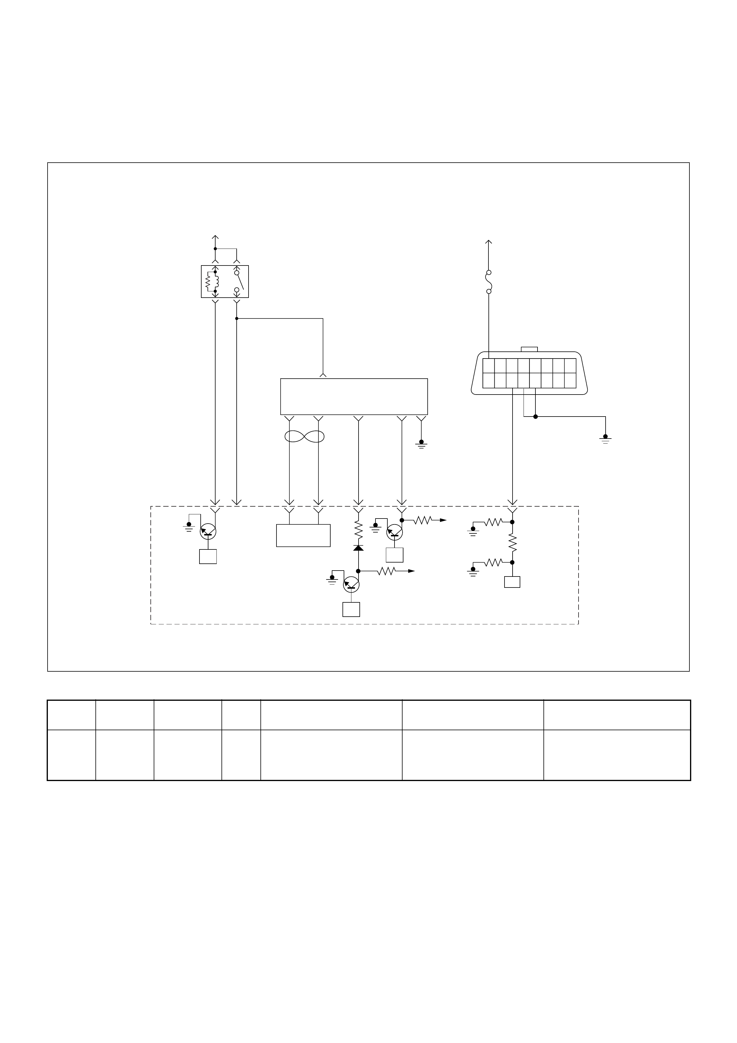
Diagnostic Trouble Code (DTC) P0180 (Symptom Code B)
(Flash Code 15) Fuel Temperature Sensor Circuit Range/performance
Condition for setting the DTC and action taken when the DTC sets
Circuit Desc rip tio n
The fuel temp erature sensor is assembled in side of the
pump con tro l uni t (PS G). T he signa l of fuel tem per at ure
is sent via the CAN-bus from the PSG to ECM.
If the fuel temperature is excessively high or low
condition, a DTC P0180 will be stored.
Diagnostic Aids
An intermittent may be caused by the following:
• Poor connections.
• Misrouted harness.
• Rubbed through wire insulation.
• Broken wire inside the insulation.
Check for the following conditions:
• Poor connection at ECM and PSG-Inspect harness
connectors for backed out terminals, improper
mating, broken locks, improperly formed or damaged
terminals, and poor terminal to wire connection.
• Damaged harness-Inspect the wiring harness for
damage. If the harness appears to be OK, observe
the “Fuel Temperature” display on the Tech2 while
moving connectors and wiring harness related to the
sensor.
Flash
Code Code Symptom
Code MIL DTC Name DTC Setting Condition F ail-Safe (Back Up)
15 P0180 B ON Fuel Temperature Sensor
Circuit Range/Performance FT sensor output is high
temperature (more than
150°C) or low temperature
(below -40°C).
The ECM use 75°C conditions
as sub stitute.
45
16151413121110 9
87654321
Battery
Voltage Battery
Voltage
0.5
RED/
YEL
2.0
BLU/
RED
7
PSG(Pump Control Unit) Injection
Pump
21 5 8
0.5
WHT
2.0
BLU/
RED
0.5
BLU/
BLK
0.5
RED 0.5
ORG
100358 99 105 91
0.5
PNK
62.0
BLK
µP
CAN
Controller
Batt
Batt
IC
µP
0.5
BLU
Stop
Light
10A
1.25
BLK
µP
Engine
Control
Module
(ECM)
ECM
Main Relay

Diagnostic Trouble Code (DTC) P0180 (Symptom Code B) (Flash Code 15)
Fuel Temperature Sensor Circuit Range/Performance
Step Action Value(s) Yes No
1 Was the “On-Board Diagnostic (OBD) System Check”
performed?
—Go to Step 2
Go to On
Board
Diagnostic
(OBD) System
Check
2 1. Connect the Tech 2.
2. Review and record the failure information.
3. Select “F0: Read DTC Infor As Stored By ECU” in
“F0: Diagnostic Trouble Codes”.
Is the DTC P0180 (Symptom Code B) stored as
“Present Failure”? — Go to Step 3
Refer to
Diagnostic
Aids and Go to
Step 3
3 1. Using the Tech 2, ignition “On” and engine “Off”.
2. Select “F1: Clear DTC Information” in “F0:
Diagnostic Trouble Codes” with the Tech 2 and
clear the DTC information.
3. Operate the vehicle and monitor the “F0: Read
DTC Infor As Stored By ECU” in the “F0:
Diagnostic Trouble Codes”.
Was the DTC P0180 (Symptom Code B) stored in this
ignition cycle? — Go to Step 4
Refer to
Diagnostic
Aids
4 Is the ECM programmed with the latest software
release?
If not, downlo ad the latest software to the ECM using
the “SPS (Service Programming System)”.
Was the problem solved? — Verify repair Go to Step 5
5 Substitute a known good ECM and recheck.
Was the problem solved?
IMPORTANT: The replacement ECM must be
programmed. Refer to section of the Service
Programming System (SPS) in this manual.
Foll owing ECM pr ogramming, the immobi liser system
(if equipped) must be linked to the ECM. Refer to
section 11 “Immobiliser System-ECM replacement” for
the ECM/Immobiliser linking procedure. —Go to Step 6 Go to Step 7
6 Replace the ECM.
Is the action complete?
IMPORTANT: The replacement ECM must be
programmed. Refer to section of the Service
Programming System (SPS) in this manual.
Foll owing ECM pr ogramming, the immobi liser system
(if equipped) must be linked to the ECM. Refer to
section 11 “Immobiliser System-ECM replacement” for
the ECM/Immobiliser linking procedure. — Verify repair —
7 Replace the injection pump assembly.
Is the action complete? — Verify repair —
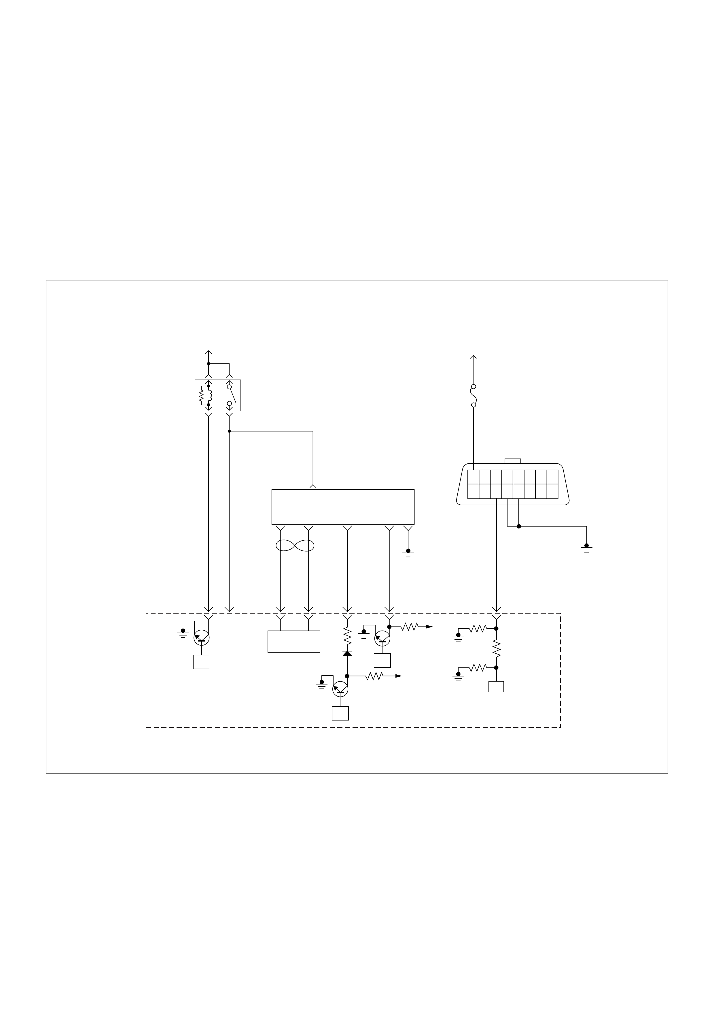
Diagnostic Trouble Code (DTC) P0215 (Symptom Code A)
(Flash Code 52) Fuel Cutoff Solenoid Valve Malfunction
Diagnostic Trouble Code (DTC) P0215 (Symptom Code B)
(Flash Code 52) Fuel Cutoff Solenoid Valve Circuit High Input
Diagnostic Trouble Code (DTC) P0215 (Symptom Code C)
(Flash Code 52) Fuel Cutoff Solenoid Valve Always Active
Diagnostic Trouble Code (DTC) P0215 (Symptom Code D)
(Flash Code 52) Fuel Cutoff Solenoid Valve Malfunction
45
16151413121110 9
87654321
Battery
Voltage Battery
Voltage
0.5
RED/
YEL
2.0
BLU/
RED
7
PSG(Pump Control Unit) Injection
Pump
21 5 8
0.5
WHT
2.0
BLU/
RED
0.5
BLU/
BLK
0.5
RED 0.5
ORG
100358 99 105 91
0.5
PNK
62.0
BLK
µP
CAN
Controller
Batt
Batt
IC
µP
0.5
BLU
Stop
Light
10A
1.25
BLK
µP
Engine
Control
Module
(ECM)
ECM
Main Relay

Condition for setting the DTC and action taken when the DTC sets
Circuit Desc rip tio n
When the ignition switch is turned “Off”, the fuel
solenoid valve (MAB) signal is supplied from the ECM to
the PSG. This signal is the command for the PSG to turn
“Off” the engine.
If the MAB signal circuit is short to voltage circuit or
short to ground circuit, a DTC P0215 (Symptom Code
B) or P0215 (Symptom Code C) will be stored.
Diagnostic Aids
An intermittent may be caused by the following:
• Poor connections.
• Misrouted harness.
• Rubbed through wire insulation.
• Broken wire inside the insulation.
Check for the following conditions:
• Poor connection at ECM and PSG-Inspect harness
connectors for backed out terminals, improper
mating, broken locks, improperly formed or damaged
terminals, and poor terminal to wire connection.
Flash
Code Code Symptom
Code MIL DTC Name DTC Setting Condition F ail-Safe (Back Up)
52 P0215 A ON at
next
ignitio
n
cycle
Fuel Cutoff Solenoid Valve
Malfunction 1. Ignition key switch off.
2. Engine speed is below
1500rpm.
3. Vehicle speed is below
1.5km/h.
4. PS G (pump control unit)
recognizes MAB (fuel cutoff
solenoid valve) signal from
the ECM, but the MAB
could not operate.
1. MA B (f uel cutoff solenoid
valve) is operated.
2. Desired injection quantity
becomes 0mg/strk.
B ON Fuel Cutoff Solenoid Valve
Circuit High Input ECM does not command
MAB (fuel cutoff solenoid
valve) signal to the PSG
(pump control unit), but PSG
detected MAB signal line
circuit is high level.
Engine does not start.
C ON Fuel Cutoff Solenoid Valve
Always Active 1. Ignition key switch off.
2. Engine speed is below
1500rpm.
3. Vehicle speed is below
1.5km/h.
4. PS G (pump control unit)
does not recognize MAB
(fuel cutoff solenoid valve)
signal from the ECM.
1. MA B (f uel cutoff solenoid
valve) is operated.
2. Desired injection quantity
becomes 0mg/strk.
D ON Fuel Cutoff Solenoid Valve
Malfunction 1. Ignition key switch off.
2. CAN controller does not
operate Bus-off.
No fail-safe function.

Diagnostic Trouble Code (DTC) P0215 (Symptom Code A) (Flash Code 52)
Fuel Cutoff Solenoid Valve Malfunction
Diagnostic Trouble Code (DTC) P0215 (Symptom Code B) (Flash Code 52)
Fuel Cutoff Solenoid Valve Circuit High Input
Step Action Value(s) Yes No
1 Was the “On-Board Diagnostic (OBD) System Check”
performed?
—Go to Step 2
Go to On
Board
Diagnostic
(OBD) System
Check
2 1. Connect the Tech 2.
2. Review and record the failure information.
3. Select “F0: Read DTC Infor As Stored By ECU” in
“F0: Diagnostic Trouble Codes”.
Is the DTC P0215 (Symptom Code A) stored as
“Present Failure”? — Go to Step 3
Refer to
Diagnostic
Aids and Go to
Step 3
3 1. Using the Tech 2, ignition “On” and engine “Off”.
2. Select “F1: Clear DTC Information” in “F0:
Diagnostic Trouble Codes” with the Tech 2 and
clear the DTC information.
3. Operate the vehicle and monitor the “F0: Read
DTC Infor As Stored By ECU” in the “F0:
Diagnostic Trouble Codes”.
Was the DTC P0215 (Symptom Code A) stored in this
ignition cycle? — Go to Step 4
Refer to
Diagnostic
Aids
4 Replace the injection pump assembly.
Is the action complete? — Verify repair —
Step Action Value(s) Yes No
1 Was the “On- Board Diagnos tic (OBD) Sy stem Check”
performed?
—Go to Step 2
Go to On
Board
Diagnostic
(OBD) System
Check
2 1. Connect the Tech 2.
2. Review and record the failure information.
3. S elect “F0: Read DTC I nfor As Stored B y ECU” in
“F0: Diagnostic Trouble Codes”.
Is the DTC P0215 (Symptom Code B) stored as
“Present Failure”? — Go to Step 3
Refer to
Diagnostic
Aids and Go to
Step 3
3 1. Using the Tech 2, ignition “On” and engine “Off”.
2. Select “F1: Clear DTC Information” in “F0:
Diagnostic Trouble Codes” with the Tech 2 and
clear the DTC information.
3. Operate the vehicle and monitor the “F0: Read
DTC Infor As Stored By ECU” in the “F0:
Diagnostic Trouble Codes”.
Was the DTC P0215 (Symptom Code B) stored in this
ignition cycle? — Go to Step 4
Refer to
Diagnostic
Aids and Go to
Step 4
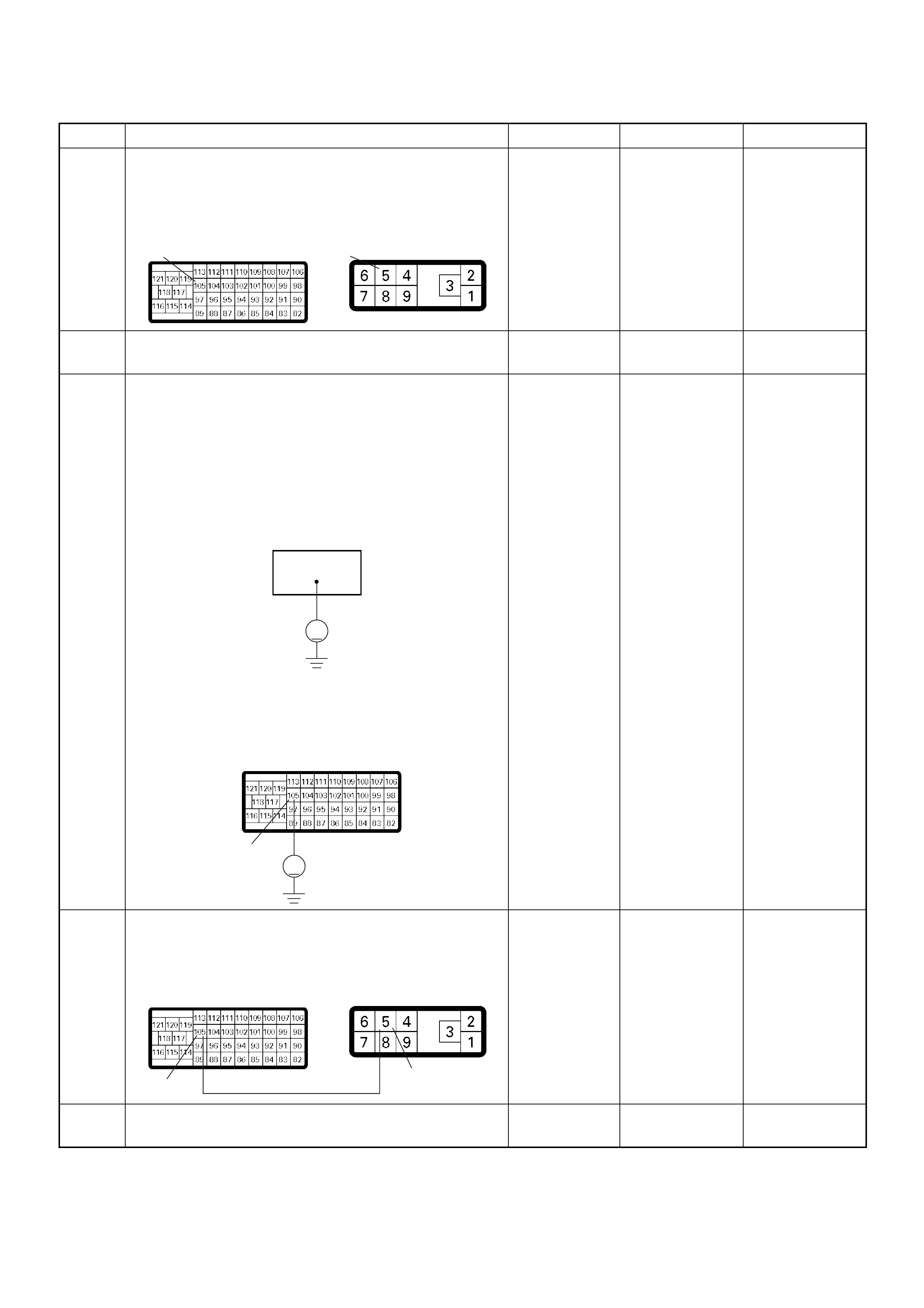
4 Check for poor/faulty connection at the ECM or PSG
(pump control unit) connector. If a poor/faulty
connection is found, repair as necessary.
Was the problem found?
— Verify repair Go to Step 5
5 Visually check the PS G (p ump contro l unit) .
Was the problem found? — Go to Step 8 Go to Step 6
6 Using the DVM and check the MAB (fuel cutoff
solenoid valve) circuit.
Breaker box is available:
1. Ignition “Off”, engine “Off”.
2. Install the breaker box as type B. (ECM
connected) Ref. Page 6E-81
3. Check the circuit for short to voltage circuit.
Was the DVM indicated specified value?
Breaker box is not available:
1. Check the circuit for short to voltage circuit.
Was the DVM indicated specified value?
Less than 1V Go to Step 8 Go to Step 7
7 Repair the short to voltage circuit between the ECM
and PSG (pump control unit).
Was the problem solved?
— Verify repair Go to Step 8
8 Replace the injection pump assembly.
Is the action complete? — Verify repair —
Step Action Value(s) Yes No
105 5E-6C-57
105
V
V
105
C-57
105 5
E-6C-57
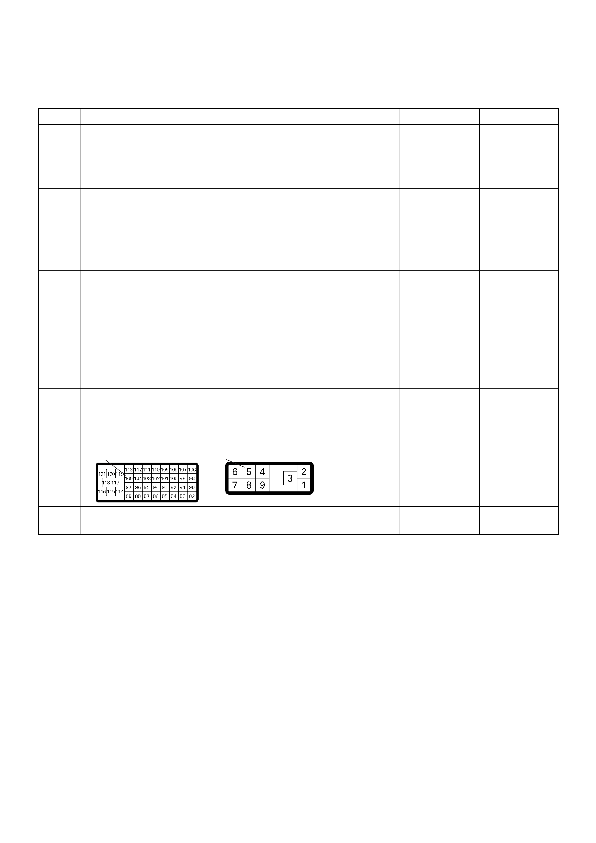
Diagnostic Trouble Code (DTC) P0215 (Symptom Code C) (Flash Code 52)
Fuel Cutoff Solenoid Valve Always Active
Step Action Value(s) Yes No
1 Was the “On-Board Diagnostic (OBD) System Check”
performed?
—Go to Step 2
Go to On
Board
Diagnostic
(OBD) System
Check
2 1. Connect the Tech 2.
2. Review and record the failure information.
3. Select “F0: Read DTC Infor As Stored By ECU” in
“F0: Diagnostic Trouble Codes”.
Is the DTC P0215 (Symptom Code C) stored as
“Present Failure”? — Go to Step 3
Refer to
Diagnostic
Aids and Go to
Step 3
3 1. Using the Tech 2, ignition “On” and engine “Off”.
2. Select “F1: Clear DTC Information” in “F0:
Diagnostic Trouble Codes” with the Tech 2 and
clear the DTC information.
3. Operate the vehicle and monitor the “F0: Read
DTC Infor As Stored By ECU” in the “F0:
Diagnostic Trouble Codes”.
Was the DTC P0215 (Symptom Code C) stored in this
ignition cycle? — Go to Step 4
Refer to
Diagnostic
Aids and Go to
Step 4
4 Check for poor/faulty connection at the ECM or PSG
(pump control unit) connector. If a poor/faulty
connection is found, repair as necessary.
Was the problem found?
— Verify repair Go to Step 5
5 Visually check the PS G (p ump contro l unit) .
Was the problem found? — Go to Step 7 Go to Step 6
105 5E-6C-57
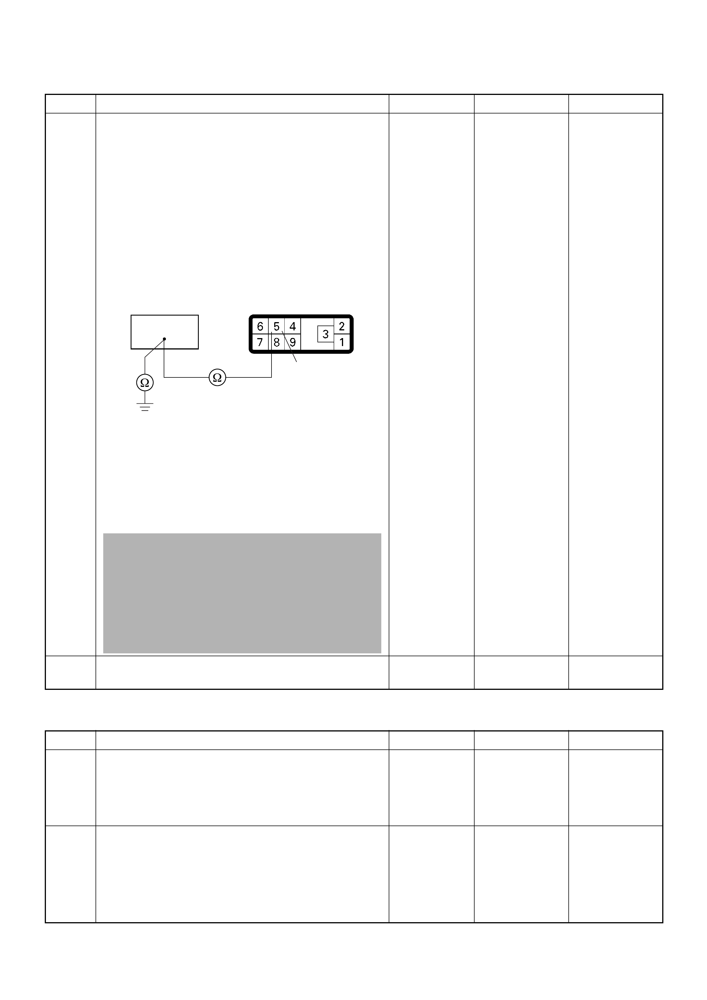
Diagnostic Trouble Code (DTC) P0215 (Symptom Code D) (Flash Code 52)
Fuel Cutoff Solenoid Valve Malfunction
6 Using the DVM and check the MAB (fuel cutoff
solenoid valve) circuit.
Breaker box is available:
1. Ignition “Off”, engine “Off”.
2. Install the breaker box as type A. (ECM
disconnected) Ref. Page 6E-81
3. Disconnect the PSG (pump control unit)
connector.
4. Check the circuit for open or short to ground
circuit.
Was the problem found?
Breaker box is not available:
1. Ignition “Off”, engine “Off”.
2. Disconnect the PSG (pump control unit)
connector.
3. Check the circuit for open or short to ground
circuit.
Was the problem found?
—
Repair faulty
harness and
verify repair Go to Step 7
7 Replace the injection pump assembly.
Is the action complete? — Verify repair —
Step Action Value(s) Yes No
1 Was the “On-Board Diagnostic (OBD) System Check”
performed?
—Go to Step 2
Go to On
Board
Diagnostic
(OBD) System
Check
2 1. Connect the Tech 2.
2. Review and record the failure information.
3. Select “F0: Read DTC Infor As Stored By ECU” in
“F0: Diagnostic Trouble Codes”.
Is the DTC P0215 (Symptom Code D) stored as
“Present Failure”? — Go to Step 3
Refer to
Diagnostic
Aids and Go to
Step 3
Step Action Value(s) Yes No
105
5
E-6

3 1. Using the Tech 2, ignition “On” and engine “Off”.
2. Select “F1: Clear DTC Information” in “F0:
Diagnostic Trouble Codes” with the Tech 2 and
clear the DTC information.
3. Operate the vehicle and monitor the “F0: Read
DTC Infor As Stored By ECU” in the “F0:
Diagnostic Trouble Codes”.
Was the DTC P0215 (Symptom Code D) stored in this
ignition cycle? — Go to Step 4
Refer to
Diagnostic
Aids
4 Is the ECM programmed with the latest software
release?
If not, downlo ad the latest software to the ECM using
the “SPS (Service Programming System)”.
Was the problem solved? — Verify repair Go to Step 5
5 Substitute a known good ECM and recheck.
Was the problem solved?
IMPORTANT: The replacement ECM must be
programmed. Refer to section of the Service
Programming System (SPS) in this manual.
Foll owing ECM pr ogramming, the immobi liser system
(if equipped) must be linked to the ECM. Refer to
section 11 “Immobiliser System-ECM replacement” for
the ECM/Immobiliser linking procedure. — Go to Step 6 Go to Step 7
6 Replace the ECM.
Is the action complete?
IMPORTANT: The replacement ECM must be
programmed. Refer to section of the Service
Programming System (SPS) in this manual.
Foll owing ECM pr ogramming, the immobi liser system
(if equipped) must be linked to the ECM. Refer to
section 11 “Immobiliser System-ECM replacement” for
the ECM/Immobiliser linking procedure. — Verify repair —
7 Replace the injection pump assembly.
Is the action complete? — Verify repair —
Step Action Value(s) Yes No
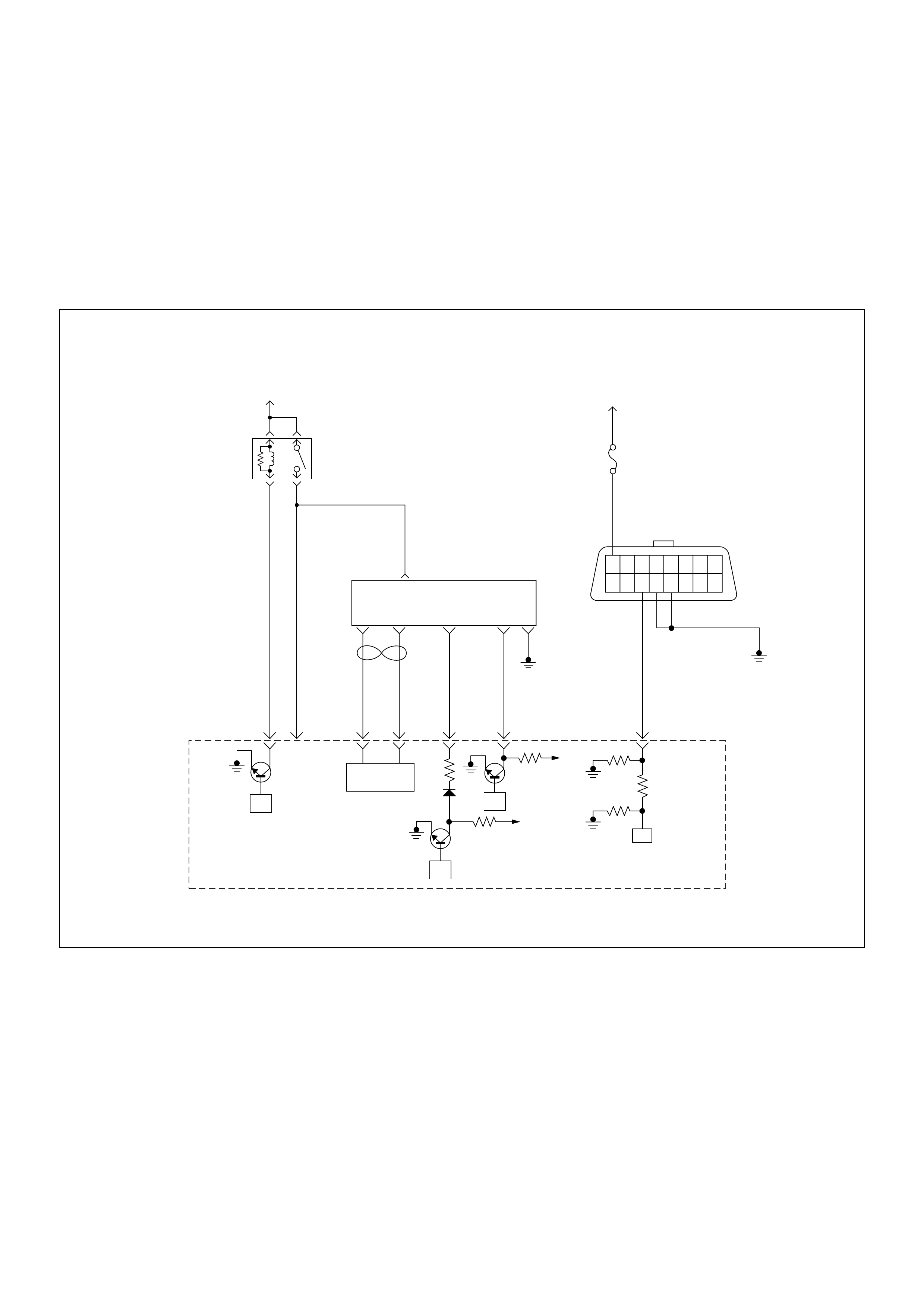
Diagnostic Trouble Code (DTC) P0216 (Symptom Code A)
(Flash Code 54) Injection Timing Control Circuit
Malfunction (Timer Deviation)
Diagnostic Trouble Code (DTC) P0216 (Symptom Code B)
(Flash Code 54) Injection Timing Control Circuit
Malfunction (Timer Fluctuation)
45
16151413121110 9
87654321
Battery
Voltage Battery
Voltage
0.5
RED/
YEL
2.0
BLU/
RED
7
PSG(Pump Control Unit) Injection
Pump
21 5 8
0.5
WHT
2.0
BLU/
RED
0.5
BLU/
BLK
0.5
RED 0.5
ORG
100358 99 105 91
0.5
PNK
62.0
BLK
µP
CAN
Controller
Batt
Batt
IC
µP
0.5
BLU
Stop
Light
10A
1.25
BLK
µP
Engine
Control
Module
(ECM)
ECM
Main Relay

Condition for setting the DTC and action taken when the DTC sets
Circuit Desc rip tio n
The ECM is calculates an injection quantity and an
injection timing using the various sensors (crankshaft
position sensor, camshaft position sensor, engine
coolant temperature sensor, etc.). The timing control
valve (TCV) operation performs an injection timing
decision.
The TCV pe rfor ms as a v ariab le th ro ttle , using the ra pi d
opening and closing cycle of the valve needle in the
TCV.
The TCV is assembled in the injection pump. The signal
of desired injection timing and actual injection timing are
exchanged via the CAN-bus between the PSG and
ECM.
If the timer position is out of tolerance (deviation or
fluctuation), a DTC P0216 will be stored.
Diagnostic Aids
An intermittent may be caused by the following:
• Poor connections.
• Misrouted harness.
• Rubbed through wire insulation.
• Broken wire inside the insulation.
• Insufficient air bleeding of fuel line.
Check for the following conditions:
• Insufficient air bleeding of fuel line inside, clogged
fuel filter or pinched fuel pipe/hose may cause the
DTC store or improper engine performance.
• Poor connection at ECM and PSG-Inspect harness
connectors for backed out terminals, improper
mating, broken locks, improperly formed or damaged
terminals, and poor terminal to wire connection.
• Damaged harness-Inspect the wiring harness for
damage. If the harness appears to be OK, observe
the “A ct ual In je ction Start” displ ay o n the Tech2 whi le
moving connectors and wiring harness related to the
sensor.
Flash
Code Code Symptom
Code MIL DTC Name DTC Setting Condition F ail-Safe (Back Up)
54 P0216 A ON Injection Timing Control
Circuit Malfunction (Timer
Deviation)
1. Engine speed is more than
700rpm.
2. Fuel injection quantity is
more than 4mg/stk.
3. Deviation of actual injection
timing and desired injection
timing is more than +3°CA
or -6°CA for 8 seconds.
Fuel injection quantity is
reduced.
B ON Injection Timing Control
Circuit Malfunction (Timer
Fluctuation)
1. Engine speed is more than
2014rpm.
2. Fluctuation of actual
injection timing is more
than ±5.2°CA.

Diagnostic Trouble Code (DTC) P0216 (Symptom Code A) (Flash Code 54)
Injection Timing Control Circuit Malfunction (Timer Deviation)
Diagnostic Trouble Code (DTC) P0216 (Symptom Code B) (Flash Code 54)
Injection Timing Control Circuit Malfunction (Timer Fluctuation)
Step Action Value(s) Yes No
1 Was the “On-Board Diagnostic (OBD) System Check”
performed?
—Go to Step 2
Go to On
Board
Diagnostic
(OBD) System
Check
2 1. Connect the Tech 2.
2. Review and record the failure information.
3. Select “F0: Read DTC Infor As Stored By ECU” in
“F0: Diagnostic Trouble Codes”.
Is the DTC P0216 (Symptom Code A) stored as
“Present Failure”? — Go to Step 3
Refer to
Diagnostic
Aids and Go to
Step 3
3 1. Using the Tech 2, ignition “On” and engine “Off”.
2. Select “F1: Clear DTC Information” in “F0:
Diagnostic Trouble Codes” with the Tech 2 and
clear the DTC information.
3. Operate the vehicle and monitor the “F0: Read
DTC Infor As Stored By ECU” in the “F0:
Diagnostic Trouble Codes”.
Was the DTC P0216 (Symptom Code A) stored in this
ignition cycle? — Go to Step 4
Refer to
Diagnostic
Aids
4 Replace the injection pump assembly.
Is the action complete? — Verify repair —
Step Action Value(s) Yes No
1 Was the “On-Board Diagnostic (OBD) System Check”
performed?
—Go to Step 2
Go to On
Board
Diagnostic
(OBD) System
Check
2 1. Connect the Tech 2.
2. Review and record the failure information.
3. Select “F0: Read DTC Infor As Stored By ECU” in
“F0: Diagnostic Trouble Codes”.
Is the DTC P0216 (Symptom Code B) stored as
“Present Failure”? — Go to Step 3
Refer to
Diagnostic
Aids and Go to
Step 3
3 1. Using the Tech 2, ignition “On” and engine “Off”.
2. Select “F1: Clear DTC Information” in “F0:
Diagnostic Trouble Codes” with the Tech 2 and
clear the DTC information.
3. Operate the vehicle and monitor the “F0: Read
DTC Infor As Stored By ECU” in the “F0:
Diagnostic Trouble Codes”.
Was the DTC P0216 (Symptom Code B) stored in this
ignition cycle? — Go to Step 4
Refer to
Diagnostic
Aids and Go to
Step 4
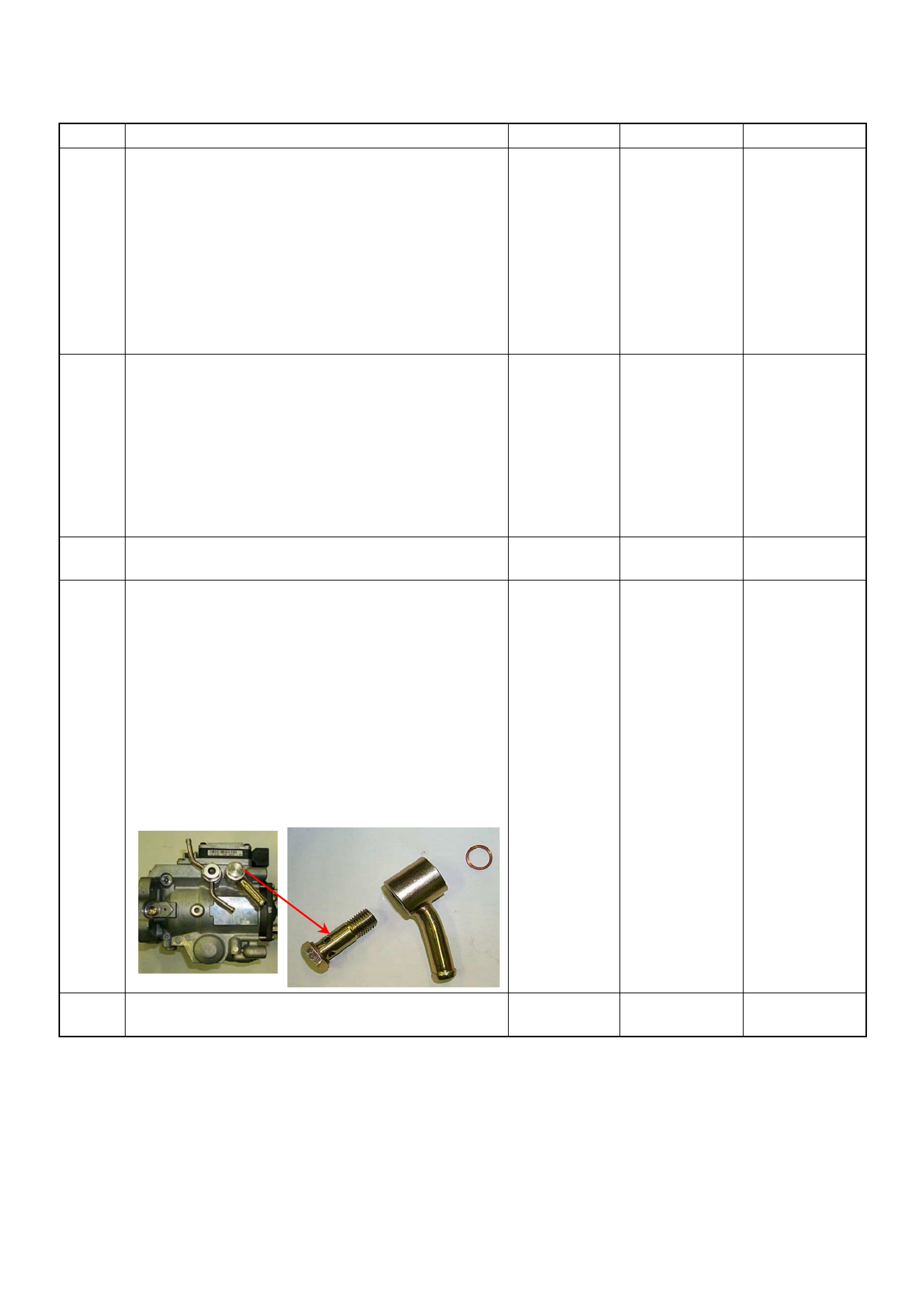
4 Perform the air bleeding in the fuel line sufficiently.
1. Using the Tech 2, ignition “On” and engine “Off”.
2. Select “F1: Clear DTC Information” in “F0:
Diagnostic Trouble Codes” with the Tech 2 and
clear the DTC information.
3. Operate the vehicle and monitor the “F0: Read
DTC Infor As Stored By ECU” in the “F0:
Diagnostic Trouble Codes”.
Was the DTC P0216 (Symptom Code B) restored in
this ignition cycle? — Go to Step 5 Verify repair
5 Visually/physically inspect for the following conditions.
• Restrict fuel supply system. Check for a pinched
fuel hose/pipe.
• Check for a condition that causes fuel waxing or
icing, such as the customer is using an incorrect
fuel type in winter season or water mixed with the
fuel.
If a problem is found, repair as necessary.
Was a problem found? — Verify repair Go to Step 6
6 Replace the fuel filter.
Was the problem solved? — Verify repair Go to Step 7
7 Remove the eye bolt with gauze filter from the
injection pump and check for the following conditions.
• Objects blocking at the gauze filter. Check for a
condition that causes contaminated fuel, such as
the customer is using an aftermarket fuel filter or
extended mai nte nan ce int erva l.
• Check for a condition that causes fuel waxing or
icing, such as the customer is using an incorrect
fuel type in winter season or water mixed with the
fuel.
If a problem is found, repair as necessary.
Was the problem found?
—
Replace the
eye bolt with
gauze filter and
verify repair G o to Step 8
8 Replace the injection pump assembly.
Is the action complete? — Verify repair —
Step Action Value(s) Yes No
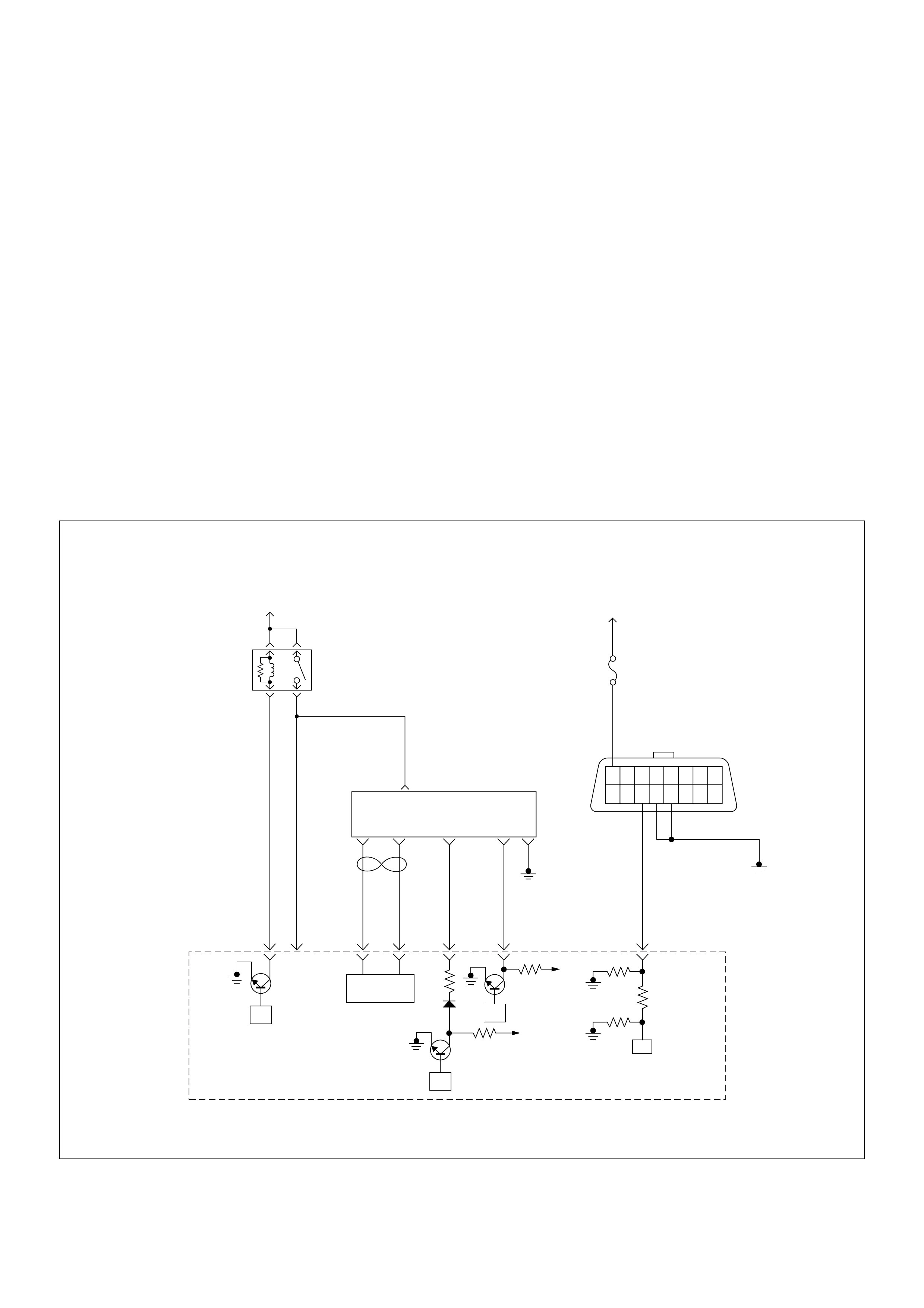
Diagnostic Trouble Code (DTC) P0251 (Symptom Code 6)
(Flash Code 53) Injection Pump Malfunction
Diagnostic Trouble Code (DTC) P0251 (Symptom Code 7)
(Flash Code 53) Injection Pump Malfunction
Diagnostic Trouble Code (DTC) P0251 (Symptom Code 9)
(Flash Code 53) Injection Pump Malfunction
Diagnostic Trouble Code (DTC) P0251 (Symptom Code A)
(Flash Code 53) Injection Pump Malfunction
Diagnostic Trouble Code (DTC) P0251 (Symptom Code B)
(Flash Code 53) Injection Pump Malfunction
Diagnostic Trouble Code (DTC) P0251 (Symptom Code D)
(Flash Code 53) Injection Pump Malfunction
Diagnostic Trouble Code (DTC) P0251 (Symp tom Code E)
(Flash Code 53) Injection Pump Malfunction
45
16151413121110 9
87654321
Battery
Voltage Battery
Voltage
0.5
RED/
YEL
2.0
BLU/
RED
7
PSG(Pump Control Unit) Injection
Pump
21 5 8
0.5
WHT
2.0
BLU/
RED
0.5
BLU/
BLK
0.5
RED 0.5
ORG
100358 99 105 91
0.5
PNK
62.0
BLK
µP
CAN
Controller
Batt
Batt
IC
µP
0.5
BLU
Stop
Light
10A
1.25
BLK
µP
Engine
Control
Module
(ECM)
ECM
Main Relay

Condition for setting the DTC and action taken when the DTC sets
Circuit Desc rip tio n
The ECM is calculates an injection quantity and an
injecti on ti min g us ing the v ariou s s ens or s. And the PSG
control s the high pr essure sol enoid val ve depending o n
programmed pump map data.
The signal of desired injection quantity and actual
injection quantify are exchanged via the CAN-bus
between the PSG and ECM.
If the relatio n of eng ine spe ed sign al an d dou ble d pum p
camshaft spe ed signal excessiv ely large , a DTC P025 1
(Symptom Code 7) will be stored.
If the CAN high or low circ uit is defected, a DTC P0251
(Symptom Code E) will be stored.
Diagnostic Aids
An intermittent may be caused by the following:
• Poor connections.
• Misrouted harness.
• Rubbed through wire insulation.
• Broken wire inside the insulation.
Check for the following conditions:
• Poor connection at ECM and PSG-Inspect harness
connectors for backed out terminals, improper
mating, broken locks, improperly formed or damaged
terminals, and poor terminal to wire connection.
• Damaged harness-Inspect the wiring harness for
damage. If the harness appears to be OK, observe
the “Injection Quantity” display on the Tech2 while
moving connectors and wiring harness related to the
sensor.
Flash
Code Code Symptom
Code MIL DTC Name DTC Setting Condition F ail-Safe (Back Up)
53 P0251 6 ON Injection Pump Malfunction 1. No pump camshaft speed
sensor error.
2. High pressure solenoid
valve control pulse width
does not match with
desired fuel injection
quantity.
1. MA B (f uel cutoff solenoid
valve) is operated.
2. Desired injection quantity
becomes 0mg/strk.
7 ON Injection Pump Malfunction 1. No pump camshaft speed
sensor error.
2. No CKP sensor error.
3. Difference of engine speed
and doubled pump
camshaft speed is more
than 720rpm (4JA1-TC) or
690rpm (4JH1-TC).
9 ON Injection Pump Malfunction No pump map programmed in
the PSG (pump control unit)
or PSG malfunction.
A ON Injection Pump Malfunction EEPROM or A/D converter
malfunction in the PSG (pump
control unit).
Fuel injection quantity is
reduced.
B ON Injection Pump Malfunction PSG (pump control unit)
recognized high pressure
solenoid valve drive circuit
error.
No fail-safe function.
D ON Injection Pump Malfunction PSG (pump control unit) could
not measure the high
pressure solenoid valve drive
voltage.
E ON Injection Pump Malfunction ECM could not accept PSG
(pump control unit) message. 1. MAB (fuel cutoff solenoid
valve) is operated.
2. Desired injection quantity
becomes 0mg/strk.

Diagnostic Trouble Code (DTC) P0251 (Symptom Code 6) (Flash Code 53) Injection Pump Malfunction
Diagnostic Trouble Code (DTC) P0251 (Symptom Code 7) (Flash Code 53) Injection Pump Malfunction
Step Action Value(s) Yes No
1 Was the “On-Board Diagnostic (OBD) System Check”
performed?
—Go to Step 2
Go to On
Board
Diagnostic
(OBD) System
Check
2 1. Connect the Tech 2.
2. Review and record the failure information.
3. Select “F0: Read DTC Infor As Stored By ECU” in
“F0: Diagnostic Trouble Codes”.
Is the DTC P0251 (Symptom Code 6) stored as
“Present Failure”? — Go to Step 3
Refer to
Diagnostic
Aids and Go to
Step 3
3 1. Using the Tech 2, ignition “On” and engine “Off”.
2. Select “F1: Clear DTC Information” in “F0:
Diagnostic Trouble Codes” with the Tech 2 and
clear the DTC information.
3. Operate the vehicle and monitor the “F0: Read
DTC Infor As Stored By ECU” in the “F0:
Diagnostic Trouble Codes”.
Was the DT C P0 251 (Sy mpt om Code 6) stor e d i n th is
ignition cycle? — Go to Step 4
Refer to
Diagnostic
Aids
4 Replace the injection pump assembly.
Is the action complete? — Verify repair —
Step Action Value(s) Yes No
1 Was the “On- Board Diagnos tic (OBD) Sy stem Check”
performed?
—Go to Step 2
Go to On
Board
Diagnostic
(OBD) System
Check
2 1. Connect the Tech 2.
2. Review and record the failure information.
3. S elect “F0: Read DTC I nfor As Stored B y ECU” in
“F0: Diagnostic Trouble Codes”.
Is the DTC P0251 (Symptom Code 7) stored as
“Present Failure”? — Go to Step 3
Refer to
Diagnostic
Aids and Go to
Step 3
3 1. Using the Tech 2, ignition “On” and engine “Off”.
2. Select “F1: Clear DTC Information” in “F0:
Diagnostic Trouble Codes” with the Tech 2 and
clear the DTC information.
3. Operate the vehicle and monitor the “F0: Read
DTC Infor As Stored By ECU” in the “F0:
Diagnostic Trouble Codes”.
Was the DT C P0 251 (Sy mpt om Code 7) stor e d i n th is
ignition cycle? — Go to Step 4
Refer to
Diagnostic
Aids and Go to
Step 4
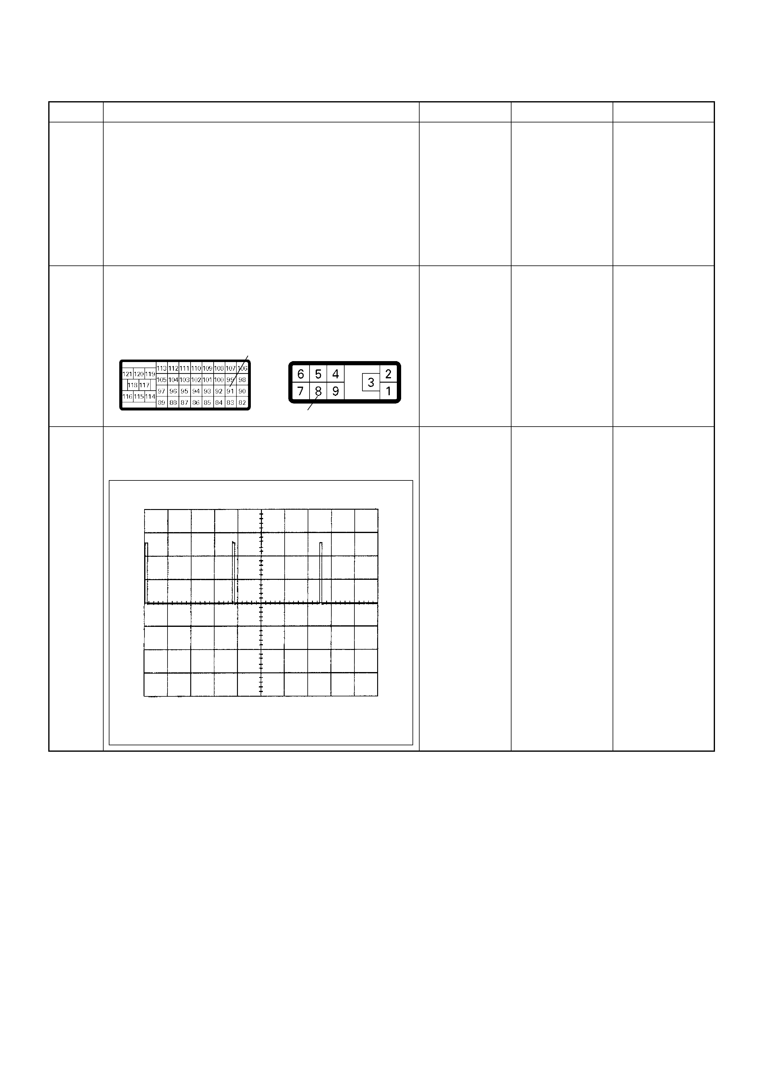
4 Was the DTC P0335 (Symptom Code B), P0335
(Symptom Code D) or P1335 (Symptom Code A)
stored at the same time?
—
Go to DTC
Chart P0335
(Symptom
Code B)
(Symptom
Code D) or
P1335
(Symptom
Code A) Go to Step 5
5 Check for poor/faulty connection at the ECM or PSG
(pump control unit) connector. If a poor/faulty
connection is found, repair the faulty terminal.
Was the problem found?
— Verify repair Go to Step 6
6 I f a oscillosc ope is availabl e, monitor the CKP sensor
output signal. Does the oscilloscope indicate correct
wave form?
—Go to Step 13
Not available:
Go to Step 7
Fixed at low:
Go to Step 7
Fixed at High:
Go to Step 8
Step Action Value(s) Yes No
91
8
C-57(B) E-6
CKP Sensor Output Reference Wave Form
0V→
Measurement Terminal: 91 (+) 1 (-)
Measurement Scale: 5.0V/div 2.0ms/div
Measurement Condition: Engine speed at 2000rpm

7 Using the DVM and check the CKP sensor output
circuit.
Breaker box is available:
1. Ignition “Off”, engine “Off”.
2. Install the breaker box as type A. (ECM
disconnected) Ref. Page 6E-81
3. Disconnect the PSG (pump control unit)
connector.
4. Check the circuit for open or short to ground
circuit.
Was the problem found?
Breaker box is not available:
1. Ignition “Off”, engine “Off”.
2. Disconnect the ECM connector.
3. Disconnect the PSG (pump control unit)
connector.
4. Check the circuit for open or short to ground
circuit.
Was the problem found?
—
Repair faulty
harnes s and
verify repair G o to Step 8
8 Using the DVM and check the CKP sensor output
circuit.
1. Ignition “On”, engine “Off”.
2. Disconnect the PSG (pump control unit)
connector.
3. Check the circuit for short to power supply circuit.
Was the DVM indicated specified value?
Less than 1V Go to Step 9
Repair faulty
harness and
verify repair
Step Action Value(s) Yes No
91
8
E-6
91 8
C-57(B) E-6
8
V
E-6

Diagnostic Trouble Code (DTC) P0251 (Symptom Code 9) (Flash Code 53) Injection Pump Malfunction
9 Check any accessory parts which may cause electric
interference or magnetic interference.
Was the problem found? —
Remove the
accessory parts
and verify repair Go to Step 10
10 Is the ECM programmed with the latest software
release?
If not, download the latest software to the ECM using
the “SPS (Service Programming System)”.
Was the problem solved? — Verify repair Go to Step 11
11 Substitute a known good ECM and recheck.
Was the problem solved?
IMPORTANT: The replacement ECM must be
programmed. Refer to section of the Service
Programming System (SPS) in this manual.
Following ECM programming, the immobiliser system
(if equipped) must be linked to the ECM. Refer to
section 11 “Immobiliser System-ECM replacement” for
the ECM/Immobiliser linking procedure. — Go to Step 12 Go to Step 13
12 Replace the ECM.
Is the action complete?
IMPORTANT: The replacement ECM must be
programmed. Refer to section of the Service
Programming System (SPS) in this manual.
Following ECM programming, the immobiliser system
(if equipped) must be linked to the ECM. Refer to
section 11 “Immobiliser System-ECM replacement” for
the ECM/Immobiliser linking procedure. — Verify repair —
13 Replace the injection pump assembly.
Is the action complete? — Verify repair —
Step Action Value(s) Yes No
1 Was the “On-Board Diagnostic (OBD) System Check”
performed?
—Go to Step 2
Go to On
Board
Diagnostic
(OBD) System
Check
2 1. Connect the Tech 2.
2. Review and record the failure information.
3. Select “F0: Read DTC Infor As Stored By ECU” in
“F0: Diagnostic Trouble Codes”.
Is the DTC P0251 (Symptom Code 9) stored as
“Present Failure”? — Go to Step 3
Refer to
Diagnostic
Aids and Go to
Step 3
3 1. Using the Tech 2, ignition “On” and engine “Off”.
2. Select “F1: Clear DTC Information” in “F0:
Diagnostic Trouble Codes” with the Tech 2 and
clear the DTC information.
3. Operate the vehicle and monitor the “F0: Read
DTC Infor As Stored By ECU” in the “F0:
Diagnostic Trouble Codes”.
Was the DT C P0 251 (Sy mpt om Code 9) stor e d i n th is
ignition cycle? — Go to Step 4
Refer to
Diagnostic
Aids
4 Replace the injection pump assembly.
Is the action complete? — Verify repair —
Step Action Value(s) Yes No

Diagnostic Trouble Code (DTC) P0251 (Symptom Code A) (Flash Code 53) Injection Pump Malfunction
Diagnostic Trouble Code (DTC) P0251 (Symptom Code B) (Flash Code 53) Injection Pump Malfunction
Step Action Value(s) Yes No
1 Was the “On-Board Diagnostic (OBD) System Check”
performed?
—Go to Step 2
Go to On
Board
Diagnostic
(OBD) System
Check
2 1. Connect the Tech 2.
2. Review and record the failure information.
3. Select “F0: Read DTC Infor As Stored By ECU” in
“F0: Diagnostic Trouble Codes”.
Is the DTC P0251 (Symptom Code A) stored as
“Present Failure”? — Go to Step 3
Refer to
Diagnostic
Aids and Go to
Step 3
3 1. Using the Tech 2, ignition “On” and engine “Off”.
2. Select “F1: Clear DTC Information” in “F0:
Diagnostic Trouble Codes” with the Tech 2 and
clear the DTC information.
3. Operate the vehicle and monitor the “F0: Read
DTC Infor As Stored By ECU” in the “F0:
Diagnostic Trouble Codes”.
Was the DTC P0251 (Symptom Code A) stored in this
ignition cycle? — Go to Step 4
Refer to
Diagnostic
Aids
4 Replace the injection pump assembly.
Is the action complete? — Verify repair —
Step Action Value(s) Yes No
1 Was the “On- Board Diagnos tic (OBD) Sy stem Check”
performed?
—Go to Step 2
Go to On
Board
Diagnostic
(OBD) System
Check
2 1. Connect the Tech 2.
2. Review and record the failure information.
3. S elect “F0: Read DTC I nfor As Stored B y ECU” in
“F0: Diagnostic Trouble Codes”.
Is the DTC P0251 (Symptom Code B) stored as
“Present Failure”? — Go to Step 3
Refer to
Diagnostic
Aids and Go to
Step 3
3 1. Using the Tech 2, ignition “On” and engine “Off”.
2. Select “F1: Clear DTC Information” in “F0:
Diagnostic Trouble Codes” with the Tech 2 and
clear the DTC information.
3. Operate the vehicle and monitor the “F0: Read
DTC Infor As Stored By ECU” in the “F0:
Diagnostic Trouble Codes”.
Was the DTC P0251 (Symptom Code B) stored in this
ignition cycle? — Go to Step 4
Refer to
Diagnostic
Aids
4 Replace the injection pump assembly.
Is the action complete? — Verify repair —

Diagnostic Trouble Code (DTC) P0251 (Symptom Code D) (Flash Code 53) Injection Pump Malfunction
Diagnostic Trouble Code (DTC) P0251 (Symptom Code E) (Flash Code 53) Injection Pump Malfunction
Step Action Value(s) Yes No
1 Was the “On-Board Diagnostic (OBD) System Check”
performed?
—Go to Step 2
Go to On
Board
Diagnostic
(OBD) System
Check
2 1. Connect the Tech 2.
2. Review and record the failure information.
3. Select “F0: Read DTC Infor As Stored By ECU” in
“F0: Diagnostic Trouble Codes”.
Is the DTC P0251 (Symptom Code D) stored as
“Present Failure”? — Go to Step 3
Refer to
Diagnostic
Aids and Go to
Step 3
3 1. Using the Tech 2, ignition “On” and engine “Off”.
2. Select “F1: Clear DTC Information” in “F0:
Diagnostic Trouble Codes” with the Tech 2 and
clear the DTC information.
3. Operate the vehicle and monitor the “F0: Read
DTC Infor As Stored By ECU” in the “F0:
Diagnostic Trouble Codes”.
Was the DTC P0251 (Symptom Code D) stored in this
ignition cycle? — Go to Step 4
Refer to
Diagnostic
Aids
4 Replace the injection pump assembly.
Is the action complete? — Verify repair —
Step Action Value(s) Yes No
1 Was the “On- Board Diagnos tic (OBD) Sy stem Check”
performed?
—Go to Step 2
Go to On
Board
Diagnostic
(OBD) System
Check
2 1. Connect the Tech 2.
2. Review and record the failure information.
3. S elect “F0: Read DTC I nfor As Stored B y ECU” in
“F0: Diagnostic Trouble Codes”.
Is the DTC P0251 (Symptom Code E) stored as
“Present Failure”? — Go to Step 3
Refer to
Diagnostic
Aids and Go to
Step 3
3 1. Using the Tech 2, ignition “On” and engine “Off”.
2. Select “F1: Clear DTC Information” in “F0:
Diagnostic Trouble Codes” with the Tech 2 and
clear the DTC information.
3. Operate the vehicle and monitor the “F0: Read
DTC Infor As Stored By ECU” in the “F0:
Diagnostic Trouble Codes”.
Was the DTC P0251 (Symptom Code E) stored in this
ignition cycle? — Go to Step 4
Refer to
Diagnostic
Aids
4 Was the DTC P1650 (Symptom Code A) or P1651
(Symptom Code B) stored at the same time?
—
Go to DTC
Chart P1650
(Symptom
Code A) Go to Step 5

5 Is the ECM programmed with the latest software
release?
If not, downlo ad the latest software to the ECM using
the “SPS (Service Programming System)”.
Was the problem solved? — Verify repair Go to Step 6
6 Substitute a known good ECM and recheck.
Was the problem solved?
IMPORTANT: The replacement ECM must be
programmed. Refer to section of the Service
Programming System (SPS) in this manual.
Foll owing ECM pr ogramming, the immobi liser system
(if equipped) must be linked to the ECM. Refer to
section 11 “Immobiliser System-ECM replacement” for
the ECM/Immobiliser linking procedure. —Go to Step 7 Go to Step 8
7 Replace the ECM.
Is the action complete?
IMPORTANT: The replacement ECM must be
programmed. Refer to section of the Service
Programming System (SPS) in this manual.
Foll owing ECM pr ogramming, the immobi liser system
(if equipped) must be linked to the ECM. Refer to
section 11 “Immobiliser System-ECM replacement” for
the ECM/Immobiliser linking procedure. — Verify repair —
8 Replace the injection pump assembly.
Is the action complete? — Verify repair —
Step Action Value(s) Yes No
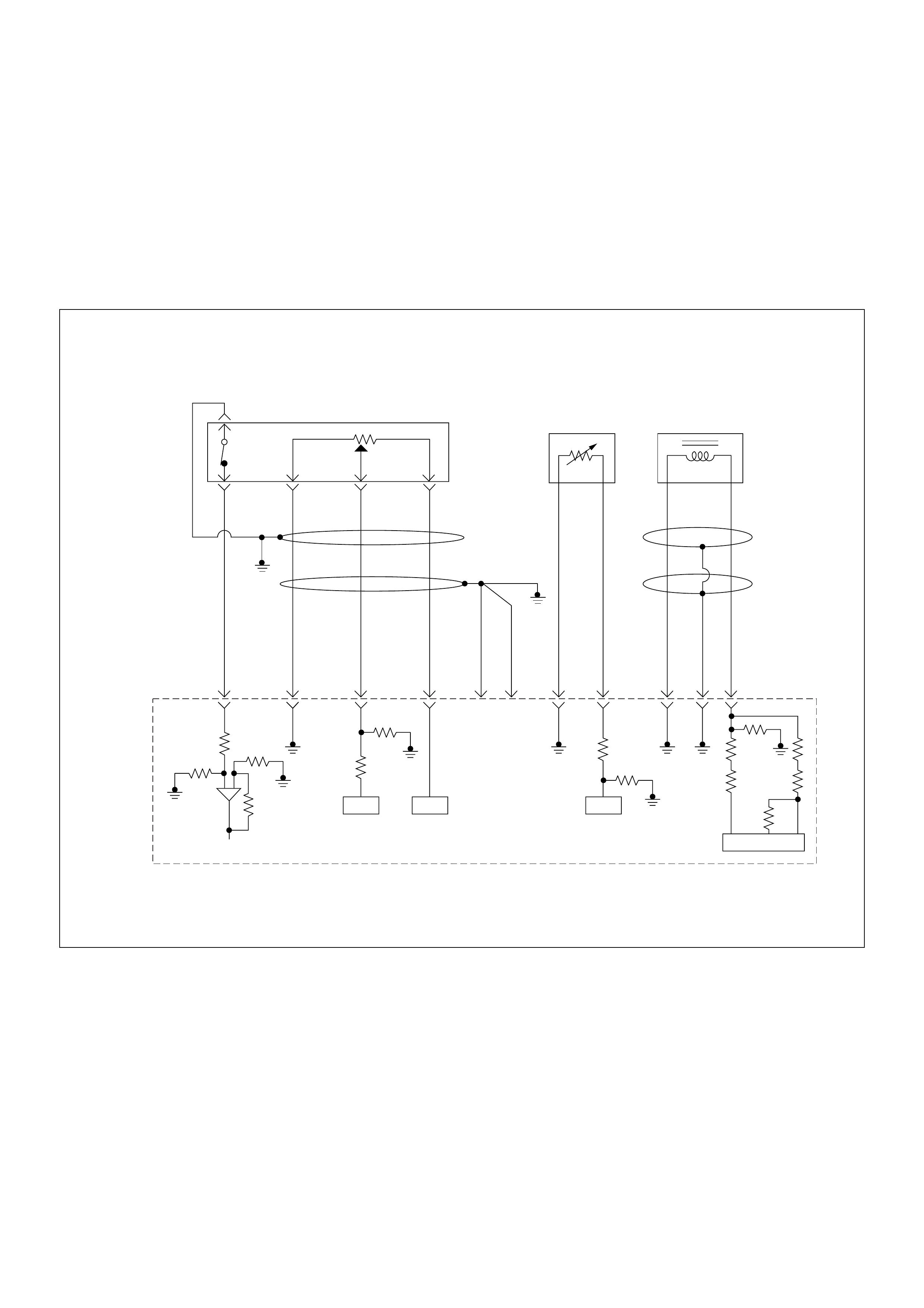
Diagnostic Trouble Code (DTC) P0335 (Symptom Code B)
(Flash Code 43)crankshaft Position Sensor Circuit Malfunction
Diagnostic Trouble Code (DTC) P0335 (Symptom Code D)
(Flash Code 43) Crankshaft Position Sensor Malfunction
Diagnostic Trouble Code (DTC) P0335 (Symp tom Code E)
(Flash Code 43) Engine Speed Input Circuit Range/performan ce
0.5
BLK
0.5
GRN/
BLK
69
0.5
RED/
GRN
49
0.5
GRN/
ORG
38
0.5
BLK/
GRN
57
2.0
BLK
1
2.0
BLK
2
0.5
BLK/
PNK
93
0.5
GRY
ECT
Sensor
TPS &
Idle SW
89
0.5
WHT
98 101
0.5
GRN/
RED
CKP
Sensor
90
ICIC IC
IC
Engine
Control
Module
(ECM)

Condition for setting the DTC and action taken when the DTC sets
Circuit Desc rip tio n
The CKP sensor is located on top of the flywheel
housing of the flywheel and fixed with a bolt. The CKP
sensor is of the magnet coil type. The inductive pickup
sensors four gaps in the flywheel exciter ring and is
used to determine the engine speed and engine
cylinder top dead center.
If the CKP sensor harness or sensor malfunction is
detected during engine run, DTC P0335 (Symptom
Code B) is stored.
If the CKP sensor harness or sensor malfunction is
detected during engine cranking, a DTC P0335
(Symptom Code D) is stored.
If the CKP sensor signal frequency is excessively high
or engine over-running, a DTC P0335 (Symptom Code
E) is stored.
Diagnostic Aids
An intermittent may be caused by the following:
• Poor connections.
• Misrouted harness.
• Rubbed through wire insulation.
• Broken wire inside the insulation.
Check for the following conditions:
• Poor con nection at ECM-I nspect harnes s connectors
for backed out terminals, improper mating, broken
locks, improperly formed or damaged terminals, and
poor terminal to wire connection.
• Damaged harness-Inspect the wiring harness for
damage. If the harness appears to be OK, observe
the “Engine Speed” display on the Tech2 while
moving connectors and wiring harness related to the
sensor.
Flash
Code Code Symptom
Code MIL DTC Name DTC Setting Condition F ail-Safe (Back Up)
43 P0335 B ON Crank shaft Position Sensor
Circuit Malfunction 1. Engine speed is more than
665rpm.
2. CKP sensor pulse width
error.
When pump camshaft speed
sensor is OK:
ECM uses doubled pump
camshaft speed as substitute
engine speed.
When pump camshaft speed
sensor is not OK:
1. MA B (f uel cutoff solenoid
valve) is operated.
2. Desired injection quantity
becomes 0mg/strk.
D ON Crankshaft Position Sensor
Circuit Malfunction 1. No pump cam shaft speed
sensor error.
2. “Crank shaft Position
Sensor Circuit Malfunction
(Symptom Code B)” is not
stored.
3. Engine speed is 0rpm.
4. Doubled pump cam shaft
speed is more than 50rpm.
When pump camshaft speed
sensor is OK:
ECM uses doubled pump
camshaft speed as substitute
engine speed.
Other than pump camshaft
speed sensor is OK:
Fuel injection quantity is
reduced.
E ON Engine Speed In put Circuit
Range/Performance En gine speed is more than
5700rpm. When intermittent malfunction:
1. MA B (f uel cutoff solenoid
valve) is operated.
2. Desired injection quantity
becomes 0mg/strk.
When preliminary malfunction:
ECM uses doubled pump
camshaft speed as substitute
engine speed.
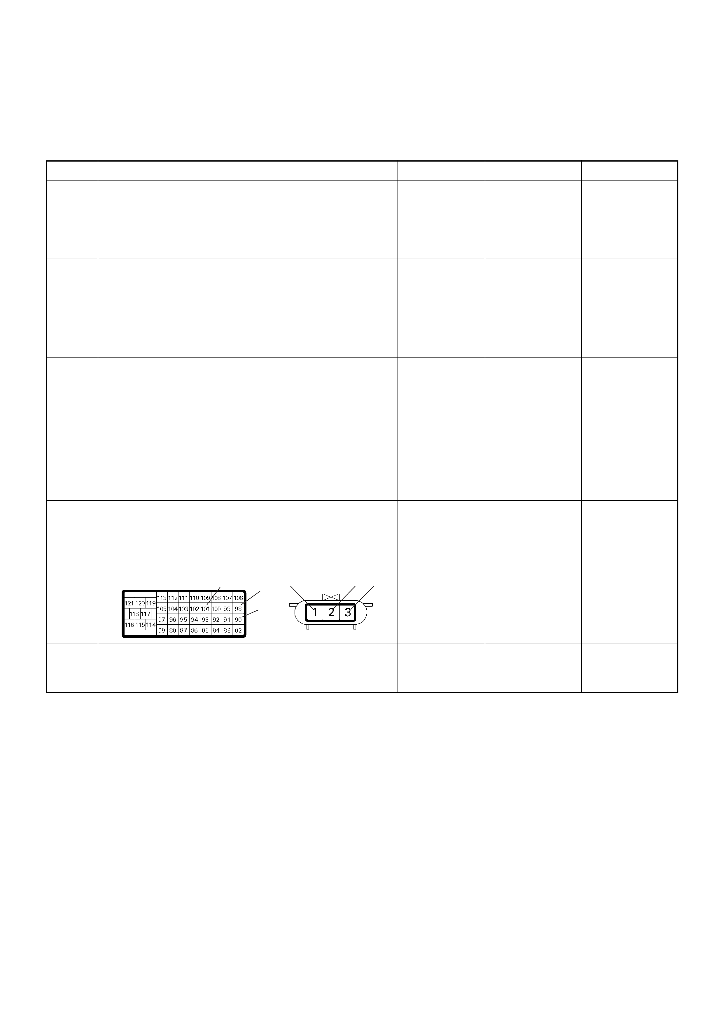
Diagnostic Trouble Code (DTC) P0335 (Symptom Code B) (Flash Code 43)
Crankshaft Position Sensor Circuit Malfunction
Diagnostic Trouble Code (DTC) P0335 (Symptom Code D) (Flash Code 43)
Crankshaft Position Sensor Malfunction
Step Action Value(s) Yes No
1 Was the “On-Board Diagnostic (OBD) System Check”
performed?
—Go to Step 2
Go to On
Board
Diagnostic
(OBD) System
Check
2 1. Connect the Tech 2.
2. Review and record the failure information.
3. Select “F0: Read DTC Infor As Stored By ECU” in
“F0: Diagnostic Trouble Codes”.
Is the DTC P0335 (Symptom Code B) or P0335
(Symptom Code D) stored as “Present Failure”? — Go to Step 3
Refer to
Diagnostic
Aids and Go to
Step 3
3 1. Using the Tech 2, ignition “On” and engine “Off”.
2. Select “F1: Clear DTC Information” in “F0:
Diagnostic Trouble Codes” with the Tech 2 and
clear the DTC information.
3. Operate the vehicle and monitor the “F0: Read
DTC Infor As Stored By ECU” in the “F0:
Diagnostic Trouble Codes”.
Was the DTC P0335 (Symptom Code B) or P0335
(Symptom Code D) stored in this ignition cycle? — Go to Step 4
Refer to
Diagnostic
Aids and Go to
Step 4
4 Check for poor/faulty connection at the CKP sensor or
ECM connector. If a poor/faulty connection is found,
repair the faulty terminal.
Was the problem found?
— Verify repair Go to Step 5
5 Visually check the CKP sensor. If a faulty installation
is found, repair as necessary.
Was the problem found? — Verify repair Go to Step 6
101
90
98 2 31 E-9C-57(B)
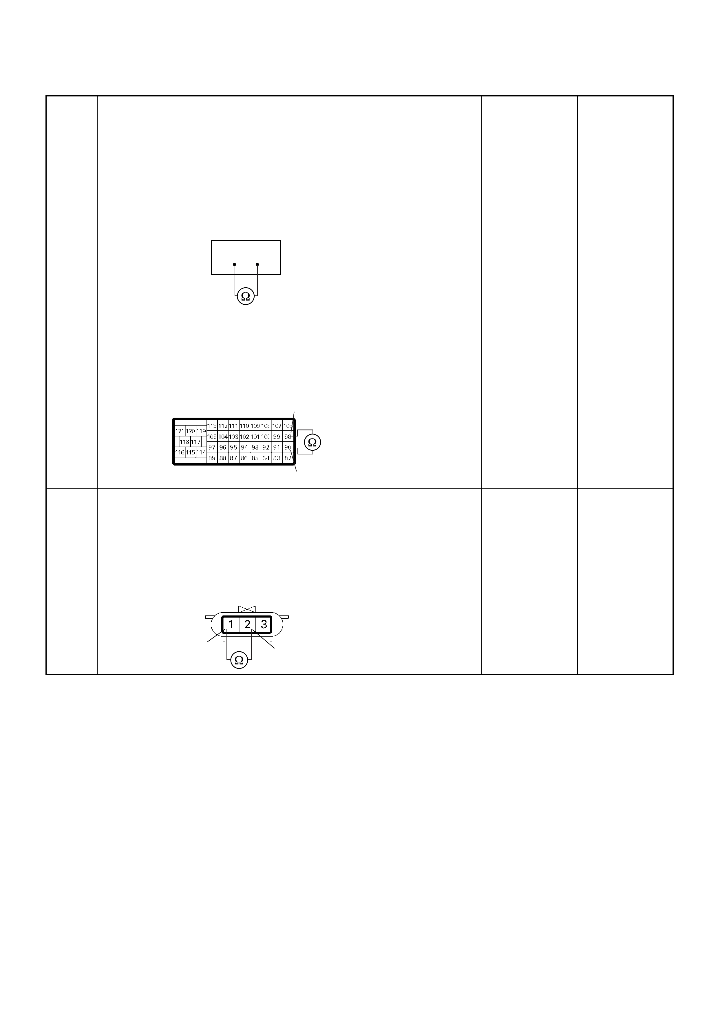
6 Using the DVM and check the CKP sensor circuit.
Breaker box is available:
1. Ignition “Off”, engine “Off”.
2. Install the breaker box as type A. (ECM
disconnected) Ref. Page 6E-81
3. Check the resistance of the CKP sensor.
Was the DVM indicated specified value?
Breaker box is not available:
1. Ignition “Off”, engine “Off”.
2. Disconnect the ECM connector.
3. Check the resistance of the CKP sensor.
Was the DVM indicated specified value?
Approximately
0.9kΩ at 20°C Go to Step 10 Go to Step 7
7 Using the DVM and check the CKP sensor circuit.
1. Ignition “Off”, engine “Off”.
2. Disconnect the CKP sensor connector.
3. Check the resistance of the CKP sensor.
Was the DVM indicated specified value?
Approximately
0.9kΩ at 20°C Go to Step 8 Go to Step 14
Step Action Value(s) Yes No
90 98
90
98
C-57(B)
12
E-9
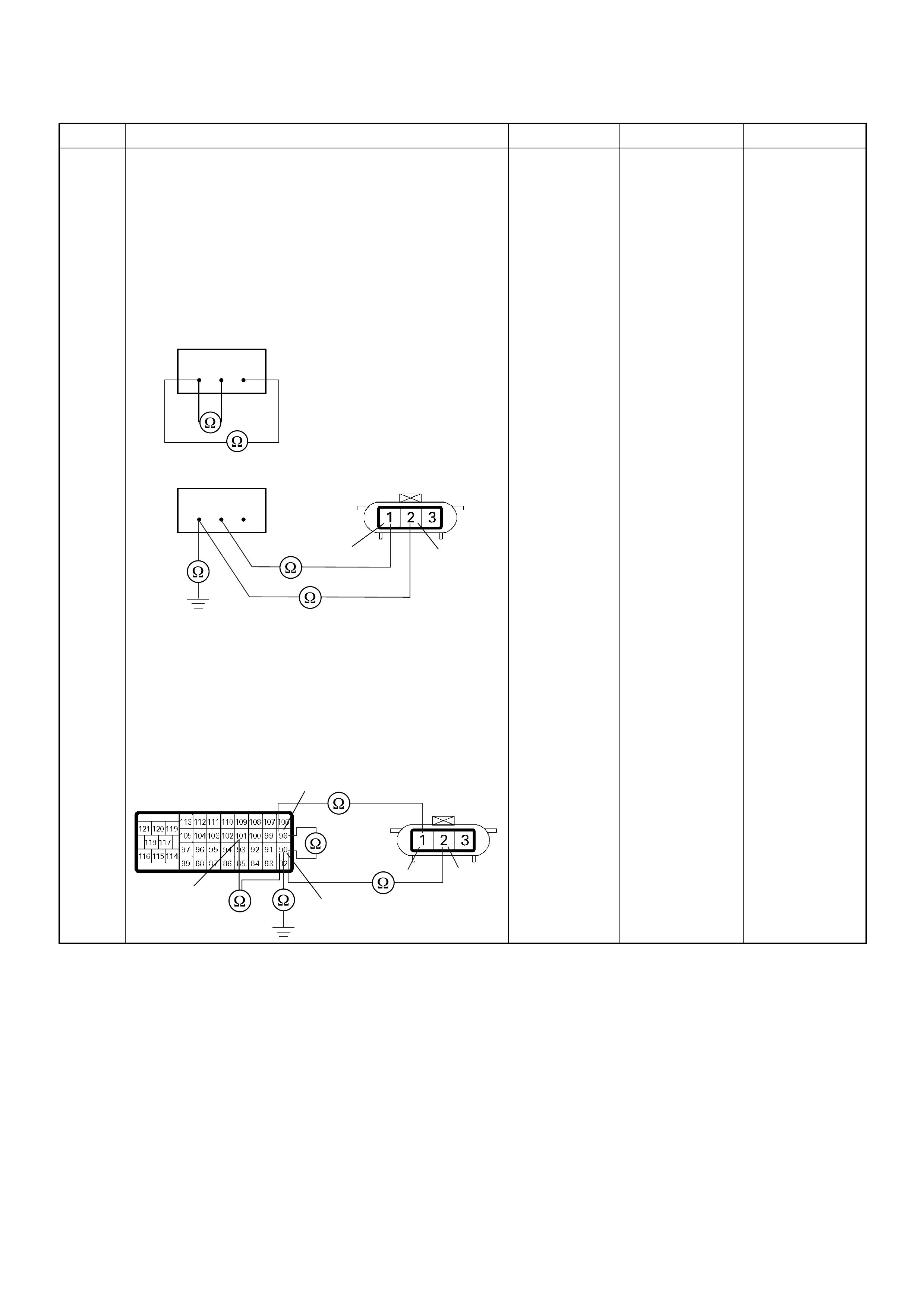
8 Using the DVM and check the CKP sensor circuit.
Breaker box is available:
1. Ignition “Off”, engine “Off”.
2. Install the breaker box as type A. (ECM
disconnected) Ref. Page 6E-81
3. Disconnect the CKP sensor connector.
4. Check the circui t for open, short to se nsor wire or
short to ground circuit.
Was the problem found?
Breaker box is not available:
1. Ignition “Off”, engine “Off”.
2. Disconnect the ECM connector.
3. Disconnect the CKP sensor connector.
4. Check the circui t for open, short to se nsor wire or
short to ground circuit.
Was the problem found?
—
Repair faulty
harnes s and
verify repair G o to Step 9
Step Action Value(s) Yes No
90 98101
90 98101
12
E-9
101
98
90
2
1
E-9C-57(B)
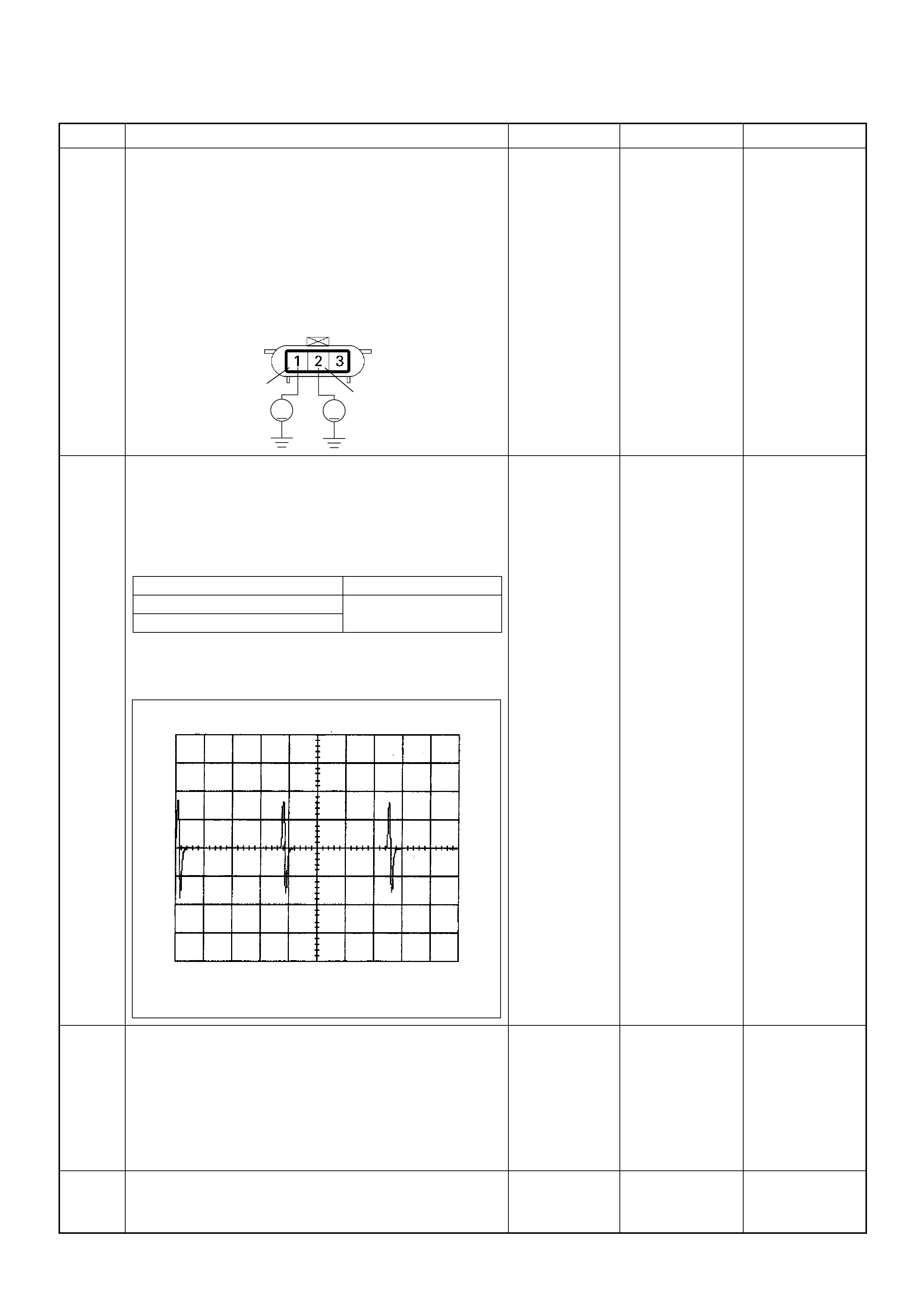
9 Using the DVM and check the CKP sensor circuit.
1. Ignition “On”, engine “Off”.
2. Disconnect the CKP sensor connector.
3. Check the circuit for short to power supply circuit.
If the DVM indicated out of specified value, repair
faulty harness and verify repair.
Is the action complete?
Less than 1V Verify repair —
10 Using the DVM and check the CKP sensor signal.
1. Ignition “On”, engine “On”.
2. Measure the CKP output voltage at the sensor
and ECM.
Does the tester indicate standard voltage?
If a osci lloscope is ava ilable, moni tor the CKP sensor
signal. Does the oscilloscope indicate correct wave
form?
Go to Step 13 Go to Step 11
11 Remove the CKP sensor from the flywheel housing
and visually check.
Check for the following conditions.
• Objects sticking the CKP sensor.
• Objects sticking the CKP sensor pulser.
If a problem is found, repair as necessary.
Was the problem found? — Verify repair Go to Step 12
12 Check the CKP sensor shield wire for open or short
circuit.
Was the problem found? —
Repair faulty
harnes s and
verify repair Go to Step 13
Step Action Value(s) Yes No
12
VV
E-9
Measurement Point Voltage (V) (AC Range)
At CKP sensor terminal 2 & 1 Appr oximately 1.0 V at
2000rpm
At ECM C57 connector 90 & 98
CKP Sensor Reference Wave Form
0V→
Measurement Terminal: 90 (+) 98(-)
Measurement Scale: 20V/div 2.0ms/div
Measurement Condition: Engine speed at 2000rpm

Diagnostic Trouble Code (DTC) P0335 (Symptom Code E) (Flash Code 43)
Engine Speed Input Circuit Range/Performance
13 Check any accessory parts which may cause electric
interference or magnetic interference.
Was the problem found? —
Remove the
accessory parts
and verify repair Go to Step 14
14 Substitute a known good CKP sensor and recheck.
Was the problem solved? — Go to Step 15 Go to Step 16
15 Replace the CKP sensor.
Was the problem solved? — Verify repair Go to Step 16
16 Is the ECM programmed with the latest software
release?
If not, download the latest software to the ECM using
the “SPS (Service Programming System)”.
Was the problem solved? — Verify repair Go to Step 17
17 Replace the ECM.
Is the action complete?
IMPORTANT: The replacement ECM must be
programmed. Refer to section of the Service
Programming System (SPS) in this manual.
Foll owing ECM pr ogramming, the immobi liser system
(if equipped) must be linked to the ECM. Refer to
section 11 “Immobiliser System-ECM replacement” for
the ECM/Immobiliser linking procedure. — Verify repair —
Step Action Value(s) Yes No
1 Was the “On- Board Diagnos tic (OBD) Sy stem Check”
performed?
—Go to Step 2
Go to On
Board
Diagnostic
(OBD) System
Check
2 1. Connect the Tech 2.
2. Review and record the failure information.
3. S elect “F0: Read DTC I nfor As Stored B y ECU” in
“F0: Diagnostic Trouble Codes”.
Is the DTC P0335 (Symptom Code E) stored as
“Present Failure”? — Go to Step 3
Refer to
Diagnostic Aids
and Go to Step
3
3 1. Using the Tech 2, ignition “On” and engine “Off”.
2. Select “F1: Clear DTC Information” in “F0:
Diagnostic Trouble Codes” with the Tech 2 and
clear the DTC information.
3. Operate the vehicle and monitor the “F0: Read
DTC Infor As Stored By ECU” in the “F0:
Diagnostic Trouble Codes”.
Was the DTC P0335 (Symptom Code E) stored in this
ignition cycle? — Go to Step 4
Refer to
Diagnostic
Aids and Go to
Step 4
4 Ask to the customer whether over-speed condition
such a s miss-gear shifting etc. has been experien ced
or not. —
Expla in the
reason of DTC
to the customer Go to Step 5
Step Action Value(s) Yes No

5 Check for poor/faulty connection at the CKP sensor or
ECM connector. If a poor/faulty connection is found,
repair the faulty terminal.
Was the problem found?
— Verify repair Go to Step 6
6 Using the DVM and check the CKP sensor signal.
1. Ignition “On”, engine “On”.
2. Measure the CKP output voltage at the sensor
and ECM.
Does the tester indicate standard voltage?
If a osci lloscope is ava ilable, moni tor the CKP sensor
signal. Does the oscilloscope indicate correct wave
form?
Go to Step 9 Go to Step 7
7 Remove the CKP sensor from the flywheel housing
and visually check.
Check for the following conditions.
• Objects sticking the CKP sensor.
• Objects sticking the CKP sensor pulser.
If a problem is found, repair as necessary.
Was the problem found? — Verify repair Go to Step 8
8 Check the CKP sensor shield wire for open or short
circuit.
Was the problem found? —
Repair faulty
harnes s and
verify repair G o to Step 9
9 Check any accessory parts which may cause electric
interference or magnetic interference.
Was the problem found? —
Remove the
accessory parts
and verify repair Go to Step 10
10 Substitute a known good CKP sensor and recheck.
Was the problem solved? — Go to Step 11 Go to Step 12
Step Action Value(s) Yes No
101
90
98 2 31 E-9C-57(B)
Measurement Point Voltage (V) (AC Range)
At CKP sensor terminal 2 & 1 Appr oximately 1.0 V at
2000rpm
At ECM C57 connector 90 & 98
CKP Sensor Reference Wave Form
0V→
Measurement Terminal: 90 (+) 98(-)
Measurement Scale: 20V/div 2.0ms/div
Measurement Condition: Engine speed at 2000rpm

11 Replace the CKP sensor.
Was the problem solved? — Verify repair Go to Step 12
12 Is the ECM programmed with the latest software
release?
If not, downlo ad the latest software to the ECM using
the “SPS (Service Programming System)”.
Was the problem solved? — Verify repair Go to Step 13
13 Replace the ECM.
Is the action complete?
IMPORTANT: The replacement ECM must be
programmed. Refer to section of the Service
Programming System (SPS) in this manual.
Foll owing ECM pr ogramming, the immobi liser system
(if equipped) must be linked to the ECM. Refer to
section 11 “Immobiliser System-ECM replacement” for
the ECM/Immobiliser linking procedure. — Verify repair —
Step Action Value(s) Yes No
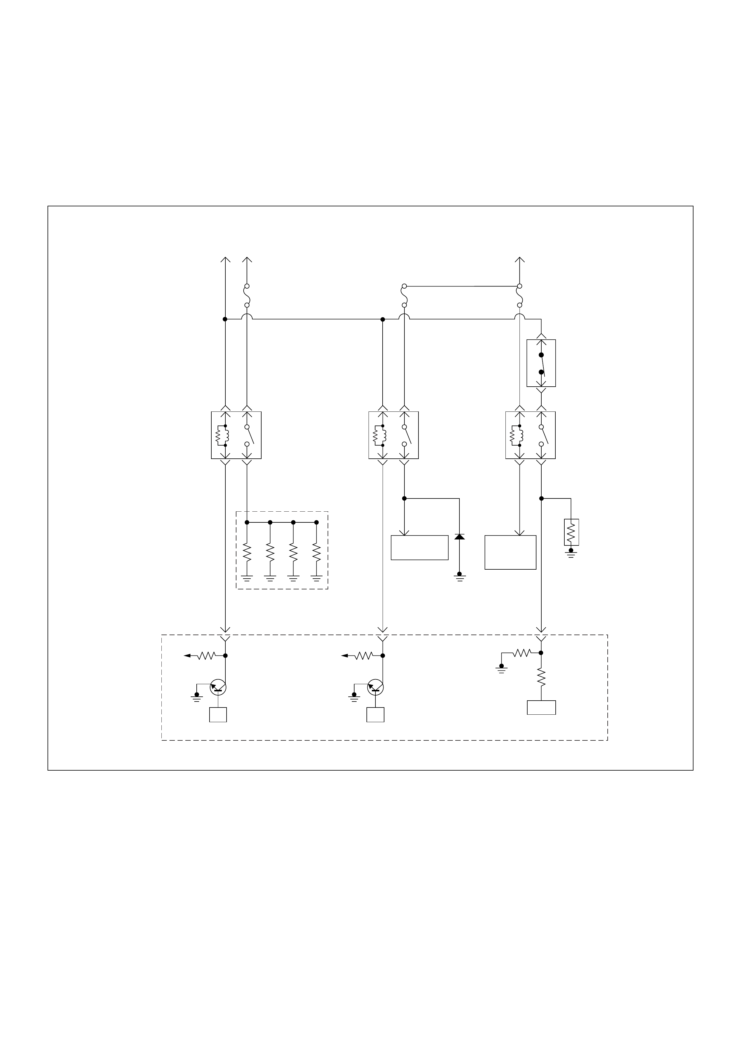
Diagnostic Trouble Code (DTC) P0380 (Symptom Code 4)
(Flash Code 66) Glow Relay Circuit Voltage Low
Diagnostic Trouble Code (DTC) P0380 (Symptom Code 8)
(Flash Code 66) Glow Relay Circuit Voltage High
Resister
A/C
Compressor
ECM
Main Relay Battery
Voltage
Glow
80A
Glow
Relay
Glow
Plug
0.5
BLU/
RED
0.5
BLK/
BLU
94
0.5
BRN/
RED
0.5
BLK
41
0.5
GRN
33
5.0
RED/
WHT
0.5
BLU/
RED
0.5
GRY
0.5
GRN 0.5
GRN
0.5
BRN
0.5
GRY/
YEL
A/C
10A
Heater
Relay
Blower
20A
A/C
Compressor
Relay
A/C
Thermo
Relay
Pressure
SW
5.0
BLK/
RED
Electronic
Thermostat
µP
Batt
µP
Batt
IC
Engine
Control
Module
(ECM)

Condition for setting the DTC and action taken when the DTC sets
Circuit Desc rip tio n
The voltage on the coil of the relay glow plug is supplied
by the relay engine control module (ECM) main. The
ECM switc hes glow r elay to operate gl ow plug d epends
on the coolant temperature.
In the after glow phase the lamp is not illuminated but
the glow plugs remain active for a certain period
depending on engine coolant temperature.
Diagnostic Aids
An intermittent may be caused by the following:
• Poor connections.
• Misrouted harness.
• Rubbed through wire insulation.
• Broken wire inside the insulation.
Check for the following conditions:
• Poor con nection at ECM-I nspect harnes s connectors
for backed out terminals, improper mating, broken
locks, improperly formed or damaged terminals, and
poor terminal to wire connection.
• Damaged harness-Inspect the wiring harness for
damage. If the harness appears to be OK, observe
the DTC P0380 display on the Tech2 while moving
connectors and wiring harnesses. A change in the
display will indicate the location of the fault.
Flash
Code Code Symptom
Code MIL DTC Name DTC Setting Condition F ail-Safe (Back Up)
66 P0380 4 ON Glow Relay Circuit Voltage
Low Glow relay circuit open or
short to ground circuit. No fail-safe function.
8 ON Glow Relay Circuit Voltage
High Glow relay circuit short to
voltage circuit.
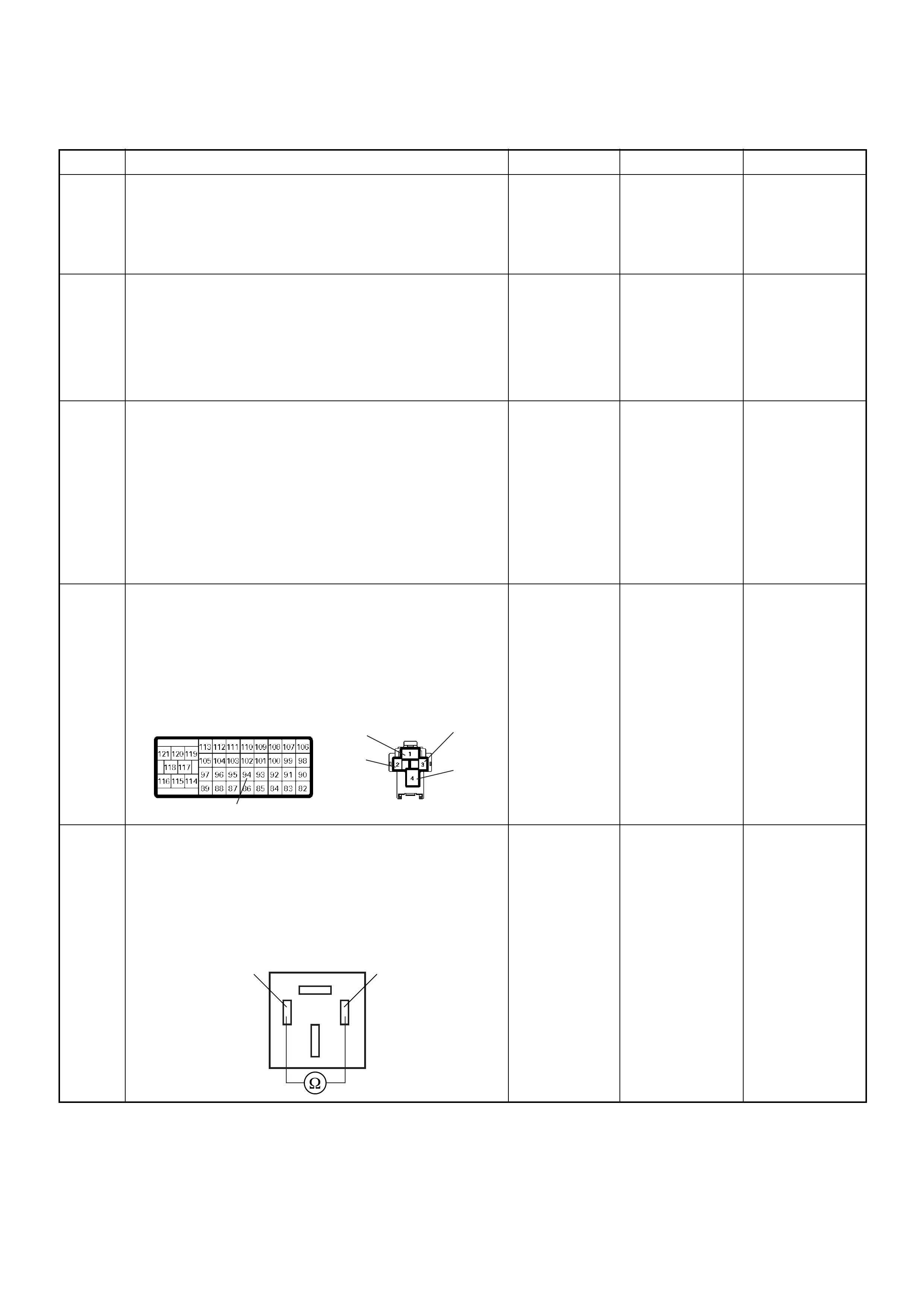
Diagnostic Trouble Code (DTC) P0380 (Symptom Code 4) (Flash Code 66) Glow Relay Circuit Voltage Low
Step Action Value(s) Yes No
1 Was the “On-Board Diagnostic (OBD) System Check”
performed?
—Go to Step 2
Go to On
Board
Diagnostic
(OBD) System
Check
2 1. Connect the Tech 2.
2. Review and record the failure information.
3. Select “F0: Read DTC Infor As Stored By ECU” in
“F0: Diagnostic Trouble Codes”.
Is the DTC P0380 (Symptom Code 4) stored as
“Present Failure”? — Go to Step 3
Refer to
Diagnostic
Aids and Go to
Step 3
3 1. Using the Tech 2, ignition “On” and engine “Off”.
2. Select “F1: Clear DTC Information” in “F0:
Diagnostic Trouble Codes” with the Tech 2 and
clear the DTC information.
3. Operate the vehicle and monitor the “F0: Read
DTC Infor As Stored By ECU” in the “F0:
Diagnostic Trouble Codes”.
Was the DT C P0 380 (Sy mpt om Code 4) stor e d i n th is
ignition cycle? — Go to Step 4
Refer to
Diagnostic
Aids and Go to
Step 4
4 Check for poor/faulty connection at the glow relay or
ECM connector. If a poor/faulty connection is found,
repair as necessary.
Was the problem found?
— Verify repair Go to Step 5
5 Using the DVM and check the glow relay.
1. Ignition “Off”, engine “Off”.
2. Remove the glow relay from the relay box.
3. Check the relay coil.
Was the DVM indicated specified value?
Continuity Go to Step 6
Replace glow
relay and verify
repair
94
3
4
2
1
C-49
4JA1-TC X-12
4JH1-TC
C-57
Glow Relay 23
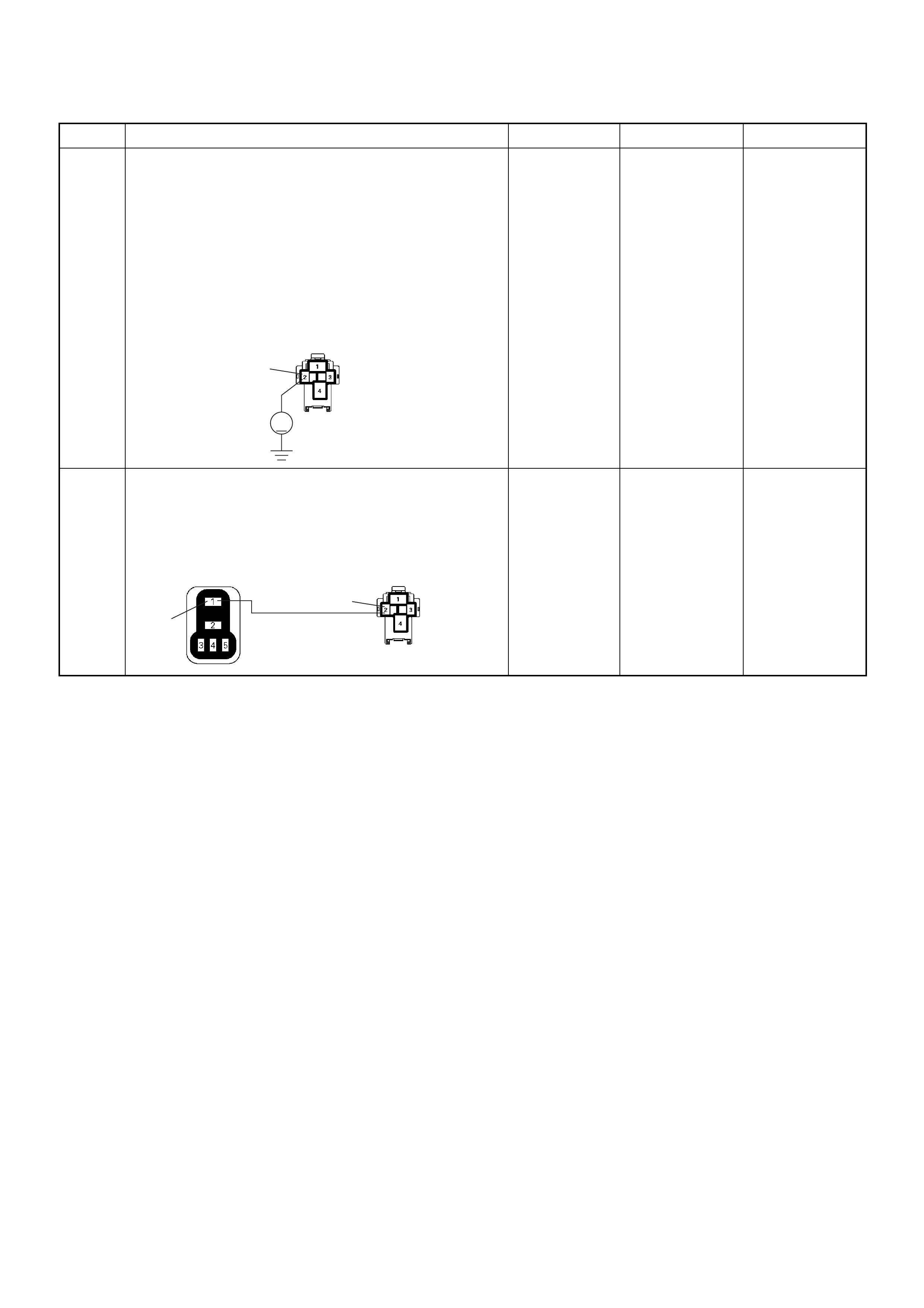
6 Using the DVM and check the glow relay power
supply circuit.
1. Ignition “On”, engine “Off”.
2. Remove the glow relay from the relay box.
3. Check the circuit for open or short to ground
circuit.
Was the DVM indicated specified value?
Battery
voltage Go to Step 8 Go to Step 7
7 Repair the open or short to ground circuit between the
ECM main relay and glow relay.
Is the action complete?
— Verify repair —
Step Action Value(s) Yes No
2
V
C-49
4JA1-TC X-12
4JH1-TC
2
1
C-49X-4 4JA1-TC X-12
4JH1-TC
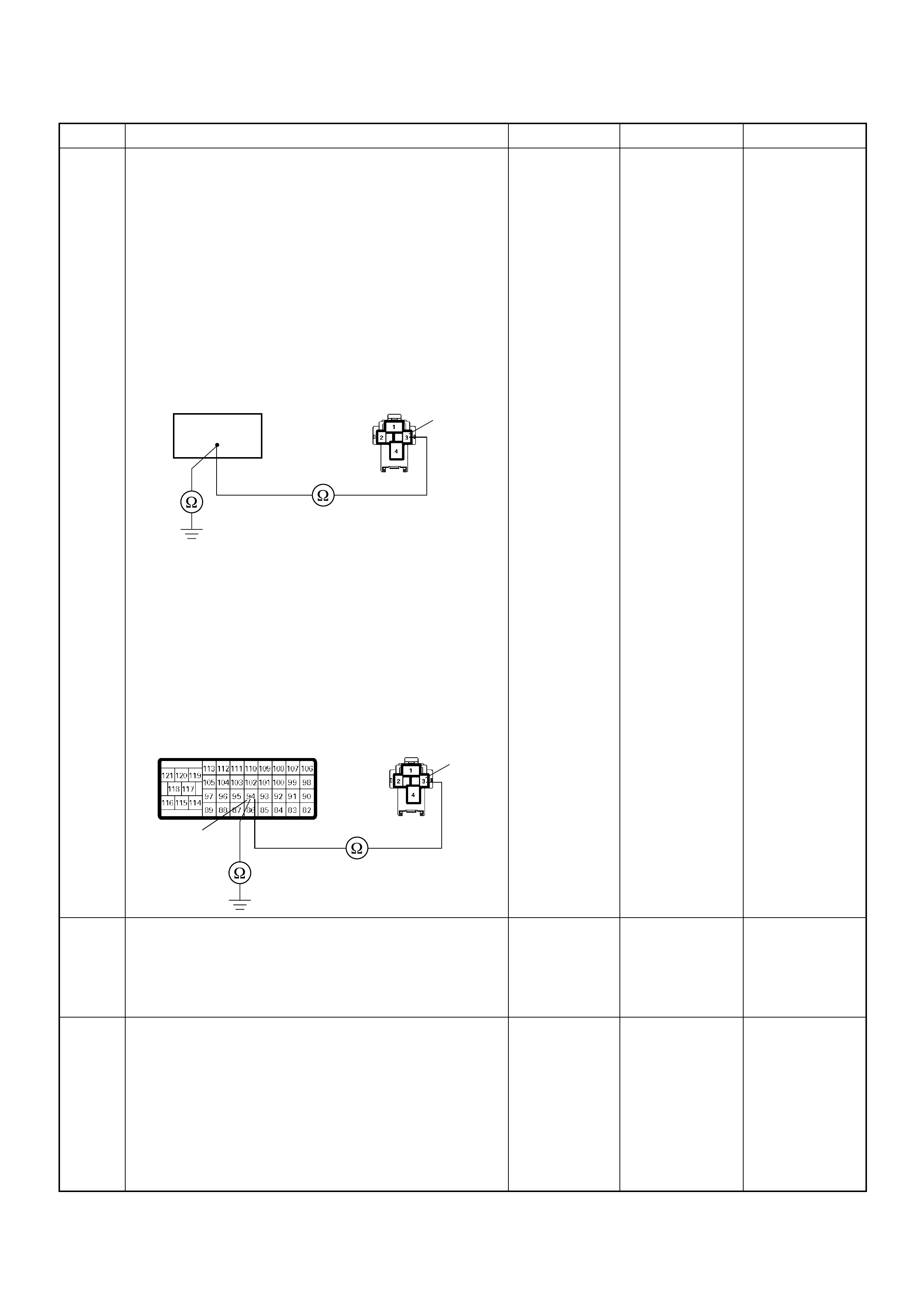
8 Using the DVM and check the glow relay ground
circuit.
Breaker box is available:
1. Ignition “Off”, engine “Off”.
2. Install the breaker box as type A. (ECM
disconnected) Ref. Page 6E-81
3. Remove the glow relay from the relay box.
4. Check the circuit for open or short to ground
circuit.
Was the problem found?
Breaker box is not available:
1. Ignition “Off”, engine “Off”.
2. Disconnect the ECM connector.
3. Remove the glow relay from the relay box.
4. Check the circuit for open or short to ground
circuit.
Was the problem found?
—
Repair faulty
harnes s and
verify repair G o to Step 9
9 Is the ECM programmed with the latest software
release?
If not, downlo ad the latest software to the ECM using
the “SPS (Service Programming System)”.
Was the problem solved? — Verify repair Go to Step 10
10 Replace the ECM.
Is the action complete?
IMPORTANT: The replacement ECM must be
programmed. Refer to section of the Service
Programming System (SPS) in this manual.
Foll owing ECM pr ogramming, the immobi liser system
(if equipped) must be linked to the ECM. Refer to
section 11 “Immobiliser System-ECM replacement” for
the ECM/Immobiliser linking procedure. — Verify repair —
Step Action Value(s) Yes No
94 3
C-49
4JA1-TC X-12
4JH1-TC
3
94
C-57 C-49
4JA1-TC X-12
4JH1-TC

Diagnostic Trouble Code (DTC) P0380 (Symptom Code 8) (Flash Code 66) Glow Relay Circuit Voltage High
Step Action Value(s) Yes No
1 Was the “On-Board Diagnostic (OBD) System Check”
performed?
—Go to Step 2
Go to On
Board
Diagnostic
(OBD) System
Check
2 1. Connect the Tech 2.
2. Review and record the failure information.
3. Select “F0: Read DTC Infor As Stored By ECU” in
“F0: Diagnostic Trouble Codes”.
Is the DTC P0380 (Symptom Code 8) stored as
“Present Failure”? — Go to Step 3
Refer to
Diagnostic
Aids and Go to
Step 3
3 1. Using the Tech 2, ignition “On” and engine “Off”.
2. Select “F1: Clear DTC Information” in “F0:
Diagnostic Trouble Codes” with the Tech 2 and
clear the DTC information.
3. Operate the vehicle and monitor the “F0: Read
DTC Infor As Stored By ECU” in the “F0:
Diagnostic Trouble Codes”.
Was the DT C P0 380 (Sy mpt om Code 8) stor e d i n th is
ignition cycle? — Go to Step 4
Refer to
Diagnostic
Aids
4 Is the ECM programmed with the latest software
release?
If not, downlo ad the latest software to the ECM using
the “SPS (Service Programming System)”.
Was the problem solved? — Verify repair Go to Step 5
5 Substitute a known good ECM and recheck.
Was the problem solved?
IMPORTANT: The replacement ECM must be
programmed. Refer to section of the Service
Programming System (SPS) in this manual.
Foll owing ECM pr ogramming, the immobi liser system
(if equipped) must be linked to the ECM. Refer to
section 11 “Immobiliser System-ECM replacement” for
the ECM/Immobiliser linking procedure. —Go to Step 6 —
6 Replace the ECM.
Is the action complete?
IMPORTANT: The replacement ECM must be
programmed. Refer to section of the Service
Programming System (SPS) in this manual.
Foll owing ECM pr ogramming, the immobi liser system
(if equipped) must be linked to the ECM. Refer to
section 11 “Immobiliser System-ECM replacement” for
the ECM/Immobiliser linking procedure. — Verify repair —

Diagnostic Trouble Code (DTC) P0381 (Sub Code 4) (Flash Code 67)
Glow Plug Ind icator Circu it Voltage Low
Diagnostic Trouble Code (DTC) P0381 (Sub Code 8) (Flash Code 67)
Glow Plug Indicator Circuit Voltage High
Ignition
SW
Meter
15A
615 7
Batt
Batt
0.5
RED/
WHT
29
0.5
ORG/
BLU
43
0.5
BRN/
YEL
42
0.5
BLK/
RED
27
0.5
BLU/
WHT
0.5 BLU/BLK
68
0.5
WHT
2.0
BLK
35
VSS
0.85
YEL
Imnobiliser
Control Unit
78
0.5
BRN/
YEL
IC
0.85
YEL
Glow
Check
Engine
Tacho
Meter
Speed
Meter
A/T
TCM
µPµPµPµP
Engine
Control
Module
(ECM)

Condition for setting the DTC and action taken when the DTC sets
Circuit Desc rip tio n
The functio n of the gl ow time ind icato r lamp is to inform
the driver whether the glow system is activated.
When the lamp turned off, the engine can be started.
This does not imply that the glow plugs are no longer
activated.
In the after-glow phase the lamp is not illuminated but
the glow plugs remain active for a certain period
depending on engine coolant temperature.
Diagnostic Aids
An intermittent may be caused by the following:
• Poor connections.
• Misrouted harness.
• Rubbed through wire insulation.
• Broken wire inside the insulation.
Check for the following conditions:
• Poor con nection at ECM-I nspect harnes s connectors
for backed out terminals, improper mating, broken
locks, improperly formed or damaged terminals, and
poor terminal to wire connection.
• Damaged harness-Inspect the wiring harness for
damage. If the harness appears to be OK, observe
the DTC P0381 display on the Tech2 while moving
connectors and wiring harnesses. A change in the
display will indicate the location of the fault.
Flash
Code Code Symptom
Code MIL DTC Name DTC Setting Condition F ail-Safe (Back Up)
67 P0381 4 ON Glow Plug Indicator Circuit
Voltage Low Glow plug indicator circuit
open or short to ground
circuit.
No fail-safe function.
8 ON Glow Plug Indicator Circuit
Voltage High Glow plug indicator circuit
short to voltage circuit.
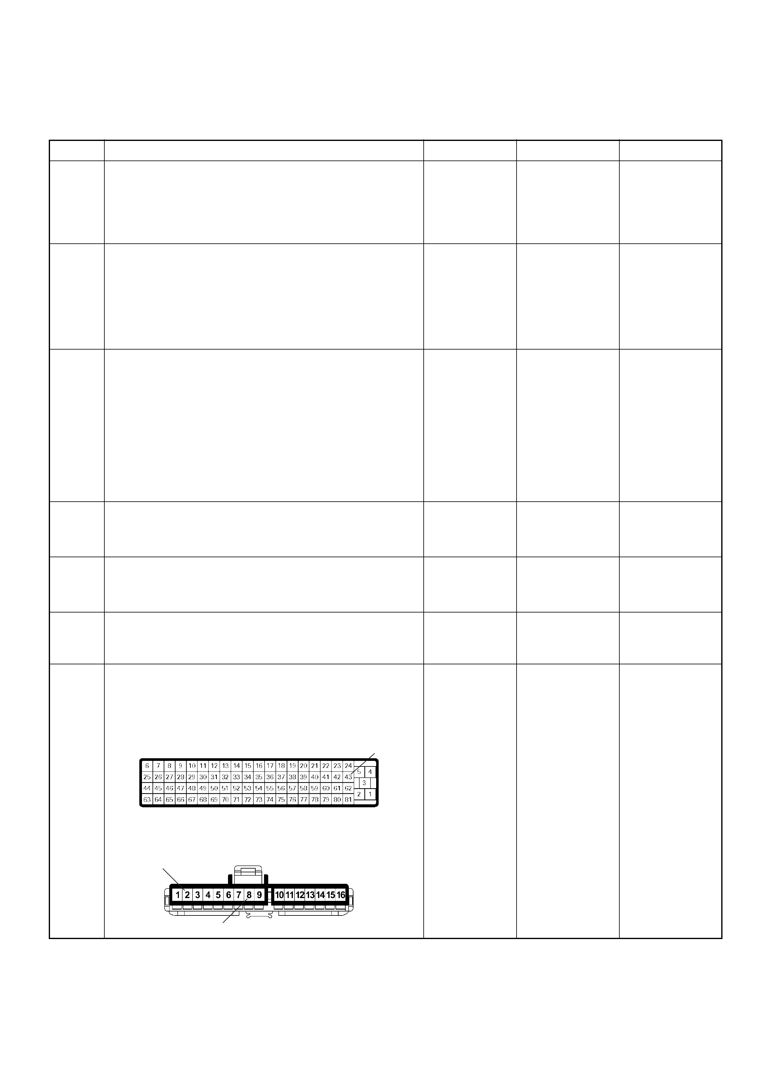
Diagnostic Trouble Code (DTC) P0381 (Symptom Code 4) (Flash Code 67)
Glow Plug Indicator Circuit Voltage Low
Step Action Value(s) Yes No
1 Was the “On-Board Diagnostic (OBD) System Check”
performed?
—Go to Step 2
Go to On
Board
Diagnostic
(OBD) System
Check
2 1. Connect the Tech 2.
2. Review and record the failure information.
3. Select “F0: Read DTC Infor As Stored By ECU” in
“F0: Diagnostic Trouble Codes”.
Is the DTC P0381 (Symptom Code 4) stored as
“Present Failure”? — Go to Step 3
Refer to
Diagnostic
Aids and Go to
Step 3
3 1. Using the Tech 2, ignition “On” and engine “Off”.
2. Select “F1: Clear DTC Information” in “F0:
Diagnostic Trouble Codes” with the Tech 2 and
clear the DTC information.
3. Operate the vehicle and monitor the “F0: Read
DTC Infor As Stored By ECU” in the “F0:
Diagnostic Trouble Codes”.
Was the DT C P0 381 (Sy mpt om Code 4) stor e d i n th is
ignition cycle? — Go to Step 4
Refer to
Diagnostic
Aids and Go to
Step 4
4 1. Ignition “On”, engine “Off”.
2. Check the glow plug indicator lamp.
Does the lamp turn “On”? — Go to Step 5 Go to Step 6
5 1. Ignition “On”, engine “Off”.
2. Check the glow plug indicator lamp.
Does the lamp turn “Off”? — Go to Step 9 Go to Step 7
6 Check the glow plug indicator lamp bulb.
If the bulb is burnt out, repair as necessary.
Was the problem found? — Verify repair Go to Step 7
7 Check for poor/faulty connection at the meter
connector and ECM connector. If a poor/faulty
connection is found, repair as necessary.
Was the problem found?
— Verify repair Go to Step 8
43
2
8
B-24
C-56
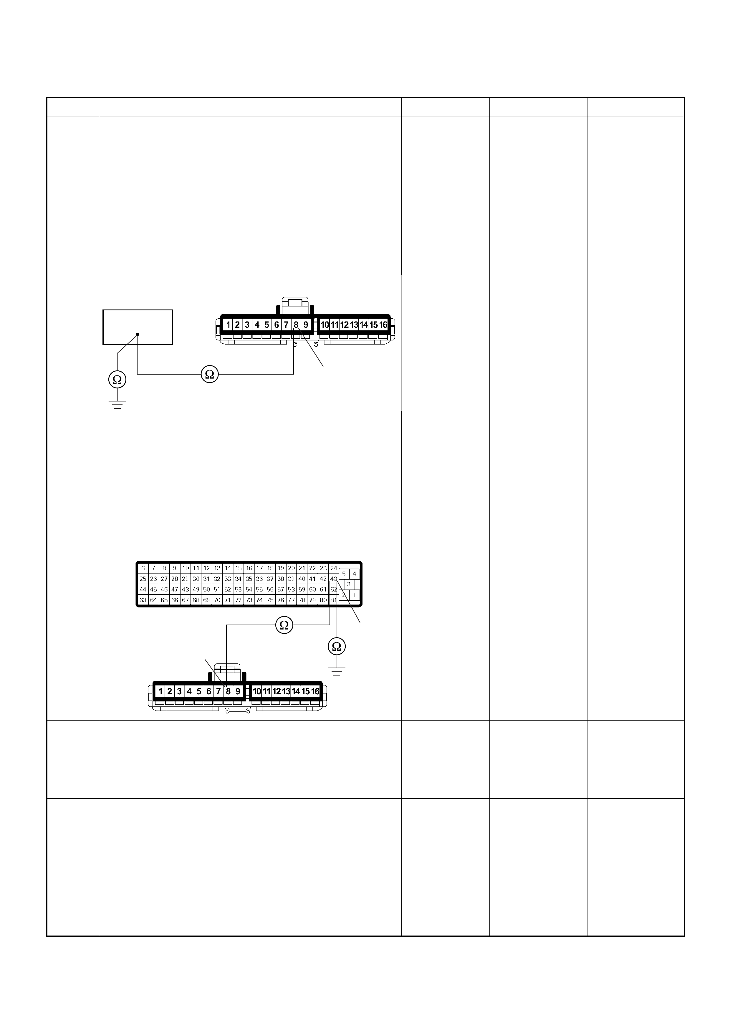
8 Using the DVM and check the glow time telltale circuit.
Breaker box is available:
1. Ignition “Off”, engine “Off”.
2. Install the breaker box as type A. (ECM
disconnected) Ref. Page 6E-81
3. Remove the meter connector.
4. Check the circuit for open or short to ground
circuit.
Was the problem found?
Breaker box is not available:
1. Ignition “Off”, engine “Off”.
2. Disconnect the ECM connector.
3. Remove the meter connector.
4. Check the circuit for open or short to ground
circuit.
Was the problem found?
—
Repair faulty
harnes s and
verify repair Go to Step 9
9 Is the ECM programmed with the latest software
release?
If not, downlo ad the latest software to the ECM using
the “SPS (Service Programming System)”.
Was the problem solved? — Verify repair Go to Step 10
10 Replace the ECM.
Is the action complete?
IMPORTANT: The replacement ECM must be
programmed. Refer to section of the Service
Programming System (SPS) in this manual.
Foll owing ECM pr ogramming, the immobi liser system
(if equipped) must be linked to the ECM. Refer to
section 11 “Immobiliser System-ECM replacement” for
the ECM/Immobiliser linking procedure. — Verify repair —
Step Action Value(s) Yes No
8
B-24
43
43
8B-24
C-56

Diagnostic Trouble Code (DTC) P0381 (Symptom Code 8) (Flash Code 67)
Glow Plug Indicator Circuit Voltage High
Step Action Value(s) Yes No
1 Was the “On-Board Diagnostic (OBD) System Check”
performed?
—Go to Step 2
Go to On
Board
Diagnostic
(OBD) System
Check
2 1. Connect the Tech 2.
2. Review and record the failure information.
3. Select “F0: Read DTC Infor As Stored By ECU” in
“F0: Diagnostic Trouble Codes”.
Is the DTC P0381 (Symptom Code 8) stored as
“Present Failure”? — Go to Step 3
Refer to
Diagnostic
Aids and Go to
Step 3
3 1. Using the Tech 2, ignition “On” and engine “Off”.
2. Select “F1: Clear DTC Information” in “F0:
Diagnostic Trouble Codes” with the Tech 2 and
clear the DTC information.
3. Operate the vehicle and monitor the “F0: Read
DTC Infor As Stored By ECU” in the “F0:
Diagnostic Trouble Codes”.
Was the DT C P0 381 (Sy mpt om Code 8) stor e d i n th is
ignition cycle? — Go to Step 4
Refer to
Diagnostic
Aids
4 Is the ECM programmed with the latest software
release?
If not, downlo ad the latest software to the ECM using
the “SPS (Service Programming System)”.
Was the problem solved? — Verify repair Go to Step 5
5 Substitute a known good ECM and recheck.
Was the problem solved?
IMPORTANT: The replacement ECM must be
programmed. Refer to section of the Service
Programming System (SPS) in this manual.
Foll owing ECM pr ogramming, the immobi liser system
(if equipped) must be linked to the ECM. Refer to
section 11 “Immobiliser System-ECM replacement” for
the ECM/Immobiliser linking procedure. —Go to Step 6 —
6 Replace the ECM.
Is the action complete?
IMPORTANT: The replacement ECM must be
programmed. Refer to section of the Service
Programming System (SPS) in this manual.
Foll owing ECM pr ogramming, the immobi liser system
(if equipped) must be linked to the ECM. Refer to
section 11 “Immobiliser System-ECM replacement” for
the ECM/Immobiliser linking procedure. — Verify repair —
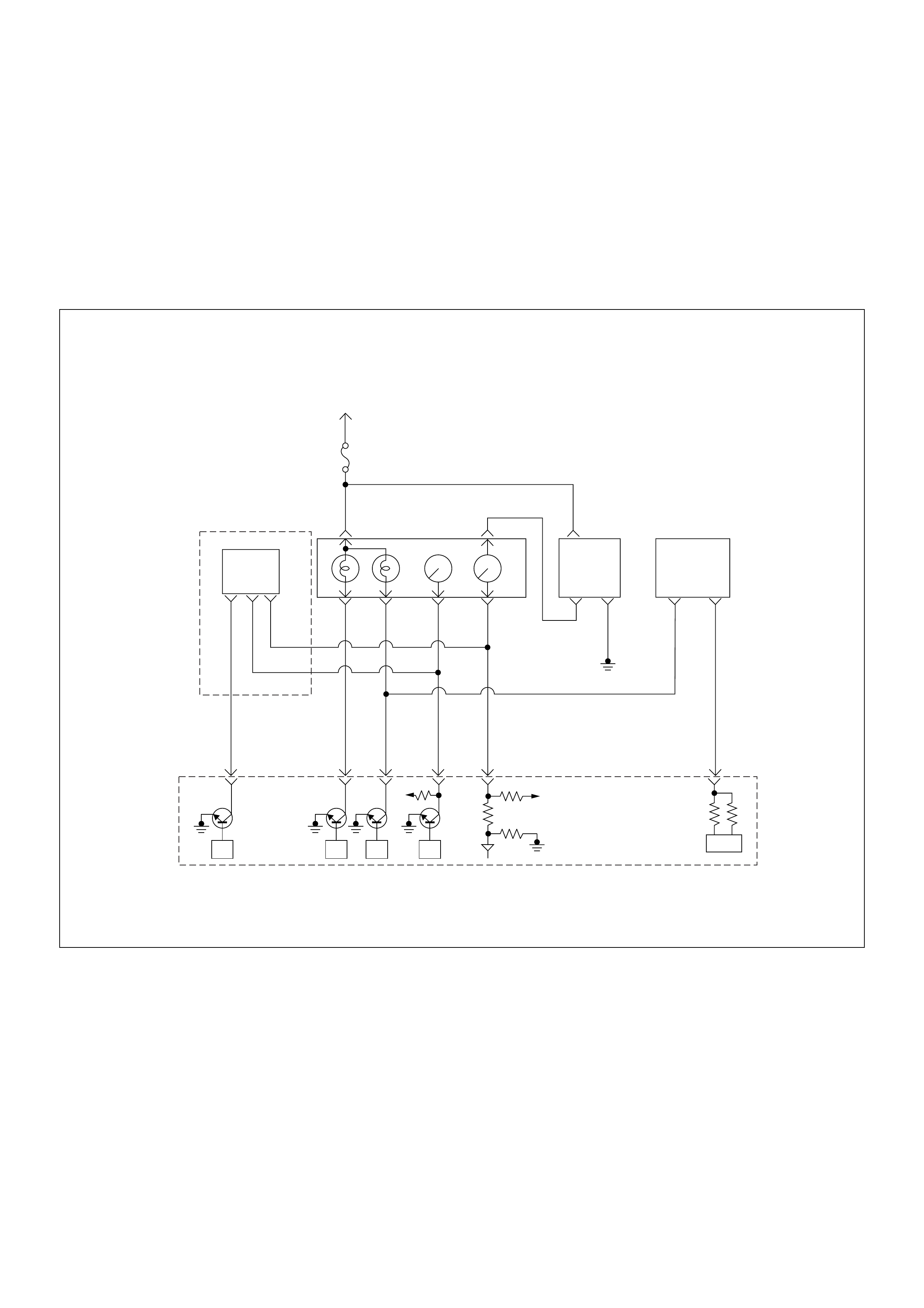
Diagnostic Trouble Code (DTC) P0500 (Symptom Code 1) (Flash Code 24)
Vehicle Speed Sensor Circuit High Input
Diagnostic Trouble Code (DTC) P0500 (Symptom Code A) (Flash Code 24)
Vehicle Speed Sensor Input Signal Frequency Too High
Diagnostic Trouble Code (DTC) P0500 (Symptom Code B) (Flash Code 24)
Vehicle Speed Sensor Incorrect Signal
Ignition
SW
Meter
15A
615 7
Batt
Batt
0.5
RED/
WHT
29
0.5
ORG/
BLU
43
0.5
BRN/
YEL
42
0.5
BLK/
RED
27
0.5
BLU/
WHT
0.5 BLU/BLK
68
0.5
WHT
2.0
BLK
35
VSS
0.85
YEL
Imnobiliser
Control Unit
78
0.5
BRN/
YEL
IC
0.85
YEL
Glow
Check
Engine
Tacho
Meter
Speed
Meter
A/T
TCM
µPµPµPµP
Engine
Control
Module
(ECM)

Condition for setting the DTC and action taken when the DTC sets
Circuit Desc rip tio n
The VSS is a magnet rotated by the transmission output
shaft. The VSS uses a hall ele ment. It in teracts with the
magnetic field treated by the r otating magnet. It out puts
pulse signal. The 12 volts operating supply from the
meter fuse.
The engine control module (ECM) calculates the vehicle
speed by VSS.
Diagnostic Aids
An intermittent may be caused by the following:
• Poor connections.
• Misrouted harness.
• Rubbed through wire insulation.
• Broken wire inside the insulation.
Check for the following conditions:
• Poor con nection at ECM-I nspect harnes s connectors
for backed out terminals, improper mating, broken
locks, improperly formed or damaged terminals, and
poor terminal to wire connection.
• Damaged harness-Inspect the wiring harness for
damage. If the harness appears to be OK, observe
the DTC P0500 display on the Tech2 while moving
connectors and wiring harnesses. A change in the
display will indicate the location of the fault.
Flash
Code Code Symptom
Code MIL DTC Name DTC Setting Condition F ail-Safe (Back Up)
24 P0500 1 ON
at
next
ignitio
n
cycle
Vehicle Speed Sensor Circuit
High Input Vehicle speed is more than
200km/h. EC M uses vehicle speed 5km /
h condition as substitute.
AON
at
next
ignitio
n
cycle
Vehicle Speed Sensor Input
Signal Frequency Too High Input signal frequency is too
high. ECM uses vehicle speed 5km/
h condition as substitute.
BON
at
next
ignitio
n
cycle
Vehicle Speed Sensor
Incorrect Signal 1. Engine speed is more than
3600rpm.
2. Fuel injection quantity is
more than 41mg/stk.
3. Vehicle speed is below
1.5km/h.
Fuel injection quantity is
reduced.

Diagnostic Trouble Code (DTC) P0500 (Symptom Code 1) (Flash Code 24)
Vehicle Speed Sensor Circuit High Input
Step Action Value(s) Yes No
1 Was the “On-Board Diagnostic (OBD) System Check”
performed?
—Go to Step 2
Go to On
Board
Diagnostic
(OBD) System
Check
2 1. Connect the Tech 2.
2. Review and record the failure information.
3. Select “F0: Read DTC Infor As Stored By ECU” in
“F0: Diagnostic Trouble Codes”.
Is the DTC P0500 (Symptom Code 1) stored as
“Present Failure”? — Go to Step 3
Refer to
Diagnostic
Aids and Go to
Step 3
3 1. Using the Tech 2, ignition “On” and engine “Off”.
2. Select “F1: Clear DTC Information” in “F0:
Diagnostic Trouble Codes” with the Tech 2 and
clear the DTC information.
3. Operate the vehicle and monitor the “F0: Read
DTC Infor As Stored By ECU” in the “F0:
Diagnostic Trouble Codes”.
Was the DT C P0 500 (Sy mpt om Code 1) stor e d i n th is
ignition cycle? — Go to Step 4
Refer to
Diagnostic
Aids and Go to
Step 4
4 Perform test drive and check the speed meter.
Does the speed meter indicate correct vehicle speed. — Go to Step 5 Go to Step 6
5 Perform test drive and use the Tech 2.
Monitor the “Vehicle Speed” in the data display.
Does the Tech 2 indicate correct vehicle speed as
same as the speed meter indication in the instrument
panel? — Go to Step 14 Go to Step 7
6 Remove the VSS from the housing case and visually
check.
Was the problem found? — Go to Step 8 Go to Step 7

7 Using the DVM and check the VSS signal.
1. Ignition “On”, vehicle “Run (lift up)”.
2. Measur e the VSS outpu t voltage at sensor, meter
and ECM.
Does the tester indicate specified value?
If a oscilloscope is available, monitor the VSS signal
at each connector connection. Does the oscilloscope
indicate correct wave form?
Refer to
Diagnostic
Aids and Go to
Step 14 Refer the table
8 Replace the VSS.
Is the action complete? — Verify repair
9 Using the DVM and check the VSS signal circuit.
1. Ignition “On”, engine “Off”.
2. Disconnect the meter connector.
3. Check the circuit for short to power supply circuit.
Was the DVM indicated specified value?
Less than 1V Go to Step 10
Repair faulty
harness and
verify repair
Step Action Value(s) Yes No
Measurement Position Voltage (V)
(AC Range) If No
Good
VSS terminal 3 & GND Ap proximate ly 6.5
V at 20km/h Go to
Step 8
Meter B23 connector 9 &
GND Go to
Step 9
Meter B23 connector 8 &
GND Go to
Step 11
ECM C56 connector 68 &
GND Go to
Step 12
Vehicle Speed Sensor Reference Wave Form
0V→
Measurement Scale: 10V/div 50ms/div
Measurement Condition: Vehicle Speed 20km/h
Measurement Terminal: At Engine Control Module
9
V
B-23
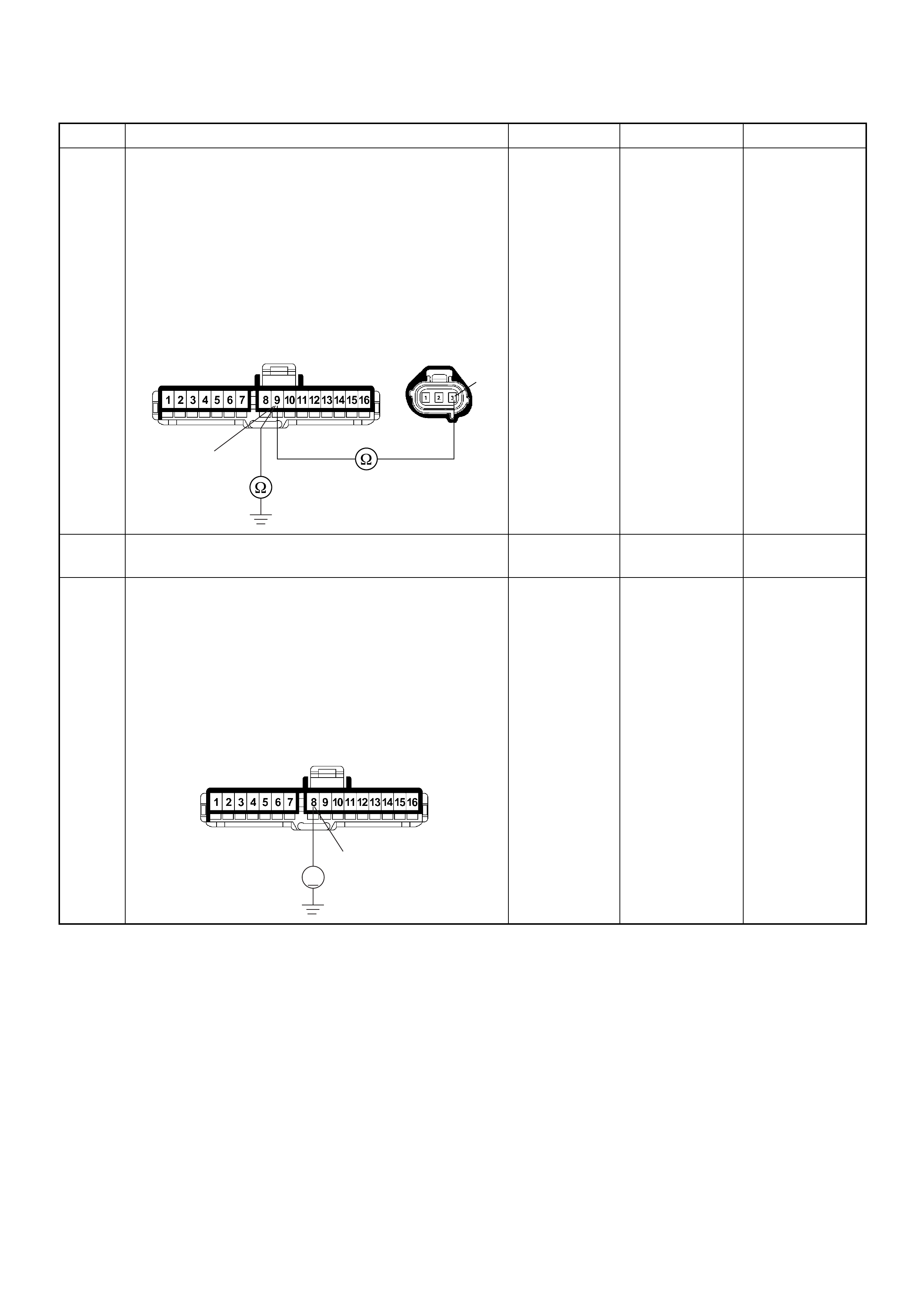
10 Using the DVM and check the VSS signal circuit.
1. Ignition “Off”, engine “Off”.
2. Disconnect the VSS connector and meter
connector.
3. Check the circuit for open or short to ground
circuit.
If a open o r short to gr ound circui t is found, repair the
faulty harness and verify repair.
Is the action complete?
— Verify repair —
11 Replace the speed meter.
Is the action complete? — Verify repair —
12 Using the DVM and check the VSS signal circuit.
1. Ignition “Off”, engine “Off”.
2. Disconnect the meter connector and ECM
connector.
3. Ignition “On”.
4. Check the circuit for short to power supply circuit.
Was the DVM indicated specified value?
Less than 1V Go to Step 13
Repair faulty
harness and
verify repair
Step Action Value(s) Yes No
3
9
E-44
B-23
8
V
B-23
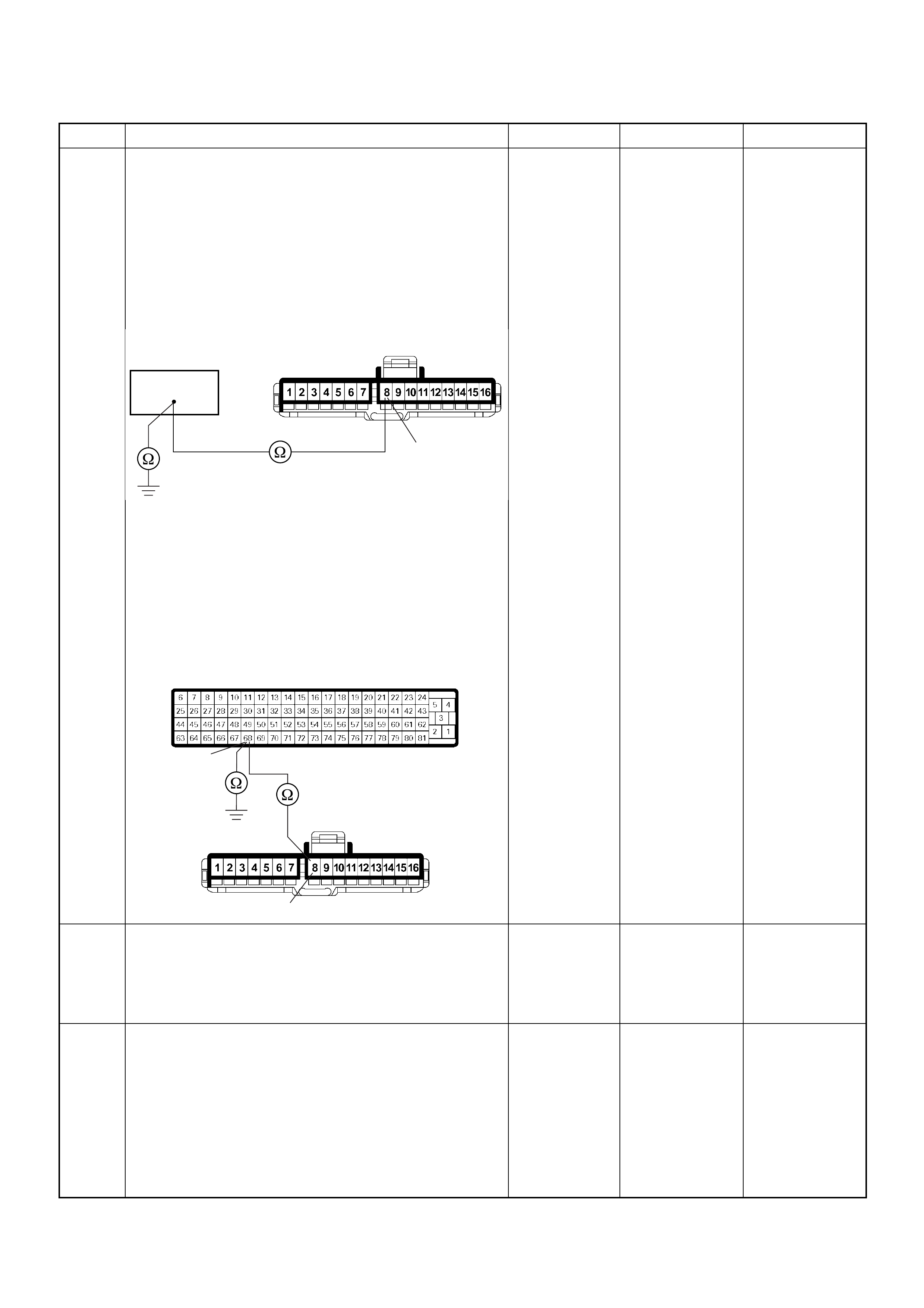
13 Using the DVM and check the VSS signal circuit.
Breaker box is available:
1. Ignition “Off”, engine “Off”.
2. Install the breaker box as type A. (ECM
disconnected) Ref. Page 6E-81
3. Disconnect the meter connector.
4. Check the circuit for open or shot to ground circuit.
Was the problem found?
Breaker box is not available:
1. Ignition “Off”, engine “Off”.
2. Disconnect the meter connector and ECM
connector.
3. Check the circuit for open or short to ground
circuit.
Was the problem found?
—
Repair faulty
harnes s and
verify repair Go to Step 14
14 Is the ECM programmed with the latest software
release?
If not, downlo ad the latest software to the ECM using
the “SPS (Service Programming System)”.
Was the problem solved? — Verify repair Go to Step 15
15 Replace the ECM.
Is the action complete?
IMPORTANT: The replacement ECM must be
programmed. Refer to section of the Service
Programming System (SPS) in this manual.
Foll owing ECM pr ogramming, the immobi liser system
(if equipped) must be linked to the ECM. Refer to
section 11 “Immobiliser System-ECM replacement” for
the ECM/Immobiliser linking procedure. — Verify repair —
Step Action Value(s) Yes No
8
B-23
68
68
8
B-23
C-56

Diagnostic Trouble Code (DTC) P0500 (Symptom Code A) (Flash Code 24)
Vehicle Speed Sensor Input Signal Frequency Too High
Step Action Value(s) Yes No
1 Was the “On-Board Diagnostic (OBD) System Check”
performed?
—Go to Step 2
Go to On
Board
Diagnostic
(OBD) System
Check
2 1. Connect the Tech 2.
2. Review and record the failure information.
3. Select “F0: Read DTC Infor As Stored By ECU” in
“F0: Diagnostic Trouble Codes”.
Is the DTC P0500 (Symptom Code A) stored as
“Present Failure”? — Go to Step 3
Refer to
Diagnostic
Aids and Go to
Step 3
3 1. Using the Tech 2, ignition “On” and engine “Off”.
2. Select “F1: Clear DTC Information” in “F0:
Diagnostic Trouble Codes” with the Tech 2 and
clear the DTC information.
3. Operate the vehicle and monitor the “F0: Read
DTC Infor As Stored By ECU” in the “F0:
Diagnostic Trouble Codes”.
Was the DTC P0500 (Symptom Code A) stored in this
ignition cycle? — Go to Step 4
Refer to
Diagnostic
Aids and Go to
Step 4
4 Perform test drive and check the speed meter.
Does the speed meter indicate correct vehicle speed. — Go to Step 5 Go to Step 6
5 Perform test drive and use the Tech 2.
Monitor the “Vehicle Speed” in the data display.
Does the Tech 2 indicate correct vehicle speed as
same as the speed meter indication in the instrument
panel? — Go to Step 9 Go to Step 7
6 Remove the VSS from the housing case and visually
check.
Was the problem found? — Go to Step 8 Go to Step 7
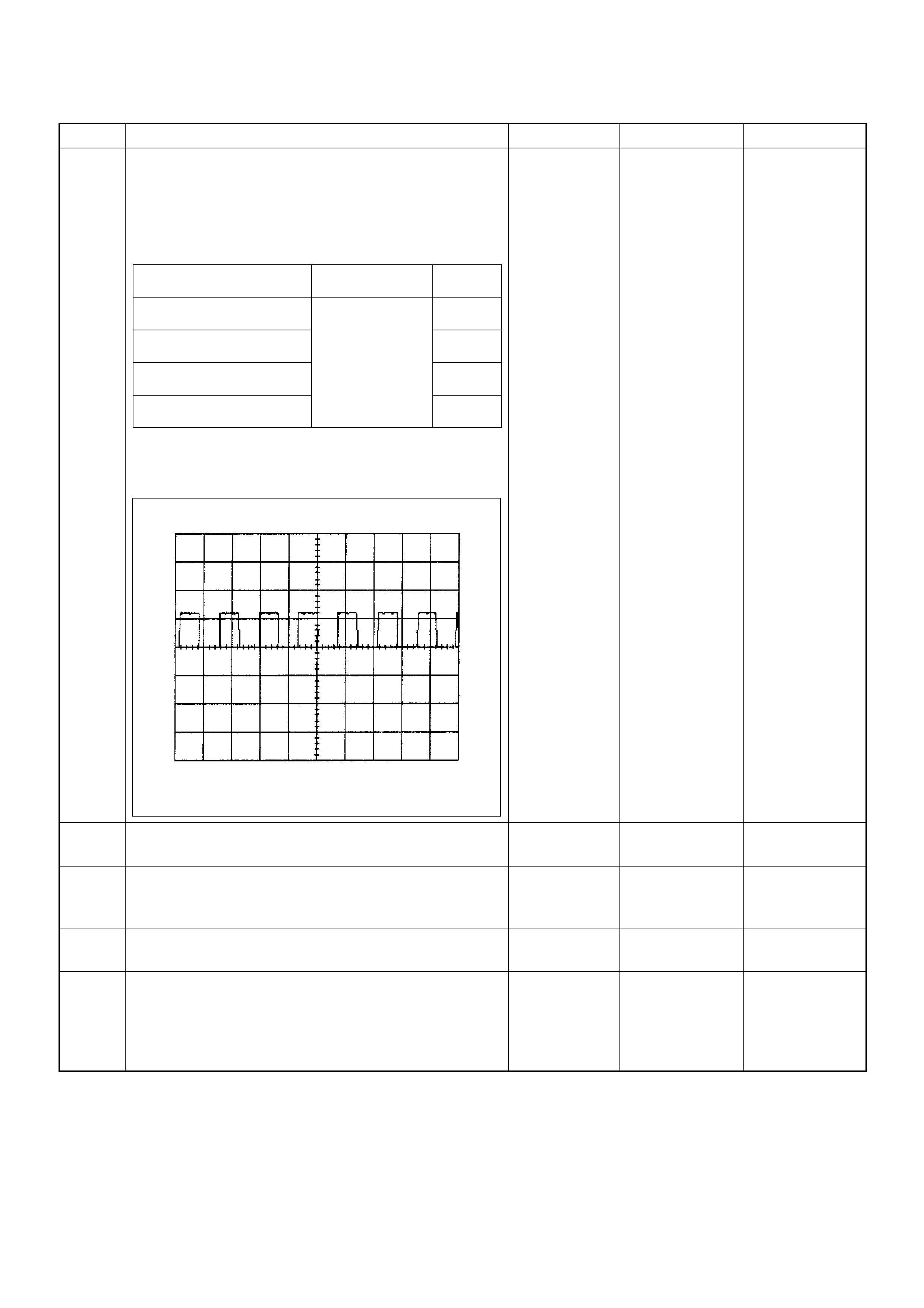
7 Using the DVM and check the VSS signal.
1. Ignition “On”, vehicle “Run (lift up)”.
2. Measur e the VSS outpu t voltage at sensor, meter
and ECM.
Does the tester indicate specified value?
If a oscilloscope is available, monitor the VSS signal
at each connector connection. Does the oscilloscope
indicate correct wave form?
Refer to
Diagnostic
Aids and Go to
Step 9 Refer the table
8 Replace the VSS.
Is the action complete? — Verify repair
9 Check any accessory parts which may cause electric
interference or magnetic interference.
Was the problem found? —
Remove the
accessory parts
and verify repair Go to Step 11
10 Replace the speed meter.
Is the action complete? — Verify repair —
11 Is the ECM programmed with the latest software
release?
If not, downlo ad the latest software to the ECM using
the “SPS (Service Programming System)”.
Was the problem solved? — Verify repair Go to Step 12
Step Action Value(s) Yes No
Measurement Position Voltage (V)
(AC Range) If No
Good
VSS terminal 3 & GND Ap proximate ly 6.5
V at 20km/h Go to
Step 8
Meter B23 connector 9 &
GND Go to
Step 9
Meter B23 connector 8 &
GND Go to
Step 10
ECM C56 connector 68 &
GND Go to
Step 9
Vehicle Speed Sensor Reference Wave Form
0V→
Measurement Scale: 10V/div 50ms/div
Measurement Condition: Vehicle Speed 20km/h
Measurement Terminal: At Engine Control Module

Diagnostic Trouble Code (DTC) P0500 (Symptom Code B) (Flash Code 24)
Vehicle Speed Sensor Incorrect Signal
12 Replace the ECM.
Is the action complete?
IMPORTANT: The replacement ECM must be
programmed. Refer to section of the Service
Programming System (SPS) in this manual.
Following ECM programming, the immobiliser system
(if equipped) must be linked to the ECM. Refer to
section 11 “Immobiliser System-ECM replacement” for
the ECM/Immobiliser linking procedure. — Verify repair —
Step Action Value(s) Yes No
1 Was the “On- Board Diagnos tic (OBD) Sy stem Check”
performed?
—Go to Step 2
Go to On
Board
Diagnostic
(OBD) System
Check
2 1. Connect the Tech 2.
2. Review and record the failure information.
3. S elect “F0: Read DTC I nfor As Stored B y ECU” in
“F0: Diagnostic Trouble Codes”.
Is the DTC P0500 (Symptom Code B) stored as
“Present Failure”? — Go to Step 3
Refer to
Diagnostic
Aids and Go to
Step 3
3 1. Using the Tech 2, ignition “On” and engine “Off”.
2. Select “F1: Clear DTC Information” in “F0:
Diagnostic Trouble Codes” with the Tech 2 and
clear the DTC information.
3. Operate the vehicle and monitor the “F0: Read
DTC Infor As Stored By ECU” in the “F0:
Diagnostic Trouble Codes”.
Was the DTC P0500 (Symptom Code B) stored in this
ignition cycle? — Go to Step 4
Refer to
Diagnostic
Aids and Go to
Step 4
4 Perform test drive and check the speed meter.
Does the speed meter indicate correct vehicle speed. — Go to Step 5 Go to Step 6
5 Perform test drive and use the Tech 2.
Monitor the “Vehicle Speed” in the data display.
Does the Tech 2 indicate correct vehicle speed as
same as the speed meter indication in the instrument
panel? — Go to Step 16 Go to Step 7
Step Action Value(s) Yes No
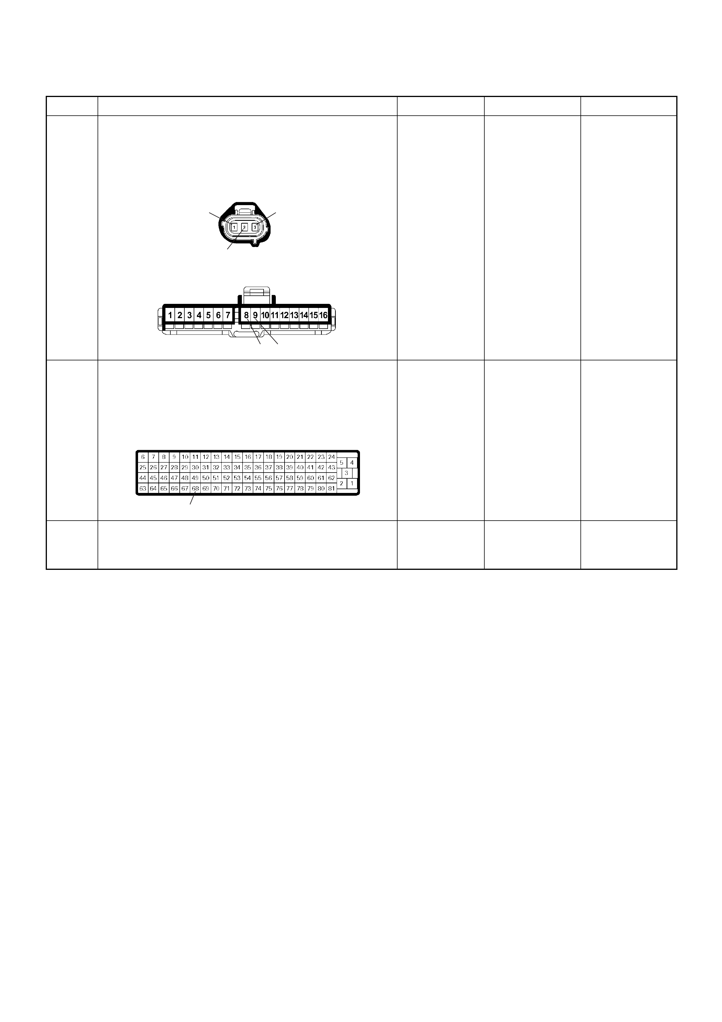
6 Check for poor/faulty connection at the VSS and
meter c on nector s . If a po or/fau lty c onn ec tio n i s found ,
repair the faulty terminal.
Was the problem found?
— Verify repair Go to Step 8
7 Check for poor/faulty connection at the ECM and
other connectors. If a poor/faulty connection is found,
repair the faulty terminal.
Was the problem found?
— Verify repair Go to Step 9
8 Remove the VSS from the housing case and visually
check.
Was the problem found? — Go to Step 10 Go to Step 9
Step Action Value(s) Yes No
13
2
98
B-23
E-44
68
C-56
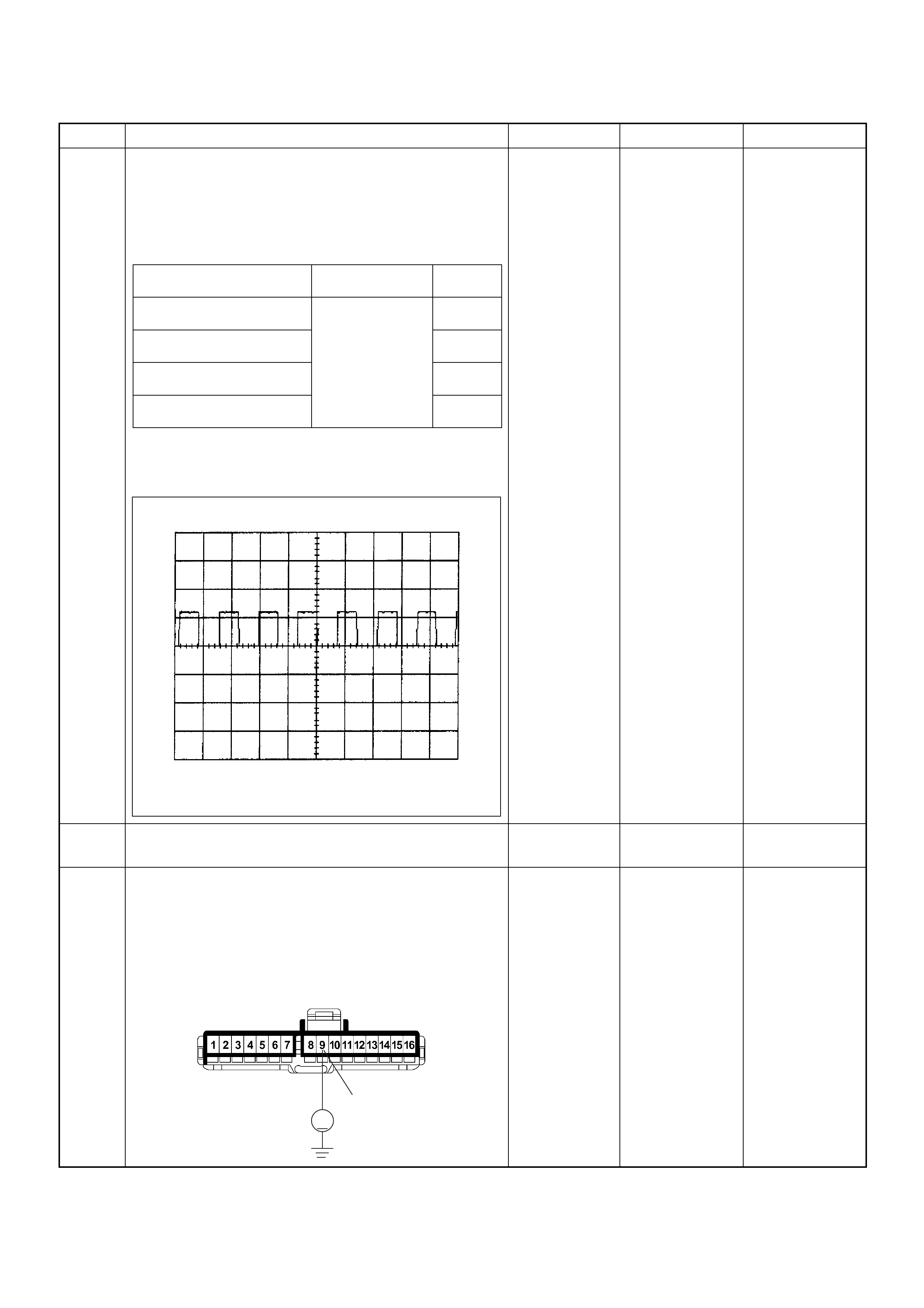
9 Using the DVM and check the VSS signal.
1. Ignition “On”, vehicle “Run (lift up)”.
2. Measur e the VSS outpu t voltage at sensor, meter
and ECM.
Does the tester indicate specified value?
If a oscilloscope is available, monitor the VSS signal
at each connector connection. Does the oscilloscope
indicate correct wave form?
Refer to
Diagnostic
Aids and Go to
Step 16 Refer the table
10 Replace the VSS.
Is the action complete? — Verify repair
11 Using the DVM and check the VSS signal circuit.
1. Ignition “On”, engine “Off”.
2. Disconnect the meter connector.
3. Check the circuit for short to power supply circuit.
Was the DVM indicated specified value?
Less than 1V Go to Step 12
Repair faulty
harness and
verify repair
Step Action Value(s) Yes No
Measurement Position Voltage (V)
(AC Range) If No
Good
VSS terminal 3 & GND Ap proximate ly 6.5
V at 20km/h Go to
Step 10
Meter B23 connector 9 &
GND Go to
Step 11
Meter B23 connector 8 &
GND Go to
Step 13
ECM C56 connector 68 &
GND Go to
Step 14
Vehicle Speed Sensor Reference Wave Form
0V→
Measurement Scale: 10V/div 50ms/div
Measurement Condition: Vehicle Speed 20km/h
Measurement Terminal: At Engine Control Module
9
V
B-23
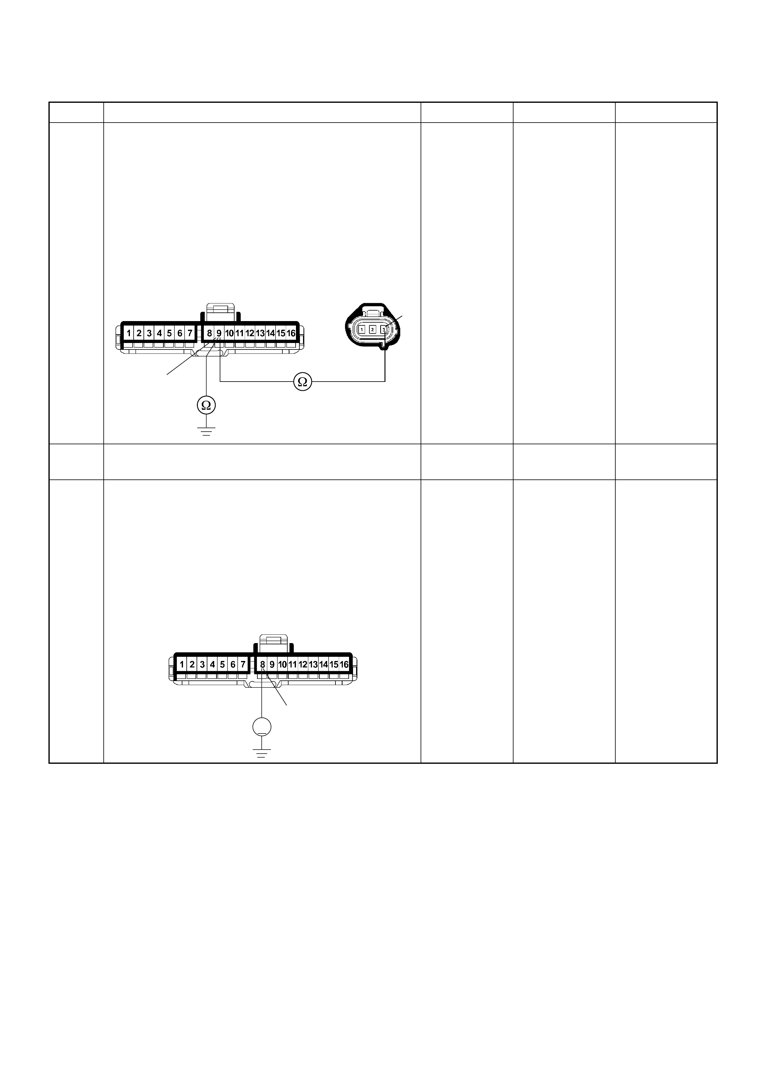
12 Using the DVM and check the VSS signal circuit.
1. Ignition “Off”, engine “Off”.
2. Disconnect the VSS connector and meter
connector.
3. Check the circuit for open or short to ground
circuit.
If a open o r short to gr ound circui t is found, repair the
faulty harness and verify repair.
Is the action complete?
— Verify repair —
13 Replace the speed meter.
Is the action complete? — Verify repair —
14 Using the DVM and check the VSS signal circuit.
1. Ignition “Off”, engine “Off”.
2. Disconnect the meter connector and ECM
connector.
3. Ignition “On”.
4. Check the circuit for short to power supply circuit.
Was the DVM indicated specified value?
Less than 1V Go to Step 15
Repair faulty
harness and
verify repair
Step Action Value(s) Yes No
3
9
E-44
B-23
8
V
B-23

15 Using the DVM and check the VSS signal circuit.
Breaker box is available:
1. Ignition “Off”, engine “Off”.
2. Install the breaker box as type A. (ECM
disconnected) Ref. Page 6E-81
3. Disconnect the meter connector.
4. Check the circuit for open or shot to ground circuit.
Was the problem found?
Breaker box is not available:
1. Ignition “Off”, engine “Off”.
2. Disconnect the meter connector and ECM
connector.
3. Check the circuit for open or short to ground
circuit.
Was the problem found?
—
Repair faulty
harnes s and
verify repair Go to Step 16
16 Is the ECM programmed with the latest software
release?
If not, downlo ad the latest software to the ECM using
the “SPS (Service Programming System)”.
Was the problem solved? — Verify repair Go to Step 17
17 Replace the ECM.
Is the action complete?
IMPORTANT: The replacement ECM must be
programmed. Refer to section of the Service
Programming System (SPS) in this manual.
Foll owing ECM pr ogramming, the immobi liser system
(if equipped) must be linked to the ECM. Refer to
section 11 “Immobiliser System-ECM replacement” for
the ECM/Immobiliser linking procedure. — Verify repair —
Step Action Value(s) Yes No
8
B-23
68
68
8
B-23
C-56
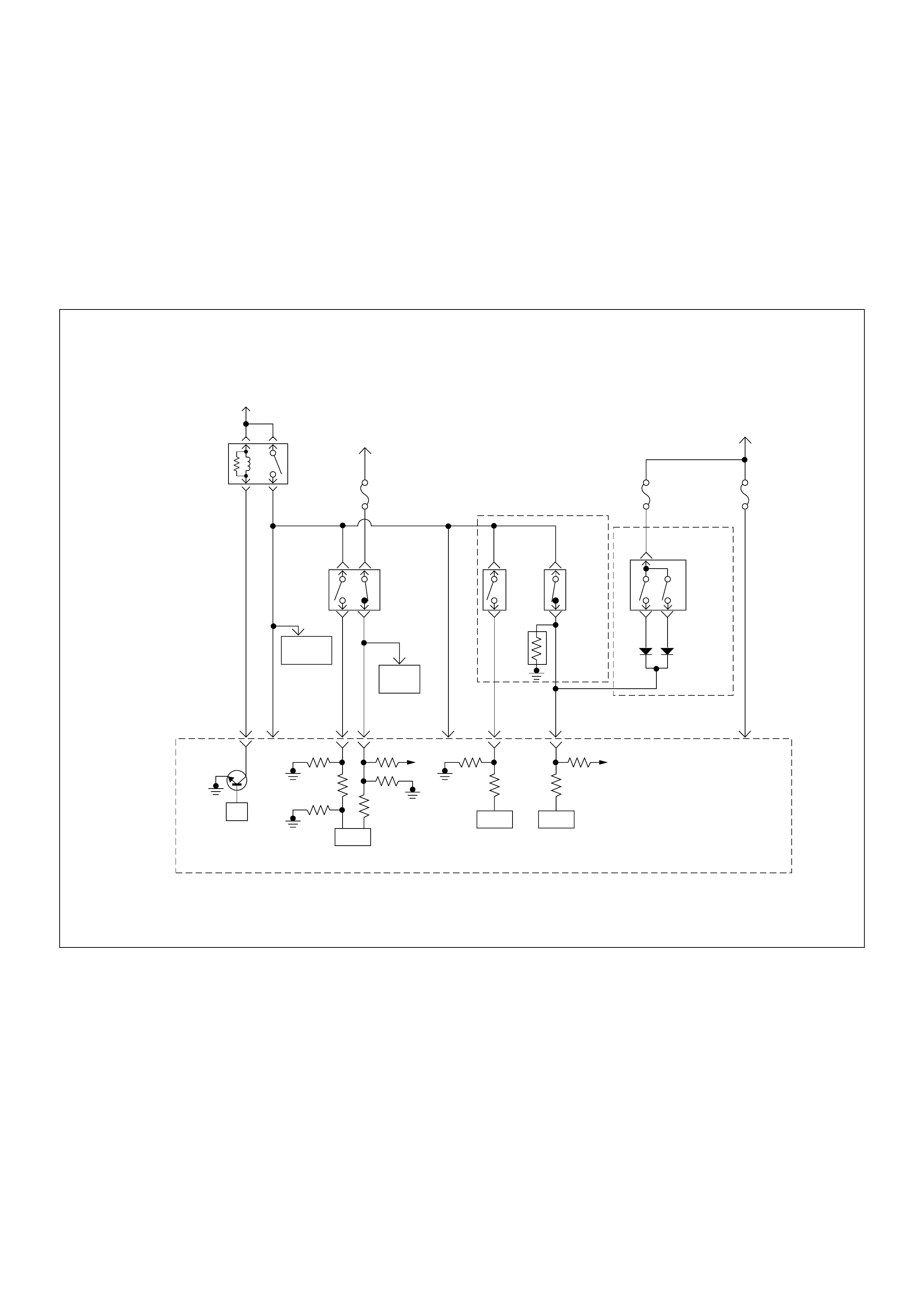
Diagnostic Trouble Code (DTC) P0560 (Symptom Code 1) (Flash Code 35)
System Voltage Too High
Diagnostic Trouble Code (DTC) P0560 (Symptom Code 2) (Flash Code 35)
System Voltage Too Low
Diagnostic Trouble Code (DTC) P0560 (Symptom Code A) (Flash Code 35)
System Voltage Malfunction (PSG)
Battery
Voltage
Battery
Voltage
ECM
Main Relay
Stop
Light
10A
Injection
Pump Stop
Lamp
IC IC CPU
0.5
BLU/
BLK
58
2.0
BLU/
RED
0.5
BLU/
RED
3
0.5
WHT/
BLK
65
0.85
RED
0.85
RED
0.85
GRN
30
0.5
BLU/
RED
63
0.5
YEL
31
0.5
RED/
BLK
0.5
BLU/
RED
0.5
BLU/
RED
0.85
WHT
0.5
WHT/
RED
0.5
RED/
GRN
Clutch
SW
Resister
Neutral
SW
87
0.5
BLU/
YEL
39
Brake
SW
M/T A/T
Inhibitor
SW
Ignition
SW
Back,
Turn
15A Engine
15A
µP
NP
Engine
Control
Module
(ECM) Batt Batt

Condition for setting the DTC and action taken when the DTC sets
Circuit Desc rip tio n
The ECM and PSG m onitors th e system vol tage on the
ignition feed terminal to the ECM or PSG. If the system
voltage to the ECM excessively high or low, a DTC
P0560 (Sympt om Code 1) or P0560 (Sympto m Code 2)
will be stored. If the system voltage to the PSG
excess ively hig h or low, a DTC P0560 (Sym ptom Code
A) will be stored.
Diagnostic Aids
An intermittent may be caused by the following:
• Poor connections.
• Misrouted harness.
• Rubbed through wire insulation.
• Broken wire inside the insulation.
Check for the following conditions:
• Poor connection at ECM and PSG-Inspect harness
connectors for backed out terminals, improper
mating, broken locks, improperly formed or damaged
terminals, and poor terminal to wire connection.
• Damaged harness-Inspect the wiring harness for
damage. If the harness appears to be OK, observe
the “System Voltage” display on the Tech2 while
moving connectors and wiring harness related to the
sensor.
Flash
Code Code Symptom
Code MIL DTC Name DTC Setting Condition F ail-Safe (Back Up)
35 P0560 1 OFF S yst em Voltage Too High System voltage is more than
20V. ECM uses 9V conditions as
substitute.
2 OFF System Voltage Too Low System voltage is below 7V.
A O FF System Voltage Malfunction
(PSG) System voltage of PSG
(pump control unit) is below
4.5V or more than 27V.
PSG uses default voltage as
substitute.

Diagnostic Trouble Code (DTC) P0560 (Symptom Code 1) (Flash Code 35) System Voltage Too High
Diagnostic Trouble Code (DTC) P0560 (Symptom Code 2) (Flash Code 35) System Voltage Too Low
Step Action Value(s) Yes No
1 Was the “On-Board Diagnostic (OBD) System Check”
performed?
—Go to Step 2
Go to On
Board
Diagnostic
(OBD) System
Check
2 1. Connect the Tech 2.
2. Review and record the failure information.
3. Select “F0: Read DTC Infor As Stored By ECU” in
“F0: Diagnostic Trouble Codes”.
Is the DTC P0560 (Symptom Code 1) stored as
“Present Failure”? — Go to Step 3
Refer to
Diagnostic
Aids and Go to
Step 3
3 1. Using the Tech 2, ignition “On” and engine “Off”.
2. Select “F1: Clear DTC Information” in “F0:
Diagnostic Trouble Codes” with the Tech 2 and
clear the DTC information.
3. Operate the vehicle and monitor the “F0: Read
DTC Infor As Stored By ECU” in the “F0:
Diagnostic Trouble Codes”.
Was the DTC P0560 (Symptom Code 1) stored in this
ignition cycle? — Go to Step 4
Refer to
Diagnostic
Aids and Go to
Step 4
4 Was the battery jump start cable incorrectly
connecting? —Verify
procedure Go to Step 5
5 1. Using the Tech 2, ignition “On” and engine “On”.
2. Monitor the “System Voltage” in the data display.
3. Load the electrical system by turning on the
headlights, etc..
Does the Tech 2 indicate correct ignition voltage? 10 - 14V Go to Step 6
Check the
charging
system
6 Is the ECM programmed with the latest software
release?
If not, download the latest software to the ECM using
the “SPS (Service Programming System)”.
Was the problem solved? — Verify repair Go to Step 7
7 Replace the ECM.
Is the action complete?
IMPORTANT: The replacement ECM must be
programmed. Refer to section of the Service
Programming System (SPS) in this manual.
Foll owing ECM pr ogramming, the immobi liser system
(if equipped) must be linked to the ECM. Refer to
section 11 “Immobiliser System-ECM replacement” for
the ECM/Immobiliser linking procedure. — Verify repair —
Step Action Value(s) Yes No
1 Was the “On- Board Diagnos tic (OBD) Sy stem Check”
performed?
—Go to Step 2
Go to On
Board
Diagnostic
(OBD) System
Check
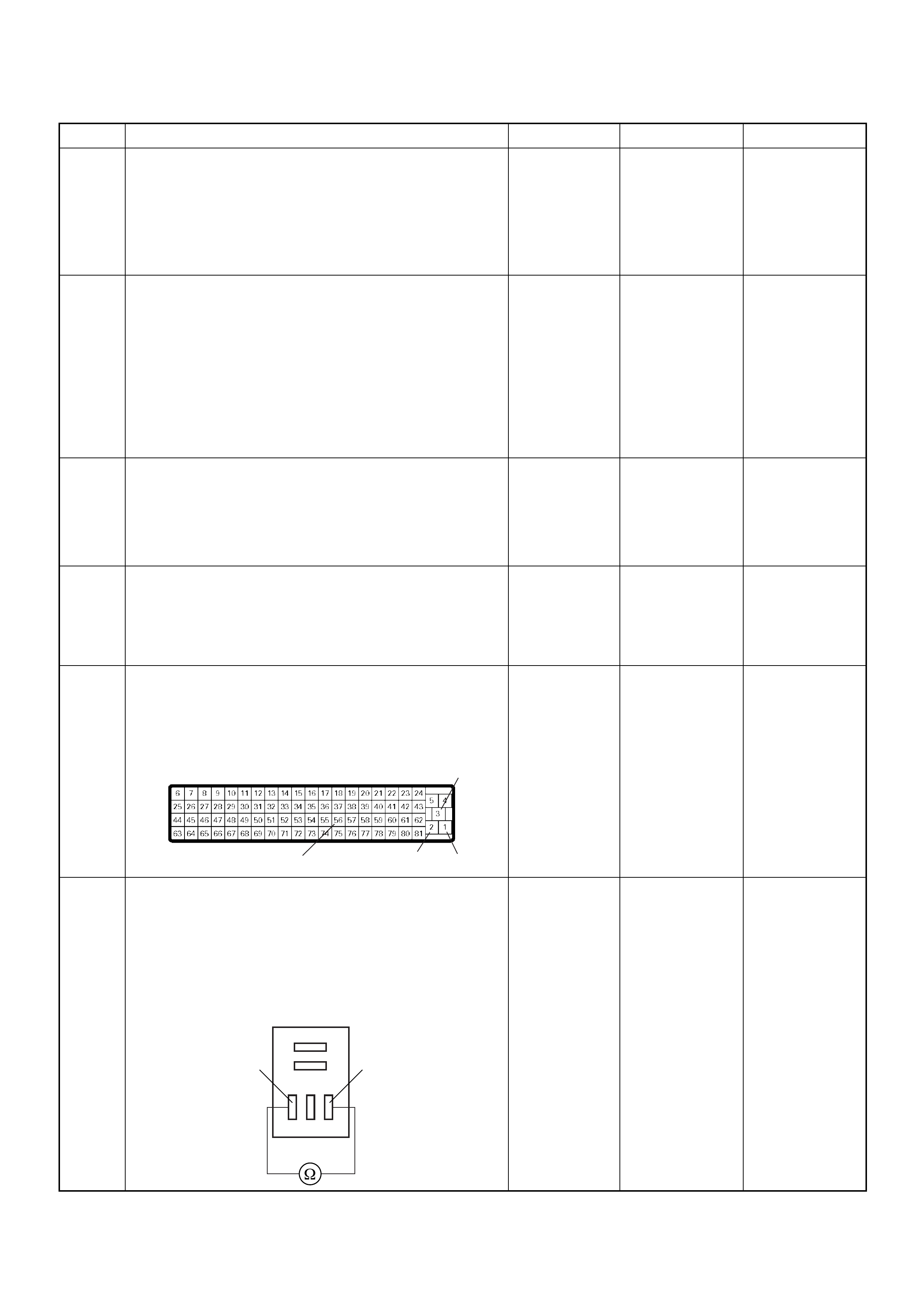
2 1. Connect the Tech 2.
2. Review and record the failure information.
3. S elect “F0: Read DTC I nfor As Stored B y ECU” in
“F0: Diagnostic Trouble Codes”.
Is the DTC P0560 (Symptom Code 2) stored as
“Present Failure”? — Go to Step 3
Refer to
Diagnostic
Aids and Go to
Step 3
3 1. Using the Tech 2, ignition “On” and engine “Off”.
2. Select “F1: Clear DTC Information” in “F0:
Diagnostic Trouble Codes” with the Tech 2 and
clear the DTC information.
3. Operate the vehicle and monitor the “F0: Read
DTC Infor As Stored By ECU” in the “F0:
Diagnostic Trouble Codes”.
Was the DT C P0 560 (Sy mpt om Code 2) stor e d i n th is
ignition cycle? — Go to Step 4
Refer to
Diagnostic
Aids and Go to
Step 4
4 1. Using the Tech 2, ignition “On” and engine “On”.
2. Monitor the “System Voltage” in the data display.
3. Load the electrical system by turning on the
headlights, etc..
Does the Tech 2 indicate enough ignition voltage? 10 - 14V Go to Step 6 Go to Step 5
5 Using the DVM and check the battery voltage at the
battery terminal.
Does the tester indicate enough battery voltage?
10 - 14V Go to Step 6
Check the
charging
system , charge
or replace the
battery
6 Check for poor/faulty connection at the ECM
connector. If a poor/faulty connection is found, repair
as necessary.
Was the problem found?
— Verify repair Go to Step 7
7 Using the DVM and check the ECM main relay.
1. Ignition “Off”, engine “Off”.
2. Remove the ECM main relay from the relay box.
3. Check the relay coil.
Was the DVM indicated specified value?
Continuity Go to Step 8
Replace ECM
main relay and
verify repair
Step Action Value(s) Yes No
3
21
56
C-56
ECM Main Relay
35

Diagnostic Trouble Code (DTC) P0560 (Symptom Code A) (Flash Code 35) System Voltage Malfunction (PSG)
8 Check for poor/faulty connection of the ECM ground
at the fender panel. If a poor/faulty connection is
found, repair as necessary.
Was the problem found?
— Verify repair Go to Step 9
9 Is the ECM programmed with the latest software
release?
If not, download the latest software to the ECM using
the “SPS (Service Programming System)”.
Was the problem solved? — Verify repair Go to Step 10
10 Replace the ECM.
Is the action complete?
IMPORTANT: The replacement ECM must be
programmed. Refer to section of the Service
Programming System (SPS) in this manual.
Foll owing ECM pr ogramming, the immobi liser system
(if equipped) must be linked to the ECM. Refer to
section 11 “Immobiliser System-ECM replacement” for
the ECM/Immobiliser linking procedure. — Verify repair —
Step Action Value(s) Yes No
1 Was the “On- Board Diagnos tic (OBD) Sy stem Check”
performed?
—Go to Step 2
Go to On
Board
Diagnostic
(OBD) System
Check
2 1. Connect the Tech 2.
2. Review and record the failure information.
3. S elect “F0: Read DTC I nfor As Stored B y ECU” in
“F0: Diagnostic Trouble Codes”.
Is the DTC P0560 (Symptom Code A) stored as
“Present Failure”? — Go to Step 3
Refer to
Diagnostic
Aids and Go to
Step 3
3 1. Using the Tech 2, ignition “On” and engine “Off”.
2. Select “F1: Clear DTC Information” in “F0:
Diagnostic Trouble Codes” with the Tech 2 and
clear the DTC information.
3. Operate the vehicle and monitor the “F0: Read
DTC Infor As Stored By ECU” in the “F0:
Diagnostic Trouble Codes”.
Was the DTC P0560 (Symptom Code A) stored in this
ignition cycle? — Go to Step 4
Refer to
Diagnostic
Aids and Go to
Step 4
Step Action Value(s) Yes No
C-36
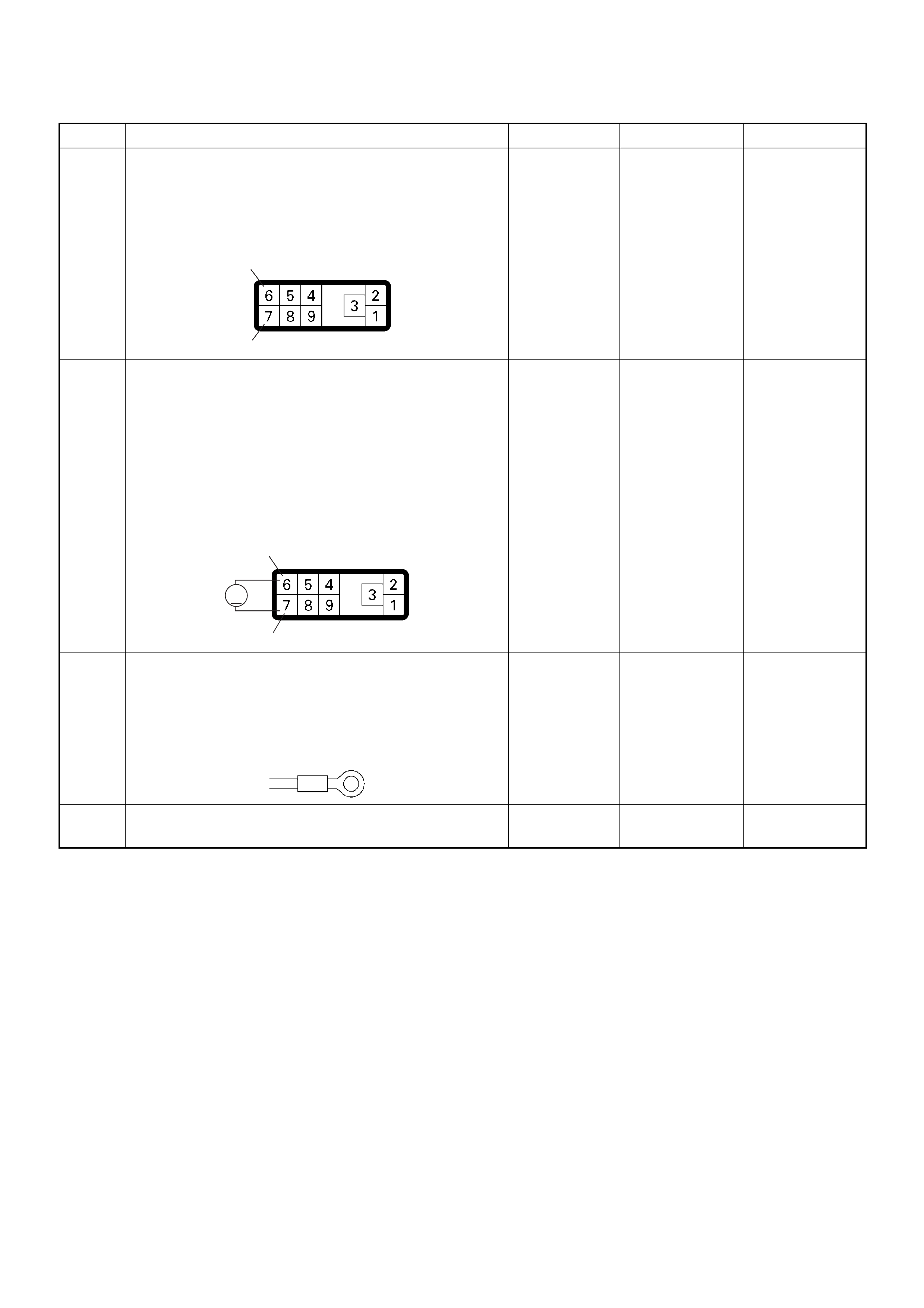
4 Check for poor/faulty connection at the PSG (pump
control unit) connector. If a poor/faulty connection is
found, repair as necessary.
Was the problem found?
— Verify repair Go to Step 5
5 Using the DVM and check the PSG (pump control
unit) power supply circuit.
1. Ignition “On”, engine “Off”.
2. Disconnect the PSG (pump control unit)
connector.
3. Check the PSG (pump control unit) power supply
circuit.
Was the DVM indicated specified value?
10 - 14V Go to Step 7 Go to Step 6
6 Check for poor/faulty connection of the PSG (pump
control unit) ground at the cylinder body. If a poor/
faulty co nnec ti on is found, repair as nece ssa ry.
Was the problem found?
— Verify repair Go to Step 7
7 Replace the injection pump assembly.
Is the action complete? — Verify repair —
Step Action Value(s) Yes No
6
7
E-6
6
7
V
E-6
E-10
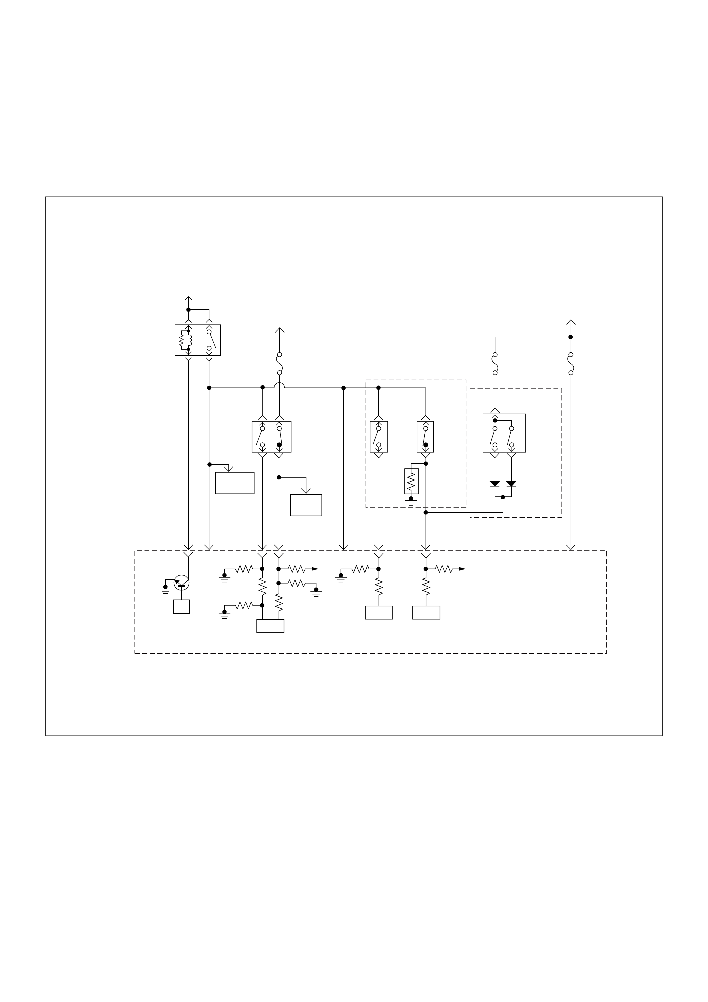
Diagnostic Trouble Code (DTC) P0561 (Symptom Code A)
(Flash Code 18) System Voltage Circuit Malfunction
Diagnostic Trouble Code (DTC) P0561 (Symptom Code B)
(Flash Code 18) System Voltage Circuit Malfunction
Battery
Voltage
Battery
Voltage
ECM
Main Relay
Stop
Light
10A
Injection
Pump Stop
Lamp
IC IC CPU
0.5
BLU/
BLK
58
2.0
BLU/
RED
0.5
BLU/
RED
3
0.5
WHT/
BLK
65
0.85
RED
0.85
RED
0.85
GRN
30
0.5
BLU/
RED
63
0.5
YEL
31
0.5
RED/
BLK
0.5
BLU/
RED
0.5
BLU/
RED
0.85
WHT
0.5
WHT/
RED
0.5
RED/
GRN
Clutch
SW
Resister
Neutral
SW
87
0.5
BLU/
YEL
39
Brake
SW
M/T A/T
Inhibitor
SW
Ignition
SW
Back,
Turn
15A Engine
15A
µP
NP
Engine
Control
Module
(ECM) Batt Batt

Condition for setting the DTC and action taken when the DTC sets
Circuit Desc rip tio n
The ECM monitors the ignition switch signal on the feed
terminal to the ECM. If the ignition switch signal with
malfunction, a DTC P0561 (Symptom Code A) or a DTC
P0561 (Symptom Code B) will be stored.
Diagnostic Aids
An intermittent may be caused by the following:
• Poor connections.
• Misrouted harness.
• Rubbed through wire insulation.
• Broken wire inside the insulation.
Check for the following conditions:
• Poor con nection at ECM-I nspect harnes s connectors
for backed out terminals, improper mating, broken
locks, improperly formed or damaged terminals, and
poor terminal to wire connection.
• Damaged harness-Inspect the wiring harness for
damage. If the harness appears to be OK, observe
the “Ignition Status” display on the Tech2 while
moving connectors and wiring harness related to the
sensor.
Flash
Code Code Symptom
Code MIL DTC Name DTC Setting Condition F ail-Safe (Back Up)
18 P0561 A OFF S yst em Voltage Circuit
Malfunction The ECM recognized ignition
switch turn off signal during
ECM is activated.
ECM stops engine.
B ON Syst em Voltage Circuit
Malfunction Ignition switch circuit is
malfunction.

Diagnostic Trouble Code (DTC) P0561 (Symptom Code A) (Flash Code 18) System Voltage Circuit Malfunction
Diagnostic Trouble Code (DTC) P0561 (Symptom Code B) (Flash Code 18) System Voltage Circuit Malfunction
Step Action Value(s) Yes No
1 Was the “On-Board Diagnostic (OBD) System Check”
performed?
—Go to Step 2
Go to On
Board
Diagnostic
(OBD) System
Check
2 1. Connect the Tech 2.
2. Review and record the failure information.
3. Select “F0: Read DTC Infor As Stored By ECU” in
“F0: Diagnostic Trouble Codes”.
Is the DTC P0561 (Symptom Code A) or P0561
(Symptom Code B) stored as “Present Failure”? — Go to Step 3
Refer to
Diagnostic
Aids and Go to
Step 3
3 1. Using the Tech 2, ignition “On” and engine “Off”.
2. Select “F1: Clear DTC Information” in “F0:
Diagnostic Trouble Codes” with the Tech 2 and
clear the DTC information.
3. Operate the vehicle and monitor the “F0: Read
DTC Infor As Stored By ECU” in the “F0:
Diagnostic Trouble Codes”.
Was the DTC P0561 (Symptom Code A) or P0561
(Symptom Code B)stored in this ignition cycle? — Go to Step 4
Refer to
Diagnostic
Aids and Go to
Step 4
4 Check the “Engine-2” fuse (10A).
If the fuse is burnt out, repair as necessary.
Was the problem found? — Verify repair Go to Step 5
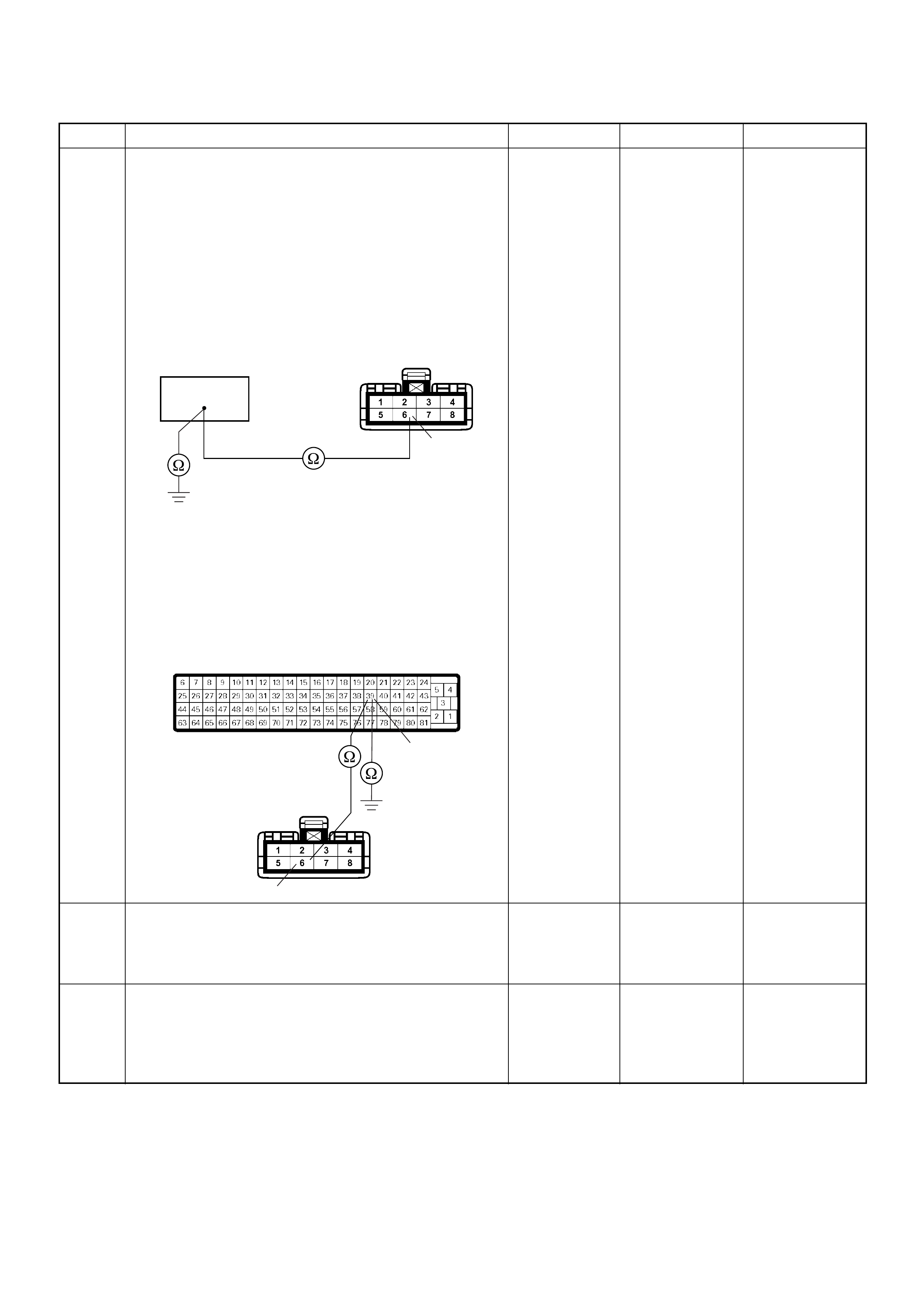
5 Using the DVM and check the ignition power feed
circuit.
Breaker box is available:
1. Ignition “Off”, engine “Off”.
2. Install the breaker box as type A. (ECM
disconnected)
3. Check the circuit for open or short to ground
circuit.
Was the problem found?
Breaker box is not available:
1. Ignition “Off”, engine “Off”.
2. Disconnect the ECM connector.
3. Check the circuit for open or short to ground
circuit.
Was the problem found?
—
Repair faulty
harnes s and
verify repair G o to Step 6
6 Check the ignition switch.
If a poor/faulty connection is found, repair as
necessary.
Was the problem found? — Verify repair Go to Step 7
7 Is the ECM programmed with the latest software
release?
If not, downlo ad the latest software to the ECM using
the “SPS (Service Programming System)”.
Was the problem solved? — Verify repair Go to Step 8
Step Action Value(s) Yes No
39
6
C-41
39
6
C-56
C-41

8 Replace the ECM.
Is the action complete?
IMPORTANT: The replacement ECM must be
programmed. Refer to section of the Service
Programming System (SPS) in this manual.
Foll owing ECM pr ogramming, the immobi liser system
(if equipped) must be linked to the ECM. Refer to
section 11 “Immobiliser System-ECM replacement” for
the ECM/Immobiliser linking procedure. — Verify repair —
Step Action Value(s) Yes No

Diagnostic Trouble Code (DTC) P0602 ECU Programming Error
Condition for setting the DTC and action taken when the DTC sets
Circuit Description & Diagnostic Aids
The replacement ECM must be programmed by the
Service Programming System (SPS). When the service
ECM is used without SPS, a DTC P0602 will be set.
Diagnostic Trouble Code (DTC) P0602 ECU Programming Error
Flash
Code Code Symptom
Code MIL DTC Name DTC Setting Condition Fail-Safe (Back Up)
- P0602 - - Programming Error ECM memory area error. Engine control disabled.
Step Action Value(s) Yes No
1 Was the “On-Board Diagnostic (OBD) System Check”
performed?
—Go to Step 2
Go to On
Board
Diagnostic
(OBD) System
Check
2 1. Connect the Tech 2.
2. Review and record the failure information.
3. Select “F0: Read DTC Infor As Stored By ECU” in
“F0: Diagnostic Trouble Codes”.
Is the DTC P0602 stored as “Present Failure”? — Go to Step 3
Refer to
Diagnostic
Aids
3 Download the latest software to the ECM using the
“SPS (Service Programming System)”.
Foll owing ECM pr ogramming, the immobi liser system
(if equipped) must be linked to the ECM. Refer to
section 11 “Immobiliser System-ECM replacement” for
the ECM/Immobiliser linking procedure.
Is the action complete? — Verify repair —

Diagnostic Trouble Code (DTC) P0606 (Symptom Code A) (Flash Code 28)
ECU Malfunction
Diagnostic Trouble Code (DTC) P0606 (Symptom Code B) (Flash Code 28)
ECU Malfunction
Condition for setting the DTC and action taken when the DTC sets
Circuit Description & Diagnostic Aids
An internal ECM failure (IC, circuit, memory, etc,) will
result in a DTC P0606 (Symptom Code A) or P0606
(Symptom Code B) being stored.
Flash
Code Code Symptom
Code MIL DTC Name DTC Setting Condition F ail-Safe (Back Up)
28 P0606 A ON E CM Malfunction (1) Gate Array com municat ion
error. 1. MA B (fuel cutoff solenoid
valve cutoff) is operated.
2. Desired injection quantity
becomes 0mg/strk.
B ON ECM Malfunction (2) 1. Throttle position is below
1%.
2. Desired injection quantity is
more than 0mg/strk.
3. Engine speed is more than
2000rpm.
MAB (fuel cutoff solenoid valve
cutoff) is operated.

Diagnostic Trouble Code (DTC) P0606 (Symptom Code A) (Flash Code 28) ECU Malfunction
Step Action Value(s) Yes No
1 Was the “On-Board Diagnostic (OBD) System Check”
performed?
—Go to Step 2
Go to On Board
Diagnostic
(OBD) System
Check
2 1. Connect the Tech 2.
2. Review and record the failure information.
3. Select “F0: Read DTC Infor As Stored By ECU” in
“F0: Diagnostic Trouble Codes”.
Is the DTC P0606 (Symptom Code A) stored as
“Present Failure”? — Go to Step 3
Refer to
Diagnostic Aids
and Go to Step
3
3 1. Using the Tech 2, ignition “On” and engine “Off”.
2. Select “F1: Clear DTC Information” in “F0:
Diagnostic Trouble Codes” with the Tech 2 and
clear the DTC information.
3. Operate the vehicle and monitor the “F0: Read
DTC Infor As Stored By ECU” in the “F0:
Diagnostic Trouble Codes”.
Was the DTC P0606 (Symptom Code A) stored in this
ignition cycle? — Go to Step 4 Refer to
Diagnostic Aids
4 Is the ECM programmed with the latest software
release?
If not, downlo ad the latest software to the ECM using
the “SPS (Service Programming System)”.
Was the problem solved? — Verify repair Go to Step 5
5 Replace the ECM.
Is the action complete?
IMPORTANT: The replacement ECM must be
programmed. Refer to section of the Service
Programming System (SPS) in this manual.
Foll owing ECM pr ogramming, the immobi liser system
(if equipped) must be linked to the ECM. Refer to
section 11 “Immobiliser System-ECM replacement” for
the ECM/Immobiliser linking procedure. — Verify repair —

Diagnostic Trouble Code (DTC) P0606 (Symptom Code B) (Flash Code 28) ECU Malfunction
Step Action Value(s) Yes No
1 Was the “On-Board Diagnostic (OBD) System Check”
performed?
—Go to Step 2
Go to On Board
Diagnostic
(OBD) System
Check
2 1. Connect the Tech 2.
2. Review and record the failure information.
3. Select “F0: Read DTC Infor As Stored By ECU” in
“F0: Diagnostic Trouble Codes”.
Is the DTC P0606 (Symptom Code B) stored as
“Present Failure”? — Go to Step 3
Refer to
Diagnostic Aids
and Go to Step
3
3 1. Using the Tech 2, ignition “On” and engine “Off”.
2. Select “F1: Clear DTC Information” in “F0:
Diagnostic Trouble Codes” with the Tech 2 and
clear the DTC information.
3. Operate the vehicle and monitor the “F0: Read
DTC Infor As Stored By ECU” in the “F0:
Diagnostic Trouble Codes”.
Was the DTC P0606 (Symptom Code B) stored in this
ignition cycle? — Go to Step 4 Refer to
Diagnostic Aids
4 Is the ECM programmed with the latest software
release?
If not, downlo ad the latest software to the ECM using
the “SPS (Service Programming System)”.
Was the problem solved? — Verify repair Go to Step 5
5 Substitute a known good ECM and recheck.
Was the problem solved?
IMPORTANT: The replacement ECM must be
programmed. Refer to section of the Service
Programming System (SPS) in this manual.
Foll owing ECM pr ogramming, the immobi liser system
(if equipped) must be linked to the ECM. Refer to
section 11 “Immobiliser System-ECM replacement” for
the ECM/Immobiliser linking procedure. —Go to Step 6 Go to Step 7
6 Replace the ECM.
Is the action complete?
IMPORTANT: The replacement ECM must be
programmed. Refer to section of the Service
Programming System (SPS) in this manual.
Foll owing ECM pr ogramming, the immobi liser system
(if equipped) must be linked to the ECM. Refer to
section 11 “Immobiliser System-ECM replacement” for
the ECM/Immobiliser linking procedure. — Verify repair —
7 Replace the injection pump assembly.
Is the action complete? — Verify repair —

DIagnostic Trouble Code (DTC) P0645 (Symptom Code 4)
(Flash Code 46) A/C Compressor Relay Circuit Voltage Low
Diagnostic Trouble Code (DTC) P0645 (Symptom Code 8)
(Flash Code 46) A/C Compressor Relay Circuit Voltage High
Resister
A/C
Compressor
ECM
Main Relay Battery
Voltage
Glow
80A
Glow
Relay
Glow
Plug
0.5
BLU/
RED
0.5
BLK/
BLU
94
0.5
BRN/
RED
0.5
BLK
41
0.5
GRN
33
5.0
RED/
WHT
0.5
BLU/
RED
0.5
GRY
0.5
GRN 0.5
GRN
0.5
BRN
0.5
GRY/
YEL
A/C
10A
Heater
Relay
Blower
20A
A/C
Compressor
Relay
A/C
Thermo
Relay
Pressure
SW
5.0
BLK/
RED
Electronic
Thermostat
µP
Batt
µP
Batt
IC
Engine
Control
Module
(ECM)

Condition for setting the DTC and action taken when the DTC sets
Circuit Desc rip tio n
The voltage on the coil of the A/C compressor is
supplied by the ECM main relay. The ECM switches A/C
compressor relay to operate A/C compressor according
to the A/C request signal and certain setting conditions.
Diagnostic Aids
An intermittent may be caused by the following:
• Poor connections.
• Misrouted harness.
• Rubbed through wire insulation.
• Broken wire inside the insulation.
Check for the following conditions:
• Poor con nection at ECM-I nspect harnes s connectors
for backed out terminals, improper mating, broken
locks, improperly formed or damaged terminals, and
poor terminal to wire connection.
• Damaged harness-Inspect the wiring harness for
damage. If the harness appears to be OK, observe
the DTC P0645 display on the Tech2 while moving
connectors and wiring harnesses.
Flash
Code Code Symptom
Code MIL DTC Name DTC Setting Condition F ail-Safe (Back Up)
46 P0645 4 ON A/C Compressor Relay Circuit
Voltage Low A/C compressor relay circuit
open or short to ground
circuit.
No fail-safe function.
8 ON A/C Compressor Relay Circuit
Voltage High A/C compressor relay circuit
short to voltage circuit.
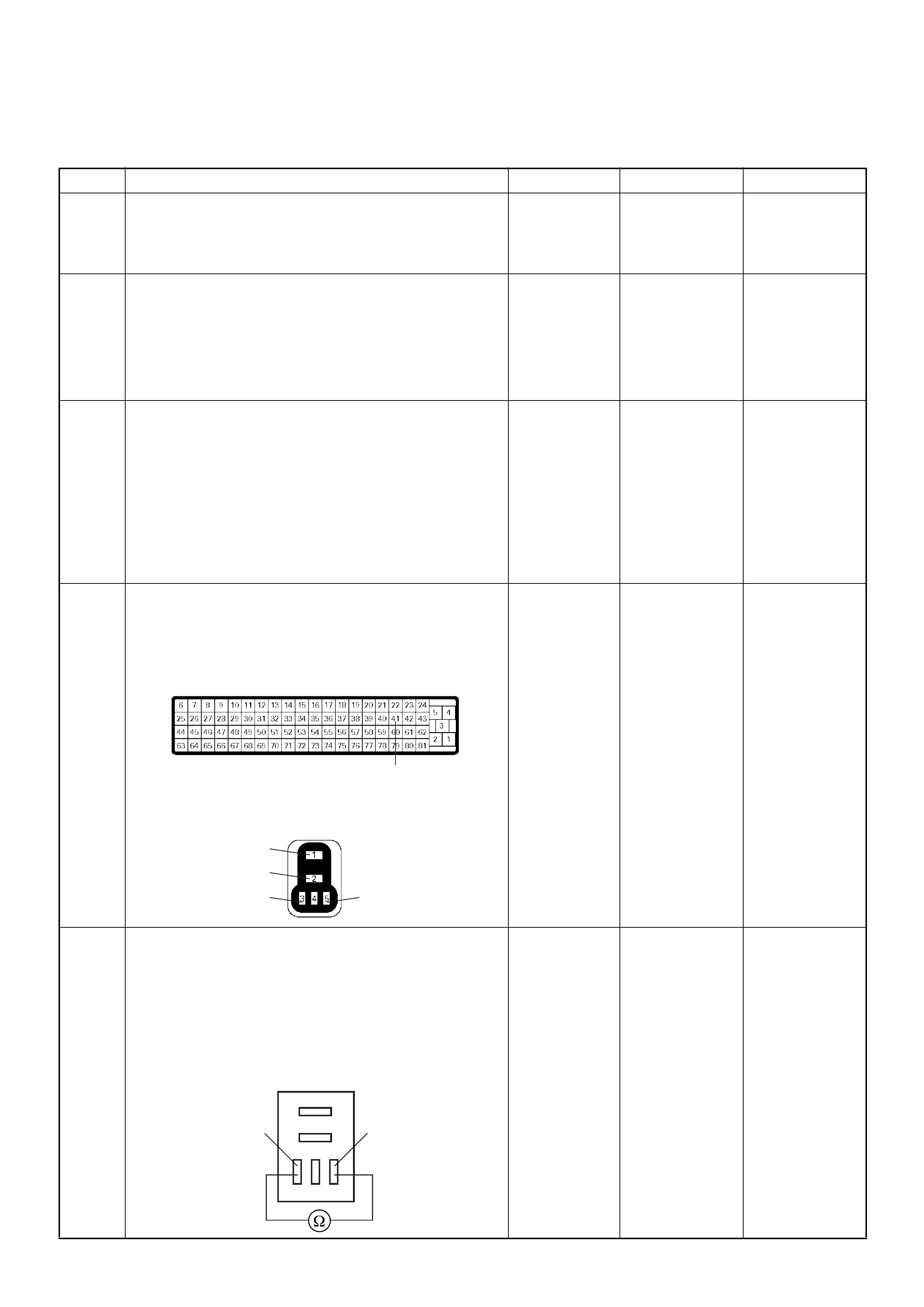
Diagnostic Trouble Code (DTC) P0645 (Symptom Code 4) (Flash Code 46)
A/C Compressor Relay Circuit Voltage Low
Step Action Value(s) Yes No
1 Was the “On-Board Diagnostic (OBD) System Check”
performed?
—Go to Step 2
Go to On Board
Diagnostic
(OBD) System
Check
2 1. Connect the Tech 2.
2. Review and record the failure information.
3. Select “F0: Read DTC Infor As Stored By ECU” in
“F0: Diagnostic Trouble Codes”.
Is the DTC P0645 (Symptom Code 4) stored as
“Present Failure”? — Go to Step 3
Refer to
Diagnostic Aids
and Go to Step
3
3 1. Using the Tech 2, ignition “On” and engine “Off”.
2. Select “F1: Clear DTC Information” in “F0:
Diagnostic Trouble Codes” with the Tech 2 and
clear the DTC information.
3. Operate the vehicle and monitor the “F0: Read
DTC Infor As Stored By ECU” in the “F0:
Diagnostic Trouble Codes”.
Was the DT C P0 645 (Sy mpt om Code 4) stor e d i n th is
ignition cycle? — Go to Step 4
Refer to
Diagnostic Aids
and Go to Step
4
4 Check for poor/faulty connection at the A/C
compressor relay or ECM connector. If a poor/faulty
connection is found, repair as necessary.
Was the problem found?
— Verify repair Go to Step 5
5 Using the DVM and check the A/C compressor relay.
1. Ignition “Off”, engine “Off”.
2. Remove the A/C compressor relay from the relay
box.
3. Check the relay coil.
Was the DVM indicated specified value?
Continuity Go to Step 6
Replace A/C
compressor
relay and verify
repair
41
1
2
35
C-56
X-5
4JA1-TC X-10
4JH1-TC
53
A/C Compressor Relay
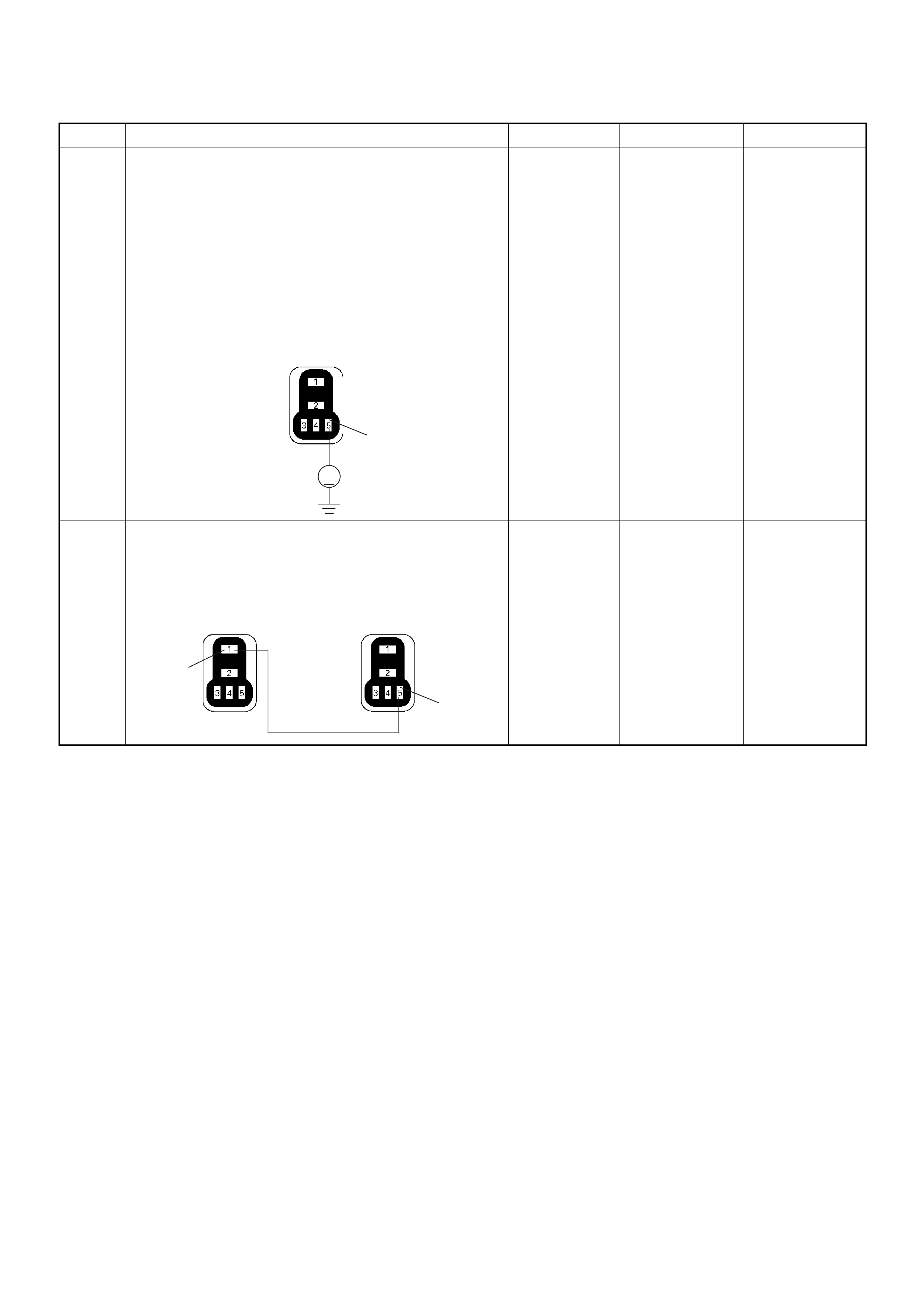
6 Using the DVM and check the A/C compressor relay
power supply circuit.
1. Ignition “On”, engine “Off”.
2. Remove the A/C compressor relay from the relay
box.
3. Check the circuit for open or short to ground
circuit.
Was the DVM indicated specified value?
Battery
voltage Go to Step 8 Go to Step 7
7 Repair the open or short to ground circuit between the
ECM main relay and A/C compressor relay.
Is the action complete?
— Verify repair —
Step Action Value(s) Yes No
5
V
X-5
4JA1-TC X-10
4JH1-TC
5
1
X-5
4JA1-TC X-10
4JH1-TC
X-4
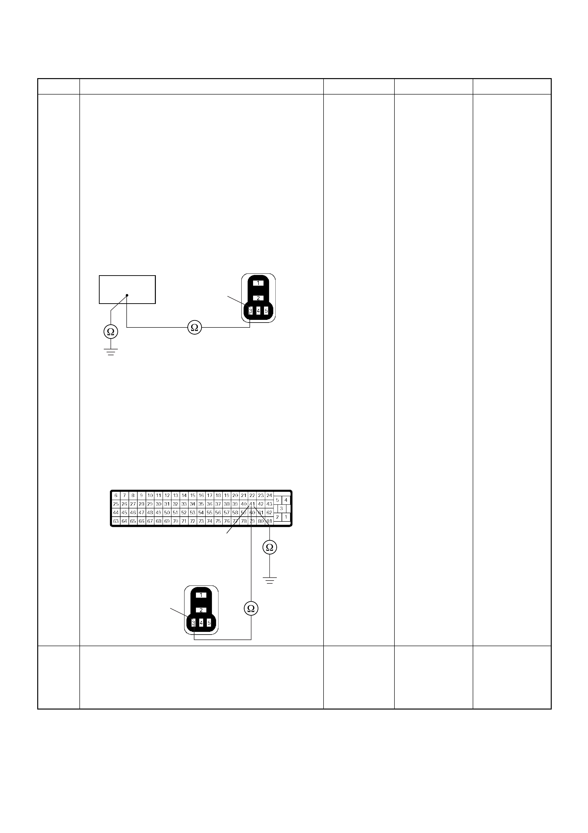
8 Using the DVM and check the A/C compressor relay
ground circuit.
Breaker box is available:
1. Ignition “Off”, engine “Off”.
2. Install the breaker box as type A. (ECM
disconnected)
3. Remove the A/C compressor relay from the relay
box.
4. Check the circuit for open or short to ground
circuit.
Was the problem found?
Breaker box is not available:
1. Ignition “Off”, engine “Off”.
2. Disconnect the ECM connector.
3. Remove the A/C compressor relay from the relay
box.
4. Check the circuit for open or short to ground
circuit.
Was the problem found?
—
Repair faulty
harnes s and
verify repair G o to Step 9
9 Is the ECM programmed with the latest software
release?
If not, downlo ad the latest software to the ECM using
the “SPS (Service Programming System)”.
Was the problem solved? — Verify repair Go to Step 10
Step Action Value(s) Yes No
41 3
X-5
4JA1-TC X-10
4JH1-TC
41
3
C-56
X-5
4JA1-TC X-10
4JH1-TC

Diagnostic Trouble Code (DTC) P0645 (Symptom Code 8) (Flash Code 46)
A/C Compressor Relay Circuit Voltage High
10 Replace the ECM.
Is the action complete?
IMPORTANT: The replacement ECM must be
programmed. Refer to section of the Service
Programming System (SPS) in this manual.
Foll owing ECM pr ogramming, the immobi liser system
(if equipped) must be linked to the ECM. Refer to
section 11 “Immobiliser System-ECM replacement” for
the ECM/Immobiliser linking procedure. — Verify repair —
Step Action Value(s) Yes No
1 Was the “On- Board Diagnos tic (OBD) Sy stem Check”
performed?
—Go to Step 2
Go to On Board
Diagnostic
(OBD) System
Check
2 1. Connect the Tech 2.
2. Review and record the failure information.
3. S elect “F0: Read DTC I nfor As Stored B y ECU” in
“F0: Diagnostic Trouble Codes”.
Is the DTC P0645 (Symptom Code 8) stored as
“Present Failure”? — Go to Step 3
Refer to
Diagnostic Aids
and Go to Step
3
3 1. Using the Tech 2, ignition “On” and engine “Off”.
2. Select “F1: Clear DTC Information” in “F0:
Diagnostic Trouble Codes” with the Tech 2 and
clear the DTC information.
3. Operate the vehicle and monitor the “F0: Read
DTC Infor As Stored By ECU” in the “F0:
Diagnostic Trouble Codes”.
Was the DT C P0 645 (Sy mpt om Code 8) stor e d i n th is
ignition cycle? — Go to Step 4 Refer to
Diagnostic Aids
4 Is the ECM programmed with the latest software
release?
If not, downlo ad the latest software to the ECM using
the “SPS (Service Programming System)”.
Was the problem solved? — Verify repair Go to Step 5
5 Substitute a known good ECM and recheck.
Was the problem solved?
IMPORTANT: The replacement ECM must be
programmed. Refer to section of the Service
Programming System (SPS) in this manual.
Foll owing ECM pr ogramming, the immobi liser system
(if equipped) must be linked to the ECM. Refer to
section 11 “Immobiliser System-ECM replacement” for
the ECM/Immobiliser linking procedure. —Go to Step 6 —
6 Replace the ECM.
Is the action complete?
IMPORTANT: The replacement ECM must be
programmed. Refer to section of the Service
Programming System (SPS) in this manual.
Foll owing ECM pr ogramming, the immobi liser system
(if equipped) must be linked to the ECM. Refer to
section 11 “Immobiliser System-ECM replacement” for
the ECM/Immobiliser linking procedure. — Verify repair —
Step Action Value(s) Yes No
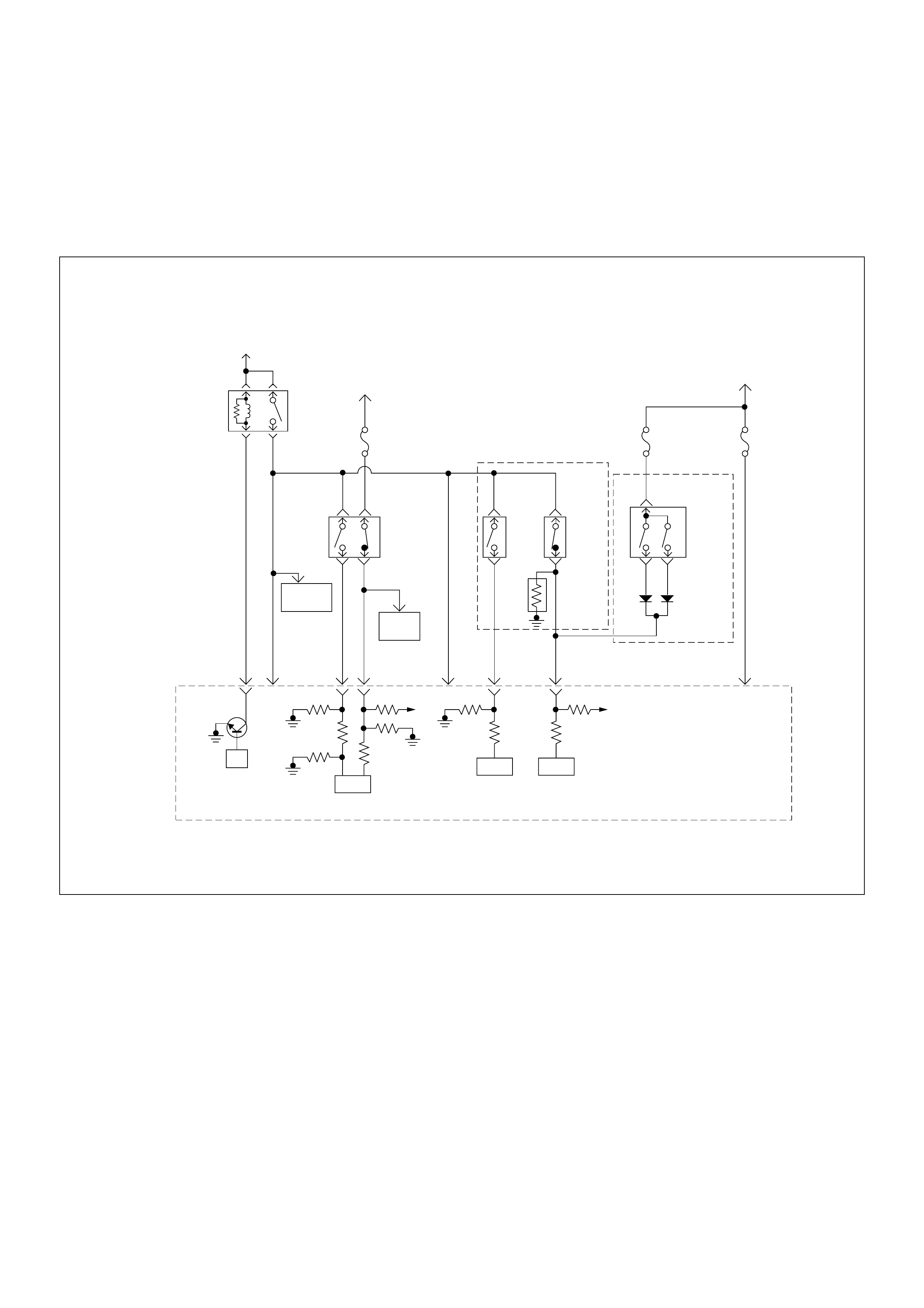
Diagnostic Trouble Code (DTC) P0703 (Symptom Code A)
(Flash Code 25) Brake Switch Malfunction
Diagnostic Trouble Code (DTC) P0703 (Symptom Code B)
(Flash Code 25) Brake Switch Malfunction
Battery
Voltage
Battery
Voltage
ECM
Main Relay
Stop
Light
10A
Injection
Pump Stop
Lamp
IC IC CPU
0.5
BLU/
BLK
58
2.0
BLU/
RED
0.5
BLU/
RED
3
0.5
WHT/
BLK
65
0.85
RED
0.85
RED
0.85
GRN
30
0.5
BLU/
RED
63
0.5
YEL
31
0.5
RED/
BLK
0.5
BLU/
RED
0.5
BLU/
RED
0.85
WHT
0.5
WHT/
RED
0.5
RED/
GRN
Clutch
SW
Resister
Neutral
SW
87
0.5
BLU/
YEL
39
Brake
SW
M/T A/T
Inhibitor
SW
Ignition
SW
Back,
Turn
15A Engine
15A
µP
NP
Engine
Control
Module
(ECM) Batt Batt

Condition for setting the DTC and action taken when the DTC sets
Circuit Desc rip tio n
The ECM monitors the brake switch signal on the feed
terminal to the ECM. If the brake switch 1 or 2 circuit
malfunctions, a DTC P0703 (Symptom Code A) or
P0703 (Symptom Code B) will be stored.
Diagnostic Aids
An intermittent may be caused by the following:
• Poor connections.
• Misrouted harness.
• Rubbed through wire insulation.
• Broken wire inside the insulation.
Check for the following conditions:
• Poor con nection at ECM-I nspect harnes s connectors
for backed out terminals, improper mating, broken
locks, improperly formed or damaged terminals, and
poor terminal to wire connection.
• Damaged harness-Inspect the wiring harness for
damage. If the harness appears to be OK, observe
the “Br ake Sw itch 1 ” and “B rake Switch 2” disp lay on
the Tech2 while moving connectors and wiring
harness related to the sensor.
Flash
Code Code Symptom
Code MIL DTC Name DTC Setting Condition F ail-Safe (Back Up)
25 P0703 A ON Brake Switch Malfunction 1. Throttle position is more
than 0%.
2. Engine speed is more than
665rpm
3. Vehicle speed is more than
0km/h.
4. Brake switch 1 signal and
brake switch 2 signal are
differently inputted to the
ECM since the ignition
switch was turned on.
No fail-safe function.
B ON Brake Switch Malfunction 1. Throttle position is more
than 0%.
2. Engine speed is more than
665rpm
3. Vehicle speed is more than
0km/h.
4. Brake switch 1 signal and
brake switch 2 signal are
differently inputted to the
ECM.
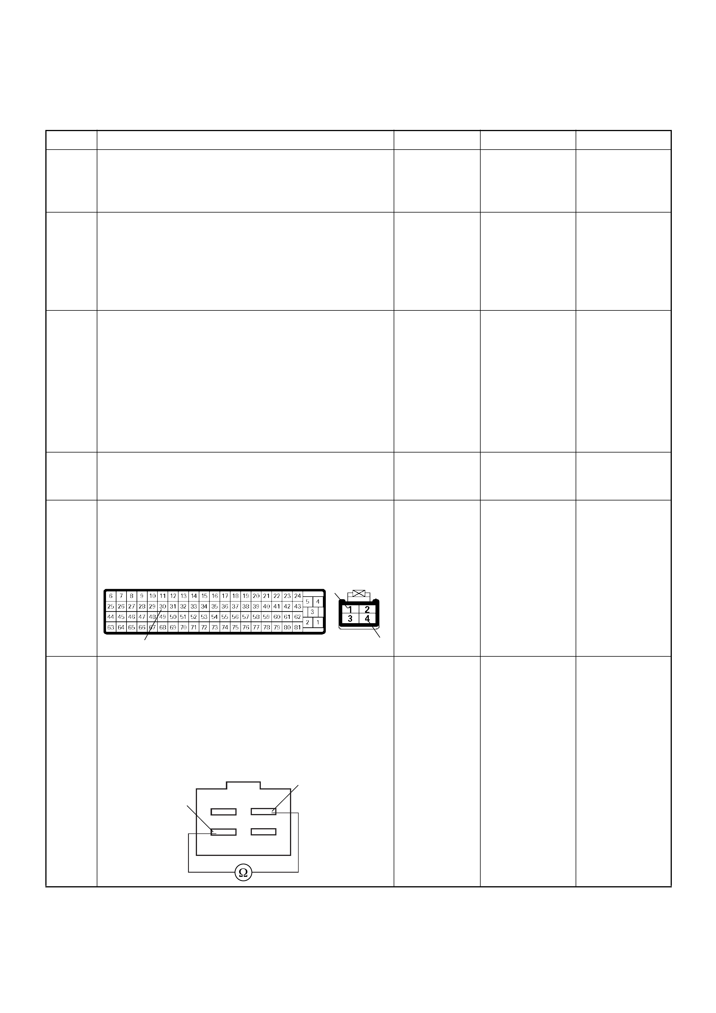
Diagnostic Trouble Code (DTC) P0703 (Symptom Code A) (Flash Code 25) Brake Switch Malfunction
Step Action Value(s) Yes No
1 Was the “On-Board Diagnostic (OBD) System Check”
performed?
—Go to Step 2
Go to On Board
Diagnostic
(OBD) System
Check
2 1. Connect the Tech 2.
2. Review and record the failure information.
3. Select “F0: Read DTC Infor As Stored By ECU” in
“F0: Diagnostic Trouble Codes”.
Is the DTC P0703 (Symptom Code A) stored as
“Present Failure”? — Go to Step 3
Refer to
Diagnostic Aids
and Go to Step
3
3 1. Using the Tech 2, ignition “On” and engine “Off”.
2. Select “F1: Clear DTC Information” in “F0:
Diagnostic Trouble Codes” with the Tech 2 and
clear the DTC information.
3. Operate the vehicle and monitor the “F0: Read
DTC Infor As Stored By ECU” in the “F0:
Diagnostic Trouble Codes”.
Was the DTC P0703 (Symptom Code A) stored in this
ignition cycle? — Go to Step 4
Refer to
Diagnostic Aids
and Go to Step
4
4 Check the “Stop Light fuse (10A)”.
If the fuse is burnt out, repair as necessary.
Was the problem found? — Verify repair Go to Step 5
5 Check for poor/faulty connection at the brake switch
or ECM connector . If a poor/faulty connection is found,
repair as necessary.
Was the problem found?
— Verify repair Go to Step 6
6 Using the DVM and check the brake switch 1.
1. Ignition “Off”, engine “Off”.
2. Remove the brake switch connector at the brake
pedal.
3. Check the brake switch 1.
Was the DVM indicated specified value?
Pedal is not
stepped on:
Continuity
Pedal stepped
on: No
continuity Go to Step 7
Replace pedal
switch and
verify repair
30
1
4
C-56 C-44
Brake Switch 1
4
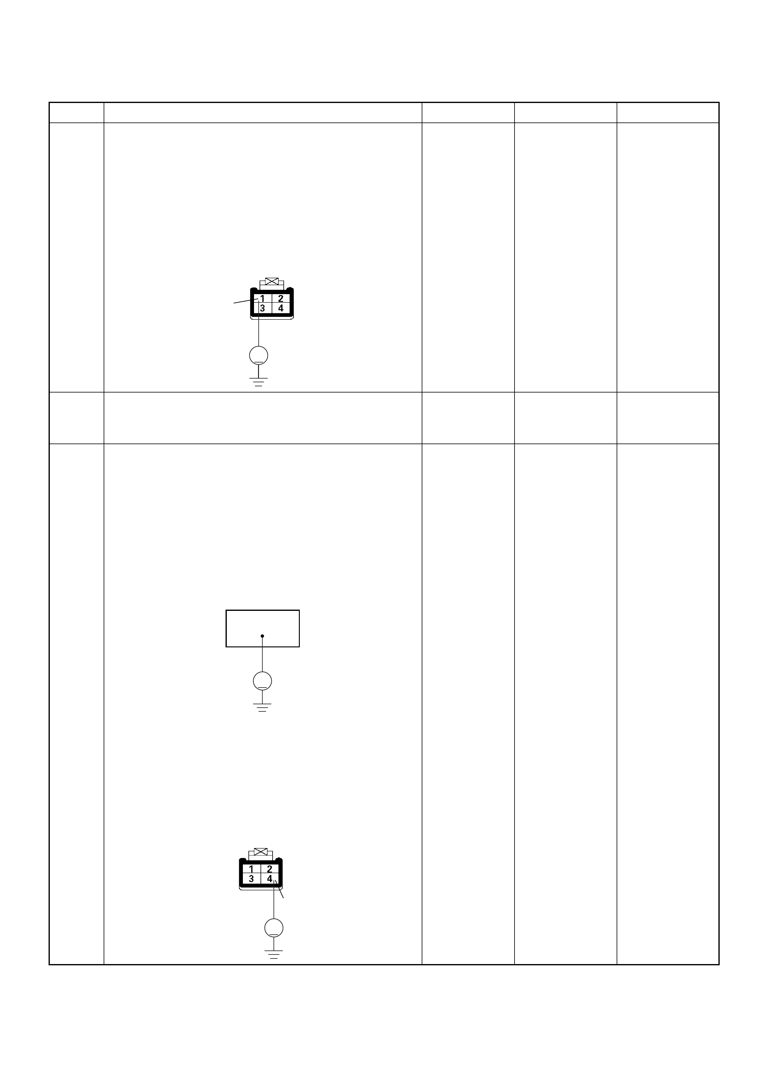
7 Using the DVM and check the brake switch 1 power
supply circuit.
1. Ignition “Off”, engine “Off”.
2. Remove the brake switch connector from the
brake switc h.
3. Check the circuit for open circuit.
Was the DVM indicated specified value?
Battery
voltage Go to Step 9 Go to Step 8
8 Repair the open circuit between the “Stop Light fuse
(10A)” and brake switch 1.
Is the action complete? — Verify repair —
9 Using the DVM and check the brake switch 1 circuit.
Breaker box is available:
1. Ignition “Off”, engine “Off”.
2. Install the breaker box as type B. (ECM
connected) Ref. Page 6E-81
3. Ignition “On”, engine “Off”.
4. Check the circuit for open or short to voltage
circuit.
Was the DVM indicated specified value?
Breaker box is not available:
1. Ignition “On”, engine “Off”.
2. Back probe the DVM to the brake switch 1 and
check the circuit for open or short to voltage
circuit.
Was the problem found?
Pedal is not
stepped on:
Less than 1V
Pedal stepped
on: Battery
voltage Go to Step 12
Fixed at battery
voltage: Go to
Step 10
Fixed at less
than 1V: Go to
Step 11
Step Action Value(s) Yes No
V
1
C-44
30
V
V
4
C-44

10 Repair the short to voltage circuit between the brake
switch 1 connector and ECM.
Is the action complete?
— Verify repair —
11 Repair the open circuit between the brake switch 1
connector and ECM.
Is the action complete?
— Verify repair —
12 Is the ECM programmed with the latest software
release?
If not, downlo ad the latest software to the ECM using
the “SPS (Service Programming System)”.
Was the problem solved? — Verify repair Go to Step 13
13 Replace the ECM.
Is the action complete?
IMPORTANT: The replacement ECM must be
programmed. Refer to section of the Service
Programming System (SPS) in this manual.
Foll owing ECM pr ogramming, the immobi liser system
(if equipped) must be linked to the ECM. Refer to
section 11 “Immobiliser System-ECM replacement” for
the ECM/Immobiliser linking procedure. — Verify repair —
Step Action Value(s) Yes No
30 4
C-56 C-44
30 4
C-56 C-44
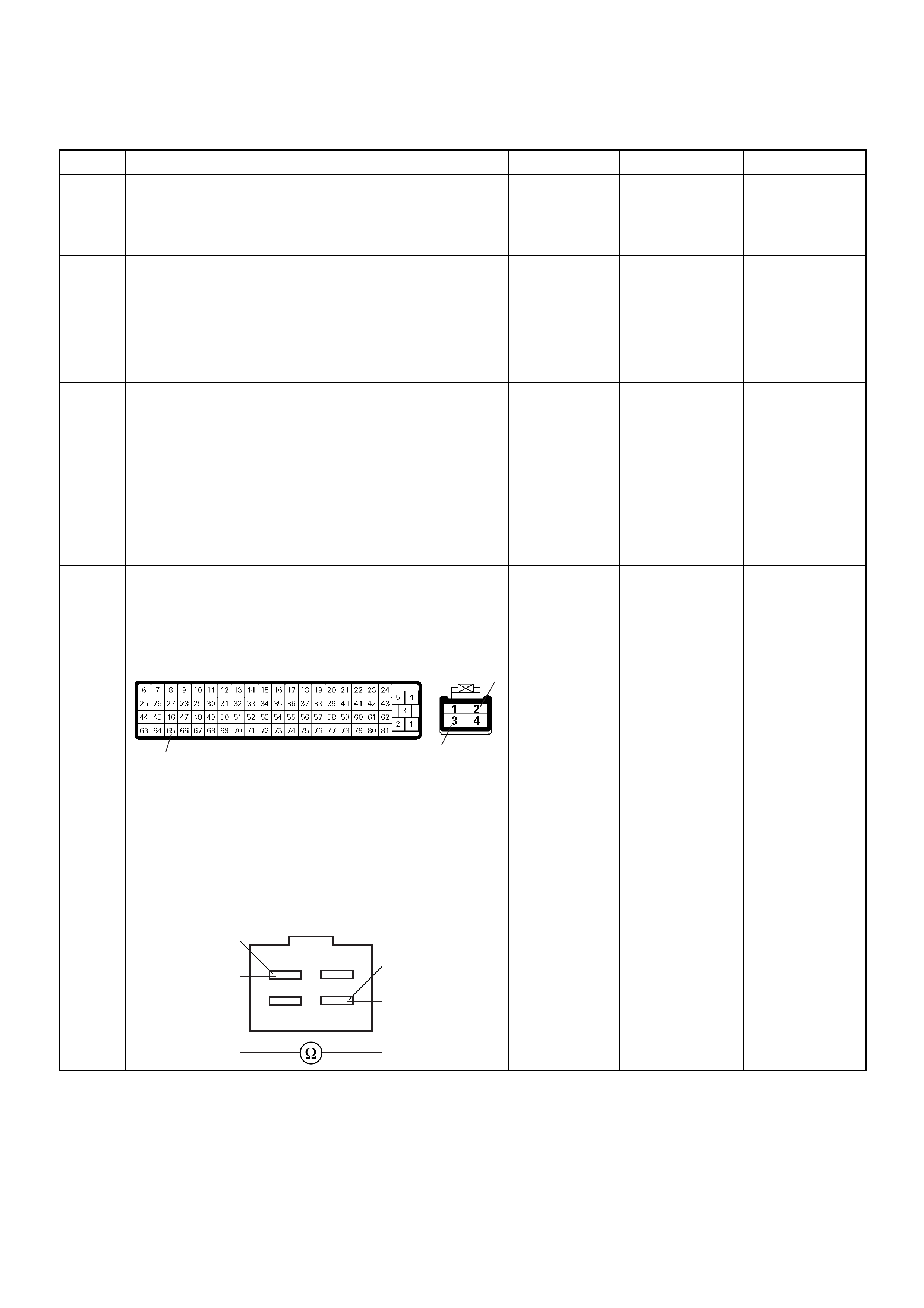
Diagnostic Trouble Code (DTC) P0703 (Symptom Code B) (Flash Code 25) Brake Switch Malfunction
Step Action Value(s) Yes No
1 Was the “On-Board Diagnostic (OBD) System Check”
performed?
—Go to Step 2
Go to On Board
Diagnostic
(OBD) System
Check
2 1. Connect the Tech 2.
2. Review and record the failure information.
3. Select “F0: Read DTC Infor As Stored By ECU” in
“F0: Diagnostic Trouble Codes”.
Is the DTC P0703 (Symptom Code B) stored as
“Present Failure”? — Go to Step 3
Refer to
Diagnostic Aids
and Go to Step
3
3 1. Using the Tech 2, ignition “On” and engine “Off”.
2. Select “F1: Clear DTC Information” in “F0:
Diagnostic Trouble Codes” with the Tech 2 and
clear the DTC information.
3. Operate the vehicle and monitor the “F0: Read
DTC Infor As Stored By ECU” in the “F0:
Diagnostic Trouble Codes”.
Was the DTC P0703 (Symptom Code B) stored in this
ignition cycle? — Go to Step 4
Refer to
Diagnostic Aids
and Go to Step
4
4 Check for poor/faulty connection at the brake switch
or ECM connector . If a poor/faulty connection is found,
repair as necessary.
Was the problem found?
— Verify repair Go to Step 5
5 Using the DVM and check the brake switch 2.
1. Ignition “Off”, engine “Off”.
2. Remove the brake switch connector at the brake
pedal.
3. Check the brake switch 2.
Was the DVM indicated specified value?
Pedal is not
stepped on:
No continuity
Pedal stepped
on: Continuity Go to Step 6
Replace pedal
switch and
verify repair
65
3
2
C-56 C-44
Brake Switch
3
2
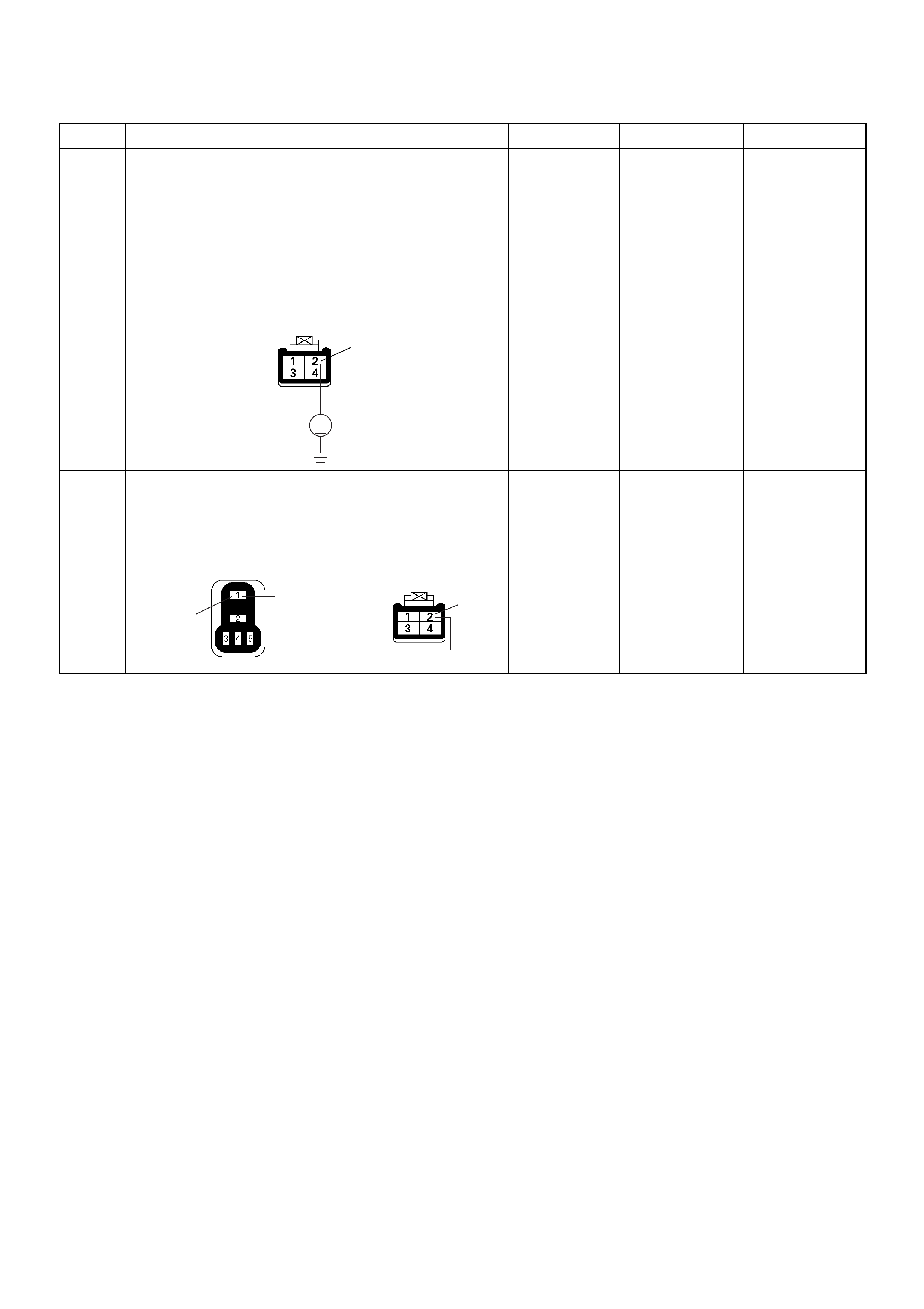
6 Using the DVM and check the brake switch 2 power
supply circuit.
1. Ignition “On”, engine “Off”.
2. Remove the brake switch connector from the
brake switc h.
3. Check the circuit for open circuit.
Was the DVM indicated specified value?
Battery
voltage Go to Step 8 Go to Step 7
7 Repair the open circuit between the “ECM Main
Relay” and brake switch 2.
Is the action complete?
— Verify repair —
Step Action Value(s) Yes No
V
2
C-44
2
1
C-44X-4
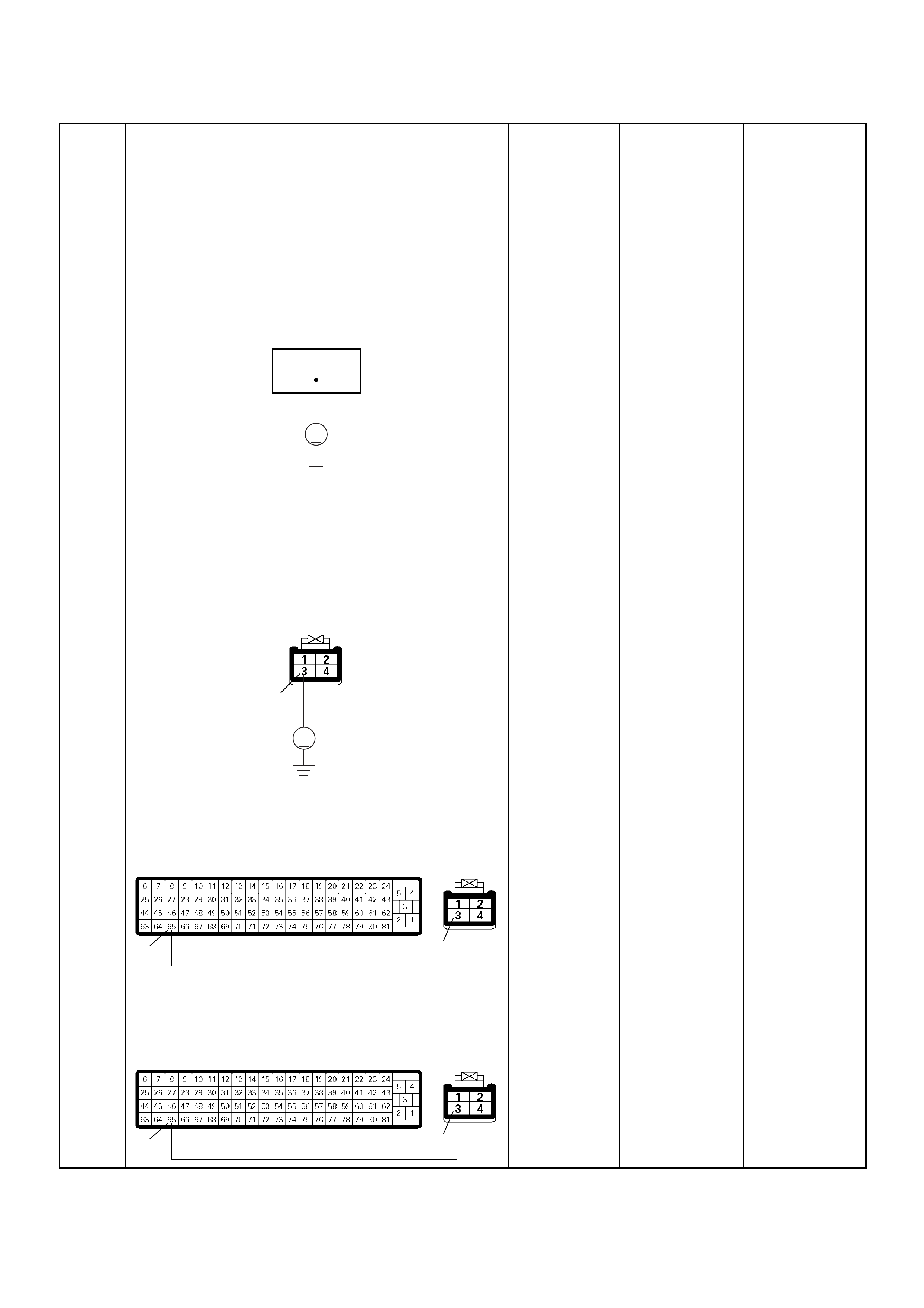
8 Using the DVM and check the brake switch 2 circuit.
Breaker box is available:
1. Ignition “Off”, engine “Off”.
2. Install the breaker box as type B. (ECM
connected)
3. Ignition “On”, engine “Off”.
4. Check the circuit for open or short to voltage
circuit.
Was the DVM indicated specified value?
Breaker box is not available:
1. Ignition “On”, engine “Off”.
2. Back probe the DVM to the brake switch 2 and
check the circuit for open or short to voltage
circuit.
Was the problem found?
Pedal is not
stepped on:
Battery
voltage
Pedal stepped
on: Less than
1V Go to Step 11
Fixed at battery
voltage: Go to
Step 9
Fixed at less
than 1V: Go to
Step 10
9 Repair the short to voltage circuit between the brake
switch 2 connector and ECM.
Is the action complete?
— Verify repair —
10 Repair the open circuit between the brake switch 2
connector and ECM.
Is the action complete?
— Verify repair —
Step Action Value(s) Yes No
65
V
V
3
C-44
65 3
C-56 C-44
65 3
C-56 C-44

11 Is the ECM programmed with the latest software
release?
If not, downlo ad the latest software to the ECM using
the “SPS (Service Programming System)”.
Was the problem solved? — Verify repair Go to Step 12
12 Replace the ECM.
Is the action complete?
IMPORTANT: The replacement ECM must be
programmed. Refer to section of the Service
Programming System (SPS) in this manual.
Foll owing ECM pr ogramming, the immobi liser system
(if equipped) must be linked to the ECM. Refer to
section 11 “Immobiliser System-ECM replacement” for
the ECM/Immobiliser linking procedure. — Verify repair —
Step Action Value(s) Yes No
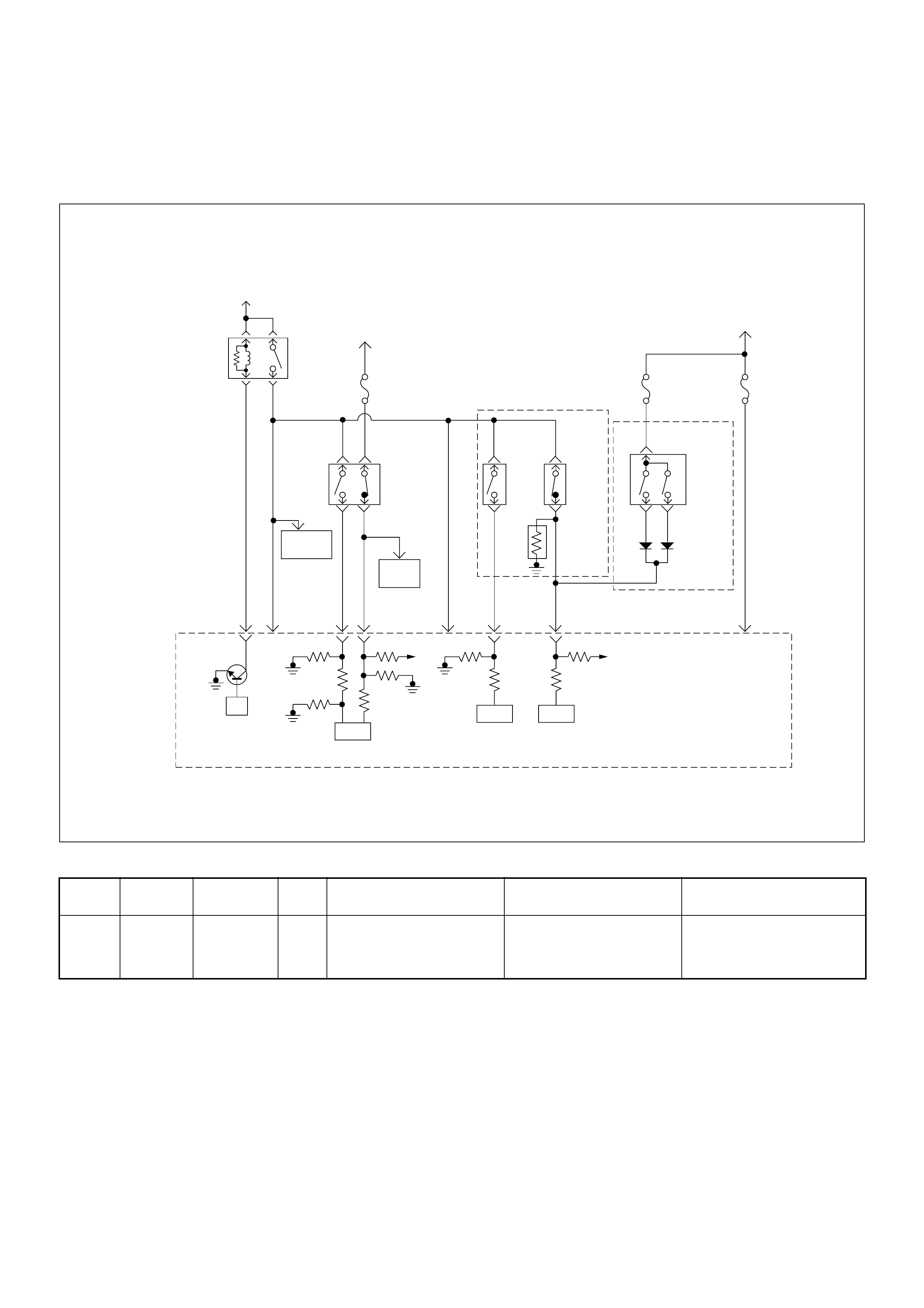
Diagnostic Trouble Code (DTC) P0704 (Symptom Code 6)
(Flash Code 57) Clutch Switch Circuit Malf unc tion
Condition for setting the DTC and action taken when the DTC sets
Circuit Desc rip tio n
The ECM monitors the clutch switch signal on the feed
terminal to the ECM. If the clutch switch circuit with
malfunctions, a DTC P0704 (Symptom Code 6) will be
stored.
Diagnostic Aids
An intermittent may be caused by the following:
• Poor connections.
• Misrouted harness.
• Rubbed through wire insulation.
• Broken wire inside the insulation.
Check for the following conditions:
• Poor con nection at ECM-I nspect harnes s connectors
for backed out terminals, improper mating, broken
locks, improperly formed or damaged terminals, and
poor terminal to wire connection.
• Damaged harness-Inspect the wiring harness for
damage. If the harness appears to be OK, observe
the “Clutch Switch” display on the Tech2 while
moving connectors and wiring harness related to the
sensor.
Flash
Code Code Symptom
Code MIL DTC Name DTC Setting Condition F ail-Safe (Back Up)
57 P0704 6 ON Clutch Switch Circuit
Malfunction Clutch signal does not change
between vehicle speed
1.5km/h and 80km/h since
ignition switch was tuned on.
No fail-safe function.
Battery
Voltage
Battery
Voltage
ECM
Main Relay
Stop
Light
10A
Injection
Pump Stop
Lamp
IC IC CPU
0.5
BLU/
BLK
58
2.0
BLU/
RED
0.5
BLU/
RED
3
0.5
WHT/
BLK
65
0.85
RED
0.85
RED
0.85
GRN
30
0.5
BLU/
RED
63
0.5
YEL
31
0.5
RED/
BLK
0.5
BLU/
RED
0.5
BLU/
RED
0.85
WHT
0.5
WHT/
RED
0.5
RED/
GRN
Clutch
SW
Resister
Neutral
SW
87
0.5
BLU/
YEL
39
Brake
SW
M/T A/T
Inhibitor
SW
Ignition
SW
Back,
Turn
15A Engine
15A
µP
NP
Engine
Control
Module
(ECM) Batt Batt
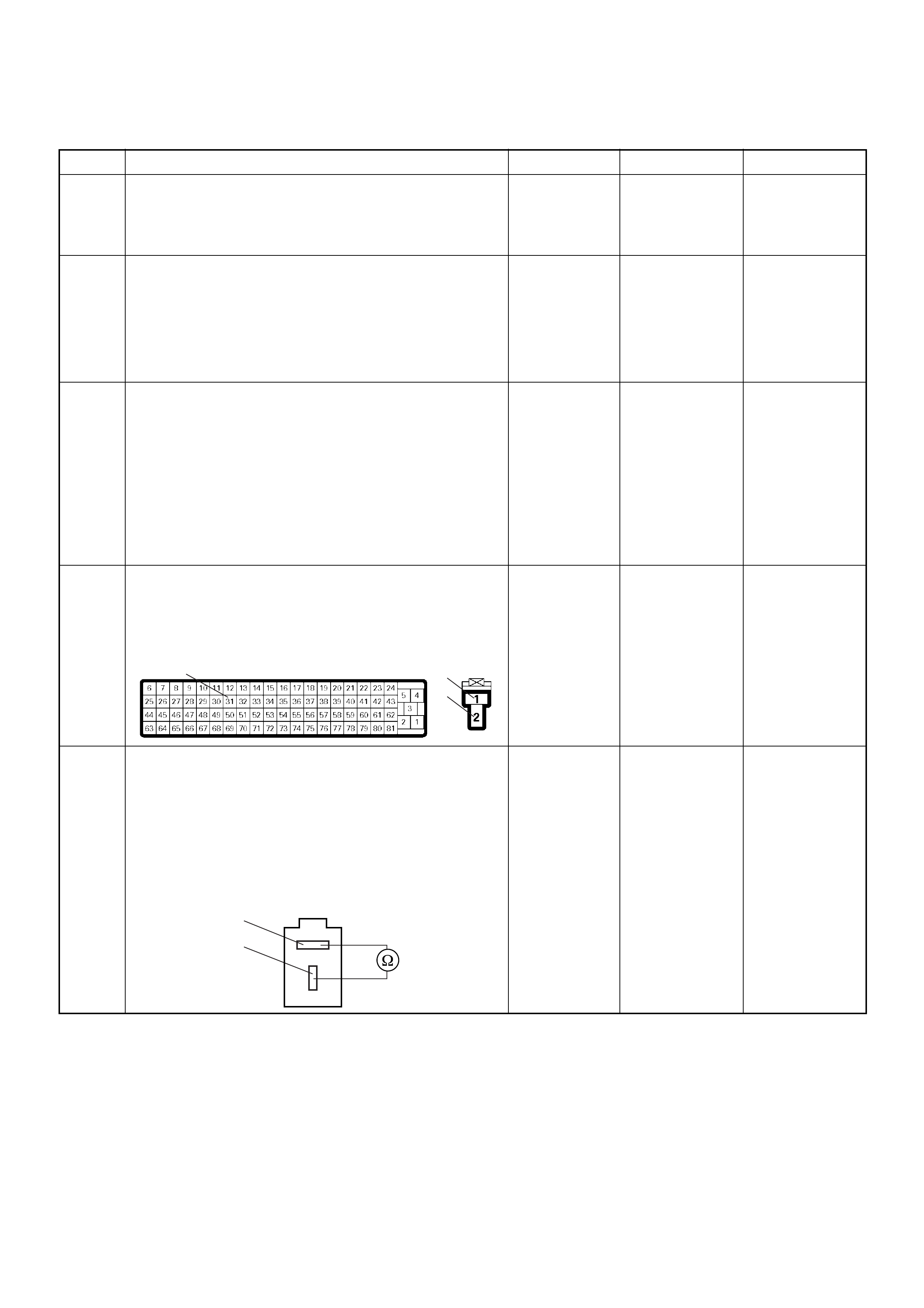
Diagnostic Trouble Code (DTC) P0704 (Symptom Code 6) (Flash Code 57) Clutch Switch Circuit Malfunction
Step Action Value(s) Yes No
1 Was the “On-Board Diagnostic (OBD) System Check”
performed?
—Go to Step 2
Go to On Board
Diagnostic
(OBD) System
Check
2 1. Connect the Tech 2.
2. Review and record the failure information.
3. Select “F0: Read DTC Infor As Stored By ECU” in
“F0: Diagnostic Trouble Codes”.
Is the DTC P0704 (Symptom Code 6) stored as
“Present Failure”? — Go to Step 3
Refer to
Diagnostic Aids
and Go to Step
3
3 1. Using the Tech 2, ignition “On” and engine “Off”.
2. Select “F1: Clear DTC Information” in “F0:
Diagnostic Trouble Codes” with the Tech 2 and
clear the DTC information.
3. Operate the vehicle and monitor the “F0: Read
DTC Infor As Stored By ECU” in the “F0:
Diagnostic Trouble Codes”.
Was the DTC P0704 (Symptom Code 6) stored in this
ignition cycle? — Go to Step 4
Refer to
Diagnostic Aids
and Go to Step
4
4 Check for poor/faulty connection at the clutch switch
or ECM connector . If a poor/faulty connection is found,
repair as necessary.
Was the problem found?
— Verify repair Go to Step 5
5 Using the DVM and check the clutch switch.
1. Ignition “Off”, engine “Off”.
2. Remove the clutch switch connector at the clutch
pedal.
3. Check the clutch switch.
Was the DVM indicated specified value?
Pedal is not
stepped on:
Continuity
Pedal stepped
on: No
continuity Go to Step 6
Replace pedal
switch and
verify repair
31
1
2
C-56 C-53
Clutch Switch
1
2
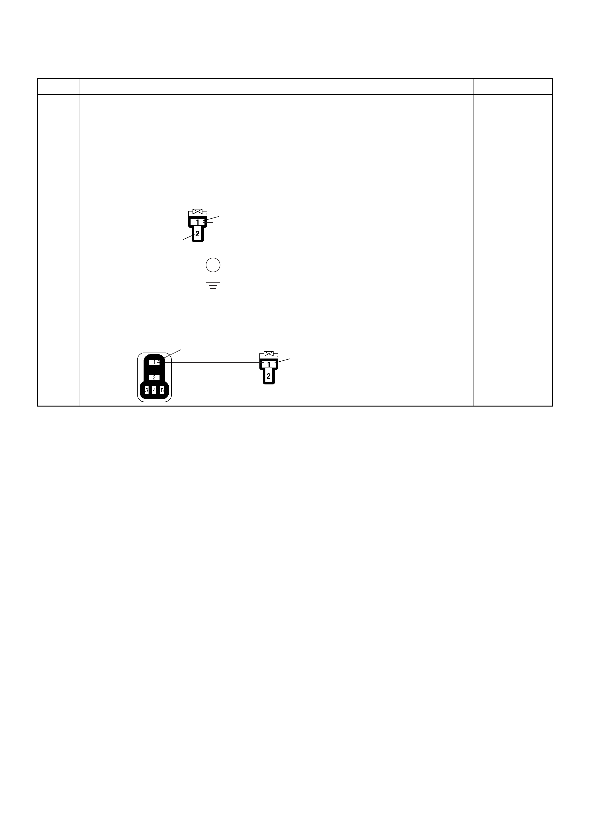
6 Using the DVM and check the clutch switch power
supply circuit.
1. Ignition “On”, engine “Off”.
2. Remove the clutch switch connector from the
clutch switch.
3. Check the circuit for open circuit.
Was the DVM indicated specified value?
Battery
voltage Go to Step 8 Go to Step 7
7 Repair the open circuit between the “ECM Main
Relay” and clutch switch.
Is the action complete?
— Verify repair —
Step Action Value(s) Yes No
V
1
2
C-53
1
1
X-4 C-53

8 Using the DVM and check the clutch switch circuit.
Breaker box is available:
1. Ignition “Off”, engine “Off”.
2. Install the breaker box as type B. (ECM
connected) Ref. Page 6E-81
3. Ignition “On”, engine “Off”.
4. Check the circuit for open or short to voltage
circuit.
Was the DVM indicated specified value?
Breaker box is not available:
1. Ignition “On”, engine “Off”.
2. Back probe the DVM to the clutch switch and
check the circuit for open or short to voltage
circuit.
Was the problem found?
Pedal is not
stepped on:
Battery
voltage
Pedal stepped
on: Less than
1V Go to Step 11
Fixed at battery
voltage: Go to
Step 9
Fixed at less
than 1V: Go to
Step 10
9 Repair the short to voltage circuit between the clutch
switch connector and ECM.
Is the action complete?
— Verify repair —
10 Repair the open circuit between the clutch switch
connector and ECM.
Is the action complete?
— Verify repair —
Step Action Value(s) Yes No
31
V
V
2
C-53
31 2
C-56 C-53
31 2
C-56 C-53

11 Is the ECM programmed with the latest software
release?
If not, downlo ad the latest software to the ECM using
the “SPS (Service Programming System)”.
Was the problem solved? — Verify repair Go to Step 12
12 Replace the ECM.
Is the action complete?
IMPORTANT: The replacement ECM must be
programmed. Refer to section of the Service
Programming System (SPS) in this manual.
Foll owing ECM pr ogramming, the immobi liser system
(if equipped) must be linked to the ECM. Refer to
section 11 “Immobiliser System-ECM replacement” for
the ECM/Immobiliser linking procedure. — Verify repair —
Step Action Value(s) Yes No

Diagnostic Trouble Code (DTC) P1105 (Symptom Code 1)
(Flash Code 86) Barometric Pressure Sensor Circuit High Input
Diagnostic Trouble Code (DTC) P1105 (Symptom Code 2)
(Flash Code 86) Barometric Pressure Sensor Circuit Low Input
Condition for setting the DTC and action taken when the DTC sets
Circuit Description
The ECM monitors the barometric pressure signal
internally. If the sensor malfunctions , a DTC P1105
(Symptom Code 1) or P1105 (Symptom Code 2) will be
stored.
Diagnostic Aids
If the DTC P1105 is stored, sensor or circuit of ECM
inside is failed.
Diagnostic Trouble Code (DTC) P1105 (Symptom Code 1) (Flash Code 86)
Barometric Pressure Sensor Circuit High Input
Diagnostic Trouble Code (DTC) P1105 (Symptom Code 2) (Flash Code 86)
Barometric Pressure Sensor Circuit Low Input
Flash
Code Code Symptom
Code MIL DTC Name DTC Setting Condition Fail-Safe (Back Up)
86 P1105 1 ON Barometric Pressure Sensor
Circuit High InputBarometric pressure sensor
output voltage is more than
4.4V.
ECM uses 1013hpa condition
as substitute.
2 ON Barometric Pressure Sensor
Circuit Low Input Barometric pressure sensor
output voltage is below 1.5V.
Step Action Value(s) Yes No
1 Was the “On-Board Diagnostic (OBD) System Check”
performed?
—Go to
Step 2
Go to
On Board
Diagnostic
(OBD) System
Check
2 1. Connect the Tech 2.
2. Review and record the failure information.
3. Select “F0: Read DTC Infor As Stored By ECU” in “F0:
Diagnostic Trouble Codes”.
Is the DTC P1105 (Symptom Code 1) or P1105 (Symptom
Code 2) stored as “Present Failure”? — Go to
Step 3
Refer to
Diagnostic Aids
and Go to
Step 3
3 1. Using the Tech 2, ignition “On” and engine “Off”.
2. Select “F1: Clear DTC Information” in “F0: Diagnostic
Trouble Codes” with the Tech 2 and clear the DTC
information.
3. Operate the vehicle and monitor the “F0: Read DTC
Infor As Stored By ECU” in the “F0: Diagnostic Trouble
Codes”.
Was the DTC P1105 (Symptom Code 1) or P1105
(Symptom Code 2) stored in this ignition cycle? — Go to
Step 4
Refer to
Diagnostic Aids
4 Is the ECM programmed with the latest software release?
If not, download the latest software to the ECM using the
“SPS (Service Programming System)”.
Was the problem solved? — Verify repair Go to
Step 5
5 Replace the ECM.
Is the action com ple te?
IMPORTANT: The replacement ECM must be programmed.
Refer to section of the Service Programming System (SPS)
in this manual .
Following ECM programming, the immobiliser system (if
equipped) must be linked to the ECM. Refer to section 11
“Immobiliser System-ECM replacement” for the ECM/
Immobiliser linking procedure. — Verif y repai r —
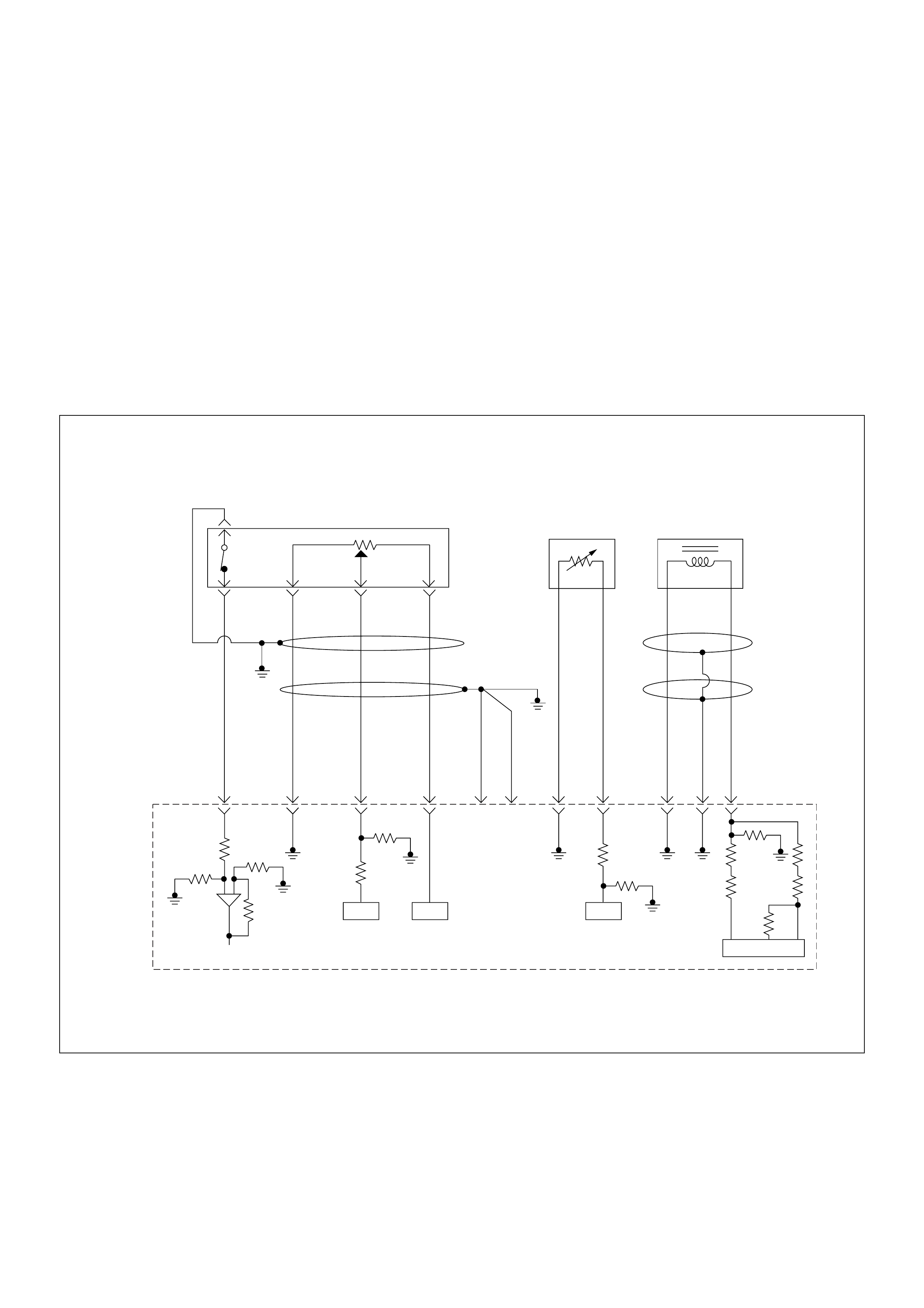
Diagnostic Trouble Code (DTC) P1120 (Symptom Code 1) (Flash Code 21)
Pedal/throttle Position Sensor Circuit High Input
Diagnostic Trouble Code (DTC) P1120 (Symptom Code 7) (Flash Code 21)
Pedal/throttle Position Sensor Voltage Supply Circuit High Input
Diagnostic Trouble Code (DTC) P1120 (Symptom Code 9) (Flash Code 21)
Pedal/throttle Position Sensor Voltage Supply Circuit Low Input
Diagnostic Trouble Code (DTC) P1120 (Symptom Code D) (Flash Code 21)
Pedal/throttle Position Sensor Brake Switch Err or
Diagnostic Trouble Code (DTC) P1120 (Symptom Code E) (Flash Code 21)
Peda l/throttle Position Sensor Idle Position Switch Error
0.5
BLK
0.5
GRN/
BLK
69
0.5
RED/
GRN
49
0.5
GRN/
ORG
38
0.5
BLK/
GRN
57
2.0
BLK
1
2.0
BLK
2
0.5
BLK/
PNK
93
0.5
GRY
ECT
Sensor
TPS &
Idle SW
89
0.5
WHT
98 101
0.5
GRN/
RED
CKP
Sensor
90
ICIC IC
IC
Engine
Control
Module
(ECM)

Condition for setting the DTC and action taken when the DTC sets
Circuit Desc rip tio n
The TPS is a potentiometer connected to the
acceler ator pedal . It is ins talled to the acce lerat or pe dal
bracket inside the cab. It consists of the vatiable
potntiometer and an idle position switch.
The engine control module (ECM) monitors the voltage
on the signal line and calculates throttle position. As the
accelerator pedal moved toward the floor. the output
increases so that the output voltage should be high
when the pedal is at full travel.
The ECM monitors the TPS supply voltage and TPS
output vo ltage. The supply vo ltage is out of range, DTC
P1120 (Sym ptom Cod e 7) or P 0100 (Sy mptom Code 9)
will be stored. The output voltage excessively high, DTC
P1120 (Symptom Code 1) will be stored.
If the brake pedal is depressed during accelerator pedal
is depressing, DTC P1120 (Symptom Code D) will be
stored.
If the relation of idle switch and TPS position are
incorrect, DTC P1120 (Symptom Code E) will be stored.
Diagnostic Aids
An intermittent may be caused by the following:
• Poor connections.
• Misrouted harness.
• Rubbed through wire insulation.
• Broken wire inside the insulation.
Check for the following conditions:
• Poor con nection at ECM-I nspect harnes s connectors
for backed out terminals, improper mating, broken
locks, improperly formed or damaged terminals, and
poor terminal to wire connection.
• Damaged harness-Inspect the wiring harness for
damage. If the harness appears to be OK, observe
the “Thrott le Po si ti on”, “I dle Switch”, “ Brak e Swi tc h 1”
and “Brake Switch 2” display on the Tech2 while
moving connectors and wiring harness related to the
sensor.
Flash
Code Code Symptom
Code MIL DTC Name DTC Setting Condition F ail-Safe (Back Up)
21 P1120 1 ON Pedal/Throttle Position
Sensor Circuit High Input Throttle position sensor
output voltage is more than
4.5V.
ECM increases idle speed up
to 1400rpm.
7 ON Pedal/Throttle Position
Sensor V oltage Supply Circuit
High Input
Throttle position sensor
power supply voltage is more
than 5.2V.
9 ON Pedal/Throttle Position
Sensor V oltage Supply Circuit
Low Input
Throttle position sensor
power supply voltage is below
4.6V.
D ON Pedal/Throttle Position
Sensor Brake Switch Error 1. Engine speed is more than
1700rpm.
2. Throttle position sensor is
more than 8.7%.
3. When brake pedal is
depressed during
accelerator pedal is
depressing.
E ON Pedal/Throttle Position
Sensor Idle Position Switch
Error
1. When idle switch is turned
off, throttle position sensor
was below 0.35%.
or
2. When idle switch is tuned
on, throttle position sensor
was more than 7.8%.

Diagnostic Trouble Code (DTC) P1120 (Symptom Code 1) (Flash Code 21)
Pedal/Throttle Position Sensor Circuit High Input
Step Action Value(s) Yes No
1 Was the “On-Board Diagnostic (OBD) System Check”
performed?
—Go to Step 2
Go to On Board
Diagnostic
(OBD) System
Check
2 1. Connect the Tech 2.
2. Review and record the failure information.
3. Select “F0: Read DTC Infor As Stored By ECU” in
“F0: Diagnostic Trouble Codes”.
Is the DTC P1120 (Symptom Code 1) stored as
“Present Failure”? — Go to Step 3
Refer to
Diagnostic Aids
and Go to Step
3
3 1. Using the Tech 2, ignition “On” and engine “Off”.
2. Select “F1: Clear DTC Information” in “F0:
Diagnostic Trouble Codes” with the Tech 2 and
clear the DTC information.
3. Operate the vehicle and monitor the “F0: Read
DTC Infor As Stored By ECU” in the “F0:
Diagnostic Trouble Codes”.
Was the DT C P1120 (Sym ptom Cod e 1) stor ed in th is
ignition cycle? — Go to Step 4
Refer to
Diagnostic Aids
and Go to Step
4
4 Check for poor/faulty connection at the TPS or ECM
connector. If a poor/faulty connection is found, repair
as necessary.
Was the problem found?
— Verify repair Go to Step 5
5 Vis ual ly chec k the TPS .
Was the problem found? — Go to Step 12 Go to Step 6
49 39
57
2 31
C-56
4JA1-TC C-93
4JH1-TC
E-7
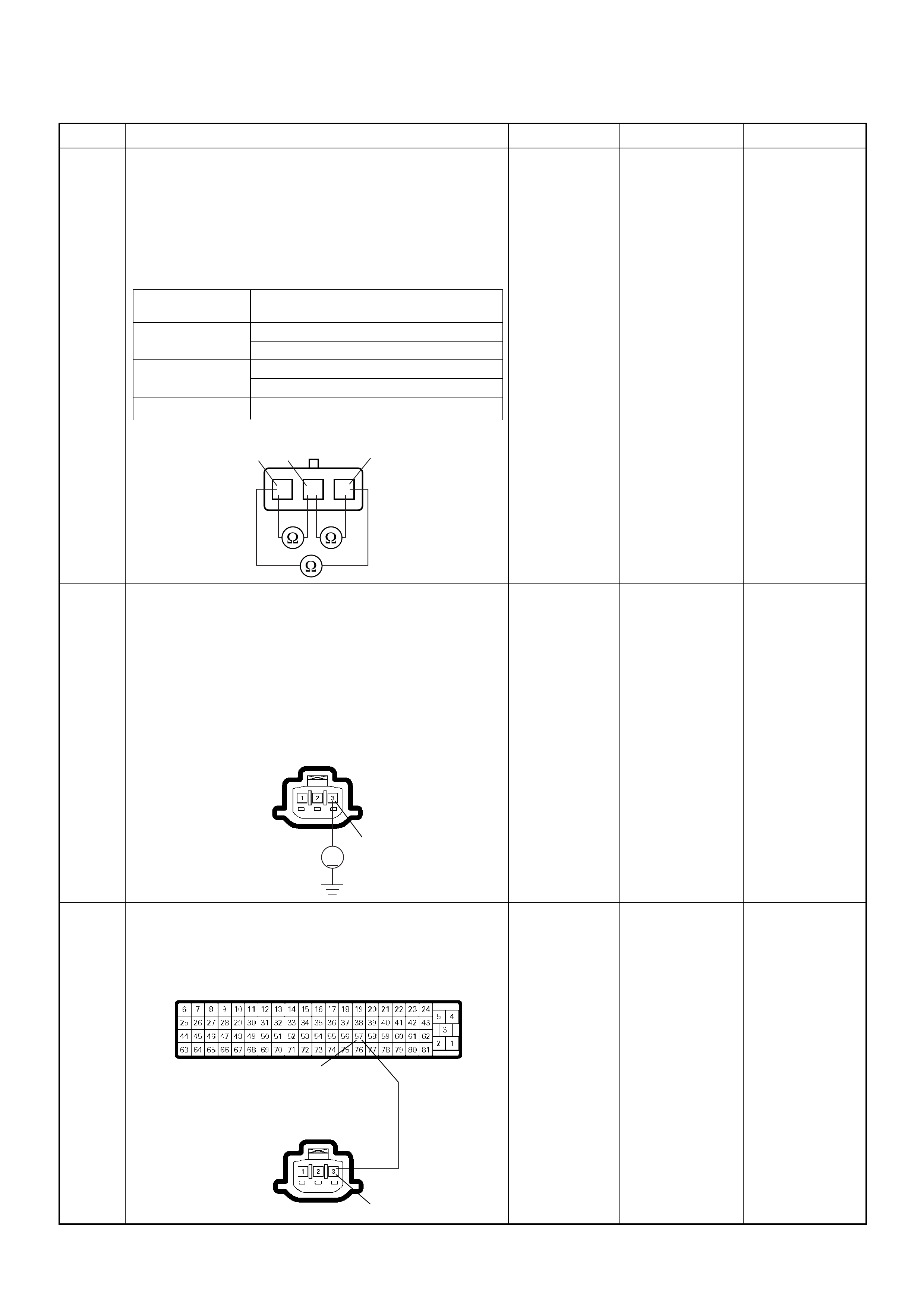
6 Using the DVM and check the TPS.
1. Ignition “Off”, engine “Off”.
2. Disconnect TPS connector.
3. Measure the resistance of TPS.
Does the tester indicate standard resistance as shown
in the following table?
Standard
resistance Go to Step 7 Go to Step 12
7 Using the DVM and check the TPS power supply
circuit.
1. Ignition “On”, engine “Off”.
2. Disconnect the TPS connector.
3. Check the circuit for short to voltage circuit.
Was the DVM indicated specified value?
Approximately
5.0V Go to Step 9 Go to Step 8
8 Repair the short to voltage circuit between the ECM
and TPS.
Was the problem solved?
— Verify repair Go to Step 14
Step Action Value(s) Yes No
Measurement
Terminal Resistance (Ω)
1 - 2 Approximately 0.5kΩ at idle position
Approximately 4.0kΩ at WOT
2 - 3 Approximately 4.3kΩ at idle position
Approximately 0.8kΩ at WOT
1 - 3 Approximately 4.6kΩ at idle position &
WOT
TPS
123
1
2
3
V
3
4JA1-TC C-93
4JH1-TC
E-7
57
3
C-56
4JA1-TC C-93
4JH1-TC
E-7
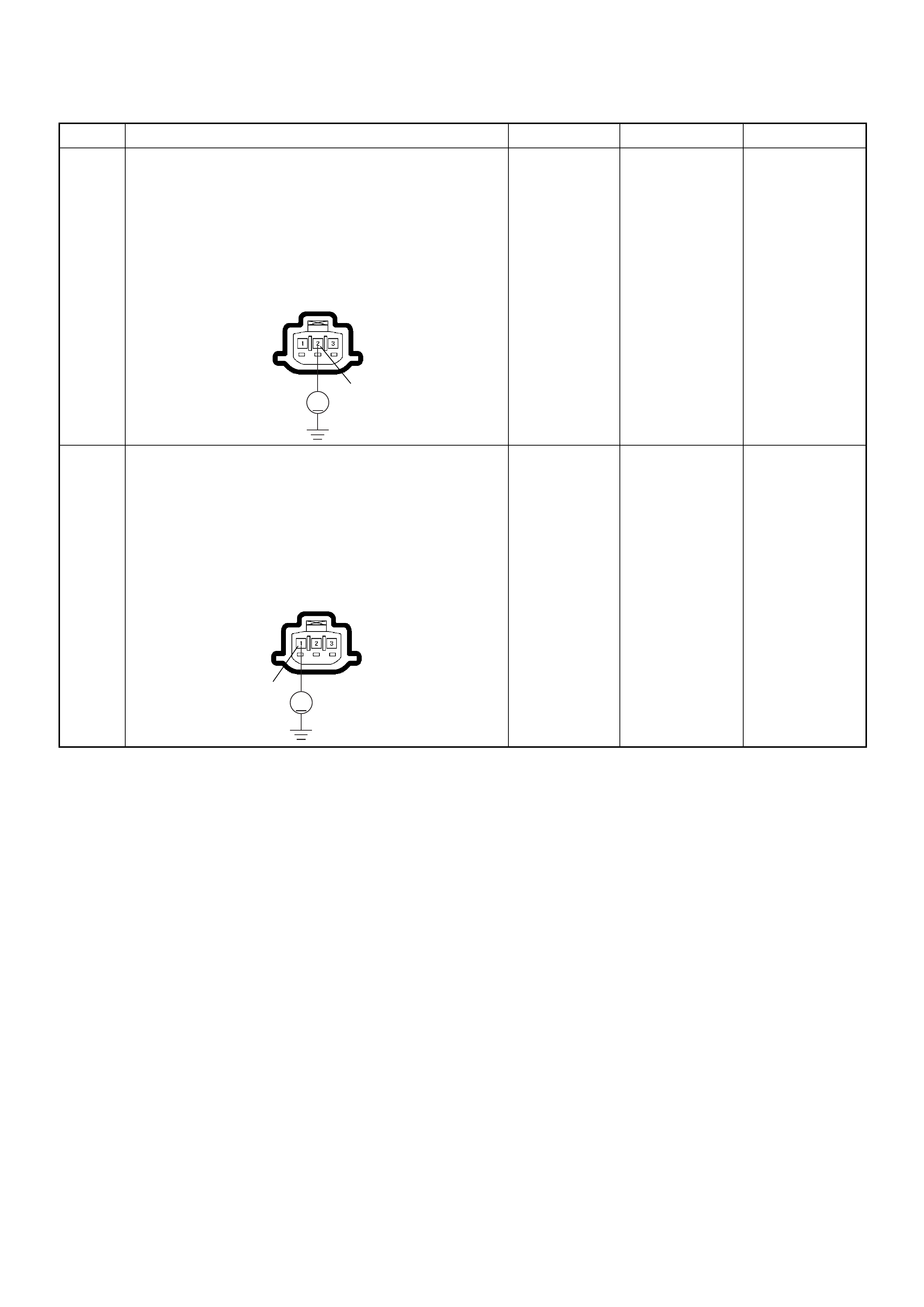
9 Using the DVM and check the TPS signal circuit.
1. Ignition “On”, engine “Off”.
2. Disconnect the TPS connector.
3. Check the circuit for short to power supply circuit.
Was the DVM indicated specified value?
Less than 1V Go to Step 10
Repair faulty
harness and
verify repair
10 Using the DVM and check the TPS ground circuit.
1. Ignition “On”, engine “Off”.
2. Disconnect the TPS connector .
3. Check the circuit for short to power supply circuit.
Was the DVM indicated specified value?
Less than 1V Go to Step 11
Repair faulty
harness and
verify repair
Step Action Value(s) Yes No
V
2
4JA1-TC C-93
4JH1-TC
E-7
V
1
4JA1-TC C-93
4JH1-TC
E-7
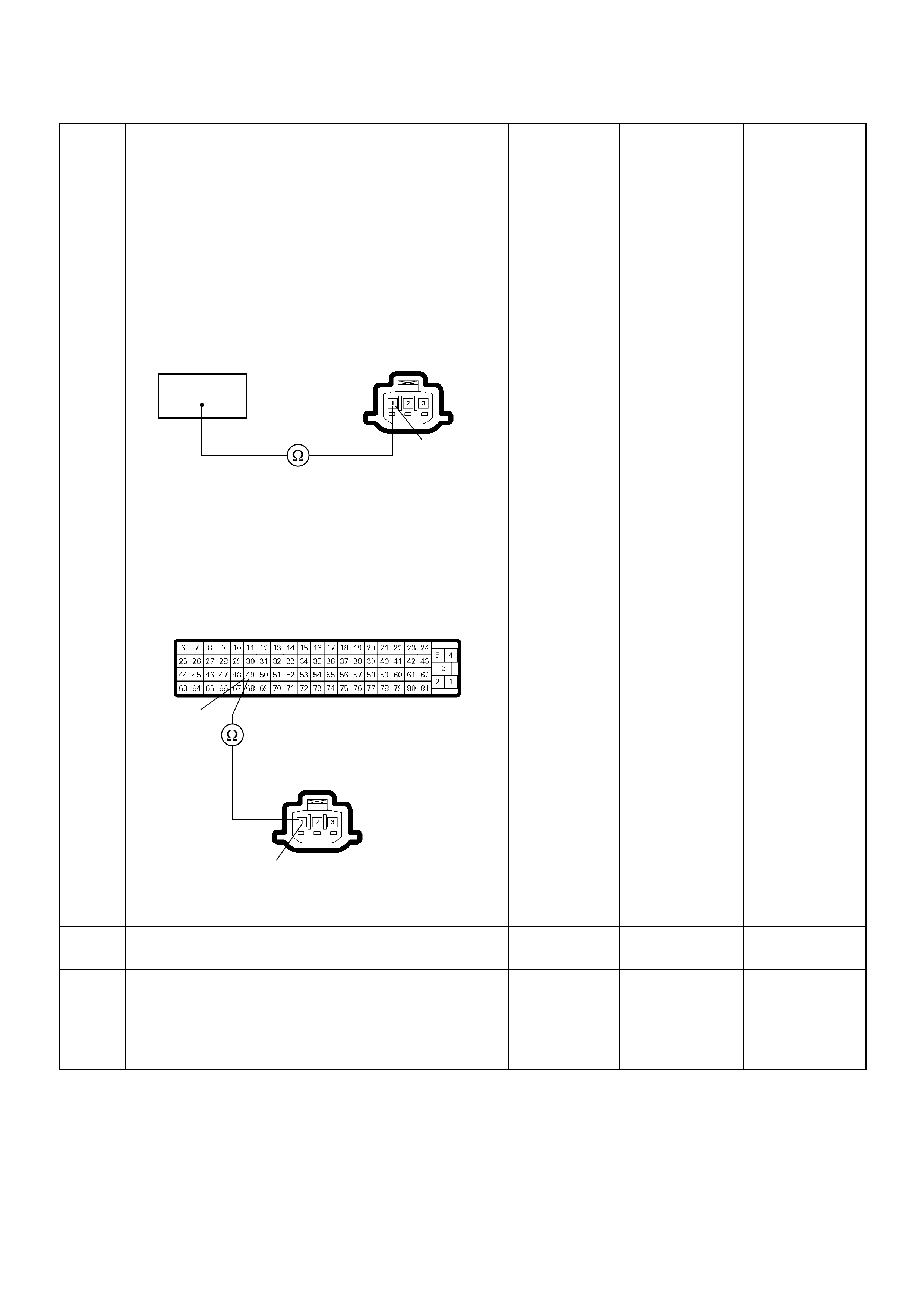
11 Using the DVM and check the TPS ground circuit.
Breaker box is available:
1. Ignition “Off”, engine “Off”.
2. Install the breaker box as type A. (ECM
disconnected) Ref. Page 6E-81
3. Disconnect the TPS connector.
4. Check the circuit for open circuit.
Was the problem found?
Breaker box is not available:
1. Ignition “Off”, engine “Off”.
2. Disconnect the TPS connector and ECM
connector.
3. Check the circuit for open circuit.
Was the problem found?
—
Repair faulty
harnes s and
verify repair Go to Step 14
12 Substitute a known good TPS and recheck.
Was the problem solved? — Go to Step 13 Go to Step 14
13 Replace the TPS.
Is the action complete? — Verify repair —
14 Is the ECM programmed with the latest software
release?
If not, downlo ad the latest software to the ECM using
the “SPS (Service Programming System)”.
Was the problem solved? — Verify repair Go to Step 14
Step Action Value(s) Yes No
49
1
4JA1-TC C-93
4JH1-TC
E-7
49
1
C-56
4JA1-TC C-93
4JH1-TC
E-7
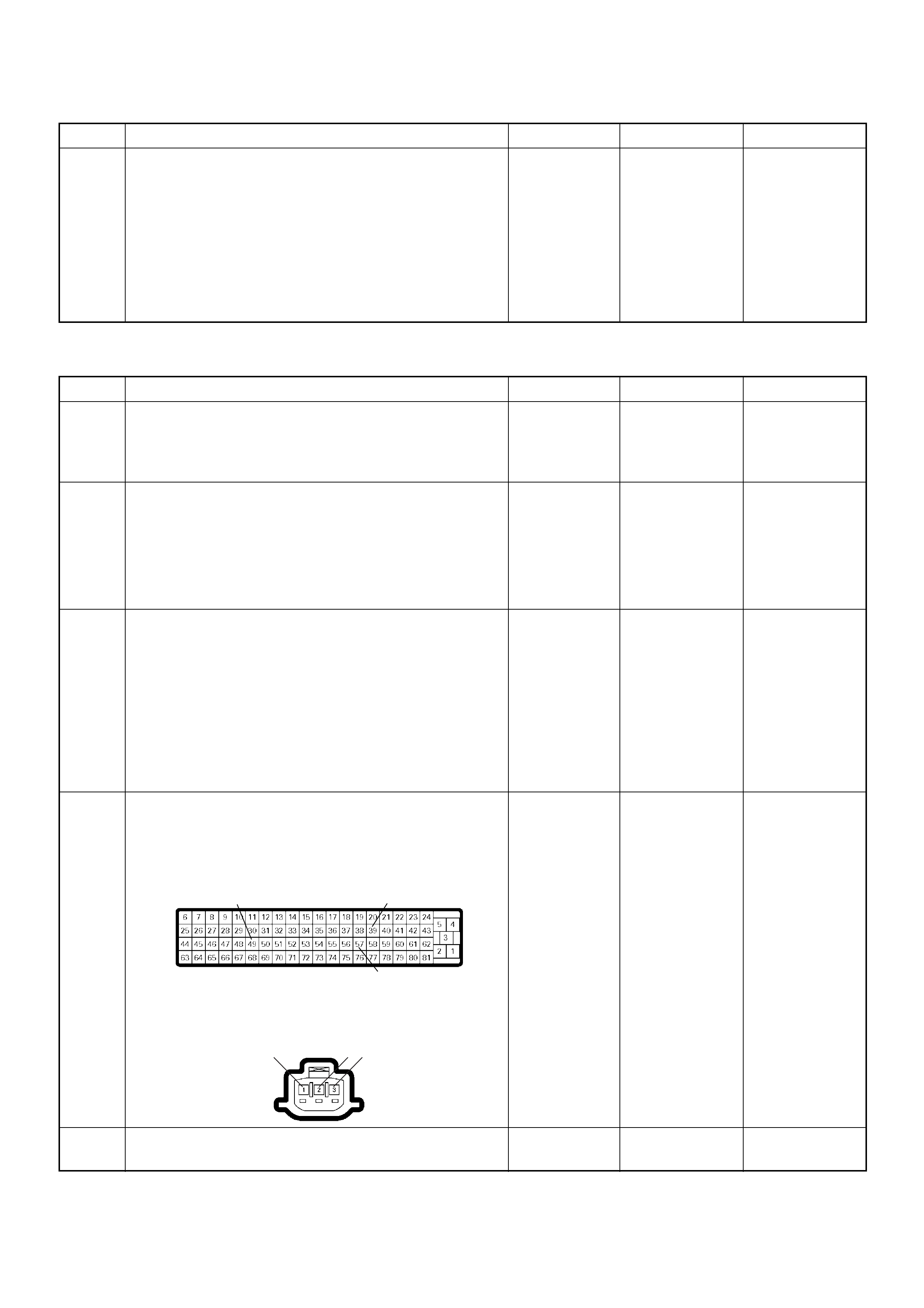
Diagnostic Trouble Code (DTC) P1120 (Symptom Code 7) (Flash Code 21)
Pedal/Throttle Position Sensor Voltage Supply Circuit High Input
15 Replace the ECM.
Is the action complete?
IMPORTANT: The replacement ECM must be
programmed. Refer to section of the Service
Programming System (SPS) in this manual.
Foll owing ECM pr ogramming, the immobi liser system
(if equipped) must be linked to the ECM. Refer to
section 11 “Immobiliser System-ECM replacement” for
the ECM/Immobiliser linking procedure. — Verify repair —
Step Action Value(s) Yes No
1 Was the “On- Board Diagnos tic (OBD) Sy stem Check”
performed?
—Go to Step 2
Go to On Board
Diagnostic
(OBD) System
Check
2 1. Connect the Tech 2.
2. Review and record the failure information.
3. S elect “F0: Read DTC I nfor As Stored B y ECU” in
“F0: Diagnostic Trouble Codes”.
Is the DTC P1120 (Symptom Code 7) stored as
“Present Failure”? — Go to Step 3
Refer to
Diagnostic Aids
and Go to Step
3
3 1. Using the Tech 2, ignition “On” and engine “Off”.
2. Select “F1: Clear DTC Information” in “F0:
Diagnostic Trouble Codes” with the Tech 2 and
clear the DTC information.
3. Operate the vehicle and monitor the “F0: Read
DTC Infor As Stored By ECU” in the “F0:
Diagnostic Trouble Codes”.
Was the DT C P1120 (Sym ptom Cod e 7) stor ed in th is
ignition cycle? — Go to Step 4
Refer to
Diagnostic Aids
and Go to Step
4
4 Check for poor/faulty connection at the TPS or ECM
connector. If a poor/faulty connection is found, repair
as necessary.
Was the problem found?
— Verify repair Go to Step 5
5 Vis ual ly chec k the TPS .
Was the problem found? — Go to Step 8 Go to Step 6
Step Action Value(s) Yes No
49 39
57
2 31
C-56
4JA1-TC C-93
4JH1-TC
E-7
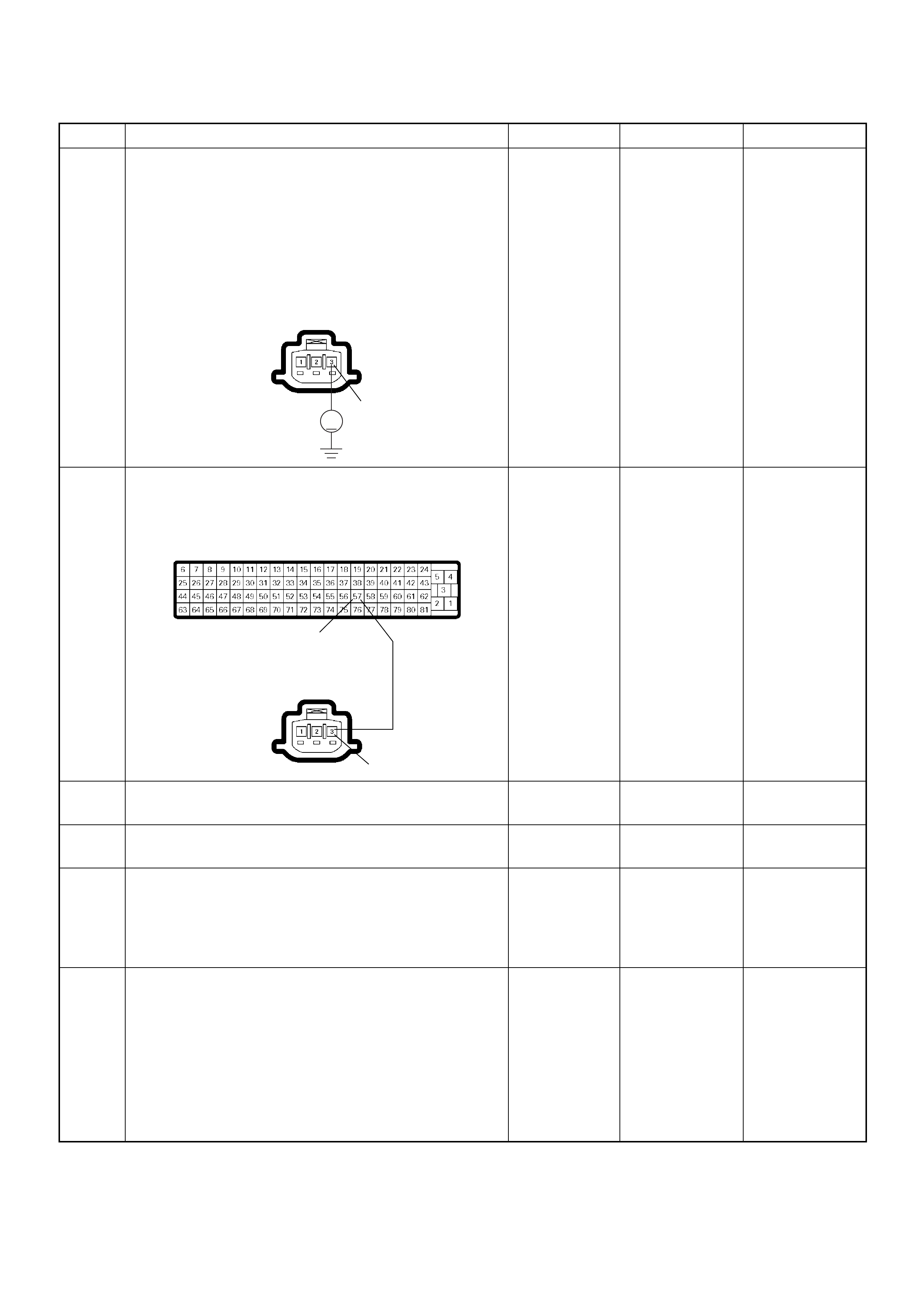
6 Using the DVM and check the TPS power supply
circuit.
1. Ignition “On”, engine “Off”.
2. Disconnect the TPS connector.
3. Check the circuit for short to ground circuit.
Was the DVM indicated specified value?
Approximately
5.0V Go to Step 12 Go to Step 7
7 R epair the short to batter y voltage circuit bet ween the
ECM and TPS.
Was the problem solved?
— Verify repair Go to Step 8
8 Substitute a known good TPS and recheck.
Was the problem solved? — Go to Step 9 Go to Step 10
9 Replace the TPS.
Is the action complete? — Verify repair —
10 Is the ECM programmed with the latest software
release?
If not, downlo ad the latest software to the ECM using
the “SPS (Service Programming System)”.
Was the problem solved? — Verify repair Go to Step 11
11 Replace the ECM.
Is the action complete?
IMPORTANT: The replacement ECM must be
programmed. Refer to section of the Service
Programming System (SPS) in this manual.
Foll owing ECM pr ogramming, the immobi liser system
(if equipped) must be linked to the ECM. Refer to
section 11 “Immobiliser System-ECM replacement” for
the ECM/Immobiliser linking procedure. — Verify repair —
Step Action Value(s) Yes No
V
3
4JA1-TC C-93
4JH1-TC
E-7
57
3
C-56
4JA1-TC C-93
4JH1-TC
E-7
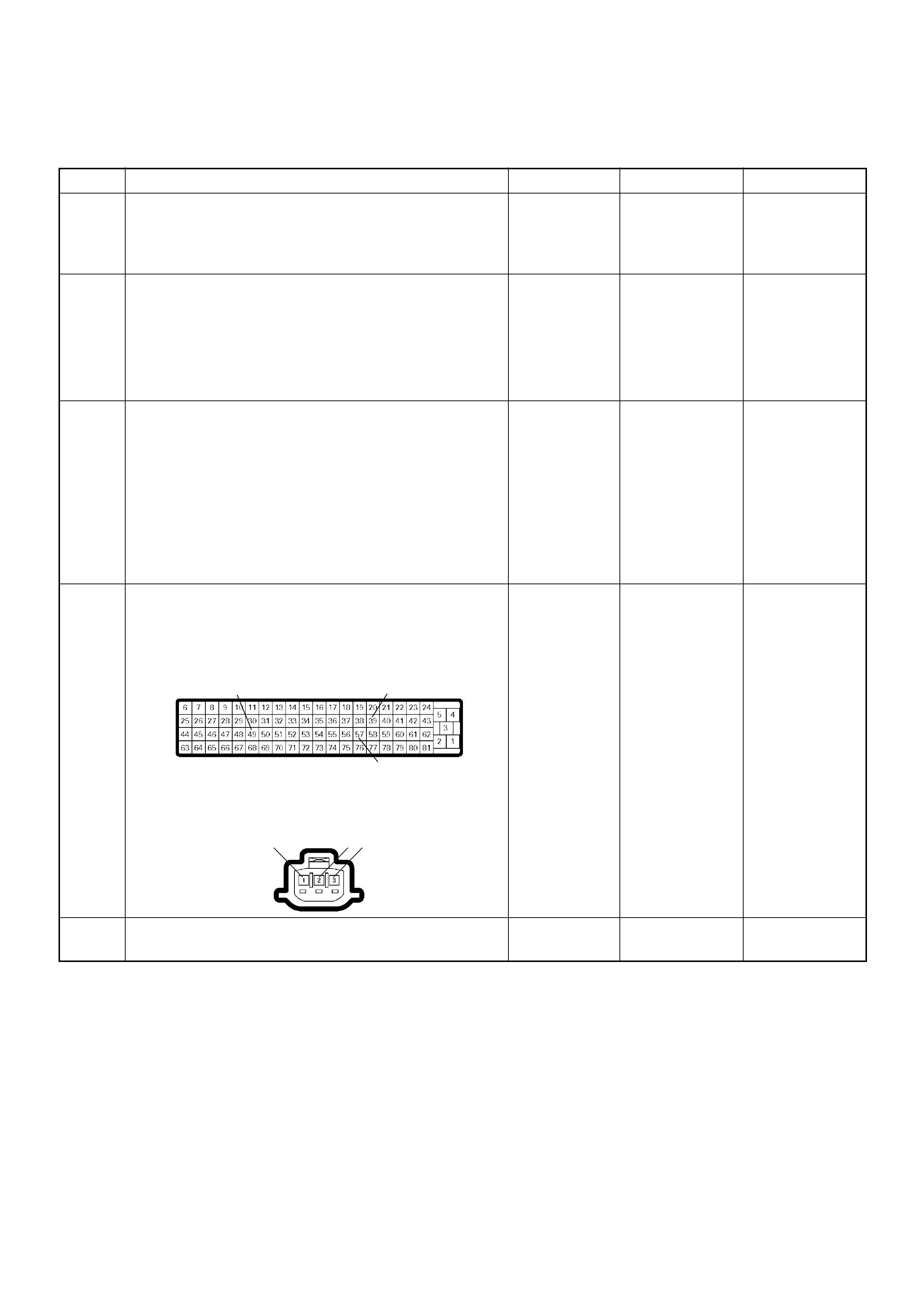
Diagnostic Trouble Code (DTC) P1120 (Symptom Code 9) (Flash Code 21)
Pedal/Throttle Position Sensor Voltage Supply Circuit Low Input
Step Action Value(s) Yes No
1 Was the “On-Board Diagnostic (OBD) System Check”
performed?
—Go to Step 2
Go to On Board
Diagnostic
(OBD) System
Check
2 1. Connect the Tech 2.
2. Review and record the failure information.
3. Select “F0: Read DTC Infor As Stored By ECU” in
“F0: Diagnostic Trouble Codes”.
Is the DTC P1120 (Symptom Code 9) stored as
“Present Failure”? — Go to Step 3
Refer to
Diagnostic Aids
and Go to Step
3
3 1. Using the Tech 2, ignition “On” and engine “Off”.
2. Select “F1: Clear DTC Information” in “F0:
Diagnostic Trouble Codes” with the Tech 2 and
clear the DTC information.
3. Operate the vehicle and monitor the “F0: Read
DTC Infor As Stored By ECU” in the “F0:
Diagnostic Trouble Codes”.
Was the DT C P1120 (Sym ptom Cod e 9) stor ed in th is
ignition cycle? — Go to Step 4
Refer to
Diagnostic Aids
and Go to Step
4
4 Check for poor/faulty connection at the TPS or ECM
connector. If a poor/faulty connection is found, repair
as necessary.
Was the problem found?
— Verify repair Go to Step 5
5 Vis ual ly chec k the TPS .
Was the problem found? — Go to Step 10 Go to Step 6
49 39
57
2 31
C-56
4JA1-TC C-93
4JH1-TC
E-7
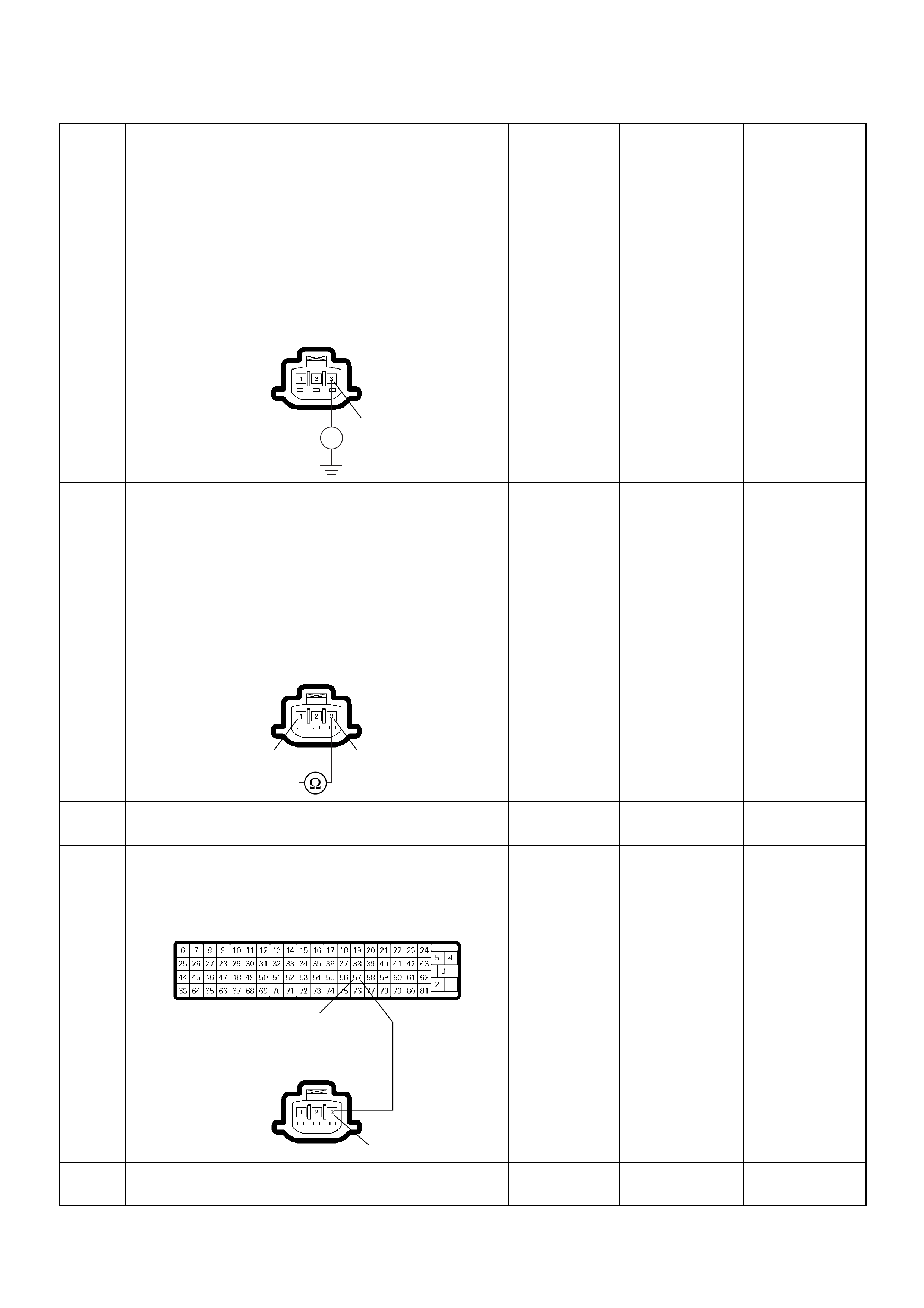
6 Using the DVM and check the TPS power supply
circuit.
1. Ignition “On”, engine “Off”.
2. Disconnect the TPS connector.
3. Check the circuit for short to battery voltage
circuit.
Was the DVM indicated specified value?
Approximately
5.0V Go to Step 10 Go to Step 7
7 Using the DVM and check the TPS power supply
circuit.
1. Ignition “Off”, engine “Off”.
2. Disconnect the TPS connector and ECM
connector.
3. Check the circuit for short to TPS ground circuit.
Was the DVM indicated specified value?
No continuity Go to Step 9 Go to Step 8
8 R e pair the circui t for shor t to TPS groun d circuit .
Is the action complete? — Verify repair —
9 Repair the short to ground circuit between the ECM
and TPS.
Was the problem solved?
— Verify repair Go to Step 12
10 Substitute a known good TPS and recheck.
Was the problem solved? — Go to Step 11 Go to Step 12
Step Action Value(s) Yes No
V
3
4JA1-TC C-93
4JH1-TC
E-7
3
1
4JA1-TC C-93
4JH1-TC
E-7
57
3
C-56
4JA1-TC C-93
4JH1-TC
E-7

Diagnostic Trouble Code (DTC) P1120 (Symptom Code D) (Flash Code 21)
Pedal/Throttle Position Sensor Brake Switch Error
11 Replace the TPS.
Is the action complete? — Verify repair —
12 Is the ECM programmed with the latest software
release?
If not, download the latest software to the ECM using
the “SPS (Service Programming System)”.
Was the problem solved? — Verify repair Go to Step 13
13 Replace the ECM. Is the action complete?
IMPORTANT: The replacement ECM must be
programmed. Refer to section of the Service
Programming System (SPS) in this manual.
Foll owing ECM pr ogramming, the immobi liser system
(if equipped) must be linked to the ECM. Refer to
section 11 “Immobiliser System-ECM replacement” for
the ECM/Immobiliser linking procedure. — Verify repair —
Step Action Value(s) Yes No
1 Was the “On- Board Diagnos tic (OBD) Sy stem Check”
performed?
—Go to Step 2
Go to On Board
Diagnostic
(OBD) System
Check
2 1. Connect the Tech 2.
2. Review and record the failure information.
3. S elect “F0: Read DTC I nfor As Stored B y ECU” in
“F0: Diagnostic Trouble Codes”.
Is the DTC P1120 (Symptom Code D) stored as
“Present Failure”? — Go to Step 3
Refer to
Diagnostic Aids
and Go to Step
3
3 1. Using the Tech 2, ignition “On” and engine “Off”.
2. Select “F1: Clear DTC Information” in “F0:
Diagnostic Trouble Codes” with the Tech 2 and
clear the DTC information.
3. Operate the vehicle and monitor the “F0: Read
DTC Infor As Stored By ECU” in the “F0:
Diagnostic Trouble Codes”.
Was the DTC P1120 (Symptom Code D) stored in this
ignition cycle? — Go to Step 4
Refer to
Diagnostic Aids
and Go to Step
4
4 Vis ual ly chec k the TPS .
Check for the following conditions.
• Accelerator pedal sticking.
If a problem is found, repair as necessary.
Was the problem found? — Verify repair Go to Step 5
5 1. Using the Tech 2, ignition “On” and engine “Off”.
2. Monitor the “Throttle Position” in the data display.
Does the Tech 2 indicate correct “Throttle Position”
from 0% to 100% depending on accelerator pedal
operation? — Go to Step 7 Go to Step 6
6 1. Using the Tech 2, ignition “On” and engine “Off”.
2. Monitor the “Throttle Position” in the data display.
3. Adjust the TPS within 0% to 100%.
Was the problem solved? — Verify repair Go to Step 11
Step Action Value(s) Yes No

Diagnostic Trouble Code (DTC) P1120 (Symptom Code E) (Flash Code 21)
Pedal/Throttle Position Sensor Idle Position Switch Error
7 1. Using the Tech 2, ignition “On” and engine “Off”.
2. Monitor the “Brake Switch 1” and “Brake Switch 2”
in the data display.
Does the Tech 2 indicate “Inactive” when the brake
pedal was not stepped on? — Go to Step 13 Go to Step 8
8 Adjust the brake switch.
Was the problem solved? — Verify repair Go to Step 9
9 Substitute a known good brake switch and recheck.
Was the problem solved? — Go to Step 10 Go to Step 13
10 Replace the brake switch.
Is the action complete? — Verify repair —
11 Substitute a known good TPS and recheck.
Was the problem solved? — Go to Step 12 Go to Step 13
12 Replace the TPS.
Is the action complete? — Verify repair —
13 Is the ECM programmed with the latest software
release?
If not, download the latest software to the ECM using
the “SPS (Service Programming System)”.
Was the problem solved? — Verify repair Go to Step 14
14 Replace the ECM.
Is the action complete?
IMPORTANT: The replacement ECM must be
programmed. Refer to section of the Service
Programming System (SPS) in this manual.
Following ECM programming, the immobiliser system
(if equipped) must be linked to the ECM. Refer to
section 11 “Immobiliser System-ECM replacement” for
the ECM/Immobiliser linking procedure. — Verify repair —
Step Action Value(s) Yes No
1 Was the “On- Board Diagnos tic (OBD) Sy stem Check”
performed?
—Go to Step 2
Go to On Board
Diagnostic
(OBD) System
Check
2 1. Connect the Tech 2.
2. Review and record the failure information.
3. S elect “F0: Read DTC I nfor As Stored B y ECU” in
“F0: Diagnostic Trouble Codes”.
Is the DTC P1120 (Symptom Code E) stored as
“Present Failure”? — Go to Step 3
Refer to
Diagnostic Aids
and Go to Step
3
3 1. Using the Tech 2, ignition “On” and engine “Off”.
2. Select “F1: Clear DTC Information” in “F0:
Diagnostic Trouble Codes” with the Tech 2 and
clear the DTC information.
3. Operate the vehicle and monitor the “F0: Read
DTC Infor As Stored By ECU” in the “F0:
Diagnostic Trouble Codes”.
Was the DT C P1120 (S ym ptom Cod e E) s tored in th is
ignition cycle? — Go to Step 4
Refer to
Diagnostic Aids
and Go to Step
4
Step Action Value(s) Yes No

4 Vis ual ly chec k the TPS .
Was the problem found? — Go to Step 8 Go to Step 5
5 1. Using the Tech 2, ignition “On” and engine “Off”.
2. Monitor the “Throttle Position” in the data display.
Does the Tech 2 indicate correct “Throttle Position”
from 0% to 100% depending on accelerator pedal
operation? — Go to Step 7 Go to Step 6Go
to Step 6
6 1. Using the Tech 2, ignition “On” and engine “Off”.
2. Monitor the “Throttle Position” in the data display.
3. Adjust the TPS within 0% to 100%.
Was the problem solved? — Verify repair Go to Step 8
7 1. Using the Tech 2, ignition “On” and engine “Off”.
2. Monitor the “Idle Switch” in the data display.
Does the Tech 2 indicate “Inactive” when the
accelerator pedal was stepped on? — Go to Step 10 Go to Step 8
8 Substitute a known good TPS and recheck.
Was the problem solved? — Go to Step 9 Go to Step 10
9 Replace the TPS.
Is the action complete? — Verify repair —
10 Is the ECM programmed with the latest software
release?
If not, downlo ad the latest software to the ECM using
the “SPS (Service Programming System)”.
Was the problem solved? — Verify repair Go to Step 11
11 Replace the ECM.
Is the action complete?
IMPORTANT: The replacement ECM must be
programmed. Refer to section of the Service
Programming System (SPS) in this manual.
Foll owing ECM pr ogramming, the immobi liser system
(if equipped) must be linked to the ECM. Refer to
section 11 “Immobiliser System-ECM replacement” for
the ECM/Immobiliser linking procedure. — Verify repair —
Step Action Value(s) Yes No

Diagnostic Trouble Code (DTC) P1173 (Symptom Code 3)
(Flash Code 22) Fuel Reduction Caused By High Coolant Temperature
Diagnostic Trouble Code (DTC) P1173 (Symptom Code 7)
(Flash Code 22) Fuel Reduction Caused By High Fuel Temperature
Diagnostic Trouble Code (DTC) P1173 (Symptom Code A)
(Flash Code 22) Fuel Reduction Caused By Low Temperature
Condition for setting the DTC and action taken when the DTC sets
Circuit Desc rip tio n
The engine coolant temperature (ECT) sensor is
installed on the coolant stream. High coolant
temperature produces a low resistance. The ECM
supplies 5 volts signal to the ECT sensor through
resisters in the ECM and measures the voltage. The
signal voltage will be low when the engine temperature
is hot.
The fuel temp erature sensor is assembled in side of the
pump con tro l uni t (PS G). T he signa l of fuel tem per at ure
is sent via the CAN-bus from the PSG to ECM.
If the engine coolant temperature is excessively high
condition, a DTC P1173 (Symptom Code 3) will be
stored.
If the fuel temperature is excessively high or low
condition, a DTC P1173 (Symptom Code 7) or P1173
(Symptom Code A) will be stored.
Diagnostic Aids
An intermittent may be caused by the following:
• Poor connections.
• Misrouted harness.
• Rubbed through wire insulation.
• Broken wire inside the insulation.
Check for the following conditions:
• Poor connection at ECM and PSG-Inspect harness
connectors for backed out terminals, improper
mating, broken locks, improperly formed or damaged
terminals, and poor terminal to wire connection.
• Damaged harness-Inspect the wiring harness for
damage. If the harness appears to be OK, observe
the “Coolant Temperature” or “Fuel Temperature”
display on the Tech2 while moving connectors and
wiring harness related to the sensor.
Flash
Code Code Symptom
Code MIL DTC Name DTC Setting Condition F ail-Safe (Back Up)
22 P1173 3 OFF Fuel Reduction Caused By
High Coolant Temperature Excessive high engine
coolant temperature is
detected.
No fail-safe function.
7 OFF Fuel Reduction Caused By
High Fuel Temperature Fuel temperature is more than
100°C. PSG (pump control unit)
controls fuel injection quantity
based on engine speed and
fuel temperature.
A OFF Fuel Reduction Caused By
Low Fuel Temperature Excessive low fuel
temperature is detected. No fail-safe function.

Diagnostic Trouble Code (DTC) P1173 (Symptom Code 3) (Flash Code 22)
Fuel Reduction Caused By High Coolant Temperature
Step Action Value(s) Yes No
1 Was the “On-Board Diagnostic (OBD) System Check”
performed?
—Go to Step 2
Go to On Board
Diagnostic
(OBD) System
Check
2 1. Connect the Tech 2.
2. Review and record the failure information.
3. Select “F0: Read DTC Infor As Stored By ECU” in
“F0: Diagnostic Trouble Codes”.
Is the DTC P1173 (Symptom Code 3) stored as
“Present Failure”? — Go to Step 3
Refer to
Diagnostic Aids
and Go to Step
3
3 1. Using the Tech 2, ignition “On” and engine “Off”.
2. Select “F1: Clear DTC Information” in “F0:
Diagnostic Trouble Codes” with the Tech 2 and
clear the DTC information.
3. Operate the vehicle and monitor the “F0: Read
DTC Infor As Stored By ECU” in the “F0:
Diagnostic Trouble Codes”.
Was the DT C P1173 (Sym ptom Cod e 3) stor ed in th is
ignition cycle? — Go to Step 4
Refer to
Diagnostic Aids
and Go to Step
4
4 Check the engine overheat condition.
Was the problem found?
—
Repair the
cause of
overheat and
verify repair G o to Step 5
5 1. Using the Tech 2, ignition “On” and engine “On”.
2. Monitor the “Coolant Temperature” in the data
display.
Does the Tech 2 indicate correct “Coolant
Temperature” depending on warm up time? — Go to Step 9 Go to Step 6
6 Using the DVM and check the ECT sensor.
1. Ignition “Off”, engine “Off”.
2. Disconnect ECT sensor connector.
3. Measure the resistance of ECT sensor.
Does the tester indicate standard resistance as shown
in the following table?
Standard
resistance Go to Step 9 Go to Step 7
Temperat ure (°C) Resistance (Ω) (Approximately)
-30 27500
-20 16100
0 5760
20 2370
40 1080
60 537
80 290
100 161
120 95
12
ECT Sensor 12

Diagnostic Trouble Code (DTC) P1173 (Symptom Code 7) (Flash Code 22)
Fuel Reduction Caused By High Fuel Temperature
Diagnostic Trouble Code (DTC) P1173 (Symptom Code A) (Flash Code 22)
Fuel Reduction Caused By Low Temperature
7 Substitute a known good ECT sensor assembly and
recheck.
Was the problem solved? — Go to Step 8 Go to Step 9
8 Replace the ECT sensor.
Is the action complete? — Verify repair —
9 Is the ECM programmed with the latest software
release?
If not, download the latest software to the ECM using
the “SPS (Service Programming System)”.
Was the problem solved? — Verify repair Go to Step 10
10 Replace the ECM.
Is the action complete?
IMPORTANT: The replacement ECM must be
programmed. Refer to section of the Service
Programming System (SPS) in this manual.
Foll owing ECM pr ogramming, the immobi liser system
(if equipped) must be linked to the ECM. Refer to
section 11 “Immobiliser System-ECM replacement” for
the ECM/Immobiliser linking procedure. — Verify repair —
Step Action Value(s) Yes No
1 Was the “On- Board Diagnos tic (OBD) Sy stem Check”
performed?
—Go to Step 2
Go to On Board
Diagnostic
(OBD) System
Check
2 1. Connect the Tech 2.
2. Review and record the failure information.
3. S elect “F0: Read DTC I nfor As Stored B y ECU” in
“F0: Diagnostic Trouble Codes”.
Is the DTC P1173 (Symptom Code 7) or P1173
(Symptom Code A) stored as “Present Failure”? — Go to Step 3
Refer to
Diagnostic Aids
and Go to Step
3
3 1. Using the Tech 2, ignition “On” and engine “Off”.
2. Select “F1: Clear DTC Information” in “F0:
Diagnostic Trouble Codes” with the Tech 2 and
clear the DTC information.
3. Operate the vehicle and monitor the “F0: Read
DTC Infor As Stored By ECU” in the “F0:
Diagnostic Trouble Codes”.
Was the DTC P1173 (Symptom Code 7) or P1173
(Symptom Code A) stored in this ignition cycle? — Go to Step 4 Refer to
Diagnostic Aids
4 Is the ECM programmed with the latest software
release?
If not, downlo ad the latest software to the ECM using
the “SPS (Service Programming System)”.
Was the problem solved? — Verify repair Go to Step 5
Step Action Value(s) Yes No

5 Substitute a known good ECM and recheck.
Was the problem solved?
IMPORTANT: The replacement ECM must be
programmed. Refer to section of the Service
Programming System (SPS) in this manual.
Foll owing ECM pr ogramming, the immobi liser system
(if equipped) must be linked to the ECM. Refer to
section 11 “Immobiliser System-ECM replacement” for
the ECM/Immobiliser linking procedure. —Go to Step 6 Go to Step 7
6 Replace the ECM.
Is the action complete?
IMPORTANT: The replacement ECM must be
programmed. Refer to section of the Service
Programming System (SPS) in this manual.
Foll owing ECM pr ogramming, the immobi liser system
(if equipped) must be linked to the ECM. Refer to
section 11 “Immobiliser System-ECM replacement” for
the ECM/Immobiliser linking procedure. — Verify repair —
7 Replace the injection pump assembly.
Is the action complete? — Verify repair —
Step Action Value(s) Yes No
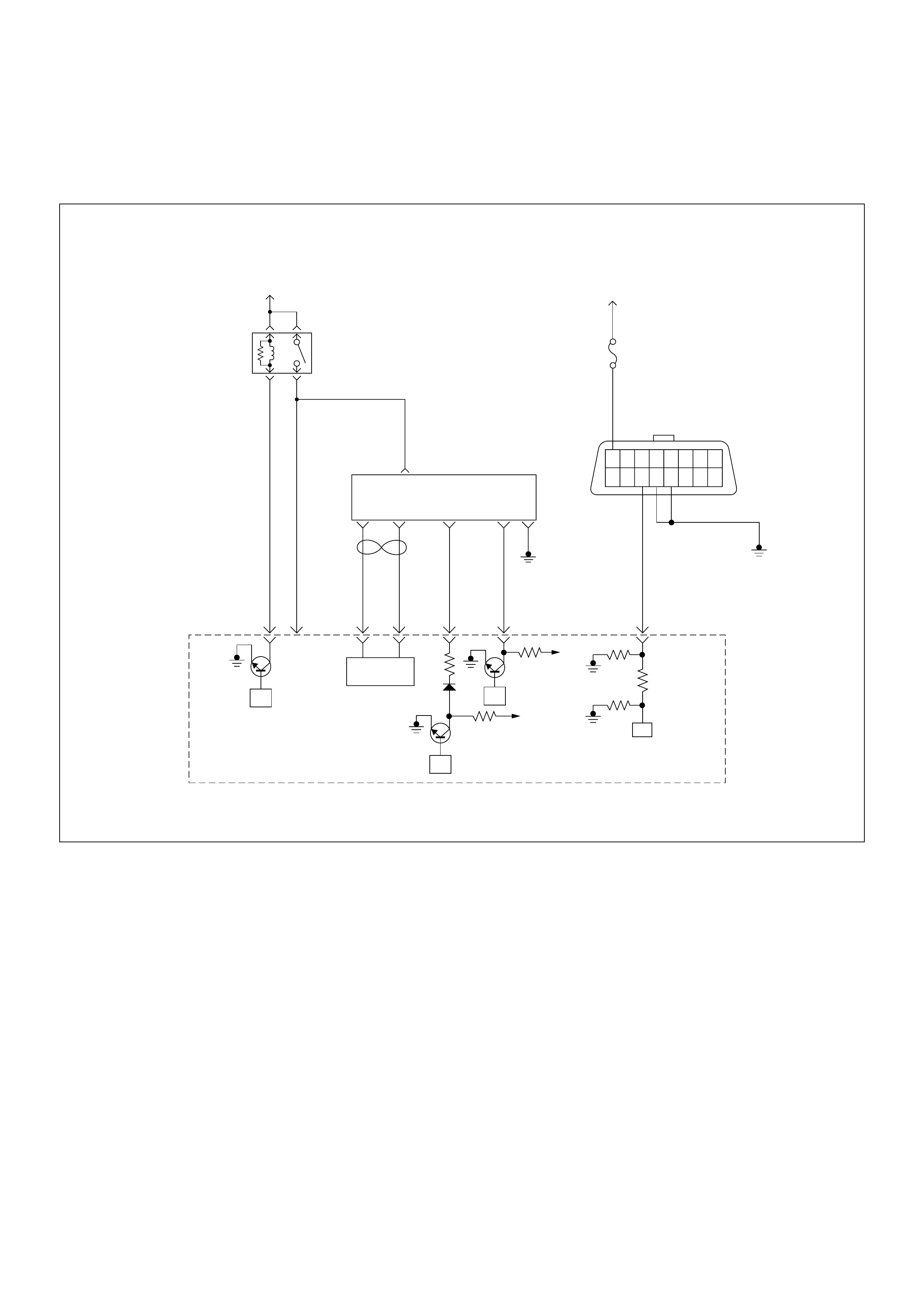
Diagnostic Trouble Code (DTC) P1335 (Symptom Code A)
(Flash Code 43) Engine Speed Output Circuit Malfunction
45
16151413121110 9
87654321
Battery
Voltage Battery
Voltage
0.5
RED/
YEL
2.0
BLU/
RED
7
PSG(Pump Control Unit) Injection
Pump
21 5 8
0.5
WHT
2.0
BLU/
RED
0.5
BLU/
BLK
0.5
RED 0.5
ORG
100358 99 105 91
0.5
PNK
62.0
BLK
µP
CAN
Controller
Batt
Batt
IC
µP
0.5
BLU
Stop
Light
10A
1.25
BLK
µP
Engine
Control
Module
(ECM)
ECM
Main Relay

Condition for setting the DTC and action taken when the DTC sets
Circuit Desc rip tio n
The CKP sensor is located on top of the flywheel
housing of the flywheel and fixed with a bolt. The CKP
sensor is of the magnet coil type. The inductive pickup
sensors four gaps in the flywheel exciter ring and is
used to determine the engine speed and engine
cylinder top dead center.
The ECM converts sine wave signal to square wave
signal. And this signal is provided from the ECM to
pump control unit (PSG).
Diagnostic Aids
An intermittent may be caused by the following:
• Poor connections.
• Misrouted harness.
• Rubbed through wire insulation.
• Broken wire inside the insulation.
Check for the following conditions:
• Poor con nection at ECM-I nspect harnes s connectors
for backed out terminals, improper mating, broken
locks, improperly formed or damaged terminals, and
poor terminal to wire connection.
• Damaged harness-Inspect the wiring harness for
damage.
• Contaminated sensor - remove and clean the sensor.
• If the harness appears to be OK, observe the “Engine
Speed” display on the Tech2 while moving
connectors and wiring harness related to the sensor.
Flash
Code Code Symptom
Code MIL DTC Name DTC Setting Condition F ail-Safe (Back Up)
43 P1335 A ON Engine Speed Output Circuit
Malfunction The PSG (pump control unit)
is recognized defective
engine speed signal form the
ECM.
Fuel injection quantity is
reduced.
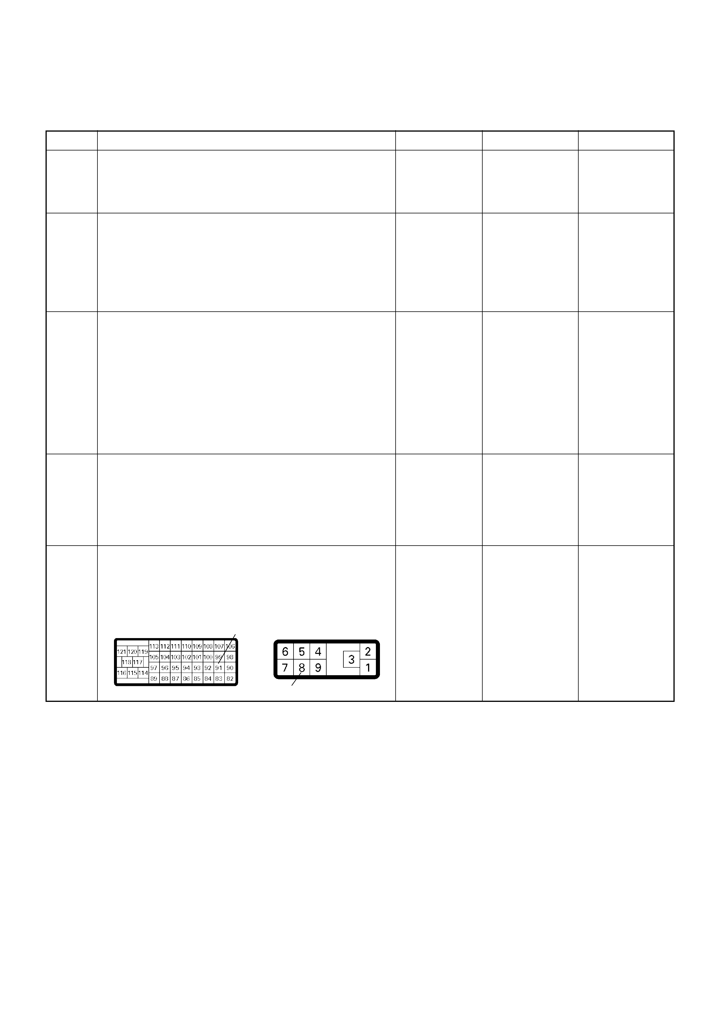
Diagnostic Trouble Code (DTC) P1335 (Symptom Code A) (Flash Code 43)
Engine Speed Output Circuit Malfunction
Step Action Value(s) Yes No
1 Was the “On-Board Diagnostic (OBD) System Check”
performed?
—Go to Step 2
Go to On Board
Diagnostic
(OBD) System
Check
2 1. Connect the Tech 2.
2. Review and record the failure information.
3. Select “F0: Read DTC Infor As Stored By ECU” in
“F0: Diagnostic Trouble Codes”.
Is the DTC P1335 (Symptom Code A) stored as
“Present Failure”? — Go to Step 3
Refer to
Diagnostic Aids
and Go to Step
3
3 1. Using the Tech 2, ignition “On” and engine “Off”.
2. Select “F1: Clear DTC Information” in “F0:
Diagnostic Trouble Codes” with the Tech 2 and
clear the DTC information.
3. Operate the vehicle and monitor the “F0: Read
DTC Infor As Stored By ECU” in the “F0:
Diagnostic Trouble Codes”.
Was the DTC P1335 (Symptom Code A) stored in this
ignition cycle? — Go to Step 4
Refer to
Diagnostic Aids
and Go to Step
4
4 Was the DTC P0335 (Symptom Code B) or P0335
(Symptom Code D) stored at the same time?
—
Go to DTC
Chart P0335
(Symptom
Code B)
(Symptom
Code C) Go to Step 5
5 Check for poor/faulty connection at the ECM or PSG
(pump control unit) connector. If a poor/faulty
connection is found, repair the faulty terminal.
Was the problem found?
— Verify repair Go to Step 6
91
8
C-57(B) E-6

6 I f a oscillosc ope is availabl e, monitor the CKP sensor
output signal. Does the oscilloscope indicate correct
wave form?
—Go to Step 13
Not available:
Go to Step 7
Fixed at low:
Go to Step 7
Fixed at High:
Go to Step 8
Step Action Value(s) Yes No
CKP Sensor Output Reference Wave Form
0V→
Measurement Terminal: 91 (+) 1 (-)
Measurement Scale: 5.0V/div 2.0ms/div
Measurement Condition: Engine speed at 2000rpm
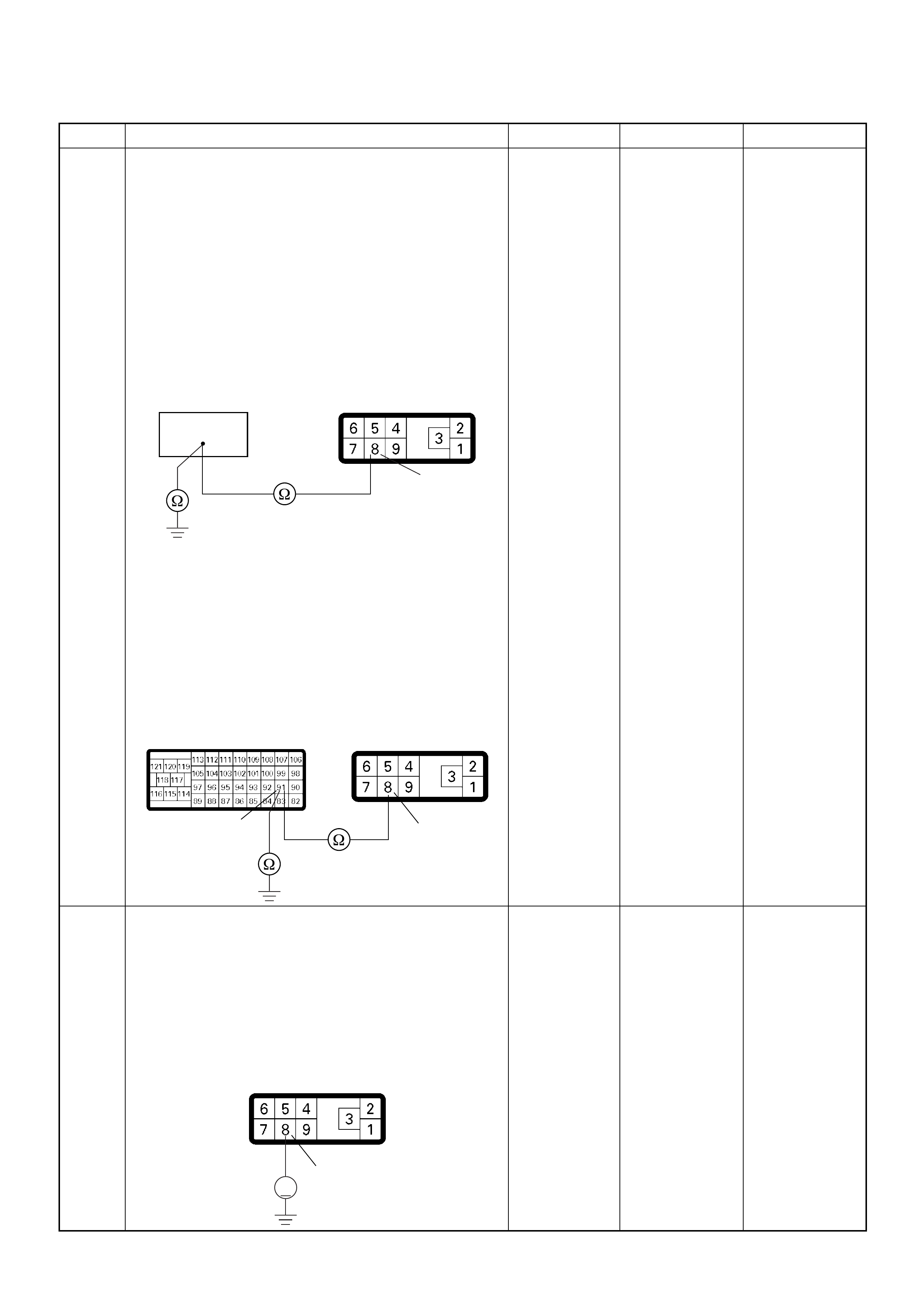
7 Using the DVM and check the CKP sensor output
circuit.
Breaker box is available:
1. Ignition “Off”, engine “Off”.
2. Install the breaker box as type A. (ECM
disconnected) Ref. Page 6E-81
3. Disconnect the PSG (pump control unit)
connector.
4. Check the circuit for open or short to ground
circuit.
Was the problem found?
Breaker box is not available:
1. Ignition “Off”, engine “Off”.
2. Disconnect the ECM connector.
3. Disconnect the PSG (pump control unit)
connector.
4. Check the circuit for open or short to ground
circuit.
Was the problem found?
—
Repair faulty
harnes s and
verify repair G o to Step 8
8 Using the DVM and check the CKP sensor output
circuit.
1. Ignition “On”, engine “Off”.
2. Disconnect the PSG (pump control unit)
connector.
3. Check the circuit for short to power supply circuit.
Was the DVM indicated specified value?
Less than 1V Go to Step 9
Repair faulty
harness and
verify repair
Step Action Value(s) Yes No
91
8
E-6
91 8
C-57(B) E-6
8
V
E-6

9 Check any accessory parts which may cause electric
interference or magnetic interference.
Was the problem found? —
Remove the
accessory parts
and verify repair Go to Step 10
10 Is the ECM programmed with the latest software
release?
If not, downlo ad the latest software to the ECM using
the “SPS (Service Programming System)”.
Was the problem solved? — Verify repair Go to Step 11
11 Substitute a known good ECM and recheck.
Was the problem solved?
IMPORTANT: The replacement ECM must be
programmed. Refer to section of the Service
Programming System (SPS) in this manual.
Foll owing ECM pr ogramming, the immobi liser system
(if equipped) must be linked to the ECM. Refer to
section 11 “Immobiliser System-ECM replacement” for
the ECM/Immobiliser linking procedure. —Go to Step 12 Go to Step 13
12 Replace the ECM.
Is the action complete?
IMPORTANT: The replacement ECM must be
programmed. Refer to section of the Service
Programming System (SPS) in this manual.
Foll owing ECM pr ogramming, the immobi liser system
(if equipped) must be linked to the ECM. Refer to
section 11 “Immobiliser System-ECM replacement” for
the ECM/Immobiliser linking procedure. — Verify repair —
13 Replace the injection pump assembly.
Is the action complete? — Verify repair —
Step Action Value(s) Yes No
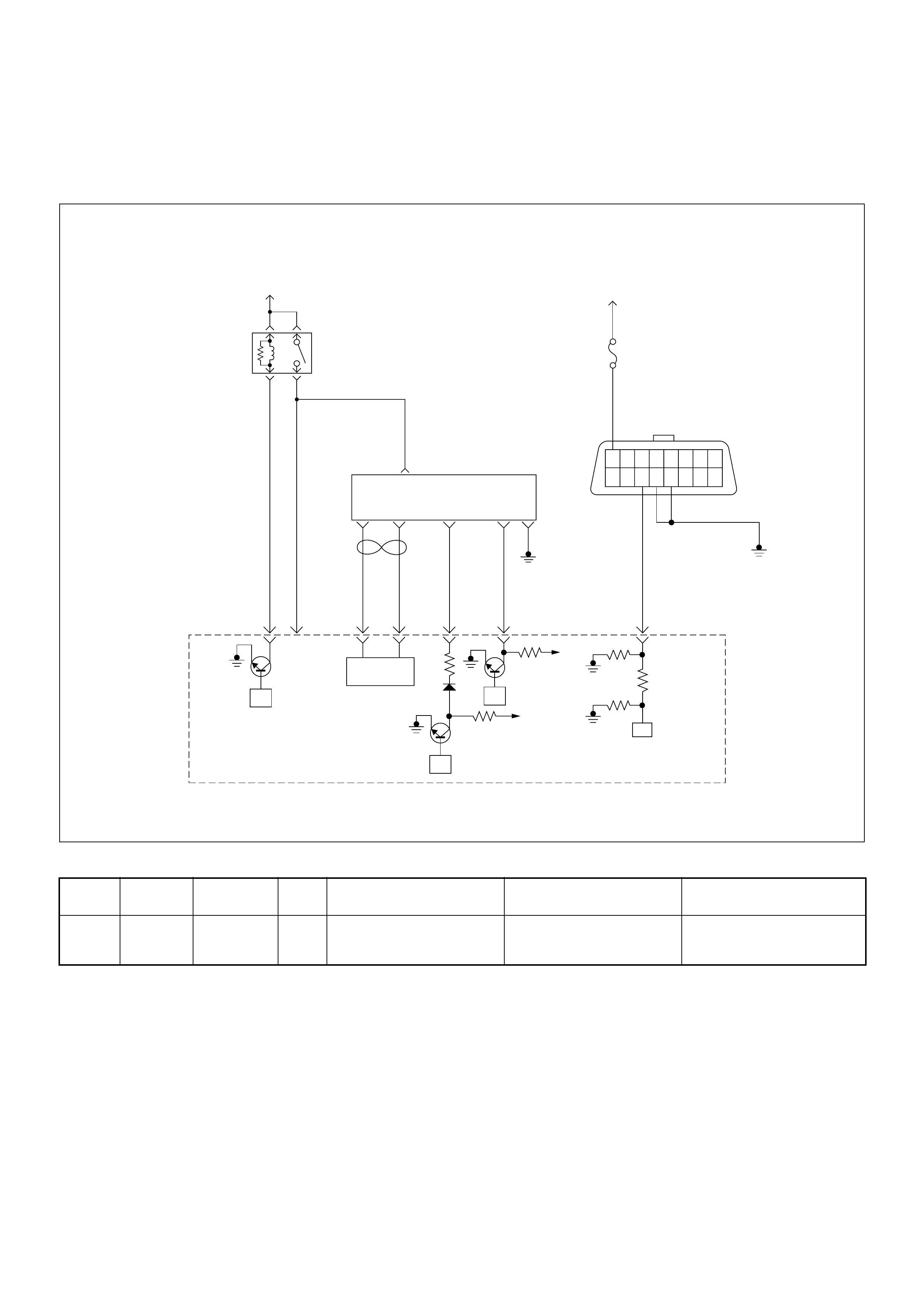
Diagnostic Trouble Code (DTC) P1345 (Symptom Code A)
(Flash Code 45) Camshaft Speed Malfunction
Condition for setting the DTC and action taken when the DTC sets
Circuit Desc rip tio n
The pump camshaft sensor is a magnet with a coil. It
uses to combine with the p ulser. T he pulser is attached
main shaft in the pump. It likes a gear shape.
The pump camshaft sensor is attached to the pump
control unit ( PSG). The s ignal o f pump c amshaft s peed
is sent via the CAN-bus from the PSG to ECM.
Diagnostic Aids
An intermittent may be caused by the following:
• Poor connections.
• Misrouted harness.
• Rubbed through wire insulation.
• Broken wire inside the insulation.
Check for the following conditions:
• Poor connection at ECM and PSG-Inspect harness
connectors for backed out terminals, improper
mating, broken locks, improperly formed or damaged
terminals, and poor terminal to wire connection.
• Damaged harness-Inspect the wiring harness for
damage. If the harness appears to be OK, observe
the “Pump Speed” display on the Tech2 while moving
connectors and wiring harnesses. A change in the
display will indicate the location of the fault.
Flash
Code Code Symptom
Code MIL DTC Name DTC Setting Condition F ail-Safe (Back Up)
45 P1345 A ON Cam shaft Speed Malf unction T he PSG (pump cont rol unit)
is recognized incorrect
camshaft speed signal.
No fail-safe function.
45
16151413121110 9
87654321
Battery
Voltage Battery
Voltage
0.5
RED/
YEL
2.0
BLU/
RED
7
PSG(Pump Control Unit) Injection
Pump
21 5 8
0.5
WHT
2.0
BLU/
RED
0.5
BLU/
BLK
0.5
RED 0.5
ORG
100358 99 105 91
0.5
PNK
62.0
BLK
µP
CAN
Controller
Batt
Batt
IC
µP
0.5
BLU
Stop
Light
10A
1.25
BLK
µP
Engine
Control
Module
(ECM)
ECM
Main Relay

Diagnostic Trouble Code (DTC) P1345 (Symptom Code A) (Flash Code 45) Camshaft Speed Malfunction
Step Action Value(s) Yes No
1 Was the “On-Board Diagnostic (OBD) System Check”
performed?
—Go to Step 2
Go to On Board
Diagnostic
(OBD) System
Check
2 1. Connect the Tech 2.
2. Review and record the failure information.
3. Select “F0: Read DTC Infor As Stored By ECU” in
“F0: Diagnostic Trouble Codes”.
Is the DTC P1345 (Symptom Code A) stored as
“Present Failure”? — Go to Step 3
Refer to
Diagnostic Aids
and Go to Step
3
3 1. Using the Tech 2, ignition “On” and engine “Off”.
2. Select “F1: Clear DTC Information” in “F0:
Diagnostic Trouble Codes” with the Tech 2 and
clear the DTC information.
3. Operate the vehicle and monitor the “F0: Read
DTC Infor As Stored By ECU” in the “F0:
Diagnostic Trouble Codes”.
Was the DTC P1345 (Symptom Code A) stored in this
ignition cycle? — Go to Step 4
Refer to
Diagnostic Aids
and Go to Step
4
4 1. Using the Tech 2, ignition “On” and engine “Off”.
2. Monitor the “Pump Speed” in the data display.
Does the Tech 2 indicate correct “Pump Speed”
depending on engine speed? — Go to Step 6 Go to Step 5
5 Check any accessory parts which may cause electric
interference or magnetic interference.
Was the problem found? —
Remove the
accessory parts
and verify repair Go to Step 9
6 Is the ECM programmed with the latest software
release?
If not, downlo ad the latest software to the ECM using
the “SPS (Service Programming System)”.
Was the problem solved? — Verify repair Go to Step 7
7 Substitute a known good ECM and recheck.
Was the problem solved?
IMPORTANT: The replacement ECM must be
programmed. Refer to section of the Service
Programming System (SPS) in this manual.
Foll owing ECM pr ogramming, the immobi liser system
(if equipped) must be linked to the ECM. Refer to
section 11 “Immobiliser System-ECM replacement” for
the ECM/Immobiliser linking procedure. —Go to Step 8 Go to Step 9
8 Replace the ECM.
Is the action complete?
IMPORTANT: The replacement ECM must be
programmed. Refer to section of the Service
Programming System (SPS) in this manual.
Foll owing ECM pr ogramming, the immobi liser system
(if equipped) must be linked to the ECM. Refer to
section 11 “Immobiliser System-ECM replacement” for
the ECM/Immobiliser linking procedure. — Verify repair —
9 Replace the injection pump assembly.
Is the action complete? — Verify repair —

Diagnostic Trouble Code (DTC) P1520 (Symptom Code A)
(Flash Code 47) Neutral Switch On Error
Diagnostic Trouble Code (DTC) P1520 (Symptom Code B)
(Flash Code 47) Neutral Switch Off Error
Battery
Voltage
Battery
Voltage
ECM
Main Relay
Stop
Light
10A
Injection
Pump Stop
Lamp
IC IC CPU
0.5
BLU/
BLK
58
2.0
BLU/
RED
0.5
BLU/
RED
3
0.5
WHT/
BLK
65
0.85
RED
0.85
RED
0.85
GRN
30
0.5
BLU/
RED
63
0.5
YEL
31
0.5
RED/
BLK
0.5
BLU/
RED
0.5
BLU/
RED
0.85
WHT
0.5
WHT/
RED
0.5
RED/
GRN
Clutch
SW
Resister
Neutral
SW
87
0.5
BLU/
YEL
39
Brake
SW
M/T A/T
Inhibitor
SW
Ignition
SW
Back,
Turn
15A Engine
15A
µP
NP
Engine
Control
Module
(ECM) Batt Batt

Condition for setting the DTC and action taken when the DTC sets
Circuit Desc rip tio n
The ECM monitors the neutral switch (A/T: N or P
position switch in inhibitor switch) signal on the feed
terminal to the ECM. If the neutral switch malf unctions,
a DTC P1520 (Symptom Code A) or P1520 (Symptom
Code B) will be stored.
Diagnostic Aids
An intermittent may be caused by the following:
• Poor connections.
• Misrouted harness.
• Rubbed through wire insulation.
• Broken wire inside the insulation.
Check for the following conditions:
• Poor con nection at ECM-I nspect harnes s connectors
for backed out terminals, improper mating, broken
locks, improperly formed or damaged terminals, and
poor terminal to wire connection.
• Damaged harness-Inspect the wiring harness for
damage. If the harness appears to be OK, observe
the “Neutral Switch” display on the Tech2 while
moving connectors and wiring harness related to the
sensor.
Flash
Code Code Symptom
Code MIL DTC Name DTC Setting Condition F ail-Safe (Back Up)
47 P1520 A ON Neutral Switch ON Error Neutral switch signal is
inputted “On” three times
consecutively under driving
conditions.
No fail-safe function.
B ON Neutral Switch OFF Error Neutral switch signal is
inputted “Off” three times
consecutively under driving
conditions.
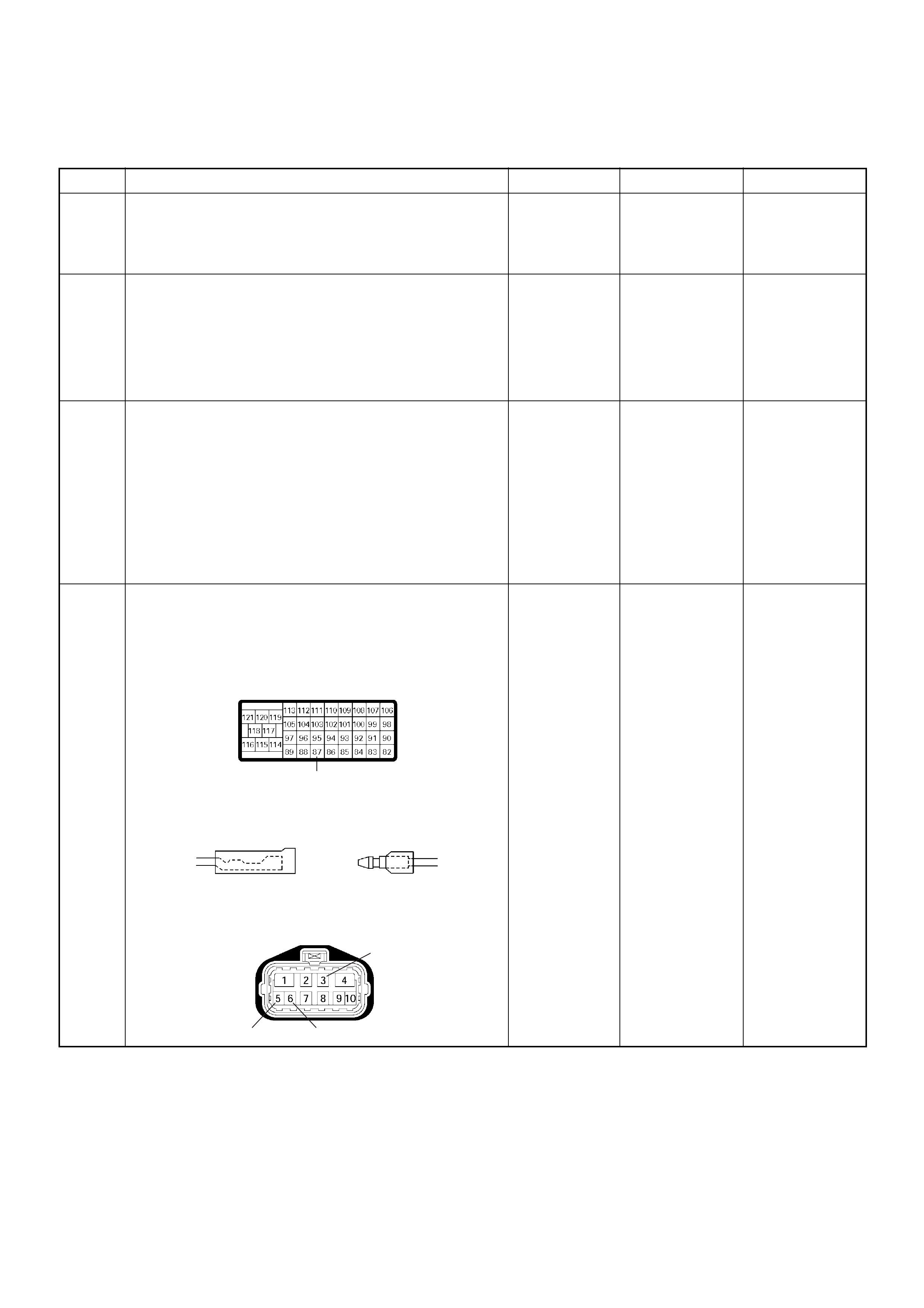
Diagnostic Trouble Code (DTC) P1520 (Symptom Code A) (Flash Code 47) Neutral Switch ON Error
Diagnostic Trouble Code (DTC) P1520 (Symptom Code B) (Flash Code 47) Neutral Switch OFF Error
Step Action Value(s) Yes No
1 Was the “On-Board Diagnostic (OBD) System Check”
performed?
—Go to Step 2
Go to On Board
Diagnostic
(OBD) System
Check
2 1. Connect the Tech 2.
2. Review and record the failure information.
3. Select “F0: Read DTC Infor As Stored By ECU” in
“F0: Diagnostic Trouble Codes”.
Is the DTC P1520 (Symptom Code A) or P1520
(Symptom Code B) stored as “Present Failure”? — Go to Step 3
Refer to
Diagnostic Aids
and Go to Step
3
3 1. Using the Tech 2, ignition “On” and engine “Off”.
2. Select “F1: Clear DTC Information” in “F0:
Diagnostic Trouble Codes” with the Tech 2 and
clear the DTC information.
3. Operate the vehicle and monitor the “F0: Read
DTC Infor As Stored By ECU” in the “F0:
Diagnostic Trouble Codes”.
Was the DTC P1520 (Symptom Code A) or P1520
(Symptom Code B) stored in this ignition cycle? — Go to Step 4
Refer to
Diagnostic Aids
and Go to Step
4
4 C heck for poor/faulty c onnection at the neutra l switch
(inhibitor switch) or ECM connector. If a poor/faulty
connection is found, repair as necessary.
Was the problem found?
— Verify repair Go to Step 5
87
C-57
E-11 M/T E-12
3
56
E-51
A/T
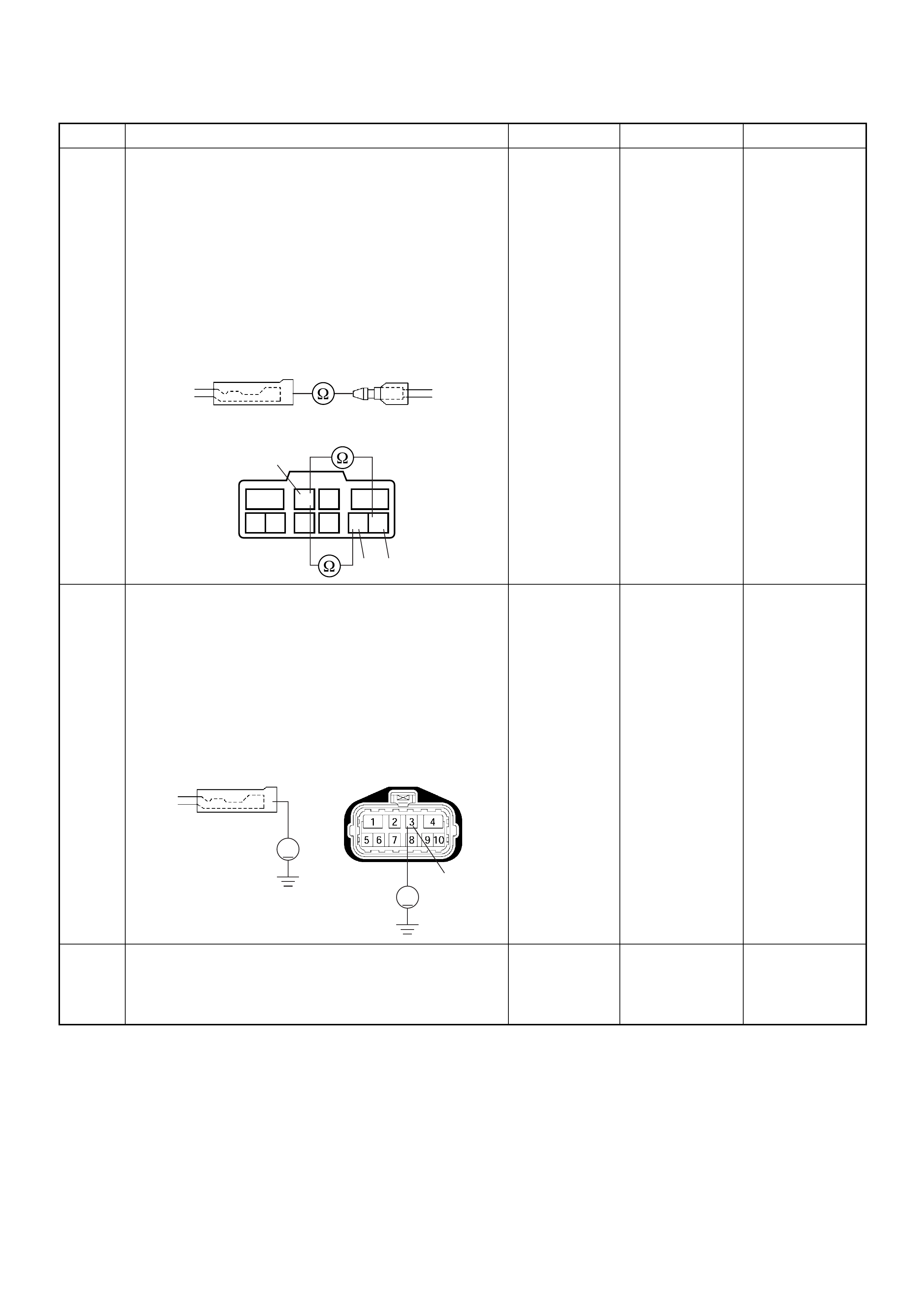
5 U sing the DVM and ch eck the neutral switc h (inhibi tor
switch).
1. Ignition “Off”, engine “Off”.
2. Remove the neutral switch connector (inhibitor
switch connector) at the transmission.
3. Check the neutral switch (P range N range
switch).
Was the DVM indicated specified value?
Neutral (P or
N): Continuity
Other than
neutral (P or
N): No
continuity Go to Step 6
Replace neutral
switch (inhibitor
switch) and
verify repair
6 U sing the DVM and ch eck the neutral switc h (inhibi tor
switch) power su pply ci rcui t.
1. Ignition “On”, engine “Off”.
2. Remove the neutral switch (inhibitor switch)
connector from the switch.
3. Check the circuit for open circuit.
Was the DVM indicated specified value?
Battery
voltage Go to Step 8 Go to Step 7
7 R epair the open cir cuit between the E CM Main Relay
and neutral switch (between the “Back, Turn fuse
(15A)” and inhibitor switch).
Is the action complete? — Verify repair —
Step Action Value(s) Yes No
E-11 E-12
M/T
5
12
104 3 679 8
6
3
5
A/T
V
3
V
M/T E-51E-11 A/T
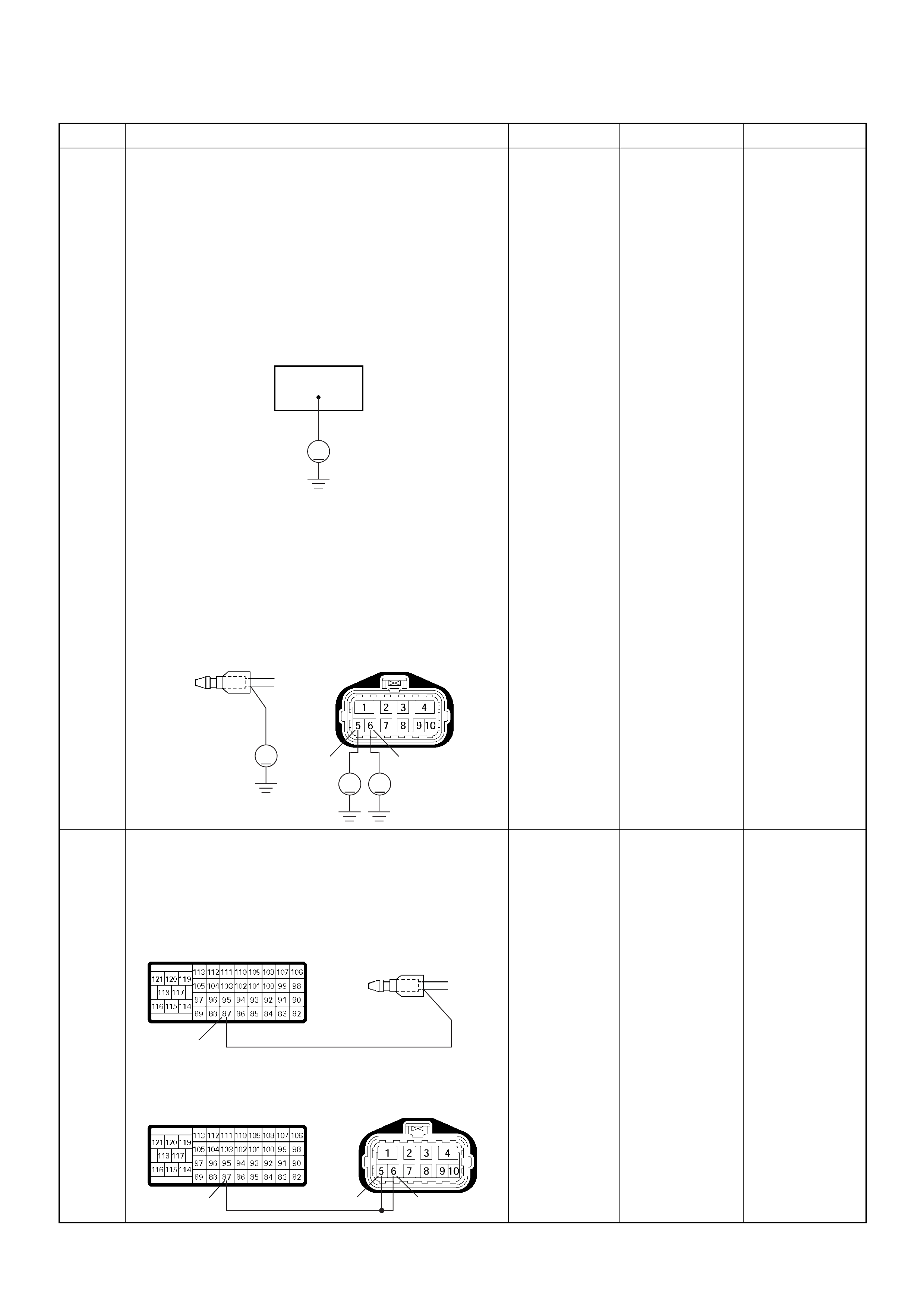
8 U sing the DVM and ch eck the neutral switc h (inhibi tor
swi tch) ci rc ui t.
Breaker box is available:
1. Ignition “Off”, engine “Off”.
2. Install the breaker box as type B. (ECM
connected) Ref. Page 6E-81
3. Ignition “On”, engine “Off”.
4. Check the circuit for open or short to voltage
circuit.
Was the DVM indicated specified value?
Breaker box is not available:
1. Ignition “On”, engine “Off”.
2. Back probe the DVM to the neutral switch
(inhibitor switch) and check the circuit for ope n or
short to voltage circuit.
Was the DVM indicated specified value?
Neutral (P or
N): Battery
voltage
Other than
neutral (P or
N): Less than
1V Go to Step 11
Fixed at battery
voltage: Go to
Step 9
Fixed at less
than 1V: Go to
Step 10
9 R epair the short to voltage ci rcuit between the neutral
switch connector (inhibitor switch connector) and
ECM.
Is the action complete?
— Verify repair —
Step Action Value(s) Yes No
87
V
V
65
V
V
E-51
A/T
E-12
M/T
87
87 65
C-57
C-57
M/T
A/T
E-12
E-51
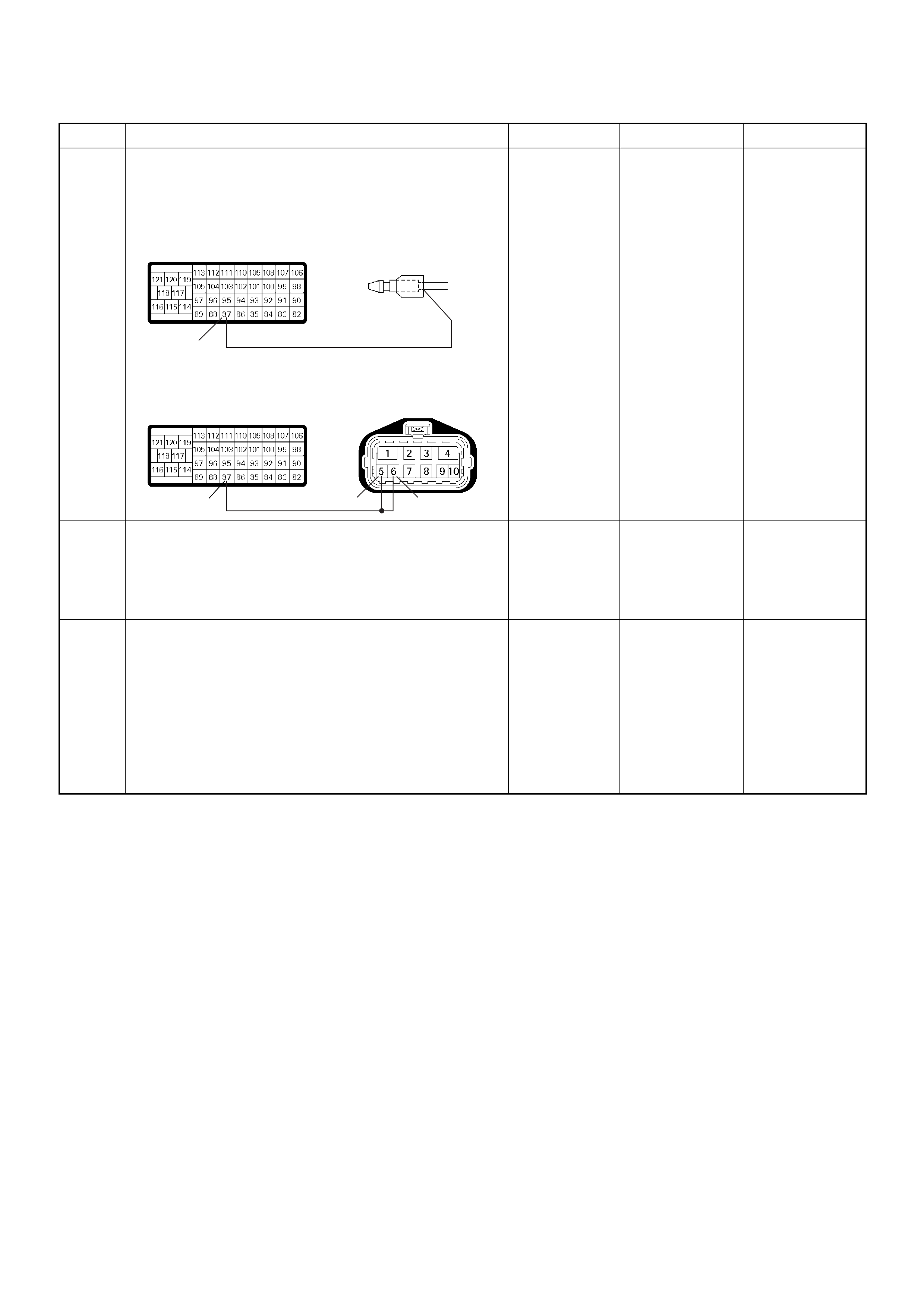
10 Repair the open circuit between the neutral switch
connector (inhibitor switch connector) and ECM.
Is the action complete?
— Verify repair —
11 Is the ECM programmed with the latest software
release?
If not, downlo ad the latest software to the ECM using
the “SPS (Service Programming System)”.
Was the problem solved? — Verify repair Go to Step 12
12 Replace the ECM.
Is the action complete?
IMPORTANT: The replacement ECM must be
programmed. Refer to section of the Service
Programming System (SPS) in this manual.
Foll owing ECM pr ogramming, the immobi liser system
(if equipped) must be linked to the ECM. Refer to
section 11 “Immobiliser System-ECM replacement” for
the ECM/Immobiliser linking procedure. — Verify repair —
Step Action Value(s) Yes No
87
87 65
C-57
C-57
M/T
A/T
E-12
E-51

Diagnostic Trouble Code (DTC) P1576 (Symptom Code 4) (Flash Code 71)
Exhaust Throttle Vsv 1 Circuit Voltage Low
Diagnostic Trouble Code (DTC) P1576 (Symptom Code 8) (Flash Code 71)
Exhaust Throttle Vsv 1 Circuit Voltage High
Batt
µP
Batt
µP
Batt
µP
0.5
BLK/
URG
0.5
BRN/
RED
0.5
BLU/
RED
0.5
BLU/
RED
4JA1-TC
0.5
GRY/
YEL
974661
0.5
WHT/
RED
83
0.5
GRN/
RED
88
0.5
BLK/
RED
92
0.5
BLK/
BLU
84
IAT
Sensor MAF &
IAT
Sensor
Rr Fog
Light
10A
EGR-
EVRV
0.5
WHT/
BLK
0.5
BLU/
RED
0.5
WHT/
BLU
0.5
BLU/
RED
0.5
GRN/
RED
0.5
BLU/
RED
Exhaust
Throttle
VSV2
Exhaust
Throttle
VSV1
Engine
Warming Up
SW
Thermo
SW
2
4531
Battery
Voltage
ECM
Main Relay
IC ICIC CPU
Engine
Control
Module
(ECM)
40

Condition for setting the DTC and action taken when the DTC sets
Circuit Description
The switch engine warming signals the engine control
module (ECM) to activate the quick warm-up system
(QWS).
Switch only provides the request and that the ECM
decides when to activated when certain conditions are
met.
If the exhaust throttle VSV 1 circuit is open or shorted to
ground, a DTC P1576 (Symptom Code 4) is stored.
If the exhaust throttle VSV 1 circuit is shorted to power,
a DTC P1576 (Symptom Code 8) is stored.
Diagnostic Aids
An intermittent may be caused by the following:
• Poor connections.
• Misrouted harness.
• Rubbed through wire insulation.
• Broken wire inside the insulation.
Check for the following conditions:
• Poor connection at ECM-Inspect harness connectors
for backed out terminals, improper mating, broken
locks, improperly formed or damaged terminals, and
poor terminal to wire connection.
• Damaged harness-Inspect the wiring harness for
damage. If the harness appears to be OK, observe
the DTC P1576 display on the Tech2 while moving
connectors and wiring harnesses.
Diagnostic Trouble Code (DTC) P1576 (Symptom Code 4) (Flash Code 71)
Exhaust Throttle VSV 1 Circuit Voltage Low
Flash
Code Code Symptom
Code MIL DTC Name DTC Setting Condition Fail-Safe (Back Up)
71 P1576 4 ON Exhaust Throttle VSV 1
Circuit Voltage Low Exhaust throttle VSV 1 circuit
open or short to ground
circuit.
No fail-safe function.
8 ON Exhaust Throttle VSV 1
Circuit Voltage High Exhaust throttle VSV 1 circuit
short to voltage circuit.
Step Action Value(s) Yes No
1 Was the “On-Board Diagnostic (OBD) System Check”
performed?
—Go to Step 2
Go to On Board
Diagnostic
(OBD) System
Check
2 1. Connect the Tech 2.
2. Review and record the failure information.
3. Select “F0: Read DTC Infor As Stored By ECU” in
“F0: Diagnostic Trouble Codes”.
Is the DTC P1576 (Symptom Code 4) stored as
“Present Failure”? — Go to Step 3
Refer to
Diagnostic Aids
and Go to Step
3
3 1. Using the Tech 2, ignition “On” and engine “Off”.
2. Select “F1: Clear DTC Information” in “F0:
Diagnostic Trouble Codes” with the Tech 2 and
clear the DTC information.
3. Operate the vehicle and monitor the “F0: Read
DTC Infor As Stored By ECU” in the “F0:
Diagnostic Trouble Codes”.
Was the DT C P1 576 (Sy mpt om Code 4) stor e d i n th is
ignition cycle? — Go to Step 4
Refer to
Diagnostic Aids
and Go to Step
4
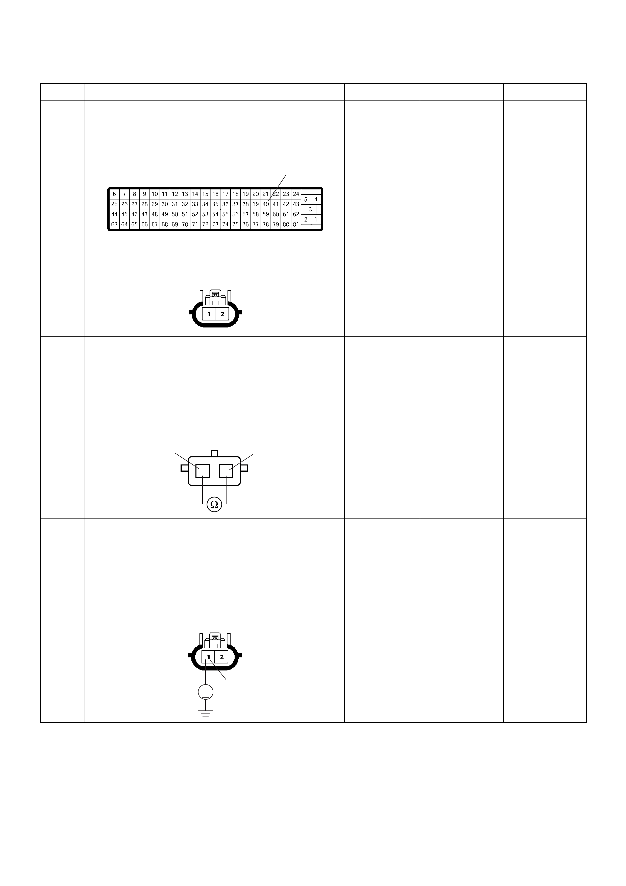
4 Check for poor/faulty connection at the exhaust
throttle VSV 1 or ECM connector. If a poor/faulty
connection is found, repair as necessary.
Was the problem found?
— Verify repair Go to Step 5
5 Using the DVM and check the exhaust throttle VSV 1.
1. Ignition “Off”, engine “Off”.
2. Disconnect the exhaust throttle VSV 1 connector.
3. Measure the resistance of exhaust throttle VSV 1
solenoid coil.
Does the tester indicate standard resistance?
Approximately
40Ω at 20°C Go to Step 6 Go to Step 9
6 U sing the DVM an d check the exh aust throttle VSV 1
power supply circuit.
1. Ignition “On”, engine “Off”.
2. Remove the exhaust throttle VSV 1 connector.
3. Check the circuit for open circuit.
Was the DVM indicated specified value?
Battery
voltage Go to Step 8 Go to Step 7
Step Action Value(s) Yes No
40
C-56
C-13
12
1
2VSV-1
V
1
C-13
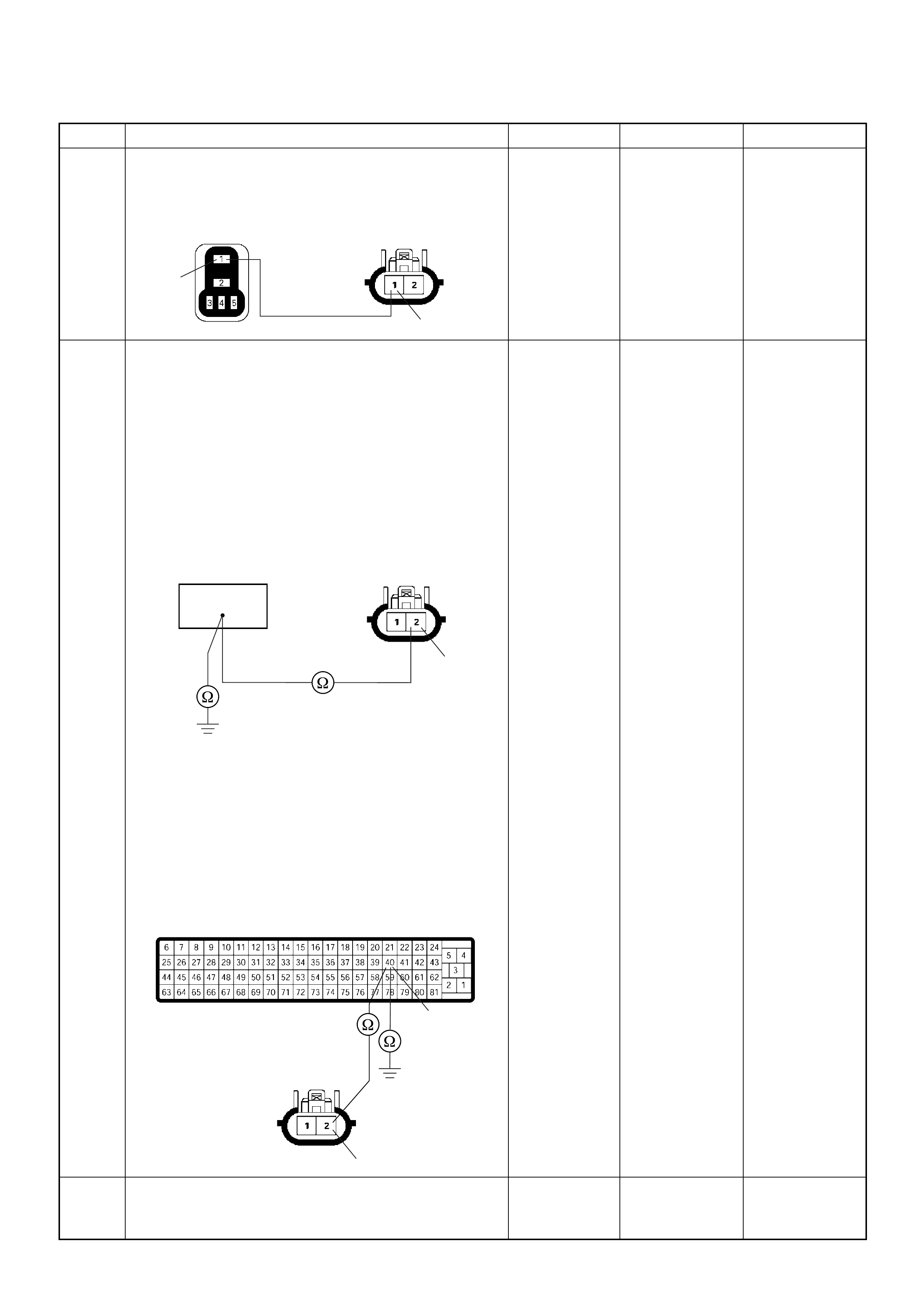
7 Repair the open circuit between the ECM main relay
and exhaust throttle VSV 1.
Is the action complete?
— Verify repair —
8 U sing the DVM an d check the exh aust throttle VSV 1
circuit.
Breaker box is available:
1. Ignition “Off”, engine “Off”.
2. Install the breaker box as type A. (ECM
disconnected) Ref. Page 6E-81
3. Remove the exhaust throttle VSV 1 connector.
4. Check the circuit for open or short to ground
circuit.
Was the problem found?
Breaker box is not available:
1. Ignition “Off”, engine “Off”.
2. Disconnect the ECM connector.
3. Remove the exhaust throttle VSV 1 connector.
4. Check the circuit for open or short to ground
circuit.
Was the problem found?
—
Repair faulty
harnes s and
verify repair Go to Step 11
9 Substitute a known good exhaust throttle VSV 1 and
recheck.
Was the problem solved? — Go to Step 10 Go to Step 11
Step Action Value(s) Yes No
1
1
C-13X-4
2
40
C-13
2
40
C-13
C-56

Diagnostic Trouble Code (DTC) P1576 (Symptom Code 8) (Flash Code 71)
Exhaust Throttle VSV 1 Circuit Voltage High
10 Replace the exhaust throttle VSV 1.
Is the action complete? — Verify repair —
11 Is the ECM programmed with the latest software
release?
If not, download the latest software to the ECM using
the “SPS (Service Programming System)”.
Was the problem solved? — Verify repair Go to Step 12
12 Replace the ECM.
Is the action complete?
IMPORTANT: The replacement ECM must be
programmed. Refer to section of the Service
Programming System (SPS) in this manual.
Foll owing ECM pr ogramming, the immobi liser system
(if equipped) must be linked to the ECM. Refer to
section 11 “Immobiliser System-ECM replacement” for
the ECM/Immobiliser linking procedure. — Verify repair —
Step Action Value(s) Yes No
1 Was the “On- Board Diagnos tic (OBD) Sy stem Check”
performed?
—Go to Step 2
Go to On Board
Diagnostic
(OBD) System
Check
2 1. Connect the Tech 2.
2. Review and record the failure information.
3. S elect “F0: Read DTC I nfor As Stored B y ECU” in
“F0: Diagnostic Trouble Codes”.
Is the DTC P1576 (Symptom Code 8) stored as
“Present Failure”? — Go to Step 3
Refer to
Diagnostic Aids
and Go to Step
3
3 1. Using the Tech 2, ignition “On” and engine “Off”.
2. Select “F1: Clear DTC Information” in “F0:
Diagnostic Trouble Codes” with the Tech 2 and
clear the DTC information.
3. Operate the vehicle and monitor the “F0: Read
DTC Infor As Stored By ECU” in the “F0:
Diagnostic Trouble Codes”.
Was the DT C P1 576 (Sy mpt om Code 8) stor e d i n th is
ignition cycle? — Go to Step 4 Refer to
Diagnostic Aids
Step Action Value(s) Yes No

4 Check for poor/faulty connection at the exhaust
throttle VSV 1 or ECM connector. If a poor/faulty
connection is found, repair as necessary.
Was the problem found?
— Verify repair Go to Step 5
5 Using the DVM and check the exhaust throttle VSV 1.
1. Ignition “Off”, engine “Off”.
2. Disconnect the exhaust throttle VSV 1 connector.
3. Measure the resistance of EGR EVRV solenoid
coil.
Does the tester indicate standard resistance?
Approximately
40Ω at 20°C Go to Step 6 Go to Step 8
6 U sing the DVM an d check the exh aust throttle VSV 1
circuit.
1. Ignition “Off”, engine “Off”.
2. Remove the exhaust throttle VSV 1 connector and
ECM connector.
3. Check the circuit for short to voltage circuit.
Was the DVM indicated specified value?
No continuity Go to Step 10 Go to Step 7
7 Repair the short to voltage circuit.
Is the action complete? — Verify repair —
8 Substitute a known good exhaust throttle VSV 1 and
recheck.
Was the problem solved? — Go to Step 9 Go to Step 10
9 Replace the exhaust throttle VSV 1.
Is the action complete? — Verify repair —
Step Action Value(s) Yes No
40
C-56
C-13
12
1
2VSV-1
21 C-13

10 Is the ECM programmed with the latest software
release?
If not, downlo ad the latest software to the ECM using
the “SPS (Service Programming System)”.
Was the problem solved? — Verify repair Go to Step 11
11 Replace the ECM.
Is the action complete?
IMPORTANT: The replacement ECM must be
programmed. Refer to section of the Service
Programming System (SPS) in this manual.
Foll owing ECM pr ogramming, the immobi liser system
(if equipped) must be linked to the ECM. Refer to
section 11 “Immobiliser System-ECM replacement” for
the ECM/Immobiliser linking procedure. — Verify repair —
Step Action Value(s) Yes No
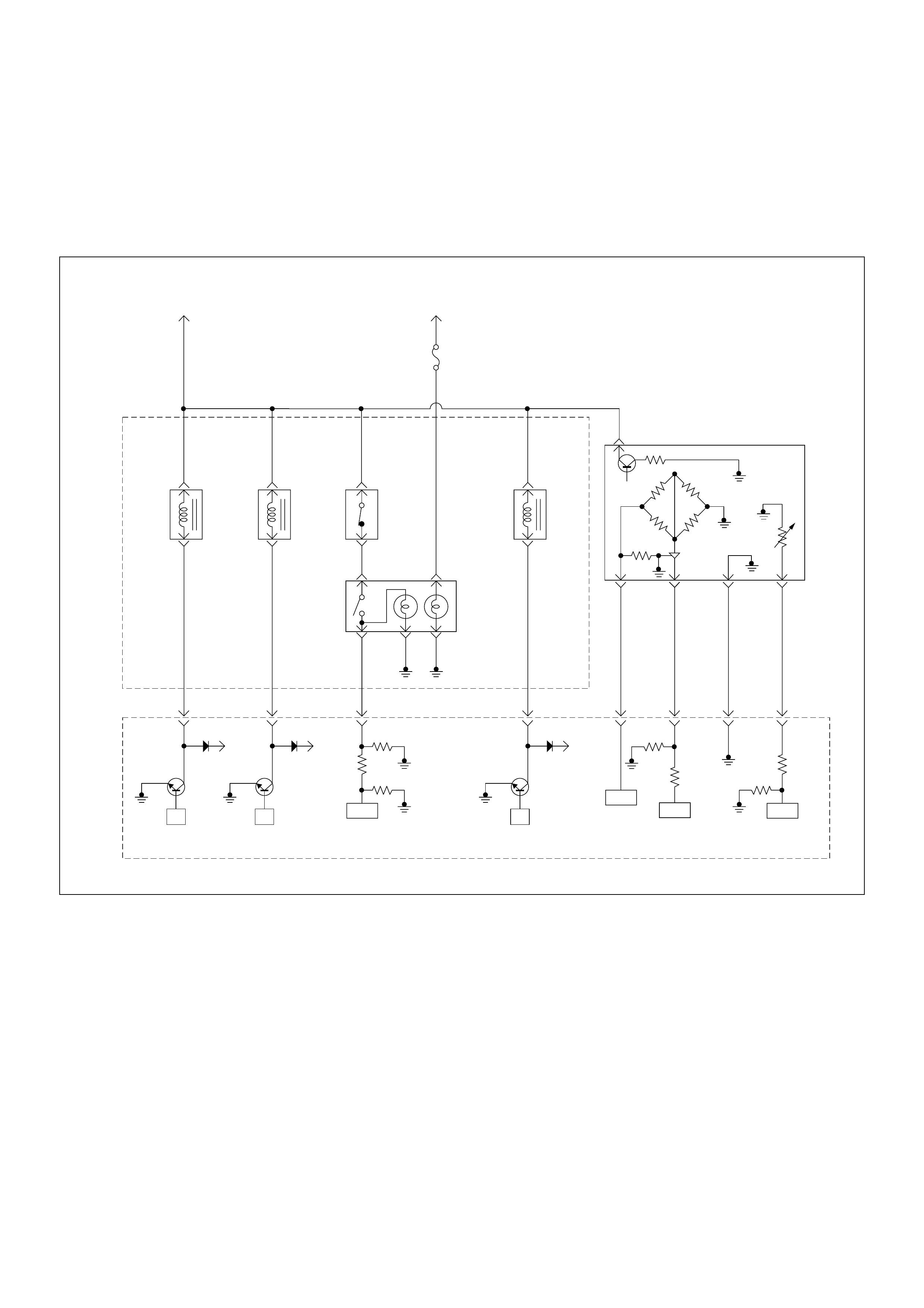
Diagnostic Trouble Code (DTC) P1577 (Symptom Code 4)
(Flash Code 71) Exhaust Throttle VSV 2 Circuit Voltage Low
Diagnostic Trouble Code (DTC) P1577 (Symptom Code 8)
(Flash Code 71) Exhaust Throttle VSV 2 Circuit Voltage High
Batt
µP
Batt
µP
Batt
µP
0.5
BLK/
URG
0.5
BRN/
RED
0.5
BLU/
RED
0.5
BLU/
RED
4JA1-TC
0.5
GRY/
YEL
974661
0.5
WHT/
RED
83
0.5
GRN/
RED
88
0.5
BLK/
RED
92
0.5
BLK/
BLU
84
IAT
Sensor MAF &
IAT
Sensor
Rr Fog
Light
10A
EGR-
EVRV
0.5
WHT/
BLK
0.5
BLU/
RED
0.5
WHT/
BLU
0.5
BLU/
RED
0.5
GRN/
RED
0.5
BLU/
RED
Exhaust
Throttle
VSV2
Exhaust
Throttle
VSV1
Engine
Warming Up
SW
Thermo
SW
2
4531
Battery
Voltage
ECM
Main Relay
IC ICIC CPU
Engine
Control
Module
(ECM)
40

Condition for setting the DTC and action taken when the DTC sets
Circuit Description
The switch engine warming signals the engine control
module (ECM) to activate the quick warm-up system
(QWS).
Switch only provides the request and that the ECM
decides when to activated when certain conditions are
met.
If the exhaust throttle VSV 2 circuit is open or shorted to
ground, a DTC P1577 (Symptom Code 4) is stored.
If the exhaust throttle VSV 2 circuit is shorted to power,
a DTC P1577 (Symptom Code 8) is stored.
Diagnostic Aids
An intermittent may be caused by the following:
• Poor connections.
• Misrouted harness.
• Rubbed through wire insulation.
• Broken wire inside the insulation.
Check for the following conditions:
• Poor connection at ECM-Inspect harness connectors
for backed out terminals, improper mating, broken
locks, improperly formed or damaged terminals, and
poor terminal to wire connection.
• Damaged harness-Inspect the wiring harness for
damage. If the harness appears to be OK, observe
the DTC P1577 display on the Tech2 while moving
connectors and wiring harnesses.
Diagnostic Trouble Code (DTC) P1577 (Symptom Code 4) (Flash Code 71)
Exhaust Throttle VSV 2 Circuit Voltage Low
Flash
Code Code Symptom
Code MIL DTC Name DTC Setting Condition Fail-Safe (Back Up)
71 P1577 4 ON Exhaust Throttle VSV 2
Circuit Voltage Low Exhaust throttle VSV 2 circuit
open or short to ground
circuit.
No fail-safe function.
8 ON Exhaust Throttle VSV 2
Circuit Voltage High Exhaust throttle VSV 2 circuit
short to voltage circuit.
Step Action Value(s) Yes No
1 Was the “On-Board Diagnostic (OBD) System Check”
performed?
—Go to Step 2
Go to On Board
Diagnostic
(OBD) System
Check
2 1. Connect the Tech 2.
2. Review and record the failure information.
3. Select “F0: Read DTC Infor As Stored By ECU” in
“F0: Diagnostic Trouble Codes”.
Is the DTC P1577 (Symptom Code 4) stored as
“Present Failure”? — Go to Step 3
Refer to
Diagnostic Aids
and Go to Step
3
3 1. Using the Tech 2, ignition “On” and engine “Off”.
2. Select “F1: Clear DTC Information” in “F0:
Diagnostic Trouble Codes” with the Tech 2 and
clear the DTC information.
3. Operate the vehicle and monitor the “F0: Read
DTC Infor As Stored By ECU” in the “F0:
Diagnostic Trouble Codes”.
Was the DT C P1 577 (Sy mpt om Code 4) stor e d i n th is
ignition cycle? — Go to Step 4
Refer to
Diagnostic Aids
and Go to Step
4
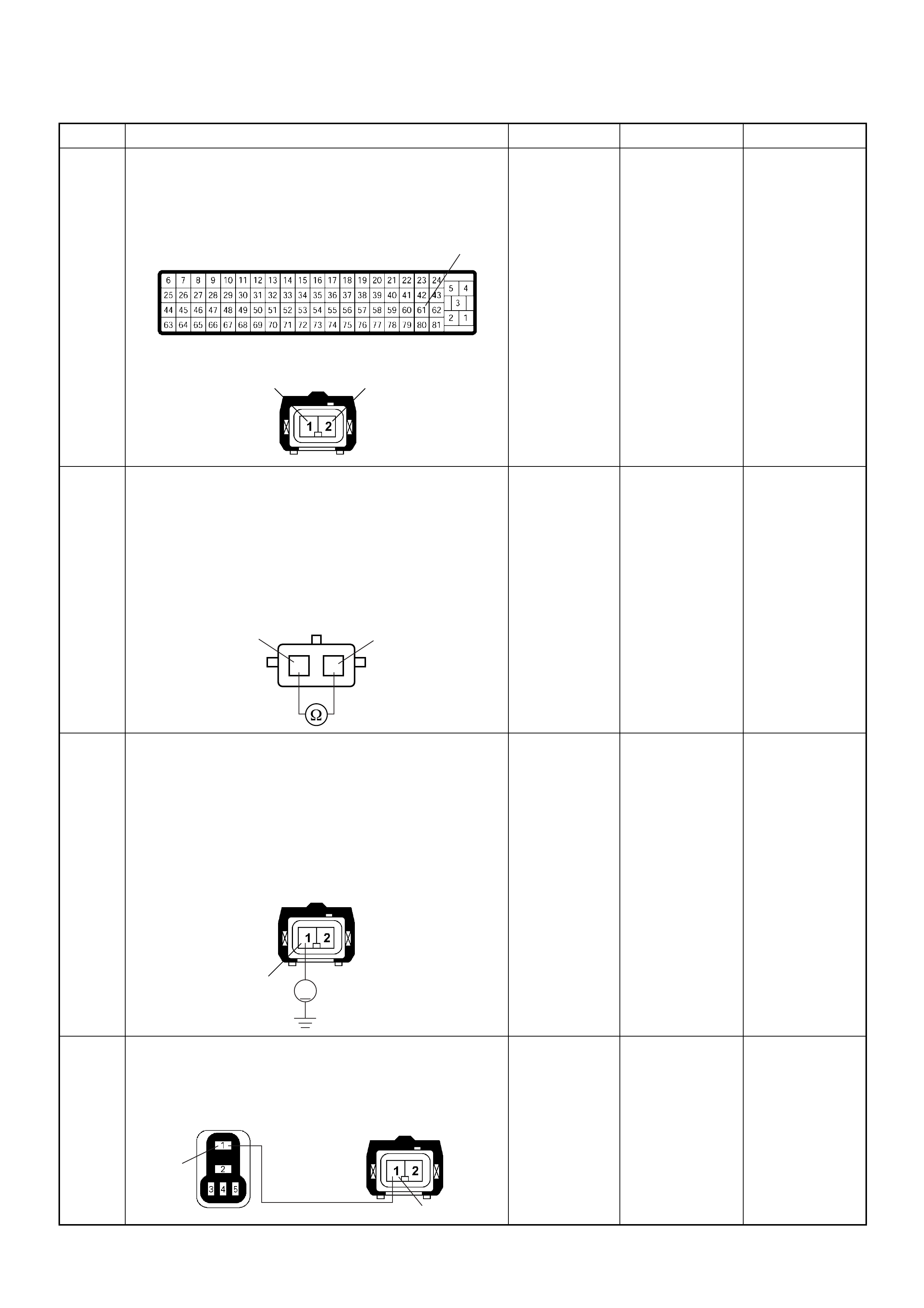
4 Check for poor/faulty connection at the exhaust
throttle VSV 2 or ECM connector. If a poor/faulty
connection is found, repair as necessary.
Was the problem found?
— Verify repair Go to Step 5
5 Using the DVM and check the exhaust throttle VSV 2.
1. Ignition “Off”, engine “Off”.
2. Disconnect the exhaust throttle VSV 2 connector.
3. Measure the resistance of exhaust throttle VSV 2
solenoid coil.
Does the tester indicate standard resistance?
Approximately
40Ω at 20°C Go to Step 6 Go to Step 9
6 U sing the DVM an d check the exh aust throttle VSV 2
power supply circuit.
1. Ignition “On”, engine “Off”.
2. Remove the exhaust throttle VSV 2 connector.
3. Check the circuit for open circuit.
Was the DVM indicated specified value?
Battery
voltage Go to Step 8 Go to Step 7
7 Repair the open circuit between the ECM main relay
and exhaust throttle VSV 2.
Is the action complete?
— Verify repair —
Step Action Value(s) Yes No
61
21 C-14
C-56
12
1
2VSV-2
V
1
C-14
1
1
X-4 C-14
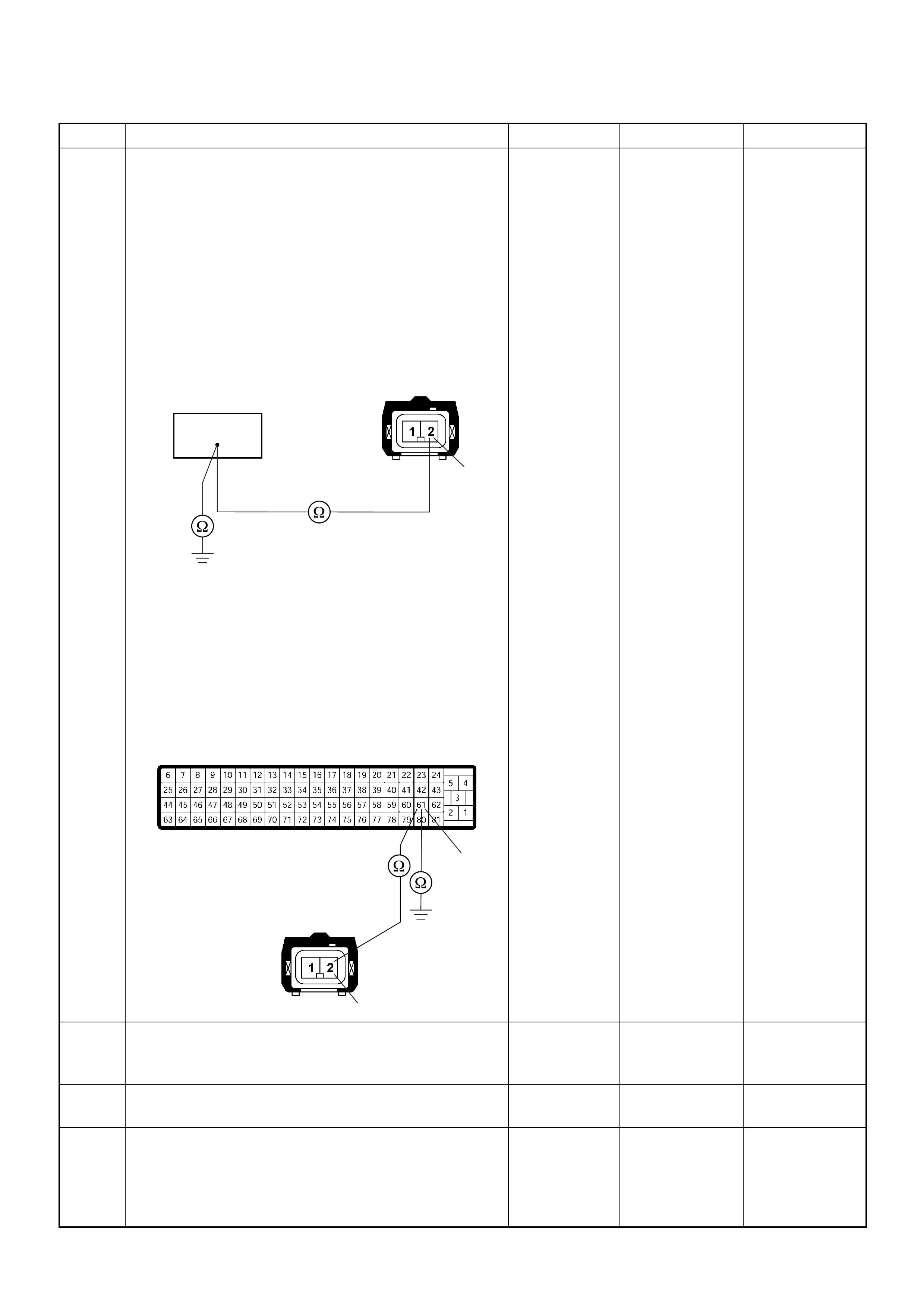
8 U sing the DVM an d check the exh aust throttle VSV 2
circuit.
Breaker box is available:
1. Ignition “Off”, engine “Off”.
2. Install the breaker box as type A. (ECM
disconnected) Ref. Page 6E-81
3. Remove the exhaust throttle VSV 2 connector.
4. Check the circuit for open or short to ground
circuit.
Was the problem found?
Breaker box is not available:
1. Ignition “Off”, engine “Off”.
2. Disconnect the ECM connector.
3. Remove the exhaust throttle VSV 2 connector.
4. Check the circuit for open or short to ground
circuit.
Was the problem found?
—
Repair faulty
harnes s and
verify repair Go to Step 11
9 Substitute a known good exhaust throttle VSV 2 and
recheck.
Was the problem solved? — Go to Step 10 Go to Step 11
10 Replace the exhaust throttle VSV 2.
Is the action complete? — Verify repair —
11 Is the ECM programmed with the latest software
release?
If not, downlo ad the latest software to the ECM using
the “SPS (Service Programming System)”.
Was the problem solved? — Verify repair Go to Step 12
Step Action Value(s) Yes No
2
C-14
61
2
61
C-56
C-14
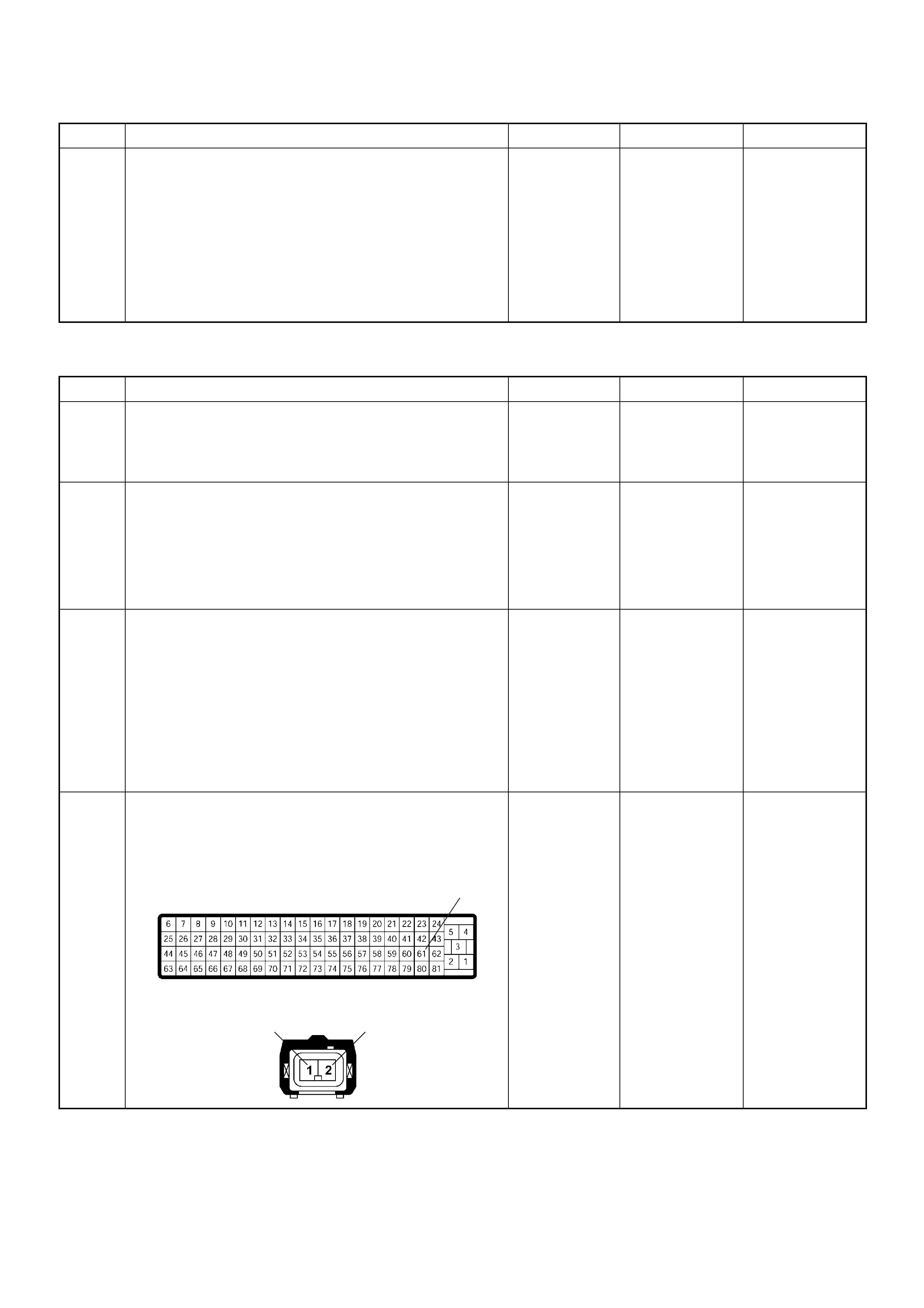
Diagnostic Trouble Code (DTC) P1577 (Symptom Code 8) (Flash Code 71)
Exhaust Throttle VSV 2 Circuit Voltage High
12 Replace the ECM.
Is the action complete?
IMPORTANT: The replacement ECM must be
programmed. Refer to section of the Service
Programming System (SPS) in this manual.
Foll owing ECM pr ogramming, the immobi liser system
(if equipped) must be linked to the ECM. Refer to
section 11 “Immobiliser System-ECM replacement” for
the ECM/Immobiliser linking procedure. — Verify repair —
Step Action Value(s) Yes No
1 Was the “On- Board Diagnos tic (OBD) Sy stem Check”
performed?
—Go to Step 2
Go to On Board
Diagnostic
(OBD) System
Check
2 1. Connect the Tech 2.
2. Review and record the failure information.
3. S elect “F0: Read DTC I nfor As Stored B y ECU” in
“F0: Diagnostic Trouble Codes”.
Is the DTC P1577 (Symptom Code 8) stored as
“Present Failure”? — Go to Step 3
Refer to
Diagnostic Aids
and Go to Step
3
3 1. Using the Tech 2, ignition “On” and engine “Off”.
2. Select “F1: Clear DTC Information” in “F0:
Diagnostic Trouble Codes” with the Tech 2 and
clear the DTC information.
3. Operate the vehicle and monitor the “F0: Read
DTC Infor As Stored By ECU” in the “F0:
Diagnostic Trouble Codes”.
Was the DT C P1 577 (Sy mpt om Code 8) stor e d i n th is
ignition cycle? — Go to Step 4 Refer to
Diagnostic Aids
4 Check for poor/faulty connection at the exhaust
throttle VSV 2 or ECM connector. If a poor/faulty
connection is found, repair as necessary.
Was the problem found?
— Verify repair Go to Step 5
Step Action Value(s) Yes No
61
21 C-14
C-56
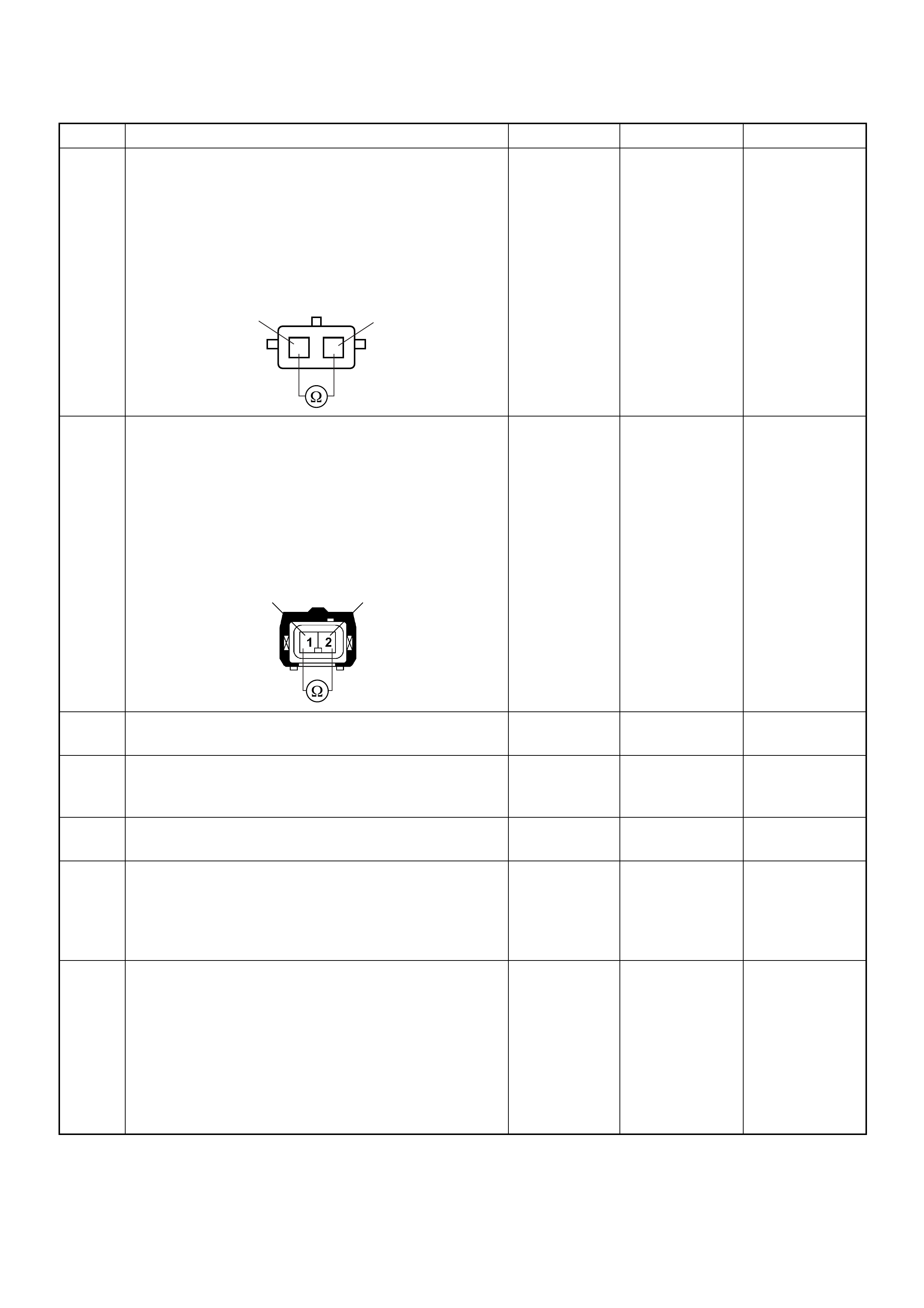
5 Using the DVM and check the exhaust throttle VSV 2.
1. Ignition “Off”, engine “Off”.
2. Disconnect the exhaust throttle VSV 2 connector.
3. Measure the resistance of EGR EVRV solenoid
coil.
Does the tester indicate standard resistance?
Approximately
40Ω at 20°C Go to Step 6 Go to Step 8
6 U sing the DVM an d check the exh aust throttle VSV 2
circuit.
1. Ignition “Off”, engine “Off”.
2. Remove the exhaust throttle VSV 2 connector and
ECM connector.
3. Check the circuit for short to voltage circuit.
Was the DVM indicated specified value?
No continuity Go to Step 10 Go to Step 7
7 Repair the short to voltage circuit.
Is the action complete? — Verify repair —
8 Substitute a known good exhaust throttle VSV 2 and
recheck.
Was the problem solved? — Go to Step 9 Go to Step 10
9 Replace the exhaust throttle VSV 2.
Is the action complete? — Verify repair —
10 Is the ECM programmed with the latest software
release?
If not, downlo ad the latest software to the ECM using
the “SPS (Service Programming System)”.
Was the problem solved? — Verify repair Go to Step 11
11 Replace the ECM.
Is the action complete?
IMPORTANT: The replacement ECM must be
programmed. Refer to section of the Service
Programming System (SPS) in this manual.
Foll owing ECM pr ogramming, the immobi liser system
(if equipped) must be linked to the ECM. Refer to
section 11 “Immobiliser System-ECM replacement” for
the ECM/Immobiliser linking procedure. — Verify repair —
Step Action Value(s) Yes No
12
1
2VSV-2
21 C-14

Diagnostic Trouble Code (DTC) P1605 (Symptom Code D)
(Flash Code 55) EEPROM Defect
Diagnostic Trouble Code (DTC) P1605 (Symp tom Code E)
(Flash Code 55) EEPROM Defect
Condition for setting the DTC and action taken when the DTC sets
Circuit Description & Diagnostic Aids
The ECM used in this vehicle utilises an Electrically
Erasable & Programmable Read Only Memory
(EEPROM). The EEPROM contains program
informat ion and the cali brations requir ed for engin e and
diagnostics operation.
If the ECM fails internally (IC, circuit, memory, etc,), a
DTC P1605 (Symptom Code C), P1605 (Symptom
Code D) or P1605 (Symptom Code E) will be stored.
Flash
Code Code Symptom
Code MIL DTC Name DTC Setting Condition F ail-Safe (Back Up)
55 P1605 D ON EEPROM Defect Write and read from the
EEPROM are failed during
initialization of the ECM.
ECM uses default values from
the EPROM.
E ON EEPROM Defect EEPROM checksum does not
match with the read check
sum during initialization of the
ECM.

Diagnostic Trouble Code (DTC) P1605 (Symptom Code D) (Flash Code 55) EEPROM Defect
Diagnostic Trouble Code (DTC) P1605 (Symptom Code E) (Flash Code 55) EEPROM Defect
Step Action Value(s) Yes No
1 Was the “On-Board Diagnostic (OBD) System Check”
performed?
—Go to Step 2
Go to On Board
Diagnostic
(OBD) System
Check
2 1. Connect the Tech 2.
2. Review and record the failure information.
3. Select “F0: Read DTC Infor As Stored By ECU” in
“F0: Diagnostic Trouble Codes”.
Is the DTC P1605 (Symptom Code D) or P1605
(Symptom Code E) stored as “Present Failure”? — Go to Step 3
Refer to
Diagnostic Aids
and Go to Step
3
3 1. Using the Tech 2, ignition “On” and engine “Off”.
2. Select “F1: Clear DTC Information” in “F0:
Diagnostic Trouble Codes” with the Tech 2 and
clear the DTC information.
3. Operate the vehicle and monitor the “F0: Read
DTC Infor As Stored By ECU” in the “F0:
Diagnostic Trouble Codes”.
Was the DTC P1605 (Symptom Code D) or P1605
(Symptom Code E) stored in this ignition cycle? — Go to Step 4 Refer to
Diagnostic Aids
4 Is the ECM programmed with the latest software
release?
If not, downlo ad the latest software to the ECM using
the “SPS (Service Programming System)”.
Was the problem solved? — Verify repair Go to Step 5
5 Replace the ECM.
Is the action complete?
IMPORTANT: The replacement ECM must be
programmed. Refer to section of the Service
Programming System (SPS) in this manual.
Foll owing ECM pr ogramming, the immobi liser system
(if equipped) must be linked to the ECM. Refer to
section 11 “Immobiliser System-ECM replacement” for
the ECM/Immobiliser linking procedure. — Verify repair —

Diagnostic Trouble Code (DTC) P1610 (Symptom Code A)
(Flash Code 56) Security Key & Security Code Not Programmed
Condition for setting the DTC and action taken when the DTC sets
Circuit Desc rip tio n
The ECM decides if there is an abnormality in the
immobiliser control system. A DTC P1610 (Symptom
Code A) i s recorded whe n immobilis er functio n was not
programmed in the ECM.
Diagnostic Aids
Check for the following conditions:
• Poor connection at ECM and immobiliser control unit-
Inspect harne ss con nectors for bac ked out terminal s,
improper mating, broken locks, improp erly formed or
damaged terminals, and poor terminal to wire
connection.
• Damaged harness-Inspect the wiring harness for
damage. If the harness appears to be OK, observe
the DTC P1610 display on the Tech2 while moving
connectors and wiring harnesses.
Flash
Code Code Symptom
Code MIL DTC Name DTC Setting Condition F ail-Safe (Back Up)
56 P1610 A - Security Key and Security
Code not Programmed Immobiliser functions are not
programmed in the ECM. 1. Engine does not start.
2. Check engine lamp flash.
Ignition
SW
Meter
15A
615 7
Batt
Batt
0.5
RED/
WHT
29
0.5
ORG/
BLU
43
0.5
BRN/
YEL
42
0.5
BLK/
RED
27
0.5
BLU/
WHT
0.5 BLU/BLK
68
0.5
WHT
2.0
BLK
35
VSS
0.85
YEL
Imnobiliser
Control Unit
78
0.5
BRN/
YEL
IC
0.85
YEL
Glow
Check
Engine
Tacho
Meter
Speed
Meter
A/T
TCM
µPµPµPµP
Engine
Control
Module
(ECM)

Diagnostic Trouble Code (DTC) P1610 (Symptom Code A) (Flash Code 56)
Security Key and Security Code Not Programmed
Step Action Value(s) Yes No
1 Was the “On-Board Diagnostic (OBD) System Check”
performed?
—Go to Step 2
Go to On Board
Diagnostic
(OBD) System
Check
2 1. Connect the Tech 2.
2. Review and record the failure information.
3. Select “F0: Read DTC Infor As Stored By ECU” in
“F0: Diagnostic Trouble Codes”.
Is the DTC P1610 (Symptom Code A) stored as
“Present Failure”? — Go to Step 3
Refer to
Diagnostic Aids
and Go to Step
3
3 1. Using the Tech 2, ignition “On” and engine “Off”.
2. Select “F1: Clear DTC Information” in “F0:
Diagnostic Trouble Codes” with the Tech 2 and
clear the DTC information.
3. Operate the vehicle and monitor the “F0: Read
DTC Infor As Stored By ECU” in the “F0:
Diagnostic Trouble Codes”.
Was the DTC P1610 (Symptom Code A) stored in this
ignition cycle? — Go to Step 4
Refer to
Diagnostic Aids
and Go to Step
4
4 1. Using the Tech 2, ignition “On” and engine “Off”.
2. Select “Immobiliser” in the system selectio n menu
“Body”.
3. Sele ct “Read D TC Info Or dered By P riority” in the
“Diagnostic Trouble Code”.
Was the any DTC's B**** stored in this ignition cycle? —
Refer to
“Immobiliser
Workshop
Manual” & Go
to DTC Chart
B**** Go to Step 5
5 Is the ECM programmed with the latest software
release?
If not, downlo ad the latest software to the ECM using
the “SPS (Service Programming System)”.
Was the problem solved? — Verify repair Go to Step 6
6 Replace the ECM.
Is the action complete?
IMPORTANT: The replacement ECM must be
programmed. Refer to section of the Service
Programming System (SPS) in this manual.
Foll owing ECM pr ogramming, the immobi liser system
(if equipped) must be linked to the ECM. Refer to
section 11 “Immobiliser System-ECM replacement” for
the ECM/Immobiliser linking procedure. — Verify repair —
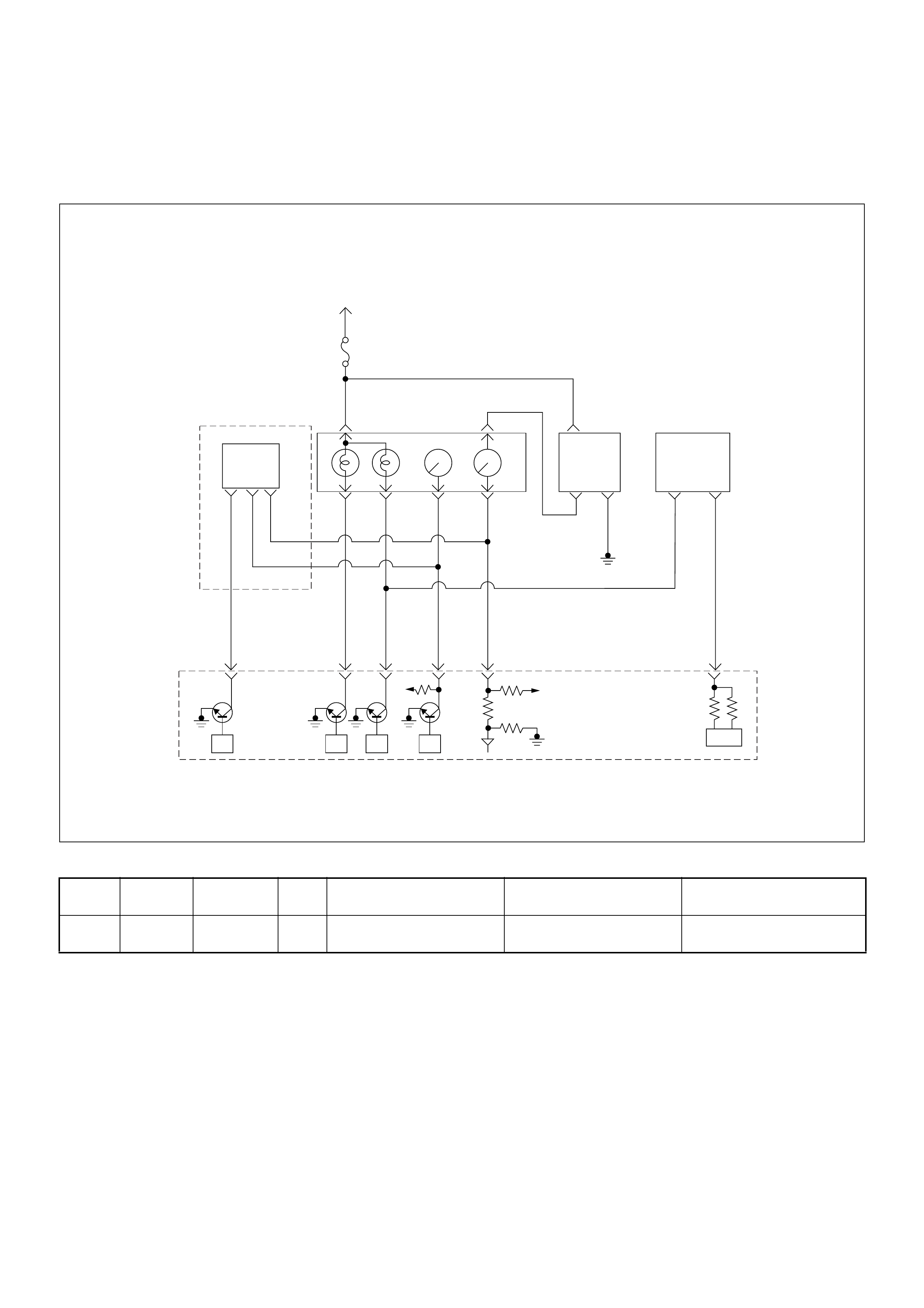
Diagnostic Trouble Code (DTC) P1611 (Symptom Code A)
(Flash Code 56) W rong Security Code Entered
Condition for setting the DTC and action taken when the DTC sets
Circuit Desc rip tio n
The ECM decides if there is an abnormality in the
immobiliser control system. A DTC P1611 (Symptom
Code A) is recorded when received immobiliser security
code was not co rrec t.
Diagnostic Aids
Check for the following conditions:
• Poor connection at ECM and immobiliser control unit-
Inspect harne ss con nectors for bac ked out terminal s,
improper mating, broken locks, improp erly formed or
damaged terminals, and poor terminal to wire
connection.
• Damaged harness-Inspect the wiring harness for
damage. If the harness appears to be OK, observe
the DTC P1611 display on the Tech2 while moving
connectors and wiring harnesses.
Flash
Code Code Symptom
Code MIL DTC Name DTC Setting Condition F ail-Safe (Back Up)
56 P1611 A - Wrong Security Code Entered Received security code is not
correct. 1. Engine does not start.
2. Check engine lamp flash.
Ignition
SW
Meter
15A
615 7
Batt
Batt
0.5
RED/
WHT
29
0.5
ORG/
BLU
43
0.5
BRN/
YEL
42
0.5
BLK/
RED
27
0.5
BLU/
WHT
0.5 BLU/BLK
68
0.5
WHT
2.0
BLK
35
VSS
0.85
YEL
Imnobiliser
Control Unit
78
0.5
BRN/
YEL
IC
0.85
YEL
Glow
Check
Engine
Tacho
Meter
Speed
Meter
A/T
TCM
µPµPµPµP
Engine
Control
Module
(ECM)

Diagnostic Trouble Code (DTC) P1611 (Symptom Code A) (Flash Code 56) Wrong Security Code Entered
Step Action Value(s) Yes No
1 Was the “On-Board Diagnostic (OBD) System Check”
performed?
—Go to Step 2
Go to On Board
Diagnostic
(OBD) System
Check
2 1. Connect the Tech 2.
2. Review and record the failure information.
3. Select “F0: Read DTC Infor As Stored By ECU” in
“F0: Diagnostic Trouble Codes”.
Is the DTC P1611 (Symptom Code A) stored as
“Present Failure”? — Go to Step 3
Refer to
Diagnostic Aids
and Go to Step
3
3 1. Using the Tech 2, ignition “On” and engine “Off”.
2. Select “F1: Clear DTC Information” in “F0:
Diagnostic Trouble Codes” with the Tech 2 and
clear the DTC information.
3. Operate the vehicle and monitor the “F0: Read
DTC Infor As Stored By ECU” in the “F0:
Diagnostic Trouble Codes”.
Was the DT C P1 611 (Sym ptom Cod e A) s tored in th is
ignition cycle? — Go to Step 4
Refer to
Diagnostic Aids
and Go to Step
4
4 1. Using the Tech 2, ignition “On” and engine “Off”.
2. Select “Immobiliser” in the system selectio n menu
“Body”.
3. Sele ct “Read D TC Info Or dered By P riority” in the
“Diagnostic Trouble Code”.
Was the any DTC's B**** stored in this ignition cycle? —
Refer to
“Immobiliser
Workshop
Manual” & Go
to DTC Chart
B**** Go to Step 5
5 Is the ECM programmed with the latest software
release?
If not, downlo ad the latest software to the ECM using
the “SPS (Service Programming System)”.
Was the problem solved? — Verify repair Go to Step 6
6 Replace the ECM.
Is the action complete?
IMPORTANT: The replacement ECM must be
programmed. Refer to section of the Service
Programming System (SPS) in this manual.
Foll owing ECM pr ogramming, the immobi liser system
(if equipped) must be linked to the ECM. Refer to
section 11 “Immobiliser System-ECM replacement” for
the ECM/Immobiliser linking procedure. — Verify repair —

Diagnostic Trouble Code (DTC) P1612 (Symptom Code A)
(Flash Code 56) Immobiliser No Or Wrong Signal
Condition for setting the DTC and action taken when the DTC sets
Circuit Desc rip tio n
The ECM decides if there is an abnormality in the
immobiliser control system. A DTC P1612 (Symptom
Code A) is recorded when received immobiliser
challenge signal was not correct.
Diagnostic Aids
Check for the following conditions:
• Poor connection at ECM and immobiliser control unit-
Inspect harne ss con nectors for bac ked out terminal s,
improper mating, broken locks, improp erly formed or
damaged terminals, and poor terminal to wire
connection.
• Damaged harness-Inspect the wiring harness for
damage. If the harness appears to be OK, observe
the DTC P1612 display on the Tech2 while moving
connectors and wiring harnesses.
Flash
Code Code Symptom
Code MIL DTC Name DTC Setting Condition F ail-Safe (Back Up)
56 P1612 A - Immobiliser No or Wrong
Signal Received challenge signal is
not correct or not received. 1. Engine does not start.
2. Check engine lamp flash.
Ignition
SW
Meter
15A
615 7
Batt
Batt
0.5
RED/
WHT
29
0.5
ORG/
BLU
43
0.5
BRN/
YEL
42
0.5
BLK/
RED
27
0.5
BLU/
WHT
0.5 BLU/BLK
68
0.5
WHT
2.0
BLK
35
VSS
0.85
YEL
Imnobiliser
Control Unit
78
0.5
BRN/
YEL
IC
0.85
YEL
Glow
Check
Engine
Tacho
Meter
Speed
Meter
A/T
TCM
µPµPµPµP
Engine
Control
Module
(ECM)

Diagnostic Trouble Code (DTC) P1612 (Symptom Code A) (Flash Code 56) Immobiliser No or Wrong Signal
Step Action Value(s) Yes No
1 Was the “On-Board Diagnostic (OBD) System Check”
performed?
—Go to Step 2
Go to On Board
Diagnostic
(OBD) System
Check
2 1. Connect the Tech 2.
2. Review and record the failure information.
3. Select “F0: Read DTC Infor As Stored By ECU” in
“F0: Diagnostic Trouble Codes”.
Is the DTC P1612 (Symptom Code A) stored as
“Present Failure”? — Go to Step 3
Refer to
Diagnostic Aids
and Go to Step
3
3 1. Using the Tech 2, ignition “On” and engine “Off”.
2. Select “F1: Clear DTC Information” in “F0:
Diagnostic Trouble Codes” with the Tech 2 and
clear the DTC information.
3. Operate the vehicle and monitor the “F0: Read
DTC Infor As Stored By ECU” in the “F0:
Diagnostic Trouble Codes”.
Was the DTC P1612 (Symptom Code A) stored in this
ignition cycle? — Go to Step 4
Refer to
Diagnostic Aids
and Go to Step
4
4 1. Using the Tech 2, ignition “On” and engine “Off”.
2. Select “Immobiliser” in the system selectio n menu
“Body”.
3. Sele ct “Read D TC Info Or dered By P riority” in the
“Diagnositic Trouble Code”.
Was the any DTC's B**** stored in this ignition cycle? —
Refer to
“Immobiliser
Workshop
Manual” & Go
to DTC Chart
B**** Go to Step 5
5 Check for poor/faulty connection at the immobiliser
control unit connector or ECM connector. If a poor/
faulty co nnec ti on is found, repair as nece ssa ry.
Was the problem found?
— Verify repair Go to Step 6
42
35
78
C-56
B-68
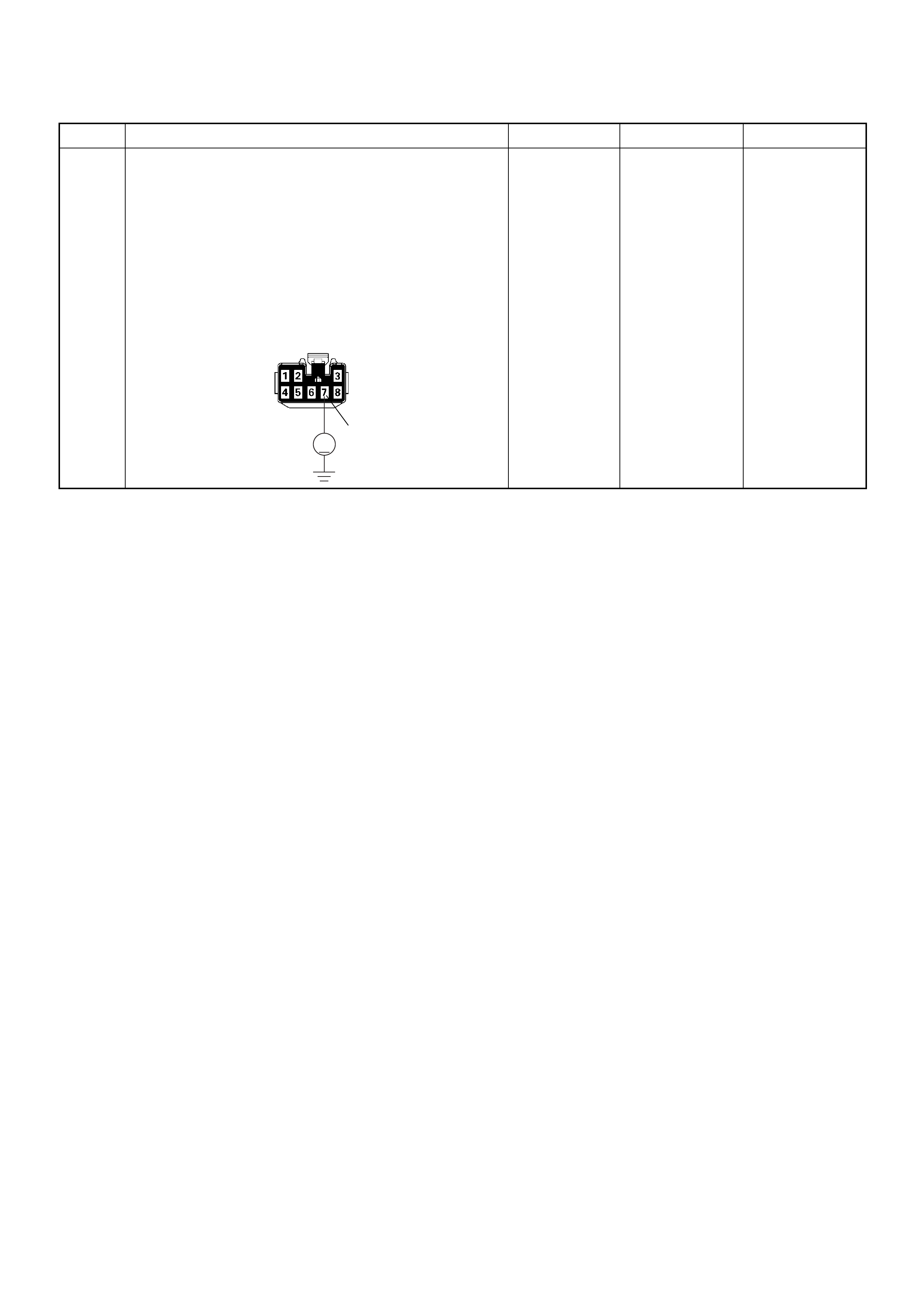
6 Using the DVM and check the “CHECK ENGINE”
lamp circuit.
1. Ignition “Off”, engine “Off”.
2. Disconnect the meter connector and immobiliser
control unit connector.
3. Ignition “On”.
4. Check the circuit for short to power supply circuit.
Was DVM indicated specified value?
Less than 1V Go to Step 7
Repair faulty
harness and
verify repair
Step Action Value(s) Yes No
7
V
B-68
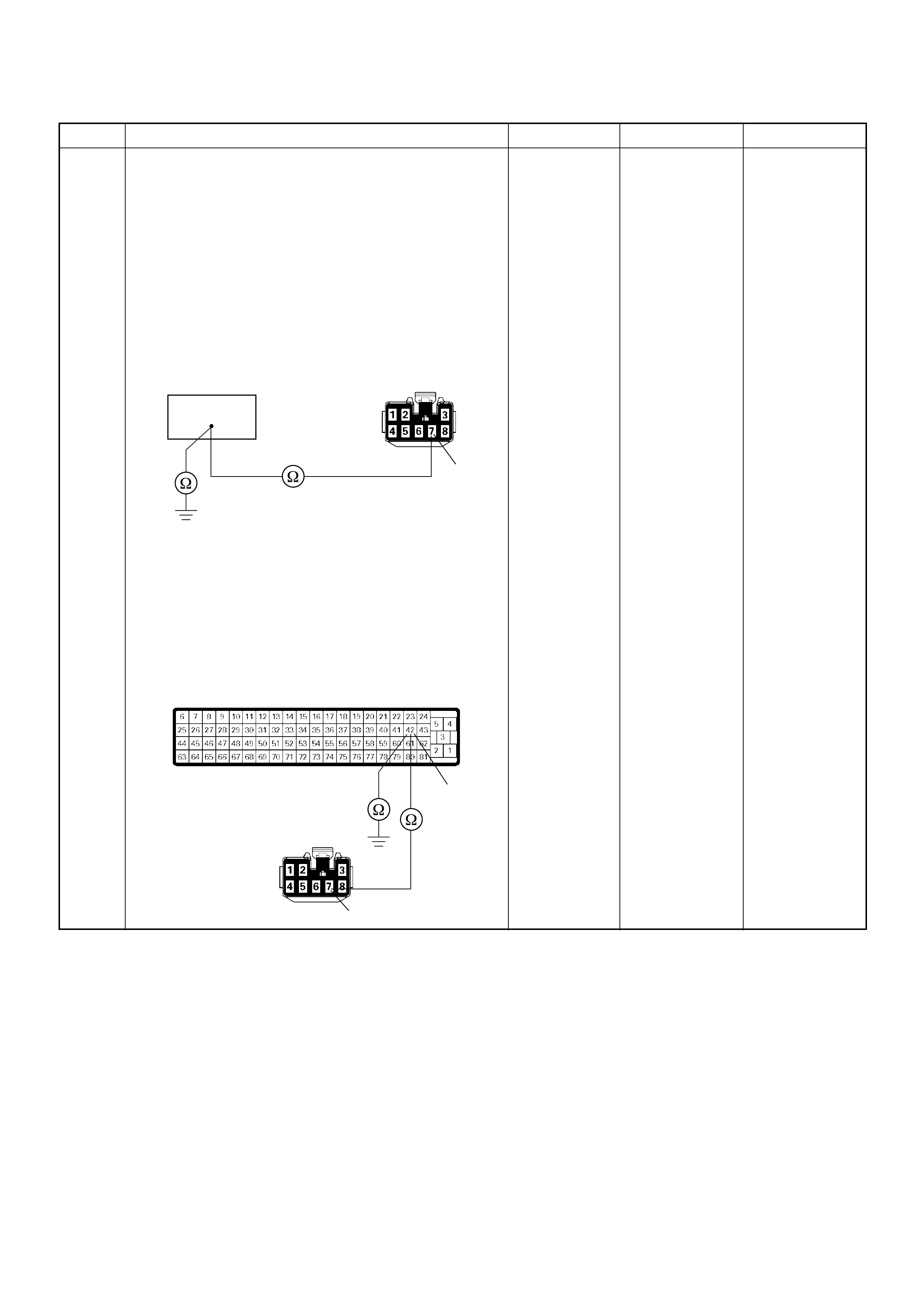
7 Using the DVM and check the “CHECK ENGINE”
lamp circuit.
Breaker box is available:
1. Ignition “Off”, engine “Off”.
2. Install the breaker box as type A. (ECM
disconnected) Ref. Page 6E-81
3. Disconnect the immobiliser control unit connector.
4. Check the circuit for open or short to ground
circuit.
Was the problem found?
Breaker box is not available:
1. Ignition “Off”, engine “Off”.
2. Disconnect the the immobiliser control unit
connector and ECM connector.
3. Check the circuit for open or short to ground
circuit.
Was the problem found?
—
Repair faulty
harnes s and
verify repair G o to Step 8
Step Action Value(s) Yes No
42
7
B-68
42
7
C-56
B-68
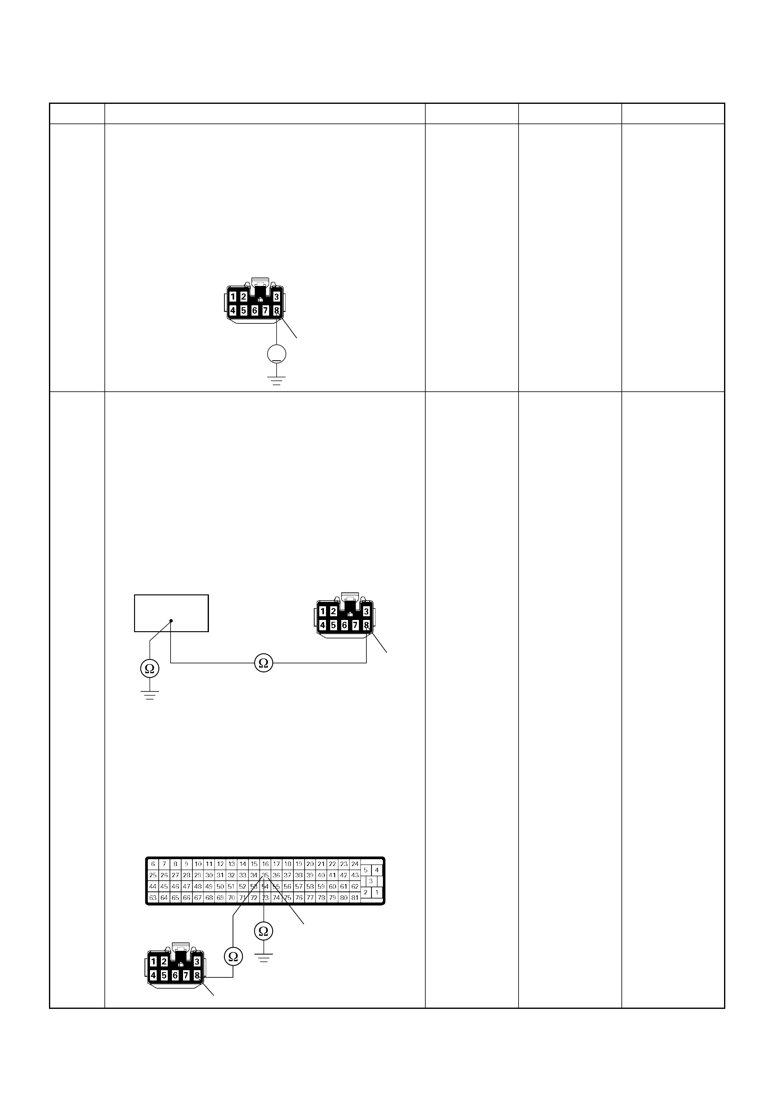
8 Using the DVM and check the ECM and immobiliser
control unit communication circuit.
1. Ignition “Off”, engine “Off”.
2. Disconnect the immobiliser control unit connector.
3. Ignition “On”.
4. Check the circuit for short to power supply circuit.
Was the DVM indicated specified value?
Less than 1V Go to Step 9
Repair faulty
harness and
verify repair
9 Using the DVM and check the ECM and immobiliser
control unit communication circuit.
Breaker box is available:
1. Ignition “Off”, engine “Off”.
2. Install the breaker box as type A. (ECM
disconnected) Ref. Page 6E-81
3. Disconnect the immobiliser control unit connector.
4. Check the circuit for open or short to ground
circuit.
Was the problem found?
Breaker box is not available:
1. Ignition “Off”, engine “Off”.
2. Disconnect the the immobiliser control unit
connector and ECM connector.
3. Check the circuit for open or short to ground
circuit.
Was the problem found?
—
Repair faulty
harnes s and
verify repair Go to Step 10
Step Action Value(s) Yes No
8
V
B-68
35
8
B-68
35
8
C-56
B-68

10 Is the ECM programmed with the latest software
release?
If not, downlo ad the latest software to the ECM using
the “SPS (Service Programming System)”.
Was the problem solved? — Verify repair Go to Step 11
11 Replace the ECM.
Is the action complete?
IMPORTANT: The replacement ECM must be
programmed. Refer to section of the Service
Programming System (SPS) in this manual.
Foll owing ECM pr ogramming, the immobi liser system
(if equipped) must be linked to the ECM. Refer to
section 11 “Immobiliser System-ECM replacement” for
the ECM/Immobiliser linking procedure. — Verify repair —
Step Action Value(s) Yes No

Diagnostic Trouble Code (DTC) P1613 (Symptom Code A)
(Flash Code 56) Immobiliser No Or Wrong Signal
Condition for setting the DTC and action taken when the DTC sets
Circuit Desc rip tio n
The ECM decides if there is an abnormality in the
immobiliser control system. A DTC P1613 (Symptom
Code A) is recorded when received immobiliser
response signal was not correct.
Diagnostic Aids
Check for the following conditions:
• Poor connection at ECM and immobiliser control unit-
Inspect harne ss con nectors for bac ked out terminal s,
improper mating, broken locks, improp erly formed or
damaged terminals, and poor terminal to wire
connection.
• Damaged harness-Inspect the wiring harness for
damage. If the harness appears to be OK, observe
the DTC P1613 display on the Tech2 while moving
connectors and wiring harnesses.
Flash
Code Code Symptom
Code MIL DTC Name DTC Setting Condition F ail-Safe (Back Up)
56 P1613 A - Immobiliser No or Wrong
Signal Received response signal is
not correct or not received. 1. Engine does not start.
2. Check engine lamp flash.
Ignition
SW
Meter
15A
615 7
Batt
Batt
0.5
RED/
WHT
29
0.5
ORG/
BLU
43
0.5
BRN/
YEL
42
0.5
BLK/
RED
27
0.5
BLU/
WHT
0.5 BLU/BLK
68
0.5
WHT
2.0
BLK
35
VSS
0.85
YEL
Imnobiliser
Control Unit
78
0.5
BRN/
YEL
IC
0.85
YEL
Glow
Check
Engine
Tacho
Meter
Speed
Meter
A/T
TCM
µPµPµPµP
Engine
Control
Module
(ECM)
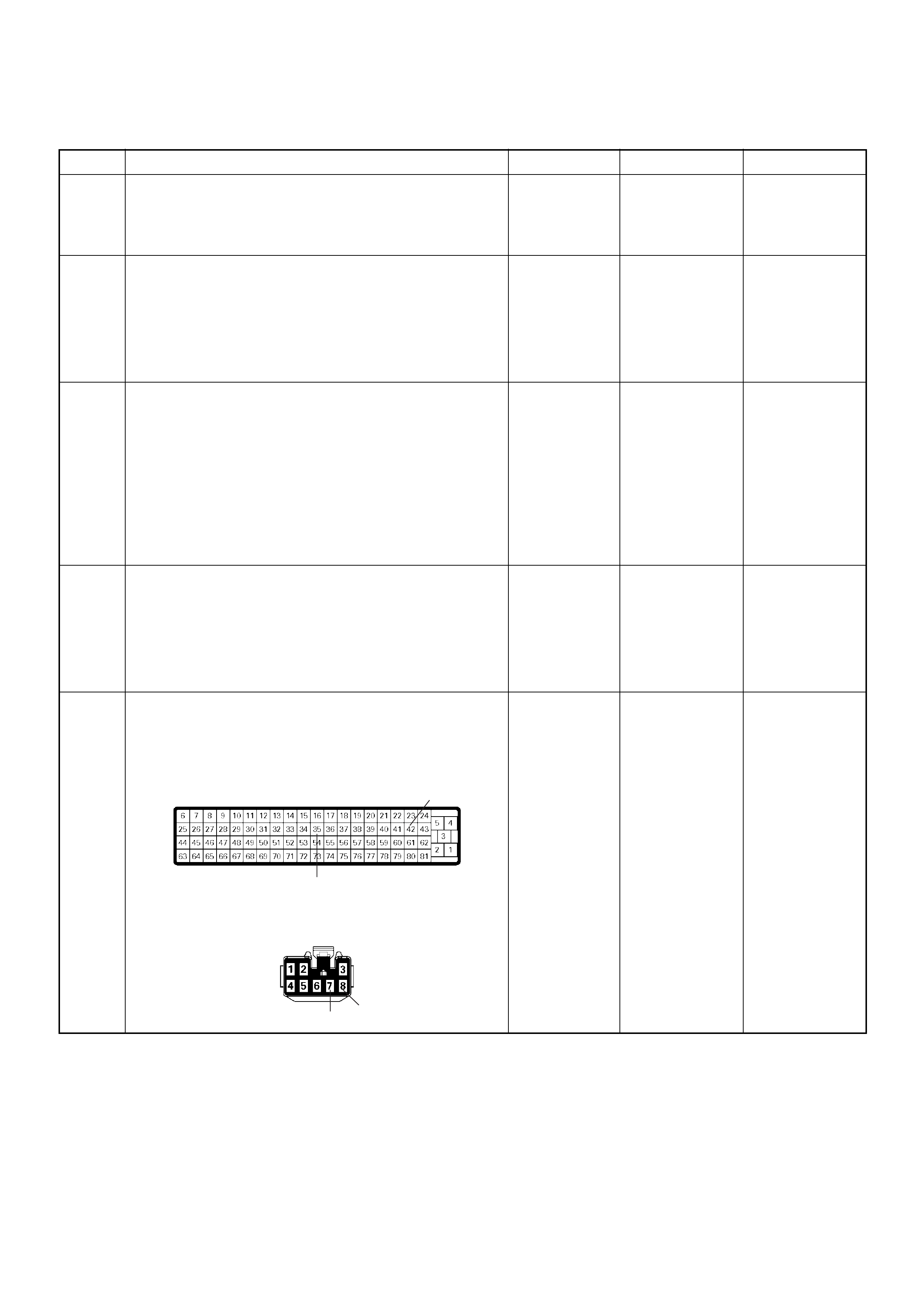
Diagnostic Trouble Code (DTC) P1613 (Symptom Code A) (Flash Code 56) Immobiliser No or Wrong Signal
Step Action Value(s) Yes No
1 Was the “On-Board Diagnostic (OBD) System Check”
performed?
—Go to Step 2
Go to On Board
Diagnostic
(OBD) System
Check
2 1. Connect the Tech 2.
2. Review and record the failure information.
3. Select “F0: Read DTC Infor As Stored By ECU” in
“F0: Diagnostic Trouble Codes”.
Is the DTC P1613 (Symptom Code A) stored as
“Present Failure”? — Go to Step 3
Refer to
Diagnostic Aids
and Go to Step
3
3 1. Using the Tech 2, ignition “On” and engine “Off”.
2. Select “F1: Clear DTC Information” in “F0:
Diagnostic Trouble Codes” with the Tech 2 and
clear the DTC information.
3. Operate the vehicle and monitor the “F0: Read
DTC Infor As Stored By ECU” in the “F0:
Diagnostic Trouble Codes”.
Was the DTC P1613 (Symptom Code A) stored in this
ignition cycle? — Go to Step 4
Refer to
Diagnostic Aids
and Go to Step
4
4 1. Using the Tech 2, ignition “On” and engine “Off”.
2. Select “Immobiliser” in the system selectio n menu
“Body”.
3. Sele ct “Read D TC Info Or dered By P riority” in the
“Diagnositic Trouble Code”.
Was the any DTC's B**** stored in this ignition cycle? —
Refer to
“Immobiliser
Workshop
Manual” & Go
to DTC Chart
B**** Go to Step 5
5 Check for poor/faulty connection at the immobiliser
control unit connector or ECM connector. If a poor/
faulty co nnec ti on is found, repair as nece ssa ry.
Was the problem found?
— Verify repair Go to Step 6
42
35
78
C-56
B-68

6 Using the DVM and check the “CHECK ENGINE”
lamp circuit.
1. Ignition “Off”, engine “Off”.
2. Disconnect the meter connector and immobiliser
control unit connector.
3. Ignition “On”.
4. Check the circuit for short to power supply circuit.
Was DVM indicated specified value?
Less than 1V Go to Step 7
Repair faulty
harness and
verify repair
Step Action Value(s) Yes No
7
V
B-68
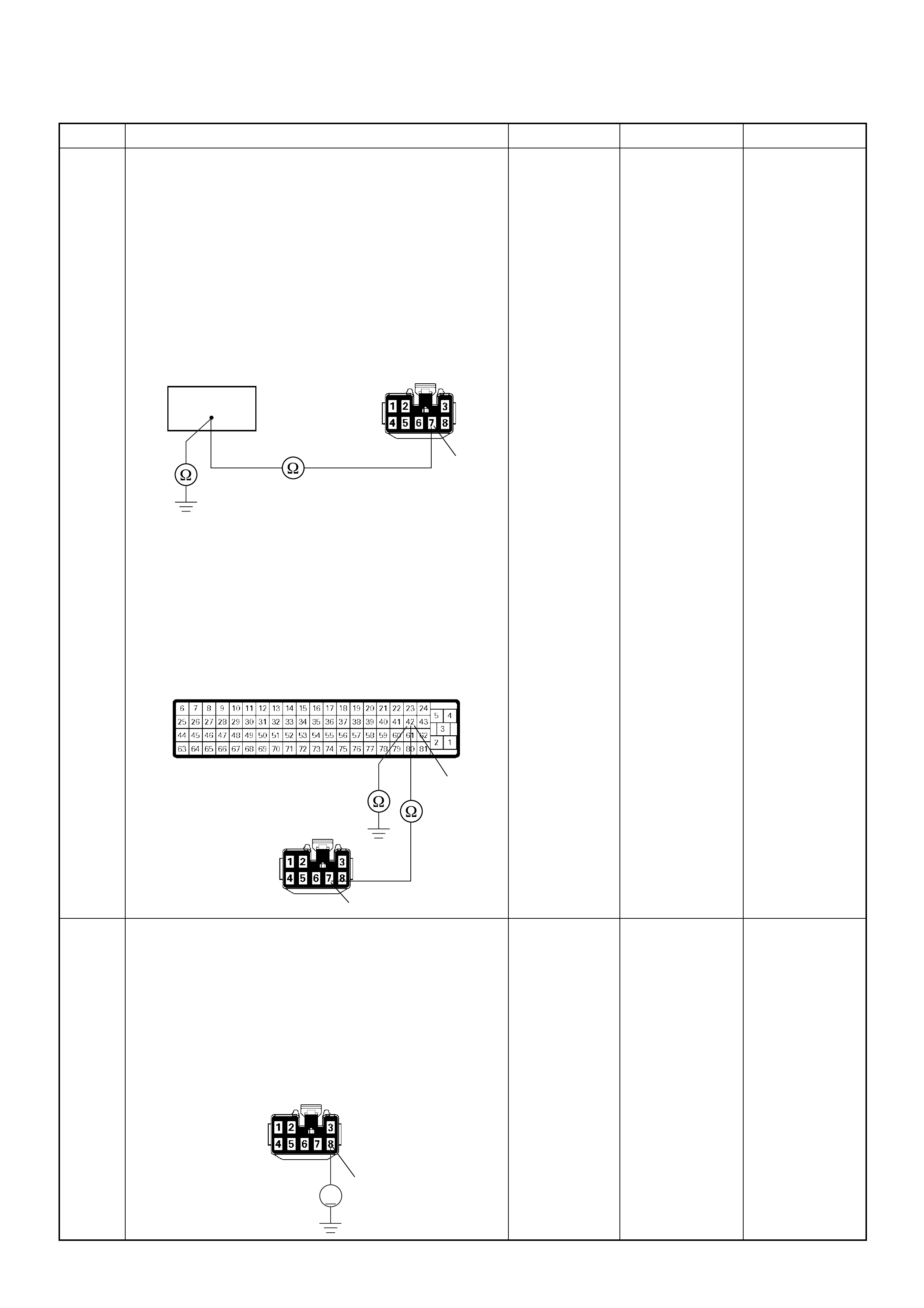
7 Using the DVM and check the “CHECK ENGINE”
lamp circuit.
Breaker box is available:
1. Ignition “Off”, engine “Off”.
2. Install the breaker box as type A. (ECM
disconnected) Ref. Page 6E-81
3. Disconnect the immobiliser control unit connector.
4. Check the circuit for open or short to ground
circuit.
Was the problem found?
Breaker box is not available:
1. Ignition “Off”, engine “Off”.
2. Disconnect the the immobiliser control unit
connector and ECM connector.
3. Check the circuit for open or short to ground
circuit.
Was the problem found?
—
Repair faulty
harnes s and
verify repair G o to Step 8
8 Using the DVM and check the ECM and immobiliser
control unit communication circuit.
1. Ignition “Off”, engine “Off”.
2. Disconnect the immobiliser control unit connector.
3. Ignition “On”.
4. Check the circuit for short to power supply circuit.
Was the DVM indicated specified value?
Less than 1V Go to Step 9
Repair faulty
harness and
verify repair
Step Action Value(s) Yes No
42
7
B-68
42
7
C-56
B-68
8
V
B-68
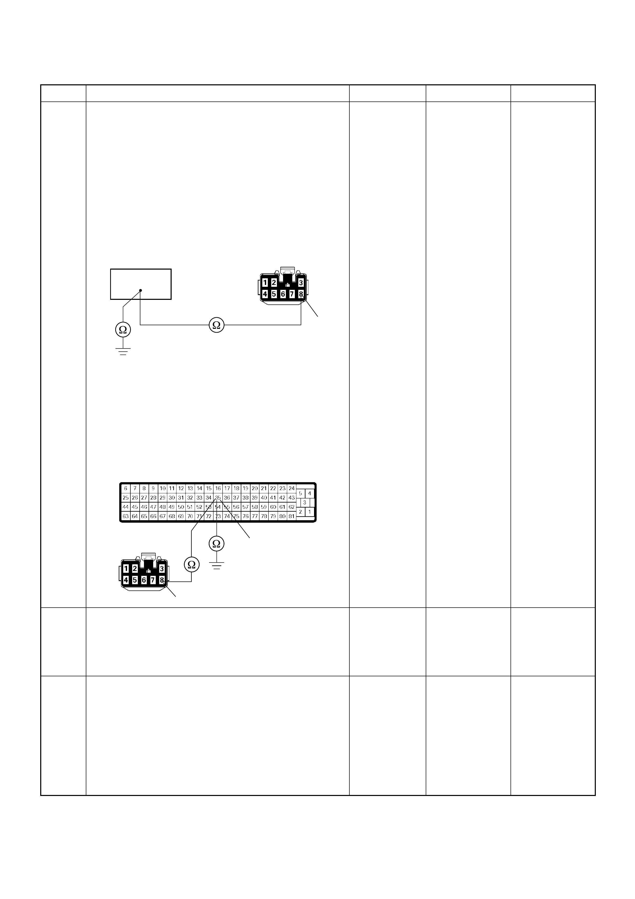
9 Using the DVM and check the ECM and immobiliser
control unit communication circuit.
Breaker box is available:
1. Ignition “Off”, engine “Off”.
2. Install the breaker box as type A. (ECM
disconnected) Ref. Page 6E-81
3. Disconnect the immobiliser control unit connector.
4. Check the circuit for open or short to ground
circuit.
Was the problem found?
Breaker box is not available:
1. Ignition “Off”, engine “Off”.
2. Disconnect the the immobiliser control unit
connector and ECM connector.
3. Check the circuit for open or short to ground
circuit.
Was the problem found?
—
Repair faulty
harnes s and
verify repair Go to Step 10
10 Is the ECM programmed with the latest software
release?
If not, downlo ad the latest software to the ECM using
the “SPS (Service Programming System)”.
Was the problem solved? — Verify repair Go to Step 11
11 Replace the ECM.
Is the action complete?
IMPORTANT: The replacement ECM must be
programmed. Refer to section of the Service
Programming System (SPS) in this manual.
Foll owing ECM pr ogramming, the immobi liser system
(if equipped) must be linked to the ECM. Refer to
section 11 “Immobiliser System-ECM replacement” for
the ECM/Immobiliser linking procedure. — Verify repair —
Step Action Value(s) Yes No
35
8
B-68
35
8
C-56
B-68
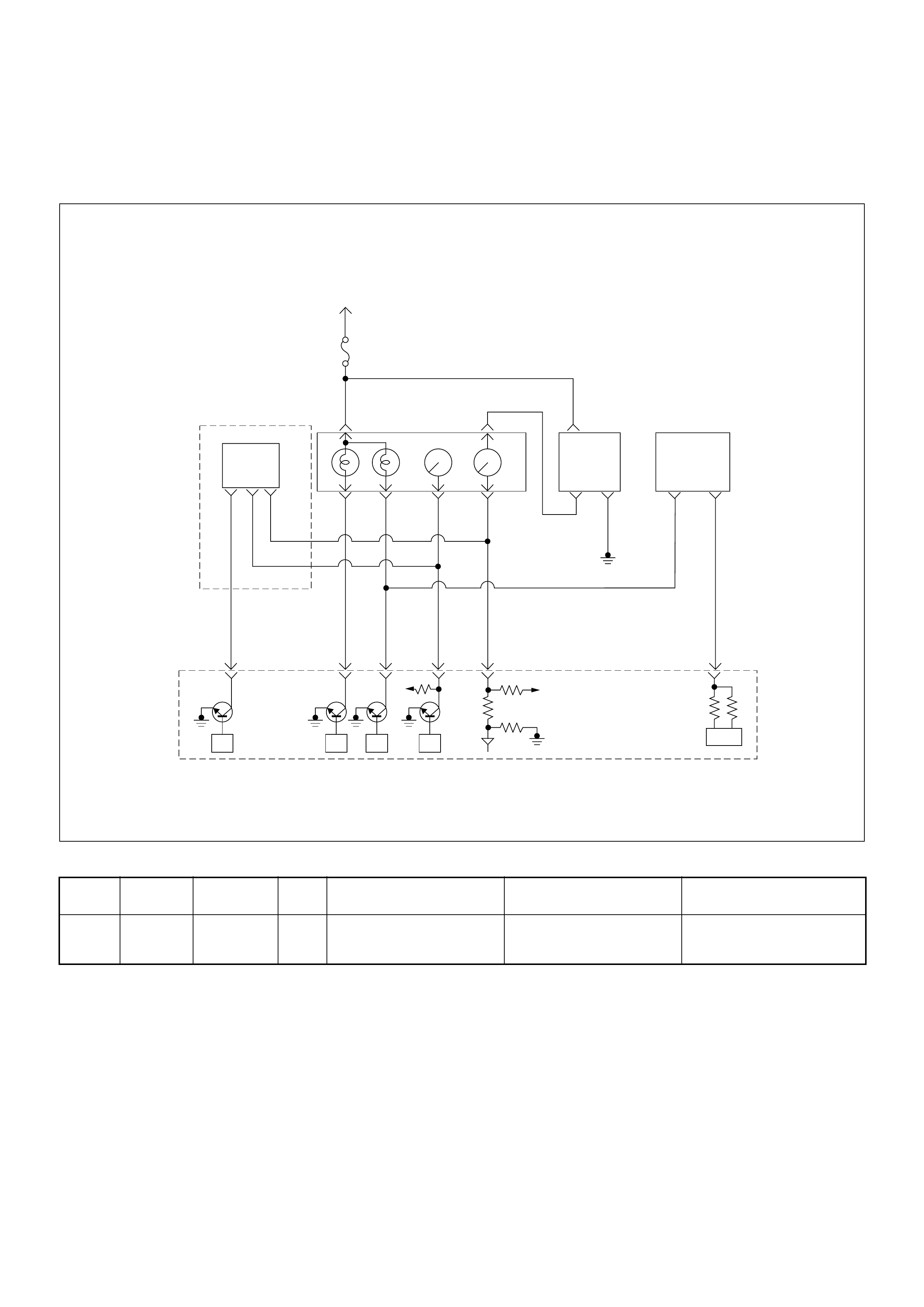
Diagnostic Trouble Code (DTC) P1614 (Symptom Code A)
(Flash Code 56) W rong Transponder Key
Condition for setting the DTC and action taken when the DTC sets
Circuit Desc rip tio n
The ECM decides if there is an abnormality in the
immobiliser control system. A DTC P1614 (Symptom
Code A) is recorded when received immobiliser
response signal was not correct from the transponder
key.
Diagnostic Aids
Check for the following conditions:
• Poor connection at ECM and immobiliser control unit-
Inspect harne ss con nectors for bac ked out terminal s,
improper mating, broken locks, improp erly formed or
damaged terminals, and poor terminal to wire
connection.
• Damaged harness-Inspect the wiring harness for
damage. If the harness appears to be OK, observe
the DTC P1614 display on the Tech2 while moving
connectors and wiring harnesses.
Flash
Code Code Symptom
Code MIL DTC Name DTC Setting Condition F ail-Safe (Back Up)
56 P1614 A - Wrong Transponder Key Received response signal is
not correct from the
transponder key.
1. Engine does not start.
2. Check engine lamp flash.
Ignition
SW
Meter
15A
615 7
Batt
Batt
0.5
RED/
WHT
29
0.5
ORG/
BLU
43
0.5
BRN/
YEL
42
0.5
BLK/
RED
27
0.5
BLU/
WHT
0.5 BLU/BLK
68
0.5
WHT
2.0
BLK
35
VSS
0.85
YEL
Imnobiliser
Control Unit
78
0.5
BRN/
YEL
IC
0.85
YEL
Glow
Check
Engine
Tacho
Meter
Speed
Meter
A/T
TCM
µPµPµPµP
Engine
Control
Module
(ECM)

Diagnostic Trouble Code (DTC) P1614 (Symptom Code A) (Flash Code 56) Wrong Transponder Key
Step Action Value(s) Yes No
1 Was the “On-Board Diagnostic (OBD) System Check”
performed?
—Go to Step 2
Go to On Board
Diagnostic
(OBD) System
Check
2 1. Connect the Tech 2.
2. Review and record the failure information.
3. Select “F0: Read DTC Infor As Stored By ECU” in
“F0: Diagnostic Trouble Codes”.
Is the DTC P1614 (Symptom Code A) stored as
“Present Failure”? — Go to Step 3
Refer to
Diagnostic Aids
and Go to Step
3
3 1. Using the Tech 2, ignition “On” and engine “Off”.
2. Select “F1: Clear DTC Information” in “F0:
Diagnostic Trouble Codes” with the Tech 2 and
clear the DTC information.
3. Operate the vehicle and monitor the “F0: Read
DTC Infor As Stored By ECU” in the “F0:
Diagnostic Trouble Codes”.
Was the DTC P1614 (Symptom Code A) stored in this
ignition cycle? — Go to Step 4
Refer to
Diagnostic Aids
and Go to Step
4
4 1. Using the Tech 2, ignition “On” and engine “Off”.
2. Select “Immobiliser” in the system selectio n menu
“Body”.
3. Sele ct “Read D TC Info Or dered By P riority” in the
“Diagnostic Trouble Code”.
Was the any DTC's B**** stored in this ignition cycle? —
Refer to
“Immobiliser
Workshop
Manual” & Go
to DTC Chart
B**** Go to Step 5
5 Is the ECM programmed with the latest software
release?
If not, downlo ad the latest software to the ECM using
the “SPS (Service Programming System)”.
Was the problem solved? — Verify repair Go to Step 6
6 Replace the ECM.
Is the action complete?
IMPORTANT: The replacement ECM must e
programmed. Refer to section of the Service
Programming System (SPS) in this manual.
Foll owing ECM pr ogramming, the immobi liser system
(if equipped) must be linked to the ECM. Refer to
section 11 “Immobiliser System-ECM replacement” for
the ECM/Immobiliser linking procedure. — Verify repair —
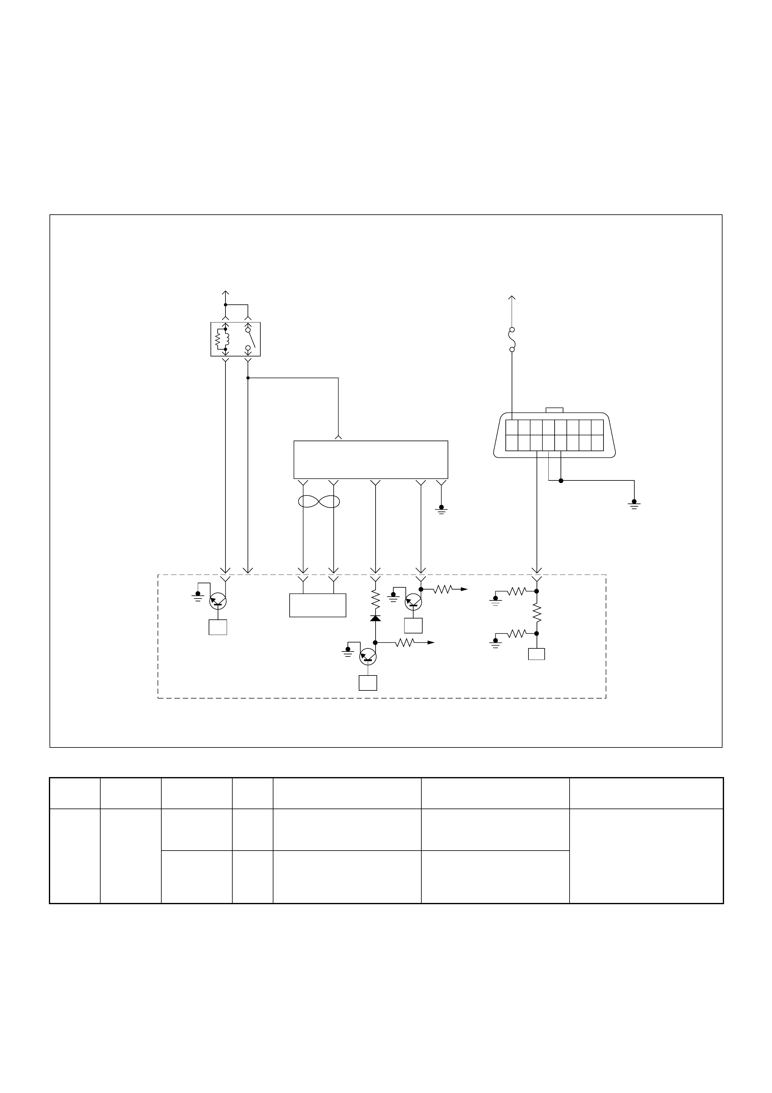
Diagnostic Trouble Code (DTC) P1625 (Symptom Code A)
(Flash Code 76) Ecm Main Relay Switched Off Too Early
Diagnostic Trouble Code (DTC) P1625 (Symptom Code B)
(Flash Code 76) Ecm Main Relay Switched Off Too Late
Condition for setting the DTC and action taken when the DTC sets
Flash
Code Code Symptom
Code MIL DTC Name DTC Setting Condition F ail-Safe (Back Up)
76 P1625 A OFF E CM Main Relay Switc hed
Off Too Early When ignition switch was
turned off, the ECM main
relay is turning off too early.
No fail-safe function.
B O FF ECM Main Relay Switched
Off Too Late When ignition switch was
turned off, the ECM main
relay is turning off too late or
does not off.
45
16151413121110 9
87654321
Battery
Voltage Battery
Voltage
0.5
RED/
YEL
2.0
BLU/
RED
7
PSG(Pump Control Unit) Injection
Pump
21 5 8
0.5
WHT
2.0
BLU/
RED
0.5
BLU/
BLK
0.5
RED 0.5
ORG
100358 99 105 91
0.5
PNK
62.0
BLK
µP
CAN
Controller
Batt
Batt
IC
µP
0.5
BLU
Stop
Light
10A
1.25
BLK
µP
Engine
Control
Module
(ECM)
ECM
Main Relay

Circuit Description
The ECM switches ECM main relay to operate ECM
and other sensors or controller.
Diagnostic Aids
An intermittent may be caused by the following:
• Poor connections.
• Misrouted harness.
• Rubbed through wire insulation.
• Broken wire inside the insulation.
Check for the following conditions:
• Poor connection at ECM-Inspect harness connectors
for backed out terminals, improper mating, broken
locks, improperly formed or damaged terminals, and
poor terminal to wire connection.
• Damaged harness-Inspect the wiring harness for
damage. If the harness appears to be OK, observe
the “Main Relay” display on the Tech2 while moving
connectors and wiring harnesses. A change in the
display will indicate the location of the fault.
Diagnostic Trouble Code (DTC) P1625 (Symptom Code A) (Flash Code 76)
ECM Main Relay Switched Off Too Early
Step Action Value(s) Yes No
1 Was the “On-Board Diagnostic (OBD) System Check”
performed?
—Go to Step 2
Go to On Board
Diagnostic
(OBD) System
Check
2 1. Connect the Tech 2.
2. Review and record the failure information.
3. Select “F0: Read DTC Infor As Stored By ECU” in
“F0: Diagnostic Trouble Codes”.
Is the DTC P1625 (Symptom Code A) stored as
“Present Failure”? — Go to Step 3
Refer to
Diagnostic Aids
and Go to Step
3
3 1. Using the Tech 2, ignition “On” and engine “Off”.
2. Select “F1: Clear DTC Information” in “F0:
Diagnostic Trouble Codes” with the Tech 2 and
clear the DTC information.
3. Operate the vehicle and monitor the “F0: Read
DTC Infor As Stored By ECU” in the “F0:
Diagnostic Trouble Codes”.
Was the DTC P1625 (Symptom Code A) stored in this
ignition cycle? — Go to Step 4 Refer to
Diagnostic Aids
4 Is the ECM programmed with the latest software
release?
If not, downlo ad the latest software to the ECM using
the “SPS (Service Programming System)”.
Was the problem solved? — Verify repair Go to Step 5
5 Replace the ECM.
Is the action complete?
IMPORTANT: The replacement ECM must be
programmed. Refer to section of the Service
Programming System (SPS) in this manual.
Foll owing ECM pr ogramming, the immobi liser system
(if equipped) must be linked to the ECM. Refer to
section 11 “Immobiliser System-ECM replacement” for
the ECM/Immobiliser linking procedure. — Verify repair —
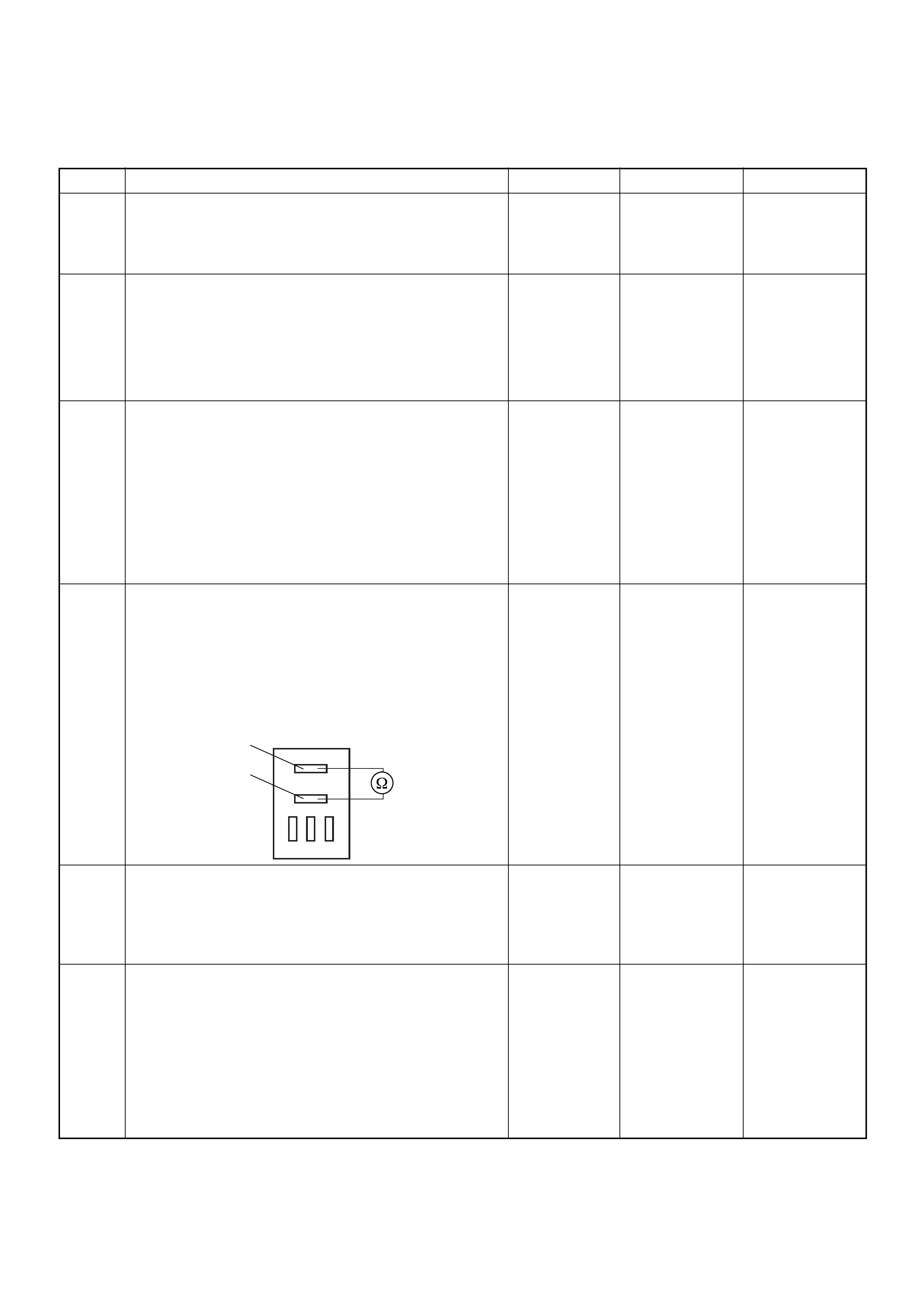
Diagnostic Trouble Code (DTC) P1625 (Symptom Code B) (Flash Code 76)
ECM Main Relay Switched Off Too Late
Step Action Value(s) Yes No
1 Was the “On-Board Diagnostic (OBD) System Check”
performed?
—Go to Step 2
Go to On Board
Diagnostic
(OBD) System
Check
2 1. Connect the Tech 2.
2. Review and record the failure information.
3. Select “F0: Read DTC Infor As Stored By ECU” in
“F0: Diagnostic Trouble Codes”.
Is the DTC P1625 (Symptom Code B) stored as
“Present Failure”? — Go to Step 3
Refer to
Diagnostic Aids
and Go to Step
3
3 1. Using the Tech 2, ignition “On” and engine “Off”.
2. Select “F1: Clear DTC Information” in “F0:
Diagnostic Trouble Codes” with the Tech 2 and
clear the DTC information.
3. Operate the vehicle and monitor the “F0: Read
DTC Infor As Stored By ECU” in the “F0:
Diagnostic Trouble Codes”.
Was the DTC P1625 (Symptom Code B) stored in this
ignition cycle? — Go to Step 4 Refer to
Diagnostic Aids
4 Using the DVM and check the ECM main relay.
1. Ignition “Off”, engine “Off”.
2. Remove the ECM main relay from the relay box.
3. Check the relay switch.
Was the DVM indicated specified value?
No continuitly Go to Step 5
Replace ECM
main relay and
verify repair
5 Is the ECM programmed with the latest software
release?
If not, downlo ad the latest software to the ECM using
the “SPS (Service Programming System)”.
Was the problem solved? — Verify repair Go to Step 6
6 Replace the ECM.
Is the action complete?
IMPORTANT: The replacement ECM must be
programmed. Refer to section of the Service
Programming System (SPS) in this manual.
Foll owing ECM pr ogramming, the immobi liser system
(if equipped) must be linked to the ECM. Refer to
section 11 “Immobiliser System-ECM replacement” for
the ECM/Immobiliser linking procedure. — Verify repair —
1
2
ECM
Main Relay
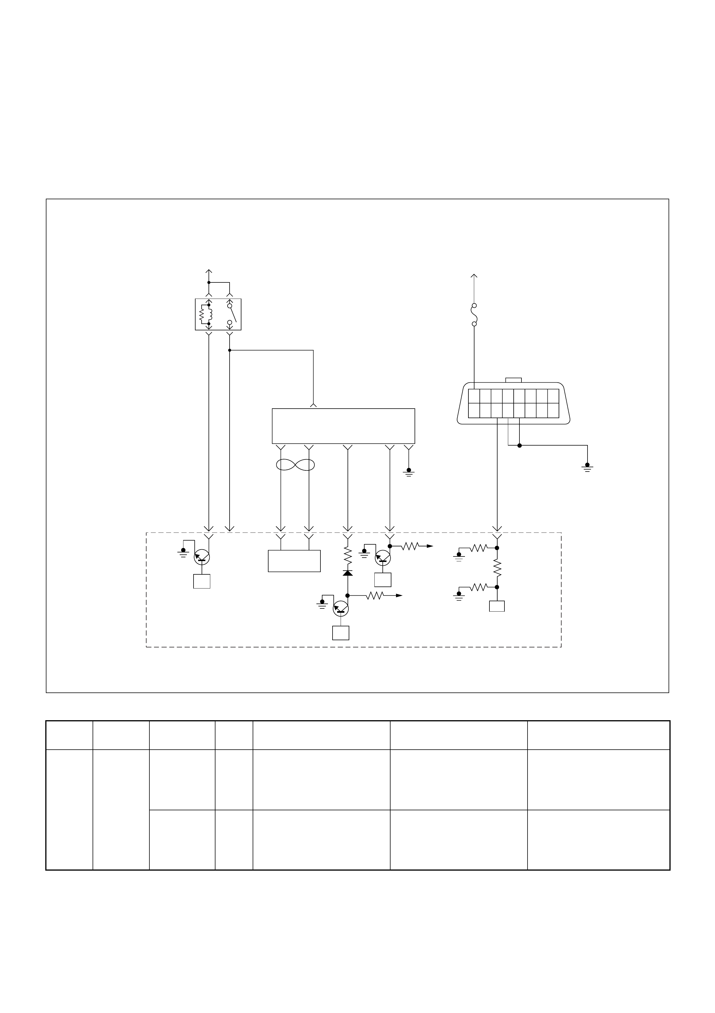
Diagnostic Trouble Code (DTC) P1630 (Symptom Code A)
(Flash Code 51) Fuel Injection Quantity Circuit Malfunct ion
Diagnostic Trouble Code (DTC) P1630 (Symptom Code B)
(Flash Code 51) Fuel Injection Quantity Circuit Malfunct ion
Condition for setting the DTC and action taken when the DTC sets
Circuit Desc rip tio n
The ECM is calculates an injection quantity and an
injecti on ti min g us ing the v ariou s s ens or s. And the PSG
control s the high pr essure sol enoid val ve depending o n
programmed pump map data.
Diagnostic Aids
An intermittent may be caused by the following:
• Poor connections.
Flash
Code Code Symptom
Code MIL DTC Name DTC Setting Condition F ail-Safe (Back Up)
51 P1630 A ON Fuel Injection Quantity Circuit
Malfunction The PSG (pump control unit)
detects high pressure
solenoid valve control circuit
malfunction due to high
current.
Fuel injection quantity is
reduced.
B ON Fuel Injection Quantity Circuit
Malfunction The PSG (pump control unit)
detects high pressure
solenoid valve control circuit
malfunction due to continuous
current.
1. MA B (f uel cutoff solenoid
valve) is operated.
2. Desired injection quantity
becomes 0mg/strk.
45
16151413121110 9
87654321
Battery
Voltage Battery
Voltage
0.5
RED/
YEL
2.0
BLU/
RED
7
PSG(Pump Control Unit) Injection
Pump
21 5 8
0.5
WHT
2.0
BLU/
RED
0.5
BLU/
BLK
0.5
RED 0.5
ORG
100358 99 105 91
0.5
PNK
62.0
BLK
µP
CAN
Controller
Batt
Batt
IC
µP
0.5
BLU
Stop
Light
10A
1.25
BLK
µP
Engine
Control
Module
(ECM)
ECM
Main Relay

• Misrouted harness.
• Rubbed through wire insulation.
• Broken wire inside the insulation.
Check for the following conditions:
• Poor connection at ECM and PSG-Inspect harness
connectors for backed out terminals, improper
mating, broken locks, improperly formed or damaged
terminals, and poor terminal to wire connection.
Diagnostic Trouble Code (DTC) P1630 (Symptom Code A) (Flash Code 51)
Fuel Injection Quantity Circuit Malfunction
Diagnostic Trouble Code (DTC) P1630 (Symptom Code B) (Flash Code 51)
Fuel Injection Quantity Circuit Malfunction
Step Action Value(s) Yes No
1 Was the “On-Board Diagnostic (OBD) System Check”
performed?
—Go to Step 2
Go to On Board
Diagnostic
(OBD) System
Check
2 1. Connect the Tech 2.
2. Review and record the failure information.
3. Select “F0: Read DTC Infor As Stored By ECU” in
“F0: Diagnostic Trouble Codes”.
Is the DTC P1630 (Symptom Code A) or P1630
(symptom Code B) stored as “Present Failure”? — Go to Step 3
Refer to
Diagnostic Aids
and Go to Step
3
3 1. Using the Tech 2, ignition “On” and engine “Off”.
2. Select “F1: Clear DTC Information” in “F0:
Diagnostic Trouble Codes” with the Tech 2 and
clear the DTC information.
3. Operate the vehicle and monitor the “F0: Read
DTC Infor As Stored By ECU” in the “F0:
Diagnostic Trouble Codes”.
Was the DTC P1630 (Symptom Code A) or P1630
(symptom Code B) stored in this ignition cycle? — Go to Step 4 Refer to
Diagnostic Aids
4 Replace the injection pump assembly.
Is the action complete? — Verify repair —
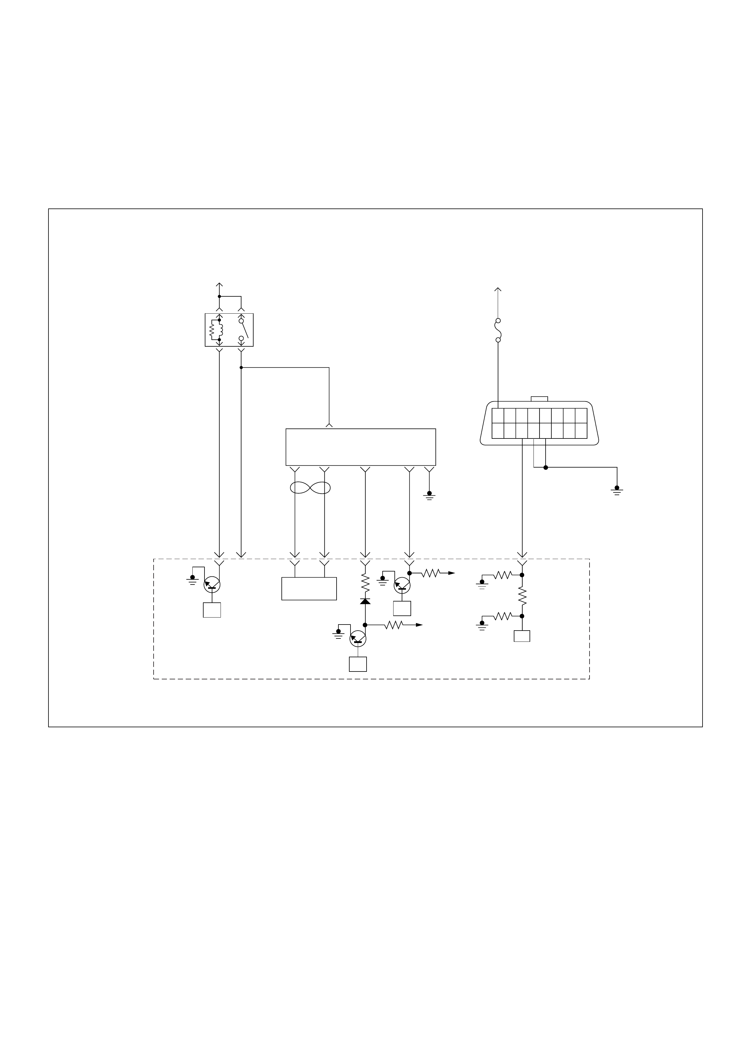
Diagnostic Trouble Code (DTC) P1650 (Symptom Code A)
(Flash Code 44) Can Device Offline
Diagnostic Trouble Code (DTC) P1650 (Symptom Code B)
(Flash Code 44) Can Device Hang-up
45
16151413121110 9
87654321
Battery
Voltage Battery
Voltage
0.5
RED/
YEL
2.0
BLU/
RED
7
PSG(Pump Control Unit) Injection
Pump
21 5 8
0.5
WHT
2.0
BLU/
RED
0.5
BLU/
BLK
0.5
RED 0.5
ORG
100358 99 105 91
0.5
PNK
62.0
BLK
µP
CAN
Controller
Batt
Batt
IC
µP
0.5
BLU
Stop
Light
10A
1.25
BLK
µP
Engine
Control
Module
(ECM)
ECM
Main Relay

Condition for setting the DTC and action taken when the DTC sets
Circuit Description
The interchange of data between the engine control
module (ECM) and the pump control unit (PSG) is
performed via a CAN-bus system. The individual CAN-
bus systems are connected via two interfaces and can
exchange information and data. This allows control
modules that are connected to different CAN-bus
systems to communicate.
Diagnostic Aids
An intermittent may be caused by the following:
• Poor connections.
• Misrouted harness.
• Rubbed through wire insulation.
• Broken wire inside the insulation.
Check for the following conditions:
• Poor connection at ECM and PSG-Inspect harness
connectors for backed out terminals, improper
mating, broken locks, improperly formed or damaged
terminals, and poor terminal to wire connection.
• Damaged harness-Inspect the wiring harness for
damage. If the harness appears to be OK, observe
the DTC P1650 display on the Tech2 while moving
connectors and wiring harnesses.
Diagnostic Trouble Code (DTC) P1650 (Symptom Code A) (Flash Code 44) CAN Device Offline
Flash
Code Code Symptom
Code MIL DTC Name DTC Setting Condition Fail-Safe (Back Up)
44 P1650 A ON CAN Device Offline CAN controller detects Bus-
off or canceling. MAB (fuel cutoff solenoid
valve) is operated.
B ON CAN Device Hang-up CAN controller does not react
under engine running.
Step Action Value(s) Yes No
1 Was the “On-Board Diagnostic (OBD) System Check”
performed?
—Go to Step 2
Go to On Board
Diagnostic
(OBD) System
Check
2 1. Connect the Tech 2.
2. Review and record the failure information.
3. Select “F0: Read DTC Infor As Stored By ECU” in
“F0: Diagnostic Trouble Codes”.
Is the DTC P1650 (Symptom Code A) stored as
“Present Failure”? — Go to Step 3
Refer to
Diagnostic Aids
and Go to Step
3
3 1. Using the Tech 2, ignition “On” and engine “Off”.
2. Select “F1: Clear DTC Information” in “F0:
Diagnostic Trouble Codes” with the Tech 2 and
clear the DTC information.
3. Operate the vehicle and monitor the “F0: Read
DTC Infor As Stored By ECU” in the “F0:
Diagnostic Trouble Codes”.
Was the DTC P1650 (Symptom Code A) stored in this
ignition cycle? — Go to Step 4
Refer to
Diagnostic Aids
and Go to Step
4
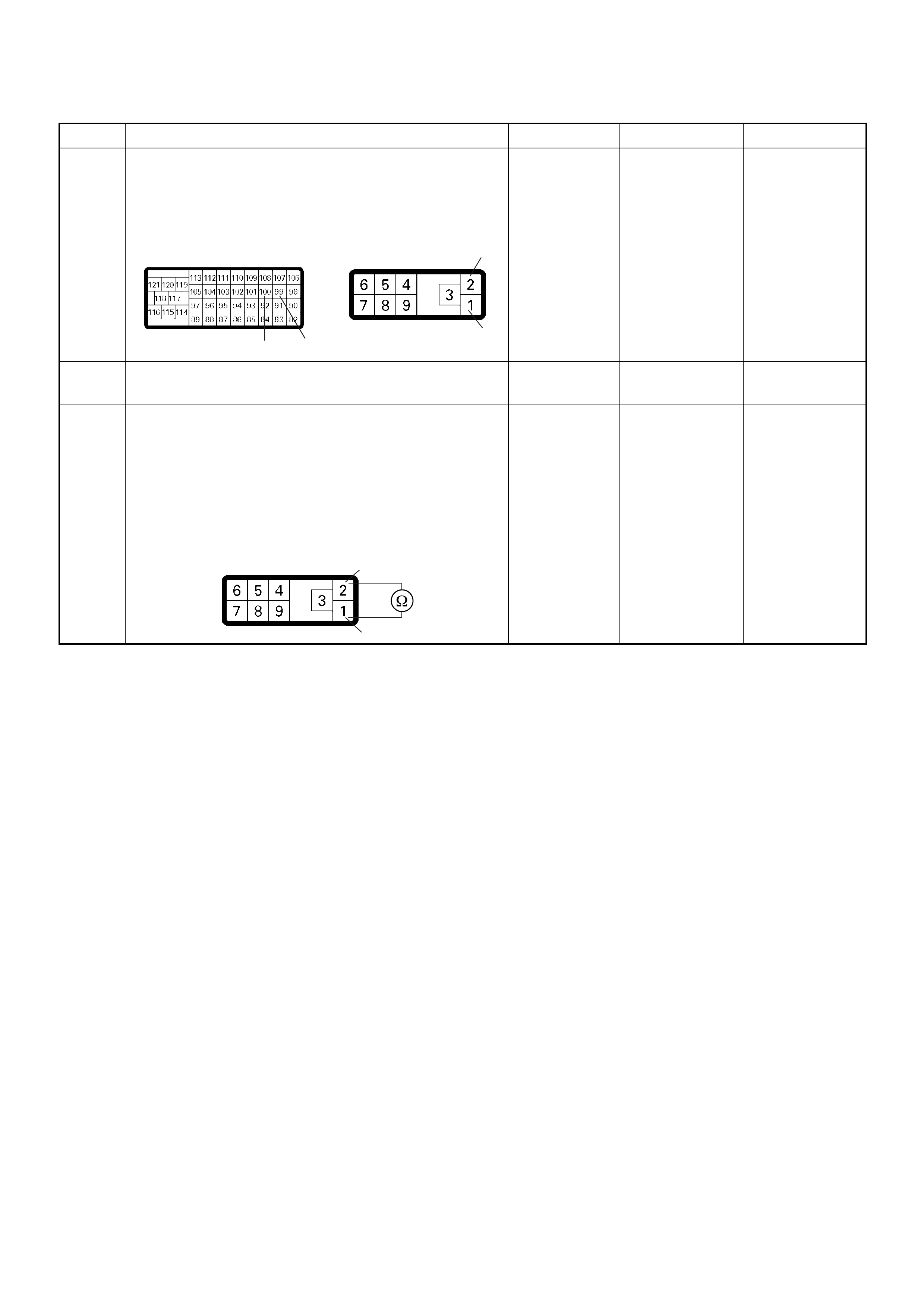
4 Check for poor/faulty connection at the ECM or PSG
(pump control unit) connector. If a poor/faulty
connection is found, repair as necessary.
Was the problem found?
— Verify repair Go to Step 5
5 Visually check the PS G (p ump contro l unit) .
Was the problem found? — Go to Step 18 Go to Step 6
6 Using the DVM and check the CAN high circuit.
1. Ignition “Off”, engine “Off”.
2. Disconnect the ECM connector and PSG (pump
control unit) connector.
3. Check the circuit for short to CAN low circuit.
Was the DVM indicated specified value?
No continuity Go to Step 7
Repair faulty
harness and
verify repair
Step Action Value(s) Yes No
100 99 1
2
C-57 E-6
2
1
E-6

7 Using the DVM and check the CAN high circuit.
Breaker box is available:
1. Ignition “Off”, engine “Off”.
2. Install the breaker box as type A. (ECM
disconnected) Ref. Page 6E-81
3. Disconnect the PSG (pump control unit)
connector.
4. Check the circuit for open or short to ground
circuit.
Was the problem found?
Breaker box is not available:
1. Ignition “Off”, engine “Off”.
2. Disconnect the PSG (pump control unit)
connector.
3. Check the circuit for open or short to ground
circuit.
Was the problem found?
—
Repair faulty
harnes s and
verify repair G o to Step 8
Step Action Value(s) Yes No
100
2
E-6
100 2
C-57 E-6
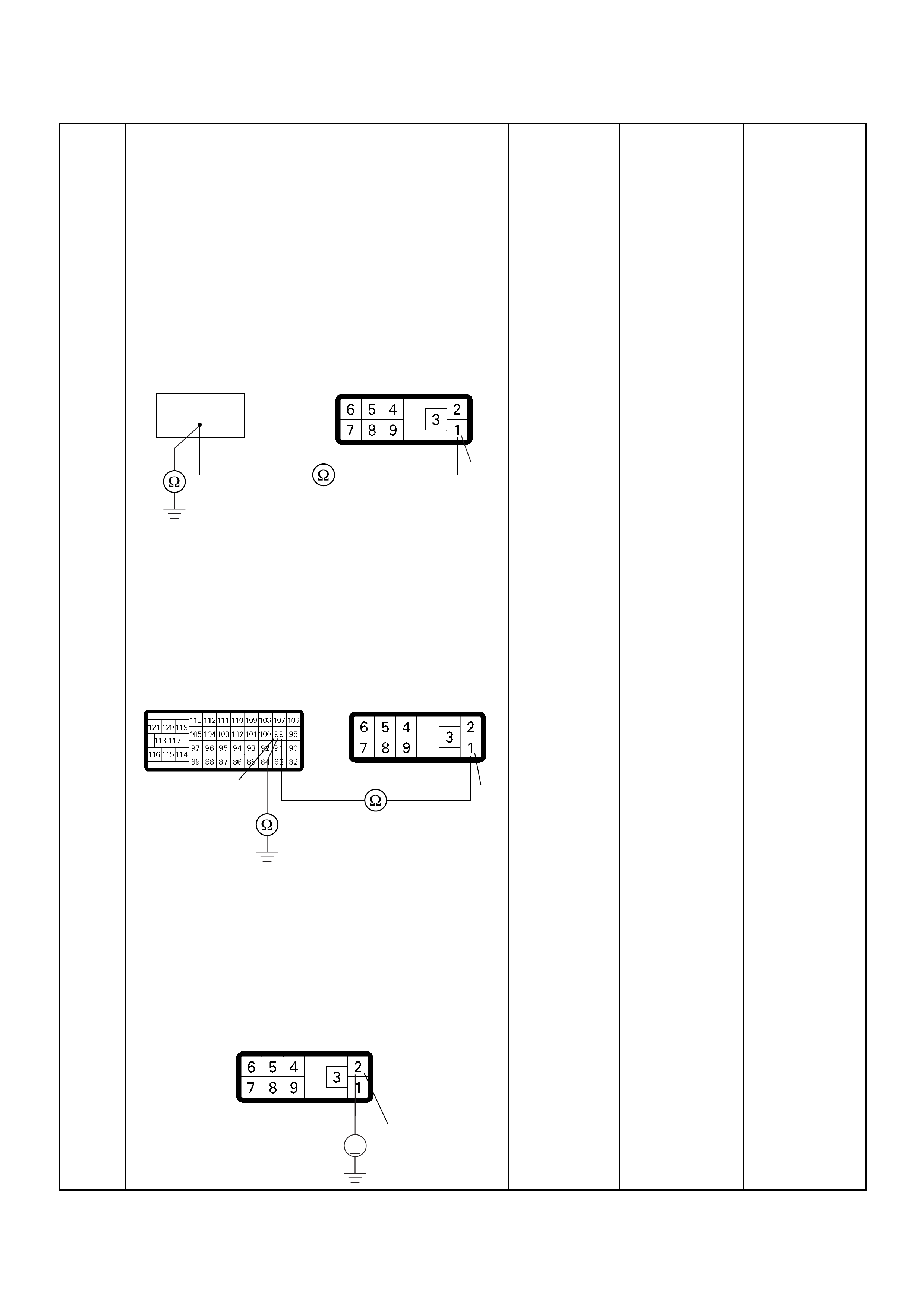
8 Using the DVM and check the CAN low circuit.
Breaker box is available:
1. Ignition “Off”, engine “Off”.
2. Install the breaker box as type A. (ECM
disconnected) Ref. Page 6E-81
3. Disconnect the PSG (pump control unit)
connector.
4. Check the circuit for open or short to ground
circuit.
Was the problem found?
Breaker box is not available:
1. Ignition “Off”, engine “Off”.
2. Disconnect the PSG (pump control unit)
connector.
3. Check the circuit for open or short to ground
circuit.
Was the problem found?
—
Repair faulty
harnes s and
verify repair G o to Step 9
9 Using the DVM and check the CAN high circuit.
1. Ignition “On”, engine “Off”.
2. Disconnect the PSG (pump control unit)
connector.
3. Check the circuit for short to power supply circuit.
Was the DVM indicated battery voltage or
approximately 5V?
—Go to Step 10 Go to Step 11
Step Action Value(s) Yes No
99
1
E-6
99 1
C-57 E-6
2
V
E-6

10 Repair the short to voltage circuit between the ECM
and PSG (pump control unit).
Is the action complete?
— Verify repair —
11 Using the DVM and check the CAN low circuit.
1. Ignition “On”, engine “Off”.
2. Disconnect the PSG (pump control unit)
connector.
3. Check the circuit for short to power supply circuit.
Was the DVM indicated battery voltage or
approximately 5V?
—Go to Step 12 Go to Step 13
12 Repair the short to voltage circuit between the ECM
and PSG (pump control unit).
Is the action complete?
— Verify repair —
13 Using the DVM and check the PSG (pump control
unit) ground circuit.
1. Ignition “Off”, engine “Off”.
2. Disconnect the PSG (pump control unit)
connector.
3. Check the circuit for open circuit.
Was the problem found?
—
Repair faulty
harnes s and
verify repair Go to Step 14
Step Action Value(s) Yes No
100 2
C-57 E-6
1
V
E-6
99 1
C-57 E-6
6
E-6

Diagnostic Trouble Code (DTC) P1650 (Symptom Code B) (Flash Code 44) CAN Device Hang-up
14 Check any accessory parts which may cause electric
interference.
Was the problem found? —
Remove the
accessory parts
and verify repair Go to Step 15
15 Is the ECM programmed with the latest software
release?
If not, download the latest software to the ECM using
the “SPS (Service Programming System)”.
Was the problem solved? — Verify repair Go to Step 16
16 Substitute a known good ECM and recheck.
Was the problem solved?
IMPORTANT: The replacement ECM must be
programmed. Refer to section of the Service
Programming System (SPS) in this manual.
Following ECM programming, the immobiliser system
(if equipped) must be linked to the ECM. Refer to
section 11 “Immobiliser System-ECM replacement” for
the ECM/Immobiliser linking procedure. —Go to Step 17 Go to Step 18
17 Replace the ECM.
Is the action complete?
IMPORTANT: The replacement ECM must be
programmed. Refer to section of the Service
Programming System (SPS) in this manual.
Following ECM programming, the immobiliser system
(if equipped) must be linked to the ECM. Refer to
section 11 “Immobiliser System-ECM replacement” for
the ECM/Immobiliser linking procedure. — Verify repair —
18 Replace the injection pump assembly.
Is the action complete? — Verify repair —
Step Action Value(s) Yes No
1 Was the “On-Board Diagnostic (OBD) System Check”
performed?
—Go to Step 2
Go to On Board
Diagnostic
(OBD) System
Check
2 1. Connect the Tech 2.
2. Review and record the failure information.
3. Select “F0: Read DTC Infor As Stored By ECU” in
“F0: Diagnostic Trouble Codes”.
Is the DTC P1650 (Symptom Code B) stored as
“Present Failure”? — Go to Step 3
Refer to
Diagnostic Aids
and Go to Step
3
3 1. Using the Tech 2, ignition “On” and engine “Off”.
2. Select “F1: Clear DTC Information” in “F0:
Diagnostic Trouble Codes” with the Tech 2 and
clear the DTC information.
3. Operate the vehicle and monitor the “F0: Read
DTC Infor As Stored By ECU” in the “F0:
Diagnostic Trouble Codes”.
Was the DTC P1650 (Symptom Code B) stored in this
ignition cycle? — Go to Step 4 Refer to
Diagnostic Aids
Step Action Value(s) Yes No

4 Is the ECM programmed with the latest software
release?
If not, downlo ad the latest software to the ECM using
the “SPS (Service Programming System)”.
Was the problem solved? — Verify repair Go to Step 5
5 Substitute a known good ECM and recheck.
Was the problem solved?
IMPORTANT: The replacement ECM must be
programmed. Refer to section of the Service
Programming System (SPS) in this manual.
Foll owing ECM pr ogramming, the immobi liser system
(if equipped) must be linked to the ECM. Refer to
section 11 “Immobiliser System-ECM replacement” for
the ECM/Immobiliser linking procedure. —Go to Step 6 Go to Step 7
6 Replace the ECM.
Is the action complete?
IMPORTANT: The replacement ECM must be
programmed. Refer to section of the Service
Programming System (SPS) in this manual.
Foll owing ECM pr ogramming, the immobi liser system
(if equipped) must be linked to the ECM. Refer to
section 11 “Immobiliser System-ECM replacement” for
the ECM/Immobiliser linking procedure. — Verify repair —
7 Replace the injection pump assembly.
Is the action complete? — Verify repair —
Step Action Value(s) Yes No

Diagnostic Trouble Code (DTC) P1651 (Symptom Code A)
(Flash Code 45) Can Malfunction (PSG)
Diagnostic Trouble Code (DTC) P1651 (Symptom Code B)
(Flash Code 45) Can Received Error
45
16151413121110 9
87654321
Battery
Voltage Battery
Voltage
0.5
RED/
YEL
2.0
BLU/
RED
7
PSG(Pump Control Unit) Injection
Pump
21 5 8
0.5
WHT
2.0
BLU/
RED
0.5
BLU/
BLK
0.5
RED 0.5
ORG
100358 99 105 91
0.5
PNK
62.0
BLK
µP
CAN
Controller
Batt
Batt
IC
µP
0.5
BLU
Stop
Light
10A
1.25
BLK
µP
Engine
Control
Module
(ECM)
ECM
Main Relay

Condition for setting the DTC and action taken when the DTC sets
Circuit Description
The interchange of data between the engine control
module (ECM) and the pump control unit (PSG) is
performed via a CAN-bus system. The individual CAN-
bus systems are connected via two interfaces and can
exchange information and data. This allows control
modules that are connected to different CAN-bus
systems to communicate.
Diagnostic Aids
An intermittent may be caused by the following:
• Poor connections.
• Misrouted harness.
• Rubbed through wire insulation.
• Broken wire inside the insulation.
Check for the following conditions:
• Poor connection at ECM and PSG-Inspect harness
connectors for backed out terminals, improper
mating, broken locks, improperly formed or damaged
terminals, and poor terminal to wire connection.
• Damaged harness-Inspect the wiring harness for
damage. If the harness appears to be OK, observe
the DTC P1651 display on the Tech2 while moving
connectors and wiring harnesses.
Diagnostic Trouble Code (DTC) P1651 (Symptom Code A) (Flash Code 45) CAN Malfunction (PSG)
Flash
Code Code Symptom
Code MIL DTC Name DTC Setting Condition Fail-Safe (Back Up)
45 P1651 A ON CAN Malfunction (PSG) The PSG (pump control unit)
does not recognize CAN
signal from the CAN
controller.
1. MAB (fuel cutoff solenoid
valve) is operated.
2. Desired injection quantity
becomes 0mg/strk.
B ON CAN Receives Error The ECM does not read CAN
signal from the PSG (pump
control unit).
Step Action Value(s) Yes No
1 Was the “On-Board Diagnostic (OBD) System Check”
performed?
—Go to Step 2
Go to On Board
Diagnostic
(OBD) System
Check
2 1. Connect the Tech 2.
2. Review and record the failure information.
3. Select “F0: Read DTC Infor As Stored By ECU” in
“F0: Diagnostic Trouble Codes”.
Is the DTC P1651 (Symptom Code A) stored as
“Present Failure”? — Go to Step 3
Refer to
Diagnostic Aids
and Go to Step
3
3 1. Using the Tech 2, ignition “On” and engine “Off”.
2. Select “F1: Clear DTC Information” in “F0:
Diagnostic Trouble Codes” with the Tech 2 and
clear the DTC information.
3. Operate the vehicle and monitor the “F0: Read
DTC Infor As Stored By ECU” in the “F0:
Diagnostic Trouble Codes”.
Was the DTC P1651 (Symptom Code A) stored in this
ignition cycle? — Go to Step 4 Refer to
Diagnostic Aids
4 Is the ECM programmed with the latest software
release?
If not, downlo ad the latest software to the ECM using
the “SPS (Service Programming System)”.
Was the problem solved? — Verify repair Go to Step 5

Diagnostic Trouble Code (DTC) P1651 (Symptom Code B) (Flash Code 45) CAN Received Error
5 Substitute a known good ECM and recheck.
Was the problem solved?
IMPORTANT: The replacement ECM must be
programmed. Refer to section of the Service
Programming System (SPS) in this manual.
Foll owing ECM pr ogramming, the immobi liser system
(if equipped) must be linked to the ECM. Refer to
section 11 “Immobiliser System-ECM replacement” for
the ECM/Immobiliser linking procedure. —Go to Step 6 Go to Step 7
6 Replace the ECM.
Is the action complete?
IMPORTANT: The replacement ECM must be
programmed. Refer to section of the Service
Programming System (SPS) in this manual.
Foll owing ECM pr ogramming, the immobi liser system
(if equipped) must be linked to the ECM. Refer to
section 11 “Immobiliser System-ECM replacement” for
the ECM/Immobiliser linking procedure. — Verify repair —
7 Replace the injection pump assembly.
Is the action complete? — Verify repair —
Step Action Value(s) Yes No
1 Was the “On- Board Diagnos tic (OBD) Sy stem Check”
performed?
—Go to Step 2
Go to On Board
Diagnostic
(OBD) System
Check
2 1. Connect the Tech 2.
2. Review and record the failure information.
3. S elect “F0: Read DTC I nfor As Stored B y ECU” in
“F0: Diagnostic Trouble Codes”.
Is the DTC P1651 (Symptom Code B) stored as
“Present Failure”? — Go to Step 3
Refer to
Diagnostic Aids
and Go to Step
3
3 1. Using the Tech 2, ignition “On” and engine “Off”.
2. Select “F1: Clear DTC Information” in “F0:
Diagnostic Trouble Codes” with the Tech 2 and
clear the DTC information.
3. Operate the vehicle and monitor the “F0: Read
DTC Infor As Stored By ECU” in the “F0:
Diagnostic Trouble Codes”.
Was the DTC P1651 (Symptom Code B) stored in this
ignition cycle? — Go to Step 4
Refer to
Diagnostic Aids
and Go to Step
4
4 Was the DTC P1 650 ( Sympt om Code A ) sto re d a t th e
same time?
—
Go to DTC
Chart P1650
(Symptom
Code A) Go to Step 5
Step Action Value(s) Yes No
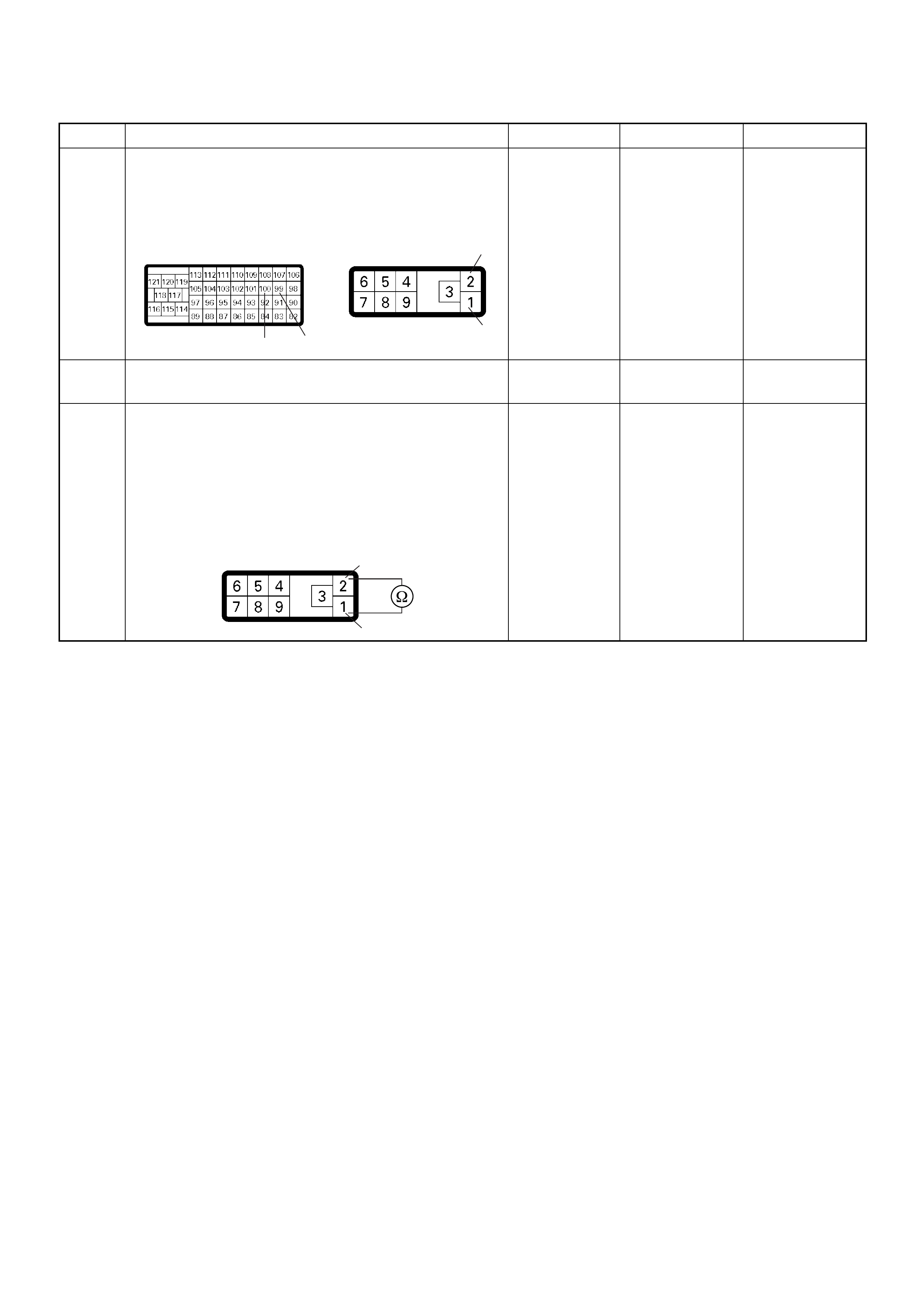
5 Check for poor/faulty connection at the ECM or PSG
(pump control unit) connector. If a poor/faulty
connection is found, repair as necessary.
Was the problem found?
— Verify repair Go to Step 6
6 Visually check the PS G (p ump contro l unit) .
Was the problem found? — Go to Step 19 Go to Step 7
7 Using the DVM and check the CAN high circuit.
1. Ignition “Off”, engine “Off”.
2. Disconnect the ECM connector and PSG (pump
control unit) connector.
3. Check the circuit for short to CAN low circuit.
Was the DVM indicated specified value?
No continuity Go to Step 8
Repair faulty
harness and
verify repair
Step Action Value(s) Yes No
100 99 1
2
C-57 E-6
2
1
E-6
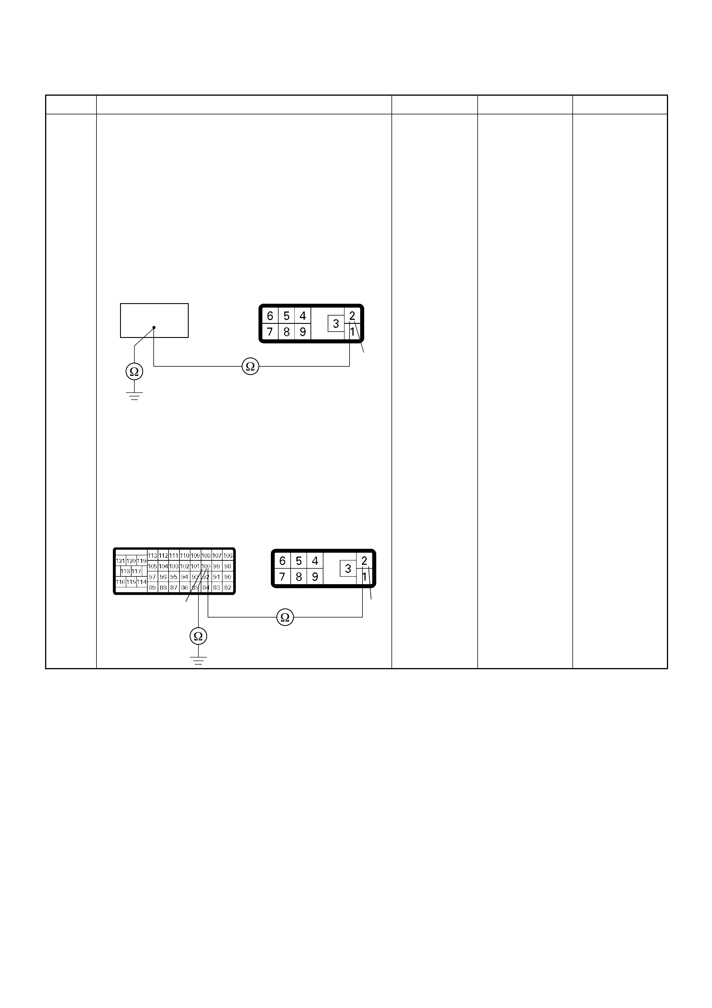
8 Using the DVM and check the CAN high circuit.
Breaker box is available:
1. Ignition “Off”, engine “Off”.
2. Install the breaker box as type A. (ECM
disconnected) Ref. Page 6E-81
3. Disconnect the PSG (pump control unit)
connector.
4. Check the circuit for open or short to ground
circuit.
Was the problem found?
Breaker box is not available:
1. Ignition “Off”, engine “Off”.
2. Disconnect the PSG (pump control unit)
connector.
3. Check the circuit for open or short to ground
circuit.
Was the problem found?
—
Repair faulty
harnes s and
verify repair G o to Step 9
Step Action Value(s) Yes No
100
2
E-6
100 2
C-57 E-6
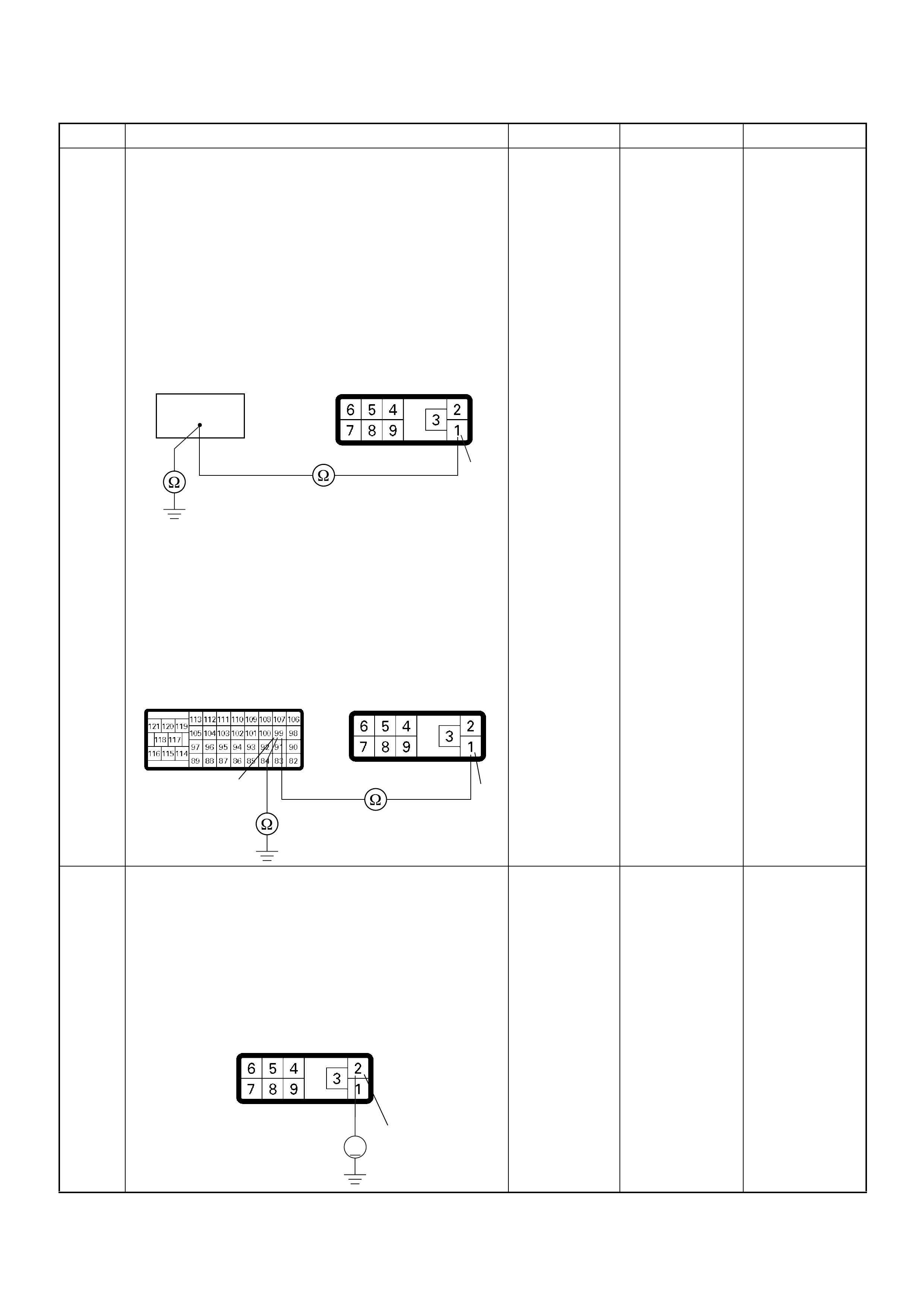
9 Using the DVM and check the CAN low circuit.
Breaker box is available:
1. Ignition “Off”, engine “Off”.
2. Install the breaker box as type A. (ECM
disconnected) Ref. Page 6E-81
3. Disconnect the PSG (pump control unit)
connector.
4. Check the circuit for open or short to ground
circuit.
Was the problem found?
Breaker box is not available:
1. Ignition “Off”, engine “Off”.
2. Disconnect the PSG (pump control unit)
connector.
3. Check the circuit for open or short to ground
circuit.
Was the problem found?
—
Repair faulty
harnes s and
verify repair Go to Step 10
10 Using the DVM and check the CAN high circuit.
1. Ignition “On”, engine “Off”.
2. Disconnect the PSG (pump control unit)
connector.
3. Check the circuit for short to power supply circuit.
Was the DVM indicated battery voltage or
approximately 5V?
— Go to Step 11 Go to Step 12
Step Action Value(s) Yes No
99
1
E-6
99 1
C-57 E-6
2
V
E-6
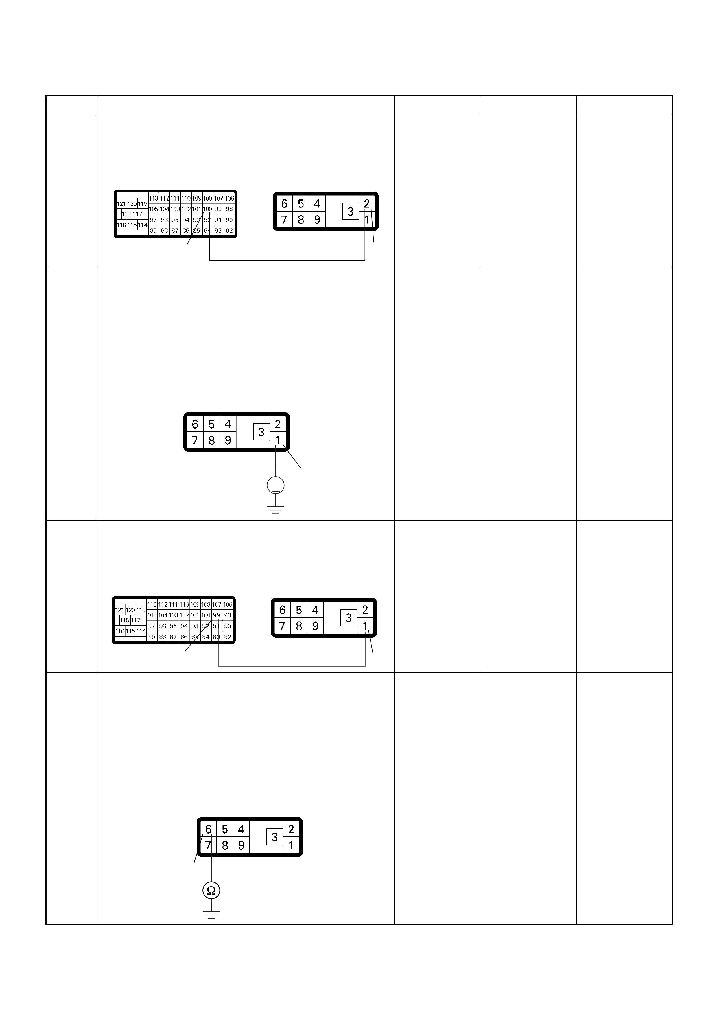
11 Repair the short to voltage circuit between the ECM
and PSG (pump control unit).
Is the action complete?
— Verify repair —
12 Using the DVM and check the CAN low circuit.
1. Ignition “On”, engine “Off”.
2. Disconnect the PSG (pump control unit)
connector.
3. Check the circuit for short to power supply circuit.
Was the DVM indicated battery voltage or
approximately 5V?
—Go to Step 13 Go to Step 14
13 Repair the short to voltage circuit between the ECM
and PSG (pump control unit).
Is the action complete?
— Verify repair —
14 Using the DVM and check the PSG (pump control
unit) ground circuit.
1. Ignition “Off”, engine “Off”.
2. Disconnect the PSG (pump control unit)
connector.
3. Check the circuit for open circuit.
Was the problem found?
—
Repair faulty
harnes s and
verify repair Go to Step 15
Step Action Value(s) Yes No
100 2
C-57 E-6
1
V
E-6
99 1
C-57 E-6
6
E-6

15 Check any accessory parts which may cause electric
interference.
Was the problem found? —
Remove the
accessory parts
and verify repair Go to Step 16
16 Is the ECM programmed with the latest software
release?
If not, downlo ad the latest software to the ECM using
the “SPS (Service Programming System)”.
Was the problem solved? — Verify repair Go to Step 17
17 Substitute a known good ECM and recheck.
Was the problem solved?
IMPORTANT: The replacement ECM must be
programmed. Refer to section of the Service
Programming System (SPS) in this manual.
Foll owing ECM pr ogramming, the immobi liser system
(if equipped) must be linked to the ECM. Refer to
section 11 “Immobiliser System-ECM replacement” for
the ECM/Immobiliser linking procedure. —Go to Step 18 Go to Step 19
18 Replace the ECM.
Is the action complete?
IMPORTANT: The replacement ECM must be
programmed. Refer to section of the Service
Programming System (SPS) in this manual.
Foll owing ECM pr ogramming, the immobi liser system
(if equipped) must be linked to the ECM. Refer to
section 11 “Immobiliser System-ECM replacement” for
the ECM/Immobiliser linking procedure. — Verify repair —
19 Replace the injection pump assembly.
Is the action complete? — Verify repair —
Step Action Value(s) Yes No
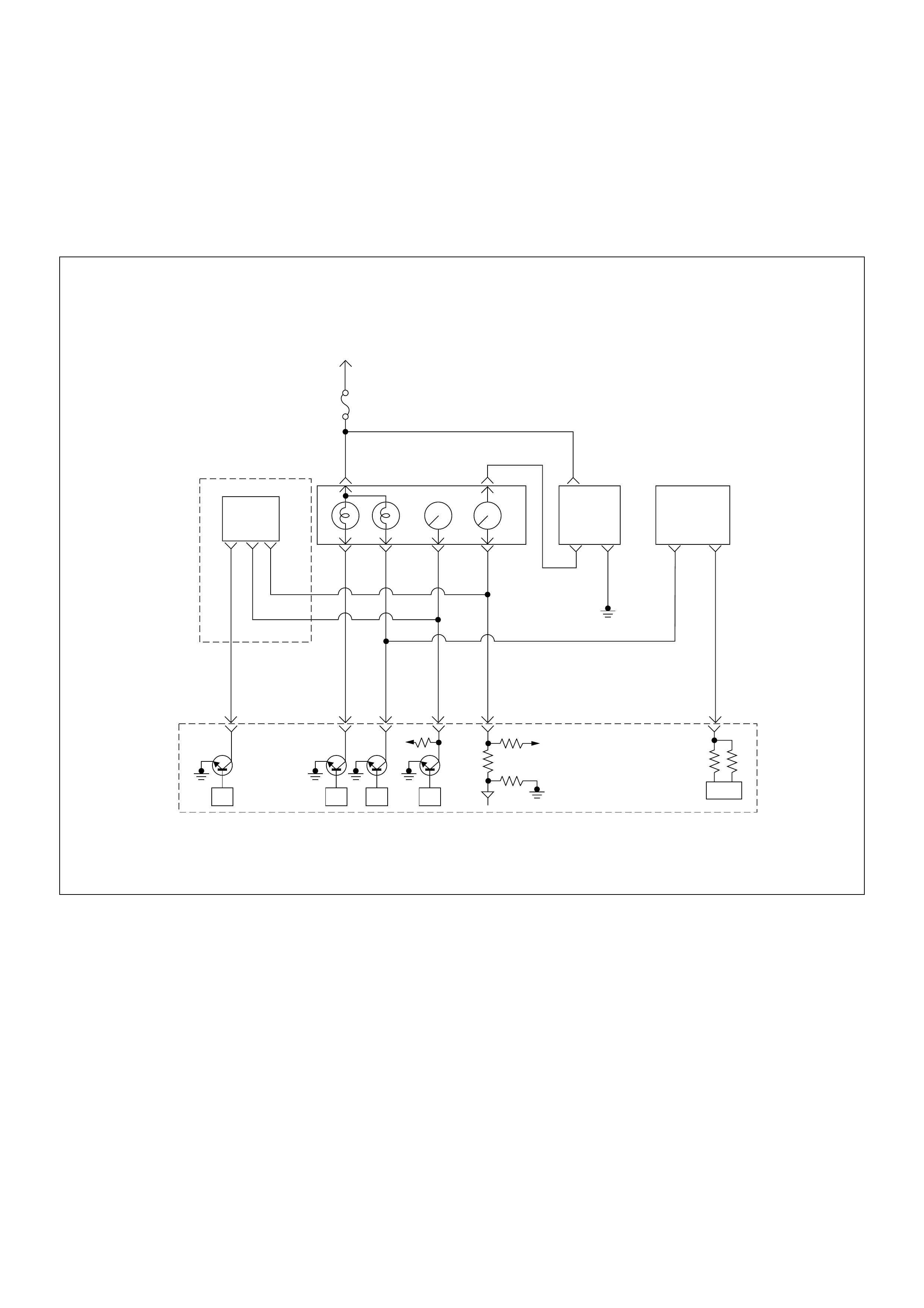
Diagnostic Trouble Code (DTC) P1690 (Symptom Code 4)
(Flash Code 77) Check Engine Lamp (MIL) Circuit Voltage Low
Diagnostic Trouble Code (DTC) P1690 (Symptom Code 8)
(Flash Code 77) Check Engine Lamp (MIL) Circuit Voltage High
Ignition
SW
Meter
15A
615 7
Batt
Batt
0.5
RED/
WHT
29
0.5
ORG/
BLU
43
0.5
BRN/
YEL
42
0.5
BLK/
RED
27
0.5
BLU/
WHT
0.5 BLU/BLK
68
0.5
WHT
2.0
BLK
35
VSS
0.85
YEL
Imnobiliser
Control Unit
78
0.5
BRN/
YEL
IC
0.85
YEL
Glow
Check
Engine
Tacho
Meter
Speed
Meter
A/T
TCM
µPµPµPµP
Engine
Control
Module
(ECM)

Condition for setting the DTC and action taken when the DTC sets
Circuit Description
The Check Engine Lamp (Malfunction Indicator Lamp
=MIL) should always be illuminated and steady with
ignition “On” and the engine not running. Ignition feed
voltage is supplied to the Check Engine Lamp bulb
through the meter fuse. The ECM turns the Check
Engine Lamp “On” by grounding the check engine lamp
driver circuit for a certain time.
Diagnostic Aids
An intermittent may be caused by the following:
• Poor connections.
• Misrouted harness.
• Rubbed through wire insulation.
• Broken wire inside the insulation.
Check for the following conditions:
• Poor connection at ECM-Inspect harness connectors
for backed out terminals, improper mating, broken
locks, improperly formed or damaged terminals, and
poor terminal to wire connection.
• Damaged harness-Inspect the wiring harness for
damage. If the harness appears to be OK, observe
the “Check Engine Lamp” display on the Tech2 while
moving connectors and wiring harnesses. A change
in the display will indicate the location of the fault.
Diagnostic Trouble Code (DTC) P1690 (Symptom Code 4) (Flash Code 77)
Check Engine Lamp (MIL) Circuit Voltage Low
Flash
Code Code Symptom
Code MIL DTC Name DTC Setting Condition Fail-Safe (Back Up)
77 P1690 4 OFF Check Engine Lamp (MIL)
Circuit Voltage Low Check engine lamp circuit
open or short to ground
circuit.
No fail-safe function.
8 OFF Check Engine Lamp (MIL)
Circuit Voltage High Check engine lamp circuit
short to ground circuit.
Step Action Value(s) Yes No
1 Was the “On-Board Diagnostic (OBD) System Check”
performed?
—Go to Step 2
Go to On Board
Diagnostic
(OBD) System
Check
2 1. Connect the Tech 2.
2. Review and record the failure information.
3. Select “F0: Read DTC Infor As Stored By ECU” in
“F0: Diagnostic Trouble Codes”.
Is the DTC P1690 (Symptom Code 4) stored as
“Present Failure”? — Go to Step 3
Refer to
Diagnostic Aids
and Go to Step
3
3 1. Using the Tech 2, ignition “On” and engine “Off”.
2. Select “F1: Clear DTC Information” in “F0:
Diagnostic Trouble Codes” with the Tech 2 and
clear the DTC information.
3. Operate the vehicle and monitor the “F0: Read
DTC Infor As Stored By ECU” in the “F0:
Diagnostic Trouble Codes”.
Was the DT C P1 690 (Sy mpt om Code 4) stor e d i n th is
ignition cycle? — Go to Step 4
Refer to
Diagnostic Aids
and Go to Step
4
4 1. Ignition “On”, engine “Off”.
2. Check the “Check Engine” lamp.
Does the lamp turn “On”? — Go to Step 5 Go to Step 6
5 1. Ignition “On”, engine “Off”.
2. Check the “Check Engine” lamp.
Does the lamp turn “Off”? — Go to Step 9 Go to Step 7
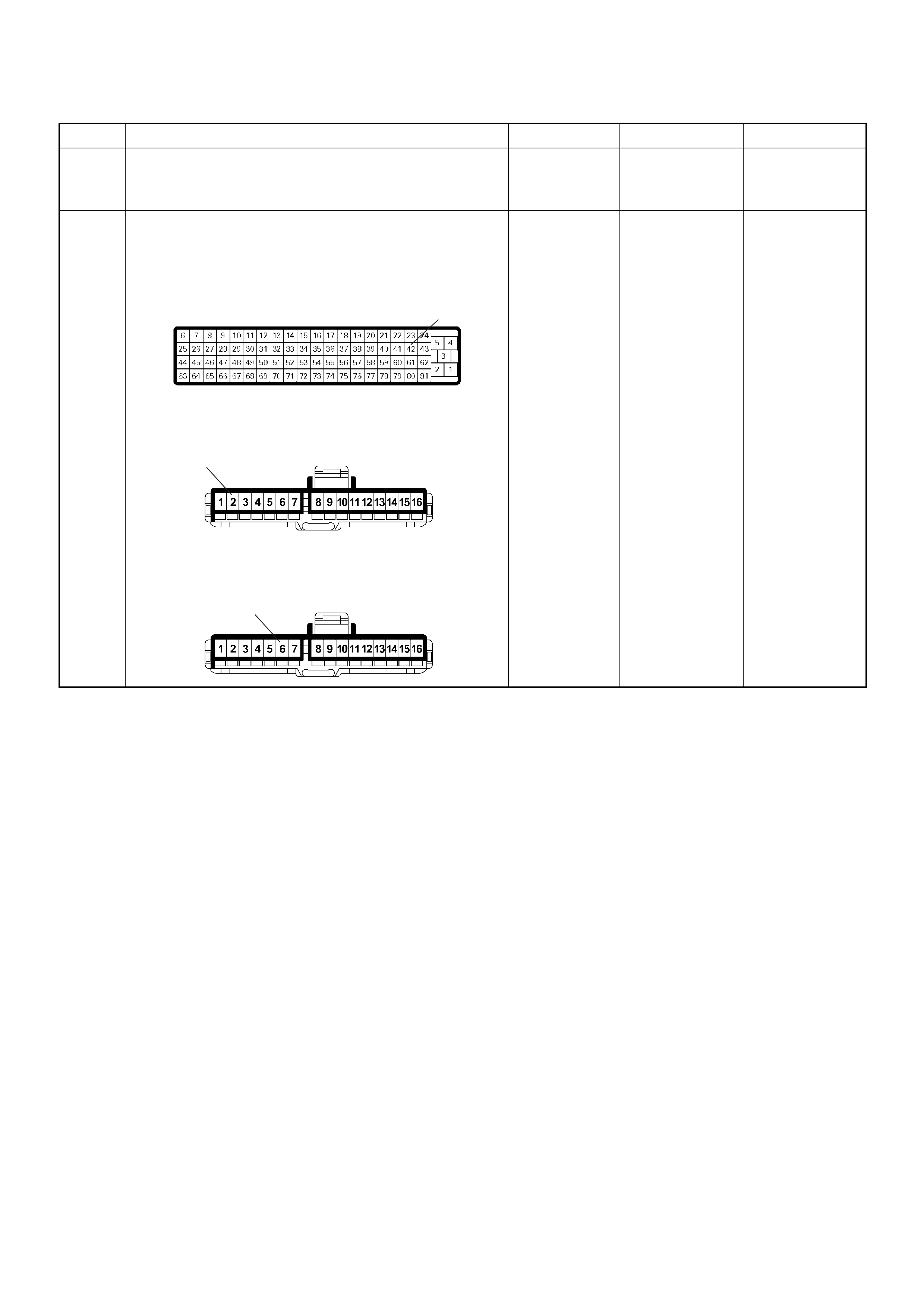
6 Check the “Check Engine” lamp bulb.
If the bulb is burnt out, repair as necessary.
Was the problem found? — Verify repair Go to Step 7
7 Check for poor/faulty connection at the meter
connector and ECM connector. If a poor/faulty
connection is found, repair as necessary.
Was the problem found?
— Verify repair Go to Step 8
Step Action Value(s) Yes No
2
6
42
C-56
B-23
4JA1-TC
B-23
4JH1-TC
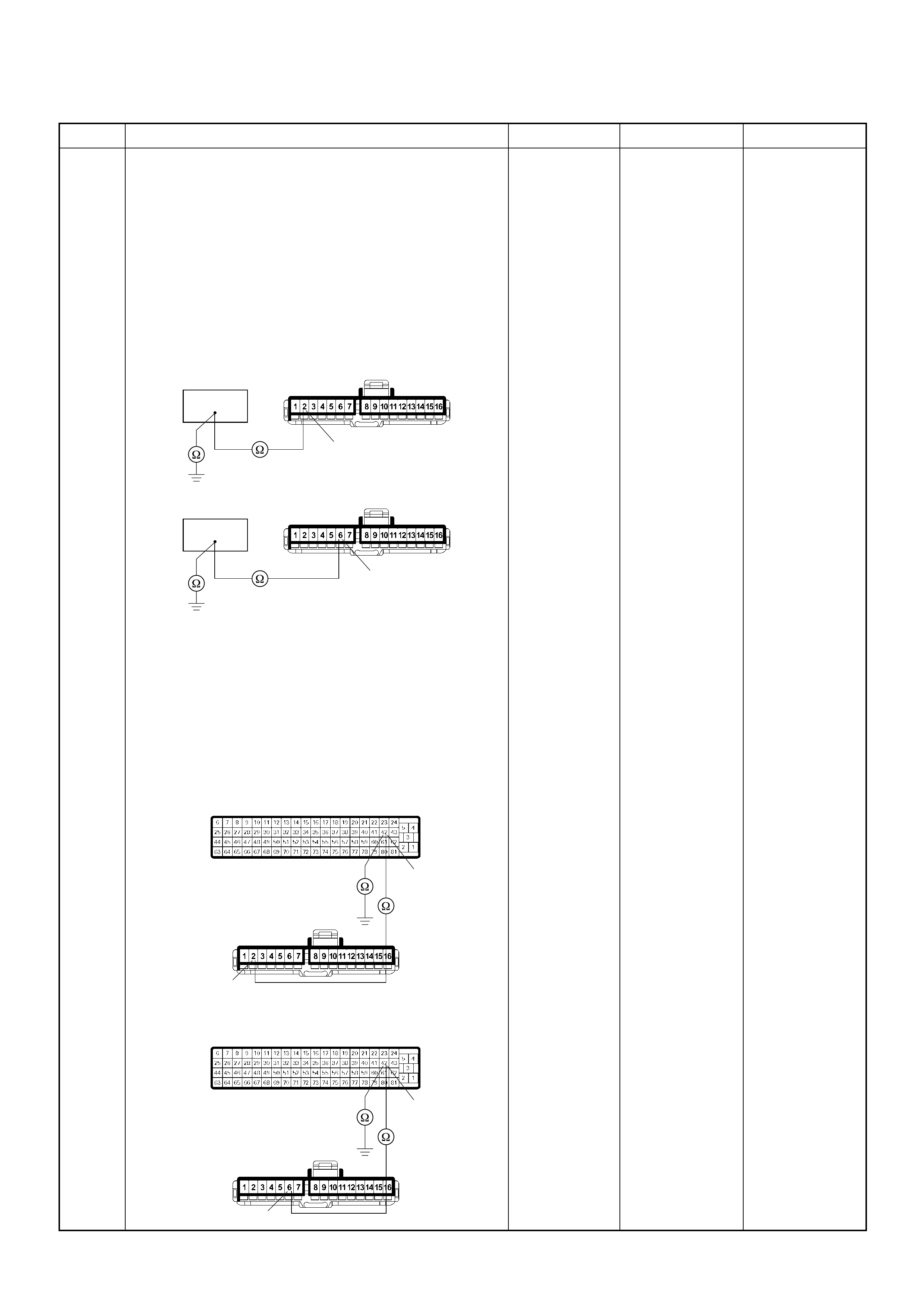
8 Using the DVM and check the “Check Engine” lamp
circuit.
Breaker box is available:
1. Ignition “Off”, engine “Off”.
2. Install the breaker box as type A. (ECM
disconnected) Ref. Page 6E-81
3. Remove the meter connector.
4. Check the circuit for open or short to ground
circuit.
Was the problem found?
Breaker box is not available:
1. Ignition “Off”, engine “Off”.
2. Disconnect the ECM connector.
3. Remove the meter connector.
4. Check the circuit for open or short to ground
circuit.
Was the problem found?
—
Repair faulty
harnes s and
verify repair G o to Step 9
Step Action Value(s) Yes No
42
42
2
6
B-234JA1-TC
B-234JH1-TC
42
2
42
6
C-56
4JA1-TC
B-23
C-56
4JH1-TC
B-23

Diagnostic Trouble Code (DTC) P1690 (Symptom Code 8) (Flash Code 77)
Check Engine Lamp (MIL) Circuit Voltage High
9 Is the ECM programmed with the latest software
release?
If not, download the latest software to the ECM using
the “SPS (Service Programming System)”.
Was the problem solved? — Verify repair Go to Step 10
10 Replace the ECM.
Is the action complete?
IMPORTANT: The replacement ECM must be
programmed. Refer to section of the Service
Programming System (SPS) in this manual.
Foll owing ECM pr ogramming, the immobi liser system
(if equipped) must be linked to the ECM. Refer to
section 11 “Immobiliser System-ECM replacement” for
the ECM/Immobiliser linking procedure. — Verify repair —
Step Action Value(s) Yes No
1 Was the “On- Board Diagnos tic (OBD) Sy stem Check”
performed?
—Go to Step 2
Go to On Board
Diagnostic
(OBD) System
Check
2 1. Connect the Tech 2.
2. Review and record the failure information.
3. S elect “F0: Read DTC I nfor As Stored B y ECU” in
“F0: Diagnostic Trouble Codes”.
Is the DTC P1690 (Symptom Code 8) stored as
“Present Failure”? — Go to Step 3
Refer to
Diagnostic Aids
and Go to Step
3
3 1. Using the Tech 2, ignition “On” and engine “Off”.
2. Select “F1: Clear DTC Information” in “F0:
Diagnostic Trouble Codes” with the Tech 2 and
clear the DTC information.
3. Operate the vehicle and monitor the “F0: Read
DTC Infor As Stored By ECU” in the “F0:
Diagnostic Trouble Codes”.
Was the DT C P1 690 (Sy mpt om Code 8) stor e d i n th is
ignition cycle? — Go to Step 4 Refer to
Diagnostic Aids
4 Is the ECM programmed with the latest software
release?
If not, downlo ad the latest software to the ECM using
the “SPS (Service Programming System)”.
Was the problem solved? — Verify repair Go to Step 5
5 Substitute a known good ECM and recheck.
Was the problem solved?
IMPORTANT: The replacement ECM must be
programmed. Refer to section of the Service
Programming System (SPS) in this manual.
Foll owing ECM pr ogramming, the immobi liser system
(if equipped) must be linked to the ECM. Refer to
section 11 “Immobiliser System-ECM replacement” for
the ECM/Immobiliser linking procedure. —Go to Step 6 —
Step Action Value(s) Yes No

6 Replace the ECM.
Is the action complete?
IMPORTANT: The replacement ECM must be
programmed. Refer to section of the Service
Programming System (SPS) in this manual.
Foll owing ECM pr ogramming, the immobi liser system
(if equipped) must be linked to the ECM. Refer to
section 11 “Immobiliser System-ECM replacement” for
the ECM/Immobiliser linking procedure. — Verify repair —
Step Action Value(s) Yes No

Symptom Diagnosis
Preliminary Checks
Before using this section, perform the “On-Board
Diagnostic (OBD) System Check” and verify all of the
following items:
• The engine control module (ECM) and check engine
lamp (MIL=malfunction indicator lamp are operating
correctly.
• There are no Diagnostic Trouble Code(s) stored.
• Tech 2 data is within normal operating range. Refer to
Typical Scan Data Values.
• Verify the customer complaint and locate the correct
symptom in the table of contents. Perform the
procedure included in the symptom chart.
Visual/physical Check
Several of the symptom procedures call for a careful
visual/physical check. This can lead to correcting a
problem without further checks and can save valuable
time. This check should include the following items:
• ECM grounds for cleanliness, tightness and proper
location.
• Vacuum hoses for splits, kinks, and proper
connection. Check thoroughly for any type of leak or
restriction.
• Air intake ducts for collapsed or damaged areas.
• Air leaks at throttle body mounting area, mass air flow
(MAF) sensor and intake manifold sealing surfaces.
• Wiring for proper connections, pinches and cuts.
Intermittent
Important: An intermittent problem may or may not turn
on the check engine lamp (MIL=malfunction indicator
lamp) or store a Diagnostic Trouble Code. Do NOT use
the Diagnostic Trouble Code (DTC) charts for
intermittent problems.
The fault must be present to locate the problem.
Most intermittent problems are cased by faulty electrical
connections or wiring. Perform a careful visual/physical
check for the following conditions.
• Poor mating of the connector halves or a terminal not
fully seated in the connector (backed out).
• Improperly formed or damaged terminal.
• All connector terminals in the problem circuit should
be carefully checked for proper contact tension.
• Poor terminal-to-wire connection. This requires
removing the terminal form the connector body to
check.
• Check engine lamp (MIL=malfunction indicator lamp)
wire to ECM shorted to ground.
• Poor ECM grounds. Refer to the ECM wiring
diagrams.
Road test the vehicle with a Digital Multimeter
connected to a suspected circuit. An abnormal voltage
when the malfunction occurs is a good indication that
there is a fault in the circuit being monitored.
Using Tech 2 to help detect intermittent conditions. The
Tech 2 have several features that can be used to
located an intermittent condition. Use the following
features to find intermittent faults:
To check for loss of diagnostic code memory,
disconnect the MAF sensor and idle the engine until the
check engine lamp (MIL=malfunction indicator lamp)
comes on. Diagnostic Trouble Code P0100 should be
stored and kept in memory when the ignition is turned
OFF.
If not, the ECM is faulty. When this test is completed,
make sure that you clear the Diagnostic Trouble Code
P0100 from memory.
An intermittent check engine lamp (MIL=malfunction
indicator lamp) with no stored Diagnostic Trouble Code
may be caused by the following:
• Check engine lamp (MIL=malfunction indicator lamp)
wire to ECM short to ground.
• Poor ECM grounds. Refer to the ECM wiring
diagrams.
Check for improper installation of electrical options such
as light, cellular phones, etc. Check all wires from ECM
to the ignition control module for poor connections.
Check for an open diode across the A/C compressor
clutch and check for other open diodes (refer to wiring
diagrams in Electrical Diagnosis).
If problem has not been found, refer to ECM connector
symptom tables.
• Check the “Broadcast Code” of the ECM, and
compare it with the lates t Isuzu servic e bulletins and /
or Isuzu EEPROM reprogramming equipment to
determine if an update to the ECM's reprogrammable
memory has been released.
This identifies the contents of the reprogrammable
software and calibration contained in the ECM.
If the “Broadcast Code” is not the most current
available, it is advisable to reprogram the ECM's
EEPROM memory, which may either help identify a
hard-to find problem or may fix the problem.
The Service Programming System (SPS) will not allow
incorrect software programming or incorrect calibration
changes.
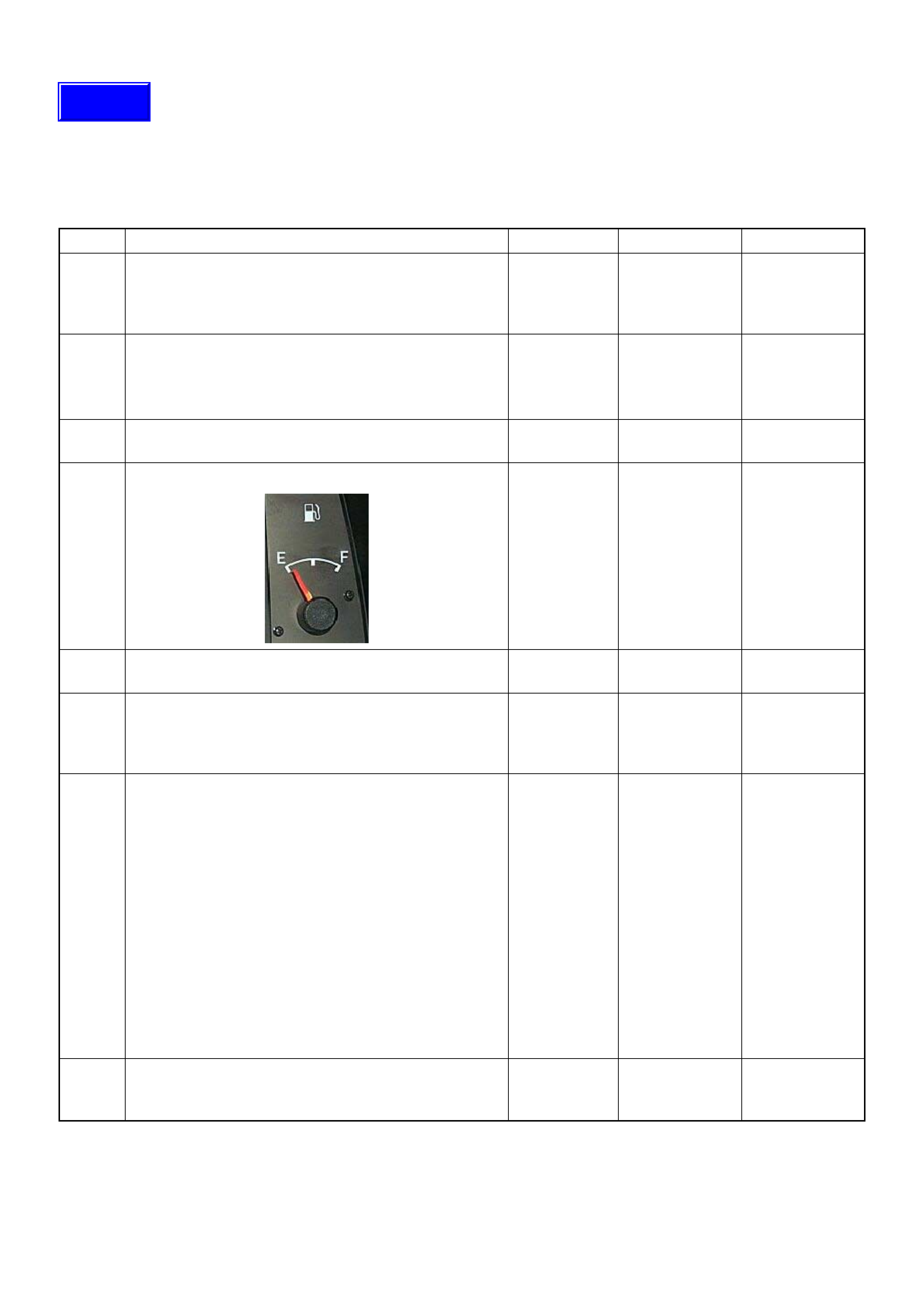
Engine Cranks But Will Not Run
DEFINITIONS: Engine cranks, but will not run. (The engine does not start.)
NOTE: The vehicle has an immobiliser system, this system may be activated. Check the immobiliser system
diagnosis.
Step Action Value(s) Yes No
1 Was the “On- Board Diagnos tic (OBD) Sy stem Check”
performed?
—Go to Step 2
Go to On Board
Diagnostic
(OBD) System
Check
2 1. Perform a bulletin search.
2. If a bulletin that addresses the symptom is found,
correct the condition as instructed in the bulletin.
Was a bulletin found that addresses the symptom? — Verify repair Go to Step 3
3 Was a visually/physical check performed? —Go to Step 4 Go to Visual /
physical Check
4 Is there enough fuel in the fuel tank?
—Go to Step 5 Add fuel to the
tank
5 Is the customer using the incorrect fuel type? Diesel fuel
only Replace with
diesel fuel Go to Step 6
6 Check the “Engine-1” fuse (15A) and “Engine-2” fuse
(10A).
If the fuse is burnt out, repair as necessary.
Was the problem found? — Verify repair Go to Step 7
7 Visually/physically inspect for the following conditions.
• Restricted air intake system. Check for a restricted
air filter element, o r foreign ob jects blocking th e air
intake system
• Che ck f or o bjects blo cking or e xces siv e depo sits i n
the throttle bore and on the throttle plate
• Check for a condition that causes a large vacuum
leak, such as an incorrectly installed or faulty
crankc as e ven til ati on hose.
• Restrict air intake system at the turbocharger.
Check for objects blocking the turbocharger
compressor wheel or turbine shaft sticking.
If a problem is found, repair as necessary.
Was a problem found? — Verify repair Go to Step 8
8 Check the ECM & PSG grounds to verify that they are
clean and tight. Refer to the ECM wiring diagrams.
Was a problem found? — Verify repair Go to Step 9
Techline
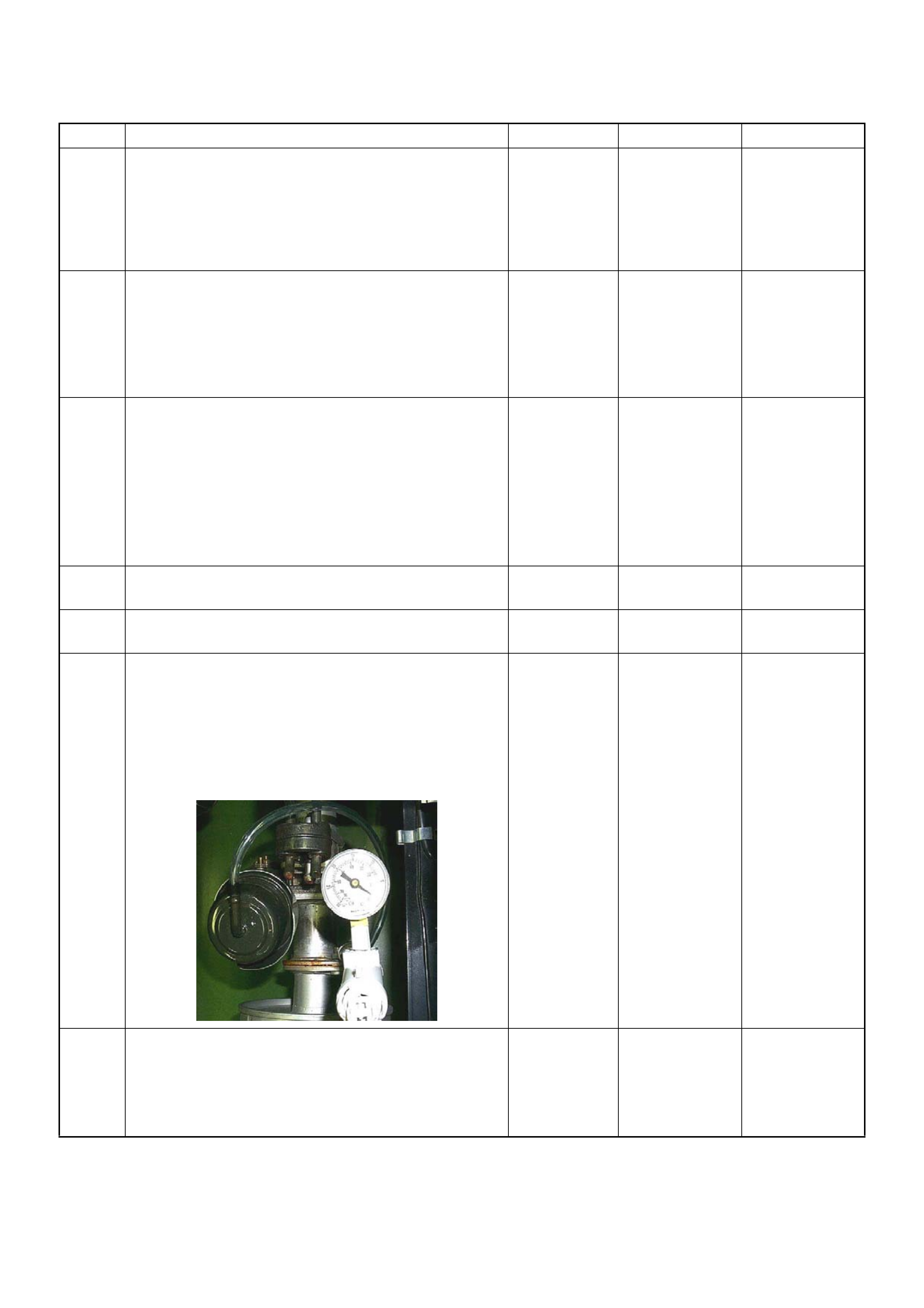
9 1. Using the Tech 2, ignition “On” and engine “Off”.
2. Monitor the “Neutral Switch” in the data display.
Does the Tech 2 indicate correct “Neutral Switch”
status depending on any shift positions?
If a problem is found, repair as necessary.
Was the problem found? — Verify repair Go to Step 10
10 Remove the CKP sensor from the flywheel housing
and check for the following conditions.
• Objects sticking the CKP sensor.
• Objects sticking the CKP sensor pulser.
If a problem is found, repair as necessary.
Was the problem found? — Verify repair Go to Step 11
11 Check the CKP sensor harness for the following
conditions.
• Check for poor connector connection.
• Check for misrouted harness.
• Check for any accessory parts which may cause
electric interference.
If a problem is found, repair as necessary.
Was a problem found? — Verify repair Go to Step 12
12 Substitute a known good CKP sensor and recheck.
Was the problem solved? — Go to Step 13 Go to Step 14
13 Replace the CKP sensor.
Is the action complete? — Verify repair —
14 Using the vacuum pump and check the exhaust
throttle valve (if equipped) operation for the following
condition.
• Restrict shaft movement. Check for objects sticking
the shaft, broken diaphragm or excessive carbon
deposit.
Was a problem found?
— Verify repair Go to Step 15
15 Check the exhaust system for a possible restriction.
• Damaged or collapsed pipes or catalytic converter.
• Internal muffler failure.
If a problem is found, repair as necessary.
Was a problem found? — Verify repair Go to Step 16
Step Action Value(s) Yes No
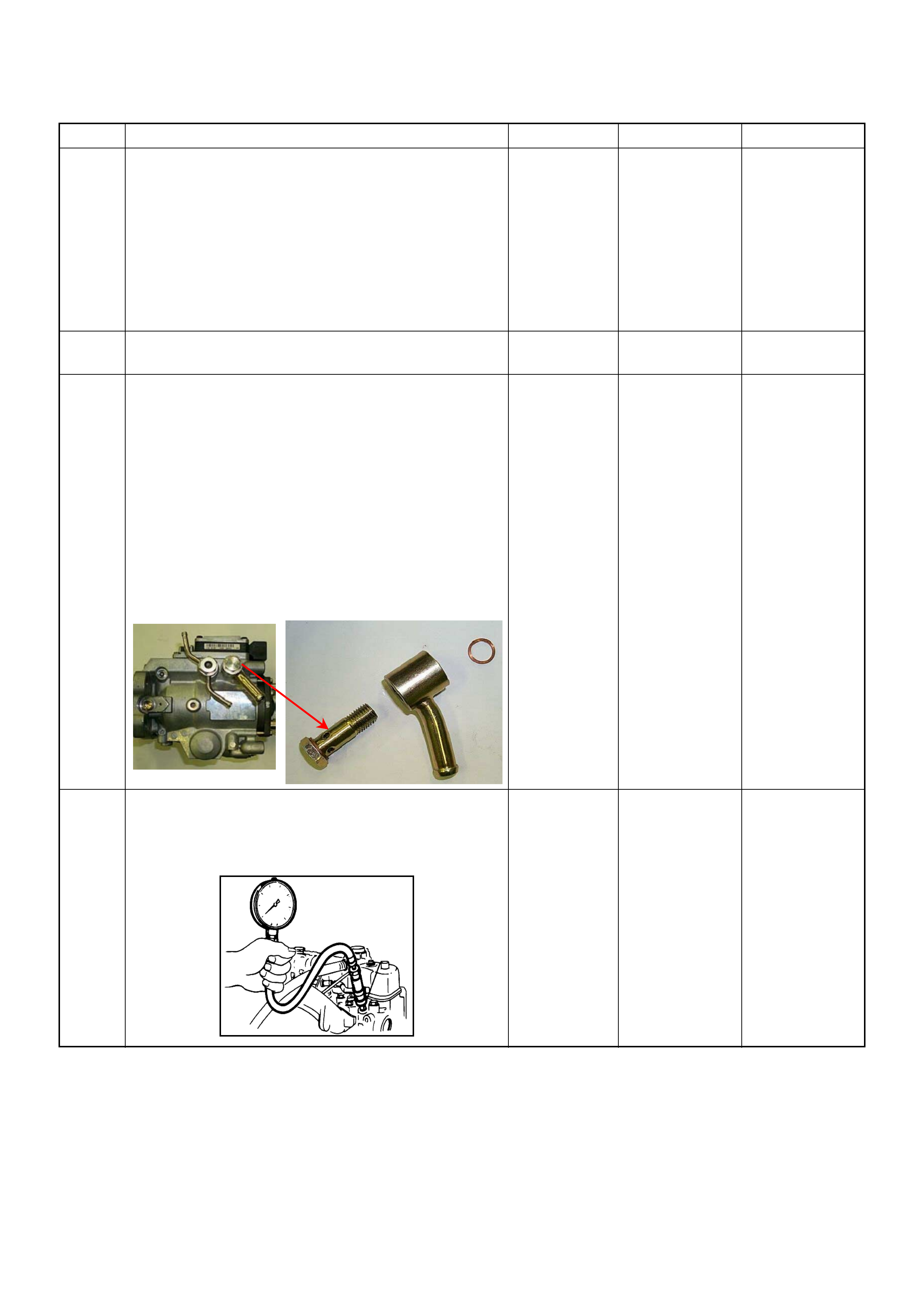
16 Visually/physically inspect for the following conditions.
• Restrict fuel supply system. Check for a pinched
fuel hose/pipe.
• Check for a condition that causes fuel waxing or
icing, such as the customer is using an incorrect
fuel type in winter season or water mixed with the
fuel.
If a problem is found, repair as necessary.
Was a problem found? — Verify repair Go to Step 17
17 Replace the fuel filter.
Was the problem solved? — Verify repair Go to Step 18
18 Remove the eye bolt with gauze filter from the
injection pump and check for the following conditions.
• Objects blocking at the gauze filter. Check for a
condition that causes contaminated fuel, such as
the customer is using an aftermarket fuel filter or
extended mai nte nan ce int erva l.
• Check for a condition that causes fuel waxing or
icing, such as the customer is using an incorrect
fuel type in winter season or water mixed with the
fuel.
If a problem is found, repair as necessary.
Was the problem found?
—
Replace the
eye bolt with
gauze filter and
verify repair Go to Step 19
19 Check the engine compression pressure for each
cylinders.
If a problem is found, repair as necessary.
Was the problem found?
More than 30
Mpa (31.0 kg/
cm
2
) Verify repair Go to Step 20
Step Action Value(s) Yes No

20 If the injection pump was replaced, are the timing
gears or injection pump correctly installed?
—Go to Step 21 Re pair as
necessary
21 1. Review all diagnostic procedures within this table.
2. If all procedures have been completed and no
malfunctions have been found, review/ inspect the
following:
• Visual/physical inspection
• Tech 2 data
• All electrical connections within a suspected circuit
and/or system
Was a problem found? — Verify repair Go to Step 22
22 Is the ECM programmed with the latest software
release?
If not, downlo ad the latest software to the ECM using
the “SPS (Service Programming System)”.
Was the problem solved? — Verify repair Go to Step 23
23 Substitute a known good ECM and recheck.
Was the problem solved?
IMPORTANT: The replacement ECM must be
programmed. Refer to section of the Service
Programming System (SPS) in this manual.
Foll owing ECM pr ogramming, the immobi liser system
(if equipped) must be linked to the ECM. Refer to
section 11 “Immobiliser System-ECM replacement” for
the ECM/Immobiliser linking procedure. — Go to Step 24 Go to Step 25
24 Replace the ECM.
Is the action complete?
IMPORTANT: The replacement ECM must be
programmed. Refer to section of the Service
Programming System (SPS) in this manual.
Foll owing ECM pr ogramming, the immobi liser system
(if equipped) must be linked to the ECM. Refer to
section 11 “Immobiliser System-ECM replacement” for
the ECM/Immobiliser linking procedure. — Verify repair —
25 Replace the injection pump assembly.
Is the action complete? — Verify repair —
Step Action Value(s) Yes No

Hard Start Sy mptom
DEFINITIONS: Engine cranks, but does not start for a long time. Does eventually start, or may start and then
immediately stall.
Step Action Value(s) Yes No
1 Was the “On- Board Diagnos tic (OBD) Sy stem Check”
performed?
—Go to Step 2
Go to On Board
Diagnostic
(OBD) System
Check
2 1. Perform a bulletin search.
2. If a bulletin that addresses the symptom is found,
correct the condition as instructed in the bulletin.
Was a bulletin found that addresses the symptom? — Verify repair Go to Step 3
3 Was a visually/physical check performed? —Go to Step 4 Go to Visual /
physical Check
4 Is the customer using the incorrect fuel type? Diesel fuel
only Replace with
diesel fuel Go to Step 6
5 Visually/physically inspect for the following conditions.
• Restrict air intake system. Check for a restricted air
filter element, or foreign objects blocking the air
intake system
• Che ck f or o bjects blo cking or e xces siv e depo sits i n
the throttle bore and on the throttle plate
• Check for a condition that causes a large vacuum
leak, such as an incorrectly installed or faulty
crankc as e ven til ati on hose.
• Restrict air intake system at the turbocharger.
Check for objects blocking the turbocharger
compressor wheel or turbine shaft sticking.
If a problem is found, repair as necessary.
Was a problem found? — Verify repair Go to Step 6
6 Check the ECM & PSG grounds to verify that they are
clean and tight. Refer to the ECM wiring diagrams.
Was a problem found? — Verify repair Go to Step 7
7 1. Using th e Tec h 2, d ispl ay the ECT sens or an d I AT
sensor value.
2. Check the displayed value.
Does the Tech 2 indicate correct temperature
depending on engine condition?
If a problem is found, repair as necessary.
Was the problem found? — Verify repair Go to Step 8
8 1. Using the Tech 2, display the FT sensor value.
2. Check the displayed value.
Does the Tech 2 indicate correct temperature
depending on engine condition?
If a problem is found, repair as necessary.
Was the problem found? — Go to Step 20 Go to Step 9
9 1. Using the Tech 2, ignition “On”.
2. Monitor the “Glow Time Relay” in the data display.
Does the Tech 2 indicate correct “Glow Time Relay”
status depending on the time from ignition switch
“On”?
If a problem is found, repair as necessary.
Was the problem found? — Go to Step 20 Go to Step 10
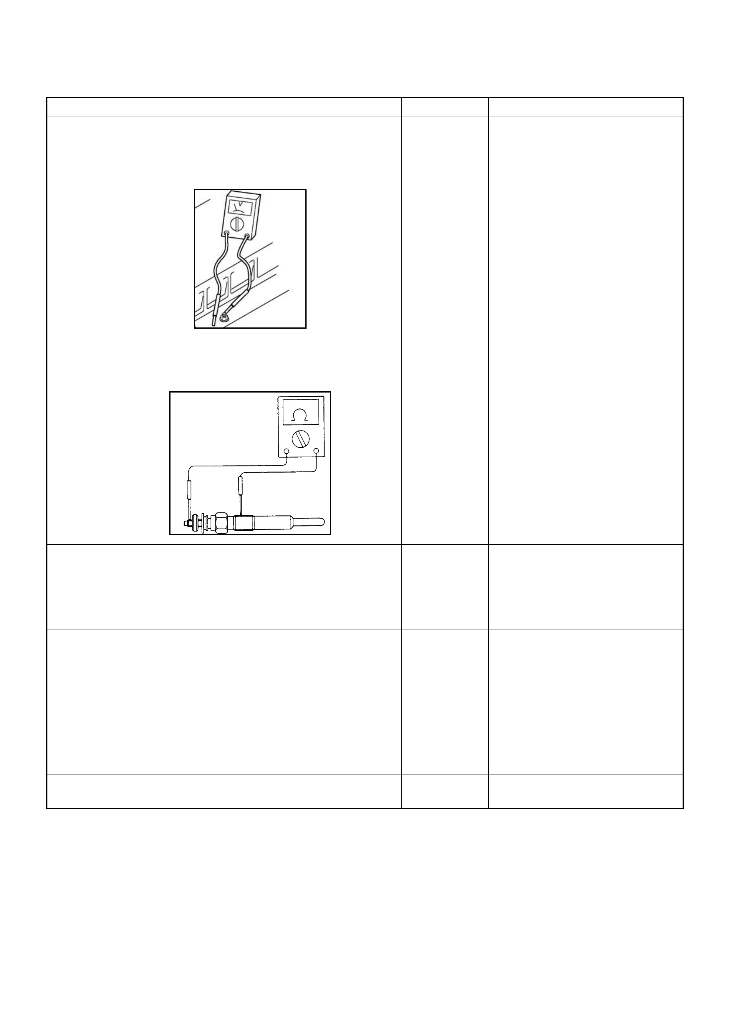
10 1. Using the Tech 2, ignition “On”.
2. Monitor the “Glow Time Rela y” in the data displ ay
and then, does the supply voltage correctly supply
to the glow plug?
—Go to Step 11
Repair voltage
supply circuit
and verify repair
11 Check the glow plugs for continuity.
If a problem is found, repair as necessary.
Was a problem found?
— Verify repair Go to Step 12
12 Check the exhaust system for a possible restriction.
• Damaged or collapsed pipes or catalytic converter.
• Internal muffler failure.
If a problem is found, repair as necessary.
Was a problem found? — Verify repair Go to Step 13
13 Visually/physically inspect for the following conditions.
• Restrict fuel supply system. Check for a pinched
fuel hose/pipe.
• Check for a condition that causes fuel waxing or
icing, such as the customer is using an incorrect
fuel type in winter season or water mixed with the
fuel.
If a problem is found, repair as necessary.
Was a problem found? — Verify repair Go to Step 14
14 Replace the fuel filter.
Was the problem solved? — Verify repair Go to Step 15
Step Action Value(s) Yes No
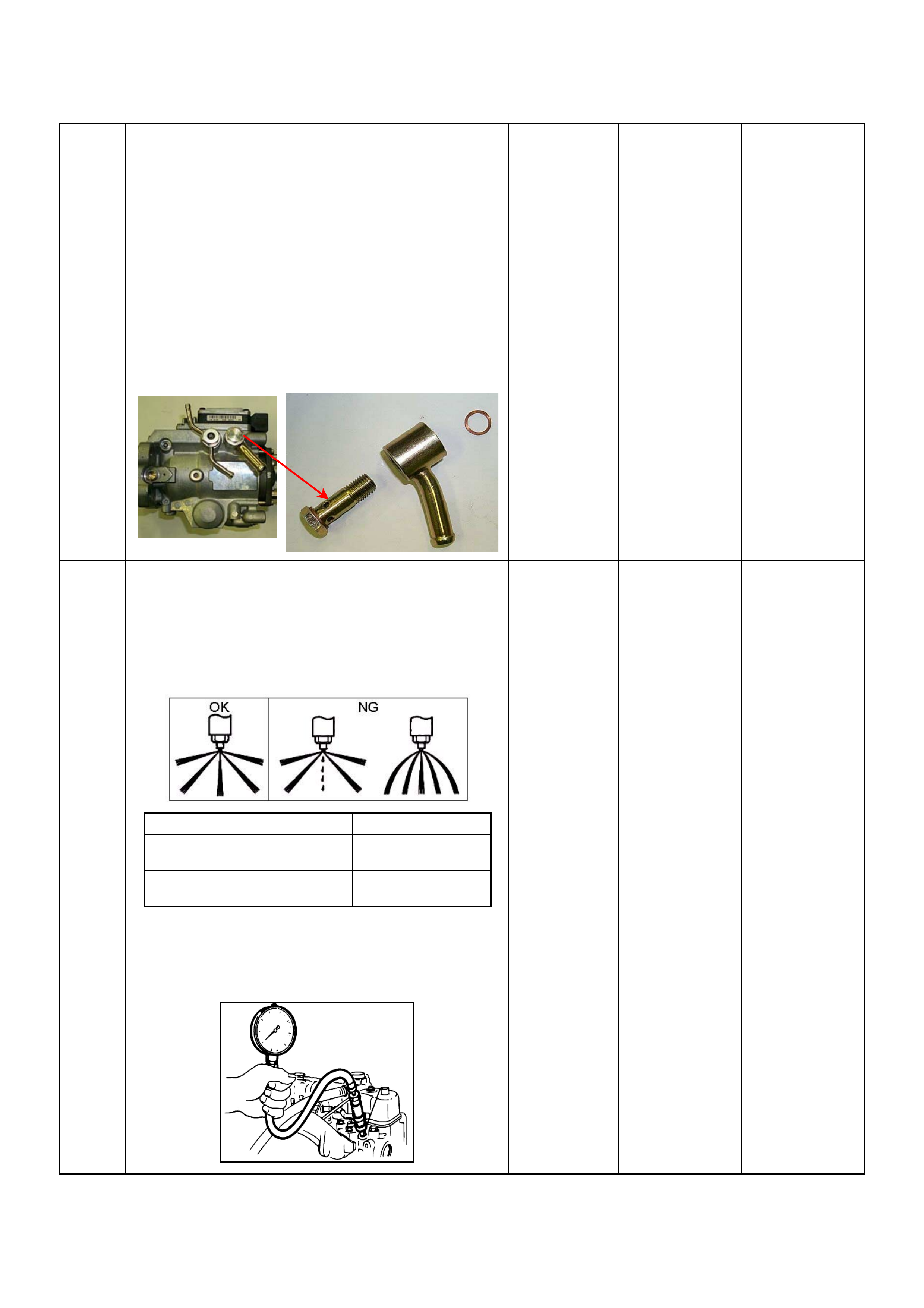
15 Remove the eye bolt with gauze filter from the
injection pump and check for the following conditions.
• Objects blocking at the gauze filter. Check for a
condition that causes contaminated fuel, such as
the customer is using an aftermarket fuel filter or
extended mai nte nan ce int erva l.
• Check for a condition that causes fuel waxing or
icing, such as the customer is using an incorrect
fuel type in winter season or water mixed with the
fuel.
If a problem is found, repair as necessary.
Was the problem found?
—
Replace the
eye bolt with
gauze filter and
verify repair Go to Step 16
16 Remove the injection nozzles from the engine and
check for the following conditions.
• Improper splay condition.
• Operating pressure is incorrect.
If a problem is found, repair as necessary.
Was the problem found?
—
Replace the
injection nozzle
and verify repair Go to Step 17
17 Check the engine compression pressure for each
cylinders.
If a problem is found, repair as necessary.
Was the problem found?
More than 30
Mpa (31.0 kg/
cm
2
) Verify repair Go to Step 18
Step Action Value(s) Yes No
1
st
Stage 2
nd
St age
4JA1-TC 19.5 - 20.5 Mpa
(199 -209 kg/cm
2
)34.0 - 35.5 Mpa
(347 - 362 kg/cm
2
)
4JH1-TC 20.0 - 21.0 Mpa
(204 -214 kg/cm
2
)34.3 - 35.8 Mpa
(350 - 365 kg/cm
2
)

18 Check the inlet/exhaust valve clearance for each
valves.
Are the valve clearances within the specified value?
0.4mm at cold
(In/Ex) Go to Step 19 Adjust and
verify repair
19 1. Review all diagnostic procedures within this table.
2. If all procedures have been completed and no
malfunctions have been found, review/ inspect the
following:
• Visual/physical inspection
• Tech 2 data
• All electrical connections within a suspected circuit
and/or system
Was a problem found? — Verify repair Go to Step 20
20 Is the ECM programmed with the latest software
release?
If not, downlo ad the latest software to the ECM using
the “SPS (Service Programming System)”.
Was the problem solved? — Verify repair Go to Step 21
21 Substitute a known good ECM and recheck.
Was the problem solved?
IMPORTANT: The replacement ECM must be
programmed. Refer to section of the Service
Programming System (SPS) in this manual.
Foll owing ECM pr ogramming, the immobi liser system
(if equipped) must be linked to the ECM. Refer to
section 11 “Immobiliser System-ECM replacement” for
the ECM/Immobiliser linking procedure. — Go to Step 22 Go to Step 23
22 Replace the ECM.
Is the action complete?
IMPORTANT: The replacement ECM must be
programmed. Refer to section of the Service
Programming System (SPS) in this manual.
Foll owing ECM pr ogramming, the immobi liser system
(if equipped) must be linked to the ECM. Refer to
section 11 “Immobiliser System-ECM replacement” for
the ECM/Immobiliser linking procedure. — Verify repair —
23 Replace the injection pump assembly.
Is the action complete? — Verify repair —
Step Action Value(s) Yes No

Rough, Unstable, Or Incorrect Idle, Stalling Symptom
DEFINITIONS: Engine runs unevenly at idle. If severe,
the engine or vehicle may shake. Engine idle speed
may vary in RPM. Either condition may be severe
enough to stall the engine.
X
time
rpm
Rough Idle Stall
Step Action Value(s) Yes No
1 Was the “On- Board Diagnos tic (OBD) Sy stem Check”
performed?
—Go to Step 2
Go to On Board
Diagnostic
(OBD) System
Check
2 1. Perform a bulletin search.
2. If a bulletin that addresses the symptom is found,
correct the condition as instructed in the bulletin.
Was a bulletin found that addresses the symptom? — Verify repair Go to Step 3
3 Was a visually/physical check performed? —Go to Step 4 Go to Visual /
physical Check
4 Is the customer using the incorrect fuel type? Diesel fuel
only Replace with
diesel fuel Go to Step 5
5 1. Check for incorrect idle speed. Ensure that the
following conditions are present.
• Engine fully warm.
• Accessories are “OFF”.
2. Using a Tech 2, monitor “Desired Engine Idle
Speed” and “Engine Speed”.
Is the “Engine Speed” within the specified values?
Desired
Engine Idl e
Speed ± 25
rpm Go to Step 7 Go to Step 6
6 Visually/physically inspect for the following conditions.
• Restrict air intake system. Check for a restricted air
filter element, or foreign objects blocking the air
intake system
• Che ck f or o bjects blo cking or e xces siv e depo sits i n
the throttle bore and on the throttle plate
• Check for a condition that causes a large vacuum
leak, such as an incorrectly installed or faulty
crankc as e ven til ati on hose.
• Restrict air intake system at the turbocharger.
Check for objects blocking the turbocharger
compressor wheel or turbine shaft sticking.
If a problem is found, repair as necessary.
Was a problem found? — Verify repair Go to Step 7
7 Check the ECM & PSG grounds to verify that they are
clean and tight. Refer to the ECM wiring diagrams.
Was a problem found? — Verify repair Go to Step 8

8 1. Using the Tech 2, ignition “On” and engine “Off”.
2. Monitor the “Neutral Switch” in the data display.
Does the Tech 2 indicate correct “Neutral Switch”
status depending on any shift positions?
If a problem is found, repair as necessary.
Was the problem found? — Verify repair Go to Step 9
9 1. Using the Tech 2, ignition “On” and engine “Run”.
2. Monitor the “A/C Information Switch” in the data
display.
Does the Tech 2 indicate correct “A/C Information
Switch ” status depend ing on A/C switc h posi tion?
If a problem is found, repair as necessary.
Was the problem found? — Verify repair Go to Step 10
10 1. Usin g th e Tec h 2, d ispl ay the E CT s ens or an d I AT
sensor value.
2. Check the displayed value.
Does the Tech 2 indicate correct temperature
depending on engine condition?
If a problem is found, repair as necessary.
Was the problem found? — Verify repair Go to Step 11
11 1. Using the Tech 2, ignition “On” and engine “Run”.
2. Monitor the “Mass Air Flow” in the data display.
Does the Tech 2 indicate correct “Mass Air Flow”
depending on accelerator pedal operation? — Go to Step 16 Go to Step 12
12 Remove the MAF & IAT sensor assembly and check
for the following conditions.
• Objects blocking at the MAF sensor element.
If a problem is found, repair as necessary.
Was the problem found? — Verify repair Go to Step 13
13 Check the MAF sensor harness for the following
conditions.
• Check for poor connector connection.
• Check for misrouted harness.
• Check for any accessory parts which may cause
electric interference.
If a problem is found, repair as necessary.
Was a problem found? — Verify repair Go to Step 14
14 Substitute a known good MAF & IAT sensor assembly
and recheck.
Was the problem solved? — Go to Step 15 Go to Step 36
15 Replace the MAF & IAT sensor assembly.
Is the action complete? — Verify repair —
16 1. Using the Tech 2, ignition “On” and engine “Off”.
2. Monitor the “Pedal/Throttle Position” and “Idle
Switch” in the data display.
Does the Tech 2 indicate correct “Pedal/Throttle
Position” from 0% to 100% and correct “Idle Switch”
status depending on accelerator pedal operation? — Go to Step 21 Go to Step 17
Step Action Value(s) Yes No

17 1. Using the Tech 2, ignition “On” and engine “Off”.
2. Monitor the “Pedal/Throttle Position” and “Idle
Switch” in the data display.
3. Adjust the accelerator cable or TPS within 0% to
100%.
Was the problem solved? — Verify repair Go to Step 18
18 Check the TPS harness for the following conditions.
• Check for poor connector connection.
• Check for misrouted harness.
• Check for any accessory parts which may cause
electric interference.
If a problem is found, repair as necessary.
Was a problem found? — Verify repair Go to Step 19
19 Substitute a known good TPS and recheck.
Was the problem solved? — Go to Step 20 Go to Step 36
20 Replace the TPS.
Is the action complete? — Verify repair —
21 Remove the CKP sensor from the flywheel housing
and check for the following conditions.
• Objects sticking the CKP sensor.
• Objects sticking the CKP sensor pulser.
If a problem is found, repair as necessary.
Was the problem found? — Verify repair Go to Step 22
22 Check the CKP sensor harness for the following
conditions.
• Check for poor connector connection.
• Check for misrouted harness.
• Check for any accessory parts which may cause
electric interference.
If a problem is found, repair as necessary.
Was a problem found? — Verify repair Go to Step 23
23 Substitute a known good CKP sensor and recheck.
Was the problem solved? — Go to Step 24 Go to Step 25
24 Replace the CKP sensor.
Is the action complete? — Verify repair —
Step Action Value(s) Yes No
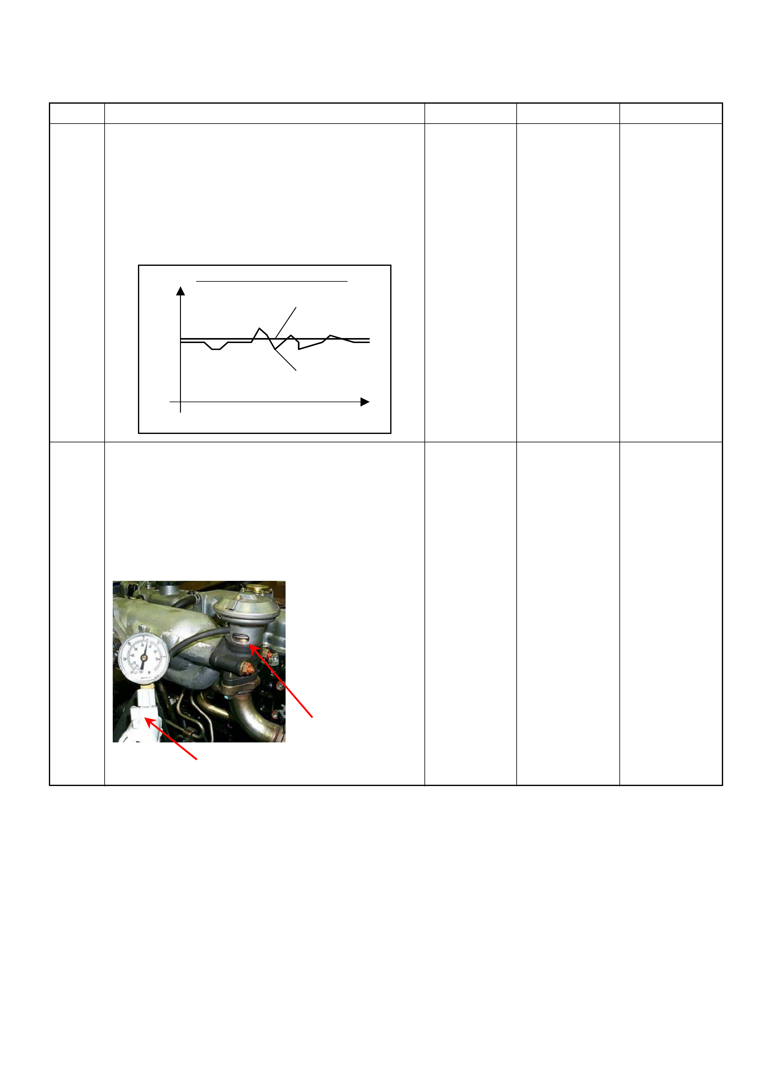
25 1. Using the Tech 2 and ignition “On” and engine
“Run”.
2. Monitor the following parameters in the data
display.
• “Desired Injection Quantity” & “Injection Quantity”
• “Desired Injection Start” & “Actual Injection Start”
Are the large gap or unstable parameter displayed
between “Desired” and “Actual”?
—Go to Step 29 Go to Step 26
26 Us ing the vacuum pump and chec k the EGR valve ( if
equipped) operation for the following condition
through the small window.
• Restrict shaft movement. Check for objects sticking
the shaft, broken diaphragm or excessive carbon
deposit.
If a problem is found, repair as necessary.
Was a problem found?
— Verify repair Go to Step 27
Step Action Value(s) Yes No
When idling or part-throttle
High Desired
Low
Time
Actual
Vacuum Pump
Small Window

27 Using the vacuum pump and check the exhaust
throttle valve (if equipped) operation for the following
condition.
• Restrict shaft movement. Check for objects sticking
the shaft, broken diaphragm or excessive carbon
deposit.
Was a problem found?
— Verify repair Go to
Step 28
28 Check the exhaust system for a possible restriction.
• Damaged or collapsed pipes or catalytic conve rter.
• Internal muffler failure.
If a pro blem is found, repair as necessary.
Was a problem found? — Verify repair Go to
Step 29
29 Visually/physically inspect for the following conditions.
• Restrict fuel supply system. Check for a pinched
fuel hose/pipe.
• Check for a condition that causes fuel waxing or
icing, such as the customer is using an incorrect
fuel type in winter season or water mixed with the
fuel.
If a pro blem is found, repair as necessary.
Was a problem found? — Verify repair Go to
Step 30
30 Replace the fuel f ilter.
Was the problem solved ? — Verify repair Go to
Step 31
Step Action Value(s) Yes No
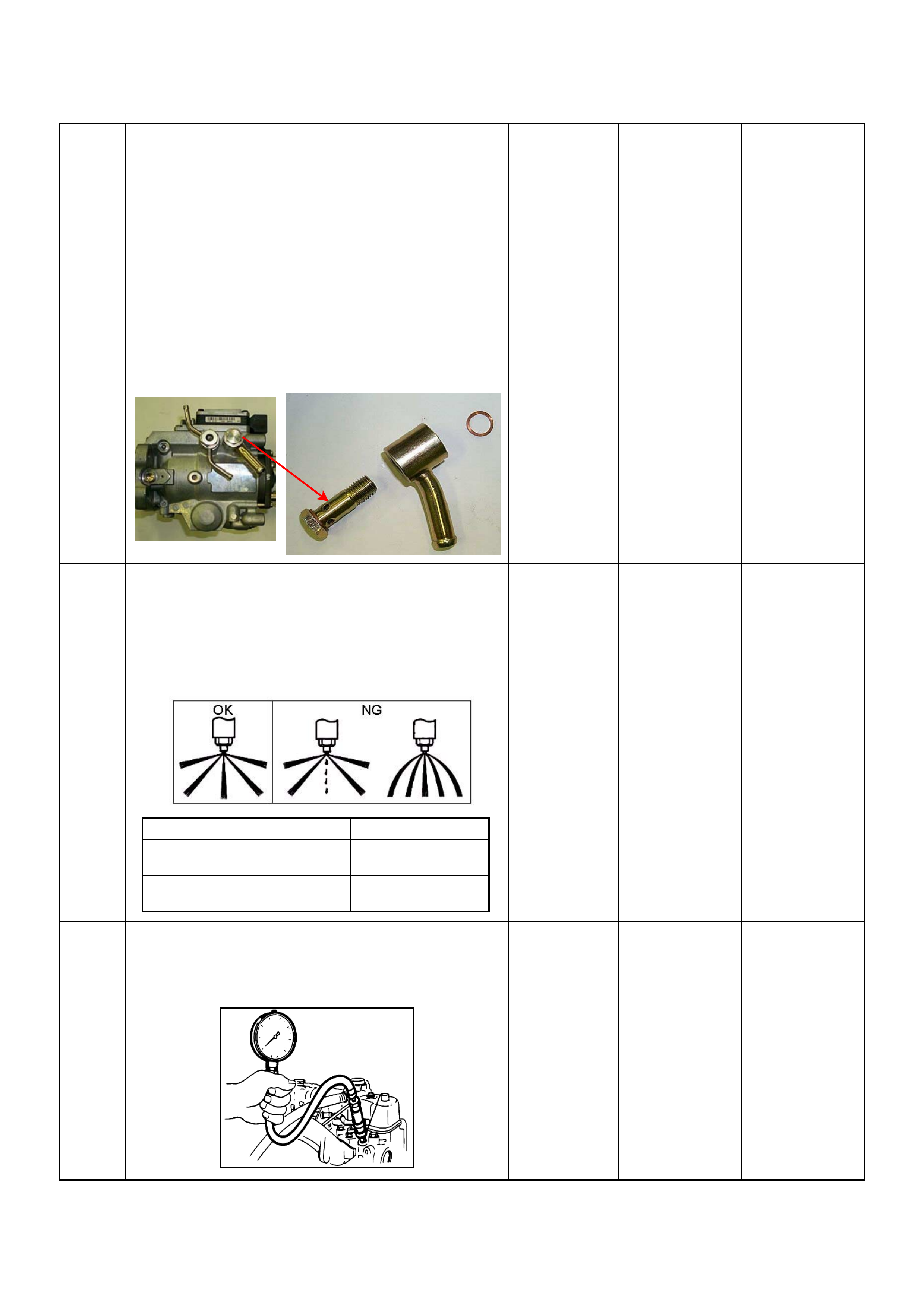
31 Remove the eye bolt with gauze filter from the
injection pump and check for the followin g conditions.
• Objects blocking at the gauze filter. Check for a
condition that causes contaminated fuel, such as
the customer is using an aftermarket fuel filter or
extended mai nte nance int erva l.
• Check for a condition that causes fuel waxing or
icing, such as the customer is using an incorrect
fuel type in winter season or water mixed with the
fuel.
If a pro blem is found, repair as necessary.
Was the problem found?
—
Replace the
eye bolt with
gauze filter and
verify repair Go to
Step 32
32 Remove the injection nozzles from the engine and
check for the following conditions.
• Improper splay condition.
• Operating pressu re is incorrect.
If a pro blem is found, repair as necessary.
Was the problem found?
—
Replace the
injection nozzle
and ve rify repair Go to
Step 33
33 Check the engine compression pressure for each
cylinders.
If a pro blem is found, repair as necessary.
Was the problem found?
More than 30
Mpa (31.0 kg/
cm
2
) Verify repair Go to
Step 34
Step Action Value(s) Yes No
1
st
Stage 2
nd
Stage
4JA1-TC 19.5 - 20.5 Mpa
(199 -209 kg/cm
2
)34.0 - 35.5 Mpa
(347 - 362 kg/cm
2
)
4JH1-TC 20.0 - 21.0 Mpa
(204 -214 kg/cm
2
)34.3 - 35.8 Mpa
(350 - 365 kg/cm
2
)

34 Check the inlet/exhaust valve clearance for each
valves.
Are the valve clearances within the s p ecified value?
0.4mm at cold
(In/Ex) Go to
Step 35
Adjust and
verify repair
35 1. Review all diagnostic procedures within this table.
2. If all procedures have been completed and no
malfunctions have been found, review/inspect the
following:
• Visual/physical inspection
• Tech 2 data
• All electrical connections within a suspected circuit
and/or system
Was a problem found? — Verify repair Go to
Step 36
36 Is the ECM programmed with the latest software
release?
If not, download the latest software to the ECM using
the
“SPS (Service Programming System)”
.
Was the problem solved ? — Verify repair Go to
Step 37
37 Substitute a known good ECM and recheck.
Was the problem solved?
IMPORTANT:
The replacement ECM must be
programmed. Refer to section of the Service
Programming System (SPS) in this manual.
Following ECM programming, th e immobiliser system
(if equipped) must be linked to the ECM. Refer to
section 11 “Immobiliser System-ECM replacement” for
the EC M/Immobiliser linking proc edure. — Go to
Step 38
Go to
Step 39
38 Replace the ECM.
Is the action complete?
IMPORTANT:
The replacement ECM must be
programmed. Refer to section of the Service
Programming System (SPS) in this manual.
Following ECM programming, th e immobiliser system
(if equipped) must be linked to the ECM. Refer to
section 11 “Immobiliser System-ECM replacement” for
the EC M/Immobiliser linking proc edure. — Verify repair —
39 Replace the injecti on pump assembly.
Is the action complete? — Verify repair —
Step Action Value(s) Yes No

Surges And/or Chugs Symptom
DEFINITIONS:
Engine power variation under steady
throttle or cruise. Feels like the vehicle speeds up and
slows down with no charge in the accelera tor pedal.
time
rpm
Surge
Step Action Value(s) Yes No
1 Was the “On-Boar d Diagnostic (OBD) Sys tem Check”
performed?
—Go to
Step 2
Go to
On Board
Diagnostic
(OBD) System
Check
2 1. Perform a bulletin search.
2. If a bulletin that addresses the symptom is found,
correct the condition as instructed in the bulletin.
Was a bulletin found that addresses t he symptom? — Verify repair Go to
Step 3
3 Was a visually/phy sical check performed? —Go to
Step 4
Go to
Visual /
physical Check
4 Is the customer using the i ncorrect fuel type? Diesel fuel
only Replace with
diesel fuel Go to
Step 5
5 Visually/physically inspect for the following conditions.
• Restrict air intake system. Check for a restricted air
filter element, or foreign objects blocking the air
intake system
• Che ck for o bjects blo cking or exces sive depo sits in
the throttle bore and o n the thro ttle plate
• Check for a condition that causes a large vacuum
leak, such as an incorrectly installed or faulty
crankcas e ven tilati on hose.
• Restrict air intake system at the turbocharger.
Check for objects blocking the turbocharger
compressor wheel or turbine shaft sticking.
If a pro blem is found, repair as necessary.
Was a problem found? — Verify repair Go to
Step 6
6 Check the ECM & PSG groun ds to verify that they are
clean and tight. Refer to the ECM wiring diagrams.
Was a problem found? — Verify repair Go to
Step 7
7 1. Using the Tech 2, ignition “On ” and eng ine “Run”.
2. Monitor the “A/C Information Switch” in the data
display.
Does the Tech 2 indicate correct “A/C Information
Switch ” status depend ing on A/C switch posi tion?
If a pro blem is found, repair as necessary.
Was the problem found? — Verify repair Go to
Step 8

8 1. Using th e Tech 2, d ispl ay the E CT sens or an d IAT
sensor val ue.
2. Check the displayed value.
Does the Tech 2 indicate correct temperature
depending on engine condition?
If a pro blem is found, repair as necessary.
Was the problem found? — Verify repair Go to
Step 9
9 1. Using the Tech 2, ignition “On ” and eng ine “Run”.
2. Monitor the “Mass Air Flow” in the data display.
Does the Tech 2 indicate correct “Mass Air Flow”
depending on a cc elerator pedal operation? — Go to
Step 14
Go to
Step 10
10 Remove the MAF & IAT sensor assembly and check
for the following conditions.
• Objects blocking at the MAF sensor element.
If a pro blem is found, repair as necessary.
Was the problem found? — Verify repair Go to
Step 11
11 Check the MAF sensor harness for the following
conditions.
• Check for poor connector connection.
• Che ck for misrouted harness.
• Check for any accessory parts which may cause
electric interference.
If a pro blem is found, repair as necessary.
Was a problem found? — Verify repair Go to
Step 12
12 Substitute a known good MAF & IAT sensor assembly
and recheck.
Was the problem s olv ed? — Go to
Step 13
Go to
Step 29
13 Replace the MAF & IAT sensor ass embly.
Is the action complete? — Verify repair —
14 1. Using the Tech 2, ignition “On” and engine “Off”.
2. Monitor the “Pedal/Throttle Position” and “Idle
Switch” in the data display.
Does the Tech 2 indicate correct “Pedal/Throttle
Position” from 0% to 100% and correct “Idle Switch”
status depending on accelerator pedal operat ion? — Go to
Step 19
Go to
Step 15
15 1. Using the Tech 2, ignition “On” and engine “Off”.
2. Monitor the “Pedal/Throttle Position” and “Idle
Switch” in the data display.
3. Adjust the accelerator cable or TPS within 0% to
100%.
Was the problem solved ? — Verify repair Go to
Step 16
16 Check the TPS harness for the following conditions.
• Check for poor connector connection.
• Che ck for misrouted harness.
• Check for any accessory parts which may cause
electric interference.
If a pro blem is found, repair as necessary.
Was a problem found? — Verify repair Go to
Step 17
17 Substitute a known good TPS and recheck.
Was the problem solved? — Go to Step 18 Go to
Step 29
18 Replace the TPS.
Is the action complete? — Verify repair —
Step Action Value(s) Yes No
19 Remove the CKP sensor from the flywheel housing
and check for the following conditions.
• Objects sticking the CKP sensor.
• Objects sticking the CKP sensor pulser.
If a pro blem is found, repair as necessary.
Was the problem found? — Verify repair Go to
Step 20
20 Check the CKP sensor harness for the following
conditions.
• Check for poor connector connection.
• Che ck for misrouted harness.
• Check for any accessory parts which may cause
electric interference.
If a pro blem is found, repair as necessary.
Was a problem found? — Verify repair Go to
Step 21
21 Substitute a known good CKP sensor and recheck.
Was the problem s olv ed? — Go to
Step 22
Go to
Step 23
22 Replace the CKP sensor.
Is the action complete? — Verify repair —
23 1. Using the Tech 2 and ignition “On” and engine
“Run”.
2. Monitor the following parameters in the data
display.
• “Desired Injection Quantity” & “Injection Quantity”
• “Desired Injection Start” & “Actual Injection Start”
Are the large gap or unstable parameter displayed
between “Desired” and “Actual”?
—Go to
Step 25
Go to
Step 24
24 Us ing the vacuum pum p and check the EGR valve (if
equipped) operation for the following condition
through the small window.
• Restrict shaft movement. Check for objects sticking
the shaft, broken diaphragm or excessive carbon
deposit.
If a pro blem is found, repair as necessary.
Was a problem found?
— Verify repair Go to
Step 25
Step Action Value(s) Yes No
When idling or part-throttle When accelerated
High Desired
Low
Time
Actual
High
Low
Desired
Actual
Time
Vacuum Pump
Small Window

25 Visually/physically inspect for the following conditions.
• Restrict fuel supply system. Check for a pinched
fuel hose/pipe.
• Check for a condition that causes fuel waxing or
icing, such as the customer is using an incorrect
fuel type in winter season or water mixed with the
fuel.
If a pro blem is found, repair as necessary.
Was a problem found? — Verify repair Go to
Step 26
26 Replace the fuel f ilter.
Was the problem solved ? — Verify repair Go to
Step 27
27 Remove the eye bolt with gauze filter from the
injection pump and check for the followin g conditions.
• Objects blocking at the gauze filter. Check for a
condition that causes contaminated fuel, such as
the customer is using an aftermarket fuel filter or
extended mai nte nance int erva l.
• Check for a condition that causes fuel waxing or
icing, such as the customer is using an incorrect
fuel type in winter season or water mixed with the
fuel.
If a pro blem is found, repair as necessary.
Was the problem found?
—
Replace the
eye bolt with
gauze filter and
verify repair Go to
Step 28
28 1. Re view all diagnostic procedures within this table.
2. If all procedures have been completed and no
malfunctions have been found, review/inspect the
following:
• Visual/physical inspection
• Tech 2 data
• All electrical connections within a suspected circuit
and/or system
Was a problem found? — Verify repair Go to
Step 29
29 Is the ECM programmed with the latest software
release?
If not, download the latest software to the ECM using
the
“SPS (Service Programming System)”
.
Was the problem solved ? — Verify repair Go to
Step 30
Step Action Value(s) Yes No

30 Substitute a known good ECM and recheck.
Was the problem solved?
IMPORTANT:
The replacement ECM must be
programmed. Refer to section of the Service
Programming System (SPS) in this manual.
Following ECM programming, th e immobiliser system
(if equipped) must be linked to the ECM. Refer to
section 11 “Immobiliser System-ECM replacement” for
the EC M/Immobiliser linking proc edure. — Go to
Step 31
Go to
Step 32
31 Replace the ECM.
Is the action complete?
IMPORTANT:
The replacement ECM must be
programmed. Refer to section of the Service
Programming System (SPS) in this manual.
Following ECM programming, th e immobiliser system
(if equipped) must be linked to the ECM. Refer to
section 11 “Immobiliser System-ECM replacement” for
the EC M/Immobiliser linking proc edure. — Verify repair —
32 Replace the injecti on pump assembly.
Is the action complete? — Verify repair —
Step Action Value(s) Yes No

Hesitation, Sag, Stumble Symptom
DEFINITIONS:
Momentary lack of response as the
accelerator is pushed down. Can occur at any vehicle
speed. Usually most pronounced when first trying to
make the vehicle move, as from a stop sign. May cause
the engine to stall if severe enough.
time
rpm
Sug
Hesitation
Stumble
Step Action Value(s) Yes No
1 Was the “On-Boar d Diagnostic (OBD) Sys tem Check”
performed?
—Go to
Step 2
Go to
On Board
Diagnostic
(OBD) System
Check
2 1. Perform a bulletin search.
2. If a bulletin that addresses the symptom is found,
correct the condition as instructed in the bulletin.
Was a bulletin found that addresses t he symptom? — Verify repair Go to
Step 3
3 Was a visually/phy sical check performed? —Go to
Step 4
Go to Visual /
physical Check
4 Is the customer using the i ncorrect fuel type? Diesel fuel
only Replace with
diesel fuel Go to
Step 5
5 Check the torque converter clutch (TCC) for proper
operation (if A/T model). If a problem is found, repair
as necessary.
Was a problem found? — Verify repair Go to
Step 6
6 Visually/physically inspect for the following conditions.
• Restrict air intake system. Check for a restricted air
filter element, or foreign objects blocking the air
intake system
• Che ck for o bjects blo cking or exces sive depo sits in
the throttle bore and o n the thro ttle plate
• Check for a condition that causes a large vacuum
leak, such as an incorrectly installed or faulty
crankcas e ven tilati on hose.
• Restrict air intake system at the turbocharger.
Check for objects blocking the turbocharger
compressor wheel or turbine shaft sticking.
If a pro blem is found, repair as necessary.
Was a problem found? — Verify repair Go to
Step 7
7 Check the ECM & PSG groun ds to verify that they are
clean and tight. Refer to the ECM wiring diagrams.
Was a problem found? — Verify repair Go to
Step 8

8 1. Using th e Tech 2, d ispl ay the E CT sens or an d IAT
sensor val ue.
2. Check the displayed value.
Does the Tech 2 indicate correct temperature
depending on engine condition?
If a pro blem is found, repair as necessary.
Was the problem found? — Verify repair Go to
Step 9
9 1. Using the Tech 2, ignition “On ” and eng ine “Run”.
2. Monitor the “Mass Air Flow” in the data display.
Does the Tech 2 indicate correct “Mass Air Flow”
depending on a cc elerator pedal operation? — Go to
Step 14
Go to
Step 10
10 Remove the MAF & IAT sensor assembly and check
for the following conditions.
• Objects blocking at the MAF sensor element.
If a pro blem is found, repair as necessary.
Was the problem found? — Verify repair Go to
Step 11
11 Check the MAF sensor harness for the following
conditions.
• Check for poor connector connection.
• Che ck for misrouted harness.
• Check for any accessory parts which may cause
electric interference.
If a pro blem is found, repair as necessary.
Was a problem found? — Verify repair Go to
Step 12
12 Substitute a known good MAF & IAT sensor assembly
and recheck.
Was the problem s olv ed? — Go to
Step 13
Go to
Step 31
13 Replace the MAF & IAT sensor ass embly.
Is the action complete? — Verify repair —
14 1. Using the Tech 2, ignition “On” and engine “Off”.
2. Monitor the “Pedal/Throttle Position” and “Idle
Switch” in the data display.
Does the Tech 2 indicate correct “Pedal/Throttle
Position” from 0% to 100% and correct “Idle Switch”
status depending on accelerator pedal operat ion? — Go to
Step 19
Go to
Step 15
15 1. Using the Tech 2, ignition “On” and engine “Off”.
2. Monitor the “Pedal/Throttle Position” and “Idle
Switch” in the data display.
3. Adjust the accelerator cable or TPS within 0% to
100%.
Was the problem solved ? — Verify repair Go to
Step 16
16 Check the TPS harness for the following conditions.
• Check for poor connector connection.
• Che ck for misrouted harness.
• Check for any accessory parts which may cause
electric interference.
If a pro blem is found, repair as necessary.
Was a problem found? — Verify repair Go to
Step 17
17 Substitute a known good TPS and recheck.
Was the problem s olv ed? — Go to
Step 18
Go to
Step 31
18 Replace the TPS.
Is the action complete? — Verify repair —
Step Action Value(s) Yes No

19 Remove the CKP sensor from the flywheel housing
and check for the following conditions.
• Objects sticking the CKP sensor.
• Objects sticking the CKP sensor pulser.
If a pro blem is found, repair as necessary.
Was the problem found? — Verify repair Go to
Step 20
20 Check the CKP sensor harness for the following
conditions.
• Check for poor connector connection.
• Che ck for misrouted harness.
• Check for any accessory parts which may cause
electric interference.
If a pro blem is found, repair as necessary.
Was a problem found? — Verify repair Go to
Step 21
21 Substitute a known good CKP sensor and recheck.
Was the problem s olv ed? — Go to
Step 22
Go to
Step 23
22 Replace the CKP sensor.
Is the action complete? — Verify repair —
23 1. Using the Tech 2 and ignition “On” and engine
“Run”.
2. Monitor the following parameters in the data
display.
• “Desired Injection Quantity” & “Injection Quantity”
• “Desired Injection Start” & “Actual Injection Start”
Are the large gap or unstable parameter displayed
between “Desired” and “Actual”?
—Go to
Step 27
Go to
Step 24
24 Us ing the vacuum pum p and check the EGR valve (if
equipped) operation for the following condition
through the small window.
• Restrict shaft movement. Check for objects sticking
the shaft, broken diaphragm or excessive carbon
deposit.
If a pro blem is found, repair as necessary.
Was a problem found?
— Verify repair Go to
Step 25
Step Action Value(s) Yes No
When idling or part-throttle When accelerated
High Desired
Low
Time
Actual
High
Low
Desired
Actual
Time
Vacuum Pump
Small Window
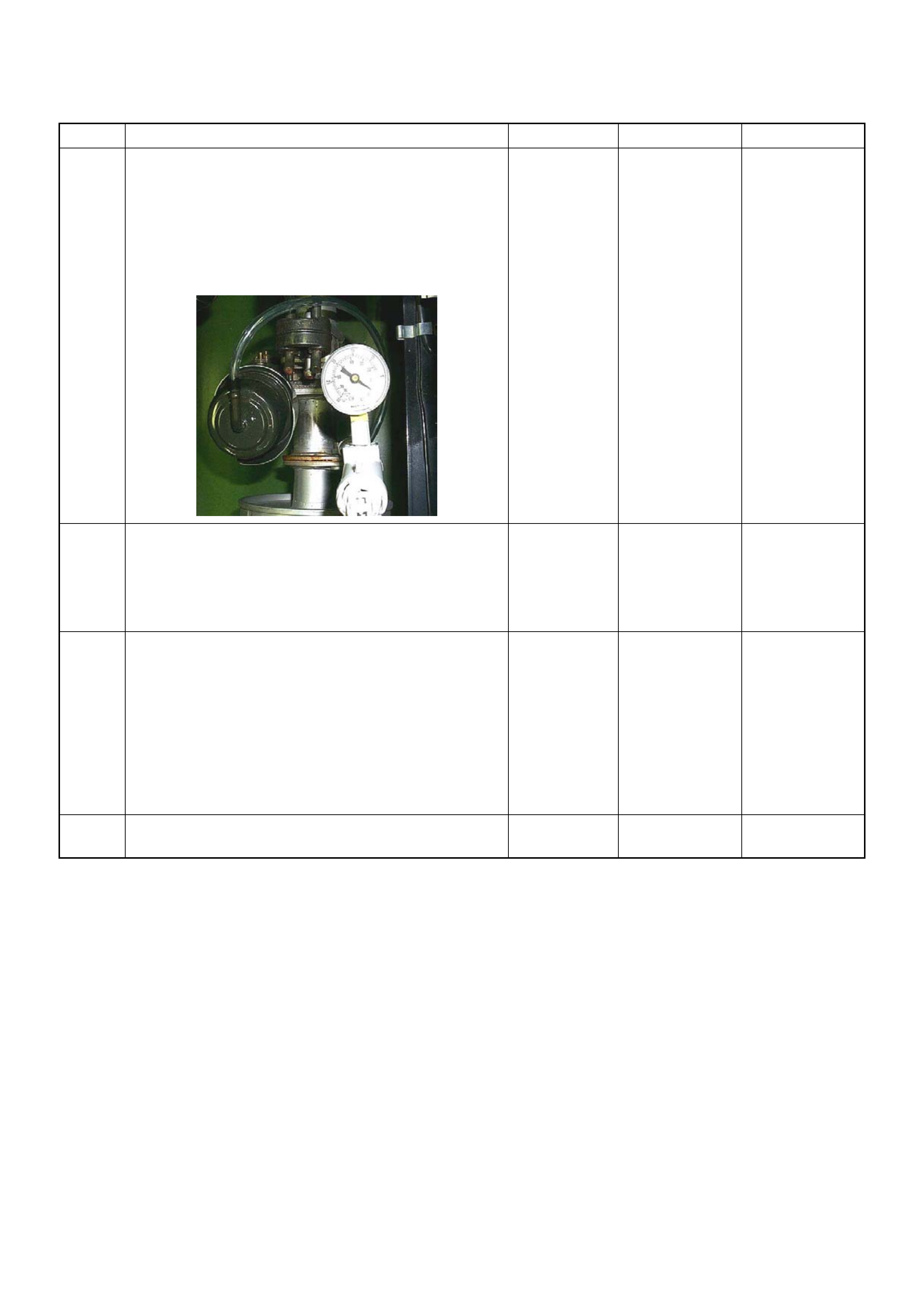
25 Using the vacuum pump and check the exhaust
throttle valve (if equipped) operation for the following
condition.
• Restrict shaft movement. Check for objects sticking
the shaft, broken diaphragm or excessive carbon
deposit.
Was a problem found?
— Verify repair Go to
Step 26
26 Check the exhaust system for a possible restriction.
• Damaged or collapsed pipes or catalytic conve rter.
• Internal muffler failure.
If a pro blem is found, repair as necessary.
Was a problem found? — Verify repair Go to
Step 27
27 Visually/physically inspect for the following conditions.
• Restrict fuel supply system. Check for a pinched
fuel hose/pipe.
• Check for a condition that causes fuel waxing or
icing, such as the customer is using an incorrect
fuel type in winter season or water mixed with the
fuel.
If a pro blem is found, repair as necessary.
Was a problem found? — Verify repair Go to
Step 28
28 Replace the fuel f ilter.
Was the problem solved ? — Verify repair Go to
Step 29
Step Action Value(s) Yes No
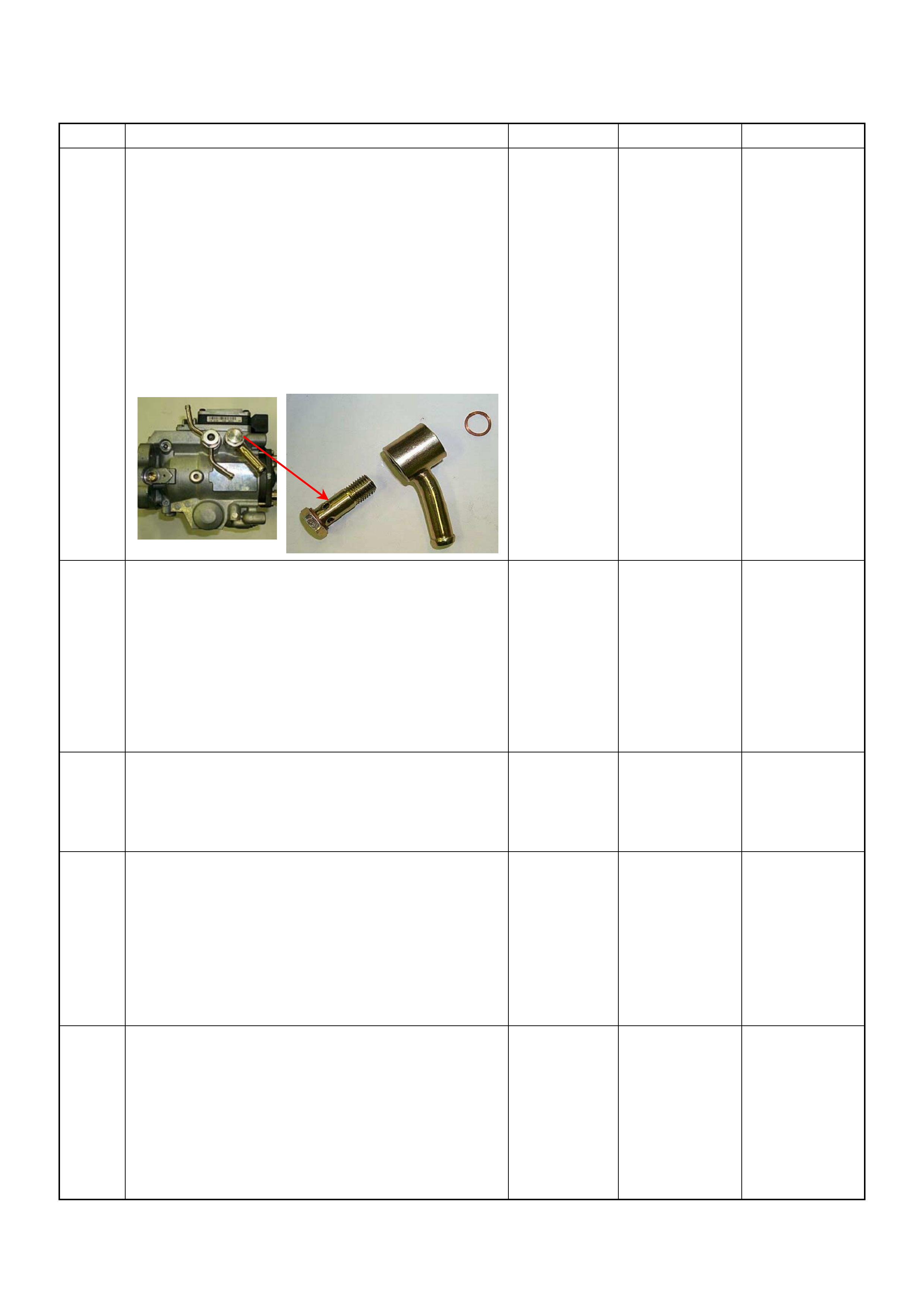
29 Remove the eye bolt with gauze filter from the
injection pump and check for the followin g conditions.
• Objects blocking at the gauze filter. Check for a
condition that causes contaminated fuel, such as
the customer is using an aftermarket fuel filter or
extended mai nte nance int erva l.
• Check for a condition that causes fuel waxing or
icing, such as the customer is using an incorrect
fuel type in winter season or water mixed with the
fuel.
If a pro blem is found, repair as necessary.
Was the problem found?
—
Replace the
eye bolt with
gauze filter and
verify repair Go to
Step 30
30 1. Review all diagnostic procedures within this table.
2. If all procedures have been completed and no
malfunctions have been found, review/inspect the
following:
• Visual/physical inspection
• Tech 2 data
• All electrical connections within a suspected circuit
and/or system
Was a problem found? — Verify repair Go to
Step 31
31 Is the ECM programmed with the latest software
release?
If not, download the latest software to the ECM using
the
“SPS (Service Programming System)”
.
Was the problem solved ? — Verify repair Go to
Step 32
32 Substitute a known good ECM and recheck.
Was the problem solved?
IMPORTANT:
The replacement ECM must be
programmed. Refer to section of the Service
Programming System (SPS) in this manual.
Following ECM programming, th e immobiliser system
(if equipped) must be linked to the ECM. Refer to
section 11 “Immobiliser System-ECM replacement” for
the EC M/Immobiliser linking proc edure. — Go to
Step 33
Go to
Step 34
33 Replace the ECM.
Is the action complete?
IMPORTANT:
The replacement ECM must be
programmed. Refer to section of the Service
Programming System (SPS) in this manual.
Following ECM programming, th e immobiliser system
(if equipped) must be linked to the ECM. Refer to
section 11 “Immobiliser System-ECM replacement” for
the EC M/Immobiliser linking proc edure. — Verify repair —
Step Action Value(s) Yes No

34 Replace the injecti on pump assembly.
Is the action complete? — Verify repair —
Step Action Value(s) Yes No

Cuts Out, Miss es Sympt o m
DEFINITIONS: Steady pulsation or jerking that follows
engine s pee d; us ual ly m or e p ro nou nced as en gin e l oa d
increases.
time
rpm
Step Action Value(s) Yes No
1 Was the “On- Board Diagnos tic (OBD) Sy stem Check”
performed?
—Go to Step 2
Go to On Board
Diagnostic
(OBD) System
Check
2 1. Perform a bulletin search.
2. If a bulletin that addresses the symptom is found,
correct the condition as instructed in the bulletin.
Was a bulletin found that addresses the symptom? — Verify repair Go to Step 3
3 Was a visually/physical check performed? —Go to Step 4 Go to Visual /
physical Check
4 Is the customer using the incorrect fuel type? Diesel fuel
only Replace with
diesel fuel Go to Step 5
5 Visually/physically inspect for the following conditions.
• Restrict air intake system. Check for a restricted air
filter element, or foreign objects blocking the air
intake system
• Che ck f or o bjects blo cking or e xces siv e depo sits i n
the throttle bore and on the throttle plate
• Check for a condition that causes a large vacuum
leak, such as an incorrectly installed or faulty
crankc as e ven til ati on hose.
• Restrict air intake system at the turbocharger.
Check for objects blocking the turbocharger
compressor
wheel or turbine shaft sticking.
If a problem is found, repair as necessary.
Was a problem found? — Verify repair Go to Step 6
6 Check the ECM & PSG grounds to verify that they are
clean and tight. Refer to the ECM wiring diagrams.
Was a problem found? — Verify repair Go to Step 7
7 1. Using the Tech 2, perform test drive.
2. Monitor the “Vehicle Speed” in the data display.
Does the Tech 2 indicate correct “Vehicle Speed”
depending on driving speed?
—Go to Step 11 Go to Step 8
8 Check the VSS harness for the following conditions.
• Check for poor connector connection.
• Check for misrouted harness.
• Check for any accessory parts which may cause
electric interference.
If a problem is found, repair as necessary.
Was a problem found? — Verify repair Go to Step 9
9 Substitute a known good VSS and recheck.
Was the problem solved? — Go to Step 10 Go to Step 31
10 Replace the VSS assembly.
Is the action complete? — Verify repair —
11 1. Using the Tech 2, ignition “On” and engine “Run”.
2. Monitor the “Mass Air Flow” in the data display.
Does the Tech 2 indicate correct “Mass Air Flow”
depending on accelerator pedal operation? — Go to Step 16 Go to Step 12
12 Remove the MAF & IAT sensor assembly and check
for the following conditions.
• Objects blocking at the MAF sensor element.
If a problem is found, repair as necessary.
Was the problem found? — Verify repair Go to Step 13
13 Check the MAF sensor harness for the following
conditions.
• Check for poor connector connection.
• Check for misrouted harness.
• Check for any accessory parts which may cause
electric interference.
If a problem is found, repair as necessary.
Was a problem found? — Verify repair Go to Step 14
14 Substitute a known good MAF & IAT sensor assembly
and recheck.
Was the problem solved? — Go to Step 15 Go to Step 31
15 Replace the MAF & IAT sensor assembly.
Is the action complete? — Verify repair —
Step Action Value(s) Yes No
When constant vehicle speed
High Correct Speed
Low
Time
Unstable Data

16 1. Using the Tech 2, ignition “On” and engine “Off”.
2. Monitor the “Pedal/Throttle Position” and “Idle
Switch” in the data display.
Does the Tech 2 indicate correct “Pedal/Throttle
Position” from 0% to 100% and correct “Idle Switch”
status depending on accelerator pedal operat ion? — Go to
Step 21
Go to
Step 17
17 1. Using the Tech 2, ignition “On” and engine “Off”.
2. Monitor the “Pedal/Throttle Position” and “Idle
Switch” in the data display.
3. Adjust the accelerator cable or TPS within 0% to
100%.
Was the problem solved ? — Verify repair Go to
Step 18
18 Check the TPS harness for the following conditions.
• Check for poor connector connection.
• Che ck for misrouted harness.
• Check for any accessory parts which may cause
electric interference.
If a pro blem is found, repair as necessary.
Was a problem found? — Verify repair Go to
Step 19
19 Substitute a known good TPS and recheck.
Was the problem s olv ed? — Go to
Step 20
Go to
Step 31
20 Replace the TPS.
Is the action complete? — Verify repair —
21 Remove the CKP sensor from the flywheel housing
and check for the following conditions.
• Objects sticking the CKP sensor.
• Objects sticking the CKP sensor pulser.
If a pro blem is found, repair as necessary.
Was the problem found? — Verify repair Go to
Step 22
22 Check the CKP sensor harness for the following
conditions.
• Check for poor connector connection.
• Che ck for misrouted harness.
• Check for any accessory parts which may cause
electric interference.
If a pro blem is found, repair as necessary.
Was a problem found? — Verify repair Go to
Step 23
23 Substitute a known good CKP sensor and recheck.
Was the problem s olv ed? — Go to
Step 24
Go to
Step 25
24 Replace the CKP sensor.
Is the action complete? — Verify repair —
Step Action Value(s) Yes No
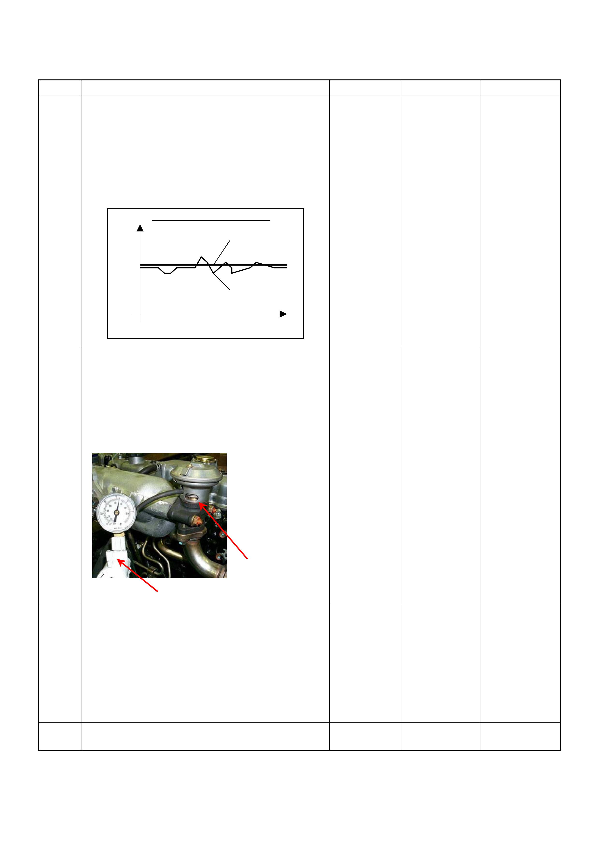
25 1. Using the Tech 2 and ignition “On” and engine
“Run”.
2. Monitor the following parameters in the data
display.
• “Desired Injection Quantity” & “Injection Quantity”
• “Desired Injection Start” & “Actual Injection Start”
Are the large gap or unstable parameter displayed
between “Desired” and “Actual”?
—Go to
Step 29
Go to
Step 26
26 Us ing the vacuum pum p and check the EGR valve (if
equipped) operation for the following condition
through the small window.
• Restrict shaft movement. Check for objects sticking
the shaft, broken diaphragm or excessive carbon
deposit.
If a pro blem is found, repair as necessary.
Was a problem found?
— Verify repair Go to
Step 27
27 Visually/physically inspect for the following conditions.
• Restrict fuel supply system. Check for a pinched
fuel hose/pipe.
• Check for a condition that causes fuel waxing or
icing, such as the customer is using an incorrect
fuel type in winter season or water mixed with the
fuel.
If a pro blem is found, repair as necessary.
Was a problem found? — Verify repair Go to
Step 28
28 Replace the fuel f ilter.
Was the problem solved ? — Verify repair Go to
Step 29
Step Action Value(s) Yes No
When idling or part-throttle
High Desired
Low
Time
Actual
Vacuum Pump
Small Window

29 Remove the eye bolt with gauze filter from the
injection pump and check for the following conditions.
• Objects blocking at the gauze filter. Check for a
condition that causes contaminated fuel, such as
the customer is using an aftermarket fuel filter or
extended maintenance interval.
• Check for a condition that causes fuel waxing or
icing, such as the customer is using an incorrect
fuel type in winter season or water mixed with the
fuel.
If a problem is found, repair as necessary.
Was the problem found?
—
Replace the
eye bolt with
gauze filter and
verify repair Go to
Step 30
30 1. Review all diagnostic procedures within this table.
2. If all procedures have been completed and no
malfunctions have been found, review/inspect the
following:
• Visual/physical inspection
• Tech 2 data
• All electrical connections within a suspected circuit
and/or system
Was a problem found? — Verify repair Go to
Step 31
31 Is the ECM programmed with the latest software
release?
If not, download the latest software to the ECM using
the
“SPS (Service Programming System)”
.
Was the problem solved? — Verify repair Go to
Step 32
32 Substitute a known good ECM and recheck.
Was the problem solved?
IMPORTANT:
The replacement ECM must be
programmed. Refer to section of the Service
Programming System (SPS) in this manual.
Following ECM programming, the immobiliser system
(if equipped) must be linked to the ECM. Refer to
section 11 “Immobiliser System-ECM replacement” for
the ECM/Immobiliser linking procedure. — Go to
Step 33
Go to
Step 34
33 Replace the ECM.
Is the action complete?
IMPORTANT:
The replacement ECM must be
programmed. Refer to section of the Service
Programming System (SPS) in this manual.
Following ECM programming, the immobiliser system
(if equipped) must be linked to the ECM. Refer to
section 11 “Immobiliser System-ECM replacement” for
the EC M/Immobiliser linking proc edure. — Verify repair —
Step Action Value(s) Yes No

34 Replace the injecti on pump assembly.
Is the action complete? — Verify repair —
Step Action Value(s) Yes No

Lack Of Power, Sluggish Or Spongy Symptom
DEFINITIONS:
Engine delivers less than expected power. Attempting part-throttle acceleration results in little or no
increase in vehicle speed .
Step Action Value(s) Yes No
1 Was the “On-Boar d Diagnostic (OBD) Sys tem Check”
performed?
—Go to
Step 2
Go to
On Board
Diagnostic
(OBD) System
Check
2 1. Perform a bulletin search.
2. If a bulletin that addresses the symptom is found,
correct the condition as instructed in the bulletin.
Was a bulletin found that addresses t he symptom? — Verify repair Go to
Step 3
3 Was a visually/phy sical check performed? —Go to
Step 4
Go to
Visual /
physical Check
4 Is the customer using the i ncorrect fuel type? Diesel fuel
only Replace with
diesel fuel Go to
Step 5
5 Visually/physically inspect for the following conditions.
• Restrict air intake system. Check for a restricted air
filter element, or foreign objects blocking the air
intake system
• Che ck for o bjects blo cking or exces sive depo sits in
the throttle bore and o n the thro ttle plate
• Check for a condition that causes a large vacuum
leak, such as an incorrectly installed or faulty
crankcas e ven tilati on hose.
• Restrict air intake system at the turbocharger.
Check for objects blocking the turbocharger
compressor wheel or turbine shaft sticking.
If a pro blem is found, repair as necessary.
Was a problem found? — Verify repair Go to
Step 6
6 Check the ECM & PSG groun ds to verify that they are
clean and tight. Refer to the ECM wiring diagrams.
Was a problem found? — Verify repair Go to
Step 7
7 1. Using th e Tech 2, d ispl ay the E CT sens or an d IAT
sensor val ue.
2. Check the displayed value.
Does the Tech 2 indicate correct temperature
depending on engine condition?
If a problem is found, repair as n ecessary.
Was the problem found? — Verify repair Go to
Step 8
8 1. Using the Tech 2, display the FT sensor value.
2. Check the displayed value.
Does the Tech 2 indicate correct temperature
depending on engine condition?
If a problem is found, repair as n ecessary.
Was the problem found? — Go to
Step 30
Go to
Step 9
9 1. Using the Tech 2, ignition “On ” and eng ine “Run”.
2. Monitor the “Mass Air Flow” in the data display.
Does the Tech 2 indicate correct “Mass Air Flow”
depending on a cc elerator pedal operation? — Go to
Step 14
Go to
Step 10

10 Remove the MAF & IAT sensor assembly and check
for the following conditions.
• Objects blocking at the MAF sensor element.
If a pro blem is found, repair as necessary.
Was the problem found? — Verify repair Go to
Step 11
11 Check the MAF sensor harness for the following
conditions.
• Check for poor connector connection.
• Che ck for misrouted harness.
• Check for any accessory parts which may cause
electric interference.
If a pro blem is found, repair as necessary.
Was a problem found? — Verify repair Go to
Step 12
12 Substitute a known good MAF & IAT sensor assembly
and recheck.
Was the problem s olv ed? — Go to
Step 13
Go to
Step 30
13 Replace the MAF & IAT sensor ass embly.
Is the action complete? — Verify repair —
14 1. Using the Tech 2, ignition “On” and engine “Off”.
2. Monitor the “Pedal/Throttle Position” and “Idle
Switch” in the data display.
Does the Tech 2 indicate correct “Pedal/Throttle
Position” from 0% to 100% and correct “Idle Switch”
status depending on accelerator pedal operat ion? — Go to
Step 19
Go to
Step 15
15 1. Using the Tech 2, ignition “On” and engine “Off”.
2. Monitor the “Pedal/Throttle Position” and “Idle
Switch” in the data display.
3. Adjust the accelerator cable or TPS within 0% to
100%.
Was the problem solved ? — Verify repair Go to
Step 16
16 Check the TPS harness for the following conditions.
• Check for poor connector connection.
• Che ck for misrouted harness.
• Check for any accessory parts which may cause
electric interference.
If a pro blem is found, repair as necessary.
Was a problem found? — Verify repair Go to
Step 17
17 Substitute a known good TPS and recheck.
Was the problem s olv ed? — Go to
Step 18
Go to
Step 30
18 Replace the TPS.
Is the action complete? — Verify repair —
Step Action Value(s) Yes No
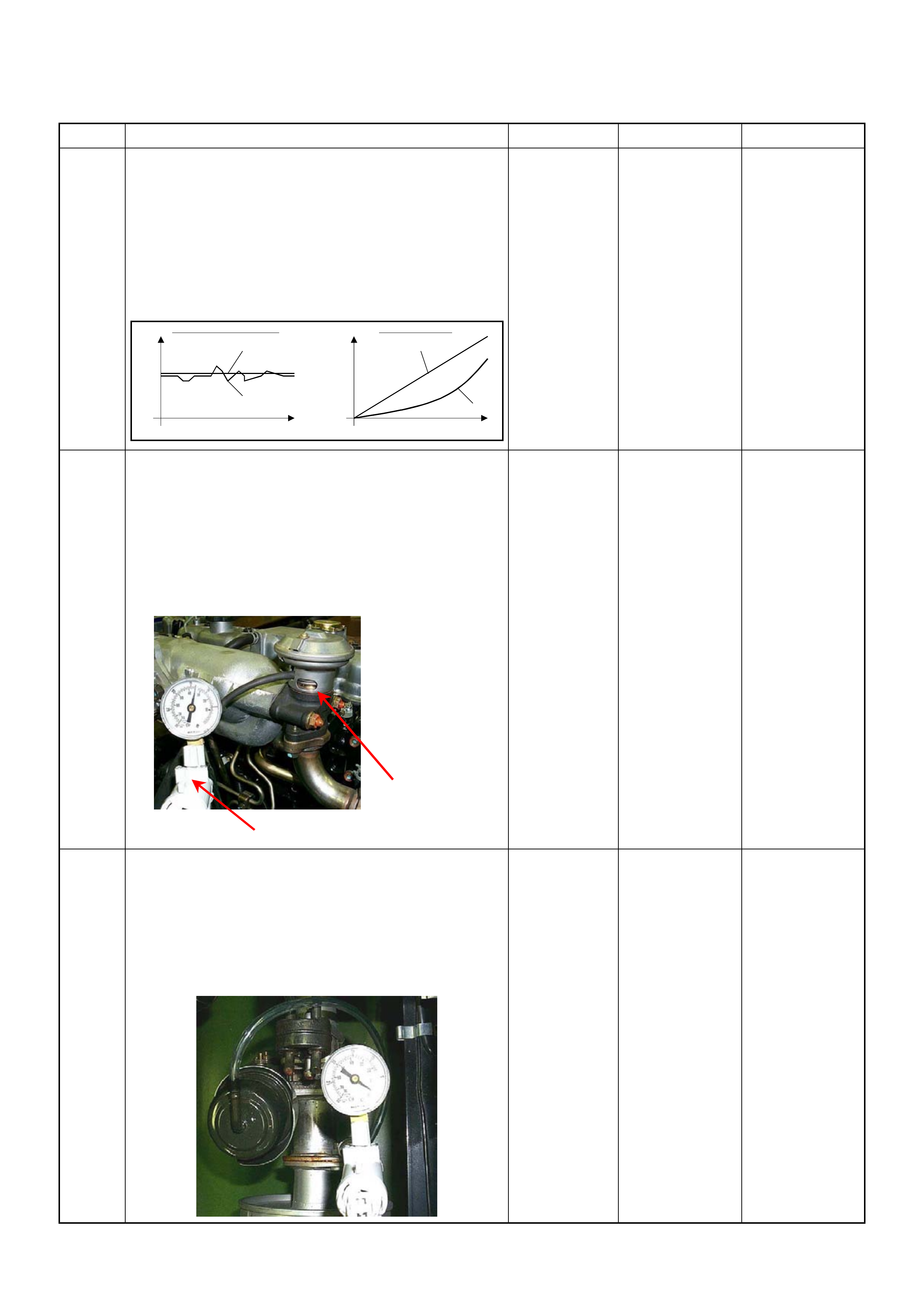
19 1. Using the Tech 2 and ignition “On” and engine
“Run”.
2. Monitor the following parameters in the data
display.
• “Desired Injection Quantity” & “Injection Quantity”
• “Desired Injection Start” & “Actual Injection Start”
Are the large gap or unstable parameter displayed
between “Desired” and “Actual”?
—Go to
Step 23
Go to
Step 20
20 Us ing the vacuum pum p and check the EGR valve (if
equipped) operation for the following condition
through the small window.
• Restrict shaft movement. Check for objects sticking
the shaft, broken diaphragm or excessive carbon
deposit.
If a pro blem is found, repair as necessary.
Was a problem found?
— Verify repair Go to
Step 21
21 Using the vacuum pump and check the exhaust
throttle valve (if equipped) operation for the following
condition.
• Restrict shaft movement. Check for objects sticking
the shaft, broken diaphragm or excessive carbon
deposit.
Was a problem found?
— Verify repair Go to
Step 22
Step Action Value(s) Yes No
When idling or part-throttle When accelerated
High Desired
Low
Time
Actual
High
Low
Desired
Actual
Time
Vacuum Pump
Small Window
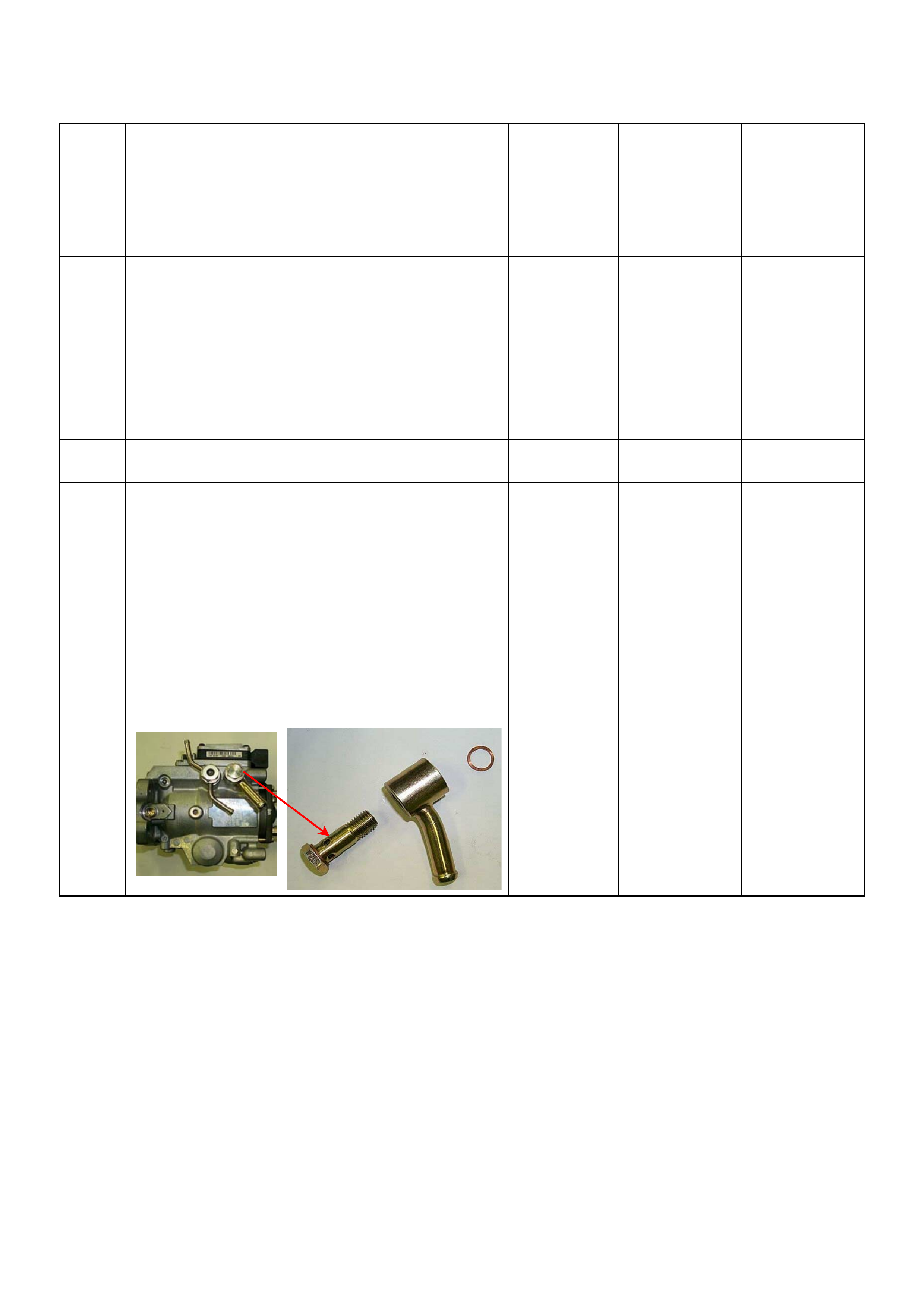
22 Check the exhaust system for a possible restriction.
• Damaged or collapsed pipes or catalytic conve rter.
• Internal muffler failure.
If a pro blem is found, repair as necessary.
Was a problem found? — Verify repair Go to
Step 23
23 Visually/physically inspect for the following conditions.
• Restrict fuel supply system. Check for a pinched
fuel hose/pipe.
• Check for a condition that causes fuel waxing or
icing, such as the customer is using an incorrect
fuel type in winter season or water mixed with the
fuel.
If a pro blem is found, repair as necessary.
Was a problem found? — Verify repair Go to
Step 24
24 Replace the fuel f ilter.
Was the problem solved ? — Verify repair Go to
Step 25
25 Remove the eye bolt with gauze filter from the
injection pump and check for the followin g conditions.
• Objects blocking at the gauze filter. Check for a
condition that causes contaminated fuel, such as
the customer is using an aftermarket fuel filter or
extended mai nte nance int erva l.
• Check for a condition that causes fuel waxing or
icing, such as the customer is using an incorrect
fuel type in winter season or water mixed with the
fuel.
If a pro blem is found, repair as necessary.
Was the problem found?
—
Replace the
eye bolt with
gauze filter and
verify repair Go to
Step 26
Step Action Value(s) Yes No
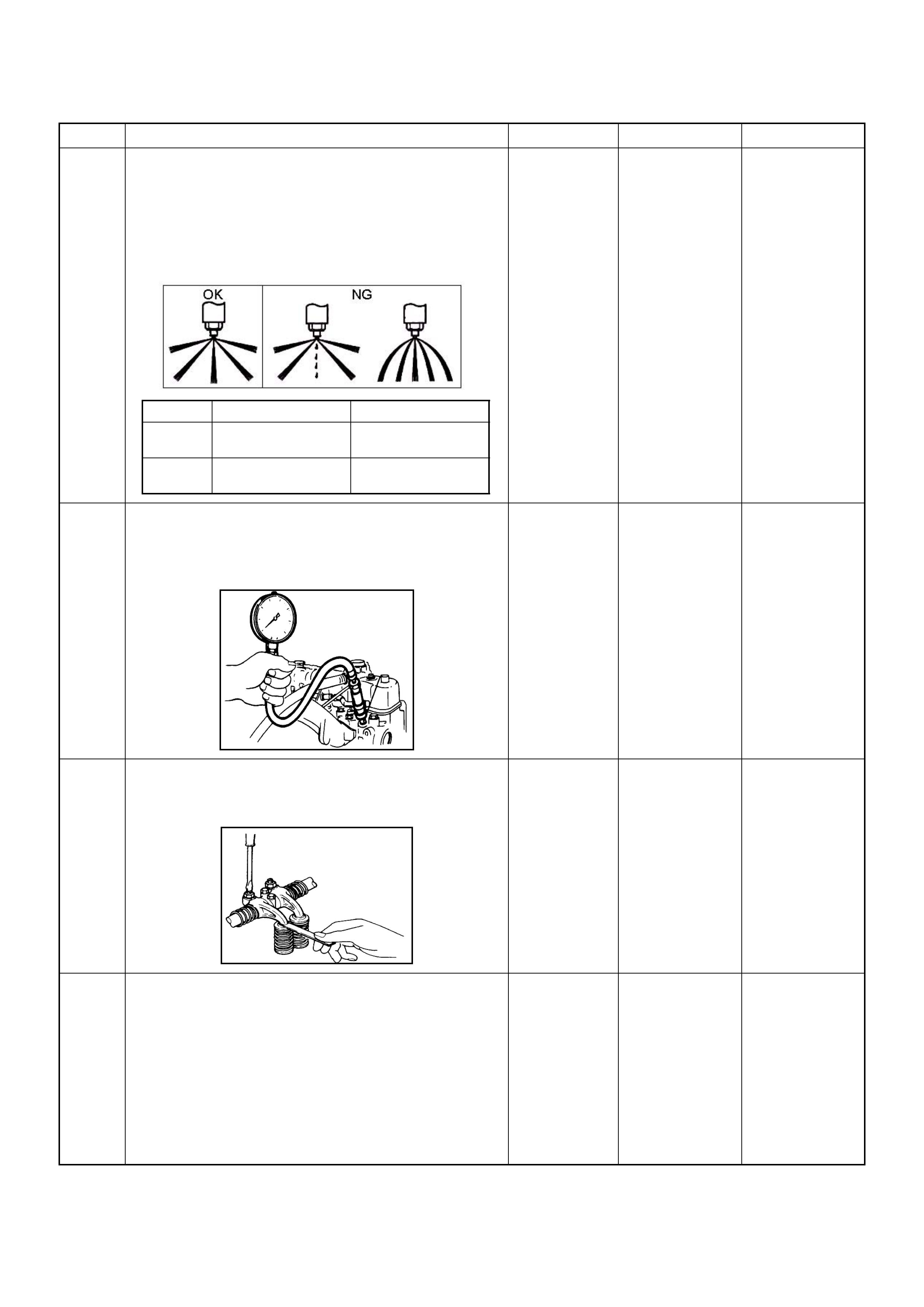
26 Remove the injection nozzles from the engine and
check for the following conditions.
• Improper splay condition.
• Operating pressu re is incorrect.
If a pro blem is found, repair as necessary.
Was the problem found?
—
Replace the
injection nozzle
and ve rify repair Go to
Step 27
27 Check the engine compression pressure for each
cylinders.
If a pro blem is found, repair as necessary.
Was the problem found?
More than 30
Mpa (31.0 kg/
cm
2
) Verify repair Go to
Step 28
28 Check the inlet/exhaust valve clearance for each
valves.
Are the valve clearances within the s p ecified value?
0.4mm at cold
(In/Ex) Go to
Step 29
Adjust and
verify repair
29 1. Review all diagnostic procedures within this table.
2. If all procedures have been completed and no
malfunctions have been found, review/inspect the
following:
• Visual/physical inspection
• Tech 2 data
• All electrical connections within a suspected circuit
and/or system
Was a problem found? — Verify repair Go to
Step 30
Step Action Value(s) Yes No
1
st
S tage 2
nd
S tage
4JA1-TC 19.5 - 20.5 Mpa
(199 -209 kg/cm
2
)34.0 - 35.5 Mpa
(347 - 362 kg/cm
2
)
4JH1-TC 20.0 - 21.0 Mpa
(204 -214 kg/cm
2
)34.3 - 35.8 Mpa
(350 - 365 kg/cm
2
)

30 Is the ECM programmed with the latest software
release?
If not, download the latest software to the ECM using
the
“SPS (Service Programming System)”
.
Was the problem solved? — Verify repair Go to
Step 31
31 Substitute a known good ECM and recheck.
Was the problem solved?
IMPORTANT:
The replacement ECM must be
programmed. Refer to section of the Service
Programming System (SPS) in this manual.
Following ECM programming, th e immobiliser system
(if equipped) must be linked to the ECM. Refer to
section 11 “Immobiliser System-ECM replacement” for
the EC M/Immobiliser linking proc edure. — Go to
Step 32
Go to
Step 33
32 Replace the ECM.
Is the action complete?
IMPORTANT:
The replacement ECM must be
programmed. Refer to section of the Service
Programming System (SPS) in this manual.
Following ECM programming, th e immobiliser system
(if equipped) must be linked to the ECM. Refer to
section 11 “Immobiliser System-ECM replacement” for
the EC M/Immobiliser linking proc edure. — Verify repair —
33 Replace the injecti on pump assembly.
Is the action complete? — Verify repair —
Step Action Value(s) Yes No

Poor Fuel Economy Symptom
DEFINITIONS:
Fuel economy, as measured by an actual road test, is noticeably lower than expected. Also, economy
is noticeably lower than it was on this vehicle at one time, as previously shown by an actual road test. (Larger than
standard tires will cause odometer readings to be incorrect, and that may cause fuel economy to appear poor when it
is actually normal.)
Step Action Value(s) Yes No
1 Was the “On-Board Diagnostic (OBD) System Check”
performed?
—Go to
Step 2
Go to
On Board
Diagnostic
(OBD) System
Check
2 1. Perform a bulletin search.
2. If a bulletin that addresses the symptom is found,
correct the condition as instructed in the bulletin.
Was a bulletin found that addresses the symptom? — Verify repair Go to
Step 3
3 Was a visually/physical check performed? —Go to
Step 4
Go to
Visual /
physical Check.
4 Check owner's driving habits.
• Is the A/C “On” full time?
• Are tires at the correct pressure?
• Are excessively heavy loads being carried?
• Is acceleration too much, too often? — Go to
Step 5
Go to
Step 6
5 Review the items in Step 4 with the customer and
advise as necessary.
Is the action complete? — System OK —
6 Check for low engine coolant level.
Was a problem found? — Verify repair Go to
Step 7
7 Check for incorrect or faulty engine thermostat. Refer
to Engine Cool ing.
Was a problem found? — Verify repair Go to
Step 8
8 Check for proper calibration of th e speedometer.
Does the s peed indicated on the sp eed meter close ly
match the vehicle speed display ed on the Tech 2? — Go to
Step 10
Go to
Step 9
9 Diagnose and repair the inaccurate speedometer
condition as necessary. Refer to Vehicle Speed
Sensor in Electrical Diagnosis. — Verify repair —
10 Check for proper calibration of the fuel gauge.
Was a problem found? — Verify repair Go to
Step 11
11 Check the torque converter clutch (TCC) for proper
operation (if A/T model). If a problem is found, repair
as necessary.
Was a problem found? — Verify repair Go to
Step 12
12 1. Using the Tech 2, ignition “On” and engine “Off”.
2. Monitor the “Neutral Switch” in the data display.
Does the Tech 2 indicate correct “Neutral Switch”
status depe nding on any shift positions?
If a pro blem is found, repair as necessary.
Was the problem found? — Verify repair Go to
Step 13

13 1. Using the Tech 2, ignition “On” and engine “Run”.
2. Monitor the “A/C Information Switch” in the data
display.
Does the Tech 2 indicate correct “A/C Information
Switch ” status depend ing on A/C switch posi tion?
If a pro blem is found, repair as necessary.
Was the problem found? — Verify repair Go to
Step 14
14 Visually/physically inspect for the following conditions.
• Restrict air intake system. Check for a restricted air
filter element, or foreign objects blocking the air
intake system
• Che ck for o bjects blo cking or exces sive depo sits in
the throttle bore and o n the thro ttle plate
• Check for a condition that causes a large vacuum
leak, such as an incorrectly installed or faulty
crankcas e ven tilati on hose.
• Restrict air intake system at the turbocharger.
Check for objects blocking the turbocharger
compressor wheel or turbine s haft sticking.
If a problem is found, repair as n ecessary.
Was a problem found? — Verify repair Go to
Step 15
15 1. Using th e Tec h 2, displ ay the E CT sens or and I AT
sensor val ue.
2. Check the displayed value.
Does the Tech 2 indicate correct temperature
depending on engine condition?
If a pro blem is found, repair as necessary.
Was the problem found? — Verify repair Go to
Step 16
16 1. Usin g the Tech 2, display the FT sensor value.
2. Check the displayed value.
Does the Tech 2 indicate correct temperature
depending on engine condition?
If a pro blem is found, repair as necessary.
Was the problem found? — Go to
Step 31
Go to
Step 17
17 1. Using the Tech 2, ignition “On” and engine “Run”.
2. Monitor the “Mass Air Flow” in the data display.
Does the Tech 2 indicate correct “Mass Air Flow”
depending on a cc elerator pedal operation? — Go to
Step 22
Go to
Step 18
18 Remove the MAF & IAT sensor assembly and check
for the following conditions.
• Objects blocking at the MAF sensor element.
If a pro blem is found, repair as necessary.
Was the problem found? — Verify repair Go to
Step 19
19 Check the MAF sensor harness for the following
conditions.
• Check for poor connector connection.
• Che ck for misrouted harness.
• Check for any accessory parts which may cause
electric interference.
If a pro blem is found, repair as necessary.
Was a problem found? — Verify repair Go to
Step 20
Step Action Value(s) Yes No
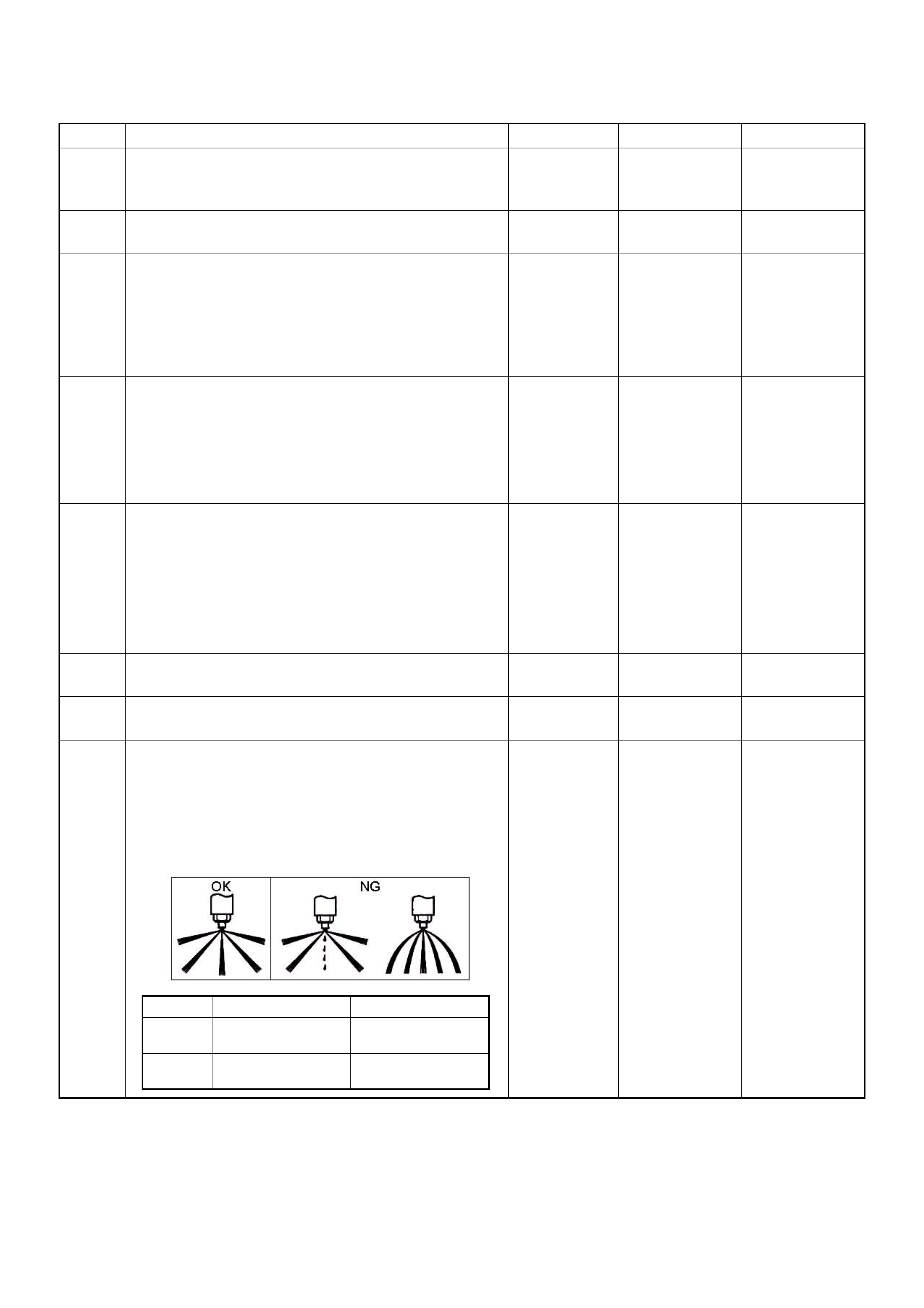
20 Substitute a known good MAF & IAT sensor assembly
and recheck.
Was the problem s olv ed? — Go to
Step 21
Go to
Step 31
21 Replace the MAF & IAT sensor ass embly.
Is the action complete? — Verify repair —
22 1. Using the Tech 2, ignition “On” and engine “Off”.
2. Monitor the “Pedal/Throttle Position” and “Idle
Switch” in the data display.
Does the Tech 2 indicate correct “Pedal/Throttle
Position” from 0% to 100% and correct “Idle Switch”
status depending on accelerator pedal operat ion? — Go to
Step 27
Go to
Step 23
23 1. Using the Tech 2, ignition “On” and engine “Off”.
2. Monitor the “Pedal/Throttle Position” and “Idle
Switch” in the data display.
3. Adjust the accelerator cable or TPS within 0% to
100%.
Was the problem solved ? — Verify repair Go to
Step 24
24 Check the TPS harness for the following conditions.
• Check for poor connector connection.
• Che ck for misrouted harness.
• Check for any accessory parts which may cause
electric interference.
If a pro blem is found, repair as necessary.
Was a problem found? — Verify repair Go to
Step 25
25 Substitute a known good TPS and recheck.
Was the problem s olv ed? — Go to
Step 26
Go to
Step 31
26 Replace the TPS.
Is the action complete? — Verify repair —
27 Remove the injection nozzles from the engine and
check for the following conditions.
• Improper splay condition.
• Operating pressu re is incorrect.
If a pro blem is found, repair as necessary.
Was the problem found?
—
Replace the
injection nozzle
and ve rify repair Go to
Step 28
Step Action Value(s) Yes No
1
st
S tage 2
nd
Stage
4JA1-TC 19.5 - 20.5 Mpa
(199 -209 kg/cm
2
)34.0 - 35.5 Mpa
(347 - 362 kg/cm
2
)
4JH1-TC 20.0 - 21.0 Mpa
(204 -214 kg/cm
2
)34.3 - 35.8 Mpa
(350 - 365 kg/cm
2
)
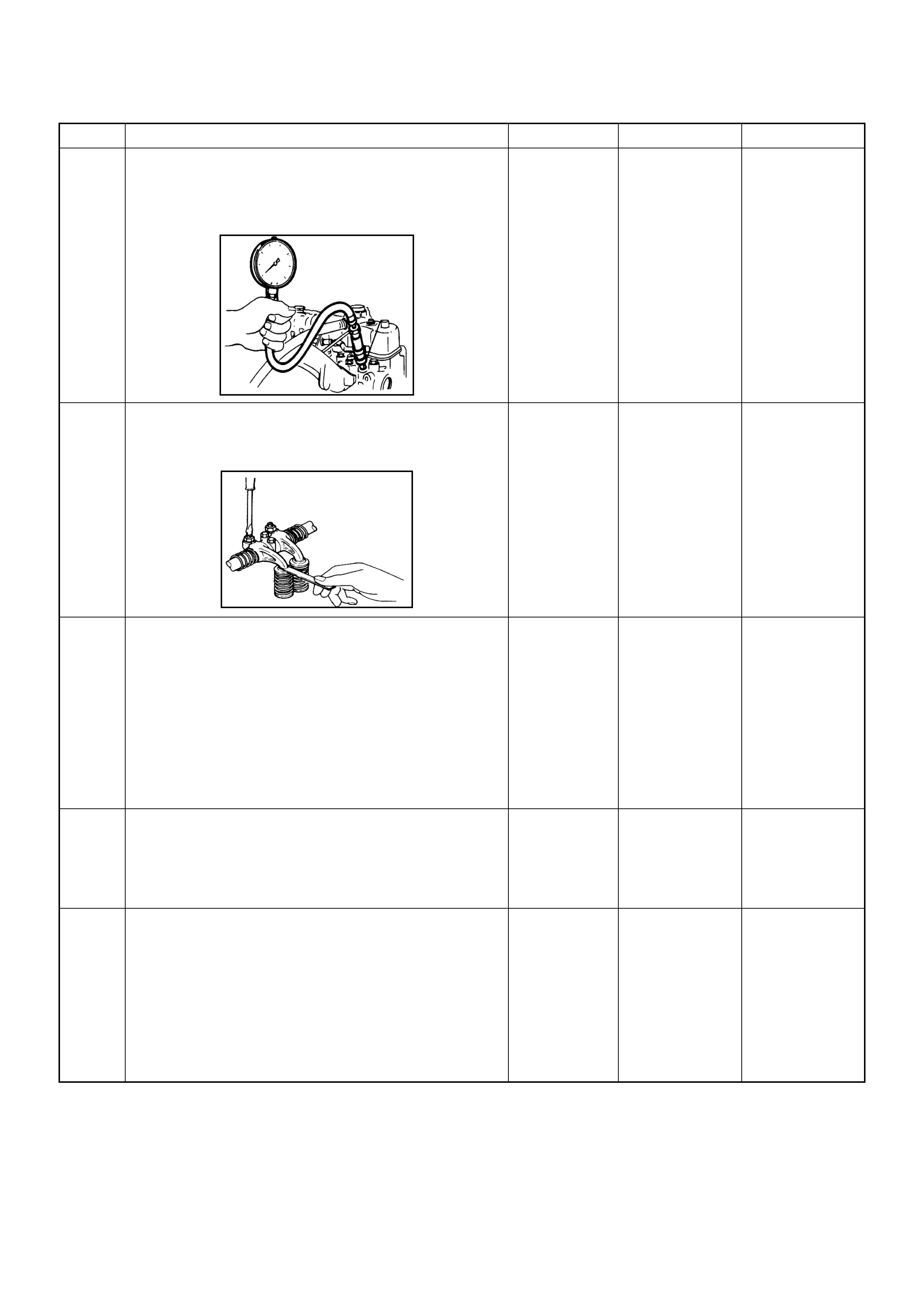
28 Check the engine compression pressure for each
cylinders.
If a problem is found, repair as necessary.
Was the problem found?
More than 30
Mpa (31.0 kg/
cm
2
) Verify repair Go to
Step 29
29 Check the inlet/exhaust valve clearance for each
valves.
Are the valve clearances within the specified value?
0.4mm at cold
(In/Ex) Go to
Step 30
Adjust and
verify repair
30 1. Review all diagnostic procedures within this table.
2. If all procedures have been completed and no
malfunctions have been found, review/inspect the
following:
• Visual/physical inspection
• Tech 2 data
• All electrical connections within a suspected circuit
and/or system
Was a problem found? — Verify repair Go to
Step 31
31 Is the ECM programmed with the latest software
release?
If not, download the latest software to the ECM using
the
“SPS (Service Programming System)”
.
Was the problem solved? — Verify repair Go to
Step 32
32 Substitute a known good ECM and recheck.
Was the problem solved?
IMPORTANT:
The replacement ECM must be
programmed. Refer to section of the Service
Programming System (SPS) in this manual.
Following ECM programming, th e immobiliser system
(if equipped) must be linked to the ECM. Refer to
section 11 “Immobiliser System-ECM replacement” for
the EC M/Immobiliser linking proc edure. — Go to
Step 33
Go to
Step 34
Step Action Value(s) Yes No

33 Replace the ECM.
Is the action complete?
IMPORTANT:
The replacement ECM must be
programmed. Refer to section of the Service
Programming System (SPS) in this manual.
Following ECM programming, the immobiliser system
(if equipped) must be linked to the ECM. Refer to
section 11 “Immobiliser System-ECM replacement” for
the EC M/Immobiliser linking proc edure. — Verify repair —
34 Replace the injecti on pump assembly.
Is the action complete? — Verify repair —
Step Action Value(s) Yes No

Excessive White Smoke
Step Action Value(s) Yes No
1 Was the “On-Board Diagnostic (OBD) System Check”
performed?
—Go to
Step 2
Go to
On Board
Diagnostic
(OBD) System
Check
2 1. Perform a bulletin search.
2. If a bulletin that addresses the symptom is found,
correct the condition as instructed in the bulletin.
Was a bulletin found that addresses the symptom? — Verify repair Go to
Step 3
3 Was a visually/physical check performed? —Go to
Step 4
Go to
Visual /
physical Check.
4 Is the customer using the incorrect fuel type? Diesel fuel
onlyReplace with
diesel fuel Go to
Step 5
5 Check the engine coolant consumption to verify that it
leaks to combustion chamber or exhaust through the
gasket.
Was a problem found? — Verify repair Go to
Step 6
6 Check the ECM & PSG grounds to verify that they are
clean and tight. Refer to the ECM wiring diagrams.
Was a problem found? — Verify repair Go to
Step 7
7 1. Using th e Tech 2, d ispl ay the E CT sens or an d IAT
sensor val ue.
2. Check the displayed value.
Does the Tech 2 indicate correct temperature
depending on engine condition?
If a problem is found, repair as n ecessary.
Was the problem found? — Verify repair Go to
Step 8
8 1. Using the Tech 2, display the FT sensor value.
2. Check the displayed value.
Does the Tech 2 indicate correct temperature
depending on engine condition?
If a problem is found, repair as n ecessary.
Was the problem found? — Go to
Step 30
Go to
Step 9
9 1. Using the Tech 2, ignition “On ” and eng ine “Run”.
2. Monitor the “Mass Air Flow” in the data display.
Does the Tech 2 indicate correct “Mass Air Flow”
depending on a cc elerator pedal operation? — Go to
Step 14
Go to
Step 10
10 Remove the MAF & IAT sensor assembly and check
for the following conditions.
• Objects blocking at the MAF sensor element.
If a pro blem is found, repair as necessary.
Was the problem found? — Verify repair Go to
Step 11
11 Check the MAF sensor harness for the following
conditions.
• Check for poor connector connection.
• Che ck for misrouted harness.
• Check for any accessory parts which may cause
electric interference.
If a pro blem is found, repair as necessary.
Was a problem found? — Verify repair Go to
Step 12
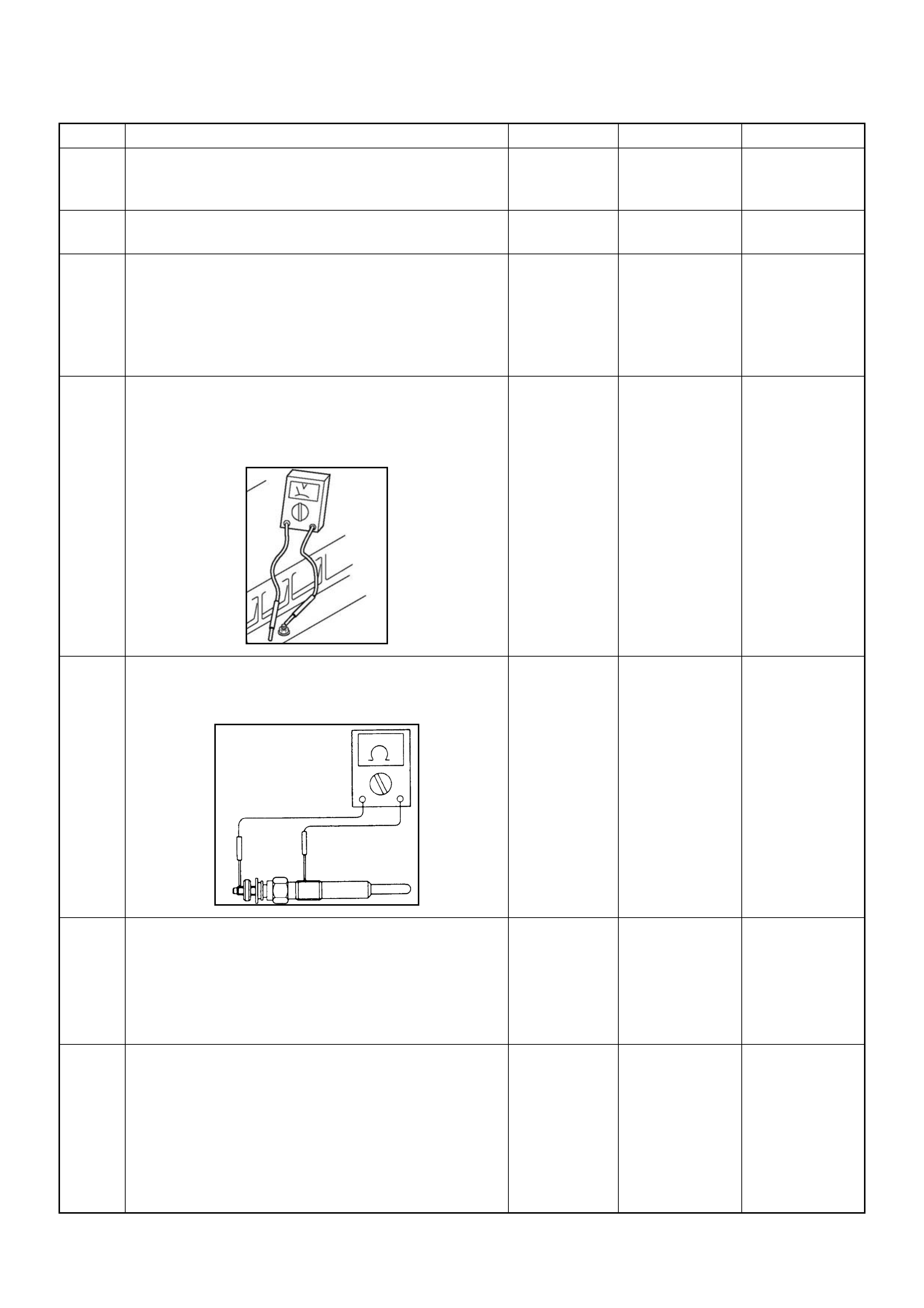
12 Substitute a known good MAF & IAT sensor assembly
and recheck.
Was the problem s olv ed? — Go to
Step 13
Go to
Step 30
13 Replace the MAF & IAT sensor ass embly.
Is the action complete? — Verify repair —
14 1. Using the Tech 2, ignition “On” and engine “Run”.
2. Monitor the “Glow Time Relay” in the data display.
Does the Tech 2 indicate correct “Glow Time Relay”
status depending on the time from engine “Run”?
If a pro blem is found, repair as necessary.
Was the problem found? — Go to
Step 30
Go to
Step 15
15 1. Using the Tech 2, ignition “On” and engine “Run”.
2. Mo nitor the “Gl ow Time Relay” in the data display
and th en, does the supply voltage correctly supply
to the glow plug?
—Go to
Step 16
Repair voltage
supply circuit
and verify repair
16 Check the glo w plugs for continuity.
If a pro blem is found, repair as necessary.
Was a problem found?
— Verify repair Go to
Step 17
17 Remove the CKP sensor from the flywheel housing
and check for the following conditions.
• Objects sticking the CKP sensor.
• Objects sticking the CKP sensor pulser.
If a pro blem is found, repair as necessary.
Was the problem found? — Verify repair Go to
Step 18
18 Check the CKP sensor harness for the following
conditions.
• Check for poor connector connection.
• Che ck for misrouted harness.
• Check for any accessory parts which may cause
electric interference.
If a pro blem is found, repair as necessary.
Was a problem found? — Verify repair Go to
Step 19
Step Action Value(s) Yes No
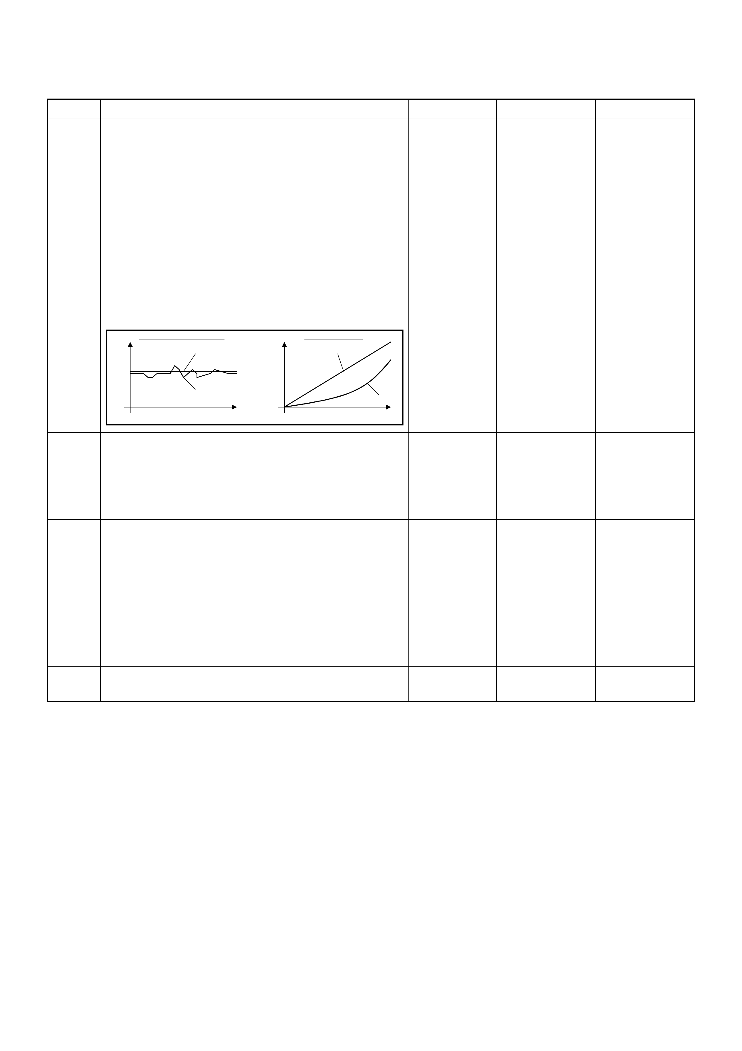
19 Substitute a known good CKP sensor and recheck.
Was the problem s olv ed? — Go to
Step 20
Go to
Step 21
20 Replace the CKP sensor.
Is the action complete? — Verify repair —
21 1. Using the Tech 2 and ignition “On” and engine
“Run”.
2. Monitor the following parameters in the data
display.
• “Desired Injection Quantity” & “Injection Quantity”
• “Desired Injection Start” & “Actual Injection Start”
Are the large gap or unstable parameter displayed
between “Desired” and “Actual”?
—Go to
Step 23
Go to
Step 22
22 Check the exhaust system for a possible restriction.
• Damaged or collapsed pipes or catalytic conve rter.
• Internal muffler failure.
If a pro blem is found, repair as necessary.
Was a problem found? — Verify repair Go to
Step 23
23 Visually/physically inspect for the following conditions.
• Restrict fuel supply system. Check for a pinched
fuel hose/pipe.
• Check for a condition that causes fuel waxing or
icing, such as the customer is using an incorrect
fuel type in winter season or water mixed with the
fuel.
If a pro blem is found, repair as necessary.
Was a problem found? — Verify repair Go to
Step 24
24 Replace the fuel f ilter.
Was the problem solved ? — Verify repair Go to
Step 25
Step Action Value(s) Yes No
When idling or part-throttle When accelerated
High Desired
Low
Time
Actual
High
Low
Desired
Actual
Time

25 Remove the eye bolt with gauze filter from the
injection pump and check for the followin g conditions.
• Objects blocking at the gauze filter. Check for a
condition that causes contaminated fuel, such as
the customer is using an aftermarket fuel filter or
extended mai nte nance int erva l.
• Check for a condition that causes fuel waxing or
icing, such as the customer is using an incorrect
fuel type in winter season or water mixed with the
fuel.
If a pro blem is found, repair as necessary.
Was the problem found?
—
Replace the
eye bolt with
gauze filter and
verify repair Go to
Step 26
26 Remove the injection nozzles from the engine and
check for the following conditions.
• Improper splay condition.
• Operating pressu re is incorrect.
If a pro blem is found, repair as necessary.
Was the problem found?
—
Replace the
injection nozzle
and ve rify repair Go to
Step 27
27 Check the engine compression pressure for each
cylinders.
If a pro blem is found, repair as necessary.
Was the problem found?
More than 30
Mpa (31.0 kg/
cm
2
) Verify repair Go to
Step 28
Step Action Value(s) Yes No
1
st
Stage 2
nd
Stage
4JA1-TC 19.5 - 20.5 Mpa
(199 -209 kg/cm
2
)34.0 - 35.5 Mpa
(347 - 362 kg/cm
2
)
4JH1-TC 20.0 - 21.0 Mpa
(204 -214 kg/cm
2
)34.3 - 35.8 Mpa
(350 - 365 kg/cm
2
)

28 Check the inlet/exhaust valve clearance for each
valves.
Are the valve clearances within the specified value?
0.4mm at cold
(In/Ex) Go to
Step 29
Adjust and
verify repair
29 1. Review all diagnostic procedures within this table.
2. If all procedures have been completed and no
malfunctions have been found, review/inspect the
following:
• Visual/physical inspection
• Tech 2 data
• All electrical connections within a suspected circuit
and/or system
Was a problem found? — Verify repair Go to
Step 30
30 Is the ECM programmed with the latest software
release?
If not, download the latest software to the ECM using
the
“SPS (Service Programming System)”
.
Was the problem solved? — Verify repair Go to
Step 31
31 Substitute a known good ECM and recheck.
Was the problem solved?
IMPORTANT:
The replacement ECM must be
programmed. Refer to section of the Service
Programming System (SPS) in this manual.
Following ECM programming, the immobiliser system
(if equipped) must be linked to the ECM. Refer to
section 11 “Immobiliser System-ECM replacement” for
the EC M/Immobiliser linking proc edure. — Go to
Step 32
Go to
Step 33
32 Replace the ECM.
Is the action complete?
IMPORTANT:
The replacement ECM must be
programmed. Refer to section of the Service
Programming System (SPS) in this manual.
Following ECM programming, th e immobiliser system
(if equipped) must be linked to the ECM. Refer to
section 11 “Immobiliser System-ECM replacement” for
the EC M/Immobiliser linking proc edure. — Verify repair —
33 Replace the injecti on pump assembly.
Is the action complete? — Verify repair —
Step Action Value(s) Yes No

Excessive Black Smoke
Step Action Value(s) Yes No
1 Was the “On-Board Diagnostic (OBD) System Check”
performed?
—Go to
Step 2
Go to
On Board
Diagnostic
(OBD) System
Check
2 1. Perform a bulletin search.
2. If a bulletin that addresses the symptom is found,
correct the condition as instructed in the bulletin.
Was a bulletin found that addresses the symptom? — Verify repair Go to Step 3
3 Was a visually/physical check performed? —Go to
Step 4
Go to
Visual /
physical Check.
4 Is the customer using the incorrect fuel type? Diesel fuel
onlyReplace with
diesel fuel Go to
Step 5
5 Visually/physically inspect for the following conditions.
• Restrict air intake system. Check for a restricted air
filter element, or foreign objects blocking the air
intake system
• Check for objects blocking or excessive deposits in
the throttle bore and on the throttle plate
• Check for a condition that causes a large vacuum
leak, such as an incorrectly installed or faulty
crankcase ventilation hose.
• Restrict air intake system at the turbocharger.
Check for objects blocking the turbocharger
compressor wheel or turbine shaft sticking.
If a problem is found, repair as necessary.
Was a problem found? — Verify repair Go to
Step 6
6 Check the ECM & PSG grounds to verify that they are
clean and tight. Refer to the ECM wiring diagrams.
Was a problem found? — Verify repair Go to
Step 7
7 1. Using th e Tech 2, d ispl ay the E CT sens or an d IAT
sensor val ue.
2. Check the displayed value.
Does the Tech 2 indicate correct temperature
depending on engine condition?
If a problem is found, repair as n ecessary.
Was the problem found? — Verify repair Go to
Step 8
8 1. Using the Tech 2, display the FT sensor value.
2. Check the displayed value.
Does the Tech 2 indicate correct temperature
depending on engine condition?
If a problem is found, repair as n ecessary.
Was the problem found? — Go to
Step 22
Go to
Step 9
9 1. Using the Tech 2, ignition “On ” and eng ine “Run”.
2. Monitor the “Mass Air Flow” in the data display.
Does the Tech 2 indicate correct “Mass Air Flow”
depending on a cc elerator pedal operation? — Go to
Step 14
Go to
Step 10
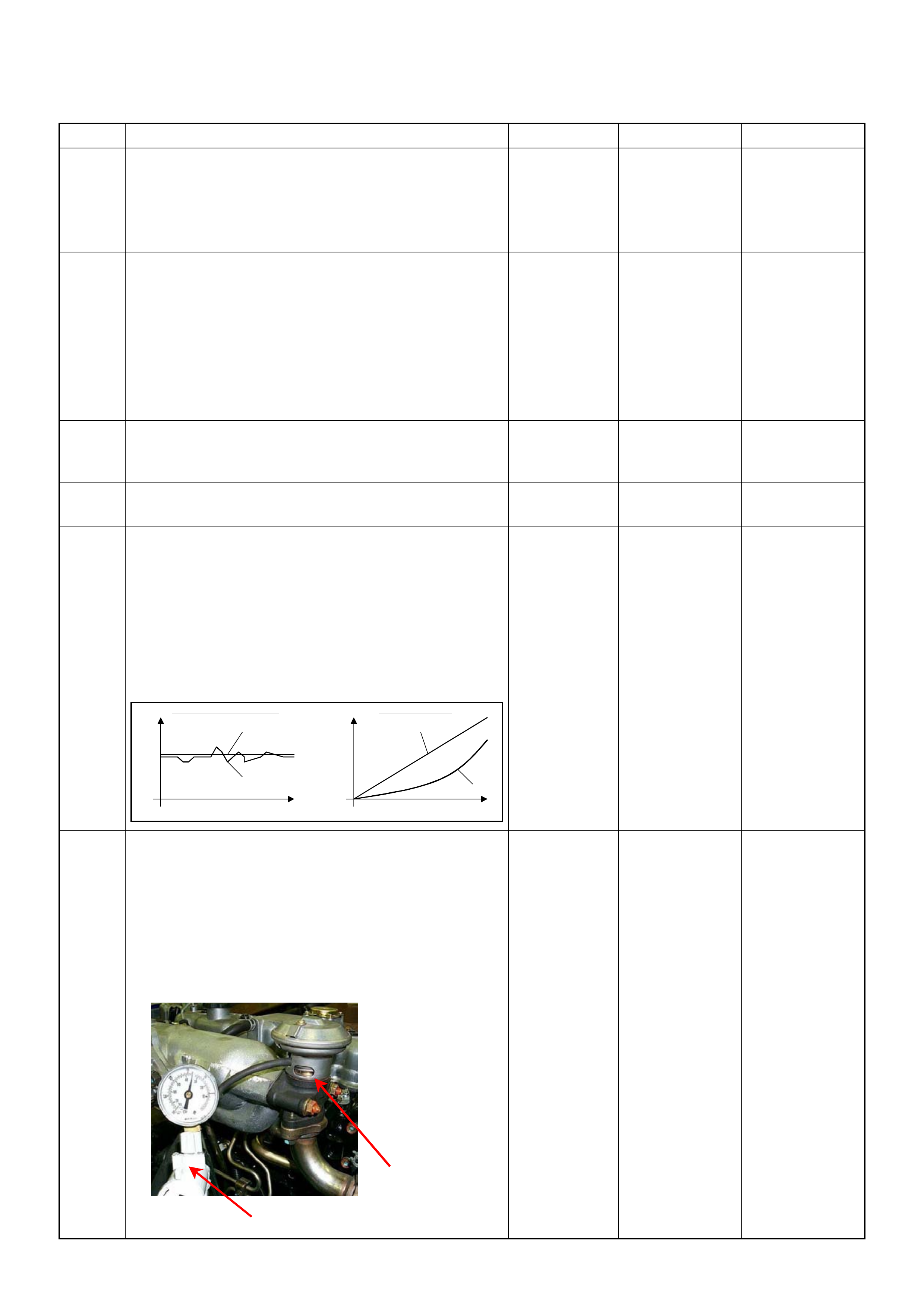
10 Remove the MAF & IAT sensor assembly and check
for the following conditions.
• Objects blocking at the MAF sensor element.
If a pro blem is found, repair as necessary.
Was the problem found? — Verify repair Go to
Step 11
11 Check the MAF sensor harness for the following
conditions.
• Check for poor connector connection.
• Che ck for misrouted harness.
• Check for any accessory parts which may cause
electric interference.
If a pro blem is found, repair as necessary.
Was a problem found? — Verify repair Go to
Step 12
12 Substitute a known good MAF & IAT sensor assembly
and recheck.
Was the problem s olv ed? — Go to
Step 13
Go to
Step 22
13 Replace the MAF & IAT sensor ass embly.
Is the action complete? — Verify repair —
14 1. Using the Tech 2 and ignition “On” and engine
“Run”.
2. Monitor the following parameters in the data
display.
• “Desired Injection Quantity” & “Injection Quantity”
• “Desired Injection Start” & “Actual Injection Start”
Are the large gap or unstable parameter displayed
between “Desired” and “Actual”?
—Go to
Step 21
Go to
Step 15
15 Us ing the vacuum pum p and check the EGR valve (if
equipped) operation for the following condition
through the small window.
• Restrict shaft movement. Check for objects sticking
the shaft, broken diaphragm or excessive carbon
deposit.
If a pro blem is found, repair as necessary.
Was a problem found?
— Verify repair Go to
Step 16
Step Action Value(s) Yes No
When idling or part-throttle When accelerated
High Desired
Low
Time
Actual
High
Low
Desired
Actual
Time
Vacuum Pump
Small Window
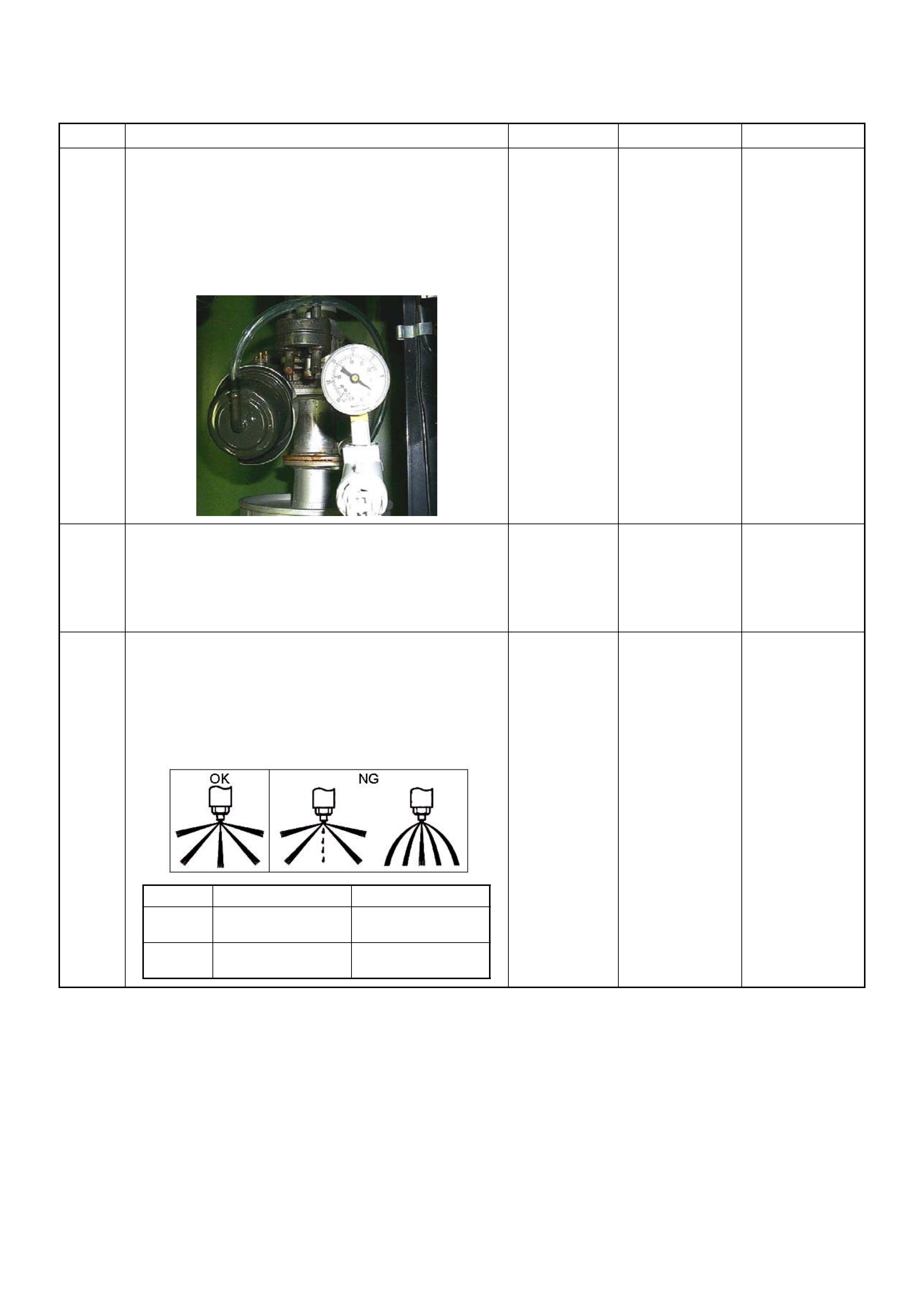
16 Using the vacuum pump and check the exhaust
throttle valve (if equipped) operation for the following
condition.
• Restrict shaft movement. Check for objects sticking
the shaft, broken diaphragm or excessive carbon
deposit.
Was a problem found?
— Verify repair Go to
Step 17
17 Check the exhaust system for a possible restriction.
• Damaged or collapsed pipes or catalytic conve rter.
• Internal muffler failure.
If a pro blem is found, repair as necessary.
Was a problem found? — Verify repair Go to
Step 18
18 Remove the injection nozzles from the engine and
check for the following conditions.
• Improper splay condition.
• Operating pressu re is incorrect.
If a pro blem is found, repair as necessary.
Was the problem found?
—
Replace the
injection nozzle
and ve rify repair Go to
Step 19
Step Action Value(s) Yes No
1
st
Stage 2
nd
Stage
4JA1-TC 19.5 - 20.5 Mpa
(199 -209 kg/cm
2
)34.0 - 35.5 Mpa
(347 - 362 kg/cm
2
)
4JH1-TC 20.0 - 21.0 Mpa
(204 -214 kg/cm
2
)34.3 - 35.8 Mpa
(350 - 365 kg/cm
2
)

19 Check the engine compression pressure for each
cylinders.
If a problem is found, repair as necessary.
Was the problem found?
More than 30
Mpa (31.0 kg/
cm
2
) Verify repair Go to
Step 20
20 Check the inlet/exhaust valve clearance for each
valves.
Are the valve clearances within the specified value?
0.4mm at cold
(In/Ex) Go to
Step 21
Adjust and
verify repair
21 1. Review all diagnostic procedures within this table.
2. If all procedures have been completed and no
malfunctions have been found, review/inspect the
following:
• Visual/physical inspection
• Tech 2 data
• All electrical connections within a suspected circuit
and/or system
Was a problem found? — Verify repair Go to
Step 22
22 Is the ECM programmed with the latest software
release?
If not, download the latest software to the ECM using
the
“SPS (Service Programming System)”
.
Was the problem solved? — Verify repair Go to
Step 23
23 Substitute a known good ECM and recheck.
Was the problem solved?
IMPORTANT:
The replacement ECM must be
programmed. Refer to section of the Service
Programming System (SPS) in this manual.
Following ECM programming, th e immobiliser system
(if equipped) must be linked to the ECM. Refer to
section 11 “Immobiliser System-ECM replacement” for
the EC M/Immobiliser linking proc edure. — Go to
Step 24
Go to
Step 25
Step Action Value(s) Yes No

24 Replace the ECM.
Is the action complete?
IMPORTANT:
The replacement ECM must be
programmed. Refer to section of the Service
Programming System (SPS) in this manual.
Following ECM programming, th e immobiliser system
(if equipped) must be linked to the ECM. Refer to
section 11 “Immobiliser System-ECM replacement” for
the EC M/Immobiliser linking proc edure. — Verify repair —
25 Replace the injecti on pump assembly.
Is the action complete? — Verify repair —
Step Action Value(s) Yes No
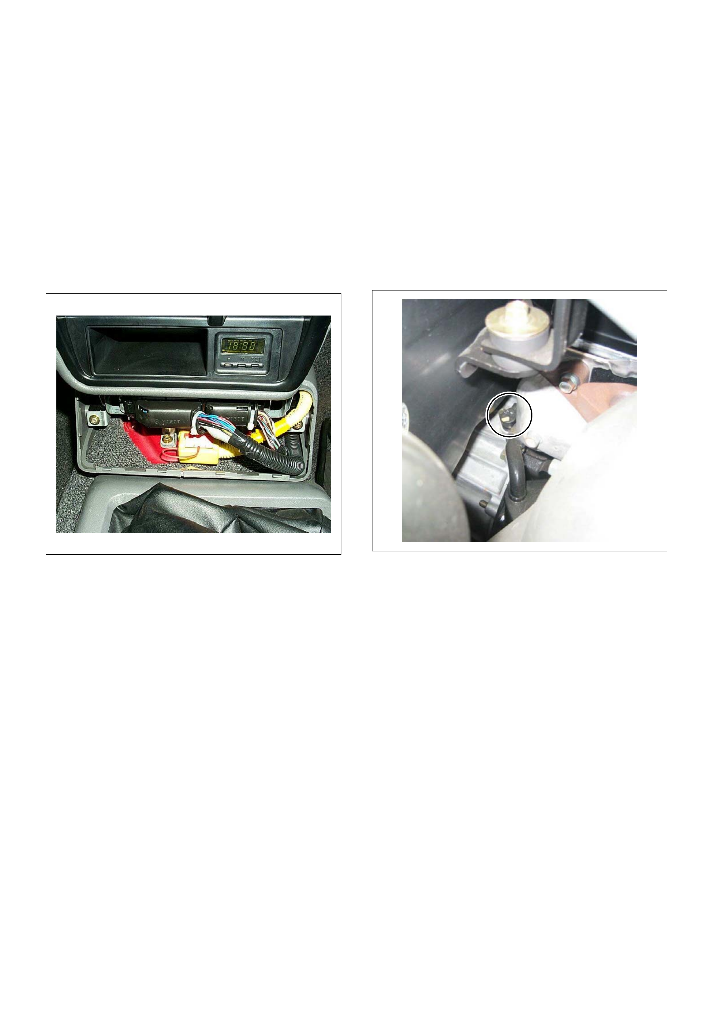
On-vehicle Service Procedure
Engine Control Module (ECM)
Location
Upper the transmission tunnel.
Removal Procedure
1. Disconnect the negative battery cable.
2. Remove the ECM cover.
3. Disconnect the two connectors from the ECM.
4. Remove four screws from the ECM braket.
Installation Procedure
1. Put on the ECM to the braket and tighten by four
screws.
2. Connect the two connectors to the ECM.
3. Refit the ECM cover by four screws.
4. Connect the negative battery cable.
NOTE:
The replacement ECM must be programmed.
Refer to section of the Service Programming System
(SPS) in this manual.
Following ECM programming, the immobiliser system (if
equipped) must be linked to the ECM. Refer to section
11 “Immobiliser System-ECM replacement” for the
ECM/Immobiliser linking proc edure.
Crankshaft Position (CKP) Sensor
Location
Installed to the clutch housing.
Removal Procedure
1. Disconnect the negative battery cable.
2. Disconnect connector from the CKP sensor.
3. L oosen a bolt and remov e the CKP sensor fro m the
clutch housing.
Installation Procedure
1. Install the CKP sens or to the clutch housing.
2. Tighten CKP sensor by a bolt with specified
tightening torque .
Tightening Torque
• Bolts: 8.0 - 12.0 N·m
(0.8 - 1.2 k gf·m)
3. Connect a CKP sensor connector to the CKP
sensor.
4. Connect the negative battery cab le.
NOTE:
Verify any DTCs (diagnosis Trouble Code) are
not stored after replacement.
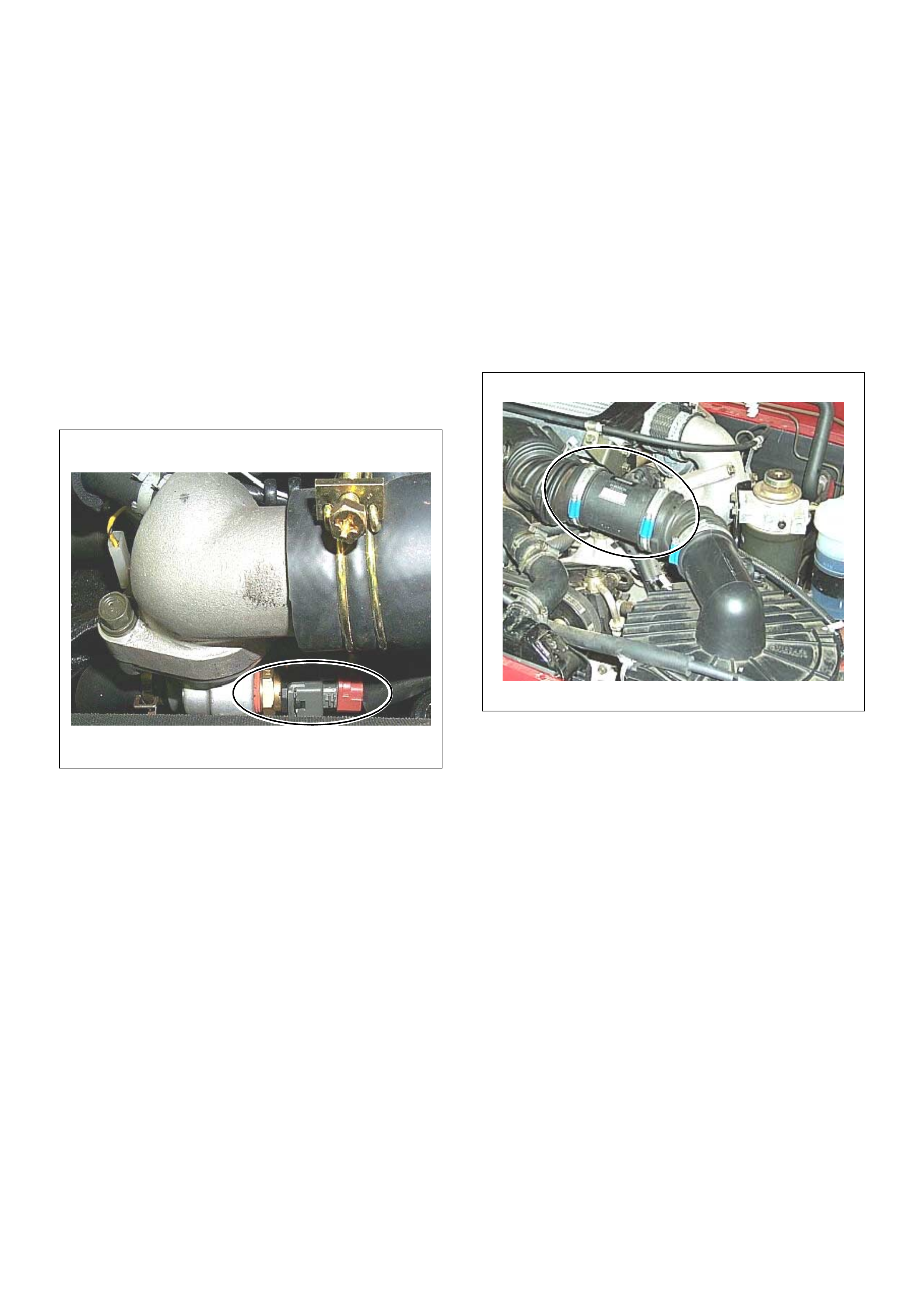
Engine Coolant Temperature (ECT) Sensor
Location
Installed to the thermostat housing.
Removal Procedure
1. Disconnect the negativ e battery cable.
2. Drain enough engine coolant so that the coolant
level will be below th e ECT sensor.
3. Disconnect connector from the ECT sensor.
4. Loosen and remove the ECT sensor from the
thermostat housing.
NOTE:
Cool down the en gine before above p rocedures
are carried out.
Installation Procedure
1. Apply sealer to threads of screw at the E CT sensor.
2. Tighten the ECT sensor with specified tightening
torque.
Tightening Torque
• Bolt: 13N·m (1.3kgf·m )
3. Connect a ECT sensor connector to the ECT
sensor.
4. Fill the engine coolant.
5. Connect the negative battery cable.
NOTE:
Verify any DTCs (diagnosis Trouble Code) are
not stored after replacement.
Verify no engine coolant leaking from the sensor
threads after replacement.
Mass Air Flow (MAF) & Intake Air
Temper ature (IAT) Sensor
Location
Installed to the intake duc t housing .
Removal Procedure
1. Disconnect the negative battery cable.
2. Di sconnec t a MA F & IAT se nsor conn ector from the
MAF & IAT sensor assembly.
3. Loosen th e clips and remove the MA F & IAT sensor
assemb ly from the intake duct housing.
Installation Procedure
1. Install the MAF & IAT sensor assembly into intake
air duct.
2. Tighten the clips.
3. Connect a MAF & IAT sens or conne ctor to the MAF
& IAT sensor assembly.
4. Connect the negative battery cab le.
NOTE:
Verify any DTCs (diagnosis Trouble Code) are
not stored after replacement.
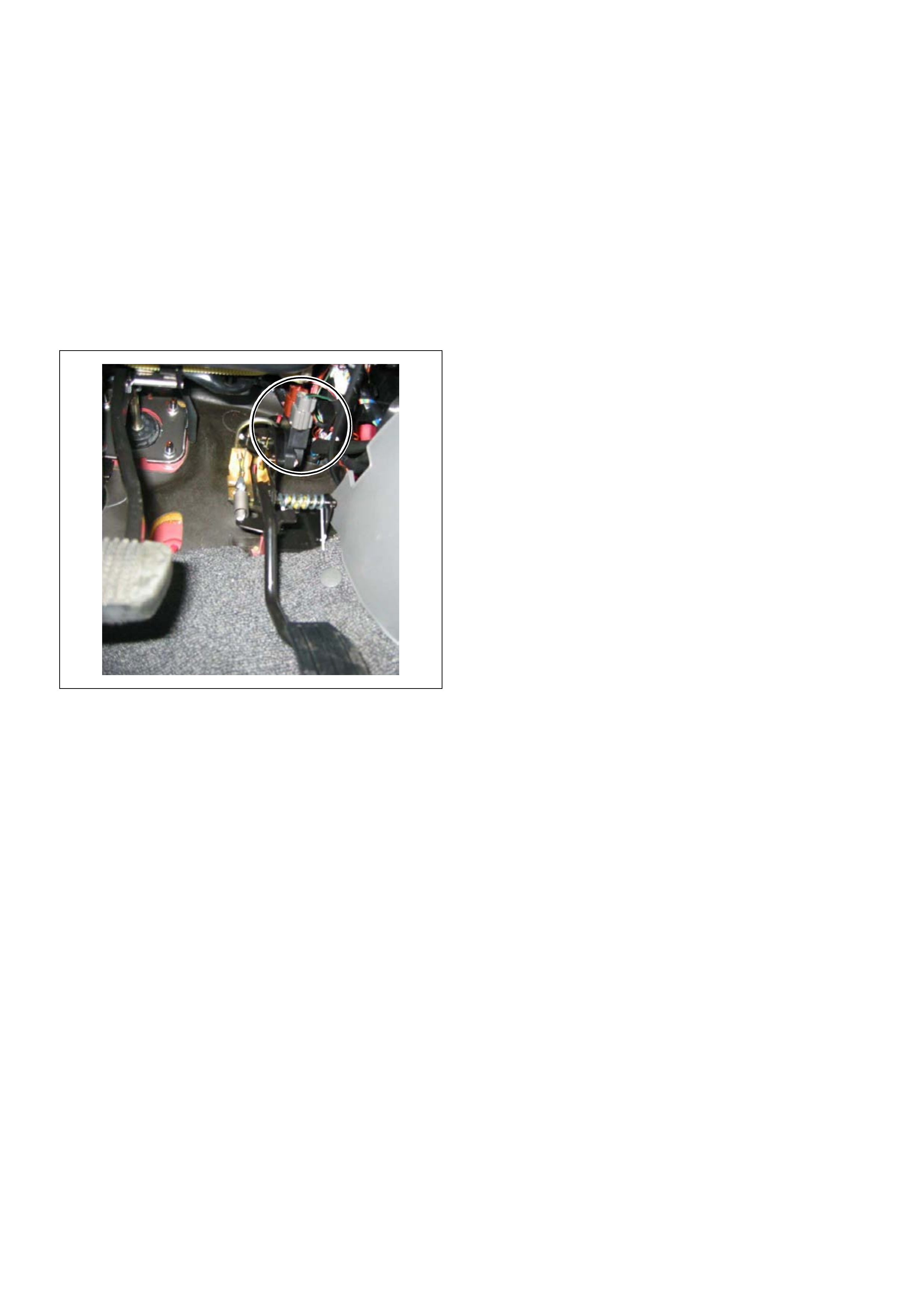
Pedal(Throttle) Position Sensor (TPS)
Location
Installed on the accelerator pedal mou nting bra cket.
Removal Procedure
1. Disconnect the negativ e battery cable.
2. Disco nne ct the TPS co nnec to r.
3. Loosen two screws and remove TPS from the
throttle body.
Installation Procedure
1. Temporary tighten the TPS by two screws.
2. Connect a TPS con nectors to the TPS.
3. Connect the Tech2 to the vehicle.
4. Connect the negative battery cable.
5. Select “Data Display” with the Tech2.
6. Check the throttle position data and adjust the TPS
position.
7. Tighten two screws.
NOTE:
Verify any DTCs (diagnosis Trouble Code) are
not stored after replacement.
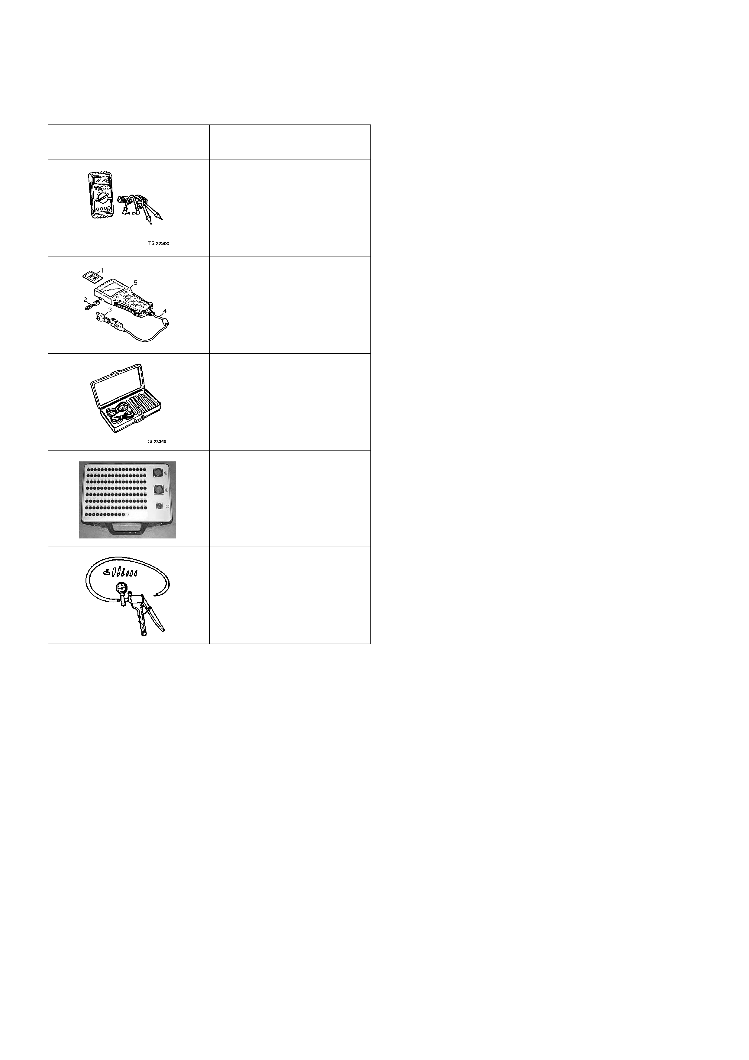
Special Service Tools
ILLUSTRATION TOOL NO.
TOLL NAME
5-8840-0285-0
(J 39200)
High Impeda nce
Multimeter
(Digital Vo ltmeter -DVM)
(1) PCMCIA Card
(2) RS232 Loop Back
Connector
(3) SAE 1 6/19 Adapter
(4) DLC Cable
(5) TECH 2
5-8840-0385-0
(J 35616-A/BT-8637)
Connector Test Adapter Kit
Breaker Box
5-8840-0279-0
(J 23738-A)
Vacuum P ump with Gauge