
SECTION 6B - ENGINE COOLING (C22NE MODELS)
GENERAL DESCRIPTION
SERVICE PRECAUTION
WATER PUMP
THERMOSTAT
RADIATOR
DIAGNOSIS
ENGINE COOLING TROUBLE
DRAINING AND REFILLING COOLING SYSTEM
WATER PUMP
WATER PUMP AND ASSOCIATED PARTS
REMOVAL
INSPECTION
INSTALLATION
THERMOSTAT
REMOVAL
INSPECTION
INSTALLATION
FAN CLUTCH WITH COOLING FAN
INSPECTION AND REPAIR
RADIATOR
RADIATOR AND ASSOCIATED PARTS
REMOVAL
INSPECTION
RADIATOR CAP
RADIATOR CORE
FLUSHING THE RADIATOR
COOLING SYSTEM LEAKAGE CHECK
INSTALLATION
MAIN DATA AND SPECIFICATIONS
GENERAL SPECIFICATIONS
SPECIAL SERVICE TOOL
Techline
Techline
Techline
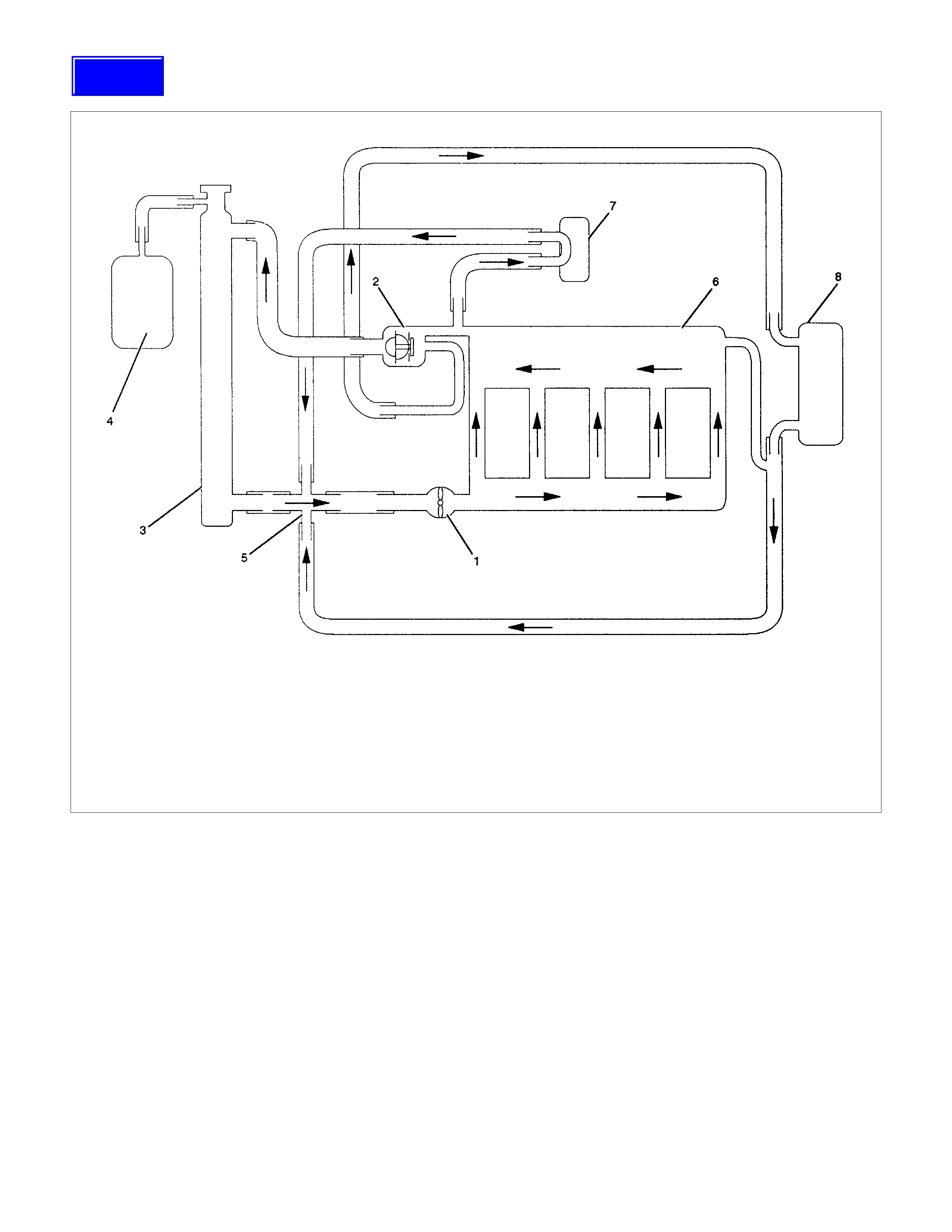
GENERAL DESCRIPTION
Legend
1 Water Pump
2 Thermostat
3 Radiator
4 Reserve Tank
5 Coolant Distributor
6 Cylinder Block and Head
7 Throttle Body
8 Heater
The Cooling System is a pressurized type, where the water pump, which is cam-belt driven, forces the circulation of the
coolant through the cylinder block and head. The thermostat regulates the flow of coolant between the radiator and the
bypass circuit. The heater is part of the bypass circuit. The throttle body pre-heat is a separate circuit, which is not
regulated by the thermostat. An oil cooler may be fitted as part of this circuit.
Techline
SERVICE PRECAUTION
CAUTION:
Always use the correct fastener in the proper location.
When you replace a fastener, use ONLY the exact part
number for that application. HOLDEN will call out those
fasteners that require a replacement after removal.
HOLDEN will also call out the fasteners that require thread
lockers or thread sealant. UNLESS OTHERWISE
SPECIFIED, do not use supplemental coatings (Paints,
greases, or other corrosion inhibitors) on threaded
fasteners or fastener joint interfaces. Generally, such
coatings adversely affect the fastener torque and the joint
clamping force, and may damage the fastener. When you
install fasteners, use the correct tightening sequence and
specifications. Following these instructions can help you
avoid damage to parts and sys tems.
WATER PUMP
The water pump is centrifugal type and is driven by the
camshaft timing belt.
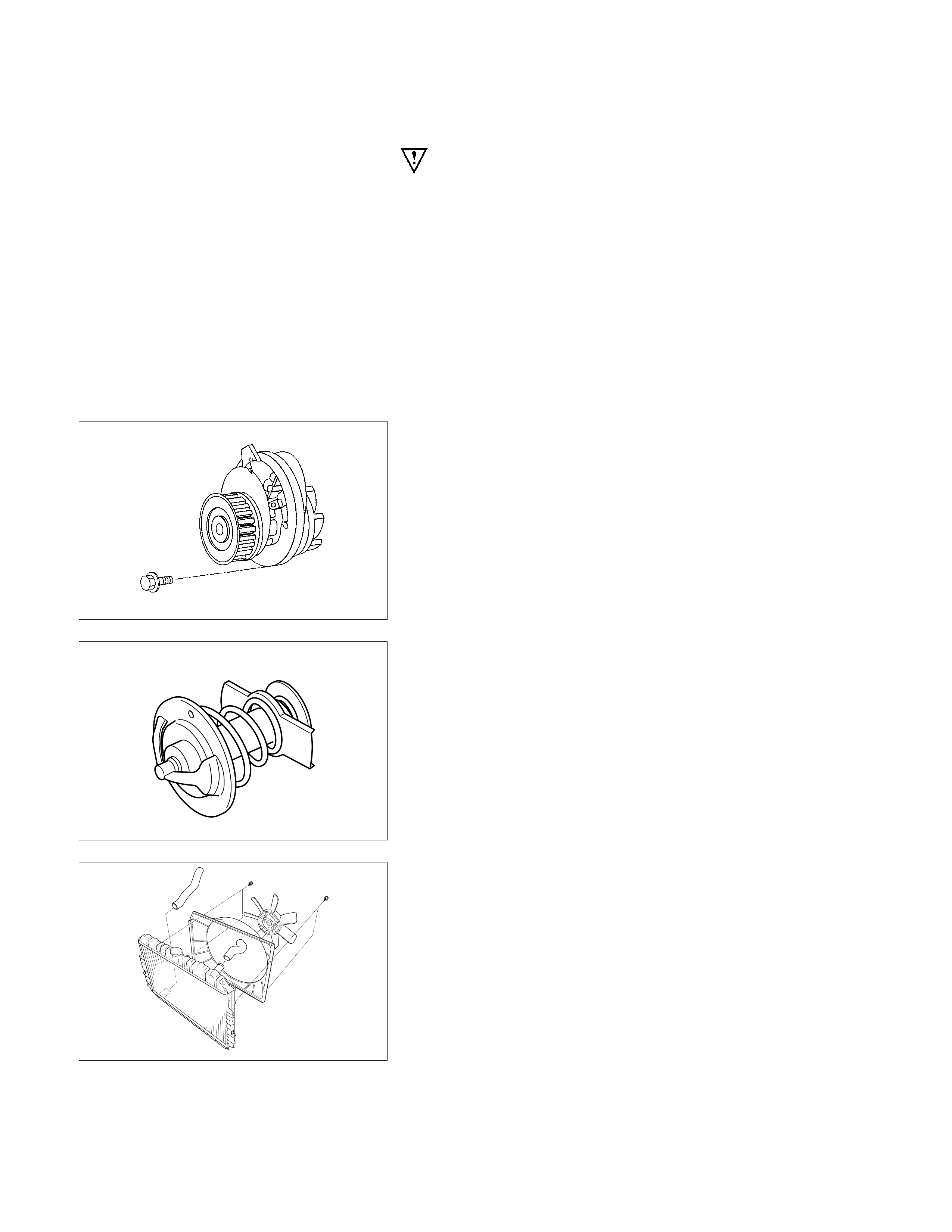
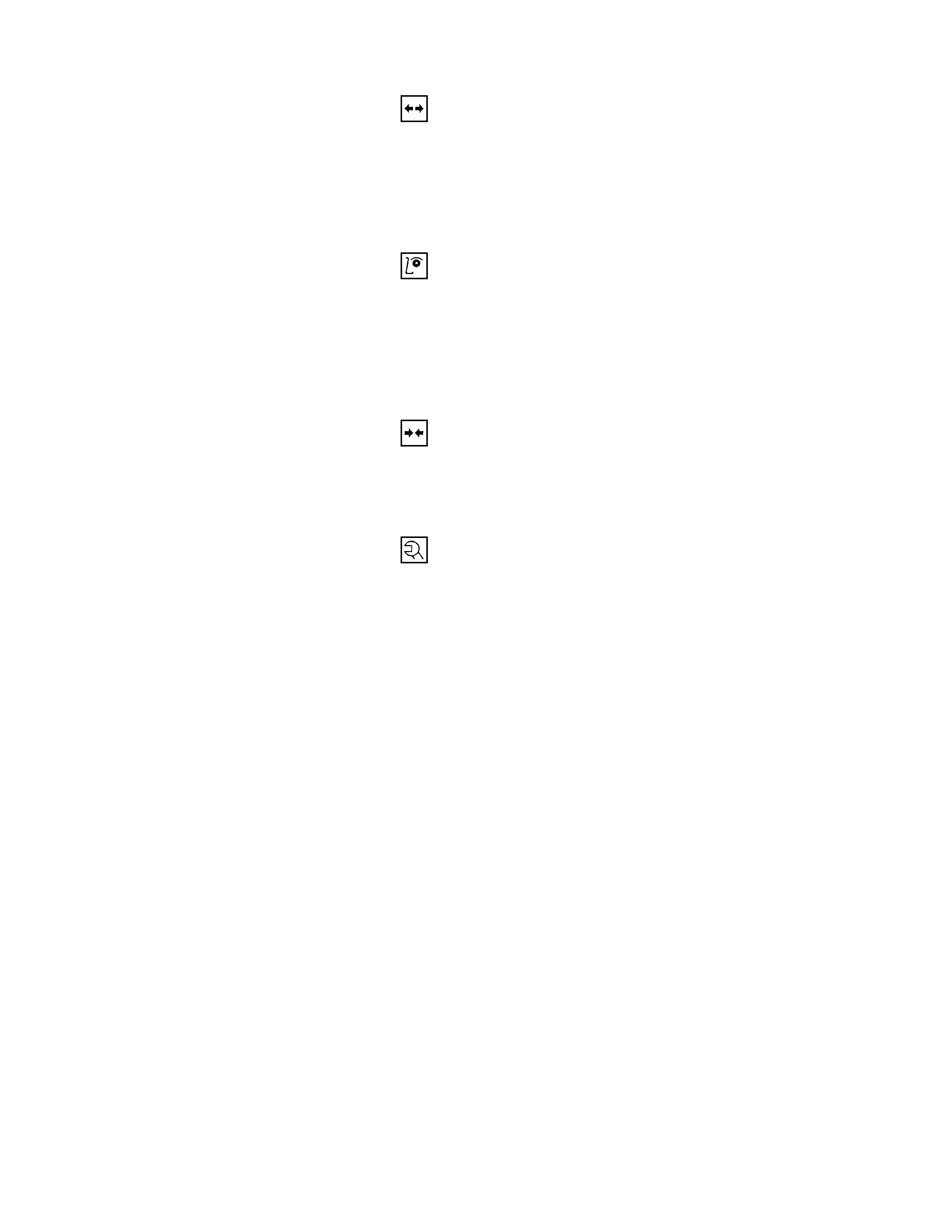
THERMOSTAT
The thermostat is a bypass type and is a wax pellet type with
an air hole (1).
RADIATOR
The radiator is a flow type with corrugated fins.
COOLANT
50% HN 2043 with w a ter
DIAGNOSIS
ENGINE COOLING TROUBLE
CONDITION POSSIBLE CAUSE CORRECTION
Engine overheating Low Engine Coolant level Replenish
Faulty Temp. Gauge unit faulty Replace
Faulty thermostat Replace
Faulty Engine Coolant temperature
sensor Repair or replace
Clogged radiator Clean or replace
Faulty radiator cap Replace
Low engine oil level or use of
improper engine oil Replenish or change oil
Clogged exhaust system Clean exhaust system or replace
faulty parts
Faulty Throttle Position sensor Replace throttle valve assembly
Open or shorted Throttle Position
sensor circuit Repair or replace
Damaged cylinder head gasket Replace
Loosen V-belt tension Adjust belt tension or replace.
Collapsed hoses Replace
Faulty Fan clutch Replace
Engine overcooling Faulty thermostat Replace
Engine slow to warm-up Faulty thermostat Replace
Temp gauge faulty Replace

DRAINING AND REFILLING COOLING SYSTEM
Before draining the cooling system, inspect the system and
perform any necessary service to ensure that it is clean, does
not leak and is in proper working order. The engine coolant
(EC) level should be between the "MIN" and "MAX" lines of
reserve tank when the engine is cold. If low, check for leakage
and add EC up to the "MAX" line. There should not be any
excessive deposit of rust or scales around the radiator cap or
radiator filler hole, and the EC should also be free from oil.
Replace the EC if excessively dirty.
1. Completely drain the cooling system by opening the drain
plug at the bottom of the radiator.
2. Remove the radiator cap.
WARNING:
TO AVOID THE DANGER OF BEING BURNED, DO NOT
REMOVE THE CAP WHILE THE ENGINE AND RADIATOR
ARE STILL HOT. SCALDING FLUID AND STEA M CAN BE
BLOWN OUT UNDER PRESSURE.
3. Disconnect all hoses from the EC reserve tank.
Scrub and clean the ins ide of the reserve tank with soap and
water. Flush it well with clean water, and then drain it.
Install the reserve tank and hoses.
4. Refill the cooling system with 50% HN 2043 coolant with
water.
5. Fill the radiator to the base of the filler neck.
Fill the EC reserve tank to "MAX" line when the engine is
cold.
6. Block the drive wheels and firmly apply the park ing brake.
Shift an autom atic transm ission to "P" (Park ) or a manual
transmission to neutral.
7. Remove the r adiator cap. Start the engine and warm it up
at 2,500 - 3,000 rpm for about 30 minutes.
8. When the air comes out from the radiator filler neck and
the EC level has gone down, replenish with the EC.
Repeat this procedure until the EC level does not go
down. Then stop the engine and install the radiator cap.
Let the engine cool down.
9. After the engine has cooled, replenish with EC up to the
"MAX" line of the reserve tank.
10. Start the engine. With the engine running at 3,000 rpm,
make sure there is no running water sound from the
heater core (behind the center console).
11. If the running water sound is heard, repeat steps 8 to 10.
WATER PUMP
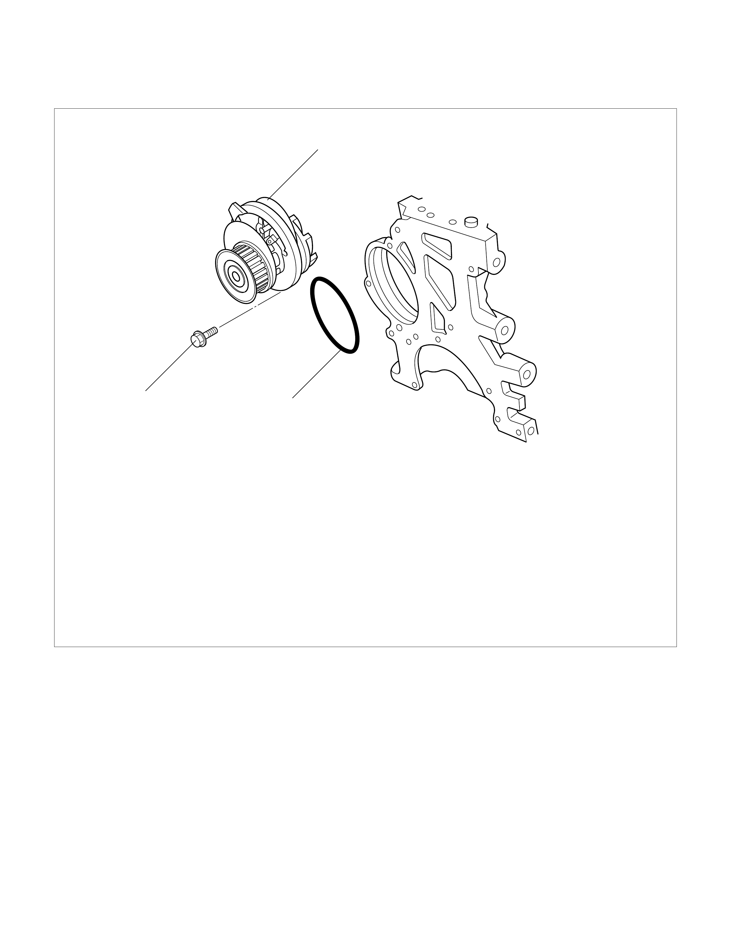
WATER PUMP AND ASSOCIATED PARTS
Legend
1 Water Pump Assembly 2 O-Ring
3 Bolt
2
3
1
REMOVAL
1. Disconnect battery ground cable.
2. Drain coolant.
3. Radiator hose (on inlet pipe side).
4. Remove timing belt, refer to "Timing Belt" in this manual.
5. Remove water pump assembly.
INSPECTION
Make necessary repair and parts replacement if extreme wear
or damage is found during inspection. Should any of the
following problems occur, the entire water pump assembly
must be replaced:
•Crack in the water pump body
•EC leakage from the seal unit
•Play or abnormal noise in the bearing
•Cracks or corrosion in the impeller
INSTALLATION
1. Before installing water pump, coat sealing surface with
silicon grease.
2. Install water pump assembly and tighten bolts to the
specified torque.
Torque: 25 N⋅
⋅⋅⋅m (2.5 kgf.m)
3. Timing belt
•Install timing belt, refer to timing belt installation step in
"Timing Belt" in this manual.
4. Connect radiator hose and replenish EC.
5. Connect battery ground cable.
THERMOSTAT
REMOVAL
1. Disconnect battery ground cable.
2. Drain engine coolant from the radiator and engine.
3. Disconnect radiator hose from the inlet pipe.
4. Remove thermostat housing.
5. Remove thermostat from thermostat housing.
INSPECTION
Suspend the thermostat in a water-filled container using thin
wire. Place a thermometer next to the thermostat.
Do not directly heat the thermostat.
Gradually increase the water temperature. Stir the water so
that the entire water is same temperature.
Confirm the temperature when the valve first begins to open.
Valve opening temperature 92°
°°
°C (197.6°
°°
°F)
Confirm the temperature when the valve is fully opened.
Valve full open temperature 107°
°°
°C(224.6°
°°
°F)
Make necessary repairs and parts replacement if extreme
wear or damage is found during inspection.
INSTALLATION
1. Before installing thermostat, coat sealing surface with
silicon grease.
2. Install O-ring.
3. Install thermos tat housing and tighten bolts to the specified
torque.
Torque: 15 N⋅
⋅⋅⋅m (1.5 kgf.m)
4. Installation rubber hose.
5. Replenish engine coolant (EC).
6. Start engine and check for EC leakage.
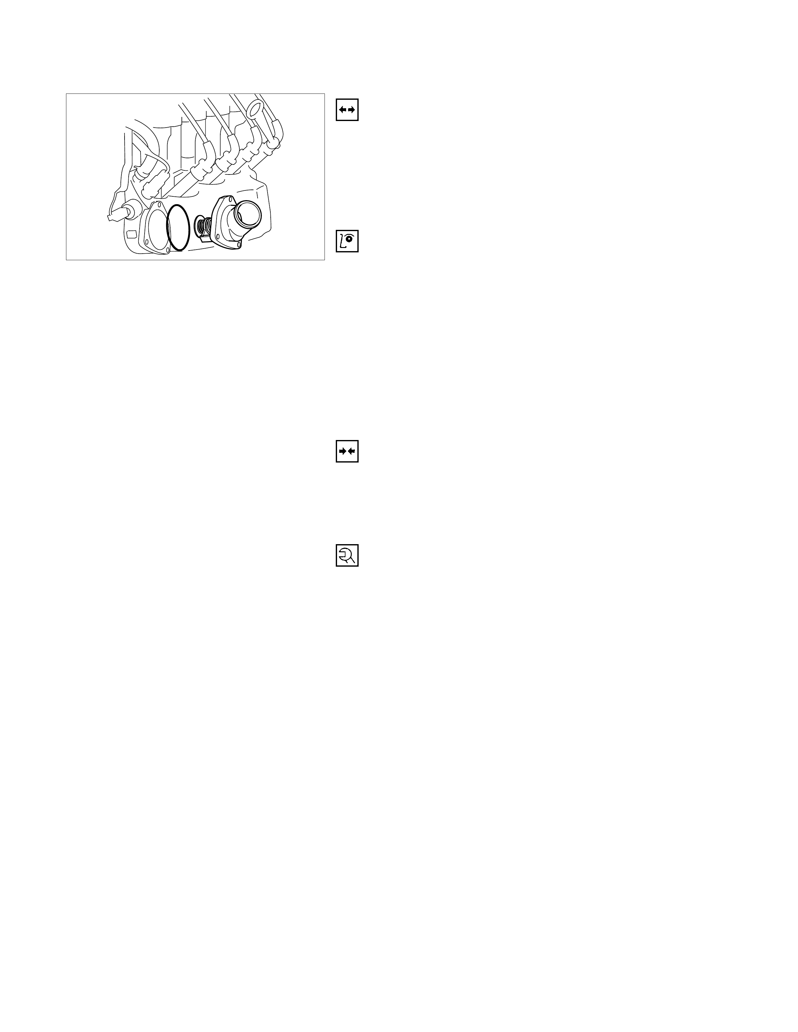
FAN CLUTCH WITH COOLING FAN
INSPECTION AND REPAIR
Make necessary correction or parts replacement if wear,
damage or any other abnormal condition is found through
inspection.
Visually inspect for damage, leak (silicon grease) or other
abnormal conditions.
1. Inspection (on-vehicle)
1) Turn the fan clutch by hand when in a low temperature
condition before starting the engine, and confirm that it
can be turned readily.
2) Start the engine to warm it up until the temperature at the
fan clutch portion gets to around 80°C. Then stop the
engine and confirm that the fan clutch can be turned with
considerable effort (clutch torque) when turned by hand.
If the fan clutch rotates more readily, however, this
indicates that the silicon grease is leaking internally.
Replace the fan clutch with a new one.
2. Inspection (in unit)
Warm up the bimetal of the f an c lutch by using the heat gun
until the temperature gets to about 80°C when measured
with the thermistor . Then confir m that the fan clutc h can be
turned with considerable effort (clutch torque).
If the fan clutch rotates m ore readily at this tim e, this indicates
that the silicon grease is leaking internally.
Replace the fan clutch with a new one.
RADIATOR
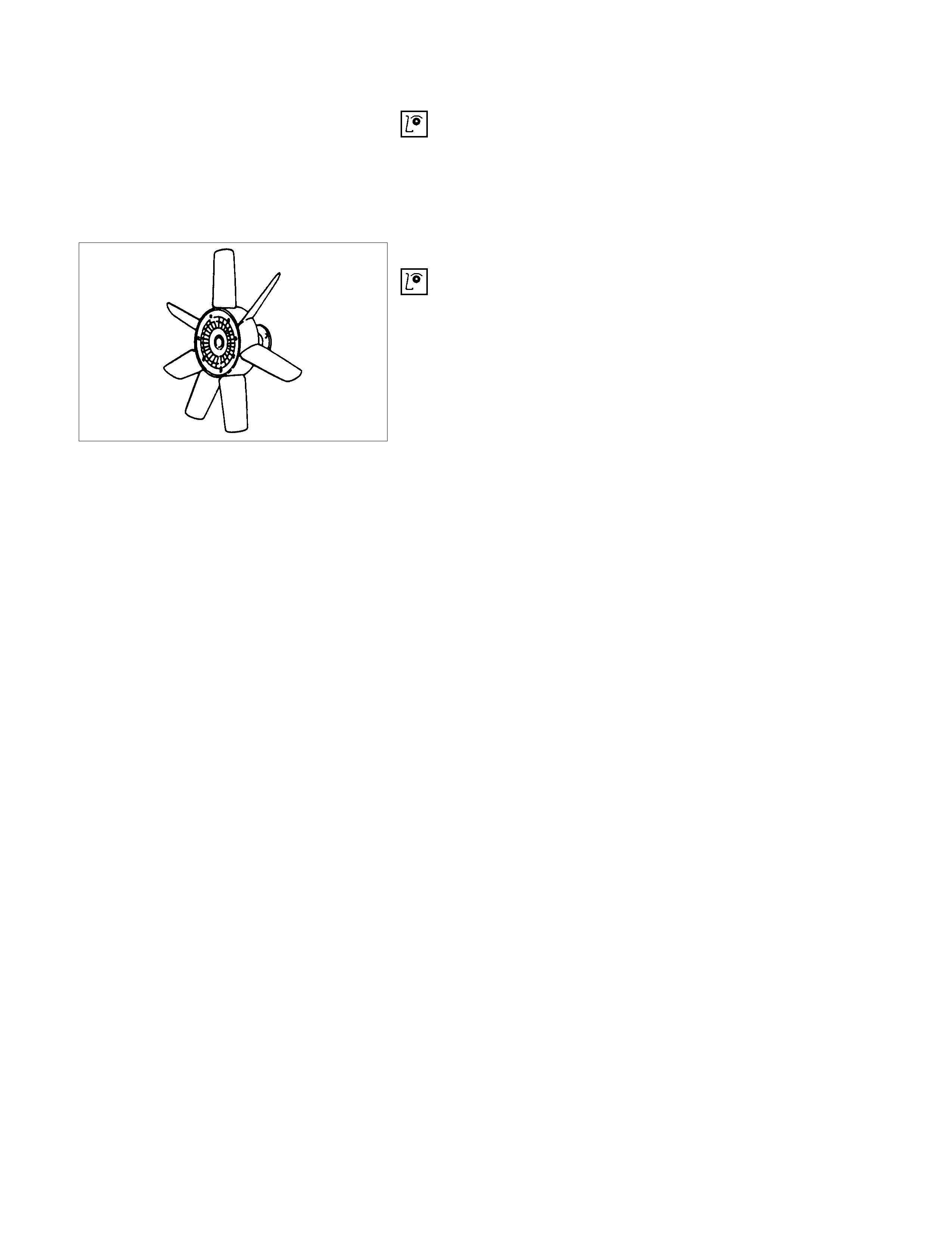
RADIATOR AND ASSOCIATED PARTS
Legend
1 Radiator
2 Radiator Cap
3 Radiator Upper Hose
4 Radiator Lower Hose
5 Cooling Fan Shroud
6 Cooling Fan
REMOVAL
1. Disconnect battery ground cable.
2. Loosen a drain plug to drain engine coolant (EC).
3. Disconnect radiator inlet hose and outlet hose.
4. Disconnect the reserve tank hose from radiator.
5. Lift out the radiator assembly, taking care not to damage
the radiator core.
INSPECTION
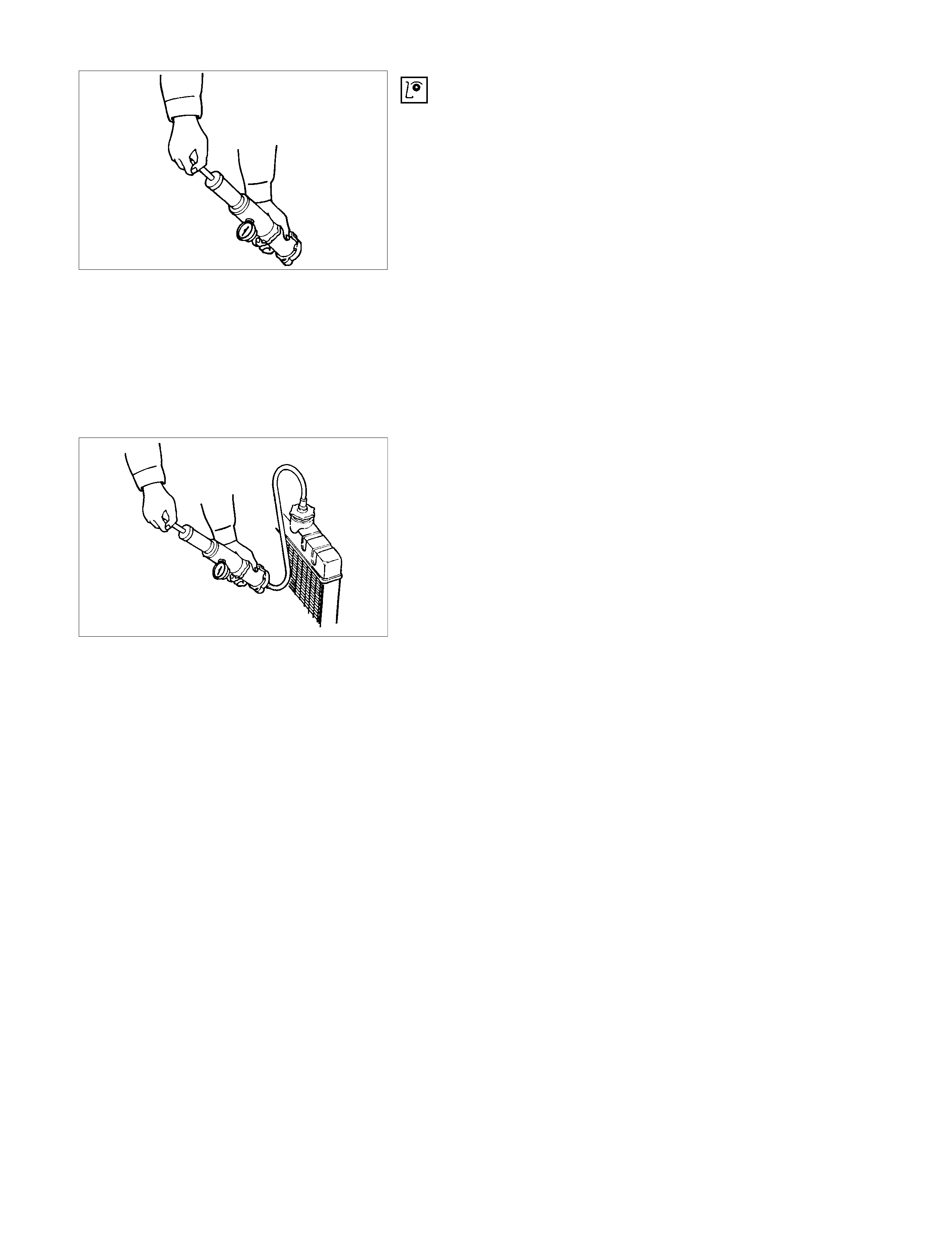
RADIATOR CAP
Measure the valve opening pressure of the pressurizing valve
with a radiator filler cap tester.
Replace the cap if the valve opening pressure is outside the
standard range.
Valve opening pressure kPa (psi) 88.3 - 1117.7
(13.5 - 17.8)
Cap tester: 5-8840-0277-0
Adapter: 5-8840-2603-0
Check the condition of the vacuum valve in the center of the
valve seat side of the cap. If considerable rust or dirt is found,
or if the valve seat cannot be moved by hand, clean or replace
the cap.
Valve opening vacuum kPa (psi) 1.9 - 4.9
(0.28 - 0.71)
RADIATOR CORE
1. A bent fin m ay result in r educed ventilation and overheating
may occur. All bent fins must be straightened. Pay close
attention to the base of the fin when it is being straightened.
2. Remove all dust, bugs and other foreign material.
FLUSHING THE RADIATOR
Thoroughly wash the inside of the radiator and the engine
coolant passages with cold water and mild detergent. Remove
all sign of scale and rust.
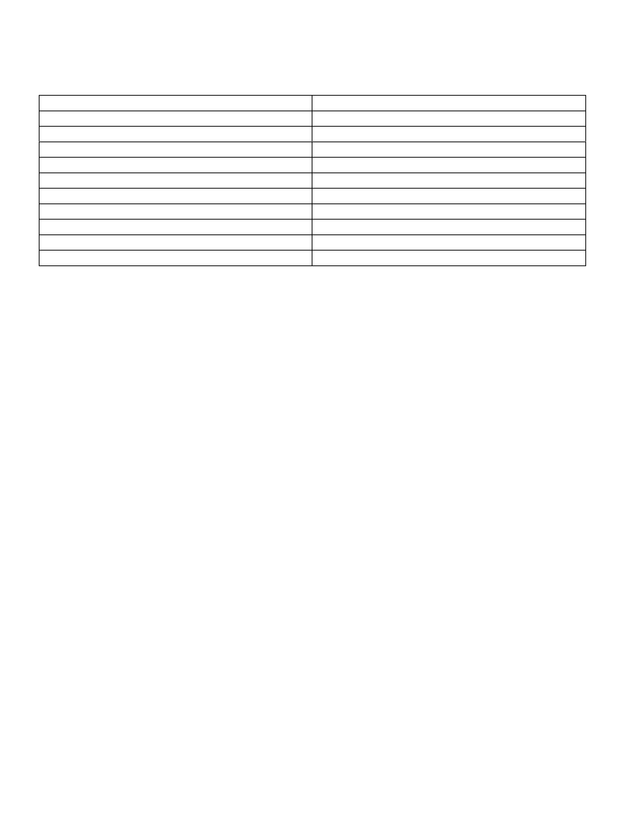
COOLING SYSTEM LEAKAGE CHECK
Use a radiator cap tester to force air into the radiator through
the filler neck at the specified pressure of 196 kPa (28.5 psi)
with a cap tester:
•Leakage from the radiator
•Leakage from the coolant pump
•Leakage from the water hoses
•Check the rubber hoses for swelling.
Cap tester: 5-8840-0277-0
Adapter: 5-8840-2603-0

INSTALLATION
1. Install radiator assembly, taking care not to damage the
radiator core.
2. Install the radiator assembly.
3. Connect reserve tank hose.
4. Connect radiator inlet hose and outlet hose.
5. Pour engine coolant up to filler neck of radiator, and up to
MAX mark of reserve tank.
Important operation (in case of 100% engine coolant
change) procedure for filling with engine coolant.
•Remove radiator cap.
•Fill with engine coolant (EC) to the radiator filler neck.
•Fill with EC to the "MAX" line on the reservoir tank.
•Start the engine with the radiator cap removed and bring to
operating temperature by running engine at 2,500 - 3,000
rpm for 30 minutes.
•By EC temperature gauge reading make sure that the
thermostat is open.
•If air bubbles come up to the radiator filler neck, replenish
with EC. Repeat until the EC level does not dr op any further .
Install the radiator cap and stop the engine.
•Replenish EC to the "MAX" line on the reservoir tank and
leave as it is until the engine gets cool.
•After the engine gets cool, start the engine and make sure
there is no water running noise heard from the heater core
while the engine runs at 3000 rpm.
•Should water running noise be heard, repeat the same
procedure from the beginning.
MAIN DATA AND SPECIFICATIONS
GENERAL SPECIFICATIONS
Cooling system Engine Coolant forced circulation
Radiator Tube type corrugated (2 tube in row)
Heat radiation capacity 59.100 kcal/h
Heat radiation area 10.915
Radiator front area 0.228
Radiator dry (weight) 66.6N, 6.9kg
Radiator cap valve opening pressure 88.3 - 117.7kpa
Engine coolant capacity 2.3L
Engine coolant pump Centrifugal type
Thermostat Bypass type
Engine coolant total capacity 6.9 litres
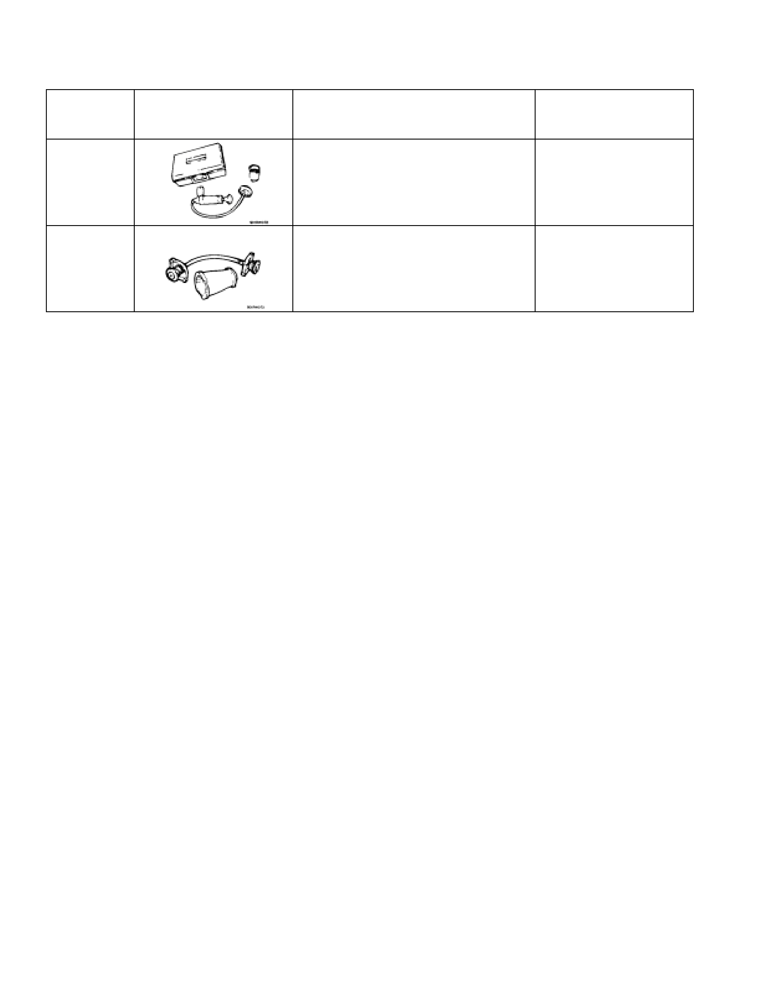
SPECIAL SERVICE TOOL
ITEM NO. ILLUSTRATION PART NO. PART NAME
15-8840-0277-0 Tester; radiator cap
25-8840-2603-0 Adapter; radiator cap