
SECTION 6C1 - DRIVEABILITY AND EMISSIONS (C22NE MODELS)
SPECIFICATION
TIGHTENING SPECIFICATIONS
EMISSION CONTROL SYSTEM SCHEMATICS
DIAGRAMS AND SCHEMATICS
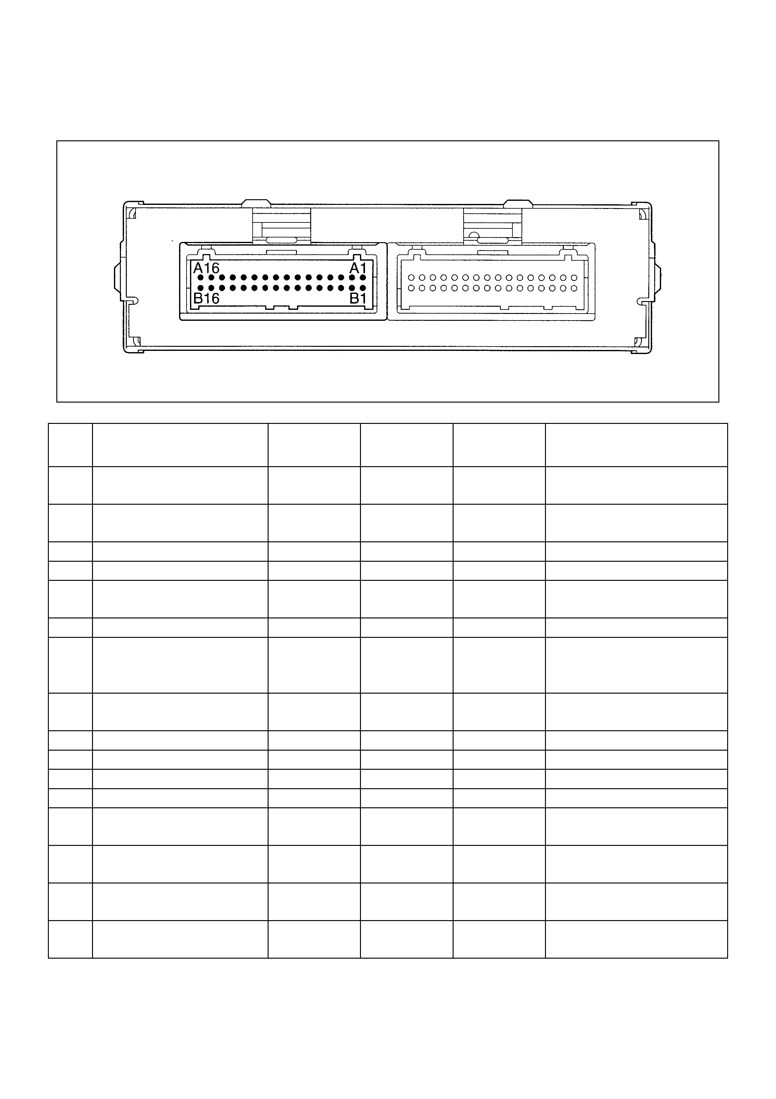
ECM PINOUTS
ECM PINOUT TABLE, 32-PI N BLUE CONNECTOR-ROW "J1"
ECM PINOUT TABLE, 32-PI N BLUE CONNECTOR-ROW "J1"
ECM PINOUT TABLE, 32-PIN RED CONNECTOR-ROW "J 2"
ECM PINOUT TABLE, 32-PIN RED CONNECTOR-ROW "J 2"
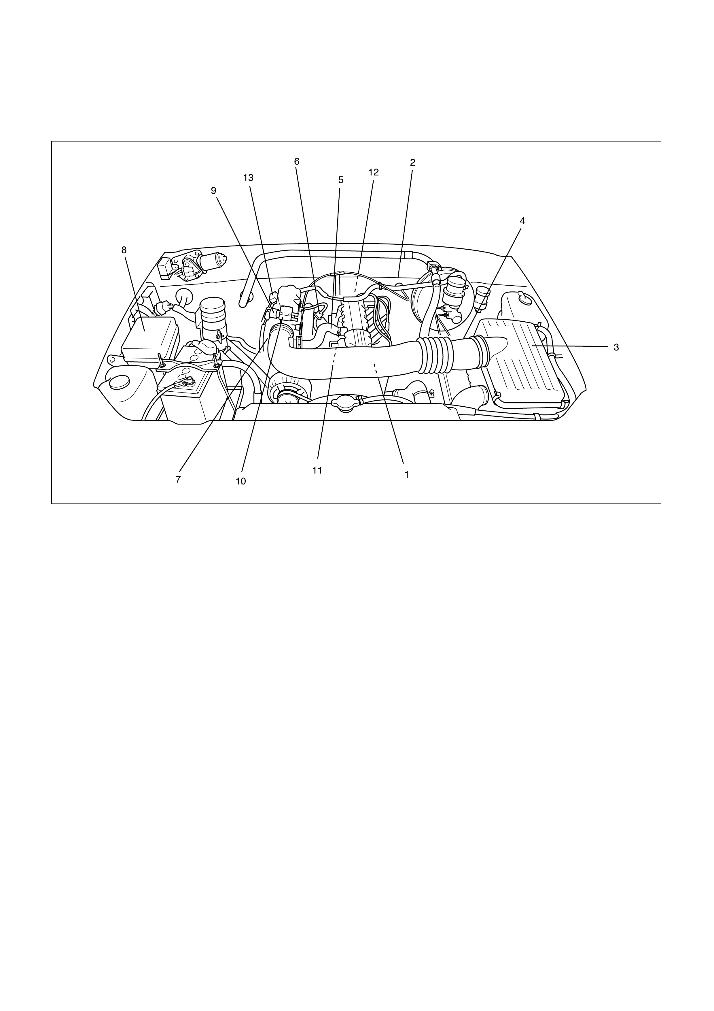
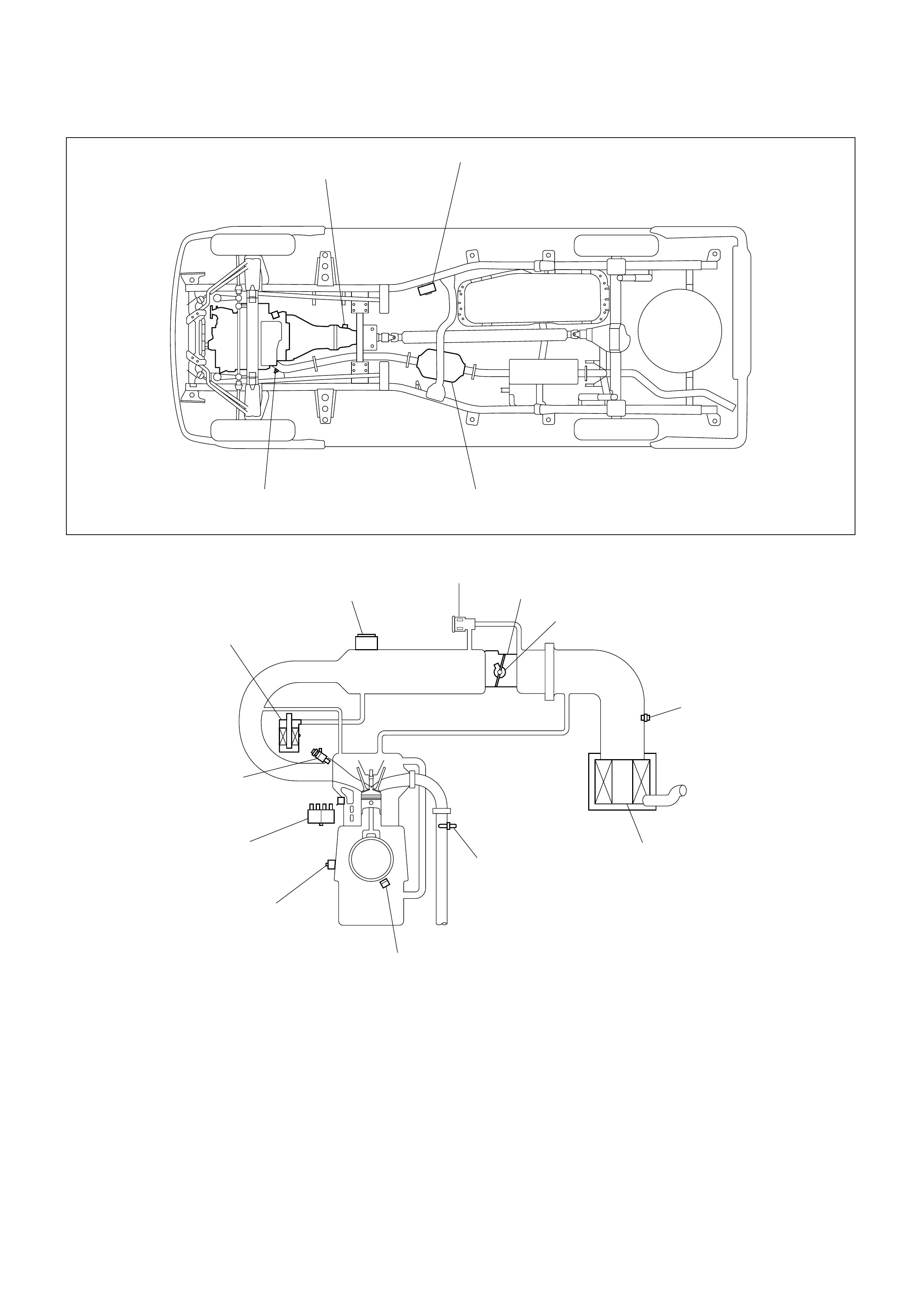
COMPONENT LOCATOR
ENGINE COMPONENT LOCATOR TABLE
UNDERCARRIAGE COMPONENT LOCATOR TABLE
UNDERHOOD (U/H) FUSE AND RELAY PANEL
INSTRUMENT PANEL (I/P) FUSE BLOCK
DIAGNOSIS
STRATEGY-BASED DIAGNOSTICS
DTC STORED
NO DTC
NO MATCHING SYMPTOM
INTERMITTENTS
NO TROUBLE FOUND
VERIFYING VEHICLE REPAIR
Techline
Techline
Techline

GENERALSERVICE INFORMATION
OBD SERVICEABILITY ISSUES
FUEL QUALITY
NON-OEM PARTS
POOR VEHICLE MAINTENANCE
RELATED SYSTEM FAULTS
MAINTENANCE SCHEDULE
VISUAL/PHYSICAL ENGINE COMP ARTMENT INSPECTION
BASIC KNOWLEDGE OF TOOLS REQUIRED
SERIAL DATA COMMUNICATIONS
ON-BOARD DIAGNOSTIC (OBD)
ON-BOARD DIAGNOSTIC TESTS
COMPREHENSIVE COMP ONENT MONITOR DIAGNOSTIC OPE RATION
INPUT COMPONENTS
OUTPUT COMPONENTS
PASSIVE AND ACTIVE DIAGNOSIS TESTS
INTRUSIVE DIAGNOSIS TESTS
WARM-UP CYCLE
COMMON OBD TERMS
DIAGNOSTIC FOR CLOSED LOOP SYSTEM
FOR CLOSED LOOP SYSTEM
ENABLE CRITERIA
TRIP

THE DIAGNOS I TIC E XECUTIVE
DIAGNOSTIC INFORMATION
MALFUNCTION INDICATOR LAMP (MIL)
EXTINGUISH THE MIL
DATA LINK CONNECTOR (DLC)
READING FLASH DIAGNOSTIC TROUBLE CODES
READING DIAGNOSTIC TROUBLE CODES USING A TECH 2
CLEARING DIAGNOSTIC TROUBLE CODES
ON-BOARD DIAGNOSIS (SELF-DIAGNOSI S)
TECH 2 SCAN TOOL
GETTING STARTED
OPERATING PROCEDURE
MENU
VERIFYING VEHICLE REPAIR
READING DIAGNOSTIC TROUBLE CODES USING A SCAN TOOL
CLEARING DIAGNOSTIC TROUBLE CODES
DTC MODES
DTC INFORMATION MODE
CLEAR DTC INFORMATION
PRIMARY SYSTEM-BASED DIAGNOSTICS
FUEL CONTROL HEATED OXYGEN SENSORS (IF APPLICABLE)
HO2S HEATER
ON-BOARD DIAGNOSTIC (OBD) SYSTEM CHECK
A/C CLUTCH CONTROL CIRCUIT DIAGNOSIS
ELECTRIC IGNITION SYSTEM DIAGNOSIS
EVAP CANISTER PURGE SOLENOID (IF APPLICABLE)
VISUAL CHECK OF THE EVAPORATIVE EMISSION CANISTER (IF APPLICABLE)
IDLE AIR CONTROL (IAC) VALVE
FUEL SYSTEM PRESSURE TEST
FUEL METERING SYSTEM CHECK
FUEL INJECTOR COIL TEST PROCEDURE AND
FUEL INJECTOR BALANCE TEST PROCEDURE
TEST DESCRIPTION
INJECTOR COIL TEST PROCE DURE (STEP1-6) AND
INJECTOR BALANCE TEST PROCEDURE (STEP7-11)

ENGINE CONTROL MODULE(ECM) DIAGNOSIS
MULTIPLE ECM INFORMATION SENSOR DTCS SET
ENGINE SCAN TOOL DATA DEFINITIONS AND RANGES
TYPICAL SCAN DATA VALUES
TEST CONDITIONS
2.2L/2.0L L-4 ENGINE
GENERAL DESCRIPTION (EVAPORATIVE (EVAP) EMISSION SYSTEM) (IF APPLICABLE)
EVAP EMISSION CONTROL SYSTEM PURPOSE
VAPOR CANISTER
EVAP CONTROL SYSTEM
RESULTS OF INCORRECT OPERATION
DIAGNOSIS
VISUAL CHECK OF CANISTE R
EVAPORATIVE EMISSION CANISTER PURGE CONTROL
SOLENOID VALVE CHECK (IF APPLICABLE)
GENERAL DE S CRIPTION
ECM DIAGNOSTIC TROUBLE CODES
SYMPTOM DIAGNOSIS
PRELIMINARY CHECKS
VISUAL/PHYSICAL CHECK
INTERMITTENT
HARD START SYMPTOM
SURGES AND/OR CHUGGLES SYMPTOM
LACK OF POWER, SLUGGISH OR SPONGY SYMPTOM
DETONATION/SPARK KNOCK SYMPTOM
ROUGH, UNSTABLE, OR INCORRECT IDLE,
STALLING SYMPTOM (FOR OPEN LOOP SYSTEM)
ROUGH, UNSTABLE, OR INCORRECT IDLE,
STALLING SYMPTON (FOR CLOSED LOOP SYSTEM)
IDLE CO CONCENTRATION CHECK AND ADJUSTMENT
POOR FUEL ECONOMY SYMPTOM
DIESELING, RUN-ON SYMPTOM
BACKFIRE S YMPTOM
CUTS, OUT, MISSES SYMPTOM
HESITATION, SAG, STUMBLE SYMPTOM

DEFAULT MATRIX TABLE
SERVICE P ROCE DURE DEFAULT STRATEGY
DEFAULT MATRIX TABLE
ENGINE CRANKS BUT WILL NOT RUN
FUEL SYSTEM ELECTRICAL TEST
FUEL SYSTEM DIAGNOSIS
MANIFOLD ABSOLUTE PRESSURE (MAP) OUTPUT CHECK
EVAPORATIVE EMISSIONS (EVAP) CANISTER PURGE
CONTROL SOLENOID VALVE CHECK
THROTTLE POSITION (TP) SENSOR CIRCUIT RANGE/PERFORMANCE PROBLEM
DIAGNOSTIC TROUBLE CODE (DTC) (FLASH DTC=2 2)
THROTTLE POSITION (TP) SENSOR CIRCUIT LOW INPUT
DIAGNOSTIC TROUBLE CODE (DTC) (FLASH DTC=2 1)
THROTTLE POSITION (TP) SENSOR CIRCUIT HIGH INPUT
DIAGNOSTIC TROUBLE CODE (DTC) (FLASH DTC=1 3)
02 SENS O R CIRCUIT NOT READY DETECTED (IF APPLICABLE)
DIAGNOSTIC TROUBLE CODE (DTC) (FLASH DTC=4 4)
02 SENSOR TOO LEAN (IF APPLICABLE)
DIAGNOSTIC TROUBLE CODE (DTC) (FLASH DTC=4 5)
02 SENSOR TOO RICH (IF APPLICABLE)
DIAGNOSTIC TROUBLE CODE (DTC) (FLASH DTC=1 4)
EINGINE COOLANT TEMPERATURE(ECT) SENSO R CIRCUIT HIGH INPUT
DIAGNOSTIC TROUBLE CODE (DTC) (FLASH DTC=1 5)
ENGINE COOLANT TE MP ERATURE (ECT) S ENSOR CIRCUIT LOW INPUT
DIAGNOSI TC TROUBLE CODE (DTC) (FLASH DTC=16)
KNOCK SENSOR (KS) DISCONNE CTED MALFUNCTION
DIAGNOSTIC TROUBLE CODE (DTC) (FLASH DTC=18) DIGITALLY
CONTROLED SIGNAL TO NOIS E ENHANCEME NT FILTER FAILURE
DIAGNOSTIC TROUBLE CODE (DTC) (FLASH DTC=1 9)
CRANKSHAFT POSITION(CKP) SENSO R SIGNAL INCORRECT
DIAGNOSTIC TROUBLE CODE (DTC) (FLASH DTC=2 4)
VEHICLE SPEED SENSOR (VSS) FAULT
DIAGNOSTIC TROUBLE CODE (DTC) (FLASH DTC=3 3)
MANIFOLD ABSOLUTE PRESSURE (MAP) TOO HIGH

DIAGNOSTIC TROUBLE CODE (DTC) (FLASH DTC=3 4)
MANIFOLD ABSOLUTE PRESSURE (MAP) TOO LOW
DIAGNOSTIC TROUBLE CODE (DTC) (FLASH DTC=4 9)
SYSTEM VOLTAGE HIGH
DIAGNOSTIC TROUBLE CODE (DTC) (FLASH DTC=6 9)
INTAKE AIR TEMPERATURE (IAT) SENSOR TOO HIGH
DIAGNOSTIC TROUBLE CODE (DTC) (FLASH DTC=7 1)
INTAKE AIR TEMPERATURE (IAT) SENSOR TOO LOW
DIAGNOSTIC TROUBLE CODE (DTC) (FLASH DTC=1 7)
INJECTOR CIRCUIT MALFUNCTION
DIAGNOSTIC TROUBLE CODE (DTC) (FLASH DTC=4 1)
IGNITION COIL DRIVER "B" SHORT TO BATTERY
DIAGNOSTIC TROUBLE CODE (DTC) (FLASH DTC=4 2)
IGNITION COIL DRIVER "A" SHORT TO BATTERY
DIAGNOSTIC TROUBLE CODE (DTC) (FLASH DTC=6 3)
IGNITION COIL DRIVER "B" SHORT TO GROUND
DIAGNOSTIC TROUBLE CODE (DTC) (FLASH DTC=6 4)
IGNITION COIL DRIVER "A" SHORT TO GROUND
DIAGNOSTIC TROUBLE CODE (DTC) (FLASH DTC=3 5)
IDLE AIR CONTROL (IAC) ERROR
DIAGNOSTIC TROUBLE CODE (DTC) 56 (FLASH DTC=56)
CHECK ENGINE LAMP LOW ERROR
DIAGNOSTIC TROUBLE CODE (DTC) 57 (FLASH DTC=57)
CHECK ENGINE LAMP HIGH ERROR
DIAGNOSTIC TROUBLE CODE (DTC) (FLASH DTC=6 1)
EVAPORATIVE EMISSION (EVAP) CONTROL SYSTEM CANISTER
PURGE CONTROL VALVE CIRCUIT LOW ERROR (IF APPLICABLE)
DIAGNOSTIC TROUBLE CODE (DTC) (FLASH DTC=6 2)
EVAPORATIVE EMISSION (EVAP) CONTROL SYSTEM CANISTER
PURGE CONTROL VALVE CIRCUIT HIGH ERROR (IF APPLICABLE )
DIAGNOSTIC TROUBLE CODE (DTC) (FLASH DTC=8 7)
A/C COMPRESSOR CLUTCH RELAY LOW ERROR
DIAGNOSTIC TROUBLE CODE (DTC) (FLASH DTC=8 8)
A/C COMPRESSOR CLUTCH RELAY HIGH ERROR

DIAGNOSTIC TROUBLE CODE (DTC) (FLASH DTC=9 3)
QUAD DRIVER SUB MODULE
DIAGNOSTIC TROUBLE CODE (DTC) (FLASH DTC=5 1)
ELECTRICALLY PROGRAMMABLE READ-ONLY MEMORY(EPROM) ERROR
DIAGNOSTIC TROUBLE CODE (DTC) (FLASH DTC=5 5)
ELECTRICALLY ERASABLE PROGRAMMABLE READ-ONLY
MEMORY (EEPROM) ERROR
DIAGNOSTIC TROUBLE CODE (DTC) (FLASH DTC=9 1)
TACHO OUT LOW ERROR
DIAGNOSTIC TROUBLE CODE (DTC) (FLASH DTC=9 2)
TACHO OUT HIGH ERROR
DIAGNOSTIC TROUBLE CODE (DTC) (FLASH DTC=2 9)
FUEL PUMP RELAY SHORTED TO GROUND
DIAGNOSTIC TROUBLE CODE (DTC) (FLASH DTC=3 2)
FUEL PUMP RELAY SHORTED TO BATTERY
DIAGNOSTIC TROUBLE CODE (DTC) (FLASH DTC=8 3)
RECEIVED RESPONSE WAS NOT CORRECT
DIAGNOSTIC TROUBLE CODE (DTC) (FLASH DTC=8 4)
NO RESPONSE FROM IMMOBILIZER
DIAGNOSTIC TROUBLE CODE (DTC) (FLASH DTC=8 5)
SECURITY CODE & SE CURITY KEY NOT PROGRAMME D
DIAGNOSTIC TROUBLE CODE (DTC) (FLASH DTC=86) RECEIVED INCORRECT
SECURITY CODE
ON-VEHICLE SERV I CE PROCEDURE ECM AND SENSOR
CRANKSHAFT POSITION (CKP) SENSOR
REMOVAL
INSTALLATION
ENGINE COOLANT TEMPERATURE (ECT) SENSOR
REMOVAL
INSTALLATION
HEATED OXYGEN SENSOR (HO2S) (IF APPLICABLE)
REMOVAL
INSPECTION
INSTALLATION

INTAKE AIR TEMPERATURE (IAT) SENSOR
REMOVAL
INSTALLATION
MANIFOLD ABSOLUTE PRESSURE (MAP) SENSOR
REMOVAL
INSTALLATION
MALFUNCTION INDICATOR LAMP(MIL)
ENGINE CONTROL MODULE (ECM)
ELECTROSTATIC DISCHARGE (ESD) DAMAGE
ENGINE CONTROL MODULE (ECM)
REMOVAL
INSTALLATION
POWER STEERING PRESSURE (PSP) SWITCH
REMOVAL
INSTALLATION
THROTTLE POSTION SENSOR (TPS)
REMOVAL
FUNCTION CHECK
INSTALLATION
VEHICLE SPEED SENSOR (VSS)
REMOVAL
INSPECTION
INSTALLATION
AIR INDUCTION SYSTEM
AIR FILTER
REMOVAL
INSTALLATION
IDLE AIR CONTROL (IAC) VALVE
REMOVAL
CLEANING AND INSPECTION
MEASUREMENT
INSTALLATION
INTAKE AIR DUCT
REMOVAL
INSTALLATION

KNOCK SENSOR
REMOVAL
INSTALLATION
OIL PRESSURE SWITCH
REMOVAL
INSTALLATION
FUEL METERING SYSTEM
ACCELERATOR CABLE ASSEMBLY
REMOVAL
INSPECTION
INSTALLATION
ACCELE RATOR CABLE ADJUSTMENT
ADJUSTMENT
ACCELELATOR PEDAL REPLACEMENT
REMOVAL
INSTALLATION
FUEL FILLER CAP
INSPECTION
FUEL FILTER
REMOVAL
INSPECTION
INSTALLATION
FUEL INJECTORS
REMOVAL
INSPECTION
INSTALLATION
FUEL PRESSURE REGULATOR
REMOVAL
INSTALLATION
FUEL PRESSURE RELIEF
FUEL PUMP ASSEMBLY
REMOVAL
INSPECTION
INSTALLATION

FUEL PUMP RELAY
REMOVAL
INSTALLATION
FUEL RAIL ASSEMBLY
REMOVAL
INSTALLATION
FUEL TANK
REMOVAL
INSTALLATION
THROTTLE BODY (TB)
REMOVAL
INSPECTION
INSTALLATION
ELECTRONIC IGNITION SYSYTEM
IGNITION COIL
REMOVAL
INSTALLATION
SPARK PLUGS
REMOVAL
INSPECTION
INSTALLATION
SPARK PLUG CABLES
INSPECTION
EMISSIONS
CATALYTIC CONVERTER (IF APPLICABLE)
AIR CONDITIONING RELAY
REMOVAL
INSTALLATION
IGNITION TIMING ADJUSTMENT
EVAP CANISTER HOSES (IF APPLICABLE)

EVAP CANISTER (IF APPLICABLE)
REMOVAL
INSPECTION
INSTALLATION
EVAP CANISTER PURGE VALVE SOLENOID (IF APPLICABLE)
REMOVAL
INSTALLATION
WIRING AND CONNECTORS
WIRING HARNESS SERVICE
ECM CONNECTORS AND TERMINALS
REMOVAL
INSTALLATION
CONNECTORS AND TERMINALS
WIRE HARNESS REPAIR:TWISTED SHIELDED CABLE
REMOVAL
INSTALLATION
TWISTED LEADS
REMOVAL
INSTALLATION
WEATHER-PACK CONNECTOR
TOOLS REQUIRED
REMOVAL
INSTALLATION
COM-PACK III
METRI-PACK
TOOLS REQUIRED
REMOVAL
INSTALLATION

GENERAL DE S CRIPTION
ECM AND SENSORS
58X REFE RENCE ECM INPUT
A/C REQUEST SIGNAL
CRANKSHAFT POSITION (CKP) SENSOR
ENGINE COOLANT TEMPERATURE (ECT) SENSOR
FUEL CONTROL HEATED OXYGEN SENSOR (IF APPLICABLE)
INTAKE AIR TEMPERATURE (IAT) SENSOR
MANIFOLD ABSOLUTE PRESSURE (MAP) SENSOR
ENGINE CONTROL MODULE (ECM)
ECM FUNCTION
ECM COMPONENTS
ECM VOLTAGE DESCRIPTION
ECM INPUT/OUTPUTS
INPUT-OPERATING CONDITIONS READ
OUTPUTS-SYSTEMS CONTROLLED
ECM SERVICE PRECAUTIONS
THROTTLE POSITION SENSOR (TPS)
VEHICLE SPEED SENSOR (VSS)
USE OF CIRCUIT TESTING TOOLS
AFTERMARKET ELECTRICAL AND VACUUM E Q UIPMENT
ELECTROSTATIC DISCHARGE DAMAGE
AIR INDUCTION
AIR INDUCTION SYSTEM
FUEL METERING
ACCELERATION MODE
ACCELERATOR CONTROLS
BATTERY VO LTAGE CORRECTION MODE
CLEAR FLOOD MODE
DECELERATION FUEL CUTOFF (DFCO) MODE
ENGINE SPEED/VEHICLE SPEED/FUEL DISABLE MODE
FUEL CUTOFF MODE
FUEL INJECTOR

FUEL METERING SYSTEM COMPONENTS
BASIC SYSTEM OPERATION
FUEL METERING SYSTEM PURPOSE
FUEL PRESSURE REGULATOR
FUEL PUMP ELECTRICAL CIRCUIT
FUEL RAIL
IDLE AIR CONTROL (IAC) VALVE
RUN MODE (APPLICABLE TO CLOSED LOOP SYSTEMS)
STARTING MODE
THROTTLE BODY UNIT
ELECTRONIC IGNITION SYSTEM
CRANKSHAFT POSITION (CKP) SENSOR
ELECTRONIC IGNITON
IGNITION COILS
IGNITION CONTROL
IGNITION CONTROL ECM OUTPUT
ENGINE CONTROL MODULE (ECM)
SPARK PLUG
A/C CLUTCH DIAGNOSIS
A/C CLUTCH CIRCUIT OPE RATION
A/C CLUTCH CIRCUIT PURPOSE
A/C REQUEST SIGNAL
EVAPORATIVE EMISSION (EVAP) SYSTEM (IF APPLICABLE)
EVAP EMISSION CONTROL SYSTEM PURPOSE
EVAP EMISSION CONTROL SYSTEM OPERATION
SYSTEM FALUT DETECTION
POSITIVE CRANKCASE VENTILATION (PCV) SYSTEM
CRANKCASE VENTILATION SYSTEM PURPOSE
SPECIAL SERVICE TOOLS
SPECIFICATIONS
TIGHTENING SPECIFICATIONS
APPLICATION N⋅
⋅⋅⋅m Lb Ft. Lb In.
Crankshaft Position Sensor Mounting Bolt 9 - 78
Engine Coolant Temperature Sensor 30 22 -
Fuel Pressure Regulator Attaching Screw 6.5 - 60
Fuel Rail Bolts 7 - 75
Heated Oxygen Sensor (If applicable) 5 40 -
Spark Plugs 25 18 -
Throttle Body Mounting Bolts 13 - 120
VSS Retaining Bolt 13 - 120
Intake Manifold to Cylinder Head 22 16 -
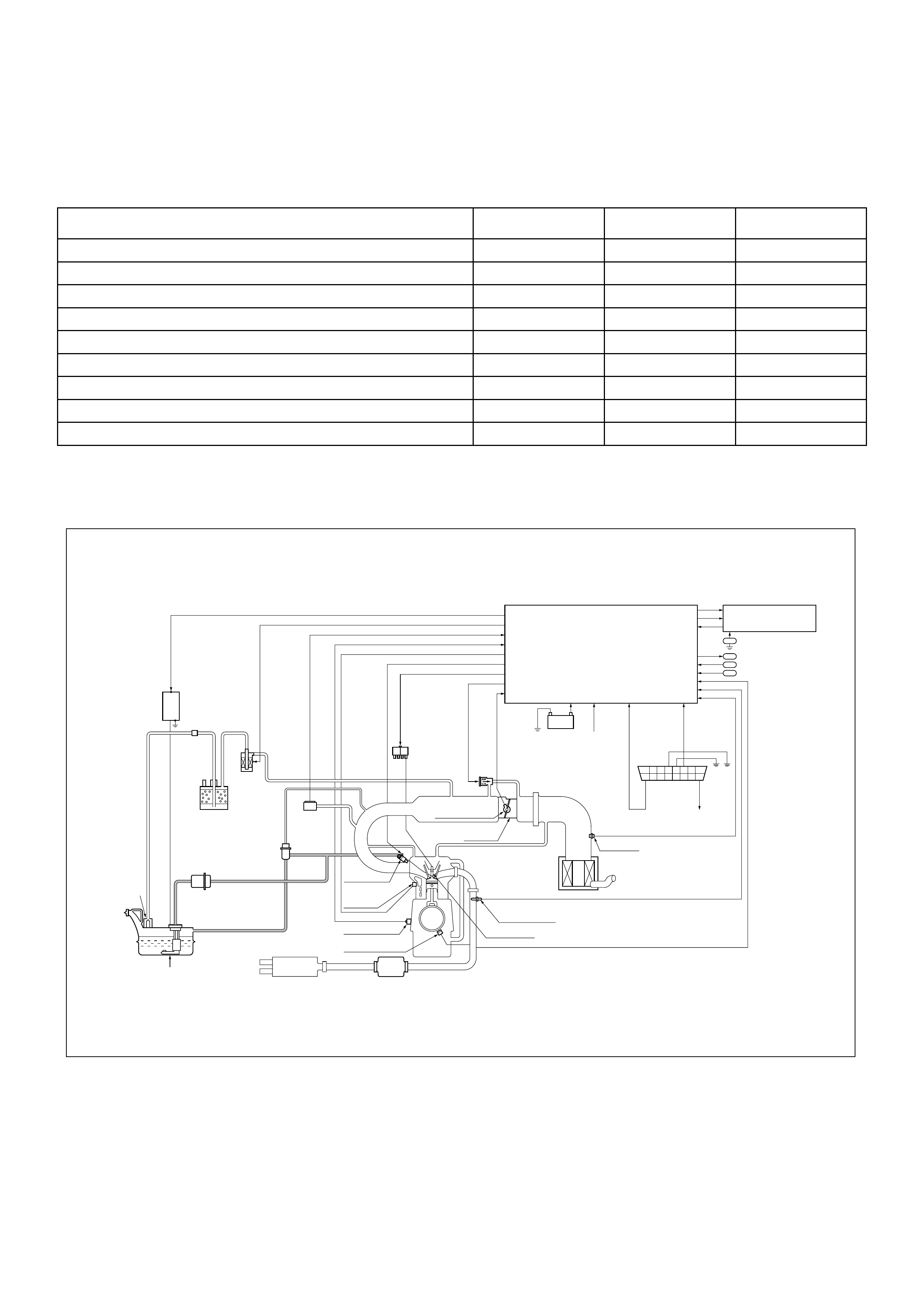
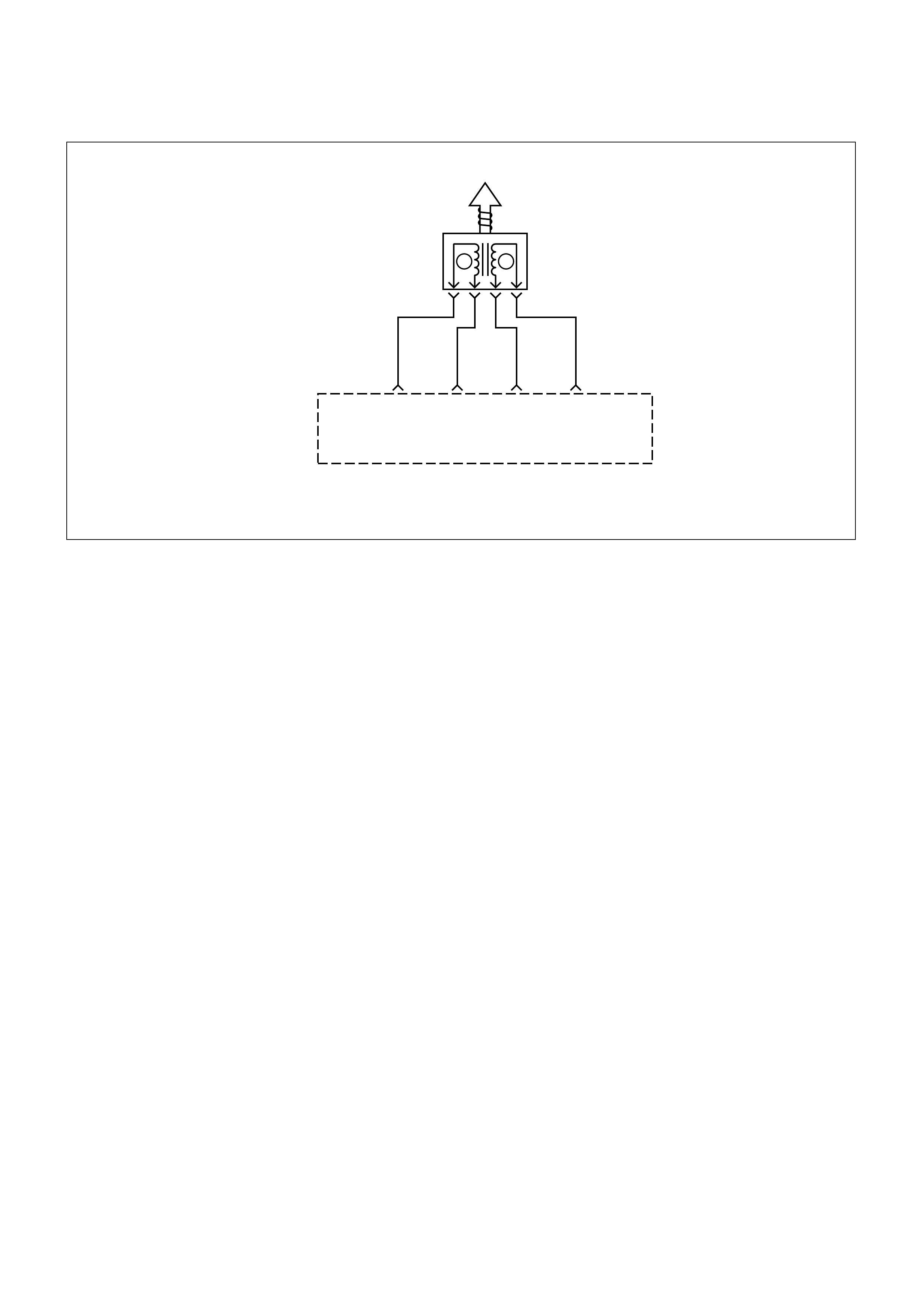
EMISSION CONTROL SYSTEM SCHEM ATICS
1
10 11 12 13 14 15 16
2345678
9
ROLL OVER&
FLOAT VALVE
FUEL PUMP
TWC CONVERTER
CRANKSHAFT
POSITION SENSOR
KNOCK SENSOR
COOLANT
TEMPERATURE
SENSOR
FUEL INJECTOR
MAP SENSOR
AIR CLEANER
HEATED
OXYGEN SENSOR
IGNITION PLUG
IAT SENSOR
THROTTLE
BODY
THROTTLE
POSITION SENSOR
IAC
VALVE
IGNITION
COIL
DUTY
SOLENOID
VALVE
CHARCOAL
CANISTER
FUEL PRESSURE
CONTROL VALVE
FUEL FILTER
FUEL PUMP
RELAY
CHECK VLV
BATTERY
+12V
IGUNITION
10A FUSE
(STOP)
DIAG
SDATA
DATA LINK
CONNECTOR
ENGINE CONTROL MODULE
METER CLUSTER
TACHO SIGNAL OUT
SPEED METER
VEHICLE SPEED SENSOR
A/C CLUTCH
A/C REQUEST
POWER STEERING SWITCH
MIL LAMP(CHECK ENGINE)
*
*
*
*
*
Refer to the matrix for engine specification, page 6A-11 thru 6A-17.
* If equipped.
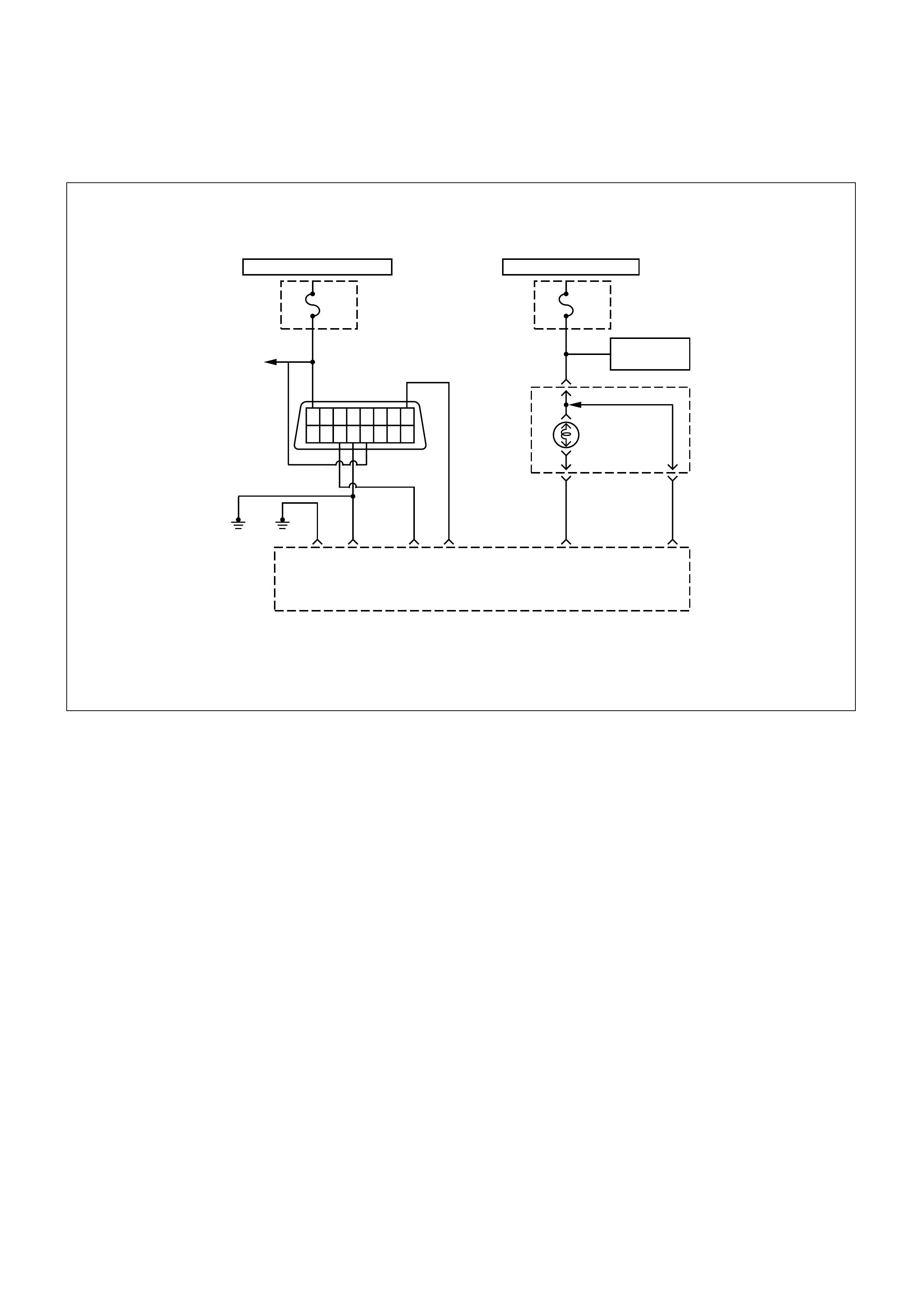
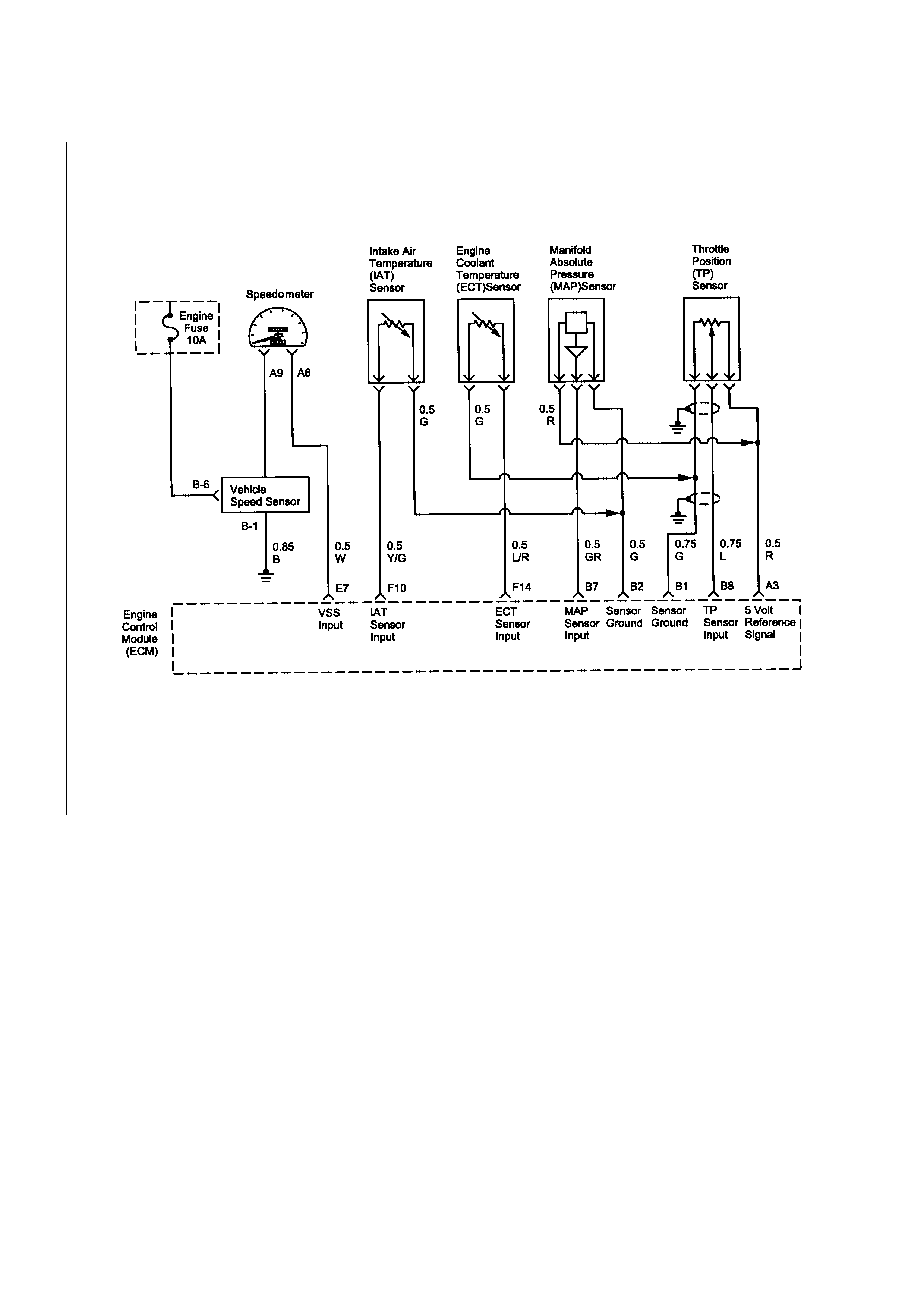
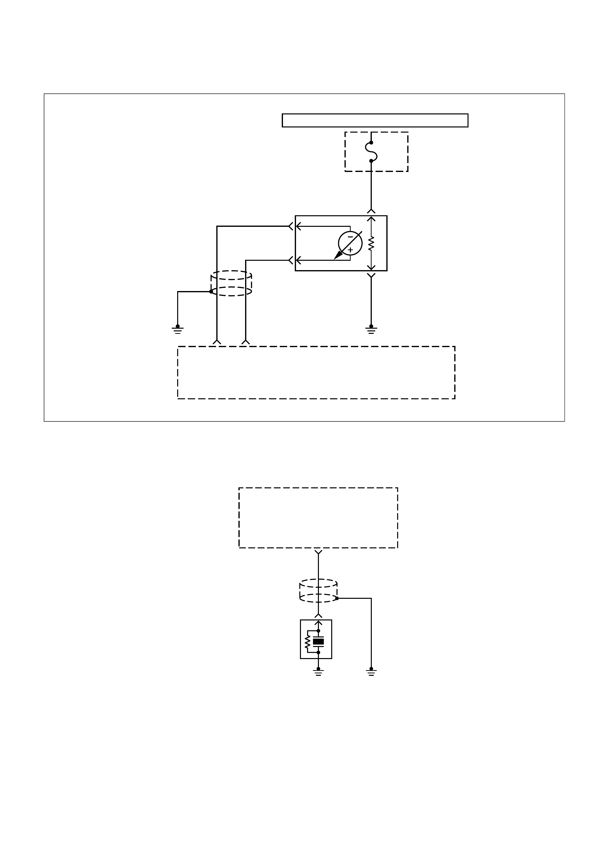
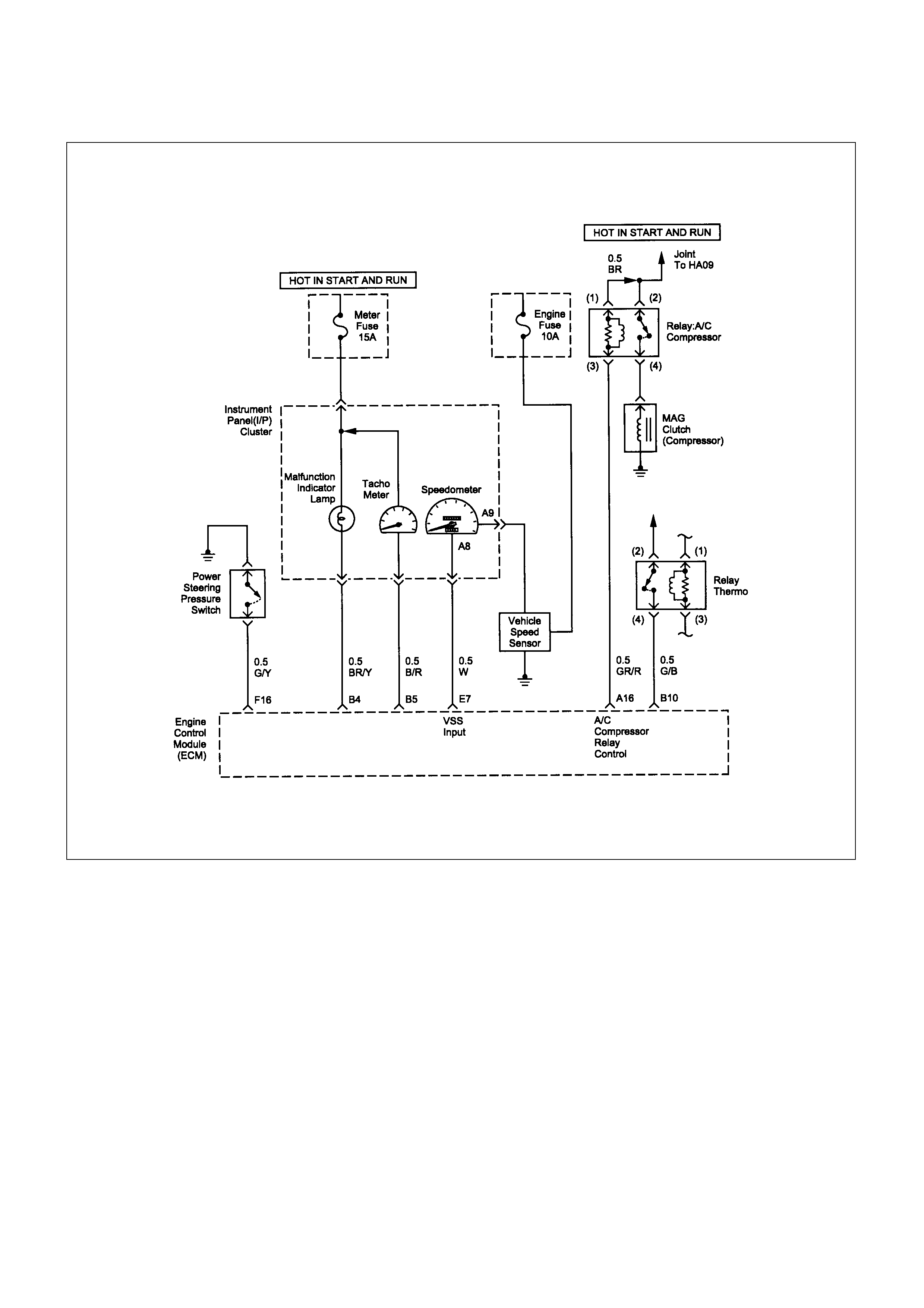
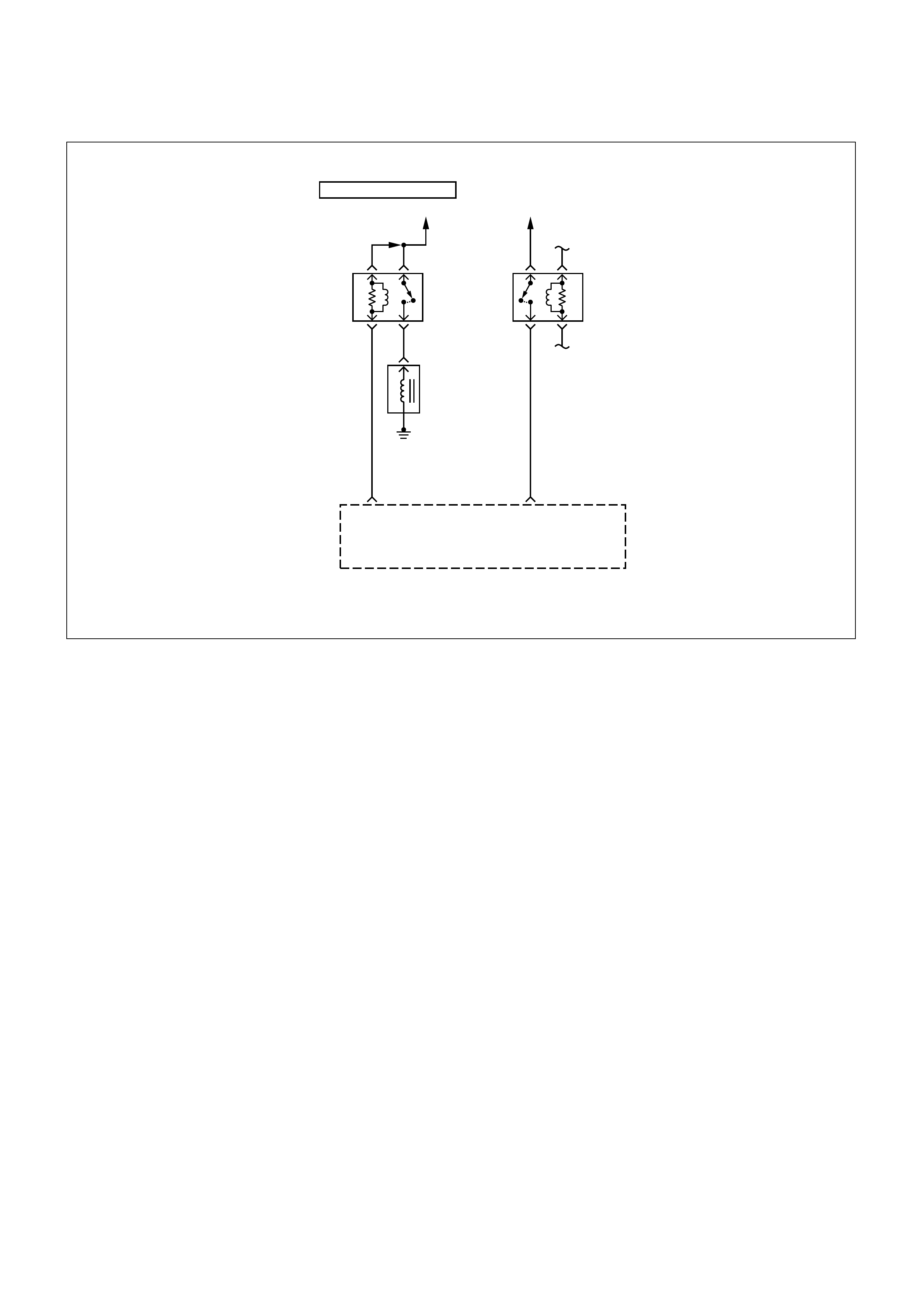
DIAGRAMS AND SCHEMATICS
16 15 14 13 12 11 10 9
87654321
HOT AT ALL TIMES
Fuse
Stop
U/H
FUSE
BLOCK
To
Stop
Lamp
Engine
Control
Module
(ECM)
R
A1 A2 B11 E8
B/R B/L B/W O
ECM
Grounds
(Engine Block)
Diag Serial Data
HOT IN START AND RUN
Meter
Fuse
15A
I/P
FUSE
BLOCK
Malfunction
Indicator
Lamp
0.85
YEL
Vehicle
Speed Sensor
0.5
BR/Y
Instrument
Panel(I/P)
Cluster
B4
Malfunction
Indicator
Lamp
Control
0.5
BR
B5
ECM
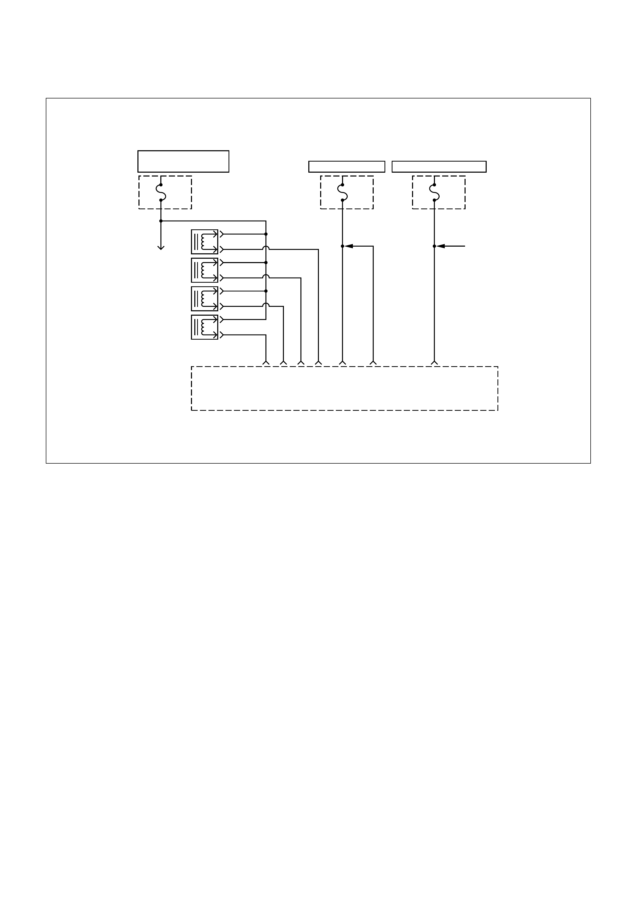
Fuse
15A
Engine
Fuse
10A
Canister
Purge
Solenoid
1.25
R/W
0.85G/W
2B/R
0.85G/R
0.85G/B
0.85G
1.25
R/W
0.85
L/Y
Fuel
Injector
Fuse
20A
Fuel
Pump
A4A6 A8 A9 A7 A5 E16
Fuel
Injector
Control
#4
A
B
#3
A
B
#2
A
B
#1
A
B
Engine
Control
Module
(ECM)
HOT WITH FUEL PUMP
RELAY ENERGIZED HOT AT ALL TIMES HOT IN RUN AND START
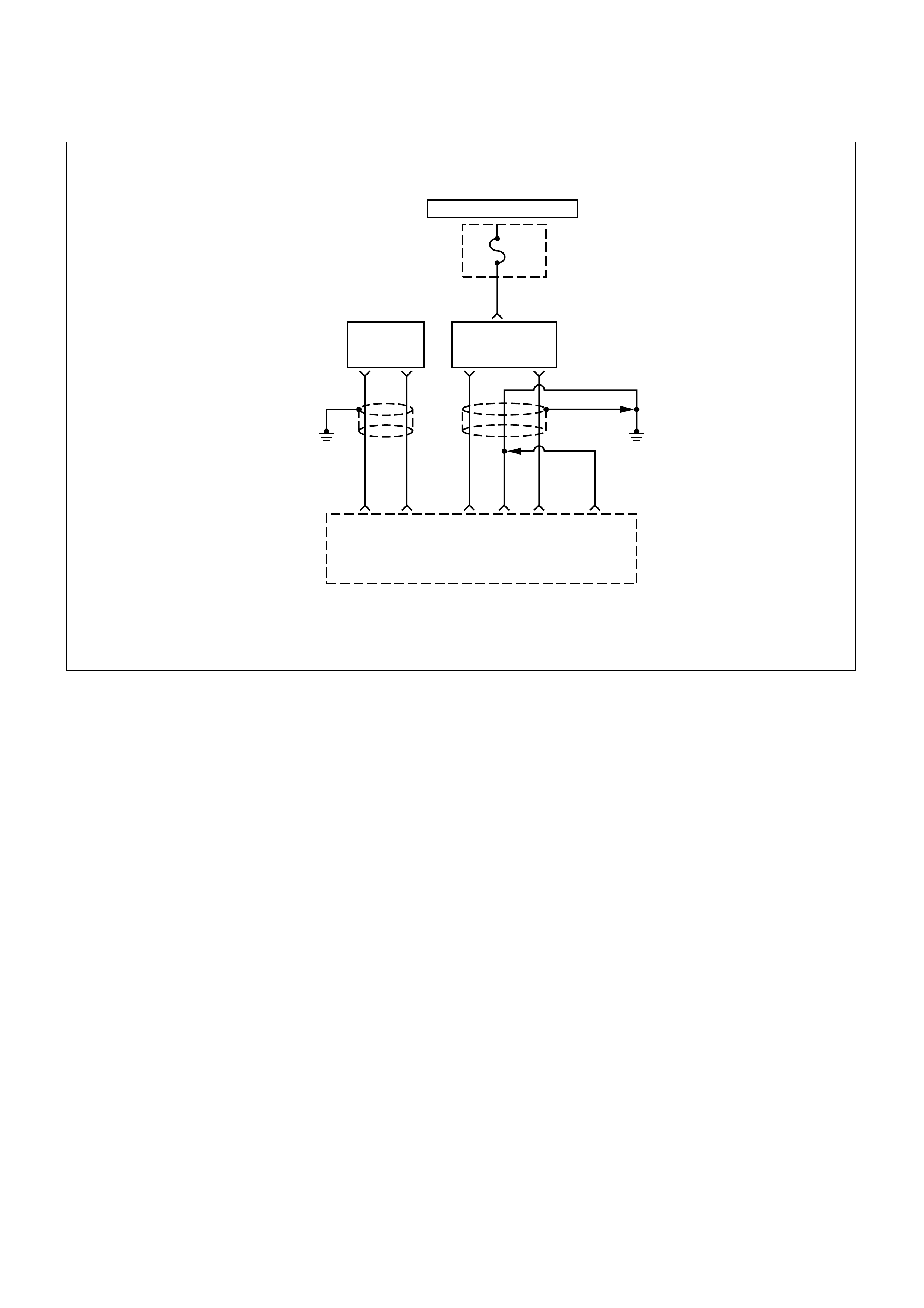
HOT IN START AND RUN
IG.
Coil
Fuse
15A
I/P
FUSE
BLOCK
0.85
B/O
Ignition
Coil
1.25
G
1.25
L
Engine
Control
Module
(ECM)
E1 E4 E3
Electronic Spark
Timing Control
1.25
B
1.25
B
E2
0.5
R
0.5
G
Crankshaft
Position
Sensor
F1
E5
HOT WITH FUEL PUMP RELAY ENERGIZED
O
2
Sensor
10A
U/H
FUSE
BLOCK
0.85
R/G
0.5
BLK
0.5
L
0.5WHT
0.5RED
0.5
P
0.5
BLK/
RED
Engine
Control
Module
(ECM)
O
2
Sensor
Low
O
2
Sensor
High
Heated
O
2
Sensor
(D)
(C)
F12 F15
(B)
(A)
(If Applicable)
0.5 YEL
0.5 YEL
Knock
Sensor
Input
Knock
Sensor
(KS)
F6
Engine
Control
Module
(ECM)
A/C
Compressor
Relay
Control
A16
MAG
Clutch
(Compressor)
Relay
Thermo
(1) (2)
(3) (4)
Relay:A/C
Compressor
Joint
To HA09
0.5
BR
0.5
GR/R
B10
0.5
G/B
HOT IN START AND RUN
(2) (1)
(4) (3)
Engine
Control
Module
(ECM)
Engine
Control
Module
(ECM)
B16
0.5
L
0.5
L/W
0.5
L/R
Idle Air
Control
(IAC)
Valve
0.5
L/B
B15
DCBA
B13 B14
IAC
A
High
IAC
A
Low
IAC
B
High
IAC
B
Low
A B
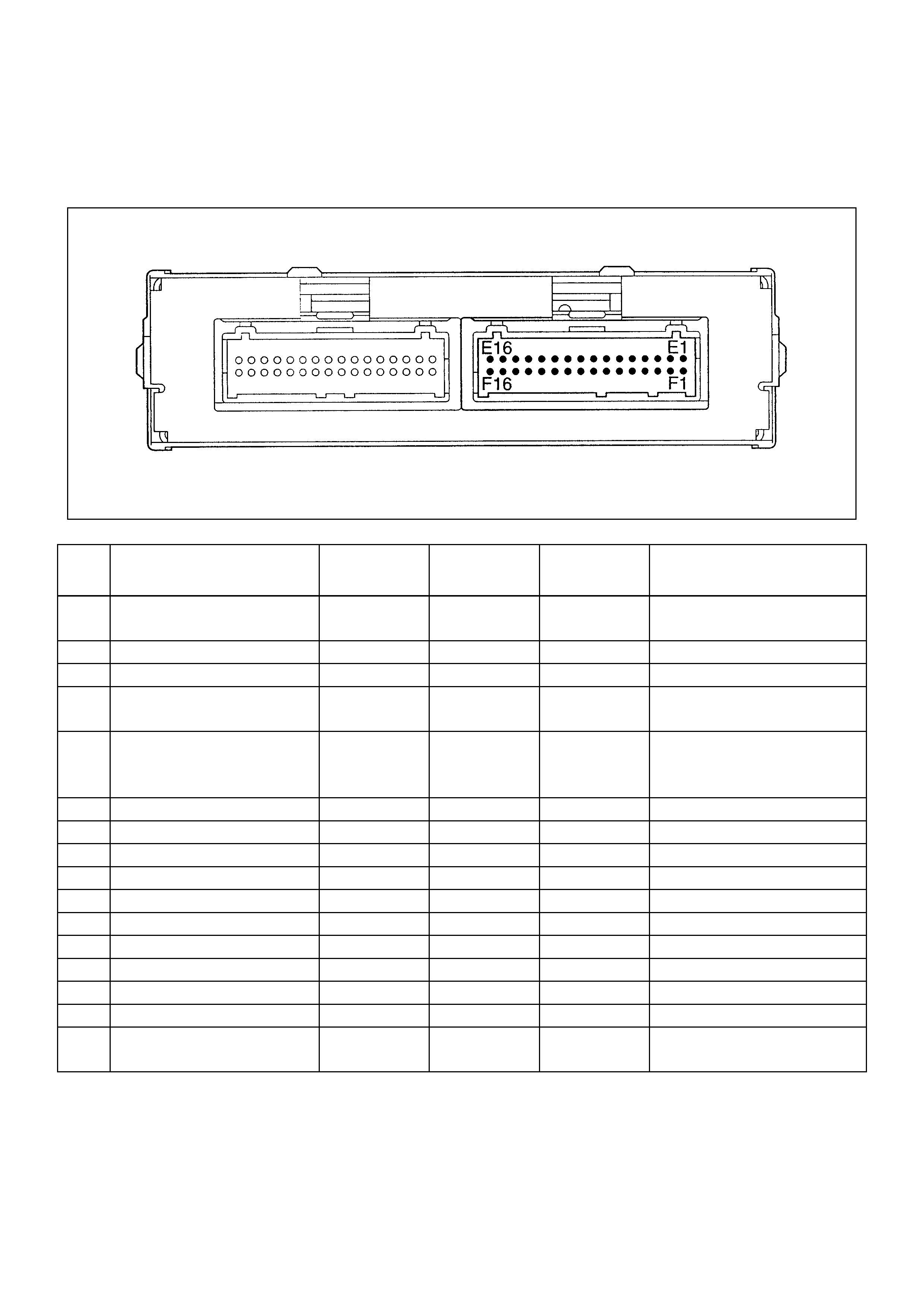
ECM PINOUTS
ECM PINO UT TABLE, 32- PIN BLUE CONNECTOR-RO W “J1”
PIN PIN FUNCTION WIRE
COLOR IGN ON ENG RUN REFER TO
E1 Electronic Spark Timing
Coil Driver A G 12V 14V -
E2 Coil Ground A B 0V 0V -
E3 Coil Ground B B 0V 0V -
E4 Electronic Spark Timing
Coil Driver B L 12V 14V -
E5 Crank Position Sensor High G 1V 1V General Description and
Operation, Crank Position
Sensor
E6 Not Used - - - -
E7 Vss Input W 9V 11V Chassis Electrical
E8 Serial Data R 5V 5V Serial Data
E9 Not Used - - - -
E10 Not Used - - - -
E11 Not Used - - - -
E12 Not Used - - - -
E13 Not Used - - - -
E14 Not Used - - - -
E15 Not Used - - - -
E16 Ignition Feed B/Y 12V 14V General Description and
Operation
ECM PINO UT TABLE, 32- PIN BLUE CONNECTOR-RO W “J1”
PIN PIN FUNCTION WIRE
COLOR IGN ON ENG RUN REFER TO
F1 Crankshaft Position Sensor
Low R 1V 1V General Description and
Operation, Crankshaft
Position Sensor
F2 Not Used - - - -
F3 Not Used - - - -
F4 Not Used - - - -
F5 Not Used - - - -
F6 Knock Sensor Input Y 0V 0V General Description and
Operation, Knock Sensor
F7 Not Used - - - -
F8 Not Used - - - -
F9 Not Used - - - -
F10 Intake Air Temperature
Sensor Y/G 2V 2V General Description and
Operation, IAT
F11 Not Used - - - -
F12 Heated O2 Sensor Low
(If applicable) - - - General Description and
Operation, Heated O2
Sensor
F13 Not Used - - - -
F14 Engine Coolant
Temperature L/R 2V
(0V=151°C) 3V
(5V=-40°C) General Description and
Operation, Engine Coolant
Temperature Sensor
F15 Heated O2 Sensor
(If applicable) L 1.0V 0V General Description and
Operation, Heated O2
Sensor
F16 Power Steering Pressure
Switch Input G/Y 12V 14V General Description and
Operation, PSP
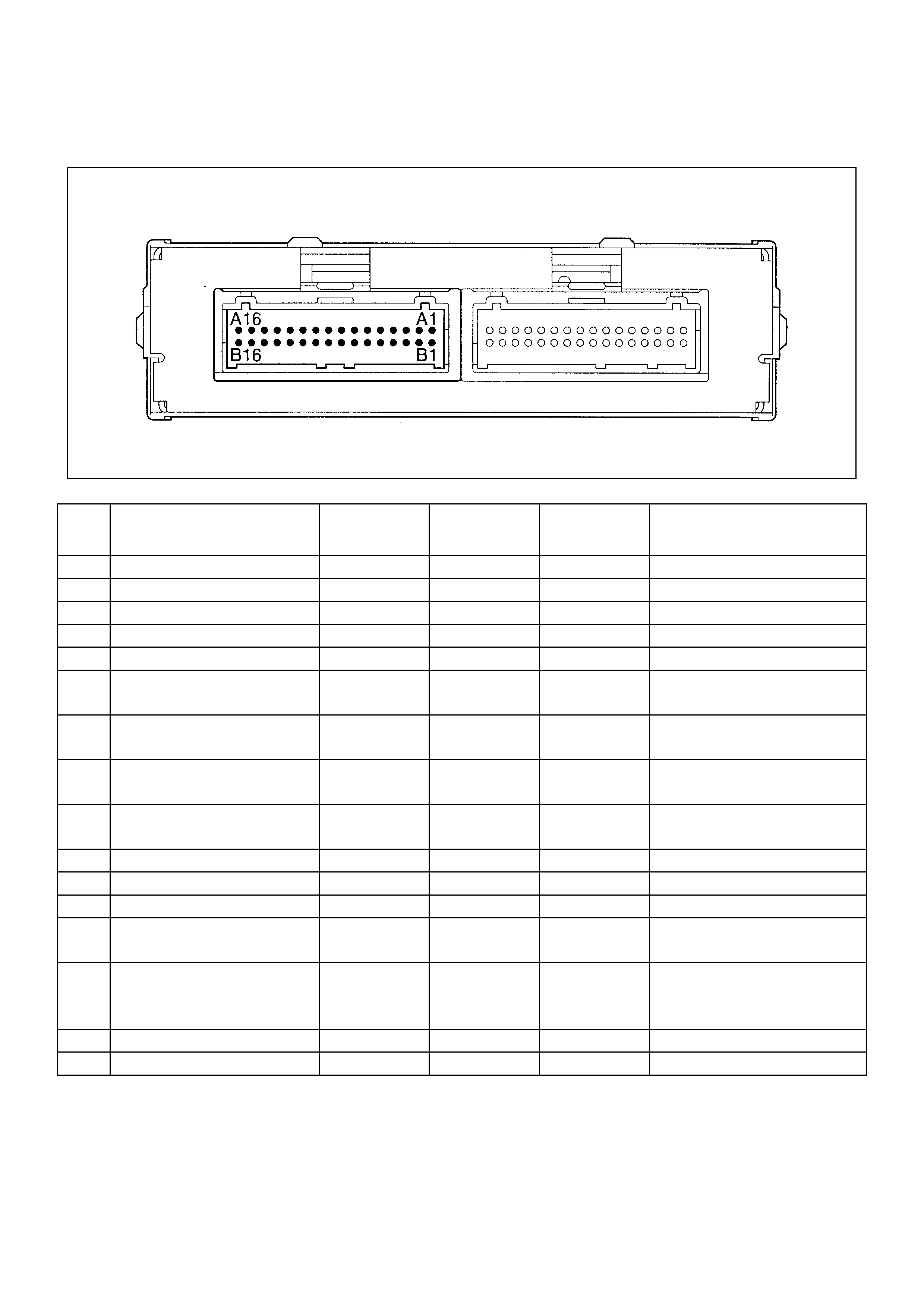
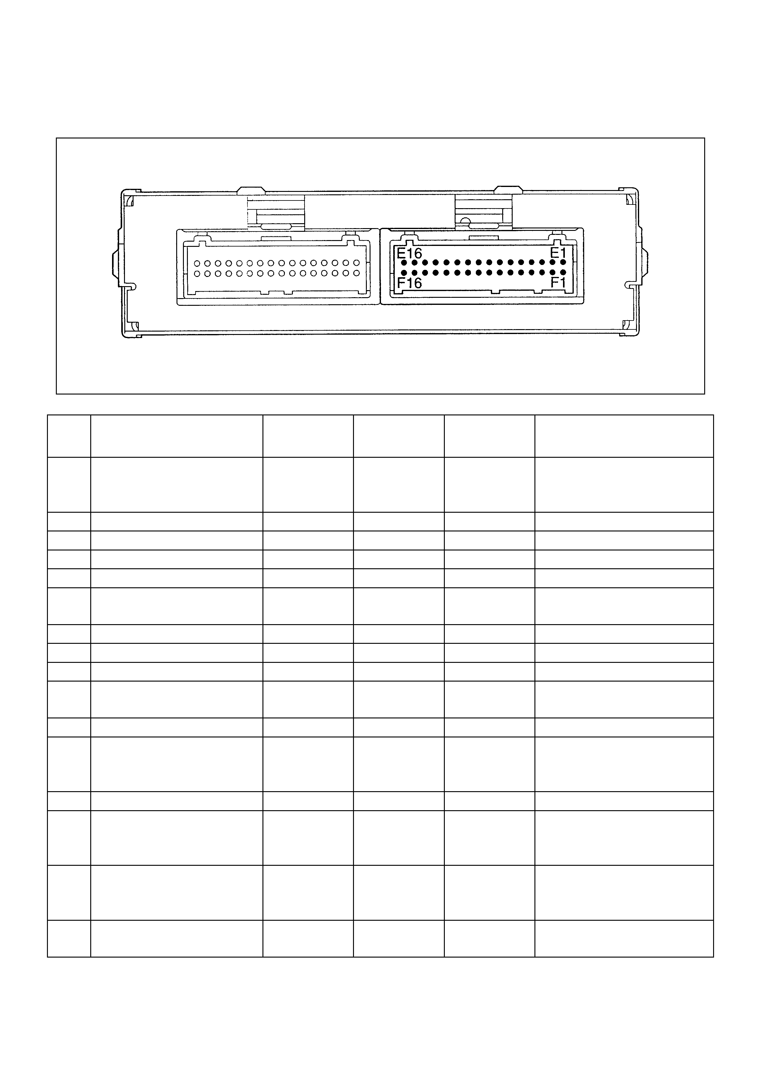
ECM PINO UT TABLE, 32- PIN RED CONNECTOR-RO W “J2”
PIN PIN FUNCTION WIRE
COLOR IGN ON ENG RUN REFER TO
A1 Power Ground A B/R 0.0V 0V Appropriate Sensor
A2 Sensor Ground B B/L 0.0V 0V Appropriate Sensor
A3 5 Volt Reference Signal R 5.0V 5V Appropriate Sensor
A4 Battery Feed R/W 12V 14V Chassis Electrical
A5 Battery R/W 12V 14V Chassis Electrical
A6 Injector #4 Cyl G 0V 14V General Description and
Operation, Fuel Injector
A7 Injector #1 Cyl G/W 0V 14V General Description and
Operation, Fuel Injector
A8 Injector #3 Cyl G/B 0V 14V General Description and
Operation, Fuel Injector
A9 Inject #2 Cyl G/R 0V 14V General Description and
Operation, Fuel Injector
A10 Not Used - - - -
A11 Not Used - - - -
A12 Not Used - - - -
A13 Fuel Pump Relay G/W 12V 0V On-Vehicle Service Fuel
Pump Relay
A14 Charcoal Canister Purge
Solenoid Valve
(If applicable)
R/L 12V 14V -
A15 Not Used - - - -
A16 A/C Clutch W/R 0V 0V -
ECM PINO UT TABLE, 32- PIN RED CONNECTOR-RO W “J2”
PIN PIN FUNCTION WIRE
CLOLR IGN ON ENG RUN RDFER TO
B1 TPS
5 Volt Reference Signal A G 0V 0V Appropriate Sensor
B2 TPS
5 Volt Reference Signal B G 0V 0V Appropriate Sensor
B3 Not Used - - - -
B4 Check Engine Lamp R/Y 0V 14V Chassis Electrical
B5 Tacho-meter Signal B/R 12V 8-10V General Description and
Operation
B6 Not Used - - - -
B7 Map Input W 5.0V
(0V=10kpa) 1.0V
(5V=104kpa) General Description and
Operation, Manifold Absolute
Sensor
B8 Throttle Position Sensor B 1.0V 1.0V General Description and
Operation, TPS
B9 Not Used - - - -
B10 A/C Request Signal G/B 0V 0V -
B11 DLC (Digital Input) B/W 12V 14V Diagnosis, Serial Data
B12 Not Used - - - -
B13 IAC ”B” High L/R 1V 1V General Description and
Operation, IAC
B14 IAC ”B” Low L/B 11V 13V General Description and
Operation, IAC
B15 IAC ”A” Low L/W 1V 1V General Description and
Operation, IAC
B16 IAC ”A” High L 11V 13V General Description and
Operation, IAC
COMP ONENT LOCATOR
HO2S(if applicable) THREE-WAY CATALYTIC CONVERTER
(if applicable)
VEHICLE
SPEED SENSOR
(VSS)
FUEL FILTER
THROTTLE POSITION SENSOR
MAP SENSOR
EVAP PURGE CONTROL
SOLENOID VALVE
FUEL INJECTOR
IGNITION COIL
KNOCK SENSOR
CRANKSHAFT POSITION SENSOR
HEATED
OXGEN
SENSOR
(if applicable)
THROTTLE BODY
IAC VALVE
AIR CLEANER
INTAKE AIR
TEMPERATURE
SENSOR

ENGINE CO MPONENT LOCATO R TABLE
NUMBER NAME LOCATION
1 Engine Coolant Temperature (ECT) Sensor Front of engine, next to the thermostat housing
2Heated Oxygen Sensor (HO2S) On the exhaust pipe, left side of engine,
immediately behind the exhaust manifold
3 Air Cleaner Left front the engine bay
4 Intake Air Temperature (IAT) Sensor On the intake air duct near the air cleaner
5 Positive Crankcase Ventilation (PCV) Port On the right front corner of the valve cover
6 Fuel Pressure Regulator On the rear end of the fuel rail
7 Throttle Body Between the intake air duct and the intake
manifold
8 Fuse/Relay Box Along the inside of the right fender
9 Throttle Position (TP) Sensor On the front of the throttle body
10 Idle Air Control (IAC) Valve Under the TP sensor
11 EVAP Canister Purge Control Solenoid On the intake manifold
12 Ignition Coil Above the starter motor
13 Manifold Absolute Pressure (MAP) Sensor Bolted to the front edge of the intake
manifold, under the fuel rail
*14 EVAP Canister On the left side Tire house
*15 Check and Relief valve On the canister hold brace
* If applicable
UNDERCARRI AGE COMPONENT LOCATOR TABLE
NAME LOCATION
Fuel Pump Assembly Installed in the top of the fuel tank
EVAP Purge Control Solenoid Valve At the right rear of the engine
Vehicle Speed Sensor (VSS) Protrudes from the right side of the transmission
housing, rear the output shaft
Crankshaft Position (CKP) Sensor Lower left hand front of engine, behind power steering
pump bracket
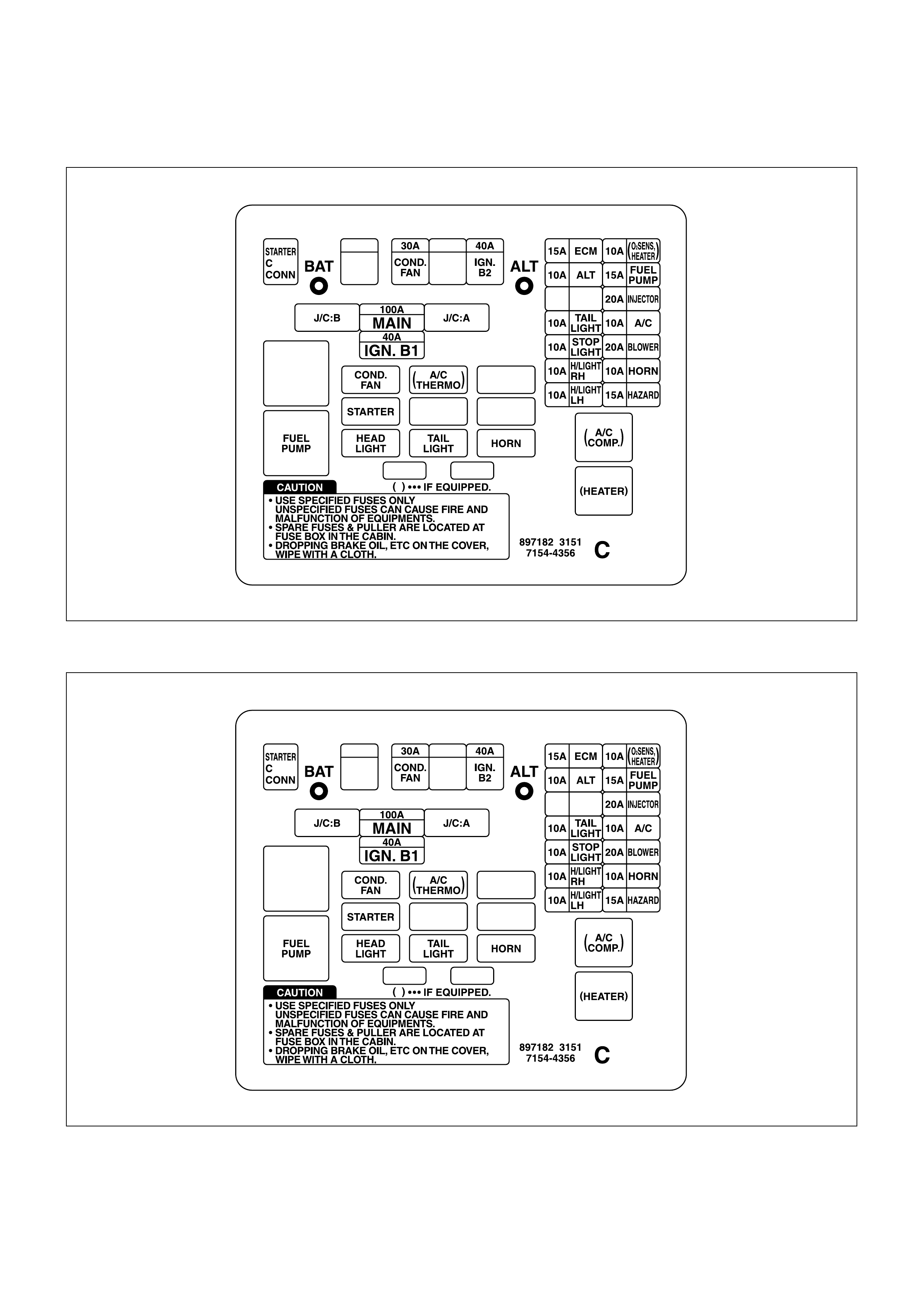
UNDERHOOD ( U/H) FUSE AND RELAY PANEL
INSTRUMENT PANEL (I/P) FUSE BLO CK

DIAGNOSIS
STRATEGY-BASED DIAGNO STICS
The strategy-based diagnostic is a uniform approach
to repair all Electrical/Electronic (E/E) systems. The
diagnostic flow can always be used to resolve an E/E
system problem and is a starting point when repairs
are necessary. The following steps will instruct the
technician how to proceed with a diagnosis:
1. Verify the customer complaint.
•To verify the customer complaint, the technician
should know the normal operation of the system.
2. Perform preliminary checks.
•Conduct a thorough visual inspection.
•Review the service history.
•Detect unusual sounds or odors.
•Gather diagnostic trouble code information to
achieve an effective repair.
3. Check bulletins and other service information.
•This includes videos, newsletters, etc.
4. Refer to service info (manual) system check(s).
•“System checks” contain information on a
system that may not be supported by one or
more DTCs. System checks verify proper
operation of the system. This will lead the
technician in an organized approach to
diagnostics.
5. Refer to service diagnostics.
DTC STORED
Follow the designated DTC chart exactly to make an
effective repair.
NO DTC
Select the symptom from the symptom tables. Follow
the diagnostic paths or suggestions to complete the
repair. You may refer to the applicable
component/system check in the system checks.
NO MATCHING SYM PTOM
1. Analyze the complaint.
2. Develop a plat for diagnostics.
3. Utilize the wiring diagrams and the theory of
operation.
Call technical assistance for similar cases where
repair history may be available. Combine technician
knowledge with efficient use of the available service
information.
INTERMITTENTS
Conditions that are not always present are called
intermittents. To resolve intermittents, perform the
following steps:
1. Observe DTCs and DTC modes
2. Evaluate the symptoms and the conditions
described by the customer.
3. Use a check sheet or other method to identify the
circuit or electrical system component.
4. Follow the suggestions for intermittent diagnosis
found in the service documentation.
Most Scan T ools, suc h as the Tech 2 and the 5-8840-
2392-0, have data-capturing capabilities that can
assist in detecting intermittents.
NO TROUBLE FOUND
This condition exists when the vehicle is found to
operate normally. The condition described by the
customer may be normal. Verify the customer
complaint against another vehicle that is operating
norm ally. T he condition may be intermittent. Verif y the
complaint under the conditions described by the
customer before releasing the vehicle.
1. Re-examine the complaint.
When the complaint cannot be successfully found
or isolated, a re-evaluation is necessary. The
complaint should be re-verified and could be
intermittent as defined in Intermittents, or could be
normal.
2. Repair and verify.
After isolating the cause, the repairs should be
made. Validate for proper operation and verify that
the symptom has been c orrec ted. T his m ay involve
road testing or other methods to verify that the
complaint has been resolved under the following
conditions:
•Conditions noted by the customer.
•If a DTC was diagnosed, verify a repair by
duplicating conditions present when the DTC
was set as noted in the customer complaint.

VERIFYING VEHICLE REPAIR
Verification of the vehicle repair will be more
comprehensive for vehicles with OBD system
diagnostics. Following a repair, the technician should
perform the following steps:
IMPORTANT: Follow the steps below when you verif y
repairs on O BD system s. Failure to f ollow these steps
could result in unnecessary repairs.
1. Review and record the customer complaint for the
DTC which has been diagnosed.
2. Clear the DTC(s).
3. Operate the vehicle within conditions noted in the
customer complaint.
4. Monitor the DTC status information for the specific
DTC which has been diagnosed until the diagnos tic
test associated with that DTC runs.
GENERAL SERVICE INFORMATION
OBD SERVICEABILITY ISSUES
FUEL QUALITY
Fuel quality is not a new issue for the automotive
industry. The Reed Vapor Pressure of the fuel can
also create problems in the fuel system, especially
during the spring and fall months when severe
ambient temperature swings occur. A high Reed
Vapor Pressure could show up as a rich DTC due to
excessive canister loading. High vapor pressures
generated in the fuel tank can also affect the
Evaporative Emission diagnostic as well.
Using fuel with the wrong octane rating for your
vehicle may cause driveability problems. Many of the
major fuel companies advertise that using “premium”
gasoline will improve the performance of your vehicle.
Most premium fuels use alcohol to increase the
octane rating of the fuel. Although alcohol-enhanced
fuels may raise the octane rating, the fuel's ability to
turn into vapor in cold tem peratures deteriorates. This
may affect the starting ability and cold driveability of
the engine.
Low fuel levels can lead to fuel star vation, lean engine
operation, and eventually engine misfire.
NON-O E M PARTS
All of the OBD diagnos tics have been c alibrated to run
with OEM parts. Small leaks in the exhaust system
near the heated oxygen sensor can also cause the
MIL (“Check Engine“ lamp) to turn on.
Aftermarket electronics, such as cellular phones,
stereos, and anti-theft devices, may radiate EMI into
the control s ystem if they are improper ly installed. T his
may cause a f alse sens or reading and turn on the MIL
(“Check Engine” lamp).
POOR VEHICLE MAINTENANCE
The sensitivity of OBD diagnostics will cause the MIL
(“Check Engine” lam p) to turn ON if the vehicle is not
maintained properly. Restricted air filters, fuel filters,
and crankcase deposits due to lack of oil changes or
improper oil viscosity can trigger actual vehicle faults.
Poor vehicle maintenance can not be classified as a
“non-vehicle fault” , but with the sensitivity of OBD
diagnostics, vehicle maintenance schedules must be
more closely followed.
RELATED SYSTEM FAULTS
Many of the OBD system diagnostic s will not run if the
ECM detects a fault on a related system or
component. One example would be that if the ECM
detected a Evap. Purge Solenoid fault, The diagnosis
on the Oxygen Sensor (If applicable) would be
suspended until the Evap. Purge Solenoid repaired. If
this happened, the customer may have to make two
trips to the dealership in order to repair the vehicle.
MAINTENANCE SCHEDULE
Refer to the Maintenance Schedule.
VISUAL /PHYSICAL ENGINE
CO MPARTMENT INSPECTION
Perform a careful visual and physical engine
compartment inspection when performing any
diagnostic procedure or diagnosing the cause of an
emis sion test failure. T his can of ten lead to repairing a
problem without further steps. Use the following
guidelines when performing a visual/thysical
inspection:
•Inspect all vacuum hoses for punches, cuts,
disconnects, and correct routing.
•Inspect hoses that are difficult to see behind other
components.
•Inspect all wires in the engine compartment for
proper connections, burned or chafed spots,
pinched wires, contact with sharp edges or contact
with hot exhaust manifolds or pipes.
BASIC KNOWLEDGE OF TOOLS
REQUIRED
Notice: Lack of basic knowledge of this powertrain
when perform ing diagnostic pr ocedures c ould result in
an incorrect diagnosis or damage to powertrain

components. Do not attempt to diagnose a powertrain
problem without this basic knowledge.
A basic understanding of hand tools is necessary to
effectively use this section of the Service Manual.
SERIAL DATA CO MMUNICATIONS
This vehicle utilizes the serial data communication
system. Each bit of information can have one of two
lengths: long or short. This allows vehicle wiring to be
reduced by transmitting and receiving multiple signals
over a single wire. The messages carried on serial
data streams are also prioritized. If two messages
attempt to establish communications on the data line
at the same time, only the message with higher prior ity
will continue. The device with the lower priority
message must wait. For more information on this
system of coding. On this vehicle the Scan
Tool displays the actual values for vehicle parameters.
It will not be necessary to perform any conversions
from coded values to actual values.
ON-BOARD DIAGNOSTIC (OBD)
ON-BO ARD DIAGNOSTIC TESTS
Miscellaneous Test:
A miscellaneous test is a kind of the On-Board
Diagnostics.
Using a tech 2, the miscellaneous test can be
conducted, followings are brief description about the
miscellaneous tests.
To perform the miscellaneous test, allows the
displayed menu on the tech 2. Sub-menu of
miscellaneous test are as follows.
•Check powertrain lamp:
This test allows to turn on and off the powertrain
warning lamp in the instrument cluster.
•Fuel Pump:
Fuel pump test allows to turn on and off the fuel
pump.
If turned off while the engine is running, the engine
will stall.
•A/C Clutch:
The A/C Clutch test allows to turn on and off the
airconditioning.
•Canister Purge Control Solenoid Valve:
This function takes control of the canister purge
control solenoid valve.
The on command represents a 100% pwm, the off
command a 0% pwm.
•IAC (Idle Air Control) System:
•RPM control
This function allows the user to slew the desired
RPM via increments of 25 RPM with a minimum
of 600 RPM and a maximum of 2000 RPM.
The start value will be at 1150 RPM.
•IAC Control
This function allows the user to slew the IAC via
increments of 25 steps with a minim um of 0 s teps
and a maximum of 250 steps.
The start value will be at idle steps.
•IAC Reset
The user will have the ability to perform an IAC
reset.
Each keypress will actuate the command to reset.
•Fuel Trim Reset:
This function allows the user to command the ECM
to perform an Long Term Fuel Trim reset, also
known as a Block Learn Memory reset.
Each keypress will actuate the command to reset.
•Fueling Mode:
This function provides the user with the ability to
enable or disable closed loop fuel control.
•Air Fuel Ratio:
This function allows the user to slew the control
state of the A/F ratio within a minimum of 11.7:1
and a maximum of 17.7:1.
The test starts at an A/F ratio of 14.7 : 1.
The incremental control is 0.5 steps per keypress.
COMPREHENSIVE COMP ONENT
MO NITOR DIAGNOSTIC
OPERATION
Comprehensive component monitoring diagnostics
are involved to monitor emissions-related input and
output engine components.
INPUT COMPONENTS
Input components are monitored for circuit continuity
and out-of-range values. This includes rationality
checking. Rationality checking refers to indicating a
fault when the signal from a sensor does not seem
reasonable, i.e. Throttle Position (TP) sensor that
indicates high throttle position at low engine loads or
MAP voltage). Input com ponents may include, but are
not limited to the following sensors:
•Vehicle Speed Sensor (VSS)
•Crankshaft Position (CKP) sensor
•Throttle Position (TP) sensor
•Engine Coolant Temperature (ECT) sensor

•Intake Air Temperature Sensor (IAT)
•Manifold Absolute Pressure (MAP) sensor
In addition to the circuit c ontinuity and rationality c hec k
the ECT sensor is m onitored for its ability to ac hieve a
steady s tate tem perature to enable “Clos ed Loop” fuel
control (If applicable).
OUTPUT CO MPONENTS
Output components are diagnosed for proper
response to control module commands. Components
where functional monitoring is not feasible will be
monitor ed f or c irc uit continuity and out-of-r ange values
if applicable.
Output components to be monitored include, but are
not limited to the following circuit:
•Idle Air Control (IAC) Motor
•EVAP Canister Purge Valve Solenoid
•A/C relays
•VSS output
•MIL control
Refer to ECM and Sensors in General Descriptions.
PASSI VE AND ACTIVE DIAGNOSTIC TESTS
A passive test is a diagnostic test which simply
monitors a vehicle system or component. Conversely,
an active test, actually tak es s ome sor t of action when
perfor m ing diagnostic functions , often in res ponse to a
failed passive test.
INTRUSIVE DIAGNOSTIC TESTS
This is any on-board test run by the Diagnostic
Management System which may have an effect on
vehicle performance or emission levels.
WARM -UP CYCLE
A warm-up cycle means that engine at temperature
must reach a minimum of 70°C(160°F) and rise at
least 22°C(40°F) over the course of a trip.
COMMON OBD TERMS
DIAGNOSTIC FOR CLOSED LOOP SYSTEM
When used as a noun, the word diagnostic refers to
any on-board test run by the vehicle's Diagnostic
Management System . A diagnostic is sim ply a test run
on a system or component to determine if the system
or component is operating according to specification.
FOR CLOSED LO OP SYSTEM
There are many diagnostics, shown in the following
list:
•Oxygen sensors
•Oxygen sensor heaters
ENABLE CRITERI A
The term “enable criteria” is engineering language for
the conditions necessary for a given diagnostic test to
run. Each diagnostic has a specific list of conditions
which must be met before the diagnostic will run.
“Enable criteria” is another way of saying “conditions
required” .
The enable criteria for each diagnostic is listed on the
first page of the DTC description under the heading
“Conditions for Setting the DTC” . Enable criteria
varies with each diagnostic, and typically includes, but
is not limited to the following items:
•engine speed
•vehicle speed
•ECT
•MAP
•IAT
•TP
•high canister purge (If applicable)
•A/C ON
TRIP
Technically, a trip is a key on-run-key off cycle in
which all the enable criteria for a given diagnostic are
met, allowing the diagnostic to run. Unfortunately, this
concept is not quite that simple. A trip is official when
all the enable criteria for a given diagnostic are met.
But because the enable criteria vary from one
diagnostic to another, the definition of trip varies as
well. Some diagnostics are run when the vehicle is at
operating temperature, some when the vehicle first
start up; som e requir e that the vehicle be c ruising at a
steady highway speed, some run only when the
vehicle is at idle. Som e run only im mediately following
a cold engine start-up.
A trip then, is defined as a key on-run-key off cycle in
which the vehicle was operated in such a way as to
satisfy the enabled criteria for a given diagnostic, and
this diagnostic will consider this cycle to be one trip.
However, another diagnostic with a different set of
enable criteria (which were not m et) during this driving
event, would not consider it a trip. No tr ip will occ ur f or
that particular diagnostic until the vehicle is driven in
such a way as to meet al the enable criteria
THE DIAGNOSTIC EXECUTIVE
The Diagnostic Executive is a unique segment of
software which is des igned to coordinate and prioritize
the diagnostic procedures as well as define the
protocol f or recording and displaying their r esults. T he
main responsibilities of the Diagnostic Executive are
listed as follows:
•Commanding the MIL(“Check Engine” lamp) ON
and OFF
•DTC logging and clearing
•Current status information ON each diagnostic
The Diagnos tic Exec utive records DT Cs and tur ns ON
the MIL when em is sion- related f aults oc c ur. It c an als o
turn OFF the MIL if the conditions c ease which c aus ed
the DTC to set.
DIAGNOSTIC INFORMATION
The diagnostic charts and functional checks are
designed to locate a faulty circuit or component
through a process of logical decisions. The charts are
prepared with the requirement that the vehicle
functioned correctly at the time of assembly and that
there are not multiple faults present.
Ther e is a continuous self -diagnosis on certain control
functions. This diagnostic capability is complimented
by the diagnos tic proc edur es contained in this manual.
The language of communicating the source of the
malfunction is a system of diagnostic trouble codes.
When a malf unc tion is detec ted by the control m odule,
a diagnostic trouble code is set and the Malfunction
Indicator Lamp (MIL)(“Check Engine” lamp) is
illuminated.
MALFUNCTION INDICATOR LAMP (MI L)
The Malfunction Indicator Lamp (MIL) looks the same
as the MIL you are already familiar with (“Check
Engine” lamp).
Basically, the MIL is turned ON when the ECM detects
a DTC.
EXTINGUISHING THE MIL
The MIL (“Check Engine” lamp) is on the instrument
panel and has the following functions:
•It informs the driver that a fault that affects vehicle
emission levels has occurred and that the vehicle
should be taken for service as soon as possible.
•As a bulb and system check, the MIL will come on
with the key on and the engine not running. When
the engine is started, the MIL will turn OFF.
•When the MIL remains on while the engine is
running, or when a malfunction is suspected due to
a driveability or emissions problem, a Powertrain
On-Board Diagnostic (OBD) System Check must be
performed. The procedures for these checks are
given in On-Board Diagnostic (OBD) System
Check. These checks will expose faults which may
not be detected if other diagnostics are performed
first.
Once the ECM determines that a fault(s) has been
rectified then the MIL will switch OFF, although the
fault code will remain in the ECM memory.
Any fault codes will remain in ECM memory until -
1. They are cleared by disconnecting the Battery for
more than 30 seconds.
2. A service tool such as Tech 2 is used to clear them.
3. Ten consecutive starts without logging a fault.
Refer to clearing Diagnostic Trouble Code
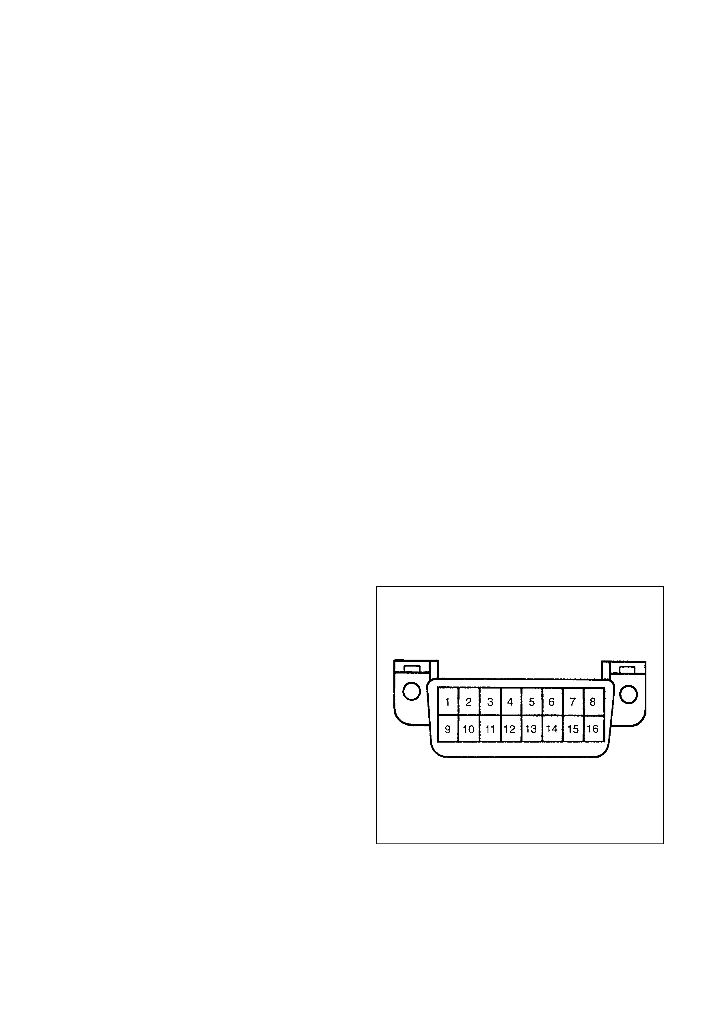
DATA LINK CONNECTOR (DLC)
The Provision for communicating with the control
module is the Data Link Connector ( DLC). It is located
at the lower left of the instrum ent panel behind a s m all
square cover. The DLC is used to connect to a Scan
Tool. Some comm on uses of the Scan Tool are listed
below:
•Identifying stored Diagnostic Trouble Codes (DTCs)
•Clearing DTCs
•Performing output control tests
•Reading serial data

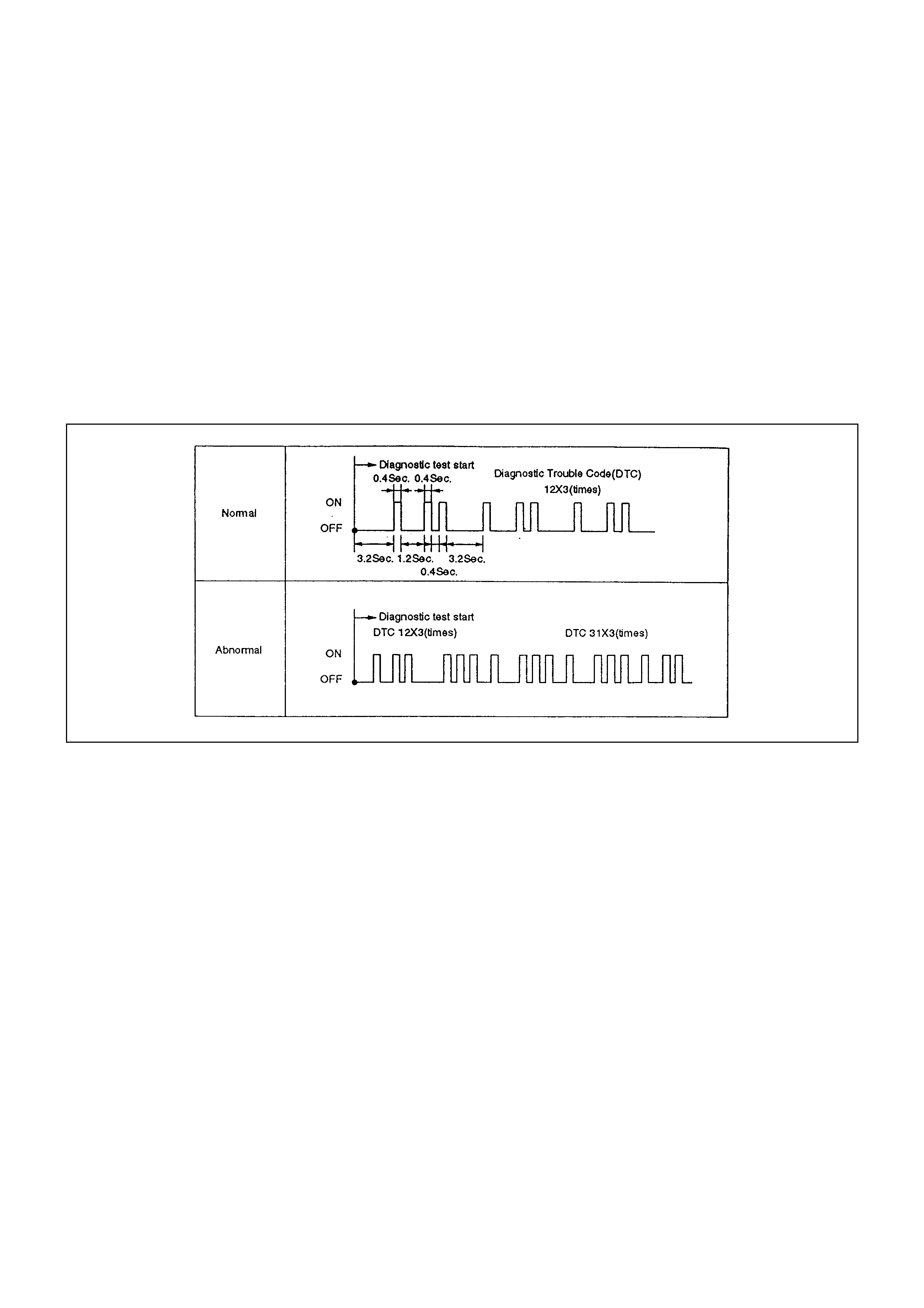
READING FLASH DIAGNOSTIC TROUBLE
CODES
The provision for communicating with the Engine
Control Module (ECM) is the Data Link Connector
(DLC). The DLC is located behind the lower front
instrument panel. It is used in the assembly plant to
receive information in checking that the engine is
operating properly before it leaves the plant.
The diagnostic trouble code(s) (DTCs) stored in the
ECM’s memory can be read either through a hand-
held diagnostic scanner plugged into the DLC or by
counting the number of f lashes of the ”Check Engine”
Malfunction lndicator Lamp (MIL) when the diagnostic
test terminal of the DLC is grounded. The DLC
terminal ”6” (diagnostic request) is pulled ”Low”
(grounded) by jumpering to DLC ter m inal ”5”, Whic h is
a ground wire.
This will signal the ECM that you want to ”flash”
DTC(s ), if any are pr esent. Once term inals ”5” and ”6”
have been connected, the ignition switch must be
moved to the ”ON” position, with the engine not
running. At this point, the ”Check Engine” MIL should
flash DTC12 three times consecutively.
This would be the following flash, sequence: ”flash,
pause, flash-flash, long pause, flash, pause, flash-
flash, long pause, flash, pause, flash-flash”. DTC12
indicates that the ECM’s diagnostic system is
operating. If DTC12 is not indicated, a problem is
present within the diagnostic system itself, and should
be addressed by consulting the appropriate diagnos tic
chart in DRIVEABILITY AND EMISSIONS.
Following the output of DTC12, the ”Check Engine”
MIL will indicate a DTC three times if a DTC is
present, or it will simply continue to output DTC12. If
more than one DTC three has been stored in the
ECM’s memory, the DTC(s) will be output from the
lowest to the highest, with each DTC being displayed
three times.
READING DIAGNOSTIC TROUBLE CODES
USING A TECH 2
The procedure for reading diagnostic trouble code(s)
is to used a diagnostic Tech 2. When r eading DTC(s ),
follow instructions supplied by Tech 2 manufacturer.
CLEARI NG DIAGNOSTIC TROUBLE CODES
IMPORTANT: Do not clear DTCs unless directed to
do so by the service information provided for each
diagnostic procedure.
If the fault that caused the DTC to be stored into
mem ory has been correc ted, the Diagnostic Executive
will begin to count the ”warm -up” c ycles with no further
faults detected, the DTC will automatically be cleared
from the ECM memory.
To clear Diagnostic Trouble Codes (DTCs), use the
Tech 2 ”clear DTCs” or ”clear information” function.
When clearing DTCs follow instructions supplied by
the Tech 2 manufacturer.
When a Tech 2 is not available, DTCs can also be
cleared by disconnecting one of the following sources
for at least thirty (30) seconds.
NOTE: To prevent system damage, the ignition key
must be ”OFF” when disconnecting or reconnecting
battery power.
•The power sour ce to the contr ol m odule. Exam ples :
fuse, pigtail at battery ECM connectors etc.
•The negative battery cable. (Disconnecting the
negative battery cable will result in the loss of other
on-board memory data, such as preset radio
tuning).
ON-BO ARD DIAGNO SIS (SELF-DIAG NOSIS)
1. The Engine Control Module (ECM) conducts a self-
test of most of the wiring and components in the
system each tim e the key is turned to ON, and can
detect faults in the system while the key is ON. If a
fault is detected, the ECM will store a trouble code
in mem ory and flash the CHECK ENGINE indicator
to alert the driver.
2. The Diagnostic Trouble Codes (DTC) can be
displayed by shorting together terminals and of the
Data Link Connector (DLC) located behind front
console.
The CHECK ENGINE indicator will flash DTC 12
three times, followed by any DTC. If several DTC
are stored, each DTC will be displayed three times.
The DTC will be displayed in numerical order. The
DTC display will continue as long as the DLC is
shorted.
Some DT C can cause other DTC to be stored, It is
important to diagnose and repair the lowest
numbered DTC first before going on to the higher
numbered DTC.
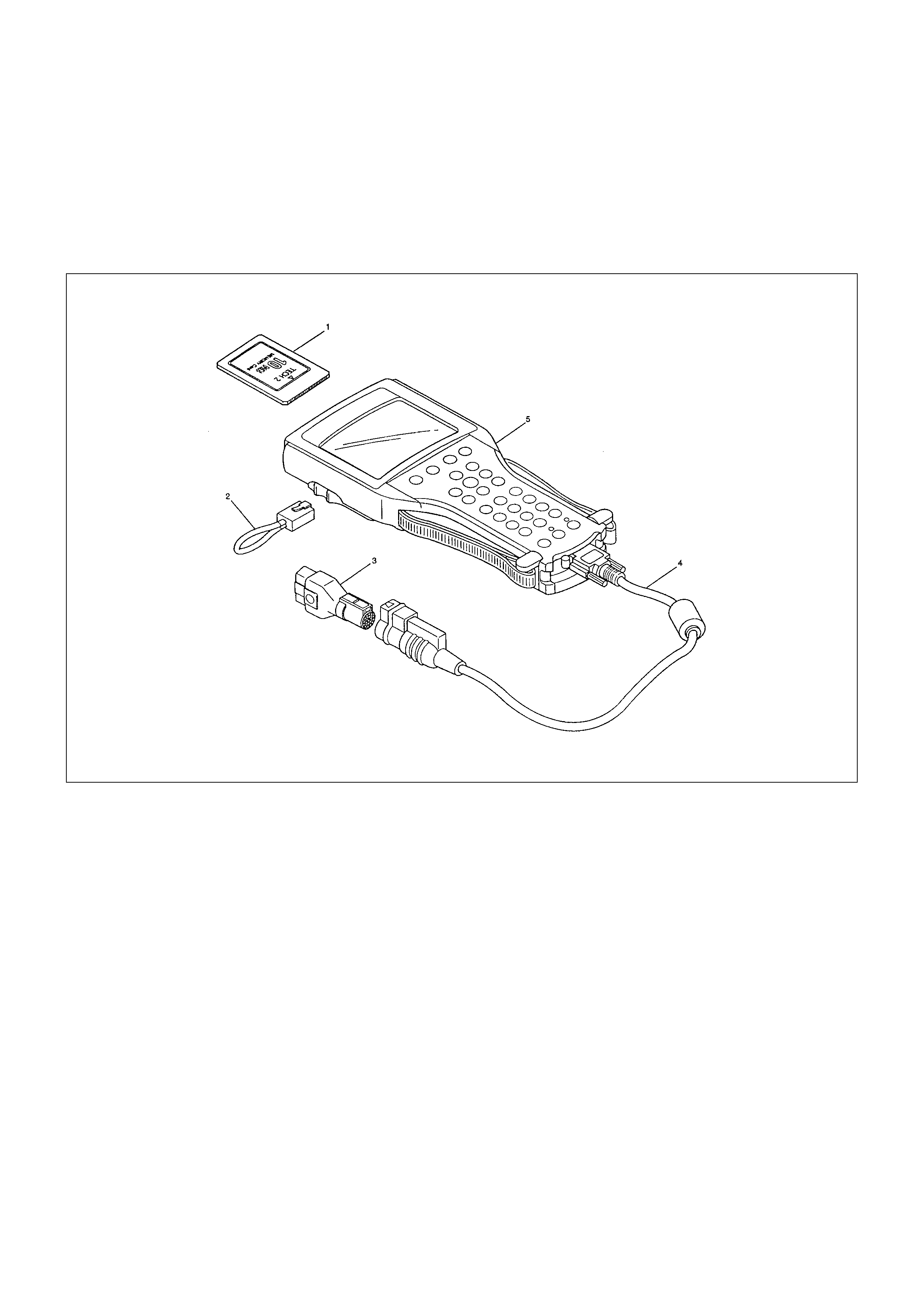
TECH 2 SCAN TOOL
From 98 MY, Isuzu dealer service departments are
recommended to use Tech 2. Please refer to Tech 2
user guide.
LEGEND
(1) PCMCIA Card
(2) RS 232 Loop Back Connector (3) SAE 16/19 Adaptor
(4) DLC Cable
(5) Tech-2
GE TTING STARTED
•Before operating the Isuzu PCMCIA card with the
Tech 2, the following steps must be performed:
1. The Is uzu 98 System PCMCIA c ard (1) inserts into
the Tech 2 (5)
2. Connect the SAE 16/19 adapter (3) to the DLC
cable (4).
3. Connect the DLC cable to the Tech 2 (5)
4. Make sure the vehicle ignition is off.
5. Connect the Tech 2 SAE 16/19 adapter to the
vehicle DLC.
6. The vehicle ignition turns on.
7. Verify the Tech 2 power up display.
NOTE: The RS232 Loop back connector is only to use
for diagnosis of Tech 2 and refer to user guide of the
Tech 2.
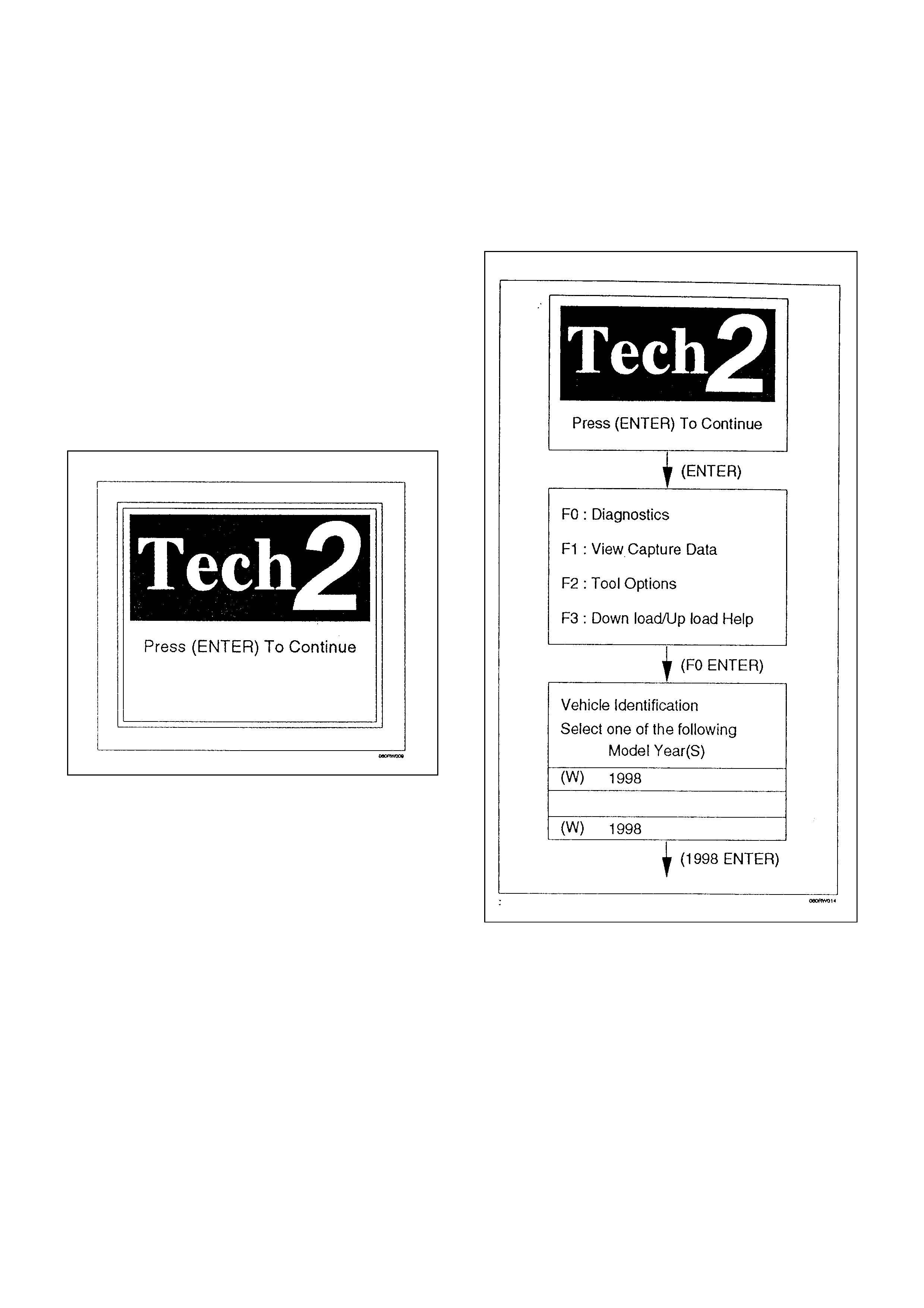
OPERATING PROCEDURE
The power up sc reen is displayed when you power up
the tester with the Isuzu systems PCMCIA card.
Follow the operating procedure below.
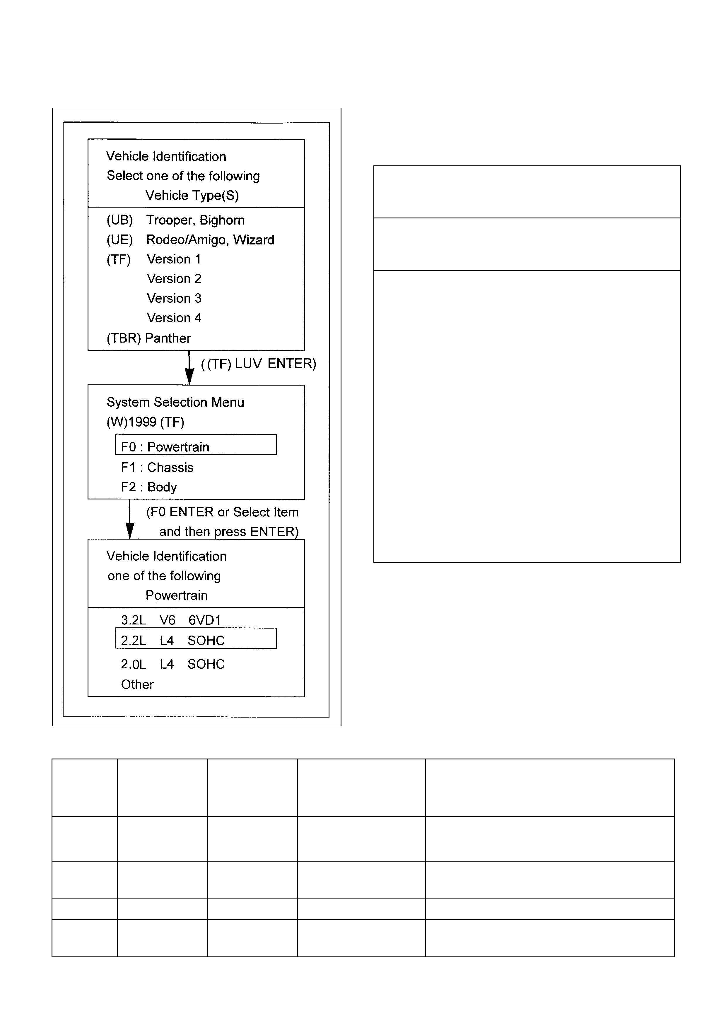
MENU
•The following table shows, the Tech 2 menu
structure.
F0: Diagnostic Trouble Codes
F0: Read DTC Info Ordered By Priority
F1: Clear DTC Information
F1: Data Display
F0: Engine Data
F2: O2 Sensor Data
F2: Snapshot
F3: Miscellaneous Tests
F0: Engine Check Light
F1: Relays
F1: A/C Relay
F2: Fuel Pump Relay
*F3: Low Fan Replay
*F4: High Fan Replay
F2: Canister Purge Solenoid
F3: IAC System
F1: RPM Control
F2: IAC Control
F3: IAC Reset
F4: Fuel System
F1: Fuel Trim Reset
F2: Fueling Mode
F7: Air Fuel Ratio
Note : *F3 & F4 not applicable to TF models
Note: Selection Table
Appricable
Version Engine
Displacement Compression
Ratio Fuel Octane No.
(RON)
Destination
*Shows w/canister for EVAP. Emission
control
Version 1 2.2L 8.6 80 Leaded/Un-
Leaded
*Ecuador, *Gulf, China, Egypt, Kenya,
Nigeria and Philippine
Version 2 2.2L 9.2 85 Leaded/Un-
Leaded Chile, Colombia, Guatemala and Costarica
Version 3 2.2L 9.2 91 Un-Leaded *Australia, *New Zealand and South Africa
Version 4 2.0L 8.8 91 Leaded/Un-
Leaded South Africa

VERIFYING VEHICLE REPAIR
Verification of vehicle repair will be more
comprehensive for vehicles with OBD system
diagnostics. Following a repair, the technician should
perform the following steps:
1. Review and record the customer complaint for the
DTC which has been diagnosed.
2. Clear DTC(s).
3. Operate the vehicle within conditions noted in the
customer complaint.
4. Monitor the DTC status information for the specific
DTC which has been diagnosed until the diagnos tic
test associated with that DTC runs.
Following these steps are very important in verifying
repairs on OBD systems. Failure to follow these steps
could result in unnecessary repairs.
READING DI AGNOSTIC TROUBLE
CODES USING A SCAN TOOL
The procedure for reading diagnostic trouble code(s)
is to use a diagnostic Scan Tool. When reading
DTC(s), follow instructions supplied by tool
manufacturer.
CLEARI NG DIAGNOSTIC TROUBLE CODES
IMPORTANT: Do not clear DTCs unless directed to
do so by the service information provided for each
diagnostic procedure.
If the fault that caused the DTC to be stored into
mem ory has been correc ted, the Diagnostic Executive
will begin to count the “warm -up” c ycles with no further
faults detected, the DTC will automatically be cleared
form the ECM memory.
To clear Diagnostic Trouble Codes (DTCs), use the
diagnostic Scan Tool “clear DTCs” or “clear
information” function. When clearing DTCs follow
instructions supplied by the tool manufacturer.
W hen a Scan T ool is not available, DT Cs can als o be
cleared by disconnecting one of the following sources
for at least thirty (30) seconds.
Notice: To prevent system damage, the ignition key
must be OFF when disconnecting or reconnecting
battery power.
•The power sour ce to the contr ol m odule. Exam ples :
fuse, pigtail at battery ECM connectors etc.
•The negative battery cable. (Disconnecting the
negative battery cable will result in the loss of other
on-board memory data, such as preset radio
tuning).
DTC MODES
There are 2 options available in the Scan Tool DTC
mode to display the enhanced information available.
After selecting DTC, the following menu appears:
•DTC Info
•Clear DTC Info
The following is a brief description of each of the sub
menus in DTC Info and Specific DTC. The order in
which they appear here is alphabetical and not
necessarily the way they will appear on the Scan Tool.
DTC INFORMATION MODE
Use the DTC info mode to search for a stored DTC
Refer to “Diagnostic Trouble Codes” list.
CLEAR DTC INFORMATIO N
The command for clearing DTC’s performs a
complete reset of the ECM.
PRIMARY SYSTEM-BASED
DIAGNOSTICS
There are primary system-based diagnostics which
evaluate system operation and its effect on vehicle
emissions. T he primary system-based diagnostics are
listed below with a brief description of the diagnostic
function:
FUEL CONTROL HEATED OXYGEN
SENSORS (IF APPLICABLE)
The main function of the fuel control heated oxygen
sensors is to provide the control module with exhaust
stream oxygen content information to allow proper
fueling and maintain emissions within mandated
levels. After it reaches operating temperature, the
sensor will generate a voltage, inversely proportional
to the amount of oxygen present in the exhaus t gas es.
The control module uses the signal voltage from the
fuel control heated oxygen sensors while in “Closed
Loop” to adjust fuel injector pulse width. While in
“Closed Loop” , the ECM can adjust fuel delivery to
maintain an air/fuel ratio which allows the best
combination of emission control and driveability. The
fuel control heated oxygen sensors are also used to
determine catalyst efficiency.

HO2S HEATER
Heated oxygen sensors are used to minimize the
amount of time requir ed for “Closed Loop” fuel contr ol
to begin operation and to allow accurate catalyst
monitoring. The oxygen sensor heater greatly
decreases the amount of tim e required for fuel control
sensor (HO2S) to become active.
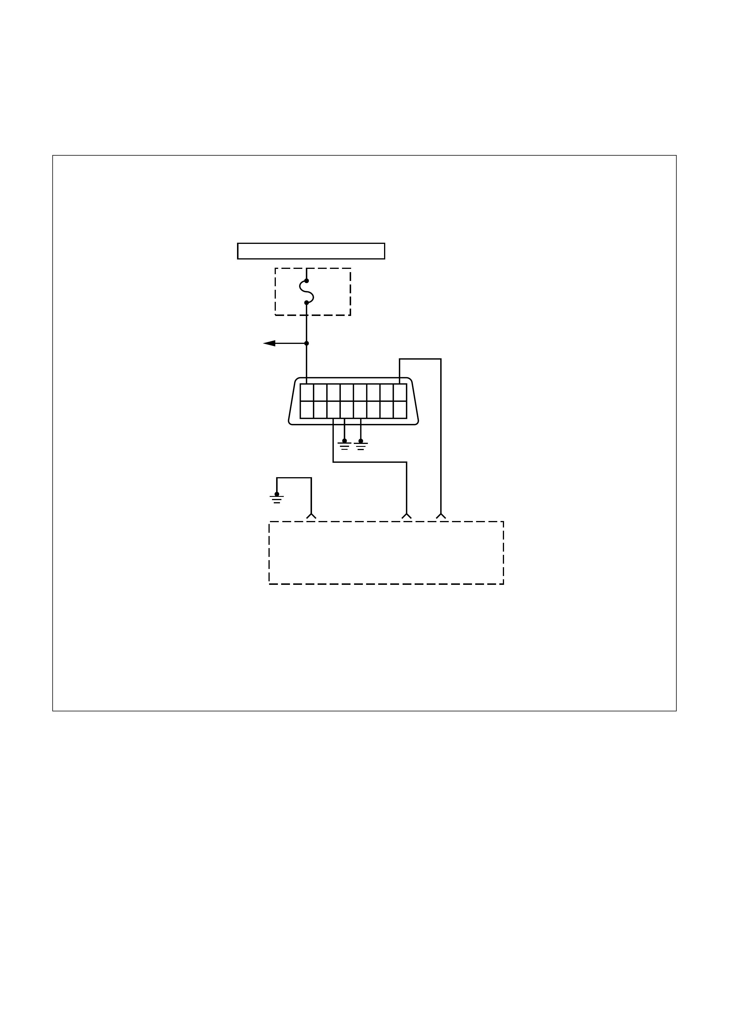
ON-BO ARD DIAGNOSTIC (OBD) SYSTEM CHECK
16 15 14 13 12 11 10 9
87654321
HOT AT ALL TIMES
Fuse
Stop
10A
U/H
FUSE
BLOCK
To
Stop
Lamp
Engine
Control
Module
(ECM)
0.5G
A1 B11 E8
B/R 0.5
BW
0.5
R
ECM
Grounds
(Engine Block)
Diag Serial Data
1.25
CIRCUIT DESCRIPTION
The on-board diagnostic system check is the starting
point for any driveability complaint diagnosis. Before
using this procedure, perform a careful visual/physical
check of the ECM and engine grounds for cleanliness
and tightness.
The on-board diagnostic system check is an organized
approach to identifying a problem created by an
electronic engine control system malfunction.
DIAGNOSTIC AIDS
An intermittent may be caused by a poor connection,
rubbed-through wire insulation or a wire broken inside
the insulation. Check for poor connections or a
damaged harness. Inspect the ECM harness and
connectors for improper mating, broken locks,
improperly formed or damaged terminals, poor
terminal-to-wire connection, and damaged harness.
TEST DESCRIPTION
Number(s) below refer to the step number(s) on the
Diagnostic Chart:
1. The MIL (“Check Engine” lamp) should be ON
steady with the ignition ON/engine OFF. If not,
isolate the malfunction in the MIL circuit.
2. Checks the serial data circuit and ensures that the
ECM is able to transmit serial data.

3. This test ensures that the ECM is capable of
controlling the MIL and the MIL driver circuit is not
shorted to ground.
4. If the engine will not start, the Cranks But Will Not
Run chart should be used to diagnose the
condition.
7. A Scan Tool parameter which is not within the
typical range may help to isolate the area which is
causing the problem.
ON-BO ARD DIAGNOSTIC (OBD) SYSTEM CHECK
STEP ACTION VALUE(S) YES NO
1
1. Ignition ON engine OFF.
2. Observe the malfunction indicator lamp (MIL or
“Check Engine” lamp).
Is the MIL (“Check Engine” lamp) ON?
-
Go to Step 2
Go to
No MIL
2
1. Ignition OFF.
2. Install a Scan Tool.
3. Ignition ON.
4. Attempt to display ECM engine data w ith the Scan Tool.
Does the Scan Tool display ECM data?
-
Go to Step 3
Go to Step 8
3
1. Using the Scan Tool output tests function, select MIL dash
lamp control and command the MIL OFF.
2. Observe the MIL.
Did the MIL turn OFF?
-
Go to Step 4
Go to
MIL(“Check
Engine” Lamp)
On Steady
4Attempt to start the engine.
Did the engine start and continue to run? - Go to Step 5
Go to
Cranks But
Will Not Run
5Select “Display DTCs” with the Scan Tool.
Are any DTCs stored? -Go to Step 6 Go to Step 7
6
Are two or more of the following DTCs stored?
•14
•21
•22
•33
•34
•69
-
Go to
“Multiple
ECM
Information
Sensor
DTCs
Set”
Go to
applicable
DTC table
7
Compare ECM data values displayed on the Scan Tool to the
typical engine scan data values.
Are the displayed values normal or close to the typical values? -
Go to Step 8
Refer to
indicated
Component
System Checks

STEP ACTION VALUE(S) YES NO
8
1. Ignition OFF, disconnect the ECM.
2. Ignition ON, engine OFF.
3. Check the serial data circuit for an open, short to ground, or
short to voltage. Also, check the DLC ignition feed circuit for an
open or short to ground and the DLC ground circuits for an
open.
4. If a problem is found, repair as necessary. Was a problem
found?
Go to Step 2 Go to Step 9
9
1. Refer to Engine Control Module (ECM) in On-Vehicle Service.
2. Attempt to display ECM data with the Scan Tool.
Does the Scan Tool display ECM engine data? -
Go to Step 2 Go to Step 10
10 Replace the EPROM or ECM. Note) Refer to 6E1-243 - Verify Repair -
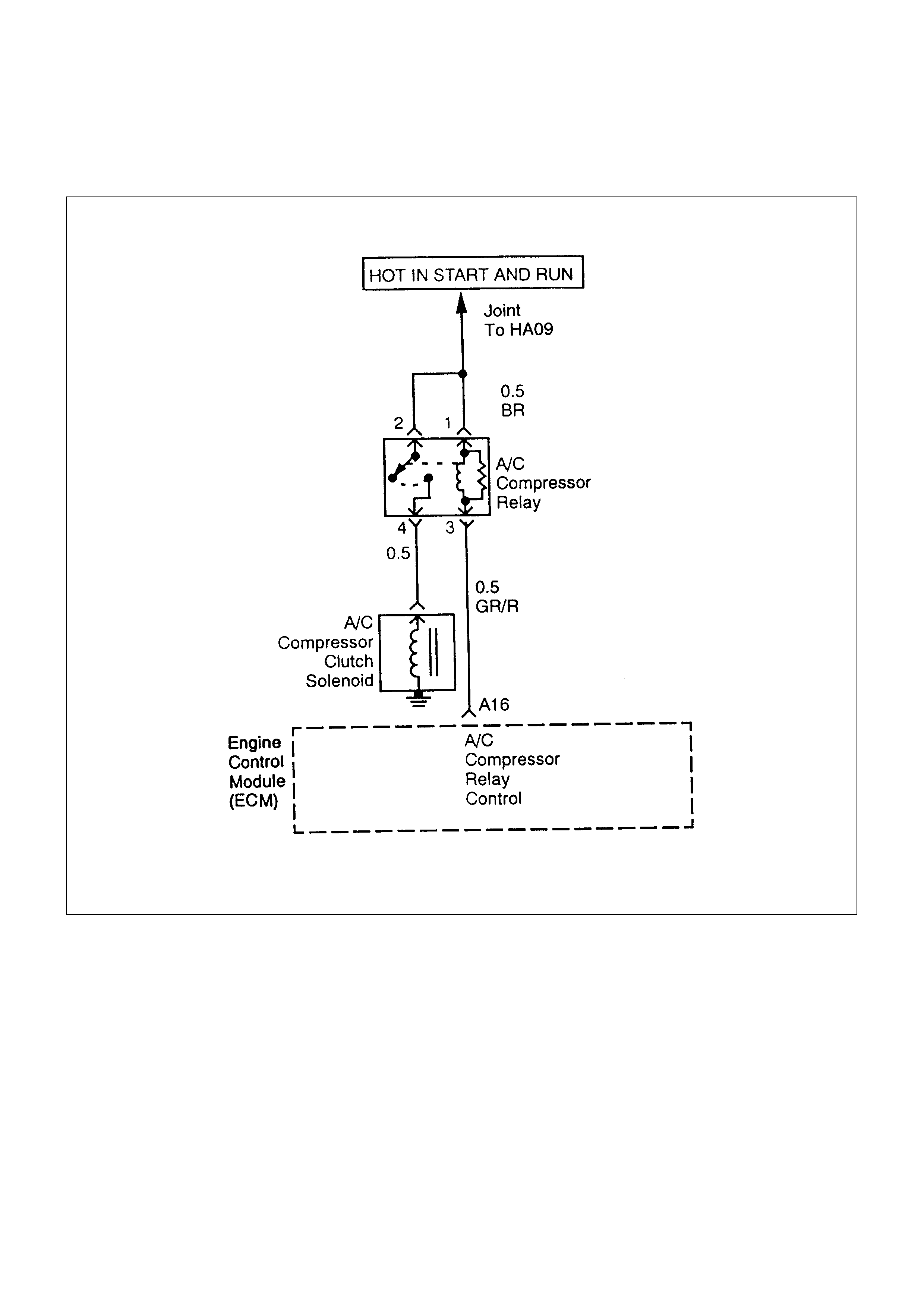
A/ C CLUTCH CONTROL CI RCUIT DIAGNOSIS
CIRCUIT DESCRIPTION
When air conditioning and blower fan are selected,
and if the system has a suf ficient refrigerant charge, a
12-volt signal is supplied to the A/C request input of
the engine control module (ECM). The A/C request
signal may be temporarily canceled during system
operation by the electronic thermostat in the
evaporator case. The electronic thermostat may
intermittently remove the control circuit ground for the
A/C thermostat relay to prevent the evaporator from
forming ice. W hen the A/C request signal is received
by the ECM, the ECM supplies a ground from the
compressor clutch relay if the engine operating
conditions are within acceptable ranges. W ith the A/C
compressor relay energized, battery voltage is
supplied to the compressor clutch coil.
The ECM will enable the c om press or clutch to engage
whenever A/C has been selected with the engine
running, unless any of the following conditions are
present:
•The throttle is greater than 95%.
•The engine speed is greater than 6000 RPM.
•The engine coolant temperature (ECT) is greater
than 122°C(252°F).
•Fan switch is OFF.
•A/C reguest switch is OFF.

• Thermo switch (FRT) is OFF.
• Pressure switch is OFF.
• Ignition switch is OFF.
DIAGNOSTIC AIDS
To diagnose an intermittent fault, check for the
following conditions:
• Poor connection at the ECM-Inspect harness
connections for backed-out terminals, improper
mating, broken locks, improperly formed or
damaged terminals, and poor terminal-to-wire
connection.
• Damaged harness-Inspect the wiring harness for
damage; shorts to Ground, shorts to Battery
Voltage, and Open circuits. If the harness appears
to be OK, observe the A/C clutch while moving
connectors and wiring harnesses related to the A/C.
A sudden clutch malfunction will indicate the source
of the intermittent fault.
A/C CLUTCH DIAGNOSIS
This chart should be used for diagnosing the electrical
portion of the A/C compressor clutch circuit. A Scan
Tool will be used in diagnosing the system. The Scan
Tool has the ability to read the A/C request input to the
ECM. The Scan Tool can display when the ECM has
commanded the A/C clutch ON. The Scan Tool should
have the ability to override the A/C request signal and
energize the A/C compressor relay.
A/C CLUTCH CONTROL CIRCUIT DIAGNOSIS
STEP ACTION VALUE(S) YES NO
1Was the “On-Board Diagnostic (OBD) System Check”
performed? - Go to Step 2 Go to OBD
System Check
2
1. Ignition ON, Engine OFF.
2. Review and record the customer complaint.
3. Operate the vehicle within the costomer complaint conditions
as noted.
4. Using the Scan Tool, monitor “DTC” info for DTC 87 or 88.
-Refer to
Diagnostic Aids
Go to step 3
3
1. Ignition OFF.
2. Remove the A/C Compressor Clutch Rela y from the
Underhood Electrical Center.
3. Ignition ON, Engine OFF.
4. Using a Digital Voltmeter (DVM), check for voltage on the
Fused pins of the A/C Compressor Clutch Relay connector.
Does the DVM read the following value?
12 Volts Go to Step 5 Go to Step 4
4
Check the suspect circuit(s) between the A/C Compressor
Clutch Relay connector and the Fuse for the following
conditions:
•A short to ground
•An open circuit
•A short to voltage
Was the problem found?
-Verify Repair -

STEP ACTION VALUE(S) YES NO
5
1. Ignition OFF.
2. Disconnect the Engine Control Module (ECM) connectors
from the ECM.
3. Check the A/C Compressor Clutch Relay control circuit
between the ECM and Underhood Electrical Center for the
following conditions:
•A Short to ground
•An open circuit
•A short to voltage
Was the problem found?
-Verify Repair Go to Step 6
6
1. Reinstall the A/C Compressor Clutch Relay.
2. Using a fused jumper, ground the A/C Compressor Clutch
Relay control circuit at the ECM connector.
3. Ignition ON, Engine OFF.
Does the A/C Compressor turn ON?
-Go to Step 9 Go to Step 7
7
1. Ignition OFF.
2. Check the A/C Compressor Clutch circuit between the A/C
Compressor Clutch Relay and A/C Compressor Clutch for
the following conditions:
•A Short to ground
•An open circuit
•A short to voltage
Was the problem found?
-Verify Repair Go to Step 8
8Replace the A/C Compressor Clutch Relay.
Is the action complete? -Verify Repair -
9 Replace the EPROM or ECM. Note) Refer to 6E1-243 - --
ELECTRONIC IGNITION SYSTEM
DIAGNOSIS
If the engine cranks but will not run or immediately
stalls, the Engine Cranks But Will Not Start chart
must be used to determine if the failure is in the
ignition system or the fuel system. If DTC19, or
DTC18 is set, the appropriate diagnos tic trouble c ode
chart must be used for diagnosis.
If a misfire is being experienced refer to the
Symptoms section for diagnosis.
EVAP CANISTER PURGE
CONTROL SOLENOID (IF
APPLICABLE)
A continuous purge condition with no purge
commanded by the ECM will set a DTC62. Refer to
the DTC charts for further information.
VISUAL CHECK OF THE
EVAPORATIVE EMISSION
CANISTER (IF APPLICABLE)
•If the canister is cracked or damaged, replace the
canister.
•If fuel is leaking from the canister, replace the
canister and check hoses and hose routing.
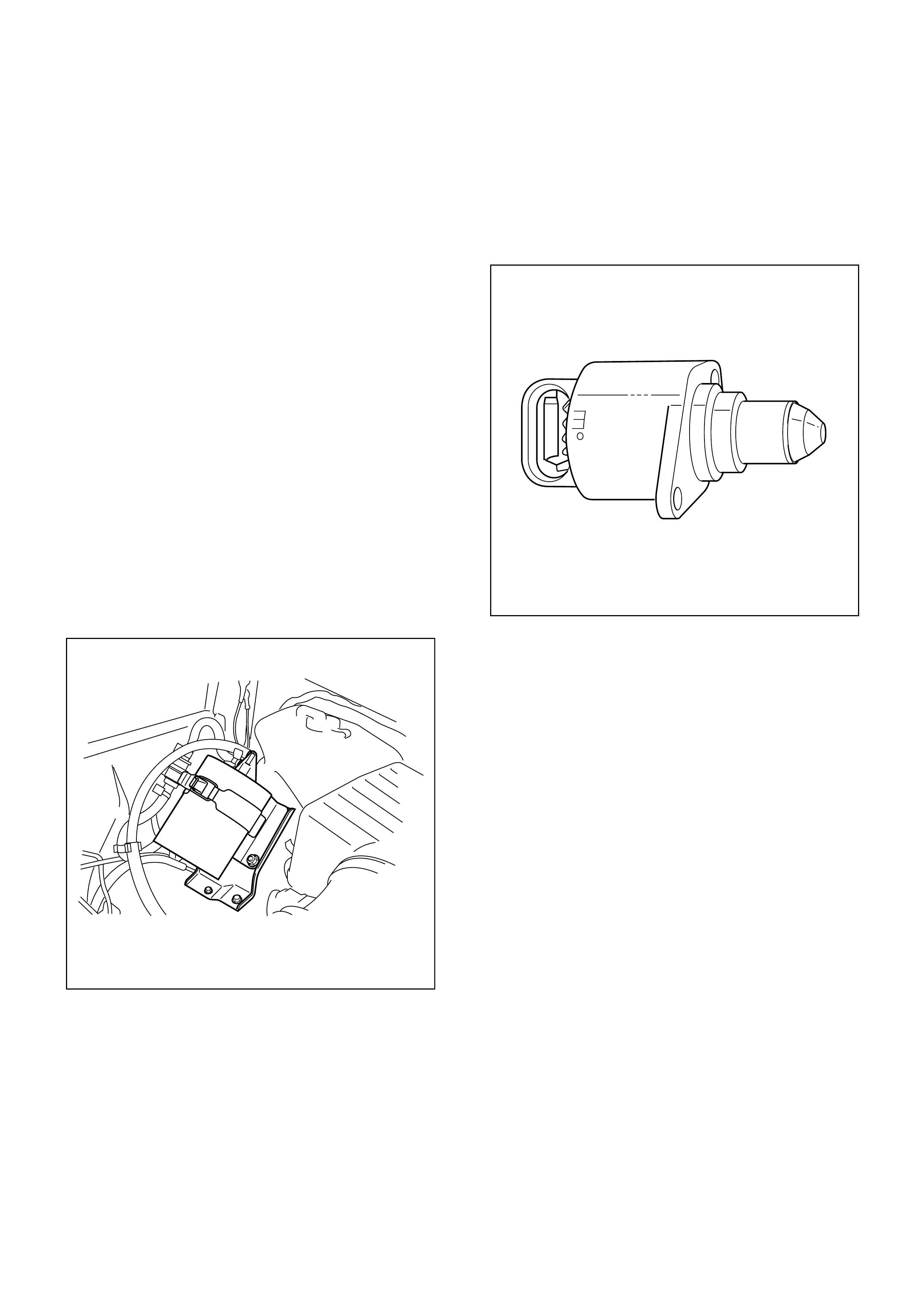
IDLE AI R CONTROL (I AC) VALVE
The Scan Tool displays the IAC pintle position in
counts. A count of “O” indicates the ECM is
commanding the IAC pintle to be driven all the way
into a fully-seated position. This is usually caused by
a vacuum leak.
The higher the number of counts, the more air is
being comm anded to bypass the throttle blade. Ref er
to IAC System Check in order to diagnose the IAC
system. Refer to Rough, Unstable, or Incorrect
Idle, Stalling in Symptoms for other possible causes
of idle problems.
FUEL SYSTEM PRESSURE TEST
A fuel system pressure test is part of several of the
diagnostic charts and symptom checks. To perform
this test, refer to Fuel System Diagnosis.
FUEL METERING SYSTEM CHECK
Some failures of the fuel metering system will result
in an “Engine Cranks But Will Not Run” symptom. If
this condition ex ists , r ef er to the Cranks But Will Not
Run chart. This chart will determine if the problem is
caused by the ignition system, the ECM, or the fuel
pump electrical circuit.
Refer to Fuel System Electrical Test for the fuel
system wiring schematic.
If there is a fuel delivery problem, refer to Fu el System
Diagnosis, which diagnoses the fuel inj ectors, the fuel
pressure regulator, and the fuel pump.
Followings are applicable to the vehicles with
closed Loop S y ste m:
If a malfunction occurs in the fuel metering system, it
usually results in either a rich HO2S signal or a lean
HO2S signal. This condition is indicated by the HO2S
voltage, which causes the ECM to change the fuel
calculation (fuel injector pulse width) based on the
HO2S reading. Changes made to the fuel calculation
will be indicated by a change in the long term fuel trim
values which can be m onitor ed with a Scan T ool. Ideal
long term fuel trim values are around 0%; for a lean
HO2S signal, the ECM will add fuel, resulting in a fuel
trim value above 0%. Some variations in fuel trim
values are normal because all engines are not exactly
the same. If the evapor ative em ission c anister pur ge is
02 status may be rich condition. 02 status indic ates the
lean condition, refer to DTC44 for items which can
cause a lean HO2S signal.
FUEL INJECTOR COIL TEST
PROCEDURE AND FUEL
INJECTOR BALANCE TEST
PROCEDURE
TEST DESCRIPTION
Number(s) below refer to the step number(s) on the
Diagnostic Chart:
2. Relieve the fuel pressure by connecting 5-8840-
0378-0 T-Joint to the fuel pressure connection on
the fuel rail.
CAUTION: In order to reduce the risk of fire
and personal injury, wrap a shop towel
around the fuel pressure connection. The
tow el will absorb any fuel leakage that occurs
during the connection of the fuel pressure
gauge. Place the towel in an approved
container when the connection of the fuel
pressure gauge is complete.
Place the fuel pressure gauge bleed hose in an
approved gasoline container.
With the ignition switch OFF open the valve on the
fuel pressure gauge.
3. Record the lowest voltage displayed by the DVM
after the first second of the test. (During the first
second, voltage displayed by the DVM may be
inaccurate due to the initial current surge.)
Injector Specifications:
RESISTANCE
OHMS VOLTAGE
SPECIFICATION AT
10°C-35°C (50°F-95°F)
11.8-12.6 5.7-6.6
•The voltage displayed by the DVM should be
within the specified range.
•The voltage displayed by the DVM may
increase throughout the test as the fuel injector
windings warm and the resistance of the fuel
injector windings changes.
•An erratic voltage reading (large fluctuations in
voltage that do not stabilize) indicates an
intermittent connection within the fuel injector.
5. Injector Specifications:
HIGHEST ACCEPTABLE
VOLTAGE
READING
ABOVE/BELOW
35°C/10°C (95°F/50°F)
ACCEPTABLE
SUBTRACTED
VALUE
9.5Volts 0.6Volt
7. The Fuel Injector Balance Test portion of this
chart (Step 7 through Step 11) checks the
mechanical (fuel delivery) portion of the fuel
injector . An engine cooldown period of 10 minutes
is necessary in order to avoid irregular fuel
pressure readings due to “Hot Soak” fuel boiling.
INJECTOR COIL TEST PROCEDURE (STEPS 1-6)
AND INJECTOR BALANCE TEST PROCEDURE (STEPS 7-11)
CYLINDER
1234
1st Reading (1) 296kPa
(43psi) 296kPa
(43psi) 296kPa
(43psi) 296kPa
(43psi)
2nd Reading (2) 205kPa
(29psi) 205kPa
(29psi) 196kPa
(28psi) 274kPa
(39psi)
Amount of Drop
(1st Reading-2nd Reading) 91kPa
(14psi) 91kPa
(14psi) 100kPa
(15psi) 22kPa
(4psi)
Av. Drop = 166kPa/24psi
±10kPa/1.5psi
= 156 − 176kPa or
22.5 − 25.5psi
Faulty, Lean
(Too Little
Fuel Drop)
Faulty, Lean
(Too Little
Fuel Drop)
Faulty, Lean
(Too Little
Fuel Drop)
Faulty, Lean
(Too Little
Fuel Drop)
NOTE: These figures are examples only.

INJECTOR COIL TEST PROCEDURE (STEPS 1-6) AND
INJECTOR BALANCE TEST PROCEDURE (STEPS 7-11)
STEP ACTION VALUE(S) YES NO
1Was the “On-Board Diagnostic (OBD) System
Check” performed? -Go to Step 2
Go to OBD
System Check
2
1. Turn the engine OFF.
Notice: In order to prevent flooding of a single cylinder and
possible engine damage, relieve the fuel pressure before
performing the fuel injector coil test procedure.
2. Relieve the fuel pressure. Refer to Test Description Number 2.
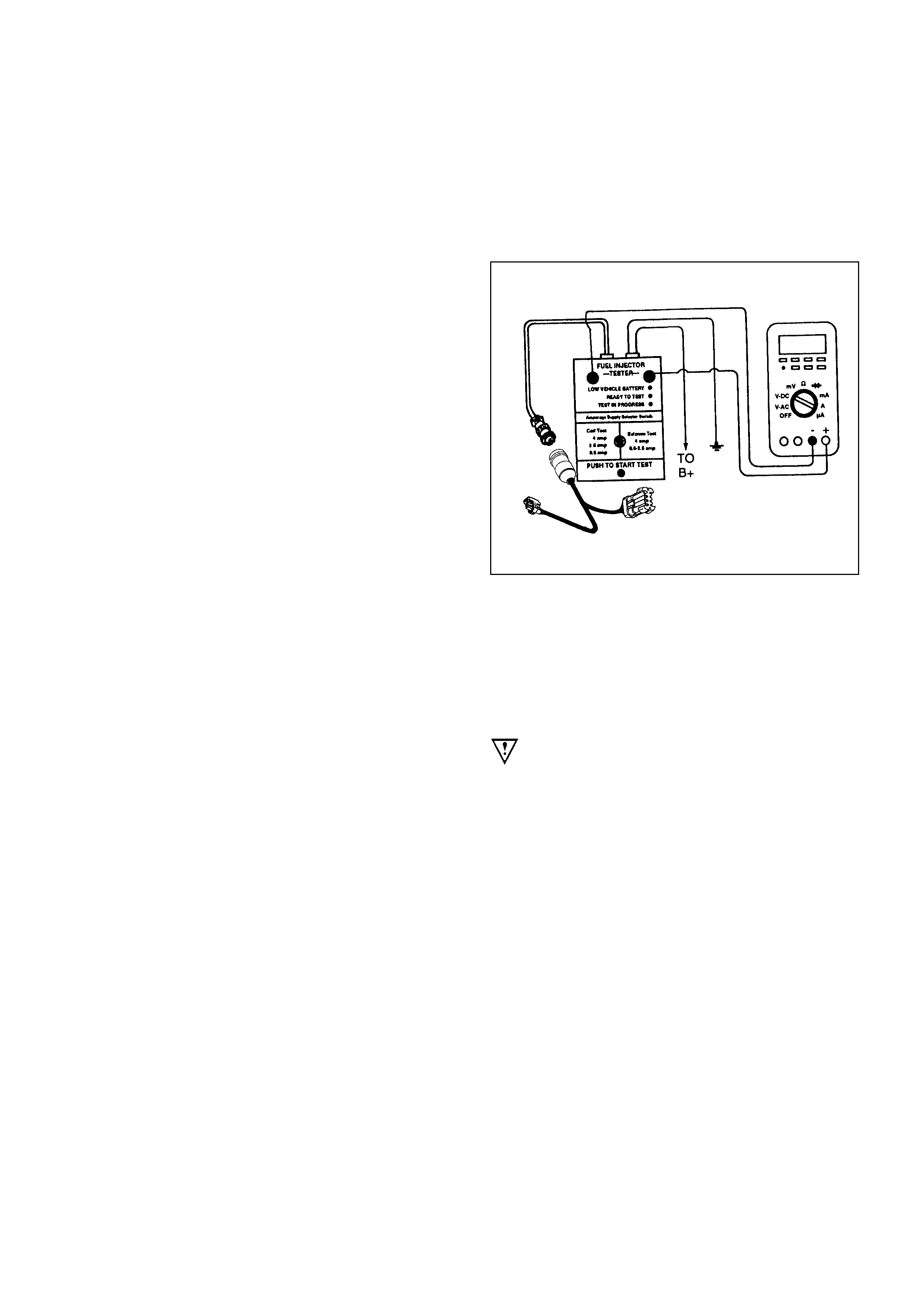
3. Connect the 5-8840-2618-0 Fuel Injector Tester to B+ and
ground, and to the 5-8840-2589-0 Injector Adapter Cable.
4. Remove the harness connector of the Fuel Injector and connect
the 5-8840-2589-0 Injector Adapter Cable for F/I check.
5. Set the amperage supply selector switch on the fuel injector
tester to the “Coil Test” 0.5 amp position.
6. Connect the leads from the 5-8840-2392-0 Digital Voltmeter
(DVM) to the fuel injector tester. Refer to the illustrations
associated with the test description.
7. Set the DVM to the tenths scale (0.0).
8. Observe the engine coolant temperature.
Is the engine coolant temperature within the specified values?
10°C (50°F)
to
35°C (95°F) Go to Step 3 Go to Step 5
3
1. Set the injector adapter cable to injector #1.
2. Press the “Push to Start Test” button on the fuel injector tester.
3. Observe the voltage reading on the DVM.
IMPORTANT: The voltage reading may rise during the test.
4. Record the lowest voltage observed after the first second of the
test.
5. Set the injector adapter cable to the next injector and repeat
steps 2, 3, and 4.
Did any fuel injector have an erratic voltage reading (large
fluctuations in voltage that did not stabilize) or a voltage reading
outside of the specified values? 5.7-6.6V Go to Step 4 Go to Step 7
4Replace the faulty fuel injector(S). Refer to Fuel Injector.
Is the action complete? -Go to Step 7 -

STEP ACTION VALUE(S) YES NO
5
1. Set the Injector Adapter Cable to injector #1.
2. Press the “Push to Start Test” button on the fuel injector tester.
3. Observe the voltage reading on the DVM.
IMPORTANT: The voltage reading may rise during the test.
4. Record the lowest voltage observed after the first second of the
test.
5. Set the Injector Adapter Cable to the next injector and repeat
steps 2, 3, and 4.
Did any fuel injector have an erratic voltage reading (large
fluctuations in voltage that did not stabilize) or a voltage reading
above the specified value? 9.5V Go to Step 4 Go to Step 6
6
1. Identify the highest voltage reading recorded (other than those
above 9.5V).
2. Subtract the voltage reading of each injector from the highest
voltage selected in step 1. Repeat until you have a subtracted
value for each injector.
For any injector, is the subtracted value in step 2 greater than the
specified value? 0.6V Go to Step 4 Go to Step 7
7
CAUTION: In order to reduce the risk of fire and personal
injury, wrap a shop towel around the fuel pressure connection.
The towel will absorb any fuel leakage that occurs during the
connection of the fuel pressure gauge. Place the Towel in an
approved container when the connection of the fuel pressure
gauge is complete.
1. Connect the 5-8840-0378-0 Fuel Pressure Gauge to the fuel
pressure test port.
2. Energize the fuel pump using the Scan Tool.
3. Place the bleed hose of the fuel pressure gauge into an
approved gasoline container.
4. Bleed the air out of the fuel pressure gauge.
5. With the fuel pump running, observe the reading on the fuel
pressure gauge.
Is the fuel pressure within the specified values?
296kPa-
376kPa
(43-55psi) Go to Step 8
Go to
Fuel System
Diagnosis
8Turn the fuel pump OFF.
Does the fuel pressure remain constant? -
Go to Step 9
Go to
Fuel System
Diagnosis

STEP ACTION VALUE(S) YES NO
9
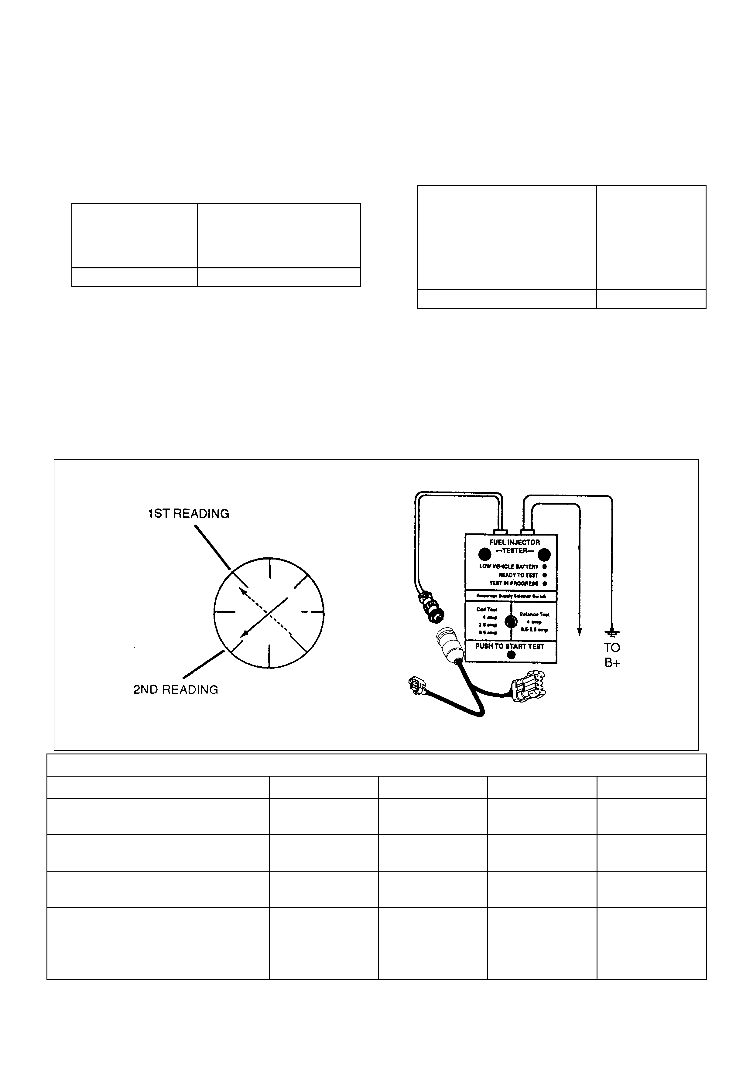
1. Connect the 5-8840-0378-0 Fuel Injector Tester and 5-8840-
2589-0 Injector Adapter Cable to the fuel injector harness
connector.
2. Set the amperage supply selector switch on the fuel injector
tester to the “Balance Test” 0.5-2.5 amp position.
3. Using the Scan Tool turn the fuel pump ON then OFF in order
to pressurize the fuel system.
4. Record the fuel pressure indicated by the fuel pressure
gauge after the fuel pressure stabilizes.
This is the first pressure reading.
5. Energize the fuel injector by depressing the “Push to Start
Test” button on the fuel injector tester.
6. Record the fuel pressure indicated by the fuel pressure
gauge after the fuel pressure gauge needle has stopped
moving. This is the second pressure reading.
7. Repeat steps 1 through 6 for each fuel injector.
8. Subtract the second pressure reading from the first pressure
reading for one fuel injector. The result is the pressure drop
value.
9. Obtain a pressure drop value for each fuel injector.
10. Add all of the individual pressure drop values.
This is the total pressure drop.
11. Divide the total pressure drop by the number of fuel injectors.
This is the average pressure drop.
Does any fuel injector have a pressure drop value that is either
higher than the average pressure drop or lower than the average
pressure drop by the specified value? 10kPa
(1.5psi) Go to Step 10
Go to OBD
System Check
10
Re-test any fuel injector that does not meet the specification. Refer
to the procedure in step 11.
Notice: Do not repeat any portion of this test before running the
engine in order to prevent the engine from flooding.
Does any fuel injector still have a pressure drop value that is either
higher than the average pressure drop or lower than the average
pressure drop by the specified value? 10kPa
(1.5psi) Go to Step 11
Go to
Symptoms
11
1. Replace the faulty fuel injector(s). Refer to Fuel Injector.
2. Disconnect the 5-8840-2589-0 Injector Adapter Cable for F/I
check and re-connect the original F/I check connector.
Is the action complete? -
Verify repair
-
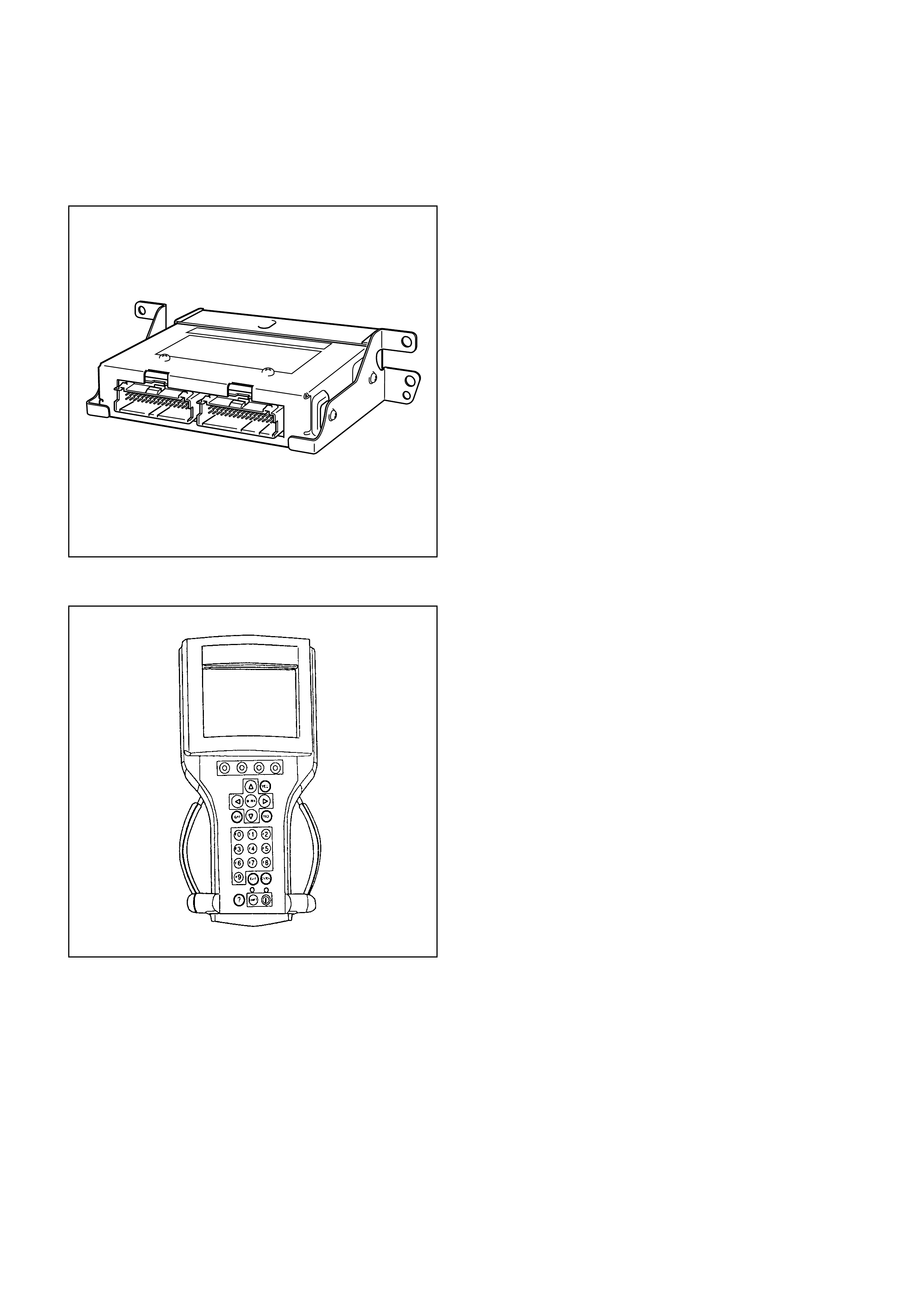
ENGINE CONTROL MODULE
(ECM) DI AGNOSIS
To read and clear diagnostic trouble codes, use a
Scan Tool.
IMPORTANT: Use of a Sc an Tool is rec omm ended to
clear diagnostic trouble codes f rom the ECM m emor y.
Diagnostic trouble codes can also be cleared by
turning the ignition OFF and disconnecting the battery
power from the ECM for 30 seconds. Turning off the
ignition and disconnecting the battery power from the
ECM will cause all diagnostic information in the ECM
memory to be cleared. Therefore, all the diagnostic
tests will have to be re-run.
Since the ECM can have a failure which may affect
only one c ircuit, following the diagnostic procedures in
this section will determ ine which circuit has a problem
and where it is.
If a diagnostic chart indicates that the ECM
connections or the ECM is the cause of a problem,
and the EPROM or ECM is r eplaced, but this does not
correct the problem, one of the following may be the
reason:
•There is a problem with the ECM terminal
connections. The terminals may have to be
rem oved from the connector in order to check them
properly.
•The problem is intermittent. This means that the
problem is not present at the time the system is
being checked. In this c ase, ref er to the Symptoms
portion of the manual and make a careful physical
inspection of all components and wiring associated
with the affected system.
•There is a shorted solenoid, relay coil, or harness.
Solenoids and relays are turned ON and OFF by the
ECM using internal electronic switches called
drivers. A shorted solenoid, relay coil, or harness
will not damage the ECM but will cause the solenoid
or relay to be inoperative.

MULTIPLE ECM INFORM ATION
SENSOR DTCS SET
CIRCUIT DESCRIPTION
The engine control module (ECM) monitors various
sensors to determine the engine operating conditions.
The ECM controls fuel delivery, spark advance, and
emission control device operation based on the sensor
inputs.
The ECM provides a sensor ground to all of the
sensors. The ECM applies 5 volts through a pull-up
resistor, and determines the status of the following
sensors by monitoring the voltage present between
the 5-volt supply and the resistor:
•The throttle position (TP) sensor
•The manifold absolute pressure (MAP) sensor
The ECM provides the following sensors with a 5-volt
reference and a sensor ground signal:
•Intake Air Temp Sensor (IAT).
•Engine Coolant Temp Sensor (ECT).
•Manifold Absolute Pressure Sensor (MAP).
•Throttle Position Sensor (TPS).
The ECM monitors the separate feedback signals
from these sensors in order to determine their
operating status.
DIAGNOSTIC AIDS
IMPORTANT: Be sure to inspect ECM and engine
grounds for being secure and clean.
A short to voltage in one of the sensor input circuits
may cause one or more of the following DTCs to be
set:
•21/33
IMPORTANT: If a sensor input circuit has been
shorted to voltage, ensure that the sensor is not
damaged. A dam aged sensor will continue to indicate
a high or low voltage after the affected circuit has
been repaired. If the sensor has been damaged,
replace it.
A short to ground in the circuit between ECM and
sensors will cause one or more of the following DTCs
to be set:
•14/22
•34/69
Check for the following conditions:
POOR CONNECTION AT ECM.
Inspect the harness connectors for backed-out
terminals, improper mating, broken locks, improperly
form ed or damaged term inals, and a poor terminal-to-
wire connection.
DAMAGED HARNESS.
Inspect the wiring harness for damage. If the harness
is not damaged, observe an affected sensor's
displayed value on the Scan Tool with the ignition ON
and the engine OFF while you move the connectors
and the wiring harnesses related to the following
sensors:
•IAT
•ECT
•TPS
•MAP

MULTIPLE ECM INFORMATION SENSOR DTCS SET
STEP ACTION VALUE(S)
YES NO
1Was the “On-Board Diagnostic (OBD) System
Check” performed? -Go to Step 2
Go to OBD
System Check
2
1. Turn the ignition OFF disconnect the ECM.
2. Turn the ignition ON check the 5 volt reference circuits for the
following conditions:
•A poor connection at the ECM.
•An open between the ECM connector and the splice.
•A short to ground.
•A short to voltage.
Is there an open or short?
-
Go to Step 3 Go to Step 4
3Repair the open or short.
Is the action complete? -Verify repair -
4
Check the sensor ground circuit for the following conditions:
•A poor connection at the ECM or the affected sensors.
•An open between the ECM connector and the affected sensors.
Is there an open or a poor connection? -
Go to Step 5 Go to Step 6
5Repair the open or the poor connection.
Is the action complete? -Verify repair -
6Measure the voltage between the MAP sensor signal circuit at the
ECM harness connector and ground.
Does the voltage measure near the specified value? 0V
Go to Step 7 Go to Step 10
7Measure the voltage between the TP sensor signal circuit at the
ECM harness connector and ground.
Does the voltage measure near the specified value? 0V
Go to Step 8 Go to Step 11
8Measure the voltage between the IAT sensor signal circuit at the
ECM harness connector and ground.
Does the voltage measure near the specified value? 0V
Go to Step 9 Go to Step 12
9Measure the voltage between the ECT sensor signal circuit at the
ECM harness connector and ground.
Does the voltage measure near the specified value? 0V
Go to Step 14 Go to Step 13
10 Locate and repair the short to voltage in the MAP sensor signal
circuit.
Is the action complete? -
Verify repair
-
11 Locate and repair the short to voltage in the TP sensor signal
circuit.
Is the action complete? -
Verify repair
-
12 Locate and repair the short to voltage in the IAT sensor signal
circuit.
Is the action complete? -
Verify repair
-
13 Locate and repair the short to voltage in the ECT sensor signal
circuit.
Is the action complete? -
Verify repair
-
14 Replace the EPPROM or ECM. Note) Refer to 6E1-243 -Go to OBD
System Check -

ENGINE SCAN TOOL DATA
DEFINITI ONS AND RANGES
A/C CLUTCH - Scan Tool Displays ON or OFF -
Indicates whether the ECM has commanded the A/C
clutch ON. Used in A/C system diagnostics.
A/C REQUEST - Scan Tool Displays NO or OFF -
Indicates the state of the A/C reques t input cir cuit from
the HVAC controls. The ECM uses the A/C request
signal to determine whether A/C compressor operation
is being requested.
AIR/FUEL RATIO - Scan Tool Range 0-0:1-25.5:1 -
Air/fuel ratio indicates the ECM commanded value. In
“Closed Loop” , the air/fuel ratio should normally be
displayed around “14.2-14.7” . A lower air/fuel ratio
indicates a richer commanded mixture, which may be
seen during power enrichment or TWC (If applicable)
protection modes. A higher air/fuel ratio indicates a
leaner commanded mixture. This can be seen during
deceleration fuel mode.
BARO kPa - Scan Tool Range 10-105 - The
barometric pressure reading is determined from the
MAP sensor signal monitored during key up and wide
open throttle (WOT) conditions. The barometric
pressure is used to compensate for altitude
differences and is normally displayed around “61-104”
depending on altitude and barometric pressure.
DECELERATION FUEL CUT OFF - YES or NO-
Scan Tool Displays - “ACTIVE” displayed indicates
that the ECM has detected conditions appropriate to
operate in deceleration fuel mode. The ECM will
command the deceleration fuel mode when it detects
a closed throttle position while the vehicle is traveling
over 20 m ph. W hile in the deceleration f uel m ode, the
ECM will decrease the amount of fuel delivered by
entering “Open Loop” and decreasing the injector
pulse width.
DESIRED IDLE - Scan Tool Range 0-3187 RPM -
The idle speed that the ECM is commanding. The
ECM will compensate for various engine loads based
on engine coolant temperature, to keep the engine at
the desired speed.
ECT TEMP. - (Engine Coolant Temperature) Scan
Tool Range −
−−
−40°C to 151°C (−
−−
−40°F to 304°F) - The
engine coolant temperature (ECT) is mounted in the
coolant stream and sends engine temperature
information to the ECM. The ECM applies 5 volts to
the ECT sensor circuit. The sensor is a thermistor
which changes internal resistance as the temperature
changes. When the sensor is cold (high resistance),
the ECM monitor s a high signal voltage and interprets
that as a cold engine. As the sensor warms
(decreasing resistance), the voltage signal will
decrease and the ECM will interpret the lower voltage
as a warm engine.
TIME FROM START - Scan Tool Range 00:00:00-
99:99:99 Hrs:Min:Sec - Indicates the time elapsed
since the engine was star ted. If the engine is stopped,
engine run time will be reset to 00:00:00.
ENGINE SPEED - Range 0-9999 RPM - Engine
speed is computed by the ECM form the 58X
reference input. It should remain close to desired idle
under various engine loads with engine idling.
EVAP PURGE PWM (If applicable) - Scan Tool
Range 0%-100% - Represents the ECM commanded
PWM duty cycle of the EVAP purge solenoid valve.
“0%” displayed indicates no purge; “100%” displayed
indicates full purge.
FUEL PUMP RELAY - Scan Tool Displays ON or
OFF - Indicates the ECM comm anded s tate of the f uel
pump relay driver circuit.
02 BLM CELL NUMBER (If applicable)- Scan Tool
Range 0-21 - The 02 BLM cell is dependent upon
engine speed and MAP sensor readings. A plot of
RPM vs. MAP is divided into 22 cells. 02 BLM cell
indicates which cell is currently active.
B1 HO2S BANK 1 (If applicable)- Scan Tool Range
0-1000 mV - Represents the fuel control exhaust
oxygen sensor output voltage. Should fluctuate
constantly within a range between 10 mV (lean
exhaust) and 1000 mV (rich exhaust) while operating
in “Closed Loop” .
B1 HO2S READY BANK 1 (If applicable)- Scan Tool
Displays YES or NO - Indicates the status of the
exhaust oxygen sensor. The Scan Tool will indicate
that the exhaust oxygen sensor is ready when the
ECM detects a fluctuating HO2S voltage sufficient to
allow “Closed Loop” operation. This will not occur
unless the exhaust sensor is warmed up.
IAC CONTROL STEP - Scan Tool Range 0-255
steps - Displays the commanded position of the idle
air control pintle in counts. A larger number of counts
means that more air is being comm anded through the
idle air passage. Idle air control should respond fairly
quickly to changes in engine load to maintain desired
idle RPM.
IAT (INTAKE AIR TEMPERATURE) - Scan Tool
Range −
−−
−40°C to 151°C (−
−−
−40°F to 304°F) - The ECM
converts the resistance of the intake air temperature
sensor to degrees. Intake air temperature (IAT) is

used by the ECM to adjust fuel delivery and spark
timing according to incoming air density.
BATTERY - Scan Tool Range 0-25.5 Volts - This
represents the system voltage measured by the ECM
at its ignition feed.
INJ. PULSE WIDTH - Scan Tool Range 0-1000
msec. - Indicates the amount of time the ECM is
commanding each injector ON during each engine
cycle. A longer injector pulse width will cause more
fuel to be delivered. Injector pulse width should
increase with increased engine load.
FUELING MODE (If applicable) - Scan Tool
Displays OPEN or CLOSED - “CLOSED” indicates
that the ECM is controlling fuel delivery according to
oxygen sensor voltage. In “OPEN” the ECM ignores
the oxygen sensor voltage and bases the amount of
fuel to be delivered on T P s ensor, and engine coolant,
sensor inputs only.
MAP - Scan Tool Range 10-105 kPa (0.00-4.97
Volts) - The manif old abs olute pr ess ur e (MAP) s ens or
measures the change in the intake manifold pressure
from engine load, and speed changes. As intake
manifold pressure increases, intake vacuum
decreases, resulting in a higher MAP sensor voltage
and kPa reading. The MAP sensor signal is used to
monitor intake manifold pressure changes to update
the BARO reading, and as an enabling factor for
several of the diagnostics.
CEL-CHECK ENGINE LIGHT - Scan Tool Displays
ON or OFF - Indicates the ECM commanded state of
the malfunction indicator lamp (“Check Engine
Lamp”).
02 STATUS (If applicable) - Scan Tool Displays
RICH or LEAN - Indicates whether oxygen sensor
voltage is above a 600 mV thr eshold voltage (“R ICH” )
or below a 3000 mV threshold voltage (“LEAN” ).
Should change constantly while in “Closed Loop” ,
indicating that the ECM is controlling the air/fuel
mixture properly.
ELECTRIC SPARK CONTROL - Scan Tool Range
−
−−
−64°CA to 64°CA - Displays the amount of spark
advance being commanded by the ECM on the IC
circuit.
THROTT L E POSITION - Scan Tool Ran ge 0%-100%
- TP (throttle position) angle is computed by the ECM
from the TP sensor voltage. TP angle should display
“0%” at idle and “100%” at wide open throttle.
TPS SIGNAL - Scan Tool Range 0.00-5.00 Volts -
The voltage being monitored by the ECM on the TP
sensor signal circuit.
TYPICAL SCAN DATA VALUES
Use the T ypical Scan Data Values Table only after the
On- Board Diagnostic System Check has been
completed, no DTC(s) were noted, and you have
determined that the on-board diagnostics are
functioning properly. Scan Tool values from a
properly-running engine may be used for comparison
with the engine you are diagnosing. The typical scan
data values represent values that would be seen on a
normally-running engine.
Notice: A Scan Tool that displays faulty data should
not be used, and the problem should be reported to
the Scan Tool manufac tur er. Us e of a f aulty Scan Tool
can result in misdiagnosis and unnecessary
replacement of parts.
Only the parameters listed below are r ef er r ed to in this
service manual for use in diagnosis. For further
information on using the Scan Tool to diagnose the
ECM and related sensors, refer to the applicable
reference section listed below. If all values are within
the typical range described below, refer to the
Symptoms section for diagnosis.
TEST CONDITIONS
Engine running, lower radiator hose hot, transmission
in park or neutral, “Closed Loop” (If applicable),
accessories OFF, brake not applied and air
conditioning OFF.

2.2L/2.0L L-4 ENGINE
SCAN TOOL
PARAMETER DATA LIST UNITS
DISPLAYED TYPICAL DATA
VALUES (IDLE) TYPICAL DATA
VALUES
(2500 RPM)
REFER TO
A/C Clutch Engine On/Off Off Off General Description and
Operation, A/C Clutch Circuit
Operation
A/C Request Engine No/Off Off Off General Description and
Operation, A/C Request
Signal
Air/Fuel Ratio
(If applicable) Engine Ratio: _to 1 14.6:1 14.6:1 General Description and
Operation, Fuel System
Metering Purpose
BARO kPa Engine kPa 103 (depends on
altitude and
barometric)
103 (depends on
altitude and
barometric)
General Description and
Operation
Broadcast Code
‘PROM’
Identification
Engine 5 Figures Depends on
latest level of
engine
software and
calibration.
Review Technical
Service Bulletins
for most current
level.
Depends on latest
level of engine
software and
calibration.
Review Technical
Service Bulletins
for most current
level.
-
Decel Fuel Mode Engine Active/
Inactive Inactive Inactive General Description and
Operation, Deceleration Mode
Desired Idle Engine RPM 825 - General Description and
Operation, Idle Air Control
(IAC) Valve
ECT
(Engine Coolant
Temp)
Engine Degrees C,
Degrees F 80-100°C
(176-212°F) 80-100°C
(176-212°F) General Description and
Operation, Engine Coolant
Temperature (ECT) Sensor
Time From Start Engine Hrs:Min:Sec Varies. Resets at
each engine start. Varies. Resets at
each engine start. -
Engine Speed Engine RPM Within −50 to
+100
of “Desired Idle”
Actual engine
speed -
EVAP Purge
PWM
(If applicable)
Engine Percent 0% 0% Diagnosis, EVAP Emission
Canister Purge Valve Check
Fuel Pump Engine On/Off On On Engine Fuel
02 BLM
Cell Number
(If applicable)
Engine Cell number 20 5 Diagnosis, Fuel Trim Cell
Diagnostic Weights
HO2S
(If applicable)
(millivolts)
Engine Millivolts 160-800 changing
quickly 160-800, always
changing quickly General Description and
Operation, Fuel Control HO2S

SCAN TOOL
PARAMETER DATA LIST UNITS
DISPLAYED TYPICAL DATA
VALUES (IDLE) TYPICAL DATA
VALUES
(2500 RPM)
REFER TO
HO2S
(If applicable)
(ready/
not ready)
Specific Eng:
HO2S Ready/
Not Ready Ready Ready General Description and
Operation, Fuel Control
HO2S; DTC: DTC13
IAT
(Intake Air Temp) Engine Degrees C,
Degrees F 0-100°C,
(32°F-212°F)
depends
on underhood
0-80°C, depends
(32°F-176°F)
on underhood
General Description and
Operation, Intake Air
Temperature (IAT) Sensor
Battery Engine Volts 14 34 General Description and
Operation, Electronic Ignition
System
Inj. Pulse Engine Milliseconds 1.8-1.9 1.4-1.5 General Description, Fuel
Metering, Fuel Injector
Fueling Mode
(If applicable) Engine Open/Closed Closed Closed General Description and
Operation, Fuel Me tering
System; DTCs: DTC13
MAP kPa
(Manifold
Absolute
Pressure)
Engine Kilopascals 37 29 General Description and
Operation, Manifold Absolute
Pressure (MAP) Sensor;
DTCs: DTC33/34
CEL Engine On/Off Off Off On-Board Diagnostic System
Check
PSP Switch
(Power Steering
Pressure)
Engine ON/OFF - - Power Steering Gear and
Pump, General Description,
Pressure Switch
02 STATUS
(If applicable) Engine Rich/Lean Always changing Always changing General Description and
Operation, Fuel Control HO2S
Electric spark
control Engine Degrees
Before Top
Dead Center
14 34 General Description and
Operation, Electronic Ignition
System
TP
(Throttle Position) Engine Degrees open 0 5 General Description and
Operation, Throttle Position
(TP) Sensor; DTCs: DTC
21/22
TP Sensor
(Throttle Position) Engine Volts 0.80 1.02 General Description and
Operation, Throttle Position
(TP) Sensor; DTCs: DTC
21/22
Vehicle Speed Engine km/h 0 0
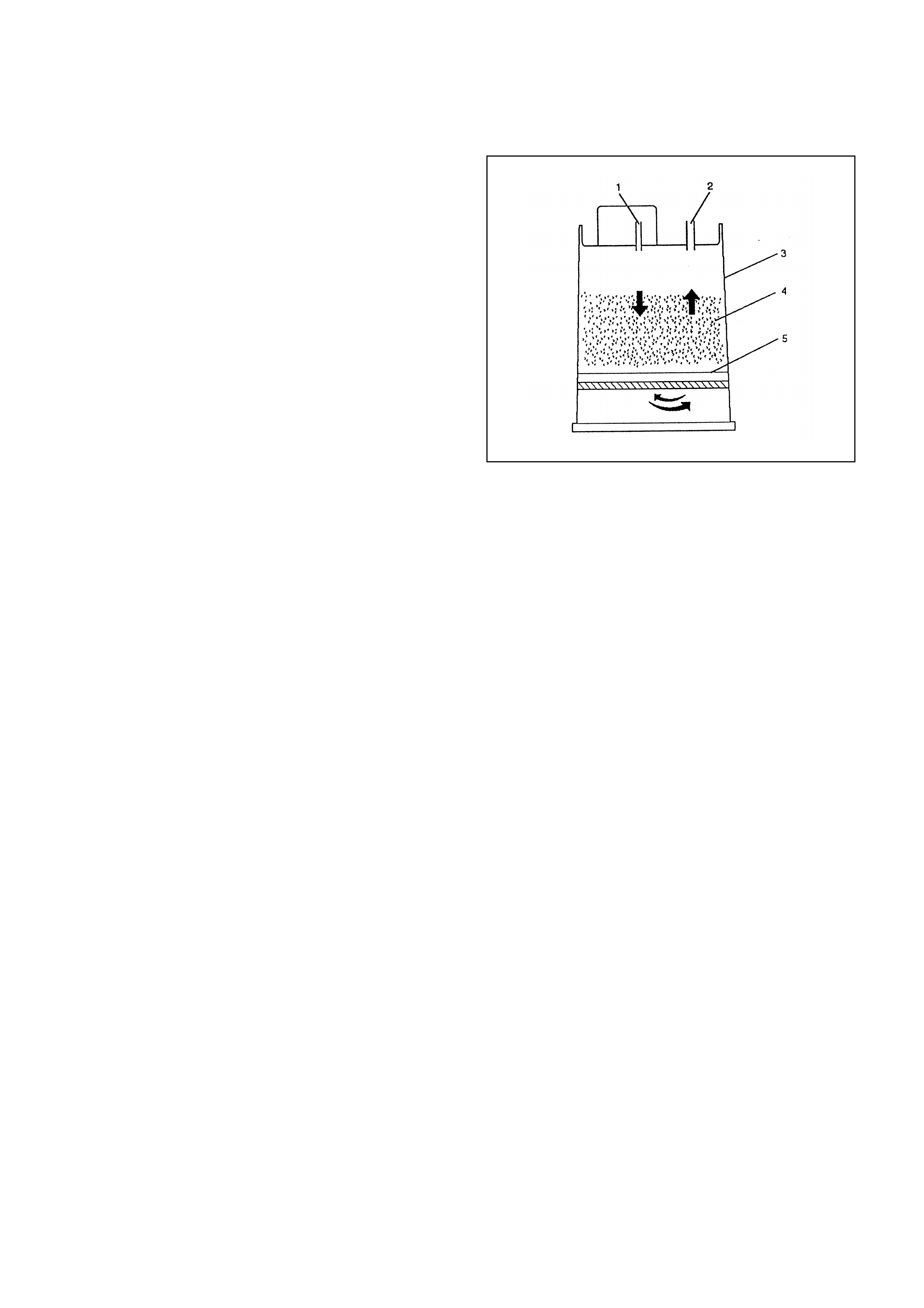
GENERAL DESCRIPTION
(EVAPORATIVE (EVAP) EMISSION
SYSTEM) (IF APPLICABLE)
EVAP EMISSION CONTROL SYSTEM
PURPOSE
The basic Evaporative Emission (EVAP) Control
System used on all vehicle is the charcoal canister
storage method. This method transfers fuel vapor
from the fuel tank to an activated carbon (charcoal)
storage device (canister) to hold the vapors when the
vehicle is not operating. When the engine is running,
the fuel vapor is purged from the carbon element by
intake air flow and consumed in the normal
combustion process.
VAPO R CANISTER
Gasoline vapors from the fuel tank flow into the tube
labeled tank. Any liquid fuel goes into a reservoir in the
bottom of the canister to protect the integrity of the
carbon bed. These vapors are absorbed into the
carbon. The canister is purged when the engine is
running or commanded by Engine Control Module
(ECM). Ambient air is allowed into the canister through
the air tube in the top. The air mixes with the vapor
and the mixture is drawn into the intake manifold.
EVAP CONTROL SYSTEM
The solenoid used with this canister uses Vacuum
Switch Valve to control purge. The ECM opens and
closes the solenoid to control purge.
The ECM operates a Normally Closed (N/C) solenoid
valve which controls the vac uum to pur ge the char c oal
canister. Under cold engine or idle conditions, the
solenoid is not energized by the ECM, which blocks
vacuum to purge the canister.
The ECM energizes the solenoid valve and allows
purge when:
•Engine is warm above 69°C (156°F)
•After the engine has been running a specified time.
LEGEND
(1) Vapor from Fuel Tank
(2) Evaporate Emission Canister Purge Vacuum
(3) Canister Body
(4) Carbon
(5) Filter
(6) Grid
(7) Air Flow During Purge
•Throttle position is above 7% throttle position
sensor.
RESULTS OF INCORRECT OPERATION
Poor idle, stalling and poor driveability can be caused
by:
•Inoperative purge solenoid.
•Damaged canister.
•Hoses split, cracked and/or not connected to the
proper tubes.
Evidence of f uel los s or f uel vapor odor c an be c aused
by:
•Liquid fuel leaking from fuel lines, or fuel pump.
•Cracked or damaged canister.
•Disconnected, misrouted, kinked, deteriorated or
damaged vapor hoses, or control hoses.
If the solenoid is always open, the canister can purge
to the intake manif old at all tim es. This can allow extra
fuel at idle or dur ing war m-up, which can cause rough
or unstable idle, or too rich operation.
If the solenoid is always closed, the canister can
become over-loaded, resulting in fuel odor.
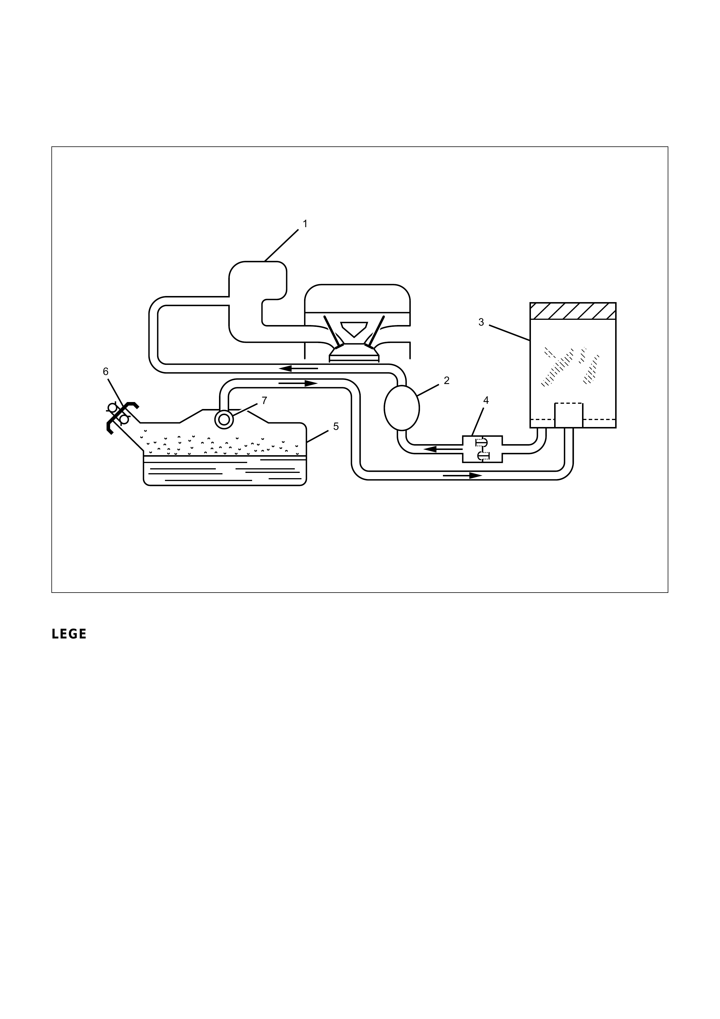
DIAGNOSIS
;;
;;
;;
;;
;
;
;
1
7
5
62
3
4
LEGEND
(1) Intake Manifold
(2) Fuel Vapor Purge Control Solenoid
(3) Fuel Vapor Canister
(4) Check and Relief valve
(5) Fuel Tank
(6) Pressure/ Vacuum Vented
(7) Rollover Valve
VISUAL CHECK OF CANISTER
Cracked or damaged, replace canister.
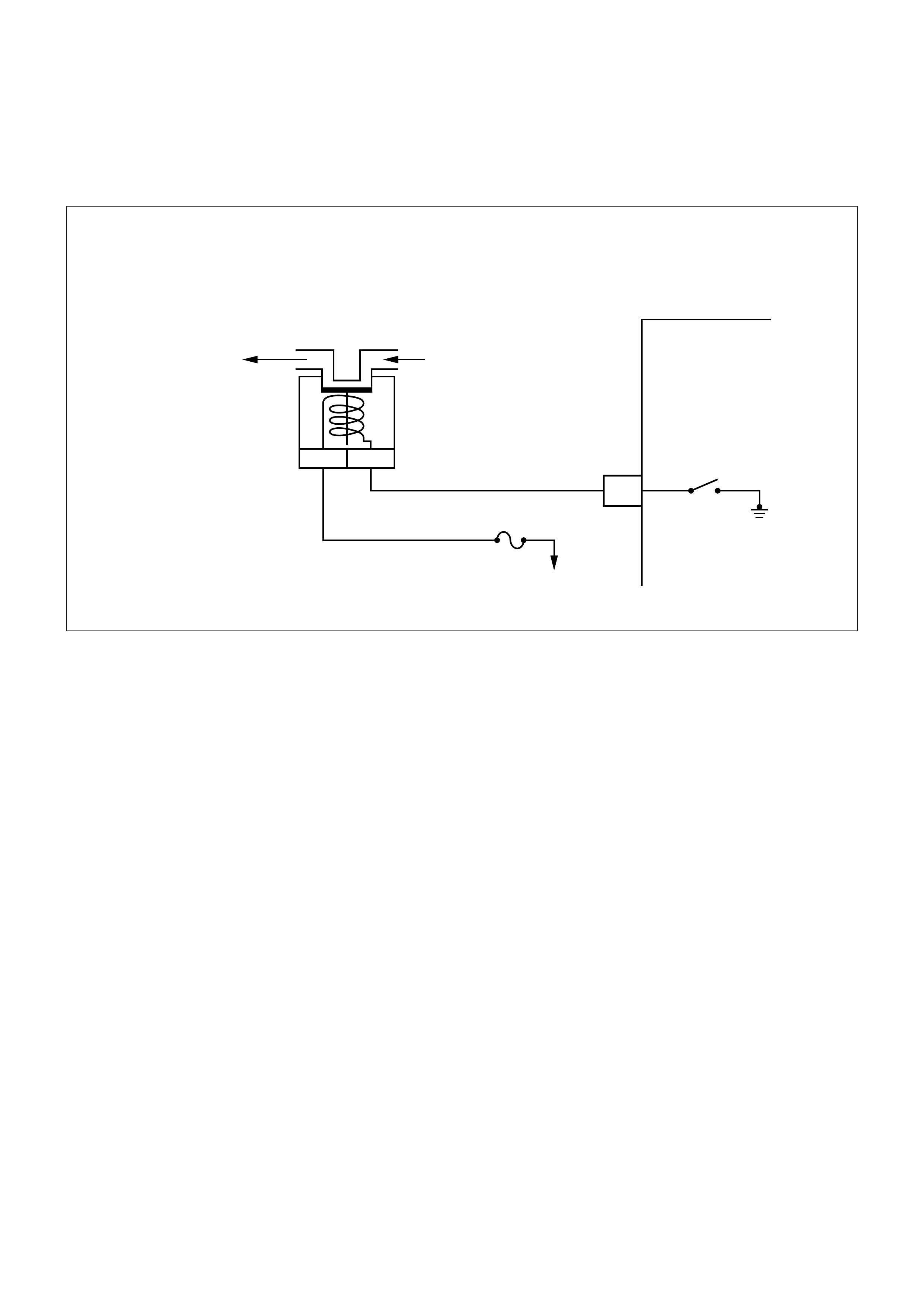
EVAPORATIVE EMISSION CANISTER PURGE CONTROL SOLENOID VALVE
CHECK (IF APPLICABLE)
ENGINE
CONTROL
MODULE
(ECM)
ENGINE FUSE
15A
IGNITION
EVAPORETIVE
EMISSION
CANISTER PURGE
SOLENOID
CONTROL DRIVER
EVAPORATIVE
EMISSION
CANISTER
PURGE CONTLOL
SOLENOID VALVE
12
N.C.
MANIFOLD
VACUUM
TO CANISTER
CIRCUIT DESCRIPTION:
The EVAP canister purge is controlled by a solenoid
valve that allows the manifold vacuum to purge the
canister . The engine control m odule (ECM) supplies a
ground to energize the solenoid valve (purge on). The
EVAP purge solenoid control is pulse- width
modulated (PWM) (turned on and off several times a
second). The duty cycle ( pulse width) is determined by
engine operating conditions including load, throttle
position, coolant temperature and ambient
temper ature. The duty cyc le is calculated by the ECM.
The output is commanded when the appropriate
conditions have been met. These condi-tions are:
•The engine is fully warmed up.
•The engine has been running for a specified time.
•The IAT reading is above 10°C (50°F).
The EVAP purge vacuum switch is a normally closed
switch positioned in the purge line between the
canister and the EVAP purge control solenoid valve.
A continuous purge condition with no purge
commanded by the ECM will set a DTC62.
Poor idle, stalling and poor driveability can be caused
by:
•A malfunctioning purge solenoid.
•A damaged canister.
•Hoses that are split, cracked, or not connected
properly.
TEST DESCRIPTION:
Numbers below refer to circled numbers on the
diagnostic chart.
1. Check to see if the solenoid is opened or closed.
The solenoid is normally de-energized in this step,
so it should be closed.
2. Check to determine if solenoid was open due to
electrical CKT problem or defective solenoid.
3. Completes functional check by grounding test
terminal. This should normally energize the
solenoid opening the valve which should allow the
vacuum to drop (purge “ON“).
DIAGNOSTIC AIDS:
Make a visual check of vacuum hose(s). Check
throttle body for possible cracked, or plugged vacuum
block.
Malfunction indicator lamp for possible mechanical
problem.
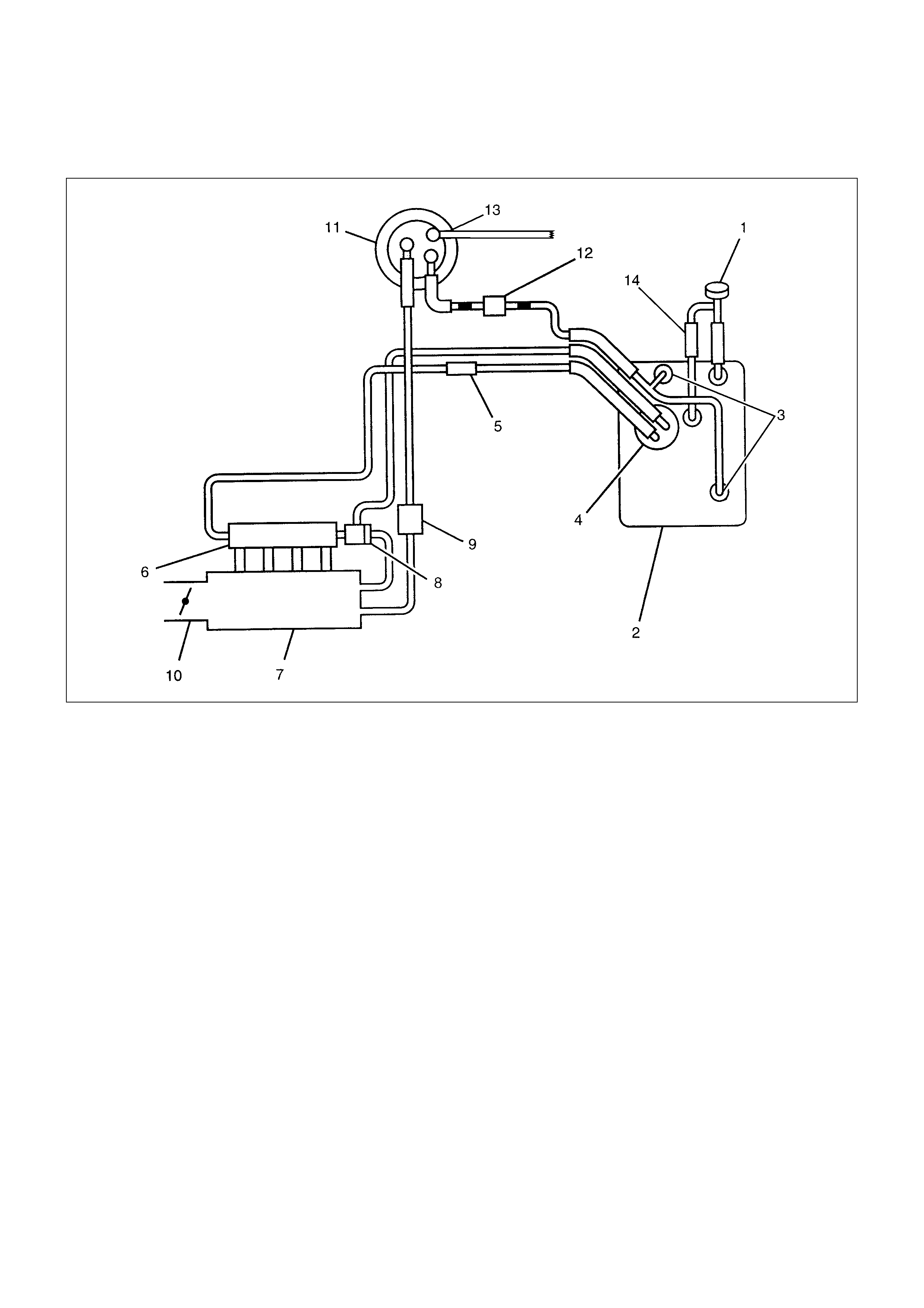
GENERAL DESCRIPTION
LEGEND
(1) Filler Cap
(2) Fuel Tank
(3) Rollover Valve
(4) Fuel Pump
(5) Fuel Filter
(6) Fuel Rail
(7) Intake Manifold
(8) Fuel Pressure Regulator
(9) Duty Solenoid Valve (Evap. Purge Control
Solenoid)
(10) Throttle Valve
(11) Canister
(12) Check and Relief Valve
(13) Drain Hose
(14) 2 Way Valve

ECM DIAGNOSTI C TROUBLE CODES
The following table lists the diagnostic trouble codes
supported a Tech 2 and to flash. If any DTCs not listed
here are displayed by a Tech 2, the Tech 2 data may
be faulty; notify the T ech 2 manuf acturer of any DTCs
displayed that are not included in the following table.
ECM DIAGNOSTIC TROUBLE CODES
DTC USING A
TECH 2 FLASH DTC DESCRIPTION ILLUMINATE MIL
22 22 Throttle position low yes
21 21 Throttle position high yes
13 13 Oxygen sensor not ready (If applicable) yes
44 44 Oxygen sensor too lean (If applicable) yes
45 45 Oxygen sensor rich too long (If applicable) yes
14 14 Coolant High yes
15 15 Coolant Low yes
16 16 Knock sensor disconnected circuit open yes
18 18 Digital Signal to Noise Enhancement Filter failure yes
19 19 58X signal incorrect yes
24 24 Vehicle Speed Senser fault yes
33 33 Manifold Absolute Pressure Sensor too high yes
34 34 MAP too low yes
49 49 Batt voltage too high yes
69 69 Intake Air Temp. Sensor too high yes
71 71 IAT too low yes
17 17 Injector malf yes
41 41 Coil Driver B short to battery yes
42 42 Coil Driver A short to battery yes
63 63 Coil Driver B short to ground yes
64 64 Coil Driver A short to ground yes
35 35 Idle Air Control Value error yes
56 56 Check Engine Lamp low error yes
57 57 Check Engine Lamp high error yes
61 61 Charcoal Canister Purge low error (If applicable) yes
62 62 CCP Solenoid high error (If applicable) yes
87 87 AC Clutch relay low error yes
88 88 AC Clutch relay high error yes
93 93 Quad Driver Sub Module error yes
51 51 EPROM error yes
55 55 EEPROM error yes
91 91 Tacho out low error yes
92 92 Tacho out high error yes
29 29 Fuel Pump relay shorted to ground yes
32 32 Fuel Pump relay shorted to battery yes

SYMPTOM DIAGNOSIS
PRELIMI NARY CHECKS
Before using this section, perform the "On-Board
Diagnostic (OBD) System Check" and verify all of the
following items:
•The engine control module (ECM) and malfunction
indicator lamp (MIL) (Check Engine lamp) are
operating correctly.
•There are no Diagnostic Trouble Code(s) stored.
•Scan Tool data is within normal operating range.
Refer to Typical Scan Data Values.
•Verify the customer complaint and locate the
correct symptom in the table of contents. Perform
the procedure included in the symptom chart.
VISUAL /PHYSICAL CHECK
Several of the symptom procedures call for a careful
visual/physical check. This can lead to correcting a
problem without further checks and can save valuable
time. This check should include the following items:
•ECM grounds for cleanliness, tightness and proper
location.
•Vacuum hoses for splits, kinks, and proper
connections, shown on the " Emission Control
Sys tem Schem atics". Chec k thoroughly for any type
of leak or restriction.
•Air intake ducts for collapsed or damaged areas.
•Air leaks at throttle body mounting area, manifold
absolute pressure (MAP) sensor and intake
manifold sealing surfaces.
•Ignition wires for cracking, hardness, and carbon
tracking.
•Wiring for proper connections, pinches and cuts.
INTERMITTENT
Important: An intermittent problem may or may not
turn on the malfunction indicator lamp (MIL) or store a
Diagnostic Trouble Code. DO NOT use the Diagnostic
Trouble Code (Diagnostic Trouble Code) charts for
intermittent problems. The fault must be present to
locate the problem.
Most intermittent problems are caused by faulty
electrical connections or wiring. Perform a careful
visual/physical check for the following conditions.
•Poor mating of the connector halves or a terminal
not fully seated in the connector (backed out).
•Improperly formed or damaged terminal.
•All connector ter m inals in the problem circ uit s hould
be carefully checked for proper contact tension.
•Poor terminal-to-wire connection. This requires
removing the terminal from the connector body to
check.
•Ignition coil shorted to ground and arcing at ignition
wires or plugs.
•MIL (Check Engine lamp) wire to ECM shorted to
ground.
•Poor ECM grounds. Refer to the
ECM wiring diagrams.
Road test the vehicle with a 5-8840-2392-0 Digital
Multimeter connected to a suspected circuit. An
abnormal voltage when the malfunction occurs is a
good indication that there is a fault in the circuit being
monitored.
Use a Scan Tool to help detect intermittent conditions.
The Scan Tools have several features that can be
used to locate an intermittent condition. Use the
following features to find intermittent faults:
To check for loss of diagnostic code memory,
disconnect the MAP sensor and idle the engine until
the MIL (Check Engine lamp) comes on. Diagnostic
Trouble Code 34 should be stored and kept in memory
when the ignition is turned "OFF." If not, the ECM is
faulty. When this test is completed, make sure that
you clear the Diagnostic Trouble Code 34 from
memory.
Check for improper installation of electrical options
such as lights, cellular phones, etc. Check all wires
from the ECM to the ignition control module for poor
connections.
Check for an open diode across the A/C compressor
clutch and check for other open diodes (refer to wiring
diagrams in Electrical Diagnosis).
If problem has not been found, refer to
ECM Connector Symptom tables.

HARD START SYMPTOM
STEP ACTION VALUE(S) YES NO
DEFINITION: Engine cranks, but does not start for a long time. Does eventually run, or may start but immediately stalls.
1Was the On-Board Diagnostic (OBD) System Check performed? -
Go to Step 2
Go to OBD
System Check
2
1. Perform a bulletin search.
2. If a bulletin that addresses the symptom is found, correct the
condition as instructed in the bulletin.
Was a bulletin found that addresses the symptom?
-
Verify Repair Go to Step 3
3Was a visual/physical check performed? -
Go to Step 4
Go to
Visual/Physical
Check
4
Check engine coolant temperature (ECT) sensor for shift in
value.
1. After 8 hours with the hood up and the engine not running,
connect the Scan Tool.
2. Ignition ON, engine not running.
3. Using the Scan Tool, compare Engine Coolant Temperature
to Intake Air Temperature.
Are ECT and IAT within the specified value of each other? ±5°C
(±9°F) Go to Step 8 Go to Step 5
5
1. Using a Scan Tool, display the engine coolant temperature
and note the value.
2. Check the resistance of the engine coolant temperature
sensor.
3. Refer to Temperature vs. Resistance chart in Diagnostic
Trouble Code 14 for resistance specifications.
Is the actual resistance near the resistance value in the chart for
the temperature that was noted?
-
Go to Step 7 Go to Step 6
6Replace the ECT sensor.
Is the action complete? -Verify repair -
7Located and repair high resistance or connection in the ECT
signal circuit or the ECT signal circuit or the ECM sensor
ground. -
Verify repair
-
8Check for a faulty, plugged, or incorrectly installed PCV hoses.
Was a problem found? -
Verify repair Go to Step 9
9
Visually/Physically inspect the secondary ignition wires. Check
for the following conditions:
•Verify that all ignition wire resistance are less than the
specified value.
•Verify that ignition wires are correctly routed to eliminate
cross-firing.
•Verify that ignition wires are not arcing to ground.
Spraying the secondary ignition wires with a light mist of water
may help locate an intermittent problem.
Was a problem found?
#1 cyl. 4.7kΩ
#2 cyl. 3.9kΩ
#3 cyl. 3.4kΩ
#4 cyl. 3.1kΩVerify repair Go to Step 10

STEP ACTION VALUE(S) YES NO
10 Check for proper ignition voltage output with a spark tester (Use
commercially available tool).
Was a problem found? -
Verify repair Go to Step 11
11
1. Remove the spark plugs and check for gas or oil fouling
cracks, wear, improper gap, burned electrodes, heavy
deposits, or improper heat range.
If spark plugs are fouled, the cause of fouling must be
determined before replacing the spark plugs.
Was a problem found?
-
Verify repair Go to Step 12
12 Check for a loose ignition control module ground.
Was a problem found? -Verify repair Go to Step 13
13
1. Check the ignition coil secondary resistance.
2. Replace the coil if it is greater than the specified resistance.
Did the coil require replacement? 2.5 kΩVerify repair Go to Step 14
14 Check IAC operation. Perform the procedure in the diagnostic
chart Diagnostic Trouble Code 35, Step 6.
Was a problem found? -
Verify repair Go to Step 15
15 Check for water or alcohol contaminated fuel.
Was a problem found? -Verify repair Go to Step 16
16 Perform the procedure in Fuel System Pressure Test to
determine if there is a problem with fuel delivery.
Was a problem found? -
Verify repair Go to Step 17
17
Check for the following engine mechanical problems (refer to
Engine Mechanical):
•Low compression
•Leaking cylinder head gaskets
•Worn camshaft
•Camshaft drive belt slipped or stripped
Was a problem found?
-
Verify repair Go to Step 18
18
1. Review all diagnostic procedures within this table.
2. If all procedures have been completed and no malfunctions
have been found, review/inspect the following:
•Visual/physical inspection
•Scan Tool data
•All electrical connections within a suspected circuit and/or
system
Was a problem found?
-
Verify repair
Contact
Technical
Assistance

SURGES AND/OR CHUGGLES SYMPTOM
STEP ACTION VALUE(S) YES NO
DEFINITION: Engine power variation under steady throttle or cruise. Feels like the vehicle speeds up and slows down with no
change in the accelerator pedal.
1Was the On-Board Diagnostic (OBD) System Check performed? -
Go to Step 2
Go to OBD
System Check
2
1. Perform a bulletin search.
2. If a bulletin that addresses the symptom is found, correct the
condition as instructed in the bulletin.
Was a bulletin found that addresses the symptom?
-
Verify Repair Go to Step 3
3
Was a visual/physical check performed?
-
Go to Step 4
Go to Visual/
Physical
Check
4
Be sure that the driver understands A/C compressor operation
as explained in the owner's manual.
Inform the customer how the A/C clutch operate.
Is the customer experiencing a normal condition?
-
System OK Go to Step 5
5
Check the fuel control Heated Oxygen Sensor (HO2S) (If
applicable). When monitored on the Scan Tool, the HO2S
should respond quickly to different throttle positions. If it doesn't
check for silicon or other contaminants from fuel or use of
improper RTV sealant. The sensors may have a white powdery
coating. Silicon contamination sends a rich exhaust signal which
causes the ECM to command an excessively lean air/fuel
mixture.
Was a problem found?
-
Verify repair Go to Step 6
6Check the fuel pressure. Refer to Fuel System Pressure Test.
Was a problem found? -
Verify repair Go to Step 7
7Monitor "02 Status" on the Scan Tool (If applicable).
Is "02 Status" in the (rich condition)? -Go to Step 8 Go to Step 9
8Check items that can cause the engine to run rich.
Refer to Diagnostic Aids in Diagnostic Trouble Code 45 (If
applicable).
Was a problem found?
-
Verify repair Go to Step 10
9Check items that can cause the engine to run lean.
Refer to Diagnostic Aids in Diagnostic Trouble Code 44 (If
applicable).
Was a problem found?
-
Verify repair Go to Step 10
10 Check for proper ignition voltage output with the spark tester
(Use commercially available tool).
Was a problem found? -
Verify repair Go to Step 11
11 Check for a loose ignition control module ground.
Was a problem found? -Verify repair Go to Step 12

STEP ACTION VALUE(S) YES NO
12
Visually/Physically inspect the secondary ignition wires. Check
for the following conditions.
•Verify that all ignition wire resistance are less than the
specified value.
•Verify that ignition wires are correctly routed to eliminate
cross-firing.
•Verify that ignition wires are not arcing to ground.
Spraying the secondary ignition wires with a light mist of water
may help locate an intermittent problem.
Was a problem found?
#1 cyl. 4.7kΩ
#2 cyl. 3.9kΩ
#3 cyl. 3.4kΩ
#4 cyl. 3.1kΩVerify repair Go to Step 13
13
1. Check ignition coil secondary resistance.
2. Replace the coil if it is greater than the specified resistance.
Did the coil require replacement? 2.5 kΩVerify repair Go to Step 14
14
1. Remove the spark plugs and check for gas or oil fouling
cracks, wear, improper gap, burned electrodes, heavy
deposits or improper heat range.
2. If spark plugs are fouled, the cause of fouling must be
determined before replacing the spark plugs.
Was a problem found?
-
Verify repair Go to Step 15
15
1. Check the injector connectors.
2. If any of the connectors are connected at an improper
cylinder, correct as necessary.
Was a problem found?
-
Verify repair Go to Step 16
16
Check the ECM grounds to verify that they are clean and tight.
Refer to the ECM wiring diagrams in Electrical Diagnosis.
Was a problem found? -
Verify repair Go to Step 17
17
Visually/Physically check the vacuum hoses for splits, kinks and
proper connections and proper connections and routing as
shown on the "Emission Control System Schematics".
Was a problem found? -
Verify repair Go to Step 18
18 Check the exhaust system for a possible restriction:
•Damaged or collapsed pipes
•Internal muffler failure -Verify repair Go to Step 19
19
1. Review all the diagnostic procedures within this table.
2. If all procedures have been completed and no malfunctions
have been found, review/inspect the following:
•Visual/physical inspection.
•Scan Tool data.
•All electrical connections within a suspected circuit and/or
system.
Was a problem found?
-
Verify repair
Contact
Technical
Assistance

LACK OF POWER, SLUGGISH OR SPONGY SYMPTOM
STEP ACTION VALUE(S) YES NO
DEFINITION: Engine delivers less than expected power. Little or no increase in speed when accelerator pedal is pushed down
part-way.
1Was the On-Board Diagnostic (OBD) System Check performed? -
Go to Step 2
Go to OBD
System Check
2
1. Perform a bulletin search.
2. If a bulletin that addresses the symptom is found, correct the
condition as instructed in the bulletin.
Was a bulletin found that addresses the symptom?
-
Verify Repair Go to Step 3
3Was a visual/physical check performed? -
Go to Step 4
Go to
Visual/Physical
Check
4
1. Remove and check the air filter element for dirt or
restrictions. Refer to Air Intake System in On-Vehicle
Service.
2. Replace the air filter element if necessary.
Was a repair required?
-
Verify repair Go to Step 5
5Check for proper ignition voltage output with the spark tester
(Use commercially available tool).
Was a problem found? -
Verify repair Go to Step 6
6
1. Remove the spark plugs and check for gas or oil fouling,
cracks, wear, improper gap, burned electrodes, heavy
deposits or improper heat range.
2. If spark plugs are fouled, the cause of fouling must be
determined before replacing the spark plugs.
Was a problem found?
-
Verify repair Go to Step 7
7Check the fuel pressure. Refer to Fuel System Pressure Test.
Was a problem found? -
Verify repair Go to Step 8

STEP ACTION VALUE(S) YES NO
8Check for water or alcohol contaminated fuel.
Was a problem found? -Verify repair Go to Step 9
9
Check the ECM grounds to verify that they are clean and tight.
Refer to the ECM wiring diagrams in Electrical Diagnosis.
Was a problem found? -
Verify repair Go to Step 10
10
Check the exhaust system for a possible restriction:
•Damaged or collapsed pipes
•Internal muffler failure
Was a problem found?
-
Verify repair Go to Step 10
11
Check for the following engine mechanical problems:
•Low compression
•Leaking cylinder head gasket
•Worn or incorrect camshaft
•Loose timing belt
Was a problem found?
-
Verify repair Go to Step 12
12
1. Review all the diagnostic procedures within this table.
2. If all procedures have been completed and no malfunctions
have been found, review/inspect the following:
•Visual/physical inspection.
•Scan Tool data.
•All electrical connections within a suspected circuit and/or
system.
Was a problem found?
-
Verify repair
Contact
Technical
Assistance

DETONATION/SPARK KNOCK SYMPTOM
STEP ACTION VALUE(S) YES NO
DEFINITION: A mild to severe ping, usually worse under acceleration. The engine makes sharp metallic knocks that change with
throttle opening.
1Was the On-Board Diagnostic (OBD) System Check performed? -
Go to Step 2
Go to OBD
System Check
2
1. Perform a bulletin search.
2. If a bulletin that addresses the symptom is found, correct the
condition as instructed in the bulletin.
Was a bulletin found that addresses the symptom?
-
Verify Repair Go to Step 3
3Was a visual/physical check performed? -
Go to Step 4
Go to
Visual/Physical
Check
4
1. If scan tool readings are normal (refer to Typical Scan
Values) and there are no engine mechanical faults, fill the
fuel tank with a known quality gasoline that has a minimum
octane rating Showing on the applicable specification list.
2. Re-evaluate the vehicle performance.
Is detonation present?
-
Go to Step 5 Verify Repair
5
1. Check for obvious overheating problems:
•Low engine coolant.
•Restricted air flow to radiator, or restricted water flow
through radiator.
•Incorrect coolant solution. It should be a 50/50 mix of
approved antifreeze/water.
2. If a problem is found, repair as necessary.
Was a problem found?
-
Verify repair Go to Step 6
6Check fuel pressure. Refer to Fuel System Pressure Test.
Was a problem found? -Verify repair Go to Step 7
7Check items that can cause the engine to run lean.
Refer to Diagnostic Aids in Diagnostic Trouble Code 44 (If
applicable).
Was a problem found?
-Verify repair Go to Step 8

STEP ACTION VALUE(S) YES NO
8Check spark plugs for proper heat range. Refer to General
Information.
Were incorrect spark plugs installed? -
Verify repair Go to Step 9
9
1. Remove excessive carbon buildup with a top engine cleaner.
Refer to instructions on the top engine cleaner can.
2. Re-evaluate vehicle performance.
Is detonation still present? -
Go to Step 10 Verify repair
10 Check for an engine mechanical problem. Perform a cylinder
compression check. Refer to Engine Mechanical.
Was a problem found? -
Verify repair Go to Step 11
11
1. Review all diagnostic procedures within this table.
2. If all procedures have been completed and no malfunctions
have been found, review/inspect the following:
•Visual/physical inspection.
•Scan tool data.
•All electrical connections within a suspected circuit and/or
system.
Was a problem found?
-
Verify repair
Contact
Technical
Assistance

ROUGH, UNSTABLE, OR INCORRECT IDLE, STALLING SYMPTOM (FOR OPEN LOOP SYSTEM)
STEP ACTION VALUE(S) YES NO
DEFINITION: Engine runs unevenly at idle. If severe, the engine or vehicle may shake. Engine idle speed may vary in RPM.
Either condition may be severe enough to stall the engine.
1Was the On-Board Diagnostic (OBD) System Check performed? -
Go to Step 2
Go to OBD
System Check
2
1. Perform a bulletin search.
2. If a bulletin that addresses the symptom is found, correct the
condition as instructed in the bulletin.
Was a bulletin found that addresses the symptom?
-
Verify Repair Go to Step 3
3Was a visual/physical check performed, including the rotor,
ignition coil and secondary ignition wires? -
Go to Step 4
Go to
Visual/Physical
Check
4
1. Check for incorrect idle speed. Ensure that the following
conditions are present.
•Engine fully warm.
•Accessories are OFF.
2. Using a Scan Tool, monitor IAC position.
Is the IAC position within the specified values?
Between 8 and
50 counts
Go to Step 7 Go to Step 5
5
1. Visually/Physically inspect for the following conditions:
•Restricted air intake system. Check for a restricted air
filter element, or foreign objects blocking the air intake
system.
•Check for objects blocking the IAC passage or throttle
bore, excessive deposits in the IAC passage and on the
IAC pintle, and excessive deposits in the throttle bore and
on the throttle plate.
•Check for a condition that causes a large vacuum leak,
such as an incorrectly installed or faulty crankcase
ventilation hose/brake booster hose.
Was a problem found?
-
Verify repair Go to Step 6
6
Using a Scan Tool, monitor TP angle with the engine idling.
Is the TP angle at the specified value and steady?
0% Go to Step 7
Refer to
Diagnostic
Trouble Code
21 for further
diagnosis
7Check for proper ignition voltage output with the spark tester
(Use commercially available tool).
Was a problem found? -
Verify repair Go to Step 8
8
1. Remove the spark plugs and check for gas or oil fouling
cracks, wear, improper gap, burned electrodes, heavy
deposits or improper heat range
2. If spark plugs are fouled, the cause of fouling must be
determined before replacing the spark plugs.
Was a problem found?
-
Verify repair Go to Step 9

STEP ACTION VALUE(S) YES NO
9Check for a lose ignition coil ground.
Refer to Electrical Ignition System.
Was a problem found? -
Verify repair Go to Step 10
10 Check the items that can cause the engine to run lean.
Refer to Idle CO Concentration Check and Adjustment.
Was a problem found?
-
Verify repair Go to Step 11
11 Check the injector connections, if any of the injectors are
connected an incorrect cylinder, correct as necessary.
Was a problem found? -
Verify repair Go to Step 12
12 Perform the injector Coil/Balance Test.
Was a problem found? -Verify repair Go to Step 13
13
Check the following engine mechanical problems:
Low compression
Leaking cylinder head gasket
Worn or incorrect camshaft
Sticking or leaking valves
Broken valve springs
Camshaft drive belt slipped or stripped
Was a problem found?
-
Verify repair Go to Step 14
14
1. Check for faulty motor mounts. Refer to Engine Mechanical
for inspection of mounts.
2. If a problem is found, repair as necessary.
Was a problem found?
-
Verify repair Go to Step 15
15
1. Review all the diagnostic procedures within this table.
2. If all procedures have been completed and no malfunctions
have been found, review/inspect the following:
Visual/ Physical inspection
Scan tool data
All electrical connections within a suspected circuit and/or
system
Was a problem found?
-
Verify repair
Contact
Technical
Assistance

ROUGH, UNSTABLE, OR INCORRECT IDLE, STALLING SYMPTON (FOR CLOSED LOOP SYSTEM)
STEP ACTION VALUE(S) YES NO
1Was the “On-Board Diagnostic (OBD) System Check”
performed? -
Go to Step 2
Go to OBD
System Check
2
1. Read the “Caution” above.
2. Relieve the fuel system pressure and install the fuel pump
pressure gauge to the test fitting.
3. Use a scan tool to command the fuel pump ON.
Is there an immediate pressure build-up which indicates the
pump is running?
-
Go to Step 3 Go to Step 4
3
1. Verify that the pump is not running by removi ng the fuel filler
cap and listening.
2. Command the pump ON with the scan tool.
Did the pump turn OFF after 2 seconds?
-Test
completed Go to Step 12
4
1. Ignition OFF.
2. Remove the fuel pump relay.
3. Using a test light connected to ground, probe the battery
feed to the relay.
Did the light illuminate?
-
Go to Step 6 Go to Step 5
5Repair short or open battery feed to fuel pump relay.
Is the action complete? -Verify repair -
6
1. Connect a test light between the two wires that connect to
the fuel pump relay pull-in coil.
2. Ignition ON.
Did the test light illuminate for 2 seconds and then turn off? -
Go to Step 12 Go to Step 7
7
1. With a test light connected to battery (-), probe the fuel
pump relay connector at the wire which runs from the relay
pull-in coil to the ECM.
2. Ignition ON.
Did the test light illuminate for 2 seconds and then turn off?
-
Go to Step 8 Go to Step 9
8Locate and repair open in the fuel pump relay ground circuit.
Is the action complete? -
Verify repair
-
9
Check for short or open between the ECM and the fuel pump
relay.
Was a problem found? -Verify repair Go to Step 10
10
1. Check the fuel pump relay circuit for a poor terminal
connection at the ECM.
2. If a problem is found, replace terminal as necessary.
Was a problem found?
-
Verify repair Go to Step 11
11
Replace the ECM.
Important: The replacement ECM must be programmed. Refer
to On-Vehicle Service in Powertrain Control Module and
Sensors for procedures.
Is the action complete?
-
Verify repair
-

STEP ACTION VALUE(S) YES NO
12
1. Reconnect the fuel pump relay.
2. Disconnect the fuel pump electrical connector at the fuel
tank.
3. Using a test light connected to ground, probe the fuel pump
feed wire (harness side).
4. Command the fuel pump ON with a scan tool.
Did the light illuminate for 2 seconds?
-
Go to Step 15 Go to Step 13
13
1. Honk the horn to verify that horn relay is functioning.
2. Susbstitute the horn relay for the fuel pump relay.
3. Leave the test light connected as in step 12.
4. Command the fuel pump ON with the scan tool.
Did the test light illuminate for 2 seconds when the fuel pump
was commanded ON?
-
Go to Step 17 Go to Step 14
14
1. Re-connect the horn relay in its proper location.
2. Check for a short circuit, blown fuse or open circuit between
the relay and the fuel tank.
Is the action complete?
-
Verify repair
-
15
1. with the fuel pump electrical connector at the fuel tank
disconnected, connect a test light between the feed wire and
the ground wire (harness side).
2. Command the fuel pump ON with a scan tool.
Did the test light illuminate for 2 seconds.
-
Go to Step 18 Go to Step 16
16 Repair the open circuit in the fuel pump ground wire.
Is the action complete? -Verify repair -
17 1. Re-connect the horn relay in its proper location.
2. Replace the fuel pump relay.
Is the action complete? -
Verify repair
-
18 Replace the fuel pump.
Is the action complete? -Verify repair -
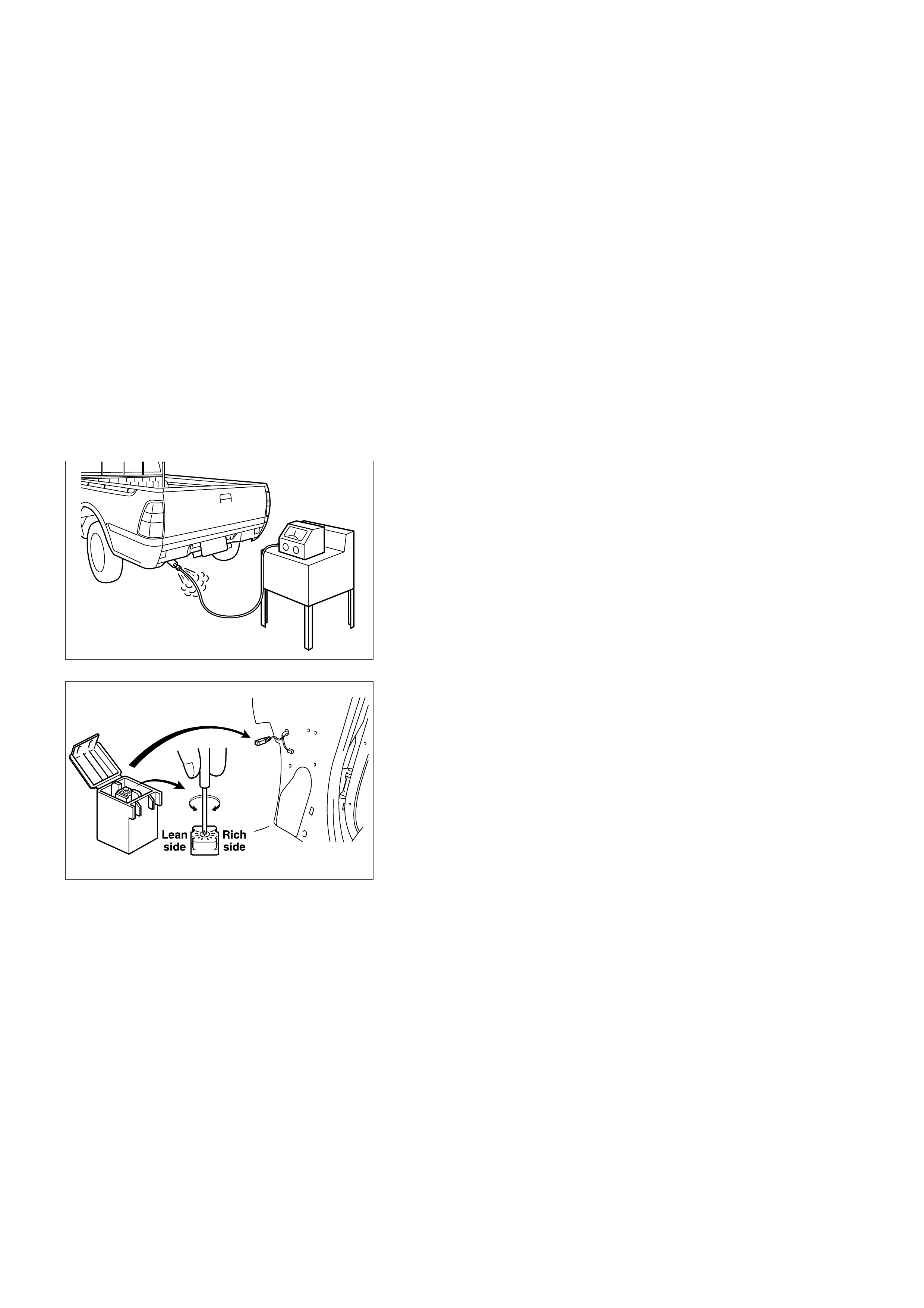
IDLE CO CONCENTRATION CHECK AND
ADJUSTMENT
1. Before starting adjusting work, check and confirm the
following conditions.
Normal engine operating temperature.
All accessories switched off.
Throttle valve closed.
Transmission in neutral.
2. Before starting adjusting work, step on accelerator pedal
a few times and do racing up to 3000rpm.
3. After taking foot off accelerator pedal, short out pins #5 +
#6 of ALDL Connector(Fixed under center console panel)
short.
(When you do this, Check Engine Lamp will blink, and
engine rpm will rise to 100 to 1600rpm)
4. In this condition, connect CO meter with Tail Pig and
check CO value(%).
5. If CO value is within the range shown below, leave as it
is. If it is out of range, adjust I t by turning the screw of
CO Adjuster.
(After adjusting, confirm that CO value becomes stable.)
Note: After adjusting work is finished, apply the liquid gasket to
the CO adjuster screw. And after that, all conditions to
restore to former state.
Regulated range of CO concentration value:
1.0 +0.2
- 0.5

POOR FUEL ECONOMY SYMPTOM
STEP ACTION VALUE(S) YES NO
DEFINITION: Fuel economy, as measured by an actual road test, is noticeably lower than expected. Also, economy is noticeably
lower than it was on this vehicle at one time, as previously shown by an actual road test.
1Was the On-Board Diagnostic (OBD) System Check performed? -
Go to Step 2
Go to OBD
System Check
2
1. Perform a bulletin search.
2. If a bulletin that addresses the symptom is found, correct the
condition as instructed in the bulletin.
Was a bulletin found that addresses the symptom?
-
Verify Repair Go to Step 3
3Was a visual/physical check performed? -
Go to Step 4
Go to
Visual/Physical
Check
4
Check owner's driving habits.
•Is the A/C On full time (defroster mode ON)?
•Are tires at the correct pressure?
•Are excessively heavy loads being carried?
•Is acceleration too much, too often?
-
Go to Step 5 Go to Step 6
5Review the items in Step 4 with the customer and advise as
necessary.
Is the action complete? -
System OK
-
6
1. Visually/Physically check: Vacuum hoses for splits, kinks,
and improper connections and routing as shown on the
"Emission Control System schematics".
Was a problem found?
-
Verify repair Go to Step 7
7Remove and check the air filter element for dirt or for
restrictions.
Was a problem found? -
Verify repair Go to Step 8
8
1. Remove the spark plugs and check for gas or oil fouling
cracks, wear, improper gap, burned electrodes of heavy
deposits.
2. Is spark plugs are fouled, the cause of fouling must be
determined before replacing the spark plugs.
Was a problem found?
-
Verify repair Go to Step 9
9Check for low engine coolant level.
Was a problem found? -Verify repair Go to Step 10
10 Check for an incorrect or faulty engine thermostat.
Refer to Engine Cooling.
Was a problem found? -
Verify repair Go to Step 11
11 Check for low engine compression. Refer to Engine Mechanical.
Was a problem found? -
Verify repair Go to Step 12

STEP ACTION VALUE(S) YES NO
12 Check for proper calibration of the speedometer.
Does the speed indicated on the speedometer closely match the
vehicle speed displayed on the Scan Tool? -
Go to Step 14 Go to Step 13
13 Diagnose and repair the inaccurate speedometer condition as
necessary. Refer to Vehicle Speed Sensor in Electrical
Diagnosis.-
Verify repair
-
14 Check the air intake system and the crankcase for air leaks.
Was a problem found? -
Verify repair Go to Step 15
15
1. Review all the diagnostic procedures within this table.
2. If all procedures have been completed and no malfunctions
have been found, review/inspect the following:
•Visual/physical inspection
•Scan tool data
•All electrical connections within a suspected circuit and/or
system
Was a problem found?
-
Verify repair Go to Step 16
16 Perform the procedure in Fuel System Pressure Test .
Was the fuel pressure normal? - Contact
Technical
Assistance Verify repair

DIESELING, RUN-ON SYMPTOM
STEP ACTION VALUE(S) YES NO
DEFINITION: Engine continues to run after key is turned OFF, but runs very rough. If engine runs smoothly, check the ignition
switch and adjustment.
1Was the On-Board Diagnostic (OBD) System Check performed? -
Go to Step 2
Go to OBD
System Check
2
1. Perform a bulletin search.
2. If a bulletin that addresses the symptom is found, correct the
condition as instructed in the bulletin.
Was a bulletin found that addresses the symptom?
-
Verify repair Go to Step 3
3 Was a visual/physical check performed? -
Go to Step 4
Go to
Visual/Physical
Check
41. Check for a short between B+ and the ignition feed circuit.
Was a problem found? -
Verify repair Go to Step 5
5
1. Review all the diagnostic procedures within this table.
2. If all procedures have been completed and no malfunctions
have been found, review/inspect the following:
•Visual/physical inspection.
•Scan Tool data.
•All electrical connections within a suspected circuit and/or
system.
Was a problem found?
-
Verify repair
Contact
Technical
Assistance

BACKFIRE SYMPTOM
STEP ACTION VALUE(S) YES NO
DEFINITION: Fuel ignites in the intake manifold, or in the exhaust system, making a loud popping noise.
1Was the On-Board Diagnostic (OBD) System Check performed? -
Go to Step 2
Go to OBD
System Check
2
1. Perform a bulletin search.
2. If a bulletin that addresses the symptom is found, correct the
condition as instructed in the bulletin.
Was a bulletin found that addresses the symptom?
-
Verify repair Go to Step 3
3Was a visual/physical check performed? -
Go to Step 4
Go to
Visual/Physical
Check
4Check for proper ignition voltage output with the spark tester
(Use commercially available tool).
Was a problem found? -
Verify repair Go to Step 5
5
1. Remove the spark plugs and check for gas or oil fouling
cracks, wear, improper gap, burned electrodes of heavy
deposits.
2. If spark plugs are fouled, the cause of fouling must be
determined before replacing the spark plugs.
Was a problem found?
-
Verify repair Go to Step 6
6
1. Visually/Physically inspect the secondary ignition wires.
Check for the following conditions:
•Verify that all ignition wire resistance are less than the
specified value.
•Verify that ignition wires are correctly routed to eliminate
cross-firing.
•Verify that ignition wires are not arcing to ground. Spraying
the secondary ignition wires with a light mist of water may
help locate an intermittent problem.
Was a problem found?
-
Verify repair Go to Step 7
7
Check for an intermittent ignition system malfunction:
•Intermittent CKP 58X signal.
•Intermittent ignition feed circuit or sensor ground circuit to the
crankshaft position sensor.
Was a problem found?
-
Verify repair Go to Step 8

STEP ACTION VALUE(S) YES NO
8Refer to Fuel System Diagnosis to determine if there is a
problem with fuel delivery.
Was a problem found? -
Verify repair Go to Step 9
9
Check for the following engine mechanical problems:
•Low compression
•Leaking cylinder head gasket
•Worn or incorrect camshaft
•Incorrect valve timing
•Sticking or leaking valves
•Camshaft drive belt slipped or stripped.
Was a problem found?
-
Verify repair Go to Step 10
10 Check the intake and exhaust manifold(s) for casting flash.
Refer to Engine Mechanical.
Was a problem found? -
Verify repair Go to Step 11
11
1. Review all the diagnostic procedures within this table.
2. If all procedures have been completed and no malfunctions
have been found, review/inspect the following:
•Visual/physical inspection.
•Scan Tool data.
•All electrical connections within a suspected circuit and/or
system.
Was a problem found?
-
Verify repair
Contact
Technical
Assistance

CUTS OUT, MISSES SYMPTOM
STEP ACTION VALUE(S) YES NO
DEFINITION: Steady pulsation or jerking that follows engine speed; usually more pronounced as engine load increases.
1Was the On-Board Diagnostic (OBD) System Check performed? -
Go to Step 2
Go to OBD
System Check
2
1. Perform a bulletin search.
2. If a bulletin that addresses the symptom is found, correct the
condition as instructed in the bulletin.
Was a bulletin found that addresses the symptom?
-
Verify Repair Go to Step 3
3Was a visual/physical check performed? -
Go to Step 4
Go to Visual/
Physical
Check
4
Check the ECM grounds to verify that they are clean and tight.
Refer to the ECM wiring diagrams in Electrical Diagnosis.
Was a problem found? -
Verify repair Go to Step 5
5Monitor "02 Status" on the Scan Tool.
Is the "02 Status" in the rich condition (If applicable) ? Go to Step 6 Go to Step 7
6Check items that can cause the engine to run rich.
Refer to "Diagnostic Aids" in Diagnostic Trouble Code 45 (If
applicable).
Was a problem found?
-
Verify repair Go to Step 9
7 Is the "02 Status" significantly in the lean condition (If
applicable)? -Go to Step 8 Go to Step 9
8Check items that can cause the engine to run lean.
Refer to Diagnostic Aids in Diagnostic Trouble Code 44 (If
applicable).
Was a problem found?
-
Verify repair Go to Step 9
9
1. Check for incorrect idle speed. Ensure that the following
conditions are present:
•Engine fully warm.
•Accessories are OFF.
2. Using a Scan Tool, monitor the IAC position.
Is the IAC position within the specified values?
Between
5 and 50
counts Go to Step 11 Go to Step 10
10
1. Visually/Physically inspect for the following conditions:
•Restricted air intake system. Check for a restricted air
filter element, or foreign objects blocking the air intake
system.
•Check for objects blocking the IAC passage or throttle
bore, excessive deposits in the IAC passage and on the
IAC pintle, and excessive deposits in the throttle bore and
on the throttle plate.
•Check for a condition that causes a large vacuum leak,
such as an incorrectly installed or faulty crankcase
ventilation hoses or brake booster hose disconnected.
Was a problem found?
-
Verify repair Go to Step 11

STEP ACTION VALUE(S) YES NO
11
1. Check the injector connections. If any of the injectors are
connected to an incorrect cylinder, correct as necessary.
Was a problem found? -
Verify repair Go to Step 12
12 1. Perform the Injector Coil/Balance Test.
Was a problem found? -Verify repair Go to Step 13
13
1. Check for fuel in the pressure regulator vacuum hose.
2. If fuel is present, replace the fuel pressure regulator
assembly.
Was a problem found?
-
Verify repair Go to Step 14
14 Check for proper ignition voltage output with the spark tester
(Use commercially available tool).
Was a problem found? -
Verify repair Go to Step 15
15
1. Remove spark plugs and check for gas or oil fouling cracks,
wear, improper gap, burned electrodes of heavy deposits.
2. If spark plugs are fouled, the cause of fouling must be
determined before replacing the spark plugs.
Was a problem found?
-
Verify repair Go to Step 16
16 Check for a loose ignition control module ground.
Was a problem found? -Verify repair Go to Step 17
17
Using a Scan Tool, monitor the TP angle with the engine idling.
Is the TP angle at the specified value and steady?
0% Go to Step 18
Refer to
Diagnostic
Trouble Code
21 for further
diagnosis

STEP ACTION VALUE(S) YES NO
18 Check the PCV passage for proper operation.
Was a problem found? -Verify repair Go to Step 19
19
Check the following engine mechanical problems:
•Low compression
•Leaking cylinder head gasket
•Worn or incorrect camshaft
•Sticking or leaking valves
•Valve timing
•Broken valve springs
•Camshaft drive belt slipped or stripped.
Was a problem found?
-
Verify repair Go to Step 20
20 Check for faulty motor mounts. Refer to Engine Mechanical for
inspection of mounts.
Was a problem found? -
Verify repair Go to Step 21
21
1. Review all the diagnostic procedures within this table.
2. If all procedures have been completed and no malfunctions
have been found, review/inspect the following:
•Visual/physical inspection.
•Scan Tool data.
•All electrical connections within a suspected circuit and/or
system.
Was a problem found?
-
Verify repair
Contact
Technical
Assistance

HESITATION, SAG, STUMBLE SYMPTOM
STEP ACTION VALUE(S) YES NO
DEFINITION: Momentary lack of response as the accelerator is pushed down. Can occur at any vehicle speed.
Usually most pronounced when first trying to make the vehicle move, as from a stop sign. May cause the engine to stall if severe
enough.
1Was the On-Board Diagnostic (OBD) System Check performed? -
Go to Step 2
Go to OBD
System Check
2
1. Perform a bulletin search.
2. If a bulletin that addresses the symptom is found, correct the
condition as instructed in the bulletin.
Was a bulletin found that addresses the symptom?
-
Verify Repair Go to Step 3
3Was a visual/physical check performed? -
Go to Step 4
Go to
Visual/Physical
Check
4
1. Check the fuel control heated oxygen sensor (If applicable).
The HO2S should respond quickly to different to throttle
positions. If it doesn't, check for silicon or other contaminants
from fuel or use of improper RTV sealant. The sensors may
have a white powdery coating. Silicon contamination sends a
rich exhaust signal which causes the ECM to command an
excessively lean air/fuel mixture.
Was a problem found?
-
Verify repair Go to Step 5
5Check the fuel pressure. Refer to Fuel System Pressure Test.
Was a problem found? -
Verify repair Go to Step 6
6
Observe the "TP angle" display on the Scan Tool while slowly
increasing throttle pedal.
Does the TP angle display steadily increase from 0% at closed
throttle to 100% at WOT?
-
Go to Step 7 Go to Step 13
7Monitor "Long Term Fuel Trim" on the Scan Tool.
Is the "Long Term Fuel Trim" in the negative range (rich
condition)? -
Go to Step 8 Go to Step 9
8Check items that can cause the engine to run rich.
Refer to Diagnostic Aids in Diagnostic Trouble Code 45 (If
applicable).
Was a problem found?
-
Verify repair Go to Step 10
9Check items that can cause the engine to run lean.
Refer to Diagnostic Aids in Diagnostic Trouble Code 44 (If
applicable).
Was a problem found?
-
Verify repair Go to Step 10
10
Check for proper ignition voltage output with spark tester (Use
commercially available tool). Refer to Electronic Ignition System
for the procedure.
Was a problem found?
-
Verify repair Go to Step 11
11 Check for a loose ignition control module ground.
Was a problem found? -Verify repair Go to Step 12

STEP ACTION VALUE(S) YES NO
12
Visually/Physically inspect the secondary ignition wires. Check
for the following conditions.
•Verify that all ignition wire resistance are less than the
specified value.
•Value that ignition wires are correctly routed to eliminate
cross-firing.
•Verify that ignition wires are not arcing to ground. Spraying
the secondary ignition wires with a light mist of water may
help locate an intermittent problem.
Was a problem found?
#1 cyl. 4.7kΩ
#2 cyl. 3.9kΩ
#3 cyl. 3.4kΩ
#4 cyl. 3.1kΩVerify repair Go to Step 14
13 Replace the TP sensor. - Verify repair -
14 1. Check the ignition coil secondary resistance.
2. Replace the coil if it is greater than the specified value.
Was a problem found? 2.5 kΩVerify repair Go to Step 15
15
1. Remove the spark plugs and check for gas or oil fouling
cracks, wear, improper gap, burned electrodes of heavy
deposits.
2. If spark plugs are fouled, the cause of fouling must be
determined before replacing the spark plugs.
Was a problem found?
-
Verify repair Go to Step 16
16
Check the ECM grounds to verify that they are clean and tight.
Refer to the ECM wiring diagrams in Electrical Diagnosis.
Was a problem found? -
Verify repair Go to Step 17
17
Visually/Physically check the vacuum hoses for splits, kinks and
proper connections and proper connections and routing as
shown on the "Emission Control System Schematics".
Was a problem found? -
Verify repair Go to Step 18
18
1. Review all the diagnostic procedures within this table.
2. If all procedures have been completed and no malfunctions
have been found, review/inspect the following:
•Visual/physical inspection.
•Scan Tool data.
•All electrical connections within a suspected circuit and/or
system.
3. If a problem is found, repair as necessary.
Was a problem found?
-
Verify repair
Contact
Technical
Assistance

DEFAULT MATRIX TABLE
SERVICE PROCEDURE DEFAULT STRATEG Y
A referral strategy has been established to assist the
technician with additional information when the cause
of the failure cannot be determined. If no problem is
found after performing diagnostics, then refer to the
default matrix table for further diagnostic information.

DEFAULT MATRIX TABLE
STRATEGY BASED
DIAGNOSTIC CHARTS INITIAL DIAGNOSIS DEFAULT SECTION(S)
On-Board Diagnostic (OBD)
System Check Vehicle does not enter diagnostics. Chassis Electrical
On-Board Diagnostic (OBD)
System Check Vehicle enters diagnostics and communicates with
the Scan Tool.
MIL is ON in diagnostics. Engine does not start and
run.
Ignition System Check
On-Board Diagnostic (OBD)
System Check Engine starts and runs, no ECM codes set. Customer
complains of vibration. -
ECM Power and Ground
Check On-Board Diagnostic (OBD) System Check. Chassis Electrical
ECM Power and Ground
Check On-Board Diagnostic (OBD) System Check. ECM
power and ground circuits OK. Data link voltage
incorrect.
Chassis Electrical
SYMPTOMS INITIAL DIAGNOSIS DEFAULT SECTION(S)
Intermittens 1. On-board diagnostic (OBD) system check.
2. Careful visual/physical inspections. Chassis Electrical
Hard Starts 1. OBD system check.
2. Sensors (ECT, MAP, TP); MAP output chart.
3. Fuel system electrical test, fuel system diagnosis.
4. Ignition system.
5. IAC system check.
Engine Mechanical, Ignition System
Check, Exhaust System Diagnosis
Surges and/or Chuggles 1. OBD system check.
2. Heated oxygen sensors (If applicable).
3. Fuel system diagnosis.
4. Ignition system.
Calibration ID "Broadcast Code"
/Service Bulletins, Ignition System
Check, Generator Output, Exhaust
System Diagnosis
STRATEGY BASED
DIAGNOSTIC CHARTS INITIAL DIAGNOSIS DEFAULT SECTION(S)
Lack of Power, Sluggish or
Spongy 1. OBD system check.
2. Fuel system diagnosis.
3. Ignition system.
Refer to Exhaust System in Engine
Exhaust, Calibration ID/Service
Bulletins
Detonation/Spark Knock 1. OBD system check.
2. Fuel system diagnosis.
3. Ignition system.
Cooling System, Ignition System
Check, Calibration ID/Service Bulletins
Hesitation, Sag, Stumble 1. OBD system check.
2. TP.
3. MAP output check.
4. Fuel system diagnosis.
5. Fuel injector and fuel injector balance test.
6. EVAP emission canister purge control solenoid
valve (If applicable).
7. Ignition system.
Generator Output Voltage (refer to
Chassis Electrical), Calibration
ID/Service Bulletins, Ignition System
Check
Cuts Out, Misses 1. OBD system check.
2. Cylinder balance test. Ignition System Check

STRATEGY BASED
DIAGNOSTIC CHARTS INITIAL DIAGNOSIS DEFAULT SECTION(S)
Rough, Unstable, or
Incorrect Idle, Stalling 1. OBD system check.
2. Fuel injector and fuel injector balance test.
3. EVAP emission canister purge control solenoid
valve check (If applicable).
4. Ignition system.
5. IAC operation.
MAP Output Check, Throttle Linkage,
IAC System Check, A/C Clutch Control
Circuit Diagnosis, Crankcase
Ventilation System, Calibration
ID/Service Bulletins, Generator Output
Voltage (refer to Chassis Electrical),
Exhaust Diagnosis
Poor Fuel Economy 1. OBD system check.
2. Careful visual/physical inspection.
3. Ignition system.
4. Cooling system.
Exhaust System (refer to Engine
Exhaust)
Engine Cranks But Will Not
Run 1. OBD system check. Fuel System Electrical Diagnosis, Fuel
System Diagnosis, Fuel Injector and
Fuel Injector Balance Test.
Excessive Exhaust
Emissions or Odors 1. OBD system check.
2. Emission test.
3. Cooling system.
4. Fuel system diagnosis.
5. Fuel injector and fuel injector balance test.
6. EVAP emission canister purge control solenoid
valve (If applicable).
7. Crankcase ventilation system.
8. Ignition system.
9. MAP output check.
Exhaust Diagnosis, Calibration
ID/Service Bulletins
Dieseling, Run-On 1. OBD system check.
2. Careful visual/physical inspection.
3. Fuel system diagnosis.
-
Backfire 1. OBD system check.
2. Ignition system.
3. Fuel system diagnosis.
4. Fuel injector and fuel injector balance test.
Exhaust System Diagnosis, Intake
Casting Flash, Ignition System Check
Misfire 1. OBD system check.
2. Ignition system.
3. Fuel system diagnosis.
4. Fuel injector and fuel injector balance test.
Vibrations, Transmission, Driveshaft
and Axle
Catalyst Monitor 1. OBD system check.
2. Careful visual/physical inspection.
3. Heated oxygen sensors. (If applicable)
Exhaust System
Fuel Trim 1. OBD system check.
2. Careful visual/physical inspection.
3. Fuel system diagnosis.
4. Heated oxygen sensors. (If applicable)
Exhaust System Intake Air System
Evaporative Emissions
(If applicable) 1. OBD system check.
2. Careful visual/physical inspection.
3. Fuel system diagnosis. -
Heated Oxygen Sensors
(If applicable) 1. OBD system check.
2. Careful visual/physical inspection. Exhaust System

ENGINE CRANKS BUT WILL NOT RUN
CIRCUIT DESCRIPTION
The electronic ignition system uses a dual coil method
of spark distribution. In this type of ignition system, the
engine control module (ECM) triggers the correct
driver inside the ECM, which then triggers the correct
ignition timing based on the 58X signal received from
the crankshaft position sensor (CKP). The spark plug
connected to the coil fires when the coildriver opens
the ground circuit for the coil's primary circuit.
During crank, the ECM monitors the CKP 58X signal.
The CKP signal is used to determine which cylinder
will fire first. After the CKP 58X signal has been
processed by the ECM, the four injectors are divided
into two groups, one is composed of #1 and #4
cylinders, the other group, #2 and #3 cylinders.
58X signal is processed by ECM and it issues the
following command to each group at every turn of the
crankshaft.
To jet a half amount of the fuel required for a single
combustion stroke to each cylinder.
DIAGNOSTIC AIDS
An intermittent problem may be caused by a poor
connection, rubbed-through wire insulation or a wire
broken inside the insulation. Check for the following
items:
• Poor connection or damaged harness - Inspect the
ECM harness and connectors for improper mating,
broken locks, improperly formed or damaged
terminals, poor terminal-to-wire connection, and
damaged harness.
• Faulty engine coolant temperature sensor - Using a
scan tool, compare engine coolant temperature with
intake air temperature on a completely cool engine.
Engine coolant temperature should be within 10°C
of intake air temperature. If not, replace the ECT
sensor.
ENGINE CRANKS BUT WILL NOT RUN
STEP ACTION VALUE(S) YES NO
1Was the “On-Board Diagnostic (OBD) System
Check” performed? -
Go to Step 2
Go to OBD
System Check
2Use the Scan Tool and check for any DTC's.
Are any DTC's stored? - Go to
Applicable
DTC Table Go to Step 3
3Check the 15A ignition coil fuse, the 15A engine device fuse,
and the 15A ECM fuse.
Was a fuse blown? -
Go to Step 4 Go to Step 5
4Check for a short to ground and replace the fuse.
Is the action complete? -Verify repair -
5
1. Ignition ON
2. Use a grounded test lamp to verify that B+ is available at the
ignition coil fuse, the engine device fuse, and the ECM fuse.
3. Was B+ available at the fuses?
-
Go to Step 7 Go to Step 6
6
Repair the open ignition feed circuit.
-
Go to
Fuel System
Electrical Test
Go to
Fuel System
Diagnosis

STEP ACTION VALUE(S) YES NO
7
1. Disconnect the ignition secondary wire at the No.1.
2. Install a spark tester (Use commercially available tool) at the
end of the disconnected ignition coil.
3. Clip the spark tester (Use commercially available tool) to a
good ground (not near the battery).
4. Observe the spark tester while the engine is cranking.
Was a crisp blue spark observed? (Only one or two sparks
followed by no result is considered the same as “No Spark." )
-
Go to Step 16 Go to Step 8
8
1. Disconnect the ignition coil harness connector.
2. Check for an open or short circuit between the ignition coil
and the ECM?
Was a problem found?
-
Go to Step 9 Go to Step 10
9 Repair the faulty circuit. - Verify repair -
10
1. Ignition ON.
2. Using a Digital Voltmeter (DVM) check the ignition wire coil
at the ignition coil harness connector?
Was the voltage equal to the specified value?
B+
Go to Step 12 Go to Step 11
11 Repair the open circuit. - Verify repair -
12
1. Ignition OFF.
2. With DVM, check for an open in the ground wire at the
ignition coil harness connector.
Was the ground wire OK?
-
Go to Step 14 Go to Step 13
13 Repair the faulty wire. - Verify Repair -
14 Replace the ignition coil, verify the repair.
Attempt to start the engine.
Is there still a problem? -
Go to Step 15 Verify repair
15 Replace the EPROM or ECM. - Verify repair -
16
Use an ohmmeter to check the ignition coil primary winding
resistance.
Was the primary winding resistance approximately equal to the
specified value? 0.8-18ΩGo to Step 17 Go to Step 18
17
Use an ohmmeter to check the ignition coil secondary winding
resistance.
Was the secondary winding resistance hear arround the to the
specified value? 2.5kΩGo to Step 19 Go to Step 18
18 Replace the ignition coil. - Verify repair -
19
Test the resistance of the coil-to-spark plug secondary ignition
wire.
Was the resistance greater than the specified value?
#1 cyl. 4.7kΩ
#2 cyl. 3.9kΩ
#3 cyl. 3.4kΩ
#4 cyl. 3.1kΩGo to Step 20 Go to Step 21
20
Replace the coil-to-spark plug secondary ignition wire and any
other secondary wi res which exceed the specified value.
Is there still a problem?
#1 cyl. 4.7kΩ
#2 cyl. 3.9kΩ
#3 cyl. 3.4kΩ
#4 cyl. 3.1kΩGo to Step 21 Verify repair

STEP ACTION VALUE(S) YES NO
21
1. Remove the spark plugs from all cylinders.
2. Visually inspect the spark plug electrodes.
3. Replace any spark plugs with loose or missing electrodes or
cracked insulators.
Did your inspection reveal any spark plugs exhibiting excessing
fouling?
-.
Correct the
fouling
condition Go to Step 33
22 Verify repair.
Attempt to start the engine.
Is there still a problem? -Go to Step 23 Go to Step 22
23
1. Ignition OFF install a fuel pressure gauge at the test fitting
on the fuel supply line in the engine compartment.
Caution: Use a shop cloth to absorb any fuel leakage while
making the connection.
2. Check the engine and observe the fuel pressure.
Is the fuel pressure within the specified values, and does it hold
steady for 2 seconds? 285-375 kPa
(43-55 psi)
Go to Step 25 Go to Step 24
24
Is any fuel pressure indicated?
-
Go to Fuel
System
Electrical Test
Go to Fuel
System
Diagnosis
25
1. Install switch box Injector Adaptor Cable 5-8840-2589-0 and
Fuel Injector Tester 5-8840-2618-0 to the injector connector.
2. Activate an injector.
Did the fuel pressure drop when the injector was activated? -
Go to Step 26
Go to Fuel
System
Diagnosis
26
Pressurize the fuel system using the ignition ON and switch the
injector connector to test pressure drop for each injector.
Was there a pressure drop when each injector was activated? -
Go to Step 27
Go to Fuel
System
Diagnosis
27
1. Remove all SST and re-assemble the all connectors and fuel
hoses to original position.
2. Crank the engine.
Does the engine start smoothly?
-
Go to Step 33 Go to Step 28
28
1. Raise the vehicle and disconnect the CKP sensor harness.
2. Ignition ON.
3. With a test light to ground, probe the CKP ignition feed
harness terminal.
Did the light illuminate?
-
Go to Step 29 Go to Step 30
29
1. Ignition ON.
2. At the CKP harness connector, connect a test lamp between
the ignition and ground terminals.
Did the lamp illuminate?
-
Go to Step 31 Go to Step 32

STEP ACTION VALUE(S) YES NO
30 Check the CKP High circuit between the sensor and the ECM
for a short to ground or open circuit.
Was a problem found? -
Verify Repair Go to Step 33
31 Replace the CKP position sensor.
Is there still a problem? -Go to Step 34 -
32 Check the CKP Low circuit between the sensor and the ECM
for: an open circuit, a short to ground, or short to voltage. Was
the problem found? -
Verify Repair Go to Step 33
33 Replace the EPROM or ECM. Note) Refer to 6E-243 - Verify Repair -
34
1. Test the fuel for contamination.
2. If a problem is found, clean the fuel system and correct the
contaminated fuel condition as necessary. Replace the fuel
filter and replace any injectors that are not delivering fuel
(see Injector Balance Test).
Was a problem found?
-
Verify repair Go to Step 35
35
Refer to Engine Mechanical Diagnosis to diagnose the following
conditions:
•Slipped camshaft drive belt.
•Leaking or sticky valves or rings.
•Excessive valve deposits.
•Loose or worn rocker arms.
•Weak valve springs.
•Leaking head gasket.
Is the action complete?
-
Verify repair
-
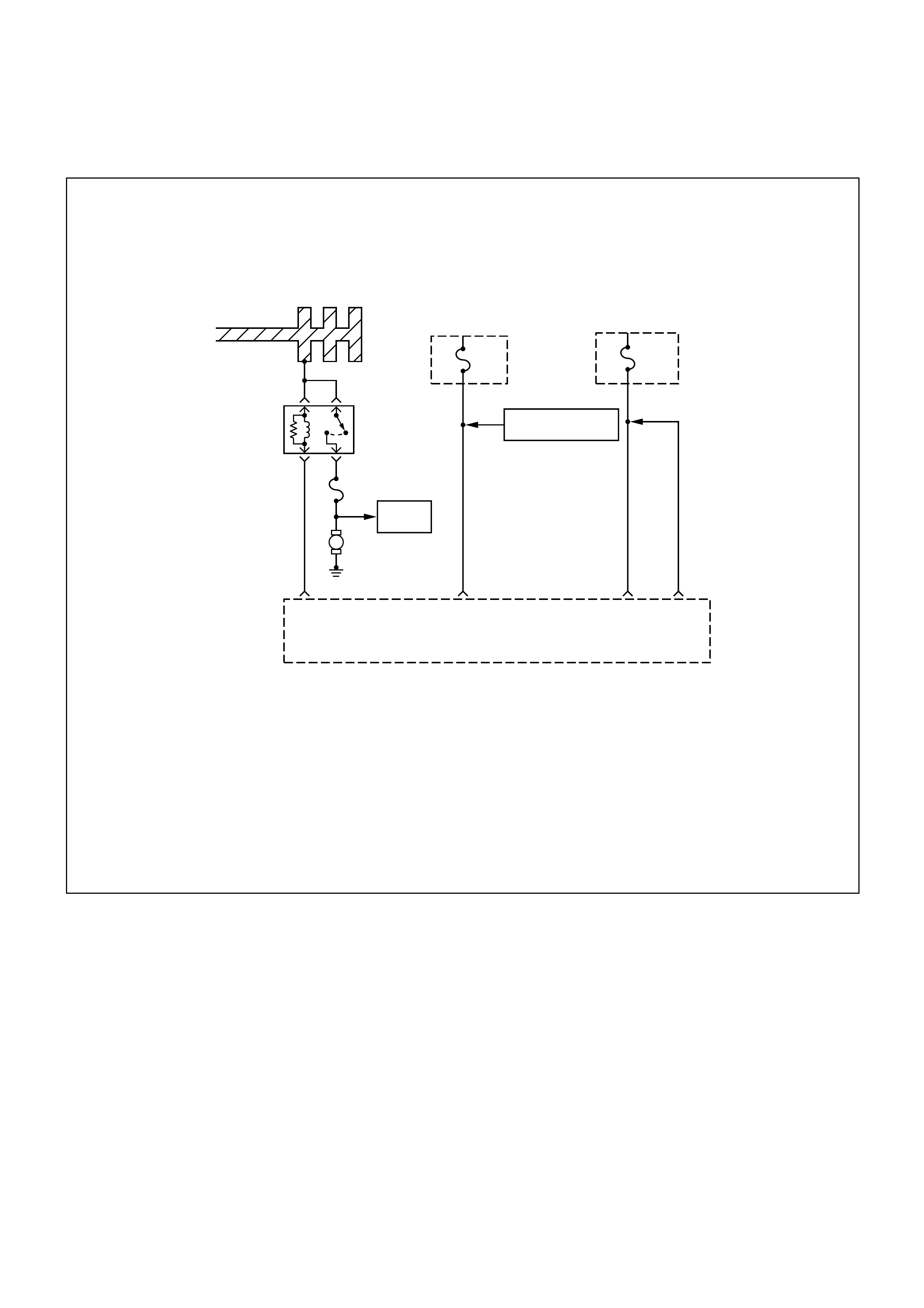
FUEL SYSTEM ELECTRICAL TEST
A13
Fuel
Injectors
M
Battery Joint Cable
ECM
Fuse
15A
1.25
R/W
1.25
R/W
A4 A5
Engine
Fuse
15A
Canister Purge
Control Solenoid Valve
E16
Engine
Control
Module
(ECM)
Fuel
Pump
Relay
Fuel Pump Fuse
20A
0.5
P/W
0.85
B/Y
CIRCUIT DESCRIPTION
When the ignition switch is first turned ON, the engine
control module (ECM) energizes the fuel pump relay
which applies power to the in-tank fuel pump. The fuel
pump relay will remain ON as long as the engine is
running or cranking and the ECM is receiving 58X
crankshaft position pulses. If no 58X crankshaft
position pulses are present, the ECM de-energizes the
fuel pump relay within 2 seconds after the ignition is
turned ON or the engine is stopped.
The fuel pump delivers fuel to the fuel rail and
injectors, then to the fuel pressure regulator. The fuel
pressure regulator controls fuel pressure by allowing
excess fuel to be returned to the fuel tank. With the
engine stopped and ignition ON, the fuel pump can be
turned ON by using a command by the scan tool.
DIAGNOSTIC AIDS
An intermittent may be caused by a poor connection,
rubbed-through wire insulation, or a wire broken inside
the insulation. Check for the following items:
•Poor connection or damaged harness - Inspect the
ECM harness and connectors for improper mating,
broken locks, improperly formed or damaged
terminals, poor terminal-to-wire connection, and
damaged harness.

TEST DESCRIPTION
Number(s) below refer to the step number(s) on the
Diagnostic Chart.
2. If the fuel pump is operating but incorrect pressure
is noted, the fuel pump wiring is OK and the “Fuel
System Pressure Test” chart should be used for
diagnosis.
Caution: To reduce the risk of fire and
personal injury:
• It is necessary to relieve fuel system
pressure before connecting a fuel pressure
gauge. Refer to Fuel Pressure Relief
Procedure, below.
• A small amount of fuel may be released
when disconnecting the fuel lines. Cover
fuel line fittings with a shop towel before
disconnecting, to catch any fuel that may
leak out. Place the towel in an approved
container when the disconnect is
completed.
FUEL PRESSURE RELIEF PROCEDURE
1. Remove the fuel cap.
2. Remove the fuel pump relay from the underhood
relay center.
3. Start the engine and alow it to stall.
4. Crank the engine for an additional 3 seconds.
FUEL PRESSURE GAUGE INSTALLATION
1. Remove the shoulder fitting cap.
2. Install fuel pressure gauge 5-8840-0378-0 to the
fuel feed line located in front of and above the right
side valve cover.
3. Reinstall the fuel pump relay.
FUEL SYSTEM ELECTRICAL TEST
STEP ACTION VALUE(S) YES NO
1Was the “On-Board Diagnostic (OBD) System
Check” performed? -
Go to Step 2
Go to OBD
System Check
2
1. Turn Ignition “ON”.
2. Install Scan Tool
3. Command Fuel Pump “ON”.
Did the Fuel Pump turn on?
-Go to Fuel
System
Diagnosis Go to Step 3
3
1. Ignition OFF.
2. Remove the fuel pump relay.
3. Using a test light connected to ground, probe the battery
feed to the relay.
Did the light illuminate?
-
Go to Step 5 Go to Step 4
4Repair short or open battery feed to fuel pump relay.
Is the action complete? -Verify repair -
5
1. Connect a test light between the two wires that connect to
the fuel pump relay pull-in coil.
2. Ignition ON.
Did the test light illuminate for 2 seconds and then turn off? -
Go to Step 11 Go to Step 6
6
1. With a test light connected to battery (−), probe the fuel
pump relay connector at the wire which runs form the relay
pull-in coil to the ECM.
2. Ignition ON.
Did the test light illuminate for 2 seconds and then turn off?
-
Go to Step 7 Go to Step 8

STEP ACTION VALUE(S) YES NO
7Locate and repair open in the fuel pump relay ground circuit. Is
the action complete? -Verify repair -
8Check for short or open between the ECM and the fuel pump
relay.
Was a problem found?
-
Verify repair Go to Step 9
9
1. Check the fuel pump relay circuit for a poor terminal
connection at the ECM.
2. If a problem is found, replace terminal as necessary.
Was a problem found?
-
Verify repair Go to Step 10
10 Replace the EPROM or ECM.
Is the action complete? Note) Refer to 6E1-243. -Verify repair -
11
1. Reconnect the fuel pump relay.
2. Disconnect the fuel pump electrical connector at the fuel
tank
3. Using a test light connected to ground, probe the fuel pump
feed wire (harness side).
4. Command the fuel pump ON with a scan tool.
Did the light illuminate for 2 seconds?
-
Go to Step 14 Go to Step 12
12
1. Honk the horn to verify that the horn relay is functioning.
2. Substitute the horn relay for the fuel pump relay.
3. Leave the test light connected as in step 12.
4. Command the fuel pump ON with the scan tool.
Did the test light illuminate for 2 seconds when the fuel pump
was commanded ON?
-
Go to Step 16 Go to Step 13
13
1. Re-connect the horn relay in its proper location.
2. Check for a short circuit, blown fuse or open circuit between
the relay and the fuel tank.
Is the action complete?
-
Verify repair
-
14
1. With the fuel pump electrical connector at the fuel tank
disconnected, connect a test light between the feed wire and
the ground wire (harness side).
2. Command the fuel pump ON with a scan tool.
Did the test light illuminate for 2 seconds?
-
Go to Step 17 Go to Step 15
15 Repair the open circuit in the fuel pump ground wire.
Is the action complete? -Verify repair -
16 1. Re-connect the horn relay in its proper location.
2. Replace the fuel pump relay.
Is the action complete? -
Verify repair
-
17 Replace the fuel pump.
Is the action complete? -Verify repair -
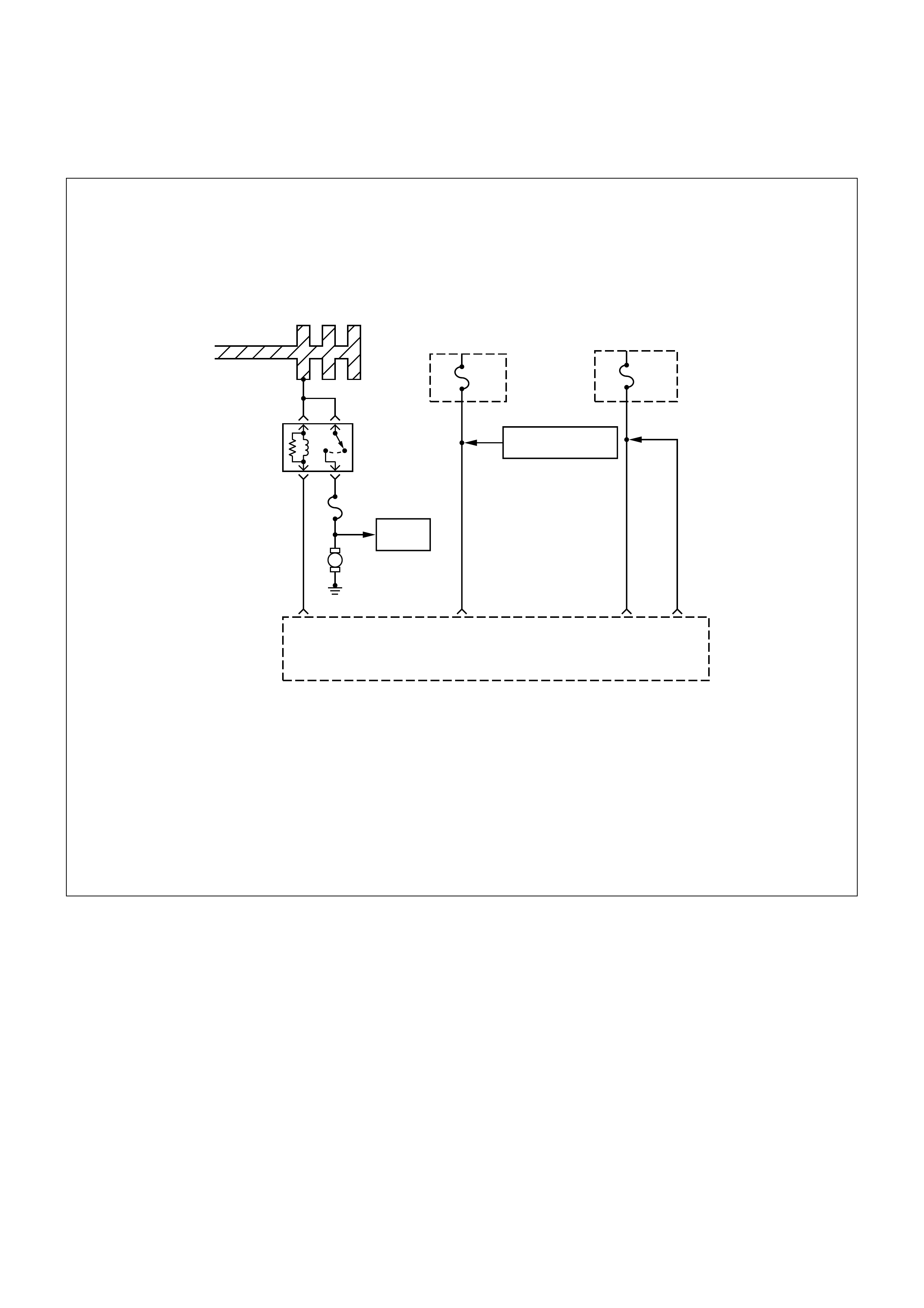
FUEL SYSTEM DIAGNOSIS
A13
Fuel
Injectors
M
Battery Joint Cable
ECM
Fuse
15A
1.25
R/W
1.25
R/W
A4 A5
Engine
Fuse
15A
Canister Purge
Control Solenoid Valve
E16
Engine
Control
Module
(ECM)
Fuel
Pump
Relay
Fuel Pump Fuse
20A
0.5
P/W
0.85
B/Y
CIRCUIT DESCRIPTION
When the ignition switch is turned ON, the engine
control module (ECM) will turn ON the in-tank fuel
pump. The in-tank fuel pump will remain ON as long
as the engine is cranking or running and the ECM is
receiving 58X crankshaft position pulses. If there are
no 58X crankshaft position pulses, the ECM will turn
the in-tank fuel pump OFF 2 seconds after the
ignition switch is turned ON or 2 seconds after the
engine stops running.
The in-tank fuel pump is an electric pump within an
integral reservoir. The in-tank fuel pump supplies fuel
through an in-line fuel filter to the fuel rail assembly.
The fuel pump is designed to provide fuel at a
pressure above the pressure needed by the fuel
injectors. A fuel pressure regulator, attached to the
fuel rail, keeps the fuel available to the fuel injectors
at a regulated pressure. Unused fuel is returned to
the fuel tank by a separate fuel return line.
TEST DESCRIPTION
Number(s) below refer to the step number(s) on the
Diagnostic Chart.
2. Connect the fuel pressure gauge to the fuel feed
line as shown in the f uel system illustration. W rap
a shop towel around the fuel pressure connection
in order to absorb any duel leakage that may
occur when installing the fuel pressure gauge.
With the ignition switch ON and the fuel pump
running, the fuel pressure indicated by the fuel
pressure gauge should be 283-376 kPa (41-55

psi). This pressure is controlled by the amount of
pressure the spring inside the fuel pressure
regulator can provide.
3. A f uel system that cannot m aintain a c onstant f uel
pressure has a leak in one or more of the
following areas:
•The fuel pump check valve.
•The fuel pump flex line.
•The valve or valve seat within the f uel pressure
regulator.
•The fuel injector(s).
4. Fuel pressure that drops off during acceleration,
cruise, or hard cornering may case a lean
condition. A lean condition can cause a loss of
power, surging, or m is fire. A lean c ondition c an be
diagnosed using a Tech 2 Scan Tool.
Following are applicable to the vehicle with
closed Loop System:
If an extremely lean condition occurs, the oxygen
sensor(s) will stop toggling. The oxygen sensor
output voltage(s) will drop below 500 mV. Also,
the fuel injector pulse width will increase.
Important: Make sure the fuel system is not
operating in the “Fuel Cut-Off Mode."
W hen the engine is at idle, the manifold pressure
is low (high vacuum). This low pressure (high
vacuum) is applied to the fuel pressure regulator
diaphragm. The low pressure (high vacuum) will
offset the pressure being applied to the fuel
pressure regulator diaphragm by the spring inside
the fuel pressure regulator. When this happens,
the result is lower f uel press ure. T he fuel pr essur e
at idle will vary slightly as the barom etric pressure
changes, but the fuel pressure at idle should
always be less than the fuel pressure noted in
step 2 with the engine OFF.
16.Check the spark plug associated with a particular
fuel injector for fouling or saturation in order to
determine if that particular fuel injector is leaking.
If checking the spark plug associated with a
particular fuel injector for fouling or saturation
does not determine that a particular f uel injector is
leaking, use the following procedure:
•Remove the fuel rail, but leave the fuel lines
and injectors c onnected to the fuel rail. Ref er to
Fuel Rail Assembly in On-Vehicle Service.
•Lift the fuel rail just enough to leave the fuel
injector nozzles in the fuel injector ports.
Caution: In order to reduce the risk of fire an d
personal injury that may result from fuel
spraying on the engi ne, verify that the fu el rail
is positioned over the fuel injector ports and
verify that the fuel injector retaining clips are
intact.
•
••
•Pressurize the fuel system by connecting a
20 amp fused jumper between B+ and the
fuel pump relay connector.
•
••
•Visually and physically inspect the fuel
injector nozzles for leaks.
17.A rich condition may result from the fuel pressure
being above 376 kPa (55 psi). A rich condition
may cause a 45 to set. Driveability conditions
associated with rich conditions can include hard
starting (followed by black smoke) and a strong
sulfur smell in the exhaust.
20.This test determines if the high fuel pressure is
due to a restricted fuel r eturn line or if the high f uel
pressure is due to a faulty fuel pressure regulator.
21.A lean condition may result from fuel pressure
below 333 kPa (48 psi). A lean condition may
cause a 44 to set. Driveability conditions
associated with lean conditions can include hard
starting (when the engine is c old), hesitation, poor
driveability, lack of power, surging, and misfiring.
22.Restricting the fuel return line causes the fuel
pressure to rise above the regulated fuel pressure.
Command the fuel pump ON with the scan tool.
The fuel pressure should rise above 376 kPa (55
psi) as the fuel return line becomes partially
closed.
Notice: Do not allow the fuel pressure to exceed 414
kPa (60 psi). Fuel pressure in excess of 414 kPa (60
psi) may damage the fuel pressure regulator.
Caution: To reduce the risk of fire and
personal injury:
•It is necessary to relieve fuel system
pressure before connecting a fuel pressure
gauge. Refer to Fuel Pressure Relief
Procedure, below.
•A small amount of fuel may be released
when disconnecting the fuel lines. Cover
fuel line fittings with a shop towel before
disconnecting, to catch any fuel that may
leak out. Place the towel in an approved
container when the disconnect is
completed.

FUEL PRESSURE RELIEF PROCEDURE
1. Remove the fuel cap.
2. Located on the intake manifold which is at the top
right part of the engine.
3. Start the engine and allow it to stall.
4. Crank the engine for an additional 3 seconds.
FUEL PRESSURE GAUGE INSTALLATION
1. Remove the shoulder fitting cap.
2. Install fuel pressure gauge 5-8840-0378-0 to the
fuel feed line located on the upper right side of the
engine.
3. Reinstall the fuel pump relay.
FUEL SYSTEM DIAGNOSIS
STEP ACTION VALUE(S) YES NO
1Was the “On-Board Diagnostic (OBD) System
Check” performed? -
Go to Step 2
Go to OBD
System Check
2
1. Turn the ignition OFF.
2. Turn the air conditioning system OFF.
3. Relieve fuel system pressure and install the fuel pressure
gauge.
4. Turn the ignition ON.
Note: The fuel pump will run for approximately 2 seconds. Use
the Scan Tool to command the fuel pump ON.
5. Observe the fuel pressure indicated by the fuel pressure
gauge with the fuel pump running.
Is the fuel pressure within the specified limits? 283-376 kPa
(41-55 psi) Go to Step 3 Go to Step 17
3
Does the fuel pressure indicated by the fuel pressure gauge
remain constant?
Note: The fuel pressure will drop when the fuel pump stops
running, then it should stabilize and remain constant.
-
Go to Step 4 Go to Step 12
4
1. When the vehicle is at normal operating temperature, turn
the ignition ON to build fuel pressure and observe the
measurement on the gauge.
2. Start the engine and observe the fuel pressure gauge.
Did the reading drop by the amount specified after the engine
was started? 21-105 kPa
(3-15 psi) Go to Step 5 Go to Step 9
5Is fuel pressure dropping off during acceleration, cruise, or hard
cornering? -
Go to Step 6
Check for
improper fuel
6
Visually and physically inspect the following items for a
restriction:
•The in-pipe fuel filter.
•The fuel feed line.
Was a restriction found?
-
Verify repair Go to Step 7
7
Remove the fuel tank and visually and physically inspect the
following items:
•The fuel pump strainer for a restriction.
•The fuel line for a leak.
•Verify that the correct fuel pump is in the vehicle.
Was a problem found in any of these areas?
-
Verify repair Go to Step 8

STEP ACTION VALUE(S) YES NO
8Replace the fuel pump.
Is the action complete? -Verify repair -
9
1. Disconnect the vacuum hose from the fuel pressure
regulator.
2. With the engine idling, apply 12-14 inches of vacuum to the
fuel pressure regulator.
Does the fuel pressure indicated by the fuel pressure gauge
drop by the amount specified? 21-105 kPa
(3-15 psi) Go to Step 10 Go to Step 11
10 Locate and repair the loss of vacuum to the fuel pressure
regulator.
Is the action complete? -
Verify repair
-
11 Replace the fuel pressure regulator.
Is the action complete? -Verify repair -
12
1. Run the fuel pump with the Scan Tool.
2. After pressure has built up, turn off the pump and clamp the
supply hose shut with suitable locking pliers.
Does the fuel pressure indicated by the fuel pressure gauge
remain constant?
-
Go to Step 13 Go to Step 15
13 Visually inspect the fuel supply line and repair any leaks.
Was a problem found? -Verify repair
Go to STep 14
14 Remove the fuel tank and inspect for leaky hose or in-tank fuel
line.
Was a problem found? -
Verify repair Go to STep 8
15
1. If the pliers are still clamped to the fuel supply hose, remove
the locking pliers.
2. With suitable locking pliers, clamp the fuel return line to
prevent fuel from returning to the fuel tank.
3. Run the fuel pump with the Scan Tool.
4. After pressure has built up, remove power to the pump.
Does the fuel pressure indicated by the fuel pressure gauge
remain constant?
-
Go to Step 11 Go to Step 16
16 Locate and replace any leaking fuel injector(s).
Is the action complete? -Verify repair -
17 Is the fuel pressure indicated by the fuel pressure gauge above
the specified limit? 376 kPa
(55 psi) Go to Step 18 Go to Step 21
18
1. Relieve the fuel pressure. Refer to the Fuel Pressure Relief.
2. Disconnect the fuel return line from the fuel rail.
3. Attach a length of flexible hose to the fuel rail return outlet
passage.
4. Place the open end of the flexible hose into an approved
gasoline container.
5. Run the fuel pump with the Scan Tool.
6. Observe the fuel pressure indicated by the fuel pressure
gauge with the fuel pump running.
Is the fuel pressure within the specified limits? 290-376 kPa
(42-55 psi) Go to Step 19 Go to Step 20

STEP ACTION VALUE(S) YES NO
19 Locate and correct the restriction in the fuel return line.
Is the action complete? -Verify repair -
20 Visually and physically inspect the fuel rail outlet passages for a
restriction.
Was a restriction found? -
Verify repair Go to Step 11
21 Is the fuel pressure indicated by the fuel pressure gauge above
the specified value? 0 kPa (0 psi) Go to Step 22 Go to Step 23
22
1. Command the fuel pump ON with the Scan Tool.
2. Using suitable pliers which will not damage the fuel hose,
gradually apply pressure with the pliers to pinch the flexible
fuel return hose closed.
Does the fuel pressure indicated by the fuel pressure gauge rise
above the first specified value?
Caution: Do not let the fuel pressure exceed the second
specified value.
376 kPa
(55 psi)
414 kPa
(60 psi) Go to Step 11 Go to Step 7
23
1. Command the fuel pump ON with the Scan Tool.
2. Remove the fuel filler cap and listen for the sound of the fuel
pump running.
3. Turn the pump off.
Was the fuel pump running?
-
Go to Step 7
Go to
Fuel System
Electrical Test
Chart
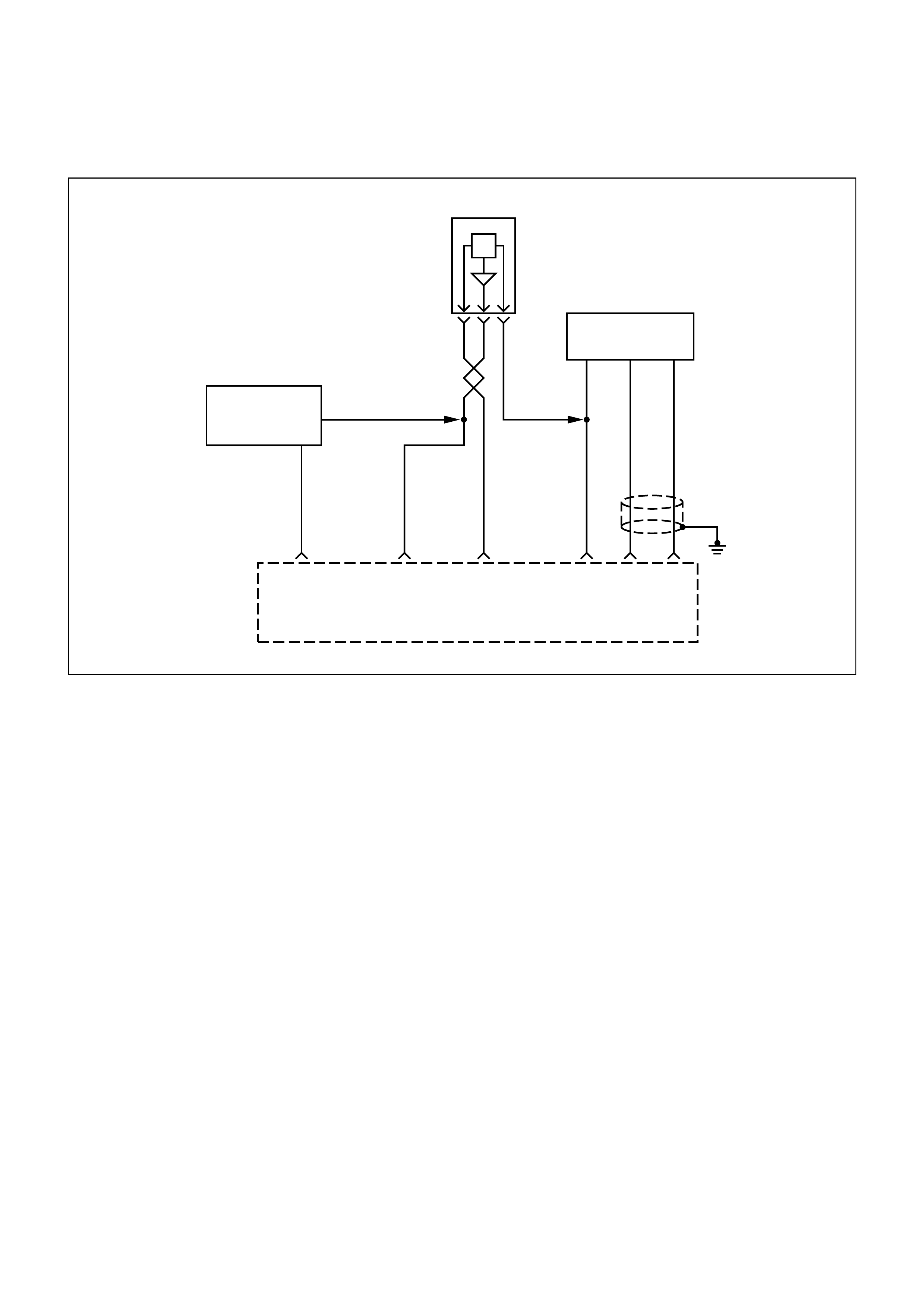
MANIFOLD ABSOLUTE PRESSURE (MAP) OUTPUT CHECK
0.5
YEL/
GRN
0.5
GRN
0.5
RED
0.5
RED
0.5
GRN
0.5
RED
Manifold
Absolute
Pressure
(MAP)
Sensor
F10 B2
0.5
GRN
B7 A3
5 Volt
Reference
Signal
MAP Sensor
Input
Sensor
Ground
0.75
L
B8
0.75
G
B1
AB C
Intake
Air Temperature
Sensor
Throttle Position
Sensor
Engine
Control
Module
(ECM)
HI OUT LO
0.5
G
CIRCUIT DESCRIPTION
The manifold absolute pressure (MAP) sensor
measures the changes in the intake MAP which result
from engine load (intake manifold vacuum) and engine
speed changes; and converts these into a voltage
output. The engine control module (ECM) sends a 5-
volt reference voltage to the MAP sensor. As the MAP
changes, the output voltage of the sensor also
changes. By monitoring the sensor output voltage, the
ECM knows the MAP. A lower pressure (low voltage)
output voltage will be about 1-2 volts at idle. Higher
pressure (high voltage) output voltage will be about 4-
4.8 volts at wide open throttle. The MAP sensor is also
used, under certain conditions, to measure barometric
pressure, allowing the ECM to make adjustments for
different altitudes.
TEST DESCRIPTION
Important: Be sure to use the same diagnostic test
equipment for all measurements.
The number(s) below refer to the step number(s) on
the Diagnostic Chart.
1. When you compare the Scan Tool readings to a
known good vehicle, it is important to compare
vehicles that use MAP s ensors that have the sam e
part number.
2. Applying 34 kPa (10 Hg) vacuum to the MAP
sensor s hould cause the voltage to be 1.5- 2.1 volts
less than the voltage at step 1. Upon applying
vacuum to the sensor, the change in voltage
should be instantaneous. A slow voltage change
indicates a faulty sensor.
3. Check the vacuum hose to the sensor for leaking
or restriction. Be sure that no other vacuum
devices are connected to the MAP hose.
Important: Make sure the electrical connector
remains securely fastened.
4. Disconnect the sensor from the bracket. Twist the
sensor with your hand to check for an intermittent
connection. Output changes greater than 0.10 volt
indicate a bad sensor.

MANIFOLD ABSOLUTE PRESSURE (MAP) O UTPUT CHECK
STEP ACTION VALUE(S) YES NO
1
1. Turn the ignition OFF and leave it OFF for 15 seconds.
2. Ignition ON. Do not crank engine.
3. The Scan Tool should indicate a manifold absolute pressure
(MAP) sensor voltage.
4. Compare this scan reading to the scan reading of a known
good vehicle obtained using the exact same procedure as in
Steps 1-4.
Is the voltage reading the same +/−0.40 volt?
-
Go to Step 2 Go to Step 5
2
1. Disconnect the MAP sensor and plug the hole on the intake
manifold.
2. Using an adequate rubber hose, connect a hand vacuum
pump to the MAP sensor.
3. Check for the following condition:
•MAP port sealing rubber damaged or split?
•Intake vacuum leaks at;
•Vacuum leaks at throttle body;
If a problem is found, repair as necessary.
Was a problem found?
4. Start the engine.
5. Apply 34 kPa (10 Hg) of vacuum and note the voltage
change.
Is the voltage change 1.5-2.1 volts less than step 1?
-
Go to Step 3 Go to Step 4
3No trouble found. Check the sensor seal rubber (color : orange)
for leakage or restriction.
Does the hose supply vacuum to the MAP sensor only? -
Go to Step 5 Go to Step 4
4Repair the seal rubber (color : orange) to ensure the hose
supplies vacuum to the MAP sensor only
Is the action complete? -
Verify repair
-
5Check the sensor connection.
Is the sensor connection good? -Go to Step 6 Go to Step 7
6Replace the sensor. Refer to On-Vehicle Service, MAP Sensor.
Is the action complete? -
Verify repair
-
7Repair the poor connection.
Is the action complete? -Verify repair -
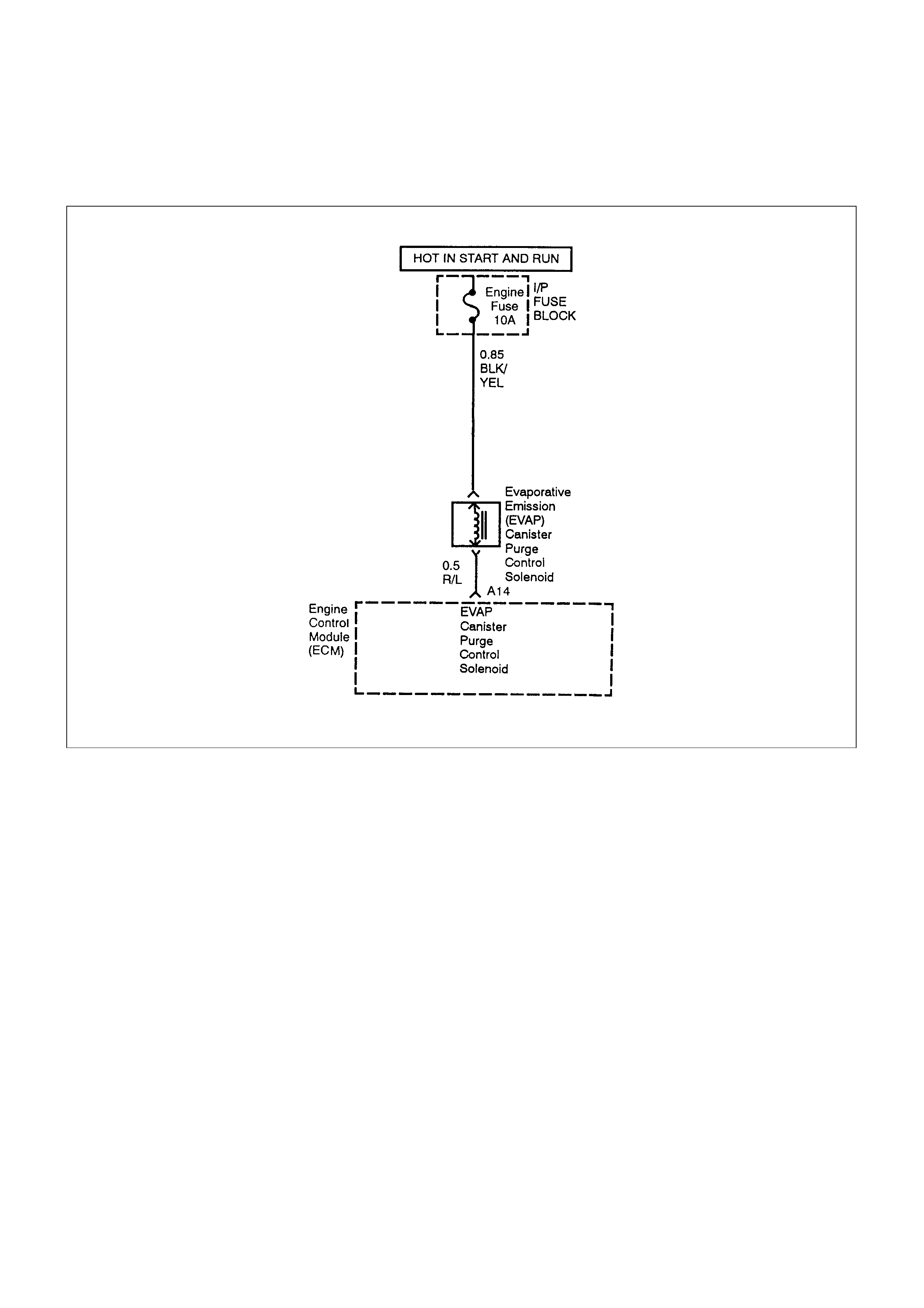
EVAPORATIVE EMISSIONS (EVAP) CANISTER PURGE CONTROL
SOLENOID VALVE CHECK (IF APPLICABLE)
CIRCUIT DESCRIPTION
Canister purge is controlled by a solenoid valve that
allows manifold vacuum to purge the canister. The
engine control module (ECM) supplies a ground to
energize the solenoid valve (purge ON). The EVAP
(purge solenoid control is turned ON time) is
determined by engine operating conditions including
load, throttle position, coolant temperature and
ambient temperature. The duty cycle is calculated by
the ECM and the purge solenoid is enabled when the
appropriate conditions have been met:
•The engine run time after start is more than 60
seconds.
•The engine coolant temperature is above 30°C
(86°F).
•The fuel control system is operating in the “Closed-
Loop” mode (If applicable).
DIAGNOSTIC AIDS
•Make a visual check of vacuum hoses.
•Check the throttle body for possible cracked or
plugged vacuum block.
•Check the malfunc tion indicator lamp for a possible
mechanical problem.
TEST DESCRIPTION
The number(s) below refer to the step number(s) on
the Diagnostic Chart.
1. Check to see if the solenoid is open or closed. The
solenoid is normally de-energized in this step, so it
should be closed.
2. This step checks to determine if the solenoid was
open due to an electrical circuit problem or a
defective solenoid.
3. This should normally energize the solenoid,
opening the valve and allowing the vacuum to dr op
(Purge ON).

EVAPORATIVE EMISSIO NS ( EVAP) CANISTER PURGE VALVE SOLENOID CHECK
STEP ACTION VALUE(S) YES NO
1
1. Ignition OFF.
2. Ignition ON, engine OFF.
3. At the intake manifold, disconnect the hose that goes to the
pump solenoid.
4. Using a hand vacuum purge with an attached vacuum gauge
5-8840-0279-0, apply vacuum (10” Hg or 34 kPa) to the
solenoid.
Does the solenoid hold vacuum?
-
Go to Step 3 Go to Step 2
2
1. Disconnect the solenoid electrical connector.
2. As in Step 1, apply vacuum (10” Hg or 34 kPa) to the
solenoid.
Does the solenoid hold vacuum?
-
Go to Step 4 Go to Step 7
3
1. At the intake manifold, put a cap over the vacuum port where
the hose was disconnected for testing.
This is to prevent a vacuum leak when the engine is started.
2. Ignition OFF.
3. Install the scan tool.
4. Apply vacuum to the purge control solenoid with the hand
vacuum pump.
5. Start the engine, run at 2500 RPM.
6. Using the Scan Tool command the purge control solenoid
ON.
Did the vacuum drop when the purge was turned on?
-
Go to Step 8 Go to Step 9
4Check for a short to ground or open in the wire between the
solenoid and the ECM.
Is there a problem? -
Go to Step 5 Go to Step 6
5Repair the faulty wire.
Is the action complete? -Verify repair -
6 Replace the EPROM or ECM.Note) Refer to 6E1-243. - Verify repair -
7Replace the faulty purge control solenoid. Refer to On-Vehicle
Service, EVAP Canister Purge Solenoid.
Is the action complete? -.
Verify repair
-
8
1. Turn the ignition OFF.
2. Verify the purge hose nipple is not plugged.
-
No problem
found in the
EVAP
emission
canister purge
valve check.
Refer to
Diagnostic
Aids
9
1. Turn the Ignition OFF.
2. Disconnect the solenoid's electrical connector.
3. Connect a test lamp between the harness terminals.
4. Turn the ignition ON.
Does the test lamp light?
-
Go to Step 7 Go to Step 10

STEP ACTION VALUE(S) YES NO
10 Probe each terminal of the solenoid valve electrical connector
with a test lamp to ground.
Does the test lamp light on both terminals? -
Go to Step 11 Go to Step 12
11 Repair the short to voltage in the wire between the solenoid and
the ECM.
Is the action complete? -
Verify repair
-
12 Does the ignition feed terminals light the test lamp? - Go to Step 13 Go to Step 14
13 Check for an open in the wire between the purge control
solenoid and the ECM.
Was there an open circuit? -
Go to Step 15 Go to Step 6
14 Repair the open in the ignition feed wire.
Is the action complete? -Verify repair -
15 Repair the open wire.
Is the action complete? -Verify repair -
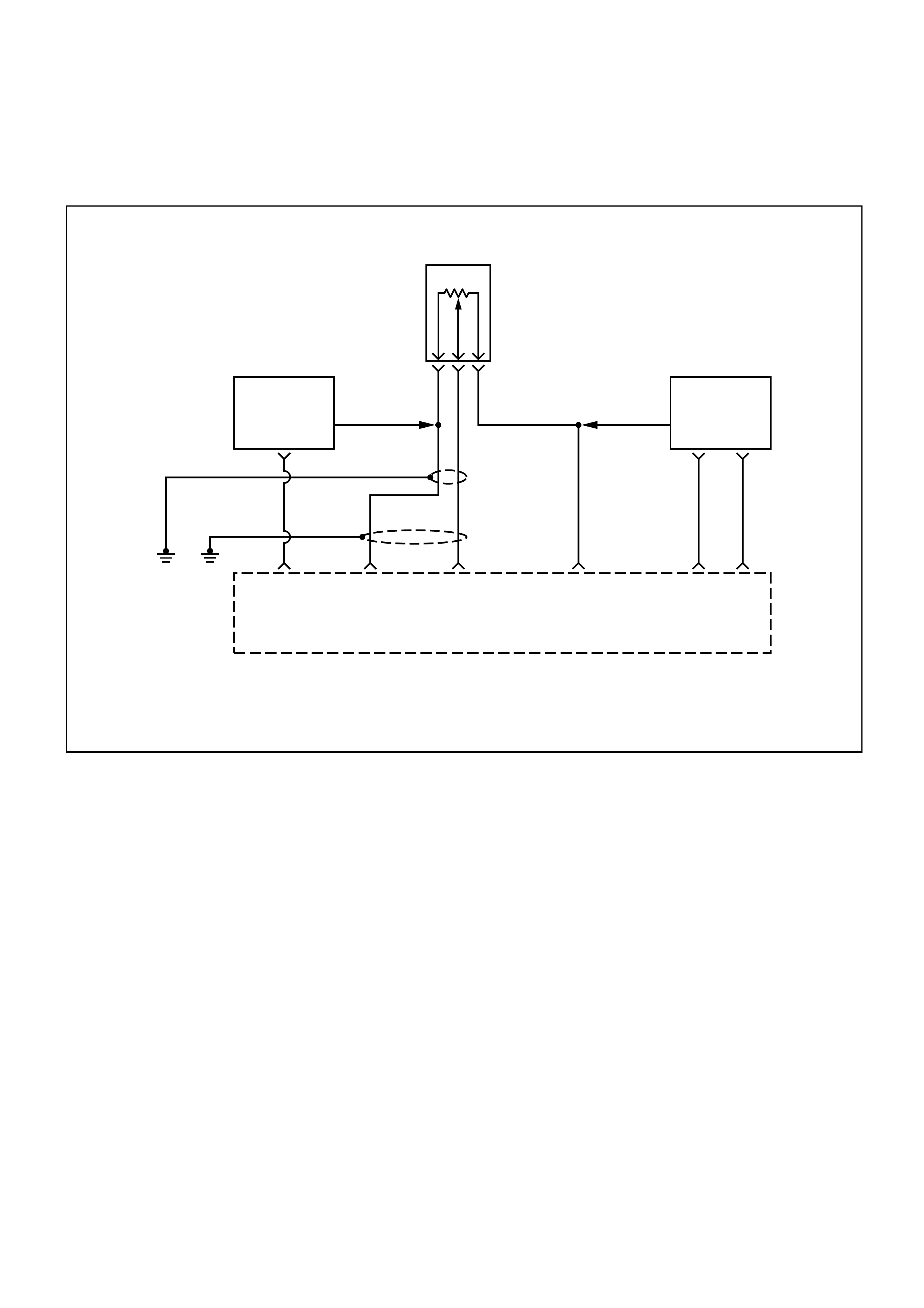
THROTTLE POSITION (TP) SENSOR CI RCUIT RANGE/ PERFORMANCE
PROBLEM
0.5
R
0.5
G
0.5
GR
0.5
RED
0.75
GRN
0.75
L
0.5
GRN
Engine
Control
Module
(ECM)
F14 B1 A3
5 Volt
Reference
Signal
Throttle
Position
(TP)
Sensor
Input
Sensor
Ground
Sensor
Ground
B7 B2
Throttle
Position
(TP)
Sensor
B C A
Manifold
Absolute
Pressure
Sensor
Engine
Coolant
Temperature
Sensor
B8
LO HI
OUT
0.5
L/R
CIRCUIT DESCRIPTION
The throttle position (TP) sensor circuit provides a
voltage signal that changes relative to throttle blade
angle. The signal voltage will vary from about 0.25
volts at closed throttle to about 4.75 volts at wide open
throttle (WOT).
The Throttle Position (TP) signal is used by the engine
control module (ECM) for fuel control and most of the
ECM-controlled outputs. The ECM monitors throttle
position and compares actual throttle positions from
the TP sensor to a predicted TP value calculated from
engine speed.
DIAGNOSTIC AIDS
Check for the following conditions:
•Skewed MAP signal or faulty MAP sensor-An
incorrect MAP signal may cause the ECM to
incorrectly calculate the predicted TP sensor value
during high engine load situations. Check for an
unusually low MAP reading.
•Poor connection at ECM-Inspect harness
connectors for backed-out terminals, improper
mating, br oken lock, im pr oper ly form ed or damaged
terminals, and poor terminal-to-wire connection.
•Damaged Harness-Inspect the wiring harness for
damage: An open Circuit, shorts to Ground, or
shorts to Batter y Positive. If the har ness appears to
be OK, observe the TP display on the Scan Tool
while moving connectors and wiring harnesses
related to the sensor. A change in the display will
indicate the location of the fault.

TP SENSOR CIRCUIT RANGE/PERFORMANCE PROBLEM
STEP ACTION VALUE(S) YES NO
1Was the "On-Board Diagnostic (OBD) System Check "
performed? -
Go to Step 2
Go to OBD
System Check
2
1. Ignition ON, engine OFF.
2. Monitor the TP value on the Scan Tool While moving the
throttle between 0% and 100%.
Does the TP value on the Scan Tool move smoothly from 0%
(0.25 volts) to 100% (4.75 volts)?
-
Go to Step 3 Go to Step 10
3
1. Ignition OFF.
2. Disconnect the Throttle Position (TP) Sensor electrical
connector, located on the RH side of the Throttle body.
3. Start the engine, and monitor the TP value with the Scan
Tool.
Does the TP value on the Scan Tool hold steadily within the
given range?
0-0.25 volts
0%
Go to Step 5 Go to Step 4
4
Check the TP sensor signal circuit, between the TP sensor and
the Engine Control Module (ECM), for a short to voltage.
Was the problem found? -
Verify Repair Go to Step 11
5
Check the TP sensor signal circuit, between the TP sensor and
the ECM, the following conditions:
•A short to ground
•An open circuit
Was the problem found?
-
Verify Repair Go to Step 6
6
Check the 5 Volt signal circuit between the TP sensor and the
ECM, for the following conditions:
•An Open Circuit
•A short to ground
•A short to voltage
Was the problem found?
-
Verify Repair Go to Step 7

STEP ACTION VALUE(S) YES NO
7
1. Ignition OFF.
2. Place a fused jumper between the TP sensor circuit and the
5 volt signal circuit both at the wiring harness TP sensor
connector.
3. Ignition ON, engine OFF.
4. Observe the TP value displayed on the Scan Tool.
Does the Scan Tool read the following value?
about 5 volts
100%
Go to Step 8 Go to Step 11
8
Check the TP sensor ground circuit, between the TP sensor and
the ECM, for the following conditions:
•An Open Circuit
•A short to ground
•A short to voltage
Was the problem found?
-
Verify Repair Go to Step 9
9
1. Ignition OFF.
2. Place a Digital Multimeter (DVM), set to measure voltage
between the ground circuit and the 5 volt signal circuit, both
at the wiring harness' TP sensor connector.
3. Ignition ON, engine OFF.
Does the DVM indicate the following value?
about 5 volts
Go to Step 10 Go to Step 11
10 Replace the TP sensor.
Verify repair. ---
11 Replace the EPROM or ECM. Note) Refer to 6E1-243. - - -
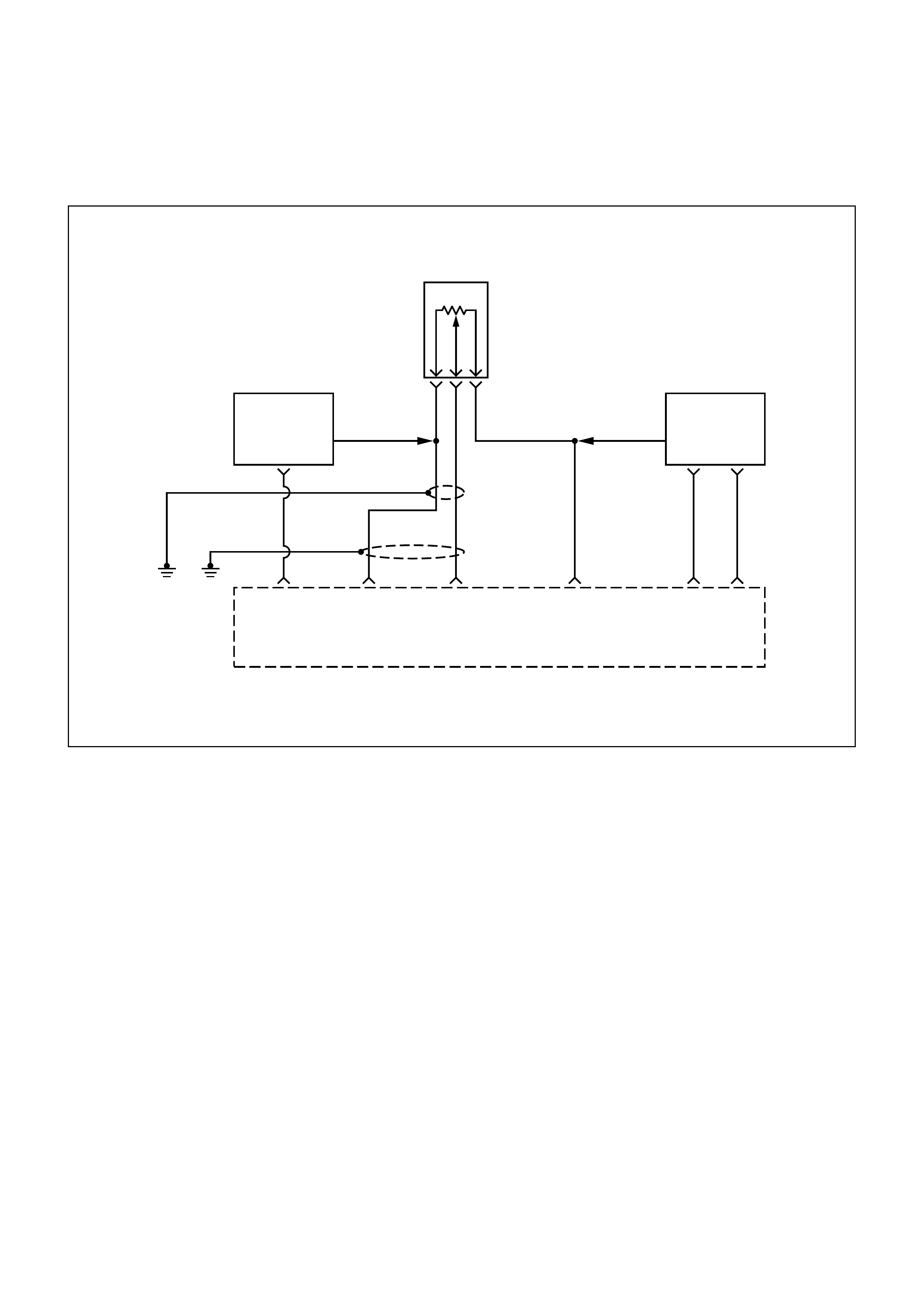
DIAG NOSTI C TROUBLE CODE (DTC) (FLASH DTC = 22)
THROTTLE POSITION (TP) SENSOR CI RCUIT LOW INPUT
0.5
R
0.5
G
0.5
GR
0.5
RED
0.75
GRN
0.75
L
0.5
GRN
Engine
Control
Module
(ECM)
F14 B1 A3
5 Volt
Reference
Signal
Throttle
Position
(TP)
Sensor
Input
Sensor
Ground
Sensor
Ground
B7 B2
Throttle
Position
(TP)
Sensor
B C A
Manifold
Absolute
Pressure
Sensor
Engine
Coolant
Temperature
Sensor
B8
LO HI
OUT
0.5
L/R
CIRCUIT DESCRIPTION
The throttle position (Throttle Position) sensor circuit
provides a voltage signal that changes relative to
throttle blade angle. The signal voltage will vary from
below 1 volt at closed throttle to about 4 volts at wide
open throttle (WOT).
The Throttle Position signal is used by the engine
control module (ECM) for fuel control and most of the
ECM-controlled outputs. If the ECM detects a low
inpedance short to ground in the Throttle Position
sensor or circuit, then a code 22 will set.
CONDITIO NS FOR SETTING THE DTC
•Throttle Position sensor signal voltage is less than
0.19 volt.
ACTIO N TAKEN WHEN THE DTC SETS
•The ECM will illuminate the malfunction indicator
lamp (MIL) the first time the fault is detected.
•The ECM will use a default throttle position based
on RPM.
CONDITIO NS FOR CLEARI NG THE MIL/DTC
Once the ECM determines that a fault(s) has been
rectified then the CEL will switch OFF, although the
fault code will remain in the ECM memory.
Any fault codes will remain in ECM memory until -
1. They are cleared by disconnecting the Battery for
more than 30 seconds.
2. A service tool such as Tech 2 is used to clear them.
3. Ten consecutive starts without logging a fault.

DIAGNOSTIC AIDS
Check for the following conditions:
• Poor connection at ECM - Inspect harness
connectors for backed-out terminals, improper
mating, broken locks, improperly formed or
damaged terminals, and poor terminal-to-wire
connection.
• Damaged harness - Inspect the wiring harness for
damage. If the harness appears to be OK, observe
the throttle position display on the Scan Tool while
moving connectors and wiring harnesses related to
the throttle Position sensor. A change in the display
will indicate the location of the fault.
DTC (FLASH DTC = 22) THROTTLE POSITION (TP) SENSOR CIRCUIT LOW INPUT
STEP ACTION VALUE(S) YES NO
1Was the "On-Board Diagnostic (OBD) System Check"
performed? -
Go to Step 2
Go to OBD
System Check
2
1. Ignition ON, engine OFF.
2. With the throttle closed, observe the "Throttle Position
Sensor" display on the Scan Tool. is the "Throttle Position
Sensor" below the specified value? 0.19V
Go to Step 4 Go to Step 3
3
1. Ignition ON engine OFF.
2. Using a Scan Tool, monitor info for Diagnostic Trouble Code
22.
Does the Scan Tool indicate Diagnostic Trouble Code 22 failed? -
Go to Step 4
Refer to
Diagnostic
Aids
4
1. Ignition OFF.
2. Disconnect the Throttle Position sensor electrical connector.
3. Jumper the 5 volt reference circuit and the Throttle Position
signal together at the Throttle Position sensor harness
connector.
4. Ignition ON.
Observe the "Throttle Position Sensor" value displayed on the
Scan Tool.
Is the "Throttle Position Sensor" at the specified value? 5V
Go to Step 10 Go to Step 5
5
1. Disconnect jumper.
2. Connect a test light between B+ and the Throttle Position
sensor signal circuit at the Throttle Position sensor harness
connector.
Observe the "Throttle Position Sensor" value displayed on the
Scan Tool.
Is the "Throttle Position Sensor" at the specified value? 5V
Go to Step 6 Go to Step 8
6
1. Ignition OFF.
2. Disconnect the ECM and check the 5 volt reference circuit
for an open or short to ground.
3. If the 5 volt reference circuit is open or shorted to ground,
repair it as necessary.
Was the 5 volt reference circuit open or shorted to ground?
-
Verify repair Go to Step 7

STEP ACTION VALUE(S) YES NO
7Check the 5 volt reference circuit for a poor connection at the
ECM and replace the terminal if necessary.
Did the terminal require replacement? -
Verify repair Go to Step 12
8
1. Ignition OFF.
2. Disconnect the ECM, and check the Throttle Position signal
circuit for an open, short to ground, or short to the sensor
ground circuit.
3. If the Throttle Position sensor signal circuit is open or
shorted to ground, repair it as necessary.
Was the Throttle Position signal circuit open or shorted to
ground?
-
Verify repair Go to Step 9
9
Check the Throttle Position sensor signal circuit for a poor
connection at the ECM and replace the terminal if necessary.
Did the terminal require replacement? -
Verify repair Go to Step 12
10
Check the Throttle Position sensor signal circuit for a poor
connection at the Throttle Position sensor and replace the
terminal if necessary.
Did the terminal require replacement?
-
Verify repair Go to Step 11
11 Replace the Throttle Position sensor.
Is the action complete? -Verify repair -
12 Replace the EPROM or ECM.
Is the action complete? Note) Refer to 6E1-243. -Verify repair -
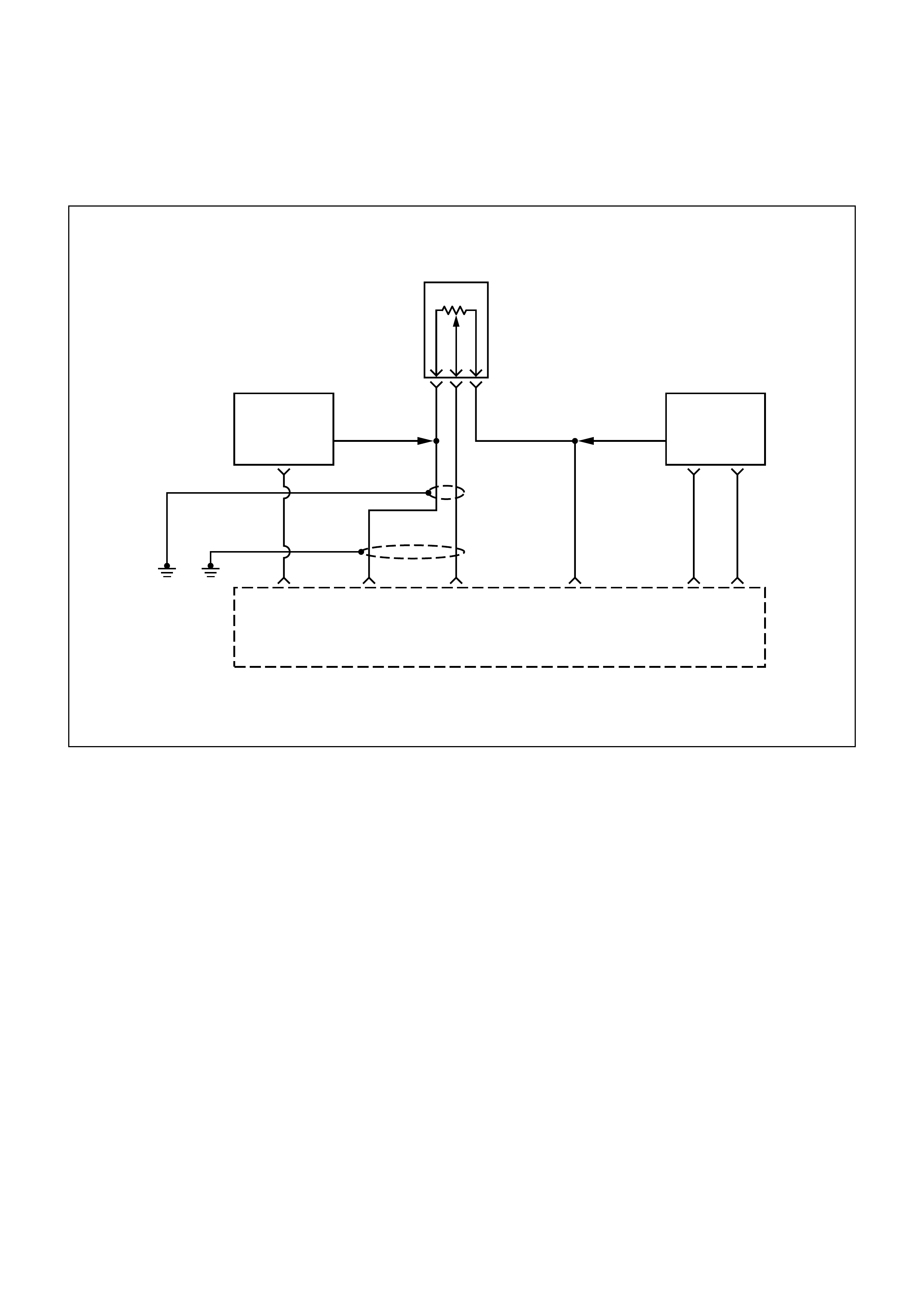
DIAG NOSTI C TROUBLE CODE (DTC) (FLASH DTC = 21)
THROTTLE POSITION (TP) SENSOR CI RCUIT HIGH INPUT
0.5
R
0.5
G
0.5
GR
0.5
RED
0.75
GRN
0.75
L
0.5
GRN
Engine
Control
Module
(ECM)
F14 B1 A3
5 Volt
Reference
Signal
Throttle
Position
(TP)
Sensor
Input
Sensor
Ground
Sensor
Ground
B7 B2
Throttle
Position
(TP)
Sensor
B C A
Manifold
Absolute
Pressure
Sensor
Engine
Coolant
Temperature
Sensor
B8
LO HI
OUT
0.5
L/R
CIRCUIT DESCRIPTION
The throttle position (TP) sensor circuit provides a
voltage signal that changes relative to throttle blade
angle. The signal voltage will vary from below 1 volt at
closed throttle to about 4 volts at wide open throttle
(WOT).
The throttle Position signal is used by the engine
control module (ECM) for fuel control and most of the
PCM-controlled outputs. If the ECM detects a low
impedance short to battery in the Throttle Position
sensor or circuit, then a code 21 will set.
CONDITIO NS FOR SETTING THE DTC
•Throttle Position Sensor signal is greater than 4.69
volts.
•Engine revolution is less than 3000rpm and
manifold vacuum is less than 85kpa.
ACTIO N TAKEN WHEN THE DTC SETS
•The ECM will illuminate the malfunction indicator
lamp (MIL) the first time the fault is detected.
•The ECM will use a default throttle position based
on RPM. Conditions for Clearing the MIL/DTC
DIAGNOSTIC AIDS
Check for the following conditions:
•Poor connection at ECM - Inspect harness
connectors for backed-out terminals, improper
mating, broken locks, improperly formed or
damaged terminals, and poor terminal-to-wire
connection.
•Damaged harness - Inspect the wiring harness for
damage. If the harness appears to be OK, observe
the Throttle Position sensor display on the Scan
Tool while m oving connec tors and wiring harness es
related to the throttle Position sensor. A change in
the display will indicate the location of the fault.

• Faulty Throttle Position sensor - With the ignition
key ON engine OFF observe the Throttle Position
sensor display on the Scan Tool while slowly
depressing the accelerator to wide open throttle. If a
voltage over 4.88 volts is seen at any point in
normal accelerator travel, replace the Throttle
Position sensor.
TEST DESCRIPTION
Number(s) below refer to the step number(s) on the
Diagnostic Chart.
7. Components that share the Throttle Position
sensor 5 volt reference circuit include the following
device:
• Engine Coolant Temperature Sensor
• MAP Sensor
Disconnect the component while observing the
Throttle Position sensor display on the Scan Tool. If
the reading changes drastically when this
component is disconnected, replace the component
that affected the reading.
DTC (FLASH DTC = 21) THROTTLE POSITION (TP) SENSOR CIRCUIT HIGH INPUT
STEP ACTION VALUE(S) YES NO
1Was the "On-Board Diagnostic (OBD) System Check"
performed? -
Go to Step 2
Go to OBD
System Check
2
1. Ignition ON, engine OFF.
2. With the throttle closed, observe the "Throttle Position
Sensor" values displayed on the Scan Tool.
Is the "Throttle Position Sensor" above the specified value? 4.78V
Go to Step 4 Go to Step 3
3
1. Ignition ON, engine OFF.
2. Using a Scan Tool, monitor info for Diagnostic Trouble Code
21.
Does the Scan Tool indicate Diagnostic Trouble Code 21 failed. -
Go to Step 4
Refer to
Diagnostic
Aids
4
1. Disconnect the Throttle Position sensor electrical connector.
2. Observe the "Throttle Position Sensor" values displayed on
the Scan Tool.
Is the "Throttle Position Sensor" near the specified value? 0V
Go to Step 5 Go to Step 6
5
Probe the sensor ground circuit at the Throttle Position sensor
harness connector with a test light connected to B+.
Is the test light ON? -
Go to Step 7 Go to Step 10
6
1. Ignition OFF disconnect the ECM.
2. Ignition ON, engine OFF.
3. Check for a short to voltage on the Throttle Position sensor
signal circuit.
4. If the Throttle Position sensor signal circuit is shorted, repair
it as necessary.
Was the Throttle Position sensor signal circuit shorted?
-
Verify repair Go to Step 12

STEP ACTION VALUE(S) YES NO
7
1. Ignition ON.
2. Monitor the "Throttle Position Sensor" Scan Tool display
while disconnecting each of the components that share the 5
volt reference circuit (one at a time).
3. If the "Throttle Position Sensor" values displayed changes,
replace the component that caused the display to change
when disconnected.
Does disconnecting any of these components cause the
"Throttle Position Sensor" values displayed to change?
-
Verify repair Go to Step 8
8
1. Ignition OFF disconnect the ECM.
2. Ignition ON, engine OFF.
3. Check for a short to B+ on the 5 volt reference circuit.
4. If the 5 volt reference circuit is shorted, repair it as
necessary.
Was the 5 volt reference circuit shorted?
-
Verify repair Go to Step 9
9Check for poor electrical connections at the Throttle Position
Sensor and replace terminals if necessary.
Did any terminals require replacement? -
Verify repair Go to Step 11
10
1. Ignition OFF.
2. Disconnect the ECM, and check for an open sensor ground
circuit to the Throttle Position Sensor.
3. If a problem is found, repair it as necessary.
Was the sensor ground circuit to the Throttle Position Sensor
open?
-
Verify repair Go to Step 12
11 Replace the Throttle Position Sensor.
Is the action complete? -Verify repair -
12 Replace the EPROM or ECM.
Is the action complete? Note) Refer to 6E1-243. -Verify repair -

DIAG NOSTI C TROUBLE CODE (DTC) (FLASH DTC = 13) O2 SENSOR
CIRCUIT NOT READY DETECTED (IF APPLICABLE)
CIRCUIT DESCRIPTION
•The engine control module (ECM) supplies a bias
voltage of about 450mV between the heated
oxygen sensor (HO2S) high and low circuits. W hen
meas ured with a 10 m egaohm digital voltm eter, this
may display as low as 320mV. The oxygen sensor
varies the voltage within a range of about 900mV
when the ex haust is r ich, down through about 60mV
when exhaust is lean. The ECM cons tantly monitors
the HO2S signal during "Closed Loop" operation
and compensates for a rich or lean condition by
decreasing or increasing injector pulse width as
necessary. This code determines whether the
oxygen sensor is ready for use as a feedback for
fuel control system. Then the DTC 13 will set.
CONDITIO NS FOR SETTING THE DTC
•Engine run time is longer than 60 seconds.
All the above conditions are met and the following
condition is met:
•HO2S signal voltage remains between 343mV and
540mV.
•Throttle angle is greater than 5%.
•ECT greater than 70°C.
ACTIO N TAKEN WHEN THE DTC SETS
•The ECM will illuminate the malfunction indicator
lamp (MIL) the second time the fault is detected.
•"Open Loop" fuel control will be in effect.
CONDITIO NS FOR CLEARI NG THE MIL/DTC
Once the ECM determines that a fault(s) has been
rectified then the CEL will switch OFF, although the
fault code will remain in the ECM memory.
Any fault codes will remain in ECM memory until -
1. They are cleared by disconnecting the Battery for
more than 30 seconds.
2. A service tool such as Tech 2 is used to clear them.
3. Ten consecutive starts without logging a fault.

DIAGNOSTIC AIDS
Check for the following conditions:
• Poor connection or damaged harness - Inspect the
harness connectors for backed-out terminals,
improper mating, broken locks, improperly formed
or damaged terminals, poor terminal-to-wire
connection, and damaged harness.
• Faulty HO2S heater or heater circuit - With the
ignition ON engine OFF after a cool down period,
the HO2S voltage displayed on the Scan Tool is
normally 455-460mV. A reading over 1000mV
indicates a signal line shorted to voltage. A reading
under 5mV indicates a signal line shorted to ground
or signal lines shorted together. Disconnect the
HO2S and connect a test light between the HO2S
battery feed and heater ground circuits. If the test
light does not light for 2 seconds when the ignition
is turned on, repair the open battery feed or sensor
ground circuit as necessary. If the test light lights
and the HO2S signal and low circuits are OK,
replace the HO2S.
• Intermittent test - With the ignition ON monitor the
HO2S signal voltage while moving the wiring
harness and related connectors. If the fault is
induced, the HO2S signal voltage will change. This
may help isolate the location of the malfunction.
DTC (FLASH DTC = 13) O2 SENSOR CIRCUIT NOT READY
STEP ACTION VALUE(S) YES NO
1Was the "On-Board Diagnostic (OBD) System Check"
performed? -
Go to Step 2
Go to OBD
System Check
2
1. Install the Scan Tool.
2. Run the engine at operating temperature.
3. Operate the engine above 1200 RPM for three minutes.
Does the Scan Tool indicate HO2S voltage varying outside the
specified values? 400-500mV Go to Step 3 Go to Step 4
3
1. Ignition ON, engine OFF.
2. Using a Scan Tool, monitor info for Diagnostic Trouble Code
13.
3. Note the test result.
Does the Scan Tool indicate Diagnostic Trouble Code 13 failed
this ignition?
-
Go to Step 4
Refer to
Diagnostic
Aids
4Check for a damaged harness.
Was a problem found? -Verify repair Go to Step 5
5
Check for poor HO2S high and low circuit terminal connections
at the HO2S harness connector and replace terminal(s) if
necessary.
Did any terminals require replacement?
-
Verify repair Go to Step 6
6
Check for poor HO2S high and low circuit terminal connections
at the ECM and replace terminals if necessary.
Did any terminals require replacement? -
Verify repair Go to Step 7

STEP ACTION VALUE(S) YES NO
7
1. Ignition OFF.
2. With the ECM disconnected, check continuity of the HO2S
high circuit.
3. If the HO2S high circuit measures over 0.5 ohms, repair
open or poor connection as necessary.
Was a HO2S high circuit problem found and corrected?
-
Verify repair Go to Step 8
8
1. Ignition OFF.
2. With the ECM disconnected, check continuity of the HO2S
low circuit.
3. If the HO2S low circuit measures over 5 ohms, repair open
or poor connection as necessary.
Was a HO2S low circuit problem found and corrected?
-
Verify repair Go to Step 9
9
1. Ignition ON, engine OFF.
2. Disconnect HO2S and jumper the HO2S high and low
circuits (ECM side) to ground.
3. Using a Scan Tool, monitor HO2S voltage.
Is HO2S voltage approximately equal to the specified value? 10mV Go to Step 10 Go to Step 11
10 Replace HO2S.
Is the action complete? -Verify repair -
11 Replace the EPROM or ECM. Note) Refer to 6E1-243.
Is the action complete? -Verify repair -

DIAG NOSTI C TROUBLE CODE (DTC) (FLASH DTC = 44)
O2 SENSOR TOO LEAN (IF APPLICABLE)
CIRCUIT DESCRIPTION
The engine control module (ECM) supplies a bias
voltage of about 450mV between the heated oxygen
sensor (HO2S) signal and low circuits. When
measured with a 10 megaohm digital voltmeter, this
may display as low as 350mV. The oxygen sensor
varies the voltage within a range of about 900mV
when the exhaust is rich, down through about 60mV
when exhaust is lean. The ECM constantly monitors
the HO2S signal during "Closed Loop" operation and
compensates for a rich or lean condition by
decreasing or increasing injector pulse width as
necessary. If the HO2S voltage remains excessively
low for an extended period of time.
This code detects a lean oxygen sensor reading.
CONDITIO NS FOR SETTING THE DTC
•Engine run time is longer than 60sec.
•Engine coolant temperature is above 70 °C(158°F).
•Throttle angle is greater than 5%.
All above conditions met and the following condition is
met:
•HO2S signal voltage remains less than 274mV.
ACTIO N TAKEN WHEN THE DTC SETS
•The ECM will illuminate the malfunction indicator
lamp (MIL) the first time the fault is detected.
•"Open Loop" fuel control will be in effect.

CONDITIO NS FOR CLEARI NG THE MIL/DTC
Once the ECM determines that a fault(s) has been
rectified then the CEL will switch OFF, although the
fault code will remain in the ECM memory.
Any fault codes will remain in ECM memory until -
1. They are cleared by disconnecting the Battery for
more than 30 seconds.
2. A service tool such as Tech 2 is used to clear them.
3. Ten consecutive starts without logging a fault.
DIAGNOSTIC AIDS
Check for the following conditions:
•Heated oxygen sensor wiring - The sensor pigtail
may be routed incorrectly and contacting the
exhaust system.
•Poor ECM to engine block ground.
•Fuel pressure - The system will go lean if pressure
is too low. The ECM can compensate for some
decrease. However, if fuel pressure is too low, a
diagnostic Trouble Code 44 may be set. Refer to
Fuel System Diagnosis .
•Lean injector(s) - Perform "Injector Balance Test."
•Vacuum leaks - Check for disconnected or
damaged vacuum hoses and for vacuum leaks at
the intake manifold, throttle body, and PCV system.
•Exhaust leaks - An exhaus t leak m ay cause outside
air to be pulled into the exhaust gas stream past the
HO2S, causing the system to appear lean. Check
for exhaust leaks that may cause a false lean
condition to be indicated.
•Fuel contam ination - Water, even in sm all am ounts,
can be delivered to the f uel inj ect ors . The water c an
cause a lean exhaust to be indicated, Excessive
alcohol in the fuel can also cause this condition.
Refer to Fuel System Diagnosis for the procedure
to check for fuel contamination.
If none of the above conditions are present, replace
the affected HO2S.

DTC (FLASH DTC = 44) O2 SENSOR TOO LEAN
STEP ACTION VALUE(S) YES NO
1Was the "On-Board Diagnostic (OBD) System Check"
performed? -
Go to Step 2
Go to OBD
System Check
2
1. Install the Scan Tool.
2. Run the engine at operating temperature.
3. Operate the vehicle within the parameters specified under
"Conditions for Setting the Diagnostic Trouble Code" criteria
included in Diagnostic Support.
4. Using a Scan Tool, monitor HO2S voltage.
Does the HO2S voltage remain below the specified value? 300mV Go to Step 4 Go to Step 3
31. Ignition ON, engine OFF.
2. Using a Scan Tool, monitor info for Diagnostic Trouble Code
44. -Go to Step 4 Refer to
Diagnostic
Aids
4
1. Turn the ignition OFF.
2. Disconnect the ECM.
3. Check the HO2S high and low circuits for a short to ground
or a short to the heater ground circuit.
Are the HO2S signal circuits shorted to ground?
-
Go to Step 5 Go to Step 6
5Repair the HO2S signal circuit.
Is the action complete? -Verify repair -
6
1. Turn the ignition OFF HO2S and ECM disconnected.
2. Check for continuity between the high and low signal circuits.
Was there continuity between the high and low circuits? -
Go to Step 7 Go to Step 8
7Repair the short between the high and low circuits.
Is the action complete? -Verify repair -
8
1. Ignition OFF.
2. Reconnect the ECM, leave the sensor disconnected.
3. Ignition ON.
Does the Scan Tool indicate HO2S voltage near the specified
value? 430-450mV
Refer to
Diagnostic
Aids Go to Step 9
9Replace the EPROM or ECM.
Is the action complete? Note) Refer to 6E1-243. -Verify repair -
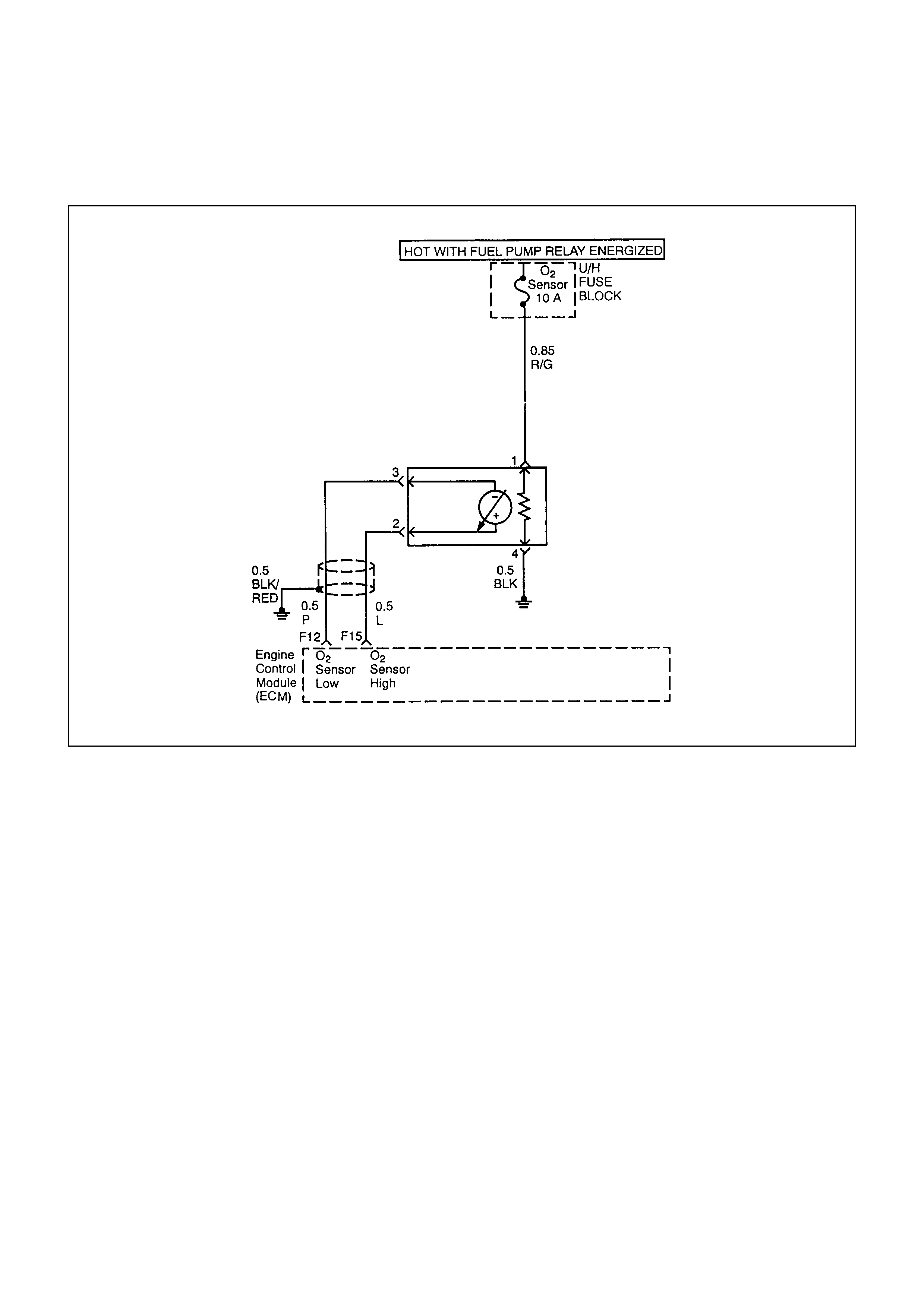
DIAG NOSTI C TROUBLE CODE (DTC) (FLASH DTC = 45)
O2 SENSOR TOO RICH (IF APPLICABLE)
CIRCUIT DESCRIPTION
The engine control module (ECM) supplies a bias
voltage of about 450mV between the heated oxygen
sensor (HO2S) signal and low circuits. When
measured with a 10 megaohm digital voltmeter, this
may display as low as 320mV. The oxygen sensor
varies the voltage within a range of about 900mV
when the exhaust is rich, down through about 10mV
when exhaust is lean. The ECM constantly monitors
the HO2S signal during "Closed Loop" operation and
compensates for a rich or lean condition by
decreasing or increasing injector pulse width as
necessary. If the HO2S voltage remains excessively
high for an extended period of time.
This code detects a rich oxygen sensor reading.
CONDITIO NS FOR SETTING THE DTC
•Engine run time is longer than 60sec.
•Engine coolant temperature is above 70°C(158°F).
•Throttle angle is greater than 5%.
•Following Diagnostic Trouble Codes are not set:
Malfunction DTC: 21, 22, 33, 24
•Closed Loop fuel integrator is not reset and closed
loop fuel enabled.
ACTIO N TAKEN WHEN THE DTC SETS
•The ECM will illuminate the malfunction indicator
lamp (MIL).
•"Open Loop" fuel control will be in effect.

CONDITIO NS FOR CLEARI NG THE MIL/DTC
Once the ECM determines that a fault(s) has been
rectified then the CEL will switch OFF, although the
fault code will remain in the ECM memory.
Any fault codes will remain in ECM memory until -
1. They are cleared by disconnecting the Battery for
more than 30 seconds.
2. A service tool such as Tech 2 is used to clear them.
3. Ten consecutive starts without logging a fault.
DIAGNOSTIC AIDS
Check the following items:
•Fuel pressure - The system will go rich if pressure
is too high. The ECM can compensate for some
increase. However, if fuel pressure is too high, a
Diagnostic Trouble Code 45 may be set. Refer to
Fuel System Diagnosis .
•Perform "Injector Balance Test" - Refer to
Fuel System Diagnosis .
•Check the EVAP canister for fuel saturation - If full
of fuel, check canister control and hoses. Refer to
Evaporative (EVAP) Emission Control System.
•Check for a leak in the fuel pressure regulator
diaphragm by checking the vacuum line to toe
regulator for the presence of fuel.
•An intermittent TP sensor output will cause the
system to go rich due to a false indication of the
engine accelerating.
•Silicon contamination of the HO2S can also cause a
high HO2S voltage to be indicated. T his c ondition is
indicated by a powdery white deposit on the portion
of the HO2S exposed to the exhaust stream. If
contamination is noticed, replace the affected
HO2S.
•Operate the vehicle while monitoring the HO2S
voltage with a Scan Tool. If the HO2S voltage is
limited within a range between 300mV to 600mV,
check the HO2S high and low circuit wiring and
associated terminal connections. If the wiring and
connections are OK, replace the HO2S.

DTC (FLASH DTC = 45) O2 SENSOR TOO RICH
STEP ACTION VALUE(S) YES NO
1Was the "On-Board Diagnostic (OBD) System Check"
performed? -
Go to Step 2
Go to OBD
System Check
2
1. Install the Scan Tool.
2. Run the engine at operating temperature.
3. Operate the vehicle within parameters specified under
"Conditions for Setting the Diagnostic Trouble Code".
4. Using a Scan Tool, monitor HO2S voltage.
Does the HO2S voltage remain above the specified value?
952 mV
(500mV in
deceleration
fuel cutoff
mode) Go to Step 4 Go to Step 3
3
1. Ignition ON.
2. Using a Scan Tool, monitor info for Diagnostic Trouble Code
45.
3. Does the Scan Tool indicate Diagnostic Trouble Code 45. -Refer to
Diagnostic
Aids Go to Step 4
4
1. Ignition OFF.
2. Disconnect HO2S.
3. Ignition ON.
4. At HO2S connector (ECM side) use a DVM to measure
voltages at the high and low signal terminals.
Are the voltages in the specified range? 5-14V Go to Step 5 Go to Step 6
5 Repair short to voltage in signal circuit. - Verify repair -
6
1. Ignition OFF.
2. Disconnect the ECM connector.
3. Check for damage to the ECM pins and terminals.
Was a problem found?
-
Verify repair Go to Step 7
7
1. Ignition ON, engine OFF.
2. Disconnect HO2S and jumper the HO2S high and low
circuits (ECM side) to ground.
3. Using a Scan Tool, monitor HO2S voltage.
Is HO2S voltage below the specified value? 10mV Go to Step 8 Go to Step 9
8Replace HO2S.
Is the action complete? -Verify repair -
9Replace the EPROM or ECM.
Is the action complete? Note) Refer to 6E1-243. -Verify repair -
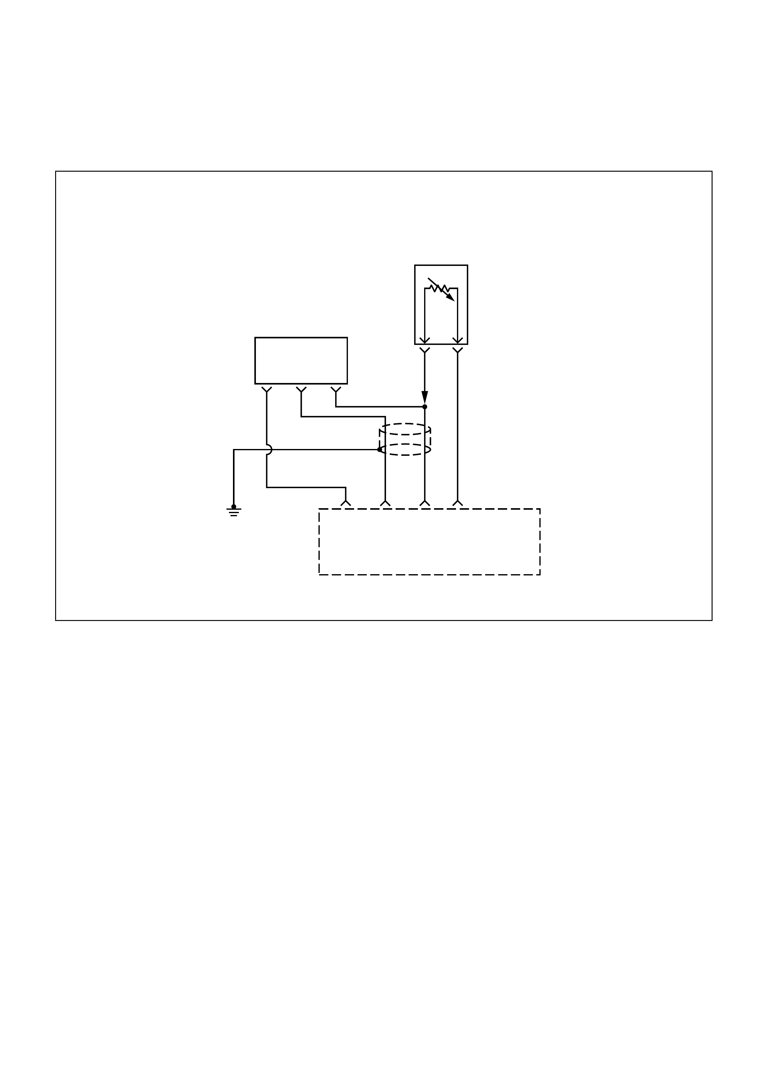
DIAG NOSTI C TROUBLE CODE (DTC) (FLASH DTC = 14) ENGINE COOLANT
TEMPERATURE (ECT) SENSOR CIRCUIT HIGH INPUT
0.75
G
0.75
L
0.5
R
0.5
GRN
0.5
L/R
Engine
Control
Module
(ECM)
A3 F14
B1
B8
ECT
Sensor
Input
Sensor
Ground
Engine
Coolant
Temperature
(ECT)
Sensor
BA
TPS
HI OUT LO
CIRCUIT DESCRIPTION
The engine coolant temperature (ECT) sensor is a
thermistor mounted in the engine coolant stream. The
engine control module (ECM) applies a voltage (about
5 volts) through a pull-up resistor to the ECT signal
circuit. When the engine coolant is cold, the sensor
(thermistor) resistance is high, therefore the ECM will
measure a high signal voltage. As the engine coolant
warms, the sensor resistance becomes lower, and the
ECT signal voltage measured at the ECM drops. With
a fully warmed up engine, the ECT signal voltage
should measure about 1.5 to 2.0 volts. If the ECM
detect a continuous open in the ECT sensor or circuit,
then a code 14 will set.
CONDITIO NS FOR SETTING THE DTC
•Engine running time is longer than 10secs.
•The ECT sensor signal indicates an engine coolant
temperature greater than 140°C (284°F).
ACTIO N TAKEN WHEN THE DTC SETS
•The ECM will illuminate the malfunction indicator
lamp (MIL) fault is detected.
•The ECM will substitute the ECT reading with a
default engine coolant temperature value. The
default value is based on start-up intake air
temperature and running time.
CONDITIO NS FOR CLEARI NG THE MIL/DTC
Once the ECM determines that a fault(s) has been
rectified then the CEL will switch OFF, although the
fault code will remain in the ECM memory.
Any fault codes will remain in ECM memory until -
1. They are cleared by disconnecting the Battery for
more than 30 seconds.
2. A service tool such as Tech 2 is used to clear them.
3. Ten consecutive starts without logging a fault.

DIAGNOSTIC AIDS
Check for the following conditions:
•Poor connection at ECM - Inspect harness
connectors for backed-out terminals, improper
mating, broken locks, improperly formed or
damaged terminals, and poor terminal-to-wire
connection.
•Damaged harness - Inspect the wiring harness for
damage, If the harness appears to be OK, observe
the ECT display on the Scan Tool while moving
connectors and wiring harnesses related to the ECT
sensor. A change in the ECT display will indicate
the location of the fault.
TEST DESCRIPTION
Number(s) below refer to the step number(s) on the
Diagnostic Chart.
2. Verifies that the fault is present.
3. Refer to the "Temperature vs. Resistance Value"
table. The table may be used to test the ECT
sensor at various temperatures to evaluate the
possibility of a "shifted" sens or that m ay be stored
above or below a certain temperature. If this is the
case, replace the ECT sensor. If the ECT sensor
appears to be OK, the fault is intermittent; refer to
Diagnostic Aids.
ENGINE COOLANT TEMPERATURE SENSOR
°C °F OHMS
Temperature vs. Resistance Values
(approximate)
100 212 177
80 176 332
60 140 667
45 113 1188
35 95 1802
25 77 2796
15 59 4450
5 41 7280
−5 23 12300
−15 5 21450
−30 −22 52700
−40 −40 100700

DTC (FLASH DTC = 14) ECT SENSOR CIRCUIT HIGH INPUT
STEP ACTION VALUE(S) YES NO
1Was the "On-Board Diagnostic (OBD) System Check"
performed? -
Go to Step 2
Go to OBD
System Check
2
1. Ignition ON engine OFF
2. Observe the "Eng Coolant Temp" displayed on the Scan
Tool.
Is the "Eng Coolant Temp" below the specified value? −35°C
(−31°F) Go to Step 4 Go to Step 3
3
1. Ignition ON engine OFF.
2. Using a Scan Tool, monitor the info for Diagnostic Trouble
Code 14.
Does the Scan Tool indicate Diagnostic Trouble Code 14.
-Refer to Test
Description
Refer to
Diagnostic
Aids
4
1. Disconnect the ECT sensor electrical connector.
2. Jumper the ECT signal circuit and the sensor ground circuit
together at the ECT sensor harness connector.
3. Observe the "Eng Coolant Temp" displayed on the Scan
Tool.
Is the "Eng Coolant Temp" at the specified value? 140°C
(284°F) Go to Step 6 Go to Step 5
5
1. Jumper the ECT signal circuit at the ECT sensor harness
connector to chassis ground.
2. Observe the "Eng Coolant Temp" displayed on the Scan
Tool.
Is the "Eng Coolant Temp" at the specified value? 140°C
(284°F) Go to Step 7 Go to Step 6
6Check for poor connections at the ECT sensor and replace
terminals if necessary.
Did any terminals require replacement? -
Verify repair Go to Step 8
7
1. Ignition OFF.
2. Disconnect the ECM, and check the ECT sensor ground
circuit for an Short to ground.
3. If the ECT sensor ground circuit is Short to ground, repair it
as necessary.
Was the ECT sensor ground circuit Short to ground?
-
Verify repair Go to Step 8
8
Check for a poor sensor ground or ECT signal circuit terminal
connection at the ECM and replace terminal(s) if necessary.
Did any of the terminal need to be replaced? -
Verify repair Go to Step 9
9Replace the ECT sensor.
Is the action complete? -Verify repair -
10 Replace the EPROM or ECM.
Is the action complete? Note) Refer to 6E1-243. -
Verify repair
-
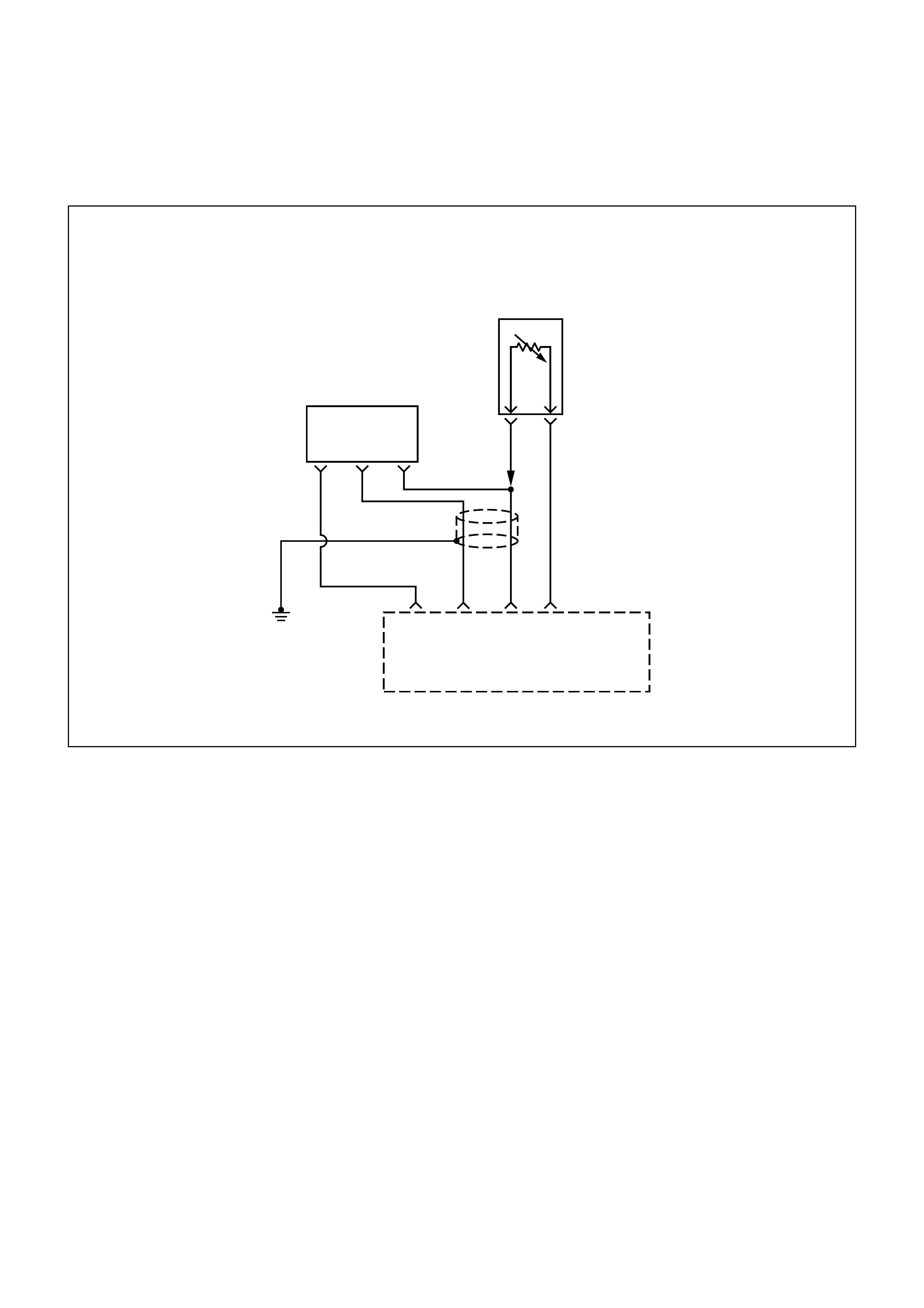
DIAG NOSTI C TROUBLE CODE (DTC) (FLASH DTC = 15) ENGINE COOLANT
TEMPERATURE (ECT) SENSOR CIRCUIT LOW INPUT
0.75
G
0.75
L
0.5
R
0.5
GRN
0.5
L/R
Engine
Control
Module
(ECM)
A3 F14
B1
B8
ECT
Sensor
Input
Sensor
Ground
Engine
Coolant
Temperature
(ECT)
Sensor
BA
TPS
HI OUT LO
CIRCUIT DESCRIPTION
The ECT sensor is a thermistor mounted in the engine
coolant stream. The engine control module (ECM)
applies a voltage (about 5 volts) through a pull-up
resistor to the ECT signal circuit. When the engine
coolant is cold, the sensor (thermistor) resistance is
high, therefore the ECM will measure a high signal
voltage. As the engine coolant warms, the sensor
resistance becomes lower, and the ECT signal voltage
measured at the ECM drops. With a fully warmed-up
engine, the ECT signal voltage should measure about
1.5 to 2.0 volts.
CONDITIO NS FOR SETTING THE DTC
•Engine running time is longer than 30 secs.
•The ECT sensor signal indicates an engine coolant
temperature less than -35°C (-31°F).
ACTIO N TAKEN WHEN THE DTC SETS
•The ECM will illuminate the malfunction indicator
lamp (MIL) the first time the fault is detected.
•The ECM will substitute the ECT reading with a
default engine coolant temperature value. The
default value is based on start-up intake air
temperature and running time.
CONDITIO NS FOR CLEARI NG THE MIL/DTC
Once the ECM determines that a fault(s) has been
rectified then the CEL will switch OFF, although the
fault code will remain in the ECM memory.
Any fault codes will remain in ECM memory until -
1. They are cleared by disconnecting the Battery for
more than 30 seconds.
2. A service tool such as Tech 2 is used to clear them.
3. Ten consecutive starts without logging a fault.

DIAGNOSTIC AIDS
Check for the following conditions:
•Poor connection at ECM - Inspect harness
connectors for backed-out terminals, improper
mating, broken locks, improperly formed or
damaged terminals, and poor terminal-to-wire
connection.
•Damaged harness - Inspect the wiring harness for
damage, If the harness appears to be OK, observe
the ECT display on the Scan Tool while moving
connectors and wiring harnesses related to the ECT
sensor. A change in the ECT display will indicate
the location of the fault.
TEST DESCRIPTION
Number(s) below refer to the step number(s) on the
Diagnostic Chart.
2. Verifies that the fault is present.
3. Refer to the "Temperature vs. Resistance Value"
table. The table may be used to test the ECT
sensor at various temperatures to evaluate the
possibility of a "shifted" sens or that m ay be stored
above or below a certain temperature. If this is the
case, replace the ECT sensor. If the ECT sensor
appears to be OK, the fault is intermittent; refer to
Diagnostic Aids.
ENGINE COOLANT TEMPERATURE SENSOR
°C °F OHMS
Temperature vs. Resistance Values
(approximate)
100 212 177
80 176 332
60 140 667
45 113 1188
35 95 1802
25 77 2796
15 59 4450
5 41 7280
−5 23 12300
−15 5 21450
−30 −22 52700
−40 −40 100700

DTC (FLASH DTC = 15) ENGINE COOLANT TEMPERATURE (ECT) SENSOR CIRCUIT LOW INPUT
STEP ACTION VALUE(S) YES NO
1Was the "On-Board Diagnostic (OBD) System Check"
performed? -
Go to Step 2
Go to OBD
System Check
2 1. Ignition ON, engine OFF
2. Observe the "Eng Coolant Temp" displayed on the Scan
Tool.
Is the "Eng Coolant Temp" below the specified value? 140°C
(284°F) Go to Step 4 Go to Step 3
3
1. Ignition ON, engine OFF.
2. Using a Scan Tool, monitor info for Diagnostic Trouble Code
15.
Does the Scan Tool indicate Diagnostic Trouble Code 15?
-
Go to Step 4
Refer to
Diagnostic
Aids
4
1. Disconnect the ECT sensor electrical connector.
2. Observe the "Eng Coolant Temp" displayed on the Scan
Tool.
Is the "Eng Coolant Temp" at the specified value? −35°C
(−31°F) Go to Step 6 Go to Step 5
5
1. Ignition OFF.
2. Disconnect the ECM and check the ECT circuit for a an open
or a short to battery in the sensor circuit.
3. If the ECT circuit is short to battery or open, repair it as
necessary.
Was the ECT signal circuit shorted to ground?
-
Verify repair Go to Step 7
6Replace the ECT sensor.
Is the action complete? -Verify repair -
7Replace the EPROM or ECM.
Is the action complete? Note) Refer to 6E1-243. -Verify repair -
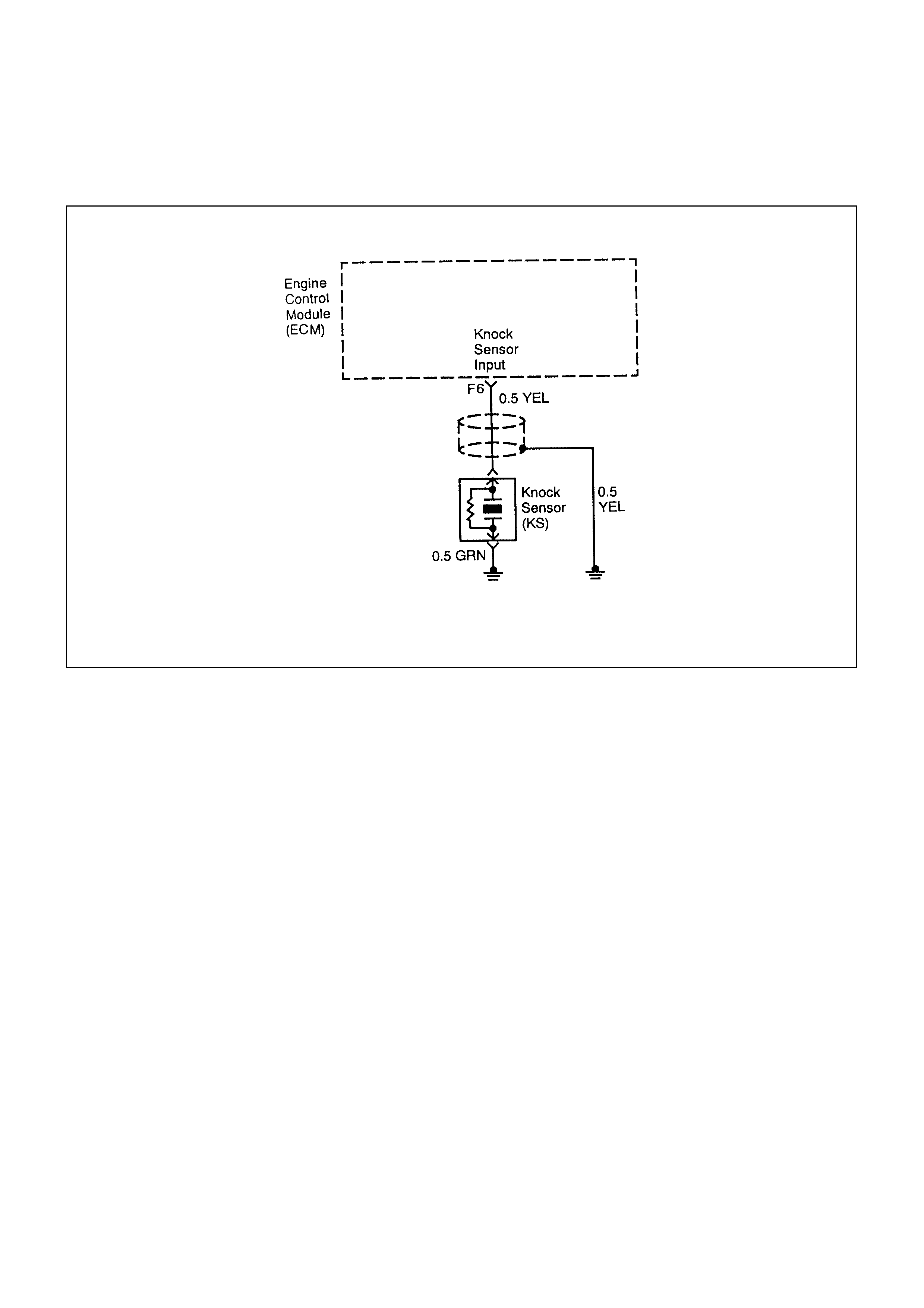
DIAG NOSTI C TROUBLE CODE (DTC) (FLASH DTC = 16)
KNOCK SENSOR (KS) DISCONNECTED MALFUNCTI ON
CIRCUIT DESCRIPTION
The knock sensor (KS) system is used to detect
engine detonation. The knock sensor produced an AC
voltage signal. The knock sensor sends this signal to
the ECM. The amplitude and the frequency of the AC
voltage signal depends upon the knock level being
detected. The ECM will then retard the spark timing
based on the signals from the Knock Sensor.
This code detects a disconnected knock sensor. Then
a DTC 16 will set.
CONDITIO NS FOR SETTING THE DTC
•Electronic and spark control enabled.
•Engine running.
•ECM powered up.
•Engine speed is greater than 2400rpm.
All the above mentioned conditions are met.
ACTIO N TAKEN WHEN THE DTC SETS
•The Malfunc tion Indic ator Lamp (MIL) will illum inate
the fault is detected.
•The ECM will use a c alculated spark retard value in
order to minimize the knock during the conditions
when the knock is likely to occur. The calculated
value will vary based on the engine speed and load.
CONDITIO NS FOR CLEARI NG THE MIL/DTC
Once the ECM determines that a fault(s) has been
rectified then the CEL will switch OFF, although the
fault code will remain in the ECM memory.
Any fault codes will remain in ECM memory until -
1. They are cleared by disconnecting the Battery for
more than 30 seconds.
2. A service tool such as Tech 2 is used to clear them.
3. Ten consecutive starts without logging a fault.
DIAGNOSTIC AIDS
Correct any abnormal engine noise before using the
diagnostic table.
Check for an open ignition feed circuit.

TEST DESCRIPTION
Number(s) below refer to the step number(s) on the
Diagnostic Table.
2. If the conditions for the test as described above are
met, a Diagnostic Trouble Code 16 will set and MIL
will illuminate.
4. If the engine has an internal knock or audible noise
that causes a knocking type noise on the engine
block, the knock sensor may be responding to the
noise.
6. Any circuitry, that is suspected as causing the
complaint, should be thoroughly checked for
backed out terminals, improper mating, broken
locks, improperly formed or damaged terminals,
poor terminal to wiring connections or physical
damage to the wiring harness.
8. Checking the internal resistance of the knock
sensor verifies if the knock sensor or the wiring to
the knock sensor is OK.
DTC (FLASH DTC = 16) KS SENSOR DISCONNECTED MALFUNCTION
STEP ACTION VALUE(S) YES NO
1
Was the Powertrain On-Board Diagnostic (OBD) System Check
performed? -
Go to Step 2
Go to
Powertrain
OBD System
Check
2
1. Start the engine.
2. Install a Scan Tool.
3. Clear the Diagnostic Trouble Codes.
4. Run the engine at slightly more than 10% throttle angle.
Does the Malfunction Indicator Lamp (MIL) illuminate?
-
Go to Step 4 Go to Step 3
31. Turn the ignition Switch ON, with engine OFF.
Does the Malfunction Indicator Lamp (MIL) illuminate? -Go to Step 4 Go to Step 12
4Listen to the engine while raising and lowering the engine
speed.
Is a knock or audible noise present? -
Go to Step 5 Go to Step 6
5Repair the mechanical engine problem or a loose bracket or
component.
Is the action complete? -
Go to Step 12
-
6Check for a poor connection at the ECM connector,
Knock sensor signal circuit and repair as necessary.
Was a repair necessary? -
Go to Step 12 Go to Step 7
7Replace the EPROM or ECM.
Is the action complete? Note) Refer to 6E1-243. -Go to Step 12 -

STEP ACTION VALUE(S) YES NO
8
1. Turn the ignition switch OFF.
2. Disconnect the ECM connectors at the ECM.
3. With a Digital Voltmeter (DVM) connected to ground,
measure the resistance of the knock sensor through the
knock sensor signal circuit.
Is the measured value wi thin the specified value?
95K-105K
OHMS
Go to Step 6 Go to Step 9
9Check the knock sensor electrical connector for a poor
connection and repair as necessary.
Was a repair necessary? -
Go to Step 12 Go to Step 10
10 Check the knock sensor signal circuit for an open or a short to
ground or to voltage and repair as necessary.
Was a repair necessary? -
Go to Step 12 Go to Step 11
11 Replace the Knock Sensor(KS).
Is the action complete? -Go to Step 12 -
12
1. Using the Scan Tool, clear the Diagnostic Trouble Codes.
2. Start the engine and idle at normal operating temperature.
3. Operate the vehicle within the conditions for setting this
Diagnostic Trouble Code as specified in the supporting text.
Does the Scan Tool indicate that this diagnostic has ran and
passed? -
Go to Step 13 Go to Step 2
13
Check is any additional Diagnostic Trouble Codes are set.
Are any Diagnostic Trouble Codes displayed that have not been
diagnosed? -
Go to
applicable
Diagnostic
Trouble Code
table System OK
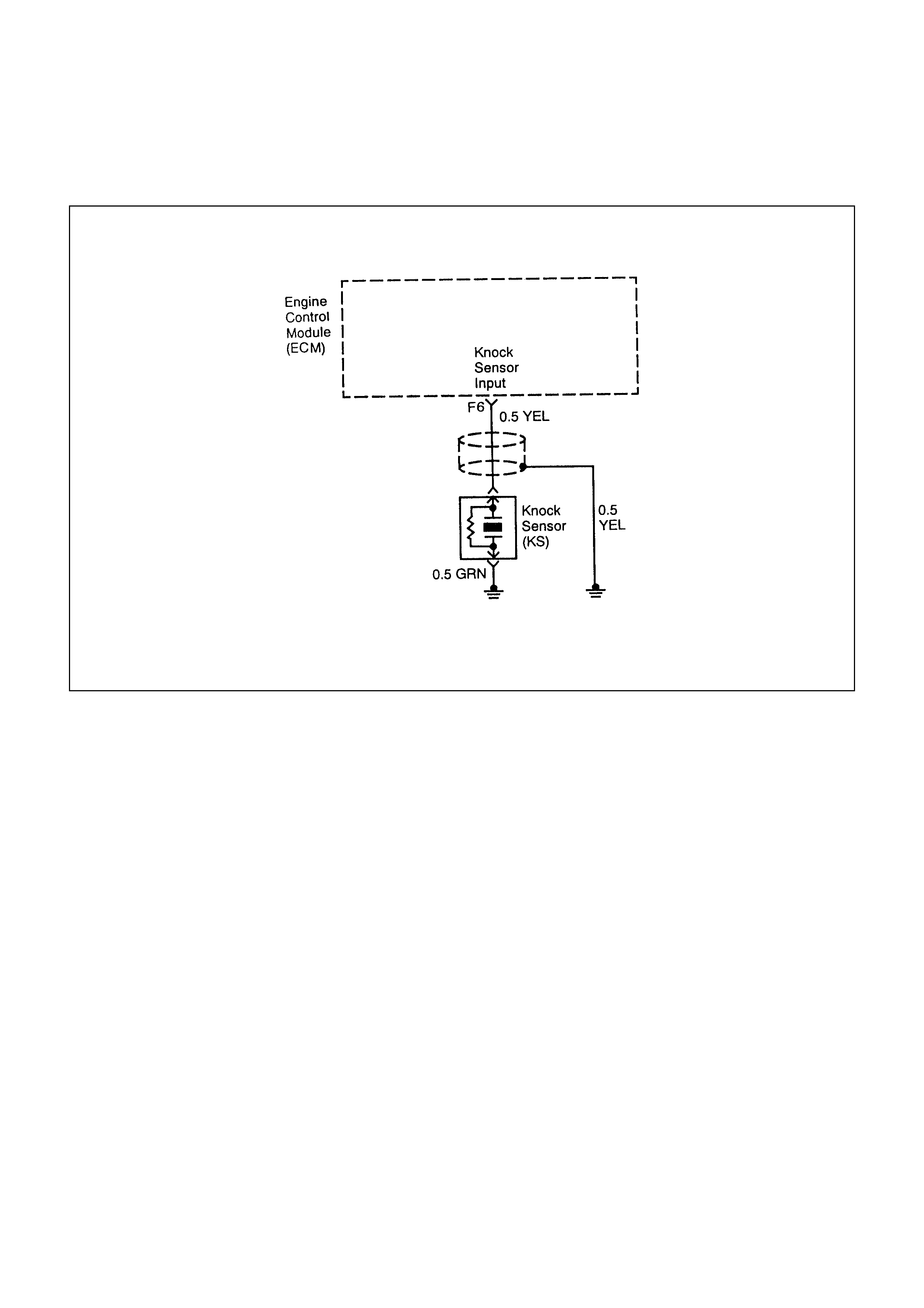
DIAG NOSTI C TROUBLE CODE (DTC) (FLASH DTC = 18) DIGITALLY
CONTROLED SIGNAL TO NOISE ENHANCEMENT FILTER FAILURE
CIRCUIT DESCRIPTION
The knock sensor (KS) system is used to detect
engine detonation. The knock sensor produced an AC
voltage signal. The knock sensor sends this signal to
the ECM. The amplitude and the frequency of the AC
voltage signal depends upon the knock level being
detected. The ECM will then retard the spark timing
based on the signals from the Knock Sensor.
This code detects a digitally controlled signal to noise
enhancement filter failure. Then the DTC 18 will set.
CONDITIO NS FOR SETTING THE DTC
•ECM powered up, Engine running, Electronic spark
control enabled and Engine rpm is greater than 96
rpm.
•Malfunction 16 is not triggered.
ACTIO N TAKEN WHEN THE DTC SETS
•The Malfunc tion Indic ator Lamp (MIL) will illum inate
the second time the fault is detected.
•The ECM will use a c alculated spark retard value in
order to minimize the knock during the conditions
when the knock is likely to occur. The calculated
value will vary based on the engine speed and load.
CONDITIO NS FOR CLEARI NG THE MIL/DTC
Once the ECM determines that a fault(s) has been
rectified then the CEL will switch OFF, although the
fault code will remain in the ECM memory.
Any fault codes will remain in ECM memory until -
1. They are cleared by disconnecting the Battery for
more than 30 seconds.
2. A service tool such as Tech 2 is used to clear them.
3. Ten consecutive starts without logging a fault.
DIAGNOSTIC AIDS
Correct any abnormal engine noise before using the
diagnostic table.
Check for an open ignition feed circuit.

TEST DESCRIPTION
Number(s) below refer to the step number(s) on the
Diagnostic Table.
2. If the conditions for the test as described above are
met, a Diagnostic Trouble Code 18 will set and MIL
will illuminate.
5. Any circuitry, that is suspected as causing the
complaint, should be thoroughly checked for
backed out terminals, improper mating, broken
locks, improperly formed or damaged terminals,
poor terminal to wiring connections or physical
damage to the wiring harness.
9. If the KS module was previously replaced and the
Diagnostic Trouble Code resets, a malfunctioning
ECM is indicated.
DTC (FLASH DTC = 18) DIGITALLY CONTROLLED SIGNAL
TO NOISE ENHANCEMENT FILTER FAILURE
STEP ACTION VALUE(S) YES NO
1
Was the On-Board Diagnostic(OBD) System Check performed?
-
Go to Step2
Go to
Powertrain
OBD System
Check
2
1. Operate the engine within the conditions specified in the
diagnostic support Conditions for Setting the Diagnostic
Trouble Code.
2. Using a Scan Tool, monitor the Specific DTC information for
DTC 18.
3. Observe the test results.
Does the Scan Tool indicate the DTC 18.
-
Go to Step 3
Go to
Diagnostic
Aids
3
1. Turn ON the ignition with the engine leaving OFF.
2. Disconnect the KS electrical connector.
3. Using a Digital Voltmeter (DVM), measure the voltage
between the KS signal circuit at the knock sensor harness
connectors and ground.
Is the voltage at the specified value? Approx.5.0V Go to Step 4 Go to Step 7
4
Measure the resistance of the KS sensor by connecting the
between the KS sensor terminal and the engine block.
Is the resistance of the KS sensor near the specified value? 100K OHMS Go to Step 5 Go to Step 8
5
1. Check the KS signal circuit for a poor terminal connection at
the knock sensor.
2. If a problem is found, repair as necessary. Refer to Wiring
Repairs in Engine Electrical.
Was a problem found?
-
Go to Step 6 Go to Step 8
6
1. Re-Connect the KS Sensor in order to monitor the voltage
between the KS sensor terminal and the engine ground.
2. Tap on the engine lift bracket, near the KS Sensor, while
observing the signal indicated on the Scan Tool.
Is any signal indicated on the while tapping on the engine lift
bracket?
-
Go to Step 10 Go to Step 7

STEP ACTION VALUE(S) YES NO
7
1. Turn OFF the ignition.
2. Disconnect the ECM.
3. Turn ON the ignition.
4. Check the KS signal circuit between the ECM and the KS
sensor connector for an open, a short to voltage, or a short
to ground.
5. If a wiring problem is found, repair as necessary.
Was a problem found?
-
Go to Step 10 Go to Step 9
8Replace the KS Sensor. Refer to Knock Sensor.
Is action complete? -Go to Step 10 -
9Replace the EPROM or ECM. Note) Refer to 6E1-243.
Is the action complete? -Go to Step 10 -
10
1. Using the Scan Tool, select the DTC and the Clear Info.
2. Start the Engine.
3. Idle at the normal operating temperature.
4. Select Specific DTC.
5. Enter the DTC number which was set.
6. Operate the vehicle within the conditions for setting this DTC
as specified in the supporting text.
Does the Scan Tool indicate that this diagnostic ran and
passed?
-
Go to Step 11 Go to Step 2
11
Using the Scan Tool, select the Capture Info and the Review
Info.
Are any DTC displayed that have not been diagnosed? -
Go to the
applicable
Diagnostic
Trouble Code
table System OK
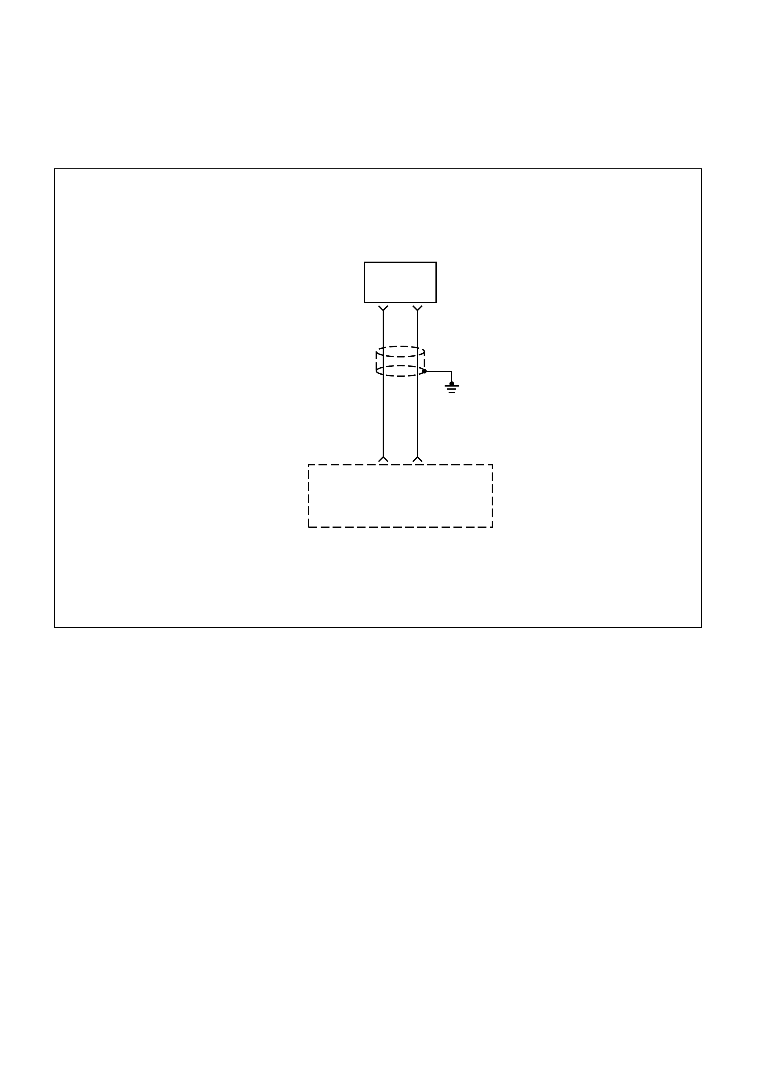
DIAG NOSTI C TROUBLE CODE (DTC) (FLASH DTC = 19)
CRANKSHAFT POSITION (CKP) SENSOR SI GNAL INCORRECT
Engine
Control
Module
(ECM)
CKP
Sensor
Input
Sensor
Ground
0.5
G
E5
0.5
R
F1
Crankshaft
Position
(CKP)
Sensor
21
CIRCUIT DESCRIPTION
The 58X reference signal is produced by the
crankshaft position (CKP) sensor. During one
crankshaft revolution, 58 crankshaft pulses will be
produced. The engine control module (ECM) uses the
58X reference signal to calculate engine RPM and
crankshaft position. The ECM constantly monitors the
number of pulses on the 58X reference circuit. If the
ECM receives an incorrect number of pulses on the
58X reference circuit, Diagnostic Trouble Code 19 will
set.
CONDITIO NS FOR SETTING THE DTC
•Engine is running.
•Number of revolutions with pulses not equal to 58 is
greater than 20.
ACTIO N TAKEN WHEN THE DTC SETS
•The ECM will illuminate the malfunction indicator
lamp (MIL) after the fault is detected.
CONDITIO NS FOR CLEARI NG THE MIL/DTC
Once the ECM determines that a fault(s) has been
rectified then the CEL will switch OFF, although the
fault code will remain in the ECM memory.
Any fault codes will remain in ECM memory until -
1. They are cleared by disconnecting the Battery for
more than 30 seconds.
2. A service tool such as Tech 2 is used to clear them.
3. Ten consecutive starts without logging a fault.

DIAGNOSTIC AIDS
An intermittent may be caused by a poor connection,
rubbed-through wire insulation or a wire broken inside
the insulation. Check for:
• Poor connection - Inspect the ECM harness and
connectors for improper mating, broken locks,
improperly formed or damaged terminals, and poor
terminal-to-wire connection.
• Damaged harness - Inspect the wiring harness for
damage; shorts to Ground, shorts to Battery
Positive, and Open circuits. If the harness appears
to be OK, disconnect the ECM, turn the ignition on
and observe a voltmeter connected to the 58X
reference circuit at the ECM harness connector
while moving connectors and wiring harnesses
related to the ECM. A change in voltage will indicate
the location of the fault.
• This code detects an incorrect 58X signal caused
by intermittent failures.
DTC (FLASH DTC = 19) CRANKSHAFT POSITION (CKP) SENSOR SIGNAL INCORRECT
STEP ACTION VALUE(S) YES NO
1Was the "On-Board Diagnostic (OBD) System Check"
performed? -
Go to Step 2
Go to OBD
System Check
2
Attempt to start the engine.
Does the engine start? -
Go to Step 3
Refer to
Engine Cranks
But Will Not
Run chart
3
1. Clear Diagnostic Trouble Code 19.
2. Start the engine and idle for 1 minute.
3. Observe Diagnostic Trouble Codes.
Is Diagnostic Trouble Code 18 set?
-
Go to Step 4
Refer to
Diagnostic
Aids
4
1. Disconnect the ECM and CKP sensor.
2. Check for an open or a short to ground in the 58X reference
circuit between the CKP sensor connector and the ECM
harness connector.
3. If a problem is found, repair as necessary.
Was a problem found?
-
Verify repair Go to Step 5
5
1. Reconnect the ECM and CKP sensor.
2. Connect a Digital Voltmeter (DVM) to measure voltage on
the 58X reference circuit at the ECM connector.
3. Observe the voltage while cranking the engine.
Is the voltage near the specified value? 2.5V
Go to Step 8 Go to Step 6
6Check the connections at the CKP sensor and replace the
terminals if necessary.
Did any terminals require replacement? -
Verify repair Go to Step 7
7Replace the CKP sensor.
Is the action complete? -Verify repair -
8Check connections at the ECM and replace the terminals if
necessary.
Did any terminals require replacement? -
Verify repair Go to Step 9
9Replace the EPROM or ECM.
Is the action complete? Note) Refer to 6E1-243. -Verify repair -
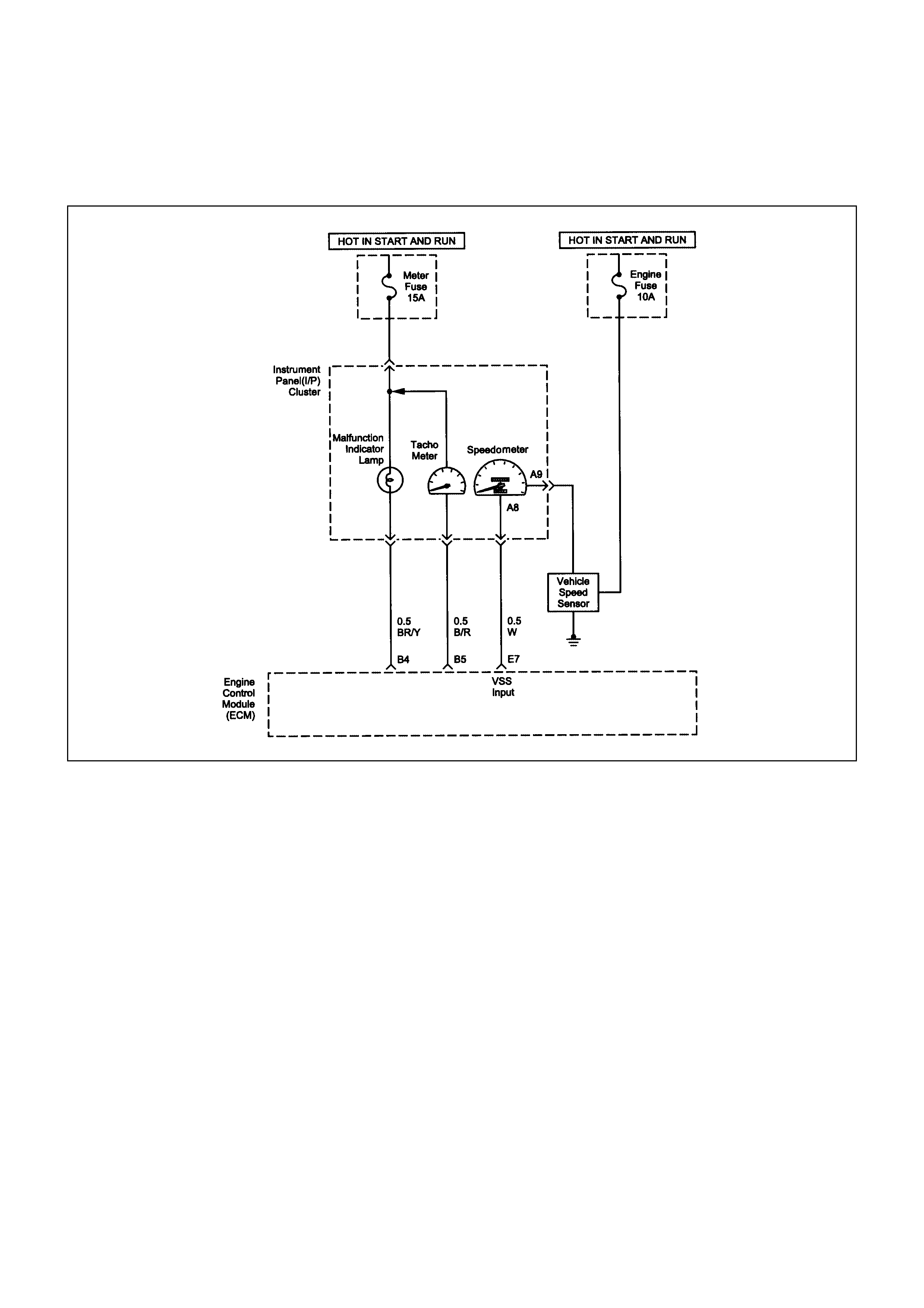
DIAG NOSTI C TROUBLE CODE (DTC) (FLASH DTC = 24)
VEHICLE SPEED SENSOR (VSS) FAULT
CIRCUIT DESCRIPTION
The vehicle speed sensor has a magnet rotated by the
transmission output shaft. Attached to the sensor is a
hall effect circuit that interacts with the magnetic field
created by the rotating magnet. A 12-volt operating
supply for the speed sensor hall circuit is supplied
from the meter fuse. The VSS pulses to ground the 5-
volt signal sent from the engine control module (ECM)
on the reference circuit. The ECM interprets vehicle
speed by the number of pulses to ground per second
on the reference circuit. Then a DTC 24 will set.
CONDITIO NS FOR SETTING THE DTC
•Vehicle speed is less than 3 km/h.
•Engine is running.
•MAP is less than 24kPa.
•Throttle closed and in Drive.
•Engine Speed is between 2000 RPM and 5000
RPM.
•Following malf unctions are not set: DT C 21, 22, 33,
34 are not set.
When the above conditions are met, one of the
following tests will run:
ACTIO N TAKEN WHEN THE DTC SETS
•The ECM will illuminate the malfunction indicator
lamp (MIL) the fault is detected.
CONDITIO NS FOR CLEARI NG THE MIL/DTC
Once the ECM determines that a fault(s) has been
rectified then the CEL will switch OFF, although the
fault code will remain in the ECM memory.
Any fault codes will remain in ECM memory until -
1. They are cleared by disconnecting the Battery for
more than 30 seconds.
2. A service tool such as Tech 2 is used to clear them.
3. Ten consecutive starts without logging a fault.

DIAGNOSTIC AIDS
•Poor connection at the ECM: Inspect harness
connectors for backed out terminals, improper
mating, broken locks, improperly formed or
damaged terminals, and poor terminal to wire
connection.
•Damaged harness: Inspect the wiring harness to
the Speedometer, Tachometer and check Engine
Lamp for an intermittent open or intermittent short
circuit.

DTC (FLASH DTC = 24) VEHICLE SPEED SENSOR (VSS) FAULT
STEP ACTION VALUE(
S) YES NO
1Was the "On-Board Diagnostic (OBD) System Check"
performed? -Go to Step 2
Go to OBD
System Check
2
1. Ignition OFF.
2. Disconnect the VSS connector.
3. Using a test light to battery +, probe the connector ground
wire.
Did the light illuminate?
-
Go to Step 4 Go to Step 3
3 Repair the open in the sensor ground circuit. - Verify repair -
4
1. Ignition ON.
2. Using a Digital Voltmeter (DVM), measure at the VSS
connector between ground and voltage supply.
Was the measurement near the specified value?
Battery
voltage
Go to Step 6 Go to Step 5
5 Repair the open or short to ground in the sensor circuit. - Verify repair -
6
1. Ignition OFF.
2. Check the white wire between the VSS sensor connector
and the ECM for the following conditions:
•An open circuit
•A short to ground
Was the faulty condition located?
-
Verify repair Go to Step 9
7Using a DVM, measure the resistance between the VSS sensor
body and transmission case (ground).
Is the resistance above the specified value?
10K
OHMS Verify repair Go to Step 9
81. Remove the VSS from the transmission c ase.
2. Visually inspect the VSS for damage.
Does the VSS appear to be OK? -Verify repair -
9 Replace the VSS - Verify repair -
10 Replace the EPROM or ECM.
Verify repair. Note) Refer to 6E1-243. -Verify repair -
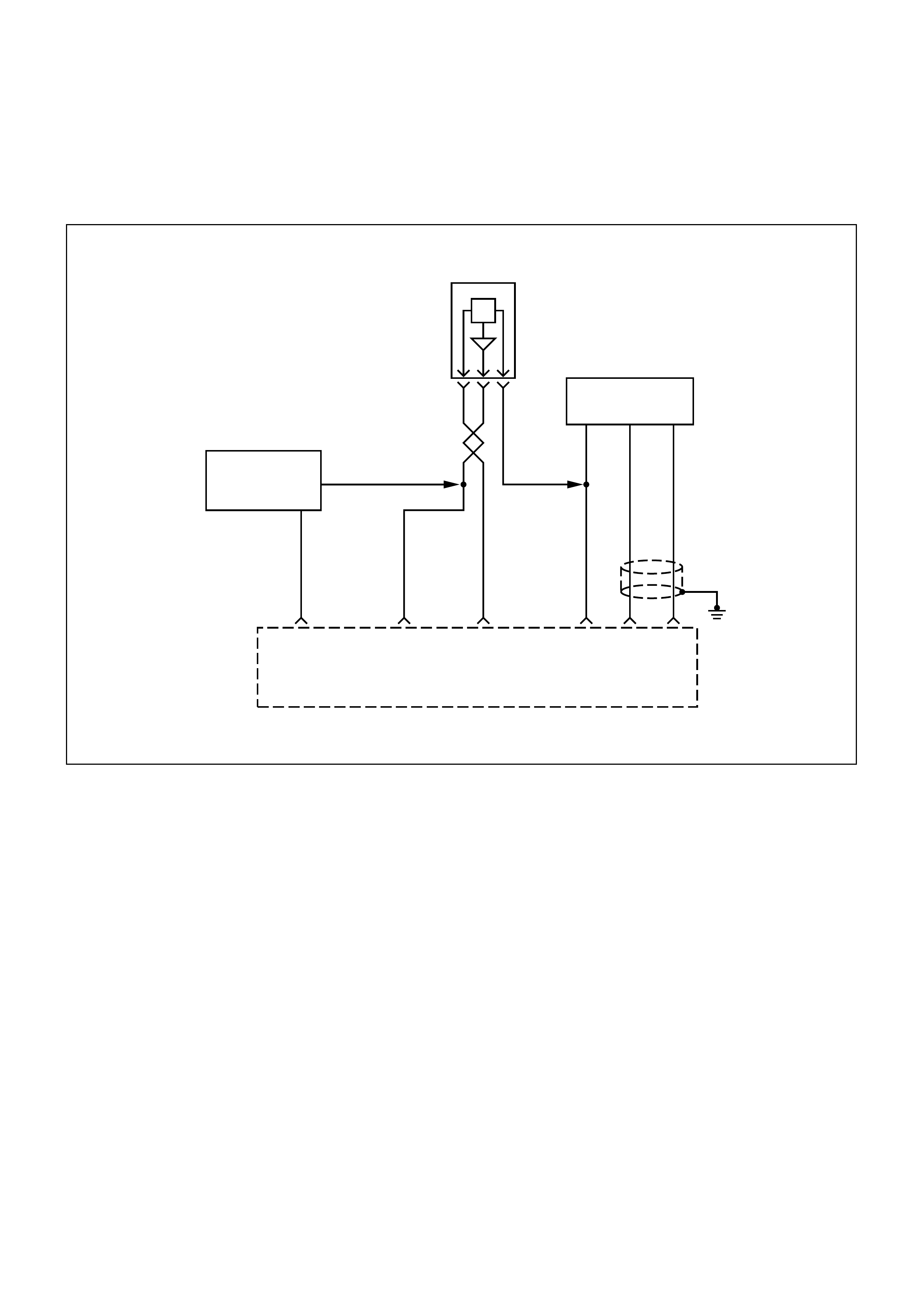
DIAG NOSTI C TROUBLE CODE (DTC) (FLASH DTC = 33)
MANIFOLD ABSOLUTE PRESSURE (MAP) TOO HIGH
0.5
YEL/
GRN
0.5
GRN
0.5
RED
0.5
RED
0.5
GRN
0.5
RED
Manifold
Absolute
Pressure
(MAP)
Sensor
F10 B2
0.5
GRN
B7 A3
5 Volt
Reference
Signal
MAP Sensor
Input
Sensor
Ground
0.75
L
B8
0.75
G
B1
AB C
Intake
Air Temperature
Sensor
Throttle Position
Sensor
Engine
Control
Module
(ECM)
HI OUT LO
0.5
G
CIRCUIT DESCRIPTION
The manifold absolute pressure (MAP) sensor
responds to changes in intake manifold pressure.
The MAP sensor signal voltage to the engine control
module (ECM) varies from below 2 volts at idle (low
manifold pressure) to above 4 volts with the ignition
ON, engine not running or at wide-open throttle (high
manifold pressure).
A "speed density" method of determining engine
load is used. This is calculated using inputs from the
MAP sensor, the CKP Sensor, and the Intake Air
Temperature (IAT) sensor. The MAP sensor is the
main sensor used in this calculation, and measuring
engine load is its main function. The ECM monitors
the MAP signals for voltages outside the normal
range of the MAP sensor. This code defects a short
to MAP signal voltage in the MAP sensor circuit.
Diagnostic Trouble Code 33 will be set.
CONDITIO NS FOR SETTING THE DTC
• No TP sensor Diagnostic Trouble Codes 21 or 22
present.
• Engine is running.
• Not in power enrich mode.
•Throttle Position Sensor value is less than 1%.
• Altitude Compensated Manifold Absolute Pressure
is greater than 95kpa.
ACTIO N TAKEN WHEN THE DTC SETS
•The ECM will illuminate the malfunction indicator
lamp (MIL).

CONDITIO NS FOR CLEARI NG THE MIL/DTC
Once the ECM determines that a fault(s) has been
rectified then the CEL will switch OFF, although the
fault code will remain in the ECM memory.
Any fault codes will remain in ECM memory until -
1. They are cleared by disconnecting the Battery for
more than 30 seconds.
2. A service tool such as Tech 2 is used to clear
them.
3. Ten consecutive starts without logging a fault.
DIAGNOSTIC AIDS
Check for the following conditions:
• Poor connection at ECM - Inspect harness
connectors for backed-out terminals, improper
mating, broken locks, improperly formed or
damaged terminals, and poor terminal-to-wire
connection.
• Damaged harness - Inspect the wiring harness for
damage, shorts to Ground, shorts to Battery
positive, and Open circuits. If the harness appears
to be OK, observe the MAP display on the Scan
Tool while moving connectors and wiring
harnesses related to the sensor. A change in the
display will indicate the location of the fault.

DTC (FLASH DTC = 33) MANIFOLD ABSOLUTE PRESSURE (MAP) TOO HIGH
STEP ACTION VALUE(S) YES NO
1Was the "On-Board Diagnostic (OBD) System Check"
performed? -
Go to Step 2
Go to OBD
System Check
2
1. If the engine idle is rough, unstable or incorrect, repair the
idle problem before using this chart.
Refer to Symptoms section.
2. With the engine idling, note the MAP value on the Scan Tool.
Is the MAP reading above the specified value?
About 4V
90 kPa
Go to Step 4 Go to Step 3
3
1. Ignition ON engine OFF.
2. Using the Scan Tool, monitor info for Diagnostic Trouble
Code 33.
Does the Scan Tool indicate Diagnostic Trouble Code 33 failed? -
Go to Step 4
Refer to
Diagnostic
Aids
4
1. Ignition OFF.
2. Disconnect the MAP sensor electrical connector.
3. Ignition ON.
4. Observe the MAP value displayed on the Scan Tool.
Is the MAP value near the specified value? 0V
10.3 Kpa Go to Step 5 Go to Step 6
5
Check the MAP sensor signal circuit, between the MAP sensor
and the Engine control Module (ECM), for a short to voltage.
Was the problem found? -
Verify Repair Go to Step 12
6
Check the MAP sensor signal circuit, between the MAP sensor
and the ECM for the following conditions:
•A short to ground
•An open circuit
Was the problem found?
-
Verify repair Go to Step 7

STEP ACTION VALUE(S) YES NO
7
Check the 5 volt signal circuit, between the MAP sensor and the
ECM for the following conditions:
•A short to ground
•An open circuit
•A short to voltage
Was the problem found?
-
Verify Repair Go to Step 8
8
1. Ignition OFF.
2. Place a fused jumper between the MAP sensor circuit and
the 5 volt signal circuit, both at the wiring harness' MAP
sensor connector.
3. Ignition ON, Engine OFF.
4. Observe the MAP value displayed on the Scan Tool.
Does the Scan Tool read the following value?
5 Volts
104 kPa
Go to Step 9 Go to Step 12
9
Check the MAP sensor ground circuit, between the MAP sensor
and the ECM, for the following conditions:
•A short to ground
•An open circuit
•A short to voltagen
Was the problem found?
-
Verify Repair Go to Step 10
10
1. Ignition OFF.
2. Place a Digital Multimeter (DVM), set to measure voltage
between the ground circuit and the 5 volt signal circuit, both
at the wiring harness' MAP sensor connector.
3. Ignition ON, Engine OFF.
Does the DVM read the following value?
5 Volts
Go to Step 11 Go to Step 12
11 Replace the MAP Sensor.
Verify Repair. ---
12 Replace the EPROM or ECM.
Verify Repair. Note) Refer to 6E1-243. ---
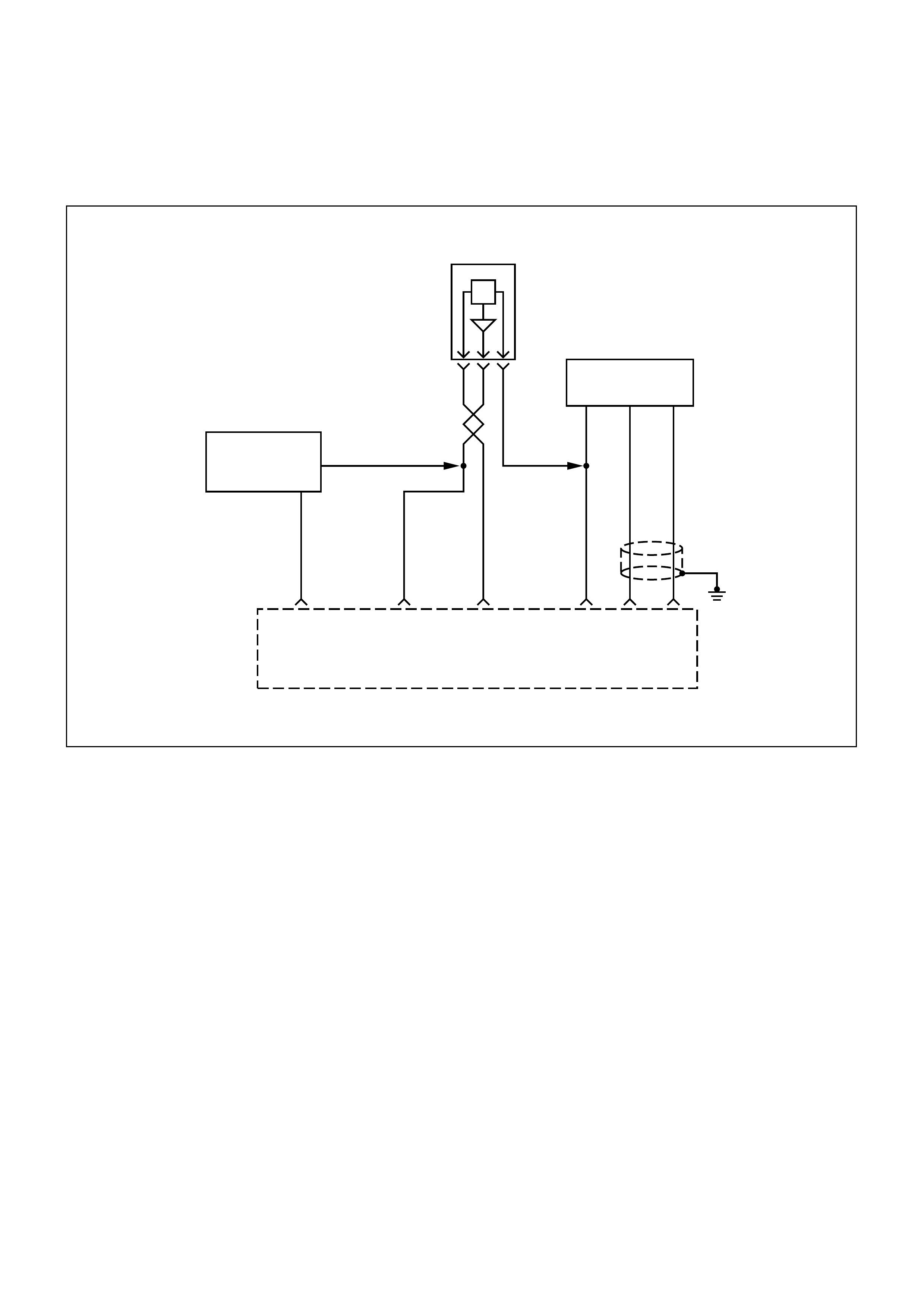
DIAG NOSTI C TROUBLE CODE (DTC) (FLASH DTC = 34)
MANIFOLD ABSOLUTE PRESSURE (MAP) TOO LOW
0.5
YEL/
GRN
0.5
GRN
0.5
RED
0.5
RED
0.5
GRN
0.5
RED
Manifold
Absolute
Pressure
(MAP)
Sensor
F10 B2
0.5
GRN
B7 A3
5 Volt
Reference
Signal
MAP Sensor
Input
Sensor
Ground
0.75
L
B8
0.75
G
B1
AB C
Intake
Air Temperature
Sensor
Throttle Position
Sensor
Engine
Control
Module
(ECM)
HI OUT LO
0.5
G
CIRCUIT DESCRIPTION
The manifold absolute pressure (MAP) sensor
responds to changes in intake manifold pressure.
The MAP sensor signal voltage to the engine control
module (ECM) varies from below 2 volts at idle (low
manifold pressure) to above 4 volts with the ignition
ON engine not running or at wide-open throttle (high
manifold pressure).
A "speed density" method of determining engine
load is used. This is calculated using inputs from the
MAP sensor, the CKP Sensor, and the Intake Air
Temperature (IAT) sensor. The MAP sensor is the
main sensor used in this calculation, and measuring
engine load is its main function. The ECM monitors
the MAP signals for voltages outside the normal
range (10-104 kpa) of the MAP sensor. If the ECM
detects a MAP signal voltage that is excessively low,
Diagnostic Trouble Code 34 will be set.
CONDITIO NS FOR SETTING THE DTC
• Manifold Absolute Pressure is less than 14 kpa
and one of following condition is met the DTC will
set.
Condition A:
• Malfunction 21 not pr esent and rpm is les s than
1050.
Or,
Condition B:
• Malfunction 21 not present and rpm is greater
than 1050 and TP opening is greater than
18.75% and ignition ON.
ACTIO N TAKEN WHEN THE DTC SETS
• The ECM will illuminate the malfunction indicator
lamp (MIL).

CONDITIONS FOR CLEARING THE MIL/DTC
Once the ECM determines that a fault(s) has been
rectified then the CEL will switch OFF, although the
fault code will remain in the ECM memory.
Any fault codes will remain in ECM memory until -
1. They are cleared by disconnecting the Battery for
more than 30 seconds.
2. A service tool such as Tech 2 is used to clear
them.
3. Ten consecutive starts without logging a fault.
DIAGNOSTIC AIDS
Check for the following conditions:
• Poor connection at ECM - Inspect harness
connectors for backed-out terminals, improper
mating, broken locks, improperly formed or
damaged terminals, and poor terminal-to-wire
connection.
• Damaged harness - Inspect the wiring harness for
damage, shorts to Ground, shorts to Battery
positive, and Open circuits. If the harness appears
to be OK, observe the MAP display on the Scan
Tool while moving connectors and wiring
harnesses related to the sensor. A change in the
display will indicate the location of the fault.
• A faulty 5 volt reference circuit could also set a TP
Sensor Diagnostic Trouble Code because the two
sensors share the same 5 volt reference pin at the
ECM.
DTC (FLASH DTC = 34) MANIFOLD ABSOLUTE PRESSURE (MAP) TOO LOW
STEP ACTION VALUE(S) YES NO
1Was the "On-Board Diagnostic (OBD) System
Check" performed? -
Go to Step 2
Go to OBD
System Check
2
1. Ignition ON engine OFF.
2. With the throttle closed, observe the MAP value displayed on
the Scan Tool.
Is the MAP value near the specified value?
0V
10.3 kPa
at sea level Go to Step 4 Go to Step 3
3
1. Ignition ON, engine OFF.
2. Using a Scan Tool, monitor info for Diagnostic Trouble Code
34.
Does the Scan Tool indicate Diagnostic Trouble Code 34 failed? -
Go to Step 4
Refer to
Diagnostic
Aids
4
1. Ignition OFF.
2. Disconnect the MAP sensor electrical connector.
3. Jumper the 5 volt reference circuit and the MAP signal
together at the MAP sensor harness connector.
4. Ignition ON.
5. Observe the MAP value displayed on the Scan Tool.
Is the MAP value near the specified value? 5V
104 kPa Go to Step 10 Go to Step 5
5
1. Disconnect the jumper.
2. Connect a test light between B+ and the MAP sensor signal
circuit at the MAP sensor harness connector.
3. Observe the MAP value displayed on the Scan Tool.
Is the MAP value near the specified value? 5V
104 kPa Go to Step 6 Go to Step 8

STEP ACTION VALUE(S) YES NO
6
1. Ignition OFF.
2. Disconnect the ECM and check the 5 volt reference circuit
for an open or short to ground.
3. If the 5 volt reference circuit is open or shorted to ground,
repair it as necessary.
Was the 5 volt reference circuit open or shorted to ground?
-
Verify repair Go to Step 7
7Check the 5 volt reference circuit for a poor connection at the
ECM and replace the terminal if necessary.
Did the terminal require replacement? -
Verify repair Go to Step 11
8
1. Ignition OFF.
2. Disconnect the ECM, and check the MAP signal circuit for an
open,short to ground, or short to the sensor ground circuit.
3. If the MAP sensor signal circuit is open or shorted to ground,
repair it as necessary.
Was the MAP signal circuit open or shorted to ground?
-
Verify repair Go to Step 9
9
Check the MAP sensor signal circuit for a poor connection at the
ECM and the MAP sensor; replace the terminal if necessary.
Did the terminal require replacement? -
Verify repair Go to Step 11
10 Replace the MAP sensor.
Is the action complete? -Verify repair -
11 Replace the EPROM or ECM. Note) Refer to 6E1-243.
Is the action complete? -Verify repair -
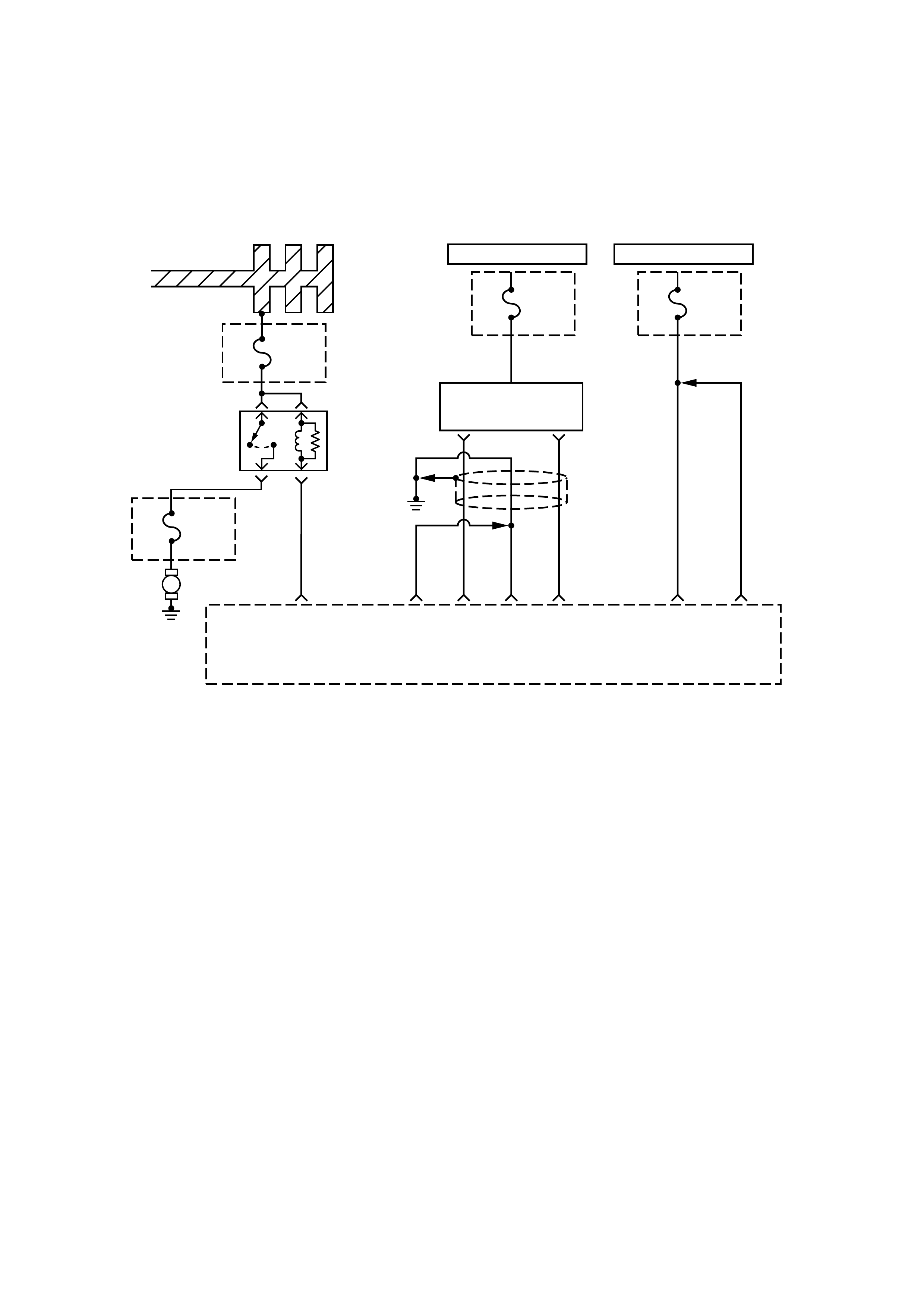
DIAG NOSTI C TROUBLE CODE (DTC) (FLASH DTC = 49)
SYSTEM VOLTAGE HIGH
HOT AT ALL TIMES
Ignition
Coil
Fuse
15A
I/P
FUSE
BLOCK
Engine
Control
Module
(ECM)
E1
HOT AT ALL TIMES
ECM
Fuse
15A
U/H
FUSE
BLOCK
1.25
RED/
WHT
1.25
L
1.25
BLK
1.25
G
1.25
BLK
2
W/G
1.25
RED/
WHT
A4 A5
Batt+
Ignition
Coil
A13
0.5
G/W
E3 E2 E4
Ignition Feeds
1,4 2,3
Relay
Fuel
Pump
ECM
Fuse
15A
F/Pump
Fuse
20A
M
CIRCUIT DESCRIPTION
The engine control module (ECM) monitors the
system voltage on the ignition feed terminal to the
ECM. A system voltage Diagnostic Trouble Code will
set whenever the voltage is above a calibrated value.
This malfunction detects an over-voltage condition in
the battery voltage circuit.
CONDITIO NS FOR SETTING THE DTC
•Engine is running.
•Battery Voltage is greater than 17.2V.
ACTIO N TAKEN WHEN THE DTC SETS
•The ECM will illuminate the malfunction indicator
lamp (MIL) for the first time the malfunction is
detected.
CONDITIO NS FOR CLEARI NG THE MIL/DTC
Once the ECM determines that a fault(s) has been
rectified then the CEL will switch OFF, although the
fault code will remain in the ECM memory.
Any fault codes will remain in ECM memory until -
1. They are cleared by disconnecting the Battery for
more than 30 seconds.
2. A service tool such as Tech 2 is used to clear them.
3. Ten consecutive starts without logging a fault.
DIAGNOSTIC AIDS
•Check for a faulty charging system components.

DTC (FLASH DTC = 49) SYSTEM VOLTAGE HIGH
STEP ACTION VALUE(
S) YES NO
1 Was the "On-Board Diagnostic (OBD) System Check"
performed? -Go to Step 2
Go to OBD
System Check
2
1. Ignition OFF, engine OFF.
2. Using a Digital Voltmeter (DVM), measure the battery
voltage at the battery.
Is the battery voltage greater than the specified va lue? 16V Go to Step 3 Go to Step 4.
3
1. Charge the battery and clean the battery terminals.
2. Clean the battery ground cable connection if corrosion is
indicated.
Is the battery voltage greater than the specified va lue? 16V Replace battery Go to Step 4
4
1. Turn OFF all the accessories.
2. Install the Scan Tool.
3. Select the ignition voltage parameter on the data list.
4. Start the engine and raise the engine speed to 2000 RPM.
Is it the voltage above the specified value? 16V Go to Step 5 Go to Step 6
5Replace or repair the generator (see Charging System).
Is a malfunction present? -Verify Repair -
6Replace the EPROM or ECM.
Is the action complete? Note) Refer to 6E1-243. -Verify Repair -
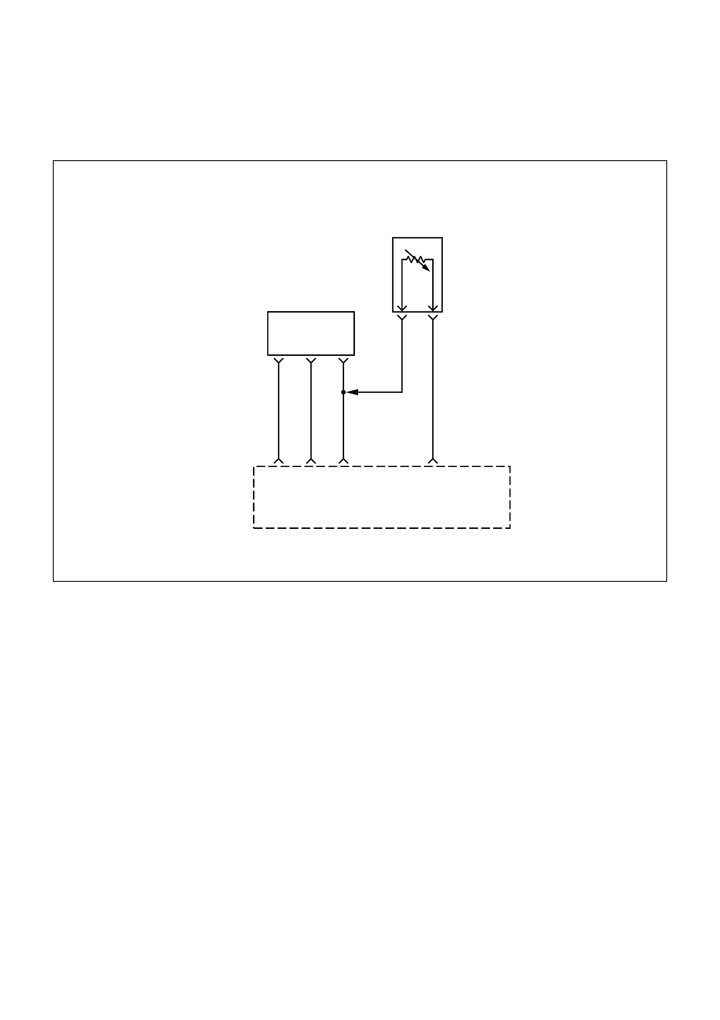
DIAG NOSTI C TROUBLE CODE (DTC) (FLASH DTC = 69)
INTAKE AIR TEMPERATURE (I AT) SENSOR TOO HIGH
0.5
G
0.5
GR
0.5
R
0.5
G0.5
YEL/
GRN
Engine
Control
Module
(ECM)
A3 F10
B2
B7
IAT
Sensor
Input
Sensor
Ground
Intake Air
Temperature
(IAT)
Sensor
AB
MAP
Sensor
CIRCUIT DESCRIPTION
The intake air temperature (IAT) sensor is a thermistor
which measures the temperature of the air entering
the engine. The engine control module (ECM) applies
5 volts through a pull-up resistor to the IAT sensor.
When the intake air is cold, the sensor resistance is
high and the ECM will monitor a high signal voltage on
the IAT signal circuit. If the intake air is warm, the
sensor resistance is lower, causing the ECM to
monitor a lower voltage. Diagnostic Trouble Code 69
will set when the ECM detects an excessively high
signal voltage on the intake air temperature sensor
signal circuit.
CONDITIO NS FOR SETTING THE DTC
•The engine is running.
•IAT sensor temperature is greater than 140 degC.
The above conditions are met.
ACTIO N TAKEN WHEN THE DTC SETS
•The ECM will illuminate the malfunction indicator
lamp (MIL) the first time the fault is detected.
•The ECM will use a default IAT value based on
ECM inputs and engine run time.
CONDITIO NS FOR CLEARI NG THE MIL/DTC
Once the ECM determines that a fault(s) has been
rectified then the CEL will switch OFF, although the
fault code will remain in the ECM memory.
Any fault codes will remain in ECM memory until -
1. They are cleared by disconnecting the Battery for
more than 30 seconds.
2. A service tool such as Tech 2 is used to clear them.
3. Ten consecutive starts without logging a fault.

DIAGNOSTIC AIDS
Check for the following conditions:
•Poor connection at ECM - Inspect harness
connectors for backed-out terminals, improper
mating, broken locks, improperly formed or
damaged terminals, and poor terminal-to-wire
connection.
•Damaged harness - Inspect the wiring harness for
damage, shorts to Ground, shorts to Battery
Positive, and Open Circuits. If the harness appears
to be OK, observe the IAT display on the Sc an T ool
while moving connectors and wiring harnesses
related to the IAT sensor. A change in the IAT
display will indicate the location of the fault.
If Diagnostic Trouble Code 69 cannot be duplicated,
the information included in the Failure Records data
can be useful in determining vehicle mileage since the
Diagnostic Trouble Code was last set.
TEST DESCRIPTION
Number(s) below refer to the step number(s) on the
Diagnostic Chart.
2. Verifies that the fault is present.
3. If Diagnostic Trouble Code 69 can be repeated
only by duplicating the Failure Records conditions,
refer to the "Temperature vs. Resistance Values"
table. The table may be used to test the IAT s ens or
at various temperatures to evaluate the possibility
of a "shifted" sensor that may be open above or
below a certain temperature. If this is the case,
replace the IAT sensor. If the IAT sensor appears
to be OK, the fault is intermittent; refer to
Diagnostic Aids.
INTAKE AIR TEMPERATURE SENSOR
°C °F OHMS
Temperature vs. Resistance Values
(approximate)
100 212 177
80 176 332
60 140 667
45 113 1188
35 95 1802
25 77 2796
15 59 4450
5 41 7280
−5 23 12300
−15 5 21450
−30 −22 52700
−40 −40 100700

DTC (FLASH DTC = 69) INTAKE AIR TEMPERATURE (IAT) SENSOR TOO HIGH
STEP ACTION VALUE(S) YES NO
1Was the "On-Board Diagnostic (OBD) System Check"
performed? -
Go to Step 2
Go to OBD
System Check
2Ignition ON, engine OFF Observe the "Intake Air Temp" values
displayed on the Scan Tool.
Is the "Intake Air Temp" values below the specified value?
5V
−36°C
(−32.8°F) Go to Step 4 Go to Step 3
3
1. Ignition ON, engine OFF.
2. Using a Scan Tool, monitor info for Diagnostic Trouble Code
69.
Does the Scan Tool indicate Diagnostic Trouble Code 69 failed? -
Refer to Test
Description
Refer to
Diagnostic
Aids
4
1. Ignition OFF.
2. Disconnect the IAT sensor electrical connector.
3. Jumper the IAT signal circuit and the sensor ground circuit
together at the IAT sensor harness connector.
4. Ignition ON.
5. Observe the "Intake Air Temp" values displayed on the
Scan Tool.
Is the "Intake Air Tempe" values at the specified value?
0V
140°C
(284°F) Go to Step 6 Go to Step 5
5
1. Jumper the IAT signal circuit at the IAT sensor harness
connector to chassis ground.
2. Observe the "Intake Air Temp" display on the Scan Tool.
Is the "Intake Air Tempe" at the specified value? 0V
140°C
(284°F) Go to Step 7 Go to Step 8
6Check for poor connections at the IAT sensor and replace
terminals if necessary.
Did any terminals require replacement? -
Verify repair Go to Step 10
7
1. Ignition OFF.
2. Disconnect the ECM, and check the IAT sensor ground
circuit for an open.
3. If the IAT sensor ground circuit is open, repair it as
necessary.
Was the IAT sensor ground circuit open?
-
Verify repair Go to Step 9
8
1. Ignition OFF.
2. Disconnect the ECM, and check the IAT signal circuit for an
open.
3. If the IAT sensor signal circuit is open, repair it as necessary.
Was the IAT signal circuit open?
-
Verify repair Go to Step 9
9
Check for a poor sensor ground or IAT signal circuit terminal
connection at the ECM and replace terminal(s) if necessary.
Did any of the terminal need to be replaced? -
Verify repair Go to Step 11
10 Replace the IAT sensor.
Is the action complete? -Verify repair -
11 Replace the EPROM or ECM.
Is the action complete? Note) Refer to 6E1-243. -Verify repair -
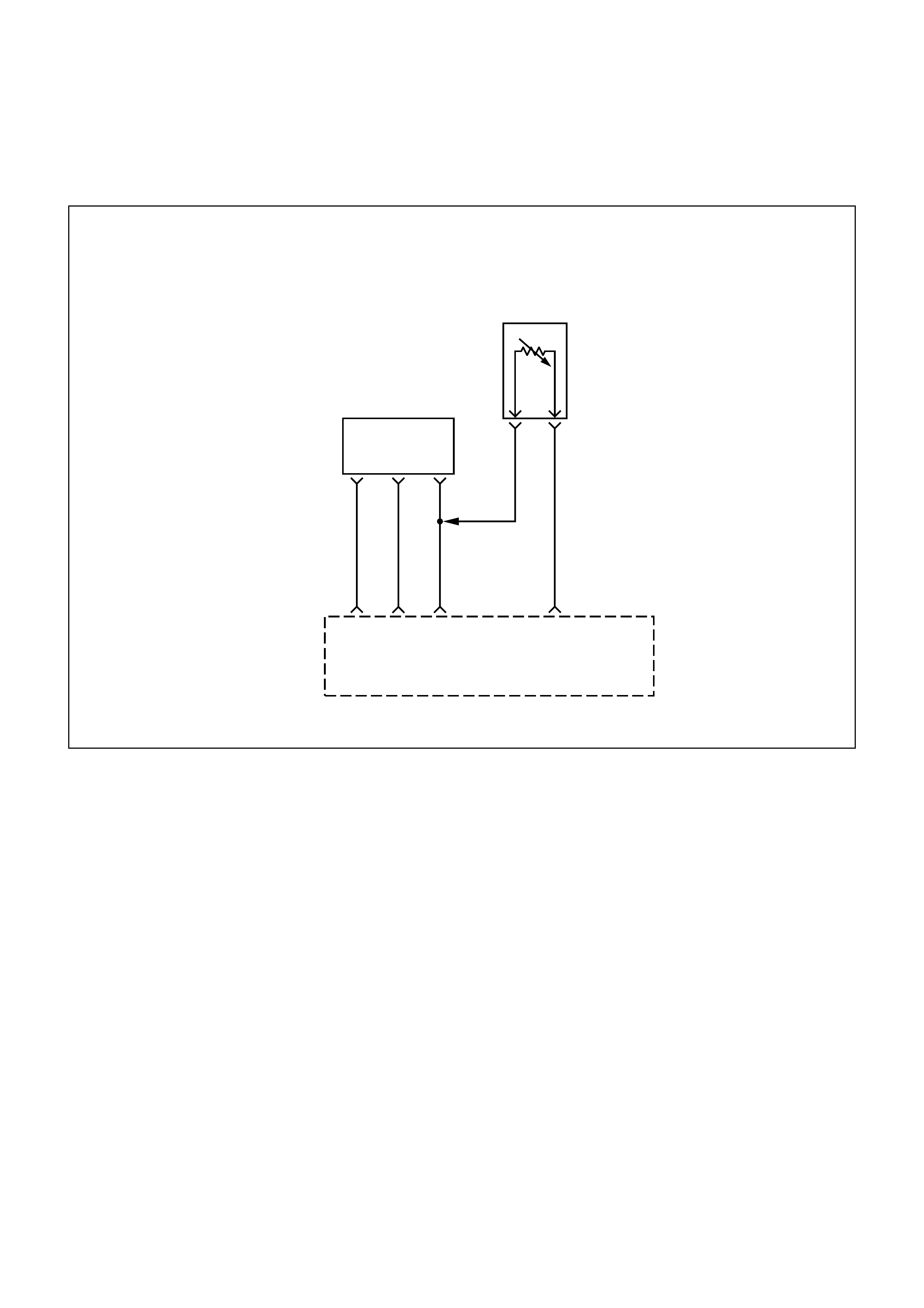
DIAG NOSTI C TROUBLE CODE (DTC) (FLASH DTC = 71)
INTAKE AIR TEMPERATURE (I AT) SENSOR TOO LOW
0.5
G
0.5
GR
0.5
R
0.5
G0.5
YEL/
GRN
Engine
Control
Module
(ECM)
A3 F10
B2
B7
IAT
Sensor
Input
Sensor
Ground
Intake Air
Temperature
(IAT)
Sensor
AB
MAP
Sensor
CIRCUIT DESCRIPTION
The intake air temperature (IAT) sensor is a thermistor
which measures the temperature of the air entering
the engine. The engine control module (ECM) applies
5 volts through a pull-up resistor to the IAT sensor.
When the intake air is cold, the sensor resistance is
high and the ECM will monitor a high signal voltage on
the IAT signal circuit. If the intake air is warm, the
sensor resistance is lower, causing the ECM to
monitor a lower voltage. Diagnostic Trouble Code 71
will set when the ECM detects an excessively low
signal voltage (short to ground) on the intake air
temperature sensor signal circuit.
CONDITIO NS FOR SETTING THE DTC
•The engine has been running for over 2 minutes.
•IAT sensor temperature is less than −36 degC.
The above conditions are met.
ACTIO N TAKEN WHEN THE DTC SETS
•The ECM will illuminate the malfunction indicator
lamp (MIL).
•The ECM will use a default IAT value based on
PCM inputs and engine run time.
CONDITIO NS FOR CLEARI NG THE MIL/DTC
Once the ECM determines that a fault(s) has been
rectified then the CEL will switch OFF, although the
fault code will remain in the ECM memory.
Any fault codes will remain in ECM memory until -
1. They are cleared by disconnecting the Battery for
more than 30 seconds.
2. A service tool such as Tech 2 is used to clear them.
3. Ten consecutive starts without logging a fault.

DIAGNOSTIC AIDS
Check for the following conditions:
•Poor connection at ECM - Inspect harness
connectors for backed-out terminals, improper
mating, broken locks, improperly formed or
damaged terminals, and poor terminal-to-wire
connection.
•Damaged harness - Inspect the wiring harness for
damage, shorts to ground, shorts to battery, and
open circuits. If the harness appears to be OK,
observe the IAT display on the Scan Tool while
moving connectors and wiring harnesses related to
the IAT sensor. A change in the IAT display will
indicate the location of the fault.
If Diagnostic Trouble Code 71 cannot be duplicated,
the information included in the Failure Records data
can be useful in determining vehicle mileage since the
Diagnostic Trouble Code was last set.
TEST DESCRIPTION
Number(s) below refer to the step number(s) on the
Diagnostic Chart:
2. Verifies that the fault is present.
3. If Diagnostic Trouble Code 71 can be repeated
only by duplicating the Failure Records condition,
refer to the Temperature vs. Resistance Value
table. The table may be used to test the IAT s ens or
at various temperatures to evaluate the possibility
of a "shifted" sensor that m ay be stored above or
below a certain temperature. If this is the case,
replace the IAT sensor. If the IAT sensor appears
to be OK, the fault is intermittent; refer to
Diagnostic Aids.
INTAKE AIR TEMPERATURE SENSOR
°C °F OHMS
Temperature vs. Resistance Values
(approximate)
100 212 177
80 176 332
60 140 667
45 113 1188
35 95 1802
25 77 2796
15 59 4450
5 41 7280
−5 23 12300
−15 5 21450
−30 −22 52700
−40 −40 100700

DTC (FLASH DTC = 71) INTAKE AIR TEMPERATURE (IAT) SENSOR TOO LOW
STEP ACTION VALUE(S) YES NO
1Was the "On-Board Diagnostic (OBD) System Check"
performed? -
Go to Step 2
Go to OBD
System Check
2
1. Ignition ON, engine OFF
2. Using a Scan Tool, monitor the intake air temperature (IAT).
Is the intake air temperature greater then the specified value? 140°C
(284°F) Go to Step 4 Go to Step 3
3
1. Ignition ON, engine OFF Review and record Scan Tool
Failure Records data.
2. Using a Scan Tool, monitor the info for Diagnostic Trouble
Code 71.
Does the Scan Tool indicate Diagnostic Trouble Code 71?
-
Refer to Test
Description
Refer to
Diagnostic
Aids
4
1. Ignition OFF.
2. Disconnect the IAT sensor electrical connector.
3. Ignition ON.
4. Observe the intake air temperature on the Scan Tool.
Is the intake air temperature below the specified value? −36°C
(−32.8°F) Go to Step 6 Go to Step 5
5
1. Ignition OFF.
2. Disconnect the PCM electrical connectors.
3. Check the IAT sensor signal circuit for a short to ground.
Is the IAT sensor signal circuit shorted to ground? -
Verify repair Go to Step 7
6Replace the IAT sensor.
Is the action complete? -Verify repair -
7Replace the EPROM or ECM. Note) Refer to 6E1-243.
Is the action complete? -Verify repair -
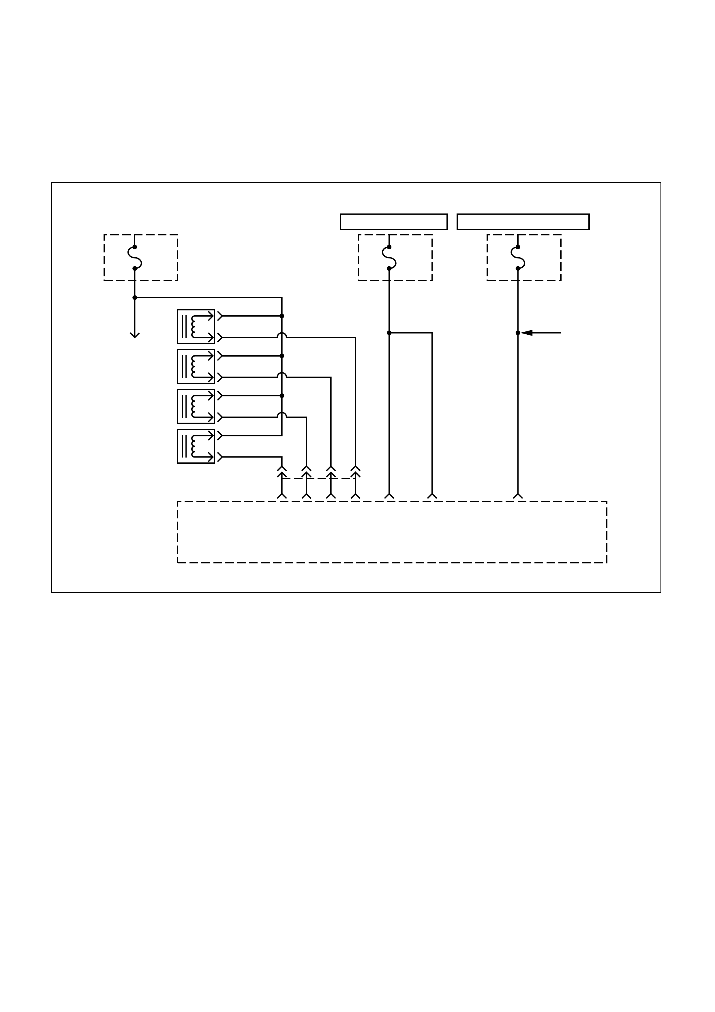
DIAG NOSTI C TROUBLE CODE (DTC) (FLASH DTC = 17)
INJECTOR CIRCUIT M ALFUNCTION
ECM
Fuse
15A
Engine
Fuse
15A
Canister
Purge
Solenoid
1.25
R/W
0.85G/W
2B/R
0.85G/R
0.85G/B
0.85G
1.25
R/W
0.85
L/Y
Injector
Fuse
20A
Fuel
Pump
A4A6 A8 A9 A7 A5 E16
Fuel
Injector
Control
#4
A
B
#3
A
B
#2
A
B
#1
A
B
Engine
Control
Module
(ECM)
HOT AT ALL TIMES HOT IN RUN AND START
CIRCUIT DESCRIPTION
The engine control module (ECM) has 2 injector driver
circuits. Each controls 2 injectors as a one group.
When a driver circuit is grounded by the ECM, the
injector is activated. The ECM monitors the current in
each driver circuit. The ECM measures a voltage drop
through a fixed resistor and controls it. The voltage on
each driver is monitored to detect a fault. If the voltage
is not what the ECM expects to monitor on the circuit,
a Diagnostic Trouble Code is set. This Diagnostic
Trouble Code is also set if an injector driver is shorted
to voltage. This code an injectors short to ground,
battery or a disconnected injector, then a DTC 17 will
be set.
CONDITIO NS FOR SETTING THE DTC
•The actual output voltage of injector driver is
opposite to the expected state thus setting injector
feedback line low.
•Fuel pump relay is commanded on and Fuel pump
relay is not shorted to bettery and battery voltage is
greater than 9 volts.
ACTIO N TAKEN WHEN THE DTC SETS
•The ECM will illuminate the malfunction indicator
lamp (MIL).
•"Open Loop" fuel control will be in effect.
CONDITIO NS FOR CLEARI NG THE MIL/DTC
Once the ECM determines that a fault(s) has been
rectified then the CEL will switch OFF, although the
fault code will remain in the ECM memory.
Any fault codes will remain in ECM memory until -
1. They are cleared by disconnecting the Battery for
more than 30 seconds.
2. A service tool such as Tech 2 is used to clear them.
3. Ten consecutive starts without logging a fault.

DIAGNOSTIC AIDS
An injector driver circuit that is open or shorted to
voltage will cause a Diagnostic Trouble Code 17 to
set. It will also cause a misfire due to an inoperative
injector.
Long term and short term fuel trims that are
excessively high or low are a good indication that an
injector is faulty. Use Fuel Injector Coil Test Procedure
to check for faulty injectors.
TEST DESCRIPTION
The number(s) below refer to the step number(s) on
the Diagnostic Chart.
3. This step determines if Diagnostic Trouble Code 17
is the result of a hard failure or an intermittent
condition.
4. This steps tests the harness wiring and ECM
control of the injectors.
6. Because the test light was ON steady, voltage to
the injector is OK, but the driver circuit is grounded
at all times. This step determines if the circuit is
shorted to ground or the ECM is faulty.
8. Because the test light was OFF steady, the injector
driver circuit is shorted to voltage.
10.Normal injector resistance is slightly more than if
tested directly at the injector because it includes
resistance of the harness wires. The normal value
is about 13.5Ω.
DTC (FLASH DTC = 17) INJECTOR CIRCUIT MALFUNCTION
(REPEAT FOLLOWING STEPS FOR EACH INJECTOR IF NECESSARY)
STEP ACTION VALUE(S) YES NO
1Was the "On-Board Diagnostic (OBD) System Check"
performed? -
Go to Step 2
Go to OBD
System Check
2Will the engine start?
-Go to Step 3
Cranks But
Will Not Run
Chart
31. Install the Scan Tool.
2. Idle the engine for one minute.
Does the Diagnostic Trouble Code 17 Set? -
Go to Step 4
Go to
Diagnostic
Aids
4
1. Ignition off.
2. Disconnect the injector connector of No.1 Cyl. And then start
the engine to check the injector working condition.
3. Repeat above steps on all injectors.
4. If the injector and injector driver circuit is normal condition,
the engine becomes rough running.
Does the engine running condition change?
-
Go to OBD
System Check
Go to Step 5
5Does the engine Idle Condition change?
Note the detected faulty injector. -Go to Step 6 Go to Step 8
6
1. Ignition off.
2. Disconnect the ECM connector for the affected injectors.
3. With a test light (commercial available) connected to B+,
probe the affected applicable injector circuit.
Does the test light illuminate?
-
Go to Step 7 Go to Step 8

STEP ACTION VALUE(S) YES NO
7Repair short to ground in the injector driver circuit.
Is the action complete? - Verify Repair -
8
Re-connect the ECM connector.
1. Disconnect the injector test connector.
2. Ignition ON.
3. Use a test light (commercial available)
connected to ground to probe the injector connector
terminal.
4. Only the Ign+ terminal should illuminate the test high.
Besides the Ign+, did any other terminal illuminate the test light?
-
Go to Step 9 Go to Step 10
9 Repair the short to voltage in the injector driver circuit. - Verify Repair Go to Step 10
10
1. Ignition OFF.
2. Disconnect the ECM connector.
3. Clip one lead of an ohmmeter to the ignition pin on the
harness side ECM connector.
4. Touch the other lead to the another pin in that connector.
Instead of normal injector resistance, did the ohmmeter indicate
an open circuit?
-
Go to Step 11 Go to Step 12
11 Repair the open circuit or open injector. - Verify Repair Go to Step 12
12 Replace the *EPROM or ECM. Note) *Refer to 6E1-243. - Verify repair -
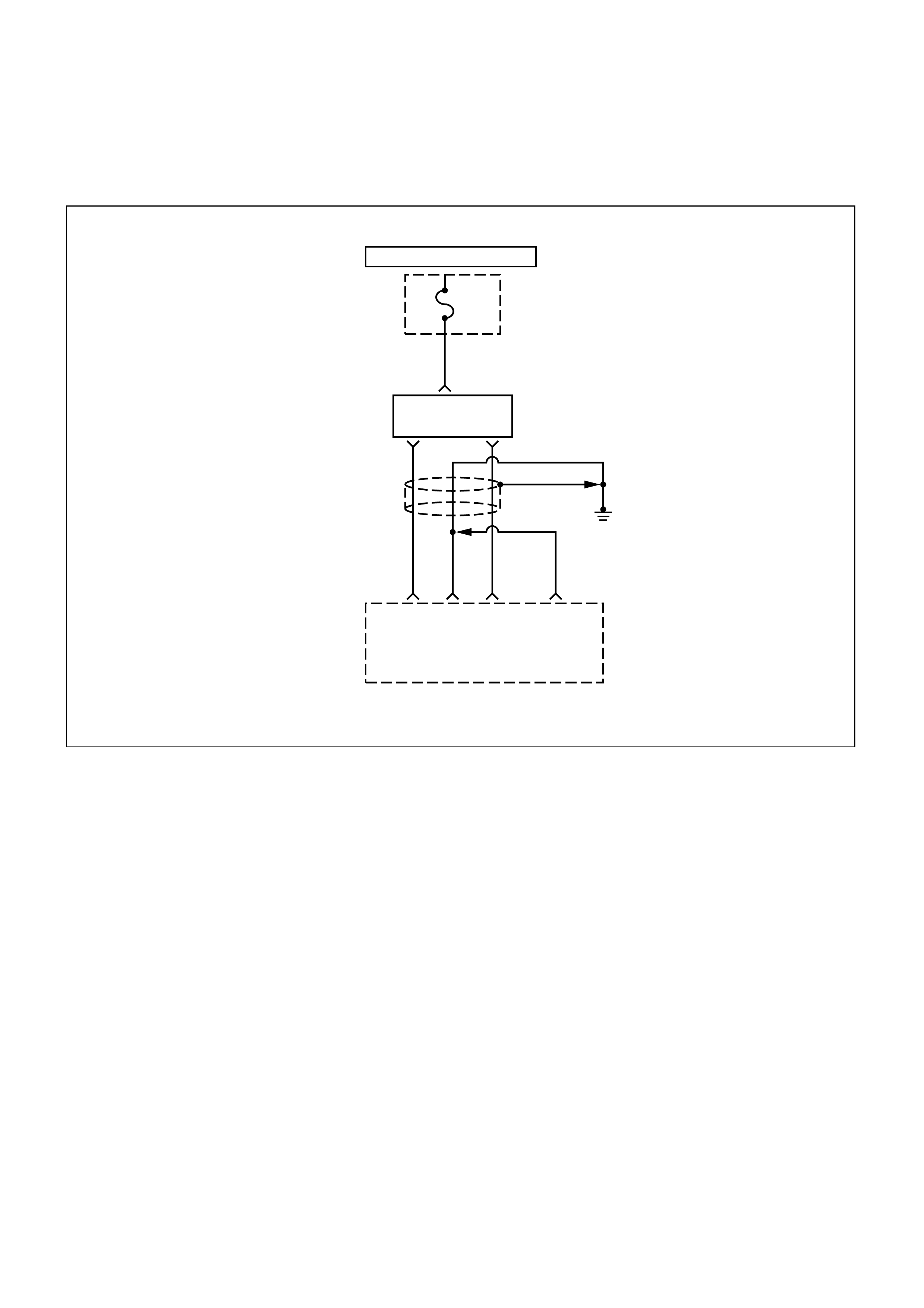
DIAG NOSTI C TROUBLE CODE (DTC) (FLASH DTC = 41)
IGNI TI ON COIL DRIVER "B" SHORT TO BATTERY
HOT IN START AND RUN
IG.
Coil
Fuse
15A
I/P
FUSE
BLOCK
2
W/G
Ignition
Coil
Ignition
Coil
1.25
G
1.25
L
Engine
Control
Module
(ECM)
E1 E4 E3
Electronic Spark
Timing Control
1.25
BLK
1.25
BLK
E2
1,4 2,3
CIRCUIT DESCRIPTION
The ignition control circuit in ECM provides a zero volt
or a 5 volt signal to the ignition coil driver. The normal
circuit voltage is zero volts. When the coil driver
receives the 5 volt signal from the ignition control
circuit, it provides a ground path for the B+ voltage
supplied to the ignition primary coil. When the ECM
turns off the 5 volts to the module, the module will
remove the ground path of the ignition primary coils;
causing the magnetic field produces a voltage in the
secondary coils which fires the spark plug.
The circuit between the coil driver and the ignition
control circuit is monitored for a short to battery on the
Electronic Spark Timing B/coil driver B line. When the
ECM detects a problem in the ignition control circuit, it
will set DTC 41.
CONDITIO NS FOR SETTING THE DTC
•Fault feedback line generates an interrupt on start
of dwell.
•No Electronic Spark Timing actiration requested by
serial data.
ACTIO N TAKEN WHEN THE DTC SETS
•The ECM will illuminate the malfunction indicator
lamp (MIL) the first time the fault is detected.
CONDITIO NS FOR CLEARI NG THE MIL/DTC
Once the ECM determines that a fault(s) has been
rectified then the CEL will switch OFF, although the
fault code will remain in the ECM memory.
Any fault codes will remain in ECM memory until -
1. They are cleared by disconnecting the Battery for
more than 30 seconds.
2. A service tool such as Tech 2 is used to clear them.
3. Ten consecutive starts without logging a fault.

DIAGNOSTIC AIDS
Check for the following conditions:
• Poor connection at the ECM - Inspect the harness
connectors for backed-out terminals, improper
mating, broken locks, improperly formed or
damaged terminals, and poor terminal-to-wire
connections.
• Damaged harness - Inspect the wiring harness for
damage; Open circuits, shorts to ground, or shorts
to Voltage. If the harness appears to be OK,
observe the Scan Tool display related to DTC 41
while moving the connector and wiring related to the
ignition system. A change in the display will indicate
the location of the fault.
• This code detects a short to battery on the
Electronic Spark Timing B/Coil Driver B (#2, #3 cyl.)
line.
DTC (FLASH DTC = 41) IGNITION COIL DRIVER "B" SHORT TO BATTERY
STEP ACTION VALUE(S) YES NO
1Was the "On-Board Diagnostic (OBD) System Check"
performed? -
Go to Step 2
Go to OBD
System Check
2Check for a faulty connection or damaged terminals at the
ignition coil.
Was a problem found? -
Verify repair Go to Step 3
3Check for a faulty connection or damaged terminals at the ECM
connector.
Was a problem found? -
Verify repair Go to Step 4
4
1. Ignition OFF.
2. Disconnect the ignition coil.
3. Check the ignition coil circuit for a short to battery.
Was a problem found?
-
Verify repair Go to Step 5
5Check for a short circuit between the ignition coil and the ECM.
If a problem is found, repair the wire harness.
Is there still a problem? -
Verify repair Go to Step 6
6Replace the ignition control module.
Verify repair.
Is there still a problem? -
Go to Step 8
-
7Replace the EPROM or ECM.
Is the repair complete? Note) Refer to 6E1-243. -Verify repair -
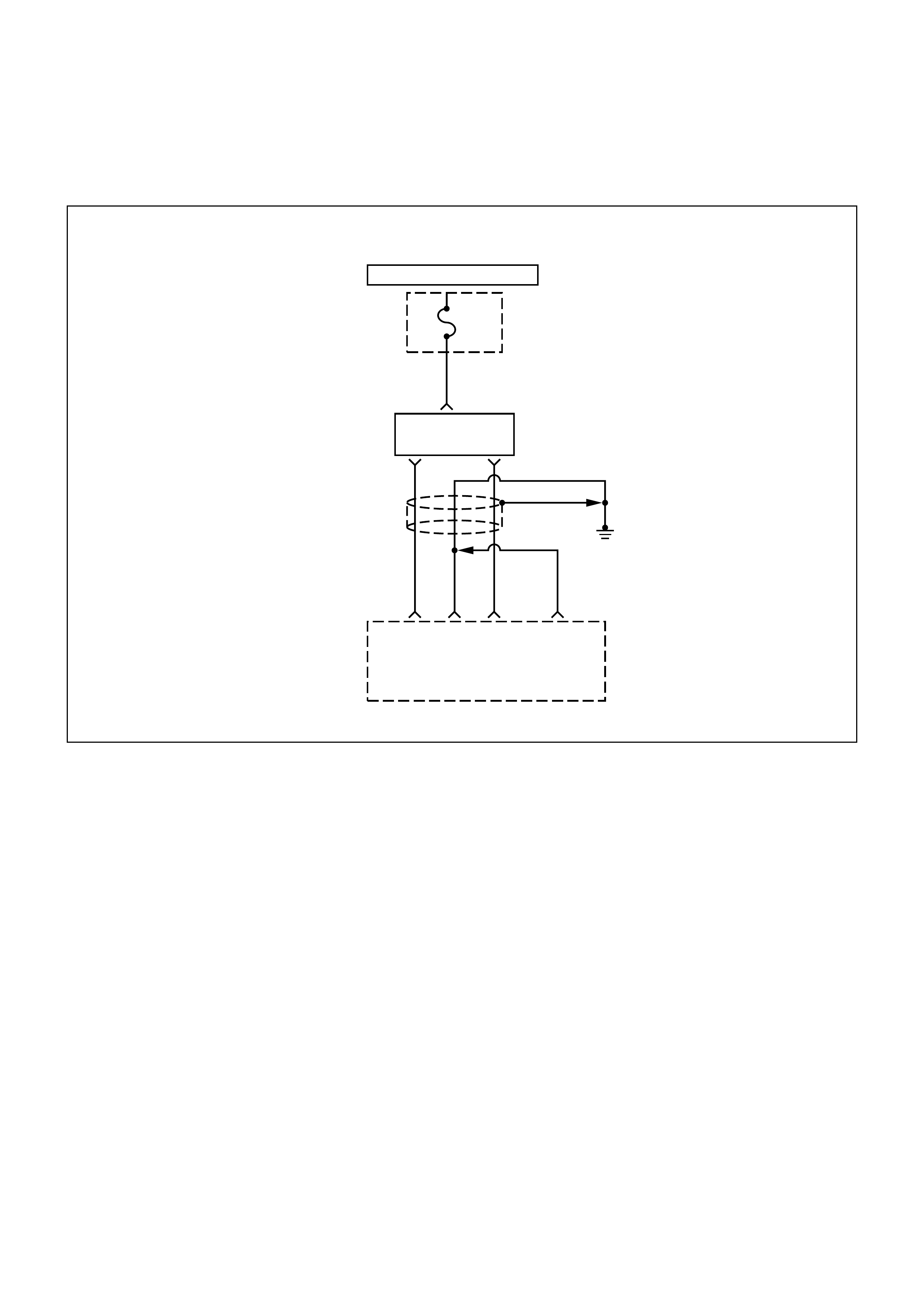
DIAG NOSTI C TROUBLE CODE (DTC) (FLASH DTC = 42)
IGNI TI ON COIL DRIVER "A" SHORT TO BATTERY
HOT IN START AND RUN
IG.
Coil
Fuse
15A
I/P
FUSE
BLOCK
2
W/G
Ignition
Coil
Ignition
Coil
1.25
G
1.25
L
Engine
Control
Module
(ECM)
E1 E4 E3
Electronic Spark
Timing Control
1.25
BLK
1.25
BLK
E2
1,4 2,3
CIRCUIT DESCRIPTION
The ignition control circuit in ECM provides a zero volt
or a 5 volt signal to the ignition coil driver. The normal
circuit voltage is zero volts. When the module receives
the 5 volt signal from the ignition control circuit, it
provides a ground path for the B+ voltage supplied to
the ignition primary coil. When the ECM turns off the 5
volts to the module, the module will remove the
ground path of the ignition primary coils; causing the
magnetic field produces a voltage in the secondary
coils which fires the spark plug.
The circuit between the coil driver and the ignition
control circuit is monitored for a short to battery on the
Electronic Spark Timing A/coil driver A line. When the
ECM detects a problem in the ignition control circuit, it
will set DTC 42.
CONDITIO NS FOR SETTING THE DTC
•Fault feedback line generates an interrupt on start
of dwell.
•No Electronic Spark Timing requested by serial
data.
ACTIO N TAKEN WHEN THE DTC SETS
•The ECM will illuminate the malfunction indicator
lamp (MIL) the first time the fault is detected.
CONDITIO NS FOR CLEARI NG THE MIL/DTC
Once the ECM determines that a fault(s) has been
rectified then the CEL will switch OFF, although the
fault code will remain in the ECM memory.
Any fault codes will remain in ECM memory until -
1. They are cleared by disconnecting the Battery for
more than 30 seconds.
2. A service tool such as Tech 2 is used to clear them.
3. Ten consecutive starts without logging a fault.

DIAGNOSTIC AIDS
Check for the following conditions:
• Poor connection at the ECM - Inspect the harness
connectors for backed-out terminals, improper
mating, broken locks, improperly formed or
damaged terminals, and poor terminal-to-wire
connections.
• Damaged harness - Inspect the wiring harness for
damage; Open circuits, shorts to ground, or shorts
to Voltage. If the harness appears to be OK,
observe the Scan Tool display related to DTC 42
while moving the connector and wiring related to the
ignition system. A change in the display will indicate
the location of the fault.
• This code detects a short to battery on the
Electronic Spark Timing A/Coil Driver A (#1, #4 cyl.)
line.
DTC (FLASH DTC = 42) IGNITION COIL DRIVER "A" SHORT TO BATTERY
STEP ACTION VALUE(S) YES NO
1Was the "On-Board Diagnostic (OBD) System Check"
performed? -
Go to Step 2
Go to OBD
System Check
2Check for a faulty connection or damaged terminals at the
ignition coil.
Was a problem found? -
Verify repair Go to Step 3
3Check for a faulty connection or damaged terminals at the ECM
connector.
Was a problem found? -
Verify repair Go to Step 4
4
1. Ignition OFF.
2. Disconnect the ignition coil.
3. Check the ignition coil circuit for a short to battery.
Was a problem found?
-
Verify repair Go to Step 5
5
Check for a short circuit between the ignition coil and the ECM.
If a problem is found, repair the wire harness.
Is there still a problem? -
Verify repair Go to Step 6
6Replace the ignition control module.
Verify repair.
Is there still a problem? --
Go to Step 7
7Replace the EPROM or ECM.
Is the repair complete? Note) Refer to 6E1-243. -Verify repair -
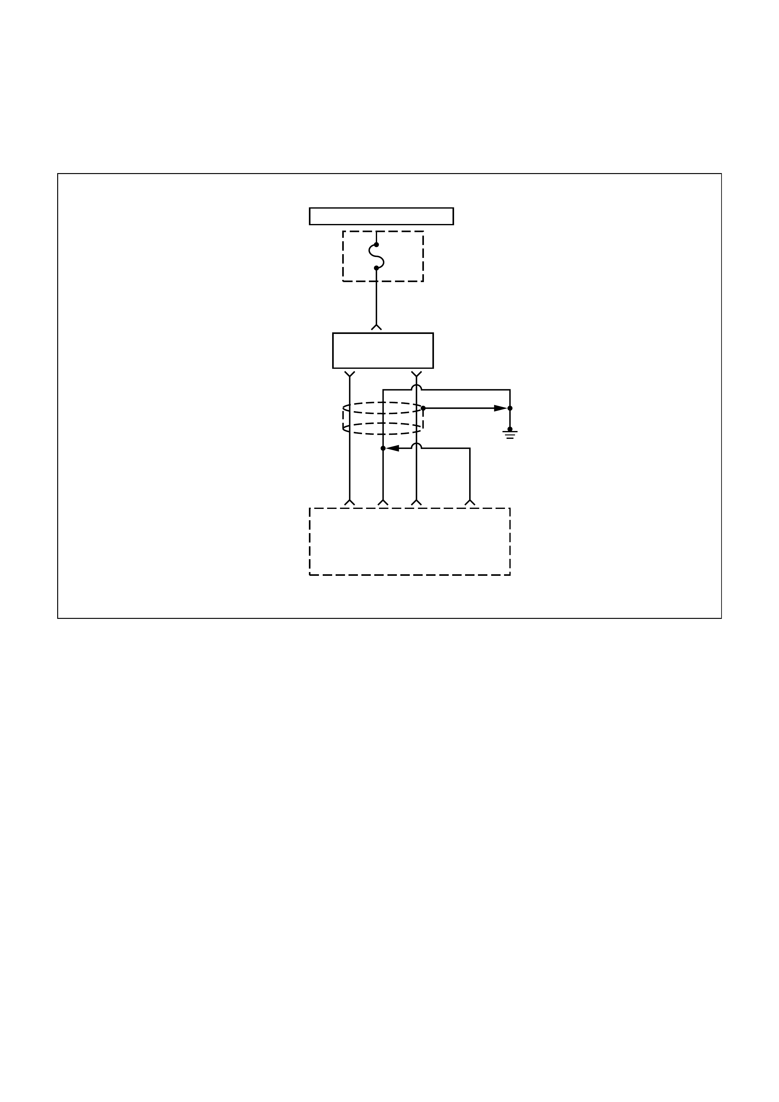
DIAG NOSTI C TROUBLE CODE (DTC) (FLASH DTC = 63)
IGNITION COIL DRIVER "B" SHORT TO GROUND
HOT IN START AND RUN
IG.
Coil
Fuse
15A
I/P
FUSE
BLOCK
2
W/G
Ignition
Coil
Ignition
Coil
1.25
G
1.25
L
Engine
Control
Module
(ECM)
E1 E4 E3
Electronic Spark
Timing Control
1.25
BLK
1.25
BLK
E2
1,4 2,3
CIRCUIT DESCRIPTION
The ignition control circuit provides a zero volt or a 5
volt signal to the ignition coil driver. The normal circuit
voltage is zero volts. When the module receives the 5
volt signal from the engine control module (ECM), it
provides a ground path for the B+ voltage supplied to
the ignition primary coil. When the ECM turns off the 5
volts to the module, the module will remove the
ground path of the ignition primary coils; causing the
magnetic field produces a voltage in the secondary
coils which fires the spark plug.
The circuit between the ECM and the ignition control
module is monitored for a short to ground on the
Electronic Spark Timing B/coil driver B line. When the
ECM detects a problem in the ignition control circuit, it
will set DTC 63.
CONDITIO NS FOR SETTING THE DTC
•Fault feedbac k line gener ates an interr upt on end of
dwell.
•No Electronic Spark T iming activation reguested by
serial data.
ACTIO N TAKEN WHEN THE DTC SETS
•The ECM will illuminate the malfunction indicator
lamp (MIL) the first time the fault is detected.
CONDITIO NS FOR CLEARI NG THE MIL/DTC
Once the ECM determines that a fault(s) has been
rectified then the CEL will switch OFF, although the
fault code will remain in the ECM memory.
Any fault codes will remain in ECM memory until -
1. They are cleared by disconnecting the Battery for
more than 30 seconds.
2. A service tool such as Tech 2 is used to clear them.
3. Ten consecutive starts without logging a fault.

DIAGNOSTIC AIDS
Check for the following conditions:
• Poor connection at the ECM - Inspect the harness
connectors for backed-out terminals, improper
mating, broken locks, improperly formed or
damaged terminals, and poor terminal-to-wire
connections.
• Damaged harness - Inspect the wiring harness for
damage; Open circuits, shorts to ground, or shorts
to Voltage. If the harness appears to be OK,
observe the Scan Tool display related to DTC 63
while moving the connector and wiring related to the
ignition system. A change in the display will indicate
the location of the fault.
• This code detects a short to ground on the
Electronic Spark Timing B/coil Driver B(#2, #3 cyl.)
line.
DTC (FLASH DTC = 63) IGNITION COIL DRIVER "B" SHORT TO GROUND
STEP ACTION VALUE(S) YES NO
1Was the "On-Board Diagnostic (OBD) System Check"
performed? -
Go to Step 2
Go to OBD
System Check
2Check for a faulty connection or damaged terminals at the
ignition control module.
Was a problem found? -
Verify repair Go to Step 3
3Check for a faulty connection or damaged terminals at the ECM
connector.
Was a problem found? -
Verify repair Go to Step 4
4
Check for an open circuit between the ignition coil and ECM.
If a problem is found, repair the wire harness.
Is there still a problem? -
Verify repair Go to Step 5
5
Check for an short to ground between the ignition coil and
battery +.
If a problem is found, repair the wire harness.
Is there still a problem?
-
Verify repair Go to Step 6
6
1. Ignition OFF.
2. Disconnect the ignition coil.
3. Check for an open circuit in the ignition coil.
Was a problem found?
-
Verify repair Go to Step 5
7Replace the ignition coil.
Verify repair.
Is there still a problem? -
Go to Step 8
-
8Replace the EPROM or ECM.
Is the repair complete? Note) Refer to 6E1-243. -Verify repair -
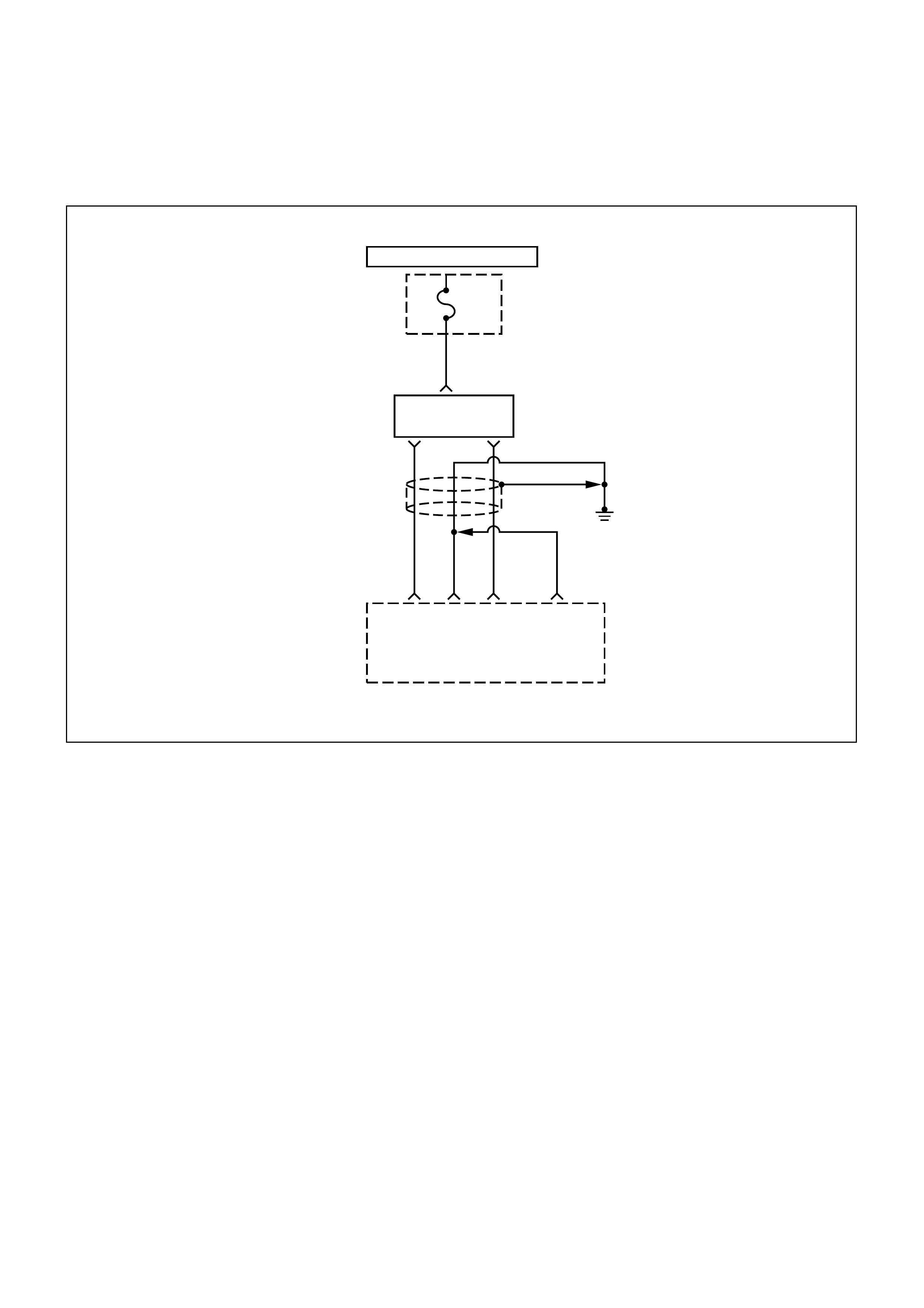
DIAG NOSTI C TROUBLE CODE (DTC) (FLASH DTC = 64)
IGNITION COIL DRIVER "A" SHORT TO GROUND
HOT IN START AND RUN
IG.
Coil
Fuse
15A
I/P
FUSE
BLOCK
2
W/G
Ignition
Coil
Ignition
Coil
1.25
G
1.25
L
Engine
Control
Module
(ECM)
E1 E4 E3
Electronic Spark
Timing Control
1.25
BLK
1.25
BLK
E2
1,4 2,3
CIRCUIT DESCRIPTION
The ignition control circuit in ECM provides a zero volt
or a 5 volt signal to the ignition coil driver. The normal
circuit voltage is zero volts. When the coil driver
receives the 5 volt signal from the ignition control
circuit, it provides a ground path for the B+ voltage
supplied to the ignition primary coil. When the ECM
turns off the 5 volts to the module, the module will
remove the ground path of the ignition primary coils;
causing the magnetic field produces a voltage in the
secondary coils which fires the spark plug.
The circuit between the coil driver and the ignition
control circuit is monitored for a short to ground on the
Electronic Spark Timing A/coil drive A line. When the
ECM detects a problem in the ignition control circuit, it
will set DTC 64.
CONDITIO NS FOR SETTING THE DTC
•Fault feedbac k line gener ates an interr upt on end of
dwell.
•No Electronic Spark T iming activation requested by
serial data.
ACTIO N TAKEN WHEN THE DTC SETS
•The ECM will illuminate the malfunction indicator
lamp (MIL) the first time the fault is detected.
CONDITIO NS FOR CLEARI NG THE MIL/DTC
Once the ECM determines that a fault(s) has been
rectified then the CEL will switch OFF, although the
fault code will remain in the ECM memory.
Any fault codes will remain in ECM memory until -
1. They are cleared by disconnecting the Battery for
more than 30 seconds.
2. A service tool such as Tech 2 is used to clear them.
3. Ten consecutive starts without logging a fault.

DIAGNOSTIC AIDS
Check for the following conditions:
• Poor connection at the ECM - Inspect the harness
connectors for backed-out terminals, improper
mating, broken locks, improperly formed or
damaged terminals, and poor terminal-to-wire
connections.
• Damaged harness - Inspect the wiring harness for
damage; Open circuits, shorts to ground, or shorts
to Voltage. If the harness appears to be OK,
observe the Scan Tool display related to DTC 64
while moving the connector and wiring related to the
ignition system. A change in the display will indicate
the location of the fault.
• This code detects a short to ground on the
Electronic Spark Timing A/Coil Driver A (#1, #4 cyl.)
line.
DTC (FLASH DTC = 64) IGNITION COIL DRIVER "A" SHORT TO GROUND
STEP ACTION VALUE(S) YES NO
1Was the "On-Board Diagnostic (OBD) System Check"
performed? -
Go to Step 2
Go to OBD
System Check
2Check for a faulty connection or damaged terminals at the
ignition control module.
Was a problem found? -
Verify repair Go to Step 3
3Check for a faulty connection or damaged terminals at the ECM
connector.
Was a problem found? -
Verify repair Go to Step 4
4
Check for a open circuit between the ignition coil and ECM.
If a problem is found, repair the wire harness.
Is there still a problem? -
Verify repair Go to Step 5
5
Check for a short to ground between the ignition coil and battery
+.
If a problem is found, repair the wire harness.
Is there still a problem?
-
Verify repair Go to Step 6
6
1. Ignition OFF.
2. Disconnect the ignition coil.
3. Check the ignition control circuit for a short to voltage.
Was a problem found?
-
Verify repair Go to Step 7
7Replace the ignition control module.
Verify repair.
Is there still a problem? -
Go to Step 8
-
8Replace the EPROM or ECM.
Is the repair complete? Note) Refer to 6E1-243. -Verify repair -
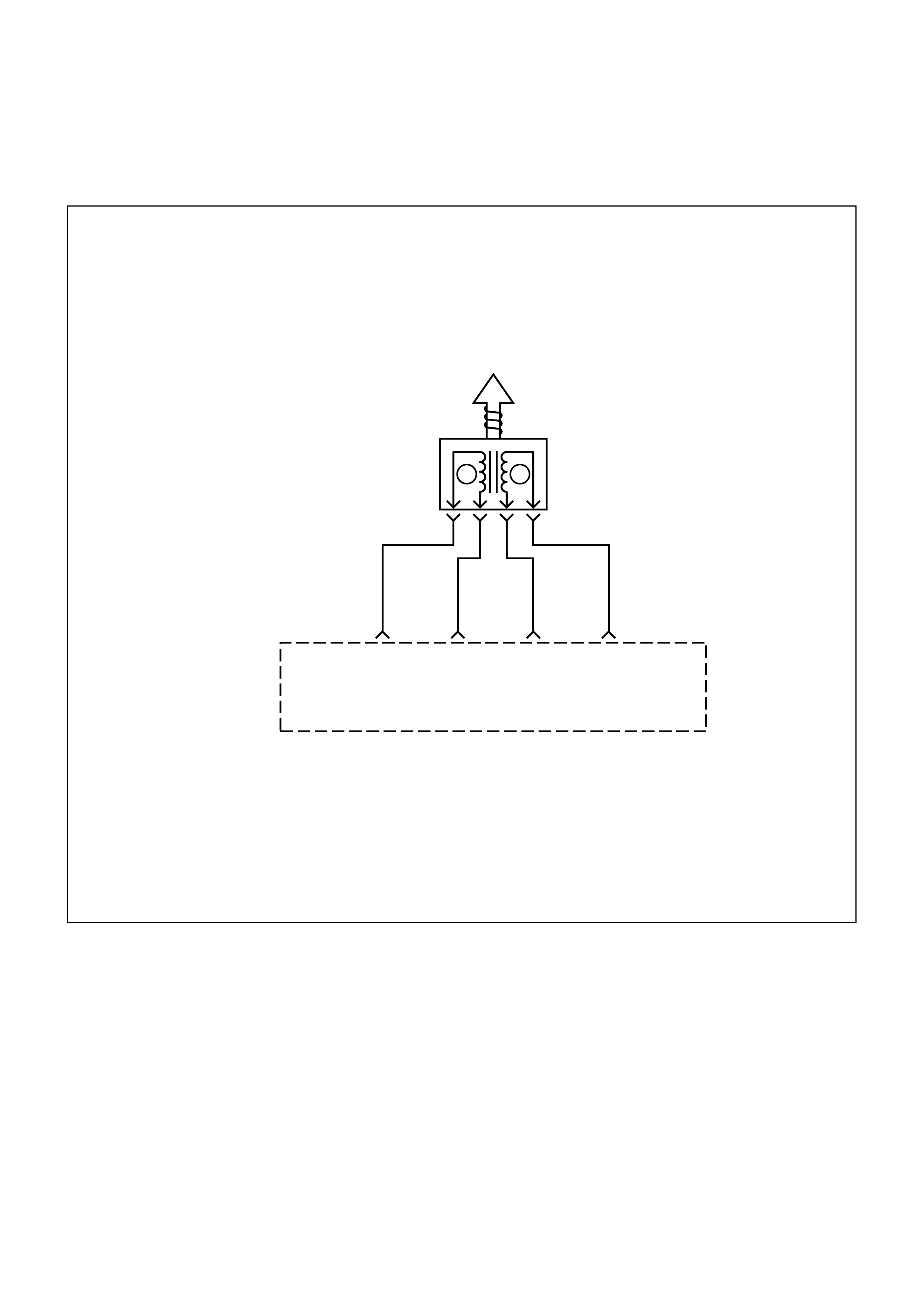
DIAG NOSTI C TROUBLE CODE (DTC) (FLASH DTC = 35)
IDLE AI R CONTROL (IAC) ERROR
Engine
Control
Module
(ECM)
B16
0.5
L
0.5
L/W
0.5
L/R
Idle Air
Control
(IAC)
Valve
0.5
L/B
B15
DCBA
B13 B14
IAC
A
High
IAC
A
Low
IAC
B
High
IAC
B
Low
A B
CIRCUIT DESCRIPTION
The engine control module (ECM) controls engine idle
speed with the idle air control (IAC) valve. To increase
idle speed, the ECM retracts the IAC valve pintle away
from its seat, allowing more air to bypass the throttle
bore. To decrease idle speed, it extends the IAC valve
pintle towards its seat, reducing bypass air flow. A
Scan Tool will read the ECM commands to the IAC
valve in counts. Higher counts indicate more air
bypass (higher idle). Lower counts indicate less air is
allowed to bypass (lower idle).
This malfunction detects an error in the IAC control
logic, then DTC 35 will set.
CONDITIO NS FOR SETTING THE DTC
•Engine rpm error is greater than 175 rpm.
•No DTC 21, 22 and 24 present.
And,
•Engine desired rpm is not fixed by tester.
•IAC movement is not inhibited by low or high battery
voltage.
And,
•IAC normal closed loop is enabled.
•Coolant of lesets are decayed to 0.

ACTIO N TAKEN WHEN THE DTC SETS
•The ECM will illuminate the malfunction indicator
lamp (MIL).
CONDITIO NS FOR CLEARI NG THE MIL/DTC
Once the ECM determines that a fault(s) has been
rectified then the CEL will switch OFF, although the
fault code will remain in the ECM memory.
Any fault codes will remain in ECM memory until -
1. They are cleared by disconnecting the Battery for
more than 30 seconds.
2. A service tool such as Tech 2 is used to clear them.
3. Ten consecutive starts without logging a fault.
DIAGNOSTIC AIDS
A slow, unstable, or fast idle may be caused by a non-
IAC system problem that cannot be overcome by the
IAC valve. Out of control range IAC Scan Tool counts
will be above 60 if idle is too low, and zero counts if
idle is too high. The following checks should be made
to repair a non-IAC system problem:
•Vacuum leak (high idle) - If idle is too high, stop the
engine. Fully extend (low) IAC with the IAC motor
analyzer 5-8840-2312-0. Start the engine. If idle
speed is above 825 RPM, locate and correct the
vacuum leak, including the PCV system. Check for
binding of the throttle blade or linkage.
Following are applicable to the vehicle with
closed Loop System.
•Throttle body - Remove the IAC valve and inspect
the bore for foreign material.
•IAC valve electrical connections - IAC valve
connections should be carefully checked for proper
contact.
•PCV hose - An incor r ec t or faulty hose may result in
an incorrect idle s peed. Ref er to Diagnosis, Rough
Idle, Stalling. If intermittent poor driveability or idle
symptoms are resolved by disconnecting the IAC,
carefully recheck the connections and valve
terminal resistance, or replace the IAC.
•Lean heated oxygen sensor signal (high air/fuel
ratio) - The idle speed may be too high or too low.
Engine speed may vary up and down, and
disconnecting the IAC valve does not help.
Diagnostic trouble code 44 may be set. Scan Tool
oxygen (O2) voltage will be less than 27 mV (2.74
V). Check for low regulated fuel pressure, waterin
fuel, or a restricted injector.
•Rich heated oxygen sens or signal ( low air/fuel ratio)
- The idle speed will be too low. Scan Tool IAC
counts will usually be above 80. The system is
obviously rich and may exhibit black smoke in the
exhaust.
•Scan T ool O2 voltage will be fixed at about 750 m V
(0.75 V). Check for high fuel pressure, or a leaking
or sticking injector. A silicon-contaminated heated
oxygen sensor will show an O2 voltage slow to
respond on the Scan Tool.
TEST DESCRIPTION
Number(s) below refer to the step number(s) on the
Diagnostic Chart.
1. The IAC motor analyzer 5-8840-2312-0 is used to
extend and retract the IAC valve. Valve movement
is verified by an engine speed change. If no
change in engine speed occurs, the valve can be
resettled when removed from the throttle body.
2. This step checks the quality of the IAC movement
in step 1. Between 700 revolutions per minute
(RPM) and about 1500 RPM, the engine speed
should change smoothly with each flash of the
tester light in both extend and retract. If the IAC
valve is retracted beyond the control range (about
1500 RPM), it m ay take m any flashes to ex tend the
IAC valve before engine speed will begin to drop.
This is normal on certain engines. Fully extending
the IAC may cause engine stall. This may be
normal.
6. Steps 1 and 2 verified the proper IAC valve
operation. This step checks the IAC circuits. Each
lamp on the noid light should flash red and green
while the IAC valve is cycled. While the sequence
of color is not important, if either light is OFF or
does not flas h red and green, check the circuits for
faults, beginning with poor terminal contacts.

DTC (FLASH DTC = 35) I DLE AIR CONTROL (IAC) ERROR
STEP ACTION VALUE(S) YES NO
1
1. Ignition OFF..
2. Connect the IAC motor analyze r 5-8840-2312-0 to the IAC
valve.
3. Set the parking brake.
4. Block the wheels.
5. Turn the air conditioning OFF.
6. Idle the engine in Park (A/T) or Neutral (M/T).
7. Install the scan tool. Display the RPM.
8. Use the IAC motor analyzer 5-8840-2312-0 to extend and
retract the IAC valve.
9. The engine speed should decrease and increase as the IAC
is cycled.
Does the RPM change?
-
Go to Step 2 Go to Step 3
2RPM should change smoothly with each flash of the IAC motor
analyzer 5-8840-2312-0 light.
Does the RPM change within the range specified? 700-1500
RPM Go to Step 6 Go to Step 3
3Check the IAC passages.
Are the IAC passages blocked? -Go to Step 4 Go to Step 5
4Clear any obstruction from the IAC passages.
Is the action complete? -Verify repair -
5Replace the IAC. Refer to On-Vehicle Service, Idle Air Control
Valve.
Is the action complete? -
Verify repair
-
6
1. Install the appropriate IAC noid light from 5-8840-2312-0 into
the powertrain control module harness.
2. Cycle the IAC motor analyzer 5-8840-2312-0 and observe
the noid lights.
3. Both the lights should cycle red and green, but never OFF,
as the RPM is changed over its range.
Do the noid lights cycle red and green?
-
Go to Step 7 Go to Step 8
7
1. Use the other connector on the IAC motor analyzer 5-8840-
2312-0 pigtail.
2. Check the resistance across the IAC coils.
Measure the resistance between terminal A and terminal B.
3. Measure the resistance between terminal C and terminal D.
Is the resistance within the specified range?
40-80 ohms Go to Step 9 Go to Step 10
8
If the circuits did not test green and red, check the following:
•Faulty connector terminal contacts.
•Open circuits, including connections.
•Circuits shorted to ground or voltage.
•Faulty engine control module connector(s) or engine control
module.
Are repairs necessary?
-
Go to Step 13
-

STEP ACTION VALUE(S) YES NO
9
1. Check the resistance between the IAC terminal B and
terminal C.
2. Check the resistance between the IAC terminal A and
terminal D.
Is the resistance infinite?
-
Go to Step 11 Go to Step 12
10 Replace the IAC. Refer to On-Vehicle Service, Idle Air Control
Valve.
Is the action complete? -
Go to Step 7
-
11 Check the IAC valve and circuit.
Are the IAC valve and circuit OK? - Refer to
Diagnostic
Aids Go to Step 12
12 Replace the IAC. Refer to On-Vehicle Service, Idle Air Control
Valve.
Is the action complete?
-Go to Step 9 -
13 Repair or replace the faulty component(s).
Is the action complete? -Go to Step 6 -
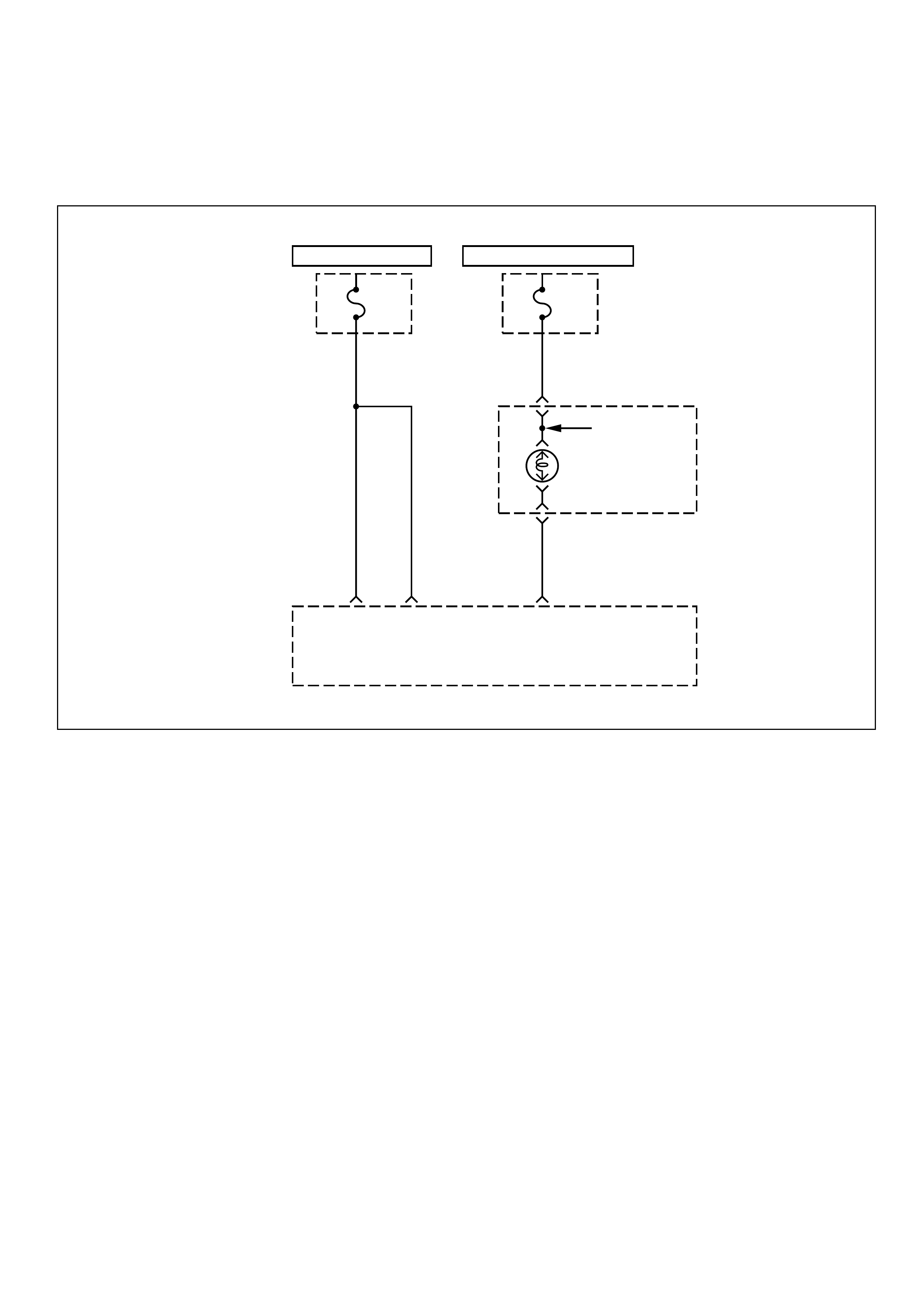
DIAG NOSTI C TROUBLE CODE (DTC) 56 (FLASH DTC = 56)
CHECK ENGINE LAMP LOW ERROR
HOT AT ALL TIMES
ECM
Fuse
15A
U/H
FUSE
BLOCK
HOT IN START AND RUN
Meter
Fuse
15A
I/P
FUSE
BLOCK
Malfuntion
Indicator
Lamp
0.85
YEL
1.25
RED/
WHT
1.25
RED/
WHT
0.5
BR/Y
Instrument
Panel(I/P)
Cluster
Engine
Control
Module
(ECM)
A4 A5 B4
Batt+ Malfunction
Indicator
Lamp
Control
TACHO
CIRCUIT DESCRIPTION
The “Check Engine” lamp (MIL) should always be
illuminated and steady with the ignition ON and the
engine stopped. Battery feed Voltage is supplied to the
MIL bulb through the meter fuse. The engine control
module (ECM) turns the MIL ON by grounding the MIL
driver circuit.
CONDITIO NS FOR SETTING THE DTC
•This code detects a low impedanc e short to ground
on an open contact on the MIL output.
•Driver f eedback infor m ation shows a low state at its
operation even when commanded high.
ACTIO N TAKEN WHEN THE DTC SETS
•The MIL will not turn ON.
CONDITIO NS FOR CLEARI NG THE DTC
Once the ECM determines that a fault(s) has been
rectified then the CEL will switch OFF, although the
fault code will remain in the ECM memory.
Any fault codes will remain in ECM memory until -
1. They are cleared by disconnecting the Battery for
more than 30 seconds.
2. A service tool such as Tech 2 is used to clear them.
3. Ten consecutive starts without logging a fault.

DIAGNOSTIC AIDS
An intermittent MIL may be caused by a poor
connection, rubbed-through wire insulation, or a wire
broken inside the insulation. Check for the following
items:
• Inspect the ECM harness and connections for
improper mating, broken locks, improperly formed
or damaged terminals, poor terminal-to-wire
connection, and damaged harness.
• If the engine runs OK, check for a faulty light bulb,
an open in the MIL driver circuit, or an open in the
instrument cluster ignition feed.
• If the engine cranks but will not run, check for an
open ECM ignition or battery feed, or a poor ECM to
engine ground.
TEST DESCRIPTION
Number(s) below refer to the step number(s) on the
Diagnostic Chart.
2. A “No MIL” condition accompanied by a no-start
condition suggests a faulty ECM ignition feed or
battery feed circuit.
9. Using a test light connected to B+, probe each of
the ECM ground terminals to ensure that a good
ground is present. Refer to ECM Terminal End
View for terminal locations of the ECM ground
circuits.
DTC (FLASH DTC = 56) CHECK ENGINE LAMP LOW ERROR
STEP ACTION VALUE(S) YES NO
1Was the “On-Board Diagnostic (OBD) System
Check” performed? -
Go to Step 2
Go to OBD
System Check
2Attempt to start the engine.
Does the engine start? -Go to Step 3 Go to Step 6
3Check the meter fuse for the instrument cluster turn, back and
gauge.
Is the fuse OK? -
Go to Step 4 Go to Step 16
5
1. Ignition OFF.
2. Disconnect the ECM.
3. Jumper the MIL driver circuit at the ECM connector to
ground.
4. Ignition ON.
Is the MIL ON?
-
Go to Step 10 Go to Step 11
6Check the ECM ignition feed and battery feed fuses
(15A Ignition fuse and 15A ECM fuse).
Are both fuses OK? -
Go to Step 8 Go to Step 15
8Probe the battery feed circuit at the ECM harness connector
with a test light to ground.
Is the test light ON? -
Go to Step 9 Go to Step 14
9Check for a faulty ECM ground connection.
Was a problem found? -Verify repair Go to Step 10

STEP ACTION VALUE(S) YES NO
10 Check for damaged terminals at the ECM.
Was a problem found? -Verify repair Go to Step 17
11 Check for an open MIL driver circuit between the ECM and the
MIL.
Was a problem found? -
Verify repair Go to Step 18
14 Locate and repair the open ECM battery feed circuit.
Is the action complete? -Verify repair -
15 Locate and repair the short to ground in the ECM battery feed
circuit.
Is the action complete? -
Verify repair
-
16 Locate and repair the short to ground in the MIL feed circuit to
the instrument cluster, and replace the fuse.
Is the action complete? -
Verify repair
-
17 Replace the EPROM or ECM. Note) Refer to 6E1-243. - Verify repair -
18
Check the MIL driver circuit for a poor connection at the
instrument panel connector.
Was a problem found? -
Verify repair
Go to
Instrument
Panel in
Electrical
Diagnosis
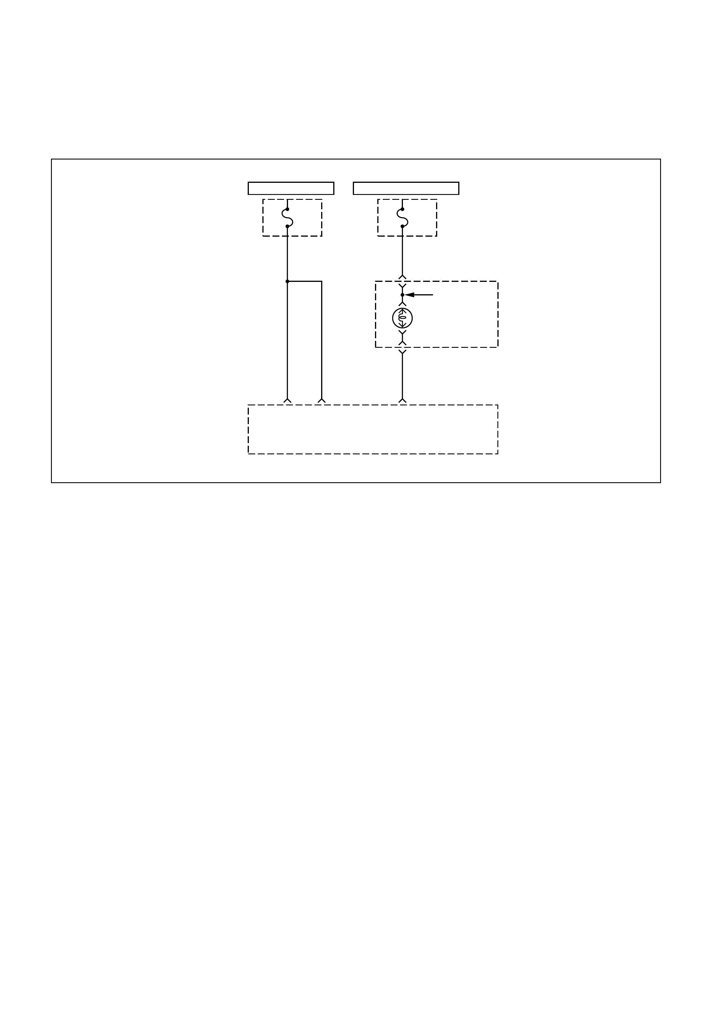
DIAG NOSTI C TROUBLE CODE (DTC) 57 (FLASH DTC = 57)
CHECK ENGINE LAMP HI GH ERROR
HOT AT ALL TIMES
ECM
Fuse
15A
U/H
FUSE
BLOCK
HOT IN START AND RUN
Meter
Fuse
15A
I/P
FUSE
BLOCK
Malfuntion
Indicator
Lamp
0.85
YEL
1.25
RED/
WHT
1.25
RED/
WHT
0.5
BR/Y
Instrument
Panel(I/P)
Cluster
Engine
Control
Module
(ECM)
A4 A5 B4
Batt+ Malfunction
Indicator
Lamp
Control
TACHO
CIRCUIT DESCRIPTION
The malfunction indicator lamp (MIL) should always be
illuminated and steady with the ignition ON and the
engine stopped. Battery feed voltage is supplied
directly to the MIL indicator. The engine control
module (ECM) turns the MIL ON by grounding the MIL
driver circuit.
CONDITIO NS FOR SETTING THE DTC
•This code detects a low im pedance short to battery
on the MIL output.
•Driver f eedback infor m ation shows a low state at its
operation even when commanded high.
ACTIO N TAKEN WHEN THE DTC SETS
•The MIL will stay ON.
CONDITIO NS FOR CLEARI NG THE DTC
Once the ECM determines that a fault(s) has been
rectified then the CEL will switch OFF, although the
fault code will remain in the ECM memory.
Any fault codes will remain in ECM memory until -
1. They are cleared by disconnecting the Battery for
more than 30 seconds.
2. A service tool such as Tech 2 is used to clear them.
3. Ten consecutive starts without logging a fault.
DIAGNOSTIC AIDS
An intermittent may be caused by a poor connection,
rubbed-through wire insulation, or a wire broken inside
the insulation. Check for the following items:
•Poor connection or damaged harness - Inspect the
ECM harness and connectors for improper mating,
broken locks, improperly formed or damaged
terminals, poor terminal-to-wire connection, and
damaged harness.
TEST DESCRIPTION
Number(s) below refer to the step number(s) on the
Diagnostic Chart.
2. If the MIL does not remain ON when the ECM is
disconnected, the MIL driver wiring is not faulty.
3. If the MIL driver circuit is OK, the instrum ent panel
cluster is faulty.

DTC (FLASH DTC = 57) CHECK ENGINE LAMP HIGH ERROR
STEP ACTION VALUE(S) YES NO
1Was the “On-Board Diagnostic (OBD) System
Check” performed? -
Go to Step 2
Go to OBD
System Check
21. Ignition OFF, disconnect ECM.
2. Ignition ON, observe the MIL.
Is the MIL ON? -
Go to Step 3 Go to Step 5
3
1. Ignition OFF, disconnect the instrument panel cluster.
2. Check the MIL driver circuit between the ECM and the
instrument panel cluster for a short to battery.
3. If a problem is found, repair as necessary.
Was the MIL driver circuit shorted to battery?
-Go to OBD
System Check
Go to Step 4
4Replace the instrument panel cluster.
Is the action complete? - Go to OBD
System Check -
5
1. Ignition OFF, reconnect the ECM.
2. Refer to On-Vehicle Service in Engine Control Module and
Sensors for procedures.
3. Using the scan tool output controls function, select MIL dash
lamp control and command the MIL OFF.
Did the MIL turn OFF?
-Go to OBD
System Check
Go to Step 6
6Replace the EPROM or ECM. Note) Refer to 6E1-243. -Go to OBD
System Check -
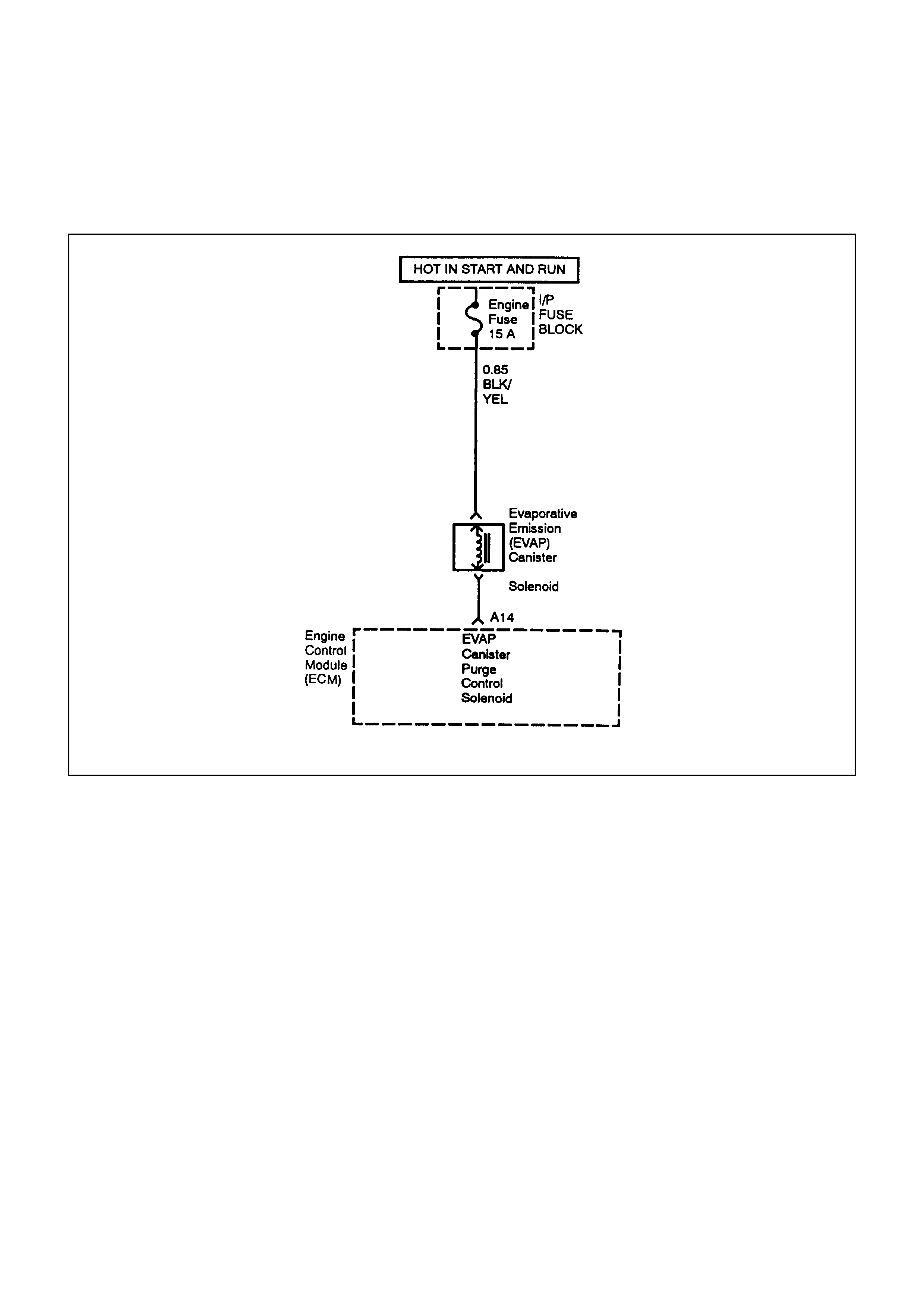
DIAG NOSTI C TROUBLE CODE (DTC) (FLASH DTC = 61)
EVAPORATIVE EMISSION (EVAP) CONTROL SYSTEMCANISTER
PURGE CONTROL VALVE CIRCUIT LOW ERROR (IF APPLICABLE)
Purge Control
0.5 R/L
CIRCUIT DESCRIPTION
The engine control Module (ECM) controls the
Evaporative Emission (EVAP) Canister Purge control
Solenoid Valve through the use of a control (ground)
circuit. If the ECM commands the Purge solenoid to
maximum duty cycle (100%) but the voltage remains
High (12 volts); or, if the ECM commands the Purge
solenoid to high duty cycle (100%) but the voltage
remains low (0 volts), this malfunction detects a low
impedance short to ground or open contact on the
canister purge solenoid output. Then DTC 61 will set.
CONDITIO NS FOR SETTING THE DTC
•Driver f eedback infor m ation shows a low state at its
operation even when commanded high.
ACTIO N TAKEN WHEN THE DTC SETS
•The ECM will illuminate the Malfunction Indicator
Lamp (MIL).
CONDITIO NS FOR CLEARI NG THE MIL/DTC
Once the ECM determines that a fault(s) has been
rectified then the CEL will switch OFF, although the
fault code will remain in the ECM memory.
Any fault codes will remain in ECM memory until -
1. They are cleared by disconnecting the Battery for
more than 30 seconds.
2. A service tool such as Tech 2 is used to clear them.
3. Ten consecutive starts without logging a fault.
DIAGNOSTIC AIDS
•Poor connections, or a damaged harness - Inspect
the harness connectors for: backed-out terminals,
improper mating or dam aged terminals. Also check
for open circuits, shorts to ground, and shorts to
voltage.
•This malfunction detects a low impedance short to
ground or open contact on the purge control
solenoid output.

DTC (FLASH DTC = 61) EVAPORATIVE EMISSION (EVAP) CONTROL SYSTEM CANISTER
PURGE CONTROL VALVE CIRCUIT LOW ERROR
STEP ACTION VALUE(
S) YES NO
1Was the "On-Board Diagnostic (OBD) System Check"
performed? - Go to Step 2
Go to OBD
System Check
2
1. Ignition ON, Engine OFF.
2. Using the Scan Tool, monitor info for Diagnostic Trouble
Code 61.
Does the Scan Tool indicate DTC 61.
-Refer to
Diagnostic Aids Go to Step 3
3
1. Ignition OFF.
2. Disconnect the EVAP Canister Purge Control Solenoid from
the wiring harness connector from the EVAP Canister Purge
Control Solenoid.
3. Ignition ON, Engine OFF.
4. Using a Digital Voltmeter (DVM), check for voltage on the
"Engine IG." Fuse pin of the EVAP Canister Purge Control
Solenoid wiring harness connector.
Does the DVM read the following value? 12 Volts Go to Step 5 Go to Step 4
4
Check the suspect circuit between the EVAP Canister Purge
Control Solenoid connector and the "Engine IG." Fuse for the
following conditions:
•A short to ground
•An open circuit
•A short to voltage
Was the problem found?
-
Verify repair -
5Using a DVM, check the resistance of the EVAP Canister Purge
Control Solenoid.
Does the DVM read the following value?
less than
5 ohms
Go to Step 6 Go to Step 7
6Replace the EVAP Canister Purge Control Solenoid.
Verify repair. ---
7 Replace the EPROM or ECM. Note) Refer to 6E1-243. - - -
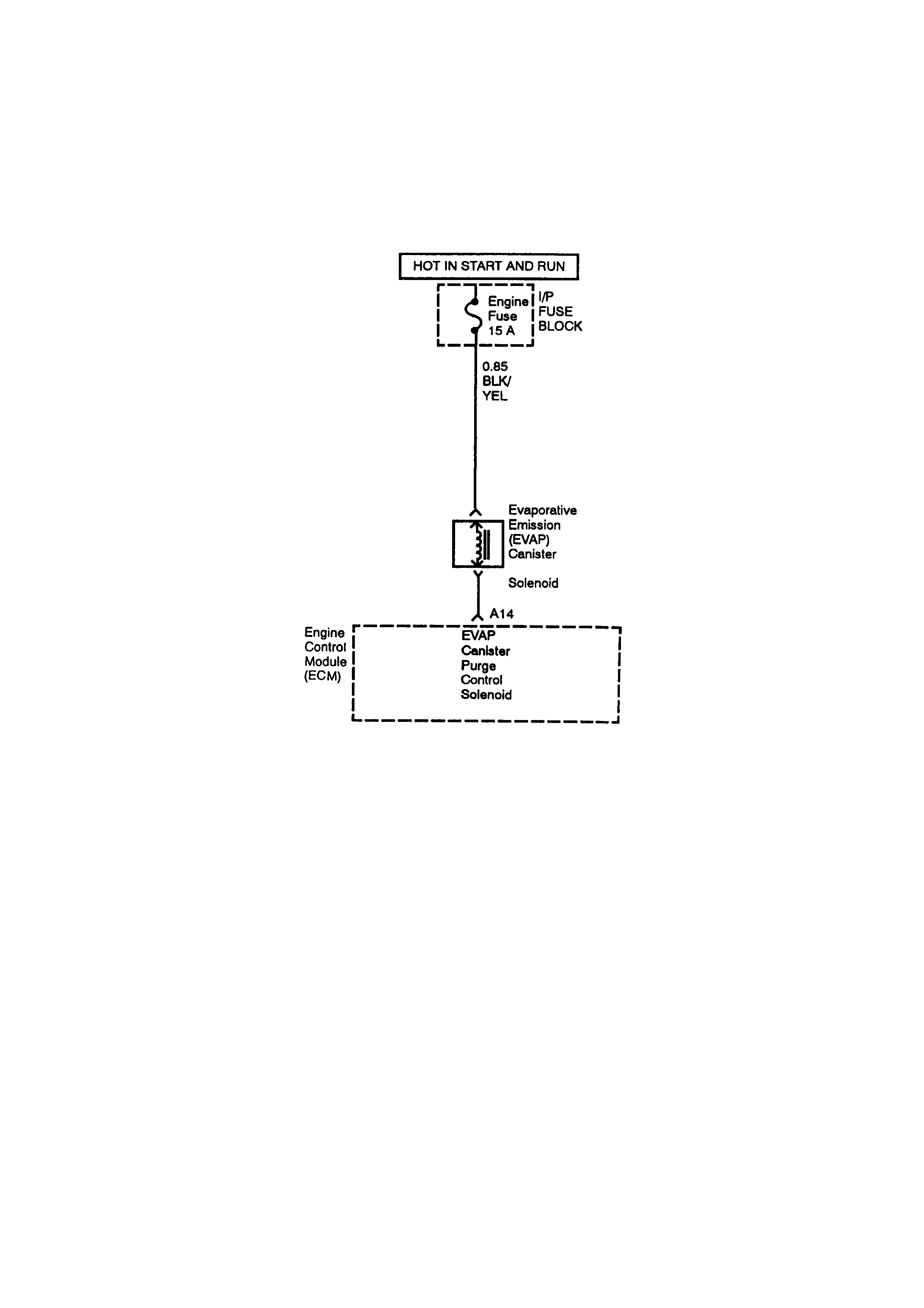
DIAG NOSTI C TROUBLE CODE (DTC) (FLASH DTC = 62)
EVAPORATIVE EMISSION (EVAP) CONTROL SYSTEM CANISTER
PURGE CONTROL VALVE CIRCUIT HIGH ERROR (IF APPLICABLE)
Purge Control
0.5 R/L
CIRCUIT DESCRIPTION
The engine control Module (ECM) controls the
Evaporative Emission (EVAP) Canister Purge
Solenoid Valve through the use of a control (ground)
circuit. If the ECM commands the Purge solenoid to
maximum duty cycle (100%) but the voltage remains
High (12 volts); or, if the ECM commands the Purge
solenoid to minimum duty cycle (0%) but the voltage
remains high (12 volts), this malfunction detects a high
impedance short to ground or open contact on the
canister purge solenoid output. Then DTC 62 will set.
CONDITIO NS FOR SETTING THE DTC
•Driver feedback information shows a high state at
its operation even when commanded low.
ACTIO N TAKEN WHEN THE DTC SETS
•The ECM will illuminate the Malfunction Indicator
Lamp (MIL).
CONDITIO NS FOR CLEARI NG THE MIL/DTC
Once the ECM determines that a fault(s) has been
rectified then the CEL will switch OFF, although the
fault code will remain in the ECM memory.
Any fault codes will remain in ECM memory until -
1. They are cleared by disconnecting the Battery for
more than 30 seconds.
2. A service tool such as Tech 2 is used to clear them.
3. Ten consecutive starts without logging a fault.
DIAGNOSTIC AIDS
•Poor connections, or a damaged harness - Inspect
the harness connectors for: backed-out terminals,
improper mating or dam aged terminals. Also check
for open circuits, shorts to ground, and shorts to
voltage.
•This malf unction detects a high impedance short to
ground or open contact on the purge control
solenoid output.

DTC (FLASH DTC = 62) EVAPORATIVE EMISSION (EVAP) CONTROL SYSTEM CANISTER
PURGE CONTROL VALVE CIRCUIT HIGH ERROR
STEP ACTION VALUE(
S) YES NO
1Was the "On-Board Diagnostic (OBD) System Check"
performed? - Go to Step 2
Go to OBD
System Check
2
1. Ignition ON, Engine OFF.
2. Using the Scan Tool, monitor info for Diagnostic Trouble
Code 62.
Does the Scan Tool indicate DTC 62.
-Refer to
Diagnostic Aids Go to Step 3
3
1. Ignition OFF.
2. Disconnect the EVAP Canister Purge Control Solenoid from
the wiring harness connector from the EVAP Canister Purge
Control Solenoid.
Using a DVM, check the resistance of the EVAP Canister Purge
Control Solenoid.
Does the DVM read the following value?
less than
5 ohms
Go to Step 4 Go to Step 5
4
1. Ignition OFF.
2. Disconnect the engine Control Module (ECM) connectors
from the ECM.
3. Check the EVAP Canister Purge Control Solenoid control
circuit between the ECM and EVAP Canister Purge Control
Solenoid for the following conditions:
•A short to ground
•An open circuit
•A short to voltage
Was the problem found?
-
Verify repair Go to Step 6
5Replace the EVAP Canister Purge Control Solenoid.
Verify repair. ---
6 Replace the EPROM or ECM. Note) Refer to 6E1-243. - - -

DIAG NOSTI C TROUBLE CODE (DTC) (FLASH DTC = 87)
A/C COMPRESSOR CLUTCH RELAY LOW ERROR
A/C
Compressor
Relay
Control
A16
MAG
Clutch
(Compressor)
Relay
Thermo
(1) (2)
(3) (4)
Relay:A/C
Compressor
Joint
To HA09
0.5
BR
0.5
GR/R
B10
0.5
G/B
HOT IN START AND RUN
(2) (1)
(4) (3)
Engine
Control
Module
(ECM)
CIRCUIT DESCRIPTION
The engine control module (ECM) controls the A/C
Compressor Clutch Solenoid through the use of a
relay and a control (ground) circuit. This malfunction
detects a low impedance short to ground or open
contact on the A/C clutch relay output, then DTC 87
will set.
CONDITIO NS FOR SETTING THE DTC
•Driver f eedback infor m ation shows a low state at its
operation even when commanded high.
ACTIO N TAKEN WHEN THE DTC SETS
•The ECM will illuminate Malfunction Indicator lamp
(MIL).
CONDITIO NS FOR CLEARI NG THE DTC
Once the ECM determines that a fault(s) has been
rectified then the CEL will switch OFF, although the
fault code will remain in the ECM memory.
Any fault codes will remain in ECM memory until -
1. They are cleared by disconnecting the Battery for
more than 30 seconds.
2. A service tool such as Tech 2 is used to clear them.
3. Ten consecutive starts without logging a fault.
DIAGNOSTIC AIDS
•This malfunction detects a low impedance short to
ground or open contact on the AC clutch relay
output.
To diagnose an intermittent fault, check for the
following conditions:
•Poor connection at the ECM-Inspect harness
connections for backed-out terminals, improper
mating, broken locks, improperly formed or
damaged terminals, and poor terminal-to-wire
connection.

• Damaged harness-Inspect the wiring harness for
damage; shorts to Ground, shorts to Battery
Voltage, and Open circuits. If the harness appears
to be OK, observe the A/C clutch while moving
connectors and wiring harnesses related to the A/C.
A sudden clutch malfunction will indicate the source
of the intermittent fault.
A/C CLUTCH DIAGNOSIS
This chart should be used for diagnosing the electrical
portion of the A/C compressor clutch circuit. A Scan
Tool will be used in diagnosing the system. The Scan
Tool has the ability to read the A/C request input to the
ECM. The Scan Tool can display when the ECM has
commanded the A/C clutch ON. The Scan Tool should
have the ability to override the A/C request signal and
energize the A/C compressor relay.
DTC (FLASH DTC = 87) A/C COMPRESSOR CLUTCH RELAY LOW ERROR
STEP ACTION VALUE(
S) YES NO
1Was the "On-Board Diagnostic (OBD) System Check"
performed? -Go to Step 2
Go to OBD
System Check
21. Ignition ON, engine OFF.
2. Using the Scan Tool, monitor info for DTC 87.
Does the Scan Tool indicate DTC 87?
-Refer to
Diagnostic Aids Go to Step 3
3
1. Ignition OFF.
2. Check for an open circuit at the pressure switch and thermo
switch.
And also check for an open circuit at the wire harness
between pressure switch and the ECM, pressure switch and
thermo switch, thermo switch and the Fuse.
Repair it necessary.
-
Verify Repair Go to Step 4
4
1. Remove the A/C Compressor Clu tch Relay from the
Underhood Electrical Center.
2. Ignition ON, engine OFF.
3. Using a Digital Voltmeter (DVM), check for voltage on the
Fused pins of the A/C Compressor Clutch Relay connector.
Does the DVM read the following value?
12 Volts
Go to Step 6 Go to Step 5
5
Check the suspect circuit(s) between the A/C Compressor
Clutch Relay connector and the Fuse for the following
conditions:
•A short to ground
•An open circuit
Was the problem found?
-
Verify Repair
-

STEP ACTION VALUE(
S) YES NO
6
1. Ignition OFF.
2. Disconnect the Engine Control Module (ECM) connectors
from the ECM.
3. Check the A/C Compressor Clutch Relay control circuit
between the ECM and Underhood Electrical Center for the
following conditions:
•A short to ground
•An open circuit
Was the problem found?
-
Verify Repair Go to Step 7
7
1. Reinstall the A/C Compressor Clutch Relay.
2. Using a fused jumper, ground the A/C Compressor Clutch
Relay control circuit at the ECM connector.
3. Ignition ON, Engine OFF.
Does the A/C Compressor turn ON?
-
Go to Step 10 Go to Step 8
8
1. Ignition OFF.
2. Check the A/C Compressor Clutch circuit between the A/C
Compressor Clutch Relay and A/C Compressor Clutch for
the following conditions:
•A short to ground
•An open circuit
Was the problem found?
-
Verify Repair Go to Step 9
9Replace the A/C Compressor Clutch Relay.
Is the action complete? -Verify Repair -
10 Replace the EPROM or ECM.
Varify Repair Note) Refer to 6E1-243. -- -
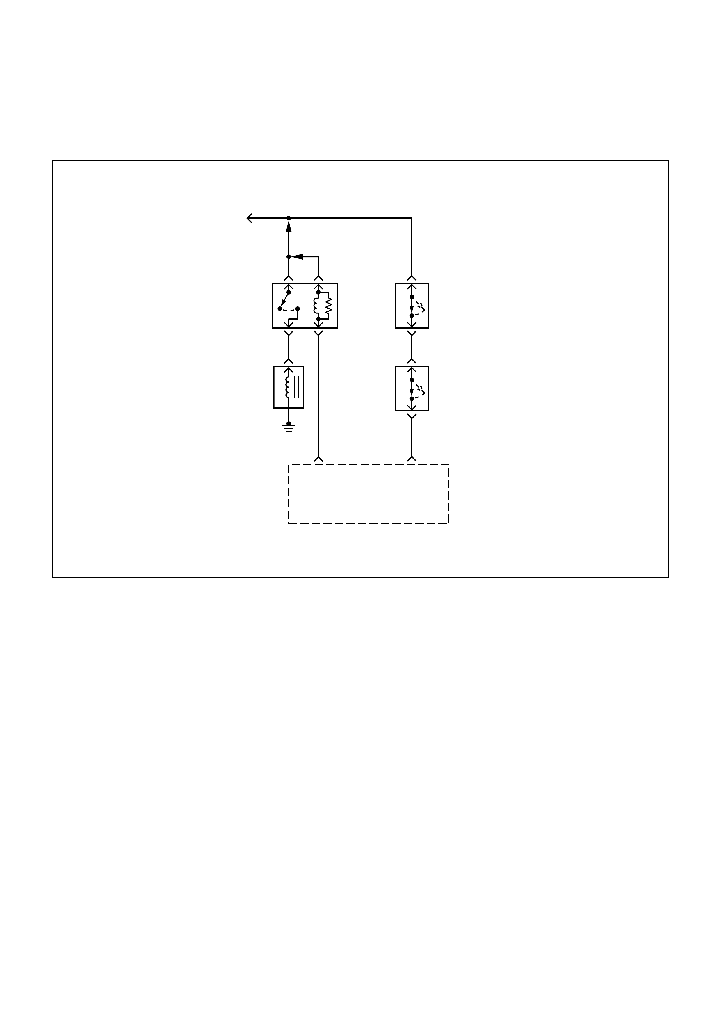
DIAG NOSTI C TROUBLE CODE (DTC) (FLASH DTC = 88)
A/C COMPRESSOR CLUTCH RELAY HIGH ERROR
Engine
Control
Module
(ECM)
A/C
Compressor
Relay
Control
A16 B10
Thermo
Switch
Pressure
Switch
0.5G/W 0.5G/W
0.5G/W
A/C Switch
0.5
G/Y
0.5
GR/Y
0.5
G/R
0.5
G/B
CIRCUIT DESCRIPTION
The engine control module (ECM) controls the A/C
Compressor Clutch Solenoid through the use of a
relay and a control (ground) circuit. This malfunction
detects a low impedance short to ground or open
contact on the A/C clutch relay output, then DTC 88
will set.
CONDITIO NS FOR SETTING THE DTC
•Driver feedback information shows a high state at
its operation even when commanded low.
ACTIO N TAKEN WHEN THE DTC SETS
•The ECM will illuminate Malfunction Indicator lamp
(MIL).
CONDITIO NS FOR CLEARI NG THE DTC
Once the ECM determines that a fault(s) has been
rectified then the CEL will switch OFF, although the
fault code will remain in the ECM memory.
Any fault codes will remain in ECM memory until -
1. They are cleared by disconnecting the Battery for
more than 30 seconds.
2. A service tool such as Tech 2 is used to clear them.
3. Ten consecutive starts without logging a fault.
DIAGNOSTIC AIDS
•This malfunction detects a low impedance short to
battery on the AC clutch relay output.
To diagnose an intermittent fault, check for the
following conditions:
•Poor connection at the ECM-Inspect harness
connections for backed-out terminals, improper
mating, broken locks, improperly formed or
damaged terminals, and poor terminal-to-wire
connection.

• Damaged harness-Inspect the wiring harness for
damage; shorts to Battery Voltage, and Open
circuits. If the harness appears to be OK, observe
the A/C clutch while moving connectors and wiring
harnesses related to the A/C. A sudden clutch
malfunction will indicate the source of the
intermittent fault.
A/C CLUTCH DIAGNOSIS
This chart should be used for diagnosing the electrical
portion of the A/C compressor clutch circuit. A Scan
Tool will be used in diagnosing the system. The Scan
Tool has the ability to read the A/C request input to the
ECM. The Scan Tool can display when the ECM has
commanded the A/C clutch ON. The Scan Tool should
have the ability to override the A/C request signal and
energize the A/C compressor relay.
DTC (FLASH DTC = 88) A/C COMPRESSOR CLUTCH RELAY HIGH ERROR
STE
PACTION VALUE
(S)YES NO
1Was the "On-Board Diagnostic (OBD) System Check"
performed? -Go to Step 2 Go to OBD
System Check
21. Ignition ON, engine OFF.
2. Using the Scan Tool, monitor info for DTC 88.
Does the Scan Tool indicate DTC 88? -Refer to
Diagnostic Aids Go to Step 3
3
1. Ignition OFF.
2. Remove the A/C Compressor Clutch Relay from the
Underhood Electrical Center.
3. Ignition ON, engine OFF.
4. Using a Digital Voltmeter (DVM), check for voltage on
the Fused pins of the A/C Compressor Clutch Relay
connector.
Does the DVM read the following value?
12 Volts
Go to Step 4 Go to Step 5
4
1. Ignition OFF.
2. Disconnect the Engine Control Module (ECM)
connectors from the ECM.
3. Check the A/C Compressor Clutch Relay control circuit
between the ECM and Underhood Electrical Center for
the following conditions:
•A short to battery
Was the problem found?
-
Verify Repair Go to Step 5
5
1. Reinstall the A/C Compressor Clutch Relay.
2. Using a fused jumper, ground the A/C Compressor
Clutch Relay control circuit at the ECM connector.
3. Ignition ON, Engine OFF.
Does the A/C Compressor turn ON?
-
Go to Step 8 Go to Step 6
6
1. Ignition OFF.
2. Check the A/C Compressor Clutch circuit between the
A/C Compressor Clutch Relay and A/C Compressor
Clutch for the following conditions:
•A short to battery
Was the problem found?
-
Verify Repair Go to Step 7
7Replace the A/C Compressor Clutch Relay.
Is the action complete? -Verify Repair -
8Replace the EPROM or ECM.
Varify Repair Note) Refer to 6E1-243. -- -
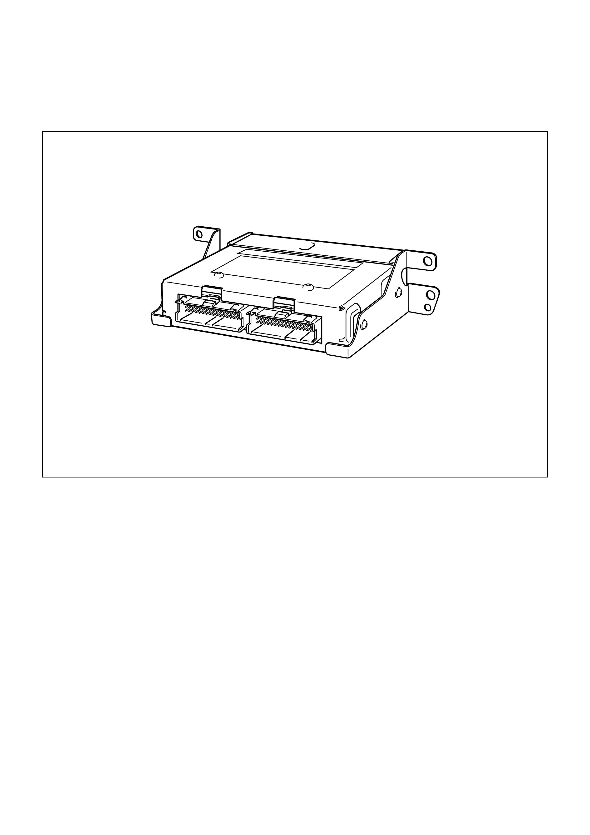
DIAG NOSTI C TROUBLE CODE (DTC) (FLASH DTC = 93)
QUAD DRIVER SUB MODULE
CIRCUIT DESCRIPTION
Quad Driver Sub Module (QDSM) are used by the
engine control module (ECM) to turn ON many of the
current-driven devices that are needed to control
various engine and transmission functions. Each
QDSM is capable of controlling up to 4 separate
outputs by applying ground to the device which the
ECM is commanding ON.
QDSMs have the capability of diagnosing each output
circuit individually. DTC 93 set indicates an improper
voltage level has been detected on a QDSM output.
This DTC detects a short to battery or Open Load or
Short to ground at the QDSM output, then DTC P93
will set.
CONDITIO NS FOR SETTING THE DTC
•If fault line from the QDSM is detected low.
ACTIO N TAKEN WHEN THE DTC SETS
•The ECM will illuminate the malfunction indicator
lamp (MIL).
CONDITIO NS FOR CLEARI NG THE DTC
Once the ECM determines that a fault(s) has been
rectified then the CEL will switch OFF, although the
fault code will remain in the ECM memory.
Any fault codes will remain in ECM memory until -
1. They are cleared by disconnecting the Battery for
more than 30 seconds.
2. A service tool such as Tech 2 is used to clear them.
3. Ten consecutive starts without logging a fault.

DIAGNOSTIC AIDS
Check for the following conditions:
• Poor connection at ECM - Inspect harness
connectors for backed-out terminals, improper
mating, broken locks, improperly formed or
damaged terminals, and poor terminal-to-wire
connection.
• Damaged harness - Inspect the wiring harness for
damage. If the harness appears to be OK,
disconnect the ECM, turn the ignition ON and
observe a voltmeter connected to the MIL driver
circuit at the ECM harness connector while moving
connectors and rewiring harnesses relates to the
MIL. A change in voltage will indicate the location of
the fault.
This malfunction detects a:
Short to battery or Open Load or Short to ground at
QDSM output.
DTC (FLASH DTC = 93) QUAD DRIVER SUB MODULE
STEP ACTION VALUE(S) YES NO
1Was the "On-Board Diagnostic (OBD) System Check"
performed? -
Go to Step 2
Go to OBD
System Check
2Replace the EPROM or ECM. Note) Refer to 6E1-243.
Is the action complete? -Verify Repair -
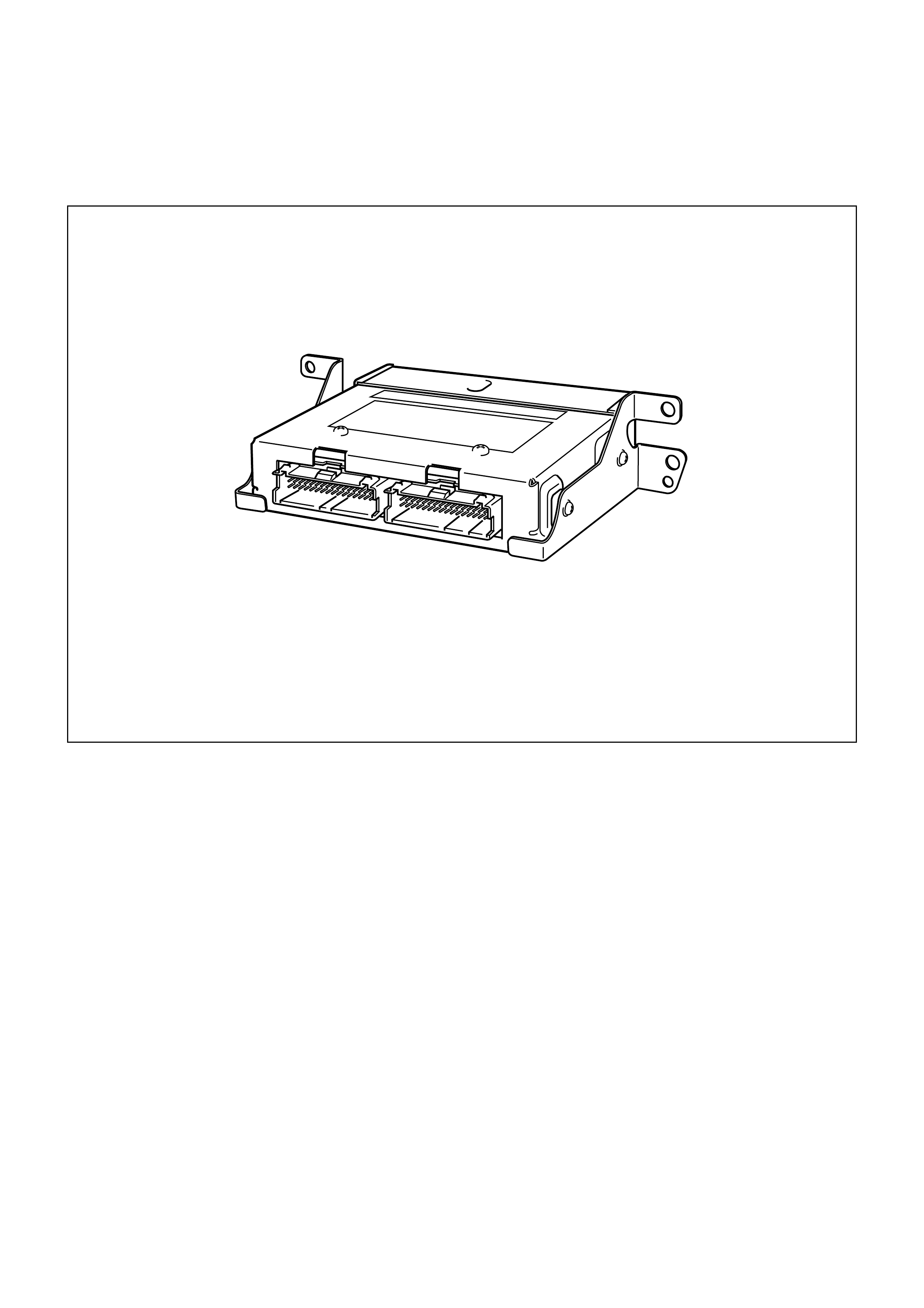
DIAG NOSTIC TROUBLE CODE DTC (FLASH DTC=51)
ELECTRICALLY PROGRAMMABLE READ-ONLY MEMORY (EPROM) ERROR
CIRCUIT DESCRIPTION
The Engine control module (ECM) used in this vehicle
utilizes an electrically programmable read- only
memory (EPROM). The EPROM contains program ID-
Calibration variable.
This malfunction checks the integrity of the EPROM
(ECM will not run), then DTC 51 will set.
CONDITIO NS FOR SETTING THE DTC
•If calculated check sum is not equal to the stored
check sum.
ACTIO N TAKEN WHEN THE DTC SETS
•The ECM will illuminate the malfunction indicator
lamp (MIL) the first time the malfunction is detected.

CONDITIONS FOR CLEARING THE MIL/DTC
• Once the ECM determines that a fault(s) has been
rectified then the CEL will switch OFF, although the
fault code will remain in the ECM memory.
Any fault codes will remain in ECM memory until -
1. They are cleared by disconnecting the Battery
for more than 30 seconds.
2. A service tool such as Tech 2 is used to clear
them.
3. Ten consecutive starts without logging a fault.
DIAGNOSTIC AIDS
• Diagnostic Trouble Code 51 indicates that the ECM
will not run. The only possible repair is the EPROM
or ECM replacement.
DTC (FLASH DTC = 51) ELECTRICALLY PROGRAMMABLE READ-ONLY MEMORY (EPROM)
ERROR
ACTION VALUE(S) YES NO
Was the "On-Board Diagnostic (OBD) System Check" performed? -
Go to step 2
Go to OBD
System Check
Refer to Service Bulletins.
Is there still a problem? -Go to step 3 Verify Repair
Replace the EPROM or ECM.
Is the action complerte? Note) Refer to 6E1-243. Verify Repair -

DIAG NOSTIC TROUBLE CODE DTC (FLASH DTC = 55) ELECTRICALLY
ERASABLE PROGRAMMABLE READ-ONLY MEM O RY (EEPROM) ERROR
CIRCUIT DESCRIPTION
The Engine control module (ECM) used in this vehicle
utilizes an electrically erasable programmable read-
only memory (EEPROM). The EEPROM contains
program information and the calibrations required for
engine, diagnostics operation.
This malfunction checks the integrity of
microprocessor config resister located in the
EEPROM (ECM will not run), then DTC 55 will set.
CONDITIO NS FOR SETTING THE DTC
•The ECM detects an internal program fault.
ACTIO N TAKEN WHEN THE DTC SETS
•The ECM will illuminate the malfunction indicator
lamp (MIL) the first time the malfunction is detected.

CONDITIONS FOR CLEARING THE MIL/DTC
• Once the ECM determines that a fault(s) has been
rectified then the CEL will switch OFF, although the
fault code will remain in the ECM memory.
Any fault codes will remain in ECM memory until -
1. They are cleared by disconnecting the Battery
for more than 30 seconds.
2. A service tool such as Tech 2 is used to clear
them.
3. Ten consecutive starts without logging a fault.
DIAGNOSTIC AIDS
• Diagnostic Trouble Code 55 indicates that ECM will
not run. The only possible repair is the EPROM or
ECM replacement.
DTC (FLASH DTC = 55) ELECTRICALLY ERASABLE
PROGRAMMABLE READ-ONLY MEMORY ERROR
ACTION VALUE(S) YES NO
Was the "On-Board Diagnostic (OBD) System Check" performed? -
Go to step 2
Go to OBD
System Check
Refer to Service Bulletins.
Is there still a problem? -Go to step 3 Verify Repair
Replace the EPROM or ECM.
Is the action complerte? Note) Refer to 6E1-243. Verify Repair -
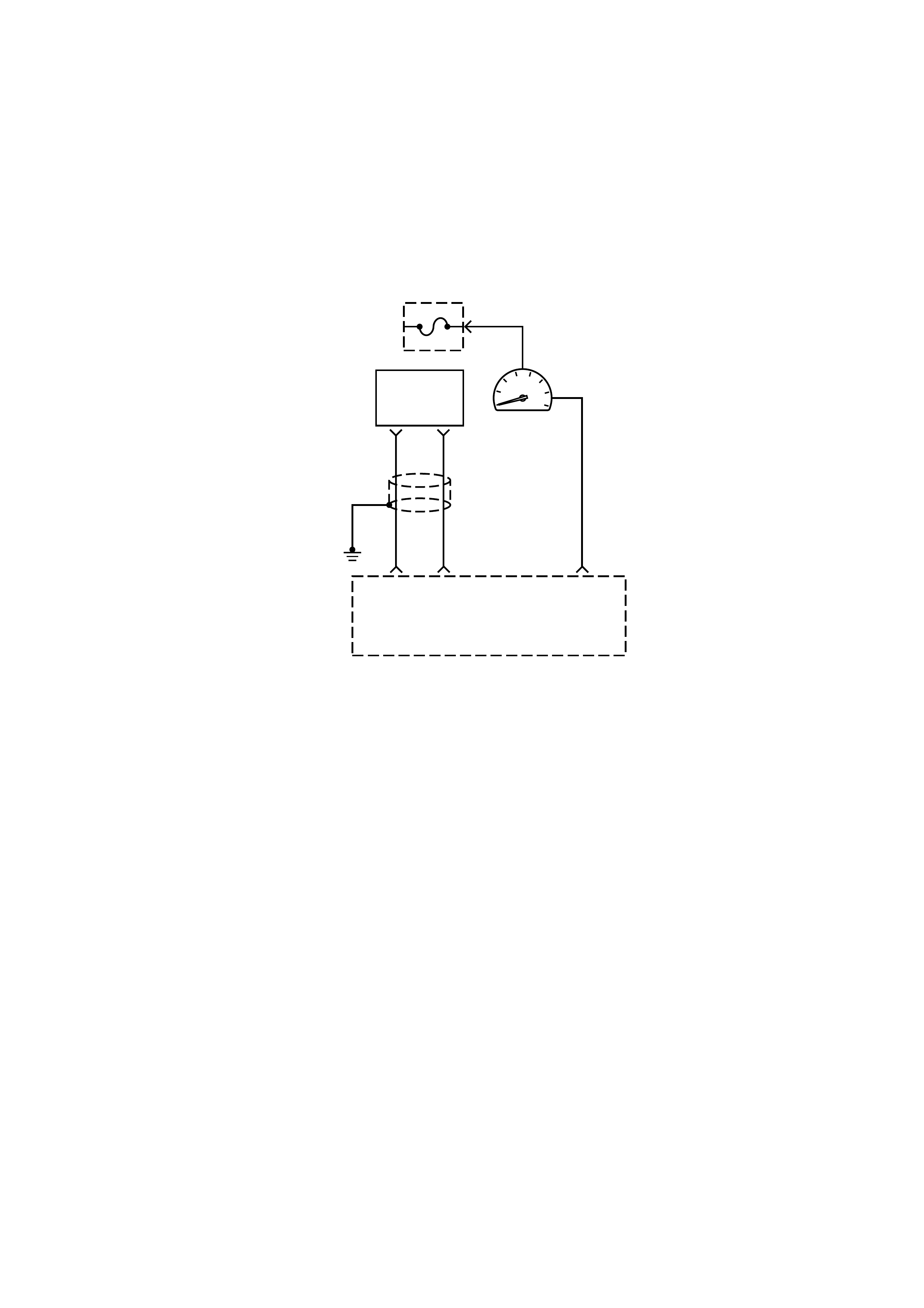
DIAG NOSTI C TROUBLE CODE (DTC) (FLASH DTC = 91)
TACHO OUT LOW ERROR
0.5
R
0.5
B/R
0.5
G
Engine
Control
Module
(ECM)
Crank
Angle
Sensor
F1
E5 B5
Tacho
Meter
Meter
Fuse
15A
21
CIRCUIT DESCRIPTION
Based on the information from the Crank Position
Sensor (CKP), X58 reference signal is generated at
each rotation of the crankshaft.
Engine Control Module (ECM) converts X58 reference
signal into rectangle wave and delivers it as output
signal to drive the pulse motor of the crankshaft.
When the wave length of the output signal is long, the
tacho meter indicates the engine speed is low, and
vise versa.
This malfunction detects a low impedance short to
ground or open contact on the Tacho output, the
Diagnostic Trouble Code 91 will be set.
CONDITIO NS FOR SETTING THE DTC
•Driver f eedback infor m ation shows a low state at its
operation even when commanded low.
ACTIO N TAKEN WHEN THE DTC SETS
•The ECM will turn ON the Malfunction Indicator
Lamp
CONDITIO NS FOR CLEARI NG THE DTC
Once the ECM determines that a fault(s) has been
rectified then the CEL will switch OFF, although the
fault code will remain in the ECM memory.
Any fault codes will remain in ECM memory until -
1. They are cleared by disconnecting the Battery for
more than 30 seconds.
2. A service tool such as Tech 2 is used to clear them.
3. Ten consecutive starts without logging a fault.
DIAGNOSTIC AIDS
•Poor connections or a damaged harness - Inspect
the harness connections for: backed out terminals,
imprope, mating or damaged terminals. Also check
for open circuit, short to ground, and short to
voltage.
•This malfunction detects a low impedance short to
ground or open contact on the ECM out put circuit.

DTC (FLASH DTC = 91) TACHO OUT LOW ERROR
STEP ACTION VALUE(
S) YES NO
1Was the "On-Board Diagnostic (OBD) System Check"
performed? -Go to Step 2
Go to OBD
System Check
2
1. Ignition OFF.
2. Check for a faulty connection or damaged terminals at the
ECM connector.
Was a problem found?
-
Verify repair Go to Step 3
3Check for a faulty connection or damaged terminals at the ECM
connector.
Was a problem found? -
Verify repair Go to Step 4
4
1. Check for an open or short to ground in the circuit between
the meter cluster connector and the ECM connector.
If a problem is found, repair as necessary. -
Verify repair Go to Step 5
51. Check for an open circuit between the meter cluster
connector and the ground.
If a problem is found, repair as necessary. -
Verify repair Go to Step 6
61. Check for an open circuit between the meter cluster and
battery feed.
If a problem is found, repair as necessary. -
Verify repair Go to Step 7
71. Disconnect the meter cluster Panel.
2. Check the tacho meter circuit for an open.
Was a problem found? -
Go to Step 5 Go to Step 9
8
1. Disconnect the ECM and CKP sensor.
2. Check for an open in the 58X reference circuit between the
connector and the ECM harness connector.
3. If a problem is found, repair as necessary.
Was a problem found?
-
Verify repair Go to Step 9
9
1. Reconnect the ECM and CKP sensor.
2. Connect a Digital Voltmeter (DVM) to measure voltage on
the 58X reference circuit at the ECM connector.
3. Observe the voltage while cranking the engine.
Is the voltage near the specified value?
2.5V
Go to Step 12 Go to Step 10
10 Check the connections at the CKP sensor and replace the
terminals if necessary.
Did any terminals require replacement? -
Verify repair Go to Step 11
11 Replace the CKP sensor.
Is the action complete? -Verify repair -
12 Check connections at the ECM and replace the terminals if
necessary.
Did any terminals require replacement? -
Verify repair Go to Step 13
13 Replace the EPROM or ECM.
Is the action complete? Note) Refer to 6E1-243. -Verify repair -
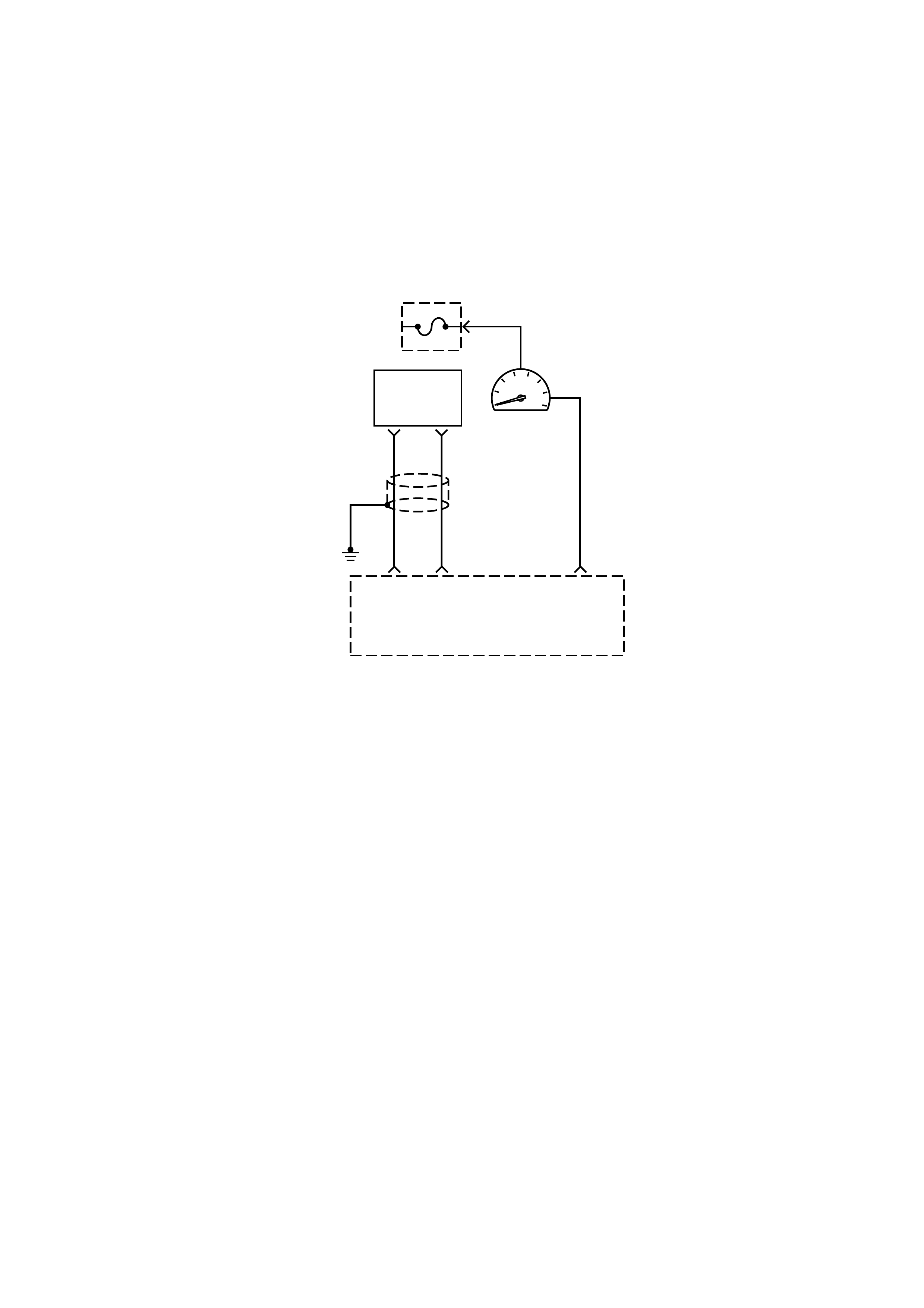
DIAG NOSTI C TROUBLE CODE (DTC) (FLASH DTC =92)
TACHO OUT HIGH ERROR
0.5
R
0.5
B/R
0.5
G
Engine
Control
Module
(ECM)
Crank
Angle
Sensor
F1
E5 B5
Tacho
Meter
Meter
Fuse
15A
21
CIRCUIT DESCRIPTION
Based on the information from the Crank Position
Sensor (CKP), X58 reference signal is generated at
each rotation of the crankshaft.
Engine Control Module (ECM) converts X58 reference
signal into rectangler wave and delivers it as output
signal to drive the pulse motor of the crankshaft.
When the wave length of the output signal is long, the
tacho meter indicates the engine speed is low, and
vise versa.
This malfunction detects a low impedance short to
battery or on the Tacho output, then Diagnostic
Trouble Code 92 will be set.
CONDITIO NS FOR SETTING THE DTC
•Driver f eedback infor m ation shows a low state at its
operation even when commanded low.
ACTIO N TAKEN WHEN THE DTC SETS
•The ECM will turn ON the Malfunction Indicator
Lamp
CONDITIO NS FOR CLEARI NG THE DTC
Once the ECM determines that a fault(s) has been
rectified then the CEL will switch OFF, although the
fault code will remain in the ECM memory.
Any fault codes will remain in ECM memory until -
1. They are cleared by disconnecting the Battery for
more than 30 seconds.
2. A service tool such as Tech 2 is used to clear them.
3. Ten consecutive starts without logging a fault.
DIAGNOSTIC AIDS
•Poor connections or a damaged harness - Inspect
the harness connections for: backed out terminals,
imprope, mating or damaged terminals. Also check
for open circuit, and short to battery.

DTC (FLASH DTC = 92) TACHO OUT HIGH ERROR
STEP ACTION VALUE(S) YES NO
1Was the "On-Board Diagnostic (OBD) System Check"
performed? -
Go to Step 2
Go to OBD
System Check
2
1. Ignition OFF.
2. Check for a faulty connection or damaged terminals at the
tacho meter connector.
Was a problem found?
-
Verify repair Go to Step 3
3Check for a faulty connection or damaged terminals at the ECM
connector.
Was a problem found? -
Verify repair Go to Step 4
4
Check for a short circuit between the meter cluster connector
and the ECM.
If a problem is found, repair the wire harness.
Is there still a problem?
-
Verify repair Go to Step 5
51. Disconnect the ECM.
2. Check the ignition control circuit for a short to voltage.
Was a problem found? -
Verify repair Go to Step 6
6Replace the meter cluster.
Verify repair.
Is there still a problem? -
Go to Step 8
Refer to CKP
Sensor Signal
Incorrect
7
1. Disconnect the ECM and CKP sensor.
2. Check for a short to ground in the 58X reference circuit
between the CKP sensor connector and the ECM harness
connector.
3. If a problem is found, repair as necessary.
Was a problem found?
-
Verify repair Go to Step 8
8
1. Reconnect the ECM and CKP sensor.
2. Connect a Digital Voltmeter (DVM) to measure voltage on
the 58X reference circuit at the ECM connector.
3. Observe the voltage while cranking the engine.
Is the voltage near the specified value?
2.5V
Go to Step 11 Go to Step 9
9Check the connections at the CKP sensor and replace the
terminals if necessary.
Did any terminals require replacement? -
Verify repair Go to Step 10
10 Replace the CKP sensor.
Is the action complete? -Verify repair -
11 Check connections at the ECM and replace the terminals if
necessary.
Did any terminals require replacement? -
Verify repair Go to Step 12
12 Replace the EPROM or ECM.
Is the action complete? Note) Refer to 6E1-243. -Verify repair -
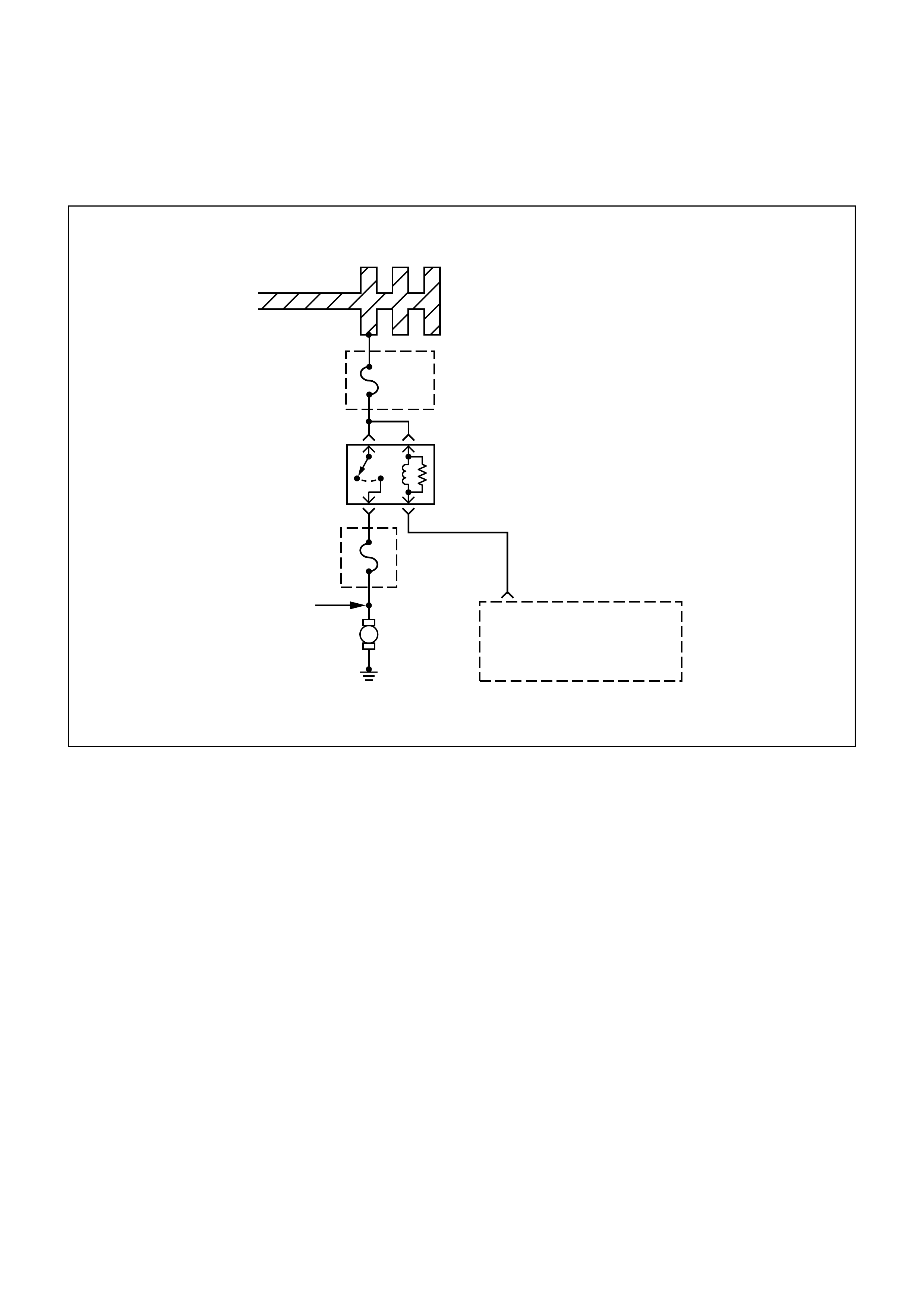
DIAG NOSTI C TROUBLE CODE (DTC) (FLASH DTC = 29)
FUEL PUMP RELAY SHORTED TO GROUND
Fuel
Pump
Fuse
20A
Relay
Fuel
Pump
A13
Fuel
Injectors
Fuel
Pump M
0.85W
Battery Joint Cable
2B
0.5
G/W
Engine
Control
Module
(ECM)
ECM
Fuse
15A
CIRCUIT DESCRIPTION
When the ignition switch is first turned ON, the engine
control module (ECM) energizes the fuel pump relay
which applies power to the in-tank fuel pump. The fuel
pump relay will remain ON as long as the engine is
running or cranking and the ECM is receiving 58X
crankshaft position pulses. If no 58X crankshaft
position pulses are present, the ECM de-energizes the
fuel pump relay within 2 seconds after the ignition is
turned ON or the engine is stopped.
The fuel pump delivers fuel to the fuel rail and
injectors, then to the fuel pressure regulator. The fuel
pressure regulator controls fuel pressure by allowing
excess fuel to be returned to the fuel tank. With the
engine stopped and ignition ON, the fuel pump can be
turned ON by using a command by the scan tool.
This code detects a fuel pump relay short to ground or
disconnected.
CONDITIO NS FOR SETTING THE DTC
•ECM has commanded Fuel Pump relay to be de-
energized.
•Feedback information shows relay is still energized
or, an open contact is present.
ACTIO N TAKEN WHEN THE DTC SETS
•The ECM will turn ON the Malfunction Indicator
Lamp.
CONDITIO NS FOR CLEARI NG THE DTC
Once the ECM determines that a fault(s) has been
rectified then the CEL will switch OFF, although the
fault code will remain in the ECM memory.
Any fault codes will remain in ECM memory until -
1. They are cleared by disconnecting the Battery for
more than 30 seconds.
2. A service tool such as Tech 2 is used to clear them.
3. Ten consecutive starts without logging a fault.

DIAGNOSTIC AIDS
An intermittent may be caused by a poor connection,
rubbed-through wire insulation, or a wire broken inside
the insulation. Check for the following items:
• Poor connection or damaged harness - Inspect the
ECM harness and connectors for improper mating,
broken locks, improperly formed or damaged
terminals, poor terminal-to-wire connection, and
damaged harness.
• This malfunction detects a fuel pump relay short to
ground or disconnection.
TEST DESCRIPTION
Number(s) below refer to the step number(s) on the
Diagnostic Chart.
2. If the fuel pump is operating but incorrect pressure
is noted, the fuel pump wiring is OK and the “Fuel
System Pressure Test” chart should be used for
diagnosis.
CAUTION: To reduce the risk of fire and
personal injury:
• It is necessary to relieve fuel system
pressure before connecting a fuel pressure
gauge. Refer to Fuel Pressure Relief
Procedure, below.
• A small amount of fuel may be released
when disconnecting the fuel lines. Cover
fuel line fittings with a shop towel before
disconnecting, to catch any fuel that may
leak out. Place the towel in an approved
container when the disconnect is
completed.
FUEL PRESSURE RELIEF PROCEDURE
1. Remove the fuel cap.
2. Remove the fuel pump relay from the underhood
relay center.
3. Start the engine and alow it to stall.
4. Crank the engine for an additional 3 seconds.
FUEL PRESSURE GAUGE INSTALLATION
1. Remove the shoulder fitting cap.
2. Install fuel pressure gauge 5-8840-0378-0 to the
fuel feed line located in front of and above the right
side valve cover.
3. Reinstall the fuel pump relay.
DTC (FLASH DTC = 29) FUEL PUMP RELAY SHORTED TO GROUND
STEP ACTION VALUE(S) YES NO
1Was the “On-Board Diagnostic (OBD) System
Check” performed? -
Go to Step 2
Go to OBD
System Check
2
1. Read the “Caution” above.
2. Relieve the fuel system pressure and install the fuel pump
pressure gauge to the test fitting.
3. Use a scan tool to command the fuel pump ON.
Is there an immediate pressure build-up which indicates the
pump is running?
-
Go to Step 3 Go to Step 4
3
1. Verify that the pump is not running by removing the fuel filler
cap and listening.
2. Check the fuel pump relay connector is loosely fitting or
disconnected.
Repair it necessary.
3. Command the pump ON with the scan tool.
Did the pump turn OFF after 2 seconds?
-
Test
completed Go to Step 4

STEP ACTION VALUE(S) YES NO
4
1. Ignition OFF.
2. Remove the fuel pump relay.
3. Connect a test light between the two wires that connect to
the fuel pump relay pull-in coil.
4. Ignition ON.
Did the test light illuminate for 2 seconds and then turn off?
-
Go to Step 9 Go to Step 5
5
1. With a test light connected to battery (−), probe the fuel
pump relay connector at the wire which runs form the relay
pull-in coil to the ECM.
2. Ignition ON.
Did the test light illuminate for 2 seconds and then turn off?
-
Go to Step 6 Go to Step 7
6Check for short to ground between the ECM and the fuel pump
relay.
Was a problem found?
-
Verify repair Go to Step 7
7
1. Check the fuel pump relay circuit for a poor terminal
connection at the ECM.
2. If a problem is found, replace terminal as necessary.
Was a problem found?
-
Verify repair Go to Step 8
8Replace the EPROM or ECM.
Is the action complete? Note) Refer to 6E1-243. -Verify repair -
9
1. Honk the horn to verify that the horn relay is functioning.
2. Substitute the horn relay for the fuel pump relay.
3. Leave the test light connected as in step 12.
4. Command the fuel pump ON with the scan tool.
Did the test light illuminate for 2 seconds when the fuel pump
was commanded ON?
-
Go to Step 13 Go to Step 10
10
1. Re-connect the horn relay in its proper location.
2. Check for a short circuit, blown fuse or open circuit between
the relay and the fuel tank.
Is the action complete?
-
Verify repair
-
11
1. With the fuel pump electrical connector at the fuel tank
disconnected, connect a test light between the feed wire and
the ground wire (harness side).
2. Command the fuel pump ON with a scan tool.
Did the test light illuminate for 2 seconds?
-
Go to Step 14 Go to Step 12
12 Repair the open circuit in the fuel pump ground wire.
Is the action complete? -Verify repair -
13 1. Re-connect the horn relay in its proper location.
2. Replace the fuel pump relay.
Is the action complete? -
Verify repair
-
14 Replace the fuel pump.
Is the action complete? -Verify repair -

DIAG NOSTI C TROUBLE CODE (DTC) (FLASH DTC = 32)
FUEL PUMP RELAY SHORTED TO BATTERY
Fuel
Pump
Fuse
20A
Relay
Fuel
Pump
A13
Fuel
Injectors
Fuel
Pump M
0.85W
Battery Joint Cable
2B
0.5
G/W
Engine
Control
Module
(ECM)
ECM
Fuse
15A
CIRCUIT DESCRIPTION
When the ignition switch is first turned ON, the engine
control module (ECM) energizes the fuel pump relay
which applies power to the in-tank fuel pump. The fuel
pump relay will remain ON as long as the engine is
running or cranking and the ECM is receiving 58X
crankshaft position pulses. If no 58X crankshaft
position pulses are present, the ECM de-energizes the
fuel pump relay within 2 seconds after the ignition is
turned ON or the engine is stopped.
The fuel pump delivers fuel to the fuel rail and
injectors, then to the fuel pressure regulator. The fuel
pressure regulator controls fuel pressure by allowing
excess fuel to be returned to the fuel tank. With the
engine stopped and ignition ON, the fuel pump can be
turned ON by using a command by the scan tool.
This code detects a fuel pump relay short to battery.
CONDITIO NS FOR SETTING THE DTC
•ECM has commanded Fuel Pump relay to be
energized.
•Feedback information shows relay is still de-
energized.
ACTIO N TAKEN WHEN THE DTC SETS
•The ECM will turn ON the Malfunction Indicator
Lamp.
CONDITIO NS FOR CLEARI NG THE DTC
Once the ECM determines that a fault(s) has been
rectified then the CEL will switch OFF, although the
fault code will remain in the ECM memory.
Any fault codes will remain in ECM memory until -
1. They are cleared by disconnecting the Battery for
more than 30 seconds.
2. A service tool such as Tech 2 is used to clear them.
3. Ten consecutive starts without logging a fault.

DIAGNOSTIC AIDS
An intermittent may be caused by a poor connection,
rubbed-through wire insulation, or a wire broken inside
the insulation. Check for the following items:
• Poor connection or damaged harness - Inspect the
ECM harness and connectors for improper mating,
broken locks, improperly formed or damaged
terminals, poor terminal-to-wire connection, and
damaged harness.
• Fuel pump relay short to battery.
TEST DESCRIPTION
Number(s) below refer to the step number(s) on the
Diagnostic Chart.
2. If the fuel pump is operating but incorrect pressure
is noted, the fuel pump wiring is OK and the “Fuel
System Pressure Test” chart should be used for
diagnosis.
CAUTION: To reduce the risk of fire and
personal injury:
• It is necessary to relieve fuel system
pressure before connecting a fuel pressure
gauge. Refer to Fuel Pressure Relief
Procedure, below.
• A small amount of fuel may be released
when disconnecting the fuel lines. Cover
fuel line fittings with a shop towel before
disconnecting, to catch any fuel that may
leak out. Place the towel in an approved
container when the disconnect is
completed.
FUEL PRESSURE RELIEF PROCEDURE
1. Remove the fuel cap.
2. Remove the fuel pump relay from the underhood
relay center.
3. Start the engine and alow it to stall.
4. Crank the engine for an additional 3 seconds.
FUEL PRESSURE GAUGE INSTALLATION
1. Remove the shoulder fitting cap.
2. Install fuel pressure gauge 5-8840-0378-0 to the
fuel feed line located in front of and above the right
side valve cover.
3. Reinstall the fuel pump relay.
DTC (FLASH DTC = 32) FUEL PUMP RELAY SHORTED TO BATTERY
STEP ACTION VALUE(S) YES NO
1Was the “On-Board Diagnostic (OBD) System
Check” performed? -
Go to Step 2
Go to OBD
System Check
2
1. Read the “Caution” above.
2. Relieve the fuel system pressure and install the fuel pump
pressure gauge to the test fitting.
3. Use a scan tool to command the fuel pump ON.
Is there an immediate pressure build-up which indicates the
pump is running?
-
Go to Step 3 Go to Step 4
3
1. Verify that the pump is not running by removing the fuel filler
cap and listening.
2. Command the pump ON with the scan tool.
Did the pump turn OFF after 2 seconds?
-Test
completed Go to Step 12
4
1. Ignition OFF.
2. Remove the fuel pump relay.
3. Using a test light connected to ground, probe the battery
feed to the relay.
Did the light illuminate?
-
Go to Step 6 Go to Step 5
5Repair short or open battery feed to fuel pump relay.
Is the action complete? -Verify repair -

STEP ACTION VALUE(S) YES NO
6
1. Connect a test light between the two wires that connect to
the fuel pump relay pull-in coil.
2. Ignition ON.
Did the test light illuminate for 2 seconds and then turn off? -
Go to Step 12 Go to Step 7
7
1. With a test light connected to battery (−), probe the fuel
pump relay connector at the wire which runs form the relay
pull-in coil to the ECM.
2. Ignition ON.
Did the test light illuminate for 2 seconds and then turn off?
-
Go to Step 8 Go to Step 9
8Locate and repair open in the fuel pump relay ground circuit. Is
the action complete? -Verify repair -
9
1. Check for short or open between the battery and the fuel
pump relay.
2. Check the fuel pump relay circuit for a poor terminal
connection at the ECM.
3. If a problem is found, replace terminal as necessary.
Was a problem found?
-
Verify repair Go to Step 10
10 Replace the EPROM or ECM.
Is the action complete? Note) Refer to 6E1-243. -Verify repair -
11
1. Reconnect the fuel pump relay.
2. Disconnect the fuel pump electrical connector at the fuel
tank
3. Using a test light connected to ground, probe the fuel pump
feed wire (harness side).
4. Command the fuel pump ON with a scan tool.
Did the light illuminate for 2 seconds?
-
Go to Step 14 Go to Step 12
12
1. Honk the horn to verify that the horn relay is functioning.
2. Substitute the horn relay for the fuel pump relay.
3. Leave the test light connected as in step 11.
4. Command the fuel pump ON with the scan tool.
Did the test light illuminate for 2 seconds when the fuel pump
was commanded ON?
-
Go to Step 16 Go to Step 13

STEP ACTION VALUE(S) YES NO
13
1. Re-connect the horn relay in its proper location.
2. Check for a short circuit, blown fuse or open circuit between
the relay and the fuel tank.
Is the action complete?
-
Verify repair
-
14
1. With the fuel pump electrical connector at the fuel tank
disconnected, connect a test light between the feed wire and
the ground wire (harness side).
2. Command the fuel pump ON with a scan tool.
Did the test light illuminate for 2 seconds?
-
Go to Step 17 Go to Step 15
15 Repair the open circuit in the fuel pump ground wire.
Is the action complete? -Verify repair -
16 1. Re-connect the horn relay in its proper location.
2. Replace the fuel pump relay.
Is the action complete? -
Verify repair
-
17 Replace the fuel pump.
Is the action complete? -Verify repair -

DIAG NOSTI C TROUBLE CODE (DTC) (FLASH DTC=83)
RECEIVED RESPONSE WAS NOT CORRECT
KEY
TRANSPONDER
ENCRYPT
ENCRYPT
TECH-2
CARTRIDGE
ENCRYPT
BATTERY
IGN''ON'' IGN''ON'' IGN''ON''
GND BATTERY
INJECTION:STOP
IGNITION:STOP
GND
CPU ECM
ANTENNA COIL
RELAY
(STARTER CUT)
VEHICLE
SPEED SENSOR
IMMOBILIZER
CONTROL UNIT
VSS IN
OTHER SYSTEM DIAGNOSIS
VEHICLE SPEED SENSOR LINE
VSS OUT
CHECK
ENGINE
LAMP
(MIL) ENGINE
MANAGEMENT
SYSTEM
DIAGNOSIS
DLC
CIRCUIT DESCRIPTION
An encrypted signal is transmitted from the
Immobiliser Control Unit to the ECM when the ignition
is turned ON.
CONDITION FOR SETTING THE DTC
A DTC 83 will set when:
• An incorrect signal is transmitted from the ICU to
the ECM within 0.5 secs of turning the ignition ON.
ACTIO N TAKEN WHEN THE DTC SETS
• Rapid (4Hz) flashing of the MIL ("CHECK
ENGINE" lamp).
• The engine does not start.
CONDITIO N FOR CLEARI NG THE MIL/DTC
•Use clear DTC information with TECH 2 - Refer to
Section 0C TECH 2 Diagnosis
DIAGNOSTIC AIDS
Check for the following conditions:
• Poor connection at ECM and Immobiliser-Inspect
harness connectors for backed out terminals,
improper mating, broken locks, improperly formed
or damaged terminals, and poor terminal to wire
connection.
• Damaged harness-Inspect the wiring harness for
damage, If the harness appears to be OK,
disconnect the ECM and Immobiliser, turn the
ignition "ON" and obs erve a voltm eter c onnected to
the suspect driver circuit at the ECM and
Immobiliser harness connector while moving
connectors and wiring harnesses that relate to the
MIL. A change in voltage will indicate the location
of the fault.

DTC (FLASH DTC=83) RECEIVED RESPONSE WAS NOT CORRECT
STEP ACTION VALUE(S) YES NO
1 Was the "On-Board Diagnostic (OBD) system Check" performed? -Go to Step 2
Go to OBD
system
check
2 Check the ECM and ICU harness and connectors for:
1. Backed out terminals, improper mating, broken locks, improperly
formed or damaged terminals and poor terminal to wire
connection.
2. Damaged harness - inspect the wiring harness for damage.
If a problem is found, repair as necessary.
Was a problem found?
-
Verify repair Go to Step 3
3 Replace the ECM.
IMPORTANT: The replacement ECM must be programmed. Refer to
Section OC-1 - Service programming.
IMPORTANT: Refer to Section 11A - Engine Immobiliser System for
the Immobiliser Programming Procedure
IMPORTANT: Ensure the latest software program is downloaded to the
ECM.
Is the action complete?
-
Verify repair
-
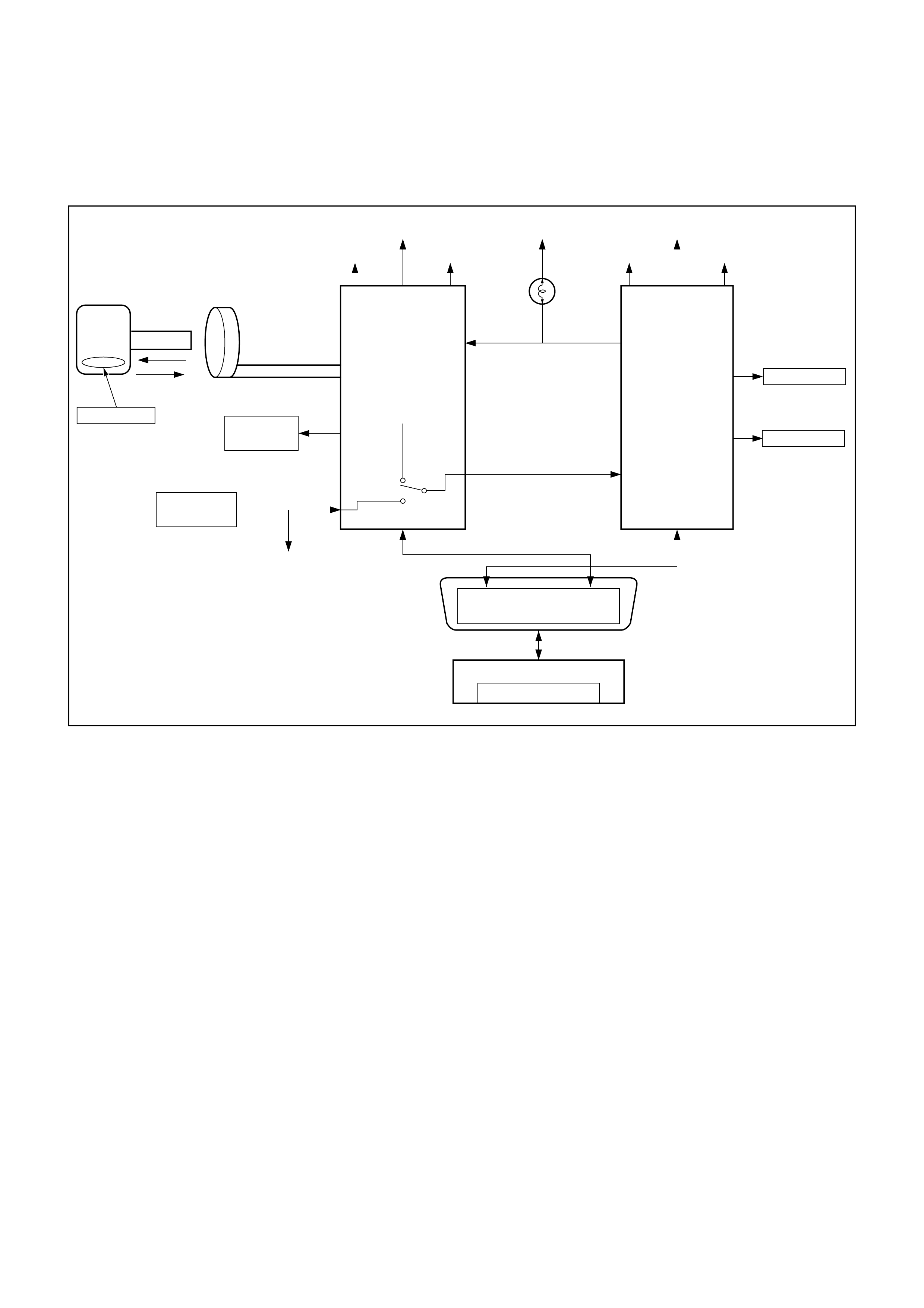
DIAG NOSTI C TROUBLE CODE (DTC) (FLASH DTC=84)
NO RESPONSE FROM IMM OBILISER
KEY
TRANSPONDER
ENCRYPT
ENCRYPT
TECH-2
CARTRIDGE
ENCRYPT
BATTERY
IGN''ON'' IGN''ON'' IGN''ON''
GND BATTERY
INJECTION:STOP
IGNITION:STOP
GND
CPU ECM
ANTENNA COIL
RELAY
(STARTER CUT)
VEHICLE
SPEED SENSOR
IMMOBILIZER
CONTROL UNIT
VSS IN
OTHER SYSTEM DIAGNOSIS
VEHICLE SPEED SENSOR LINE
VSS OUT
CHECK
ENGINE
LAMP
(MIL) ENGINE
MANAGEMENT
SYSTEM
DIAGNOSIS
DLC
CIRCUIT DESCRIPTION
An encrypted signal is transmitted from the
Immobiliser Control Unit to the ECM when the ignition
is turned ON.
CONDITION FOR SETTING THE DTC
A DTC 84 will set when:
• No signal is transmitted from the ICU to the ECM
within 0.5 secs of turning the ignition ON.
ACTIO N TAKEN WHEN THE DTC SETS
• Rapid (4Hz) flashing of the MIL ("CHECK
ENGINE" lamp).
• The engine does not start.
ACTIO N TAKEN WHEN THE DTC SETS
• Rapid (4Hz) flashing of the MIL ("CHECK
ENGINE" lamp).
• The engine does not start.
CONDITIO N FOR CLEARI NG THE MIL/DTC
•Use clear DTC information with TECH 2 - Refer to
Section 0C TECH 2 Diagnosis
DIAGNOSTIC AIDS
Check for the following conditions:
• Poor connection at ECM and Immobiliser-Inspect
harness connectors for backed out terminals,
improper mating, broken locks, improperly formed
or damaged terminals, and poor terminal to wire
connection.
• Damaged harness-Inspect the wiring harness for
damage, If the harness appears to be OK,
disconnect the ECM and Immobiliser, turn the
ignition "ON" and obs erve a voltm eter c onnected to
the suspect driver circuit at the ECM and
Immobiliser harness connector while moving
connectors and wiring harnesses that relate to the
MIL. A change in voltage will indicate the location
of the fault.

DTC (FLASH DTC=84) NO RESPONSE FROM IMMOBILISER
STEP ACTION VALUE(S) YES NO
1 Was the "On-Board Diagnostic (OBD) system Check" performed?
-Go to Step 2
Go to OBD
system
check
2 Using the Tech2 system selection menu, select Body function.
Does the Tec h2 indic ate DTC B****?
-
Refer to
Section 11A -
Engine
Immobiliser
System
Go to Step 3
3 Does the Tech2 indicate DTC 84? -Go to Step 4
Refer to
Diagnostic
Aids
4 Check the ECM and ICU harness and connectors for:
1. Backed out terminals, improper mating, broken locks, improperly
formed or damaged terminals and poor terminal to wire
connection.
2. Damaged harness - inspect the wiring harness for damage.
If a problem is found, repair as necessary.
Was a problem found?
-
Verify repair Go to Step 5
5 1. Disconnect the Vehicle Speed Sensor line VSS OUT harness.
2. Check for an open circuit or short to ground in the wire between
the ECM pin 8 and ICU pin J1-E7 by DMM.
If a problem found, repair as necessary.
Was a problem found? - Verify repair Go to Step 6
6 Replace the ECM.
IMPORTANT: The replacement ECM must be programmed. Refer to
Section OC-1 - Service programming.
IMPORTANT: Refer to Section 11A - Engine Immobiliser System for
the Immobiliser Programming Procedure
IMPORTANT: Ensure the latest software program is downloaded to the
ECM.
Is the action complete?
-
Verify repair
-
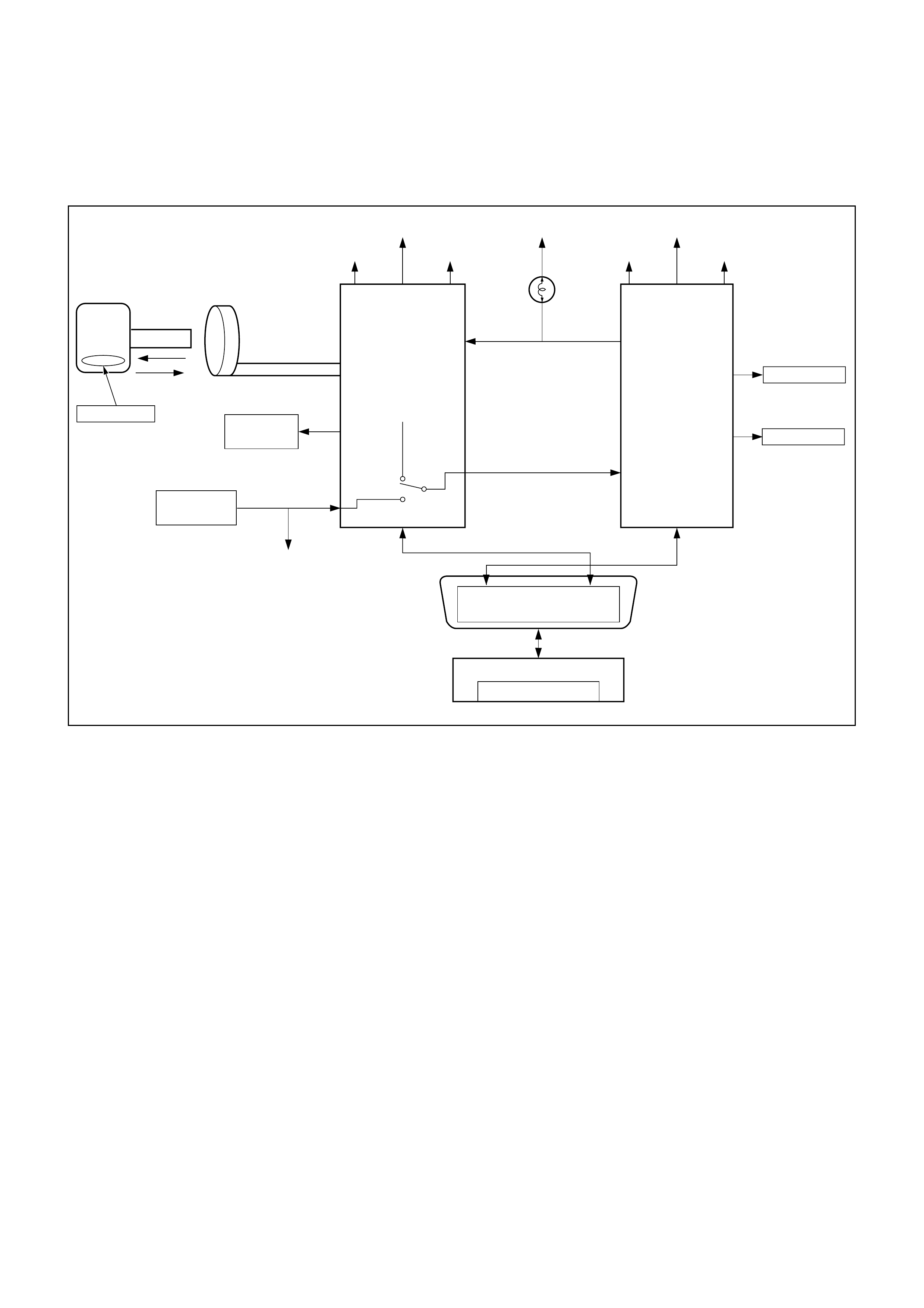
DIAG NOSTI C TROUBLE CODE (DTC) (FLASH DTC=85)
SECURITY CODE & SECURITY KEY NOT PROGRAMME D
KEY
TRANSPONDER
ENCRYPT
ENCRYPT
TECH-2
CARTRIDGE
ENCRYPT
BATTERY
IGN''ON'' IGN''ON'' IGN''ON''
GND BATTERY
INJECTION:STOP
IGNITION:STOP
GND
CPU ECM
ANTENNA COIL
RELAY
(STARTER CUT)
VEHICLE
SPEED SENSOR
IMMOBILIZER
CONTROL UNIT
VSS IN
OTHER SYSTEM DIAGNOSIS
VEHICLE SPEED SENSOR LINE
VSS OUT
CHECK
ENGINE
LAMP
(MIL) ENGINE
MANAGEMENT
SYSTEM
DIAGNOSIS
DLC
CIRCUIT DESCRIPTION
The ECM is programmed with security information
during installation.
CONDITION FOR SETTING THE DTC
A DTC 85 will set when:
• The security c ode and the trans ponder k ey are not
programmed into the ECM.
ACTIO N TAKEN WHEN THE DTC SETS
• Rapid (4Hz) flashing of the MIL ("CHECK
ENGINE" lamp).
• The engine does not start.
ACTIO N TAKEN WHEN THE DTC SETS
• Rapid (4Hz) flashing of the MIL ("CHECK
ENGINE" lamp).
• The engine does not start.
CONDITIO N FOR CLEARI NG THE MIL/DTC
•Use clear DTC information with TECH 2 - Refer to
Section 0C TECH 2 Diagnosis
DIAGNOSTIC AIDS
Check for the following conditions:
• Poor connection at ECM and Immobiliser-Inspect
harness connectors for backed out terminals,
improper mating, broken locks, improperly formed
or damaged terminals, and poor terminal to wire
connection.
• Damaged harness-Inspect the wiring harness for
damage, If the harness appears to be OK,
disconnect the ECM and Immobiliser, turn the
ignition "ON" and obs erve a voltm eter c onnected to
the suspect driver circuit at the ECM and
Immobiliser harness connector while moving
connectors and wiring harnesses that relate to the
MIL. A change in voltage will indicate the location
of the fault.

DTC (FLASH DTC=85) SECURITY CODE & SECRET KEY NOT PROGRAMMED
STEP ACTION VALUE(S) YES NO
1 Was the "On-Board Diagnostic (OBD) system Check"
performed? -Go to Step 2
Go to OBD
system
check
2 Using the Tech2 system selection menu, select Body function.
Does the Tec h2 indic ate DTC B****?
-
Refer to
Section 11A -
Engine
Immobiliser
System
Go to Step 3
3 Replace the ECM.
IMPORTANT: The replacement ECM must be programmed.
Refer to Section OC-1 - Service programming.
IMPORTANT: Refer to Section 11A - Engine Immobiliser
System for the Immobiliser Programming Procedure
IMPORTANT: Ensure the latest software program is
downloaded to the ECM.
Is the action complete?
-
Verify repair
-
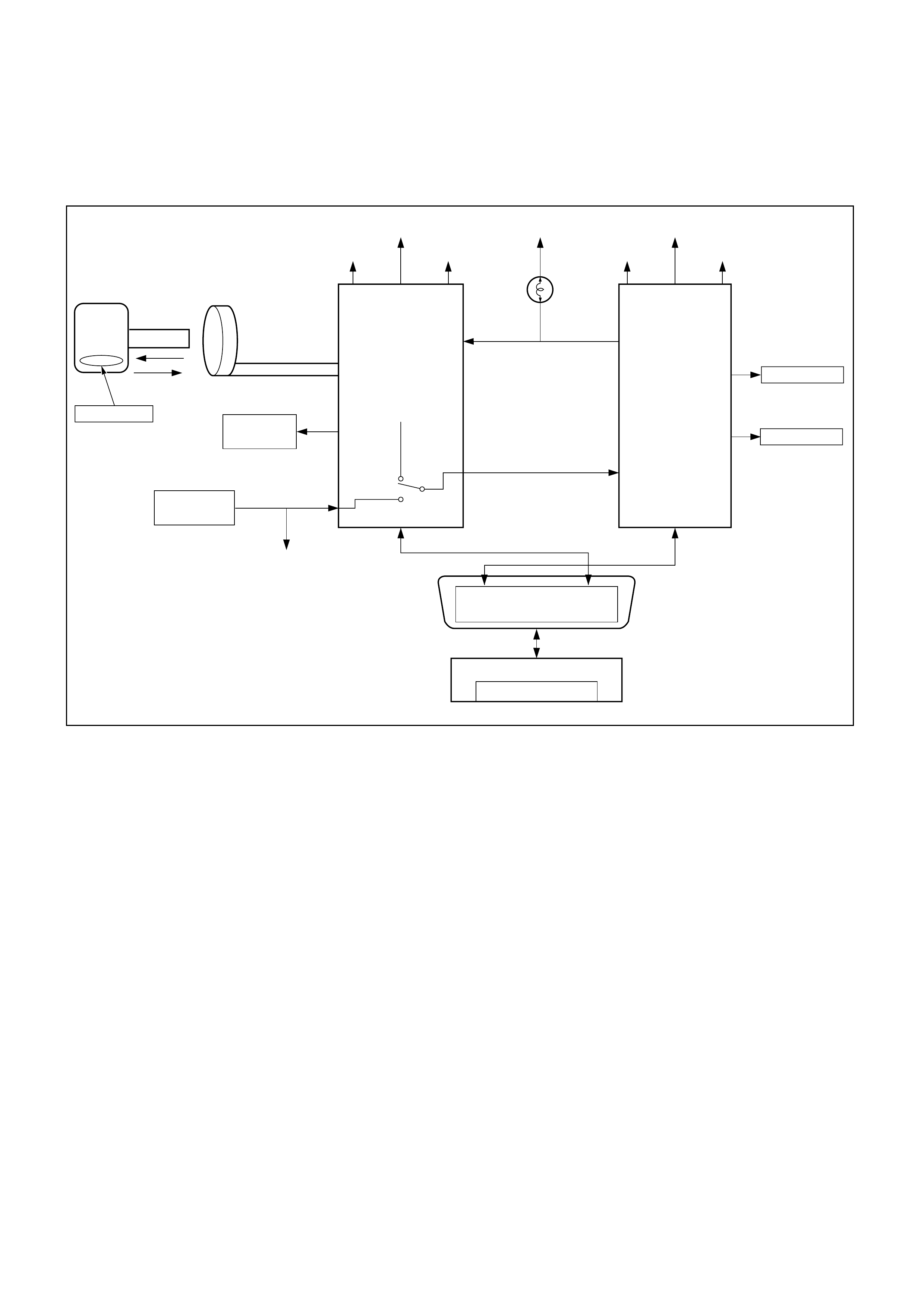
DIAG NOSTI C TROUBLE CODE (DTC) (FLASH DTC=86)
RECEIVED INCORRECT SECURI TY CODE
KEY
TRANSPONDER
ENCRYPT
ENCRYPT
TECH-2
CARTRIDGE
ENCRYPT
BATTERY
IGN''ON'' IGN''ON'' IGN''ON''
GND BATTERY
INJECTION:STOP
IGNITION:STOP
GND
CPU ECM
ANTENNA COIL
RELAY
(STARTER CUT)
VEHICLE
SPEED SENSOR
IMMOBILIZER
CONTROL UNIT
VSS IN
OTHER SYSTEM DIAGNOSIS
VEHICLE SPEED SENSOR LINE
VSS OUT
CHECK
ENGINE
LAMP
(MIL) ENGINE
MANAGEMENT
SYSTEM
DIAGNOSIS
DLC
CIRCUIT DESCRIPTION
The ICU transmits a security code to the ECM when
the ignition is turned ON.
CONDITION FOR SETTING THE DTC
A DTC 86 will set when:
• An incorrect signal is transmitted from the ICU to
the ECM.
ACTIO N TAKEN WHEN THE DTC SETS
• Rapid (4Hz) flashing of the MIL ("CHECK
ENGINE" lamp).
• The engine does not start.
ACTIO N TAKEN WHEN THE DTC SETS
• Rapid (4Hz) flashing of the MIL ("CHECK
ENGINE" lamp).
• The engine does not start.
CONDITIO N FOR CLEARI NG THE MIL/DTC
•Use clear DTC information with TECH 2 - Refer to
Section 0C TECH 2 Diagnosis
DIAGNOSTIC AIDS
Check for the following conditions:
• Poor connection at ECM and Immobiliser-Inspect
harness connectors for backed out terminals,
improper mating, broken locks, improperly formed
or damaged terminals, and poor terminal to wire
connection.
• Damaged harness-Inspect the wiring harness for
damage, If the harness appears to be OK,
disconnect the ECM and Immobiliser, turn the
ignition "ON" and obs erve a voltm eter c onnected to
the suspect driver circuit at the ECM and
Immobiliser harness connector while moving
connectors and wiring harnesses that relate to the
MIL. A change in voltage will indicate the location
of the fault.

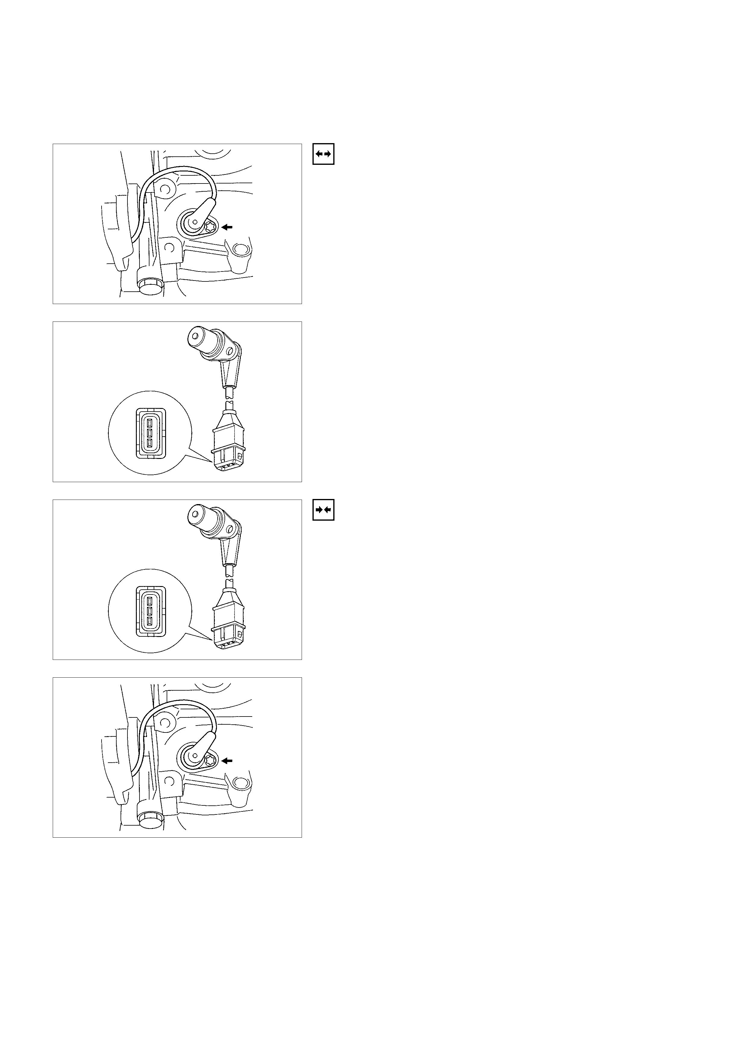
ON-VEHICLE SERVICE PROCEDURE ECM AND SENSORS
CRANKSHAFT POSITION ( CKP) SENSOR
REMOVAL
1. Disconnect the negative battery cable.
2. Remove the drive belt. Refer to
Engine Mechanical Section.
3. Remove the A/C compressor from engine. Refer to
A/C compressor
4. Disconnect electrical connector from the sensor.
5. Remove the retaining bolt and sensor from the engine
block.
Note: Use caution to avoid any hot oil that might drip out.
INSTALLATION
1. Install the crank shaft position sensor to its position.
2. Install and tighten the mounting bolt. Refer to
Engine Mechanical Section.
3. Reinstall the A/C compressor to the engine.
4. Reinstall the accessory drive belt.
5. Connect the negative battery cable.
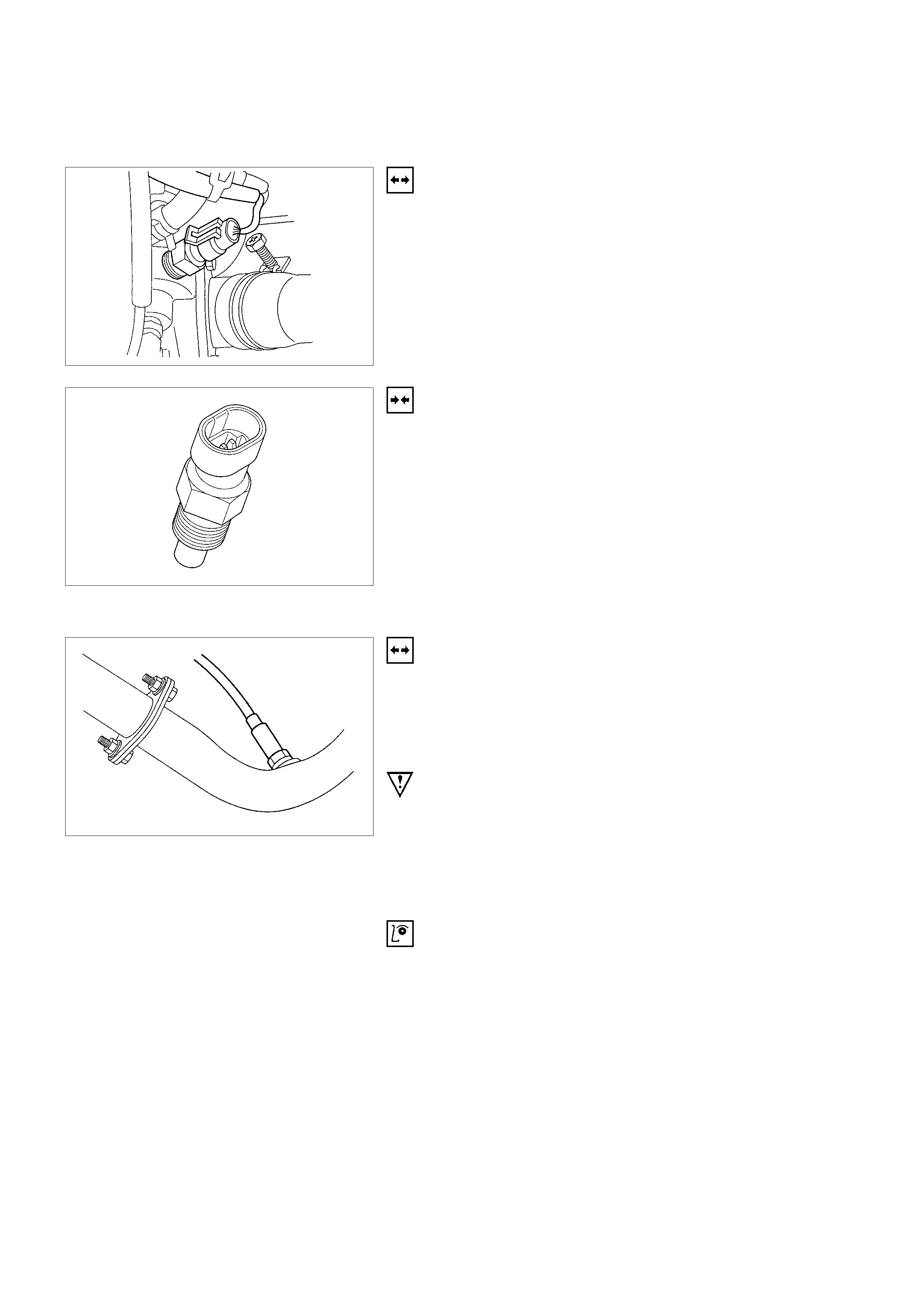
ENGINE COOLANT TEMPERATURE (ECT) SENSOR
REMOVAL
1. Disconnect the negative battery cable.
2. Drain enough engine coolant so that the coolant level will
be below the ECT sensor.
3. Remove electrical connector from the sensor located on
the thermostat housing.
4. Unscrew the sensor from the thermostat housing.
INSTALLATION
1. Install the sensor into the thermostat housing. Do not
over tighten.
2. Connect electrical connector.
3. Add engine coolant to required level. Refer to
Engine Cooling Sys tem Section.
4. Connect the negative battery cable.
HEATED OXYG EN SENSO R (HO2S) (IF APPLI CABLE)
REMOVAL
1. Disconnect the negative battery cable.
2. The sensor is mounted on the exhaust pipe ahead of the
catalytic converter.
3. Disconnect pig tail electrical connector.
IMPORTANT: The pigtail is permanently attached to the
sensor. Be careful not to pull the wires out.
4. Unscrew sensor from the exhaust pipe. Because of the
expansion and contraction of the metal in the exhaust
system over time, this may be difficult if the engine
temperature is below 48 degree C.
INSPECTION
Note: The sensor is identical. Inspect each in the same way.
1. Inspect the pigtail and the electrical connector for grease,
dirt, corrosion and bare wire or worn insulation.
2. Inspect the louvered end of the sensor for grease, dirt,
excessive carbon build up or other contaminants.
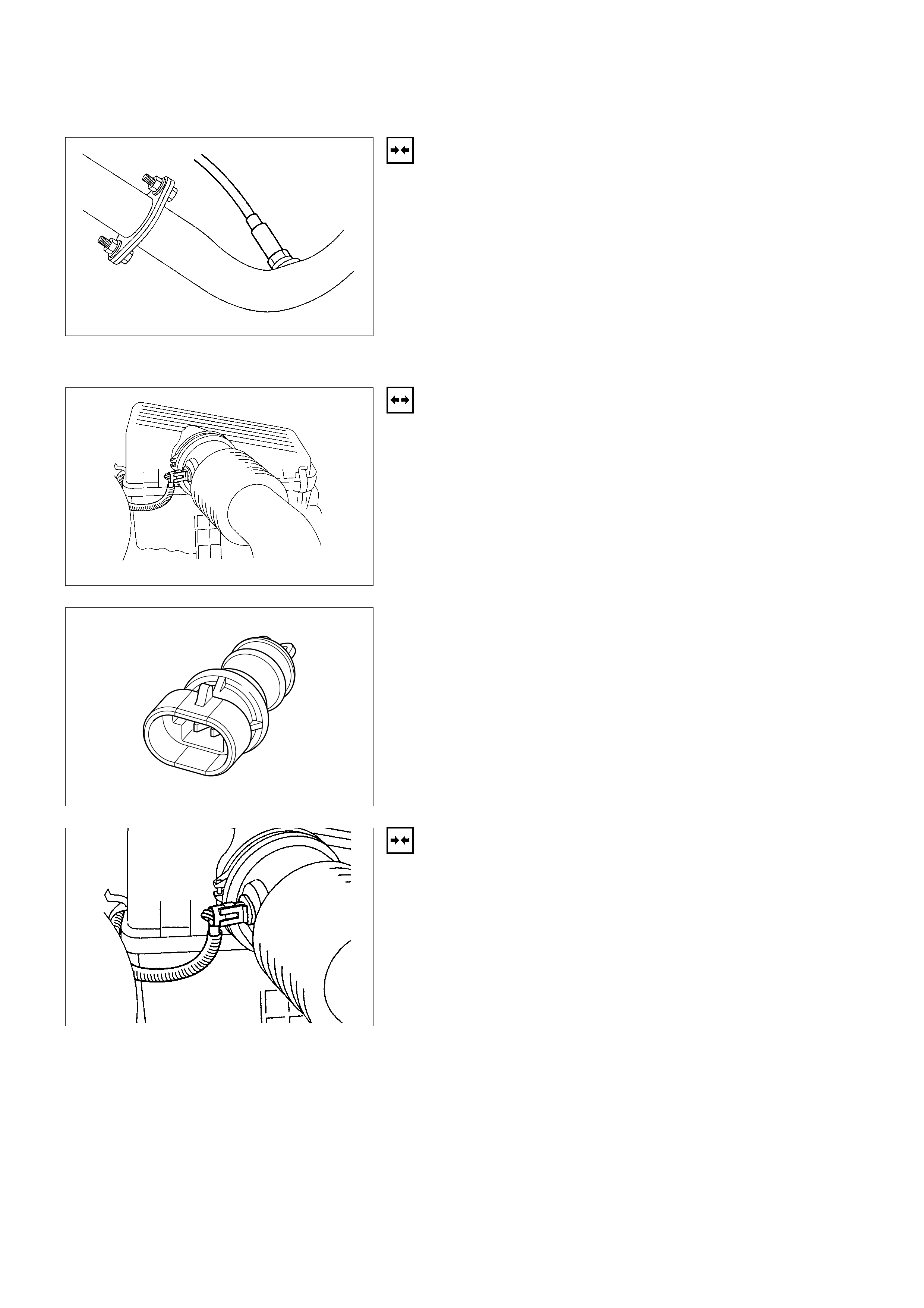
INSTALLATION
Note: If HO2S is reinstalled after removal.
1. Install HO2S on the exhaust pipe.
2. Tighten the sensor to 55 Nm(7.6kgf⋅m).
3. Connect the pigtail to the wiring harness.
4. Connect the negative battery cable.
INTAKE AIR TEMPERATURE (IAT) SENSOR
REMOVAL
1. Disconnect the negative battery cable.
2. The IAT sensor is located in the intake air duct between
the air filter and the throttle body.
3. Disconnect the electrical connector from the sensor.
4. Remove the sensor from intake air duct by using a
rocking motion while pulling the sensor.
INSTALLATION
1. Install the IAT sensor into intake air duct. Make sure the
sensor is pushed all the way into the intake air duct.
2. Connect electrical connector.
3. Connect the negative battery cable.
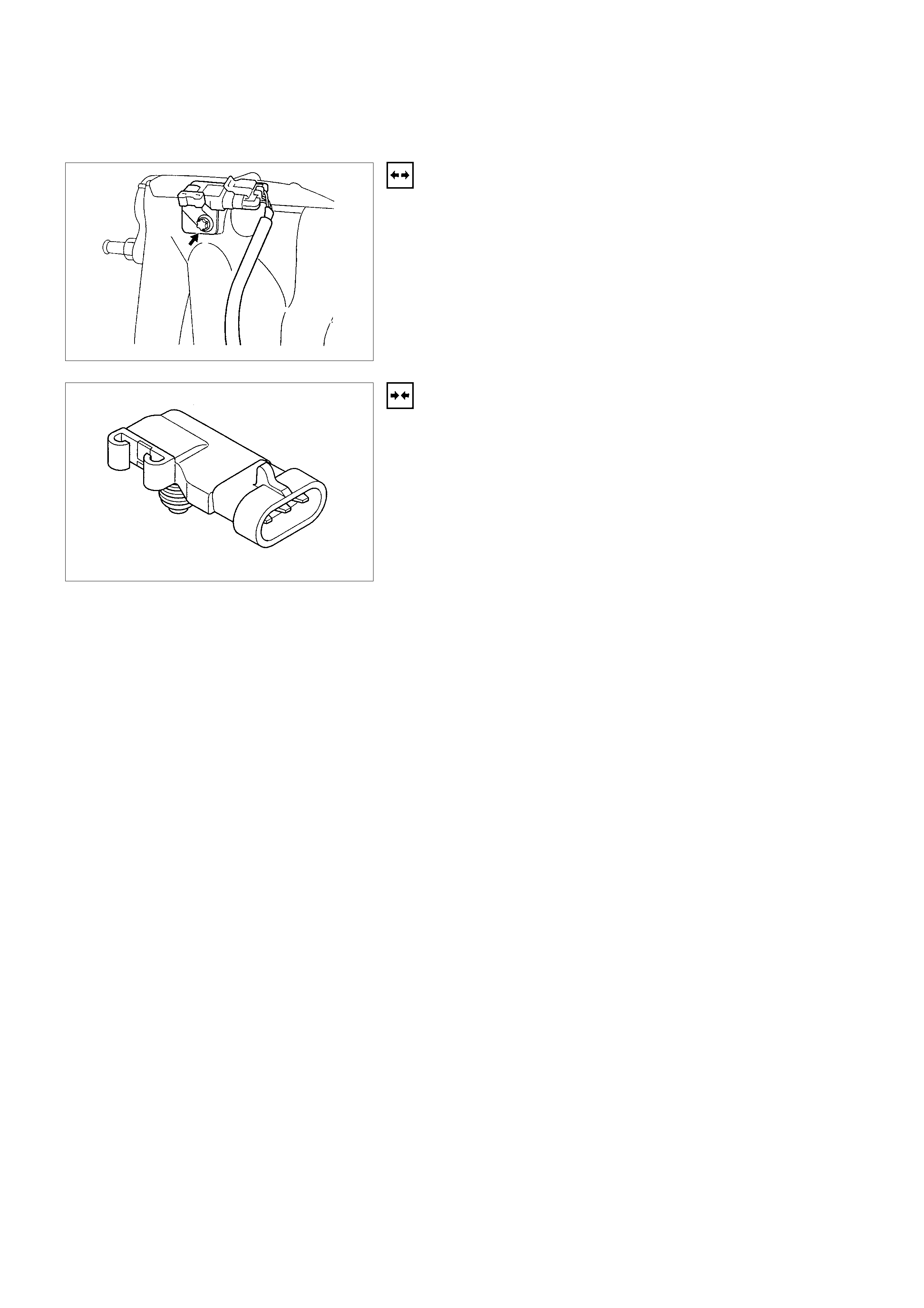
MANIFOLD ABSOLUTE PRESSURE (MAP) SENSO R
REMOVAL
1. Disconnect the negative battery cable.
2. Disconnect the electrical connector from the sensor. (The
MAP sensor is located on the intake manifold behind
throttle body.)
3. Connect electrical connector.
4. Connect the negative battery cable.
INSTALLATION
1. Push MAP sensor into the manifold. Make sure the
sensor is pushed always into its position.
2. Install a mounting bolts and tighten.
3. Remove a mounting bolt securing the sensor to the
manifold.
4. Remove the sensor from the intake manifold using
rocking motion while pulling the sensor.
MALFUNCTION INDICATOR LAMP (M IL)
Refer to Instrument Panel Removal P rocedure.

ENGINE CONTROL MODULE (ECM )
ELECTROSTATIC DISCHARGE (ESD) DAMAGE
Electronic components used in the control system are often
designed to carry very low voltage. Electronic components are
susceptible to damage caused by electrostatic discharge. Less
than 100 volts of static electricity can cause damage to same
electronic components. By comparison, it takes as much as
4000 volts for a person to even feel the zap of a static
discharge. There are several way for a person to become
statically charged. The most common methods of charging are
by friction and by induction. An example of charging by friction
is a person sliding across a car seat. Charging by induction
occurs when a person with well insulated shoes stands near a
highly charged object and momentarily touches ground.
Charge of the same polarity are drained off leaving the person
highly charged with opposite polarity. Static charge can cause
damage, therefore, it is important to use care when handling
and testing electronic components.
Notice: To prevent possible Electrostatic Discharge damage,
follow these guidelines:
•Do not touch the control module connector pins or
soldered components on the control module circuit
board.
•Do not open the replacement part package until the part
is ready to be installed.
•Before removing the parts from the package, ground the
package to a known good ground on the vehicle.
•If the parts been handled while sliding across the seat, or
while sitting from standing position, or walking a distance,
touch a known good ground before installing the parts.
Notice: To prevent internal ECM damage, the ignition must be
OFF position in order to disconnect or reconnect power to the
ECM (for example: battery cable, pig-tail, ECM fuse, jumper
cable, etc.).
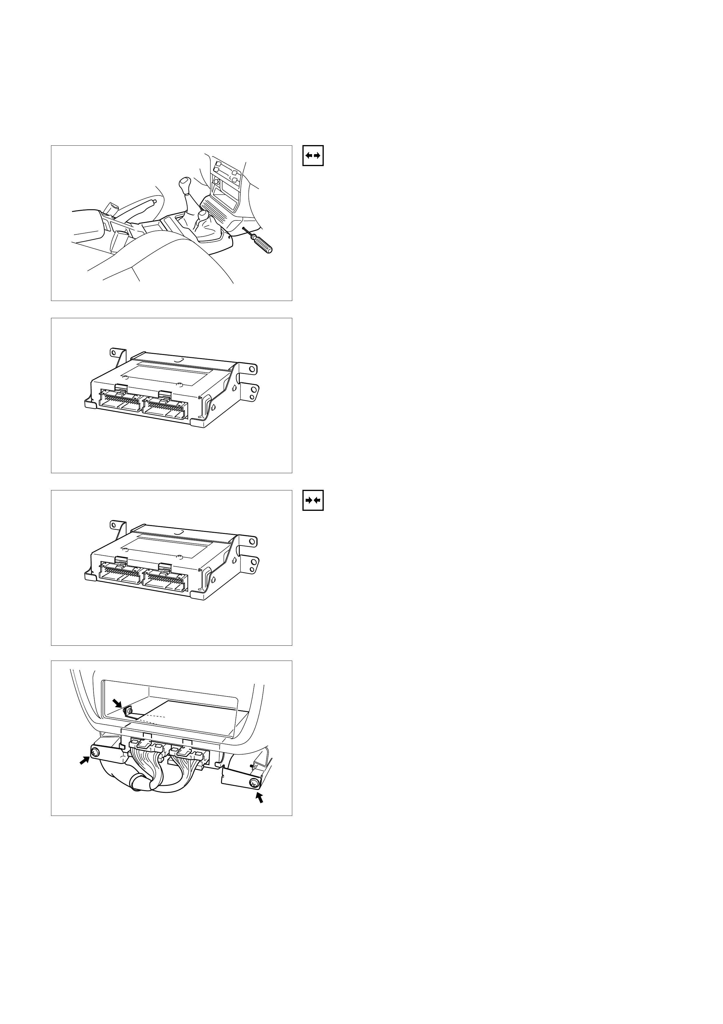
ENGINE CO NTROL MODULE (ECM)
REMOVAL
1. The ECM cover is located at the Instrument panel lower
center cover assembly.
2. Remove the center cover assembly.
3. Remove the three screws.
4. Pull out the ECM.
5. Disconnect both red and tan connectors.
6. Remove the four screws located on both sides and then
remove the brackets from the ECM.
INSTALLATION
1. Attach the brackets to both sides of the ECM main body
by securely tightening the screws.
2. Connect both red and tan connectors.
3. Replace the ECM to the original position by tightening the
screws.
4. Attach the center cover assembly.
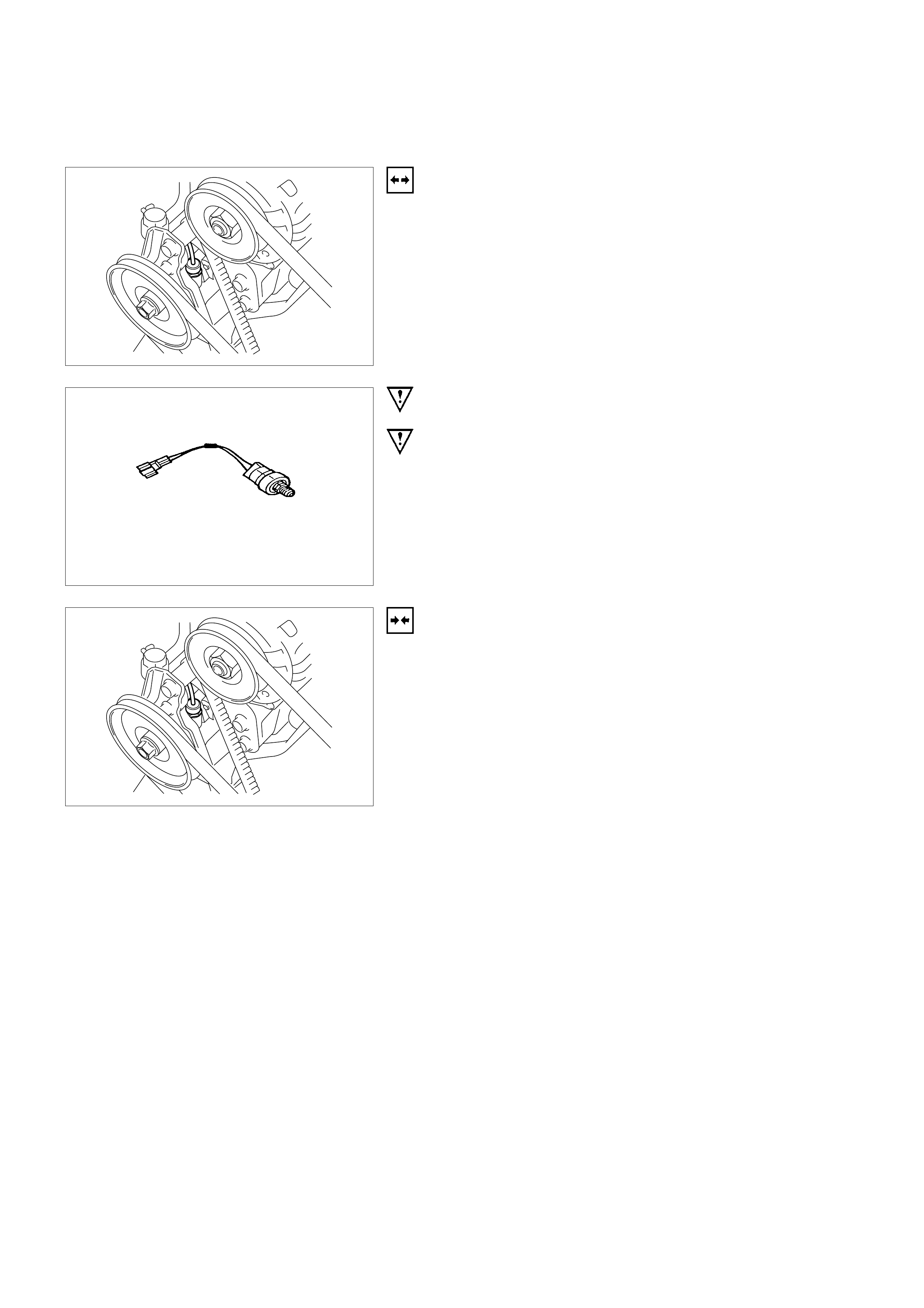
POWER STEERING PRESSURE (PSP) SWI TCH
REMOVAL
1. Disconnect the battery negative cable.
2. Disconnect the PSP switch pigtail from the wiring
harness.
IMPORTANT: The pigtail is permanently attached to the
switch. Do not attempt to remove the wire from the switch.
IMPORTANT: Have container ready to catch the power
steering fluid that leaks out of the line when the switch is
removed.
3. Unscrew the PSP switch from the power steering pump.
INSTALLATION
1. Install the PSP switch into the power steering pump.
2. Connect electrical connector.
3. Ensure power steering fluid level and no leakage. Add
power steering fluid if necessary. Refer to
Power Steering Section.
4. Connect the negative battery cable.
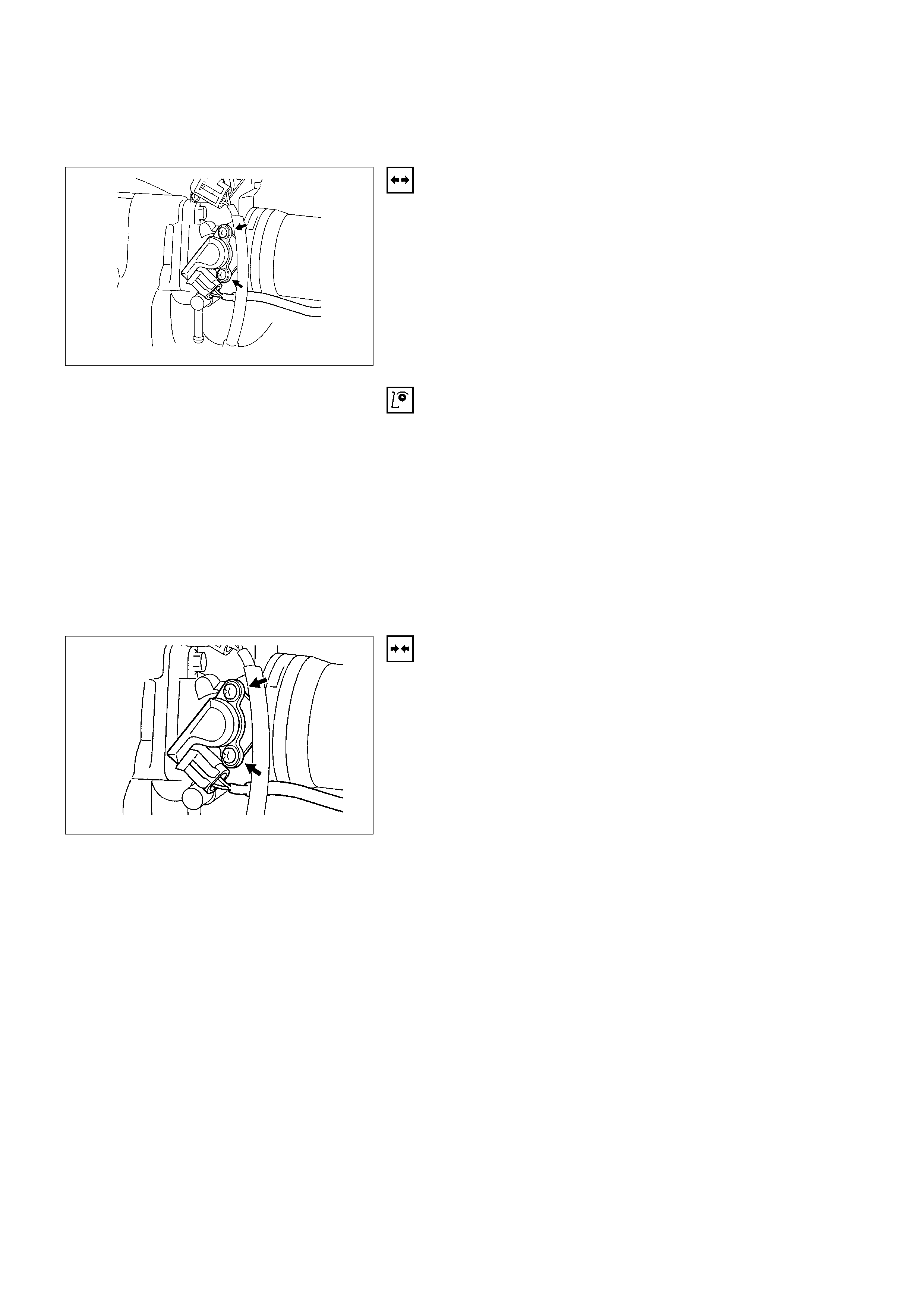
THROTTLE POSITION SENSOR (TPS)
REMOVAL
1. Disconnect the negative battery cable.
2. Disconnect the TPS electrical connector.
3. Remove the two screws and TP sensor from the throttle
body.
Notice: Do not clean the TP sensor by soaking it in solvent.
The sensor will be damaged as a result.
FUNCTION CHECK
Use a Scan Tool to check the TP sensor output voltage at
closed throttle.
•The voltage should be under 0.25 volts.
•If the reading is greater than 0.25 volts, check the throttle
shaft to see if it is binding. Check that the throttle cable is
properly adjusted, also. Refer to
Throttle Cable Adjustme nt.
•If the throttle shaft is not binding and the throttle cable is
properly adjusted, install a new TP sensor.
INSTALLATION
1. Install the TP sensor on the throttle body with two
screws.
2. Connect the electrical connector.
3. Connect the negative battery cable.
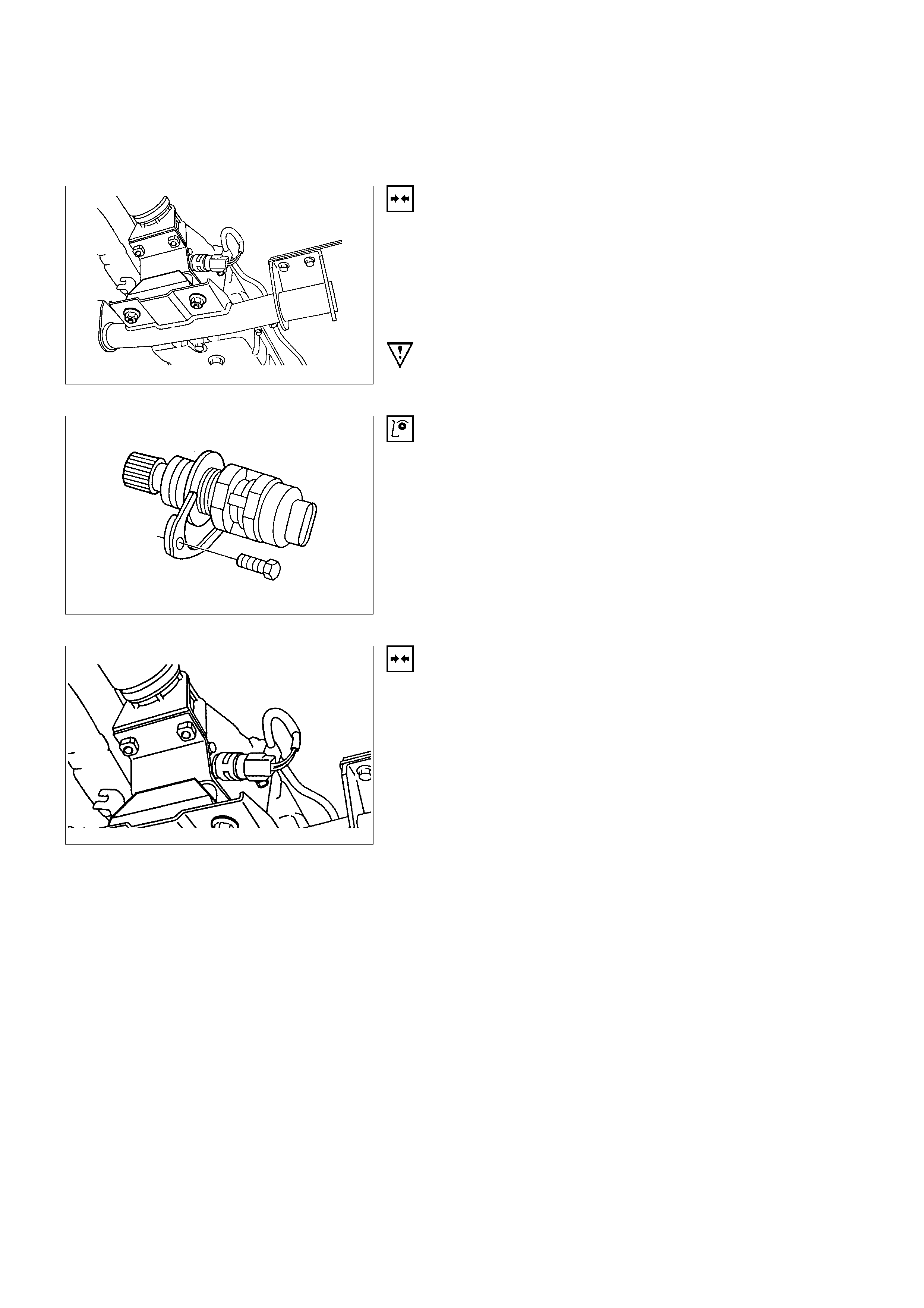
VEHICLE SPEED SENSOR ( VSS)
REMOVAL
1. Disconnect the negative battery cable.
2. VSS is located on the right side of the transmission case
just ahead of the rear propeller shaft. Disconnect the
VSS electrical connector.
3. Remove the bolt and the VSS from the transmission
case by wiggling it slightly and pulling it straight out.
IMPORTANT: Have a container ready to catch any fluid that
leaks out when the VSS is removed from the transfer case.
INSPECTION
1. Inspect the electrical connector for signs of corrosion or
warping. Replace the VSS if the electrical connector is
corroded or warped.
2. Inspect the VSS driven gear for chips, breaks, or worn
condition. Replace the VSS if the driven gear is chipped,
broken or worn.
3. Inspect the O-ring for wear, nicks, tears, or looseness.
Replace the O-ring if necessary.
INSTALLATION
1. Install the VSS in the transmission case with the notch
for the connector facing the rear.
2. Secure the VSS with mounting bolt. Tighten the bolt to 16
N⋅m (17kgf⋅m).
3. Connect electrical connector to the VSS.
4. Check the transmission oil level. Add oil if necessary.
5. Connect the negative battery cable.
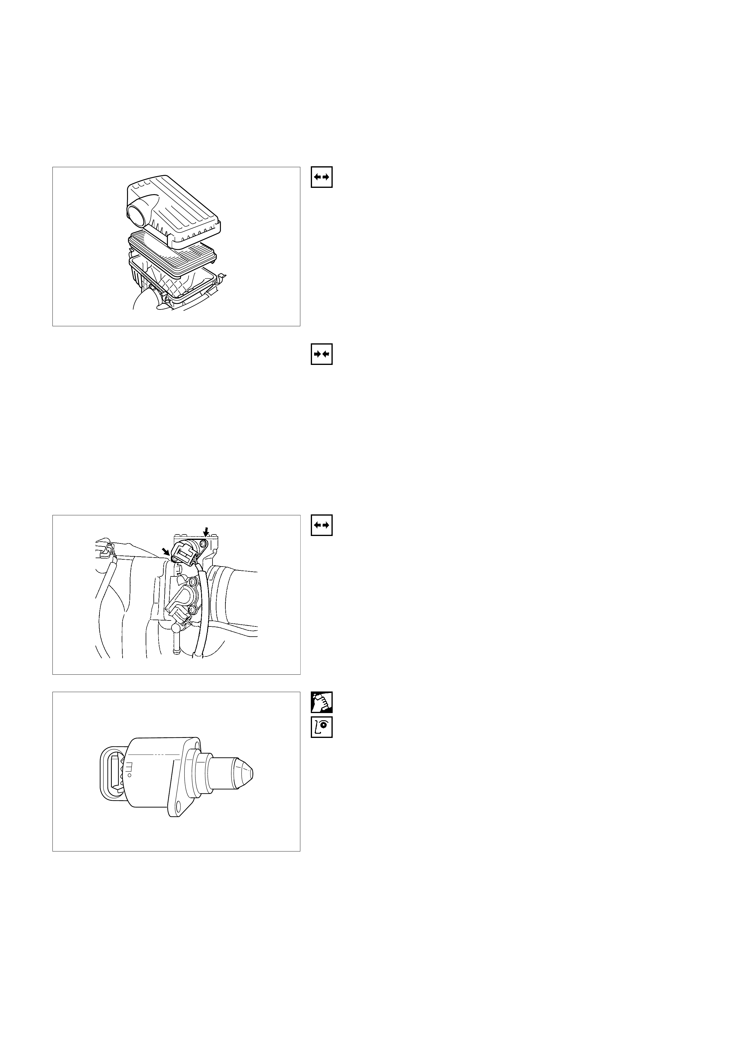
AIR INDUCTION SYSTEM
AIR FILTER
REMOVAL
1. Disconnect electrical connector at the IAT sensor.
2. Release the four latches securing the lid to the air
cleaner housing.
3. Remove the air cleaner lid.
4. Remove the air filter element.
INSTALLATION
1. Install the air filter element in the air cleaner housing.
2. Install the air cleaner lids.
3. Secure the three latches, holding the lid on the air
cleaner housing.
4. Connect the electrical connector to the IAT sensor.
IDLE AIR CONTROL (IAC) VALVE
REMOVAL
1. Disconnect the negative battery cable.
2. Disconnect the IAC electrical connector.
3. Remove the two screws and IAC valve from the throttle
body.
Notice: Do not clean the IAC valve by soaking it in solvent.
The valve will be damaged as a result.
CLEANI NG AND INSPECTION
•Clean the IAC valve O-ring sealing surface, pintle valve
seat and air passage.
•Use carburetor cleaner and a parts cleaning brush to
remove carbon deposit. Do not use a cleaner that contain
methyl ethyl ketone. This is an extremely strong solvent
and not necessary for this type of deposit.
•Shiny spots on the pintle are normal and do not indicate
misalignment or a bent pintle shaft.
•Inspect the IAC valve O-ring for cuts, cracks or distortion.
Replace the O-ring if damaged.
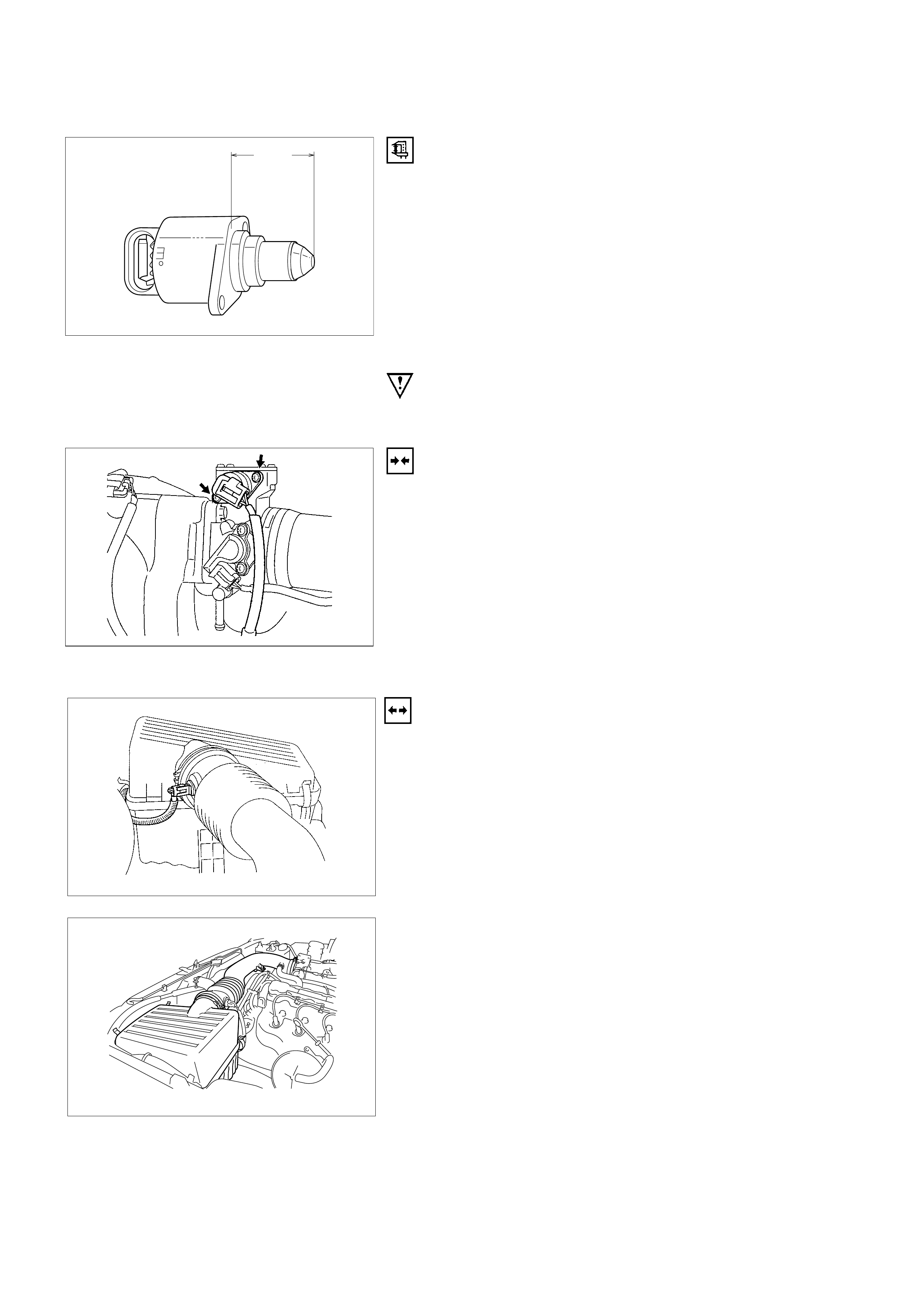
28mm
max.
MEASUREMENT
•In order to install a new IAC valve, measure the distance
between the tip of the pintle and the mounting flange. If
that measurement is 28 mm or less, the valve needs no
adjustment. If the measurement is greater than 28 mm,
apply finger pressure and retract the valve. The force
required to retract the pintle on a new valve will not
damage the valve, shaft or pintle.
Notice: Do not push or pull on the IAC valve pintle on IAC
valve that has been in service. The force required to move the
pintle may damage it.
Important: Use an identical replacement part in order to
replace a valve. IAC valve pintle shape and diameter are
designed for the specific application.
INSTALLATION
1. Install IAC valve on the throttle valve body with the two
screws. Tighten the screws to 1 N⋅m (1.2kgf⋅m).
2. Connect electrical connector to IAC valve.
3. Connect the negative battery cable.
INTAKE AIR DUCT
REMOVAL
1. Disconnect the negative battery cable.
2. Disconnect electrical connector at IAT sensor.
3. Remove the IAT sensor if necessary. Refer to
Intake Air Temperature Sensor Removal.
4. Loosen retaining clamps at the throttle body and at the
air filter box.
5. Disconnect brake booster vacuum hose at intake
manifold and at brake booster.
6. Remove retaining nut at the intake air duct bracket at top
of valve cover.
7. Disconnect the intake air duct from the throttle body and
at the air filter box.
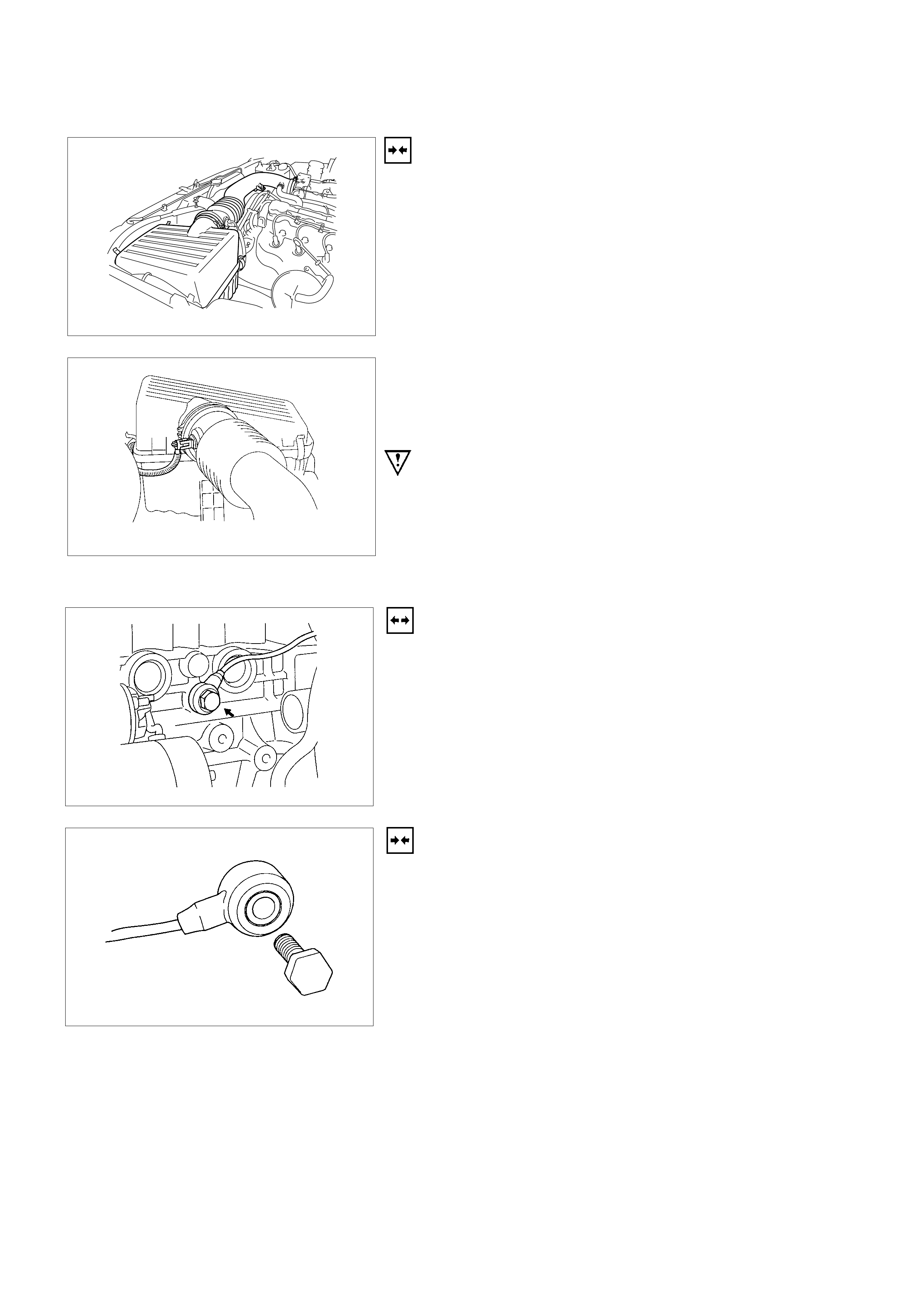
INSTALLATION
1. Connect the intake air duct at the throttle body and at the
air filter box. Make sure retaining hole is inserted to the
intake air duct bracket.
2. Tighten retaining clamp at the throttle body and at the air
filter box.
3. Install a nut to the intake air duct bracket and tighten.
4. Connect brake booster vacuum hose to intake manifold
and to brake booster and secure them with clamps.
5. Install IAT sensor if necessary. Refer to
Intake Air Temperature Sensor Installation.
6. Connect electrical connector at IAT sensor.
7. Connect the negative battery cable.
Important: Use an identical replacement part in order to
replace a valve. IAC valve pintle shape and diameter are
designed for the specific application.
KNOCK SENSOR
REMOVAL
1. Disconnect the negative battery cable.
2. Disconnect pig tail electrical connector at near the top of
generator.
3. Unscrew retaining bolt from Knock Sensor located on the
passenger side of engine block just front of starter.
4. Remove Knock Sensor with retaining bolt.
INSTALLATION
1. Install Knock Sensor with retaining bolt. Tighten the
screws to 20N⋅m (2.0kgf⋅m).
2. Connect pigtail electrical connector.
3. Connect battery negative cable.
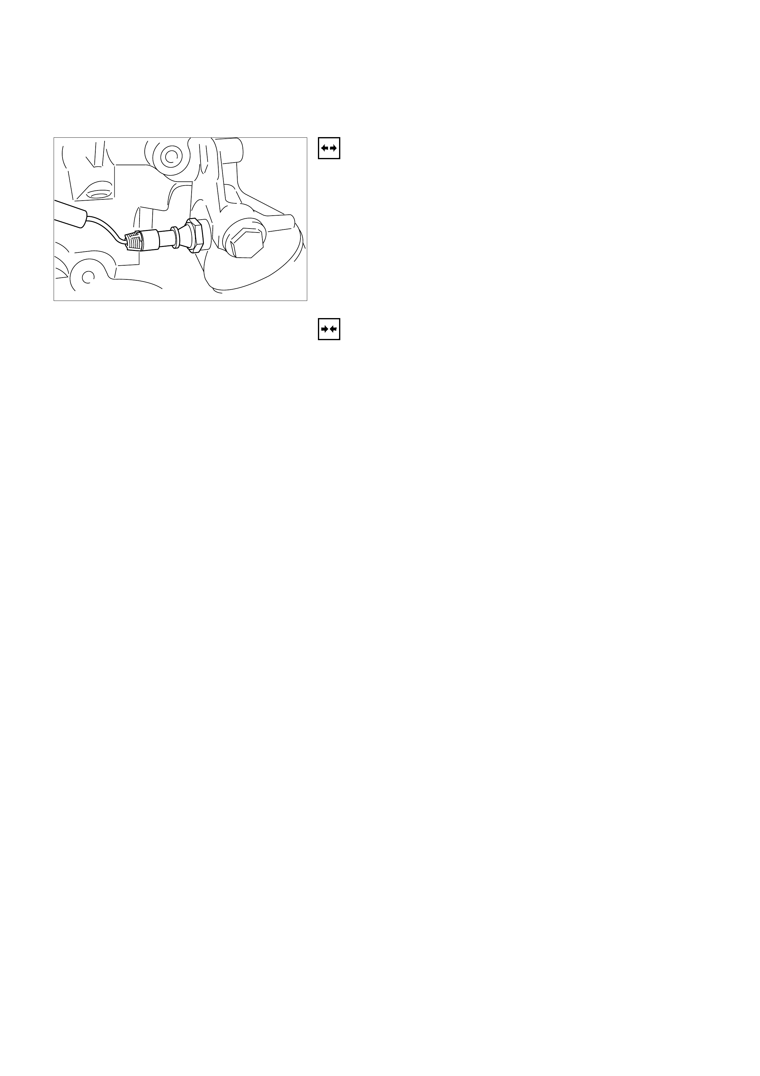
OIL PRESSURE SWITCH
REMOVAL
1. Disconnect battery negative cable.
2. Disconnect electrical connector at Oil Pressure Switch.
3. Unscrew Oil Pressure Switch from Oil Filter Mounting
Housing.
INSTALLATION
1. Install Oil Pressure Switch into Oil Filter Mounting
Housing and tighten. Tighten the screws to 30 -50Nm
(3.1 -5.1kgf⋅m).
2. Connect electrical connector.
3. Connect battery negative cable.
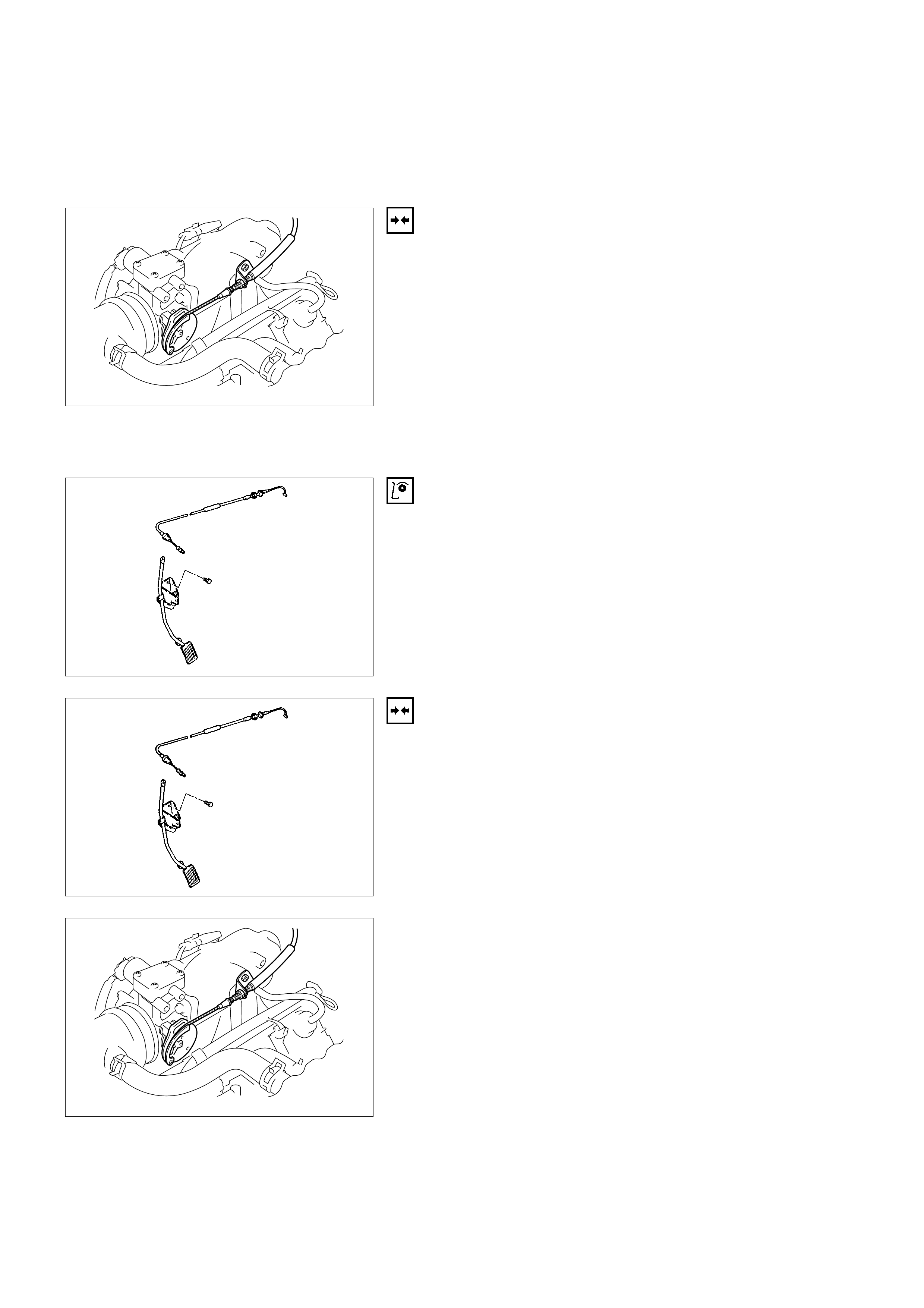
FUEL METERING SYSTEM
ACCELERATO R CABLE ASSEMBLY
REMOVAL
1. Loosen the adjusting nut on the cable bracket mounting
on the throttle body.
2. Remove the cable clip from holding bracket.
3. Remove accelerator control cable (on the throttle valve
end).
4. Remove the accelerator control cable (on the accelerator
pedal end).
5. Remove the grommet.
6. Remove the accelerator control cable.
INSPECTION
Check the following items, and replace the control cable if any
abnormality is found:
•The control cable should move smoothly.
•The control cable should not be bent or kinked.
•The control cable should be free of damage and
corrosion.
INSTALLATION
1. Install the accelerator control cable.
2. Install the grommet.
3. Install the accelerator control cable on the accelerator
pedal.
4. Install the accelerator control cable on the throttle valve.
5. Install the cable clip to the holding bracket.
6. Adjust the accelerator cable. Refer to
Accelerator Cable Adjustment Section.
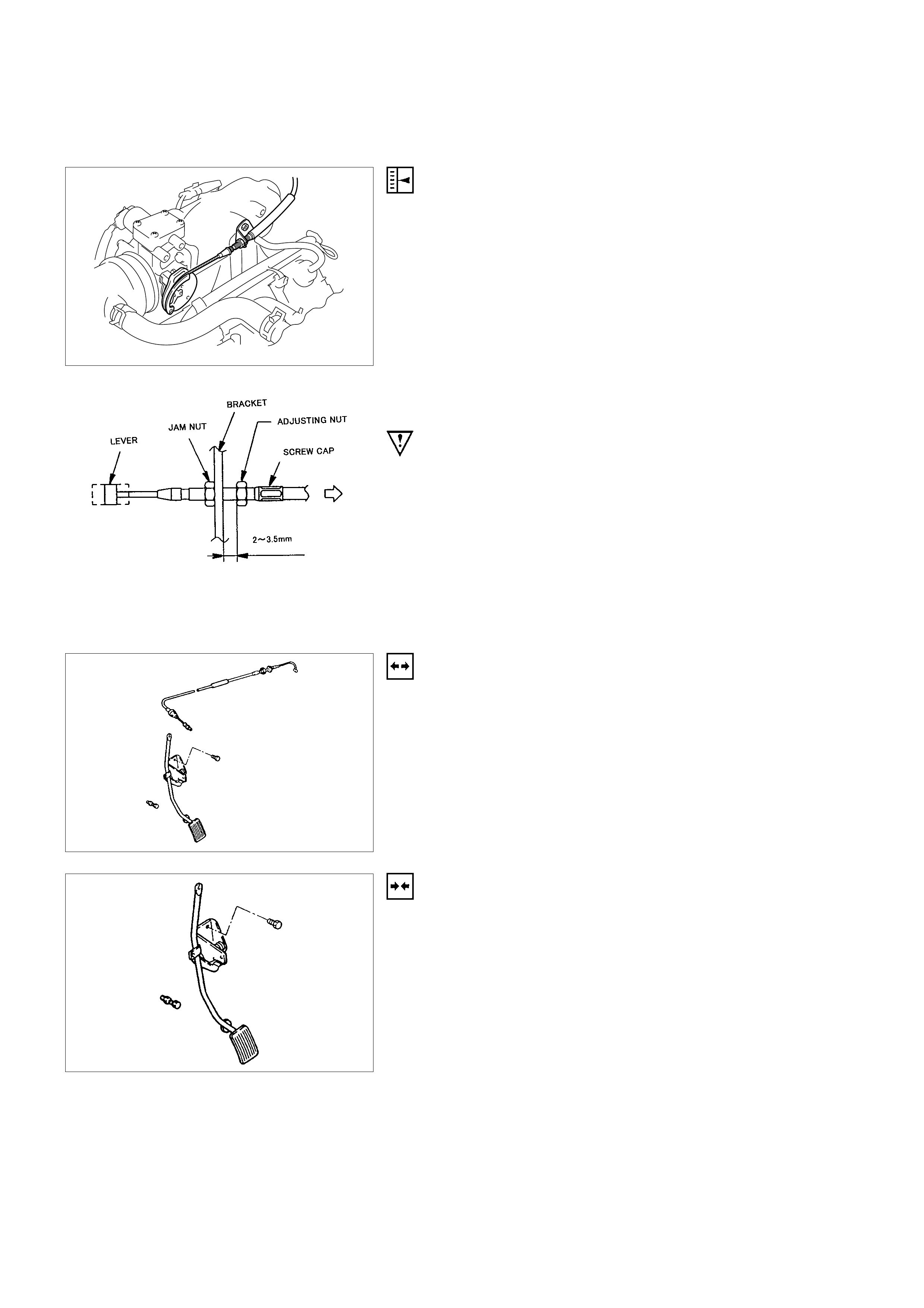
ACCELERATO R CABLE ADJUSTMENT
ADJUSTMENT
1. Loosen the adjusting nut.
2. Loosen the jam nut.
3. Pull the outer cable while fully closing the throttle valve.
4. Tighten the adjusting nut.
5. Tighten the jam nut.
6. Loosen the adjusting nut and adjust clearance between
adjusting nut and bracket to 2∼3.5mm.
7. Tighten the jam nut again.
8. Manually operate valve.
IMPORTANT: The valve lever must return up to the stopper
screw. If the valve lever does not reach the stopper screw,
repeat the procedure again from Step 1.
ACCELERATO R PEDAL REPLACEMENT
REMOVAL
1. Disconnect the accelerator pedal control cable from the
accelerator pedal assembly.
2. Remove the two screws retaining the accelerator pedal
to the bulkhead.
3. Remove the accelerator pedal from the bulkhead.
INSTALLATION
1. Install the accelerator pedal assembly to the bulkhead
with two screws.
2. Connect the accelerator control cable to the accelerator
pedal assembly.
3. Adjust accelerator cable if necessary. Refer to
Accelerator Control Cable Adjustment Section.
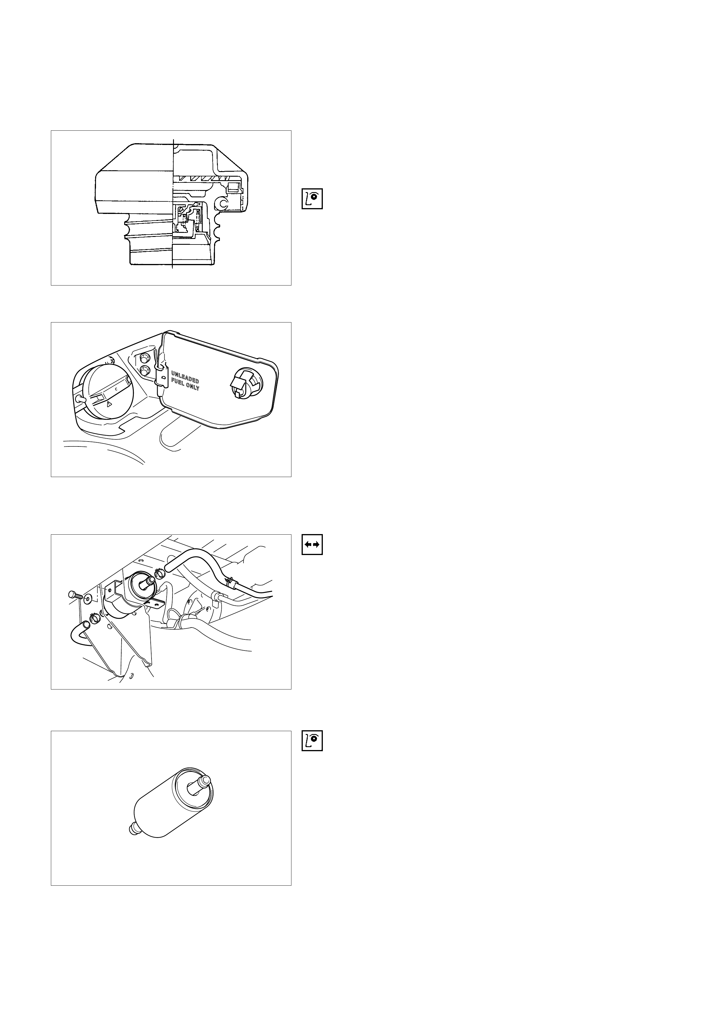
FUEL FILLER CAP
The Fuel Filler Cap includes a vacuum valve. If high vacuum
occurs in the fuel tank, the vacuum valve works to adjust the
pressure in order to prevent damage to the tank.
INSPECTION
Notice: Replace the fuel filler cap with the same type of filler
cap that was originally installed on the vehicle.
•Check the seal ring in the filler cap for any abnormality
and for seal condition.
•Replace the filler cap if any abnormality is found.
WARNING
REMOVE SLOWLY
FUEL SPRAY MAY
CAUSE INJURY
FUEL FILTER
REMOVAL
1. Disconnect the negative battery cable.
2. Remove the fuel filler cap.
3. Disconnect the fuel line from the fuel filter on the engine
side.
4. Disconnect the fuel line from the fuel filter on the fuel
tank side.
5. Remove the bolt on the fuel filter holder.
6. Remove the fuel filter.
INSPECTION
1. Replace the fuel filter when the following occur:
•Fuel leaks from the fuel filter body
•The fuel filter body is damaged
•The fuel filter is clogged with dirt or sediment
2. If the drain hole is clogged with dust, clean the drain hole
with air.
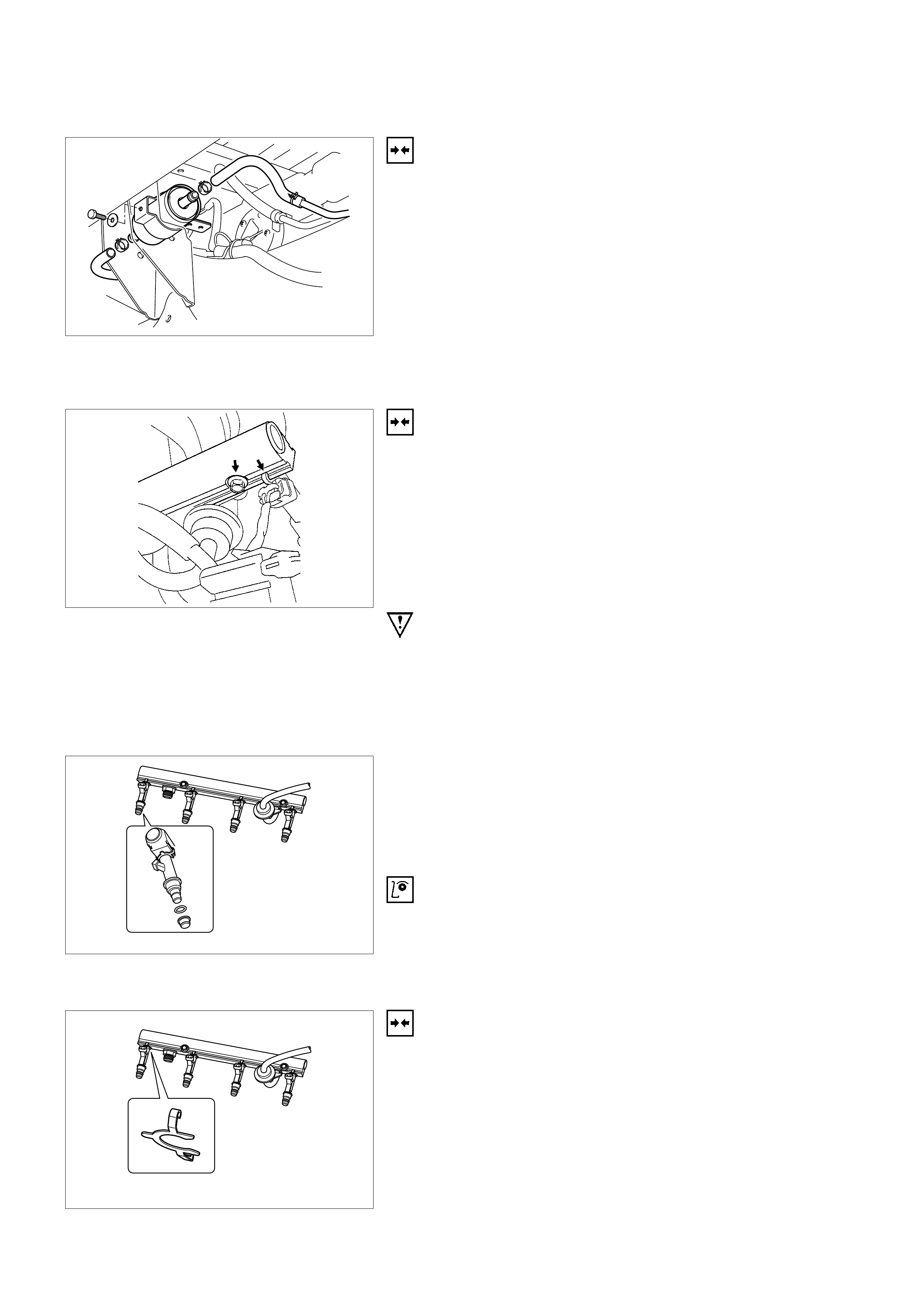
INSTALLATION
1. Install the fuel filter in the correct direction.
2. Install the bolt on the fuel filter holder.
3. Connect the fuel line on the engine side.
4. Connect the fuel line on the fuel tank side.
5. Install the fuel filler cap.
6. Connect the negative battery cable.
FUEL INJECTORS
REMOVAL
Notice: If the fuel injectors are leaking, the engine oil may be
contaminated with fuel. Check the oil for signs of
contamination and change the oil and filter if necessary.
Notice: Use care in removing the fuel injector in order to
prevent damage to the fuel injector al connector pins or fuel
injector nozzles. The fuel injector is an al component and
should not be immersed in any type of cleaner as this may
damage the fuel injector.
IMPORTANT: Fuel injectors are serviced as complete
assembly only.
1. Disconnect the negative battery cable.
2. Disconnect al connector from fuel injector.
3. Remove the fuel rail. Refer to
Fuel Rail Removal P rocedure.
4. Remove the fuel injector retainer clip.
5. Remove the fuel injector assembly from fuel rail.
6. Remove O-ring from the fuel injector.
7. Remove O-ring backup from fuel injector.
INSPECTION
1. Inspect O-ring for crack, damage or leaks.
2. Replace worn or damaged O-ring.
3. Lubricate the new O-rings with engine oil before
installation.
INSTALLATION
1. Lubricate the new O-ring with engine oil.
2. Install the O-ring backup on the fuel injector.
3. Install new O-ring on the fuel injector.
4. Install all four injector on the fuel rail.
5. Use new injector retainer clip to retain the injetor to the
fuel rail.
6. Coat the end of the fuel injector with engine oil.
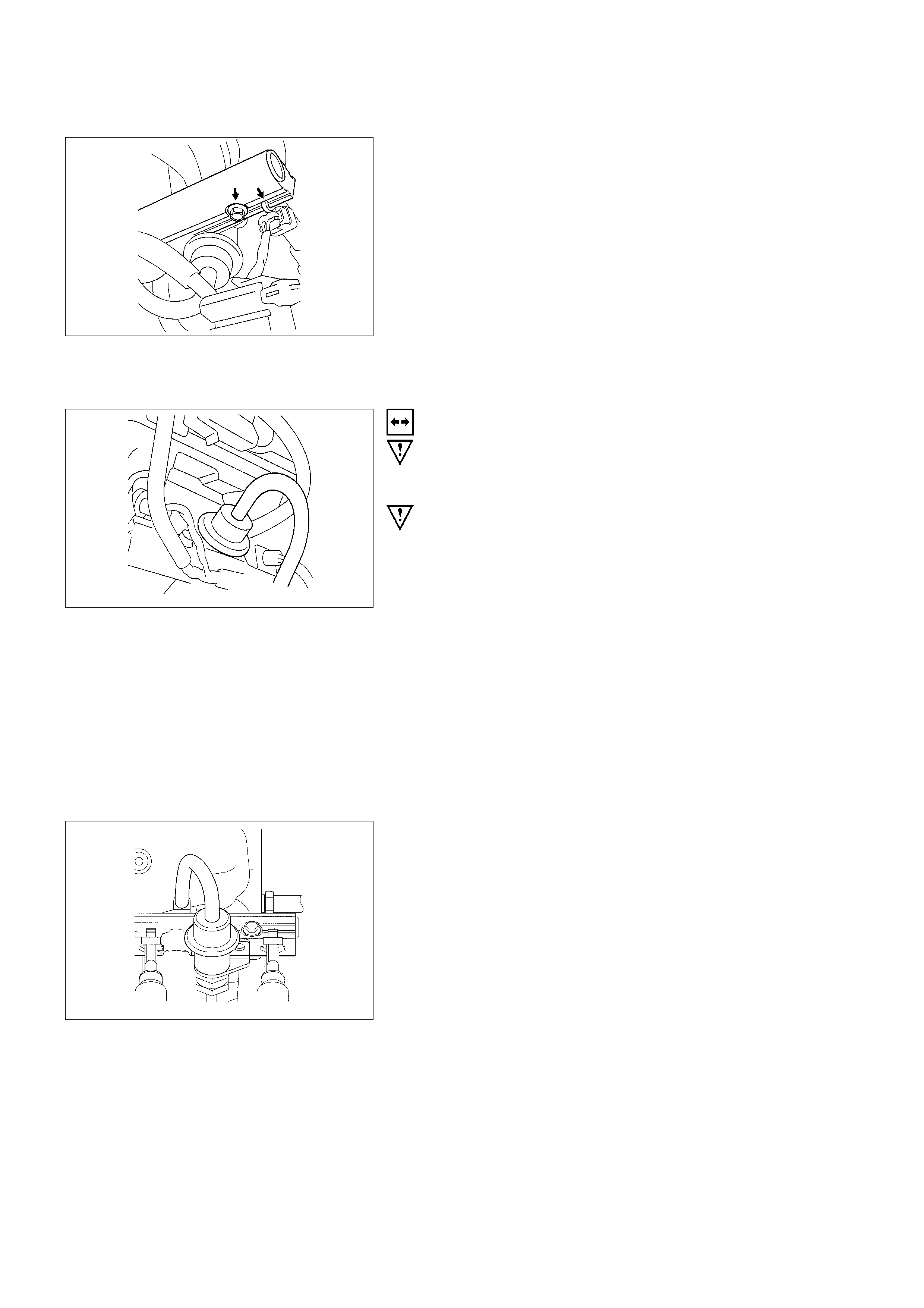
7. Install fuel rail assembly . Tighten the nuts to 19 N⋅m (1.9
kgf⋅m). Refer to Fuel Rail Installation Procedure.
Tighten the flare nut to 27 - 33 N⋅m (2.8 - 3.4 kgf⋅m).
8. Connect the negative battery cable.
FUEL PRESSURE REGULATOR
REMOVAL
CAUTION: To reduce the risk of fire and personal injury, i
t
is necessary to relieve the fuel system pressure before
servicing the fuel system components.
CAUTION: After relieving the fuel syst em pressure, a smal
l
amount of fuel may be released when servicing fuel lines
or connections. Reduce the chance of personal injury b
y
covering the fuel line fitting with a shop towel before
disconnecting the fittings. The towel will absorb any fue
l
that may leak out. When the disconnect is completed,
place the towel in an approved container.
Notice: Compressed air must never be used to test or clean a
fuel pressure regulator, as damage to the fuel pressure
regulator may occur.
Notice: To prevent damage to the fuel pressure regulator, do
not immerse the pressure regulator in solvent.
1. Depressurize the fuel system. Refer to
Fuel Pressure Relief Procedure.
2. Disconnect the negative battery cable.
3. Remove the fuel pump relay.
4. Disconnect the vacuum line form fuel pressure regulator.
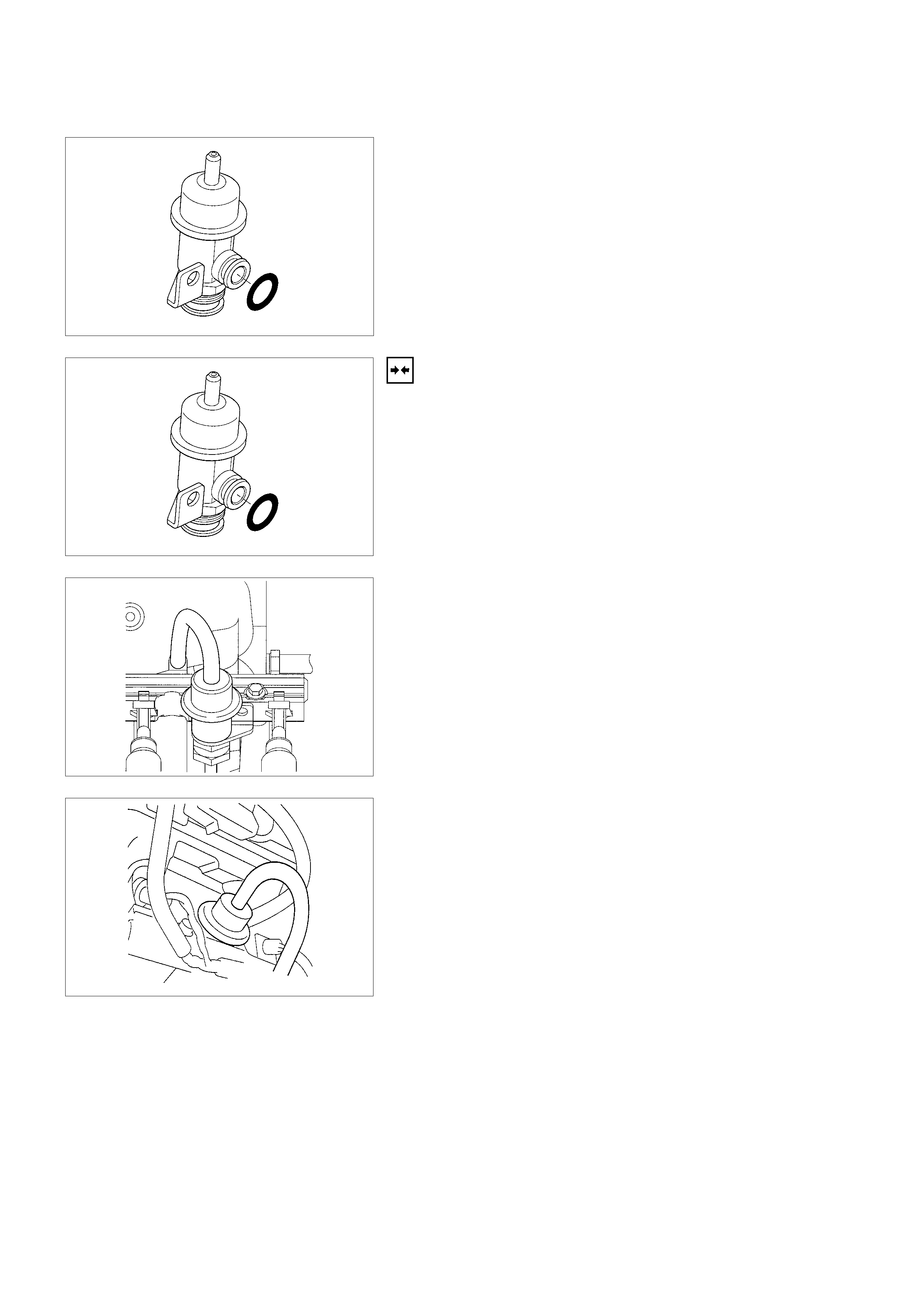
5. Remove the fuel pressure regulator retaining screw.
6. Remove the fuel pressure regulator from fuel rail.
INSTALLATION
1. Insert the fuel pressure regulator into the fuel rail.
2. Install the fuel pressure regulator retaining bracket and
tighten with a screw.
3. Connect vacuum line onto the fuel pressure regulator.
4. Install the fuel pump relay.
5. Connect the negative battery cable.
6. Crank the engine until it starts. Cranking the engine may
take longer than usual due to trapped air in the fuel line.
7. Tighten the flare nut to 27 - 33 N⋅m (2.8 - 3.4 kgf⋅m).
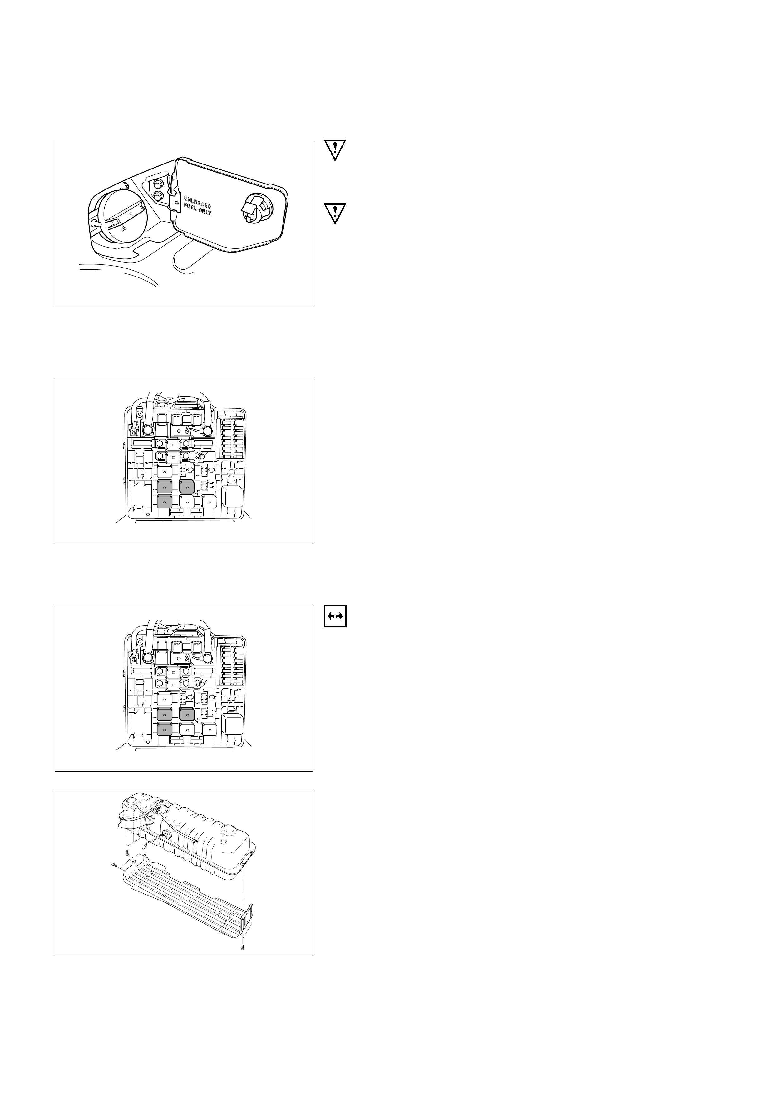
FUEL PRESSURE RELIEF
WARNING
REMOVE SLOWLY
FUEL SPRAY MAY
CAUSE INJURY
CAUTION: To reduce the risk of fire and personal injury, i
t
is necessary to relieve the fuel system pressure before
servicing the fuel system components.
CAUTION: After relieving the fuel syst em pressure, a smal
l
amount of fuel may be released when servicing fuel lines
or connections. Reduce the chance of personal injury b
y
covering the fuel line fitting with a short towel before
disconnecting the fittings. The towel will absorb any fue
l
that may leak out. When the disconnect is completed,
place the towel in an approved container.
1. Remove the fuel filler cap.
2. Remove the fuel pump relay from the underhood relay
box.
3. Start the engine and allow it to stall.
4. Crank the engine for about 30 seconds.
5. Disconnect the negative battery cable.
FUEL PUMP ASSEMBLY
REMOVAL
1. Disconnect the negative battery cable.
2. Drain all fuel from fuel tank from filler neck.
3. Remove the fuel pump relay from the fuse and relay box
at right side of engine room.
4. Remove fuel tank. Refer to
Fuel Tank Remova l Procedure.
5. Using commercially available tool, loosen the screws on
the fuel pump and remove the fuel pump from the fuel
tank.
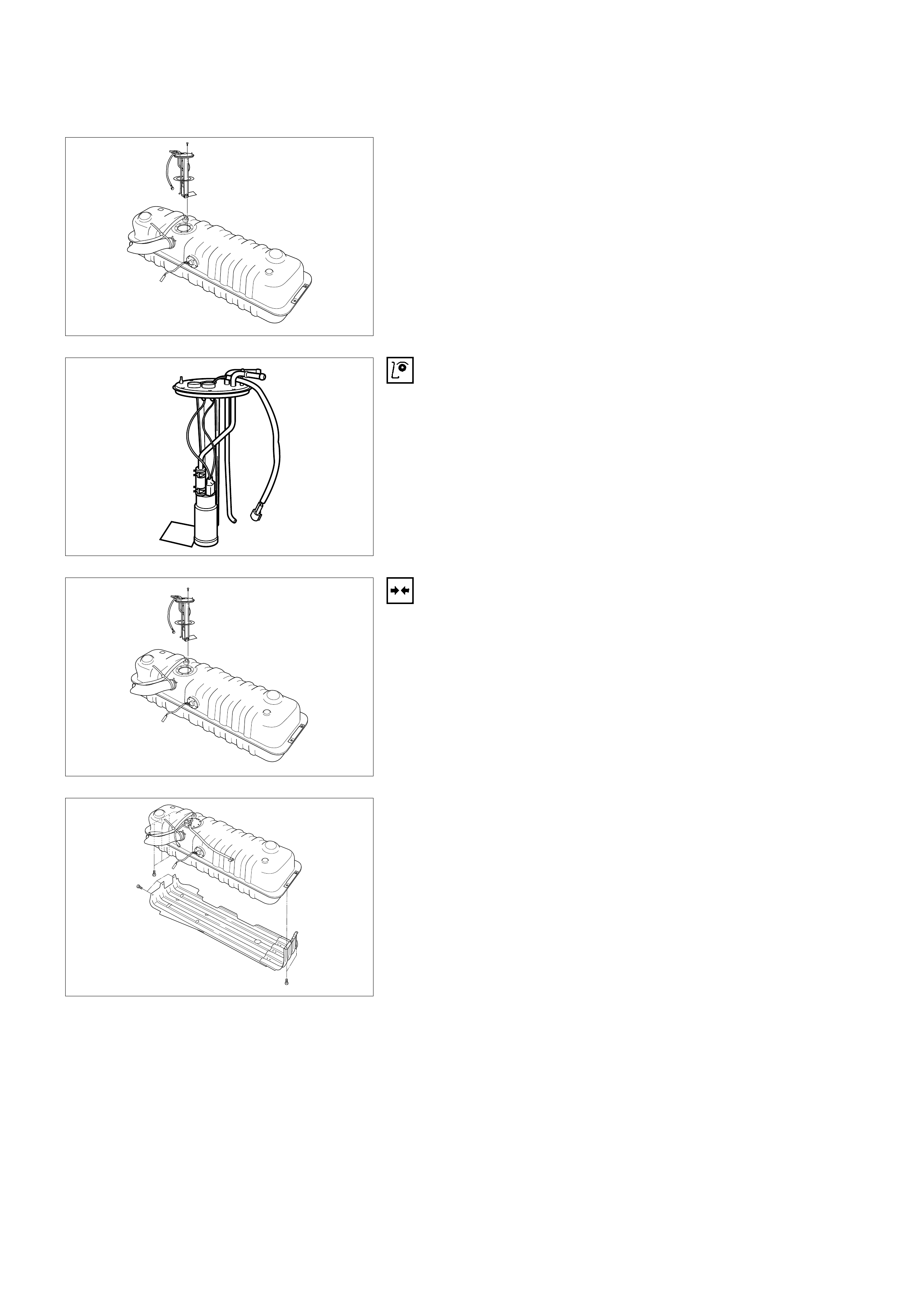
6. Lift fuel pump to remove from fuel tank.
INSPECTION
Inspect in-tank fuel filter for tears, damage of evidence of dirt
derbris or water in the fuel. If any of these condition exist,
replace the in-tank fuel filter.
INSTALLATION
1. Insert the fuel pump assembly into fuel tank and place
them in their position.
2. Using commercially available tool, tighten the screws to
the fuel pump assembly into the fuel tank.
3. Install the fuel tank. Refer to
Fuel Tank Installation Procedure.
4. Install the fuel pump relay.
5. Connect the negative battery cable.
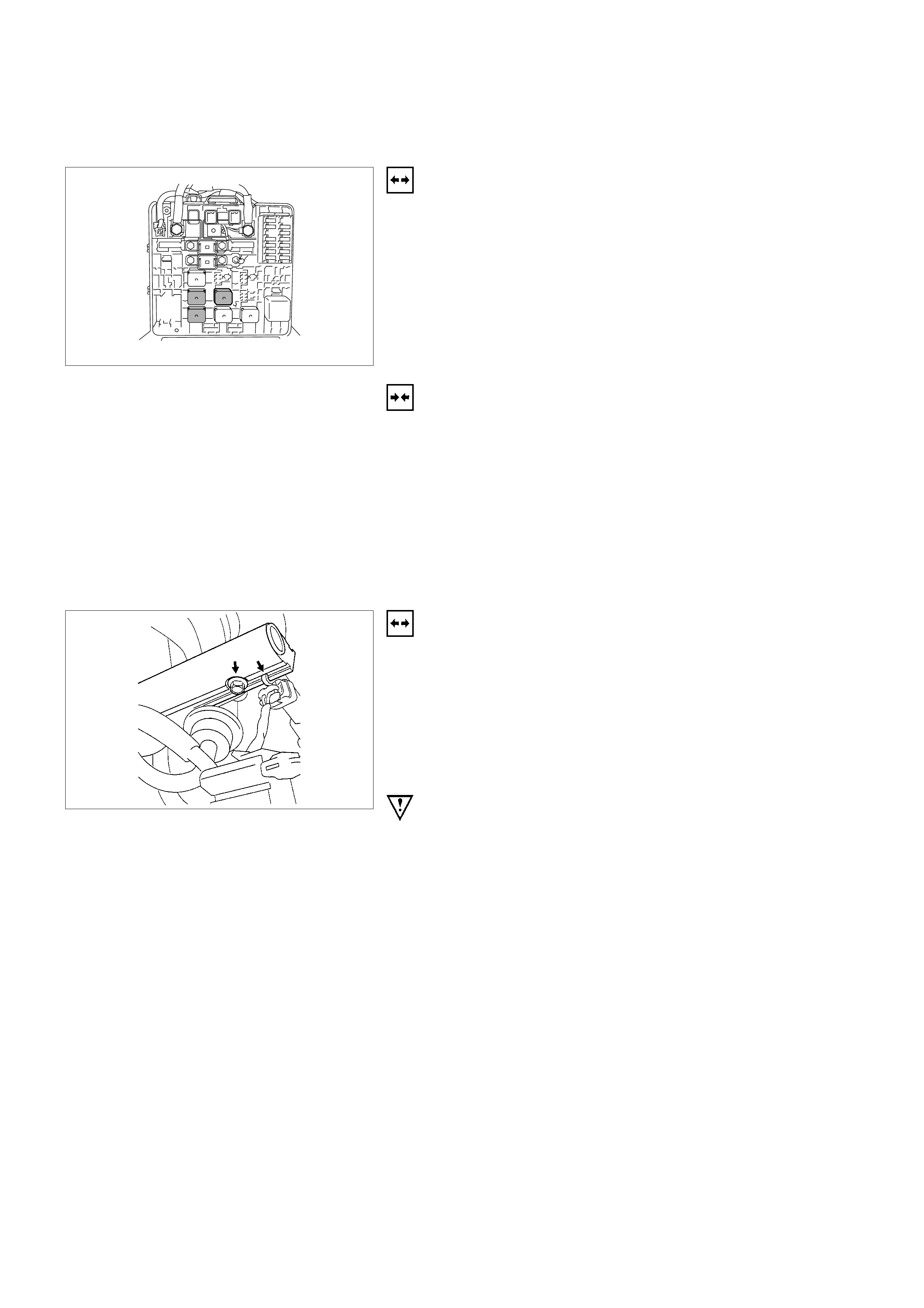
FUEL PUMP RELAY
REMOVAL
1. Remove the fuse and relay box cover located right side
of engine room.
2. Determine correct relay by referring to the diagram on
the cover.
3. Insert a small screwdriver or use thumb pressure to
release the retainer of the relay.
4. Pull the relay straight up and out of the fuse and relay
box.
INSTALLATION
1. Insert the relay into the correct place in the fuse and relay
box with the catch slot aligned to retainer.
2. Press down until the catch of retainer engages.
3. Install fuse and relay box cover.
FUEL RAIL ASSEMBLY
REMOVAL
Notice:
•Use care when removing the fuel rail assembly in order
to prevent damage to the injector al connector terminal
and the injector spray tips.
•Fitting should be capped and holes plugged during
servicing to prevent dirt and other contaminants from
entering open lines and passage.
IMPORTANT: An eight-digit identification number is stamped
on side of the fuel injector. Refer to this number when you
service the fuel rail or when a replacement part is required.
1. Disconnect 4 injector connectors.
2. Lift side-clip up on the fuel rail.
3. Disconnect fuel pressure regulator hose.
4. Disconnect wiring harness from the bands on the fuel
rail.
5. Remove the intake pipe.
6. Loosen flare nut.
A Lift up the injectors carefully to separate them from
intake manifold.
B Lift up the fuel rail with injectors as assembly. Do not
separate the fuel injectors from fuel rail.
C If an injector become separated from fuel rail, injector
backup O-ring and injector retainer clip must be
replaced.
D Drain residual fuel from fuel rail into an approved
container.
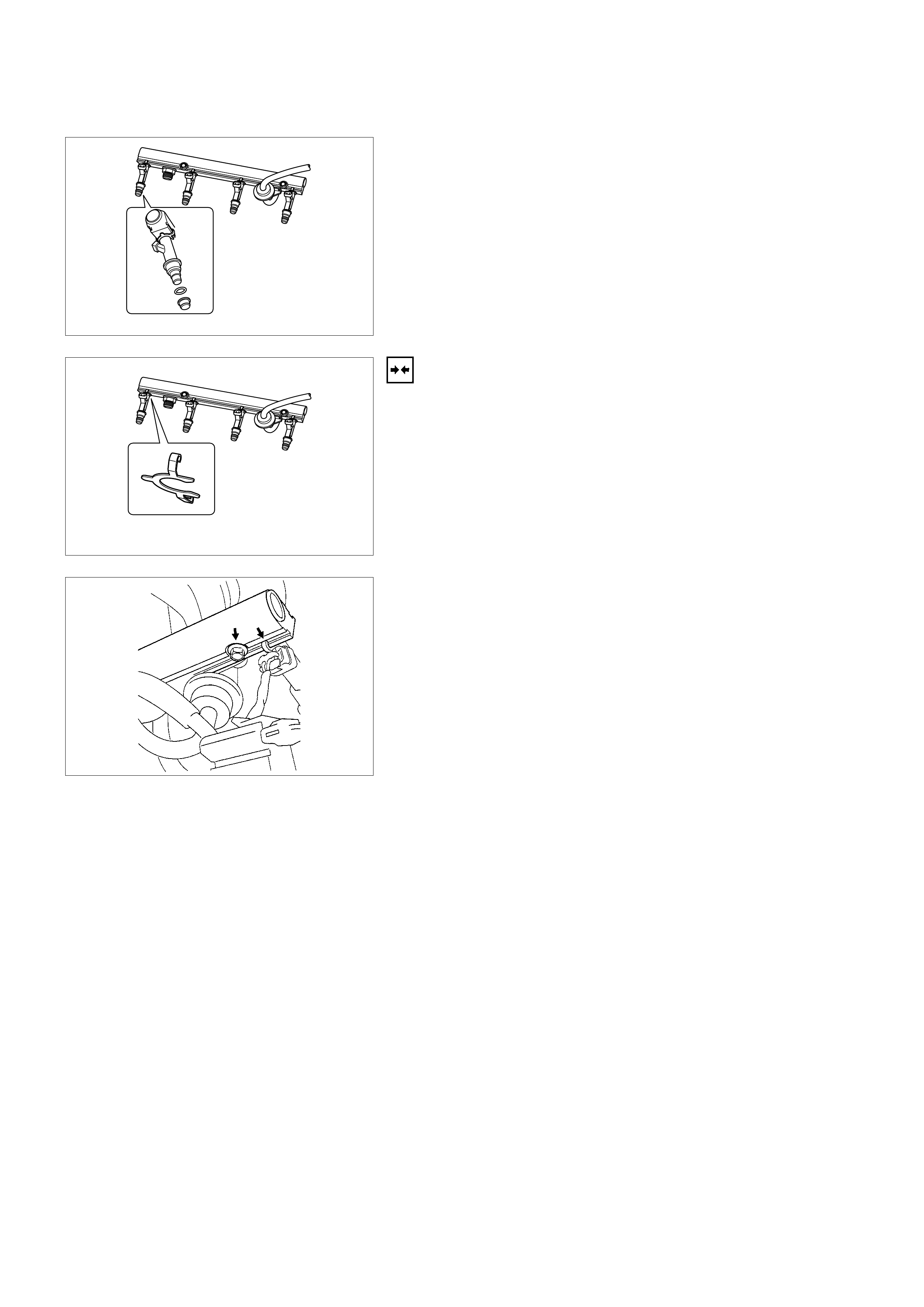
7. If removal of fuel pressure regulator is necessary, Refer
to Fuel Pressure Regulator Removal Procedure.
8. If removal of fuel injector is necessary, Refer to
Fuel Injectors Removal Procedure.
INSTALLATION
1. Install the fuel injectors if necessary. Refer to
Fuel Injector Installation Procedure.
2. Install the fuel pressure regulator if necessary. Refer to
Fuel Pressure Regulator Installation Procedure.
3. Place the fuel injector rail assembly on the manifold and
insert the injectors into each port by pushing fuel rail.
4. Install two fuel rail retaining bolts. Tighten fuel rail
retaining bolt to 19 N⋅m (1.9kgf⋅m)
5. Place wiring harness in its place and secure it with two
nuts.
6. Connect all connector to each fuel injector.
7. Connect the fuel supply line securely. Do not over
tighten.
8. Connect the fuel return line securely. Do not over tighten.
9. Connect the negative battery cable.
10. Crank the engine until it starts. Cranking the engine may
take longer than usual due to trapped air in the fuel
system. Check for leak. If fuel leak is observed, stop
engine immediately. Before correcting fuel leak, be sure
to depressurize system again.
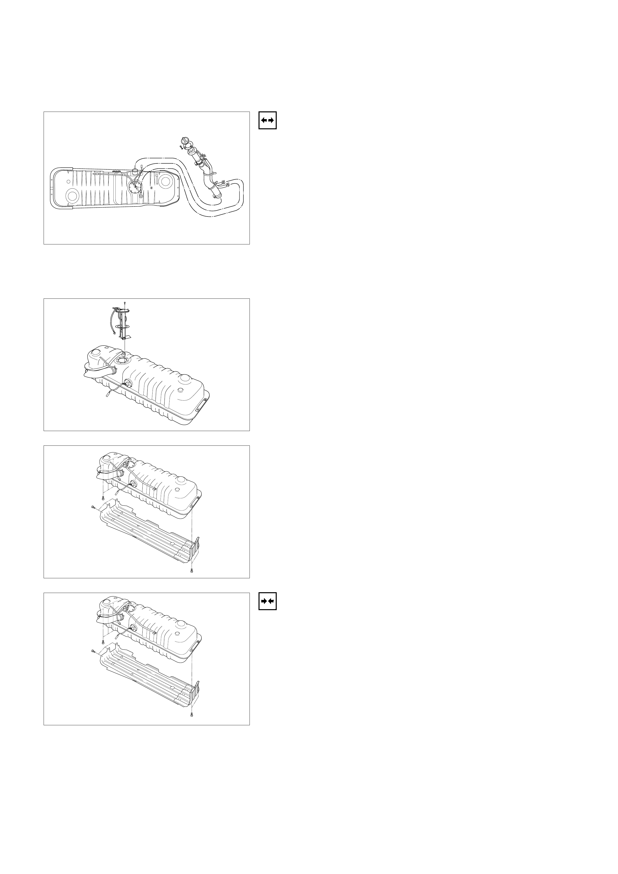
FUEL TANK
REMOVAL
1. Disconnect the negative battery cable.
2. Remove fuel filler cap.
3. Drain the fuel from fuel filler neck.
4. Disconnect the fuel filler hose at the fuel tank.
5. Disconnect the air breather hose at the fuel tank.
6. Disconnect the evaporator hose at the fuel tank.
7. Hold entire fuel tank at the bottom with stands.
8. Disconnect fuel supply lines and fuel return line at near
the fuel filter inside of body frame.
9. Remove fixing bolts holding fuel tank to the frame.
10. Lower tank assembly from the vehicle a little to make
access space on top.
11. Disconnect connectors at fuel pump.
12. Remove pump tank assembly from the vehicle.
13. Remove the tank under guard to the tank.
14. Remove the tank from the guard.
INSTALLATION
1. Secure fuel tank into under guard with retaining bolts, if
necessary.
2. Place the fuel tank assembly onto stands.
3. Lift the fuel tank assembly near the position.
4. Connect connectors at fuel pump.
5. Lift the fuel pump to its position and secure it with
mounting bolts. Make sure that all hoses and fuel lines
are out of way between the fuel tank and the fuel tank
bracket. Tighten the fuel tank retaining bolts to 36 N⋅m
(3.7kgf⋅m).
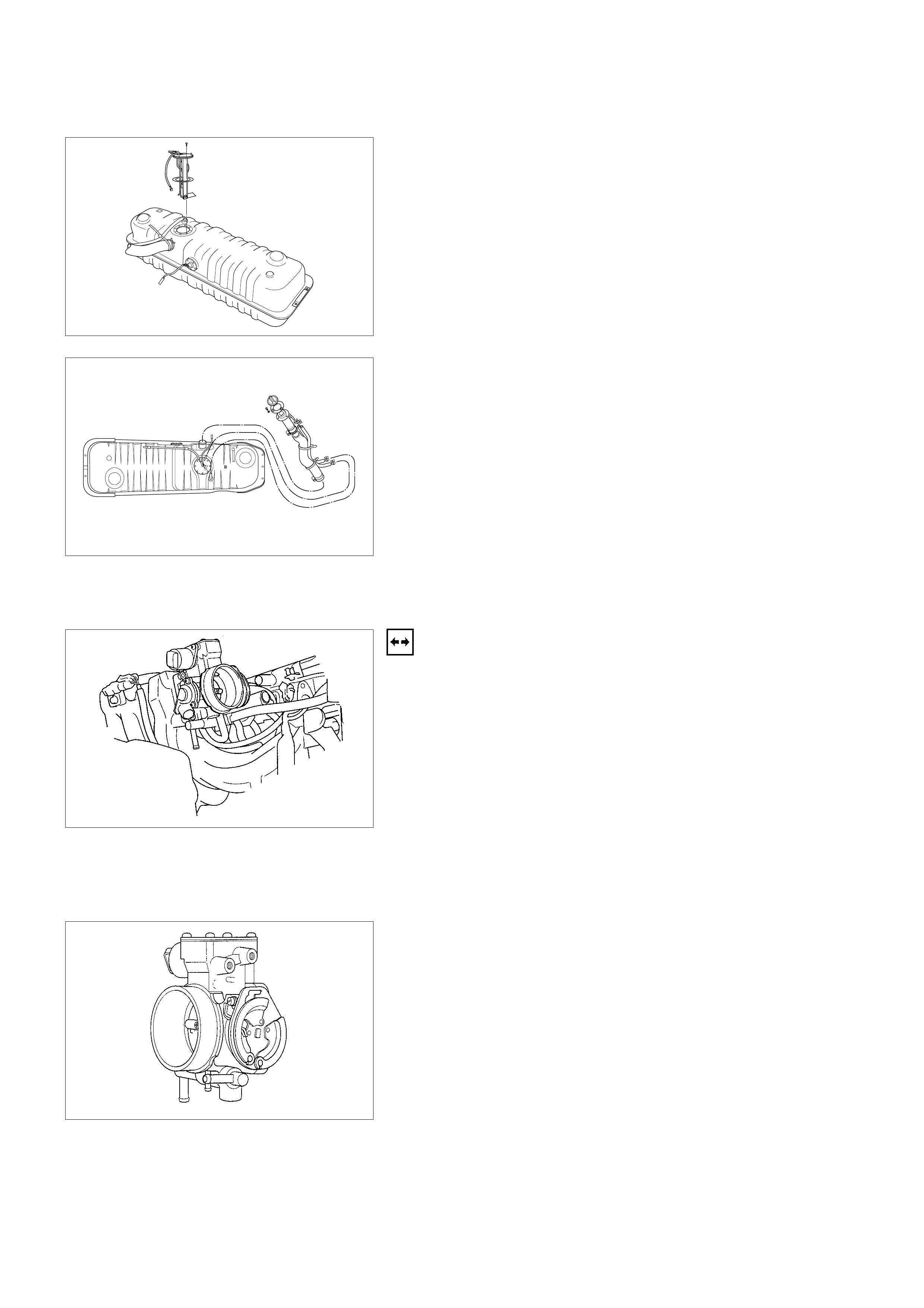
6. Connect fuel supply and return lines.
7. Connect the fuel filler hose, the air breather hose and
EVAP hose onto fuel tank and secure them with clamps.
8. Pour fuel into fuel tank.
9. Install fuel filler cap securely.
10. Connect the battery negative cable.
THROTTLE BODY (TB)
REMOVAL
1. Disconnect the negative battery cable.
2. Drain the cooling system. Refer to Cooling Sys tem.
3. Remove the air intake duct. Refer to
Air Intake Duct Removal Procedure.
4. Remove the accelerator cable from throttle. Refer to
Accelerator Cable Assembly Removal Procedure.
5. Disconnect the al connectors from the throttle position
sensor and the idle air control valve solenoid.
6. Disconnect all vacuum hoses below air horn.
7. Disconnect coolant lines.
8. Remove the mounting nuts retaining the throttle body to
the intake manifold.
9. Remove the throttle body from the intake manifold.
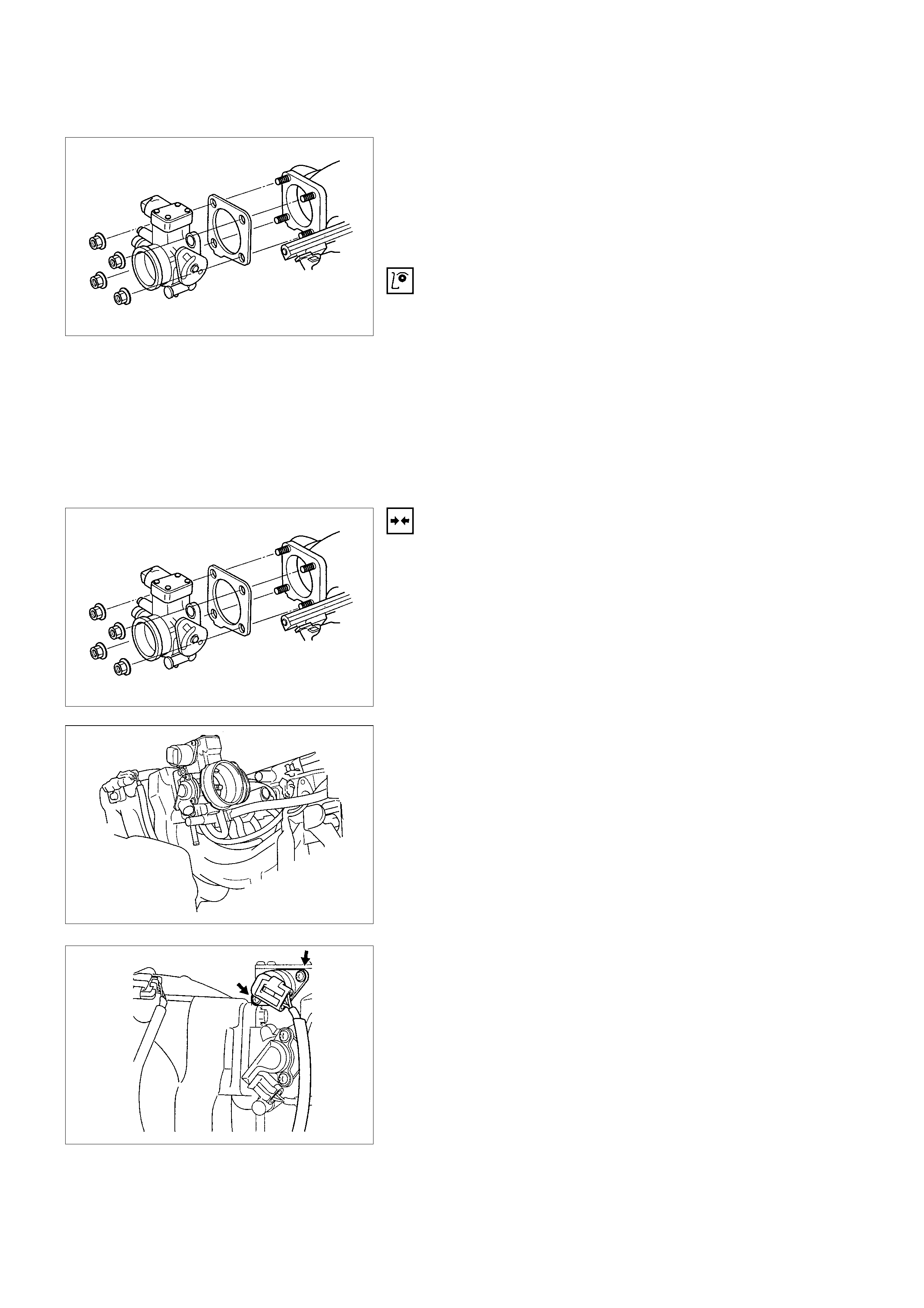
10. Remove the gaskets from the intake manifolds.
11. Remove the IAC. Refer to
Idle Air Control Valve Solenoid Removal Procedure.
12. Remove TPS. Refer to Throttle Position Sensor
Removal Procedure.
INSPECTION
Notice: Do not use solvent of any ty pe w hen y ou clean the gasket
surfaces on the intake manifold and the throttle body assembly.
The gasket surface and the throttle body assembly may be
damaged as results.
1. If the throttle body gasket needs to be released, remove
any gasket materiel that may be stuck to the mating
surfaces of the manifold.
2. Do not leave any scratches in the aluminum casting.
INSTALLATION
1. Install IAC valve onto the throttle body. Refer to
IAC valve Installation Procedure.
2. Install TPS onto the throttle body if necessary. Refer to
TPS Installation Procedure.
3. Place the gasket then the throttle body on the manifold.
4. Install four mounting bolts. Tighten the throttle body
mounting bolt to 13.5 N⋅m (1.4kgf⋅m).
5. Connect coolant line and secure them with clamps.
6. Connect all vacuum hoses and secure them with clamps
if necessary.
7. Install accelerator control cable bracket onto the throttle
body.
8. Connect accelerator control cable to throttle plate.
9. Connect al connector at IAC valve and TPS.
10. Install the air intake duct. Refer to
Air Intake Duct Installation Procedure.
11. Fill the cooling system with required coolant. Refer to
Engine Cooling Sys tem.
12. Connect the negative battery cable.
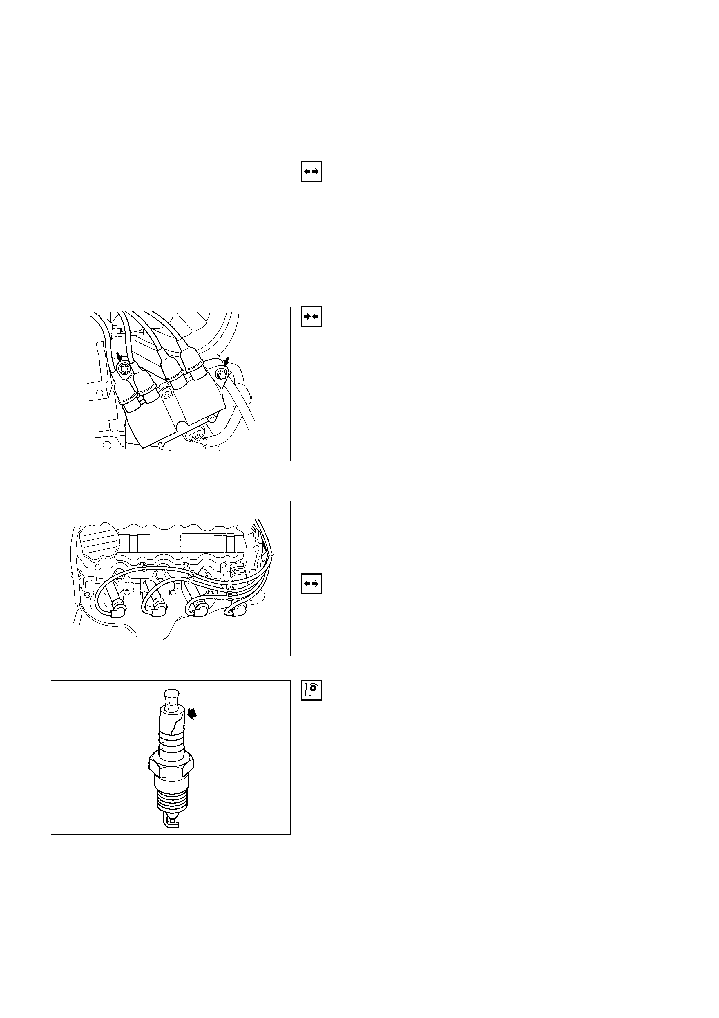
ELECTRONIC IGNITION SYSTEM
IGNITION COIL
REMOVAL
1. Disconnect the negative battery cable.
2. Disconnect all four spark plug cables from the coil.
3. Disconnect al connector from the ignition coil.
4. Remove three mounting bolts from the ignition coil.
5. Remove the ignition coil from the bracket.
INSTALLATION
1. Install the ignition coil onto the bracket with three
mounting bolts.
2. Connect al connector at the ignition coil.
3. Connect spark plug cable to the ignition coil.
4. Connect the negative battery cable.
SPARK PLUG S
Type: RN9YC4
Spark Gap: 1.0-1.1 mm (0.039" - 0.043")
Spark Plug Torque: 25N⋅m (2.5kgf⋅m)
REMOVAL
1. Disconnect the negative battery cable.
2. Remove the spark plug cable.
3. Remove the spark plug.
INSPECTION
1. Check the insulator for cracks. Replace the spark plug if
cracks are present.
2. Check the electrode condition and replace the spark plug
if necessary.
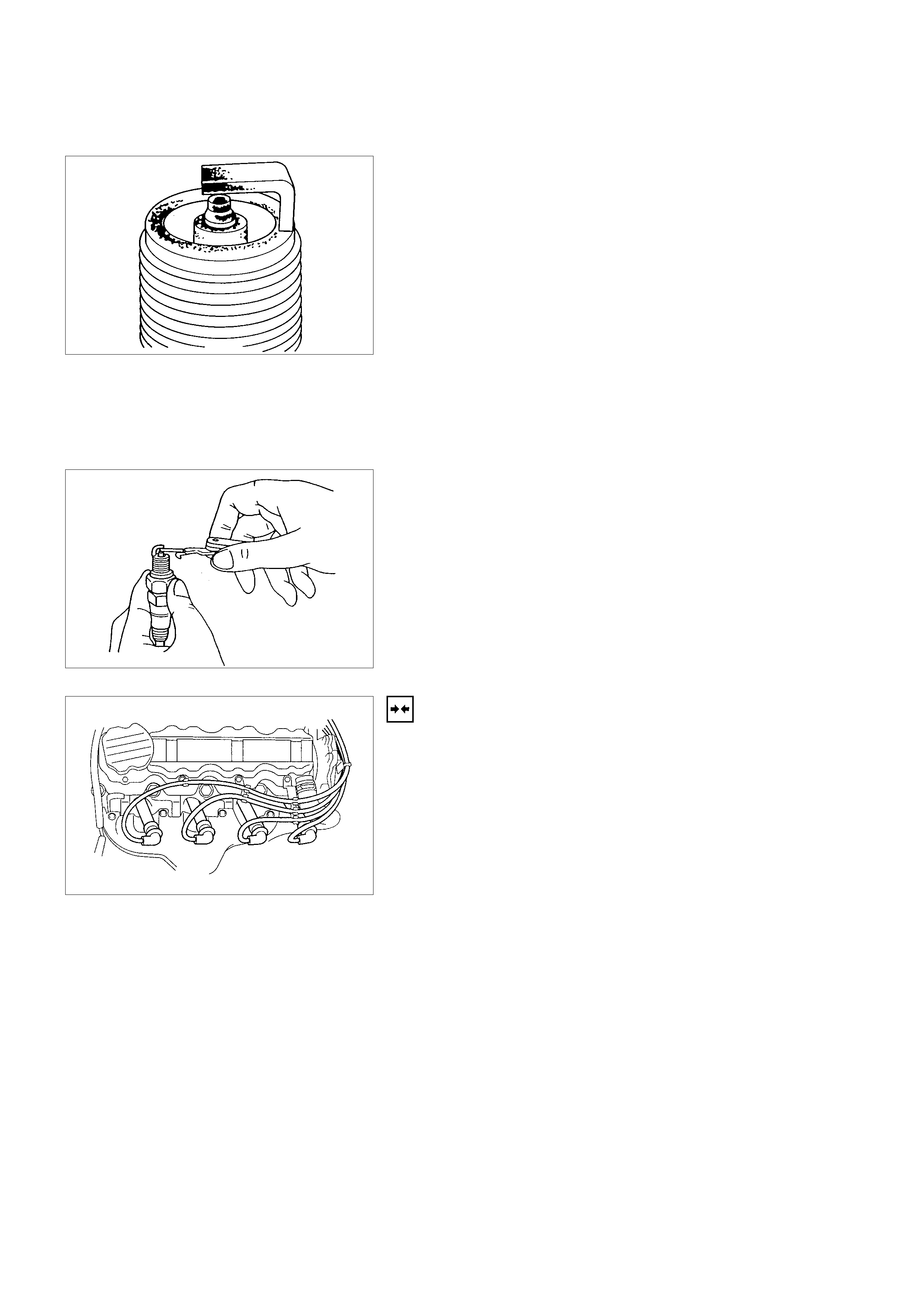
If the spark plug electrodes and insulators are fouled with carbon
or oil, the engine will not operate efficiently.
There are a number of possible causes:
•Fuel mixture is too rich.
•Oil in the combustion chamber.
•The spark plug gap is not set correctly.
If spark plug fouling is excessive, check the fuel and al system
for possible causes of trouble. If fuel and al system are normal,
install spark plugs of a higher heat range which have the same
physical dimensions as the original equipment spark plugs.
The following symptoms are characteristics of spark plugs that
are running too hot:
•Fuel mixture is too lean.
•Heat range is incorrect.
If vehicle usage does not conform to normal driving conditions,
a more suitable spark plug may be substituted.
If fuel and al system are normal, in most cases of this sort, the
problem can be corrected by using a colder type spark plug
with the same physical dimensions as the original equipment
spark plug.
3. Check the gaskets for damage and replace if necessary.
4. Measure the spark plug gap. The specification is 1.0 to
1.1mm (0.039 to 0.043").
5. Adjust the spark gap by bending the grounded electrode.
INSTALLATION
1. Tighten the spark plug to the 25N⋅m (2.5kgf⋅m).
2. Push the spark plug cable in until it snaps in.
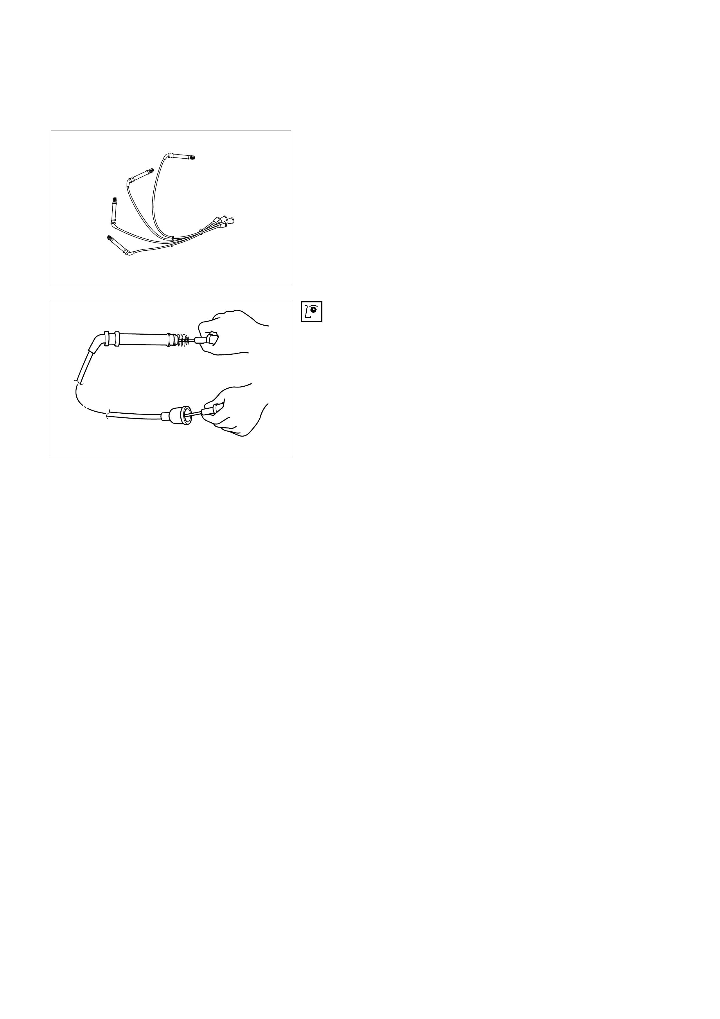
SPARK PLUG CABLES
The cable contains a synthetic conductor which is easily
damaged. Never stretch or kink the cable. Disconnect the
cable from spark plug and the ignition coil.
The original equipment cables and the ignition coil are marked
to show correct location of the cables. If spark plug cables or
the ignition coil are replaced previously, before cables are
removed from the ignition coil, mark the cables and the coil so
they can be reconnected in the same position.
INSPECTION
Notice: Never puncture the spark plug cable's insulation with a
needle or the pointed end of a probe into the cable. An
increase in resistance would be created which would cause the
cable to become defective.
1. If the cable has broken or cracked insulation, it must be
replaced.
2. If the terminals are corroded or loose, the cable must be
replaced.
3. Check that the cable resistance does not exceed #1 cyl.
4.7 kΩ, #2 cyl. 3.9 kΩ, #3 cyl. 3.4kΩ and #4 cyl. 3.1kΩ.
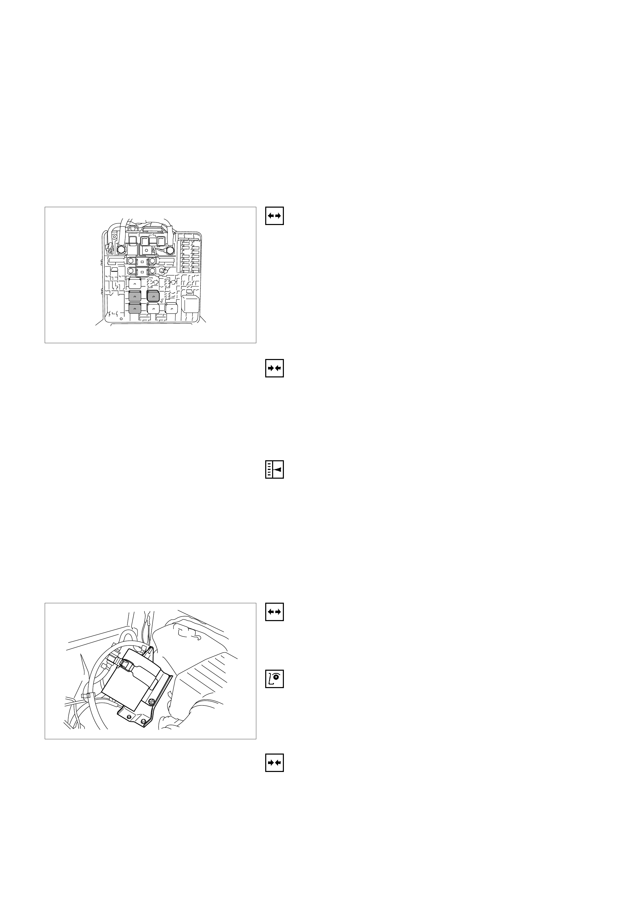
EMISSIONS
CATALYTIC CO NVERTER (IF APPLI CABLE)
Refer to Engine Exhaust.
AI R CO NDITIONING RELAY
REMOVAL
1. Remove the fuse and relay box cover at right side of
engine room.
2. Refer to the diagram on the cover to determine which is
the correct relay.
3. Insert small screwdriver or use thumb pressure to
release the retainer of the relay.
4. Pull the relay straight up and out of the fuse and relay
box.
INSTALLATION
1. Insert the relay into the correct place in the fuse and relay
box with the catch slot aligned to retainer.
2. Press down until the catch of retainer engages.
3. Install fuse and relay box cover.
IGNITION TIMING ADJUSTMENT
There is no timing adjustment. The timing signal is furnished
by the CKP, ECM control the ignition timing.
EVAP CANISTER HOSES (IF APPLI CABLE)
To see the routing of the EVAP canister hoses, refer to
Emission Control System schematics.
EVAP CANISTER (IF APPLICABLE)
REMOVAL
1. Disconnect all hoses.
2. Remove EVAP canister.
INSPECTION
1. Inspect the hoses for cracks, damage and leaks.
2. Inspect the canister for damages.
INSTALLATION
1. Install EVAP canister.
2. Connect all hoses and secure them with clamps.
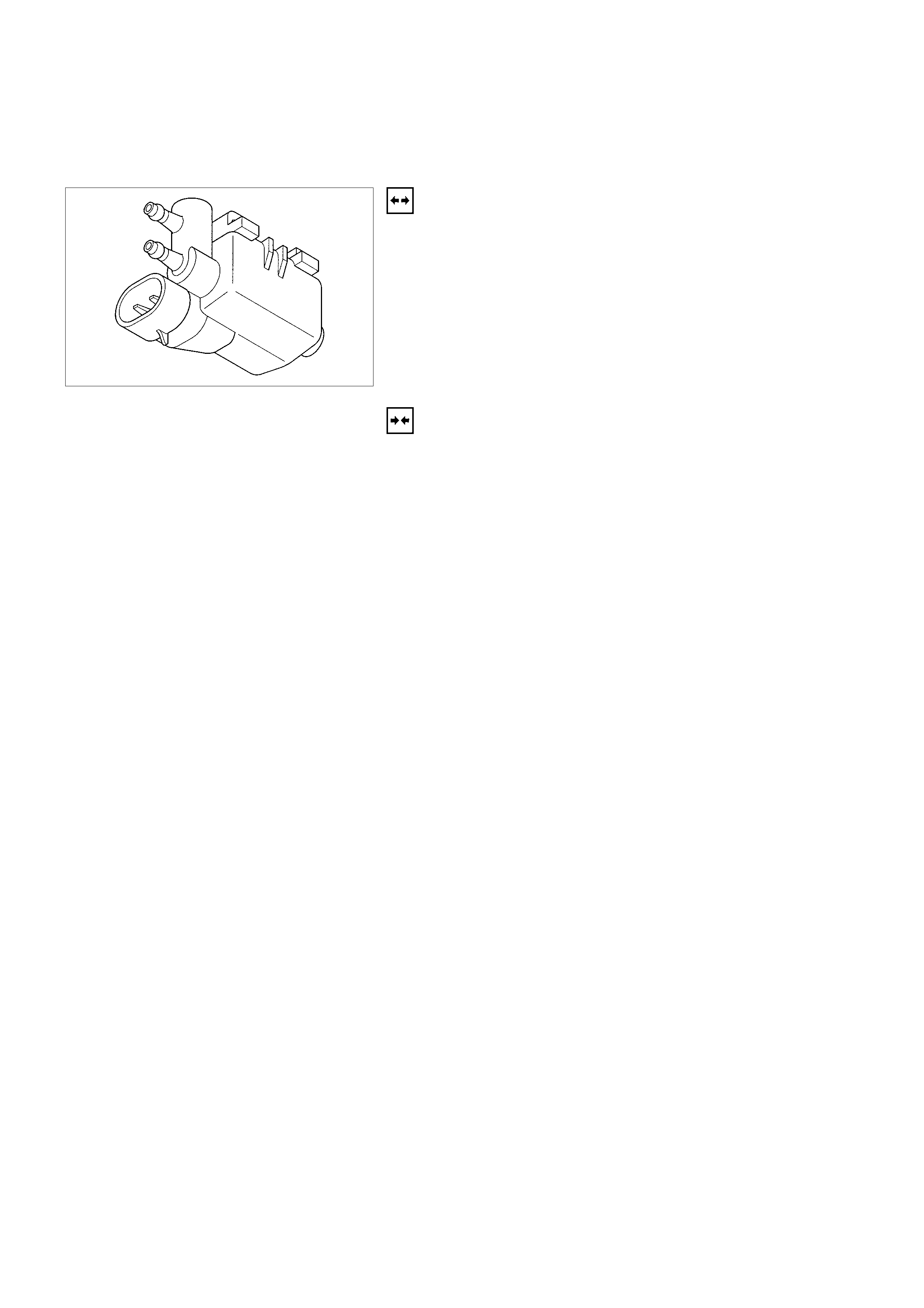
EVAP CANISTER PURGE VALVE SOLENOID
(IF APPLICABLE)
REMOVAL
1. Disconnect the negative battery cable.
2. Disconnect al connector from EVAP purge solenoid
located on the intake manifold.
3. Disconnect the vacuum hoses from the solenoid.
4. Slide EVAP purge solenoid out from the bracket.
INSTALLATION
1. Insert EVAP purge solenoid valve onto the bracket.
2. Install the bracket on the intake manifold.
3. Connect vacuum hoses and al connector at the purge
valve.

WIRING AND CONNECTORS
WIRI NG HARNESS SERVI CE
The control module harness electrically connects the control
module to the various solenoids, switches and sensors in the
vehicle engine compartment and passenger compartment.
Replace wire harnesses with the proper part number
replacement.
Because of the low amperage and voltage levels utilized in
electric control systems, it is essential that all wiring in
environmentally exposed areas be repaired with crimp and
seal splice sleeves.
The following wire harness repair information is intended as a
general guideline only. Refer to Chassis Electrical for all wire
harness repair procedures.
ECM CONNECTORS AND TERMINALS
REMOVAL
1. Remove the connector terminal retainer.
2. Push the wire connected to the affected terminal through
the connector face so that the terminal is exposed.
3. Service the terminal as necessary.
INSTALLATION
1. Bend the tab on the connector to allow the terminal to be
pulled into position within the connector.
2. Pull carefully on the wire to install the connector terminal
retainer.
CONNECTORS AND TERM INALS
Use care when probing a connector and when replacing
terminals. It is possible to short between opposite terminals.
Damage to components could result. Always use jumper wires
between connectors for circuit checking. NEVER probe
through Weather-Pack seals. Use an appropriate connector
test adapter kit which contains an assortment of flexible
connectors used to probe terminals during diagnosis. Use an
appropriate fuse remover and test tool for removing a fuse and
to adapt the fuse holder to a meter for diagnosis.
Open circuits are often difficult to locate by sight because
oxidation or terminal misalignment are hidden by the
connectors. Merely wiggling a connector on a sensor, or in the
wiring harness, may temporarily correct the open circuit.
Intermittent problems may also be caused by oxidized or loose
connections.
Be certain of the type of connector/terminal before making any
connector or terminal repair. Weather-Pack and Com-Pack III
terminals look similar, but are serviced differently.
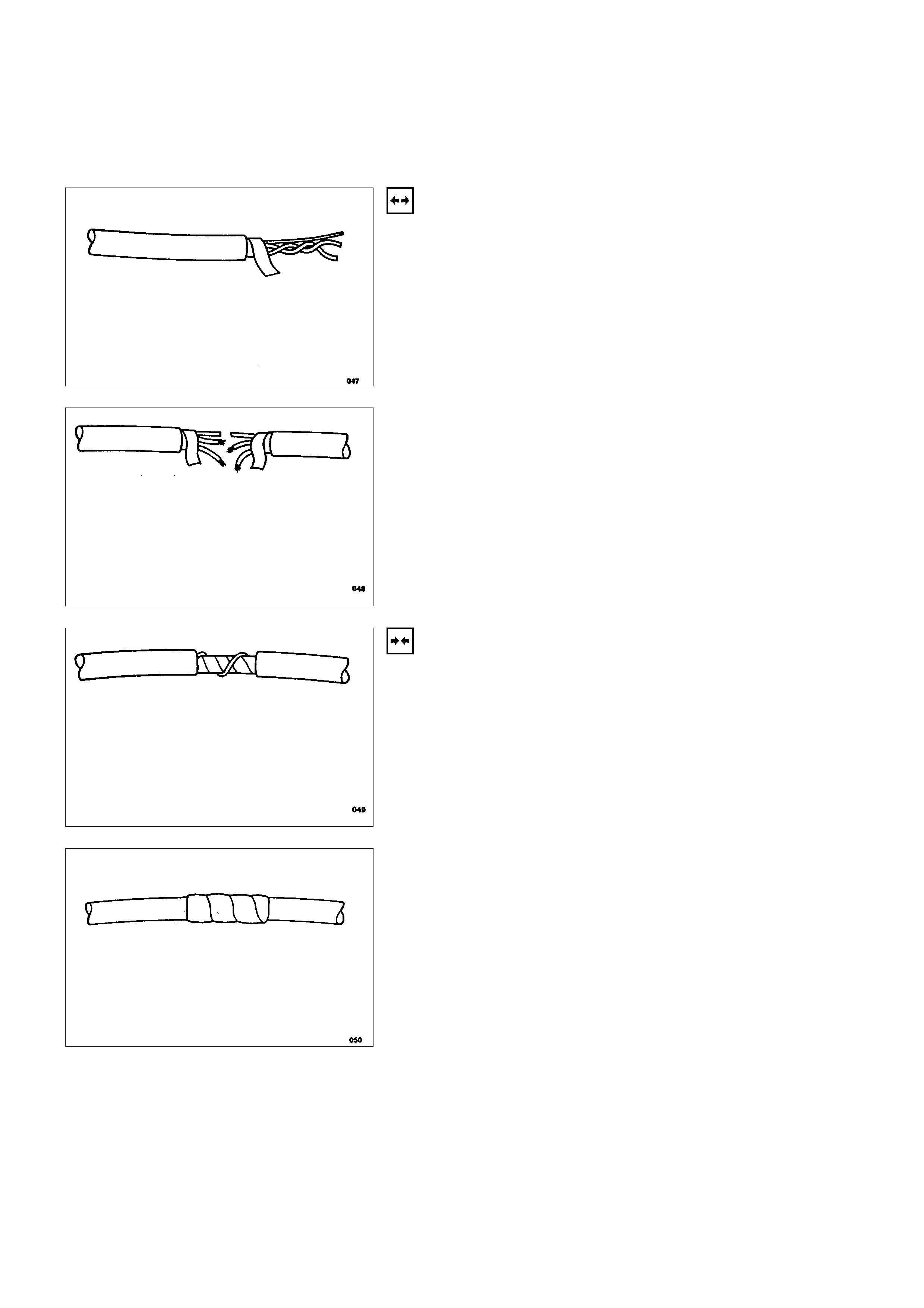
WIRE HARNESS REPAIR: TWISTED
SHIELDED CABLE
REMOVAL
1. Remove the outer jacket.
2. Unwrap the aluminum/mylar tape. Do not remove the
mylar.
3. Untwist the conductors.
4. Strip the insulation as necessary.
INSTALLATION
1. Splice the wires using splice clips and rosin core solder.
2. Wrap each splice to insulate.
3. Wrap the splice with mylar and with the drain
(uninsulated) wire.
4. Tape over the whole bundle to secure.
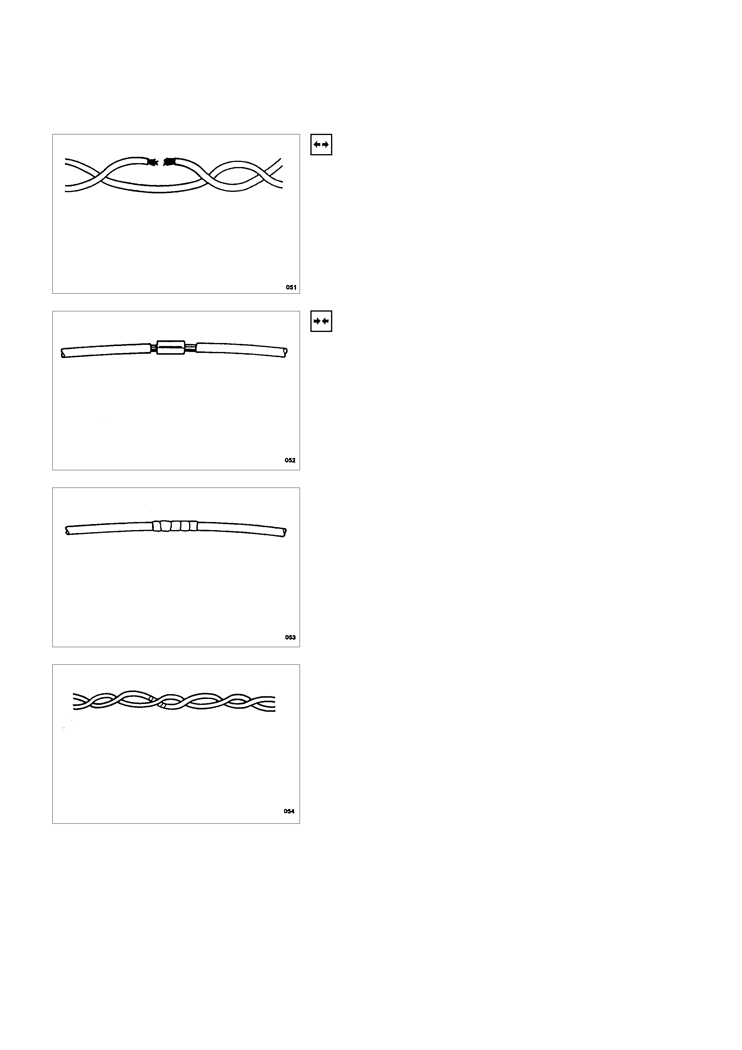
TWISTE D LEADS
REMOVAL
1. Locate the damaged wire.
2. Remove the insulation as required.
INSTALLATION
1. Use splice clips and rosin core solder in order to splice
the two wires together.
2. Cover the splice with tape in order to insulate it from the
other wires.
3. Twist the wires as they were before starting this
procedure.
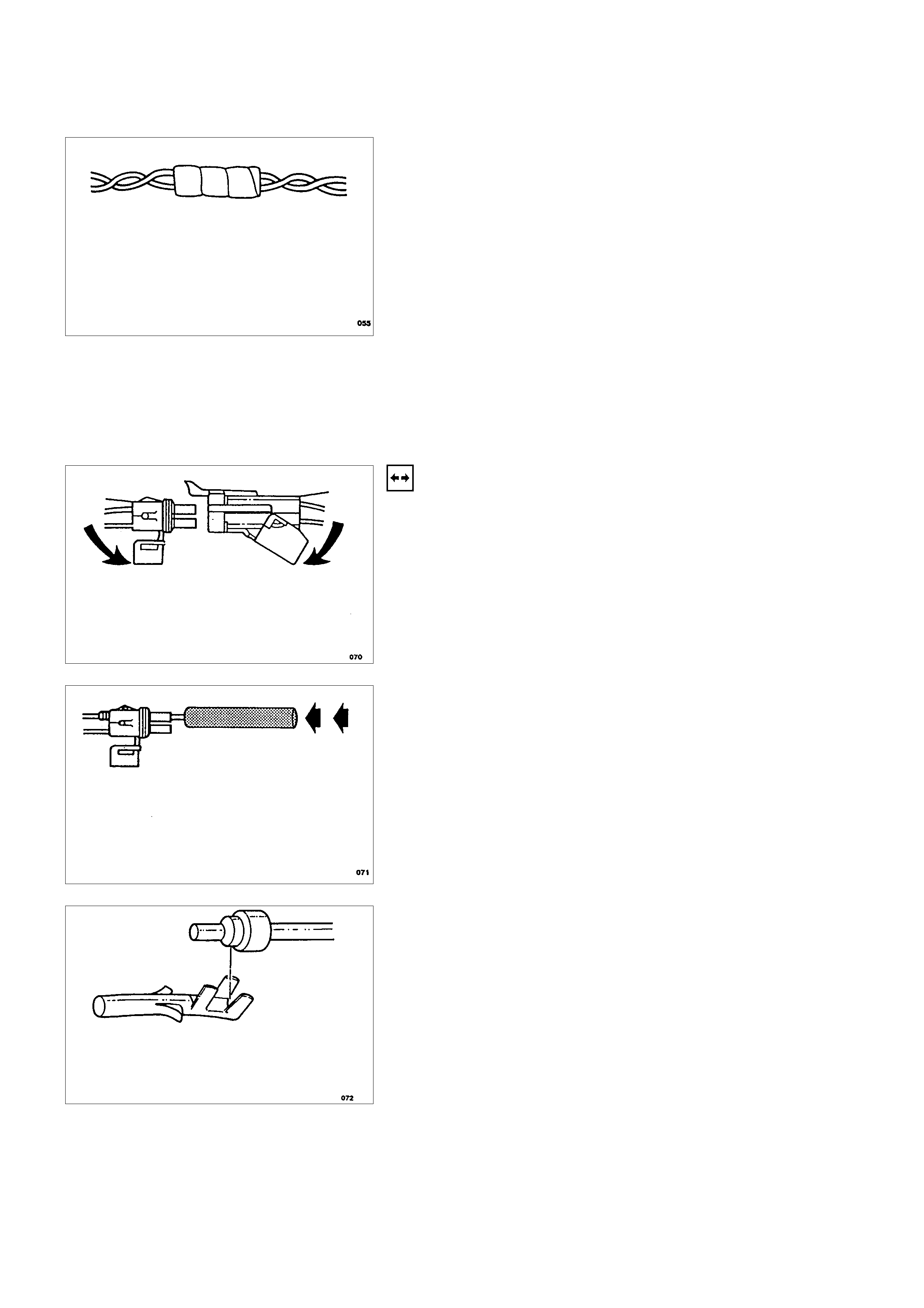
4. Tape the wires with electrical tape.
WEATHER-PACK CONNECTOR
TOOLS REQUIRED
5-8840-0388-0 Weather-Pack II Terminal Remover
REMOVAL
A Weather-Pack connector can be identified by a rubber seal
at the rear of the connector. This engine room connector
protects against moisture and dirt, which could form oxidation
and deposits on the terminals. This protection is important,
because of the low voltage and the low amperage found in the
electronic sy stems.
1. Open the secondary lock hinge on the connector.
2. Use tool 5-8840-0388-0 or the equivalent to remove the
pin and the sleeve terminals. Push on 5-8840-0388-0 to
release.
Notice: Do not use an ordinary pick or the terminal may be
bent or deformed. Unlike standard blade terminals, these
terminals cannot be straightened after they have been
improperly bent.
3. Cut the wire immediately behind the cable seal.
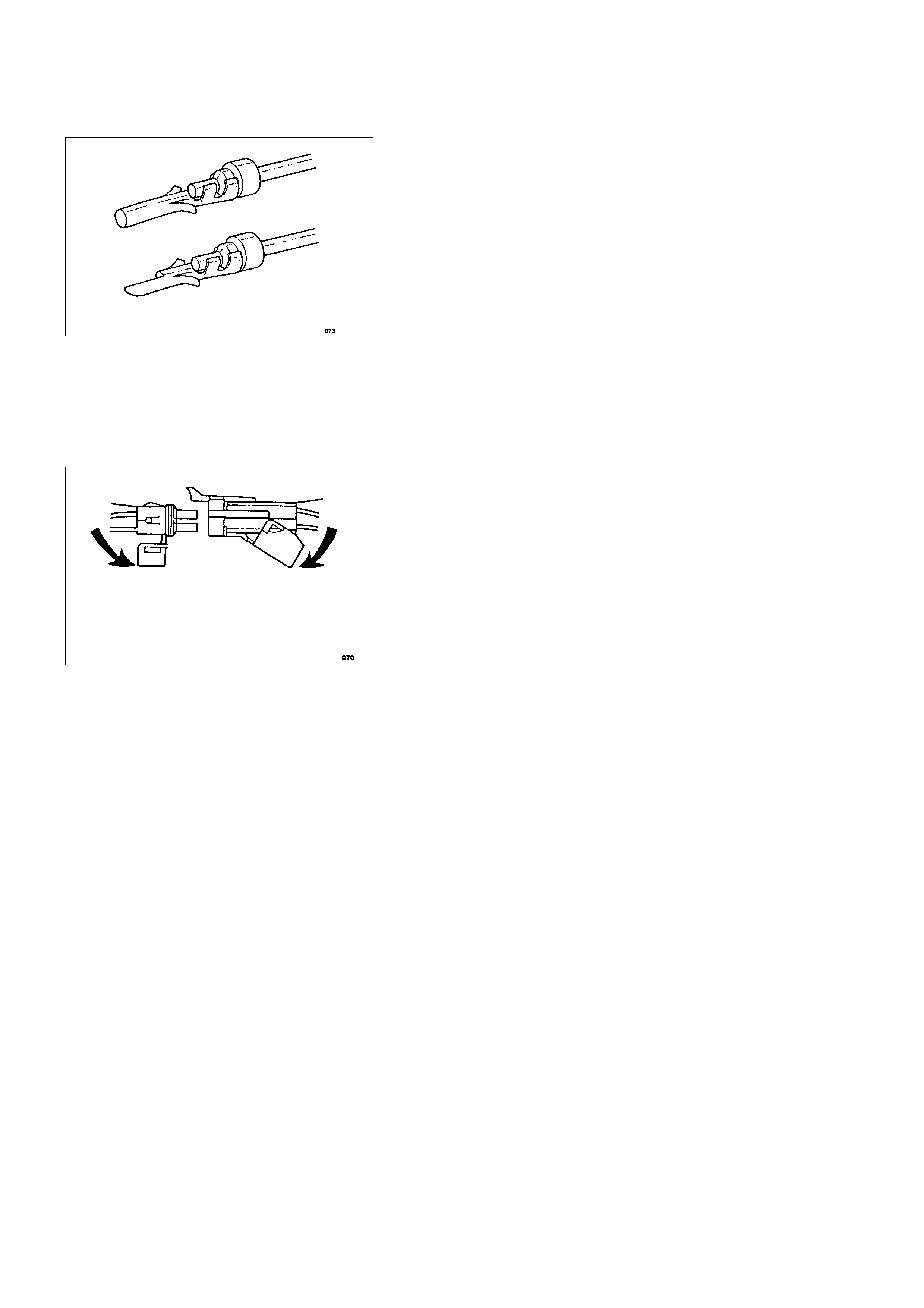
INSTALLATION
Make certain the connectors are properly seated and all of the
sealing rings are in place when you reconnect the leads. The
secondary lock hinge provides a backup locking feature for the
connector. The secondary lock hinge is used for added
reliability. This flap should retain the terminals even if the small
terminal lock tangs are not positioned properly.
Do not replace the Weather-Pack connections with standard
connections. Read the instructions provided with the Weather-
Pack connector and terminal packages.
1. Replace the terminal.
2. Slip the new seal onto the wire.
3. Strip 5mm (0.2”) of insulation from the wire.
4. Crimp the terminal over the wire and the seal.
5. Push the terminal and the connector to engage the
locking tangs.
6. Close the secondary locking hinge.
COM- PACK III
The Com-Pack III terminal looks similar to some Weather-
Pack terminals. This terminal is not sealed and is used where
resistance to the environment is not required. Use the standard
method when repairing a terminal. Do not use the Weather-
Pack terminal tool 5-8840-0388-0 or equivalent. These will
damage the terminals.
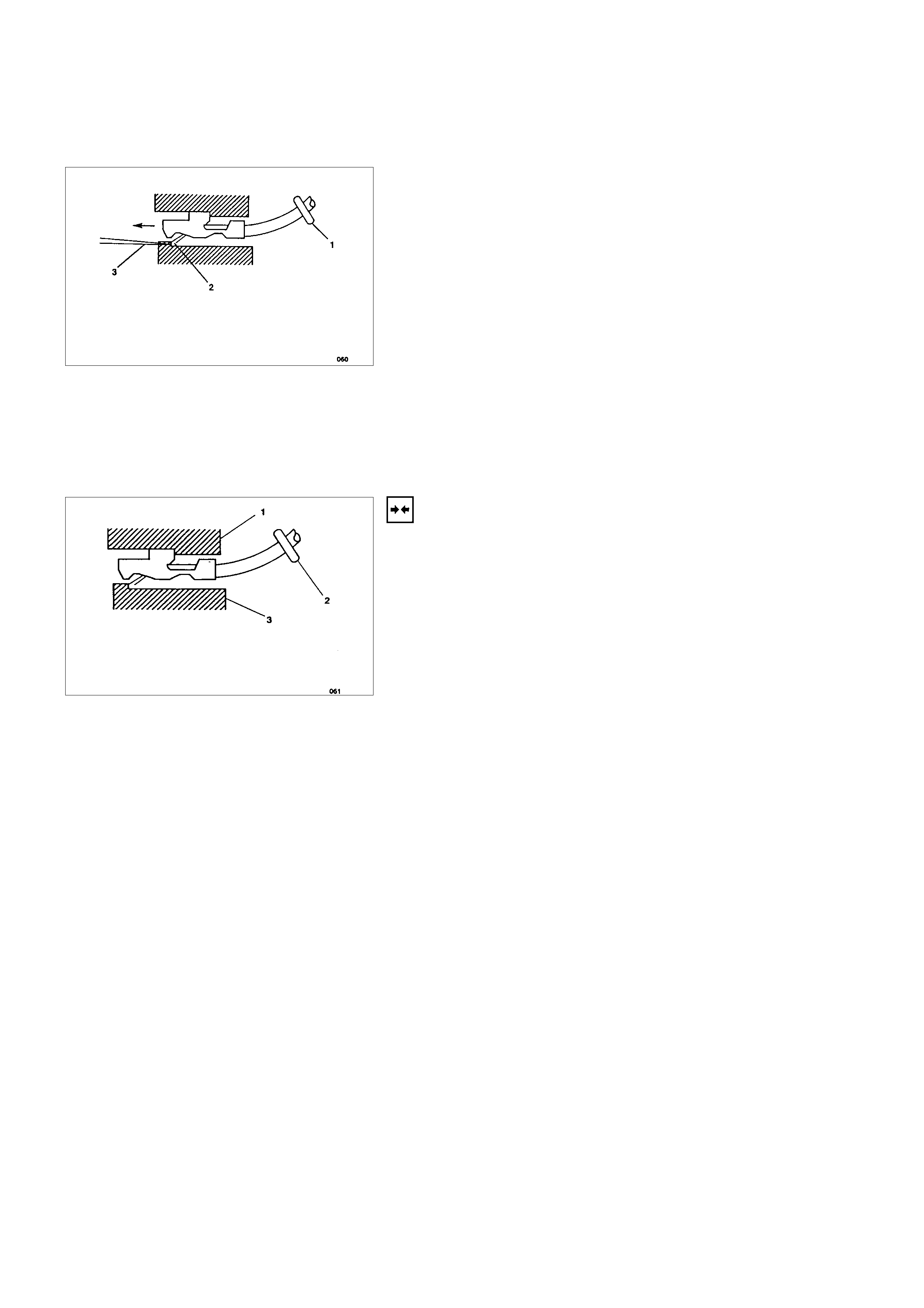
METRI-PACK
TOOLS REQUIRED
5-8840-0632-0 Terminal Remover
REMOVAL
Some connectors use terminals called Metri-Pack Series 150.
These may be used at the engine coolant temperature (ECT)
sensor.
1. Slide the seal (1) back on the wire.
2. Insert the 5-8840-0632-0 tool or equivalent (3) in order to
release the terminal locking tang (2).
3. Push the wire and the terminal out through the
connector. If you reuse the terminal, reshape the locking
tang.
INSTALLATION
Metri-Pack terminals are also referred to as "pull-to-seat"
terminals.
1. In order to install a terminal on a wire, the wire must be
inserted through the seal (2) and through the connector
(3).
2. The terminal (1) is then crimped onto the wire.
3. Then the terminal is pulled back into the connector to
seat it in place.
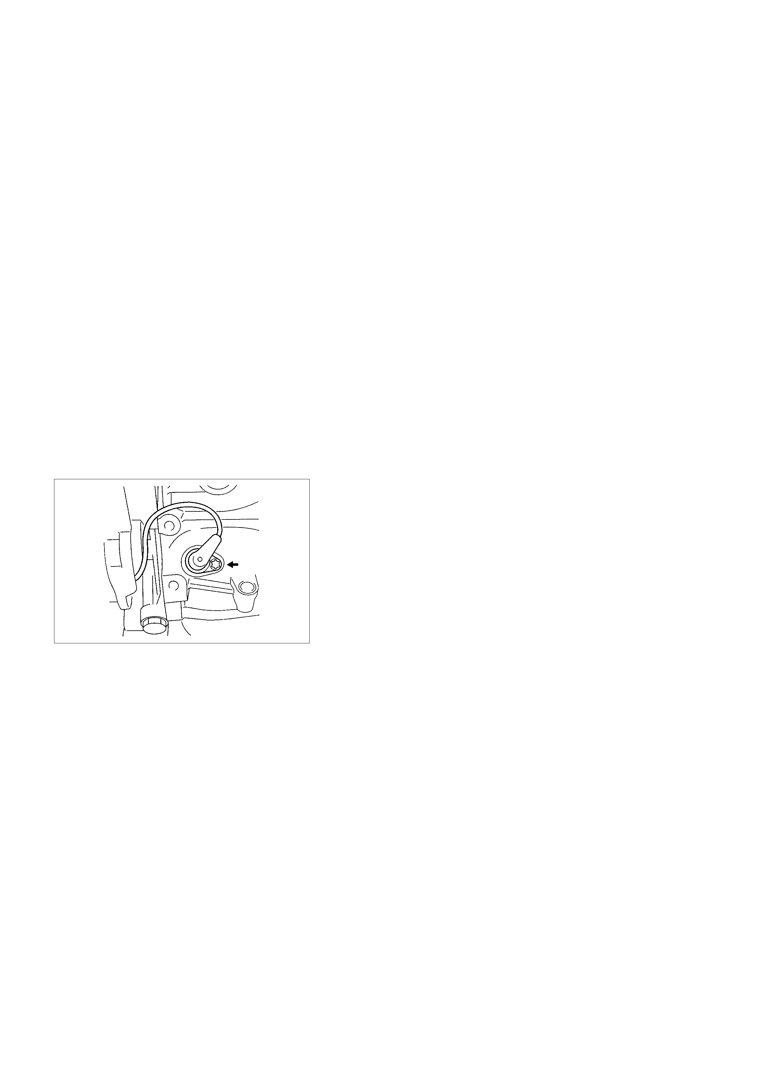
GENERAL DESCRIPTION
ECM AND SENSORS
58X REFERENCE ECM INPUT
The engine control module (ECM) uses this signal from the
crankshaft position (CKP) sensor to calculate engine RPM and
crankshaft position at all engine speeds. The ECM also uses
the pulses on this circuit to initiate injector pulses. If the ECM
receives a number of pulses other than the expected amount,
DTC 19, will set. The engine will not start and run without using
the 58X reference signal.
A/C REQUEST SIGNAL
This signal tells the ECM when the A/C mode is selected at the
A/C control switch. The ECM uses this signal to adjust the idle
speed before turning ON the A/C clutch. The A/C compressor
will be inoperative if this signal is not available to the ECM.
Refer to A/C Clutch Circuit Diagnosis for A/C wiring
diagrams and diagnosis for the A/C electrical system.
CRANKSHAFT POSITION ( CKP) SENSOR
The crankshaft position (CKP) sensor provides a signal used
by the engine control module (ECM) to calculate the ignition
sequence and ECM uses this signal as a trigger for fuel
injection timing and spark timing. The CKP sensor initiates the
58X reference pulses which the ECM uses to calculate RPM
and crankshaft position.
Refer to Electronic Ignition System for additional information.
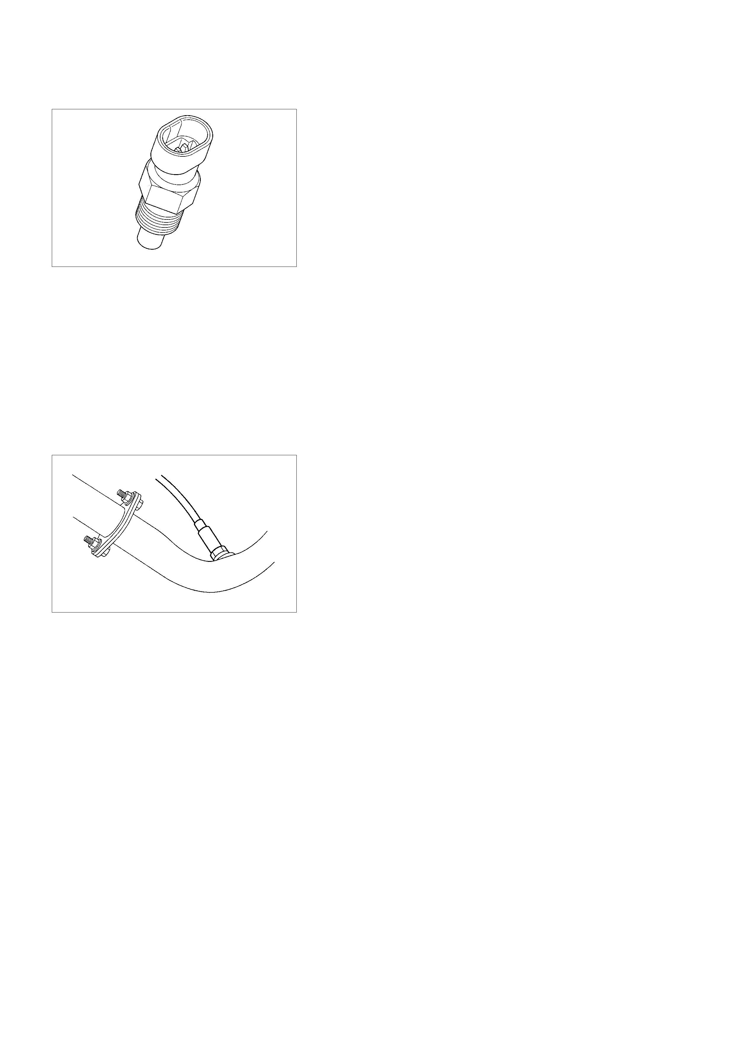
ENGINE COOLANT TEMPERATURE (ECT) SENSOR
The engine coolant temperature (ECT) sensor is a thermistor
(a resistor which changes value based on temperature)
mounted in the engine coolant stream. Low coolant
temperature produces a high resistance of about 100,000
ohms at −40°C (−40°F). High temperature causes a low
resistance of about 70 ohms at 130°C (266°F).
The ECM supplies a 5-volt signal to the ECT sensor through
resistors internal to the ECM and then measures the voltage
after the internal resistor. This signal voltage will be high when
the engine is cold and low when the engine is hot. By
measuring the voltage, the ECM calculates the engine coolant
temperature. Engine coolant temperature affects most of the
systems that the ECM controls.
The Scan Tool displays engine coolant temperature in
degrees. After engine start-up, the temperature should rise
steadily to about 92°C (197°F). It then stabilizes when the
thermostat opens. If the engine has not been run for several
hours (overnight), the engine coolant temperature and intake
air temperature displays should be close to each other. A hard
fault in the engine coolant sensor circuit will set DTC 14 or 15.
FUEL CONTROL HEATED OXYGEN SENSOR
(IF APPLICABLE)
The fuel control heated oxygen sensor is mounted in the
exhaust stream where it can monitor the oxygen content of the
exhaust gas. The oxygen present in the exhaust gas reacts
with the sensor to produce a voltage output. This voltage
should constantly fluctuate from approximately 60mV to
900mV. The heated oxygen sensor voltage can be monitored
with a Scan Tool. By monitoring the voltage output of the
oxygen sensor, the ECM calculates the pulse width command
for the injectors to produce the proper combustion chamber
mixture.
•Low HO2S voltage is a lean mixture which will result in a rich
command to compensate.
•High HO2S voltage is a rich mixture which will result in a
lean command to compensate.
When HO2S is not ready for use as a feedback for fuel control
system, Diagnostic Trouble Code 13 will be set and the scan
tool will display a voltage between 340mv and 540mv.
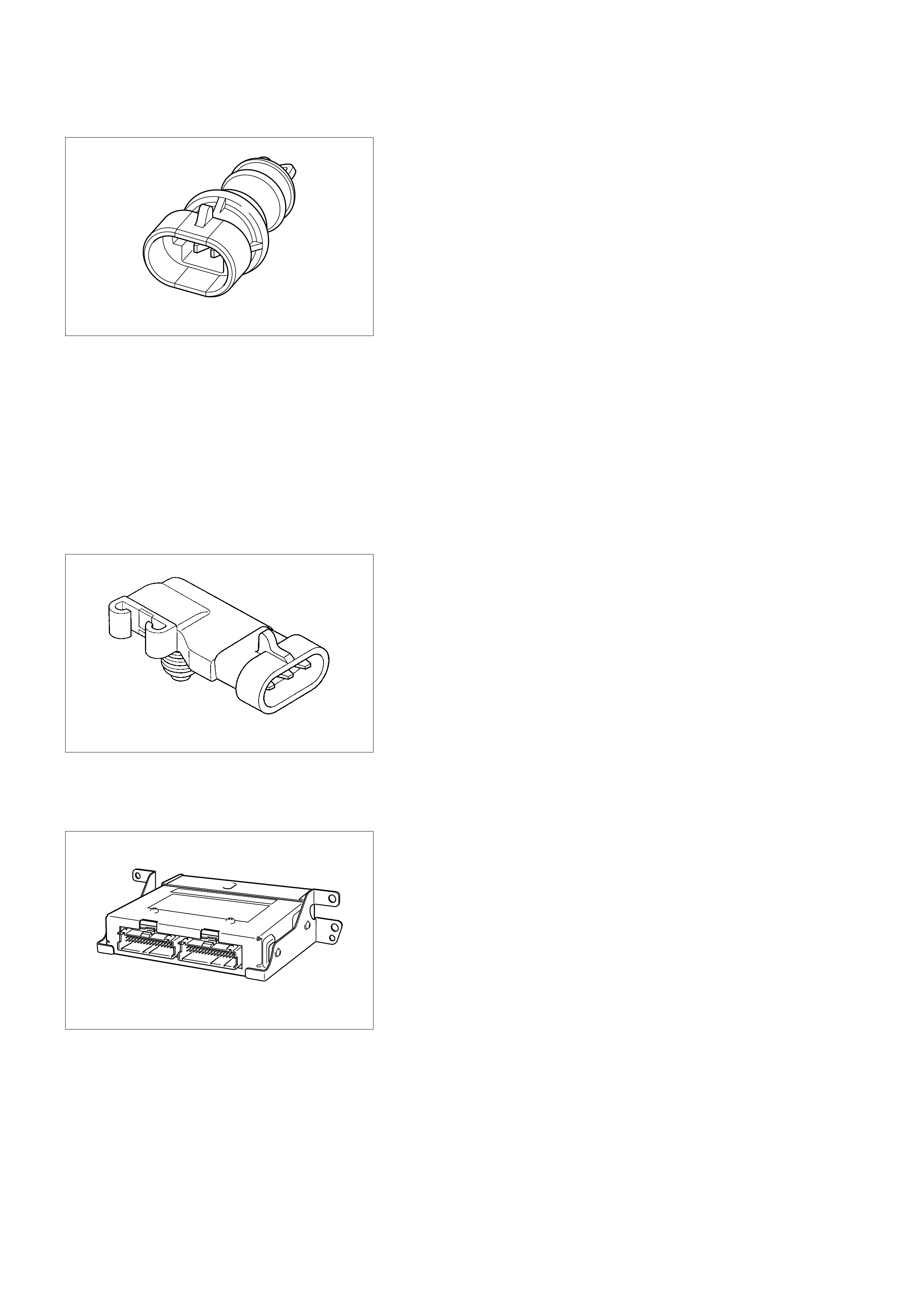
INTAKE AIR TEMPERATURE (IAT) SENSOR
The intake air temperature (IAT) sensor is a thermistor which
changes its resistance based on the temperature of air
entering the engine. Low temperature produces a high
resistance of about 100,000 ohms at −40°C (−40°F). High
temperature causes low resistance of about 70 ohms at 130°C
(266°F). The ECM supplies a 5-volt signal to the sensor
through a resistor internal to the ECM, and then monitors the
signal voltage. The voltage will be high when the incoming air
is cold. The voltage will be low when the incoming air is hot. By
measuring the voltage, the ECM calculates the incoming air
temperature. the IAT sensor signal is used to adjust spark
timing according to the incoming air density.
The Scan Tool displays the temperature of the air entering the
engine. The temperature should read close to the ambient air
temperature when the engine is cold and rise as underhood
temperature increases. If the engine has not been run for
several hours (overnight), the IAT sensor temperature and
engine coolant temperature should read close to each other. A
failure in the IAT sensor circuit will set DTC 69 or DTC 71.
MANIFOLD ABSOLUTE PRESSURE (MAP) SENSOR
The MAP sensor responds to changes in intake manifold
pressure (vacuum). the MAP sensor signal voltage to the ECM
varies from below 2 volts at idle (high vacuum) to above 4 volts
with the ignition ON, engine not running or at wide-open throttle
(low vacuum).
The MAP sensor is used to determine the following.
•Engine vacuum level for other diagnostics.
•Barometric pressure (BARO).
If the ECM detects a voltage that is lower than the possible
range of the MAP sensor, DTC 34 will be set. A signal voltage
higher than the possible range of the sensor will DTC 33.
ENGINE CO NTROL MODULE (ECM)
The engine control module (ECM) is located in the passenger
compartment at the Instrument panel lower center cover
assembly. The ECM controls the following:
•Fuel metering system.
•Ignition timing.
•On-board diagnostics for electrical functions.
The ECM constantly observes the information from various
sensors. The ECM controls the systems that affect vehicle
performance. The ECM performs the diagnostic function of the
system. It can recognize operational problems, alert the driver
through the Check Engine lamp, and store diagnostic trouble
codes (DTCs). DTCs identify the problem areas to aid the
technician in making repairs.

ECM FUNCTION
The ECM supplies either 5 or 12 volts to power various
sensors or switches. The power is supplied through resistors in
the ECM which are so high in value that a test light will not light
when connected to the circuit. In some cases, even an ordinary
shop voltmeter will not give an accurate reading because its
resistance is too low. Therefore, a digital voltmeter with at least
10 megohms input impedance is required to ensure accurate
voltage readings. Tool 5-8840-2392-0 meets this requirement.
The ECM controls output circuits such as the injectors, IAC,
etc., by controlling the ground or the power feed circuit through
transistors or through either of the following two devices:
•Output Driver Module (ODM)
•Quad Driver Module (QDM)
ECM COM PONENTS
The ECM is designed to maintain exhaust emission levels to
government mandated standards while providing excellent
driveability and fuel efficiency. The ECM monitors numerous
engine and vehicle functions via electronic sensors such as the
throttle position sensor (TPS), heated oxygen sensor (HO2S) if
applicable, and vehicle speed sensor (VSS). The ECM also
controls certain engine operations through the following:
•Fuel injector control
•Ignition control module
•Evaporative emission (EVAP) purge
•A/C clutch control
ECM VOLTAGE DESCRIPTION
The ECM supplies a buffered voltage to various switches and
sensors. It can do this because resistors in the ECM which are
so high in value that a test light may not illuminate when
connected to the circuit. An ordinary shop voltmeter may not
give an accurate reading because the voltmeter input
impedance is too low. Use a 10-megohm input impedance
digital voltmeter (such as 5-8840-2392-0) to assure accurate
voltage readings.
The input/output devices in the ECM include analog-to-digital
converters, signal buffers, counters, and special drivers. The
ECM controls most components with electronic switches which
complete a ground circuit when turned "ON." These switches
are arranged in groups of 4, called a quad driver module
(QDM), which can independently control up to 4 output.
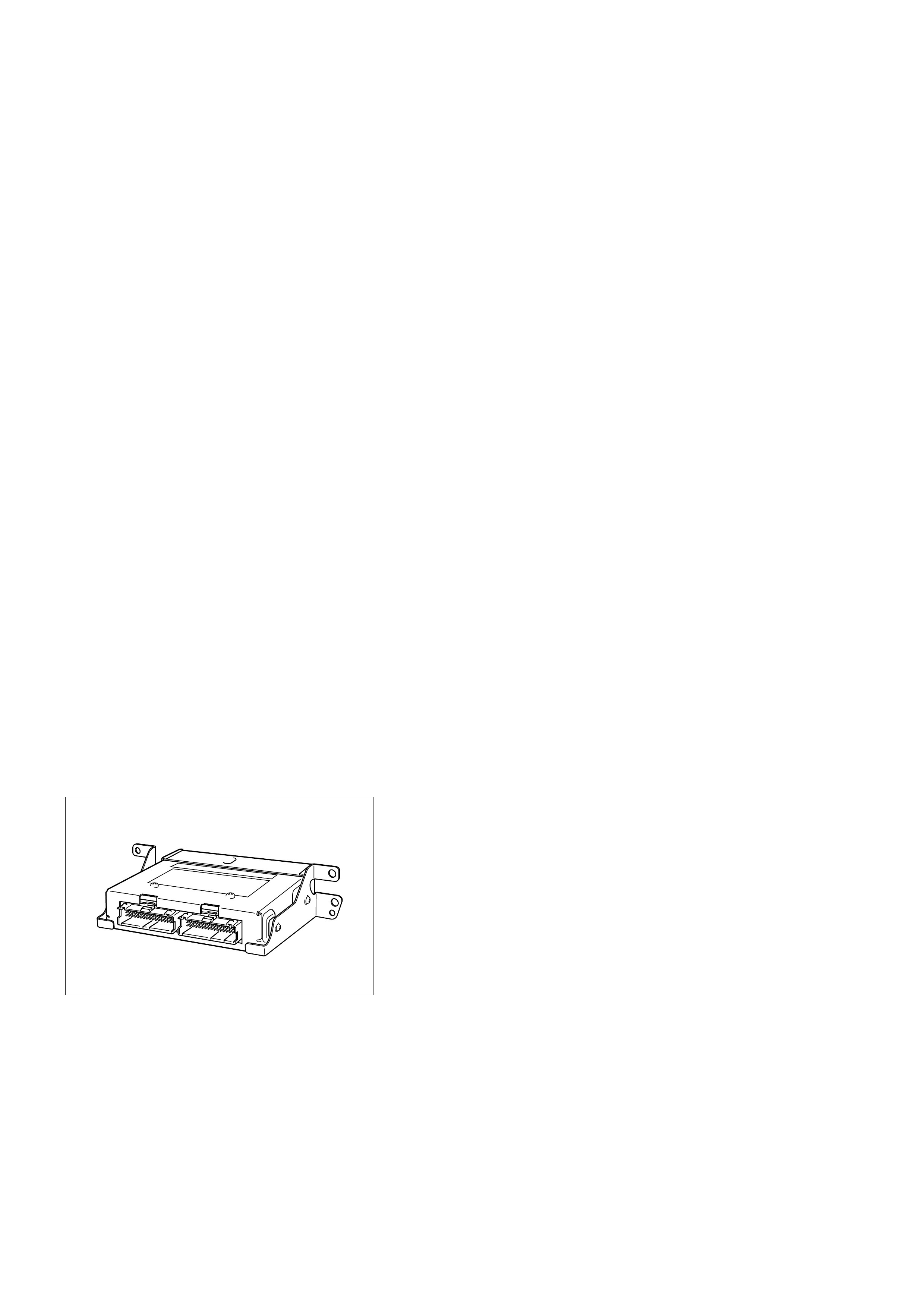
ECM INPUTS/OUTPUTS
INPUTS - OPERATING CONDITIONS READ
•Air Conditioning Compressor Clutch ON or OFF
•Engine Coolant Temperature
•Crankshaft Position
•Exhaust Oxygen Content (If equipped)
•Manifold Abso lute Pressure
•Battery Voltage
•Throttle Position
•Knock
•Vehicle Speed
•Fuel Pump Voltage
•Power Steering Pressure
•Intake Air Temperature
OUTPUTS - SYSTEMS CONTROLLED
•EVAP Canister Purge Control Solenoid Valve
•Ignition Control
•Fuel Injector Control
•Idle Air Control
•Electric Fuel Pump Relay
•Air Conditioning Compressor Clutch Relay
•Diagnostics
- OBD Malfunction Indicator Lamp (Check Engine lamp)
- Data Link Connector (DLC)
- Data Output
•Tachometer Signal
ECM SERVICE PRECAUTIONS
The ECM is designed to withstand normal current draws
associated with vehicle operation. Avoid overloading any
circuit. When testing for opens and shorts, do not ground or
apply voltage to any of the ECM's circuits unless instructed to
do so. These circuits should only be tested using digital
voltmeter 5-8840-2392-0. The ECM should remain connected
to the ECM or to a recommended breakout box.
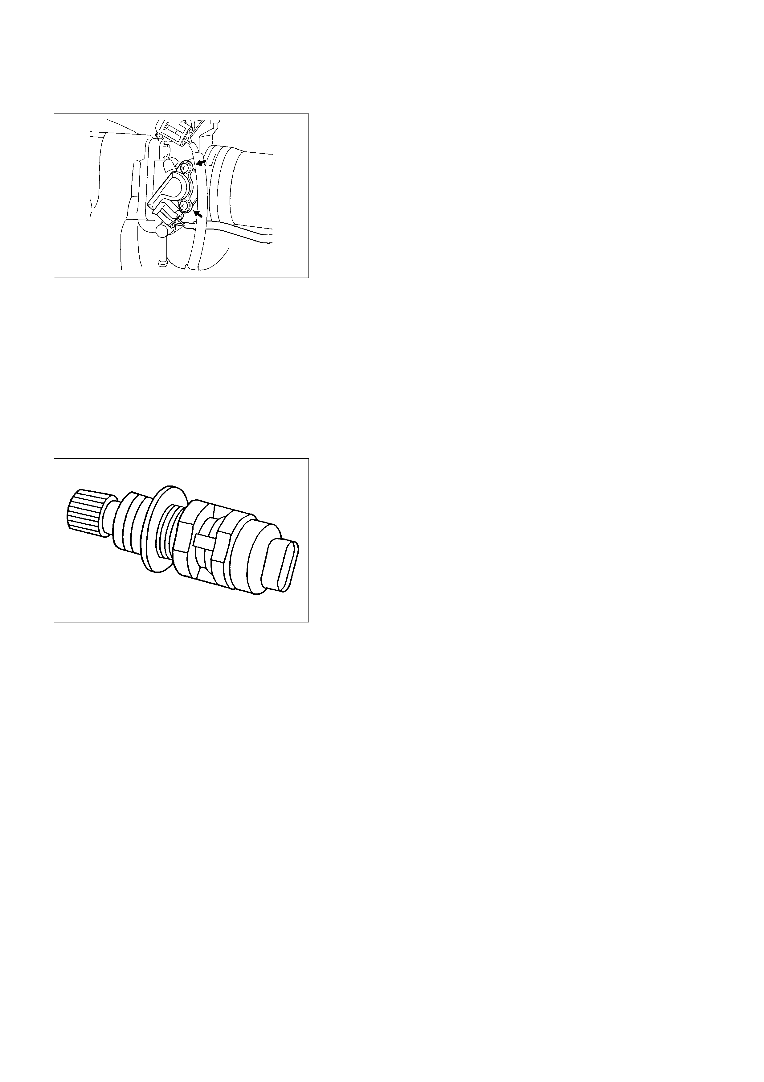
THROTTLE POSITION SENSOR (TPS)
The throttle position sensor (TPS) is a potentiometer
connected to the throttle shaft on the throttle body. The ECM
monitors the voltage on the signal line and calculates throttle
position. As the throttle valve angle is changed (accelerator
pedal moved), the TPS signal also changes. At a closed
throttle position, the output of the TPS is about 0.25 Volts. As
the throttle valve opens, the output increases so that at wide
open throttle (WOT), the output voltage should be about 4.75
volts.
The ECM calculates fuel delivery based on throttle valve angle
and manifold pressure for fuel delivery under the most
circumstances. A broken or loose TPS may cause intermittent
bursts of fuel from an injector and unstable idle because the
ECM thinks the throttle is moving. A hard failure in the TPS 5-
volt reference or signal circuits will set either a DTC21 or 22. If
ECM detects a low impedance short to ground in the TPS
circuit, Diagnostic Trouble code 22 will be set.
If ECM detects a low impedance short to battery in the TPS
circuit, Diagnostic Trouble Code 21 will be set.
VEHICLE SPEED SENSOR ( VSS)
The ECM determines the speed of the vehicle by converting a
pulsing voltage signal from the vehicle speed sensor (VSS)
into km per hour. The ECM uses this signal to operate the
speedometer.
USE OF CIRCUIT TESTING TOOLS
Do not use a test light to diagnose the electic electrical system
unless specifically instructed by the diagnostic procedures. Use
Connector Test Adapter Kit 5-8840-0385-0 whenever
diagnostic procedures call for probing connectors.

AFTERMARKET ELECTRICAL AND VACUUM
EQUIPMENT
Aftermarket (add-on) electrical and vacuum equipment is
defined as any equipment which connects to the vehicle's
electrical or vacuum systems that is installed on a vehicle after
it leaves the factory. No allowances have been made in the
vehicle design for this type of equipment.
Notice: No add-on vacuum equipment should be added to this
vehicle.
Notice: Add-on electrical equipment must only be connected
to the vehicle's electrical system at the battery (power and
ground).
Add-on electrical equipment, even when installed to these
guidelines, may still cause the electric system to malfunction.
This may also include equipment not connected to the vehicle
electrical system such as portable telephones and radios.
Therefore, the first step in diagnosing any electric problem is to
eliminate all aftermarket electrical equipment from the vehicle.
After this is done, if the problem still exists, it may be
diagnosed in the normal manner.
ELECTROSTATIC DISCHARGE DAMAGE
Electronic components used in the ECM are often designed to
carry very low voltage. Electronic components are susceptible
to damage caused by electrostatic discharge. Less than 100
volts of static electricity can cause damage to some electronic
components. By comparison, it takes as much as 4000 volts
for a person to feel even the zap of a static discharge.
There are several ways for a person to become statically
charged. The most common methods of charging are by
friction and induction.
•An exam ple of c harging by friction is a person sliding acros s
a vehicle seat.
•Charge by induction occurs when a person with well-
insulated shoes stands near a highly charged object and
momentarily touches ground. Charges of the same polarity
are drained off leaving the person highly charged with the
opposite polarity. Static charges can cause damage,
therefore it is important to use care when handling and
testing electronic components.
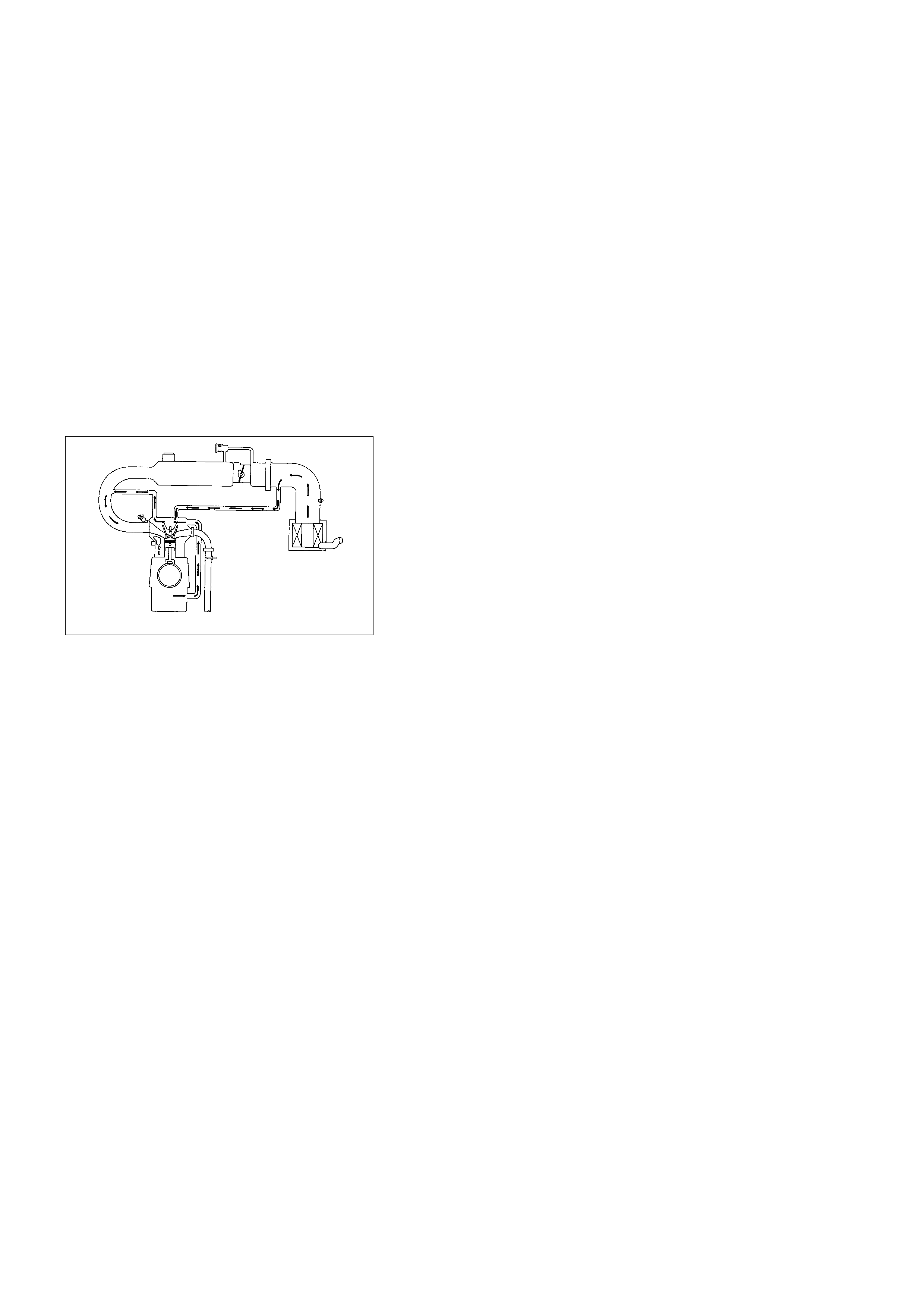
Notice: To prevent possible electrostatic discharge damage,
follow these guidelines:
•Do not touch the ECM connector pins or soldered
components on the ECM circuit board.
•Do not touch any electronic module component leads.
•Do not open the replacement part package until the part is
ready to be installed.
•Before removing the part from the package, ground the
package to a known good ground on the vehicle.
•If the part has been handled while sliding across the seat,
while sitting down from a standing position, or while walking
a distance, touc h a known good ground before installing the
part.
AI R INDUCTION
AI R INDUCTION SYSTEM
The air induction system filters contaminants from the outside air,
and directs the progress of the air as it is drawn into the engine. A
remote-mounted air cleaner prevents dirt and debris in the air from
entering the engine. The air duct assembly routes filtered air to the
throttle body. Air enters the engine by the following steps:
1. Through the throttle body.
2. Into the intake manifold.
3. Through the cylinder head intake ports.
4. Into the cylinders.
FUEL METERING
ACCELERATION MODE
The ECM provides extra fuel when it detects a rapid increase
in the throttle position and the air flow.
ACCELERATOR CONTROLS
the accelerator control system is a cable-type system with
specific linkage adjustments.
Refer to Cable Adjustment.

BATTERY VOLTAGE CORRECTION MODE
When battery voltage is low, the ECM will compensate for the
weak spark by increasing the following:
•The amount of fuel delivered.
•The idle RPM.
CLEAR FLOOD MODE
Clear a flooded engine by pushing the accelerator pedal down
all the way. The ECM then de-energizes the fuel injectors. The
ECM holds the fuel injectors de-energized as long as the
throttle remains above 75% and the engine speed is below 800
RPM. If the throttle position becomes less than 75%, the ECM
again begins to pulse the injectors ON and OFF, allowing fuel
into the cylinders.
DECELERATION FUEL CUTOFF (DFCO) M ODE
The ECM reduces the amount of fuel injected when it detects a
decrease in the throttle position and the air flow. When
deceleration is very fast, the ECM may cut off fuel completely.
Until enable conditions meet the engine revolution less 1000
rpm or manifold absolute pressure less than 10 kpa.
ENGINE SPEED/ VEHICLE SPEED/
FUEL DISABLE MODE
The ECM monitors engine speed. It turns off the fuel injectors
when the engine speed increases above 6000 RPM. The fuel
injectors are turned back on when engine speed decreases
below 3500 RPM.
FUEL CUTOFF MODE
No fuel is delivered by the fuel injectors when the ignition is
OFF. This prevents engine run-on. In addition, the ECM
suspends fuel delivery if no reference pulses are detected
(engine not running) to prevent engine flooding.
FUEL INJECTOR
The group fuel injection fuel injector is a solenoid-operated
device controlled by the ECM. The ECM energizes the
solenoid, which opens a valve to allow fuel delivery.
The fuel is injected under pressure in a conical spray pattern at
the opening of the intake valve. Excess fuel not used by the
injectors passes through the fuel pressure regulator before
being returned to the fuel tank.
A fuel injector which is stuck partly open will cause a loss of
fuel pressure after engine shut down, causing long crank
times.

FUEL METERING SYSTEM CO MPONENTS
The fuel metering system is made up of the following parts:
•The fuel injectors.
•The throttle body.
•The fuel rail.
•The fuel pressure regulator.
•The ECM.
•The crankshaft position (CKP) sensor.
•The idle air control (IAC) valve.
•The fuel pump.
•The fuel pump relay.
BASI C SYSTEM O PERATION
The fuel metering system starts with the fuel in the fuel tank.
An electric fuel pump, located in the fuel tank, pumps fuel to
the fuel rail through an in-line fuel filter. The pump is designed
to provide fuel at a pressure above the pressure needed by the
injectors. A fuel pressure regulator in the fuel rail keeps fuel
available to the fuel injectors at a constant pressure. A return
line delivers unused fuel back to the fuel tank. Refer to
Section 8A for further information on the fuel tank, line filter,
and fuel pipes.
FUEL METERING SYSTEM PURPO SE
The basic function of the air/fuel metering system is to control
the air/fuel delivery to the engine. Fuel is delivered to the
engine by individual fuel injectors mounted in the intake
manifold near each intake valve.
Following are applicable to the vehicle with closed Loop
System:
The ECM monitors signals from several sensors in order to
determine the fuel needs of the engine. Fuel is delivered under
one of several conditions called "modes." All modes are
controlled by the ECM.
The main control sensor is the heated oxygen sensor (HO2S)
located in the exhaust system. The HO2S tells the ECM how
much oxygen is in the exhaust gas. The ECM changes the
air/fuel ratio to the engine by controlling the amount of time that
the fuel injector is ON. The best mixture to minimize exhaust
emissions is 14.7 parts of air to 1 part of gasoline by weight,
which allows the catalytic converter to operate most efficiently.
Because of the constant measuring and adjusting of the
air/fuel ratio, the fuel injection system is called a "closed loop"
system.
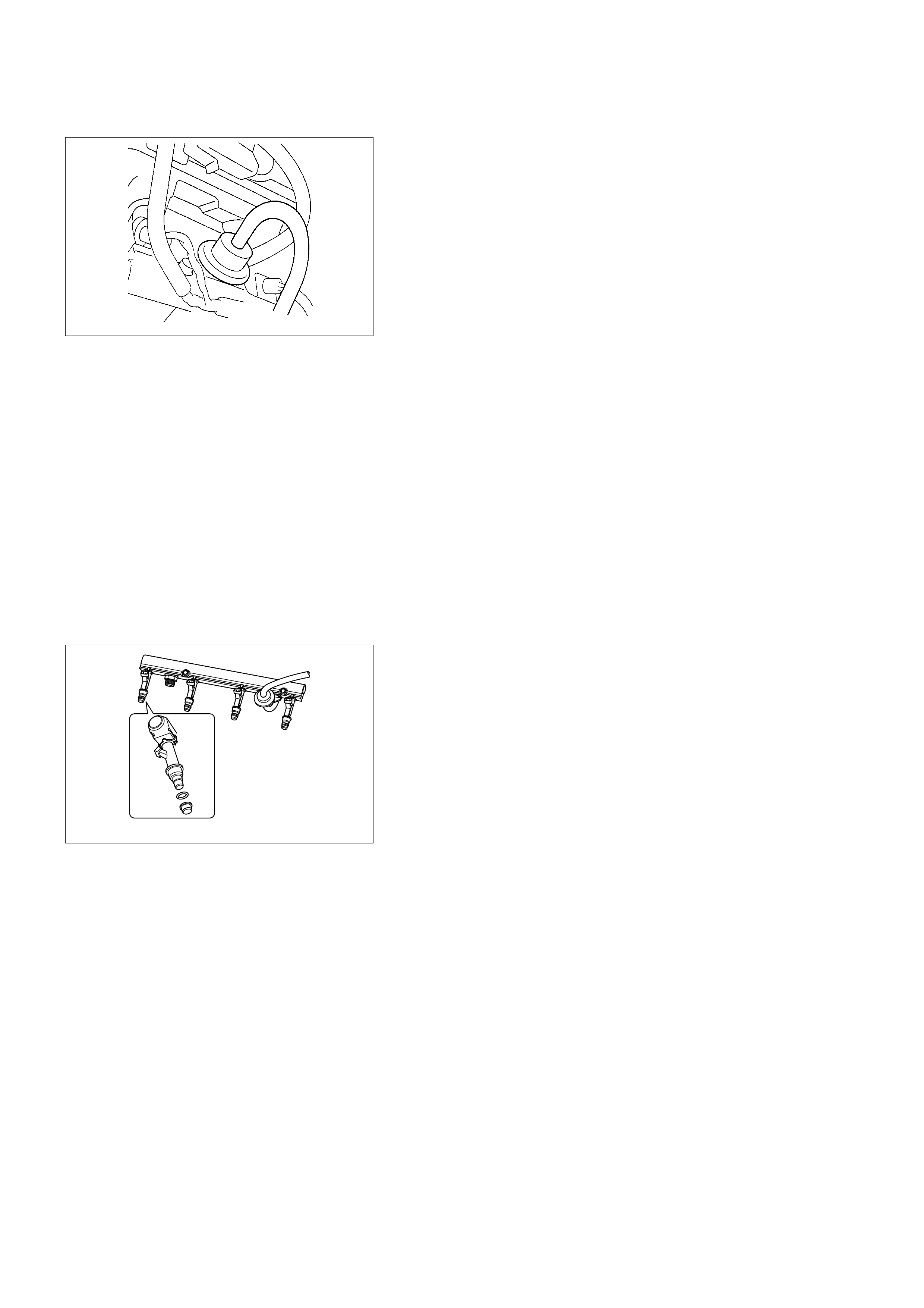
FUEL PRESSURE REGULATOR
The fuel pressure regulator is a diaphragm-operated relief
valve mounted on the fuel rail with fuel pump pressure on one
side and manifold pressure on the other side. The fuel
pressure regulator maintains the fuel pressure available to the
injector at three times barometric pressure adjusted for engine
load. It may be serviced separately.
If the pressure is too low, poor performance and a DTC 44, will
be the result. If the pressure is too high, a DTC 45 will be the
result. Refer to Fuel System Diagnosis for information on
diagnosing fuel pressure conditions.
FUEL PUMP ELECTRICAL CIRCUIT
When the key is first turned ON, the ECM energizes the fuel
pump relay for two seconds to build up the fuel pressure
quickly. If the engine is not started within two seconds, the
ECM shuts the fuel pump off and waits until the engine is
cranked. When the engine is cranked and the 58X crankshaft
position signal has been detected by the ECM, the ECM
supplies 12 volts to the fuel pump relay to energiz e the electric
in-tank fuel pump.
An inoperative fuel pump will cause a "no-start" condition. A
fuel pump which does not provide enough pressure will result
in poor performance.
FUEL RAIL
The fuel rail is mounted to the top of the engine and distributes
fuel to the individual injectors. Fuel is delivered to the fuel inlet
tube of the fuel rail by the fuel lines. The fuel goes through the
fuel rail to the fuel pressure regulator. The fuel pressure
regulator maintains a constant fuel pressure at the injectors.
Remaining fuel is then returned to the fuel tank.

IDLE AIR CONTROL (IAC) VALVE
The purpose of the idle air control (IAC) valve is to control
engine idle speed, while preventing stalls due to changes in
engine load. The IAC valve, mounted in the throttle body,
controls bypass air around the throttle plate. By moving the
conical valve (pintle) in (to decrease air flow) or out (to
increase air flow), a controlled amount of air can move around
the throttle plate. If the RPM is too low, the ECM will retract the
IAC pintle, resulting in more air moving past the throttle plate to
increase the RPM. If the RPM is too high, the ECM will extend
the IAC pintle, allowing less air to move past the throttle plate,
decreasing the RPM.
The IAC pintle valve moves in small steps called counts.
During idle, the proper position of the IAC pintle is calculated
by the ECM based on battery voltage, coolant temperature,
engine load, and engine RPM. If the RPM drops below a
specified value, and the throttle plate is closed, the ECM
senses a near-stall condition. The ECM will then calculate a
new IAC pintle valve position to prevent stalls.
If the IAC valve is disconnected and reconnected with the
engine running, the idle RPM will be wrong. In this case, the
IAC must be reset. The IAC resets when the key is cycled on
ON then OFF. When servicing the IAC, it should only be
disconnected or connected with the ignition OFF.
The position of the IAC pintle valve affects engine start-up and
the idle characteristics of the vehicle. When the ECM detects
the 175 rpm higher engine revolution than desires engine rpm,
this malfunction detects an error in the IAC control logic.
Diagnostic Trouble code 35 will be set.
RUN MODE ( APPLICABLE TO
CLOSED LOOP SYSTEMS)
The run mode has the following two conditions:
•Open loop
•Closed loop
When the engine is first started, the system is in "open loop"
operation. In "Open Loop," the ECM ignores the signal from
the heated oxygen sensor (HO2S). It calculates the air/fuel
ratio based on inputs from the TP, ECT, and MAP sensors.
The system remains in "Open Loop" until the following
conditions are met:
•The HO2S has a varying voltage output showing that it is hot
enough to operate properly (this depends on temperature).
•The ECT has reached a specified temperature.
•A specific amount of time has elapsed since starting the
engine.
•Engine speed has been greater than a specified RPM since
start-up.
The specific values for the above conditions vary with different
engines and are stored in the programmable read only memory
(PROM). When these conditions are met, the system enters
"closed loop" operation. In "closed loop," the ECM calculates
the air/fuel ratio (injector on-time) based on the signal from the
HO2S. This allows the air/fuel ratio to stay very close to 14.7:1.
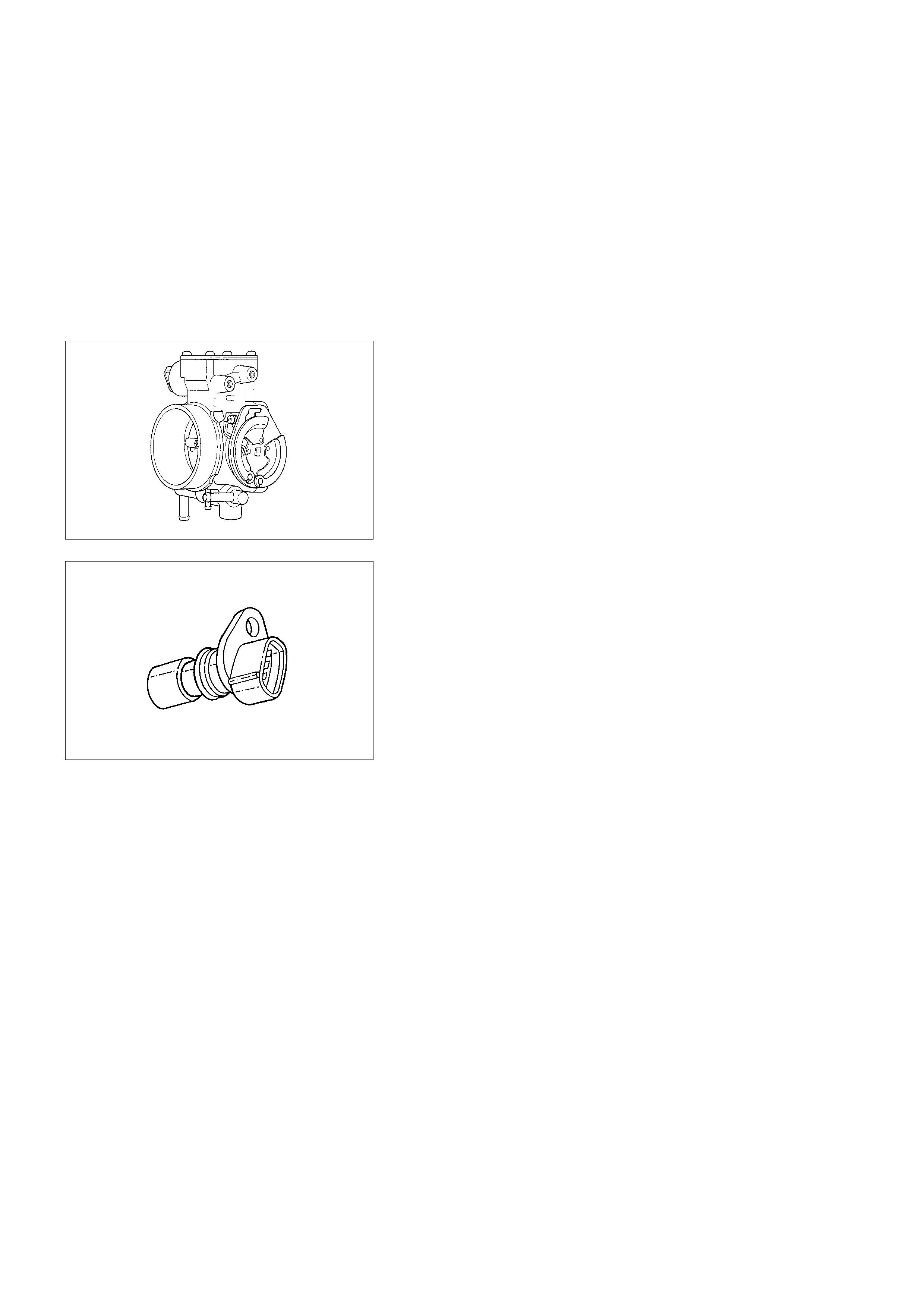
STARTING MODE
When the ignition is first turned ON, the ECM energizes the
fuel pump relay for two seconds to allow the fuel pump to build
up pressure. The ECM then checks the engine coolant
temperature (ECT) sensor and the throttle position (TP) sensor
to determine the proper air/fuel ratio for starting.
The ECM controls the amount of fuel delivered in the starting
mode by adjusting how long the fuel injectors are energized by
pulsing the injectors for very short times.
THROTTLE BODY UNIT
The throttle body has a throttle plate to control the amount of
air delivered to the engine. The TP sensor and IAC valve are
also mounted on the throttle body.
Vacuum ports located behind the throttle plate provide the
vacuum signals needed by various components. Engine
coolant is directed through a coolant cavity in the throttle body
to warm the throttle valve and to prevent icing.
ELECTRONIC IGNITION SYSTEM
CRANKSHAFT POSITION (CKP) SENSOR
The crankshaft position (CKP) sensor provides a signal used
by the engine control module (ECM) to calculate the ignition
sequence. The sensor initiates the 58X reference pulses which
the ECM uses to calculate RPM and crankshaft position. Refer
to Electronic Ignition System for additional information.
ELECTRONIC IGNITION
The electronic ignition system controls fuel combustion by
providing a spark to ignite the compressed air/fuel mixture at
the correct time. The provide optimum engine performance,
fuel economy, and control of exhaust emissions, the ECM
controls the spark advance of the ignition system. Electronic
ignition has the following advantages over a mechanical
distributor system:
•No moving parts.
•Less maintenance.
•Remote mounting capability.
•No mechanical load on the engine.
•More coil cool down time between firing events.
•Elimination of mechanical timing adjustments.
•Increased available ignition coil saturation time.

IGNITION COILS
The all engines use 2 ignition coils, 1 per 2 cylinders. A two-
wire connector provides a 12-volt primary supply through the
15-amp ignition coil fuse.
IGNITION CONTROL
The ignition control (IC) spark timing is the ECM's method of
controlling the spark advance and the ignition dwell.
The IC spark advance and the ignition dwell are calculated by
the ECM using the following inputs:
•Engine speed.
•Crankshaft position (58X reference).
•Engine coolant temperature (ECT) sensor.
•Throttle position (TP) sensor.
•Vehicle speed (vehicle speed sensor).
•ECM and ignition system supply voltage.
IGNITION CONTROL ECM OUTPUT
Ignition Coil works to generate only the secondary voltage be
receiving the primary voltage from ECM.
The primary voltage is generated at the coil driver located in
the ECM. The coil driver generate the primary voltage based
on the X58 signal. In accordance with the X58 signal, ignition
coil driver determines the adequate ignition timing and also
cylinder number to ignite.
Ignition timing is determined the Coolant Temp., Intake Air
Temp., Engine Speed, Engine Load, knock Sensor Signal, etc.
ENGINE CO NTROL MODULE (ECM)
The ECM is responsible for maintaining proper spark and fuel
injection timing for all driving conditions. To provide optimum
driveability and emissions, the ECM monitors the input signals
from the following components in order to calculate spark
timing:
•Engine coolant temperature (ECT) sensor.
•Intake air temperature (IAT) sensor.
•Throttle position sensor (TPS).
•Vehicle speed sensor (VSS).
•Crankshaft position (CKP) sensor.

SPARK PLUG
Although worn or dirty spark plugs may give satisfactory
operation at idling speed, they frequently fail at higher engine
speeds. Faulty spark plugs may cause poor fuel economy,
power loss, loss of speed, hard starting and generally poor
engine performance. Follow the scheduled maintenance service
recommendations to ensure satisfactory spark plug
performance. Refer to Maintena nce and Lubric ation.
Normal spark plug operation will result in brown to grayish-tan
deposits appearing on the insulator portion of the spark plug. A
small amount of red-brown, yellow, and white powdery material
may also be present on the insulator tip around the center
electrode. These deposits are normal combustion by-products
of fuels and lubricating oils with additives. Some electrode
wear will also occur. Engines which are not running properly
are often referred to as "misfiring." This means the ignition
spark is not igniting the air/fuel mixture at the proper time.
While other ignition and fuel system causes must also be
considered, possible causes include ignition system conditions
which allow the spark voltage to reach ground in some other
manner than by jumping across the air gap at the tip of the
spark plug, leaving the air/fuel mixture unburned. Misfiring may
also occur when the tip of the spark plug becomes overheated
and ignites the mixture before the spark jumps. This is referred
to as "pre-ignition."
Spark plugs may also misfire due to fouling, excessive gap, or
a cracked or broken insulator. If misfiring occurs before the
recommended replacement interval, locate and correct the
cause.
Carbon fouling of the spark plug is indicated by dry, black
carbon (soot) deposits on the portion of the spark plug in the
cylinder. Excessive idling and slow speeds under light engine
loads can keep the spark plug temperatures so low that these
deposits are not burned off. Very rich fuel mixtures or poor
ignition system output may also be the cause. Refer to
DTC 45.
Oil fouling of the spark plug is indicated by wet oily deposits on
the portion of the spark plug in the cylinder, usually with little
electrode wear. This may be caused by oil during break-in of
new or newly overhauled engines. Deposit fouling of the spark
plug occurs when the normal red-brown, yellow or white
deposits of combustion by-products become sufficient to cause
misfiring. In some cases, these deposits may melt and form a
shiny glaze on the insulator around the center electrode. If the
fouling is found in only one or two cylinders, valve stem
clearances or intake valve seals may be allowing excess
lubricating oil to enter the cylinder, particularly if the deposits
are heavier on the side of the spark plug facing the intake
valve.
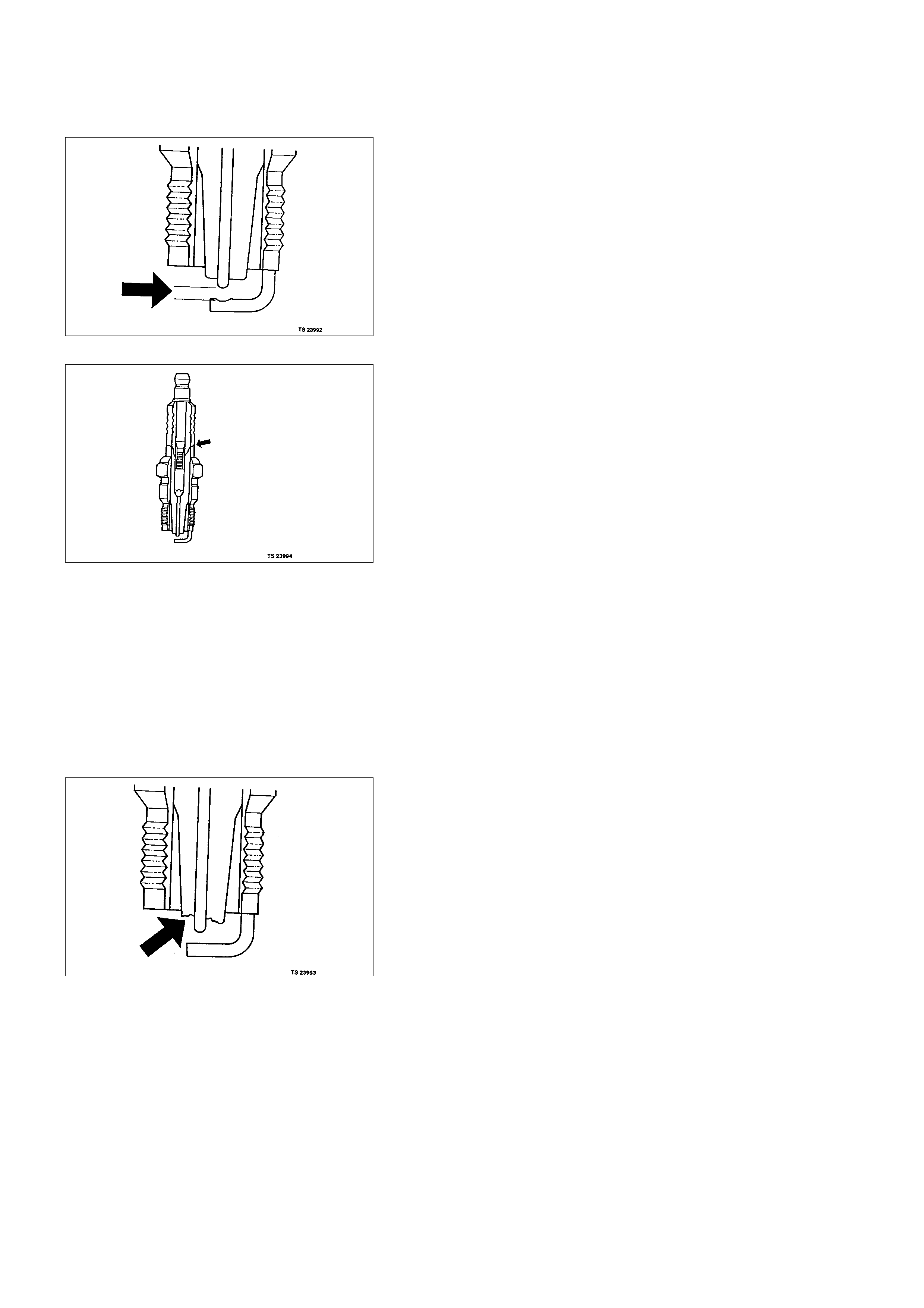
Excessive gap means that the air space between the center
and the side electrodes at the bottom of the spark plug is too
wide for consistent firing. This may be due to improper gap
adjustment or to excessive wear of the electrode during use. A
check of the gap size and comparison to the gap specified for
the vehicle in Maintenance and Lubrication will tell if the gap is
too wide. A spark plug gap that is too small may cause an
unstable idle condition. Excessive gap wear can be an
indication of continuous operation at high speeds or with
engine loads, causing the spark to run too hot. Another
possible cause is an excessively lean fuel mixture.
Low or high spark plug installation torque or improper seating
can result in the spark plug running too hot and can cause
excessive center electrode wear. The plug and the cylinder
head seats must be in good contact for proper heat transfer
and spark plug cooling. Dirty or damaged threads in the head
or on the spark plug can keep it from seating even though the
proper torque is applied. Once spark plugs are properly
seated, tighten them to the torque shown in the Specifications
Table. Low torque may result in poor contact of the seats due
to a loose spark plug. Over tightening may cause the spark
plug shell to be stretched and will result in poor contact
between the seats. In extreme cases, exhaust blow-by and
damage beyond simple gap wear may occur.
Cracked or broken insulators may be the result of improper
installation, damage during spark plug re-gapping, or heat
shock to the insulator material. Upper insulators can be broken
when a poorly fitting tool is used during installation or removal,
when the spark plug is hit from the outside, or is dropped on a
hard surface. Cracks in the upper insulator may be inside the
shell and not visible. Also, the breakage may not cause
problems until oil or moisture penetrates the crack later.
A broken or cracked lower insulator tip (around the center
electrode) may result from damage during re-gapping or from
"heat shock" (spark plug suddenly operating too hot).
•Damage during re-gapping can happen if the gapping tool is
pushed against the center electrode or the insulator around
it, causing the insulator to crack. When re-gapping a spark
plug, make the adjustment by bending only the ground side
terminal, keeping the tool clear of other parts.
•"Heat shock" breakage in the lower insulator tip generally
occurs during several engine operating conditions (high
speeds or heavy loading) and may be caused by over-
advanced timing or low grade fuels. Heat shock refers to a
rapid increase in the tip temperature that causes the
insulator material to crack.
Spark plugs with less than the recommended amount of
service can sometimes be cleaned and re-gapped, then
returned to service. However, if there is any doubt about the
serviceability of a spark plug, replace it. Spark plugs with
cracked or broken insulators should always be replaced.

A/ C CLUTCH DIAGNOSIS
A/ C CLUTCH CIRCUIT OPERATION
A 12-volt signal is supplied to the A/C request input of the ECM
when the A/C is selected through the A/C control switch.
The A/C compressor clutch relay is controlled through the
ECM. This allows the ECM to modify the idle air control
position prior to the A/C clutch engagement for better idle
quality. If the engine operating conditions are within their
specified calibrated acceptable ranges, the ECM will enable
the A/C compressor relay. This is done by providing a ground
path for the A/C relay coil within the ECM. When the A/C
compressor relay is enabled, battery voltage is supplied to the
compressor relay is enabled, battery voltage is supplied to the
compressor clutch coil.
The ECM will enable the A/C compressor clutch whenever the
engine is running and the A/C has been requested. The ECM
will not enable the A/C compressor clutch if any of the following
conditions are met:
•The engine speed is greater than 6000 RPM.
•The ECT is greater than 122°C (251°F).
•The throttle is more than 95% open.
A/ C CLUTCH CIRCUIT PURPOSE
The A/C compressor operation is controlled by the engine
control module (ECM) for the following reasons:
•It improves idle quality during compressor clutch
engagement.
•It improves wide open throttle (WOT) performance.
•It provides A/C compressor protection from operation with
incorrect refrigerant pressures.
The A/C electrical system consists of the following
components:
•The A/C control switch.
•The A/C refrigerant pressure switches.
•The A/C compressor cl utch.
•The A/C compressor clutch relay.
•The ECM.
A/C REQUEST SIGNAL
This signal tells the ECM when the A/C mode is selected at the
A/C control switch. The ECM uses this input to adjust the idle
speed before turning on the A/C clutch. The A/C compressor
will be inoperative if this signal is not available to the ECM.
Refer to A/C Clutch Circuit Diagnosis for A/C wiring
diagrams and diagnosis for the A/C electrical system.

EVAPORATIVE EMISSIO N ( EVAP) SYSTEM
(IF APPLICABLE)
EVAP EMISSION CONTROL SYSTEM PURPOSE
The basic evaporative emission (EVAP) control system used
on all vehicles is the charcoal canister storage method.
Gasoline vapors from the fuel tank flow into the canister
through the inlet labeled "TANK." These vapors are absorbed
into the activated carbon (charcoal) storage device (canister) in
order to hold the vapors when the vehicle is not operating. The
canister is purged by ECM control when the engine coolant
temperature is over 60°C (140°F), the IAT reading is over 10°C
(50°F), and the engine has been running. Air is drawn into
canister through the air inlet grid. The air mixes with the vapor
and the mixture is drawn into the intake manifold.
EVAP EMISSION CONTROL SYSTEM OPERATION
The EVAP canister purge is controlled by a solenoid valve that
allows the manifold vacuum to purge the canister. The engine
control module (ECM) supplies a ground to energize the
solenoid valve (purge on). The EVAP purge solenoid control is
pulse-width modulated (PWM) (turned on and off several times
a second). The duty cycle (pulse width) is determined by
engine operating conditions including load, throttle position,
coolant temperature and ambient temperature. The duty cycle
is calculated by the ECM. the output is commanded when the
appropriate conditions have been met. These conditions are:
•The engine is fully warmed up.
•The engine has been running for a specified time.
•The IAT reading is above 10°C (50°F).
•A continuous purge condition with no purge commanded by
the ECM will set a DTC 62.
•Purge/Vacuum Hoses. Made of rubber compounds, these
hoses route the gasoline fumes from their sources to the
canister and from the canister to the intake air flow.
•EVAP Canister. Mounted on a bracket ahead of the fuel
tank, the canister stores fuel vapors until the ECM
determined that engine conditions are right for them to be
removed and burned.
Poor idle, stalling and Poor driveability can be caused by:
•A malfunctioning purge solenoid.
•A damaged canister.
•Hoses that are split, cracked, or not connected properly.

SYSTEM FAULT DETECTION
The EVAP leak detection strategy is based on applying
vacuum to the EVAP system and monitoring vacuum decay. At
an appropriate time, the EVAP purge solenoid is turned "ON,"
allowing the engine vacuum to draw a small vacuum on the
entire evaporative emission system.
After the desired vacuum level has been achieved, the EVAP
purge solenoid is turned "OFF," sealing the system. A leak is
detected by monitoring for a decrease in vacuum level over a
given time period, all other variables remaining constant.
If the desired vacuum level cannot be achieved in the test
described above, a large leak or a faulty EVAP purge control
solenoid valve is indicated.
Leaks can be caused by the following conditions:
•Missing or faulty fuel cap
•Disconnected, damaged, pinched, or blocked EVAP purge
line
•Disconnected, damaged, pinched, or blocked fuel tank
vapor line
•Disconnected or faulty EVAP purge control solenoid valve
•Open ignition feed circuit to the purge solenoid
•Damaged EVAP canister
•Leaking fuel sender assembly O-ring
•Leaking fuel tank or fuel filler neck
The ECM supplies a ground to energize the purge control
solenoid valve (purge "ON" ). The EVAP purge control is
PWM, or turned "ON" and "OFF," several times a second.
The duty cycle (pulse width) is determined by engine operating
conditions including load, throttle position, coolant temperature
and ambient temperature. The duty cycle is calculated by the
ECM and the output is commanded when the appropriate
conditions have been met.
The system checks for conditions that cause the EVAP system
to purge continuously by commanding the EVAP purge
solenoid "OFF", EVAP purge PWM "0%". If fuel tank vacuum
level increases during the test, a continuous purge flow
condition is indicated. This can be caused by the following
conditions:
•EVAP purge solenoid leaking
•EVAP purge and engine vacuum lines s witched at the EVAP
purge control solenoid valve
•EVAP purge control solenoid valve driver circuit grounded
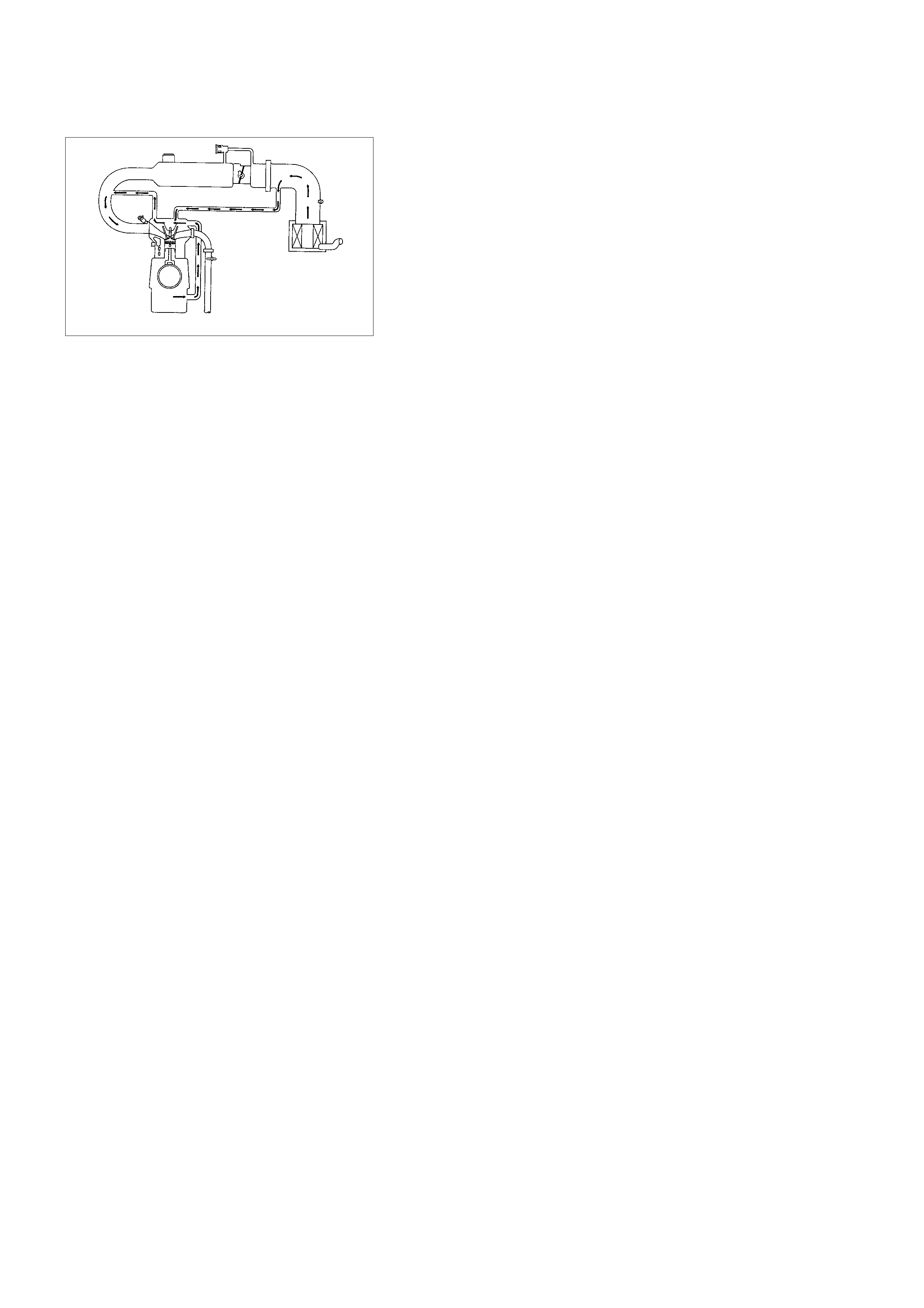
POSITIVE CRANKCASE
VENTILATION (PCV) SYSTEM
CRANKCASE VENTI LATION SYSTEM PURPOSE
The crankcase ventilation system is used to consume
crankcase vapors in the combustion process instead of venting
them to the atmosphere. Fresh air from the throttle body is
supplied to the crankcase and mixed with blow-by gases. This
mixture is then passed through the positive crankcase
ventilation (PCV) port into the intake manifold.
While the engine is running, exhaust gases and small amounts
of the fuel/air mixture escape past the piston rings and enter
the crankcase. these gases are mixed with clean air entering
through a tube from the air intake duct.
During normal, part-throttle operation, the system is designed
to allow crankcase gases to flow through the PCV hose into
the intake manifold to be consumed by normal combustion.
A plugged positive crankcase ventilation port or PCV hose may
cause the following conditions:
•Rough idle.
•Stalling or slow idle speed.
•Oil leaks.
•Sludge in the engine.
A leaking PCV hose would cause:
•Rough idle.
•Stalling.
•High idle speed.
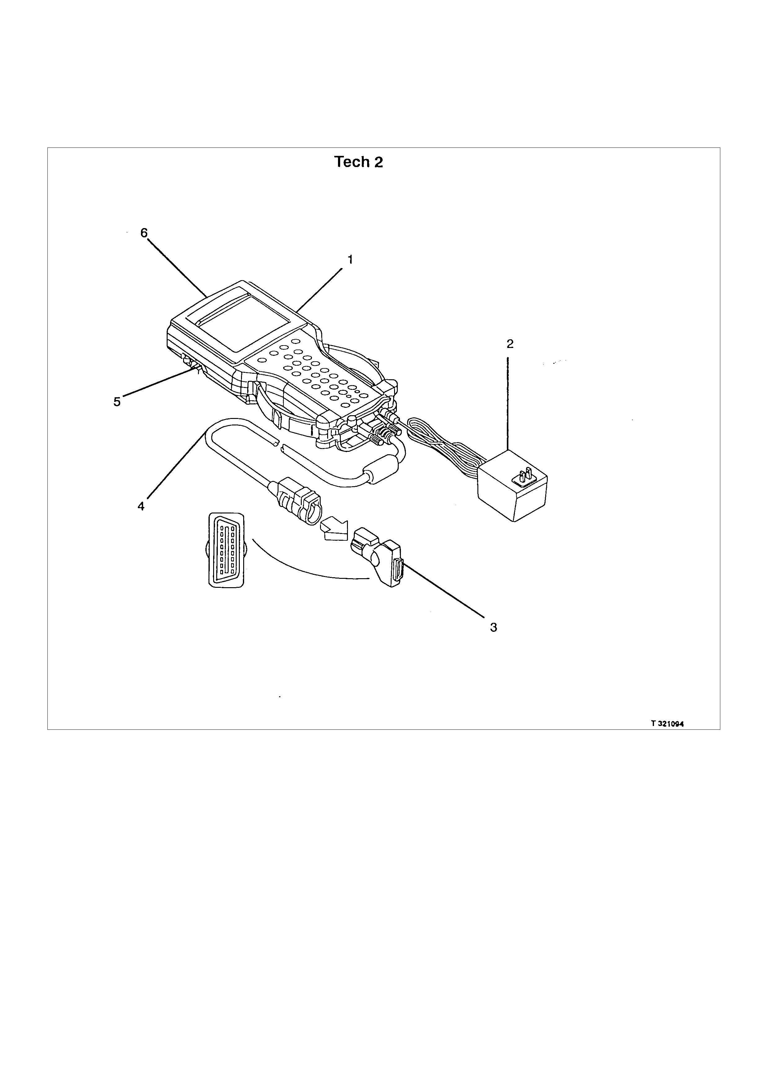
SPECIAL SERVICE TOOLS
LEGEND
(1) Tech 2 Scan Tool
(2) Tech 2 AC/DC Power Adapter
(3) Tech 2 OBD DLC Interface Connector
(4) Tech 2 DLC Interface Cable
(5) Tech 2 RS232 Connector Port
(6) Tech 2 10 Meg Memory Card
ITEM NO. ILLUSTRATION PART NO. PART NAME
5-8840-2392-0 High Impedance
Multimeter
(Digital Voltmeter -DVM)
5-8840-2312-0 IAC Motor Analyzer
5-8840-2618-0 Fuel Injector Tester
5-8840-0385-0 Connector Test AdapterKit
5-8840-0279-0 Vacuum Pump
with Gauge
5-8840-0632-0 Terminal Remover
5-8840-0388-0 Weather Pack
Terminal Remover
5-8840-0378-0 Pressure Gauge
5-8840-2607-0 EVAP Pressure/Purge
Diagnostic Station
ITEM NO. ILLUSTRATION PART NO. PART NAME
5-8840-2608-0 Ultrasonic Leak
Detector
5-8840-2589-0 Injector Adapter Cable
1 5-8840-2608-0 EVAP Pres sur e/Purge Diagnostic Station is a m ultipurpos e tool which is used to perf orm sever al
diagnostic procedures for enhanced emission testing. The station will accommodate a nitrogen gas filled cylinder
which is used to pressurize the vehicle EVAP system f or a leakdown test and leak loc ation tes t when a vehicle is
repaired for leakage in the enhanced evaporative emission control system. It also has two additional gauges
inches of mercury and inches of water) which are used to measure both source vacuum and EVAP canister
purge vacuum to verify correct operation and vapor flow within the canister purge circuit.
2 5-8840-2608- 0 Ultras onic Leak Detector is a micr oproc es sor -bas ed devic e us ed to detect leaks in the enhanc ed
evaporative emission control system. the evaporative system is pressurized to 30 inches of water using the
5-8840-2608-0 EVAP Pressure/Purge Diagnostic System. Small leaks in the EVAP system will emit sound at a
high frequenc y undetectable by a human ear but detec table with the 5-8840-2608-0. The technic ian tr ac es along
the evaporative system and can pinpoint leaks due to corroded lines, cracked hoses, or a damaged EVAP
com ponent. T he detector inc ludes a high quality set of headphones to block out sur rounding shop nois e and the
LED sensitivity meter allows a visual reference for locating leaks in conjunction with the audio output heard
through the headphones. Powered by (1) nine volt battery .