

SERVICE PRECAUTION
CAUTION:
Always use the correct fastener in the proper location.
When you replace a fastener, use ONLY the exact part
number for that application. HOLDEN will call out those
fasteners that require a replacement after removal.
HOLDEN will also call out the fasteners that require thread
lockers or thread sealant. UNLESS OTHERWISE
SPECIFIED, do not use supplemental coatings (Paints,
greases, or other corrosion inhibitors) on threaded
fasteners or fastener joint interfaces. Generally, such
coatings adversely affect the fastener torque and the joint
clamping force, and may damage the fastener. When you
install fasteners, use the correct tightening sequence and
specifications. Following these instructions can help you
avoid damage to parts and systems.
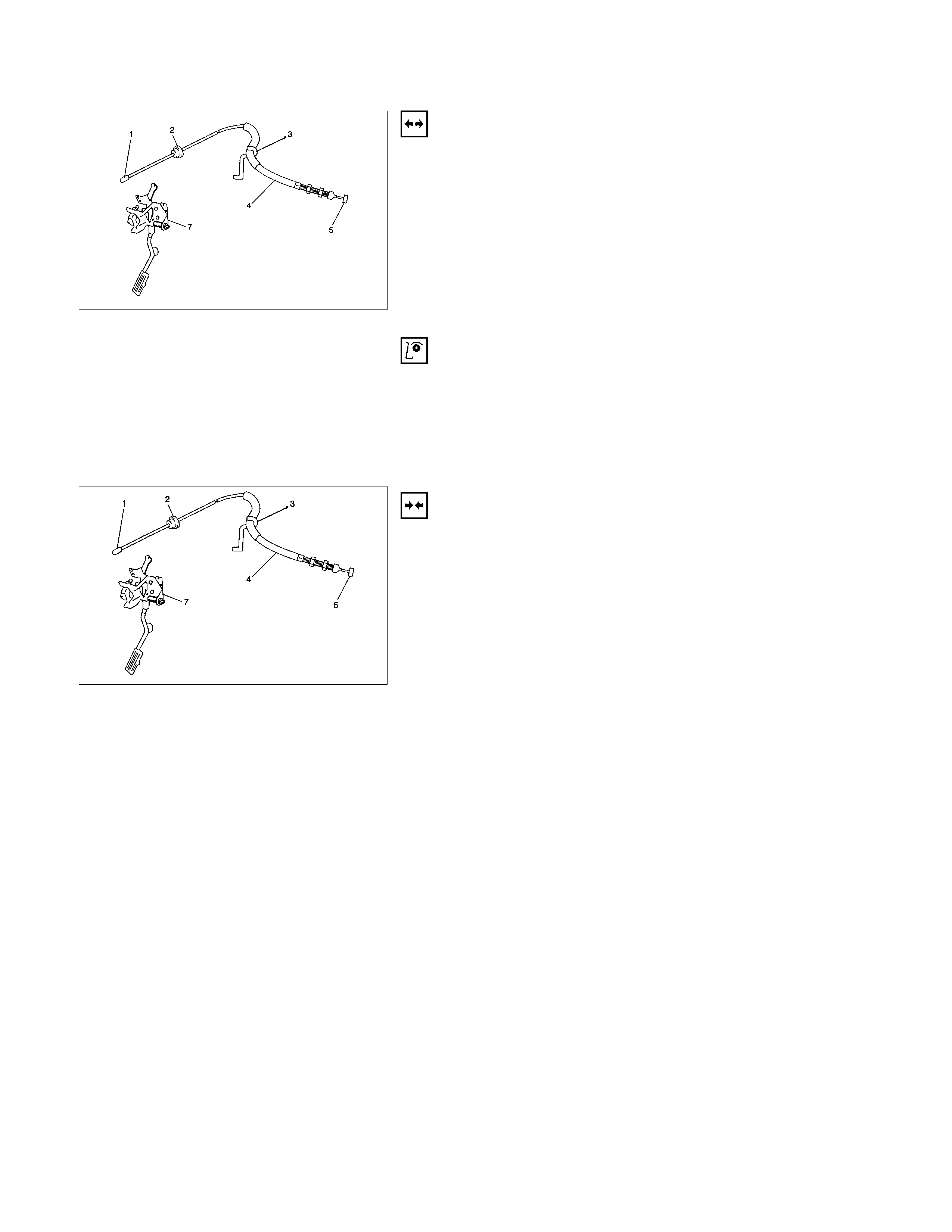
ACCELERATOR PEDAL CONTROL CABLE
REMOVAL
1. Loosen the adjust nut on the cable bracket mounted.
2. Remove cable clip (3).
3. Disconnect accelerator pedal (AP) control cable (5). (on
throttle valve side)
4. Disconnect AP control cable (1). (on AP pedal (7) side)
5. Remove grommet (2).
6. Remove AP control cable (4).
INSPECTION
Check the following items, and replace the control cable if any
abnormality is found:
•The control cable should move smoothly.
•The control cable should not be bent or kinked.
•The control cable should be free of damage and corrosion.
INSTALLATION
1. Install AP control cable (4).
2. Install grommet (2).
3. Connect AP control cable (1). (on AP (7) side)
4. Connect AP control cable (5). (on throttle valve side)
5. Install cable clip (3).
6. Install adjusting nut.
7. Confirm the free play of throttle valve control valve.
Free Play: 3 to 8 mm (0.117 to 0.312 in)
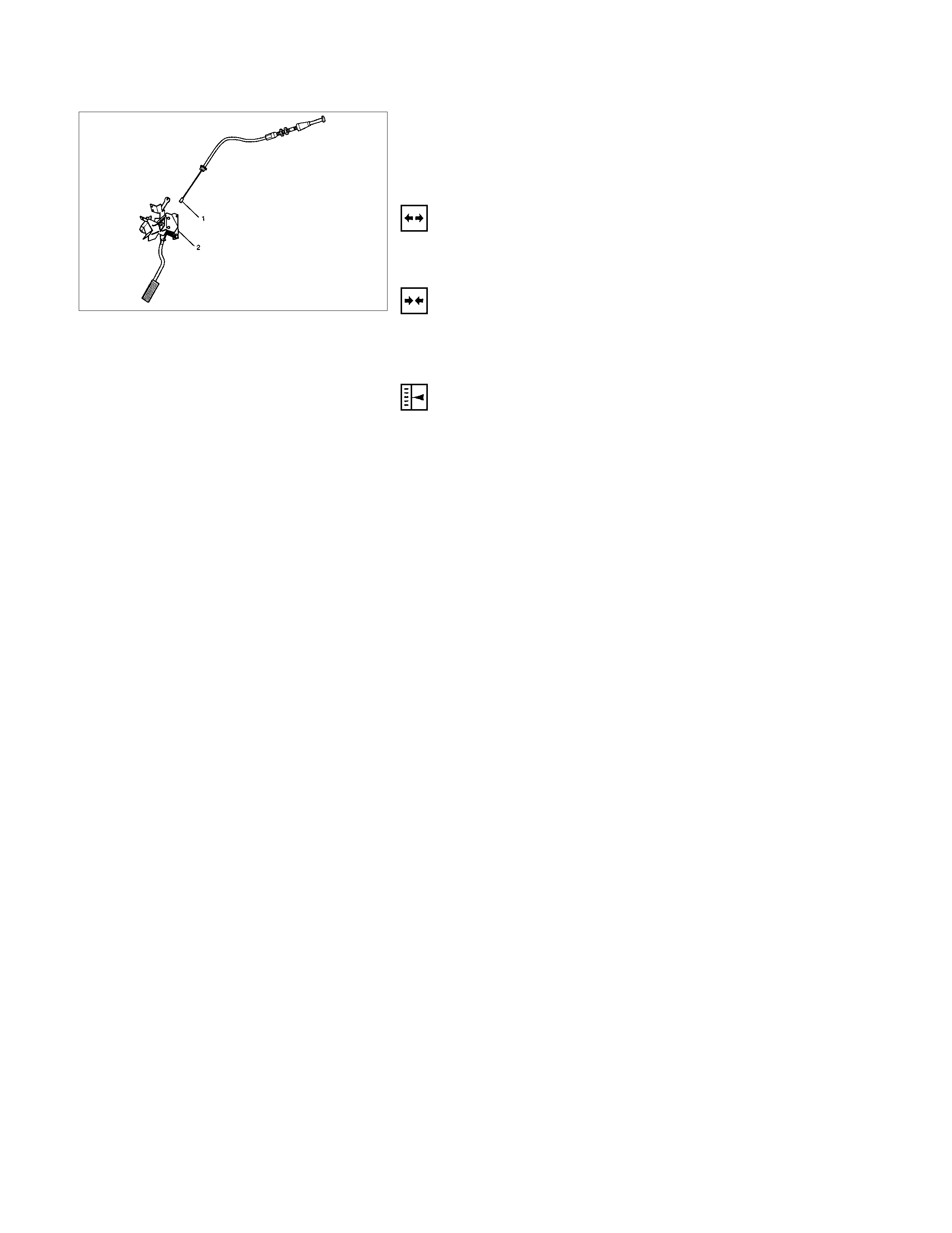
ACCELERATOR PEDAL
ACCELERATOR PEDAL AND ASSOCI ATED PARTS
LEGEND
1 Accelerator Pedal Control Cable
2 Accelerator Pedal Assembly
REMOVAL
1. Accelerator pedal control cable (1).
2. Accelerator pedal assembly (2).
INSTALLATION
1. Accelerator pedal assembly (2).
2. Accelerator pedal control cable (1).
ADJUSTMENT
MANUAL TRANSMISSION:
•Rotate countercloc kwise to loosen the loc ked nut and scre
w
the stopper bolt in sufficiently.
•Fully depress the pedal and hold it there by hand. Next,
rotate the stopper bolt until it hits the stopper of pedal
bracket. Then, lock the stopper bolt there.