
SECTION 6E - STARTING SYSTEM (C22NE MODELS)
STARTING SYSTEM
GENERAL DESCRIPTION
CRANKING CIRCUIT
STARTER
SERVICE PRECAUTION
DIAGNOSIS
STARTER
REMOVAL
INSTALLATION
DISASSEMBLED VIEW
INSPECTION AND REPAIR
ARMATURE
BRUSH
BRUSH HOLDER
MAGNETIC SWITCH
CONTINUITY OF SERIES COIL
CONTINUITY OF CONTACTS
PINION
CHARACTERISTIC TEST

STARTING SYSTEM
GENERAL DESCRIPTION
CRANKING CIRCUIT
The cranking system consists of a battery, starter, starter
switch, starter relay, etc. These main components are
connected.
STARTER
The cranking system employs a magnetic type reduction
starter in which the motor shaft is also used as a pinion shaft.
When the starter switch is turned on, the contacts of magnetic
switch are closed, and the armature rotates. At the same time,
the plunger is attracted, and the pinion is pushed forward by
the shift lever to mesh with the ring gear.
Then, the ring gear runs to start the engine. When the engine
starts and the starter switch is turned off, the plunger returns,
the pinion is disengaged from the ring gear, and the armature
stops rotation. When the engine speed is higher than the
pinion, the pinion idles, so that the armature is not driven.

SERVICE PRECAUTION
CAUTION:
Always use the correct fastener in the proper location.
When you replace a fastener, use ONLY the exact part
number for that application. HOLDEN will call out those
fasteners that require a replacement after removal.
HOLDEN will also call out the fasteners that require thread
lockers or thread sealant. UNLESS OTHERWISE
SPECIFIED, do not use supplemental coatings (Paints,
greases, or other corrosion inhibitors) on threaded
fasteners or fastener joint interfaces. Generally, such
coatings adversely affect the fastener torque and the joint
clamping force, and may damage the fastener. When you
install fasteners, use the correct tightening sequence and
specifications. Following these instructions can help you
avoid damage to parts and systems.

DIAGNOSIS
CONDITION POSSIBLE CAUSE CORRECTION
Starter does not run Charging failure Repair charging system
Battery Failure Replace Battery
Terminal connection failure Repair or replace terminal connector
and/or wiring harness
Starter switch failure Repair or replace starter switch
Starter failure Repair or replace starter
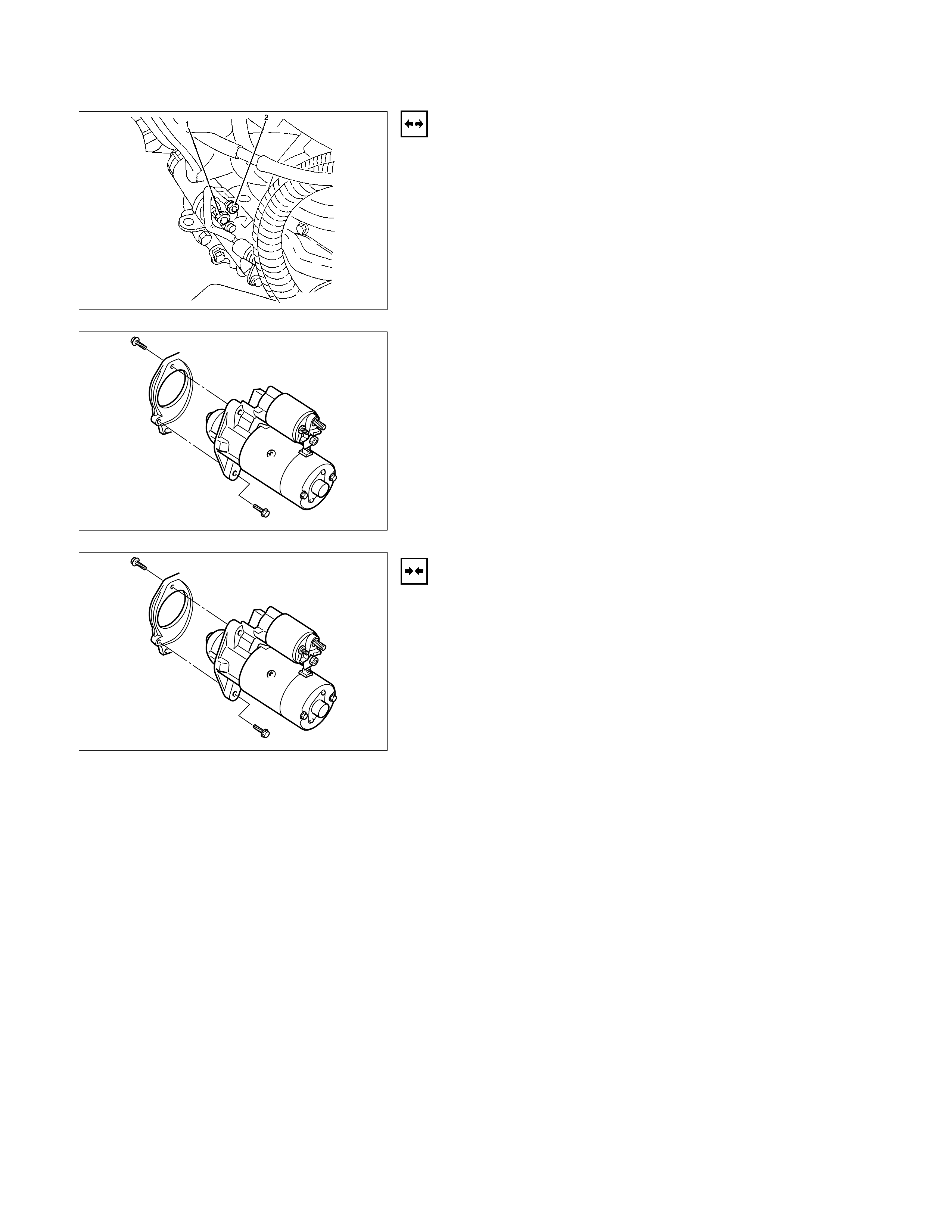
STARTER
REMOVAL
1. Battery ground cable.
2. Remove harness connectors (1) and (2).
3. Remove bolts from starter.
INSTALLATION
1. Install starter assembly.
2. Install mounting bolts and tighten bolts to specified torque.
Torque: 25 N⋅
⋅⋅⋅m (2.5 kgf.m)
3. Connect harness.
4. Reconnect the battery ground cable.
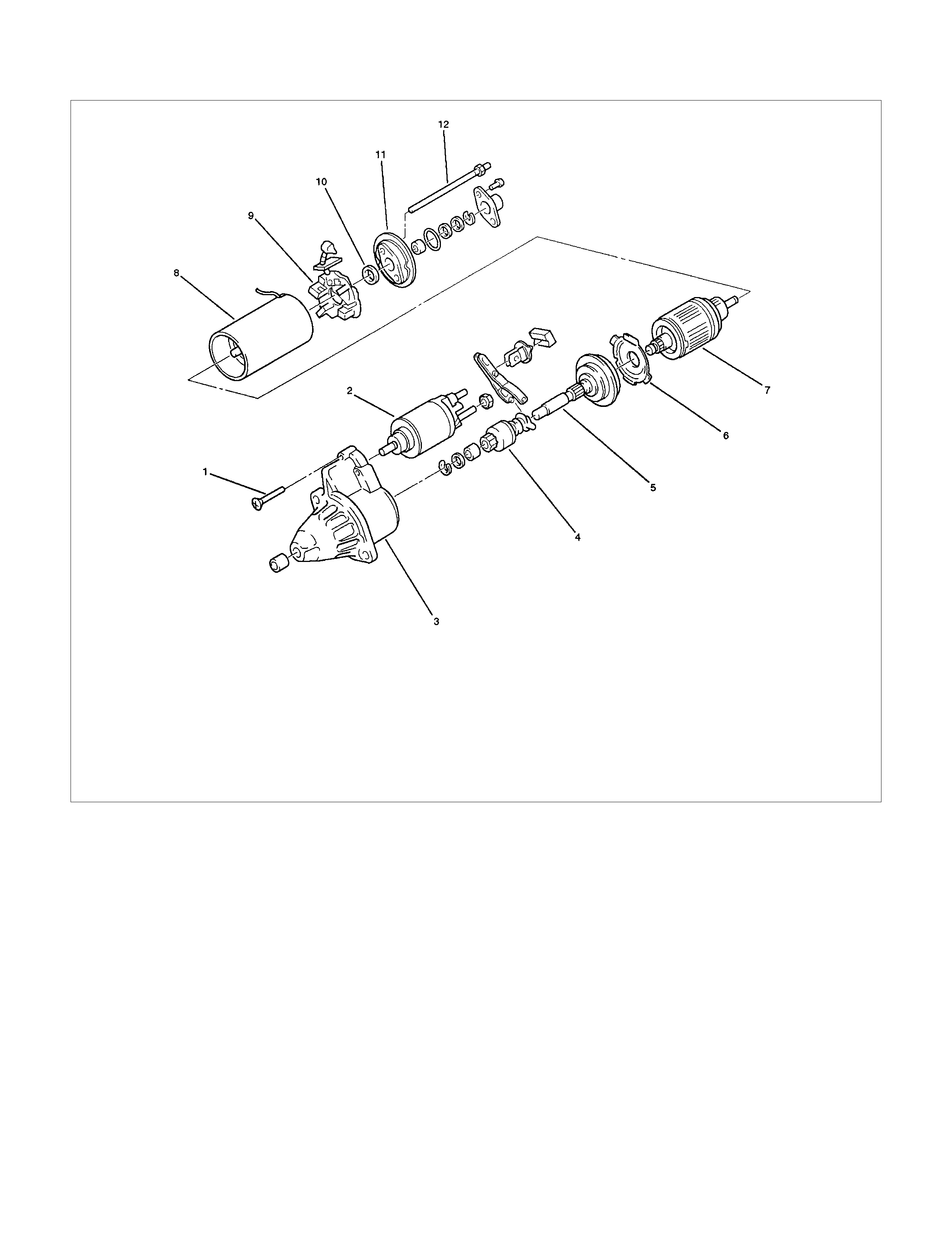
DISASSEMBLED VIEW
Legend
1 Bolt
2 Magnetic Switch
3 Gear Case
4 Piston
5 Piston Shaft
6 Center Bracket
7 Armature
8 Yoke Assembly
9 Brush and Brush Holder
10 Washer
11 Rear Cover
12 Through Bolt
INSPECTION AND REPAIR
Repair or replace necessary parts if extreme wear or damage
is found during inspection.
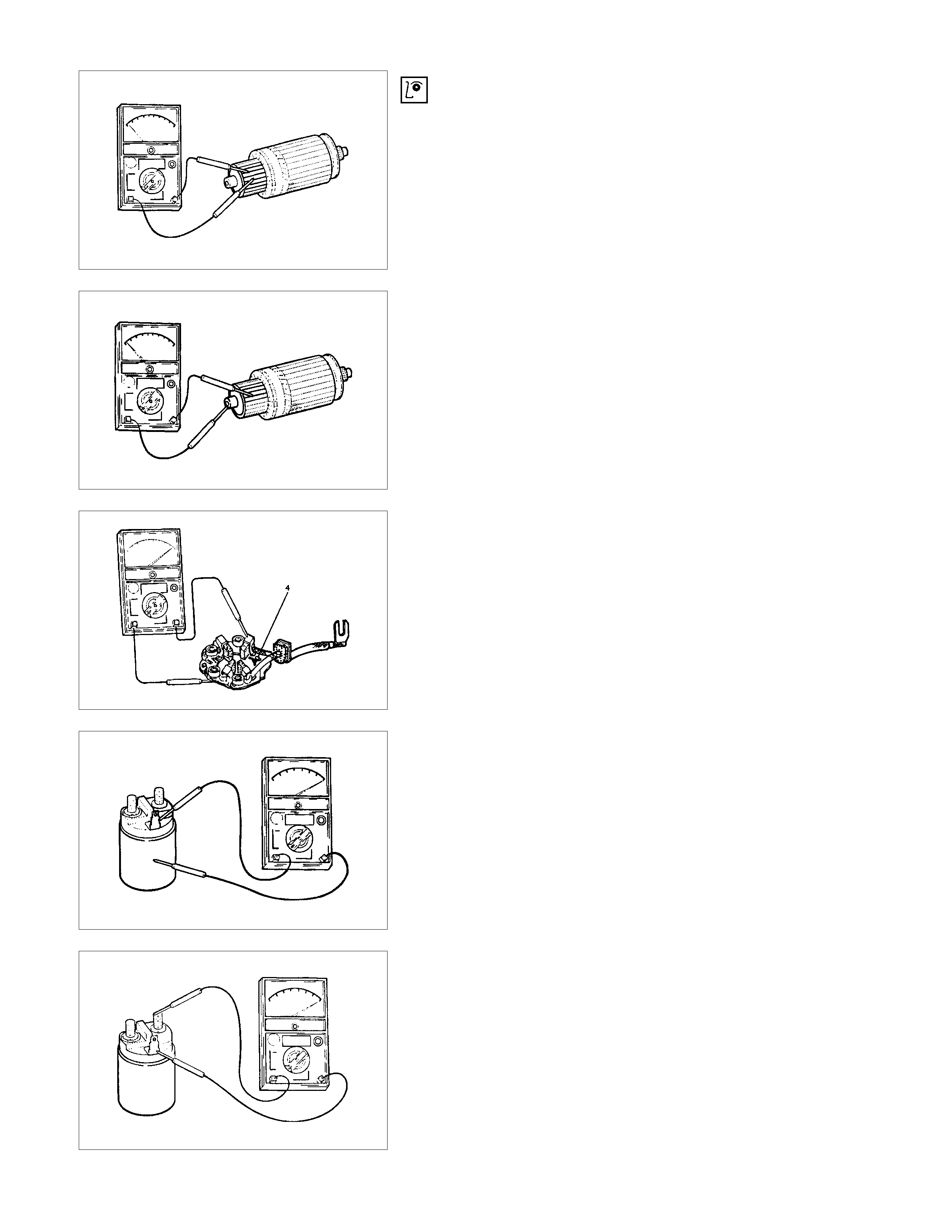
ARMATURE
Check for continuity between commutator and segment.
Replace commutator if there is no continuity (i.e.,
disconnected).
Check for continuity between commutator and shaft.
Also, check for continuity between commutator and armature
core, armature core and shaft. Replace commutator if there is
continuity (i.e., internally grounded).
BRUSH
Measure the length of brush.
Replace with a new one, if it is below the limit.
BRUSH HOLDER
Check for continuity between brush holder (+) (4) and base (-).
Replace, if there is continuity (i.e., insulation is broken).
MAGNETIC SWITCH
Check for continuity of shunt coil between terminals S and M.
Replace, if there is no continuity (i.e., coil is disconnected).
CONTINUITY OF SERIES COIL
Check for continuity between terminals S and M.
Replace, if there is no continuity (i.e., coil is disconnected).
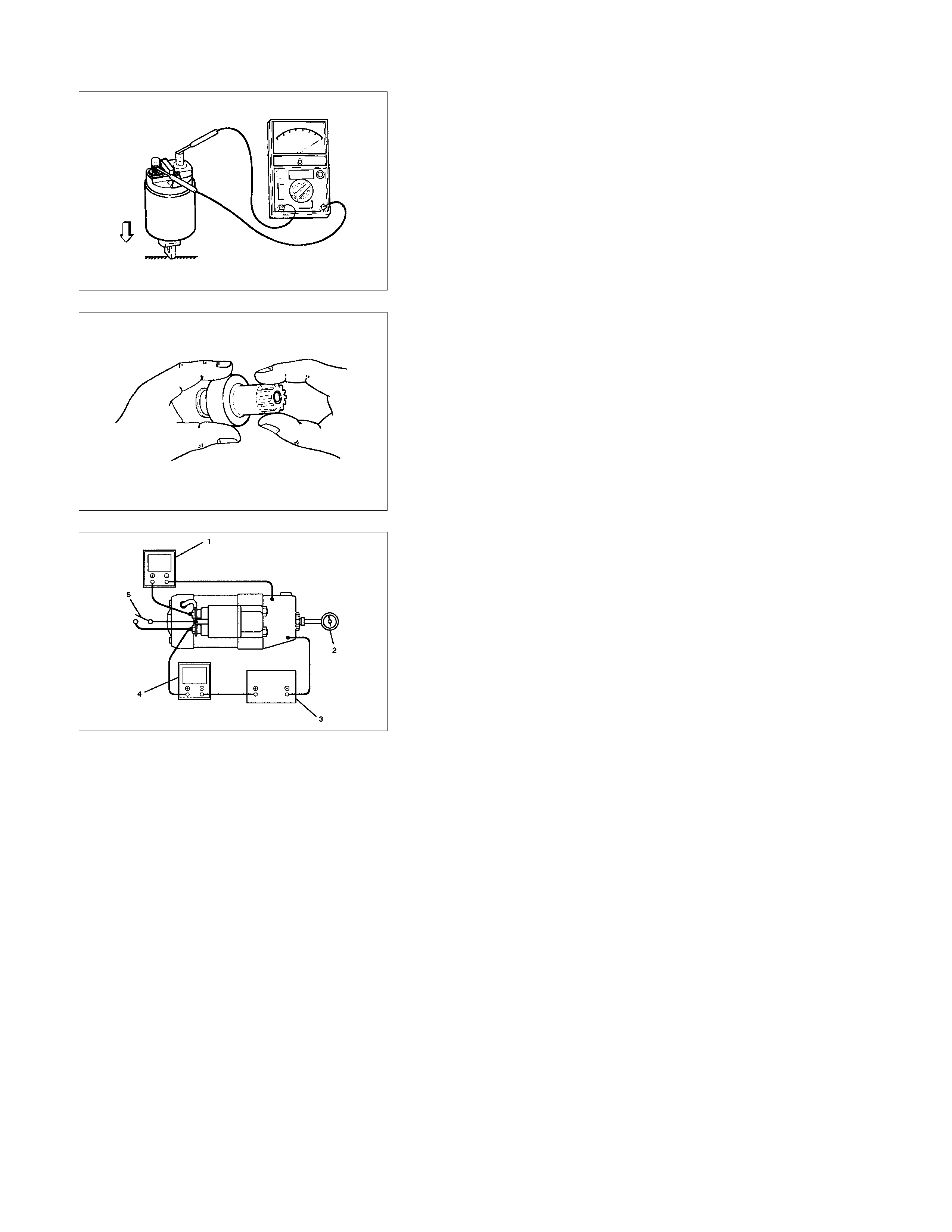
CONTINUITY O F CONTACTS
With the plunger faced downward, push down the magnetic
switch. In this state, check for continuity between terminals B
and M. Replace, if there is no continuity (i.e., contacts are
faulty).
PINION
Check if the pinion rotates smoothly in drive direction by hand,
or if it is locked when it is rotated in reverse. If not, replace the
pinion.
CHARACTERISTIC TEST
For easily confirming the characteristics, conduct the noload
test as follows:
Rating as short as 30 seconds requires rapid testing.
Fix the starter on the test bench, and wire as shown in
illustration. When the switch is closed, the current flows and
the starter runs under no load. At this time, measure current,
voltage and speed to check if they satisfy the standard.
LEGEND
1 Volt Meter
2 Revolution Indicator
3 Battery
4 Ammeter
5 Switch