
SECTION 6C - FUEL SYSTEM
Main Data & Speci fications
General Description
Fuel Flow
Injection Pump
Aneroid Compensator
Boost Compensator
Fast Idle Actuator
Wax Type Cold Start Device (W–CSD) (If So Equipped)
Fuel Filter With Built-In Water Separator
Injection Nozzle
Injection Pump
Removal & Installation
4JB1T
4JH1TC
Injection Pump Calibration Data
Injection Volume Adjustment
Identification Plate & Number
Injection Volume & Governor Performance Diagram
Injection Nozzle
Disassembly
Inspection & Repair
Reassembly
Inspection & Adjustment
Adjustment Procedure For Potentiometer
Techline

Main Data & Specifications
Description
Item 4JB1T
Injection pump type
Plunger outside diameter mm (in)
Plunger prestroke mm (in)
Bosch Distributor
11 (0.43)
0.45 (0.0177)
Governor type Mechanical limit speed
Timer type
Fuel feed pump type
Injection nozzle type
Number of injection nozzl e orifices
Oil pressure
Vane with input shaft
Hole type
5
Injection nozzle orifices mm (in) 0.27 (0.0106)
Inside diameter
Injection nozzle opening kg/cm2 (psi/MPa)
Main fuel filter type
185 (2,631/18.1)
Disposable cartridge paper element and water separator
Item 4JH1TC
Injection pump type BOSCH VP44
(electronic controlled fuel injection pump)
Injection nozzle type Hole type (Double spring type)
Number of injection nozzl e orifices 5
Injection nozzle orifices mm (in)
Inside diameter 0.21 (0.0083)
Injection nozzle opening kg/cm2 (psi/MPa) 1st: 198 (2,816/19.4)
2nd: 344 (4,906/33,800)
Main fuel filter type Disposable cartridge paper element and water separator
NOTE:
The VP44 Injection Pump and the Inject ors f itted to t he 4JH1TC engine are non-serviceabl e i tems.
Refer to the lat est service inf ormat i on bul letin for t he correct change- over procedure BEFORE
removing the injector pump or injectors f r om t he vehicle.
General Description
When working on the fuel system, there are several things to keep in mind:
・ Any time the fuel system is being worked on, disconnect the negative battery cable except for those tests where
battery voltage is required.
・ Always keep a dry chemical (Class B) fire extinguisher near the work area.
・ Replace all pipes with the same pipe and fittings that were removed.
Clean and inspect “O” rings. Replace where required.
・ Always relieve the line pressure before servicing any fuel system components.
・ Do not attempt repairs on the fuel system until you have read the instructions and checked the pictures relating to
that repairs.
Fuel Flow
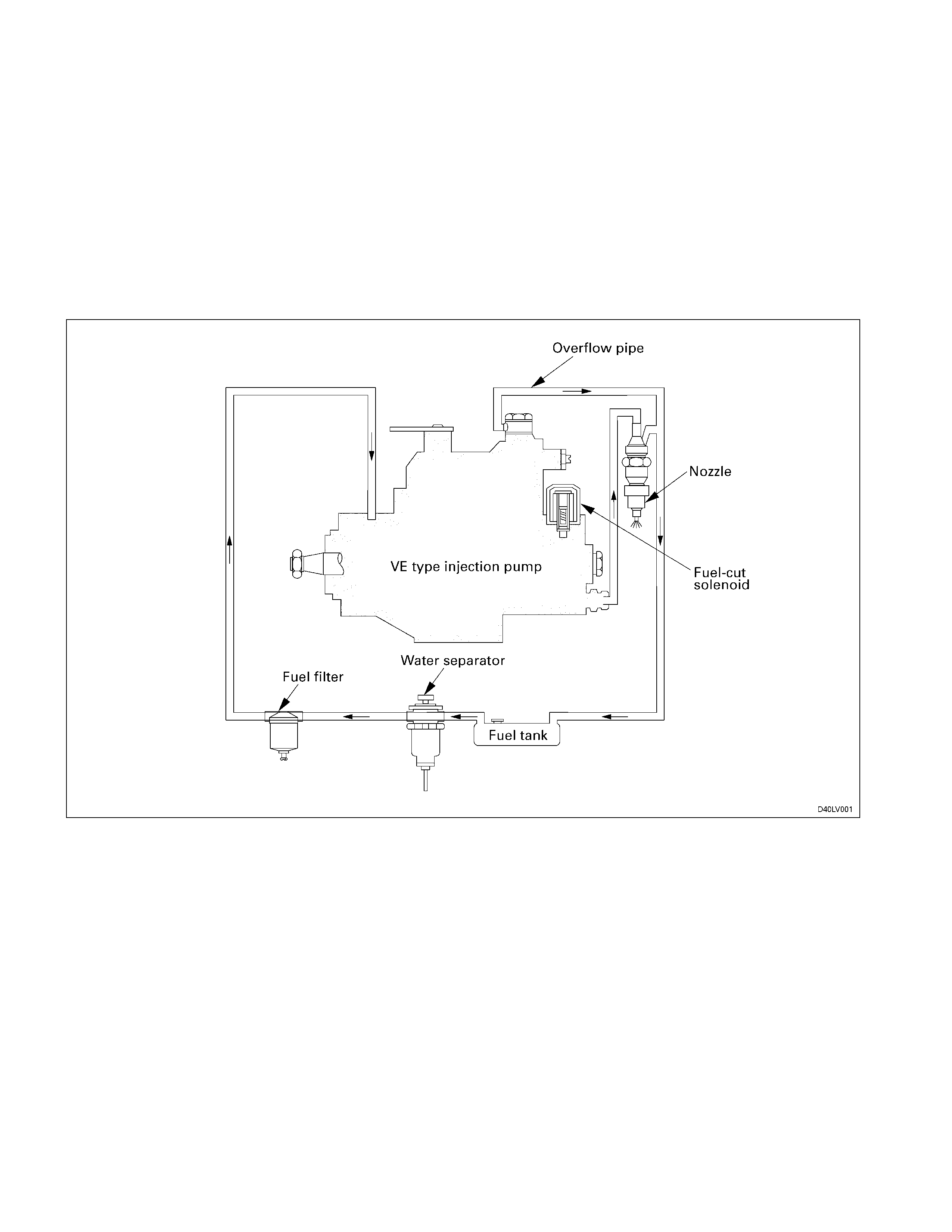
The fuel system consists of the fuel tank, the water separator, the fuel filter, the injection pump, and the injection nozzle.
The fuel from the fuel tank passes through the water separator and the fuel filter where water particles and other foreign
material are removed from the fuel.
Fuel, fed by the injection pump plunger, is delivered to the injection nozzle in the measured volume at the optimum
timing for efficient engine operation.
4JB1T En
g
ine
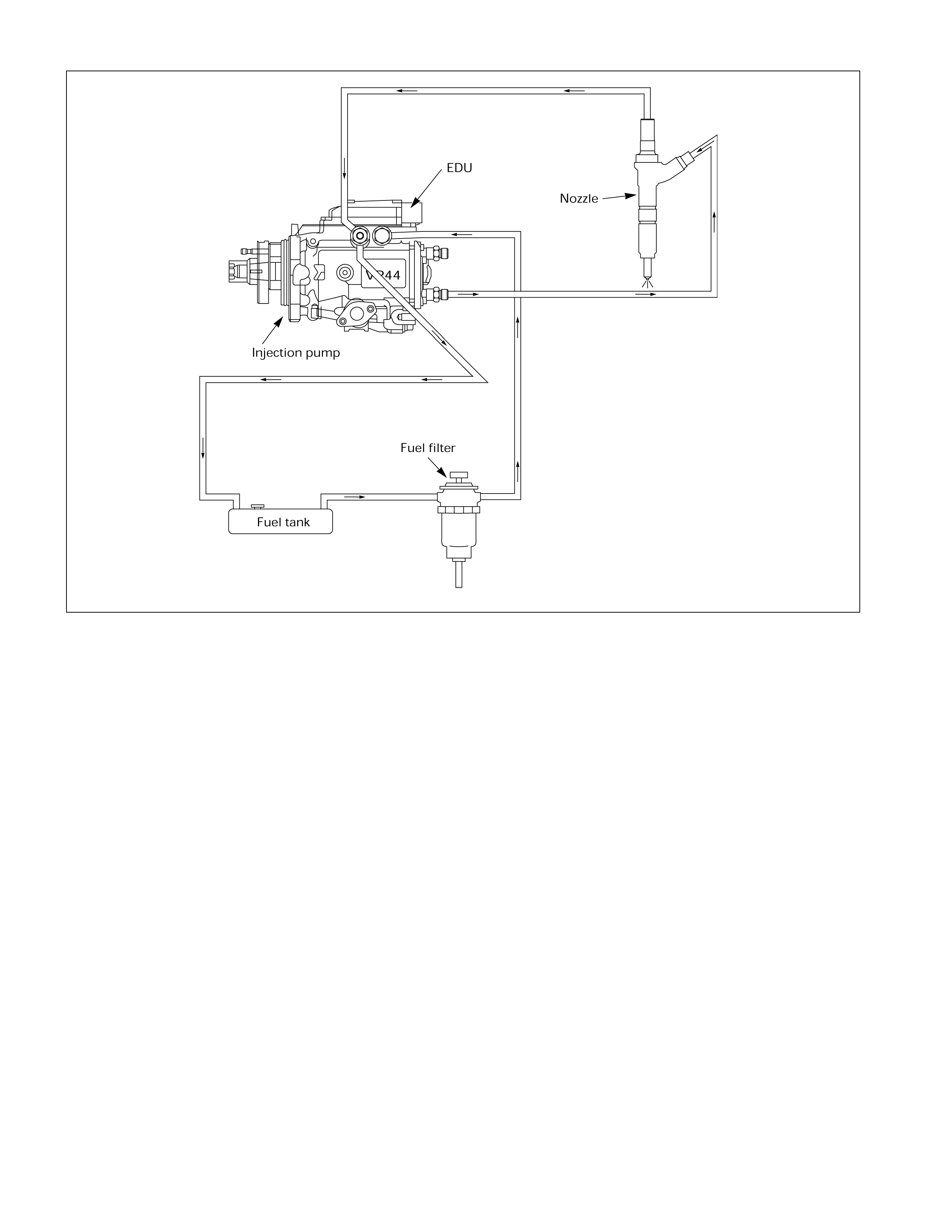
・ The 4JH1TC engine are equipped with the electronically controlled fuel injection system. For information on fuel
injection pump maintenance and/or part replacement, contact the Bosch Automotive Systems Corporation.
・ Contact the Bosch Automotive Systems Corporation for information on 4JH1TC engine fuel injection nozzle
maintenance.
4JH1TC En
g
ine
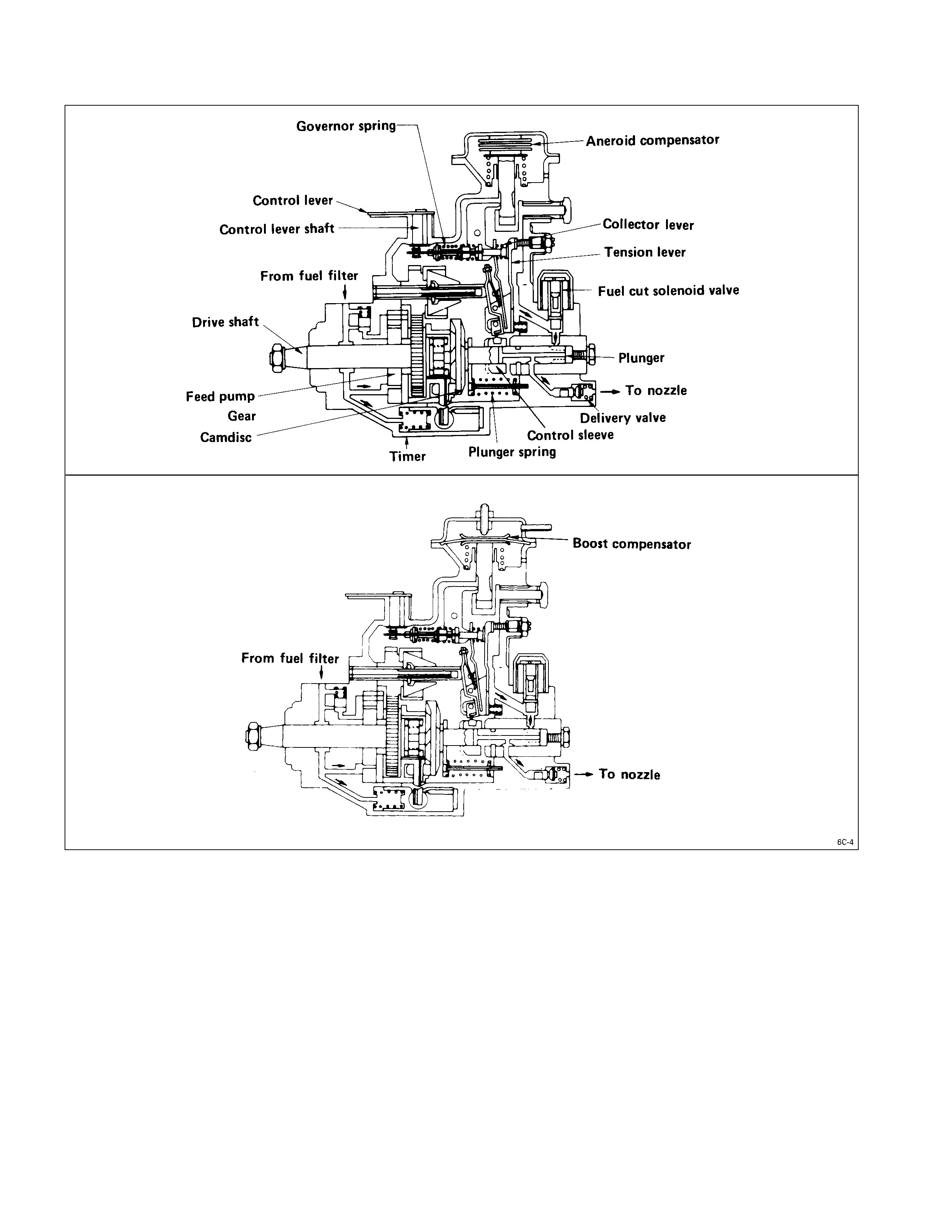
Injection Pump
A Bosch Distributor Type Injection Pump is used. A single reciprocating/revolving plunger delivers the fuel uniformly to
the injection nozzles, regardless of the number of cylinders.
The governor, the injection timer, and the feed pump are all contained in the injection pump housing. The injection
pump is compact, light weight, and provides reliable high-speed operation.
An aneroid compensator is available as an option for vehicles to be operated at high altitudes. It adjusts the fuel and air
mixing ratio.
A boost compensator is installed on turbocharger equipped vehicles.
Aneroid Compensator
The aneroid compensator consists of the compensator housing, the bellows, the adjusting pin, the aneroid
compensator lever pin, and the aneroid compensator lever.
Atmospheric pressure decreases as altitude increases. The decreased atmospheric pressure causes the bellows to
expand and push the adjusting pin down.
The adjusting pin pushes the aneroid compensator lever pin and the aneroid compensator lever to the left.
The aneroid compensator lever pushes the tension lever to the right.
The tension lever actuates the control sleeve to decrease the fuel flow.
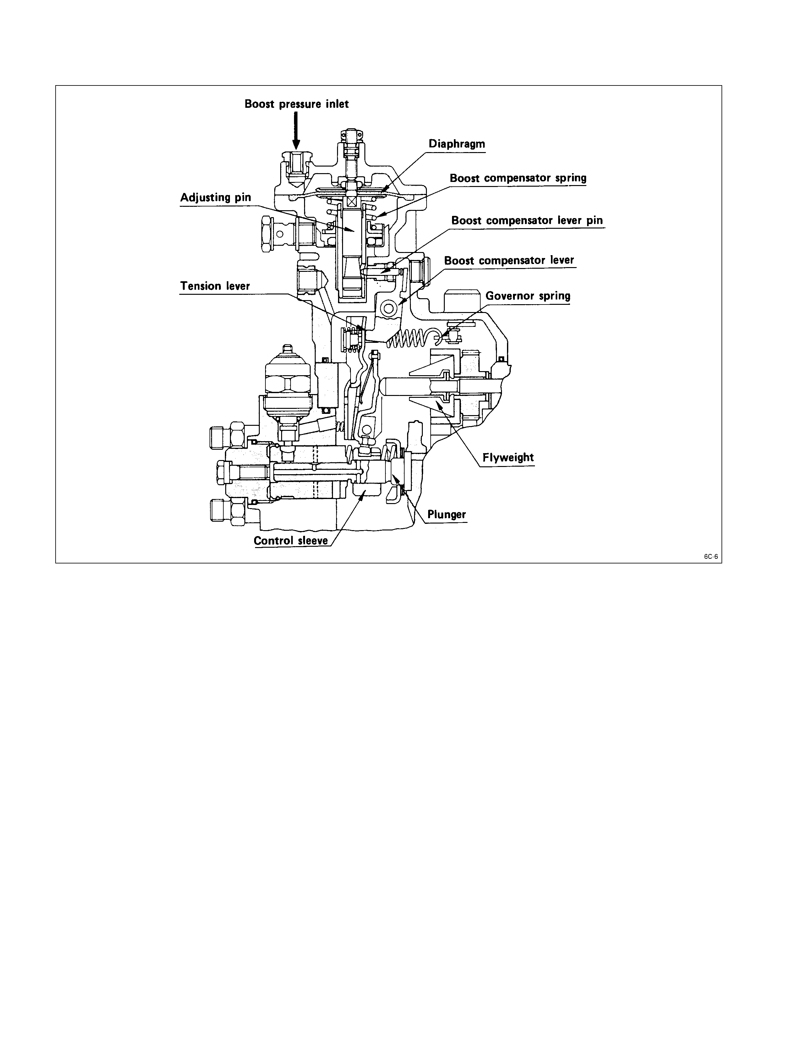
Boost Compensator
The boost compensator consists of the compensator housing, the diaphragm, the adjusting pin, the boost compensator
lever pin, and the boost compensator lever.
The increase boost pressure cause the diaphragm to lower and push the adjusting pin down.
The adjusting pin pushes the boost compensator lever pin and the boost compensator lever to the left.
The boost compensator lever pushes the tension lever to the right.
The tension lever actuates the control sleeve to increase the fuel flow.
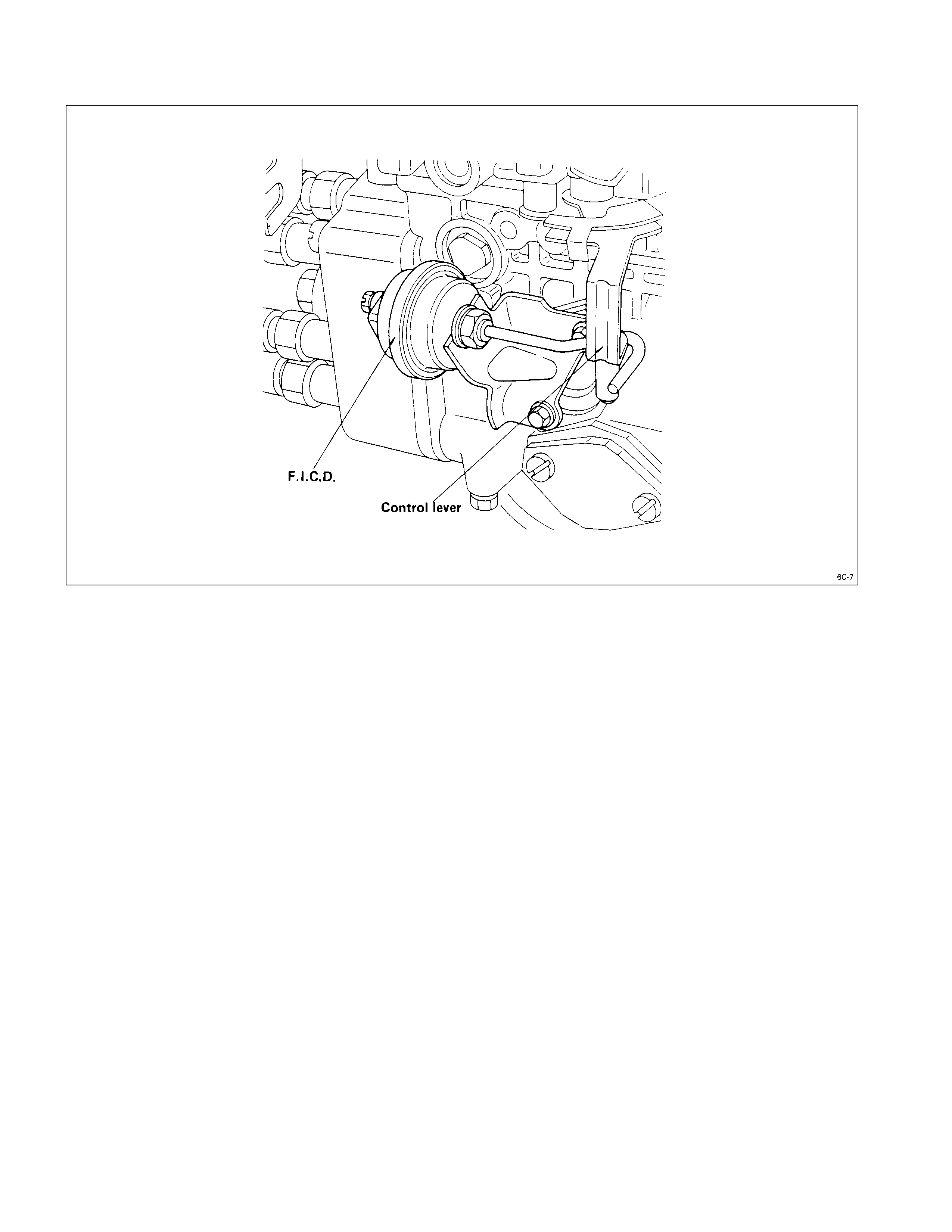
Fast Idle Actuator
The vacuum-type fast idle actuator increases the engine idling speed to provide the additional power required to
operate the air conditioner.
Fast idler diaphragm movement is caused by changes in the negative pressure created by the engine’s vacuum pump.
The diaphragm motion is transferred to the injection pump control lever to increase or decrease the idling speed.
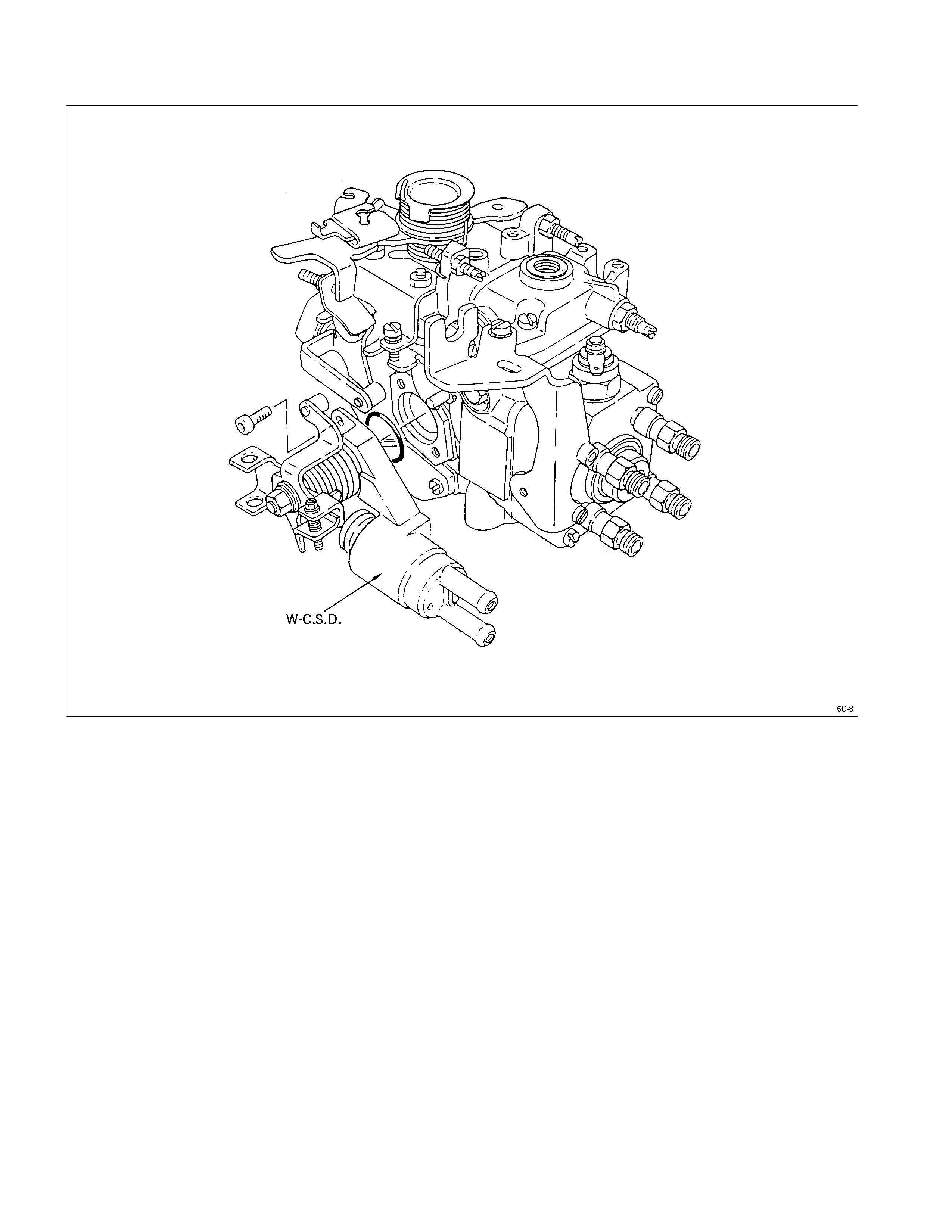
Wax Type Cold Start Device (W–CSD) (If So Equipped)
Because engine starting in cold conditions is very difficult, the W-C.S.D. (wax ty pe cold start device) has been
developed to provide the optimum fuel injection timing for engine starting by responding to temperature changes.
The thermo-wax piston contains a wax that changes its volume according to the temperature changes of the engine
coolant which flows through the unit at all times.
The engine coolant temperature above A °C the wax expands in proportion to the coolant temperature, below A °C it
contracts.
The coolant temperature A is classified as –20, -10 and 0°C.
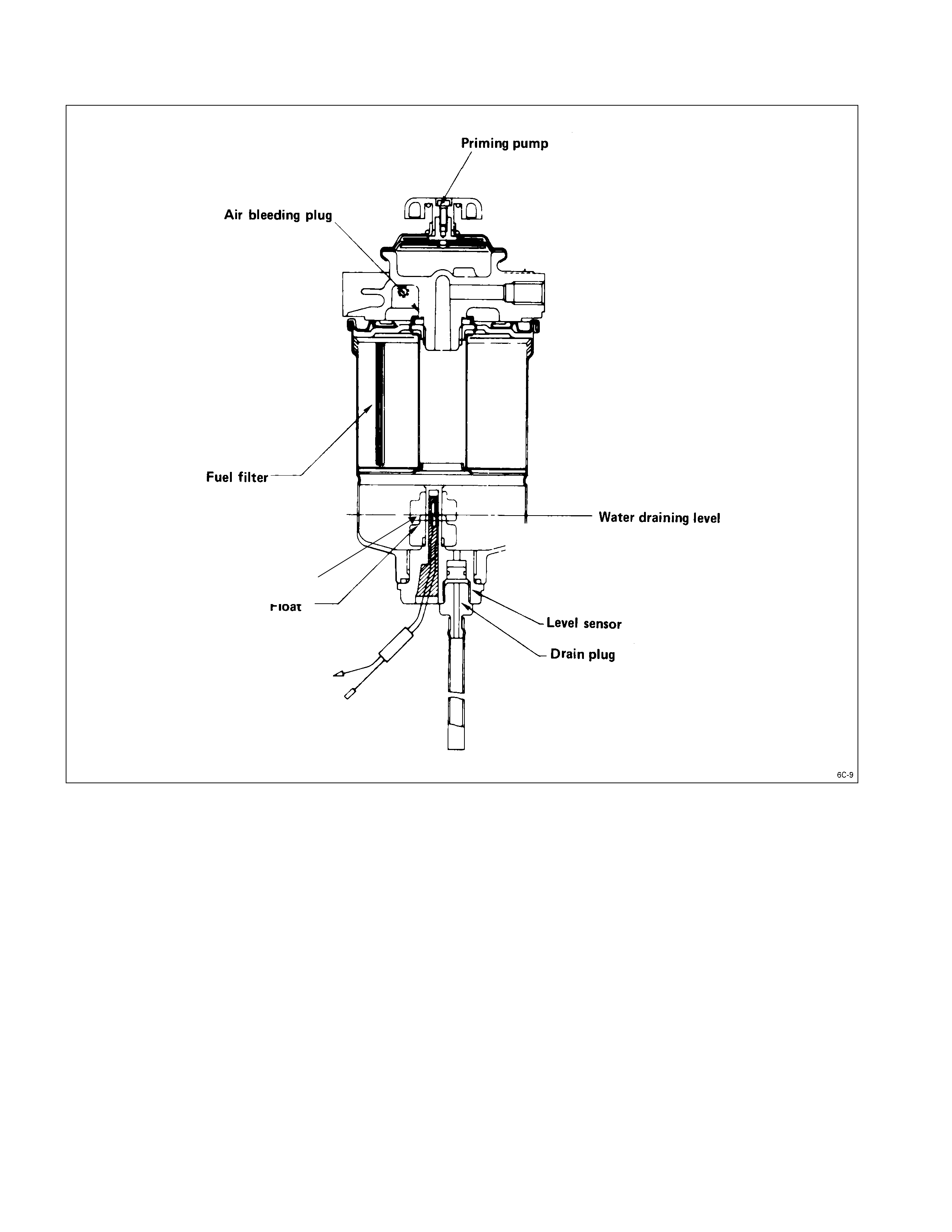
Fuel Filter With Built-In Water Separator
A fuel filter with a built-in water separator is used along with the VE type injection pump.
As the inside of the injection pump is lubricated by the fuel which it is pumping, the fuel must be perfectly clean. The
fuel filter and the water separator remove water particles and other foreign material from the fuel before it reaches the
injection pump.
The water separator has an internal float. When the float reaches the specified level, a warning light comes on to
remind you to drain the water from the water separator.
A diaphragm ty pe priming pump is installed at the top of the water separator. It is used during the water draining and
the air bleeding procedures.
Level Sensor
Injection Nozzle
A hole (with 5 orifices) type injection nozzle is used for 4JB1T Engine. It consists of the nozzle body and the needle
valve assembly.
The injection nozzle assembly sprays pressurized fuel from the injection pump into the combustion chamber through
the nozzle body injection orifice.
Injection Pump
Removal & Installation
Read this Section carefully before performing any removal and installation procedure. This Section gives you important
points as well as the order of operation. Be sure that you understand everything in this Section before you begin.
4JB1T
REMOVAL STEPS
1. Disconnect the battery ground cable.
2. Disconnect the air cleaner duct.
3. Disconnect the PCV hose.
4. Remove the head cover.
5. Remove the power steering V belt. (if so equipped)
6. Disconnect the accelerator cable and harness from
injection pump.
7. Remove the fuel pipes and injection pipes.
8. Remove the cover of timing gear case cover. (injection
pump side only)
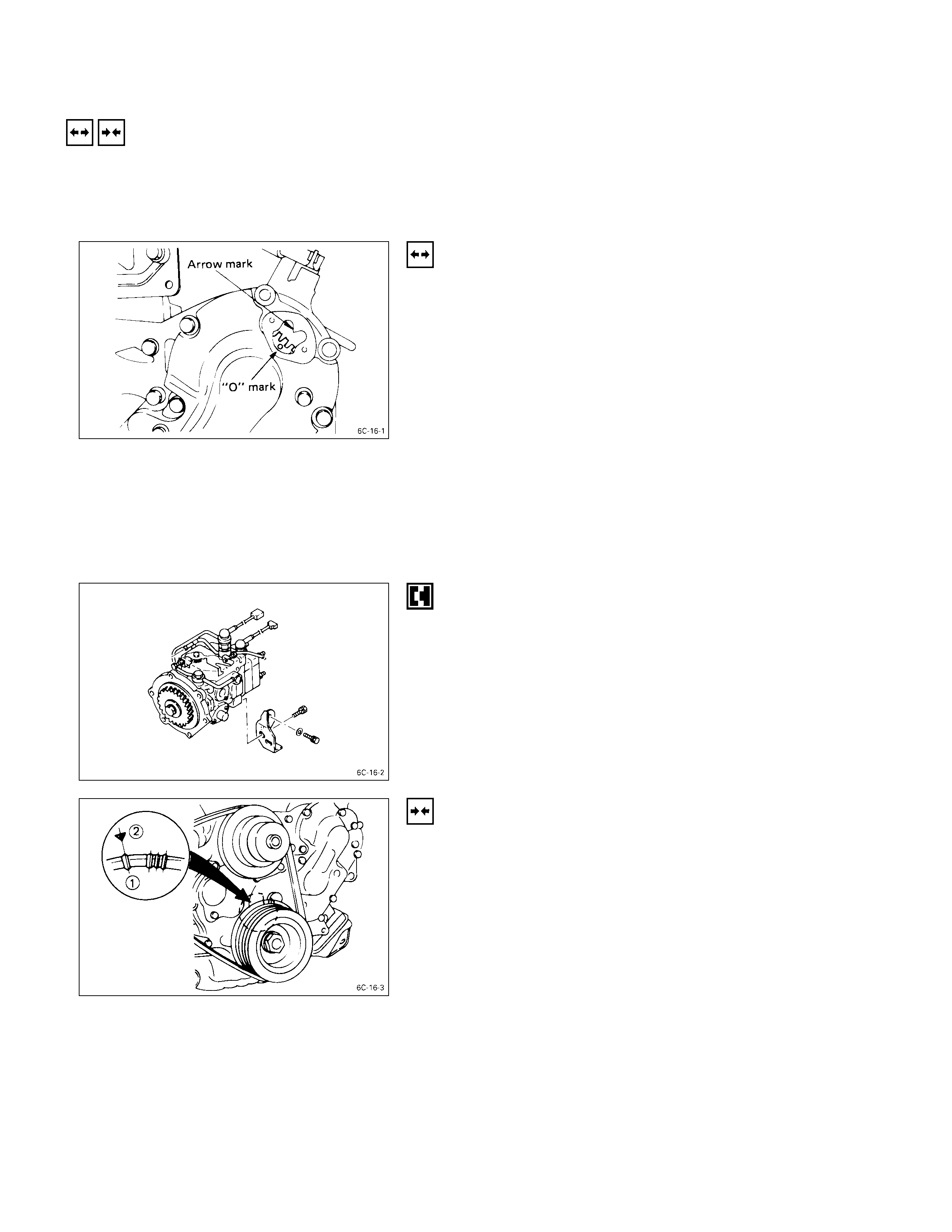
9. Remove the timing hole cover.
10. For ease in reinstalling the injection pump, align the
timing “O” mark on the pump gear with the allow mark
on the timing gear case cover using the crank shaft
turning wrench.
11. Remove the six injection pump mounting bolts from
the timing gear case cover.
12. Remove the rear bracket bolts from the injection pump
bracket.
13. Pull the injection pump together with pump gear free
toward the rear of the engine.
INSTALLATION STEPS
To install, follow the removal procedure in reverse order
and note the following point.
•Recheck the crankshaft to align the timing mark on the
crank pulley with the TDC mark.

•Install injection pump so that the timing “O” mark on
the pump gear the arrow mark on the timing gear case
cover.
4JH1TC
REMOVAL STEPS
1. Disconnect the battery ground cable.
2. Remove the intercooler.
3. Separate the air cleaner duct from the air cleaner.
4. Disconnect the radiator upper hose.
5. Remove the air conditioner V-belt.
6. Remove the power steering V-belt.
7. Remove the power steering oil tank. Place the tank in
a safe place.
8. Remove the fuel filter and its bracket.
9. Disconnect the accelerator cable and connector at the
intake duct.
10. Remove the intake duct.
11. Remove the accelerator control lever.
12. Remove the check hole cover from the timing gear
case.
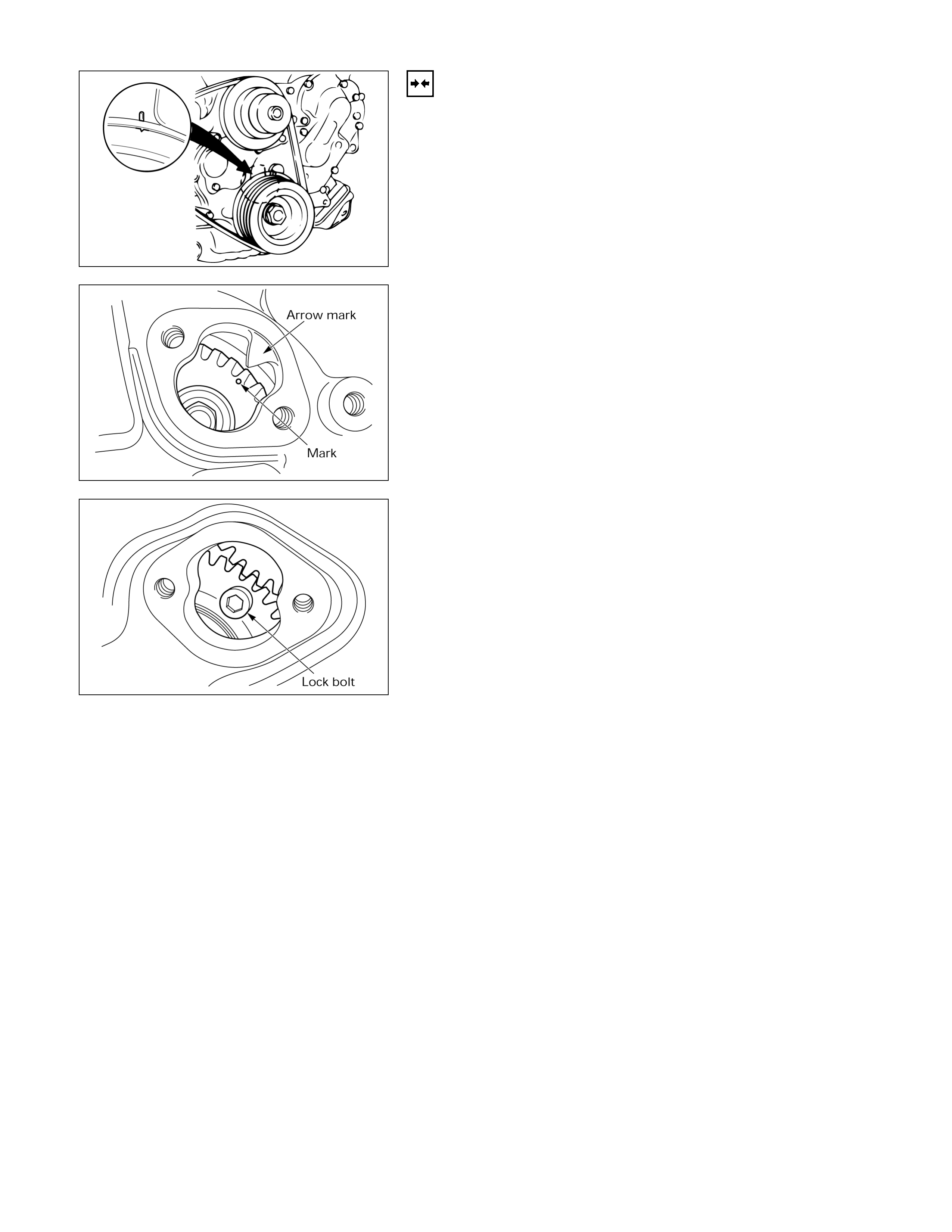
13. Rotate the crank pulley until the scissor gear fixing
hole becomes visible through the check hole (2).
14. Insert a lock bolt (M6×1 L=30) into the scissor gear
fixing hole to prevent the scissor gear from turning.
Note:
If the check hole cover is reinstalled with the lock bolt
still in place, the crank pulley will not turn.
020L200016
020L200018
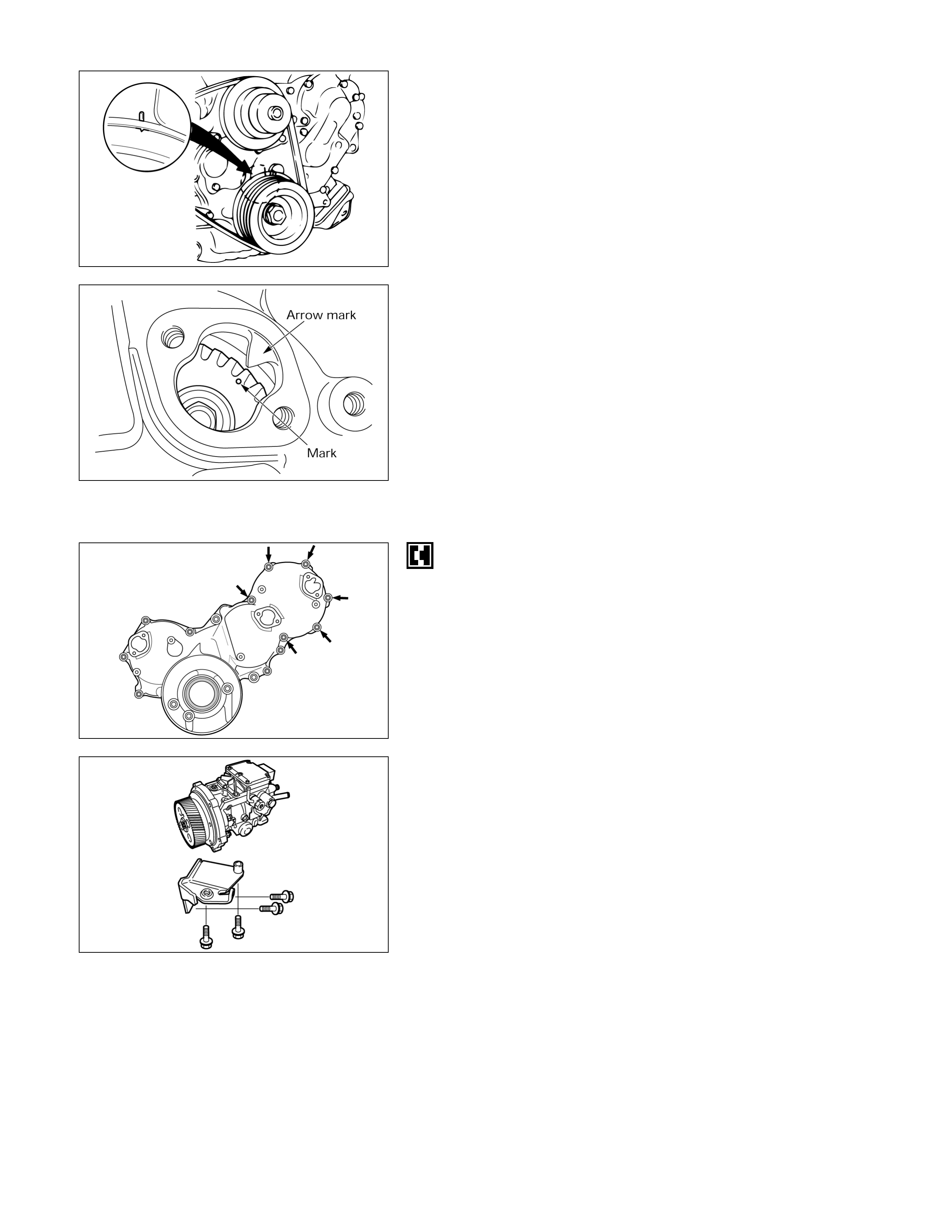
15. Rotate the crank pulley to align the crank pulley TDC
mark and the timing gear case TDC mark.
16. Look through check hole (1) to confirm that the
injection pump alignment mark is visible. If it is not
visible, turn the crank pulley an additional full turn.
17. Remove the fuel piping and the injection pipes.
18. Remove the connector from the injection pump.
19. Remove the injection pump mounting bolts (6 bolts)
from the timing gear case.
20. Remove the injection pump bracket.
21. Remove the injection pump and pump gear by pulling
it toward the rear of the engine.
015L200004
020L200017
080L200006
INSTALLATION STEPS
Follow the removal procedure in reverse order.
Pay close attention to the following.
•Be sure to align the crank pulley TDC mark and the
timing gear case TDC mark.
•Install the injection pump and pump gear so that the
timing mark (dot) on the pump gear is aligned with the
arrow on the timing gear case cover.
Note:
• Do not forget to remove the lock bolt from the
scissor gear. (if you have forgotten to remove the
bolt, the bolt will strike the check hole guides and
the crank pulley will not turn)
• Injection pump Air bleeding is required to start
the engine when the injection pump has been
replaced.
Refer to Injection Pump Air Bleeding.
015L200004
020L200017
020L200018
Injection Pump Calibration Data
Injection Volume Adjustment
TEST CONDITIONS
Item Condition
Injection nozzle
Injection nozzle holder
Injection nozzle opening pressure
kg/cm2 (psi/kPa)
Injection line dimensions mm (in)
Inside diameter
Outside diameter
Length
Fuel delivery pressure kg/cm2 (psi/kPa)
Test fuel
Test fuel temperature °C (°F)
Identification numbers
ZEXEL Part No.: 105780-0060
Bosch Type No.: DNOSD1510
ZEXEL Part No.: 105780-2150
133 (1,891/13,000)
2 (0.079)
6 (0.236)
450 (17.7)
0.2 (2.84/19.6)
Bosch Diesel Fuel OL61V11
SAE Standard Test Diesel Fuel (SAE967D)
45 – 50 (113 – 122)
104746-6192
104746-6162
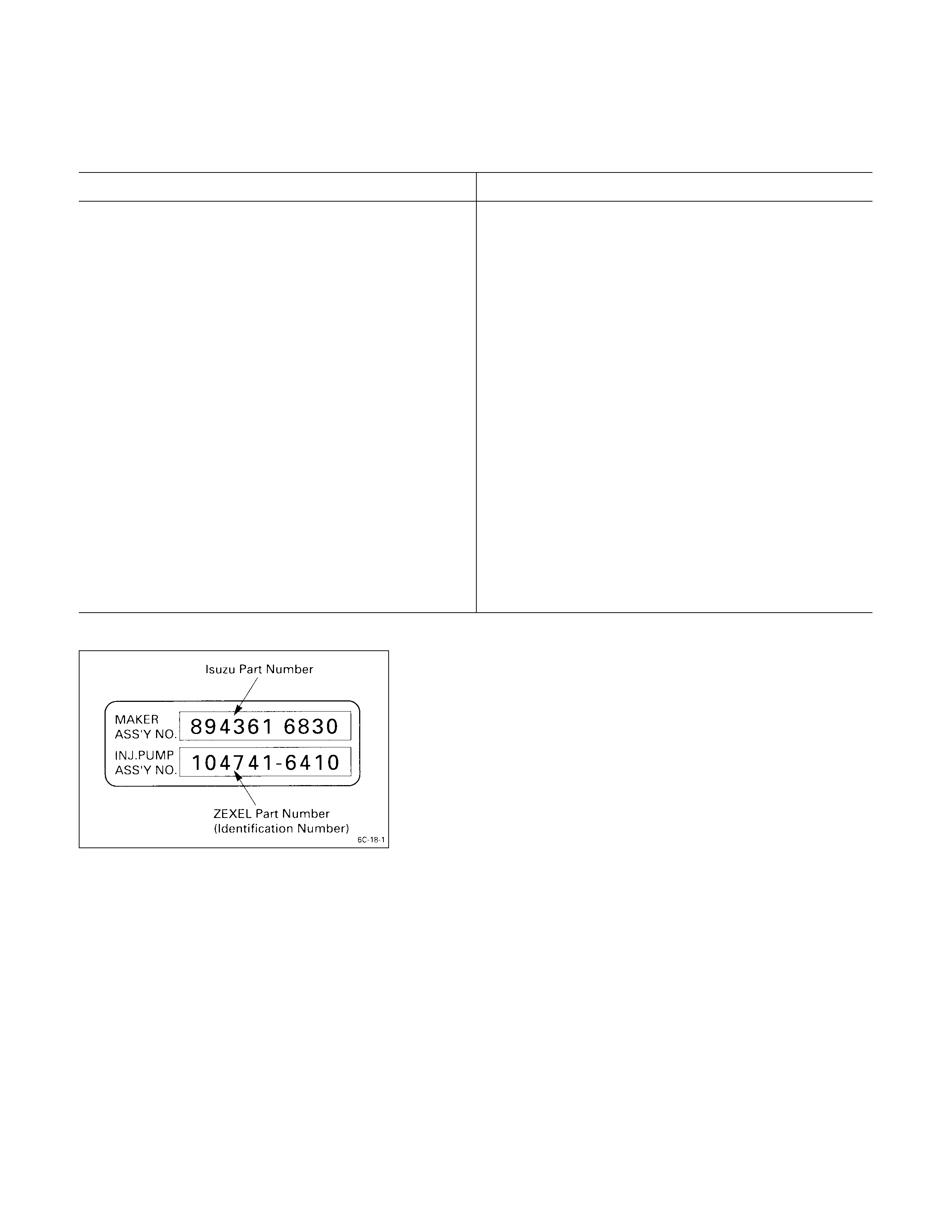
Identification Plate & Number
Use the data following the injection pump identification
number to adjust the injection volume.
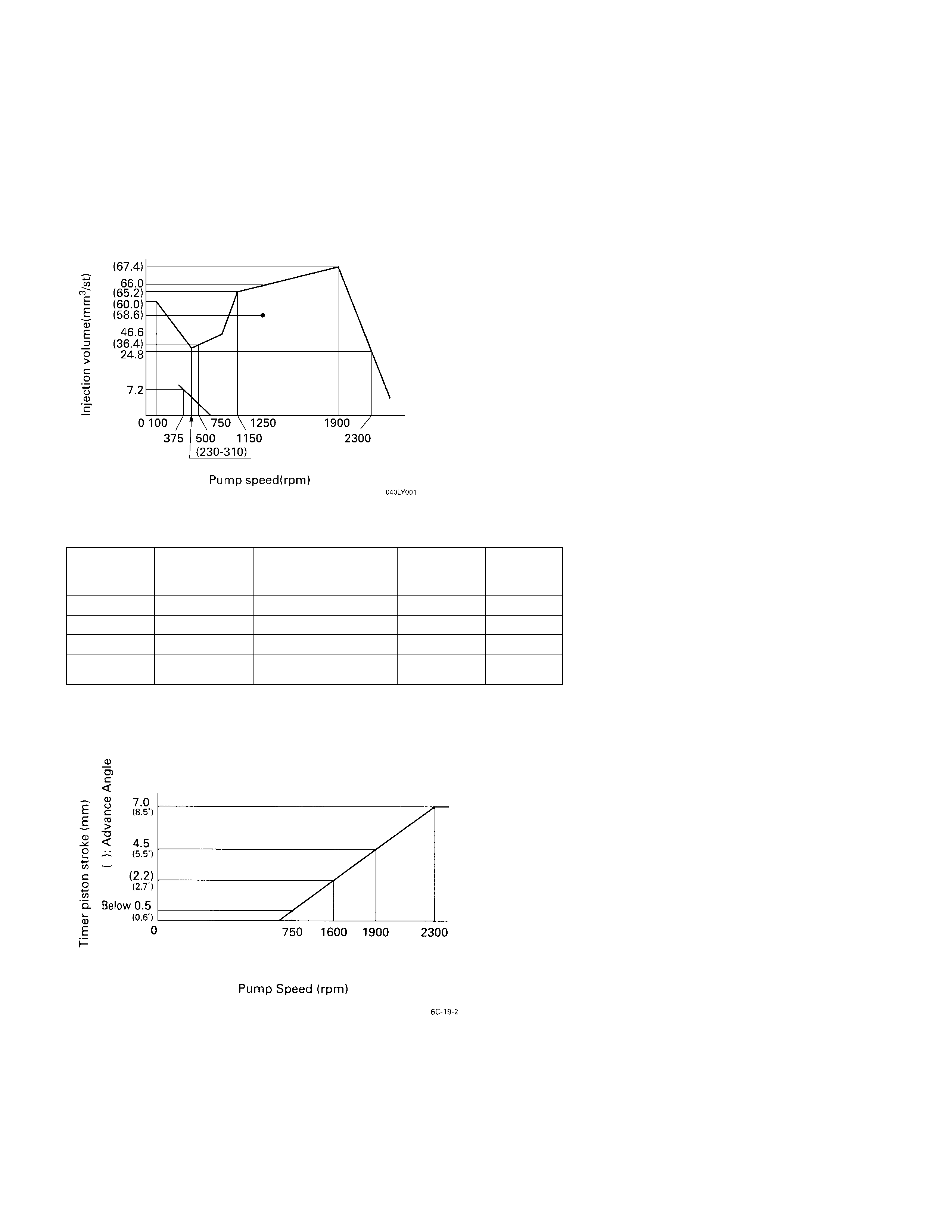
Injection Volume & Governor Performance Diagram
ENGINE: 4JB1T
IDENTIFICATION NUM BERS: 104746-6152 (I SUZU PART NUMBER 8- 97132- 678-2)
TEST FUEL: STANDARD DIESEL FUEL SAE J967D (OR ISO 4113)
GOVERNO R ADJUSTMENT
TIMER AND PUMP CASE PRESSURE
Pump
speed rpm Timer piston
stroke mm Pump case
pressure kpa
(kg/cm2)
Boost
pressure kpa
(kg/cm2)Reference
750 Below 0.5 73.3 (0.75)
1600 (2.2 ± 0.4) 73.3 (0.75)
1900 4.5 ± 0.2 618 ± 20 (6.3 ± 0.2) 73.3 (0.75) Base
2300 7.0 +0.4 73.3 (0.75)
TIMER PERFORM ANCE DIAGRAM
-0.3
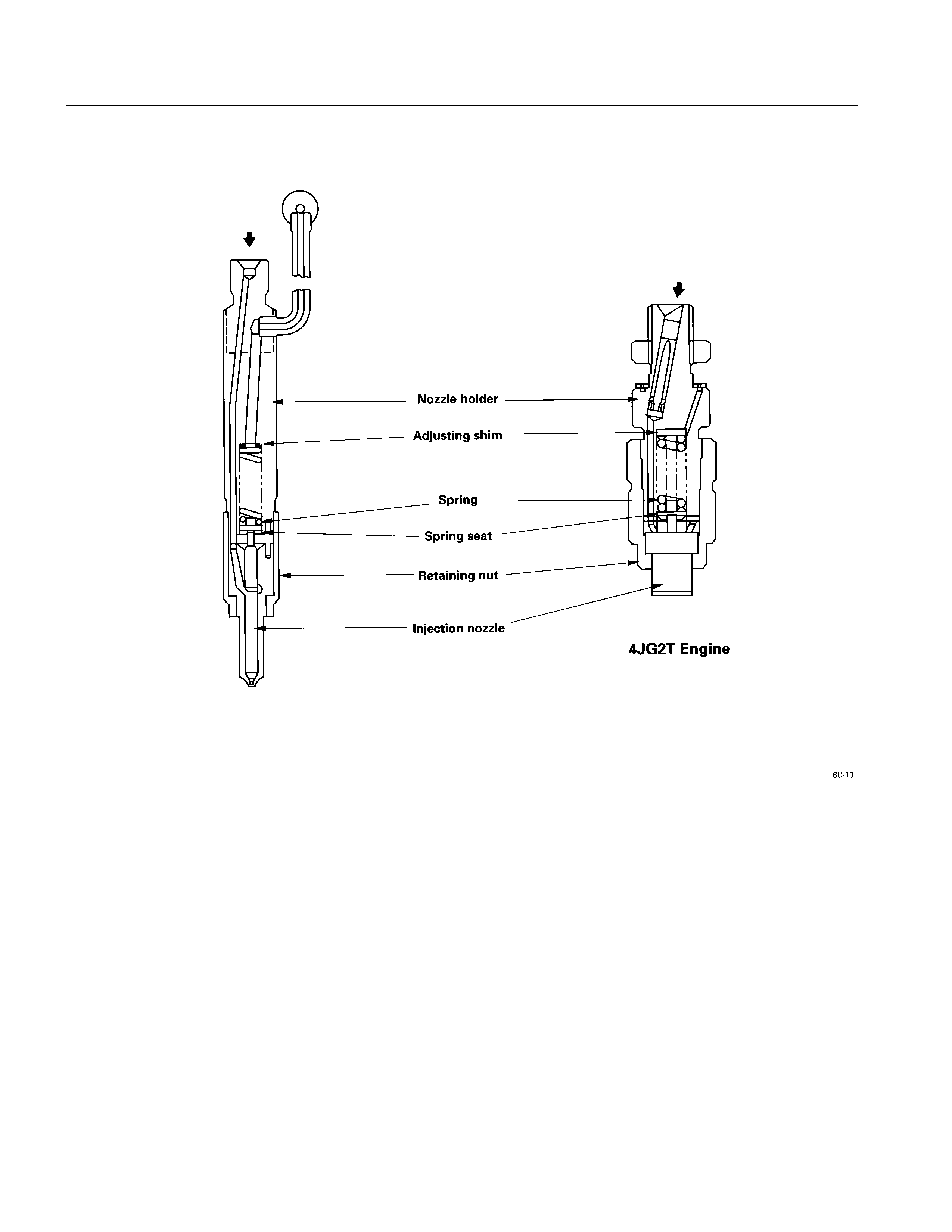
Injection Nozzle
Disassembly
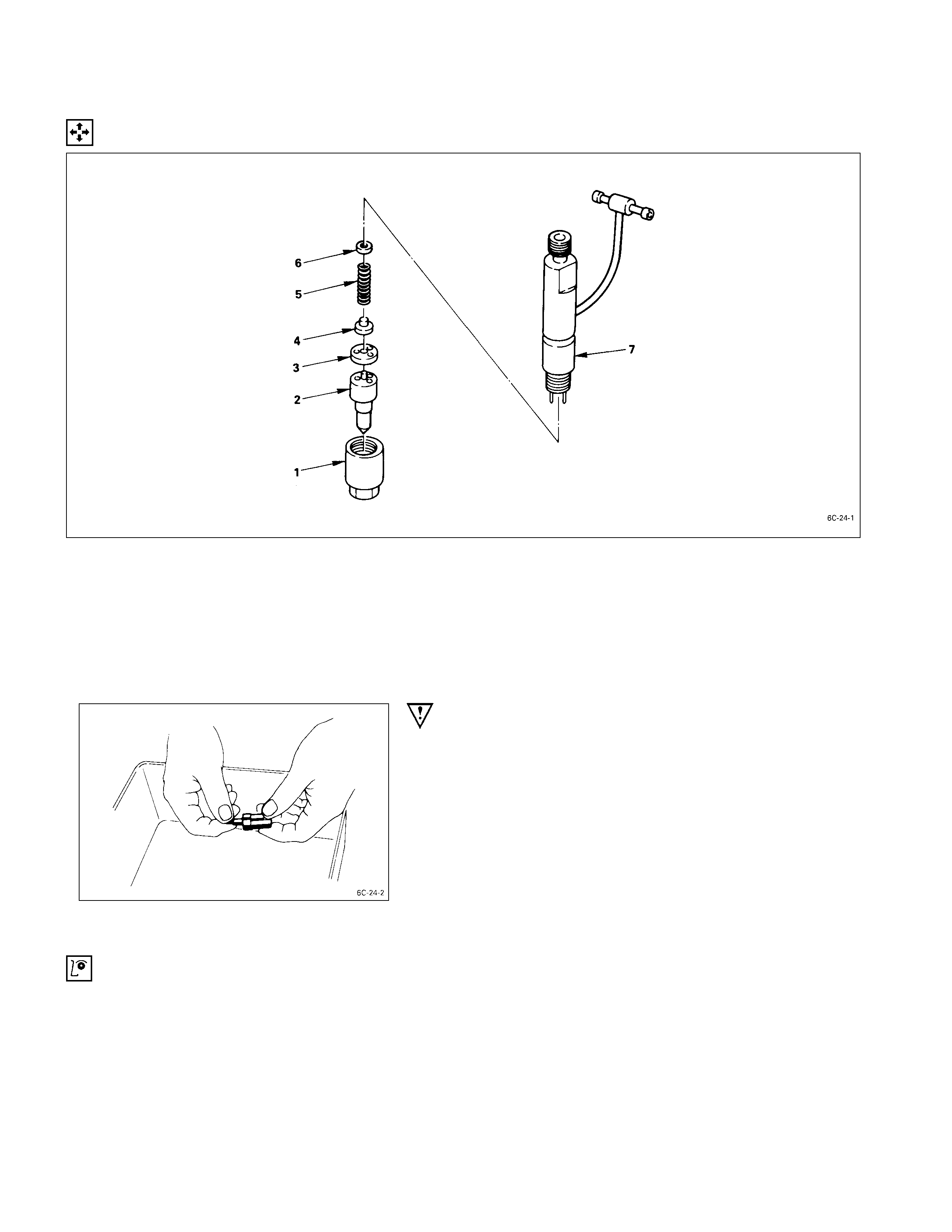
Disassembly Steps
1. Retaining nut 5. Spring
J
2. Injection nozzle 6. Adjusting shim
3. Spacer 7. Nozzle holder
4. Spring seat
IMPORTANT OPERATIONS
2. Injection nozzle
1) Remove the nozzle assemblies from the nozzle
holders.
Tag the nozzle assemblies and the nozzle holders to
ensure that they are reinstalled in their original
positions.
The nozzle assembly and nozzl e holder combinations
must not be interchanged.
2) Immerse the injection nozzles in a tool tray filled with
clean diesel oil to protect them from dust.
Inspection & Repair
Make the necessary adjustments, repairs, and part replacements if excessive wear or damage is discovered during
inspection.
INJECTION NO ZZLE NEEDLE I NSPECTION
1. Remove the nozzle needle from the nozzle body.
2. Carefully wash the noz zle needle and the nozzle body
in clean diesel fuel.
3. Check that the nozzle needle moves smoothly inside
the injection nozzle body.
If the nozzle needle does not move smoothly, it must
be replaced.
NOZZLE BODY AND NEEDLE VALVE INSPECTIO N
Check the nozzle body and the needle valve for damage
and deformation.
The nozzle and body assembly must be replaced if either
of these two conditions are discovered during inspection.
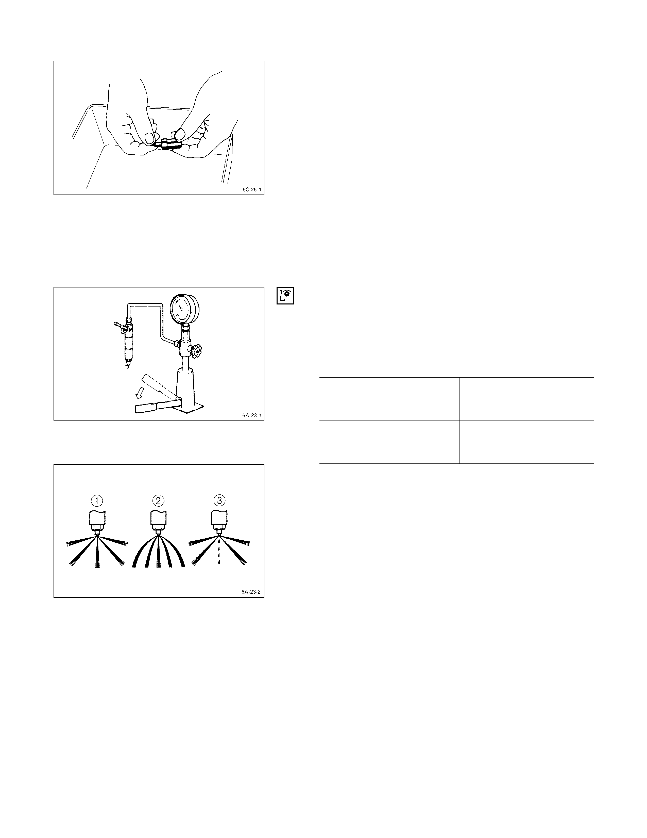
INJECTION NOZZLE INSPECTION
Use a nozzle tester to check the injection nozzle opening
pressure and the spray condition.
If the opening pressure is above or below the specified
value, the injection nozzle must be replaced or adjusted.
Injection Nozzle Opening Pressure kg/cm2 (psi/kPa)
4JA1T, 4JA1, 4JB1T 185 (2,631/18,1)
4JB1T
For ARGENTINA and
MALAYSIA only. 220 (3,128/21,575)
If the spray condition is bad, the injection nozzle must be
replaced or repaired.
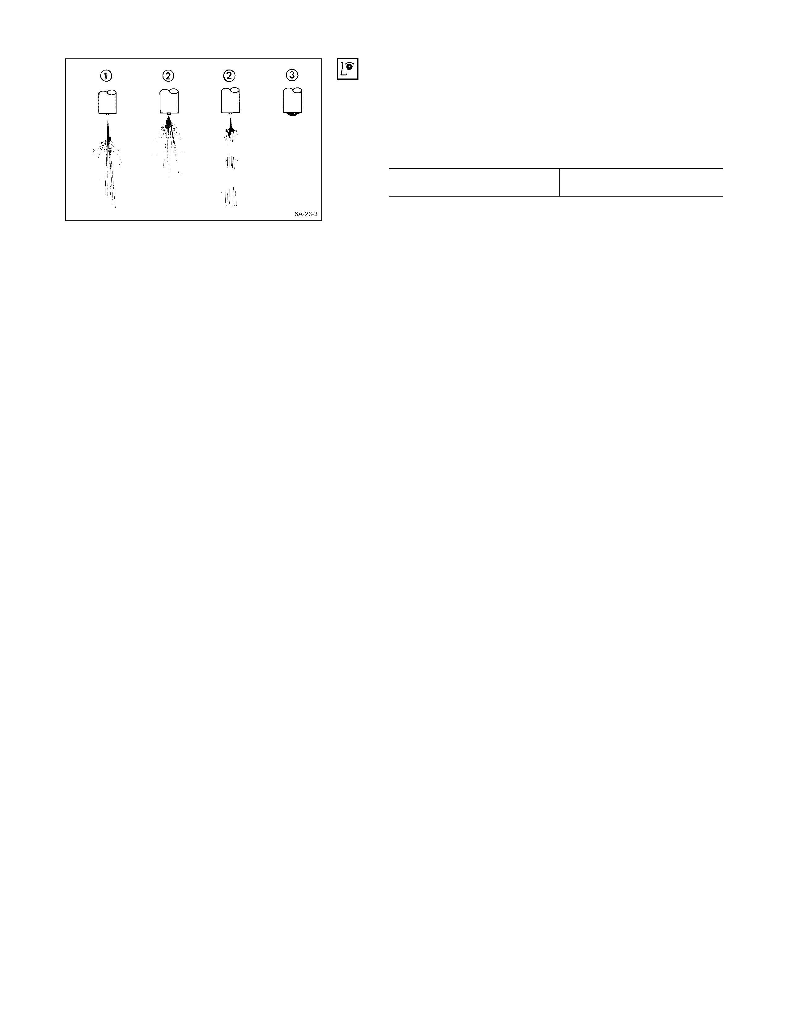
Spray Condition
QCorrect
R Incorrect (Restrictions in orifice)
SIncorrect (Dripping)
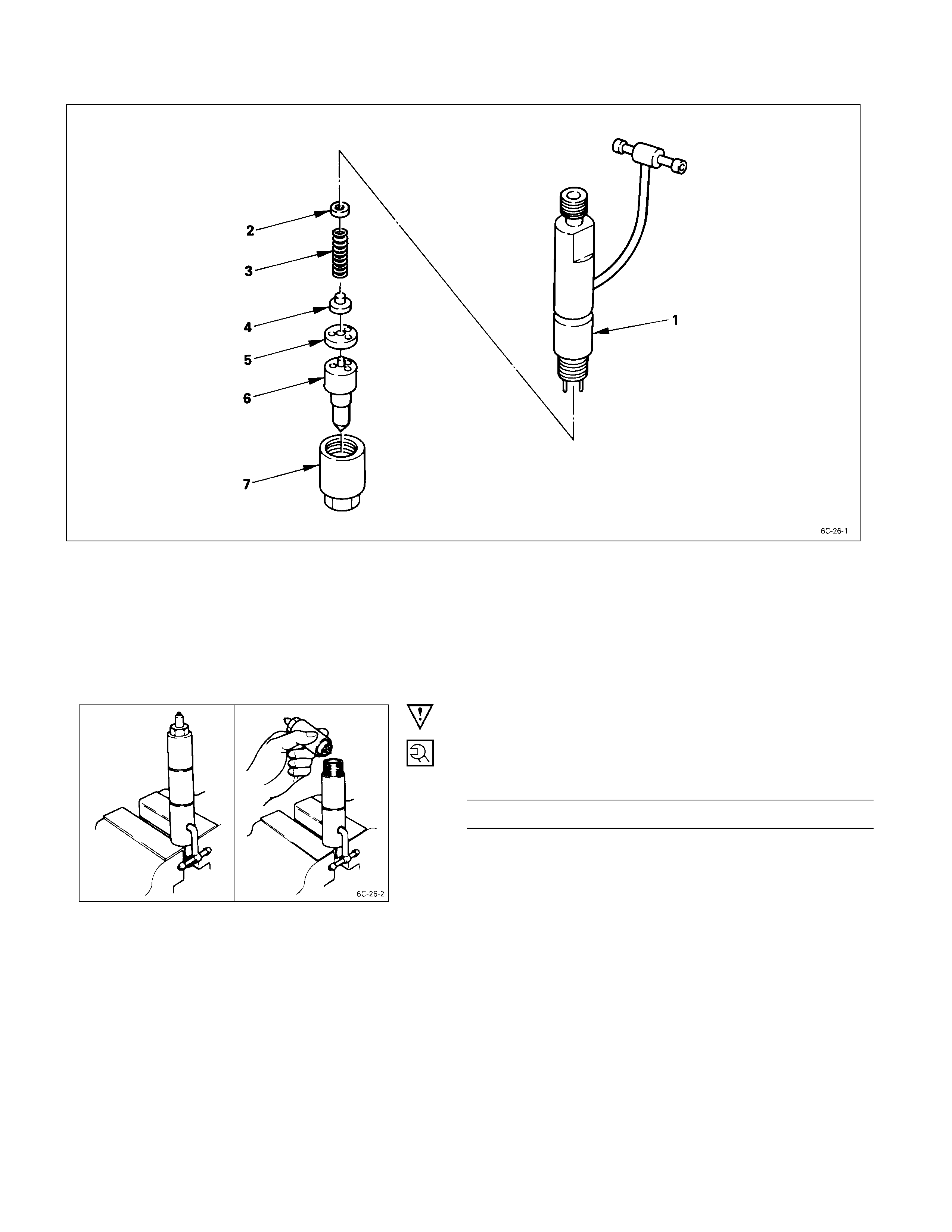
Reassembly
REASSEMBLY STEPS
1. Nozzle holder 5. Spacer
2. Adjusting shim 6. Injection nozzle
3. Spring
J
7. Retaining nut
4. Spring seat
IMPORTANT OPERATIONS
7. Retaining Nut
Tighten the retaining nut to the specified torque.
Retaining Nut Torque kg·m (lb.ft/N·m)
3.5 ± 0.5 (25.3 ± 3.6/34.3 ± 4.9)
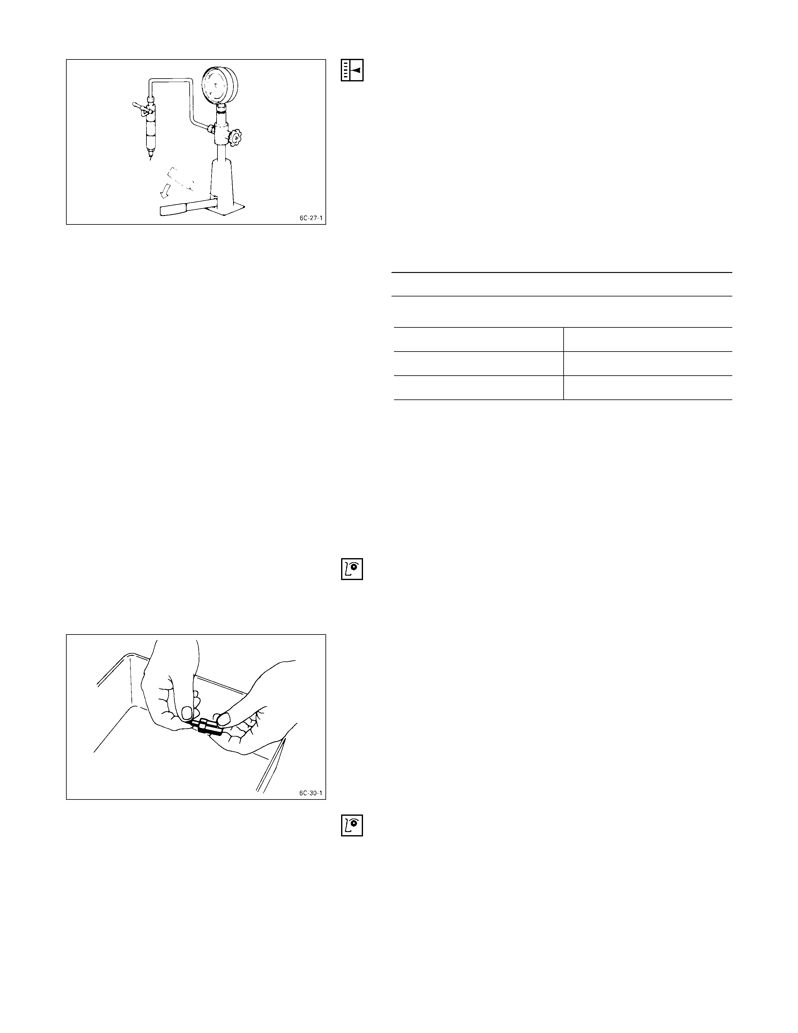
INJECTION NOZZLE ADJUSTMENT
The fuel injection starting pressure adjustment of this
injection nozzle is done by rereplacing or decreasing or
increasing the number of shims installed.
1) Attach the injection nozzle holder to the injection
nozzle tester.
2) Apply pressure to the nozzle tester to check that the
injection nozzle opens at the specified pressure.
If the injection nozzle does not open at the specified
pressure, install or remove the appropriate number of
ajusting shims to adjust it.
Nozzle Opening Pressure kg/cm2 (psi/MPa)
185 (2,631/18.1)
Adjusting Shim Availability rnm(in)
Range 0.50 – 1.50 (0.02 – 0.06)
Increment 0.025 (0.001)
Total No. of Shims 41
Removing or installing one shim will increase or decrease
the nozzle opening pressure approximately 3.77 kg/cm3
(53.6 psi/369.46 kPa).
WARNING:
TEST FLUID FROM THE INJECTION NOZZLE TESTER
WILL SPRAY OUT UNDER GREAT PRESSURE. IT CAN
EASILY PUNCTURE A PERSON’S SKIN. KEEP YOUR
HANDS AWAY FROM THE INJECTION NOZZLE
TESTER AT ALL TIMES.
Inspection & Repair
Make the necessary adjustments, repairs, and part
replacements if excessive wear or damage is discovered
during inspection.
INJECTION NO ZZLE NEEDLE SEI ZURE INSPECTION
1) Remove the injection nozzle needle from the injection
nozzle body.
2) Carefully wash the injection nozzle needle and the
injection nozzle body in clean diesel fuel.
3) Check that the injection needle valve moves smoothly
inside the injection nozzle body.
If the injection needle valve does not move smoothly, it
must be replaced.
INJECTION NO ZZLE BODY AND INJECTION NEEDLE
INSPECTION
Check the injection nozzle body and the injection needle
valve for damage and deformation.
The injection nozzl e assembly must be replaced if either of
these two conditions are discovered during inspection.
INJECTION NOZZLE INSPECTION
Use a nozzle tester to check the injection nozzle opening
pressure and the spray condition.
If the opening pressure is above or below the specified
value, the injection nozzle must be replaced or adjusted.
Injection Nozzle Opening Pressure kg/cm2 (psi/MPa)
4JG2T 150 (2,133/14.7)
If the spray condition is bad, the injection nozzle must be
replaced or repaired.
Spray Condition
QCorrect
R Incorrect (Restrictions in orifice)
SIncorrect (Dripping)
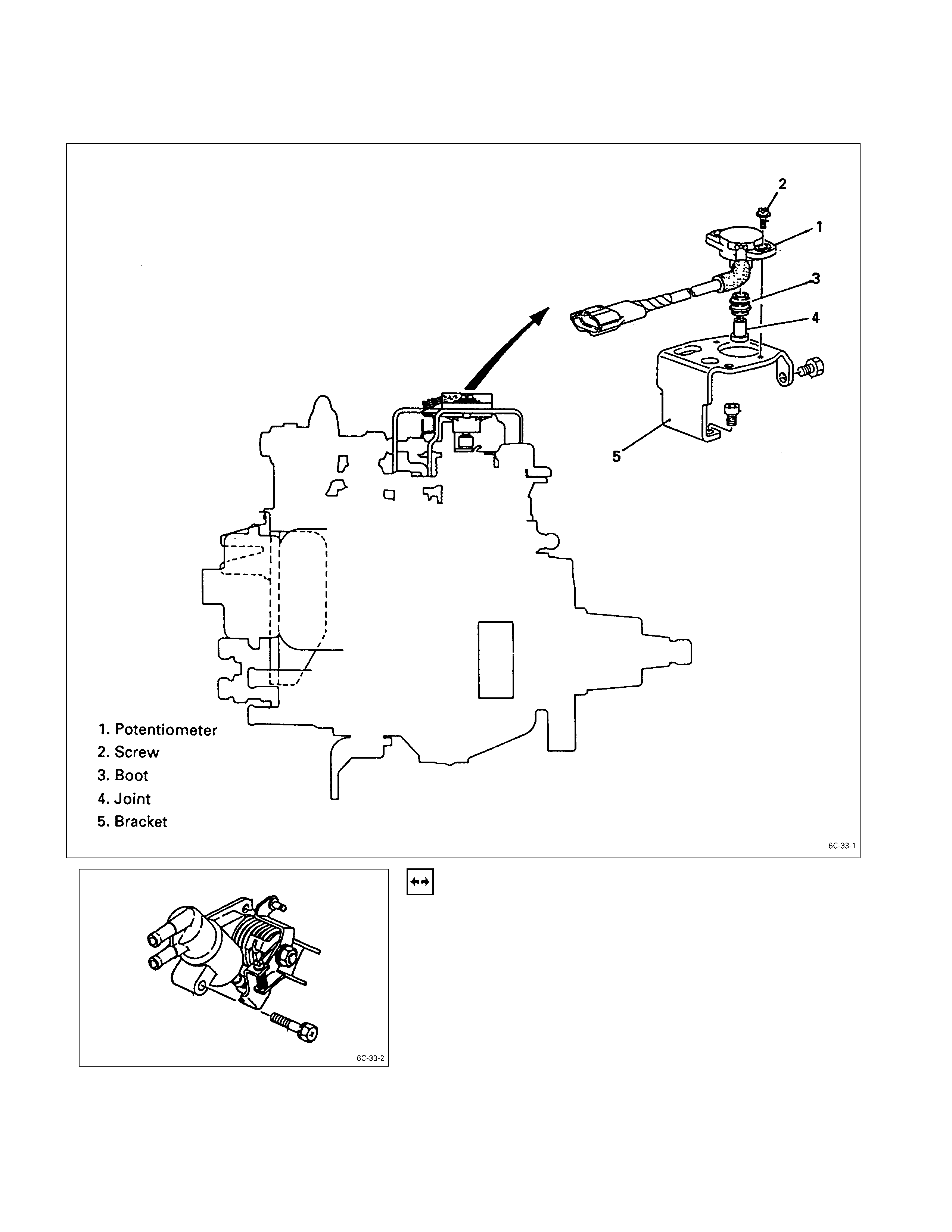
Adjustment Procedure For Potenti ometer
DEVELOPMENT VIEW OF POTENTIOM ETER
1. Advance Assembly (CSD)
Remove the advance assembly from the injection pump
assembly.
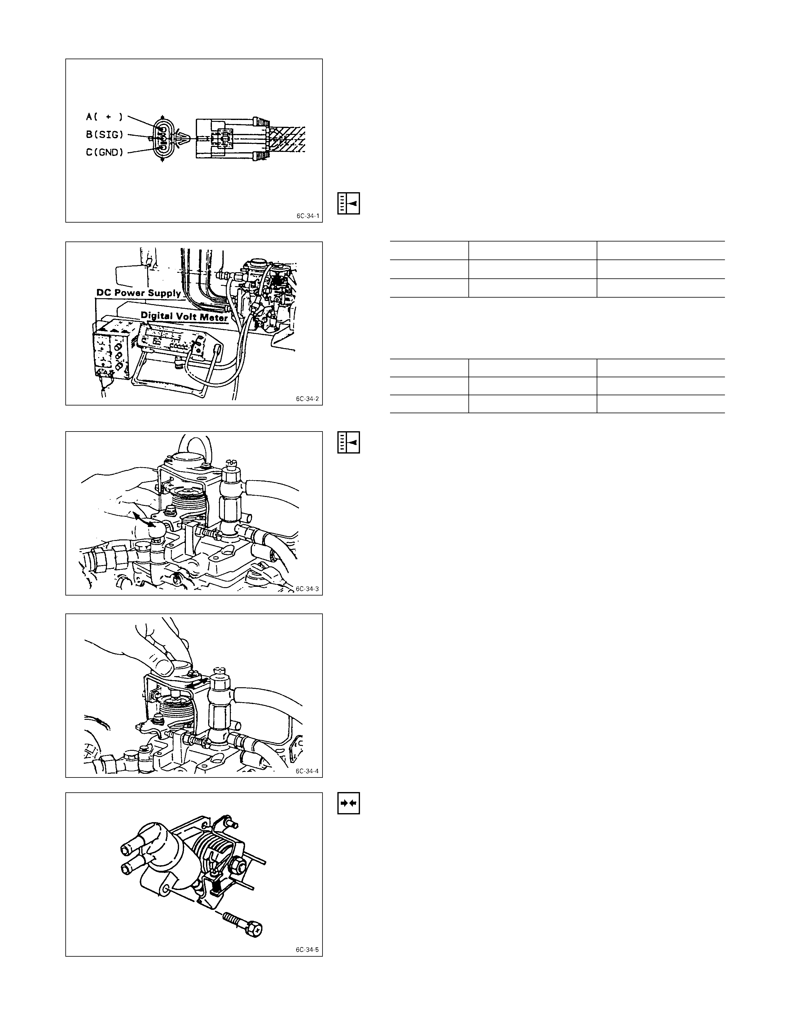
2. Digital Volt Meter and DC Constant Voltage Power
Supply.
1) Connect digital volt meter to B and C connector on
wire harness from potentiometer.
2) Connect DC constant voltage power supply to A (for
positive electricity) and C (for negative electricity)
connector on wire harness from potentiometer.
3) Supply DC 10V to between A and C connector.
4) Measure the output voltage from potentiometer at
idling position on the fuel control lever.
Idling Position Output Voltage Volt
Until 99 Model From 00 Model
4JA1T 1.62 ± 0.45 2.12 ± 0.45
4JG2T 1.41 ± 0.45 1.41 ± 0.45
5) Measure the output voltage from potentiometer at full
load position on the fuel control lever.
Full Load Position Output Voltage Volt
Until 99 Model From 00 Model
4JA1T 7.7 ± 0.45 4.1 ± 0.03
4JG2T - 3.65 ± 0.03
3. Adjustment of Output Voltage from Potentiome ter
If the Measuring value is without standard above, readjust
setting position of the potentiometer as below.
1) Loose the potentiometer fixing bolts.
2) Keep fuel control lever on idling position then move
the potentiometer until reading the output voltage
within standard.
3) Same time read the output voltage with full load
position on the control lever.
4) Make sure that fuel control lever return to idling
position by return spring.
5) Fix the advance assembly to the injection pump
assembly.
Note:
If can not be readjusted potentiometer output voltage,
recommend to contact Zexel or Bosch argent near
your garage.