
SECTION 6D - ENGINE ELECTRICAL -
CHARGING SYSTEM
Main Data & Speci fications
General Description
Generator
Charging Circuit Diagram
Wire Coding
Description
Wire Size
Wire Size Specifications
Wire Color
Wire Color-Coding
Symbols & Abbreviations
Description
Symbols
Symbol & Meaning
Abbreviations
Abbreviation & Meaning
Torque Specifications
Generator
Generator
Removal & Installation
Disassembly
Inspection & Repair
Reassembly
Troubleshooting
Battery Charging and Noise Problems
1. No Charging
2. Overcharging
3. Undercharging
4. Unstable Charging Current
5. Noise
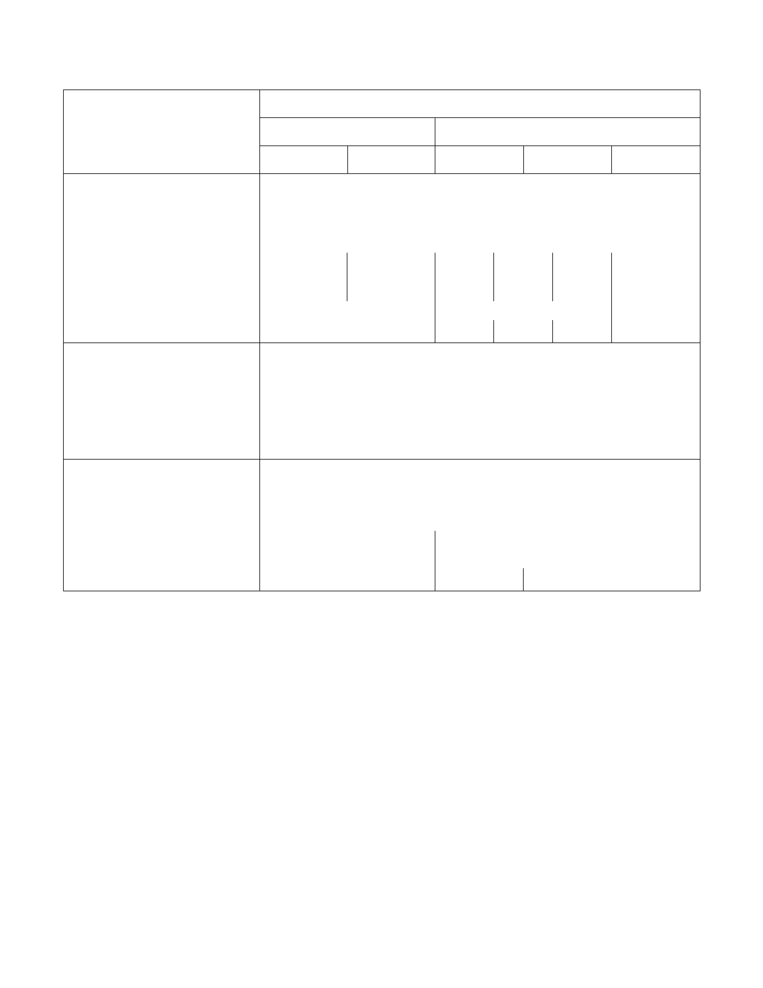
Main Data & Specifications
Description
4JH1TC 4JB1TItem
General Option General Option
Generator
Type
Voltage V
Drive and rotation
Ground polarity
AC brush with IC regulator and vacuum pump
12
V-belt, clockwise viewed from the drive pulley
Negative
Maximum output A 60
at 5,000 rpm 80
at 5,000 rpm 40
at 5,000
rpm
50
at 5,000
rpm
80
at 5,000
rpm
Engine speed ratio to 1 1.77 1.85
Maximum speed rpm 11,000 11,000 11,000 9,500
Starter Motor
Type
Rated voltage V Solenoid controlled
12
Rated output kW 2.3
Load characteristics
Terminal voltage V
Load current A 8.76
300
Vacuum Pump
Delivery volume cm3/rev
500 mmHg build up time 30
35 seconds or less at 1,000 rpm
7~10 seconds or less at 5,000 rpm
Maximum vacuum 680 mmHg or more at 5,000
rpm 650 mmHg or more at 5,000 rpm
Weight kg(lb) 0.65 (1.43) 0.9 (1.99) 1.2 (2.6)
General Description
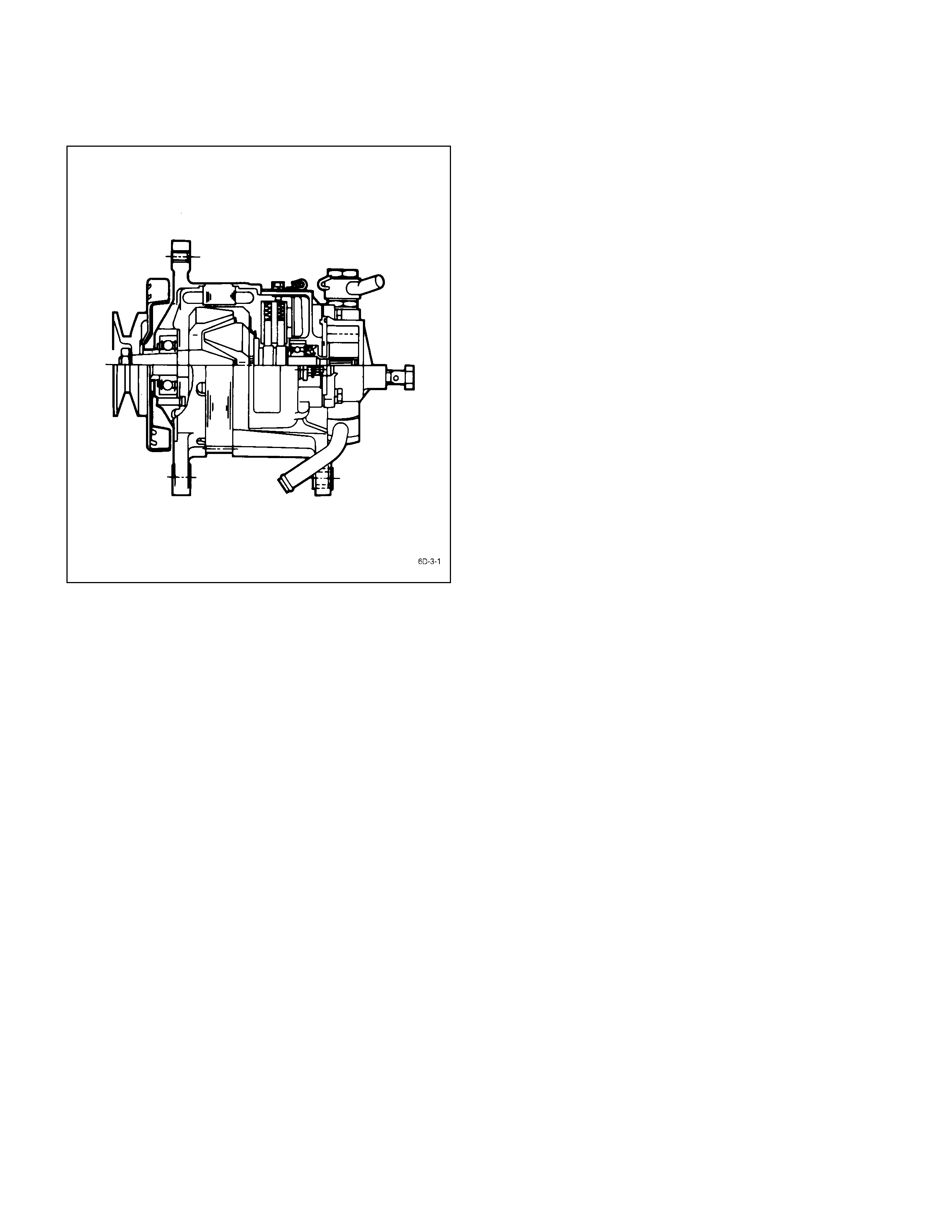
Generator
The basic charging system is the IC integral regulator charging system. The internal components are connected
electrically as shown in charging circuit diagram.
The generator features a solid state regulator that is mounted inside the generator. All regulator components are
enclosed into a solid mold, and this unit along with the brush holder assembly is attached to the slip ring end frame. The
generator voltage setting cannot be adjusted.
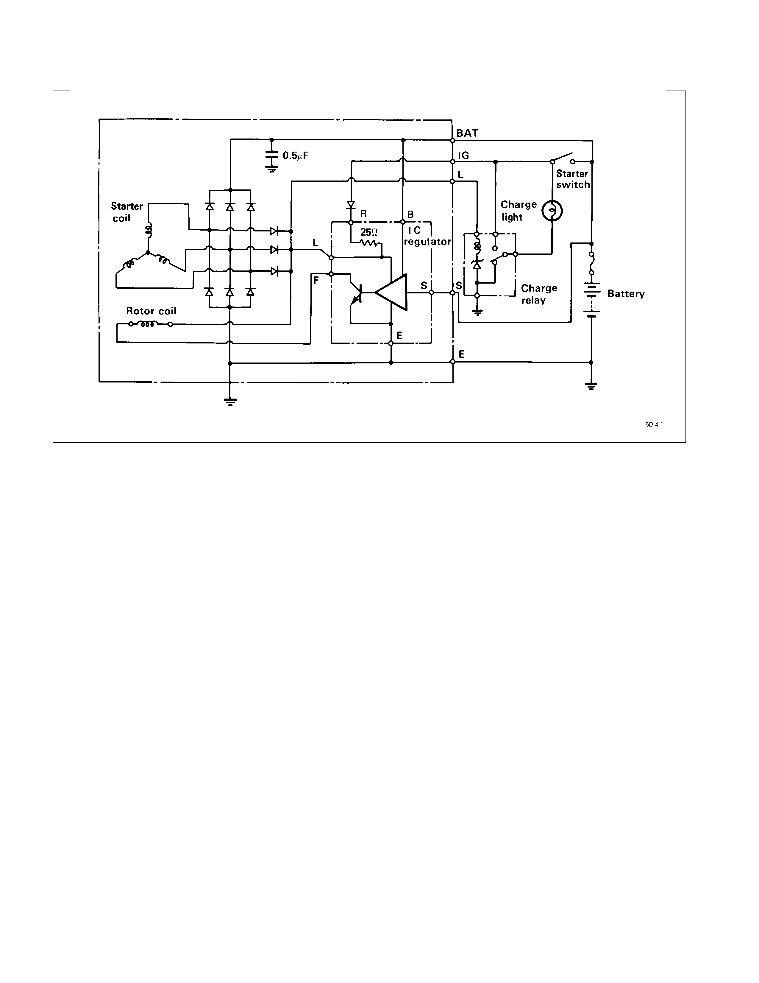
Charging Circuit Diagram
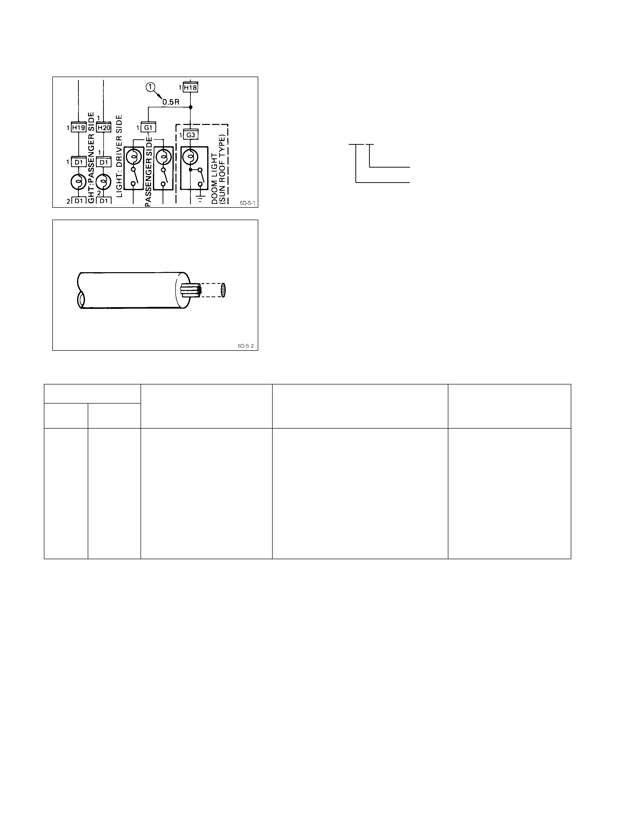
Wire Coding
Description
Codes used in the circuit diagram represent wire size and
color Q.
Example: 0.5 R
Wire color (Red)
Wire size (0.5 mm2)
Wire Size
Wire size is specified with the metric gauge system.
The metric gauge system gives the wire size in cross-
sectional area measured in square millimeters.
Wire Size Specifications
Wire size
mm2AWG
Number of wires/
Wire diameter
mm (in.)
Resistance at normal room
temperature of 20°C (68°F)
Ω/m (Ω/ft.)
Maximum allowable
current
A
0.5
0.85
1.25
2
3
5
8
15
20
30
20
18
16
14
12
10
8
6
4
2
7/0.32 (0.013)
11/0.32 (0.013)
16/0.32 (0.013)
26/0.32 (0.013)
41/0.32 (0.013)
65/0.32 (0.013)
50/0.45 (0.018)
84/0.45 (0.018)
41/0.80 (0.031)
70/0.80 (0.031)
0.03250 (0.00991)
0.02050 (0.00625)
0.01410 (0.00430)
0.00867 (0.00264)
0.00550 (0.00168)
0.00347 (0.00106)
0.00228 (0.00070)
0.00136 (0.00042)
0.00087 (0.00027)
0.00051 (0.00016)
11.3
14.8
18.8
25.4
34.2
45.9
59.8
82.8
110.9
147.0
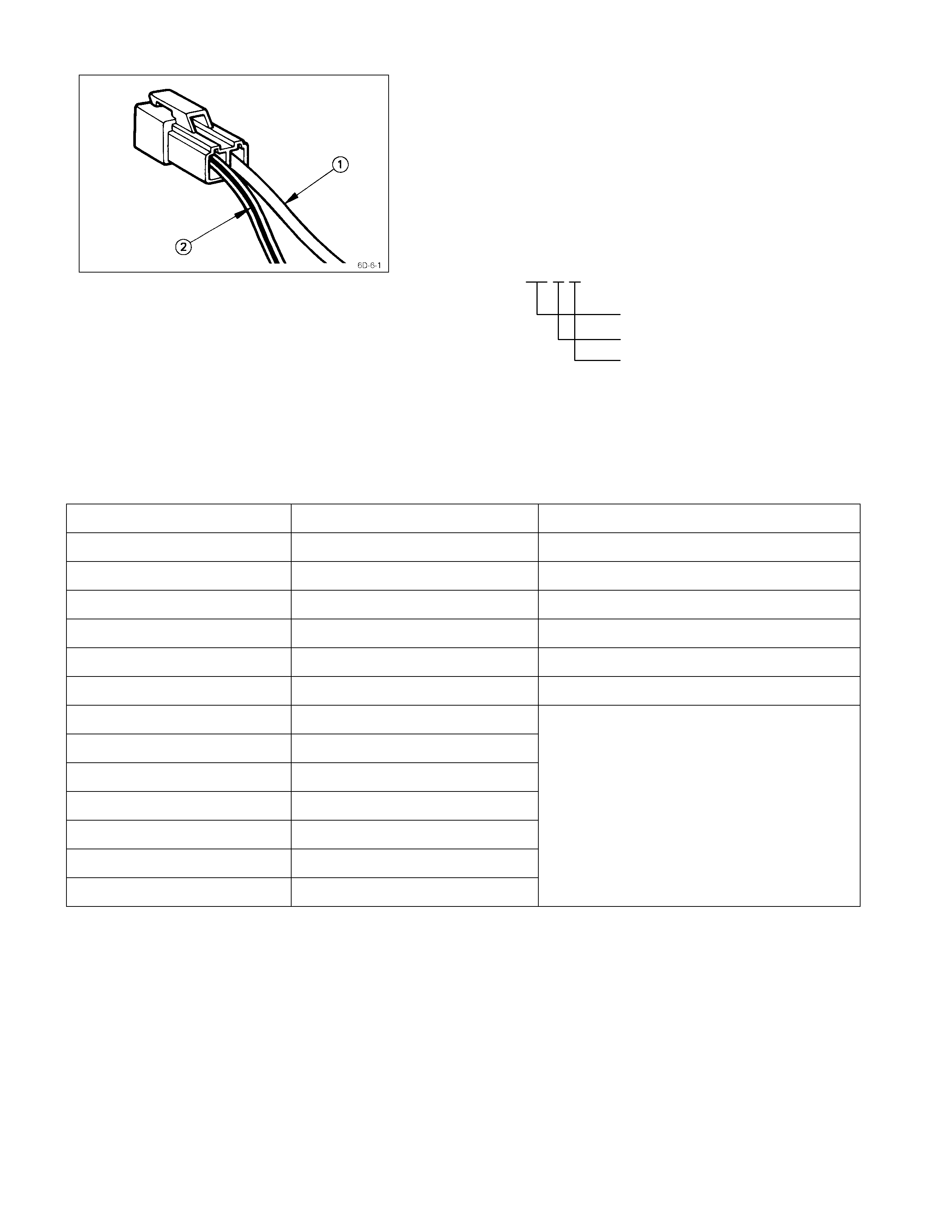
Wire Color
All wires have color-coded insulation.
Wires belonging to a system’s main harness will have a
single color Q.
Wires belonging to a system’s sub-circuits will have a
colored stripe R.
Striped wires use the following code to show wire size and
colors.
Example: 0.5 G R
Wire size (0.5 mm2)
Green (Base color)
Red (Stripe color)
Abbreviations are used to indicate wire color within a
circuit diagram.
Refer to the following table.
Wire Color-Coding
Color-coding Meaning Circuits
B Black Starter circuit and grounding circuit
W White Charging circuit
R Red Lighting circuit
G Green Signal circuit
Y Yellow Instrument circuit
L Blue Wiper circuit
O Orange
Br Brown
Lg Light green
Gy Grey
PPink
Sb Sky blue
V Violet
Other circuits
Symbol s & Abbreviations
Description
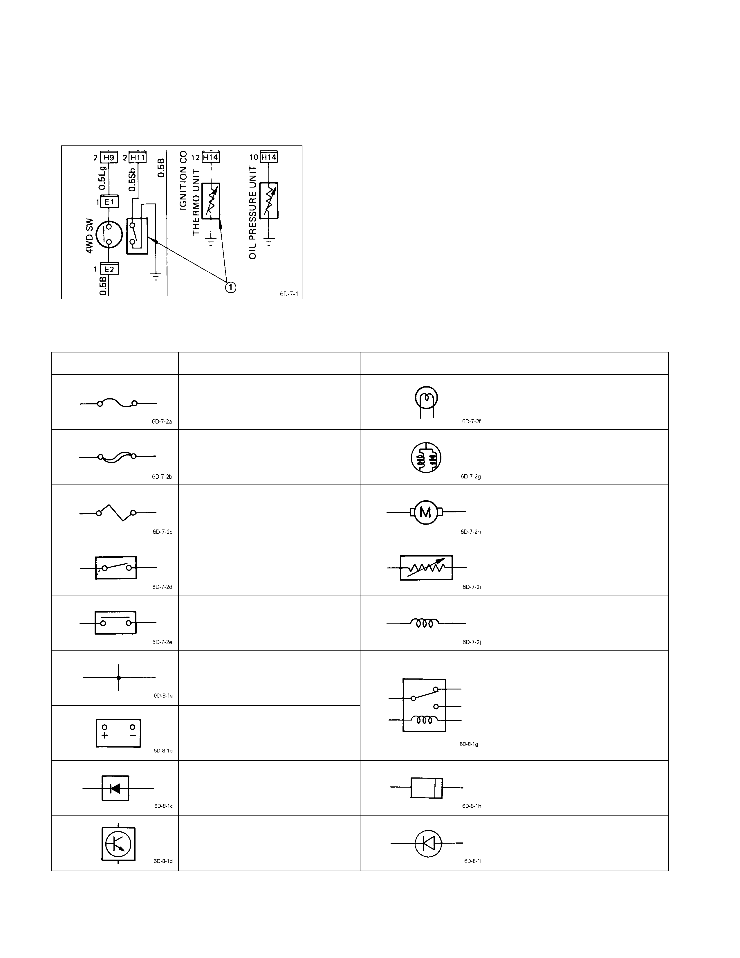
The symbols and abbreviations used in the circuit diagram
make the diagram easier to read and understand.
Symbols
The illustration at the left shows a ty pical symbol Q used
in circuit diagrams.
Refer to the following table.
Symbol & Meaning
Symbol Meaning Symbol Meaning
Fuse Single filament bulb
Main fuse Double filament bulb
Fusible link wire Motor
Switch Variable resistor
Switch Coil (Inductor)
Contact wiring
Battery
Relay
Note:
Relay contact shown in the
wiring diagram indicates
condition before a ctuation.
Diode Connector
Electronic part Light emitting diode
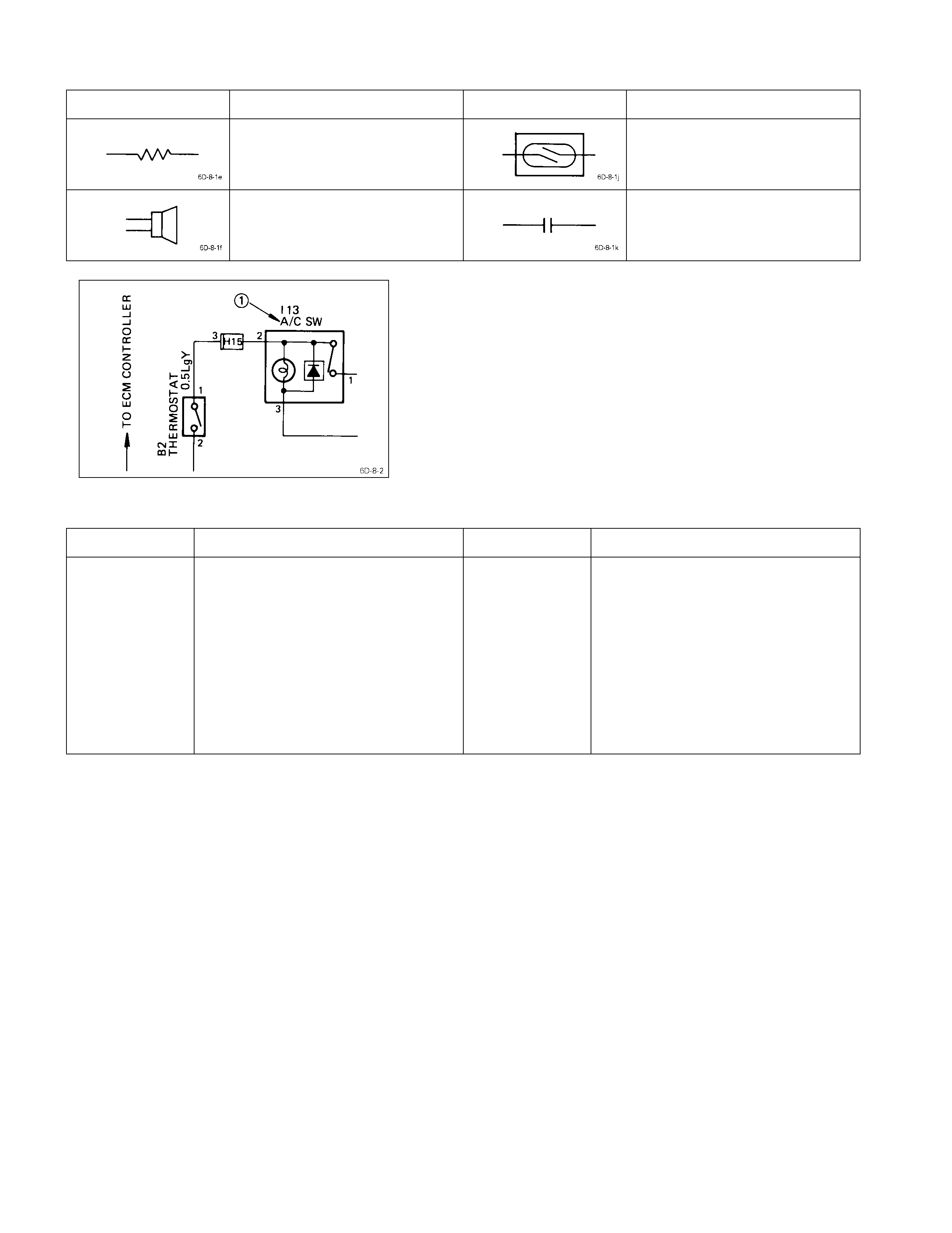
Symbol Meaning Symbol Meaning
Resistor Reed switch
Speaker Condenser
Abbreviations
The illustration at the left shows a ty pical abbreviation
used in circuit diagrams.
These same abbreviations may also appear in the next.
Refer to the following table.
Abbreviation & Meaning
Abbreviation Meaning Abbreviation Meaning
RH
LH
SW
M/T
A/T
FT
RR
FLW
TEMP
ECM
Right-hand side
Left-hand side
Switch
Manual transmission
Automatic transmission
Front
Rear
Fusible link wire
Temperature
Electronic control module
STD
OPT
W/
WO/
OD
ACC
A/C
ATF
VSV
Standard equipment
Optional equipment
With
Without
Overdrive
Accessories
Air conditioner
Automatic transmission fluid
Vacuum switching valve
Torque Specifi cati ons
Generator kgm(ft. lbs/Nm)
0.65 ±
±±
± 0.5(4.7 ±
±±
± 3.6/6.3 ±
±±
± 4.9)
Generator
Removal & Installation
Read this Section carefully before performing any removal and installation procedure. This Section gives you important
points as well as the order of operation. Be sure that you understand everything in this Section before you begin.
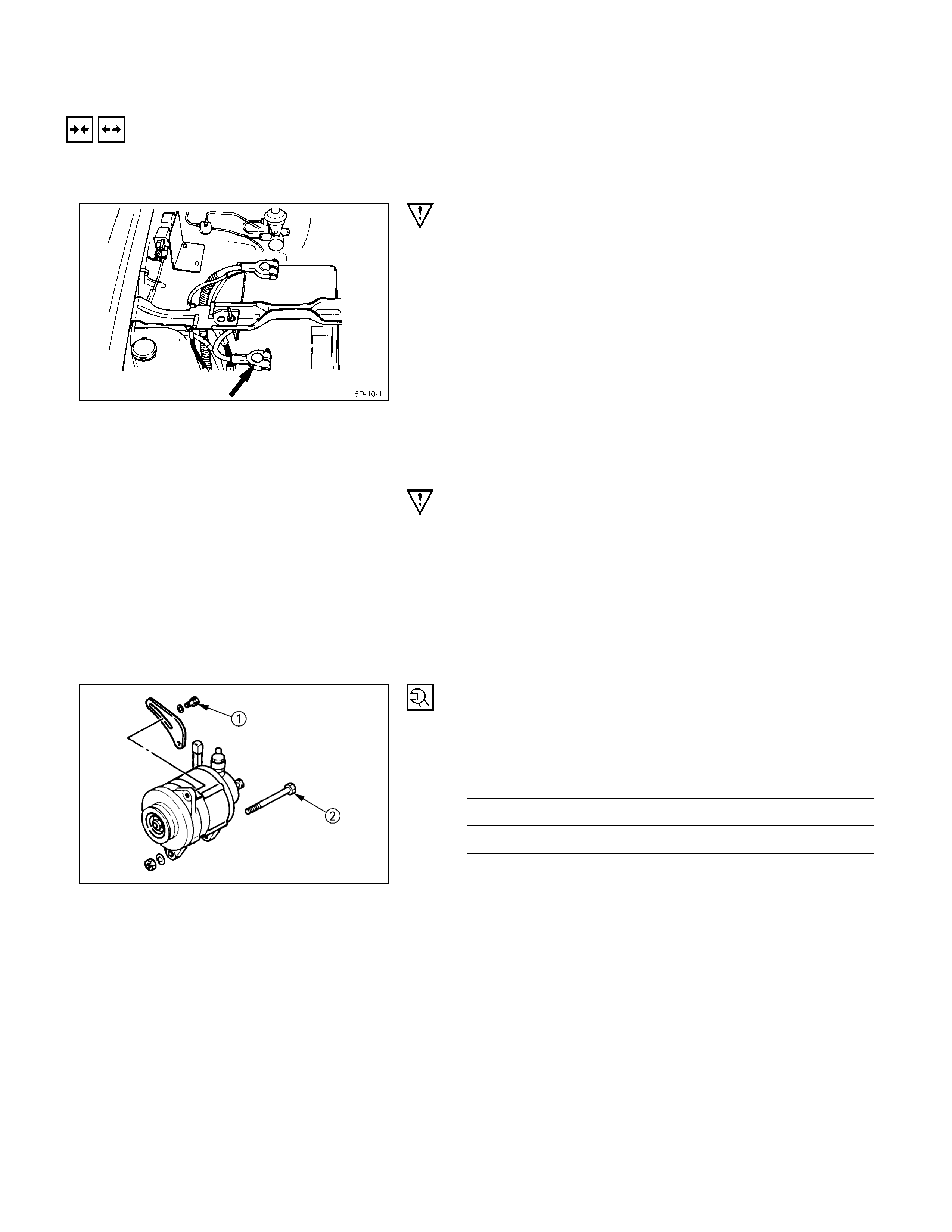
IMPO RTANT OPERATIONS-REMOVAL
COOLING FAN BELT
1) Disconnect the battery cables at the battery terminals.
2) Loosen and remove the fan belt adjusting plate bolts.
3) Remove the fan belt from the generator drive pulley.
GENERATOR
Remove the generator bolt and the generator from the
bracket.
IMPORTANT OPERATIONS-INSTALLATION
Follow the removal procedure in the reverse order to
perform the installation procedure. Pay careful attention to
the important points during the installation procedure.
GENERATOR
1) Install the generator to the bracket.
2) Tighten the generator bolt to the specified torque.
Generator Bolt Torque kg·m (lb·ft/N·m)
Q1.9 ± 0.5 (13.7 ± 3.6/18.6 ± 4.9)
R4.1 ± 0.6 (29.6 ± 4.3/40.2 ± 5.9)
066L200001
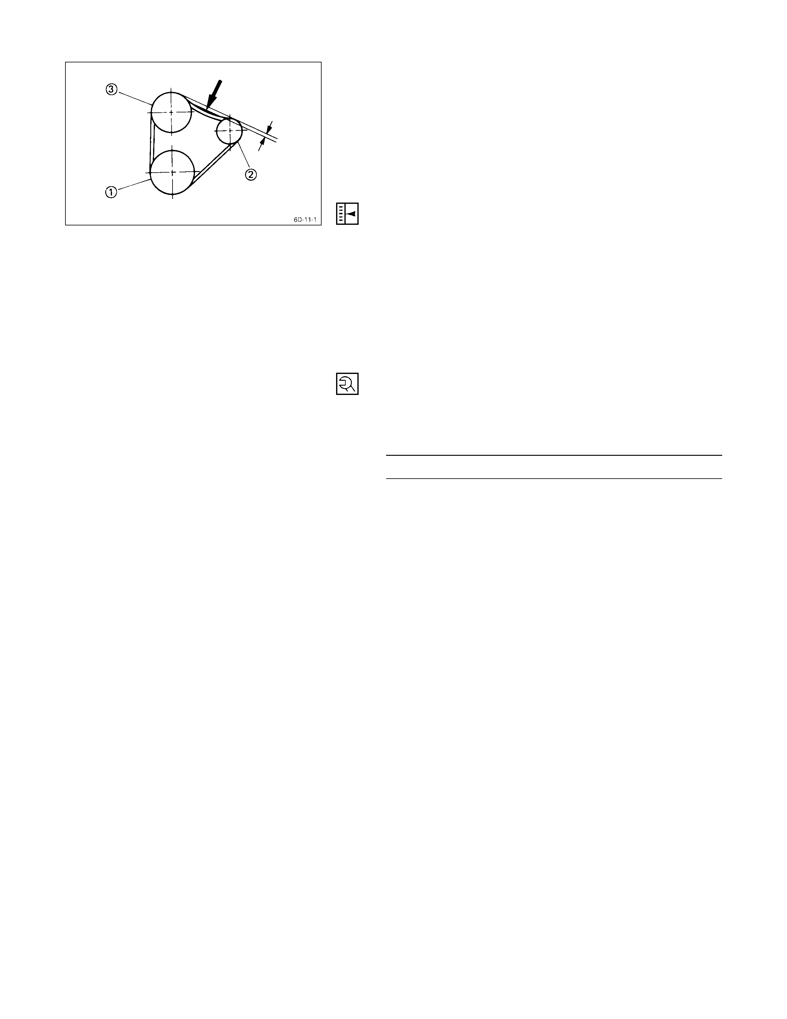
COOLING FAN BELT
1) Hold the generator toward the engine.
2) Install the fan belt to the three pulleys.
(1) Crankshaft pulley
(2) Water pump pulley
(3) Generator pulley
3) Adjust the fan belt tension
(1) Use a bar to pull the generator away from the
engine as far as possible.
(2) Use your hand to apply a pressure of 10 kg (22
lb/98N) to the area of the fan belt indicated by the
arrow in the illustration.
There should be from 8 – 12 mm (0.3 – 0.5 in) of
belt deflection.
4) Tighten the adjusting plate bolts to the specified
torque.
Pulley Nut Torque kg·m (lb·ft/N·m)
1.9 ± 0.5 (13.7 ± 3.6/18.3 ± 4.9)
5) Reconnect the battery cable to the battery.
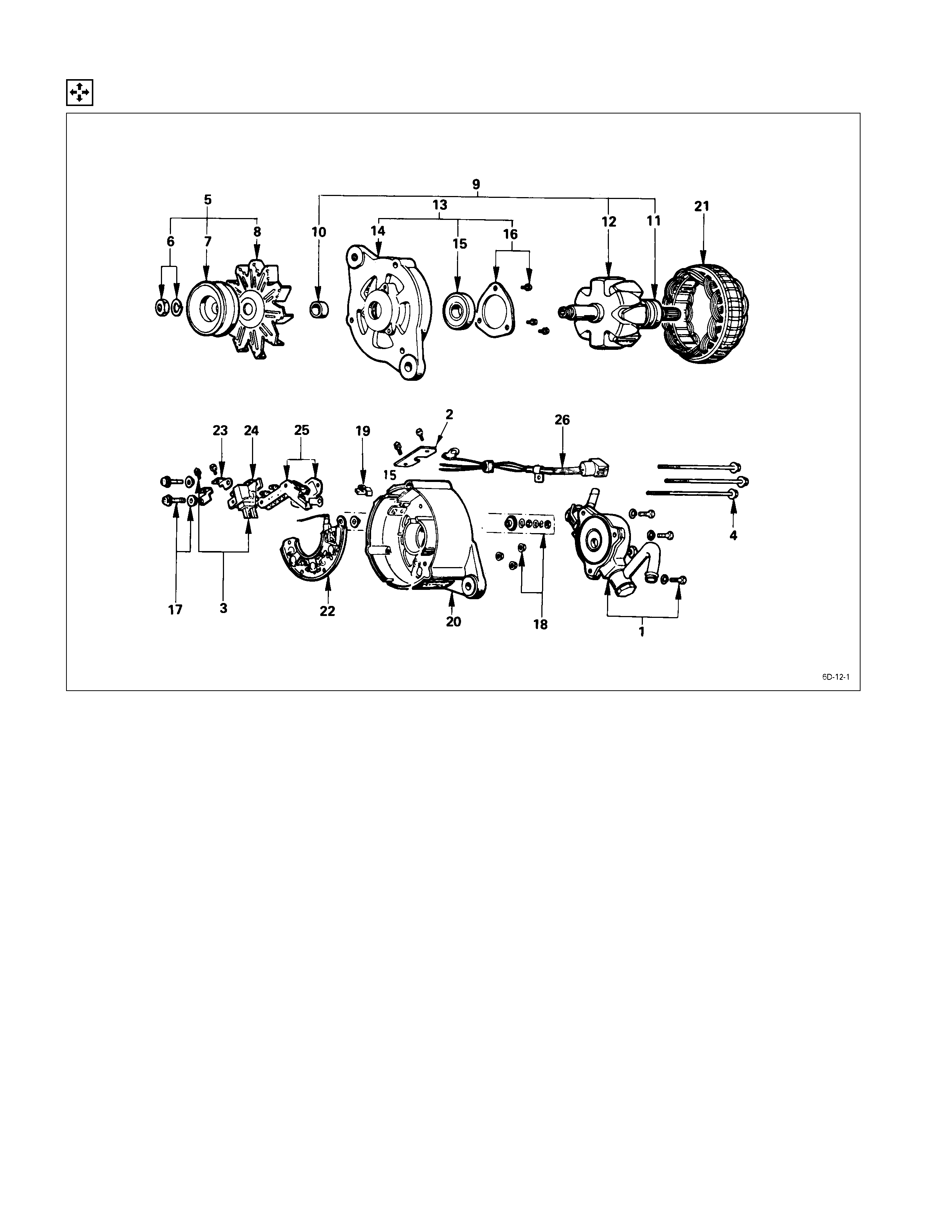
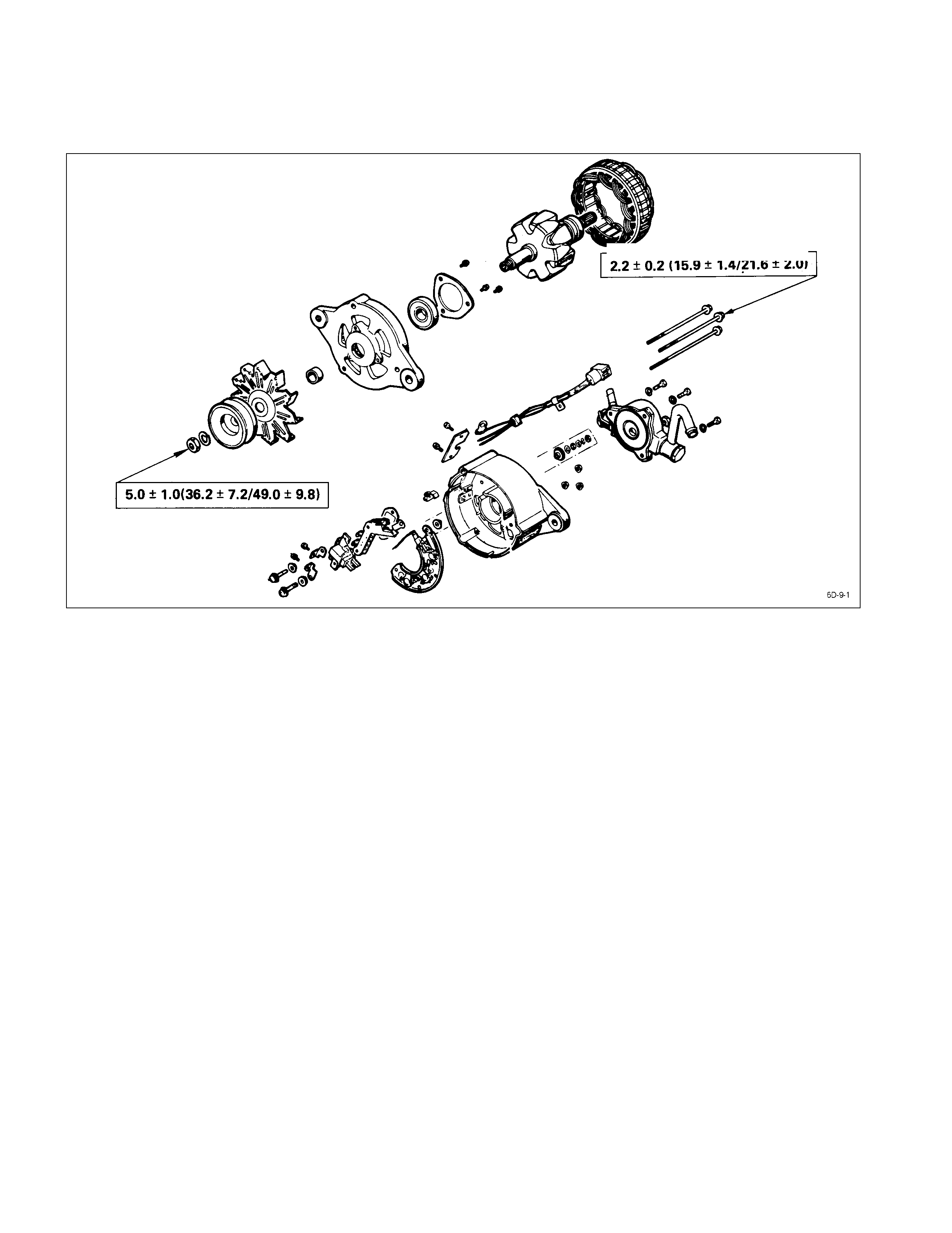
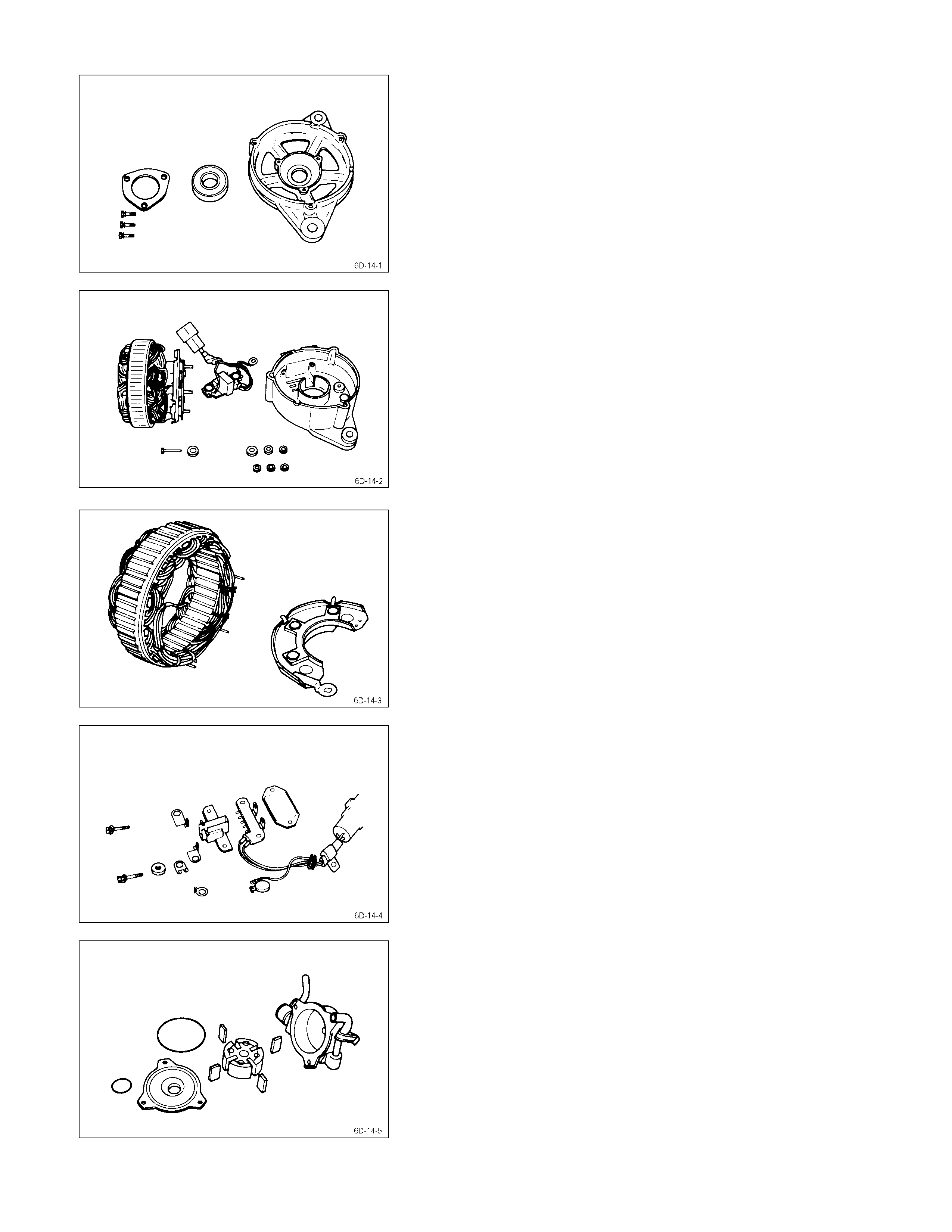
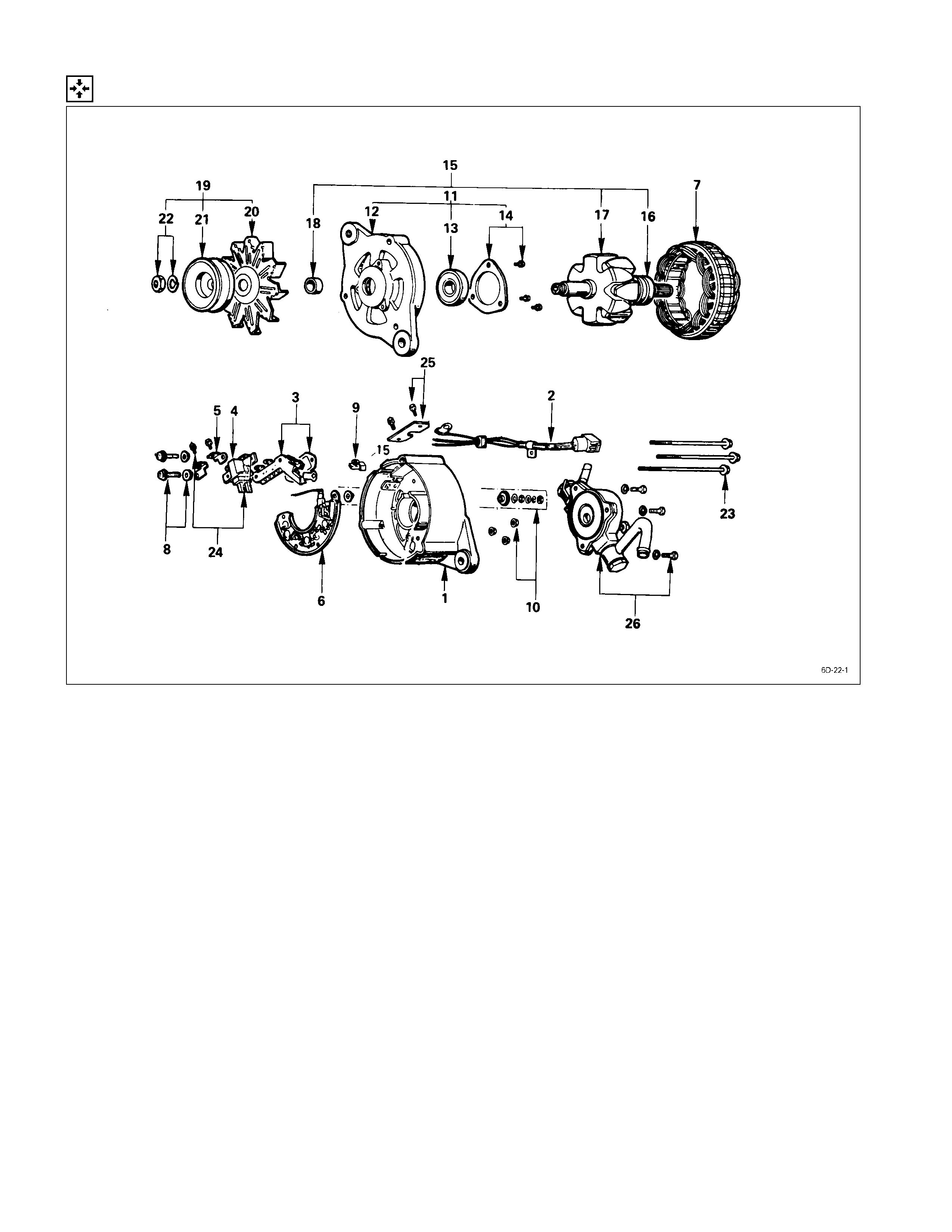
Disassembly
DISASSEMBLY STEPS
J
1. Vacuum pump 14. Front cover
J
2. Cover 15. Ball bearing
J
3. Brush 16. Bearing retainer
J
4. Through bolt 17. Screw
J
5. Pulley assembly
J
18. Terminal bolt and nut
6. Pulley nut 19. Condenser
7. Pulley
J
20. Rear cover
8. Fan
J
21. Stator
J
9. Rotor assembly
J
22. Diode
10. Spacer 23. Holder plate
11. Ball bearing 24. Brush holder
12. Rotor
J
25. IC regulator assembly
J
13. Front cover assembly 26. Lead wire
IMPORTANT OPERATIONS
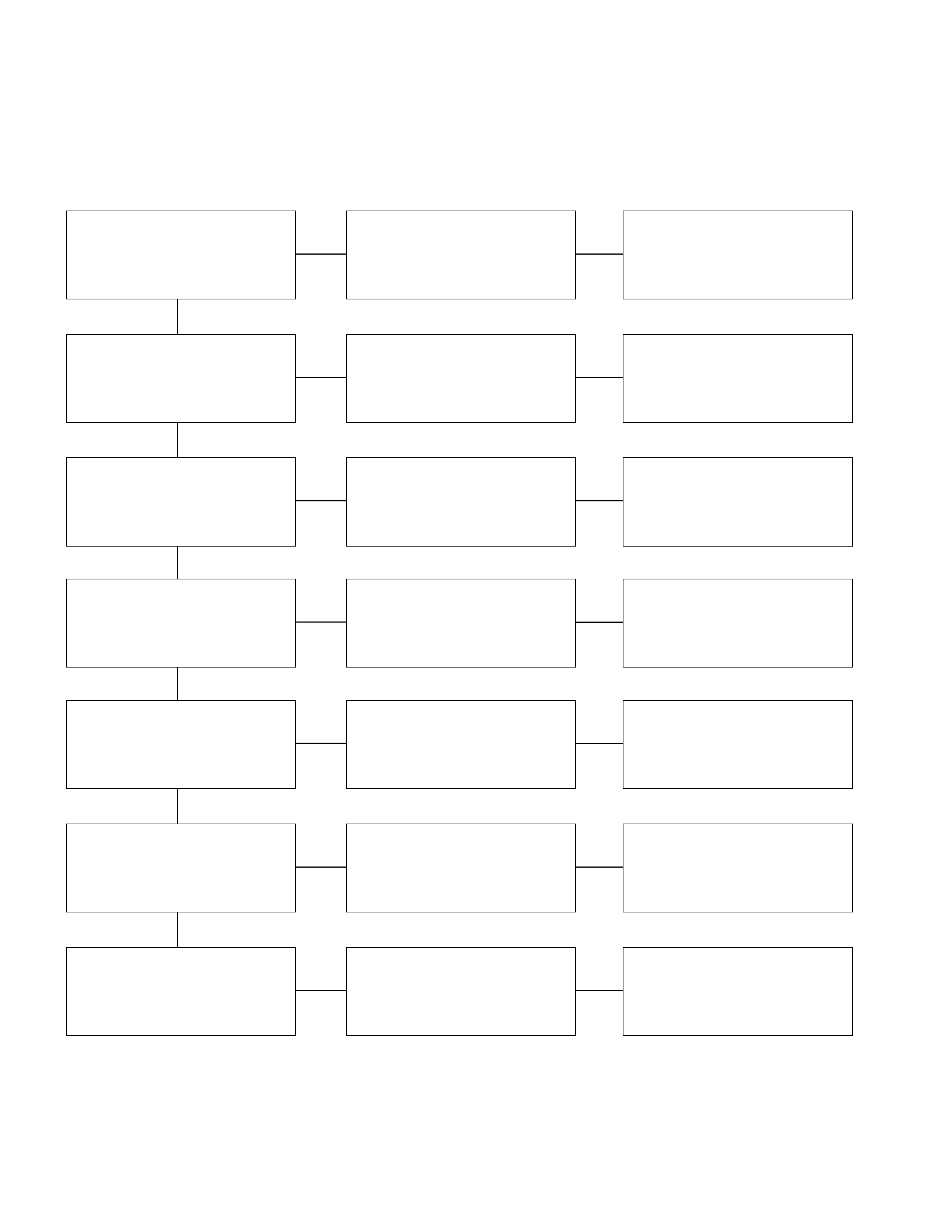
1. Vacuum Pump
1) Loosen the vacuum pump fixing bolts.
2) Support the vacuum pump center plate.
3) Carefully remove the vacuum pump.
2. Cover
3. Brush
1) Remove the cover.
2) Remove the brush fixing bolts.
3) Remove the brushes from the brush holder.
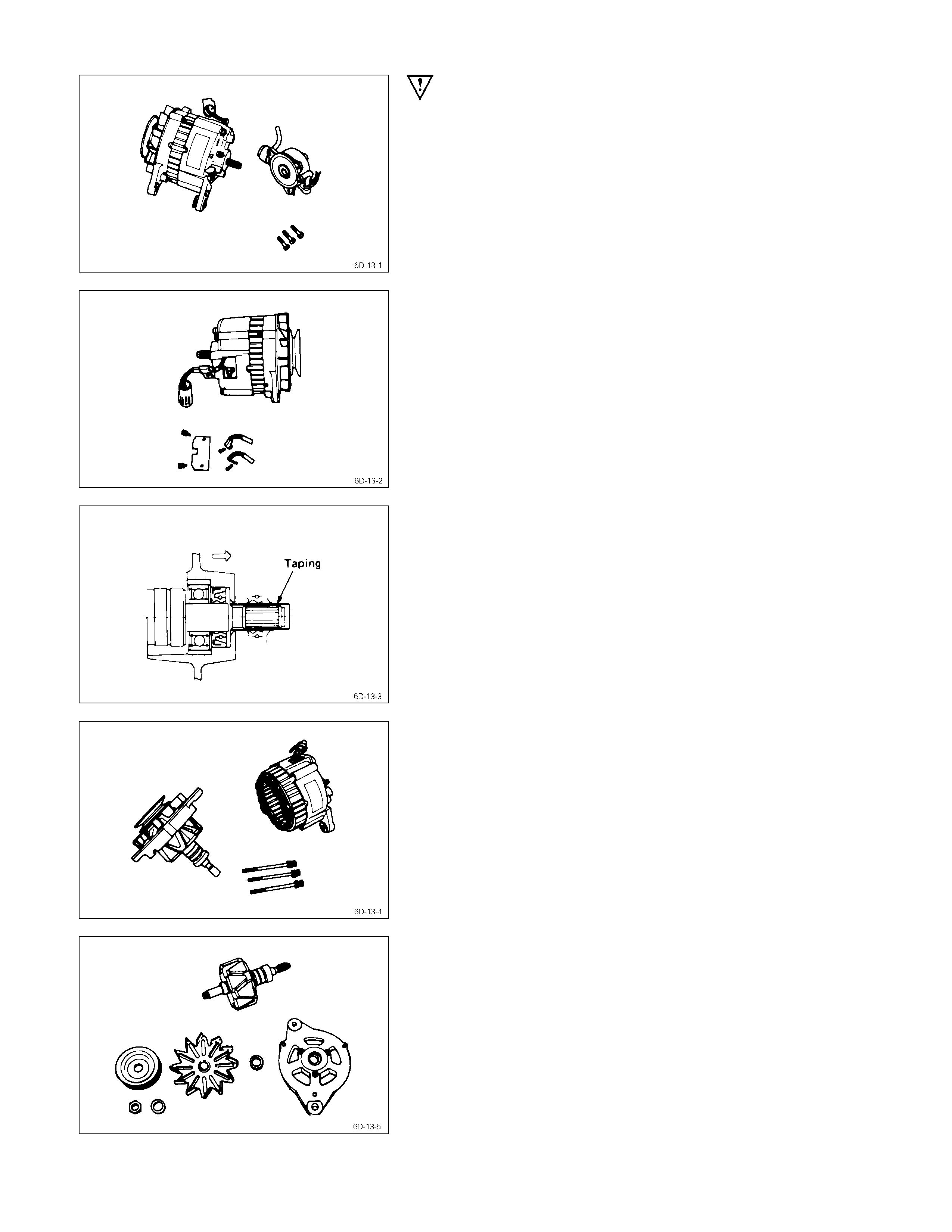
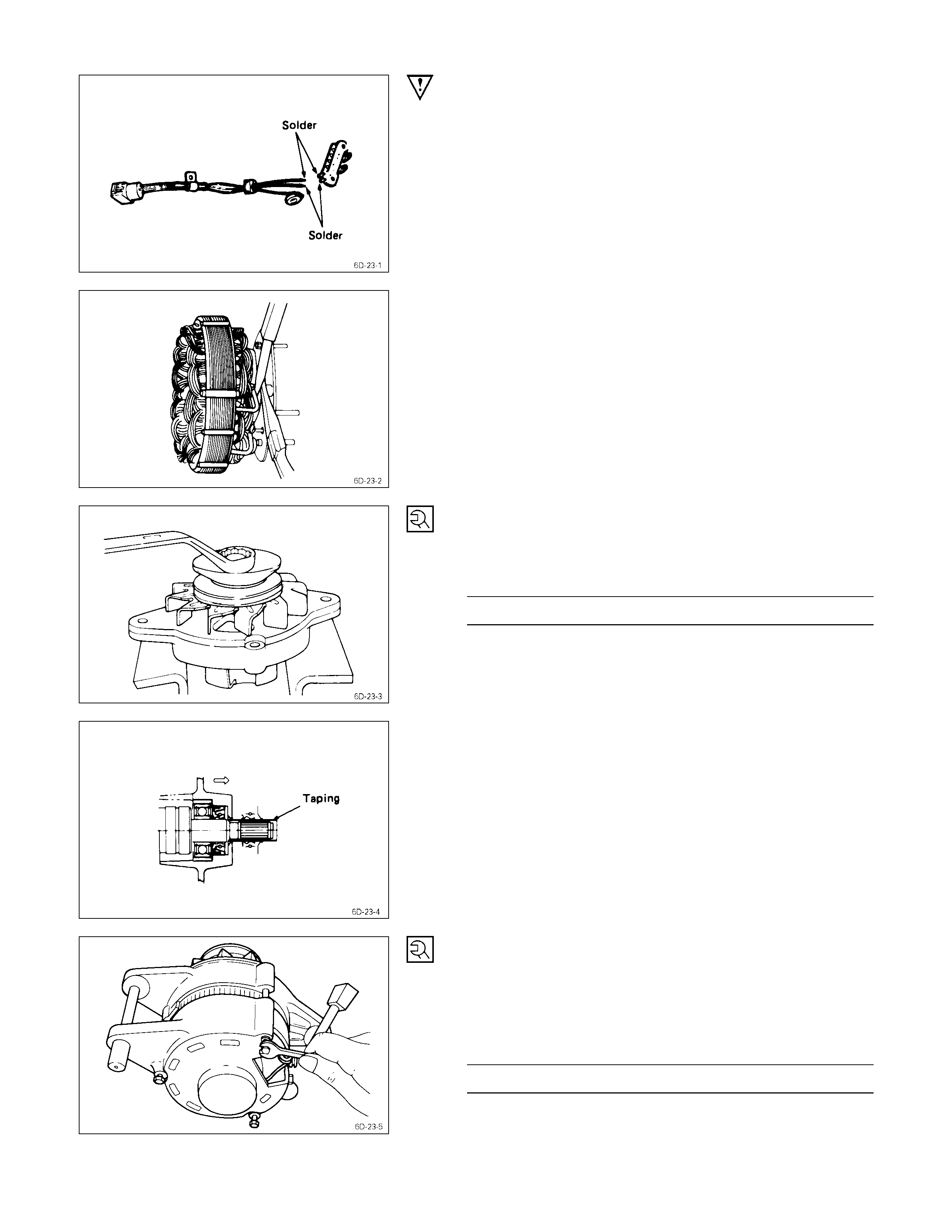
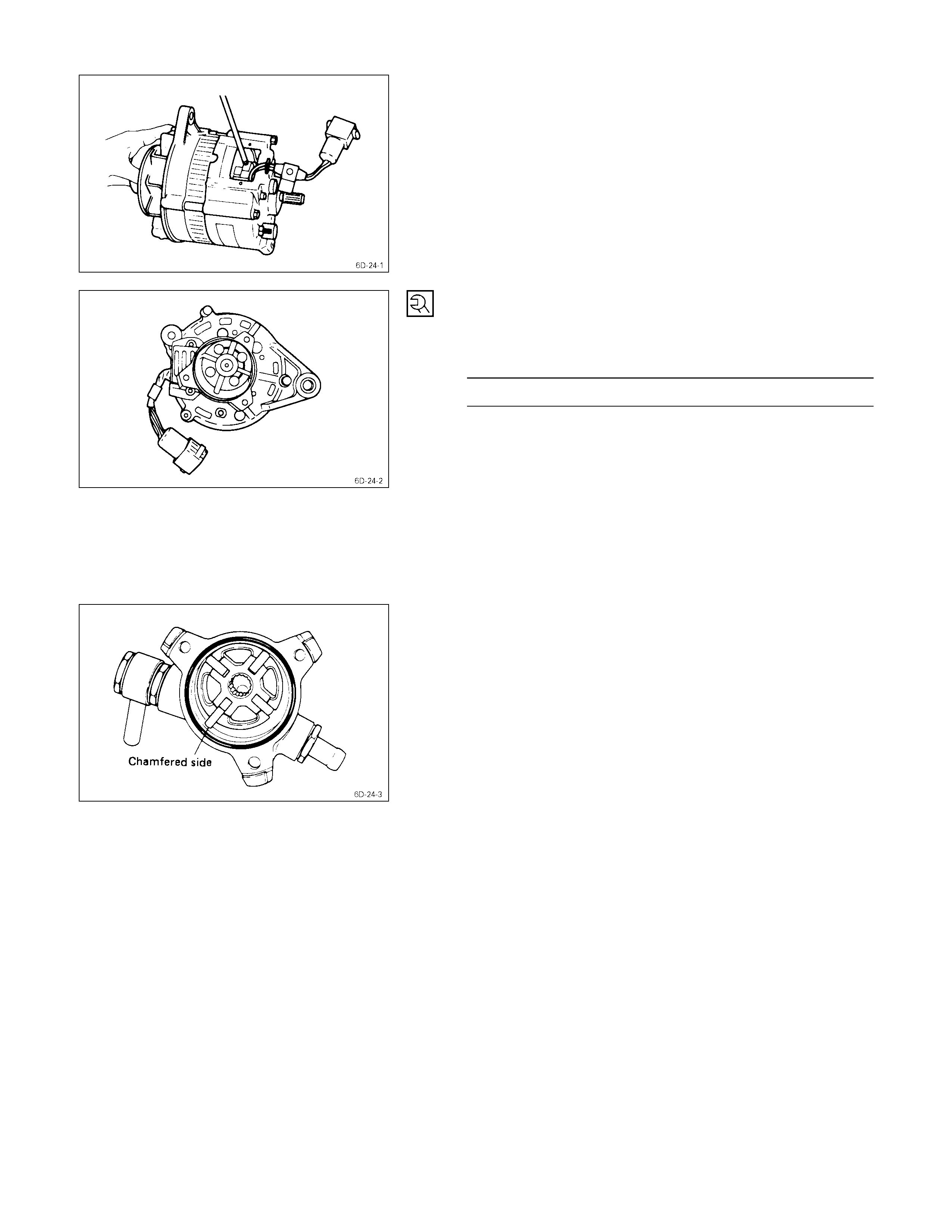
4. Through Bolt
9. Rotor Assembly
1) Loosen the through bolts.
2) Remove the rotor and front cover assembly from the
stator and rear cover assembly.
Do not allow the stator to separate from the rear
cover.
Take care not to damage the oil seal.
3) Tape the rotor splines to protect them from damage.
5. Pulley Assembly
1) Carefully clamp the rotor assembly in a vise.
2) Loosen the pulley nut.
3) Remove the pulley and the front cover from the rotor.
13. Front Cover Assembly
1. Remove the front cover bearing retainer screws.
2. Remove the bearing.
18. Terminal Nut and Bolt
20. Rear Cover
21. Stator
22. Diode
1) Loosen the terminal nuts and bolts.
2) Remove the insulators and the washers.
3) Remove the stator together with the diodes.
4) Disconnect the stator coil leads between each diode
and the N-terminal by melting the solder connection.
Hold the lead wire between the solder and the diode
with a pair of long nose pliers.
This will prevent heat transfer and resultant damage to
the diode.
25. IC Regulator Assembly
1) Melt away the solder from the IC regulator holder plate
terminal.
2) Remove the IC regulator assembly.
Remove the center plate, rotor and vane in the vacuum
pump.
Inspection & Repair
Make the necessary adjustments, repairs, and part replacement if excessive wear or damage is discovered during
inspection.
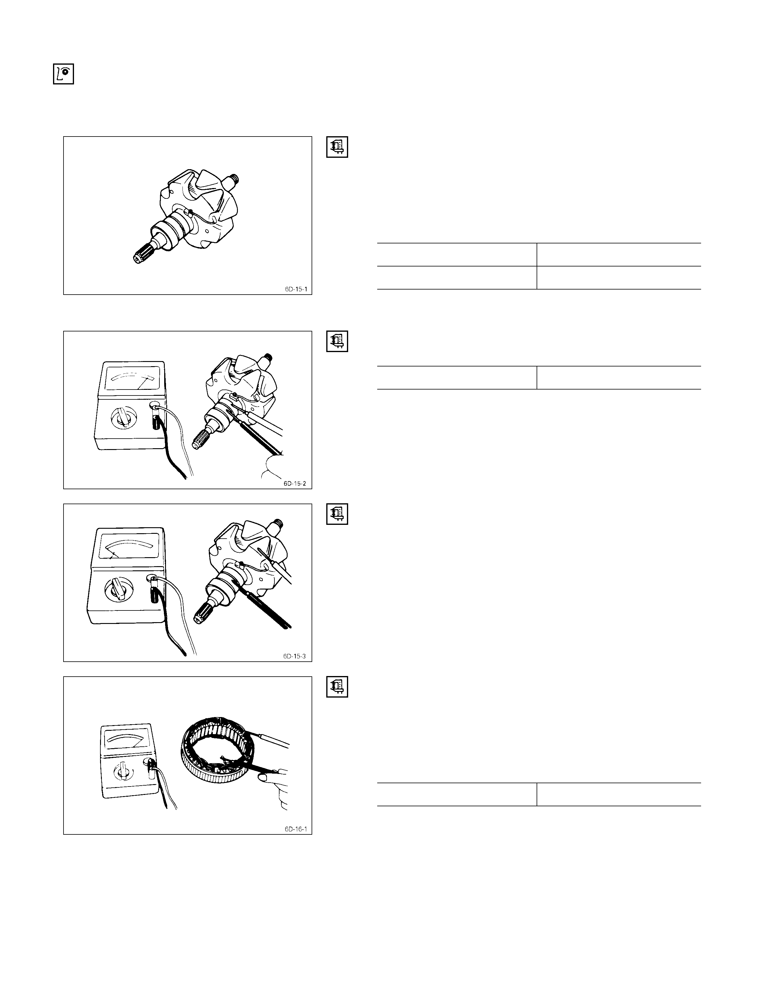
ROTOR ASSEMBLY
1. Inspect the slip ring faces for dirt and pitting.
Wipe away any dirt with a clean cloth soaked in
alcohol.
2. Measure the slip ring diameter.
Slip Ring Diameter mm (in)
Standard Limit
31.6 (1.245) 30.6 (1.183)
If the slip ring diameter is less than the specified limit, the
slip rings must be replaced.
3. Measure the rotor coil resistance.
Rotor Coil Resistance at 20°C (68°F) ohms
Standard 4.2
4. Check for continuity between the slip rings and the
rotor core or sh aft.
If there is continuity, the entire rotor assmbly must be
replaced.
STATOR COIL ASSEMBLY
1. Check for continuity across the stator coils.
If there is no continuity, the stator coils must be
replaced.
Resistance Between The Terminal “N” and the Coil Ends
(Reference) ohms
Standard 0.1
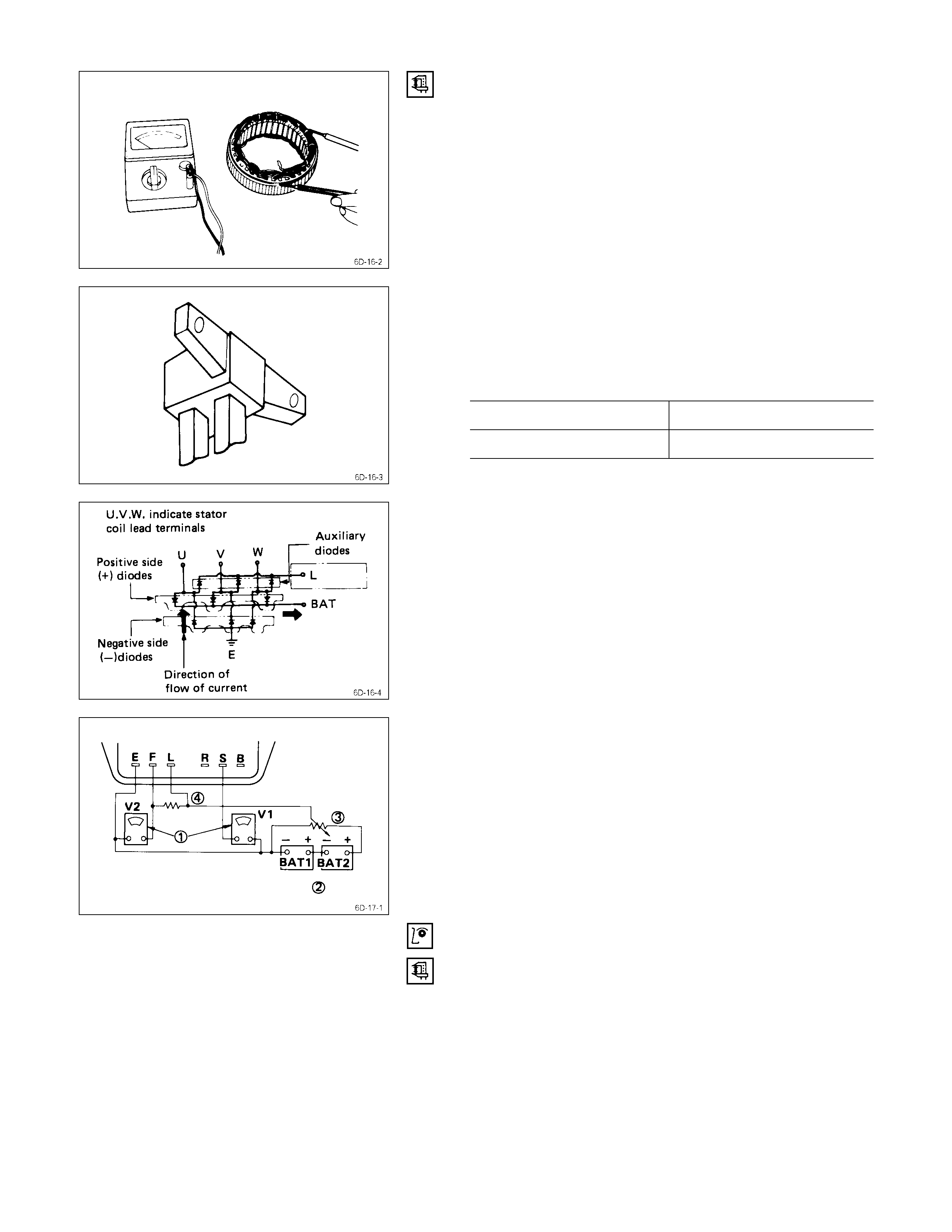
2. Check for continuity between each stator coils and the
stator core.
If there is continuity, the stator coils must be replaced.
BRUSH
Each brush has a line to indicate whether or not the brush
is serviceable.
If the line is not visible, the brush must be replaced.
Brush Length (Reference) mm (in)
Standard Limit
20 (0.8) 6 (0.2)
DIODE
1. Check for continuity between the battery and each of
the three stator coil lead terminals.
If there is continuity, the diode is normal.
If there is no continuity, the diode must be replaced.
2. Reverse the polarity of the test probes.
If there is no continuity, the diode is normal.
If there is continuity, the diode must be replaced.
IC REGULATOR
The IC regulator may be tested with either a circuit tester
or a pair of standard voltmeters.
Refer to the illustration.
(1) Circuit tester (or voltmeter) range is from 0 to 50 volts
in 0.5 volt increments.
(2) Two 12-volt batteries are required.
(3) Note the variable resistor.
(4) This resistor is rated at 100 watts or 3 ohms.
Testing the IC Regulator
Refer to the wiring diagram in the illustration when testing
the IC regulator.
1. Connect the batteries in series.
2. Measure the battery power (Voltage).
Battery Power V
20 – 26
3. Connect the circuit tester (or voltmeter V2) as shown
in the illustration.
4. Set the variable resistor (3) to zero.
5. Slowly increase the resistance of the variable resistor
toward the build-up point.
Measure the voltage between E and F.
As long as the resistance is below the build-up point,
the voltage reading should be stable and less than two
volts.
When the resistance exceeds the build-up point, the
voltage reading should be two volts or greater.
If the voltage does not exceed two volts after reaching
the build-up point, the IC regulator must be replaced.
6. Return the variable resistor to zero.
7. Connect the circuit tester (or voltmeter V1) as shown
in the illustration.
8. Measure the voltage at terminals S, L, and E.
9. Slowly increase the resistance of the variable resistor.
Note the point at which the voltage quickly builds up to
between 2 and 6 volts.
This will indicate the point at which the voltage
regulator begins to function.
If the measured voltage is outside the specified range,
the voltage regulator must be replaced.
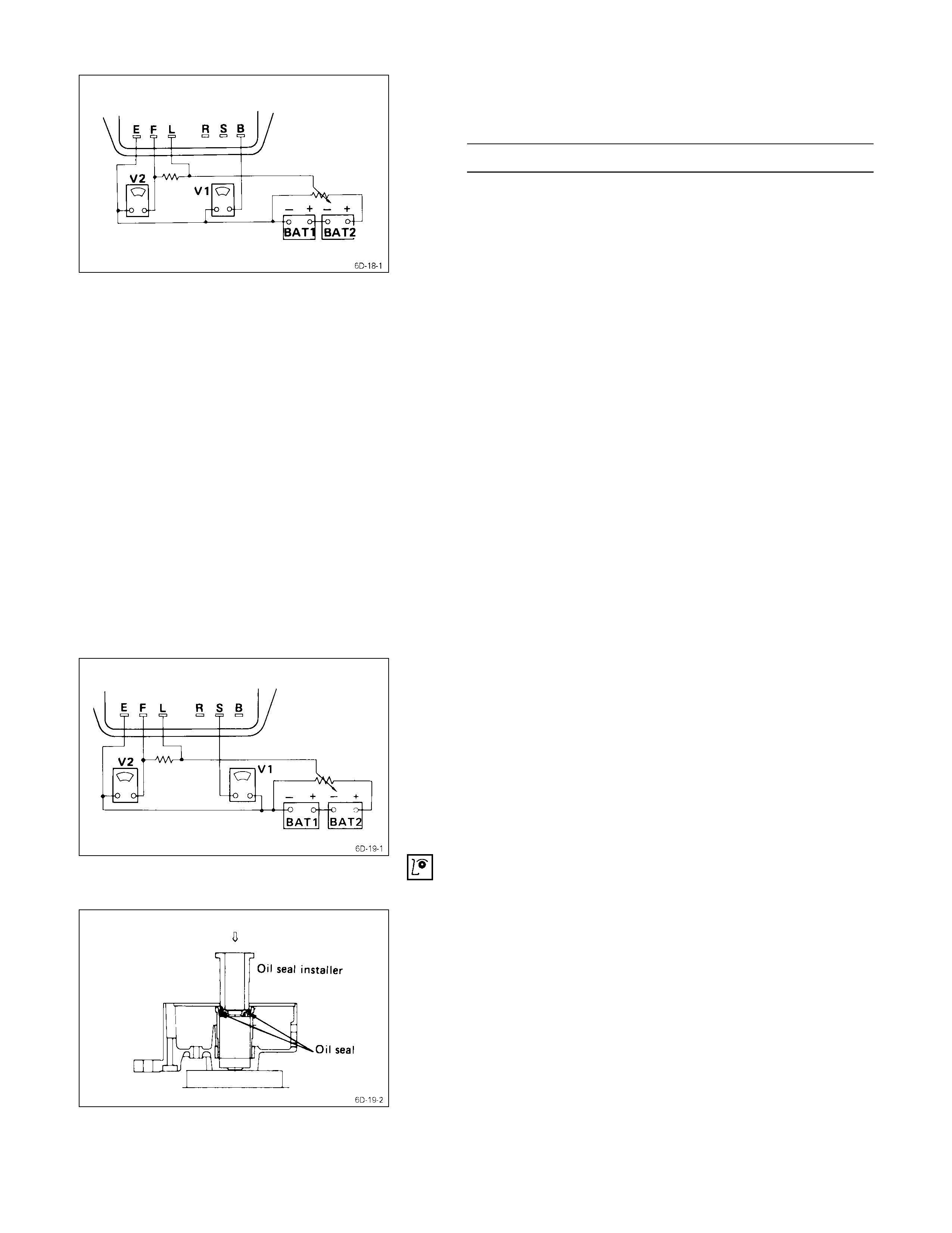
10. Repeat Steps 3 through 5 to measure the voltage
between terminals B, L, and E.
Refer to the illustration.
The regulator voltage should be between 0.5 and 3
volts higher than the measured voltage.
If the regulator voltage is outside this range, the
voltage regulator must be replaced.
OIL SEAL
Check the rear cover oil seal bore for oil leakage.
OIL SEAL REPLACEMENT
1. Use a screwdriver to remove the oil seal from the rear
cover side.
Take care not to damage the oil seal bore.
2. Discard the used oil seal.
3. Use the oil seal installer to install the new oil seal.
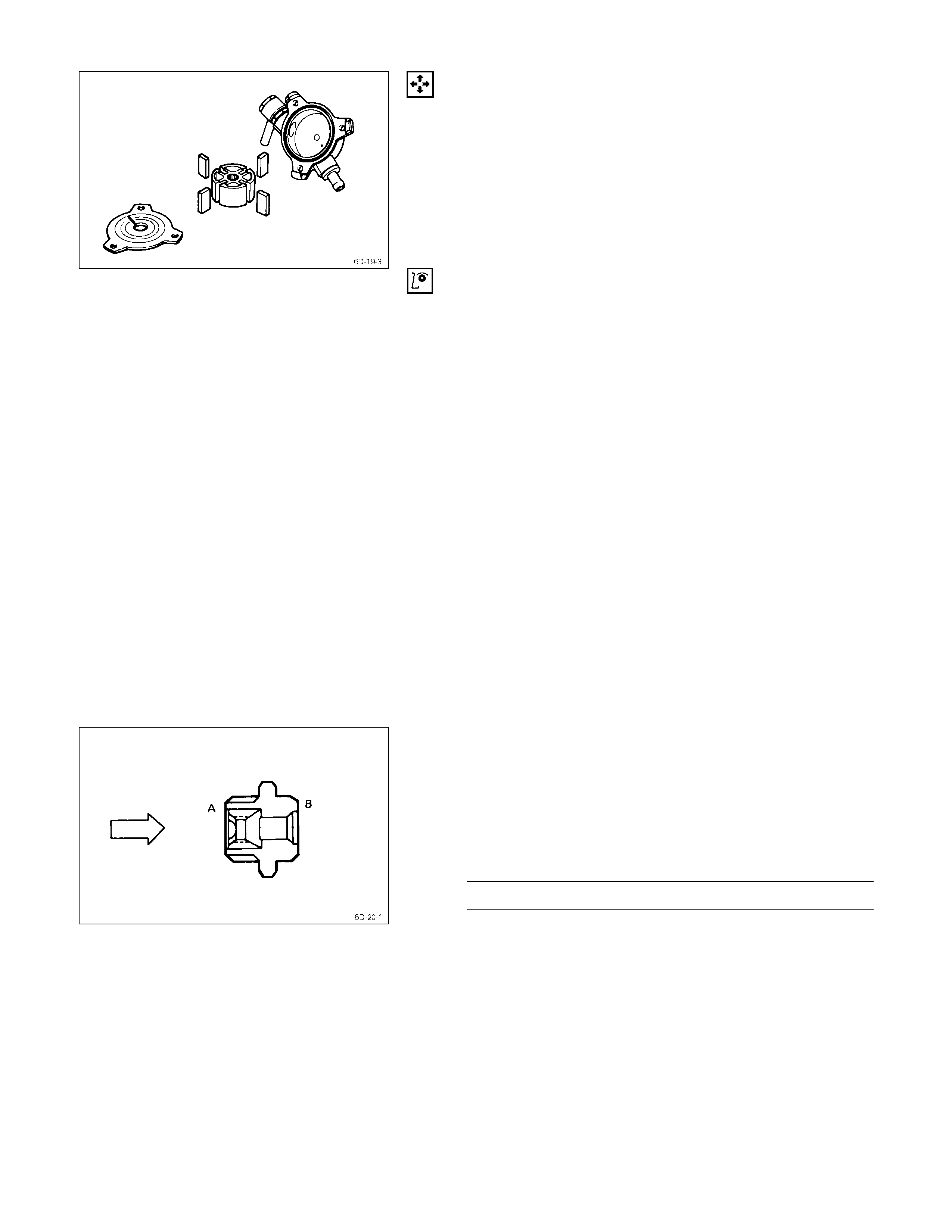
VACUUM PUMP
VACUUM PUMP DISASSEMBLY
1. Remove the center plate from the vacuum pump
housing.
2. Remove the vacuum pump rotor and the vanes from
the housing.
INSPECTION
VACUUM PUMP HO USI NG AND CENTER PLATE
Inspect the vacuum pump housing and the center plate for
excessive wear, abrasion, and scoring.
If any of these conditions are present, the vacuum pump
housing and center plate must be replaced.
VANE
Inspect the vanes for excessive wear and damage.
Replace all four vanes if either of these conditions are
present.
Never replace only one vane.
ROTOR
1. Inspect the rotor for excessive wear, abrasion, and
scoring.
Pay particular attention to the internal spline.
Replace the rotor if any of these conditions are
present.
2. Inspect the generator rotor shaft splines for backlash.
Replace the rotor if backlash is present.
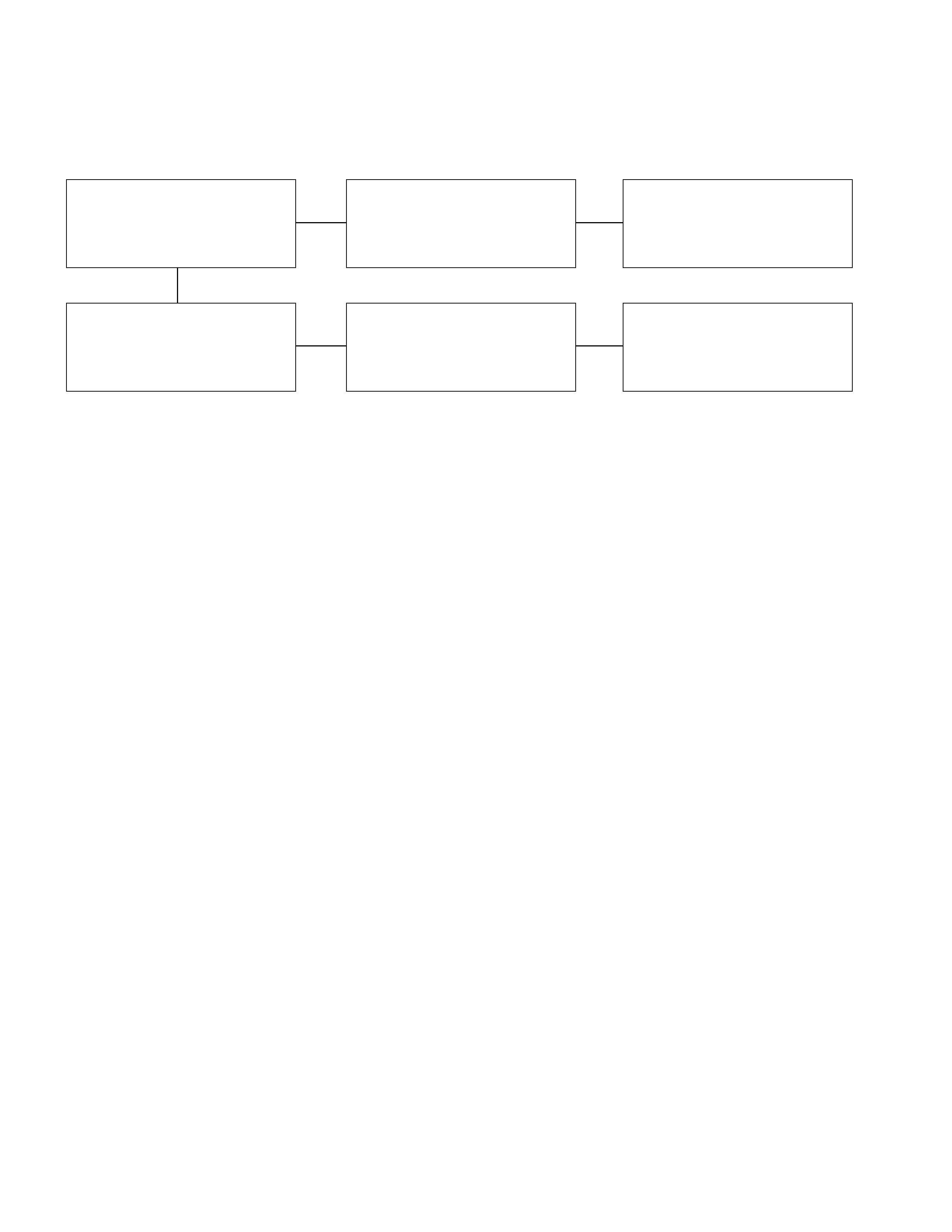
CHECK VALUE
1. Carefully force the valve from the “B” side as shown in
the illustration.
The valve must move smoothly.
If it does not, the check valve must be replaced.
2. Apply compressed air to the “A” side.
Air Pressure kg/cm2(psi/kPa)
1-5 (14 – 71/98 - 490)
Check for air leakage from the check valve.
If there is air leakage, the valve must be replaced.
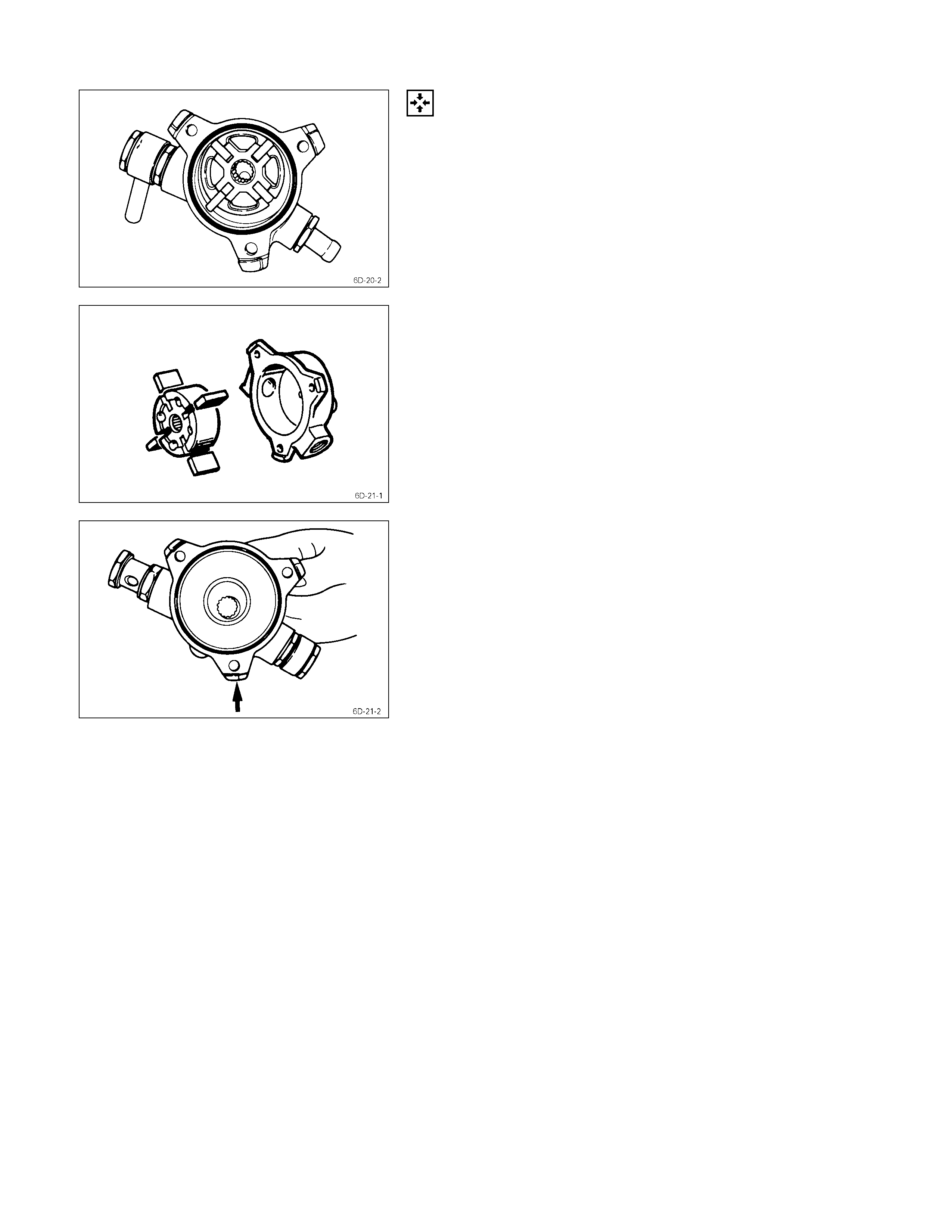
VACUUM PUMP REASSEMBLY
1. Install the vanes to the rotor slits.
The rounded side of the vanes must be facing the
rotor housing.
2. Install the rotor with the concave side facing the center
plate.
3. Install the center plate to the rotor housing.
Be sure to use a new O-ring.
Reassembly
REASSEMBLY STEPS
1. Rear cover 14. Bearing retainer
J
2. Lead wire
J
15. Rotor assembly
J
3. IC regulator assembly 16. Ball bearing
4. Brush holder 17. Rotor
5. Holder plate 18. Spacer
J
6. Diode
J
19. Pulley assembly
J
7. Stator 20. Fan
8. Screw 21. Pulley
9. Condenser 22. Nut and washer
10. Terminal bolt and nut
J
23. Through bolt
11. Front cover assembly
J
24. Brush
12. Front cover
J
25. Cover
13. Ball bearing
J
26. Vacuum pump
IMPORTANT OPERATIONS
2. Lead Wire
3. IC Regulator
Solder the IC regulator lead wires.
6. Diode
7. Stator
Use a pair of long-nose plier to connect the stator coil
leads and the diode leads.
Finish the work as quickly as possible to prevent the diode
from heat transferred by the soldering.
15. Rotor Assembly
19. Pulley Assembly
Clamp the rotor in a vise and install the pulley nut.
Pulley Nut Torque kg⋅m(lb⋅ft)
5.0 ± 1.0 (36.2 ± 7.2/49.0 ± 9.8)
Remove the tape from the splines.
23. Through Bolt
1. Place a pilot bar into the through bolt hole to align the
front cover and the rear cover.
2. Install the through bolts and tighten them to the
specified torque.
Through Bolt Torque kg⋅m(lb⋅ft)
0.65 ± 0.5 (4.7 ± 3.6/6.3 ± 4.9)
24. Brush
Install the brush into the brush holders.
25. Cover
Install the brush cover and tighten the cover bolts to the
specified torque.
Brush Cover Bolt Torque kg⋅m(lb⋅ft)
0.35 ± 0.5 (2.5 ± 3.6/3.4 ± 5.0)
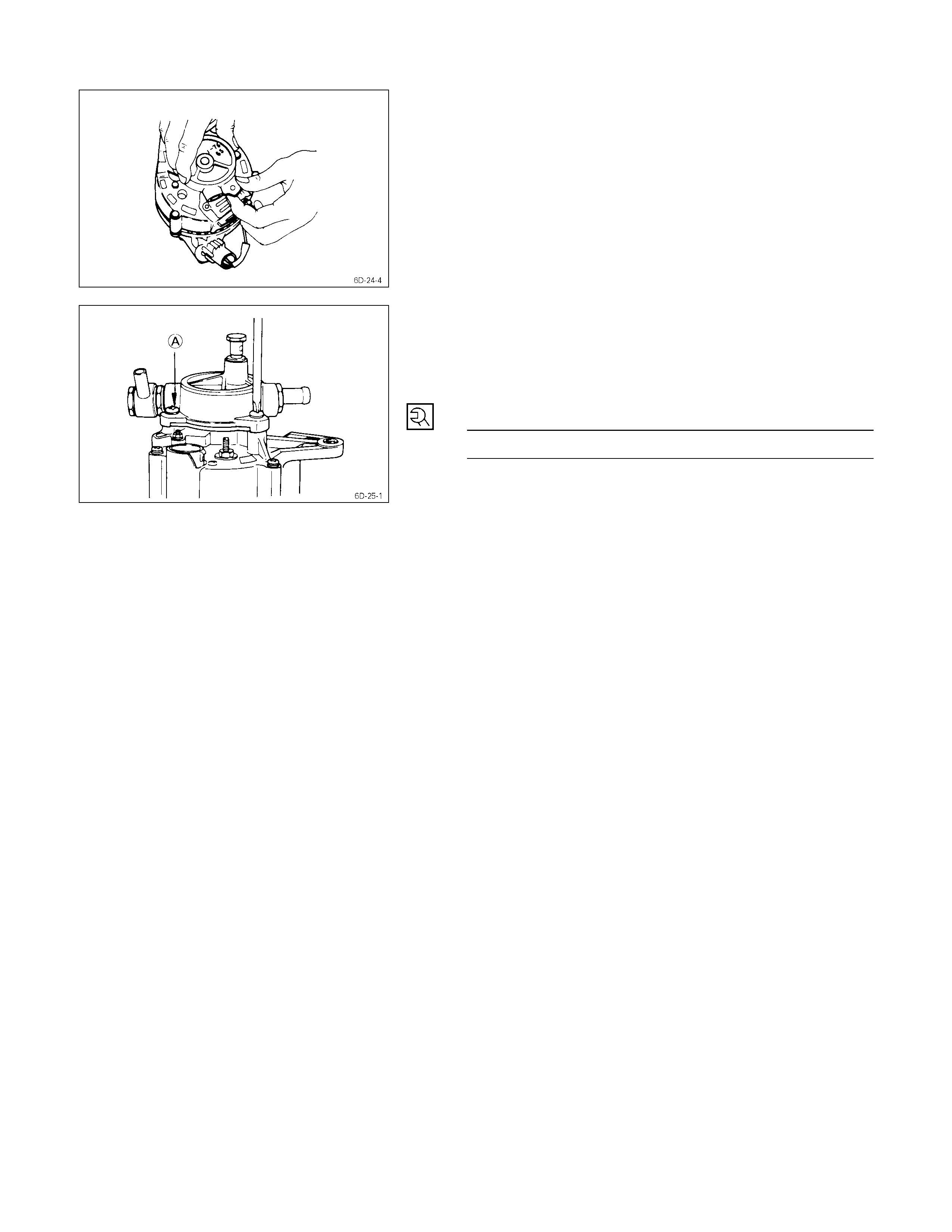
26. Vaccum Pump
Position the rotor, with the serrated boss turned up, on the
center plate and housing.
Align the holes in the center plate and the rotor.
Install vanes into slits in rotor.
The vanes should be installed with the chamfered side
facing outward.
Install the vacuum pump housing.
Make sure that the O-ring is not projecting beyond the
slots of the center plate.
Take care so that no scratching takes place on the vane
resulted by contact with the housing.
Install the housing in the generator and fix it with the three
bolts.
Supply engine oil (5cc or so) from the oil port and check
that the generator pulley can be turned smoothly with your
hand.
Generator Housing Bolt Torque kg⋅m(lb⋅ft)
0.65 ± 0.5 (4.7 ± 3.6/6.3 ± 4.9)

Troubleshooting
Refer to this Section to quickly diagnose and repair electrical problems.
Each troubleshooting chart has three headings arranged from left to right.
(1) Checkpoint (2) Trouble Cause (3) Countermeasure
Battery Charging and Noise Problems
1. No Charging
2. Overcharging
3. Undercharging
4. Unstable Charging Current
5. Noise
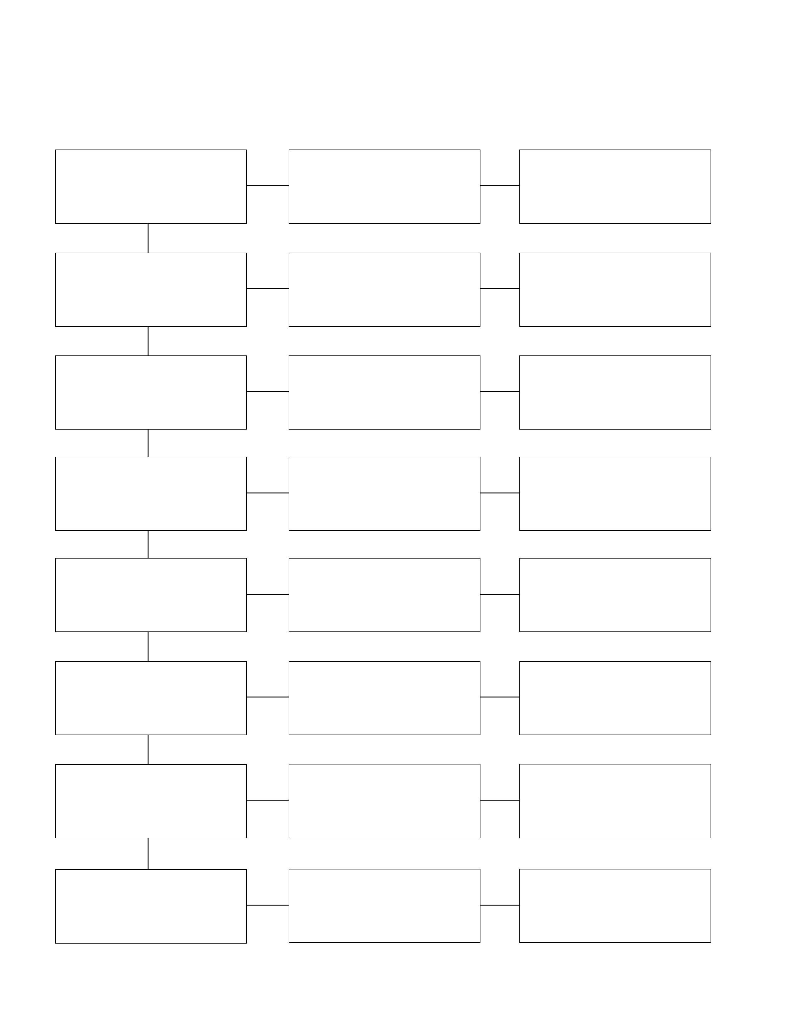
Battery Charging & Noise Problems
1. No Charging
Checkpoint Trouble Cause Countermeasure
Terminals and connectors Broken or defective Repair the push rod play
Ground connections Poorly grounded Correct
Brush with slip ring Poor contact Repair or replace
Generator stator coil Open or scorched Replace
Generator rotor coil Open or scorched Replace
Generator diode Defective Replace
IC regulator Defective Replace
OKOK
OK
OK
OK
OK
OK
NG
NG
NG
NG
NG
NG
NG
2. Overcharging
Checkpoint Trouble Cause Countermeasure
B and F terminal circuit Shorted Repair
IC regulator Excessive voltage Replace
OKOK
NG
NG
3. Undercharging
Checkpoint Trouble Cause Countermeasure
Battery terminals Loosely connected Retighten
Drive belt Slippage Adjust or replace
Brush and slip ring contact Intermittent Replace or repair the brush
holder assembly
Short circuit Repair or replace
Short or open circuit Repair or replace
Defective Replace
Insufficient voltage Replace
OKOK
OK
OK
NG
NG
NG
NG
NG
NG
NG
Generator rotor coil
Generator diode
Excessive Use a higher capacity alternator
or reduce the accessory load
NG
IC regulator
Electrical load
Generator stator coil
OK
OK
OK
OK
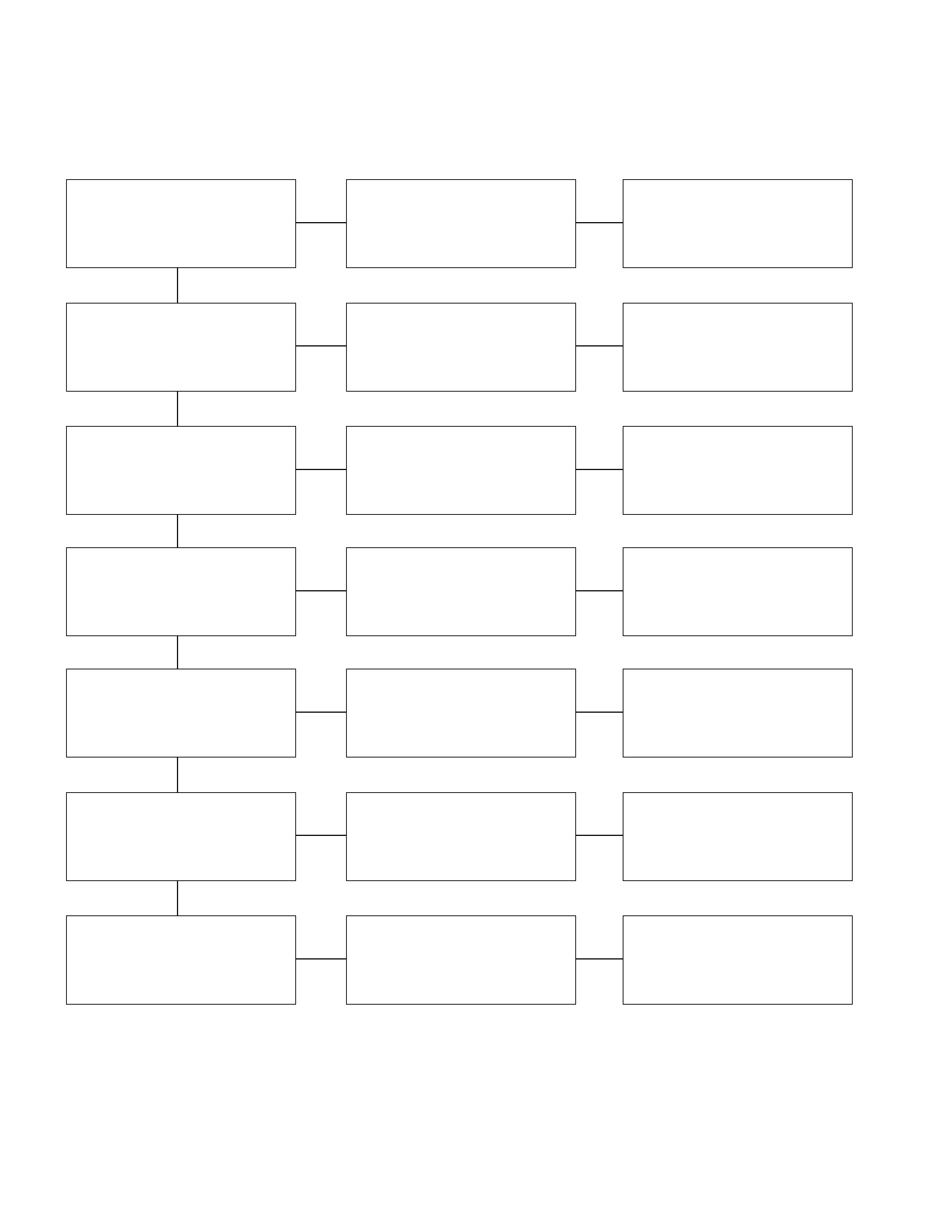
4. Unstable Charging Current
Checkpoint Trouble Cause Countermeasure
Terminals and connectors Broken or defective Repair the push rod play
Drive belt Loose Tighten (Readjust)
Brush with slip ring Poor contact Repair or replace
Generator rotor coil Open or short circuit Repair or replace
Generator stator coil Open or short circuit Repair or replace
Stator coil and diode
connections Loose Repair
IC regulator Defective Replace
OKOK
OK
OK
OK
OK
OK
NG
NG
NG
NG
NG
NG
NG

5. Noise
Checkpoint Trouble Cause Countermeasure
Part mounting fasteners Loose Tighten
Drive belt Defective Replace
Bearing Defective Replace
Diode Defective Replace
Stator coil Short circuited Repair or replace
OKOK
OK
OK
OK
NG
NG
NG
NG
NG
