
SECTION 6E - ENGINE ELECTRICAL -
STARTING SYSTEM
Main Data & Speci fications
General Description
Starting Circuit Diagram
Wire Coding
Description
Wire Size
Wire Size Specifications
Wire Color
Wire Color-Coding
Symbols & Abbreviations
Description
Symbols
Symbol & Meaning
Abbreviations
Abbreviation & Meaning
Torque Specifications
Starter Motor
Starter Motor
Removal & Installation
Disassembly
Inspection & Repair
Armature
Yoke
Brush & Brush Holder
Overrunning Clutch
Bearing
Magnetic Switch
Reassembly
Troubleshooting
Hard Starting
1. Pinion Does Not Engage The Ring Gear When The Starter Switch Is Turned On
2. Pinion Engages The Ring Gear But The Engine Does Not Turn Over
3. Incorrect Pinion And Ring Gear Engagement
4. Starter Continues To Run After The Starter Switch Is Turned Off
5. Excessive Commutator Sparking

Main Data & Specifications
Item Description
Starter Motor
Type
Rated voltage V Solenoid controlled
12
Rated output kW 2.3
Load characteristics
Terminal voltage V
Load current A 8.76
300
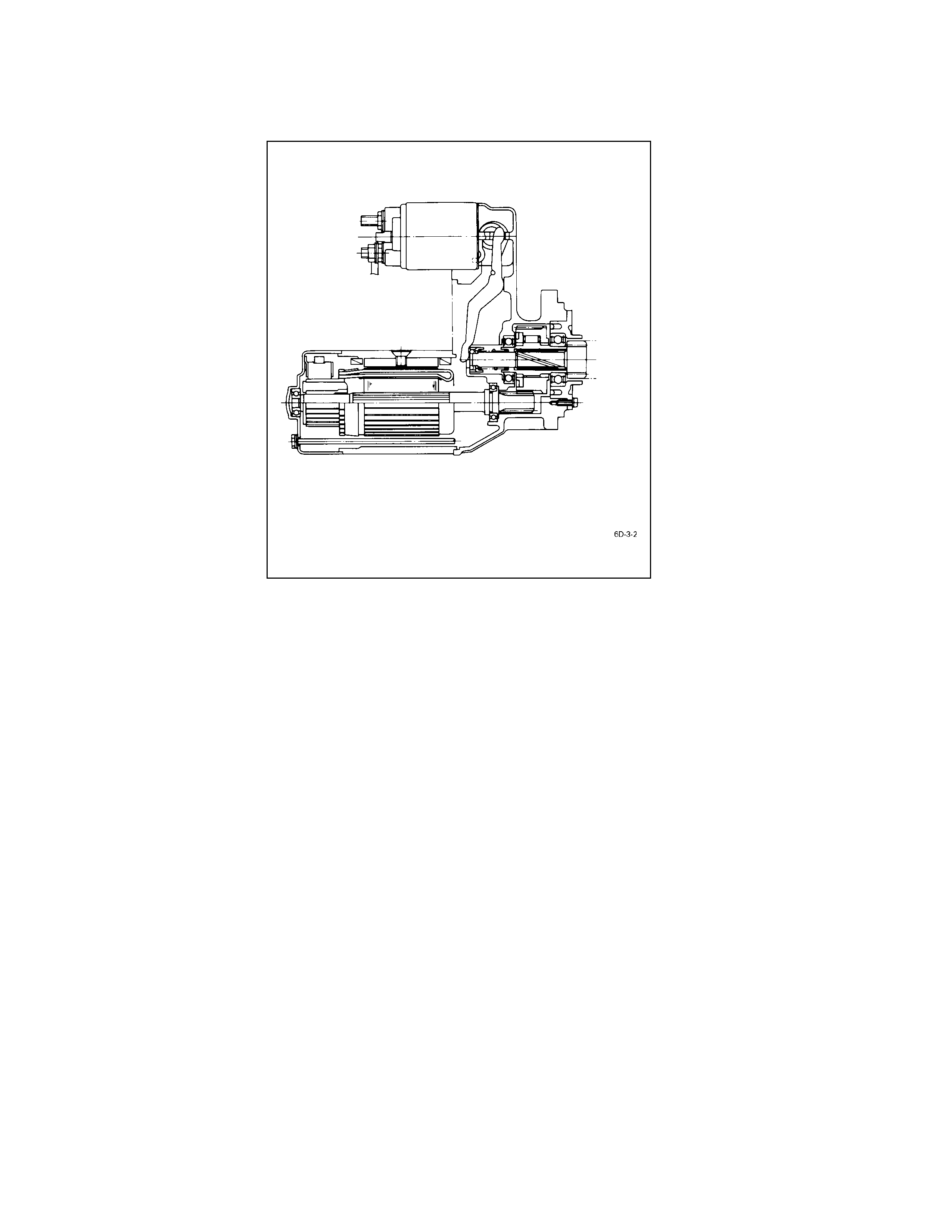
General Description
The starter motor circuit is composed of a 4-pole 4-brush type direct current series motor, starter switch with safety
lock, etc. The starter motor circuit utilizes negative ground polarity.
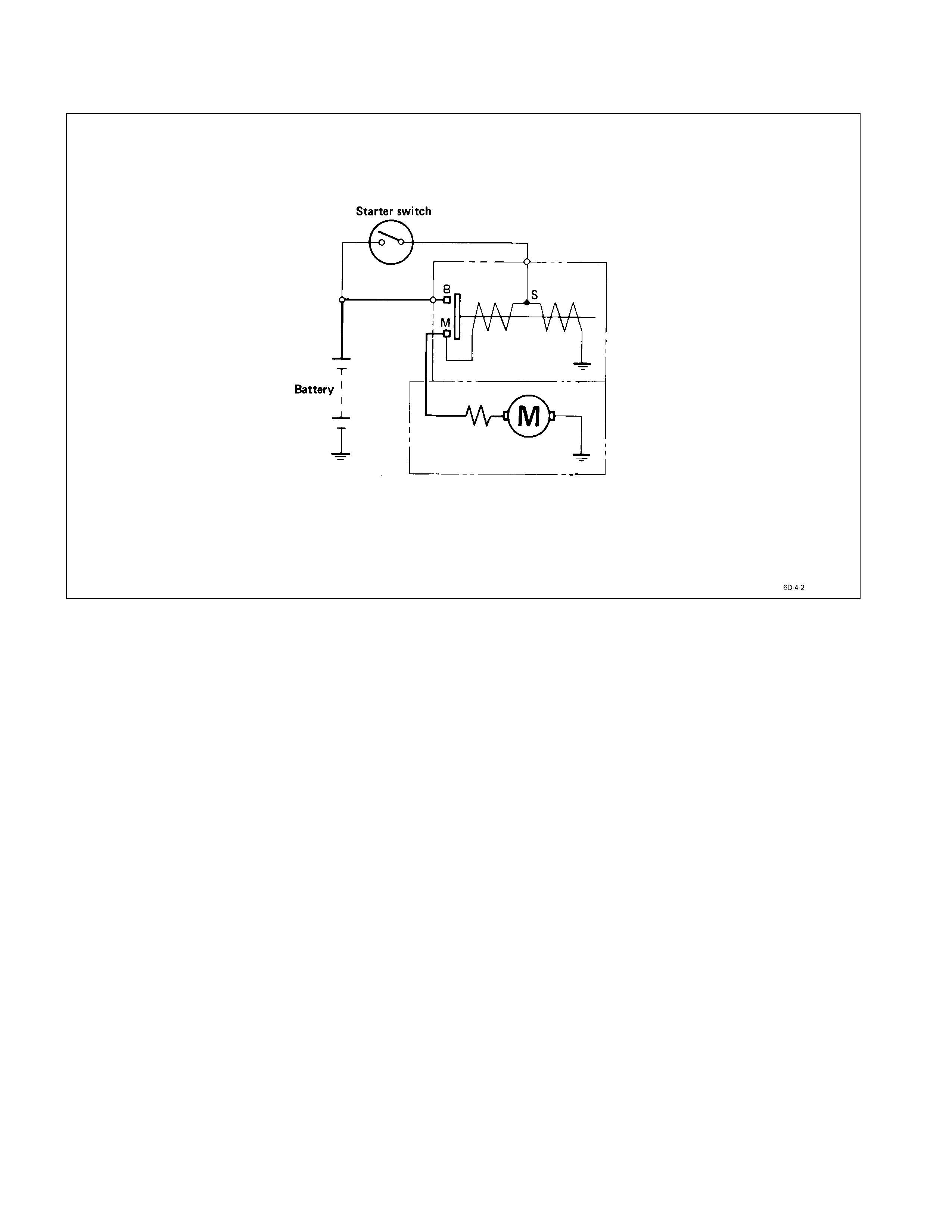
Starting Circuit Diagram
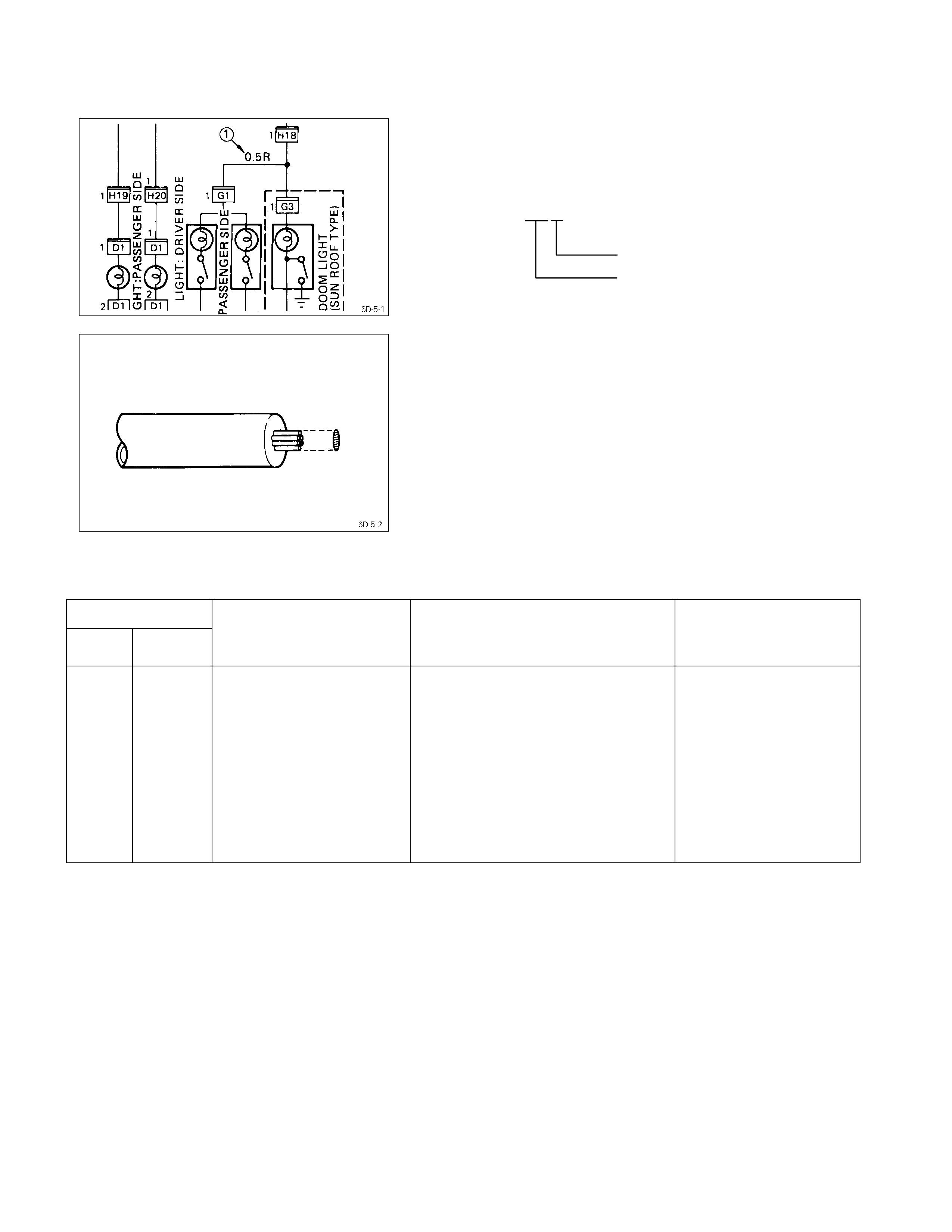
Wire Coding
Description
Codes used in the circuit diagram represent wire size and
color Q.
Example: 0.5 R
Wire color (Red)
Wire size (0.5 mm2)
Wire Size
Wire size is specified with the metric gauge system.
The metric gauge system gives the wire size in cross-
sectional area measured in square millimeters.
Wire Size Specifications
Wire size
mm2AWG
Number of wires/
Wire diameter
mm (in.)
Resistance at normal room
temperature of 20°C (68°F)
Ω/m (Ω/ft.)
Maximum allowable
current
A
0.5
0.85
1.25
2
3
5
8
15
20
30
20
18
16
14
12
10
8
6
4
2
7/0.32 (0.013)
11/0.32 (0.013)
16/0.32 (0.013)
26/0.32 (0.013)
41/0.32 (0.013)
65/0.32 (0.013)
50/0.45 (0.018)
84/0.45 (0.018)
41/0.80 (0.031)
70/0.80 (0.031)
0.03250 (0.00991)
0.02050 (0.00625)
0.01410 (0.00430)
0.00867 (0.00264)
0.00550 (0.00168)
0.00347 (0.00106)
0.00228 (0.00070)
0.00136 (0.00042)
0.00087 (0.00027)
0.00051 (0.00016)
11.3
14.8
18.8
25.4
34.2
45.9
59.8
82.8
110.9
147.0
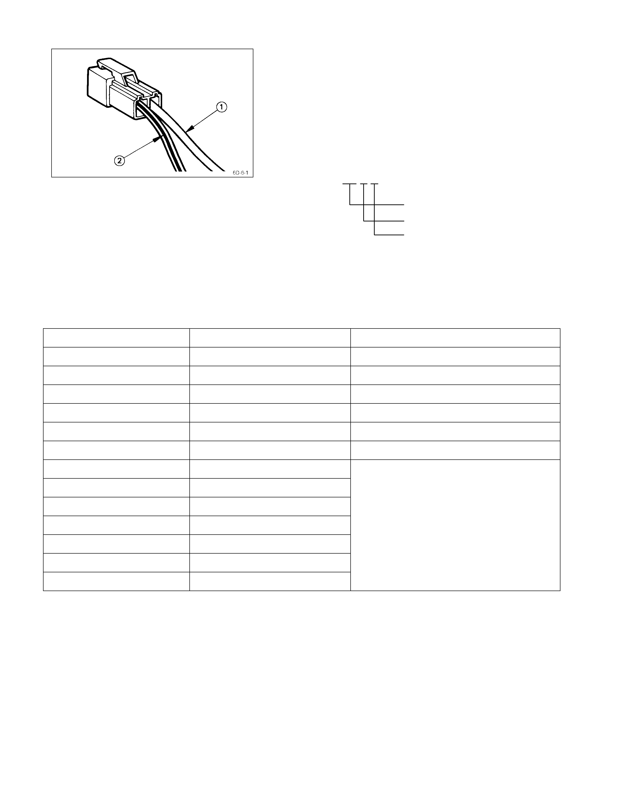
Wire Color
All wires have color-coded insulation.
Wires belonging to a system’s main harness will have a
single color Q.
Wires belonging to a system’s sub-circuits will have a
colored stripe R.
Striped wires use the following code to show wire size and
colors.
Example: 0.5 G R
Wire size (0.5 mm2)
Green (Base color)
Red (Stripe color)
Abbreviations are used to indicate wire color within a
circuit diagram.
Refer to the following table.
Wire Color-Coding
Color-coding Meaning Circuits
B Black Starter circuit and grounding circuit
W White Charging circuit
R Red Lighting circuit
G Green Signal circuit
Y Yellow Instrument circuit
L Blue Wiper circuit
O Orange
Br Brown
Lg Light green
Gy Grey
PPink
Sb Sky blue
V Violet
Other circuits
Symbol s & Abbreviations
Description
The symbols and abbreviations used in the circuit diagram
make the diagram easier to read and understand.
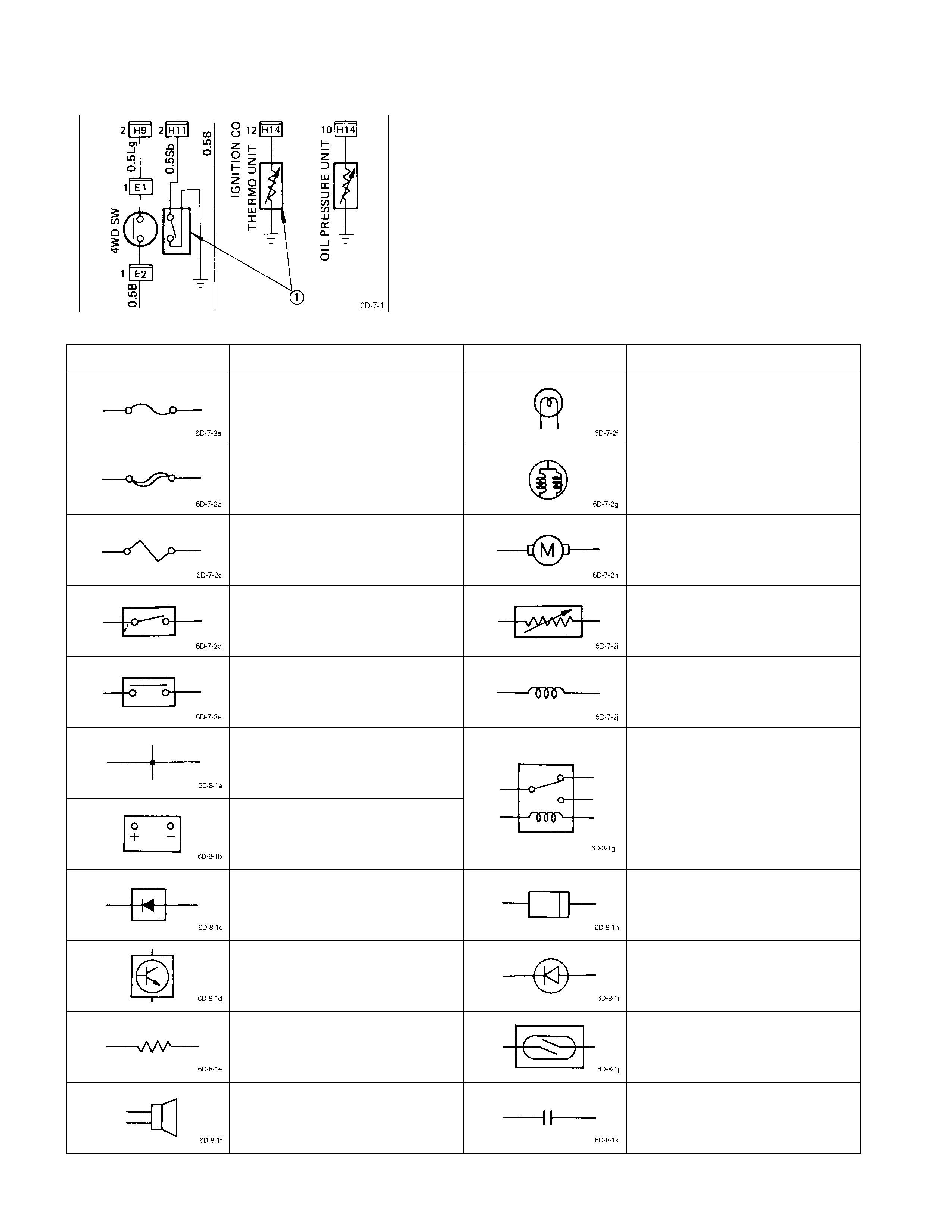
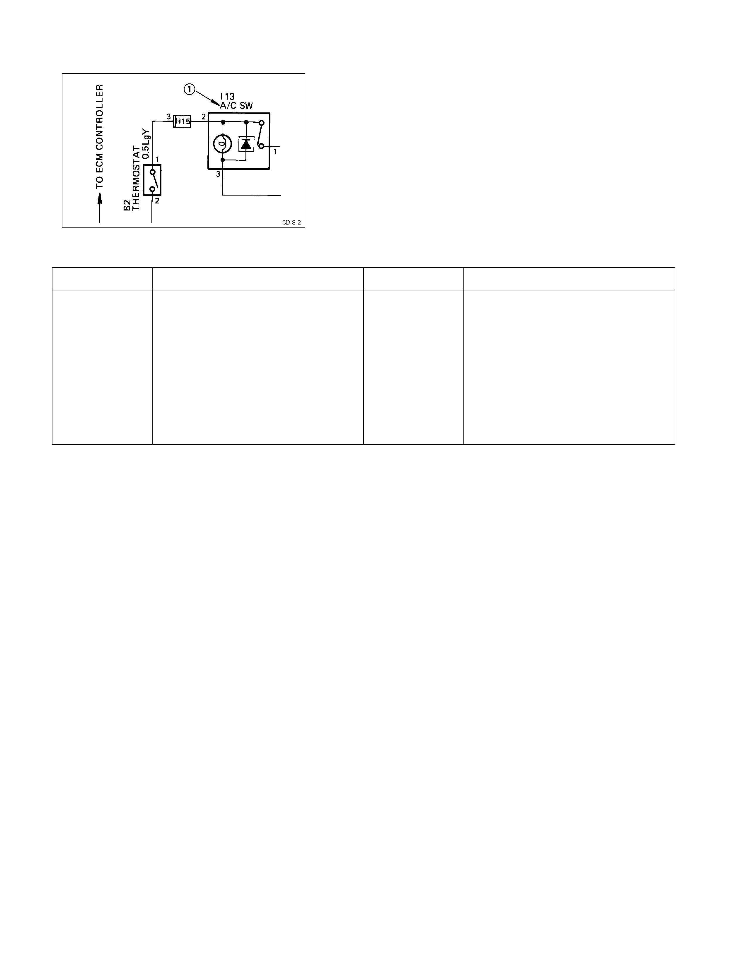
Symbols
The illustration at the left shows a ty pical symbol Q used
in circuit diagrams.
Refer to the following table.
Symbol & Meaning
Symbol Meaning Symbol Meaning
Fuse Single filament bulb
Main fuse Double filament bulb
Fusible link wire Motor
Switch Variable resistor
Switch Coil (Inductor)
Contact wiring
Battery
Relay
Note:
Relay contact shown in the
wiring diagram indicates
condition before a ctuation.
Diode Connector
Electronic part Light emitting diode
Resistor Reed switch
Speaker Condenser
Abbreviations
The illustration at the left shows a ty pical abbreviation
used in circuit diagrams.
These same abbreviations may also appear in the next.
Refer to the following table.
Abbreviation & Meaning
Abbreviation Meaning Abbreviation Meaning
RH
LH
SW
M/T
A/T
FT
RR
FLW
TEMP
ECM
Right-hand side
Left-hand side
Switch
Manual transmission
Automatic transmission
Front
Rear
Fusible link wire
Temperature
Electronic control module
STD
OPT
W/
WO/
OD
ACC
A/C
ATF
VSV
Standard equipment
Optional equipment
With
Without
Overdrive
Accessories
Air conditioner
Automatic transmission fluid
Vacuum switching valve
Torque Specifi cati ons
Starter Motor kgm(ft. lbs/Nm)
Starter Motor
Removal & Installation
Read this Section carefully before performing any removal and installation procedure. This Section gives you important
points as well as the order of operation. Be sure that you understand everything in this Section before you begin.
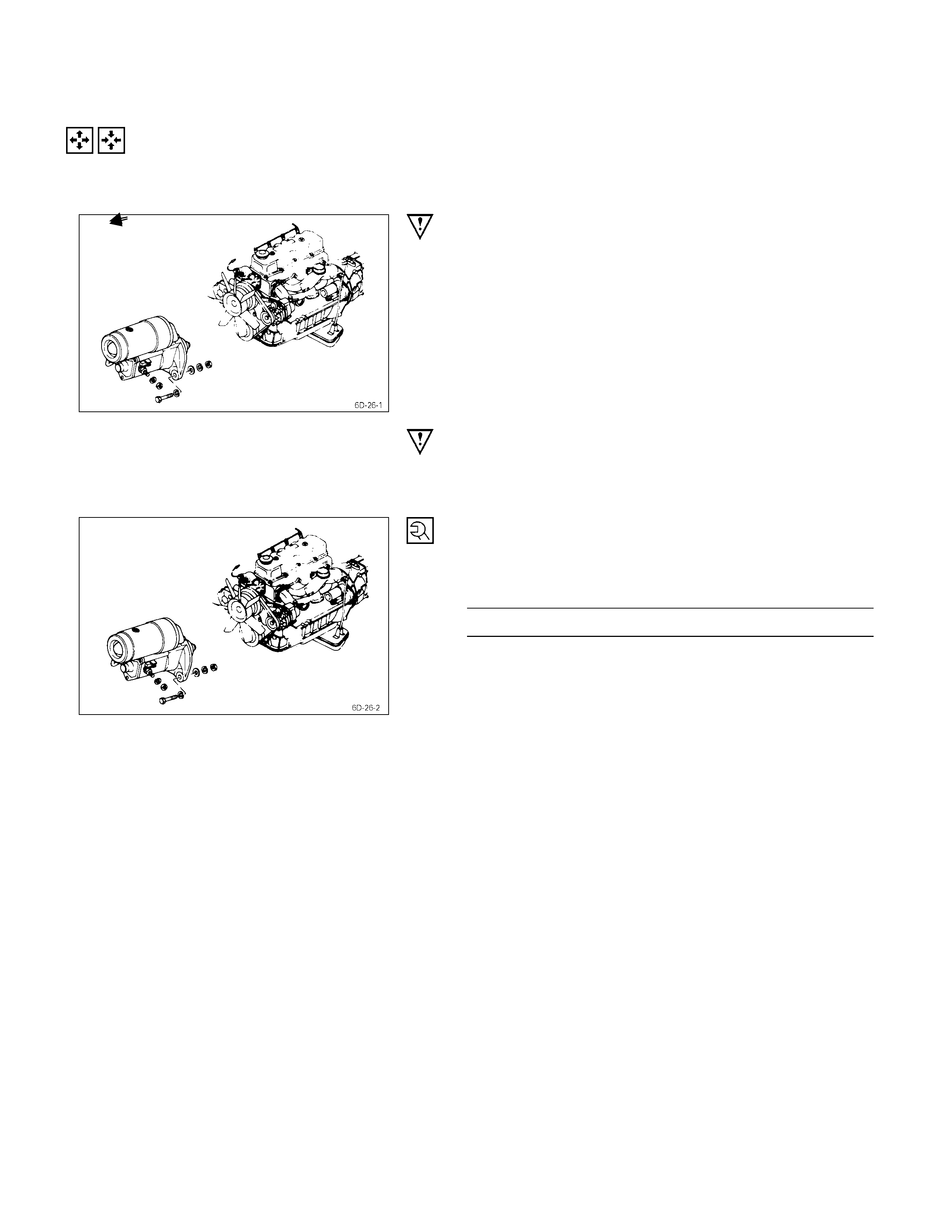
IMPO RTANT OPERATIONS - REMOVAL
Starter Motor
1) Disconnect the battery cable and the ground cable at
the battery terminals.
2) Disconnect the magnetic switch cable at the terminal
bolts.
3) Disconnect the battery cable at the starter motor and
the ground cable at the cylinder body.
4) Remove the starter motor from the engine.
IMPORTANT OPERATIONS – INSTALLATION
Follow the removal procedure in the reverse order to
perform the installation procedure. Pay careful attention to
the important points during the installation procedure.
Starter Motor
1) Install the starter motor to the rear plate.
2) Tighten the starter motor bolts to the specified torque.
Starter Motor Bolt Torque kg⋅m(lb⋅ft/N⋅m)
7 ± 1 (50.6 ± 7.2/68.7 ± 9.8)
3) Reconnect the battery cable at the starter motor and
the ground cable at the cylinder body.
4) Reconnect the battery cable and the ground cable at
the battery terminals.
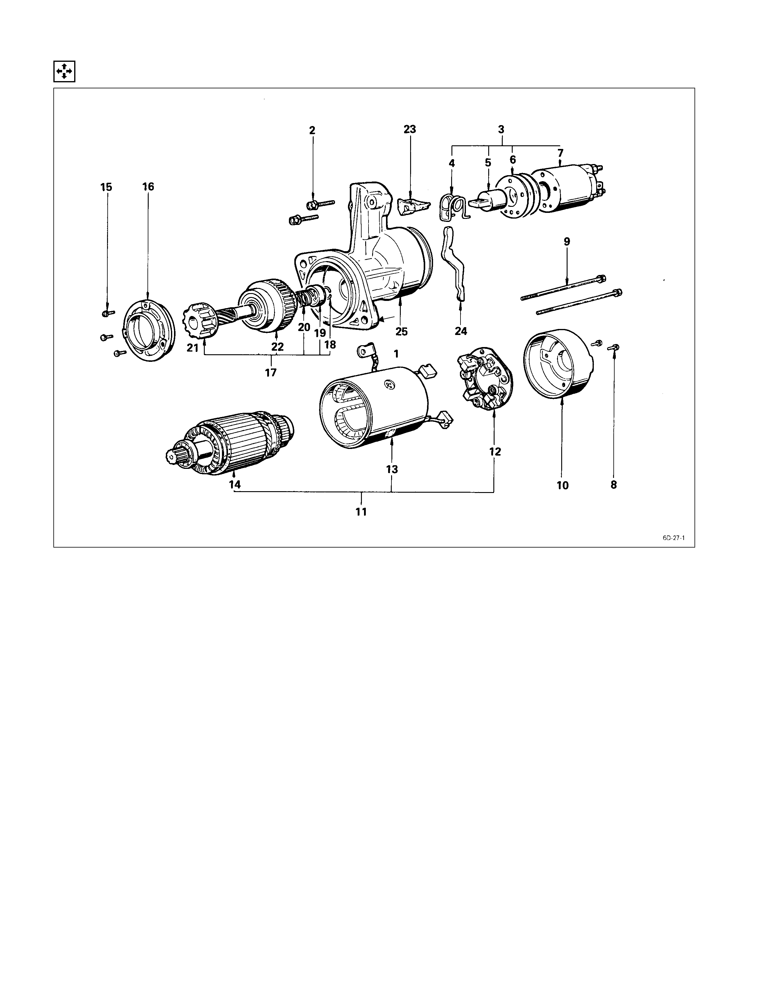
Disassembly
DISASSEMBLY STEPS
J
1. Lead wire
J
14. Armature
2. Bolt 15. Screw
J
3. Magnetic switch assembly
J
16. Bearing retainer
4. Torsion spring
J
17. Pinion assembly
5. Plunger 18. Pinion stopper clip
6. Adjusting shims 19. Pinion stopper
7. Magnetic switch 20. Return spring
J
8. Screw 21. Pinion shaft
J
9. Through bolt 22. Clutch
J
10. Rear cover
J
23. Dust cover
J
11. Motor assembly
J
24. Shift lever
J
12. Brush holder
J
25. Gear case
J
13. Yoke
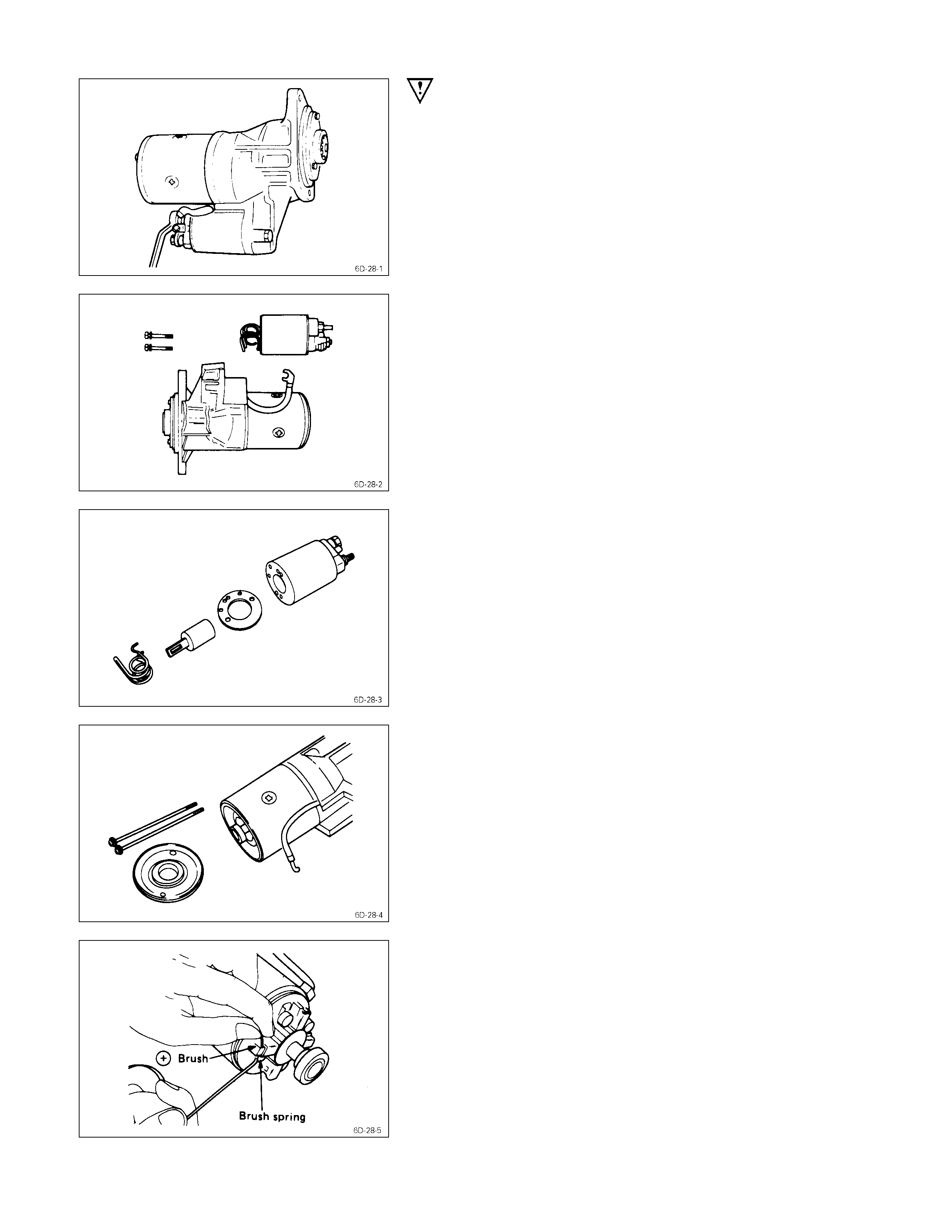
IMPORTANT OPERATIONS
1. Lead Wire
Disconnect the lead wire at the magnetic switch.
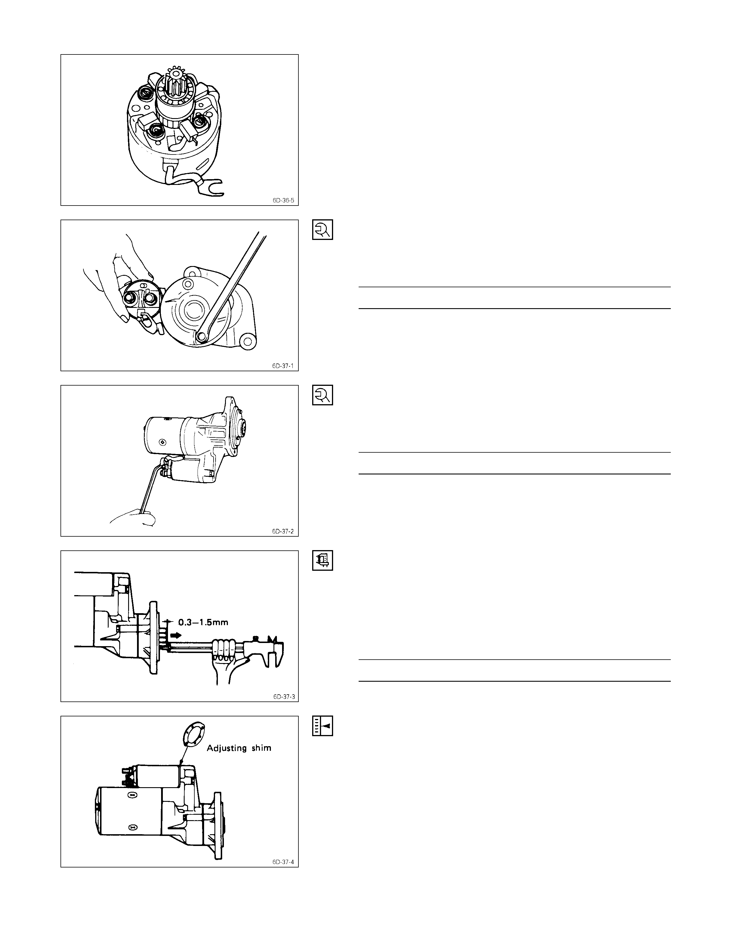
3. Magnetic Switch Assembly
Remove the magnetic switch bolts, then remove the
switch from the shift lever.
Remove the torsion spring from the magnetic switch.
1. Screw
2. Through Bolt
3. Rear Cover
Remove the through bolts, then remove the rear cover.
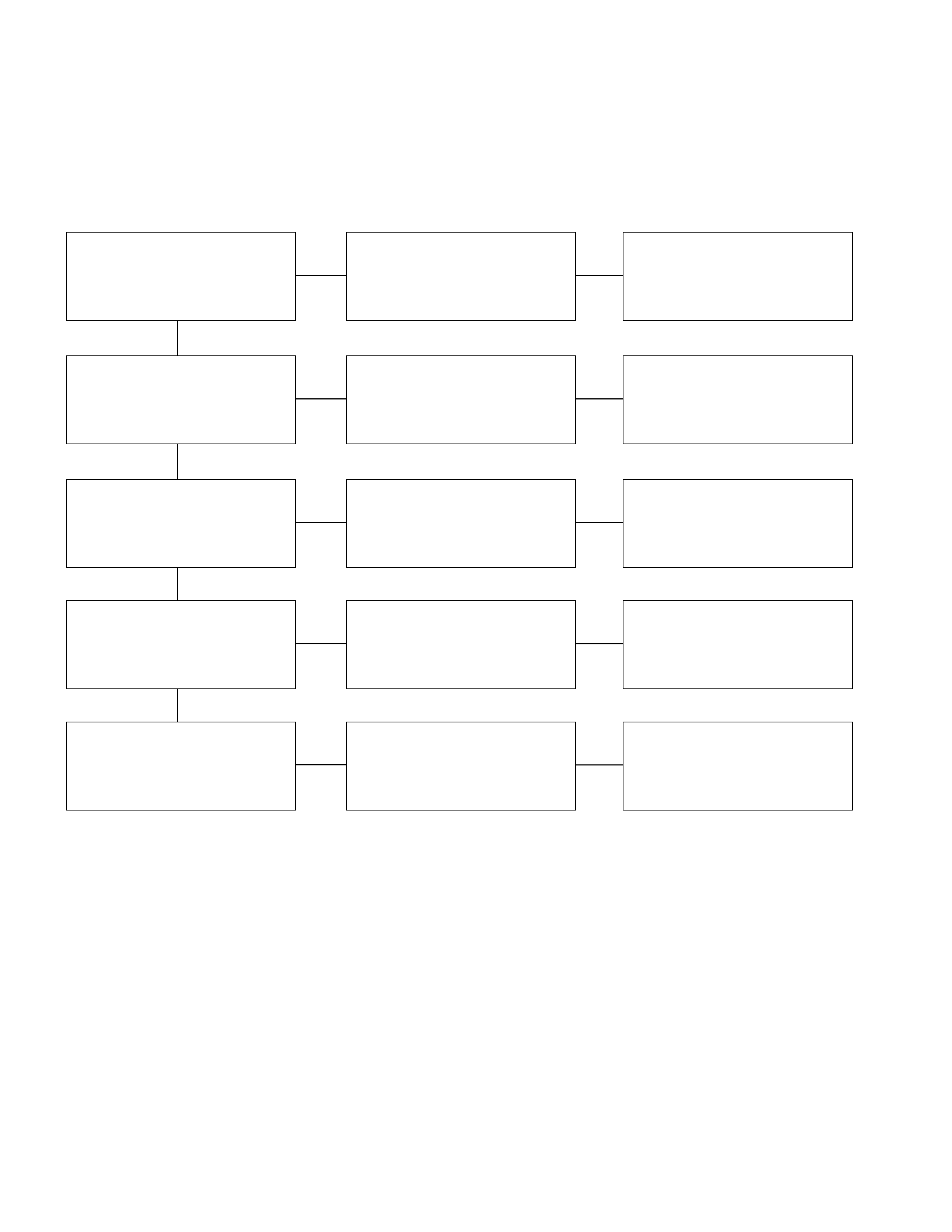
4. Motor Assembly
Remove the four brushes from the brush holders.
Remove the yoke along with the armature and the brush
holder from the gear case.
Remove the brushes and commutator carefully so as not
to allow them in contact with the adjacent parts.
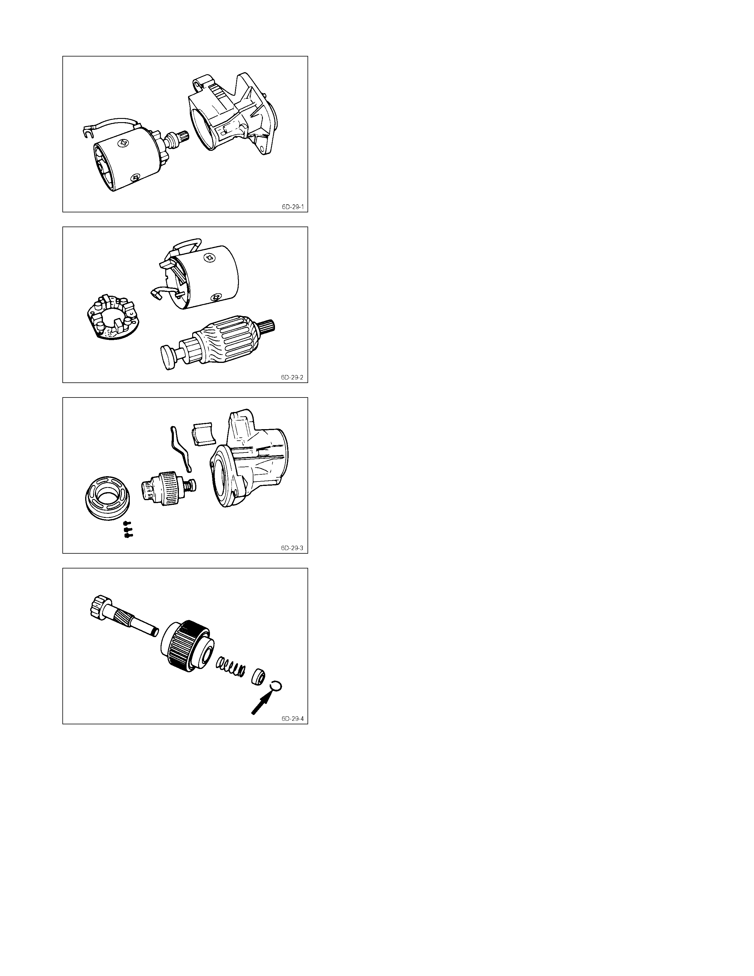
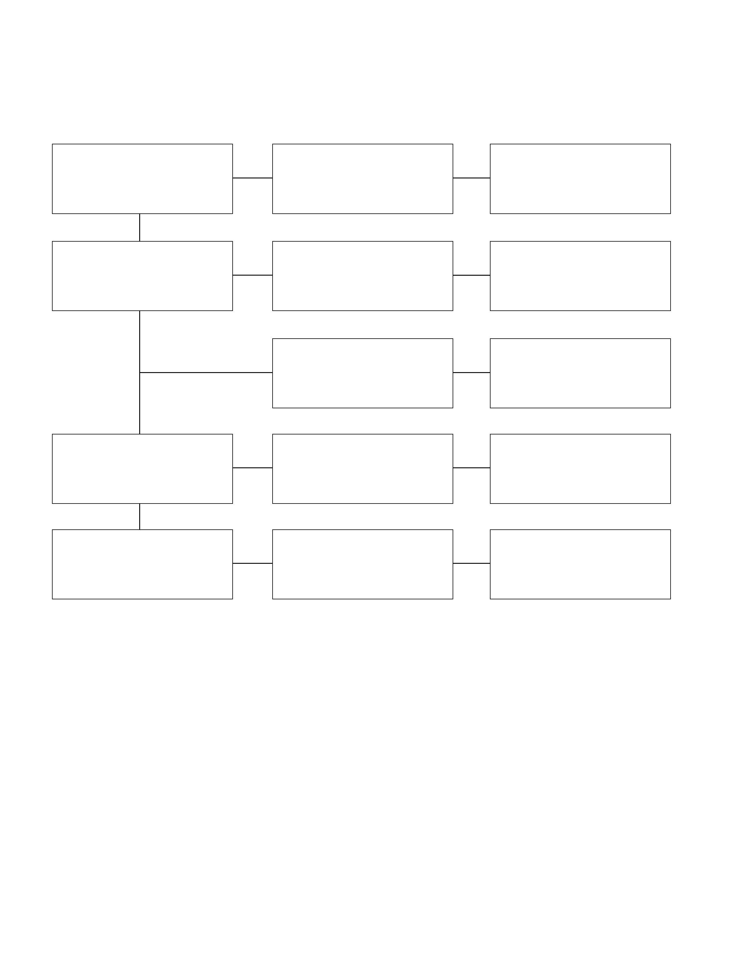
5. Brush Holder
6. Yoke
7. Armature
Remove the brush holder and pull out the armature
assembly free from the yoke.
15. Bearing Retainer
16. Pinion Assembly
23. Dust Cover
24. Shift Lever
25. Gear Case
1. Remove the bearing retainer.
2. Remove the pinion from the gear case.
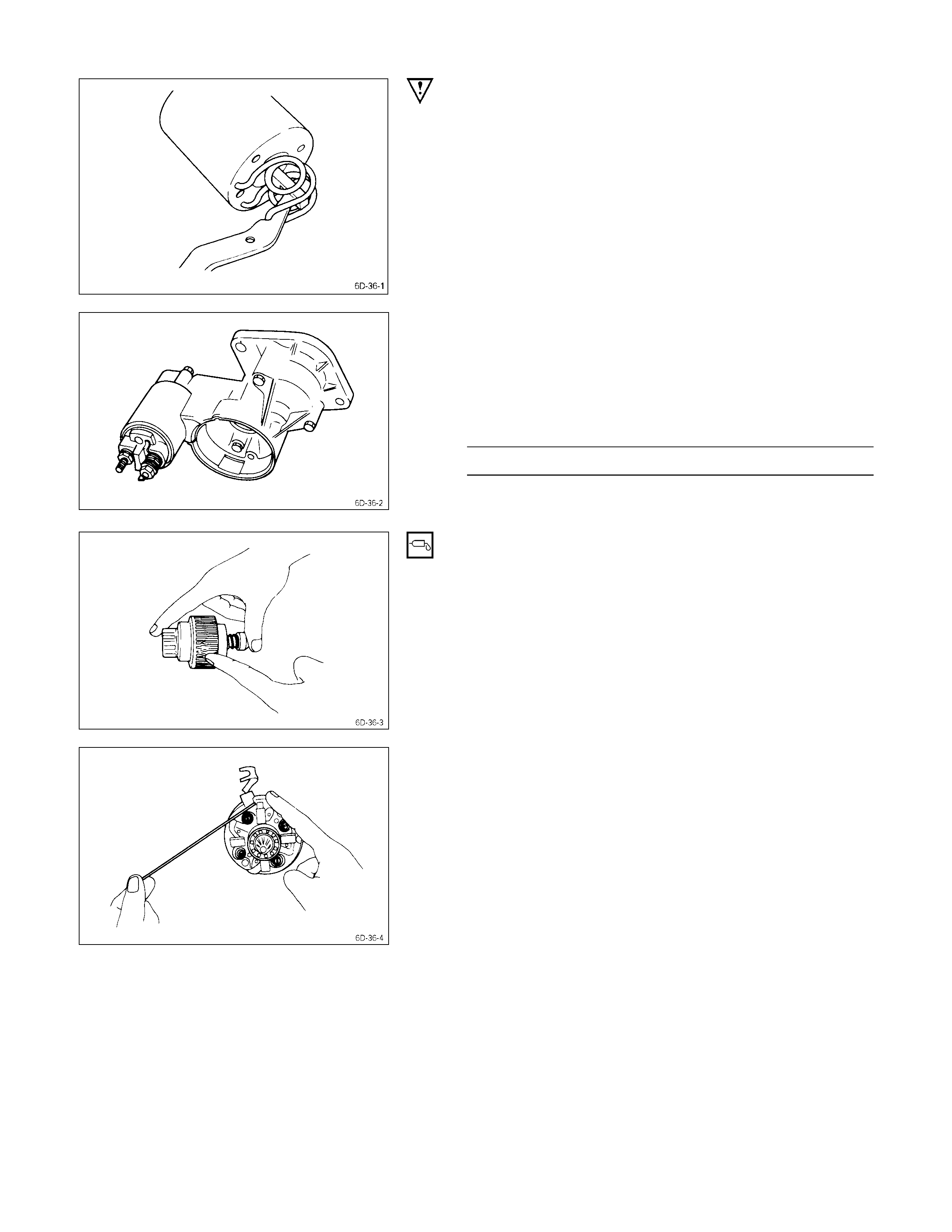
3. Use a screwdriver to remove the stopper clip. Then
disassemble the pinion assembly.
Inspection & Repair
Make the necessary adjustments, repairs, and part replacement if excessive wear or damage is discovered during
inspection.
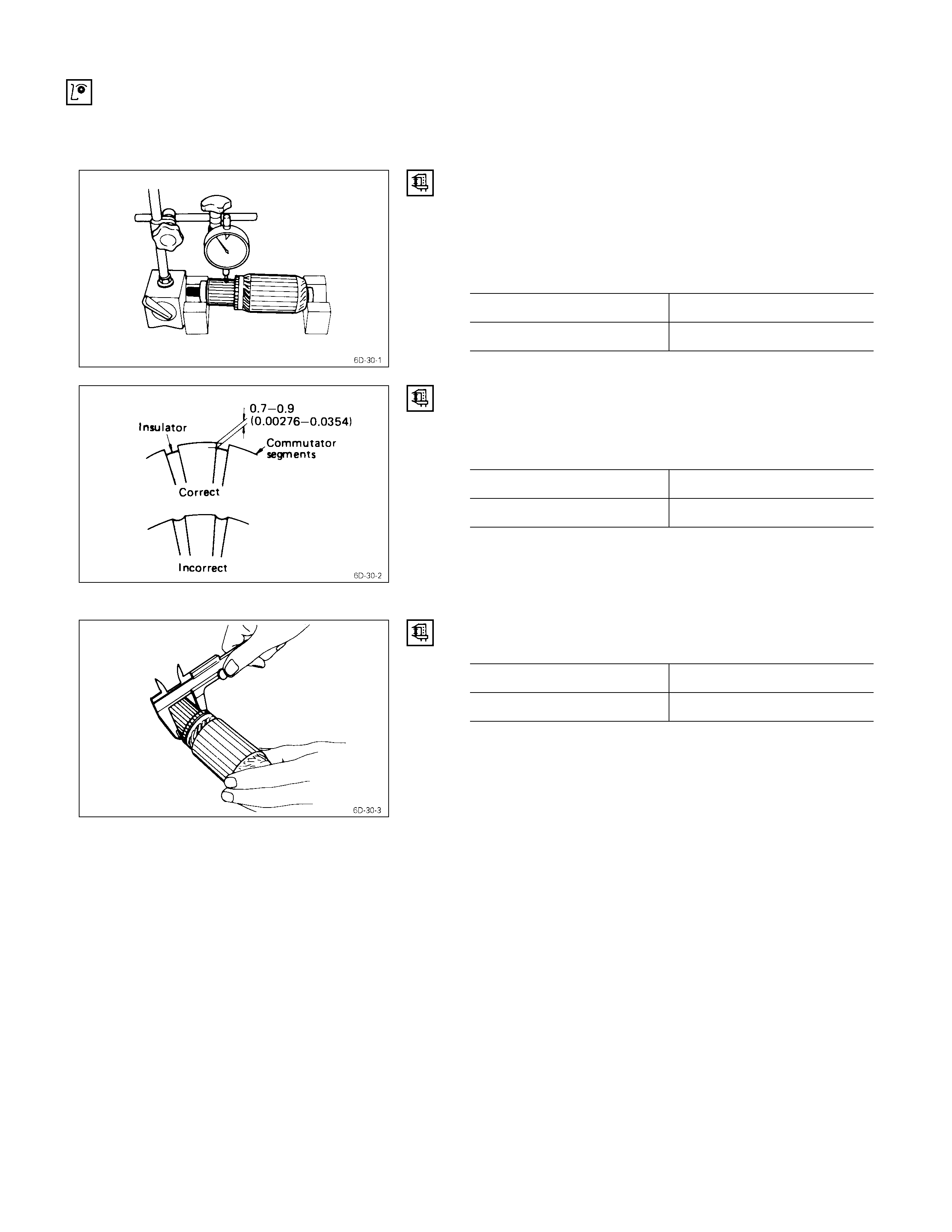
Armature
1. Measure the commutator run-out.
Replace the commutator if the measured run-out
exceeds the specified limit.
Commutator Run-Out mm (in)
Standard Limit
0.02 (0.001) 0.05 (0.002)
2. Check the commutator mica segments for excessive
wear.
3. Measure the mica segment depth.
Mica Segment Depth mm (in)
Standard Limit
0.7 – 0.9 (0.028 – 0.035) 0.2 (0.01)
If the mica segment depth is less than the standard but
more than the limit, the commutator may be reground.
If the mica segment depth is less than the limit, the
commutator must be replaced.
4. Measure the commutator outside diameter.
Commutator Outside Diameter mm (in)
Standard Limit
35 (1.4) 34 (1.3)
If the measured outside diameter is less than the specified
limit, the commutator must be replaced.
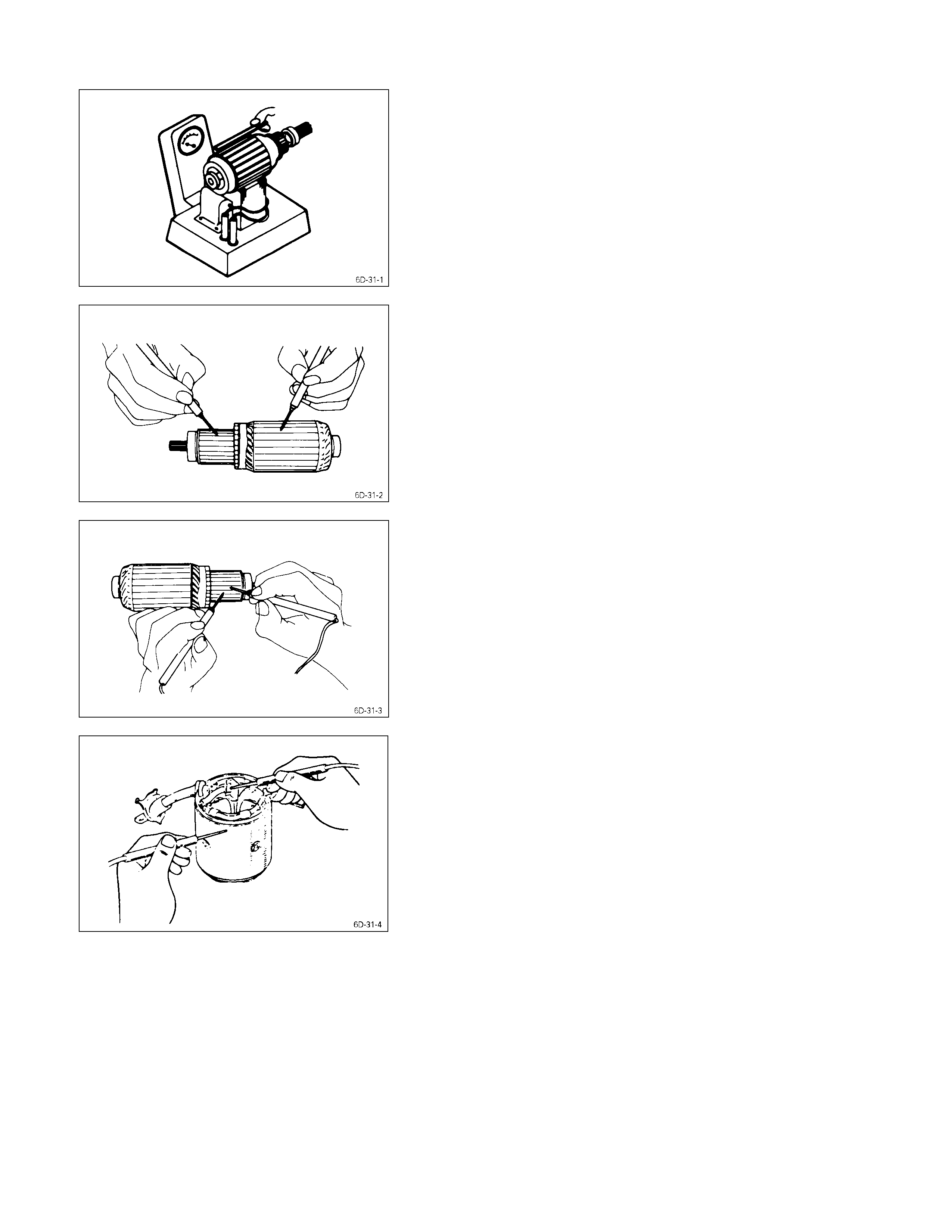
5. Test the armature for short circuiting.
a. Place the armature in a growler tester.
b. Hold a hacksaw blade against the armature core.
If the armature has a short circuit, the hacksaw blade
will vibrate.
Replace the armature if there is a short circuit.
6. Use a circuit tester to check the armature for
grounding.
1) Hold one probe of the circuit tester against the
commutator segment.
2) Hold the other circuit tester probe against the
armature core.
If the circuit tester indicates continuity, the armature is
grounded.
The armature must be replaced.
7. Use the circuit tester to check the armature for
continuity.
1) Hold the circuit tester probes against two armature
core segments.
2) Repear Step 1 at different segments of the
armature core.
There should be continuity between all segments of
the armature core.
If there is not, the armature must be replaced.
Yoke
1. Use a circuit tester to check the field winding ground.
1) Hold one circuit tester probe against the field
winding end or brush.
2) Hold the other circuit tester probe against the bare
surface of the yoke body.
There should be no continuity.
If there is continuity, the field coil is grounded.
The yoke must be replaced.
2. Use the circuit tester to check the field winding
continuity.
1) Hold one circuit tester probe against the “C”
terminal lead wire.
2) Hold the other circuit tester probe against the field
winding brush.
There should be continuity.
If there is no continuity, the yoke must be replaced.
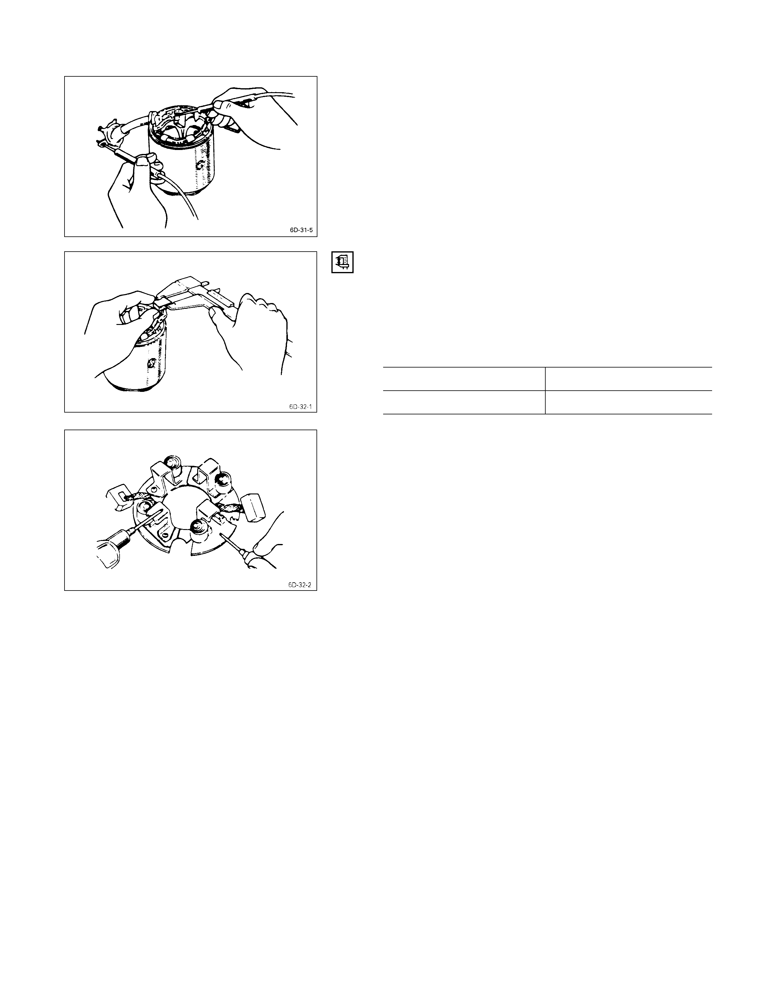
Brush & Brush Holder
1. Use a vernier caliper to measure the brush length (four
brushes).
Replace the brushes as a set if one or more of the
brush lengths is less than the specified limit.
Brush Length mm (in)
Standard Limit
14.5 (0.57) 9.5 (0.37)
2. Use a circuit tester to check the brush holder
insulation.
Touch one probe to the holder plate and the other
probe to the positive brush holder.
There should be no continuity.
3. Inspect the brushes for excessive wear.
If the negative brushes have excessive wear, the
entire brush holder assembly must be replaced.
If the positive brushes have excessive wear, only the
brushes must be replaced.
1) Use a pair of side cutters to cut the lead wire from
the brush.
2) File away any foreign material clinging to the edge
of the lead wire.
3) Remove the brushes from the brush holder.
4) Install the new brushes.
5) Straighten the bent portion of the clip.
6) File away any foreign material clinging to the clip
surface.
7) Place the lead wire in the clip.
8) Bend the clip shut.
9) Solder the brush lead.
10) Repeat the procedure for each of the brushes.
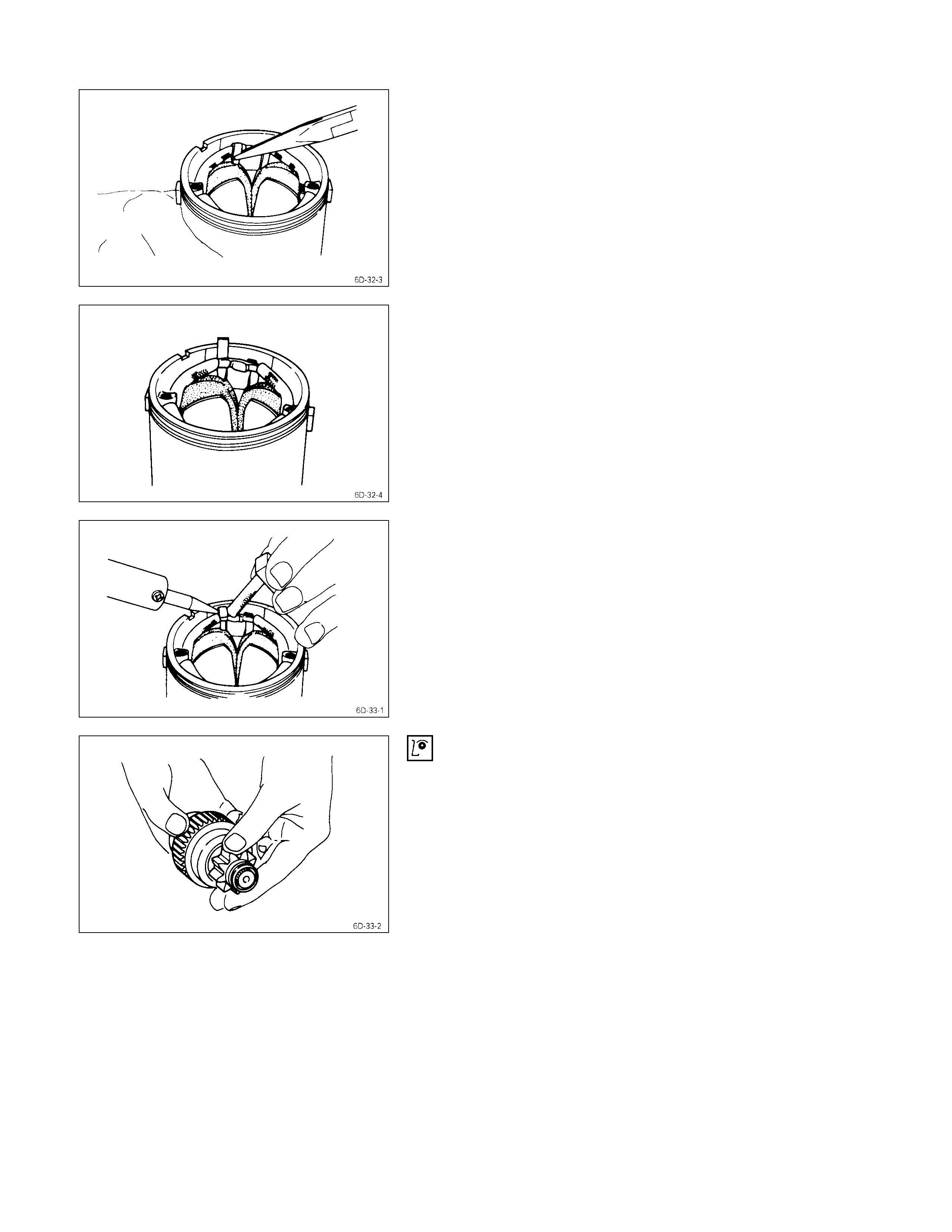
Overrunning Clutch
1. Inspect the overrunning clutch gear teeth for
excessive wear and damage.
Replace the overrunning clutch if necessary.
2. Rotate the pinion clockwise.
It should turn smoothly.
3. Try to rotate the pinion in the opposite direction.
The pinion should lock.
Bearing
Inspect the bearings for excessive wear and damage.
Replace the bearings if necessary.
Magnetic Switch
The following tests must be performed with the starter
motor fully assembled.
The yoke lead wire must be disconnected from the “C”
terminal.
To prevent coil burning, complete each test as quickly as
possible (within three to five seconds).
Temporarily connect the solenoid switch between the
clutch and the housing and run the following test.
Complete each test within three to five seconds.
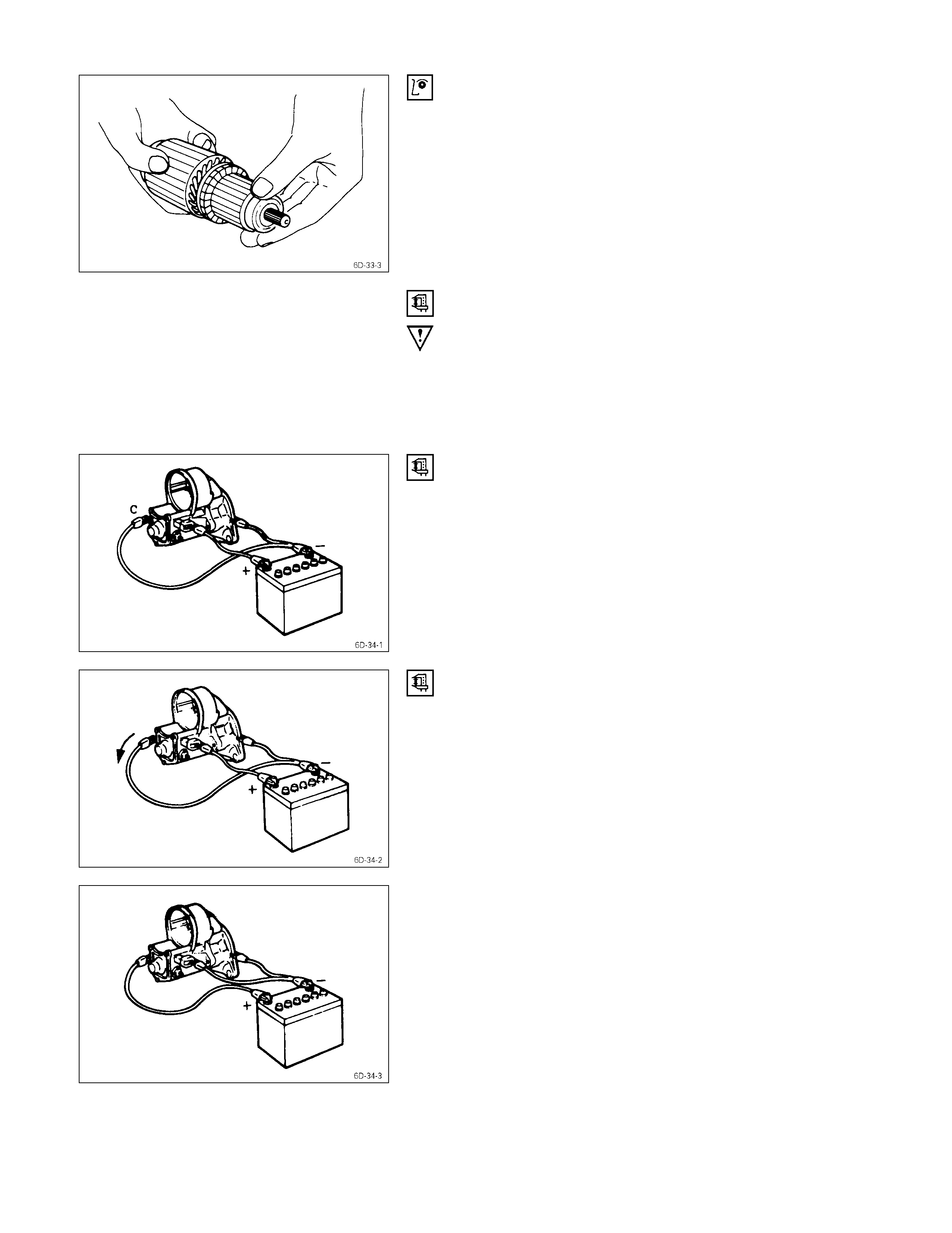
1. Pull-in Test
Connect the battery negative terminal with the solenoid
switch body and the C terminal. When current is applied to
the 50 terminal from the battery positive terminal, the
pinion should flutter.
2. Hold-in Maintenance Test
Disconnect the lead at the C terminal. The pinion should
continue to flutter.
3. Return Test
Connect the battery negative leads to the starter body and
the 50 terminal.
Connect the battery positive lead at the C terminal.
The pinion should return to its home position.

Reassembly
REASSEMBLY STEPS
J
1. Magnetic switch assembly 14. Pinion stopper
2. Magnetic switch 15. Pinion stopper clip
3. Adjusting shims 16. Bearing retainer
4. Plunger 17. Screw
5. Torsion spring 18. Motor assembly
6. Shift lever 19. Armature
J
7. Gear case 20. Yoke
J
8. Dust cover
J
21. Brush holder
9. Bolt 22. Rear cover
J
10. Pinion assembly 23. Screw
11. Clutch
J
24. Through bolt
12. Pinion shaft
J
25. Lead wire
13. Rerurn spring
IMPORTANT OPERATIONS
1. Magnetic Switch Assembly
1. Attach the torsion spring to the hole in the magnetic
switch as illustrated.
2. Insert the shift lever into the plunger hole of the
magnetic switch.
7. Gear Case
8. Dust Cover
1. Install the magnetic switch assembly in the gear case.
2. Install the dust cover.
Dust Cover Bolt Torque kg⋅m(lb⋅ft/N⋅m)
0.75 ± 0.5 (5.4 ± 3.6/7.4 ± 5)
10. Pinion Assembly
Apply a coat of grease to the reduction gear and install the
pinion assembly to the armature shaft.
21. Brush Holders
1. Install the brushes into the brush holder with raising
the spring end of the brush spring.
Take care not to damage the commutator face.
2. Install the brush holder with aligning the peripheries of
the yoke and the brush holder.
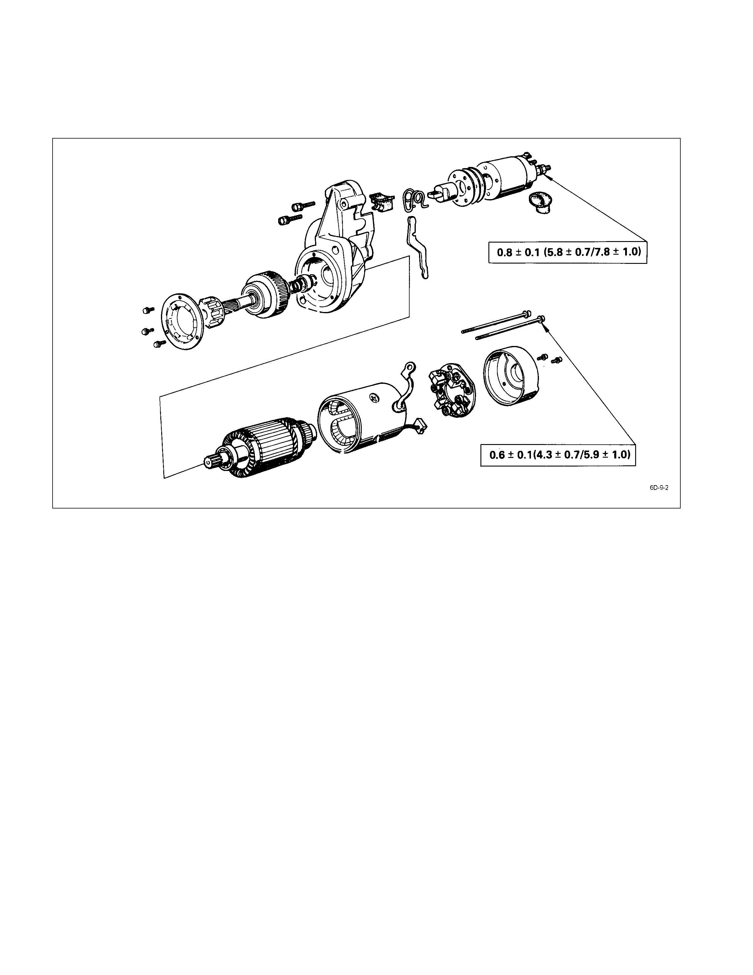
24. Through Bolt
Install the through bolts in the rear cover and tighten them
to the specified torque.
Through Bolt Torque kg⋅m(lb⋅ft/N⋅m)
0.6 ± 0.1 (4.3 ± 0.7/5.9 ± 1.0)
25. Lead Wire
Connect the lead wire in the magnetic switch and tighten
the terminal nut to the specified torque.
Lead Wire Terminal Nut Torque kg⋅m(lb⋅ft)
0.8 ± 0.1 (5.8 ± 0.7/7.8 ± 1.0)
Inspection After Assembly
Use a vernier caliper to measure the pinion shaft thrust
play.
The pinion shaft thrust play is equal to the pinion shaft end
and pinion stopper clearance.
Pinion Shaft Thrust Play mm (in)
0.3 - 1.5 (0.01 – 0.06)
In a case where the pinion gap outside the
specified value;
Make an adjustment using a shim(s).
Adjusting shims are available in 0.5 mm and 0.8 mm (0.02 and
0.03 in.) sizes.

Troubleshooting
Refer to this Section to quickly diagnose and repair electrical problems.
Each troubleshooting chart has three headings arranged from left to right.
(1) Checkpoint (2) Trouble Cause (3) Countermeasure
Hard Starting
1. Pinion Does Not Engage The Ring Gear When The Starter Switch Is Turned On
2. Pinion Engages The Ring Gear But The Engine Does Not Turn Over
3. Incorrect Pinion And Ring Gear Engagement
4. Starter Continues To Run After The Starter Switch Is Turned Off
5. Excessive Commutator Sparking
Hard Starting
1. Pinion Does Not Engage The Ring Gear When
The Starter Sw itch Is Turned On
Checkpoint Trouble Cause Countermeasure
Battery Discharged Recharge
Starter circuit Open or intermittent Clean and reconnect
Magnetic solenoid switch Contact points defective Replace
Magnetic solenoid coil Open or scorched Replace
Plunger shaft Bent or scorched Bent or scorched
OKOK
OK
OK
OK
NG
NG
NG
NG
NG
2. Pinion Engages The Ring Gear But The Engine Does Not Turn Over
Checkpoint Trouble Cause Countermeasure
Battery Weak Recharge
Brush and commutator face
contact Intermittent Repair or replace
Face dirty Clean
Pinion clutch Slippage Replace
Armature field coil Open or short circuit Repair of replace
OKOK
OK
OK
NG
NG
NG
NG
NG
3. Incorrect Pinion & Ring Gear Engagement
Checkpoint Trouble Cause Count ermeasure
4. Starter Continues To Run After The Starter Switch Is Turned Off
Checkpoint Trouble Cause Count ermeasure
Battery Discharged Recharge
Pinion and ring gear teeth Worn or broken Replace
Pinion gear return movement Incorrect Adjust
OKOK
OK
NG
NG
NG
Magnetic solenoid switch
contact points Seized Repair or replace
Starter switch Defective Replace
OKOK
NG
NG
5. Excessive Commutator Sparking
Checkpoint Trouble Cause Count ermeasure
Brush and commutator face
contact Intermittent Repair or replace
Slag accumulation on the face Clean or replace
Commutator Excessive wear or pitting Repair or replace
Loose solder Clean and repair
Armature shaft Run-out due to worn bearing Repair
Brush holder Loose in mount Repair
OK
OK
OK
NG
NG
NG
NG
NG
NG