
Main Data & Specifications
Engine Model 4JB1T, 4JH1TC
Oil pump type
Oil pressure switch operating pressure kg/cm2 (psi/kPa)
Oil filter type
Gear
0.2 – 0.5 (2.8 – 7.1/19.6 – 49.0)
Full flow with cartridge paper element
Relief valve opening pressure kg/cm2 (psi/kPa) 5.7 – 6.3
(82.5 – 89.5/558.6 – 617.4)
Safety valve opening pressure kg/cm2 (psi/kPa)
Oil cooler type
Safety valve opening pressure kg/cm2 (psi/kPa)
0.8 – 1.2 (11.38 – 17.07/78.9 – 117.6)
Water-cooled
2.3 – 2.7 (32.7 – 38.4/225.4 – 264.6)
General Description
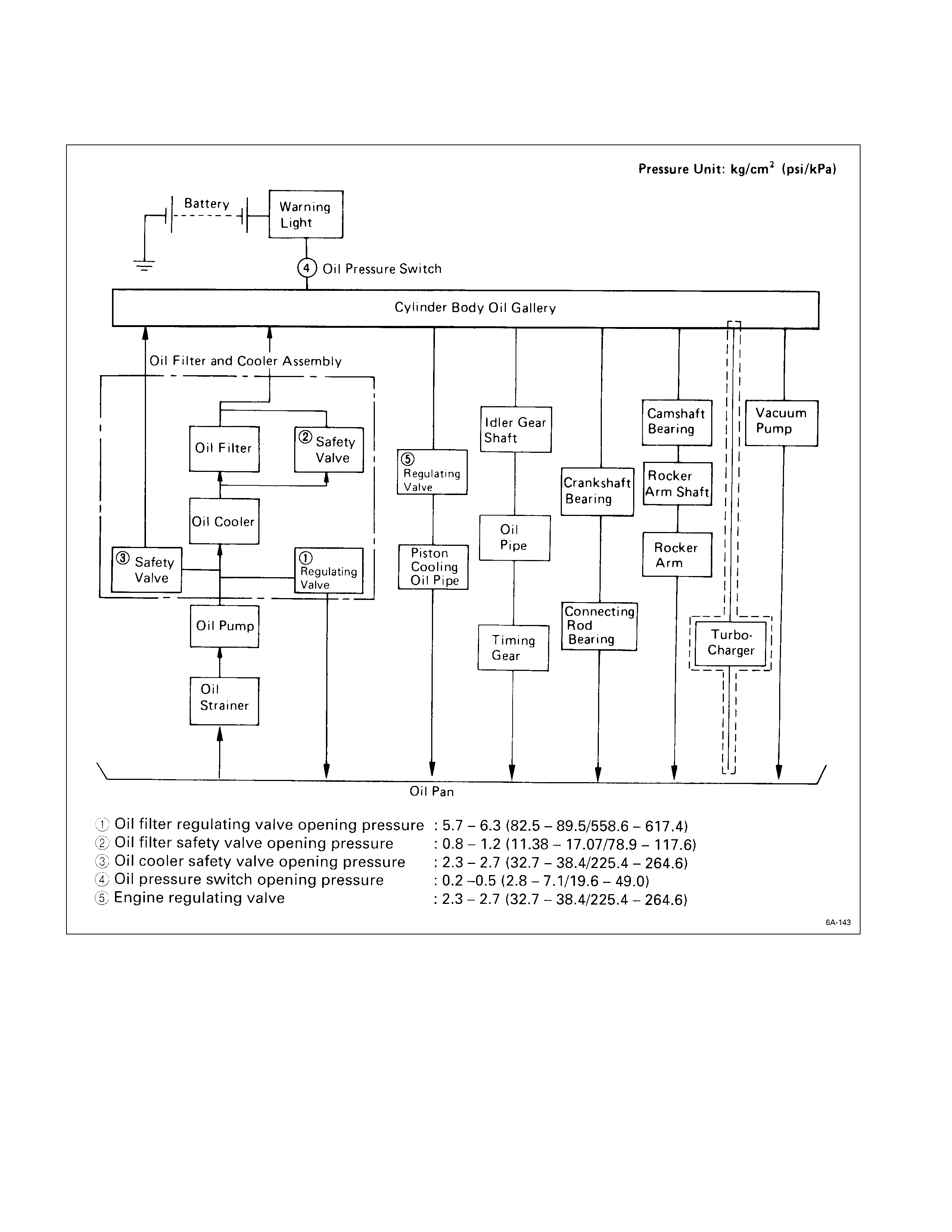
Lubricating Oil Flow
Q Oil filter safety valve opening pressure : 0.8 – 1.2 (11.4 – 17.1/78.9 – 117.6)
R Oil cooler safety valve opening pressure : 2.3 – 2.7 (32.7 – 38.4/225.4 – 264.6)
S Oil filter relief valve opening pressure : 5.7 – 6.3 (82.5 – 89.5/558.6 – 617.4)
T Oil pressure switch opening pressure : 0.2 – 0.5 (2.8 – 7.1/19.6 – 49.0)
U Engine regulating valve : 2.3 – 2.7 (32.7 – 38.4/225.4 – 264.6)
V Oil pump relief valve opening pressure : 6.7 – 7.8 (95.3 – 110.9/657.0 – 764.9)
C06L200010
The 4J series engine has a full flow type lubricating system.
Lubricating oil is pumped from the oil pump to the cylinder body oil gallery through the oil cooler and the oil filter. It is
then delivered to the vital parts of the engine from the cylinder body oil gallery.
Oiling jets installed on the cylinder body spray engine oil to the piston backside faces to achieve maximum piston
cooling effect.
4JH1TC
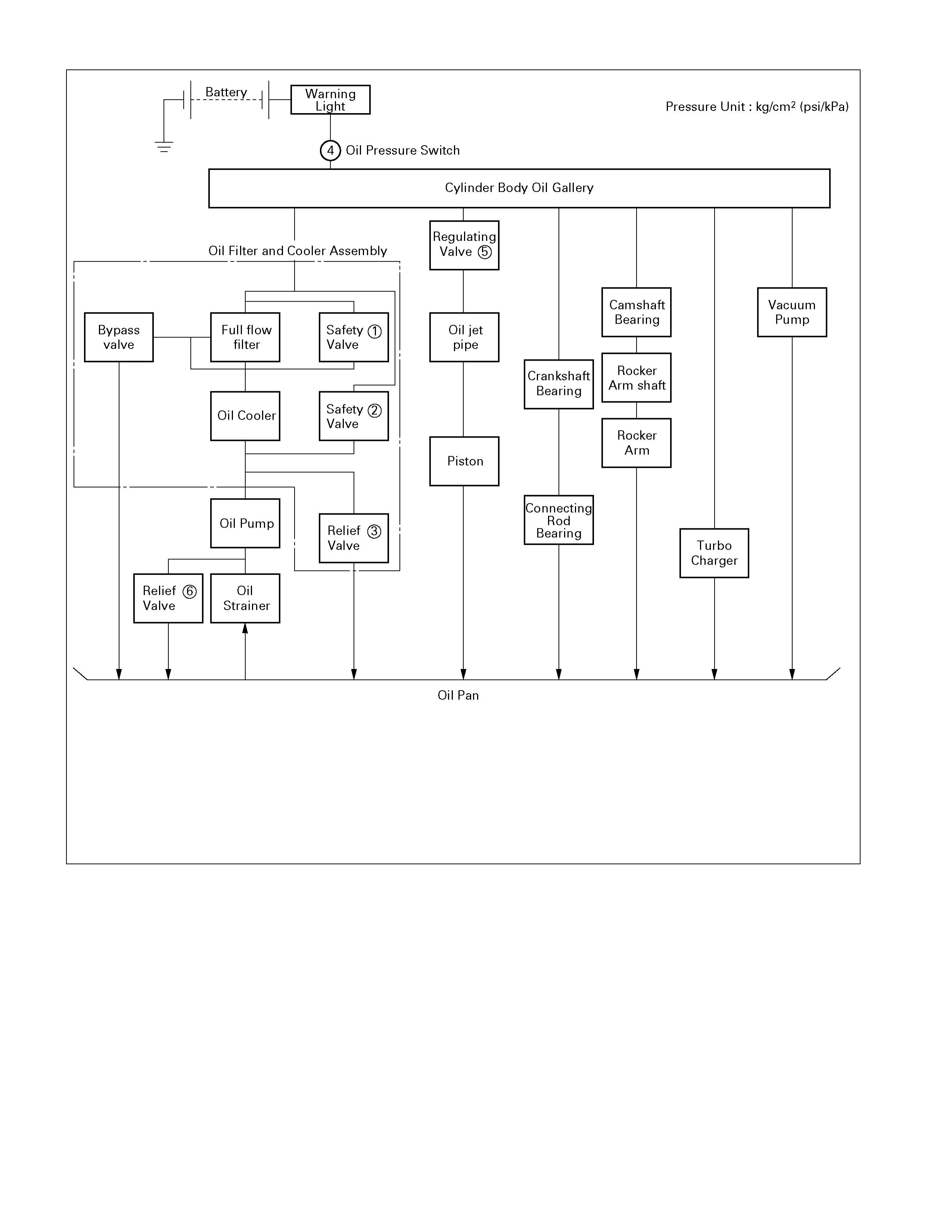
Oil Pump & Oil Filter
The 4J series engine is equipped with a gear type oil pump.
The oil filter and the water cooled oil cooler integrated a single unit to increase the cooling effect.
Except 4JA1
For 4JA1
Oil Pump
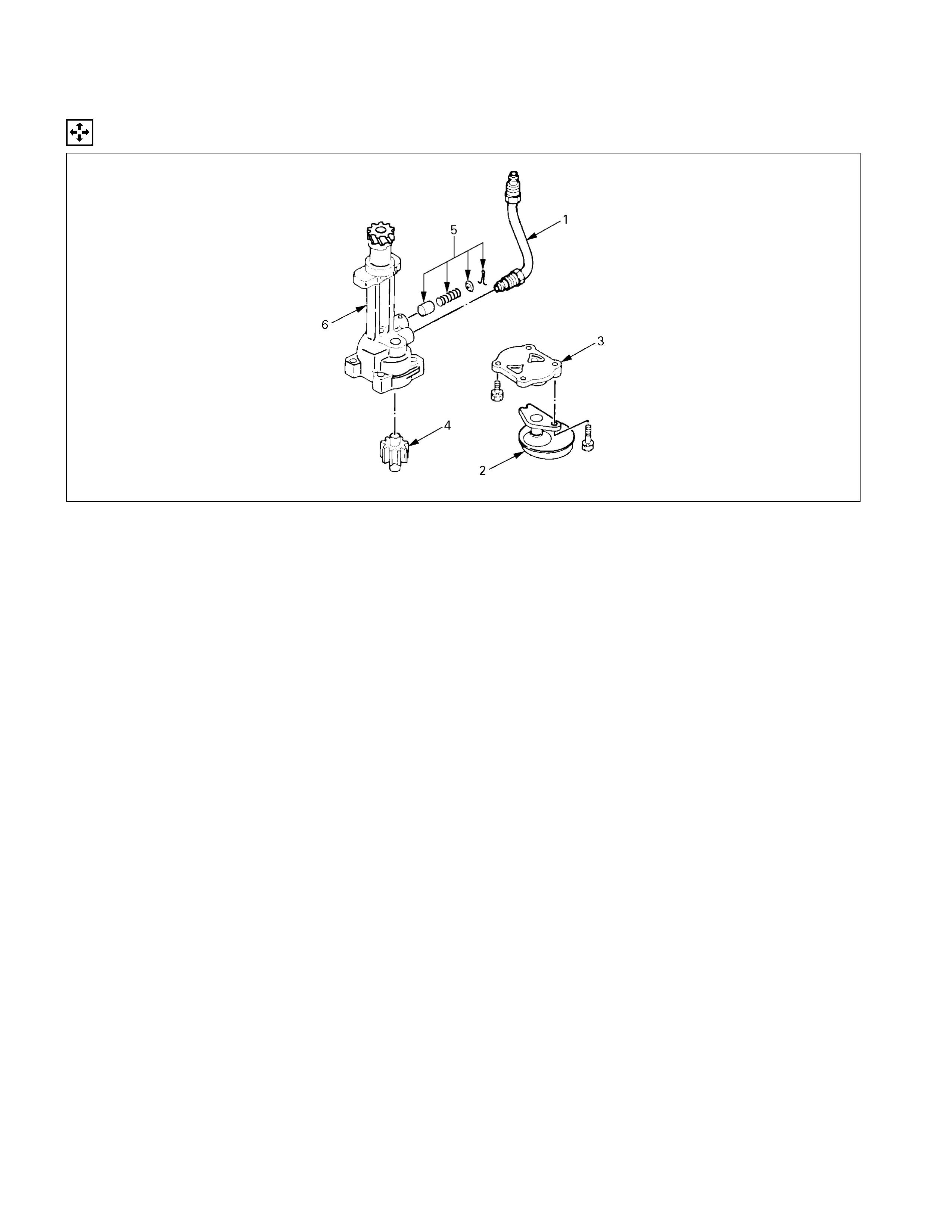
Disassembly
051L200001
DISASSEMBLY STEPS
1. Oil pipe 4. Driven gear with bush
2. Strainer 5. Relief valve asm.
3. Pump cover 6. Oil pump body
Inspection & Repair
Make the necessary adjustments, repairs, and part replacements if excessive wear or damage is discovered during
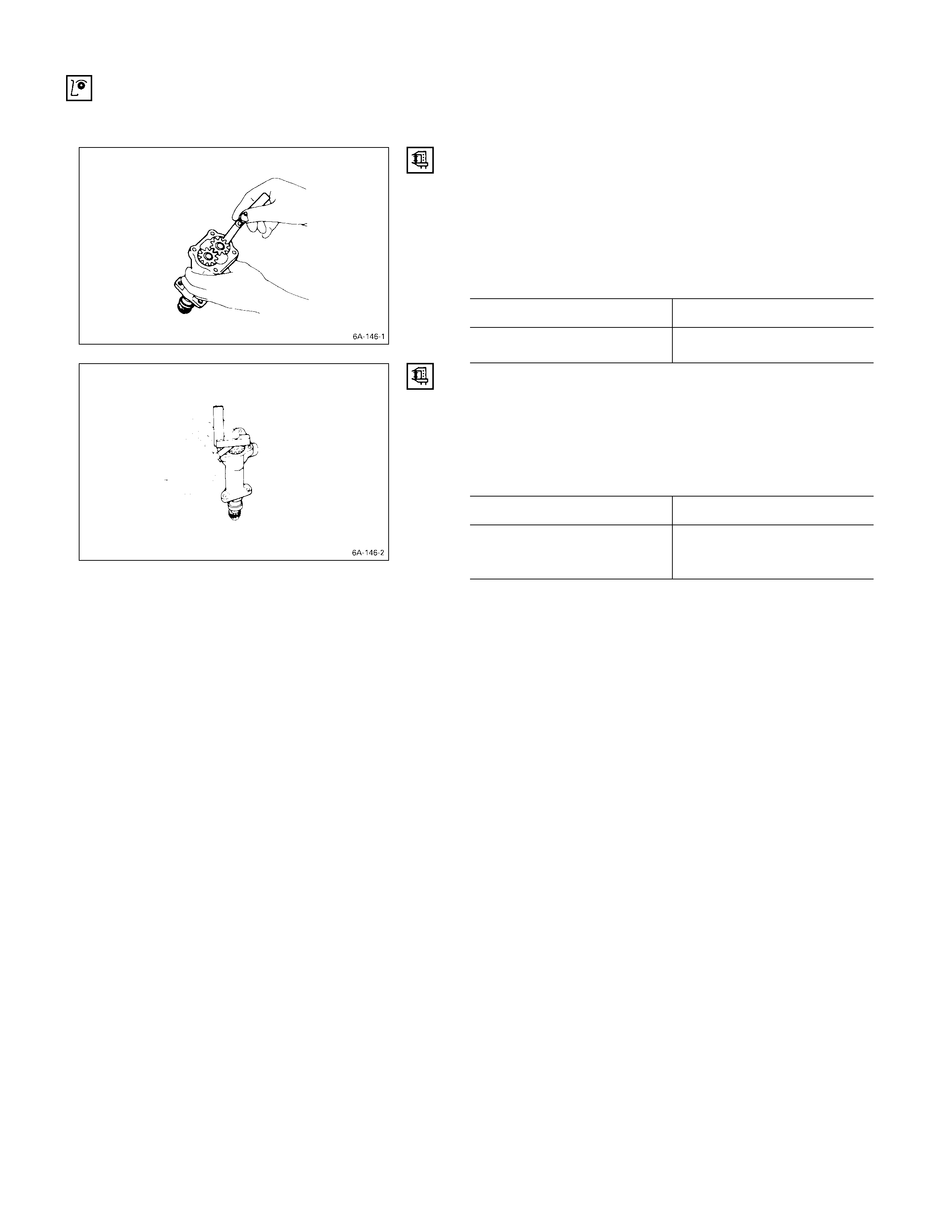
inspection. G EAR TEETH AND BODY I NNER W ALL CLEARANCE
Use a feeler gauge to measure the clearance between the
gear teeth and the body inner wall.
If the clearance between the gear teeth and the body inner
wall exceeds the specified limit, either the gear or the body
must be replaced.
Gear Teeth and Body Inner Wall Clearance mm (in)
Standard Limit
0.14 (0.0055) 0.20 (0.0079)
GEAR AND BODY CLEARANCE
Use a feeler gauge to measure the clearance between the
body and the gear.
If the clearance between the gear and the body exceeds
the specified limit, the body must be replaced.
Gear and Body Clearance mm (in)
Standard Limit
0.06 (0.024) 0.15 (0.0059)
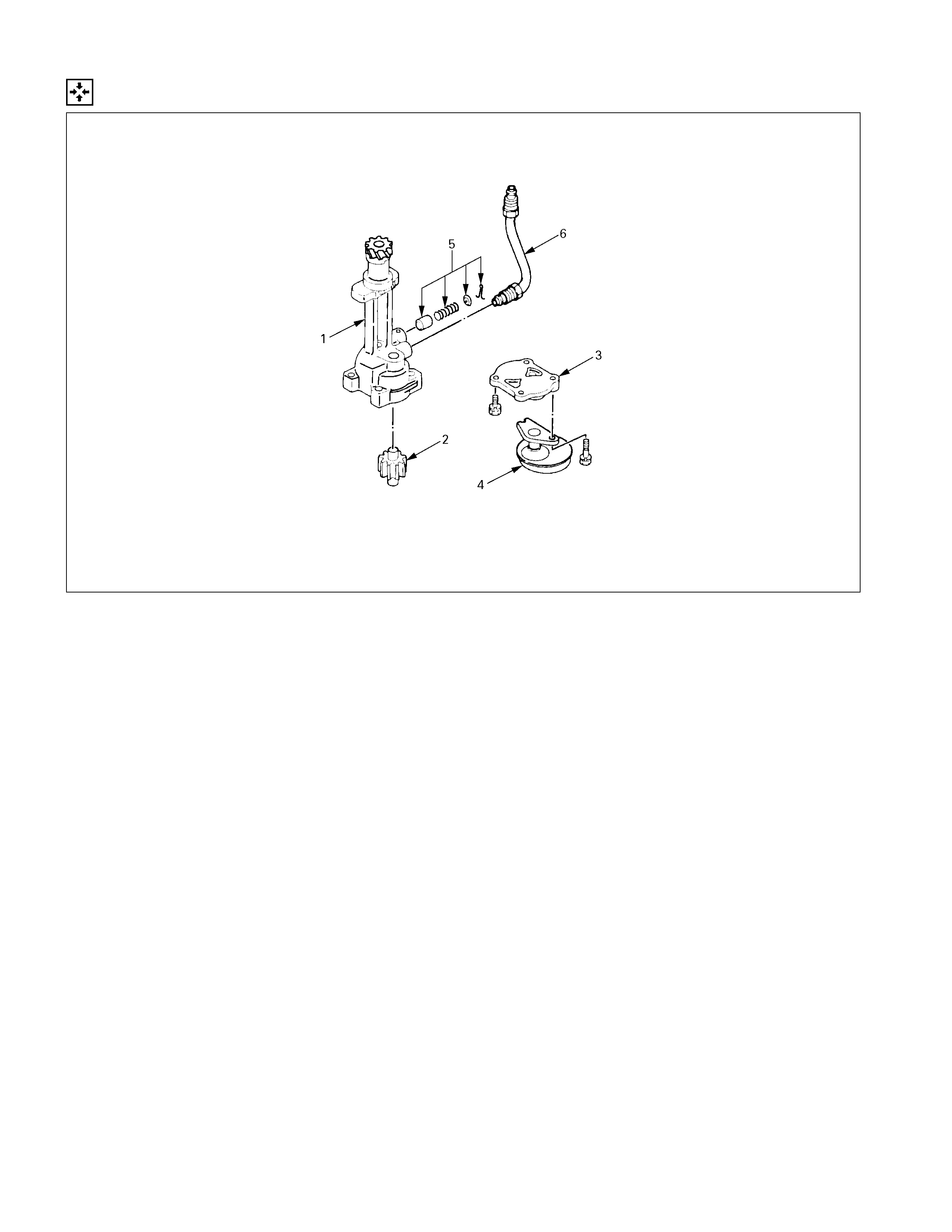
Reassembly
051L200002
REASSEMBLY STEPS
1. Oil pump body 4. Strainer
2. Driven gear with bush 5. Relief valve asm.
3. Pump cover 6. Oil pipe
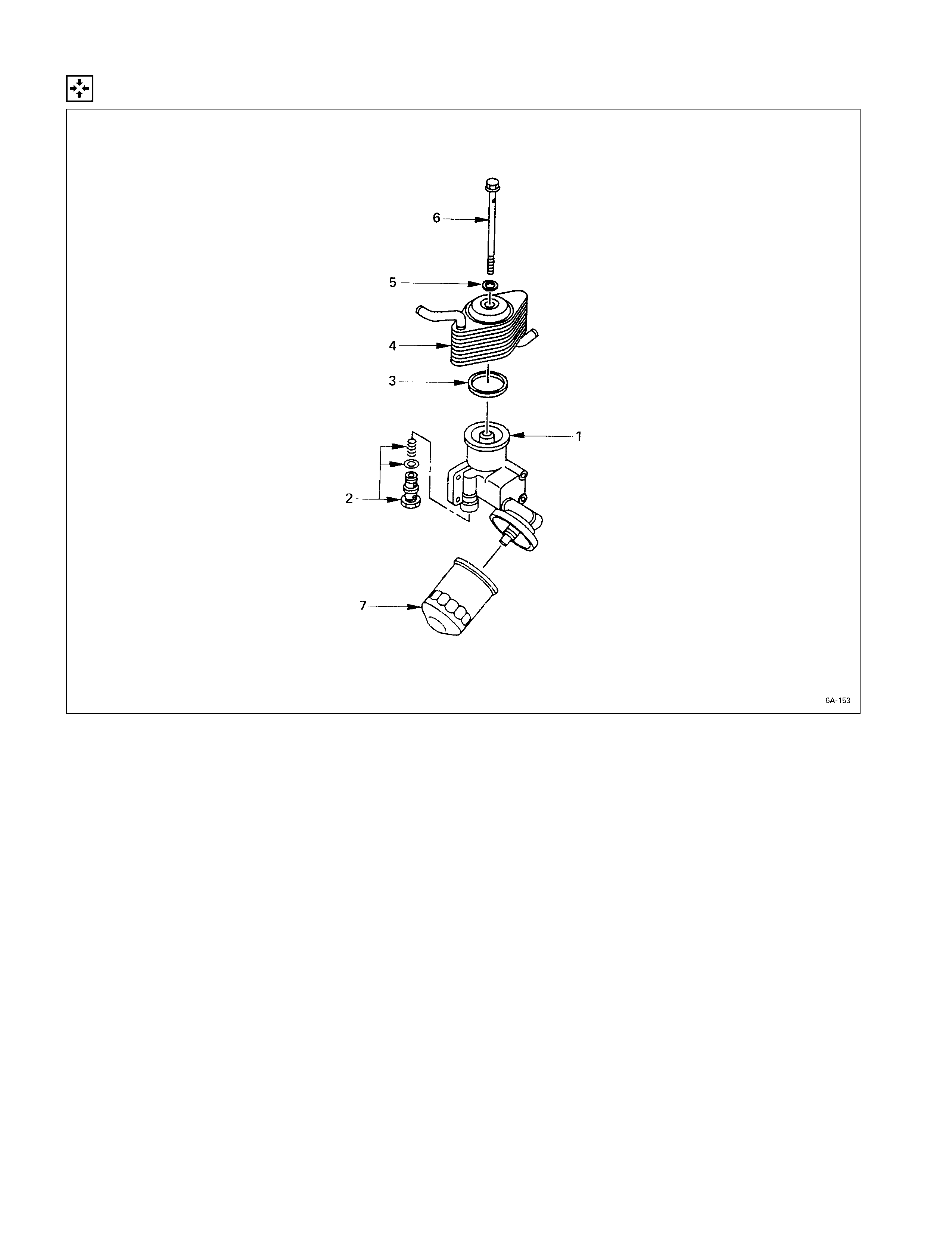
Oil Filter & Oil Cooler
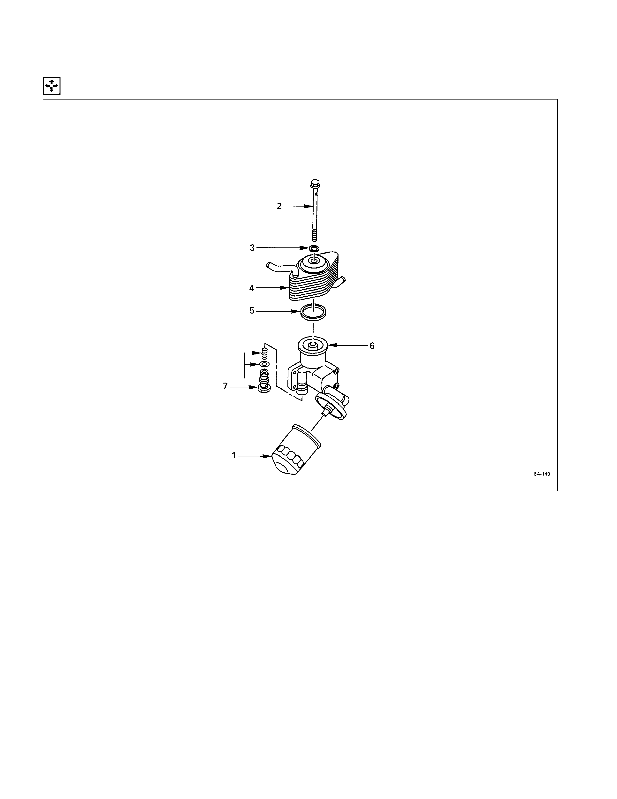
Disassembly
DISASSEMBLY STEPS
1. Oil filter cartridge 5. Gasket
2. Bolt 6. Body
3. Gasket 7. Relief valve
4. Oil cooler
Inspection & Repair
Make the necessary adjustments, repairs, and part replacements if excessive wear or damage is discovered during
inspection.
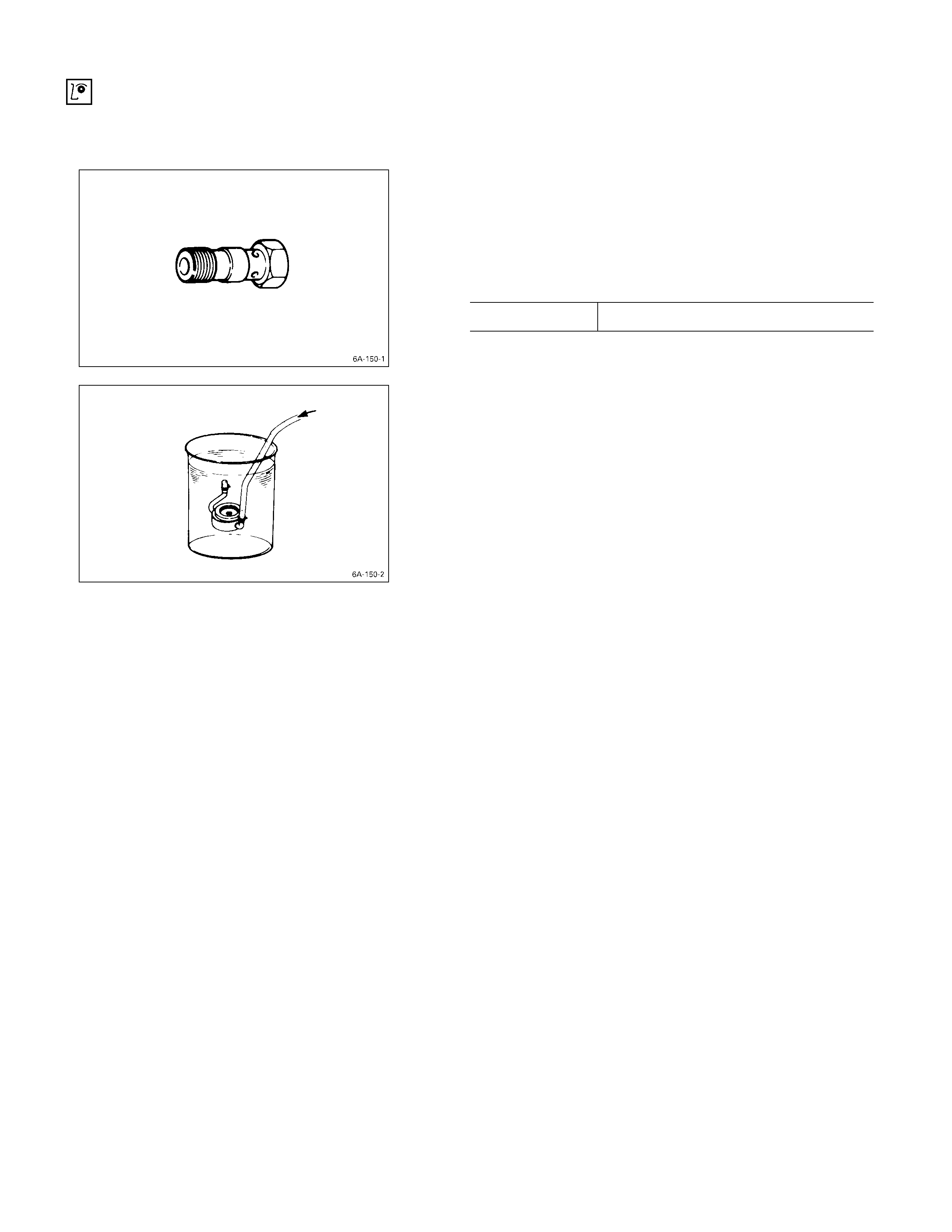
RELIEF VALVE
1. Attach an oil pressure gauge to the oil gallery near the
oil filter.
2. Start the engine to check the relief valve opening
pressure.
Relief Valve Opening Pressure kg/cm2 (psi/kPa)
4JB1T, 4JH1TC 5.7 – 6.3 (82.5 – 89.5/558.6 – 617.4)
OIL COOLER
Water Leakage at Water Passage
1. Plug one side of the oil cooler water passage.
2. Submerge the oil cooler in water.
3. Apply compressed air (2 kg/cm2 (28 psi/200 kPa)) to
the other side of the oil cooler water passage.
If air bubbles rise to the surface, there is water leakage.
Reassembly
REASSEMBLY STEPS
1. Body 5. Gasket
J
2. Relief valve
J
6. Bolt
3. Gasket
J
7. Oil filter cartridge
J
4. Oil cooler
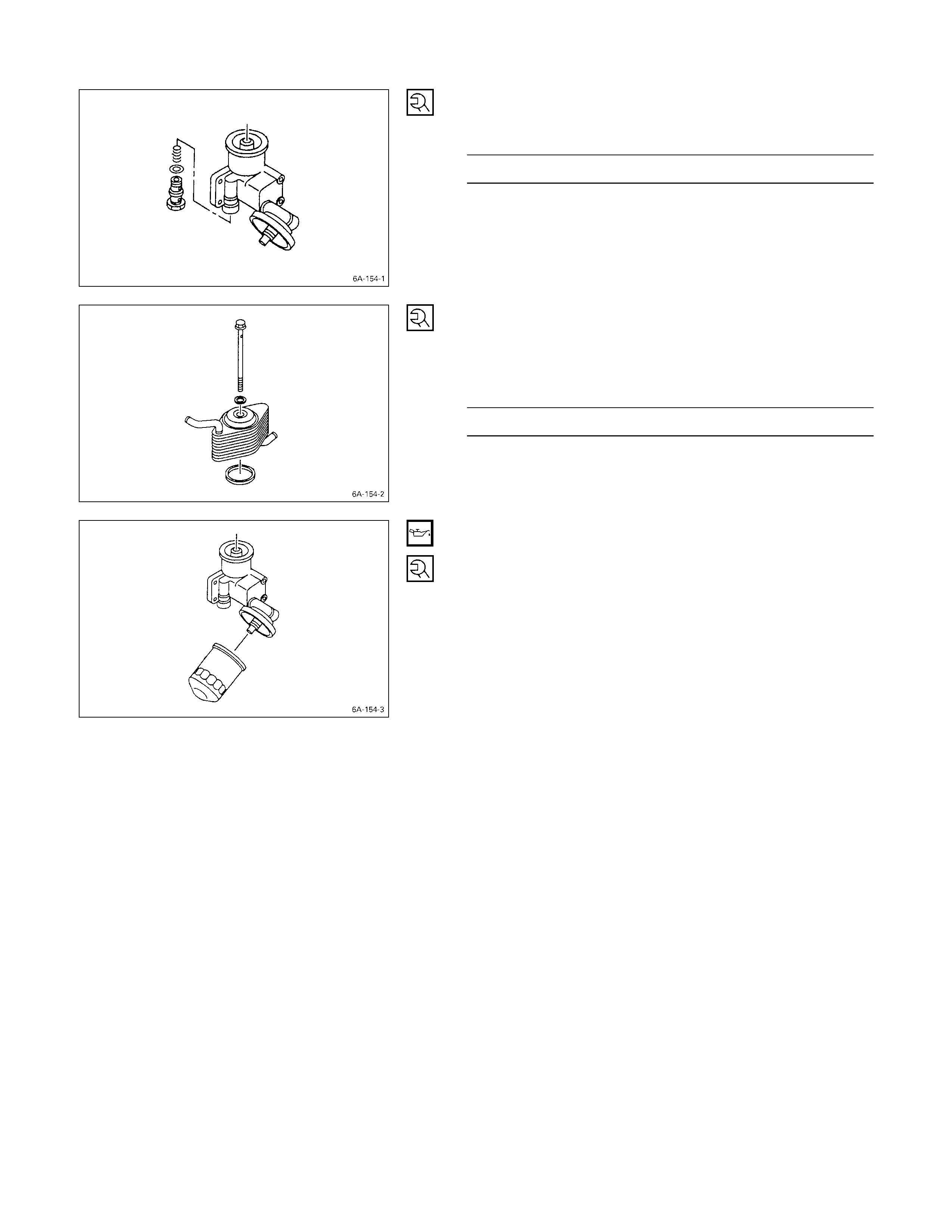
2. Relief Valve
Tighten the safety valve to the specified torque.
Safety Valve Torque kg·m (lb.ft/N·m)
0.3 ± 00.5 (4.3 ± 0.7/29.4 ± 4.9)
4. Oil Cooler
6. Bolt
Tighten Bolt with gaskets and oil cooler to the specified
torque.
Bolt Torque kg·m (lb.ft/N·m)
3.0 ± 0.5 (21.7 ± 3.6/29.4 ± 4.9)
7. Oil Filter Cartridge
1) Lightly oil the O-ring of oil filter cartridge.
2) Turn in the new oil filter cartridge by hand until the
sealing face is fitted again the O-ring.
3) Use the filter wrench to turn in the oil filter and
additional one and 1·1/8 turns.
4) Start the engine and check for oil leakage from oil
filter.