
SECTION 6G - PREHEAT & QOS
Pre-heating System
Inspection & Repair
QOS ll Preheating System
General Description
System Diagram
QOS II Timing Chart
Inspection On QOS II System Operation
QOS II System Troubleshooting
Engine Warming-Up System
General Description
Engine Warming-Up System Circuit
Type A
Type B
Troubleshooting
Quick Chart For Check Point
Inspection & Repair
Pre-Heating System
Inspection & Repair
Make the necessary adjustments, repairs, and part replacement if excessive wear or damage is discovered during
inspection.
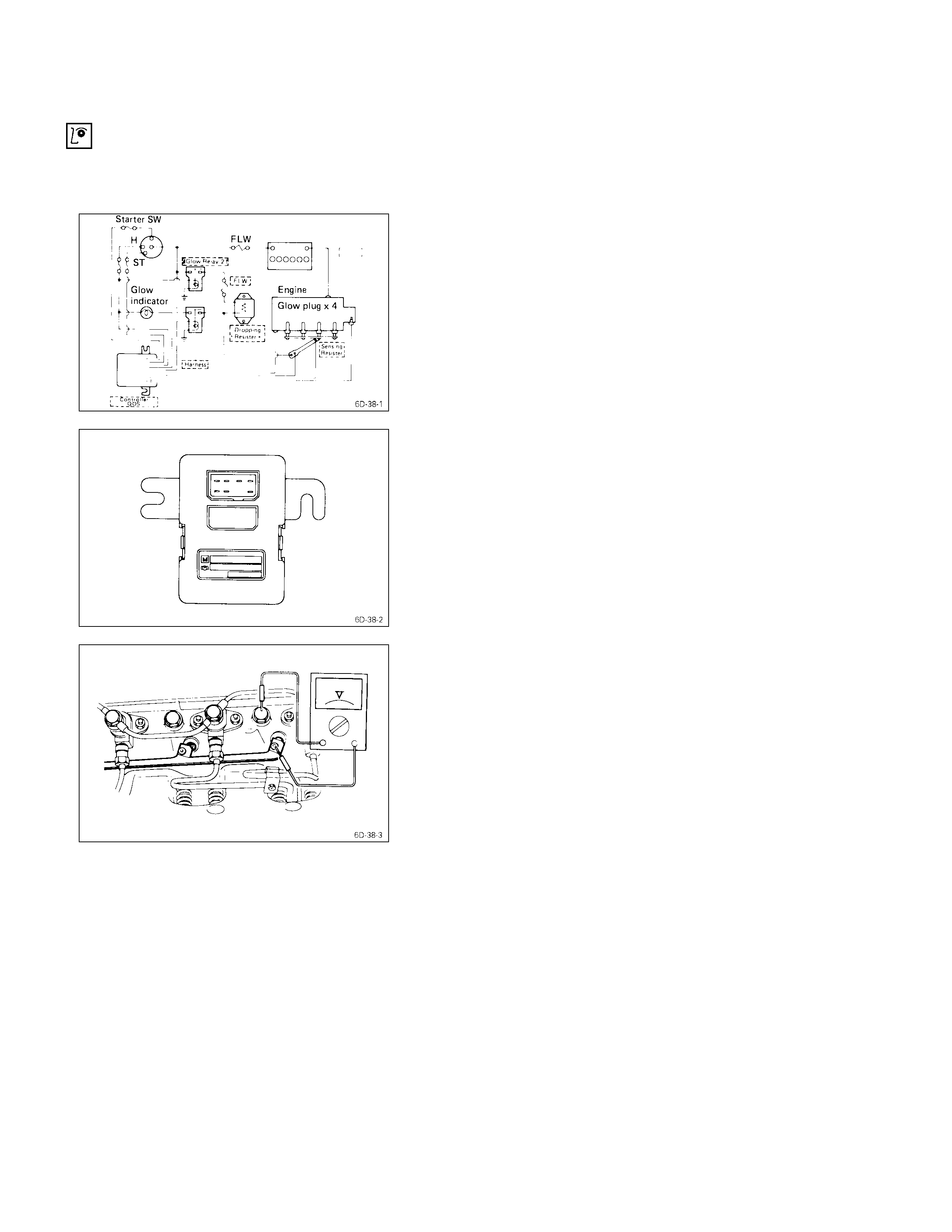
SYSTEM CIRCUIT
VISUAL CHECK
Check the main fuses and the glow indicator for damage.
Replace the part(s) if required.
GLOW TIMER
The glow timer is initially activated by the starter switch.
Thereafter, signals from the thermoswitch reach the glow
timer to control the glow plug relay operation time.
The thermoswitch and timer unit also act to protect the
battery in the event the starter key is engaged for an
excessively long time.
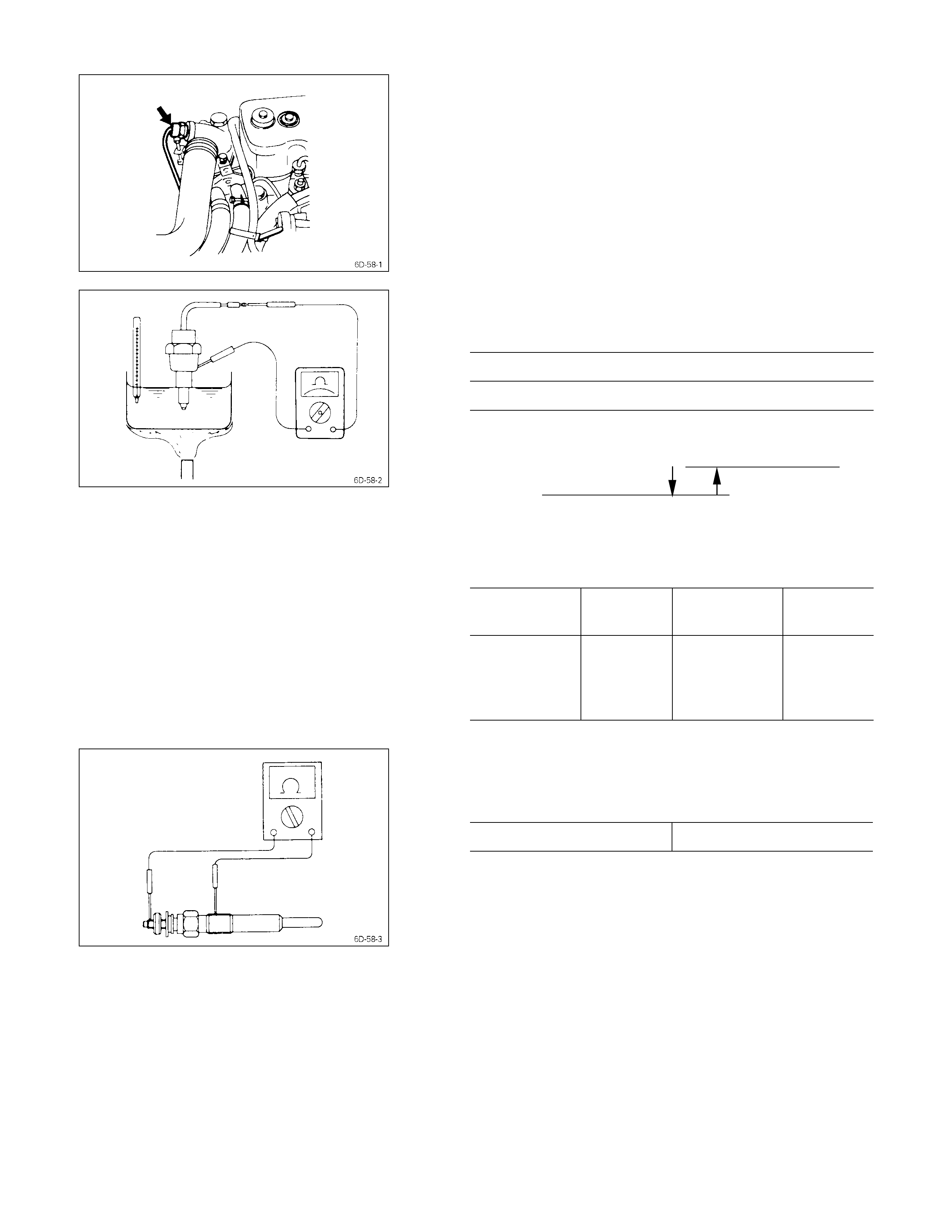
GLOW TIMER OPERATION
1. Disconnect the lead wires at the thermoswitch.
2. Connect a voltmeter between the glow plug and
ground.
3. Turn the starter switch from “OFF” to “ON”.
The engine must be stopped.
4. Note the time the glow indicator remains on.
If the glow indicator remains on for approximately 1~6
seconds (4JG2T Engine model) or 3.5 seconds (4JA1,
4JB1T Engine model), the glow timer “ON” time is
normal.
If the glow indicator does not remain on for
approximately 1~6 seconds or 3.5 seconds, trouble in
the glow timer or, the glow relay, is indicated.
5. Return the starter switch to “OFF”.
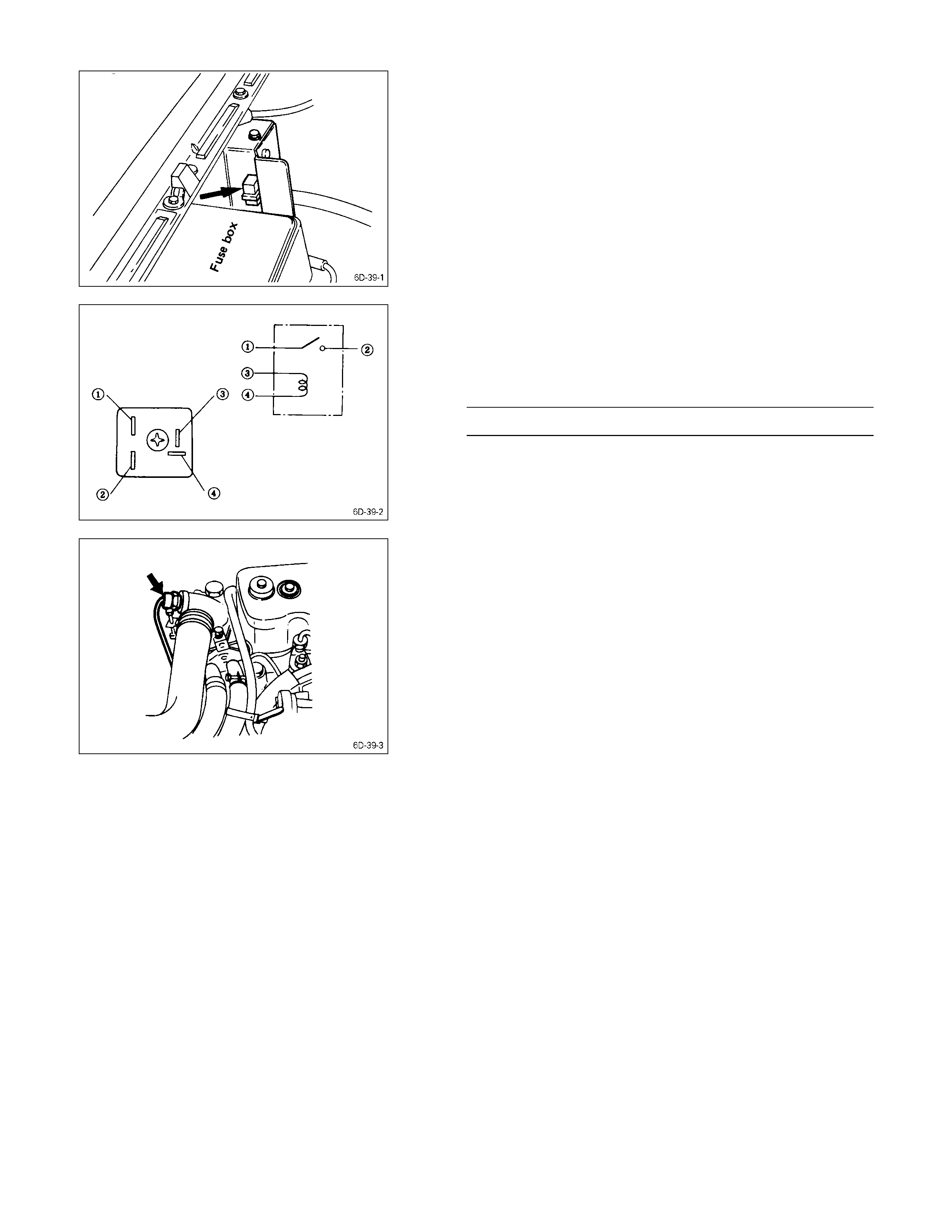
GLOW RELAY
The glow relay is located near the fuse box in the engine
compartment.
Use an ohmmeter to measure the resistance between
terminals No. 3 and No. 4.
If the measured value is outside the specified range, the
glow relay must be replaced.
Glow Relay Resistnace Ohms
10 - 15
THERMO SWI TCH/THERMO SENSOR
The thermo switch or thermo sensor are located on the
water outlet pipe.
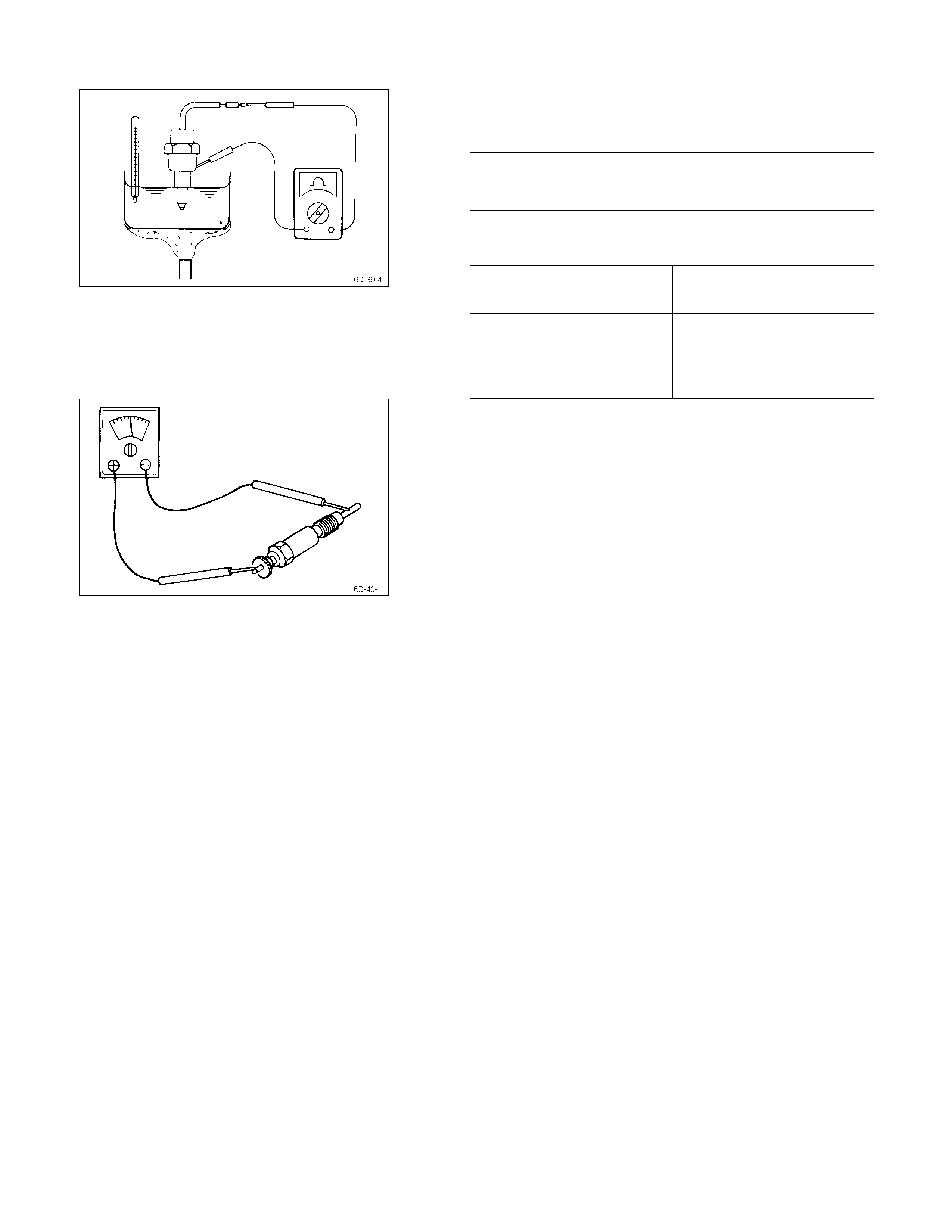
Use a circuit tester to check the thermo switch for
continuity.
•Thermo switch (4JA1, 4JB1T engine)
OFF →ON : 7 - 13°C (44.6 – 55.4°F)
ON →OFF : Below 3°C (37.4°F)
•Thermo sensor (4JG2T engine)
Thermo Sensor Resistance K-Ohm
Temperature
°C (°F) Resistance Temperature
°C (°F) Resistance
-15 (5)
0 (32)
10 (50)
20 (68)
12.00
6.00
3.60
2.45
40 (104)
60 (140)
80 (176)
1.10
0.60
0.30
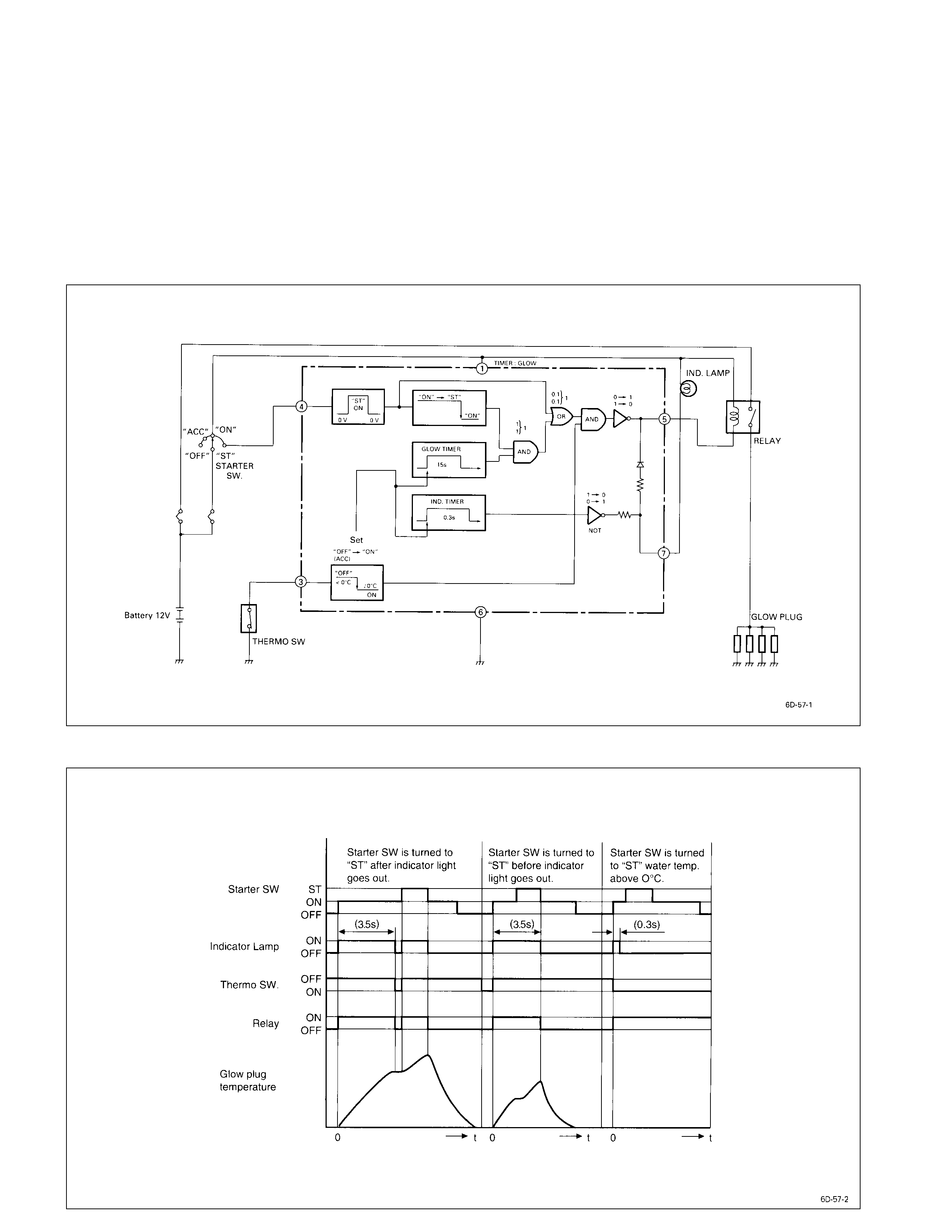
GLOW PLUG
Use a circuit tester to test the glow plugs for continuity.
Check each of the glow plugs for continuity.
QOS II Preheating System
General Description
QOS II preheating s ystem f eatur es a quick-on glow plug with therm ometer c ontr ol of the glowing time and the af ter glow
time function.
The system consists of a controller, indicator lamp, thermoswitch, relay, and glow plug (4pcs).
With the employment of the thermoswitch, the glow time changes according to the engine coolant temperature, thus
allowing optimum starting conditions to be obtained.
System Diagram
QOS II Timing Chart
Inspection on QOS II System Operation
THERMO SWITCH
The thermo switch is located on the water outlet pipe.
Use a circuit tester to check the thermo switch for
continuity.
Thermo sensor (4JA1, 4JA1T, 4JG2T engine)
OFF →ON : 7 - 13°C (44.6 – 55.4°F)
ON →OFF : Below 3°C (37.4°F)
10°CON
OFF 3°C
Thermo sensor (4JG2T engine)
Thermo Sensor Resistance K-Ohm
Temperature
°C (°F) Resistance Temperature
°C (°F) Resistance
-15 (5)
0 (32)
10 (50)
20 (68)
12.00
6.00
3.60
2.45
40 (104)
60 (140)
80 (176)
1.10
0.60
0.30
GLOW PLUG
Use a circuit tester to test the glow glugs for continuity.
Glow plug Resistance (Reference) Ohms
Quick on start model Approximately 0.9
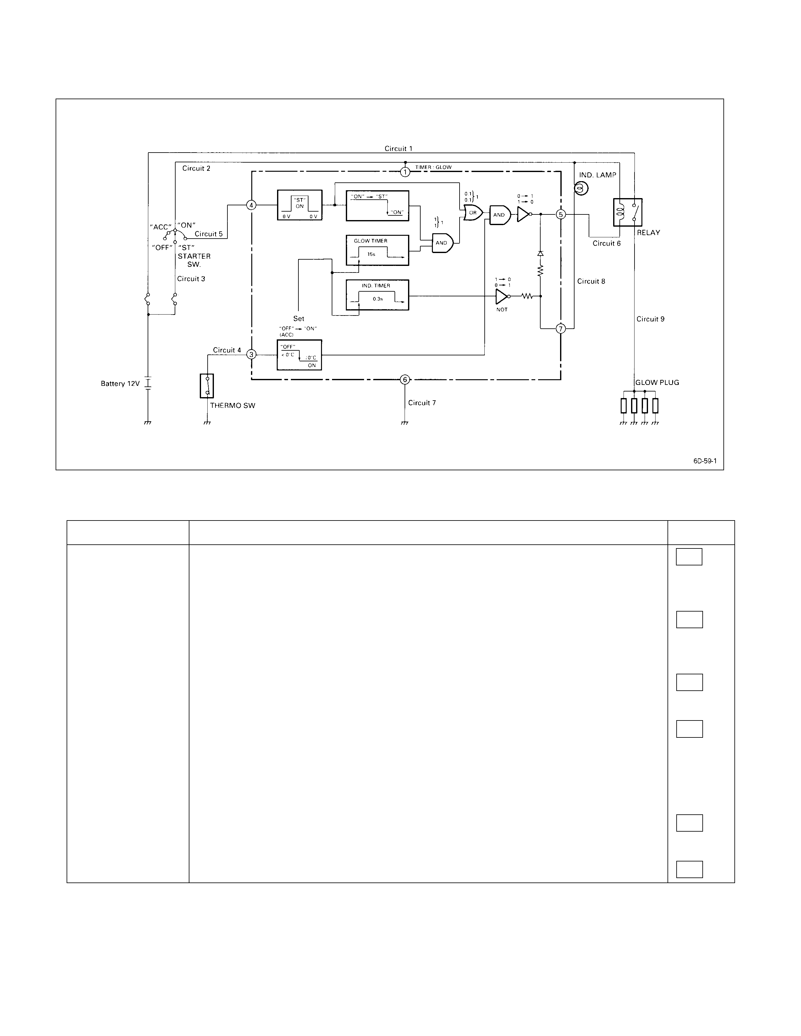
QOS II System Tr oubl eshooting
1) Problems when the water temperature of the engine is 0°C or below.
Condition Cause Circuit
Glow plug relay will
not be lit. Bad connection of FLW between battery and starter.
Bad connection or disconnection of starter SW circuit
Bad connection or disconnection Malfunction of other
of Fuse No . 8 circuits occurred
simultaneously.
Bad starter switch.
Bad connection of glow plug relay terminal.
Disconnection of glow plug relay excitation coil.
Disconnection of circuit between glow plug relay and timer.
Bad glow relay. (The main contact does not pass electricity.)
Bad connection of timer.
Bad timer.
Bad earth circuit of timer.
Bad thermoswitch. (It remains ON even in water temperature below 0°C.)
Earth short-circuiting of thermo SW.
3
2
1
6
7
7

Condition Cause Circuit
Through glow plug
relay turns ON,
preheating is not
done.
Bad connection of FLW between battery and glow relay.
Bad connection or disconnection in preheating circuit of glow relay main contact
terminal connector.
Bad connection between plug connector and preheating circuit
1
9
Glow plug relay
turns ON, but does
not go OFF.
Bad timer.
Bad timer. Short circuiting in circuit or earth between 5 terminal and glow relay.
Bad glow relay.
6
Indication lamp is
not lit. Bad timer.
Burning-out of light bulb. 8
Note: Circui t No. in rectangle is shown in the previous pre-heati ng chart .
2) Problems when the time water temperature of the engine is 0°C or above.
Condition Cause Circuit
Indicator lamp is
not lit Bad timer
Burning-out of bulb. 8
Turn glow relay
ON. Bad thermoswitch or disconnection of thermo SW circuit.
(Indicator will light up for 3.5 seconds.)
Bad timer.
Bad timer. Short-circuiting in circuit or earth between terminal 5 and glow relay.
4
Note: Circui t No. in rectangle is shown in the previous pre-heati ng chart .
3) Burning-out of glow plug
When only one line is burned out, it has no effect on the start up of the engine. Even if one line is burned out,
judging from the characteristics of the glow plug, the impressed voltage will change only slightly. Therefore, no
judgment can be made by normal testing while the glow plug is installed. In order to check for disconnections and
burn-outs, the glow plugs will have to be removed from the connectors and checked one by one for continuity.

Engine Warmi ng-Up System
General Description
The engine warm-up system is a device which changes the openning of the throttle valve for intake in accordance with
the engine rpm, controls the amount of the intake air, and changes the air ratio which is supplied to the cylinder. The
device is also provided with such functions as to measure the amount of heat capacity, to close the exhaust throttle
valve to raise the exhaust pressure, and to accelerate the rise in compression and temperature, and the increase of
fuel.
Operation of each device when warming-up switch is ON position.
Vacuum switching valve
Temp. sw.
Ambient sw.
Half sw. (only 4JA1)
Accel
sw. 1 2 FICD. EXH.
valve Intake
valve FICD
One of above sw. OFF - OFF OFF OFF Open Open NOT
Working
OFF ON OFF ON Full Close Close Working
All of above sw. ON ON ON ON ON Half Close Close Working
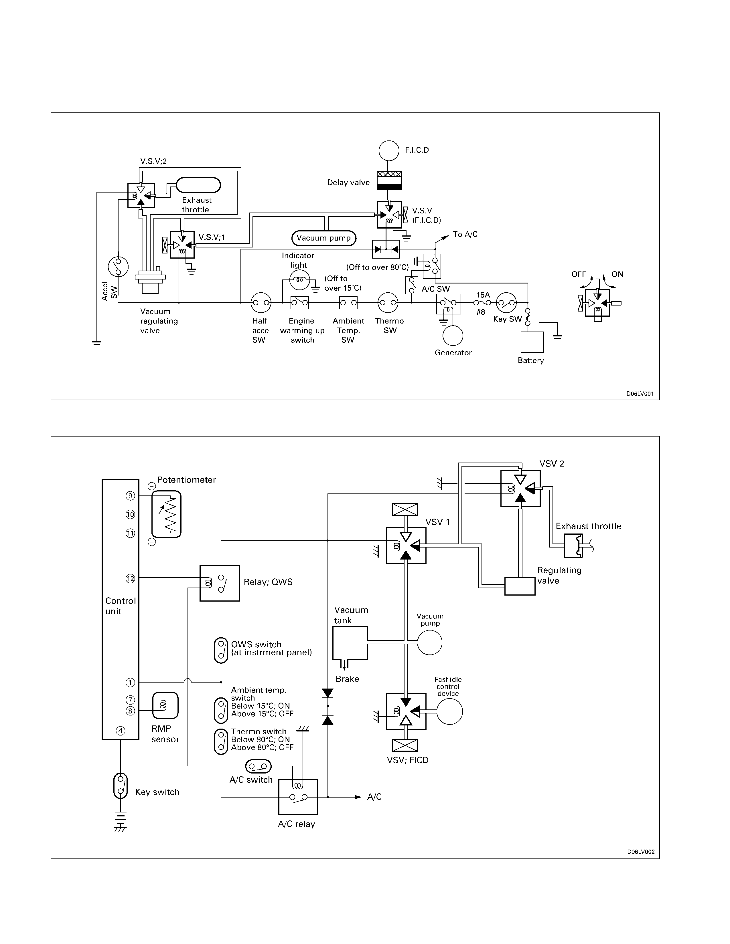
Engine Warming-Up System Circuit
Type A
Type B
Troubleshooting
Quick Chart For Check Point
ENGINE WARMING-UP
When this system is out of order, checking as follows.
Switch VSV ThrottleChecking parts
Trouble mode Engine
warming up Thermo Ambient
temperature Accel Half Accel
(only 4JA1)
ENG. Warming
up Indicat or 12
FICD INT EXH Cable
harness
The indicat or li ght does not
light when switch is ON
position.
¡¡¡ ¡
The system does not operate ¡ ¡ ¡ ¡ ¡ ¡¡¡¡¡ ¡
Abbreviation
V.S.V. ; Vacuum switching valve
FICD ; Fast idle control device
INT ; Intake
EX ; Exhaust
Inspection & Repair
Make necessary correction or parts replacement if wear,
damage or any other abnormal conditions are found
through inspection.
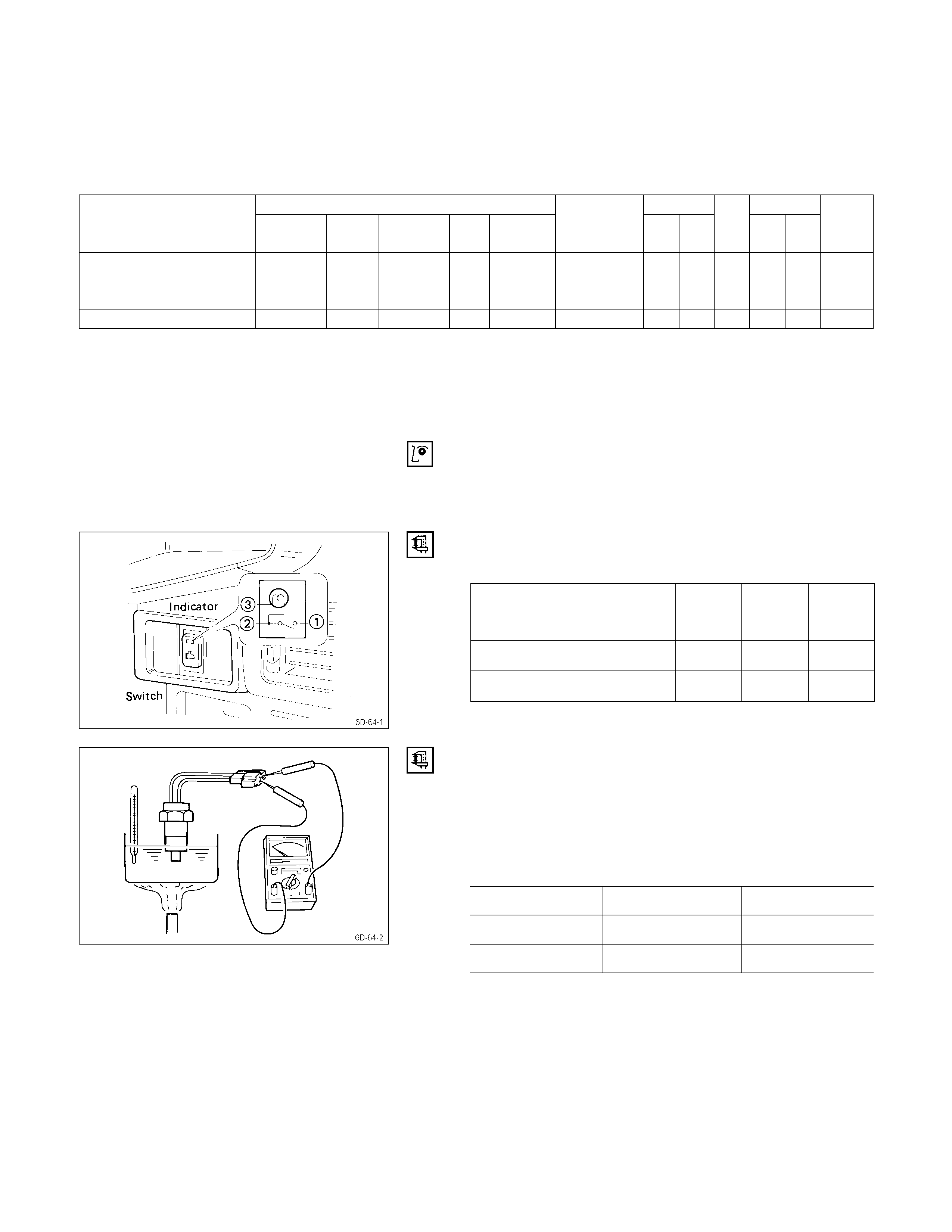
ENGINE WARMING UP SWITCH
1. Inspect the switch continuity by following table.
Terminal
SW position
ON ¡¡¡
OFF ¡¡
2. Make sure the indicator light turns on, when the engine
warming up switch is “ON” with engine running.
THERMO SWITCH/AMBIENT TEMP. SWITCH
1. Submerge end of switch in water.
2. Connect circuit tester to the connector terminals.
3. Use a burner to heat the water.
4. Check the continuity test across.
Operating temperature
Thermo Ambient temp.
OFF → ON 73°C or less 8°C or less
ON → OFF About 80°C About 15°C
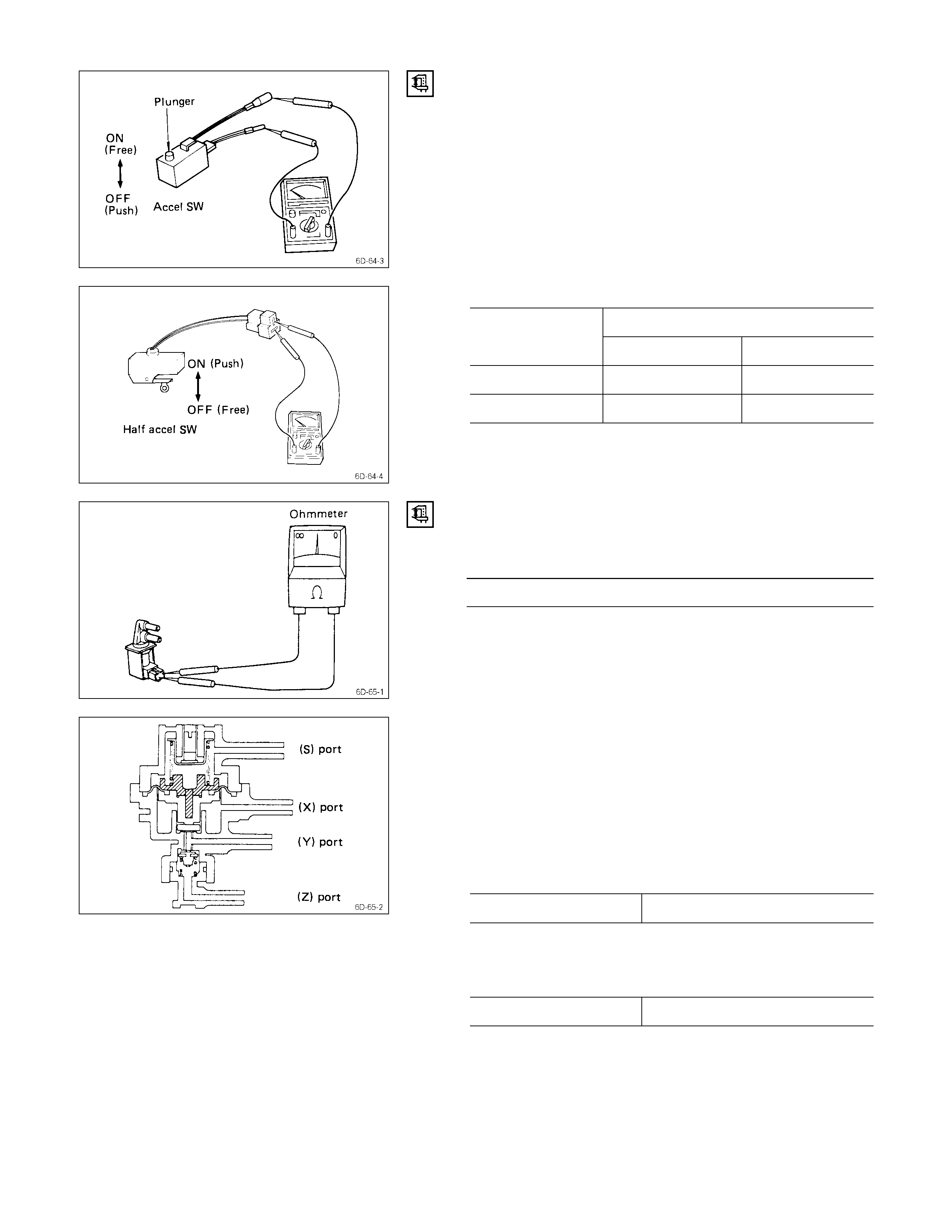
ACCEL SWI TCH
Half accel switch (only 4JA1T)
1. Connect a circuit tester to the connector terminals.
2. Check the Continuity test across.
Operating
Position
Free Push
Accel switch Continuity Not continuity
Half accel switch Not continuity Continuity
VACUUM SW ITCH VALVE (VSV)
Use a circuit tester to measure the V.S.V. resistance.
V.S.V. Resistance at 20°C
Approx. 40Ω
If the resistance is not within specification replace it.
VACUUM CO NTROL VALVE
Check the control valve operating pressure.
1. Make sure that port (X) is open to the atmosphere (no
obstructions).
2. Apply a constant pressure of − 500 mmHg to port (Z).
3. Apply a pressure of − 155 mmHg to port (S).
Measure the valve operating pressure at port (Y).
Valve Operating Pressure mmHg
Standard reading 0 to − 100
4. Apply a pressure of − 75 mmHg to port (S).
Measure the valve operating pressure at port (Y).
Valve Operating Pressure mmHg
Standard reading − 400 to − 500
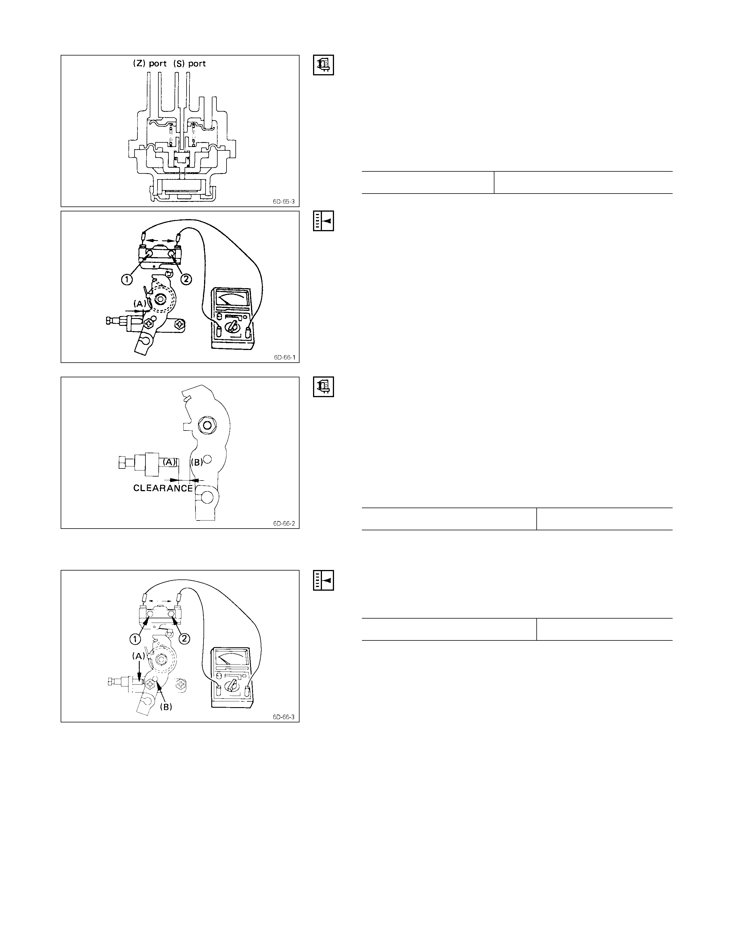
VACUUM REG ULATOR VALVE
Check the vacuum regulator valve operating pressure.
1. Apply a pressure of − 450 mmHg (− 17.7 Hg) to port
(S).
Measure the regulator pressure at port (Z).
Regulator Operating Pressure mmHg (Hg)
Standard reading − 235 to − 265 (− 9.3 to − 10.4)
HALF ACCEL. SW ITCH ADJUSTMENT (ONLY 4JA1T)
1. Insert a feeler gauge of 6 mm thickness between the
idle adjust screw end and control lever (A).
2. Loosen each bolts ( & ).
3. Set the circuit tester to micro-switch harness.
4. Find out the just continuity from OFF to ON position
with moving the micro-switch in the direction of the
arrow.
5. Tigten each bolts ( & ).
HALF ACCEL. SWITCH (ON THE VEHICLE)
Inspection
1. Connect a circuit tester to the half accel. switch
connector terminals.
2. Operate control lever slowly to a point where continuity
is switched over from “ON” to “OFF”. Then measure
the clearance between the idle stopper bolt (A) and
control lever (B).
Standard clearance mm (in) 5.0 - 7.8 (0.2 - 0.3)
If the clearance is out of the range, the switch must be
adjusted.
Adjustment
1. Insert a feeler gauge of specified thickness between
the idle stopper bolt (A) and control lever (B).
Adjustment clearance mm (in) 5.0 (0.2)
2. Loosen two switch bolts.
3. Connect a circuit tester to the switch connector
terminals.
4. Moving the switch in directions indicated by arrows.
Check to make sure of the point where continuity is
cut.
5. Tighten the two bolts & .