
SECTION 7B1 - MANUAL TRANSMISSION -
4X4 (MUA5C & TRANSFER CASE)
4 X 4 MODEL TRANSMISSION MUA5C
MAIN DATA AND SPECIFICATIONS
GENERAL DESCRIPTION
TORQUE SPECIFICATIONS
STANDARD BOLTS
FLARE NUTS
SPECIAL PARTS FIXING NUTS AND BOLTS
RECOMMENDED LIQUID GASKET
REMOVAL AND INSTALLATION
DISASSEMBLY
EXTERAL COMPONENTS
MAJ OR COMPONENTS
TRANSFER CASE
TRANSMISSION
MINOR COMPONENT
TRANSFER REAR CASE ASSEMBLY
DETENT, SHIFT ARM ASSEMBLY AND INTERLOCK PIN
TRANSFER CASE ASSEMBLY AND MAINSHAFT GEAR
INTERMEDIATE PLATE AND GEAR ASSEMBLY, DETENT, SHIFT ARM ASSEMBLY,
AND INTERLOCK PIN
REVERSE GEAR AND 5TH GEAR
TOP GEAR SHAFT, MAIN GEAR SHAFT, AND COUNTER GEAR
INSPECTION AND REPAIR
REASSEMBLY
MAJ OR COMPONENT
TRANSMISSION
TRANSFER CASE
MINOR COMPONENT
TOP GEAR SHAFT, MAIN SHAFT GEAR AND COUNTER GEAR
REVERSE GEAR AND 5TH GEAR
INTERMEDIATE PLATE AND GEAR ASSEMBLY, DETENT, SHIFT ARM ASSEMBLY
AND INTERLOCK PIN
TRANSFER CASE ASSEMBLY
DETENT, SHIFT ARM ASSEMBLY AND INTERLOCK PIN
TRANSFER REAR CASE ASSEMBLY
EXTERNAL COMPONENTS

4 ×
××
× 4 MODEL TRANSMISSION MUA5C
MAIN DATA AND SPECIFICATIONS
Transmission type Fully synchronized 5-forward and reverse gears.
Transfer case type Constant mesh type Low-High and 2H-4H gears.
Gear ratio :Transmission 1st
2nd
3rd
4th
5th
Rev.
3.767
2.248
1.404
1.000
0.809
3.873
Transfer Case High
Low 1.000
2.050
Oil capacity : Transmission lit (US gal.)
: Transfer Case lit (US gal.) 2.95(0.78)
1.45(0.38)
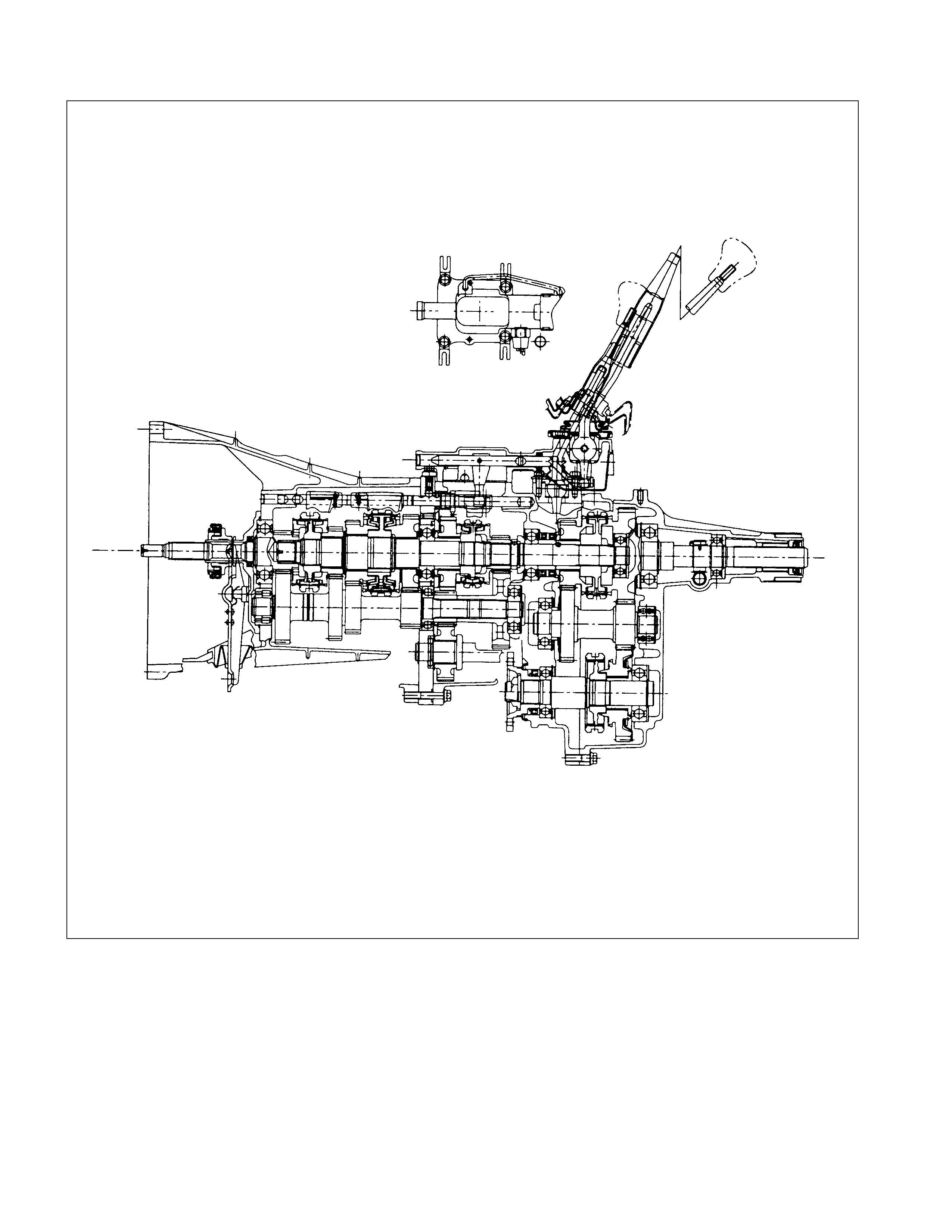
GENERAL DESCRIPTION
Principle parts of the transmission are the integral clutch housing, the intermediate plate, the rear cover, and the gears.
The gear control box is built-in to the transfer case.
Transfer gear ratio is 1: 2.050.
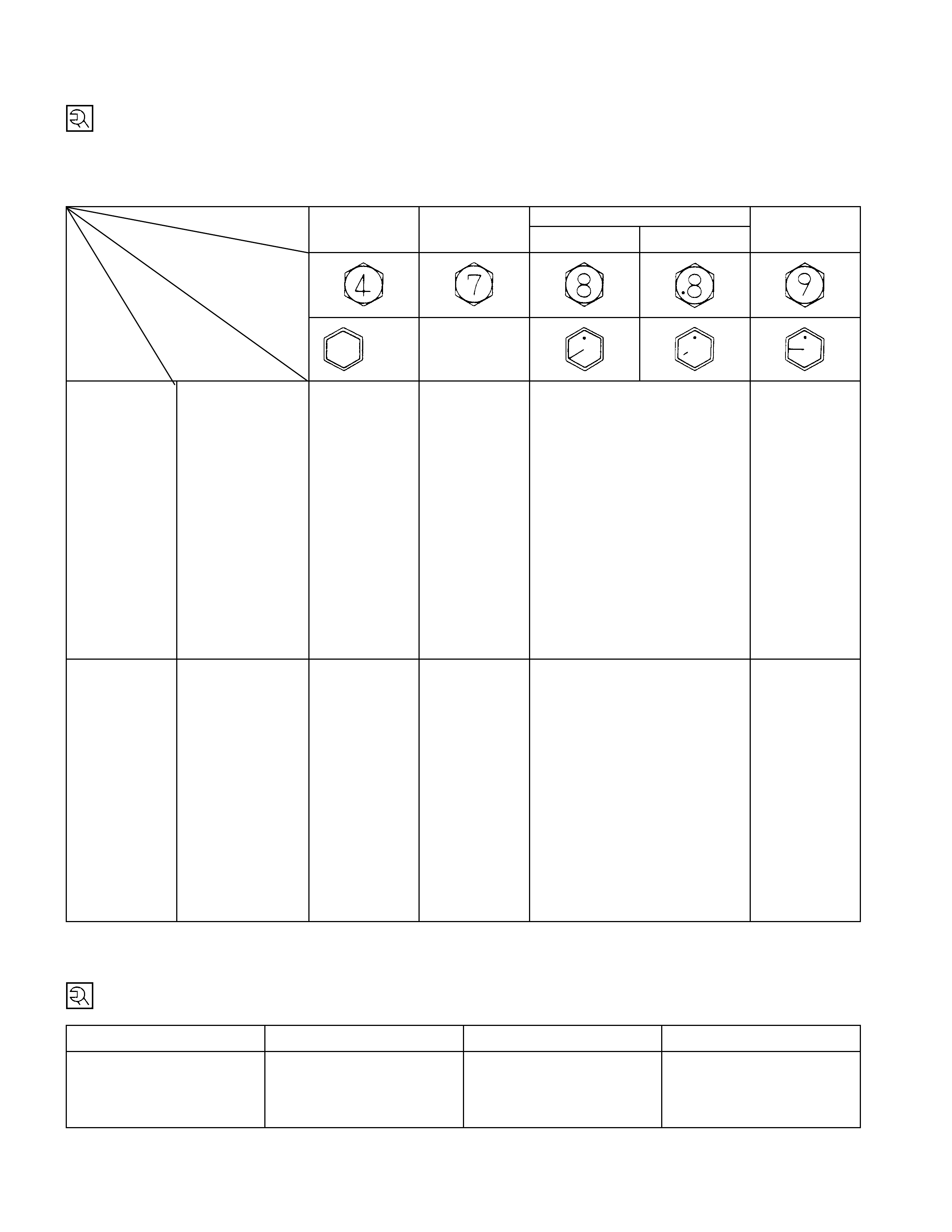
TORQUE SPECIFICATIONS
STANDARD BOLTS
The torque values given in the following table should be applied where a particular torque is not specified.
N⋅m (kgf⋅m/lb⋅ft)
Strength 4.8/4T 7T 8.8 9.8/9T
Class Refined Non-Refined
Bolt Identifi-
cation
Bolt
Diameter×
××
×
Pitch (mm) No mark -
M6 × 1. 0 6 (0. 6 / 52 lb.in) 7 (0.7 / 61 lb. i n) 8 (0.8 / 69 lb. i n) -
M8 × 1. 25 13 (1.3 / 113
lb.in) 17 (1.7 / 12) 20 (2.0 / 14) 24 (2.4 / 17)
M10 × 1.25 27 (2.8 / 20) 37 (3.8 / 27) 42 (4.3 / 31) 50 (5.1 / 37)
M12 × 1.25 61 (6.3 / 45) 76 (7.8 / 56) 87 (8.9 / 64) 95 (9.7 / 70)
M14 ×1.5 96 (9.8 / 71) 116 (11.8 / 85) 133 (13.6 / 98) 142 (14.5 / 105)
M16 × 1.5 130 (13.3 / 96) 170 (17.3 / 125) 193 (19.7 / 143) 200 (20.4 / 148)
M18 × 1.5 188 (19.2 / 139) 244 (24.9 / 180) 278 (28.3 / 205) 287 (29.3 / 212)
M20 × 1.5 258 (26.3 / 190) 337 (34.4 / 249) 385 (39.3 / 284) 396 (40.4 / 292)
M22 × 1.5 332 (33.9 / 245) 453 (46.3 / 335) 517 (52.7 / 381) 530 (54.1 / 391)
M24 × 2.0 449 (45.8 / 331) 570 (58.2 / 421) 651 (66.3 / 480) 692 (70.6 / 511)
*M10 × 1.5 26 (2.7 / 20) 36 (3.7 / 27) 41 (4.2 / 30) 48 (4.9 / 35)
*M12 × 1.75 57 (5.8 / 42) 71 (7.2 / 52) 80 (8.2 / 59) 89 (9.1 / 66)
*M14 × 2.0 89 (9.1 / 66) 110 (11.2 / 81) 125 (12.7 / 92) 133 (13.6 / 98)
*M16 × 2.0 124 (12.7 / 92) 162 (16.5 / 119) 185 (18.9 / 137) 191 (19.5 / 141)
Flange Bolt M6 × 1. 0 7 (0. 7 / 61 lb.in) 8 (0.8 / 69 lb. i n) 9 (0.9 / 78 lb. i n) -
M8 × 1. 25 15 (1. 5 / 11) 19 (1.9 / 14) 22 (2.2 / 16) 26 (2. 7 / 20)
M10 × 1.25 31 (3.2 / 23) 41 (4.2 / 30) 47 (4.8 / 35) 56 (5.7 / 41)
M12 × 1.25 69 (7.0 / 51) 85 (8.7 / 63) 97 (9.9 / 72) 106 (10.8 / 78)
M14 × 1.5 104 (10.6 / 77) 126 (12.8 / 93) 144 (14.6 / 106) 154 (15.7 / 114)
M16 × 1.5 145 (14.8 / 127) 188 (19.2 / 139) 214 (21.8 / 158) 221 (22.5 / 163)
M18 × 1.5 - - - -
M20 × 1.5 - - - -
M22 × 1.5 - - - -
M24 × 2.0 - - - -
*M10 × 1.5 30 (3.1 / 22) 40 (4.1 / 30) 46 (4.7 / 34) 54 (5.5 / 40)
*M12 × 1.75 64 (6.5 / 47) 78 (8.0 / 58) 89 (9.1 / 66) 99 (10.1 / 73)
*M14 × 2.0 97 (9.9 / 72) 119 (12.1 / 88) 135 (13.8 / 99.7) 144 (14.7 / 107)
*M16 × 2.0 137 (14.0 / 101) 178 (18.2 / 132) 203 (20.7 / 150) 210 (21.5 / 155)
The asterisk * indicates that the bolts are used for female-threaded parts that are made of soft materials such as
casting, etc.
FLARE NUTS
Pipe diameter mm (in) Torque N⋅
⋅⋅⋅m (kgf⋅
⋅⋅⋅m / lb⋅
⋅⋅⋅ft) Pipe diameter mm (in) Torque N⋅
⋅⋅⋅m (kgf⋅
⋅⋅⋅m / lb⋅
⋅⋅⋅ft)
4.76 (0.187) 16 (1.6 / 12) 10.00 (0.394) 54 (5.5 / 40)
6.35 (0.250) 26 (2.7 / 20) 12.00 (0.472) 88 (9.0 / 65)
8.00 (0.315) 44 (4.5 / 33) 15.00 (0.591) 106 (10.8 / 78)
Standard Hex.
Head Bolt
SPECIAL PARTS FIXI NG NUTS AND BO LTS
N⋅m (kgf⋅m/lb⋅ft)
39 (4/29)
39±10 (4.0±1.0/29±7) 39 (4/29)
127±10
(13±1/94±7)
18.6 (1.9/13.7) 39 (4/29)
39±10
(4.0±1.0/29±7) 39±10
(4.0±1.0/29±7)
137±20
(14±2/101±14.4)
15 (1.5/11)
137±20
(14±2/101±14.4)
RECOMMENDED LIQUID GASKET
Type Brand Name Manufacturer Remarks
ThreeBond 1207B Three Bond
RTV* ThreeBond 1207C Three Bond
Silicon Base ThreeBond 1215 Three Bond For Axle Case and
ThreeBond 1281 Three Bond Transmission Repairs
Water Base ThreeBond 1141E Three Bond For Engine Repairs
ThreeBond 1104 Three Bond
BelcoBond 4 Isuzu
BelcoBond 401 Isuzu
BelcoBond 402 Isuzu
LOCTITE 515 Loctite
LOCTITE 518 Loctite
*RTV: Room Temperature Vulcanizer
Note:
1. It is very important that the liquid gaskets listed above or their exact equivalent is used on the vehicle.
2. Be careful to use the specified amount of liquid gasket.
Follow the manufacturer's instructions at all times.
3. Be absolutely sure to remove all lubricants and moisture from the connecting surfaces before applying the
liquid gasket.
The connecting surfaces must be perfectly dry.
4. LOCTITE 515 and LOCTITE 518 harden upon contact with a metal surface.
Do not apply LOCTITE 515 or LOCTIT E 518 between tw o metal surfaces having a clearance of greater than
0.25 mm (0.01 in). Poor adhesion will result.
For Engine Repairs
For Engine Repairs
Solvent
AllAnerobic
REMOVAL AND INSTALLATION
Read this Section carefully before performing any removal and installation procedure. This Section gives you important
points as well as the order of operation. Be sure that you understand everything in this Section before you begin.
IMPO RTANT OPERATIONS-REMOVAL
Battery Cable
Disconnect the negative (-) cable from the battery terminal.
Engine Hood
Apply setting marks to the engine hood and the engine hood
hinges before removing the engine hood.
Gear Shift Lever and Transfer Change Lever
1. Place the gearshift lever in the neutral position.
2. Place the transfer change lever in the "H" position.
3. Removes the gearshift lever knob and transfer change leve
r
knob.
4. Remove the center console assembly and front console
assembly.
5. Remove the grommet and dust cover.
6. Remove the gearshift lever cover bolt.
7. Remove the gearshift lever.
8. Remove the transfer change lever retainer bolts.
9. Remove the transfer change lever and O-ring.
Note:
Cover the shift lever and change lever holes to prevent the
entry of foreign material into the transmission.
Lifting the Vehicle
1. Jack up the vehicle.
2. Place chassis stands at the front and the rear of the vehicle.
Transfer Case Protector
Remove the transfer case protector from the transmission
mounting member and the side member.
Transmission and Transfer Case Oil Draining
1. Remove the transmission oil drain plug 1.
2. Remove the transfer case oil drain plug 2,
3. Replace the drain plug(s) after draining the oil.
Exhaus t Pipe
1. Remove the front exhaust pipe.
Rear Propeller Sha ft (Single Shaft Type)
1. Remove the propeller shaft flange yoke at the drive pinion
side 1.
2. Remove the propeller shaft from the transmission main
shaft spline 2.
Rear Propeller Shaft (Dual Shaft Type)
1. Apply setting marks to the 2nd propeller shaft flange yoke.
This will prevent misaligning during the installation procedure.
2. Remove the 2nd propeller shaft flange yoke bolts at the
drive pinion side 1.
3. Remove the center bearing retainer bolts 2.
4. Remove the 1st propeller shaft 3 with the center bearing
and the 2nd propeller shaft.
Pull the 1st propeller shaft toward the rear of the vehicle
until the spline yoke is free of the transmission main shaft.
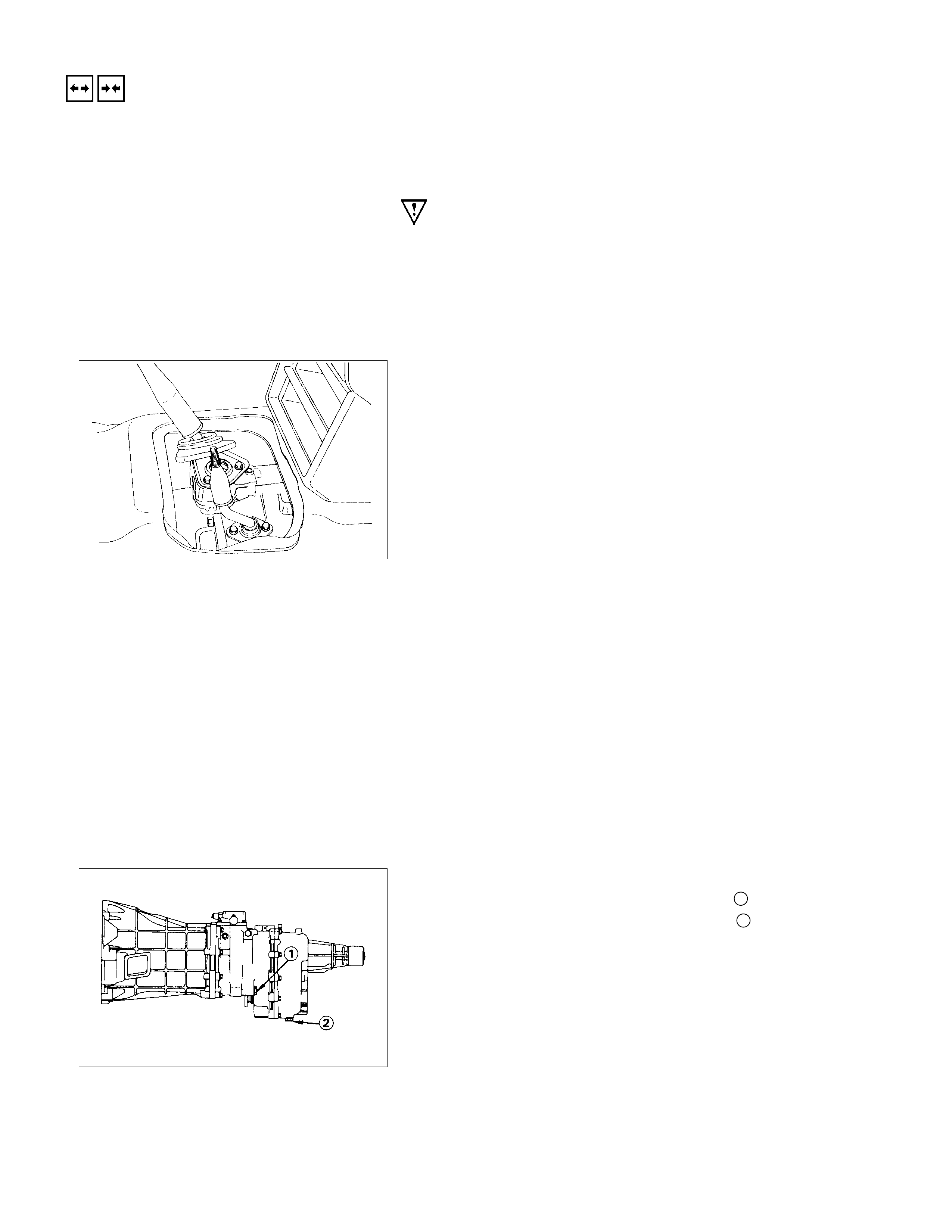
Front Propeller Shaft
Remove the splined yoke flange bolt at the transfer case side.
Do not allow the splined yoke to fall away from the front
propeller shaft.
IMPORTANT:
Apply setting marks to the splined yoke and the front propeller
shaft before removing the front propeller shaft.
If the splined yoke should fall away from the front propeller
shaft, align the setting marks 3 on the splined yoke 1 and the
propeller shaft 2 to reassemble the two parts.
Harness Connector
Disconnect the 4WD switch connectors, back up light switch
connector and the speedometer sensor connector.
Slave Cylinder
Remove the slave cylinder from the transmission case.
Engine Lifting Hanger
1. Attach the engine-lifting hanger to the front portion of the
engine.
2. Attach the lifting wire to both ends of the engine-lifting
hanger.
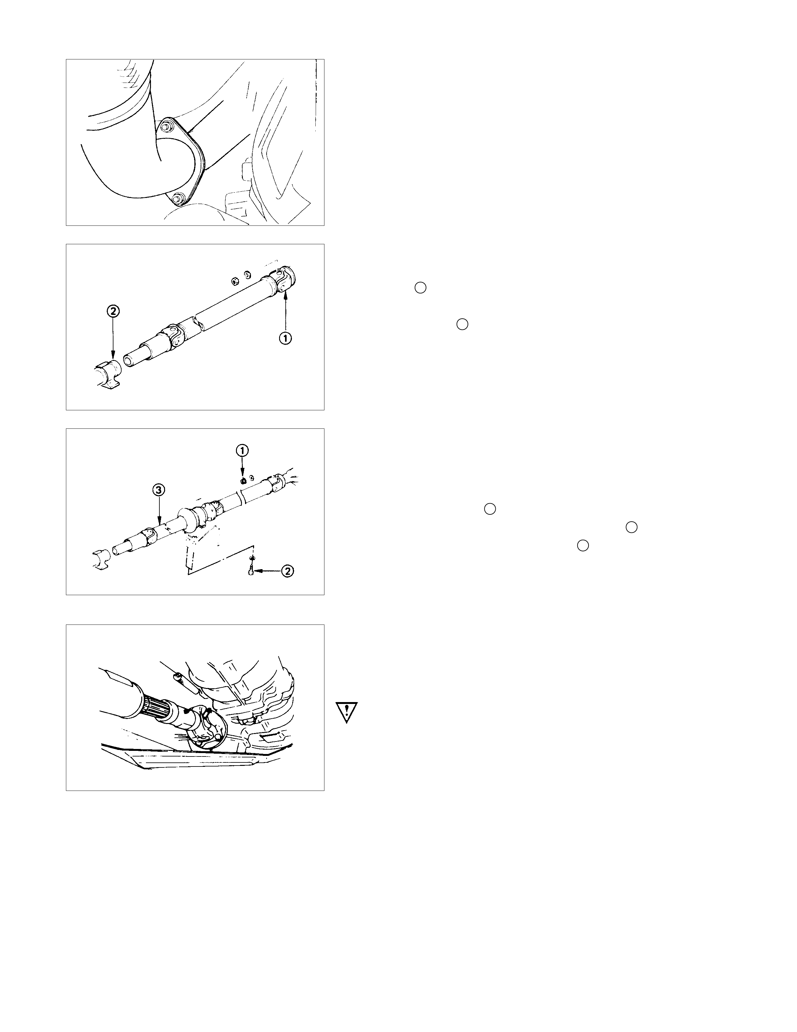
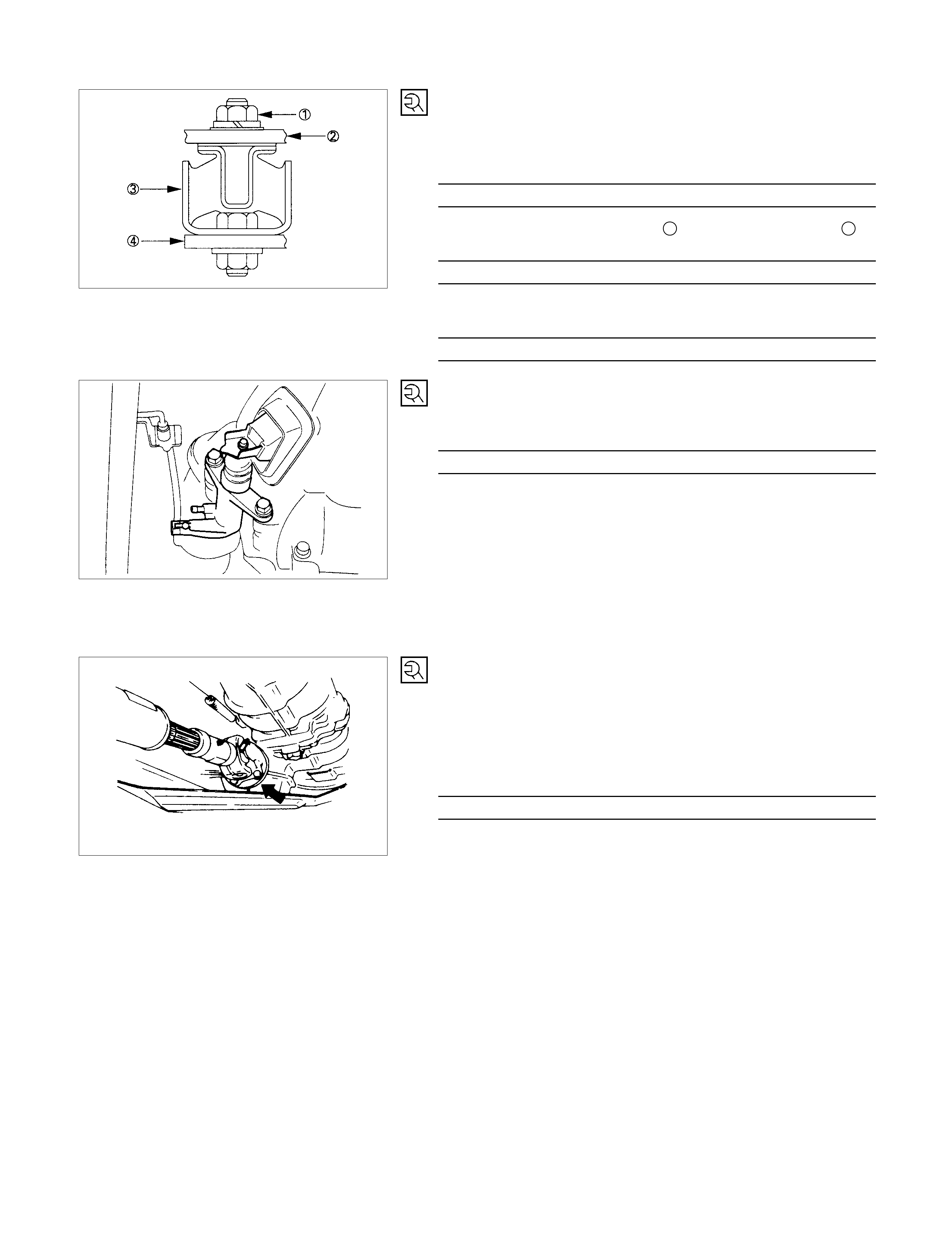
ENGINE REAR MOUNTING AND CROSSMEMBER
1. Support the transmission with a transmission jack.
2. Remove No.2 crossmember.
3. Remove the engine rear mounting nuts from No.3
crossmember 3.
4. Remove the engine rear mounting bolts from the
transmission 1.
5. Remove No.3 crossmember and bolts 3 from the side
frame.
6. Remove the engine rear mounting 2.
STARTER M OTOR
Remove the starter motor from the engine rear plate.
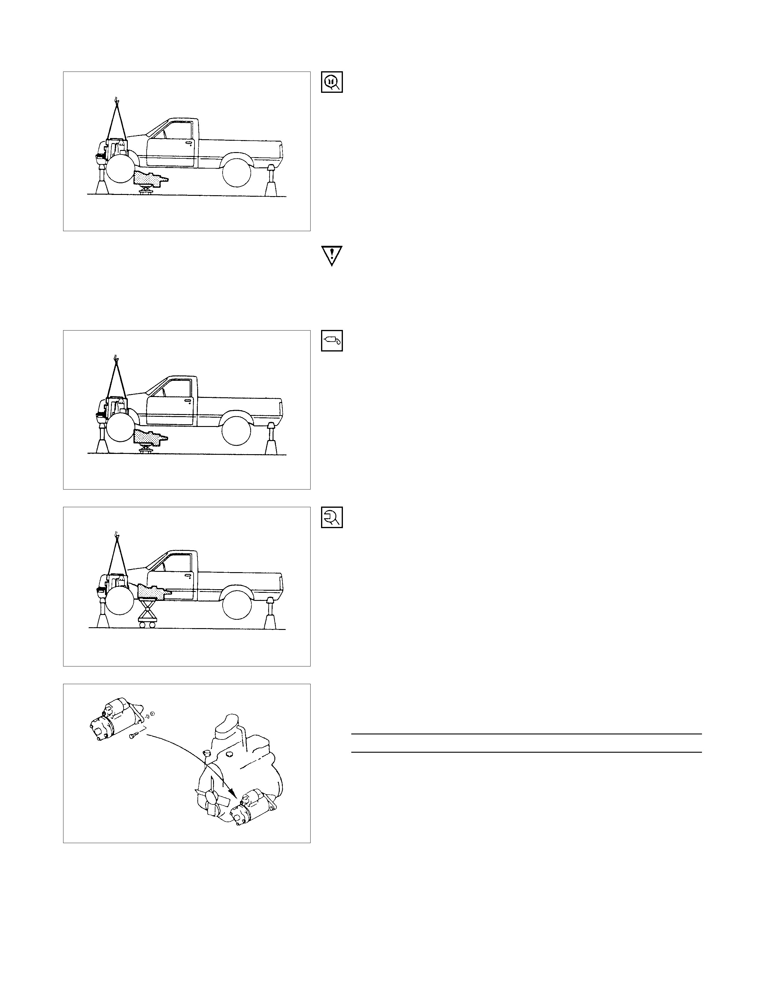
TRANSMISSION WI TH TRANSFER
1. Remove the transmission nuts and bolts from the engine
rear plate.
2. Carefully pull the transmission with the transmission jack
toward the rear of the vehicle.
3. Operate the transmission jack to slowly lower the
transmission.
IMPORTANT OPERATIONS - INSTALLATION
Follow the removal procedure in the reverse order to perform
the installation procedure. Pay careful attention to the
important points during the installation procedure.
TRANSMISSION WI TH TRANSFER
1. Apply a thin coat of m olybdenum disulf ide grease to the top
gear shaft spline.
2. Place the transmission on a transmission jack.
3. Carefully move the transmission jack and transmission into
position behind the engine.
4. Slowly raise the transmission jack until the front of the
transmission is aligned with the rear of the engine.
The slope of the engine and the transmission must be the
same.
Starter Motor
1. Install the starter motor to the engine rear plate.
Starter Motor Bolt Torque N⋅m (kgf⋅m/lb⋅ft)
78 ± 16 (8.0 ± 1.6/58 ± 12)
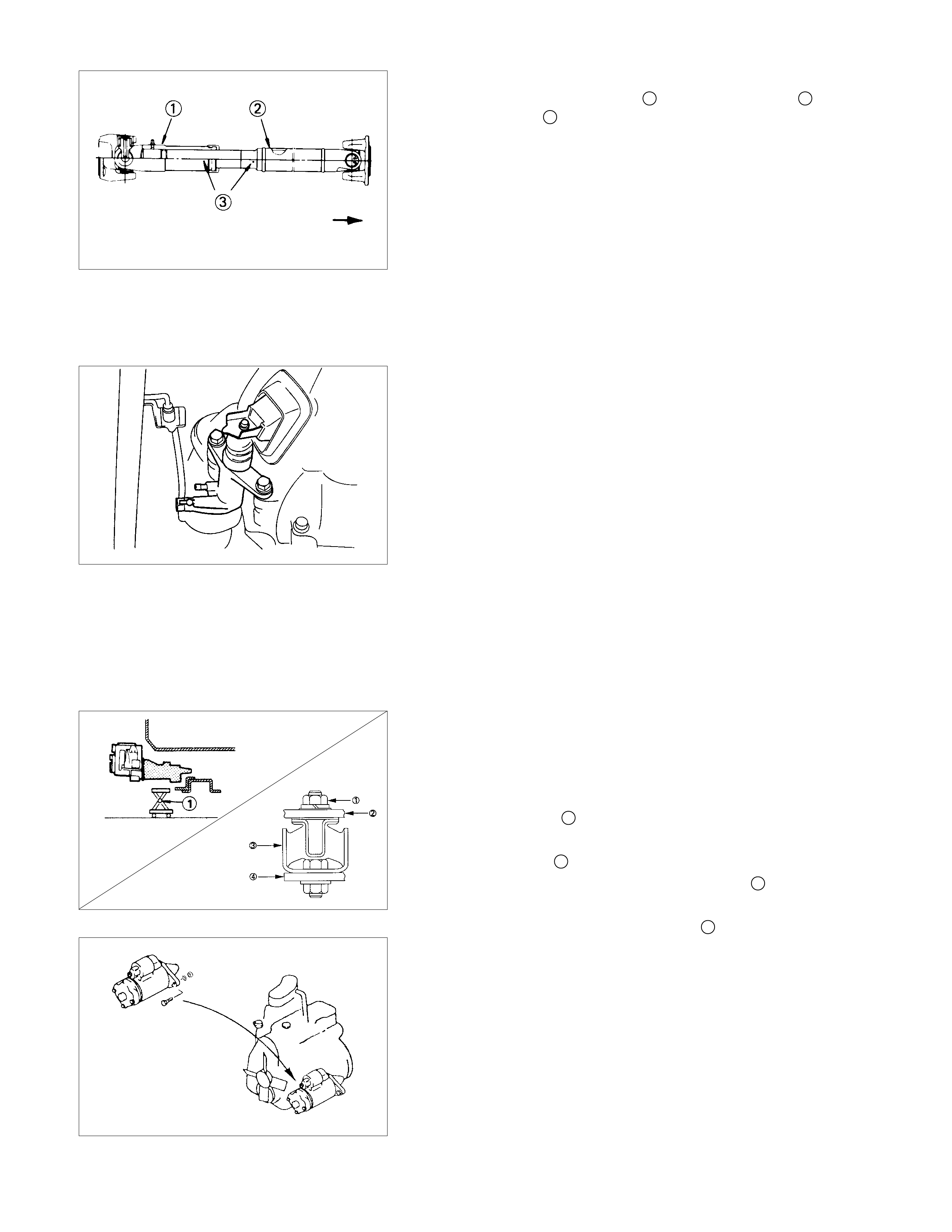
ENGINE REAR MOUNTING AND MOUNTING
MEMBER
1. Install the engine rear mounting to the transmission.
Rear Mounting Bolt Torque N⋅m (kgf⋅m/lb⋅ft
)
41 ± 4.9 (4.2 ± 0.5/30 ± 3.6)
2. Install the mounting member 1 to the mounting rubber 2.
Mounting Rubber Nut Torque N⋅m (kgf⋅m/lb⋅ft)
50 ± 6 (5.1 ± 0.6/37 ± 4.3)
3. Install the mounting member to the side-members.
Mounting Member Bolt Torque N⋅m (kgf⋅m/lb⋅ft)
50 ± 6 (5.1 ±0.6/37 ± 4.3)
SLAVE CYLI NDER
Install the slave cylinder to the transmission case.
Slave Cylinder Bolt Torque
40 ± 10 (4.1 ± 1.0 / 30 ± 7.2)
Harness Connector
Connect the 4WD switch connectors back up light switch
connector and speedometer sensor connector.
FRONT PROPELLER SHAFT
1. Connect the propeller shaft flange yoke to the matching
flange.
2. Tighten the propeller shaft flange yoke bolt to the specified
torque.
Propeller Shaft Flange Yoke Bolt Torque N⋅m (kgf⋅m/lb⋅ft
)
62.7 ±3.9 (6.4 ± 0.4 / 46.3 ± 2.9)
Note:
If the splined yoke and the front propeller shaft have
accidentally separated, align their setting marks and
recouple them.
Refer to "FRONT PROPELLER SHAFT REMOVAL".
REAR PRO PELLER SHAFT (SINGLE SHAFT TYPE)
1. Insert the splined yoke 1 with the propeller shaft into the
transmission main shaft spline 2.
2. Install the propeller shaft flange yoke 3 to the drive pinion
side.
3. Tighten the propeller shaft flange yoke bolt to the specified
torque.
Propeller Shaft Flange Yoke Bolt Torque N⋅m (kgf⋅m/lb⋅ft)
62.7 ± 3.9 (6.4 ± 0.4 / 46.3 ± 2.9)
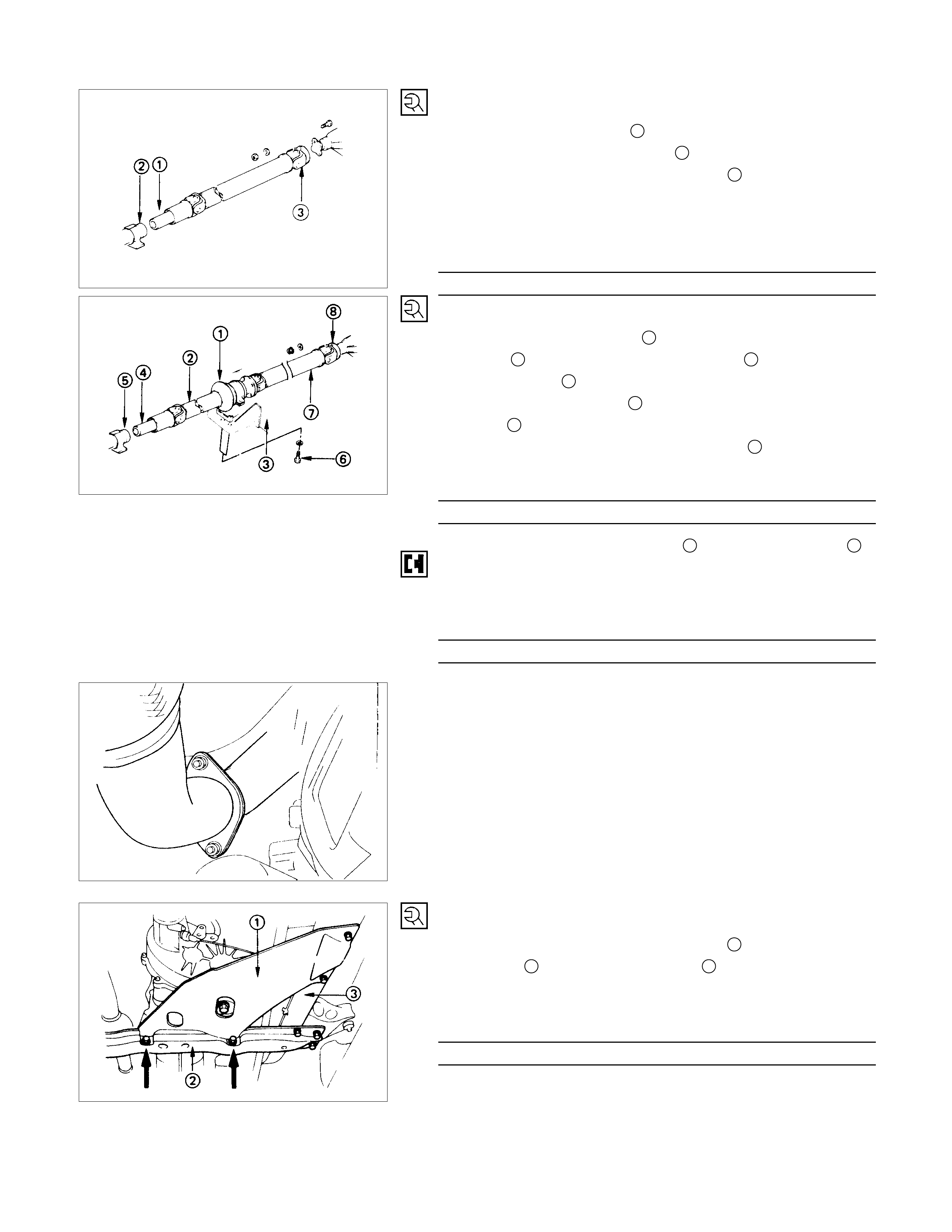
REAR PRO PELLER SHAFT (DUAL SHAFT TYPE)
1. Place the center bearing 1together with the 1st propelle
r
shaft 2 and 2nd propeller shaft 7 on the No.4
crossmember 3.
2. Insert the splined yoke 4 into the transmission main shaft
spline 5.
3. Tighten the center bearing retainer bolts 6 to the specified
torque.
Center Bearing Retainer Bolt Torque N⋅m (kgf⋅m/lb⋅ft)
60.8 ± 11.8 (6.2 ± 1.2 / 44.8 ± 8.7)
4. Connect the 2nd propeller shaft 7 and drive pinion side 8.
Be sure to align the setting marks applied at disassembly.
5. Tighten the coupling bolts to the specified torque.
Propeller Shaft Flange Yoke Bolt
Torque N⋅m (kgf⋅m/lb⋅ft)
62.7 ± 3.9 (6.4 ± 0.4 / 46.3 ± 2.9)
Exhaus t Pipe
1. Connect the front exhaust pipe and 2nd-3rd exhaust pipe.
2. Install the exhaust pipe bracket to the transmission case.
TRANSFER CASE PROTECTOR
1. Install the transfer case protector 1 to the mounting
member 2 and the side-members 3.
2. Tighten the transfer case protector bolts to the specified
torque.
Transfer Case Protector Bolt Torque N⋅m (kgf⋅m/lb⋅ft)
36.3 ± 9.8 (3.7 ± 1.0/26.8 ± 7.2)
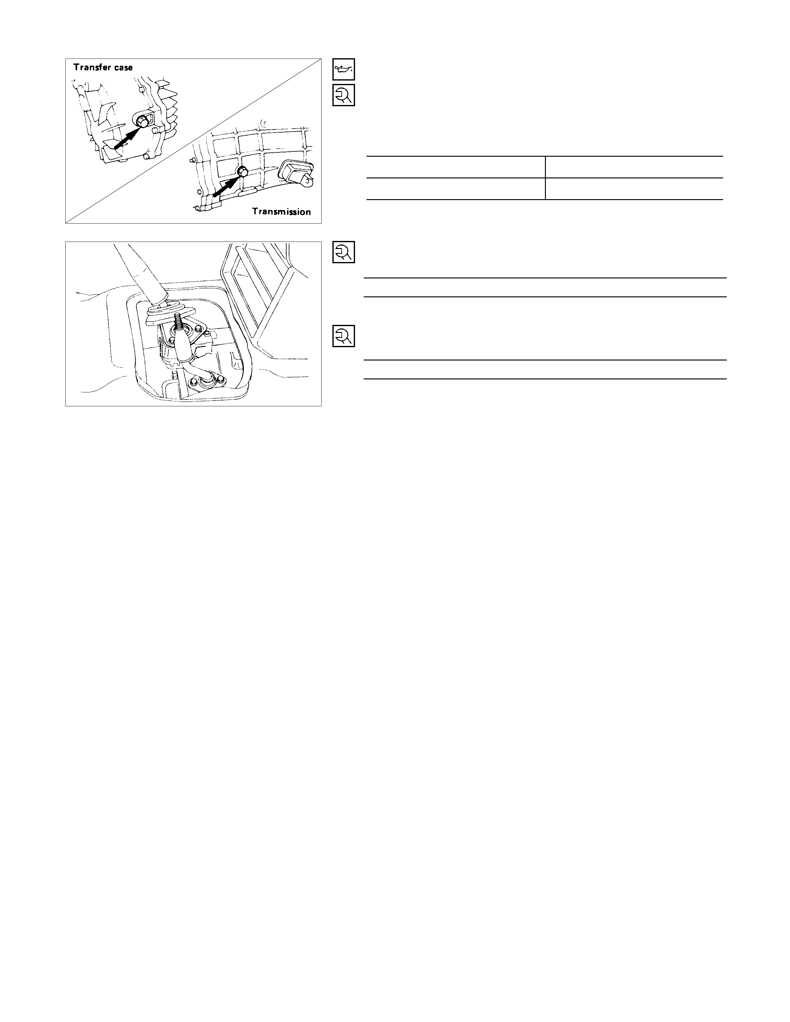
GEAR SHIFT LEVER AND TRANSFER CHANGE
LEVER
1. Replenish the transm ission case and the tr ansfer c ase with
the specified engine oil.
Transmission and Transfer Case Oil lit (US/UK qt.
)
Transmission Case 2.95 (3.12/2.6)
Transfer Case 1.45 (1.53/1.28)
2. Install the gearshift lever to the gear control box.
Shift Lever Cover Bolt Torque N⋅m (kgf ⋅m/lb⋅ft)
19.6 ± 1.96 (2.0 ± 0.2 / 14.5 ± 1.5)
3. Install the dust cover.
4. Insert the transfer case change lever to the transfer case.
Change Lever Retainer Bolt Torque N⋅m (kgf⋅m/lb⋅ft)
19.6 ± 1.96 (2.0 ± 0.2 / 14.5 ± 1.5)
5. Install the grommet
6. Install the front console assembly and center console
assembly.
7. Install the gearshift lever and the transfer change leve
r
knobs.
Lowering the Vehicle
1. Place a jack beneath the vehicle.
2. Raise the jack to remove the chassis stands.
3. Lower the vehicle to the ground.
Engine Hood
Align the setting marks (applied at removal) on the engine
hood and the engine hood hinges to install the engine hood.
Battery Cable
Connect the negative (-) cable to the battery terminal.
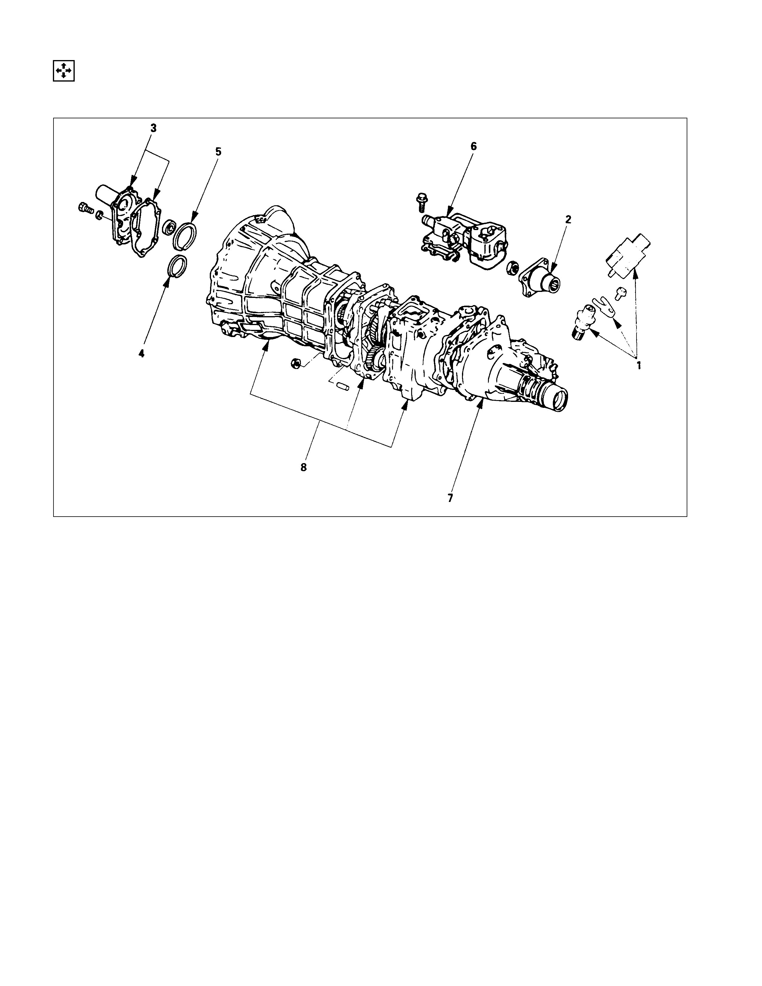
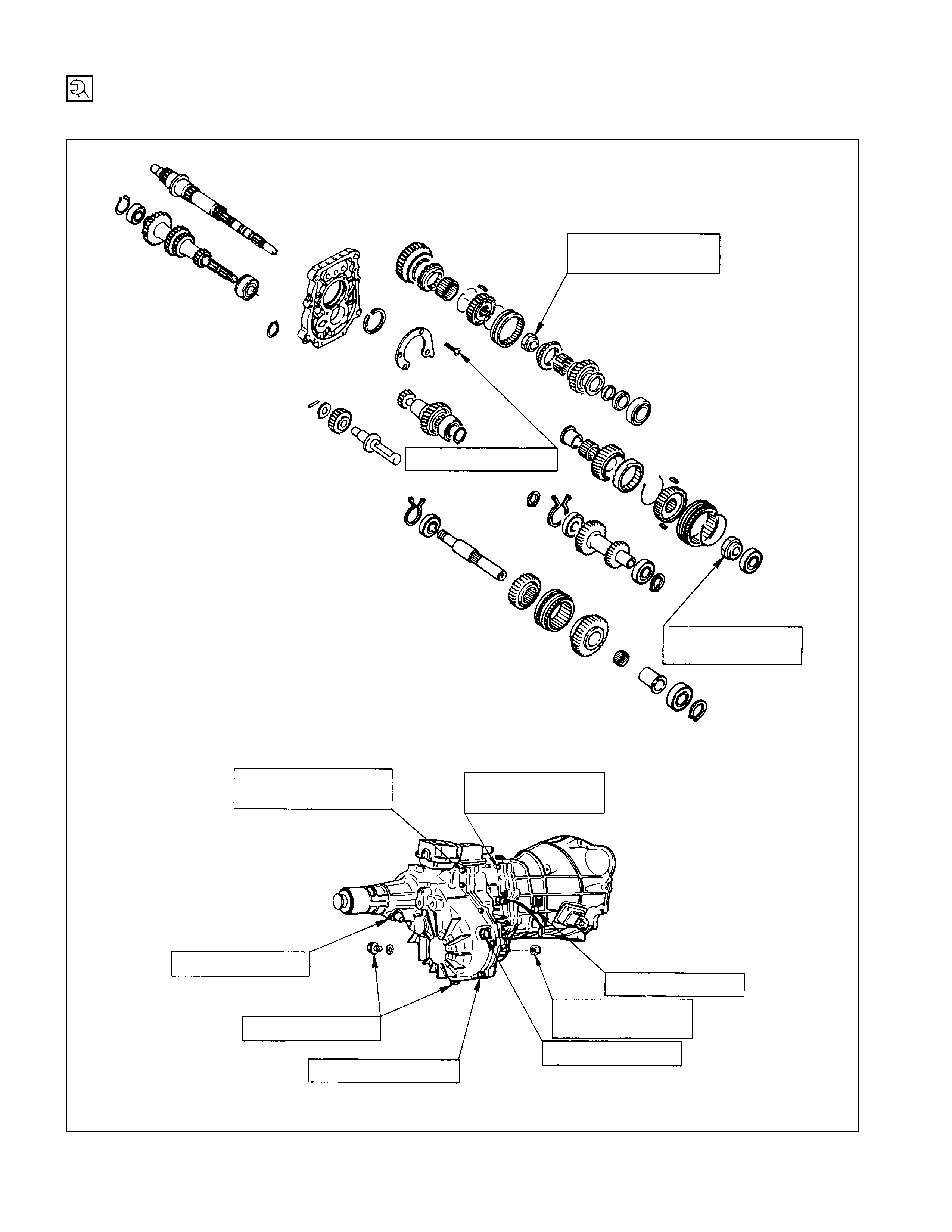
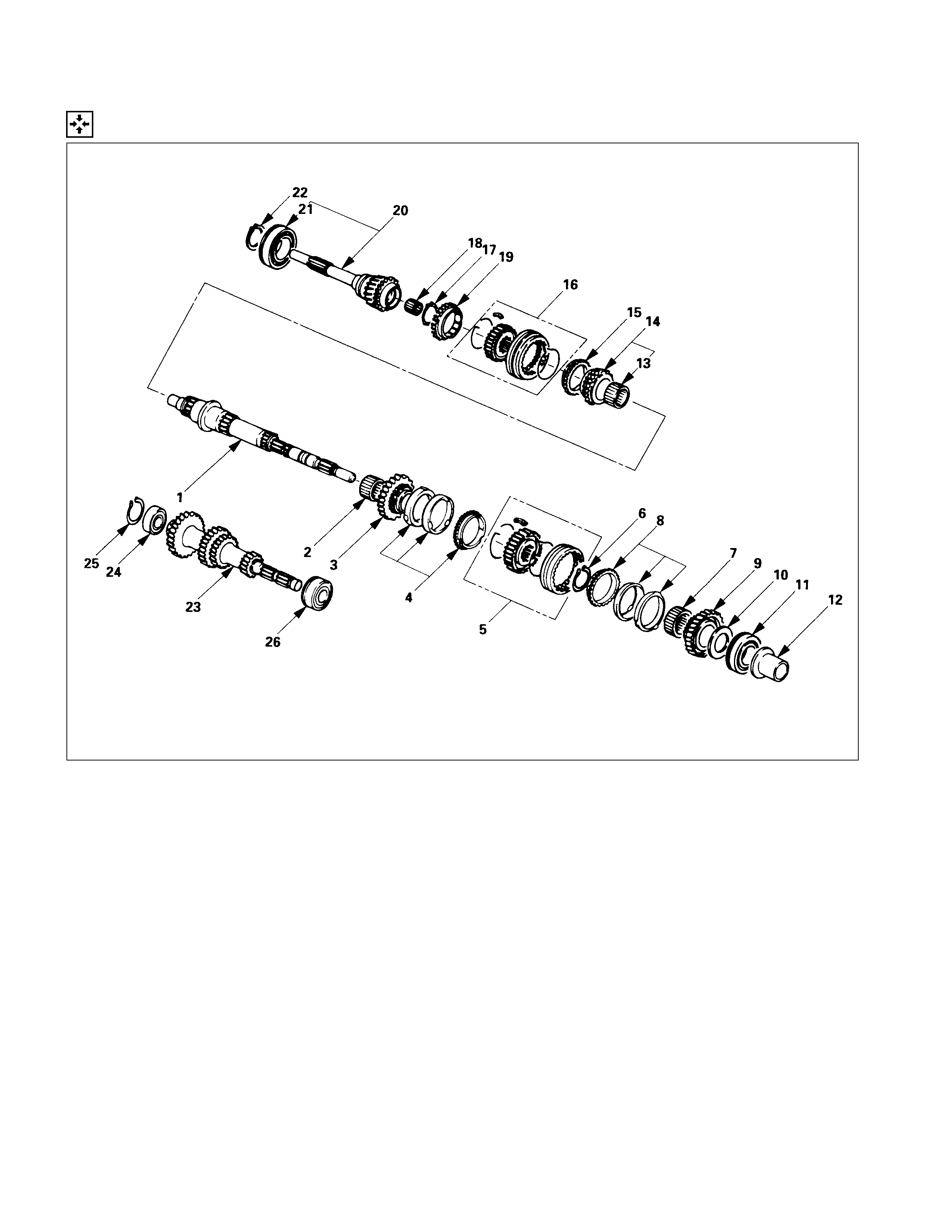
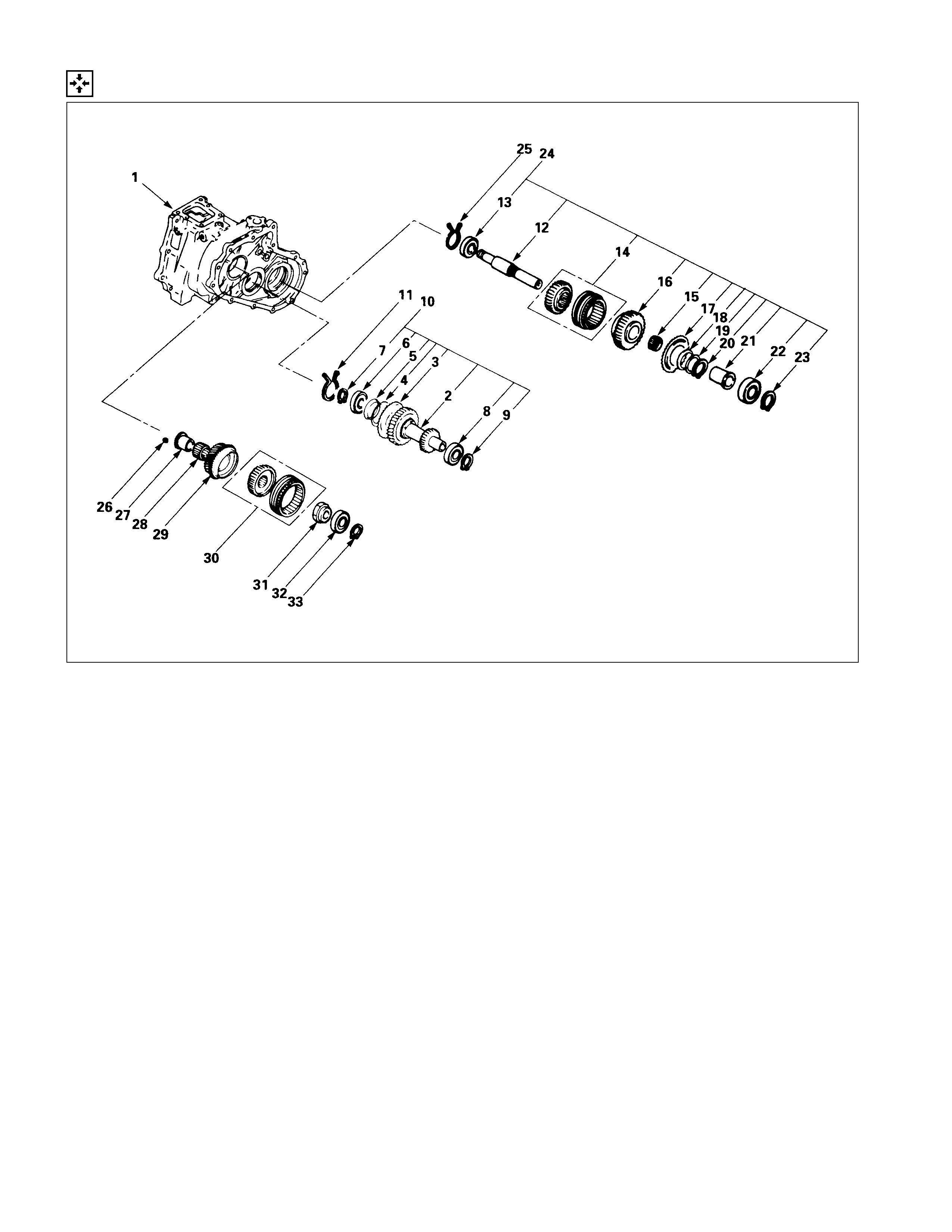
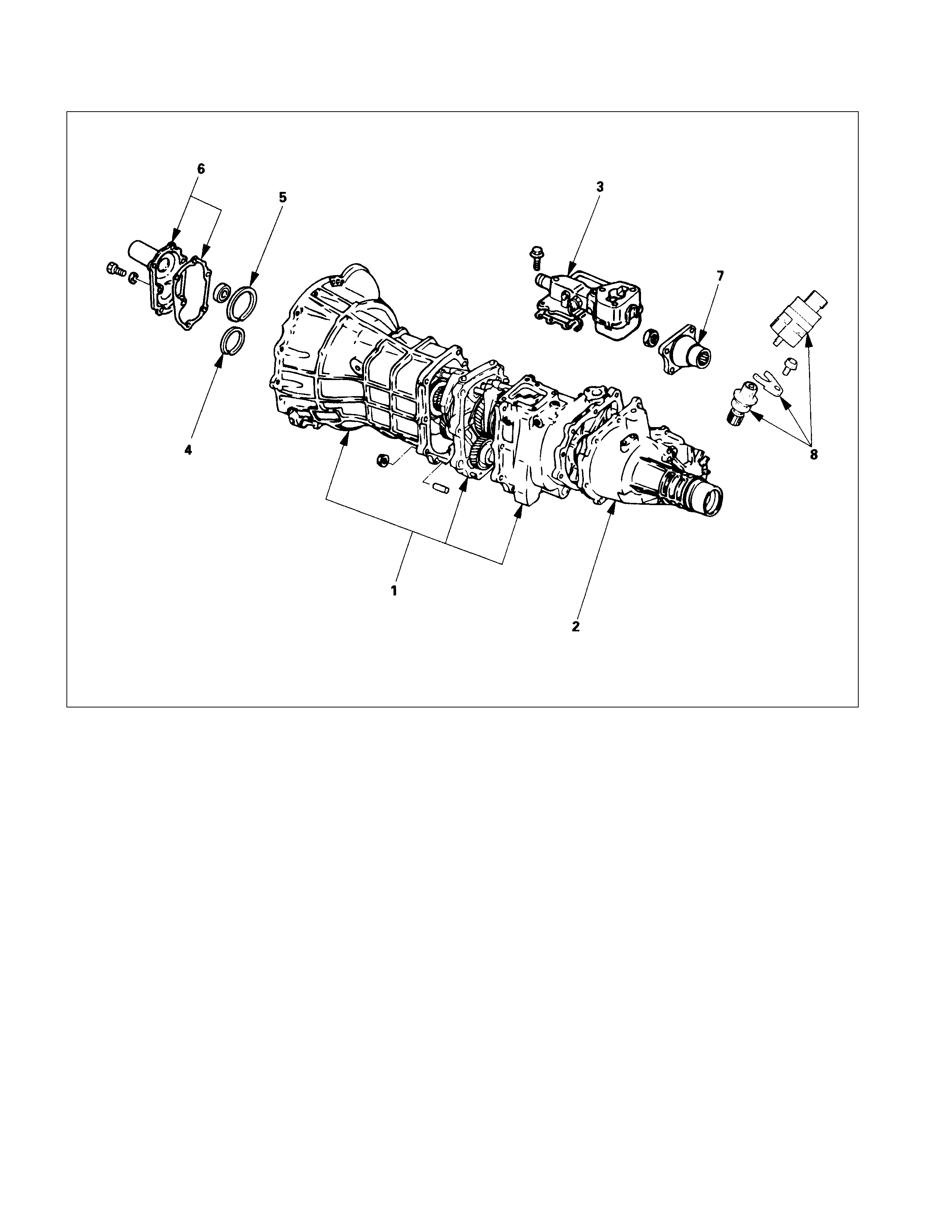
DISASSEMBLY
EXTERAL COMPONENTS
DISASSEMBLY STEPS
I1. Speedometer sensor and speedometer
driven gear
I2. Transfer flange
I3. Front cover with oil seal
I4. Counter gear snap ring
I5. Bearing snap ring
6. Gear control box assembly
7. Transfer rear case assembly
8. Transmission and transfer case
assembly
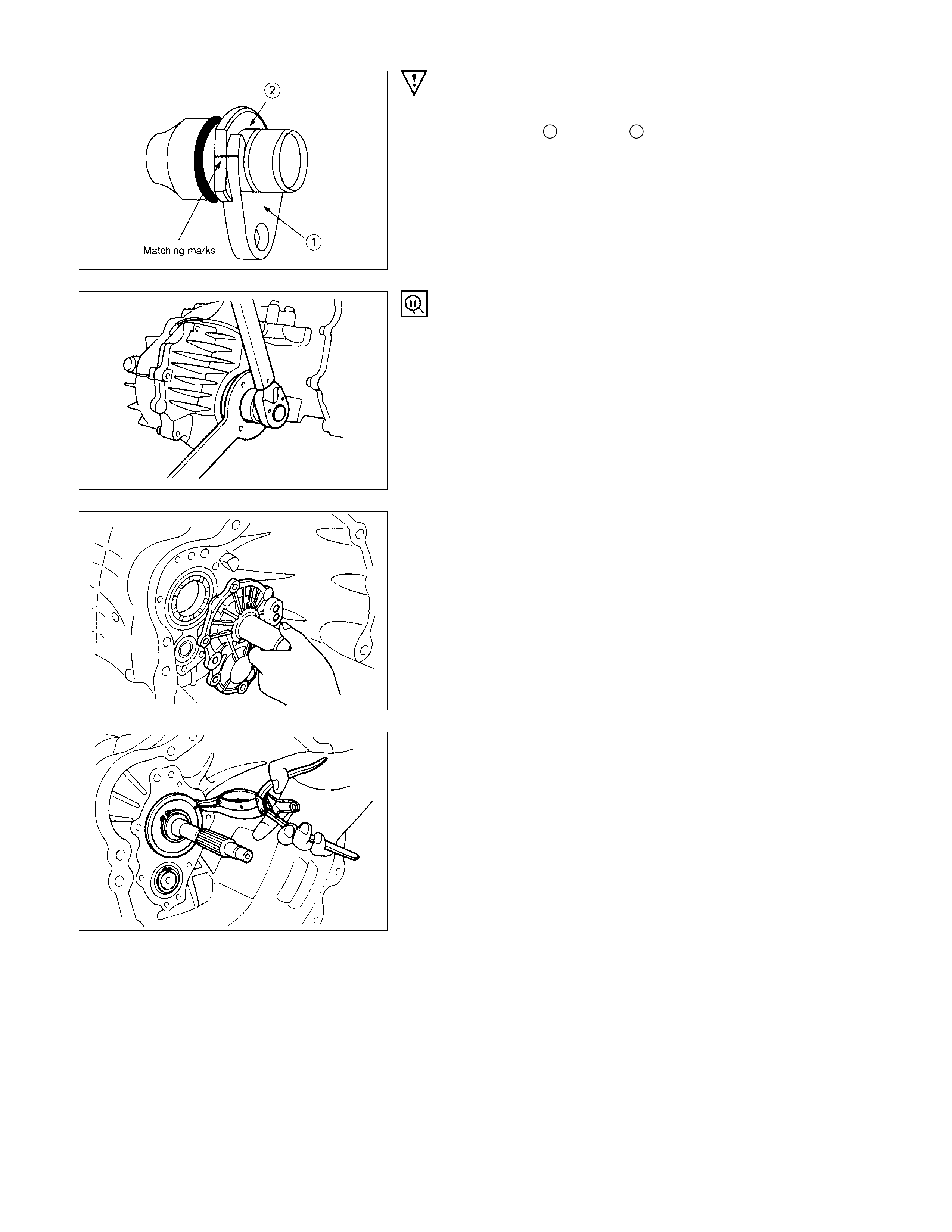
IMPORTANT OPERATIONS
1. Speedometer Sensor and Speedometer Driven Gear
Mark the plate 1 and bush 2 alignment for reassembly.
2. Transfer Flange
Use the transfer flange holder to remove the transfer flange.
Transfer Flange Holder: 5-8840-2157-0 (J-37221)
3. Front Cover with Oil Seal
Remove the front cover with oil seal from the transmission
case.
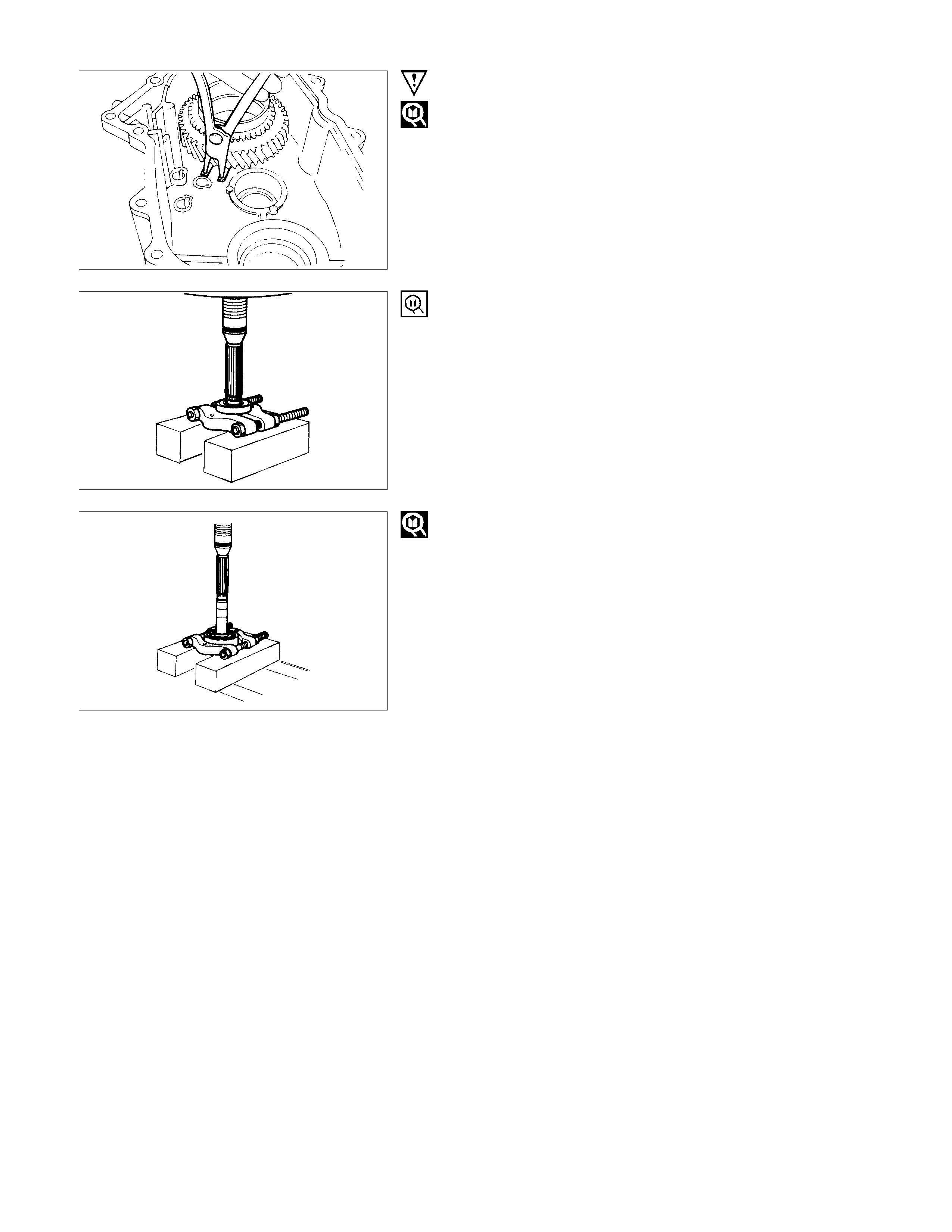
4. Counter Gear Snap Ring
5. Bearing Snap Ring
Use a pair of snap ring pliers to remove the snap ring.
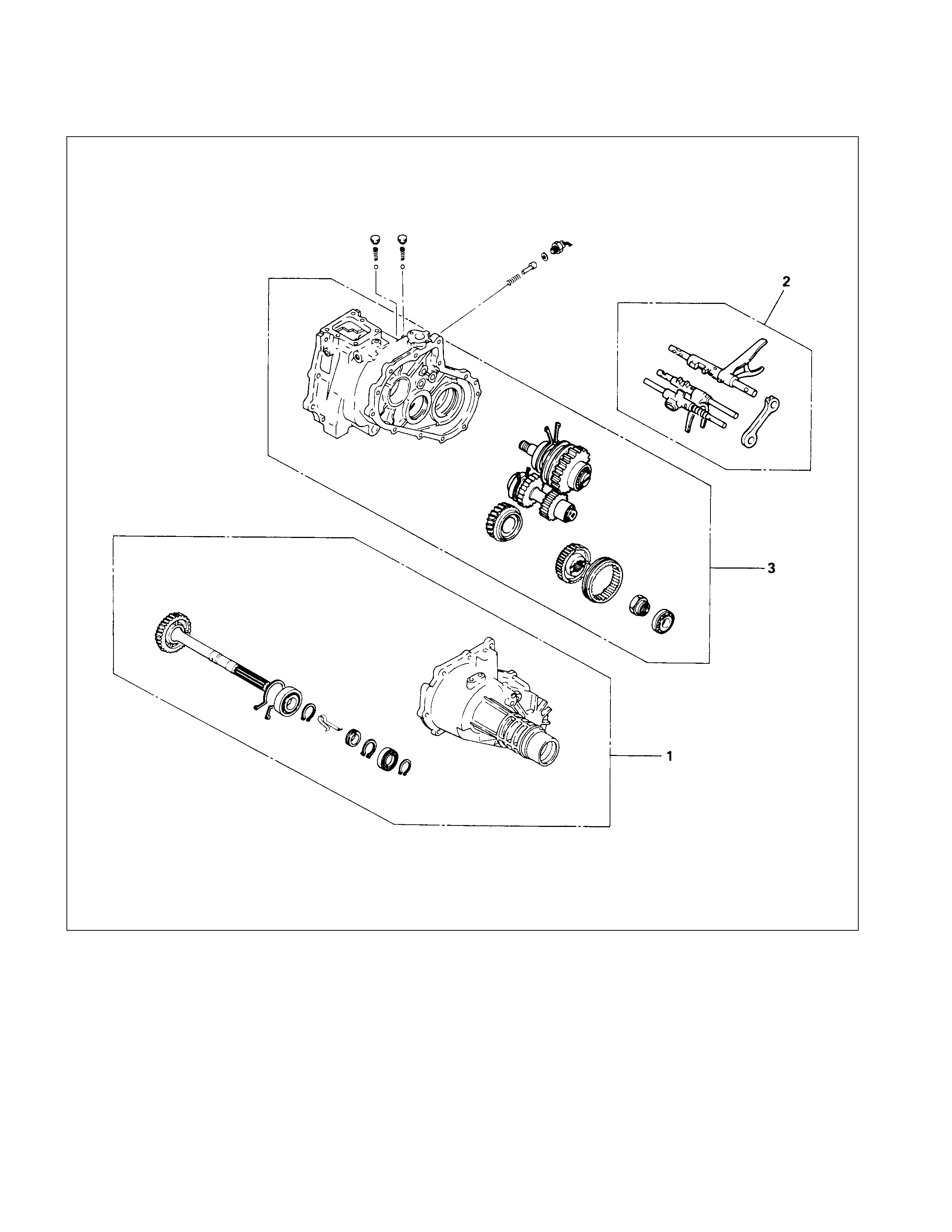
MAJOR COM PONENTS
TRANSFER CASE
DISASSEMBLY STEPS
1. Transfer rear case assembly
2. Shift fork assembly & interlock pin &
detent assembly
3. Transfer case assembly
TRANSMISSION
DISASSEMBLY STEPS
1. Detent assembly
2. Shift fork assembly & interlock pin
3. Rev. and 5th gear assembly
4. Counter gear shaft assembly
5. Top & main gear shaft assembly
MINOR COMPONENT
TRANSFER REAR CASE ASSEMBLY
DISASSEMBLY STEPS
I1. Bearing snap ring
2. Transfer rear case
3. Bearing snap ring
I4. Ball bearing
5. Bearing snap ring
6. Clip
7. Speedometer drive gear
8. Bearing snap ring
I9. Ball bearing
10. Rear output shaft
IMPORTANT OPERATIONS
1. Bearing Snap Ring
Use a pair of snap ring pliers to remove the snap ring.
4. Ball Bearing
Use a bench press and the bearing remover to remove the ball
bearing.
Bearing Remover: 5-8840-0015-0 (J-22912-01)
9. Ball Bearing
Use a bench press and the bearing remover to remove the ball
bearing.
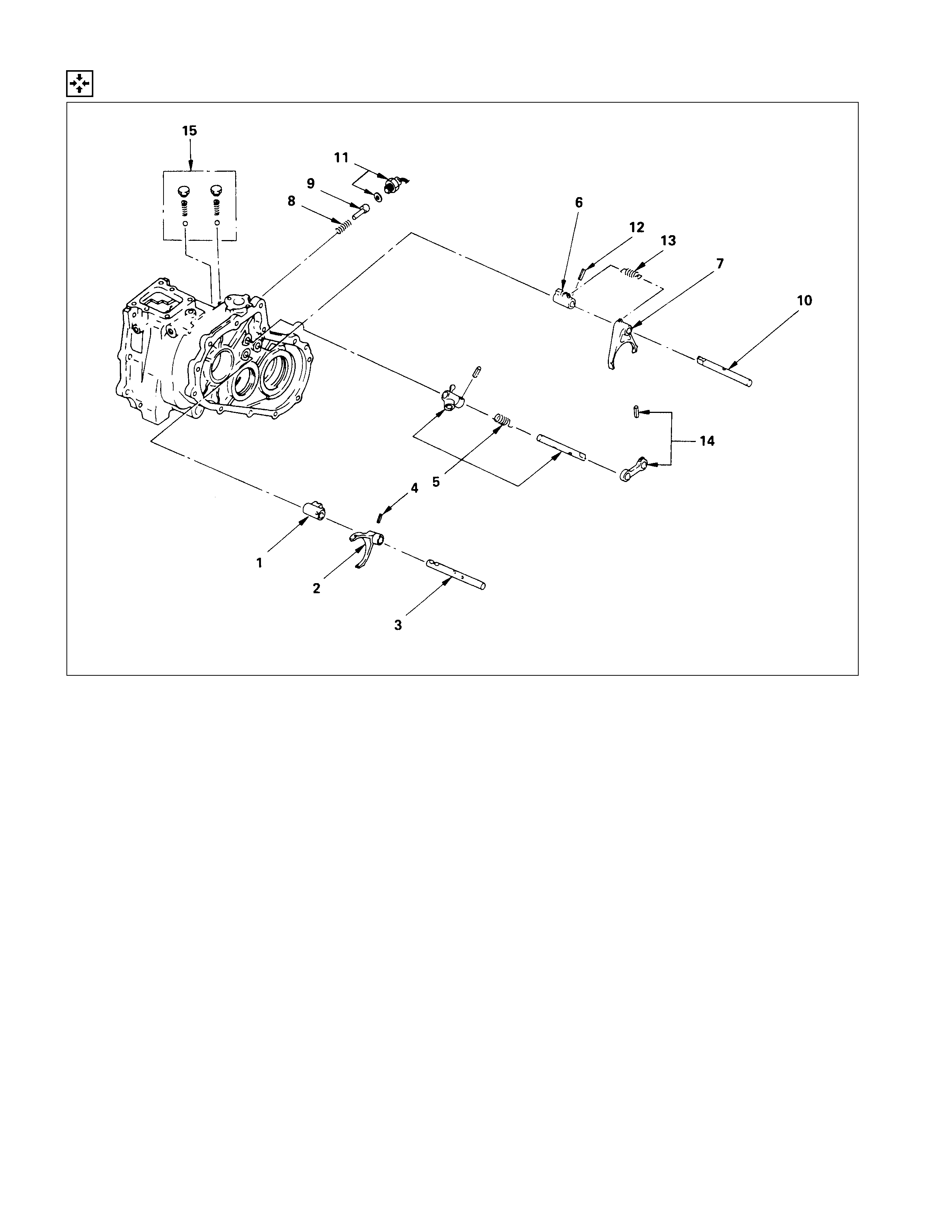
DETENT, SHIFT ARM ASSEMBLY AND INTERLOCK PIN
DISASSEMBLY STEPS
1. Detent ball, spring and plug
I2. Pin and bridge
3. Pin
4. Spring
I5. 2WD-4WD shift rod
6. Shift arm
7. Shift block
8. 4WD indicator switch
I9. Interlock pin
10. Spring
11. Select rod assembly
12. Pin
I13. High-low shift rod
14. Shift arm
15. Shift block
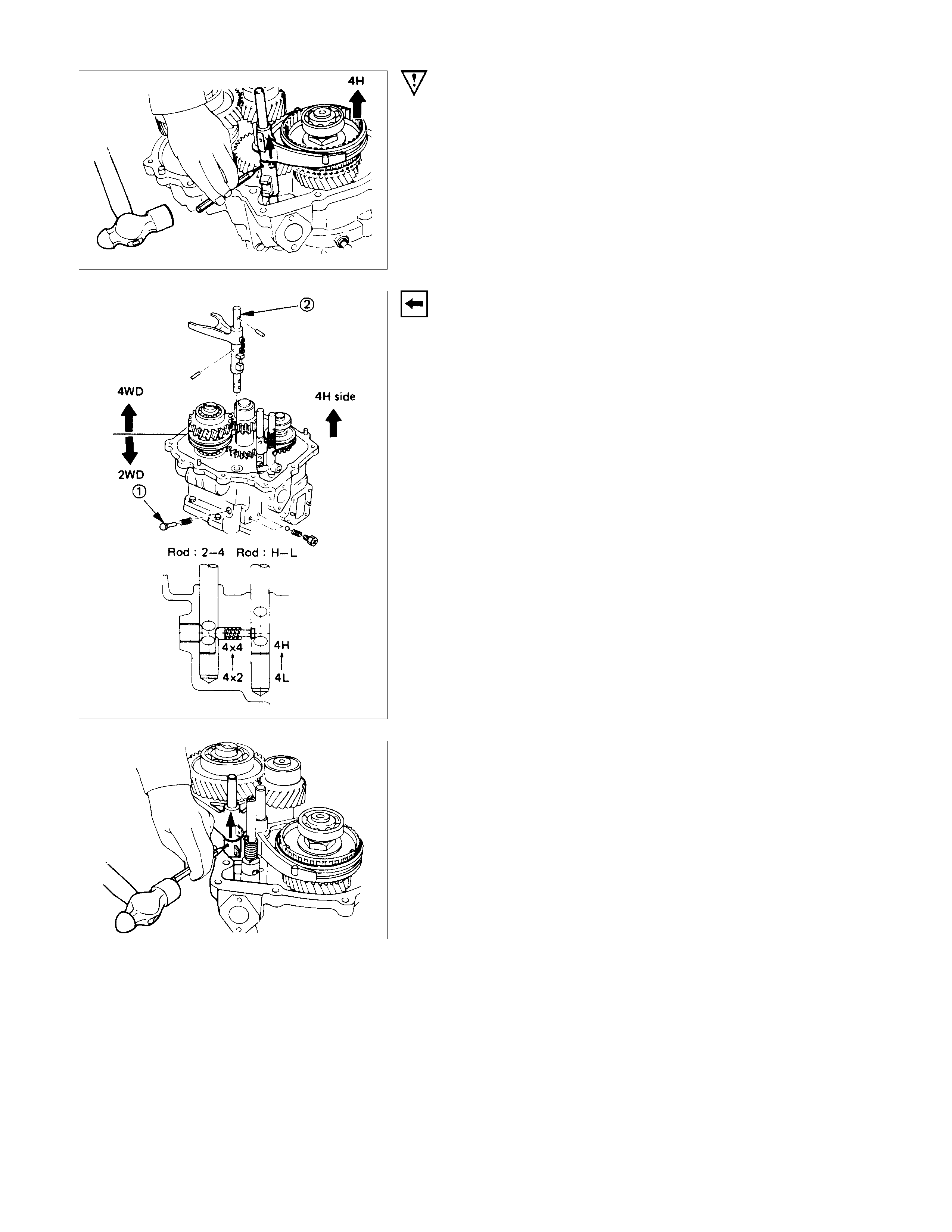
IMPORTANT OPERATIONS
2.Bridge
Use a spring pin remover to remove the spring from the bridge.
5.2WD-4WD Shift Rod
1) Engage the 2nd-4th sleeve with the front output gear.
2) Remove the spring pin from the block.
3) Remove the shift rod.
9.Interlock Pin
Use a magnetic tool to remove the interlock pin from the
transfer case.
13.High-Low Shift Rod
Use a spring pin remover to remove the shift arm spring from
the shift arm and the shift rod.
TRANSFER CASE ASSEM BLY AND MAI NSHAFT GEAR
DISASSEMBLY STEPS
1. Bearing snap ring
I2. Mainshaft end ball bearing
I3. Mainshaft end lock nut
I4. High-low clutch hub and sleeve
I5. Transfer input gear
6. Needle bearing
I7. Bearing collar
8. Ball
I9. Bearing snap ring
10. Front output gear assembly
11. Bearing snap ring
I12. Ball bearing
13. Bearing collar
I14. Anti-lash plate snap ring
15. Spacer
16. Belleville spring
17. Sub gear (Anti-lash plate)
18. Front output gear
19. Needle bearing
20. Clutch hub and sleeve
I21. Ball bearing
22. Front output shaft
23. Bearing snap ring
24. Counter gear assembly
25. Bearing snap ring
I26. Ball bearing
27. Bearing snap ring
I28. Ball bearing
29. Spacer
30. Belleville spring
31. Sub gear (Anti-lash plate)
32. Counter gear
33. Transfer case
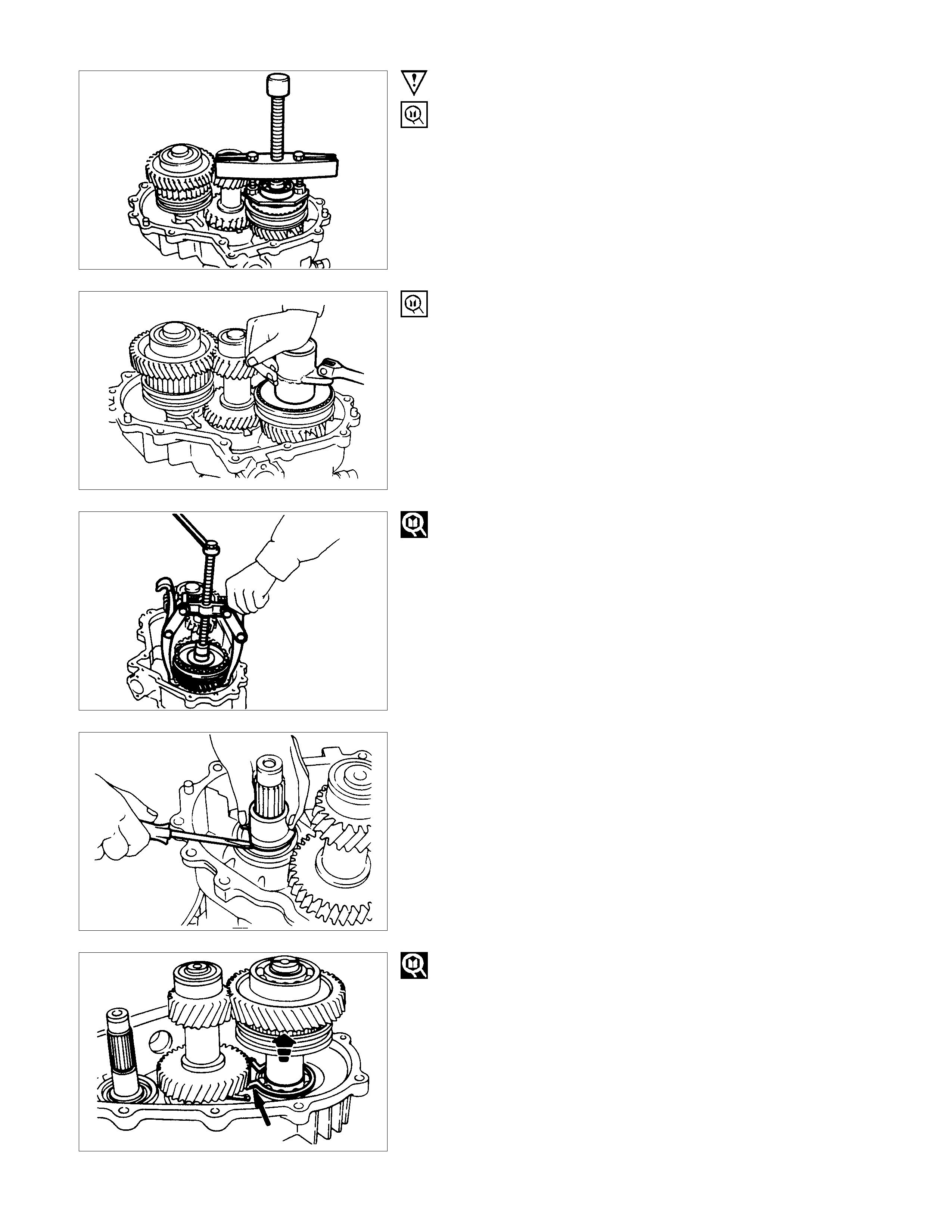
IMPORTANT OPERATIONS
2. Mainshaft End Ball Bearing
Use a bearing remover to remove the ball bearing.
Remover : 5-8840-2155-0 (J-37217)
Puller : 5-8840-2027-0
3. Mainshaft End Lock Nut
1) Engage the 3rd-top synchronizer with the 3rd gear.
2) Engage the low-2nd synchronizer with the low gear.
3) Use the lock nut wrench to remove the lock nut.
Lock Nut Wrench: 5-8840-2156-0 (J-37219)
4. High-Low Clutch Hub and Sleeve
5. Transfer Input Gear
Use the universal puller to remove the high-low synchroniser
assembly, the high-low block ring, and the transfer case input
gear.
7. 8. Bearing Collar and Ball
Using screwdriver to remove the bearing collar.
9. Bearing Snap Ring
Use a pair of snap ring pliers to expand the bearing snap ring.
Use a plastic hammer to tap the front output gear assembly
free.
12.Ball Bearing
Use a bench press and the ball bearing remover to remove the
ball bearing.
Bearing Remover: 5-8840-0015-0 (J-22912-01)
14.Anti-lash Plate Snap Ring
Use a pair of pliers to remove the snap ring.
21.Ball Bearing
Use a bench press and the bearing remover to remove the ball
bearing.
Bearing Remover: 5-8840-0015-0 (J-22912-01)
26.Ball Bearing
28.Ball Bearing
Use a bench press and the bearing remover to remove the ball
bearings.
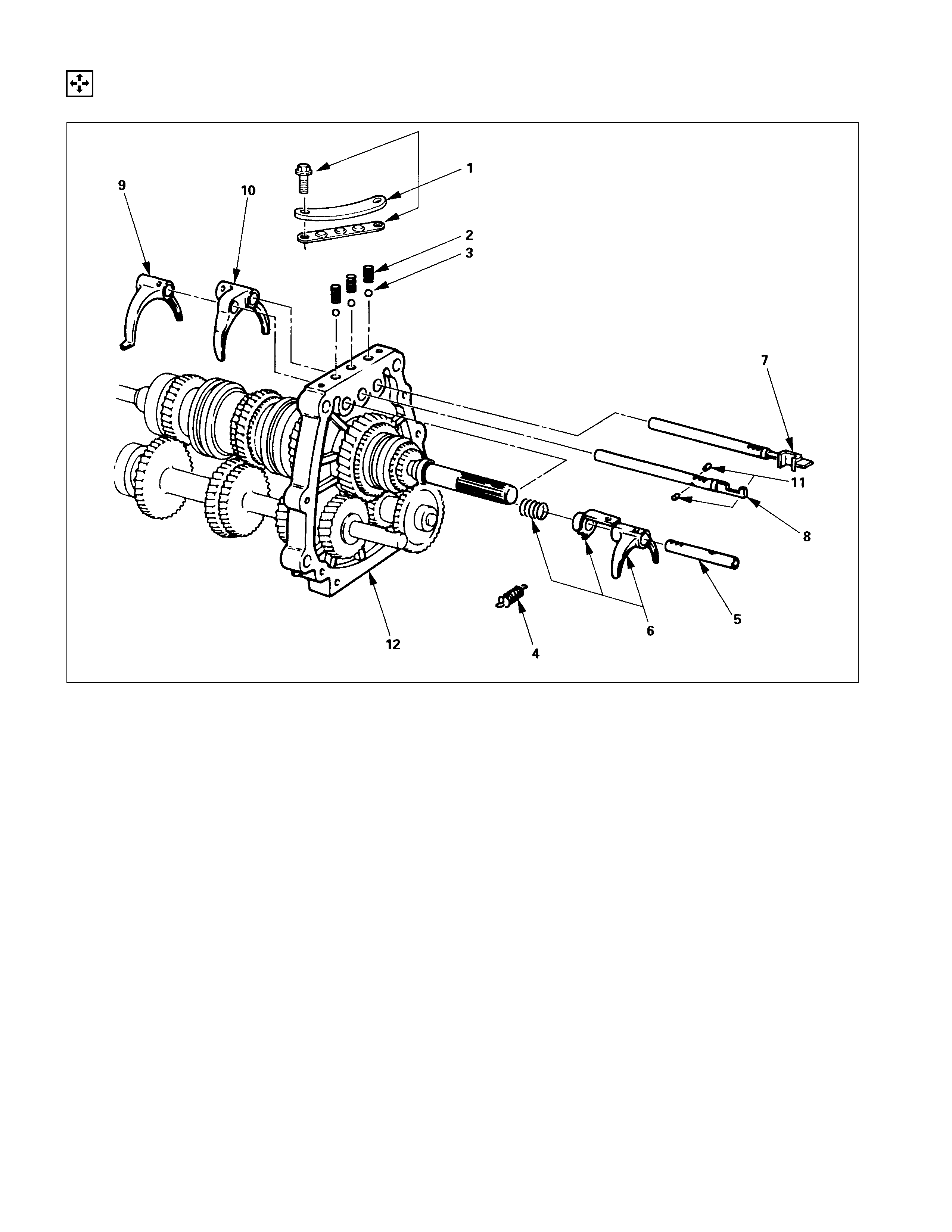
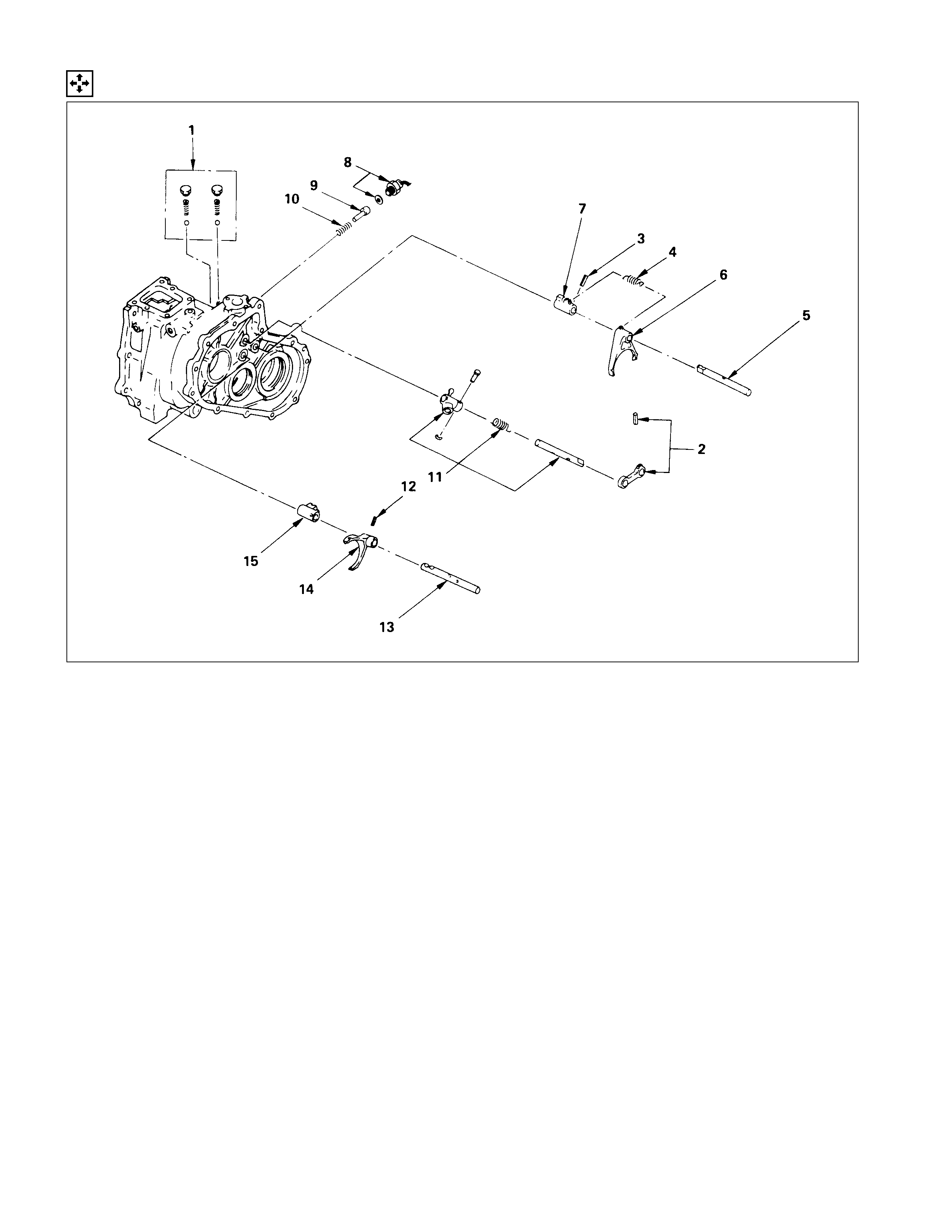
INTERMEDIATE PLATE AND GEAR ASSEMBLY, DETENT,
SHIFT ARM ASSEMBLY, AND INTERLOCK PIN
DISASSEMBLY STEPS
1. Detent spring plate and gasket
2. Detent spring
I3. Detent ball
4. Spring
5. Rev-5th shift rod
6. Rev-5th shift arm and reverse inhibitor
7. 1st-2nd shift rod
I8. 3rd-4th shift rod
I9. 3rd-4th shift arm
I10. 1st-2nd shift arm
I11. Interlock pin
12. Intermediate plate and gear assembly
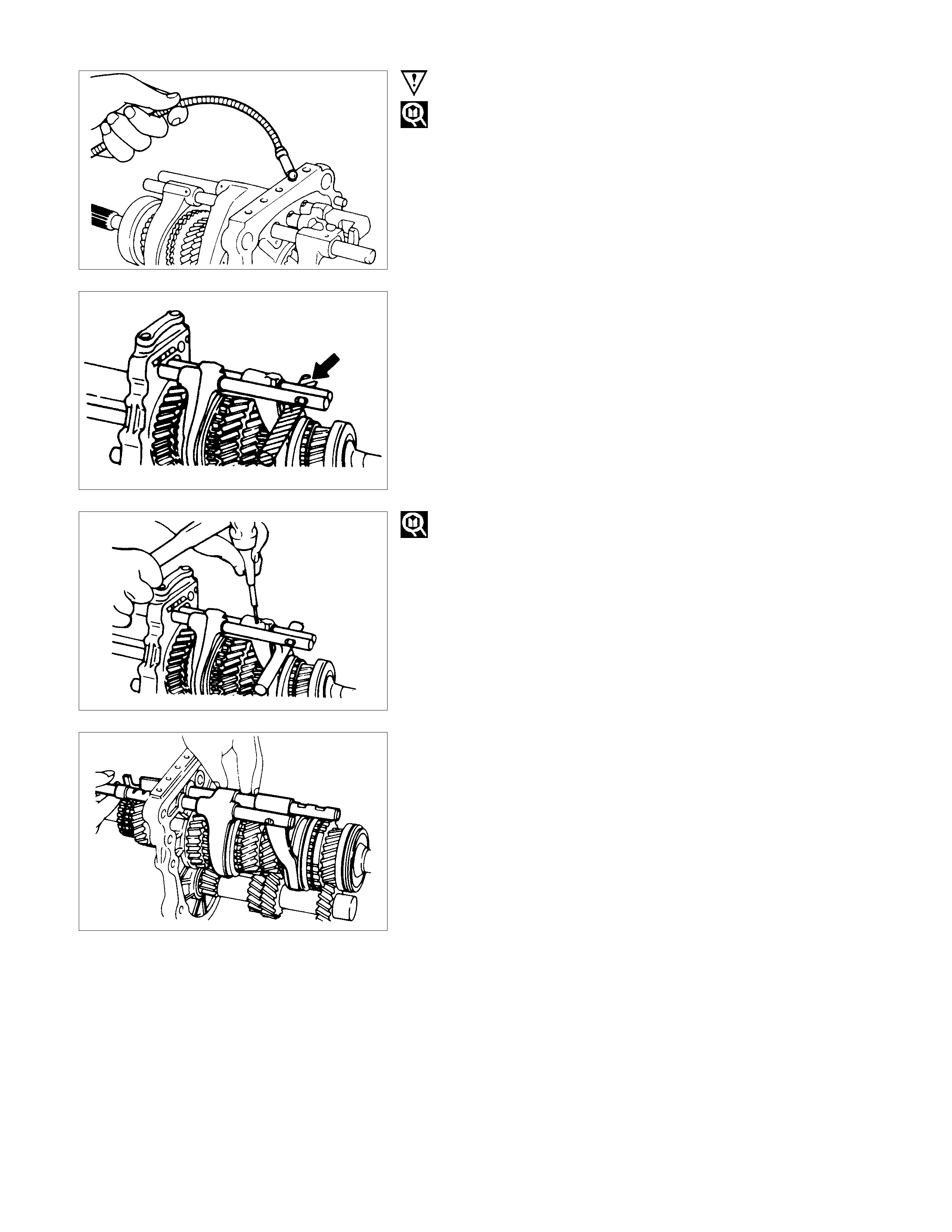
IMPORTANT OPERATIONS
3.Detent Ball
Use a magnetic tool to remove the detent balls from the
intermediate plate.
Take care not to lose the detent balls.
8.3rd-4th Shift Rod
9.3rd-4th Shift Arm
10.1st-2nd Shift Arm
1) Hold a round bar against the shift arm end.
This will prevent damage to other components.
2) Use a spring pin rem over to rem ove the s hift ar m spring pin
from the shift arm and the shift rod.
Discard the used spring pin.
3) Move the 3rd-4th shift rod forward.
Take care not to lose the interlock pins.
11.Interlock Pin
Carefully remove the reverse shifter rod forward to avoid losing
the interlock pins.
Note:
Remove the shifter rods carefully. Interlock pins are
located between the shifter rod in the intermediate plate.
REVERSE GEAR AND 5TH GEAR
DISASSEMBLY STEPS
I1. Oil seal collar
I2. Bearing
I3. Retainer
4. Thrust plate
5. Thrust washer and lock ball
I6. Reverse idler gear snap ring
7. Reverse idler shaft
8. Idle shaft pin
9. Thrust washer
10. Reverse idler gear
11. Bearing snap ring
I12. Ball bearing
I13. Counter 5th gear
14. Counter reverse gear
15. 5th gear
16. 5th block ring
I17. Needle bearing
I18. Clutch hub nut
I19. Rev-5th synchronizer assembly
I20. Reverse block ring
I21. Reverse gear
22. Needle bearing
I23. Bearing plate and screw
I24. Bearing snap ring
I25. Intermediate plate
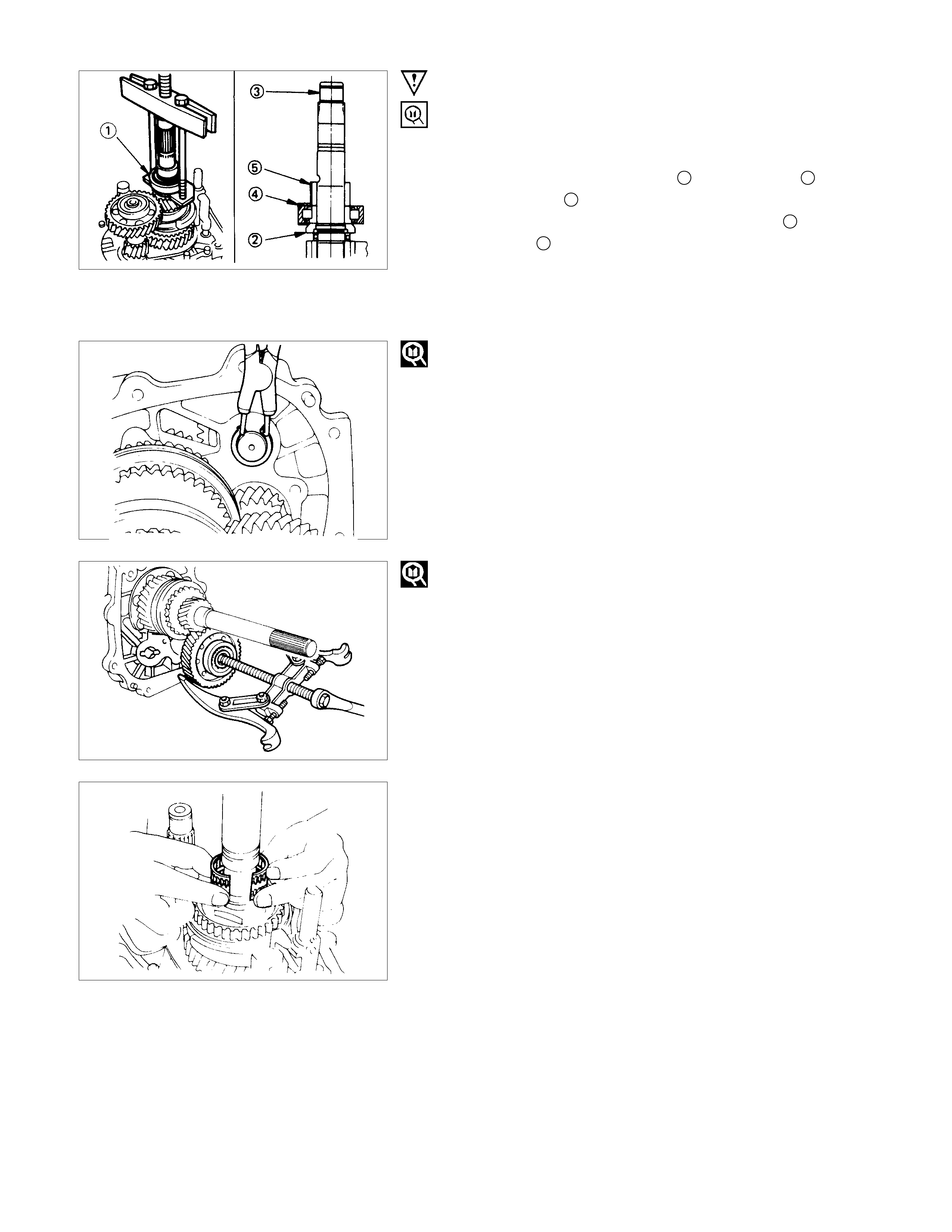
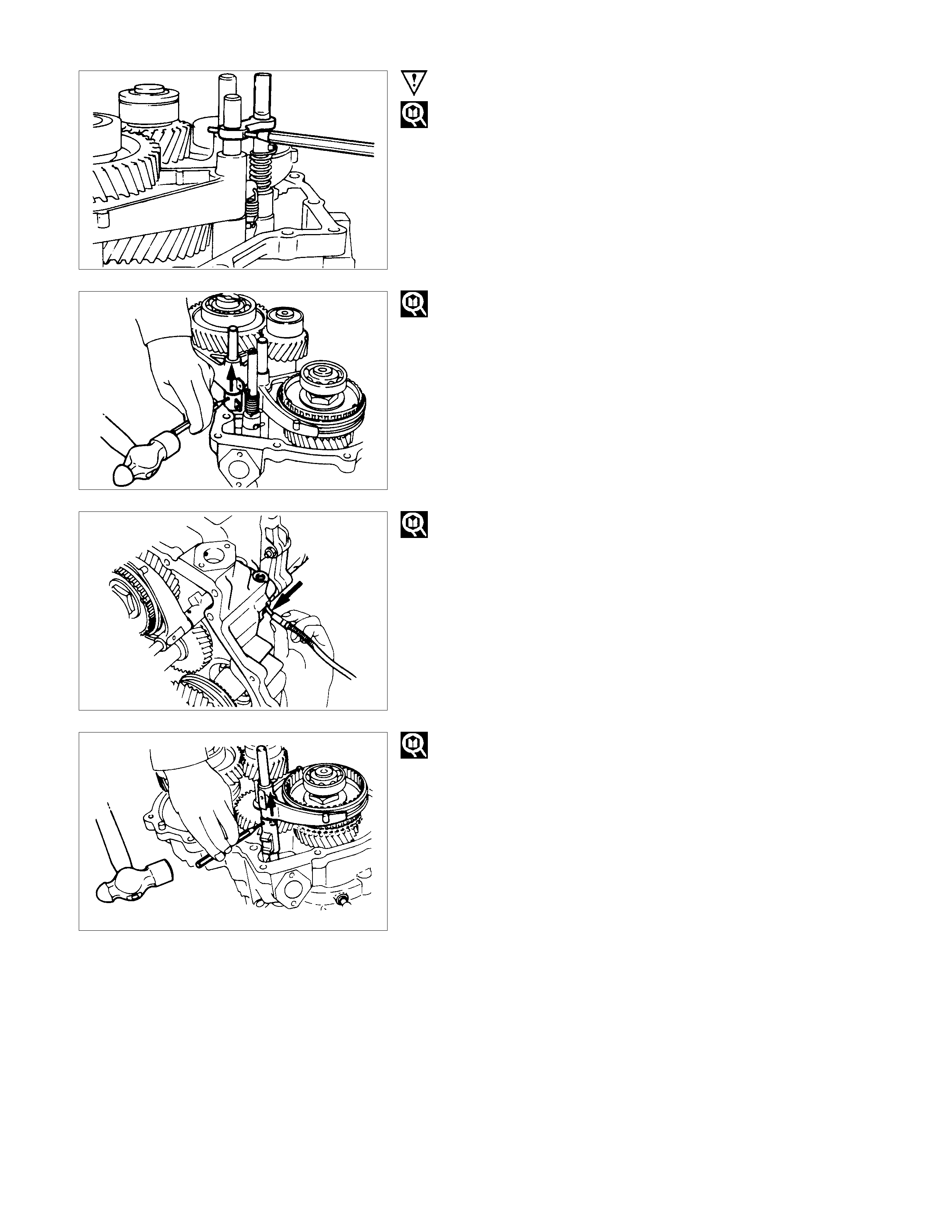
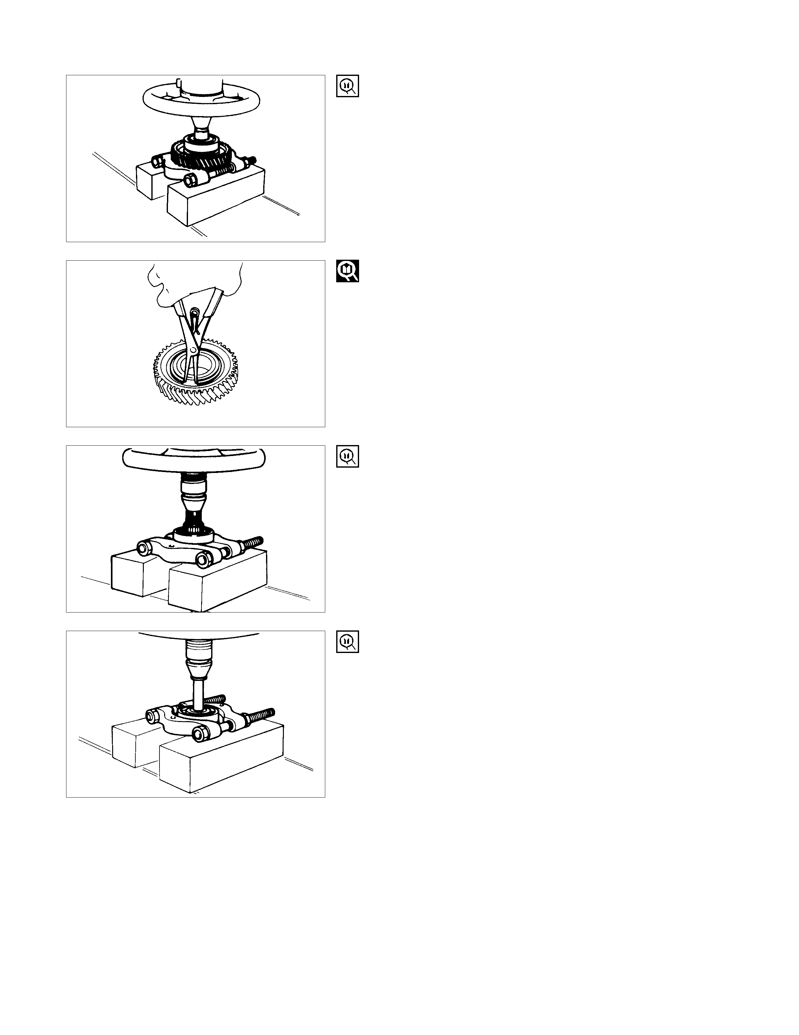
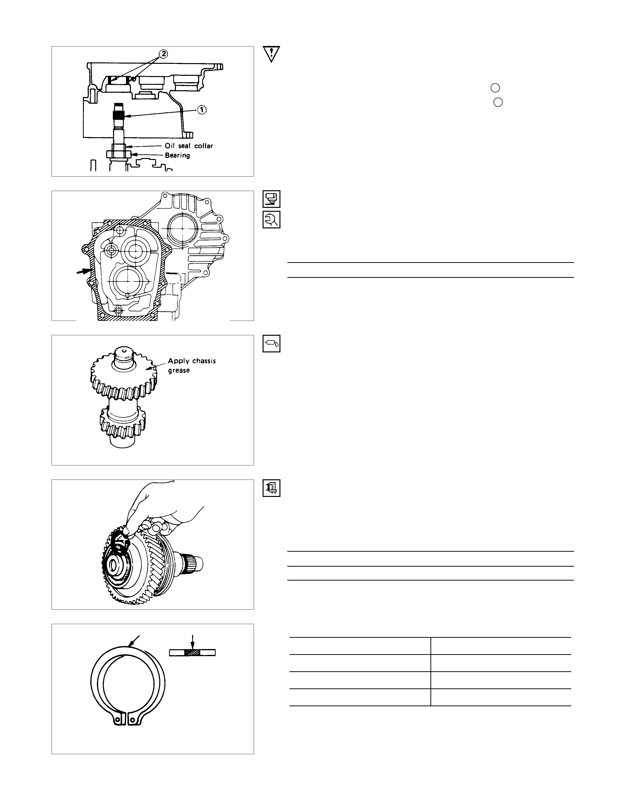
IMPORTANT OPERATIONS
1.Oil Seal Collar
2.Bearing
3.Retainer
1) Set the retaining ring remover 1 to the retainer 2 and the
Mainshaft end 3.
2) Remove the r etainer together with the bear ing 4 and the oil
seal collar 5.
The universal puller may be used in place off the retaining
ring remover.
Retainer Remover: 5-8840-2158-0 (J-37222)
Universal Puller: 5-8840-2027-0
6. Reverse Idler Gear Snap Ring
Use a pair of snap ring pliers to remove the snap ring.
12.Ball Bearing
13.Counter 5th Gear
Use the bearing remover to remove the ball bearing.
17.Needle Bearing
Remove the needle bearing (2 piece type).
18.Clutch Hub Nut
1) Engage the 3rd-4th synchronizer with the 3rd gear.
2) Engage the 1st-2nd synchronizer with the 1st gear.
3) Attach the holding fixture together with the holding base to
the mainshaft front bearing and the counter gear front
bearing.
Holding Fixture: 5-8840-2160-0 (J-37224)
Holding Base: 5-8840-0003-0 (J-3289-20)
4) Use the hub nut wrench to remove the hub nut.
Hub Nut Wrench: 5-8840-2156-0 (J-37219)
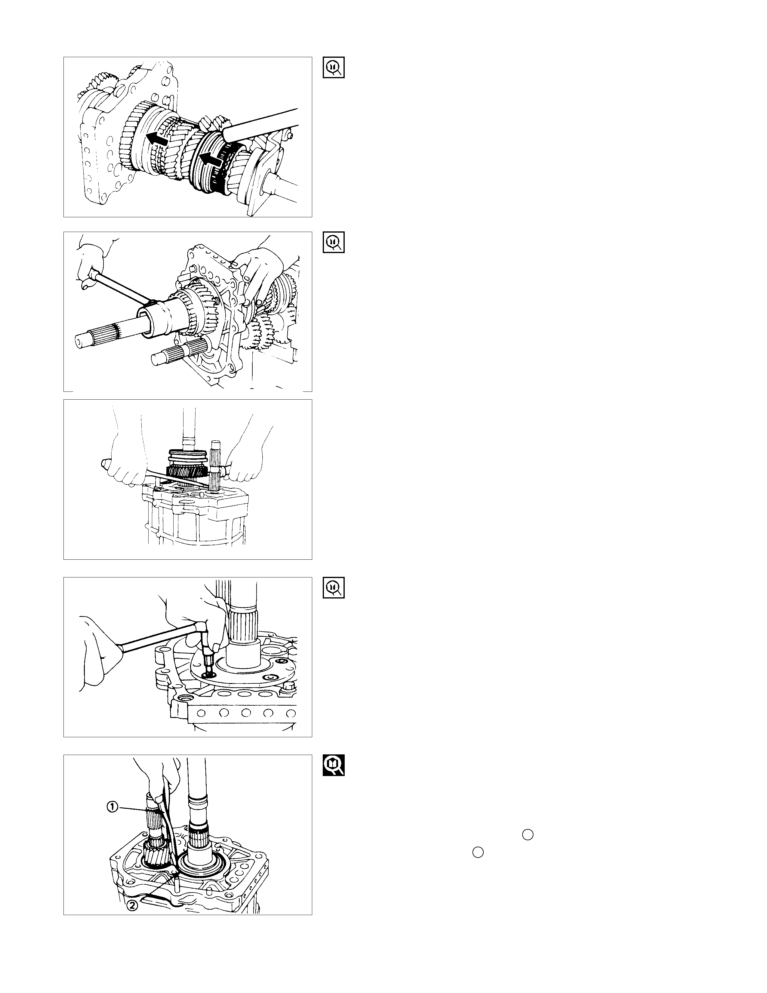
19.Rev.-5th Synchronizer Assembly
20.Reverse Ring
21.Reverse Gear
Use screw drivers between the reverse gear and bearing plate
to remove the Rev.-5th synchronizer assembly together with
reverse ring and gear.
23.Bearing Plate and Screw
Use the Torx bit to remove the bearing plate screw from the
intermediate plate.
Torx Bit Wrench: 5-8840-0047-0 (J-37225) (T45)
24.Ball Bearing Snap Ring
25.Intermediate Plate
1) Insert the snap ring pliers into the mainshaft bearing snap
ring hole.
2) Use the snap ring pliers 1 to force open the mainshaft
bearing snap ring 2.
Hold the snap ring open with the pliers.
3) Push the intermediate plate toward the rear of the
transmission to remove it.
The ball bearing snap ring will come free.
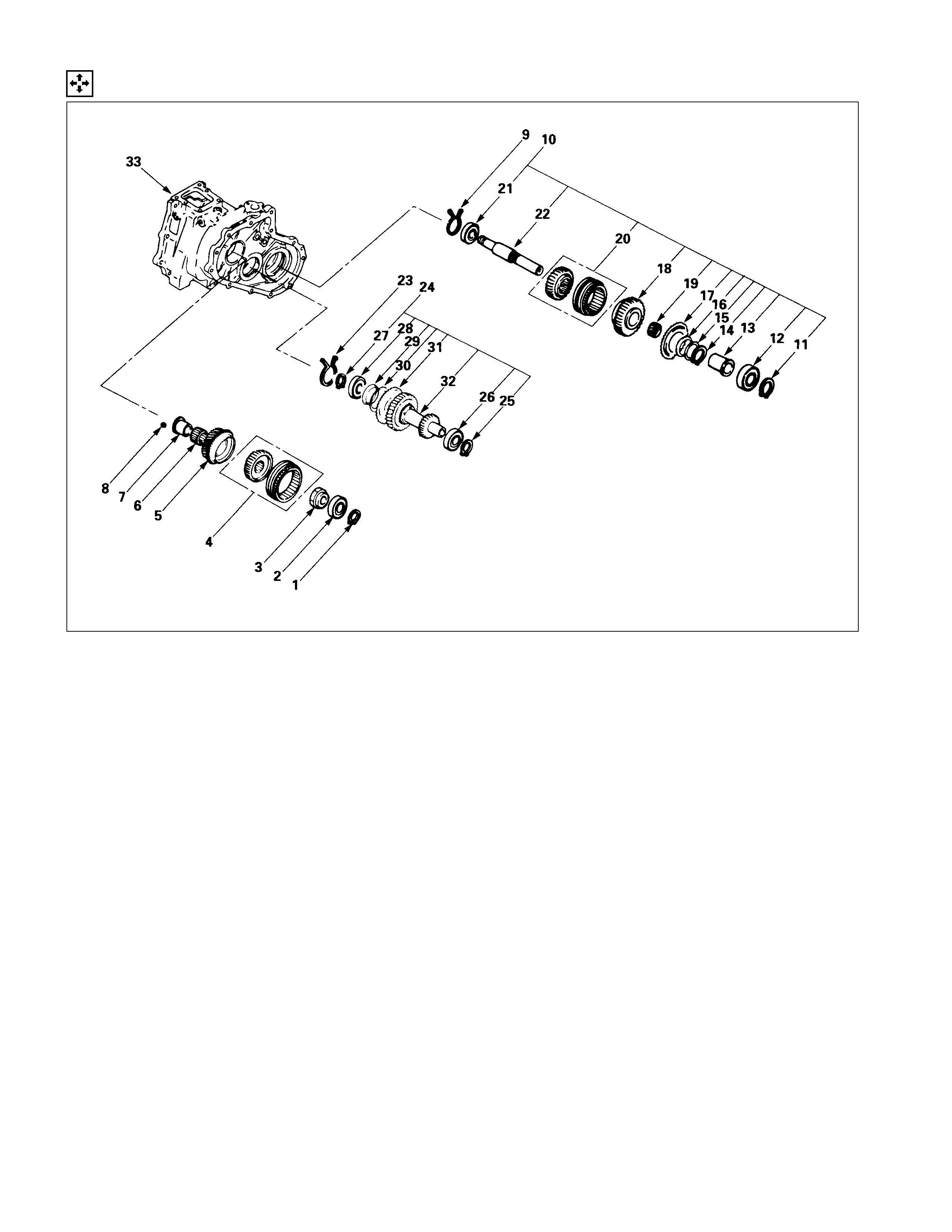
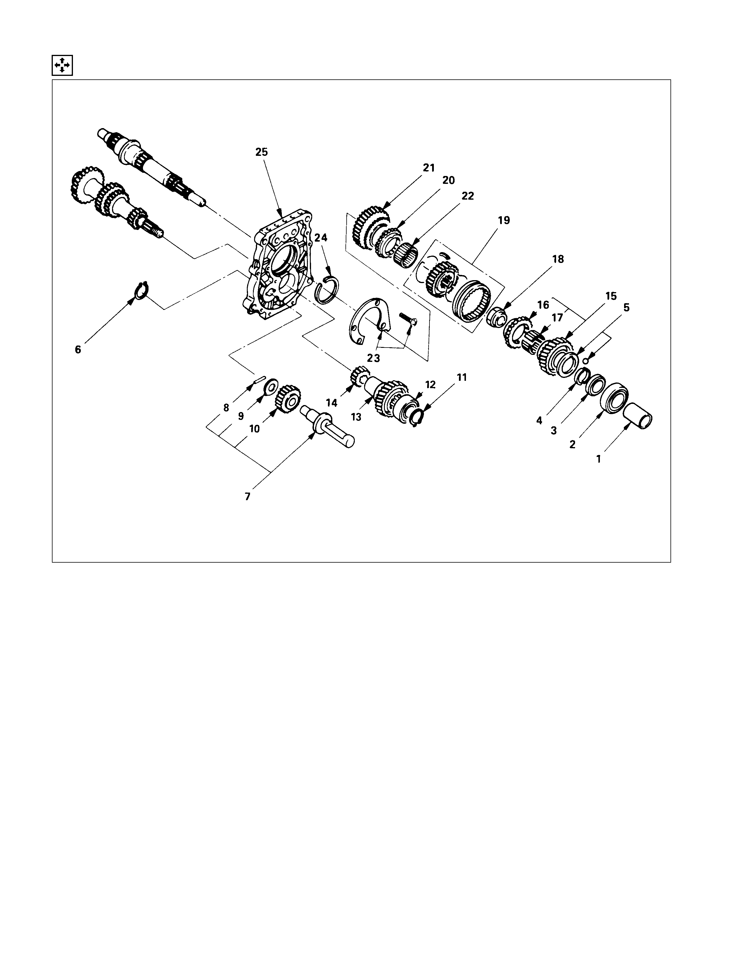
TOP GEAR SHAFT, MAIN GEAR SHAFT, AND COUNTER GEAR
DISASSEMBLY STEPS
1. Top gear shaft snap ring
2. Top gear shaft
I3. Top gear ball bearing
4. Needle bearing
5. Top block ring
I6. Mainshaft snap ring
I7. 3rd-4th synchronizer assembly
8. 3rd block ring
9. 3rd gear
10. Needle bearing
I11. Needle bearing collar
I12. Mainshaft ball bearing
I13. 1st gear thrust bearing
I14. 1st gear
15. 1st block ring (set)
16. Needle bearing
I17. Clutch hub snap ring
I18. 1st-2nd synchronizer assembly
I19. 2nd block ring (set)
I20. 2nd gear
21. Needle bearing
22. Mainshaft
23. Bearing snap ring
I24. Counter gear front bearing
25. Counter gear center bearing
26. Counter gear
IMPORTANT OPERATIONS
3.Top Gear Ball Bearing
Use a bench press and the bearing remover to remove the ball
bearing.
Bearing Remover: 5-8840-0015-0 (J-22912-01)
6.Mainshaft Snap Ring
Use a pair of snap ring pliers to remove the snap ring.
7.3rd-4th Synchronizer Assembly
1) Use a bench press and the bearing replacer to remove the
synchronizer assembly as a set.
2) Disassemble the synchronizer assembly.
1Springs
2Sleeve
3Clutch Hub
4Inserts
Note:
Mark the hub and sleeve alignment for reassembly.
11.Needle Bearing Collar
12.Mainshaft Ball Bearing
13.1st Gear Thrust Bearing
14.1st Gear
Use a bench press and the bearing remover to remove the ball
bearing.
17.Clutch Hub Snap Ring
Use a pair of snap ring pliers to remove the snap ring.
18.1st-2nd Synchronizer Assembly
19.2nd Block Ring (Set)
20.2nd Gear
1) Use a bench press and the bearing rem over to rem ove the
ball bearing 2nd gear together with synchronizer assembly.
Remover: 5-8840-0015-0 (J-22912-01)
2) Disassemble the synchronizer assembly.
1Springs
2Sleeve
3Clutch Hub
4Inserts
Note:
Mark the hub and sleeve alignment for reassembly.
24.Counter Gear Front Bearing
Use a bench press and the bearing remover to remove the
bearing.
Bearing Remover: 5-8840-0015-0 (J-22912-01)
INSPECTION AND REPAIR
Make the necessary adjustments, repairs, and part replacements if excessive wear or damage is discovered during
inspection.
SHIFT ARM THICKNESS
Use a micrometer to measure the shift arm thickness.
If the measured value is less than the specified limit, the shift
arm must be replaced.
Shift Arm Thickness mm (in)
Standard Limit
1st-2nd
Transfer 4×4/4×2
High/Low
9.60-9.85
(0.378-0.388) 9.0 (0.354)
3rd-4th
Rev.-5th 9.60-9.80
(0.378-0.386)
DETENT AND INTERLOCK SPRINGS FREE LENGTH
Use a vernier caliper to measure the spring's free length.
If the measured value is less than the specified limit, the
springs must be replaced.
Springs Free Length mm (in)
Standard Limit
Transmis s ion 26.8 (1. 06) 26.2 ( 1.03)
Transf er c as e 23.4 (0.92) 22.8 (0. 90)
(I nterlock P in) Transfer c as e 15.9 (0.626) 15.3 (0.602)
(Det ent Ball)
DETENT SPRING TENSION
Use a spring tester to measure the springs tension. If the
measured value is less than the specified standard, the springs
must be replaced.
Springs Tension N⋅m(kgf⋅m/Ib⋅ft)
Compressed
Height Standard
Transmission 20 mm
(0. 787 in) 87.2-97
(8.9-9.9/19.6-
21.8)
Transf er case 18.7 mm
(0. 736 in) 68.6-88.2
(7.0-9.0/15.4-
19.8)
(I nterlock P in) Transfer c as e 115 mm
(0. 453 in) 9.8
(1.0/2.2)
(Det ent Ball)

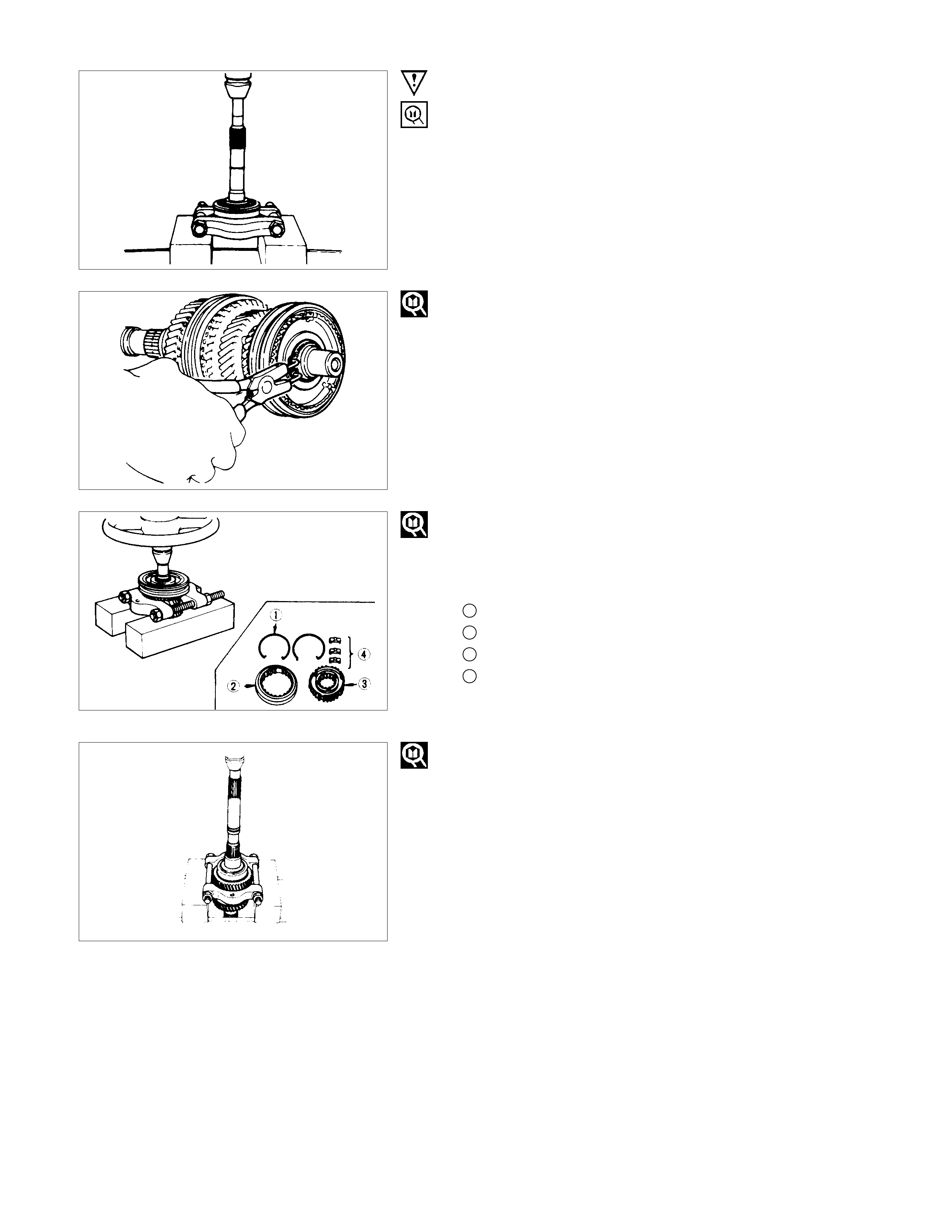
BLOCK RING AND DOG TEETH CLEARANCE
Use a thickness gauge to measure the clearance between the
block ring and the dog teeth.
If the measured value exceeds the specified limit, the block
ring must be replaced.
Block Ring and Dog Teeth Clearance mm (in)
Standard Limit
1.5 (0.059) 0.8 (0.032)
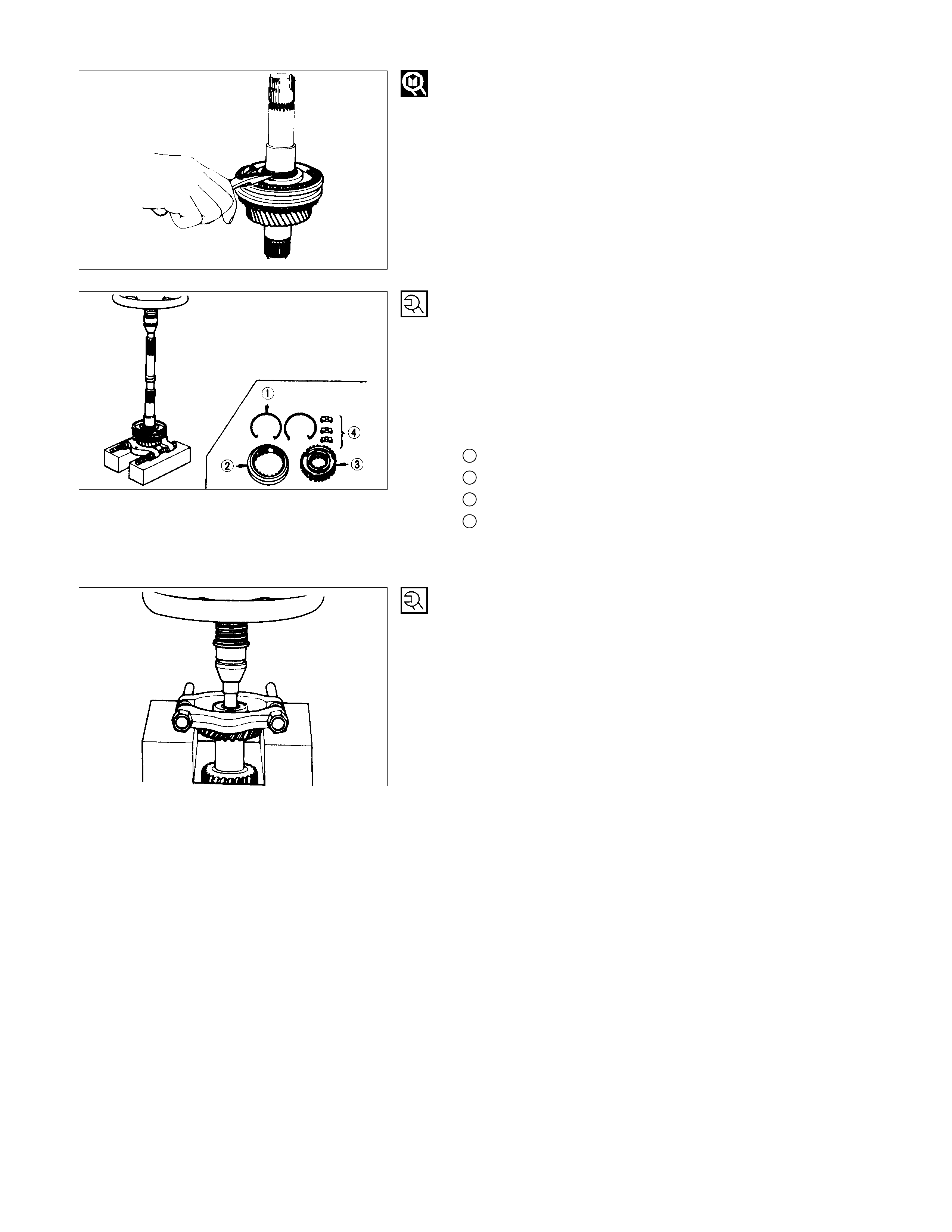
BLOCK RING AND INSERT CLEARANCE
Use a vernier caliper to measure the clearance between the
block ring and the insert.
If the measured value exceeds the specified limit, the block
ring and the insert must be replaced.
Block Ring and Insert Clearance mm (in)
Standard Limit
3rd-4th 3.46-3.74 (0.136-0.147) 4.0 (0.158)
1st-2nd 4.34-4.66 (0.171-0.183) 4.9 (0.193)
Transfer 2.46-2.74 (0.097-0.108) 3.0 (0.118)
Rev.-5th 3.59-3.91 (0.141-0.154) 4.1 (0.161)
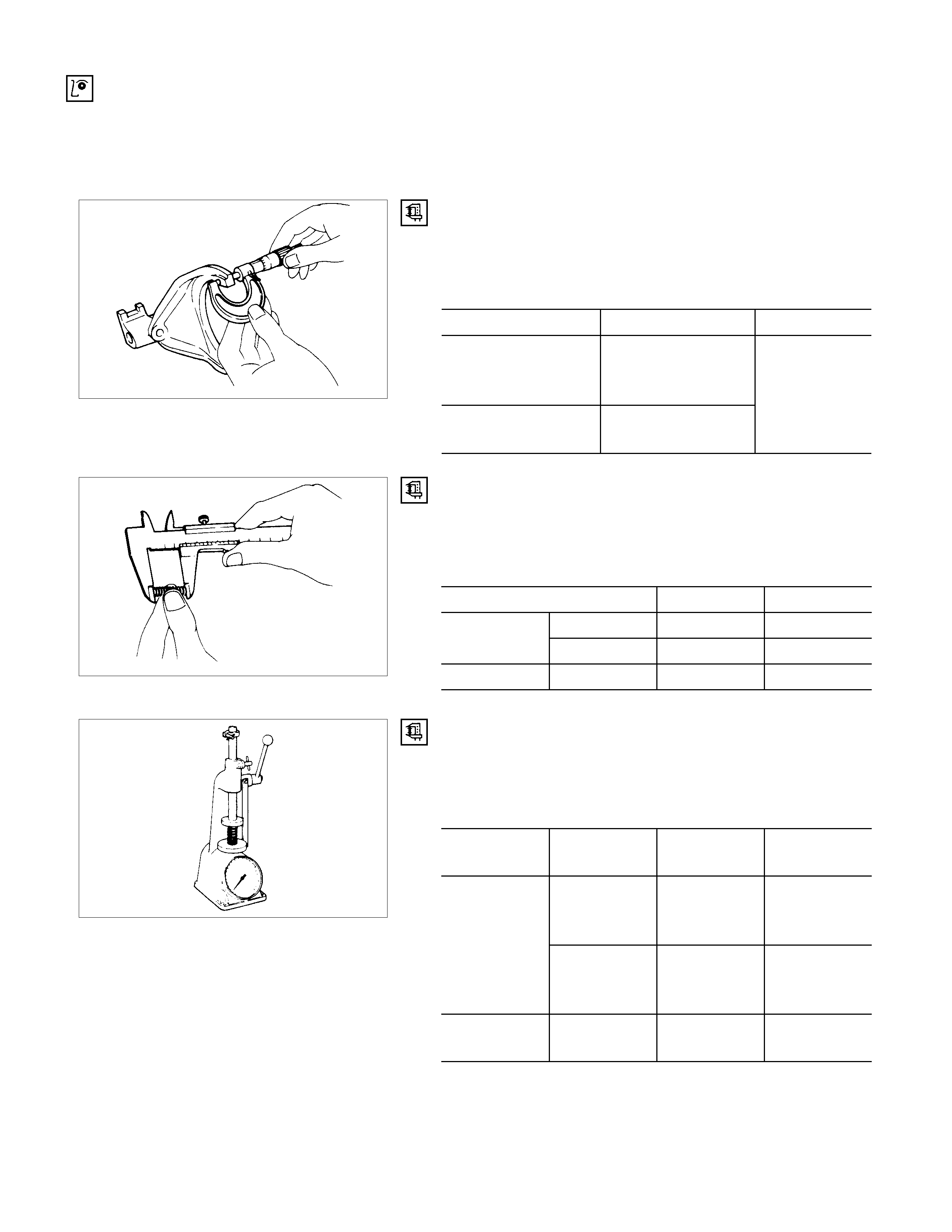
CLUTCH HUB AND INSERT CLEARANCE
Use a thickness gauge to measure the clearance between the
clutch hub and the insert.
If the measured value exceeds the specified limit, the clutch
hub and the insert must be replaced.
Clutch Hub and Insert Clearance mm (in
)
Standard Limit
3rd-4th 0.01-0.19 (0.0004-0.0075) 0.3 (0.012)
1st-2nd
Rev.-5th 0.09-0.31 (0.0035-0.0122) 0.4 (0.016)
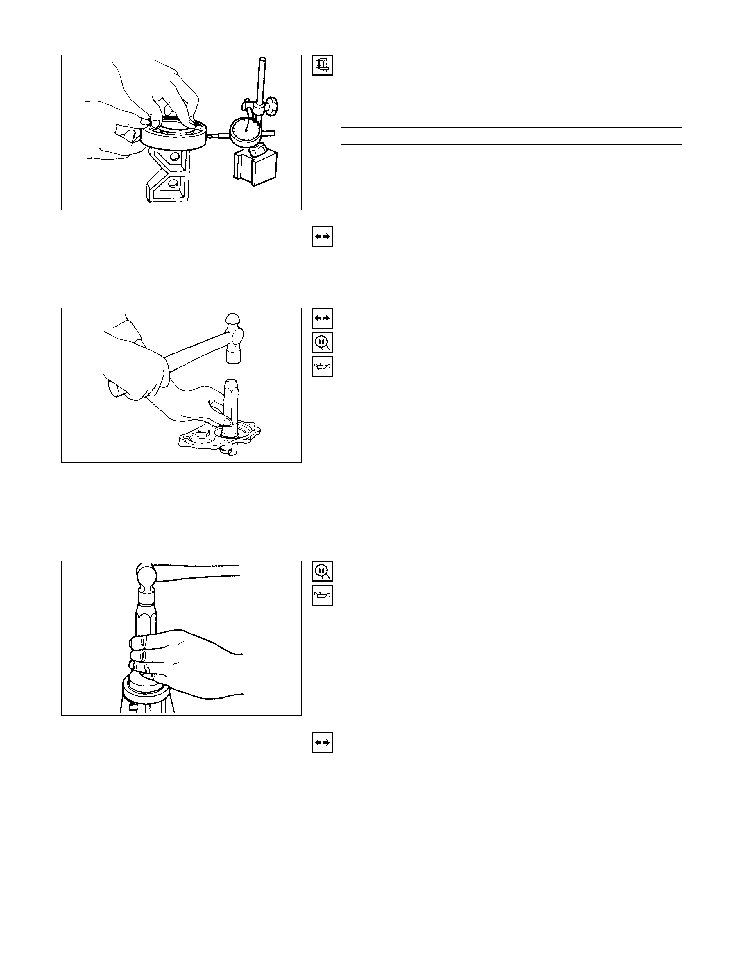
MAINSHAFT RUN-OUT
1. Install the mainshaft to a grinding machine.
2. Use a dial indicator to measure the mainshaft central
portion run-out.
If the measured mainshaft run-out exceeds the specified
limit, the mainshaft must be replaced.
Mainshaft Run Out mm (in)
Limit
0.05 (0.0020)
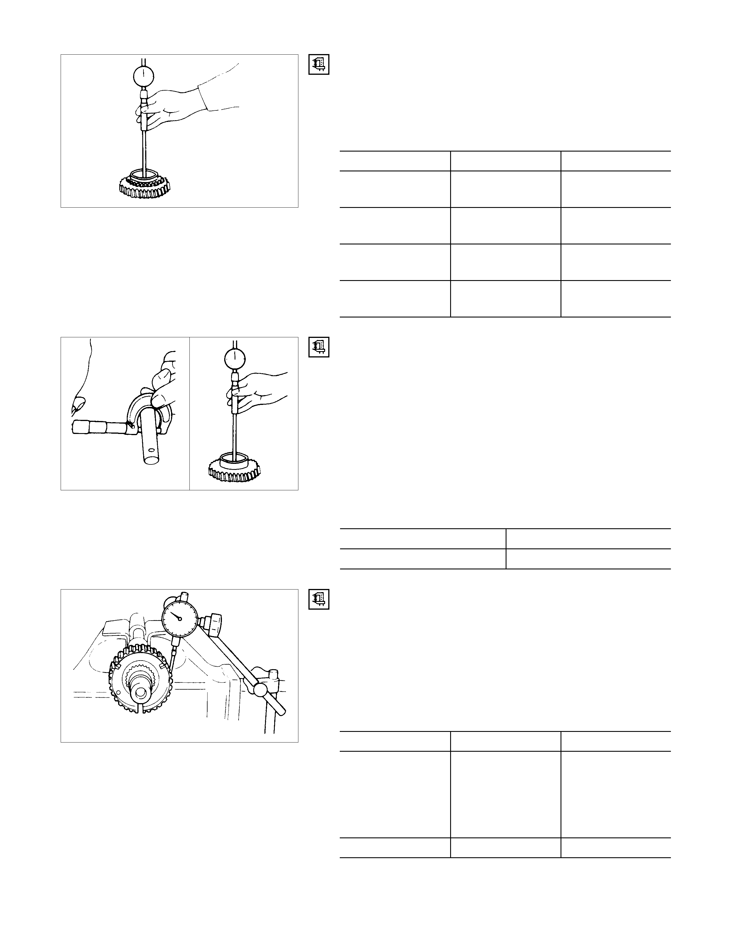
GEAR INSIDE DIAMETER
Use an inside dial indicator to measure the gear inside
diameter.
If the measured value is less than the specified limit, the gear
must be replaced.
Gear Inside Diameter mm (in)
Standard Limit
1st
3rd 45.000-45.013
(1.771-1.772) 45.100 (1.776)
2nd 52.000-52.013
(2.047-2.048) 52.100 (2.051)
Rev.
Transfer 48.000-48.013
(1.889-1.890) 48.100 (1.894)
5th 32.000-32.013
(1.259-1.260) 32.100 (1.264)
REVERSE IDLER GEAR AND IDLER GEAR SHAFT
CLEARANCE
1. Use a micrometer to measure the idler gear shaft diameter.
2. Use an inside dial indicator to m easure the idler gear inside
diameter.
3. Calculate the idler gear and idler gear shaft clearance Idle
r
gear inside diam eter - idler gear s haft diameter = idler gea
r
and idler gear shaft clearance.
If the measured value exceeds the specified limit, the idle
r
gear and/or the idler gear shaft must be replaced.
Idler Gear and Idler Gear Shaft Clearance mm (in)
Standard Limit
0.041-0.074 (0.0016-0.0029) 0.150 (0.0059)
CLUTCH HUB SPLINE PLAY
1. Set a dial indicator to the clutch hub to be measured.
2. Move the clutch hub as far as poss ible to both the right and
the left.
Note the dial indicator reading.
It the meas ur ed value ex ceeds the s pecified lim it, the c lutc h
hub must be replaced.
Clutch Hub Spline Play mm (in)
Standard Limit
1st-2nd
3rd-4th
Transf er 0-0. 1 ( 0- 0.0039) 0. 2 ( 0.0079)
4×2/4×4
High/Low
Rev. - 5th 0-0. 2 ( 0- 0.0079) 0. 3 ( 0.0118)
BALL BEARING PLAY
Use a dial indicator to measure the ball bearing play.
Ball Bearing Play mm (in)
Limit
0.2 (0.0079)
FRONT COVER OIL SEAL
Oil Seal Replacement
Oil Seal Removal
Use a screwdriver to pry the oil seal from the front cover.
OIL SEAL INSTALLATION
1. Use the oil seal installer to install the oil seal to the front
cover.
Oil Seal Installer: 5-8840-0026-0 (J-26540)
2. Apply gear oil to the oil seal lip.
REAR COVER OIL SEAL
Oil Seal Replacement
Oil Seal Removal
Use a screwdriver to pry the oil seal from the rear cover.
OIL SEAL INSTALLATION
1. Use the oil seal installer to install the oil seal to the rea
r
cover.
Oil Seal Installer: 5-8522-0050 (J-29769)
2. Apply engine oil to the oil seal lip.
TRANSFER CASE MAINSHAFT OIL SEAL
Oil Seal Replacement
Oil Seal Removal
Use a screwdriver to pry the oil seal from the transfer case.
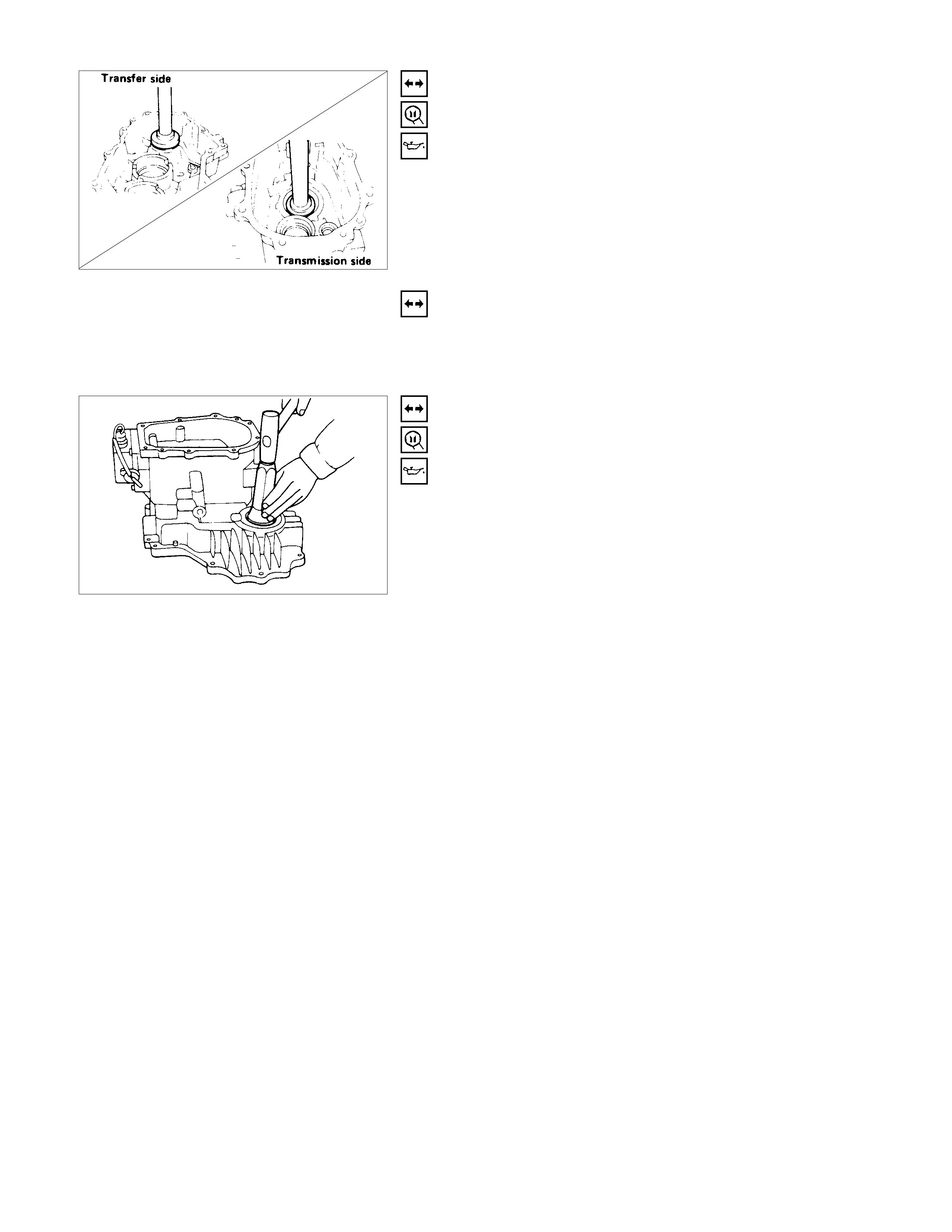
OIL SEAL INSTALLATION
1. Use the oil seal ins taller to install the oil seal to the transf e
r
case.
Oil Seal Installer: 5-8840-2193-0 (J-37488)
Drive Handle: 5-8840-0007-0 (J-8092)
2. Apply engine oil to the oil seal lip.
TRANSFER CASE FRONT OUTPUT SHAFT OIL SEAL
Oil Seal Replacement
Oil Seal Removal
Use a screwdriver to pry the oil seal from the transfer case.
OIL SEAL INSTALLATION
1. Use the oil seal ins taller to install the oil seal to the tr ansfe
r
case.
Oil Seal Installer: 5-8840-2161-0 (J-37226)
2. Apply engine oil to the oil seal lip.
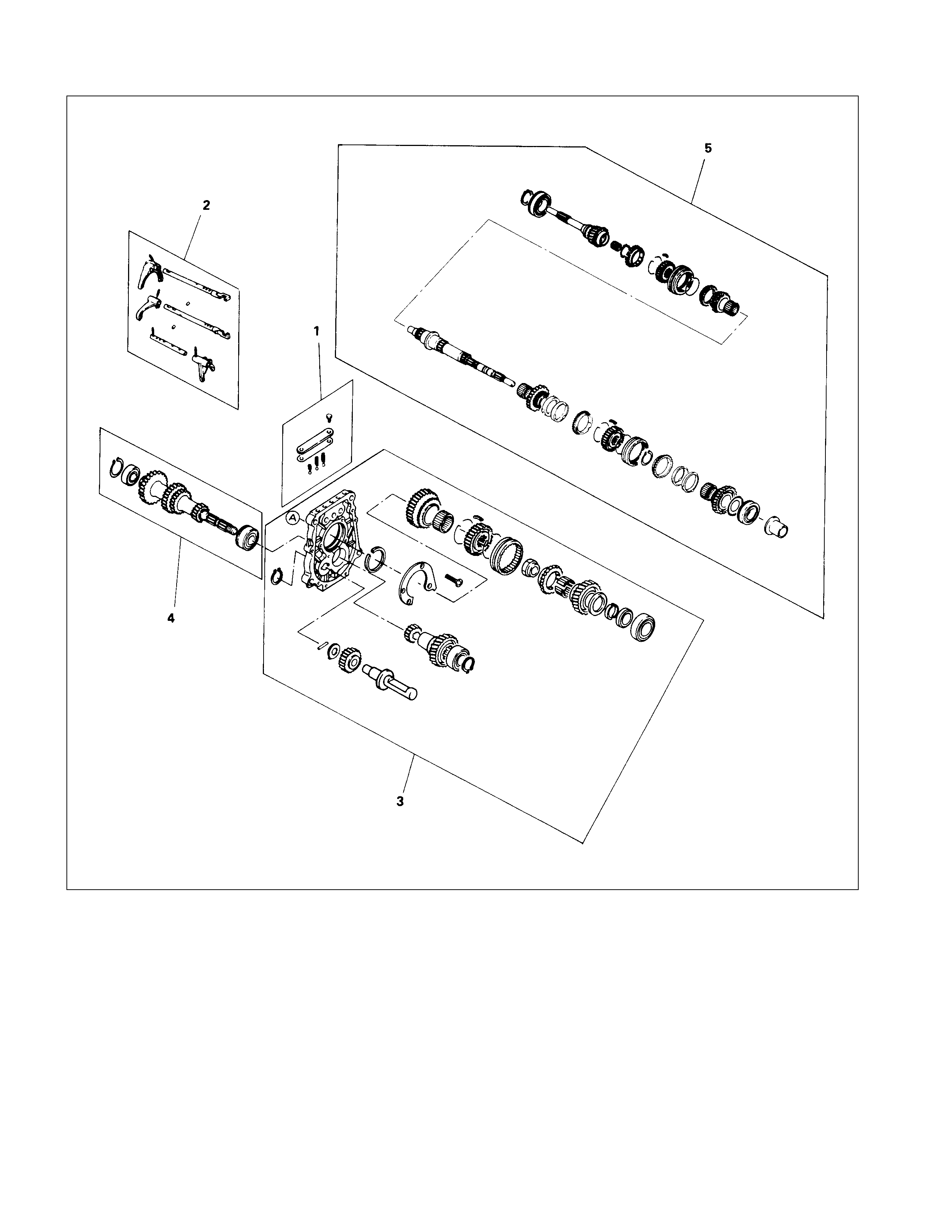
REASSEM BLY
MAJOR COM PONENT
TRANSMISSION
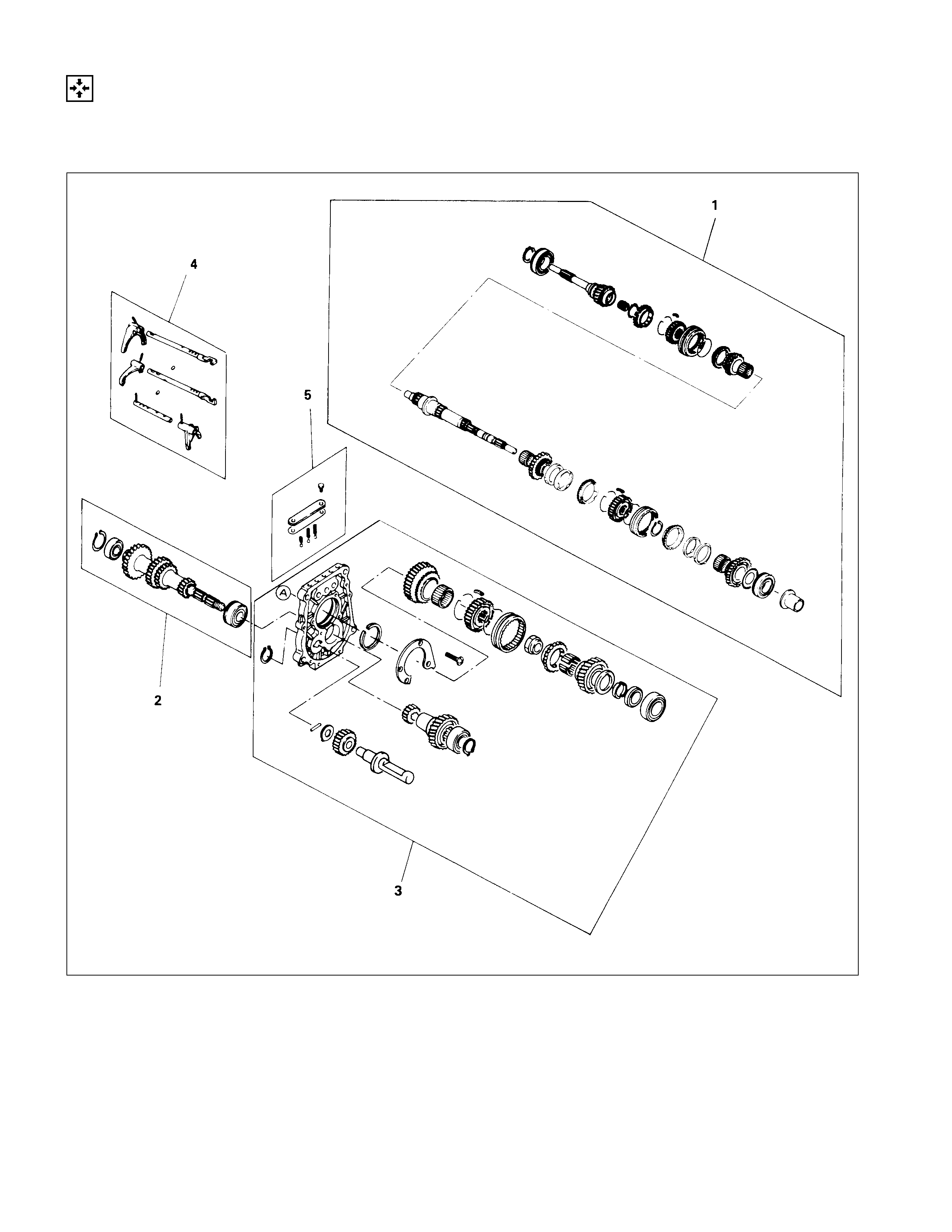
REASSEM BLY STEPS
1. Top & main gear shaft assembly
2. Counter gear shaft assembly
3. Rev. and 5th gear assembly
4. Shift arm assembly & interlock pin
5. Detent assembly
TRANSFER CASE
REASSEM BLY STEPS
1. Transfer case assembly
2. Transfer rear case assembly
MINOR COMPONENT
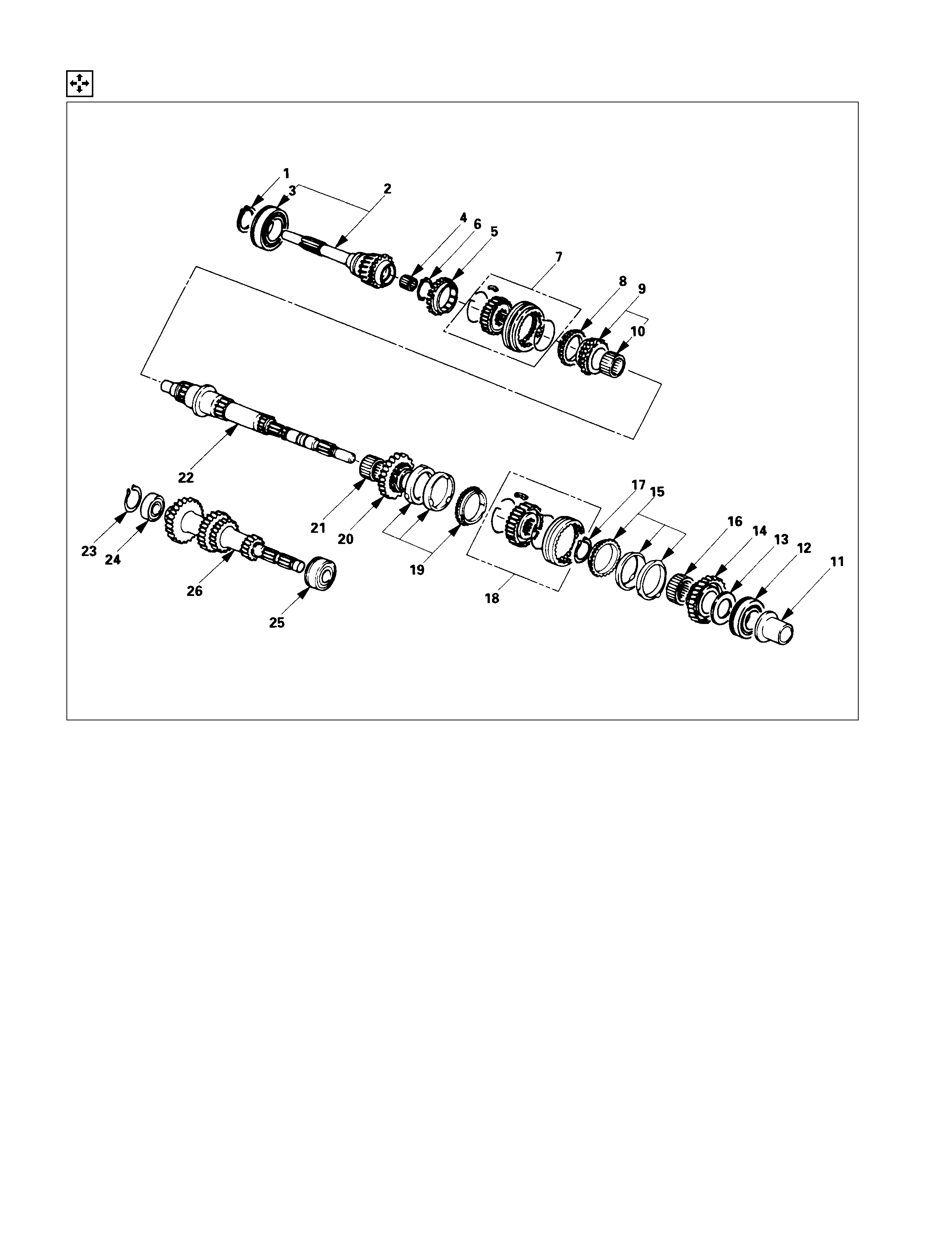
TOP GEAR SHAFT, MAIN SHAFT GEAR AND COUNTER GEAR
REASSEM BLY STEPS
1. Mainshaft
▲2. Needle bearing
▲3. 2nd gear
4. 2nd block ring (set)
▲5. 1st-2nd synchronizer assembly
▲6. Clutch hub snap ring
▲7. Needle bearing
8. 1st block ring (set)
▲9. 1st gear
▲10. 1st gear thrust bearing
▲11. Mainshaft ball bearing
▲12. Needle bearing collar
▲13. Needle bearing
▲14. 3rd gear
15. 3rd block ring
▲16. 3rd-4th synchronizer assembly
▲17. Mainshaft snap ring
18. Needle bearing
19. Top block ring
20. Top gear shaft
▲21. Ball bearing
▲22. Top gear shaft snap ring
23. Counter gear
▲24. Counter gear front bearing
25. Snap ring
26. Counter gear center bearing
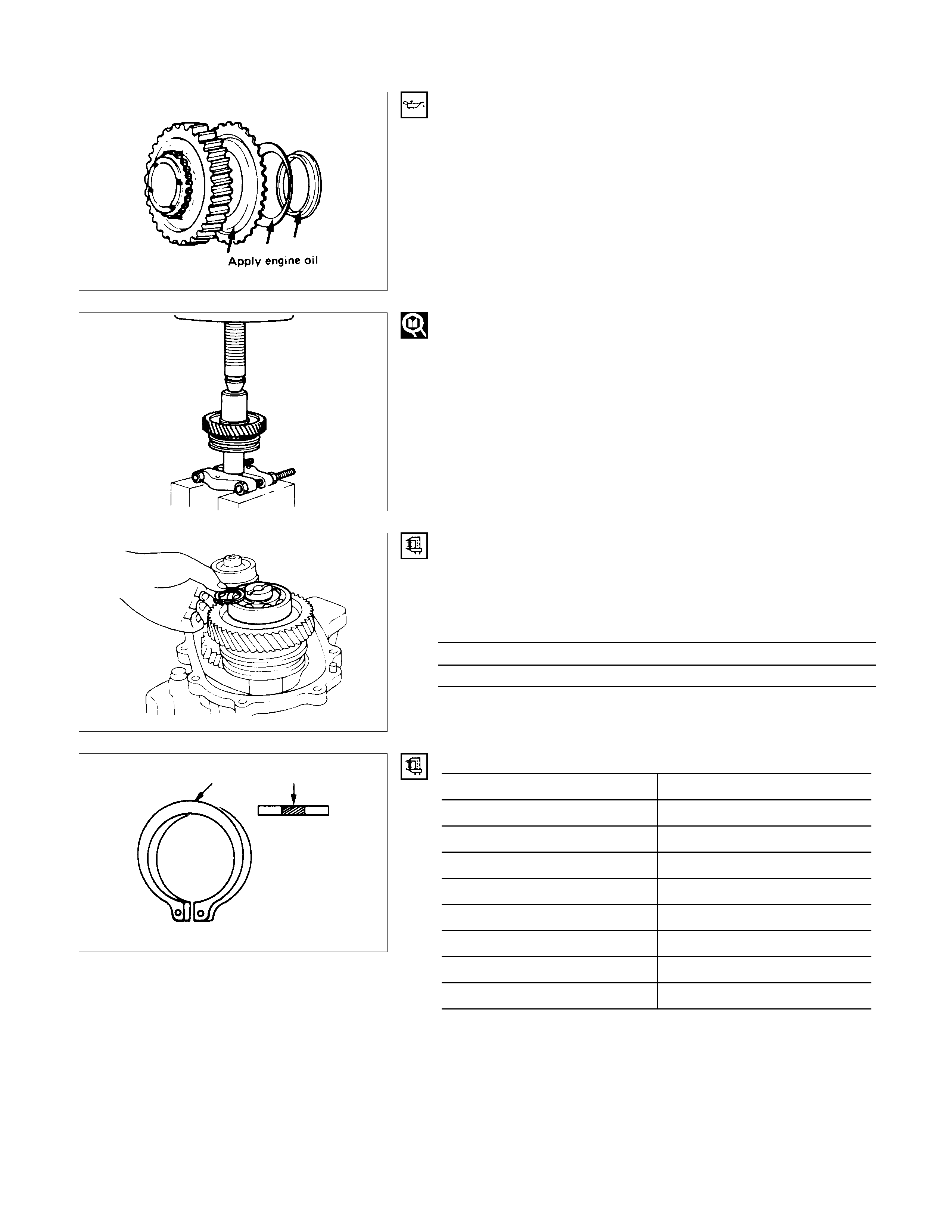
IMPORTANT OPERATIONS
2. Needle Bearing
3. 2nd Gear
1) Apply engine oil to the needle bearing and the 2nd gea
r
thrust surfaces.
2) Install the needle bearing and the 2nd gear to the
mainshaft.
The dog teeth of the 2nd gear must be facing the rear side
of the transmission.
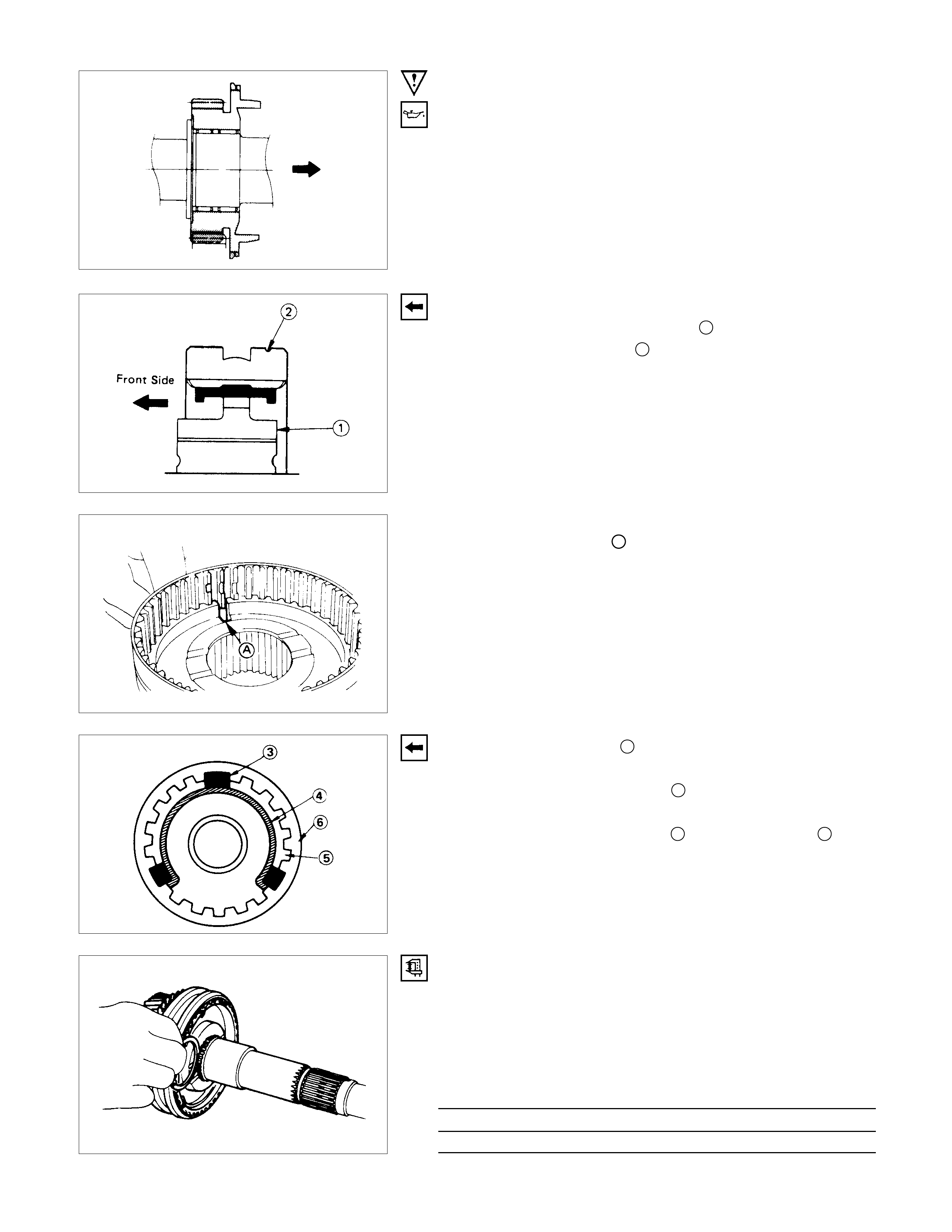
5. 1st-2nd Synchronizer Assembly
1) Turn the shallow clutch hub face 1 toward the side of the
sleeve with small groove 2 on the outer circumference.
Note:
The clutch hub groove
A
must be aligned with the key
groove of sleeve.
2) Check that the inserts 3 fit snugly into the block ring insert
grooves.
3) Check that the insert springs 4 are fitted to the inserts as
shown in the illustration.
4) Check that the clutch hub 5 and the sleeve 6 slide
smoothly.
5) Install the synchronizer assembly to the mainshaft.
The clutch hub face (with the heavy boss) must be facing
the 2nd gear side.
6. Clutch Hub Snap Ring
1) Select the snap ring, which will provide the minimum
clearance between the 1st/2nd clutch hub and the snap
ring.
There are three snap ring sizes available.
The snap rings are color-coded to indicate their thickness.
Clutch Hub and Snap Ring Clearance mm (in)
Standard
0-0.1 (0.0039)
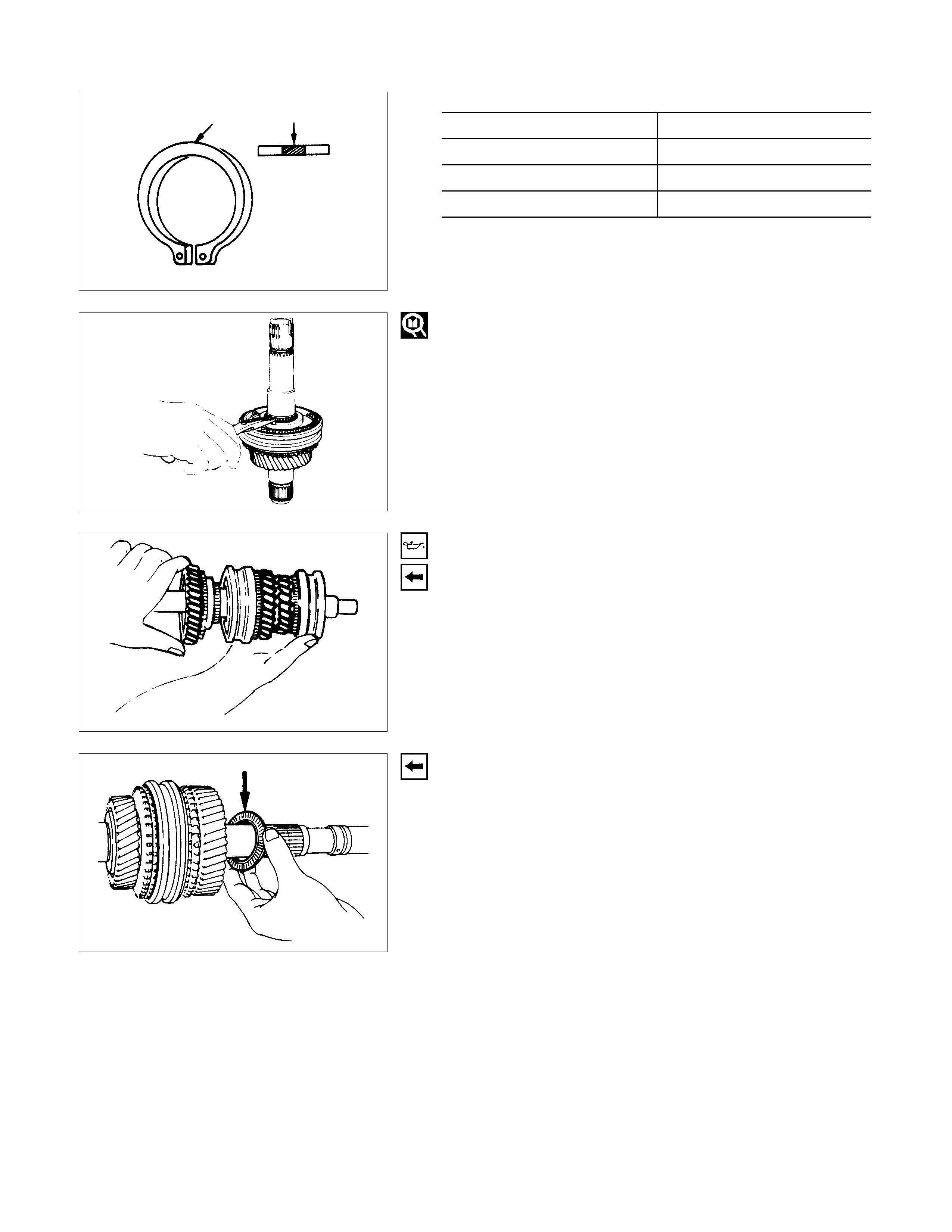
Snap Ring Availability
Thickness mm (in) Color-Coding
1.80 (0.071) White
1.85 (0.073) Yellow
1.90 (0.075) Blue
2) Use a pair of snap ring pliers to install the snap ring to the
mainshaft.
The snap ring mus t be f ully inserted into the m ains haf t s nap
ring groove.
7.Needle Bearing
9.1st Gear
1)
A
pply engine oil to the needle bearing and the 1st gea
r
thrust surfaces.
2) Install the needle bearing and the 1st gear to the mainshaft.
The 1st gear dog teeth must be facing the transmission
front side.
10.1st Gear Thrust Bearing
Install the thrust bearing to the mainshaft.
The thrust bearing side must be facing the transmission front
side.
11.Mainshaft Ball Bearing
12.Needle Bearing collar
1) Apply engine oil to the ball bearing and the mainshaft.
2) Install the ball bearing and collar to the mainshaft.
The ball bearing snap ring groove must be facing the
transmission rear side.
3) Use a bench press to slowly force the collar into place.
Installer: 5-8840-2195-0 (J-6133-01)
13.Needle Bearing
14.3rd Gear
1) Apply engine oil to the needle bearing and the 3rd gea
r
thrust surfaces.
2) Install the needle bearing and the 3rd gear to the mainshaft.
The dog teeth of the 3rd gear m ust be facing the front side
of the transmission.
16.3rd-4th Synchronizer Assembly
1) Turn the clutch hub face 1 with the heavy boss Atoward
the side of the sleeve with small groove 2on the oute
r
circumference.
2) Check that the inserts 3 fit snugly into the block ring insert
grooves.
3) Check that the insert springs 4 are fitted to the inserts as
shown in the illustration.
4) Check that the clutch hub 5 and the sleeve 6 slide
smoothly.
5) Install the synchronizer assembly to the mainshaft.
The clutch hub face (with the heavy boss) must be facing
the 3rd gear side.
17.Mainshaft Snap Ring
1) Select the snap ring, which will provide the minimum
clearance between the 3rd-4th clutch hub and the snap
ring.
There are three snap ring sizes available.
The snap rings are color-coded to indicate their thickness.
Clutch Hub and Snap Ring Clearance mm (in)
Standard
0-0.1 (0.0039)
Snap Ring Availability mm (in)
Thickness Color-Coding
1.80 (0.071) White
1.85 (0.073) Yellow
1.90 (0.075) Blue
2) Use a pair of snap ring pliers to install the snap ring to the
mainshaft.
3) The snap ring mus t be f ully inserted into the m ains haf t s nap
ring groove.
21.Ball Bearing
22.Top Gear Shaft Snap Ring
1) Use a bench press to install the top gear shaft ball bearing
to the mainshaft.
The snap ring groove m ust be fac ing the transmiss ion front
side.
2) Use a pair of snap ring pliers to install the snap ring to the
bearing.
24.Counter Gear Front Bearing
Use a bench press to install the counter gear front bearing to
the mainshaft.
The snap ring groove must be facing the transmission front
side.
Bearing installer: 5-8840-2194-0 (J-35283)
1) Apply engine oil to the bearing and install the inner race 1
and outer race with roller 2 in the proper direction to the
mainshaft.
2) Then install the inner r ace 3with taper side turned to oute
r
race 2.
Note:
The inner race 3 should be installed with stamp on die
face side turned to the front side of transmission.
REVERSE GEAR AND 5TH GEAR
REASSEM BLY STEPS
▲1. Intermediate plate
2. Bearing snap ring
▲3. Bearing plate and screw
4. Needle bearing
5. Mainshaft reverse gear
6. Reverse block ring
▲7. Rev.-5th synchronizer assembly
▲8. Clutch hub nut
9. Needle bearing
10. 5th block ring
11. 5th gear
▲12. Counter reverse gear
13. Counter 5th gear
14. Ball bearing
15. Reverse idler gear
16. Thrust washer
17. Idler shaft pin
18. Reverse idler shaft
▲19. Bearing snap ring
▲20. Reverse gear snap ring
▲21. Thrust washer and lock ball
22. Thrust plate
23. Retainer
▲24. Roller bearing
25. Oil seal collar
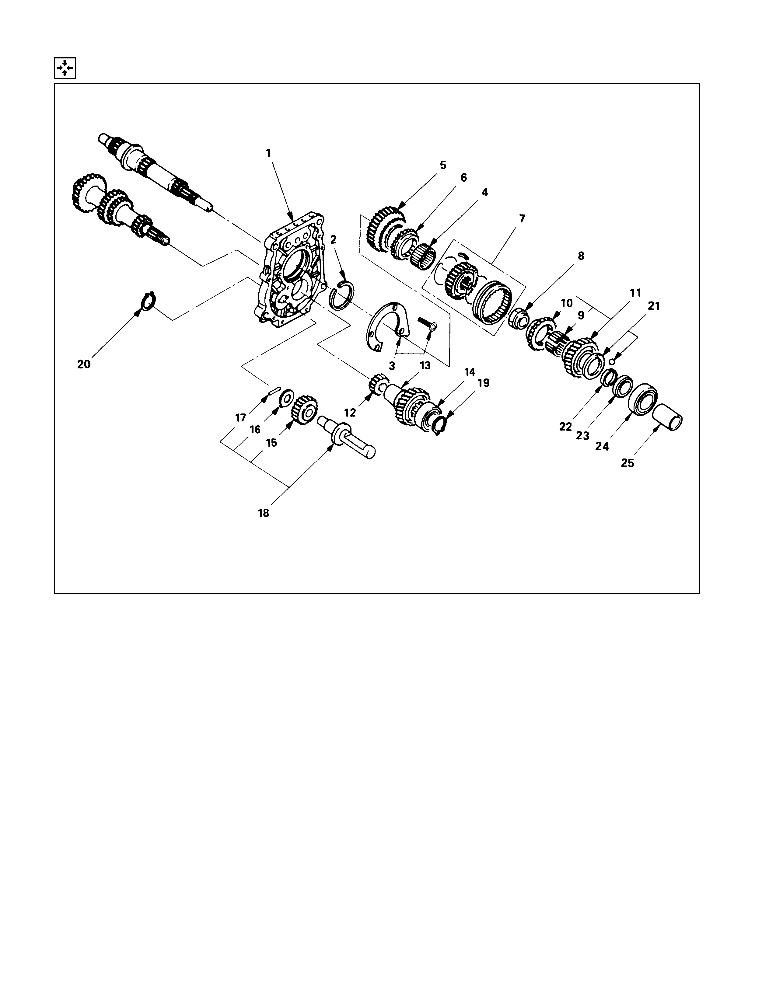
IMPORTANT OPERATIONS
1. Intermediate Plate
1) Mesh the counter gear with the mainshaft assembly.
2) Install the holding fixture to the mainshaft and the counte
r
gear.
Holding Fixture: 5-8840-2160-0 (J-37224)
Holding base: 5-8840-0003-0 (J-3289-20)
3) Place the holding fixture (with the mainshaft and the counte
r
shaft) in a vise.
4) Install the intermediate plate.
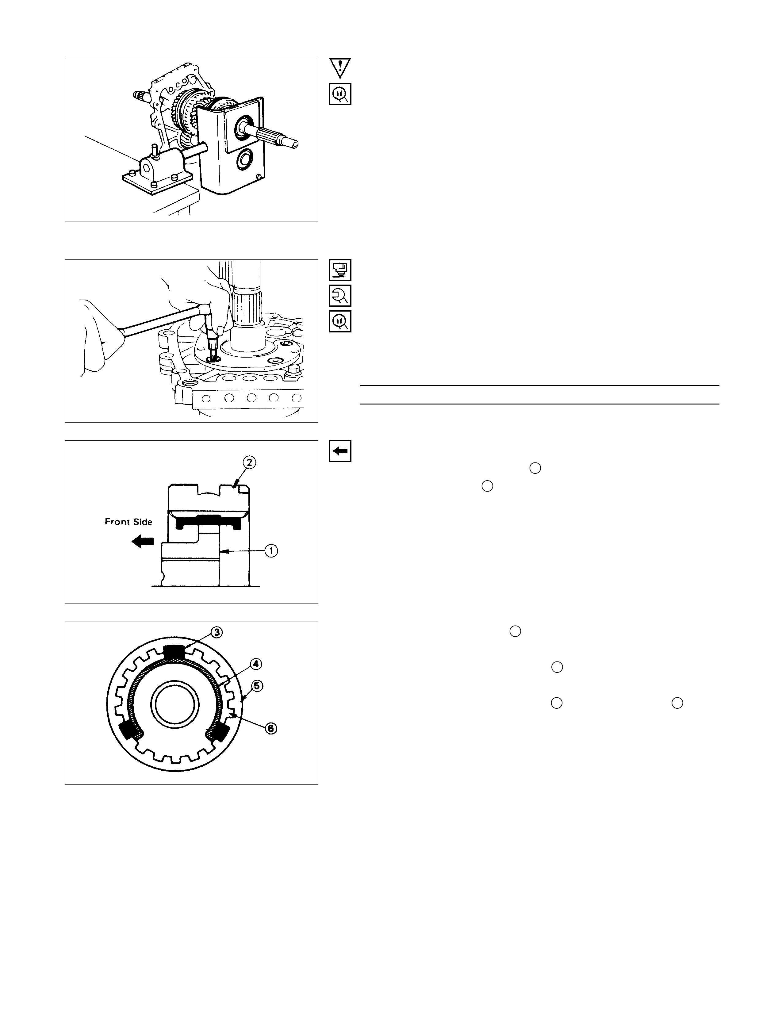
3. Bearing Plate and Screw
1) Apply recom mended thr ead locking agents or its equivalent
to each of the plate screw threads.
2) Use the wrench to tighten the screws to the specified
torque.
Torx Bit Wrench: 5-8840-0047-0 (J-37225) (T45)
Plate Screw Torque N⋅m (kgf⋅m/lb⋅ft)
15 (1.5/11)
7. Rev.-5th Synchronizer Assembly
1) Turn the clutch hub face 1 toward the side of the sleeve
with small groove 2 on the outer circumference.
2) Check that the inserts 3 fit snugly into the block ring insert
grooves.
3) Check that the insert springs 4 are fitted to the inserts as
shown in the illustration.
4) Check that the clutch hub 5 and the sleeve 6 slide
smoothly.
5) Install the synchronizer assembly to the mainshaft.
The clutch hub face (with the heavy boss) must be facing
the reverse gear side.
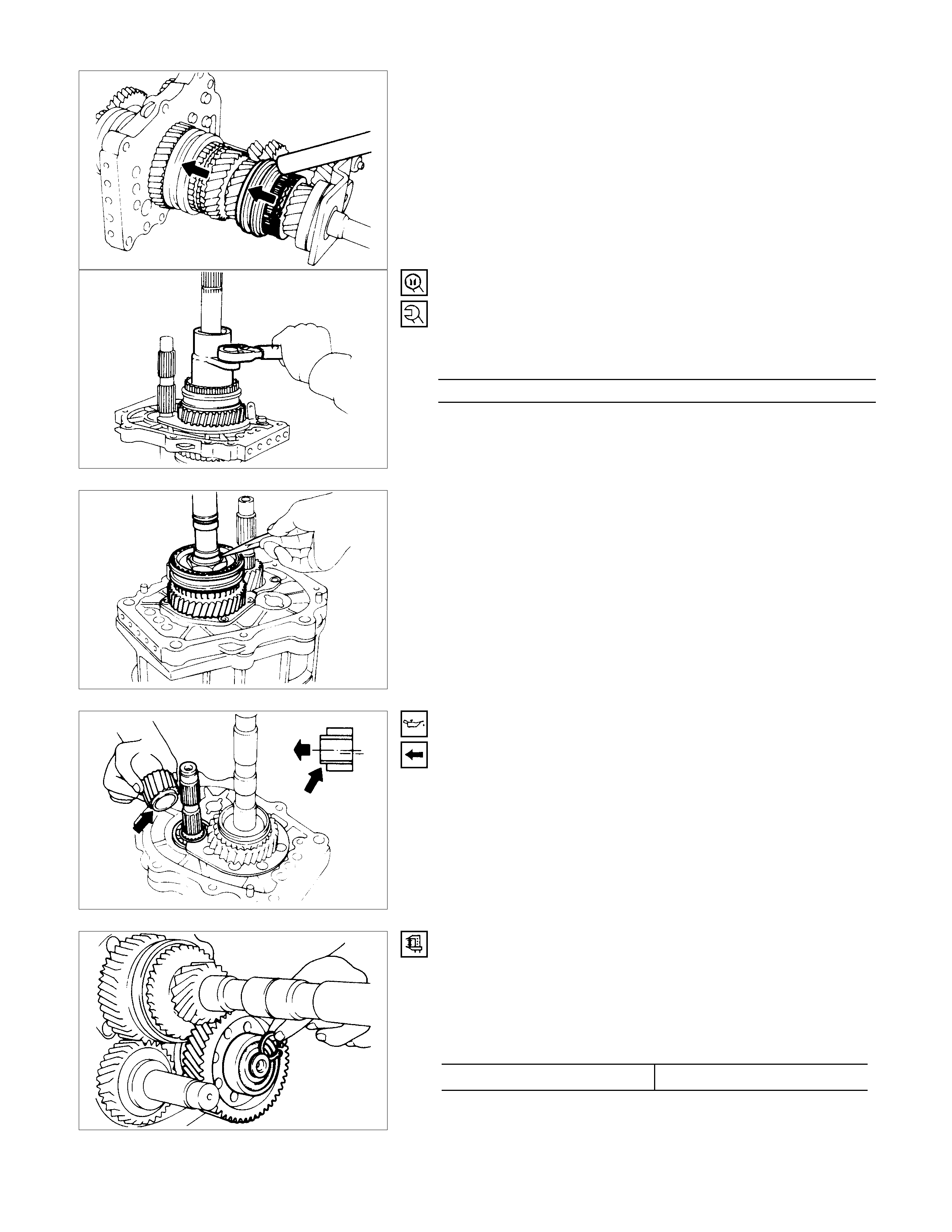
8. Clutch Hub Nut
1) Mesh the 1st-2nd synchronizer with both the 1st and 3rd
gears (double engagement).
This will prevent the mainshaft from turning.
2) Install the mainshaft lock nut.
3) Use the lock nut wrench to tighten the lock nut to the
specified torque.
Wrench: 5-8840-2156-0 (J-37219)
Hub Nut Torque N⋅m (kgf⋅m/lb⋅ft)
137 ± 20 (14 ± 2 / 101 ± 14.4)
4) Use a punch to stake the lock nut.
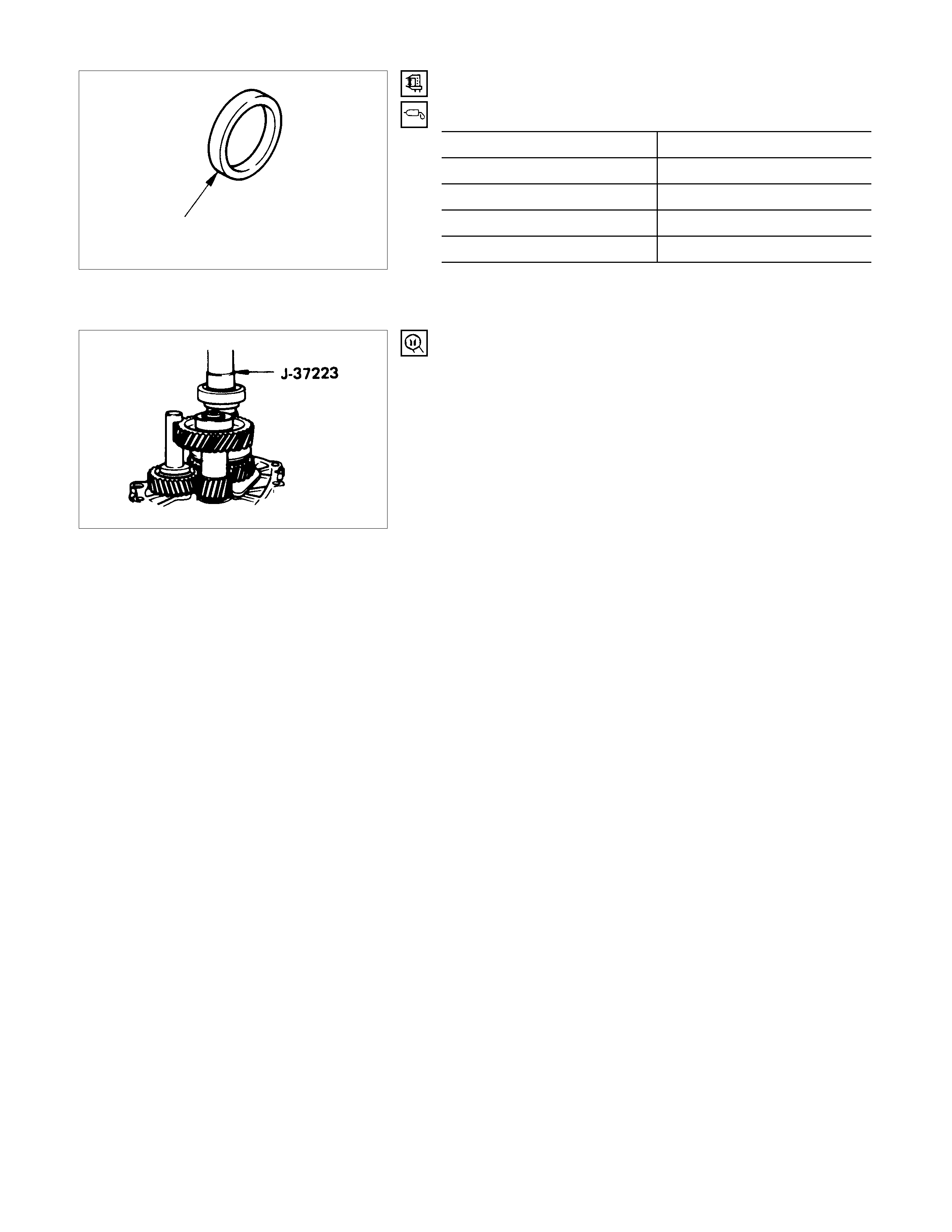
12.Counter Reverse Gear
1) Apply engine oil to the counter reverse gear and the reverse
gear.
2) Install the counter reverse gear to the counter gear.
The reverse gear projection must be facing the side of the
intermediate plate.
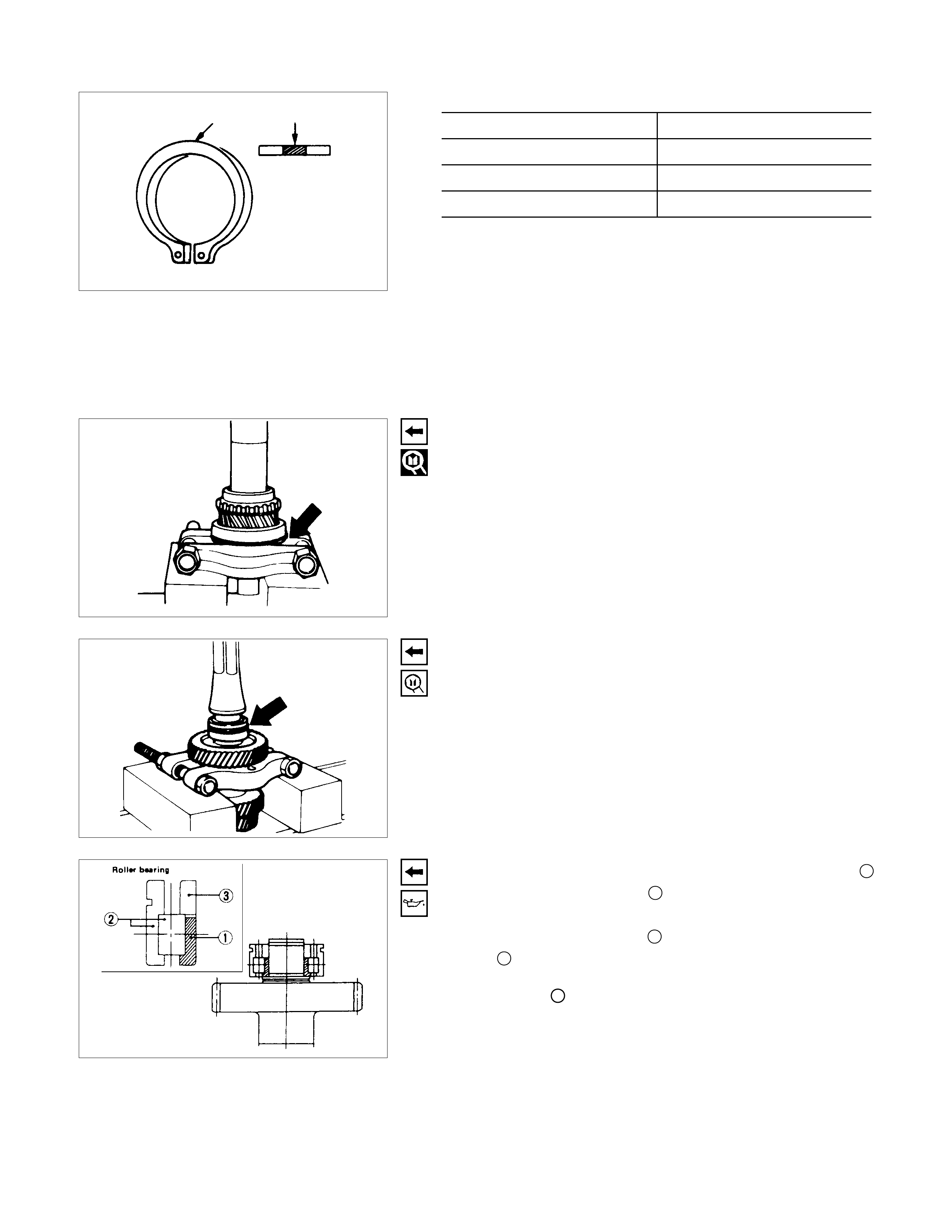
19.Bearing Snap Ring
1) Select the snap ring, which will provide the minimum
clearance between the ball bearing and the snap ring.
There are six snap ring sizes available.
The snap rings are color-coded to indicate their thickness.
Ball Bearing and Snap Ring Clearance mm (in)
Standard 0-0.15 (0-0.0059)
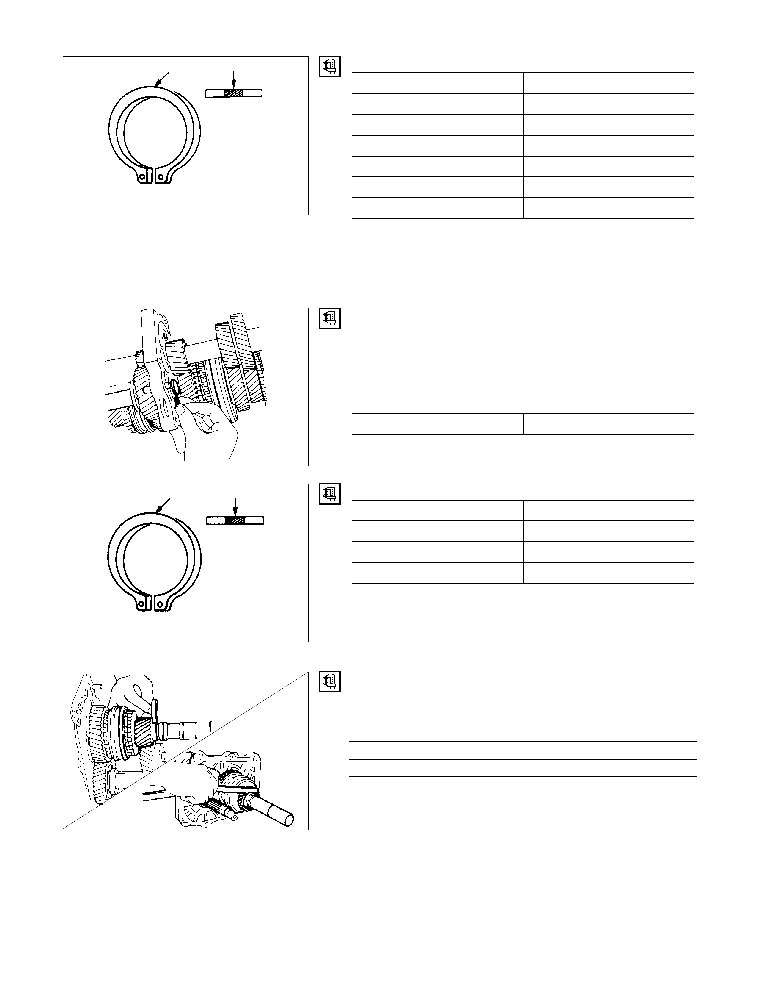
Snap Ring Availability mm (in)
Thickness mm (in) Color-Coding
1.1 (0.043) White
1.2 (0.047) Yellow
1.3 (0.051) Blue
1.4 (0.055) Pink
1.5 (0.059) Green
1.6 (0.063) Brown
2) Use a pair of snap ring pliers to install the snap ring to the
counter 5th gear.
The snap ring must be fully inserted into the counter 5th
gear snap ring groove.
20.Reverse Gear Snap Ring
1) Select the snap ring, which will provide the minimum
clearance between the intermediate plate and the snap ring.
There are three snap ring sizes available.
The snap rings are color-coded to indicate their thickness.
Intermediate Plate and Snap Ring Clearance mm (in)
Standard 0-0.15 (0-0.0059)
Snap Ring Availability mm (in
)
Thickness mm (in) Color-Coding
1.2 (0.047) White
1.3 (0.051) Yellow
1.4 (0.055) Blue
2) Use a pair of snap ring pliers to install the snap ring to the
reverse idler shaft.
The snap ring must be fully inserted into the reverse idle
r
shaft snap ring groove.
21.Thrust Washer and Lock Ball
1) Use a thickness gauge to measure the clearance between
the 5th gear and the thrust washer.
5th Gear and Thrust Washer Clearance mm (in)
Standard
0.10-0.25 (0.0039-0.0098)
If required, replace the existing thrust washer with a new thrust
washer to bring the clearance to specification.
There are four thrust washer sizes available.
The snap rings are color-coded to indicate their thickness.
Thrust Washer Availability mm (in)
Thickness Color-Coding
7.9 (0.311) White
8.0 (0.315) Yellow
8.1 (0.319) Green
8.2 (0.323) Blue
2) Apply grease to the thrust washer and the lock ball.
3) Install the thrust washer and the lock ball to the mainshaft.
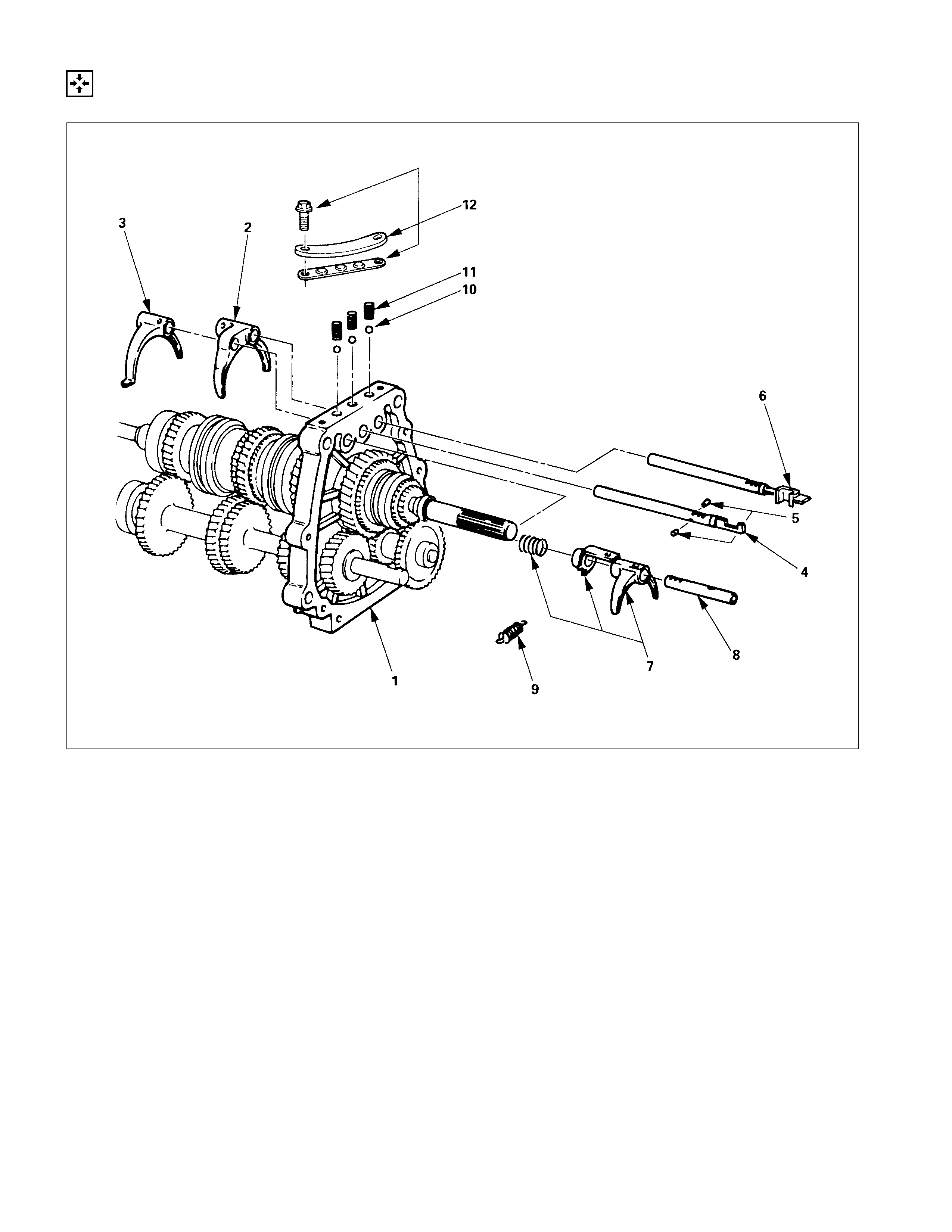
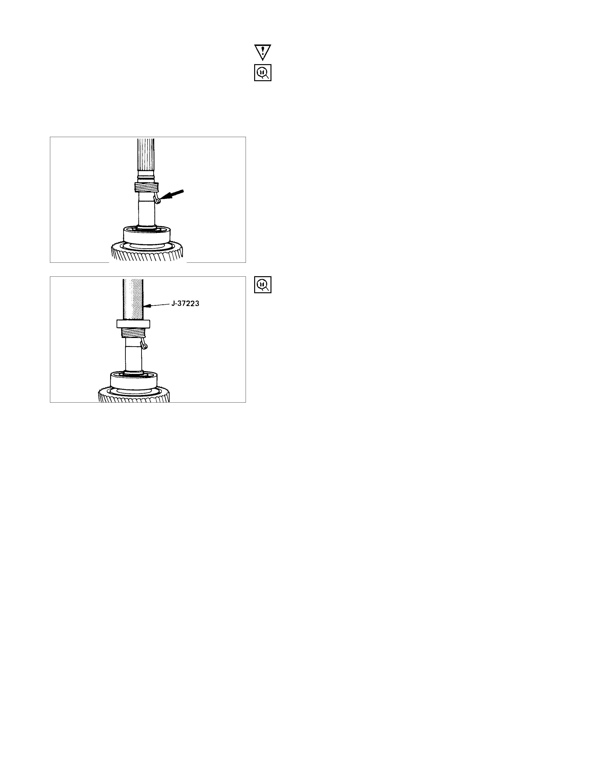
24.Roller Bearing
Apply engine oil to the bearing inner and outer circumference.
Use the installer to install the roller bearing to the mainshaft.
Installer: 5-8840-2159-0 (J-37223)
Note:
Be sure the bearing is installed in the direction it was
removed from.
INTERMEDIATE PLATE AND GEAR ASSEMBLY, DETENT,
SHIFT ARM ASSEMBLY AND INTERLOCK PIN
REASSEM BLY STEPS
1. Intermediate plate and gear assembly
▲2. 1st-2nd shift arm
▲3. 3rd-4th shift arm
▲4. 3rd-4th shift rod
▲5. Interlock pin
6. 1st-2nd shift rod
7. Rev.-5th shift arm and inhibiter
8. Rev.-5th shift rod
9. Spring
10. Detent ball
11. Detent spring
▲12. Detent spring plate and gasket
IMPORTANT OPERATIONS
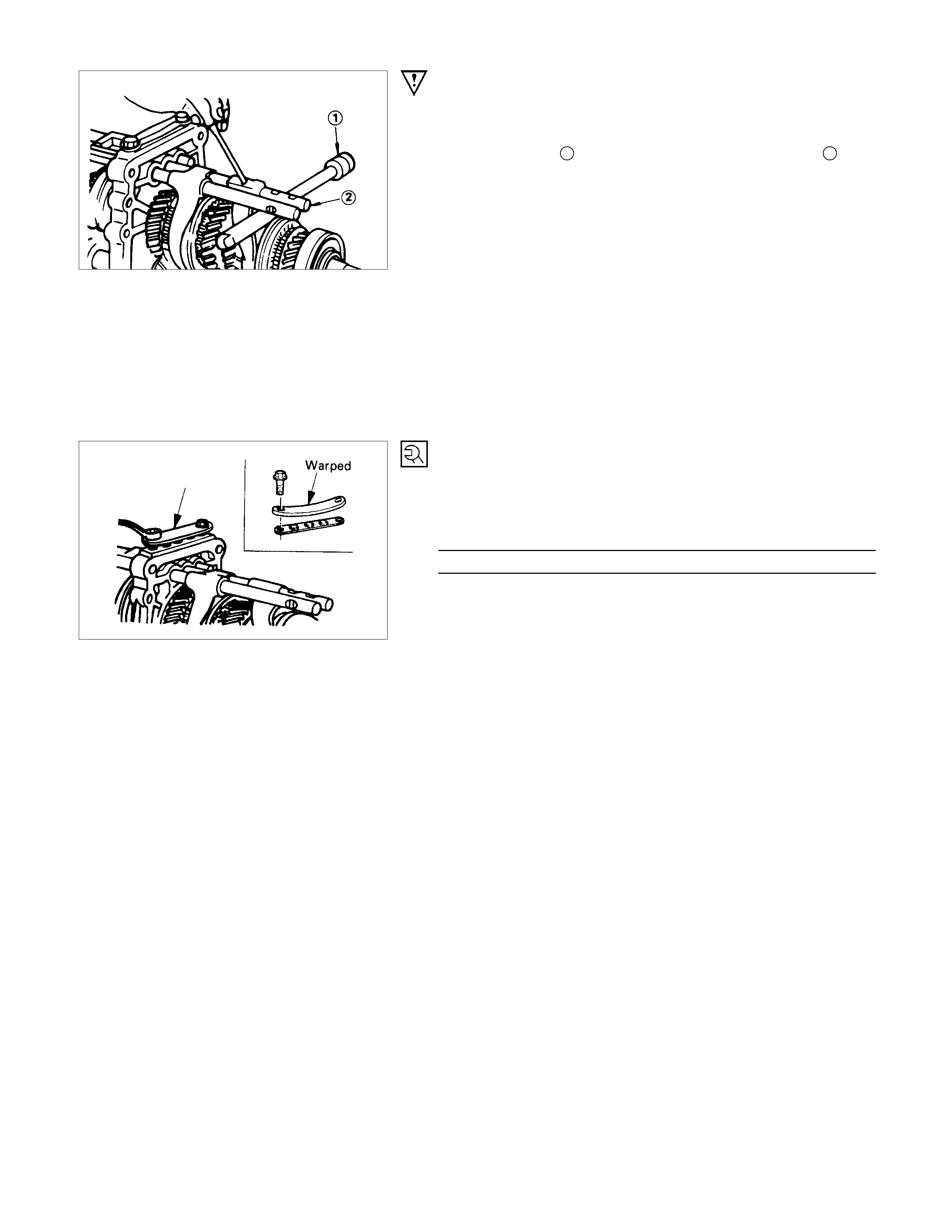
2. 1st-2nd Shift Arm
3. 3rd-4th Shift Arm
Hold a round bar 1 against the shift rod end lower face 2 to
protect it against damage.
Install the new spring pin.
Never reinstall the used spring pin.
4. 3rd-4th Shift Rod
5. Interlock pin
1) Install the interlock pin to the shift rod.
2) Install the shift rod together with the interlock pin to the
intermediate plate.
Do not allow the interlock pin to fall from the shift rod.
12.Detent spring Plate and Gasket
1) Install the new-detent plate and new gasket onto the
transmission case into the correct direction.
2) Tighten the detent spring plate bolts to specified torque.
Detent Spring Plate Bolt Torque N⋅m (kgf⋅m/lb⋅ft)
20 ± 4 (2.0 ± 0.4 / 14 ± 3)
TRANSFER CASE ASSEM BLY
REASSEM BLY STEPS
▲1. Transfer case
▲2. Counter gear
▲3. Sub gear (Anti-lash plate)
4. Belleville spring
5. Spacer
6. Ball bearing
▲7. Snap ring
8. Ball bearing
9. Snap ring
10. Counter gear assembly
11. Bearing snap ring
12. Front output shaft
13. Ball bearing
14. Clutch hub and sleeve
15. Needle bearing
▲16. Front output gear
▲17. Sub gear (Anti-lash plate)
▲18. Belleville spring
▲19. Spacer
▲20. Anti-lash plate snap ring
▲21. Bearing collar
22. Ball bearing
▲23. Snap ring
24. Front output gear assembly
25. Bearing snap ring
26. Ball
27. Bearing collar
28. Needle bearing
29. Transfer input gear
▲30. High-low clutch hub and sleeve
▲31. Mainshaft end lock nut
▲32. Ball bearing
33. Snap ring
IMPORTANT OPERATIONS
1. Transfer Case
1) Cover the shaft spline with adhesive tape 1.
This will prevent damage to the oil seal lip 2.
2) Apply recommend liquid gasket or its equivalent to the
transfer case fitting surfaces.
3) Tighten the transfer cas e bolts to the spec if ied tor que a little
at a time.
Transfer Case Bolt Torque N⋅m (kgf⋅m/lb⋅ft
)
39.2 ± 7.8 (3.8 ± 0.8 / 27.5 ± 5.8)
2. Counter Ge ar
3. Sub Gear (Anti-lash Plate)
Apply chassis grease to the sub-gear and the counter gear
thrust surfaces.
7. Snap Ring
1) Select a snap ring that will allow the minimum axial play.
2) Use a pair of snap ring pliers to install the snap ring to the
counter gear.
Bearing and Snap Ring Clearance mm (in)
Standard
0-0.1 (0-0.0039)
Snap Ring Availability mm (in)
Thickness Color-Coding
1.50 (0.059) White
1.55 (0.061) Yellow
1.60 (0.063) Blue
16.Front Output Gear
17.Sub Gear (Anti-lash Plate)
18.Belleville Spring
19.Spacer
Apply engine oil to the thrust surfaces of the sub-gear, the
belleville spring, and the spacer.
20.Anti-lash Plate Snap Ring
21.Bearing Collar
Use a bench press to install the needle bearing and collar
together with the front output gear.
23.Snap Ring
1) Select a snap ring that will allow the minimum axial play.
2) Use a pair of snap ring pliers to install the snap ring to the
output shaft.
Bearing and Snap Ring Clearance mm (in)
Standard
0-0.1 (0-0.0039)
Snap Ring Availability mm (in)
Snap Ring Thickness Color Coding
1.55 (0.061) White
1.60 (0.063) Yellow
1.65 (0.065) Blue
1.70 (0.067) Pink
1.75 (0.069) Green
1.80 (0.071) Brow n
1.85 (0.073) Red
1.90 (0.075) Orange
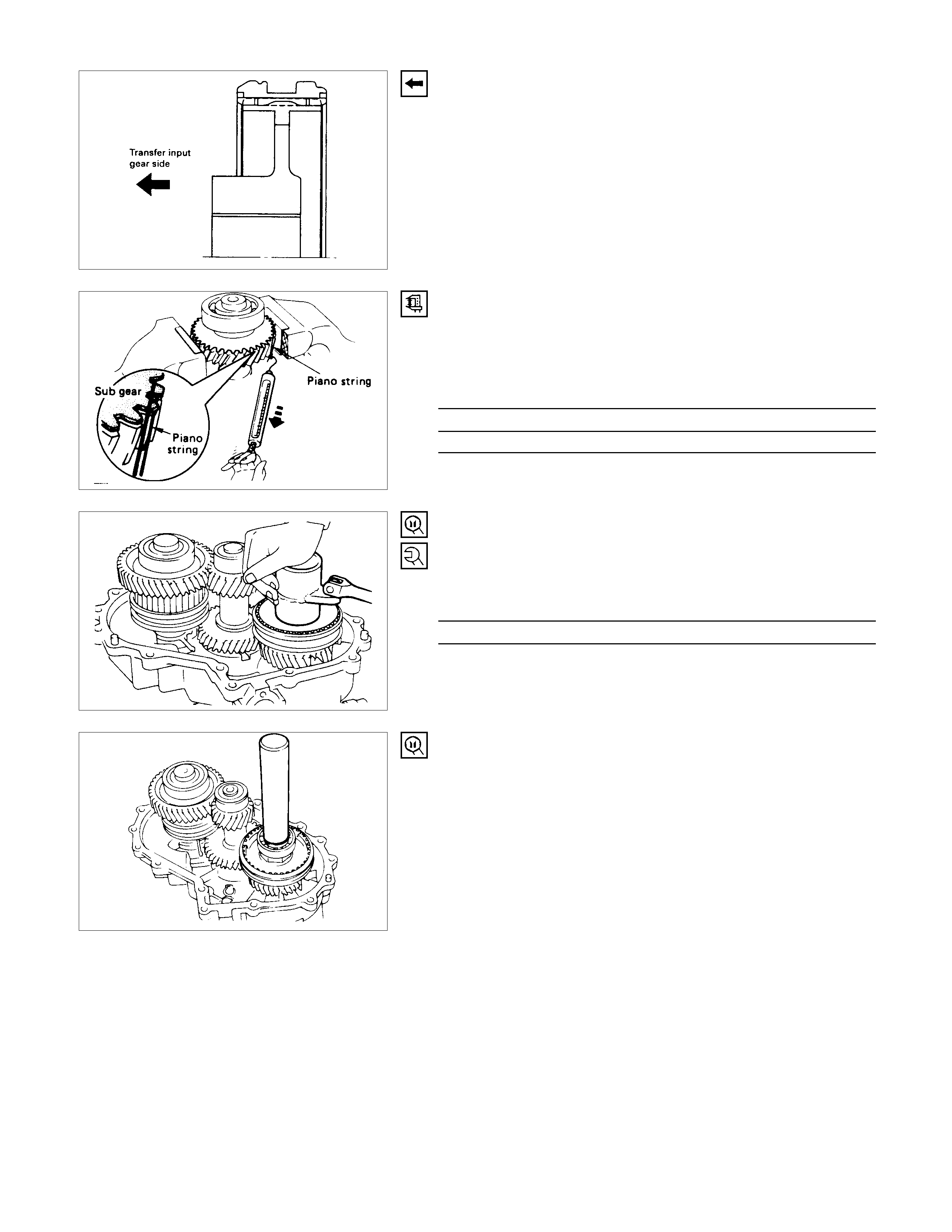
30.High-Low Clutch Hub and Sleeve
The clutch hub face with the heavy bass must be facing the
transfer input gear side.
SUB GEAR (ANTI-LASH PLATE) PRELO AD
1) Hook a length of piano wire over one of the sub-gear teeth.
2) Attach the other end of the piano wire to a spring balancer.
3) Measure the sub-gear preload.
Sub-Gear Preload N (kg/lb)
Standard
59-98 (6-10 / 13-22)
32.Mainshaft End Lock Nut
1) Use the lock nut wrench to tighten the mainshaft end lock
nut to the specified torque.
Lock Nut Wrench: 5-8840-2156-0 (J-37219)
Mainshaft End Lock Nut Torque N⋅m (kgf⋅m/Ib⋅ft)
137 ± 20 (14 ± 2/101 ± 14.4)
2) Stake the lock nut.
33.Ball Bearing
Use the ball bearing installer to install the ball bearing.
Installer: 5-8840-2159-0 (J-37223)
DETENT, SHIFT ARM ASSEMBLY AND INTERLOCK PIN
REASSEM BLY STEPS
1. Shift block
2. Shift arm
▲3. High-low shift rod
▲4. Spring pin
5. Select rod assembly
6. Shift block
7. Shift arm
8. Spring
▲9. Interlock pin
▲10. 2WD-4WD shift rod
▲11. 4WD indicator switch
▲12. Spring pin
13. Spring
14. Pin and bridge
▲15. Detent ball, spring and plug
IMPORTANT OPERATIONS
3.High-Low Shift Rod
4.Spring Pin
1) Engage the High-Low sleeve with 4H side.
2) Install the spring pin to the shift block.
9.Interlock Pin
10.2WD-4WD Shift Rod
1) Engage the High-Low synchronizers with 4H side and install
the interlock pin 1 in proper direction.
2) Install the shift rod: 2WD-4WD 2 with the interlock pin
pushed it in.
12.Spring Pin
1) Engage the 2WD-4WD sleeve with the 4WD side and install
the spring pin.
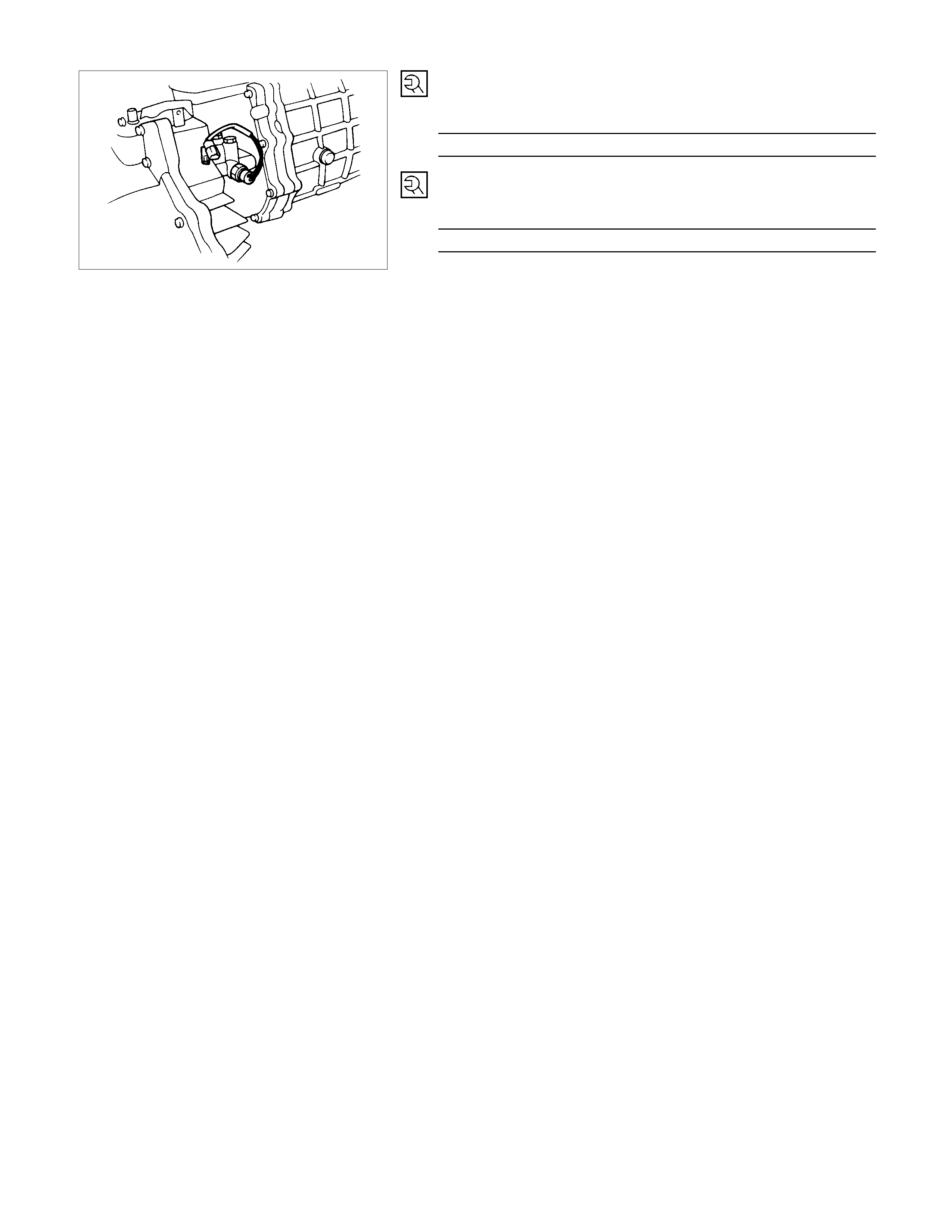
11.4WD Indicator Switch
Tighten the switch to the specified torque.
Switch Torque N⋅m (kgf⋅m/lb⋅ft)
39.2 (4/29.0)
15.Detent Ball, Spring and Plug
Tighten the plugs to the specified torque.
Plug Torque N⋅m (kgf⋅m/lb⋅ft)
18.6 ± 3.9 (1.9 ± 0.4 / 13.7 ± 2.9)

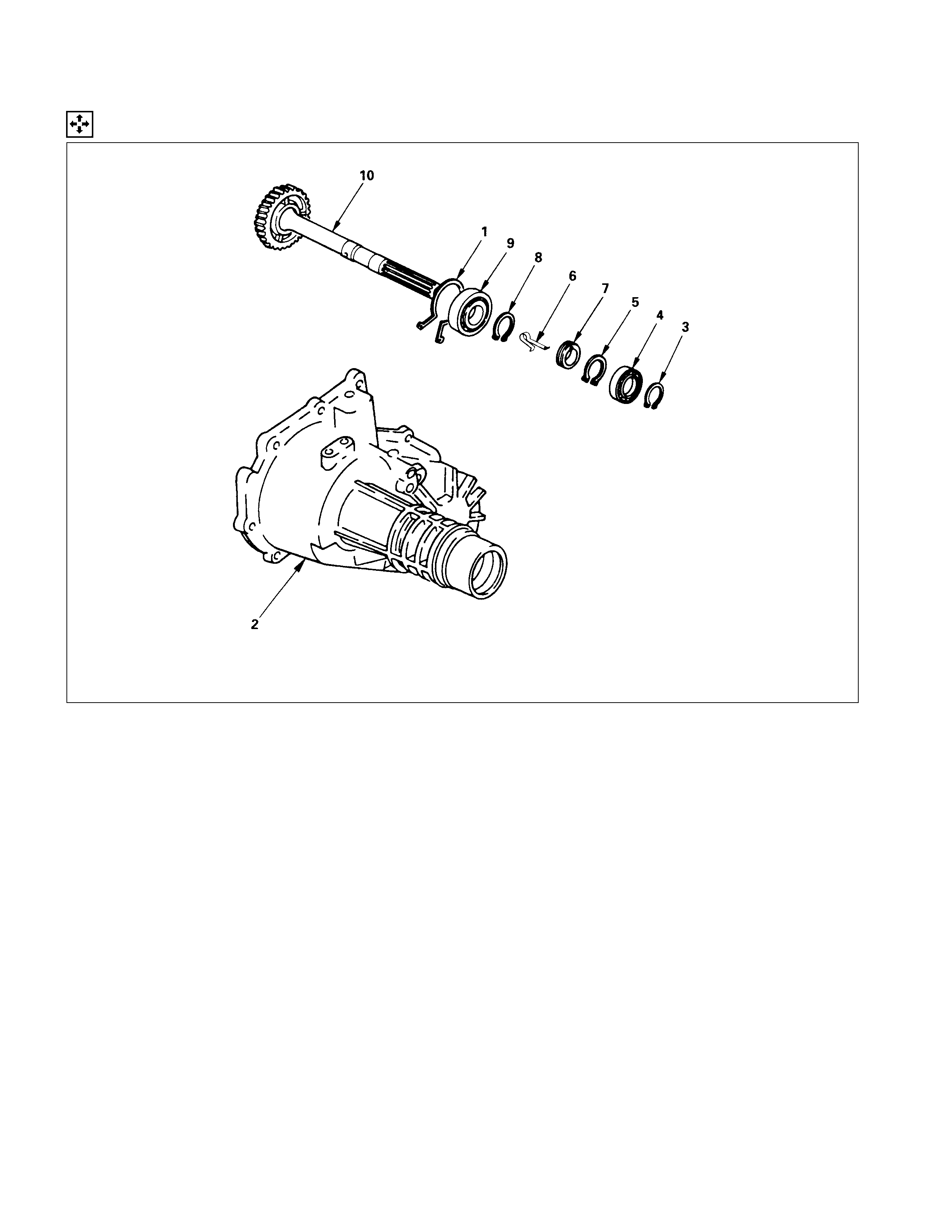
TRANSFER REAR CASE ASSEMBLY
REASSEM BLY STEPS
1. Rear output shaft
▲2. Ball bearing
3. Bearing snap ring
▲4. Clip
5. Speedometer drive gear
6. Bearing snap ring
▲7. Ball bearing
8. Bearing snap ring
9. Rear case
10. Bearing snap ring
IMPORTANT OPERATIONS
2. Ball Bearing
Use the ball bearing installer and the adapter to install the ball
bearing.
Ball Bearing Installer: 5-8840-2159-0 (J-37223)
Adapter: 5-8840-2192-1 (J-37486-A)
4. Clip
Install the clip to the drive gear groove.
7. Ball Bearing
Use the ball bearing installer to install the ball bearing.
Ball Bearing Installer: 5-8840-2159-0 (J-37223)
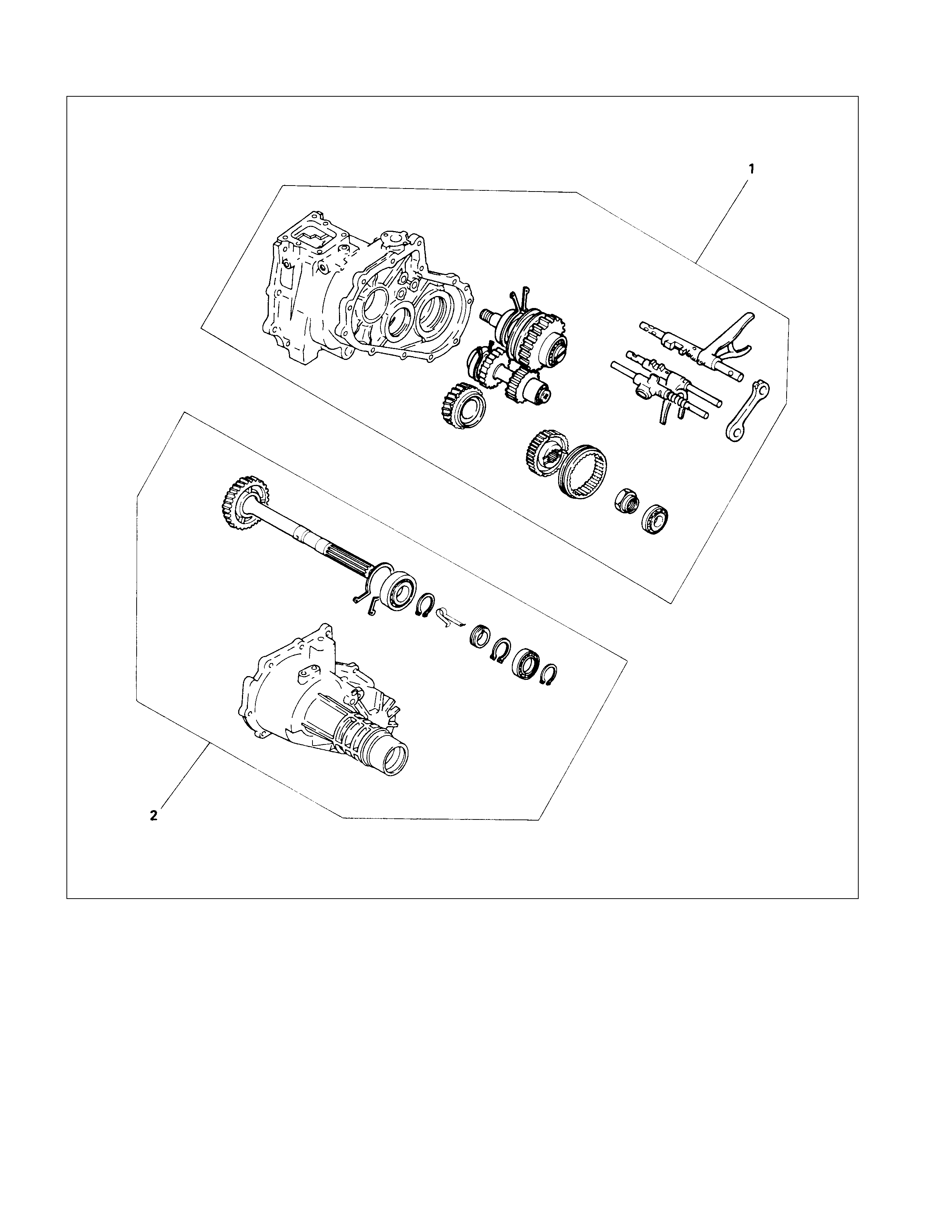
EXTERNAL COM PONENTS
REASSEM BLY STEPS
1. Transmission and transfer assembly
▲2. Transfer rear case assembly
3. Gear control box assembly
▲4. Counter gear snap ring
▲5. Bearing snap ring
▲6. Front cover with oil seal
▲7. Transfer flange
▲8. Speedometer driven gear and
speedometer sensor
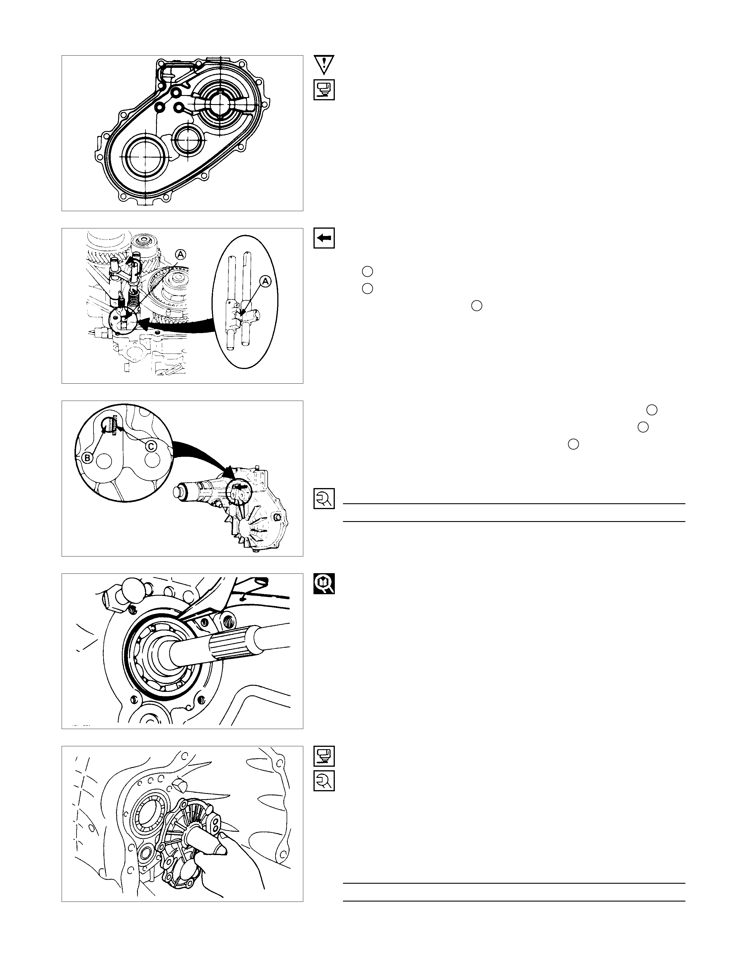
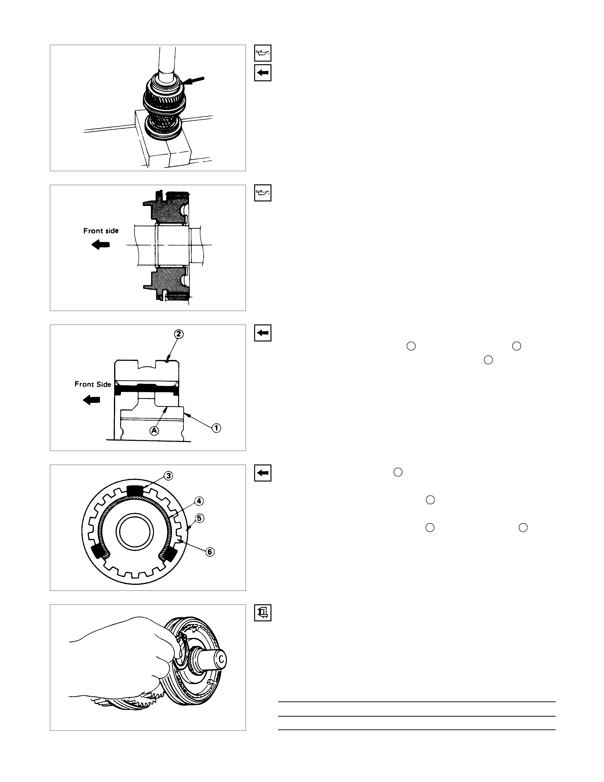
IMPORTANT OPERATIONS
2. Transfer Rear Case Assembly
1) Apply recommended liquid gasket or its equivalent to the
transfer rear case fitting faces.
2)
A
pply the following steps before fitting the transfer rea
r
case.
1Shift the High-Low synchronizer to the 4H side.
2Turn the select rod counterclockwise so that the select
block projection A may enter into the 2WD-4WD shift
block.
When the rear case is fitted under this condition 2, the
direction of the c ut-away portion of select r od head Baligns
with that of the rear case hole stopper C.
3) Tighten the rear transfer rear case bolts to the specified
torque.
Transfer Case Bolt Torque N⋅m (kgf⋅m/lb⋅ft)
37.2 ± 7.8 (3.8 ± 0.8 / 27.5 ± 5.8)
4. Counter Gear Snap Ring
5. Bearing Snap Ring
Use a pair of snap ring pliers to install the snap ring to the
mainshaft.
The snap ring must be fully inserted into the ball bearing snap
ring groove.
6. Front Cover with Oil Seal
1) Apply recommended liquid gasket or its equivalent to the
through bolt threads.
2) Install the new gask et and the f r ont co ver with oil seal to the
transmission ca se.
Take care not to damage the oil seal.
3) Tighten the front cover bolts to the specified torque.
Front Cover Bolt Torque N⋅m (kgf⋅m/lb⋅ft)
18.6 ± 3.9 (1.9 ±0.4 / 13.7 ± 2.9)
7. Transfer Flange
1) Use the flange holder to install the flange to the rea
r
transfer case.
Flange Holder: 5-8840-2157-0 (J-37221)
2) Tighten the transfer flange bolts to the specified torque.
Transfer Flange Bolt Torque N⋅m (kgf⋅m/lb⋅ft
)
137 ± 20 (14 ± 2 / 101 ± 14.4)
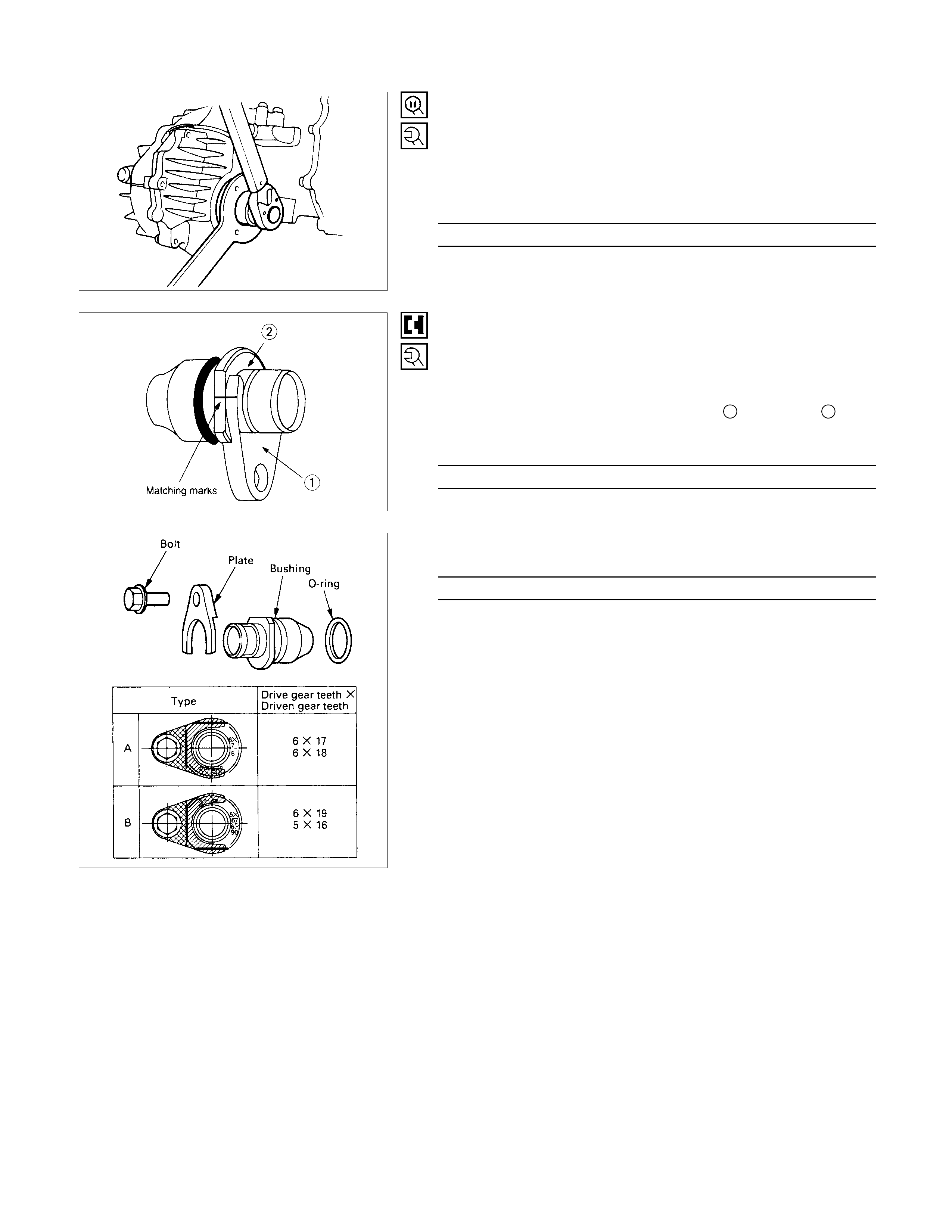
8. Speedometer Driven Gear and Speedometer Sensor
1) Install the O-ring to the speedometer driven gear bushing.
2) Install the driven gear to the speedometer driven gea
r
bushing.
3) Align the matching marks on plate 1 and bush 2 then
tighten the bolt.
Bolt Torque N⋅m (kgf⋅m/lb⋅ft)
14.7 (1.5/10.8)
4) Install the speedometer sensor. N⋅m (kgf⋅m/lb⋅ft)
27 (2.8/20)