
SECTION 7C1 - AUTOMATIC TRANSMISSION (4L30-E)
CAUTION
When fasteners are removed, always reinstall
them at the same location from which they
were removed. If a fastener needs to be
replaced, use the correct part number fastener
for that application. If the correct part number
fastener is not available, a fastener of equal
size and strength (or stronger) may be used.
Fasteners that are not reused, and those
requiring thread locking compound, will be
called out. The correct torque values must be
used when installing fasteners that require
torque. If the above conditions are not
followed, parts or system damage could
result.
General Description
Construction
Electronic Control Diagram
Transmission Control Module (TCM)
Control System Diagram
Functions of Input/Output Components
Range Reference Chart
Normal Operation of 4L30-E Transmission
Diagnosis
Introduction
Driver Information
General Diagnosis Procedure
Preliminary Inspection Chart
Checking Transmission Fluid Level and Condition
Test Driving
Mechanical/Hydraulic Diagnosis
Check Trans Indicator Chart
Mechanical/Hydraulic Diagnosis Symptoms Index
Stall Test
Line Pressure Test
Shift Speed Chart

Lock-up Speed Chart
Electronic Diagnosis
Check Trans Indicator
Diagnostic Check
”Check Trans“ Check
Flashing Codes
TECH2 Connection
Clear DTC
DTC Check
F0 : Data List Quick Check
Chart 1 : Diagnosis Connector and Voltage Supply Test
Chart 2 : Diagnostic Trouble Code (DTC)
Chart 3 : Transmission and TCM Identification
Chart 5 : F5 : Actuator Test Quick Check
Without DTC Set
TCM Precautions
Intermittent Conditions
Wiring Diagram
Connector Location
Connector List

GENERAL DESCRIPTION
The 4L30-E is a 4-speed automatic transmission. It consists primarily of a 4-element torque converter,
an oil pump, two planetary gear sets, 5 multi-plate clutch packs, a brake band, 2 one-way clutches, 2
valve bodies, sensors, actuators and a Transmission Control Module (TCM).
The torque converter acts as a fluid coupling to transmit power from the engine to the, transmission. It
also provides torque multiplication when required and the lock-up function of the pressure plate
eliminates slip by providing a mechanical coupling between the engine and transmission.
The two planetary gear sets, clutches and brake band provide the 4 forward gears and reverse.
Changing of the forward gear ratios is fully automatic – sensors provide input signals to the TCM. The
TCM interprets these signals and actuates the various solenoids inside the transmission. By using
electronics, the TCM controls shift points, shift feel and torque converter clutch operation, to provide the
correct gear ratios for all conditions of vehicle operation.
Control of shift feel is achieved by providing TCM control over a Force Motor, which is a precision
electronic pressure regulator that controls line oil pressure. Electronic pressure regulation provides
excellent shift feel by a precise match between line oil pressure and engine power output.
The TCM provides three transmission-operating modes:
· Normal Mode – normal shift pattern.
· Power Mode – delayed upshift time for maximum acceleration.
The mode of operation is selected by the driver through the Power Switch mounted to the rear of the
centre console.
A third mode, ‘Fail-safe', is provided by the transmission to allow restricted operation in the event of
electrical failure.
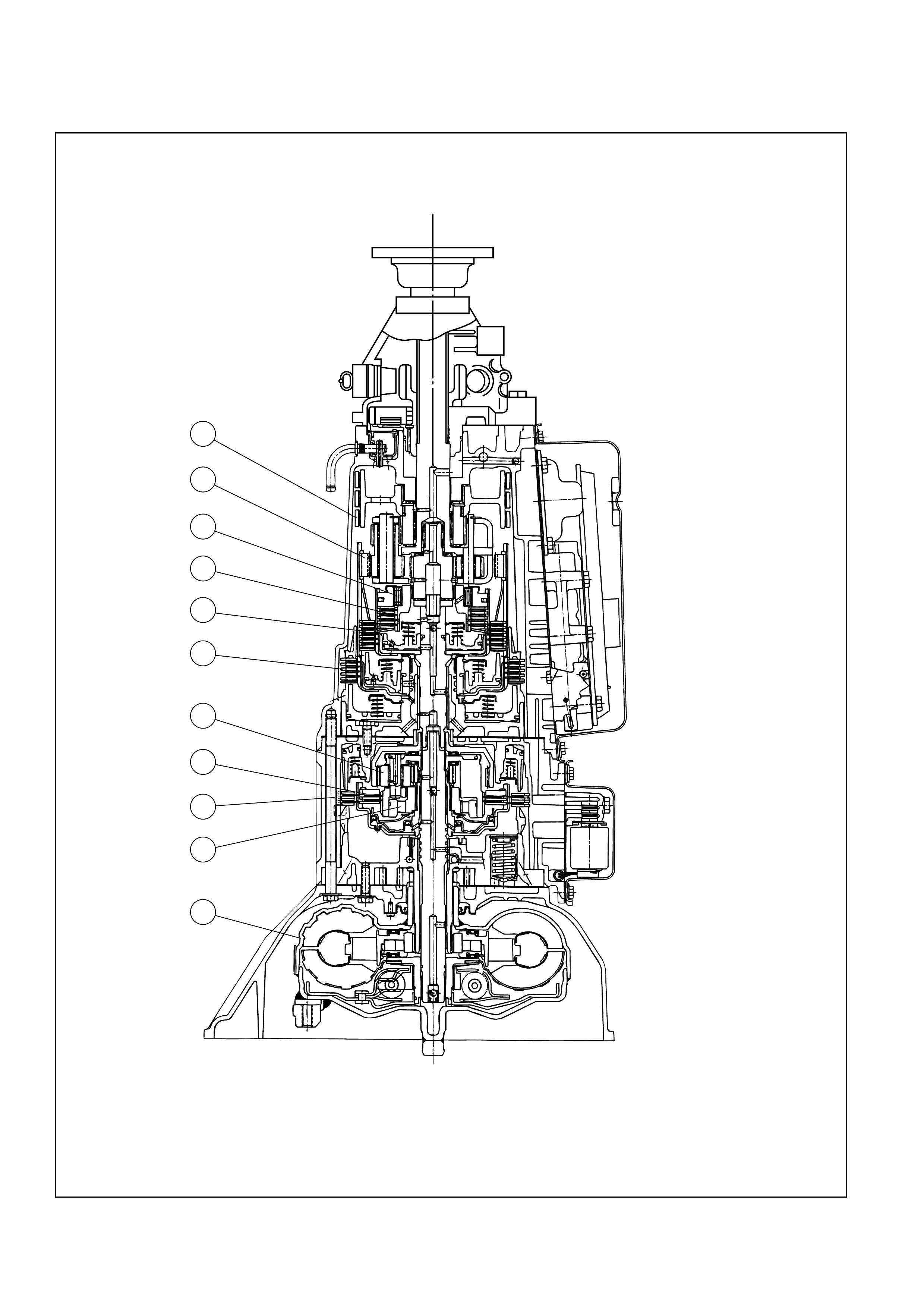
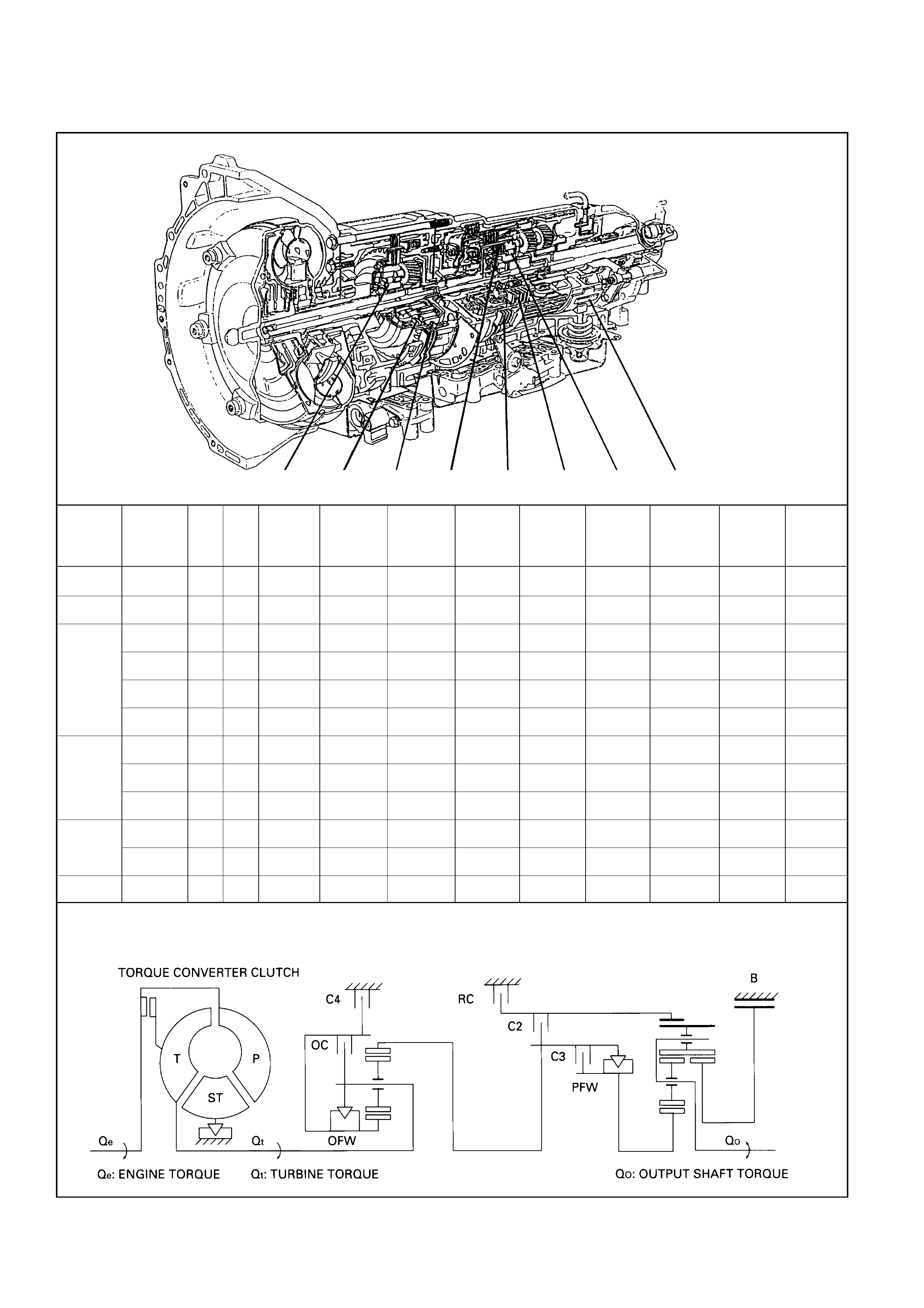
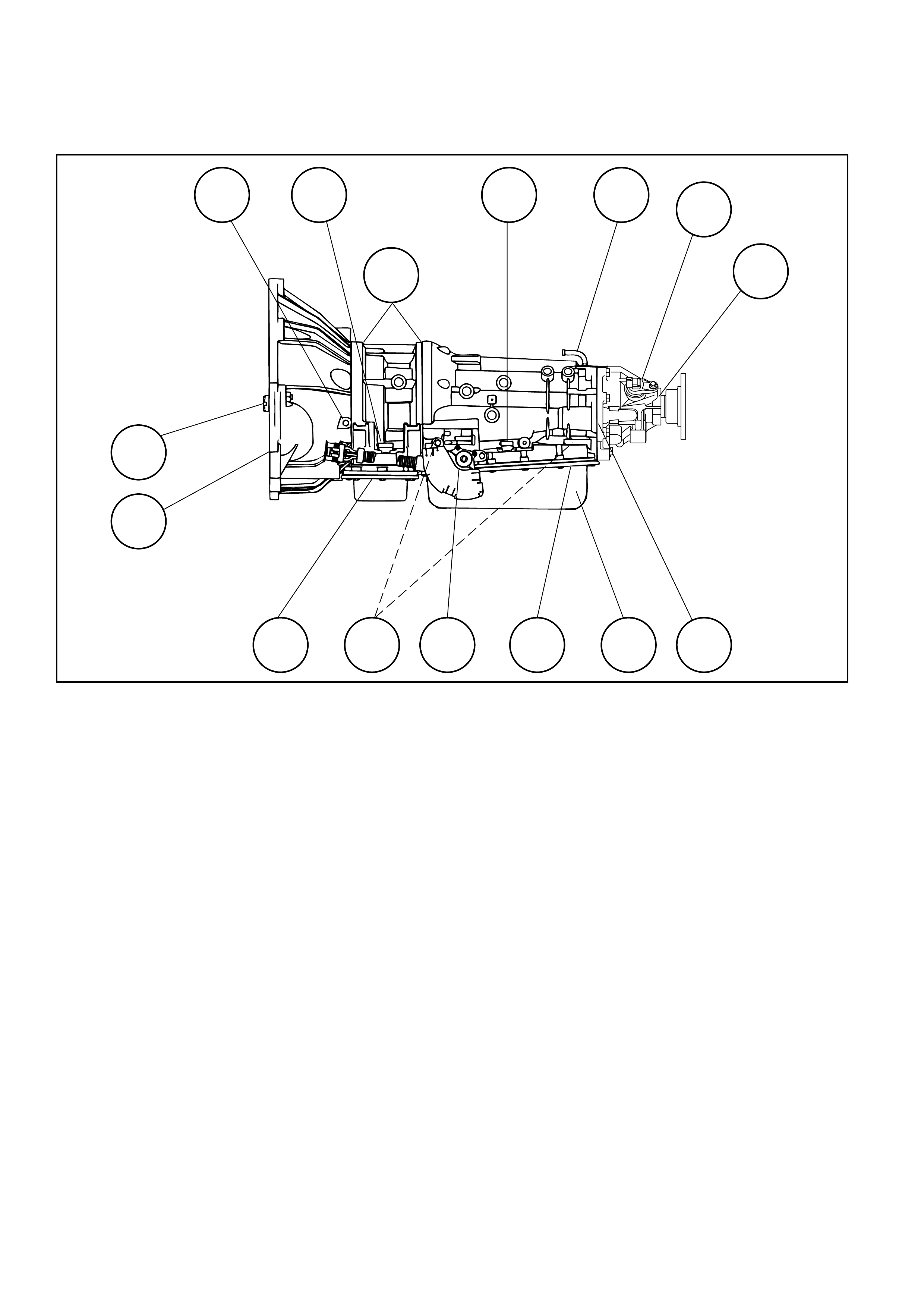
CONSTRUCTION
89
56711
10 234
1
1. TORQUE CONVERTER-CLUTCH (TCC)
2. FOURTH CLUTCH (C4)
3. OVERRUN CLUTCH (OC)
4. OVERDRIVE UNIT
5. REVERSE CLUTCH (RC)
6. SECOND CLUTCH (C2)
7. THIRD CLUTCH (C3)
8. RAVIGNEAUX PLANETARY GEARSET
9. BRAKE BAND (B)
10. OVERDRIVE FREE WHEEL
(ONE WAY CLUTCH) (OFW)
11. SPRAG FREE WHEEL
(ONE WAY CLUTCH) (PFW)
CROSS SECTION
A07LW004
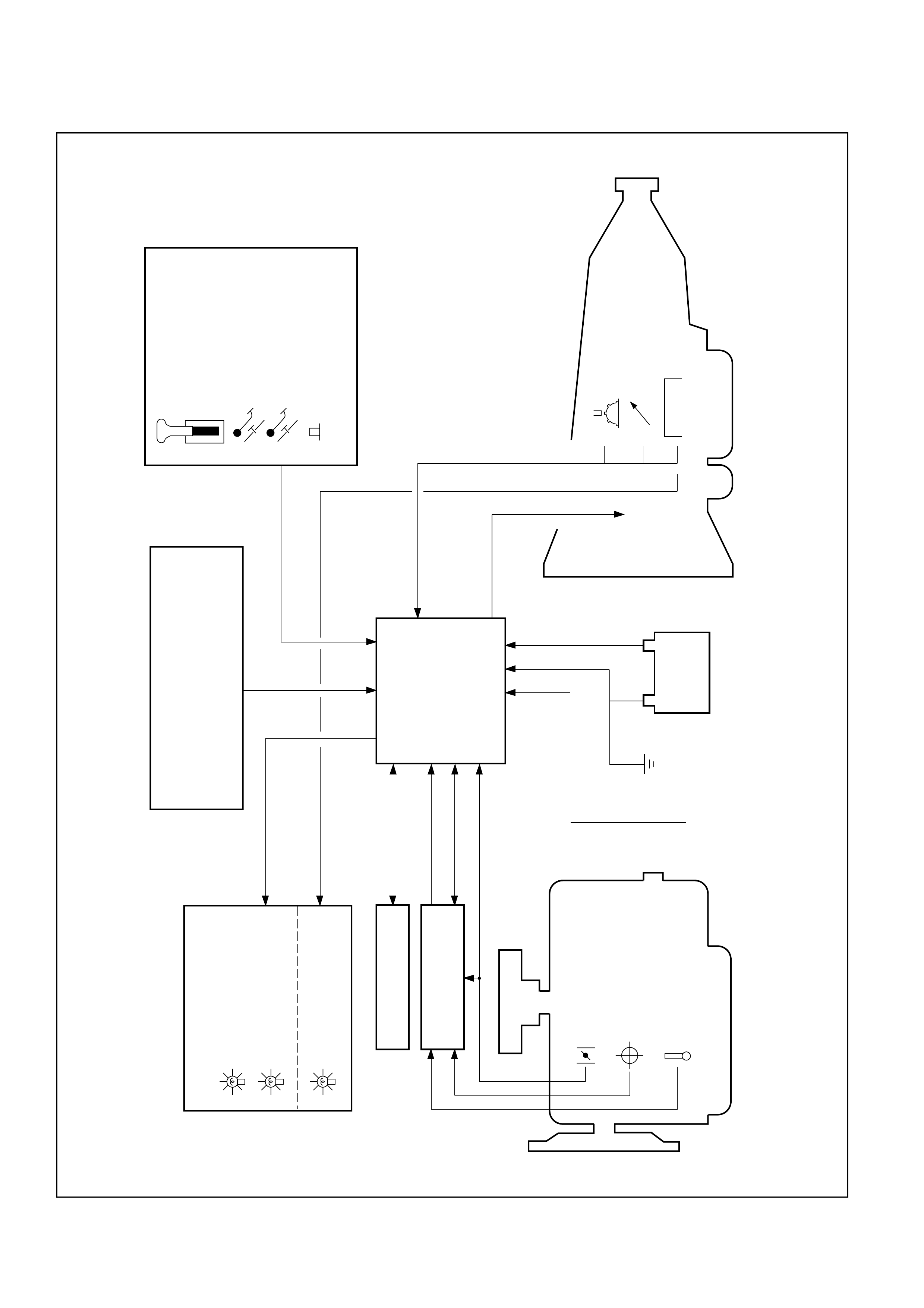
ELECTRONIC CONTROL DIAGRAM
DRIVER'S INPUT
MANUAL SELECTOR
KICKDOWN SWITCH
BRAKE SWITCH
PUSH BUTTON FOR
NORMAL/POWER
DRIVE MODE
VEHICLE SPEED
SENSOR
ATF TEMPERATURE
SENSOR
MODE SWITCH
PRND32L
5 SOLENOID
VALVES
BATTERY
+12
IGNITION
TRANSMISSION
CONTROL
MODULE
(TCM)
COMPENSATION FOR ENGINE LOAD
AIR CONDITIONING SWITCH
ON-BOARD DIAGNOSTIC
ENGINE CONTROL
MODULE(ECM)
THROTTLE POSITION
SENSOR
CRANK ANGLE SENSOR
ENGINE COOLANT
TEMPERATURE SENSOR
DASH BOARD DISPLAY
POWER DRIVE MODE
LAMP
SHIFT INDICATOR LAMP
A/T SHIFT INDICATOR
CONTROL UNIT
(
(
CHECK TRANS LAMP
C07LW003
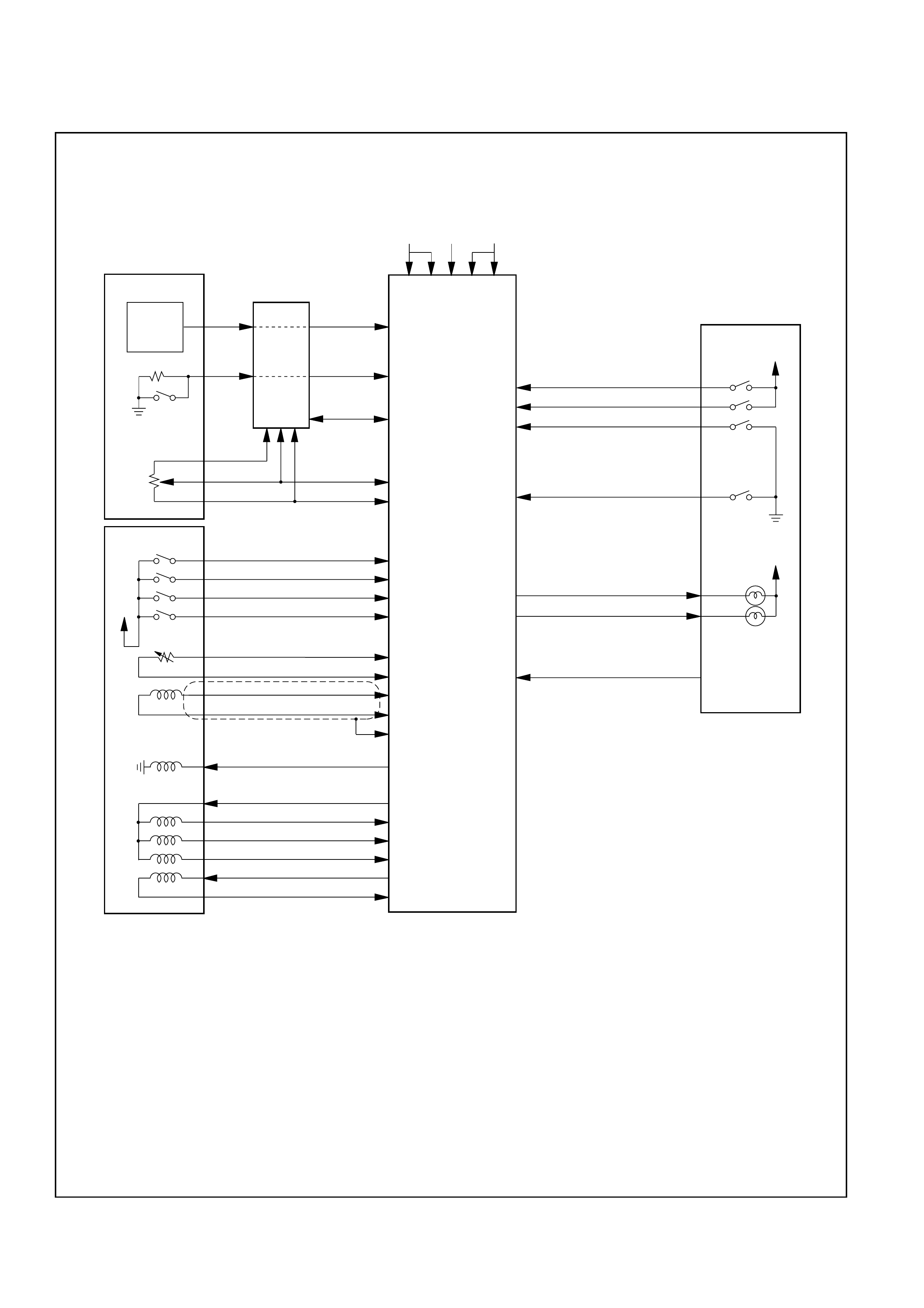
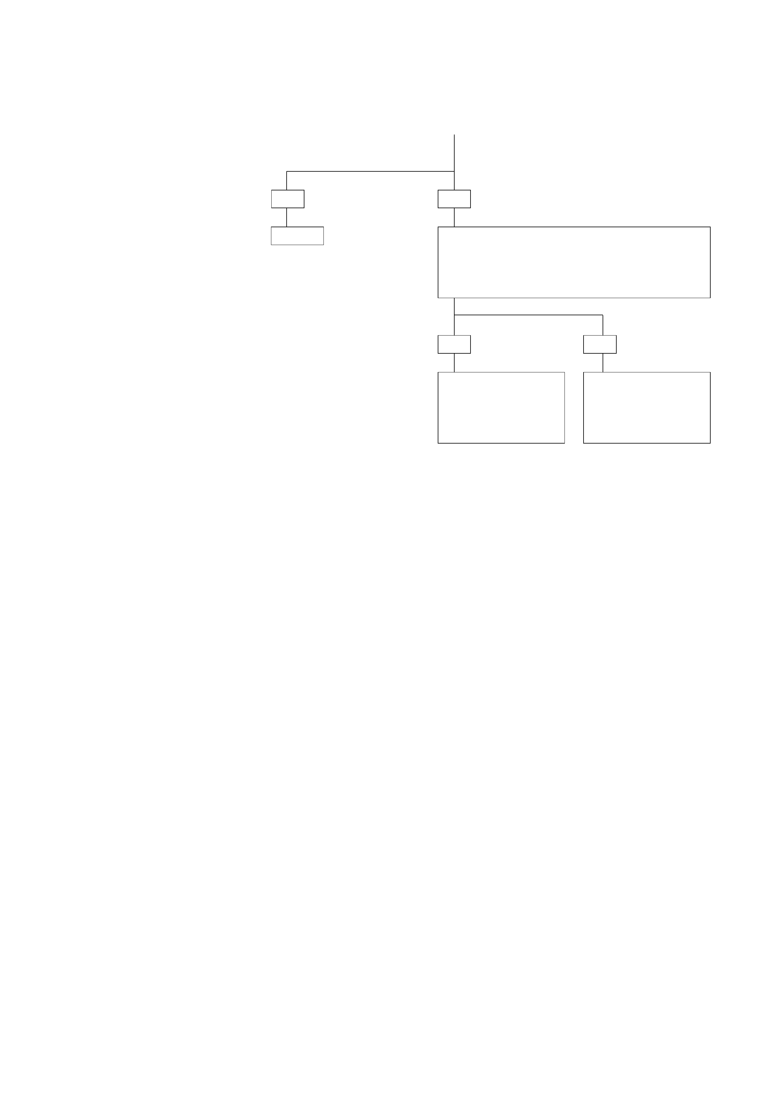
TRANSMISSION CONTROL MODULE (TCM)
C07LW002
ENGINE
VEHICLE
A7
TPS
4L30-E
Ac
Ad
Aa
Mc
Md
Ma
Mb
Ab
Ac
X2
X1
Xa
Xb
Xc
Xg
IGN
A8 A4 C1 D1
IGN
IGN
IGN BATT GND
D14
C5
C6
D7
D6
D5
D4
B3
C14
A12
B12
B11
C7
C12
A2
A3
A9
C15
C16
TCM
D9
D8
B8
B5
C10
B9
OUT
MODE SW A
MODE SW B
MODE SW C
MODE SW G
OIL TEMP
OUTPUT SPEED HI
OUTPUT SPEED LO
TCC HI
SHIFT SOL. HI
SHIFT SOL. A
SHIFT SOL. B
BAND APPLY SOL.
FORCE MOTOR HI
FORCE MOTOR LO
BRAKE SW
A/C REQUEST
POWER SW
KICKDOWN SW
CHECK TRANS LAMP
POWER LAMP
+
–
ECM:
TPS:
TCC:
Engine Control Module
Throttle Position Sensor
Torque Converter Clutch
D16 DIAG SW
CRANK
ANGLE
SENSOR
ECM D12
ENGINE
SPEED
SERIAL DATA
TORQUE
MANAGEMENT
ENGINE
COOLANT
TEMP SW
C8
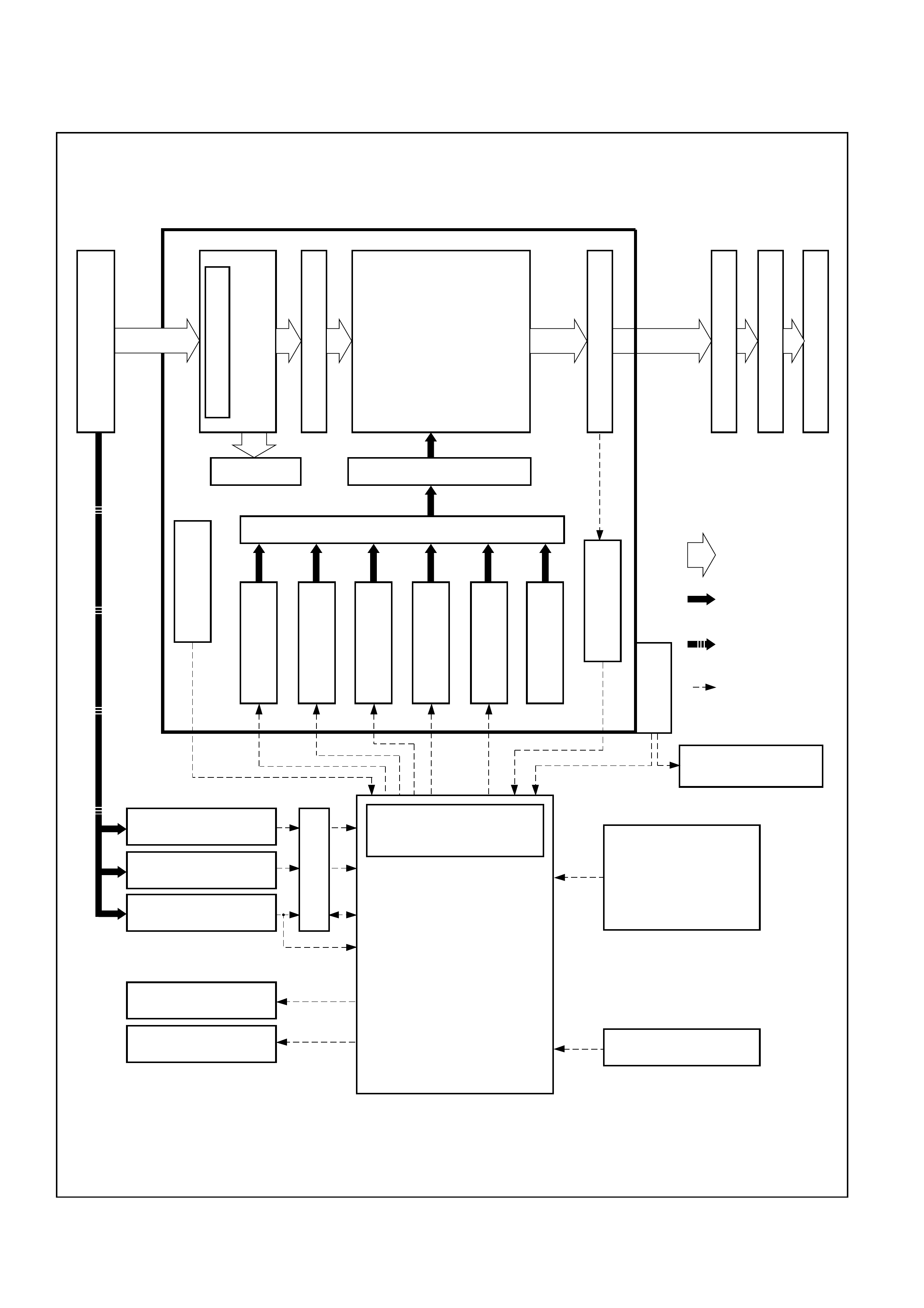
CONTROL SYSTEM DIAGRAM
AUTOMATIC TRANSMISSION ASSEMBLY
ENGINE
LOCKUP PISTON
TORQUE
CONVERTER
INPUT SHAFT
PLANETARY GEAR
MULTIPLATE CLUTCH
MULTIPLATE BRAKE
BRAKE BAND
ONE WAY CLUTCH
OUTPUT SHAFT
TIRE
FINAL DRIVE GEAR
DRIVE SHAFT
OIL PUMP SERVO MECHANISM
CONTROL VALVE
:POWER
TRANSMIT
:OIL PRESSURE
CONTROL
:MECHANICAL
SIGNAL
:ELECTRONIC
SIGNAL
OIL TEMP.
SENSOR
TORQUE CONVERTER
CLUTCH SOLENOID
SHIFT SOLENOID A
SHIFT SOLENOID B
BAND APPLY
SOLENOID
FORCE MOTOR
MANUAL VALVE
VEHICLE SPEED
SENSOR
MODE
SWITCH
CHECK TRANS LAMP
POWER LAMP
KICKDOWN SWITCH
BRAKE SWITCH
POWER MODE SWITCH
AIR CONDITIONING
SWITCH
TRANSMISSION CONTROL
MODULE (TCM)
• SHIFT CONTROL
• BAND APPLY CONTROL
• TORQUE CONVERTER CLUTCH
CONTROL
• LINE PRESSURE CONTROL
• SAFETY MODE
• ON-BOARD DIAGNOSTIC
SYSTEM
• TORQUE MANAGEMENT
SHIFT INDICATOR LAMP
A/T SHIFT INDICATOR
CONTROL UNIT
(
(
CRANK ANGLE SENSOR
THROTTLE POSITION
SENSOR
ENGINE COOLANT
TEMPERATURE SENSOR
ECM
C07LW001

Shift Control
The 4L30E transmission uses two electronic shift
solenoids to control upshift and downshift points in all
forward gear ranges. These shift solenoids operate
together in a combination of ‘OFF’ and ‘ON’ sequences
to control the position of the 1-2/3-4 and 2-3 shift valves.
The Transmission Control Module (TCM) monitors the
numerous input signals to determine the solenoid status
required for the current vehicle operating conditions.
The shift solenoids are ’Low-side Driven’, that is, the
TCM provides the ground path to energise the solenoid.
Band Apply Control
The Band Apply Solenoid is a normally open solenoid
valve located on the rear of the main valve body. The
solenoid controls the rate of brake band apply and
release in response to a Pulse Width Modulated (PWM)
signal from the TCM by regulating the flow of oil to and
from the band servo.
Varying the rate of band apply and release reduces low
speed shift-shock and provides a measure of engine
poverrun protection on a 3-2 downshift.
Torque Converter Clutch Control
The Torque Converter Clutch (TCC) solenoid is a
normally open solenoid valve, located in the Adapter
Case valve body. When the solenoid is de-energised,
the TCC is released. Energising the solenoid allows
fluid fluid pressure to move the TCC Control Valve into
the apply position, initiating TCC apply.
The TCC is normally applied in 3rd and 4th gear,
although it may apply in 2nd gear during a downshift, or
as part of the transmission ‘overheat’ strategy.
Line Pressure Control
Line pressure varies in response to the operation of the
Force Motor. The Force Motor (or Pressure Control
Solenoid) is a precision electronic pressure regulator
valve, controlled by a 600Mz PWM signal from the
TCM. The Force Motor regulates the flow of Feed Limit
fluid into the Throttle Signal pressure circuit, hence Line
Oil pressure.
Force Motor duty cycle and Line Oil pressure are
inversely proportional. That is, as duty cycle (current
flow) decreases, Line Oil pressure increases.
Under normal operating conditions - between minimum
and maximum throttle, the TCM will vary the duty cycle
signal Force Motor duty cycle signal between 60% and
0%.
In the event of electrical system failure, the current flow
to the Force Motor will 0.0 amps. This creates maximum
Line Oil pressure to prevent any apply components from
slipping until the condition can be corrected.
On–Board Diagnostic System
The TCM has a built-in diagnostic system that
recognises and identifies possible transmission
operational issues and alerts the driver by flashing the
CHECK TRANS lamp mounted in the instrument panel.
Below the RH edge of the instrument panel is the J1962
Diagnositc Link Connector (DLC). The DLC allows
access to the diagnostic system with the TECH 2 scan
tool for both active testing and Diagnostic Trouble Code
(DTC) retrieval.
Fail Safe Mechanism
Should a major electrical system failure occur which
may either adversly affect vehicle safety or damage the
transmission, the transmission will enter ‘Fail-saf’e or
‘Default’ mode.
In this mode, the transmission operates with both shift
solenoids, the TCC solenoid and the Force Motor
turned OFF. The driver maintains some manual control
over gear selection, but with some shift-shock during
selection and harsh garage shifts.
Torque Management Control
The 4L30E transmisssion utilises a ‘Torque
Management’ system to improve transmission
component durability and shift quality under medium to
full throttle operation.
Provididng a means to occur to reduce engine torque
during the shift-overlap period reduces the stress on
bands and clutches while improving the shift ‘feel’. The
process of limiting engine torque during shiting is called
Toque Management. The technique calls for a
momentary reduction (or retardation) of the spark
advance and may effectively retard the ignition timing to
0º TDC.
ATF Warning Control
The ATF warning lamp will illuminate when transmission
fluid temperature exceeds 145ºC and will extinguish
when the fluid temperature falls below 125ºC.
ABS Control (If equipped)
When the select lever is at “L” or “R” range, a signal is
sent to the ABS Modulator, resulting in a recalibration of
the ABS operation to suit the current operating
conditions.
SHIFT MODE CONTROL
1Mode type
Mode type Select lever position
Normal drive mode (NOR) Entire range (excluding “R”)
Power drive mode (PWR) Entire range (excluding “R”)
2Mode selection
SWITCH (SW) LAMP
Mode type
PWR/NOR. SW POWER DRIVE LAMP
Normal drive mode (NOR)
OFF OFF
Power drive mode (PWR)
ON ON
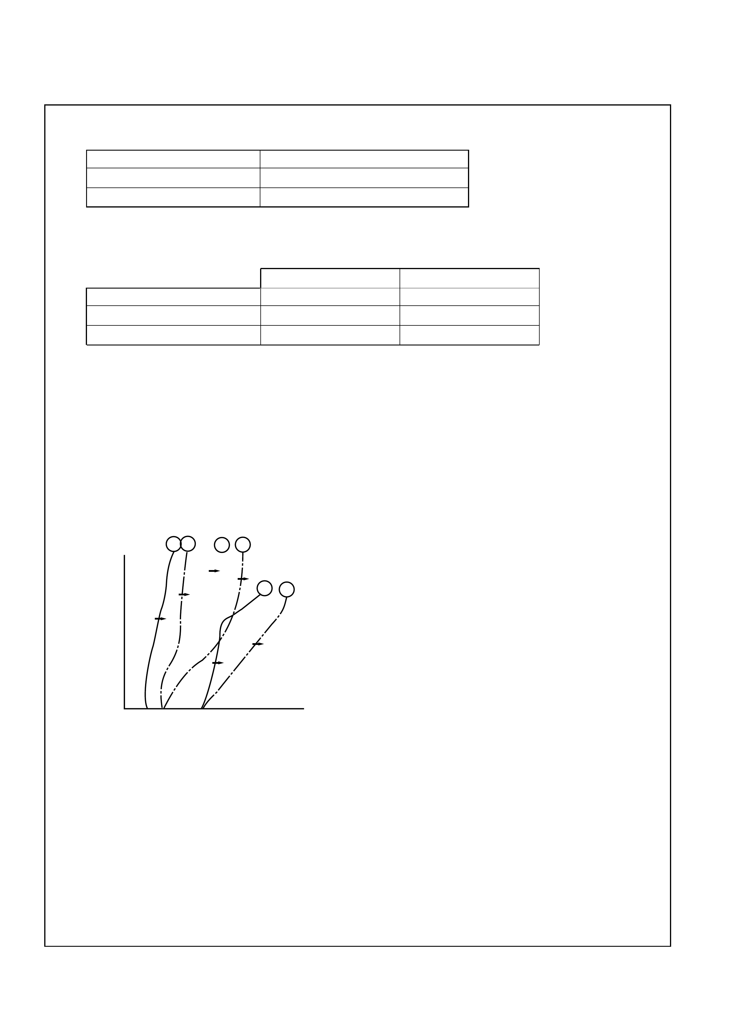
3Comparison of mode
(1) The normal drive mode is set at the normal shift points.
(2) The shift points of the power drive mode are shifted to the higher speed side, compared to the
normal drive mode.
Shift diagram
23
3
4
1
2
2
12
3
4
3
N: Normal drive mode
P: Power drive mode
Amount of
throttle
opening
Speed mph(km/h)
NPP
P
N
N
GEAR SHIFT CONTROL
1Shift pattern
2Gear position
The gear is selected by ON/OFF of two solenoids.
3Selecting gear position
Seven types of positions can be selected according to 5 signals from the mode switch as shown
below.
SELECT LEVER RANGE SHIFT PATTERN
D (Drive) 1 2TCC 3TCC 4TCC
3 (Third) 1 2TCC 3TCC 4TCC
2 (Second) 1 2TCC 3TCC
L (First) 1 2
→
←→
←
←
←
←
→
←
→
←
→
←
→
←
TCC = Torque Converter Clutch
GEAR SOL AB
4 (Fourth) ✕✕
3 (Third) ●●✕
2 (Second) ●●●●
1 (First) ✕●●
P (Park)
R (Reverse) ✕●●
N (Neutral)
●●= ON
✕= OFF
SOLENOID A ON →PRESSURE TO
(Normally closed) SHIFT VALVE
SOLENOID B OFF →PRESSURE TO
(Normally open) SHIFT VALVE
MODE SW TERMINALS
SELECT LEVER RANGE 5(D) 8(A) 7(B) 6(C) 3(G)
P (Park) •• •
R (Reverse) •••
N (Neutral) •••
D (Drive) •••
3 (Third) •••••
2 (Second) •• •
L (First) •••
•= Continuity

BACKUP MODE
If a major system failure occurs which could affect safety or damage the transmission under normal
vehicle operation, the diagnostic system detects the fault and overrides the TCM.
The “CHECK TRANS” light flashes to alert the driver, and the transmission must be manually shifted
as follows:
Select lever position Gear Ratio Selected
D 4 (Fourth)
Manual 3 4 (Fourth)
Manual 2 3 (Third)
Manual L 1 (First)
R Reverse
Shifts are firmer to prevent clutch slip and consequent wear. The fault should be corrected as soon as
possible.

FUNCTIONS OF INPUT/OUTPUT COMPONENTS
Components Function
Speed sensor Senses rotation of output shaft and feeds the data to Transmission
(fixed to transmission T/M) Control Module (TCM)
Throttle Senses the extent of throttle valve opening and the speed of the throttle
position sensor (TPS) valve lever motion to open the valve and feeds the data to TCM (fed to
(fixed to engine) Engine Control Module (ECM) also)
Brake Switch (SW) Senses whether the driver has pressed the brake pedal or not and feeds
(fixed to brake pedal) the information to TCM
Kick-down SW (fixed to Senses whether the driver has pushed the accelerator pedal fully or not
accelerator pedal) and feeds the information to TCM
Mode SW (fixed to T/M) Senses the select lever position and feeds the information to TCM
Power drive SW Senses whether the driver has selected the power mode and feeds the
(fixed to front console) information to TCM
T/M oil temp. sensor Senses the T/M oil temperature and feeds the data to TCM
Engine coolant Senses the engine cooling water temperature and feeds the data to TCM
temperature SW (feeds the signal from ECM)
Engine speed signal Feeds the signals monitoring engine speed to TCM from crank angle sensor
(feeds the signal from ECM)
Air conditioning Senses whether the air conditioner has been switched on or not and
information feeds the information to TCM
On-board diagnostic input By monitoring the Ground (GND), the location of failure is shown on the
T/M monitor lamp (“CHECK TRANS”) by flashing the diagnostic trouble
code
Shift solenoid A, B Selects shift point and gear position suited to the vehicle running con-
dition on the basis of TCM output
Band apply solenoid Controls oil flow suited to the vehicle running condition on the basis of
TCM output
Torque Converter Controls clutch engagement/disengagement suited to the vehicle
Clutch solenoid running condition on the basis of TCM output
Force motor Adjusts the oil pump delivery pressure to line pressure suited to the
(Pressure regulator vehicle running condition on the basis TCM output
valve)
Power drive mode lamp Informs the driver whether the vehicle is in power mode or not
T/M monitor lamp Informs the driver of failure in the system. It also displays the self diag-
(“CHECK TRANS”) nosis code.
Data Link Connector (DLC) When connected with TECH2 or tester, can communicate the data for
function check, etc. (fed to ECM also). When TECH2 is not connected,
can communicate the signal for torque management with ECM.
When short-circuited with the bipolar connector, the T/M monitor lamp
displays a failure by code.
S
O
L
E
N
O
I
D
O
U
T
P
U
T
S
I
G
N
A
L
I
N
P
U
T
S
I
G
N
A
L
RANGE REFERENCE CHART
1-2/3-4
2-3 O/DRIVE OVERRUN FOURTH THIRD REVERSE SECOND PRINCIPLE BAND
RANGE GEAR SOL SOL ROLLER CLUTCH CLUTCH CLUTCH CLUTCH CLUTCH SPRAG
ASSEMBLY
ENGINE
N.C. N.O. CLUTCH (OC) (C4) (C3) (RC) (C2)
ASSEMBLY
(B) BRAKING
(OFW) (PFW)
P-N OFF ON APPLIED NO
RREVERSE OFF ON LD APPLIED APPLIED LD NO
1ST OFF ON LD APPLIED LD APPLIED NO
2ND ON ON LD APPLIED APPLIED FW APPLIED YES
D3RD ON OFF LD APPLIED APPLIED APPLIED NE YES
4TH OFF OFF FW APPLIED APPLIED APPLIED NE YES
1ST OFF ON LD APPLIED LD APPLIED NO
32ND ON ON LD APPLIED APPLIED FW APPLIED YES
3RD ON OFF LD APPLIED APPLIED APPLIED NE YES
1ST OFF ON LD APPLIED APPLIED LD APPLIED YES
22ND ON ON LD APPLIED APPLIED FW APPLIED YES
L1ST OFF ON LD APPLIED APPLIED LD APPLIED YES
LD : LOCKED IN DRIVE FW : FREEWHEELING NE : NOT EFFECTIVE
C07RT010

NORMAL OPERATION OF 4L30-E
TRANSMISSION
1. TORQUE CONVERTER CLUTCH (TCC)
APPLICATION CONDITIONS:
The TCC is normally applied in 2nd, 3rd and 4th
gears only when all of the following conditions
exist:
ÐThe engine coolant temperature is above 70º C
(158ºF).
Ð The brake pedal is released.
Ð The shift pattern requests TCC apply.
Moreover, TCC is always applied in 2nd, 3rd and
4th gears when the transmission oil temperature is
above 135º C (275º F).
This mode should be canceled at 125ºC (257ºF).
2. SPECIAL SHIFT P ATTERN WHEN THE
ENGINE IS COLD:
The TCM inhibits TCC apply and delays transmission
upshifts until engine coolant temperature rises above
70ºC.

DIAGNOSIS
INTRODUCTION
The systematic trouble shooting information covered by this Section offers a practical and systematic
approach to diagnosing 4L30-E transmission, using information that can be obtained from road tests,
electrical diagnosis, oil pressure checks or noise evaluation.
The key to correcting a complaint is to make use of all of the available symptoms and logically letting them
direct you to the cause.
When dealing with automatic transmission complaints, it is best to gather as many symptoms as possible
before making the decision to remove the transmission from the vehicle.
Frequently, the correction of the cause of the complaint does not require removal of the transmission from
the vehicle.
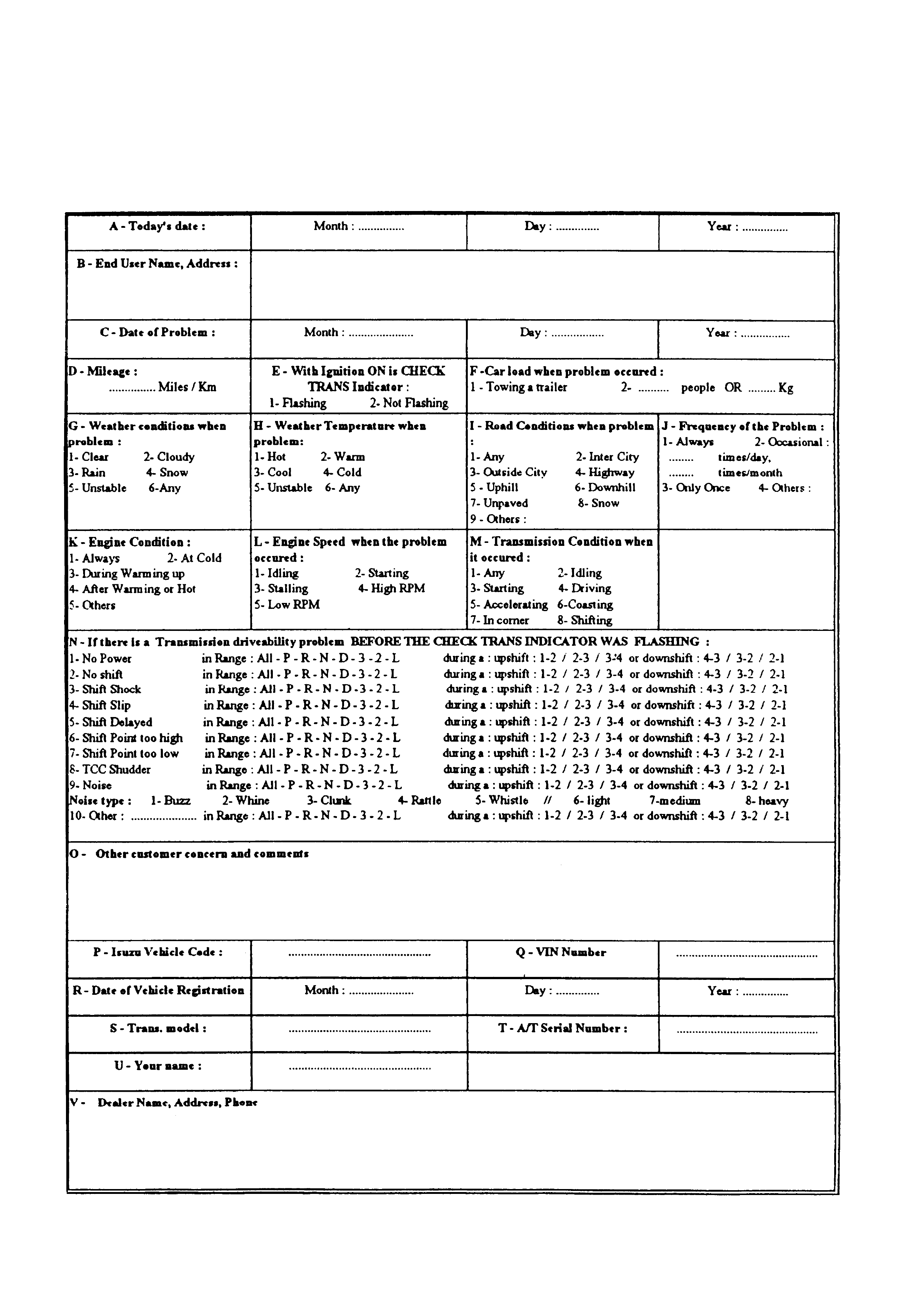
DRIVER INFORMATION
To analyze the problem fill a complete description of the owner’s complaint.
Please draw a circle around the right information and complete the following form. (Find next page an
example of form completed). You can draw a circle around many numbers if you are not sure.
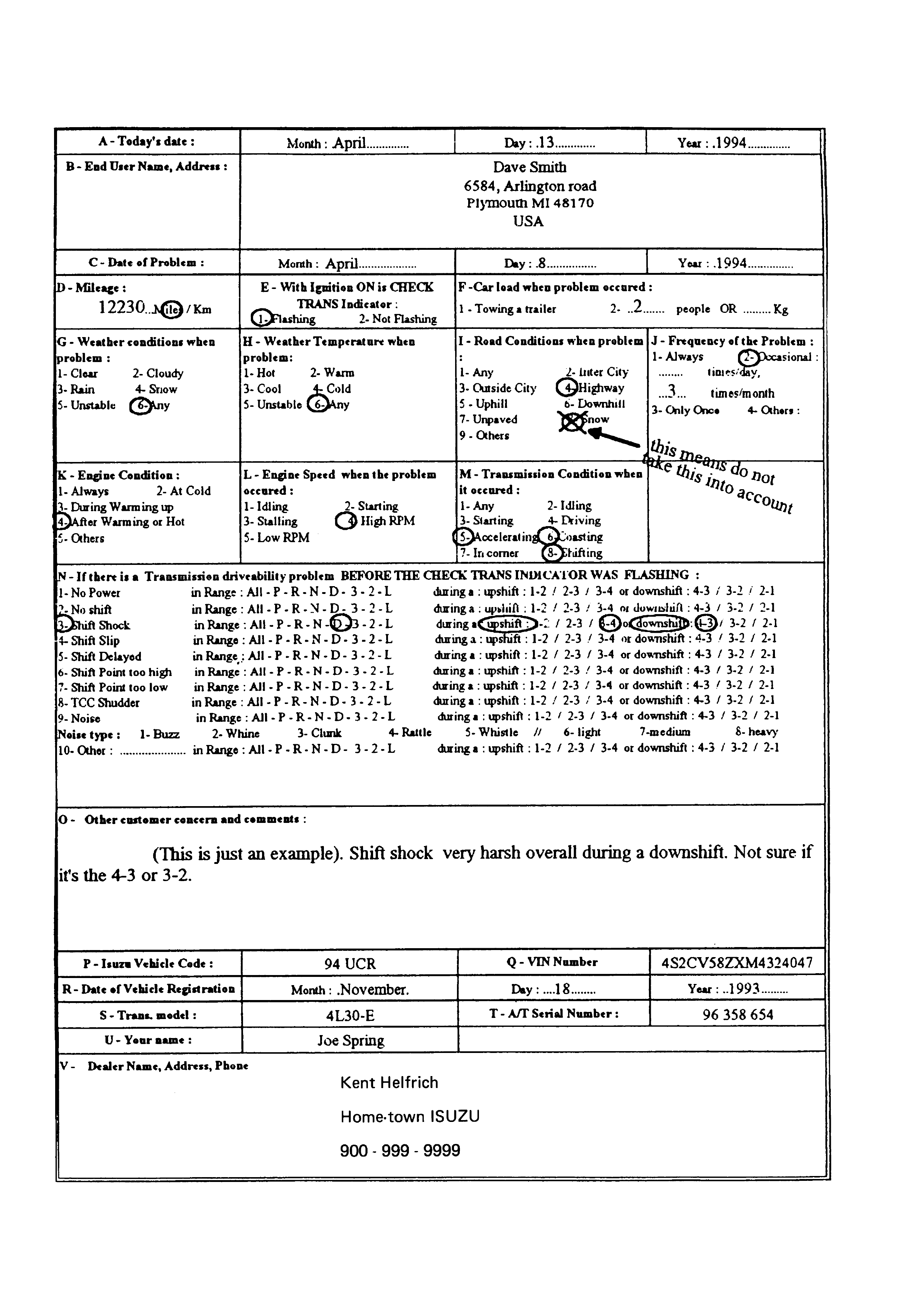
Example of form completed.
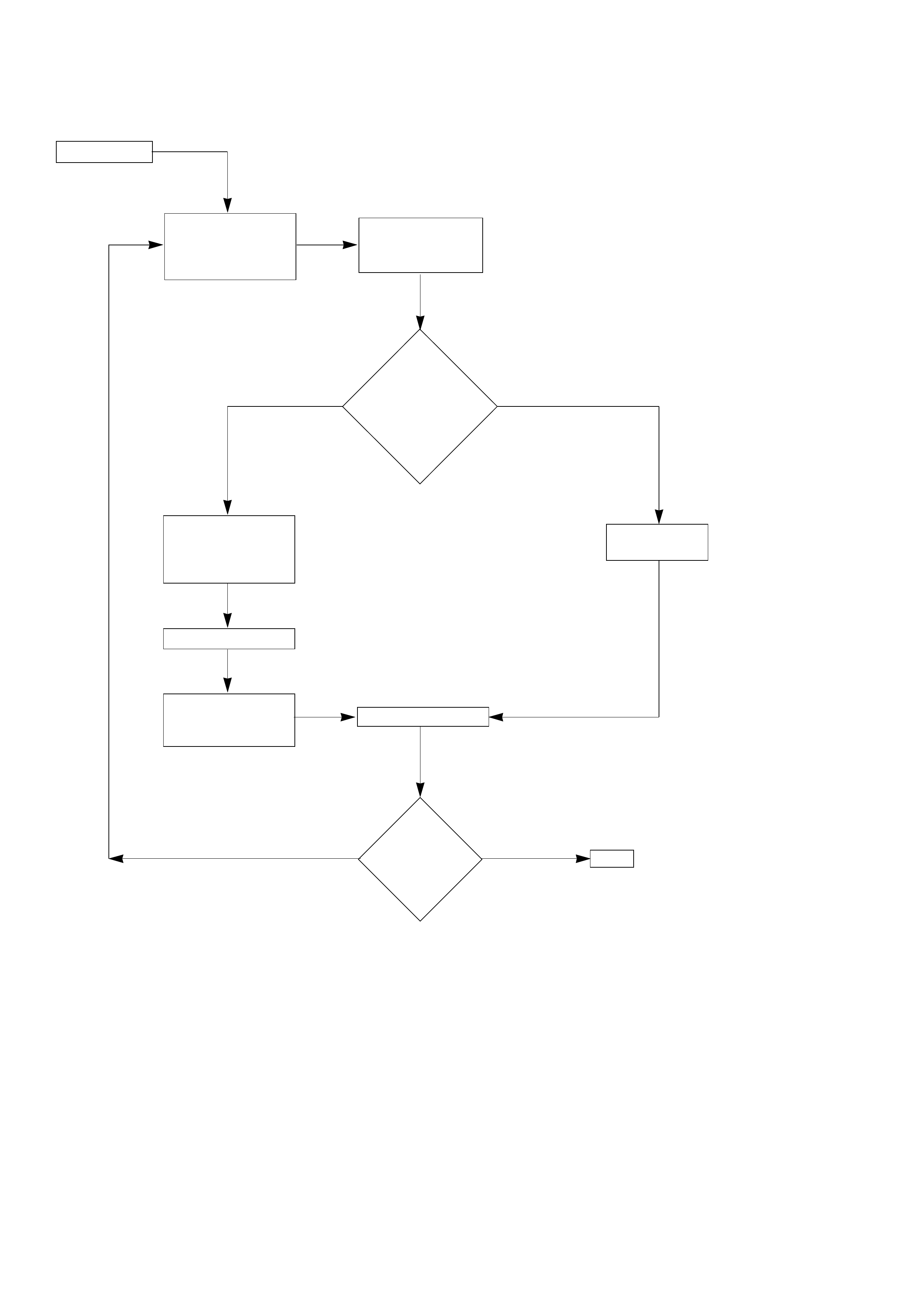
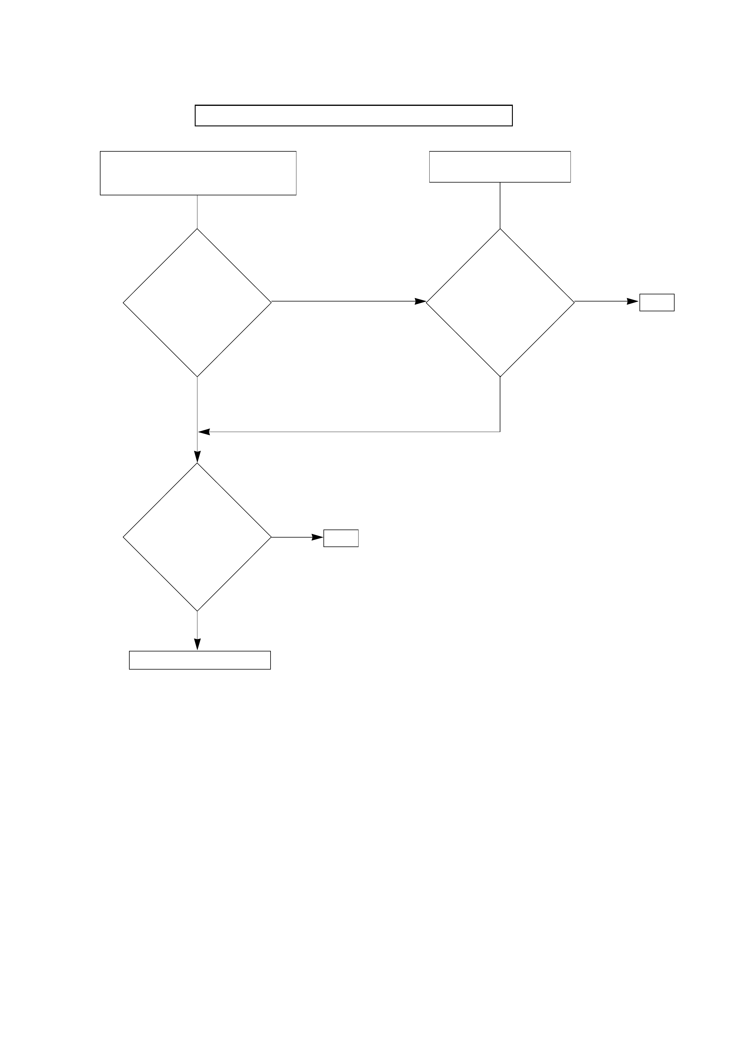
GENERAL DIAGNOSIS PROCEDURE
END
Complaint
Follow
PRELIMINARY
INSPECTION
CHART
Remove trans-
mission assembly
and repair/replace
as required
Reinstall
transmission
assembly TEST DRIVING
Flush cooler lines
Perform repair
per
SYMPTOMS CHART
Replace
component
Can
fault
be corrected
by on-car
component
replacement?
Problem
fixed?
NO
NO
YES
YES
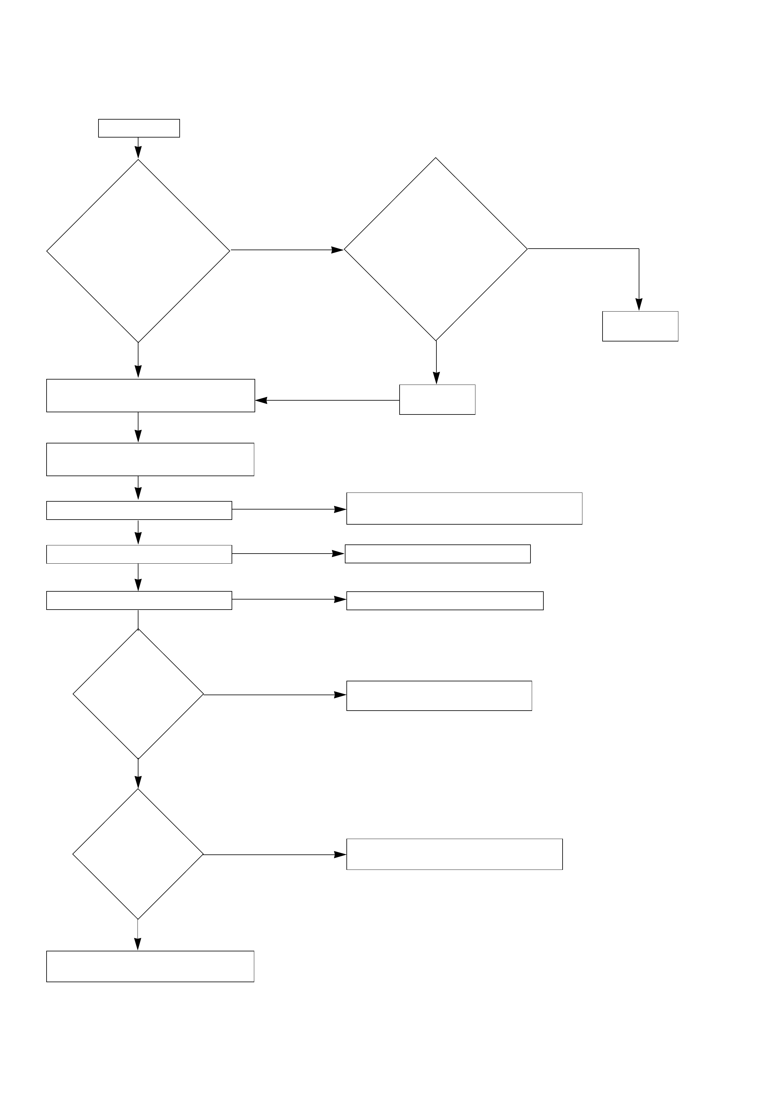
PRELIMINARY INSPECTION CHART
Complaint
Check CHART3: TRANSMISSION AND
TCM IDENTIFICATION on page 7A1-64.
Check TRANSMISSION FLUID LEVEL
and CONDITION. See page 00-4.
Check manual linkage.
Verify engine performance. Refer to Engine Section
Road test vehicle to verify concern.
See CHECK TRANS INDICATOR
CHART on page 7A1-25.
See ELECTRONIC DIAGNOSIS
Section of this manual on page 7A1-47.
See page 7A1-23 for TEST DRIVING
Refer to SELECTOR LEVER in this manual.
See page 7A1-145.
System
OK
Note
codes
Does
symptom reflect
NORMAL
OPERATIONS
OF 4L30-E
TRANSMISSION?
(See page 7A1-15)
“CHECK TRANS”
flashing
Any
Trouble Codes
stored by
TCM?
Hydraulic
system appears
OK!
Are any DTC’s
stored in
TCM?
YES
YES
YES
YES
NO
NO
NO
NO
TCM: Transmission Control Module
See MECHANICAL/HYDRAULIC
DIAGNOSIS Section on page 7A1-26.


TEST DRIVING
Some 4L30-E automatic transmission complaints
vehicles will require a test drive as a part of the
diagnostic procedure. Some codes will not set
unless the vehicle is moving. The purpose of the
test drive is to duplicate the customer’s complaint
condition and set a current Transmission Control
Module (TCM) trouble code. Perform this procedure
before each 4L30-E automatic transmission repair,
and again after repairs are made.
IMPORTANT:
• Duplicate the condition under which the
customer’s complaint was observed.
• Depending on the complaint, line pressure
gauge and the scan tool may be required
during the test drive.
• During the test drive, it is important to record
all necessary data from the areas being
monitored, for use in diagnosis. Also listen for
and note any unusual noises.
The following procedure should be used to test
drive 4L30-E automatic transmission complaint
vehicles:
1. Turn the ignition ON without starting the
engine. Check that the “CHECK TRANS” lamp
comes on for approximately 2 to 3 seconds
and then goes out and remains out.
• If the lamp is flashing, GOTO CHECK TRANS
INDICATOR.
• If no serial data is present, see Chart 1:
DIAGNOSTIC CONNECTOR AND VOLTAGE
SUPPLY TEST.
• If the lamp stays ON or stays OFF, GOTO
“CHECK TRANS” CHECK.
2. Drive the vehicle. During the test drive be sure
that the transmission achieves normal
operating temperature (approx. 20 minutes).
Allow the transmission to go through all of its
gear ranges, checking shift timing and
firmness. Duplicate the owner’s complaint
condition as closely as possible during the test
drive.
3. If, during the test drive, the “CHECK TRANS”
lamp comes on, use the scan tool to check for
trouble codes.
4. If, during the test drive, a problem is felt, but
the “CHECK TRANS” lamp does not come on
and no trouble codes are present, drive the
vehicle with the TCM disconnected (manually
shifting the vehicle).
• In Manual L, the vehicle operates in first
gear.
• In Manual 2, the vehicle operates in third
gear.
• In Manual 3 or “D”, the vehicle operates in
fourth gear.
If the problem still exists with the TCM
disconnected, refer to the MECHANICAL/
HYDRAULIC DIAGNOSIS in this Section.
5. If no problem has been found at this point,
check all underhood connections that supply
power to the TCM and ignition fuses.
Physically and visually inspect all the TCM
harness connectors for loose or corroded
terminals. Inspect the TCM ground points.
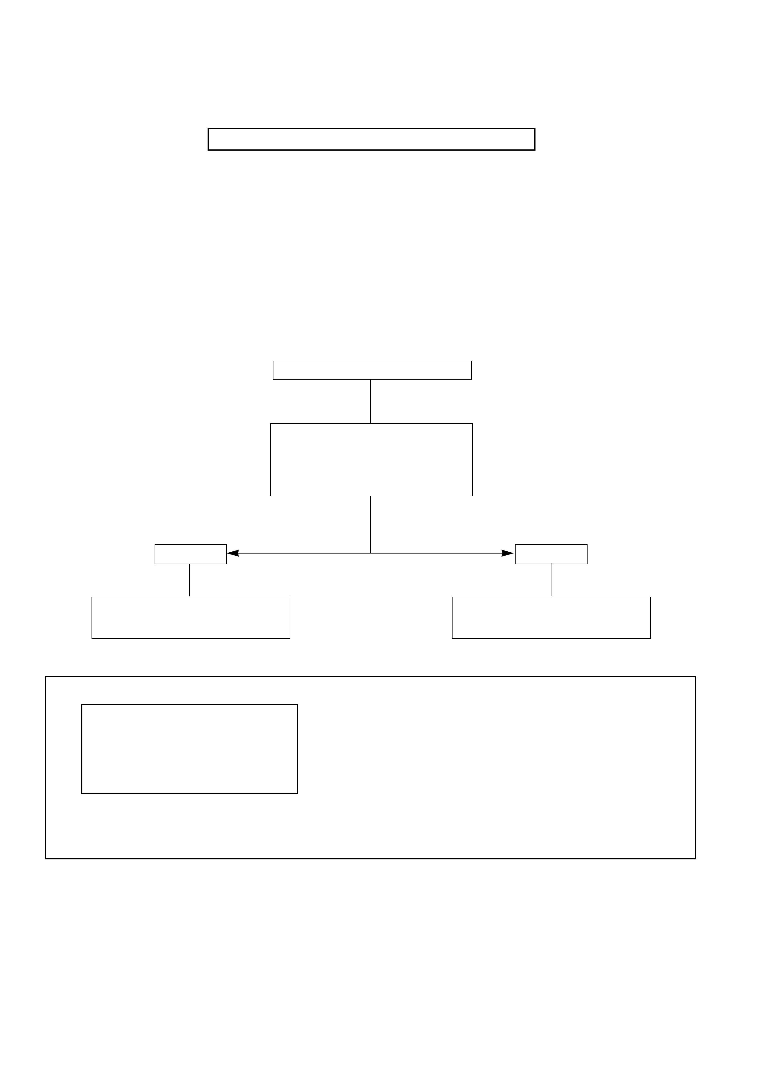
PERFORM PRELIMINARY INSPECTION FIRST!
When the “CHECK TRANS” indicator is flashing, it
indicates that a problem related to the trans-
mission, the Transmission Control Module (TCM),
or the vehicle harness has occurred:
The system is now operating in a “BACKUP MODE”
where the risk of further damaging the transmission
has been reduced. The vehicle may be shifted
manually.
If the initial problem is intermittent or seldom,
switching OFF/ON the engine might allow normal
operation again until the problem re-occurs.
“CHECK TRANS” indicator flashing
Use “CHECK TRANS” CHECK in
Electronic Diagnosis section in this
manual
Refer to appropriate DTC chart in
Electronic Diagnosis section in this
manual.
NO DTC ANY DTC
Read and record the Diagnostic
Trouble Codes (DTC) stored by TCM.
WARNING:
Disconnecting battery or TCM will
result in loss of stored trouble code(s).
BACKUP MODE PATTERN:
- No automatic shifting
- Manual shifting only
- “CHECK TRANS” Flashing
SHIFT LEVER GEAR
POSITION SELECTED
PP
RR
NN
D4
34
23
L1
MECHANICAL/HYDRAULIC DIAGNOSIS
CHECK TRANS INDICATOR CHART

MECHANICAL/HYDRAULIC DIAGNOSIS SYMPTOMS INDEX
PERFORM PRELIMINARY INSPECTION FIRST!
CHART SYMPTOMS PAGE
1 NO ENGINE START IN NEUTRAL OR PARK 7C1-27
2 NO FORWARD GEARS IN ANY RANGE/NO REVERSE 7C1-28
3 NO ENGINE BRAKE IN ANY RANGE 7C1-29
4 POOR SHIFTING IN ALL GEARS (ALL HARSH OR ALL SOFT) 7C1-30
5a DELAYS IN DRIVE AND REVERSE 7C1-31
5b DELAYS IN REVERSE ONLY
6 DIAGNOSTIC TROUBLE CODE (DTC) 61 7C1-32
7 HARSH 1-2 SHIFT 7C1-33
8 HARSH 3-4 SHIFT
9a 3-2 DOWNSHIFT COMPLAINT
9b HARSH SHIFT WHEN SHIFTING INTO “D” OR ACCELERATING
FROM STOP 7C1-34
9c COASTDOWN HARSH SHIFT OR CLUNK AT 3-2 DOWNSHIFT
10 INTERMITTENT 4TH TO 2ND GEAR DOWNSHIFT AT STEADY SPEED 7C1-35
11 ENGINE FLARE AT SHIFTING DURING TURNING ONLY 7C1-36
12 ENGINE FLARE DURING 1-2 OR 2-3 SHIFT
13 SHUDDER ONLY DURING TORQUE CONVERTER CLUTCH (TCC) APPLYING 7C1-37
14 POSSIBLE CAUSES OF TRANSMISSION NOISE 7C1-38
15a POSSIBLE CAUSES OF LOW LINE PRESSURE 7C1-39
15b POSSIBLE CAUSES OF HIGH LINE PRESSURE 7C1-40
16 POSSIBLE CAUSES OF TRANSMISSION FLUID LEAKS 7C1-41
NOTE:
Numbers with parenthesis on the following charts refer to Parts List at end of Section 7C2.
NO
NO
NO
YES
YES
YES
NO ENGINE START IN NEUTRAL
When shift lever moved from drive to
neutral mostly in hot condition
NO START IN P
(Any condition)
Replace mode switch (63)
END
END
Does
engine also not
start in neutral when
shift lever moved from
park to neutral?
Open
in neutral
start circuit of mode
switch (63)
Check
mode switch
(63) setting. Readjust
if necessary.
Problems
fixed?
( ) Refer to Parts List at the end of this Section.
CHART 1: NO ENGINE START IN NEUTRAL OR PARK
PERFORM PRELIMINARY INSPECTION FIRST!

Normal line pressure
Check internal linkage:
– Manual linkage (58) not moving
manual valve (326)
Check for internal mechanical
damage:
– Turbine shaft (506) broken loose
– Overrun roller clutch (516) broken
loose
– Etc.
Low line pressure
Use CHART 15a: POSSIBLE CAUSES
OF LOW LINE PRESSURE on page
7A1-39
Check
line pressure
CHART 2: NO FORWARD GEARS IN ANY RANGE/NO REVERSE
PERFORM PRELIMINARY INSPECTION FIRST!
Refer to Line Pressure chart
(
in this Section.
)
( ) Refer to Parts List at the end of this Section.

Check
line pressure
CHART 3: NO ENGINE BRAKE IN ANY RANGE
PERFORM PRELIMINARY INSPECTION FIRST!
Refer to Line Pressure chart
(
in this Section.
)
( ) Refer to Parts List at the end of this Section.
Low line pressure
Use CHART 15a: POSSIBLE CAUSES
OF LOW LINE PRESSURE on page
7A1-39
Normal line pressure
Check for overrun clutch leaks caused
by:
– Damaged piston lip (513)
– Check ball defective (504)
Check for overrun lockout valve (705)
stuck by foreign material
Check for leaks at turbine shaft (506)
Caused by:
– Teflon seal rings damaged (508)
– Excessive wear of turbine shaft
bearing surfaces

( ) Refer to Parts List at the end of this Section.
CHART 4: POOR SHIFTING IN ALL GEARS (ALL HARSH OR ALL SOFT)
PERFORM PRELIMINARY INSPECTION FIRST!
Check
line pressure
Low line pressure
Use CHART 15a: POSSIBLE CAUSES
OF LOW LINE PRESSURE on page
7A1-39
High line pressure
Use CHART 15b: POSSIBLE CAUSES
OF HIGH LINE PRESSURE on page
7A1-40
Check for these conditions which
could affect clutch apply time:
•Defective band apply solenoid
(323)
•Defective servo or/and
accumulator piston
•Excessive clutch piston travel
Check of possible causes of internal
leaks:
– Cut or damaged sealing ring(s)
– Damaged sealing gasket (s)
– Check ball missing or out of
location in 2nd and 3rd clutch
pistons
Check for causes of burned clutch
plates or band
Refer to Line Pressure chart
(
in this Section.
)

( ) Refer to Parts List at the end of this Section.
CHART 5a: DELAYS IN DRIVE AND REVERSE
PERFORM PRELIMINARY INSPECTION FIRST!
CHART 5b: DELAYS IN REVERSE ONLY
PERFORM PRELIMINARY INSPECTION FIRST!
Check
line pressure
Normal line pressure
More than 3 second delay in drive and
reverse with engine off 1 hour or less
Teflon seals (508) on turbine shaft
damaged
Low line pressure
Use CHART 15a: POSSIBLE CAUSES
OF LOW LINE PRESSURE on page
7A1-39
NOTE: A short delay (less than 3
seconds) when first engaging drive or
reverse after allowing vehicle to sit
overnight is normal.
Refer to Line Pressure chart
(
in this Section.
)
Check
line pressure
Refer to Line Pressure chart
(
in this Section.
)
Normal line pressure
Main case to valve body gasket (88)
damaged
Reverse check ball (85) in valve body
(84) missing or out of location
Low line pressure
Use CHART 15a: POSSIBLE CAUSES
OF LOW LINE PRESSURE on page
7A1-39
Check for restrictions at valve body
transfer plate orifice
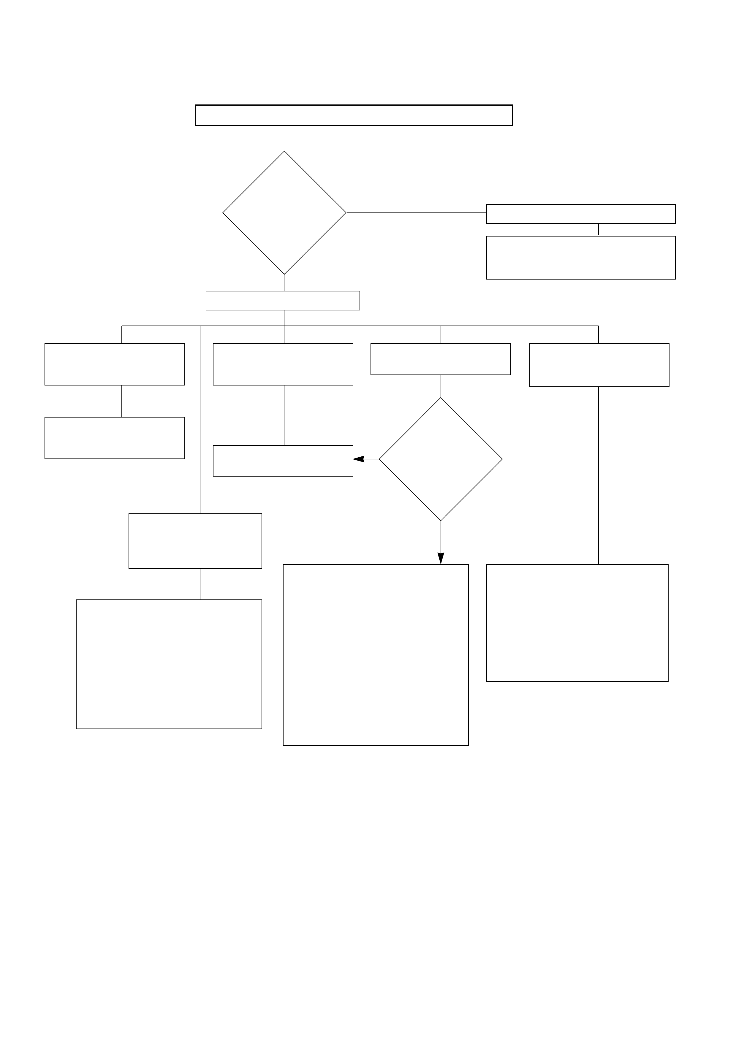
CHART 6: DIAGNOSTIC TROUBLE CODE (DTC) 61
PERFORM PRELIMINARY INSPECTION FIRST!
DTC 61 sets.
Check line
pressure
Check
3rd gear in “D”
in winter mode.
Does vehicle
move?
Check for suspected conditions
modifying delays to clutch apply:
– Overrun clutch seal damaged
– Excessive overrun clutch piston
travel
– Defective 3-4 accumulator piston
– Causes of internal leaks
– Causes of burned clutch plates
Low line pressure
Use CHART 15a: POSSIBLE CAUSES
OF LOW LINE PRESSURE on page
7A1-39
Refer to Line Pressure chart
(
in this Section.
)
Normal line pressure
1st and 4th gear missing
or 2nd and 3rd gear
missing
Shift solenoid A stuck.
Replace shift solenoid A.
1st and 2nd gear missing
or 3rd and 4th gear
missing
Check appropriate shift
valve
If OK replace solenoid
DTC 61 is set in “D” range
1st gear above 3500 rpm
Check for suspected conditions
modifying delays to clutch apply:
– 2nd clutch seal damaged
– Excessive 2nd clutch piston travel
– Defective accumulator piston
– Causes of internal leaks
– Check ball missing or out of
location in 2nd clutch
– Seals cut, damaged or missing
– Gaskets defective
– Causes of burned clutch plates
DTC 61 is set in “D” range
3rd gear between 55-80
mph *
Check for suspected conditions
modifying delays to clutch apply:
– 4th clutch seal damaged
– Excessive 4th clutch piston travel
– Defective 3-4 accumulator piston
– Causes of internal leaks
– Causes of burned clutch plates
No engine brake in any
range
(All ranges in Drive &
Reverse are OK)
YES
NO
* Perform this test within safe and legal limits.

CHART 7: HARSH 1-2 SHIFT
PERFORM PRELIMINARY INSPECTION FIRST!
CHART 8: HARSH 3-4 SHIFT
PERFORM PRELIMINARY INSPECTION FIRST!
( ) Refer to Parts List at the end of this Section.
Check
line pressure
Refer to Line Pressure chart
(
in this Section.
)
Normal line pressure
Check for 1-2 accumulator valve (320)
stuck by foreign material in main case
valve body
Use CHART 15b: POSSIBLE CAUSES
OF HIGH LINE PRESSURE on page
7A1-40
High line pressure
Check
line pressure
Refer to Line Pressure chart
(
in this Section.
)
Normal line pressure
Check for 3-4 accumulator valve (407)
stuck in adapter case valve body (401) Use CHART 15b: POSSIBLE CAUSES
OF HIGH LINE PRESSURE on page
7A1-40
High line pressure
Check for 3-4 accumulator piston (18)
stuck in adapter case (20)

CHART 9a: 3-2 DOWNSHIFT COMPLAINT
PERFORM PRELIMINARY INSPECTION FIRST!
CHART 9b: HARSH SHIFT WHEN SHIFTING INTO "D" OR ACCELERATING FROM STOP
PERFORM PRELIMINARY INSPECTION FIRST!
CHART 9c: COASTDOWN HARSH SHIFT OR CLUNK AT 3-2 DOWNSHIFT
PERFORM PRELIMINARY INSPECTION FIRST!
( ) Refer to Parts List at the end of this Section.
Check
line pressure
Refer to Line Pressure chart
(
in this Section.
)
Normal line pressure
Replace band apply solenoid (PWM)
(323) Use CHART 15a: POSSIBLE CAUSES OF
LOW LINE PRESSURE on page 7A1-39
Low line pressure
Check
line pressure
Refer to Line Pressure chart
(
in this Section.
)
Normal line pressure
Replace band apply solenoid (PWM)
(323) Use CHART 15b: POSSIBLE CAUSES OF
HIGH LINE PRESSURE on page 7A1-40
High line pressure
Check
line pressure
Refer to Line Pressure chart
(
in this Section.
)
Normal line pressure
Replace band apply solenoid (PWM)
(323) Use CHART 15b: POSSIBLE CAUSES OF
HIGH LINE PRESSURE on page 7A1-40
High line pressure
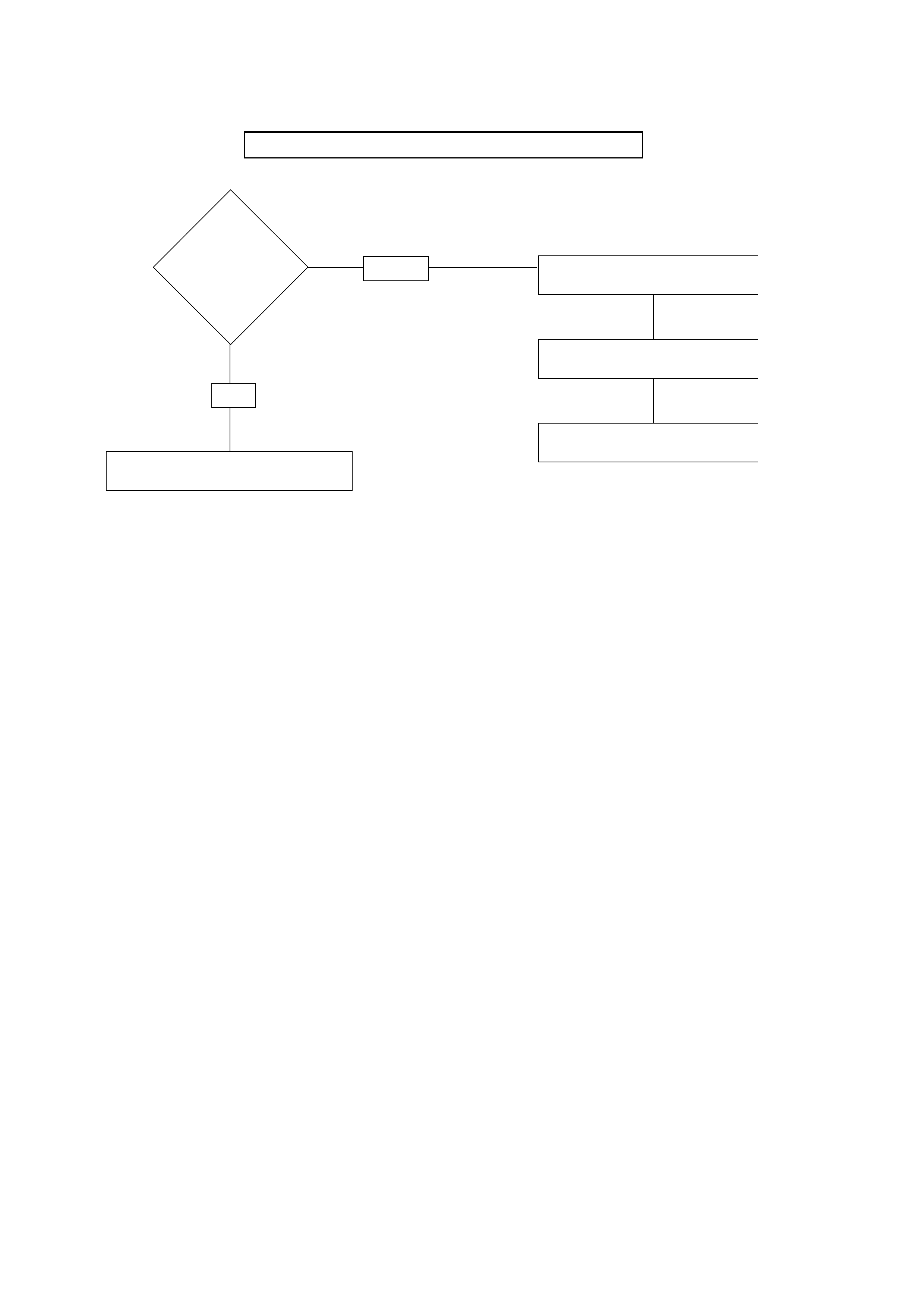
CHART 10: INTERMITTENT 4TH TO 2ND GEAR DOWNSHIFT AT STEADY SPEED
PERFORM PRELIMINARY INSPECTION FIRST!
Check for
consistent speed
sensor reading
with TECH2
OK
OK
Check for wiring harness damage
or short to ground
Check transmission speed sensor
connections
Replace transmission speed
sensor
NOT OK
OK
Replace mode switch for intermittent
contact

CHART 11: ENGINE FLARE AT SHIFTING DURING TURNING ONLY
(USUALLY WITH WARM ENGINE)
PERFORM PRELIMINARY INSPECTION FIRST!
PERFORM PRELIMINARY INSPECTION FIRST!
CHART 12: ENGINE FLARE DURING 1-2 OR 2-3 SHIFT
Check
line pressure
( ) Refer to Parts List at the end of this Section.
Leak at transmission oil filter, gasket,
or wrong filter type
Replace transmission oil filter and
gasket
Check for band apply solenoid (323)
stuck
Check for servo piston (106) leaks
Check for 1-2 accumulator valve (320)
stuck
Normal line pressure
Use CHART 15a: POSSIBLE CAUSES OF
LOW LINE PRESSURE on page 7A1-39
Low line pressure
Refer to Line Pressure chart
(
in this Section.
)

CHART 13: SHUDDER ONLY DURING TORQUE CONVERTER CLUTCH (TCC) APPLYING
PERFORM PRELIMINARY INSPECTION FIRST!
YES
NO
Replace transmission fluid and filter (remove both pans) and flush
cooler lines.
Replace converter assembly and O-ring on turbine shaft.
Drive until whole drivetrain is at normal operating temperature.
– Shudder is a SHORT BURST OF NOISE NORMALLY LESS THAN 1
SECOND IN DURATION, and can be induced by the following
maneuver:
TCC shudder is one of the most commonly misdiagnosed conditions in
an automatic transmission. The key to diagnosing TCC shudder is to
note when it happens and under what conditions. Once the TCC has
been fully applied, it is nearly impossible to make it shudder. TCC
shudder (short burst of noise normally less than 1 second) will only
occur during clutch applying. It is not a steady state condition.
From coast condition at 50 mph in “D” range (Normal mode), depress
the throttle to 1/4-1/3 throttle.
If present, shudder (short burst of noise normally less than 1 sec.) will
occur within 5 seconds together with TCC applying.
(TECH2 may be used to determine the exact time of TCC applying)
Perform mechanical inspection of
other drivetrain components.

CHART 14: POSSIBLE CAUSES OF TRANSMISSION NOISE
PERFORM PRELIMINARY INSPECTION FIRST!
CAUTION:
Before checking transmission for what is believed to be transmission noise,
ensure presence and positioning of insulating plugs, pads etc. Also make
sure that noise does not come from other drivetrain components.
1. WHINE OR BUZZ:
– Oil level low
– Plugged or restricted oil filter
– Damaged oil filter gasket
2. KNOCKING NOISE FROM FRONT OF TRANSMISSION:
– Loose bolts (Converter to flex plate)
– Cracked or broken flex plate
– Converter damaged
3. KNOCKING NOISE WHILE DRIVING - MOSTLY ON ACCELERATION:
– Transmission mount loose or broken
– Cooler line mounts loose or broken
– Cooler lines touching body or frame
4. KNOCKING NOISE WHEN VEHICLE IS STATIONARY:
– Loose flex plate mounting bolts
– Cracked or broken flex plate
– Damaged converter
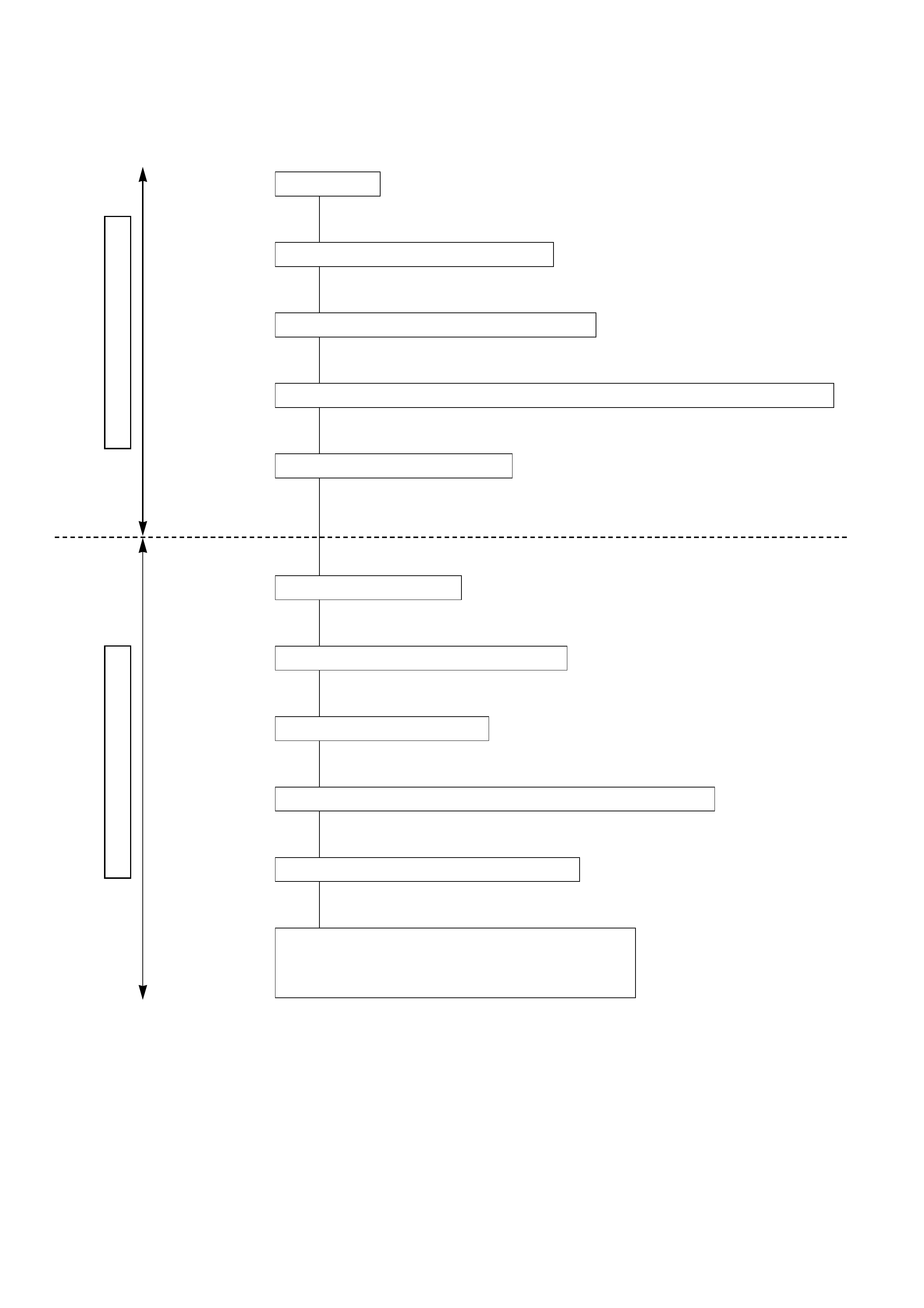
CHART 15a: POSSIBLE CAUSES OF LOW LINE PRESSURE
ON-VEHICLE SERVICE
TRANSMISSION REMOVED
OK
OK
OK
OK
OK
OK
OK
OK
OK
OK
Small
valve
body
Oil
pump
( ) Refer to Parts List at the end of this Section.
Check for loose bolts (4 & 5)
Check for pressure regulator valve (208) stuck
Check for boost valve (205) stuck
Check for intermediate oil passages to pressure regulator valve blocked
Check for defective oil pump (9, 201, 202 & 209)
Check for internal leaks
– Check balls missing or out of location in valve bodies
– Seals cut or damaged
– Gaskets defective, etc.
Check oil level
Check for defective throttle position sensor
Check for plugged, loose, or damaged oil filter (79)
Check for force motor plunger (404) stuck. (Remove force motor. Shake and listen for rattle.)
Check for feed limit valve (412) stuck
CHART 15b: POSSIBLE CAUSES OF HIGH LINE PRESSURE
PERFORM PRELIMINARY INSPECTION FIRST!
ON-VEHICLE SERVICE
TRANSMISSION REMOVED
Small
valve
body
Oil
pump
OK
OK
OK
( ) Refer to Parts List at the end of this Section.
NOTE: If transmission is operating in back-up mode, high line pressure will be
present.
Check for defective throttle position sensor
OK
Check for loose bolts (4 & 5)
OK
OK
Check for pressure regulator valve (208) stuck
Check for boost valve (205) stuck
Check for force motor plunger (404) stuck
(Remove force motor. Shake and listen for rattle.)
(Open circuit/Intermittent)
Check for feed limit valve (412) stuck
Check for internal leaks
– Check balls missing or out of location in valve bodies
– Seals cut or missing
– Gaskets defective, etc.

CHART 16: POSSIBLE CAUSES OF TRANSMISSION FLUID LEAKS
Before attempting to correct an oil leak, the actual source of the leak must be determined. In many cases,
the source of the leak may be difficult to determine due to “wind flow” around the engine and
transmission.
The suspected area should be wiped clean of all oil before inspecting for the source of the leak.
Oil leaks around the engine and transmission are generally carried toward the rear of the car by the air
stream. In determining the source of an leak, the following two checks should be made:
1. With the engine running, check for external line pressure leaks.
2. With the engine off, check for oil leaks due to the raised oil level caused by drainback of converter oil
into the transmission.
POSSIBLE CAUSES OF FLUID LEAKS
DUE TO SEALING MALFUNCTION
1) Electrical connector (Main case) seal
2) Transmission vent (Breather)
3) Speed sensor O-ring
4) Extension (Adapter) lip seal
5) Extension (Adapter) to main case gasket
6) Oil drain plug gasket
7) Oil pan gasket (Main case)
8) Selector shaft seal
9) Oil cooler connectors (2)
10) Oil pan gasket (Adapter case)
11) Converter housing attaching bolts not correctly
torqued
12) Converter housing lip seal
13) Line pressure tap plug
14) Electrical connector (Adapter case) seal
15) Adapter case seal rings (2)
67 5910 8
11
12
23
4
1
1413
15
240LW004

STALL TEST
The stall test allows you to check the transmission for
internal abrasion and the oneway clutch for slippage.
Torque converter performance can also be evaluated.
The stall test results together with the road test results will
identify transmission components requiring servicing or
adjustment.
Stall Test Procedure:
1. Check the level of the engine coolant, the engine oil,
and the automatic transmission fluid.
Replenish if necessary.
2. Block the wheels and set the parking brake.
3. Connect a tachometer to the engine.
4. Start the engine and allow it to idle until the engine
coolant temperature reaches 70 - 80°C (158 - 176°F).
5. Hold the brake pedal down as far as it will go.
6. Place the selector in the “D” range.
7. Gradually push the accelerator pedal to the floor.
The throttle valve will be fully open.
Note the engine speed at which the tachometer
needle stabilizes.
Stall Speed
Standard
2200 ± 150 rpm
NOTE:
Do not continuously run this test longer than 5
seconds.
8. Release the accelerator pedal.
9. Place the selector in the “N” range.
10. Run the engine at 1,200 rpm for one minute.
This will cool the transmission fluid.
11. Repeat Steps 7-10 for the “3”, “2”, “L” and “R”
ranges.
LINE PRESSURE TEST
The line pressure test checks oil pump and control valve
pressure regulator valve function. It will also detect oil
leakage.
Line Pressure Test Procedure:
1. Check the level of the engine coolant, the engine oil,
and the automatic transmission fluid.
Replenish if required.
2. Block the wheels and set the parking brake.
3. Remove the pressure detection plug at the left side of
the transmission case.
Set pressure gauge, adapter to the pressure detection
plug hole.
Gauge and adapter: 5-8840-0004-0 (J-21867)
Line Pressure and Force Motor Current KPa (kg/cm2/ PSI)
4. Start the engine and allow it to idle until the engine
coolant temperature reaches 70 - 80°C (158- 176°F).
5. Hold the brake pedal down as far as it will go.
6. Place the selector in the “D” range.
7. Note the pressure gauge reading with the engine
idling.
8. Gradually push the accelerator pedal to the floor. The
throttle valve will be fully open.
Note the pressure gauge reading with the accelerator
pedal fully depressed.
NOTE:
Do not continuously run this test longer than 5
seconds.
9. Release the accelerator pedal.
10. Place the selector in the “N” range.
11. Run the engine at 1,200 rpm for one minute.
This will cool the transmission fluid.
12. Repeat Steps 7 - 11 for the “3”, “2”, “L”, and “R”
ranges.
13. Install a pressure detection plug to the transmission
case, applying recommended thread locking agent
(LOCTITE 242) or its equivalent to thread of plug.
Make sure that thread is cleaned before applying
locking agents.
14. Tighten the pressure detection plug to the specified
torque.
Pressure Detection Plug Torque N·m (kg·m / lb·ft)
9 – 14 (0.9 – 1.4 / 7 – 10)
LEVER ENGINE FORCE
MODE LINE PRESSURE MOTOR
POSITION SPEED CURRENT
NORMAL/POWER D, 3, 2, L IDLE 312 – 363 (3.2 – 3.7 / 45.2 – 52.6) VARIABLE
NORMAL/POWER REVERSE IDLE 419 – 486 (4.3 – 5.0 / 60.7 – 70.5) 0.9 – 1.0A
NORMAL/POWER D, 3, 2, L STALL SPEED 1236 – 1320 (12.6 – 13.5 / 179.3 – 191.4) 0.1 – 0.2A
NORMAL/POWER REVERSE STALL SPEED 1634 – 1743 (16.7 – 17.8 / 236.9 – 252.8) 0.1 – 0.2A

SHIFT SPEED CHART Transfer gear ratio: High: 1.000
(
Rear axle ratio: 4.555
)
“Normal mode”
Downshift Km/h (mph)
Upshift Km/h (mph)
Range Throttle opening 1 →22 →33 →4
(First Gear) (Second Gear) (Second Gear) (Third Gear) (Third Gear) (Fourth Gear)
DFully opened 41 ~ 47 (25 ~ 29) 84 ~ 90 (52 ~ 56) 127 ~ 133 (79 ~ 83)
(Drive) Half throttle 33 ~ 39 (20 ~ 24) 60 ~ 66 (37 ~ 41) 117 ~ 123 (73 ~ 76)
3Fully opened 49 ~ 55 (30 ~ 34) 99 ~ 105 (62 ~ 66) –
(Third) Half throttle 32 ~ 38 (20 ~ 24) 58 ~ 64 (36 ~ 40) –
2Fully opened 49 ~ 55 (30 ~ 34) – –
(Second) Half throttle 32 ~ 38 (20 ~ 24) – –
Range Throttle opening 1 ←22 ←33 ←4
(First Gear) (Second Gear) (Second Gear) (Third Gear) (Third Gear) (Fourth Gear)
DFully opened 16 ~ 22 (10 ~ 14) 62 ~ 68 (39 ~ 42) 104 ~ 110 (65 ~ 68)
(Drive) Half throttle 15 ~ 21 (9 ~ 13) 34 ~ 40 (21 ~ 25) 67 ~ 73 (42 ~ 46)
Fully closed 14 ~ 20 (9 ~ 12) 21 ~ 27 (13 ~ 17) 29 ~ 35 (18 ~ 22)
3Fully opened 39 ~ 45 (24 ~ 28) 87 ~ 93 (54 ~ 58) –
(Third) Half throttle 15 ~ 21 (9 ~ 13) 34 ~ 40 (21 ~ 25) –
Fully closed 13 ~ 19 (8 ~ 12) 15 ~ 21 (9 ~ 13) –
2Fully opened 40 ~ 46 (25 ~ 29) 94 ~ 100 (59 ~ 63) –
(Second) Half throttle 15 ~ 21 (9 ~ 13) 94 ~ 100 (59 ~ 63) –
Fully closed 13 ~ 19 (8 ~ 12) 82 ~ 88 (51 ~ 55) –
L– 50 ~ 56 (31 ~ 35) – –
(First)

“Power mode”
Upshift Km/h (mph)
Downshift Km/h (mph)
Range Throttle opening 1 →22 →33 →4
(First Gear) (Second Gear) (Second Gear) (Third Gear) (Third Gear) (Fourth Gear)
DFully opened 49 ~ 55 (30 ~ 34) 99 ~ 105 (62 ~ 66) 169 ~ 175 (105 ~ 109)
(Drive) Half throttle 37 ~ 43 (23 ~ 27) 74 ~ 80 (46 ~ 50) 124 ~ 130 (77 ~ 81)
3Fully opened 49 ~ 55 (30 ~ 34) 99 ~ 105 (62 ~ 66) –
(Thire) Half throttle 37 ~ 43 (23 ~ 27) 74 ~ 80 (46 ~ 50) –
2Fully opened 49 ~ 55 (30 ~ 34) – –
(Second) Half throttle 37 ~ 43 (23 ~ 27) – –
Range Throttle opening 1 ←22 ←33 ←4
(First Gear) (Second Gear) (Second Gear) (Third Gear) (Third Gear) (Fourth Gear)
DFully opened 40 ~ 46 (25 ~ 29) 90 ~ 96 (56 ~ 60) 160 ~ 166 (100 ~ 104)
(Drive) Half throttle 21 ~ 27 (13 ~ 17) 53 ~ 59 (33 ~ 37) 98 ~ 104 (61 ~ 65)
Fully closed 13 ~ 19 (8 ~ 12) 24 ~ 30 (15 ~ 19) 46 ~ 52 (29 ~ 32)
3Fully opened 40 ~ 46 (25 ~ 29) 90 ~ 96 (56 ~ 60) –
(Third) Half throttle 21 ~ 27 (13 ~ 17) 53 ~ 59 (33 ~ 37) –
Fully closed 13 ~ 19 (8 ~ 12) 24 ~ 30 (15 ~ 19) –
2Fully opened 40 ~ 46 (25 ~ 29) 94 ~ 100 (59 ~ 63) –
(Second) Half throttle 21 ~ 27 (13 ~ 17) 94 ~ 100 (59 ~ 63) –
Fully closed 13 ~ 19 (8 ~ 12) 82 ~ 88 (51 ~ 55) –
L– 50 ~ 56 (31 ~ 35) – –
(First)
LOCK-UP SPEED CHART Transfer gear ratio: High: 1.000
(
Rear axle ratio: 4.555
)
Km/h (mph)
Mode Lock-Up ON Lock-Up OFF
2nd 3rd 4th 2nd 3rd 4th
Normal 75 ~ 81 55 ~ 61 67 ~ 73 70 ~ 76 47 ~ 53 62 ~ 68
(47 ~ 50 ) (34 ~ 38) (42 ~ 45) (43 ~ 47) (29 ~ 33) (39 ~ 42)
Power 72 ~ 78 77 ~ 83 77 ~ 83 67 ~ 73 68 ~ 74 72 ~ 78
(45 ~ 48 ) (48 ~ 52) (48 ~ 52) (42 ~ 45) (42 ~ 46) (45 ~ 48)
D range
Throttle
opening
9%

ELECTRONIC DIAGNOSIS
HOW TO DIAGNOSE THE PROBLEM
1. To avoid incorrect diagnostics: this book needs to be
followed accurately. Unless stated: do not jump
directly to a section that could contain the solution:
some important information may be missed.
2. The sections in CAPITALS and bold are the main
sections that can be found in the contents.
3. The GOTO “SECTION” means to continue to check
going to the “section”.
4. The GOTHROUGH “SECTION” means to go through
the “section” and then to go back to the place the
GOTHROUGH was written.
5. BASIC ELECTRIC CIRCUITS:
You should understand the basic theory of electricity.
This will include the meaning of voltage, amps,
ohms, and what happens in a circuit with an open or
shorted wire. You should also be able to read and
understand wiring diagrams.
6. IGNITION CYCLE:
When the car is driven a malfunction can occur due to
a car wiring harness problem, in this case the driver
can reset the system (as on a personal computer). To
reset the computer he must:
(1) Stop the car and the engine.
(2) Turn the key ignition OFF.
(3) Turn the key ignition ON.

CHECK TRANS INDICATOR
Find CHECK TRANS indicator and verify if it is:
A. Flashing: GOTO DIAGNOSTIC CHECK.
B. Staying on: GOTHROUGH CHECK TRANS CHECK.
C. Is never ON when the ignition key is turned on:
GOTHROUGH CHECK TRANS CHECK
D. Is ON during 2 to 3 seconds at ignition but OFF after:
Normal operation. No DTC or malfunction.
CHECK
TRANS
821LW003
DIAGNOSTIC CHECK
This test determines if the transmission itself or its
inputs or outputs connections or sensors are failing.
1. Connect the TECH2: GOTHROUGH TECH2
CONNECTION.
2. Turn on the ignition but not the engine.
3. Push “F2” on TECH2 to see the Diagnostic Trouble
Codes (DTC):
4. IF you have DTC?
YES: write down all code numbers and do the DTC
CHECK
NO: the DTC can not help you finding the problem.
(1) GOTHROUGH “CHECK TRANS” CHECK
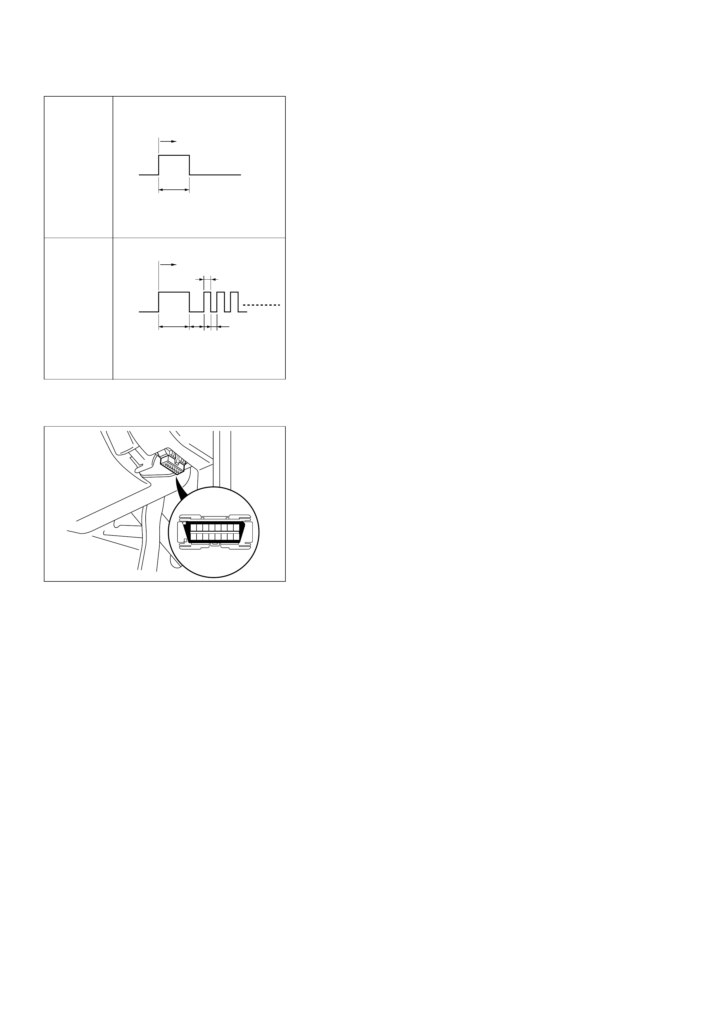
(2) IF it is flashing and the flash is 0.2 seconds ON
and 0.2 seconds OFF, this means that you should
have a DTC stored. Please recheck GOTO
DIAGNOSTIC CHECK
(3) IF the CHECK TRANS indicator is not flashing
GOTO WITHOUT DTC SET.
Normal
Abnormal
ON
OFF
IGN Key ON
3 Sec.
(Lamp check)
ON
OFF
IGN Key ON
3 Sec.
(Lamp check)
0.2 Sec.
(2.5 Hz)
3.2 Sec.
0.2 Sec.
“CHECK TRANS” CHECK
1. CASE it is ON during 2 to 3 seconds at ignition (or
when the engine is cranked) but it is OFF after. The
indicator is working normally GOTO DIAGNOSTIC
CHECK.
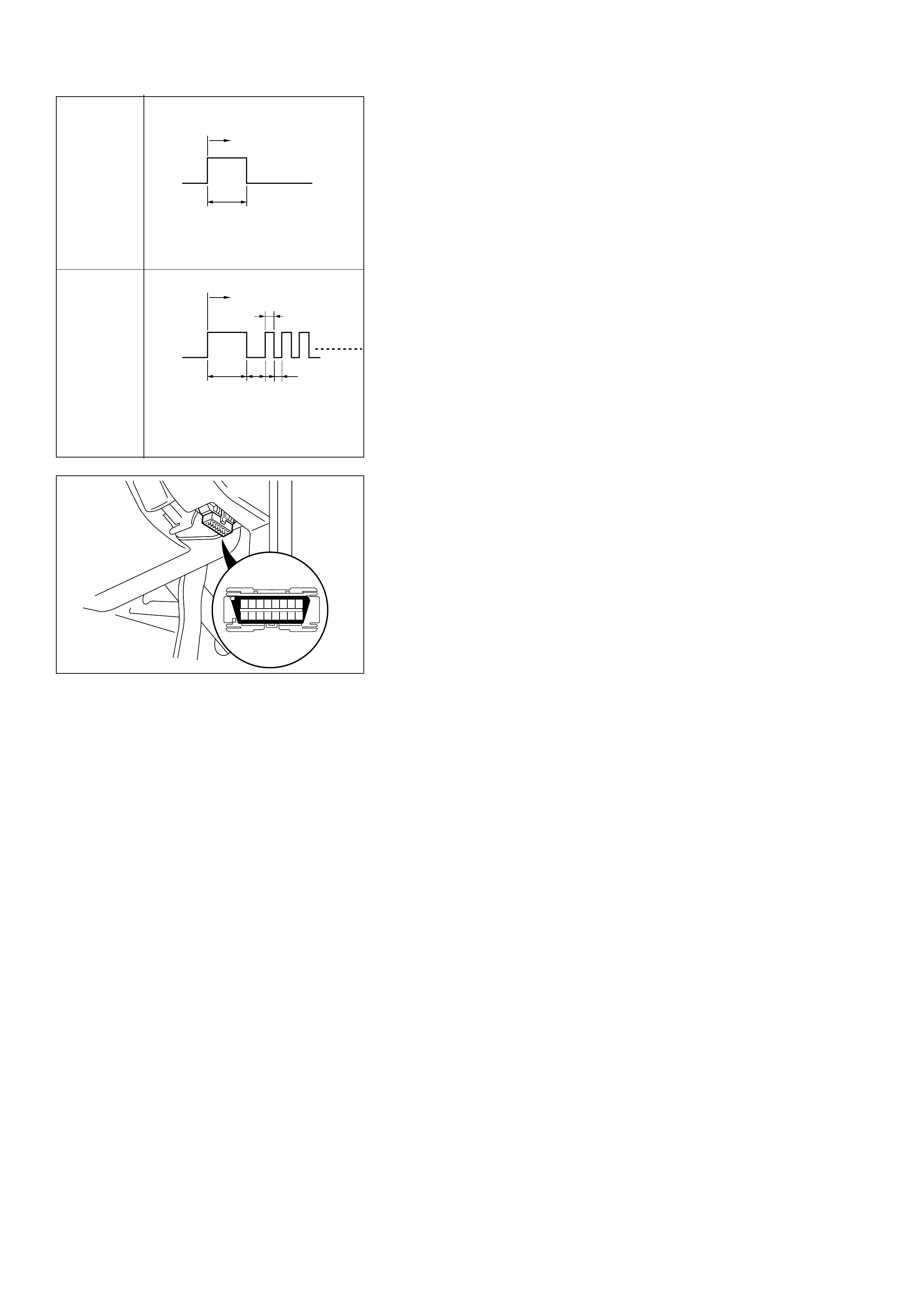
2. CASE it is flashing and the flash is 0.2 seconds ON
and 0.2 seconds OFF always when ignition is on
(engine cranked or not). This means that there is a
malfunction. GOTO DIAGNOSTIC CHECK.
3. CASE the CHECK TRANS indicator is flashing always
and the flash is 0.4 seconds ON and 0.4 second OFF.
(1) This means that the Transmission Control Module
(TCM) is in flashing code mode. This mode is only
used for service. This mode is set when the
terminal 11 of data link connector C-102 is set to
ground. To go out of this mode.
(2) Check if terminal 11 of data link connector C-102
is shorted to ground. (Voltage is about 0 volts
when there is a short to ground instead of 5
volts).
(3) Check if TCM terminal D16 has the same problem.
(4) Remove the short circuit to ground due to wiring
problems.
(5) IF problem solved: GOTO CHECK TRANS
INDICATOR.
ON
OFF
IGN Key ON
3 Sec.
(Lamp check)
ON
OFF
IGN Key ON
3 Sec.
(Lamp check)
0.2 Sec.
(2.5 Hz)
3.2 Sec.
0.2 Sec.
Normal
Abnormal
826RV061
87654321
161514131211109
TRANSMISSION
CONTROL
MODULE
(TCM)
CHECK TRANS
INDICATOR
CONTROL
DIAGNOSTIC
INPUT
CHECK TRANS
(METER)
B-248
B-242
FUSE
CB-5
15A
FUSE BOX
ORN/BLU
H-26
7
D16(16) C-95
C10(10) C-95
YEL/BLK
11 45
DATA LINK
CONNECTOR
(C-102)
ORN/BLU
4. CASE it is staying ON always when Ignition is ON.
(1) This means that connection between the Lamp
and the TCM is shorted to ground.
(2) Verify if instrument panel terminal 8 of connector
B-24 is shorted to ground.
(3) Verify if the TCM connector C-95 terminal C10 is
shorted to ground.
(4) Verify that the instrument panel terminal 2 of con-
nector B-24 is connected to battery.
(5) IF problem solved: GOTO CHECK TRANS
INDICATOR.
5. CASE it is staying OFF with the ignition ON (engine
OFF).
(1) This means that connection between the lamp
and the TCM is shorted to battery or opened.
(2) Verify if instrument panel terminal 8 of connector
B-24 is shorted to battery or open.
(3) Verify if the TCM connector C-95 terminal C10 is
shorted to battery or open.
(4) Verify that the instrument panel terminal 2 of
connector B-24 is connected to battery. If not
check the fuses and the connections voltage.
(5) IF problem solved: GOTO CHECK TRANS
INDICATOR.
D07LW004
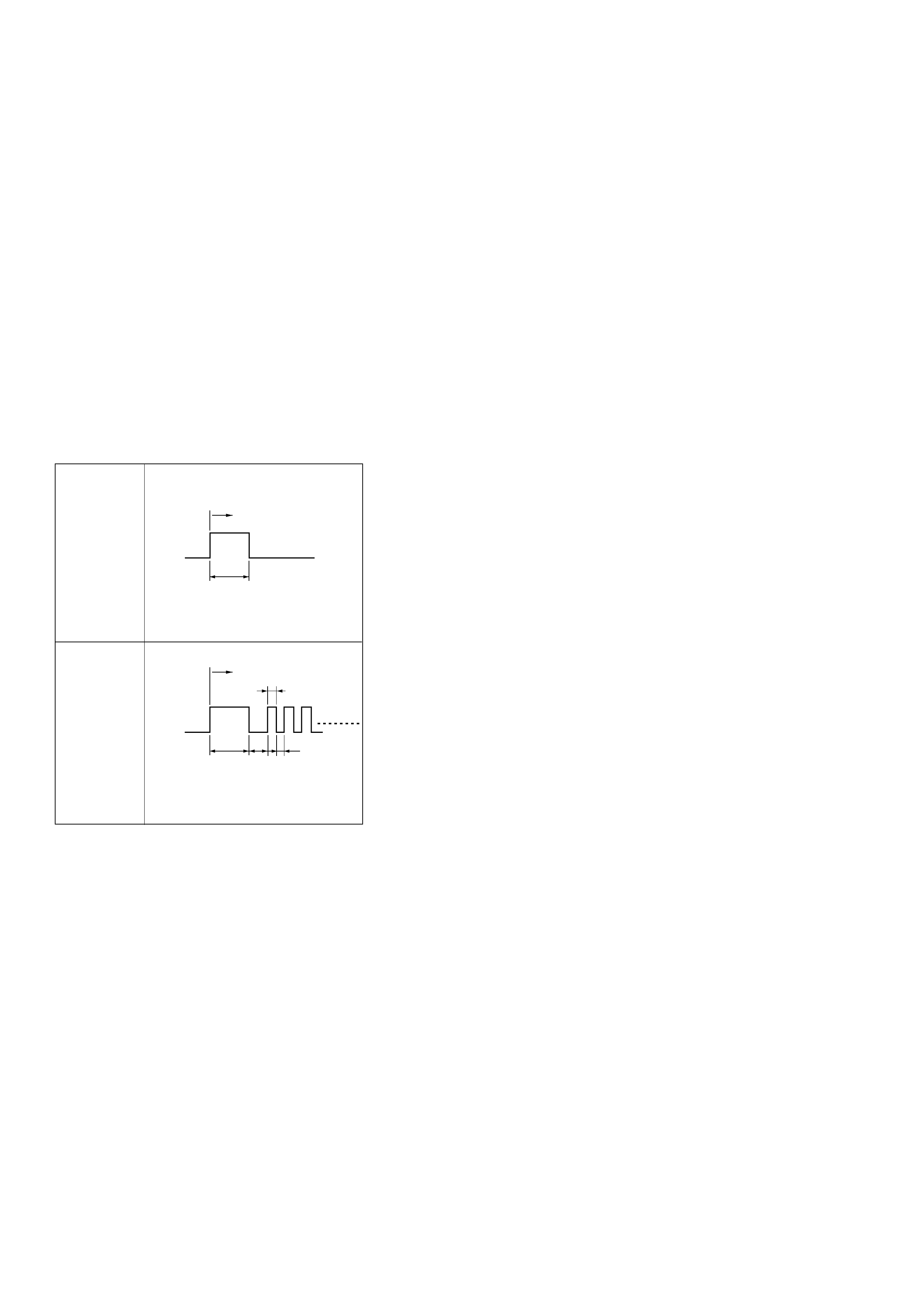
FLASHING CODES
1. ON BOARD DIAGNOSIS (SELF-DIAGNOSIS)
(1) The Transmission Control Module (TCM)
conducts a self-test of most of the wiring and
components in the system each time the key is
turned ON. If a fault is detected the TCM will store
a Diagnostic Trouble Code (DTC) in memory. It’s a
number that corresponds to a specific problem.
(2) When the problem detected is important: the
CHECK TRANS indicator is flashing (turned ON
0.2 seconds and OFF 0.2 seconds) until the fault is
repaired and the TCM memory is cleared.
ON
OFF
IGN Key ON
3 Sec.
(Lamp check)
ON
OFF
IGN Key ON
3 Sec.
(Lamp check)
0.2 Sec.
(2.5 Hz)
3.2 Sec.
0.2 Sec.
Normal
Abnormal
2. DIAGNOSTIC TROUBLE CODES (DTC)
(1) DTC can be displayed by the Transmission
Control Module (TCM) by shorting together
terminals 11 and 4 or 5 (ground) of the TCM
Diagnosis Connector (C-102) located driver
compartment.
(This grounds the TCM pin D16).
826RV061
87654321
161514131211109
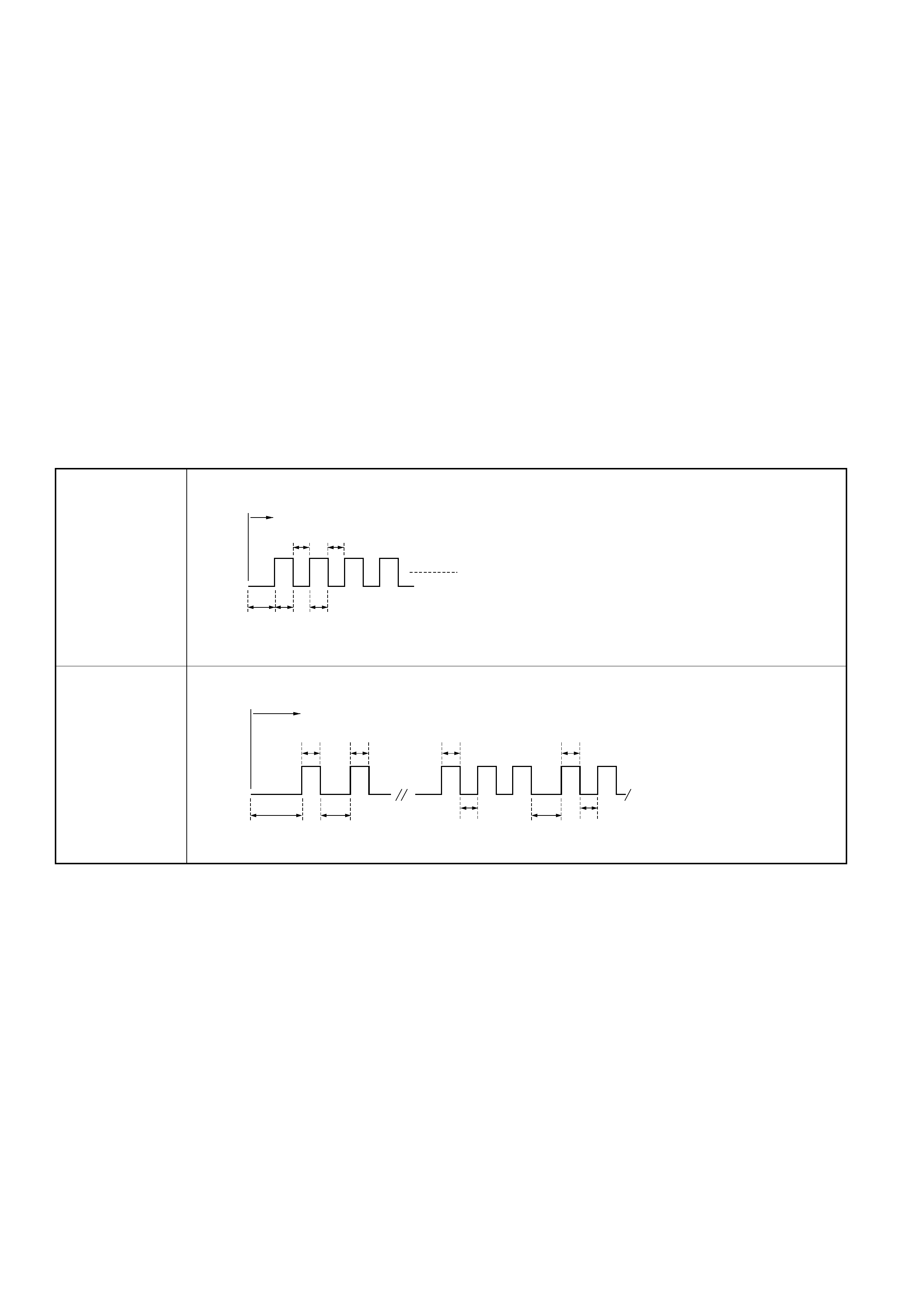
ON
OFF
Diagnostic test start
0.4 Sec. 0.4 Sec.
3.2 Sec. 0.4 Sec. 0.4 Sec.
(1.25 Hz)
ON
OFF
The trouble code(s) will flash 3 times.
Example: DTC 11 x 3 (times), DTC 32 x 3 (times)
3.2 Sec.
0.4 Sec. 0.4 Sec. 0.4 Sec. 0.4 Sec.
0.4 Sec.
1.2 Sec. 1.2 Sec. 0.4 Sec.
Diagnostic test start
Normal
Abnormal
(2) After this, the CHECK TRANS Indicator will be OFF
for 3.2 second and then will flash each DTC 3
times.
1When there are more than 9 flashes this
means that the indicator is constantly flashing,
OFF for 0.4 seconds, ON for 0.4 seconds. In
this case there is no DTC stored in memory.
•To find the problem without a scan tool and
without DTC GOTO WITHOUT DTC SET.
2When there are less than 9 flashes you will
see DTC of 2 digits repeated 3 times each and
when all codes have been displayed they are
displayed again beginning from the first one.
3Do not care about the DTC order : if “21” is
before “22” it does not matter.
4Write down all codes numbers and GOTO DTC
CHECK.
(3) IF CHECK TRANS indicator is not flashing GOTO
“CHECK TRANS” CHECK.
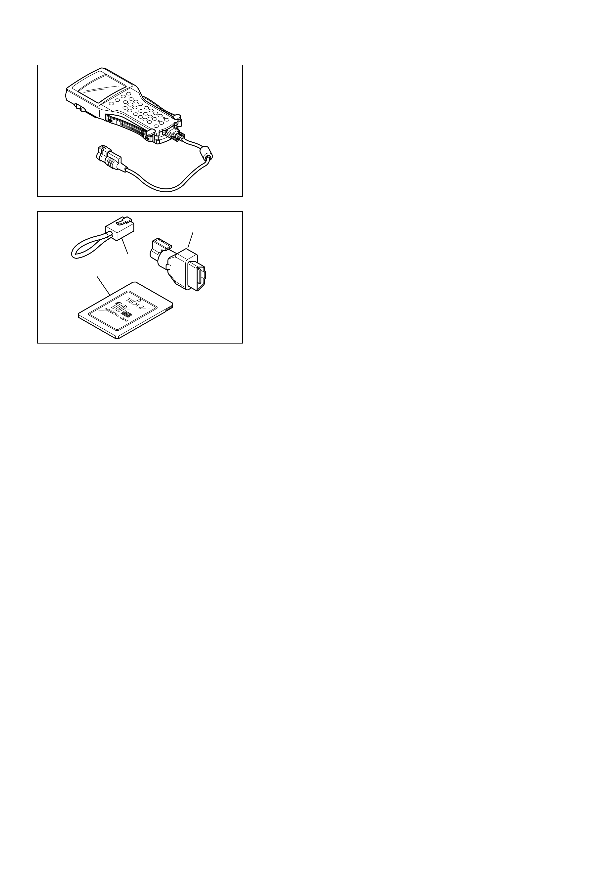
TECH2 CONNECTION
In order to access Transmission Control Module (TCM)
data, use of the TECH2 scan tool is required.
1. The electronic diagnosis equipment is composed of:
(1) TECH2 (3000094) hand-held scan tool, and DLC
cable (3000095).
(2) SAE 16/19 adapter (3000098) (1), RS 232 loop back
connector (3000112) (2), and PCMCIA card
(3000117) (3).
901RW176
F07RW033
1
2
3
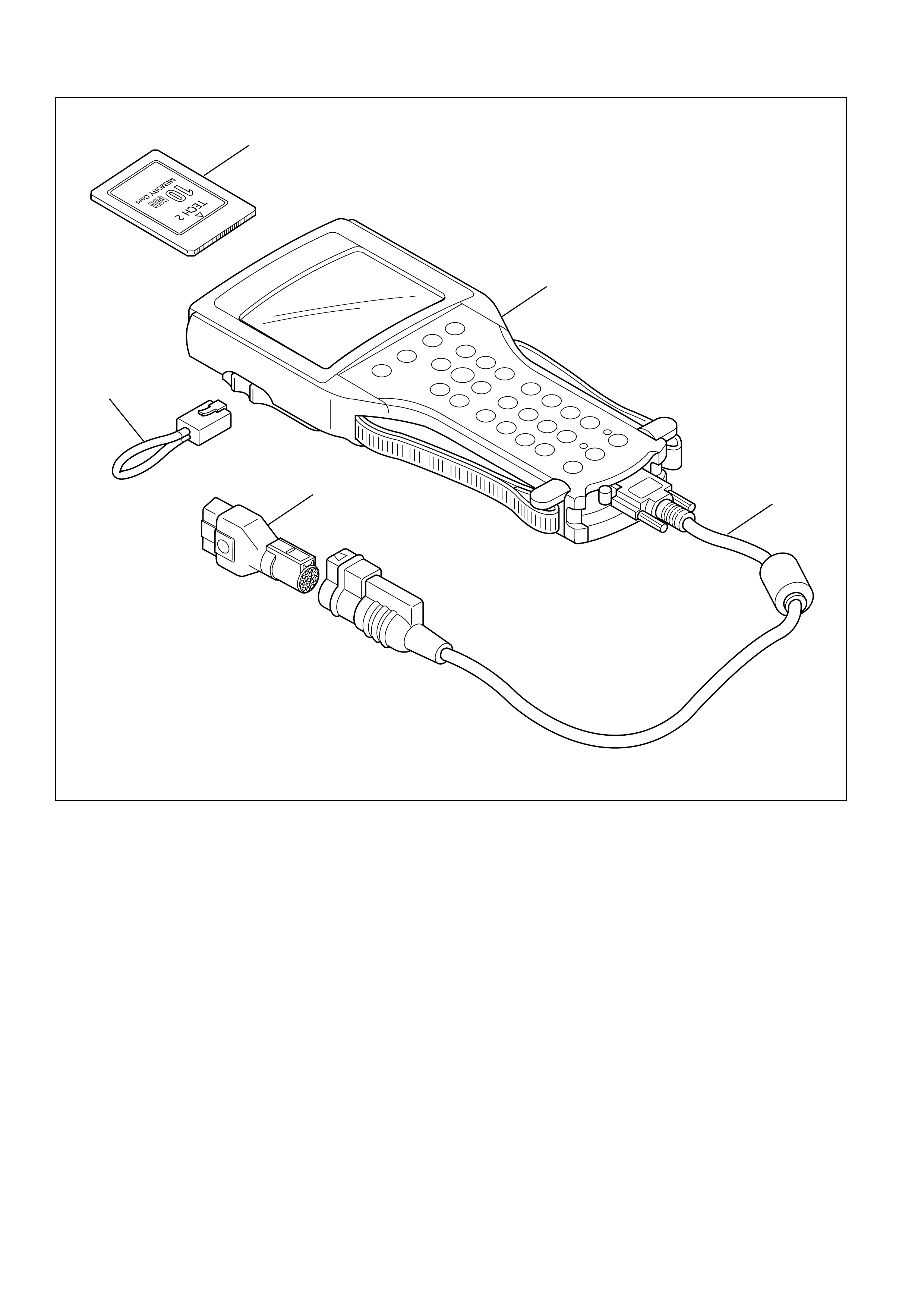
2. Connecting the TECH2
NOTE:
Always observe instructions in the TECH 2 and the Holden
Program PCMCIA card.
Before operating the Isuzu PCMCIA card with the TECH2,
the following steps must be performed:
1. The Holden Program PCMCIA card (1) inserts into the
TECH2 (5).
2. Connect the SAE 16/19 adapter (3) to the DLC
cable(4).
3. Connect the DLC cable to the TECH2 (5).
4.
CAUTION
Make sure the vehicle ignition is off.
Connecting TECH 2 with the engine running may
result in the transmission entering 'Fail- safe' mode.
Should this occur, cycle the ignition to perform a
system reset.
1
5
4
3
2
Legend
1. PCMCIA Card
2. RS232 Loop Back Connector
3. SAE 16/19 Adaper
4. DLC Cable
5. Tech2
901RW180
87654321
161514131211109
826RV061
Press (ENTER) To Continue
060RW009
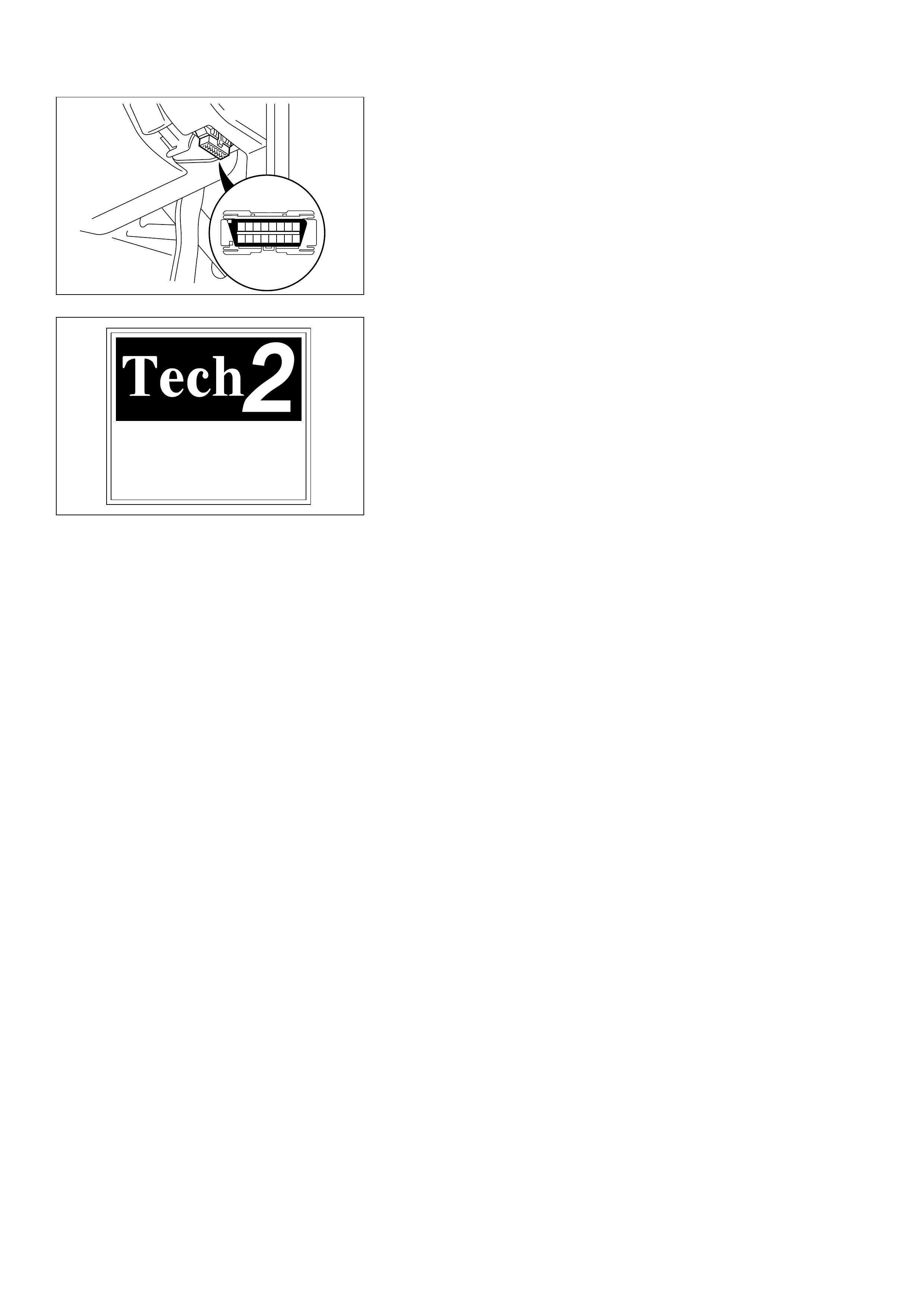
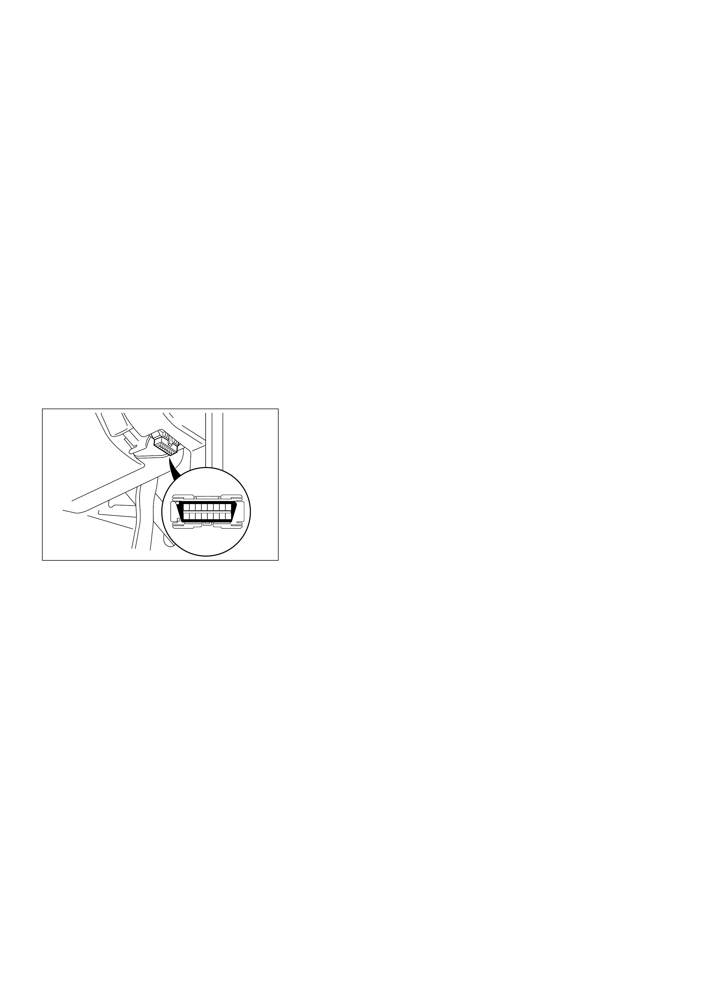
5. Connect the TECH2 SAE 16/19 adaptor to the vehicle
DLC.
6. The vehicle ignition turns on.
7. Verify the TECH2 power up display.
NOTE:
The RS232 Loop back connector is only to use for
diagnosis of TECH2 and refer to user guide of the TECH2.
CLEAR DTC
Remark: If you clear the DTC (Diagnosis Trouble
Codes) you will not be able to read any codes
recorded during the last Trouble.
Remark: To be able to use the DTC again to identify a
problem you will need to reproduce the fault or the
problem. This may require a new test drive or just
turning the ignition on (this depends on the nature of
the fault).
1. IF you have a TECH2:
(1) Connect the TECH2 if it is still not connected
GOTHROUGH TECH2 CONNECTION.
(2) Push “F4” and answer “Yes” to the question “Do
you really want to clear the codes?”
1When a malfunction remains as it is the
TECH2 displays “4L30E CODES NOT
CLEARED”. This means that the problem is
still there or that the recovery was not done
please GOTO DTC CHECK.
2When a malfunction has been repaired and
the recovery is done the TECH2 displays
“4L30E CODES CLEARED”.
2. IF you have no TECH2:
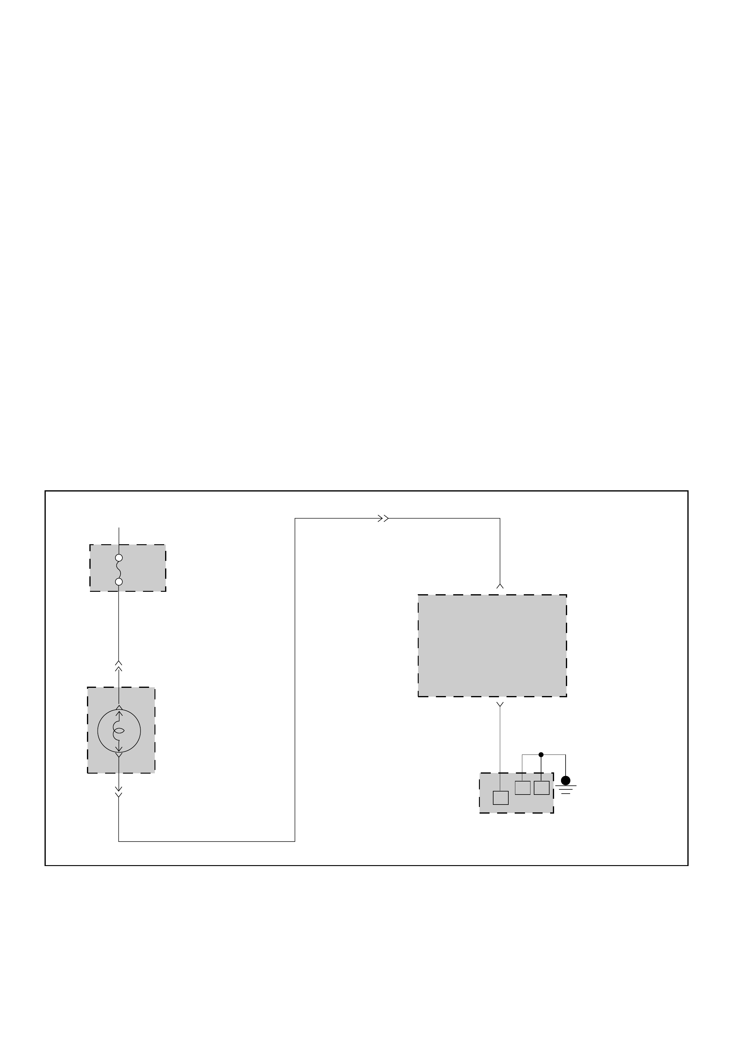
(1) Short the Data Link Connector C-102 terminal 11
to terminal 4 or 5 (ground).
1IF it is flashing and the flash is 0.4 seconds ON
and 0.4 second OFF without interruption, this
means that there is no DTC. The DTCs are
already cleared.
(2) IF a code is flashed, wait until the lamp is
flashing.
(3) Push POWER SWITCH (do this within 3 second).
1If you continue to have malfunctions: This
means that the problem is still there or that
the recovery was not done please see DTC
CHECK.
(4) IF you can not clear the DTC:
1GOTHROUGH TCM PRECAUTIONS.
2Disconnect the TCM.
3Reconnect the TCM.
4IF the DTC is not cleared: GOTO TCM MEM-
CAL REPLACEMENT.
87654321
161514131211109
826RV061

DTC CHECK
1 Diagnosis Trouble Codes (DTC) have been identified
by TECH2 or FLASHING CODES.
2. You have written the list of the DTC. The order of the
malfunctions has no meanings for this TCM. Usually
only one or two malfunctions should be set for a
given problem.
3. Check directly the DTCs you identified. The DTC are
sorted by number. See Chart 2:
DIAGNOSTIC TROUBLE CODES (Page 7A1-63).

F0: DATA LIST QUICK CHECK
TECH2 DISPLAY CONDITONS CORRECT VALUE FOR
DIAGNOSIS
SEE*1
BATTERY VOLTAGE Ignition ON 9 V ≤voltage ≤15.5 V DTC 25
(V) or 26
FORCE MOTOR CUR. Engine at idle speed approx. 0.9 A DTC 35
CALCULAT. PRESS. Parking brake on approx. 4.0 bar
Selector lever position ”D“
SOLENOID A Vehicle traveling at a speed of: approx. ACTIVE DTC 31
50 km/h (32 mph) with selector lever in or 41
position ”2“ or approx. 70 km/h (44 mph)
with selector lever in position ”3“
SOLENOID B Vehicle traveling at a speed of: approx. ACTIVE DTC 32
10 km/h (6 mph) with selector lever in or 42
position ”L“ or approx. 30 km/h (18 mph)
with selector lever in position ”2“
BAND APPLY SOL. Engine at idle speed approx. 99% DC DTC 34
Selector lever position ”L“or 44
TCC SOLENOID Vehicle traveling at a speed of approx. ON DTC 33
80 km/h (50 mph) or 43
Selector lever position ”D“
TCC SLIP RPM Constant engine speed 0±10 RPM DTC 33
Selector lever position “D”or 43
TCC on
BRAKE SWITCH Ignition ON ACTIVE DTC 55
Brake pedal pressed or 56
AT INPUT SPEED Engine speed ≤200 rpm Engine speed: (RPM) DTC 13
Output speed > 1024 rpm or 62
Selector lever position ”D“, ”3“, ”2“, ”L“
AT OUTPUT SPEED Output speed ≤0 rpm Output speed: DTC 11
Engine speed > 3000 rpm (RPM) or 13
Selector lever position ”D“, ”3“, ”2“, ”L“
BAROMETER Engine at idle speed 0.9 ~ 1.0 bar –
SENSOR approx. 0.02 V
SELECTOR POS. Ignition ON Dependent on DTC 53
Shift through all selector lever positions selector lever position or 54
P, R, N, D, 3, 2, L
ACTUAL GEAR Vehicle traveling at a speed of approx. - 4 - DTC 61
100 km/h (62 mph)
Selector lever position ”D“
NOTE: (*1) FOR DIAGNOSIS OF A DTC SEE CHART 2: DIAGNOSTIC TROUBLE CODES (DTC)
(PAGE 63)

•IF ALL VALUES ARE CORRECT, CONTINUE DIAGNOSIS WITH F5: ACTUATOR TEST QUICK CHECK.
NOTE: (*1) FOR DIAGNOSIS OF A DTC SEE CHART 2: DIAGNOSTIC TROUBLE CODES (DTC)
(PAGE 63)
TECH2 DISPLAY CONDITONS CORRECT VALUE FOR
DIAGNOSIS
SEE*1
SELECTOR PIN A Ignition ON ACTIVE DTC 53
Selector lever position: or 54
”P“, ”R“, ”3“ or ”2“
SELECTOR PIN B Ignition ON ACTIVE DTC 53
Selector lever position: or 54
”R“, ”N“,”D“ or ”3“
SELECTOR PIN C Ignition ON ACTIVE DTC 53
Selector lever position: or 54
”D“, ”3“, ”2“ or ”L“
SELECTOR PIN P Ignition ON ACTIVE DTC 53
Selector lever position: or 54
”P“, ”N“, ”3“ or ”L“
TPS SIGNAL Ignition ON
Throttle body in idle speed position 0.1 V to 0.96 V (0%) DTC 21
Throttle body in full load position 4.9 V or less (99%) or 22
KICK DOWN SWITCH Ignition ON ACTIVE DTC 52
Depress accelerator pedal to stop
A/C REQUEST Engine running. Air conditioning ON. ACTIVE
CHECK WIRE
Compressor engaged. FROM TCM
CONNECTOR
C-91
TERMINAL
D8 FOR
OPEN
CIRCUIT.
TRANSM. OIL TEMP. Engine running 70 - 120°C/158 - 248°F DTC 15
approx. 1.00 ~ 3.10 V or 16
COOLANT TEMP SW. Ignition ON: Engine warm COLD (≤63°C) DTC 51
WARM (> 70°C)
POWER SWITCH Ignition ON ACTIVE TRANSMIS-
Press “POWER” switch SION
OPERATING
POWER LAMP Engine running ON MODE TEST
Press “POWER” switch SEE PAGE
133
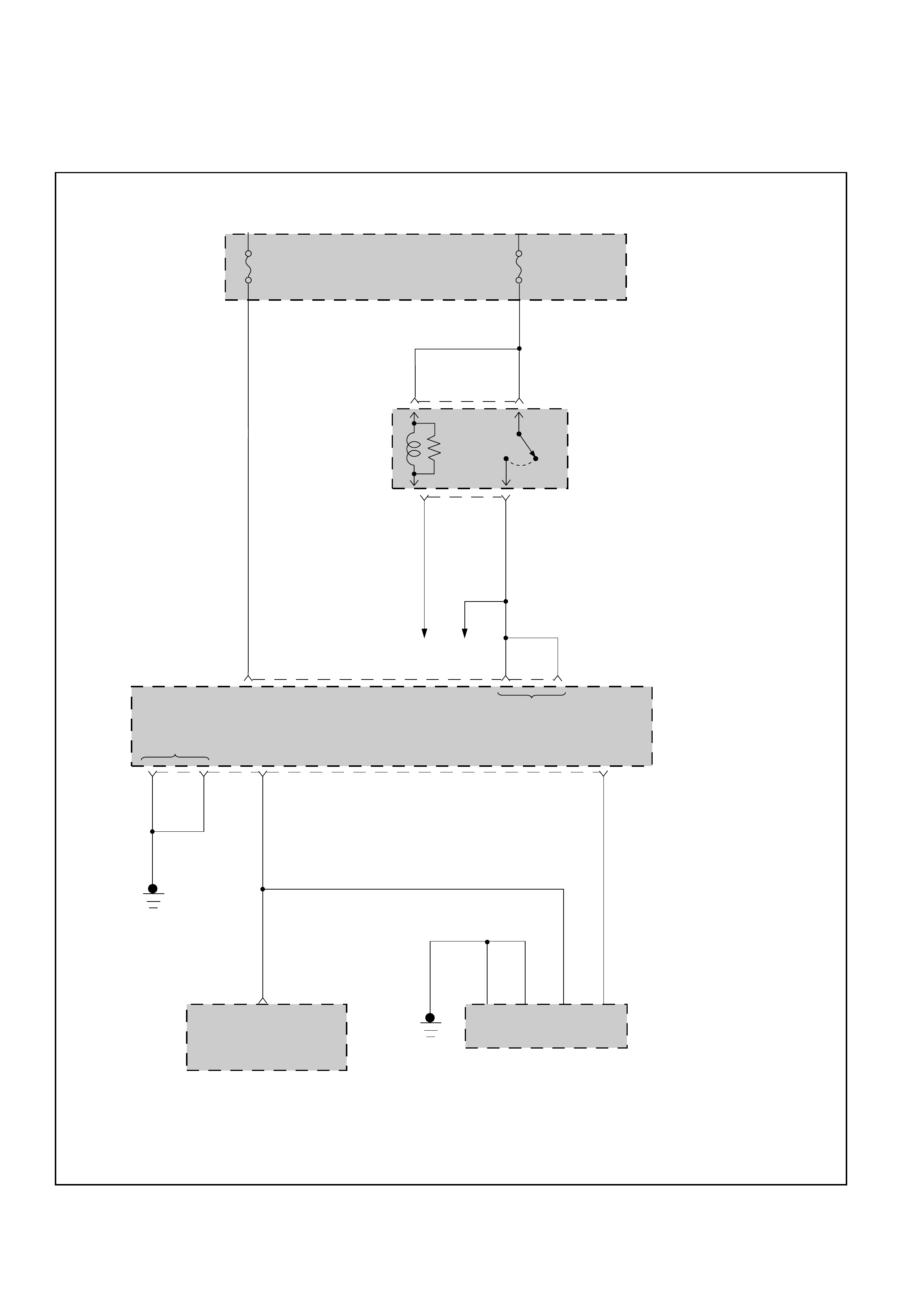
CHART 1: DIAGNOSIS CONNECTOR AND VOLTAGE SUPPLY TEST
FUSE
EB-12
10A
RELAY &
FUSE
BOX
FUSE
EB-14
20A
ECM
MAIN
RELAY
A4(4) A7(7) A8(8) C-96
TO ECM
TRANSMISSION
CONTROL
MODULE (TCM)
BATTERY
INPUT
GROUND
IGNITION
INPUT
DIAGNOSTIC
INPUT
51
X-18
3 2 X-18
RED/
GRN
GRN
SERIAL DATA
ENGINE CONTROL MODULE (ECM)
DATA LINK CONNECTOR (C-102)
35 E-61 54911
YEL YEL/BLK
BLK
C8
(8)
D1
(17)
C1
(1) C-95D16
(32)
BLU/
RED RED/
BLU
RED/BLU
YEL
BLK BLK
YEL
D07LW005

CHART 1: DIAGNOSIS CONNECTOR AND VOLTAGE SUPPLY TEST
TECH2 REFERS TO CHART 1 WHEN THE EQUIPMENT IS CORRECTLY CONNECTED, BUT NO DATA (WITH IGNITION ON) IS RECEIVED
FROM TECH2.
•PERFORM TECH2 SELF-TEST.
IS TECH2 OK?
•IGNITION SWITCH OFF.
•DISCONNECT TCM CONNECTOR C-95 AND C-96.
•IGNITION SWITCH ON.
•CONNECT VOLTMETER BETWEEN TERMINAL A4 AND
GROUND TERMINAL C1 OR D1 OF TCM CONNECTOR.
•THEN CONNECT VOLTMETER BETWEEN TERMINAL A7
OR A8 AND GROUND TERMINAL C1 OR D1 OF TCM
CONNECTOR.
DO BOTH DISPLAYS INDICATE BATTERY VOLTAGE?
•IGNITON SWITCH OFF.
•CONNECT OHMMETER BETWEEN TERMINAL 11 OF 16-PIN
DATA LINK CONNECTOR C-102 AND TERMINAL D16 OF
TCM CONNECTOR C-95.
•THEN CONNECT OHMMETER BETWEEN TERMINAL 4 OR 5
OF 16-PIN DATA LINK CONNECTOR C-102 AND GROUND.
DO BOTH DISPLAYS INDICATE APPROXIMATELY 0 OHMS?
•CHECK FOR SHORT BETWEEN TERMINAL D16 AND
GROUND AND BETWEEN TERMINAL D16 AND B+.
IF OK, REPLACE TCM
YES
YES
YES
NO
SEE TECH2 OPERATOR’S MANUAL.
NO
CHECK FUSE OR WIRE FOR OPEN.
NO
CHECK WIRE FOR OPEN.

CHART 2: DIAGNOSTIC TROUBLE CODE (DTC)
FOR
DTC MALFUNCTION DIAGNOSIS
SEE PAGE
11 OUTPUT SPEED FAILURE 7C1 - 66
13 ENGINE SPEED FAILURE 7C1 - 70
15 TRANSMISSION OIL TEMPERATURE SHORT TO PLUS OR OPEN 7C1 - 72
16 TRANSMISSION OIL TEMPERATURE SHORT TO GROUND 7C1 - 74
21 THROTTLE POSITION SENSOR SHORT TO PLUS 7C1 - 76
22 THROTTLE POSITION SENSOR SHORT TO GROUND OR OPEN 7C1 - 78
23 THROTTLE POSITION SENSOR CONNECTOR OPEN 7C1 - 80
25 SUPPLY VOLTAGE TOO LOW 7C1 - 82
26 SUPPLY VOLTAGE TOO HIGH 7C1 - 84
31 SOLENOID A SHORT TO GROUND OR OPEN 7C1 - 86
32 SOLENOID B SHORT TO GROUND OR OPEN 7C1 - 88
33 TCC HIGH SHORT TO PLUS OR OPEN 7C1 - 90
34 BAND APPLY SOLENOID SHORT TO GROUND OR OPEN 7C1 - 94
35 FORCE MOTOR OPEN OR SHORT TO PLUS OR GROUND 7C1 - 96
36 SHIFT HIGH SHORT TO GROUND OR OPEN 7C1 - 98
37 TORQUE MANAGEMENT SERIAL LINE FAULTY 7C1 - 100
41 SOLENOID A SHORT TO PLUS 7C1 - 102
42 SOLENOID B SHORT TO PLUS 7C1 - 104
43 TCC HIGH SHORT TO GROUND 7C1 - 106
44 BAND APPLY SOLENOID SHORT TO PLUS 7C1 - 108
46 SHIFT HIGH SHORT TO PLUS 7C1 - 110
51 ENGINE COOLANT SWITCH SHORT TO GROUND, PLUS OR OPEN 7C1 - 112
52 KICK DOWN ALWAYS ON OR SHORT TO GROUND 7C1 - 114
53 MODE SWITCH IN P OR N OR R BAD POSITION 7C1 - 116
54 MODE SWITCH ILLEGAL POSITION 7C1 - 118
55 BRAKE SWITCH SHORT TO GROUND OR OPEN 7C1 - 120
56 BRAKE SWITCH SHORT TO PLUS 7C1 - 122
61 GEAR ERROR 7C1 - 124
62 DOWNSHIFT PROTECTION 7C1 - 126
63 EPROM CSUM FAILURE 7C1 - 129
82 SHIFT OR BAND APPLY SOLENOIDS FAULTY DURING DRIVING 7C1 - 130
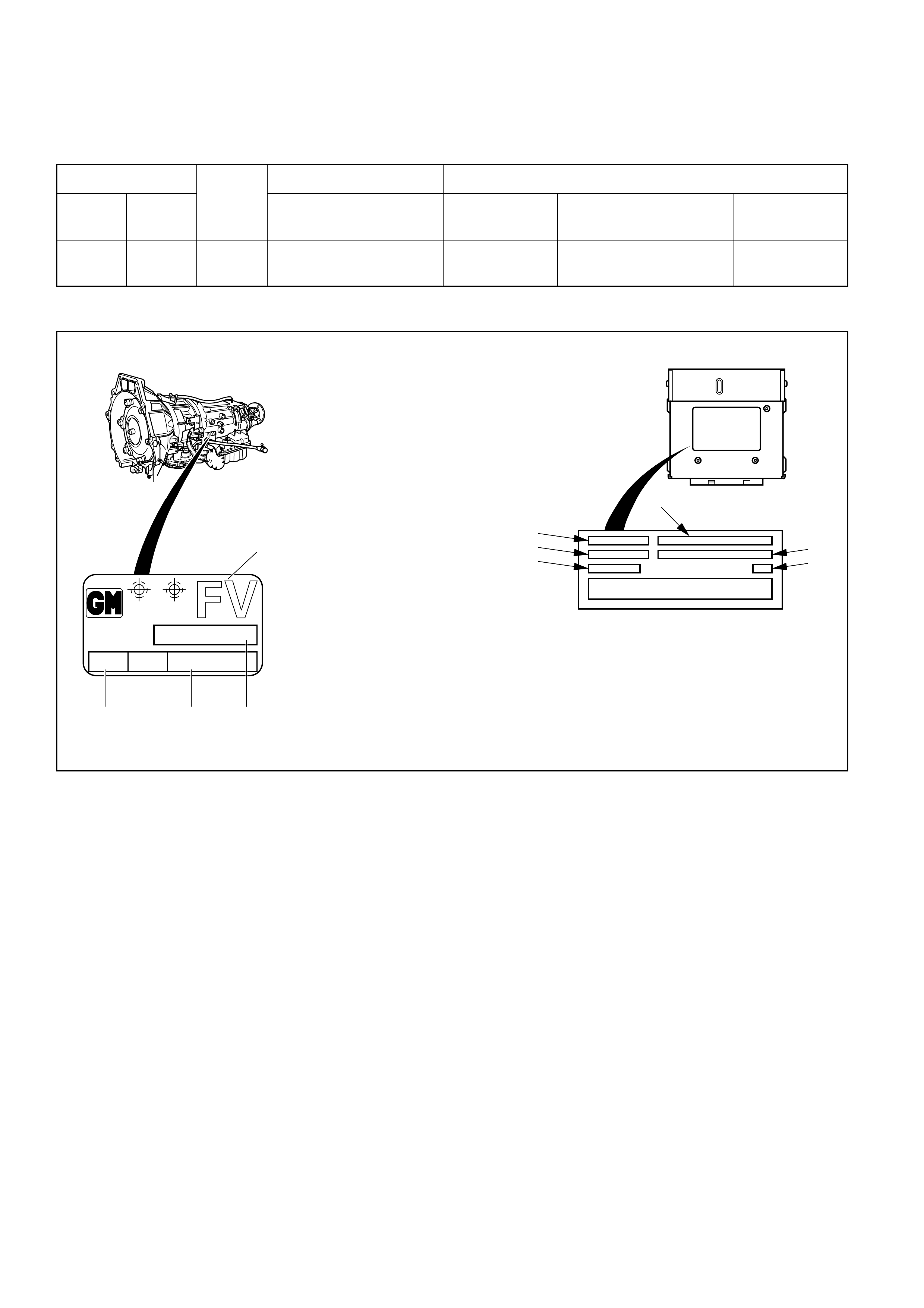
CHART 3: TRANSMISSION AND TCM IDENTIFICATION
Chart 3 contains a list of all important information concerning rear axle ratio, Transmission Control Module
(TCM), and transmission identification.
VEHICLE TCM TRANSMISSION
Type Engine Holden Part No. Calibration Holden Part No. Model Code
Code
Holden/ 3.2L V6 4.555
TFR 8-09350-909-0 G22 8-96018-434-0 FV (4X2)
Rr axle
Ratio
A
B
E
C
D
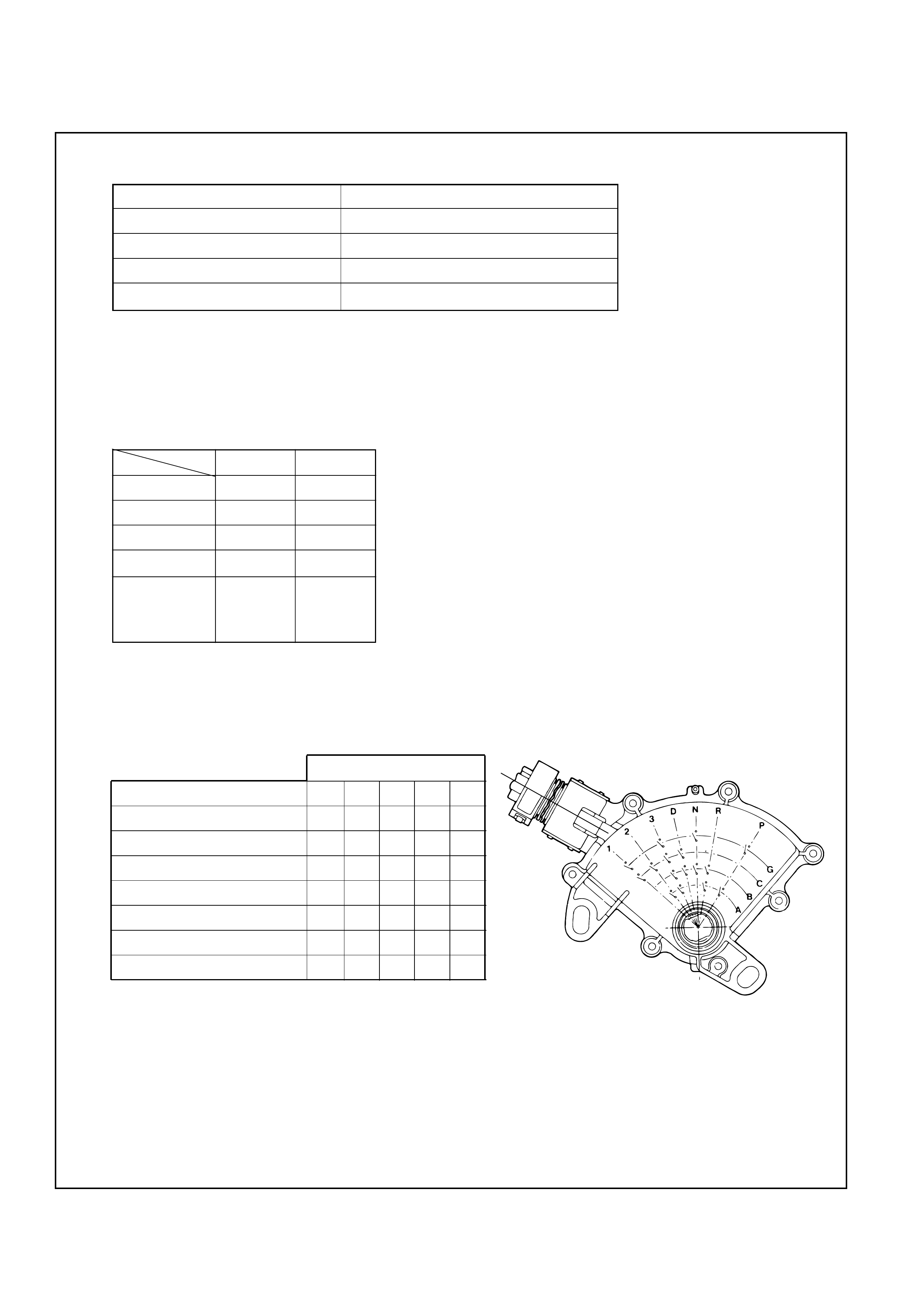
F
The idenification plate is
located on the left-hand side
of the transmission above the
mode switch.
AT Transmission identification on
vehicle identification plate :
1. Model code
2. Calibration code
3. Production serial number
4. Production part number
TCM IDENTIFICATION:
A. ISUZU part number
B. Model of car
C. DELCO part number
D. Application
E. Service TCM number
F. Broadcast code
G 22
96
0000 000
018 434
PART No.
SERIAL No.SAL
HYDRAMATIC
STRASBOURG
MADE IN FRANCE
1
234
F07LW001

CHART 5: F5: ACTUATOR TEST QUICK CHECK
Before carrying out the Actuator Test, the selector lever should be placed in selector position ”N“.
The ignition should be switched ON, and the engine not running.
FOR
TECH2 DISPLAY NOTES CORRECT RESULT DIAGNOSIS
SEE1
SOLENOID A Press arrow up (ON) “Click” heard from DTC 31
Press arrow down (OFF) transmission or 41
SOLENOID B Press arrow up (ON) “Click” heard from DTC 32
Press arrow down (OFF) transmission or 42
SHIFT SOLENOID Press arrow up (ON) “Click” heard from DTC 82
Press arrow down (OFF) transmission
TCC SOLENOID Not used ––
TCC HIGH (D) Press arrow up (ON) “Click” heard from DTC 33
Press arrow down (OFF) transmission or 43
POWER LAMP Press arrow up (ON) POWER lamp ON TRANSMISSION
Press arrow down (OFF) OPERATING
MODE TEST
(PAGE 133)
CHK. TRN. LAMP Press arrow up (ON) CHECK TRANS lamp CHECK TRANS
Press arrow down (OFF) ON CHECK (PAGE 50)
1FOR DIAGNOSIS OF A DTC SEE CHART 2: DIAGNOSTIC TROUBLE CODES (DTC) (PAGE 63)
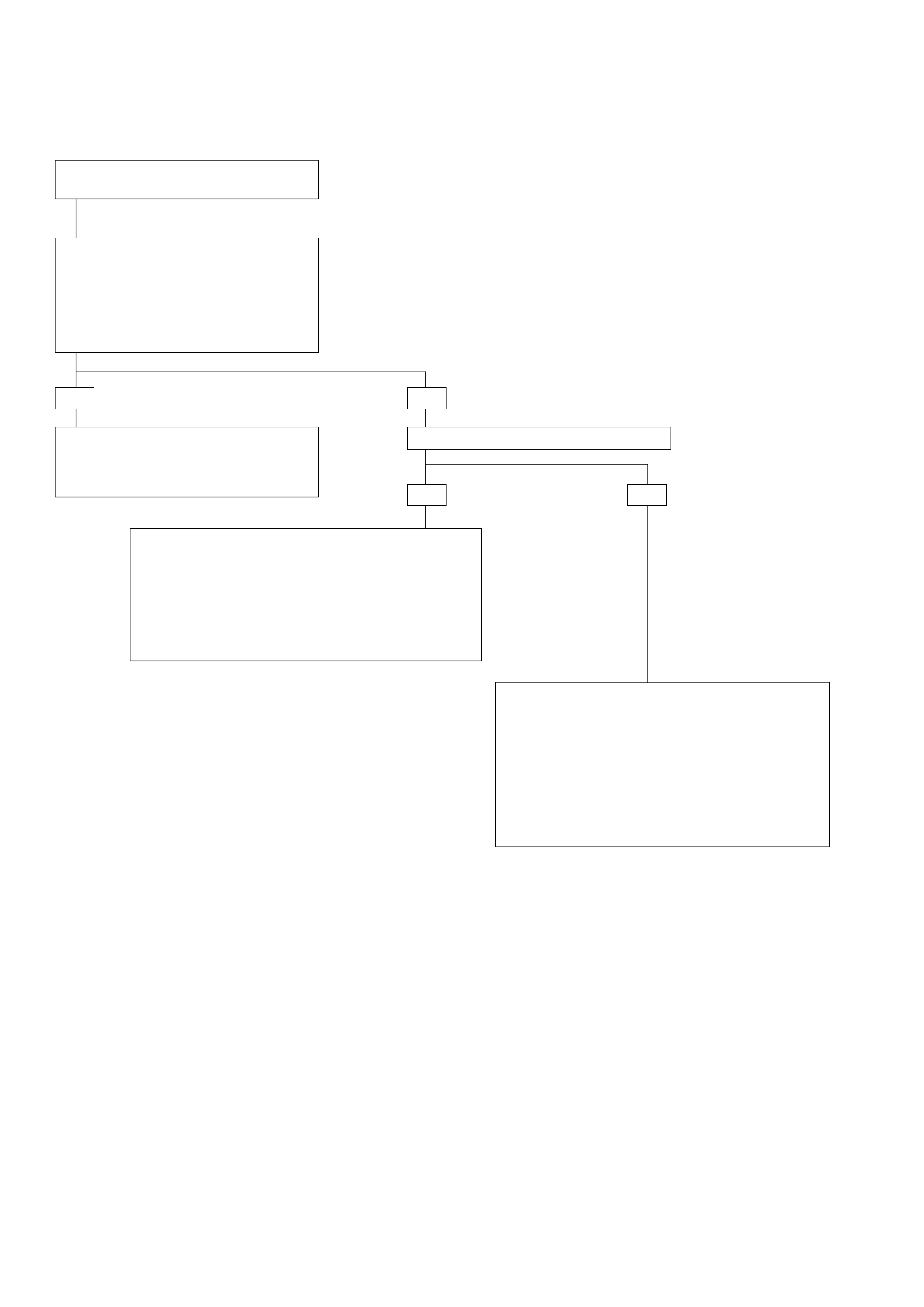
DIAGNOSTIC TROUBLE CODE (DTC) 11
OUTPUT SPEED FAILURE
This DTC flashes the CHECK TRANS indicator and
sets the BACKUP MODE.
Circuit Description:
The transmission output speed sensor provides
information on vehicle speed to the Transmission
Control Module (TCM). The speed sensor circuit
consists of a magnetic induction type sensor. The
sensor is mounted above a target wheel pressed on
the output shaft in the transmission extension. As
the output shaft turns, the target wheel teeth induce
a variable voltage in the magnetic pickup. This
alternating current (AC) signal is provided to the
TCM. The voltage increases with the speed of the
wheel but this is not used to define the speed of the
vehicle. As the vehicle moves faster, the signal
alternates faster between positive and negative
voltages. The Output speed information is
proportional to the frequency of the signal.
Diagnostic Aids:
•This diagnostic is not an electrical test done by
the TCM but a test between different information
(“logic test”).
•Detection conditions:
1Output Speed < or = 0 RPM.
2Engine Speed > 3000 RPM.
3No Malfunction: Engine Speed DTC 13. Mode
Switch DTC54.
4Selector lever not in Park, Reverse, or Neutral.
5The conditions need to be present for at least
5 seconds.
•Action after the detection time:
1CHECK TRANS Indicator is turned ON.
2TCM in BACKUP MODE
•Recovery conditions : To recover do an IGNITION
CYCLE.
TRANSMISSION
CONTROL
MODULE (TCM)
TRANSMISSION
SPEED SENSOR
A12(12)
C-96
C-95
C1(1)
D1(17)
1
M-15
2
TRANSMISSION SPEED
SENSOR SHIELDS
+
—
OUTPUT
SPEED
INPUT
H-23
10
11
9
PNK
B11(23)
B12(24)
GROUND
BLK BLK
7
H-25
PNK
BLU
BLK
BLU
D07LW006
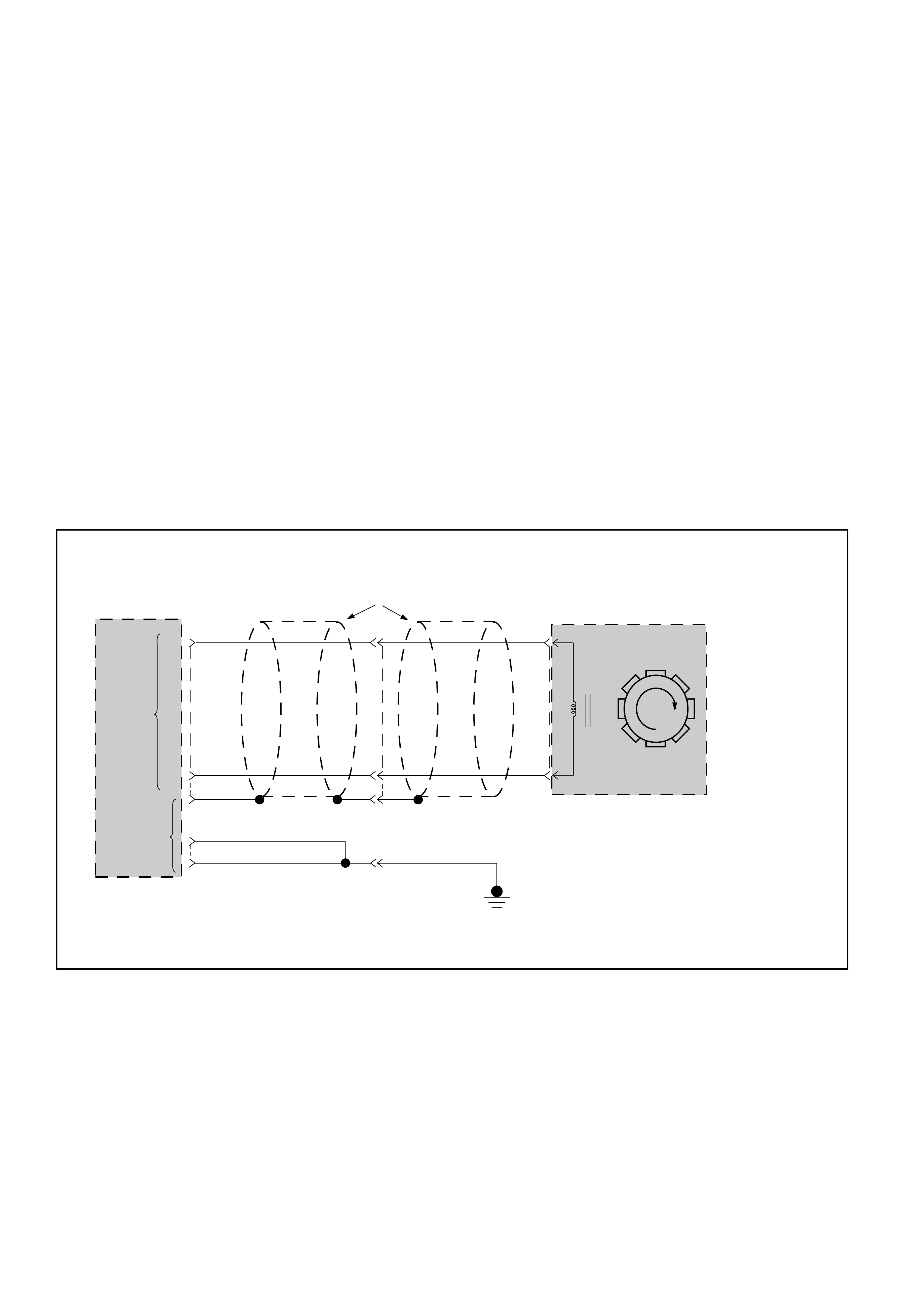
IF the DTC 53 is set:
GOTHROUGH DTC 53 first
and do a test drive.
Problem is intermittent.
GOTO INTERMITTENT
CONDITIONS.
Check for faulty TCM connection.
IF OK, REPLAC TCM
YES
YES
YES
NO
NO
NO
IF you have a SCAN TOOL: TECH2?
• Raise drive wheels.
• Connect the TECH2 GOTHROUGH TECH2
CONNECTION.
• Push “F0”: DATALIST: DISPLAY. Read “AT OUTPUT
SPEED”.
IF: Output Speed different from 0 RPM when the wheels
are turning:
• Ignition switch OFF.
• Disconnect TCM connector C-95 and C-96.
• Connect ohmmeter between connector C-96 terminal
A12 and terminal B12.
IF: display is approx. 3K ohms:
• Connect ohmmeter between connector
C-96 terminal A12 and ground connector
C-95 terminal C1.
IF: display indicates an open circuit:
Replace transmission
speed sensor.
NO
YES
NO
YES NO
YES
• Disconnect transmission speed
sensor connector M-15.
• Connect ohmmeter between
terminals 1 and 2 of the speed
sensor.
IF: display approx. 3K ohms:
• Wires from Connector
C-96 to sensor
connector are open or
shorted together.
• Repair.
HINT: the wire between TCM terminal B12 and sensor connector M-15 terminal 2
can be shorted to ground or open without creating a problem because the TCM
B12 pin is connected to the TCM ground internally and the signal is detected only
on the A12 input.
• Check wire for a short to ground between terminal A12 and sensor connector
M-15 terminal 1.
IF: display indicates a short circuit:
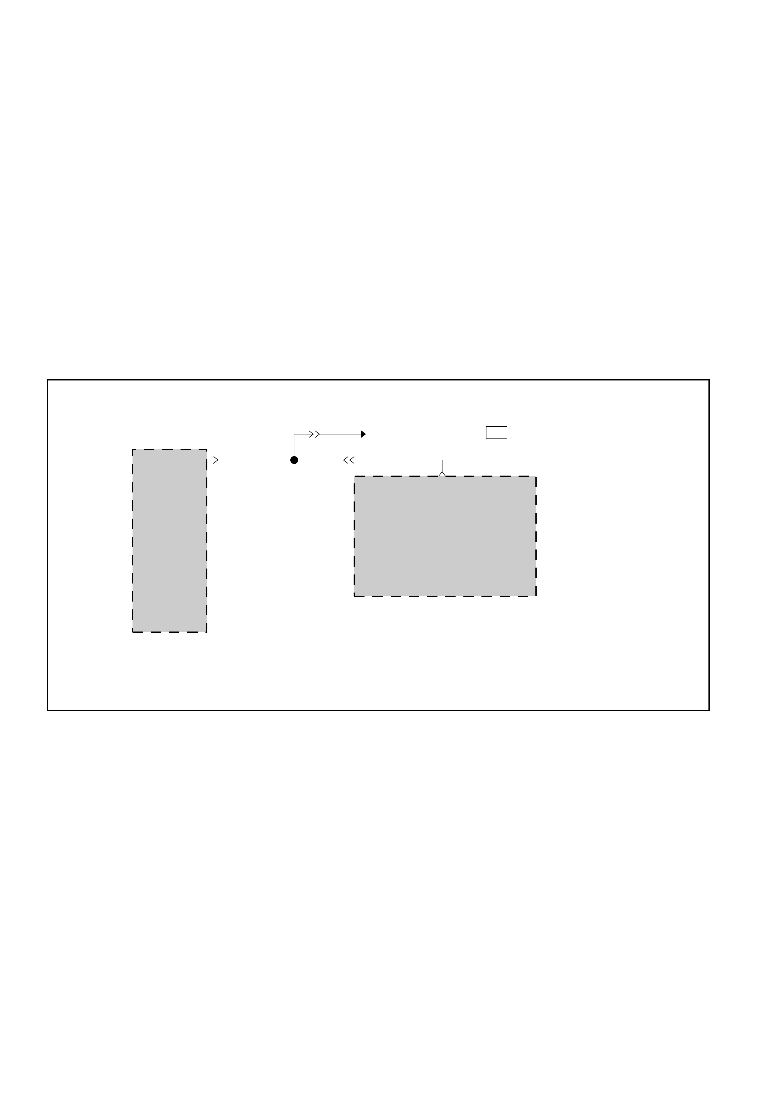
DIAGNOSTIC TROUBLE CODE (DTC) 11
OUTPUT SPEED FAILURE
CAUTION:
If wire to connector C-96 terminal B12 is short to voltage, Transmission Control Module
(TCM) will be damaged.
A
CONTINUED
ON NEXT PAGE
CONTINUED FROM
PREVIOUS PAGE
A
NOYES
YES NO
•Connect voltmeter between connector C-96
terminal A12 and ground connector C-95
terminal C1.
•Ignition switch ON.
IF: display indicates approximately 0 volt:
Check for faulty TCM
connectors.
IF OK, REPLACE THE
TCM
Check wire for a short
to voltage between
terminal A12 and
speed sensor
connector M-15.
Repair.
DIAGNOSTIC TROUBLE CODE (DTC) 13
ENGINE SPEED SIGNAL FAILURE
This DTC flashes the CHECK TRANS indicator and
set the BACKUP MODE.
Circuit Description:
The Engine Control Module (ECM) sends a signal to
the Transmission Control Module (TCM) that
indicates engine speed in RPM. When the vehicle is
in neutral gear and the engine is at idle, the engine
speed should be approximately 800 RPM.
Diagnostic Aids:
• This is not an electrical test performed by the
TCM, but a comparison of different information
signals (a “logic test”).
•Detection conditions:
1Engine speed < or = 200 RPM.
2 Output Speed > 1024 RPM.
3 Vehicle speed > 2 Kmh.
4No DTC: Output Speed DTC11, Downshift
Protection DTC62 or Mode Switch Illegal
Position DTC54.
5Selector Lever not in Park or Neutral.
6The conditions need to be present for at least
0.5 second.
•Action after the detection time: BACKUP MODE
• Recovery conditions: CYCLE IGNITION
ENGINE
RPM
INPUT
TRANSMISSION
CONTROL
MODULE (TCM)
ECM
TACHOMETER ( METER
C-95
D12(28)
ENGINE
RPM
OUTPUT
B-24 3 )
H-20
6 12 E-61
BLK/RED BLK/RED
H-6
16
D07LW007
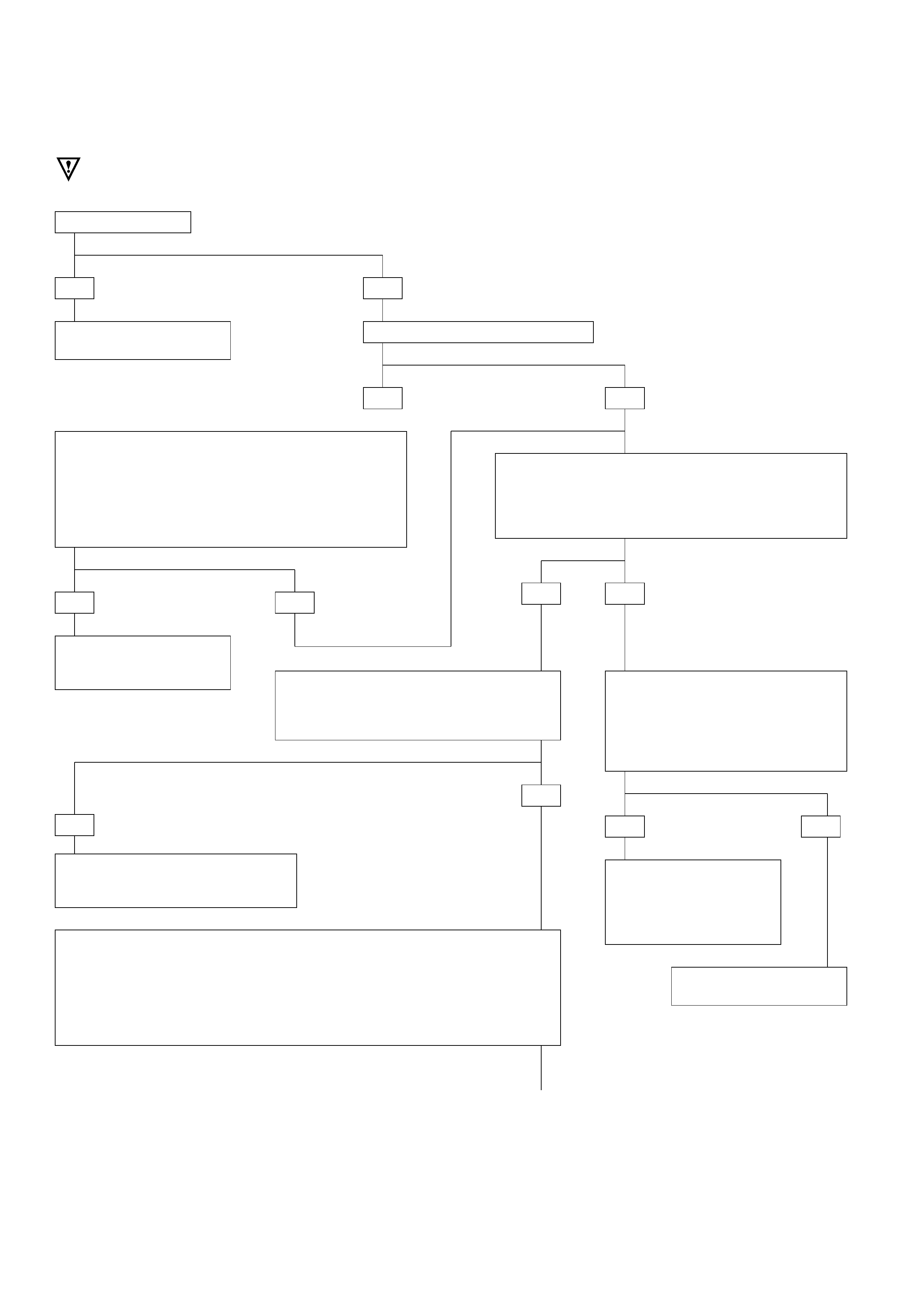
DIAGNOSTIC TROUBLE CODE (DTC) 13
ENGINE SPEED FAILURE
Install scan tool.
GOTHROUGH TECH2 CONNECTION.
•Engine running at idle.
•Brake applied.
•Selector lever position “N” or “P”.
•Selector “F0: DATA LIST: AT INPUT
SPEED”.
IF: TECH2 DISPLAY approximately 800
RPM:
This system is functioning correctly.
The problem is probably intermittent.
GOTO
INTERMITTENT CONDITIONS.
IF: Tachometer displays engine speed?
•Check wire for open or short to ground or short to
voltage between Tachometer connector B-24
terminal 3 and engine control module (ECM)
connector E-61 terminal 12 or between these
terminals and intermediate connector H-6 terminal
16.
•Repair harness. If still not working:
Check Engine electrical section.
If still problem, replace engine control module
(ECM).
YES NO
YES NO
•Check wire for open or short to ground or short to
voltage between Transmission Control Module (TCM)
and connector C-95 & C-96, and connector C-95
terminal D12 and engine control module (ECM)
connector E-61 terminal 12, and check intermediate
connector H-20 terminal 6.
•Repair harness. If still not working: GOTO TCM MEM-
CAL REPLACEMENT.
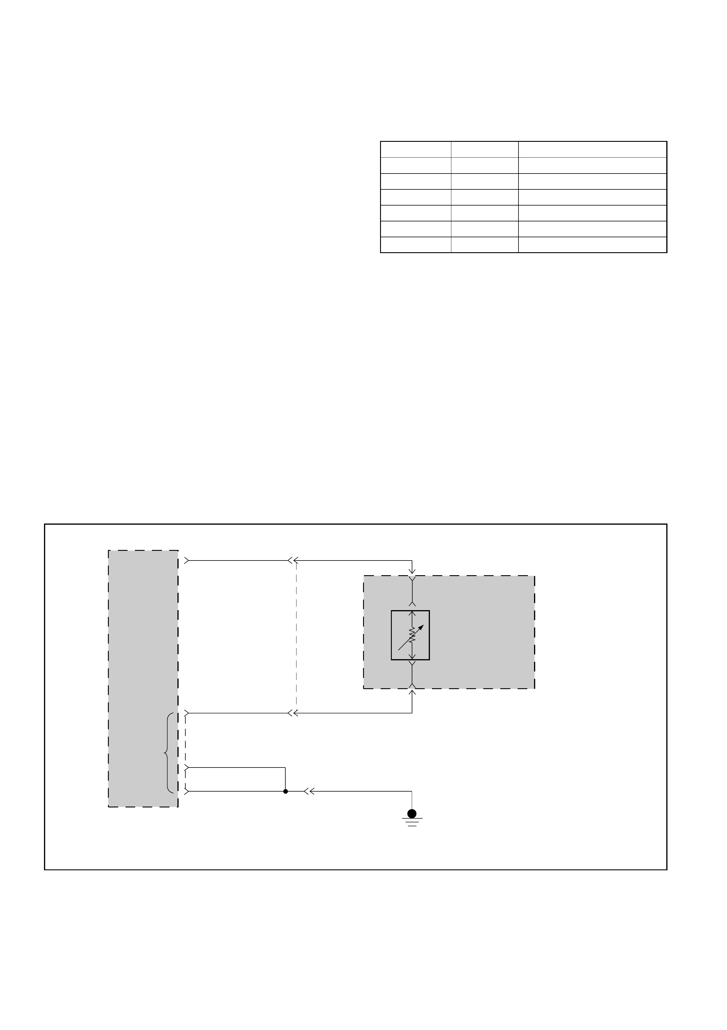
DIAGNOSTIC TROUBLE CODE (DTC) 15
TRANSMISSION OIL TEMPERATURE SHORT TO PLUS OR OPEN
This DTC does NOT flash the CHECK TRANS
indicator and does NOT set the BACKUP MODE.
Circuit Description:
•The transmission oil temperature sensor is a
thermistor within the internal wiring harness of
the transmission in the adaptor case oil pan. The
Transmission Control Module (TCM) applies 5
volts to the sensor connector M-6 terminal 3(C).
The other side of the sensor is connected to
ground through the TCM terminal C14.
When the transmission oil is cold, the sensor
resistance is high and the TCM will sense high
signal voltage.
•As the transmission oil temperature warms to
normal transmission operating temperature of
80°C (176°F), the sensor resistance becomes less
and the voltage decreases at about 3.5 volts.
Note, for more accuracy the measurement is
done differently for low temperature (less than
45°C) and high temperature (more than 50°C).
•When DTC15 is set, the transmission will use a
warm value for operation, but the scan tool will
display the actual oil temperature.
•Table shows thermistor resistance at different
temperatures.
Table:
Diagnostic Aids:
•This Diagnostic is an electrical test done by the
TCM.
•Detection conditions:
1Voltage between terminals B3 and C14 > 4.74
volts.
2The condition needs to be present for at least
20 seconds. Note: during the detection time
the TCM reads the high voltage that defines a
–40°C temperature.
•Action after the detection time: Default Trans-
mission Oil Temperature is set to 100°C.
•Recovery conditions: To recover when voltage <
or = to 4.74 volts after detection time.
°C°F Resistance (kΩ)
–40 –40 672
032 65
20 68 25
80 176 2.5
120 248 0.78
150 304 0.37
TRANSMISSION
OIL
TEMPERATURE
SENSOR
INPUT
GROUND
TRANSMISSION
CONTROL
MODULE (TCM)
AUTOMATIC
TRANSMISSION
M-6
M-6
3(C)
5(D)
C-96
TRANSMISSION
OIL
TEMPERATURE
SENSOR
H-38
GRY
H-25
1
2
BLU
C1(1)
D1(17)
BLK
BLK
7
C-95
B3(15)
C14(14)
GRY
BLU
BLK
D07LW008

DIAGNOSTIC TROUBLE CODE (DTC) 15
TRANSMISSION OIL TEMPERATURE SHORT TO PLUS OR OPEN
Install scan tool
GOTHROUGH TECH2 CONNECTION.
•Connect voltmeter between connector
C-96 terminal B3 and connector C-95
ground terminal C1.
IF: If you have more than
approximately 4.74 Volts:
•Check for a short to plus or open between connector
C-96 terminal B3 and connector C-95 terminal C14.
This faulty connection can be at the connector M-6
terminal 3 (C) or 5 (D). This faulty connection can be
at the intermediate connector H-38 terminals.
•Repair
If not OK: Disconnect sensor.
•Connect ohmmeter between sensor terminals 3(C)
and 5(D).
Refer to the table of the resistance function of the
temperature.
If resistance not correct, replace the transmission oil
temperature sensor.
YES
YES
NO
NO
DTC 15 is intermittent.
GOTO INTERMITTENT CONDITIONS.
REPLACE TCM
•Ignition switch ON. Engine not running.
•Selector lever position “P”.
•Select “F0: DATA LIST: Trans. Oil Temp”.
IF: TECH2 DISPLAY more than 4.74 Volts:
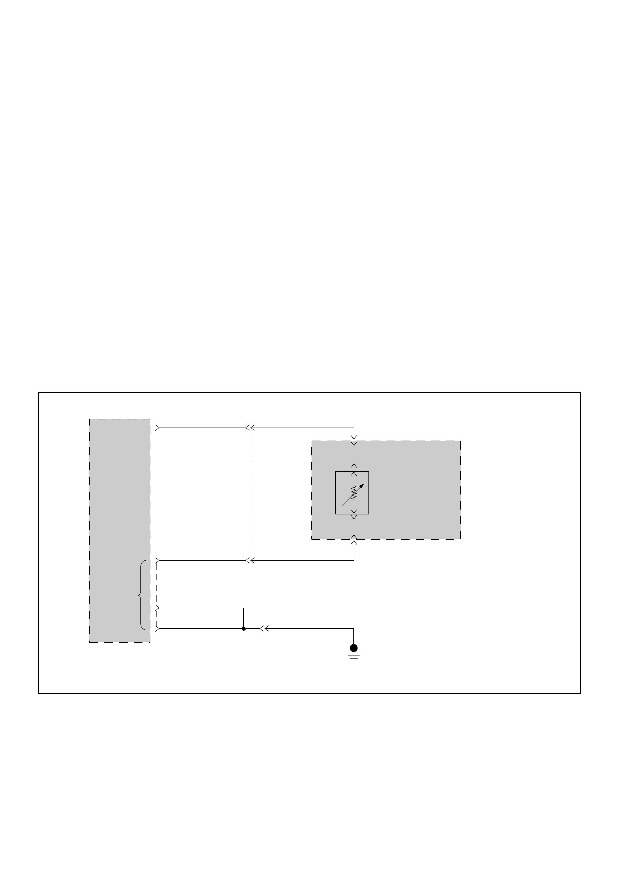
DIAGNOSTIC TROUBLE CODE (DTC) 16
TRANSMISSION OIL TEMPERATURE SHORT TO GROUND
This DTC does NOT flash the CHECK TRANS
indicator and does NOT set the BACKUP MODE.
Circuit Description:
•The transmission oil temperature sensor is a
thermistor within the internal wiring harness of
the transmission in the adaptor case oil pan. The
Transmission Control Module (TCM) applies 5
volts to the sensor connector M-6 terminal 3(C).
The other side of the sensor is connected to
ground through the TCM terminal C14. When the
transmission oil is cold, the sensor resistance is
high and the TCM will sense high signal voltage.
•As the transmission oil temperature warms to
normal transmission operating temperature of
80°C (176°F), the sensor resistance becomes less
and the voltage decreases at about 3.5 volts.
Note, for more accuracy the measurement is
done differently for low temperature (less than
45°C) and high temperature (more than 50°C).
•When DTC16 is set, the transmission will use a
warm value for operation, but the scan tool will
display the actual oil temperature.
•Table shows thermistor resistance at different
temperatures.
Diagnostic Aids:
•This Diagnostic is an electrical test done by the
TCM.
•Detection conditions:
1Voltage between terminals B3 and C14 < 0.4
volts.
2The condition needs to be present for at least
20 seconds. Note: during the detection time
the TCM reads the low voltage that defines a
170°C temperature.
•Action after the detection time: Default Trans-
mission Oil Temperature is set to 100°C.
•Recovery conditions: To recover when voltage >
or = to 0.4 volts after detection time.
TRANSMISSION
OIL
TEMPERATURE
SENSOR
INPUT
GROUND
TRANSMISSION
CONTROL
MODULE (TCM)
AUTOMATIC
TRANSMISSION
M-6
M-6
3(C)
5(D)
C-96
TRANSMISSION
OIL
TEMPERATURE
SENSOR
H-38
GRY
H-25
1
2
BLU
C1(1)
D1(17)
BLK
BLK
7
C-95
B3(15)
C14(14)
GRY
BLU
BLK
D07LW008

DIAGNOSTIC TROUBLE CODE (DTC) 16
TRANSMISSION OIL TEMPERATURE SHORT TO GROUND
Install scan tool
GOTHROUGH TECH2 CONNECTION.
•Ignition switch ON. Engine not
running.
•Selector lever position “P”.
•Select “F0: DATA LIST: Trans. Oil
Temp”.
IF: TECH2 DISPLAY less than 0.4 Volts:
DTC 16 is intermittent.
GOTO INTERMITTENT CONDITIONS.
REPLACE TCM
YES
YES
NO
NO
•Check for a short to ground between
connector C-96 terminal B3 and
connector M-6 terminal 3 (C). This
faulty connection can be at the
intermediate connector H-38 terminal
2.
•Repair
If not OK: Disconnect sensor.
•Connect ohmmeter between sensor
terminals 3(C) and 5(D).
Refer to the table of the resistance
function of the temperature (DTC 15).
If resistance not correct, replace
sensor.
•Connect voltmeter between connector
C-96 terminal B3 and connector C-95
ground terminal C1.
IF: If you have less than approximately
0.4 Volts:
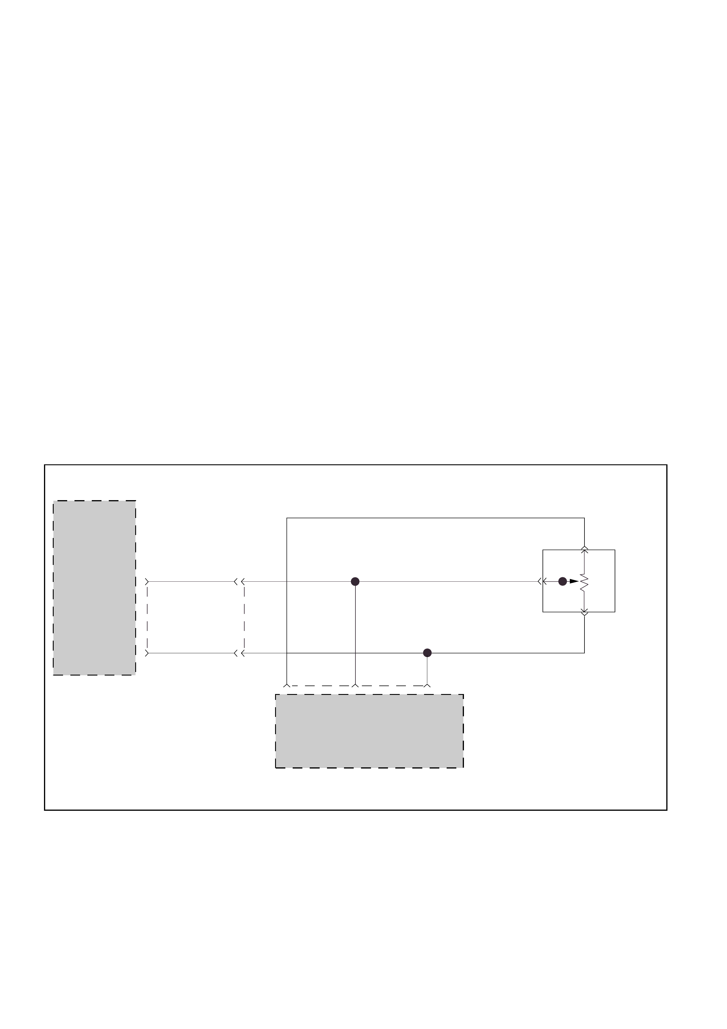
DIAGNOSTIC TROUBLE CODE (DTC) 21
THROTTLE POSITION SENSOR SHORT TO PLUS
This DTC flashes the CHECK TRANS indicator and
sets the BACKUP MODE.
Circuit Description:
•The Throttle Position Sensor (TPS) provides a
voltage signal that changes relative to the throttle
plate position. Signal voltage between connector
C-95 terminals C5 and C6 will vary from about 0.4
at idle to about 4.6 volts at wide open throttle.
•The Engine Control Module (ECM) also receives
this signal. This TPS is a variable resistance with
one side (connector E-68 terminal 1) connected
only to the ECM connector to have the 5 volts
supply voltage. The other side (connector E-68
terminal 3) is connected to the Transmission
Control Module (TCM) (floating ground) and the
ECM (ground). The “middle” (the wiper) (con-
nector E-68 terminal 2) is connected to the TCM
and the ECM.
•The ECM monitors output voltage from the TPS
and determines fuel delivery based on throttle
valve angle (driver demand).
•This TPS is an electrical component and must not
be soaked in any liquid cleaner or solvent, as
damage may result.
Diagnostic Aids:
•This Diagnostic is an electrical test done by the
TCM.
•Detection conditions:
1Voltage between connector C-95 terminals C5
and C6 > 4.9 volts. This detection occurs
when: The wiper is short to voltage (engine
can stall).
2The condition needs to be present for at least
0.5 seconds. Note: during the detection time
the TCM reads “100% (wide open throttle)”.
•Action after the detection time: BACKUP MODE.
•Recovery conditions: To recover when voltage <
or = to 4.9 volts and do an IGNITION CYCLE.
TPS
INPUT
GROUND
TRANSMISSION
CONTROL
MODULE(TCM)
C-95
C5(5) 5
H-25
3
C6(6) GRN
BLU
BLU
BLU
BLU
GRN
27
5VOLT
REFERENCE TPS
INPUT GROUND
GRY
GRY GRY
THROTTLE
POSITION
SENSOR
(TPS)
ENGINE
CONTROL
MODULE
(ECM)
26 39 E-61
E-68
E-68
E-68
2
1
3
D07LW009
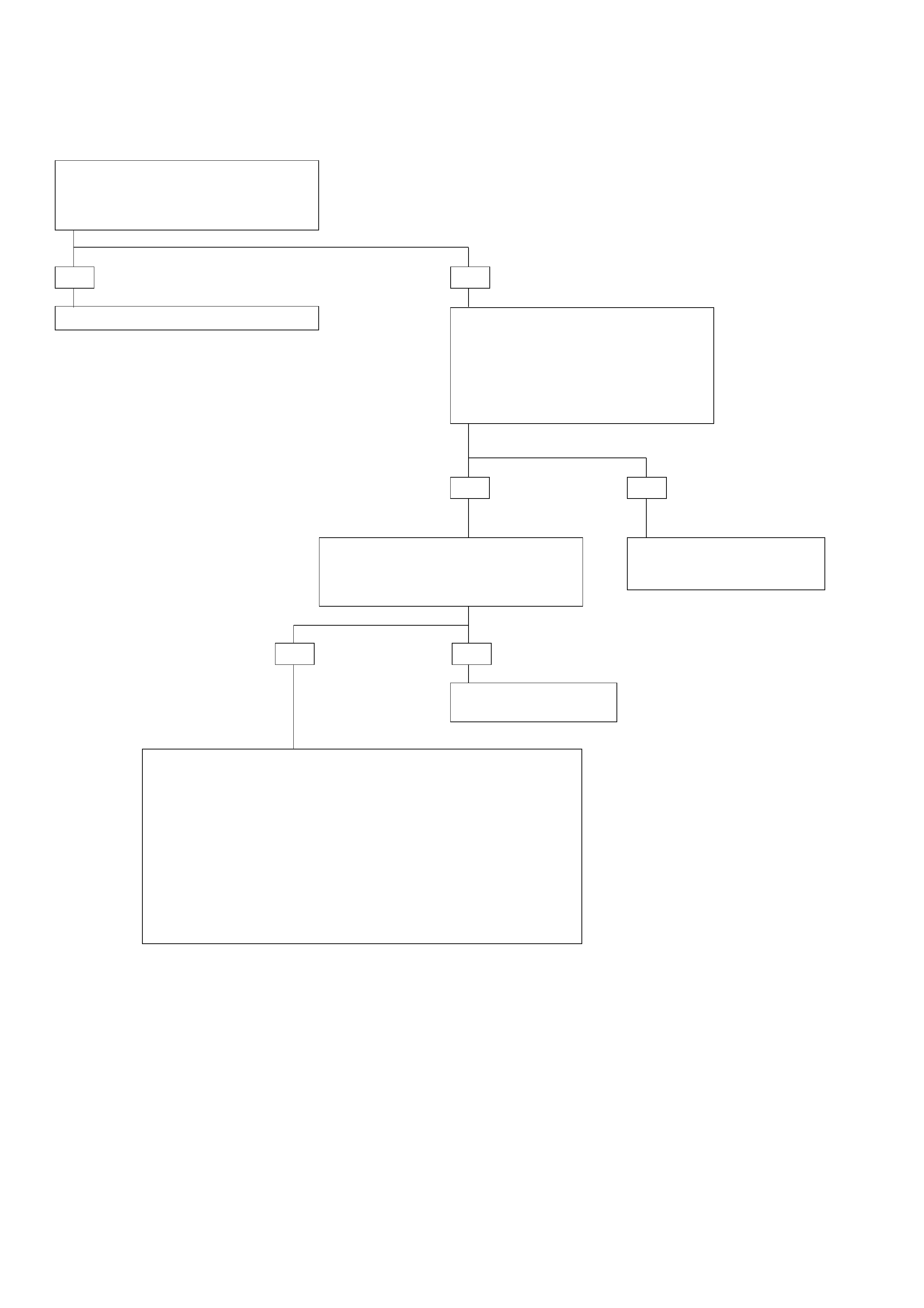
DIAGNOSTIC TROUBLE CODE (DTC) 21
THROTTLE POSITION SENSOR SHORT TO PLUS
Check Engine Control Module (ECM)
DTC.
IF: DTC on Throttle Position Sensor (TPS)
exists:
Check diagnosis of ECM and repair.
•Connect voltmeter between connector
C-95 terminal C5 and TPS ground
terminal C6.
IF: If you have more than 4.9 volts:
DTC 21 is intermittent.
GOTO INTERMITTENT
CONDITIONS.
REPLACE TCM
•Check for a short to voltage or open circuit between connector C-95
terminal C5 and connector E-68 terminal 2.
This faulty connection can be at intermediate connector H-25
terminal 5.
The short to voltage only can be at the ECM connector E-61 terminal
26.
•Repair.
If not OK: Disconnect sensor.
•Connect ohmmeter between sensor terminals 2 wiper and 3 low
side.
If resistance between TPS terminal 2 and 3 does not change when
the throttle valve angle is changed: Replace TPS.
YES NO
YES NO
NOYES
•Install scan tool GOTHROUGH TECH2
CONNECTION.
•Ignition switch ON, engine not
running.
•Selector lever position “P”.
•Select F0: DATA LIST: “TPS SIGNAL”.
IF: TECH2 DISPLAY more than 4.9 volts:

DIAGNOSTIC TROUBLE CODE (DTC) 22
THROTTLE POSITION SENSOR SHORT TO GROUND OR OPEN
This DTC flashes the CHECK TRANS indicator and
sets the BACKUP MODE.
Circuit Description:
•The Throttle Position Sensor (TPS) provides a
voltage signal that changes relative to the throttle
plate position. Signal voltage between connector
C-95 terminals C5 and C6 will vary from about 0.4
at idle to about 4.6 volts at wide open throttle.
•The Engine Control Module (ECM) also receives
this signal. This TPS is a variable resistance with
one side (connector E-68 terminal 1) connected
only to the ECM connector to have the 5 volts
supply voltage. The other side (connector E-68
terminal 3) is connected to the Transmission
Control Module (TCM) (floating ground) and the
ECM (ground). The “middle” (the wiper) (con-
nector E-68 terminal 2) is connected to the TCM
and the ECM.
•The ECM monitors output voltage from the TPS
and determines fuel delivery based on throttle
valve angle (driver demand)
•This TPS is an electrical component and must not
be soaked in any liquid cleaner or solvent, as
damage may result.
Diagnostic Aids:
•This Diagnostic is an electrical test done by the
TCM.
•Detection conditions:
1This detects a TPS wiper short to TCM ground
(except certain conditions) or open and wiper
short to TPS low. This also detects a TPS low
open.
2Voltage between connector C-95 terminals C5
and C6 < 0.2 volts.
3The condition needs to be present for at least
0.5 seconds. Note: during the detection time
the TCM reads “0% (idle)”.
•Action after the detection time: BACKUP MODE.
•Recovery conditions: To recover when voltage >
or = to 0.2 volts and do an IGNITION CYCLE.
TPS
INPUT
GROUND
TRANSMISSION
CONTROL
MODULE(TCM)
C-95
C5(5) 5
H-25
3
C6(6) GRN
BLU
BLU
BLU
BLU
GRN
27
5VOLT
REFERENCE TPS
INPUT GROUND
GRY
GRY GRY
THROTTLE
POSITION
SENSOR
(TPS)
ENGINE
CONTROL
MODULE
(ECM)
26 39 E-61
E-68
E-68
E-68
2
1
3
D07LW009

DIAGNOSTIC TROUBLE CODE (DTC) 22
THROTTLE POSITION SENSOR SHORT TO GROUND OR OPEN
Check Engine Control Module (ECM)
DTC.
IF: DTC on Throttle Position Sensor (TPS)
exists:
Check diagnosis of ECM and repair. •Install scan tool GOTHROUGH TECH2
CONNECTION.
•Ignition switch ON, engine not
running.
•Selector lever position “P”.
•Select F0: DATA LIST: “TPS SIGNAL”.
IF: TECH2 DISPLAY less than 0.2 volts:
•Connect voltmeter between connector
C-95 terminal C5 and TPS ground
terminal C6.
IF: If you have less than 0.2 volts:
DTC 22 is intermittent.
GOTO INTERMITTENT
CONDITIONS.
REPLACE TCM
•Check for a short to ground between connector C-95 terminal C5 and
connector E-68 terminal 2.
This faulty connection can be at the intermediate connector H-25
terminal 5.This faulty connection can be at the ECM connector E-61
terminal 26.
•Repair.
If not OK: Ignition switch OFF. Disconnect sensor connector E-68.
•Connect ohmmeter between connector C-95 terminal C5 and C6.
•Check if the circuit is open.
•Repair.
If not OK: Ignition switch OFF. Disconnect sensor connector E-68.
•Connect ohmmeter between sensor terminals 2 wiper and 3 low
side.
•If resistance between TPS terminal 2 and 3 does not change when
the throttle valve angle is changed: Replace TPS.
YES NO
YES NO
NOYES
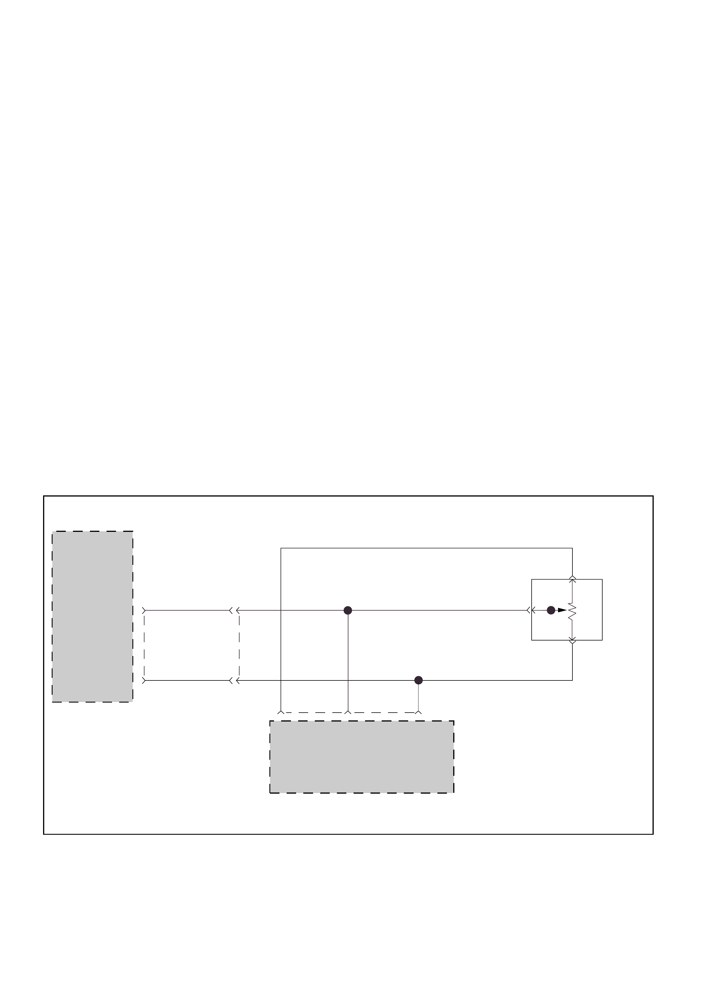
DIAGNOSTIC TROUBLE CODE (DTC) 23
THROTTLE POSITION SENSOR CONNECTOR OPEN
This DTC flashes the CHECK TRANS indicator and
sets the BACKUP MODE.
Circuit Description:
•The Throttle Position Sensor (TPS) provides a
voltage signal that changes relative to the throttle
plate position. Signal voltage between connector
C-95 terminals C5 and C6 will vary from about 0.4
at idle to about 4.6 volts at wide open throttle.
•The Engine Control Module (ECM) also receives
this signal. This TPS is a variable resistance with
one side (connector E-68 terminal 1) connected
only to the ECM connector to have the 5 volts
supply voltage. The other side (connector E-68
terminal 3) is connected to the Transmission
Control Module (TCM) (floating ground) and the
ECM (ground). The “middle” (the wiper) (con-
nector E-68 terminal 2) is connected to the TCM
and the ECM.
•The ECM monitors output voltage from the TPS
and determines fuel delivery based on throttle
valve angle (driver demand).
•This TPS is an electrical component and must not
be soaked in any liquid cleaner or solvent, as
damage may result.
Diagnostic Aids:
•This Diagnostic is not an electrical test done by
the TCM but a test between different information
(“logic test”).
•Detection conditions:
1This detects the terminals C5 and C6 open or
the connector E-68 open.
2Throttle value opening > 42%.
3Engine Speed < 2200 RPM.
4Vehicle Speed <3 Km/h.
5No DTC: Engine Speed DTC13, Output Speed
DTC11. Downshift Protection DTC62.
6Only with Selector Lever in Park or Neutral.
7The detection is authorized only during 6
seconds after ignition switch ON.
8The conditions need to be present for at least
3 seconds.
•Action after the detection time: BACKUP MODE.
•Recovery conditions: To recover do an IGNITION
CYCLE.
TPS
INPUT
GROUND
TRANSMISSION
CONTROL
MODULE(TCM)
C-95
C5(5) 5
H-25
3
C6(6) GRN
BLU
BLU
BLU
BLU
GRN
27
5VOLT
REFERENCE TPS
INPUT GROUND
GRY
GRY GRY
THROTTLE
POSITION
SENSOR
(TPS)
ENGINE
CONTROL
MODULE
(ECM)
26 39 E-61
E-68
E-68
E-68
2
1
3
D07LW009
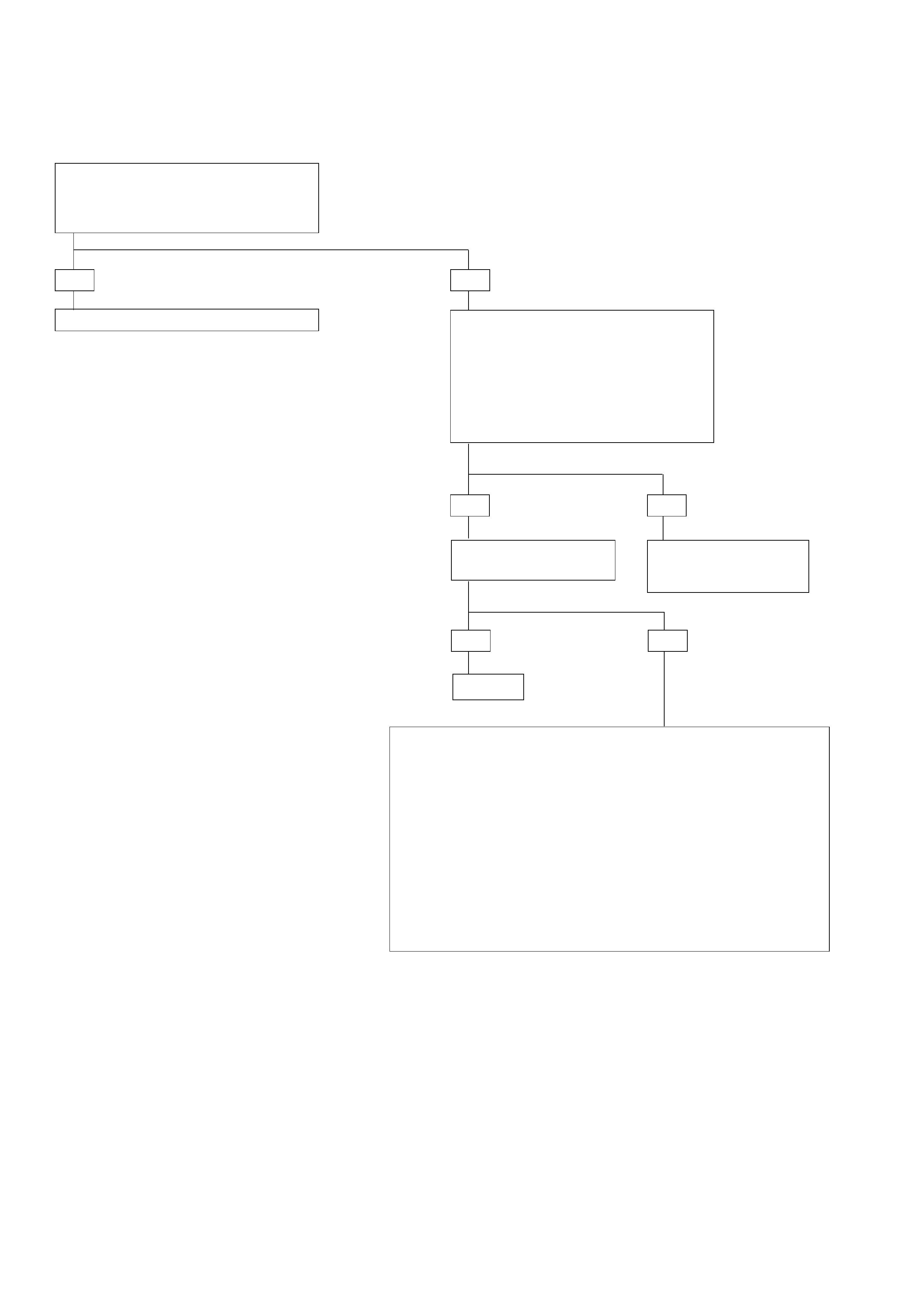
DIAGNOSTIC TROUBLE CODE (DTC) 23
THROTTLE POSITION SENSOR CONNECTOR OPEN
Check Engine Control Module (ECM)
DTC.
IF: DTC on Throttle Position Sensor (TPS)
exists:
Check diagnosis of ECM and repair. •Install scan tool GOTHROUGH TECH2
CONNECTION.
•Ignition switch ON, engine not
running.
•Selector lever position “P”.
•Select F0: DATA LIST: “TPS SIGNAL”.
IF: TECH2 DISPLAY approx. 2.5 volts
whatever the throttle valve position:
IF: TPS connector E-68
on the engine is open: DTC 23 is intermittent.
GOTO INTERMITTENT
CONDITIONS.
Repair.
•Ignition switch OFF. Disconnect connector C-95.
Connect ohmmeter between connector C-95 terminals C5 and C6.
If open circuit:
•Check for an open between connector C-95 terminal C5 to connector
E-68 terminal 2 with a simultaneous open of the terminal C6 to the
connector E-68 terminal 3.
This faulty connection can be at the intermediate connector H-25
terminal 5 and 3.
•Repair.
If not OK: Ignition switch OFF. Disconnect sensor.
•Connect ohmmeter between sensor terminals 2 wiper and 3 low
side.
If resistance between TPS terminal 2 and 3 does not change when
the throttle valve angle is changed: Replace TPS.
YES NO
YES NO
YES NO
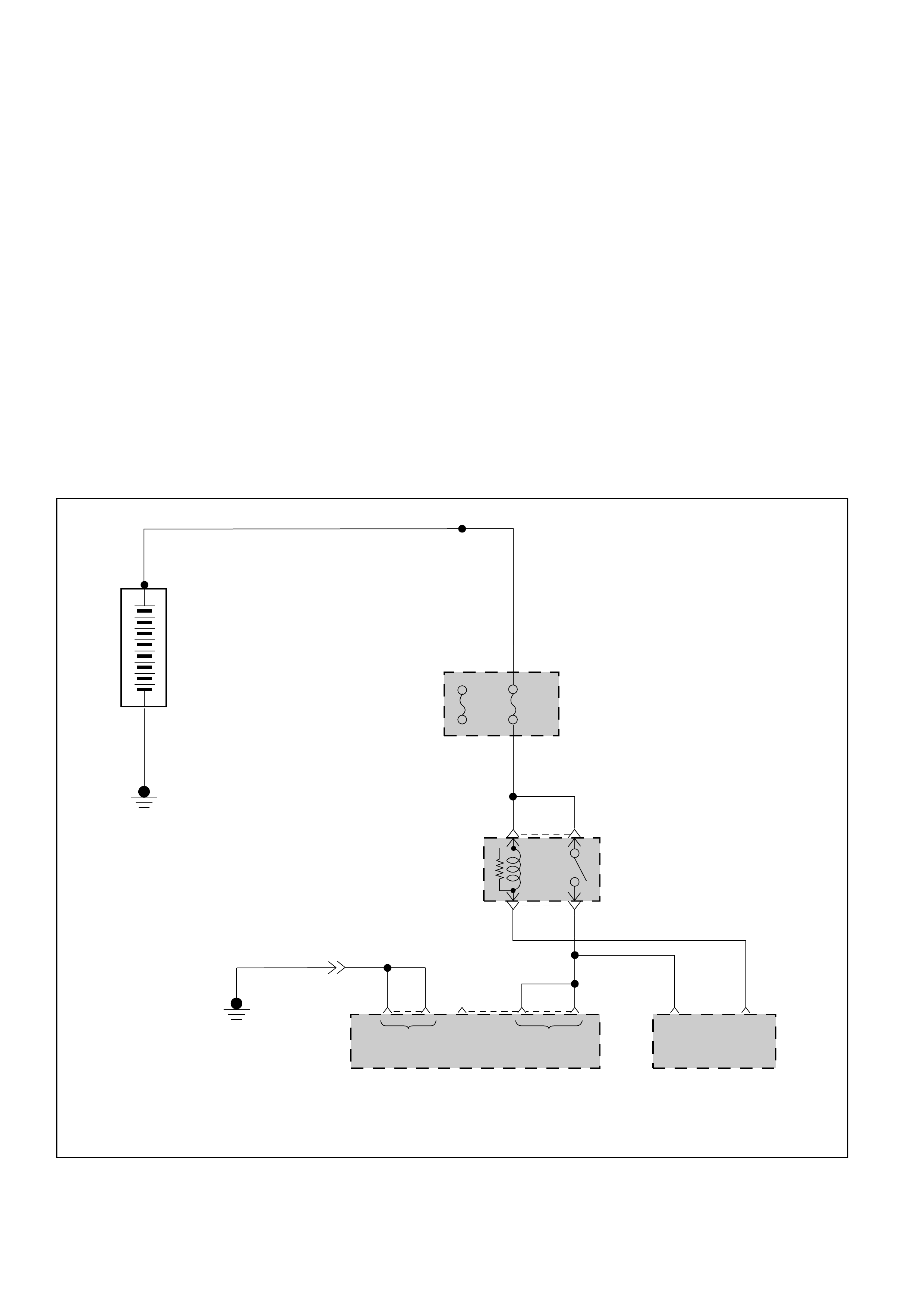
DIAGNOSTIC TROUBLE CODE (DTC) 25
SUPPLY VOLTAGE TOO LOW
This DTC flashes the CHECK TRANS indicator and
sets the BACKUP MODE.
Circuit Description:
The ignition voltage of Transmission Control
Module (TCM) terminals A7 and A8 is monitored by
the TCM and when the voltage is too low (approx. 9
volts) the DTC25 is stored and the BACKUP MODE
is set.
Diagnostic Aids:
•This Diagnostic is an electrical test done by the
TCM.
•Detection conditions:
1Ignition voltage measured between TCM
terminal A7 or A8 and ground C1 is lower
than specification.
Specification decreases with the transmission
oil temperature:
–40°C (–40°F) = 8.7 volts
90°C (194°F) = 9.0 volts
150°C (304°F) = 9.2 volts
2The condition needs to be present for at least
1 second
•Action after the detection time: BACKUP MODE
•Recovery conditions: To recover, the ignition
voltage must be higher than specification.
Specification decreases with the transmission oil
temperature:
–40°C (–40°F) = 9.2 volts
90°C (194°F) = 9.5 volts
150°C (304°F) = 9.6 volts
B
BATTERY
B
FUSE
ENGINE
CONTROL
MODULE
(ECM)
BATTERY INPUT
EB-12
10A EB-14
20A RELAY &
FUSE BOX
X-18 3
X-18 5
ECM
MAIN
RELAY
19
E-61 28E-60
BATTERY
INPUT
A4
(4)
C1
(1)
D1
(17)
TRANSMISSION
CONTROL MODULE
(TCM)
—
+
RED/
GRN
GRN
H-25
2
1
RED/BLU RED/BLU
BLU/RED
A7
(7)
BLK
C-95 C-96
7A8
(8)
GROUND IGNITION
INPUT
D07LW010

DIAGNOSTIC TROUBLE CODE (DTC) 25
SUPPLY VOLTAGE TOO LOW
•Ignition switch ON. Engine OFF.
•Connect voltmeter between B+ and B- terminals of
battery.
IF: Display greater than 9 volts:
•Engine running.
•Connect voltmeter between B+ and B- terminals of
battery.
IF: display between 13 and 16 volts?
•Ignition switch OFF.
•Disconnect Transmission Control Module (TCM)
connector C-95 and C-96.
•Ignition switch ON. Engine OFF.
•Connect voltmeter between connector C-96 terminal
A7 and connector C-95 terminal C1.
IF: Display greater than 9 volts:
Check for faulty connection and if OK.
GOTO INTERMITTENT CONDITIONS. Check fuse and wire to A7, A8 and C1 for
open circuit.
Check regulator.
Check battery.
YES
YES NO
YES NO
NO
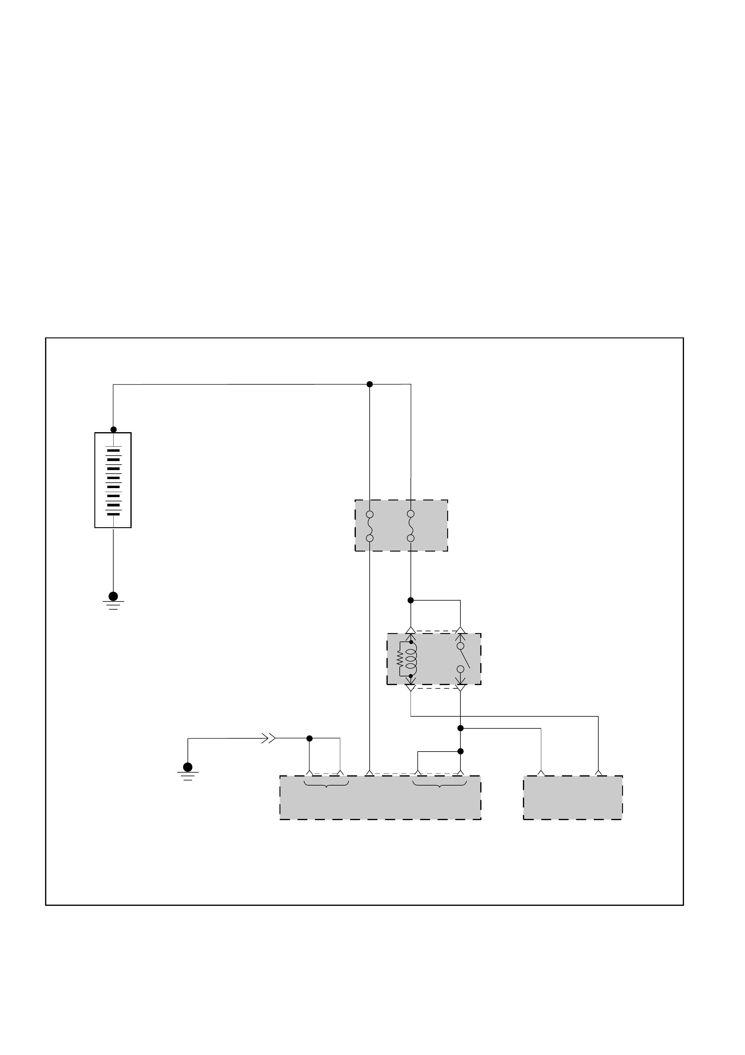
DIAGNOSTIC TROUBLE CODE (DTC) 26
SUPPLY VOLTAGE TOO HIGH
This DTC flashes the CHECK TRANS indicator and
sets the BACKUP MODE.
Circuit Description:
The ignition voltage of Transmission Control
Module (TCM) terminals A7 and A8 is monitored by
the TCM and when the voltage is too high (approx.
16 volts) the DTC26 is stored and the BACKUP
MODE is set.
Diagnostic Aids:
•This Diagnostic is an electrical test done by the
TCM.
•Detection conditions:
1Ignition voltage measured between TCM
terminal A7 or A8 and ground C1 is higher
than 15.5 volts.
2The condition needs to be present for at least
1 second.
•Action after the detection time : BACKUP MODE
•Recovery conditions: To recover, ignition voltage
<
=15.5 volts.
B
BATTERY
B
FUSE
ENGINE
CONTROL
MODULE
(ECM)
BATTERY INPUT
EB-12
10A EB-14
20A RELAY &
FUSE BOX
X-18 3
X-18 5
ECM
MAIN
RELAY
19
E-61 28E-60
BATTERY
INPUT
A4
(4)
C1
(1)
D1
(17)
TRANSMISSION
CONTROL MODULE
(TCM)
—
+
RED/
GRN
GRN
H-25
2
1
RED/BLU RED/BLU
BLU/RED
A7
(7)
BLK
C-95 C-96
7A8
(8)
GROUND IGNITION
INPUT
D07LW010
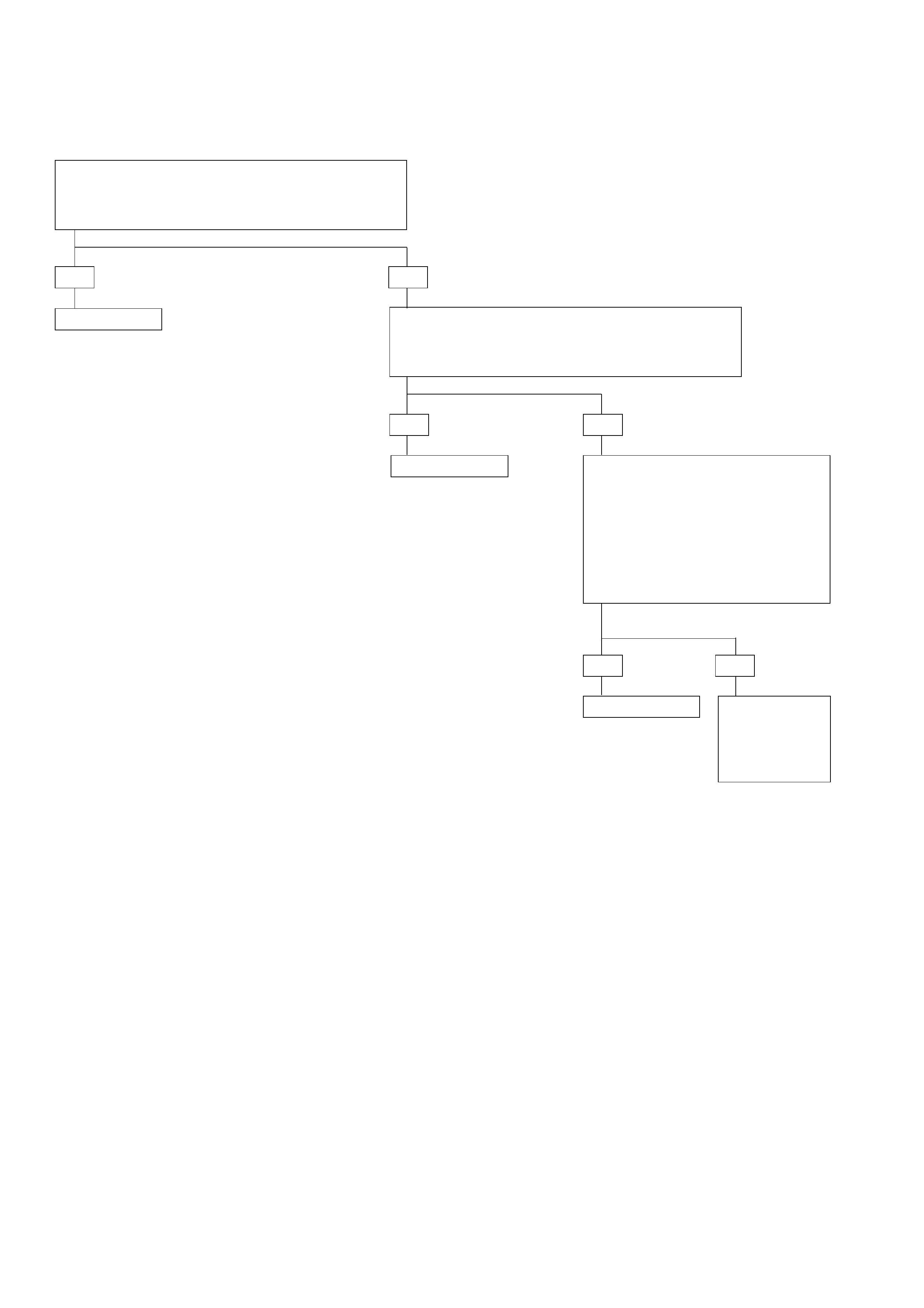
DIAGNOSTIC TROUBLE CODE (DTC) 26
SUPPLY VOLTAGE TOO HIGH
•Ignition switch ON. Engine OFF.
•Connect voltmeter between B+ and B- terminals of
battery.
IF: Display greater than 15.5 volts:
•Engine running.
•Connect voltmeter between B+ and B- terminals of
battery.
IF: Display between 3 to 15.5 volts:
Check battery.
Check regulator.
Check regulator. The problem is
intermittent.
GOTO
INTERMITTENT
CONDITIONS.
YES NO
YES NO
YES NO
•Ignition switch OFF.
•Disconnect Transmission Control
Module (TCM) connector C-95 and
C-96.
•Ignition switch ON. Engine ON.
•Connect voltmeter between
connector C-96 terminals A7 and
connector C-95 terminal C1.
IF: Display higher than 15.5 volts:
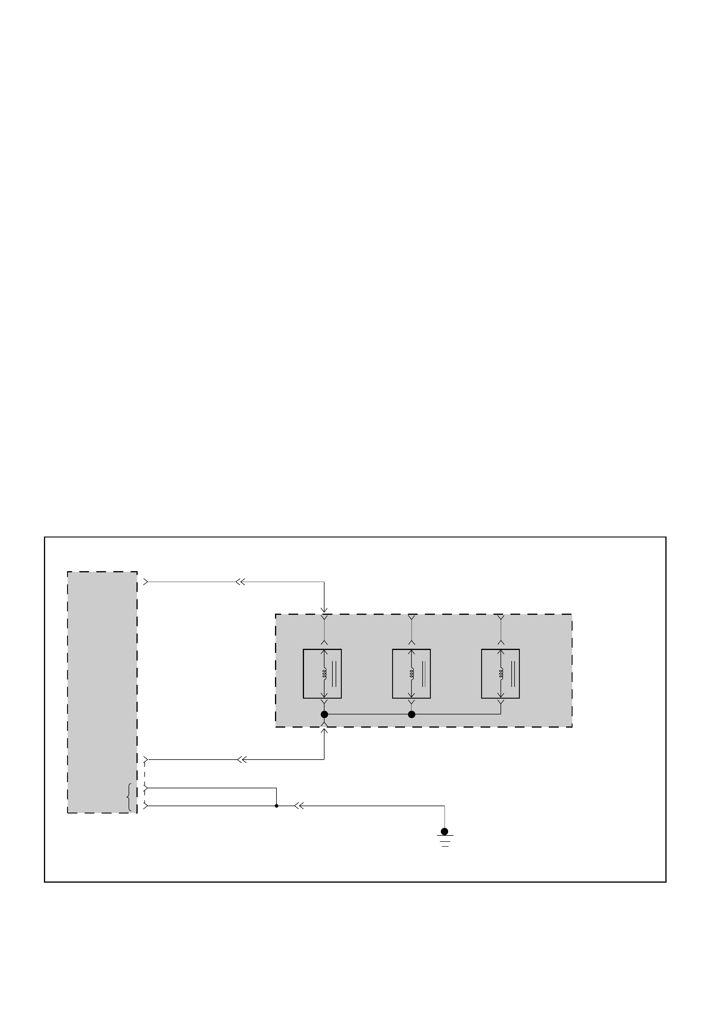
DIAGNOSTIC TROUBLE CODE (DTC) 31
SOLENOID A SHORT TO GROUND OR OPEN
SHIFT
SOLENOID A
CONTROL
GROUND
TRANSMISSION
CONTROL
MODULE (TCM)
SHIFT
SOLENOID
A
SHIFT
SOLENOID
B
BAND
APPLY
SOLENOID
AUTOMATIC
TRANSMISSION
M-7
M-7
3(D)
4(C)
C-96 YEL/GRN
H-23
14
H-23
13
H-25
BLK BLK
BLK
7
A2(2)
C-95
C12(12)
C1(1)
D1(17)
GROUND
BRN/WHT
YEL/GRN
BRN/WHT
This DTC flashes the CHECK TRANS indicator and
sets the BACKUP MODE.
Circuit Description:
•The solenoid A is a simple ON/OFF solenoid
located in the main case valve body. The
solenoid is the normally closed-type. In second or
third gear the Transmission Control Module
(TCM) energizes the solenoid to open a fluid inlet
port. When the port is open, fluid pressure
actuates the shift valve.
•The solenoid is activated by a current. This
current is produced by applying a voltage to one
side (the High side) and a ground to the other
side (Low side).
•The High Side Driver (HSD) is a circuit of the TCM
that acts as a switch between the solenoids and
the supply voltage. The High side of the solenoid
is permanently supplied with voltage, except in
BACKUP MODE or when ignition is OFF the HSD
is turned OFF.
•The TCM continually monitors the solenoid
connection to its Low Side Driver (LSD) for either
low or high voltage. The LSD is a circuit of the
TCM that acts as a switch between the solenoid
and ground. When the solenoid is commanded
ON the TCM is switching the solenoid to ground.
•There are two tests of the LSD: When the engine
is cranked (DTC82) and when the ignition is
turned ON (DTC31).
•When the ignition is turned ON, and before the
engine is cranked, the TCM activates the shift
solenoids (A, B and Band) to check for short
circuits or open circuits. To do so the gear is set
to 4th, 3rd, 1st, 1st with band apply, 4th with no
HSD. Each one of the 5 tests requires 0.15
second. If the engine is cranked before the end of
all tests, the remaining tests are not done.
Diagnostic Aids:
•This Diagnostic is an electrical test done by the
TCM.
•Detection conditions:
1The solenoid low side connected to TCM
terminal A2 is shorted to ground or open.
2The test is only done when ignition is ON.
3Engine Speed < 480 RPM (not cranked) and
Output Speed = 0 RPM.
4The conditions need to be present for 0.15 to
1.03 second after ignition switch ON.
•Action after the detection time: BACKUP MODE.
•Recovery conditions: To recover, do an IGNITION
CYCLE.
D07LW011

•Ignition switch OFF.
•Disconnect Transmission Control Module (TCM)
connector C-95 and C-96.
•Connect ohmmeter between connector C-95 terminal
C12 and connector C-96 terminal A2.
IF: Display between 17.5 and 18.5 ohms?
•Check for faulty connector or
wiring between terminal A2
and ground.
•Repair.
YES NO
YES NO
YES
DIAGNOSTIC TROUBLE CODE (DTC) 31
SOLENOID A SHORT TO GROUND OR OPEN
YES NO
NO
•Connect ohmmeter between connector C-96
terminal A2 and connector C-95 terminal C1
(TCM ground).
IF: Short circuit:
Check for an open circuit between connector C-
96 terminal A2 and connector C-95 terminal C12.
IF: Wiring problem?
The problem is intermittent.
GOTO INTERMITTENT
CONDITIONS.
The problems is
intermittent.
GOTO INTERMITTENT
CONDITIONS.
Replace the solenoid A.
Repair.
•Disconnect solenoid A connector.
•IF: Ohmmeter displays between 17.5 and 18.5
ohms on the solenoid A terminals:
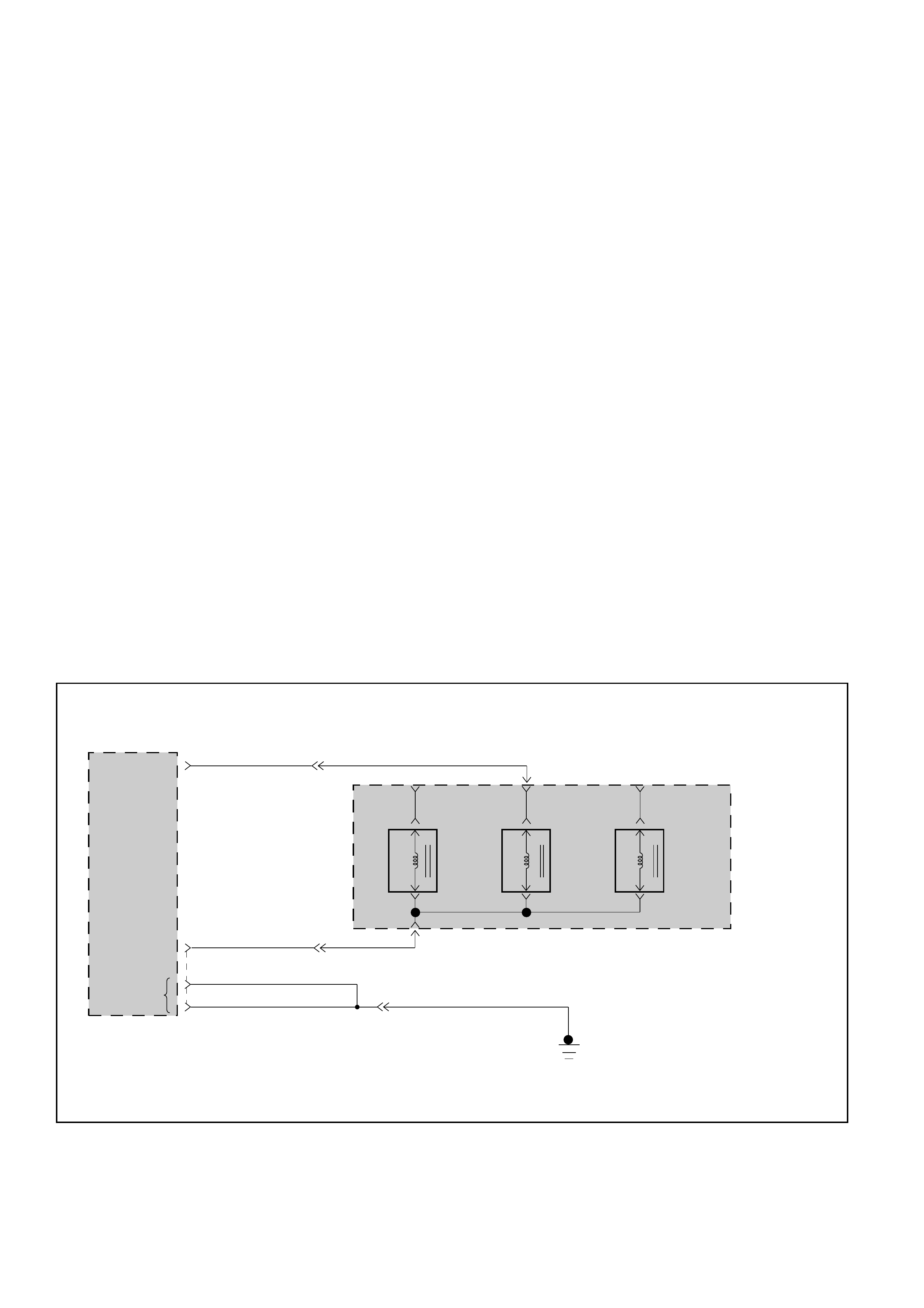
DIAGNOSTIC TROUBLE CODE (DTC) 32
SOLENOID B SHORT TO GROUND OR OPEN
This DTC flashes the CHECK TRANS indicator and
sets the BACKUP MODE.
Circuit Description:
•The solenoid B is a simple ON/OFF solenoid
located in the main case valve body. The
solenoid is the normally open-type. When the
port is open, fluid pressure actuates the shift
valve. In first or second gear the Transmission
Control Module (TCM) energizes the solenoid to
close a fluid inlet port.
•The solenoid is activated by a current. This
current is produced by applying a voltage to one
side (the High side) and a ground to the other
side (Low side).
•The High Side Driver (HSD) is a circuit of the TCM
that acts as a switch between the solenoids and
the supply voltage. The High side of the solenoid
is permanently supplied with voltage, except in
BACKUP MODE or when ignition is OFF the HSD
is turned OFF.
•The TCM continually monitors the solenoid
connection to its Low Side Driver (LSD) for either
low or high voltage. The LSD is a circuit of the
TCM that acts as a switch between the solenoid
and ground. When the solenoid is commanded
ON the TCM is switching the solenoid to ground.
•There are two tests of the LSD: When the engine
is cranked (DTC82) and when the ignition is
turned ON (DTC32).
•When the ignition is turned ON, and before the
engine is cranked, the TCM activates the shift
solenoids (A, B and Band) to check for short
circuits or open circuits. To do so the gear is set
to 4th, 3rd, 1st, 1st with band apply, 4th with no
HSD. Each one of the 5 tests requires 0.15
second. If the engine is cranked before the end of
all tests, the remaining tests are not done.
Diagnostic Aids:
•This Diagnostic is an electrical test done by the
TCM.
•Detection conditions:
1The solenoid low side connected to TCM
terminal A3 is shorted to ground or open.
2The test is only done when ignition is ON.
3Engine Speed < 480 RPM (not cranked) and
Output Speed = 0 RPM.
4The conditions need to be present for 0.15 to
0.88 second after ignition switch ON.
•Action after the detection time: BACKUP MODE.
•Recovery conditions: To recover, do an IGNITION
CYCLE.
SHIFT
SOLENOID
A
SHIFT
SOLENOID
B
BAND
APPLY
SOLENOID
AUTOMATIC
TRANSMISSION
M-7
M-7
1(A)
4(C)
C-96 BRN/BLK H-23
6
H-23
14
BRN/WHT
H-25
BLK BLK
BLK
7
A3(3)
C-95
C12(12)
C1(1)
D1(17)
SHIFT
SOLENOID B
CONTROL
GROUND
TRANSMISSION
CONTROL
MODULE (TCM)
GROUND BRN/BLK
BRN/WHT
D07LW012

DIAGNOSTIC TROUBLE CODE (DTC) 32
SOLENOID B SHORT TO GROUND OR OPEN
YES
YES
NO
NO YES NO
YES NO
•Ignition switch OFF.
•Disconnect Transmission Control Module (TCM)
connector C-95 and C-96.
•Connect ohmmeter between connector C-95 terminal
C12 and connector C-96 terminal A3.
IF: Display between 17.5 and 18.5 ohms?
•Connect ohmmeter between connector C-96
terminal A3 and connector C-95 terminal C1
(TCM ground).
IF: Short circuit:
Check for an open circuit between connector C-
96 terminal A3 and connector C-95 terminal C1.
IF: Wiring problem?
The problem is intermittent.
GOTO INTERMITTENT
CONDITIONS.
The problems is
intermittent.
GOTO INTERMITTENT
CONDITIONS.
Replace the
solenoid B.
•Check for faulty connector or
wiring between terminal A3
and ground.
Repair. •Disconnect solenoid B connector.
IF: Ohmmeter displays between 17.5 and 18.5
ohms on the solenoid B terminals:
Repair.
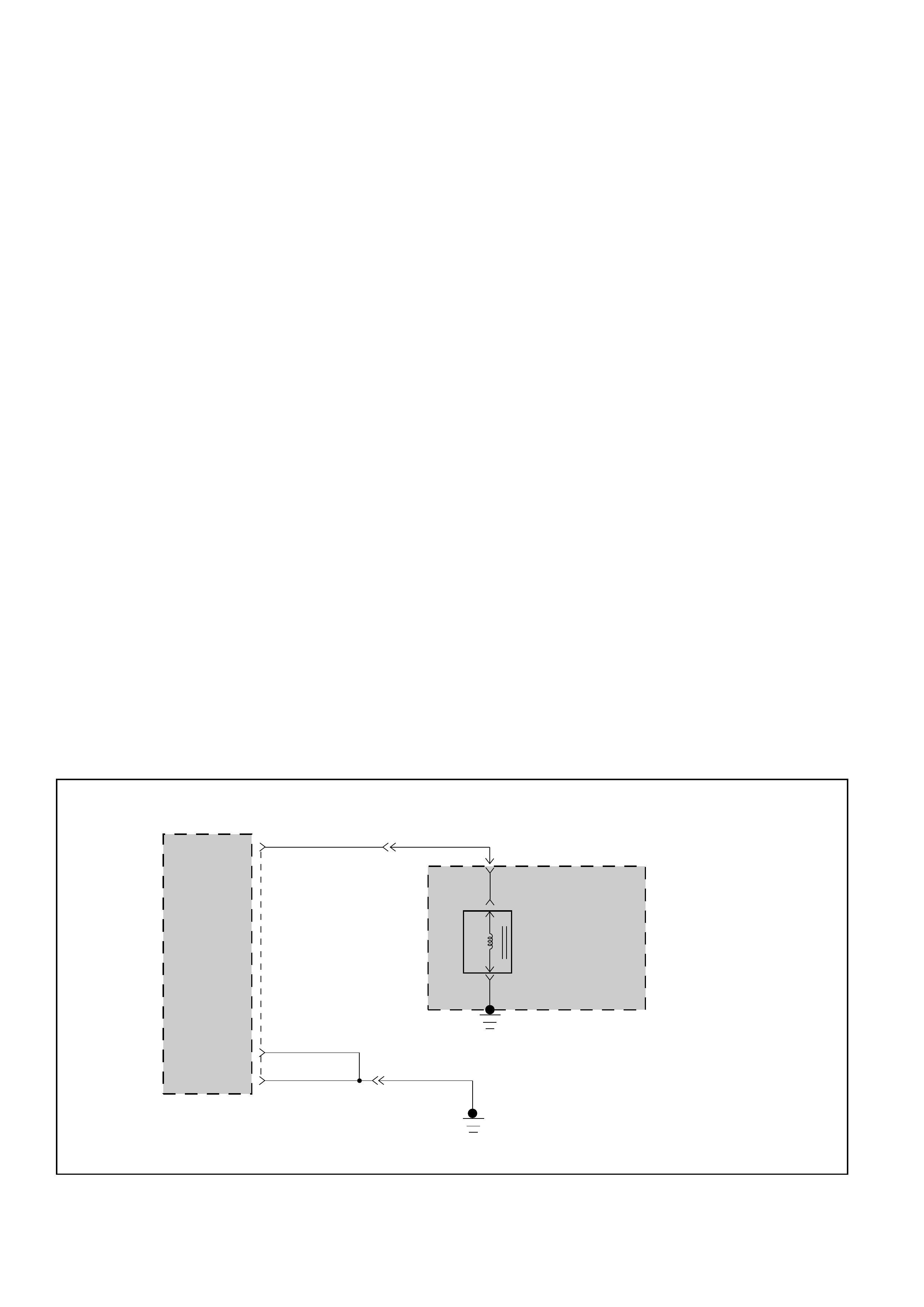
DIAGNOSTIC TROUBLE CODE (DTC) 33
TCC HIGH SHORT TO PLUS OR OPEN
This DTC flashes the CHECK TRANS indicator and
does NOT set the BACKUP MODE.
Circuit Description:
•The Torque Converter Clutch (TCC) solenoid is a
simple ON/OFF solenoid connected to the
adapter case valve body. When the solenoid is
energized by the Transmission Control Module
(TCM), it opens a fluid port. When the port is
open, line pressure actuates the converter clutch
control valve which engages the torque converter
clutch by exhausting the fluid. The TCM engages
the torque converter clutch only when all of the
following conditions exist:
1The transmission is at operating temperature.
2The brake pedal is released.
3The transmission is operating in second, third
or fourth gear.
4The engine is warm (more than 70°C).
5The shift pattern requests TCC apply.
6Shift finished.
7No malfunction which will disable the TCC:
DTC43, DTC55 (only short to ground).
•The solenoid is activated by a current. This
current is produced by applying a voltage to one
side (the High side) and a ground to the other
side (Low side).
•The High Side Driver (HSD) is a circuit of the TCM
that acts as a switch between the solenoid and
the supply voltage. The High side of the TCC
solenoid is used to turn the TCC ON or OFF
because the Low side is permanently connected
to the ground of the transmission. In BACKUP
MODE or when ignition is turned OFF the TCC
High Side is turned OFF.
•The TCM continually monitors the solenoid
connection to its High Side Driver for either low
or high voltage.
•There is only one test of the HSD for TCC: when
the engine is cranked and the TCC is turned ON.
•If this circuit is shorted to plus, the TCC solenoid
is constantly commanded ON (shifts can be firm).
In 1st gear the TCC is hydraulically OFF, whatever
the TCC solenoid position. This means that the
car can be driven even with the TCC shorted to
voltage. The engine could stall when the driver is
braking strongly, if the car is stopped when the
transmission is still in second gear with TCC
applied.
Note: The 3-2 shifts are very firm.
Diagnostic Aids:
•This diagnostic is an electrical test done by the
TCM.
•Detection conditions:
1The solenoid high side connected to TCM
terminal C7 is shorted to voltage or open.
2The condition needs to be present for 0.13
second.
•Action after the detection time:
1TCC is turned OFF.
2CHECK TRANS indicator turned ON.
•Recovery conditions: To recover, do an IGNITION
CYCLE.
TORQUE
CONVERTER
CLUTCH
SOLENOID
CONTROL
TRANSMISSION
CONTROL
MODULE (TCM)
AUTOMATIC
TRANSMISSION
M-6
4(A)
C-95
TORQUE
CONVERTER
CLUTCH
SOLENOID
H-23
12
RED/YEL
BLK BLK
BLK
7
H-25
C1(1)
D1(17)
C7(7) RED/YEL
D07LW013
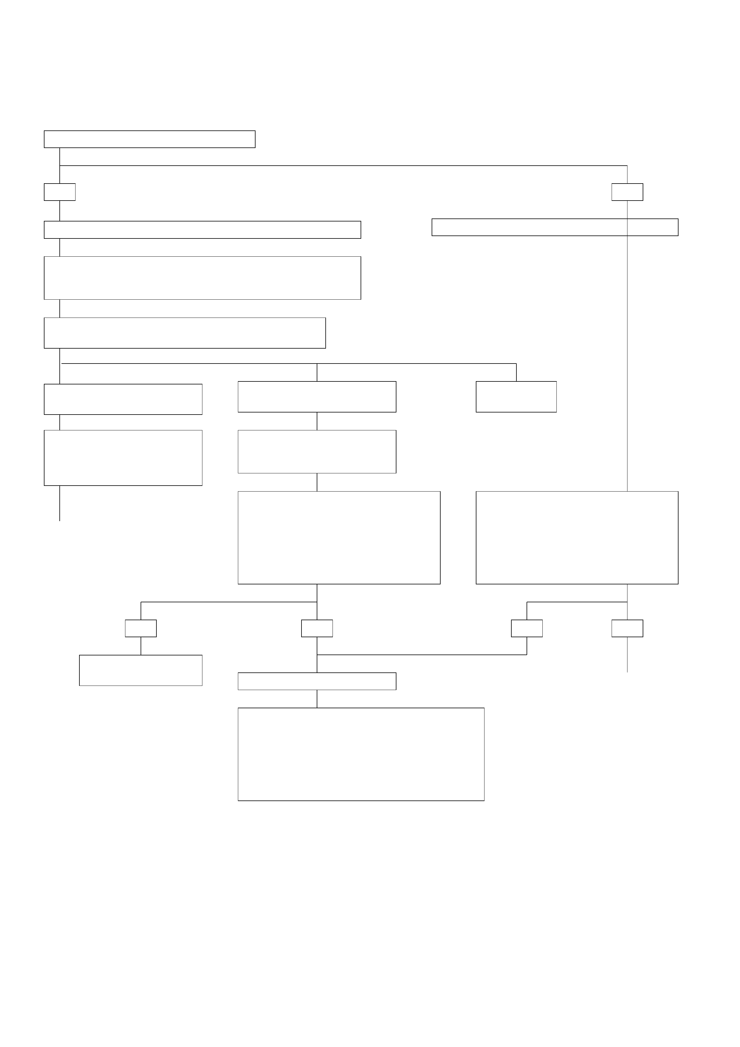
IF you have a SCAN TOOL: TECH2?
Without TECH2 you can not do preliminary test.
YES NO
DIAGNOSTIC TROUBLE CODE (DTC) 33
TCC HIGH SHORT TO PLUS OR OPEN
A
CONTINUED ON
NEXT PAGE
A
CONTINUED ON
NEXT PAGE
YES YESNO NO
TCC: Torque Converter Clutch
TCM: Transmission Control Module
SHORT TO PLUS?
•Ignition switch ON. Engine OFF.
•Connect a voltmeter between
connector C-95 terminal C7 and car
ground or with TCM ground
terminal C1.
IF: voltage found:
SHORT TO PLUS?
•Ignition switch ON. Engine OFF.
•Connect a voltmeter between
connector C-95 terminal C7 and car
ground or with TCM ground
terminal C1.
IF: voltage found:
CASE: SLIP > 20 RPM with
TCC = ON
The TCC is shorted to voltage.
•Check wire for a short to voltage between
terminal C7 and solenoid.
Note: This short can be to another wire of the
adapter case connector M-6.
In this case the problem occurs only when
voltage is present at the second wire.
•Repair.
CASE: SLIP = 0+ OR -10 RPM
with TCC = OFF at any TPS:
This means that the TCC valve
is stuck ON or TCC solenoid is
shorted to plus.
This means that the TCC valve
is stuck OFF or the TCC
solenoid connections are
OPEN.
REPLACE TCM
•Install scan tool: TECH2 GOTHROUGH TECH2 CONNECTION.
While driving the car in 2nd, 3rd or 4th gear check if the TCC is
slipping or not when the TCC solenoid is commanded OFF or
ON by the TCM.
Push F0: DATA LIST:
Read TCC state and SLIP value.
CASE: DTC43
GOTO DTC43.
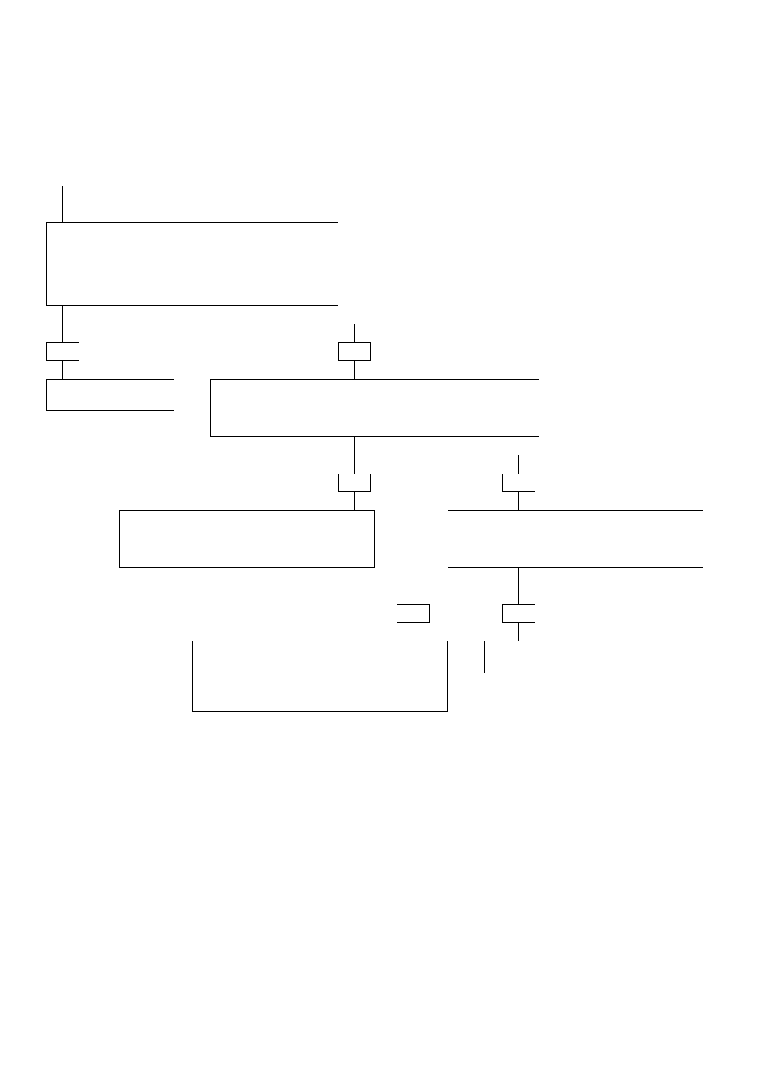
DIAGNOSTIC TROUBLE CODE (DTC) 33
TCC HIGH SHORT TO PLUS OR OPEN
(CONTINUED)
CONTINUED FROM
PREVIOUS PAGE
A
TCC: Torque Converter Clutch
TCM: Transmission Control Module
YES
YES NO
NOYES
NO
•Wire between connector C-95 terminal C7 and
adapter case connector is open or shorted to
another wire.
•Repair.
•Wire between adapter case connector and
solenoid is open.
•Or wire between transmission (ground) and
solenoid is open.
•Repair.
•Disconnect solenoid connector.
•Connect ohmmeter between the two solenoid
terminals.
IF: Display is between 17.5 and 18.5 ohms.
•Disconnect transmission adapter case connector M-6.
•Connect ohmmeter between terminal 4(A) of female half of
connector and transmission which is used as ground.
IF: Display between 17.5 and 18.5 ohms:
REPLACE TCM
Replace torque converter
clutch solenoid.
OPEN?
•Ignition switch OFF.
•Disconnect TCM connector C-95 and C-96.
•Connect ohmmeter between connector C-95 terminal
C7 and C1 (TCM ground).
IF: Display is between 17.5 and 18.5 ohms.
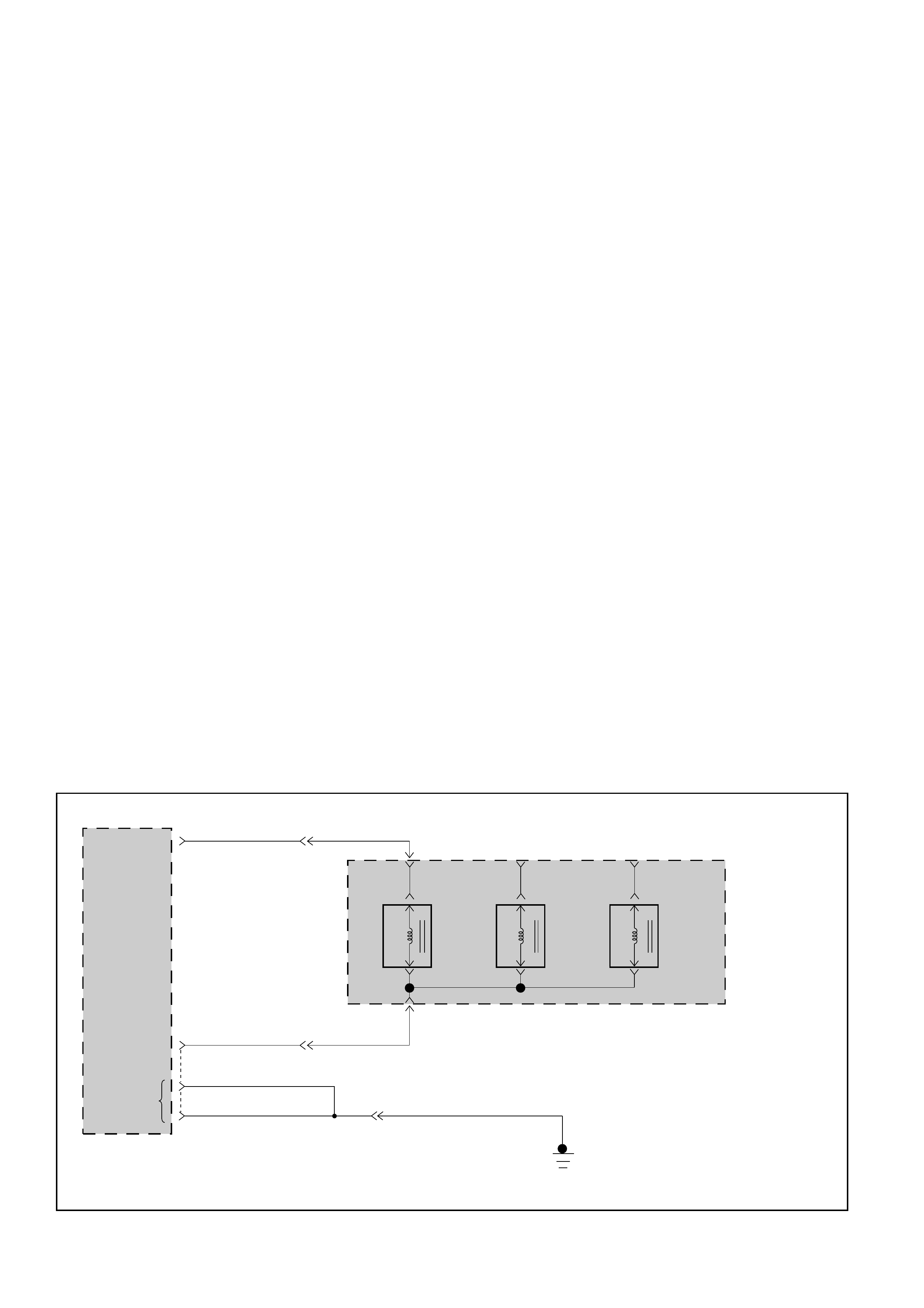
DIAGNOSTIC TROUBLE CODE (DTC) 34
BAND APPLY SOLENOID SHORT TO GROUND OR OPEN
This DTC flashes the CHECK TRANS indicator and
sets the BACKUP MODE.
Circuit Description:
•The band apply solenoid is a normally open
solenoid which controls the flow of fluid for brake
band application. The Transmission Control
Module (TCM) uses Pulse Width Modulation
(PWM) and changes the duty cycle to control the
solenoid. The TCM turns the solenoid ON
(energized) and OFF (de-energized) at a constant
frequency. The length of time the solenoid is
energized during each ON/OFF cycle is called the
pulse width. By varying or “modulating” the
pulse width, the solenoid output pressure is
changed. Since the solenoid is normally closed,
increasing the pulse width increases the duty
cycle and decreases the output pressure. PWM
control provides smooth band application
without an accumulator. The band is only applied
in first and second gears.
•In the event of an electrical failure (open), the
solenoid regulates at the maximum oil flow (0%
duty cycle).
•The solenoid is activated by a current. This
current is produced by applying a voltage to one
side (the High side) and a ground to the other
side (Low side).
•The High Side Driver (HSD) is a circuit of the TCM
that acts as a switch between the solenoids and
the supply voltage. The High side of the solenoid
is permanently supplied with voltage, except in
BACKUP MODE or when Ignition is OFF the HSD
is turned OFF.
•The TCM continually monitors the splenoid
connection to its Low Side Driver (LSD) for either
low or high voltage. The LSD is a circuit of the
TCM that acts as a switch between the solenoid
and ground. When the solenoid is commanded
ON the TCM is switching the solenoid to ground.
•There are two tests of the LSD: when the engine
is cranked (DTC82) and when the ignition is
turned ON (DTC34).
•When the ignition is turned ON, and before the
engine is cranked, the TCM activates the shift
solenoids (A, B and Band) to check for short
circuits or open circuits. To do so the gear is set
to 4th, 3rd, 1st, 1st with band apply, 4th with no
HSD. Each one of the 5 tests requires 0.15
second. If the engine is cranked before the end of
all tests, the remaining tests are not done.
Diagnostic Aids:
•This diagnostic is an electrical test done by the
TCM.
•Detection conditions:
1The solenoid Low side connected to TCM
terminal A9 is shorted to ground or open.
2The test is only done when ignition is ON.
3Engine Speed <480 RPM (not cranked) and
Output Speed = 0 RPM.
4The condition needs to be present for 0.15 to
0.75 second after ignition switch ON.
•Action after the detection time: BACKUP MODE.
•Recovery conditions: To recover, do an IGNITION
CYCLE.
BAND
APPLY
SOLENOID
CONTROL
GROUND
TRANSMISSION
CONTROL
MODULE (TCM)
SHIFT
SOLENOID
A
SHIFT
SOLENOID
B
BAND
APPLY
SOLENOID
AUTOMATIC
TRANSMISSION
M-7
M-7
2(B)
4(C)
C-96
H-23
14
H-23
16
BRN/WHT BRN/WHT
YEL/BLK
BLK BLK
BLK
7
H-25
C1(1)
D1(17)
A9(9)
C-95
C12(12)
GROUND YEL/BLK
D07LW014
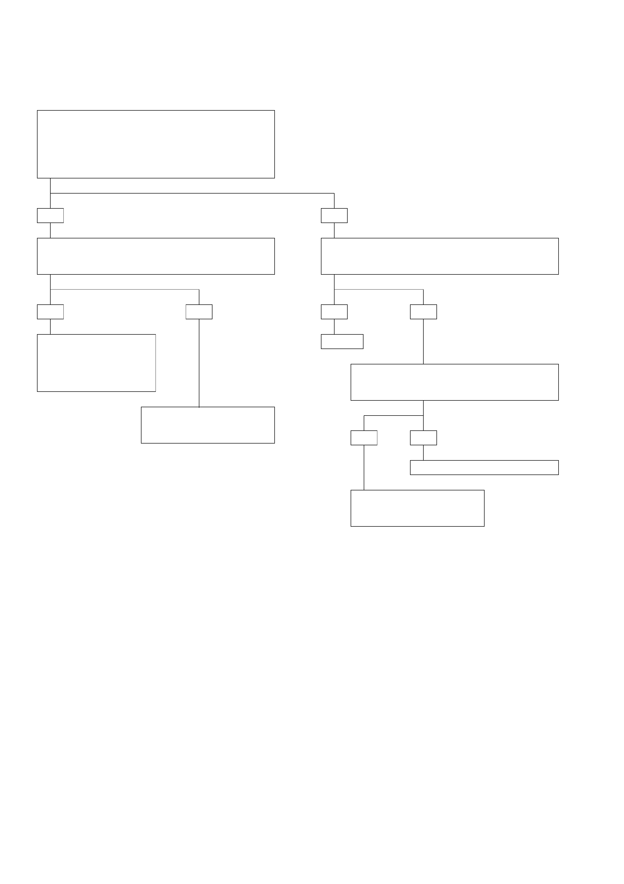
•Ignition switch off.
•Disconnect Transmission Control Module (TCM)
connector C-95 and C-96
•Connect ohmmeter between connector C-95 terminal
C12 and connector C-96 terminal A9.
IF: Display is approx. 10 ohms:
•Connect ohmmeter between connector C-96 terminal
A9 and connector C-95 terminal C1 (TCM ground)
IF: Short circuit:
•Check for an open circuit between connector C-96
terminal A9 and connector C-95 terminal C12.
IF: Wiring problem?
•Disconnect band apply solenoid connector.
IF: Ohmmeter displays approx. 10 ohms on
the band apply solenoid terminals:
The problem is intermittent.
GOTO INTERMITTENT
CONDITIONS.
The problem is intermittent.
GOTO INTERMITTENT
CONDITIONS.
YES
YES
NO
YES NO
DIAGNOSTIC TROUBLE CODE (DTC) 34
BAND APPLY SOLENOID SHORT TO GROUND OR OPEN
•Check for faulty
connector or wiring
between terminal A9
and ground.
•Repair.
Repair.
Replace the band apply solenoid.
NO
YES NO
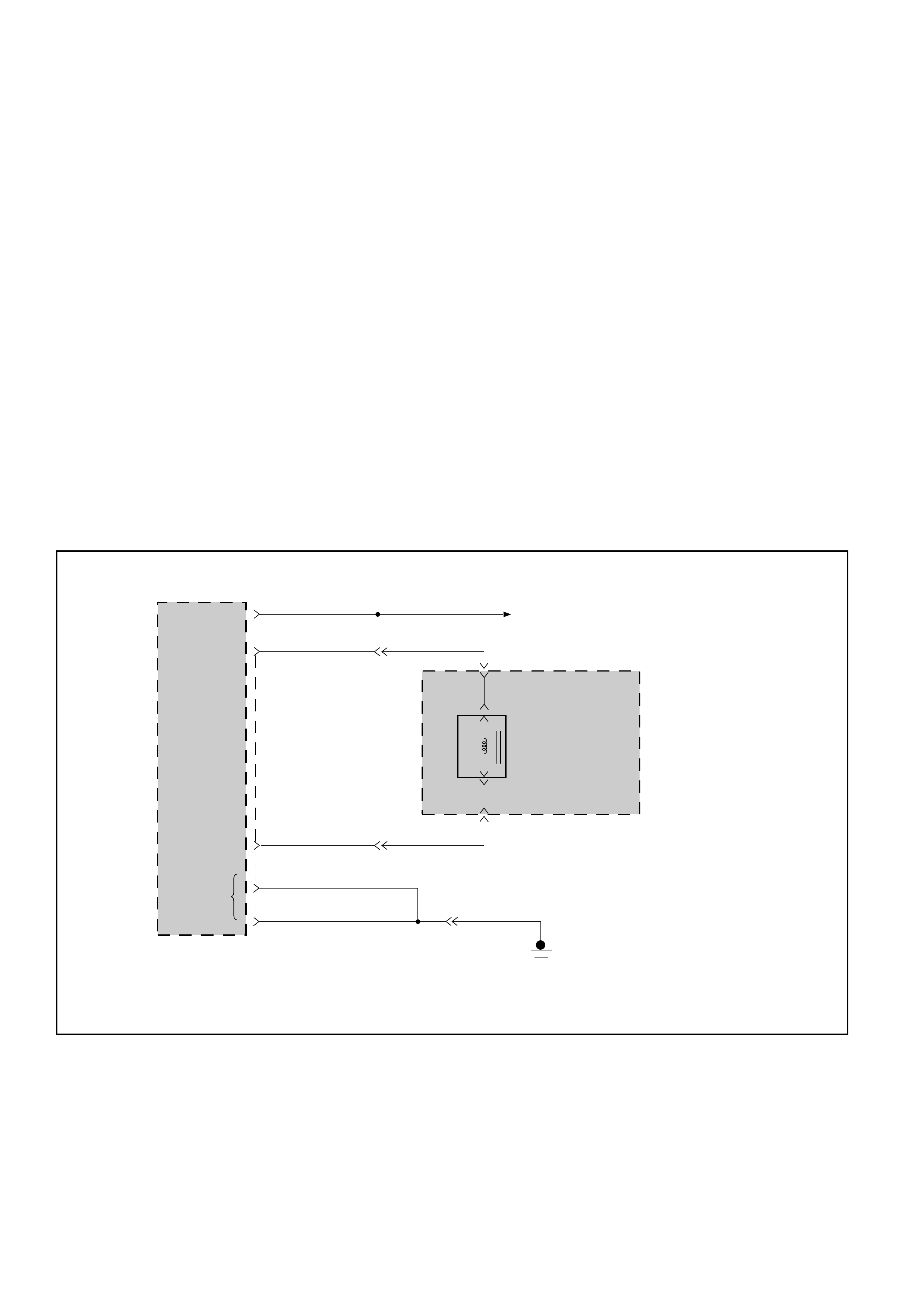
DIAGNOSTIC TROUBLE CODE (DTC) 35
FORCE MOTOR OPEN OR SHORT TO PLUS OR GROUND
This DTC flashes the CHECK TRANS indicator and
sets the BACKUP MODE.
Circuit Description:
•The force motor solenoid is a device used to
regulate transmission line pressure. The TCM
uses TPS information and vehicle speed infor-
mation to determine the line pressure appro-
priate for a given load. The TCM will regulate the
pressure by applying a varying amperage to the
force motor solenoid. The applied amperage can
vary from 0.1 to 1.1 amp. The TCM then monitors
the amperage at the return line. If the return
amperage is more than 0.2 amp from the
commanded amperage, the DTC is stored.
•The line pressure can vary from less than 50psi to
more than 200 psi. The line pressure varies
inversely to the amount of current. High current
causes low pressure and low current causes high
pressure.
Diagnostic Aids:
•This Diagnostic is an electrical test done by the
TCM.
•Detection conditions:
•The TCM monitors the amperage at the return
line. When the return amperage is more than 0.2
amp from the commanded amperage, DTC is
stored.
•Action after the detection time: BACKUP MODE
•Recovery conditions: To recover, do an IGNITION
CYCLE.
FORCE
MOTOR
SOLENOID
CONTROL
(+)
TRANSMISSION
CONTROL
MODULE (TCM)
ECM MAIN RELAY
M-6
M-6
2(B)
1(E)
C-95
FORCE
MOTOR
SOLENOID
FORCE
MOTOR
SOLENOID
CONTROL
(—)RED/GRN RED/GRN
H-23
8
H-23
5
RED/BLK
BLK
BLK BLK
7
H-25
C16(16)
C1(1)
D1(17)
C15(15)
GROUND
C-96 RED/BLU RED/BLU
IGNITION
INPUT A7(7)
AUTOMATIC
TRANSMISSION
RED/BLK
D07LW015

•Ignition switch off.
•Disconnect Transmission Control Module (TCM)
connector C-95 and C-96
•Connect ohmmeter between connector C-95
terminals C15 and C16.
IF: Display is between 3.7 and 4.7 ohms:
•Connect ohmmeter between connector C-95
terminals C15 and C1 (TCM ground) then between
terminal C15 and connecter C-96 terminal A7 (TCM
ignition) then between terminals C16 and C1 (TCM
ground) then between terminals C16 and A7 (TCM
ignition).
IF: Display indicates a short circuit:
•Disconnect automatic transmission adapter case
connector M-6.
•Connect ohmmeter between terminals 2(B) and 1(E)
of female half of the connector (solenoid side).
IF: Display between 3.7 and 4.7 ohms:
Repair wires for open between
terminals C15 or C16 and adapter
case connector.
Replace force motor solenoid.
Repair the short circuit. The problem is
intermittent.
GOTO INTERMITTENT
CONDITIONS. •Disconnect solenoid connector.
•Connect ohmmeter between solenoid
terminals.
IF: Display between 3.7 and 4.7 ohms:
Repair wires for open
between adapter case
connector and solenoid
connector.
YES NO
YES NO
DIAGNOSTIC TROUBLE CODE (DTC) 35
FORCE MOTOR OPEN OR SHORT TO PLUS OR GROUND
NOYES
YES NO
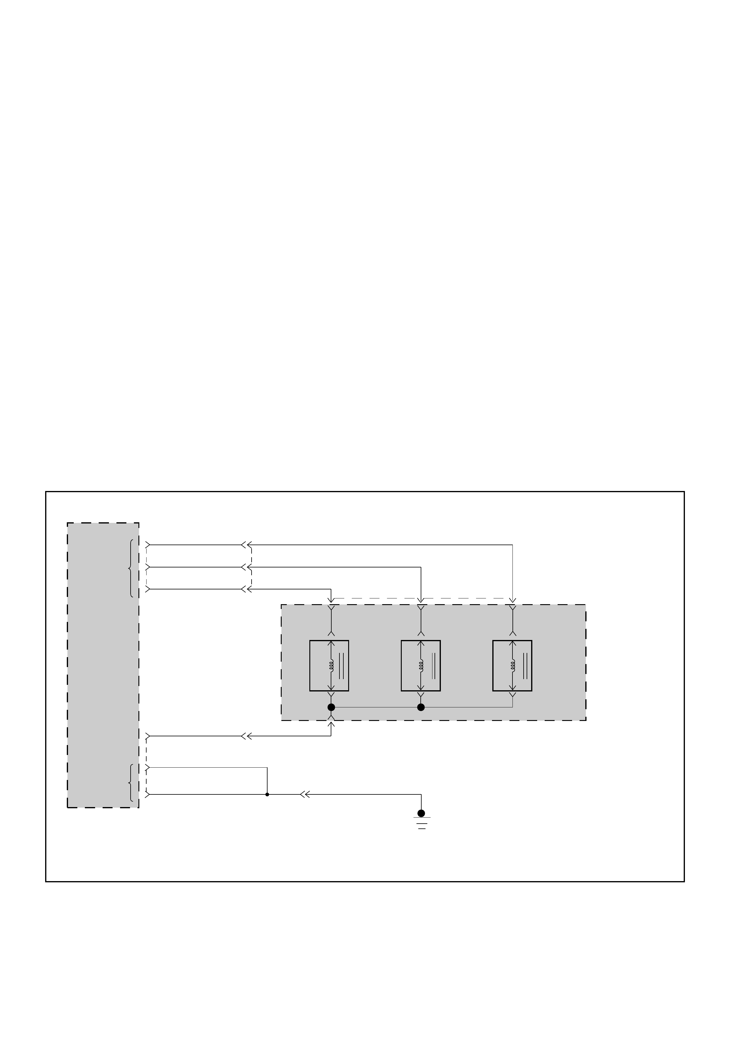
DIAGNOSTIC TROUBLE CODE (DTC) 36
SHIFT HIGH SHORT TO GROUND OR OPEN
This DTC flashes the CHECK TRANS indicator and
sets the BACKUP MODE.
Circuit Description:
•The solenoids are activated by a current. This
current is produced by applying a voltage to one
side (the High side) and a ground to the other
side (Low side).
•The High Side Driver (HSD) is a circuit of the
Transmission Control Module (TCM) that acts as
a switch between the solenoids and the supply
voltage. The High side of the solenoid is
permanently supplied with voltage, except in
BACKUP MODE or when Ignition is OFF the High
Side Driver is turned OFF.
•The TCM continually monitors the solenoid
connection to its High Side Driver for either low
or high voltage.
•There are two tests of the HSD: when the engine
is cranked (DTC82) and when the ignition is
turned ON (DTC36).
•When the ignition is turned ON, and before the
engine is cranked, the TCM activates the shift
solenoids (A, B and Band) to check for short
circuits or open circuits. To do so the gear is set
to 4th, 3rd, 1st, 1st with band apply, 4th with no
HSD. Each one of the 5 tests requires 0.15
seconds. If the engine is cranked before the end
of all tests, the remaining tests are not done.
Diagnostic Aids:
•This diagnostic is an electrical test done by the
TCM.
•Detection conditions:
1The solenoid High side connected to TCM
terminal C12 is shorted to ground or open.
2The test is only done when ignition is ON.
3Engine Speed < 480 RPM (not cranked) and
Output Speed = 0 RPM
4The condition needs to be present for 0.15 to
0.75 second after ignition switch ON.
•Action after the detection time: BACKUP MODE.
•Recovery conditions: To recover, do an IGNITION
CYCLE.
TRANSMISSION
CONTROL
MODULE (TCM)
SHIFT
SOLENOID
A
SHIFT
SOLENOID
B
BAND
APPLY
SOLENOID
AUTOMATIC
TRANSMISSION
M-7
3(D)
4(C)
BRN/WHT
YEL/GRN 1(A)
BRN/BLK
H-23
H-23
16
6
13
YEL/BLK YEL/BLK
2(B) M-7
H-25
BLK BLK
7
C12(12) 14
D1(17)
GROUND C1(1)
A2(2)
A3(3)
A9(9)
C-96
C-95
GROUND
SHIFT &
BAND APPLY
SOLENOID
CONTROL
BLK
YEL/GRN
BRN/BLK
BRN/WHT
D07LW016
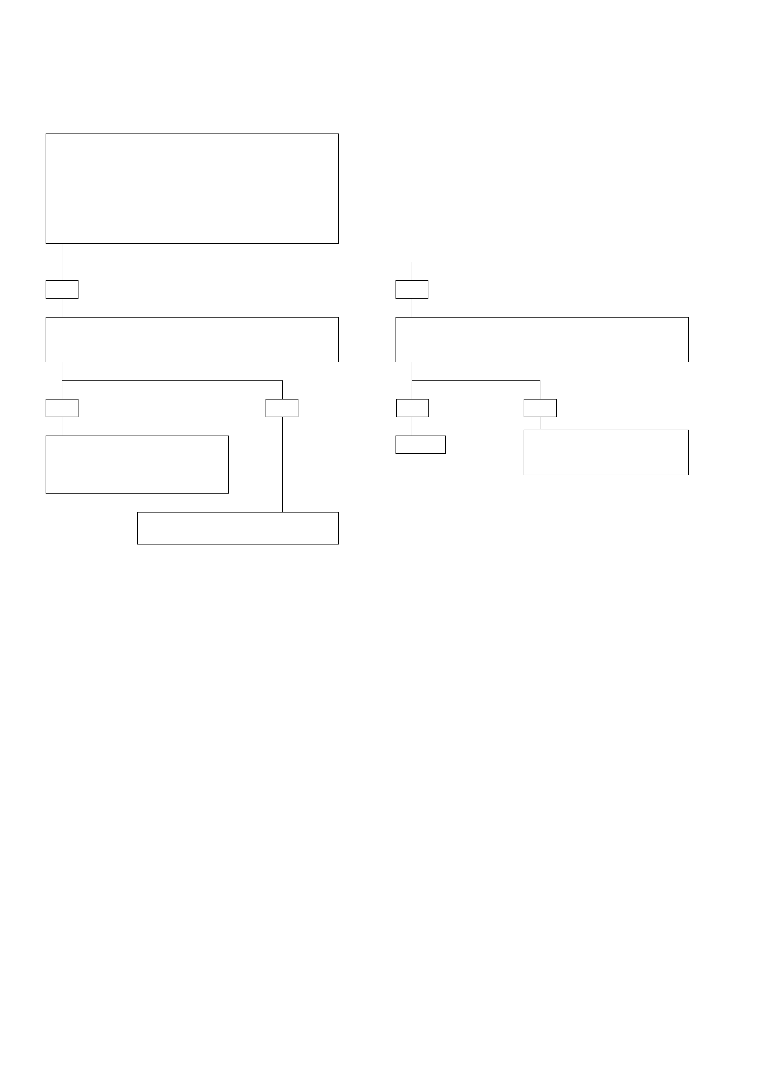
•Connect ohmmeter between connector C-95 terminal
C12 and C1 (TCM ground).
IF: Short circuit:
•Check for faulty connector or
wiring between terminal C12
and ground.
•Repair.
The problem is intermittent.
GOTO INTERMITTENT CONDITIONS.
The problem is intermittent.
GOTO INTERMITTENT
CONDITIONS.
YES
YES
NO
DIAGNOSTIC TROUBLE CODE (DTC) 36
SHIFT HIGH SHORT TO GROUND OR OPEN
YES NO NO
•Ignition switch off.
•Disconnect Transmission Control Module (TCM)
connectors C-95 and C-96.
•Connect ohmmeter between connector C-95 terminal
C12 and connector C-96 terminal A2 and between
C12 and A3 and between C12 and A9.
IF: Display is approx. 10 ohms for the band apply and 18
ohms for the other solenoids:
Repair.
•Check for an open circuit between connector C-95
terminal C12 and the other terminals A2, A3 and A9.
IF: Wiring problem?
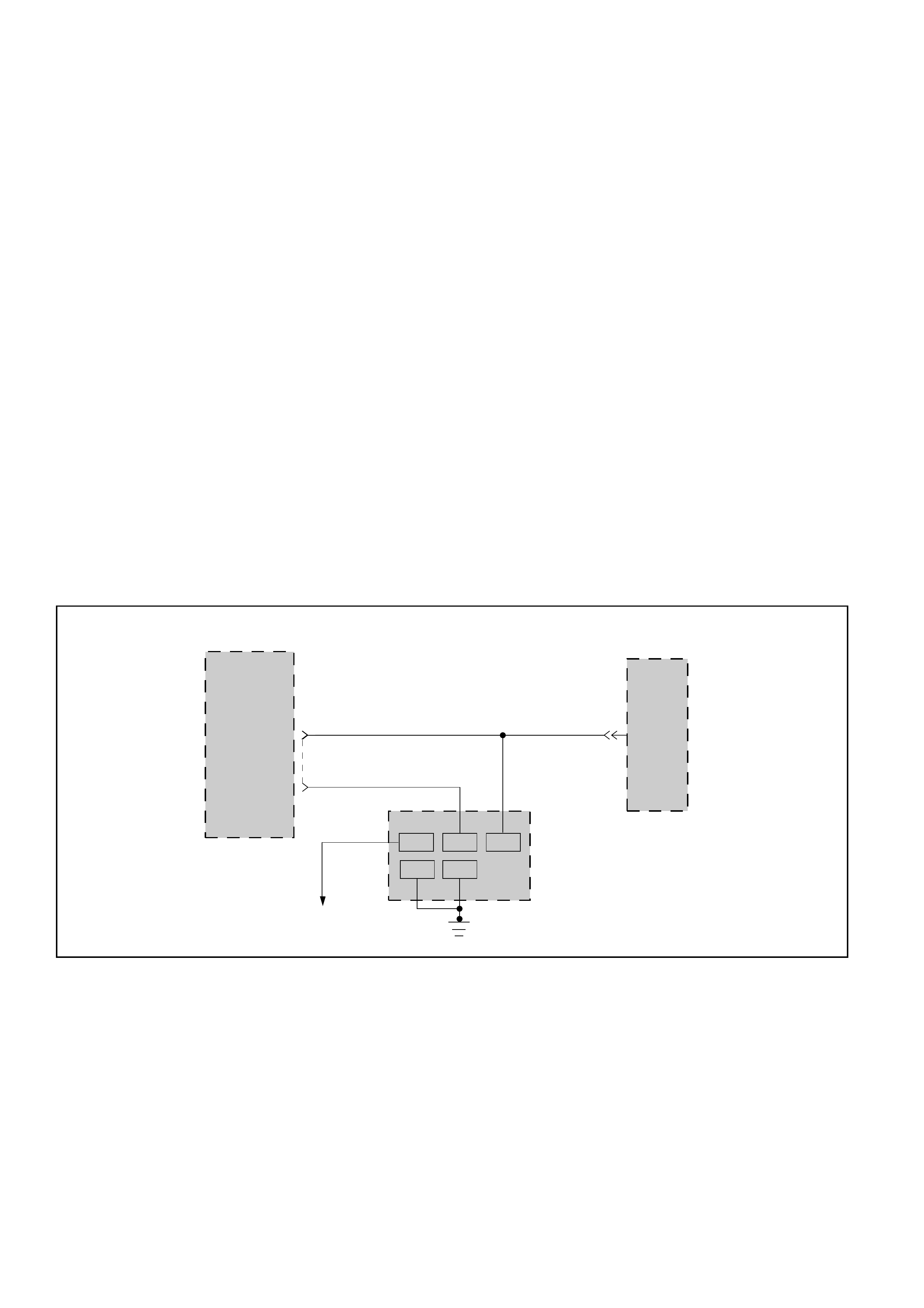
DIAGNOSTIC TROUBLE CODE (DTC) 37
TORQUE MANAGEMENT SERIAL LINE FAULTY
This DTC flashes the CHECK TRANS indicator and
sets the BACKUP MODE.
Circuit Description:
•Torque Management is a function that decreases
the engine torque during transmission shifts. To
do so the Transmission Control Module (TCM)
exchanges information on a wire with the Engine
Control Module (ECM) that governs the Engine.
This wire is the Data Link Connector which is also
used by the Scan tool to communicate with the
TCM and the ECM.
Diagnostic Aids:
•This Diagnostic is not an electrical test done by
the TCM but a test between different information
(“logic test”).
•Detection conditions:
1Torque control failure detected
2Each time a shift occurs with the Torque
Management active, the TCM sends a
message to the ECM. If the ECM does not
acknowledge this message, the DTC is stored.
•Action after the detection time: BACKUP MODE
•Recovery conditions: To recover, do an IGNITION
CYCLE.
NOTE:
1When connecting the TECH2 to the data link
connector, be sure to turn off the ignition
switch.
2Since the torque management exchanges
information between the TCM and the ECM at
all times, the DTC37 is sometimes detects in
the following condition.
However, this is not an abnormal condition.
•When the engine stops while driving and
then it is restarted.
•When the battery voltage goes down
excessively and the engine does not start
again.
When DTC37 is detected in the above
conditions, turn off the ignition switch, correct
the abnormal condition and erase the trouble
code.
SERIAL DATA
TRANSMISSION
CONTROL
MODULE (TCM)
ENGINE
CONTROL
MODULE
(ECM)
C-95
C8(8)
E-61
35 C2
YEL YEL
YEL
C-102C-102C-102
C-102
91116
4
DATA LINK
CONNECTOR
BLK
YEL/BLK
GRN
FUSE (EB-12)
D16(32)
DIAGNOSIS
INPUT
C-1025
D07LW017

YES NO
YES NO
YES NO
YES NO
DIAGNOSTIC TROUBLE CODE (DTC) 37
TORQUE MANAGEMENT SERIAL LINE FAULTY
•Peform TECH2 SELF-TEST GOTHROUGH TECH2
CONNECTION.
IF: TECH2 OK:
•Ignition switch OFF.
•Disconnect TECH2.
•Connect ohmmeter between connector C-102 terminal
4 or 5 and ground.
IF: Display approx. 0 ohms :
•Ignition switch ON.
•Connect voltmeter between connector C-102 terminal
16 and 4 or 5.
IF: Display battery voltage:
•Ignition switch OFF.
•Connect ohmmeter between connector C-102 terminal
9 and ECM connector E-61 terminal 35.
•Then connect ohmmeter between TCM connector C-95
terminal C8 and ECM connector E-61 terminal 35.
IF: Display approx. 0 ohms:
•Check for short between connector C-102 terminal 9
and ground and between connector C-102 terminal 9
and B+.
IF OK, REPLACE TCM
See TECH2 OPERATOR’S MANUAL.
Check wire for open.
Check Engine Control Module (ECM)
and wire to ECM and wire to battery
and data link connector C-102.
Check wire for open.
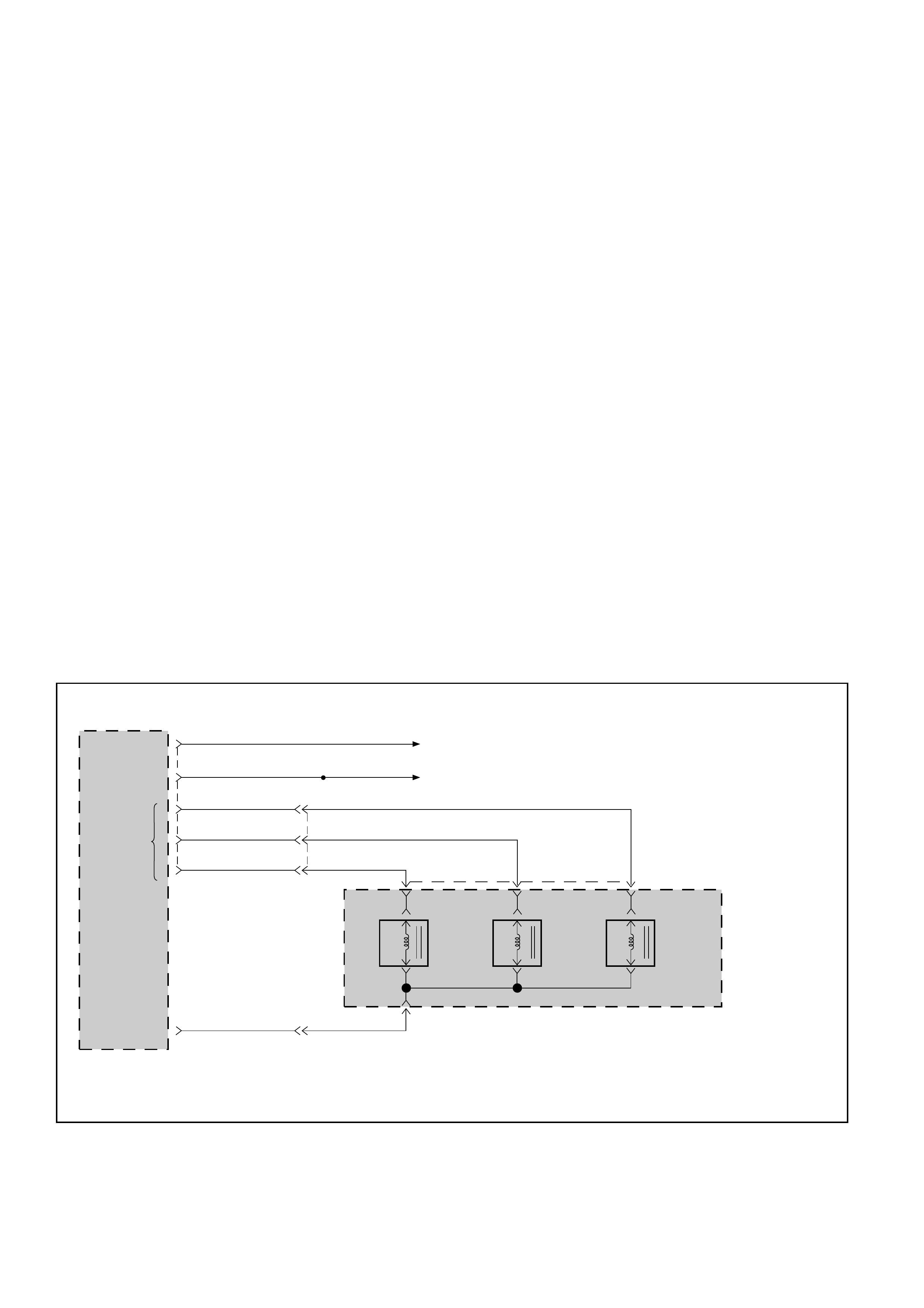
DIAGNOSTIC TROUBLE CODE (DTC) 41
SOLENOID A SHORT TO PLUS
This DTC flashes the CHECK TRANS indicator and
sets the BACKUP MODE.
Circuit Description:
•The solenoid A is a simple ON/OFF solenoid
located in the main case valve body. The
solenoid is the normally closed-type. In second or
third gear the Transmission Control Module
(TCM) energizes the solenoid to open a fluid inlet
port. When the port is open, fluid pressure
actuates the shift valve.
•The solenoid is activated by a current. This
current is produced by applying a voltage to one
side (the High side) and a ground to the other
side (Low side).
•The High Side Driver (HSD) is a circuit of the TCM
that acts as a switch between the solenoids and
the supply voltage. The High side of the solenoid
is permanently supplied with voltage, except in
BACKUP MODE or when ignition is OFF the HSD
is turned OFF.
•The TCM continually monitors the solenoid
connection to its Low Side Driver (LSD) for either
low or high voltage. The LSD is a circuit of the
TCM that acts as a switch between the solenoid
and ground. When the solenoid is commanded
ON the TCM is switching the solenoid to ground.
•There are two tests of the LSD: when the engine
is cranked (DTC82) and when the ignition is
turned ON (DTC41).
•When the ignition is turned ON, and before the
engine is cranked, the TCM activates the shift
solenoids (A, B and Band) to check for short
circuits or open circuits. To do so the gear is set
to 4th, 3rd, 1st, 1st with band apply, 4th with no
HSD. Each one of the 5 tests requires 0.15
second. If the engine is cranked before the end of
all tests, the remaining tests are not done.
Diagnostic Aids:
•This diagnostic is an electrical test done by the
TCM.
•Detection conditions:
1The solenoid Low side connected to TCM
terminal A2 is shorted to plus.
2The test is only done when ignition is ON.
3Engine Speed < 480 RPM (not cranked) and
Output Speed = 0 RPM.
4The condition needs to be present for 0.15 to
0.88 second after ignition switch ON.
•Action after the detection time: BACKUP MODE.
•Recovery conditions: To recover, do an IGNITION
CYCLE.
TRANSMISSION
CONTROL
MODULE (TCM)
SHIFT
SOLENOID
A
SHIFT
SOLENOID
B
BAND
APPLY
SOLENOID
AUTOMATIC
TRANSMISSION
M-7
3(D)
4(C)
BRN/WHT
YEL/GRN YEL/GRN 1(A)
BRN/BLK
H-23
H-23
YEL/BLK YEL/BLK
2(B) M-7
C12(12) 14
A2(2)
A3(3)
A9(9)
13
6
16
SHIFT &
BAND APPLY
SOLENOID
CONTROL
C-95
RED/BLU RED/BLU
GRN
A7(7)
A4(4) BATTERY
ECM MAIN RELAY
BATTERY
INPUT
IGNITION
INPUT
C-96
GROUND
BRN/WHT
BRN/BLK
D07LW018
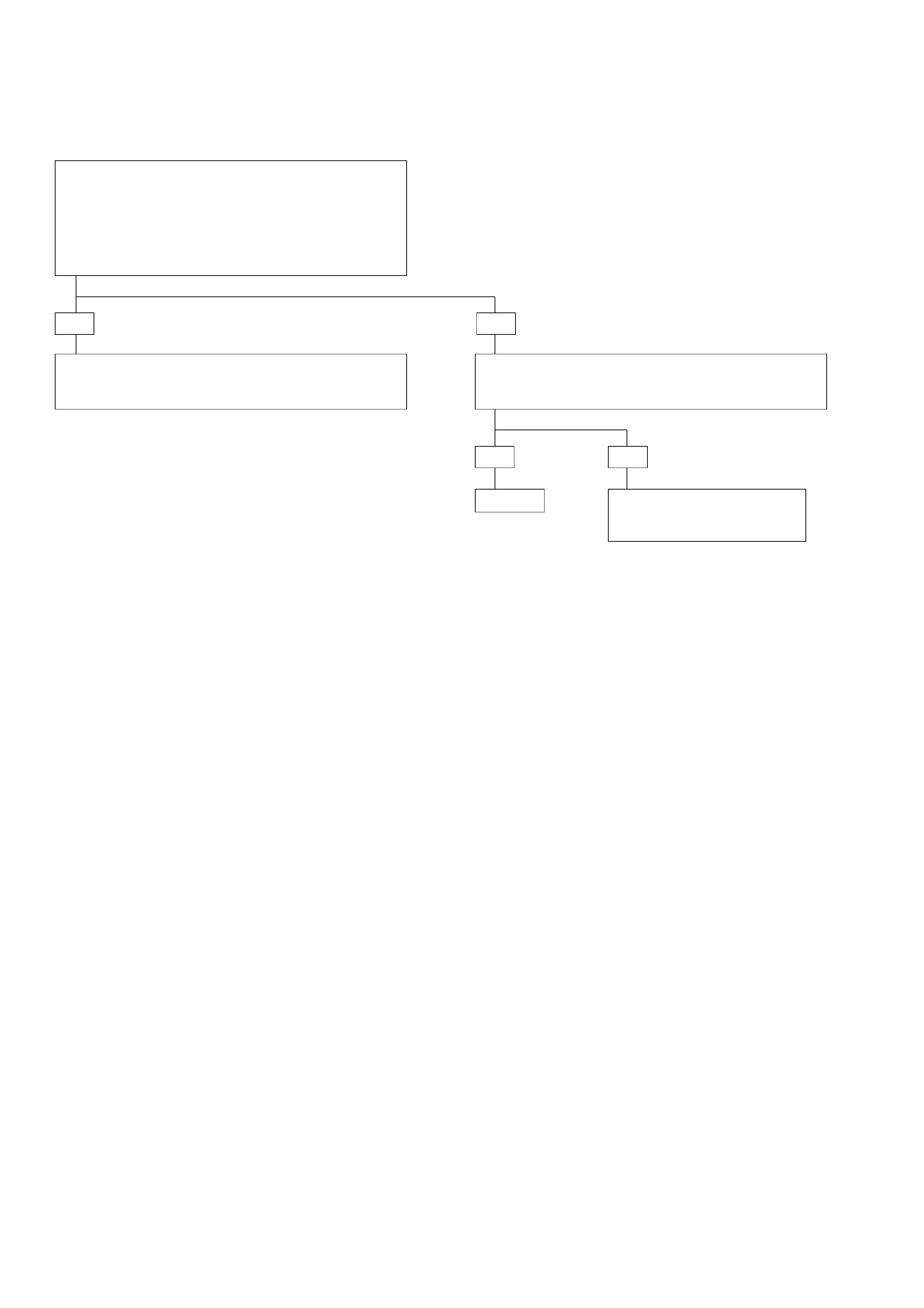
DIAGNOSTIC TROUBLE CODE (DTC) 41
SOLENOID A SHORT TO PLUS
•Ignition switch OFF.
•Disconnect Transmission Control Module (TCM)
connectors C-95 and C-96.
•Connect ohmmeter between connector C-96
terminals A2 and A7 (TCM ignition) then between A2
and A4 (TCM battery) then between A2 and C12.
IF: Short circuit:
YES
•Check for faulty connector or wiring between
terminal A2 and the shorted terminal.
•Repair.
The problem is intermittent.
GOTO INTERMITTENT
CONDITIONS.
NO
Repair.
YES
•Connect ohmmeter between A2 and A3 then between
A2 and A9.
IF: Short circuit:
NO

DIAGNOSTIC TROUBLE CODE (DTC) 42
SOLENOID B SHORT TO PLUS
This DTC flashes the CHECK TRANS indicator and
sets the BACKUP MODE.
Circuit Description:
•The solenoid B is a simple ON/OFF solenoid
located in the main case valve body. The
solenoid is the normally open-type. When the
port is open, fluid pressure actuates the shift
valve. In first or second gear the Transmission
Control Module (TCM) energizes the solenoid to
close a fluid inlet port.
•The solenoid is activated by a current. This
current is produced by applying a voltage to one
side (the High side) and a ground to the other
side (Low side).
•The High Side Driver (HSD) is a circuit of the TCM
that acts as a switch between the solenoids and
the supply voltage. The High side of the solenoid
is permanently supplied with voltage, except in
BACKUP MODE or when ignition is OFF the HSD
is turned OFF.
•The TCM continually monitors the solenoid
connection to its Low Side Driver (LSD) for either
low or high voltage. The LSD is a circuit of the
TCM that acts as a switch between the solenoid
and ground. When the solenoid is commanded
ON the TCM is switching the solenoid to ground.
•There are two tests of the LSD: when the engine
is cranked (DTC82) and when the ignition is
turned ON (DTC42).
•When the ignition is turned ON, and before the
engine is cranked, the TCM activates the shift
solenoids (A, B and Band) to check for short
circuits or open circuits. To do so the gear is set
to 4th, 3rd, 1st, 1st with band apply, 4th with no
HSD. Each one of the 5 tests requires 0.15
second. If the engine is cranked before the end of
all tests, the remaining tests are not done.
Diagnostic Aids:
•This diagnostic is an electrical test done by the
TCM.
•Detection conditions:
1The solenoid Low side connected to TCM
terminal A3 shorted to plus.
2The test is only done when ignition is ON.
3Engine Speed < 480 RPM (not cranked) and
Output Speed = 0 RPM.
4The condition needs to be present for 0.15 to
1.03 second after ignition switch ON.
•Action after the detection time: BACKUP MODE.
•Recovery conditions: To recover, do an IGNITION
CYCLE.
TRANSMISSION
CONTROL
MODULE (TCM)
SHIFT
SOLENOID
A
SHIFT
SOLENOID
B
BAND
APPLY
SOLENOID
AUTOMATIC
TRANSMISSION
M-7
3(D)
4(C)
BRN/WHT
YEL/GRN YEL/GRN 1(A)
BRN/BLK
H-23
H-23
YEL/BLK YEL/BLK
2(B) M-7
C12(12) 14
A2(2)
A3(3)
A9(9)
13
6
16
SHIFT &
BAND APPLY
SOLENOID
CONTROL
C-95
RED/BLU RED/BLU
GRN
A7(7)
A4(4) BATTERY
ECM MAIN RELAY
BATTERY
INPUT
IGNITION
INPUT
C-96
GROUND
BRN/WHT
BRN/BLK
D07LW018
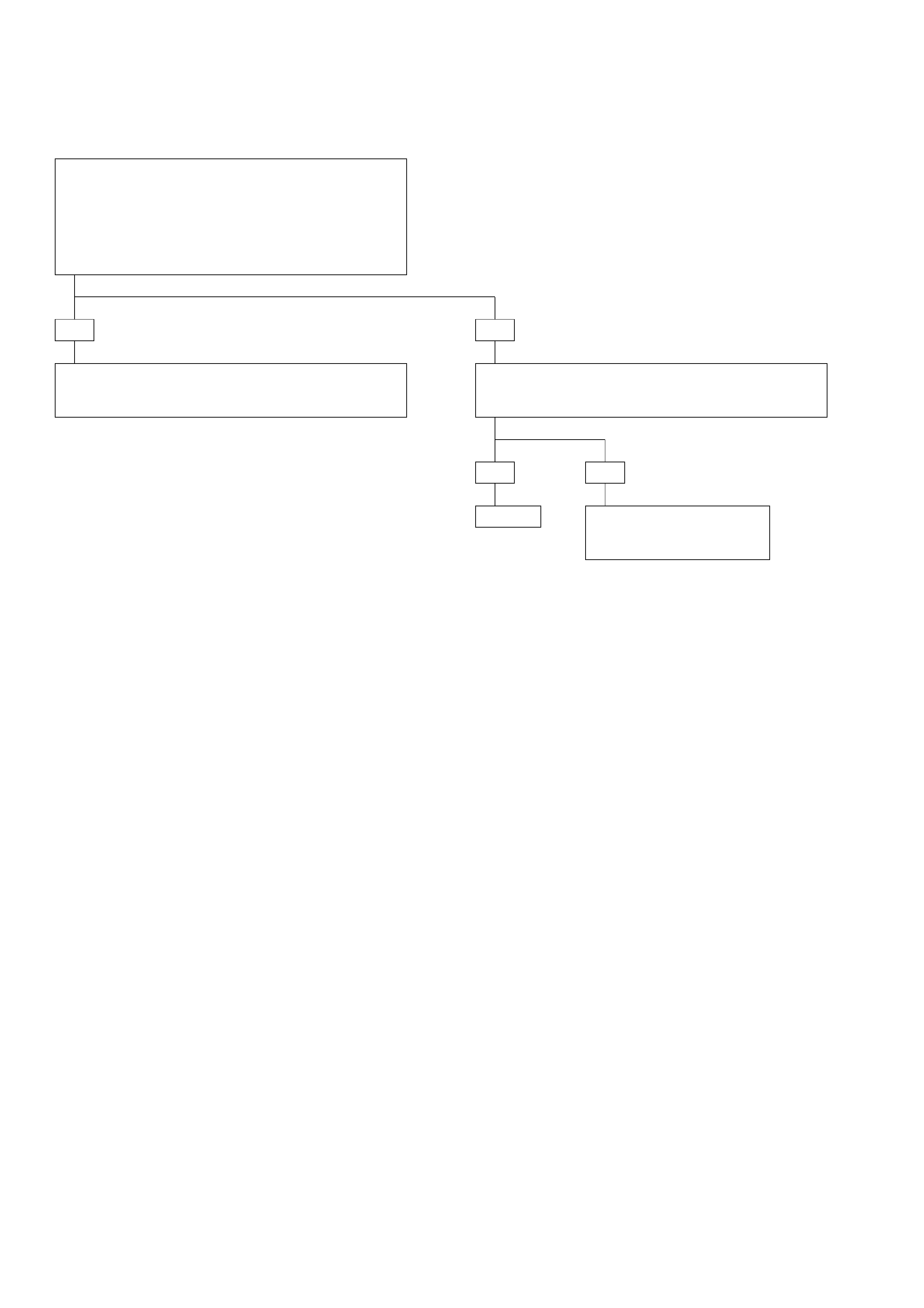
DIAGNOSTIC TROUBLE CODE (DTC) 42
SOLENOID B SHORT TO PLUS
•Ignition switch OFF.
•Disconnect Transmission Control Module (TCM)
connectors C-95 and C-96.
•Connect ohmmeter between connector C-96
terminals A3 and A7 (TCM ignition) then between A3
and A4 (TCM battery) then between A3 and C12.
IF: Short circuit:
YES
•Check for faulty connector or wiring between
terminal A3 and the shorted terminal.
•Repair.
•Connect ohmmeter between A3 and A2 then between
A3 and A9.
IF: Short circuit:
YES
Repair. The problem is intermittent.
GOTO INTERMITTENT
CONDITIONS.
NO
NO
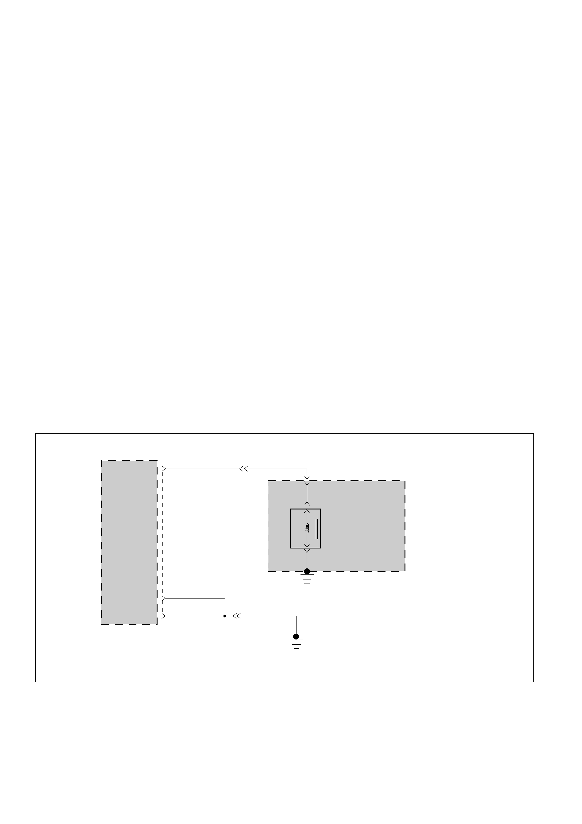
DIAGNOSTIC TROUBLE CODE (DTC) 43
TCC HIGH SHORT TO GROUND
This DTC does NOT flash the CHECK TRANS
indicator and does NOT set the BACKUP MODE.
Circuit Description:
•The Torque Converter Clutch (TCC) solenoid is a
simple ON/OFF solenoid connected to the
adapter case valve body. When the solenoid is
energized by the Transmission Control Module
(TCM), it opens a fluid port. When the port is
open, line pressure actuates the converter clutch
control valve which engages the torque converter
clutch by exhausting the fluid. The TCM engages
the torque converter clutch only when all of the
following conditions exist:
1The transmission is at operating temperature.
2The brake pedal is released.
3The transmission is operating in second, third
or fourth gear.
4The engine is warm (more than 70°C).
5The shift pattern requests TCC apply.
6Shift finished.
7No malfunction which will disable the TCC:
DTC33, DTC55 (only short to ground).
•The solenoid is activated by a current. This
current is produced by applying a voltage to one
side (the High side) and a ground to the other
side (Low side).
•The High Side Driver (HSD) is a circuit of the TCM
that acts as a switch between the solenoid and
the supply voltage. The High side of the TCC
solenoid is used to turn the TCC ON or OFF
because the Low side is permanently connected
to the ground of the transmission. In BACKUP
MODE or when ignition OFF the TCC High Side is
turned OFF.
•The TCM continually monitors the solenoid
connection of to its High Side Driver for either
low or high voltage.
•There is only one test of the HSD for TCC: when
the engine is cranked and the TCC is turned ON.
Diagnostic Aids:
•This diagnostic is an electrical test done by the
TCM.
•Detection conditions:
1The solenoid High side connected to TCM
terminal C7 is shorted to ground.
2The condition needs to be present for 0.07
seconds after ignition switch ON.
•Action after the detection time: TCC is turned
OFF.
•Recovery conditions: To recover, do an IGNITION
CYCLE.
TORQUE
CONVERTER
CLUTCH
SOLENOID
CONTROL
TRANSMISSION
CONTROL
MODULE (TCM)
AUTOMATIC
TRANSMISSION
M-6
4(A)
C-95
TORQUE
CONVERTER
CLUTCH
SOLENOID
H-23
12
RED/YEL
BLK BLK
BLK
7
H-25
C1(1)
D1(17)
C7(7) RED/YEL
D07LW013

DIAGNOSTIC TROUBLE CODE (DTC) 43
TCC HIGH SHORT TO GROUND
SHORT TO GROUND?
•Ignition switch OFF. Engine OFF.
•Disconnect Transmission Control Module (TCM)
connectors C-95 and C-96.
•Connect a ohmmeter between connector C-95
terminal C7 and car ground or with TCM ground
terminal C1.
IF: Short circuit:
YES
YES
•Install scan tool: TECH2 GOTHROUGH TECH2 CONNECTION.
While driving the car in 2nd, 3rd or 4th gear check if the TCC is
slipping or not when the TCC solenoid is commanded ON by
the TCM.
Push F0: DATA LIST:
Read TCC state and SLIP value.
IF you have a SCAN TOOL: TECH2 ?
NO
Without TECH2 you can not do preliminary test.
CASE: DTC 33
GOTO DTC33.
The problem is intermittent.
GOTO INTERMITTENT CONDITIONS.
The TCC is shorted to ground.
•Check wiring between
terminal C7 and ground.
•Repair.
CASE: SLIP > 20 RPM with
TCC = ON
This means that the TCC valve
is stuck OFF or the TCC
solenoid connections are
shorted to ground.
NO
TCC: Torque Converter Clutch
TCM: Transmission Control Module
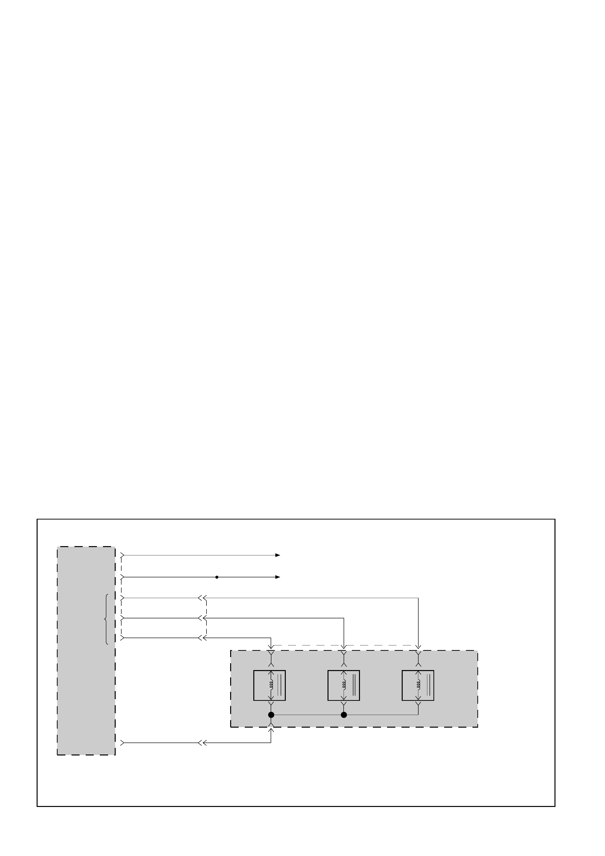
DIAGNOSTIC TROUBLE CODE (DTC) 44
BAND APPLY SOLENOID SHORT TO PLUS
This DTC flashes the CHECK TRANS indicator and
sets the BACKUP MODE.
Circuit Description:
•The band apply solenoid is a normally open
solenoid which controls the flow of fluid for brake
band application. The Transmission Control
Module (TCM) uses Pulse Width Modulation
(PWM) and changes the duty cycle to control the
solenoid. The TCM turns the solenoid ON
(energized) and OFF (de-energized) at a constant
frequency. The length of time the solenoid is
energized during each ON/OFF cycle is called the
pulse width. By varying or “modulating” the
pulse width, the solenoid output pressure is
changed. Since the solenoid is normally closed,
increasing the pulse width increases the duty
cycle and decreases the output pressure. PWM
control provides smooth band application
without an accumulator. The band is only applied
in first and second gears.
•In the event of an electrical failure (open), the
solenoid regulates at the maximum oil flow (0%
duty cycle).
•The solenoid is activated by a current. This
current is produced by applying a voltage to one
side (the High side) and a ground to the other
side (Low side).
•The High Side Driver (HSD) is a circuit of the TCM
that acts as a switch between the solenoids and
the supply voltage. The High side of the solenoid
is permanently supplied with voltage, except in
BACKUP MODE or when ignition is OFF the HSD
is turned OFF.
•The TCM continually monitors the solenoid
connection to its Low Side Driver (LSD) for either
low or high voltage. The LSD is a circuit of the
TCM that acts as a switch between the solenoid
and ground. When the solenoid is commanded
ON the TCM is switching the solenoid to ground.
•There are two tests of the LSD: when the engine
is cranked (DTC82) and when the ignition is
turned ON (DTC44).
•When the ignition is turned ON, and before the
engine is cranked, the TCM activates the shift
solenoids (A, B and Band) to check for short
circuits or open circuits. To do so the gear is set
to 4th, 3rd, 1st, 1st with band apply, 4th with no
HSD. Each one of the 5 tests requires 0.15
second. If the engine is cranked before the end of
all tests, the remaining tests are not done.
Diagnostic Aids:
•This diagnostic is an electrical test done by the
TCM.
•Detection conditions:
1The solenoid Low side connected to TCM
terminal A9 is shorted to voltage.
2The test is only done when ignition is ON.
3Engine Speed < 480 RPM (not cranked) and
Output Speed = 0 RPM.
4The condition needs to be present for 0.15 to
1.18 second after ignition switch ON.
•Action after the detection time: BACKUP MODE.
•Recovery conditions: To recover, do an IGNITION
CYCLE.
TRANSMISSION
CONTROL
MODULE (TCM)
SHIFT
SOLENOID
A
SHIFT
SOLENOID
B
BAND
APPLY
SOLENOID
AUTOMATIC
TRANSMISSION
M-7
3(D)
4(C)
BRN/WHT
YEL/GRN YEL/GRN 1(A)
BRN/BLK
H-23
H-23
YEL/BLK YEL/BLK
2(B) M-7
C12(12) 14
A2(2)
A3(3)
A9(9)
13
6
16
SHIFT &
BAND APPLY
SOLENOID
CONTROL
C-95
RED/BLU RED/BLU
GRN
A7(7)
A4(4) BATTERY
ECM MAIN RELAY
BATTERY
INPUT
IGNITION
INPUT
C-96
GROUND
BRN/WHT
BRN/BLK
D07LW018
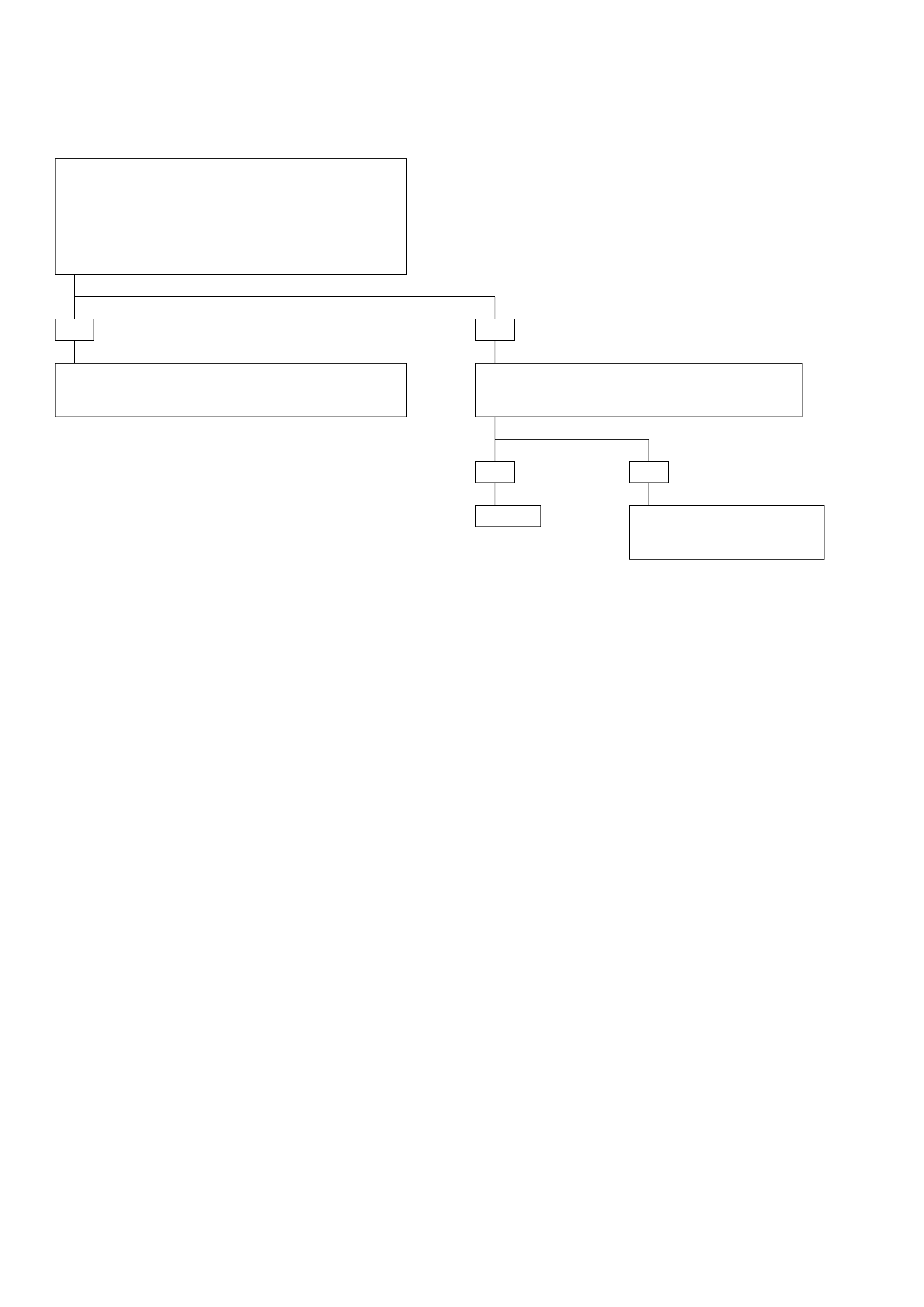
DIAGNOSTIC TROUBLE CODE (DTC) 44
BAND APPLY SOLENOID SHORT TO PLUS
•Ignition switch OFF.
•Disconnect Transmission Control Module (TCM)
connectors C-95 and C-96.
•Connect ohmmeter between connector C-96
terminals A9 and A7 (TCM ignition) then between A9
and A4 (TCM battery) then between A9 and C12.
IF: Short circuit:
YES
•Check for faulty connector or wiring between
terminal A9 and the shorted terminal.
Repair.
NO
•Connect ohmmeter between A9 and A2 then
between A9 and A3.
IF: Short circuit:
YES NO
Repair. The problem is intermittent.
GOTO INTERMITTENT
CONDITIONS.
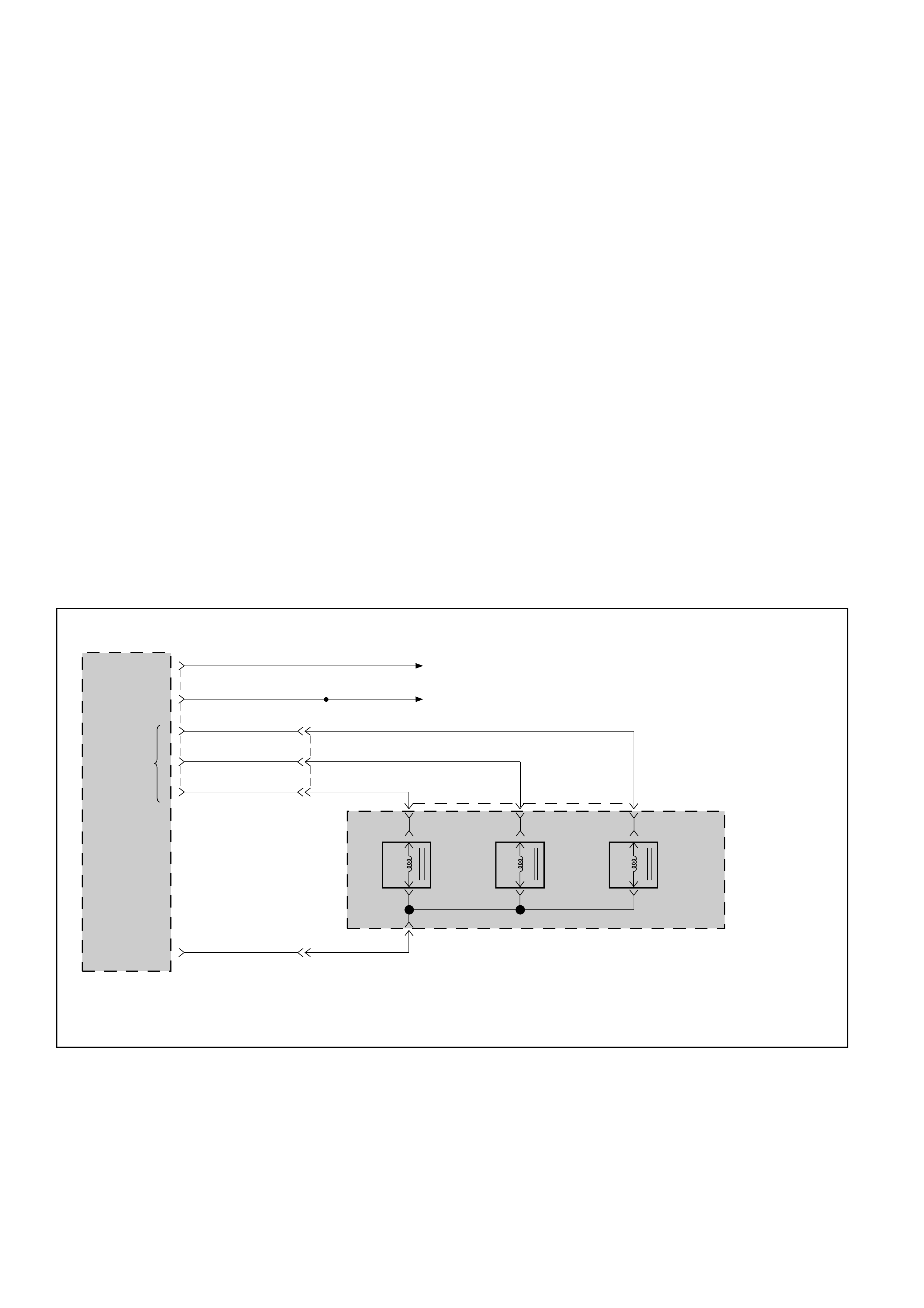
DIAGNOSTIC TROUBLE CODE (DTC) 46
SHIFT HIGH SHORT TO PLUS
This DTC flashes the CHECK TRANS indicator and
sets the BACKUP MODE.
Circuit Description:
•The solenoids are activated by a current. This
current is produced by applying a voltage to one
side (the High side) and a ground to the other
side (Low side).
•The High Side Driver (HSD) is a circuit of the
Transmission Control Module (TCM) that acts as
a switch between the solenoids and the supply
voltage. The High side of the solenoid is per-
manently supplied with voltage, except in
BACKUP MODE or when ignition is OFF the High
Side Driver is turned OFF.
•The TCM continually monitors the solenoid
connection to its High Side Driver for either low
or high voltage.
•There are two tests of the HSD: when the engine
is cranked (DTC82) and when the ignition is
turned ON (DTC46).
•When the ignition is turned ON, and before the
engine is cranked, the TCM activates the shift
solenoids (A, B and Band) to check for short
circuits or open circuits. To do so the gear is set
to 4th, 3rd, 1st, 1st with band apply, 4th with no
HSD. Each one of the 5 tests requires 0.15
second. If the engine is cranked before the end of
all tests, the remaining tests are not done.
Diagnostic Aids:
•This diagnostic is an electrical test done by the
TCM.
•Detection conditions:
1The solenoid High side connected to TCM
terminal C12 is shorted to voltage.
2The test is only done when ignition is ON.
3Engine Speed < 480 RPM (not cranked) and
Output Speed = 0 RPM.
4The condition needs to be present for 0.15 to
1.34 second after ignition switch ON.
•Action after the detection time: BACKUP MODE.
•Recovery conditions: To recover, do an IGNITION
CYCLE.
TRANSMISSION
CONTROL
MODULE (TCM)
SHIFT
SOLENOID
A
SHIFT
SOLENOID
B
BAND
APPLY
SOLENOID
AUTOMATIC
TRANSMISSION
M-7
3(D)
4(C)
BRN/WHT
YEL/GRN YEL/GRN 1(A)
BRN/BLK
H-23
H-23
YEL/BLK YEL/BLK
2(B) M-7
C12(12) 14
A2(2)
A3(3)
A9(9)
13
6
16
SHIFT &
BAND APPLY
SOLENOID
CONTROL
C-95
RED/BLU RED/BLU
GRN
A7(7)
A4(4) BATTERY
ECM MAIN RELAY
BATTERY
INPUT
IGNITION
INPUT
C-96
GROUND
BRN/WHT
BRN/BLK
D07LW018

•Ignition switch OFF.
•Disconnect Transmission Control Module (TCM)
connectors C-95 and C-96.
•Connect ohmmeter between connector C-95 terminal
C12 and connector C-96 terminal A7 (TCM ignition)
then between C12 and A4 (TCM battery).
IF: Short circuit:
YES
•Check for faulty connector or wiring between
terminal C12 and the shorted terminal.
Repair.
NO
The problem is intermittent.
GOTO INTERMITTENT CONDITIONS.
DIAGNOSTIC TROUBLE CODE (DTC) 46
SHIFT HIGH SHORT TO PLUS
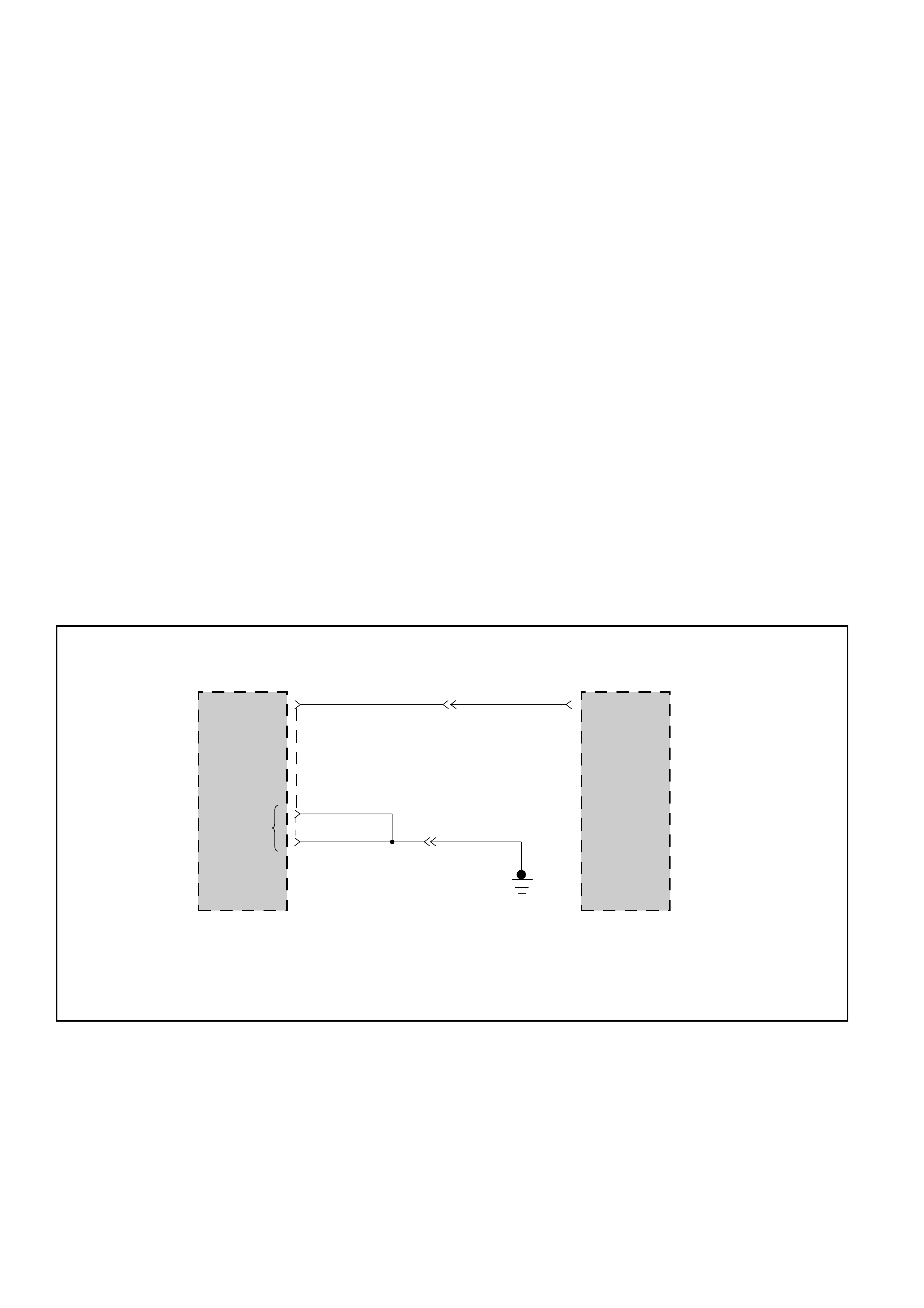
DIAGNOSTIC TROUBLE CODE (DTC) 51
ENGINE COOLANT SWITCH SHORT TO GROUND, PLUS OR OPEN
This DTC does NOT flash the CHECK TRANS
indicator and does NOT set the BACKUP MODE.
Circuit Description:
•The Engine Coolant Temperature is measured by
a sensor in the coolant system. This information
is used by the Engine Control Module (ECM) for
the engine. The ECM provides the information:
Engine Warm to the Transmission Control
Module (TCM) when the ECM measures a
temperature higher than 70°C (158°F).
•The information is provided using a wire
between the ECM terminal 10 and the TCM
terminal D14. When the engine is warm the ECM
connects its terminal 10 to ground using a Low
Side Driver. When the engine is Cold the ECM
lets this wire open and the TCM pulls it up to 5
volts.
•When Ignition is ON and Engine is OFF: the ECM
always sends the information “engine cold” even
if the engine is warm. The information is valid
only when the engine is ON.
Diagnostic Aids:
•This Diagnostic is not an electrical test done by
the TCM but a test between different information
(“logic test”).
•Detection conditions of engine always cold:
1Engine seen as cold: wire short to voltage or
open.
2Transmission Oil Temperature >150°C (302°F)
or more than 20 minutes since last ignition
cycle.
3Detection conditions need to be present for at
least 25 seconds.
•Detection conditions of engine always warm:
1Engine seen as warm: wire short to ground.
2Transmission Oil Temperature < 0°C (32°F).
3Without problem on Transmission Tem-
perature sensor then: voltage on A/T Oil
Temperature sensor <4.74 V.
4Detection conditions need to be present for at
least 6 seconds.
•Action after the detection time: No action.
•Recovery conditions: To recover, Engine Coolant
Temperature change information need to be
present for more than 6 seconds.
ENGINE
COOLANT
TEMPERATURE
INPUT
TRANSMISSION
CONTROL
MODULE (TCM)
C-95
ENGINE
COOLANT
TEMPERATURE
OUTPUT
ENGINE
CONTROL
MODULE (ECM)
10
E-61
6
H-25
BRN BRN
H-25
BLK BLK
BLK
7
C1(1)
D1(17)
GROUND
D14(30)
D07LW019
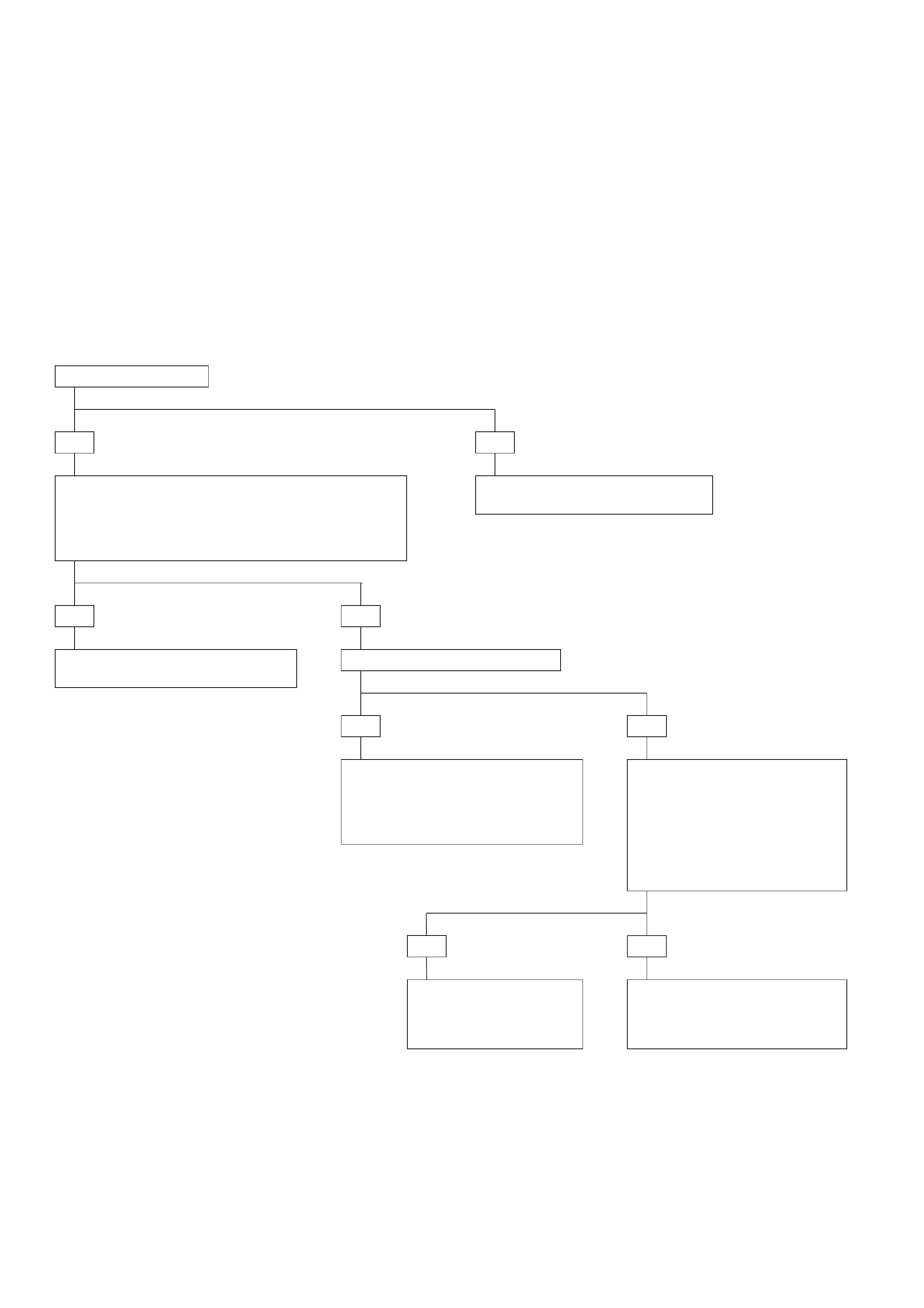
DIAGNOSTIC TROUBLE CODE (DTC) 51
ENGINE COOLANT SWITCH SHORT TO GROUND, PLUS OR OPEN
IF: You see a problem:
•This DTC can be set when there is no problem at
all. This is due to the fact that when the engine
stalls the ignition is still ON then Engine Control
Module (ECM) provides a false information:
engine cold. The Transmission Control Module
(TCM), knowing that the last ignition cycle
happened more than 20 minutes ago, then sets
DTC51.
•Using the Scan Tool you can check with TECH2:
F0: ENG. TEMP. SW information. When the
engine is cold or when the engine is OFF the
TECH2 should show: COLD. When the engine is
warm the TECH2 should show WARM.
•This DTC is not very important. In the worst case
it would not allow the Torque Converter Clutch
(TCC) to be applied. This will cause low fuel
economy.
YES
•Check voltage between connector C-95 terminal D14
and connector C-95 terminal C1 (TCM ground).
•Ignition switch ON. Engine ON.
Engine warm.
IF: Voltage higher than 5 volts:
NO
There is not currently a problem.
GOTO INTERMITTENT CONDITIONS.
YES
•There is a short circuit to voltage.
•Repair.
NO
IF: Voltage approx. 5 volts:
YES
•This is an open circuit or the ECM
is not sending the correct
information. See also ECM
information, Section 6E.
•Repair.
NO
•Voltage approx. 0 volts means
that the signal is OK or that
there is a short circuit to
ground.
•Turn the engine OFF with the
ignition ON.
IF: The voltage goes back to 5
volts:
NOYES
There is not currently a
problem.
GOTO INTERMITTENT
CONDITIONS.
•As the voltage is staying at 0
volts, there is a short to
ground.
•Repair.
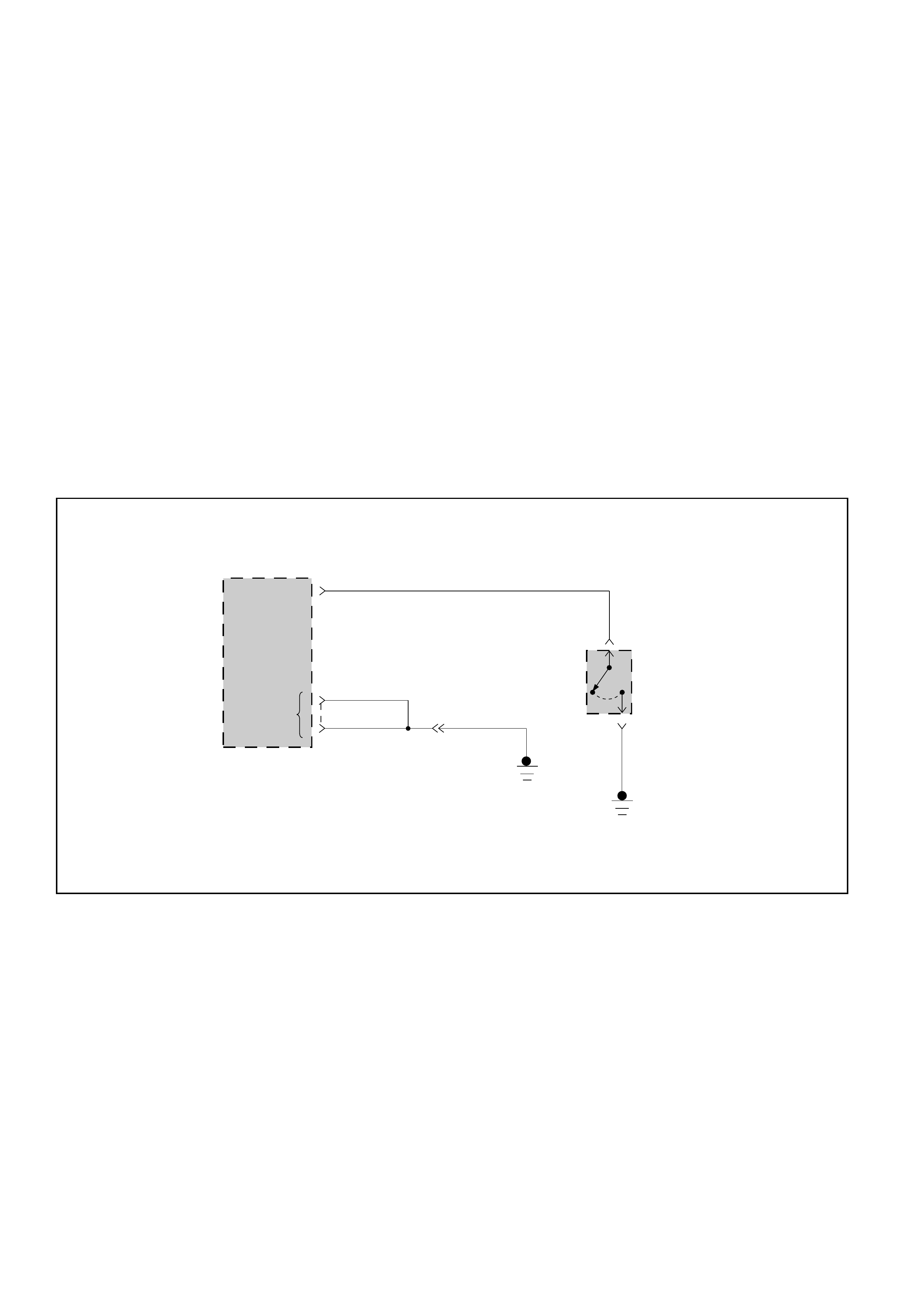
DIAGNOSTIC TROUBLE CODE (DTC) 52
KICK DOWN ALWAYS ON OR SHORT TO GROUND
This DTC does NOT flash the CHECK TRANS
indicator and does NOT set the BACKUP MODE.
Circuit Description:
•When the driver presses the accelerator pedal
down fully, the kick down switch closes, sending
a ground signal to the Transmission Control
Module (TCM).
•This information is used to do shifts with a high
Engine Speed RPM.
•When the kick down switch is closed the Throttle
Position Sensor (TPS) is already at 100%.
Diagnostic Aids:
•This diagnostic is not an electrical test done by
the TCM but a test between different information
(“logic test”).
•Detection conditions:
1Kick down switch ON (short to ground) and
TPS <70%.
2No malfunction: TPS short to voltage or
ground (DTC21 and DTC22).
3The conditions need to be present for at least
1 second.
•Action after the detection time: Kick Down
information not taken into account.
•Recovery conditions: To recover, Kick Down
needs to be seen as OFF during detection time.
KICK
DOWN
SWITCH
INPUT
TRANSMISSION
CONTROL
MODULE (TCM)
C-96
KICK DOWN
SWITCH
C-94
1
2
C-94
BLU
BLK BLK
BLK
7
H-25
C1(1)
C-95
D1(17)
GROUND
BLK
B5(17)
D07LW020

DIAGNOSTIC TROUBLE CODE (DTC) 52
KICK DOWN ALWAYS ON OR SHORT TO GROUND
IF: DTC 23 Throttle Position Sensor (TPS) connector
open too:
YES
GOTO DTC 23.
NO
•Ignition switch ON. Engine OFF.
•Accelerator pedal not depressed.
•Connect a voltmeter between connector C-96
terminal B5 and connector C-95 terminal C1 (TCM
ground).
IF: Display approx. 0 volts:
YES
•Check the wires and connector
and the switch to detect the
short to ground.
•Repair.
NO
The problem is
intermittent. GOTO
INTERMITTENT
CONDITIONS.

DIAGNOSTIC TROUBLE CODE (DTC) 53
MODE SWITCH IN P OR N OR R BAD POSITION
This DTC does NOT flash the CHECK TRANS
indicator and does NOT set the BACKUP MODE.
Circuit Description:
•The mode switch supplies the Transmission
Control Module (TCM) with information regard-
ing the selector lever position: P, R, N, D, 3, 2 or
L. The selector lever position is indicated by the
state of four ON/OFF contacts. The mode switch
is located on one side of the transmission. It is on
the transmission manual shaft and is fixed to the
main case.
•The mode switch is also used to provide the
information P or N to the engine crank wiring.
The engine can be cranked only if connector M-25
terminal 4(H) is connected to terminal 1(E), which
is connected to ground.
•The mode switch is also used to provide the back
up lamp power in reverse. This is the reason why
the mode switch is supplied through a 15A fuse
(CB-11). This fuse can burn due to short circuit in
the back up lamp.
•When this fuse is open, the mode switch does
not work and DTC54 is set.
•The mode position is defined by the shift linkage
which is a link between the shift lever and the
mode switch. A bad adjustment of the shift link-
age can create a mode switch problem (DTC53).
Diagnostic Aids:
•This Diagnostic is not an electrical test done by
the TCM but a test between different information
(“logic test”).
•Detection conditions of P or N bad position:
1A/T Input Speed <3000 RPM
2TPS > 20%
3Mode Switch = P or N
4No malfunction: TPS short to voltage or
ground (DTC 21, DTC22), Engine Speed
(DTC13).
5The conditions need to be present for at least
4 seconds.
•Action after the detection time: Default position
assumed for pressure calculation and shift
pattern = always in D.
•Recovery Conditions: To recover, have the engine
speed higher than 3000 RPM with a TPS higher
than 20% when the mode switch is not in P or N.
•Detection conditions of R bad position:
1
A/T Output Speed > 3200 RPM (approx. 100 KPH)
2Mode Switch = R
3No malfunction: Output speed (DTC11).
Downshift Protection (DTC62).
4The conditions need to be present for at least
4 seconds.
•Action after the detection time: Default position
assumed for pressure calculation and shift
pattern = always in D.
•Recovery conditions: To recover, have the output
speed higher than 3200 RPM when the mode
switch is not R.
AUTOMATIC
TRANSMISSION
MODE
SWITCH
PIN C
CB-11
15A
7(B)2(F) 6(C)
FUSE BOX
TRANSMISSION CONTROL INPUTS
M-25
5(D)
TRANSMISSION
CONTROL
MODULE (TCM)
3(G)
4123
8(A) M-25
C-95
1
2
D3
N
R
P
1
2
D3
N
R
P
1
2
D3
N
R
P
1
2
D3
N
R
P
PIN B PIN A PIN G
WHT
BLU/WHT BLU/RED BLU BLU/BLK
BLU/WHT
RED/YEL BLU/RED BLU BLU/BLK
H-23
D5(21) D6(22) D7(23) D4(20)
PIN F
BACK UP
LAMP
PIN E
1(E)
4(H) M-25
BRN/YEL
STARTER RELAY
BLK
D07LW021
DIAGNOSTIC TROUBLE CODE (DTC) 53
MODE SWITCH IN P OR N OR R BAD POSITION
IF: DTC 23 Throttle Position Sensor (TPS) connector
open or DTC 13 Engine speed, DTC 54 Mode switch
illegal position exists:
YES
GOTO DTC13 or
DTC23 or DTC 54 first.
NO
•Install scan tool GOTHROUGH TECH2 CONNECTION.
•Ignition switch ON. Engine running.
•Selector lever position “P”.
•Select F0: DATALIST: “TOP SIGNAL” or F0: DATA LIST: “AT INPUT SPEED”.
IF: Display does not change with engine speed or TPS:
YES
DTC 23 or DTC 13 not detected
but are the reason for this
DTC 53.
GOTO DTC13 or DTC23.
NO
•Ignition switch ON.
•Select F0: DATALIST: “SELECTOR POS.”.
•Move shift selector lever through all positions
and compare results with table 1.
IF: all selector pin displays correct:
NOYES
The problem is
intermittent. GOTO
INTERMITTENT
CONDITIONS.
•Check automatic transmission mode switch
adjustment. GOTHROUGH MODE SWITCH
SETTING PROCEDURE (PAGE: 7A1-147)
•Repair.
Table 1
Note: “X” indicates TECH2 displays “ACTIVE”.
SHIFT SELECTOR POSITION
TECH1 DISPLAY P R N D 3 2 L
SELECTOR PIN A X X X X
SELECTOR PIN B X X X X
SELECTOR PIN C X X X X
SELECTOR PIN P X X X X
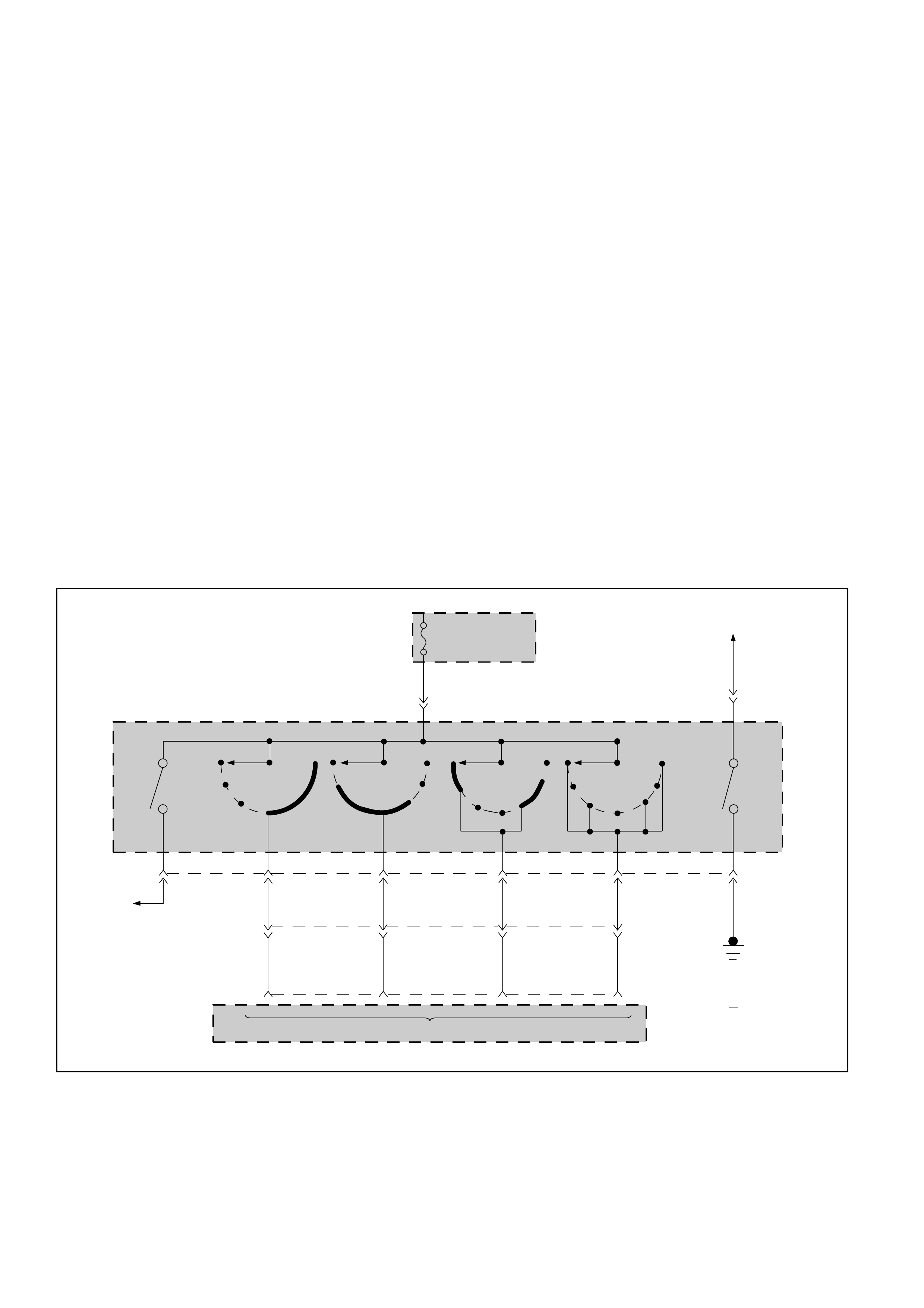
DIAGNOSTIC TROUBLE CODE (DTC) 54
MODE SWITCH ILLEGAL POSITION
This DTC flashes the CHECK TRANS indicator and
sets the BACKUP MODE.
Circuit Description:
•The mode switch supplies the Transmission
Control Module (TCM) with information re-
garding the selector lever position: P, R, N, D, 3, 2
or L. The selector lever position is indicated by
the state of four ON/OFF contacts. The mode
switch is located on one side of the transmission.
It is on the transmission manual shaft and is fixed
to the main case.
•The mode switch is also used to provide the
information P or N to the engine crank wiring.
The engine can be cranked only if connector M-25
terminal 4(H) is connected to terminal 1(E), which
is connected to ground.
•The mode switch is also used to provide the back
up lamp power in reverse. This is the reason why
the mode switch is supplied through a 15A fuse
(CB-11). This fuse can burn due to short circuit in
the back up lamp.
•When this fuse is open, the mode switch does
not work and DTC54 is set.
•The mode position is defined by the shift linkage
which is a link between the shift lever and the
mode switch. A bad adjustment of the shift
linkage can create a mode switch problem
(DTC53).
Diagnostic Aids:
•This Diagnostic is an electrical test done by the
TCM.
•Detection conditions:
1Selector Pin A and Pin B and Pin C are not
active: no position is identified then.
2Based upon Table 1, in Park shift selector
position the code is set when Pin A is open or
shorted to ground.
3The conditions need to be present for at least
5 seconds.
•Action after the detection time: BACKUP MODE
•Recovery conditions: To recover, do an IGNITION
CYCLE.
AUTOMATIC
TRANSMISSION
MODE
SWITCH
PIN C
CB-11
15A
7(B)2(F) 6(C)
FUSE BOX
TRANSMISSION CONTROL INPUTS
M-25
5(D)
TRANSMISSION
CONTROL
MODULE (TCM)
3(G)
4123
8(A) M-25
C-95
1
2
D3
N
R
P
1
2
D3
N
R
P
1
2
D3
N
R
P
1
2
D3
N
R
P
PIN B PIN A PIN G
WHT
BLU/WHT BLU/RED BLU BLU/BLK
BLU/WHT
RED/YEL BLU/RED BLU BLU/BLK
H-23
D5(21) D6(22) D7(23) D4(20)
PIN F
BACK UP
LAMP
PIN E
1(E)
4(H) M-25
BRN/YEL
STARTER RELAY
BLK
D07LW021
DIAGNOSTIC TROUBLE CODE (DTC) 54
MODE SWITCH ILLEGAL POSITION
Table 1
Note: “X” indicates TECH2 displays “ACTIVE”.
SHIFT SELECTOR POSITION
TECH1 DISPLAY P R N D 3 2 L
SELECTOR PIN A X X X X
SELECTOR PIN B X X X X
SELECTOR PIN C X X X X
SELECTOR PIN P X X X X
•Install scan tool GOTHROUGH TECH2 CONNECTION.
•Ignition switch ON. Engine OFF.
•Selector F0: DATALIST: “SELECTOR POS”.
•Move shift selector lever through all positions and
compare results with Table 1.
IF: all selector pin displays correct:
YES NO
The problem is
intermittent.
GOTO INTERMITTENT
CONDITIONS.
IF: all selector pin displays
incorrect:
YES NO
•Check fuse and wire to connector M-25
terminal 5 (D) for opens.
GOTHROUGH MODE SWITCH SETTING
PROCEDURE (PAGE: 7A1-147).
If problem not solved, replace mode
switch.
•Disconnect mode switch connector M-
25.
•Connect ohmmeter between terminal
5(D) and respectively all terminals of
mode switch connector M-25.
•Move shift selector lever through all
positions and compare results with
Table 1.
IF: One selector pin display is incorrect:
NOYES
•Check the wire and connector.
•Repair. •Check wire to cruise control unit and
Transmission Control Module (TCM).
•Repair.

DIAGNOSTIC TROUBLE CODE (DTC) 55
BRAKE SWITCH SHORT TO GROUND OR OPEN
This DTC does NOT flash the CHECK TRANS
indicator and does NOT set the BACKUP MODE.
Circuit Description:
•The brake switch is a switch on the brake pedal
that is used to provide the information: brakes
are applied. This is used by different features:
cruise control, stop light and Transmission
Control Module (TCM).
•The TCM uses the information (brakes applied)
mainly to release the Torque Converter Clutch
(TCC).
•The brake switch input is constantly connected to
battery when the pedal is pressed. TCM terminal
D9 is connected to Voltage.
•The brake switch input is opened when the pedal
is released. TCM terminal D9 is grounded.
Diagnostic Aids:
•This Diagnostic is not an electrical test done by
the TCM but a test between different information
(“logic test”).
•Detection conditions:
1Brake seen as applied during an acceleration
from less than 10 Km/h to more than 60 Km/h
within 6 seconds.
2After this acceleration the vehicle speed was
higher than 60 Km/h during at least 6
seconds.
3No Malfunction: Output Speed (DTC11).
Downshift Protection (DTC62).
4The conditions need to be present for at least
5 times during an ignition cycle.
•Action after the detection time: No action but, as
the brake is seen as applied, the TCC is never
applied.
•Recovery conditions: To recover, brake has to be
released.
BRAKE SW
INPUT
TRANSMISSION
CONTROL
MODULE (TCM)
C-95
H-25
BLK BLK
BLK
7
C1(1)
D1(17)
GROUND
D9(25) RED RED GRN
C-44
2
C-44
1FUSE EB-10(10A)
STOP LAMP SW
D07LW022

DIAGNOSTIC TROUBLE CODE (DTC) 55
BRAKE SWITCH SHORT TO GROUND OR OPEN
•Install scan tool GOTHROUGH TECH2 CONNECTION.
•Ignition switch ON. Engine ON.
•Select F0: DATA LIST: “BRAKE SWITCH”.
•Apply brake.
IF: Display is “NOT ACTIVE”:
YES NO
•Check the short circuit
to ground or open.
•Repair.
The problem is
intermittent.
GOTO INTERMITTENT
CONDITIONS.
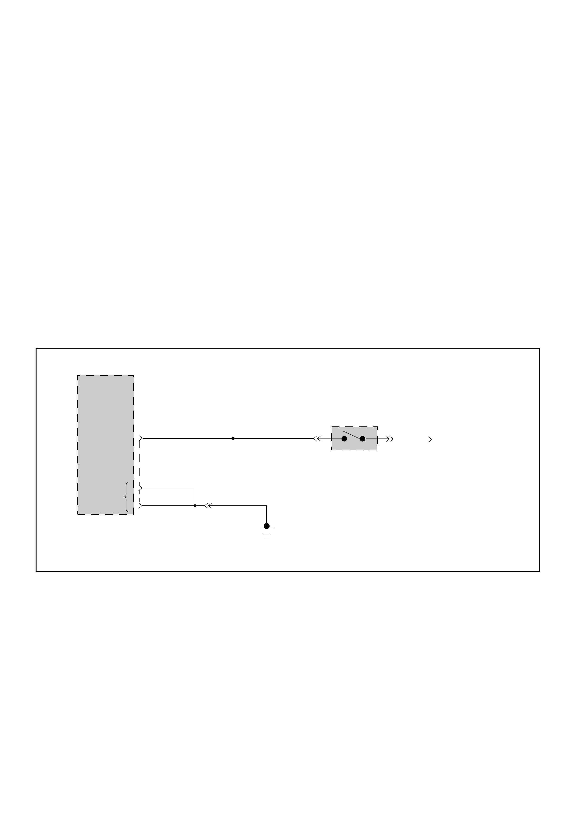
DIAGNOSTIC TROUBLE CODE (DTC) 56
BRAKE SWITCH SHORT TO PLUS
This DTC does NOT flash the CHECK TRANS
indicator and does NOT set the BACKUP MODE.
Circuit Description:
•The brake switch is a switch on the brake pedal
that is used to provide the information: brakes
are applied. This is used by different features:
cruise control, stop light and Transmission
Control Module (TCM).
•The TCM uses the information (brakes applied)
mainly to release the Torque Converter Clutch
(TCC).
•The brake switch input is constantly connected to
battery when the pedal is pressed. TCM terminal
D9 is connected to Voltage.
•The brake switch input is opened when the pedal
is released. TCM terminal D9 is grounded.
Diagnostic Aids:
•This Diagnostic is not an electrical test done by
the TCM but a test between different information
(“logic test”).
•Detection conditions:
1Brake seen as released during a deceleration
from more than 60 Km/h to less than 10 Km/h
within 6 seconds.
2Before this deceleration the car vehicle speed
was higher than 60 Km/h during at least 6
seconds.
3No Malfunction: Output Speed (DTC11).
Downshift Protection (DTC62).
4The conditions need to be present for at least
5 times during an ignition cycle.
•Action after the detection time: No action but, as
the brake is seen as released, the TCC is applied
even when the brake is applied.
•Recovery conditions: To recover, brake has to be
released.
BRAKE SW
INPUT
TRANSMISSION
CONTROL
MODULE (TCM)
C-95
H-25
BLK BLK
BLK
7
C1(1)
D1(17)
GROUND
D9(25) RED RED GRN
C-44
2
C-44
1FUSE EB-10(10A)
STOP LAMP SW
D07LW022

•Install scan tool GOTHROUGH TECH2 CONNECTION.
•Ignition switch ON. Engine ON.
•Select F0: DATA LIST: “BRAKE SWITCH”.
•Do not touch brake.
IF: Display is “NOT ACTIVE”:
YES
DIAGNOSTIC TROUBLE CODE (DTC) 56
BRAKE SWITCH SHORT TO PLUS
NO
The problem is
intermittent.
GOTO INTERMITTENT
CONDITIONS.
•Check the short circuit
to voltage.
•Repair.

DIAGNOSTIC TROUBLE CODE (DTC) 61
GEAR ERROR
This DTC flashes the CHECK TRANS indicator and
sets the BACKUP MODE.
Circuit Description:
•The Transmission Control Module (TCM) is
calculating the slippage of the Converter and
transmission based upon the Engine Speed, the
Output Speed and the current gear ratio.
•The slippage of the converter at a high enough
engine speed is low. Then the transmission
should not slip more than a given value when
there is no shift.
Diagnostic Aids:
•This Diagnostic is not an electrical test done by
the TCM but a test between different information
(“logic test”).
•Detection conditions:
1Engine Speed > 3500 RPM
2Using the ratio of the current gear the
Converter Slippage is calculated based upon
the engine speed and the output speed. This
slippage must be more than:
528 RPM in 4th gear
536 RPM in 3rd gear
556 RPM in 2nd gear
595 RPM in 1st gear
3No malfunction: Engine Speed (DTC 13).
Output Speed (DTC 11). Downshift Protection
(DTC 62).
4The last change of shift solenoid was more
than 3 seconds ago.
5The conditions need to be present for at least
5.5 seconds.
•Action after the detection time: BACKUP MODE.
•Recovery conditions: To recover, do an IGNITION
CYCLE.
NOTE:
The TCC slip data is a calculated value, and not an
accurate one.
This value should be used to see if the TCC is
engaged or not.

DIAGNOSTIC TROUBLE CODE (DTC) 61
GEAR ERROR
IF the car has been in BACKUP MODE when the problem
occurred:
YES
IF there is another DTC which causes Backup Mode
(DTC20, DTC21, DTC22, DTC23, DTC25, DTC26, DTC31,
DTC32, DTC34, DTC35, DTC36, DTC37, DTC41, DTC42,
DTC44, DTC46, DTC54, DTC63, DTC82):
YES
Verify this other diagnosis first (because,
in backup mode the DTC61 is detected in
Manual 2 at high engine speed though
there is no problem). GOTO next DTCs.
NO
IF there is other DTC:
YES
Do a test drive to reproduce the
problem using the DRIVER
INFORMATION.
NO GOTO next DTCs.
IF reproduced without Backup
Mode:
REPLACE TCM
NO

DIAGNOSTIC TROUBLE CODE (DTC) 62
DOWNSHIFT PROTECTION
This DTC flashes the CHECK TRANS indicator and
sets the BACKUP MODE.
Circuit Description:
•The output speed information is used to
determine if the transmission has to upshift or
downshift.
•If this information suddenly changes due to an
open circuit or some electrical interference the
transmission would downshift.
•To avoid this the Transmission Control Module
(TCM) is constantly checking the variations of the
Output Speed. If this variation is too great (too
much decrease or increase) DTC62 is set. This
variation is taken into amount only when the
output speed is more than 2900 RPM (approx. 90
KPH).
•The transmission output speed sensor provides
information on vehicle speed to the TCM. The
speed sensor circuit consists of a magnetic
induction type sensor. The sensor is mounted
above a target wheel pressed on the output shaft
in the transmission extension. As the output shaft
turns, the target wheel teeth induce a variable
voltage in the magnetic pickup. This alternating
current (AC) signal is provided to the TCM. The
voltage increases with the speed of the wheel but
this is not used to define the speed of the vehicle.
As the vehicle moves faster, the signal alternates
faster between positive and negative voltages.
The Output speed information is proportional to
the frequency of the signal.
Diagnostic Aids:
• This is not an electrical test performed by the
TCM but a test between differing sensor signals
(a“logic" test).
•Detection conditions:
1Variation of Output Speed >512 RPM (approx.
16 KPH)/0.025s.
2Ignition ON more than 5 seconds.
3Mode Switch not in P, N or R.
4Last Output Speed > 2900 RPM.
5The conditions need to be present for at least
0.1 second.
•Action after the detection time: BACKUP MODE.
• Recovery conditions: CYCLE IGNITION
TRANSMISSION
CONTROL
MODULE (TCM)
TRANSMISSION
SPEED SENSOR
A12(12)
C-96
C-95
C1(1)
D1(17)
1
M-15
2
TRANSMISSION SPEED
SENSOR SHIELDS
+
—
OUTPUT
SPEED
INPUT
H-23
10
11
9
PNK
B11(23)
B12(24)
GROUND
BLK BLK
7
H-25
PNK
BLU
BLK
BLU
D07LW006
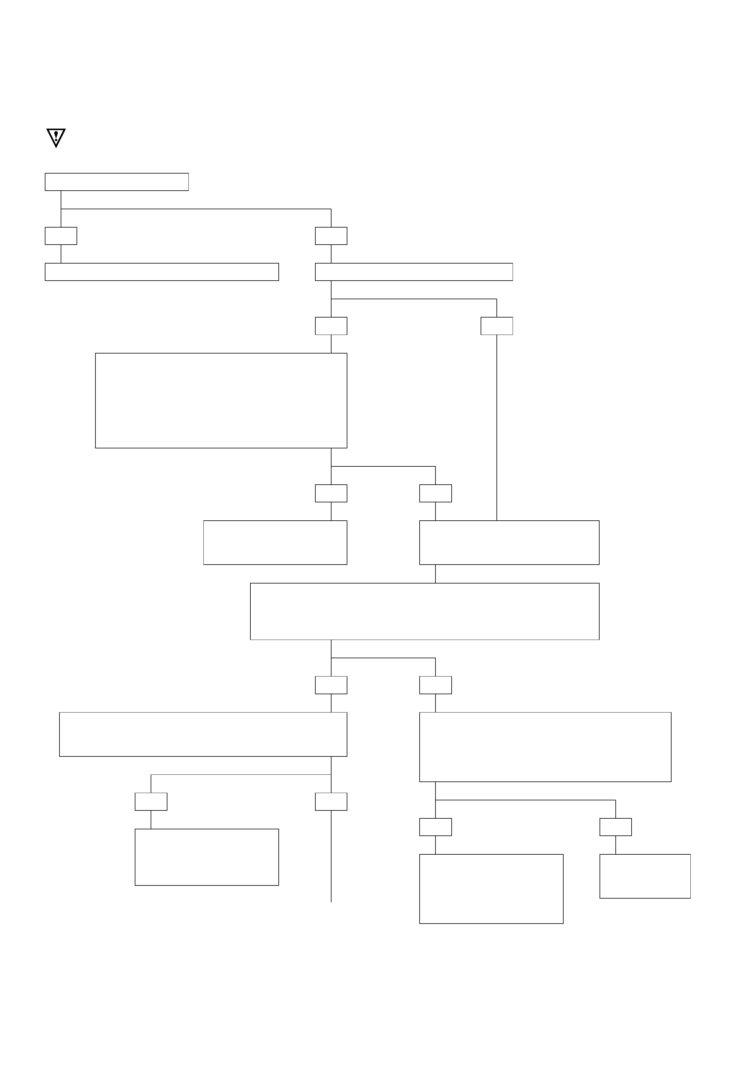
DIAGNOSTIC TROUBLE CODE (DTC) 62
DOWNSHIFT PROTECTION
If the DTC 53 is set:
CAUTION: If wire to connector C-96 terminal B12 is short to voltage,
Transmission Control Module (TCM) will be damaged.
YES
GOTHROUGH DTC53 first and do a test drive.
NO
If you have a SCAN TOOL: TECH2?
YES
•Raise drive wheels.
•Connect the TECH2 GOTHROUGH TECH2
CONNECTION.
•Push F0: DATA LIST: DISPLAY. Read “AT
OUTPUT SPEED”.
IF: Output speed different from 0 RPM when the
wheels are turning:
NO
YES NO
Problem is intermittent.
GOTO INTERMITTENT
CONDITIONS.
GOTO DTC 11: OUTPUT SPEED
FAILURE:
Diagnostic Aids.
•Ignition switch OFF.
•Disconnect TCM connector C-95 and C-96.
•Connect ohmmeter between connector C-96 terminals A12 and B12.
IF: Display is approx. 3K ohms:
NO
•Disconnect transmission speed sensor
connector M-15.
•Connect ohmmeter between terminals 1 and
2 of the speed sensor.
IF: Display approx. 3K ohms:
•Connect ohmmeter between connector C-96 terminal
A12 and ground connector C-95 terminal C1.
IF: Display indicates an open circuit:
YES
•Wires from connector
C-96 to sensor
connector are open or
shorted together.
•Repair.
Replace
transmission
speed sensor.
NO
YES
NOYES
•Check for faulty TCM
connection. If OK
REPLACE TCM
A
CONTINUED
ON NEXT PAGE
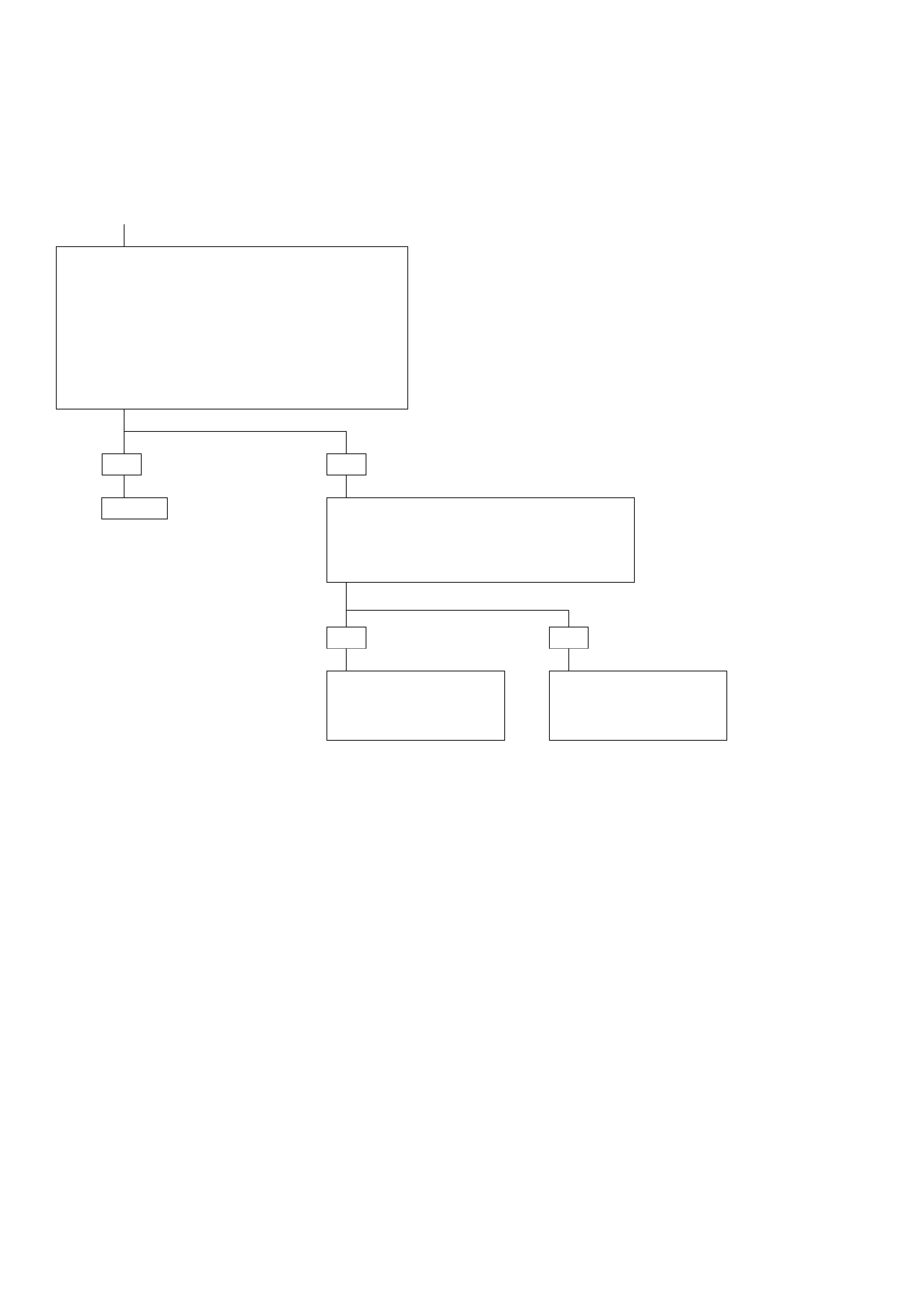
CONTINUED FROM
PREVIOUS PAGE
A
DIAGNOSTIC TROUBLE CODE (DTC) 62
DOWNSHIFT PROTECTION
(CONTINUED)
HINT:
•The wire between connector C-96 terminal B12 and
speed sensor connector M-15 terminal 2 can be
shorted to ground or open without creating a
problem because the TCM B12 pin is connected to
the TCM ground iternally and the signal is detected
only on the A12 input.
•Check wire for a short to ground between terminal
A12 and sensor connector M-15 terminal 1.
IF: Display indicates a short circuit:
YES
Repair.
NO
•Connect voltmeter between connector C-96
terminal A12 and ground connector C-95
terminal C1.
•Ignition switch ON.
IF: Display indicates approximately 0 volt:
YES NO
•Check for faulty TCM
connectors. If OK GOTO
REPLACE TCM
•Check wire for a short
to voltage between
terminal A12 and speed
sensor connector M-15.

DIAGNOSTIC TROUBLE CODE (DTC) 63
EPROM CSUM FAILURE
This DTC flashes the CHECK TRANS indicator and
sets the BACKUP MODE.
Circuit Description:
•The Erasable Programmable Read Only Memory
(EPROM) is an electronic circuit that contains the
commands that control the Transmission Control
Module (TCM).
•The EPROM content is checked automatically
approx. each second by the TCM. This is called
Check Sum (CSUM) calculation. If this CSUM is
false this means that one command is altered.
•This can be due to a circuit failure or a bad
contact between the EPROM and the TCM and
the DTC63 will be set.
•If all EPROM connections are bad, the TCM does
not work. The CSUM can not be calculated and
detected. Nothing works, not even the CHECK
TRANS indicator.
Diagnostic Aids:
•This Diagnostic is not an electrical test done by
the TCM but an internal logic test.
•Detection conditions:
1Bad EPROM Check Sum.
2 The condition needs to be present for at least
approx. 1 second.
•Action after the detection time: BACKUP MODE.
• Recovery conditions: CYCLE IGNITION
To Solve the Problem
• REPLACE TCM.

DIAGNOSTIC TROUBLE CODE (DTC) 82
SHIFT OR BAND APPLY SOLENOIDS FAULTY DURING DRIVING
This DTC flashes the CHECK TRANS indicator and
sets the BACKUP MODE.
Circuit Description:
•The shift solenoids are simple ON/OFF solenoids
located in the main case valve body. The
solenoids are normally closed or open-type.
Depending on gear the Transmission Control
Module (TCM) controls the solenoids to open or
close a fluid inlet port. When the port is open,
fluid pressure actuates the shift valve.
•The solenoid is activated by a current. This
current is produced by applying a voltage to one
side (the High side) and a ground to the other
side (Low side).
•The High Side Driver (HSD) is a circuit of the TCM
that acts as a switch between the solenoids and
the supply voltage. The High side of the solenoid
is permanently supplied with voltage, except in
BACKUP MODE or when Ignition is OFF the High
Side Driver is turned OFF.
•The Low Side Driver (LSD) is a circuit of the TCM
that acts as a switch between the solenoid and
ground. When the solenoid is commanded ON
the TCM is switching the solenoid to ground.
The TCM continually monitors each solenoid
connection to its Low Side Driver and to its High
Side Driver for either low or high voltage.
•DTC82 is activated when the Shift High Side
Driver or one of the Shift Low Side Drivers
senses a short circuit or open circuit when the
engine is cranked, then when the car is driven.
DTC82 can be set only when the TCM is
activating the solenoids in with the problem
circuit.
•To know where the fault comes from, do
IGNITION CYCLE to use the TCM self-check of
solenoids when Engine is not cranked but
Ignition ON.
Diagnostic Aids:
•This diagnostic is an electrical test done by the
TCM.
•Detection conditions:
1HSD or LSD is improperly ON.
2The condition needs to be present for at least
0.15 second.
•Action after the detection time: BACKUP MODE
• Recovery conditions: CYCLE IGNITION

DIAGNOSTIC TROUBLE CODE (DTC) 82
SHIFT OR BAND APPLY SOLENOIDS FAULTY DURING DRIVING
This DTC is set when the car is driven (Engine ON) but
the diagnostic is not specific.
To correctly identify the problem, do an IGNITION
CYCLE.
If you have not already done an IGNITION CYCLE:
•Turn ignition switch OFF. Turn ignition switch ON
and wait 3 seconds to have the specific diagnostic
done.
•Then you can turn the engine ON or not.
Check on Scan Tool or Flashing Code what other DTC is
provided. It should be one of the following:
DTC31 or DTC32 or DTC34 or DTC36 or DTC41 or DTC42
or DTC44 or DTC46.
GOTO this DTC.

WITHOUT DTC SET
1. If you have already checked the Diagnostic
Trouble Code (DTC) and the scan tool TECH2
does not provide any DTC, and you have
reproduced the problem and no DTC was
stored:
This means that you have to check the problem
by comparing the way it should work to the
way it works now that the problem exits.
2. To find the problem, perform the following
tests:
•Transmission Operating Mode Test
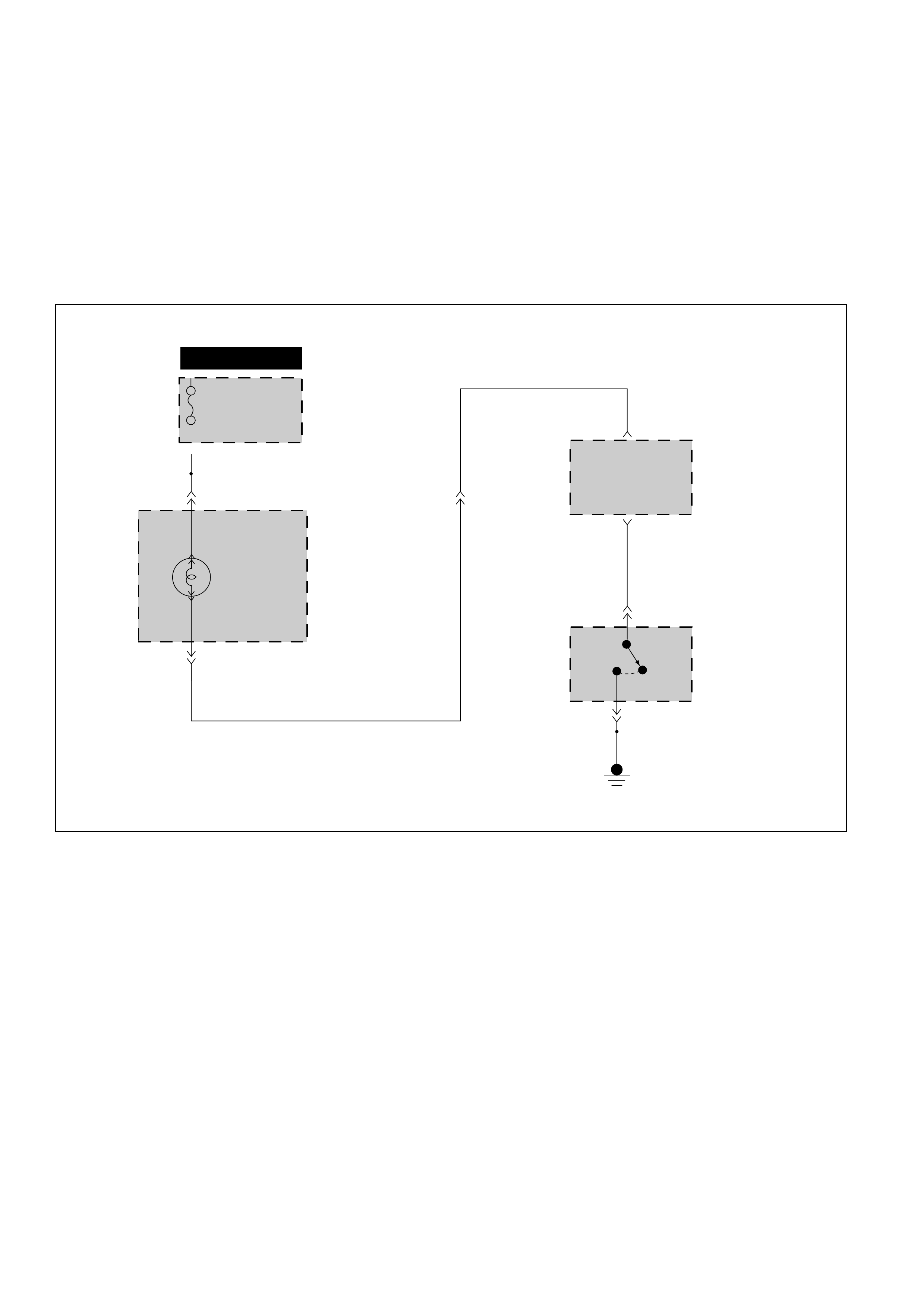
TRANSMISSION OPERATING MODE TEST
Circuit Description:
The Transmission Control Module (TCM) can
controls 4L30-E operation in two modes: Power
mode, and Normal mode. The driver determines
the transmission operating mode through the
Power/Normal mode switch.
The Power mode provides better part-throttle ac-
celeration by providing earlier part-throttle upshifts.
METER
BLK
FUSE BOX
CB-5
15A
B-242 H-268
POWER
MODE
INDICATOR
B8(20)
POWER MODE
INDICATOR
CONTROL
POWER MODE
ENABLE INPUT
B9(21) C-96
C-96
2C-98
1C-98
TRANSMISSION
CONTROL
MODULE (TCM)
POWER
SWITCH
HOT IN ON OR START
RED/WHT
GRN/YEL
B-23
RED/WHT
6
D07LW023

TRANSMISSION OPERATING MODE TEST
IF: When you operated the Power Switch the indicator
turned ON:
YES NO
No Problem. •Install scan tool GOTHROUGH TECH2 CONNECTION.
•Ignition switch ON.
•Select F0: DATA LIST: POWER SWITCH.
Does TECH2 display “INACTIVE”?
YES NO
•Check wire for short to ground between
Transmission Control Module (TCM) connector C-96
terminal B8 and the Power Switch.
IF OK, replace the Power Switch.
•Press and hold down the Power Switch.
Does TECH2 display “ACTIVE”?
YES
•Check wire for open between TCM connector C-96
terminal B8 and the Power Switch.
IF OK, replace the Powe Switch.
NO
The Power Switch is
working normally.
•Selector lever in Park.
Does Power mode indicator stay
on all the time?
YES NO
•Check wire for short to ground
between TCM connector and
indicator (SEE SCHEMATIC).
REPLACE TCM
•Select F5: ACTUATOR TEST:
CHECK POWER LAMP?”
•Press YES.
Does Power Mode Indicator light?
YES NO
The system is
functioning correctly. •Check fuse, bulb, and wire for open between
connector C-96 terminal B9 and indicator and
between indicator and fuse.
•Check wire for short to B+ between connector C-96
terminal B9 and indicator.
IF OK, REPLACE TCM
TCM: Transmission Control Module

TCM PRECAUTONS
The TCM can be damaged by:
(1) The Electrostatic discharge
(2) The short circuit of some terminals to voltage
or to ground.
Electrostatic Discharge Damage Description:
(1) Electronic components used to control systems
are often designed to carry very low voltage,
and are very susceptible to damage caused by
electrostatic discharge. It is possible for less
than 100 volts of static electricity to cause
damage to some electronic components. By
comparison, it takes as much as 4000 volts for
a person to even feel the zap of a static
discharge.
(2) There are several ways for a person to become
statically charged. The most common methods
of charging are by friction and induction. An
example of charging by friction is a person
sliding across a car seat, in which a charge of
as much as 25,000 volts can build up.
Charging by induction occurs when a person
with well insulated shoes stands near a highly
charged object and momentarily touches
ground. Charges for the same polarity are
drained off, leaving the person highly charged
with the opposite polarity. Static charges of
either type can cause damage, therefore, it is
important to use care when handling and
testing electronic components.
NOTICE: To prevent possible Electrostatic
Discharge damage:
(1) Do not touch the TCM connector pins or
soldered components on the TCM circuit
board.
(2)
When handling a TCM, do not open the
case and attempt to remove the MEM-CAL
from the circuit board.
(3) Be sure to follow the guidelines listed below if
servicing any of these electronic components:
(4) Do not open the replacement part package
until it is time to install the part.
(5) Avoid touching electrical terminals of the part.
(6) Before removing the part from its package,
ground the package to a known good ground
on the vehicle.
(7) Always touch a known good ground before
handling the part. This step should be repeated
before installing the part if the part has been
handled while sliding across the seat, while
sitting down from a standing position or while
walking some distance.
INFORMATION ON TCM:
(1) The Transmission Control Module (TCM) is
located in the passenger compartment and is
the control center of the electronic trans-
mission control system.
(2) The TCM must be maintained at a temperature
below 185 ¡F (85¡C) at all times. This is most
essential if the vehicle is put through a paint
baking process. The TCM will become in-
operative if its temperature exceeds 85 ¡C
(185¡F). Therefore, it is recommended that the
TCM be removed or that temporary insulation
be placed around the TCM during the time the
vehicle is in a paint oven or other high
temperature process.
(3) The TCM is designed to process the various
inputs and then respond by sending the
appropriate electrical signals to control trans-
mission upshift, downshift, shift feel and
torque converter clutch engagement.
(4) The TCM constantly interprets information
from the various sensors, and controls the
systems that affect transmission and vehicle
performance. By analyzing operational prob-
lems, the TCM is able to perform a diagnostic
function by displaying DTC(s) and aid the
technician in making repairs.
PROM/MEM-CAL:
(1) Information for a specific engine and vehicle is
programmed using an integrated circuit called
a Programmable Read-Only Memory (PROM).
It is also called a MEM-CAL (Memory Cali-
brator). This allows one model of controller to
be used for many different vehicles. The PROM
is located inside the TCM and has information
on the engine, transmission, calibration., etc.
While one TCM can be used by many vehicle
types, a PROM is more specific and therefore
must be used only with the correct vehicle.
For this reason, it is very important to check
the latest parts book and Service Bulletin
information for the correct part number when
replacing a TCM. The MEM-CAL is not serviced
seperately from the TCM.

INTERMITTENT CONDITIONS
If the TECH2 displays a diagnostic trouble code as
intermittent, or if after a test drive a DTC does not
reappear though the detection conditions for this
DTC are present: the problem is most likely a faulty
electrical connection or loose wiring. Terminals and
grounds should always be the prime suspect.
Intermittents rarely occur inside sophisticated
electronic components such as the TCM.
Use the DTC information to understand which wires
and sensors are involved.
When an intermittent problem is encountered,
check suspect circuits for:
(1) Poor terminal to wire connection.
(2) Terminals not fully seated in the connector
body (backed out).
(3) Improperly formed or damaged terminals.
(4) Loose, dirty, or corroded ground connections:
HINT: Any time you have an intermittent in
more than one circuit, check whether the circuits
share a common ground connection.
(5) Pinched or damaged wires.
(6) Electro-Magnetic Interference (EMI):
HINT: Check that all wires are properly routed
away from spark plug wires, distributor wires,
coil, and generator. Also check for improperly
installed electrical options, such as lights, 2-way
radios, etc.
Use the F3: SNAPSHOT mode of the TECH2 to help
isolate the cause of an intermittent fault. The
snapshot mode will record information before and
after the problem occurs. Set the snapshot to
“trigger” on the suspect DTC or, if you notice the
reported symptom during test drive, trigger the
snapshot manually.
(1) NOTE: When TECH2 is plugged the shifts are
always done at the maximum pressure. This
means that if you do SNAPSHOT while driving
you will notice firm shifts.
After the snapshot has been triggered, command
the TECH2 to play back the flow of data recorded
from each of the various sensors. Signs of an
intermittent fault in a sensor circuit are sudden
unexplainable jump in data values out of the
normal range.
CASE: problem still not solved GOTO TCM MEM-
CAL REPLACEMENT.
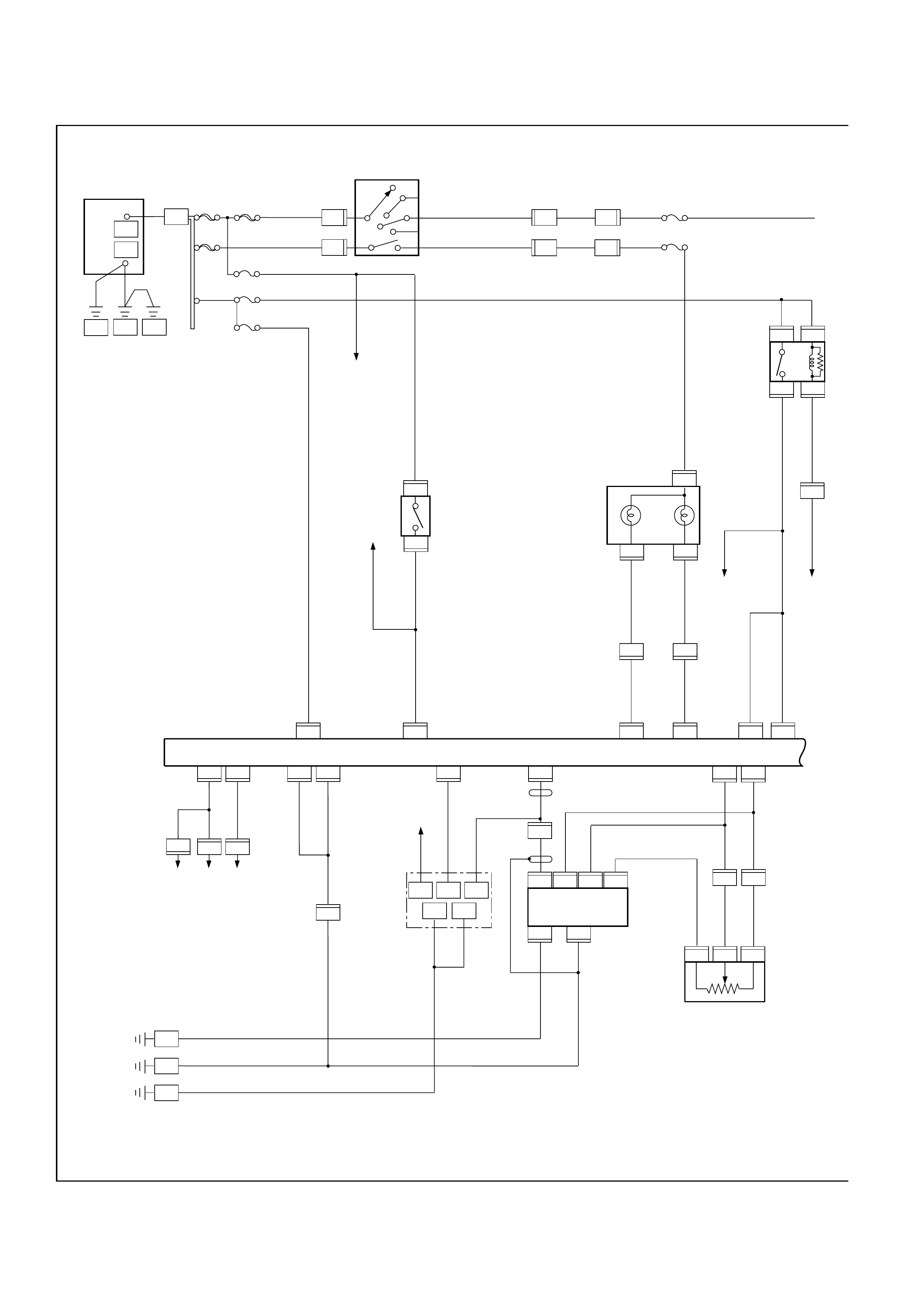
WIRING DIAGRAM
P-1
P-5
5B
30B
+
_
B2
OFF
IG2
ACC
STARTER SW
B1
ST
IG1
1
33B/R
3B/Y
3B/R
3R/G
3B/Y 0.85W
0.85R/G
CB-5
15A METER GAUGE
CB-11
15A BUCK TURN
P-11
8B/R
EB-16
100A MAIN 3W
3W/B
EB-17
40A
IGN B-2
EB-15
40A
IGN B-1
P-10 P-8 P-7
5B
ENG BODY FRAME
FENDER-RH
COMMON
CHAMBER
C-36
E-74
EB-10
10A STOP LIGHT
EB-14
20A ECM
EB-12
10A TCM
2W
0.5G
DATA LINK
CONNECTOR(16)
STOP LIGHT SW
STOP LAMP
0.5R 0.5R
2
1
3
5
3R/L
0.5L/R
EOM(A28)
C-96
X-18
RELAY; ECM MAIN
X-18
X-18 X-18
H-7 6
TCM
E-61E-61
ECM
E-61
0.5G
C-96
0.8GR
0.8L
0.8G
27263935
46
0.5R/W
C-96
6
B-23
2
POWER
4
B-24 H-20
A4
7
0.5O/L
C-95
8
B-24
0.3O/L
H-26
B9 C10
0.3R/W
A7
C-96
A8
ECM (B-19)
0.5R/L
0.5R/L
E-72
C-95
0.5B/R
ECM(B12)
D12
H-20
0.5B/R
6
TACHOMETER
H-616
0.5B/R
C-95
D14
ECM (B10) 0.5BR
C-95
C1
0.5B
C-95
D1
H-25
0.85B
7
0.85B
DATA LINK CONNECTOR
C-102 11
FUSE STOP
C-102
9
C-102
4
0.5B1.25B
0.5B
C-102
5
E-61
C-95
C8
0.5Y
0.5Y
0.8B/R
0.8BR/L
0.5Y
E-61
THROTTLE POSITION
SENSOR
E-68E-68
1
OUT
HI
23
C-95
0.5GR
H-25
0.5L
H-25
65
35
8
1
3217128 30
E-68
LO
C5 C6
C-95
0.5L
0.5G
8
10 8 721425
H-26
COMMON
CHAMBER
C-102
16
C-95
0.5Y/B
D16
E-60
CHECK
TRANS
4
1
B-44
C-44
2
C-95
D9
C-41
C-41 H-7
C-41 8
6
C-41
H-25
H-25
6
D08RW541
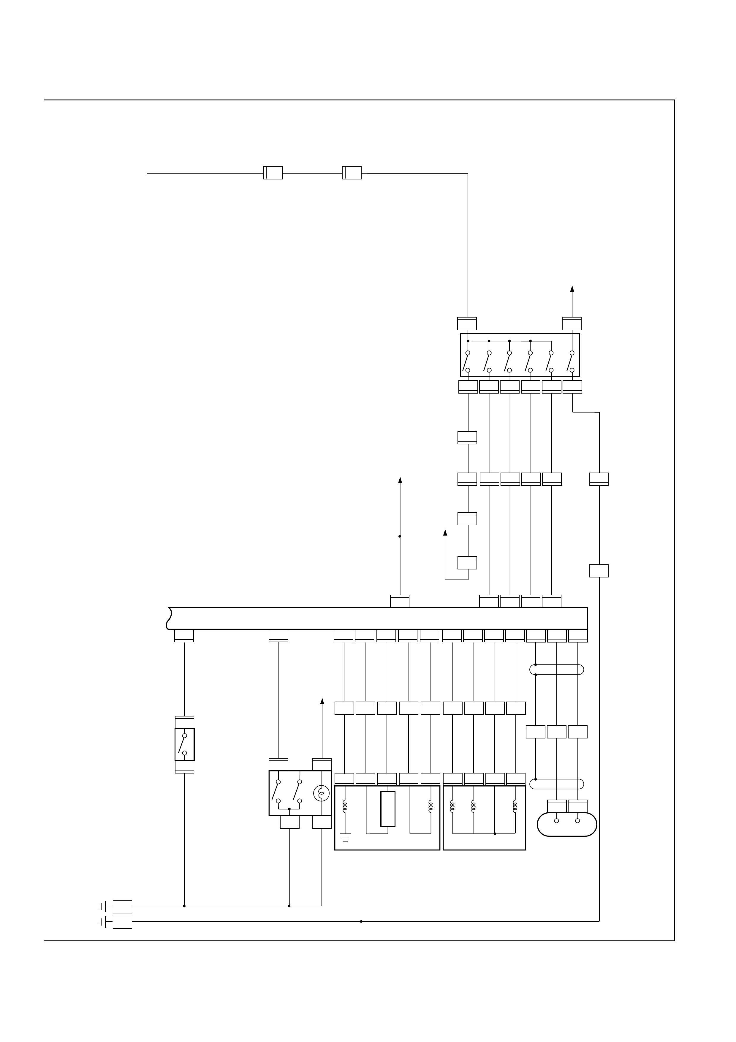
BODY-RH C-2
M-25
5
0.75R/L0.85R/Y0.85R/Y0.85R/Y
1.25BR/L0.5BR/L
M-25 M-25 M-25 M-25 M-25
2
24 23 22 21 20
87631
C-95 C-95 C-95 C-95
0.5L/B 0.5L/B
1.25B0.85B
0.5L/W 0.5L/W
0.5L/R 0.5L/R
0.5L 0.5L
MODE SW
RELAY
STARTER
4
C-95
RELAY:A/C COMPRESSOR(4)
BACK LAMP
M-25 M-25
1.25B
0.85W 0.85W 0.75W
D8 D7 D6 D5 D4
C-98
6
C-98
4
C-98
C-98
C-96
2
0.5G/Y
1
0.5B
0.5B RELAY;TAIL(4)
POWER & WINTER SW
B8 B6
H-23
C-96
6
H-23
C-95
14
H-23
13
H-23
16
1
MAIN CASE
(T/MISSION)
2-3 SOLENOID 0.5BR/B
0.5BR/W
0.5Y/G
0.5Y/B
M-7
1-2, 3-4
SOLENOID
BAND APPLY
(+)
FORCE
MOTOR
(-)
TEMP
SENSOR
TCC SOLENOID
C-96C-96
H-23
0.5R/B
0.5Y/B
0.5Y/G
0.5BR/W
0.5BR/B
8
0.5R/B
M-6
C-95
H-23
0.85R/G
5
0.75R/G
M-6
C-95
H-38
2
M-6
C-96
H-38
1
M-6
C-95
H-23
0.5R/Y
0.5L
0.5GR
12
0.5R/Y
0.5L
0.5GR
M-6
C-95
ADAPTOR CASE
(T/MISSION)
43221354
M-7
M-7M-7
C7 C14 B3 C16 C15 A9 A2 C12 A3 C-96
0.5L
0.5BR/L
H-23
11
C-96
0.5P
H-23
10
21
C-96
H-23
9
MAGNETIC
SENSOR
+-
B11 A12 B12
C-94
1
C-94
2
KICK DOWN SW
17 20 7 14 15 16 15 9 2 12 3 23 12 24
C-96
0.5L
0.5B
B5
H-22
12
H-6
12
H-15
4
H-17
1
0.5L
0.5P
E-74 0.8BR/L
M-15
M-15
H-23
1H-23
2H-23
3H-23
4H-23
7
H-25
7
2
H-6
8
H-22
D08RW542

CONNECTOR LOCATION
RELAY & FUSE BOX
(X-18)
H-26
P-11
C-2
C-41
E-60 E-61 C-36
H-20
H-25
C-98
M-6
M-7 M-17
M-15
M-25
H-15
E-74
E-72
E-68
C-94
C-102
H-17
H-6
H-7 B-23
B-24
C-95
C-96
H-22
H-23
H-38
D08RW543
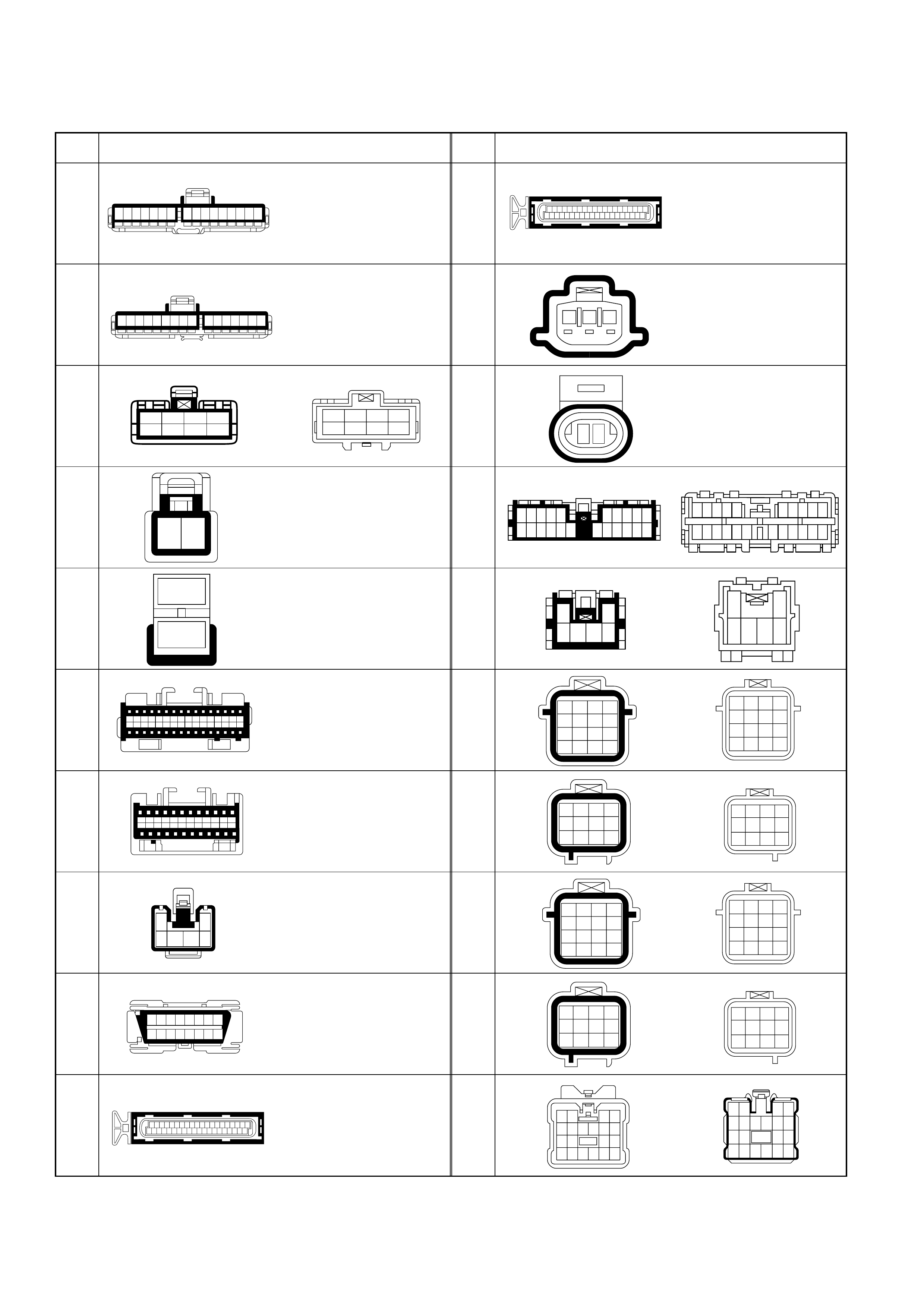
CONNECTOR LIST
No. Connector face No. Connector face
B-23
B-24
C-41
C-44
C-94
C-95
C-96
C-98
C-102
E-60
E-61
C-68
E-69
H-6
H-7
H-20
H-22
H-23
H-25
H-26
16151413121110987654321
98765432116151413121110
1234
5678
12
1
2
C1 C2 C3 C4 C5 C6 C7 C8 C9 C10C11 C12C13 C14C15C16
D1 D2 D3 D4 D5 D6 D7 D8 D9 D10D11D12D13D14D15D16
A1
B1 A2
B2 A3
B3 A4
B4 A5
B5 A6
B6 A7
B7 A8
B8 A9
B9 A10
B10 A11
B11 A12
B12
1
3456
2
87654321
161514131211109
39373533 3129272523211917151311 9 7 5 3 1
403836343230 28262422 2018161412 10 8 6 4 2
1234 5678
2 4 6 8 10121416182022242628303234363840
13579111315171921232527293133353739
123
1 2
12345
1112131415
6 7 8 9 10
181920212216 17
1
3456
2
1234
5678
9101112
13 14 15 16
1234
5678
9101112
1234
5678
9101112
13 14 15 16
1234
5678
9101112
1234
5678910
151617181920
11121314
10 9876 54321
2221201918 151413121117 16
2
6543
1
4321
8765
12 11 10 9
16 15 14 13
4321
8765
12 11 10 9
16 15 14 13
4
8
12
3
7
11
2
6
10
1
5
9
4
8
12
3
7
11
2
6
10
1
5
9
12 34
56 78910
11 12 13 14
15 16 17 18 19 20
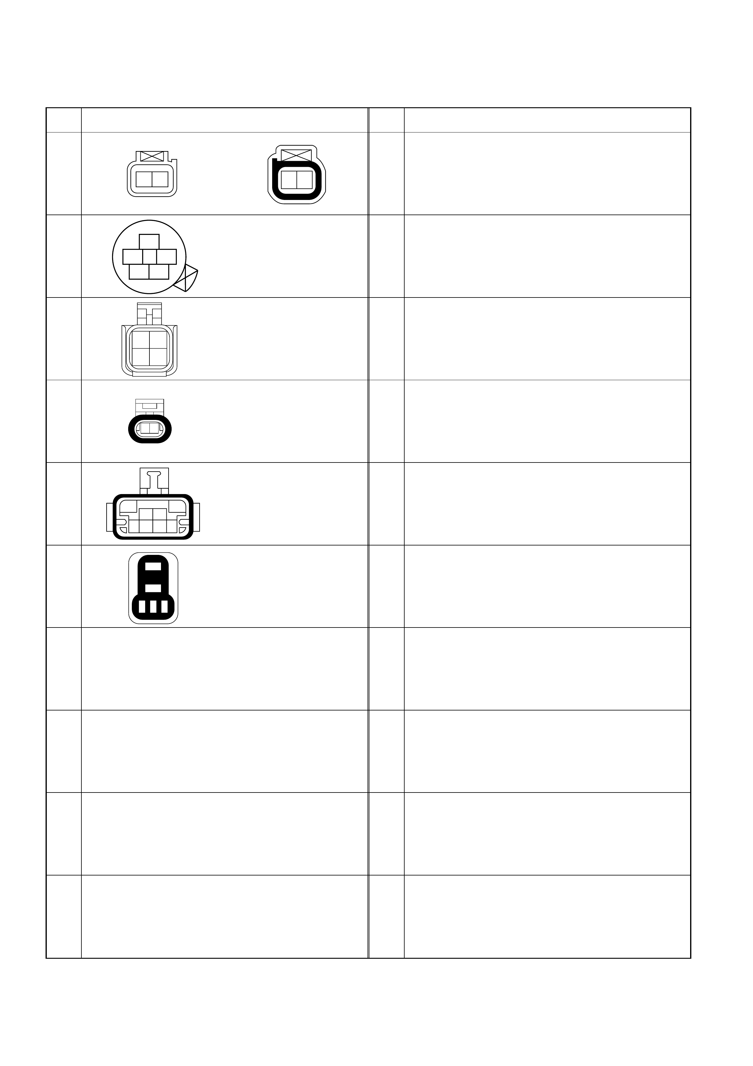
CONNECTOR LIST
No. Connector face No. Connector face
H-38
M-6
M-7
M-15
M-25
X-18
12
1
352
4
21
43
12
23
6758
14
1
2
345
12