
SECTION 7C2 - ON-VEHICLE SERVICE & UNIT REPAIR
CAUTION
When fasteners are removed, always reinstall
them at the same location from which they
were removed. If a fastener needs to be
replaced, use the correct part number fastener
for that application. If the correct part number
fastener is not available, a fastener of equal
size and strength (or stronger) may be used.
Fasteners that are not reused, and those
requiring thread locking compound, will be
called out. The correct torque values must be
used when installing fasteners that require
torque. If the above conditions are not
followed, parts or system damage could
result.
Sprag Unit
Second Clutch
3-4 Accumulator Piston
Reverse Clutch Piston and Center Suppor t
Overrun Clutch and Turbine Shaft
4L30-E Parts List
On-Vehicle Ser vice
Selector Lever
Mode Switch
Transmission (With T ransfer Case)
Solenoid Valve (Main Case Valve Body)
Solenoid Valve (Adapter Case Valve Body)
Unit Repair
Transmission (4L30-E)
Converter Housing and Oil Pump Assembly
Oil Pump
Main Case Valve Body
Adapter Case Valve Body
Third Clutch and Sprag Unit
Third Clutch

SELECTOR LEVER
2. Selector Lever Assembly
1) Disconnect shift lock cable from the selector lever
assembly side.
2) Disconnect wiring harness connectors.
3) Disconnect shift control rod from the selector
lever assembly side.
Shift lock cable
4) Remove selector lever assembly.
INSPECTION
1) Make sure that when the shifter control lever is
shifted from “P” to “L”, a “clicking” can be felt at
each shift position. Make sure that the gear
corresponds to that of the position plate indicator.
2) Check to see if the shifter lever can be shifted as
shown.
ON-VEHICLE SERVICE
REMOVAL
Preparation:
Disconnect negative (–) battery cable.
1. Front Console
Disconnect wiring harness connectors.
745LW001
256RV012
255LW007
INSTALLATION
To install, follow the removal steps in the reverse order,
noting the following points;
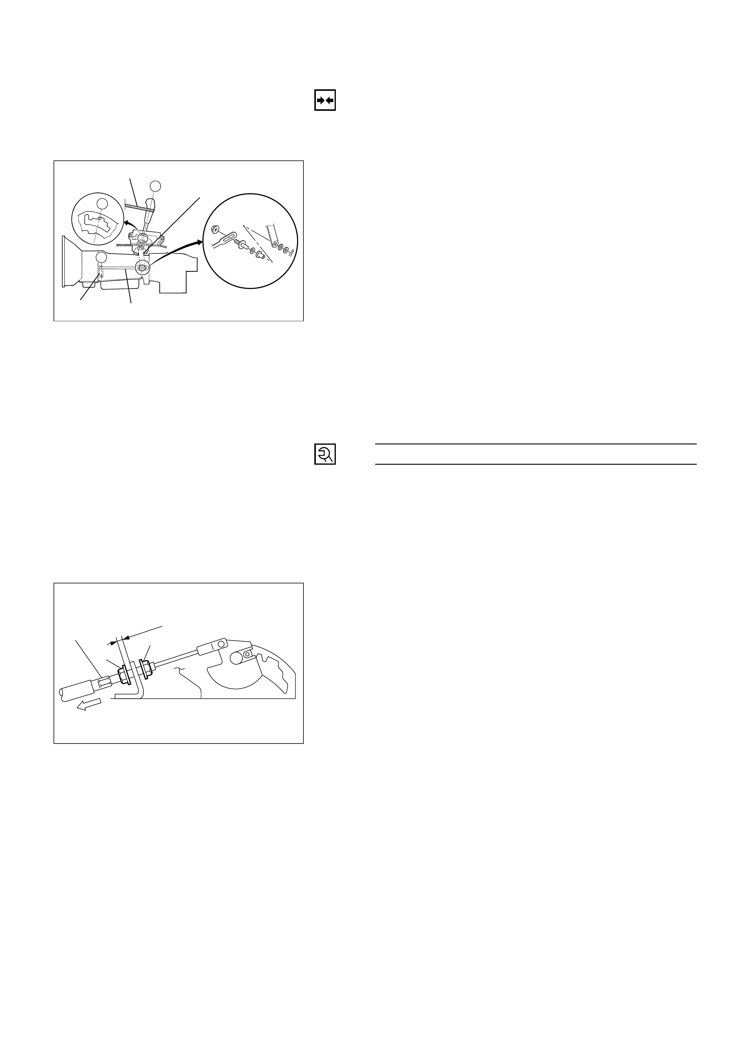
Adjustment of select lever and control rod
(1) Place the vehicle on a level surface.
NOTE:
If the vehicle is not on a level surface, the shift select
cable set positions will vary with the movement of
the engine. To prevent possible misadjustment of the
cable, the vehicle must be placed on a level surface.
(2) Install the shift control rod (1) to the transmission
select lever (2), and then place the lever in the “N”
position.
(3) Set select lever in the “N” position.
(4) Push select lever forward and secure it (using a
rubber band (3), etc.) so that pin comes into contact
with the wall of detent plate.
(5) Install the shift control rod (1) to the selector lever
arm (4).
Nut Torque N·m (kg·m / lb·ft)
32 (3.3 / 24)
NOTE:
Do not apply to threaded portions.
(6) After adjustment, make sure that the selector lever
operates normally, and that each selector position is
properly indicated. (The red mark shows through the
window.)
3
4
1
2
Adjustment of shift lock cable
1) Set IGN key in “LOCK” position and selector lever
in “P” position.
2) Adjust cable screw cap on selector lever side to
provide a gap (slack for cable) of 1 ~ 2mm
between rod on steering lock side and stopper.
Adjust cap as follows:
1Pull screw cap in arrow direction to remove
inner cable slack.
5mm
23
1
256RW014
256RW015
2With cable kept as 1, adjust gap between nut
(1) and bracket to 5mm (0.2in).
3Lock inner cable by turning nut (2) while
holding nut (1) in place.
Lock Nut Torque N·m (kg·cm / lb·in)
4 (39 / 35)
NOTE:
Clean the rod threads and do not apply oil to them.
3) Check the shift lock operation:
1Selector lever shall not move out of “P”
position with ignition key in “Lock” position.
2Selector lever can be moved out of “P”
position with ignition key in “ON” position
only when brake pedal is depressed.
3Ignition key can be turned to “LOCK” position
only when selector lever is in “P” position
(key can be pulled out).
If 1and 3fail, readjust cable. If 2fails, readjust
connector wiring and brake pedal switch.
MODE SWITCH
REMOVAL
Preparation:
•Disconnect negative (–) battery cable.
1. Place selector lever in neutral.
2. Disconnect battery ground cable.
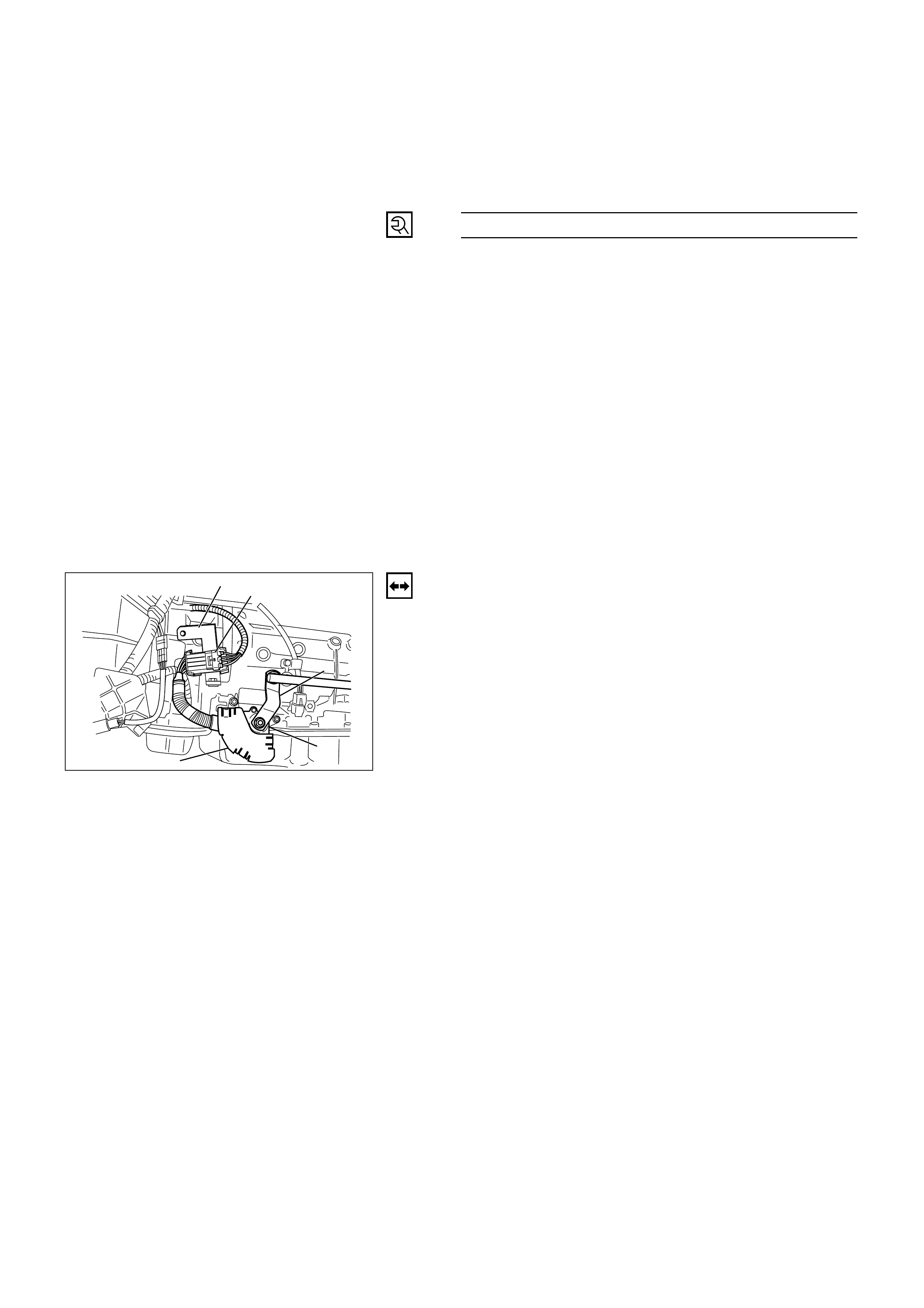
3. Remove mode switch cover (1).
4. Disconnect selector lever (2) from the mode switch.
5 Disconnect transmission harness from the mode
switch connector (3).
6 Remove bracket with mode switch connector from
the transmission case.
7. Remove mode switch connector (3) from the bracket
(4).
8. Remove two mode switch bolts and nut then remove
mode switch(5).
3
4
2
5
1
210RW008
INSTALLATION
To install, follow the removal steps in the reverse order,
noting the following points;
1. Mode Switch Bolt Torque N·m (kg·cm / lb·in)
13 (130 / 113)
Selector Lever Nut Torque N·m (kg·m / lb·ft)
23 (2.3 / 17)
2. Mode switch setting procedure
Perform either of the following adjustment
procedures:
Procedure1
a. Place selector lever in neutral.
b. Remove selector lever from the mode switch.
c. Remove the mode switch cover.
d. Loosen the two 10 mm screws.
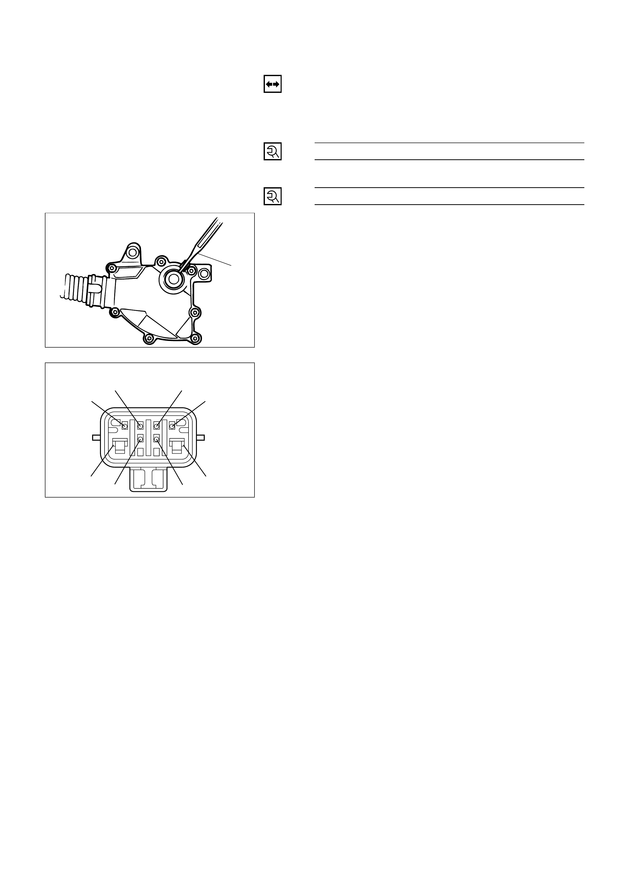
e. Rotate the mode switch until the slot in the mode
switch housing aligns with the selector shaft
bushing, and insert a 3/32 in. (2.4 mm) drill bit or
punch (1) into the slot.
f. Tighten the screws to 13 N·m (113 lb·in).
g. After completing adjustment, snap the mode
switch cover into place.
h. Reinstall the selector lever.
Procedure2
a. Place selector lever in neutral.
b. Disconnect transmission harness connector from
mode switch connector.
c. Remove mode switch connector with bracket
from the transmission case.
d. Connect multimeter (resistance mode) to
terminals 1(E) and 4(H) on mode switch
connector.
e. Loosen two mounting screws.
f. Rotate mode switch slightly in both directions to
determine the range (approx. 5 degrees) of
electrical contact.
g. Position mode switch in middle of contact range.
h. Tighten two mounting screws.
I. Remove multimeter and install mode switch
harness connector with bracket to the
transmission case.
j. Connect transmission harness connector to mode
switch connector.
1
249RW001
Mode switch connector
5 (D) 8 (A)
6 (C)
3 (G) 4 (H)
7 (B)
2 (F)
1 (E)
F07RW003
4
3
12
13
6
8
11
10
9
7
5
1
2
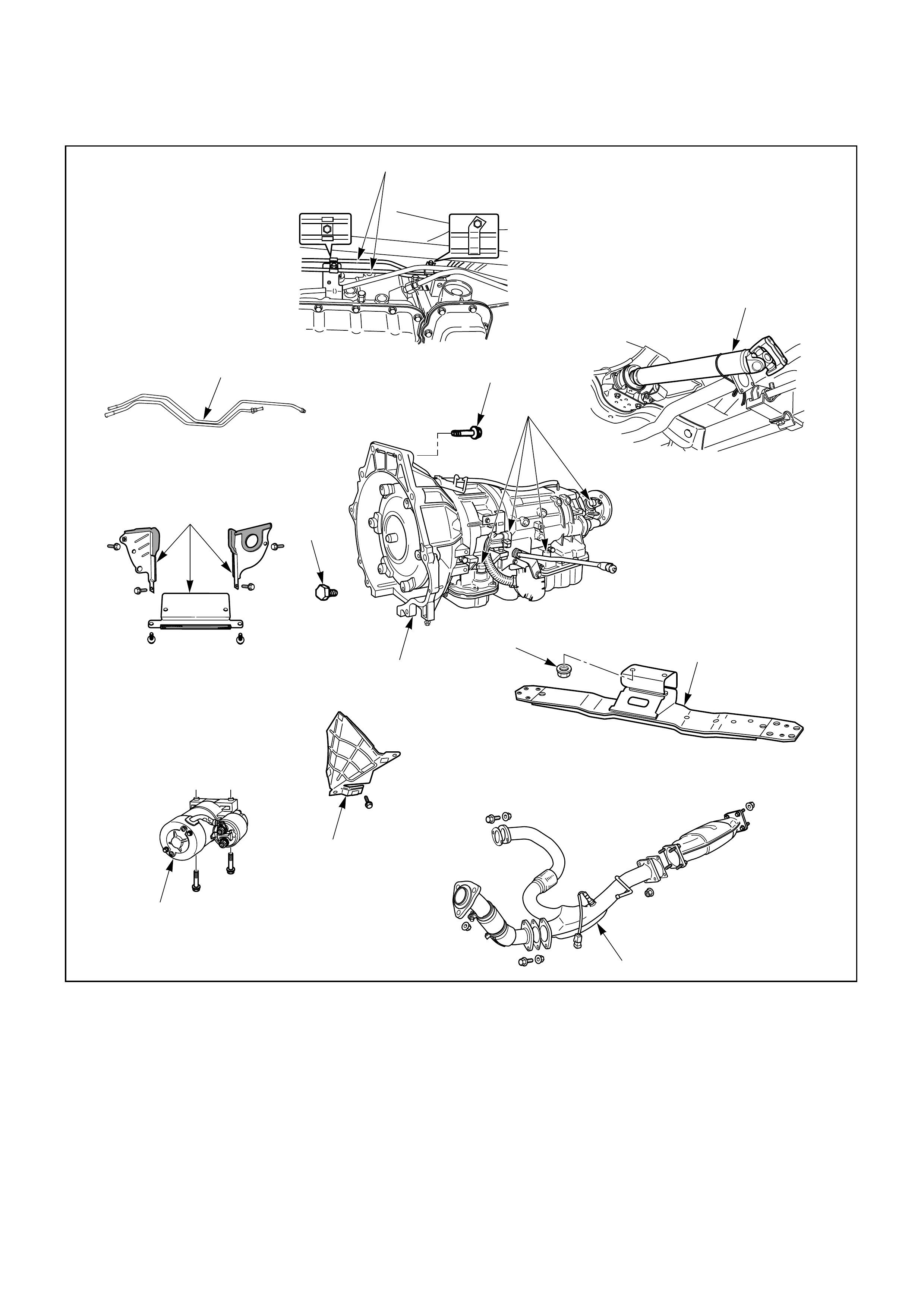
TRANSMISSION (WITH TRANSFER CASE)
240LW002
Removal Steps
1. Exhaust pipe
2. Rear propeller shaft
3. Fuel pipe
4. ATF oil cooler pipe
5. Heat protector
6. Harness connector
7. Starter
8. Flywheel under cover
9. Flywheel-Torque converter bolt
10. Rear mount nut
11. 3rd crossmember
12. Engine-transmission bolt
13. Transmission assembly
Installation Steps
To install, follow the removal steps in the
reverse order.
REMOVAL
Preparation:
•Remove engine hood.
•Disconnect negative (–) battery cable.
1. Exhaust Pipe
1) Remove catalytic converter, center pipe and left
front pipe.
2) Disconnect O2sensor connector from the
transmission harness connector.
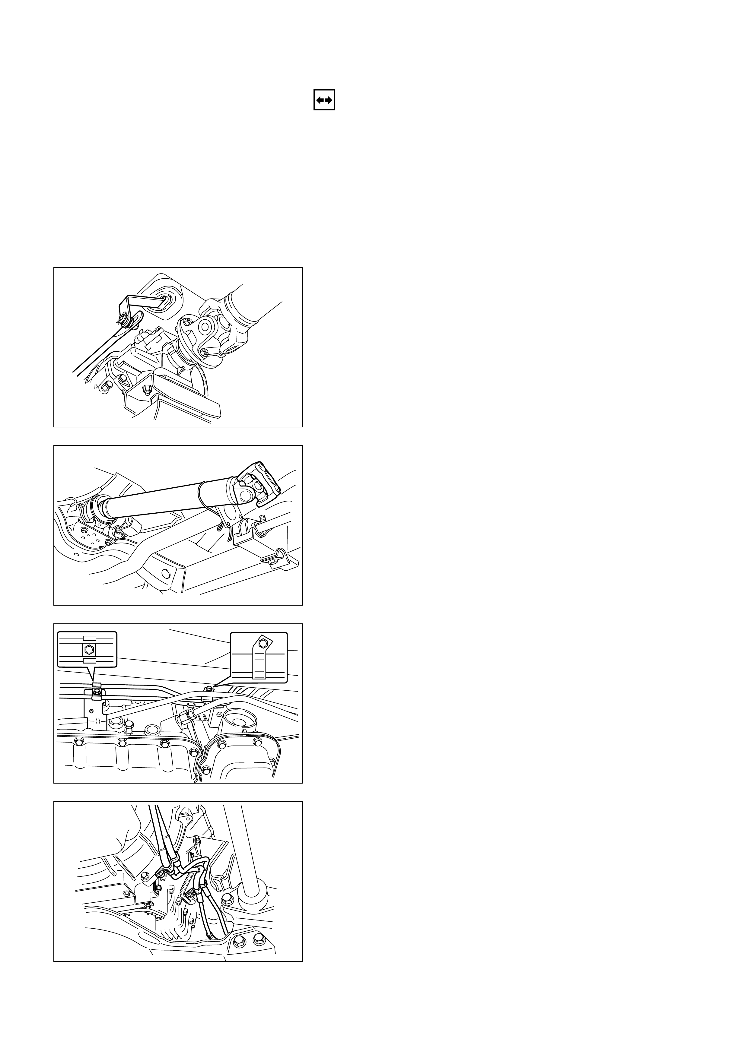
2) Disconnect rear propeller shaft transmission side.
2. Rear Propeller Shaft
1) Disconnect shift control rod from the selector
lever assembly side.
3. Fuel Pipe
Disconnect two fuel pipe clamp bracket from the
transmission case eight side.
4. ATF Oil Cooler Pipe
1) Disconnect ATF oil cooler pipe from transmission
side.
2) Remove oil pipe clamp bracket from torque
converter case.
3) Loosen oil pipe clamp bolt at the engine mount
side.
256LW004
401LW001
141LW001
253LW002
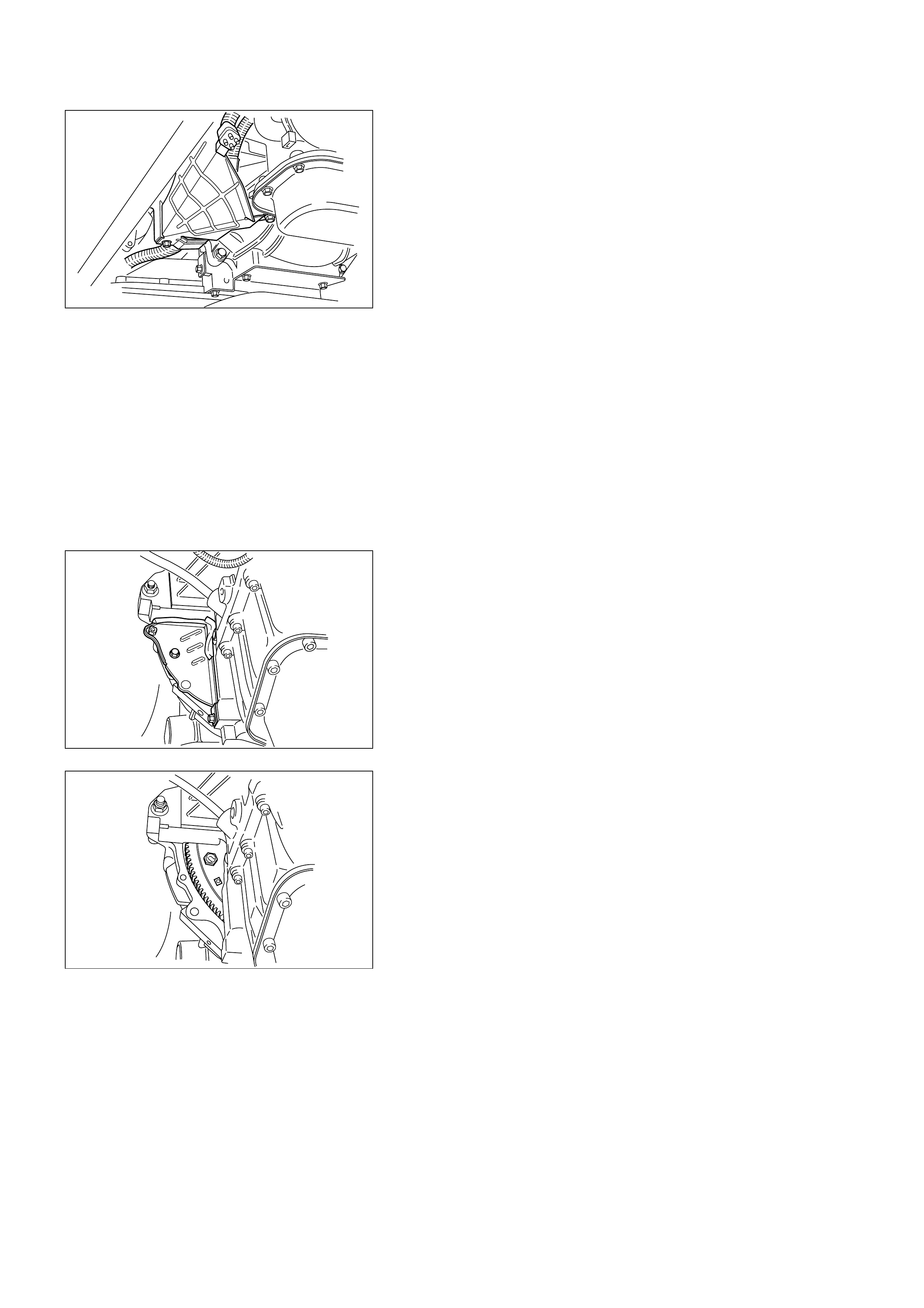
5. Heat Protector
6. Harness Connector
1) Disconnect transmission harness connectors from
transmission side connectors.
2) Disconnect harness clamp from transmission case
side.
7. Starter
8. Flywheel Under Cover
Remove flywheel under covers (3 pieces) from
transmission case.
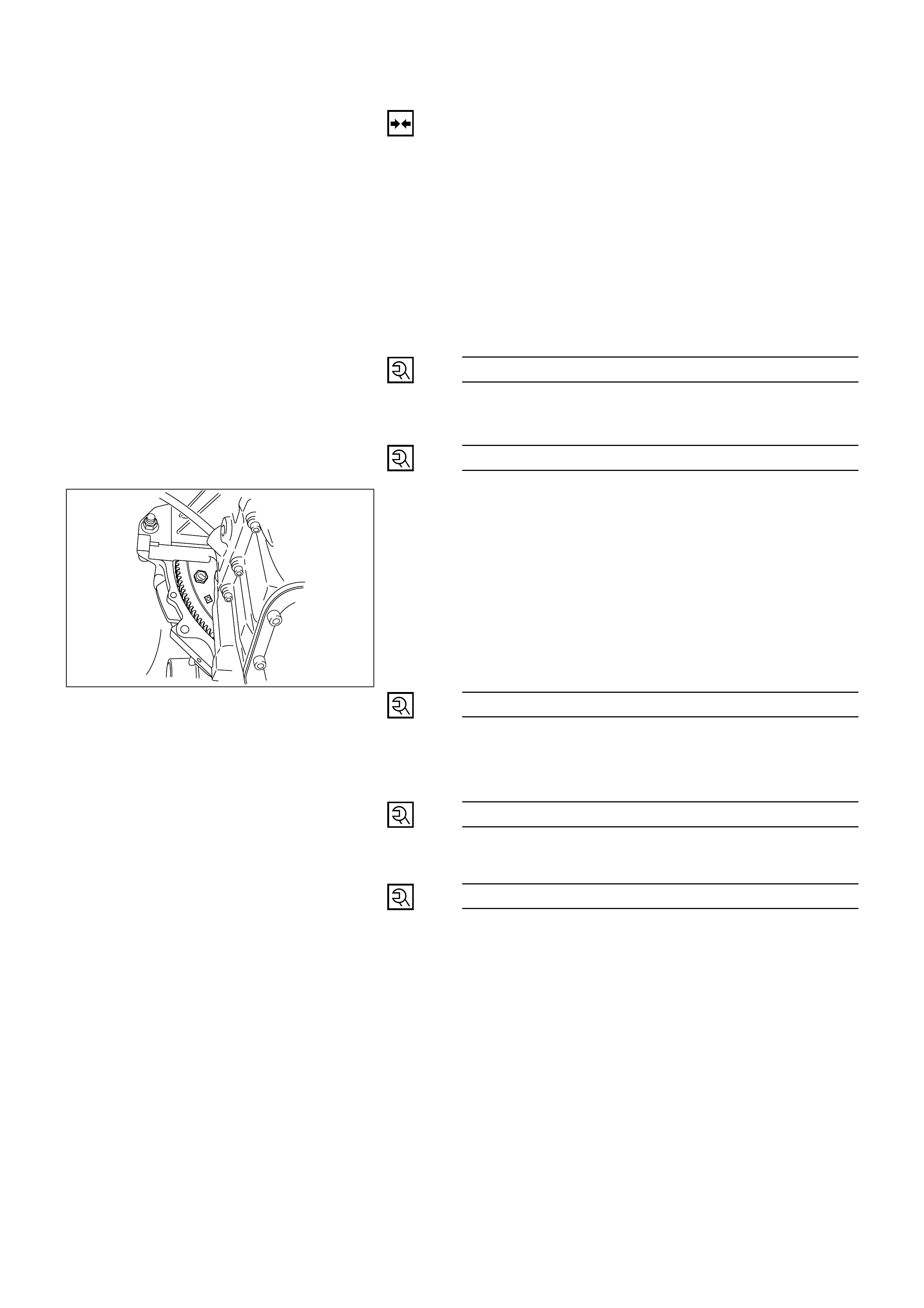
9. Flywheel – Torque Converter Bolt
Remove flywheel torque converter fixing bolts (6
pieces) by turning crankshaft.
10. Rear Mount Nut
1) Support transmission with a jack.
2) Remove two rear mount nuts from the rear
mount.
11. 3rd Crossmember
Remove eight 3rd crossmember bolts.
12. Engine-Transmission Bolt
1) Hoist engine with a chain block.
2) Remove engine-transmission bolts
13. Transmission Assembly
815LW001
210LW001
210LW002
INSTALLATION
To install, follow the removal steps in the reverse order,
noting the following points;
13. Transmission Assembly
Slowly raise transmission jack until front of the
transmission is aligned with rear of the engine.
12. Engine-Transmission Bolt
Tighten engine-transmission bolts, to the specified
torque (see next page).
11. 3rd Crossmember
3rd Crossmember Bolt Torque N·m (kg·m / lb·ft)
50 (5.1 / 37)
10 Rear Mount Nut
Rear Mount Nut Torque N·m (kg·m / lb·ft)
41 (4.2 / 30)
9. Flywheel-Torque Converter Bolt
1) Align the flywheel-torque converter bolt boss with
the starter portion of the converter housing by
turning torque converter.
2) Install new flywheel-torque converter bolts (6
pieces) by turning crankshaft.
NOTE:
Do not reuse the flywheel-torque converter bolt.
Flywheel-Torque Converter
Bolt Torque N·m (kg·m / lb·ft)
55 (5.6 / 41)
8. Flywheel Under Cover
Flywheel Under Cover
Bolt Torque N·m (kg·cm / lb·in)
8 (80 / 69)
7. Starter
Starter Bolt Torque N·m (kg·m / lb·ft)
40 (4.1 / 30)
6. Harness Connector
1) Connect transmission harness connectors to
transmission side.
2) Connect harness clamp to transmission harness
clamp bracket.
210LW002
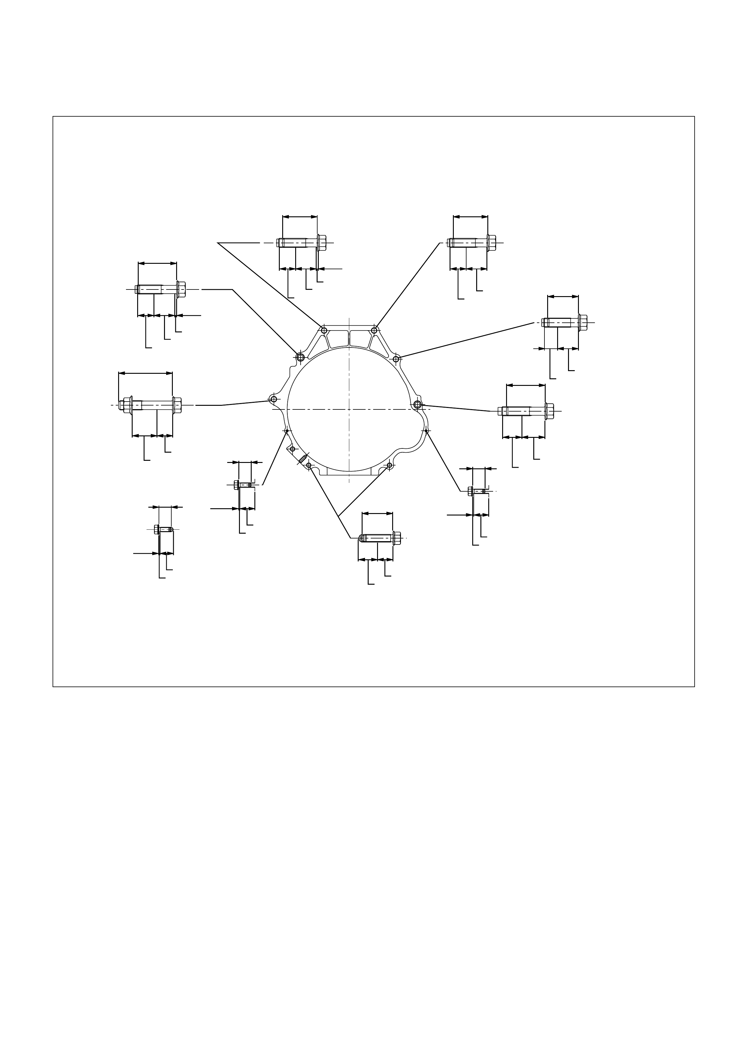
(6places)
Cylinder block
T/M case
Bracket;fuel pipe
Clip;breather hose
Cylinder block
T/M case
Under cover
Crank case
45
50
21 27 2.5
76(7.7/56)
76(7.7/56)
8(0.8/69lb in)
8(0.8/69lb in)
8(0.8/69lb in) 40(4.1/30)
76(7.7/56)
76(7.7/56)
76(7.7/56)
76(7.7/56)
Torque : N•m(kg•m/lb ft)
Length : mm
70
32 20
Cylinder block
T/M case
21 27 1.2
45
Cylinder block
T/M case
21 27
40
40
50
10
Cylinder block
T/M case
17 27
Cylinder block
T/M case
25 30
Crank case
T/M case
25 20 T/M case
0.9 20
Under cover
10
T/M case
0.9 20
Under cover
10
0.9 11
Engine-Transmission Bolt Torque
F07RW041
5. Heat Protector
Heater Protector Bolt Torque N·m (kg·cm / lb·in)
6 (60 / 52)
4. ATF Oil Cooler Pipe
1) Install ATF oil cooler pipe to transmission.
ATF Oil Cooler Pipe Nut Torque N·m (kg·m / lb·ft)
54 (5.5 / 40)
2) Install oil pipe clamp bracket to torque converter
case.
3) Tighten oil pipe clamp bolt at engine mount side.
3. Fuel Pipe
Connect fuel pipe bracket to transmission side.
2. Rear Propeller Shaft
Connect shift control rod to the selector lever assembly.
Propeller Shaft Bolt Torque N·m (kg·m / lb·ft)
63 (6.4 / 46)
1. Exhaust Pipe
Exhaust Pipe Bolt Torque N·m (kg·m / lb·ft)
Exh. pipe to exh. manifold 67 (6.8 / 49)
Exh. pipe flange bolt 43 (4.4 / 32)
Connect O2sensor connector to transmission harness
connector.
815LW001
253LW002
141LW001

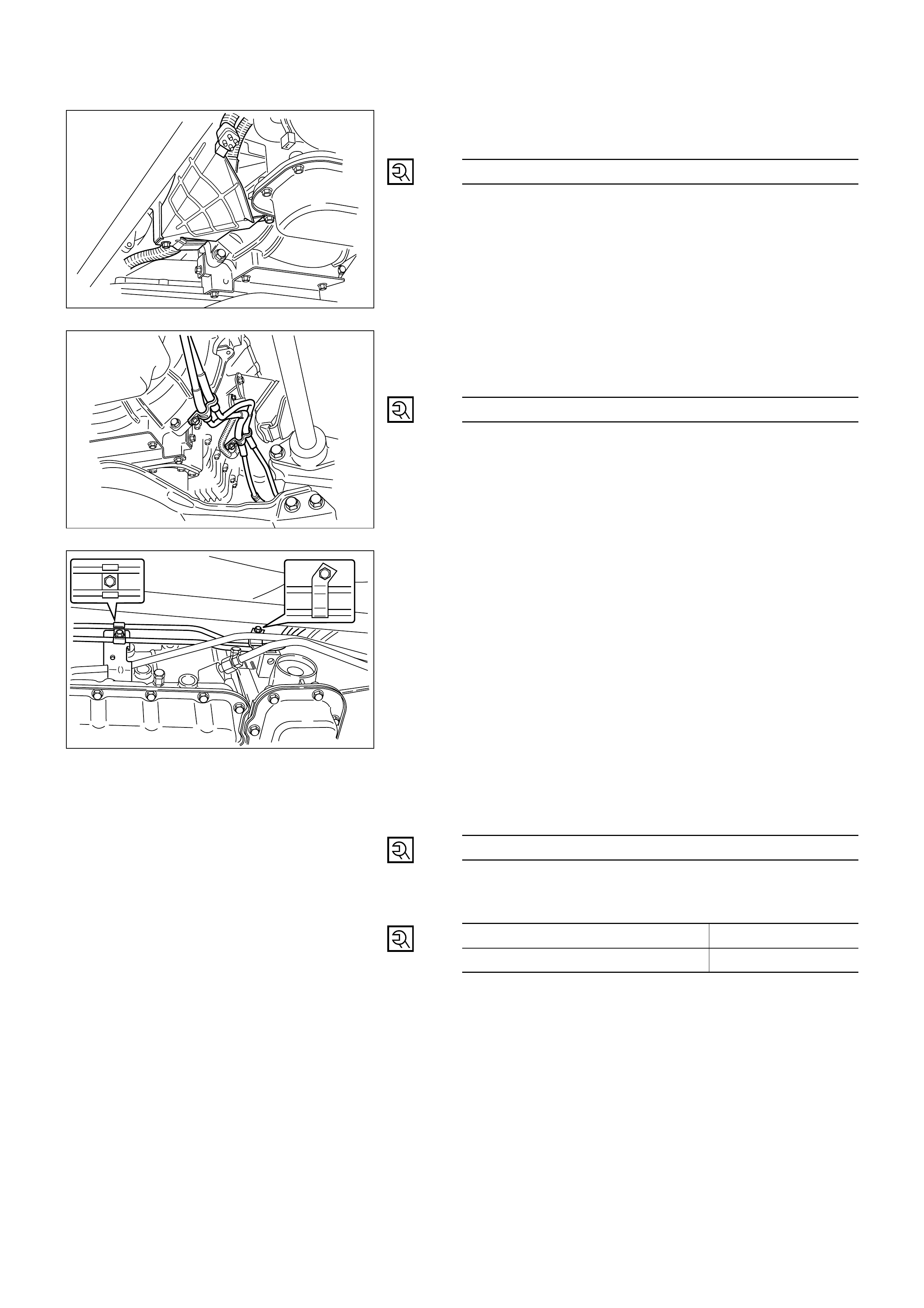
SOLENOID VALVE
(MAIN CASE VALVE BODY)
REMOVAL
Preparation:
• Disconnect negative (–) battery cable.
• Drain fluid.
Refer to “SERVICING” of the SERVICE
INFORMATION (Section 7C).
•Remove exhaust pipe and disconnect oxygen
sensor connector.
•Support transmission case with a jack and remove
third crossmember.
1. Main Case Oil Pan
Remove sixteen 10 mm screws, main case oil pan,
magnet, and gasket.
2. Oil Filter
Remove three 13 mm screws, oil filter.
3. Wiring Harness
Disconnect wiring harness from band control
solenoid, shift solenoids. Pull only on connectors, not
on wiring harness.
4. Spring Pin
Remove spring pin for shift solenoid A, shift solenoid
B, and band control solenoid respectively, using
suitable pliers taking care not to damage solenoids.
5. Solenoids
Remove shift solenoid A, shift solenoid B, band
control solenoid, and gaskets from main case valve
body. Do not pull on wiring harness. Remove
solenoids by grasping the metal tip.
210RW010
244RW003

INSTALLATION
To install, follow the removal steps in the reverse order,
noting the following points;
5. Solenoids
Install 1shift solenoid A, shift solenoid B, band control
solenoid with new gaskets to main case valve body
respectively.
4. Spring Pin
Carefully install spring pin with hammer to avoid
damage to valve body etc.
3. Wiring Harness
Connect wiring harness to solenoids.
2. Oil Filter
Install oil filter with new gasket, three 13 mm screws.
Oil Filter Bolt Torque N·m (kg·m / lb·ft)
20 (2.0 / 15)
1. Main Case Oil Pan
Install magnet, main case oil pan with new gasket,
sixteen 10 mm screws
Main Case Oil Pan Bolt Torque N·m (kg·cm / lb·in)
11 (110 / 96)
• Install third crossmember and rear mount nuts.
Rear Mount Nut Torque N·m (kg·m / lb·ft)
41 (4.2 / 30)
Third Crossmember Bolt Torque N·m (kg·m / lb·ft)
50 (5.1 / 37)
• Install exhaust pipe and connect oxygen sensor
connector.
Exhaust Pipe Flange Bolt Torque N·m (kg·m / lb·ft)
43 (4.4 / 32)
• Refill the transmission with new ATF DEXRON-III.
Refer to “SERVICING” of the SERVICE
INFORMATION (Section 7C).
•Connect negative (–) battery cable.
243RW004
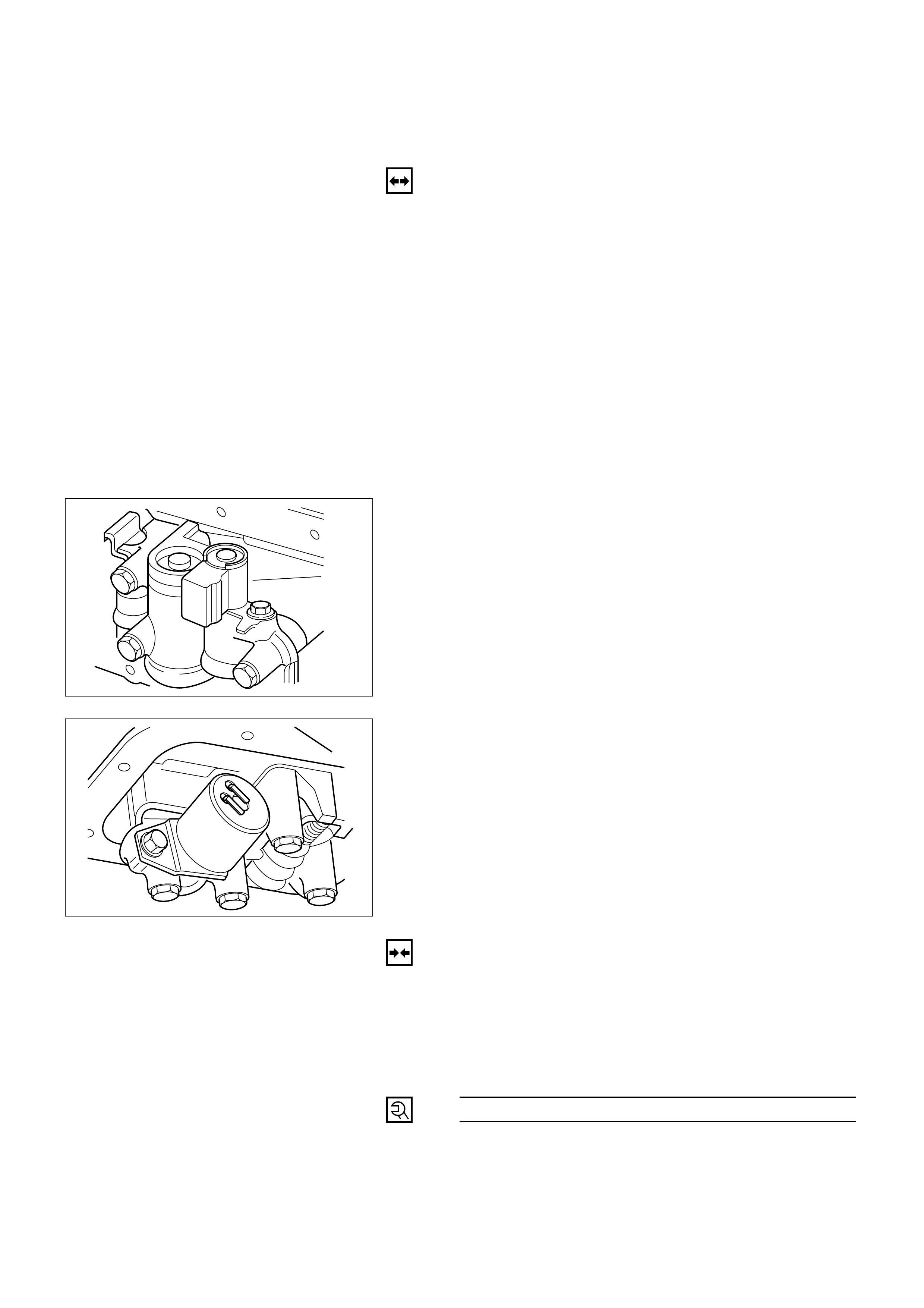
SOLENOID VALVE
(ADAPTER CASE VALVE BODY)
REMOVAL
Preparation:
• Disconnect negative (–) battery cable.
• Drain fluid.
Refer to “SERVICING” of the SERVICE
INFORMATION (Section 7C).
•Remove exhaust pipe and disconnect oxygen
sensor connector.
1. Adapter Case Oil Pan
Remove twelve 10 mm screws, adapter case oil pan,
and gasket.
2. Wiring Harness
Disconnect wiring harness from force motor solenoid,
converter clutch solenoid. Pull only on connectors,
not on wiring harness.
3. Solenoid
•Remove 11 mm bolt and converter clutch solenoid
with two O-rings.
•Remove 11 mm bolt, retainer, and force motor
solenoid.
INSTALLATION
To install, follow the removal steps in the reverse order,
noting the following points;
3. Solenoids
1) Install force motor solenoid, retainer, and 11 mm
bolt to adapter case valve body.
Retainer Bolt Torque N·m (kg·cm / lb·in)
10 (100 / 87)
210RW011
210RW009

2) Install converter clutch solenoid with two O-rings.
3) Tighten 11 mm converter clutch solenoid bolt to
adapter case valve body.
Converter Clutch Solenoid
Bolt Torque N·m (kg·cm / lb·in)
10 (100 / 87)
2. Wiring Harness
Connect wiring harness assembly to solenoids.
1. Adapter Case Oil Pan
Install adapter case oil pan, new gasket, and twelve
10 mm screws.
Adapter Case Oil Pan
Bolt Torque N·m (kg·cm / lb·in)
11 (110 / 96)
• Install exhaust pipe and connect oxygen sensor
connector.
Exhaust Pipe Flange Bolt Torque N·m (kg·m / lb·ft)
43 (4.4 / 32)
• Refill the transmission with new ATF DEXRON-III.
Refer to “SERVICING” of the SERVICE
INFORMATION (Section 7C).
•Connect negative (–) battery cable.
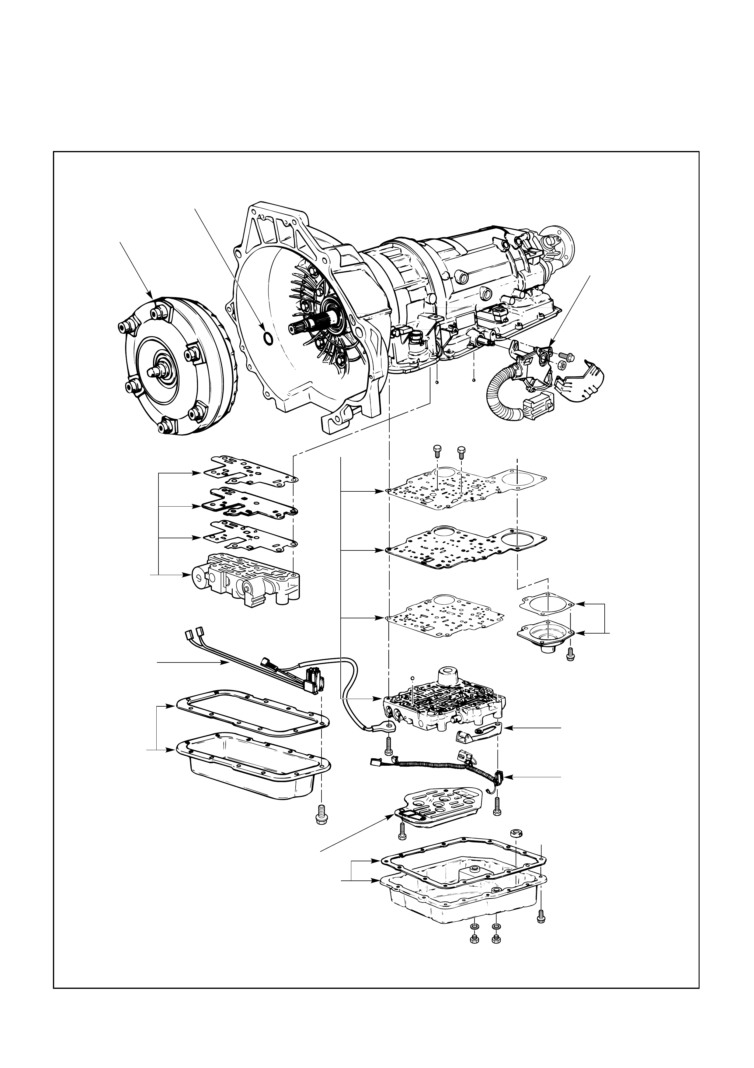
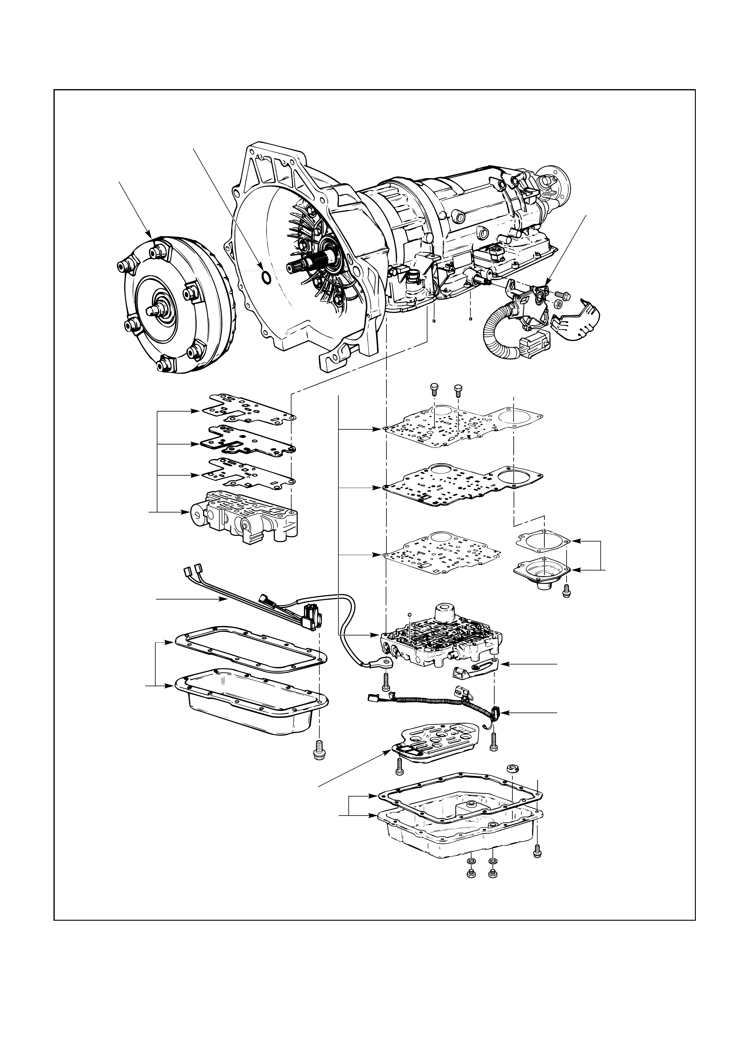
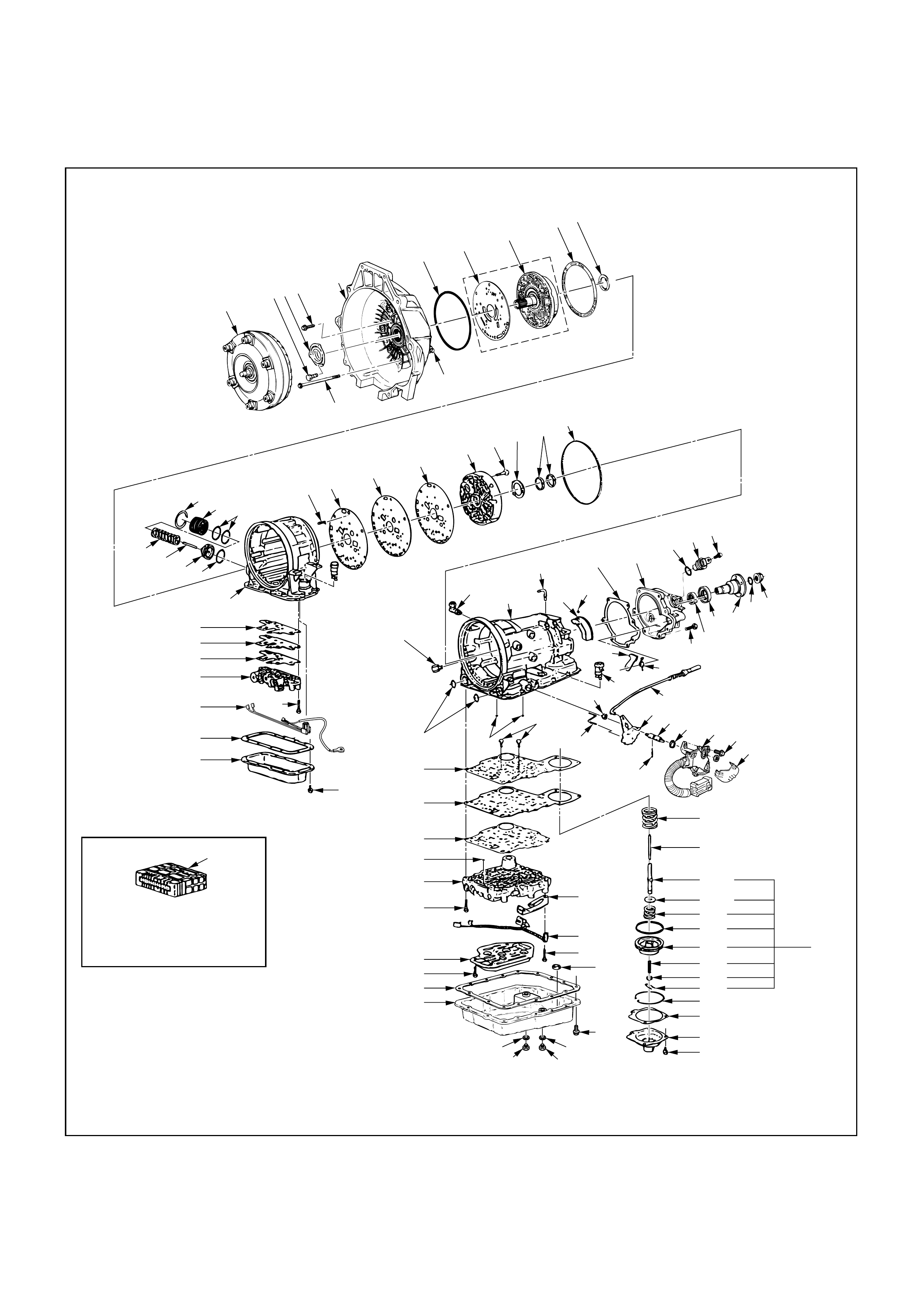
UNIT REPAIR
TRANSMISSION (4L30-E)
2. O-ring
1. Torque converter
3. Mode switch
and transmission
harness
6. Adapter case
valve body
5. Wiring harness
4. Adapter case
oil pan
8. Oil filter
7. Main case oil pan
12.Main
case
valve
body
9. Manual detent
11. Servo cover
10. Wiring harness
240LW003
DISASSEMBLY
During the disassembly and reassembly of the following
components, perform the following:
•Wash each part thoroughly and blow air through
each oil passage and groove to eliminate blockage.
•Seal rings, roll pins and gaskets should be replaced
with new parts.
•When assembling the components, apply DEXRON-
III Automatic transmission fluid to each seal, rotating
part and sliding part.
•Do not dip those parts having a facing, such as drive
plate for clutch or brake, in the cleaner when washing
it with solvent.
Also, always wash it with new ATF two or three times
after cleaning with solvent.
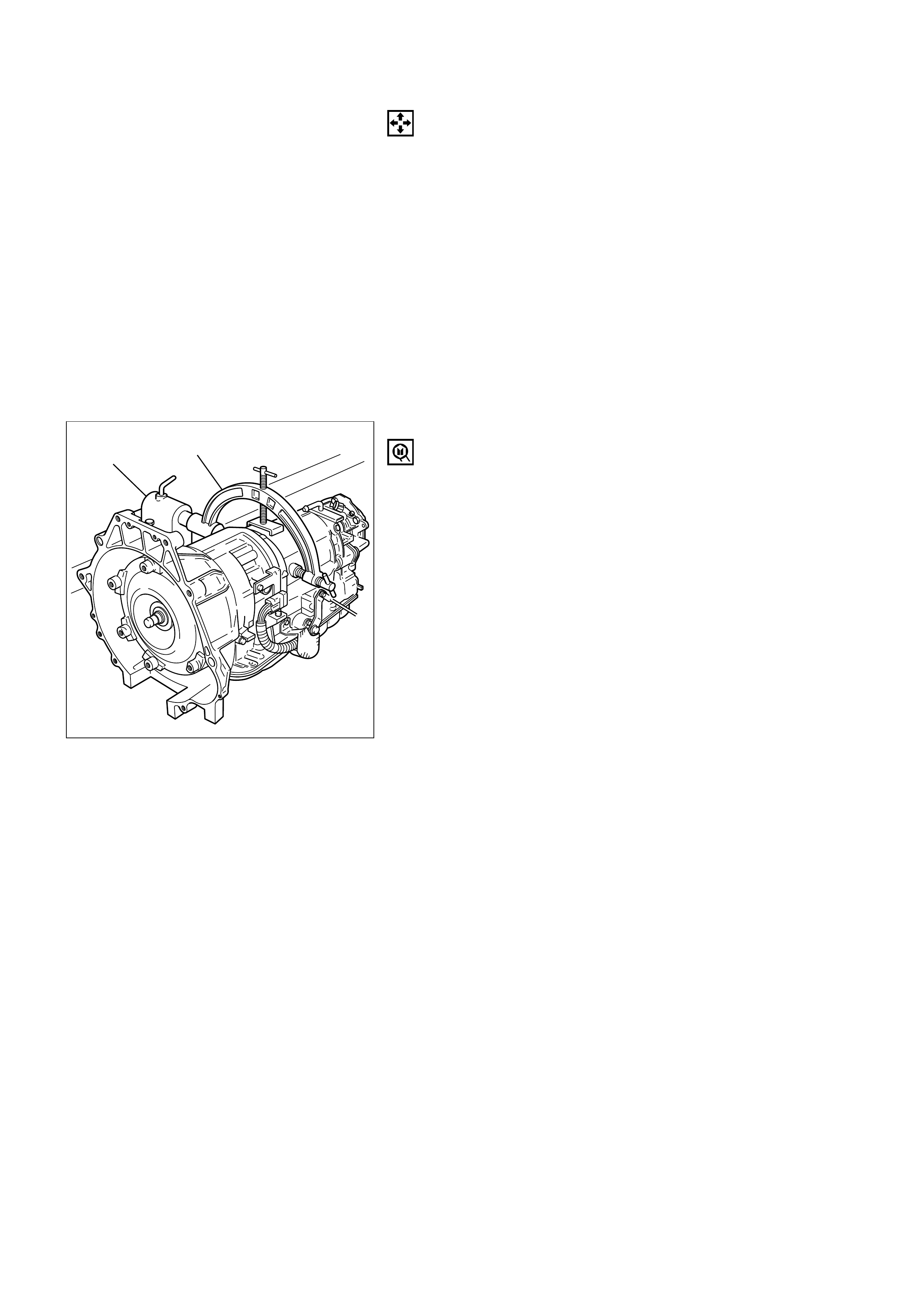
1. Torque Converter
1) Drain fluid from torque converter.
2) Attach holding fixture to the transmission and set
it on holding fixture base.
Holding fixture: 5-8840-2278-0 (J-8763-02)
Fixture base: 5-8840-0003-0 (J-3289-20)
NOTE:
Do not overtighten the tool, as case damage may
result.
2. O-Ring
Remove O-ring from turbine shaft.
3. Mode Switch
1) Remove two 10mm screws, cover and mode
switch.
4. Adapter Case Oil Pan
1) Remove twelve 10mm screws, adapter oil pan,
and gasket.
5. Wiring Harness
1) Disconnect electrical connections from solenoids.
Pull on connectors only, not on wiring harness.
6. Adapter Case Valve Body
1) Remove seven 13mm screws, adapter case valve
body assembly, transfer plate and two gaskets.
2) Remove wiring harness and 5 pin connector.
7. Main Case Oil Pan
Remove sixteen 10mm screws, main oil pan, magnet,
and gasket.
8. Oil Filter
Remove three 13mm screws, oil filter.
9. Manual Detent
Remove two 13mm screws, roller & spring and
manual detent.
5-8840-0003-0 5-8840-2278-0
420RW019
10. Wiring Harness
1) Disconnect harness assembly from band apply
solenoid, shift solenoids and main case 4 pin
connector.
2) Remove 4 pin connector.
11. Servo Cover
Remove four 13mm screws, servo cover and gasket.
12. Main Case Valve Body and Ground Wire
1) Remove seven 13mm valve body screws.
2) Remove ground wire from main case.
3) Remove main valve body assembly with manual
valve link and transfer plate.
NOTE:
Note the position of link, with the long end into valve
short end, into range selector lever.
3) Remove gasket transfer plate from main case.
4) Remove two check balls from main case.
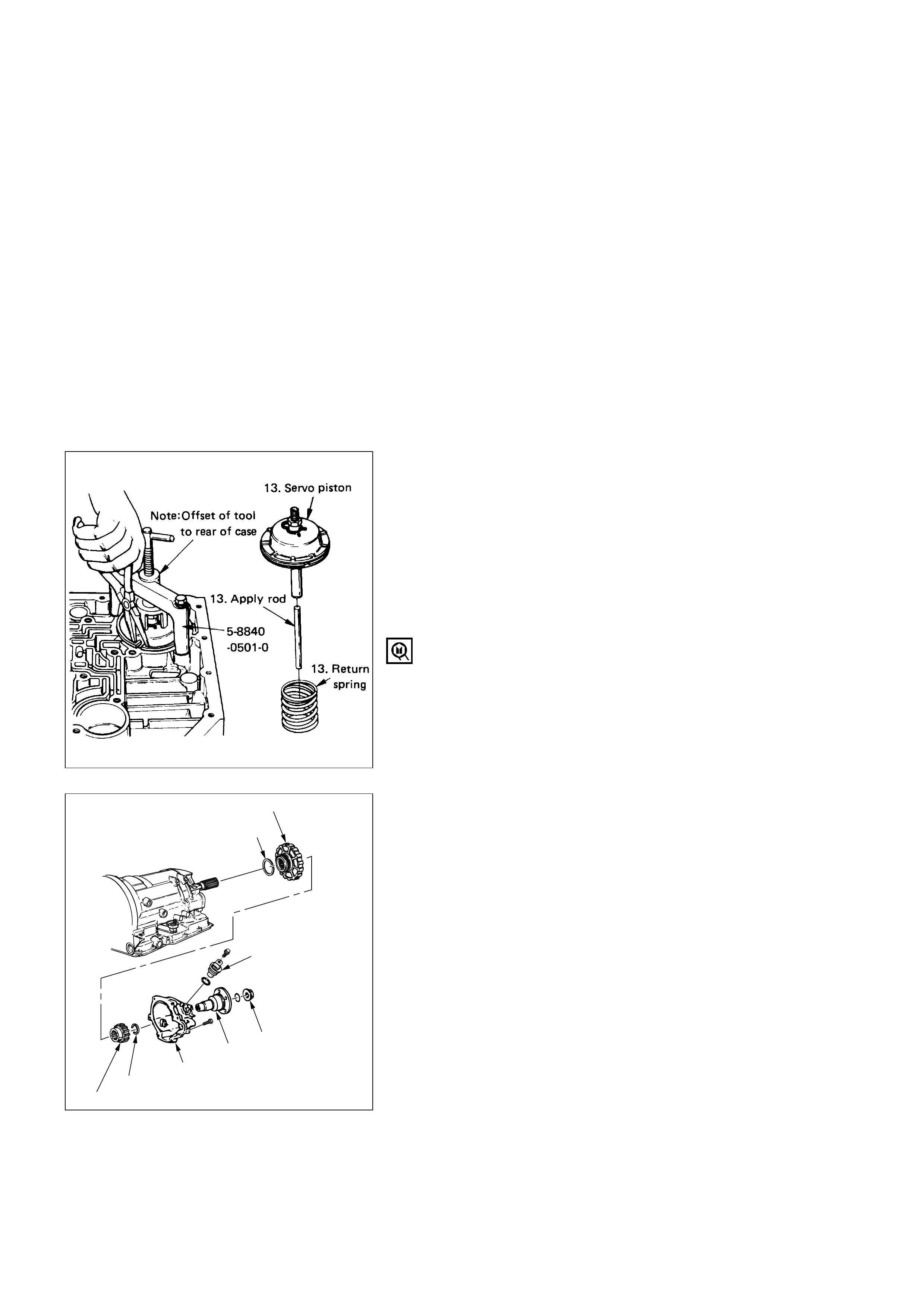
13. Servo Piston
1) Turn transmission to vertical position to drain
fluid. Return back to horizontal position when
drained.
2) Install servo piston spring compressor with offset
to the rear of case.
3) Compress servo piston assembly.
4) Remove servo piston retaining ring.
5) Slowly release servo piston assembly.
6) Remove tool.
7) Remove servo piston assembly, return spring,
and servo apply rod.
Servo piston spring compressor: 5-8840-0501-0
(J-23075)
14. Speed Sensor
1) Rotate transmission to horizontal position, pan
side down.
2) Remove one 10mm screw, and speed sensor with
O-ring.
15. Extension Housing and Flange
1) Remove seven 8mm hexagon socket head screws,
extension assembly, and gasket.
2) Remove retaining ring.
NOTE:
Use extra long nose pliers.
3) Remove flange nut.
4) Remove flange and O-ring.
5) Remove speed wheel.
6) Remove wheel parking lock (with seal ring).
15.Wheel parking lock
Seal ring
15.Speed wheel
15.Retaining ring
15.Extension housing
15.Flange
15.Flange nut
14.Speed sensor
241LW001
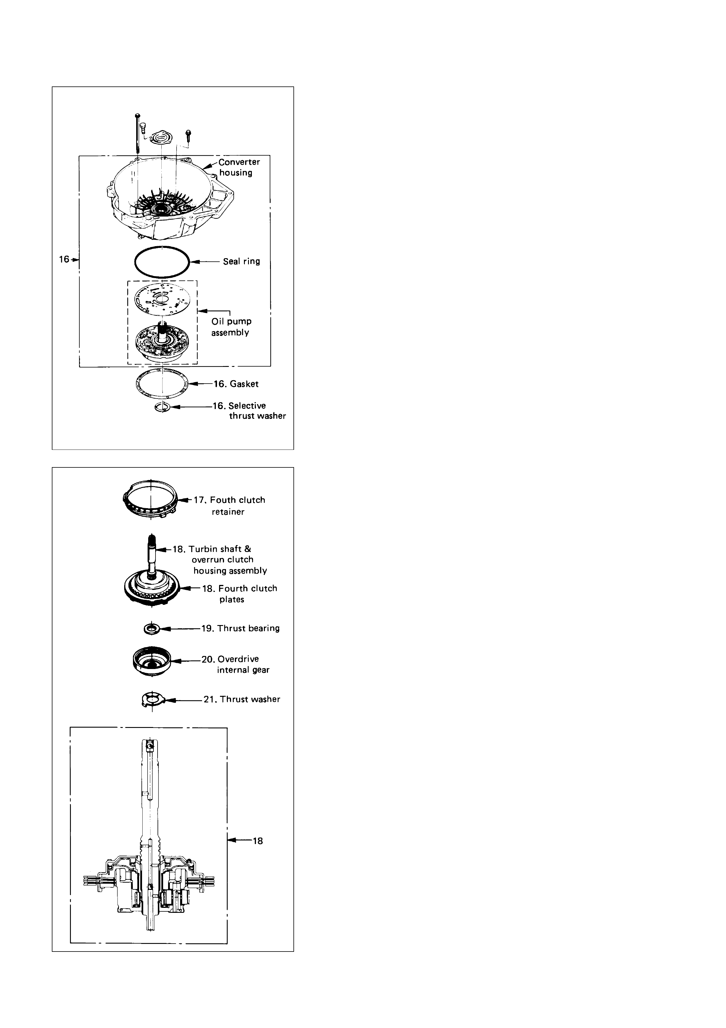
16. Converter Housing and Oil Pump Assembly
1) Rotate transmission to vertical position, converter
housing up.
2) Loosen, but not remove, five 13 mm inner screws
if oil pump disassembly required.
3) Remove seven outer screws.
4) Remove converter housing and oil pump
assembly.
5) Remove gasket.
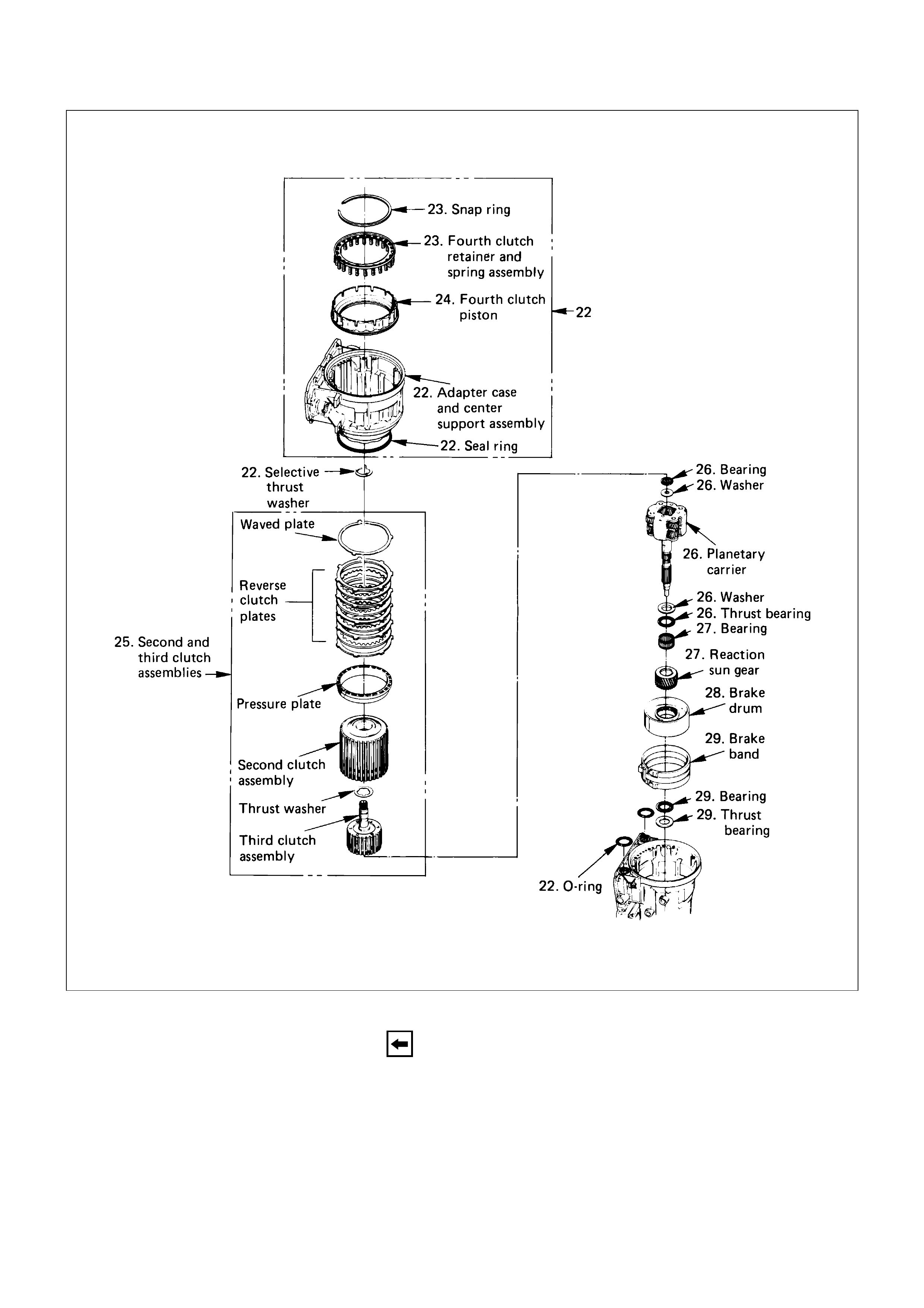
6) Remove selective thrust washer.
17. Fourth Clutch Retainer
Remove fourth clutch retainer.
18. Turbine Shaft and Clutch Plates
Grasp turbine shaft and lift out the overrun clutch
housing assembly and fourth clutch plates.
19. Thrust Bearing Assembly
Remove thrust bearing assembly.
20. Overdrive Internal Gear
Remove overdrive internal gear.
21. Thrust Washer
Remove thrust washer.

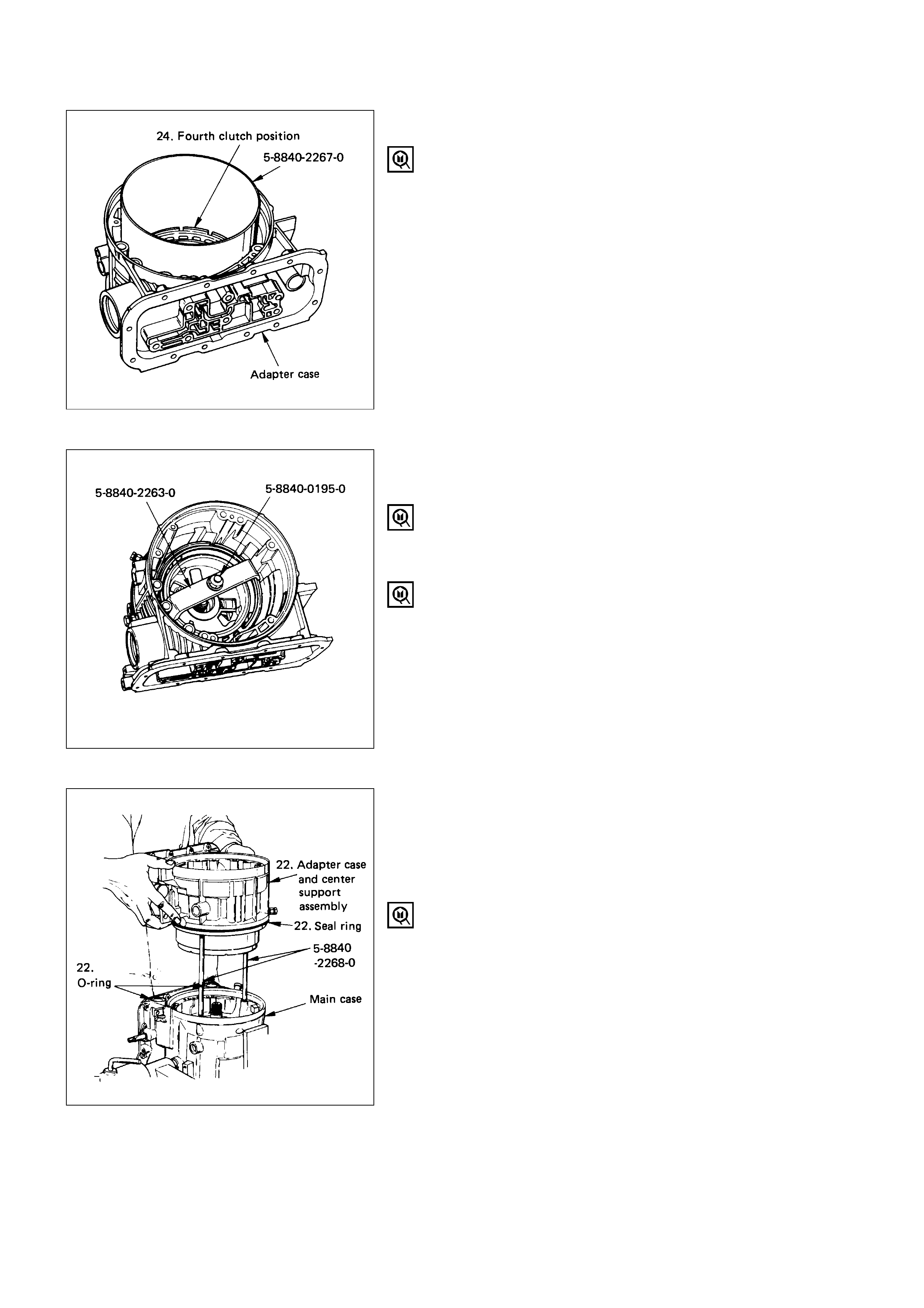
22. Adapter Case and Center Support Assembly
1) Remove adapter case and center support
assembly (with fourth clutch piston).
2) Remove seal ring.
3) Remove selective thrust washer and two O-ring
seals from main case.
23. Fourth Clutch Spring Retainer
1) Compress the fourth clutch spring retainer and
springs.
2) Release snap ring from groove.
3) Remove clutch compressor and snap ring.
4) Remove retainer and spring assembly.
Compressor: 5-8840-0195-0 (J-23327) and
5-8840-2263-0 (J-23327-90)
24. Fourth Clutch Piston
1) Insert two converter housing/main case screws to
hold adapter case while pulling out fourth clutch
piston.
2) Remove fourth clutch piston assembly.
3) Remove converter housing/main case screws.
25. Second and Third Clutch Assemblies
1) Grasp intermediate shaft, twist and pull out the
second and third clutch drum assemblies with
reverse clutch plates while holding onto output
shaft.
2) Separate 2nd and 3rd clutch assemblies.
3) Remove thrust washer.
4) Remove reverse clutch plates and reverse clutch
pressure plate.
26. Planetary Carrier Assembly
1) Remove bearing and washer.
2) Remove planetary carrier assembly.
3) Remove thrust bearing.
27. Reaction Sun Gear
1) Remove reaction sun gear
2) Remove needle bearing.
28. Brake Drum
Remove brake drum.
29. Brake Band
1) Remove brake band.
2) Remove thrust bearing.
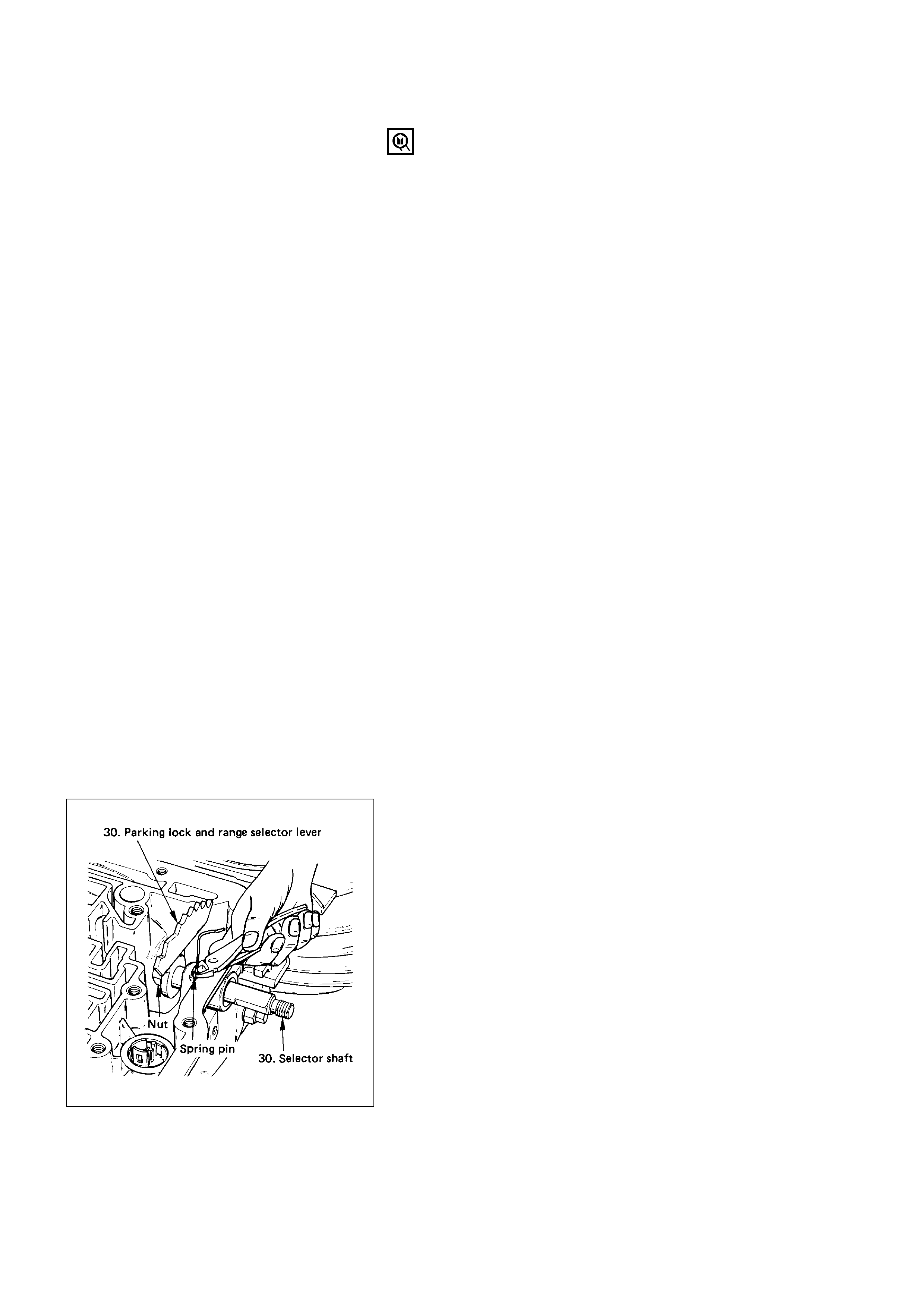
30. Parking Lock and Selector Lever Assembly
1) Rotate case to horizontal position, valve body side
facing up.
2) Remove spring pin, using cutting pliers.
NOTE:
Insert wire in the center of the spring pin to prevent
it from collapsing during removal. Be aware of pin
height. Protect machined face of main case.
3) Remove parking lock and range selector lever 17
mm nut.
4) Remove parking lock and range selector lever and
actuator assembly.
5) Remove selector shaft.
NOTE:
Inspect the shaft for burrs before removing to
prevent damaging seal. If necessary, remove burrs by
lightly sanding with an oilstone.
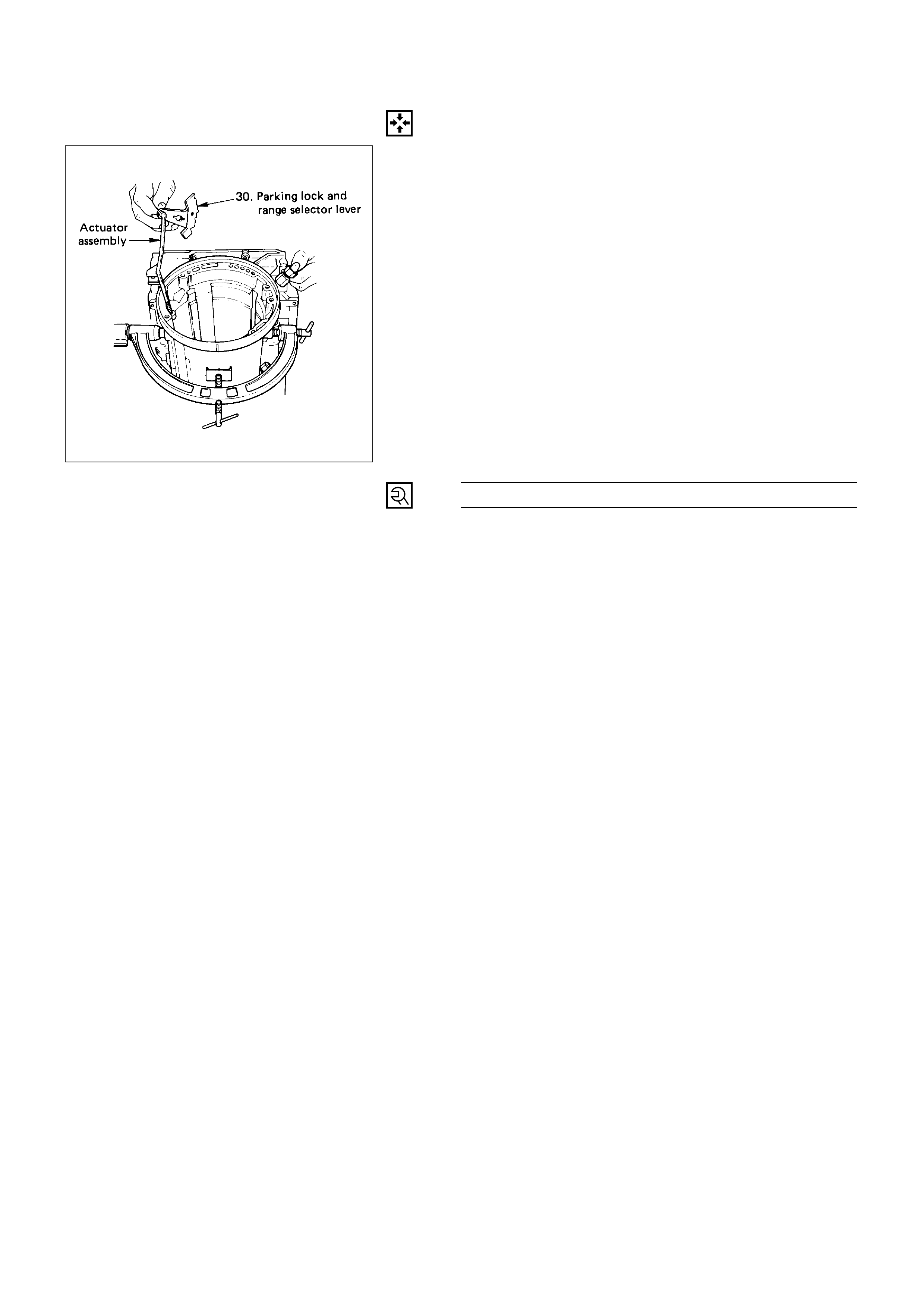
REASSEMBLY
30. Parking Lock and Selector Lever Assembly
1) Inspect selector shaft seal, replace if necessary.
NOTE:
Use a seal installer when replacing the seal.
2) Install selector shaft.
NOTE:
Spring pin groove must be positioned inside the
case.
3) Install spring pin. Be sure the selector shaft can
move freely.
Do not push the pin flush with the case surface.
Leave enough height for removal.
4) Install actuator assembly.
5) Install parking lock and range selector lever and
new 17 mm nut.
Selector Lever Nut Torque N·m (kg·m / lb·ft)
22 (2.2 / 16)
29. Brake Band
1) Rotate main case to vertical position, extension
end facing down.
2) Install brake band assembly.
NOTE:
Be sure to align servo pin area with the servo hole.
3) Install thrust bearing.
NOTE:
The case bushing acts as a guide for the thrust
bearing.
28. Brake Drum
Install brake drum.
27. Reaction Sun Gear
1) Install reaction sun gear.
2) Install needle bearing.
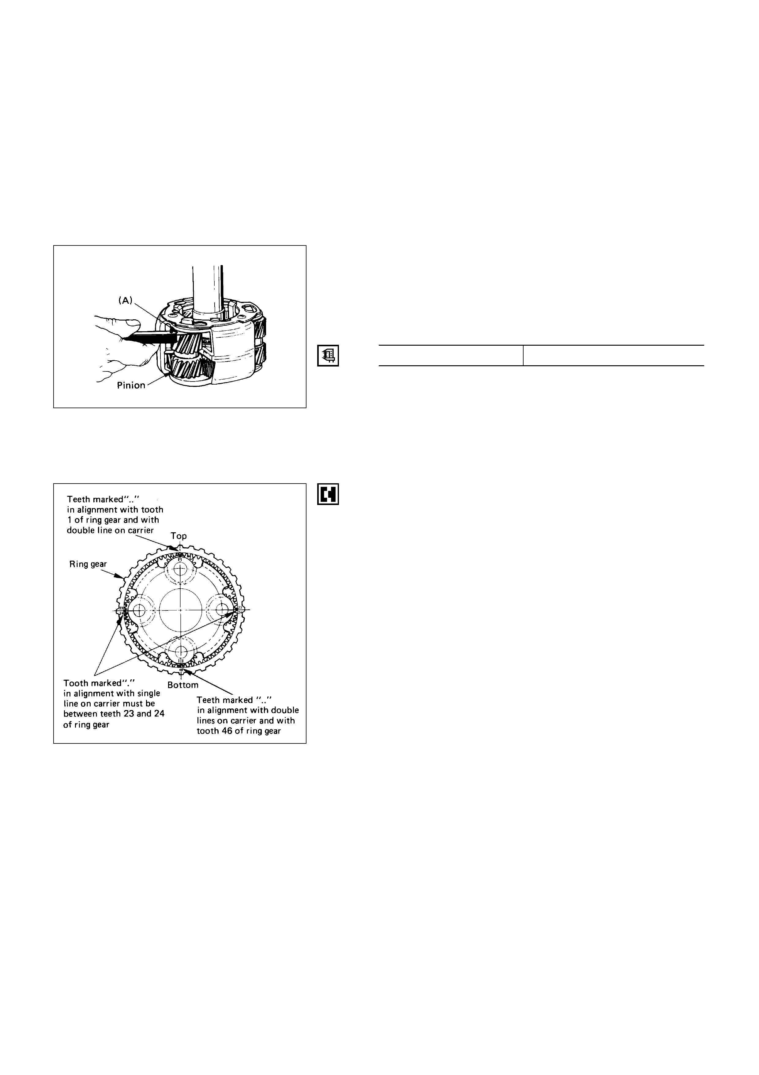
26. Planetary Carrier Assembly
1) Inspect planetary carrier assembly for wear and
damage, if necessary renew.
2) Measure pinion end play clearance (A)with a
feeler gage.
Planetary Carrier Pinion End Play (A) mm (in)
Standard 0.13 – 0.89 (0.005 – 0.035)
If clearance is outside specified valve, replace
planetary carrier assembly.
3) Install the thrust bearing on the output shaft.
NOTE:
Use petroleum jelly to hold the thrust bearing in
place.
4) Align planetary pinions. Each planetary pinion is
marked with double points to indicate the master
tooth space and exactly opposite with a single
point to indicate the master tooth. The markings
on the planetary carrier consist of double lines
which are to be lined-up with the double points
on two opposite pinions; the single lines are to be
lined-up with the single points on the other two
pinions.
5) After all four pinions are lined-up, slide on third
clutch assembly. Rotate third clutch and check
mark alignment. Considering that the ring gear
tooth between the double points of one planetary
pinion is tooth number 1, count the teeth to check
that the single points on the two adjacent pinions
are between teeth 23 and 24 of the ring gear, and
that the ring gear tooth between the double
points of the opposite pinion is tooth number 46.
If it is not so, remove, realign and try again.
6) Install planetary carrier with third clutch.
NOTE:
Do not force. When properly aligned, the parts will fit
together easily.
7) Remove the third clutch.
8) Install bearing and washer.
NOTE:
Use petroleum jelly to hold the washer and bearing
in place.
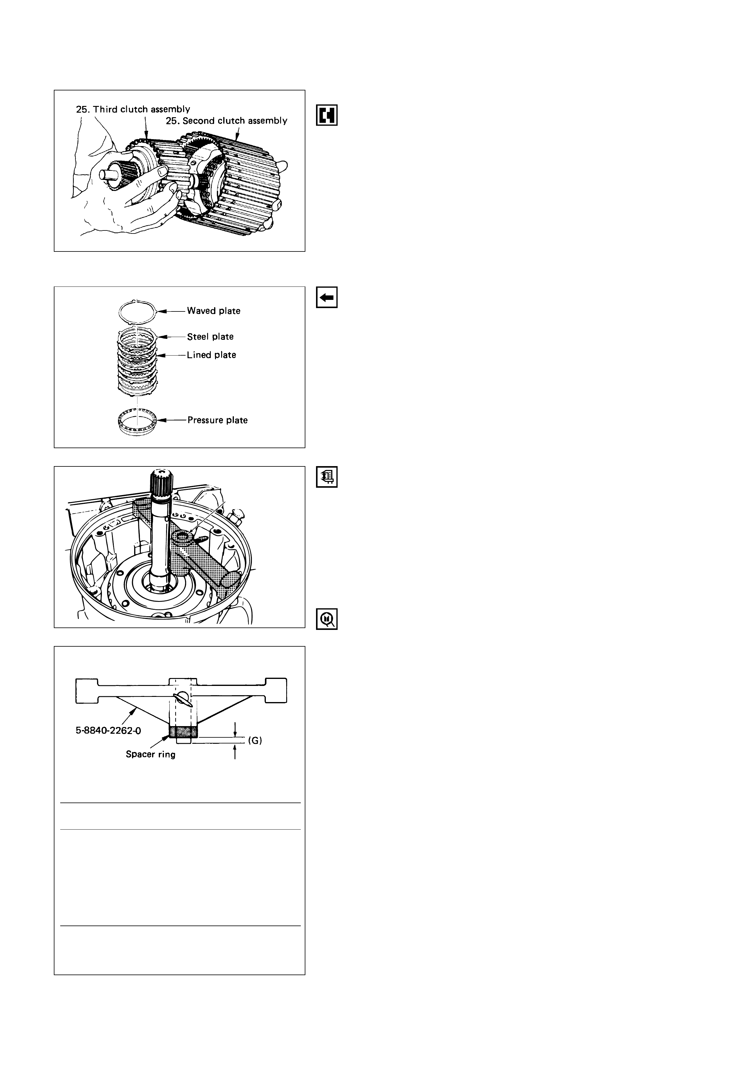
25. Second and Third Clutch Assemblies
1) Carefully align second clutch plates inner tangs.
2) Install thrust washer, tangs pointing downward,
locating tang positioned in slot on second clutch
hub.
NOTE:
Use petroleum jelly to hold thrust washer in place.
3) Install third clutch and intermediate shaft
assembly into the second clutch drum.
4) Install second and third clutch assemblies into the
main case. Twist output shaft and clutch
assemblies to insure proper fit.
5) Install pressure plate with lip side up, tang facing
valve body face.
6) Install reverse clutch plates. Start with a steel
plate and alternate with lined plates.
7) Install waved clutch plate, center tang facing valve
body side.
5-8840-2262-0
Second clutch end play measurement
1) Install the gaging tool on the case flange and
against the intermediate shaft.
2) Position the inner shaft of the gaging tool against
the thrust surface of the second clutch hub.
3) Tighten thumb screw. Remove the tool.
4) Fit the spacer ring on the inner shaft of the tool.
5) Measure gap (“G”). Select appropriate size
washer as the chart specified.
Selective washer gaging tool: 5-8840-2262-0
(J-23085-A)
Selective Thrust Washer
DIM. “G” mm(in) Color
1.53 - 1.63 (0.060 - 0.064) YELLOW
1.72 - 1.82 (0.068 - 0.072) RED
1.91 - 2.01 (0.075 - 0.079) BLACK
2.10 - 2.20 (0.083 - 0.087) NATURAL
2.29 - 2.39 (0.090 - 0.094) GREEN
2.48 - 2.58 (0.098 - 0.102) BLUE
FOLLOWING THE PROCEDURE SHOULD
RESULT IN FINAL END-PLAY FROM
0.36mm TO 0.79 mm (.014” TO .031”)
247RW007
17. Fourth clutch retainer
18. Fourth clutch plates
18. Turbine shaft and overrun clutch
Turbine shaft
Turbine shaft oil seal ring
Overrun clutch drum
Overrun clutch piston
2. O-ring
Overrun clutch relase
spring retainer
Roller clutch
Snap ring
Sun gear
Clutch plate
Backing plate
Snap ring
OD
carrier assembly
20. OD
internal gear
21. Thrust
washer
Diaphragm spring
Overrun roller clutch cam
24. Fourth clutch piston
23. Snap ring
23. Retainer and spring assembly
Fourth clutch piston
Piston seal Piston seal
19. Thrust
bearing
Snap ring
Ratainer and
ball assembly
23. Fourth Clutch Spring Retainer
1) Install retainer and spring assembly.
2) Install snap ring in adapter case.
3) Install compressor.
4) Compress retainer and spring assembly.
5) Seat snap ring in groove.
6) Remove compressor.
Fourth clutch spring compressor: 5-8840-0195-0
(J-23327) and 5-8840-2263-0 (J-23327-90)
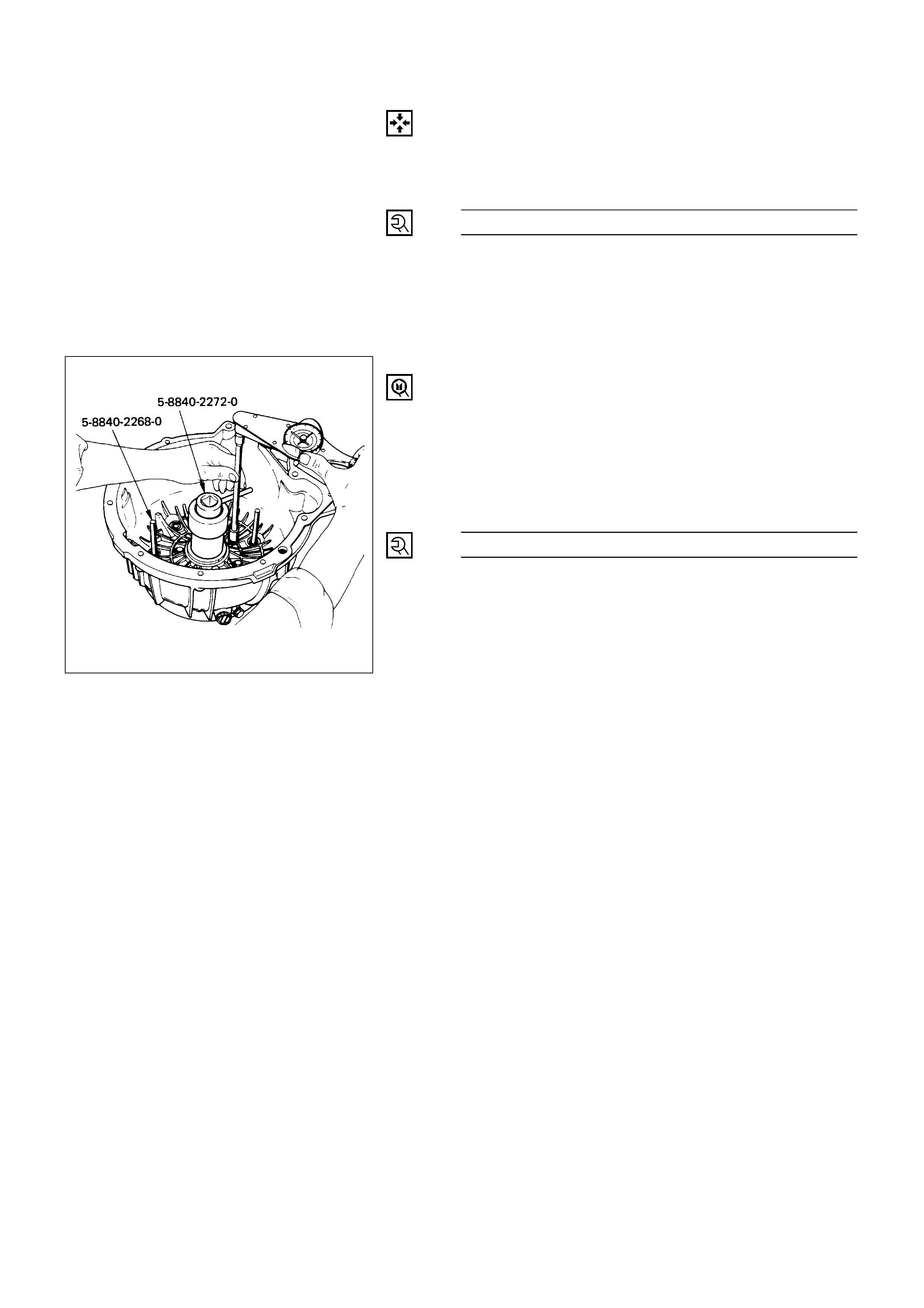
22. Adapter Case and Center Support Assembly
1) Install selective washer using petroleum jelly.
2) Install two O-ring seals in main case and adapter
case/main case seal ring.
3) Install guide pins.
4) Install adapter case complete to main case.
Guide pin: 5-8840-2268-0 (J-38588)
24. Fourth Clutch Piston
1) Inspect piston seals and replace if necessary.
2) Lubricate fitter and install on fourth clutch piston.
3) Install fourth clutch piston in adapter case.
4) Remove fitter.
Fourth clutch piston fitter: 5-8840-2267-0 (J-38554)
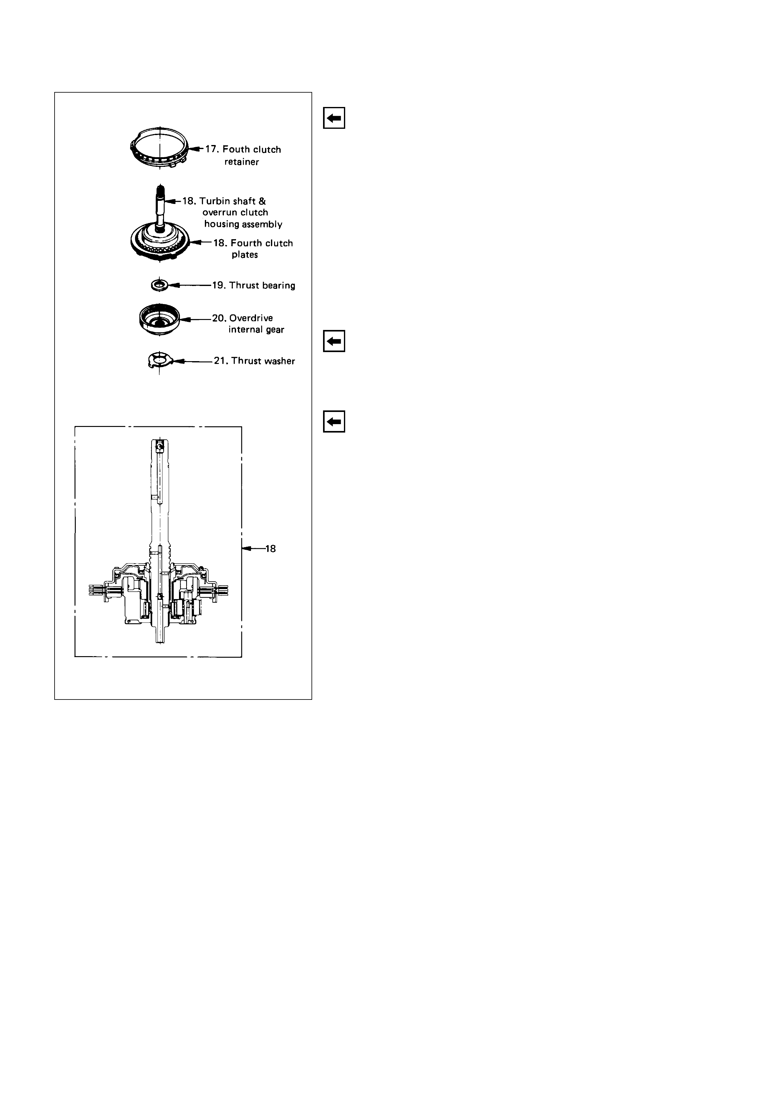
21. Thrust Washer
Install thrust washer into adapter case, with tangs
pointing downwards.
20. Overdrive Internal Gear
19. Thrust Bearing Assembly
18. Turbine Shaft and Fourth Clutch Plates
1) Preassemble overdrive internal gear and thrust
bearing assembly onto the overrun clutch
assembly complete.
NOTE
Install bearing assembly, black side up. Use
petroleum jelly to keep assembly in place.
2) Complete overdrive carrier and internal gear
assembly into adapter case.
3) Install fourth clutch plates in the following order.
Steel, Lined, Steel, Steel, Lined, Steel. Steel plates
go in with short tang facing towards valve body
surface.
17. Fourth Clutch Retainer
Install fourth clutch retainer.
Notch facing up and positioned towards valve body
surface.
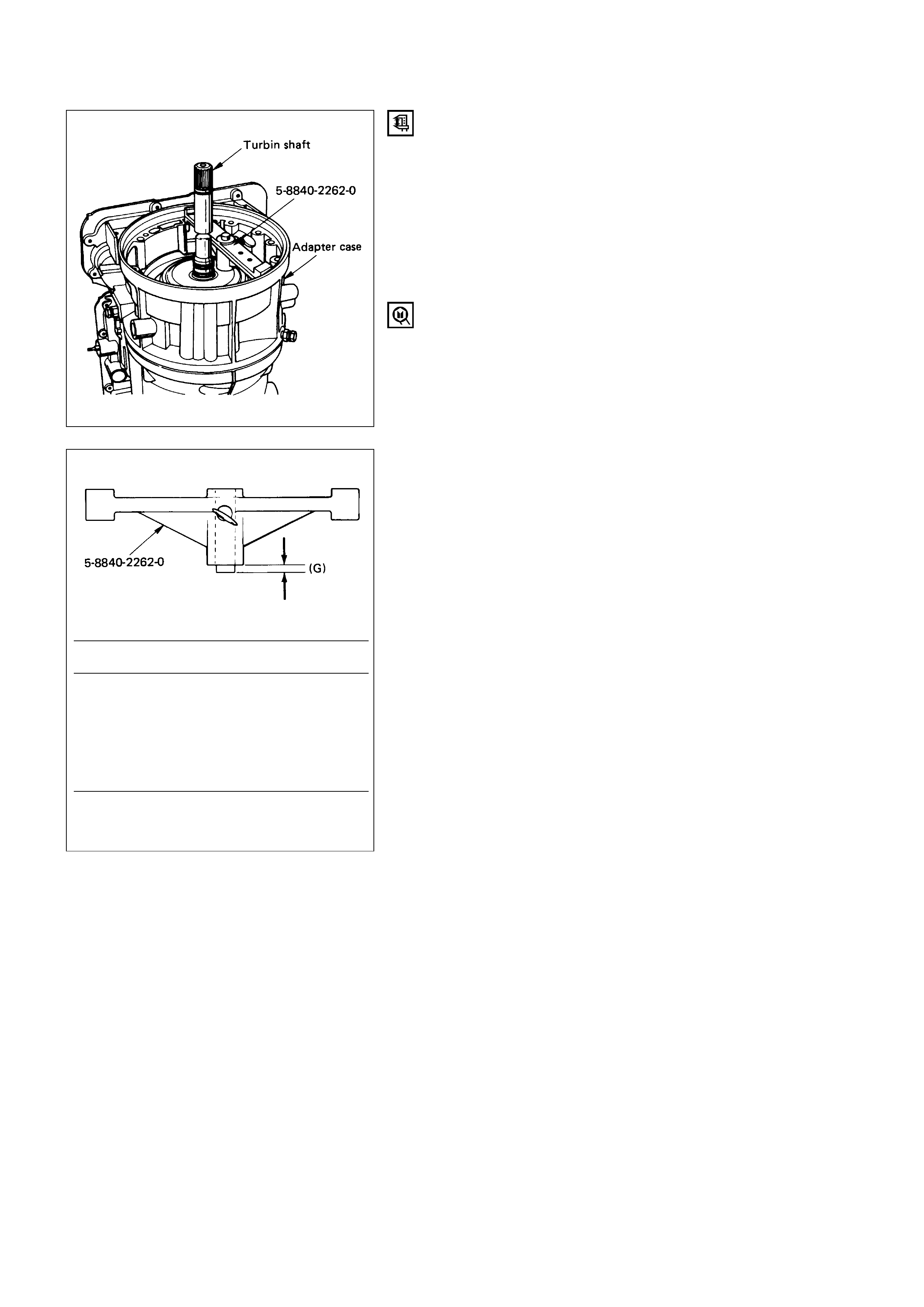
OD clutch end play measurement
1) Install the tool on the adapter case flange and
against the input shaft.
2) Position the inner shaft of the tool against the
thrust surface of the overrun clutch housing.
3) Tighten thumb screw. Remove the tool.
4) Measure gap “G”. Select appropriate size washer
as the chart specifies.
5) Set selective thrust washer aside.
Selective washer gaging tool: 5-8840-2262-0
(J-23085-A)
Selective Thrust Washer
DIM. “G” mm(in) Color
1.53 - 1.63 (0.060 - 0.064) YELLOW
1.72 - 1.82 (0.068 - 0.072) RED
1.91 - 2.01 (0.075 - 0.079) BLACK
2.10 - 2.20 (0.083 - 0.087) NATURAL
2.29 - 2.39 (0.090 - 0.094) GREEN
2.48 - 2.58 (0.098 - 0.102) BLUE
FOLLOWING THE PROCEDURE SHOULD
RESULT IN FINAL END-PLAY FROM
0.1 mm TO 0.8 mm (0.004” TO 0.03”)
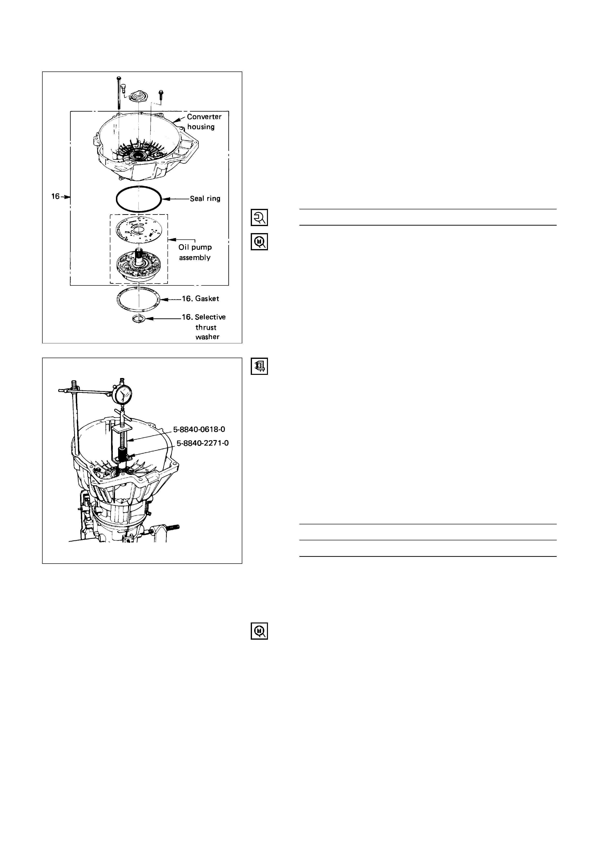
16. Converter Housing and Oil Pump Assembly
1) Install outer seal ring and gasket.
2) Install selective washer.
NOTE
Use petroleum jelly to hold selective washer in place.
3) Install complete converter housing and oil pump
assembly to adapter case.
4) Fit and tighten seven outer 13 mm screws.
Converter Housing Outer
Screw Torque N·m (kg·m / lb·ft)
39 (4.0 / 29)
5) Ensure free rotation of pump using rotation tool.
Pump rotation tool: 5-8840-2273-0 (J-23082-01)
Overdrive end play measurement
1) Fit puller on turbine shaft.
2) Position axial play checking tool on converter
housing mating face.
3) Pull turbine shaft upwards with puller until first
resistance is met.
(Due to weight of overdrive complete assembly)
Maintain shaft in this position and set indicator to
zero.
4) Pull turbine shaft further upwards with puller.
Read end play shown on indicator.
Overdrive End Play mm (in)
Standard
0.1 – 0.8 (0.004 – 0.031)
5) Remove axial play checking tool and puller.
NOTE:
If end play is not correct, repeat selective washer
selection.
Turbine shaft puller: 5-8840-2271-0 (J-25022) and
5-8840-0618-0 (J-24773-1)

15. Extension Housing and Flange
1) Inspect extension housing oil seal and
bearing.Replace if necessary.
Extension housing oil seal installer: 5-8840-2282-0
(J-36797)
2) Rotate transmission to horizontal position, with
valve body side down.
3) Inspect parking wheel seal ring. Replace if
necessary.
4) Install wheel parking lock assembly.
5) Install speed wheel and snap ring.
NOTE:
Use extra long nose pliers.
6) Install gasket onto extension assembly, using a
thin coating of oil.
7) Install extension housing assembly, and align
parking pawl shaft.
8) Install actuator assembly into extension
assembly.
9) Install seven 8 mm hexagon socket head screws.
Extension Housing Bolt Torque N·m (kg·m / lb·ft)
32 (3.3 / 24)
10) Install flange and O-ring.
11) Install flange nut.
Flange Nut Torque N·m (kg·m / lb·ft)
103 (10.5 / 76)
14. Speed Sensor
1) Inspect speed sensor O-ring. Replace if necessary.
2) Install speed sensor assembly and 10 mm screws.
Speed Sensor Bolt Torque N·m (kg·cm / lb·in)
9 (90 / 78)
Main case end play measurement
1) Attach axial play checking tool on the extension
housing and set indicator to zero on output shaft.
2) Manually push output shaft upwards.
Main Case End Play mm (in)
Standard
0.36 – 0.80 (0.014 – 0.031)
3) Remove axial play checking tool.
4) If end play is not correct, repeat selective washer
selection.
15.Wheel parking lock
Seal ring
15.Speed wheel
15.Retaining ring
15.Extension housing
15.Flange
15.Flange nut
14.Speed sensor
241LW001
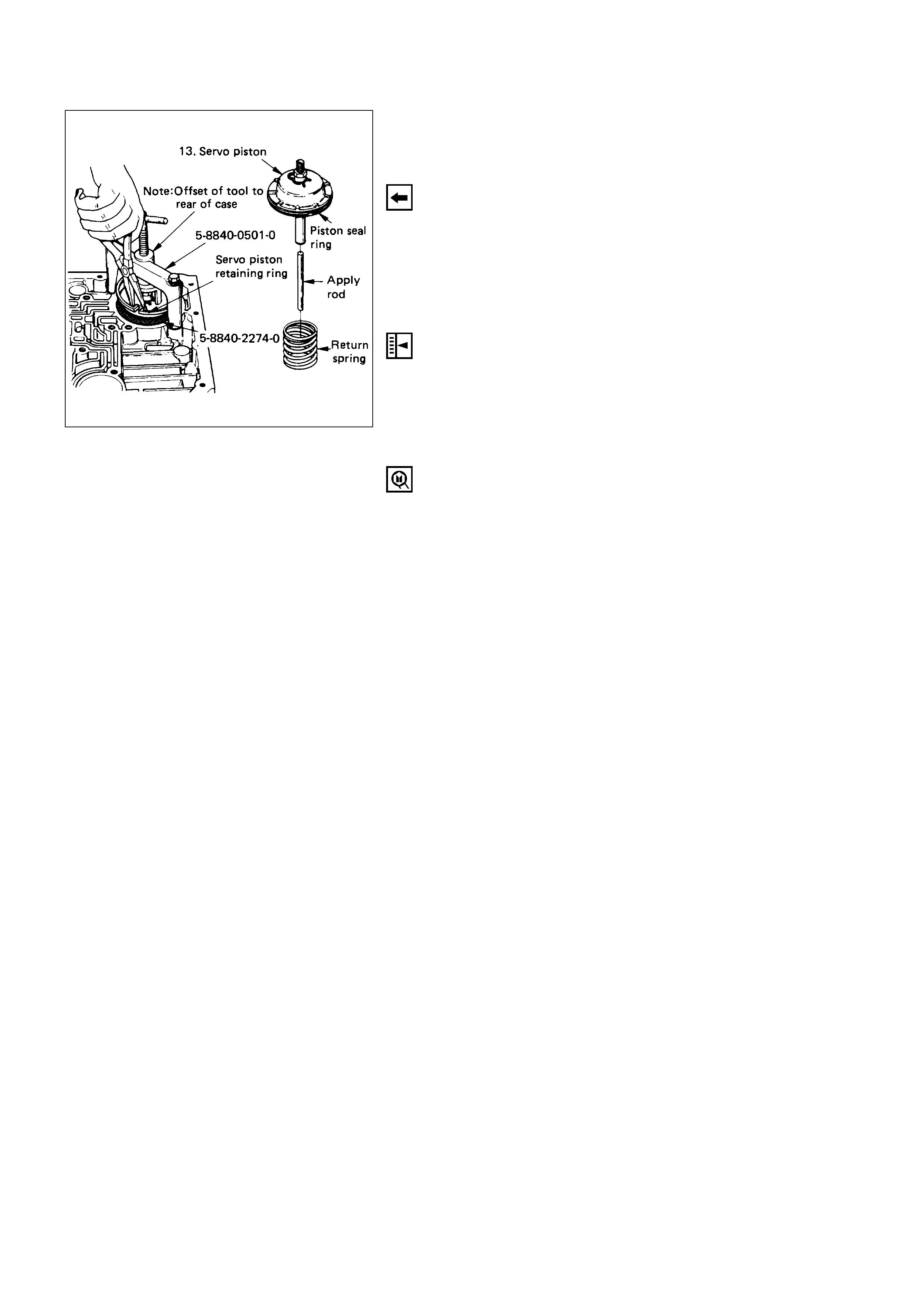
13. Servo Piston
1) Inspect piston seal ring. Replace if necessary.
2) Ensure brake band is correctly positioned. Rotate
output shaft if necessary.
3) Install servo piston fitter in servo bore.
4) Install apply rod, round end toward band, return
spring and piston assembly.
5) Install the tool with offset to rear of case.
6) Compress servo piston seal ring, using fitter while
tightening the tool screw.
7) Install servo piston retaining ring.
8) Remove tool.
9) Adjust the brake band by tightening the servo
adjusting screw to 4.5 N·m (46 kg·cm / 40 lb·in)
torque. Be certain the lock nut is loose, then back-
off the screw five turns exactly. Hold piston sleeve
with wrench and tighten lock nut to 18.5 N·m
(1.9 kg·m / 14 lb·ft) torque. Be certain the
adjusting screw does not turn.
Servo spring compressor: 5-8840-0501-0 (J-23075)
Servo piston fitter: 5-8840-2274-0 (J-38428)
2. O-ring
1. Torque converter
3. Mode switch
and transmission
harness
6. Adapter case
valve body
5. Wiring harness
4. Adapter case
oil pan
8. Oil filter
7. Main case oil pan
12.Main
case
valve
body
9. Manual detent
11. Servo cover
10. Wiring harness
240LW003
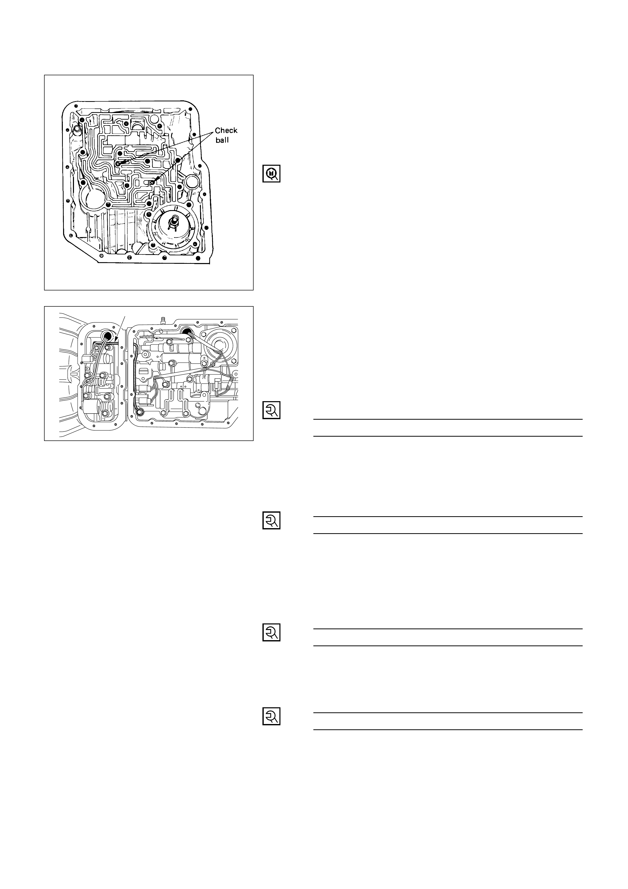
12. Main Case Valve Body and Ground Wire
1) Install two check balls.
2) Inspect electrical connector and seal, replace if
necessary.
3) Install electrical 4 pin connector/main case and
wiring harness.
4) Install two guide pins into main case.
Guide pin: 5-8840-0022-0 (J-25025-B)
5) Install valve body complete assembly and manual
valve link.
NOTE:
Valve must be extended as the short end of manual
valve link is connected to the range selector lever.
Long end of link goes into valve.
6) Install seven 13 mm screws.
7) Pass ground wire of adapter case wiring harness
assembly through the hole joining adapter fluid
area and main case fluid area.
8) Assemble 8.5 mm connector of ground wire under
the head of this valve body bolt and reinstall it.
Main Case Valve Body
Bolt Torque N·m (kg·m / lb·ft)
20 (2.0 / 15)
9) Remove two guide pins.
11. Servo Cover
Install servo cover gasket, cover and four 13 mm
screws.
Servo Cover Bolt Torque N·m (kg·m / lb·ft)
25 (2.5 / 18)
10. Wiring Harness
Connect harness to band control and shift solenoids.
9. Manual Detent
Install roller and spring assembly with clip.
Install two 13 mm screws.
Manual Detent Screw Torque N·m (kg·m / lb·ft)
20 (2.0 / 15)
8. Oil Filter
Install oil filter, three 13 mm screws.
Oil Filter Bolt Torque N·m (kg·m / lb·ft)
20 (2.0 / 15)
Earth harness
244RV001

7. Main Case Oil Pan
Install oil pan gasket, magnet, oil pan, sixteen 10 mm
screws.
Main Case Oil Pan Bolt Torque N·m (kg·cm / lb·in)
11 (110 / 96)
6. Adapter Case Valve Body
1) Inspect electrical connector and seal. Replace if
necessary.
Install electrical five pin connector and harness
assembly in bottom of adapter case.
Install gasket, transfer plate, gasket.
2) Install adapter case valve body complete and
seven 13 mm screws.
Adapter Case Valve Body
Bolt Torque N·m (kg·m / lb·ft)
20 (2.0 / 15)
5. Wiring Harness
1) Connect harness assembly to converter clutch
solenoid, and force motor.
4. Adapter Case Oil Pan
1) Install oil pan gasket, oil pan, twelve 10 mm
screws.
Adapter Case Oil Pan
Bolt Torque N·m (kg·cm / lb·in)
11 (110 / 96)
2) Rotate transmission, with bottom pan facing
down.

3. Mode Switch
1) Install mode switch, shield and two 10 mm
screws.
2) Adjust using setting tool.
Refer to “MODE SWITCH” in this section.
Selector Shaft Nut Torque N·m (kg·m / lb·ft)
23 (2.3 / 17)
Mode Switch Screw Torque N·m (kg·cm / lb·in)
13 (130 / 113)
2. O-Ring
Install O-ring on turbine shaft.
1. Torque Converter
1) The converter assembly must be replaced under
any of the following conditions:
a. Evidence of damage to the pump assembly
b. Metal particles are found after flushing the
cooler lines
c. External leaks in hub weld area
d. Converter Pilot broken, damaged or poor fit
into crankshaft
e. Converter hub scored or damaged
f. Internal failure in stator
g. Contamination from engine coolant
h. Excess end play
2) Install converter assembly.
Rotate transmission, bell housing up. Spin
converter to insure proper fit.
3) Fill transmission through the overfill screw, using
DEXRON-III ATF.
3542
1
6
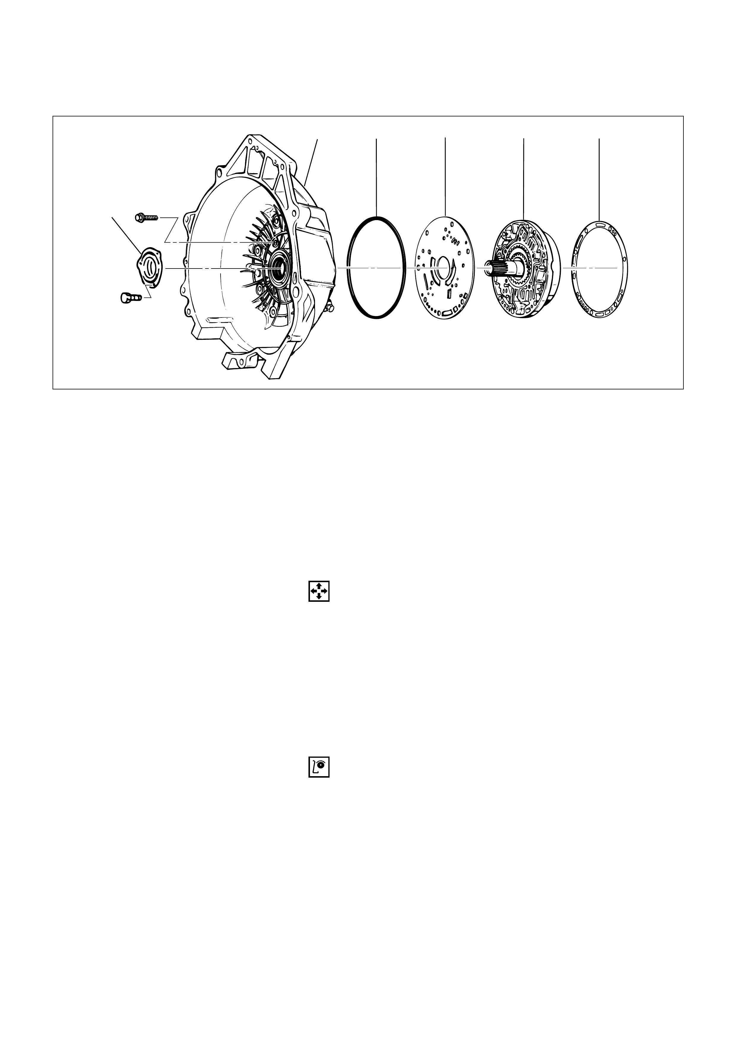
CONVERTER HOUSING AND OIL PUMP ASSEMBLY
DISASSEMBLY
1. Converter Housing
Remove five bolts from converter housing.
2. Outer Seal Ring
3. Gasket
4. Wear Plate
5. Oil Pump Assembly
6. Oil Seal Ring
INSPECTION AND REPAIR
Visual check
If any damage, deformation or local wear is found in a
converter housing, outer seal ring, wear plate or oil seal
ring, replace it.
Disassembly Steps
1. Converter housing
2. Outer seal ring
3. Gasket
4. Wear Plate
5. Oil pump assembly
6. Oil seal ring
Reassembly Steps
To reassemble, follow the disassembly steps
in the reverse order.
241RW003
REASSEMBLY
6. Oil Seal Ring
Install oil seal ring using installer.
Oil Seal Ring Bolt Torque N·m (kg·cm / lb·in)
3 (30 / 26)
5. Oil Pump Assembly
4. Wear Plate
Install wear plate onto oil pump assembly.
3. Gasket
2. Outer Seal Ring
1. Converter Housing
1) Install converter housing onto complete oil pump
assembly. Align with two short guide pins on
outer bolt holes.
2) Loosely install five 13mm bolts.
3) Center converter housing using centering tool.
4) Tighten five inner 13mm bolts in an alternating
pattern.
Converter Housing Bolt Torque N·m (kg·m / lb·ft)
20 (2.0 / 15)
Guide pin: 5-8840-2268-0 (J-38588)
Centering tool: 5-8840-2272-0 (J-38557)
14 15 16 17
11 12 13
12
7
8
9
10
6
543
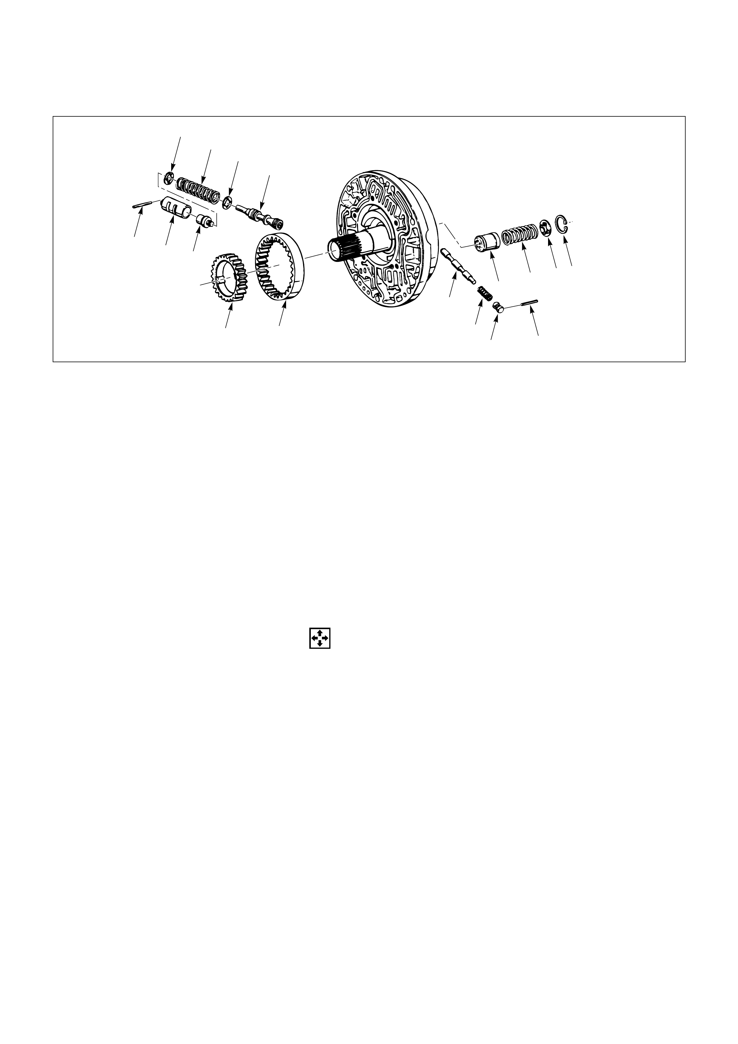
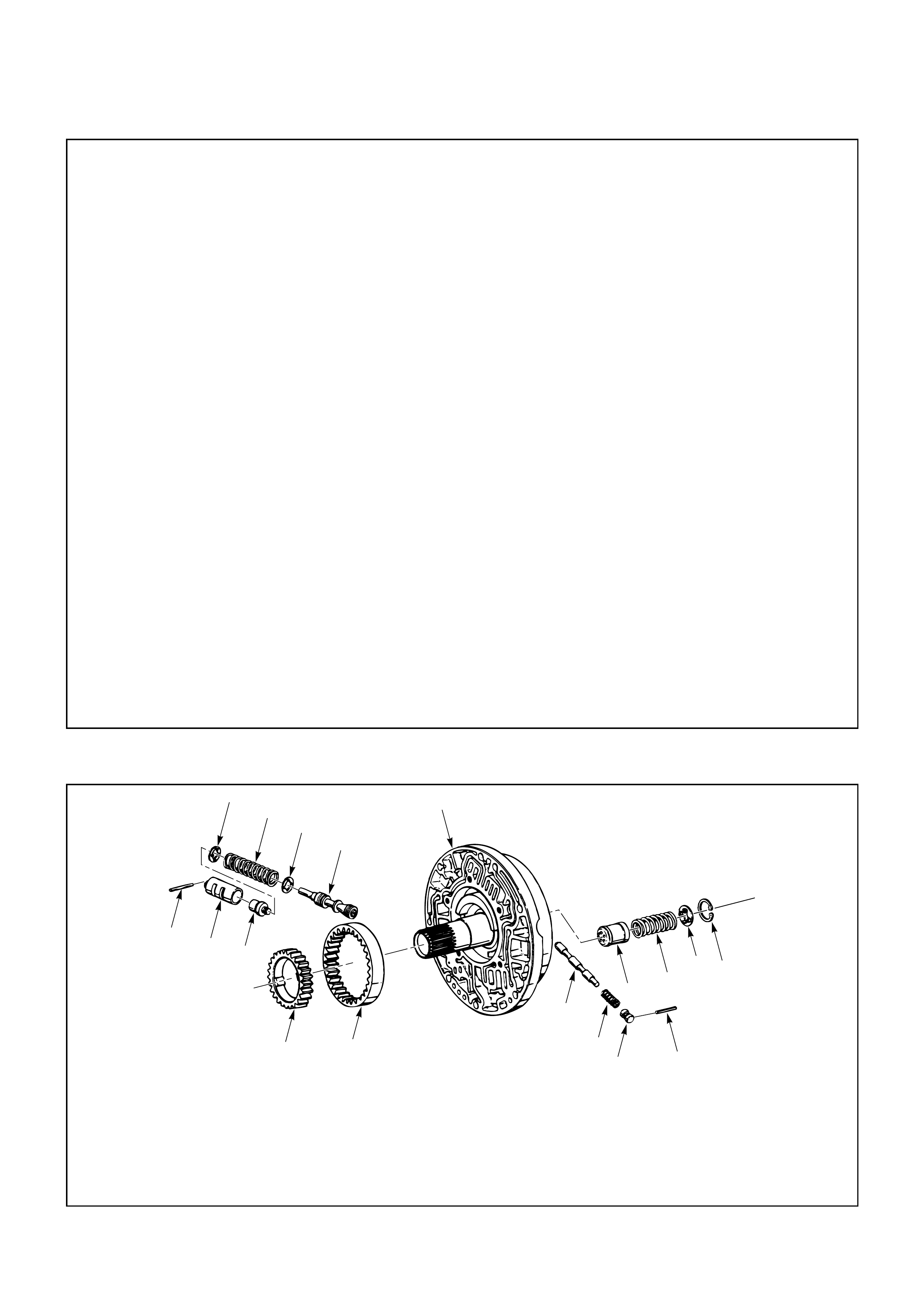
OIL PUMP
DISASSEMBLY
1. Oil Pump Drive Gear
2. Oil Pump Driven Gear
3. Pin
4. Plug
5. Spring
6. Converter Clutch Control Valve
7. Snap Ring
8. Spring Seat
9. Spring
10. Throttle Signal Accumulator Piston
11. Sleeve Pin
12. Sleeve
13. Boost Valve
14. Spring Seat
15. Valve Spring
16. Spring Seat
17. Pressure Regulator Valve
Disassembly Steps
1. Oil pump drive gear
2. Oil pump driven gear
3. Pin
4. Plug
5. Spring
6. Converter clutch control valve
7. Snap ring
8. Spring seat
9. Spring
10. Throttle signal accumulator piston
11. Sleeve pin
12. Sleeve
13. Boost valve
14. Spring seat
15. Valve spring
16. Spring seat
17. Pressure regulator valve
Reassembly Steps
To reassemble, follow the disassembly steps
in the reverse order.

INSPECTION AND REPAIR
Visual check
If any damage, deformation or local wear is found in a
snap ring, spring, spring retainer valve, gear or oil pump,
replace it.
REASSEMBLY
17. Pressure Regulator Valve
16. Spring Seat
Lubricate and preinstall pressure regulator spring
seat on valve, with the flat side against shoulder.
15. Valve Spring
14. Spring Seat
13. Boost Valve
12. Sleeve
11. Sleeve Pin
10. Throttle Signal Accumulator Piston
9. Spring
8. Spring Seat
Install throttle signal accumulator piston, spring, and
spring seat, with the flat side away from the spring
and snap ring.
7. Snap Ring
6. Converter Clutch Control Valve
5. Spring
4. Plug
3. Pin
2. Oil Pump Driven Gear
1. Oil Pump Drive Gear
1
813
27
10
9
7
6
15
14
12
11
19
18
16
17
26 25
23
24
4
53
21
22
2
20
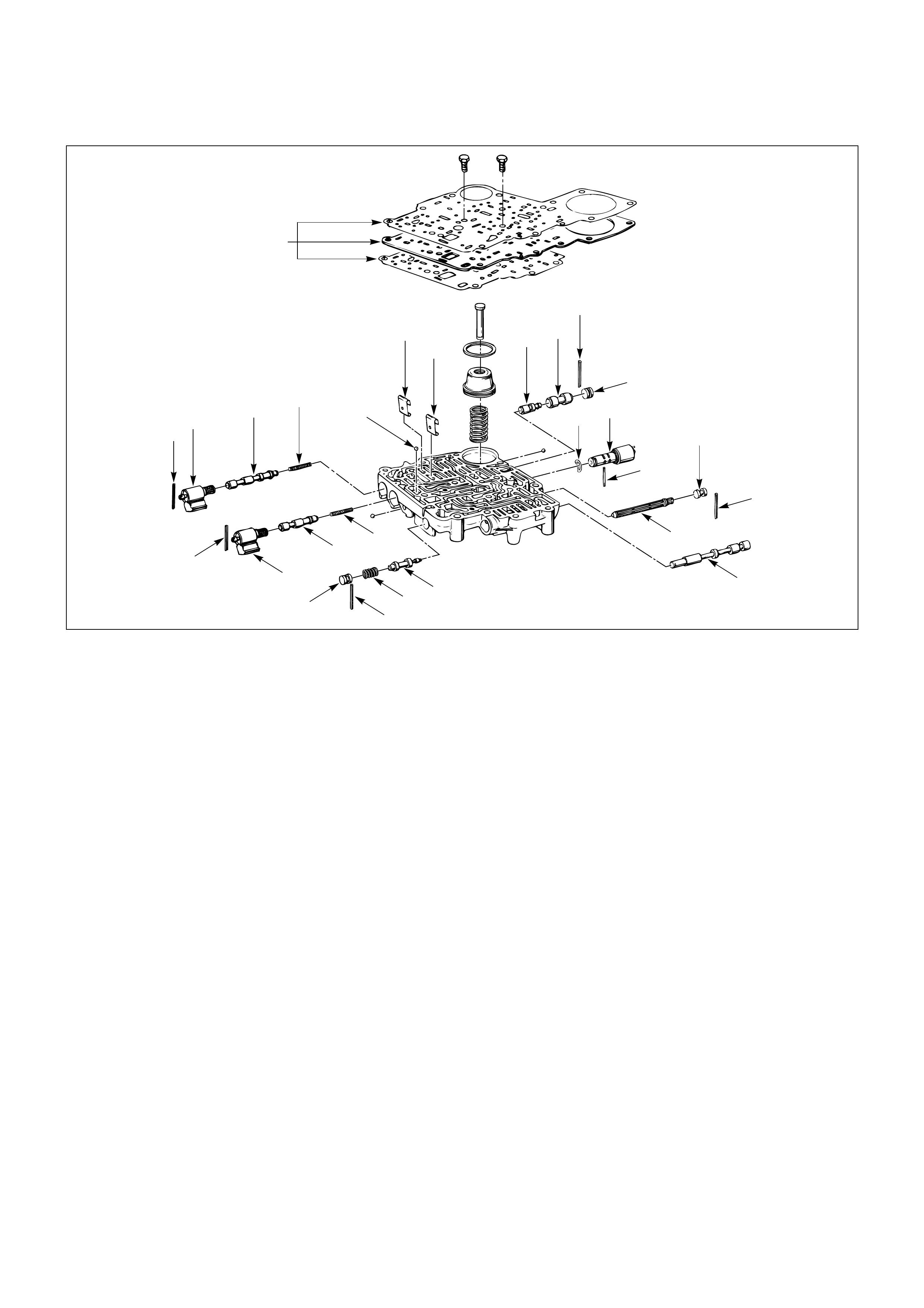
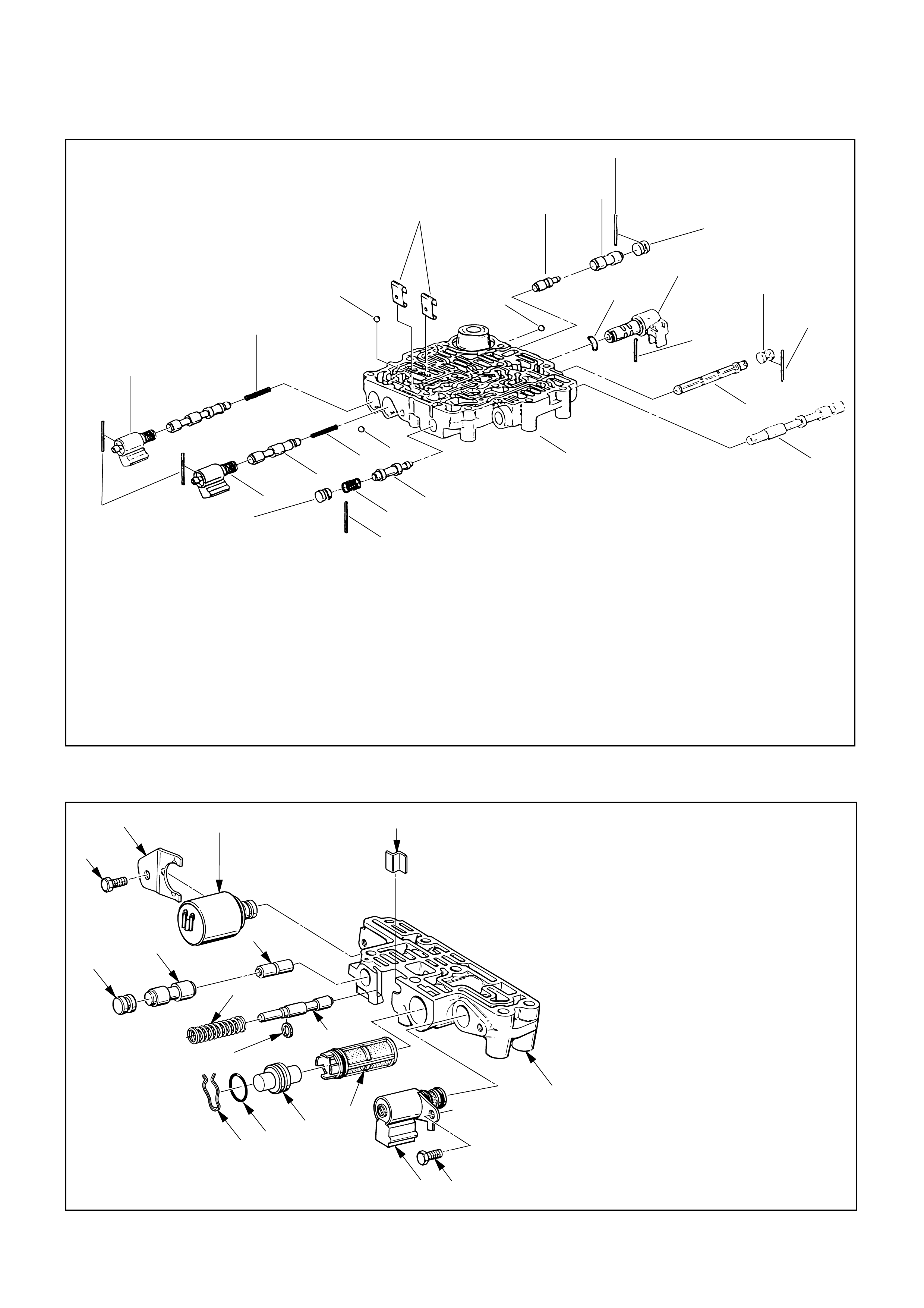
MAIN CASE VALVE BODY
Disassembly Steps
1. Gaskets and transfer plate
2. Manual valve
3. Band control solenoid
4. Pin
5. Waved washer
6. Spring pin
7. Solenoid A
8. Retainer
9. 1-2/3-4 shift valve
10. Spring
11. Spring pin
12. Solenoid B
13. Retainer
14. 2-3 shift valve
15. Spring
16. Spring pin
17. Plug
18. Spring
19. Low pressure control valve
20. Spring pin
21. Plug
22. Band control screen assembly
23. Spring pin
24. Plug
25. 1-2 accumulator valve
26. 1-2 accumulator control valve
27. Check ball
Reassembly Steps
To reassemble, follow the disassembly steps
in the reverse order.

DISASSEMBLY
1. Gaskets and Transfer Plate
Remove two 11mm bolts from valve body.
2. Manual Valve
3. Band Control Solenoid
4. Pin
5. Waved Washer
6. Spring Pin
7. Solenoid A
Remove solenoids by grasping the metal tip. Do not
grasp the connector housing.
8. Retainer
9. 1-2/3-4 Shift Valve
10. Spring
11. Spring Pin
12. Solenoid B
Remove solenoids by grasping the metal tip. Do not
grasp the connector housing.
13. Retainer
14. 2-3 Shift Valve
15. Spring
16. Spring Pin
17. Plug
18. Spring
19. Low Pressure Control Valve
20. Spring Pin
21. Plug
22. Band Control Screen Assembly
23. Spring Pin
24. Plug
25. 1-2 Accumulator Valve
26. 1-2 Accumulator Control Valve
27. Check Ball
Remove 1 check ball from valve body.
INSPECTION AND REPAIR
Inspect for the following and replace any damaged or
worn parts:
•Damage or wear to each valve.
•Damage in oil passeges.
•Cracks or damage to valve body.
•Valve operations.
•Spring fatigue.
REASSEMBLY
27. Check Ball
Install 1 check ball to valve body
26. 1-2 Accumulator Control Valve
25. 1-2 Accumulator Valve
24. Plug
23. Spring Pin
22. Band Control Screen Assembly
21. Plug
20. Spring Pin
19. Low Pressure Control Valve
18. Spring
17. Plug
16. Spring Pin
15. Spring
14. 2-3 Shift Valve
13. Retainer
12. Solenoid B
11. Spring Pin
10. Spring
9. 1-2/3-4 Shift Valve
8. Retainer
7. Solenoid A
6. Spring Pin
5. Waved Washer
4. Pin
3. Band Control Solenoid
2. Manual Valve
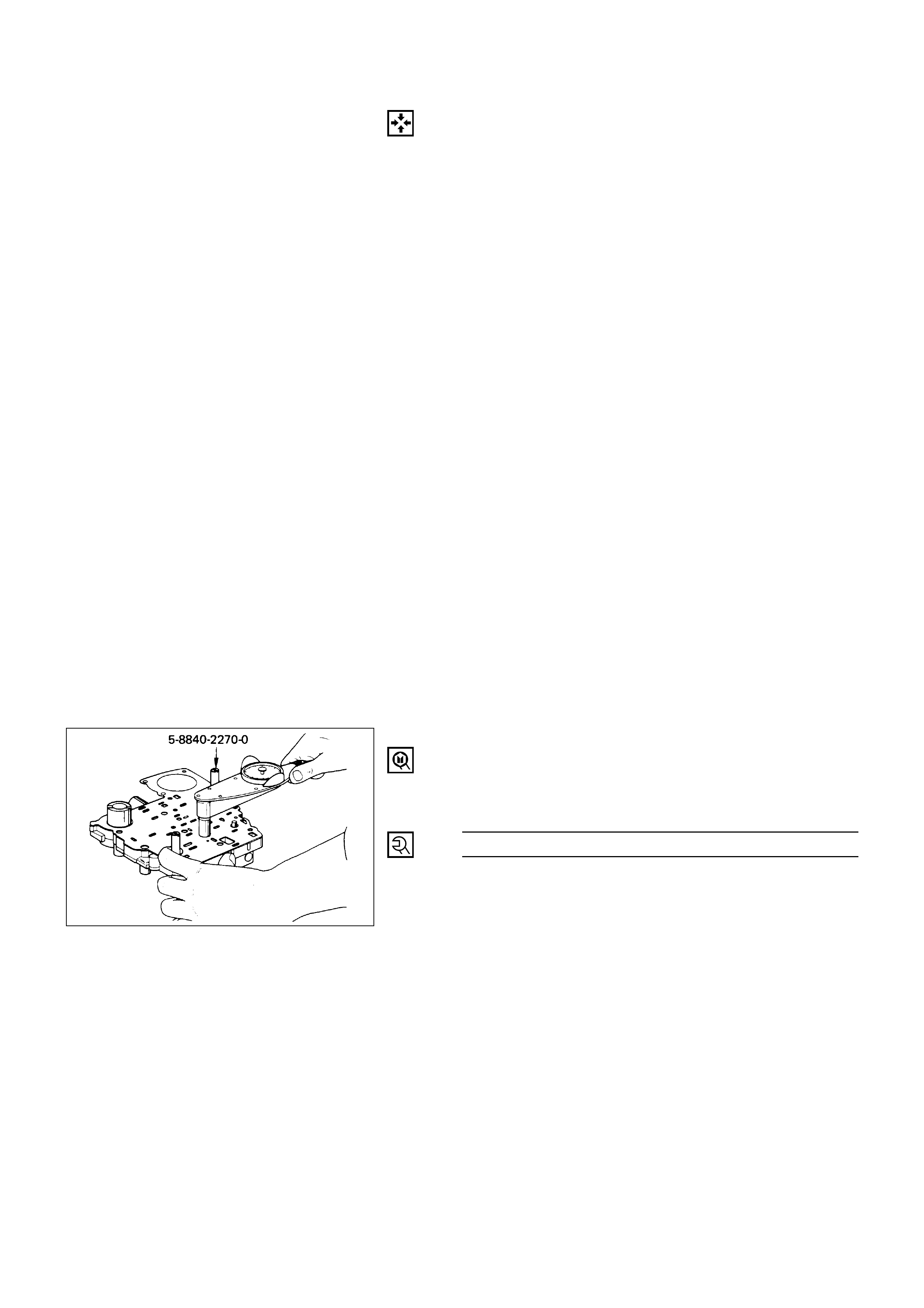
1. Gaskets and Transfer Plate
1) Install gasket (valve body/transfer plate) and
transfer plate, using two guide pins.
2) Install two 11mm bolts.
Valve Body Bolt Torque N·m (kg·cm / lb·in)
13 (130 / 113)
3) Install gasket (transfer plate/main case).
Guide pins: 5-8840-2270-0 (J-3387-2)
2
6
8
13
1
15
14
10
12
11
7
4
5
9
3
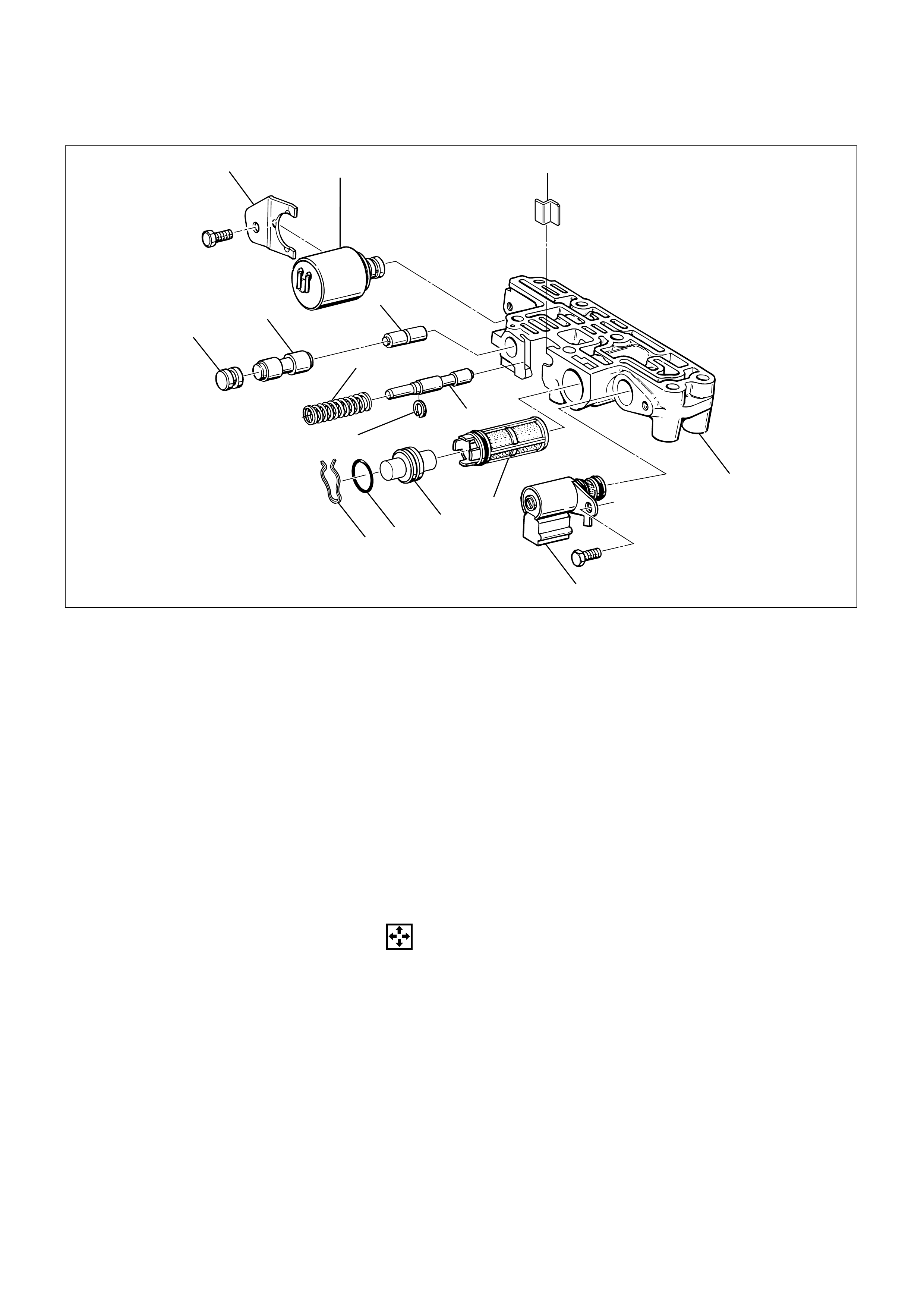
ADAPTER CASE VALVE BODY
DISASSEMBLY
1. Converter Clutch Solenoid
1) Remove 11mm bolt from valve body.
2) Remove converter control solenoid assembly with
two O-ring.
2. Retainer
Remove 11mm bolt and retainer from valve body.
3. Force Motor Solenoid
4. Retainer
5. Plug
6. 3/4 Accumulator Valve
7. 3/4 Accumulator Control Valve
Disassembly Steps
1. Converter clutch solenoid
2. Retainer
3. Force motor solenoid
4. Retainer
5. Plug
6. 3/4 accumulator valve
7. 3/4 accumulator control valve
8. Spring
9. Retaining ring
10. Feed limit valve
11. Plug retainer
12. O-ring
13. Plug
14. Force motor screen assembly
15. Adapter case valve body
Reassembly Steps
To reassemble, follow the disassembly steps
in the reverse order.
243RW001

8. Spring
9. Retaining Ring
10. Feed Limit Valve
11. Plug Retainer
12. O-ring
13. Plug
14. Force Motor Screen Assembly
Use 5mm bolt to pull plug.
INSPECTION AND REPAIR
Inspect for the following and replace any damaged or
worn parts:
•Damage or wear to each valve.
•Damage in oil passeges.
•Cracks or damage to valve body.
•Valve operations.
•Spring fatigue
REASSEMBLY
14. Force Motor Screen Assembly
13. Plug
12. O-ring
11. Plug Retainer
10. Feed Limit Valve
9. Retaining Ring
8. Spring
7. 3/4 Accumulator Control Valve
6. 3/4 Accumulator Valve
5. Plug
4. Retainer
3. Force Motor Solenoid
2. Retainer
1) Place solenoid terminals pointing towards mating
face.
2) Install retainer and bolt.
Retainer Bolt Torque N·m (kg·cm / lb·in)
10 (100 / 87)
1. Converter Clutch Solenoid
1) Install converter clutch solenoid assembly with
two O-rings to valve body.
2) Install bolt.
Bolt Torque N·m (kg·cm / lb·in)
10 (100 / 87)
67
854312
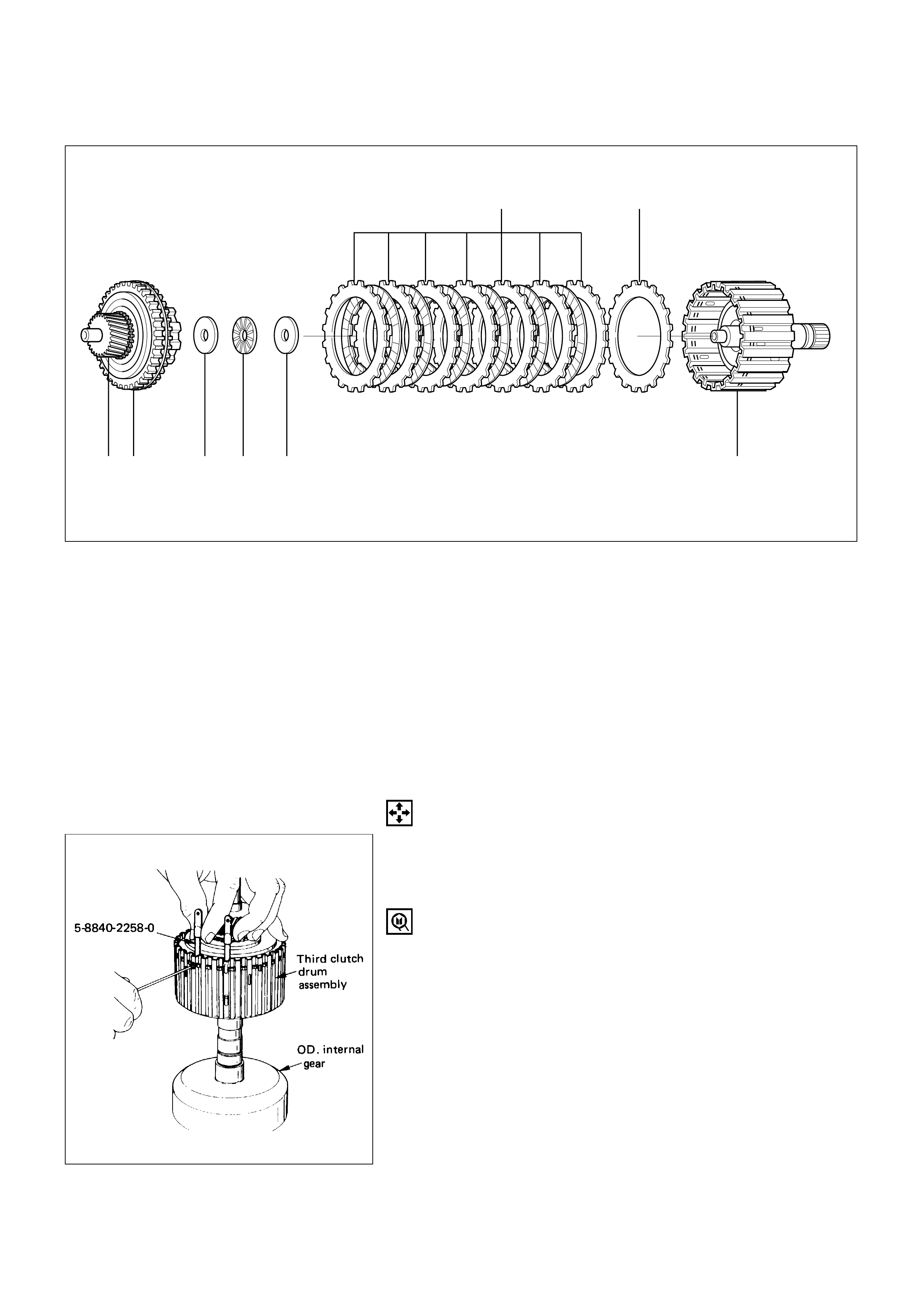
THIRD CLUTCH AND SPRAG UNIT
DISASSEMBLY
1. Retaining Ring
1) Place the third clutch housing and intermediate
shaft assembly upright, using the overdrive
internal gear as a support.
2) Locate the end of the sprag retaining ring.
Compress near the end, using a screwdriver
through the side slot and slide one tool blade
between ring and housing to hold the ring clear of
the groove.
3) Repeat with a second tool blade near the other
end of the retaining ring.
4) Repeat with a third tool blade opposite the first
two.
5) Repeat with two further blades equally spaced
apart.
Third clutch retaining ring compressor:5-8840-2258-0
(J-38450)
Disassembly Steps
1. Retaining ring
2. Input sun gear assembly
3. Retaining washer
4. Bearing
5. Thrust washer
6. Clutch plates
7. Third clutch drum
Reassembly Steps
To reassemble, follow the disassembly steps
in the reverse order.
248RW001
2. Input Sun Gear Assembly
Pull the input sun gear assembly unit until the sprag
retaining ring clears the ring groove.
3. Retaining Washer
4. Bearing
5. Thrust Washer
6. Clutch Plates
7. Third Clutch Drum
INSPECTION AND REPAIR
Visual check
If any damage, deformation or local wear is found in a
bearing, thrust washer, clutch plates or third clutch drum,
replace it.
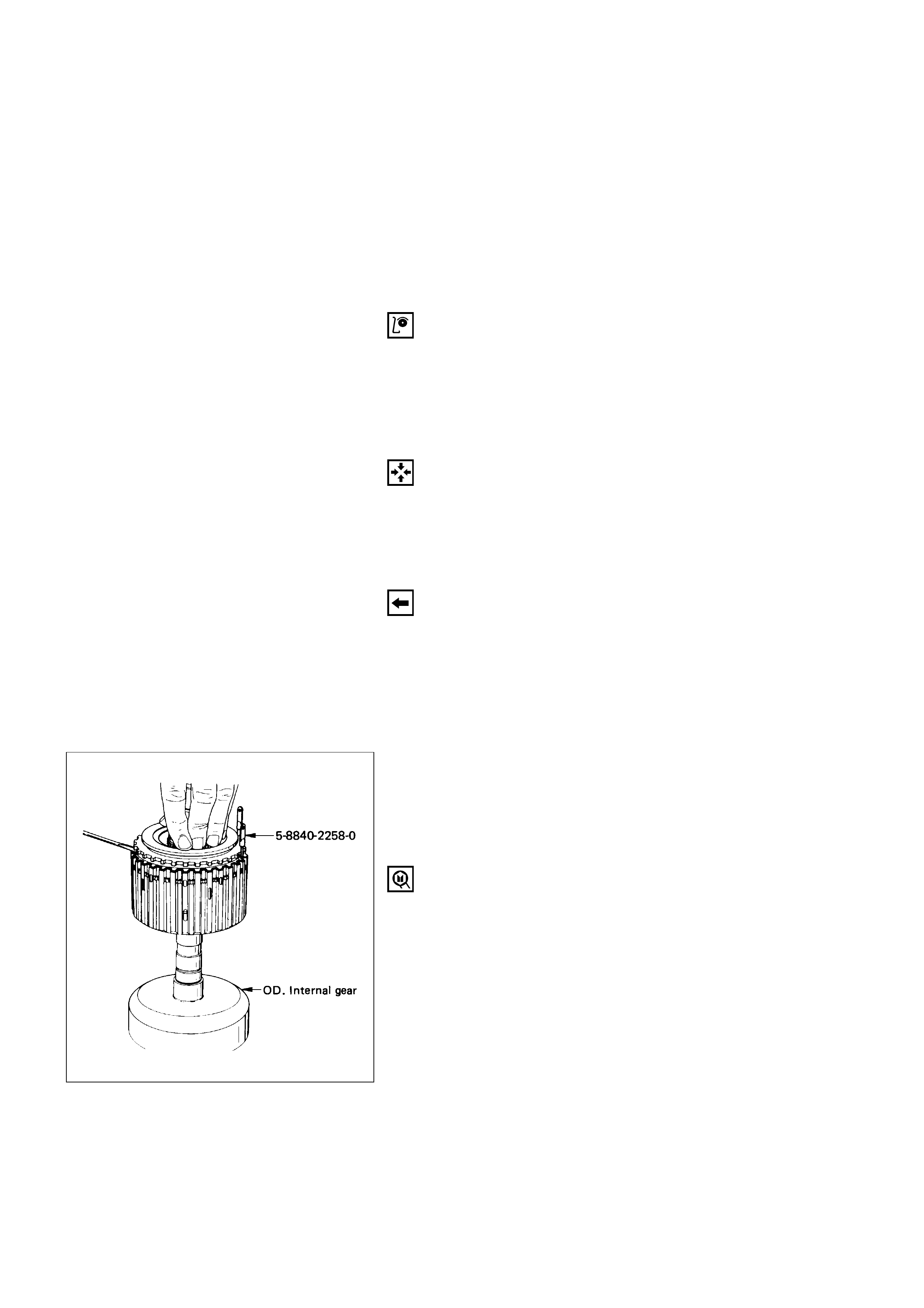
REASSEMBLY
7. Third Clutch Drum
6. Clutch Plates
1) Place third clutch housing and intermediate shaft
assembly upright, using the overdrive internal
gear as a support.
2) Install third clutch spring cushion plate, bevel face
down.
3) Install third clutch plates into clutch housing.
Start with the steel clutch plate and alternate with
lined plates.
5. Thrust Washer
4. Bearing
3. Retaining Washer
2. Input Sun Gear Assembly
1. Retaining Ring
1) Fully engage the sprag assembly hub splines into
the third clutch inner tangs.
Simultaneously rotate the outer sprag race to
engage into the third clutch housing.
2) Install a tool blade at each extremity of the
retaining ring.
3) Compress the retaining ring with a screw-driver
opposite the tool blades while pushing down on
the outer sprag race.
4) Engage retaining ring into groove.
5) Remove tool blades.
Third clutch retaining ring compressor:5-8840-2258-0
(J-38450)
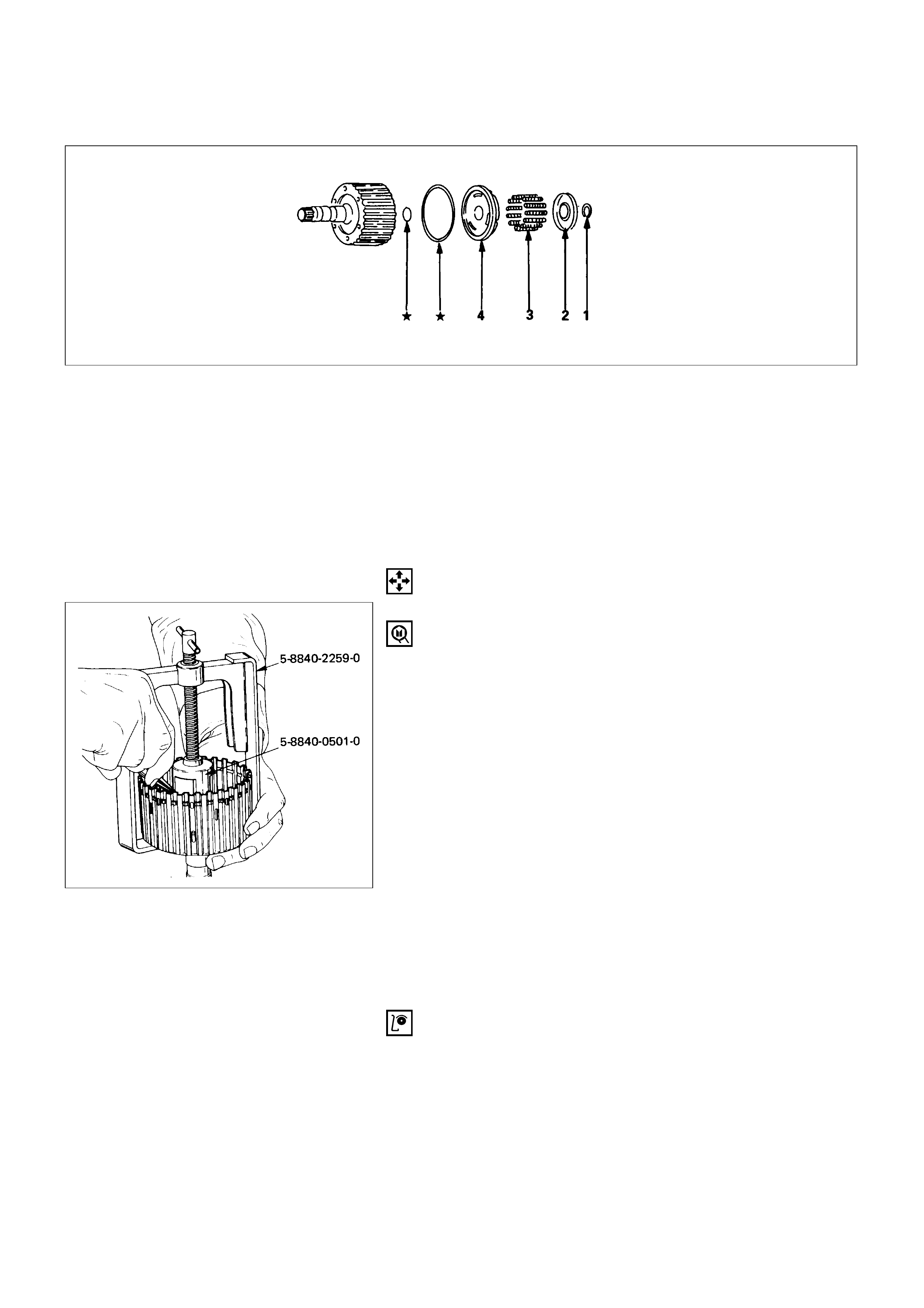
Disassembly Steps
1. Retaining ring
2. Spring seat
3. Springs
4. Piston
Reassembly Steps
To reassemble, follow the disassembly steps
in the reverse order.
★; Repair kit
THIRD CLUTCH
DISASSEMBLY
1. Retaining Ring
1) Compress spring seat using the tool.
NOTE:
Do not over-stress the springs and seat. This will
cause damage to the spring seat.
2) Remove retaining ring.
3) Release the spring seat.
NOTE:
Do not let the spring seat catch in the ring groove.
Spring compressor: 5-8840-0501-0 (J-23075)
Adapter: 5-8840-2259-0 (J-23075-12)
2. Spring Seat
3. Springs
4. Piston
INSPECTION AND REPAIR
Visual check
If any damage, deformation or local wear is found in a
retaining ring, return spring, piston seals or spring seat,
replace it.
Operation check
Shake piston and listen for check ball movement. Replace
piston if check ball is missing or falls out.
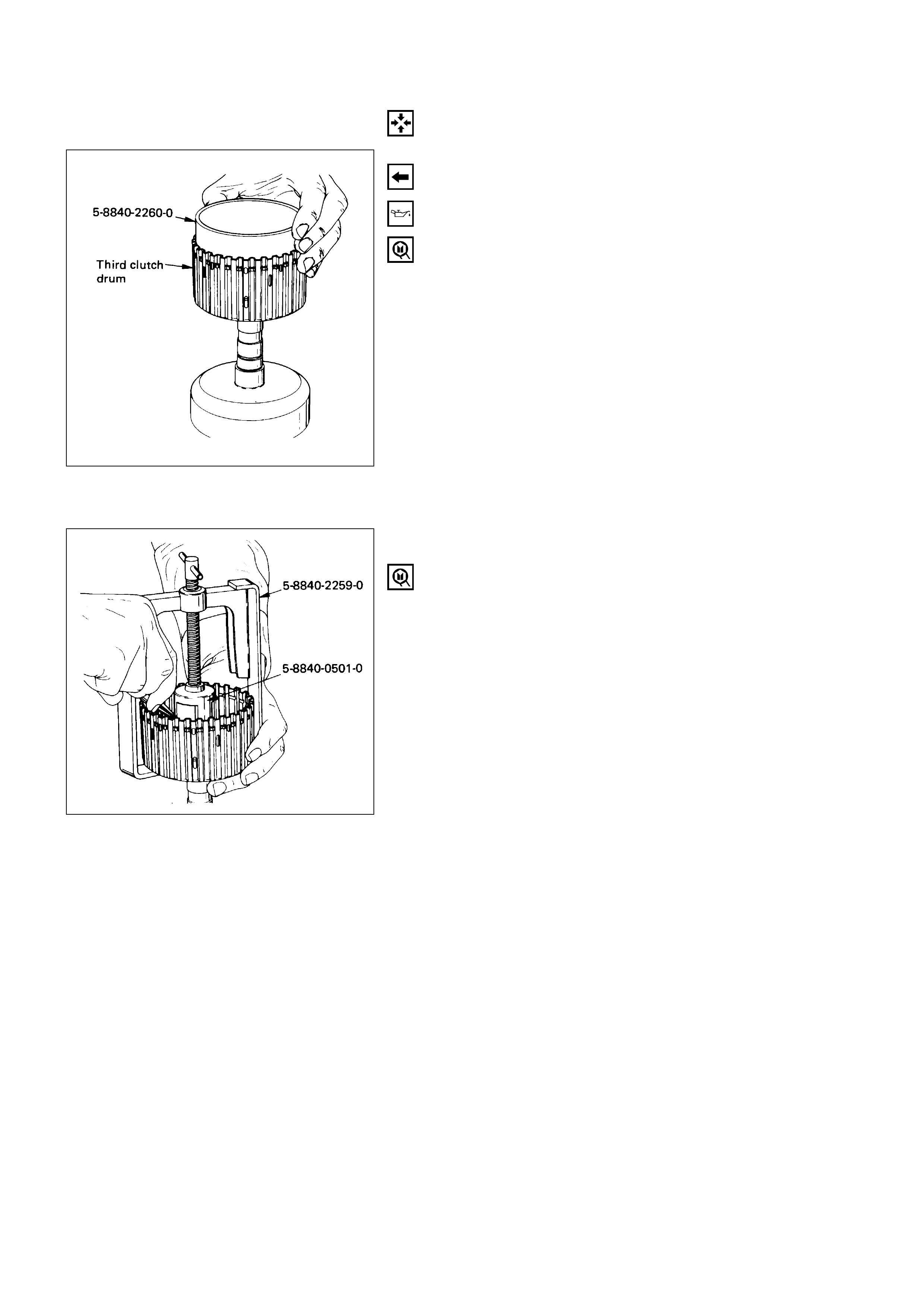
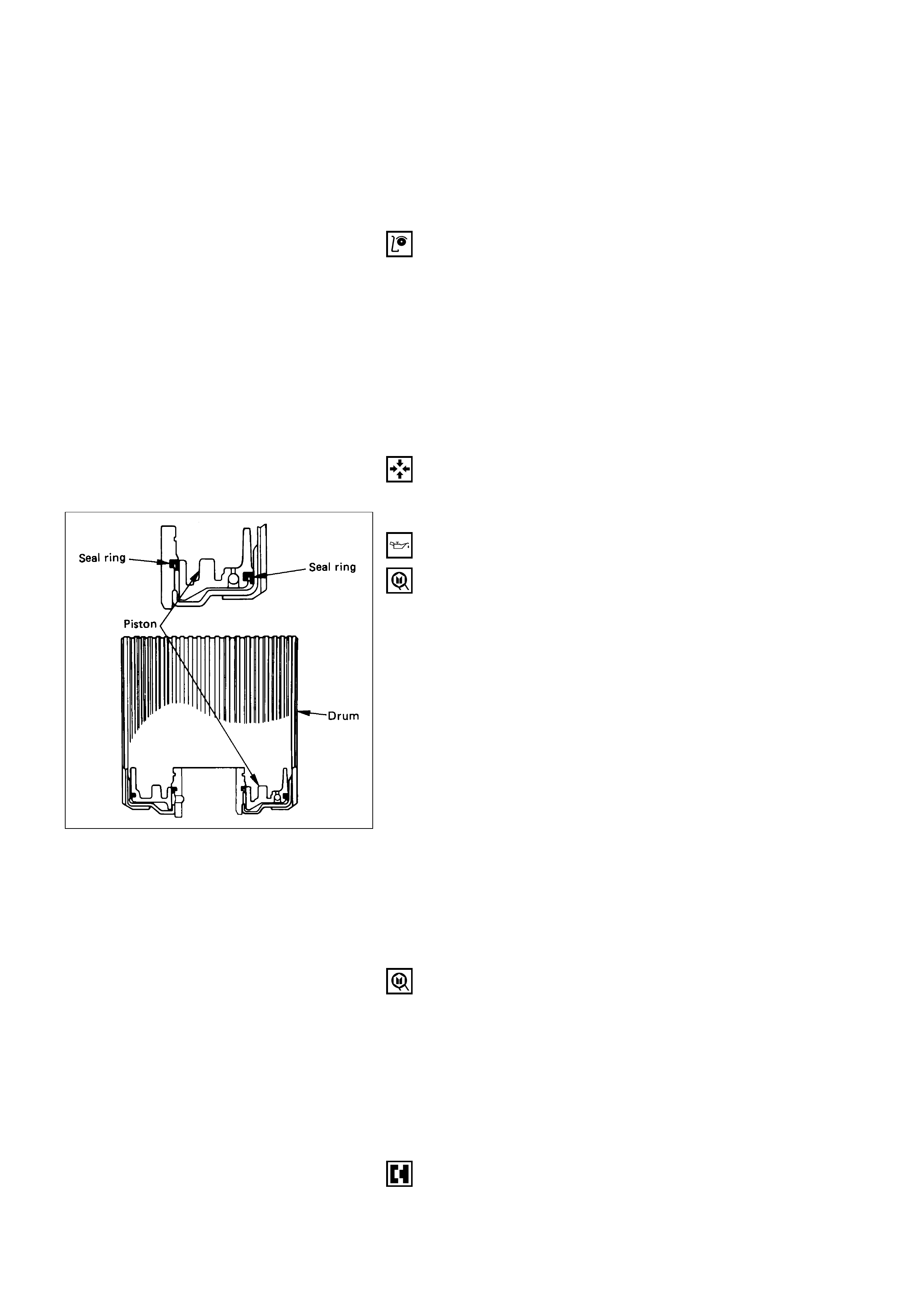
REASSEMBLY
4. Piston
1) The lip of the seals must point toward the front of
the transmission. Lubricate the lip seal with
transmission fluid.
2) Install piston assembly into the third clutch drum.
Use installer to protect the outer seal during
installation.
Third clutch piston installer: 5-8840-2260-0
(J-23084)
3. Springs
2. Spring Seat
1. Retaining Ring
1) Place retaining ring onto spring seat.
2) Compress the piston springs, using the piston
spring compressor.
NOTE:
Do not over-stress the springs and seat. Do not let
the spring seat catch in the ring groove. This may
cause damage to the spring seat.
3) Install spring seat retaining ring.
4) Remove the piston spring compressor.
Spring compressor: 5-8840-0501-0 (J-23075)
Adapter: 5-8840-2259-0 (J-23075-12)

SPRAG UNIT
DISASSEMBLY
1. Sprag Outer Race
2. Sprag Assembly
Remove sprag outer race and sprag assembly from
third clutch hub and sun gear assembly.
3. Sun Gear Assembly
INSPECTION AND REPAIR
Visual check
If any damage, deformation or local wear is found in a sun
gear, sprag assembly or sprag outer race, replace it.
REASSEMBLY
3. Sun Gear Assembly
2. Sprag Assembly
Install sprag assembly onto the sun gear.
NOTE:
Flared shoulder of the sprag cage faces the sun gear.
This procedure must be followed exactly to be sure
that the sprag assembly is installed properly.
1. Sprag Outer Race
1) Install outer sprag race assembly over the sprag
cage assembly.
2) Place third clutch hub and sun gear assembly on a
flat surface, sun gear facing up. Place sprag outer
race and sprag assembly over the sun gear
assembly, push down and turn the input sun
counterclockwise at the same time.
NOTE:
Check correct rotation by holding the sun gear in
your left hand and turning the outer race. The outer
sprag race should turn freely towards you and lock
turning away from you.
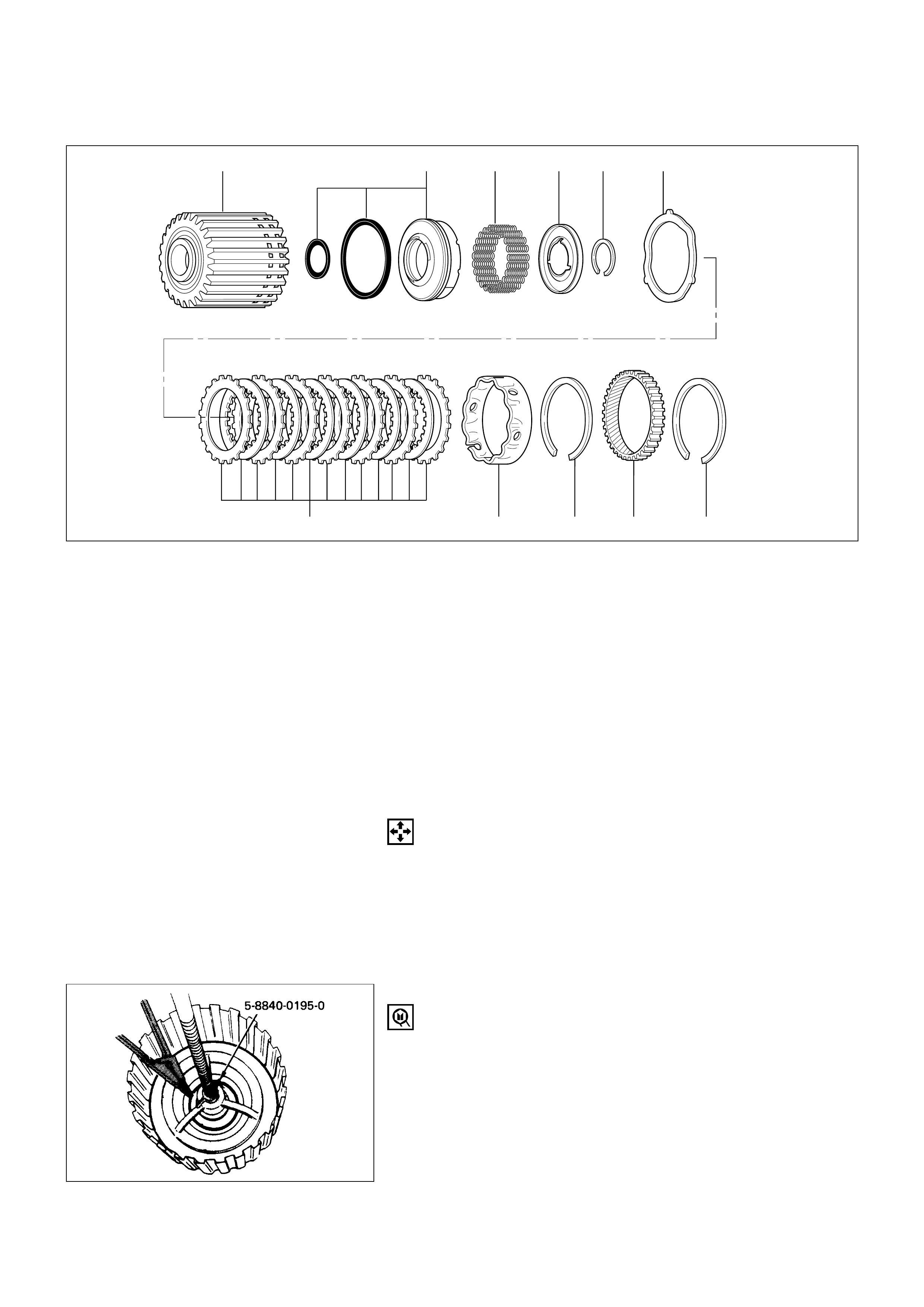
Disassembly Steps
1. Retaining ring
2. Ring gear
3. Retaining ring
4. Spacer
5. Clutch plates
6. Waved washer
7. Retaining ring
8. Spring seat
9. Springs
10. Piston
11. Second clutch drum
Removal Steps
To reassemble, follow the disassembly steps
in the reverse order.
11
54321
10 9 8 7 6
SECOND CLUTCH
DISASSEMBLY
1. Retaining Ring
2. Ring Gear
3. Retaining Ring
4. Spacer
5. Clutch Plates
6. Waved Washer
7. Retaining Ring
Compress the spring seat.
Compressor: 5-8840-0195-0 (J-23327)
247RW001
★; Repair kit
8. Spring Seat
9. Springs
10. Piston
11. Second Clutch Drum
INSPECTION AND REPAIR
Visual check
If any damage, deformation or local wear is found in a
retaining ring, ring gear, spacer, clutch plates, piston
seals, return spring or spring seat, replace it.
Operation check
Shake piston and listen for check ball movement.
Movement indicates proper check ball operation. Replace
piston if check ball is missing or falls out.
REASSEMBLY
11. Second Clutch Drum
10. Piston
Install piston assembly into the second clutch drum.
Lubricate the lip seal with liberal amounts of
transmission fluid. Use the installer to protect the
outer piston lip seal.
NOTE:
Lip of the seals point toward front of transmission.
Second clutch piston installer:5-8840-2261-0
(J-23080-A)
9. Springs
8. Spring Seat
7. Retaining Ring
1) Install twenty-two piston springs and spring seat
on the second clutch piston. Place retaining ring
onto spring seat.
2) Use the compressor to compress the piston
springs.
Compressor: 5-8840-0195-0 (J-23327)
NOTE:
Do not let spring seat catch in ring groove.
6. Waved Plate
5. Clutch Plates
Install clutch plates. Start with a steel plate and
alternate with lined plates.
Align second clutch inner tangs.
4. Spacer
Install spacer, with the fluted end toward clutch
plates.
3. Retaining Ring
2. Ring gear
1. Retaining Ring
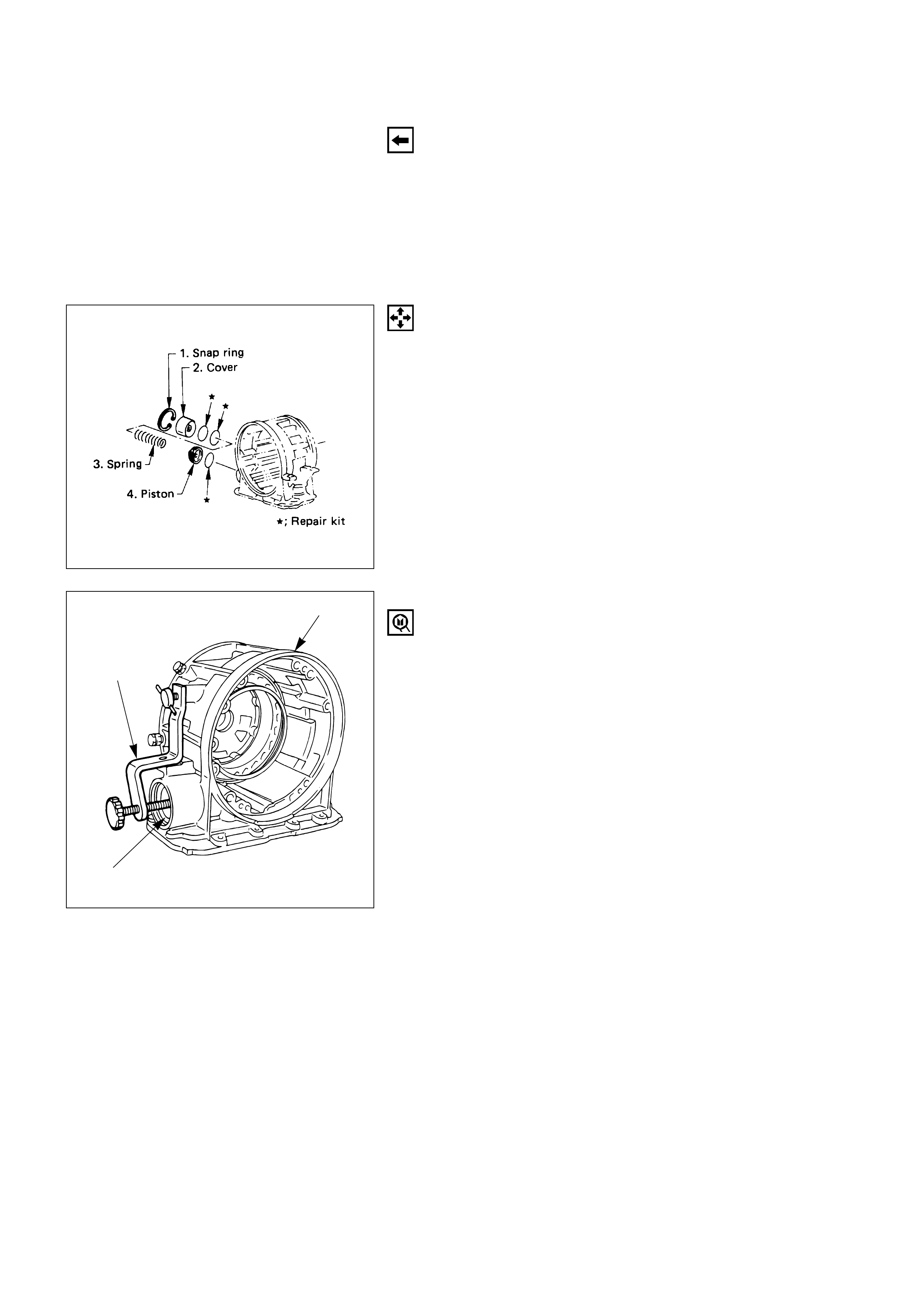
3-4 ACCUMULATOR PISTON
DISASSEMBLY
Disassembly steps
1. Snap ring
2. Cover
3. Spring
4. Piston
Reassembly steps
To reassemble, follow the disassembly steps in the
reverse order.
★Repair kit
1. Snap Ring
Install cover compressor on adapter case.
Compress piston cover. Remove snap ring.
Compressor: 5-8840-2277-1 (J-38559-A)
5-8840-2277-1
Adapter case
Piston cover
2. Cover
Install cover remover to center hole of cover.
Use slide hammer to remove cover.
Cover remove: 5-8840-2403-0 (J-41096)
Adapter: 5-8840-2266-0 (J-38584)
Slide hammer: 5-8840-0019-0 (J-23907)
3. Spring
4. Piston
INSPECTION AND REPAIR
Visual Check
If any damage, deformation or wear is found in a return
spring, piston or piston cover, replace it.
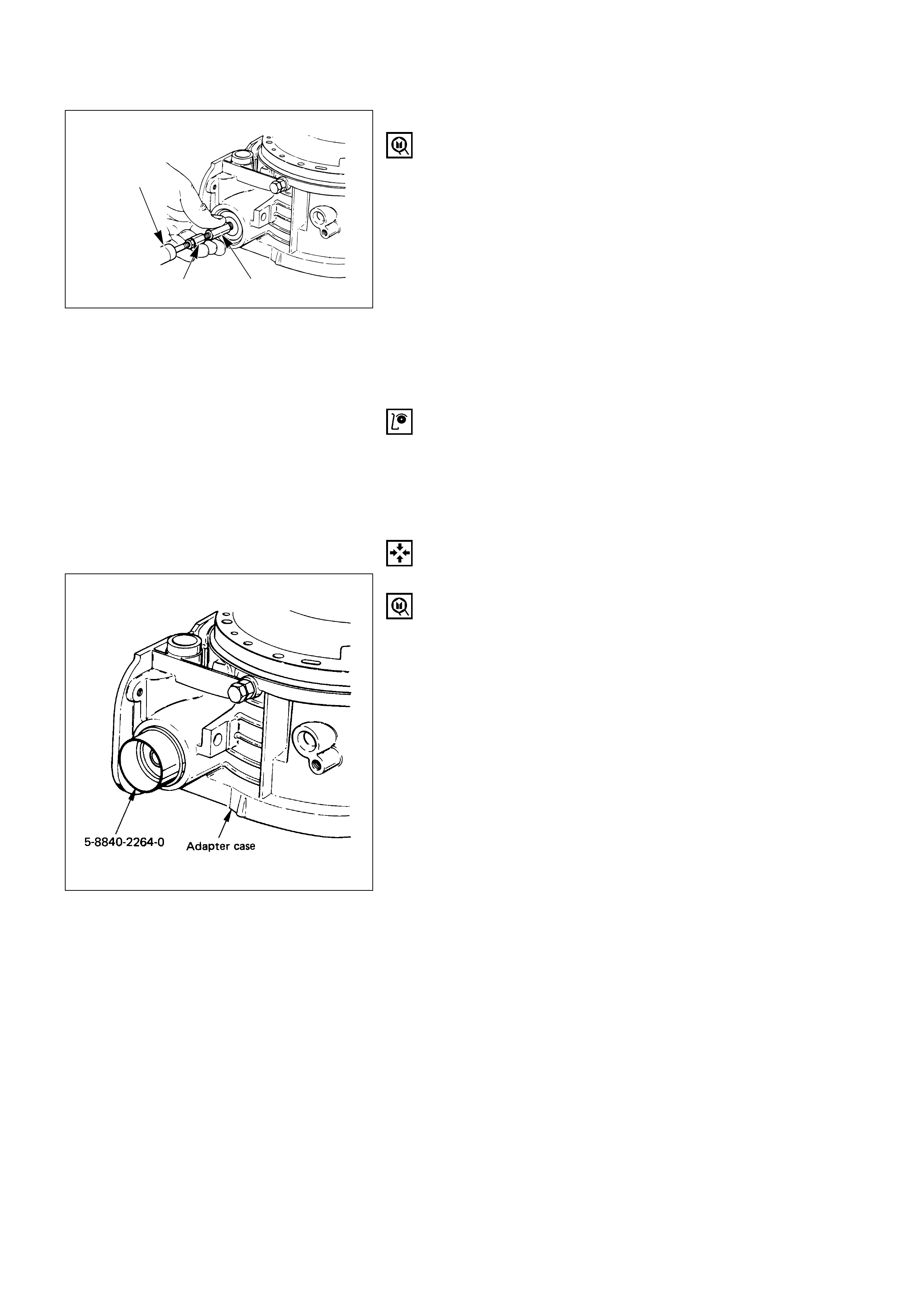
REASSEMBLY
4. Piston
Place the fitter into adaptor case and push the piston
into position, using suitable diameter tube.
Piston fitter: 5-8840-2264-0 (J-38553)
3. Spring
5-8840-0019-0
5-8840-2266-0 5-8840-2403-0
242LW001
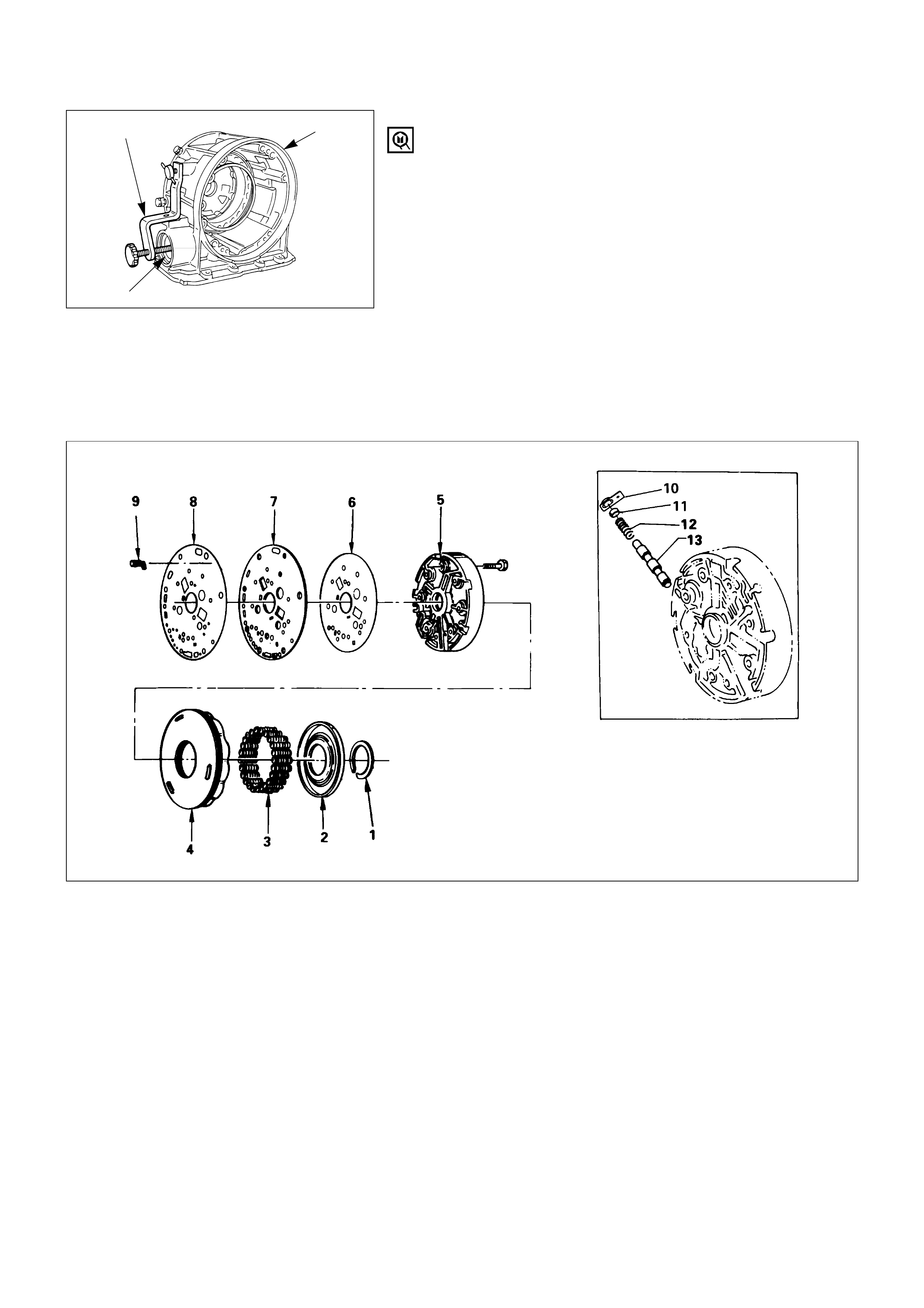
Disassembly Steps
1. Retaining ring
2. Spring seat
3. Springs
4. Piston
5. Center support
6. Gasket
7. Transfer plate
8. Gasket
9. Restrictor
10. Retainer plate
11. Plug
12. Spring
13. Overrun lock out valve
Reassembly Steps
To reassemble, follow the disassembly steps
in the reverse order.
REVERSE CLUTCH PISTON AND CENTER SUPPORT
5-8840-2277-1 Adapter case
Piston cover
2. Cover
Install cover, using compressor tool.
Compressor: 5-8840-2277-1 (J-38559-A)
1. Snap ring
Install snap ring in groove.
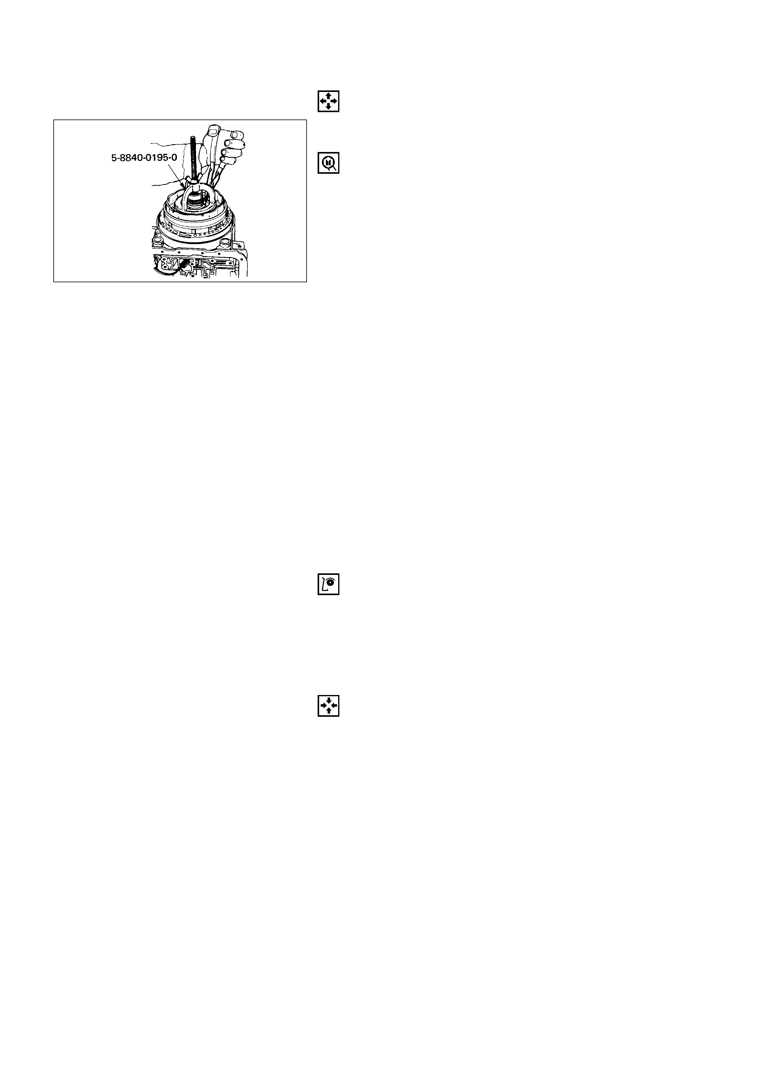
DISASSEMBLY
1. Retaining Ring
1) Install the tool on spring seat.
2) Compress the spring seat.
Compressor: 5-8840-0195-0 (J-23327)
NOTE:
Do not over-stress the springs and seat, as this will
cause damage to the spring seat.
2. Spring Seat
3. Springs
4. Piston
5. Center Support
Remove 8 bolts from center support. Remove center
support from adapter case.
6. Gasket
7. Transfer Plate
8. Gasket
9. Restrictor
10. Retainer Plate
11. Plug
12. Spring
13. Overrun Lock Out Valve
INSPECTION AND REPAIR
Visual check
If any damage, deformation or local wear is found in a
retaining ring, return spring, spring retainer, piston or
center support, replace it.
REASSEMBLY
13. Overrun Lock Out Valve
12. Spring
Install overrun lock out valve and spring.
NOTE:
Ensure correct assembly of valve. The spring should
be located over the long small diameter end.
11. Plug
10. Retainer Plate
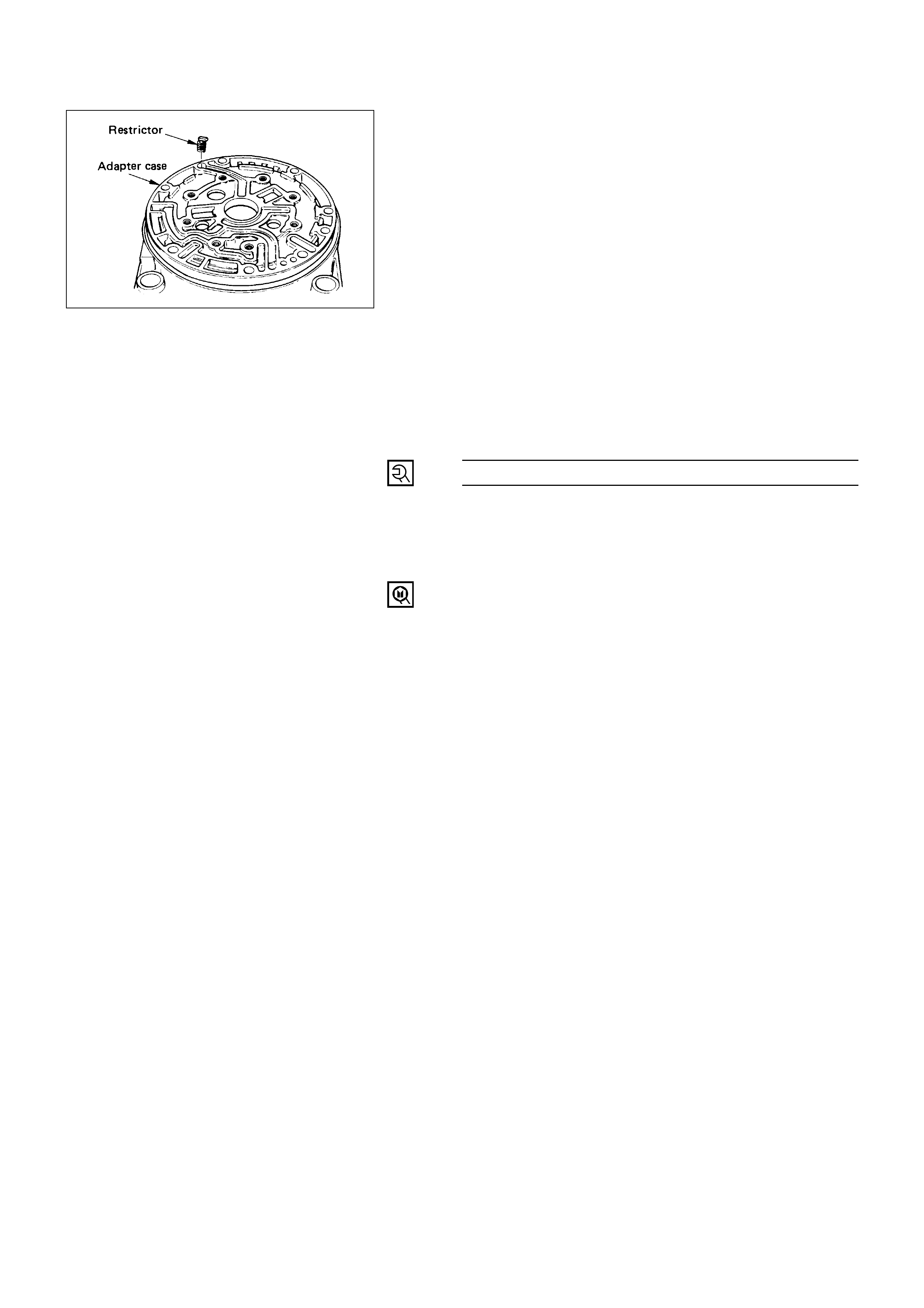
9. Restrictor
Place in the lube overdrive channel in the adapter
case housing.
8. Gasket
7. Transfer Plate
6. Gasket
5. Center Support
Install center support with 8 bolts.
Center Support Bolt Torque N·m (kg·m / lb·ft)
25 (2.5 / 18)
4. Piston
3. Springs
2. Spring Seat
1. Retaining Ring
1) Install twenty four springs, spring seat and
retaining ring.
2) Install the tool.
3) Compress retaining ring and springs.
4) Seat snap ring in groove.
Compressor: 5-8840-0195-0 (J-23327)
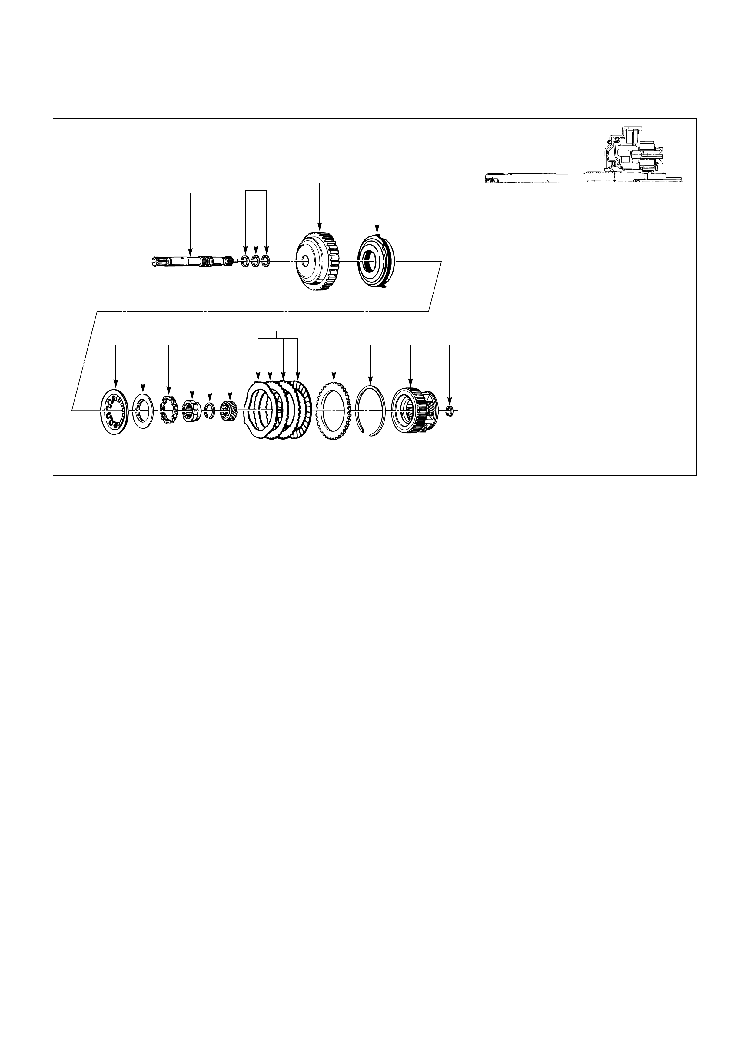
Disassembly Steps
1. Snap ring
2. Overdrive carrier assembly
3. Sun gear
4. Turbine shaft
5. Snap ring
6. Backing plate
7. Clutch plates
8. Snap ring
9. Overrun roller clutch cam
10. Roller clutch assembly
11. Overrun clutch release spring
retainer
12. Diaphragm spring
13. Piston
14. Overrun clutch drum
15. Turbine shaft seal rings
Reassembly Steps
To reassemble, follow the disassembly steps
in the reverse order.
415 14 13
12 11 10 9 8 3 765 2 1
OVERRUN CLUTCH AND TURBINE SHAFT
DISASSEMBLY
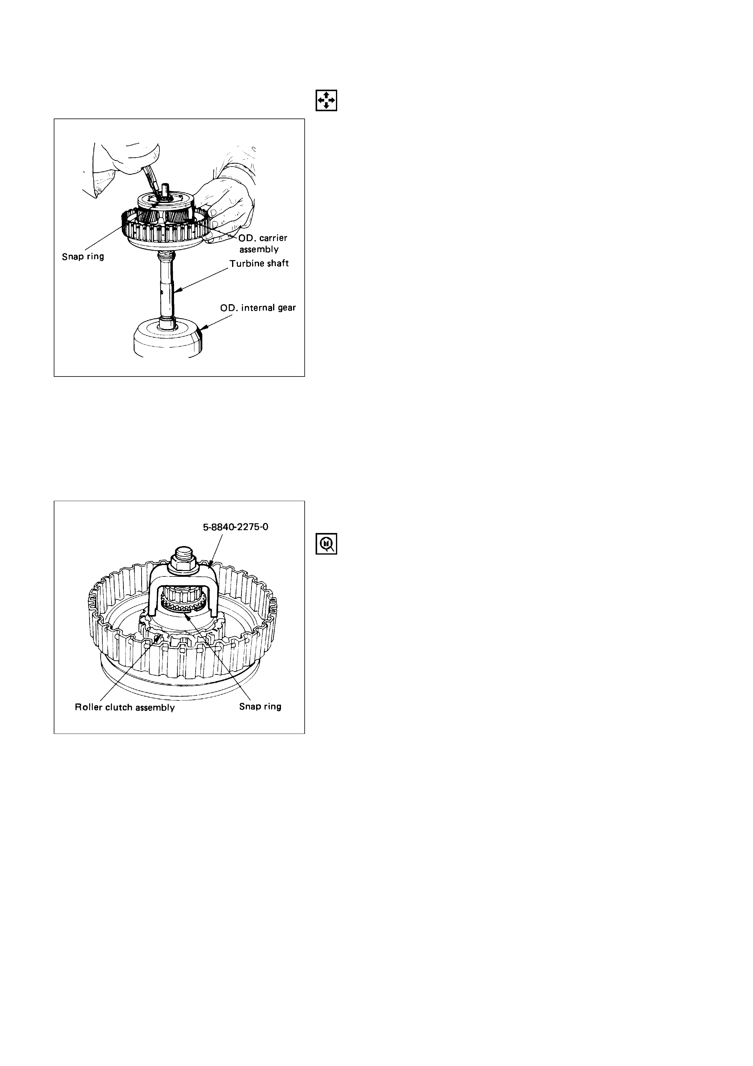
1. Snap Ring
1) Position overrun clutch assembly upright, using
the overdrive internal gear as a support.
2) Remove snap ring.
2. Overdrive Carrier Assembly
3. Sun Gear
4. Turbine Shaft
5. Snap Ring
6. Backing Plate
7. Clutch Plates
8. Snap Ring
Compress piston return spring with compressor.
Compressor: 5-8840-2275-0 (J-23327-91)
9. Overrun Roller Clutch Cam
10. Roller Clutch Assembly
11. Overrun Clutch Release Spring Retainer
12. Diaphragm Spring
13. Piston
14. Overrun Clutch Drum
15. Turbine Shaft Seal Rings
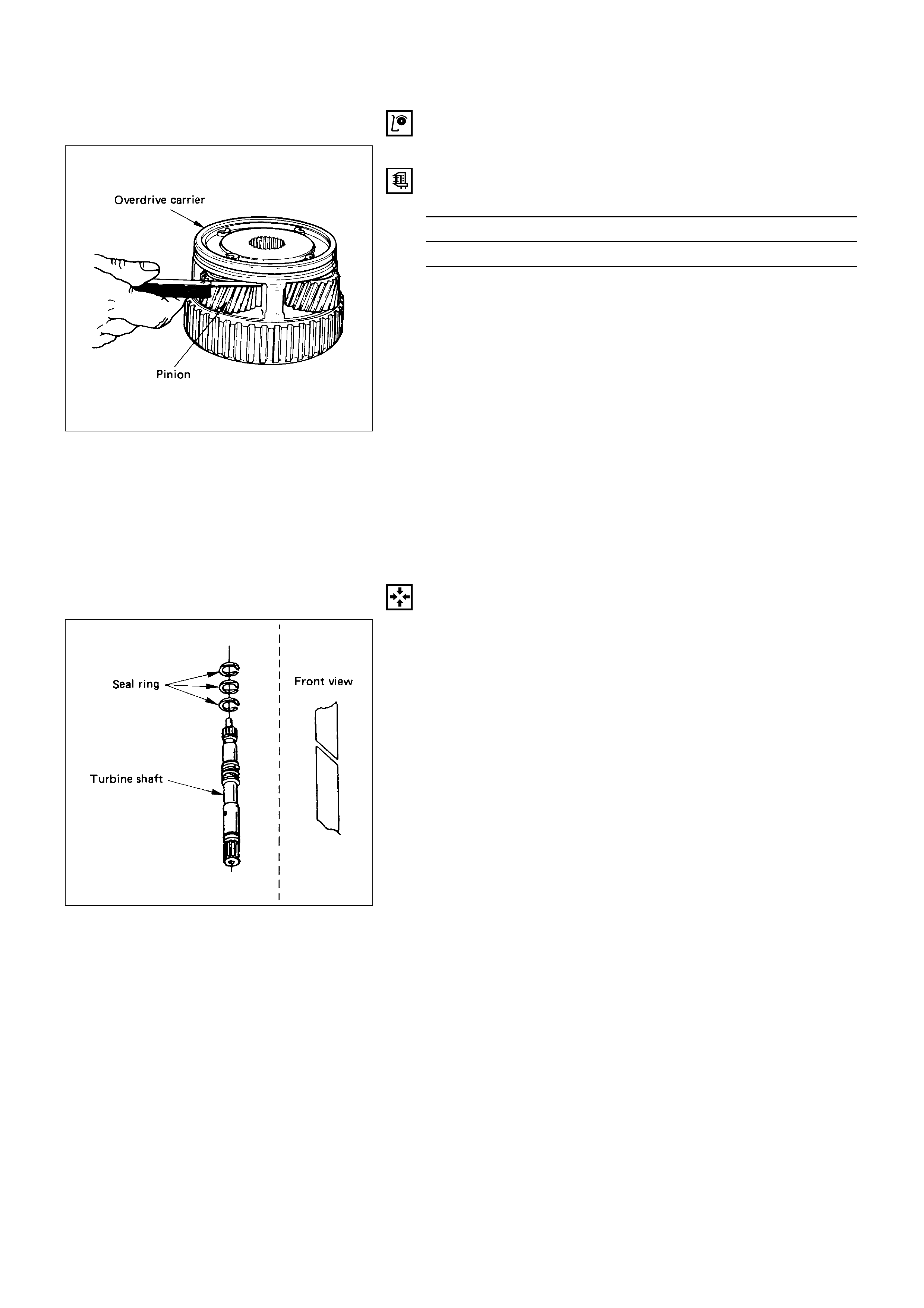
INSPECTION AND REPAIR
Overdrive carrier check
Check pinion end play with a feeler gage.
Overdrive Carrier Pinion End Play mm (in)
Standard
0.24 – 0.64 (0.0094 – 0.025)
If clearance is outside specified value, replace overdrive
carrier assemlby
REASSEMBLY
Visual check
If any damage, deformation or local wear is found in a
snap ring, diaphragm spring, or spring retainer, roller
clutch assembly, turbine shaft, piston or clutch plates,
replace it.
15. Turbine Shaft Seal Rings
Install seals with grease (petroleum jelly).
14. Overrun Clutch Drum
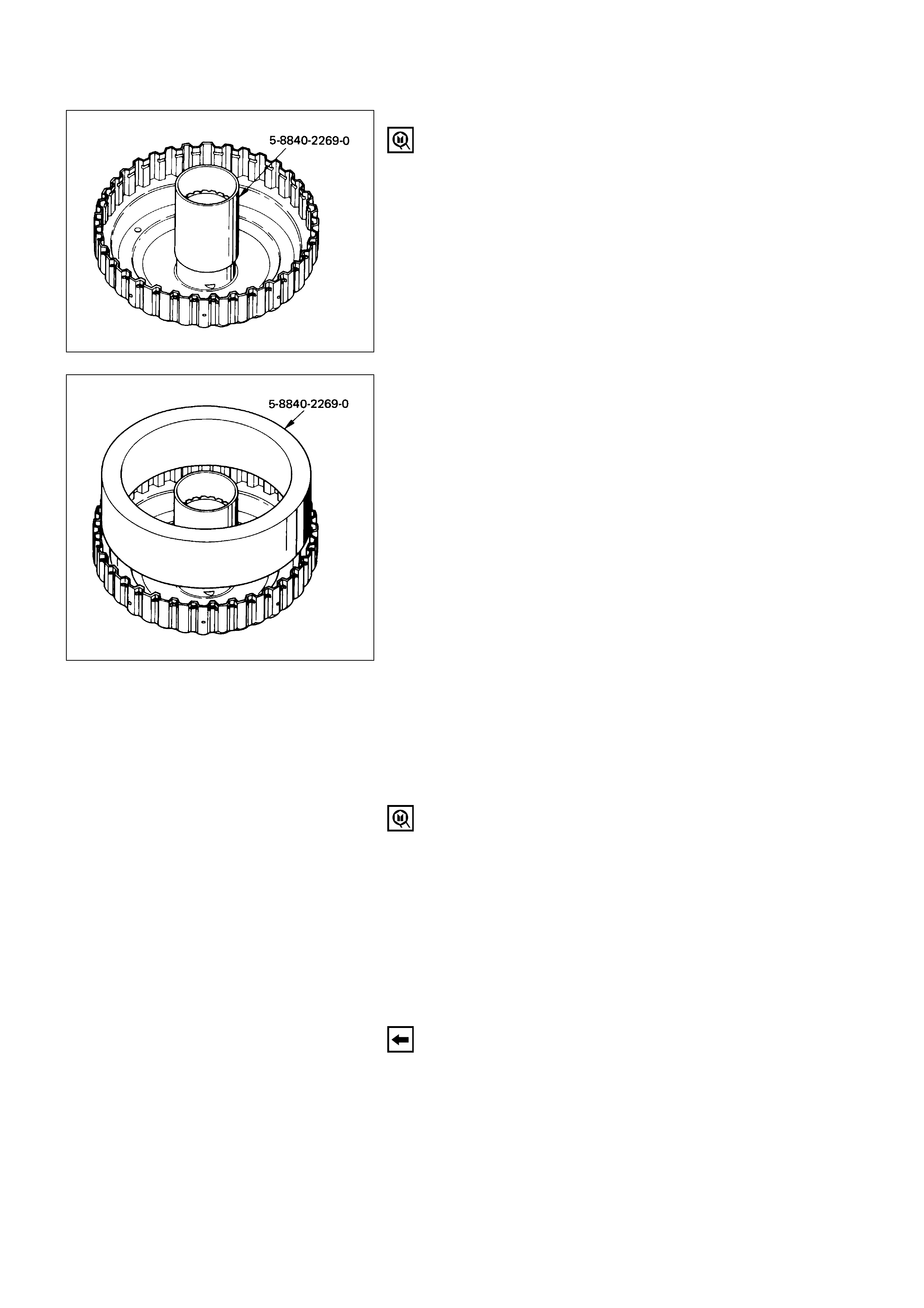
13. Piston
1) Install the inner installer on the drum.
2) Pre-install piston into outer installer.
3) Install overrun clutch piston assembly. Use the
outer installer while pushing piston into drum.
Installer: 5-8840-2269-0 (J-38555)
12. Diaphragm Spring
11. Overrun Clutch Release Spring Retainer
10. Roller Clutch Assembly
9. Overrun Roller Clutch Cam
8. Snap Ring
1) Place snap ring loosely on spring retainer.
2) Hold the compressor in a vise. Compress piston
return spring with compressor.
3) Set snap ring in ring groove.
Compressor: 5-8840-2275-0 (J-23327-91)
7. Clutch Plates
Install clutch plates, start with steel plate and
alternate with lined plates.
6. Backing Plate
5. Snap Ring
4. Turbine Shaft
3. Sun Gear
Overdrive sun gear, countersink pointing downwards.
2. Overdrive Carrier Assembly
Complete overdrive carrier assembly.
NOTE:
Turn the assembly in a counter-clockwise direction
only until roller clutch enters the outer race. After
assembly, rotate the assembly and listen for loose
rollers.
1. Snap ring
4L30-E PARTS LIST CASE AND ASSOCIATED PARTS
23
123568910 11 12
67
68
69
71
72
73
104
27 28 29
4
7
28 30 31 8
12 32
1314 15
74
75
70
70
84
85
86
87
88
33
105
79
TRANSMISSION
CONTROL MODULE
90
91
92
93
94
95
96
97 106
98
99
100
101
102
103
19
18
17
16 43 44 4546
35 36
37
39 38
4948 47
50
5251
606162 63 64
65
34
89
85
59
58
76 76
77 77
23
20
70
78
70
80
82
42
53
54
55
57 56
241LW002
1 Torque converter
2 Screw, seal ring assembly
3 Seal ring assembly, converter
housing
4 Screw, converter housing/main
case
5 Screw, converter housing/oil pump
6 Housing, converter
7 Plug, converter housing
8 Seal, O-ring
9 Wear plate, oil pump body
10 Pump assembly, oil
11 Gasket
12 Washer, thrust selective
13 Ring, snap
14 Cover, 3-4 accumulator piston
15 Seal, O-ring, 3-4 accumulator
16 Spring, 3-4 accumulator piston
17 Pin, 3-4 accumulator piston
18 Piston, 3-4 accumulator
19 Ring, 3-4, accumulator piston
20 Case, adapter
22 Connector, electrical/adapter case
27 Restrictor, oil
28 Gasket, Transfer plate/adapter
29 Plate, transfer adapter/center
support
30 Support assembly, center
31 Screw, center support
32 Ring, oil seal
33 Seal, O-ring main case
34 Fitting, cooler
35 Fitting assembly, cooler
36 Case, main
37 Breather, pipe
38 Seal, O-ring
39 Reservoir
42 Gasket, extension case
43 Extension assembly
44 Seal, O-ring/speed sensor
45 Sensor assembly, speed
46 Screw, speed sensor
47 Nut, output shaft/drive flange
48 Seal, O-ring/drive flange
49 Flange, drive
50 Seal, extension assembly
51 Bearing, needle/extension
52 Screw, extension/main case
53 Spring, parking pawl lock
54 Pawl, parking lock
55 Connector, electrical/main case
56 Actuator assembly, parking lock
57 Nut, parking lock lever
58 Link, manual valve
59 Pin, spring
60 Lever, parking lock & range
selelector
61 Shaft, selector
62 Seal, selector shaft
63 Mode switch assembly
64 Screw & conical washer assembly
65 Shield, mode switch
67 Pan, Bottom/Adapter case
68 Gasket, bottom pan/adapter case
69 Harness assembly, adapter case
70 Screw, valve body
71 Valve body assembly, adapter case
72 Gasket, adapter valve body
73 Plate, adapter valve body/transfer
74 Pan, bottom/main case
75 Gasket, bottom pan/main case
76 Gasket, screw (’97)
77 Screw, oil drain or overfill (’97)
78 Magnet, chip collector
79 Filter oil
80 Harness assembly, main case
81 Earth harness (’97)
82 Roller & spring assembly, manual
detent
84 Valve body assembly, main case
85 Ball, check
86 Gasket, main V.B./Transfer plate
87 Plate, main V.B./Transfer
88 Gasket, transfer/main case
89 Screw, transfer plate on V.B.
90 Screw, servo cover
91 Cover, servo piston
92 Gasket, cover/servo piston
93 Ring, retaining servo piston
94 Clip, servo piston
95 Nut, servo screw
96 Screw, servo piston
97 Piston, servo
98 Seal, ring/servo piston
99 Spring, cushion/servo piston
100 Seat, cushion spring
101 Sleeve, servo piston adjust
102 Rod, apply/servo piston
103 Spring, return/servo piston
104 Gasket, adapter case/transfer plate
105 Transmission control module
106 Servo piston assembly
CASE AND ASSOCIATED PARTS
PUMP ASSEMBLY
201 Gear, oil pump drive
202 Gear, oil pump driven
203 Pin, boost valve sleeve
204 Sleeve, boost valve
205 Valve, boost
206 Seat, spring/pressure regulator valve
207 Spring, pressure regulator valve
208 Valve, pressure regulator
209 Pump assembly, oil
210 Valve, converter clutch control
211 Spring, converter clutch control valve
212 Plug, converter clutch control valve
213 Pin, spring
214 Piston, throttle signal accumulator
215 Spring, throttle signal accumulator
216 Seat, spring/throttle signal accumulator
217 Ring, snap/throttle signal accumulator
206 207 206 208
203 204 205
201 202
217
216
215
214
210
211212 213
209
403
402
407
410
414
416 402
401
415
412
413
417
409
406
405
411
404
VALVE BODY ASSEMBLIES
301 Body, valve main case
302 Pin, spring
303 Solenoid assembly, on/off N.C.
304 Valve, 1-2 & 3-4 shift
305 Spring, 1-2 & 3-4 (2-3) shift
306 Retainer, valve
307 Solenoid assembly, ON/OFF N.O.
308 Valve, 2-3 shift
309 Pin, spring
310 Plug, valve bore
311 Spring, valve low pressure control
312 Valve, low pressure control
317 Ball, check
318 Valve, 1-2 accumulator control
320 Valve, 1-2 accumulator
321 Washer, waved PWM solenoid
322 Pin, solenoid PWM
323 Solenoid assembly, band control PWM
324 Screen assembly, PWM solenoid
325 Plug, screen
326 Valve, manual
318 320
309
310
321
323 325
309
322
324
326
306
317
312
302
310
308
302
303
304 305
317
301
307
305 317
311
243LW001
401 Body, valve/adapter case
402 Screw, solenoid force motor
403 Retainer, force motor
404 Solenoid, force motor
405 Plug, 3-4 accumulator
406 Retainer
407 Valve, 3-4 accumulator
409 Valve, 3-4 accumulator control
410 Spring, feed limit valve
411 Ring, retainer
412 Valve, feed limit
413 Seal, O-ring plug filter
414 Plug, screen
415 Screen assembly, force motor
416 Solenoid, torque conv. clutch on/off
N.C.
417 Plug retainer
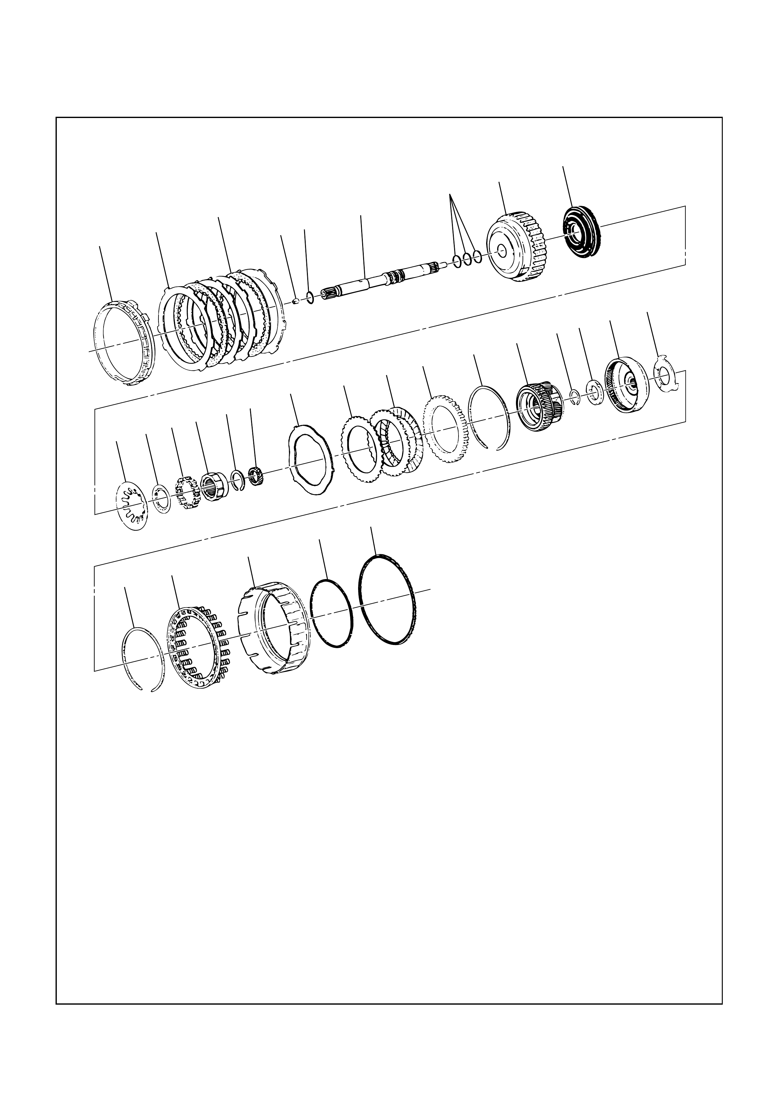
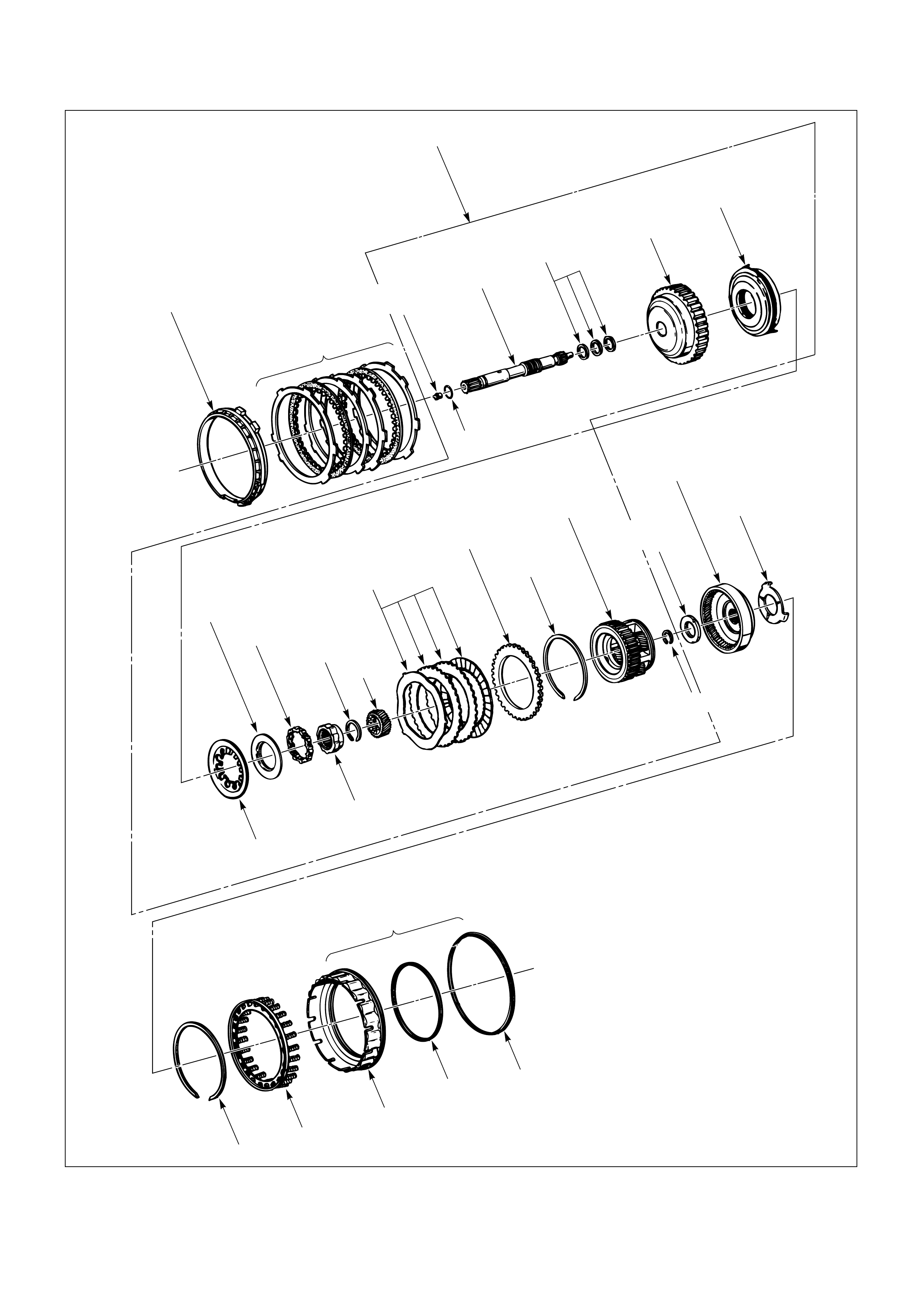
501 Retainer, 4th clutch
502 Plate, 4th clutch (steel)
503 Plate assembly, 4th clutch (lined)
504 Retainer & ball assembly, check valve
505 Seal, O-ring/turbine shaft
506 Shaft, turbine
508 Ring, oil seal/turbine shaft
510 Housing, overrun clutch
513 Piston, overrun clutch
514 Spring, overrun clutch release
515 Retainer, release spring/overrun clutch
516 Roller assembly, overdrive clutch
517 Cam, overdrive roller clutch
518 Ring, snap/overrun clutch hub
519 Gear, overdrive sun
521 Plate, overrun clutch (steel)
522 Plate assembly, overrun clutch (lined)
523 Plate, backing/overrun clutch
524 Ring, snap/overrun clutch housing
525 Carrier assembly, overdrive complete
526 Ring, snap/turbine shaft/carrier
527 Bearing assembly, thrust
528 Gear, overdrive internal
529 Washer, thrust/internal gear/support
530 Ring, snap/adapter/4th clutch spring
531 Retainer & spring assembly, 4th clutch
532 Piston, 4th clutch
533 Seal, 4th clutch piston (inner)
534 Seal, 4th clutch piston (outer)
OVERDRIVE INTERNAL COMPONENTS
252RW003
501 502 503 504 505
514 515 516 517 518 519
530 531
532 533 534
521
520
522 523 524 525 526 527 528 529
506
508 510 513
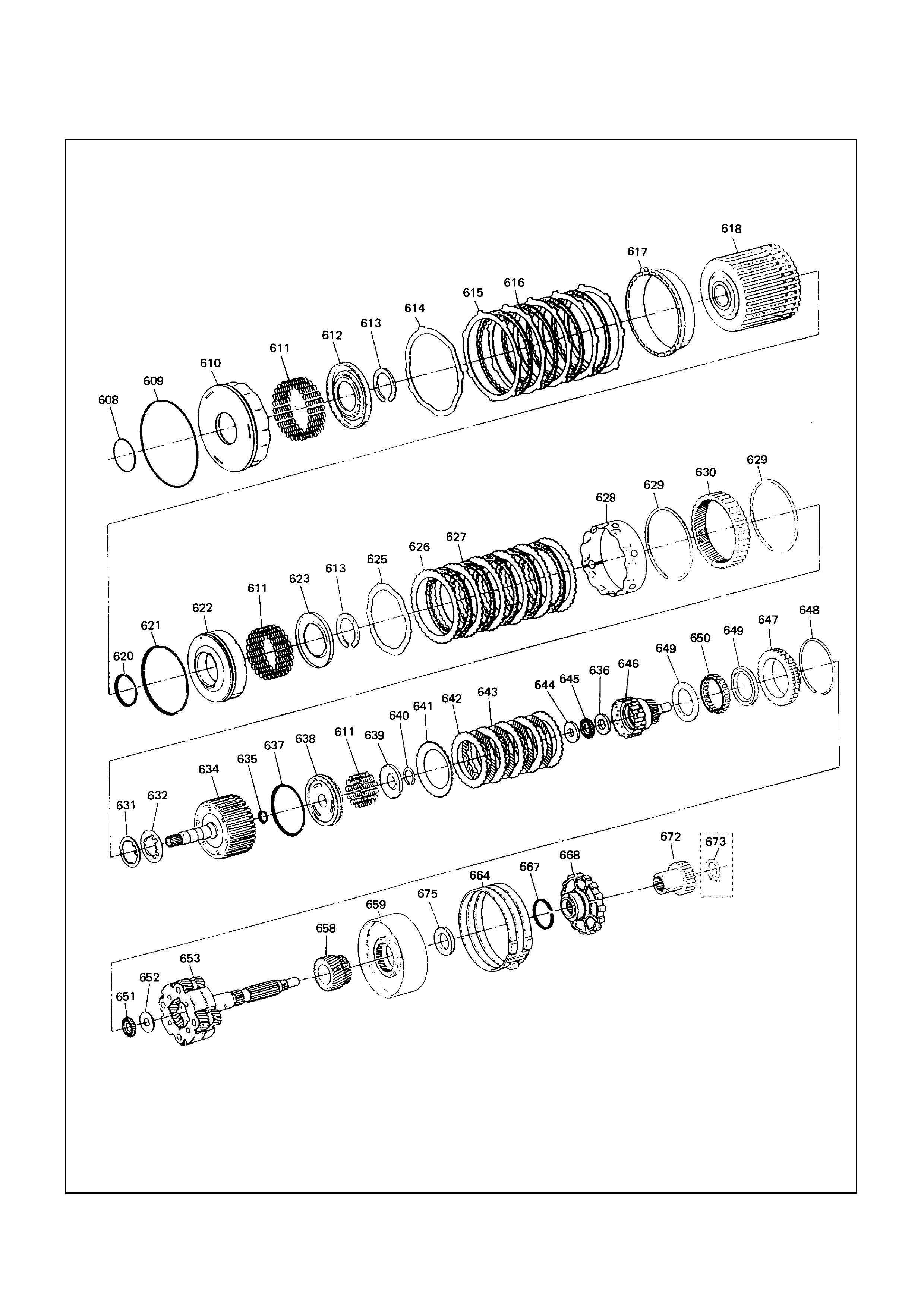
INTERNAL COMPONENTS

608 Seal, reverse clutch piston (inner)
609 Seal, reverse clutch piston (outer)
610 Piston, reverse clutch
611 Spring, piston clutch
612 Seat, spring/reverse clutch
613 Ring, Retaining
614 Plate, waved/reverse clutch
615 Plate, reverse clutch (steel)
616 Plate assembly, reverse clutch (lined)
617 Plate, reverse clutch pressure/selective
618 Drum assembly, 2nd clutch
620 Seal, 2nd clutch piston (Inner)
621 Seal, 2nd clutch piston (Outer)
622 Piston, 2nd clutch
623 Seat, spring/2nd clutch
625 Plate, waved/2nd clutch
626 Plate, 2nd clutch (Steel)
627 Plate assembly, 2nd clutch (Lined)
628 Spacer, 2nd clutch
629 Ring, retaining
630 Gear, ring
631 Washer, thrust/2nd clutch/3rd clutch
632 Thrust washer, clutch hub
634 Drum assembly, 3rd clutch
635 Seal, 3rd clutch piston (Inner)
636 Washer, retaining
637 Seal, 3rd clutch piston (Outer)
638 Piston 3rd clutch
639 Seat, spring/3rd clutch
640 Ring, retaining
641 Plate, spring cushion/3rd clutch
642 Plate, 3rd clutch (Steel)
643 Plate assembly, 3rd clutch (Lined)
644 Washer, thrust/input sun
645 Bearing, input shaft/gear assembly
646 Gear assembly, input sun
647 Race assembly, sprag
648 Ring, retaining/sprag
649 Ring, retaining
650 Cage assembly, sprag
651 Bearing, output shaft/input sun
652 Washer, output shaft/input sun
653 Carrier assembly, planetary
658 Gear, reaction sun
659 Drum, reaction sun
664 Band assembly, brake
667 Seal, ring/wheel parking lock
668 Wheel, parking lock
672 Wheel, speedo
673 Ring, retaining
675 Bearing, thrust assembly
INTERNAL COMPONENTS
CENTER SUPPORT ASSEMBLY
701 Center support
702 Retainer plate
703 Plug, lockout
704 Spring, overrun lockout
705 Valve, overrun lockout
702
703704
705
701