
SECTION 8A - ENGINE FUEL (6VD1 MODELS)
Service Precaution
General Description
Fuel Metering
Fuel Filter
Removal
Inspection
Installation
Inspection
In–Tank Fuel Filter
Fuel Pump Flow Test
Fuel Pump
Fuel Pump and Associated Parts
Removal
Installation
Fuel Pump Relay
General Description
Fuel Tank
Fuel Tank and Associated Parts
Removal
Installation
Fuel Gauge Unit
Removal and Installation
Fuel Filler Cap
General Description
Inspection
Main Data and Specifications
Service Precaution
WARNING:THIS VEHICLE HAS A SUPPLEMENTAL
RESTRAINT SYSTEM (SRS). REFER TO THE SRS
COMPONENT AND WIRING LOCATION VIEW IN
ORDER TO DETERMINE WHETHER YOU ARE
PERFORMING SERVICE ON OR NEAR THE SRS
COMPONENTS OR THE SRS WIRING. WHEN YOU
ARE PERFORMING SERVICE ON OR NEAR THE SRS
COMPONENTS OR THE SRS WIRING, REFER TO
THE SRS SERVICE INFORMATION. FAILURE TO
FOLLOW WARNINGS COULD RESULT IN POSSIBLE
AIR BAG DEPLOYMENT, PERSONAL INJURY, OR
OTHERWISE UNNEEDED SRS SYSTEM REPAIRS.
CAUTION:Always use the correct fastener in the
proper location. When you replace a fastener, use
ONLY the exact part number for that application.
Holden will call out those fasteners that require a
replacement after removal. Holden will also call out
the fasteners that require thread lockers or thread
sealant. UNLESS OTHERWISE SPECIFIED, do not
use supplemental coatings (Paints, greases, or other
corrosion inhibitors) on threaded fasteners or
fastener joint interfaces. Generally, such coatings
adversely affect the fastener torque and the joint
clamping force, and may damage the fastener . When
you install fasteners, use the correct tightening
sequence and specifications. Following these
instructions can help you avoid damage to parts and
systems.
Techline
General Description
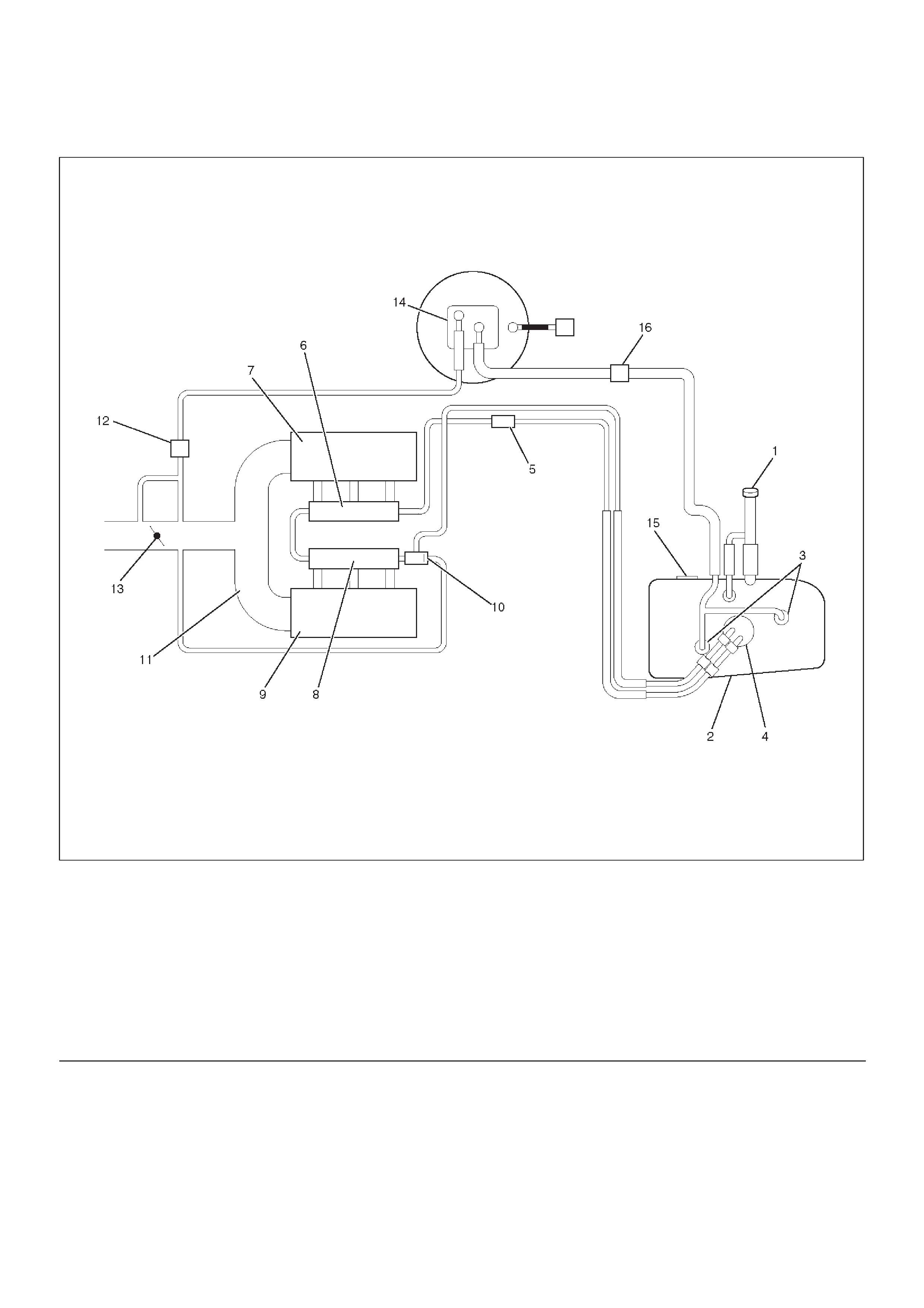
060RW245
Legend
(1) Fuel Filler Cap
(2) Fuel Tank
(3) Rollover Valve
(4) Fuel Pump Assembly
(5) Fuel Filter
(6) Fuel Rail Right
(7) Intake Air Port Right Bank
(8) Fuel Rail Left
(9) Intake Air Port Left Bank
(10) Fuel Pressure Control Valve
(11) Common Chamber
(12) Duty Solenoid Valve
(13) Throttle Valve
(14) Canister
(15) Fuel Gauge
(16) Check Valve

When working on the fuel system, there are several
things to keep in mind:
DAny time the fuel system is being worked on,
disconnect the negative battery cable except for
those tests where battery voltage is required.
DAlways keep a dry chemical (Class B) fire
extinguisher near the work area.
DReplace all pipes with the same pipe and fittings that
were removed.
DClean and inspect “O” rings. Replace if required.
DAlways relieve the line pressure before servicing any
fuel system components.
DDo not attempt repairs on the fuel system until you
have read the instructions and checked the pictures
relating to that repair.
DAdhere to all Notices and Cautions.
All gasoline engines are designed to use only unleaded
gasoline. Unleaded gasoline must be used for proper
emission control system operation.
Its use will also minimize spark plug fouling and extend
engine oil life. Using leaded gasoline can damage the
emission control system and could result in loss of
emission warranty coverage.
All cars are equipped with an Evaporative Emission
Control System. The purpose of the system is to minimize
the escape of fuel vapors to the atmosphere.
Fuel Metering
The Engine Control Module (ECM) is in complete control
of this fuel delivery system during normal driving
conditions.
The intake manifold function, like that of a diesel, is used
only to let air into the engine. The fuel is injected by
separate injectors that are mounted over the intake
manifold.
The Barometric Pressure (BARO) sensor measures the
changes in the barometric pressure which result from
engine load and speed changes, which the BARO sensor
converts to a voltage output.
This sensor generates the voltage to change
corresponding to the flow of the air drawn into the engine.
The changing voltage is transformed into an electric
signal and provided to the ECM.
With receipt of the signals sent from the BARO sensor,
Intake Air Temperature sensor and others, the ECM
determines an appropriate fuel injection pulse width
feeding such information to the fuel injector valves to
effect an appropriate air/fuel ratio.
The Multiport Fuel Injection system utilizes an injection
system where the injectors turn on at every crankshaft
revolution. The ECM controls the injector on time so that
the correct amount of fuel is metered depending on
driving conditions.
Two interchangeable “O” rings are used on the injector
that must be replaced when the injectors are removed.
The fuel rail is attached to the top of the intake manifold
and supplies fuel to all the injectors.
Fuel is recirculated through the rail continually while the
engine is running. This removes air and vapors from the
fuel as well as keeping the fuel cool during hot weather
operation.
The fuel pressure control valve that is mounted on the fuel
rail maintains a pressure differential across the injectors
under all operating conditions. It is accomplished by
controlling the amount of fuel that is recirculated back to
the fuel tank based on engine demand.
See Section “Driveability and Emission” for more
information and diagnosis.
Fuel Filter
Removal
CAUTION:When repair to the fuel system has been
completed, start engine and check the fuel system
for loose connection or leakage. For the fuel system
diagnosis, see Section “Driveability and Emission”.
1.Disconnect battery ground cable.
2.Remove Fuel filler cap.
3.Disconnect fuel hoses from fuel filter on both engine
side and fuel tank side.
4.Fuel filter fixing bolt.
DRemove the fuel filter fixing bolt on fuel filter holder.
5.Remove fuel filter.
Inspection
1.Replace the fuel filter if the fuel leaks from fuel filter
body or if the fuel filter body itself is damaged.
2.Replace the filter if it is clogged with dirt or sediment.
3.Check the drain of receive rubber and if it is clogged
with dust, clean it up with air.
Installation
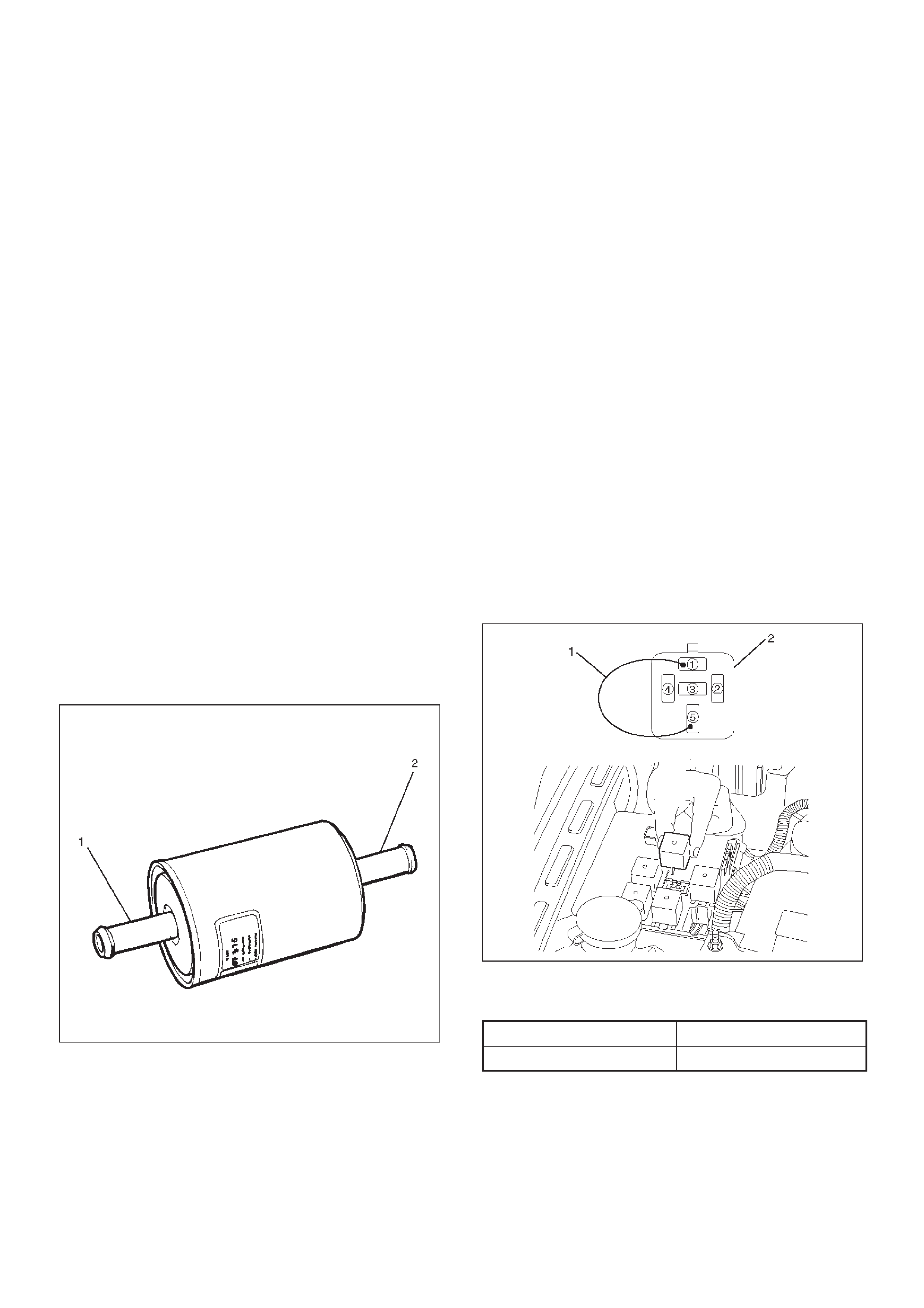
1.Install the fuel filter in the proper direction.
2.Install fuel filter holder fixing bolt.
3.Connect fuel hoses on engine side(1) and fuel tank
side(2).
041RW001
4.Install fuel filler cap
5.Connect the battery ground cable.
Inspection
After installation, start engine and check for fuel leakage.
In–Tank Fuel Filter
The filter is located on the lower end of fuel pickup tube in
the fuel tank. It prevents dirt from entering the fuel pipe
and also stops water unless the filter is completely
submerged in the water. It is a selfcleaning type, not
requiring scheduled maintenance. Excess water and
sediment in the tank restricts fuel supply to the engine,
resulting in engine stoppage. In such a case, the tank
must be cleaned thoroughly.
Fuel Pump Flow Test
If reduction of fuel supply is suspected, perform the
following checks.
1.Make sure that there is fuel in the tank.
2.With the engine running, check the fuel feed pipe and
hose from fuel tank to injector for evidence of
leakage. Retighten, if pipe or hose connection is
loose. Also, check pipes and hoses for squashing or
clogging.
3.Insert the hose from fuel feed pipe into a clean
container, and check for fuel pump flow rate.
4.Connect the pump relay terminals with a jumper
wire(1) as shown and start the fuel pump to measure
delivery.
060RW086
CAUTION:Never generate sparks when connecting
a jumper wire.
Delivery Delivery
15 seconds 0.38 liters minimum
If the measure value is out of standard, conduct the
pressure test.
Pressure test
For the pressure test to the fuel system, see Section 6C1
“Fuel Control System”.
Fuel Pump
Fuel Pump and Associated Parts
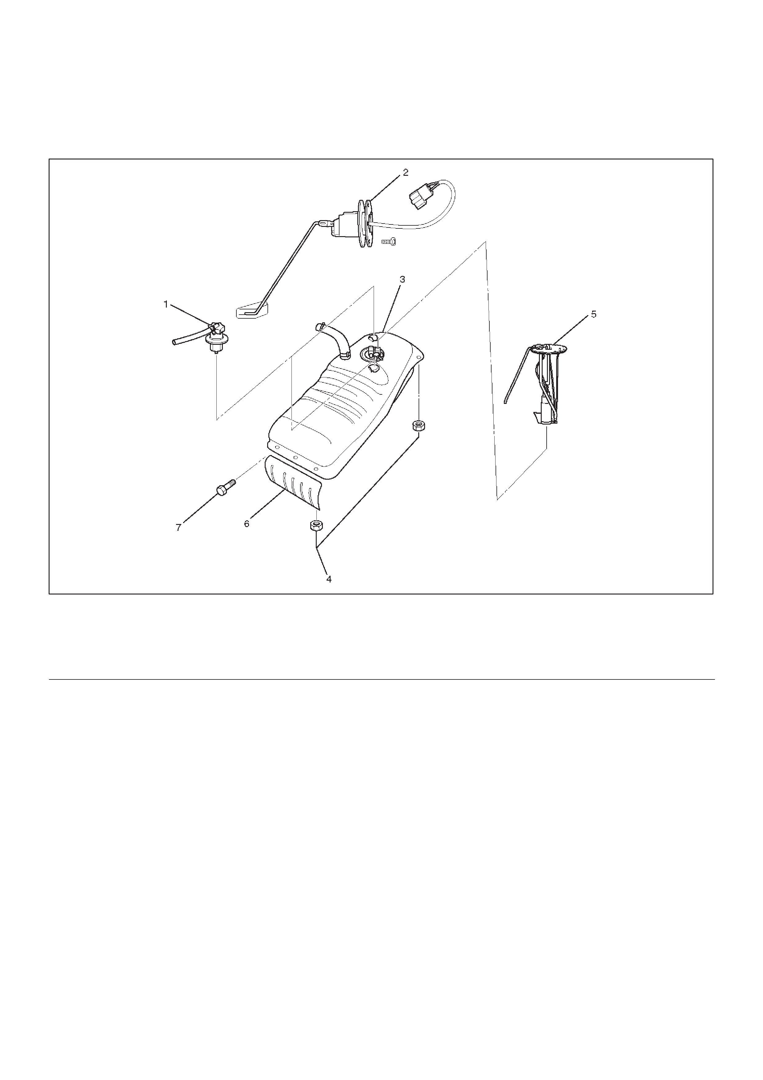
060RW099
Legend
(1)Roll Over&Float Valve
(2)Fuel Gauge
(3)Fuel Tank Assembly
(4)Nut; Fuel Tank
(5)Fuel Pump Assembly
(6)Fuel Tank Cover
(7)Tank Cover Bolt
Removal
CAUTION:When repair to the fuel system has been
completed, start engine and check the fuel system
for loose connection or leakage. For the fuel system
diagnosis, see Section “Driveability and Emission”.
1.Disconnect battery ground cable.
2.Loosen fuel filler cap.
3.Support underneath of the fuel tank assembly (3) with
a lifter.
4.Remove fuel tank assembly (3). Refer to “Fuel Tank
Removal” in this section.
5.Remove fuel pump assembly (5).
NOTE:After removing pump assembly (7), cover fuel
tank to prevent any dust entering.
Installation
1.Install FPAS assembly (5).
2.Install fuel tank assembly (3). Refer to “Fuel Tank
Installation”.
3.Fill the tank with fuel and tighten fuel filler cap.
4.Connect battery ground cable.
Fuel Pump Relay
General Description
In order to control the FPAS operation, the FPAS relay is
provided. When the starter switch is turned to “ON”
position, the FPAS relay operates the FPAS for 2
seconds.
When it is turned to “START” position, the Engine Control
Module receives the reference pulse from the Ignition
Control Module and it operates the relay, again causing
the FPAS to feed fuel.
Fuel Tank
Fuel Tank and Associated Parts
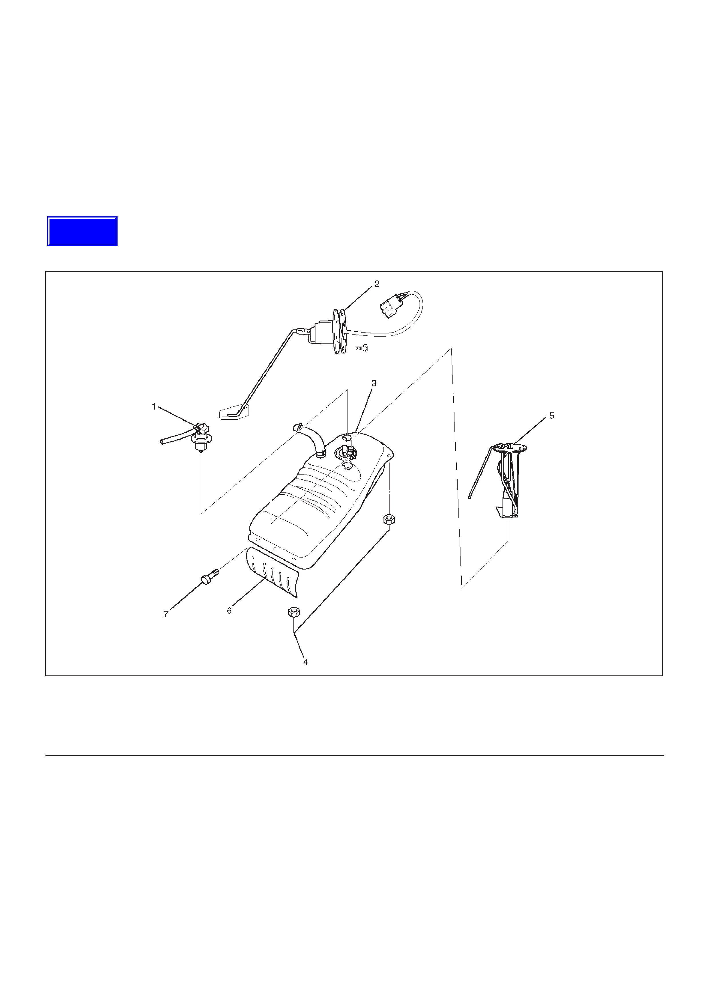
060RW099
Legend
(1)Roll Over&Float Valve
(2)Fuel Gauge
(3)Fuel Tank Assembly
(4)Nut; Fuel Tank
(5)Fuel Pump Assembly
(6)Fuel Tank Cover
(7)Tank Cover Bolt
Removal
CAUTION:When repair to the fuel system has been
completed, start engine and check the fuel system
for loose connection or leakage. For the fuel system
diagnosis, see Section “Driveability and Emission”.
1.Disconnect battery ground cable.
2.Loosen fuel filler cap.
3.Support underneath of the fuel tank (3) with a lifter.
4.Disconnect evaporative fuel hose.
5.Disconnect fuel feed hose and fuel return hose near
the fuel filter.
NOTE: Plug both ends of the fuel hoses to prevent fuel
leakage.
6.Disconnect air breather hose and fuel filler hose at the
fuel filler neck.
NOTE: Cover fuel hose to prevent any dust entering.
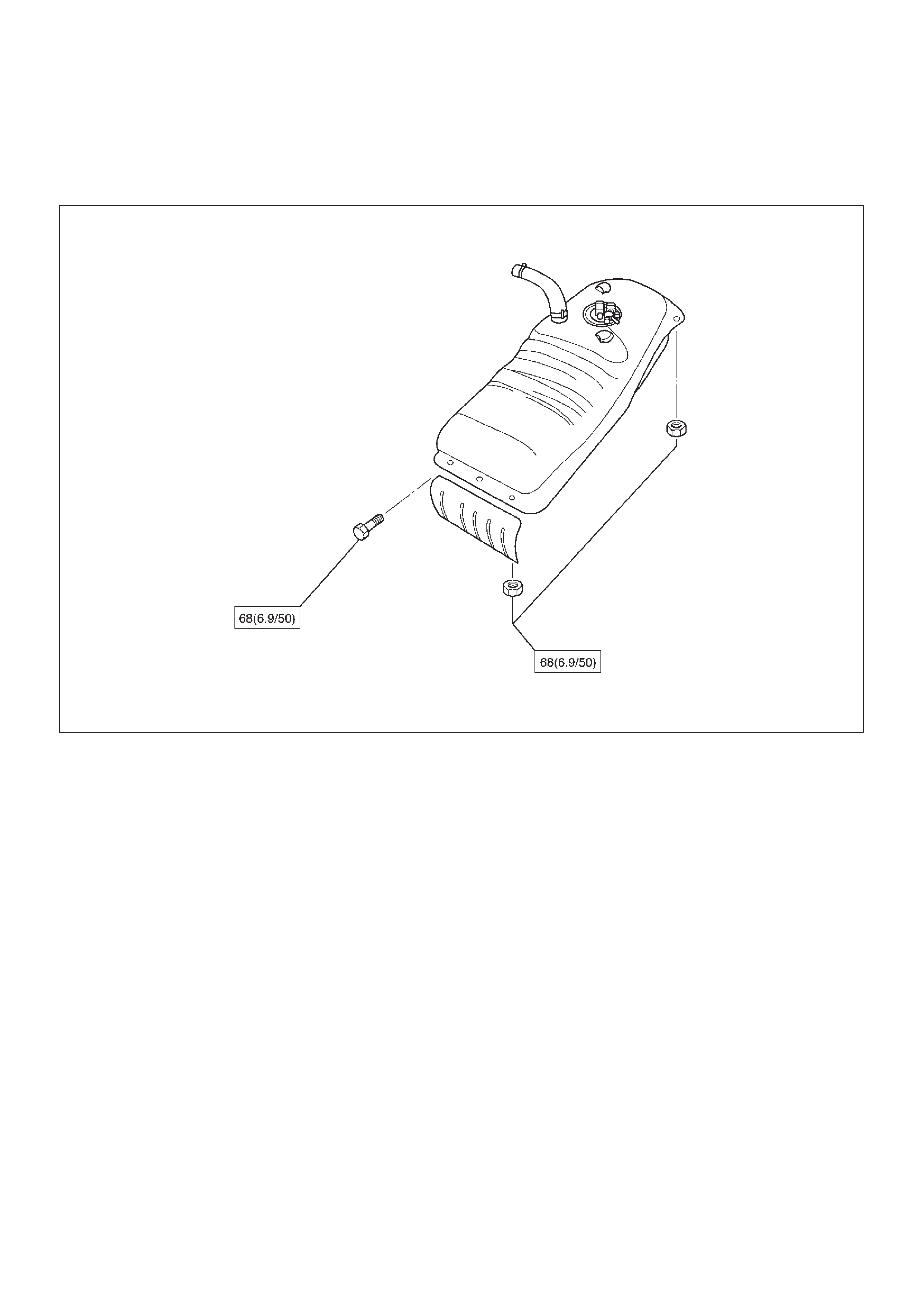
7. Remove the tank cover bolts (7) and the fuel tank
cover (6), the six fuel tank assembly fixing nuts (4) of
the tank.
Techline
8.Let down the tank and disconnect the wiring
connectors.
9.Remove fuel tank assembly.
10.Remove roll over & float valve (1) along with the
evaporative fuel hose and pipe.
11.Remove fuel pump along with the fuel hoses.
Installation
1.Install fuel pump (5).
2.Install roll over & float valve (1) by fitting in of the
retaining cover (2).
3.Lift up fuel tank assembly and connect the wiring
connectors (5,6).
4.Install fuel tank assembly along with the tank cover
and tighten the six fixing nuts to the specified torque.
Torque: 68 N·m (6.96thinsp;kg·m/50 lb ft)
5.Connect fuel filler hose and air breather hose, and clip
them firmly.
6.Connect fuel feed hose and fuel return hose, and clip
them firmly.
7.Connect evaporative fuel hose.
8.Tighten fuel filler cap.
9.Connect battery ground cable.
Fuel Gauge Unit
Removal and Installation
As for removal and installation of the Fuel Gauge Unit,
refer to “Fuel Tank” of this section 6C as the fuel gauge
unit is combined with the fuel pump and sender assembly.
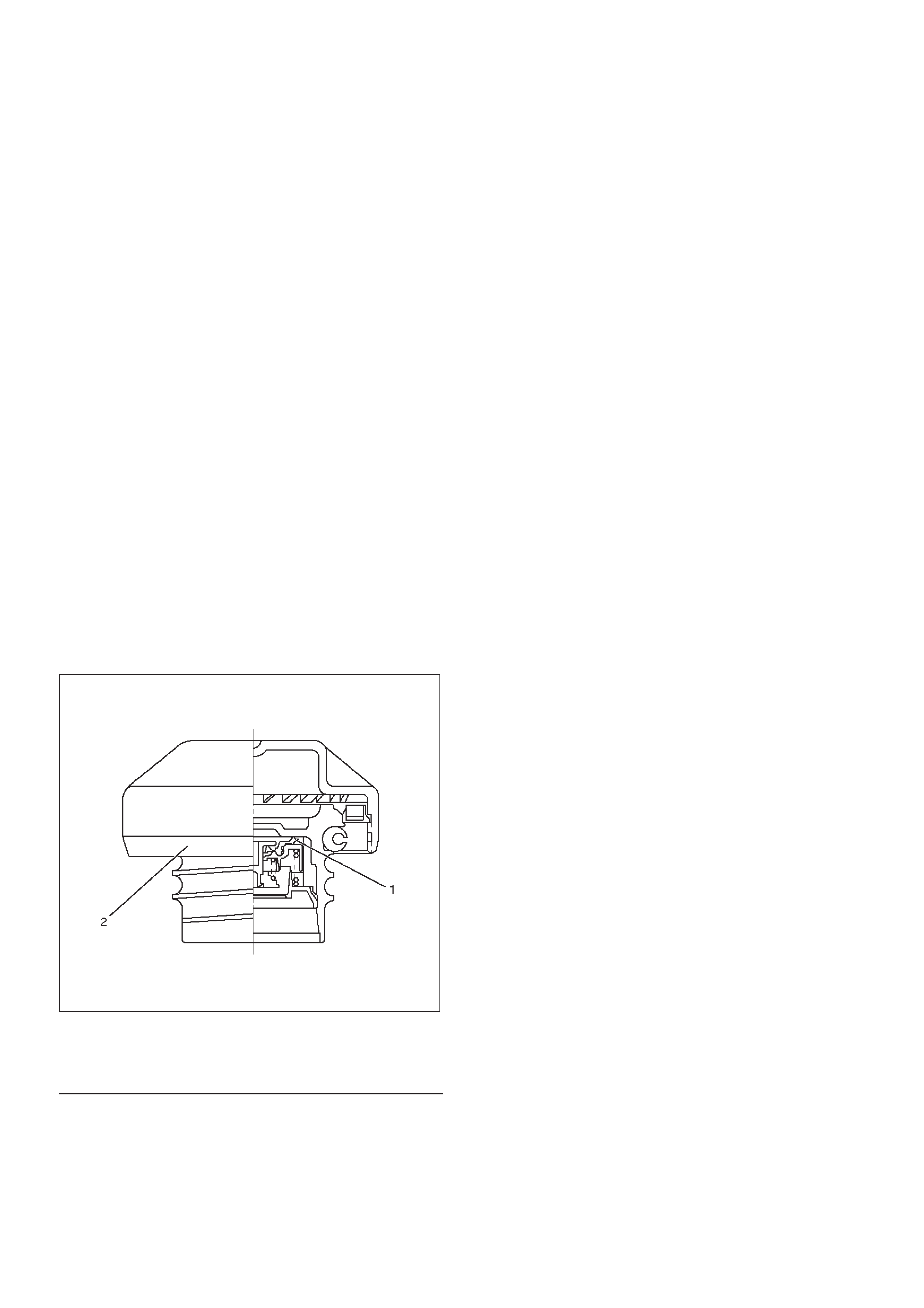
Fuel Filler Cap
General Description
Fuel filler cap includes vacuum valve.
In case any high vacuum happen in tank, the valve works
to adjust the pressure to prevent the tank from being
damaged.
060RW098
Legend
(1)Vacuum Valve
(2)Fuel Filler Cap
Inspection
Check the seal ring in the filler cap for presence of any
abnormality and for seal condition.
Replace the filler cap, if abnormal.
CAUTION:The fuel filler cap valve has
characteristics.
A defective valve, no valve at all or a valve with the
wrong characteristics will do a lot of harm to engine
operating characteristics; be sure to use the same
fuel filler cap as installed in this vehicle.
Main Data and Specifications
Torque Specification
N·m (kg·m/ lb·ft)
060RW217