
SECTION 8A - ENGINE FUEL (C22NE MODELS)
GENERAL DESCRIPTION
SERVICE PRECAUTION
FUEL METERING
FUEL FILTER
FUEL FILTER AND ASSOCIATED PARTS
REMOVAL
INSPECTION
INSTALLATION
INSPECTION
IN-TANK FUEL FILTER
FUEL PUMP
FUEL PUMP AND ASSOCIATED PARTS
REMOVAL
INSTALLATION
FUEL PUMP RELAY
GENERAL DESCRIPTION
FUEL TANK
FUEL TANK AND ASSOCIAT E D PARTS
REMOVAL
INSTALLATION
FUEL GAUGE UNIT
REMOVAL AND INSTALLATION
FUEL FILLER CAP
GENERAL DESCRIPTION
INSPECTION
FUEL FILTER
REMOVAL
INSTALLATION
FUEL TANK
REMOVAL
INSTALLATION
MAIN DATA AND SPECIFICATIONS
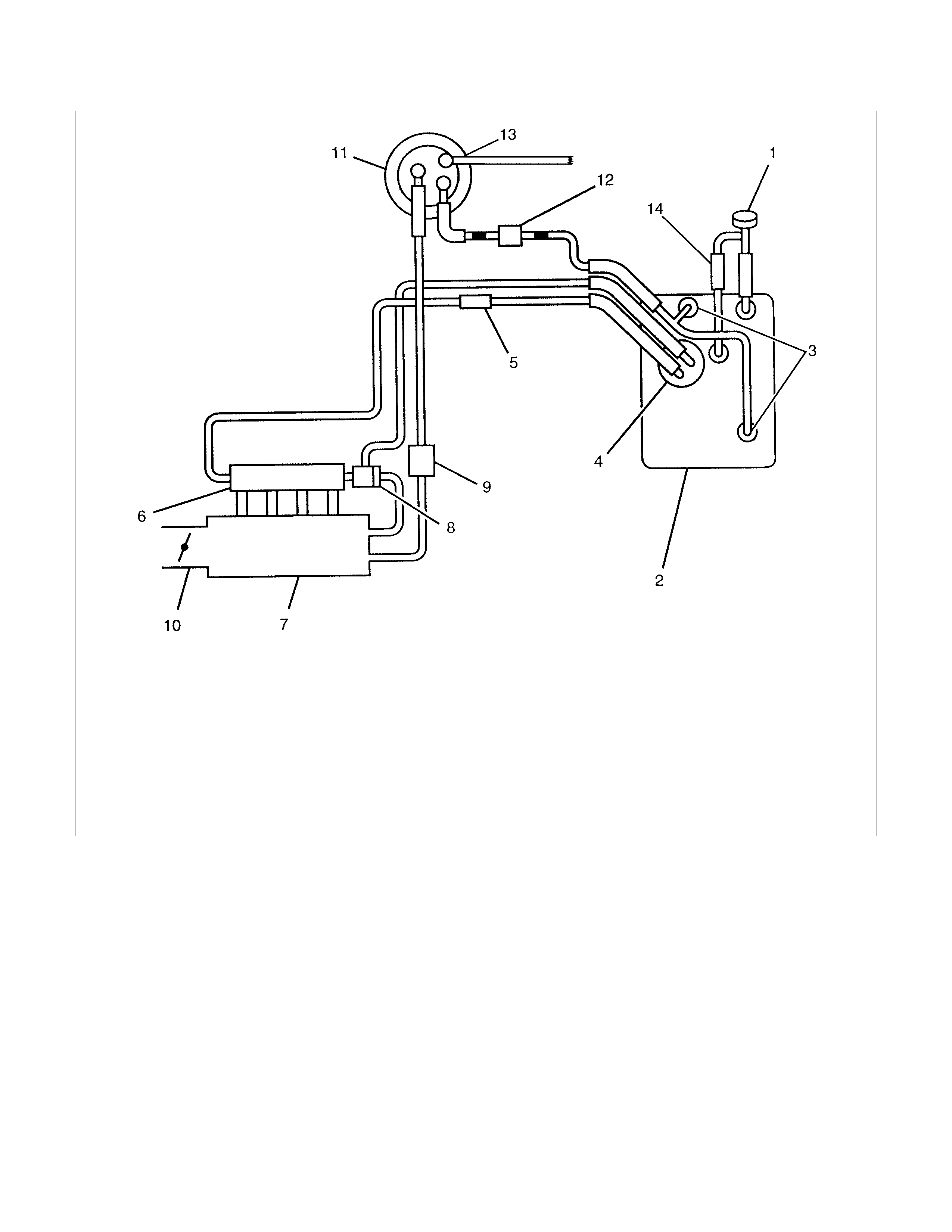
GENERAL DESCRIPTION
Legend
1 Filter Cap
2 Fuel Tank
3 Rollover Valve *
4 Fuel Pump
5 Fuel Filter
6 Fuel Rail
7 Intake Manifold
8 Fuel Pressure Control Valve
9 Duty Solenoid Valve
10 Throttle Valve
11 Canister *
12 Check and Relief Valve *
13.Drain hose *
14.2 Way Valve **
This illustration is based on the with
canister model.
* Applicable to EVAP Emission Control Sy stem
** Not applicable to EVAP Emission Control System

When working on the fuel system, there are several things to
keep in mind:
•Any time the f uel system is being work ed on, disconnect the
negative battery cable except for those tests where battery
voltage is required.
•
A
lways keep a dry chemical (Class B) fire extinguisher nea
r
the work area.
•Replace all pipes with the same pipe and fittings that were
removed.
•Clean and inspect "O" rings. Replace if required.
•Always relieve the line pressure before servicing any fuel
system components.
•Do not attempt repairs on the fuel system until you have
read the instructions and checked the pictures relating to
that repair.
•Adhere to all Notices and Cautions.
All gasoline engines are designed to use only unleaded
gasoline. Unleaded gasoline must be used for proper emission
control system operation.
Its use will also minimize spark plug fouling and extend engine
oil life. Using leaded gasoline can damage the emission control
system and could result in loss of emission warranty coverage.
All cars are equipped with an Evaporative Emission Control
System. The purpose of the system is to minimize the escape
of fuel vapors to the atmosphere.

SERVICE PRECAUTION
CAUTION:
Always use the correct fastener in the proper location.
When you replace a fastener, use ONLY the exact part
number for that application. ISUZU will call out those
fasteners that require a replacement after removal. ISUZU
will also call out the fasteners that require thread lockers
or thread sealant. UNLESS OTHERWISE SPECIFIED, do
not use supplemental coatings (Paints, greases, or other
corrosion inhibitors) on threaded fasteners or fastener
joint interfaces. Generally, such coatings adversely affect
the fastener torque and the joint clamping force, and may
damage the fastener. When you install fasteners, use the
correct tightening sequence and specifications. Following
these instructions can help you avoid damage to parts
and systems.

FUEL METERING
Engine Control Module (ECM) is in complete control of this fuel
delivery system during normal driving conditions.
The intake manifold function, like that of a diesel, is used only
to let air into the engine. The fuel is injected by separate
injectors that are mounted over the intake manifold.
The Manifold Absolute Pressure (MAP) sensor measures the
changes in the intake manifold pressure which result from
engine load and speed changes, which the MAP sensor
converts to a voltage output.
This sensor generates the voltage to change corresponding to
the flow of the air drawn into the engine.
The changing voltage is transformed into an electric signal and
provided to the ECM.
With receipt of the signals sent from the MAP sensor, Intake
Air Temperature sensor and others, the ECM determines an
appropriate fuel injection pulse width feeding such information
to the fuel injector valves to effect an appropriate air/fuel ratio.
The Multiport Fuel Injection system utilizes an injection system
where the injectors turn on at every crankshaft revolution. The
ECM controls the injector on time so that the correct amount of
fuel is metered depending on driving conditions.
Two interchangeable "O" rings are used on the injector that
must be replaced when the injectors are removed.
The fuel rail is attached to the top of the intake manifold and
supplies fuel to all the injectors.
Fuel is recirculated through the rail continually while the engine
is running. This removes air and vapors from the fuel as well
as keeping the fuel cool during hot weather operation.
The fuel pressure control valve that is mounted on the fuel rail
maintains a pressure differential across the injectors under all
operating conditions. It is accomplished by controlling the
amount of fuel that is recirculated back to the fuel tank based
on engine demand.
See Section "Driveability and Emission" for more
information and diagnosis.
FUEL FILTER
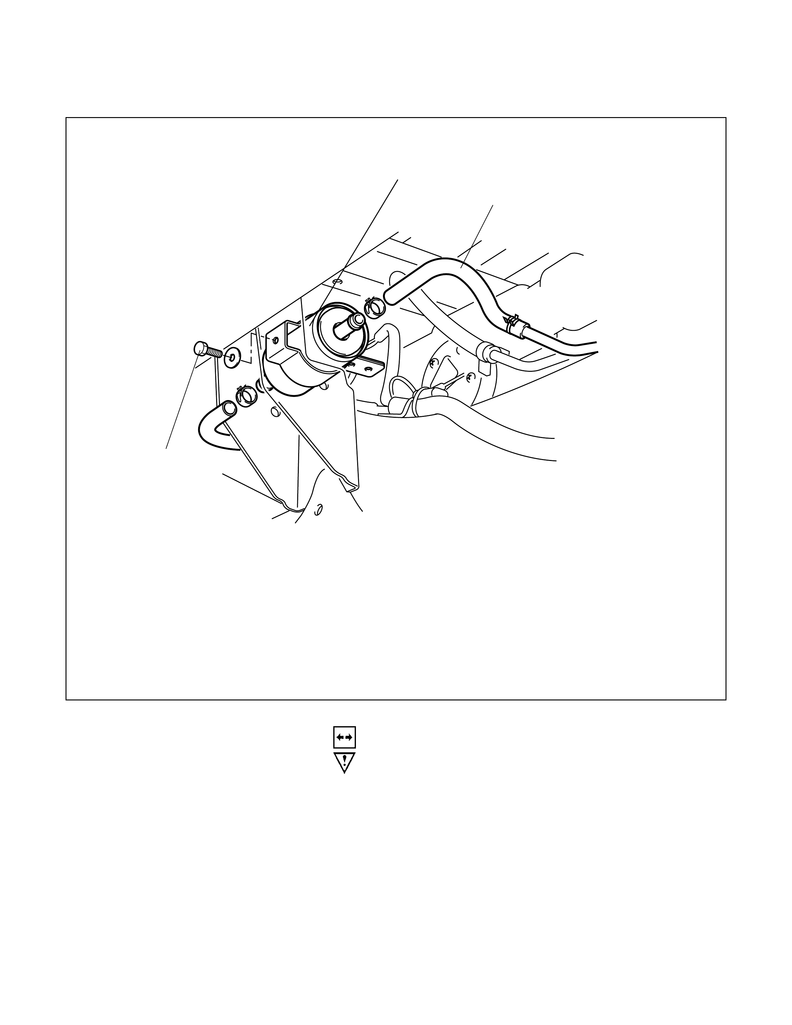
FUEL FILTER AND ASSOCIATED PARTS
Legend
1 Fuel Hose
2 Fuel Filter 3 Fixing bolt
3
1
2
REMOVAL
CAUTION: When repair to the fuel system has been
completed, start engine and check the fuel system for
loose connections or leakage. For the fuel system
diagnosis, see Section "Driveability and Emissions".
1. Disconnect battery ground cable.
2. Remove fuel filler cap.
3. Loosen the fixing bolt and disconnect fuel hoses (1).
4. Remove fuel filter (2).
INSPECTION
1. Replace the fuel filter if the fuel leak s fr om fuel f ilter body o
r
if the fuel filter body itself is damaged.
2. Replace the filter if it is clogged with dirt or sediment.
3. Check the drain and if it is clogged with dust, clean it out
with air.
INSTALLATION
1. Install the fuel filter in the proper direction.
2. Install fuel filter holder fixing bolt.
3. Connect fuel hoses on engine side and fuel tank side.
4. Install fuel filler cap
5. Connect the battery ground cable.
INSPECTION
After installation, start engine and check for fuel leak age.
IN-TANK FUEL FILTER
The filter is located on the lower end of the fuel pickup tube in
the fuel tank. It prevents dirt from entering the fuel pipe and
also stops water unless the filter is completely submerged in
the water. It is a self-cleaning type, not requiring scheduled
maintenance. Excess water and sediment in the tank restricts
fuel supply to the engine, resulting in engine stop. In such a
case, the tank must be cleaned thoroughly.
FUEL PUMP
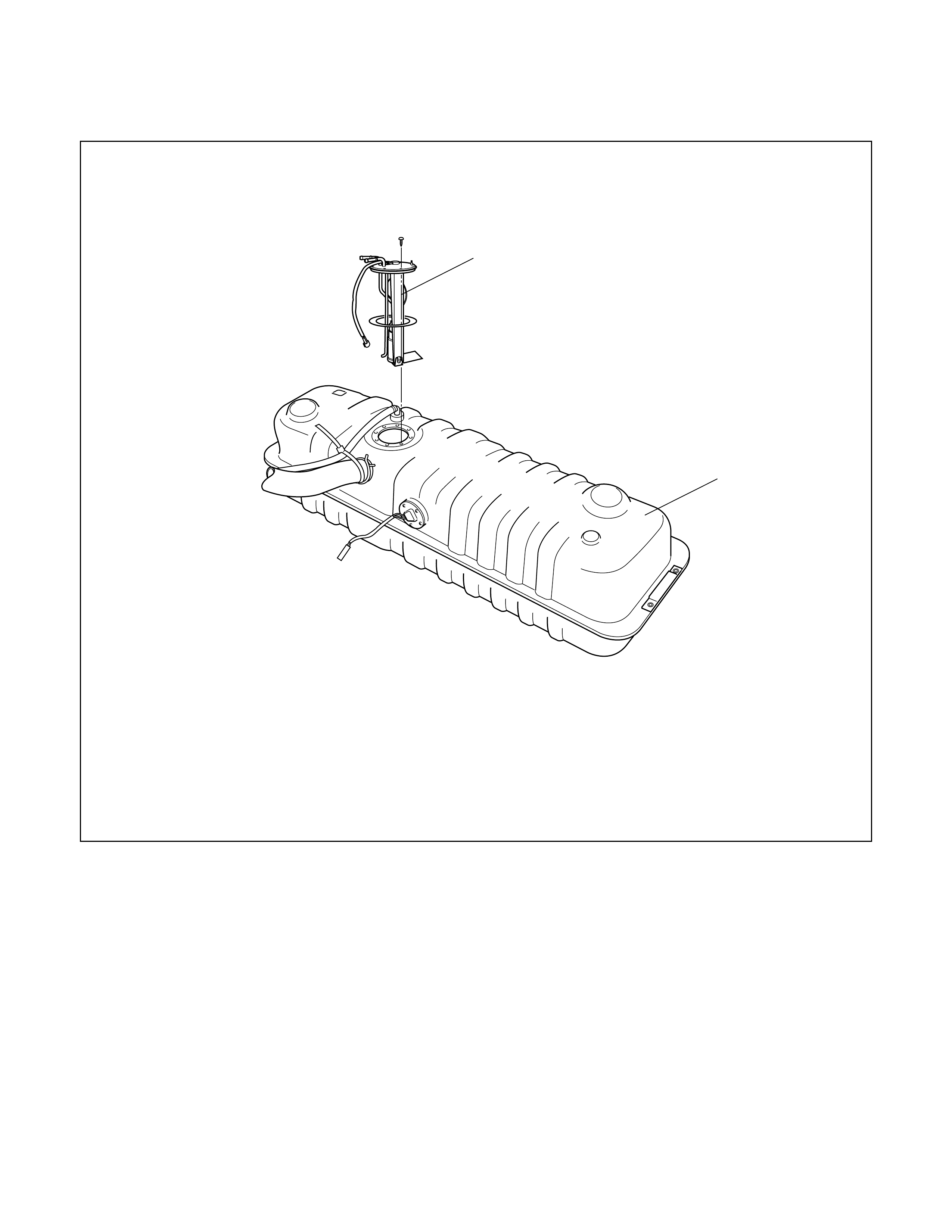
FUEL PUMP AND ASSOCIATED PARTS
Legend
1 Fuel Pump and Sender Assembly
2 Fuel Tank Assembly
2
1
REMOVAL
CAUTION: When repair to the fuel system has been
completed, start engine and check the fuel system for
loose connection or leakage. For the fuel system
diagnosis, see Section "Driveability and Emission".
1. Disconnect battery ground cable.
2. Loosen fuel filler cap.
3. Support underneath of the fuel tank assembly (2) with a
lifter.
4. Remove fuel tank assembly (2). Refer to
"Fuel Tank Removal" in this section.
5. Remove fuel pump and sender (FPAS) assembly (1) fixing
snapring and remove the FPAS assembly.
NOTE:
• After removing pump assembly (1), cover fuel tank to
prevent any dust entering.
• Remove the fuel pump lock.
INSTALLATION
1. Install FPAS assembly (1).
2. Install fuel tank assembly (2). Refer to
"Fuel Tank Installation".
3. Fill the tank with fuel and tighten fuel filler cap.
4. Connect battery ground cable.

FUEL PUMP RELAY
GENERAL DESCRIPTION
In order to control the FPAS operation, the FPAS relay is
provided. When the starter switch is turned to "ON" position,
the FPAS relay operates the FPAS for 2 seconds.
When it is turned to "START" position, the Engine Control
Module receives the reference pulse from the Ignition Control
Module and it operates the relay, again causing the FPAS to
feed fuel.
FUEL TANK
FUEL TANK AND ASSOCI ATED PARTS
Legend
1 Roll Over&Float Valve (If applicable)
2 Hose; Evaporative Fuel (If applicable)
3 Hose; Air Breather
4 Hose; Fuel Filler
5 Fuel Pump and Sender Assembly
6 Fuel Tank Assembly
7 Hose; Fuel Delivery
8 Hose; Fuel Return
4
(1, 2)
3
5
6
7
8
REMOVAL
CAUTION: When repair to the fuel system has been
completed, start engine and check the fuel system for
loose connection or leakage. For the fuel system
diagnosis, see Section "Driveability and Emission".
1. Disconnect battery ground cable.
2. Loosen fuel filler cap.
3. Support underneath of the fuel tank protector with a lifter.
4. Disconnect evaporative fuel hose at the canister.
5. Disconnect f uel delivery hose and fuel r eturn hose near the
fuel filter.
NOTE: Plug both ends of the fuel hoses to prevent fuel
leakage.
6.Disconnect air breather hose (3) and fuel filler hose (4) at
the fuel filler neck.
NOTE: Cover fuel hose to prevent any dust entering.
7.Remove the four fuel tank assembly fixing bolts at fou
r
corners of the tank.
8.Let down the tank and disconnect the wiring connectors and
the emission hose at the emission port on the fuel pump
and sending assembly (5).
9.Remove fuel tank assembly along w ith protectors.
10.Remove roll-over float valve (1) along with the evaporative
fuel hose and pipe (2).
11.Remove fuel pump and sender assembly (5) by removing
the snap ring along with the fuel hoses (7, 8).
12.Remove tank protector by removing the fixing bolts.
INSTALLATION
1. Install protectors and tighten the fixing bolts to the specified
torque.
Torque; 68 N⋅
⋅⋅⋅m (6.9 kgf.m)
2. Install fuel pum p and sender as sem bly by fitting in the snap
ring.
3.Install roll-over float valve (1).
4. Lif t up fuel tank assembly and connect the em iss ion hos e to
the emission port and the wiring connectors on the fuel
pump and sending assembly (5).
5.Install fuel tank assembly along with protectors and tighten
the four fixing bolts to the specified torque.
Torque: 68 N⋅
⋅⋅⋅m (6.9 kgf.m)
6.Connect fuel filler hose (4) and air breather hose (3), and
clip them firmly.
7. Connect fuel delivery hose (7) and f uel return hose (8) , and
clip them firmly.
8.Connect evaporative fuel hose (2).
9.Tighten fuel filler cap.
10.Connect battery ground cable.
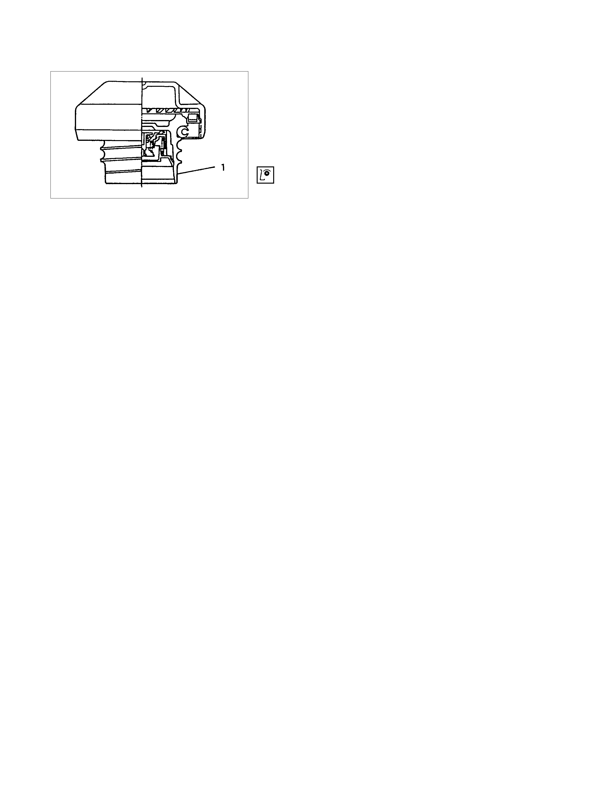
FUEL FILLER CAP
GENERAL DESCRIPTION
Fuel filler cap includes vacuum valve.
In case any high vacuum happen in tank, the valve works to
adjust the pressure to prevent the tank from being damaged.
LEGEND
1 Fuel Filler Cap
INSPECTION
Check the seal ring in the filler cap for presence of any
abnormality and for seal condition.
Replace the filler cap, if abnormal.
CAUTION: The fuel filler cap valve has characteristics.
A defective valve, no valve at all or a valve with the wrong
characteristics will do a lot of harm to engine operating
characteristics; be sure to use the same fuel filler cap as
installed in this vehicle.
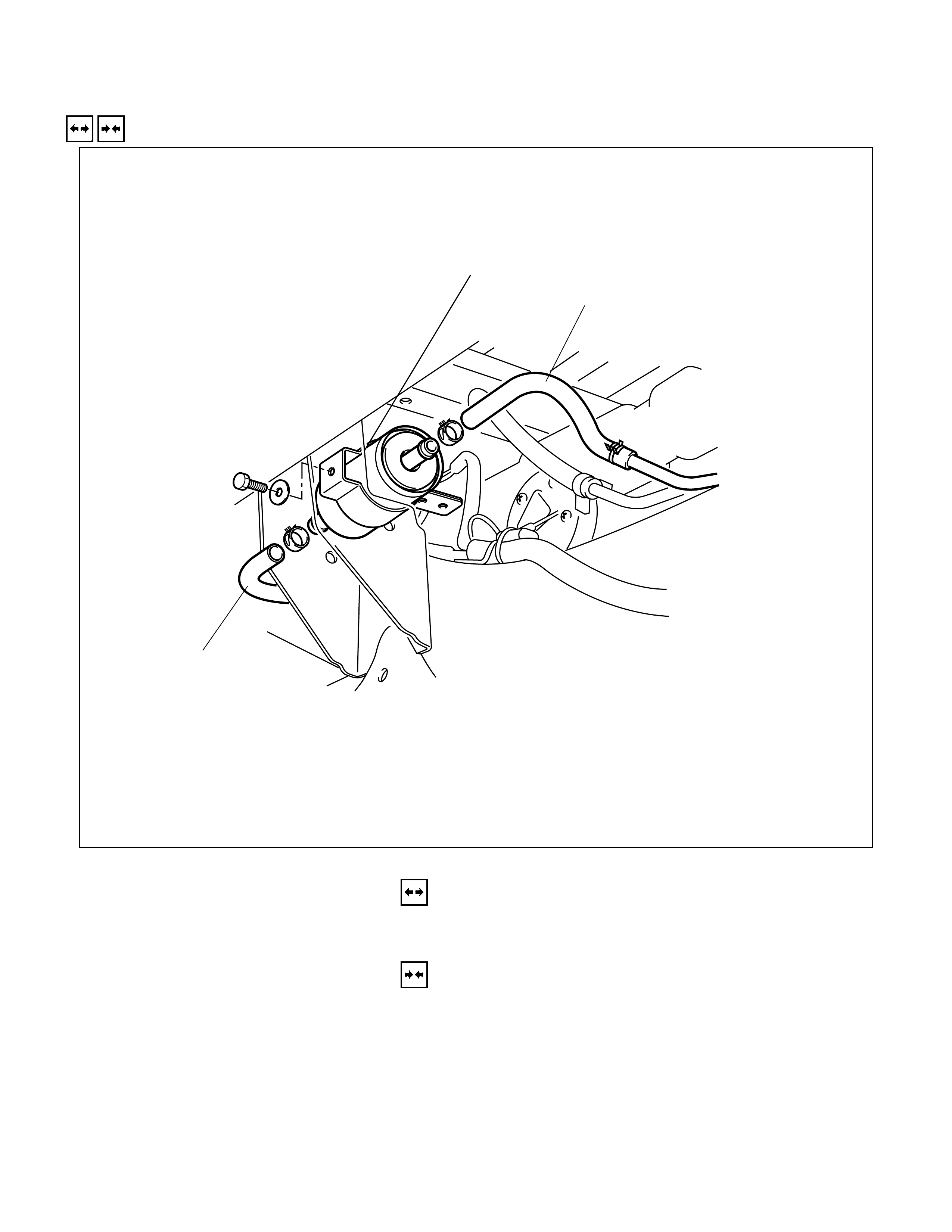
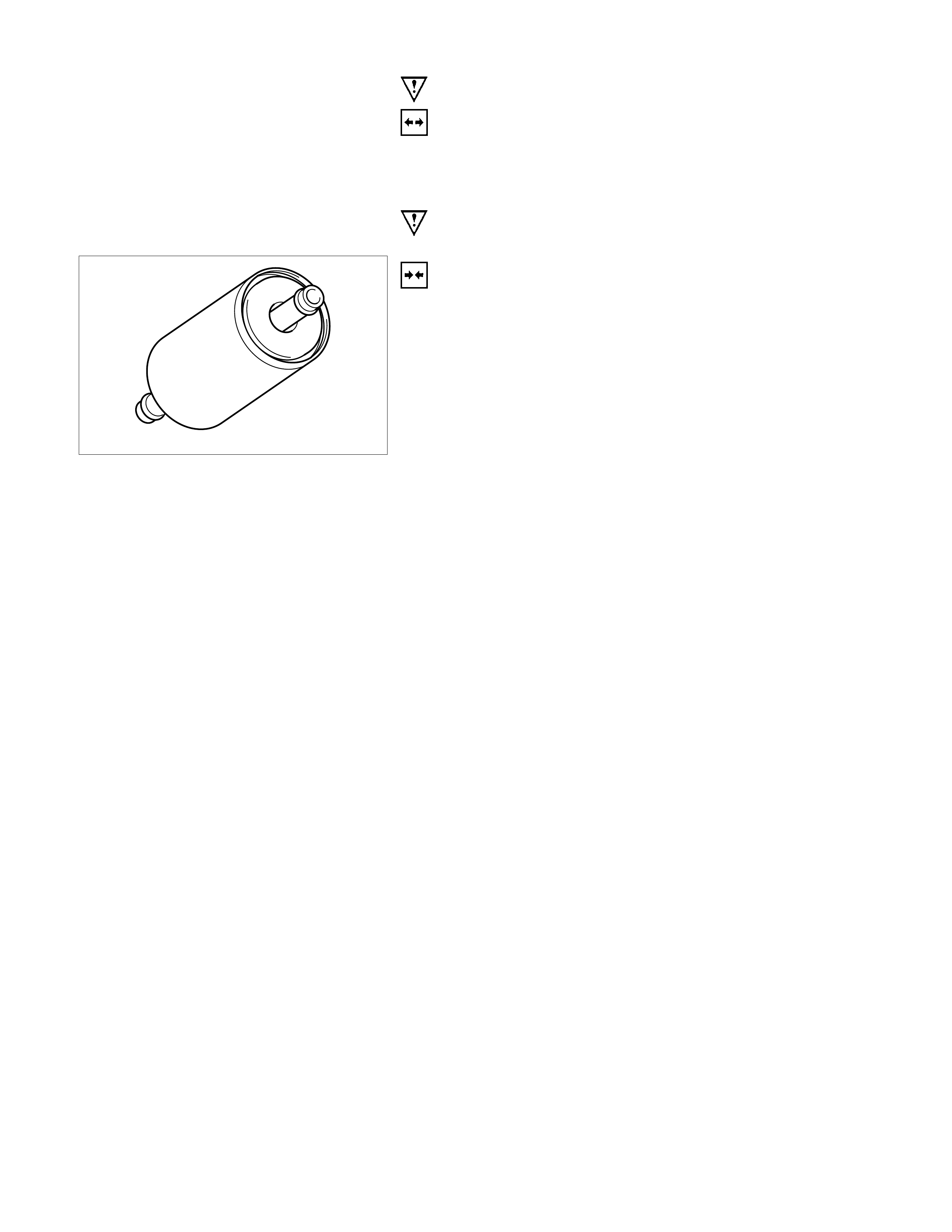
FUEL FILTER
REMOVAL AND INSTALLATION
3
1
2
REMOVAL
1. Inlet and outlet fuel hose
2. Fuel filter
INSTALLATION
2. Fuel filter
1. Inlet and outlet fuel hose
IMPO RTANT OPERATIONS - REM OVAL
1. Inlet and Outlet Fuel Hose
Use a rag to prevent the fuel from flowing from the fuel hoses.
NOTE:
Immediately plug the fuel hoses.
Do not work in close proximity to sparks or an open flame.
IMPORTANT OPERATIONS - INSTALLATION
1. Fuel Filter
1) Install the fuel filter to the fuel pump in the direction
indicated by the arrow stamped on the side of the fuel filter.
2) Start the engine.
Check for fuel leakage from the fuel hose joints.
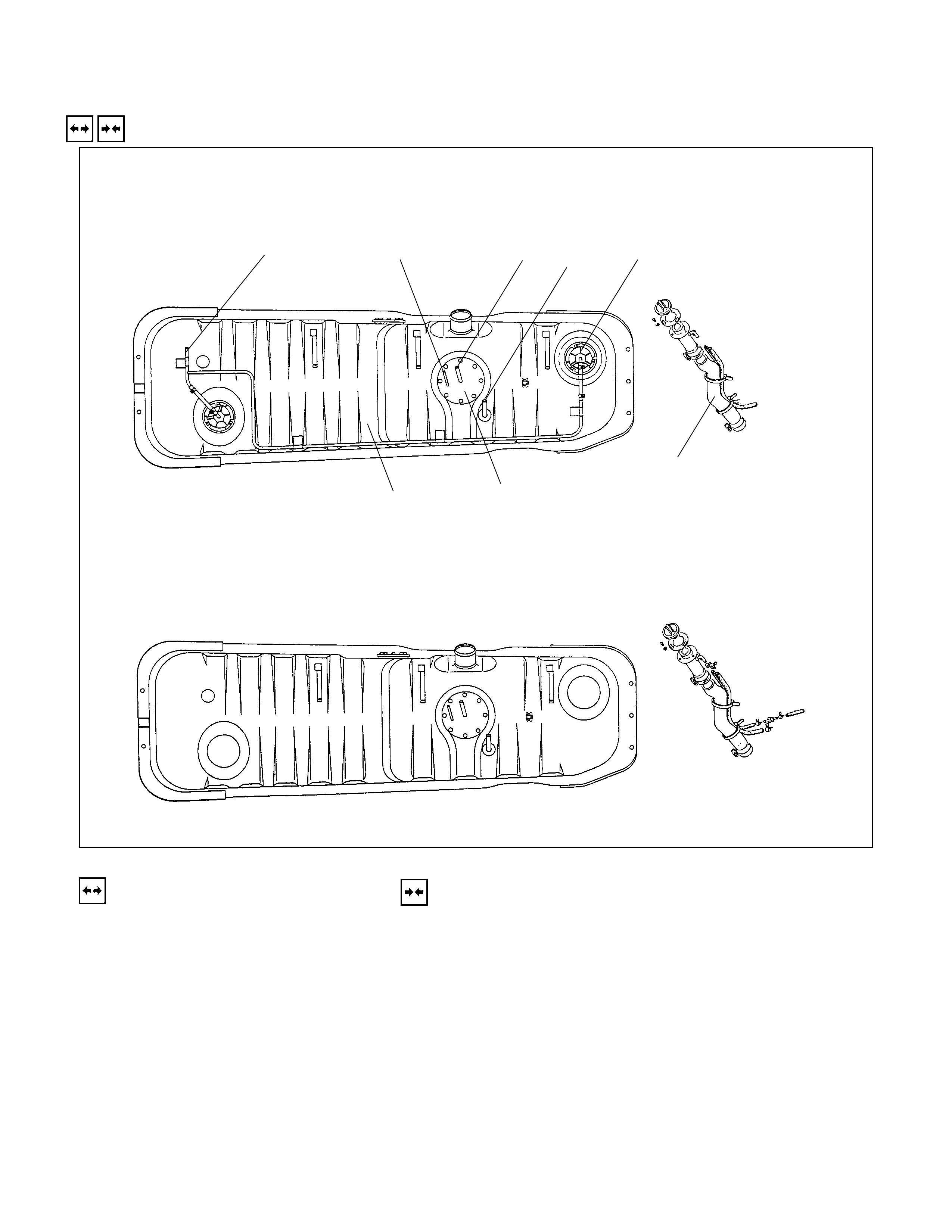
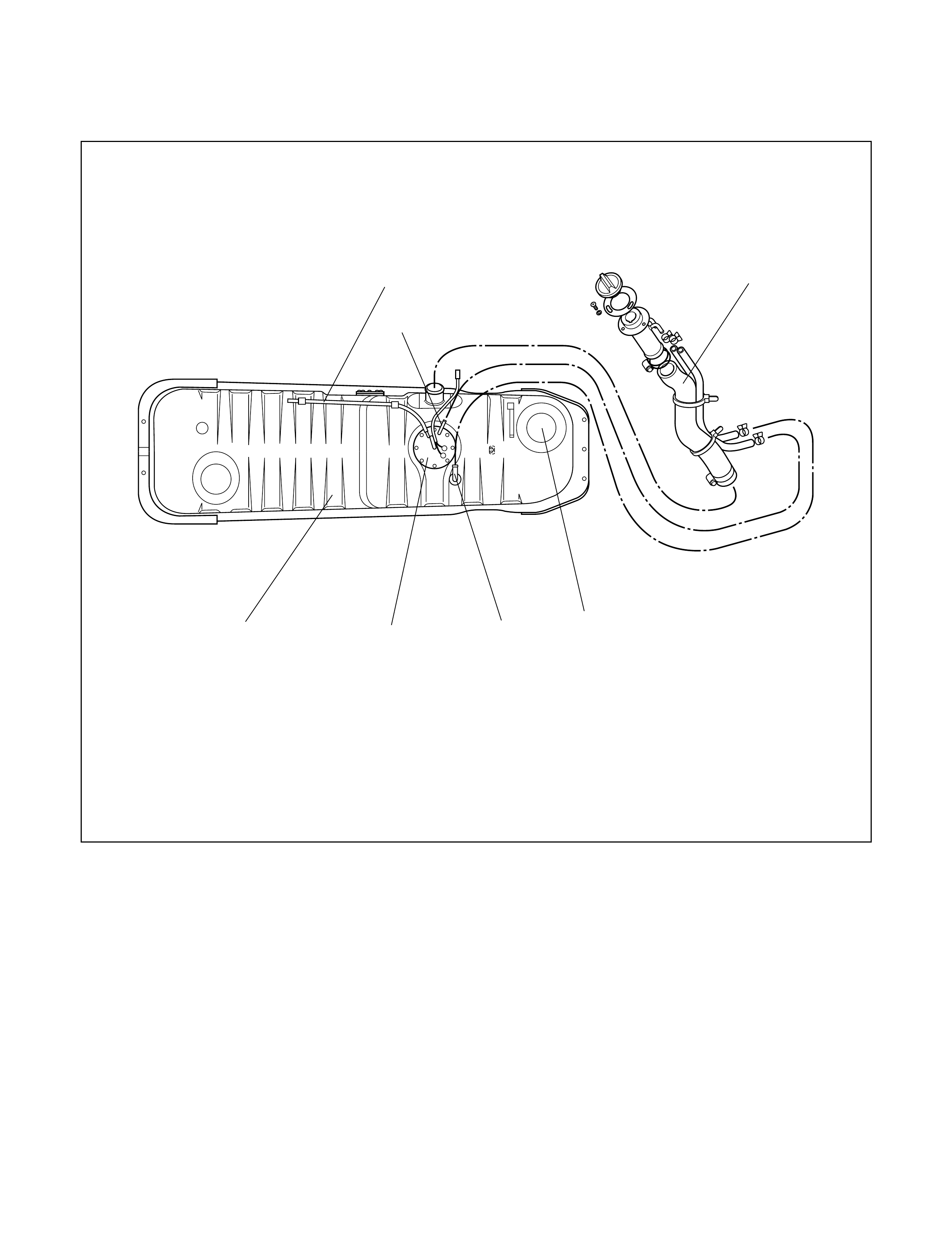
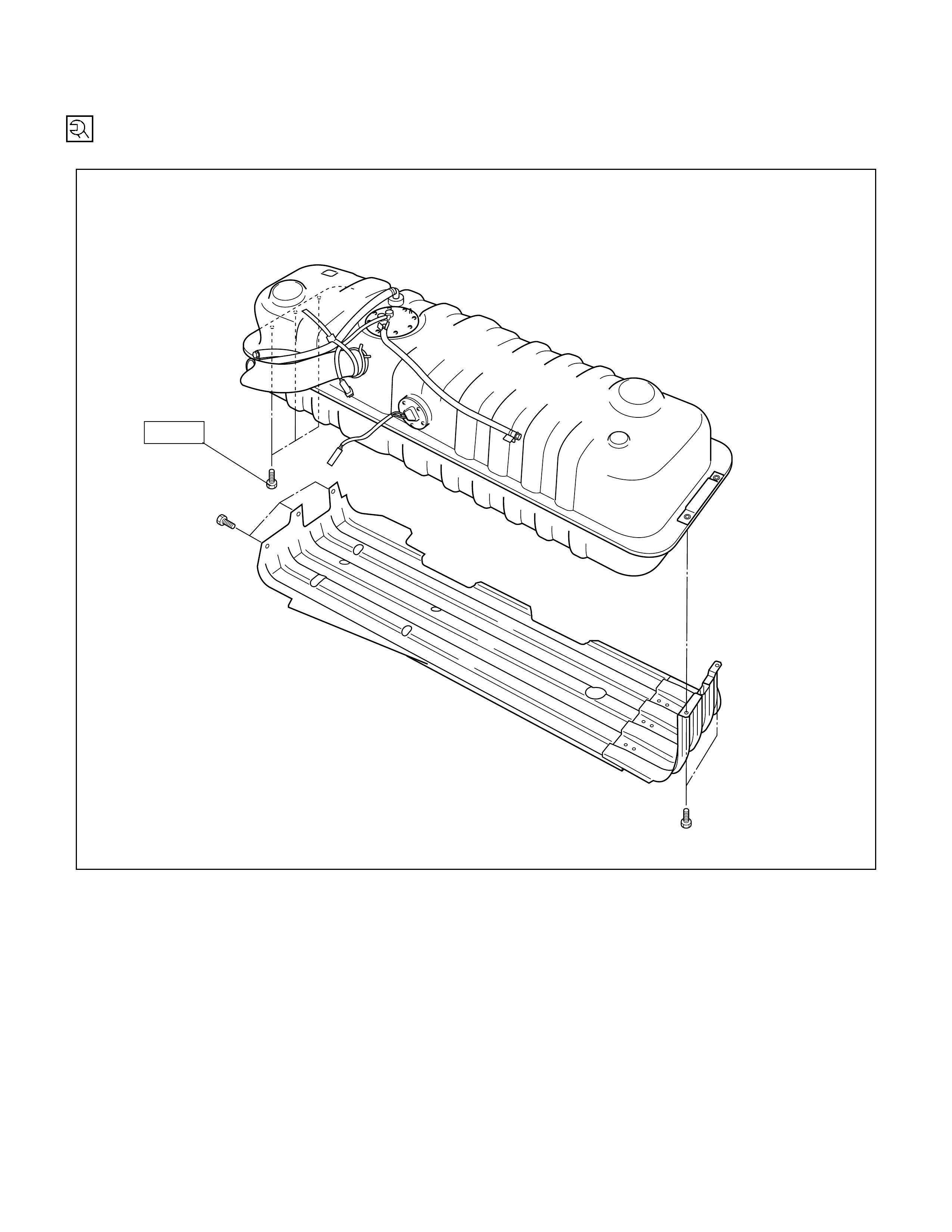
FUEL TANK
REMOVAL AND INSTALLATION
WITH CANISTER APPLICABLE TO ROLLOVER VALVE
WITH CANISTER & ROLLOVER VALVE
765
8
4
1
2
3
REMOVAL
1. Fuel hose (Delivery)
2. Fuel hose(Return)
3. Evap fuel hose
4. Breather hose
5. Fuel filler hose
6. Fuel Pump
7. Fuel tank
8. Roll over valve
INSTALLATION
To install, follow the removal steps in the reverse order.
REMOVAL
Preparation
•Disconnect battery ground cable
•Loosen fuel filler cap
•Drain fuel
Tighten drain plug to the specified torque after drain fuel.
N⋅m (kgf⋅m)
20 (2.0)
NOTE:
Cover fuel hose with waste to prevent any dust entering.
INSTALLATION
7. Fuel Tank
•Tighten fuel tank bolt
N⋅m (kgf⋅m)
26.5 (2.7)
MAIN DATA AND SPECIFICATIONS
TORQUE SPECIFICATION
N⋅m (kgf⋅m)
68 (6.9)