

MAIN DATA AND SPECIFICATIONS
Exhaust system
Pipe outside diameter × thickness
Front pipe mm (in)
Middle pipe mm (in)
Rear pipe mm (in)
Silencer
Type
Inside diameter mm (in)
Length mm (in)
Mounting
Number of suspension points
Type
50.8 × 1.6 (2.0 × 0.063)
50.8 × 1.6 (2.0 × 0.063)
50.8 × 1.6 (2.0 × 0.063)
Circular section-shell construction
of triple skin and end plates,
internal construction of baffles
and perforated tubes.
Approximately 180 (7.1)
Approximately 525 (20.7)
5
Rubber and metal
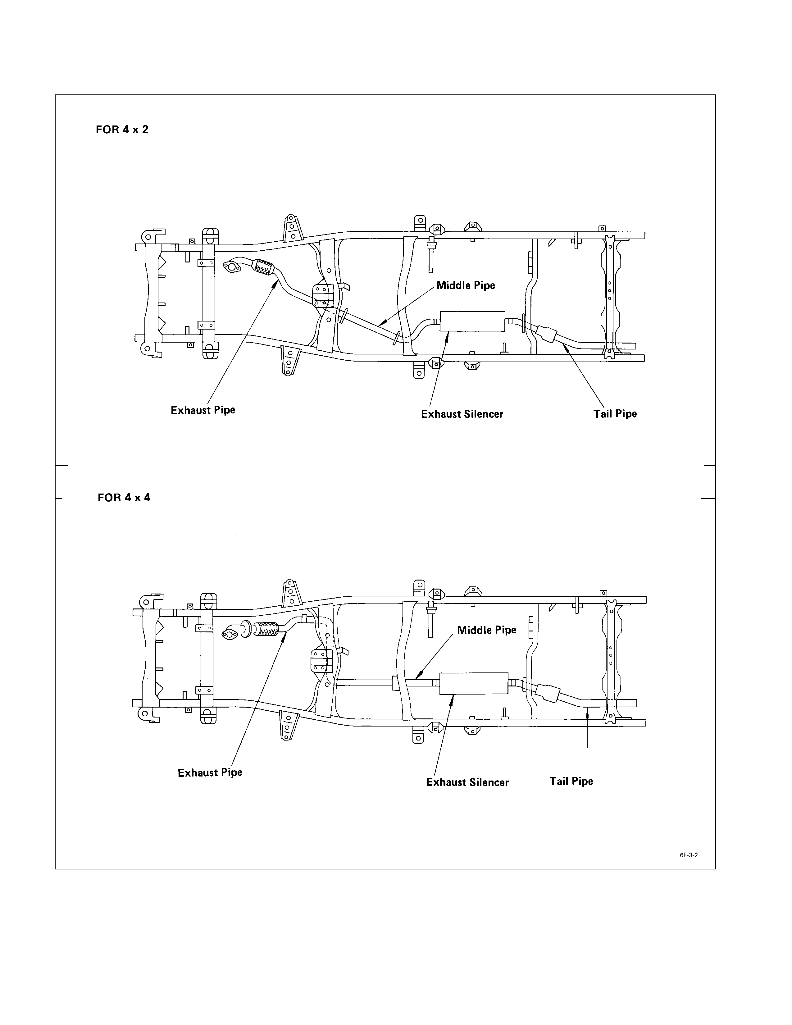
GENERAL DESCRIPTI O N
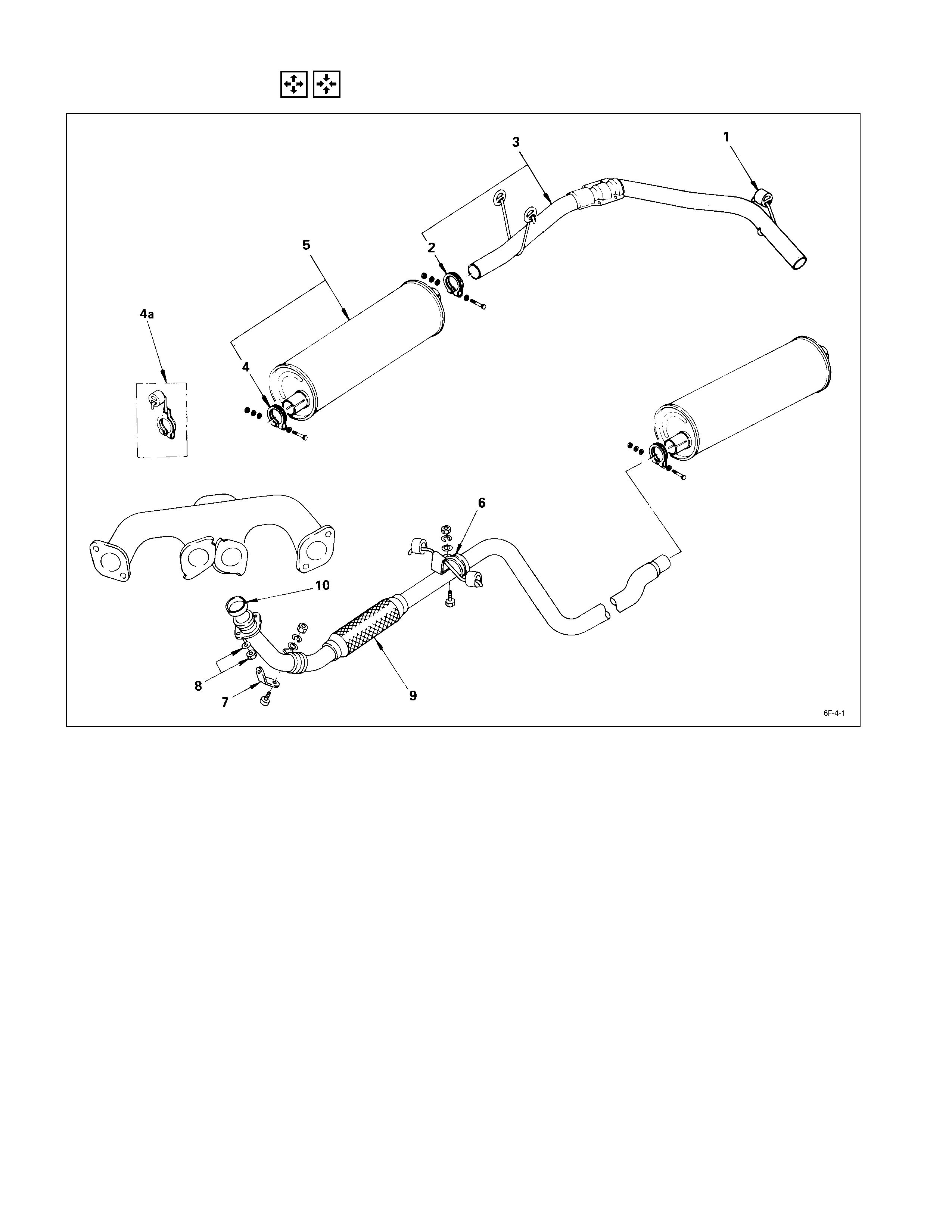
REMO VAL AND INSTALLATI ON
REMOVAL STEPS INSTALLATION STEPS
1. Rear hanger clamp 10. Exhaust pipe gasket
2. Silencer rear clamp 9. Front exhaust pipe
3. Rear exhaust pipe
J
8. Exhaust pipe nut and washer
4. Silencer front clamp 7. Exhaust front bracket
4a. Silencer front clamp 6. Front hanger clamp
(For long wheel base)
J
5. Exhaust silencer
5. Exhaust silencer 4. Silencer front clamp
6. Front hanger clamp 4a. Silencer front clamp
7. Exhaust front bracket (For long wheel base)
8. Exhaust pipe nut and washer 3. Rear exhaust pipe
9. Front exhaust pipe 2. Silencer rear clamp
10. Exhaust pipe gasket 1. Rear hanger clamp

IMPORTANT OPERATIONS – INSTALLATION
Follow the removal procedure in the reverse order to
perform the installation procedure. Pay careful attention to
the important points during the installation procedure.
8. Exhaust Pipe Nut and Washer
Connect the exhaust pipe to the exhaust manifold.
Torque kg·m (lb·ft/N·m)
6.8 ± 0.5 (49 ± 3.6/67 ± 5)
5. Exhaust Silencer
Apply muffler sealer to the joining portion of the pipes.

INSPECTION AND REPAIR
Make the necessary adjustments, repairs, and part replacements if excessive wear or damage is discovered during
inspection.
Front Exha ust Pipe
Rear Exhaust Pipe
Exhaust Silencer
Check the pipes for corrosion, cracking, damage or misalignment and repair as required.
Check the rubber rings for deterioration or damage and repair as required.
TURBOCHARGER
MAI N DATA AND SPECIFICATIONS
Engine model 4JB1T
Turbocharger model IHI RHF 4H
Turbine type
Compressor type
Radial inflow
Radial outflow
Maximum permissible speed rpm 180,000
Wastegate opening pressure mmHg (inHg)
Safety valve opening pressure mmHg (inHg)
189 – 887
850 - 910
Weight kg (lb) 4.2 (9.3)
IHI : Ishikawajima Harima Heavy Industries., Ltd.

GENERAL DESCRIPTI O N
The turbocharger internal mechanism consists of the turbine wheel, the compressor wheel, and the radial bearings. The
bearing housing supports these parts.
The turbocharger external mechanism consists of the compressor housing air intake port and the turbine housing air
exhaust port.
The turbocharger increases air intake efficiency. This results in increased engine power, reduced fuel consumption, and
minimal engine noise.
The turbocharger operates at very high speeds and temperatures. Part materials have been carefully selected and
machined to extremely high precision.
Turbocharger servicing requires great care and expertise.
If reduced performance is noted, check the engine for damage or wear. If there is no apparent engine damage or wear,
trouble with the turbocharger is indicated.
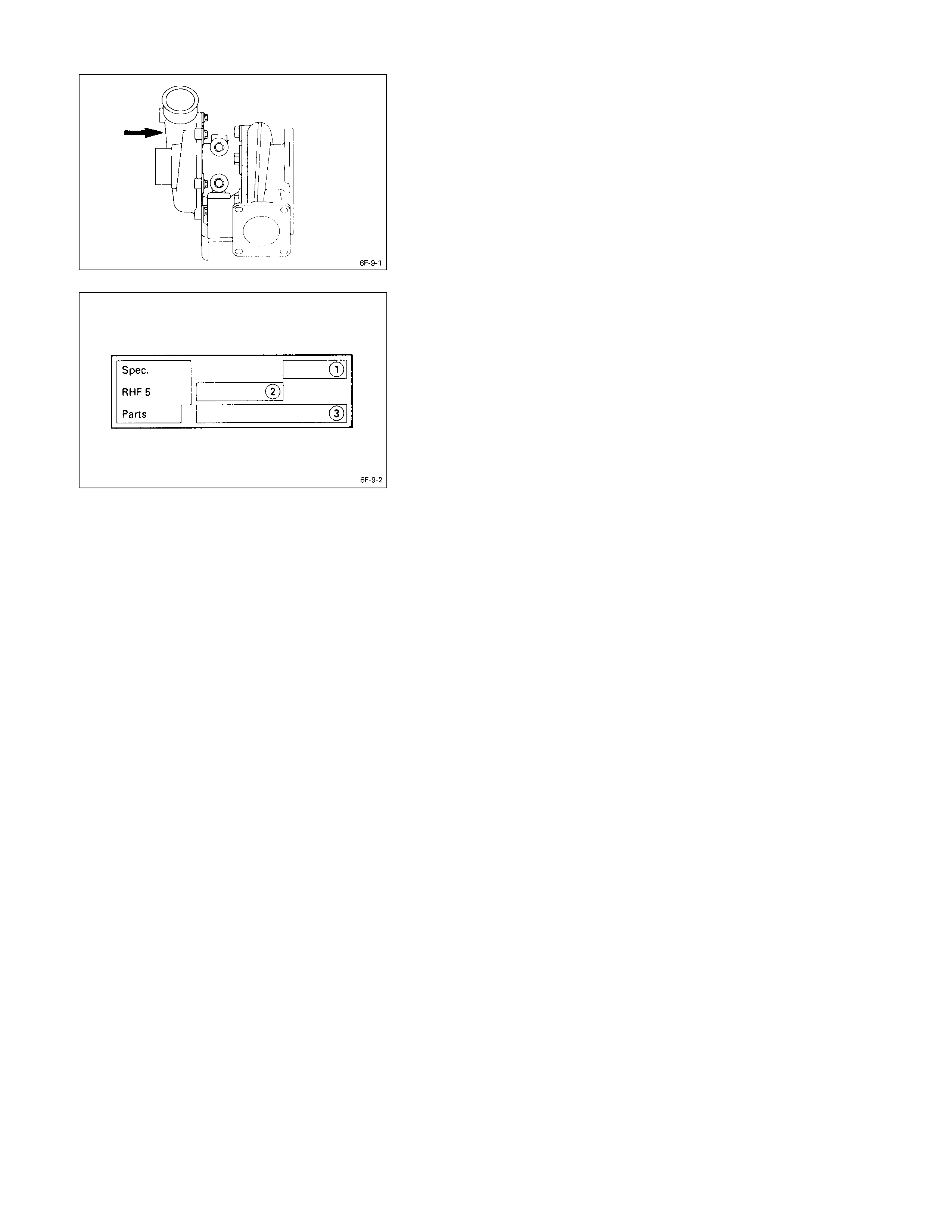
IDENTIFICATION OF UNIT
The turbocharger nameplate gives the date of manufacture
and other important information required to identify the unit
when service inquiries are made.
The turbocharger nameplate has the following information
stamped on it.
Q Turbo Specification Number, Production Year and
Month
R Production Date, Daily Serial Number
S HOLDEN Parts Number
INSPECTION AND REPAIR
Make the necessary adjustments, repairs, and part replacements if excessive wear or damage is discovered during
inspection.
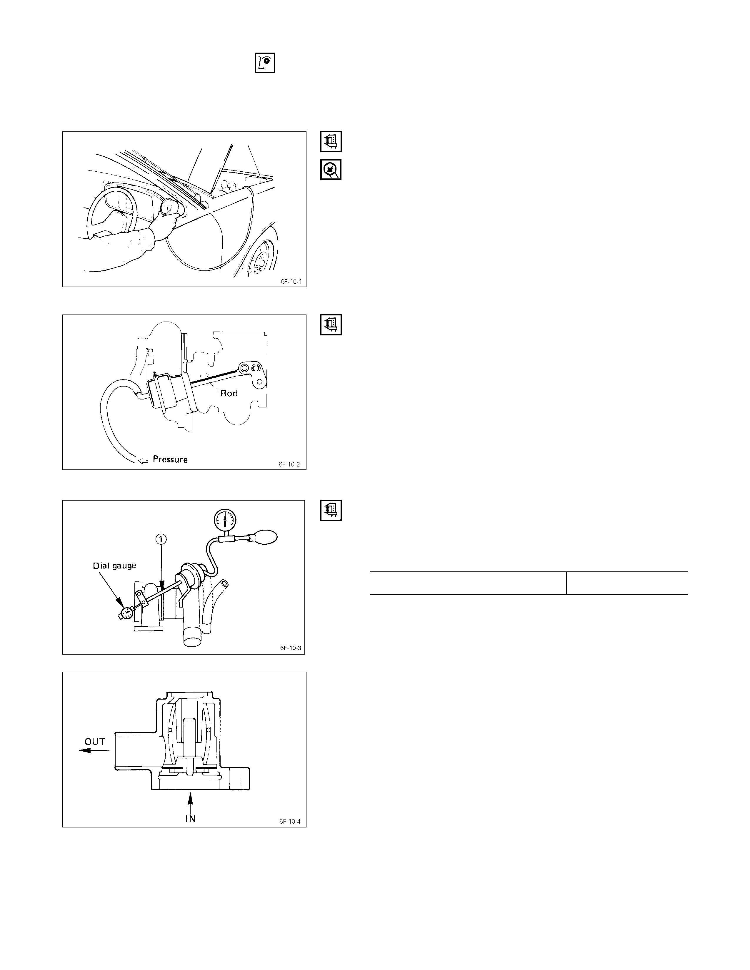
TURBOCHARGER PRESSURE CHECK
(1) Remove the pressure switch connecting hose from
intake duct.
(2) Connect the pressure gauge.
(3) Start the engine and gradually increase the engine
speed (the vehicle must be stationary with no load
applied to the engine).
(4) Check to see that turbocharger pressure rises to
approximately 300 mmHg.
Pressure Gauge : 5-8840-0075-0
WASTE GATE OPERATION CHECK
(1) Remove the hose between the waste gate and the
intake pipe.
(2) Connect the pressure gauge.
(3) Check to see that the rod begins to move when a
pressure of approximately 665 mmHg is applied to the
waste gate.
Note:
Do not apply a pressure greater than 1 kg/cm2 to the
wastegate during this check.
UNIT INSPECTION (REMOVE TURBO. FROM
ENGINE)
Check to see the pressure required to move the control
rod 2 mm is within the limits shown below.
Control Rod Operating Pressure Approx. 860 mmHg
SAFETY VALVE CHECK
Operate the valve with your hand to check its operation.
Check the valve seal are for excessive wear or damage.
Contact the “HOLDEN LIMITED” Dealer service
department or “IHI SERVICE FACILITY” for major repairs
and maintenance.
Important wheel shaft end play and bearing clearance
standards and limits are included below for your reference.

WHEEL SHAFT END PLAY
Use a dial indicator to measure the wheel shaft end play.
Apply a force of 1.2 kg (2.6 lb/11.8N) alternately to the
compressor wheel end and the turbine wheel end.
Wheel Shaft End Play mm (in)
Standard Limit
0.03 - 0.06
(0.001 - 0.002) 0.09 (0.004)
Wheel Shaft and Bearing Clearance
Use a dial indicator to measure the wheel shaft and
bearing clearance.
Wheel Shaft and Bearing Clearance mm (in)
Standard Limit
0.056 - 0.127
(0.0022 - 0.0050) 0.127 (0.0050)

SPECIAL TOOLS
ILLUSTRATION TOOL NUMBER TOOL NAME
5-8840-0070-0 Pressure Gauge