
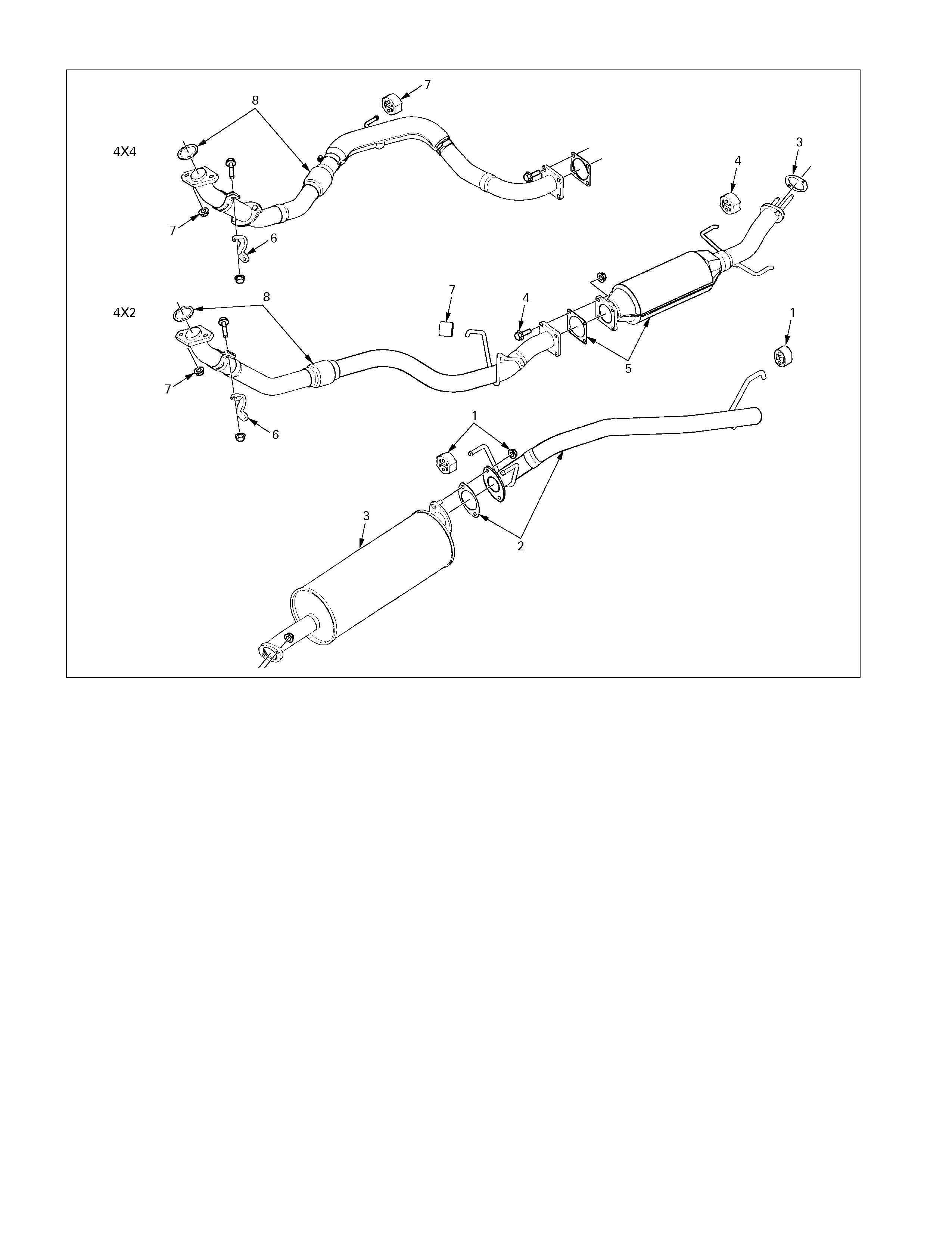
Exhaust System
General Description
150L200007
4JH1TC
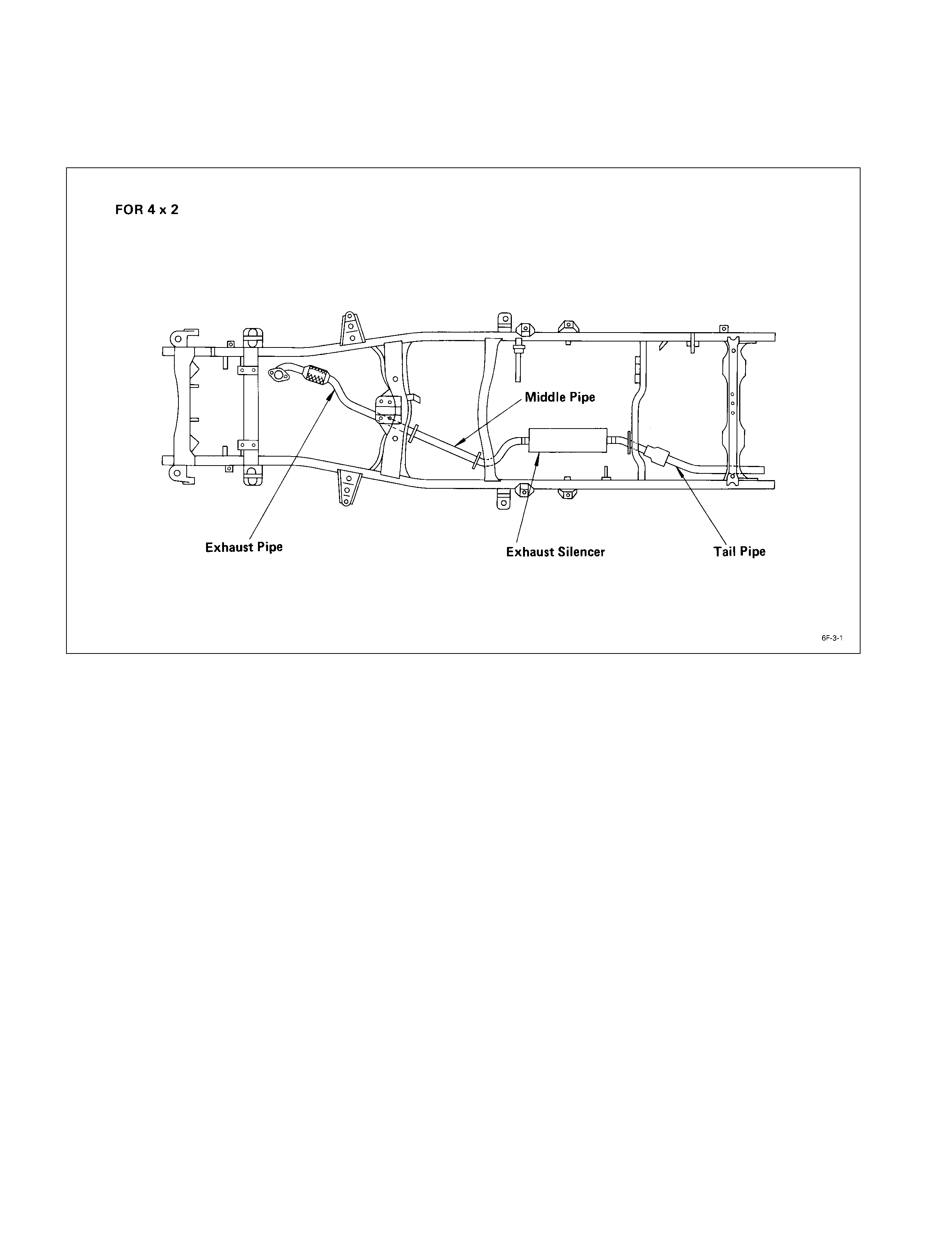
The exhaust system consists of a front exhaust pipe, a catalytic converter, a silencer and a tail pipe.
When inspecting or replacing exhaust system components, make sure there is adequate clearance from all points on
the underbody to prevent overheating of the floor pan and possible damage to the passenger compartment insulation
and trim materials.
Check complete exhaust system and nearby body areas and rear compartment lid for broken, damaged, missing or
mispositioned parts, open seams, holes, loose connections or other deterioration which could permit exhaust fumes to
seep into the rear compartment or passenger compartment. Dust or water in the rear compartment may be an
indication of a problem in one of these areas. Any faulty areas should be corrected immediately.
OXIDIZING CATALYTIC CONVERTER
The oxidizing catalytic converter is an emission control
device added to the exhaust system to reduce pollutants
from the exhaust gas stream.
Periodic maintenance of the exhaust system is not
required. If the vehicle is raised for other service, it is
advisable to check the condition of the complete exhaust
system.
A dual bed monolith catalytic converter is used in
combination with oxidizing catalytic converter.
GASKET
The gasket must be replaced whenever a new exhaust
pipe, muffler or catalytic converter is installed.
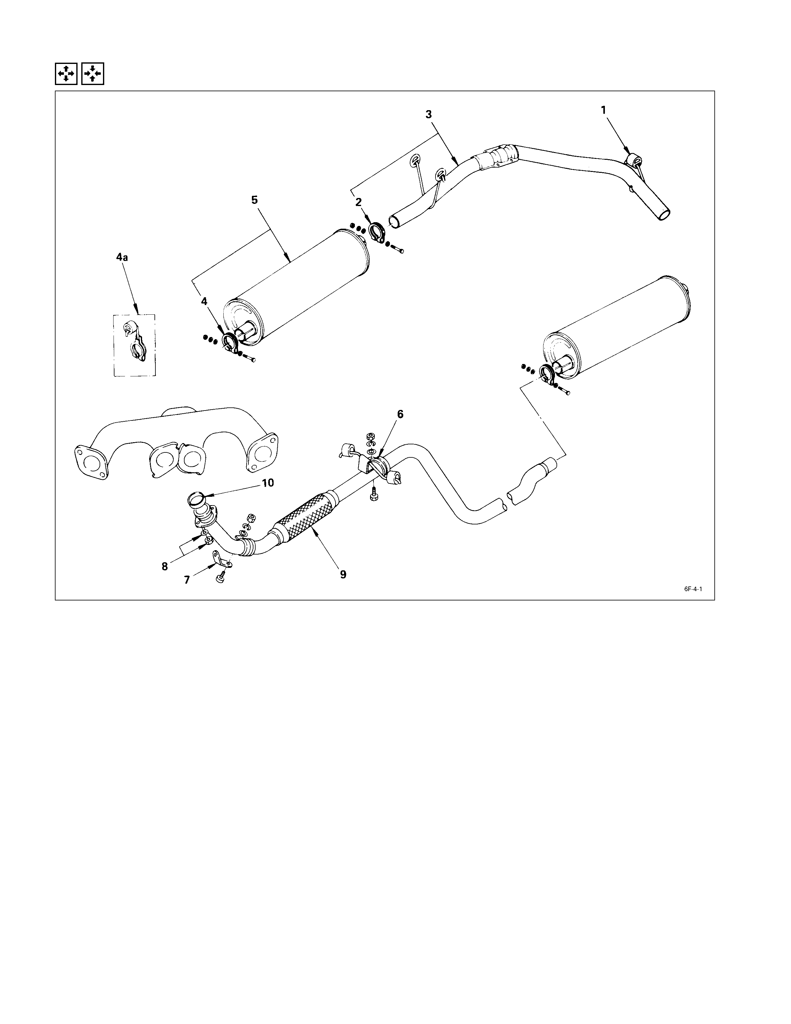
Removal & Installation
REMOVAL STEPS INSTALLATIO N STEPS
1. Rear hanger clamp 10. Exhaust pipe gasket
2. Silencer rear clamp 9. Front exhaust pipe
3. Rear exhaust pipe
J
8. Exhaust pipe nut and washer
4. Silencer front clamp 7. Exhaust front bracket
4a. Silencer front clamp 6. Front hanger clamp
(For long wheel base)
J
5. Exhaust silencer
5. Exhaust silencer 4. Silencer front clamp
6. Front hanger clamp 4a. Silencer front clamp
7. Exhaust front bracket (For long wheel base)
8. Exhaust pipe nut and washer 3. Rear exhaust pipe
9. Front exhaust pipe 2. Silencer rear clamp
10. Exhaust pipe gasket 1. Rear hanger clamp

IMPORTANT OPERATIONS – INSTALLATION
Follow the removal procedure in the reverse order to
perform the installation procedure. Pay careful attention to
the important points during the installation procedure.
8. Exhaust Pipe Nut and Was her
Connect the exhaust pipe to the exhaust manifold.
Torque kg·m (lb·ft/N·m)
6.8 ± 0.5 (49 ± 3.6/67 ± 5)
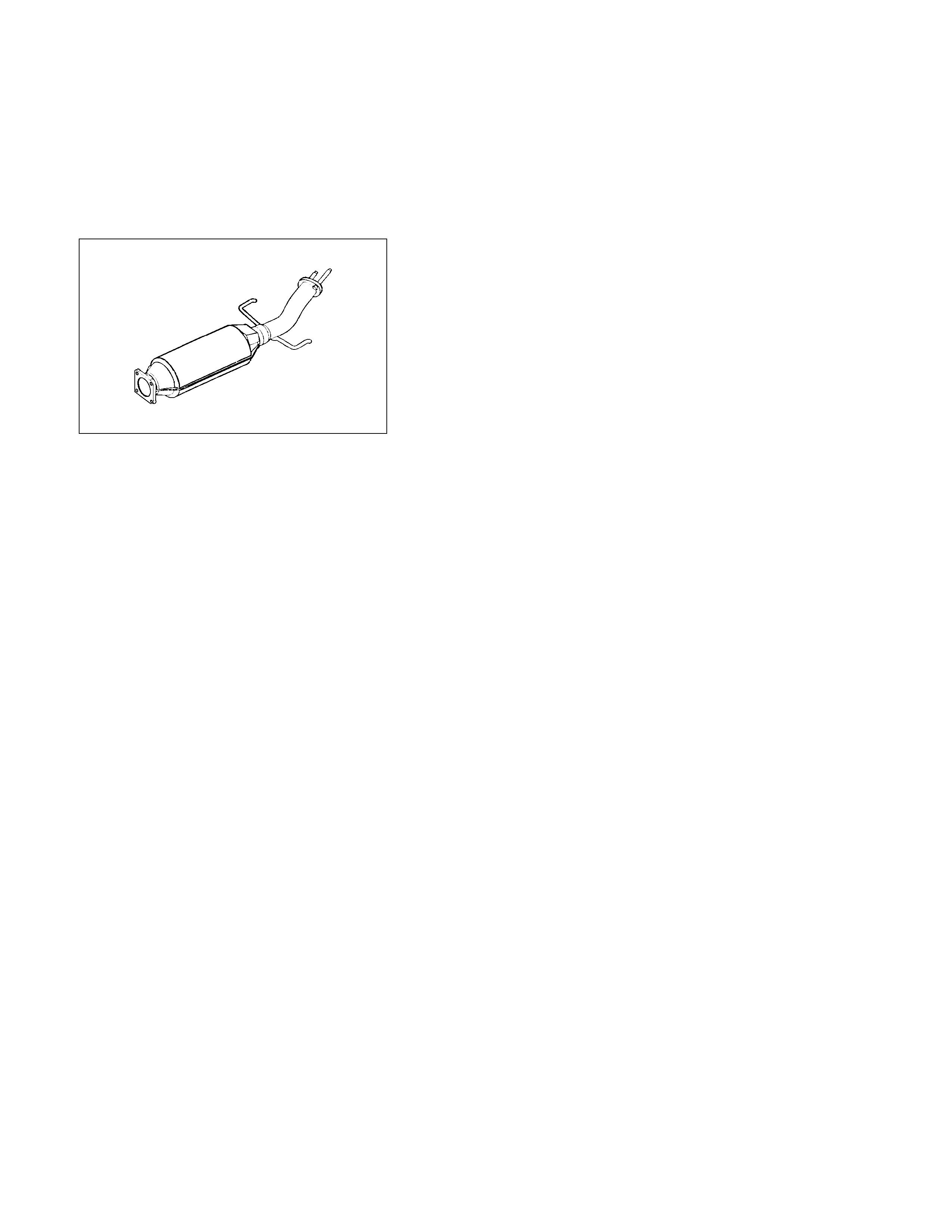
5. Exhaust Silencer
Apply muffler sealer to the joining portion of the pipes.
150L200006
REMOVAL STEPS INSTALLATIO N STEPS
1. Tail pipe hanger clamp and nuts
J
8. Front pipe with gasket
2. Tail pipe with gasket 7. Front pipe hanger clamp and nuts
3. Silencer with gasket
J
6. Front pipe BRKT
4. Oxidizing Catalytic converter hanger
clamp and bolts
J
5. Oxidizing Catalytic converter with gasket
5. Oxidizing Catalytic converter with
gasket 4. Oxidizing Catalytic converter hanger
clamp and bolts
6. Front pipe BRKT
J
3. Silencer with gasket
7. Front pipe hanger clamp and nuts
J
2. Tail pipe with gasket
8. Front pipe with gasket 1. Tail pipe hanger clamp and nuts
4JA1TC
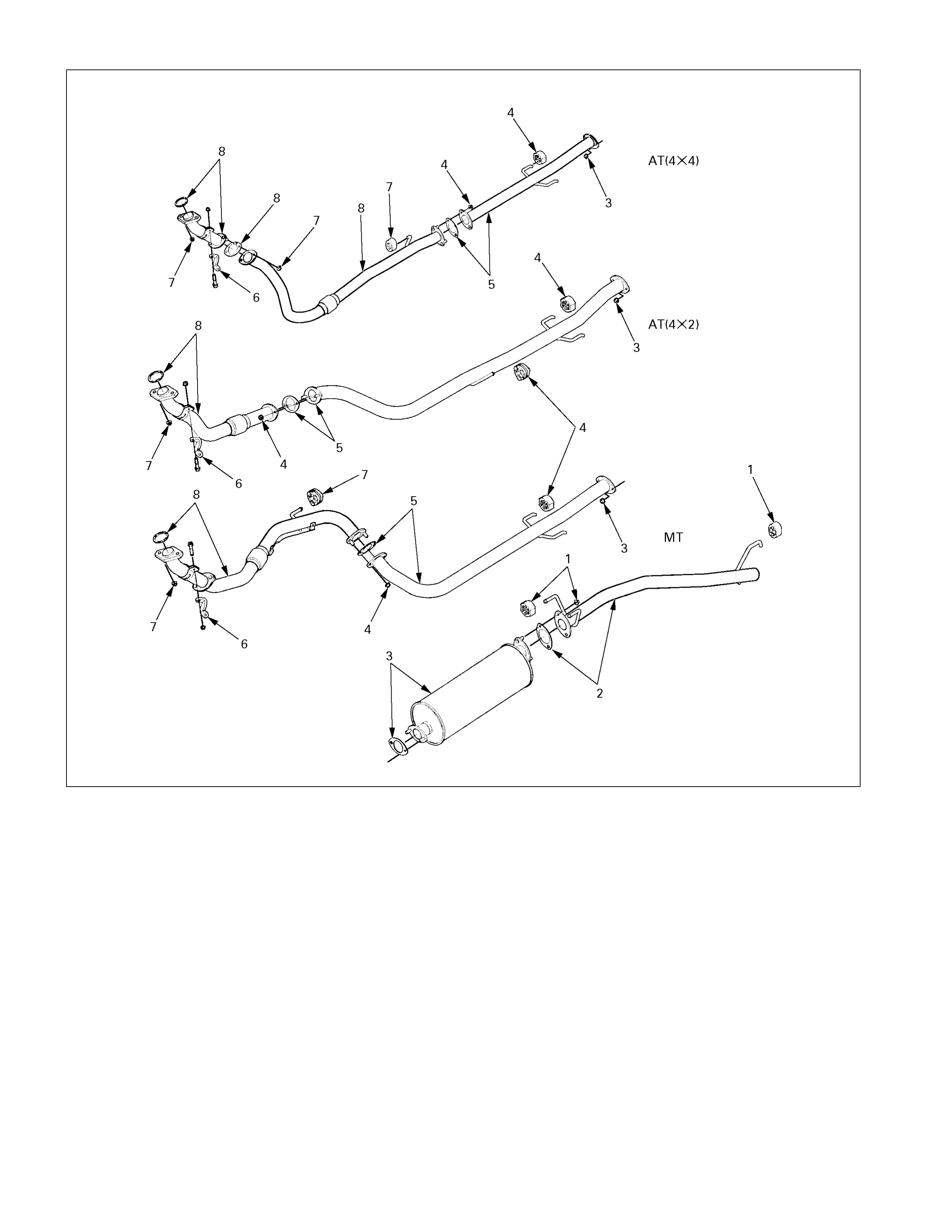
150L200008
REMOVAL STEPS INSTALLATIO N STEPS
1. Tail pipe hanger clamp and
nuts
J
8. Front pipe with gasket
2. Tail pipe with gasket 7. Front pipe hanger clamp and nuts
3. Silencer with gasket and nuts
J
6. Front pipe BRKT
4. Center pipe hanger clamp and
nuts
J
5. Center pipe with gasket
5. Center pipe with gasket 4. Center pipe hanger clamp and nuts
6. Front pipe BRKT
J
3. Silencer with gasket
7. Front pipe hanger clamp and
nuts
J
2. Tail pipe with gasket
8. Front pipe with gasket 1. Tail pipe hanger clamp and nuts
4JH1TC

IMPORTANT OPERATIONS – INSTALLATION
Follow the removal procedure in the reverse order to
perform the installation procedure. Pay careful attention to
the important points during the installation procedure.
8. Front Pipe With Gasket
Connect the front pipe to the exhaust manifold.
Torque kg⋅m(lb⋅ft/N⋅m)
6.8 ± 0.5 (49 ± 3.6/67 ± 5)
6. Front Pipe BRKT
Tighten the fixing bolt to the specified torque.
Torque kg⋅m(lb⋅ft/N⋅m)
Front pipe side 2.4 ± 0.5 (17 ± 3.6/23 ± 5)
Transmission side 4.1 ± 1.0 (30 ± 7/40 ± 1)
5. Oxidizing Catalytic Converter With Gasket (4JA1TC)
Center Pipe With Gasket (4JH1TC)
Tighten the fixing nuts to the specified torque.
Torque kg⋅m(lb⋅ft/N⋅m)
4.4 ± 1.3 (32 ± 9.4/43 ± 13)
3. Silencer With Gasket
Tighten the fixing nuts to the specified torque.
Torque kg⋅m(lb⋅ft/N⋅m)
4.4 ± 1.3 (32 ± 9.4/43 ± 13)
2. Tail Pipe With Gasket
Tighten the fixing nuts to the specified torque.
Torque kg⋅m(lb⋅ft/N⋅m)
4.4 ± 1.3 (32 ± 9.4/43 ± 13)
• Connect battery ground cable.
• After assembling each part, start the engine to check
for any leakage of gas at each connection.

Inspection & Repair
Make the necessary adjustments, repairs, and part replacements if excessive wear or damage is discovered during
inspection.
Front Exha ust Pipe
Rear Exhaust Pipe
Exhaust Silencer
Check the pipes for corrosion, cracking, damage or
misalignment and repair as required.
Check the rubber rings for deterioration or damage and repair
as required.
Turbocharger
Main Data & Speci fications
Engine model 4JB1T, 4JH1TC
Turbocharger model IHI RHF 4H RHF5H
Turbine type
Compressor type
Radial inflow
Radial outflow
Wastegate opening pressure mmHg (inHg)
Safety valve opening pressure mmHg (inHg)
189 – 887
850 - 910
Weight kg (lb) 4.2 (9.3) 4.6 (10.1)
IHI : Ishikawajima Harima Heavy Industries., Ltd.
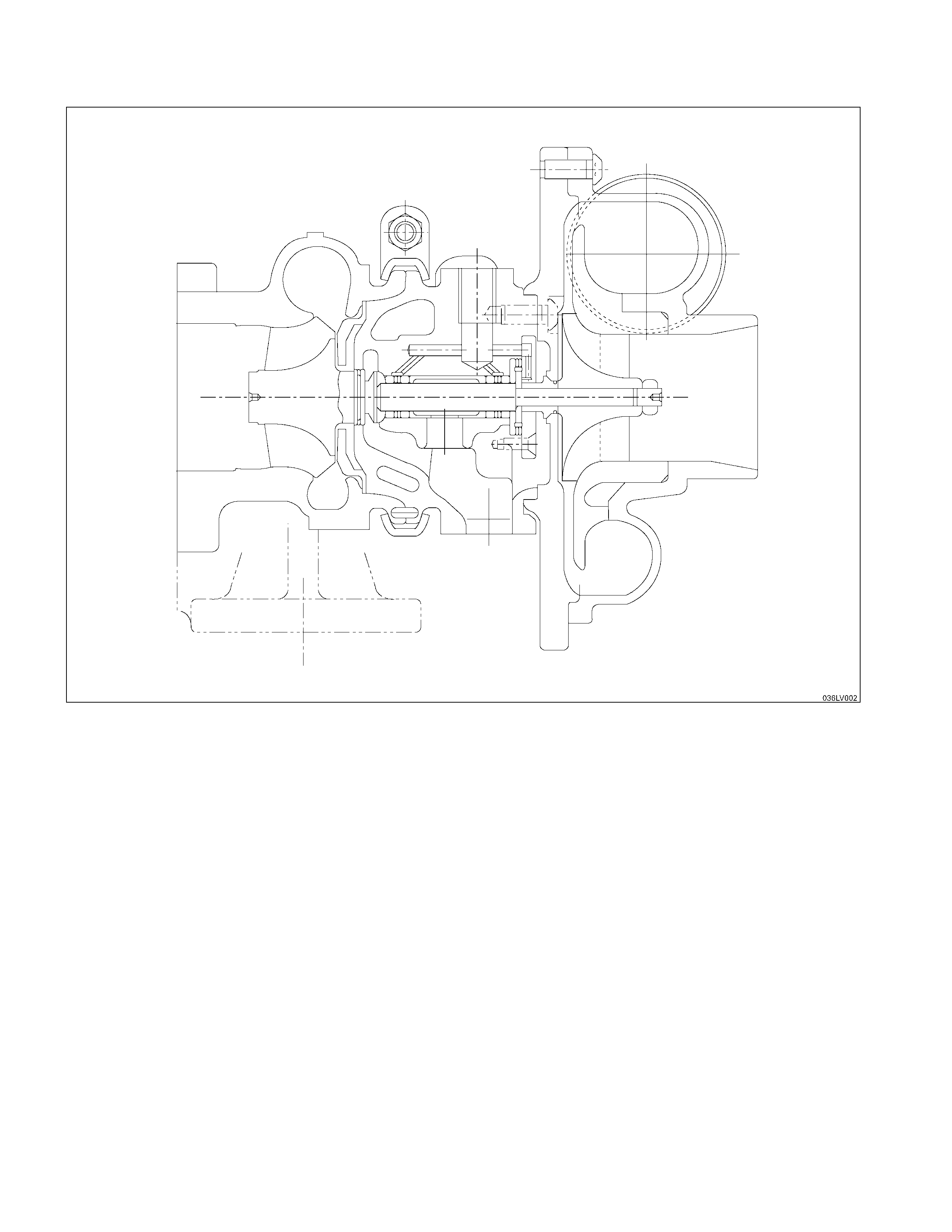
General Description
The turbocharger internal mechanism consists of the turbine wheel, the compressor wheel, and the radial bearings.
These parts are supported by the bearing housing.
The turbocharger external mechanism consists of the compressor housing air intake port and the turbine housing air
exhaust port.
The turbocharger increases air intake efficiency. This results in increased engine power, reduced fuel consumption, and
minimal engine noise.
The turbocharger operates at very high speeds and temperatures. Part materials have been carefully selected and
machined to extremely high precision.
Turbocharger servicing requires great care and expertise.
If reduced performance is noted, check the engine for damage or wear. If there is no apparent engine damage or wear,
trouble with the turbocharger is indicated.
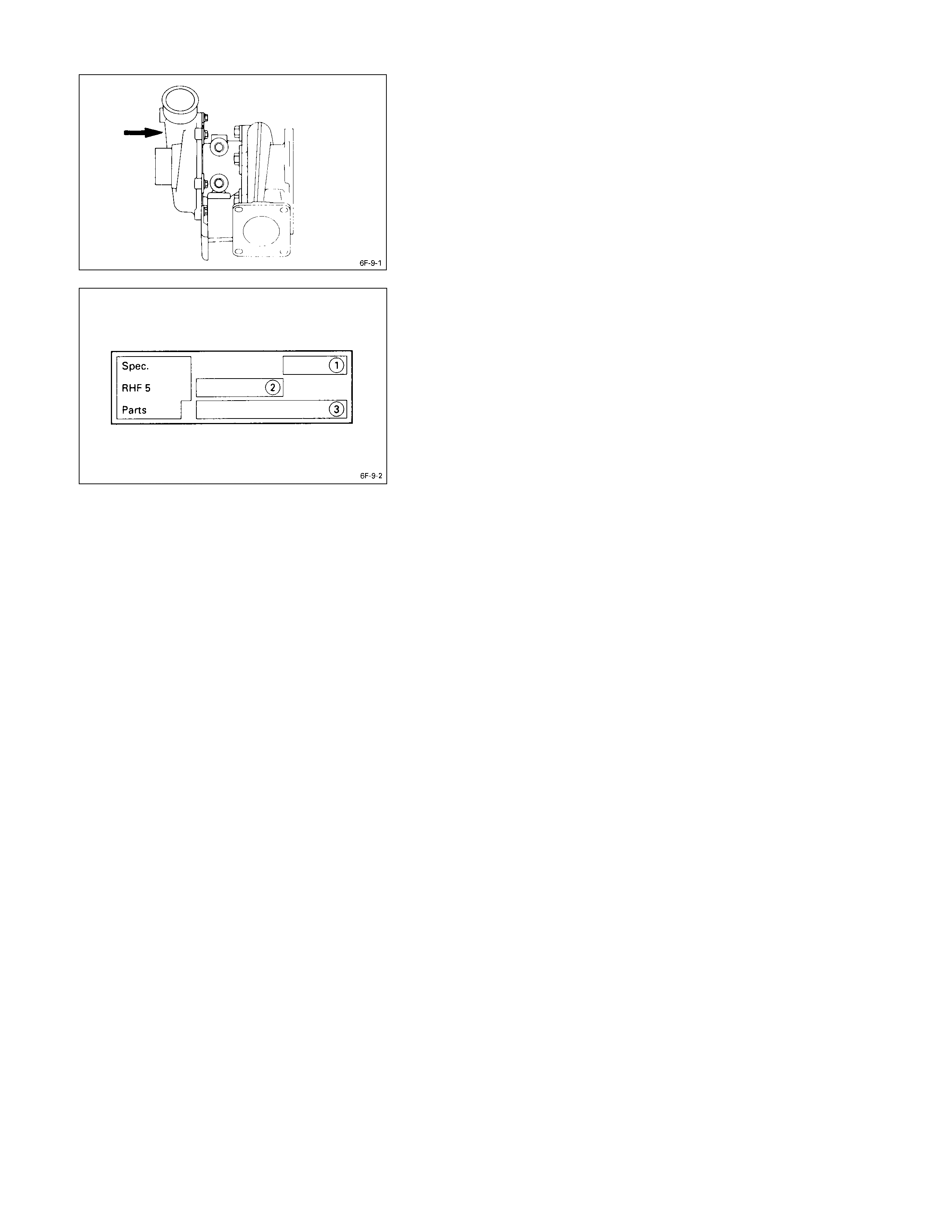
Identification Of Unit
The turbocharger nameplate gives the date of manufacture
and other important information required to identify the unit
when service inquiries are made.
The turbocharger nameplate has the following information
stamped on it.
Q Turbo Specification Number, Production Year and
Month
R Production Date, Daily Serial Number
S ISUZU Part Number

Inspection And Repair
Make the necessary adjustments, re pairs, and part replacements if excessive wear or damage is discovered durin g
inspection. Note that the quoted pressures ar e Absolute Pressure.
Turbocharger pressure check
(1) Remove the pressure switch connecting hose from
intake duct.
(2) Connect the pressure gauge.
(3) Start the engine and gradually increase the engine
speed (the vehicle must be stationary with no load
applied to the engine).
(4) Check to see that turbocharger pressure rises to
approximately 141.3 kPa (1060 mmHg).
Pressure Gauge : 5-8840-0075-0
Waste gate operation check
(1) Remove the hose between the waste gate and the
intake pipe.
(2) Connect the pressure gauge.
(3) Check to see that the rod begins to move whe n a
pressure of approximately 118 kPa (885 mm Hg) is
applied to the waste gate.
Note:
Do not apply a pressure greater than 150 kPa (1125
mm Hg) to the wastegate during this check.
Unit Inspection (Remove Turbo. from engine)
Check that the pressure required to stroke the control rod
c is at the correct value. kPa / mm Hg
4JB1-TC 147.7 / 1108
4JH1-TC 134.8 / 1101
Safety valve check
Operate the valve with your hand to check its operation.
Check the valve seal are for excessive wear or dama ge.
Contact the “ISUZU MOTORS LIMITED” Dealer service
department or “IHI SERVICE FACILITY” for major repairs
and maintenance.
Important wheel shaft end play and bearing clearance
standards and limits are included below for your
reference.
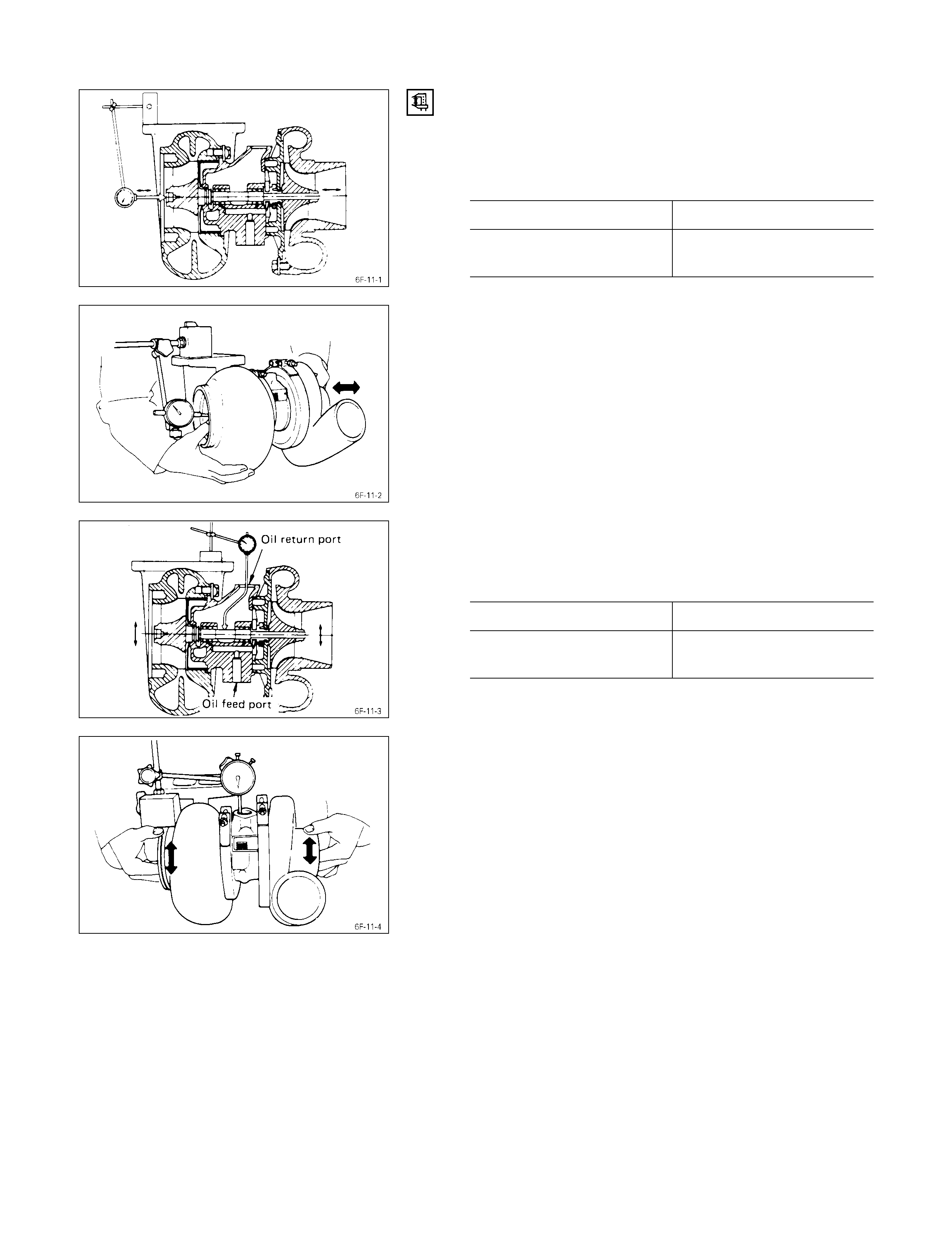
WHEEL SHAFT END PLAY
Use a dial indicator to measure the wheel shaft end play.
Apply a force of 1.2 kg (2.6 lb/11.8N) alternately to the
compressor wheel end and the turbine wheel end.
Wheel Shaft End Play mm (in)
Standard Limit
0.03 - 0.06
(0.001 - 0.002) 0.09 (0.004)
Wheel Shaft and Bearing Clearance
Use a dial indicator to measure the wheel shaft and
bearing clearance.
Wheel Shaft and Bearing Clearance mm (in)
Standard Limit
0.056 - 0.127
(0.0022 - 0.0050) 0.127 (0.0050)

Special Tool s
ILLUSTRATION TOOL NUMBER TOOL NAME
5-8840-0070-0 Pressure Gauge

IHI Service Netw ork
For inquiries relating to turbochargers, please contact your HOLDEN distributor or the nearest IHI Turbocharger Service
Facility.
HEADQUARTERS
ISHIKAWAJIMA HARIMA HEAVY INDUSTRIES CO., LTD.(IHI)
General Machinery Division
Tokyo Chuo Building 1-6-2 Marunouchi Chiyoda-ku
Tokyo 100-0005 JAPAN
TEL: 81-(3)-3286-2405 to 2407 (3 lines)
FAX: 81-(3)-3286-2430