
SECTION 9 - STEERING
MAIN DATA AND SPECIFICATIONS
TORQUE SPECIFICATIONS
STANDARD BOLTS
FLARE NUTS
SPECIAL PARTS FIXING NUTS AND BOLTS
SERVICING
POWER STEERING FLUID
DRAINING
REFILLING
STEERING WHEEL PLAY
INSPECTION
ADJUSTMENT
AIR BLEEDING
MEASUREMENT OF FLUID PRESSURE
STEERING MECHANISM
GENERAL DESCRIPTION
STEERING COLUMN
REMOVAL AND INSTALLATION
STEERING UNIT
GENERAL DESCRIPTION
MANUAL STEERING UNIT
POWER STEERING UNIT
POWER S TEERING HYDRAULIC LINE
REMOVAL AND INSTALLATION
MANUAL STEERING UNIT
DISASSEMBLY
INSPECTION AND REPAIR
REASSEMBLY
POWER STEERING UNIT
REPAIR KIT
DISASSEMBLY
INSPECTION AND REPAIR
REASSEMBLY
Techline

STEERING LINKAGE
GENERAL DESCRIPTION
REMOVAL AND INSTALLATION
DISASSEMBLY
INSPECTION AND REPAIR
REASSEMBLY
POWER STEERING OIL PUMP
GENERAL DESCRIPTION
REPAIR KIT (C22, C20 SERIES ENGINE MODEL)
REPAIR KIT (4J SERIES ENGINE MODEL)
REMOVAL AND INSTALLATION (C22, C20 SERIES ENGINE MODEL)
REMOVAL AND INSTALLATION (4J SERIES ENGINE MODEL)
REMOVAL AND INSTALLATION (6VD1 ENGINE MODEL)
DISASSEMBLY (C22, C20 SERIES ENGINE MODEL)
INSPECTION AND REPAIR (C22, C20 SERIES ENGINE MODEL)
REASSEMBLY (C22, C20 SERIES ENGINE MODEL)
DISASSEMBLY AND REASSEMBLY (4J SERIES ENGINE MODEL)
DISASSEMBLY AND REASSEMBLY (6VD1 ENGINE MODEL)
TROUBLESHOOTING
SPECIAL SERVICE TOOL (C22, C20 SERIES ENGINE MODEL)
MAIN DATA AND SPECIFICATIONS
Manual steering Power steering
Unit type Recirculating ball Integral, ball screw
Gear ratio 20.5 - 23.5 15.8:1
Sector shaft operating angle degree 95 94
Starting torque N⋅m (kgf⋅m/lb.ft) 0.064 - 1.07
(0.065 - 0.11/0.47 - 0.79) 0.59 - 0.88
(0.06 - 0.09/0.43 - 0.65)
Maxi mum oil pressure kg/cm2 (psi/kPa) - 95
(1350 / 9300),
105 (1493/10297)
Oil pump type - Vane
Steering wheel - Diameter mm (in.) 382 (15.04)
Steering wheel - Free play mm (in.) 10 - 30 (0.394 - 1.181) 10 - 30 (0.394 - 1.181)
Oil Gear oil GL-5 grade Besco ATF
(DEXRON II or III)
* : 4J Series Engine Model
TORQUE SPECIFICATIONS
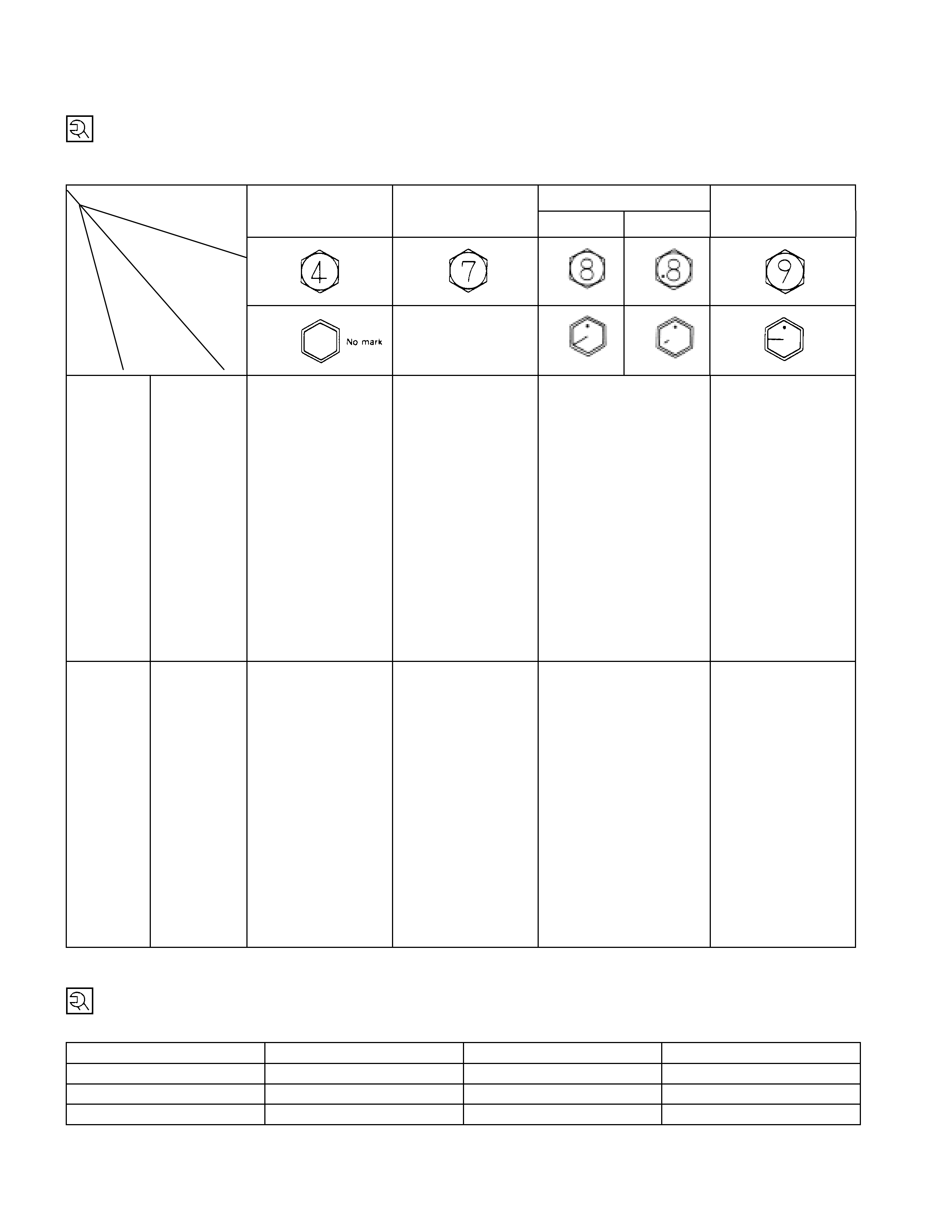
STANDARD BOLTS
The torque values given in the following table should be applied where a particular torque is not specified.
N⋅m (kgf⋅m / lb⋅ft)
4.8/4T 7T 8.8 9.8/9T
Refined Non-Refined
-
M6×1.0 6 (0.6 / 52 lb⋅in) 7 (0.7 / 61 lb⋅in) 8 (0.8 / 69 lb⋅in) -
M8×1.25 13 (1.3 113) 17 (1.7 / 12) 20 (2.0 /14) 24 (2.4 / 17)
M10×1.25 27 (2.8 / 20) 37 (3.8 / 27) 42 (4.3 / 31) 50 (5.1 / 37)
M12×1.25 61 (6.3 / 45) 76 (7.8 / 56) 87 (8.9 /64) 95 (9.7 / 70)
M14×1.5 96 (9.8 / 71) 116 (11.8 / 85) 133 (13.6 / 98) 142 (14.5 / 105)
M16×1.5 130 (13.3 / 96) 170 (17.3 / 125) 193 (19.7 / 143) 200 (20.4 / 148)
M18×1.5 188 (19.2 / 139) 244 (24.9 / 180 ) 278 (28.3 / 205) 287 (29.3 / 212)
M20×1.5 258 (26.3 / 190 337 (34.4 / 249) 385 (39.3 / 284) 396 (40.4 / 292)
M22×1.5 332 (33.9 / 245) 453 (46.3 / 335) 517 (52.7 / 381) 530 (54.1 / 391)
M24×2.0 449 (45.8 / 331) 570 (58.2 / 421) 651 (66.3 / 480) 692 (70.6 / 511)
*M10×1.5 26 (2.7 / 20) 36 (3.7 / 27) 41 (4.2 / 30) 48 (4.9 / 35)
*M12×1.75 57 (5.8 / 42) 71 (7.2 / 52) 80 (8.2 / 59) 89 (9.1 / 66)
*M14×2.0 89 (9.1 / 66) 110 (11.2 / 81) 125 (12.7 / 92) 133 (13.6 / 98)
*M16×2.0 124 (12.7 / 92) 162 (16.5 / 119) 185 (18.9 / 137) 191 (19.5 / 141)
M6×1.0 7 (0.7 /61 lb⋅in) 8 (0.8 / 69 lb⋅in) 9 (0.9 / 78 lb⋅in)
M8×1.25 15 (1.5 / 11) 19 (1.9 / 14) 22 (2.2 / 16) 26 (2.7 / 20)
M10×1.25 31 (3.2 / 23) 41 (4.2 / 30) 47 (4.8 / 35) 56 (5.7 / 41)
M12×1.25 69 (0.7 / 51) 85 (8.7 / 63) 97 (9.9 / 72) 106 (10.8 / 78)
M14×1.5 104 (10.6 / 77) 126 (12.8 / 93) 144 (14.6 / 106) 154 (5.7 / 114)
M16×1.5 145 (14.8 / 127) 188 (.2 / 139) 214 (21.8 / 158) 221 (22.5 / 163)
M18×1.5 -- - -
M20×1.5 -- - -
M22×1.5 -- - -
M24×2.0 -- - -
*M10×1.5 30 (3.1 / 22) 40 (4.1 / 30) 46 (4.7 / 34) 54 (5.5 / 40)
*M12×1.75 64 (6.5 / 47) 78 (8.0 / 58) 89 (9.1 / 66) 99 (10.1 / 73)
*M14×2.0 97 (9.9 / 72) 119 (12.1 / 88) 135 (13.8 / 99.7) 144 (14.7 / 107)
*M16×2.0 137 (14.0 / 101) 178 (18.2 / 132) 203 (20.7 / 150) 210 (21.5 / 155)
The asterisk * indicates that the bolts are used for female-threaded parts that are made of soft materials such as
casting, etc.
FLARE NUTS N⋅m (kgf⋅m / lb⋅ft)
Pipe diameter mm (in) Torque Pipe diameter mm (in) Torque
4.76 (0.187) 16 (1.6 / 12) 10.00 (0.394) 54 (5.5 / 40)
6.35 (0.250) 26 (2.7 / 20) 12.00 (0.472) 88 (9.0 / 65)
8.00 (0.315) 44 (4.5 / 33) 15.00 (0.591) 106 (10.8 / 78)
Strength
Class
Bolt
Identification
Bolt
Diameter ×
××
×
Pitch (m m)
Standard
Hex.
Head Bolt
Flange
Bolt
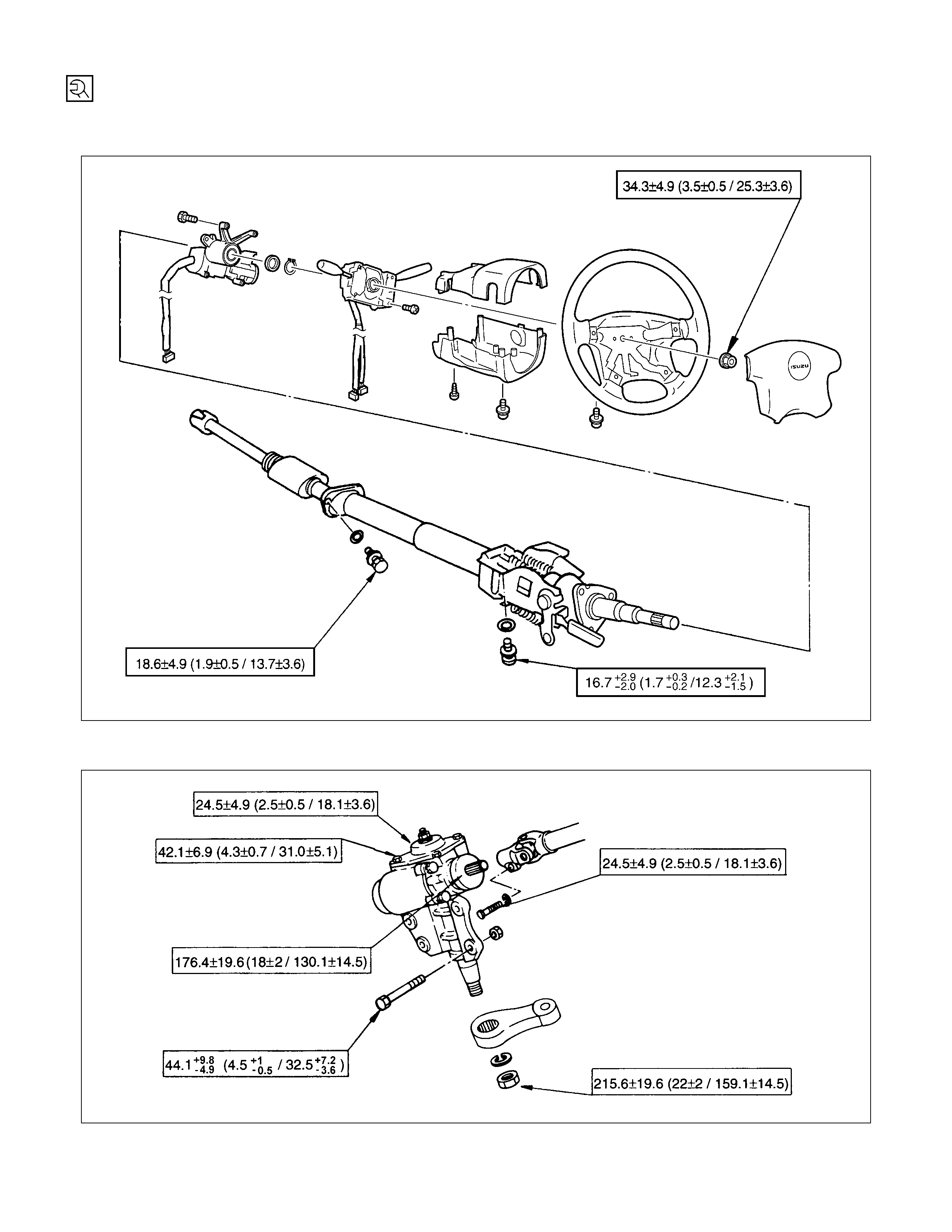
SPECIAL PARTS FI XING NUTS AND BOLTS
STEERING COLUM N N⋅m (kgf⋅m/Ib⋅ft)
STEERING UNIT N⋅m (kgf⋅m/Ib⋅ft)
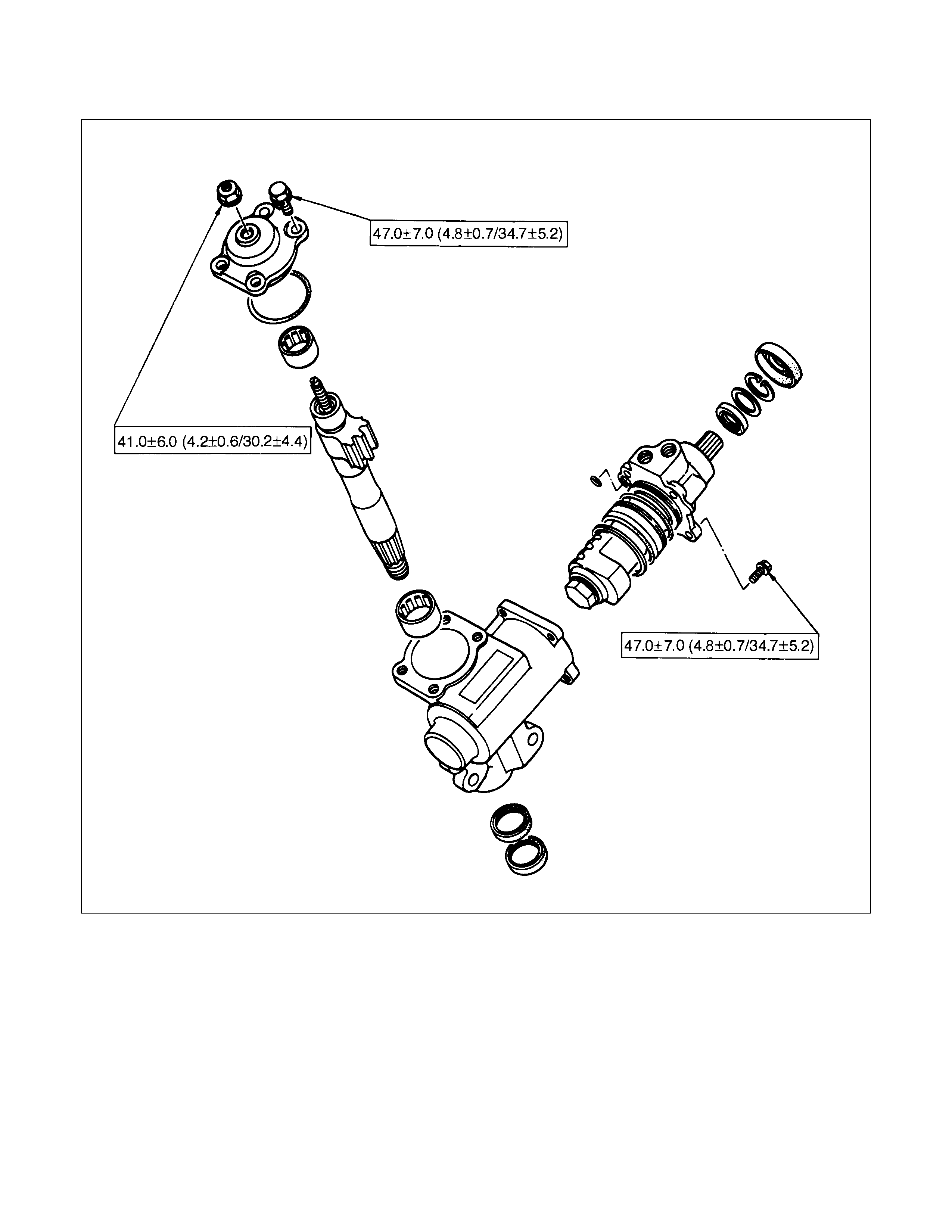
POWER STEERING UNIT N⋅m (kgf⋅m/lb⋅ft)
POWER STEERING HYDRAULIC LINE N⋅m (kgf⋅m/Ib⋅ft)
N⋅m (kgf⋅m/Ib⋅ft)
STEERING LINKAGE N⋅m (kgf⋅m/Ib⋅ft)
SERVICING
C22, C20 Series Engine Model POWER STEERING FLUID
DRAINING
1. Jack up the front wheels until they are clear of the ground.
2. Disconnect the fluid pipes between the steering unit and the
fluid reservoir, and the fluid hose between the pump and the
fluid reservoir.
3. When draining is completed, remove remaining fluid within
hydraulic system by turning the steering wheel to stop in
both directions several times.
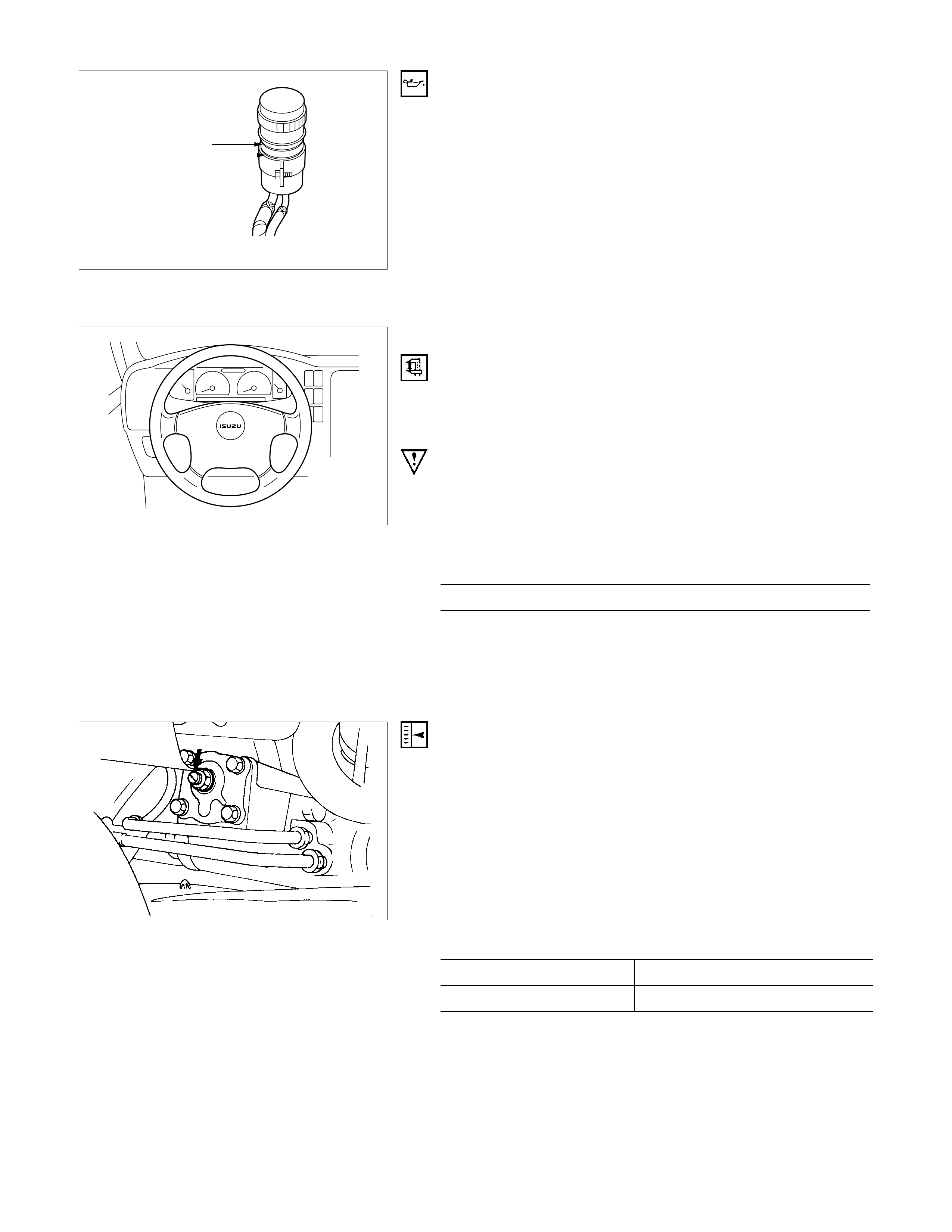
Full level
Min. level
REFILLING
1. Connect the fluid lines securely and fill the fluid reservoi
r
with specified automatic transmission fluid.
2. W hen the f luid reservoir is f illed to the specified level, allo
w
2 or 3 minutes. While refilling, keep fluid reservoi
r
replenished as necessary to prevent air from entering the
hydraulic system.
3. Lower the front wheels to the ground. Start and let the
engine idle for a few minutes.
Recheck the fluid level and replenish if necessary.
STEERING WHEEL PLAY
INSPECTION
1. Check the am ount of the steering wheel play by turning the
wheel in both directions until the tires begin to move with
the front wheels properly in the straight-ahead position.
Note:
If the vehicle is equipped with a power steering unit, the
wheel free play should be checked with the engine
running.
Free Play mm(in)
(Manual/Power Steering)
10 - 30 (0.4 - 1.2)
2. Also check the steering wheel for play and looseness in
mount by moving it back and forth and sideways. While
driving check for hard-steering, steering shimmy and
tendency of steering to pull to one side.
ADJUSTMENT
1. Align the front wheels properly in the straight ahead
position.
2. Loosen the lock nut on the adjusting screw of the steering
unit.
3. Turn the adjust screw clockwise to decrease free play o
r
counter-clockwise to increase.
4. After check of specified free play, tighten the lock nut to
specified torque.
Lock Nut Torque N⋅m (kgf⋅m/Ib⋅ft)
Manual Steering 24.5±4.9 (2.5±0.5/18.1±3.6)
Power Steering 41.2±5.9 (4.2±0.6/30.4±4.3)
AIR BLEEDING
Fill fluid reservoir with specified automatic transmission fluid
(DEXRON) and turn the steering wheel to lock in both
directions repeatedly, so that level of fluid in the reservoir to the
specified level and start the engine.
Perform the following check with the engine running at idle.
Bleeding is considered to be completed if the following
conditions apply;
(1) Turn the steering wheel to lock in both directions 3 or 4
times.
A buzz is not produced in the hydraulic line.
(2)Stop the engine with steering wheel in a straight ahead
position.
Level of fluid in reservoir does no increase.
Note:
Do not hold the steering wheel in position of loc k for more
than 5 seconds, or temperature of fluid increases sharply.
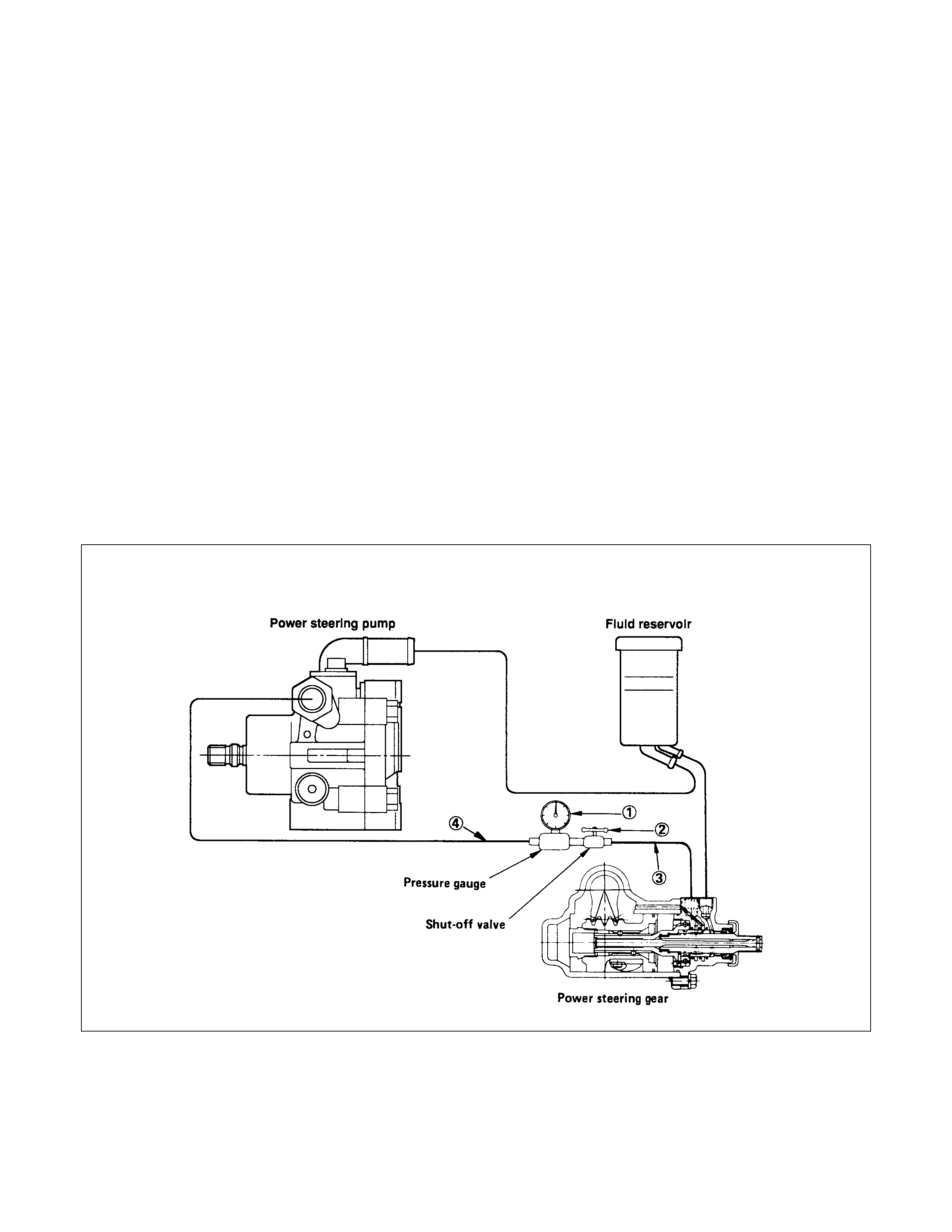
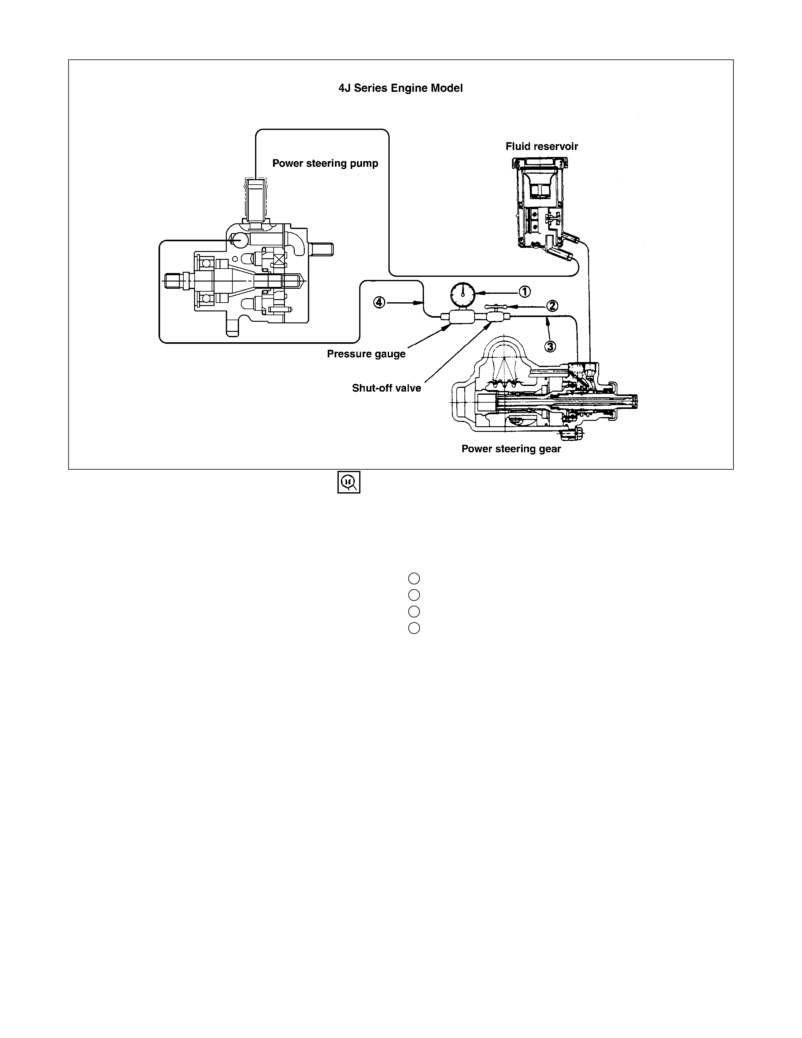
MEASUREM ENT OF FLUID PRESSURE
Measurement of fluid pressure in the power steering sy stem is performed to determine whether or not the oil pump and
power steering unit are functioning normally.
C22. C20 Series Engine Model
1. Installation of Tester
•Power Steering Tester : 5-8840-0135-0
(J-29877-A)
Adapter; Power Steering Tester :
5-8840-0136-0
(J-33996)
1Oil Pressure Gauge with Shut off Valve
2Shut off Valve
3Adapter (to steering unit)
4Adapter (to oil pump)
•Installation Procedure;
Disconnect the hose on the outlet side of the pump.
Connect the gauge hose closest to the power steering
gauge shut off valve to the hose on the vehicle.
Connect the gauge hose f urthest from the shut of f valve
to the outlet side of the power steering pump.
2. Bleeding
•Open stop valve fully.
•Refer to air bleeding procedure.
3. Measurement of Fluid Pressure
•Open stop valve fully.
•Increase engine speed to 1500 rpm.
•Measure the fluid pressure when the steering wheel is
turned to lock in both directions.
Fluid Pressure kg/cm2(psi/kPa)
95 - 100
(1351 - 1422/9316 - 9806) (C22, C20 Series Engine Model)
100 - 105
(1422 - 1493/9806 - 10297) (4J Series Engine Model)
DIAGNOSIS:
(1)W hen pr essure is higher than Specif ied pres sure, the valve
within the oil pump is defective.
(2)When the pressure is lower than Specified pressure.
•Return steering wheel to straight-ahead position.
•Close stop valve completely.
•Hold engine running at 1500 rpm, and take reading o
f
the pressure gauge.
Fluid Pressure kg/cm2(psi/kPa
)
Possible trouble
95 - 100
(1351 -1422/9316 - 9806)
(C22, C20 Series Engine Model)
100 - 105
(1422 - 1493/9806 - 10297)
(4J Series Engine Model)
Lower than 95 (1351/9316)
(C22, C20 Series Engine Model)
Lower than 100 (1422/9806)
(4J Series Engine Model)
Oil pump
Steering unit
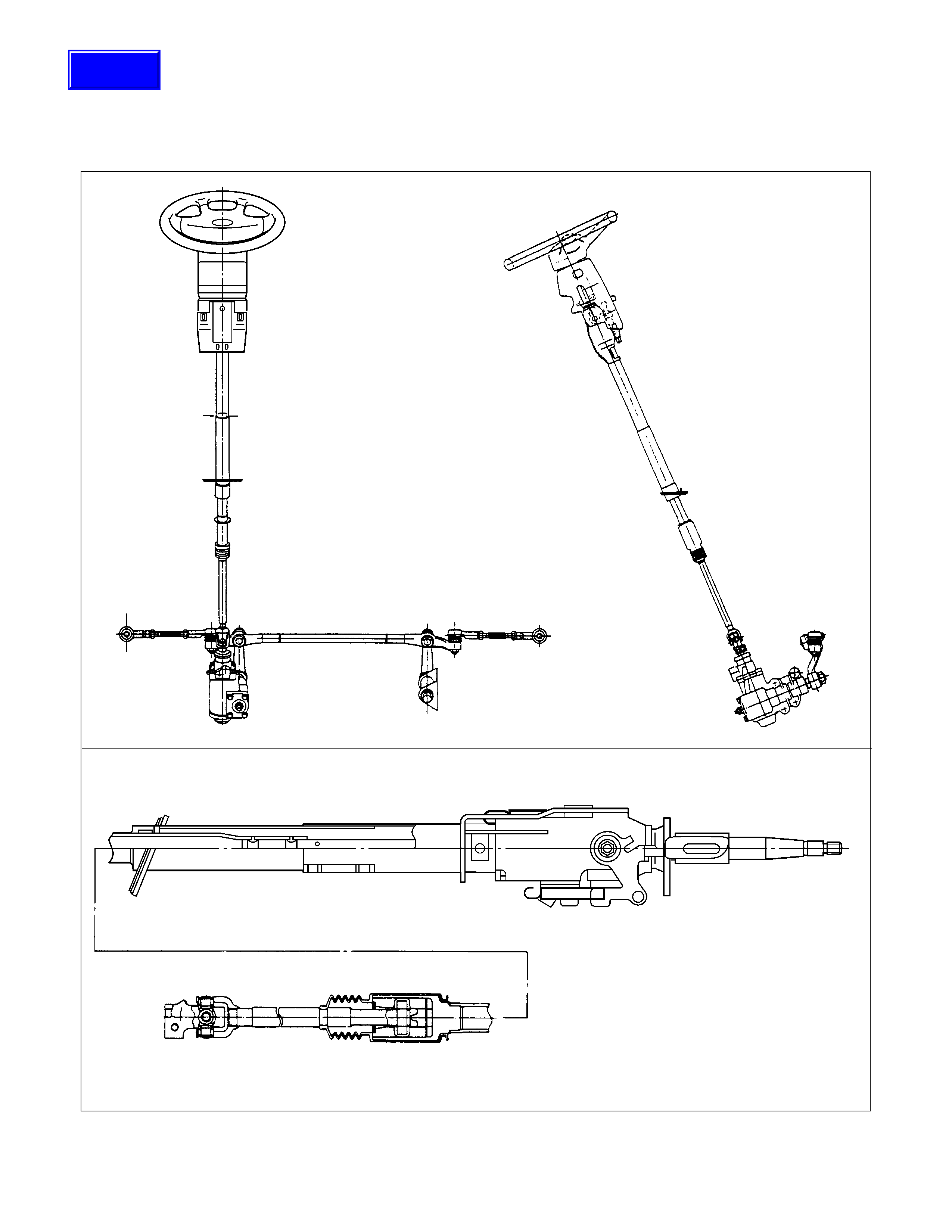
STEERING MECHANISM
GENERAL DESCRI PTION
STEERING MECHANISM
Techline
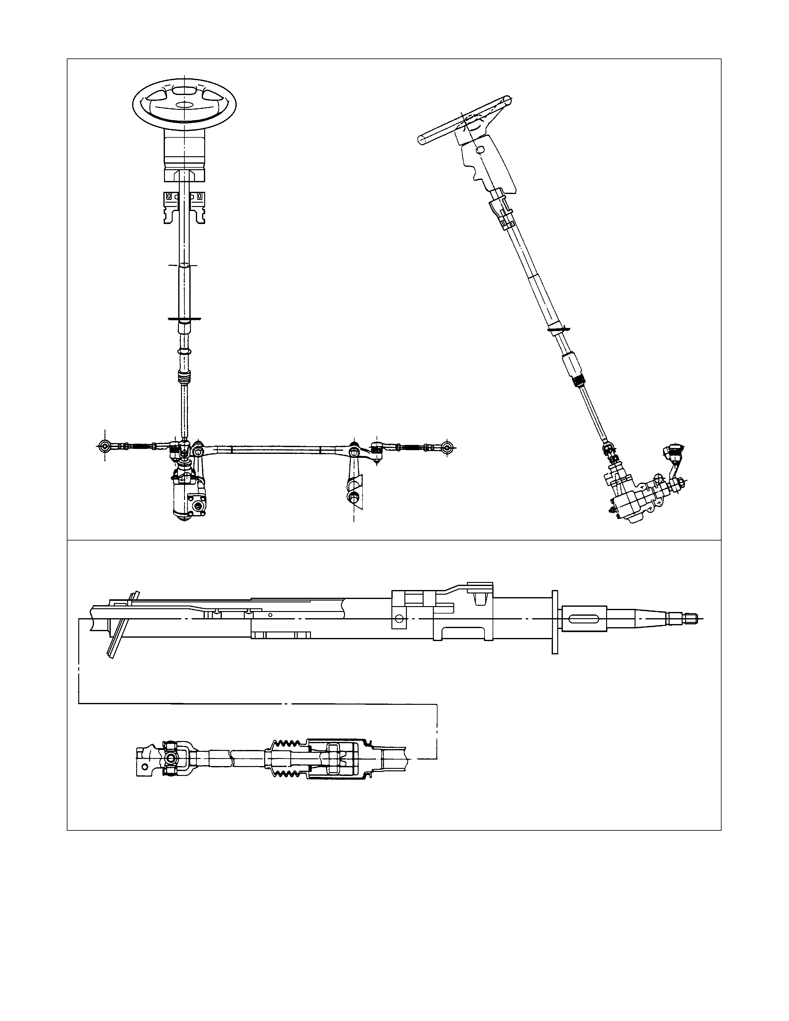
The steering mechanism comprises a steering wheel, steering column, steering shaft, steering unit, and steering
linkage.
The steering shaft is equipped with slid joints to prevent vehicle vibration from transferring to the steering wheel.
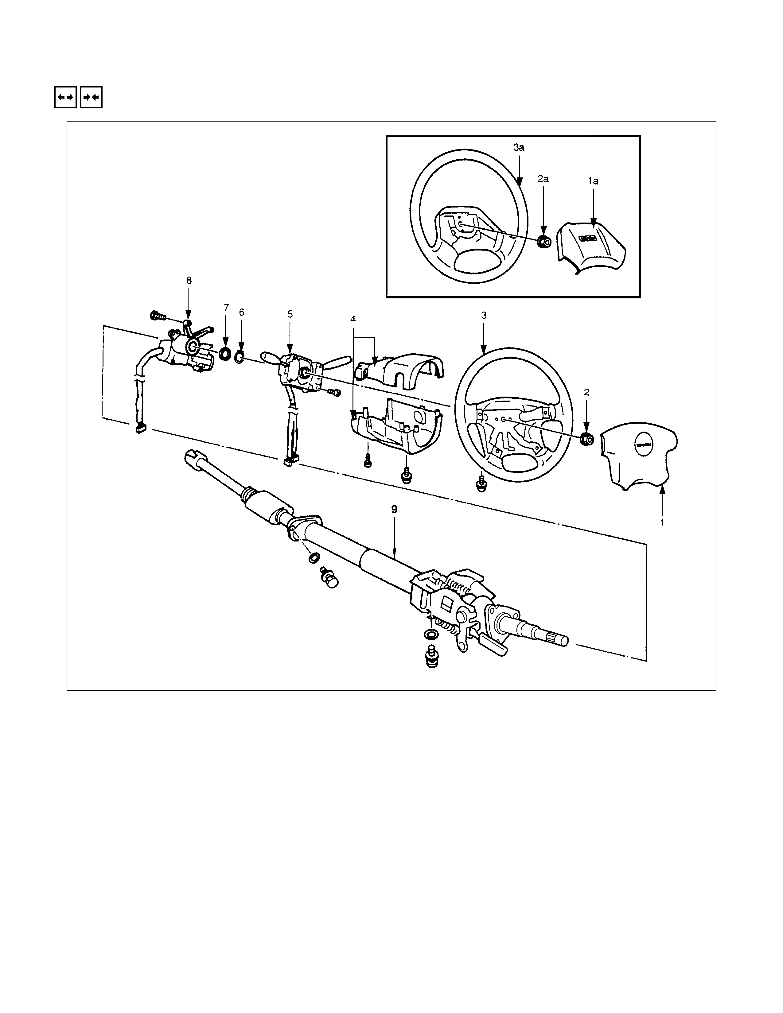
STEERING COLUM N
REMOVAL AND INSTALLATION
REMOVAL STEPS
▲1., 1a. Horn shroud
2., 2a. Nut
▲3., 3a.Steering wheel
4. Steering cowl
5. Combination switch
6. Snap ring
7. Bushing
▲8. Steering lock and bearing
▲9. Steering column assembly
INSTALLATION STEPS
▲9. Steering column assembly
▲8. Steering lock and bearing
7. Bushing
6. Snap ring
5. Combination switch
4. Steering cowl
▲3., 3a. Steering wheel
▲2., 2a. Nut
▲1., 1a. Horn shroud
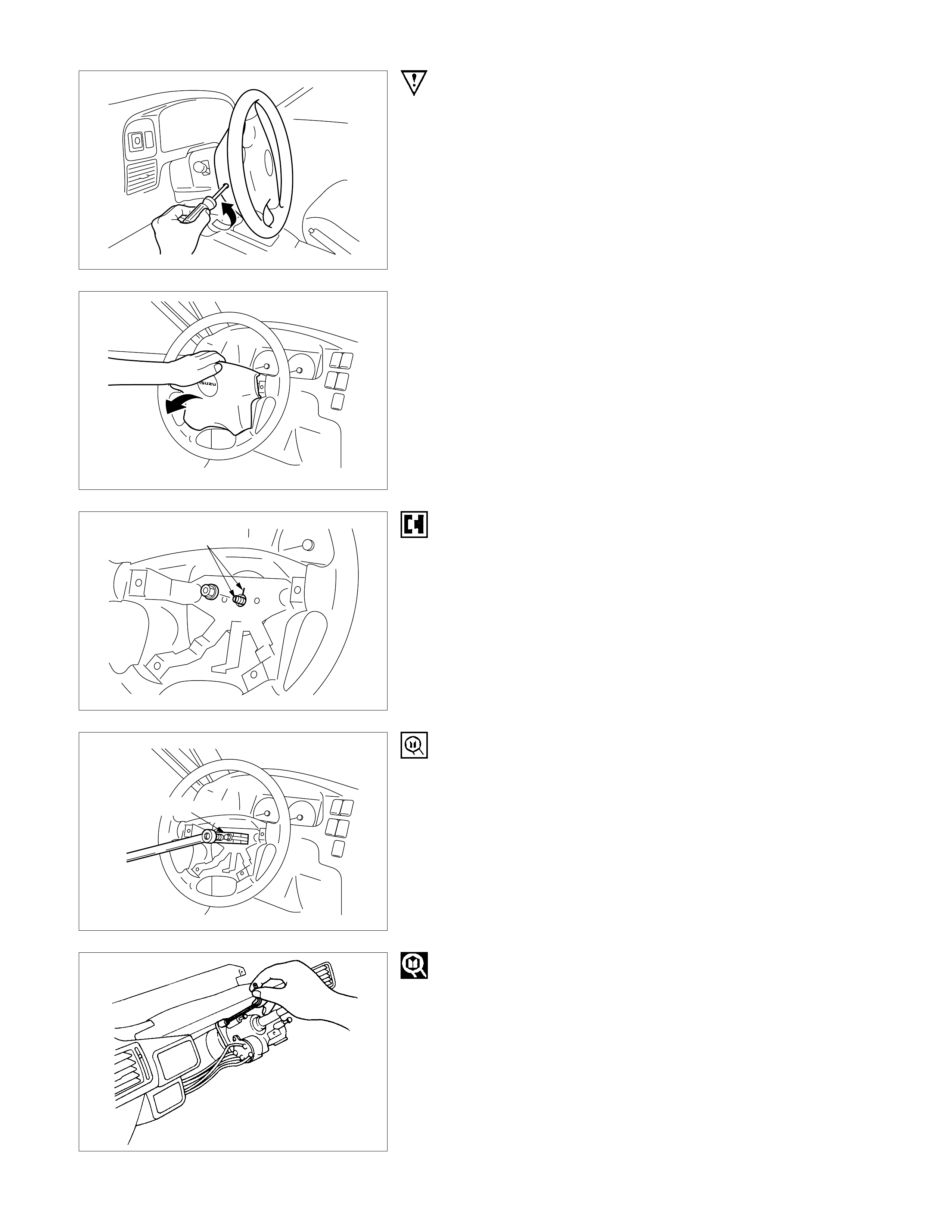
IMPORTANT OPERATIONS - REMOVAL
1. SRS AIRBAG
REFER TO SECTION 12M1 SRS - AIRBAG FOR REMOVAL
INSTRUCTIONS
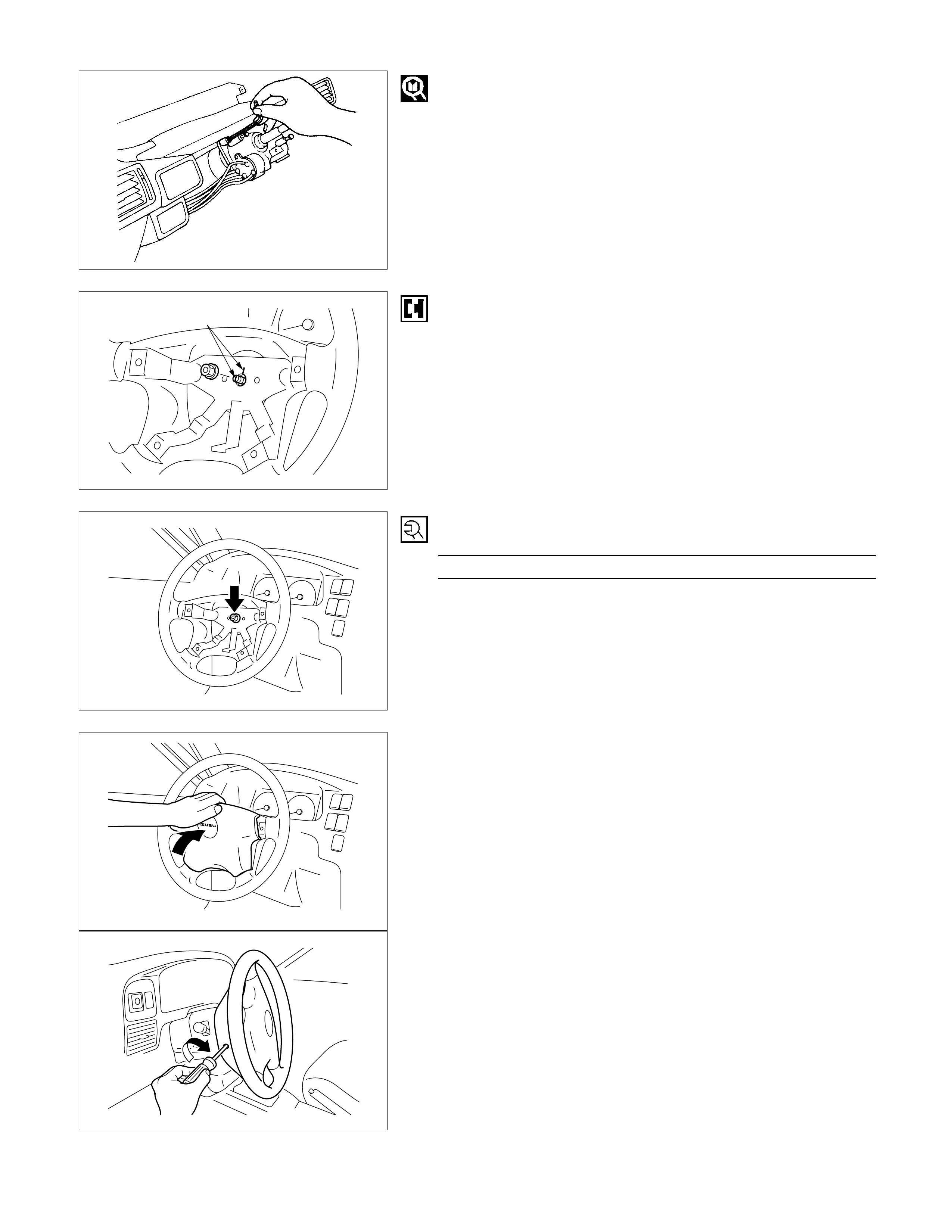
1a. Horn Cover
(1)Remove the arrowed screw at the rear side of the steering
wheel.
(2)Pull up the pad along the direction shown in the left figure
and remove from the steering wheel.
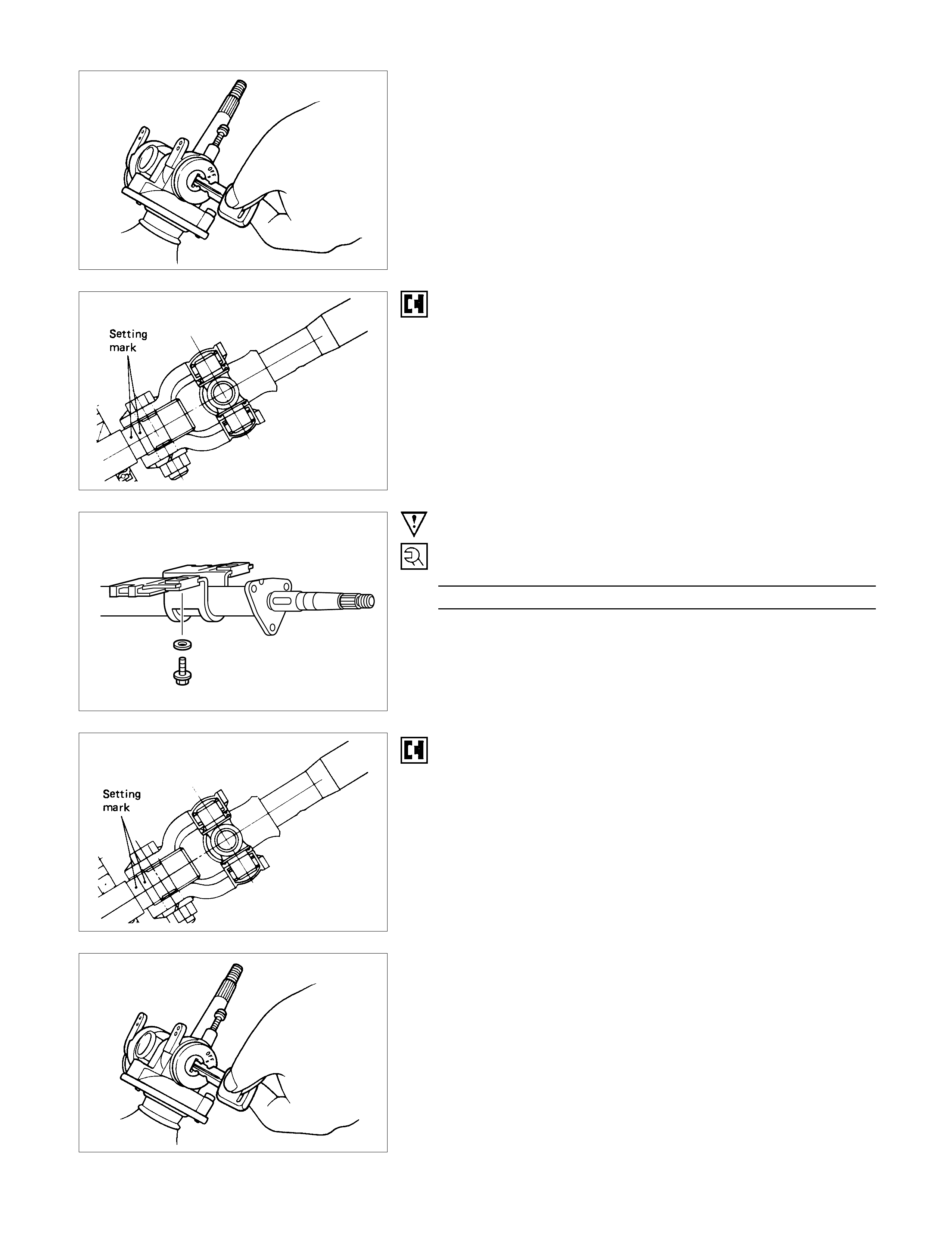
Setting mark
3., 3a. Steering Wheel
(1)Apply a setting mark acros s the s teer ing wheel and s haf t s o
parts can be reassembled in their original position.
5-8521-0016-0
(2)Steering Wheel Puller : 5-8521-0016-0
(J-29752)
Note :
Never apply blow to the setting wheel in direction of the
shaft by using a hammer or other impact tools in an
attempt to remove the steering wheel, the setting shaft is
designed as an energy absorbing unit.
8. Steering Lock and Bearing
Remove the steering lock assembly using the inner hex
wrench.
Turn the ignition/starter key to OFF position.
Note :
With the steering in lock position, the steering lock
assembly cannot be removed.
9. Steering Column Assembly
Apply a setting mark across the universal joint and steering
shaft to reassemble of the parts in their original position.
Note :
A Setting mark can be easily punched if the shaft is
withdrawn a little by loosening the steering shaft universal
joint.
IMPORTANT OPERATIONS - INSTALLATION
9. Steering Column Assembly
Steering Column Torque N⋅m (kgf⋅m/Ib⋅ft)
16.7 +2.9
−0 (1.7 +0.3
−0/12.3 +2.1
−0)
Align the setting marks made when removing.
8. Steering Lock and Bearing
Turn the ignition/starter key to OFF position.
With the steering in lock position, the steering lock assembly
cannot be installed.
Install the steering lock assembly using the inner hex wrench.
Setting mark
3., 3a. Steering Wheel
(1)Align the setting marks made when removing.
(2)Apply grease to contact ring.
Note :
Never apply blow to the setting wheel in direction of the
shaft by using a hammer or other impact tools in an
attempt to install the steering wheel, the setting shaft is
designed as an energy absorbing unit.
2., 2a. Nut
Steering Wheel Nut Torque N⋅m (kgf⋅m/Ib⋅ft
)
34.3±4.9 (3.5±0.5/25.3±3.6)
1. Horn shroud
(1)Remove the bracket from the nail at the lower side of pad
assembly with a screw driver.
(2)Install the bracket (removed at procedure 1) onto the
steering wheel sub assembly with a screw.
(3)Connect the harnesses, then, hang the nail of the pad
assembly onto the plate of the steering wheel sub
assem bly, and install the pad caref ully so that the nail is not
separated from the bracket. (See the lowest figure.)
STEERING UNIT
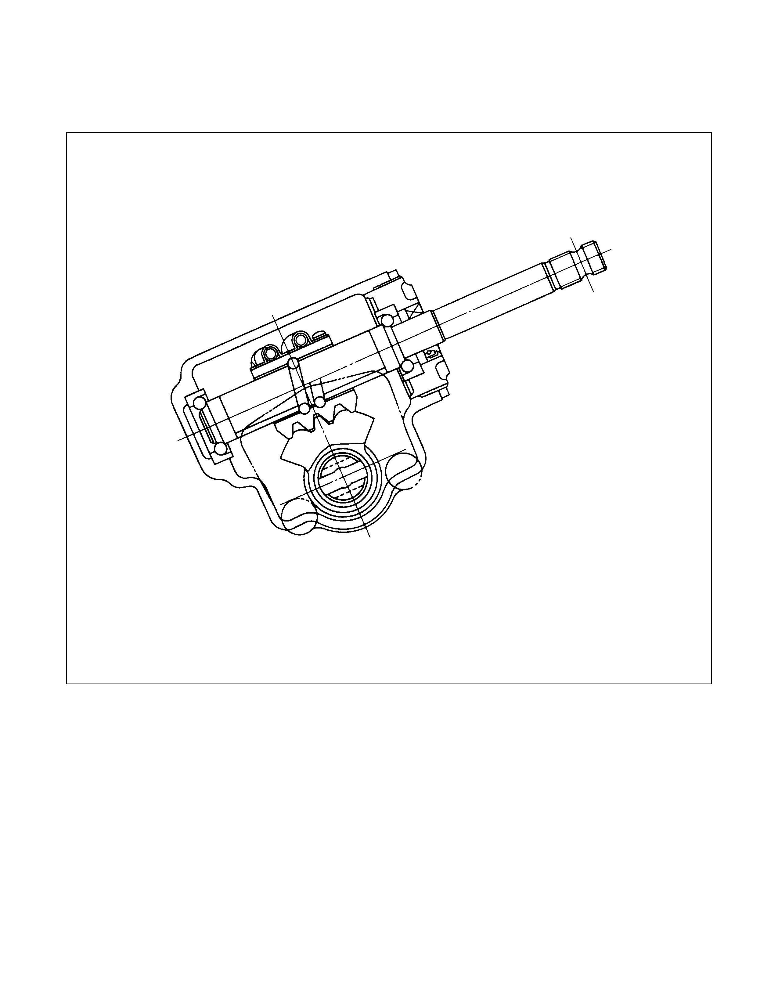
GENERAL DESCRI PITION
MANUAL STEERI NG UNIT
The steering gear is mainly comprised of the sector gear and the worm nut assembly.
There are many recirculating balls installed to the ball groove (way) between the worm nut and the steering worm shaft.
The steering gear's high mechanical efficiency provides very light steering.
Racks machined into the worm nut side face engage the fan shaped sector gear to transfer the steering wheel applied
torque to the pitman arm.
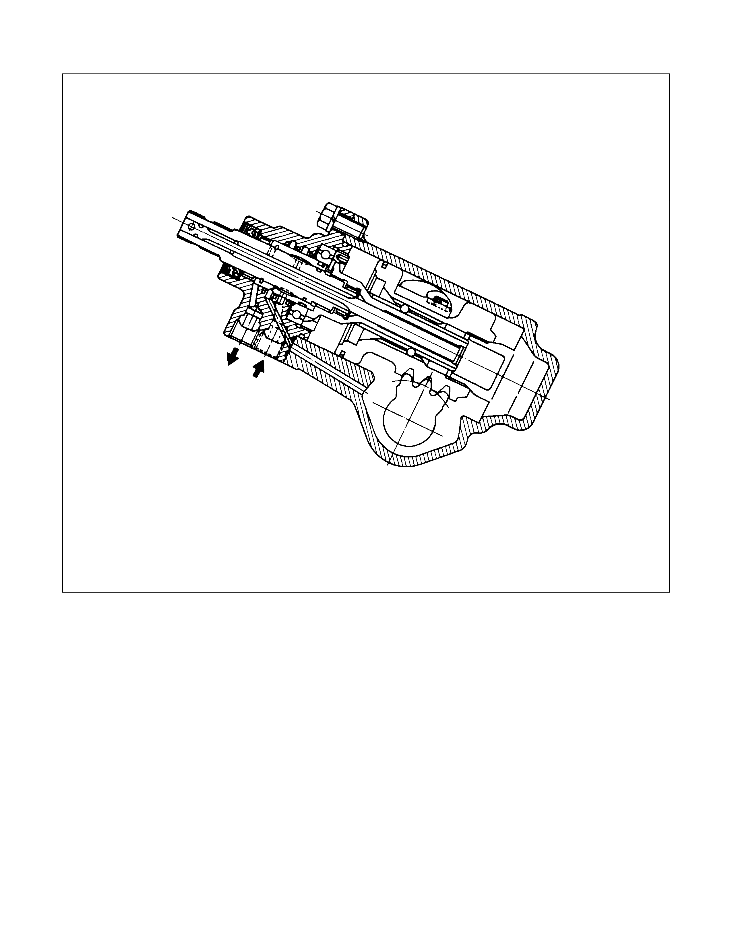
POWER STEERING UNIT
Power steering is designed to reduce the steering wheel turning effort by utilizing hydraulic pressure to bolster the
normal torque developed by the steering wheel box.
The power steering unit incorporates a power piston and sector shaft as an integral part of the steering gear. A control
valve is built into the steering housing.
Because the tire rolling resistance is constantly applied to the worm shaft, the torsion bar twists with the Steering
Wheel. As the torsion bar twists, the relative torque displacement between the worm shaft and the rotor changes. An
equivalent oil pressure is applied to the piston to bolster the normal torque.

POWER STEERING HYDRAULIC LINE
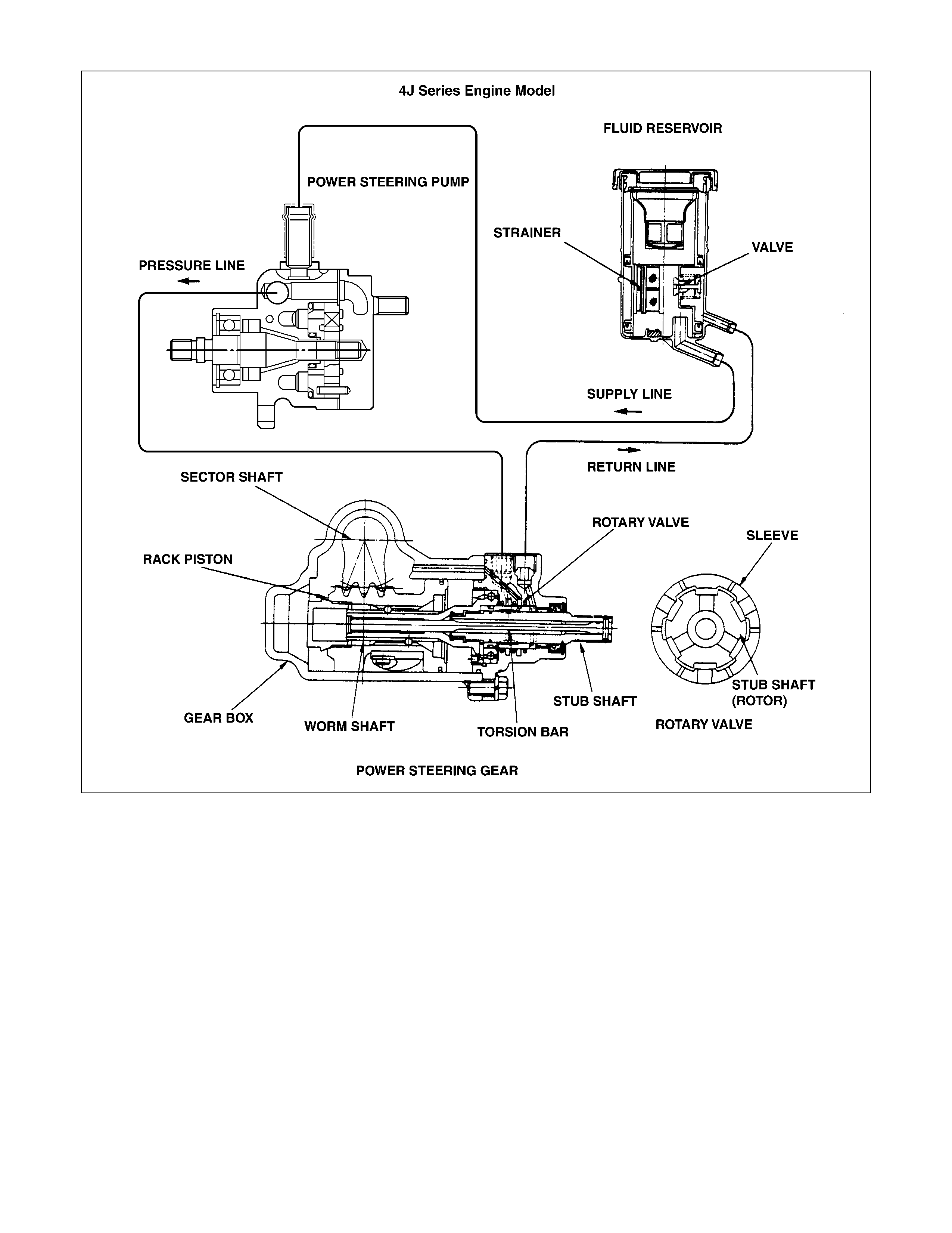
The function of each major component is described below:
Power Steering Unit
Refer to the previous page.
Oil Pump
The oil pump uses the power of the engine to send hydraulic fluid to the power steering unit.
An oil pressure relief valve and an oil flow relief valve are installed to the oil pump.
The oil pressure relief valve prevents any excessive oil pressure from reaching the hydraulic circuit.
The oil flow control valve controls the hydraulic fluid volume within the hydraulic system. It prevents too much fluid from
entering the system. This, in turn, prevents harmful heat build-up.
Oil Reservoir and Piping
The oil reservoir stores and filters the hydraulic fluid.
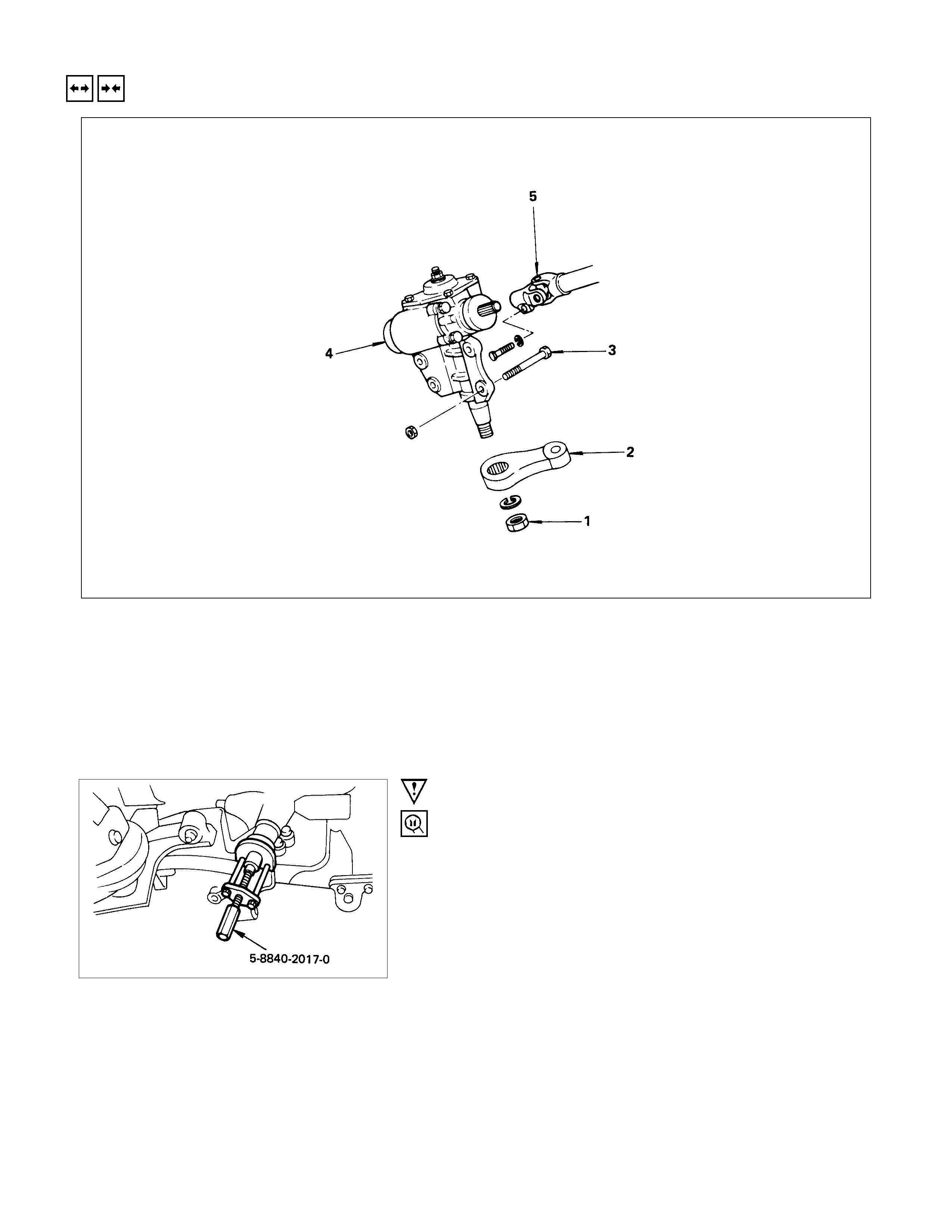
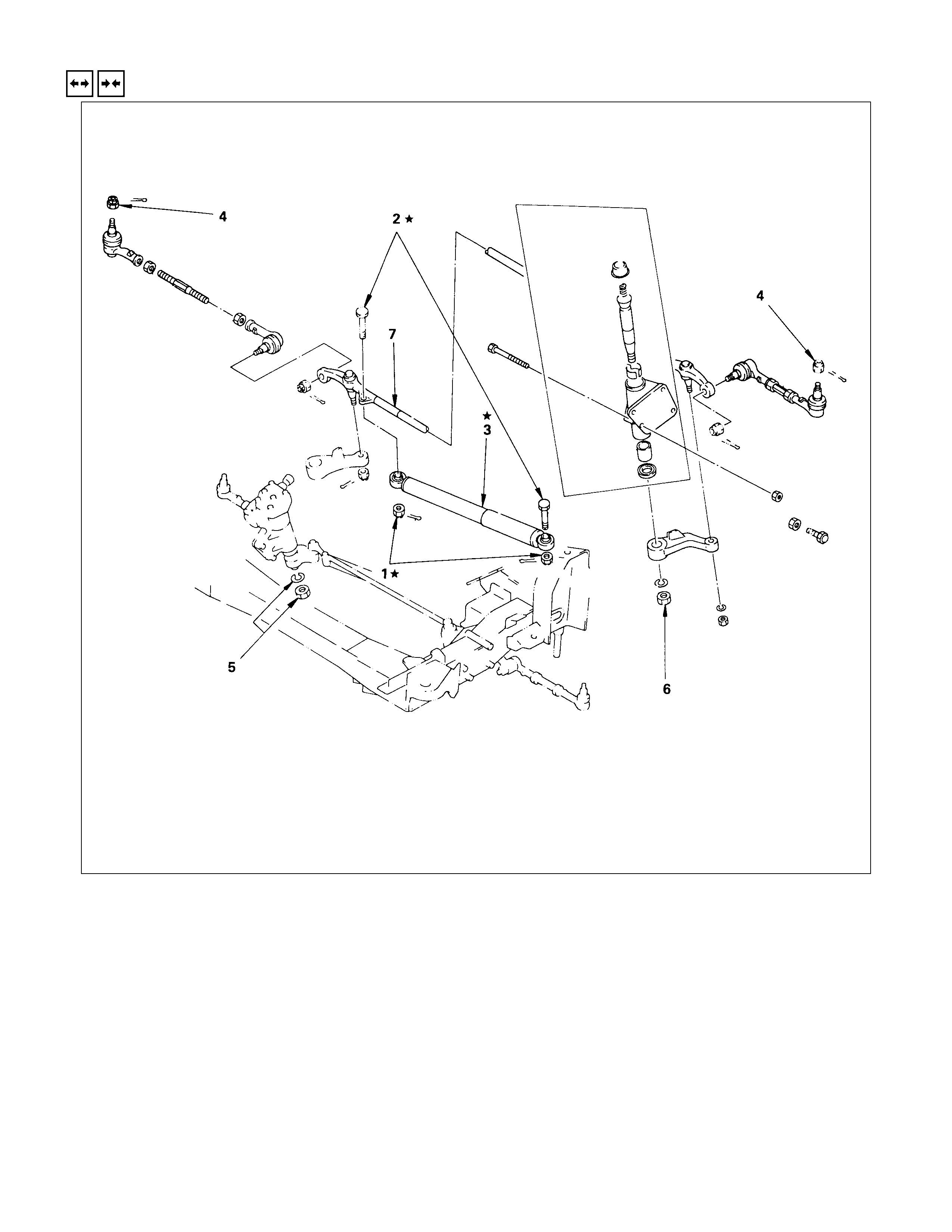
REMOVAL AND INSTALLATION
REMOVAL STEPS
1. Nut
▲2. Pitman arm
3. Bolt
4. Unit assembly
▲5. Coupling assembly
INSTALLATION STEPS
▲5. Coupling assembly
4. Unit assembly
▲3. Bolt
▲2. Pitman arm
▲1. Nut
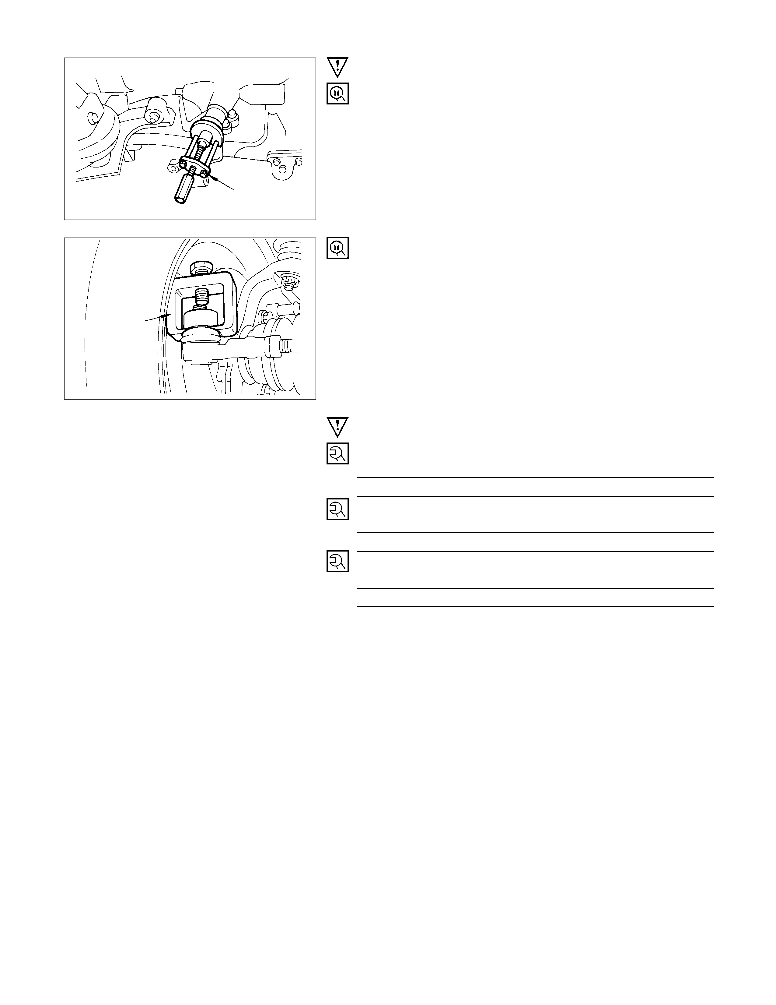
IMPO RTANT OPERATIONS - REMOVAL
2. Pitman Arm
Pitman Arm Remover : 5-8840-2017-0
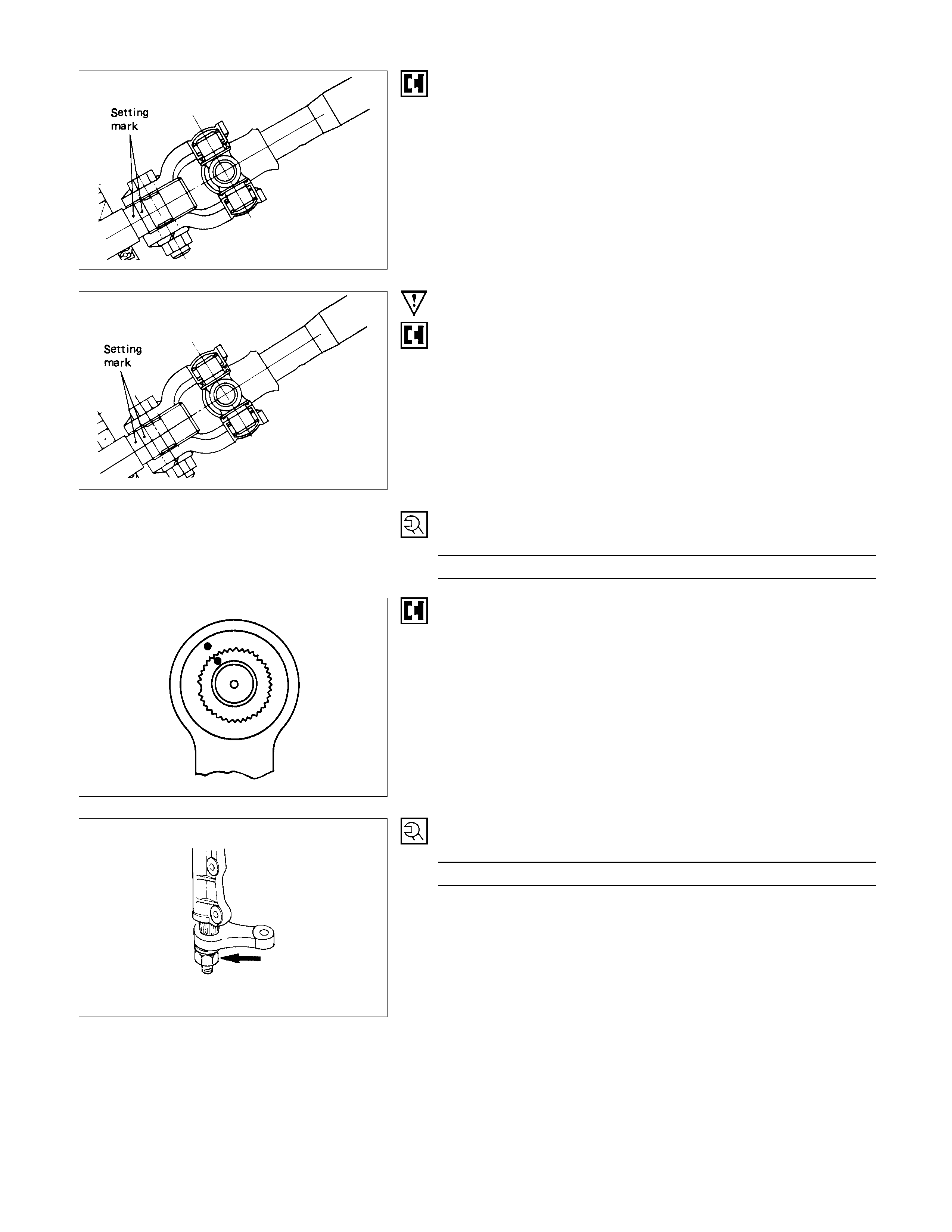
5. Coupling Assembly
Make a setting mark across the coupling flange and worm
shaft to ensure reassembly of the parts in the original position.
IMPORTANT OPERATIONS - INSTALLATION
5. Coupling Assembly
Align the Setting mark made at removal
3. Bolt
Steering Unit Bolt N⋅m (kgf⋅m/Ib⋅ft)
44.1 +9.8
−4.9 (4.5 +1
−0.5 /32.5 +7.2
−3.6 )
2. Pitman Arm
Align the notched tooth
1. Nut
Pitman Arm Nut Torque N⋅m (kgf⋅m/Ib⋅ft)
215.6±19.6 (22.0±2.0/159.0±14.5)
MANUAL STEERI NG UNIT
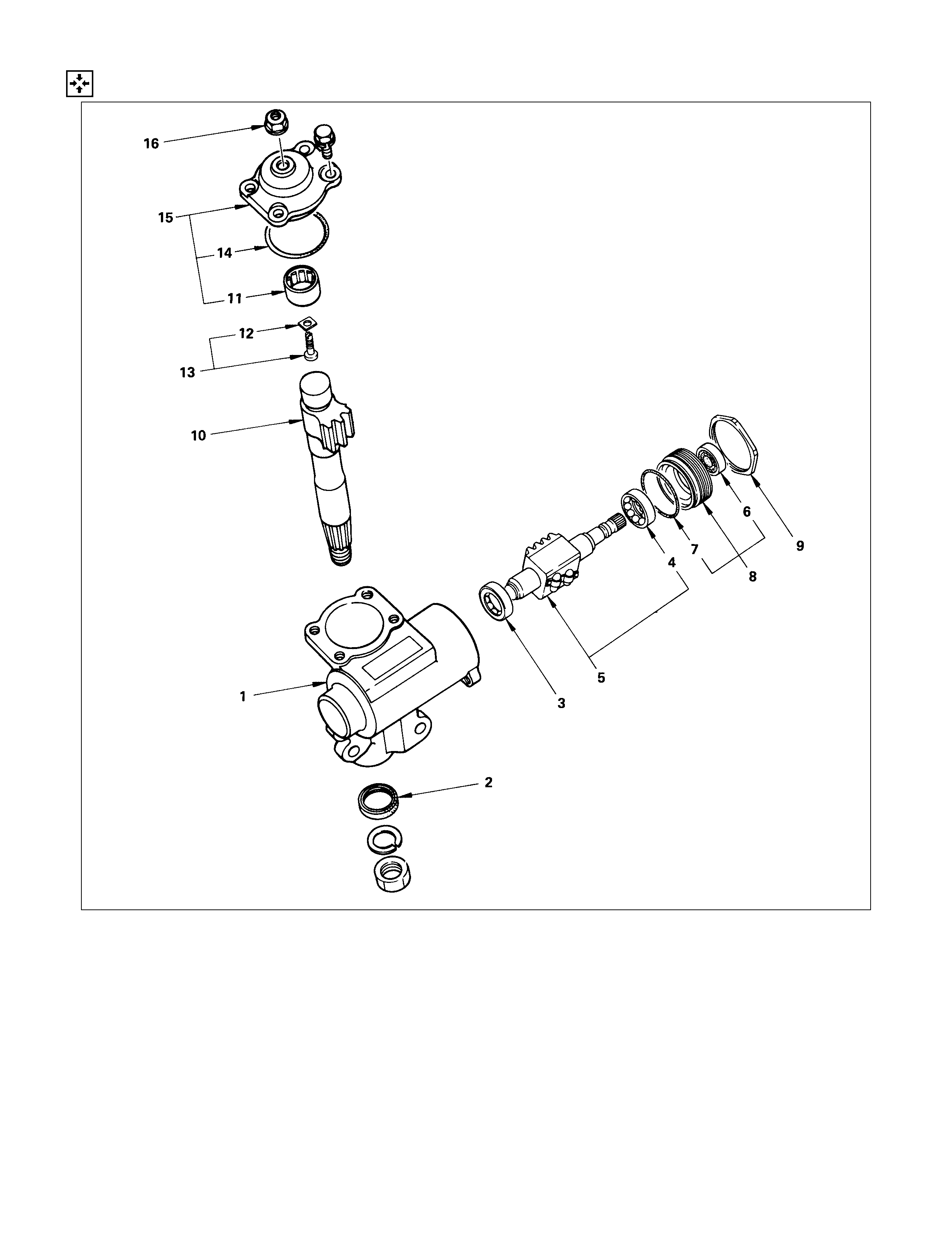
DISASSEM BLY
DISASSEM BLY STEPS
1. Lock nut
▲2. Side cover
3. Gasket
4. Adjusting screw
5. Adjusting shim
6. Needle bearing
▲7. Sector shaft
▲8. Lock nut
▲9. End cover
10. Oil seal
11. O-ring
▲12. Ball nut and worm shaft
13. Bearing
14. Bearing
15. Oil seal
16. Gear box
IMPORTANT OPERATIONS
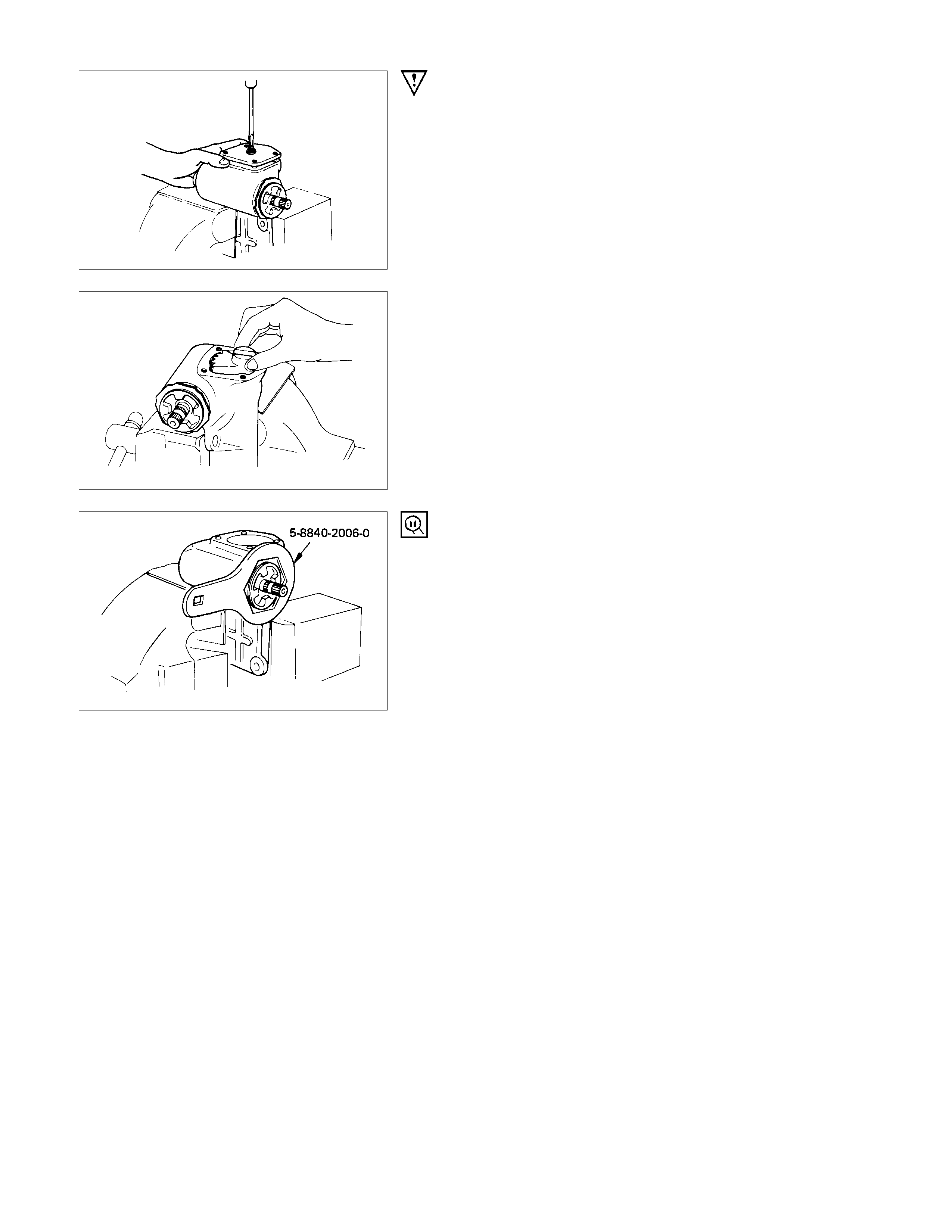
2. Side Cover
(1)Turn the adjusting screw counter-clockwise slightly, then
remove the side cover fixing bolt.
(2)Turn the adjusting scr ew clock wise with the side cover held
from turning.
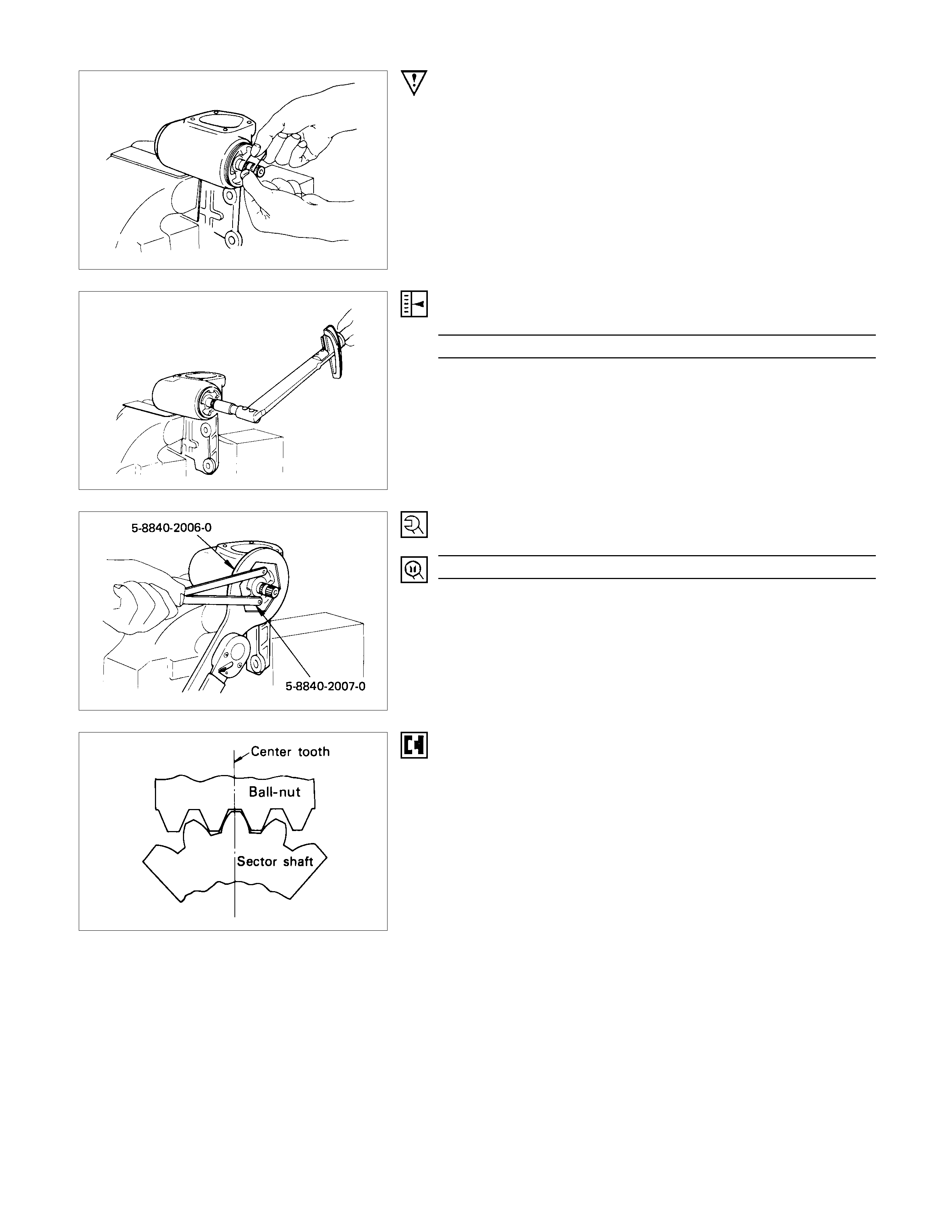
7. Sector Shaft
Hold the sector shaft in straight-ahead position when removing
it from the gear box. Do not drive the sector shaft off the gear
box with a hammer or other impact tools.
8. Lock Nut
Lock Nut Wrench : 5-8840-2006-0
(J-29753)
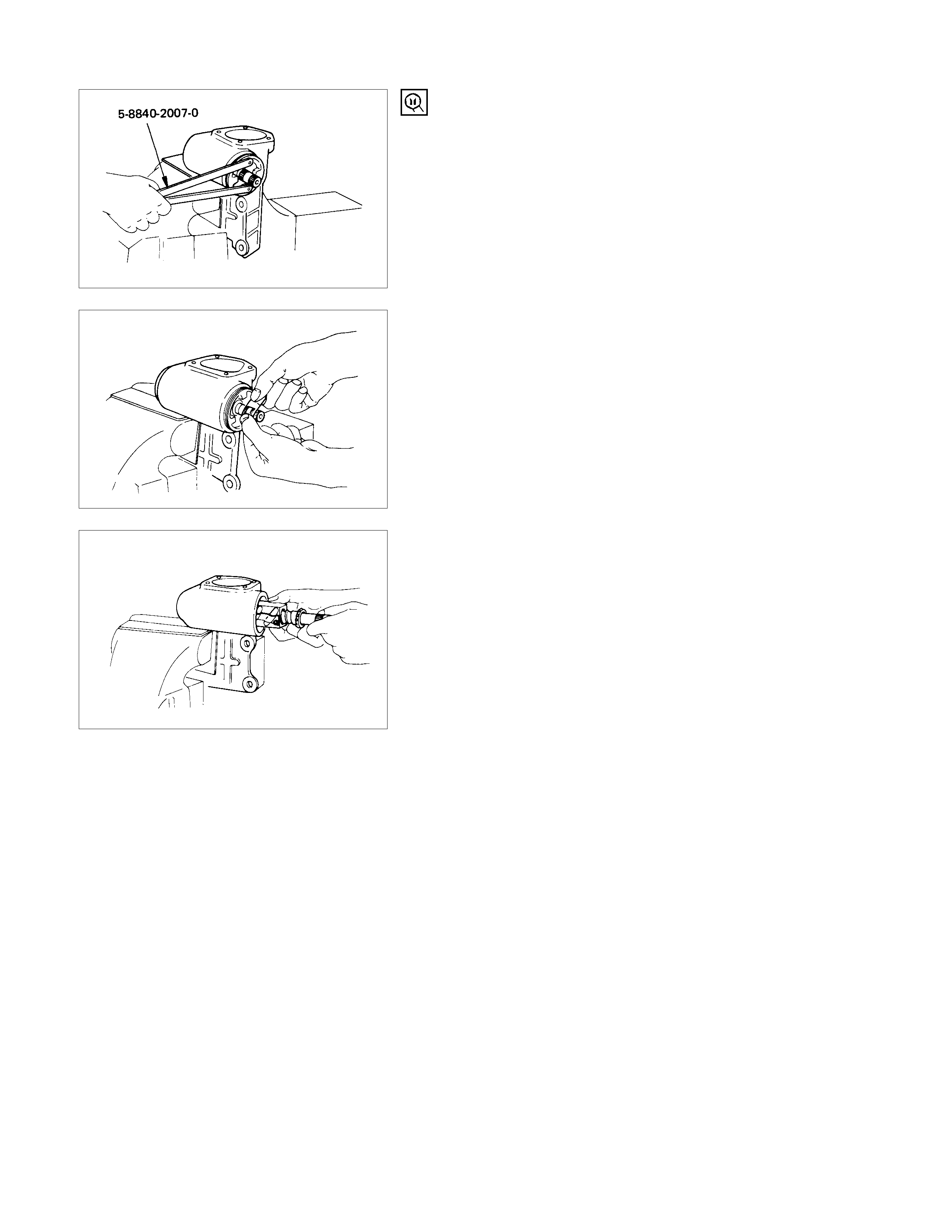
9. End Cover
(1)End Cover Remover : 5-8840-2007-0
(J-7624)
(2)When removing, take care so as not to damage the oil seal.
Taping the splines will provide some protection.
12.Ball-Nut and Worm Shaft
Always keep ball-nut assembly in a horizontal position. Do not
hold it vertically, or ball-nut will slide out.
INSPECTION AND REPAIR
Make necessary correction or parts replacement if wear, damage or any other abnormal conditions are found through
inspection.
• Bearing
• Oil seal, bushing
• Ball-nut and worm shaft
• Sector shaft
• Gear box
VISUAL CHECK
Inspect the following parts for wear, damage or other abnormal
conditions.
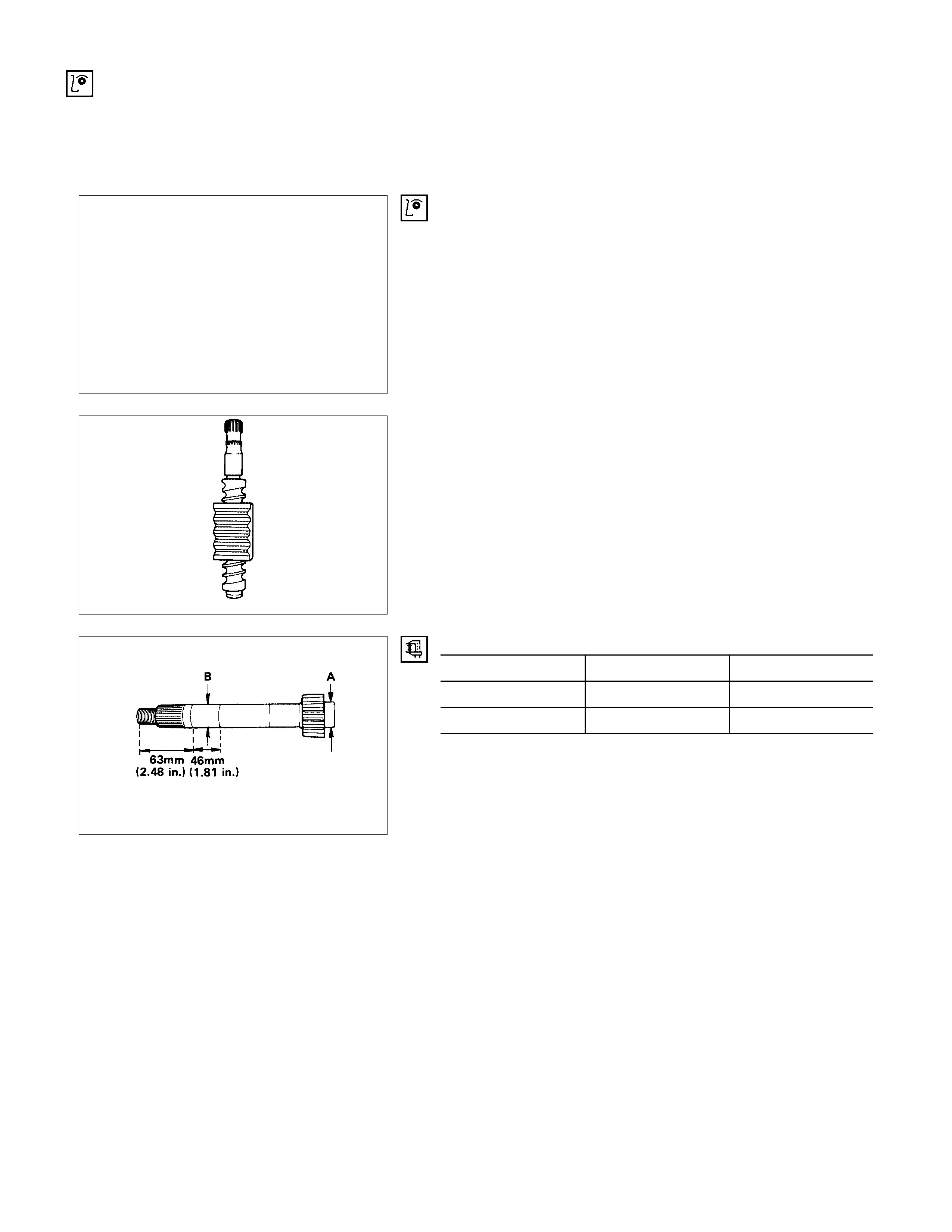
BALL-NUT ROTATIO N
Hold the worm shaft vertically and check that the ball-nut
lowers with a smooth turning motion. If the lowering of the ball-
nut by its own weight is not smooth, check the worm shaft for
bending and the ball-groove for burrs, dents, and foreign
matter.
Note :
When testing the ball-nut assembly, do not let it travel all
the way to the end of worm shaft, or damage to the ball
tubes will result.
Sector Shaft Outside Diameter mm(in)
Standard Limit
A 28.6 (1.13) 28.3 (1.12)
B 31.8 (1.25) 31.5 (1.24)
REASSEMBLY
REASSEMBLY STEPS
1. Gear box
2. Oil seal
3. Bearing
4. Bearing
5. Ball nut and worm shaft
6. Oil seal
7. O-ring
▲8. End cover
▲9. Lock nut
▲10. Sector shaft
11. Needle bearing
▲12. Adjust shim
13. Adjust screw
▲14. Gasket
▲15. Side cover
▲16. Lock nut
IMPORTANT OPERATIONS
8. End Cover
(1)When installing, take care so as not to cause damage to
the oil seal.
Taping the splines will provide some protection.
(2)Adjust the bearing preload by using socket.
Bearing Preload N⋅m (kgf⋅m/Ib⋅ft)
0.29 - 0.59 (0.03 - 0.06/0.22 - 0.43)
9. Lock Nut
Lock Nut Torque N⋅m (kgf⋅m/Ib⋅ft)
176.5±19.5 (18.0±2.0/130.2±14.4)
Lock Nut Wrench : 5-8840-2006-0
(J-29753)
End Cover Installer : 5-8840-2007-0
(J-7624)
Note:
After tightening, check the bearing preload.
10.Sector Shaft
Align the center tooth of the ball-nut with that of the sector
shaft.
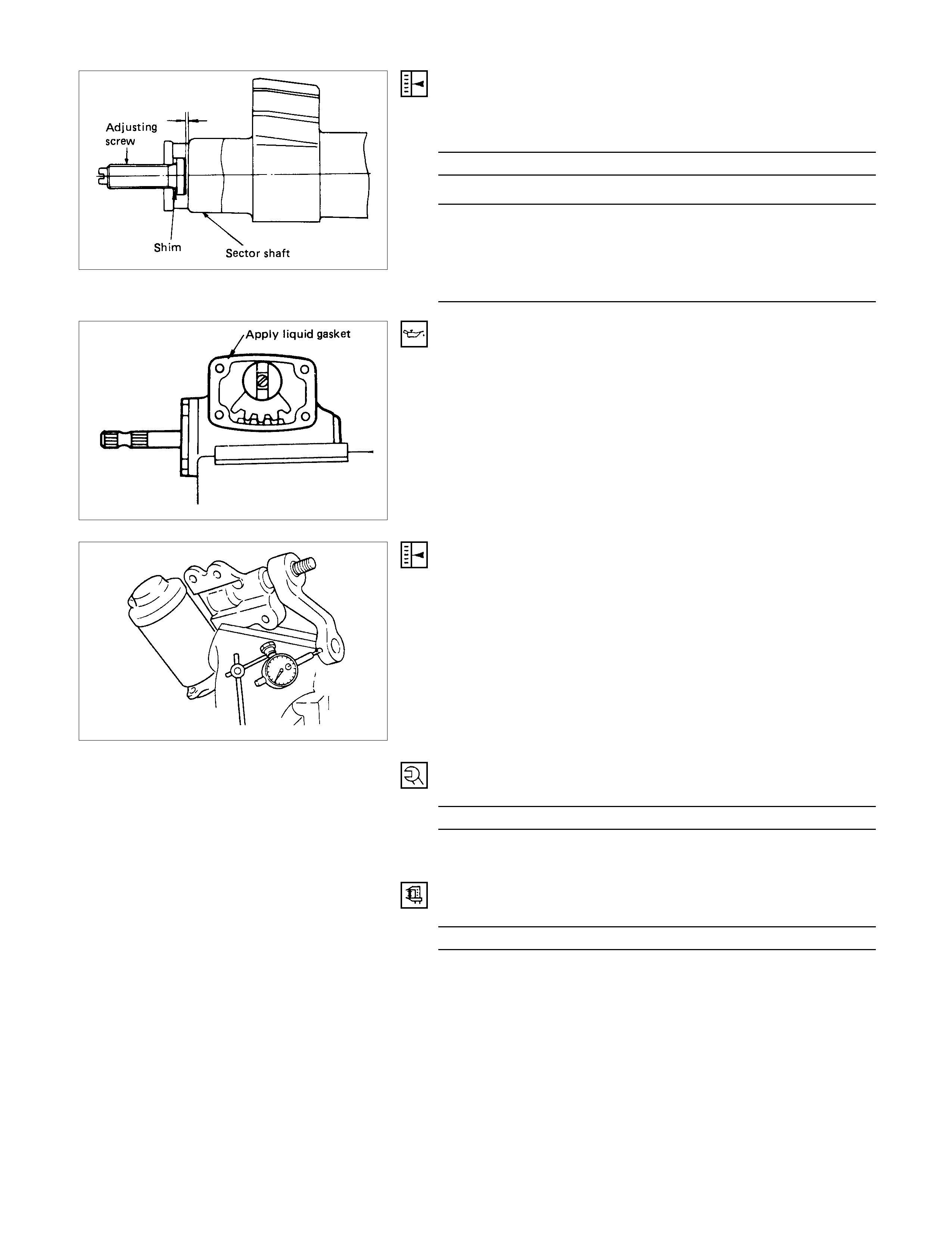
12.Adjust Shim
Adjust the clearance and check that the adjusting screw turns
freely.
Clearance mm (in)
0.1 (0.004)
Adjusting shims available mm (in)
1.524 (0.0600)
1.554 (0.0612)
1.585 (0.0624)
1.615 (0.0636)
1.646 (0.0648)
14.Gasket
15.Side Cover
Apply liquid gasket to the joining surface of each parts.
16.Lock Nut
Adjust the backlash between the sector gear and ball-nut.
(1)Install the pitman arm.
(2)Check that the sector shaft moves smoothly in the correct
working angle range, then semi-tighten the lock nut.
(3)Measure preload of worm gear.
Preload N⋅m (kgf⋅m/Ib⋅ft)
less than 1.079 (0.11/0.795)
Note:
Obtain the specified backlash by turning the adjust screw.
The backlash should be measured at the drop arm end.
Backlash mm (in
)
0.2 (0.008)
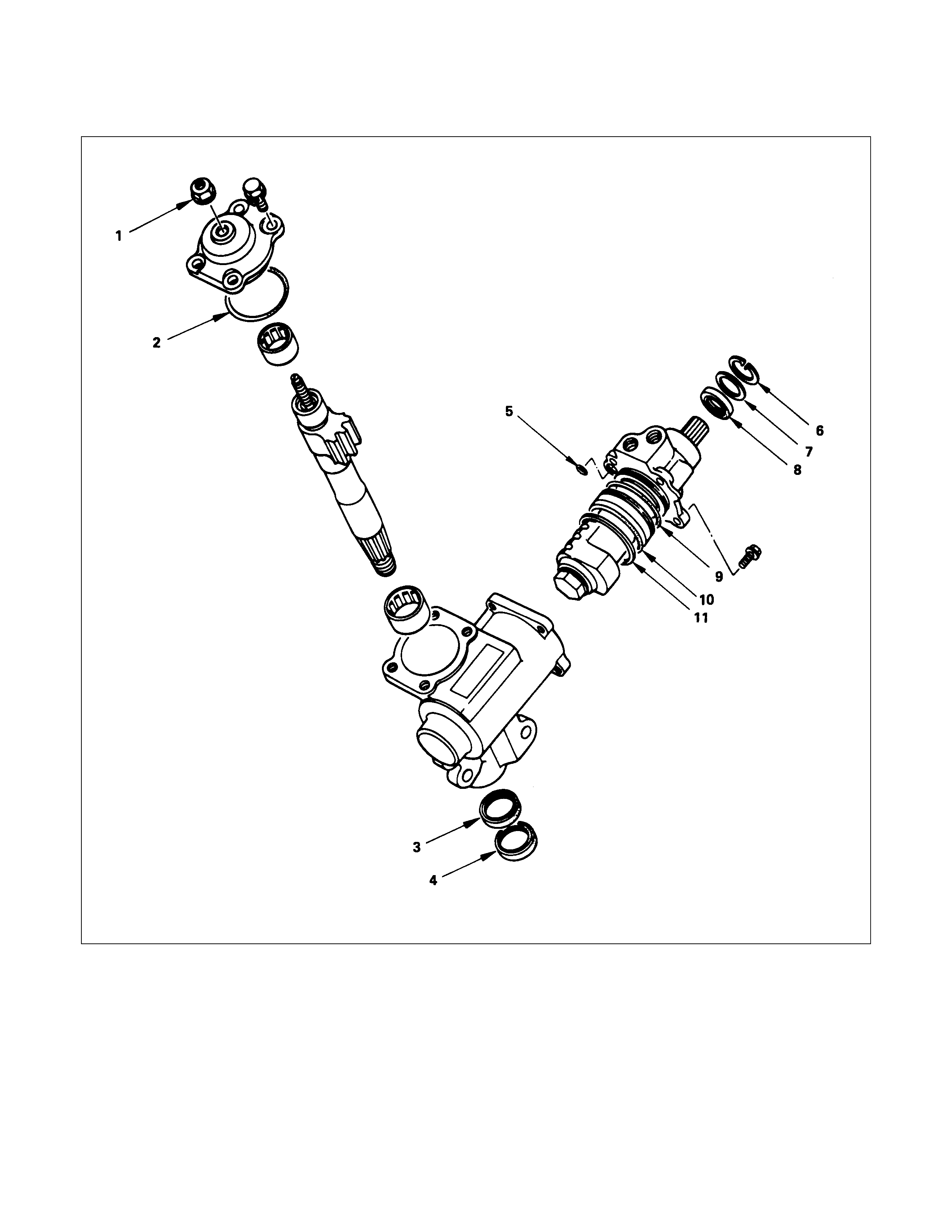
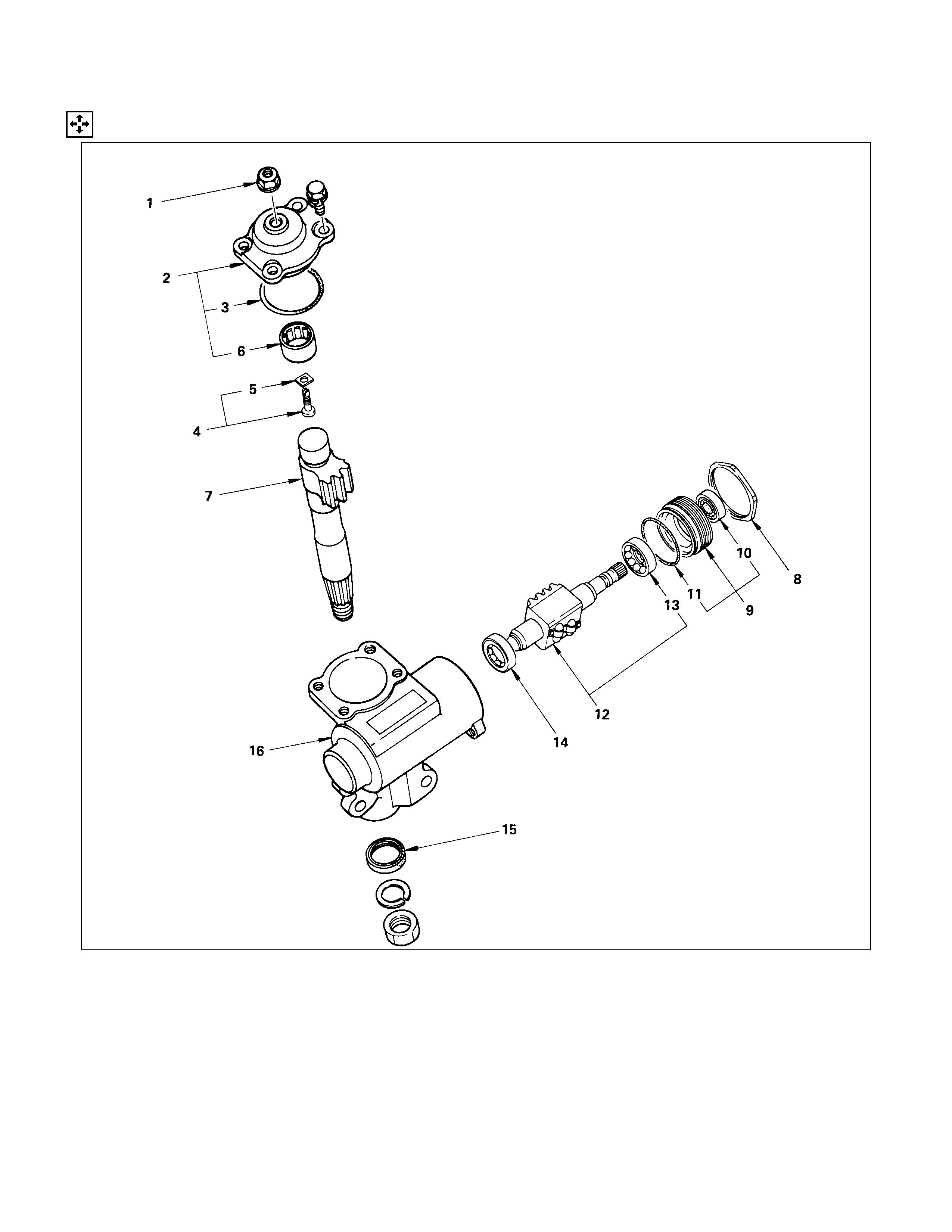
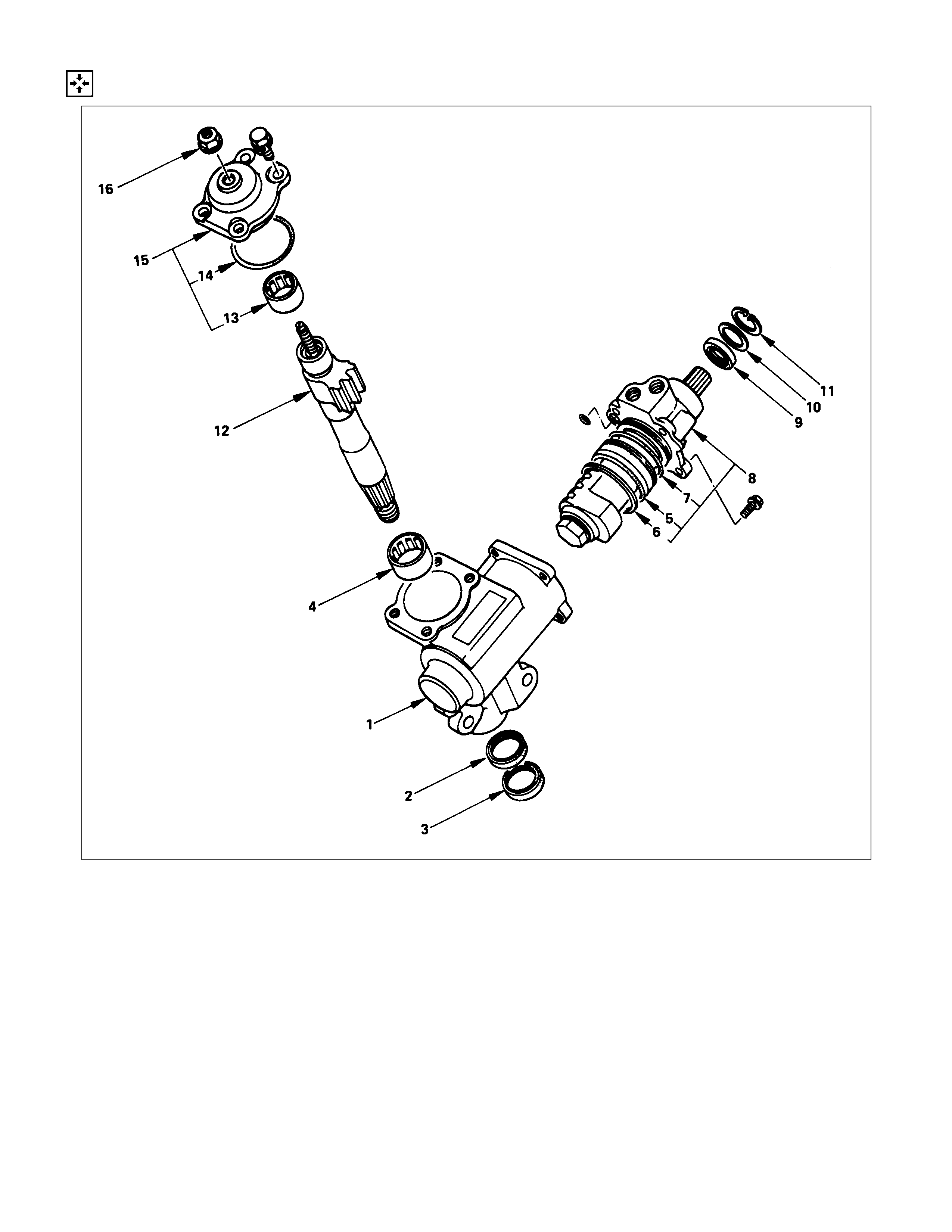
POWER STEERING UNIT
REPAIR KI T
1. Nut : adjust screw
2. Gasket : cover
3. Gasket : sector shaft
4. Seal : sector shaft
5. Gasket : housing
6. Ring : retaining
7. Ring : seal
8. Seal: oil
9. Gasket : housing
10. Gasket : housing
11. Seal ring : housing
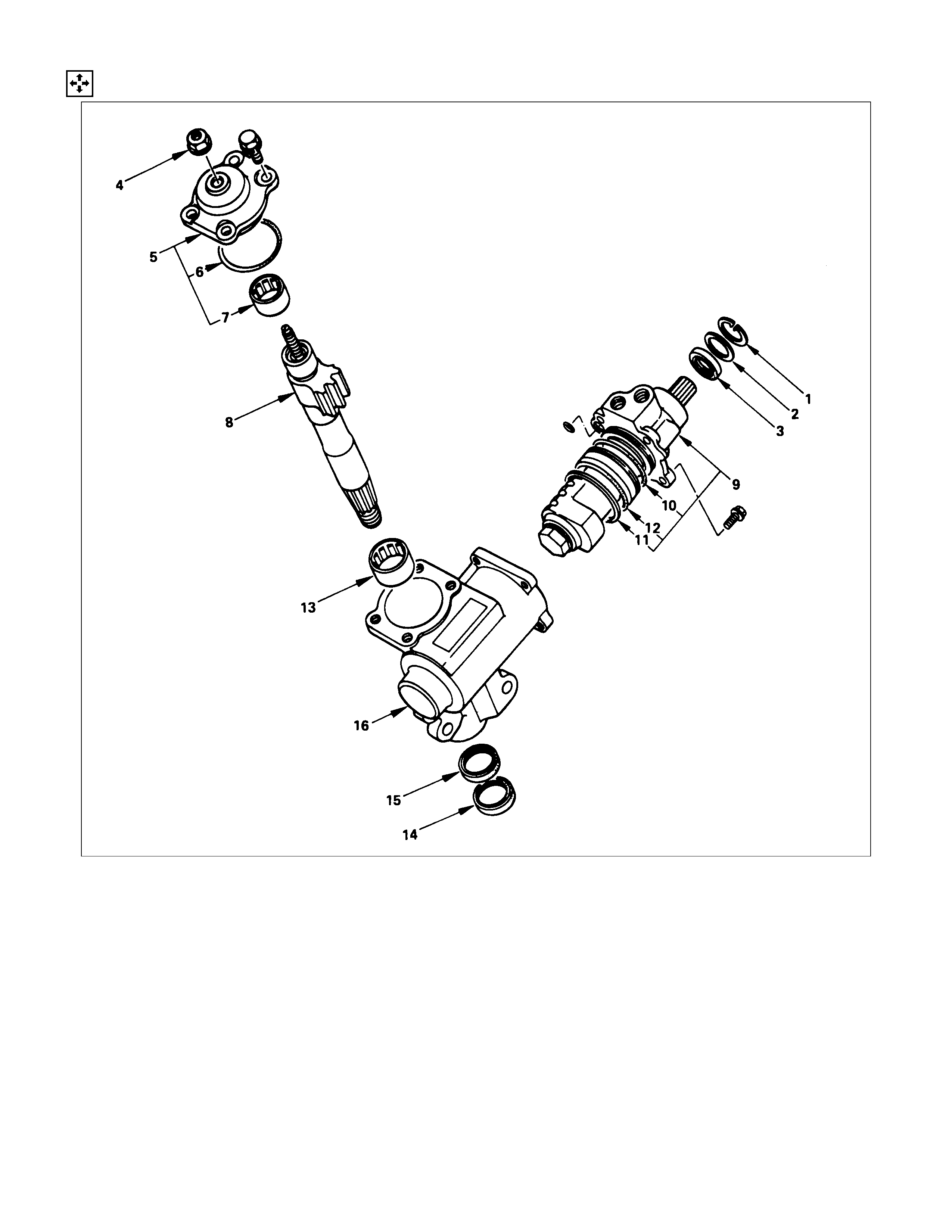
DISASSEM BLY
DISASSEM BLY STEPS
1. Retaining ring
2. Seal ring
▲3. Oil seal
▲4. Lock nut
▲5. Top cover assembly
6. O-ring
7. Needle bearing
▲8. Sector shaft
▲9. Ball nut and valve housing assembly
10. Gasket
11. Seal ring
12. Gasket
13. Needle bearing
14. Sector shaft seal
15. Sector shaft gasket
16. Gear box
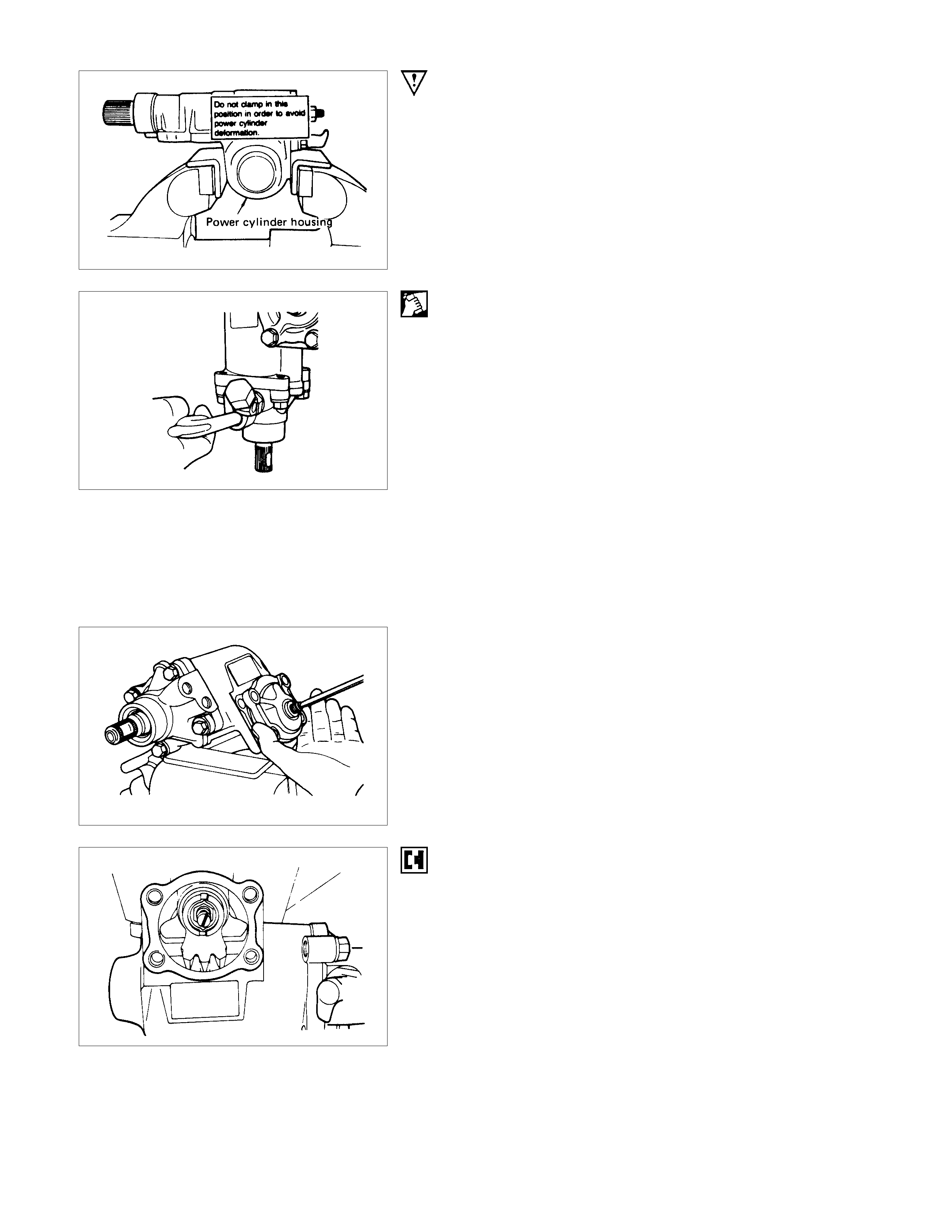
IMPORTANT OPERATIONS
Avoid clamping the steering gear assembly in a vise by the
power cylinder housing.
3. Oil Seal
(1)Clean the faces of the extended stub shaft.
(2)Plug the hose fitting on the inlet side.
(3)Rem ove the oil seal by blowing com pres sed air through the
hole in the outlet side.
4. Lock Nut
Remove the adjusting screw lock nut and turn the adjusting
screw counter-clockwise to remove the preload between the
sector gear and the rack piston, then remove the top cover
bolts.
5. Top Cover
Hold the top cover stationary, turn the adjusting screw
clockwise to raise and free the cover, then remove the cover.
8. Sector Shaft
Bring the stub shaft into straight-ahead position.
Do not force the sector shaft off the gear box with a hammer or
other impact tools.
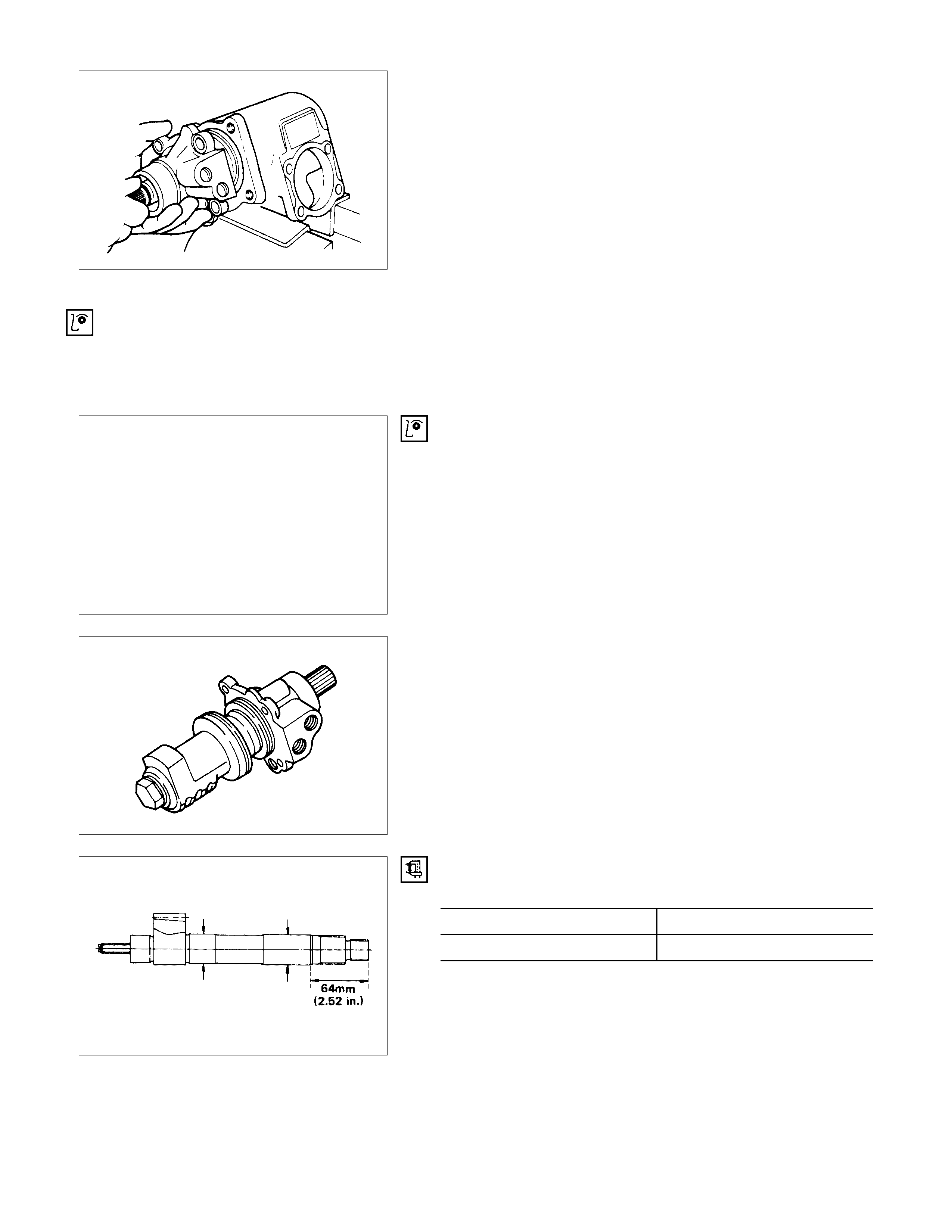
9. Ball Screw and Valve Housing Assembly
It is strongly advisable to keep the ball nut and valve housing
assembly always in a horizontal position, or the rack piston will
fall off onto the end of the worm, causing the rack piston to slip
out of the worm shaft and the balls to fall out.
INSPECTION AND REPAIR
Make necessary correction or parts replacement if wear, damage or any other abnormal conditions are found through
inspection.
• Bearing
• Oil seal, Dust seal, Dust cover
• O-Ring, seal ring
• Ball nut and valve housing
• Sector shaft
• Gear box
VISUAL CHECK
Inspect the following parts for wear, damage or other abnormal
conditions.
BALL-NUT ROTATIO N
Hold the ball nut and valve housing assembly vertically and see
if the ball-nut lowers by turning smoothly. If the lowering of the
ball-nut by its own weight is not smooth, check the worm shaft
for bending and the ball-groove for burrs, dents and foreign
matter.
Note :
When testing the ball nut and valve housing assembly, do
not let it travel all the way to the end of worm shaft, or
damage to the ball tubes will result.
SECTOR SHAFT OUTSIDE DIAMETER mm (in)
Standard Limit
32.0 (1.260) 31.97 (1.258)
REASSEMBLY
REASSEMBLY STEPS
1. Gear box
▲2. Gasket
▲3. Seal
4. Needle bearing
▲5. Gasket
▲6. Seal ring
▲7. Gasket
▲8. Ball nut and valve housing assembly
▲9. Oil seal
▲10. Seal ring
▲11. Retaining ring
▲12. Sector shaft
13. Needle bearing
14. O-ring
▲15. Top cover assembly
▲16. Lock nut

IMPORTANT OPERATIONS
2. Seal Ring
3. Dust Seal
Note the setting direction.
Apply a thin coat of grease to lip of each part.
5. O-Ring
6. Seal Ring
7. O-Ring
Apply a thin coat of grease.
8. Ball Nut and Valve Housing Assembly
(1) It is strongly advisable to keep the ball screw and valve
housing assembly always in a horizontal position and avoid
holding it vertically, or the rack piston will fall off onto the
end of the worm, causing the rack piston to slip out of the
worm shaft and balls to fall out.
(2)Be careful so as not to the drop the O-ring fitted to oil
passage in the valve housing.
(3) Tighten the valve housing retaining bolts to the specified
torque.
Valve Housing Bolt Torque N⋅m (kgf⋅m/Ib⋅ft
)
47±7 (4.8±0.8/34.7±5.8)
9. Oil Seal
Oil Seal Installer : 5-8522-0026-0
(J-26508)

10.Back Up Ring
11.Retaining Ring
Turn the face with rounded edge (outer circumference) to the
oil seal.
12.Sector Shaft
(1)Tape the sector shaft serrations to protect the seal ring
from damage.
(2)Align the center tooth of ball nut with that of the sector shaft.
15.Top Cover Assembly
Top Cover Bolt Torque N⋅m (kgf⋅m/Ib⋅ft)
47±7 (4.8±0.7/34.7 ±5.2)
16.Lock Nut
Adjust the backlash between the worm gear and the ball nut.
(1) With the worm gear rotating, set it to the straight ahead
position.
(2)Set the worm shaft preload to below 0.98 N⋅m (10 kgf⋅cm/
8.7 lb⋅in) with the sector shaft adjusting screw.
(3)Measure the worm shaft backlash with the worm gea
r
turned 450° both to the right and to the left.
The worm gear preload in these positions should be 0.3 ±
0.1 N⋅m (3 ± 1 kgf⋅cm / 2.6 ± 0.9 lb⋅in) lower than in the
straight ahead position.
(4)Lock the sector shaft adjusting screw with the lock nut.
Lock Nut Torque N⋅m (kgf⋅m/Ib⋅ft)
41±6 (4.2±0.6/30.2±4.4)
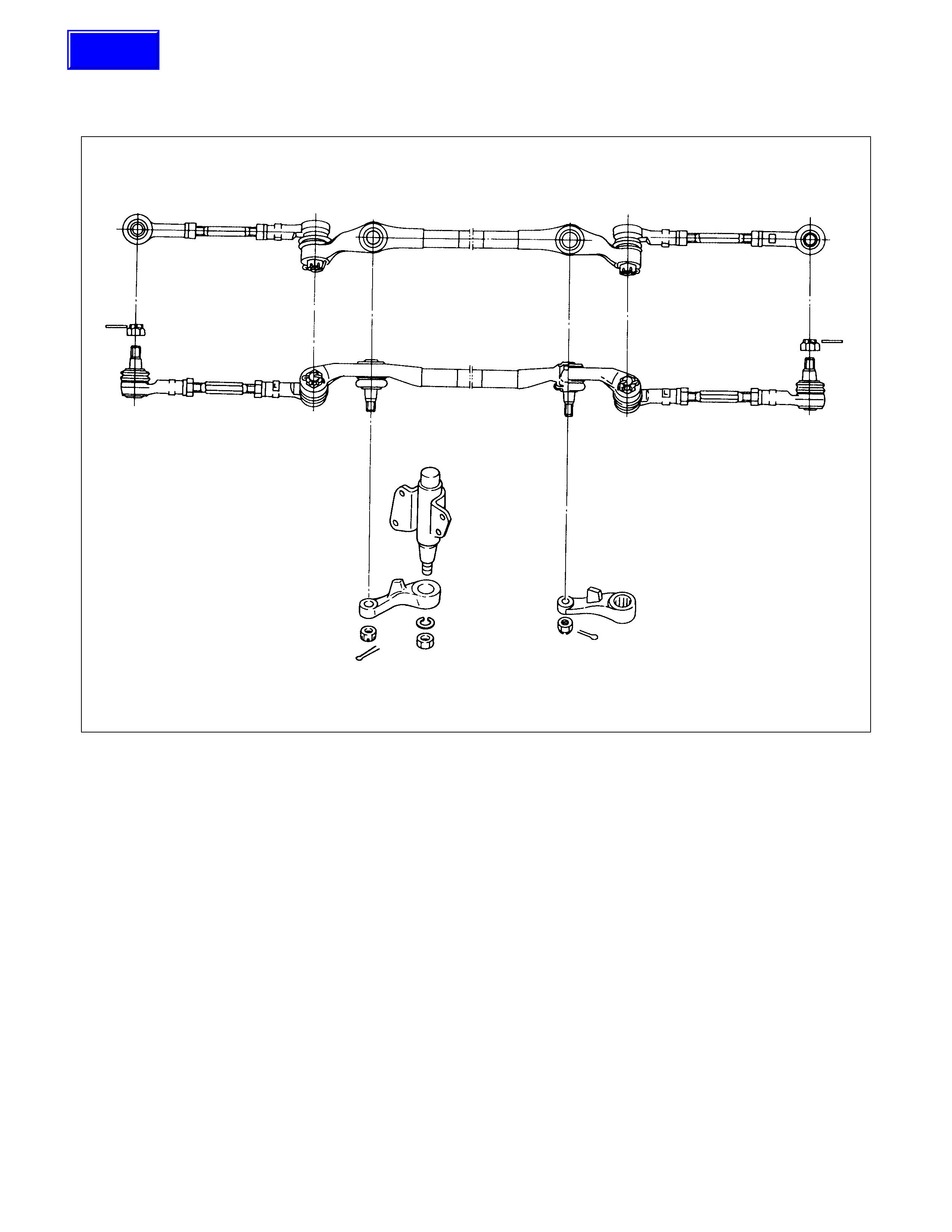
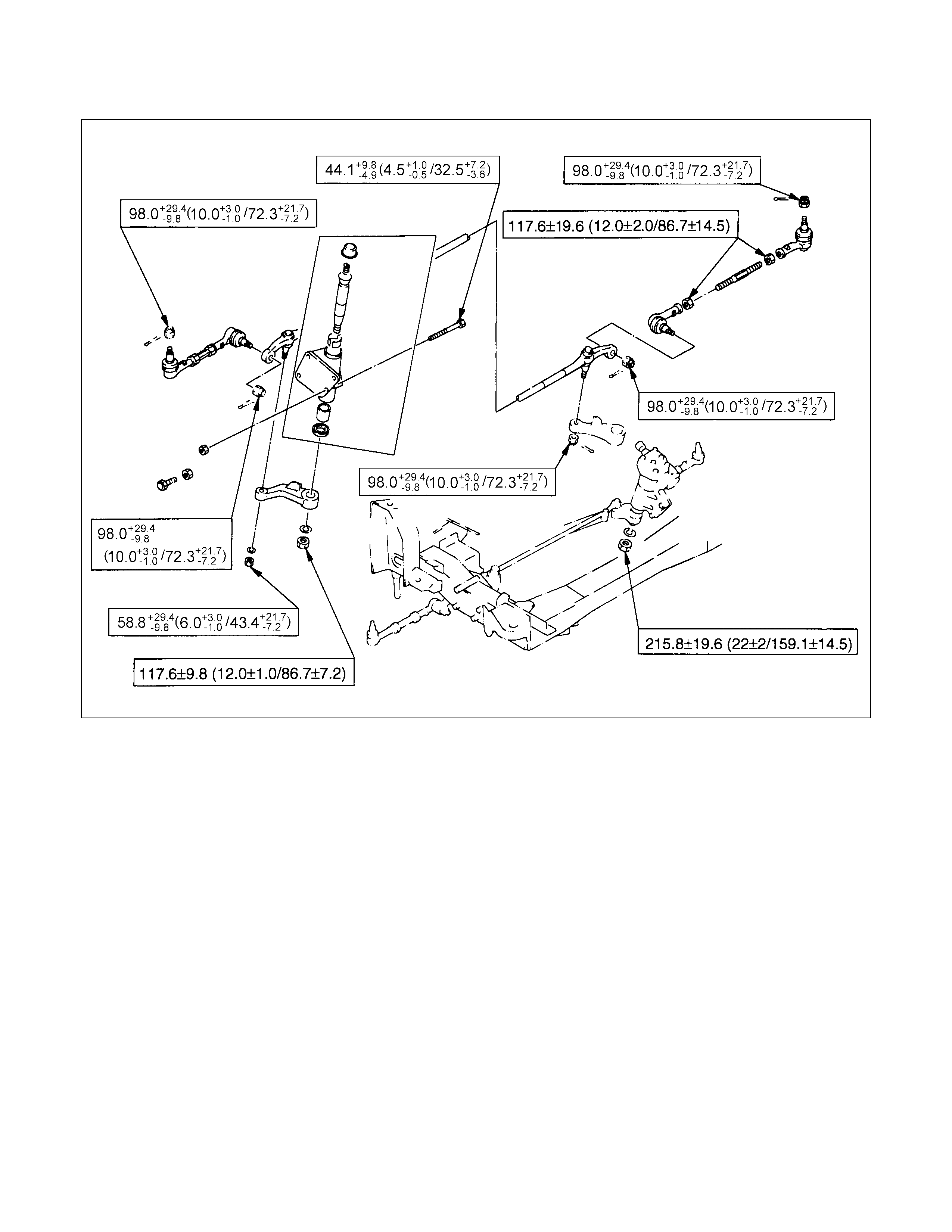
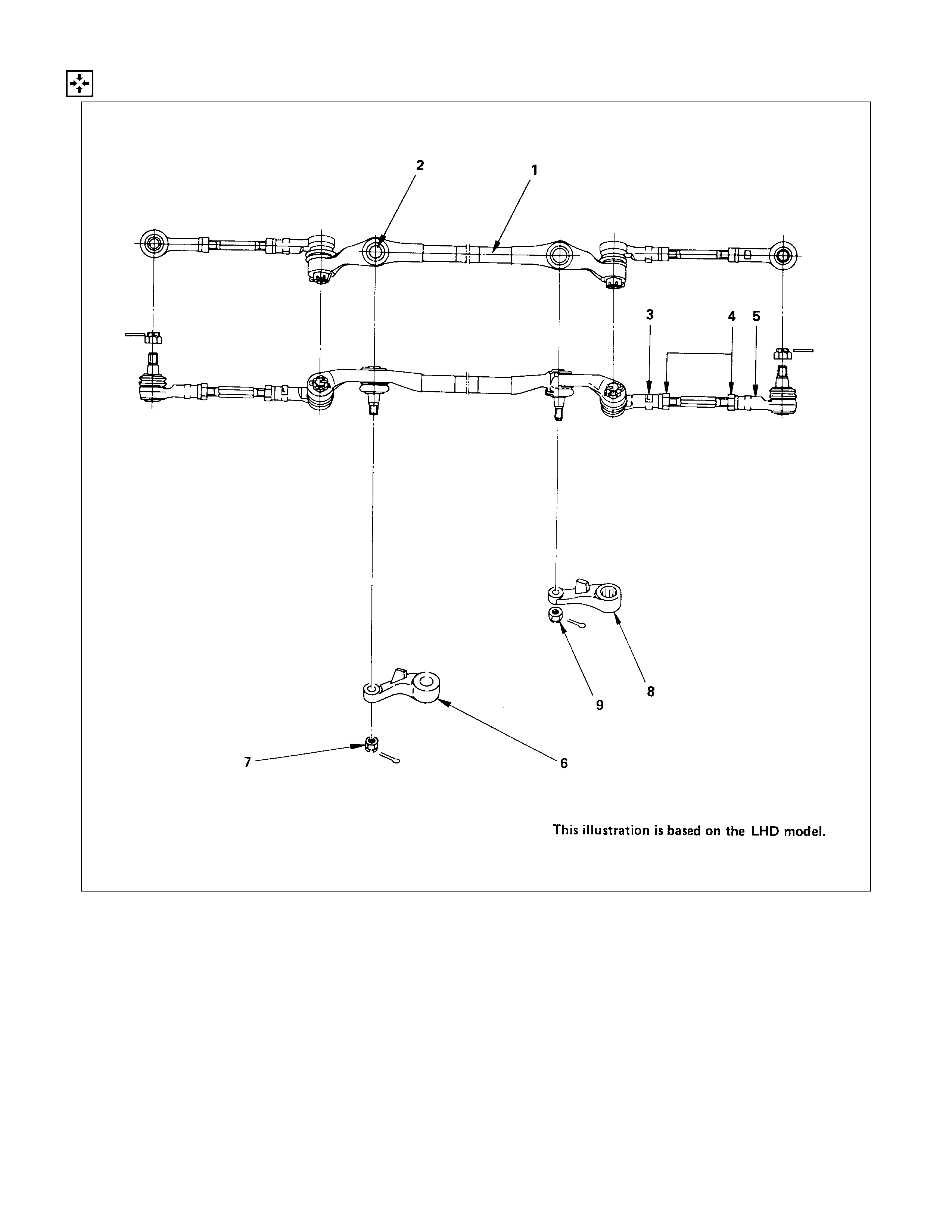
STEERING LINKAGE
GENERAL DESCRI PTION
Techline
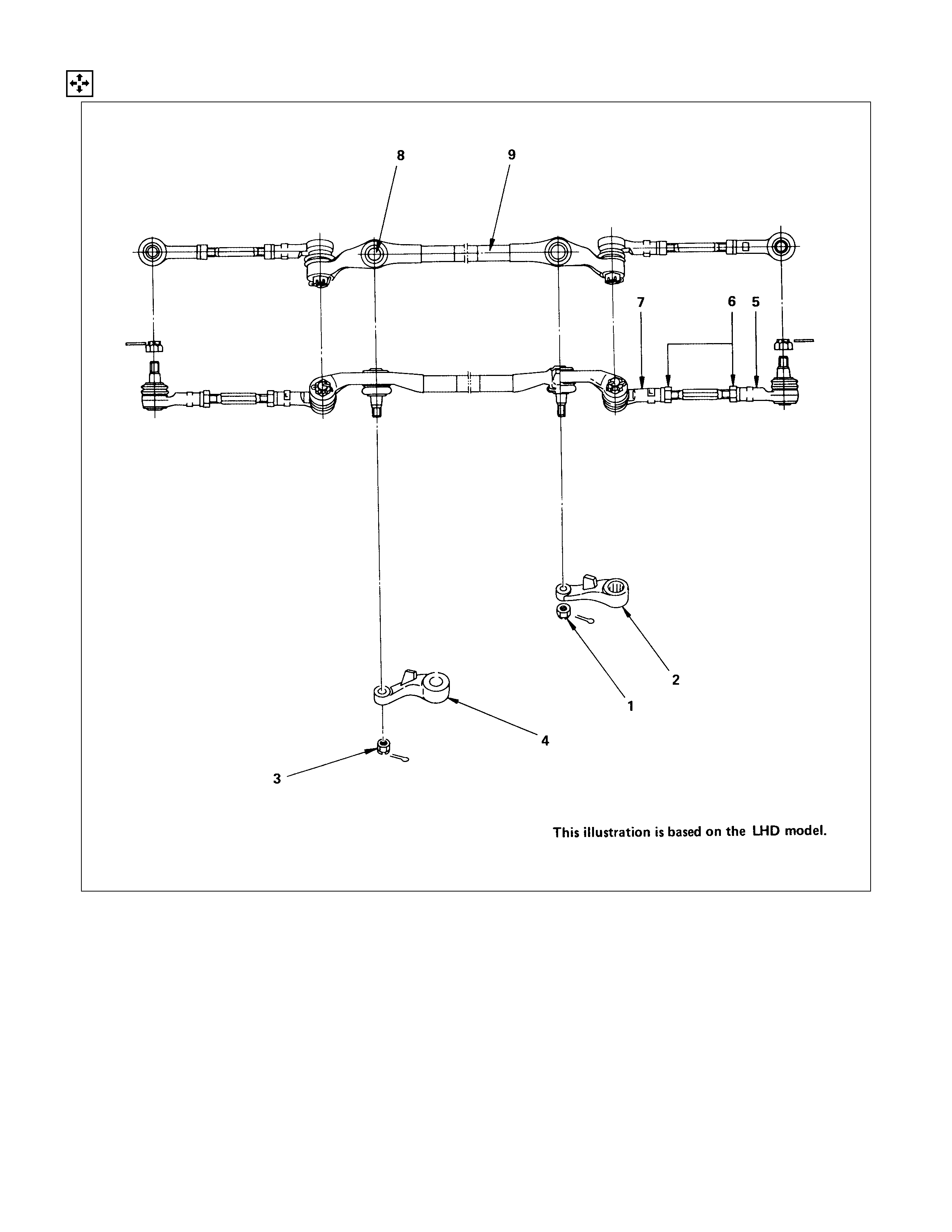
REMOVAL AND INSTALLATION
0 Except Europe and Thailand for 4J series and 6VD1 engine model
REMOVAL STEPS
1. Nut
2. Bolt
3. Steering damper
4. Nut
▲5. Nut ; pitman arm
▲6. Nut ; relay lever
▲7. Intermediate rod
INSTALLATION STEPS
7. Intermediate rod
▲6. Nut ; relay lever
▲5. Nut ; pitman arm
4. Nut
3. Steering damper
2. Bolt
▲1. Nut
5-8840-2017-0
IMPO RTANT OPERATIONS - REMOVAL
5., 6. Pitman Arm Nut and Relay Lever Nut
Remove relay lever or pitman arm to shafts nut and lock
washer. Remove the relay lever or pitman arm from the shaft
using remover.
Remover : 5-8840-2017-0
5-8840-2121-0
7. Outer Track Rod
Remove split pin from the ball stud connecting outer track rod
end. Remove the castellated nuts and disconnect the parts
using remover.
Tie Rod Remover : 5-8840-2121-0
IMPORTANT OPERATIONS - INSTALLATION
6. Nut ; Relay Lever
Relay Lever Nut Torque N⋅m (kgf⋅m/Ib⋅ft)
117.7±9.8 (12.0±1.0/86.8±7.2)
5. Nut ; Pitman Arm
Pitman Arm Nut Torque N⋅m (kgf⋅m/Ib⋅ft)
215.8±19.6 (22.0±2.0/159.2±14.5)
1. Nut
Steering Damper Torque N⋅m (kgf⋅m/Ib⋅ft)
39.2 +9.8
−4.9 (4.0 +1
−0.5 /28.9 +7.2
−3.6 )
DISASSEMBLY
DISASSEM BLY STEPS
1. Nut
2. Pitman arm
3. Nut
4. Relay lever
▲5. End assembly (outer)
6. Nut
▲7. End assembly (inner)
8. Pin assembly
9. Center track rod assembly
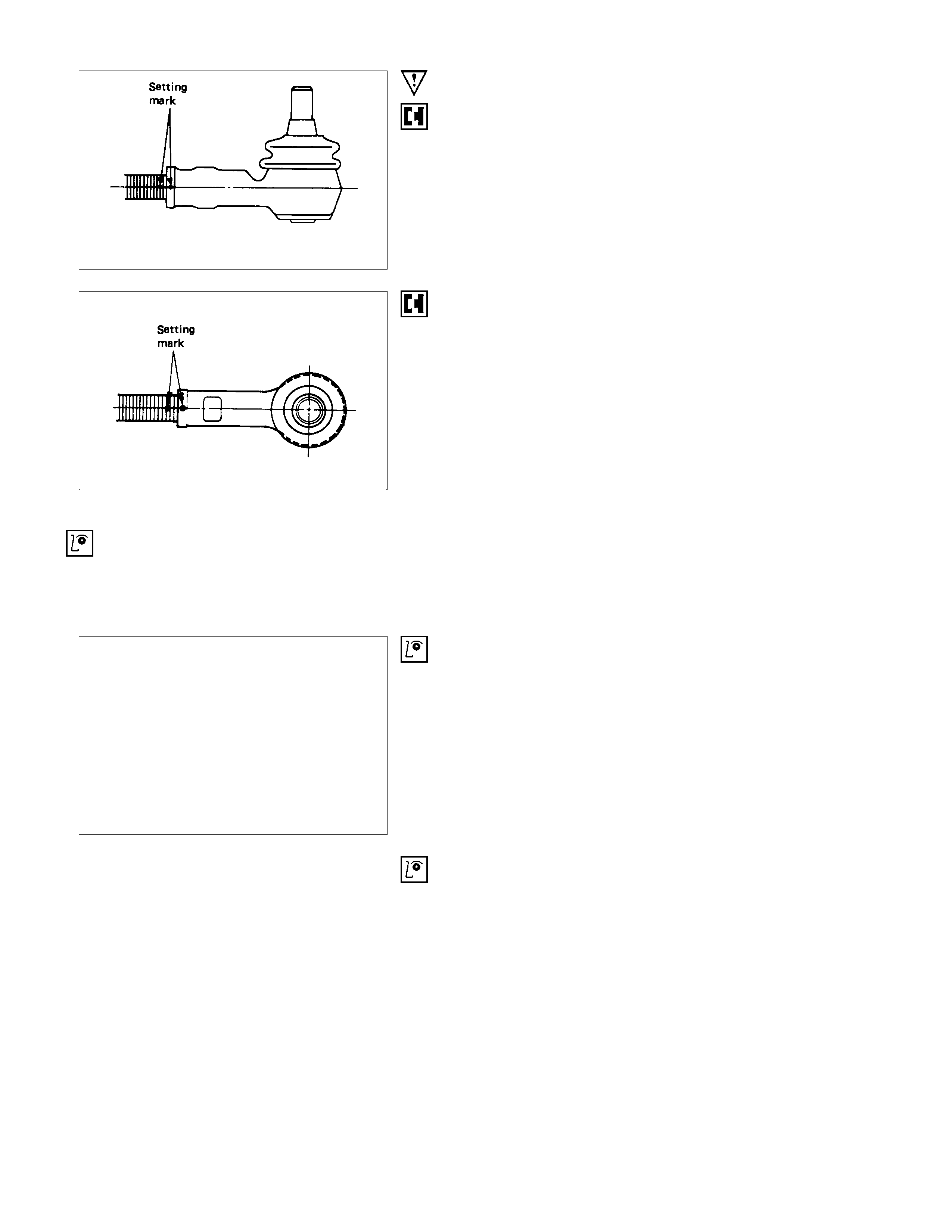
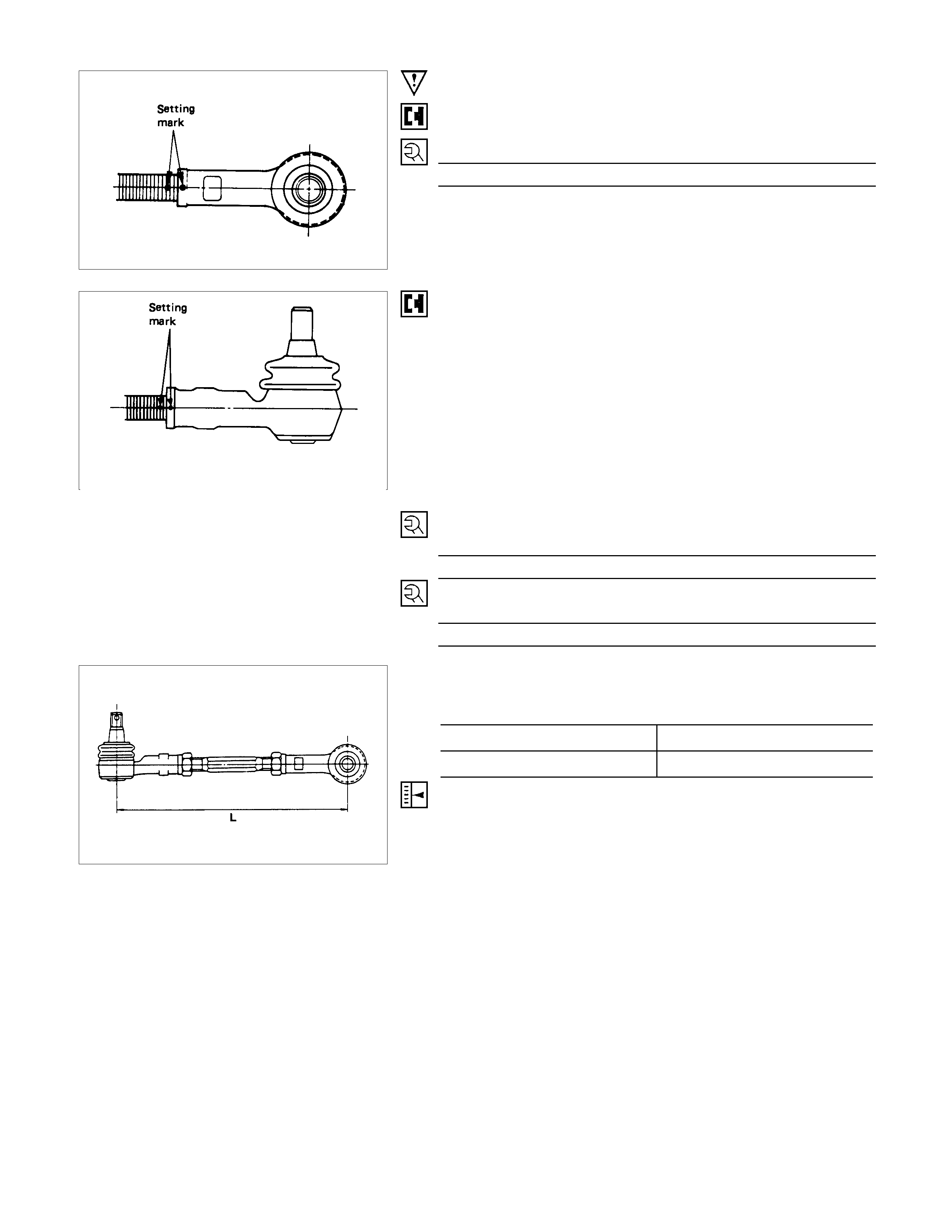
IMPORTANT OPERATIONS
5. End Assembly (Outer)
Apply the setting mark to reassemble the parts in their original
position.
7. End Assembly (Inner)
Apply the setting mark to reassemble the parts in their original
position.
INSPECTION AND REPAIR
Make all necessary adjustments, repairs, and part replacements if wear, damage, or other problems are discovered
during inspection.
• Pitman arm, relay lever
• End assembly, pin assembly
• Center track rod assembly
• Boot
VISUAL CHECK
Inspect the following parts for wear, damage or other abnormal
conditions.
BALL JOI NTS (CENTER TRACK ROD ASSEMBLY
AND OUTER TRACK ROD TRACK ROD ASSEMBLY)
Inspect the following.
If one or more of the abnormal conditions listed in parenthesis
is discovered during inspection, the entire track rod
assembly(s) must be replaced.
1. Ball joint boot (Tearing and grease leakage)
2. Ball joint (Rough movement)
The ball joint must move smoothly with no snagging.
3. Ball joint screws (Excessive damage)
4. Ball joint tapered surfaces (Excessive wear and damage)
REASSEMBLY
REASSEMBLY STEPS
1. Center track rod assembly
2. Pin assembly
▲3. End assembly (inner)
▲4. Nut
▲5. End assembly (outer)
6. Relay lever
▲7. Nut
8. Pitman arm
▲9. Nut
IMPORTANT OPERATIONS
3. End Asseembly (Inner)
Align the setting marks applied at the disassembly.
End Assembly Torque N⋅m (kgf⋅m/Ib⋅ft)
117.7±19.6 (12.0±2.0/86.8±14.5)
After tightening, stake the two portions securely.
5. End Assembly (Outer)
Align the setting marks applied during disassembly.
7. Nut
Relay Lever Nut Torque N⋅m (kgf⋅m/Ib⋅ft)
58.8+29.4
−9.8 (6.0+3
−1/43.4+21.7
−7.2 )
9. Nut
Pitman Arm Nut Torque N⋅m (kgf⋅m/lb⋅ft)
98.0+29.4
−9.8 (10+3
−1/72.3+21.7
−7.2 )
Note :
When change the track rod, adjust the track rod length.
mm (in)
4×2 (except Sporty) 306.9±1.5 (12.08±0.059)
4×4 and 4×2 Sporty 262±1.5 (10.31±0.059)
ADJUSTMENT
Adjust the toe-in angle.
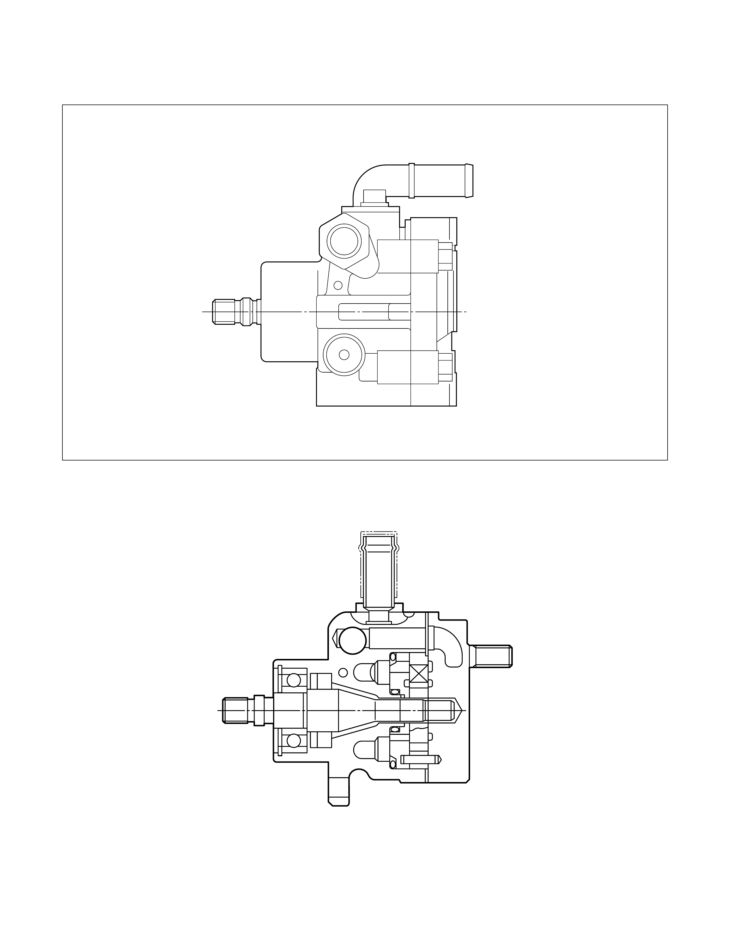
POWER STEERING OIL PUMP
GENERAL DESCRI PTION
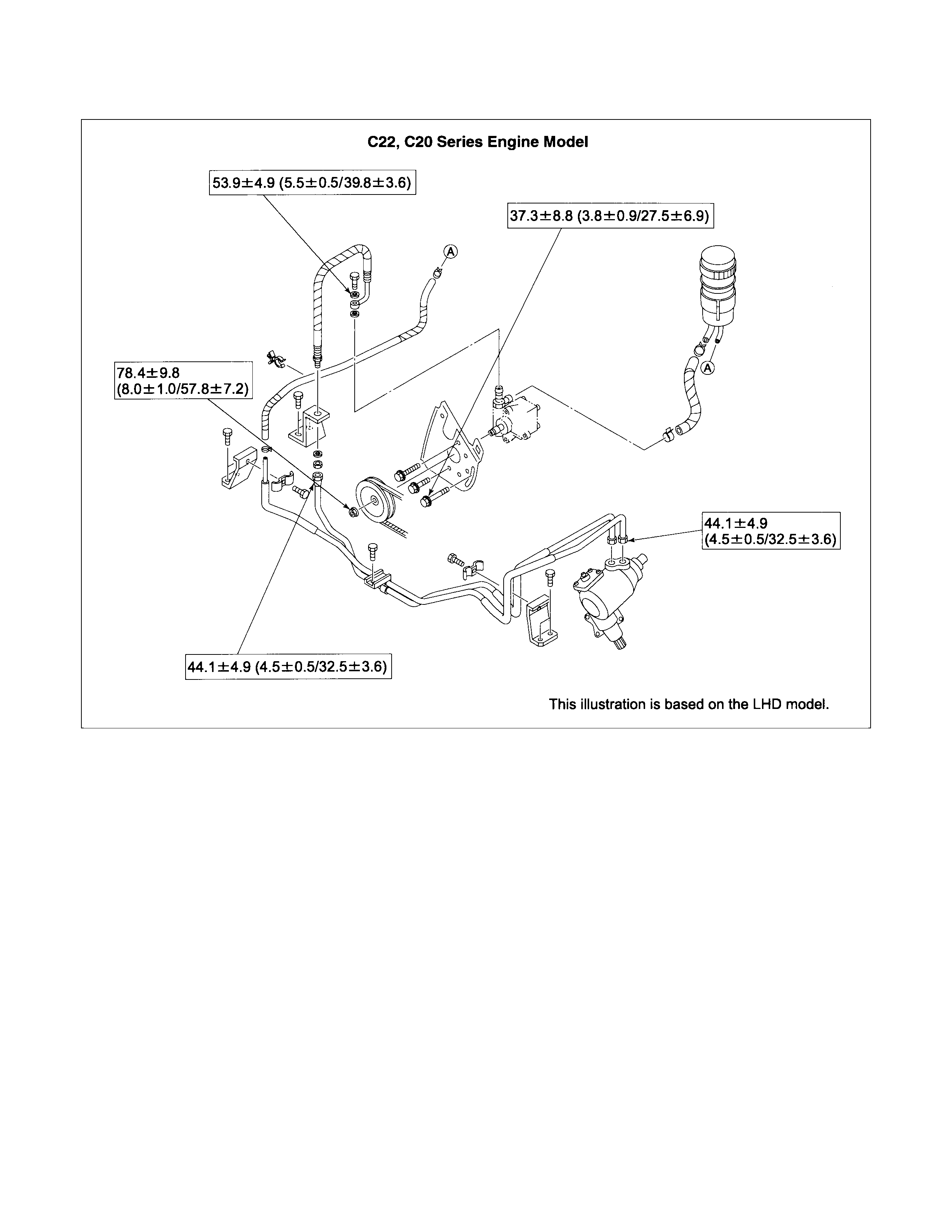
C22, C20 Series Engine Model
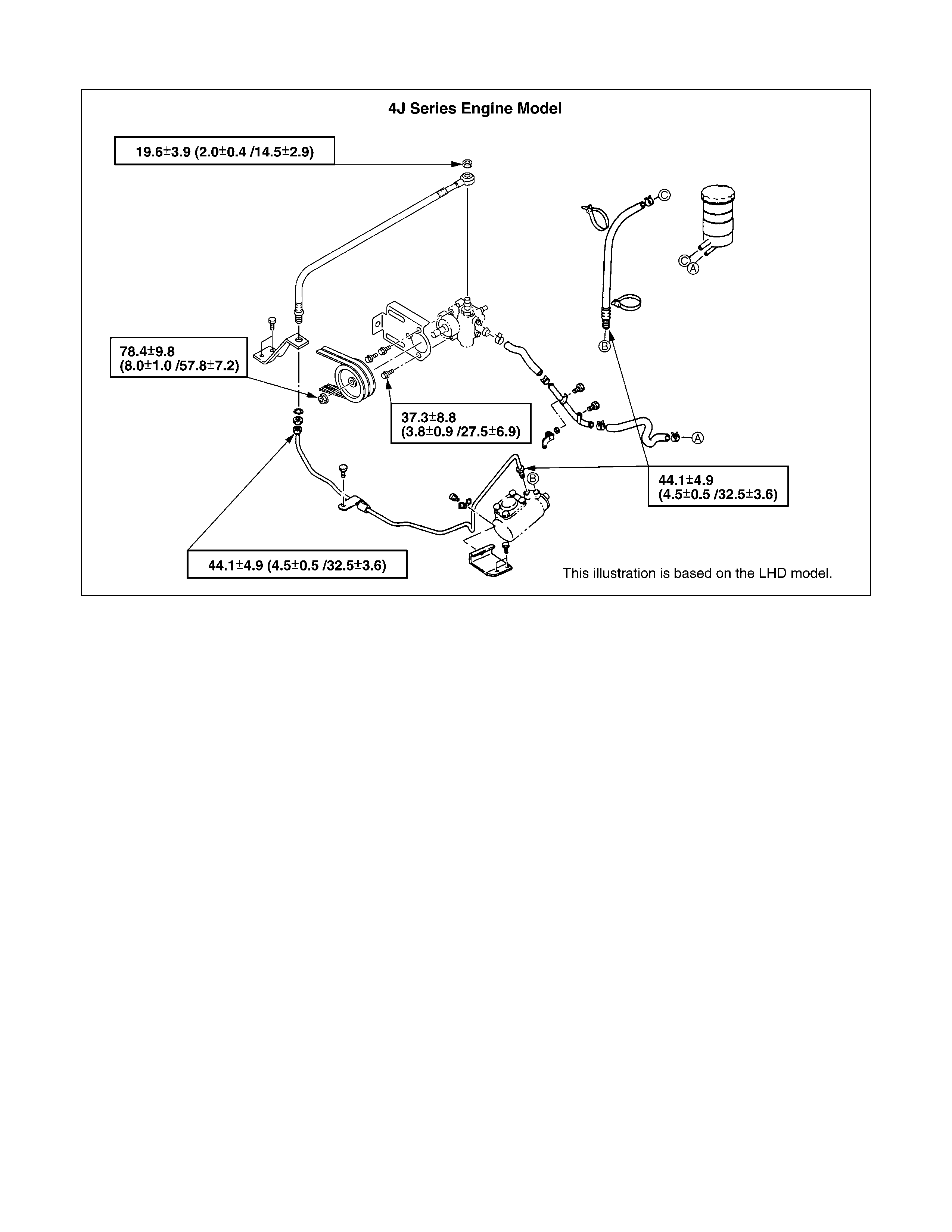
4J Series Engine Model
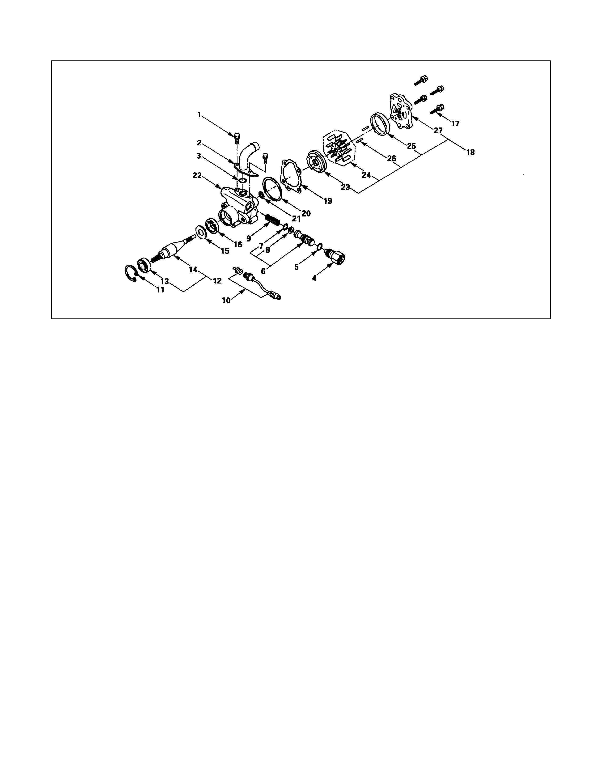
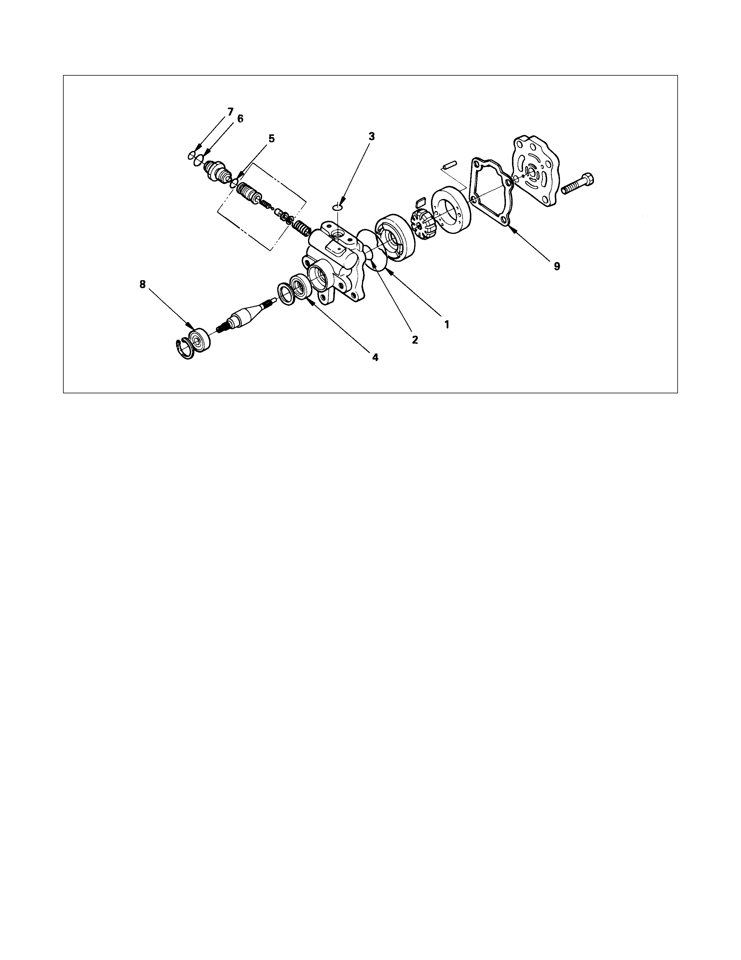
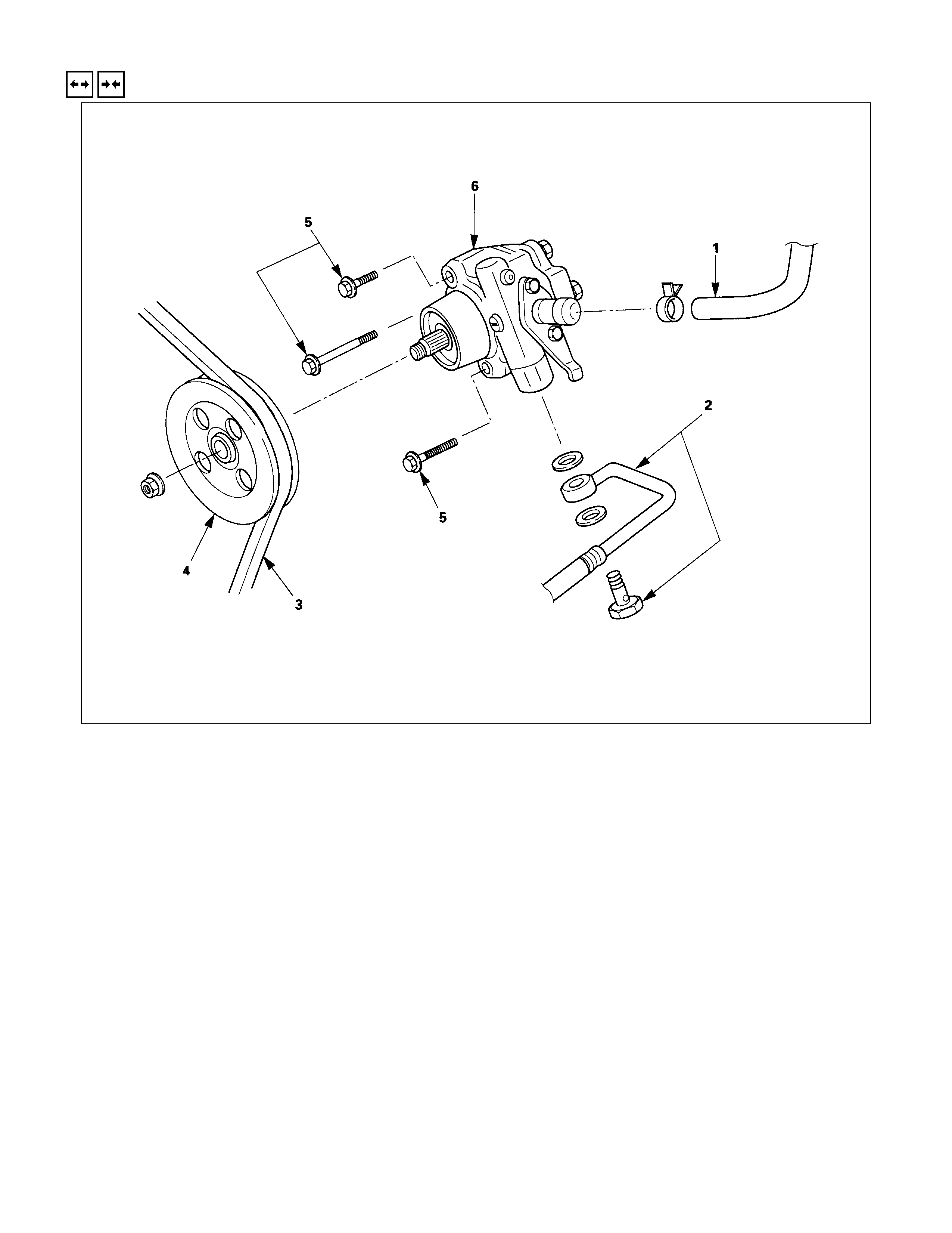
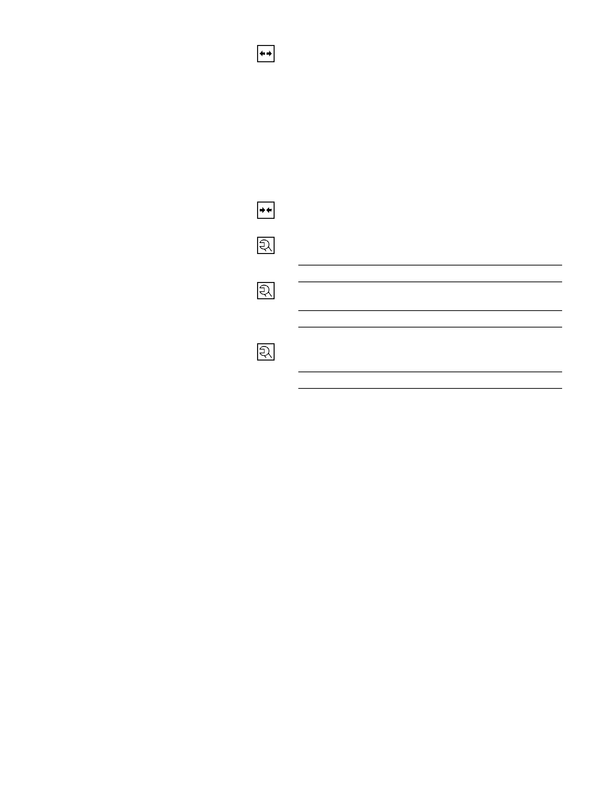
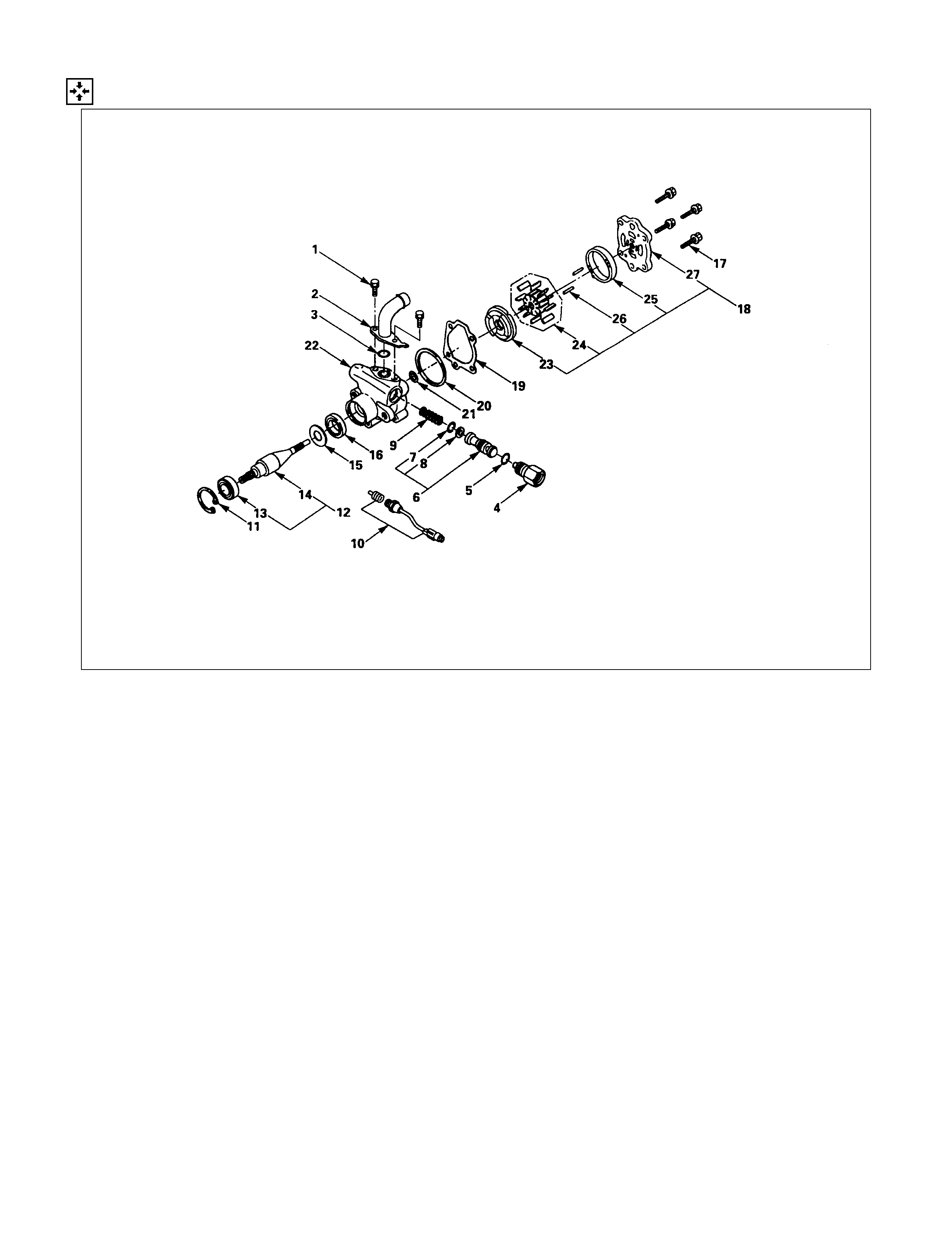
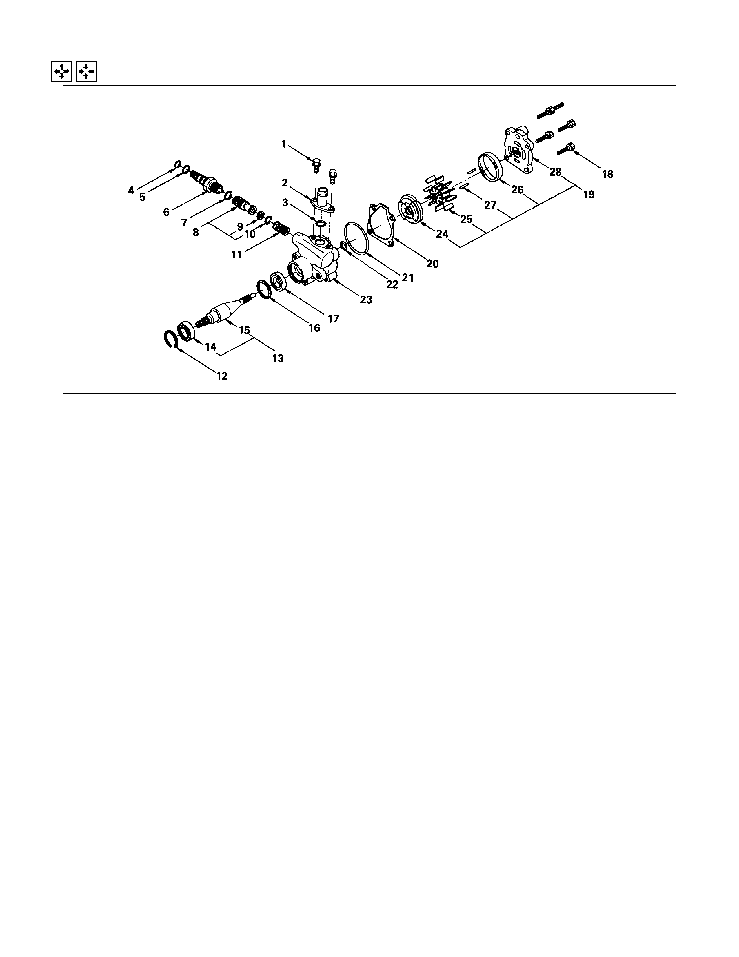
REPAIR KI T (C22, C20 SERIES ENGINE MO DEL)
LEGEND
1. Bolt
2. Suction Pipe
3. O-ring
4. Connector
5. O-ring
6. Valve
7. Retaining Ring
8. Filter
9. Spring
10. Pressure Switch
11. Retaining Ring
12. Shaft assembly
13. Bearing
14. Shaft
15. Retaining Ring
16. Oil Seal
17. Bolt
18. Rear Housing Assembly and Pump
Cartridge
19. Gasket
20. O-ring
21. O-ring
22. Front Housing
23. Pressure Plate
24. Rotor and Vane
25. Cam
26. Pin
27. Rear Housing
REPAIR KI T
3. O-ring
5. O-ring
13. Bearing
16. Oil Seal
19. Gasket
20. O-ring
21. O-ring
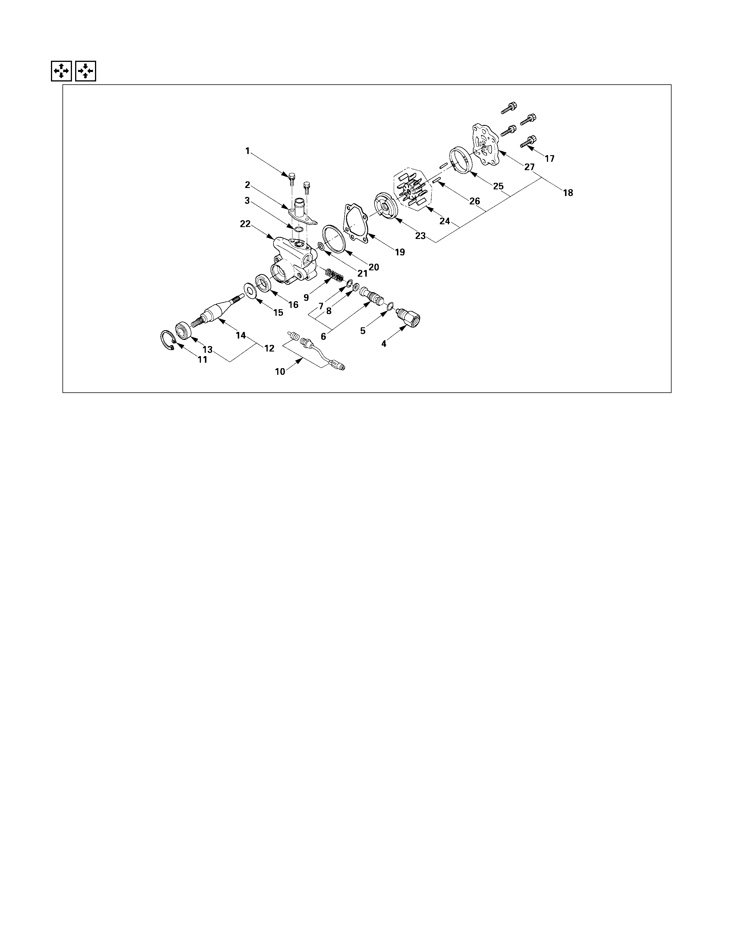
REPAIR KI T (4J SERI ES ENGINE MODEL)
1. O-ring
2. O-ring
3. O-ring
4. Oil seal
5. O-ring
6. O-ring
7. O-ring
8. Bearing
9. Gasket
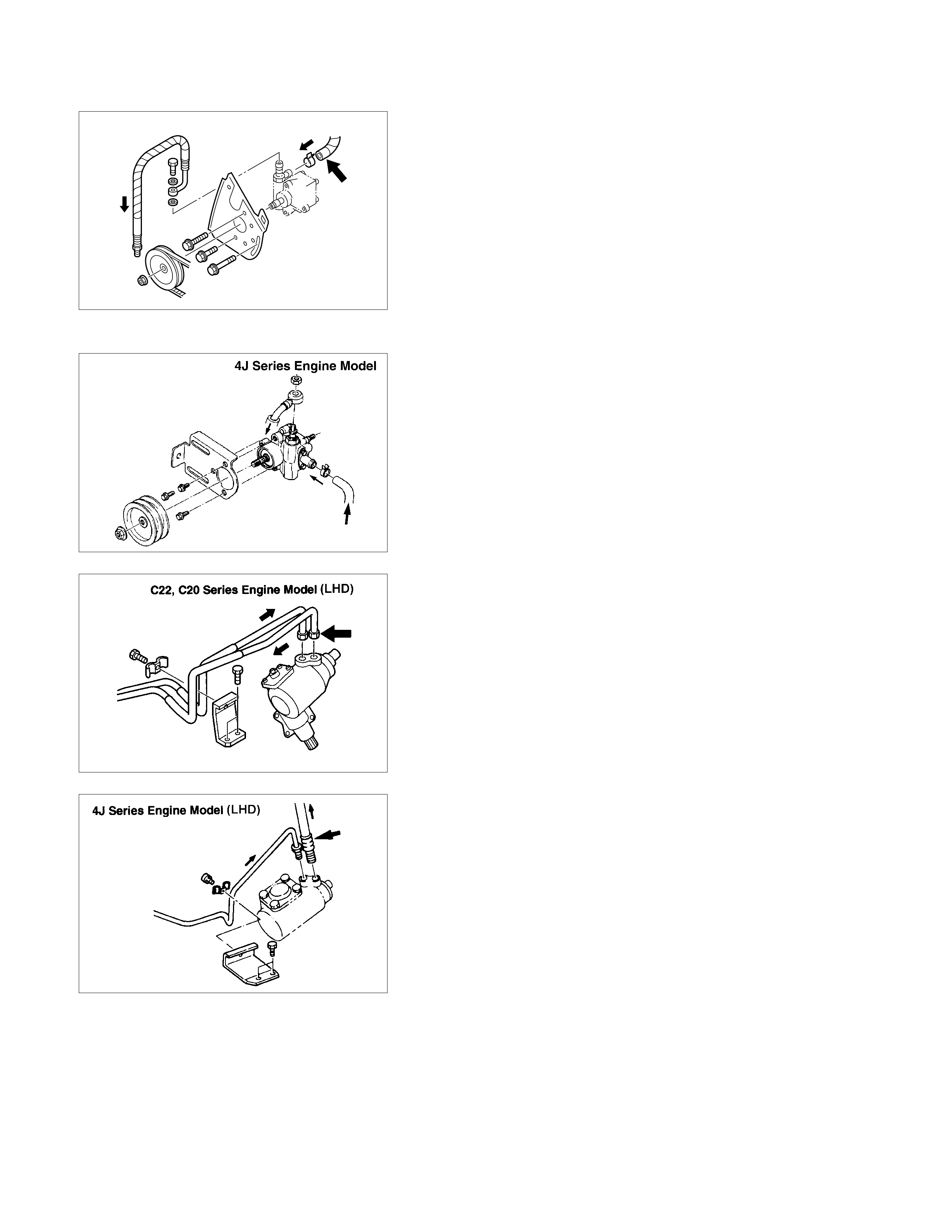
REMOVAL AND INSTALLATION (C22, C20 SERIES ENGINE MODEL)
3
6
1
4
5
2
REMOVAL STEPS
1. Belt : oil pump
2. Hose : rubber, suction
3. Hose : flexible
4. Bolts
5. Pump assembly : oil
6. Pulley : oil pump
INSTALLATION STEPS
To install follow the removal procedure in
reverse order
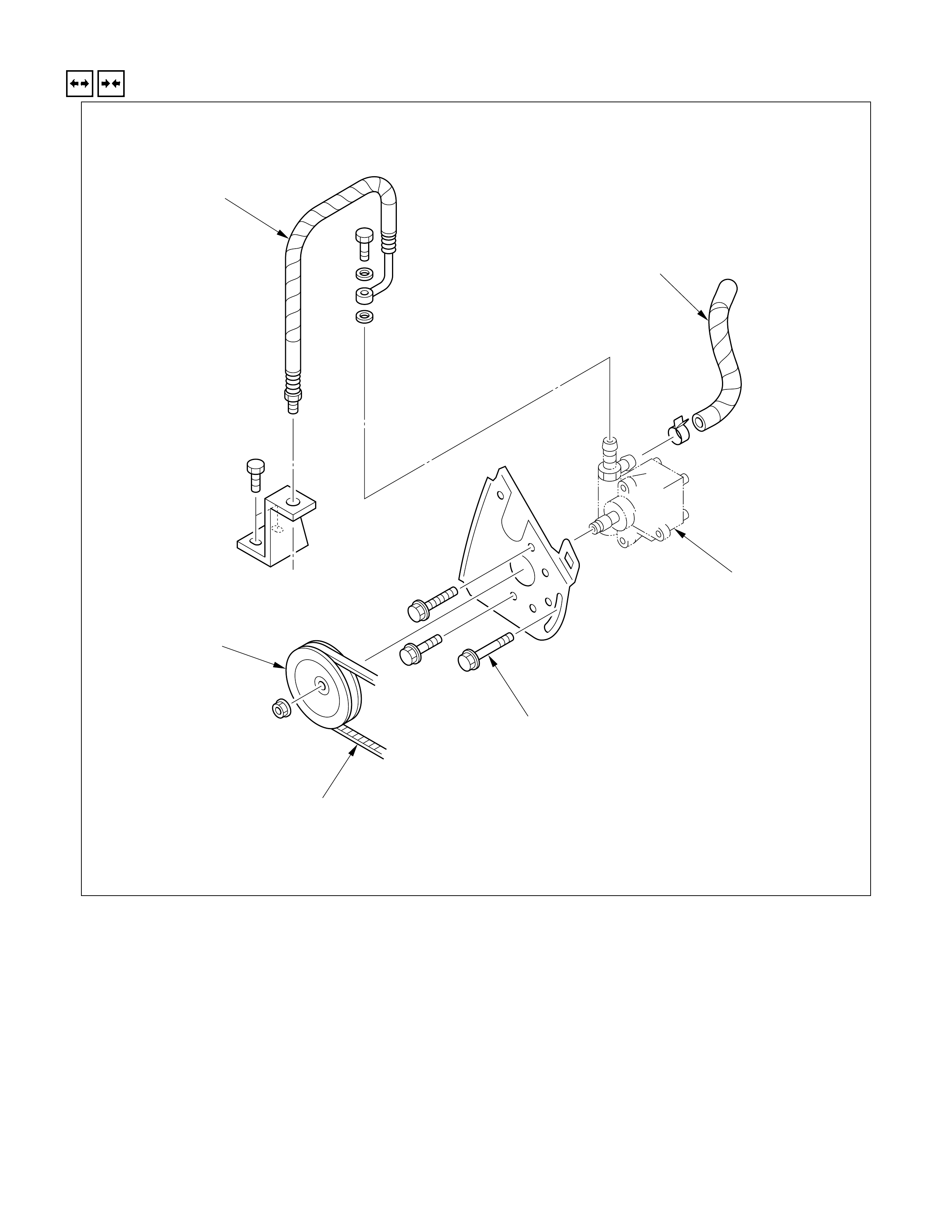
REMOVAL AND INSTALLATION (4J SERIES ENGINE MODEL)
REMOVAL STEPS
1. Hose, suction
2. Hose, flexible
3. Adjust nut
4. Bolt
5. Adjust bolt
6. Belt
7. Bracket
8. Pulley
9. Bolt
10. Bracket
11. Pump assembly
INSTALLATION STEPS
11. Pump assembly
10. Bracket
9. Bolt
8. Pulley
7. Bracket
6. Belt
5. Adjust bolt
4. Bolt
3. Adjust nut
2. Hose, flexible
1. Hose, suction
REMOVAL
Preparation:
•Place a drain pan below the pump.
1. Hose, Suction
2. Hose, Flexible
3. Adjust Nut
4. Bolt
5. Adjust Bolt
6. Belt
7. Bracket
8. Pulley
9. Bolt
10. Bracket
11. Pump A ssembly
INSTALLATION
11. Pump A ssembly
10. Bracket
9. Bolt
Bolt Torque N⋅m (kgf⋅m / lb⋅ft)
37 (3.8 / 27)
8. Pulley
Pulley Nut Torque N⋅m (kgf⋅m / lb⋅ft
)
78.4±9.8 (8.0±1.0/ 57.8±7.2)
7. Bracket
6. Belt
5. Adjust Bolt
4. Bolt
After adjusting drive belt tension, tighten bolt to specified
torque.
Bracket Bolt Torque N⋅m (kgf⋅m / lb⋅ft)
37 (3.8 / 27)
3. Adjust Nut
After adjusting drive belt tension, tighten bolt to specified
torque.
Adjust Nut Torque N⋅m (kgf⋅m / lb⋅ft
)
37 (3.8 / 27)
2. Hose Flexible
Hose, Nut Torque N⋅m (kgf⋅m / lb⋅ft)
19.6±3.9 (2.0±0.4/14.5±2.9)
1. Hose, Suction
Fill and bleed the system. Refer to "Bleeding the Power
Steering System" in this section.
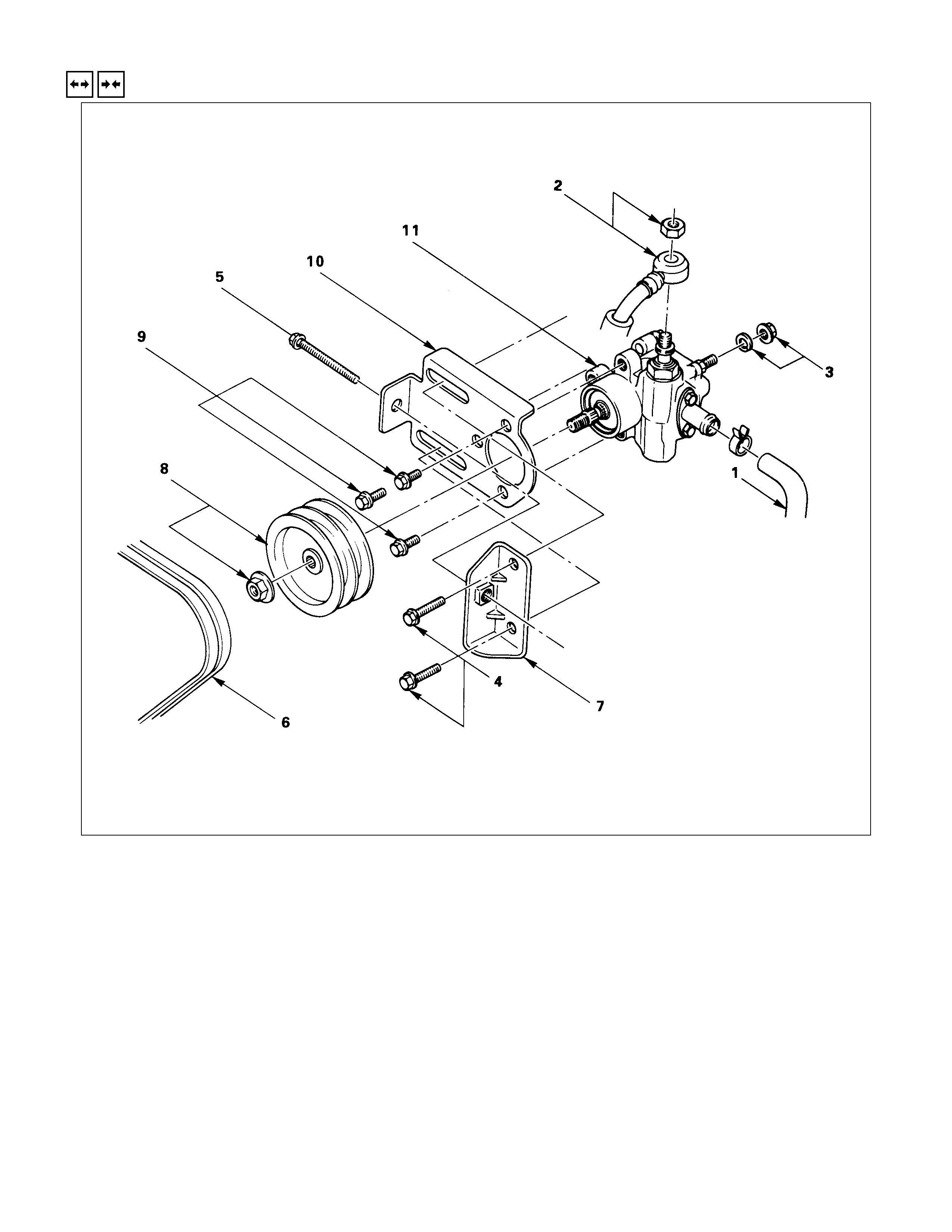
REMOVAL AND INSTALLATION (6VD1 ENGINE MODEL)
REMOVAL STEPS
1. Hose, suction
2. Hose, flexible
3. Belt
4. Pulley
5. Bolt
6. Pump assembly
INSTALLATION STEPS
6. Pump assembly
5. Bolt
4. Pulley
3. Belt
2. Hose, flexible
1. Hose, suction
REMOVAL
Preparation:
•Place a drain pan below the pump.
1. Hose, Suction
2. Hose, Flexible
3. Belt
4. Pulley
5. Bolt
6. Pump A ssembly
INSTALLATION
6. Pump A ssembly
5. Bolt
Bolt Torque N⋅m (kgf⋅m / lb⋅ft)
46 (4.7 / 34)
4. Pulley
Pulley Nut Torque N⋅m (kgf⋅m / lb⋅ft
)
78.4±9.8 (8±1/ 57.8±7.2)
3. Belt
2. Hose, Flexible
Hose, Bolt Torque N⋅m (kgf⋅m / lb⋅ft
)
53.9±4.9 (5.5±0.5 / 39.8±3.6)
1. Hose, Suction
Fill and bleed the system. Refer to "Bleeding the Power
Steering System" in this section.
DISASSEM BLY ( C22, C20 SERIES ENGINE MODEL)
DISASSEM BLY STEPS
1. Bolt
2. Suction Pipe
3. O-ring
4. Connector
5. O-ring
6. Valve
7. Retaining ring
8. Filter
9. Spring
10. Pressure switch
▲11. Retaining ring
▲12. Shaft assembly
▲13. Bearing
14. Shaft
15. Retaining ring
▲16. Oil seal
17. Bolt
18. Rear housing assembly and pump
cartridge
19. Gasket
20. O-ring
21. O-ring
22. Front housing
23. Pressure plate
24. Rotor and vane
25. Cam
26. Pin
27. Rear housing
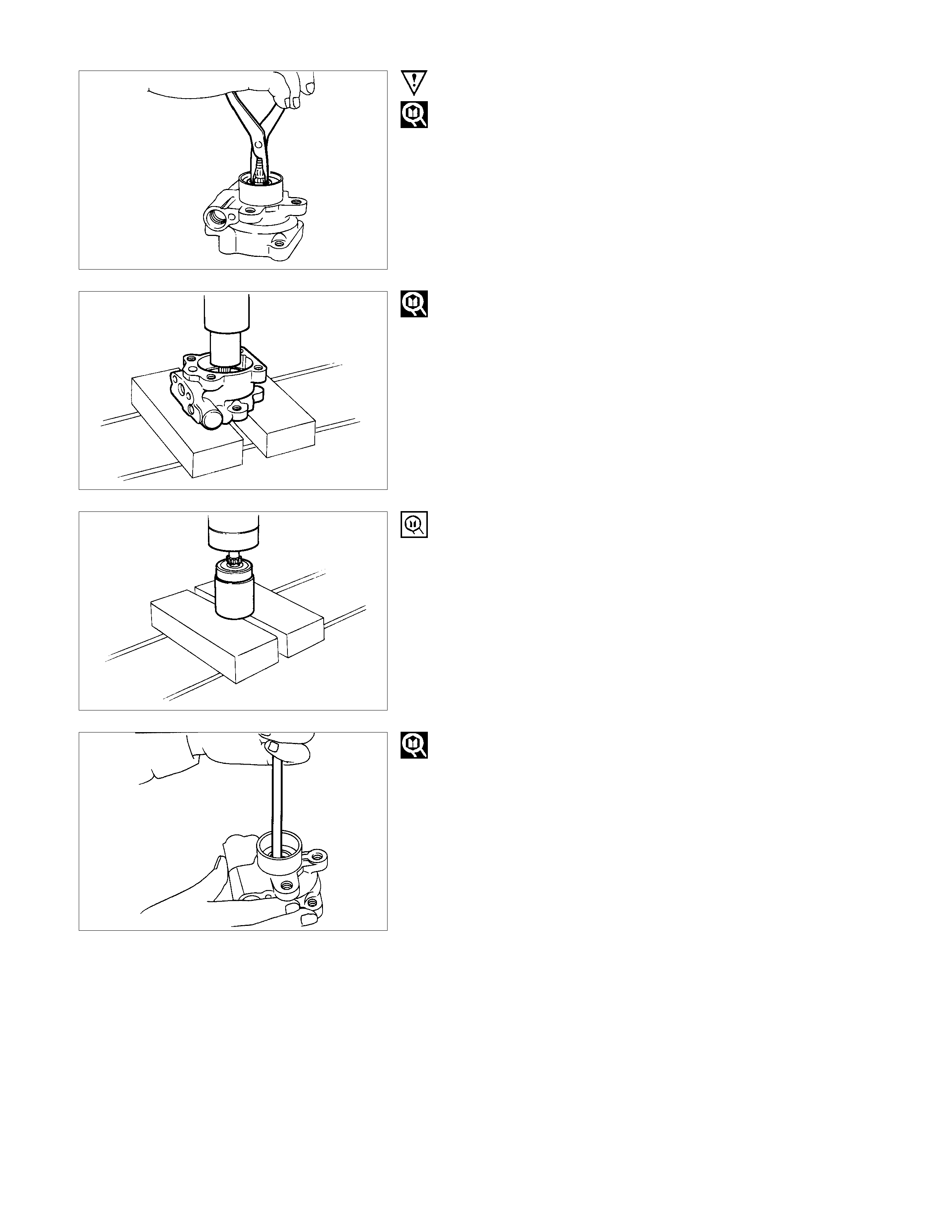
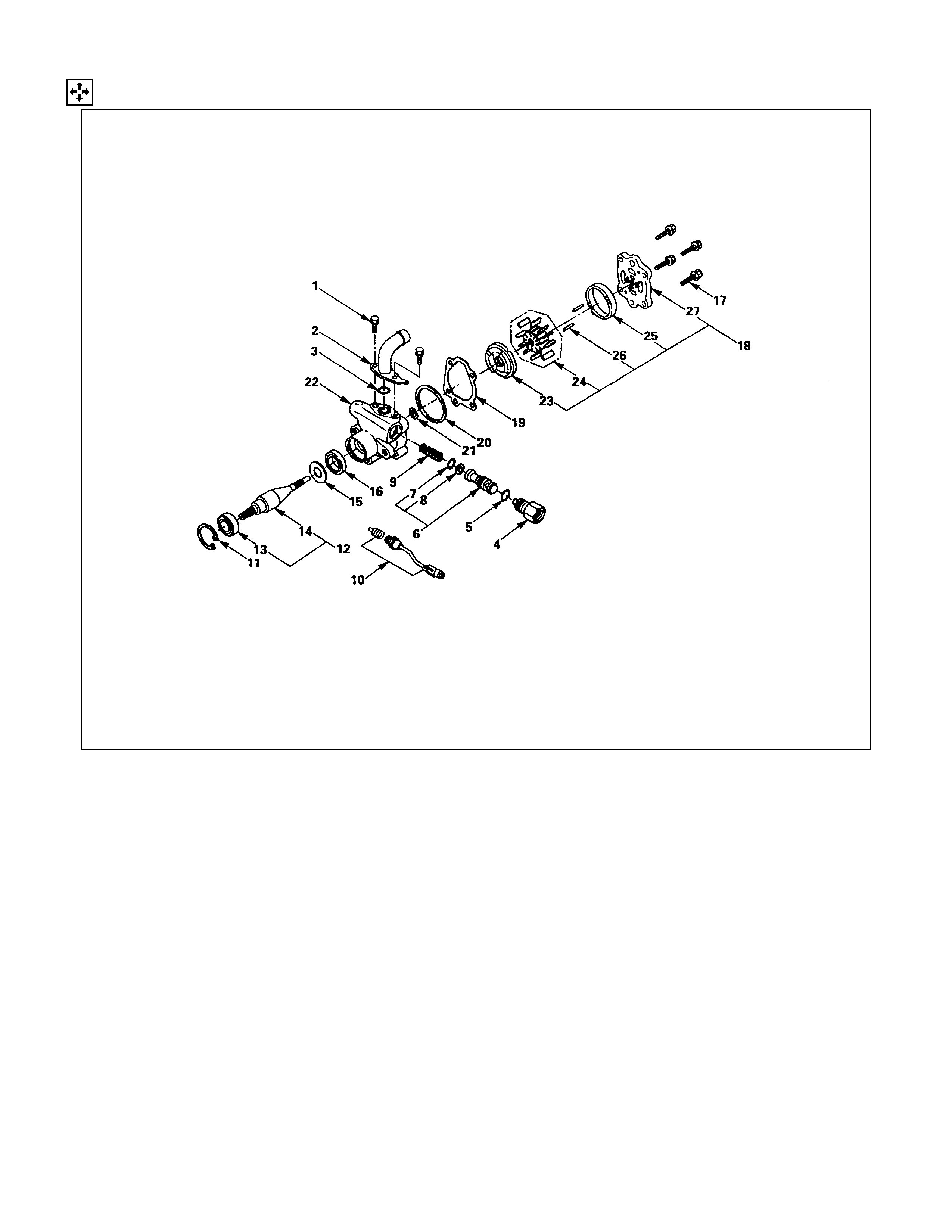
IMPORTANT OPERATIONS
11.Snap Ring
Use a pair of snap ring pliers to remove the snap ring.
12.Shaft
Use a bench press to slowly force the shaft from the rear cover
side.
Note :
Take care not to damage the end of the shaft when
removing the shaft.
13.Bearing
Use the bench press and bearing remover.
Bearing Remover : 5-8840-2206-0
Note :
Take care not to damage the shaft when removing the
shaft.
16.Oil Seal
Use a suitable bar.
INSPECTION AND REPAIR (C22, C20 SERIES ENGINE MODEL)
Make all necessary adjustments, repairs, and part replacements if wear, damage, or other problems are discovered
during inspection.
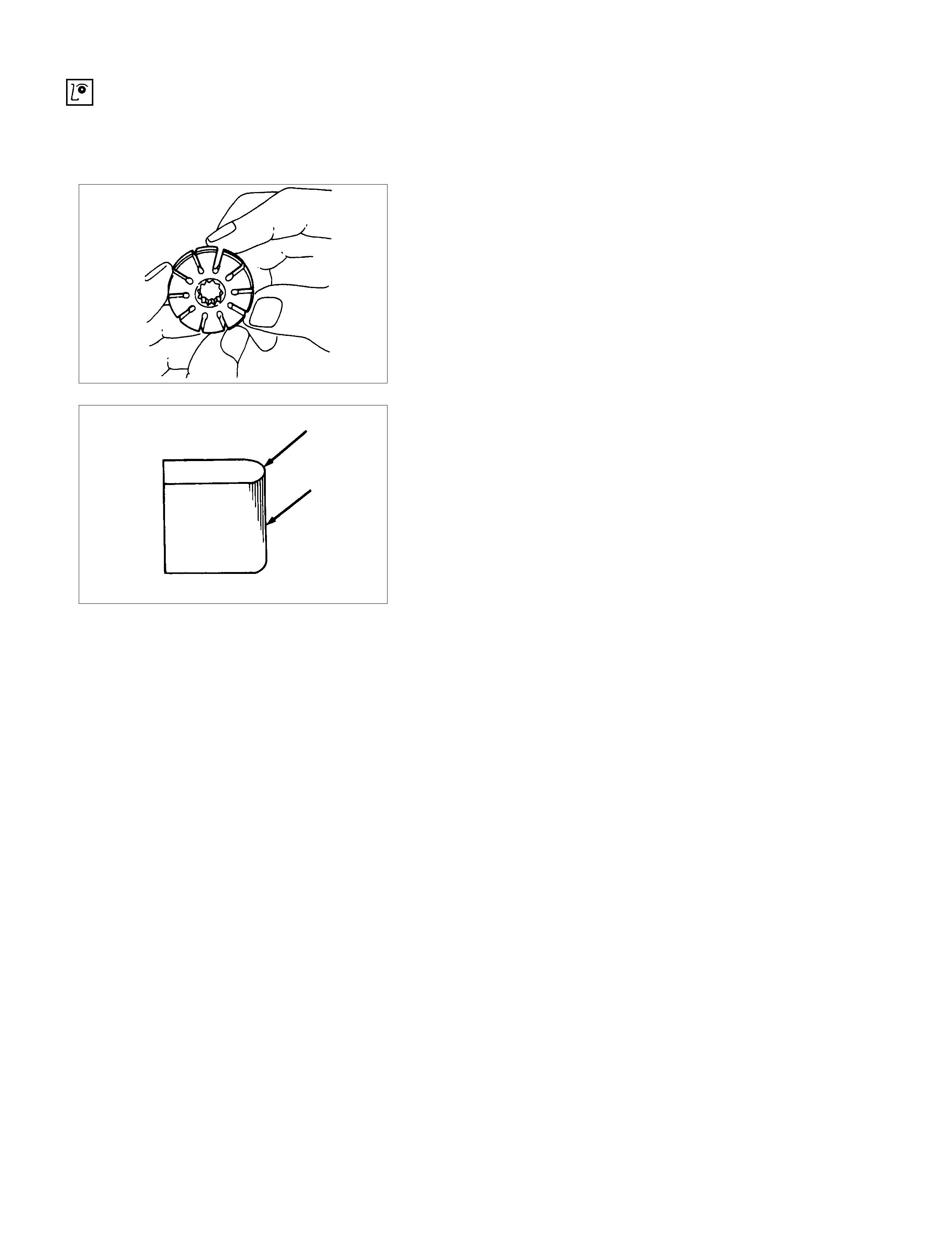
ROTOR
Check that the groove in the vane is free from excessive wear
and that the vane slides smoothly.
When part replacement becomes necessary, the pump
cartridge should preferably be replaced as a sub assembly.
VANE
Sliding faces of the vane should be free from wear.
(particularly the curved face at the tip in contact with the cam
should be free from wear and distortion.)
When part replacement becomes necessary, the pump
cartridge should preferably be replaced as a sub assembly.
CAM
The inner face of the cam should have a trace of uniform
contact without a sign of step wear.
When part replacement becomes necessary, the pump
cartridge should preferably be replaced as a sub assembly.
PRESSURE PLATE AND THRUST PLATE
The sliding faces of the parts must be free from step wear
(more than 0.01 mm) which can be felt by the finger nail.
The parts with minor scores may be reused after lapping the
face.
SHAFT
Oil seal sliding faces must be free from a step wear which can
be felt by the finger nail.
REASSEMBLY ( C22, C20 SERIES ENGINE MODEL)
REASSEMBLY STEPS
1. Rear housing
2. Pin
3. Cam
4. Rotor and vane
▲5. Pressure plate
6. Front housing
7. O-ring
8. O-ring
9. Gasket
10. Rear housing assembly and pump
cartridge
▲11. Bolt
▲12. Oil seal
13. Retaining ring
14. Shaft
15. Bearing
▲16. Shaft assembly
▲17. Retaining ring
18. Pressure switch
19. Spring
20. Filter
21. Retaining ring
22. Valve
23. O-ring
▲24. Connector
25. O-ring
26. Pipe, suction
27. Bolt
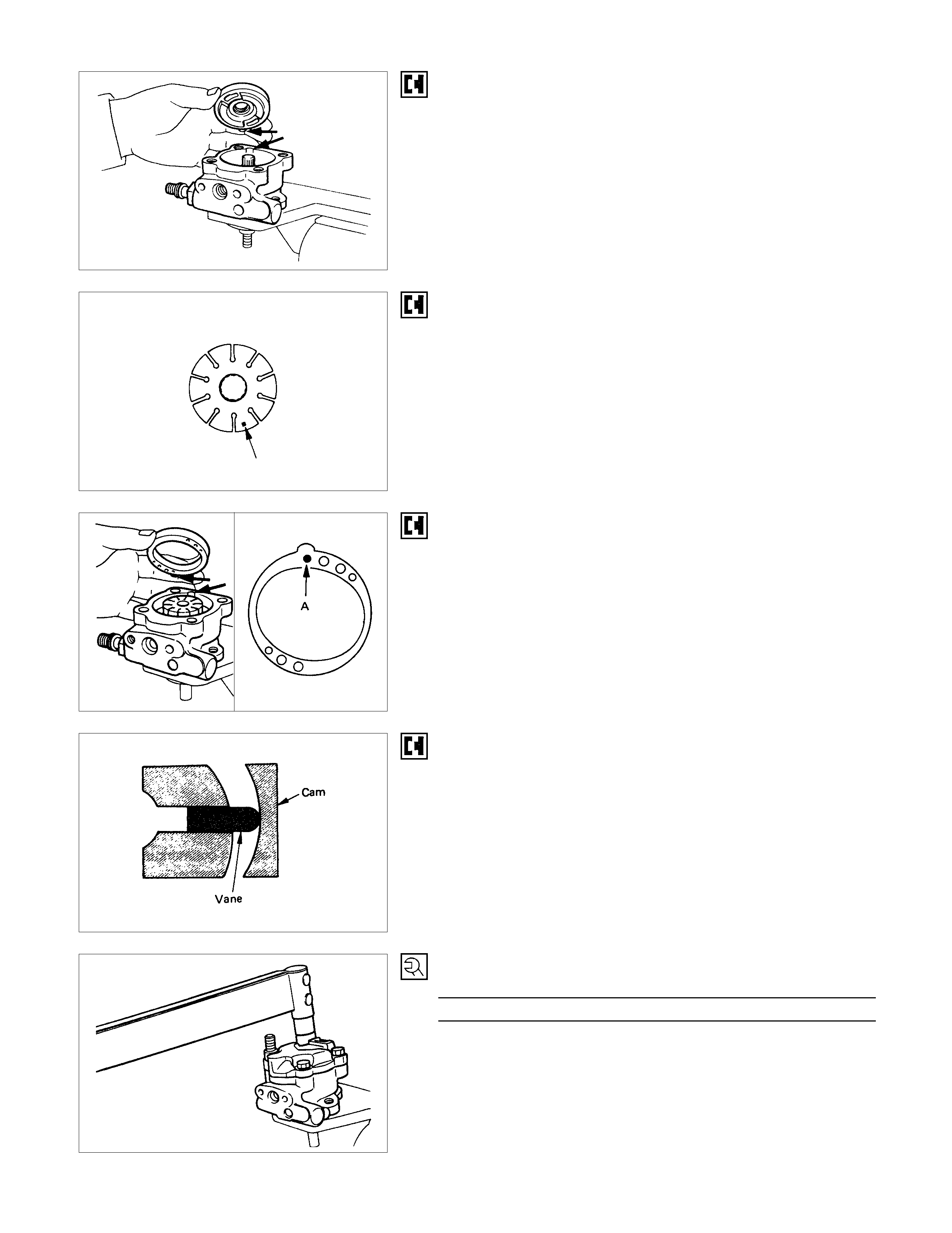
5. Pressure Plate
When installing the pressure plate, align the projection of
pressure plate with the grove of oil pump body.
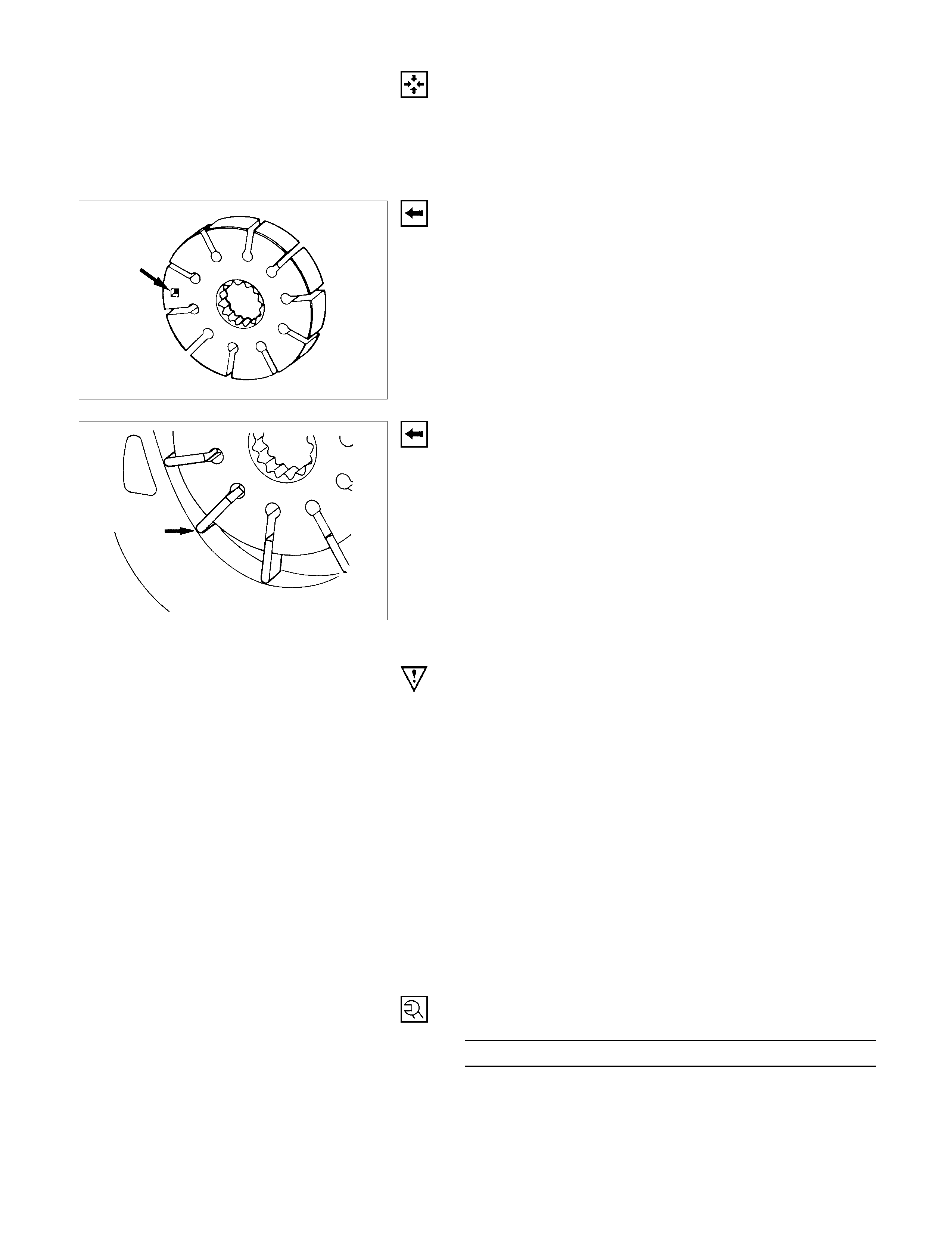
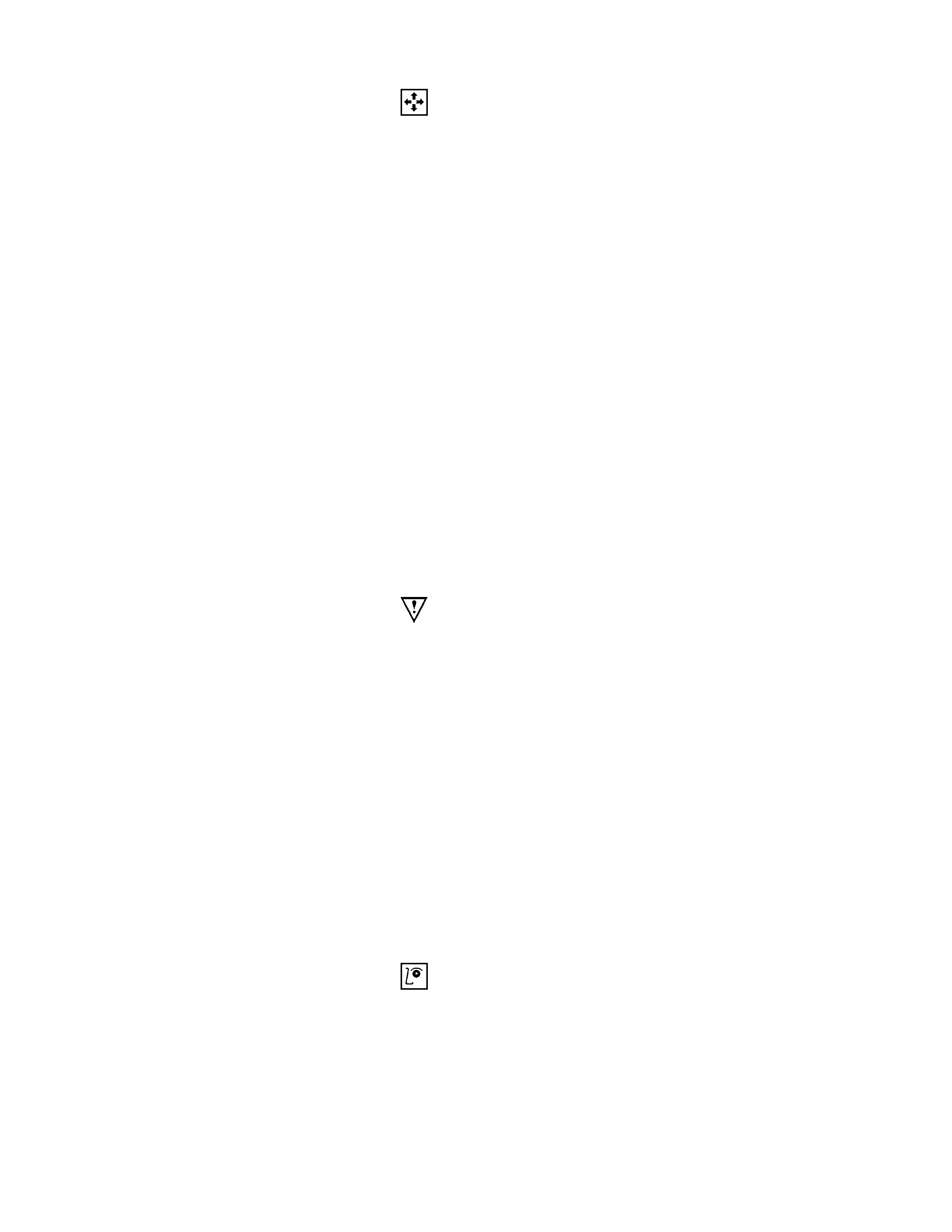
ROTOR
Place the rotor so that specified mark ■ turns down.
Note :
When part replacement becomes necessary, the pump
cartridge should be replaced as a sub assembly.
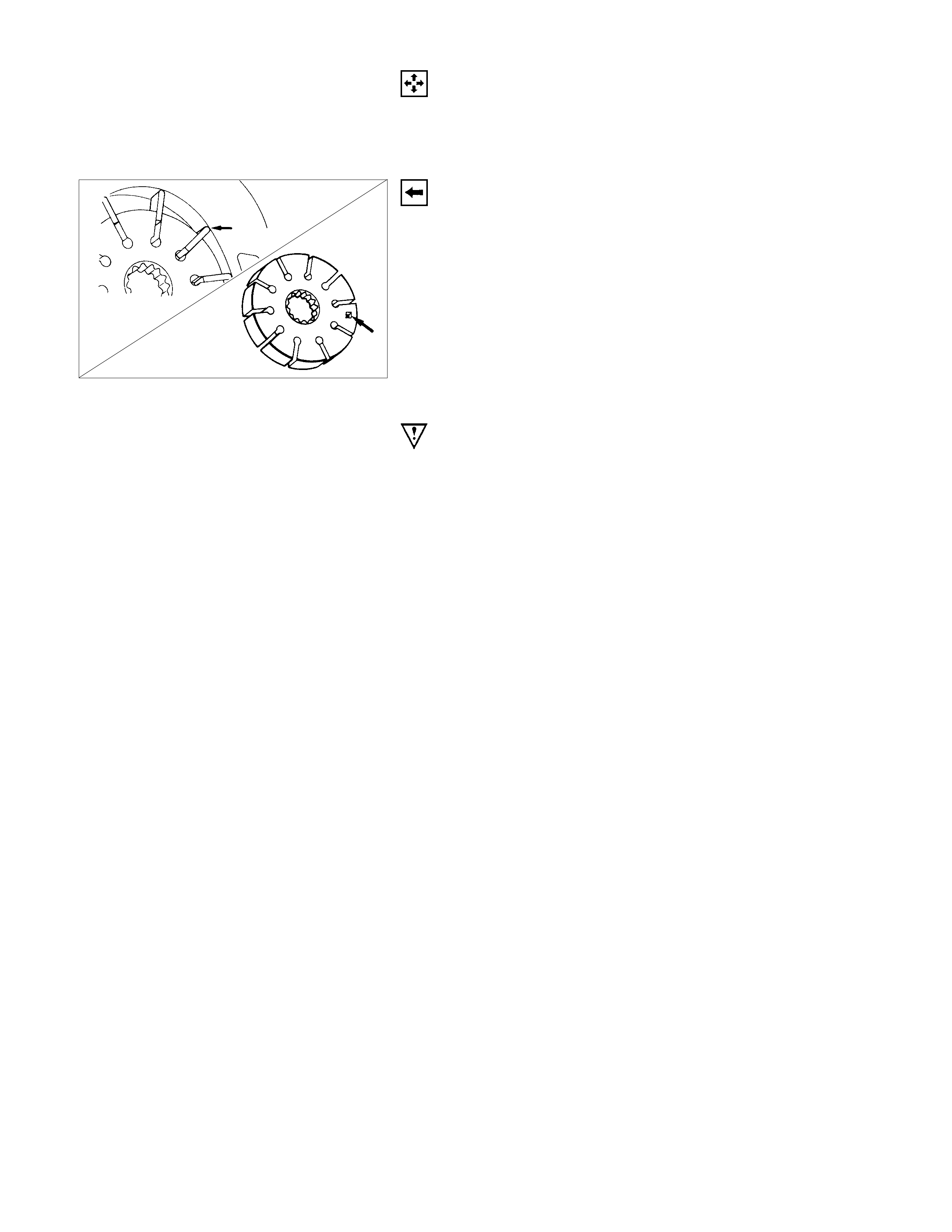
CAM
When installing the cam, align the projection of cam with the
grove of oil pump body.
Install the cam with the pin "A" side turn down.
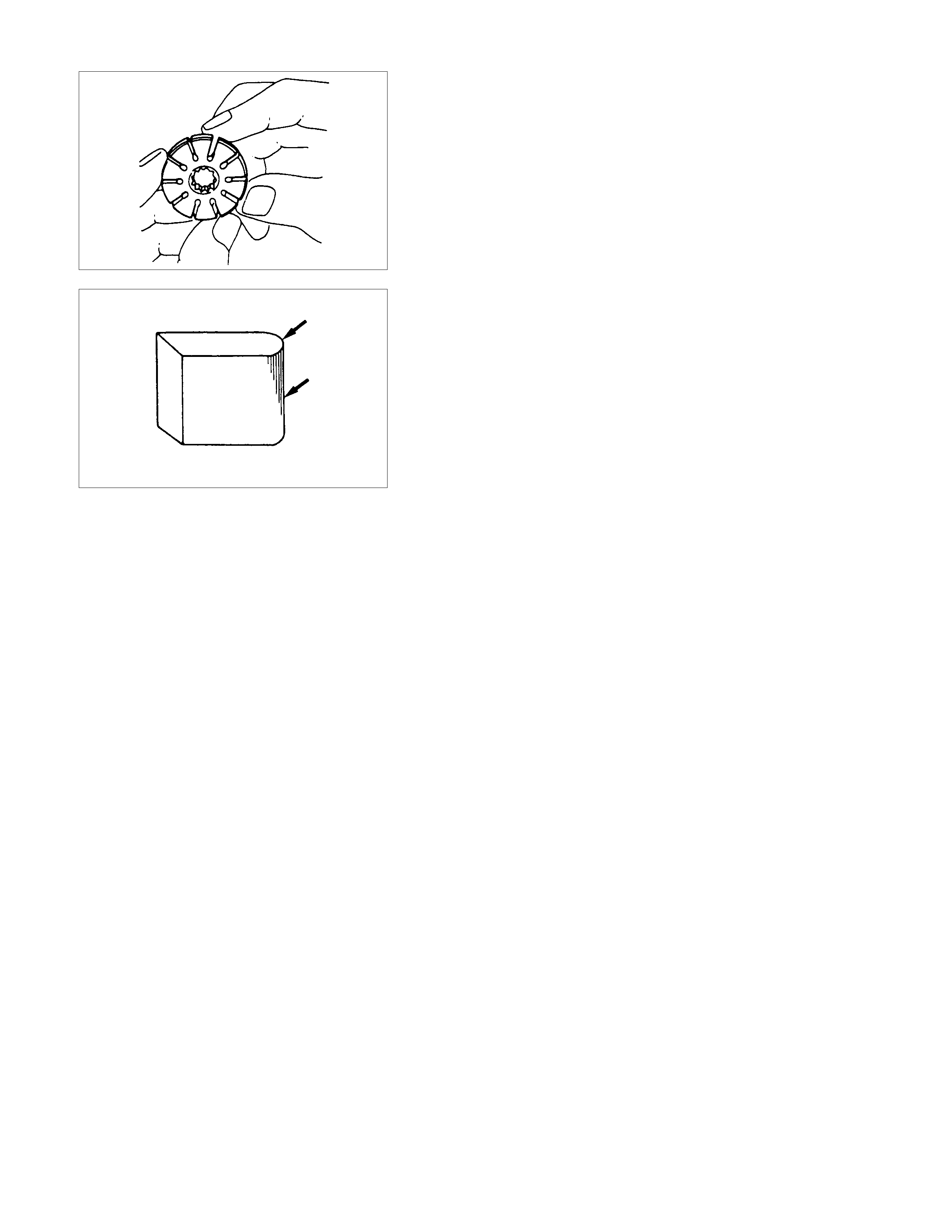
VANE
The round end of the vane should be matched to the inner
surface of the cam ring.
11.Cover and Bolt
Torque N⋅m (kgf⋅m/lb⋅ft)
53.9±4.9 (5.5±0.5 / 39.8±3.6)
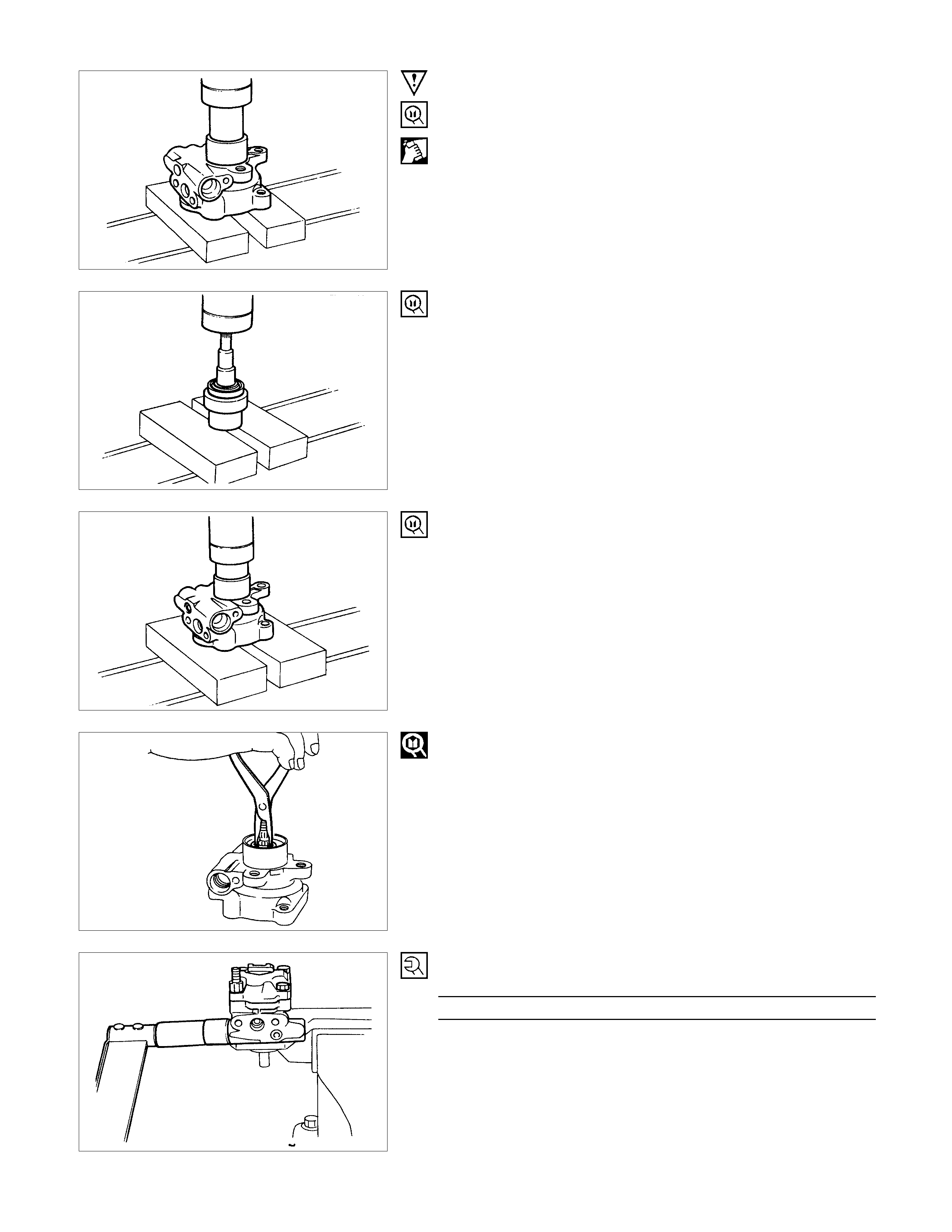
IMPORTANT OPERATIONS
12.Oil Seal
Apply compressed air to the inside of the oil pump body.
Use the bench press and oil seal installer.
Oil Seal Installer : 5-8840-2205-0
16.Shaft and Bearing
Install the bearing to the shaft with a bench press and bearing
installer.
Bearing installer : 5-8840-2206-0
Use a bench press and bearing installer to slowly force the
shaft from front side of the oil pump body.
Bearing Installer : 5-8840-2206-0
17.Snap Ring
Use a pair of snap ring pliers to install the snap ring.
24.Connector
Torque N⋅m(kgf⋅m/lb⋅ft
)
53.9±4.9 (5.5±0.5 / 39.8±3.6)
DISASSEM BLY AND REASSEMBLY (4J SERIES ENGINE MODEL)
DISASSEM BLY STEPS
1. Bolt
2. Pipe, suction
3. O-ring
4. O-ring
5. O-ring
6. Connector
7. O-ring
8. Valve
9. Retaining ring
10. Filter
11. Spring
12. Retaining ring
13. Shaft assembly
14. Bearing
15. Shaft
16. Retaining ring
17. Oil seal
18. Bolt
19. Rear housing assembly and pump
cartridge
20. Gasket
21. O-ring
22. O-ring
23. Front housing
24. Pressure plate
25. Rotor and vane
26. Cam
27. Pin
28. Rear housing
REASSEMBLY STEPS
28. Rear housing
27. Pin
26. Cam
25. Rotor and vane
24. Pressure plate
23. Front housing
22. O-ring
21. O-ring
20. Gasket
19. Rear housing assembly and pump
cartridge
18. Bolt
17. Oil seal
16. Retaining ring
15. Shaft
14. Bearing
13. Shaft assembly
12. Retaining ring
11. Spring
10. Filter
9. Retaining ring
8. Valve
7. O-ring
6. Connector
5. O-ring
4. O-ring
3. O-ring
2. Pipe
1. Bolt

DISASSEMBLY
Preparation:
Clean oil pump with solvent (its plug discharge and suction port
to prevent the entry of solvent). Be careful not to expose the oil
seal of shaft assembly to solvent.
1. Bolt
2. Pipe, Suction
3. O-ring
4. O-ring
5. O-ring
6. Connector
7. O-ring
8. Valve
9. Retaining Ring
10. Filter
11. Spring
12. Retaining Ring
13. Shaft Assembly
14. Bearing
15. Shaft
16. Retaining Ring
17. Oil Seal
CAUTION:
When removing the oil seal, be careful not to damage the
housing.
18. Bolt
19. Rear Housing Assembly and Pump Cartridge
20. Gasket
21. O-ring
22. O-ring
23. Front Housing
24. Pressure Plate
25. Rotor and Vane
26. Cam
27. Pin
28. Rear Housing
REASSEMBLY
28. Rear Housing
27. Pin
26. Cam
25. Rotor and Vane
Install the rotor with its punch mark facing the front
housing.
Install the vane with curved face in contact with the inner
wall of the cam.
24. Pressure Plate
CAUTION:
When install pressure plate, be careful not to damage its
inner surface. Damaged pressure plate may cause poor
pump performance, pump seizure or oil leakage.
23. Front Housing
22. O-ring
Be sure to discard used parts, and always used new parts
for installation.
21. O-ring
Be sure to discard used parts, and always used new parts
for installation.
20. Gasket
Be sure to discard used parts, and always used new parts
for installation.
19. Rear Housing Assembly and Pump Cartridge
18. Bolt
Rear Housing Bolt Torque N⋅m (kgf⋅m / lb⋅ft)
54 (5.5 / 40)
17. Oil Seal
Be sure to discard used parts, and always used new parts
for installation.
CAUTION:
When installing the oil seal, be careful not to damage the
oil seal contacting surface of the housing.
16. Retaining Ring
15. Shaft
14. Bearing
13. Shaft Assembly
12. Retaining Ring
11. Spring
10. Filter
9. Retaining Ring
8. Valve
7. O-ring
Be sure to discard used parts, and always used new parts
for installation.
6. Connector
Connector Torque N⋅m (kgf⋅m / lb⋅ft)
54 (5.5 / 40)
5. O-ring
Be sure to discard used parts, and always used new parts
for installation.
4. O-ring
Be sure to discard used parts, and always used new parts
for installation.
3. O-ring
Be sure to discard used parts, and always used new parts
for installation.
2. Pipe, Suction
1. Bolt
Suction Pipe Bolt Torque N⋅m (kgf⋅m / lb⋅ft)
21 (2.1 / 15)
DISASSEM BLY AND REASSEMBLY (6VD1 ENGINE MODEL)
DISASSEM BLY STEPS
1. Bolt
2. Pipe, suction
3. O-ring
4. Connector
5. O-ring
6. Valve
7. Retaining ring
8. Filter
9. Spring
10. Pressure switch
11. Retaining ring
12. Shaft assembly
13. Bearing
14. Shaft
15. Retaining ring
16. Oil seal
17. Bolt
18. Rear housing assembly and pump
cartridge
19. Gasket
20. O-ring
21. O-ring
22. Front housing
23. Pressure plate
24. Rotor and vane
25. Cam
26. Pin
27. Rear housing
REASSEMBLY STEPS
27. Rear housing
26. Pin
25. Cam
24. Rotor and vane
23. Pressure plate
22. Front housing
21. O-ring
20. O-ring
19. Gasket
18. Rear housing assembly and pump
cartridge
17. Bolt
16. Oil seal
15. Retaining ring
14. Shaft
13. Bearing
12. Shaft assembly
11. Retaining ring
10. Pressure switch
9. Spring
8. Filter
7. Retaining ring
6. Valve
5. O-ring
4. Connector
3. O-ring
2. Pipe, suction
1. Bolt
DISASSEMBLY
Preparation:
Clean oil pump with solvent (its plug discharge and suction port
to prevent the entry of solvent). Be careful not to expose the oil
seal of shaft assembly to solvent.
1. Bolt
2. Pipe, Suction
3. O-ring
4. Connector
5. O-ring
6. Valve
7. Retaining Ring
8. Filter
9. Spring
10. Pressure Switch
11. Retaining Ring
12. Shaft Assembly
13. Bearing
14. Shaft
15. Retaining Ring
16. Oil Seal
CAUTION:
When removing the oil seal, be careful not to damage the
housing.
17. Bolt
18. Rear Housing Assembly and Pump Cartridge
19. Gasket
20. O-ring
21. O-ring
22. Front Housing
23. Pressure Plate
24. Rotor and Vane
25. Cam
26. Pin
27. Rear Housing
INSPECTION AND REPAIR
Make all necessary adjustments, repairs, and part
replacements if wear, damage, or other problems are
discovered during inspection.
ROTOR
Check that the groove in the vane is free from excessive wear
and that the vane slides smoothly
When part replacement becomes necessary, the pump
cartridge should be replaced as a subassembly.
VANE
Sliding faces of the vane should be free from wear.
(Particularly the curved face at the tip in contact with the cam
should be free from wear and distortion.)
When part replacement becomes necessary, the pump
cartridge should be replaced as a subassembly.
CAM
The inner face of the cam should have a trace of uniform
contact without a sign of step wear.
When part replacement becomes necessary, the pump
cartridge should be replaced as a subassembly.
SIDE PLATE
The sliding faces of parts must be free from step wear (more
than 0.01 mm), which can be felt by the finger nail.
The parts with minor scores may be reused after lapping the
face.
VALVE
The sliding face of the valve must be free from burrs and
damage.
The parts with minor scores may be reused after smoothing
with emery cloth (#800 or finer).
SHAFT
Oil seal sliding faces must be free from a step wear which can
be felt by the finger nail.
Needle bearing fitting face must be free from disintegration and
wear.
O-RING, OIL SEAL RETAINING RING
Be sure to discard used parts, and always use new parts for
installation. Prior to installation, lubricate all seals and rings
with power steering fluid.
REASSEMBLY
27. Rear Housing
26. Pin
25. Cam
24. Rotor and Vane
1. Install the rotor with its punch mark facing the front
housing.
2. Install the vanes with curved face in contact with the
inner wall of the cam.
23. Pressure plate
CAUTION:
When install pressure plate, be careful not to damage its
inner surface. Damaged pressure plate may cause poor
pump performance, pump seizure or oil leakage.
22. Front Housing
21. O-ring
Be sure to discard used parts, and always used new parts
for installation.
20. O-ring
Be sure to discard used parts, and always used new parts
for installation.
19. Gasket
Be sure to discard used parts, and always used new parts
for installation.
18. Rear Housing Assembly and Pump Cartridge
17. Bolt
Rear Housing Bolt Torque N⋅m (kgf⋅m / lb⋅ft)
17.6 (1.8 / 12.8)
16. Oil Seal
Be sure to discard used parts, and always used new parts
for installation.
CAUTION:
When installing the oil seal, be careful not to damage the
oil seal contacting surface of the housing.
15. Retaining Ring
14. Shaft
13. Bearing
12. Shaft Assembly
11. Retaining Ring
10. Pressure Switch
Pressu re Switch Torque N⋅m (kgf⋅m / lb⋅ft)
20 (2.0 / 14)
9. Spring
8. Filter
7. Retaining ring
6. Valve
5. O-ring
Be sure to discard used parts, and always used new parts
for installation.
4. Connector
Connector Torque N⋅m (kgf⋅m / lb⋅ft
)
74 (7.5 / 54)
3. O-ring
Be sure to discard used parts, and always used new parts
for installation.
2. Pipe, Suction
1. Bolt
Suction Pipe Bolt Torque N⋅m ( kgf⋅m / lb⋅ft
)
16 (1.6 / 12)
TROUBLESHOOTING
INSPECTION PRO CEDURES FOR STEERING SYSTEM
COMPONENT AND TEST PROCEDURE
HANDLE Check for
play and
slack
1. Place the steering wheel in the straight forward position. Gently move the
wheel to the right and to the left. About ten millimeters of play in either
direction should be present before the front tires begin to move.
If the vehicle is equipped with power steering, the engine should be running
when these tests are made.
2. Grasp the steering wheel firmly with both hands. Exert force in an up and
down direction on the steering column. There should be no play.
3. Move the steering wheel to the right and to the left. Check to see the
steering shaft.
Make sure that there is no slack in those areas where parts are joined
together.
Check the
operating
condition of
the system
1. Make the following checks while actually driving the vehicle.
a. Check the position of the steering wheel when the vehicle is traveling
straight ahead.
b. Make sure that the vehicle does not have a tendency to steer to the right
or the left.
c. There should be no excessive vibration present at the steering wheel.
d. Turn the vehicle as sharply as possible to both the right and the left.
When the steering wheel is turned fully in either direction, check for
abnormal noise.
Neither should the wheel feel overly heavy when it is fully turned to either
the left or the right. Loosen your grip on the steering wheel. It should
return to its center position.
GEAR BOX Check for
oil leakage 1. Check all parts of the steering unit (the oil seals of the front cover, side
cover, sector shaft, etc.) to make sure that there is no oil leakage.
Check for
looseness
in the
assembly
1. With the wheels of the vehicle on the ground (the vehicle should not be
jacked up), have an assistant or helper turn the steering wheel to the right
and to the left. As he does this, you should carefully check all areas where
the steering unit is attached to the frame for looseness and other possible
problems.
Check for
bearing
backlash
1. Check the condition of the connections between the steering shaft and the
bearings. Move the steering shaft in the direction of the axle and make sure
that there is no backlash present.
2. Rotate the steering shaft. There should be no abnormal noise. It should
rotate smoothly and there should be no feeling of roughness.
Check to make sure that there is no abnormal or excessive bearing wear.
Check for
gear
backlash
1. The front wheels should be facing straight ahead. Have an assistant or
helper grasp the drop arm so as to immobilize it. Now try to turn the steering
wheel. Backlash should not exceed one millimeter.
Inspect the
sector shaft
for c racks
1. Remove the steering unit from the vehicle and break it down into its
component parts. Carefully inspect the sector shaft for cracks or other
damage.
COMPONENT AND TEST PROCEDURE
RODS AND
ARMS Check for
play,
backlash,
and
damage
1. With the wheels of the vehicle on the ground (the vehicle should not be
jacked up), have an assistant or helper turn the steering wheel to the right
and to the left. As he does this, you should carefully check the connecting
points of all the parts for play, slack, or damage.
a. Specifically check the pitman arm, the intermediate rod, the tie rods, the
tie rod ends, the knuckle arms and the relay lever.
2. Carefully check all of the pins for cracks and other damage.
3. Make sure that the rod end boots and related areas are not cracked or
otherwise damaged.
Check the
coupling
parts for
abrasion
and other
abnormal
conditions
1. The ball joints and the rubber bushings should be free from abrasion or any
other damage.
2. Pay careful attention to the coupling areas. Make sure that everything is
properly connected.
Check for
cracks in
the knuckle
arms and
also for
poor
knuckle
attachment
1. Make sure that both the knuckle arms and the tie rod arms are free from
cracks.
The fit between the knuckles and the tapers should be secure.
Look for any abnormal coloring which may indicate trouble.
KNUCKLES Check for
loose and
damaged
joints
1. Jack up the front axle and the front crosspiece. By hand, rotate the two front
tires in either direction. Check that the king pins and the ball joints are free
of play or slack.
If play or slack is present, have an assistant or helper, hold down the brake
pedal. Using a dial gauge, once again check the wheels for play and
vibration. It is possible that the problem lies not with the steering system but
with the wheel bearings.
Check the
gap
between
the steering
knuckles
and the
front axle
1. Use a thickness gauge or other appropriate tool to measure the width of the
gap between the steering knuckles and the front axle. Measure in the
direction of the king pin.
After measurement, thrust washers may be inserted to alter the gap.
1. HARD STEERING W ITH POOR STEERING WHEEL RETURN
Checkpoint Trouble Cause Countermeasure
Steering shaft bearings
Steering linkage
Front wheel alignment
Oil level in the reservoir
(Power steering only)
Replace the bearings
Repair or replace the joint ball
and/or the ball seat
Correct the front wheel
alignment
Replenish the oil
Bearings sticking or rusted
Joint ball sticking or rusted
Front wheels out of alignment
Insufficient oil
Steering wheel play Adjust the play
Correct the Tyre inflation
pressure
Insufficient play
Low Tyre inflation pressure
OK
OK
OK
OK
Continued on the next page
NG
NG
NG
NG
NG
NG
OK
OK
Tyre inflation pressure
Checkpoint Trouble Cause Countermeasure
Steering unit internal parts
Worm shaft bearing preload
Hydraulic system (Power
steering only)
Replace the damaged parts
Adjust the preload
Air bleeding
Part damage
Preload too heavy
Air in the hydraulic system
Control valve lock nut
(Power steering only) Retighten the lock nut to the
specified torque
Repair or replace
Control valve lock nut
overtightened
Joints and sleeve yoke
sticking or rusted
OK
OK
NG
NG
NG
NG
NG
OK
OK
Joints and sleeve yoke
Continued from the previous page

2. STEERING VIBRATION AND SHIMMY
Checkpoint Trouble Cause Countermeasure
Steering link joint ball play
Front wheel alignment
Steering wheel play
Wheel pins
Replace the joint ball and the
ball seat
Correct the front wheel
alignment
Adjust the play
Retighten or replace the wheel
pin(s)
Joint ball excessively worn
Front wheels out of alignment
Excessive play
Broken or loose wheel pin(s)
Tyres and disc wheels Correct the Tyre balance
Replace the disc wheel
Retighten the wheel nuts to
the specified torque
Unbalanced Tyres
Deformed disc wheel(s)
Wheel nuts unevenly torqued
OK
OK
OK
OK
Continued on the next page
NG
NG
NG
NG
NG
NG
OK
OK
Wheel nuts

Checkpoint Trouble Cause Countermeasure
Steering unit internal parts
Sector shaft needle bearing
Wheel bearings
Replace the damaged parts
Replace the needle bearing
Replace the bearings
Part damage
Needle bearing excessively
worn
Play in bearings excessive or
bearings disintegrated
Adjust screw and sector shaft
clearance Adjust the clearance
Replace the shock absorbers
Excessive clearance
Faulty shock absorbers
OK
OK
NG
NG
NG
NG
NG
OK
OK
Shock absorbers
Continued from the previous page
3. STEERING PULLS TO ONE SIDE OR THE OTHER
Checkpoint Trouble Cause Countermeasure
Brakes
Front wheel alignment
Shock absorbers
Tyres and disc wheels
Refer to Section 5A"BRAKE
VACUUM ASSISTED
HYDRAULIC TYPE"
Correct the front wheel
alignment
Replace the shock absorbers
Correct the Tyre balance
Replace the disc wheel
One wheel dragging
Front wheels out of alignment
Faulty shock absorbers
Unbalanced Tyres
Deformed disc wheel(s)
Wheel bearings Correct or replace
Inflate all the Tyres to the
specified pressure
Incorrect preload or damage
Tyres unevenly inflated
OK
OK
OK
OK
NG
NG
NG
NG
NG
NG
OK
OK
Tyre inflation pressure
Steering shaft end play Adjust the end playExcessive end play
NG
4. STEERING WANDER (EXCESSIVE PLAY OR LOOSENESS)
Checkpoint Trouble Cause Countermeasure
Steering shaft universal joint
Steering wheel and shaft
Front wheel alignment (Toe-
in)
Oil level in the reservoir
(Power steering only)
Tighten the bolts to the
specified torque
Tighten the lock nut to the
specified torque
Correct the front wheel
alignment
(Adjust the toe-in)
Replenish the oil
Universal joint bolts loose
Steering wheel lock nut loose
Front wheels out of alignment
(Toe-in out of adjustment)
Insufficient oil
Manual or power steering unit Tighten the steering unit bolts
to the specified torque
Replace the tires and check
the wheel alignment
Steering unit mounting loose
Tires badly worn
Rounded tire edges
OK
OK
OK
OK
OK
NG
NG
NG
NG
NG
NG
OK
OK
Tires
Continued on the next page
Steering linkage joint ball nut Tighten the nut to the
specified torque
Joint ball nut loose
NG
Checkpoint Trouble Cause Countermeasure
Worm shaft bearing preload
Front wheel bearings
Adjust the preload
Replace the bearings or adjust
the preload
Preload improperly adjusted
Bearings excessively worn or
preload incorrectly adjusted
Hydraulic system (Power
steering only) Air bleeding
Tighten the nut to the
specified torque
Air in the hydraulic system
Pitman arm nut loose
OK
NG
NG
NG
NG
OK
OK
Pitman arm and sector shaft
Continued from the previous page
5. MO MENTARY INCREASE IN STEERING EFFORT WHEN THE STEERING WHEEL IS TURNED
QUICKLY TO ONE SIDE OR THE OTHER (POWER STEERING ONLY)
Checkpoint Trouble Cause Countermeasure
Oil pump
(Power steering only) Repair or replace the oil pumpOil pump internal leakage
Replenish the oilInsufficient oil
NG
NG
OK
Oil level in the reservoir
(Power steering only)
6. STEERING WHEEL SURGE OR JERK WHEN PARKING THE VEHICLE (POWER STEERING ONLY)
Checkpoint Trouble Cause Countermeasure
Oil pump pressure Adjust the pressure and/or
replace the relief valve
Pressure too low
Replenish the oilInsufficient oil
NG
NG
OK
Oil level in the reservoir
(Power steering only)
7. EXCESSIVE RO AD SHOCK
Checkpoint Trouble Cause Countermeasure
Camber angle (4×2)
Suspension
Adjust the camber angle
Repair or replace the
applicable parts
Camber angle incorrectly
adjusted
Loose suspension
Shock absorbers Replace the shock absorbers
Inflate all the tires to the
specified pressure
Faulty shock absorbers
Tires overinflated
OK
NG
NG
NG
NG
OK
OK
Tire inflation pressure
Hub bearing preload Adjust the preloadPreload out of adjustment
OK
NG
8. ABNO RMAL NOI SE
(1) RATTLING OR CLICKING NOISE IN THE STEERING GEAR
Checkpoint Trouble Cause Countermeasure
Steering linkage
Hydraulic pressure hose
(Power steering only)
Repair or replace the steering
linkage parts
Reposition the hose
Steering linkage loose or worn
Hose touching another part of
the vehicle
Pitman arm Tighten the pitman arm nut to
the specified torque
Tighten the steering unit bolts
to the specified torque
Pitman arm loose
Steering unit mounting bolts
loose
OK
NG
NG
NG
NG
OK
OK
Manual or power steering unit
9. OIL PUMP NOISY
Checkpoint Trouble Cause Countermeasure
Oil pump NG
Pressure of air in hydraulic
circuit
Overhaul or replace
Bleed circuit
Defective
Air in circuit
Suction tube and filter for
restrictions Clean or replace
Replenish
Restrictions in tubing or filter
Insufficient
OK
NG
NG
NG
NG
OK
OK
Oil level
Steering gear box Overhaul or replaceDefective
OK
NG
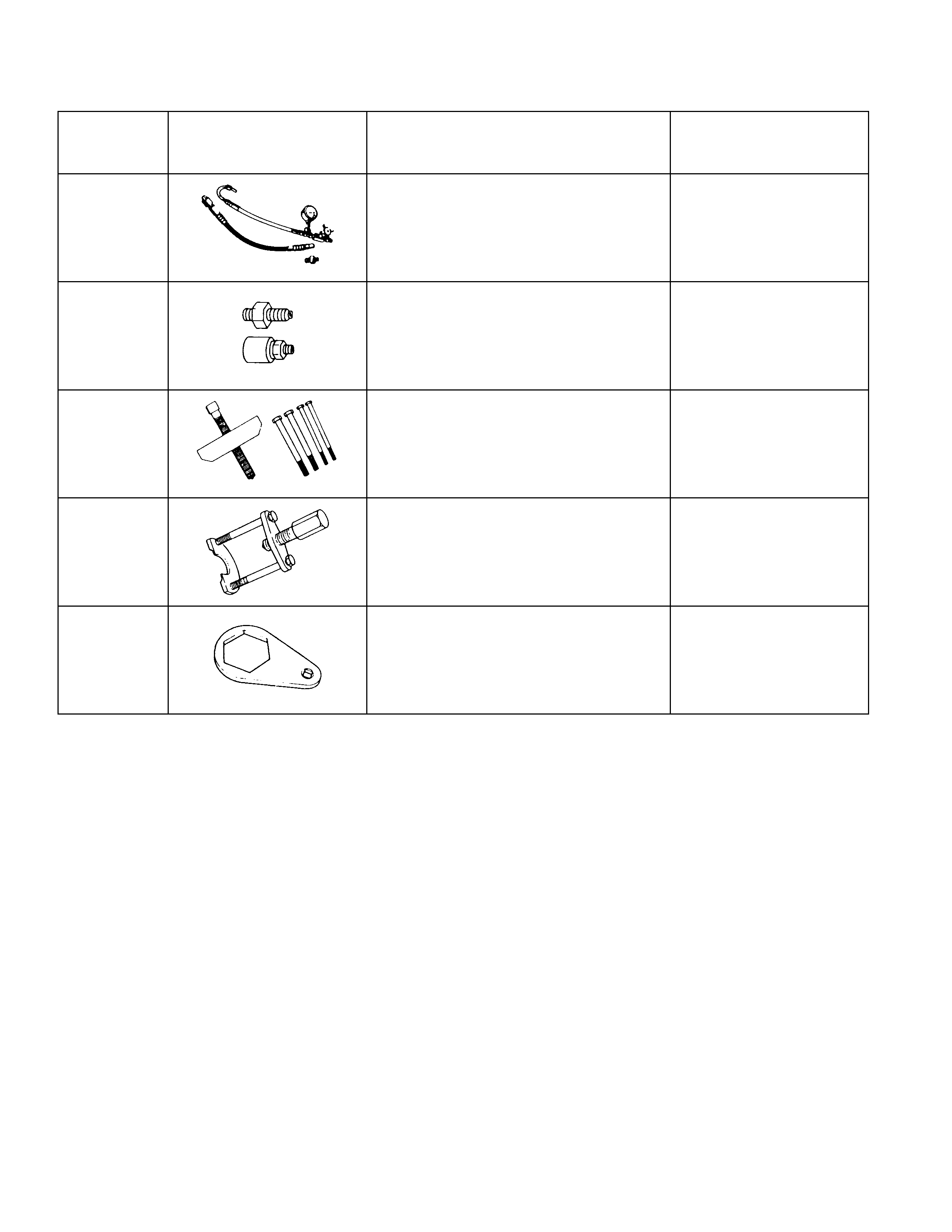
SPECIAL SERVICE TOOL (C22, C20 SERIES ENGINE MO DEL)
ITEM NO. ILLUSTRATION PART NO. PART NAME
STL-19 5-8840-0135-0
(J-29877-A) Power steering tester
STL-21 5-8840-0136-0
(J-33996) Power steering tester
adapter
STL-1 5-8521-0016-0
(J-29752) Steering wheel puller
STL-13 5-8840-2017-0
(J-35707) Pitman arm remover
STL-2 5-8840-2006-0
(J-29753) Input cover lock nut
wrench

STL-5 5-8840-2007-0
(J-7624) End cover remover
STL-8 5-8522-0026-0
(J-26508) Extension housing oil
seal installer
STL-12 5-8840-2121-0
(J-21677-2) Tie-rod remover
STL-10 5-8840-2206-0 Power steering pump
bearing remover and
installer
STL-9 5-8840-2205-0 Power steering pump
oil seal installer