
SECTION 6A - ENGINE MECHANICAL
MAIN DATA AND SPECIFICATIONS
TORQUE SPECIFICATIONS
STANDARD BOLTS
FLARE NUTS
TORQUE SPECIFICATIONS
RECOMMENDED LIQUID GASKET
LOCTITE APPLICATION PROCEDURE
SERVICING
MODEL IDENTIFICATION
AIR CLEANER
LUBRICATING SYSTEM
FUEL SYSTEM
COOLING SYSTEM
VALVE CLEARANCE ADJUSTMENT
COMPRESSION PRESSURE MEASUREMENT
GENERAL DESCRIPTION
REMOVAL AND INSTALLATION
REMOVAL
INSTALLATION
COOLANT REPLENISHMENT
ENGINE WARM-UP
ENGINE REPAIR KIT
ENGINE OVERHAUL
REMOVAL
EXTERNAL PARTS
DISASSEMBLY
INTERNAL PARTS
MAJOR COMPONENTS
MINOR COMPONENTS
INSPECTION AND REPAIR
CYLINDER HEAD
ROCKER ARM SHAFT AND ROCKER ARM
CYLINDER BODY
CAMSHAFT
CRANKSHAFT AND BEARING
CRANKSHAFT BEARING SELECTION
CRANKSHAFT PILOT BEARING
FLYWHEEL AND RING GEAR
PISTON
CYLINDER HEAD GASKET SELECTION
CONNECTING ROD
IDLER GEAR SHAFT AND IDLER GEAR
TIMING GEAR CASE COVER
REASSEMBLY
INTERNAL PARTS
MINOR COMPONENT
MAJOR COMPONENT
INSTALLATION
EXTERNAL PARTS
LUBRICATION SYSTEM
LUBRICATING FLOW
OIL PUMP AND OIL FILTER
OIL PUMP
DISASSEMBLY
INSPECTION AND REPAIR
REASSEMBLY
OIL FILTER AND OIL COOLER
DISASSEMBLY
INSPECTION AND REPAIR
REASSEMBLY
INTER COOLER
REMOVAL AND INSTALLATION
REMOVAL
INSTALLATION
SPECIAL TOOLS
MAIN DATA AND SPECIFICATIONS
Item Data
Engine type Four-cycle, overhead valve, water cooled
Combustion chamber type Direct injection
Cylinder liner type
Timing gear train system Dry type, chrome plated
Gear drive
No. of cylinders-bore × stroke mm (in) 4 – 95.4 × 104.9 (3.76 × 4.13)
No. of piston rings Compression ring: 2 / Oil ring: 1
Total piston displacement litre
Compression ratio (to 1)
2,999
18.3
Compression pressure MPa (kg/cm2/psi) 3.0 (31.0/441) – 200 rpm
Engine weight kg (lb) 4 × 2MT & 4 × 4 : Approximately 249 (549)
4 × 2AT : Approximately 236 (520)
Fuel injection order 1 – 3 – 4 - 2
Specified fuel type JIS No.2 diesel fuel
Idling speed rpm 700 ± 25 (A/C OFF)
800 ± 25 (A/C ON)
Valve clearances (At cold): Intake mm (in)
Exhaust mm (in)
Intake valves Open at (BTDC) deg
Close at (ABDC) deg
Exhaust valves Open at (BBDC) deg
Close at (ATDC) deg
Fuel system
Injection pump type
0.4 (0.016)
0.4 (0.016)
24.5
55.5
54.0
26.0
BOSCH distributor VP44 type
Injection nozzle type
Injection nozzle opening pressure
(Design value) MPa(kg/cm2/psi)
Hole with 5 orifices
1st 19.5 (199/2,828)
2nd (Reference) 34.3 - 35.8 (350/4,980 - 365/5,197)
Main fuel filter type
Lubricating system
Lubricating method
Cartridge paper element and water separator
Pressure circulation
Specified engine oil (API grade) Refer to Section 0B - Lubrication
Oil pump type
Oil filter type
Gear
Cartridge paper element
Oil capacity lit (US/UK gal)
6.5 (1.7/1.4) (For 4 × 2)
7.3 (1.9/1.6) (For 4 × 4)
Oil cooler type Water cooled

Item Data
Cooling system
Water pump type
Thermostat type
Air cleaner type
Battery type/voltage × No. of units
Generator capacity V-A
Starter motor output V-kW
Turbocharger model
Turbine type
Compressor type
Centrifugal
Wax pellet with jiggle valve
Dry paper element
95D31R × 1
12 – 60/12 – 80
12 – 2.3
*IHI RHF5
Radial-inflow
Radial-outflow
*IHI: Ishikawajima-Harima Heavy Industries. Ltd.
TORQUE SPECIFICATIONS
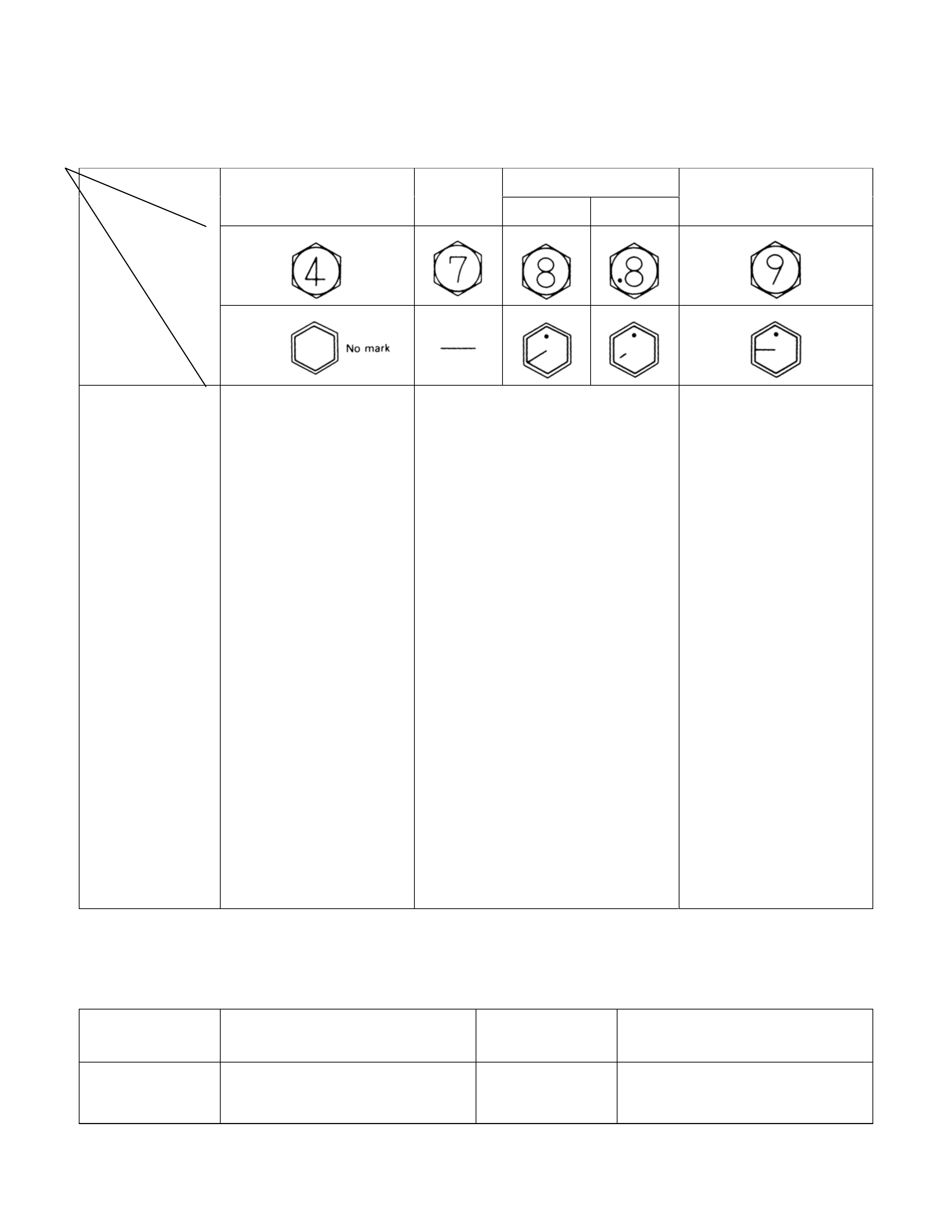
STANDARD BOLTS
The torque values given in the following table should be applied whenever a particular torque is not specified.
N·m (kg·m/lb·ft)
8.8
4.8 (4T) (7T) Refined Non-Refined 9.8 (9T)
Strength
Class
Bolt
Identification
Bolt
Diameter ×
Pitch (mm)
M 6 × 1.0
M 8 × 1.25
M 10 × 1.25
M 12 × 1.25
M 14 × 1.5
M 16 × 1.5
M 18 × 1.5
M 20 × 1.5
M 22 × 1.5
M 24 × 2.0
* M 10 × 1.5
* M 12 × 1.5
* M 14 × 2.0
* M 16 × 2.0
5.88 ± 1.96
(0.60 ± 0.20/4.33 ± 1.44)
12.74 ± 4.90
(1.30 ± 0.50/9.40 ± 3.62)
27.44 ± 6.86
(2.80 ± 0.70/20.25 ± 5.06)
61.25 ± 12.25
(6.25 ± 1.25/45.21 ± 9.04)
95.55 ± 19.11
(9.75 ±1.95/70.52 ± 14.10)
130.34 ± 26.46
(13.30 ± 2.70/96.20 ± 19.53)
188.16 ± 37.24
(19.20 ± 3.80/138.87 ± 27.49)
257.74 ± 51.94
(26.30 ± 5.30/190.23 ± 38.33)
332.22 ± 81.34
(33.90 ± 8.30/245.20 ± 60.03)
448.84 ± 90.16
(45.80 ± 9.20/331.27 ± 66.54)
26.46 ± 6.86
(2.70 ± 0.70/19.53 ± 5.06)
56.84 ± 11.76
(5.80 ± 1.20/41.95 ± 8.68)
89.18 ± 17.64
(9.10 ± 1.80/65.82 ± 13.02)
124.46 ± 24.50
(12.70 ± 2.50/91.86 ± 18.08)
7.35 ± 2.45
(0.75 ± 0.25/5.43 ± 1.80)
17.15 ± 5.39
(1.75 ± 0.55/12.66 ± 4.00)
36.75 ± 9.31
(3.75 ± 0.95/27.12 ± 6.87)
75.95 ± 15.19
(7.75 ± 1.55/56.06 ± 11.21)
116.13 ± 23.03
(11.85 ± 2.35/85.71 ± 17.00)
169.54 ± 34.30
(17.30 ± 3.50/125.13 ± 25.32)
244.02 ± 49.00
(24.90 ± 5.00/180.10 ± 36.17)
337.12 ± 67.62
(34.40 ± 6.90/248.82 ± 49.41)
453.25 ± 90.65
(46.25 ± 9.25/334.53 ± 66.91)
570.36 ± 140.14
(58.20 ± 14.30/420.96 ± 103.43)
36.26 ± 8.82
(3.70 ± 0.90/26.76 ± 6.50)
70.56 ± 13.72
(7.20 ± 1.40/52.08 ± 10.13)
109.76 ± 21.56
(11.20 ± 2.20/81.01 ± 15.91)
161.70 ± 32.34
(16.50 ± 3.30/119.34 ± 23.87)
-
23.52 ± 6.86
(2.40 ± 0.70/17.36 ± 5.06)
49.98 ± 12.74
(5.10 ± 1.30/36.89 ± 9.40)
94.57 ± 19.11
(9.65 ± 1.95/69.80 ± 14.10)
142.10 ± 28.42
(14.50 ± 2.90/104.88 ± 21.00)
199.92 ± 40.18
(20.40 ± 4.10/147.55 ± 29.66)
287.14 ± 57.82
(29.30 ± 5.90/211.93 ± 42.67)
395.92 ± 79.38
(40.40 ± 8.10/292.21 ± 58.59)
530.18 ± 105.84
(54.10 ± 10.80/391.30 ± 78.12)
691.88 ± 138.18
(70.60 ± 14.10/510.65 ± 101. 99)
48.02 ± 11.76
(4.90 ± 1.20/35.44 ±8.68)
89.18 ± 17.64
(9.10 ± 1.80/65.82 ± 13.02)
133.28 ± 26.46
(13.60 ± 2.70/98.37 ± 19.53)
191.10 ± 38.22
(19.50 ± 3.90/141.04 ± 28.21)
An asterisk (*) indicates that the bolts are used for female threaded parts that are made of soft materials such
as casting. Those shown in parentheses in the strength class indicate the classification by the old standard.
FLARE NUTS
N·m (kg·m/lb·ft)
Pipe diameter mm
(in) Torque Pipe diameter mm
(in) Torque
4.76 (0.187)
6.35 (0.250)
8.00 (0.315)
15.2 ± 2.45(1.55 ±0.25/11.2 ± 1.8)
26.48 ± 2.94(2.70 ± 0.30/19.5 ± 2.1)
44.14 ± 4.90(4.50 ± 0.50/32.5 ± 3.6)
10.00 (0.394)
12.00 (0.472)
15.00 (0.591)
53.95 ± 4.90(5.50 ± 0.5 /39.7 ± 3.6)
88.29 ± 9.80(9.00 ± 1.0/65.0 ± 7.2)
105.45 ± 12.26(10.75 ± 1.25/77.7 ± 9.0)
TORQUE SPECIFICATIONS
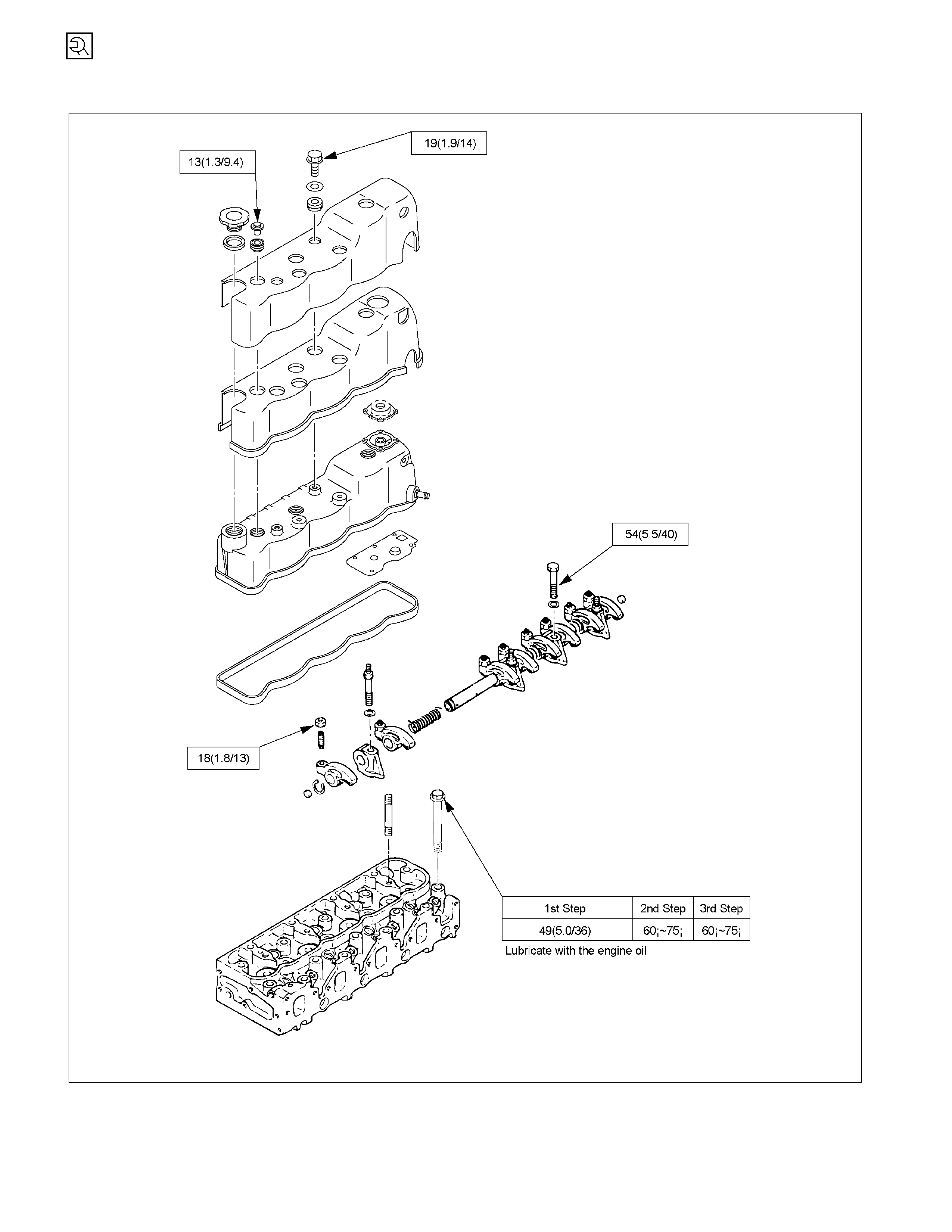
Cylinder Head Cover, Cylinder Head, and Rocker Arm Shaft Bracket N·m (kg·m/lb·ft)
RT
W46AXF000501
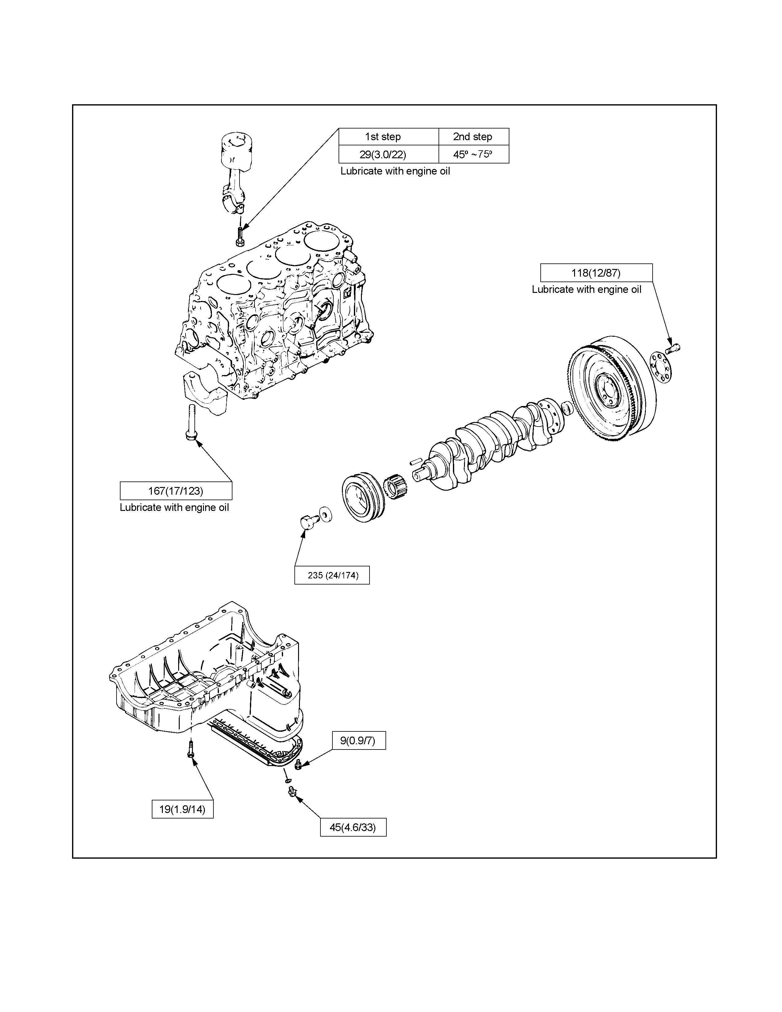
Crankshaft Bearing Cap, Connecting Rod Bearing Cap, Crankshaft Damper Pulley,
Flywheel, and Oil Pan N m (kg·m/lb·ft)
RTW36AXF000101-a
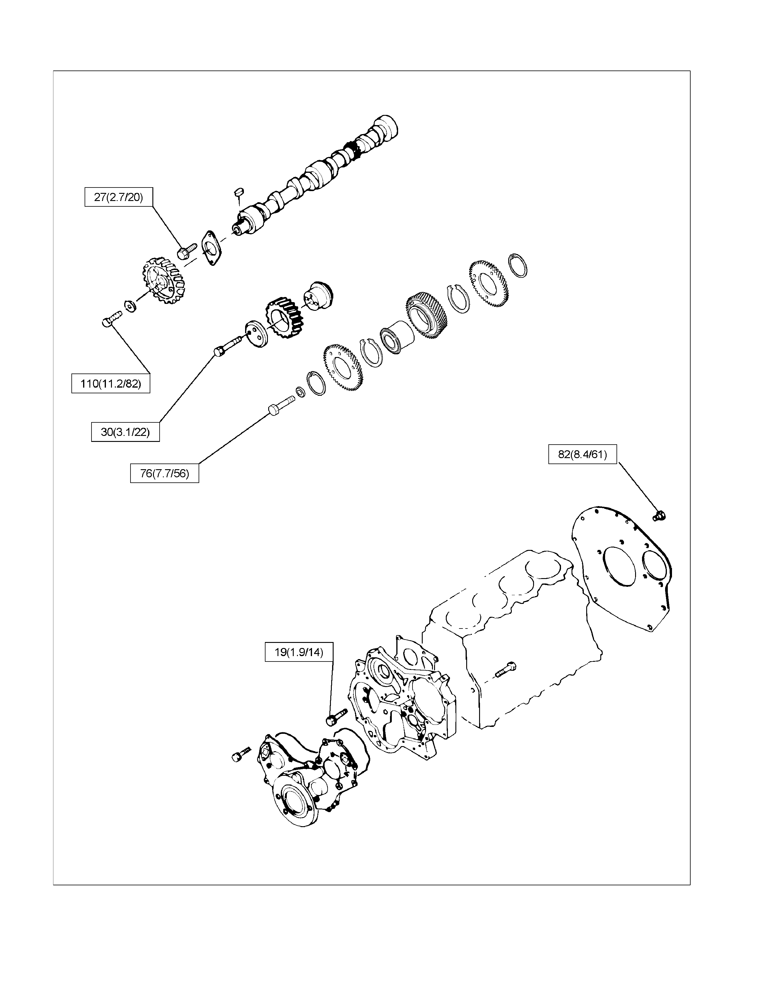
Timing Gear Case, Pulley Housing, Timing Gear, and Camshaft N·m (kg·m/lb·ft)
RTW46AXF000601
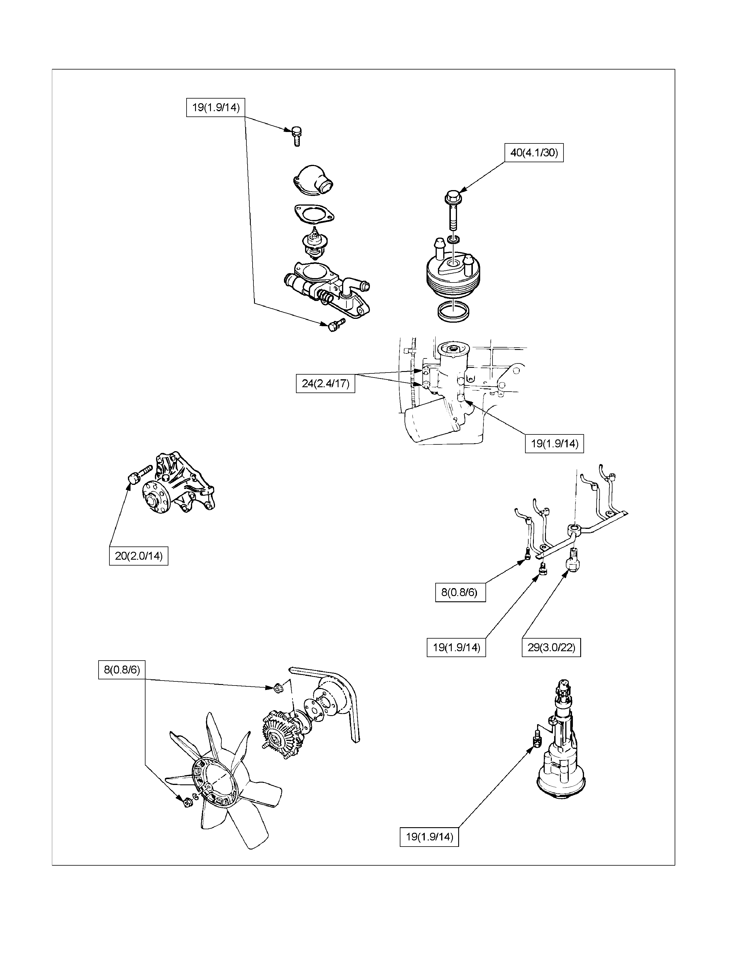
Cooling and Lubricating System N·m (kg·m/lb·ft)
RTW46AXF000701
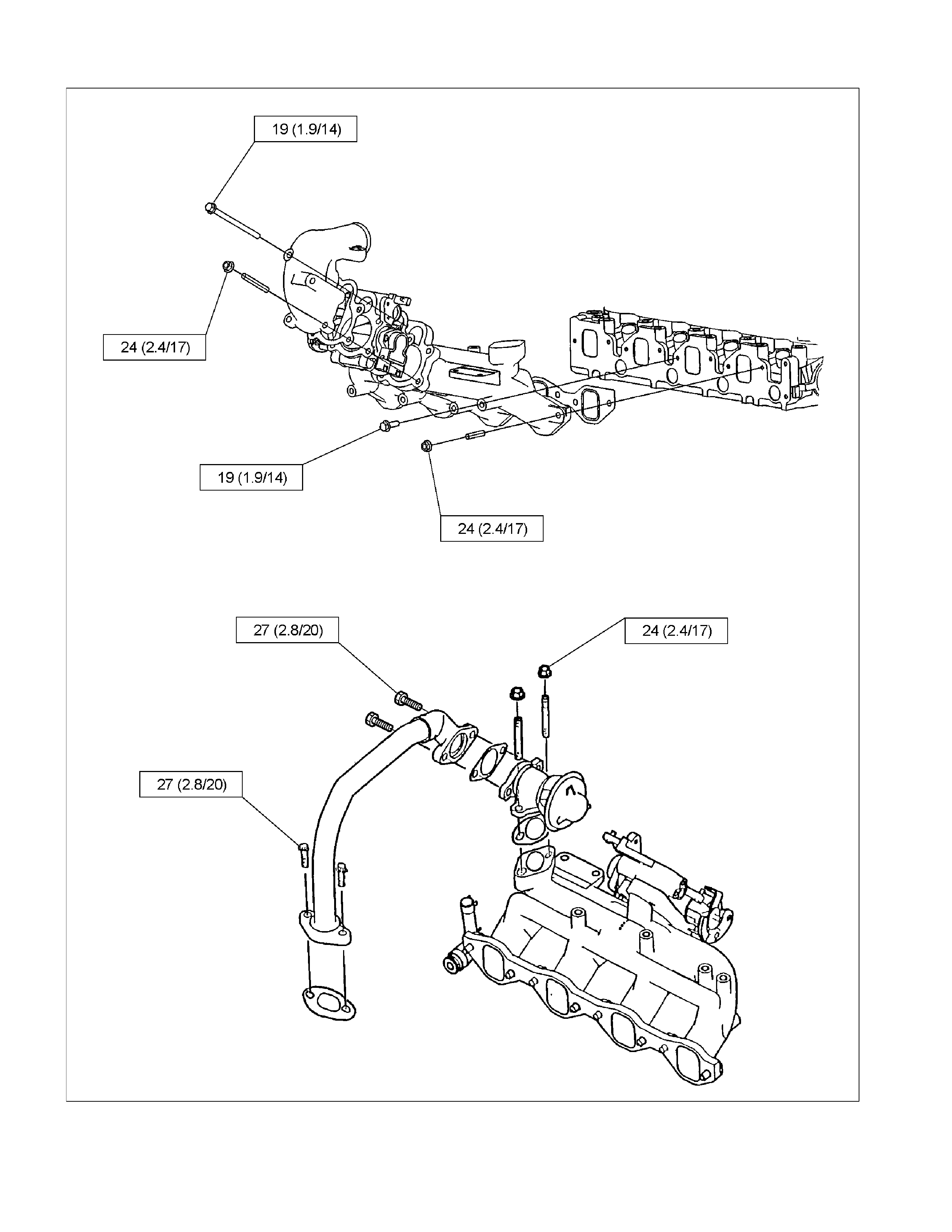
Intake Manifold and EGR Valve N·m (kg·m/lb·ft)
RTW36AXF000201
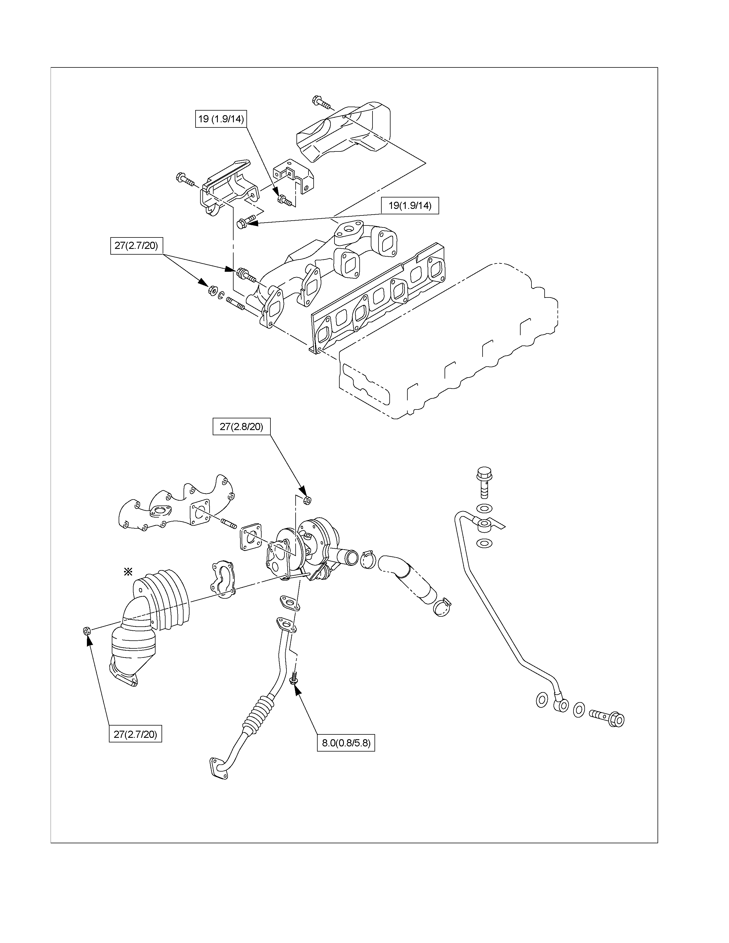
Exhaust Manifold, and Turbocharger N·m (kg·m/lb·ft)
RTW46AXF001001
Engine Electricals N·m (kg·m/lb·ft)
RTW36AXF000501

Fuel Injection System N·m (kg·m/lb·ft)
RTW46AXF001301
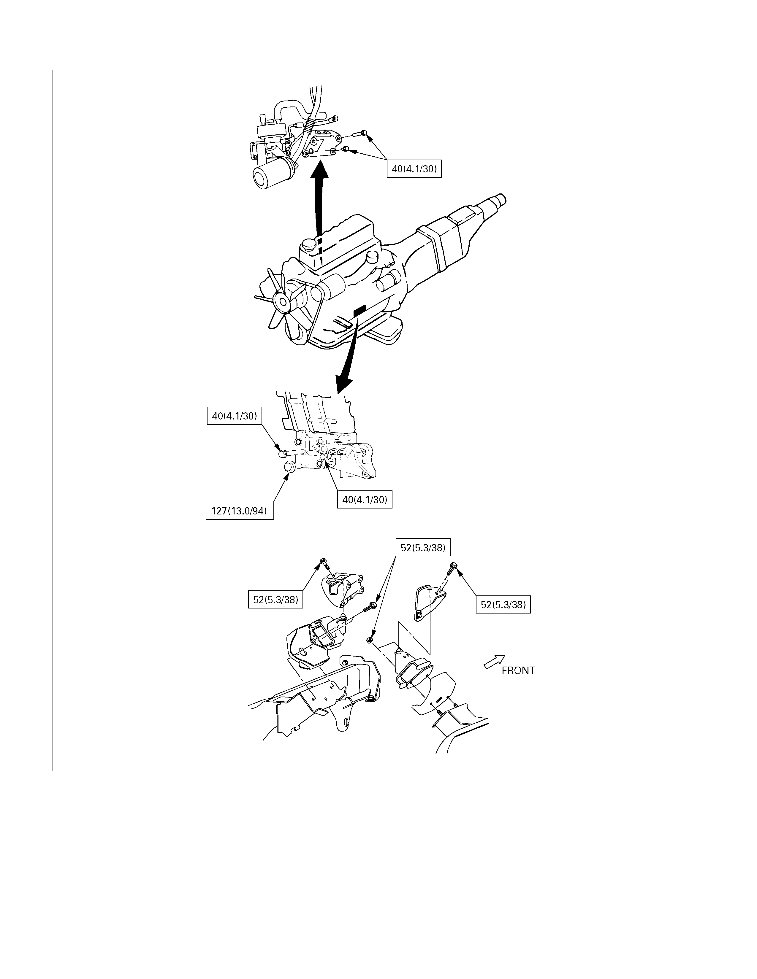
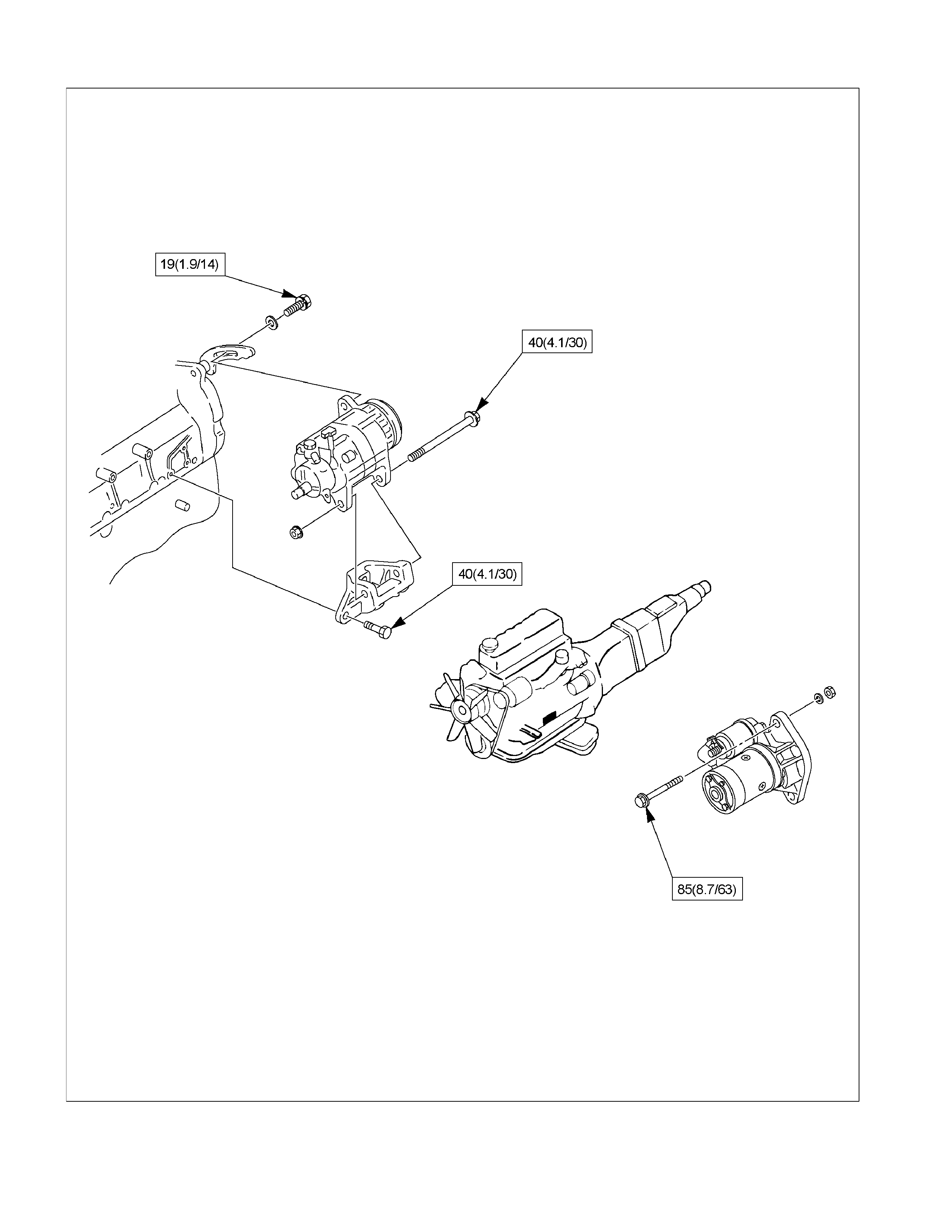
Engine Mounting Bracket
N·m (kg·m/lb·ft)
022R300001
RECOMMENDED LIQUID GASKET
Type Brand Name Manufacturer Remarks
RTV*
Silicon Base ThreeBond 1207B
ThreeBond 1207C Three Bond
Three Bond
Water Base ThreeBond 1141E
ThreeBond 1215 Three Bond
Three Bond
Solvent ThreeBond 1104
Belco Bond 4
Belco Bond 401
Belco Bond 402
Three Bond
Isuzu
Isuzu
Isuzu
Anaerobic LOCTITE 515
LOCTITE 518
LOCTITE 262
Loctite
Loctite
Loctite
Recommended for
transaxle repairs
* RTV: Room Temperature Vulcaniser
NOTE:
1. It is very important that the liquid gaskets listed abov e or their exact equivalent be used on the vehicle.
2. Be careful to use the specified amount of liquid gasket.
Follow the manufacturer’s instructions at all times.
3. Be absolutely sure to remove all lubricants and moisture from the connecting surfaces before
applying the liquid gasket.
The connecting surfaces must be perfectly dry.
4. LOCTITE 515 and LOCTITE 518 harden upon contact with a metal surface.
Do not apply LOCTITE 515 or LOCTITE 518 between two metal surfaces having a clearance of greater
than 0.25 mm (0.01 in). Poor adhesion will result.
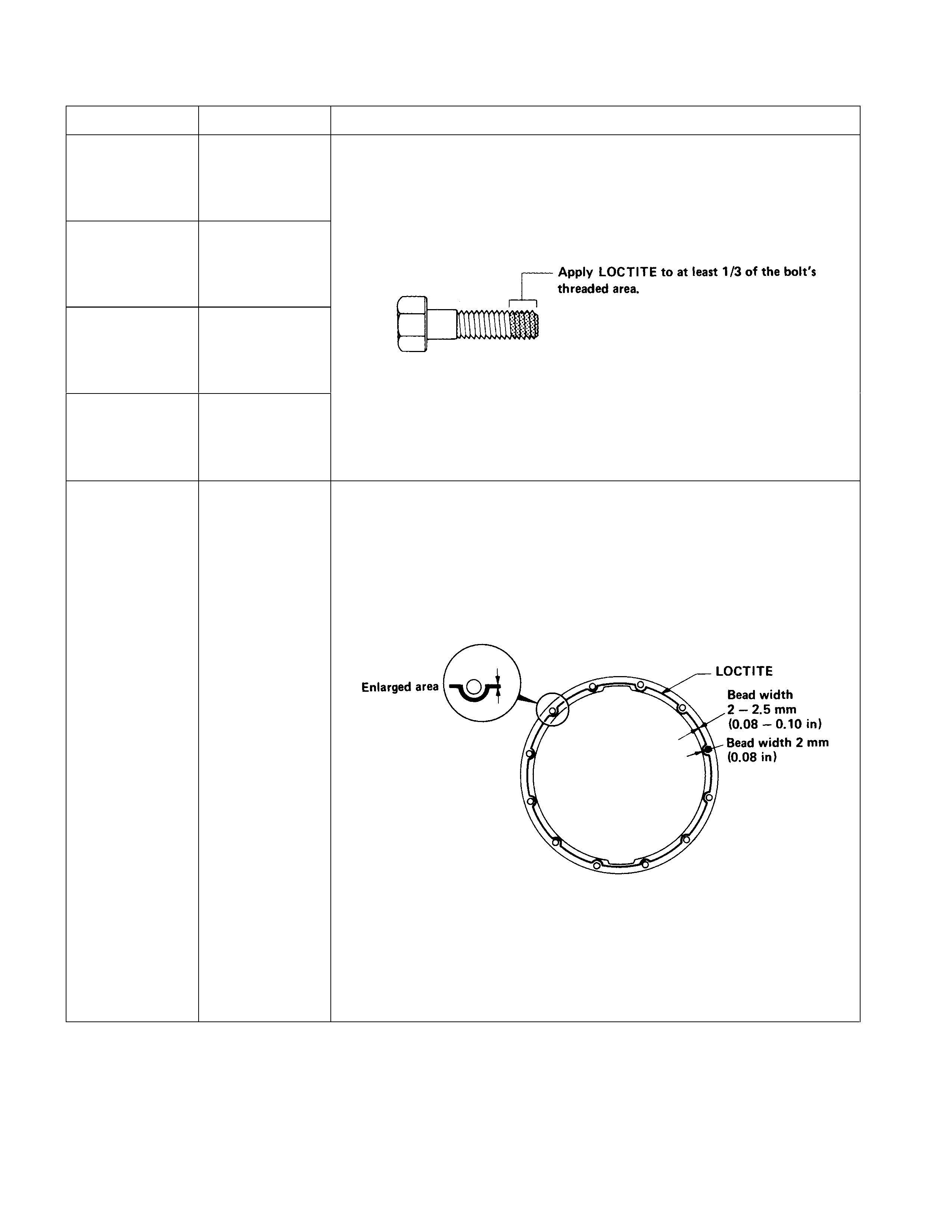
LOCTITE APPLICATION PROCEDURE
LOCTITE Type LOCTITE Color Application Steps
LOCTITE 242 Blue
LOCTITE 262 Red
LOCTITE 270 Green
LOCTITE 271 Red
1. Completely remove all lubricant and moisture from the bolts and the
female threaded surfaces of the parts to be joined.
The surfaces must be perfectly dry.
2. Apply LOCTITE to the bolts.
3. Tighten the bolts to the specified torque.
4. Wait at least one hour before continuing the installation procedure.
LOCTITE 515 Violet
1. Completely remove lubricant and moisture from the connecting
surfaces.
The surfaces must be perfectly dry.
2. Apply a 2.0 – 2.5 mm bead of LOCTITE to one of the connecting
surfaces.
There must be no gaps in the bead.
3. Tighten the bolts to the specified torque.
4. Let the joined parts set for at least thirty minutes.
SERVICING
Servicing refers to general maintenance procedures to be performed by qualified service personnel.
RTW36ASH000401
MODEL IDENTIFICATION
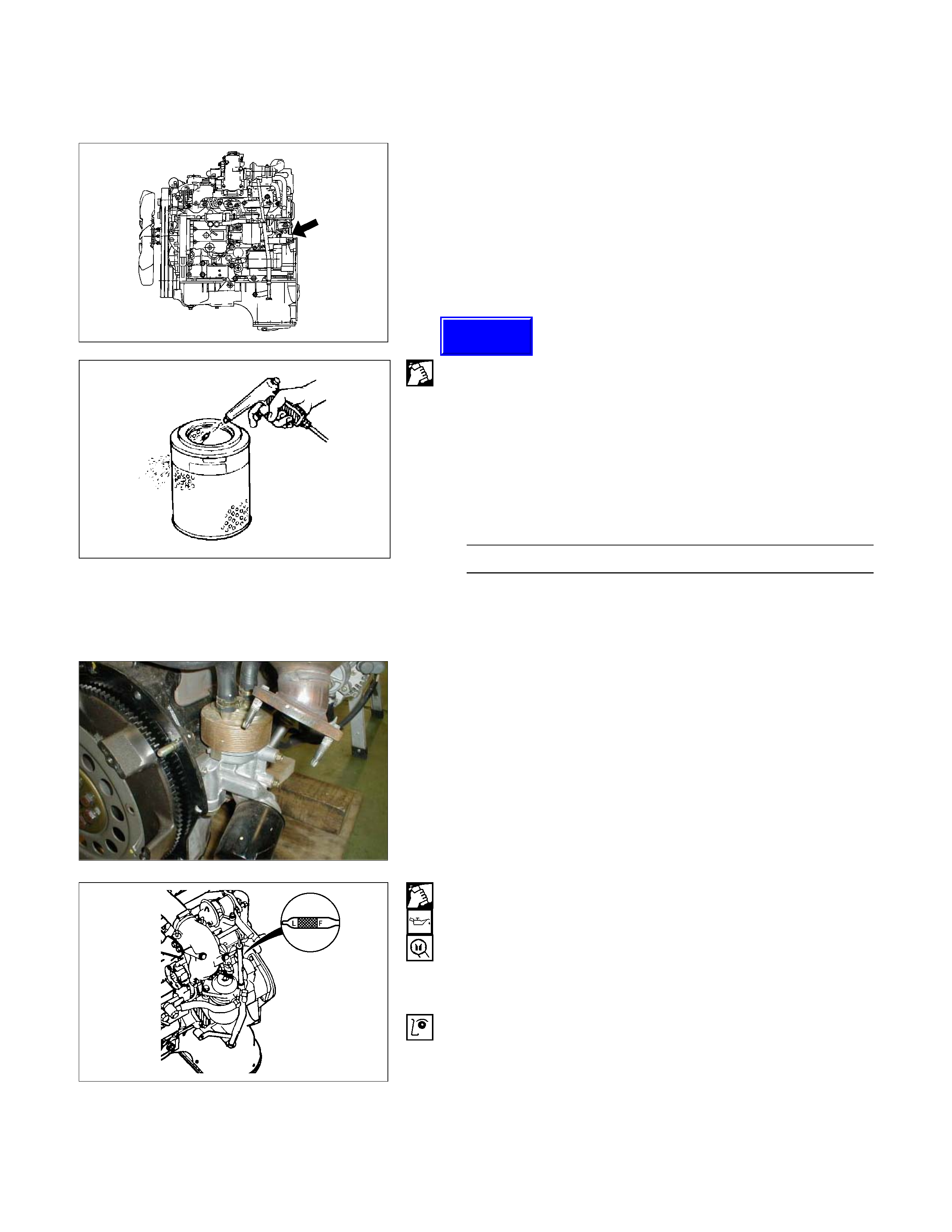
Engine Serial Number
The engine number is stamped on the rear left hand side
of the cylinder body.
The engine number is stamped in the plate in front of the
engine room as well.
AIR CLEANER
Element cleaning procedures will vary according to the
condition of the element.
Dust Fouled Element
Rotate the element with your hand while applying
compressed air to the inside of the element. This will blow
the dust free.
Compressed air pressure kPa (kg/cm2/psi)
392 – 490 (4 – 5/57 – 71)
CAUTION:
Do not hit the element against another object in an
attempt to clean it. Damage to the element will result.
LUBRICATING SYSTEM
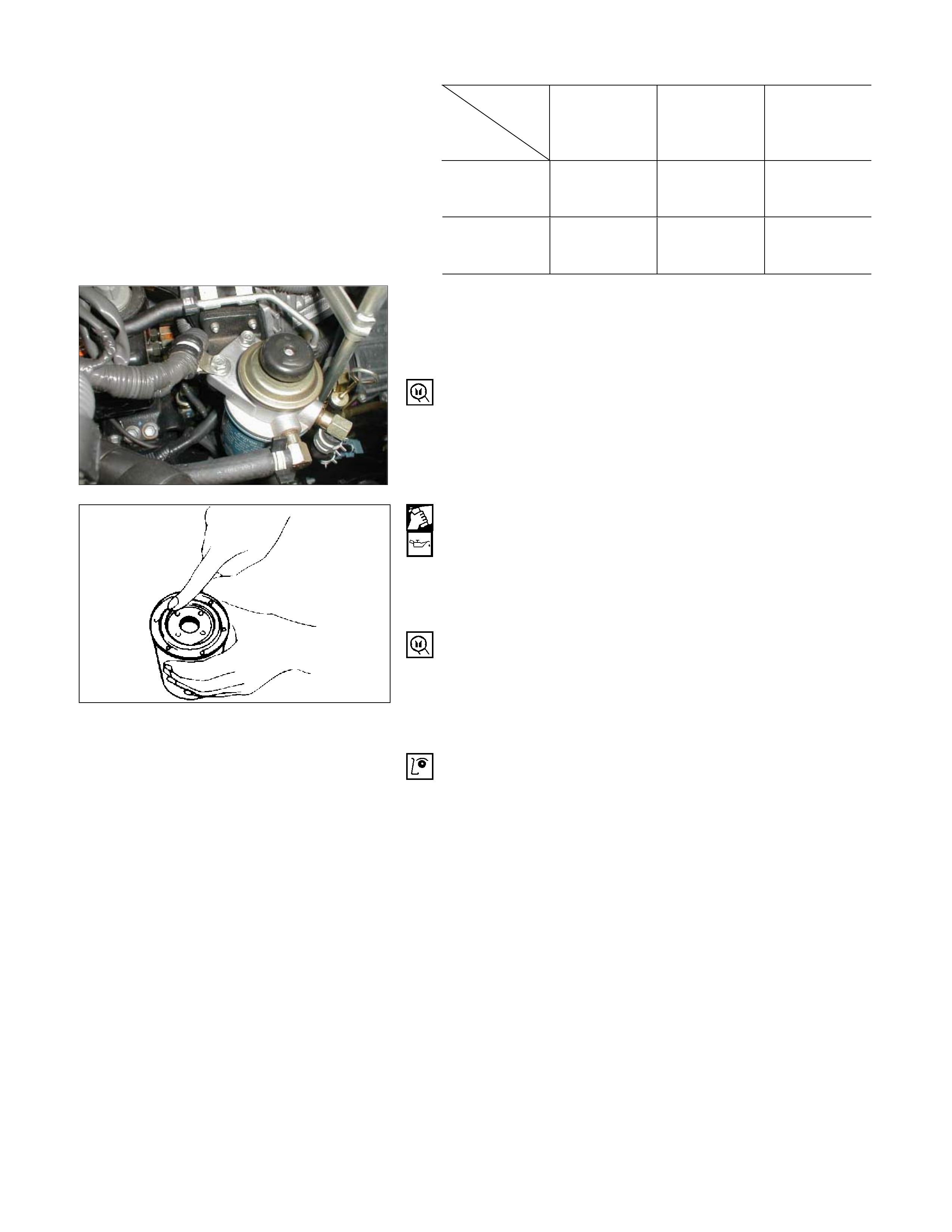
Main Oil Filter (Cartridge Type Paper Element)
Replacement Procedure
1. Drain the engine oil.
2. Retighten the drain plug.
3. Loosen the used oil filter by turning it counter
clockwise with a filter wrench.
Filter Wrench: 5-8840-0200-0
RTW36ASH000101
4. Clean the oil cooler fitting face. This will allow the new
oil filter to seat properly.
5. Apply a light coat of engine oil to the filter O-ring.
6. Turn in the new oil filter until the filter O-ring is fitted
against the sealing face.
7. Use the filter wrench to turn in the filter an additional
2/3 turns.
8. Check the engine oil level and replenish to the
specified level if required.
9. Start the engine and check for oil leakage from the
main oil filter.
130RY00003
6A-6
Techline
Replenished Engine Oil MAX lit (US/UK gal)
Condition
Model
Engine Dry
With oil filter
replacement
Without oil
filter
replacement
4 × 2 6.5 (1.7/1.4) 4.5 - 5.5
(1.19 - 1.45
/ 0.99 - 1.21)
3.5 - 4.5
(0.93 - 1.19
/ 0.77 - 0.99)
4 × 4 7.3 (1.9/1.6) 5.3 - 6.3
(1.40 - 1.66
/ 1.17 - 1.39)
4.3 - 5.3
(1.14 - 1.40
/ 0.95 - 1.17)
FUEL SYSTEM
Fuel Filter Replacement Procedure
1. Remove the fuel filter by turning it counter clockwise
with a filter wrench.
Filter Wrench: 5-8840-0253-0 (J-22700)
NOTE:
Be careful not to spill the fuel in the filter cartridge.
2. Clean the fuel filter cartridge fitting faces.
This will allow the new fuel filter to seat properly
3. Apply a light coat of engine oil to the O-ring.
4. Turn in the fuel filter until the sealing face comes in
contact with the O-ring.
5. Turn in the fuel filter an additional 2/3 of a turn with a
filter wrench.
Filter Wrench : 5-8840-0253-0 (J-22700)
6. Operate the priming pump until the air discharged
completely from fuel system.
7. Start the engine and check for fuel leakage.
NOTE:
The use of a HOLDEN genuine fuel filter is strongly
recommended.
6A-7
041RY00009
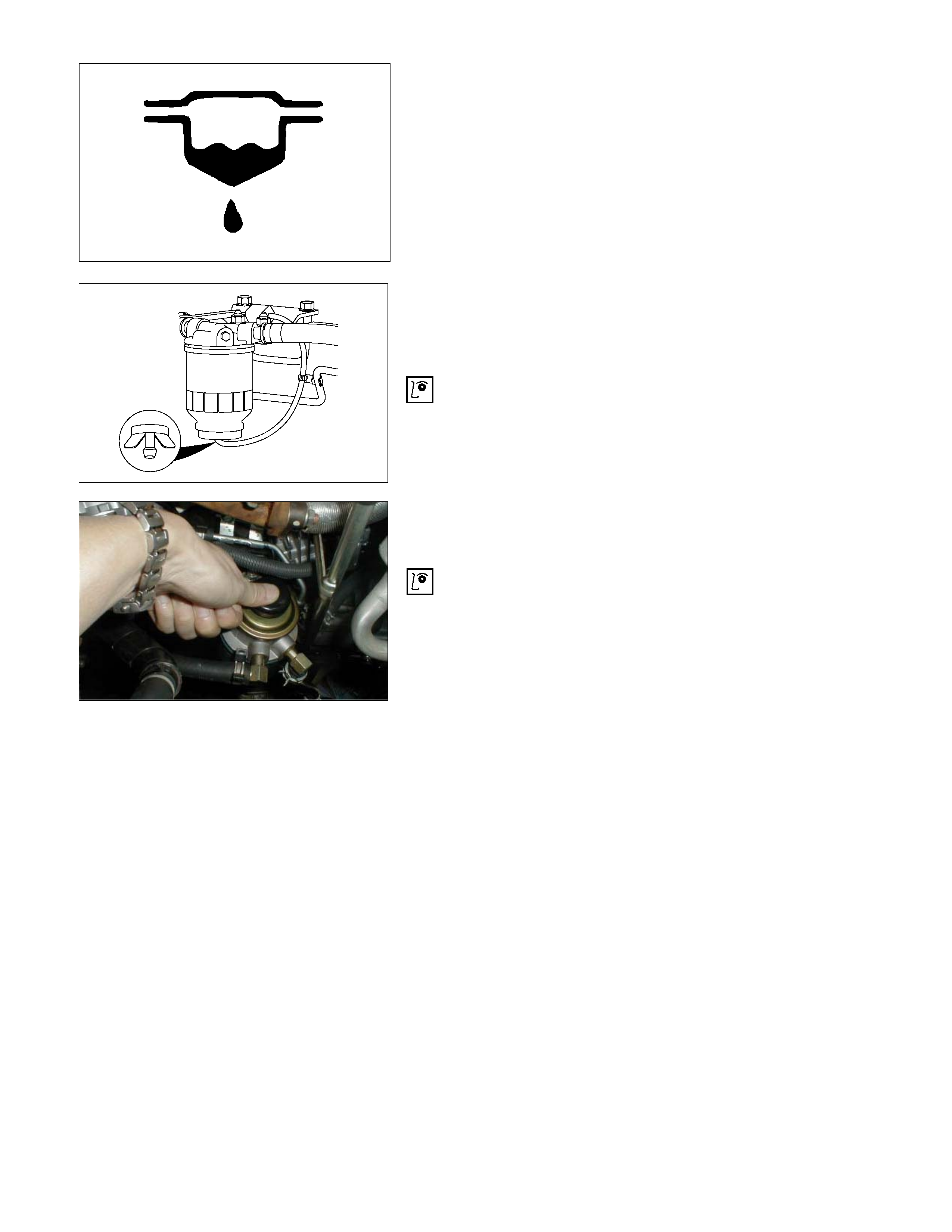
Draining Procedure
The indicator light will come on when the water level in the
water separator exceeds the specified level.
Drain the water and foreign material from the water
separator (inside chassis frame) with the following
procedure.
1. Place the drain pan under the drain plug.
2. Loosen the drain plug and drain water.
3. After draining the water, tighten the drain plug.
4. Operate the priming pump on the fuel filter several
times and check for fuel leakage.
5. Check the water separator indicator light. It should be
off.
041RY00011
041R300001
6A-8
Air Bleeding
1. Operate the priming pump until strong resistance is
felt.
2. Wait 1 minute, and operate the priming pump until
strong resistance is felt.
3. Once more wait, and operate the priming pump until
strong resistance is felt.
4. Turn the ignition switch to the "ON" position. Wait until
the glow indicator lamp turns off.
5. Turn the ignition switch to the "START" position and
crank the engine until it starts.
6. If the engine does not start, repeat Step 3 - 5.
7. Allow the engine to idle for 3 minutes to bleed air
completely form the fuel system and check for fuel
leakage.
NOTE:
Insufficient air bleeding may cause a Diagnostic Trouble
Code (DTC) to store, or improper engine performance.
111R300001
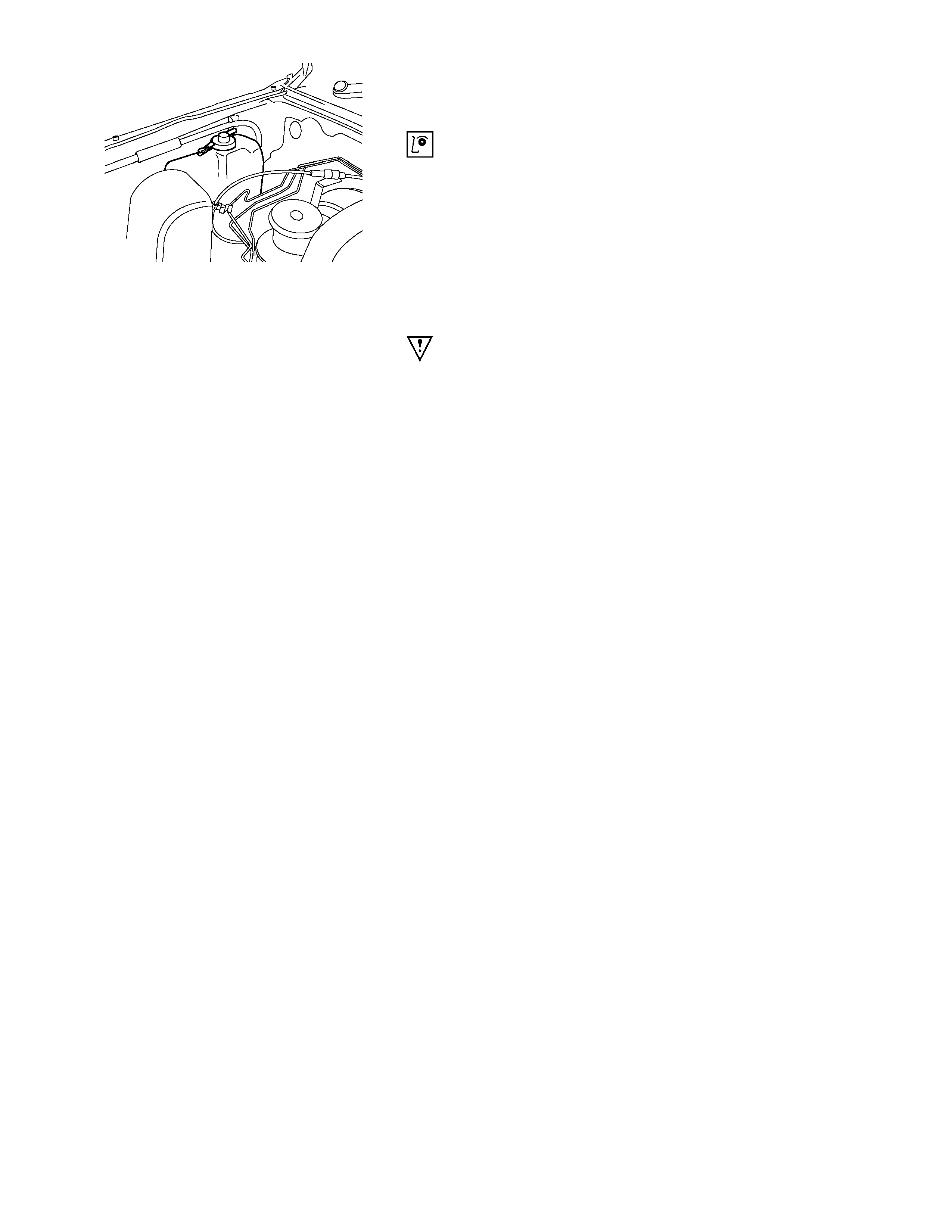
COOLING SYSTEM
Coolant Level
Check the coolant level and replenish the radiator reserve
tank as necessary.
If the coolant level falls below the “MIN” line, carefully
check the cooling system for leakage. Then add enough
coolant to bring the level up to the “MAX” line. Use only
50% water with 50% coolant to Holden HN2217
Specification.
Engine coolant filling procedure
NOTE:
Use only 50% water with 50% coolant to Holden HN2217
Specification.
1. Make sure that the engine is cool.
WARNING:
When the coolant is heated to a high temperature, be
sure not to loosen or remove the radiator cap,
otherwise you might get scalded by hot vapour or
boiling water. Wait until the coolant has become
cooler before opening the cap.
To open the radiator cap, put a piece of thick cloth on
the cap and loosen the cap slowly to reduce the
pressure.
2. Remove the radiator cap and add coolant up to the
filler neck.
3. Pour coolant into the reservoir tank up to “MAX” line.
4. Set the heater adjustment to the highest temperature
position to allow the coolant to circulate through the
heater system.
5. Tighten the radiator cap and start the engine. After
idling for 2 to 3 minutes, stop the engine and reopen
the radiator cap. If the coolant level is lower than the
filler neck, replenish the coolant level.
6. After replenishing the coolant, refit and tighten the
radiator cap. Warm up the engine at approximately
2000 rpm.
7. Continue to monitor the coolant temperature gauge.
When the coolant temperature gauge indicates that
the thermostat has opened, idle the engine for 5
minutes, then stop the engine.
8. When the engine has cooled, remove the radiator cap
and inspect that the coolant level is up to the filler
neck. Replenish if required. If there is an extreme
shortage of coolant, check the coolant system,
including the reservoir tank and hose, for leaks.
9. Pour coolant into the reservoir tank up to “MAX” line.
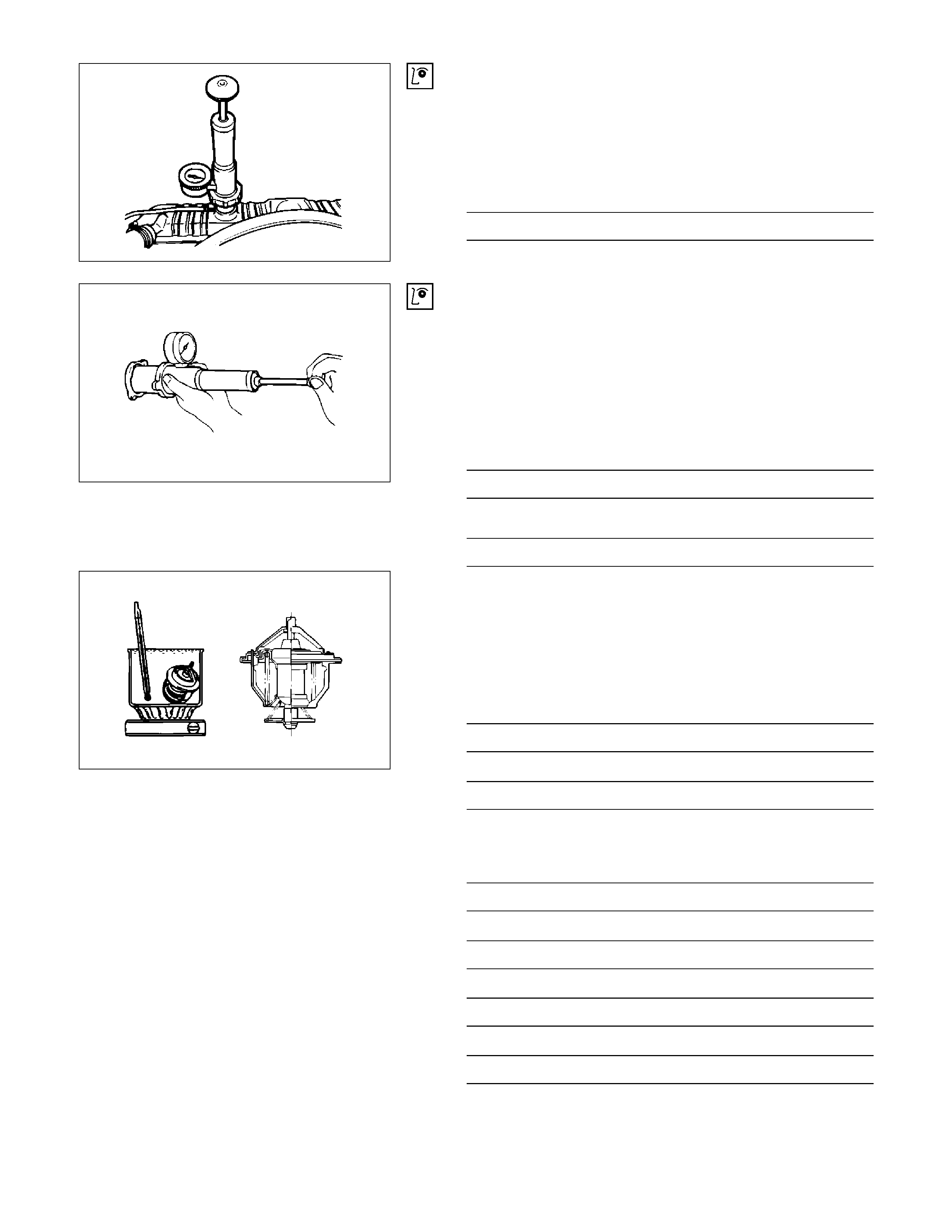
Cooling System Inspection
Install a radiator filler cap tester to the radiator. Apply
testing pressure to the cooling system to check for
leakage. The testing pressure must not exceed the
specified pressure.
Testing Pressure kPa (kg/cm2/psi)
150 (1.5/21)
Radiator Cap Inspection
The radiator filler cap is designed to maintain coolant
pressure in the cooling system at 103 kPa(1.05 kg/cm2,
15psi).
Check the radiator filler cap with a radiator filler cap tester.
The radiator filler cap must be replaced if it fails to hold
the specified pressure during the test procedure.
Radiator Cap Valve Opening Pressure
kPa (kg/cm2/psi)
90 – 120 (0.9 – 1.2/13 – 17)
Negative Valve (Reference) kPa (kg/cm2/psi)
1.9 – 4.9 (0.02 – 0.05/0.28 – 0.71)
Thermostat Operating Test
1. Completely submerge the thermostat in water.
2. Heat the water.
Stir the water constantly to avoid direct heat being
applied to the thermostat.
3. Check the thermostat initial opening temperature.
Thermostat Initial Opening Temperature °C (°F)
82 (180)
Oil Cooler Thermo Valve °C (°F)
76.5 (170)
4. Check the thermostat full opening temperature.
Thermostat Full Opening Temperature °C (°F)
95 (203)
Oil Cooler Thermo Valve °C (°F)
90 (194)
Valve Lift at Fully Open position mm (in)
9.5 (0.37)
Oil Cooler Thermo Valve mm (in)
4.5 (0.18)
030LX003
030LX002
030LX014
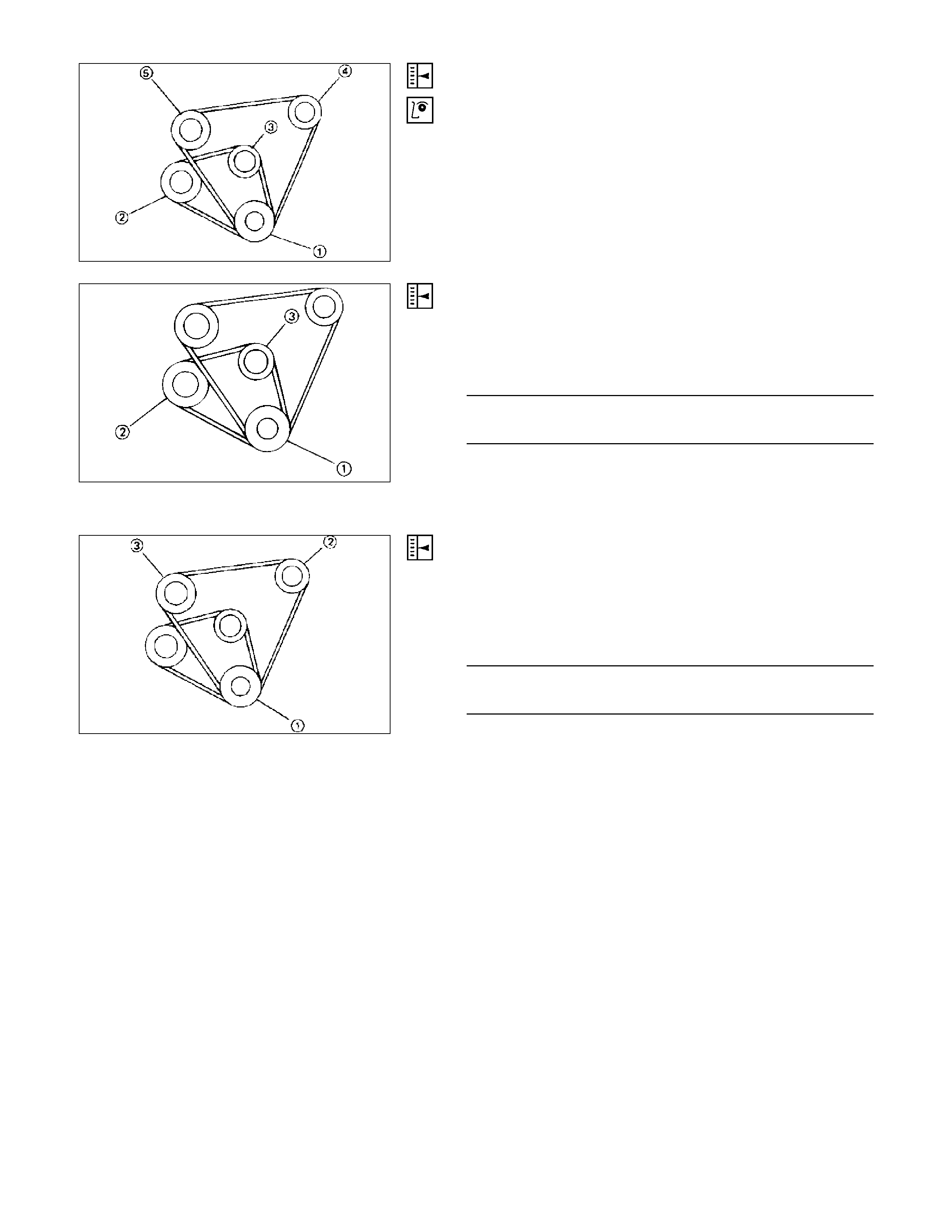
Drive Belt Adjustment
Check drive belts for wear or damage, and replace with
new ones as necessary. Check belts for tension, and
adjust as necessary.
1 Crankshaft damper pulley
2 Generator pulley
3 Cooling fan pulley
4 Oil pump pulley or idler pulley
5 Compressor pulley or idler pulley
Cooling Fan Pulley Drive Belt
Fan belt tension is adjusted by moving the generator.
Depress the drive belt mid-portion with a 98N (10 kg/22
Ib) force.
Cooling Fan Drive Belt Deflection mm (in)
New belt 4 - 7 (0.16 - 0.28)
Reuse belt 6 - 9 (0.24 - 0.35)
1 Crankshaft damper pulley
2 Generator pulley
3 Cooling fan pulley
A/C Compressor Drive Belt
Compressor belt tension is adjusted by moving the P/S
pump pulley.
Depress the drive belt mid-portion with a 98N (10 kg/22
Ib) force.
A/C Compressor Drive Belt Deflection mm (in)
New belt 9 - 10 (0.35 - 0.39)
Reuse belt 12 - 13 (0.47 - 0.51)
1 Crankshaft damper pulley
2 P/S pump pulley
3 A/C Compressor pulley
033RY00002
033RY00003
033RY00004
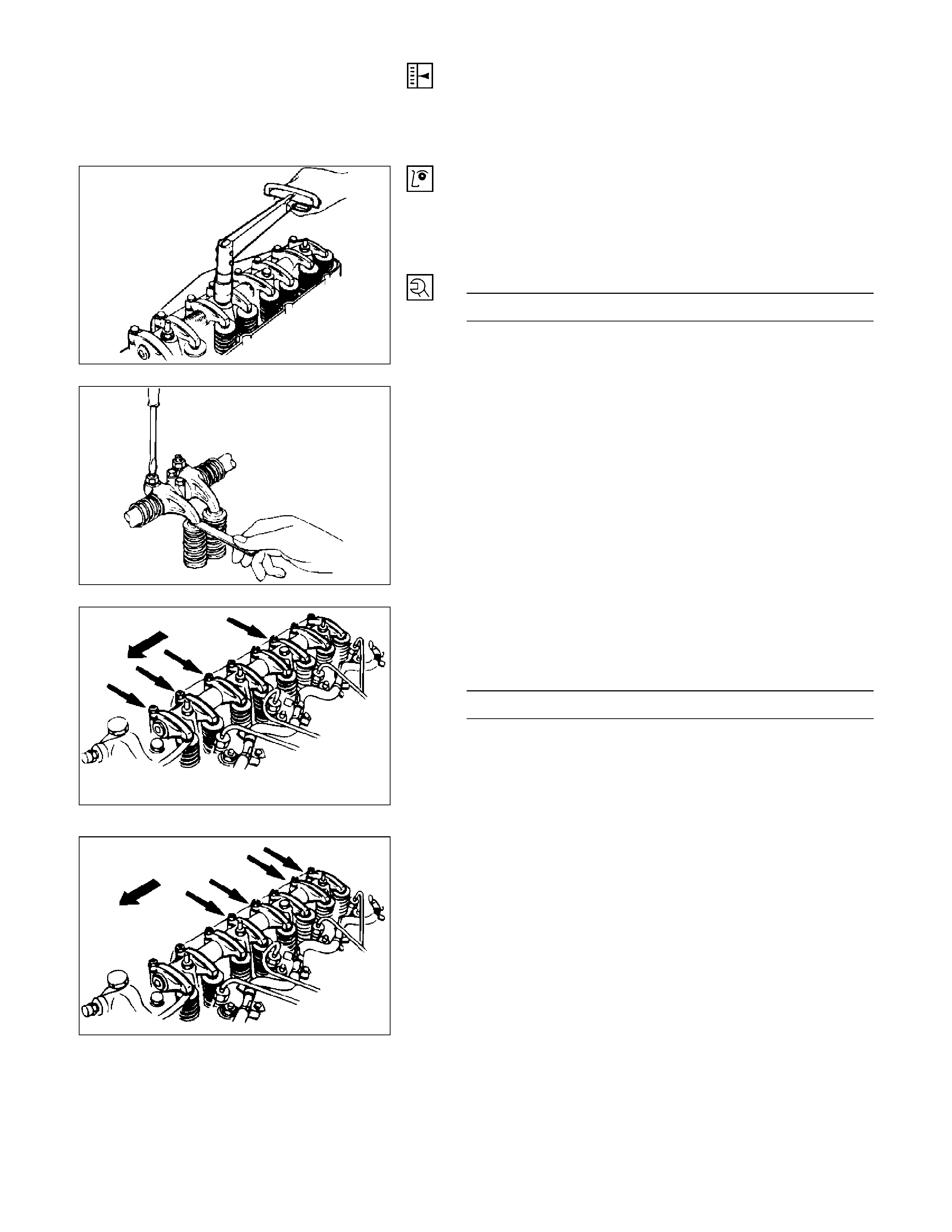
VALVE CLEARANCE ADJUSTMENT
1. Bring the piston in either the No. 1 cylinder or the No.
4 cylinder to TDC on the compression stroke by
turning the crankshaft until the crankshaft damper
pulley TDC line is aligned with the timing pointer.
2. Check the rocker arm shaft bracket nuts for
looseness.
Tighten any loose rocker arm shaft bracket nuts
before adjusting the valve clearance.
Rocker Arm Shaft Bracket Nut Torque N·m (kg·m/lb·ft)
54 (5.5/40)
3. Check for play in the No. 1 intake and exhaust valve
push rods. If the No. 1 cylinder intake and exhaust
valve push rods have play, the No. 1 piston is at TDC
on the compression stroke. If the No. 1 cylinder intake
and exhaust valve push rods are depressed, the No. 4
piston is at TDC on the compression stroke.
Adjust the No.1 or the No. 4 cylinder valve clearances
while their respective cylinders are at TDC on the
compression stroke.
Valve Clearance (At Cold) mm (in)
0.4 (0.016)
4. Loosen each valve clearance adjusting screw as
shown in the illustration.
5. Insert a feeler gauge of the appropriate thickness
between the rocker arm and the valve stem end.
6. Turn the valve clearance adjusting screw until a slight
drag can be felt on the feeler gauge.
7. Tighten the lock nut securely.
8. Rotate the crankshaft 360°.
9. Realign the crankshaft damper pulley TDC notched
line with the timing pointer.
10. Adjust the clearances for the remaining valves as
shown in the illustration.
014RY00014
014RY00015
014RY00016
014RY00017
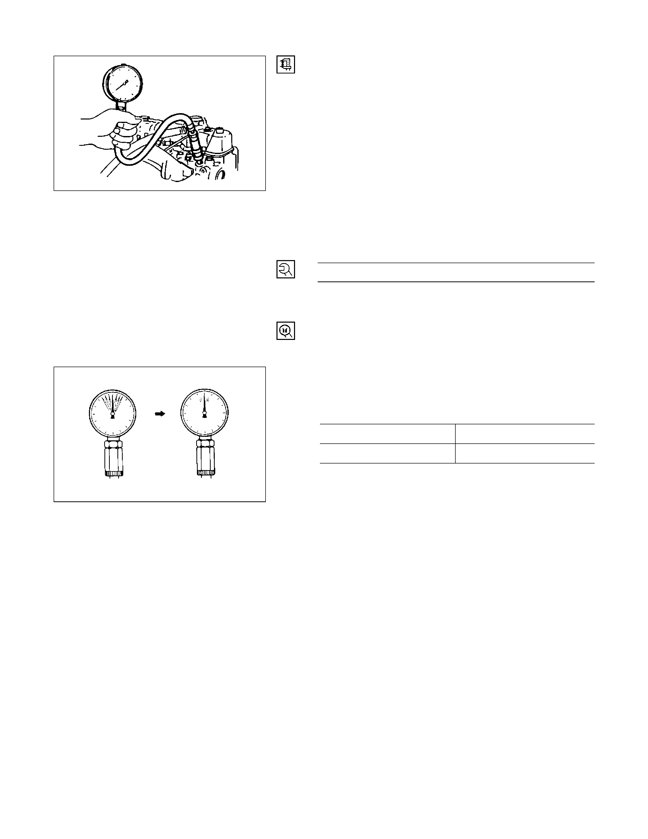
COMPRESSION PRESSURE MEASUREMENT
1. Start the engine and allow it to idle until the coolant
temperature reaches 70 – 80 °C (158 – 176 °F).
2. Remove the following parts.
• Leak off pipe
• Injection nozzle holder bracket
• Injection nozzle holder
3. Install the following parts.
• Set the adapter and compression gauge (SST) to
the No.1 cylinder injection nozzle hole.
• Injection nozzle holder bracket
Injection nozzle holder bracket Bolt Torque
N·m (kg·m/lb·ft)
37 (3.8/27)
Compression Gauge: 5-8840-2675-0
Adapter; Compression Gauge: 5-8531-7001-0
4. Turn the engine over with the starter motor and take
the compression gauge reading.
Compression Pressure MPa (kg/cm2/psi) at 200 rpm
Standard Limit
30 (31.0/441) 2.1 (21.7/309)
5. Repeat the procedure (Steps 3 and 4) for the
remaining cylinders.
If the measured value is less than the specified limit,
refer to “Troubleshooting” in this Manual.
F06XL056
901R100003
GENERAL DESCRIPTION
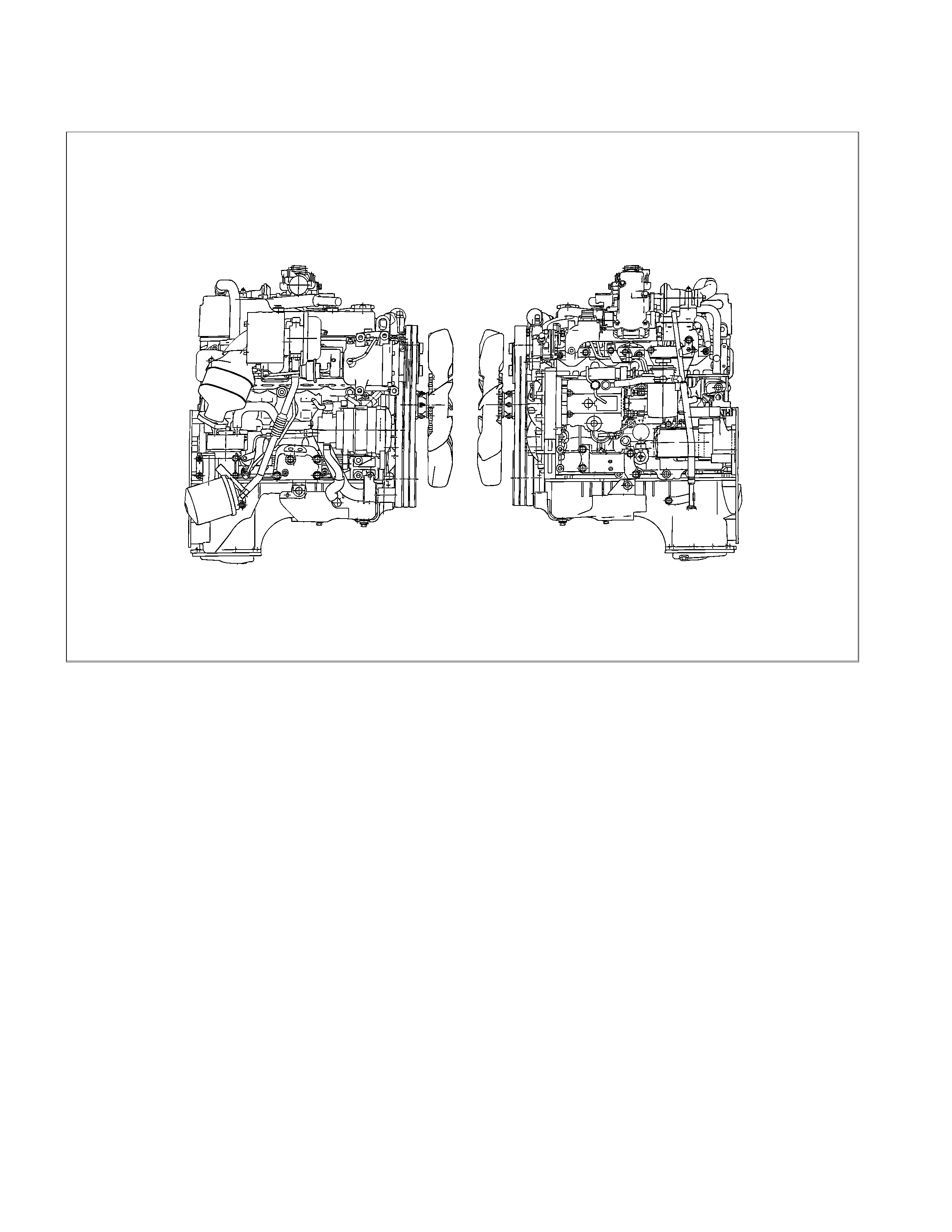
RTW36AMF000101
The 4J series automotive diesel engine feature a unique design of combustion chamber in the top of each piston. This
design provides superior fuel economy over a wide range of driving conditions.
Auto-thermatic pistons with cast steel struts are used to reduce thermal expansion, resulting in reduced engine noise
during the engine warm-up period.
Chrome plated dry type cylinder liners provide increased durability over the more conventional cast iron liners.
The laminated steel sheet cylinder head gasket increases head gasket reliability.
The crankshaft has been tufftrided to provide a longer service life. Because the crankshaft is tufftrided, it cannot be
reground.
Engine is equipped with the BOSCH VP44-Type distributor injection pump, a turbocharger and Exhaust Gas
Recirculation (EGR) system.
REMOVAL AND INSTALLATION
Read this section carefully before performing any removal and installation procedure. This section gives you important
points as well as the order of operation. Be sure that you understand everything in this section before you begin.
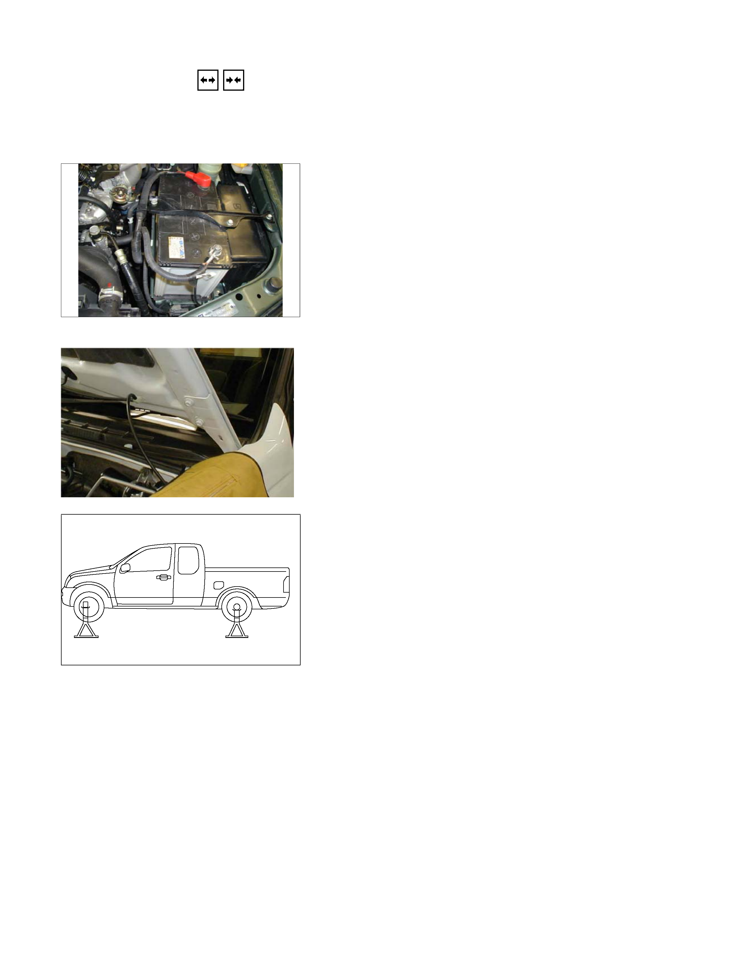
REMOVAL
P1010011
1. Battery
1) Disconnect the battery cable and the grounding cable
from the battery terminals.
2) Remove the battery clamp. Take care not to
accidentally short the battery with the wrench or some
other tool.
3) Remove the battery.
4) Disconnect the battery cable at the starter motor and
the ground cable at the cylinder body.
2. Engine Hood
Apply setting marks to the engine hood and the engine
hood hinges before removing the engine hood. This will
facilitate reinstallation of the engine hood to its original
position.
3. Supporting the Vehicle
1) Jack up the vehicle.
2) Place chassis stands at the front and the rear of the
vehicle.
4. Under cover (for 4x4 model)
5. Rear propeller shaft
1) Remove the propeller shaft flange yoke at the rear
differential.
2) Remove the center bearing retainer bolts.
3) Remove the propeller shaft together with the center
bearing from the transmission mainshaft spline.
P1010002
F06R300006

6. Front propeller shaft (for 4x4 model)
Remove the spline yoke flange bolt at the transfer output
shaft.
Do not allow the spline yoke to fall away from the front
propeller shaft.
If the spline yoke should fall away from the front propeller
shaft, align the setting marks on the spline yoke and the
propeller shaft to reassemble the two marks. The setting
marks are punched circles approx. 3mm (0.12 in) in
diameter.
7. Clutch slave cylinder (for M/T model)
8. ATF pipe (for A/T model)
9. Shift control cable (for A/T model)
10. Transmission sensor harness
11. Remove the vehicle speed sensor connector, inhibitor
switch connector (A/T), ATF temperature sensor
connector, back up light switch connector (M/T) from
transmission.
11. Breather hose (for A/T model)
12. Transmission shift lever (for M/T model)
Remove the shift lever from the floor.
13. Transfer shift lever (for 4x4 model)
Remove the shift lever from the floor.
14. Transmission member
1) Support the transmission with the transmission jack.
2) Remove the transmission member mounting bolts
fixing the transmission member to the chassis frame.
15. Torque converter bolt (for A/T model)
1) Remove the under cover under the torque converter
housing.
2) Rotate the flywheel by using tire lever or some other
tool, and then remove the torque converter bolts.
16. Transmission coupling bolt
1) Support the engine with the garage jack.
2) Use the jack to slightly lower the transmission.
3) Remove the transmission coupling bolts.
17. Transmission (and transfer)
Separate the transmission (and transfer) from the engine.
Take care not to damage the transmission, the engine,
and their related parts.
P1010025
F06R300007
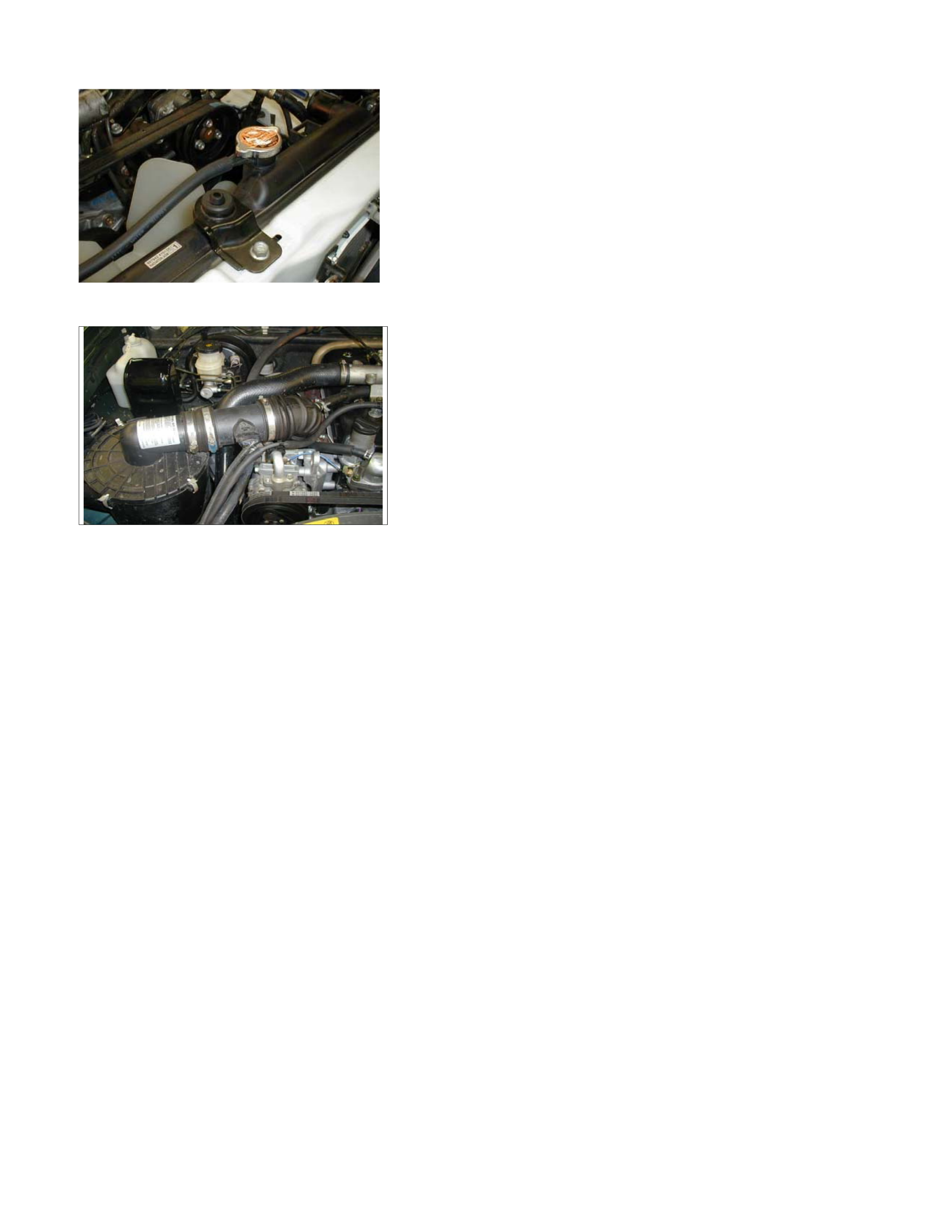
18. Radiator
1) Drain the engine coolant.
2) Remove the reservoir hose.
3) Remove the upper and lower hose.
4) Remove the fan guide.
5) Remove the radiator.
19. Fan
P1010034
20. Air cleaner
1) Remove the MAF sensor connector from air cleaner
duct.
2) Remove the air cleaner duct and the air cleaner box
from engine bay.
3) Remove the two air ducts from inter cooler.
21. Power Steering Pump
Loosen the power steering pump adjust plate bolt, then
remove the power steering pump assembly. Place the
power steering pump assembly along with piping on the
body side.
22. Air conditioner compressor
1) Remove air compressor magnet connector.
2) Remove the air conditioner compressor. Place the air
conditioner compressor along with piping on the body
side.
23. Engine Control Cable
Remove the engine control cable from its bracket.
24. Vacuum Piping
Remove the vacuum pipes from the vacuum pump, and
the EGR valve.
P1010009
25. Engine Harness
1) Remove following connectors from engine.
• TPS connector
• Oil pressure switch connector
• Thermo switch connector
• Injection pump connector
• Engine earth
• Engine Coolant Temperature sensor connector
• TDC sensor
2) Remove the clips fixing engine harness.
26. Fuel Hose
Remove the fuel hose from the fuel filter.
27. Exhaust Pipe
Remove the front exhaust pipe bolts and separate the
exhaust manifold and the front exhaust pipe.
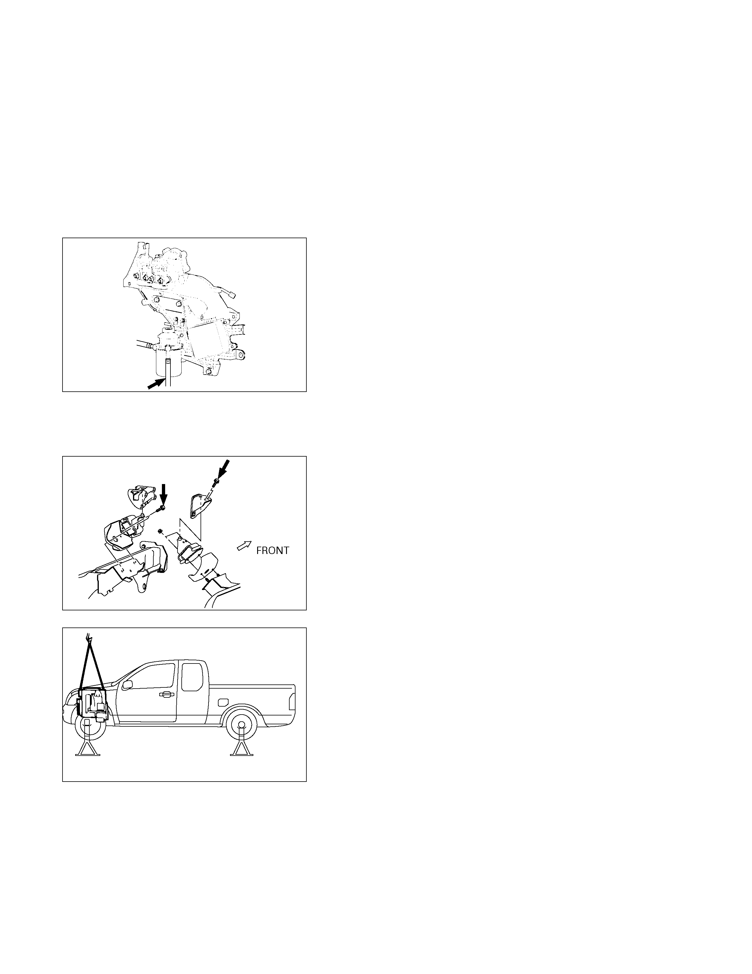
28. Engine Assembly
1) Remove two right side engine foot bolts.
2) Remove two left side engine mount bolts.
3) Use the hoist to lift the engine from the engine
compartment.
INSTALLATION
To reassemble, follow the removal steps in the reverse
order.
140R300001
022R300002
F06R300008

COOLANT REPLENISHMENT
NOTE:
Use only 50% water with 50% coolant to Holden HN2217
Specification.
1. Make sure that the engine is cool.
WARNING:
When the coolant is heated to a high temperature, be
sure not to loosen or remove the radiator cap,
otherwise you might get scalded by hot vapour or
boiling water. Wait until the coolant has become
cooler before opening the cap.
To open the radiator cap, put a piece of thick cloth on
the cap and loosen the cap slowly to reduce the
pressure.
2. Remove the radiator cap and add coolant up to the
filler neck.
3. Pour coolant into the reservoir tank up to “MAX” line.
4. Set the heater adjustment to the highest temperature
position to allow the coolant to circulate through the
heater system.
5. Tighten the radiator cap and start the engine. After
idling for 2 to 3 minutes, stop the engine and reopen
the radiator cap. If the coolant level is lower than the
filler neck, replenish the coolant level.
6. After replenishing the coolant, refit and tighten the
radiator cap. Warm up the engine at approximately
2000 rpm.
7. Continue to monitor the coolant temperature gauge.
When the coolant temperature gauge indicates that
the thermostat has opened, idle the engine for 5
minutes, then stop the engine.
8. When the engine has cooled, remove the radiator cap
and inspect that the coolant level is up to the filler
neck. Replenish if required. If there is an extreme
shortage of coolant, check the coolant system,
including the reservoir tank and hose, for leaks.
9. Pour coolant into the reservoir tank up to “MAX” line.
Coolant Capacity lit (US/UK gal)
9.5 (2.5/2.1)
ENGINE WARM-UP
After completing the required maintenance procedures,
start the engine and allow it to idle until it is warm.
Check the following:
1. Engine idling speed.
2. Engine noise level.
3. Engine lubricating system and cooling system.
Carefully check for oil and coolant leakage.
4. Clutch engagement.
5. Transmission operation.
6. Indicator warning light operation.
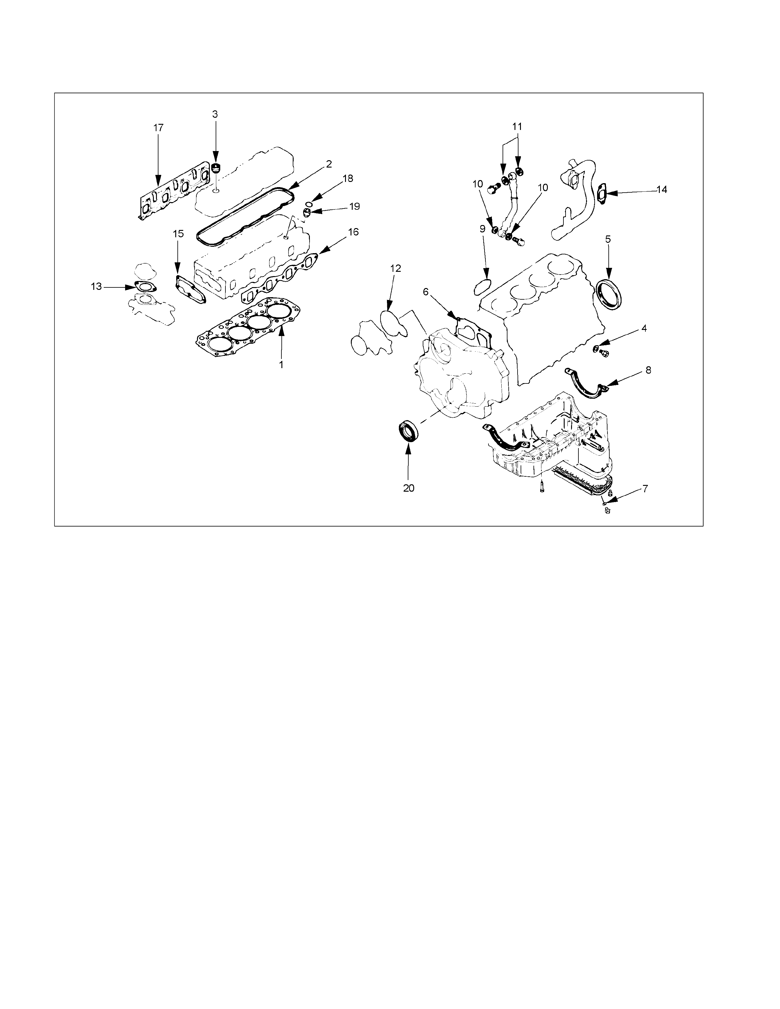
ENGINE REPAIR KIT
RTW36ALF000601
Removal Steps
1. Cylinder head gasket
2. Head cover gasket
3. Head cover cap nut gasket
4. Drain cock gasket
5. Crankshaft rear oil seal
6. Gear case gasket
7. Oil pan drain plug gasket
8. Oil pan gasket
9. Oil filter gasket
10. Joint bolt gasket
11. Vacuum pump gasket
12. Water pump O-ring
13. Water outlet pipe gasket
14. Intake pipe gasket
15. Thermostat housing gasket
16. Intake manifold gasket
17. Exhaust manifold gasket
18. Nozzle holder O-ring
19. Nozzle holder gasket
20. Crankshaft front oil seal
NOTE:
Discard all O-rings, gaskets, and seals removed at disassembly and replace them with new ones. Reuse of these parts
will result in oil, water, and gas leakage.

ENGINE OVERHAUL
REMOVAL
EXTERNAL PARTS
RTW36AMF000401
Removal Steps
1. Clutch assembly or flex plate
2. Intake pipe and throttle body
3. EGR pipe
4. EGR valve
5. Oil level gauge
6. Fuel filter assembly
7. Fuel filter bracket
8. Fuel injection pipe with clip
9. Power steering oil pump bracket
10. Intake manifold
11. Engine mounting bracket and foot
12. Injection pump cover
13. Injection pump
14. Starter motor
15. Oil pressure warning switch
16. Fuel leak-off pipe
17. Oil cooler water pipe
18. Cooling fan pulley
19. Heat protector
20. Catalytic converter
21. Turbocharger
22. Compressor bracket
23. Vacuum pump oil return hose
24. Generator and adjusting plate
25. Water inlet pipe
26. Generator bracket
27. Oil cooler with oil filter
28. Exhaust manifold
Removal
1. Clutch Assembly or Flex Plate
Remove the clutch assembly or the flex plate.
RTW36ASH000201
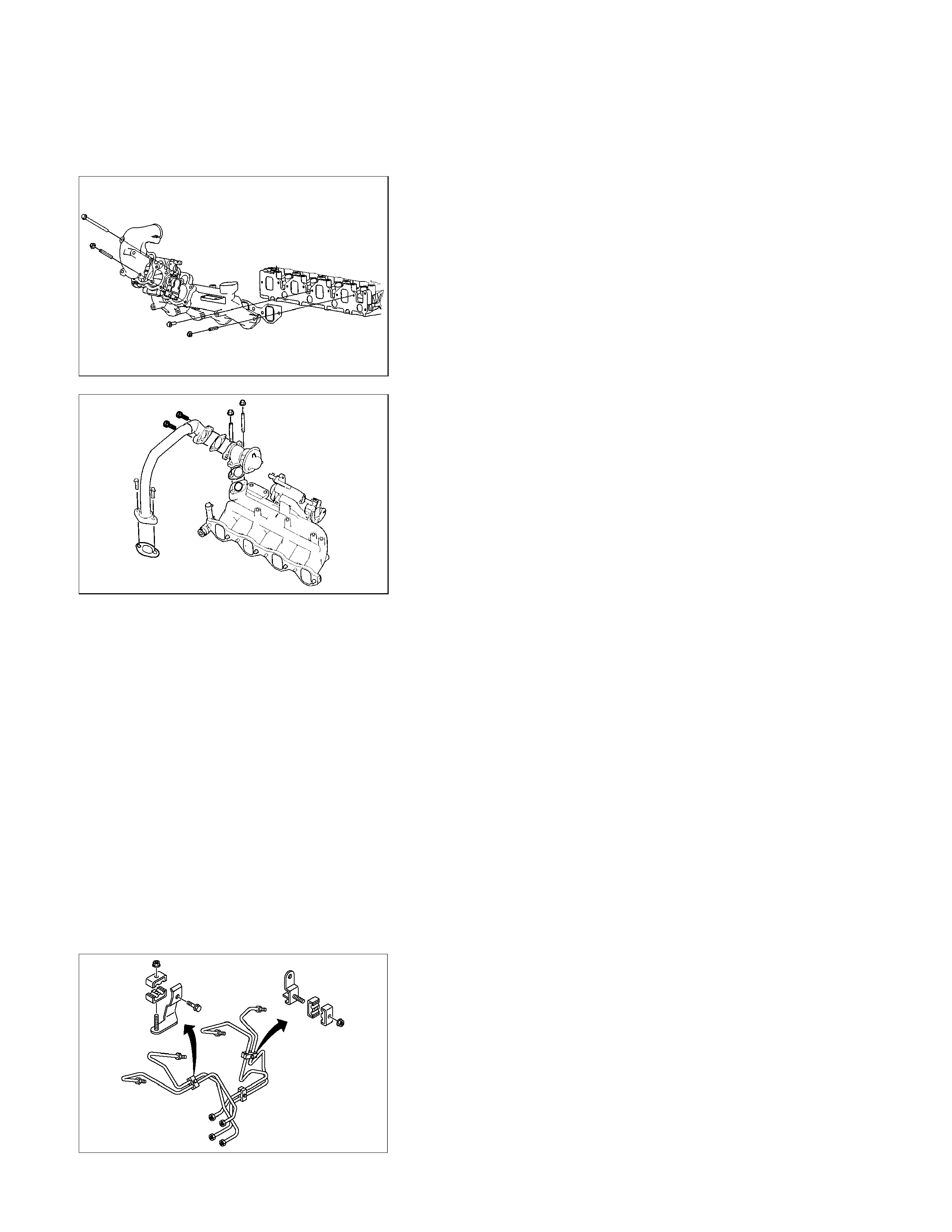
2. Intake Pipe and Throttle Body
1) Loosen hose clamp between turbocharger and intake
duct.
2) Remove the rubber hose.
3) Remove the intake pipe and the throttle body.
RTW36ASH000301
3. EGR Pipe
1) Remove two bolts from the exhaust manifold.
2) Remove two nuts from the EGR valve adapter.
3) Remove the EGR pipe with gaskets.
4. EGR Valve
1) Remove four nuts and remove the EGR valve
assembly from the intake manifold.
2) Remove four bolts and remove the adapter from the
EGR valve assembly.
5. Oil Level Gauge
1) Disconnect PCV hose.
2) Remove two bolts and remove the engine oil level
gauge.
6. Fuel Filter Assembly
1) Disconnect fuel hose.
2) Remove two bolts and remove the fuel filter.
7. Fuel Filter Bracket
Remove three bolts and remove the fuel filter bracket with
leak pipe.
RTW36ASH001201
8. Fuel Injection Pipe with Clip
1) Loosen the injection pipe sleeve nuts at pump side
and nozzle side.
Do not apply excessive force to the injection pipes.
2) Loosen the injection pipe clips.
3) Remove the injection pipe.
NOTE:
Plug the delivery holder ports with the caps to prevent the
entry of foreign material.
9. Power Steering Oil Pump Bracket
RTW36ASH000701
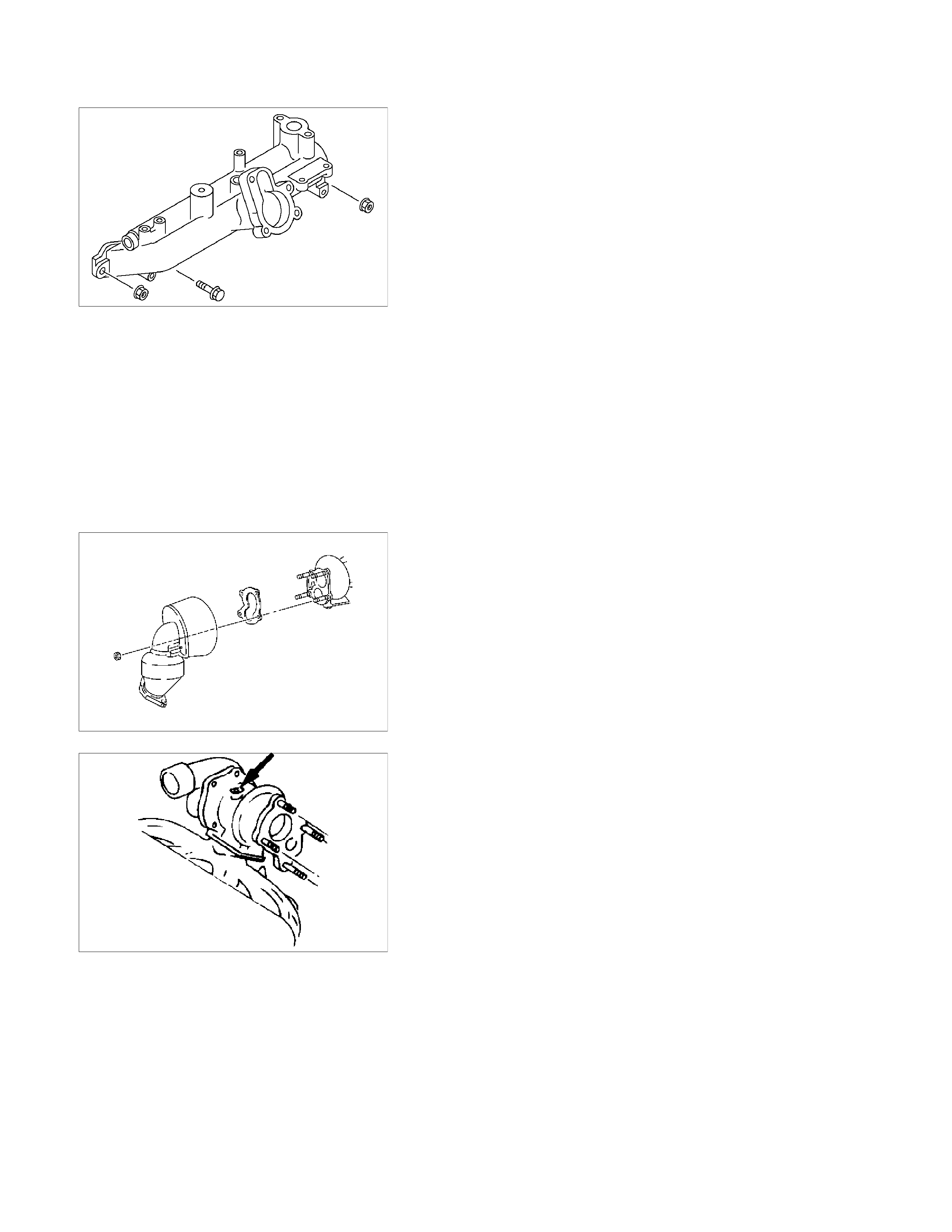
10. Intake Manifold
1) Disconnect the PCV hose from the cylinder head
cover.
2) Remove the intake manifold with gasket.
11. Engine Mounting Bracket and Foot
12. Injection Pump Cover
13. Injection Pump
Refer to Section 6C Injection Pump
14. Starter Motor
15. Oil Pressure Warning Switch
16. Fuel Leak Off Pipe
17. Oil Cooler Water Pipe
18. Cooling Fan Pulley
19. Heat Protector
20. Catalytic Converter
21. Turbocharger
1) Disconnect the water hose between thermostat
housing cover and turbocharger.
2) Disconnect the water hose between water inlet pipe
and turbocharger.
3) Remove the oil feed pipe.
4) Remove the oil return pipe.
5) Remove the turbocharger and the gasket.
NOTE:
Plug the turbocharger body oil ports and water ports after
removing the turbocharger assembly to prevent the entry of
foreign material.
22. Compressor Bracket
23. Vacuum Pump Oil Return Hose
24. Generator and Adjusting Plate
25. Water Inlet Pipe
26. Generator Bracket
27. Oil Cooler with Oil Filter
28. Exhaust Manifold
027R100007
037RY00001
DISASSEMBLY
INTERNAL PARTS
MAJOR COMPONENTS
011R300001
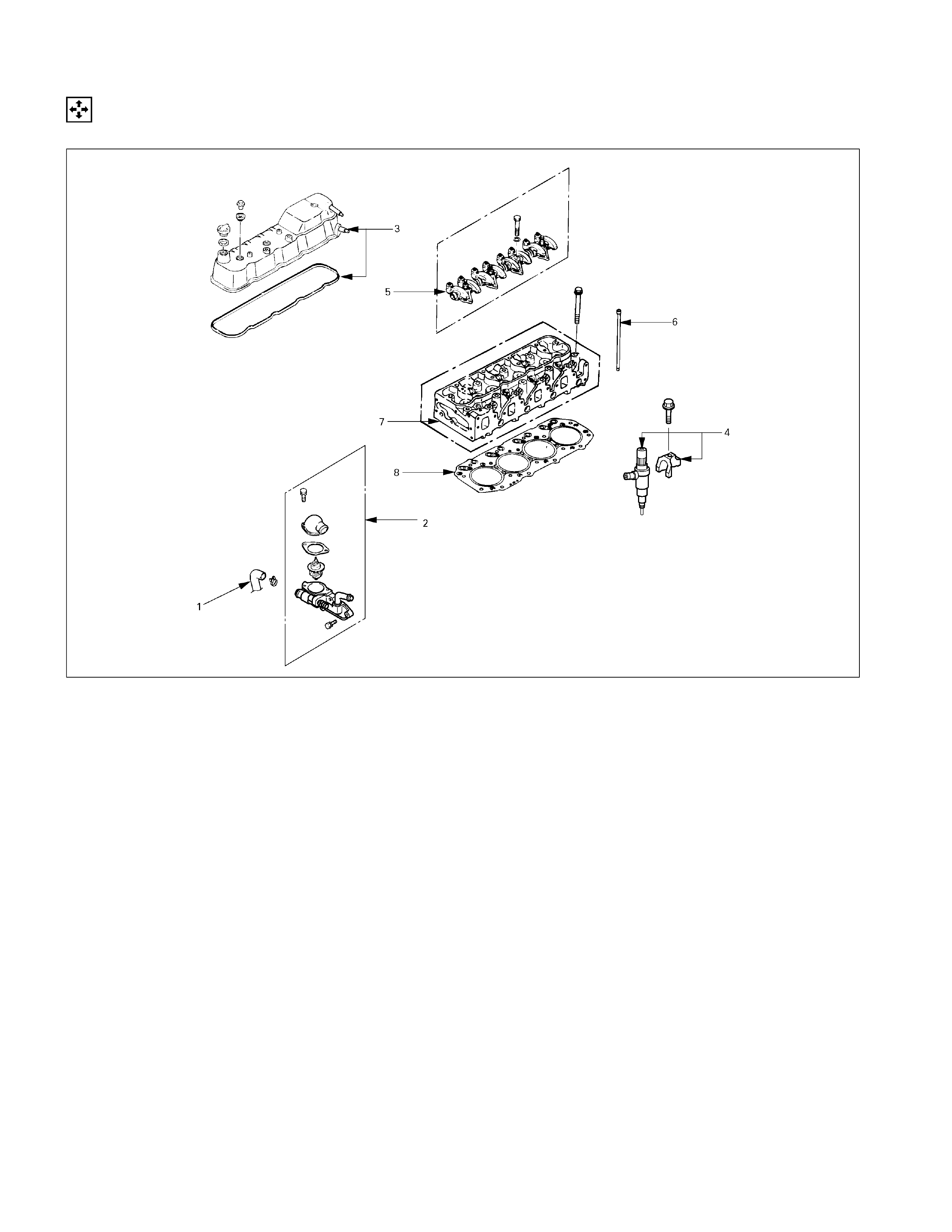
Disassembly Steps-1
1. Water bypass hose
2. Thermostat housing with thermo
switch
3. Cylinder head cover
4. Injection nozzle and bracket
5. Rocker arm shaft and rocker arm
6. Push rod
7. Cylinder head
8. Cylinder head gasket
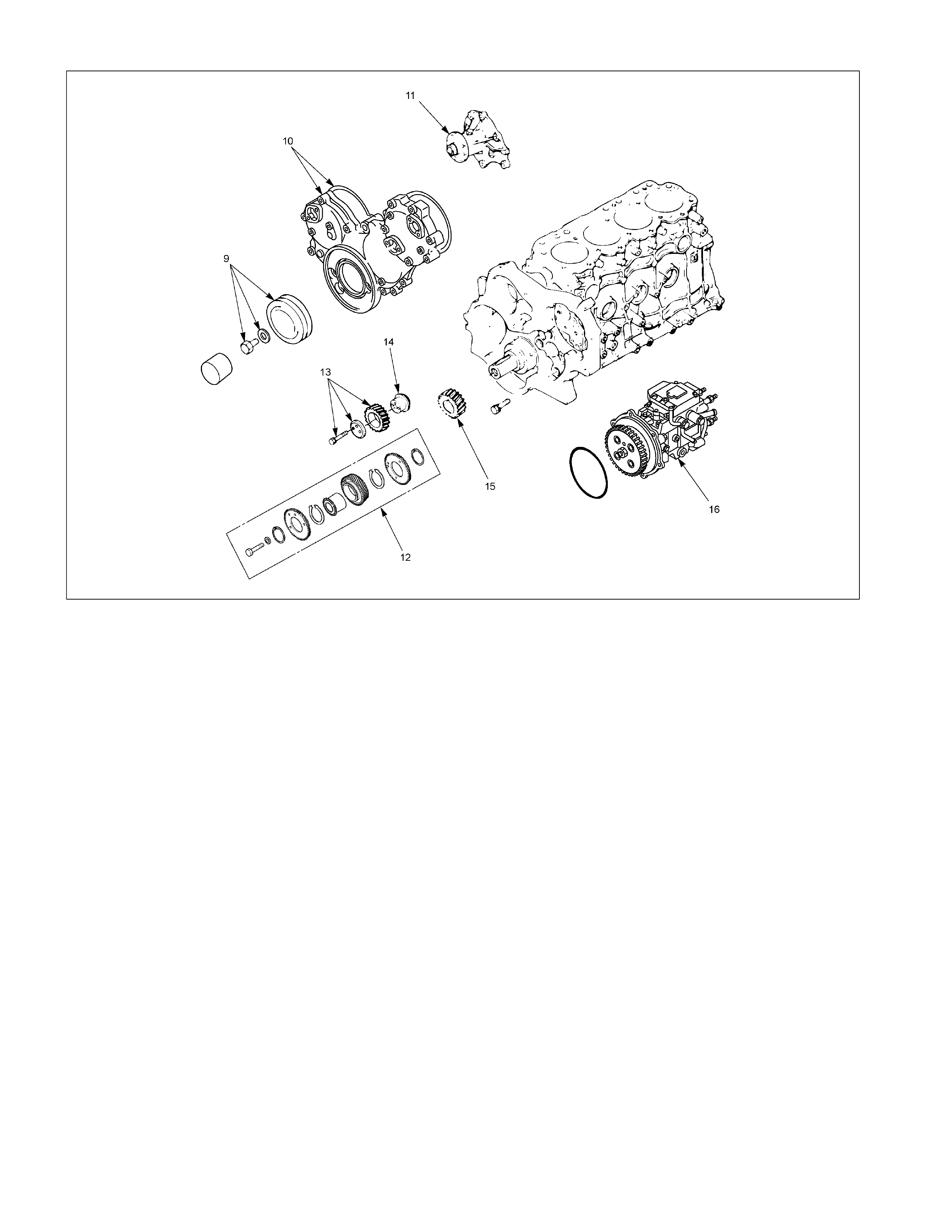
RTW36ALF000701
Disassembly Steps-2
9. Crankshaft damper pulley
10. Timing gear case cover
11. Water pump
12. Idler gear "B" and shaft
13. Idler gear "A"
14. Idler gear shaft
15. Crankshaft timing gear
16. Injection pump

014R300005
Disassembly Steps-3
17. Flywheel
18. Crank case
19. Oil pump with oil pipe
20. Camshaft timing gear
21. Camshaft thrust plate
22. Camshaft
23. Timing gear case
24. Cylinder body rear plate
25. Piston cooling oil jet
26. Connecting rod bearing cap with
lower bearing
27. Piston and connecting rod with
upper bearing
28. Crankshaft bearing cap with lower
bearing
29. Crankshaft thrust bearing
30. Crankshaft
31. Crankshaft upper bearing
32. Tappet
33. Crankshaft rear oil seal
34. Cylinder body
Disassembly
1. Water Bypass Hose
2. Thermostat Housing with Thermo Switch
3. Cylinder Head Cover
4. Injection Nozzle and Bracket
1) Remove the injection nozzle bracket bolts.
2) Use the injection nozzle remover and the sliding
hammer to remove the injection nozzle together.
Injection Nozzle Remover: 5-8840-2723-0
Sliding Hammer: 5-8840-0019-0
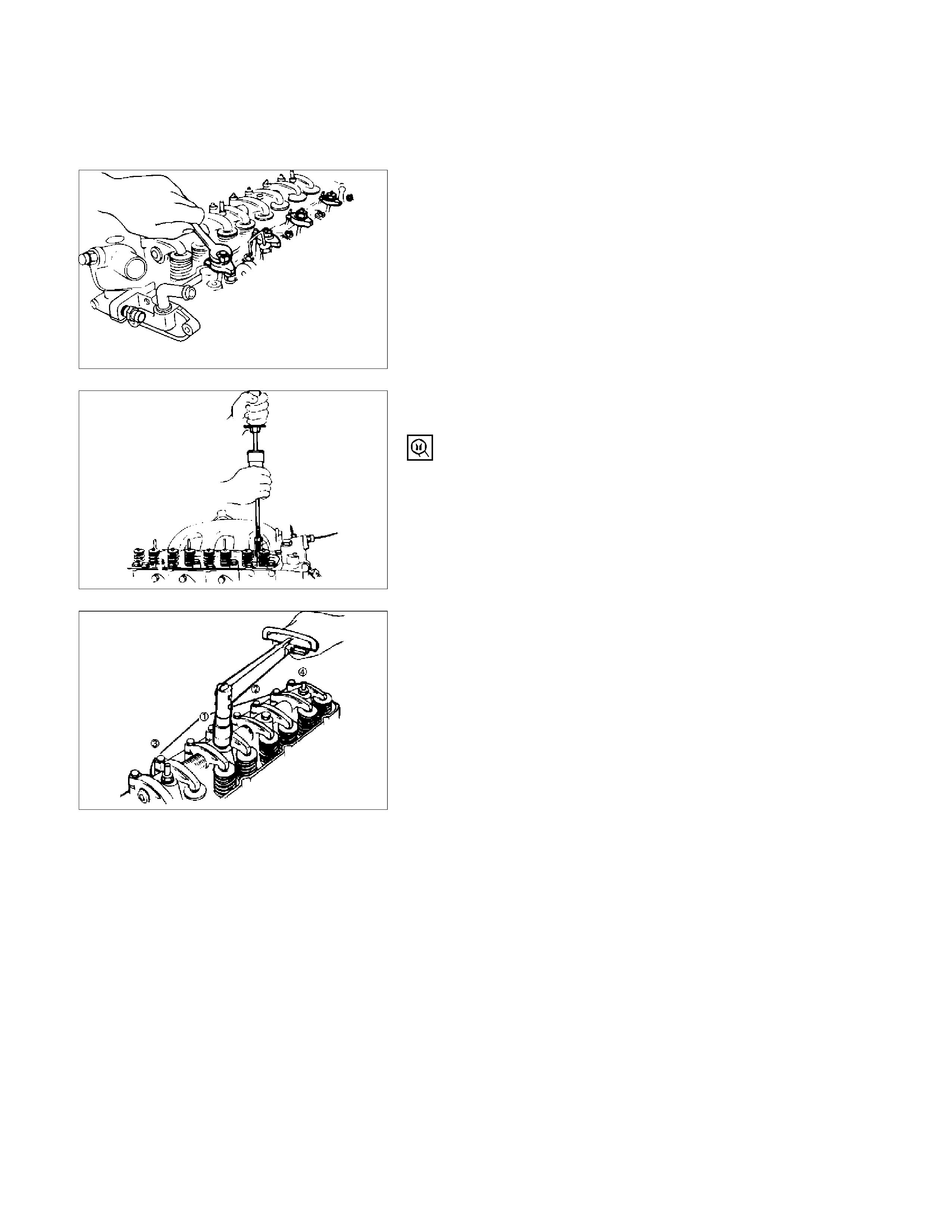
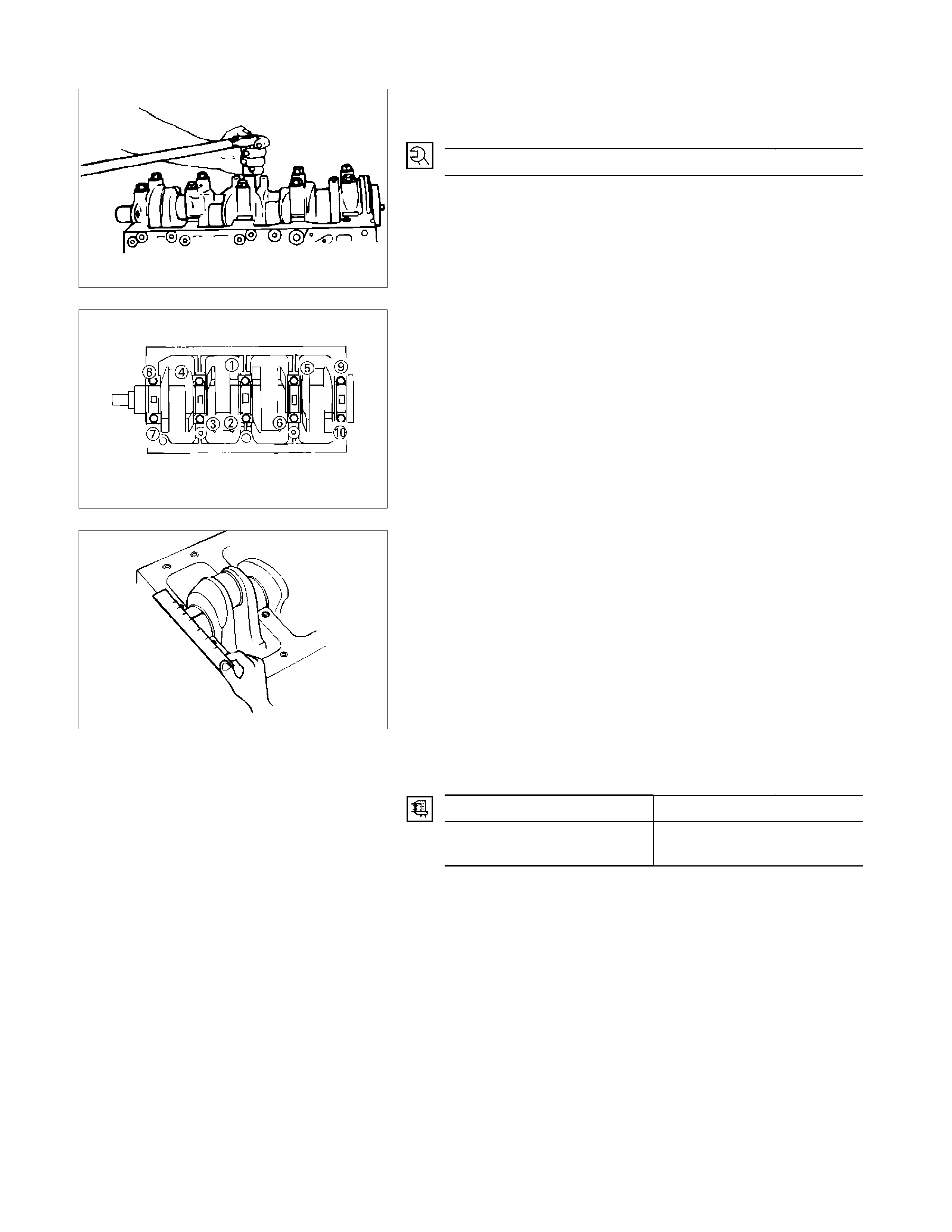
5. Rocker Arm Shaft and Rocker Arm
Loosen the rocker arm shaft bracket bolts in numerical
order a little at a time.
NOTE:
Failure to loosen the rocker arm shaft bracket bolts in
numerical order a little at a time will adversely affect the
rocker arm shaft.
6. Push Rod
011R100002
011RY00005
011RY00006
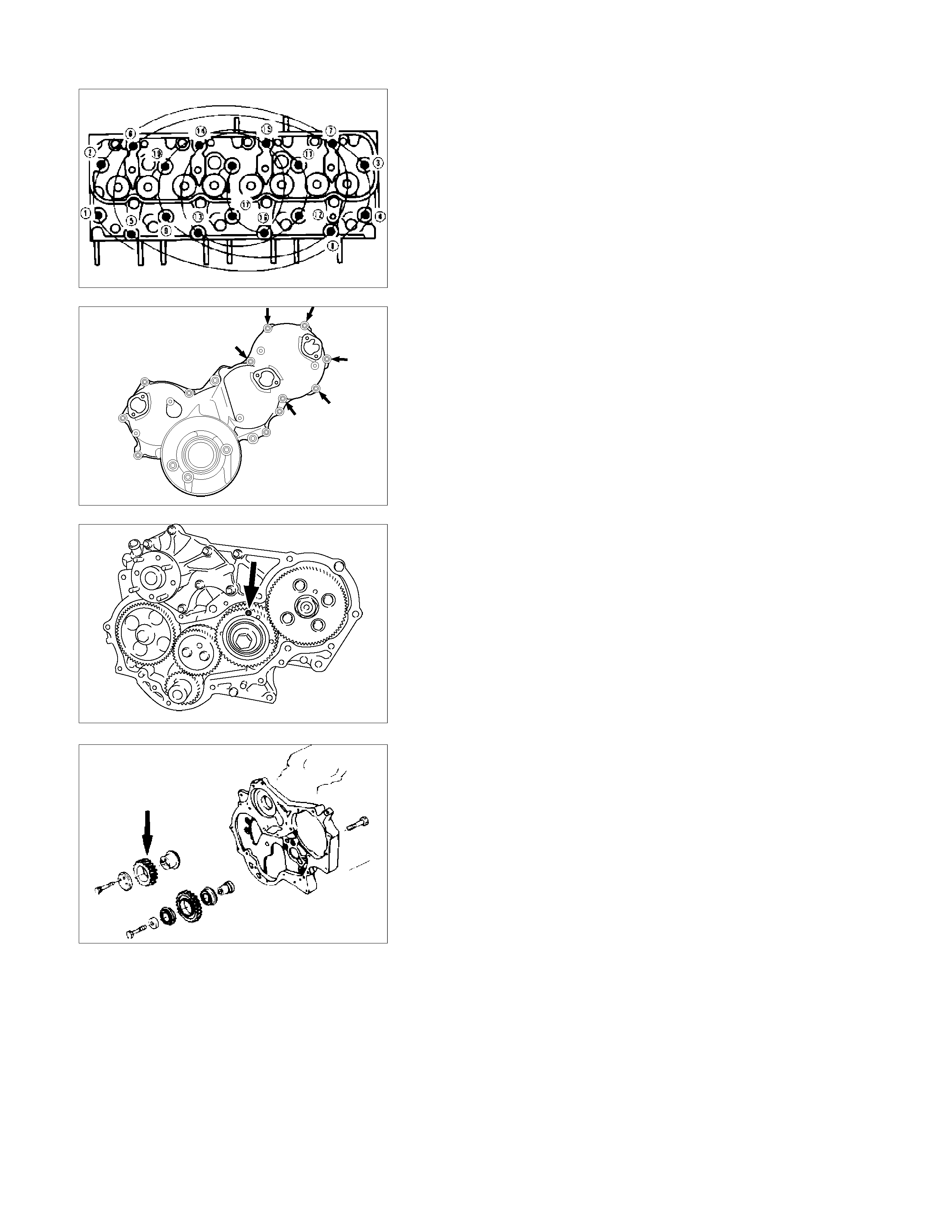
7. Cylinder Head
Loosen the cylinder head bolts in numerical order a little
at a time.
NOTE:
Failure to loosen the cylinder head bolts in numerical order a
little at a time will adversely affect the cylinder head lower
surface.
8. Cylinder Head Gasket
9. Crankshaft Damper Pulley
10. Timing Gear Case Cover
The timing gear case is tightened together with the
injection pump at the 6 points indicated by the arrows in
the illustration.
11. Water Pump
12. Idle Gear B and shaft
Before removing the idle gear B, install bolt (M6,L=30) to
the hole marked with an arrow in the illustration to hold
the scissor gear in place.
13. Idler Gear "A"
1) Measure the camshaft timing gear backlash and the
crankshaft timing gear backlash before removing the
idler gear.
2) Measure the idler gear end play before removing the
idler gear.
NOTE:
Refer to the following items for details on the backlash and
end play measurement procedures.
011RY00007
020L200006
020L200020
020RY00019
Timing Gear Backlash Measurement
1. Set a dial indicator to the timing gear to measured.
Hold both the gear to be checked and the adjusting
gear stationary.
2. Move the gear to be checked as far as possible to
both the right and the left.
Take the dial indicator reading.
If the measured value exceeds the specified limit, the
timing gear must be replaced.
Timing Gear Backlash mm (in)
Standard: 0.10 - 0.17 (0.0039 - 0.0067)
Limit: 0.30 (0.012)
RTW36ASH000801
Idler Gear "A" End Play Measurement
Insert a feeler gauge between the idler gear and the thrust
collar to measure the gap and determine the idler gear
end play.
If the measured value exceeds the specified limit, the
thrust collar must be replaced.
Idler Gear End Play mm (in)
Standard: 0.07 (0.0028)
Limit: 0.2 (0.0079)
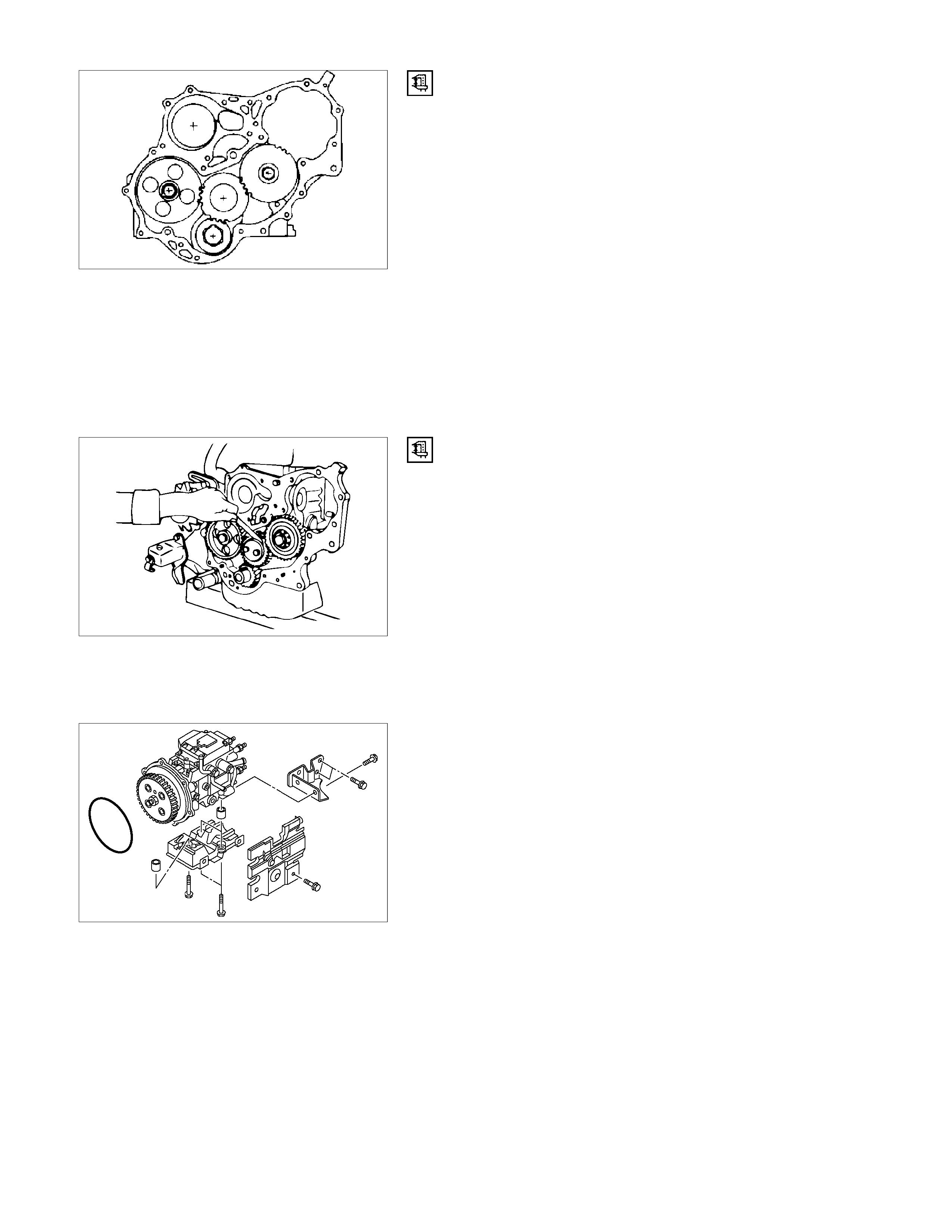
14. Idle Gear Shaft
15. Crankshaft Timing Gear
RTW36ASH001301
16. Injection Pump
1) Remove the injection pump cover.
2) Remove the injection pump bracket.
3) Pull the injection pump along with the injection pump
timing gear free toward the rear of the engine.
NOTE:
Plug the injection pump delivery ports with the caps to prevent
the entry of foreign material.
020RY00020
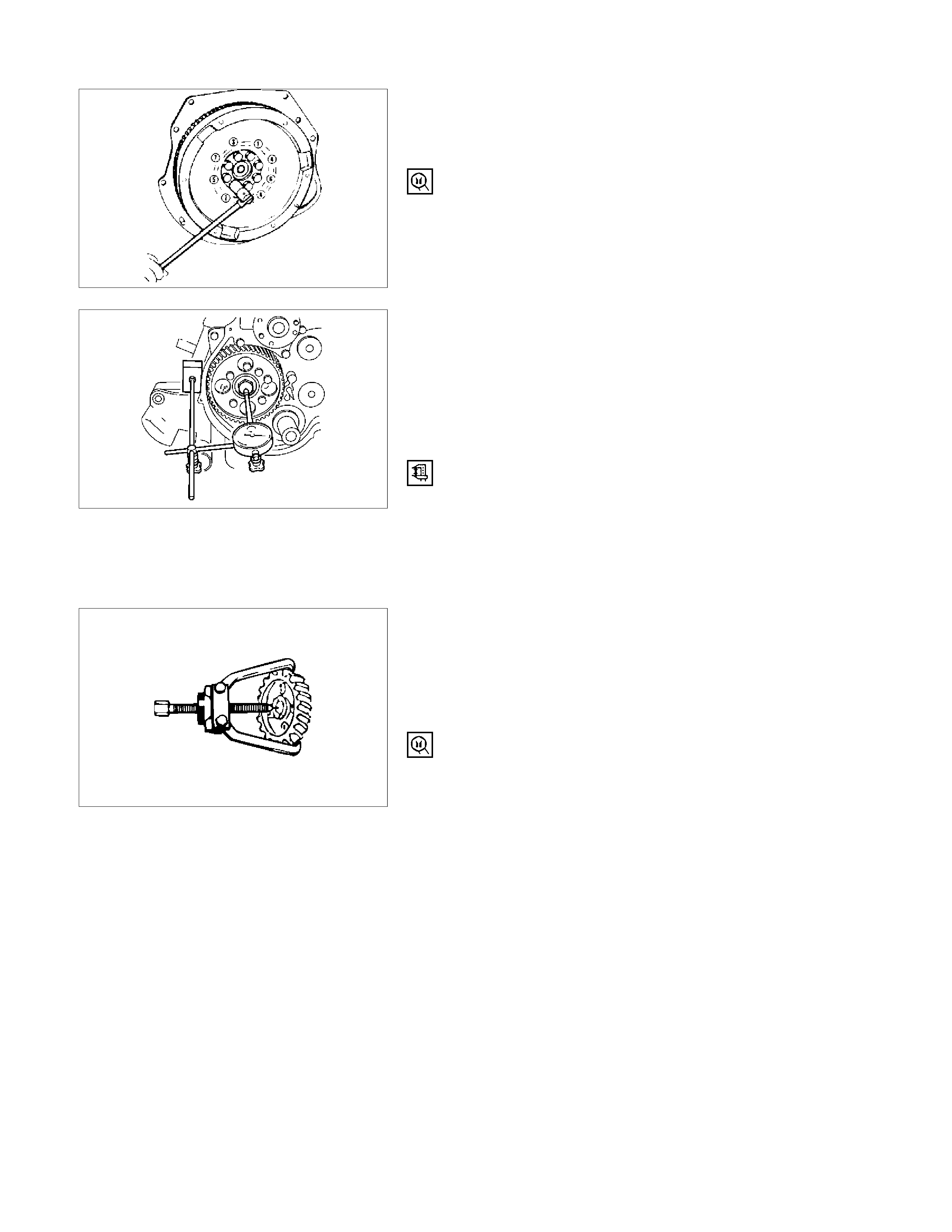
17. Flywheel
Loosen the flywheel bolts in numerical order a little at a
time.
Use the gear stoper to stop the flywheel gear.
Gear stoper: 5-8840-0214-0
18. Crank Case
19. Oil Pump With Oil Pipe
20. Camshaft Timing Gear
1) Use a dial indicator to measure the camshaft end
play.
This must be done before removing the camshaft
gear.
If the camshaft end play exceeds the specified limit,
the thrust plate must be replaced.
Camshaft End Play mm (in)
Standard: 0.050 - 0.114(0.002 - 0.0044)
Limit: 0.20(0.008)
2) Remove the camshaft timing gear bolt from the
camshaft.
NOTE:
Hold the camshaft stationary to prevent the camshaft from
turning.
3) Remove the sensor rotor plate.
4) Use the universal puller to pull out the camshaft
timing gear.
Universal Puller: 5-8521-0002-0
5) Remove the thrust plate.
21. Camshaft Thrust Plate
015RY00001
014RT0001
901R100008
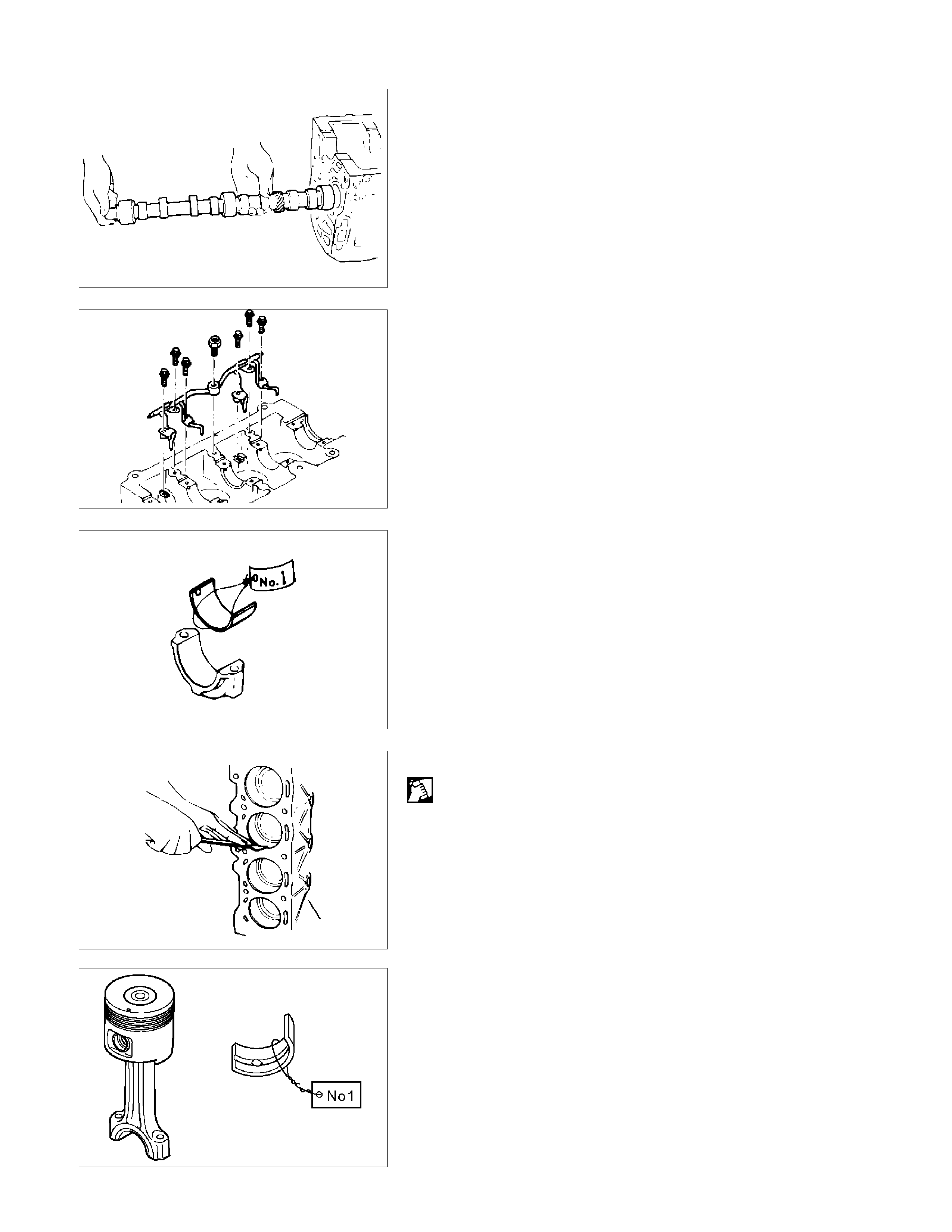
22. Camshaft
Jiggle the camshaft with your hand as you pull it free from
the front of the engine.
23. Timing Gear Case
24. Cylinder Body Rear Plate
25. Piston Cooling Oil Jet
The oiling jet uses thin steel tubing which is easily bent.
Accidental contact between the oiling jet and the cylinder
body, piston, or a tool will damage the oiling jet.
Never attempt to repair a damaged oiling jet. Replace it
with a new one.
26. Connecting Rod Bearing Cap with Lower Bearing
If the connecting rod lower bearings are to be reinstalled,
mark their fitting positions by tagging each bearing with
the cylinder number from which it was removed.
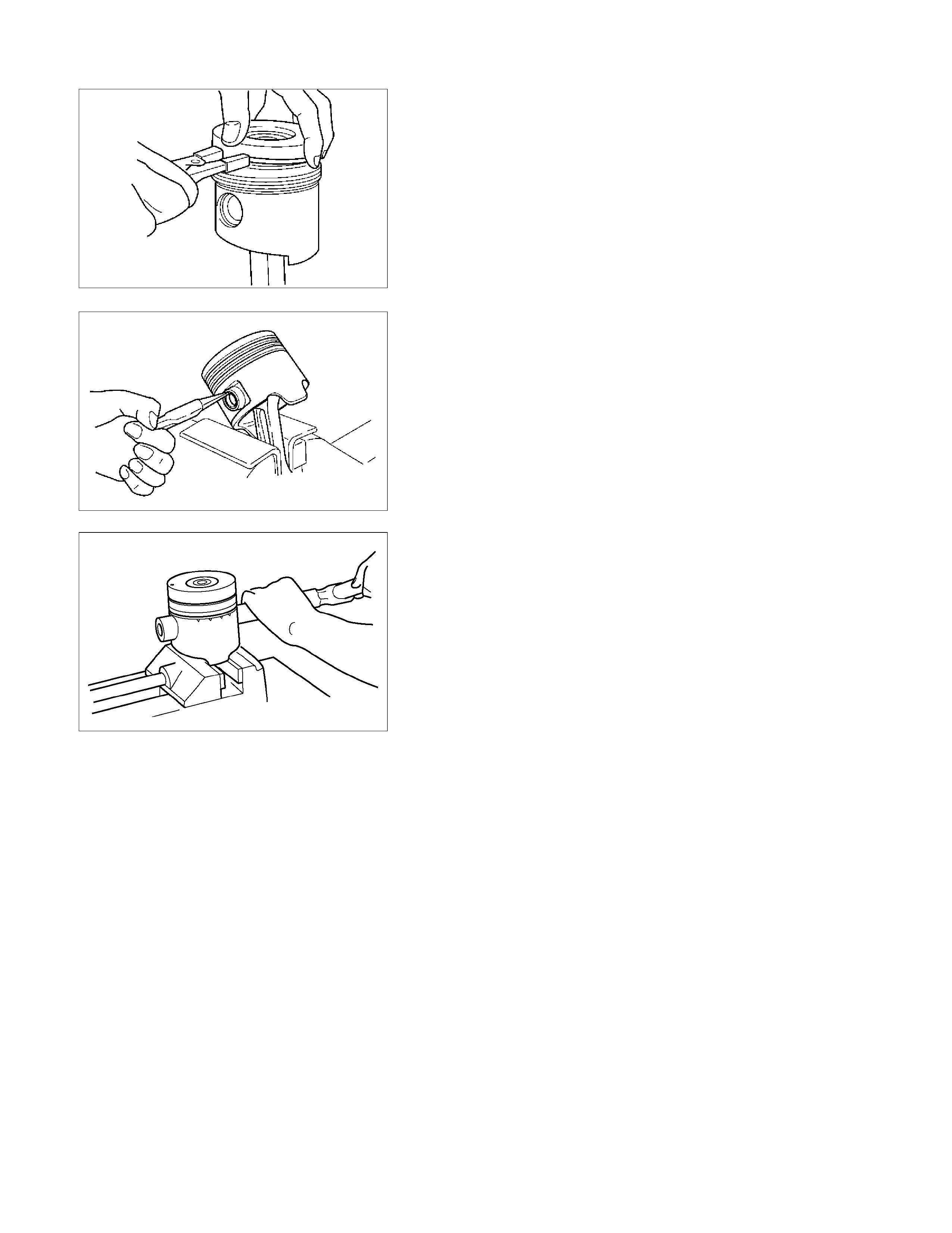
27. Piston and Connecting Rod with Upper Bearing
1) Remove carbon deposits from the upper portion of the
cylinder wall with a scraper before removing the piston
and connecting rod.
2) Move the piston to the top of the cylinder and tap it
with a hammer grip or a similar object from the
connecting rod lower side to drive it out.
RTW36ASH001501
3) If the connecting rod upper bearings are to be
reinstalled, mark their fitting positions by tagging each
bearing with the cylinder number from which it was
removed.
014RY00019
052RY00001
014LX056
015LX018
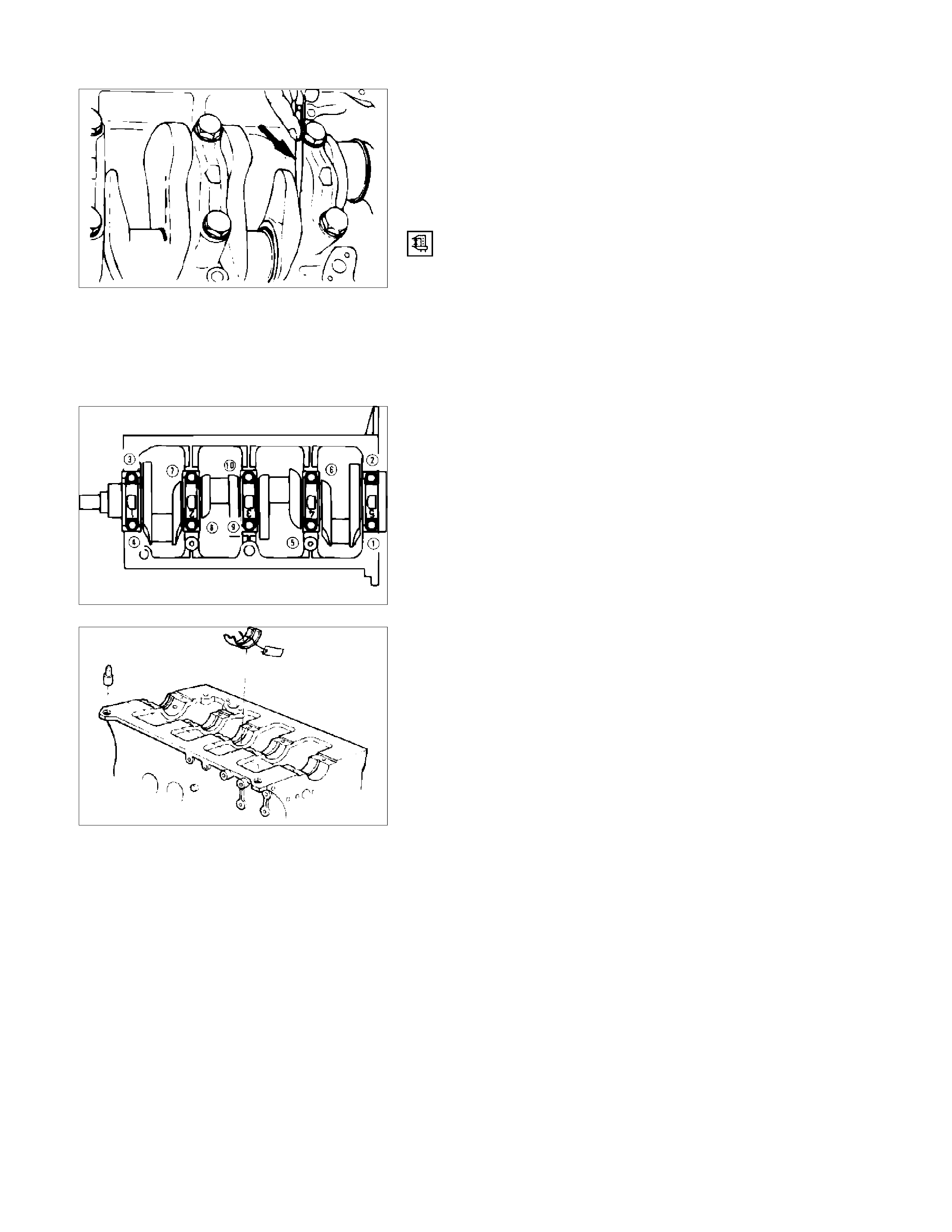
28. Crankshaft Bearing Cap with Lower Bearing
1) Measure the crankshaft end play at the center journal
of the crankshaft.
Do this before removing the crankshaft bearing caps.
If the measured value exceeds the specified limit, the
crankshaft thrust bearing must be replaced.
Crankshaft End Play mm (in)
Standard: 0.10 (0.004)
Limit: 0.30 (0.012)
2) Loosen the crankshaft bearing cap bolts in numerical
order a little at a time.
If the crankshaft bearings are to be reinstalled, mark
their fitting positions by tagging each bearing with the
cylinder number from which it was removed.
29. Crankshaft Thrust Bearing
30.Crankshaft
31. Crankshaft Upper Bearing
If the crankshaft upper bearings are to be reinstalled,
mark their fitting positions by tagging each bearing with
the cylinder number from which it was removed.
015RY00002
015RY00003
015RY00004
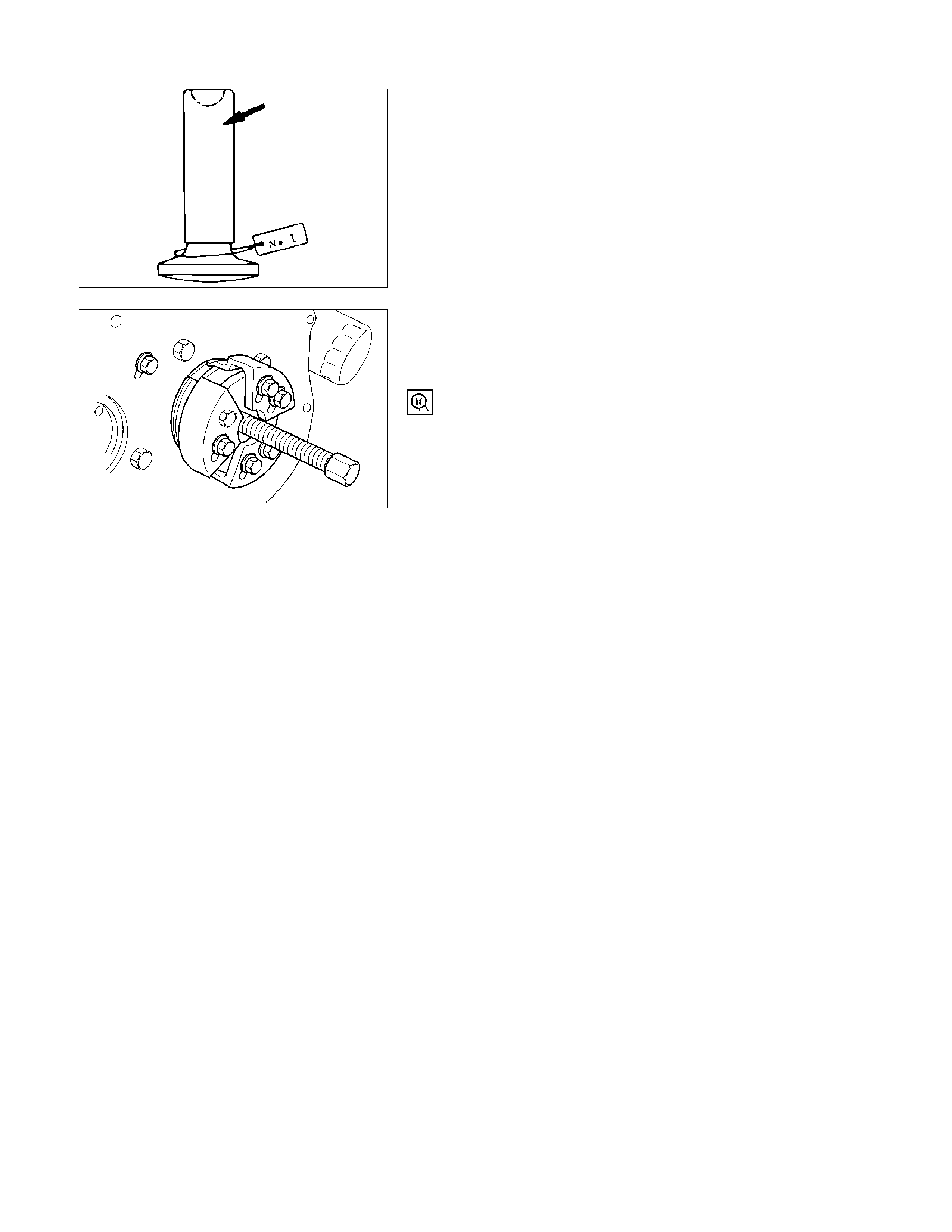
32. Tappet
If the tappets are to be reinstalled, mark their fitting
positions by tagging each tappet with the cylinder number
from which it was removed.
33. Crankshaft Rear Oil Seal
• With the oil seal pushed in deep, install the special
tool as shown in the illustration and remove the oil
seal.
Oil Seal Remover: 5-8840-2360-0
34. Cylinder Body
015RY00005
015LV002
MINOR COMPONENTS
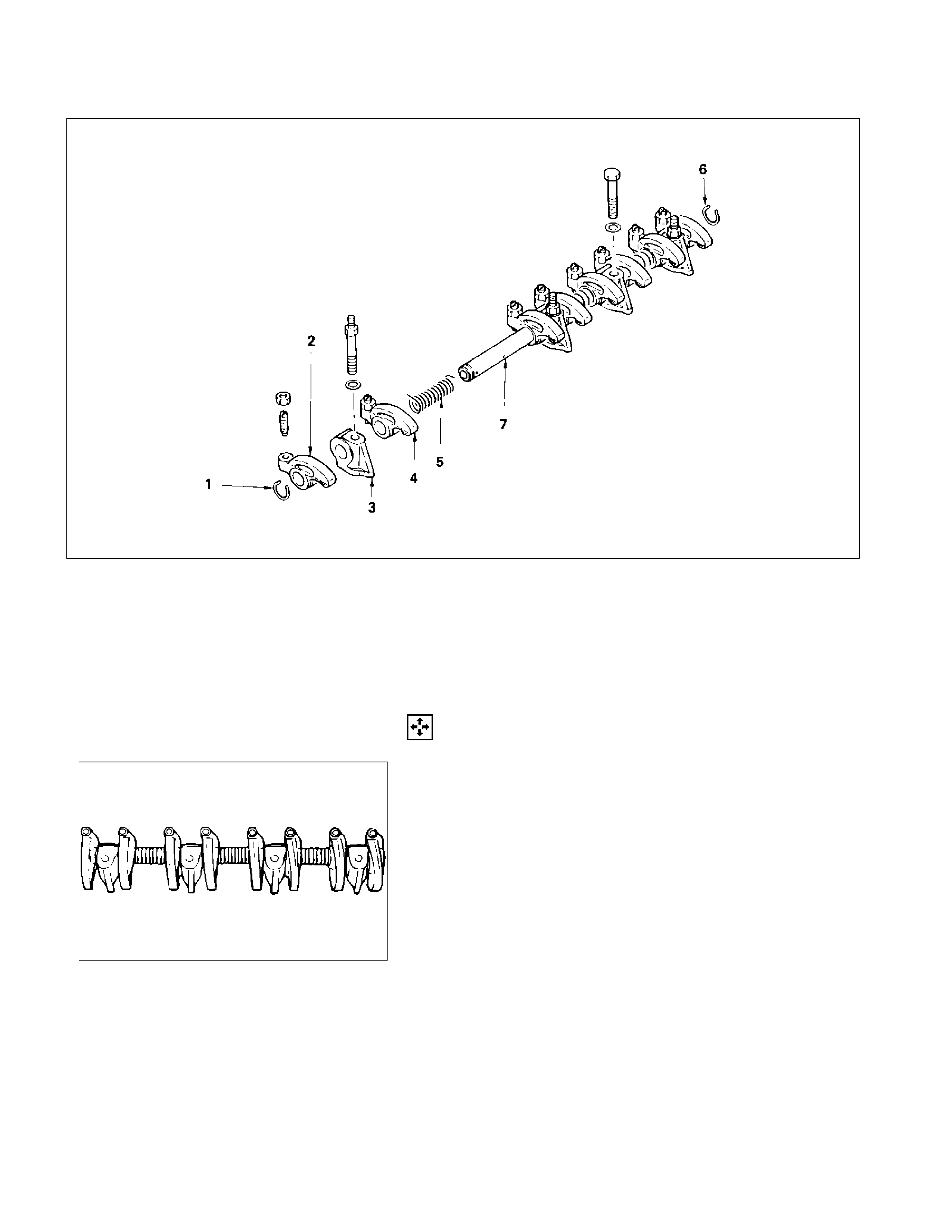
ROCKER ARM SHAFT AND ROCKER ARM
011RY00009
Disassembly Steps
1. Rocker arm shaft snap ring
2. Rocker arm
3. Rocker arm shaft bracket
4. Rocker arm
5. Rocker arm shaft spring
6. Rocker arm shaft snap ring
7. Rocker arm shaft
Disassembly
1. Rocker Arm Shaft Snap Ring
2. Rocker Arm
3. Rocker Arm Shaft Bracket
1) Use a pair of pliers to remove the snap rings.
2) Remove the rocker arms.
3) Remove the rocker arm shaft brackets.
If the rocker arms and rocker arm shaft brackets are
to be reinstalled, mark their installation positions by
tagging each rocker arm and rocker arm shaft bracket
with the cylinder number from which it was removed.
4. Rocker Arm
5. Rocker Arm Shaft Spring
6. Rocker Arm Shaft Snap Ring
7. Rocker Arm Shaft
011RY00010
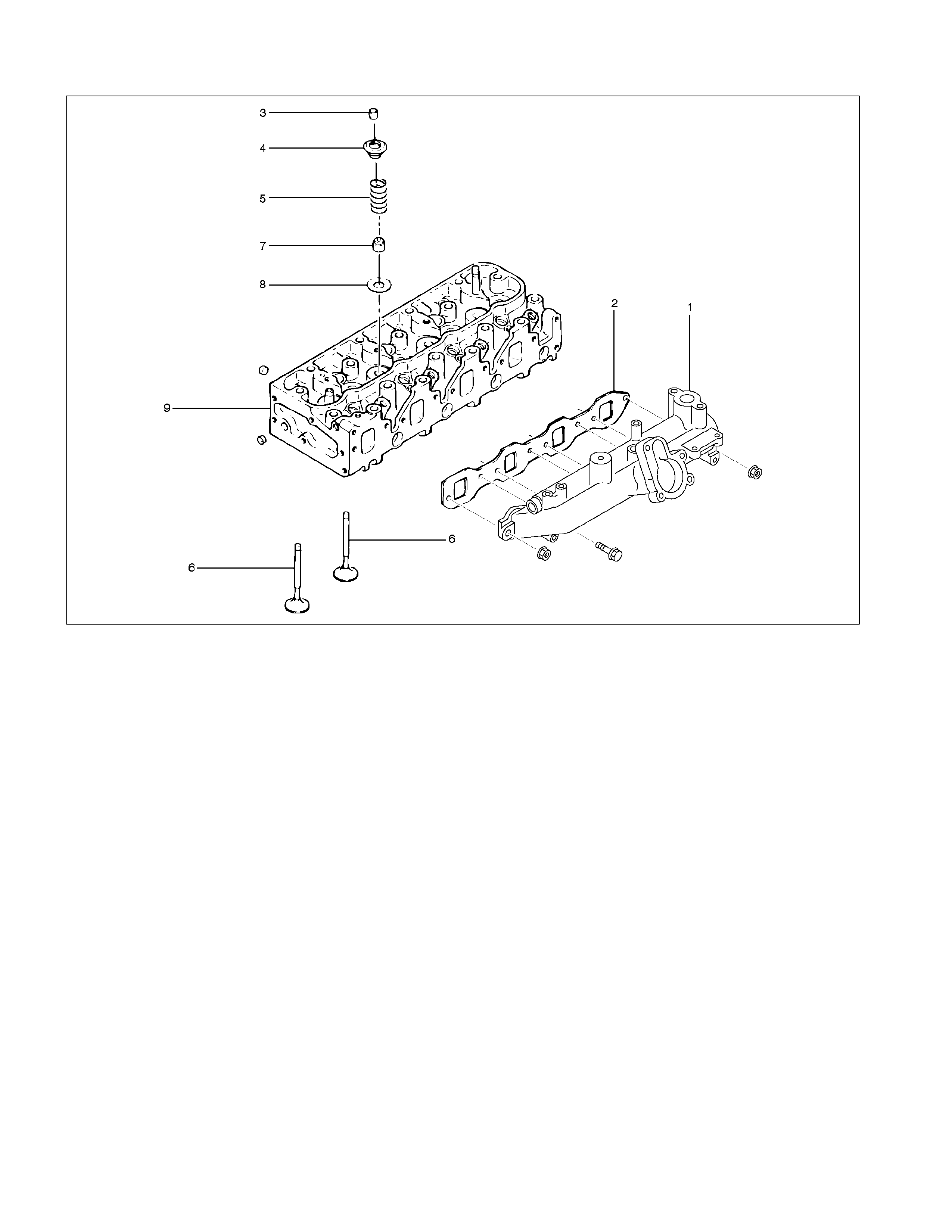
CYLINDER HEAD
RTW36ALF000901
Disassembly Steps
1. Intake manifold
2. Intake manifold gasket
3. Split collar
4. Valve spring upper seat
5. Valve spring
6. Intake and exhaust valve
7. Valve stem oil seal
8. Valve spring lower seat
9. Cylinder head
Disassembly
1. Intake Manifold
2. Intake Manifold Gasket
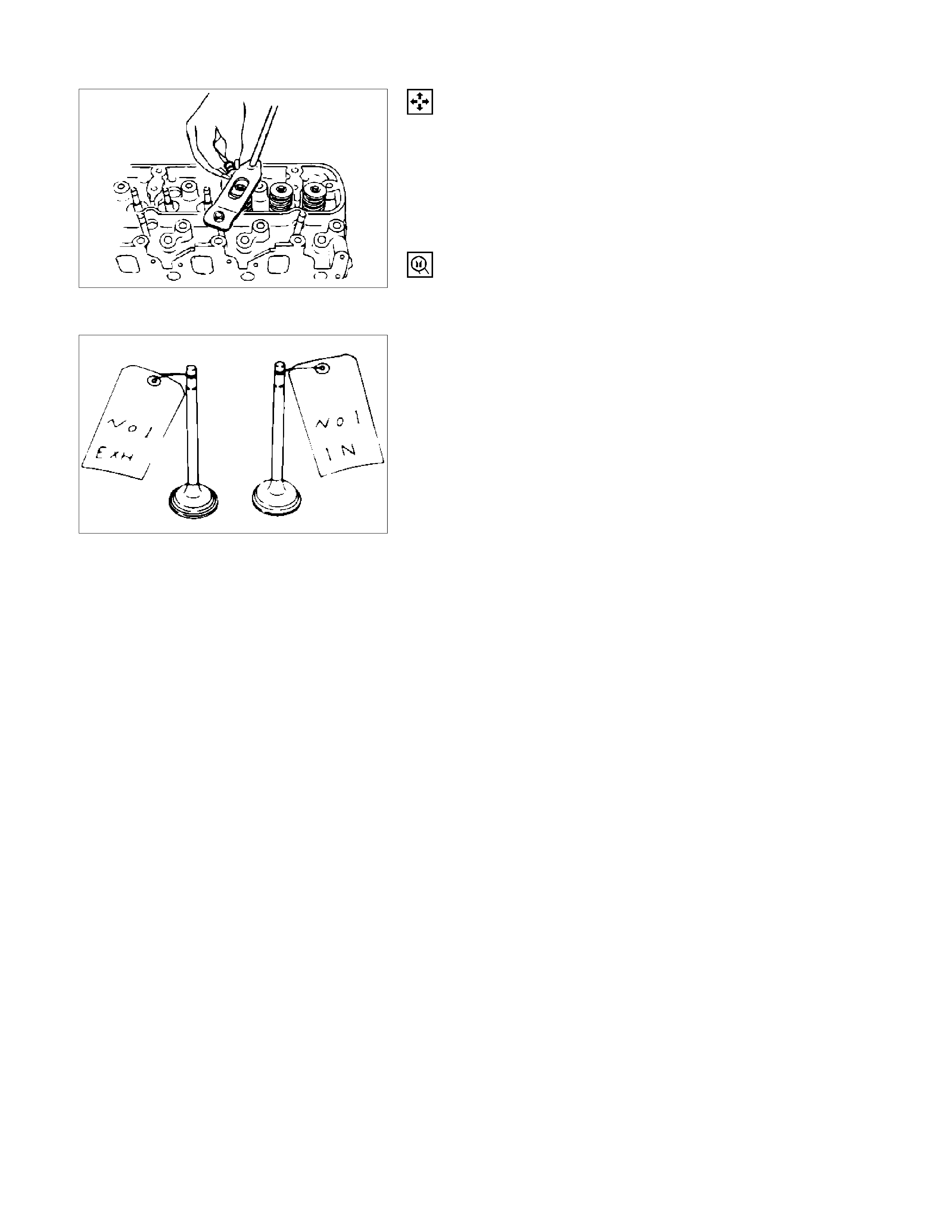
3. Split Collar
1) Place the cylinder head on a flat wooden surface.
2) Use the spring compressor to remove the split collars.
Do not allow the valve to fall from the cylinder head.
Spring Compressor: 9-8523-1423-0
4. Valve Spring Upper Seat
5. Valve Spring
6. Intake and Exhaust Valve
If the intake and exhaust valves are to be reinstalled, mark
their installation positions by tagging each valve with the
cylinder number from which it was removed.
If the intake and exhaust valves are to be replaced, the
valve guides must also be replaced.
7. Valve Stem Oil Seal
8. Valve Spring Lower Seat
9. Cylinder Head
011RY00011
011LX022
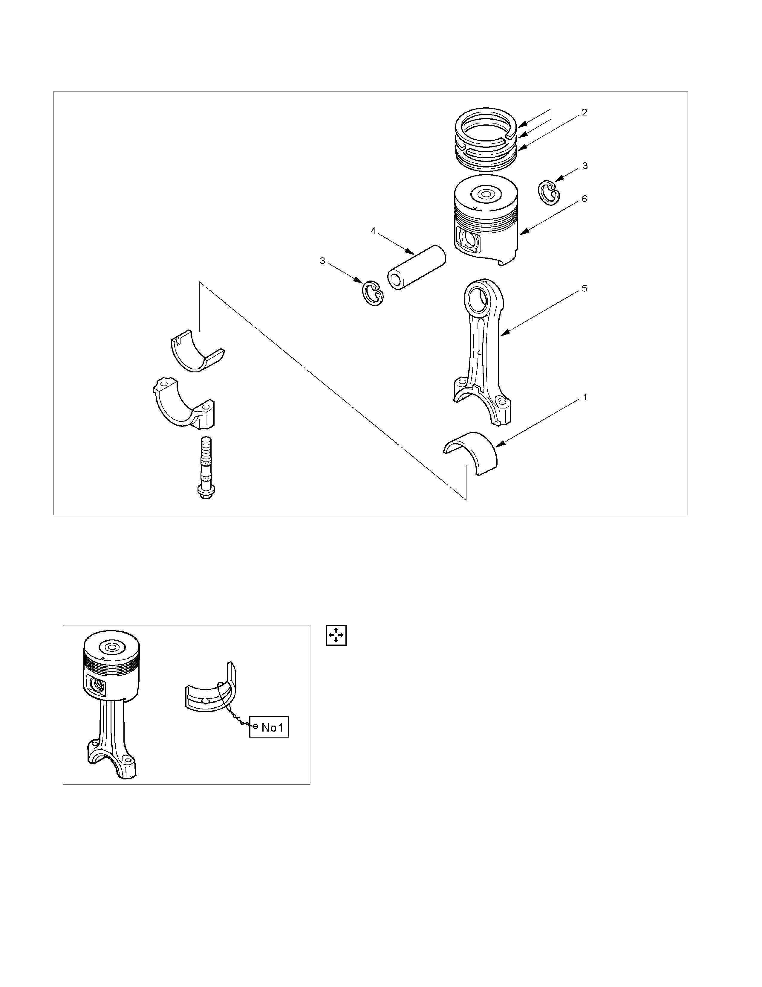
PISTON AND CONNECTING ROD
RTW36ALF0001301
Disassembly Steps
1. Connecting rod bearing
2. Piston ring
3. Piston pin snap ring
4. Piston pin
5. Connecting rod
6. Piston
RTW36ASH001501
Disassembly
1. Connecting Rod Bearing
If the connecting rod bearings are to be reinstalled, mark
their fitting positions by tagging each bearing with the
cylinder number from which it was removed.
2. Piston Ring
1) Clamp the connecting rod in a vice.
Take care not to damage the connecting rod.
2) Use a piston ring replacer to remove the piston rings.
NOTE
Piston Ring Replacer
Do not attempt to use some other tool to remove the piston
rings. Piston ring stretching will result in reduced piston ring
tension.
3. Piston Pin Snap Ring
Use a pair of pliers to remove the piston pin snap rings.
RTW36ASH001601
4. Piston Pin
5. Connecting Rod
6. Piston
Tap the piston pin out with a hammer and a brass bar.
If the pistons and piston pins are to be reinstalled, mark
their installation positions by tagging each piston and
piston pin with the cylinder number from which it was
removed.
015RW041
F06MV015
INSPECTION AND REPAIR
Make the necessary adjustments, repairs, and part replacements if excessive wear or damage is discovered during
inspection.
CYLINDER HEAD
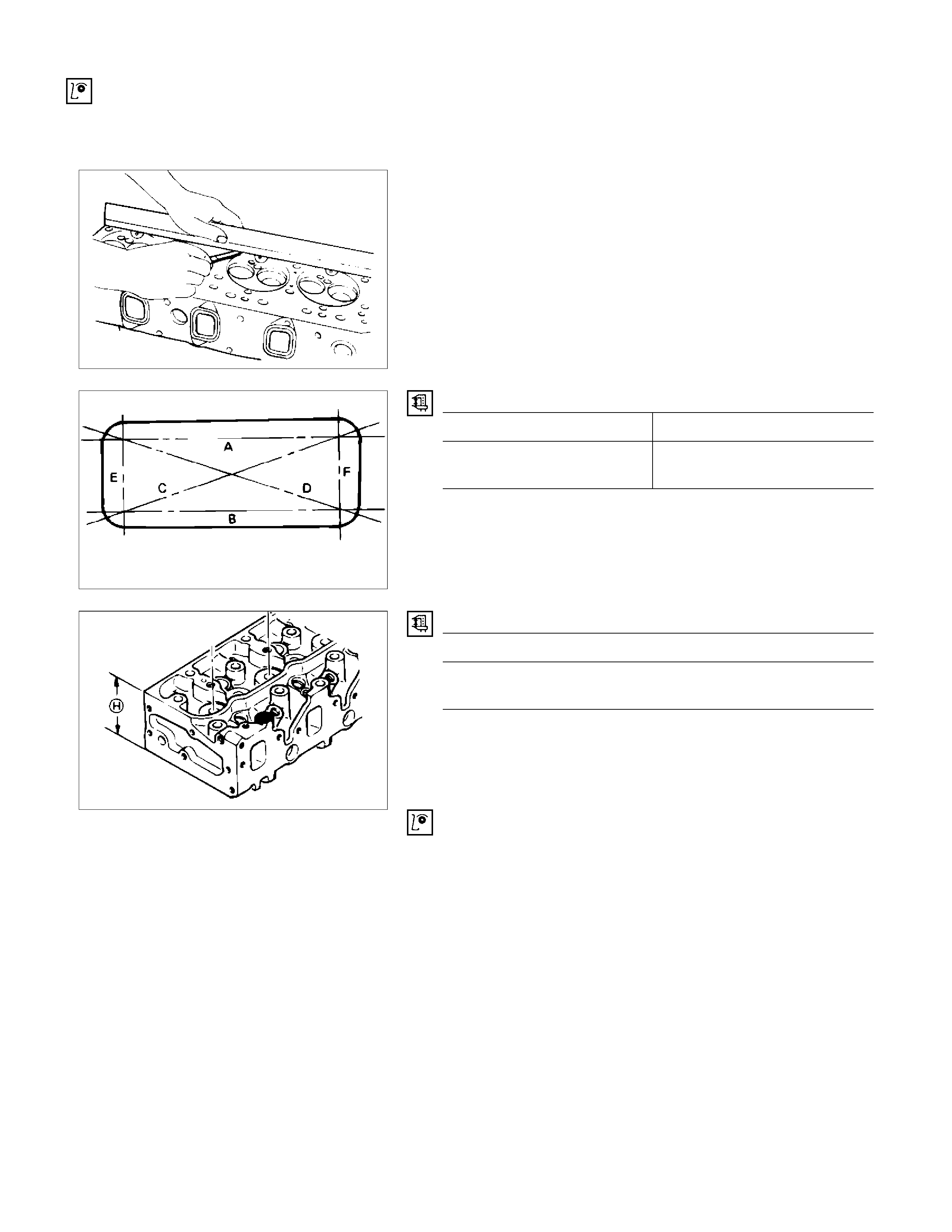
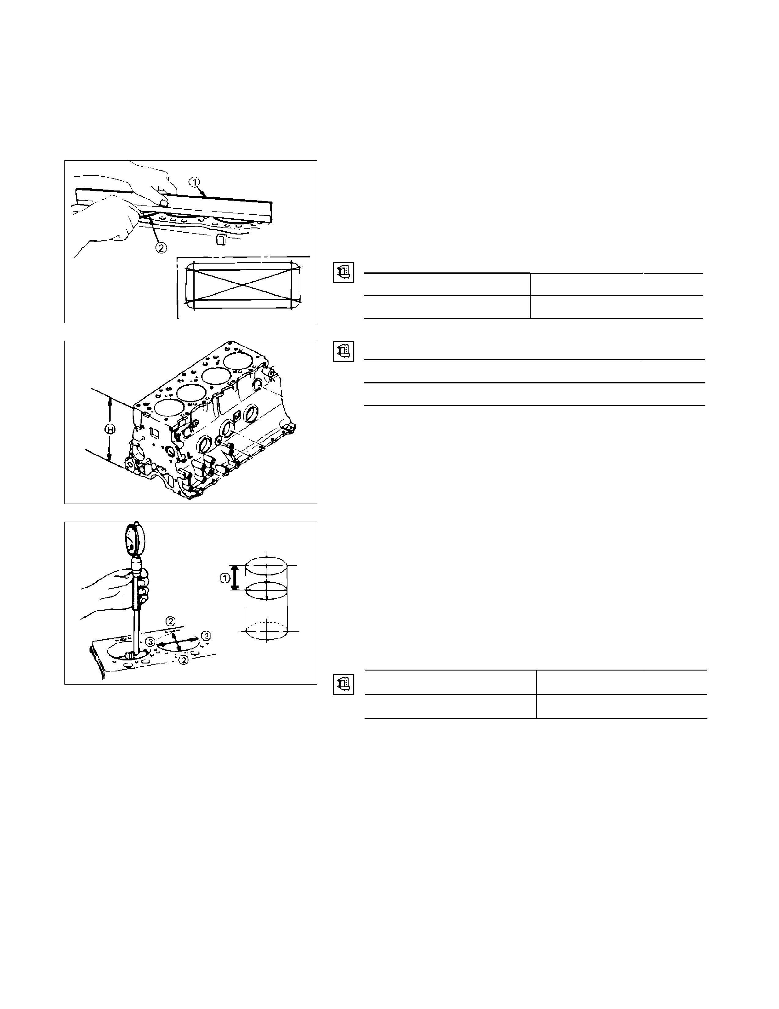
Cylinder Head Lower Face Warpage
1. Use a straight edge and a feeler gauge to measure the
four sides and the two diagonals of the cylinder head
lower face.
2. The cylinder head lower surface warpage is more than the
limit, it should be replaced.
Cylinder Head Lower Face Warpage mm (in)
Standard Limit
0.05
(0.002) or less 0.20
(0.0079)
NOTE:
The cylinder head lower face cannot be reground.
Cylinder Head Height (H) (Reference) mm (in)
Standard
91.95 – 92.05
(3.620 – 3.624)
Positive Crankcase Ventilation (PCV) Valve
1. Remove PCV valve assembly from cylinder head cover.
2. Inspect the diaphragm for broken.
3. Inspect the spring for broken or weaken.
4. If find any abnormal condition, replace the PCV valve
assembly.
011RY00012
011RY00013
011RY00014
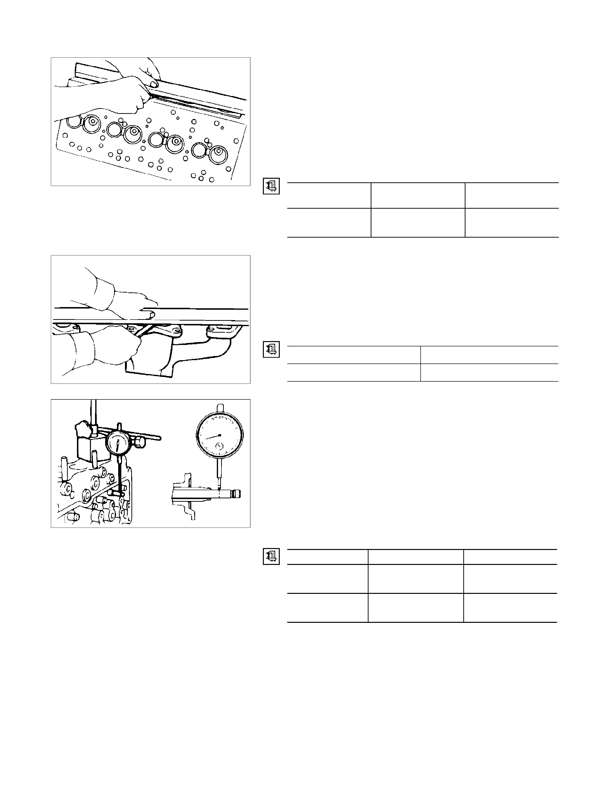
Manifold Fitting Face Warpage
Use a straight edge and a feeler gauge to measure the
manifold cylinder head fitting face warpage.
Regrind the manifold cylinder head fitting surfaces if the
measured values are greater than the specified limit but less
than the maximum grinding allowance.
If the measured values exceed the maximum grinding
allowance, the cylinder head must be replaced.
Manifold Fitting Face Warpage mm (in)
Standard Limit
Maximum Grinding
Allowance
0.05
(0.002) or less 0.20
(0.008) 0.40
(0.016)
Exhaust Manifold Warpage
Use a straight edge and a feeler gauge to measure the
manifold cylinder head fitting face warpage.
If the measured values exceed the specified limit, the manifold
must be replaced.
Exhaust Manifold Warpage mm (in)
Standard Limit
0.05 (0.002) or less 0.20 (0.008)
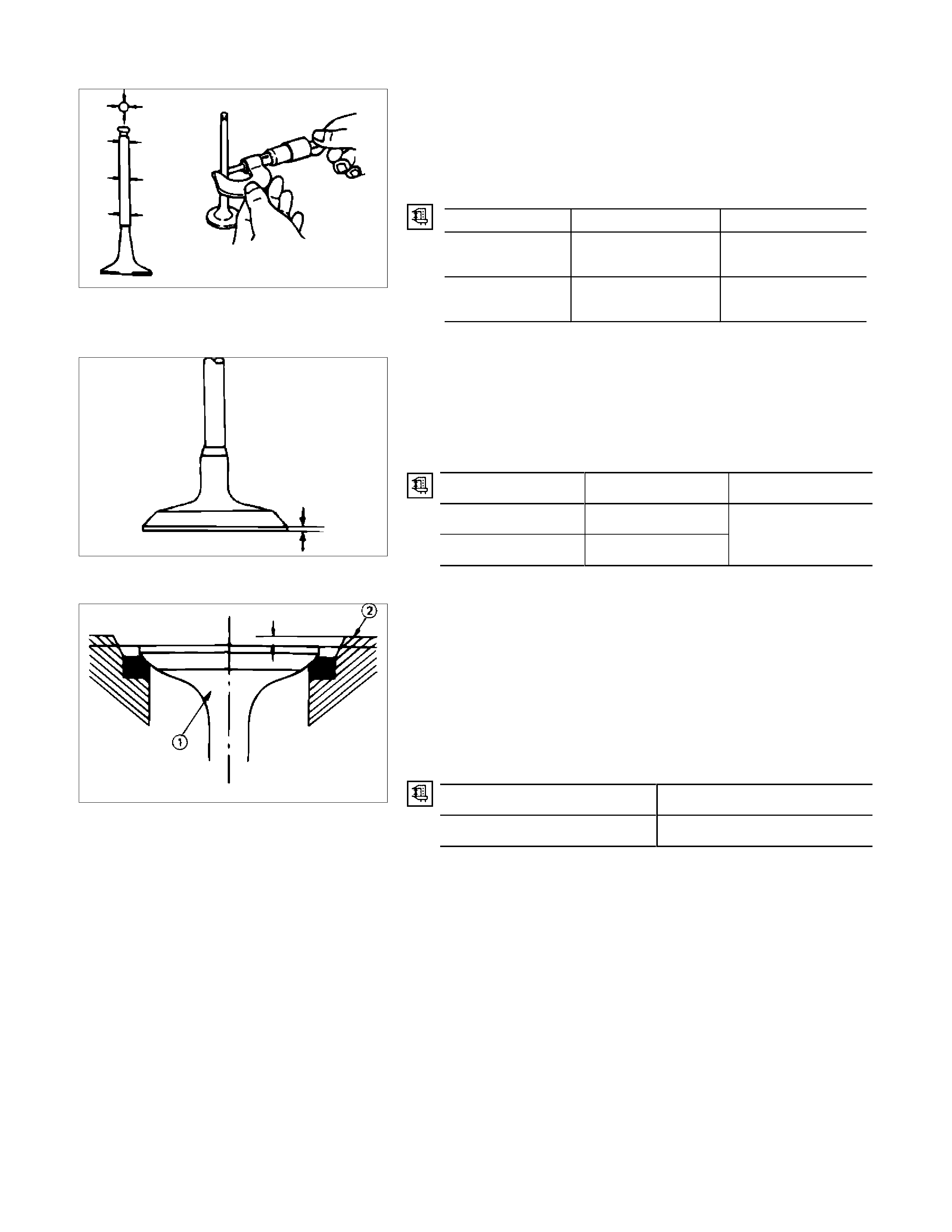
Valve Stem and Valve Guide Clearance
Measuring Method-I
1. With the valve stem inserted in the valve guide, set the dial
indicator needle to "0".
2. Move the valve head from side to side.
Read the dial indicator.
Note the highest dial indication.
If the measured values exceed the specified limit, the valve
and the valve guide must be replaced as a set.
Valve Stem Clearance mm (in)
Standard Limit
Intake Valve 0.039 - 0.071
(0.0015 - 0.0028) 0.200
(0.008)
Exhaust Valve 0.064 - 0.096
(0.0025 - 0.0038) 0.250
(0.0098)
027RY00001
027RY00002
011RY00022
Measuring Method-II
1. Measure the valve stem outside diameter.
Refer to the Item "Valve Stem Outside Diameter".
2. Use a calliper calibrator or a telescoping gauge to
measure the valve guide inside diameter.
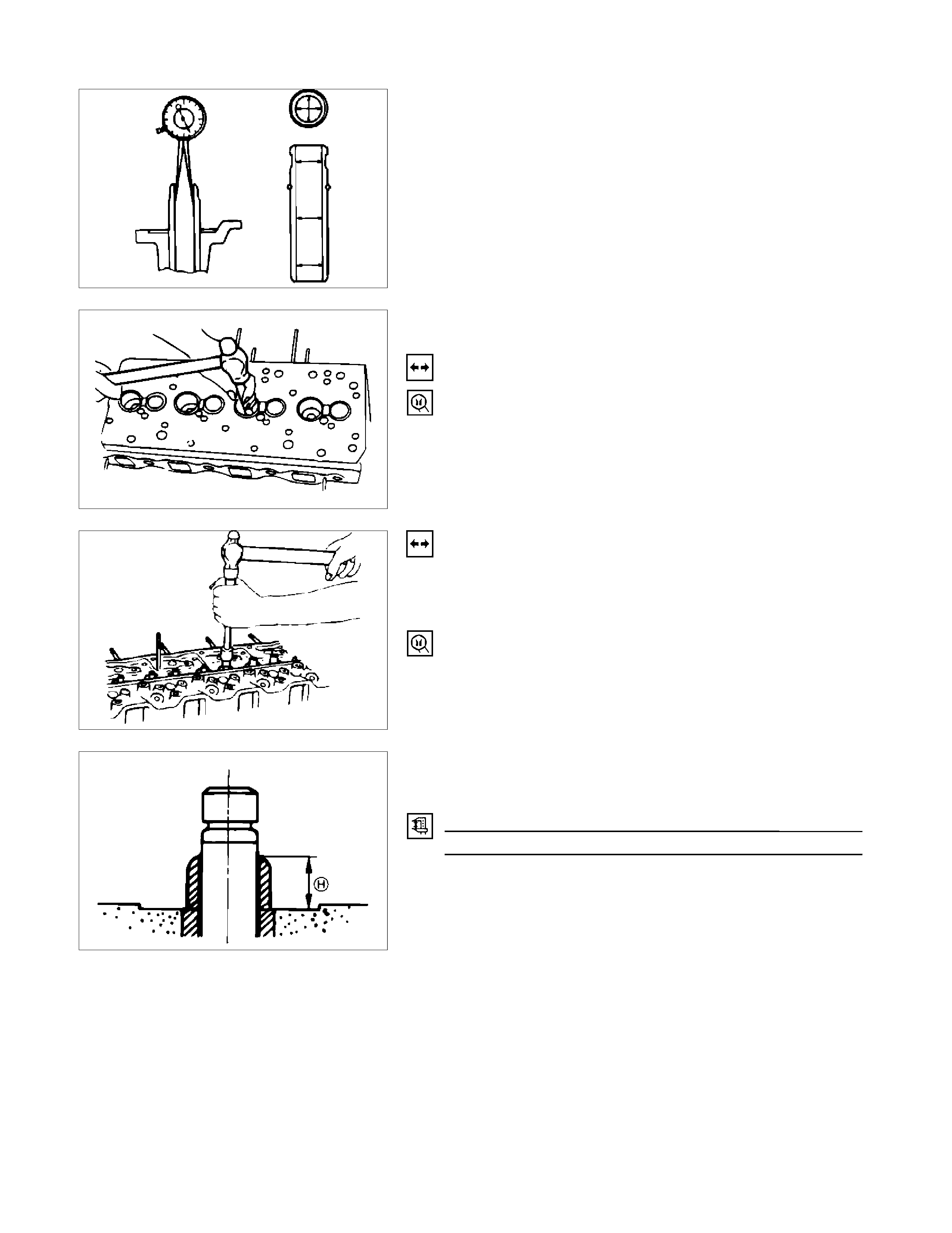
Valve Guide Replacement
Valve Guide Removal
Use a hammer and the valve guide replacer to drive out the
valve guide from the cylinder head lower face.
Valve Guide Replacer: 9-8523-1212-0
Valve Guide Installation
1. Apply engine oil to the valve guide outer circumference.
2. Attach the valve guide installer to the valve guide.
3. Use a hammer to drive the valve guide into position from
the cylinder head upper face.
Valve Guide Replacer: 9-8523-1212-0
4. Measure the height of the valve guide upper end from the
upper face of the cylinder head.
Valve Guide Upper End Height (H) (Reference) mm (in)
12.8-13.2 (0.50-0.52)
NOTE:
If the valve guide has been removed, both the valve and
the valve guide must be replaced as a set.
011RY00023
011LX029
011RY00024
011RY000025
Valve Stem Outside Diameter
Measure the valve stem diameter at three points.
If the measured value is less than the specified limit, the valve
and the valve guide must be replaced as a set.
Valve Stem Outside Diameter mm (in)
Standard Limit
Intake Valve 7.946 - 7.961
(0.3128 - 0.3134) 7.880
(0.3102)
Exhaust Valve 7.921 - 7.936
(0.3119 - 0.3124) 7.850
(0.3090)
Valve Thickness
Measure the valve thickness.
If the measured value is less than the specified limit, the valve
and the valve guide must be replaced as a set.
Intake and Exhaust Valve Thickness mm (in)
Standard Limit
Inlet 1.34 (0.054)
Exhaust 1.36 (0.055)
1.1 (0.045)
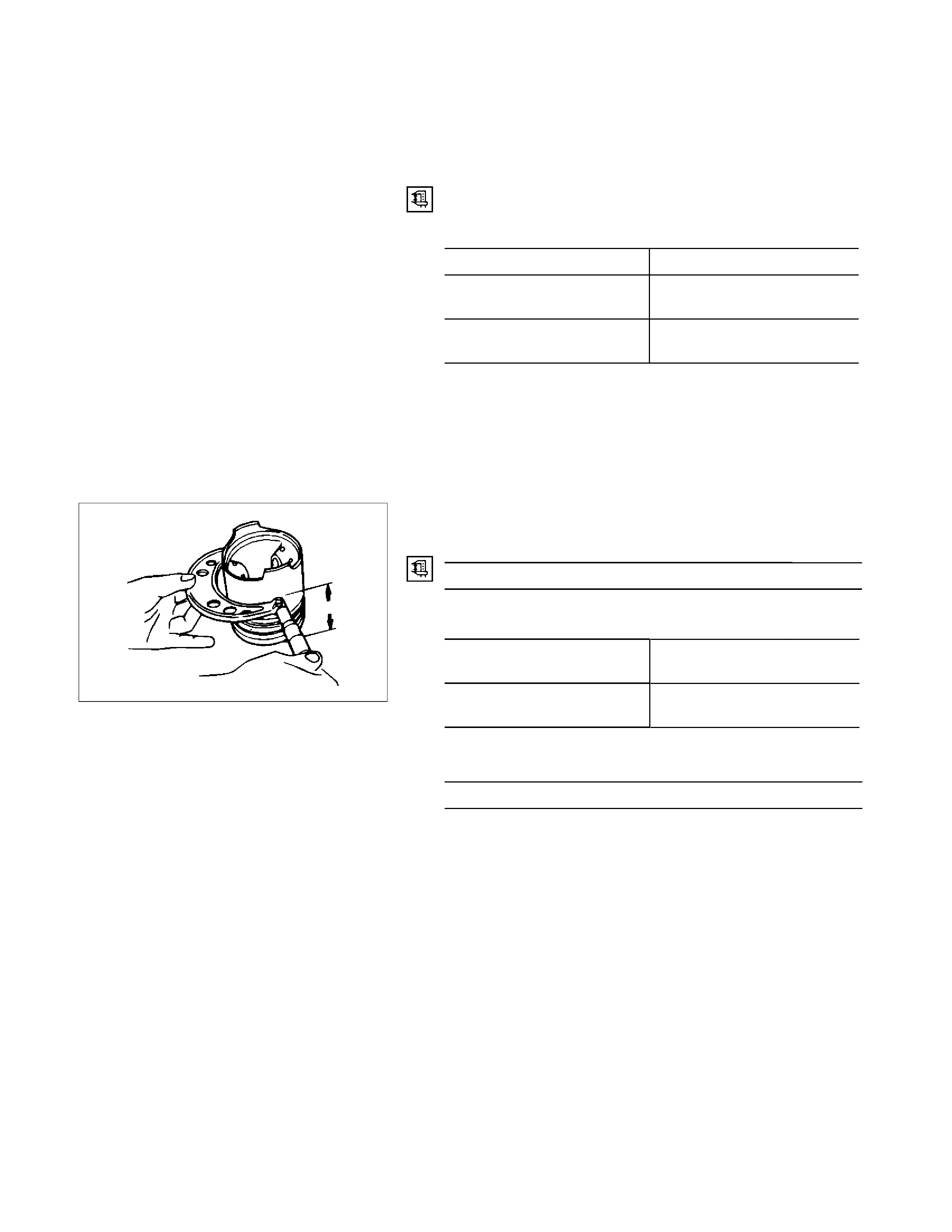
Valve Depression
1. Install the valve (1) to the cylinder head (2).
2. Use a depth gauge or a straight edge with steel rule to
measure the valve depression from the cylinder head
lower surface.
If the measured value exceeds the specified limit, the valve
seat insert must be replaced.
Valve Depression mm (in)
Standard Limit
1.17 (0.048) 1.67 (0.068)
011LX027
014RY00020
014RY00021
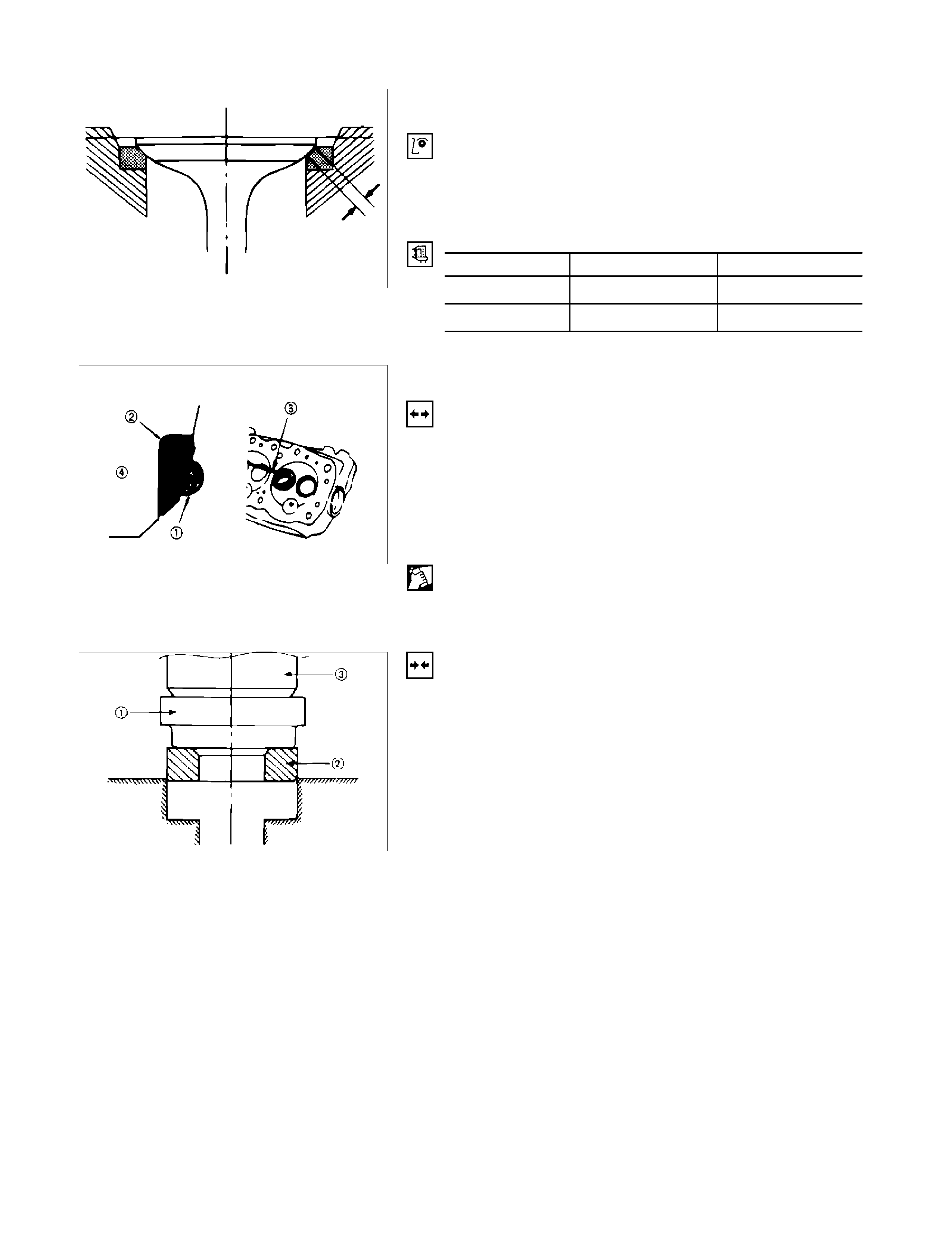
Valve Contact Width
1. Check the valve contact faces for roughness and
unevenness. Make smooth the valve contact surfaces.
2. Measure the valve contact width.
If the measured value exceeds the specified limit, the valve
seat insert must be replaced.
Valve Contact Width mm (in)
Standard Limit
Intake 1.7 (0.067) 2.2 (0.087)
Exhaust 2.0 (0.079) 2.5 (0.078)
Valve Seat Insert Replacement
Valve Seat Insert Removal
1. Arc weld the entire inside circumference (1) of the valve
seat insert (2).
2. Allow the valve seat insert to cool for a few minutes.
This will invite contraction and make removal of the valve
seat insert easier.
3. Use a screwdriver (3) to pry the valve seat insert free.
Take care not to damage the cylinder head (4).
4. Carefully remove carbon and other foreign material from
the cylinder head insert bore.
Valve Seat Insert Installation
1. Carefully place the attachment (1) (having a smaller
outside diameter than the valve seat insert) on the valve
seat insert (2).
NOTE:
The smooth side of the attachment must contact the valve
seat insert.
2. Use a bench press (3) to gradually apply pressure to the
attachment and press the valve seat insert into place.
NOTE:
Do not apply an excessive amount of pressure with the
bench press. Damage to the valve seat insert will result.
014RY00027
011LX039
014RY00026
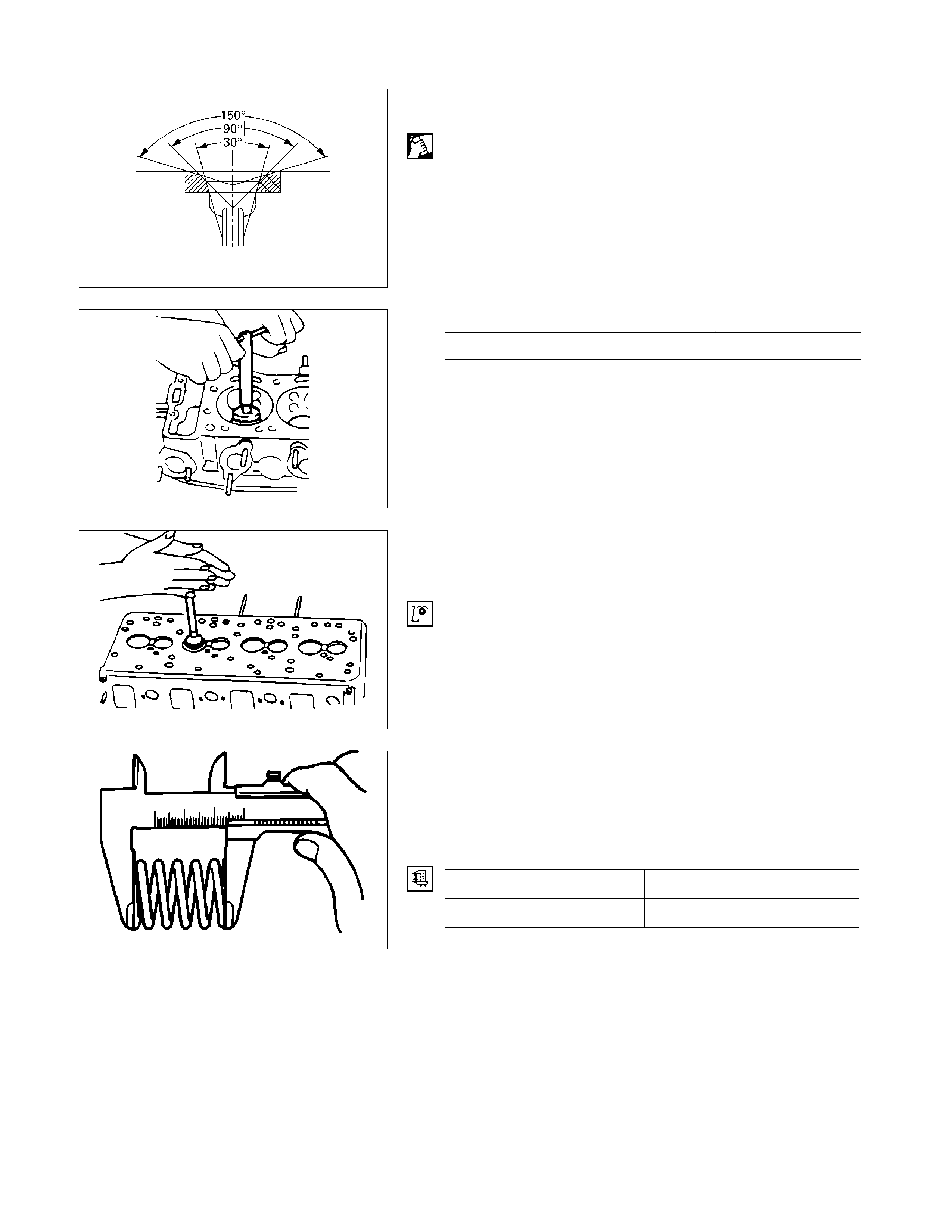
Valve Seat Insert Correction
1. Remove the carbon from the valve seat insert surface.
2. Use a valve cutter (15°, 45°, and 75° blades) to minimize
scratches and other rough areas. This will bring the
contact width back to the standard value.
Remove only the scratches and rough areas. Do not cut
away too much. Take care not to cut away unblemished
areas of the valve seat surface.
Valve Seat Angle Degree
45
NOTE:
Use an adjustable valve cutter pilot.
Do not allow the valve cutter pilot to wobble inside the
valve guide.
3. Apply abrasive compound to the valve seat insert surface.
4. Insert the valve into the valve guide.
5. Turn the valve while tapping it to fit the valve seat insert.
6. Check that the valve contact width is correct.
7. Check that the valve seat insert surface is in contact with
the entire circumference of the valve.
Valve Spring Free Height
Use a vernier calliper to measure the valve spring free height.
If the measured value is less than the specified limit, the valve
spring must be replaced.
Spring Free Height mm (in)
Standard Limit
48.0 (1.89) 47.1 (1.85)
011LX063
011LX037
011LX038
011LX024

Valve Spring Squareness
Use a surface plate and a square to measure the valve spring
squareness.
If the measured value exceeds the specified limit, the valve
spring must be replaced.
Spring Squareness mm (in)
Limit 1.7 (0.070)
Valve Spring Tension
Use a spring tester to measure the valve spring tension.
If the measured value is less than the specified limit, the valve
spring must be replaced.
Valve Spring Tension N (kg/lb)
Compressed Height Standard Limit
38.9mm
(1.53in) 296.0
(30.2/66.4) 257.7
(26.3/57.9)
ROCKER ARM SHAFT AND ROCKER ARM
Rocker Arm Shaft Run-Out
1. Place the rocker arm shaft on a V-block.
2. Use a dial indicator to measure the rocker arm shaft
central portion run-out.
If the run-out is very slight, correct the rocker arm shaft
run-out with a bench press. The rocker arm must be at
cold condition.
If the measured rocker arm shaft run-out exceeds the
specified limit, the rocker arm shaft must be replaced.
Rocker Arm Shaft Run-Out mm (in)
Limit
0.3 (0.012)
014RY00025
011LX026
015LX008
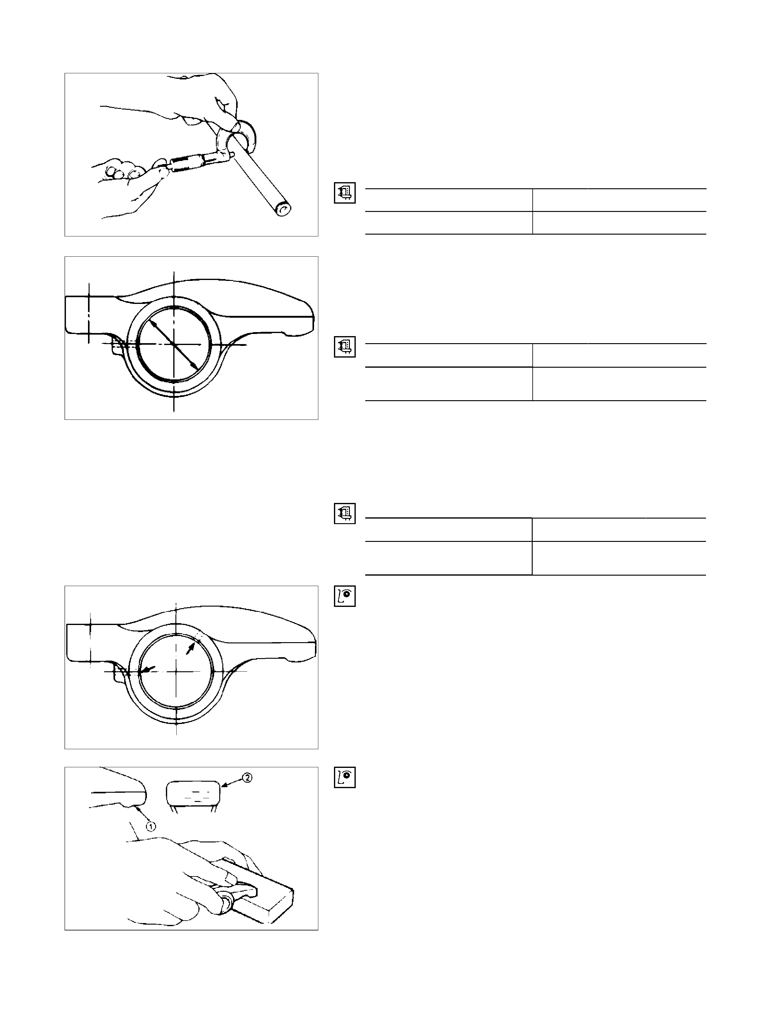
Rocker Arm Shaft Outside Diameter
Use a micrometer to measure the rocker arm fitting portion
outside diameter.
If the measured value is less than the specified limit, the
rocker arm shaft must be replaced.
Rocker Arm Shaft Outside Diameter mm (in)
Standard Limit
18.98–19.00 (0.747–0.748) 18.90 (0.744)
Rocker Arm Shaft and Rocker Arm Clearance
1. Use either a vernier calliper or a dial indicator to measure
the rocker arm inside diameter.
Rocker Arm Inside Diameter mm (in)
Standard Limit
19.010–19.030
(0.748–0.749) 19.100 (0.752)
2. Measure the rocker arm shaft outside diameter.
If the measured value exceeds the specified limit, replace
either the rocker arm or the rocker arm shaft.
Rocker Arm Shaft and Rocker Arm Clearance mm (in)
Standard Limit
0.01–0.05
(0.0004–0.0020) 0.20 (0.008)
3. Check that the rocker arm oil port is free of obstructions.
If necessary, use compressed air to clean the rocker arm
oil port.
Rocker Arm Correction
Inspect the rocker arm valve stem contact surfaces for step
wear (1) and scoring (2).
If the contact surfaces have light step wear or scoring, they
may be honed with an oil stone.
If the step wear or scoring is severe, the rocker arm must be
replaced.
015LX009
014RY00024
014RY00024
014RY00023
CYLINDER BODY
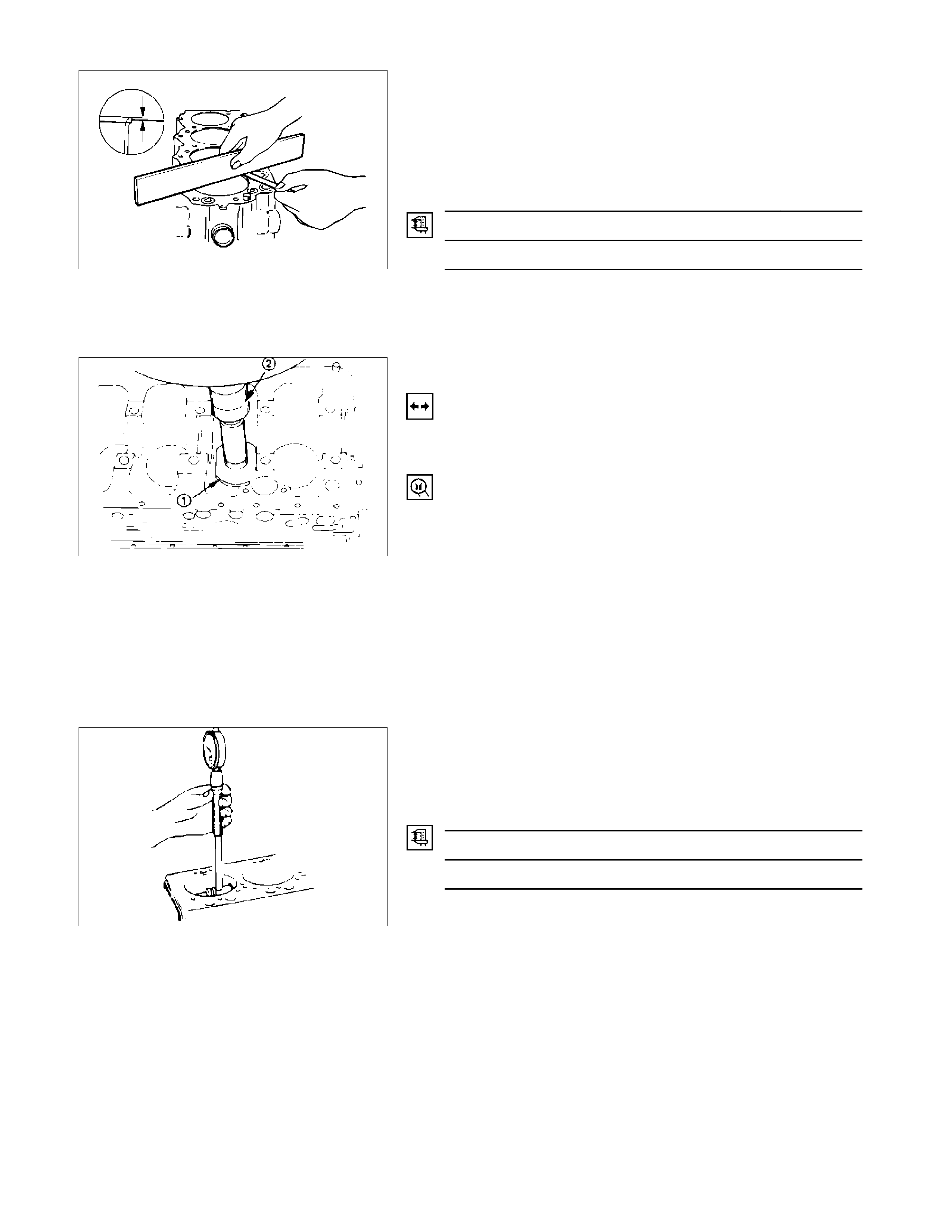
Cylinder Body Upper Face Warpage
1. Remove the cylinder body dowel.
2. Remove the cylinder liner.
Refer to "Cylinder Liner Replacement".
3. Use a straight edge (1) and a feeler gauge (2) to measure
the four sides and the two diagonals of the cylinder body
upper face.
If the measured values exceeds the limit, the cylinder body
must be replaced.
Cylinder Body Upper Face Warpage mm (in)
Standard Limit
0.05 (0.002) or less 0.20 (0.008)
Cylinder Body Height (H) (Reference) mm (in)
Standard
269.945-270.055 (10.6277-10.6320)
4. Reinstall the cylinder liner.
Refer to "Cylinder Liner Replacement".
5. Reinstall the cylinder body dowel.
Cylinder Liner Bore Measurement
Use a cylinder indicator to measure the cylinder bore at
measuring point (1) in the thrust (2-2) and axial (3-3) directions
of the crankshaft.
Measuring Point (1): 20 mm (0.79 in)
If the measured value exceeds the specified limit, the cylinder
liner must be replaced.
Cylinder Liner Bore mm (in)
Standard Limit
95.40 (3.7559) 95.48 (3.7590)
NOTE:
The inside of the dry type cylinder liner is chrome plated. It
cannot be rebored or honed.
If the inside of the cylinder liner is scored or scorched, the
cylinder liner must be replaced.
012R100001
012RY00009
012RY00010
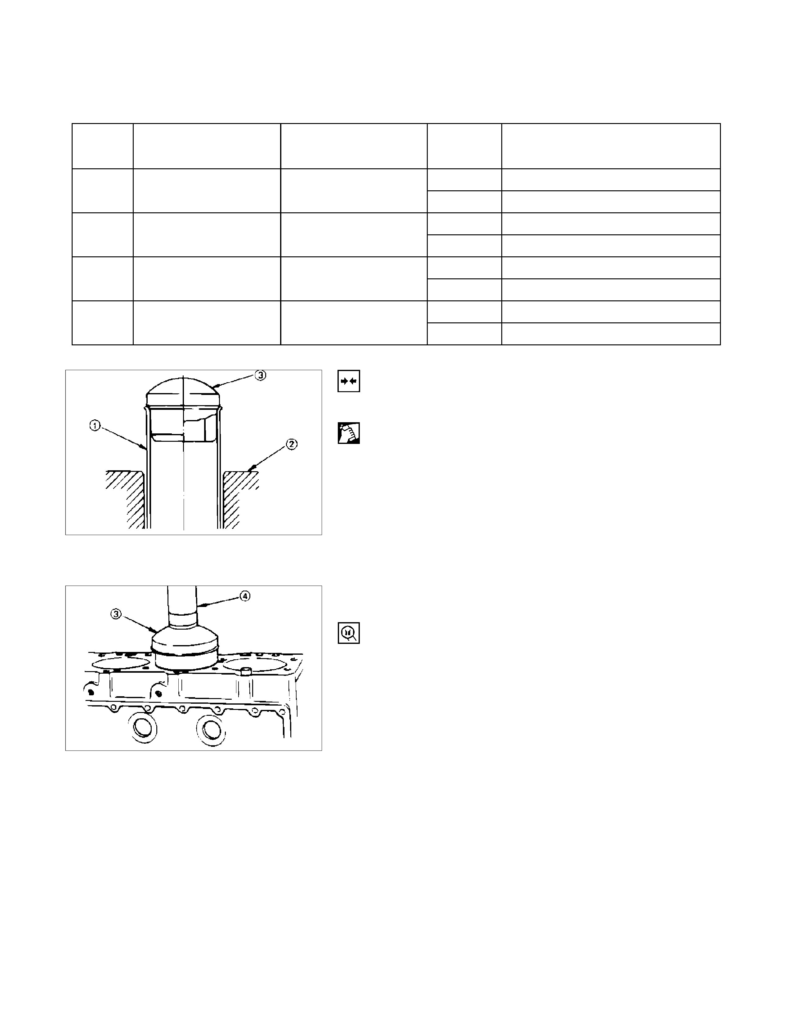
Cylinder Liner Projection Inspection
1. Hold a straight edge along the top edge of the cylinder
liner to be measured.
2. Use a feeler gauge to measure each cylinder liner
projection.
Cylinder Liner Projection mm (in)
Standard
0-0.1 (0-0.004)
The difference in the cylinder liner projection height
between any two adjacent cylinders must not exceed 0.03
mm (0.0012 in).
Cylinder Liner Replacement
Cylinder Liner Removal
1. Insert the cylinder liner remover (1) into the cylinder body
(from the lower side of the cylinder body) until it makes
firm contact with the cylinder liner.
Cylinder Liner Remover: 5-8840-2304-0
2. Use a bench press (2) to slowly force the cylinder liner
from the cylinder body.
NOTE:
Take care not to damage the cylinder body upper face
during the cylinder liner removal procedure.
3. Measure the cylinder body upper face warpage.
Refer to "Cylinder Body Upper Face Warpage".
Cylinder Liner Grade Selection
Subtract the average cylinder body bore from the average
cylinder liner outside diameter to obtain the fitting interference.
Fitting Interference mm (in)
Standard
-0.0010*-0.019 (-0.00004*-0.0007)
* A minus (-) value indicates that the cylinder body bore is
smaller than the liner outside diameter.
012LX016
012RY00012
012RY00013

Cylinder Body Bore Measurement
1. Take measurements at measuring point (1) across
positions 1-1 and 2-2.
Measuring Point (1):
18,53,88,123,158 mm (0.71,2.09,3.46,4.84,6.22 in)
Cylinder Liner Grade Selection and Standard Fitting
Interference
Accurately measured fitting interference and proper cylinder
liner grade selection are extremely important.
If the cylinder liner fitting interference is too small, engine
cooling efficiency will be adversely affected.
If the cylinder liner fitting interference is too large, it will be
difficult to insert the cylinder liner into the cylinder body.
012RY00022
A mark was stamped on the upper side of the cylinder block
during production to indicate the correct liner.
The liner grade (i.e.1.2.3.4) is indicated in metal stamp.
012RY00014
012R300001
Cylinder Liner Grade
4JH1T mm (in)
Liner
Outside
Grade
Cylinder Body
Bore Diameter Liner Outside
Diameter Liner Bore
Grade Service Liner Bore Measurement
AX 95.435-95.450 (3.7573-3.7579)
1 97.001-97.010
(3.8189-3.8193) 97.011-97.020
(3.8193-3.8197) CX 95.451-95.466 (3.7579-3.7585)
AX 95.435-95.450 (3.7573-3.7579)
2 97.011-97.020
(3.8193-3.8197) 97.021-97.030
(3.8197-3.8200) CX 95.451-95.466 (3.7579-3.7585)
AX 95.435-95.450 (3.7573-3.7579)
3 97.021-97.030
(3.8197-3.8200) 97.031-97.040
(3.8200-3.8205) CX 95.451-95.466 (3.7579-3.7585)
AX 95.435-95.450 (3.7573-3.7579)
4 97.031-97.040
(3.8200-3.8205) 97.041-97.050
(3.8205-3.8209) CX 95.451-95.466 (3.7579-3.7585)
Cylinder Liner Installation
Cylinder Liner Installation Using the Special Tool
1. Use new kerosene or diesel oil to thoroughly clean the
cylinder liners and bores.
2. Use compressed air to blow-dry the cylinder liner and
bore surfaces.
NOTE:
All foreign material must be carefully removed from the
cylinder liner and the cylinder bore before installation.
3. Insert the cylinder liner (1) into the cylinder body (2)
from the top of the cylinder body.
4. Set the cylinder liner installer (3) to the top of the
cylinder liner.
5. Cylinder Liner Installer 5-8840-2313-0 (3) is directly
beneath the bench press shaft center (4).
NOTE:
Check that the cylinder liner is set perpendicular to the
bench press and that there is no wobble.
6. Use the bench press to apply a seating force of 4,900
N (500 kg/1,100 Ib) to the cylinder liner.
7. Apply a force of 24,500 N (2,500 kg/5,500 Ib) to fully
seat the cylinder liner.
8. After installing the cylinder liner, measure the cylinder
liner projection.
Refer to "Cylinder Liner Projection Inspection".
012RY00017
012RY00018
Piston Grade Selection
Measure the cylinder liner bore after installing the cylinder
liner. Then select the appropriate piston grade for the installed
cylinder liner.
1. Measure the cylinder liner bore.
Refer to "Cylinder Liner Bore Measurement"
Cylinder Liner Bore (Service Part) Grade mm (in)
Grade Bore measurement
AX 95.435-95.450
(3.7573-3.7579)
CX 95.451-95.466
(3.7579-3.7585)
NOTE:
It is most important that the correct piston grade be used.
Failure to select the correct piston grade will result in
engine failure. Always measure the cylinder bore and
select the correct piston grade.
2. Measure the piston diameter.
P
iston Measuring Point mm (in)
70 (2.76)
Piston Grade (Service Part) mm (in)
AX 95.359-95.374
(3.7542-3.7548)
CX 95.375-95.390
(3.7548-3.7555)
Cylinder Liner and Piston Clearance mm (in)
0.047-0.065 (0.0019-0.0026)
NOTE:
Cylinder liner kit clearances are preset. However, the
cylinder liner installation procedure may result in slight
decreases in cylinder liner clearances. Always measure
the cylinder liner clearance after installation to be sure
that it is correct.
015LX021
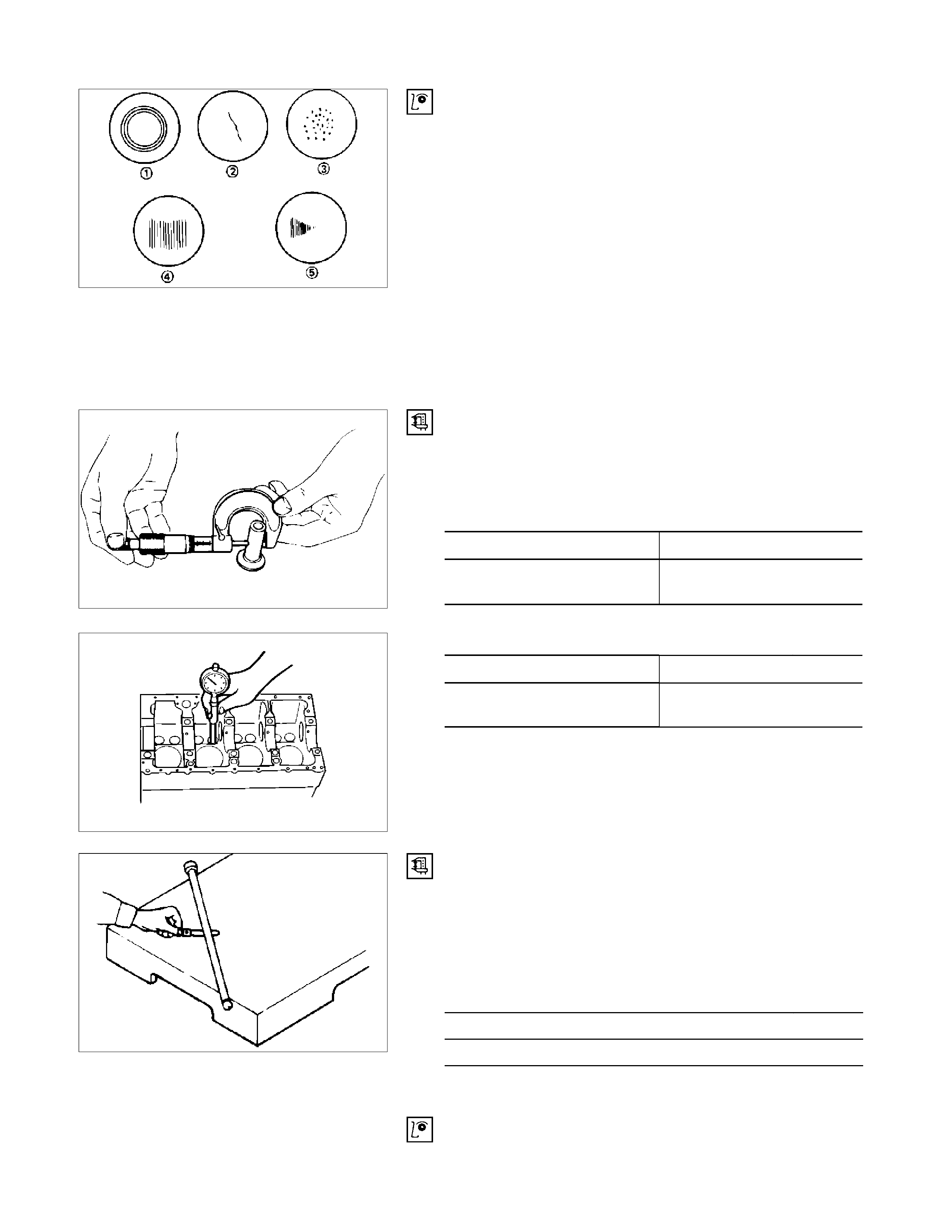
TAPPET AND PUSH ROD
Visually inspect the tappet contact surfaces for pitting,
cracking, and other abnormal conditions. The tappet must be
replaced if any of these conditions are present.
Refer to the illustration at the left.
1. Normal contact
2. Cracking
3. Pitting
4. Irregular contact Uneven contact
5. Irregular contact One-sided contact
NOTE:
The tappet surfaces are spherical. Do not attempt to grind
them with an oil stone or similar tool in an effort to repair
the tappet. If the tappet is damaged, it must be replaced.
Tappet Outside Diameter
Measure the tappet outside diameter with a micrometer.
If the measured value is less than the specified limit, the
tappet must be replaced.
T
appet Outside Diamete
r
mm (in)
Standard Limit
12.97 - 12.99
(0.510 - 0.511) 12.95 (0.510)
T
appet and Cylinder Body Clearance mm (in)
Standard Limit
0.01 - 0.046
(0.0004 - 0.0018) 0.10 (0.004)
Push Rod Curvature
1. Lay the push rod on a surface plate.
2. Roll the push rod along the surface plate and measure the
push rod curvature with a thickness gauge.
If the measured value exceeds the specified limit, the push
rod must be replaced.
Pushrod Curvature mm (in)
Limit
0.3 (0.012)
3. Visually inspect both ends of the push rod for excessive
wear and damage. The push rod must be replaced if these
conditions are discovered during inspection.
014RY00028
014RY00029
012LX014
014RY00031
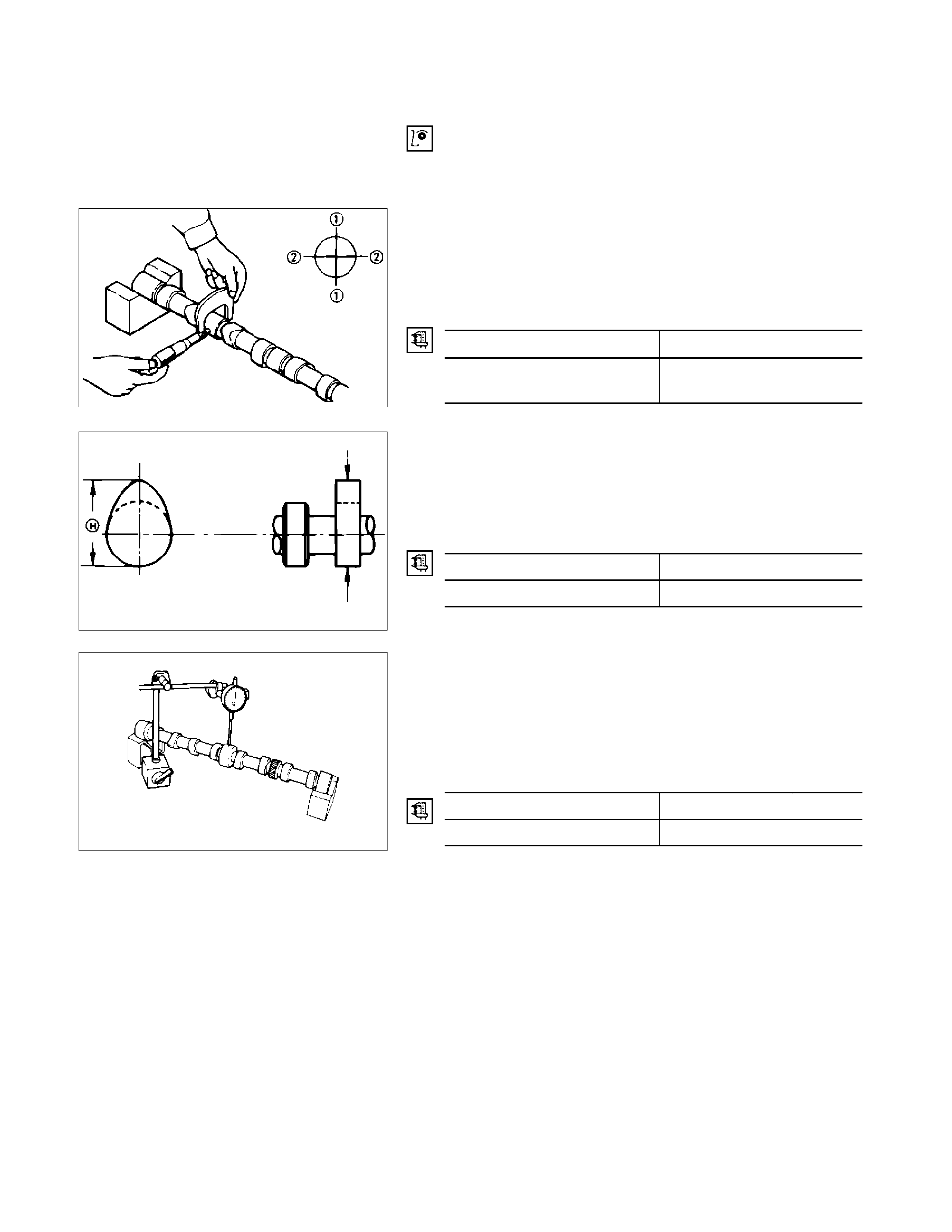
CAMSHAFT
Visually inspect the journals, the cams, the oil pump drive
gear, and the camshaft bearings for excessive wear and
damage. The camshaft and the camshaft bearings must be
replaced if these conditions are discovered during inspection.
Camshaft Journal Diameter
Use a micrometer to measure each camshaft journal diameter
in two directions (1 and 2). If the measured value is less than
the specified limit, the camshaft must be replaced.
Camshaft Journal Diamete
r
mm (in)
Standard Limit
49.945 - 49.975
(1.9663 - 1.9675) 49.60 (1.953)
Cam Height
Measure the cam height (H) with a micrometer. If the
measured value is less than the specified limit, the camshaft
must be replaced.
Cam Height (H) mm (in)
Standard Limit
42.016 (1.6542) 41.65 (1.640)
Camshaft Run-Out
1. Mount the camshaft on V-blocks.
2. Measure the run-out with a dial indicator.
If the measured value exceeds the specified limit, the
camshaft must be replaced.
Camshaft Run-Out mm (in)
Standard Limit
0.02 (0.0008) 0.10 (0.004)
014RY00032
014RY00033
014LX092

Camshaft and Camshaft Bearing Clearance
Use an inside dial indicator to measure the camshaft bearing
inside diameter.
Crankshaft Bearing Inside Diamete
r
mm (in)
Standard Limit
50.00 - 50.03
(1.968 - 1.970) 50.08 (1.972)
If the clearance between the camshaft bearing inside diameter
and the journal exceeds the specified limit, the camshaft
bearing must be replaced.
Camshaft Bearing Clearance mm (in)
Standard Limit
0.055 (0.0022) 0.12 (0.005)
Camshaft Bearing Replacement
Camshaft Bearing Removal
1. Remove the cylinder body plug plate.
2. Use the bearing replacer to remove the camshaft bearing.
Bearing Replacer: 5-8840-2038-0
Camshaft Bearing Installation
1. Align the bearing oil holes with the cylinder body oil holes.
2. Use the replacer to install the camshaft bearing.
Bearing Replacer: 5-8840-2038-0
CRANKSHAFT AND BEARING
Inspect the surface of the crankshaft journals and crankpins
for excessive wear and damage.
Inspect the oil seal fitting surfaces for excessive wear and
damage.
Inspect the oil ports for obstructions.
NOTE:
To increase crankshaft strength, tufftriding (Nitrizing
Treatment) has been applied, and because of this, it is not
possible to regrind the crankshaft surfaces.
Therefore, under size bearings are not available.
014RY00034
014RY00035
014RY00036
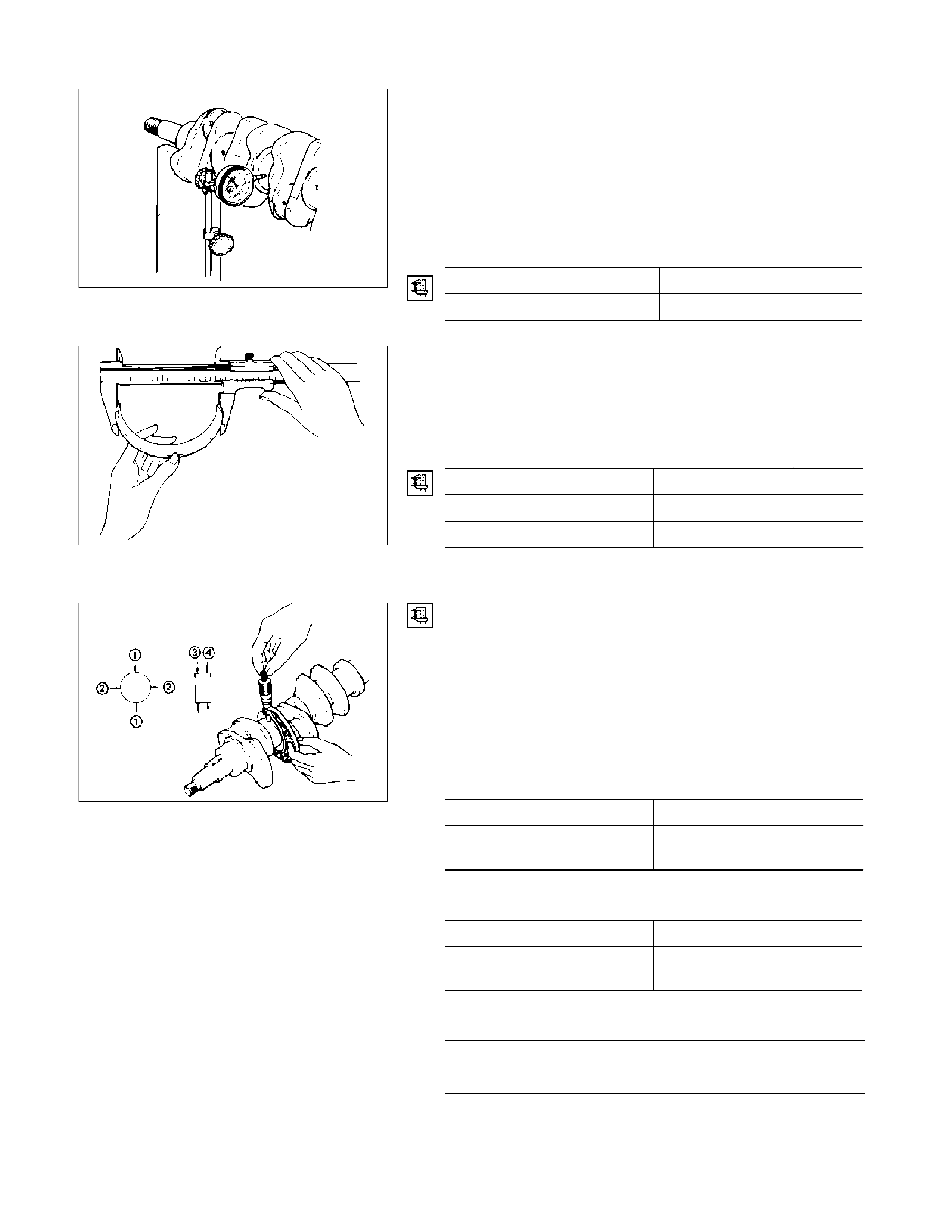
Crankshaft Run-Out
1. Set a dial indicator to the center of the crankshaft journal.
2. Gently turn the crankshaft in the normal direction of
rotation.
Read the dial indicator as you turn the crankshaft.
If the measured value exceeds the specified limit, the
crankshaft must be replaced.
Crankshaft Run-Out mm (in)
Standard Limit
0.05 (0.002) or less 0.08 (0.003)
Bearing Spread
Use a vernier calliper to measure the bearing spread.
If the measured value is less than the specified limit, the
bearing must be replaced.
Bearing Spread mm (in)
Limit
Crankshaft Bearing 74.5 (2.93)
Connecting Rod Bearing 56.5 (2.22)
Crankshaft Journal and Crankpin Diameter
1. Use a micrometer to measure the crankshaft journal
diameter across points 1 - 1 and 2 - 2.
2. Use the micrometer to measure the crankshaft journal
diameter at the two points (3 and 4).
3. Repeat Steps 1 and 2 to measure the crankpin diameter.
If the measured values are less than the specified limit, the
crankshaft must be replaced.
Crankshaft Journal and Diameter mm (in)
Standard Limit
69.917-69.932
(2.7526-2.7532) 69.91(2.7524)
Crankpin Diamete
r
mm (in)
Standard Limit
52.915 - 52.930
(2.0833 - 2.0839) 52.90 (2.083)
Crankshaft Journal and Crankpin Uneven Wear mm (in)
Standard Limit
0.05 (0.002) or less 0.08 (0.003)
015LX061
015RY00007
015RY00008
Crankshaft Journal and Crankpin Diameter
If the clearance between the measured bearing inside
diameter and the crankshaft journal diameter exceeds the
specified limit, the bearing and/or the crankshaft must be
replaced.
Crankshaft Journal and Bearing Clearance mm (in)
Standard Limit
0.032 - 0.077
(0.0013 - 0.0030) 0.110 (0.0043)
Connecting Rod Bearing Inside Diameter
1. Install the bearing to the connecting rod big end.
2. Tighten the bearing cap to the two step of angular
tightening method.
Connecting Rod Bearing Cap Bolt Torque N·m (kg·m/Ib ft)
1st step ; 29 (3.0/22)
2nd step ; 45°-60°
3. Use an inside dial indicator to measure the connecting rod
bearing inside diameter.
Crankpin and Bearing Clearance
If the clearance between the measured bearing inside
diameter and the crankpin exceeds the specified limit, the
bearing and/or the crankshaft must be replaced.
Crankpin and Bearing Clearance mm (in)
Standard Limit
0.029-0.083
(0.0011-0.033) 0.100 (0.0039)
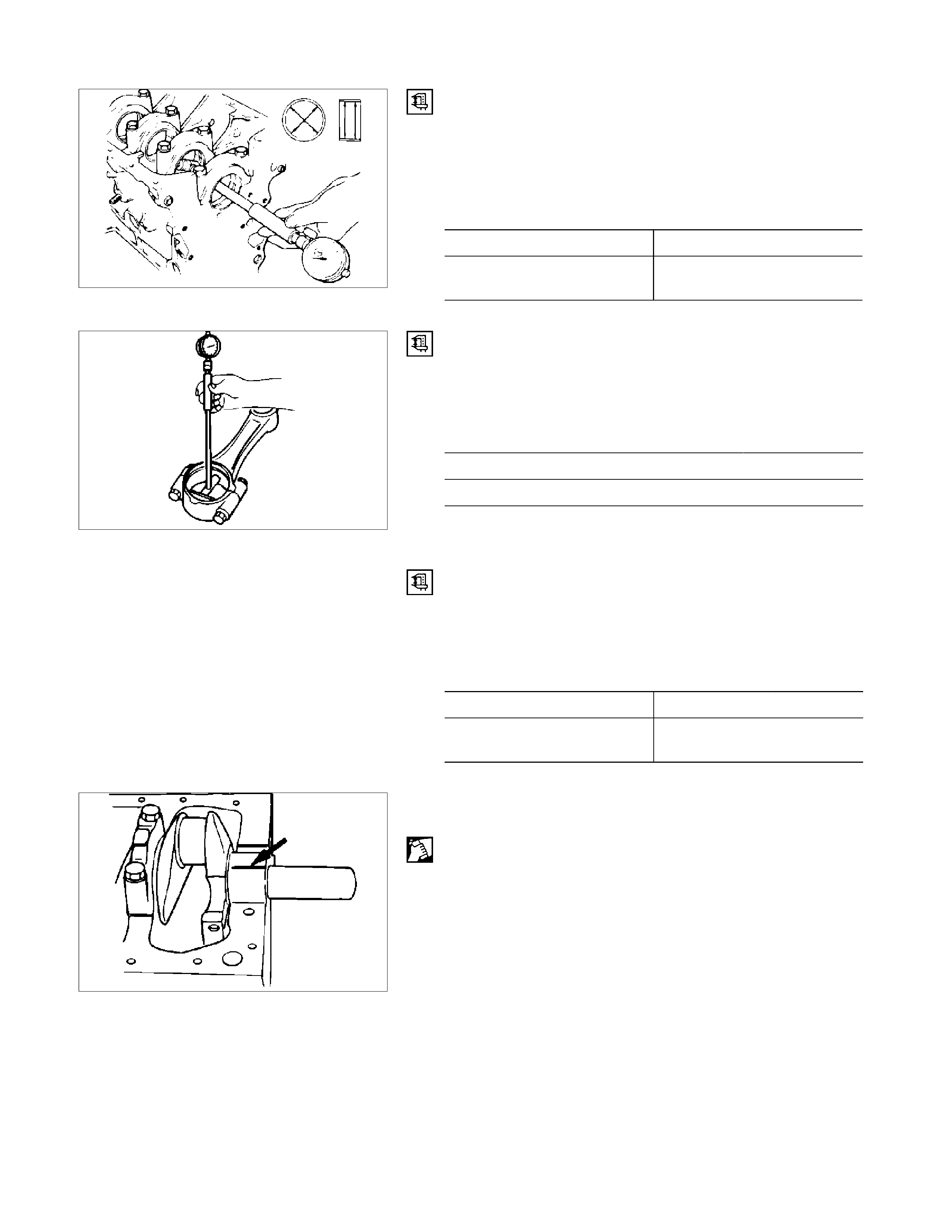
Clearance Measurements (With Plastigage)
Crankshaft Journal and Bearing Clearance
1. Clean the cylinder body, the journal bearing fitting surface,
the bearing caps, and the bearings.
2. Install the bearings to the cylinder body.
3. Carefully place the crankshaft on the bearings.
4. Rotate the crankshaft approximately 30° to seat the
bearing.
5. Place the Plastigage (arrow) over the crankshaft journal
across the full width of the bearing.
6. Install the bearing caps with the bearing.
015RY00009
015RY00011
015RY00012
7. Tighten the bearing caps to the specified torque.
Crankshaft Bearing Cap Bolt Torque mm (in)
167 (17/123)
Do not allow the crankshaft to turn during bearing cap
installation and tightening.
8. Remove the bearing cap.
9. Compare the width of the Plastigage attached to either the
crankshaft or the bearing against the scale printed on the
Plastigage container.
If the measured value exceeds the limit, perform the
following additional steps.
1) Use a micrometer to measure the crankshaft
outside diameter.
2) Use an inside dial indicator to measure the
bearing inside diameter.
3) If the crankshaft journal and bearing clearance
exceeds the limit, the crankshaft and/or the
bearing must be replaced.
Crankshaft Journal and Bearing Clearance mm (in)
Standard Limit
0.032-0.077
(0.0013-0.0030) 0.110 (0.0043)
015RY00013
015LX129
015LX060
Crankpin and Bearing Clearance
1. Clean the crankshaft, the connecting rod, the bearing cap,
and the bearings.
2. Install the bearing to the connecting rod and the bearing
cap.
Do not allow the crankshaft to move when installing the
bearing cap.
3. Prevent the connecting rod from moving.
4. Attach the Plastigage to the crankpin.
Apply engine oil to the Plastigage to keep it from falling.
5. Install the bearing cap and tighten it to the two step of
angular tightening method.
Do not allow the connecting rod to move when installing
and tightening the bearing cap.
Connecting Rod Bearing Cap Bolt Torque N·m (kg·m/Ib ft)
1st step ; 29 (3.0/22)
2nd step ; 45°-60°
6. Remove the bearing cap.
7. Compare the width of the Plastigage attached to either the
crankshaft or the bearing against the scale printed on the
Plastigage container.
If the measured value exceeds the specified limit, perform
the following additional steps.
1) Use a micrometer to measure the crankpin
outside diameter.
2) Use an inside dial indicator to measure the
bearing inside diameter.
3) If the crank pin and bearing clearance exceeds
the specified limit, the crankshaft and/or the
bearing must be replaced.
Crankpin and Bearing Clearance mm (in)
Standard Limit
0.029-0.083
(0.0011-0.0033) 0.100 (0.0039)
CRANKSHAFT BEARING SELECTION
Crankshaft bearing selection is based on the measured
diameters of the crankshaft journals and the bearing inserts.
Match the crankshaft bearing housing grade marks and the
crankshaft journal grade marks in the table below to determine
the correct crankshaft bearing size.
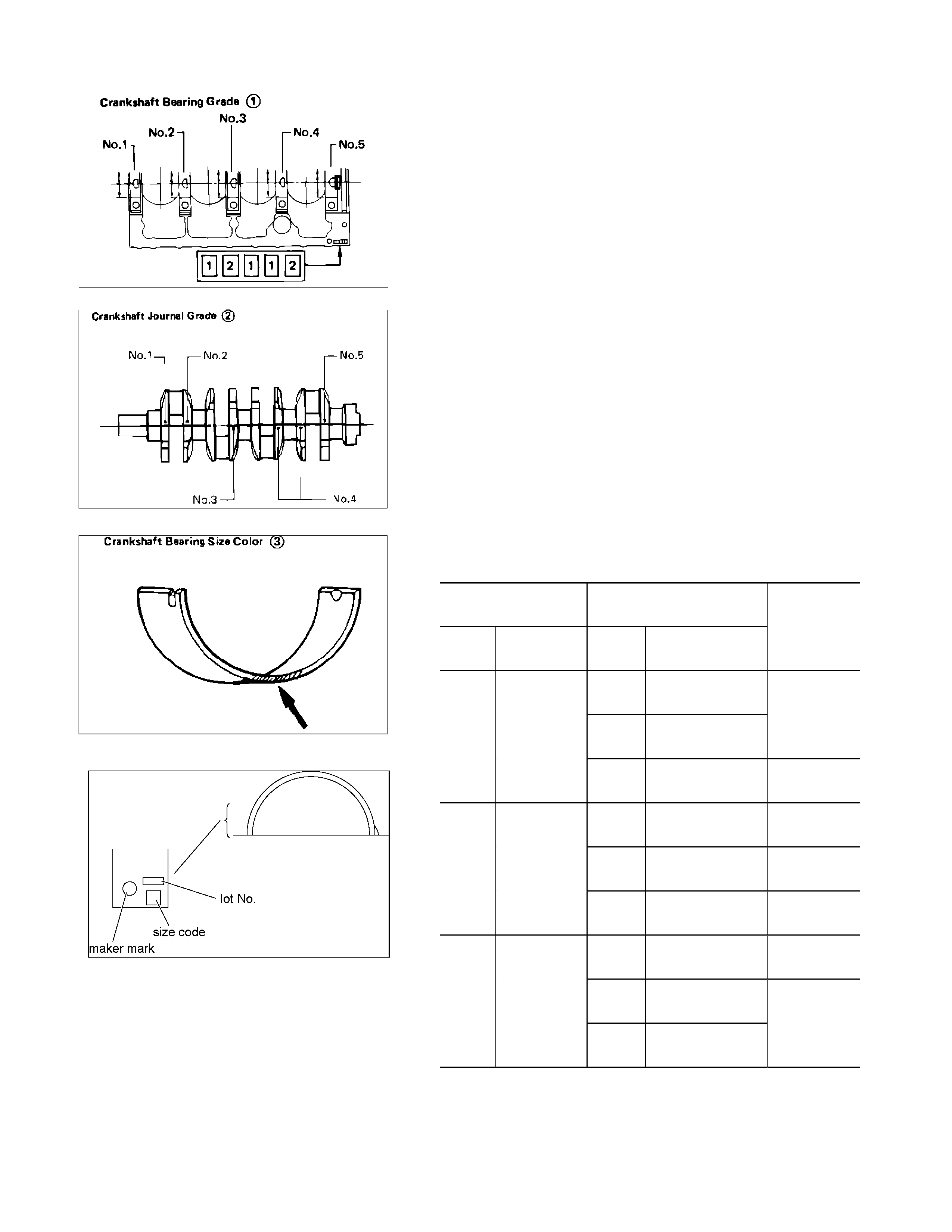
Crankshaft Bearing Housing Grade Mark Position
Crankshaft bearing housing grade marks 1, 2 or 3 are
stamped on the rear right hand side of the cylinder body.
Crankshaft Journal Grade Mark Position
The crankshaft journal grade marks (1 or -, 2 or --, 3 or ---) are
stamped on each crankshaft journal web.
The crankshaft journal and bearing clearance must be the
same for each position after installation of the crankshaft and
the crankshaft bearings.
NOTE:
The crankshaft journal mark No. 4 is stamped on
crankshaft No. 4 journal web front side or rear side.
RTW46ASH002501
REFERENCE
M
MY2003 mm (in)
Crankshaft
Bearing Housing Crankshaft Journal
Grade
Mark Diameter Grade
Mark Diameter
Crankshaft
Bearing
Size Color
Code
1 or
- 69.927-69.932
(2.7530-2.7532)
2 or
- - 69.922-69.927
(2.7528-2.7530)
Yellow
1
73.992-
74.000
(2.9131-
2.9134) 3 or
- - - 69.917-69.922
(2.7556-2.7528) Red
1 or
- 69.927-69.932
(2.7530-2.7532) Black
2 or
- - 69.922-69.927
(2.7528-2.7530) Blue
2
73.983-
73.992
(2.9127-
2.9131) 3 or
- - - 69.917-69.922
(2.7556-2.7528) Yellow
1 or
- 69.927-69.932
(2.7530-2.7532) Green
2 or
- - 69.922-69.927
(2.7528-2.7530)
3
73.975-
73.983
(2.9124-
2.9127) 3 or
- - - 69.917-69.922
(2.7526-2.7528)
Black
015LX060
015RY00016
015RY00017
RTW46ASH002501
MY2004 mm (in)
Crankshaft
Bearing Housing Crankshaft Journal
Grade
Mark Diameter Grade
Mark Diameter
Crankshaft
Bearing
Size Code
1 or
- 69.927-69.932
(2.7530-2.7532)
2 or
- - 69.922-69.927
(2.7528-2.7530)
4
1
73.992-
74.000
(2.9131-
2.9134) 3 or
- - - 69.917-69.922
(2.7556-2.7528) 5
1 or
- 69.927-69.932
(2.7530-2.7532) 2
2 or
- - 69.922-69.927
(2.7528-2.7530) 3
2
73.983-
73.992
(2.9127-
2.9131) 3 or
- - - 69.917-69.922
(2.7556-2.7528) 4
1 or
- 69.927-69.932
(2.7530-2.7532) 1
2 or
- - 69.922-69.927
(2.7528-2.7530)
3
73.975-
73.983
(2.9124-
2.9127) 3 or
- - - 69.917-69.922
(2.7526-2.7528)
2
CRANKSHAFT PILOT BEARING
Check the crankshaft pilot bearing for excessive wear and
damage and replace it if necessary.
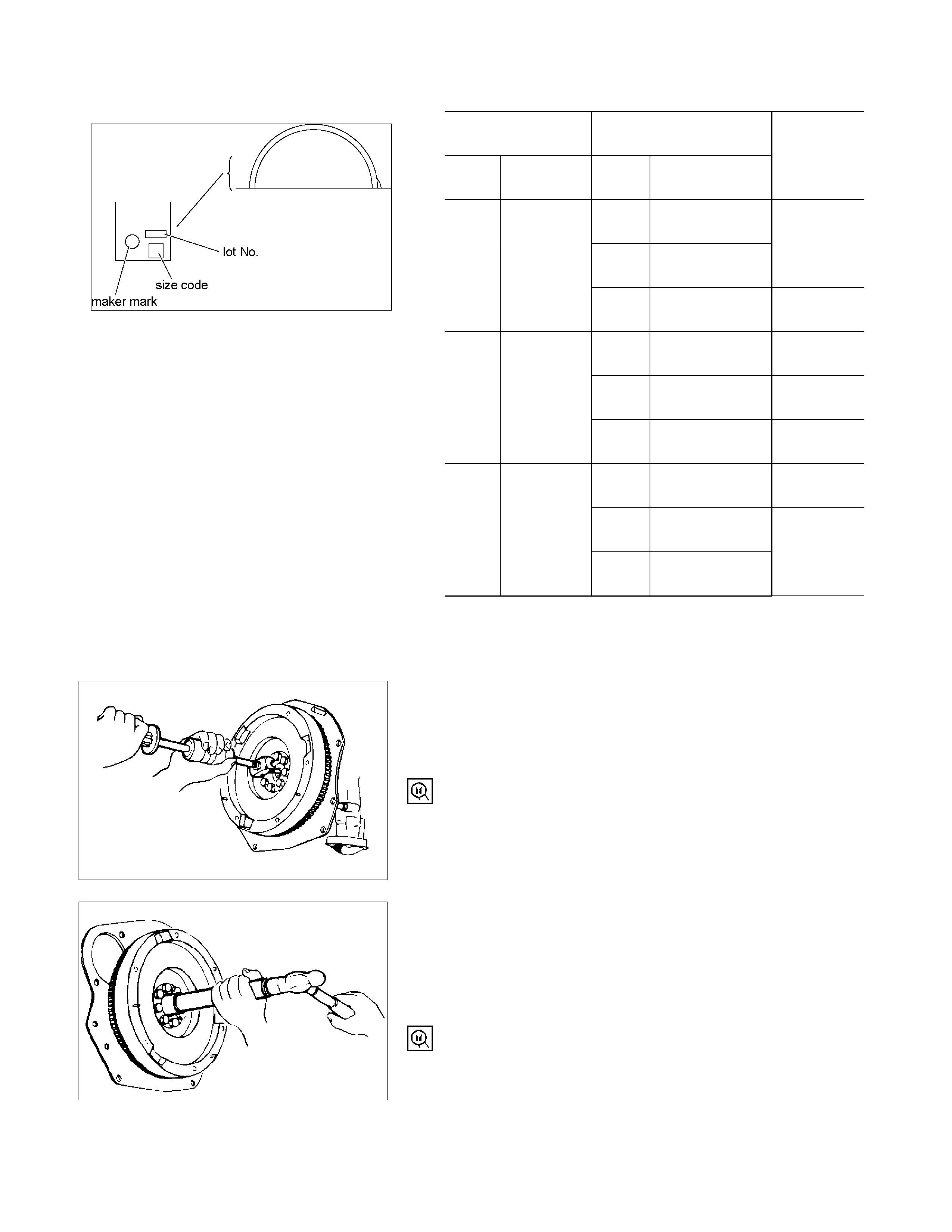
Crankshaft Pilot Bearing Replacement
Crankshaft Pilot Bearing Removal
Use the pilot bearing remover to remove the crankshaft pilot
bearing.
Pilot Bearing Remover: 5-8840-2000-0
Sliding Hammer: 5-8840-0019-0
Crankshaft Pilot Bearing Installation
1. Place the crankshaft pilot bearing right angle across the
crankshaft bearing installation hole.
2. Tap around the edges of the crankshaft pilot bearing outer
races with a brass hammer to drive the bearing into the
crankshaft bearing installation hole.
Pilot Bearing Installer: 5-8522-0024-0
NOTE:
Strike only the crankshaft pilot bearing outer race with the
hammer. Do not strike the bearing inner race. Bearing
damage and reduced bearing service life will result.
015RY00018
015RY00010
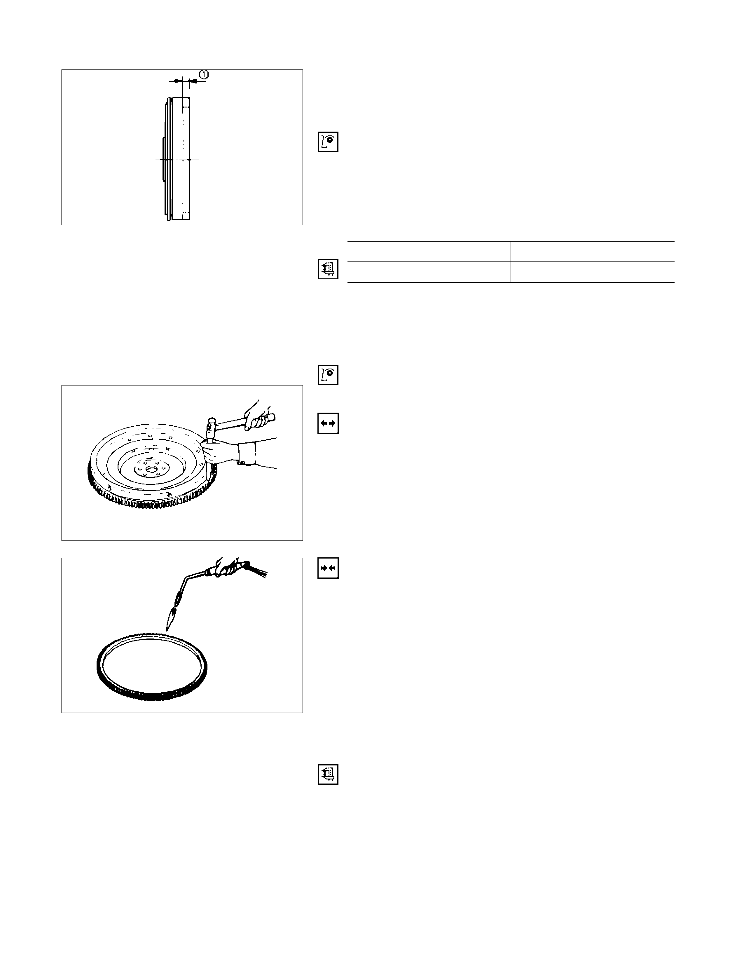
FLYWHEEL AND RING GEAR
Flywheel
1. Inspect the flywheel friction surface for excessive wear
and heat cracks.
2. Measure the flywheel friction surface depth.
If the measured value is within the specified limit, the
flywheel may be reground.
If the measured value exceeds the specified limit, the
flywheel must be replaced.
Flywheel Friction Surface Depth (1) mm (in)
Standard Limit
18 (0.7087) 19 (0.7480)
Ring Gear
Inspect the ring gear.
If the ring gear teeth are broken or excessively worn, the ring
gear must be replaced.
Ring Gear Replacement
Ring Gear Removal
Strike around the edges of the ring gear with a hammer and
chisel to remove it.
Ring Gear Installation
1. Heat the ring gear evenly with a gas burner to invite
thermal expansion.
Do not allow the temperature of the gas burner to exceed
200°C (390°F).
2. Install the ring gear when it is sufficiently heated.
The ring gear must be installed with the chamfer facing the
clutch.
PISTON
Piston Grade Selection and Cylinder Bore Measurement
Refer to the Section "Cylinder Body", Item
"Cylinder Liner Bore Measurement" for details on piston
grade selection and cylinder liner bore measurement.
015RY00019
020LX008
020LX009
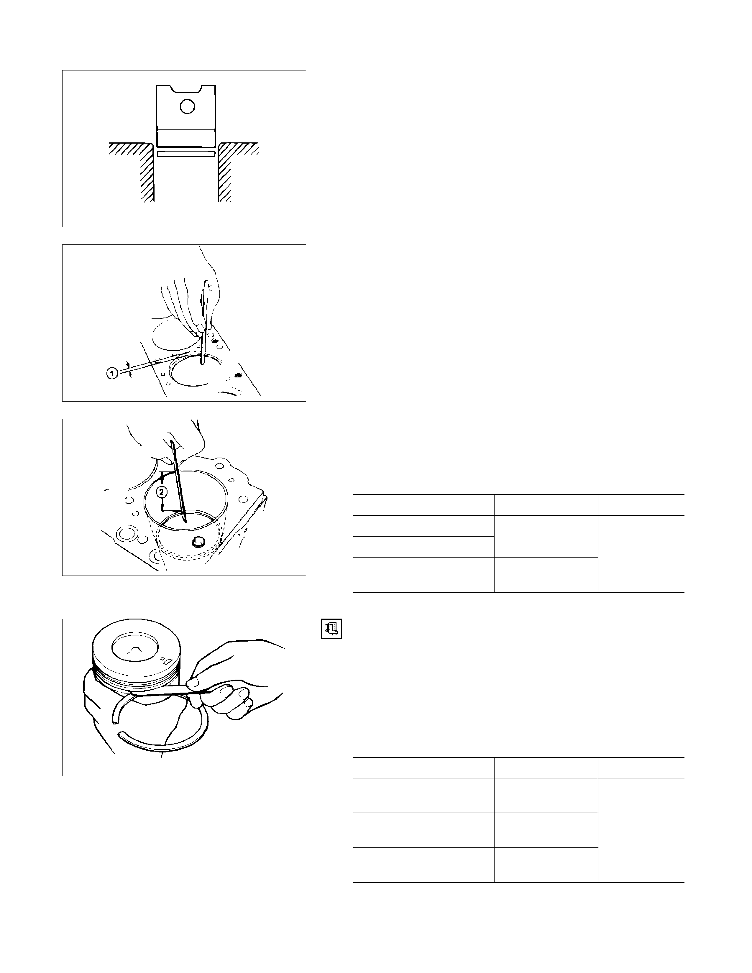
Piston Ring Gap
1. Insert the piston ring horizontally (in the position it would
assume if it were installed to the piston) into the cylinder
liner.
2. Push the piston ring into the cylinder bore until it reaches
the measuring point 1 or 2 where the cylinder liner bore is
the smallest.
Do not allow the piston ring to slant to one side or the
other. It must be perfectly horizontal.
Measuring Point 1 10 mm (0.4 in)
or
Measuring Point 2 120 mm (4.7 in)
3. Use a feeler gauge to measure the piston ring gap.
If the measured value exceeds the specified limit, the
piston ring must be replaced.
Standard Limit
1st Compression Ring
2nd Compression Ring 0.3-0.5
(0.0118-0.0197)
Oil Ring 0.250-0.450
(0.0098-0.0177)
1.5
(0.059)
Piston Ring and Piston Ring Groove Clearance
Use a feeler gauge to measure the clearance between the
piston ring and the piston ring groove at several points around
the piston.
If the clearance between the piston ring and the piston ring
groove exceeds the specified limit, the piston ring must be
replaced.
Piston Ring and Piston Ring Groove Clearance mm (in)
Standard Limit
1st Compression Ring 0.09-0.130
(0.0035-0.0051)
2nd Compression Ring 0.05-0.090
(0.0020-0.0035)
Oil Ring 0.03-0.070
(0.0012-0.0028)
1.5
(0.0059)
015LX023
015RY00020
015RY00021
015LX025
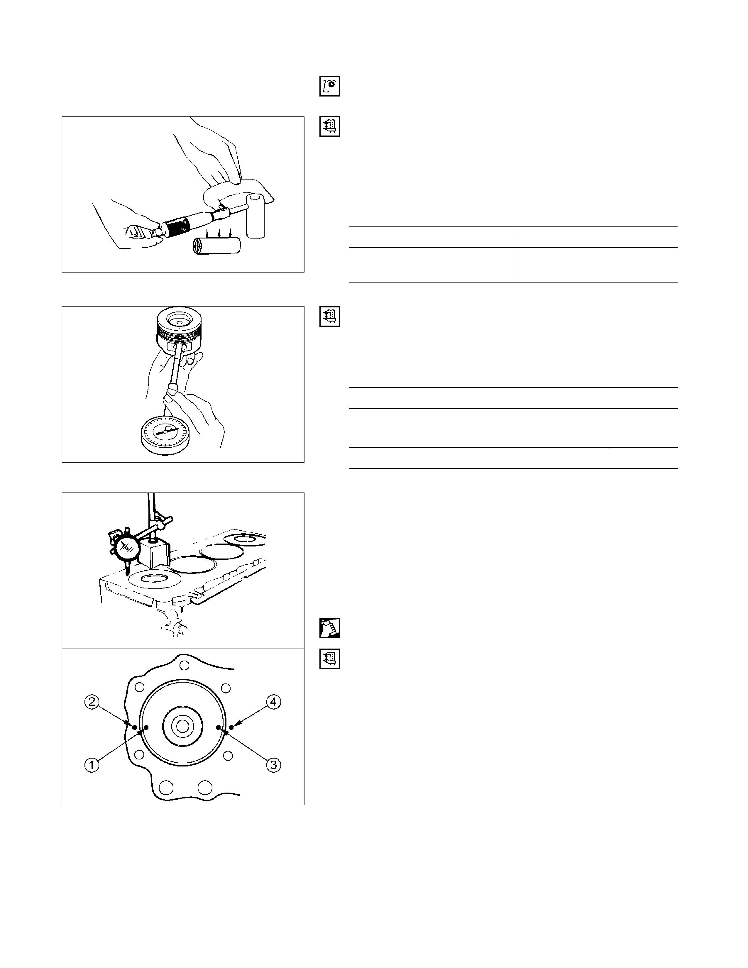
4. Visually inspect the piston rings.
If a piston ring groove is damaged or distorted, the piston
must be replaced.
Piston Pin Diameter
Use a micrometer to measure the piston pin diameter at
several points.
If the measured value is less than the specified limit, the piston
pin must be replaced.
Piston Pin Diameter mm (in)
Standard Limit
30.995-31.000
(1.2202-1.2204) 30.97
(1.2193)
Piston Pin and Piston Clearance
Use an inside dial indicator to measure the piston pin hole (in
the piston).
Piston Pin Hole mm (in)
31.005-31.013 (1.2207-1.2210)
Piston Pin and Piston Pin Hole Clearance mm (in)
0.005-0.018 (0.0002-0.0007)
CYLINDER HEAD GASKET SELECTION
Cylinder head gasket is determined by the piston head
projection from the cylinder body upper surface, in order to
improve engine performance.
Three types of gasket are provided by the difference of
thickness. Select the adequate one out of three grades of
gasket, according to the following procedure.
Before measurement, clear off carbon from the piston head
and cylinder body surface and also clean the place where a
gasket was installed.
RTW36ASH001701
Piston Head Projection Measuring Point
1. Use a dial indicator to measure the piston projection
amount.
2. Refer to the illustration for the piston head projection
measuring positions.
All measuring positions should be as close as possible to
the cylinder liner.
015LX026
015RW048
011LX011
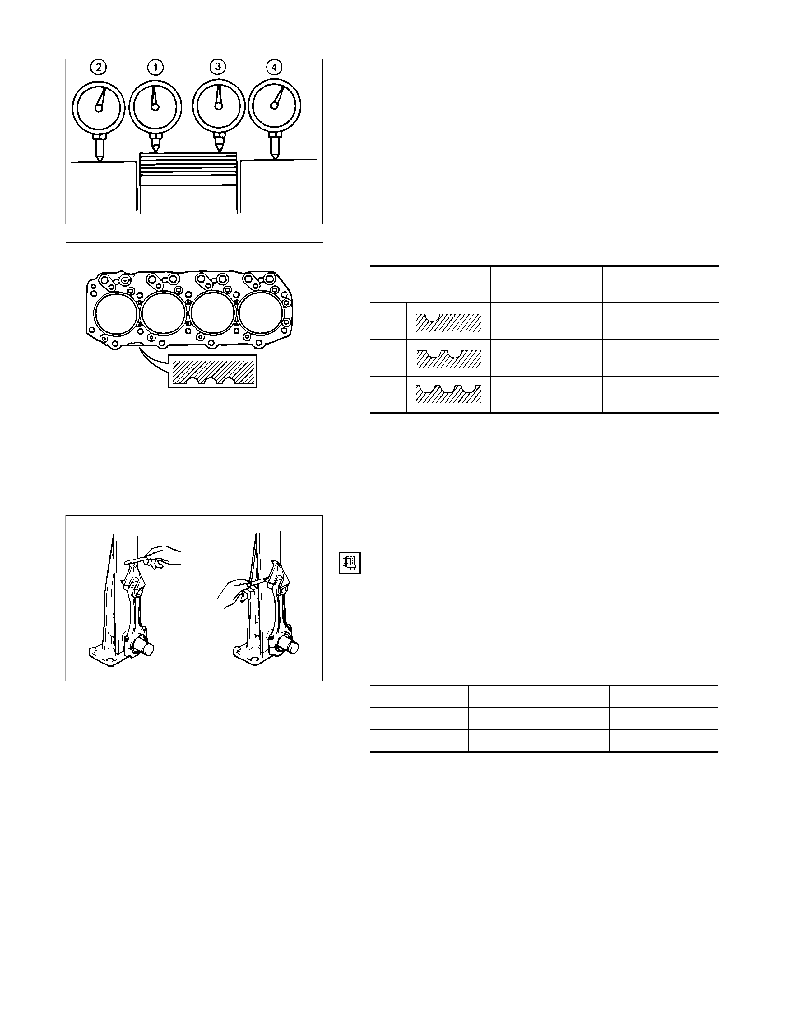
3. Measure the points 1, 2, 3, 4 and obtain two differences 1-
2 and 3-4 on each cylinder.
Calculate the average value of the piston head projection
on each cylinder.
4. Obtain the maximum value in the four cylinders.
5. Determine the gasket grade required to the maximum
value described above in accordance with the following
table.
Cylinder Head Gasket Combination mm (in)
Gasket Grade Mark Piston Projection Gasket Thickness
(Reference)
A 0.215-0.265
(0.0085-0.0104) 1.3
(0.5118)
B 0.265-0.315
(0.0104-0.0124) 1.35
(0.5315)
C 0.315-0.365
(0.0124-0.0144) 1.4
(0.5512)
NOTE:
Difference of the each piston projection and must be
equal or within 0.1 mm (0.004 in).
CONNECTING ROD
Connecting Rod Alignment
Use a connecting rod aligner to measure the distortion and the
parallelism between the connecting rod big end hole and the
connecting rod small end hole.
If either the measured distortion or parallelism exceed the
specified limit, the connecting rod must be replaced.
Connecting Rod Alignment Per Length of 100 mm (3.94 in)
mm (in)
Standard Limit
Distortion 0.08 (0.003) or Less 0.20 (0.008)
Parallelism 0.05 (0.002) or Less 0.15 (0.006)
011RY00027
011RY00030
015LX034
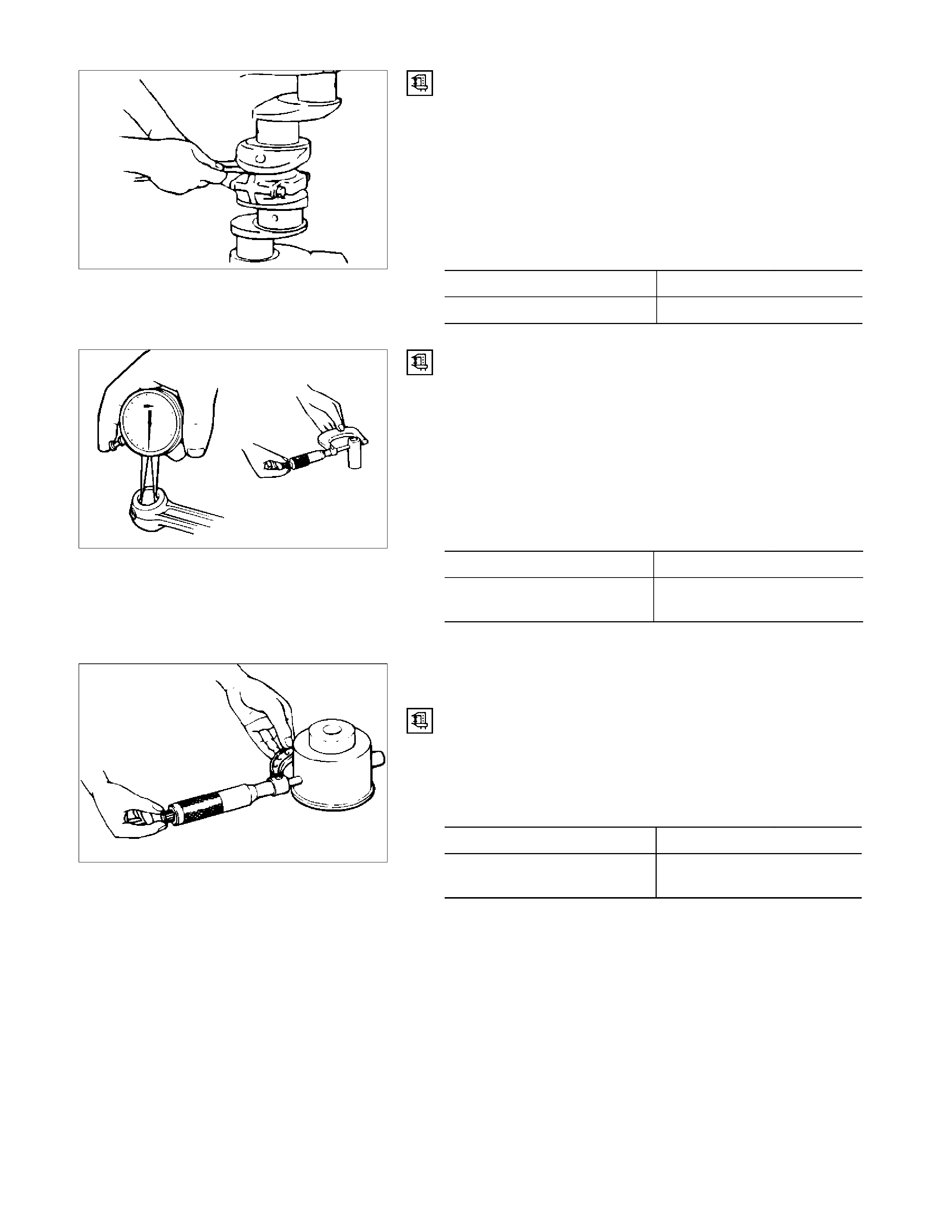
Connecting Rod Side Face Clearance
1. Install the connecting rod to the crankpin.
2. Use a feeler gauge to measure the clearance between the
connecting rod big end side face and the crankpin side
face.
If the measured value exceeds the specified limit, the
connecting rod must be replaced.
Connecting Rod Big End and Crankpin Side Face Clearance
mm (in)
Standard Limit
0.23 (0.009) 0.35 (0.014)
Piston Pin and Connecting Rod Small End Bushing
Clearance
Use a calliper calibrator and a dial indicator to measure the
piston pin and connecting rod small end bushing clearance.
If the clearance between the piston pin and the connecting rod
small end bushing exceeds the specified limit, replace the
piston pin and/or the connecting rod.
Piston Pin and Connecting Rod Small End
Bushing Clearance mm (in)
Standard Limit
0.005-0.018
(0.0002-0.0007) 0.050 (0.002)
IDLER GEAR SHAFT AND IDLER GEAR
Idler Gear "A" Shaft Outside Diameter
Use a micrometer to measure the idler gear shaft outside
diameter.
If the measured value is less than the specified limit, the idler
gear shaft must be replaced.
Idler Gear "A" Shaft Outside Diameter mm (in)
Standard Limit
44.945-44.975
(1.7695-1.7707) 44.845 (1.755)
011RY00029
015LX028
020RY00025

Idler Gear "A" Shaft inside Diameter
1. Use an inside dial indicator or an inside micrometer to
measure the idler gear inside diameter.
Idler Gear Inside Diamete
r
mm (in)
Standard Limit
45.0-45.03
(1.7717-1.7718) 45.10 (1.7756)
If the clearance between the idler gear shaft outside diameter
and the idler gear inside diameter exceeds the limit, the idler
gear must be replaced.
Idler Gear Shaft and Idler Gear Clearance mm (in)
Standard Limit
0.025-0.085
(0.0010-0.0033) 0.200 (0.0079)
TIMING GEAR CASE COVER
Replace the crankshaft front oil seal if it is excessively worn or
damaged.
Crankshaft Front Oil Seal Replacement
Oil Seal Removal
Use a plastic hammer and a screwdriver to tap around the oil
seal to free it from the gear case cover.
Take care not to damage the oil seal lip surfaces.
Oil Seal Installation
Use the special tool to install the front oil seal.
Front Oil Seal Installer: 5-8840-2361-0
1. With the oil seal attached to the sleeve, insert it into the
front end section of the crankshaft.
2. With the oil seal end section attached securely to the
crankshaft, tighten up the center bolt until the sleeve hits
the front end reference plane of the crankshaft securely.
3. Remove the sleeve.
4. With the seal pressed in, check the dimension of the oil
seal section.
Standard Dimension = 1.0 ± 0.03mm
NOTE:
Install the oil seal after assembling the timing pulley
housing. The oil seal lip section is applied with oil.
Take notice of the press-in direction of the oil seal.
014LX022
020R300004
020R300005
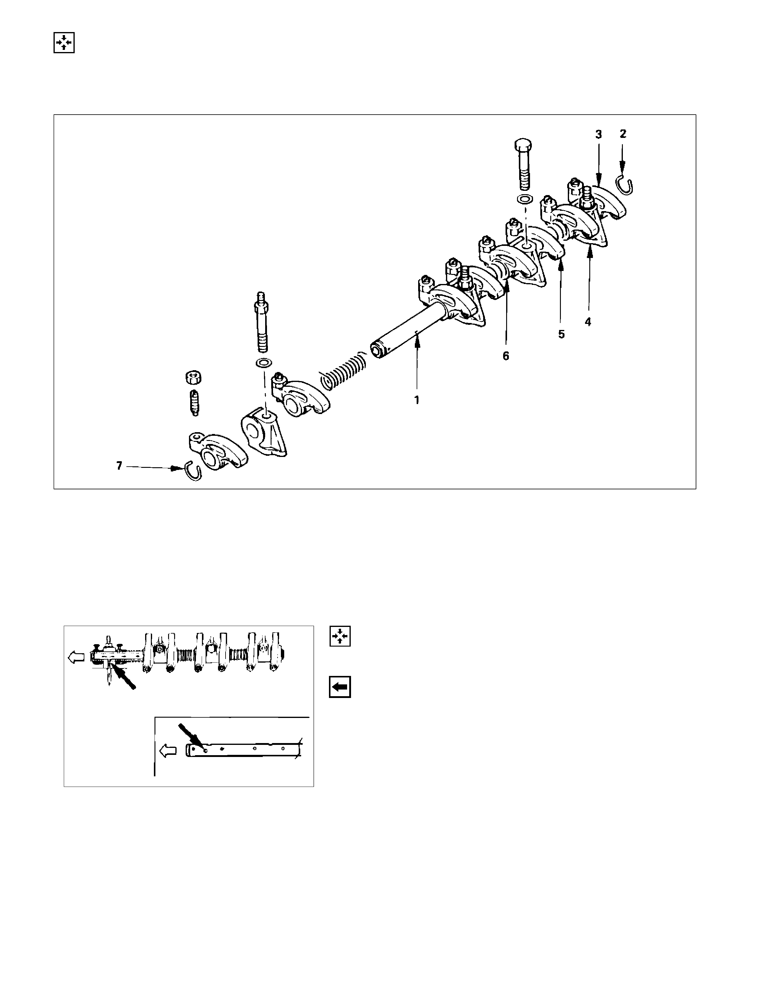
REASSEMBLY
INTERNAL PARTS
MINOR COMPONENT
ROCKER ARM SHAFT AND ROCKER ARM
020
RY00029
Reassembly Steps
1. Rocker arm shaft 5. Rocker arm
2. Rocker arm shaft snap ring 6. Rocker arm shaft spring
3. Rocker arm 7. Rocker arm shaft snap ring
4. Rocker arm shaft bracket
Reassembly
1. Rocker Arm Shaft
1) Position the rocker arm shaft with the large oil hole (4
φ) facing the front of the engine.
2) Install the rocker arm shaft together with the rocker
arm, the rocker arm shaft bracket, and the spring.
2. Rocker Arm Shaft Snap Ring
3. Rocker Arm
4. Rocker Arm Shaft Bracket
5. Rocker Arm
6. Rocker Arm Shaft Spring
7. Rocker Arm Shaft Snap Ring
014RY00037
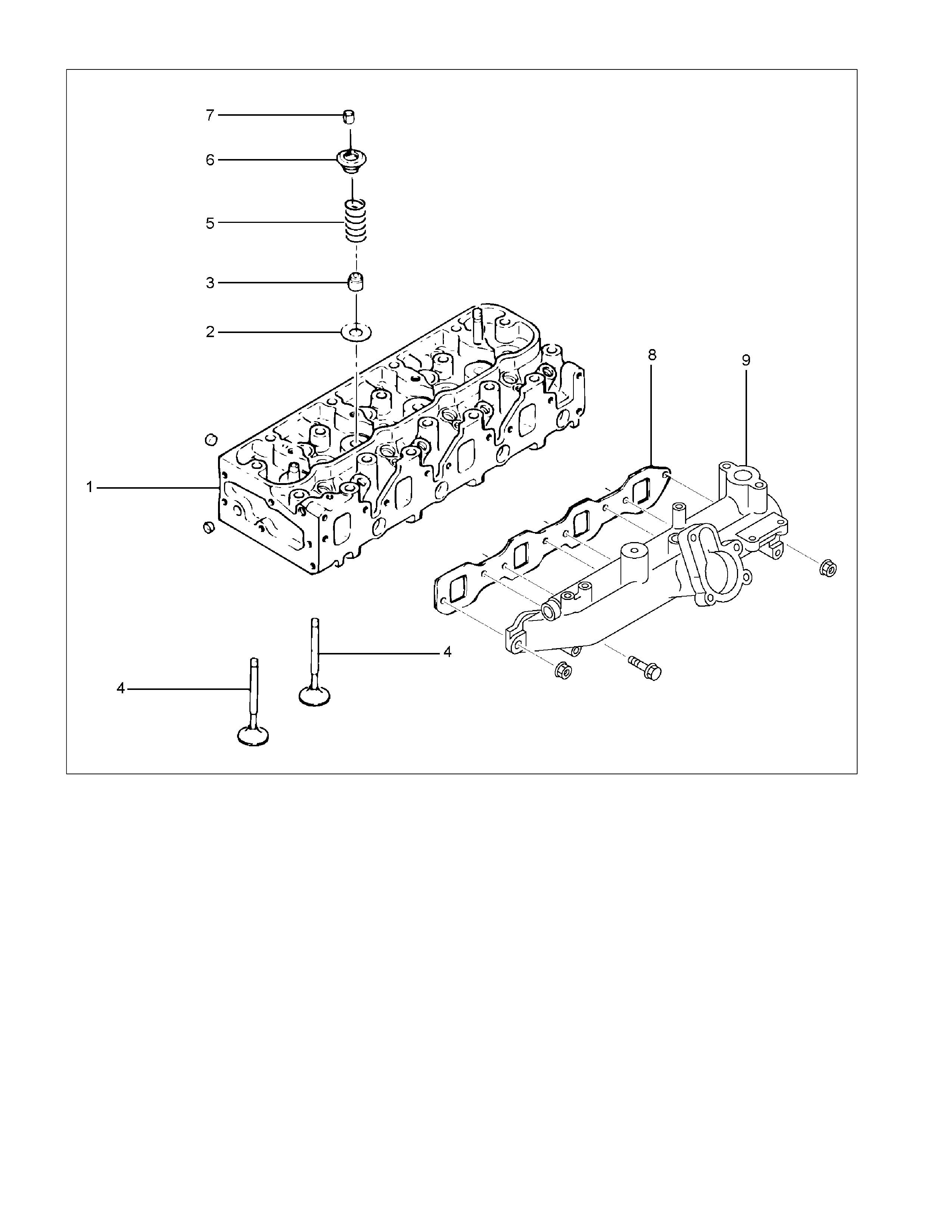
CYLINDER HEAD
RTW36ALF001001
Reassembly Steps
1 .Cylinder head 6. Valve spring upper seat
2. Valve spring lower seat 7. Split collar
3. Valve stem oil seal 8. Intake manifold gasket
4. Intake and exhaust valve 9. Intake manifold
5. Valve spring
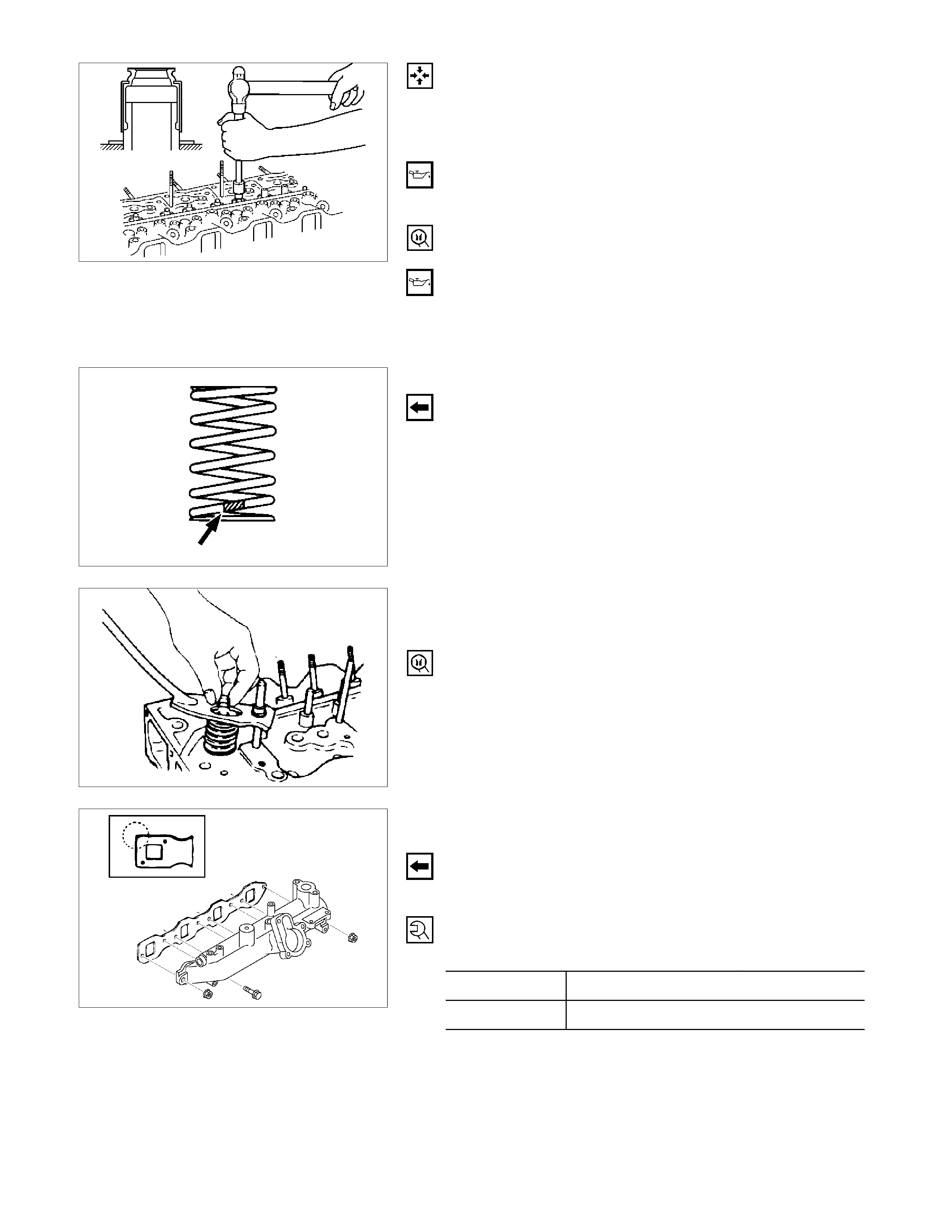
Reassembly
1. Cylinder Head
2. Valve Spring Lower Seat
3. Valve Stem Oil Seal
1) Apply a coat of engine oil to the oil seal inner face.
2) Use an oil seal installer to install the oil seal to the
valve guide.
Oil Seal Installer: 5-8840-2033-0
4. Intake and Exhaust Valve
1) Apply a coat of engine oil to each valve stem before
installation.
2) Install the intake and exhaust valves.
3) Turn the cylinder head up to install the valve springs.
Take care not to allow the installed valves to fall free.
5. Valve Spring
Install the valve spring with their fine pitched end (painted)
facing down.
6. Valve Spring Upper Seat
7. Split Collar
1) Use the spring compressor to compress the valve
spring into position.
Spring Compressor: 9-8523-1423-0
2) Install the split collars to the valve stem.
3) Set the split collars by tapping around the head of the
collar with a rubber hammer.
RTW36ASH001101
8. Intake manifold gasket
9. Intake manifold
1) Install the manifold gasket with the end having the
sharp corners facing the front of the engine.
2) Install the intake manifold to the cylinder head.
3) Tighten the manifold bolt/nuts to the specified torque.
Manifold Bolt/Nut Torque N·m (kg·m/lb·ft)
Bolt 19 (1.9/14)
Nut 24 (2.4/17)
011RW027
011LX055
014RY00039
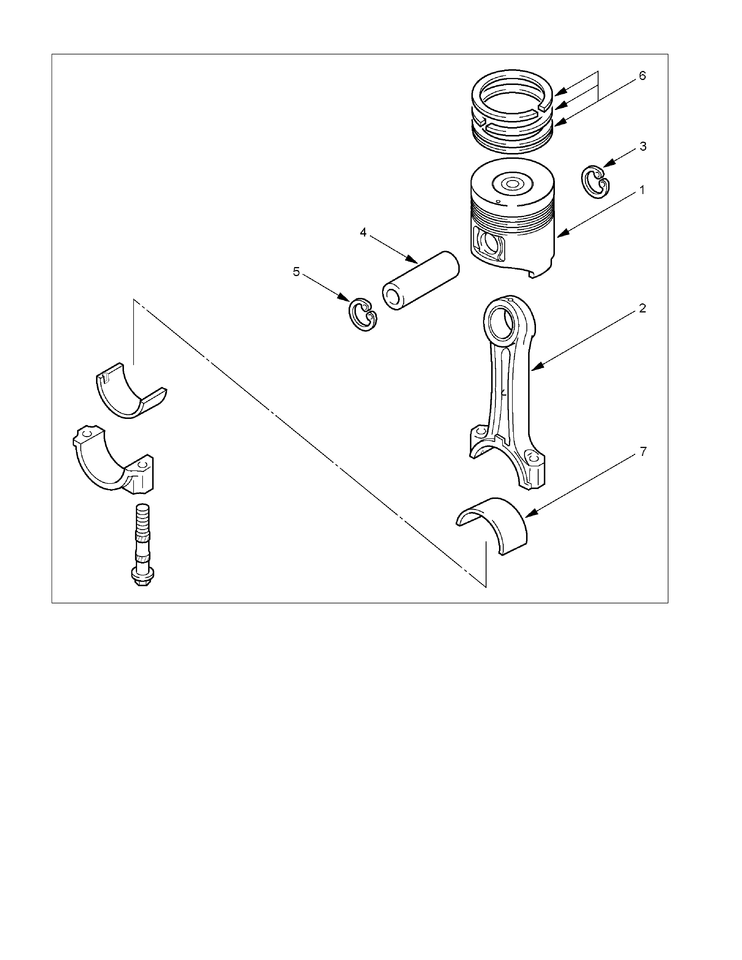
PISTON AND CONNECTING ROD
RTW36ALF001401
Reassembly Steps
1. Piston 5. Piston pin snap ring
2. Connecting rod 6. Piston ring
3. Piston pin snap ring 7. Connecting rod bearing
4. Piston pin
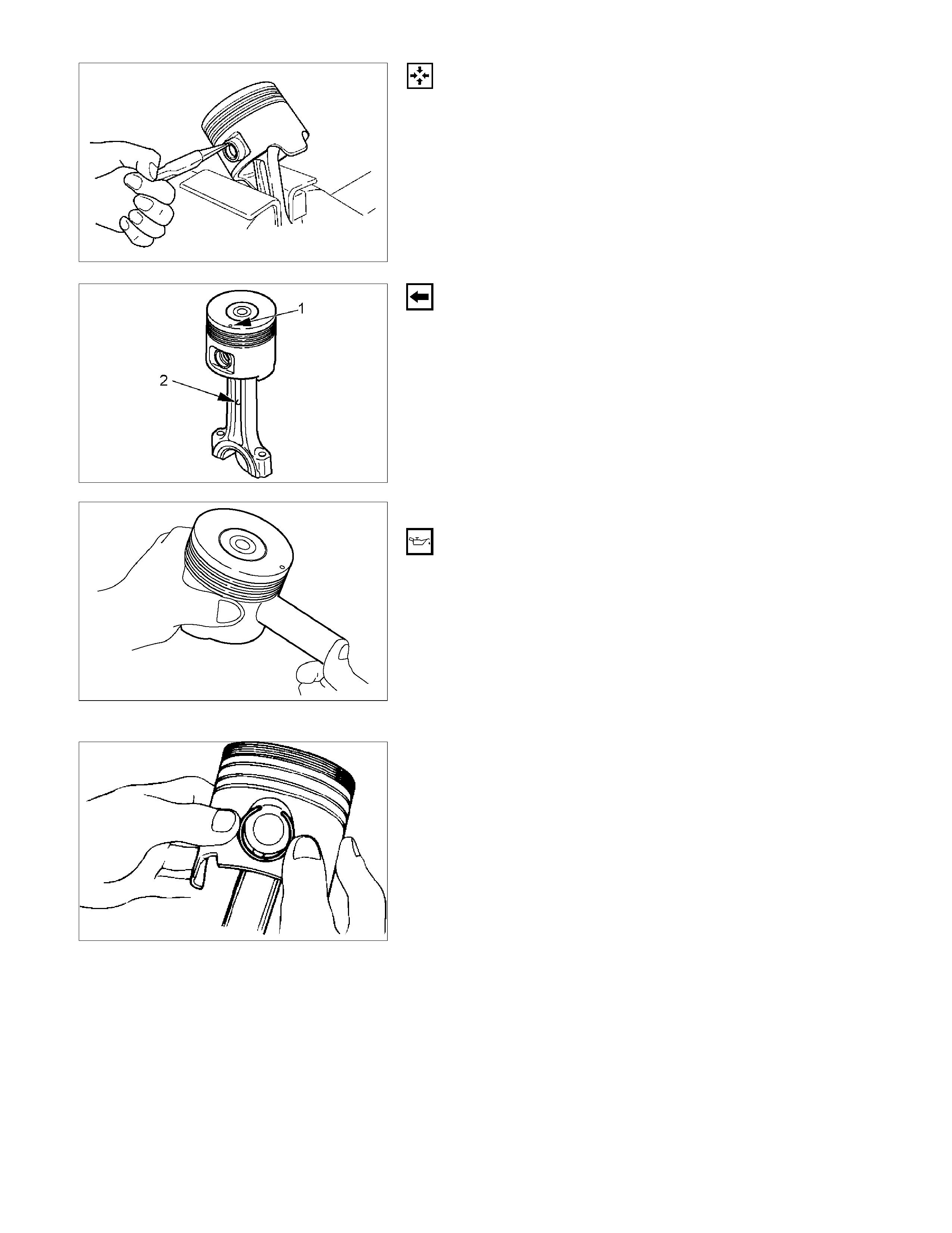
Reassembly
1. Piston
2. Connecting Rod
1) Clamp the connecting rod in a vice. Take care not to
damage the connecting rod.
2) Use a pair of pliers to install the piston pin snap ring to
the piston.
RTW36ASH001801
Install the piston to the connecting rod so that the piston
head front mark (1) and the connecting rod mark (2) are
facing in the same direction.
3. Piston Pin Snap Ring
RTW36ASH001901
4. Piston Pin
1) Apply a coat of engine oil to the piston pin and the
piston pin hole.
2) Use your fingers to force the piston pin into the piston
until it makes contact with the snap ring.
5. Piston Pin Snap Ring
1) Use your fingers to force the piston pin snap ring into
the piston snap ring groove.
2) Check that the connecting rod moves smoothly on the
piston pin.
F06MV015
015R100001
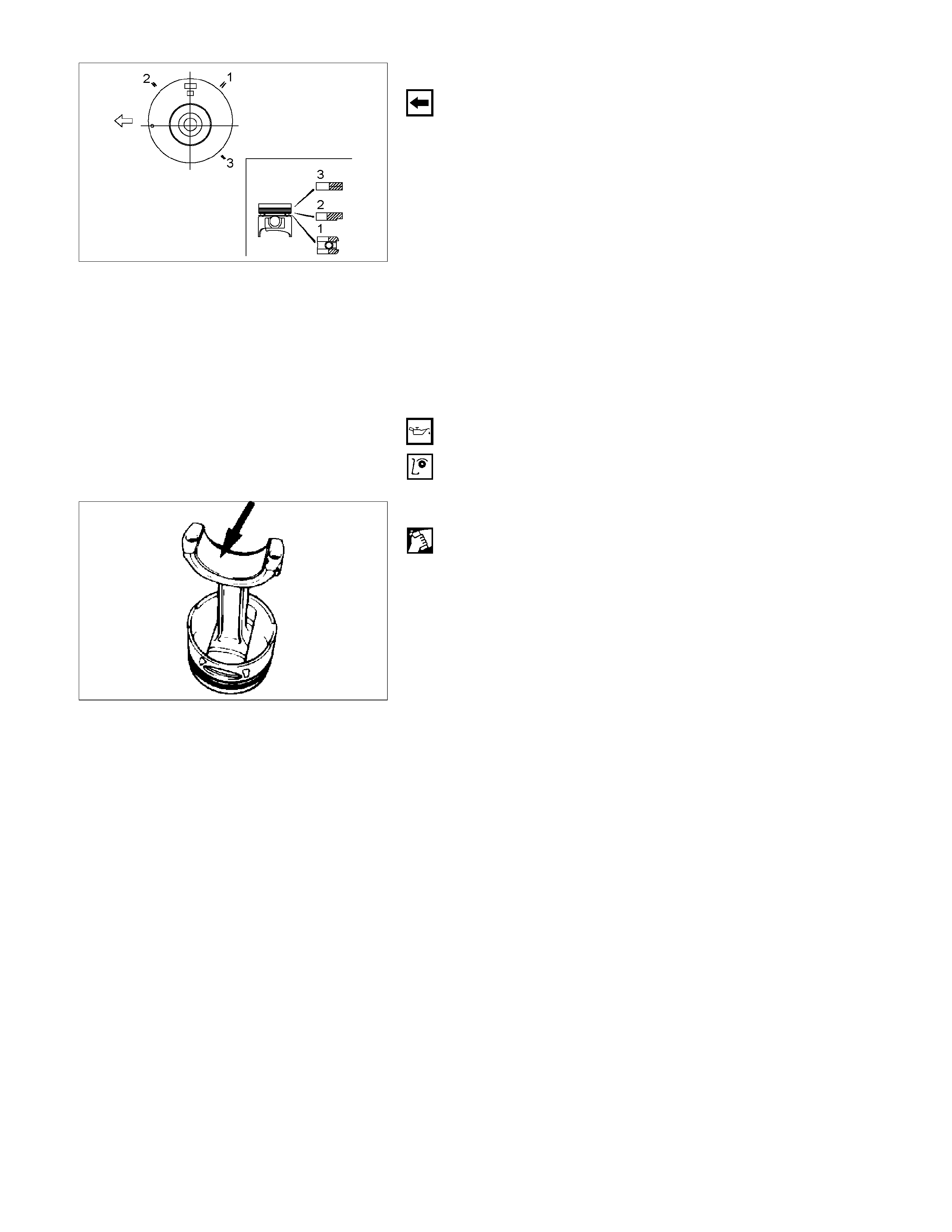
RTW36ASH002001
6. Piston Ring
1) Use a piston ring replacer to install the three piston
rings.
Piston Ring Replacer
Install the piston rings in the order shown in the
illustration.
1. Oil ring
2. 2nd compression ring
3. 1st compression ring
NOTE:
Install the compression rings with the stamped side facing
up.
Insert the expander coil into the oil ring groove so that
there is no gap on either side of the expander coil before
installing the oil ring.
2) Apply engine oil to the piston ring surfaces.
3) Check that the piston rings rotate smoothly in the
piston ring grooves
7. Connecting Rod Bearing
Carefully wipe any oil or other foreign material from the
connecting rod bearing back face and the connecting rod
bearing fitting surface.
015R100006
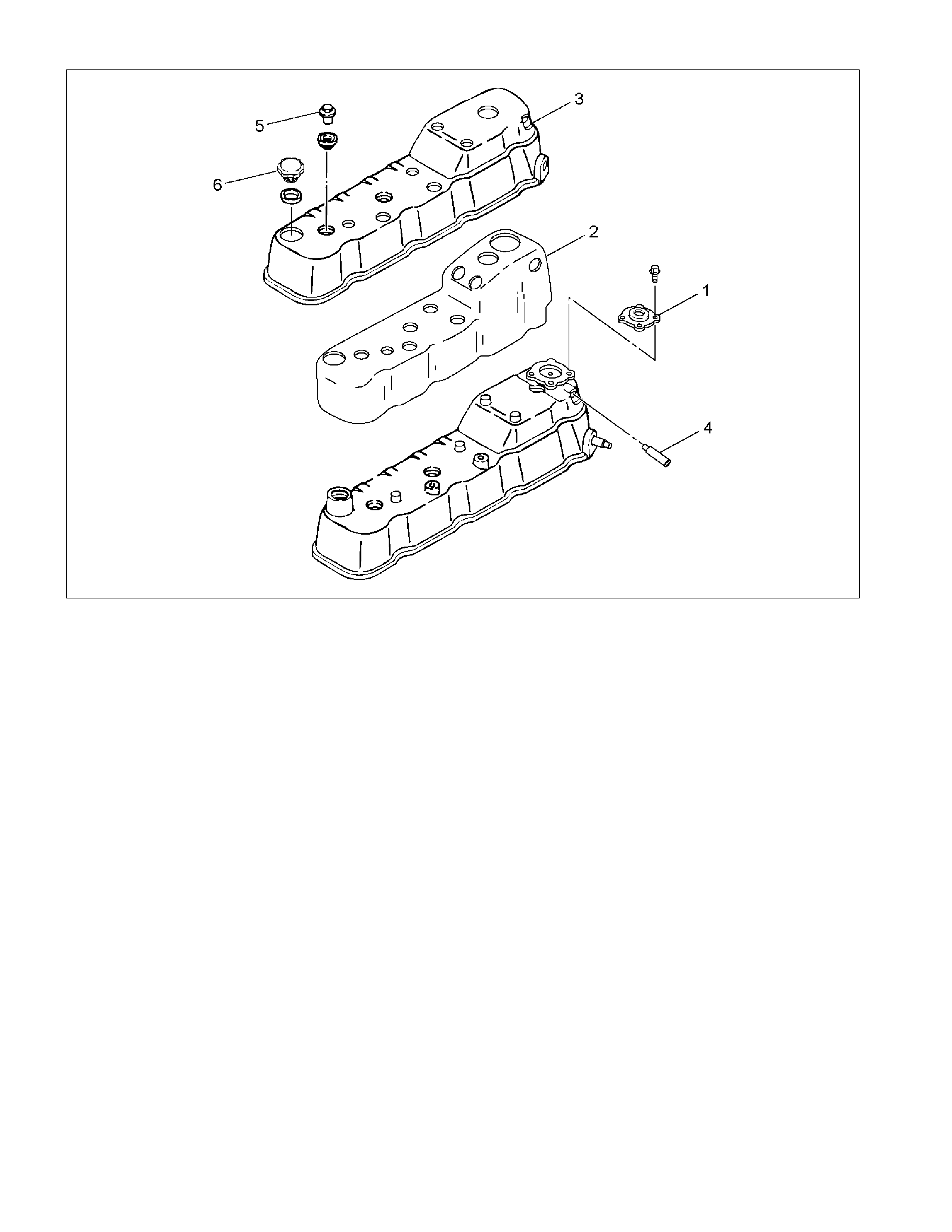
POSITIVE CRANKCASE VENTILATION (PCV) VALVE
RTW36AMF000601
Reassembly Steps
1. Positive Crankcase Ventilation (PCV)
Valve 4. Breather pipe
2. Rubber spacer 5. Fixing bolt
3. Cylinder head insulator cover 6. Oil filler cap
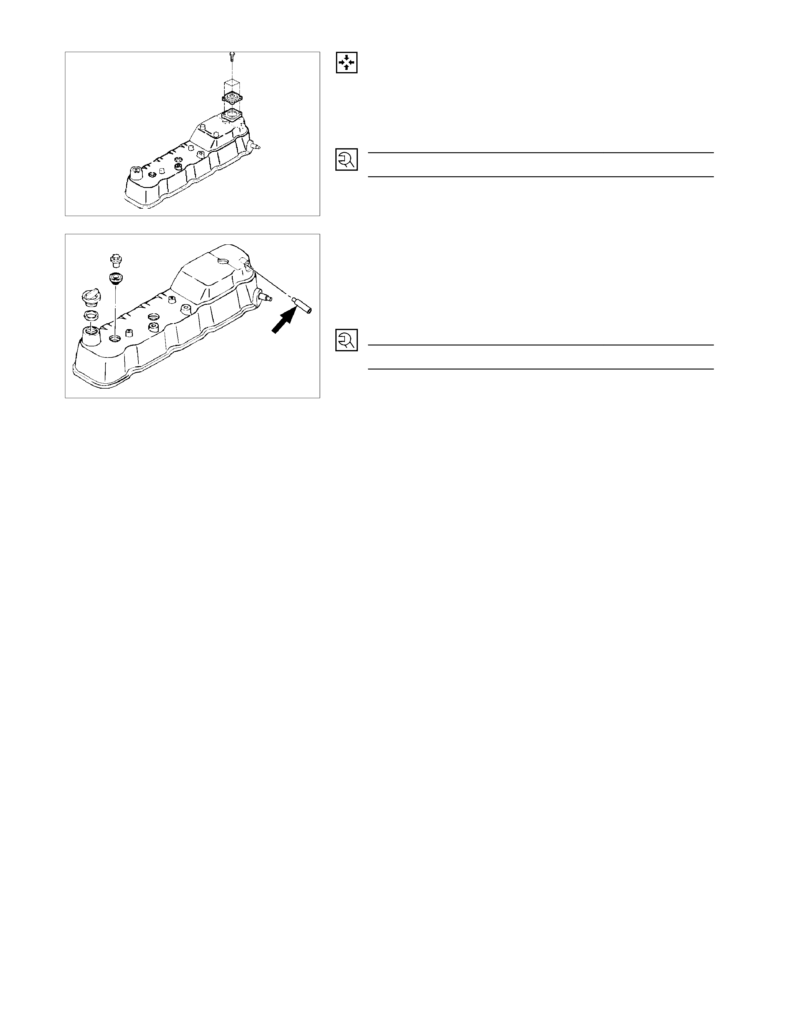
Reassembly
1. PCV Valve
Install the PCV valve and tighten the bolts to specified
torque.
PCV Valve Bolts Torque N·m (kg·m/lb·in)
2 (0.2/17)
2. Rubber Spacer
3. Cylinder Head Insulator Cover
RTW36ASH001401
4. Breather Hose
Apply LOCTITE 262 or equivalent to the new breather
pipe.
Do not reuse the breather pipe.
5. Fixing Bolt
Fixing Bolt Torque N·m (kg·m/lb·in)
19 (1.9/14)
6. Oil Filler Cap
010R100014
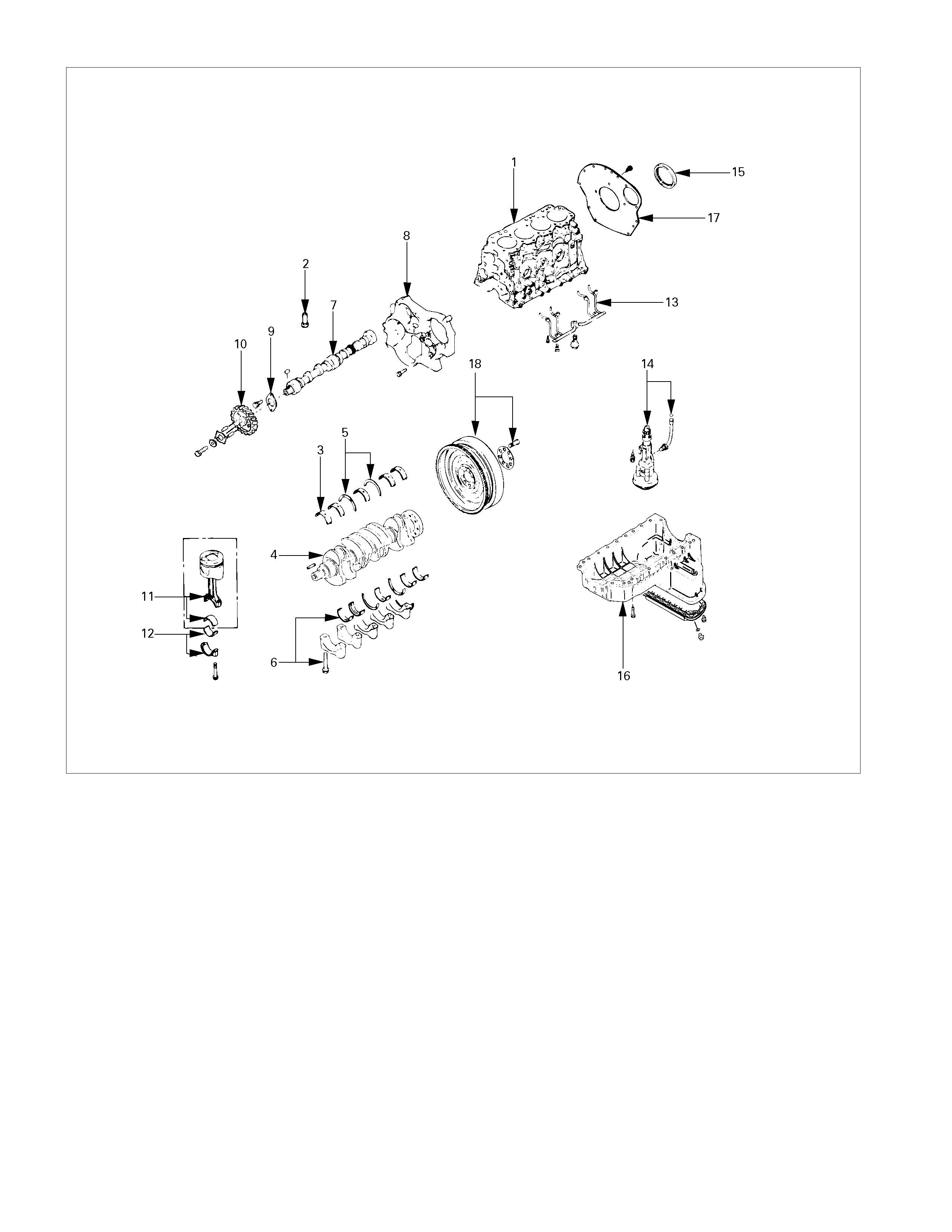
MAJOR COMPONENT
014R300004
Reassembly Steps-1
1. Cylinder body 11. Piston and connecting rod with upper bearing
2. Tappet 12. Connecting rod bearing cap with lower
bearing
3. Crankshaft upper bearing 13. Piston cooling oil pipe
4. Crankshaft 14. Oil pump with oil pipe
5. Crankshaft thrust bearing 15. Crankshaft rear oil seal
6. Crankshaft bearing cap with lower bearing 16. Crank case
7. Camshaft 17. Cylinder body rear plate
8. Timing gear case 18. Flywheel
9. Camshaft thrust plate
10. Camshaft timing gear
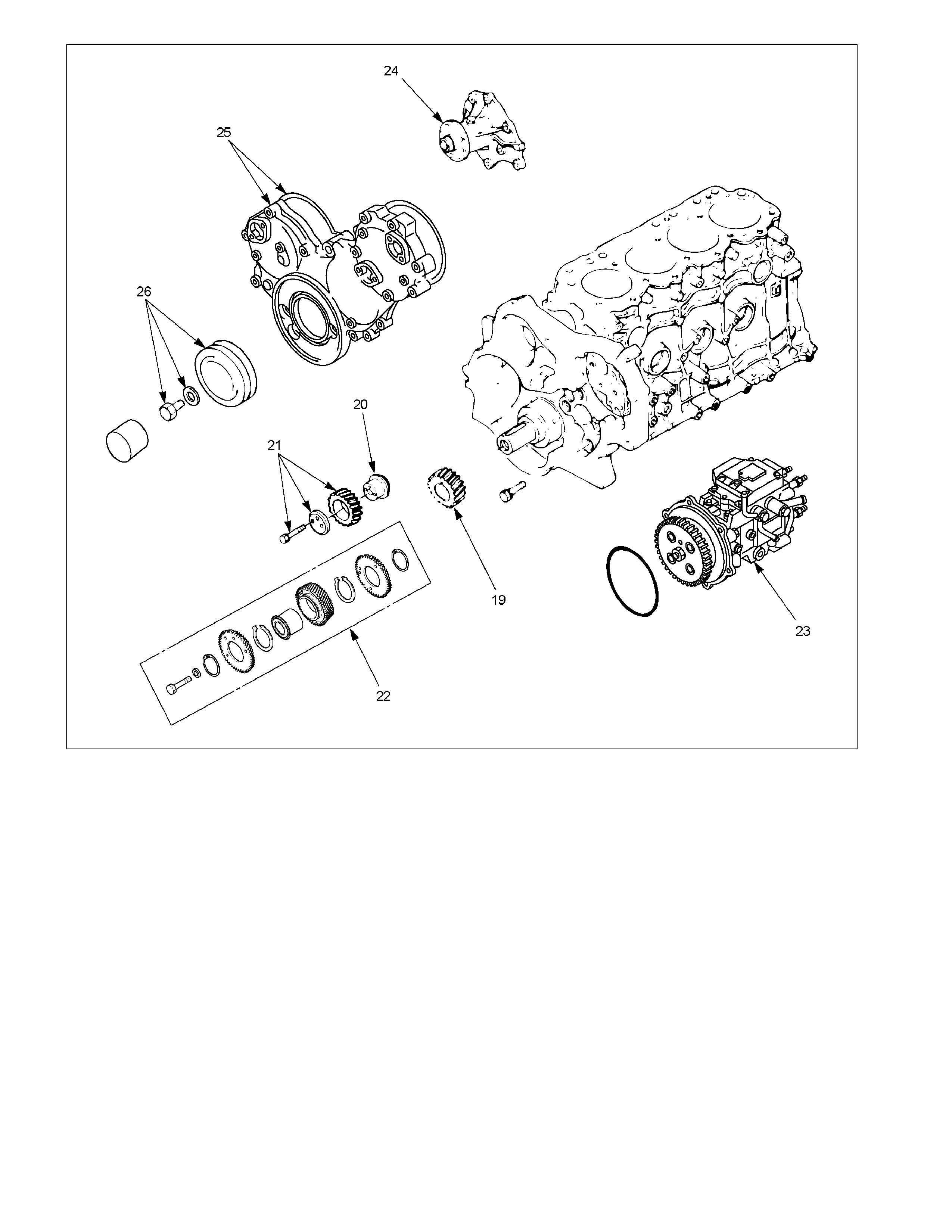
RTW36ALF000801
Reassembly Steps-2
19. Crankshaft timing gear 23. Injection pump
20. Idler gear shaft 24. Water pump
21. Idler gear "A" 25. Timing gear case cover
22. Idler gear "B" and shaft 26. Crankshaft damper pulley
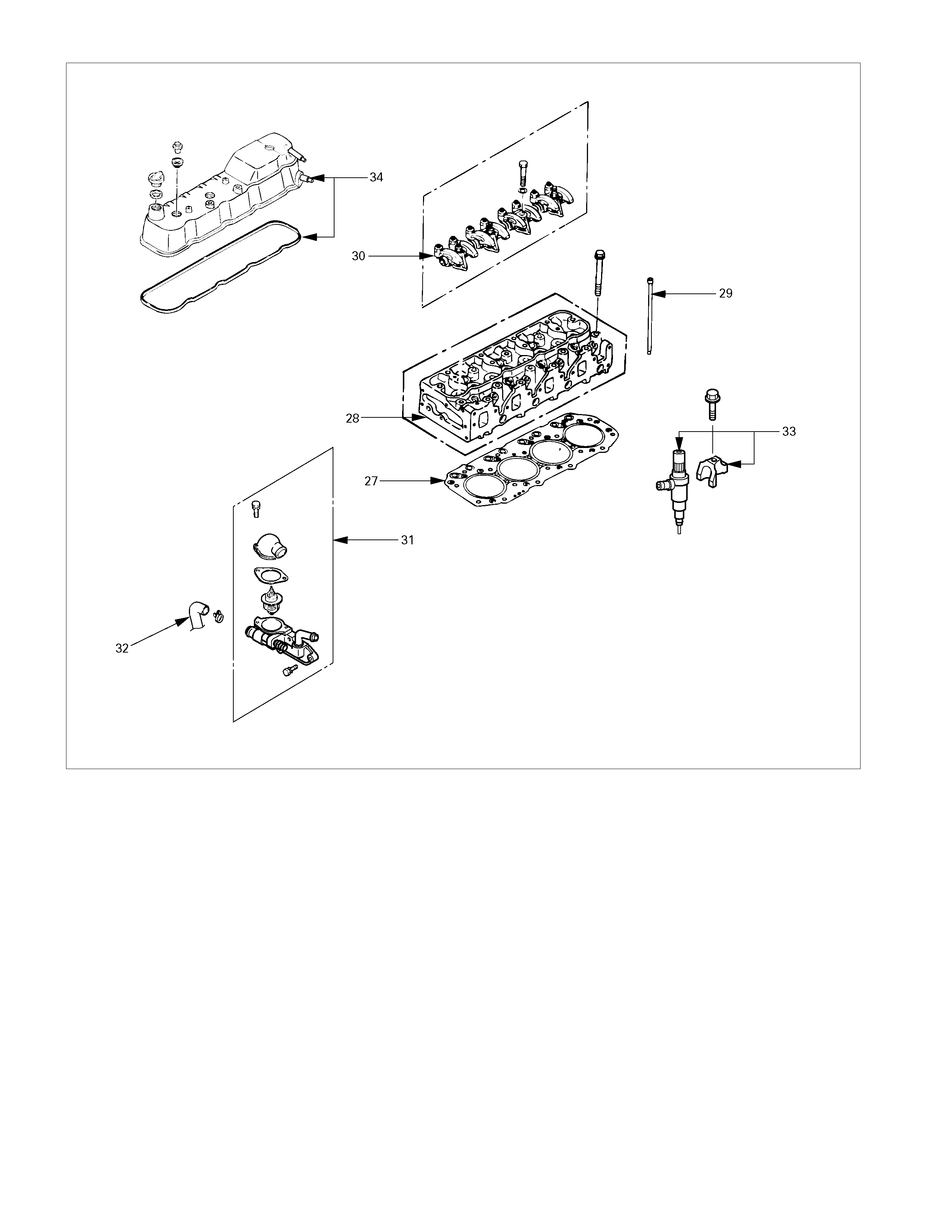
011R300002
Reassembly Steps-3
27. Cylinder head gasket 32. Water by-pass hose
28. Cylinder head 33. Injection nozzle and bracket
29. Push rod 34. Cylinder head cover with gasket
30. Rocker arm shaft and rocker arm
31. Thermostat housing with thermo switch
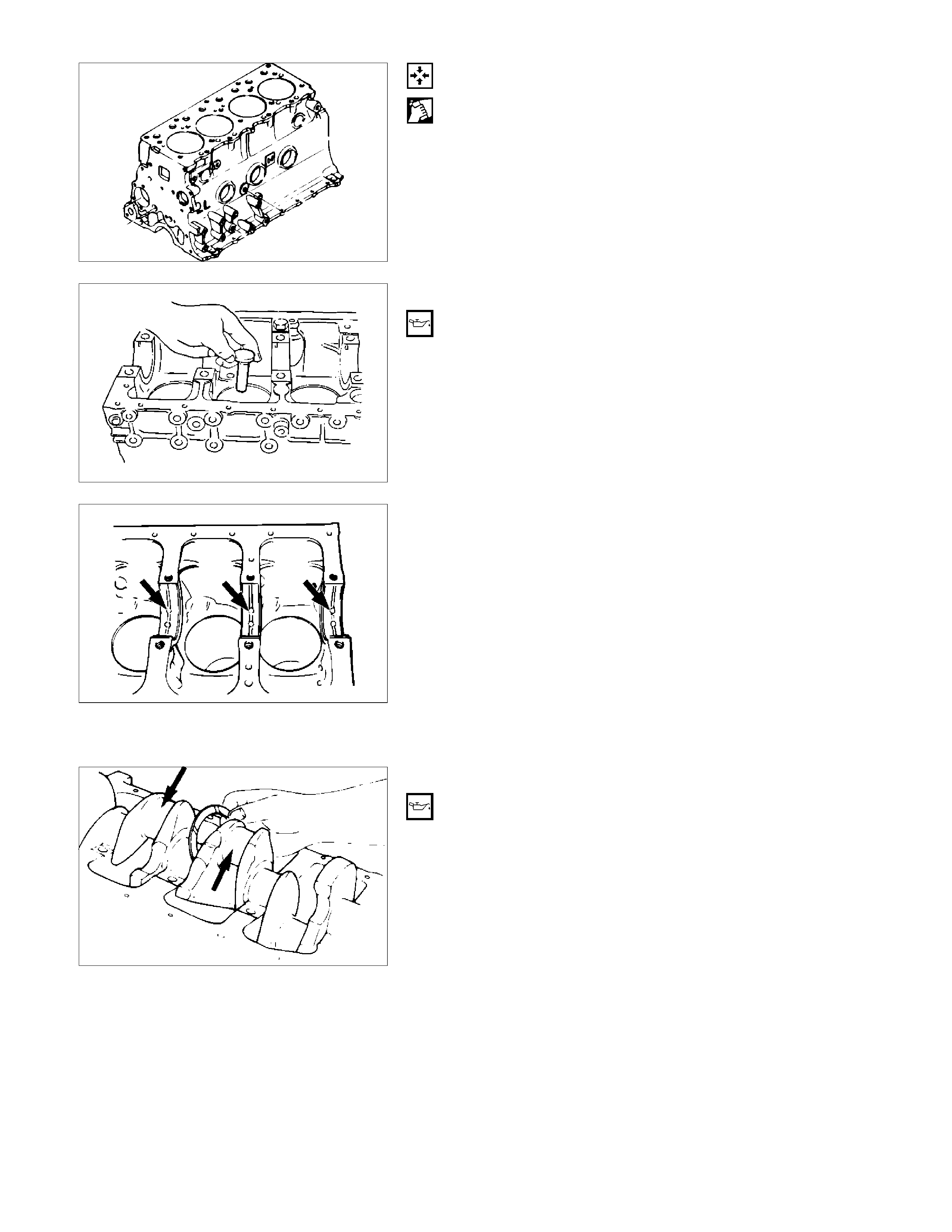
Reassembly
1. Cylinder Body
Use compressed air to thoroughly clean the inside and
outside surfaces of the cylinder body, the oil holes, and the
water jackets.
2. Tappet
1) Apply a coat of engine oil to the tappet and the
cylinder body tappet insert holes.
2) Locate the position mark applied at disassembly (if the
tappet is to be reused).
NOTE:
The tappet must be installed before the camshaft
installation.
3. Crankshaft Upper Bearing
The crankshaft upper bearings have an oil hole and an oil
groove. The lower bearings do not.
1) Carefully wipe any foreign material from the upper
bearing.
NOTE:
Do not apply engine oil to the bearing back faces and the
cylinder body bearing fitting surfaces.
2) Locate the position mark applied at disassembly if the
removed upper bearings are to be reused.
4. Crankshaft
Apply an ample coat of engine oil to the crankshaft
journals and the crankshaft bearing surfaces before
installing the crankshaft.
015R100003
014LX088
015LX125
015R100004
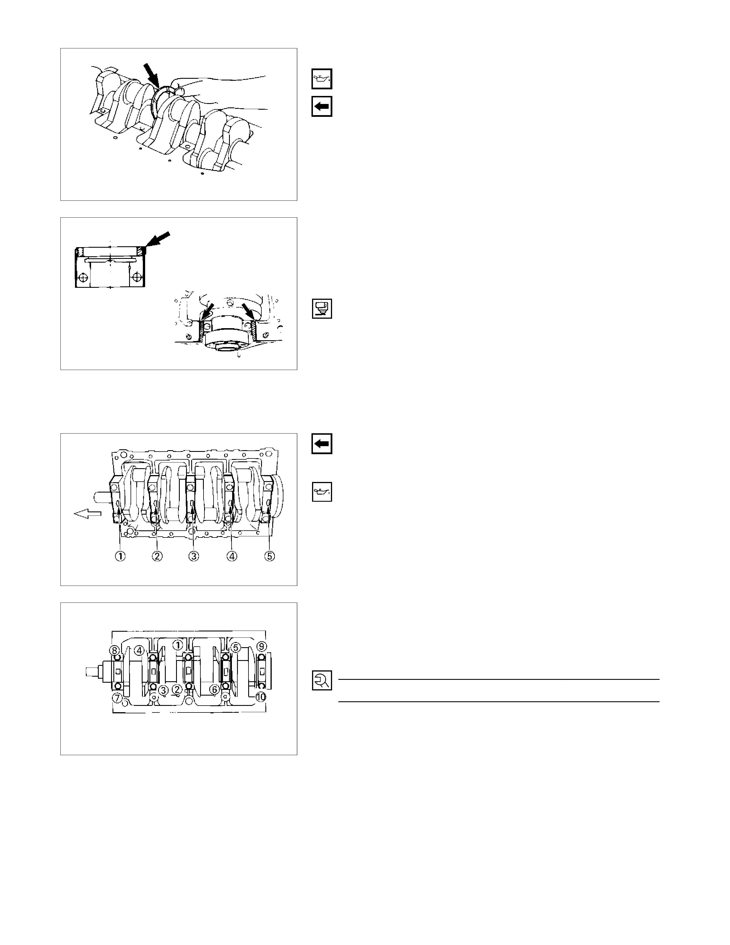
5. Crankshaft Thrust Bearing
Apply an ample coat of engine oil to the thrust bearings
before installation.
Install the thrust bearings to the crankshaft center journal.
The thrust bearing oil grooves must be facing the sliding
faces.
6. Crankshaft Bearing Cap With Lower Bearing
Before the crankshaft bearing installation, select the
appropriate bearings in accordance with the description in
CRANK BEARING SELECTION of INSPECTION AND
REPAIR.
1) Apply the recommended liquid gasket or its equivalent
to the No. 5 crankshaft bearing cap cylinder body
fitting surfaces at the points shown in the illustration.
NOTE:
Be sure that the bearing cap fitting surface is completely
free of oil before applying the liquid gasket. Do not allow
the liquid gasket to obstruct the cylinder thread holes and
bearings.
2) Install the bearing caps with the bearing cap head
arrow mark facing the front of the engine. The bearing
cap numbers must be facing up.
3) Apply engine oil to the crankshaft bearing cap bolts.
4) Tighten the crankshaft bearing cap bolts to the
specified torque a little at time in the sequence shown
in the illustration.
Crankshaft Bearing Cap Torque N·m (kg·m/lb·ft)
167 (17/123)
5) Check to see the crankshaft turns smoothly by
rotating it manually.
015LX115
015LX127
015LX128
015LX129
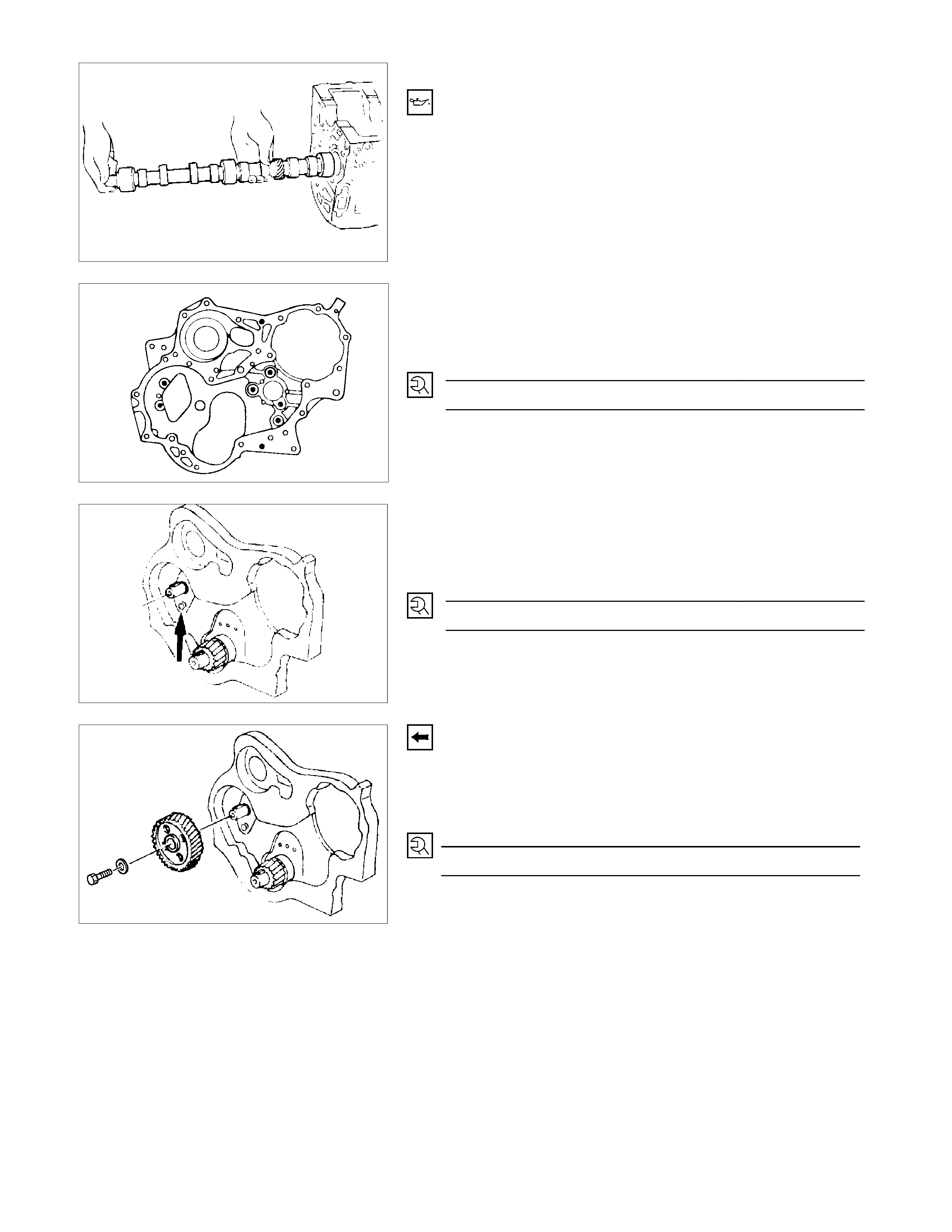
7. Camshaft
1) Apply a coat of engine oil to the camshaft and the
camshaft bearings.
2) Install the camshaft to the cylinder body. Take care
not to damage the camshaft bearings.
8. Timing Gear Case
Tighten the timing gear case with timing gear case gasket
to the specified torque.
Timing Gear Case Bolt Torque N·m (kg·m/lb·ft)
19 (1.9/14)
9. Camshaft Thrust Plate
Install the thrust plate to the cylinder body and tighten the
thrust plate bolts to the specified torque.
Thrust Plate Bolt Torque N·m (kg·m/lb·ft)
19 (1.9/14)
RTW36ASH000901
10. Camshaft Timing Gear
1) Install the camshaft timing gear to the camshaft. The
timing gear mark must be facing outward.
2) Tighten the timing gear to the specified torque.
Timing Gear Bolt Torque N·m (kg·m/lb·ft)
110 (11.2/82)
014RY00019
020R300003
020RY00032
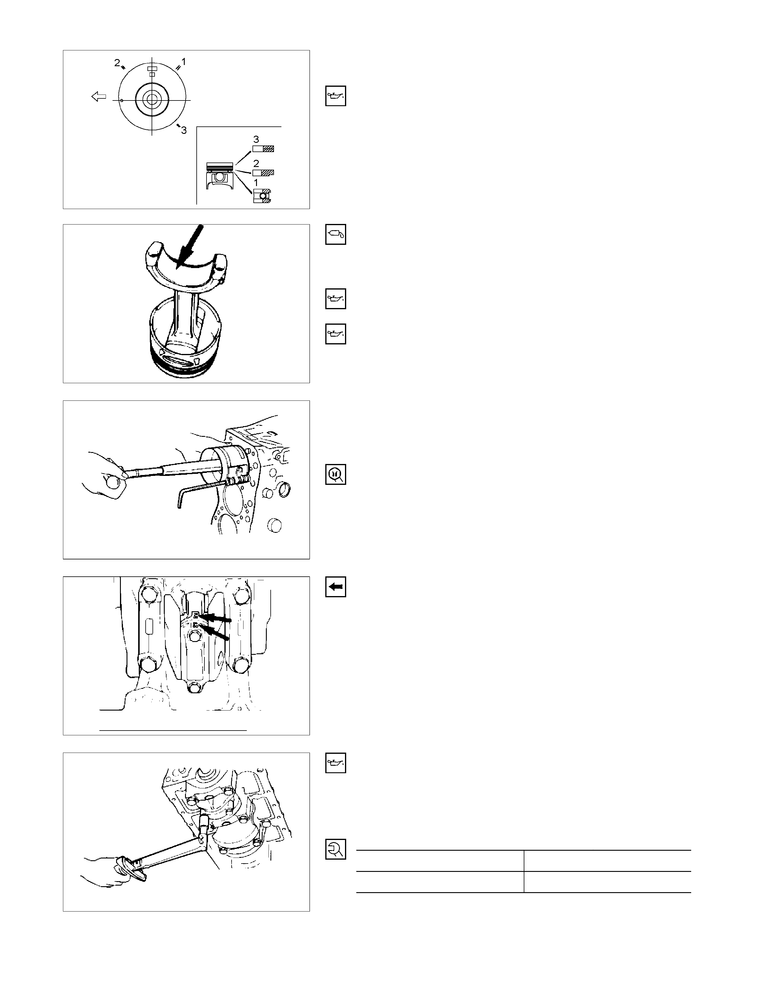
RTW36ASH002001
11. Piston and Connecting Rod with Upper Bearing
12. Connecting Rod Bearing Cap with Lower Bearing
1) Apply a coat of engine oil to the circumference of each
piston ring and piston.
2) Position the piston ring gaps as shown in the
illustration.
a) Oil ring
b) 2nd compression ring
c) 1st compression ring
3) Apply a coat of molybdenum disulfide grease to the
two piston skirts. This will facilitate smooth break-in
when the engine is first started after reassembly.
4) Apply a coat of engine oil to the upper bearing
surfaces.
5) Apply a coat of engine oil to the cylinder wall.
6) Position the piston head front mark so that it is facing
the front of the engine.
7) Use the piston ring compressor to compress the
piston rings.
Piston Ring Compressor: 5-8840-9018-0
8) Use a hammer grip to push the piston in until the
connecting rod makes contact with the crankpin.
At the same time, rotate the crankshaft until the
crankpin is at BDC.
9) Align the bearing cap cylinder number marks and the
connecting rod cylinder number marks.
The cylinder number marks must be turned toward the
exhaust manifold.
10) Apply a coat of engine oil to the threads and setting
faces of each connecting rod cap bolt.
11) Tighten the connecting rod caps to the two step of
angular tighten method.
Connecting Rod Bearing Cap Bolt Torque N·m (kg·m/lb·ft)
1st step 29 (3.0/22)
2nd step 45° - 60°
015R100006
015LX096
015R100007
015LX130
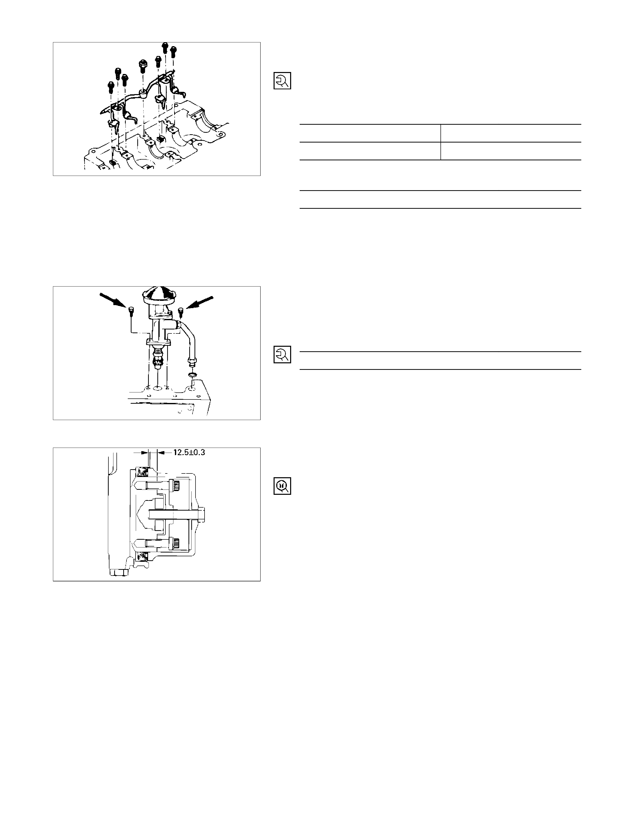
13. Piston Cooling Oil Jet
1) Install the piston cooling oil jet to the cylinder body.
2) Tighten the oil jet bolts and relief valve to the specified
torque.
Oil Jet Bolt Torque N·m (kg·m/lb·ft)
M8 × 1.25 19 (1.9/14)
M6 × 1.00 8 (0.8/6)
Relief Valve Torque N·m (kg·m/lb·ft)
29 (3.0/22)
NOTE:
Check that there is no interference between the piston
and the oiling jet by slowly rotating the crankshaft.
14. Oil Pump with Oil Pipe
Install the oil pump with the oil pipe and tighten the bolts to
the specified torque.
Oil Pump Bolt Torque N·m (kg·m/lb·ft)
19 (19/14)
NOTE:
Take care not to damage the O-rings when tightening the
oil pipe bolts.
15. Crankshaft Rear Oil Seal
Use a oil seal install to install the crankshaft rear oil seal.
Oil Seal Installer : 5-8840-2359-0
052LX010
051R100004
015LX112
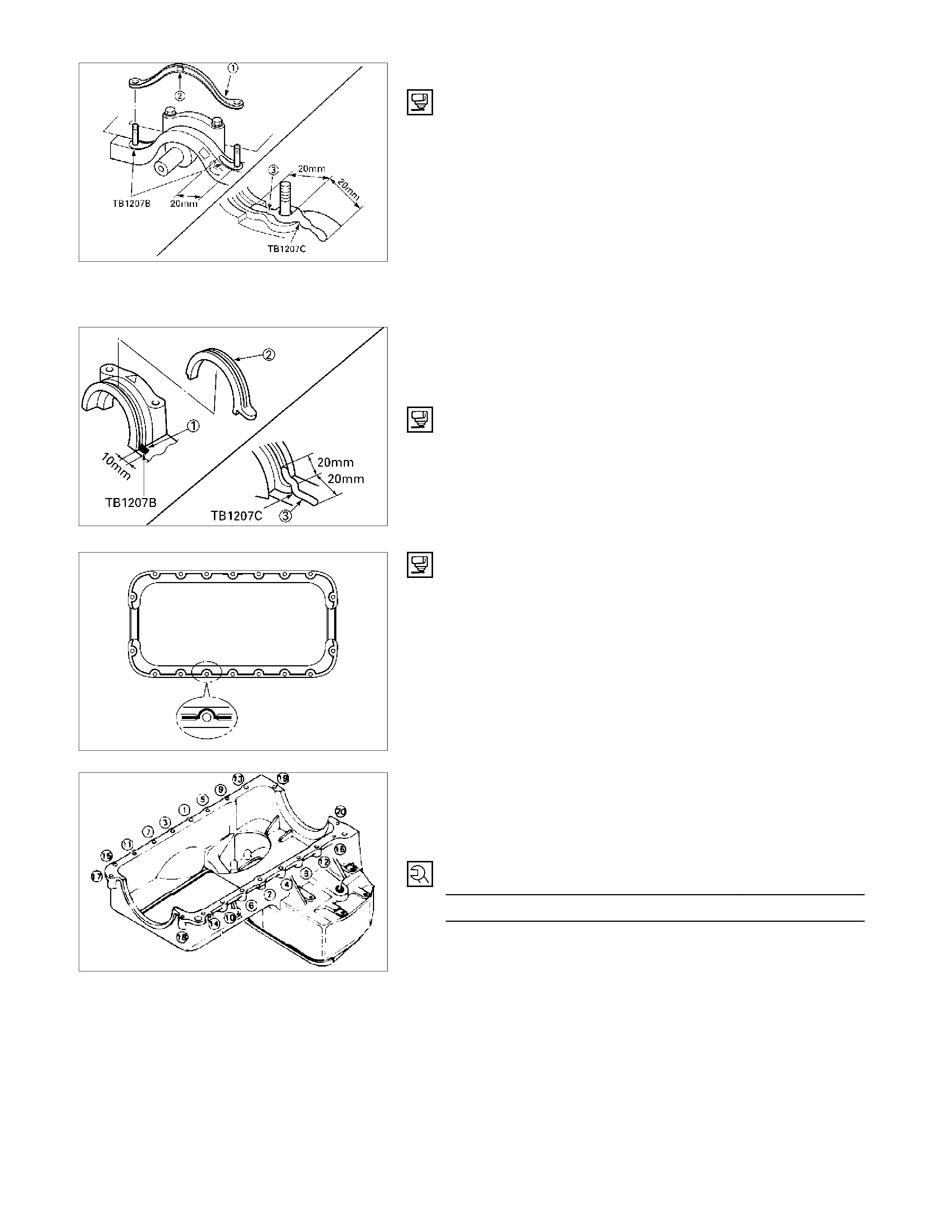
16. Crank Case
1) Apply the recommended liquid gasket (Three bond
1207B) or its equivalent to arch gasket fitting surface
as shown in the illustration.
2) Install the crank case front gasket (1) to the timing
gear case arches.
The gasket projection (2) must be facing forward.
NOTE:
ThreeBond 1207B is a fast-drying liquid gasket. Install the
arch packing to the crankcase immediately after applying
the gasket.
3) Install the rear arch gasket (2) to the No. 5 bearing
cap. Use your fingers to push the arch gasket into the
bearing cap groove. Take care not to scratch the arch
gasket outer surface.
Also apply the recommended liquid gasket (1207C) or
its equivalent to arch gasket fitting area as indicated in
the illustration.
4) Apply the recommended liquid gasket or its equivalent
to groove of the crank case fitting surface as shown in
the illustration.
NOTE:
Be sure that the crank case fitting surface is completely
free of oil and dust before applying the liquid gasket.
5) Install the crank case to the cylinder body.
6) Tighten the crank case bolts to the specified torque a
little at a time in the sequence shown in the
illustration.
Crank Case Bolt Torque N·m (kg·m/lb·ft)
19 (1.9/14)
013RW012
013RW011
013LV003
013R100001
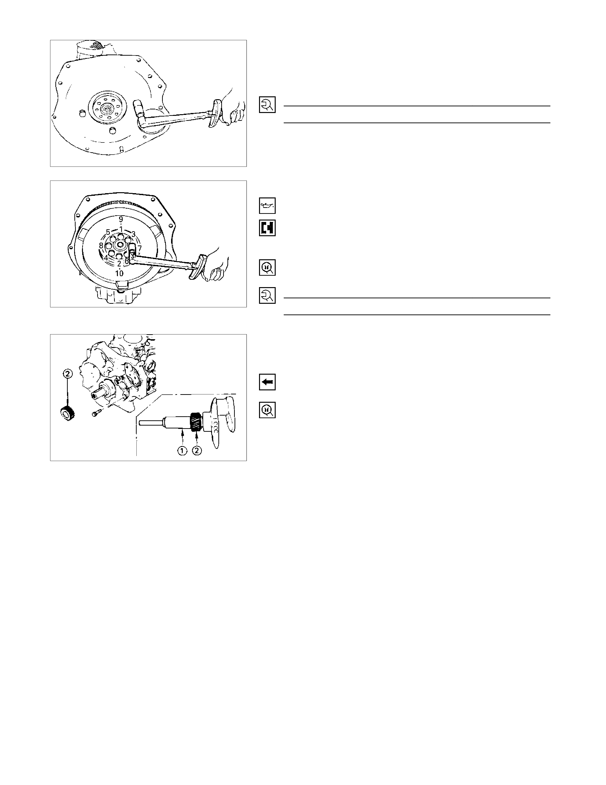
17. Cylinder Body Rear Plate
1) Align the rear plate with the cylinder body knock pins.
2) Tighten the rear plate to the specified torque.
Rear Plate Torque N·m (kg·m/lb·ft)
82 (8.4/61)
18. Flywheel
1) Apply a coat of engine oil to the threads of the
flywheel bolts.
2) Align the flywheel with the crankshaft dowel pin.
3) Tighten the flywheel bolts in the numerical order
shown in the illustration.
Gear stopper: 5-8840-0214-0
Flywheel Bolt Torque N·m (kg·m/lb·ft)
118 (12/87)
19. Crankshaft Timing Gear
Use the crankshaft timing gear installer (1) to install the
crankshaft timing gear (2).
The crankshaft timing gear setting mark must be facing
outward.
Crankshaft Timing Gear Installer: 9-8522-0020-0
020R100001
015LX113
020RY00034
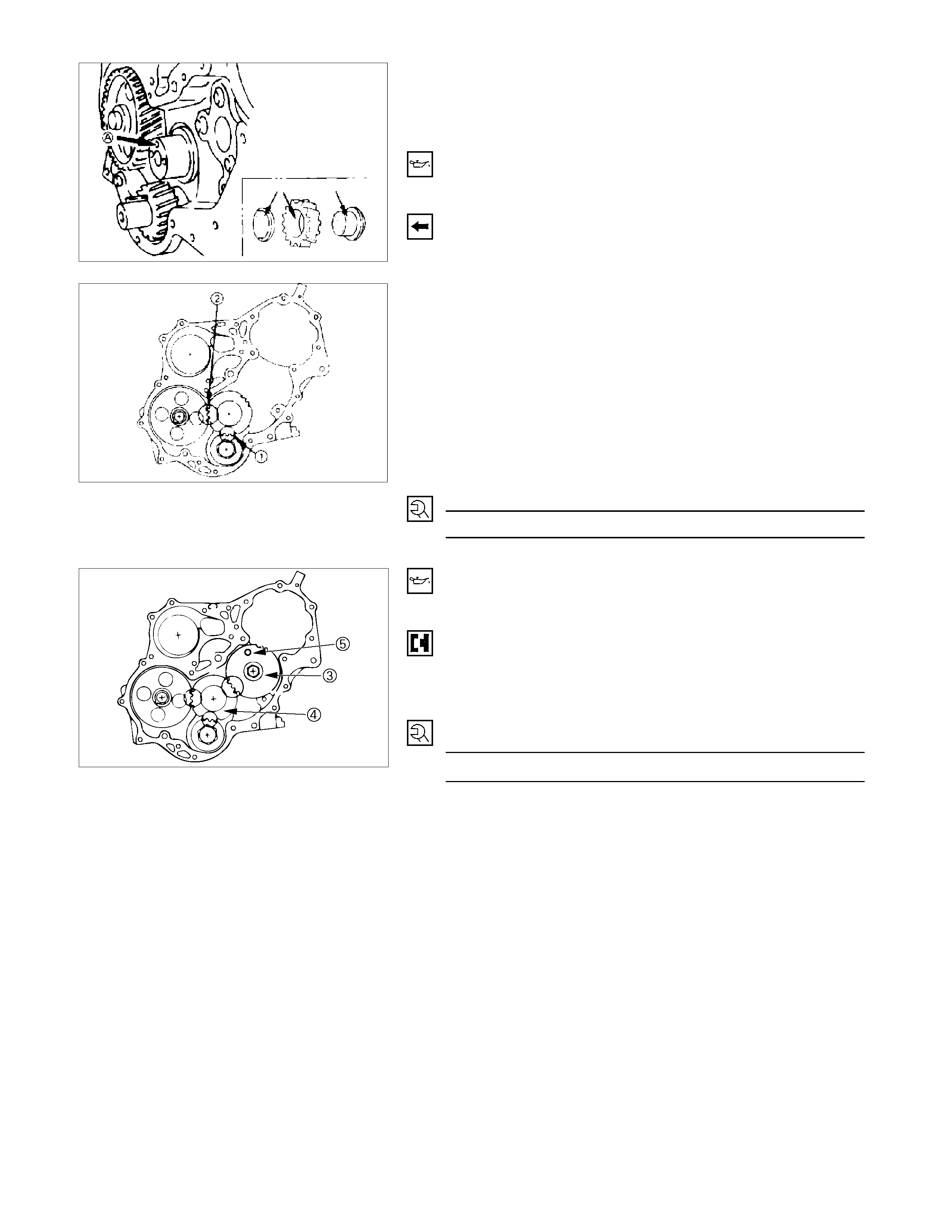
20. Idler Gear Shaft
21. Idler Gear "A"
1) Turn the crankshaft clockwise to set the DTC of the
No.1 piston.
2) Apply engine oil to the idler gear and the idler gear
shaft.
The idler gear shaft oil hole (A) must be facing up.
3) Position the idler gear setting marks so that they are
facing the front of the engine.
4) Align the idler gear setting mark with the crankshaft
timing gear (1) setting mark.
5) Align the idler gear setting mark with the camshaft
timing gear (2) setting mark.
6) Install the thrust collar and bolts to the cylinder body
through the shaft.
The thrust collar oil hole must be facing up, and the
thrust collar chamfered must be outward.
7) Tighten the idler gear bolt to the specified torque.
Idler Gear "A" Bolt Torque N·m (kg·m/lb·ft)
30 (3.1/22)
020R300006
22. Idler Gear "B" and Shaft
1) Apply engine oil to the idler gear and the idler gear
shaft.
2) Align the idler gear "B" (3) setting mark with the idler
gear "A" (4) setting mark.
3) Tighten the idler gear bolt to the specified torque.
4) Be sure to remove the lock bolt (5) from idle gear “B”.
Idler Gear "B" Bolt Torque N·m (kg·m/lb·ft)
76 (7.7/56)
020RY00035
020RY00036
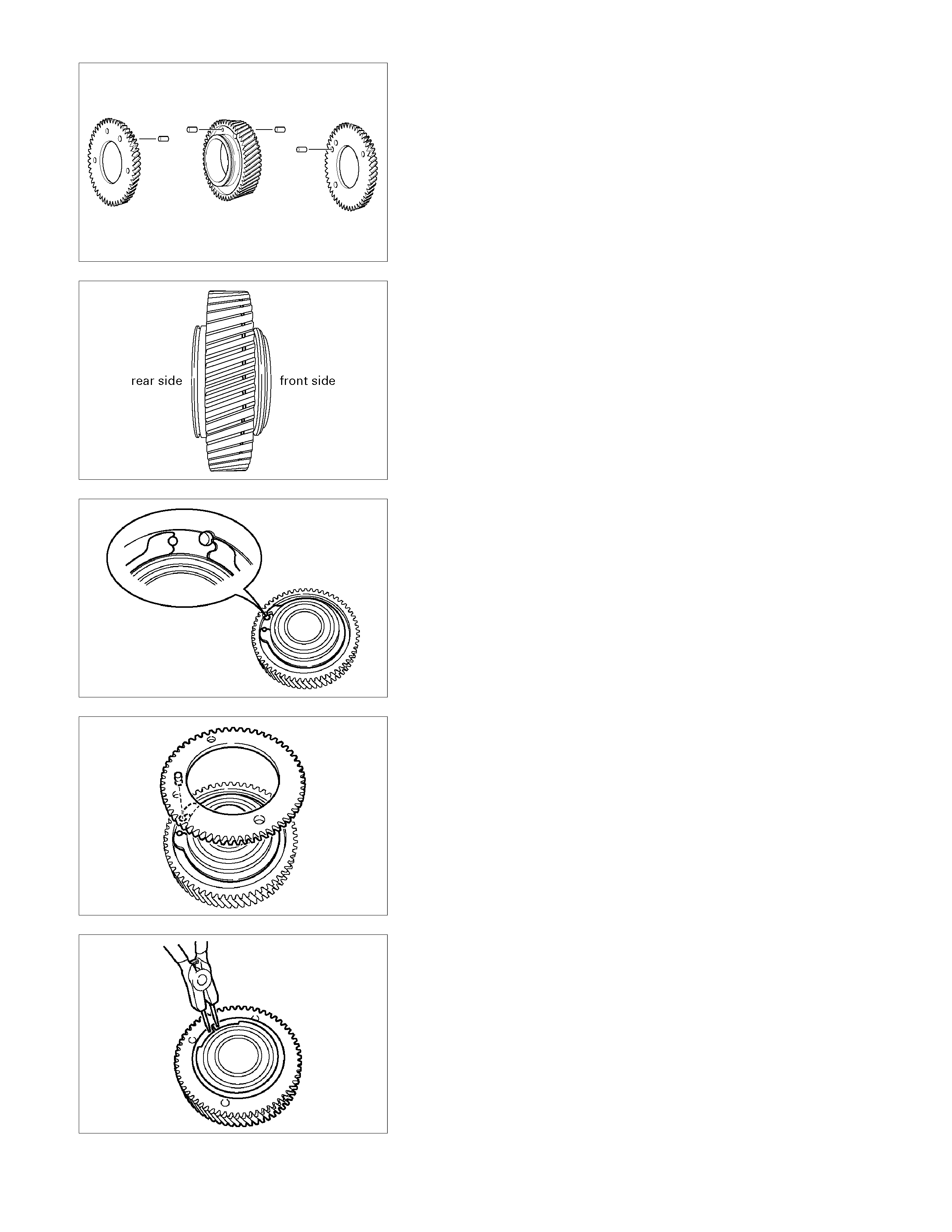
020L200019
5) If the idle gear "B" is disassembled, reassemble in the
following procedure.
a) Drive pins into the main gear, the front gear, and
the rear gear.
020L200007
b) Install the main gear bearing from the front side of
the main gear (the side with the groove).
c) Place the main gear in a vice with copper plate so
that the rear side of the main gear facing up.
RTW31BSH000101
d) Set the spring as shown in the illustration.
RTW31BSH000201
e) Position the rear gear so that the pin is aligned
with the receiving end of the spring.
RTW31BSH000301
f) Install the snap ring to the main gear groove.
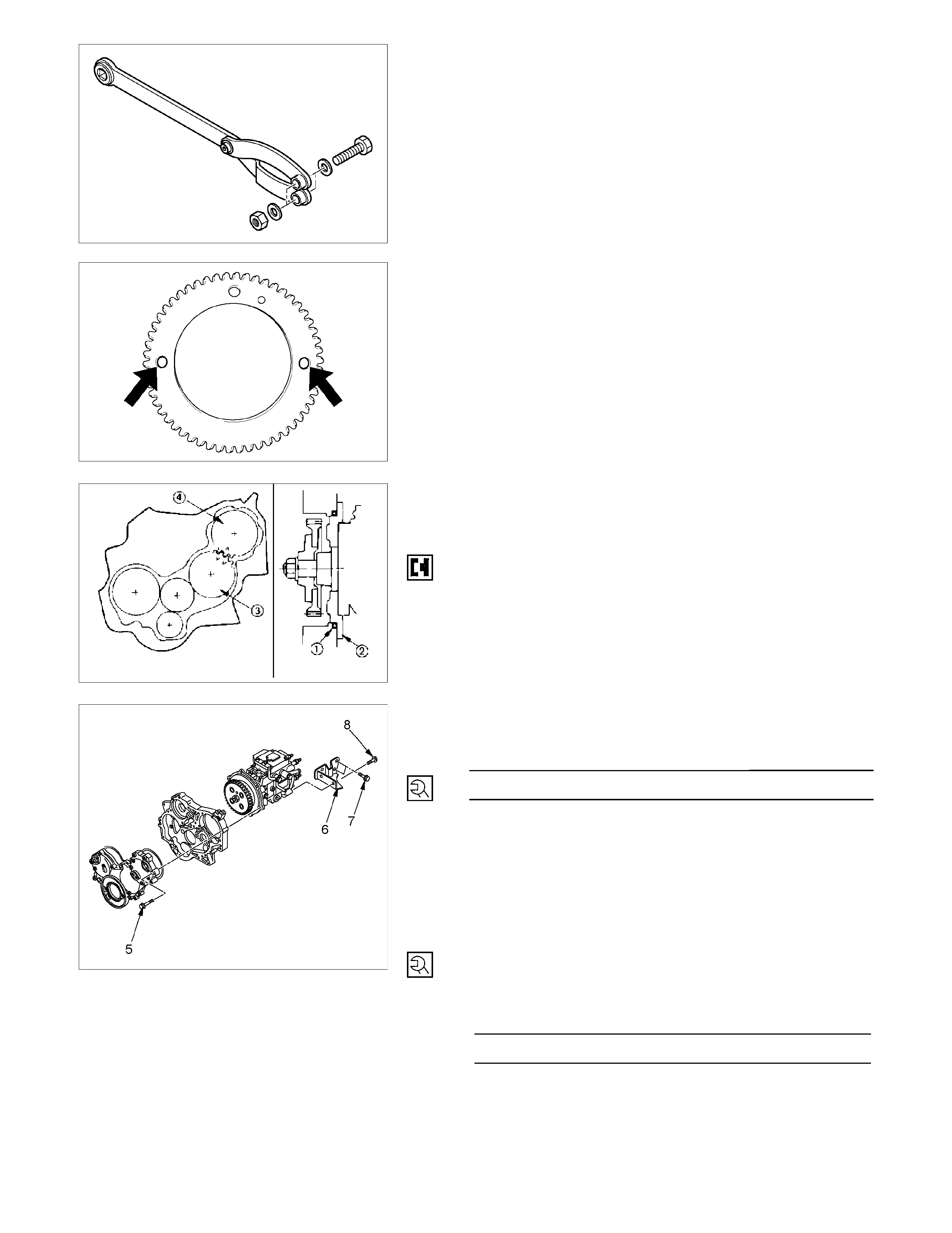
RTW31BSH000501
g) Install suitable bolts, nuts and washers to special
tool as shown in the illustration to rotate the
scissors gear.
End yoke holder: 5-8840-2447-0
RTW31BSH000401
h) Insert the bolts of the special tool into the rear
gear setting hole. Rotate the rear gear to mesh the
teeth of main gear and rear gear.
i) Insert a lock bolt (M6 × 1 L=30) into scissors gear
fixing hole to prevent the scissors gear from
turning.
j) Place the main gear in a vice with copper plate so
that the front side of the main gear facing up.
k) Repeat steps 4 to 8 to install the front gear.
l) Lock the front gear, the main gear, and the rear
gear with lock bolt (inserted at Step 8).
23. Injection Pump
1) Install the O-ring (1) to the injection pump flange (2).
2) Attach the noise insulator rubber to the cylinder body.
3) Install the injection pump to the timing gear case.
Align the idler gear "B" (3) mark with the injection
pump timing gear (4) mark.
RTW36AMH000101
4) Tighten the injection pump bolts (5) to the specified
torque.
Injection Pump Bolt Torque N·m (kg·m/lb·ft)
19 (1.9/14)
5) Install the injection pump bracket (6) and the bracket
bolts (7) and (8) to the cylinder body.
6) Temporarily tighten the bracket bolts.
7) Tighten the bracket bolts (7) to the specified torque.
8) Tighten the bracket bolts (8) to the specified torque.
NOTE:
Tighten the bracket bolt (7) first.
Injection Pump Bracket Bolt Torque N·m (kg·m/lb·ft)
19 (1.9/14)
020RY00039
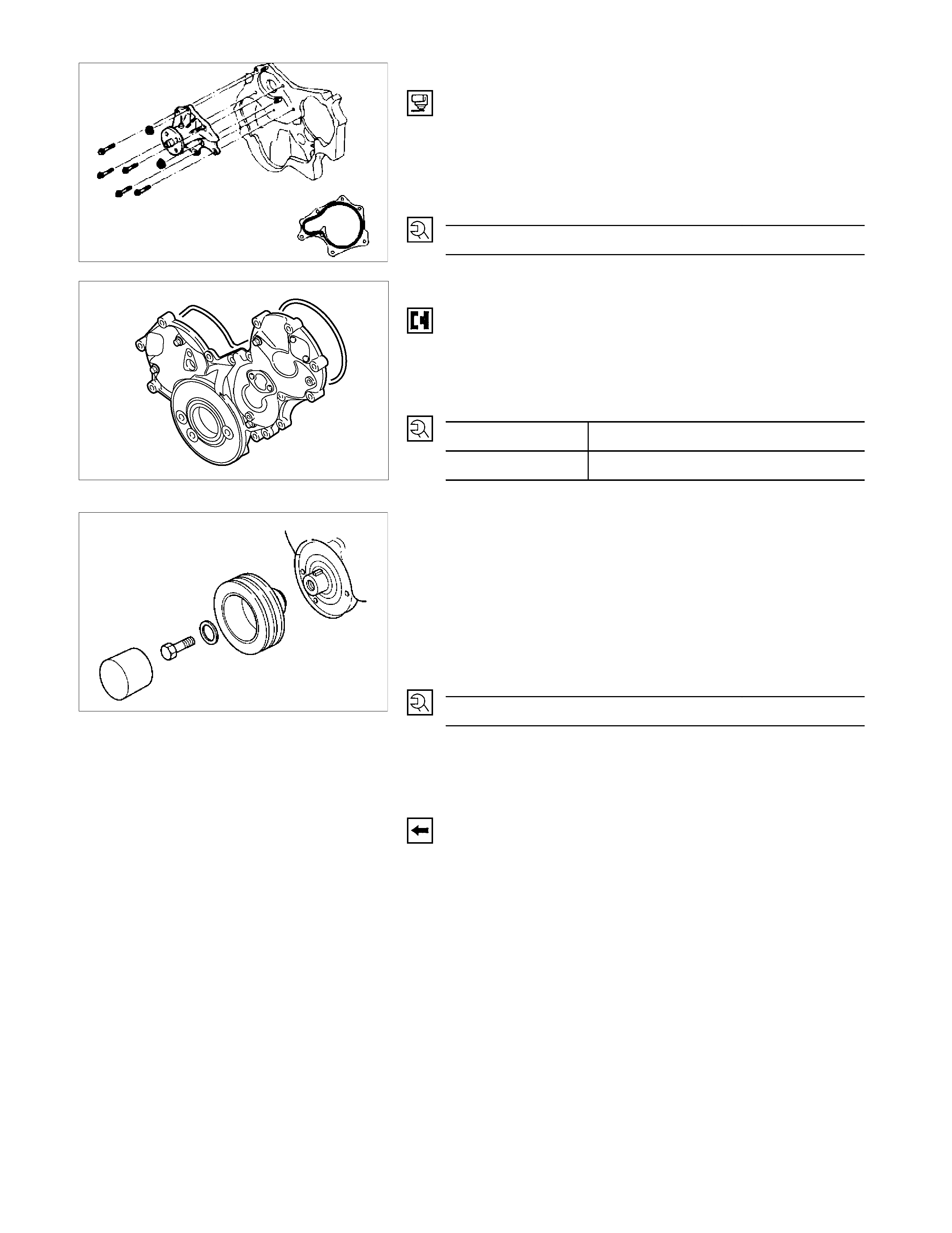
030RY00007
24. Water Pump
1) Apply the recommended liquid gasket or its equivalent
to the water pump at the position shown in the
illustration.
Do not apply an excessive amount of liquid gasket.
2) Tighten the water pump bolts to the specified torque.
Water Pump Bolt Torque N·m (kg·m/lb·ft)
20 (2.0/14)
25.Timing Gear Case Cover
1) Align the gear case with the timing gear case knock
pin and then install the timing gear case cover.
2) Tighten the gear case cover bolts to the specified
torque.
Gear Case Cover Bolt Torque N·m (kg·m/lb·ft)
M8 19 (1.9/14)
M12 76 (7.7/56)
26. Crankshaft Damper Pulley
Tighten the crankshaft damper pulley bolt to the specified
torque.
NOTE:
Hold the flywheel ring gear stationary to prevent the
crankshaft from turning when tightening the damper pulley
bolt.
Crankshaft Damper Pulley Bolt Torque N·m (kg·m/lb·ft)
235 (24/174
Take care not to damage the crankshaft damper pulley
boss.
27. Cylinder Head Gasket
The cylinder head gasket "TOP" mark must be facing up.
NOTE:
Before the gasket installation, measure the piston head
projection and select the appropriate head gasket.
Refer to "INSPECTION AND REPAIR", "Cylinder Head
Gasket Selection".
020R300004
014R100014
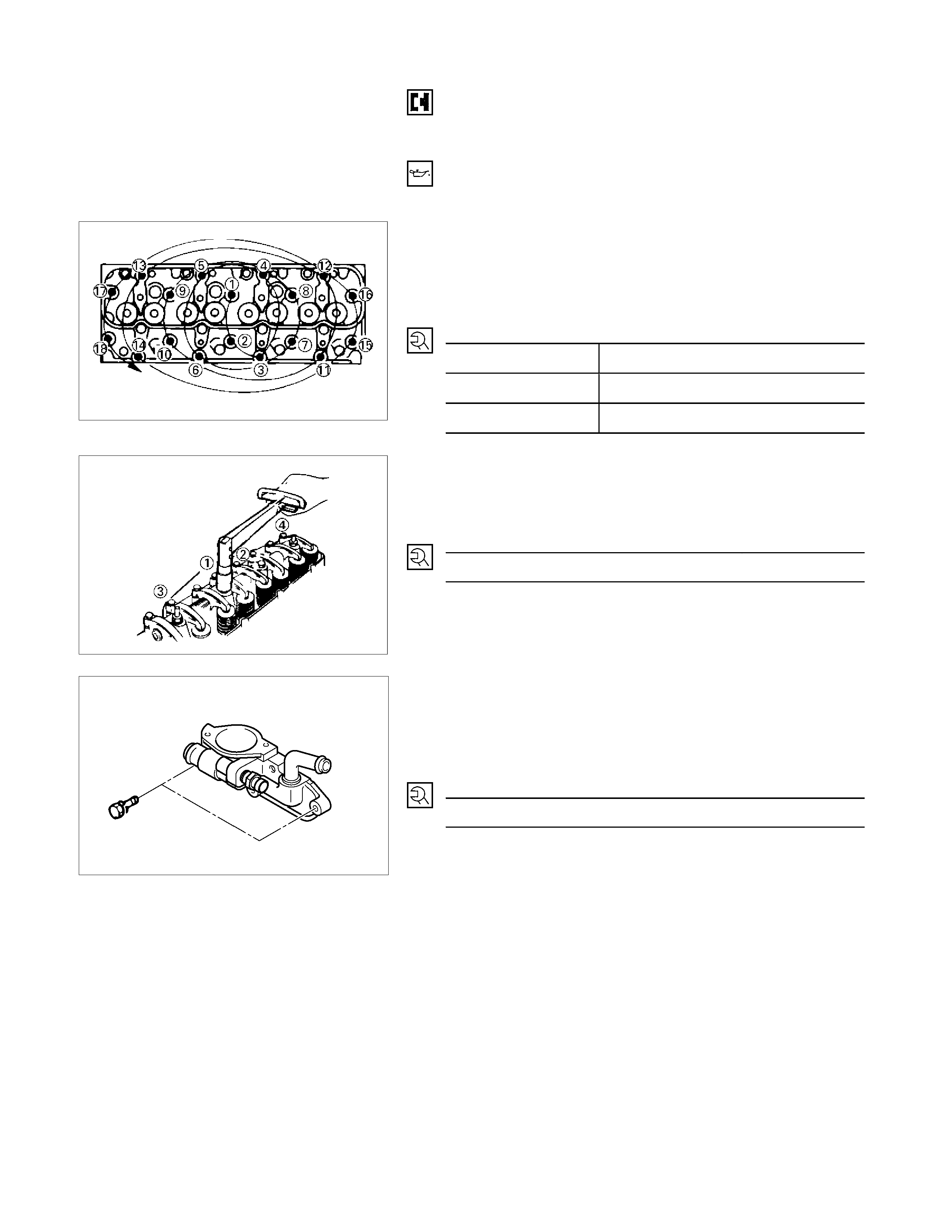
28. Cylinder Head
1) Align the cylinder body dowels and the cylinder head
dowel holes.
Carefully place the cylinder head on the cylinder head
gasket.
2) Apply a coat of engine oil to the cylinder head bolt
threads and setting faces.
3) Tighten the cylinder head bolts in three steps of
angular tightening method.
Follow the numerical sequence shown in the
illustration.
Cylinder Head Bolt Torque N·m (kg·m/lb·ft)
1st step 49 (5.0/36)
2nd step 60° - 75°
3rd step 60° - 7 5°
30. Rocker Arm Shaft and Rocker Arm
Tighten the rocker arm shaft bracket bolts in the numerical
order shown in the illustration.
Rocker Arm Shaft Bracket Bolt Torque N·m (kg·m/lb·ft)
54 (5.5/40)
31. Thermostat Housing
1) Install the thermostat housing.
2) Tighten the thermostat housing bolts to the specified
torque.
Thermostat Housing Bolt Torque N·m (kg·m/lb·ft)
19 (1.9/14)
011LX073
014LX083
031R300002
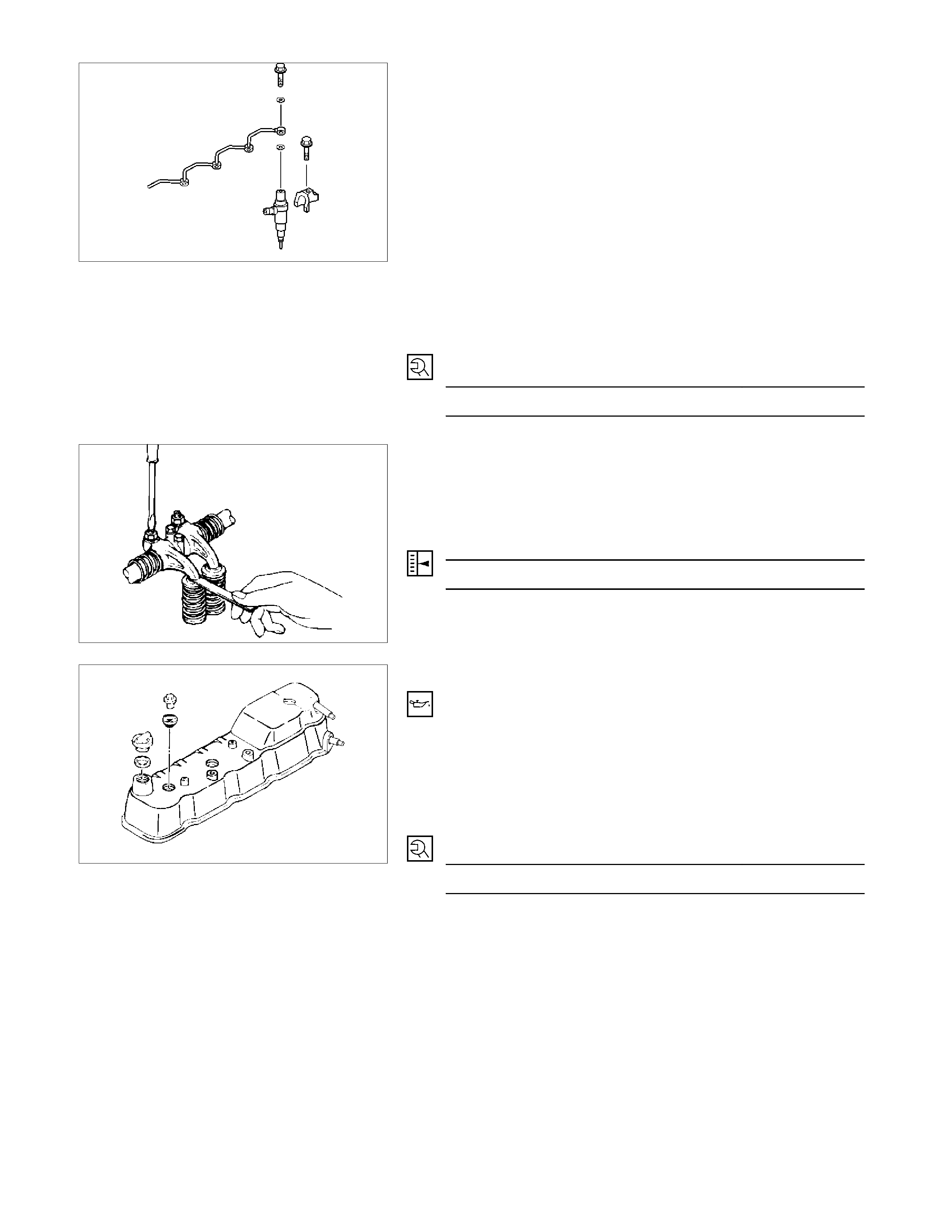
33. Injection Nozzle Holder
1) Install the injection nozzle gasket and the O-ring to the
injection nozzle holder.
Be sure that the O-ring fits snugly in the injection
nozzle groove.
2) Install the nozzle holder together with the nozzle
holder bracket to the cylinder head.
3) Tighten the nozzle holder bracket bolt to the specified
torque.
Injection Nozzle Holder Bracket Bolt
Torque N·m (kg·m/lb·ft)
37 (3.8/28)
Note on Valve Clearance Adjustment
Valve clearances must be adjusted before the cylinder
head cover is reinstalled. Refer to "Valve Clearance
Adjustment" in the "Servicing" Section of this manual.
Valve Clearance (At Cold) mm (in)
0.4 (0.0157)
34. Cylinder Head Cover
1) Apply engine oil to the rocker arm and the valve
spring.
2) Install the cylinder head cover gasket to the head
cover. Check to see that the head cover gasket has
no loose areas.
3) Tighten the cylinder head cover nuts in the numerical
order shown in the illustration.
Cylinder Head Cover Bolt Torque N·m (kg·m/lb·ft)
13 (1.3/9.4)
4) Connect the positive crankcase ventilation (PCV)
hose to the cylinder head cover.
040R100013
014RY00015
010R100018
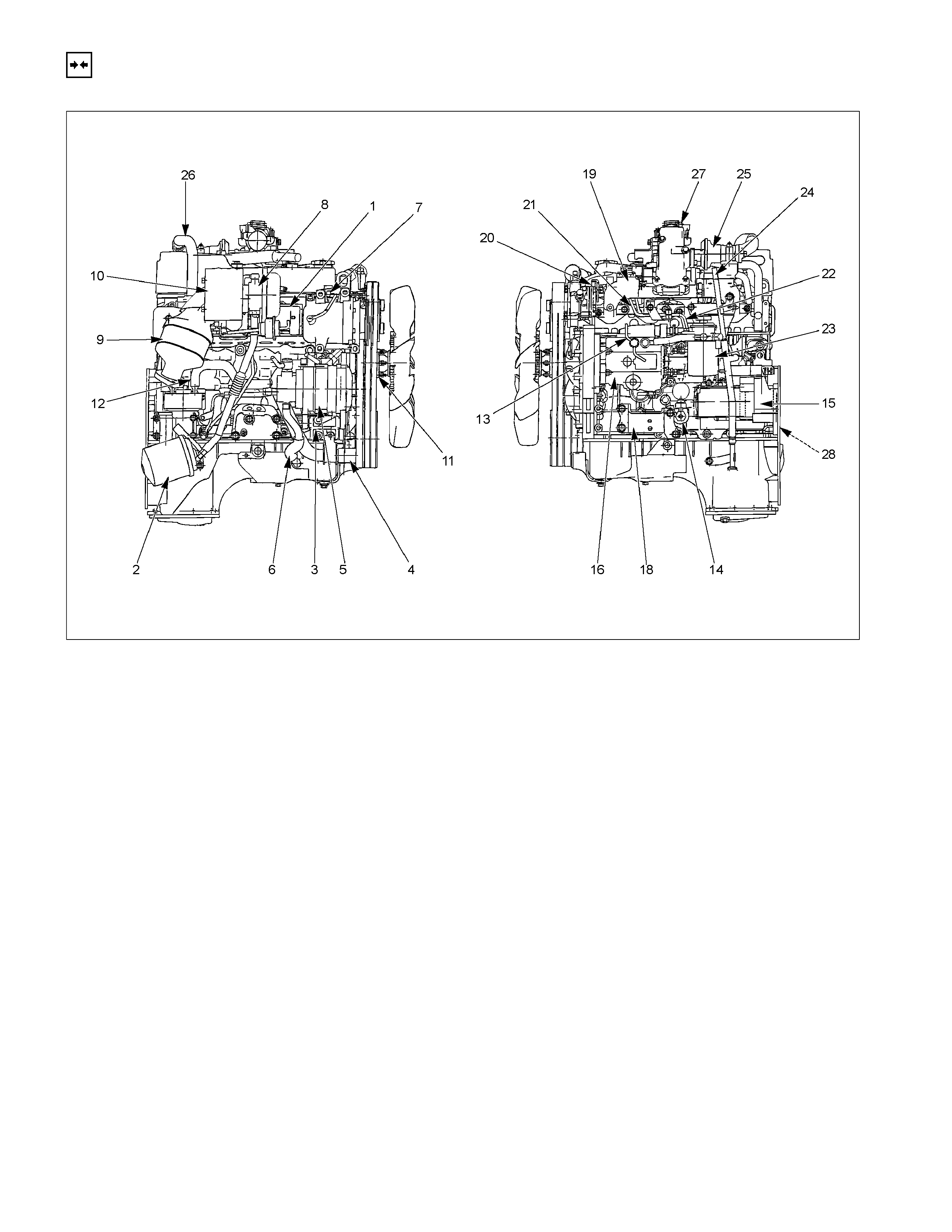
INSTALLATION
EXTERNAL PARTS
RTW36AMF000701
Installation Steps
1. Exhaust manifold 15. Starter motor
2. Oil cooler with oil filter 16. Injection pump
3. Generator bracket 17. Injection pump cover
4. Water inlet pipe 18. Engine mounting bracket and foot
5. Generator and adjusting plate 19. Intake manifold
6. Vacuum pump oil return hose 20. Power steering oil pump bracket
7. Compressor bracket 21. Fuel injection pipe with clip
8. Turbocharger 22. Fuel filter bracket
9. Catalytic converter 23. Fuel filter assembly
10. Heat protector 24. Oil level gauge
11. Cooling fan pulley 25. EGR valve
12. Oil cooler water pipe 26. EGR pipe
13. Fuel leak off pipe 27. Intake pipe and throttle body
14. Oil pressure warning switch 28. Clutch assembly or flex plate
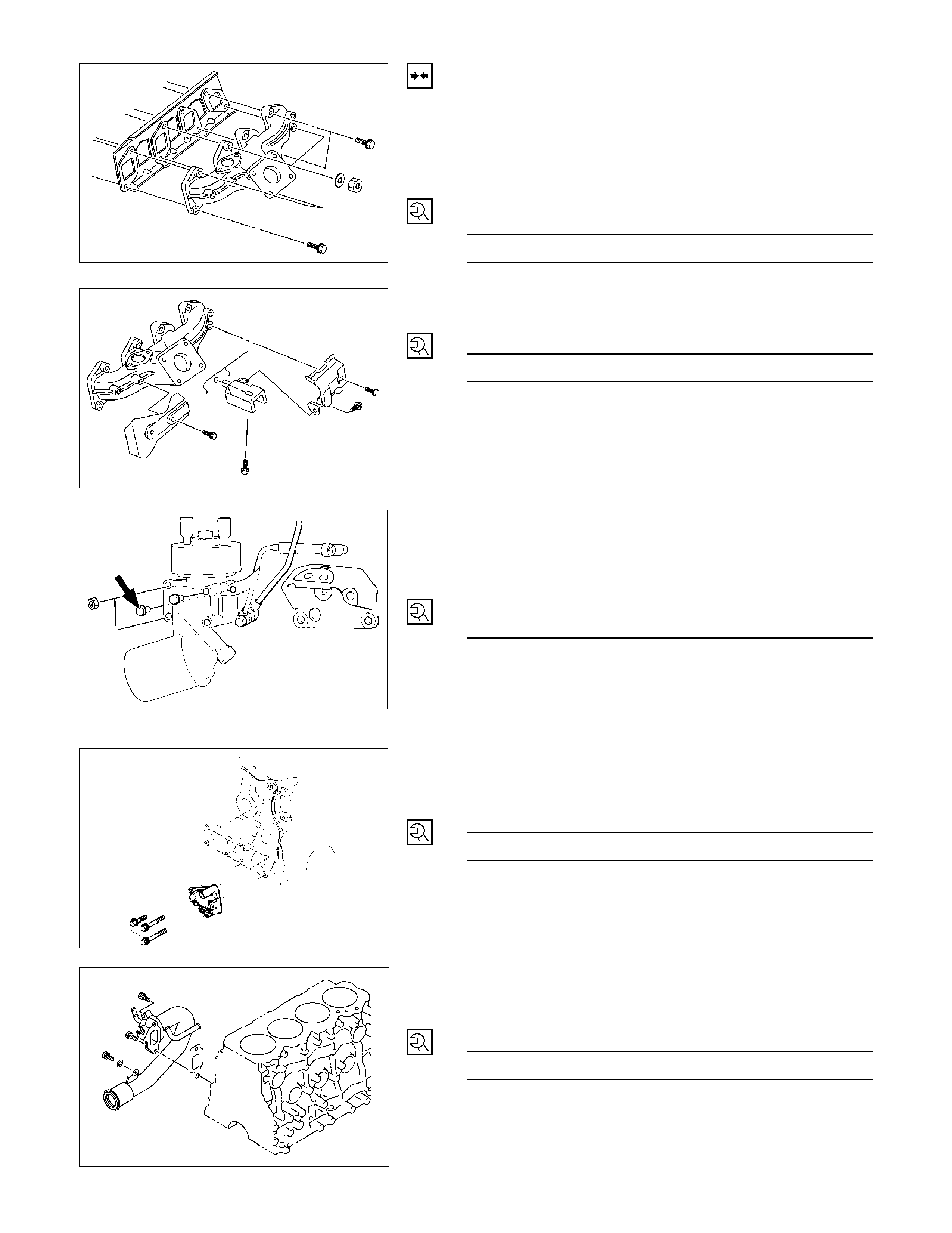
Installation
1. Exhaust Manifold
1) Install the exhaust manifold to the cylinder head with
the manifold gasket.
2) Tighten the exhaust manifold bolts and nuts to the
specified torque a little at a time.
Exhaust Manifold Bolt and Nuts
Torque N·m (kg·m/Ib·ft)
27 (2.8/20)
3) Install the exhaust manifold bracket to the manifold
and the cylinder body.
Manifold Bracket Bolt Torque N·m (kg·m/Ib·ft)
19 (1.9/14)
RTW46ASH001301
2. Oil Cooler with Oil Filter
1) Install the O-ring to the oil filter body flange groove.
2) Install the oil filter body to cylinder block and tighten to
the specified torque.
Oil Filter Body Bolt and Nut
Torque N·m (kg·m/Ib·ft)
Bolt 19 (1.9/14)
Nut 24 (2.4/17)
3. Generator Bracket
Install the generator bracket to the cylinder body and
tighten the bracket bolts to the specified torque.
Bracket Bolt Torque N·m (kg·m/Ib·ft)
40 (4.1/30)
4. Water Inlet Pipe
1) Tighten the water inlet pipe bolts to the specified
torque.
Suction Pipe Bolt Torque N·m (kg·m/Ib·ft)
19 (1.9/14)
027R100003
027R100004
066RY00001
032R300001
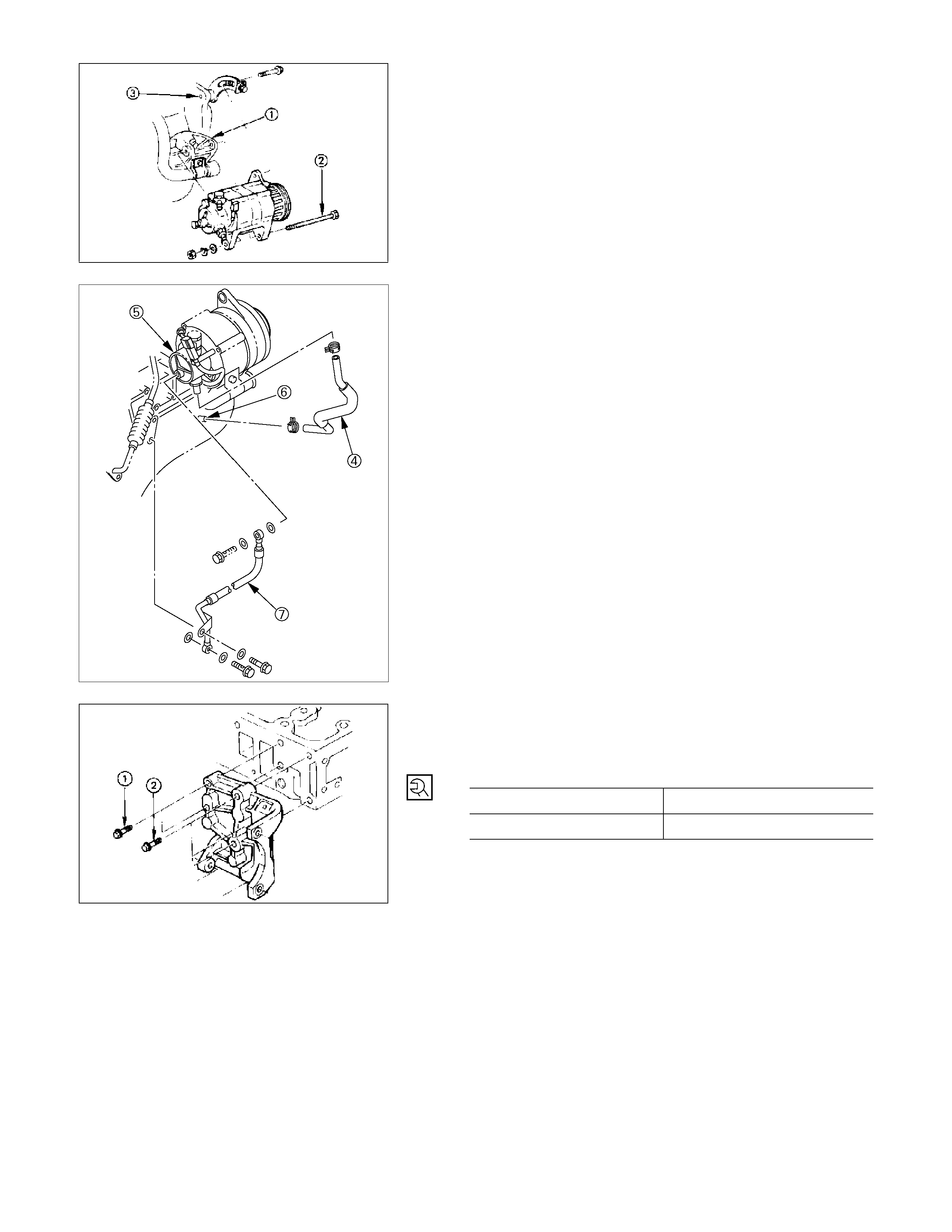
5. Generator and Adjusting Plate
1) Install the generator to the bracket (1).
2) Temporarily tighten the generator bolt (2) and
adjusting plate bolts (3).
The bolts will be finally tightened after installation of
the cooling fan drive belt.
1
3) Connect the vacuum pump rubber hose (4) to the
vacuum pump (5), and the oil pan (6).
6. Vacuum Pump Oil Return Hose
Connect the vacuum oil pipe (7) to the vacuum pump, and
the cylinder body
052R30000
7. Compressor Bracket
1) Install the compressor bracket to the cylinder head.
2) Tighten the bracket bolts to the specified torque.
Bracket Bolt Torque N·m (kg·m/Ib·ft)
M8×1.25 19 (1.9/14)
M10×1.25 40 (4.1/30)
066RY00002
042RY00003
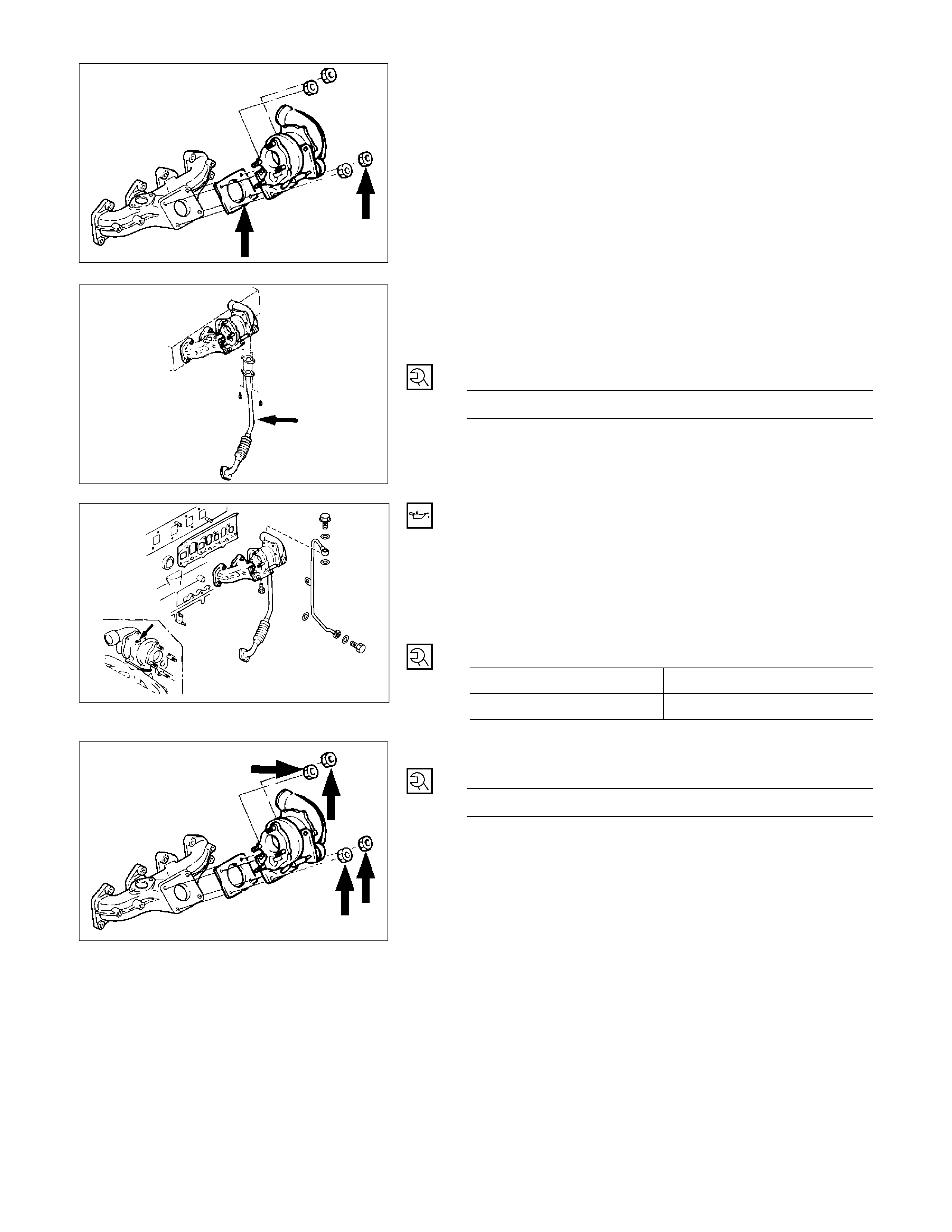
8. Turbocharger
1) Install the turbocharger and the gasket.
2) Temporarily tighten the turbocharger nuts at this time.
They will be fully tightened after the installation of the
turbocharger oil pipe.
Always install new nuts and new gasket.
3) Install the oil return pipe with gasket to the
turbocharger.
4) Tighten the turbocharger oil return pipe to the
specified torque.
Bracket Bolt Torque N·m (kg·m/Ib·ft)
8 (0.8/6)
5) Before installing the oil feed pipe, supply 10 - 20 cc of
clean engine oil to the turbocharger centre housing
through the oil feed opening.
6) Turn the rotating assembly with your hand to
thoroughly lubricate the internal parts.
7) Tighten the oil feed pipe to the specified torque.
Turbocharger Oil Feed Pipe Joint
Bolt Torque N·m (kg·m/Ib·ft)
M10×1.5 22 (2.25/16)
M14×1.5 54 (5.5/40)
8) Tighten the turbocharger nut to the specified torque.
Turbocharger Nut Torque N·m (kg·m/Ib·ft)
27 (2.8/20)
027R100002
036R100001
036R300001
027R100005
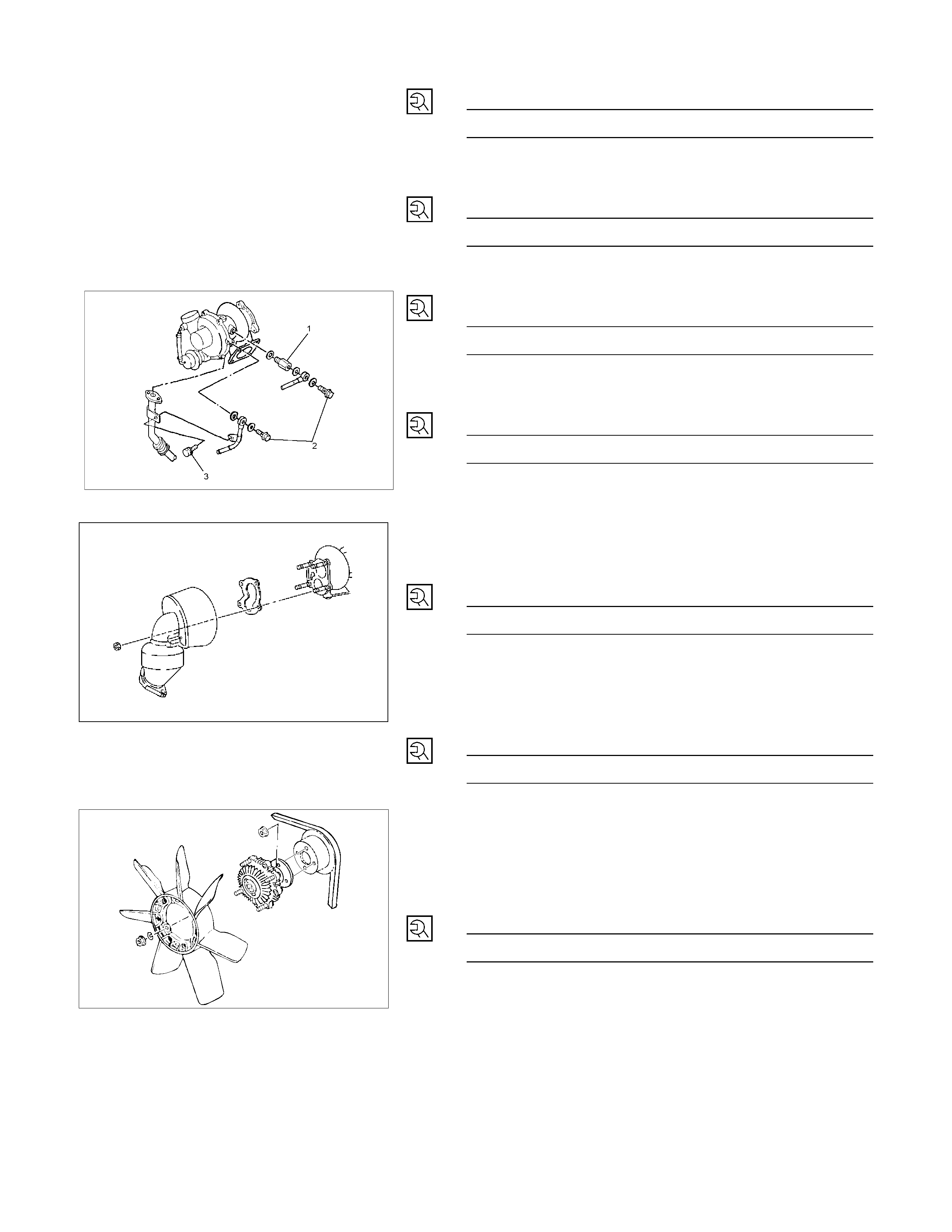
9) Install the water return adapter with the gaskets to
turbocharger and tighten to the specified torque.
Adapter Torque N·m (kg·m/Ib·ft)
39 (4.0/29)
10) Install the water return pipe with the gaskets and
tighten to the specified torque.
Water Return Pipe Torque N·m (kg·m/Ib·ft)
39 (4.0/29)
11) Install the water feed pipe with the gaskets and
tighten to the specified torque.
Water Feed Torque N·m (kg·m/Ib·ft)
39 (4.0/29)
12) Clamp the water feed pipe to the oil return pipe of the
turbocharger.
Fixing Bolt (3) Torque N·m (kg·m/Ib·ft)
8 (0.8/6)
13) Install the hoses for the water feed and return.
RTW46ASH001601
9. Catalytic Converter
Install the catalytic converter with gasket and tighten the
nut to the specified torque.
Catalytic converter Nut Torque N·m (kg·m/Ib·ft)
27 (2.8/20)
Do not install the catalytic converter, if drop down it.
10. Heat Protector
Install the heat protector and tighten the bolt to the
specified torque.
Heat Protector Bolt Torque N·m (kg·m/Ib·ft)
9 (0.9/78 Ib in)
033R300002
11. Cooling Fan Pulley
1) Install the cooling fan pulley to the water pump with
spacer.
2) Tighten the cooling fan pulley nuts to the specified
torque.
Pulley Nut Torque N·m (kg·m/Ib·ft)
8 (0.8/6)
12. Oil Cooler Water Pipe
13. Fuel Leak Off Pipe
14. Oil Pressure Warning Switch
027R100007
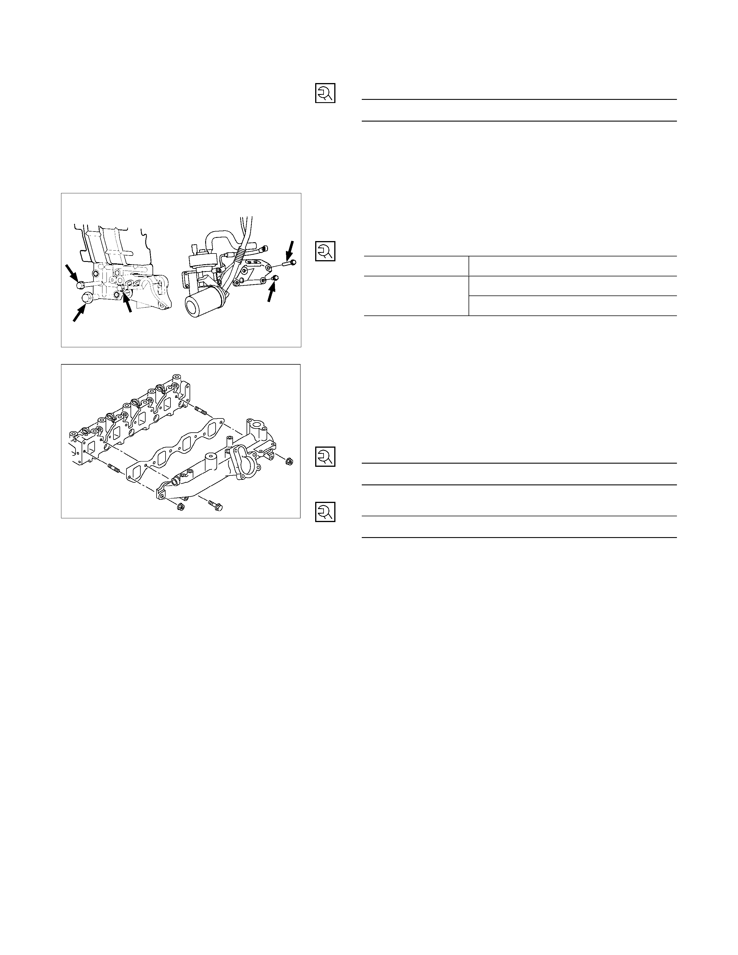
15. Starter Motor
Tighten the starter motor bolts to the specified torque.
Starter Motor Bolt Torque N·m (kg·m/Ib·ft)
85 (8.7/63)
16. Injection Pump
Refer to Section 6C Fuel System; Injection Pump
17. Injection Pump Cover
18. Engine Foot
Install the engine foot to the cylinder body and tighten the
bracket bolts to the specified torque.
Engine Foot Bolt Torque N·m (kg·m/Ib·ft)
Right Side M10×1.25 40 (4.1/30)
M10×1.25 40 (4.1/30)
Left Side M14×1.50 127 (13/93)
RTW36ASH001001
19. Intake Manifold
1) Install the manifold gasket to the intake manifold.
2) Connect the intake rubber hose to the intake duct.
3) Tighten the intake manifold bolts and the flange nuts
to the specified torque.
Intake Manifold Bolt Torque N·m (kg·m/Ib·ft)
19 (1.9/14)
Intake Manifold Flange Nut Torque N·m (kg·m/Ib·ft)
24 (2.4/18)
4) Connect the PCV hose to the cylinder head cover.
5) Install the fan drive belt and adjust the belt tension
referring SERVICING of this section
022R300003
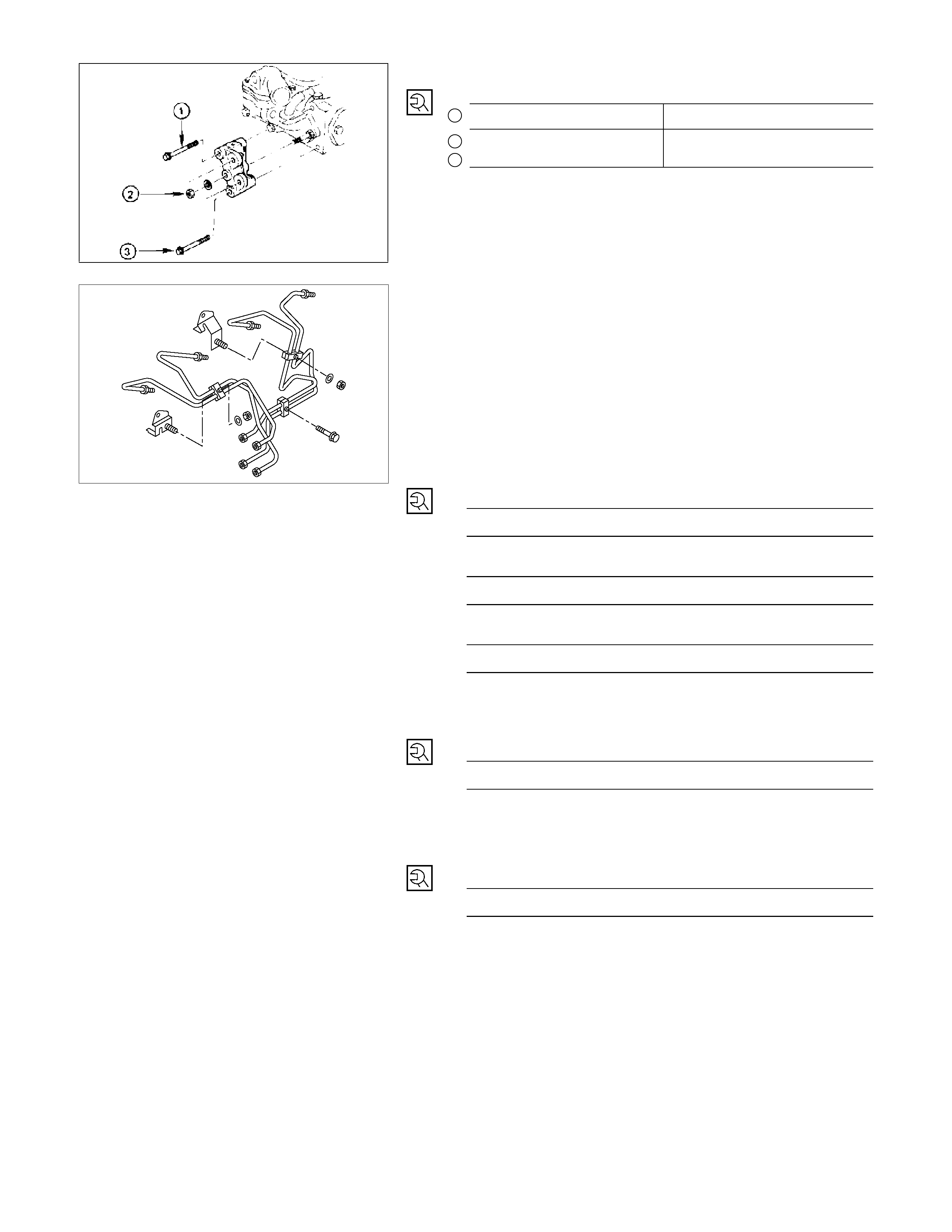
20. Power Steering Oil Pump Bracket
Oil Pump Bracket Nut and Bolt Torque N·m (kg·m/Ib·ft)
1M10×1.25 37 (3.8/28)
2
3M8×1.25 18 (1.8/13) (Bolt ID:8)
040R300005
21. Fuel Injection Pipe with Clip
1) Temporarily tighten the injection pipe sleeve nut.
2) Set the clip in the illustrated position.
NOTE:
Make absolutely sure that the clip is correctly positioned.
An improperly positioned clip will result in injection pipe
breakage and fuel pulsing noise.
3) Tighten the injection pipe sleeve nut to the specified
torque.
Torque
Injection Pump Side N·m (kg·m/Ib·ft)
40 (4.1/30)
Injection Pipe Sleeve Nuts N·m (kg·m/Ib·ft)
29 (3.0/22)
Injection Pipe Clip Nuts N·m (kg·m/Ib·ft)
8 (0.8/6)
22. Fuel Filter Bracket
Install the fuel filter bracket and tighten fixing bolts to the
specified torque.
Fuel Filter Bracket Bolt Torque N·m (kg·m/Ib·ft)
21 (2.1/15)
23. Fuel Filter Assembly
Install the fuel filter assembly and tighten fixing bolts to the
specified torque.
Fuel Filter Assembly Bolt Torque N·m (kg·m/Ib·ft)
21 (2.1/15)
431RY00013
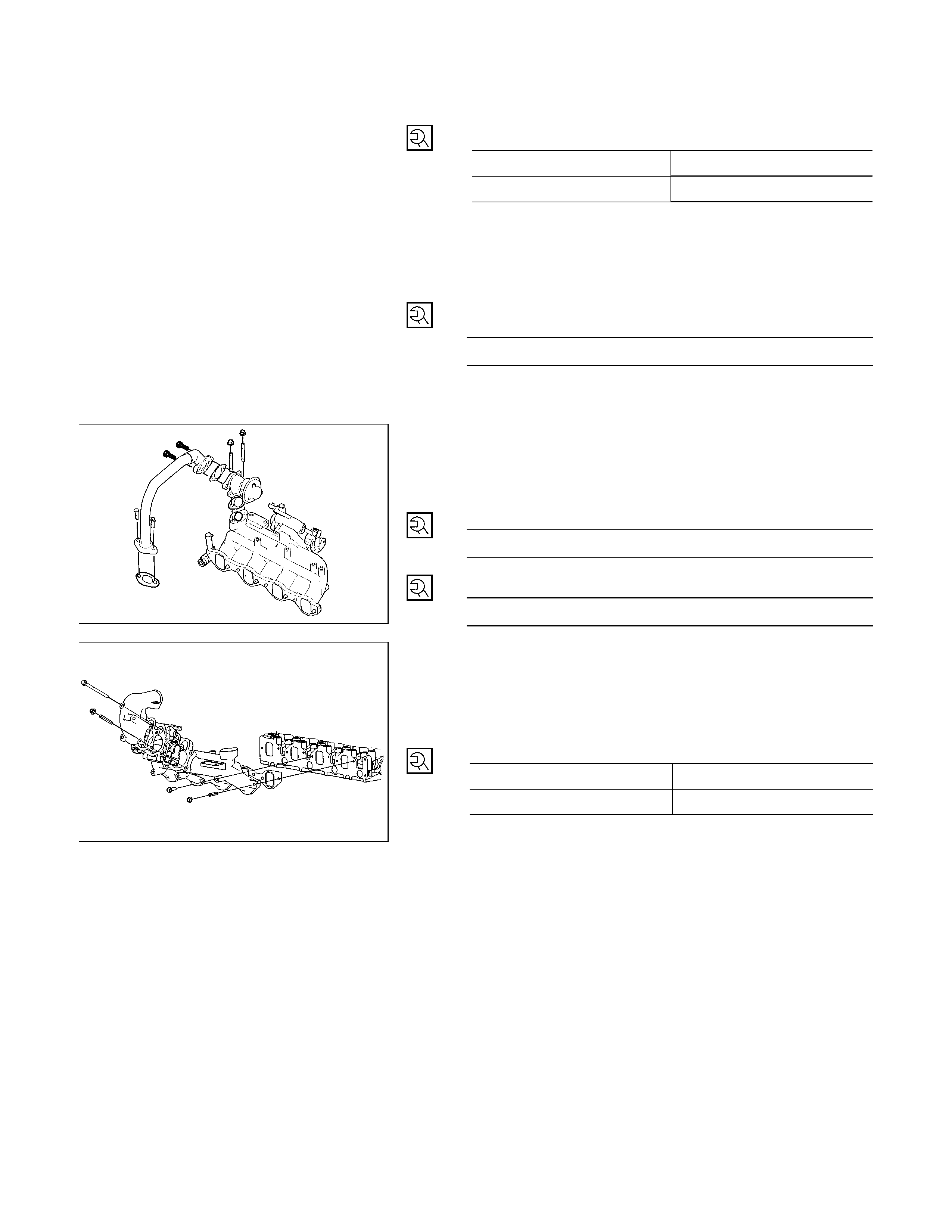
24. Oil Level Gauge
Install the oil level gauge and tighten fixing bolts to the
specified torque.
Oil Level Gauge Bolt Torque N·m (kg·m/Ib·ft)
M8 19 (1.9/14)
M6 8 (0.8/6)
25. EGR Valve
Install the EGR valve assembly to the intake manifold with
the two gasket.
Tighten the four nuts to the specified torque.
Nut Torque N·m (kg·m/Ib·ft)
31 (3.1/23)
Connector the vacuum hose.
RTW36ASH000301
26. EGR Pipe
Install the EGR valve adapter with the gasket to the EGR
valve assembly and install the EGR pipe with the gasket.
Tighten fixing bolts and nuts to the specified torque.
ECM Valve Adapter Bolts N·m (kg·m/Ib·ft)
24 (2.4/17)
EGR Pipe Bolts and Nuts N·m (kg·m/Ib·ft)
27 (2.8/20)
27. Intake Pipe and Throttle Body
Install the throttle body with the gasket to the intake
manifold and install the intake duct with the gasket.
Tighten the two bolts and the two nuts to the specified
torque.
Throttle Body and Intake Duct N·m (kg·m/Ib·ft)
Bolt 19 (1.9/14)
Nut 24 (2.4/17)
RTW36ASH000201
28. Clutch Assembly or Flex Plate
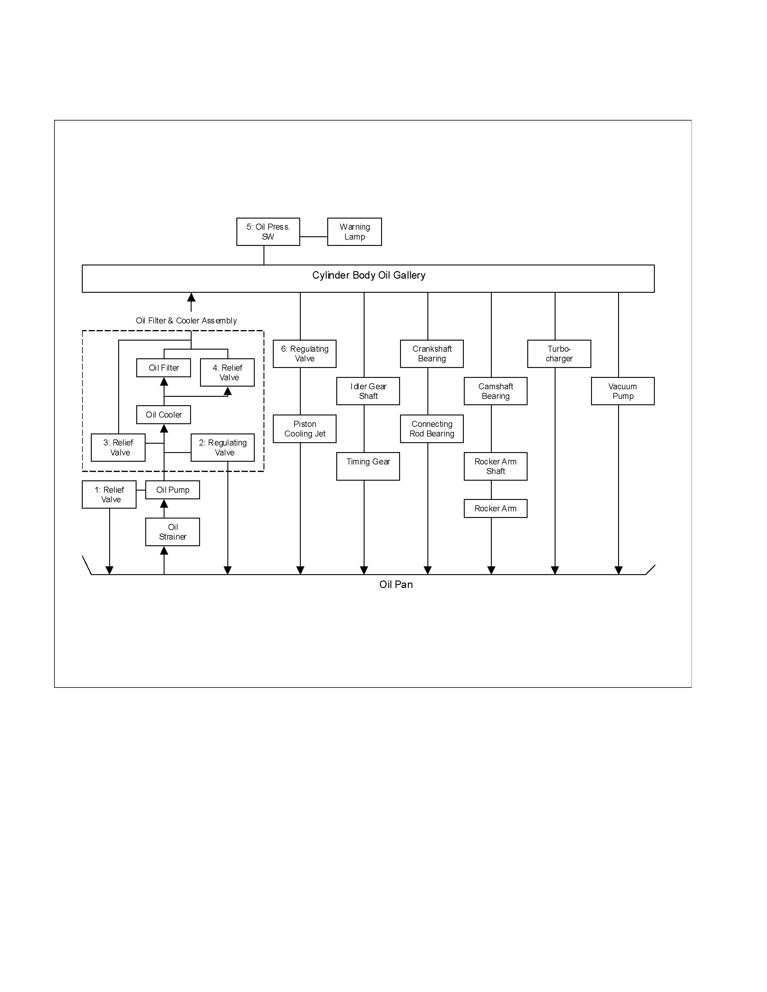
LUBRICATION SYSTEM
LUBRICATING OIL FLOW
1. Oil Pump Relief Valve Operating Pressure: 6.2 - 7.8 kg/cm2 (608 - 764 Kpa)
2. Regulating Valve Operating Pressure: 5.7 - 6.3 kg/cm2 (558.6 - 617.4 Kpa)
3. Oil Cooler Relief Valve Opening Pressure: 2.8 - 3.4 kg/cm2 (270 - 330 Kpa)
4. Oil Filter Relief Valve Opening Pressure: 0.8 - 1.2 kg/cm2 (78.4 - 117.6 Kpa)
5. Oil Pressure Switch Operating Pressure: 0.3 - 0.5 kg/cm2 (29.4 - 49.0 Kpa)
6. Regulating Valve: 1.8 - 2.2 kg/cm2 (176 - 216 Kpa)
The 4J series engine has a full flow type lubricating system.
Lubricating oil is pumped from the oil pump to the cylinder body oil gallery through the oil cooler and the oil filter. It is
then delivered to the vital parts of the engine from the cylinder body oil gallery.
Oiling jets installed on the cylinder body spray engine oil to the piston backside faces to achieve maximum piston
cooling effect.
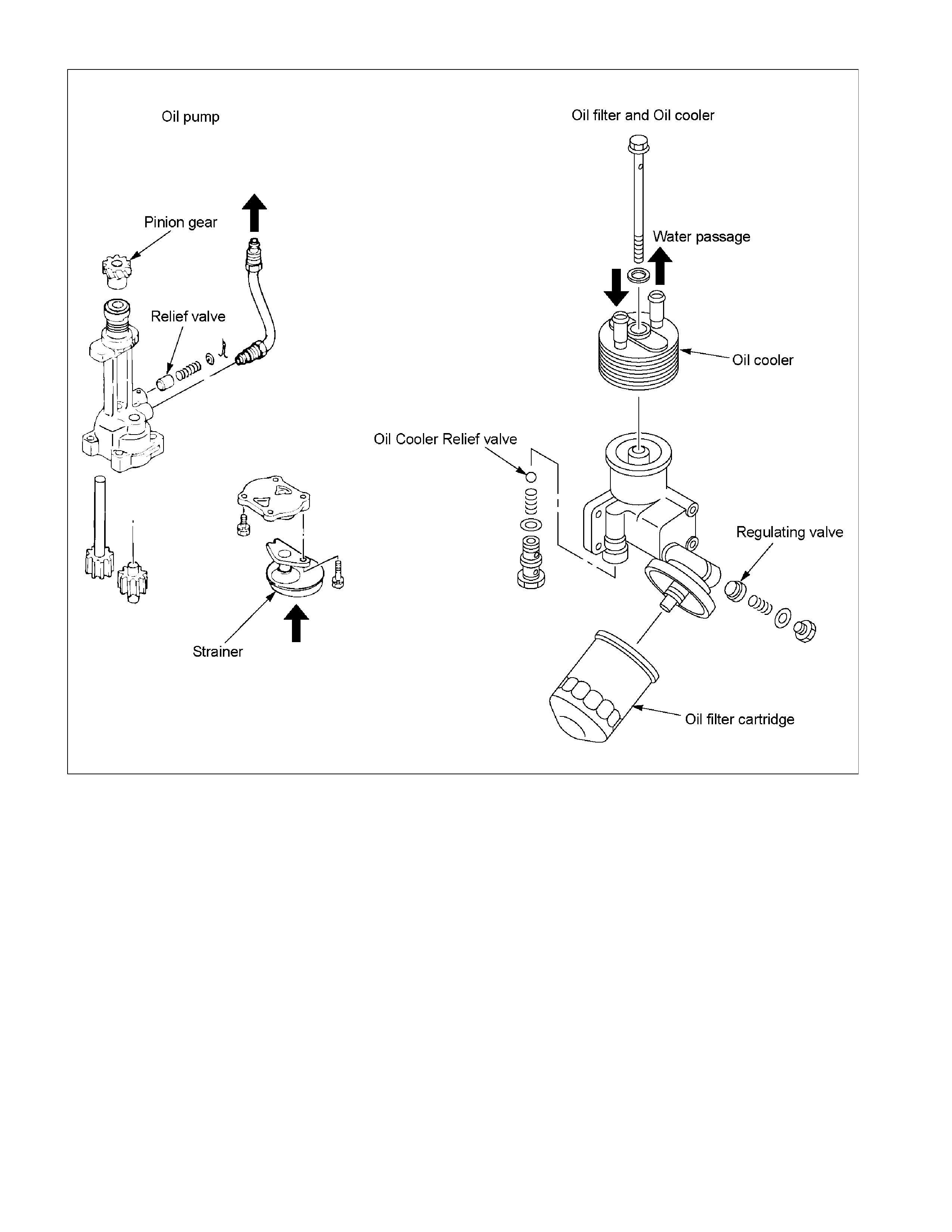
OIL PUMP AND OIL FILTER
RTW46ALF001501
The 4J series engine is equipped with a gear type oil pump.
The oil filter and the water cooled oil cooler integrated a single unit to increase the cooling effect.
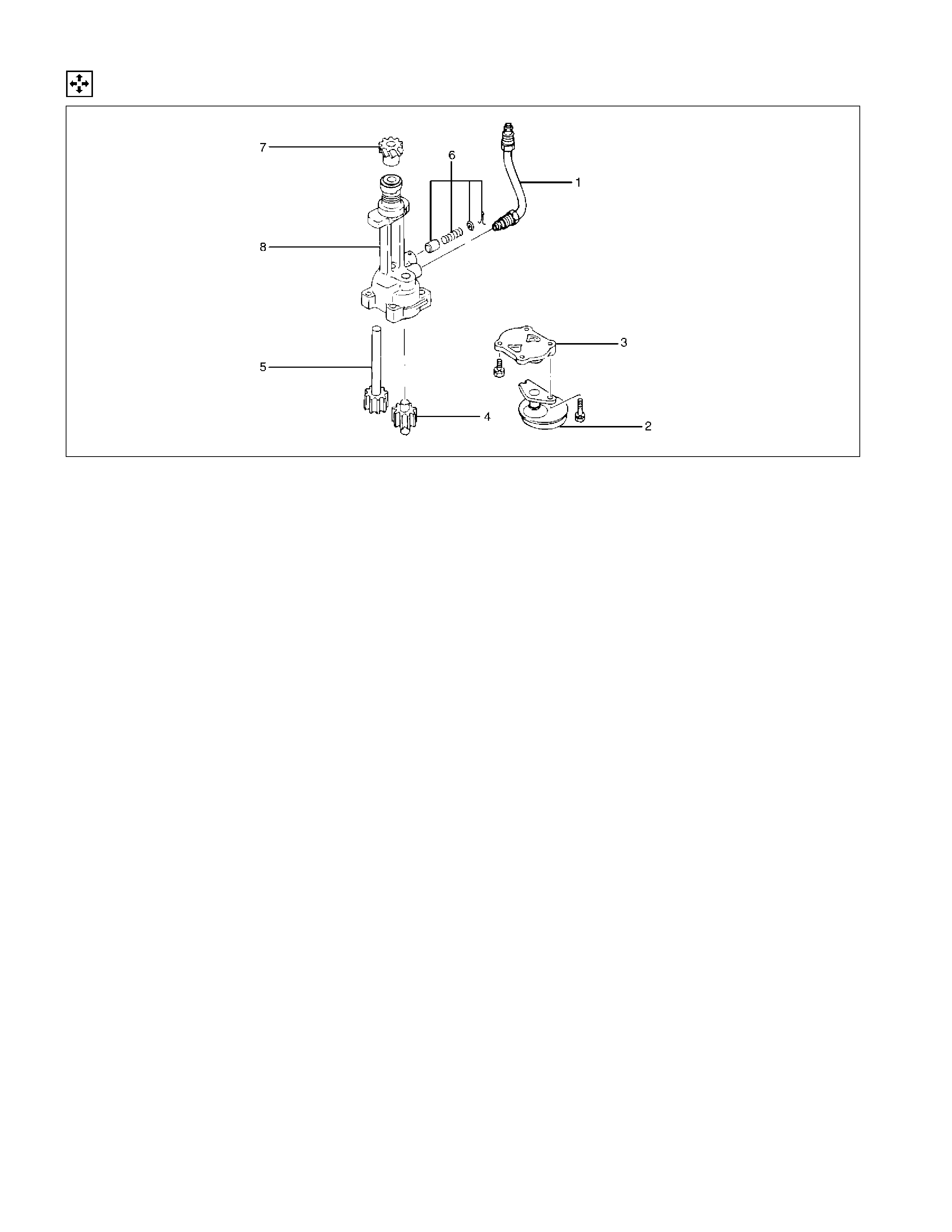
OIL PUMP
DISASSEMBLY
051R100005
Disassembly Steps
1. Oil pipe 5. Driven gear
2. Strainer 6. Relief valve assembly
3. Pump cover 7. Pinion gear
4. Driven gear with bushing 8. Oil pump body
Disassembly procedure is shown in the illustration above in numerical order.
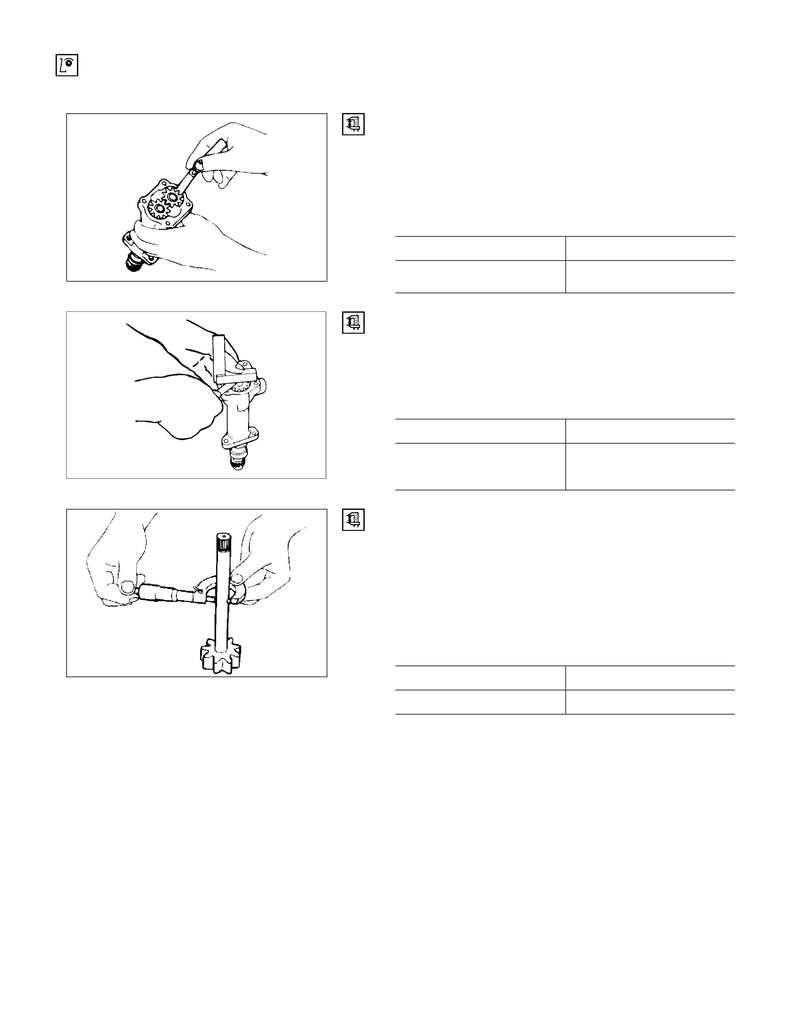
INSPECTION AND REPAIR
Make the necessary adjustments, repairs, and part replacements if excessive wear or damage is discovered during
inspection. Gear Teeth and Body Inner Wall Clearance
Use a feeler gauge to measure the clearance between the
gear teeth and the body inner wall.
If the clearance between the gear teeth and the body
inner wall exceeds the specified limit, either the gear or
the body must be replaced.
Gear teeth and body inner wall clearance mm (in)
Standard Limit
051RY00001
0.14 (0.0055) 0.20 (0.0079)
Gear and Body Clearance
Use a feeler gauge to measure the clearance between the
body and the gear.
If the clearance between the gear and the body exceeds
the specified limit, the body must be replaced.
Gear and body clearance mm (in)
Standard Limit
RTW46ASH002701
0.06 (0.024) 0.15 (0.0059)
Drive Shaft and Oil Pump Body Clearance
Use a micrometer to measure the drive shaft outside
diameter.
Use an inside dial indicator to measure the pump body
inside diameter.
If the clearance between the drive shaft and the oil pump
body exceeds the specified limit, the oil pump assembly
must be replaced.
Drive shaft and oil pump body clearance mm (in)
Standard Limit
0.04 (0.0016) 0.20 (0.0079)
051RY00003
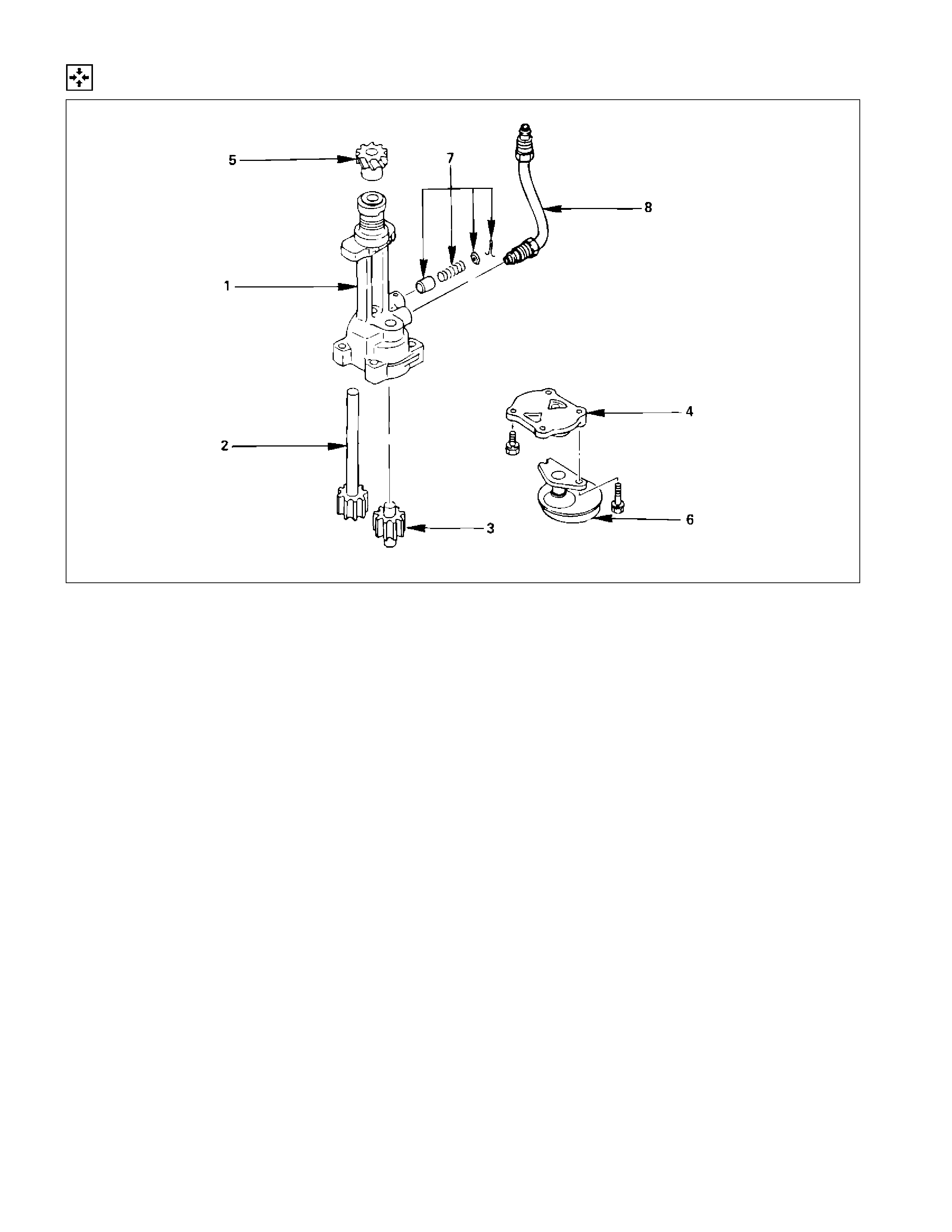
REASSEMBLY
051R100006
Reassembly Steps
1. Oil pump body 5. Pinion gear
2. Drive gear 6. Strainer
3. Driven gear 7. Relief valve assembly
4. Pump cover 8. Oil pipe
Reassembly procedure is shown in the illustration above in numerical order.
Pump cover fixing bolts torque: 16 N·m (1.6 kg·m/12 lb·ft)
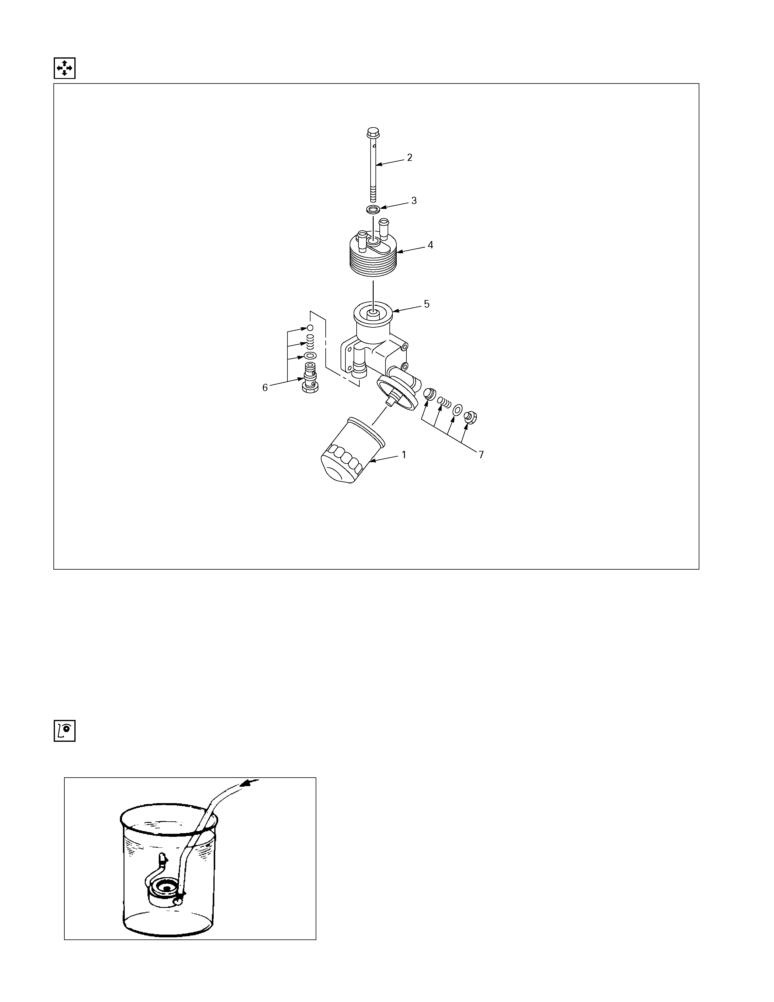
OIL FILTER AND OIL COOLER
DISASSEMBLY
050R300004
Disassembly Steps
1. Oil filter cartridge 5. Body
2. Bolt 6. Oil cooler relief valve
3. Gasket 7. Regulating valve
4. Oil cooler
Disassembly procedure is shown in the illustration above in numerical order.
INSPECTION AND REPAIR
Make the necessary adjustments, repairs, and part replacements if excessive wear or damage is discovered during
inspection.
Oil Cooler
Water Leakage at Water Passage
1. Plug one side of the oil cooler water passage.
2. Submerge the oil cooler in water.
3. Apply compressed air (200 kPa (2 kg/cm2 /28 psi)) to
the other side of the oil cooler water passage.
Check for air bubbles escaping from the oil cooler. Air bubbles
indicate the presence of a leak in the oil cooler's water
passage. If the oil cooler is leaking, it must be replaced.
050RY00002

REASSEMBLY
050R300003
Reassembly Steps
1. Body 5. Gasket
2. Regulating valve 6. Bolt
3. Oil cooler relief valve 7. Oil filter cartridge
4. Oil cooler
The numbers in the above illustration represent the order of reassembly.
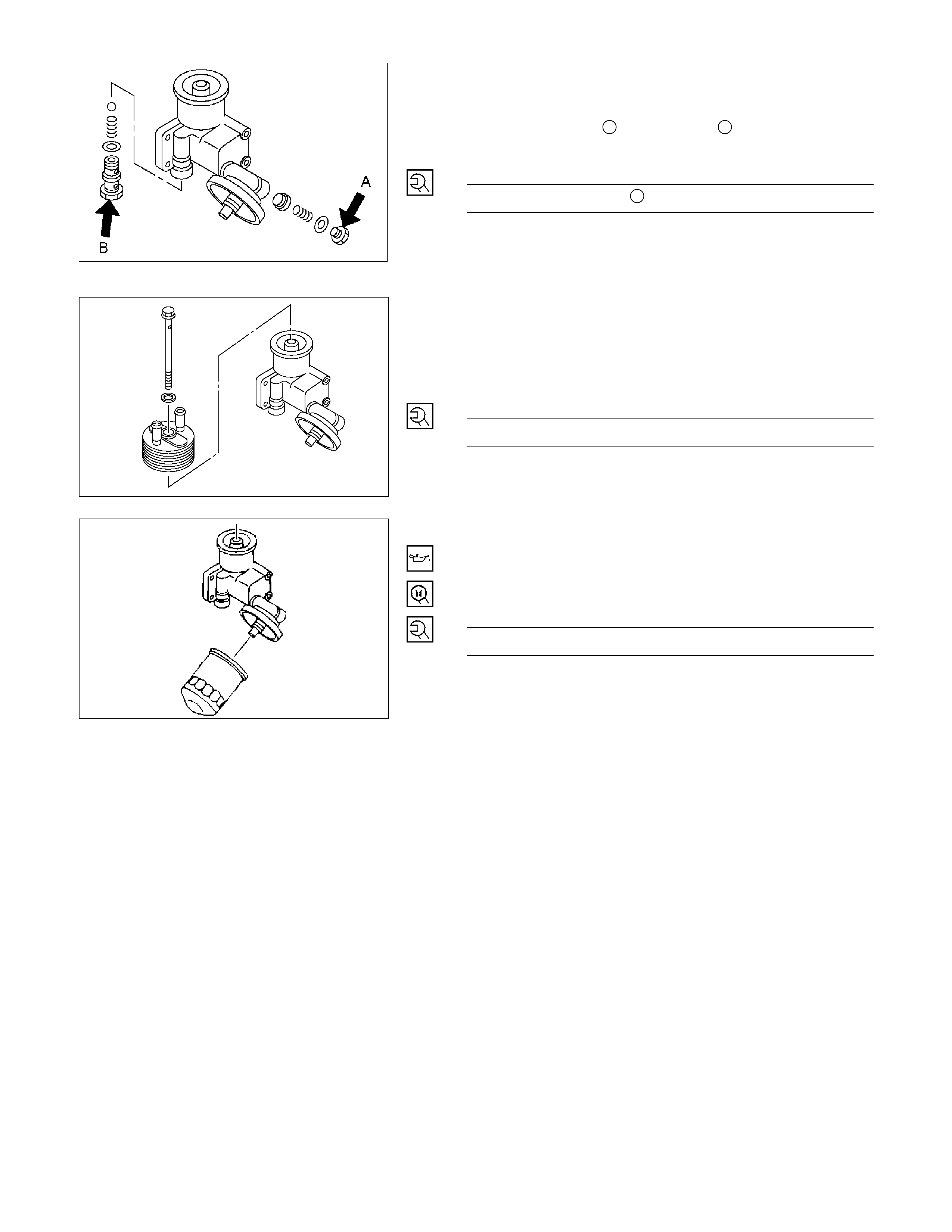
RTW46ASH001701
1. Body
2. Oil Filter Safety Valve
3. Oil Cooler Safety Valve
Tighten the oil filter A and oil cooler B relief valve to the
specified torque.
Regulating Valve N·m (kg·m/lb·ft)
A 64 (6.5/48)
4. Oil Cooler
5. Gasket
6. Bolt
Tighten bolt with gasket and oil cooler to the specified
torque.
Bolt Torque N·m (kg·m/lb·ft)
40 (4.1/30)
7. Oil Filter Cartridge
1) Apply engine oil to the O-ring.
2) Tighten the oil filter cartridge to the specified torque.
Filter wrench: 5-8840-0201-0
Oil Filter Cartridge Torque N·m (kg·m/lb·ft)
18 (1.8/13)
050R300006
050RY00004
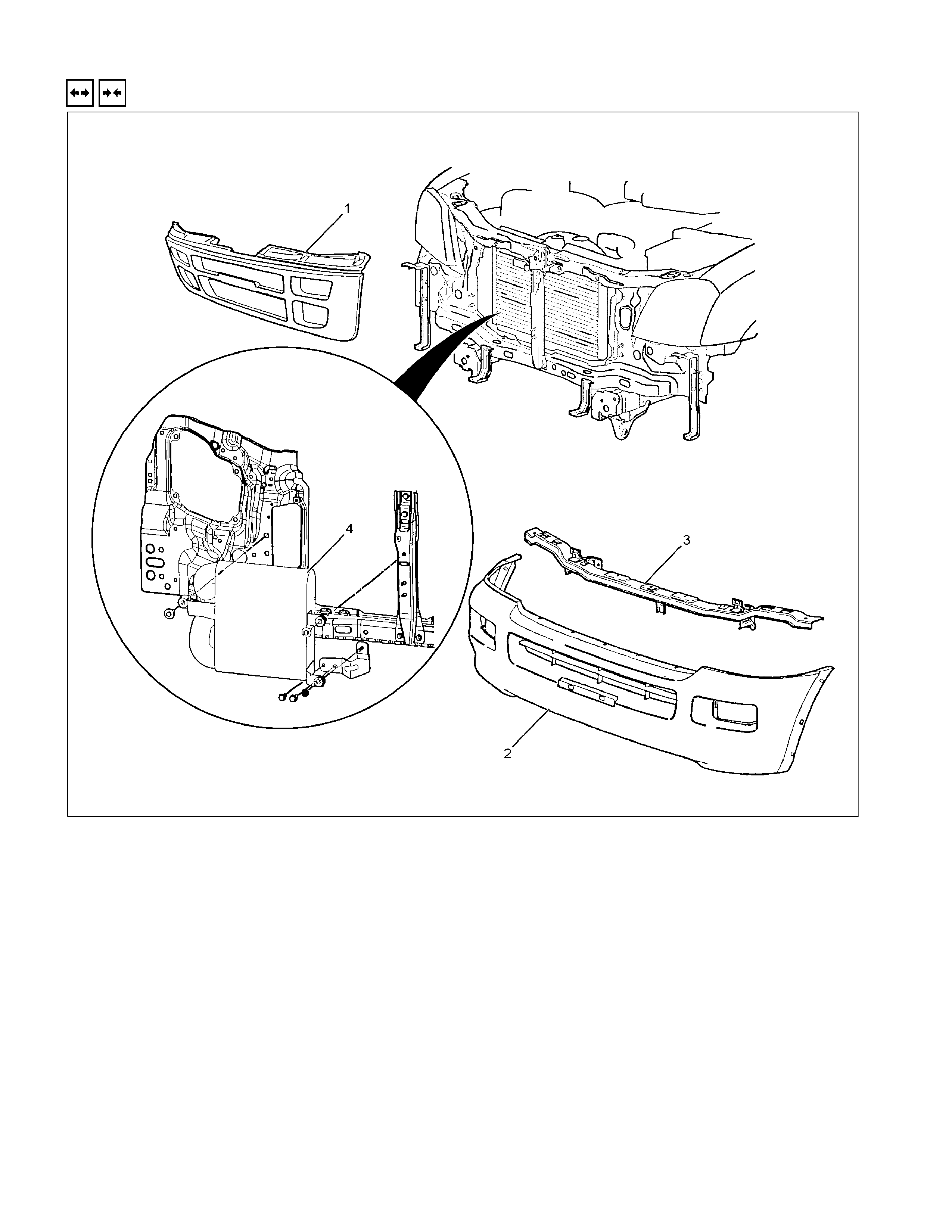
INTER COOLER
REMOVAL AND INSTALLATION
RTW46ALF001001
Removal Steps
1. Radiator grille
2. Front bumper fascia
3. Front bumper impact support assembly
4. Inter cooler
Installation Steps
4. Inter cooler
3. Front bumper impact support assembly
2. Front bumper fascia
1. Radiator grille
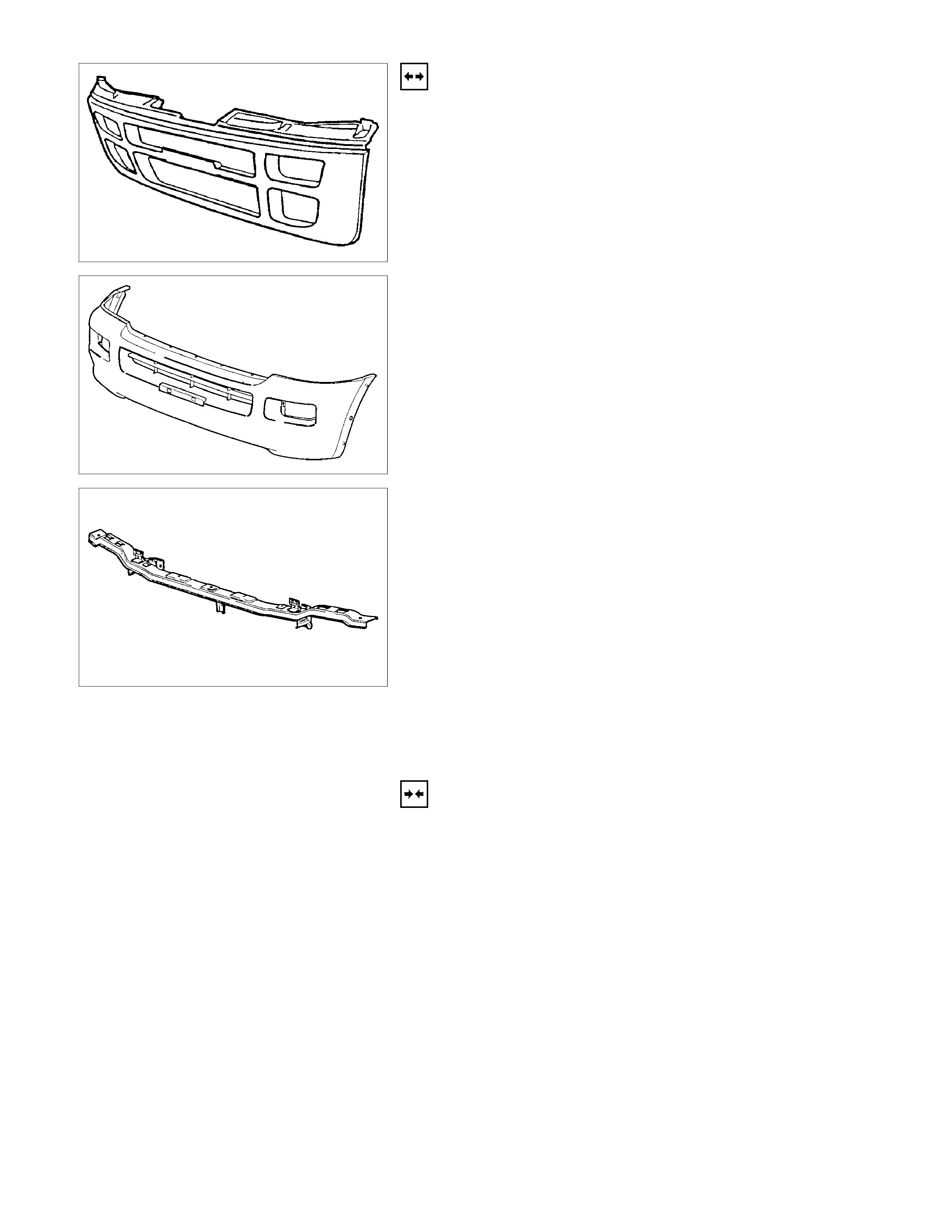
RTW36ASH000601
REMOVAL
1. Radiator Grille
• Refer to removal procedure in Sheet Metal section.
RTW36ASH000501
2. Front Bumper Fascia
• Remove the nine clips and four screws.
• Disconnect the fog light harness connectors.
RTW46ASH002101
3. Front Bumper Impact Support Assembly
• Remove the nut and two bolts.
4. Inter Cooler
• Remove the nut and two bolts.
• Disconnect the air hose.
INSTALLATION
4. Inter Cooler
• Tighten the nut and two bolts.
3. Front Bumper Impact Support Assembly
• Tighten the nut and two bolts.
2. Front Bumper Fascia
• Install the nine clips and four screws.
• Connect the fog light harness connectors.
1. Radiator grille
• Refer to installation procedure in Sheet Metal section.
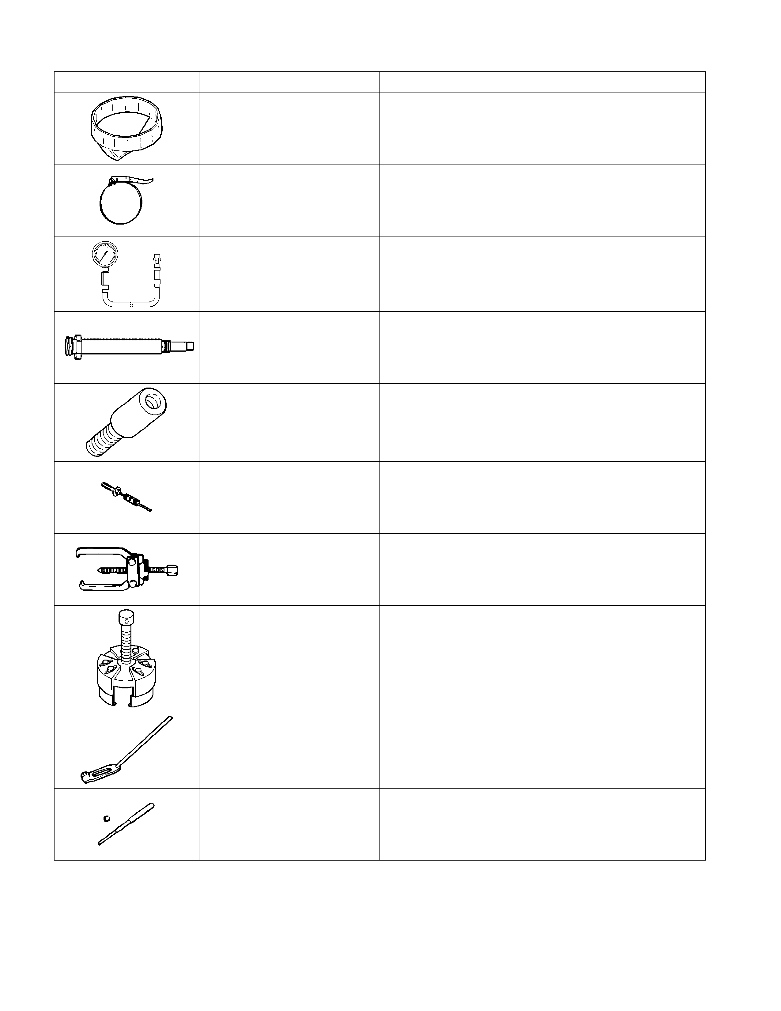
SPECIAL TOOLS
Illustration Tool Number Tool Name
5-8840-0201-0 Filter Wrench
5-8840-0253-0 Filter Wrench
5-8840-2675-0 Compression Gauge
5-8531-7001-0 Adapter; Compression Gauge
5-8840-2723-0 Nozzle Holder Remover
5-8840-0019-0 Sliding Hammer
5-8521-0002-0 Universal Puller
5-8840-2360-0 Oil Seal Remover
9-8523-1423-0 Spring Compressor
9-8523-1212-0 Valve Guide Replacer
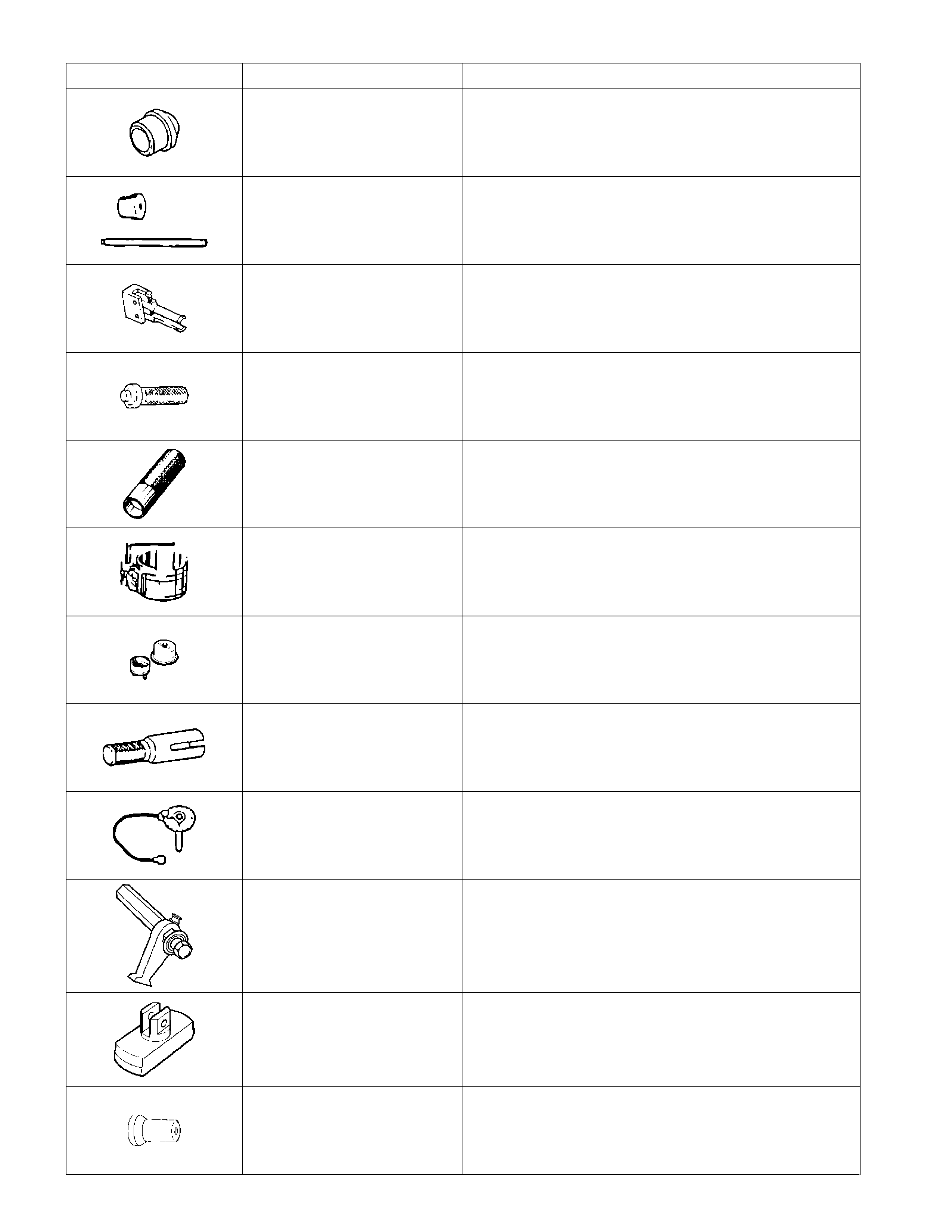
Illustration Tool Number Tool Name
5-8840-2040-0
(4JA1L/TC)
5-8840-2313-0 (4JH1TC) Cylinder Liner Installer
5-8840-2038-0 Bearing Replacer; Camshaft
5-8840-2000-0 Pilot Bearing Remover
5-8522-0024-0 Pilot Bearing Installer
5-8840-2033-0 Oil Seal Installer
5-8840-9018-0 Piston Ring Compressor
5-8840-2359-0 Oil Seal Installer
9-8522-0020-0 Crankshaft Timing Gear Installer
5-8840-0266-0 Angle Gauge
5-8840-0214-0 Gear Stopper
5-8840-2039-0
(4JA1L/TC)
5-8840-2304-0 (4JH1TC)
Cylinder Liner Remover
5-8840-2361-0 Front Oil Seal Installer
