
SECTION 6B - ENGINE COOLING
Main Data and Specifications
General Description
Coolant Flow
Water Pump
Thermostat
Radiator
Coolant Specification
Coolant Capacity
Diagnosis
Draining and Refilling Cooling System
Engine Coolant Filling Procedure
Water Pump
Removal
Inspection and Repair
Installation
Thermostat
Removal
Inspection and Repair
Installation
Radiator
Radiator and Associated Parts
Removal
Inspection and Repair
Installation
Fan Clutch with Cooling Fan
Inspection and Repair
MAIN DATA AND SPECIFICATIONS
Description
Item M/T A/T
Cooling system
Water pump type
Pump to crankshaft speed ratio (To 1)
Delivery volume lit (US/UK gal)/min
Pump speed at 3000 rpm
Water temperature at 30°C (86°F)
Pump bearing type
Thermostat type
Valve initial opening temperature °C (°F)
Valve full opening temperature °C (°F)
Valve lift at fully open position mm (in)
Engine coolant forced circulation
Centrifugal impeller type
1.2
100 (26.3/22.2)
Double row shaft
Wax pellet with jiggle valve
82 (180)
95 (203)
9.5 (0.37)
Radiator Tube type corrugated
Heat radiation capacity 93.0 kw (79,980 kcal/h)
Heat radiation area 11.63 m2 (1.081 ft2)
Radiator front area 0.28 m2 (0.026 ft2)
Radiator dry weight 52 N (5.3 kg/11.7 lb) 53 N (5.4 kg/11.9 lb)
Radiator cap valve opening pressure 93.3 ∼ 122.7 kpa (13.5 ∼ 17.8 psi)
Engine coolant total capacity 10.1 litres 10.0 litres
GENERAL DESCRIPTION
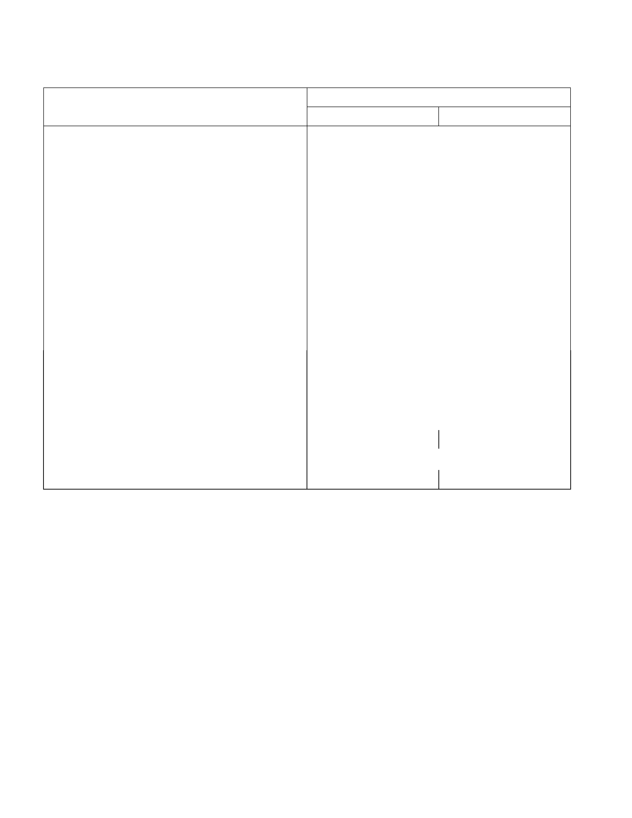
COOLANT FLOW
The engine cooling system consists of the radiator, the water pump, the cooling fan, and the thermostat.
To quickly increase cold engine coolant temperature for smooth engine operation, the coolant is circulated by the water
pump and thermostat through the bypass hose and back to the cylinder body.
The coolant does not circulate through the radiator.
When the coolant temperature reaches specified value, the thermostat will begin to open and a gradually increasing
amount of coolant will circulate through the radiator.
The thermostat will be fully open when the coolant temperature reaches specified value. All of the coolant is now
circulating through the radiator for effective engine cooling.
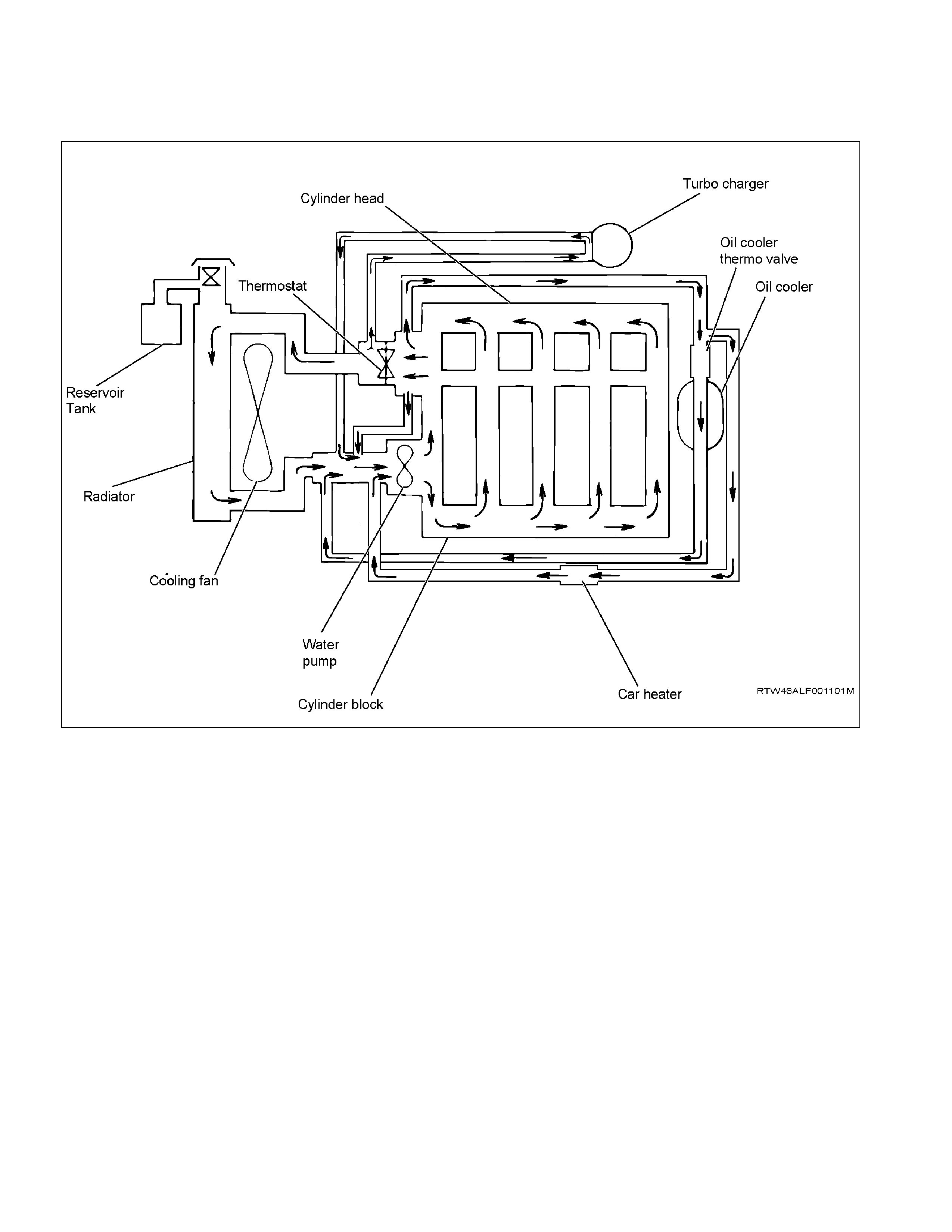
WATER PUMP
RTW36BSF000101
A centrifugal type water pump forcefully circulates the coolant through the cooling system.
The water pump is not disassembled type.
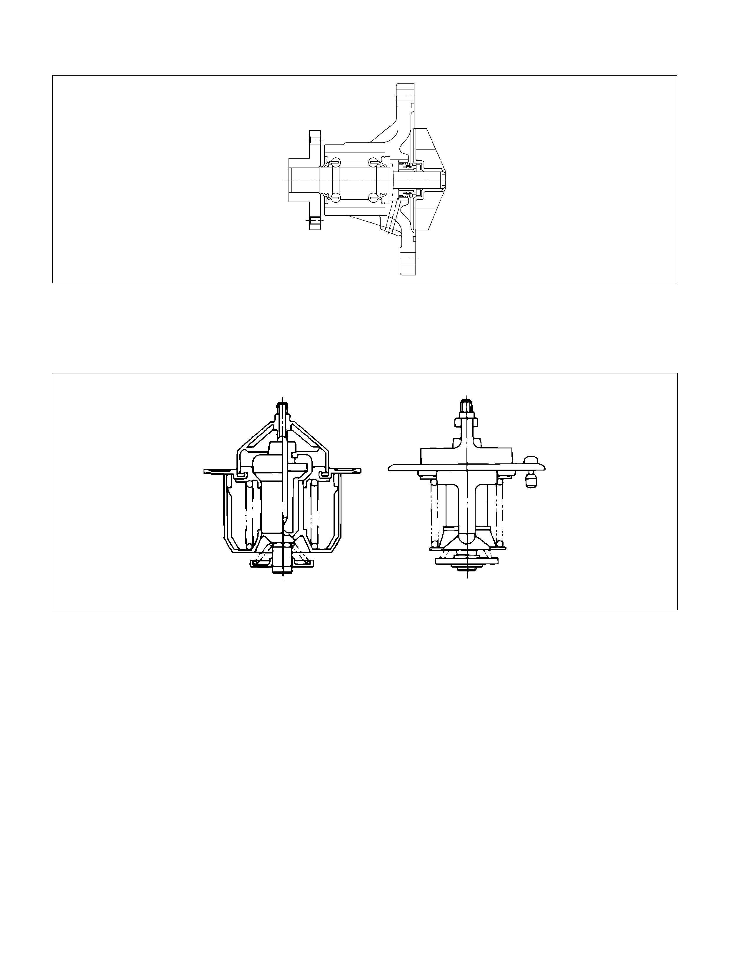
THERMOSTAT
030RY00005
A wax pellet type thermostat is used.
The jiggle valve accelerates engine warm-up.
110RS001
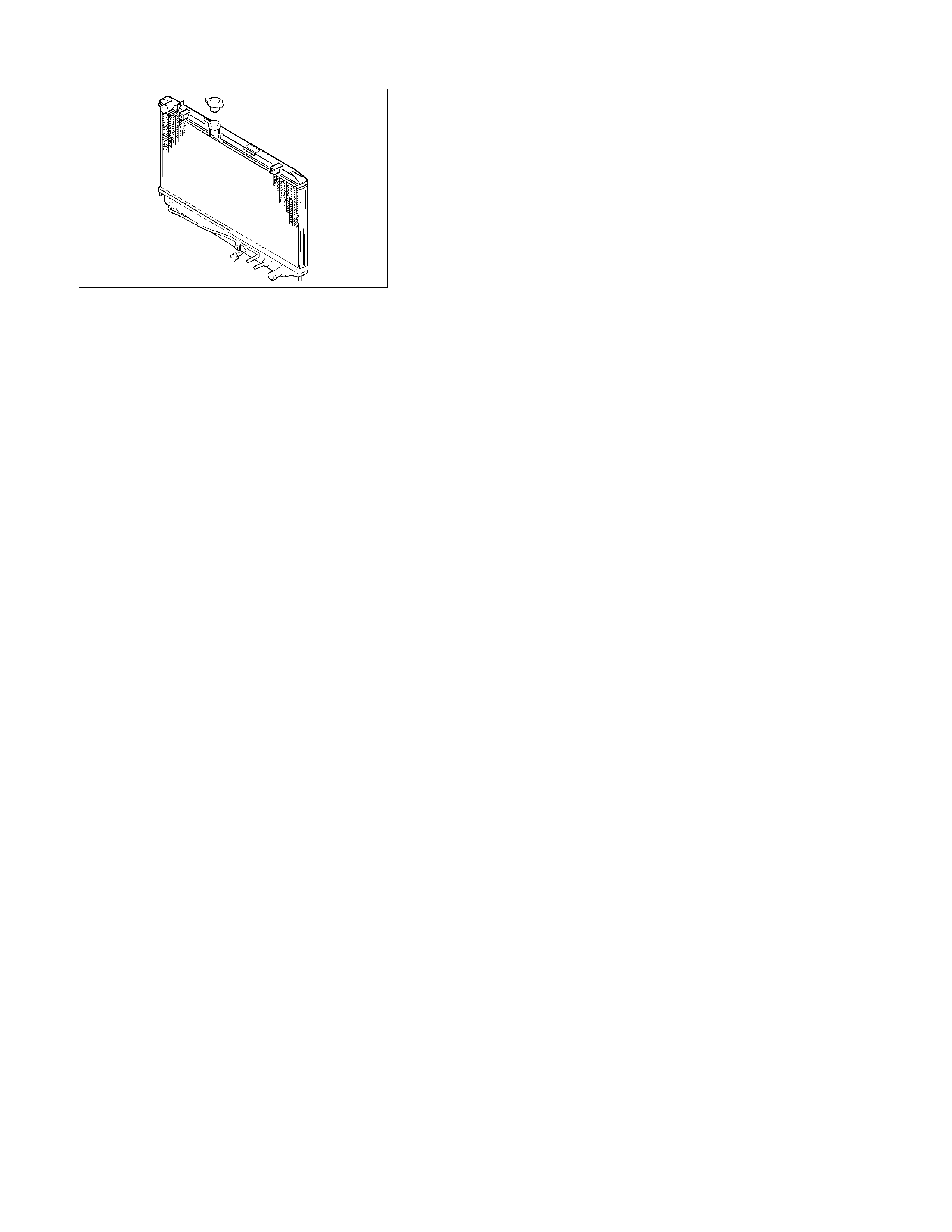
RADIATOR
The radiator is a tube type with corrugated fins. In order to
raise the boiling point of the coolant, the radiator is fitted with a
cap in which the valve is operated at 93.3 ∼ 122.7 kPa (13.5 ∼
17.8 psi) pressure. (No oil cooler provided for M/T).
COOLANT SPECIFICATION
To Holden Specification. Refer to Section 0B
COOLANT CAPACITY
Automatic Transmission: 10.0 litres
Manual Transmission: 10.1 litres
DIAGNOSIS
Engine Cooling Trouble
Symptom Possible Cause Action
Low engine coolant level Replenish
Thermo meter unit faulty Replace
Faulty thermostat Replace
Faulty engine coolant temperature
sensor Repair or replace
Clogged radiator Clean or replace
Faulty radiator cap Replace
Low engine oil level or use of
improper engine oil Replenish or change oil
Clogged exhaust system Clean exhaust system or replace
faulty parts
Faulty throttle position sensor Replace throttle valve assembly
Open or shorted throttle position
sensor circuit Repair or replace
Engine overheating
Damaged cylinder head gasket Replace
Engine overcooling Faulty thermostat Replace
Faulty thermostat Replace
Engine slow to warm–up
Thermo unit faulty Replace
Draining and Refilling Cooling System
Before draining the cooling system, inspect the system and
perform any necessary service to ensure that it is clean, does
not leak and is in proper working order. The engine coolant
(EC) level should be between the “MIN" and “MAX" lines of
reserve tank when the engine is cold. If low, check for leakage
and add EC up to the “MAX" line.
There should not be any excessive deposit of rust or scales
around the radiator cap or radiator filler hole, and the EC
should also be free from oil.
Replace the EC if excessively dirty.
P1010064
1. Completely drain the cooling system by opening the
drain plug at the bottom of the radiator.
2. Remove the radiator cap.
WARNING: To avoid the danger of being burned, do not
remove the cap while the engine and radiator are still hot.
Scalding fluid and steam can be blown out under
pressure.
3. Disconnect all hoses from the EC reserve tank.
Scrub and clean the inside of the reserve tank with
soap and water. Flush it well with clean water, then
drain it. Install the reserve tank and hoses.
4. Refill the cooling system with the EC using a solution
that is to Holden Specification. Refer Section 0B.

Engine Coolant Filling Procedure
NOTE:
Use only 50% water with 50% coolant to Holden HN2217
Specification.
1. Make sure that the engine is cool.
WARNING:
When the coolant is heated to a high temperature, be
sure not to loosen or remove the radiator cap,
otherwise you might get scalded by hot vapour or
boiling water. Wait until the coolant has become
cooler before opening the cap.
To open the radiator cap, put a piece of thick cloth on
the cap and loosen the cap slowly to reduce the
pressure.
2. Remove the radiator cap and add coolant up to the
filler neck.
3. Pour coolant into the reservoir tank up to “MAX” line.
4. Set the heater adjustment to the highest temperature
position to allow the coolant to circulate through the
heater system.
5. Tighten the radiator cap and start the engine. After
idling for 2 to 3 minutes, stop the engine and reopen
the radiator cap. If the coolant level is lower than the
filler neck, replenish the coolant level.
6. After replenishing the coolant, refit and tighten the
radiator cap. Warm up the engine at approximately
2000 rpm.
7. Continue to monitor the coolant temperature gauge.
When the coolant temperature gauge indicates that
the thermostat has opened, idle the engine for 5
minutes, then stop the engine.
8. When the engine has cooled, remove the radiator cap
and inspect that the coolant level is up to the filler
neck. Replenish if required. If there is an extreme
shortage of coolant, check the coolant system,
including the reservoir tank and hose, for leaks.
9. Pour coolant into the reservoir tank up to “MAX” line.
WATER PUMP
Read this Section carefully before performing any removal and installation procedure. This Section gives you important
points as well as the order of operation. Be sure that you understand everything in this Section before you begin.
6B_1
Removal
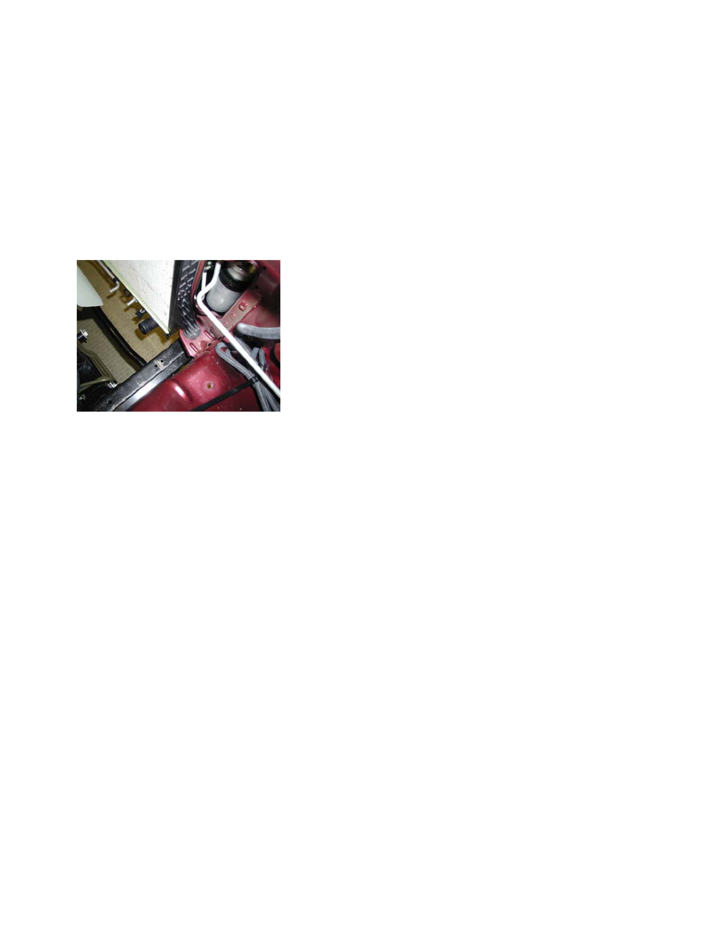
1. Radiator Upper Hose
1) Partially drain the engine coolant.
2) Remove the radiator upper hose.
2. Upper Fan Shroud
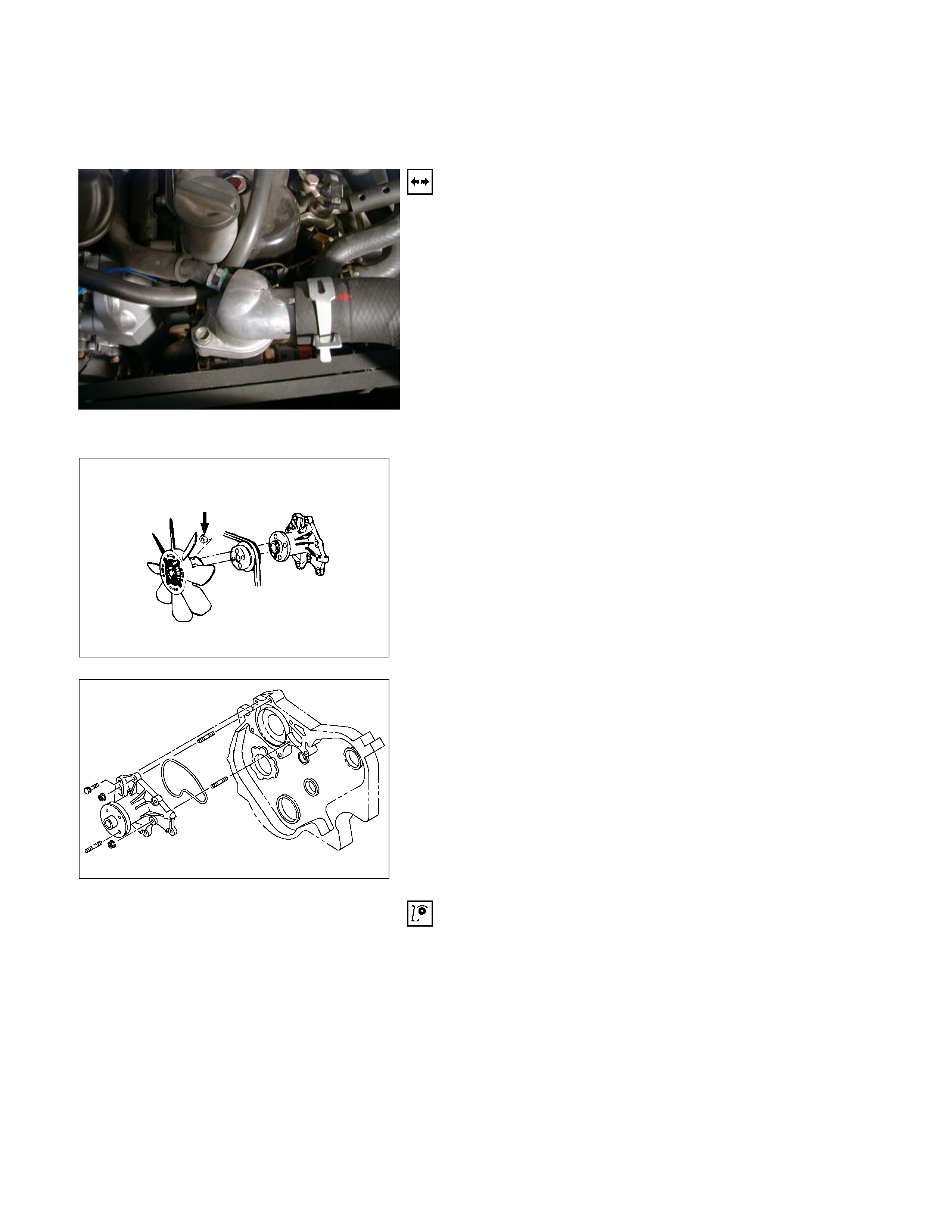
3. Fan and Fan Clutch
1) Loosen the fan clutch nuts.
2) Remove the fan together with the fan clutch. Take
care not to damage the radiator core.
4. Fan Drive Belt and Pulley
1) Loosen the tension adjust bolt on the generator.
2) Remove the fan drive belt with the fan pulley.
030R300001
5. Water Pump
1) Remove the water pump bolts.
2) Remove the water pump.
030R300002
Inspection and Repair
The water pump is not disassembled type.
Make necessary parts replacement if extreme wear or
damage is found during inspection. Should any of the
following problems occur, the entire water pump assembly
must be replaced.
Cracks in the water pump body
Coolant leakage from the seal unit
Excessive radial play or abnormal noise in the fan centre
when rotated by hand
Excessive thrust play in the fan centre (Standard play: less
than 0.2mm)
Cracks or corrosion in the impeller
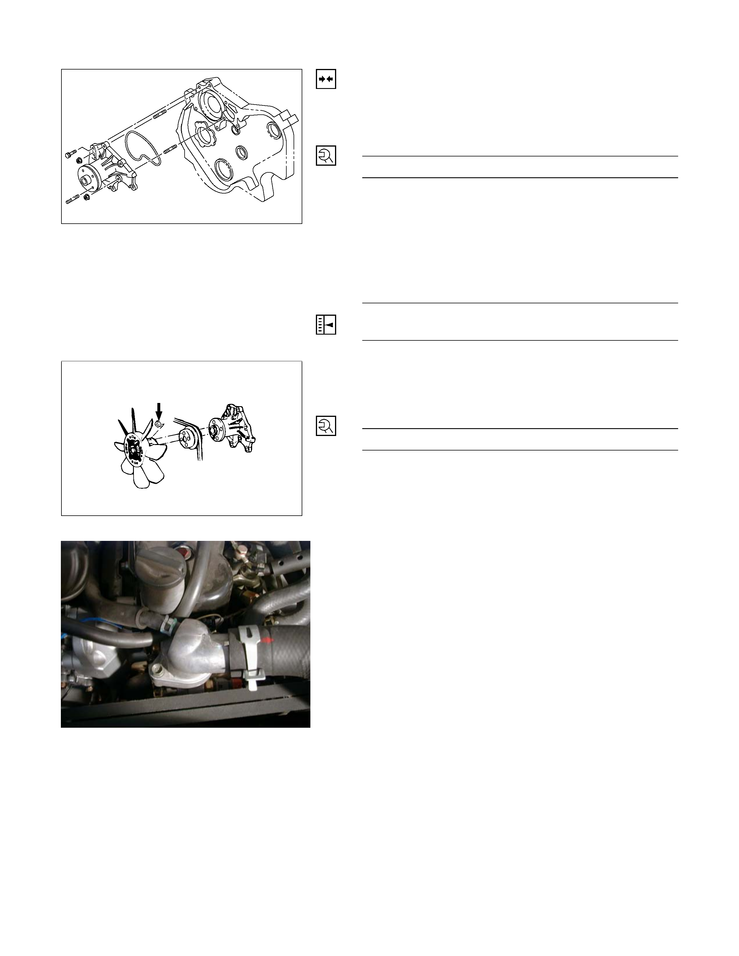
Installation
1. Water Pump
1) Install the water pump with new gasket.
2) Tighten bolts and nuts to specified torque.
Water Pump Bolt/Nut Torque N·m (kg·m/lb·ft)
20 (2.0/14)
2. Fan Drive Belt and Pulley
1) Install the fan drive belt and fan pulley.
2) Apply tension to the fan drive belt by moving the
generator.
3) Apply a force of 98 N (10 kg/22 lb) to the drive belt
mid-portion to check the drive belt deflection.
Fan Drive Belt Deflection mm (in)
New belt: 4-7 (0.16-0.28)
Reuse belt: 6-9 (0.24-0.35)
030R300002
030R300001
3. Fan and Fan Clutch
1) Install the fan and fan clutch to pulley.
2) Tighten the nuts to specified torque.
Fan Clutch Nut Torque N·m (kg·m/lb·in)
8 (0.8/69)
4. Upper Fan Shroud
6B_1
5. Radiator Upper Hose
1) Connect the radiator upper hose to the water outlet
pipe.
2) The knob of clamp shall be directed to horizontal side.
3) Replenish the engine coolant.

THERMOSTAT
Read this Section carefully before performing any removal and installation procedure. This Section gives you important
points as well as the order of operation. Be sure that you understand everything in this Section before you begin.
6B_1
Removal
1. Radiator Upper Hose
1) Partially drain the engine coolant.
2) Remove the radiator upper hose.
2. Water Outlet Pipe
1) Disconnect the turbocharger-cooling pipe from outlet
pipe.
2) Loosen the fixing bolts and remove the water outlet
bolts.
3. Thermostat
Remove the thermostat from the thermostat housing.
Take care not to damage the thermostat.
031R300003
Inspection and Repair
Make the necessary adjustments, repairs, and part
replacements if excessive wear or damage is discovered
during inspection.
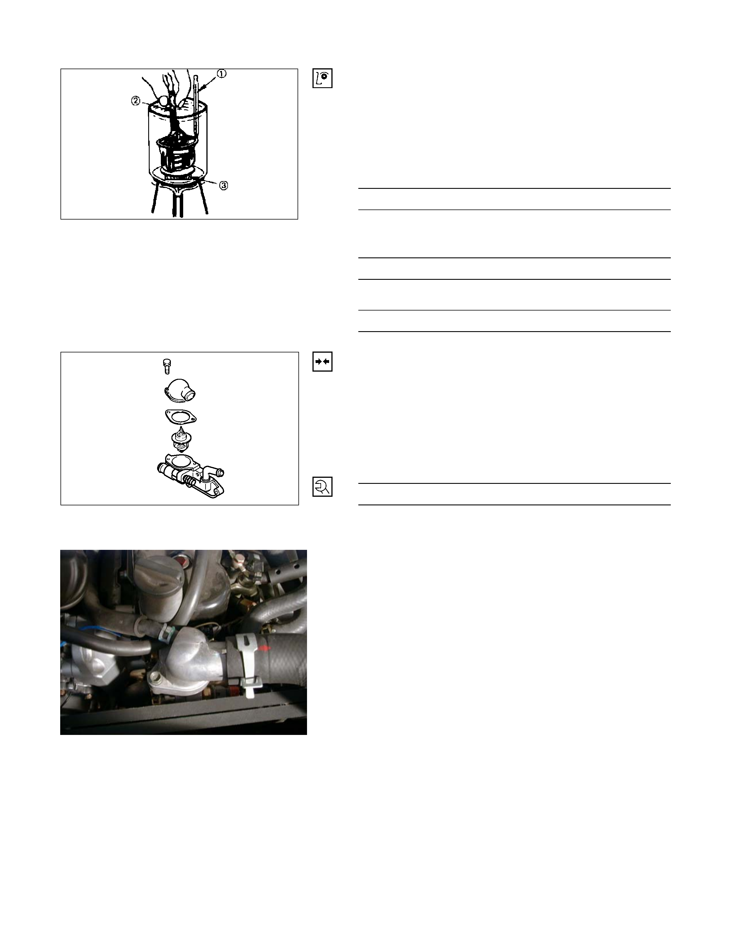
031RY00005
c Thermometer
d Agitating rod
e Wooden piece
Operating Test of Thermostat
1. Completely submerge the thermostat in water.
2. Heat the water.
Stir the water constantly to avoid direct heat being
applied to the thermostat.
3. Check the thermostat initial opening temperature.
Thermostat Initial Opening Temperature °C (°F)
82 (180)
4. Check the thermostat full opening temperature.
Thermostat Full Opening Temperature °C (°F)
95 (203)
Valve Lift At Fully Open Position mm (in)
9.5 (0.37)
Installation
1. Thermostat
Install the thermostat to the thermostat housing.
2. Water Outlet Pipe
1) Install the water outlet pipe with new gasket to the
thermostat housing.
2) Tighten the outlet pipe bolt to specified torque.
Outlet Pipe Bolt Torque N·m (kg·m/lb·ft)
19 (1.9/14)
3) Connect the turbocharger-cooling pipe to outlet pipe.
031R300003
3. Radiator Upper Hose
1) Connect the radiator upper hose to the water outlet
pipe.
2) The knob of clamp shall be directed to horizontal side.
3) Replenish the engine coolant.
6B_1
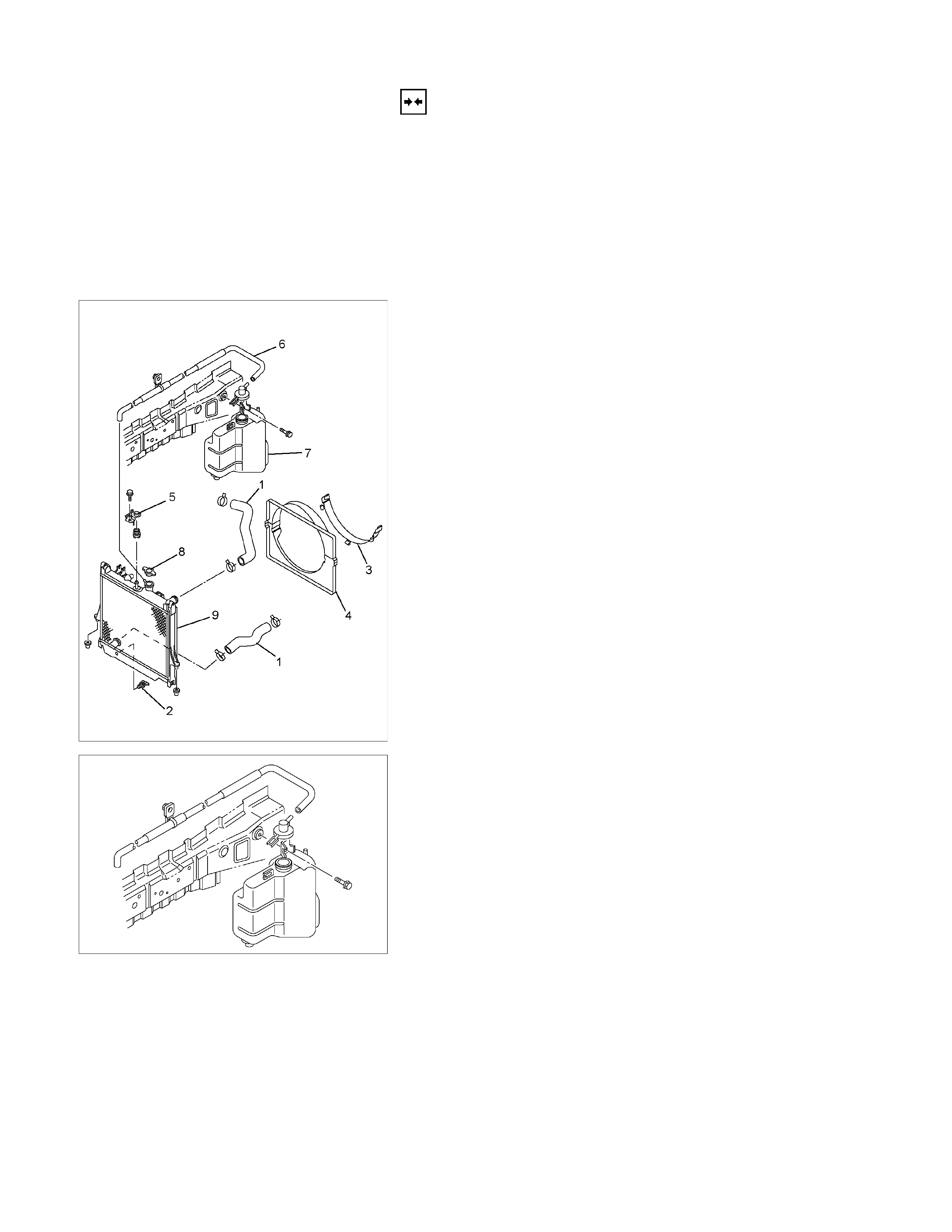
RADIATOR
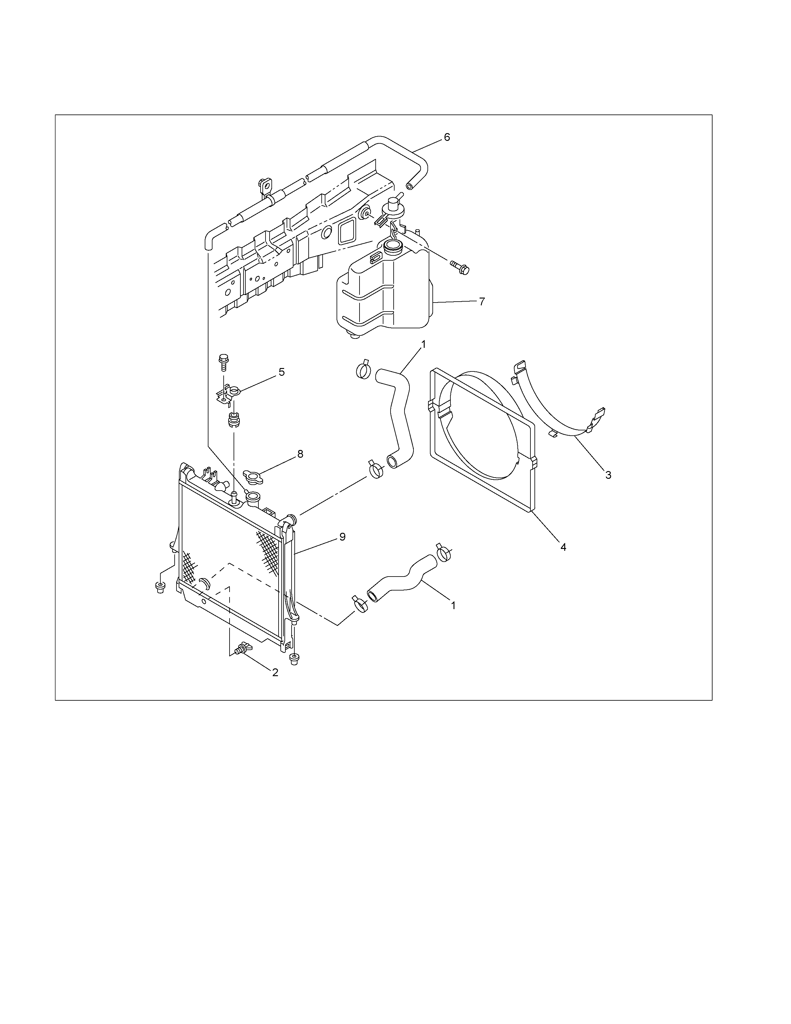
Radiator and Associated Parts
RTW36BLF000101
Legend
1. Radiator Hose
2. Drain Plug
3. Fan Guide, Lower
4. Fan Guide
5. Bracket
6. Reserve Tank Hose
7. Reserve Tank
8. Radiator Cap
9. Radiator Assembly
P1010064
Removal
1. Disconnect battery ground cable.
2. Loosen the drain plug to drain EC.
3. Disconnect oil cooler hose on automatic transmission
(A/T).
4. Disconnect radiator inlet hose and outlet hose from
the engine.
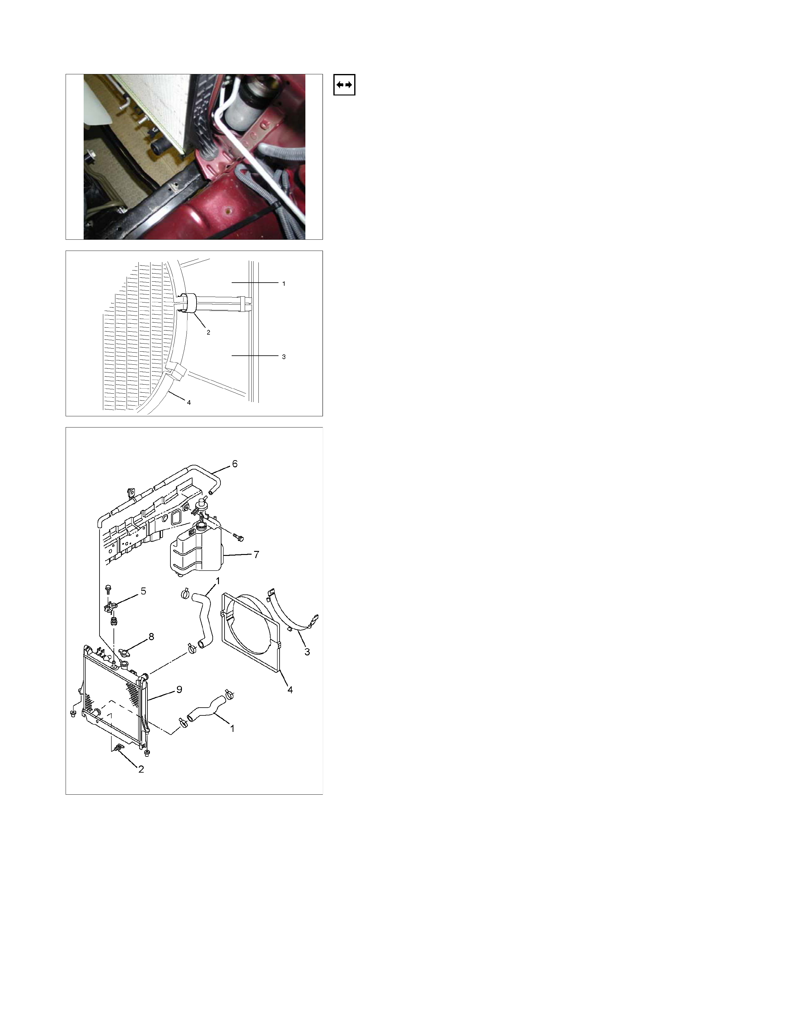
110RW001
5. Remove fan guide (1), clips (2) on both sides and the
bottom lock, then remove lower fan guide (3) with fan
shroud (4).
6. Disconnect the reserve tank hose (6) from radiator.
RTW36BMH000101
7. Remove bracket (5).
8. Lift up and remove the radiator assembly with hose,
taking care not to damage the radiator core with the
fan.
Inspection and Repair
Make the necessary adjustments, repairs, and part
replacements if excessive wear or damage is discovered
during inspection.
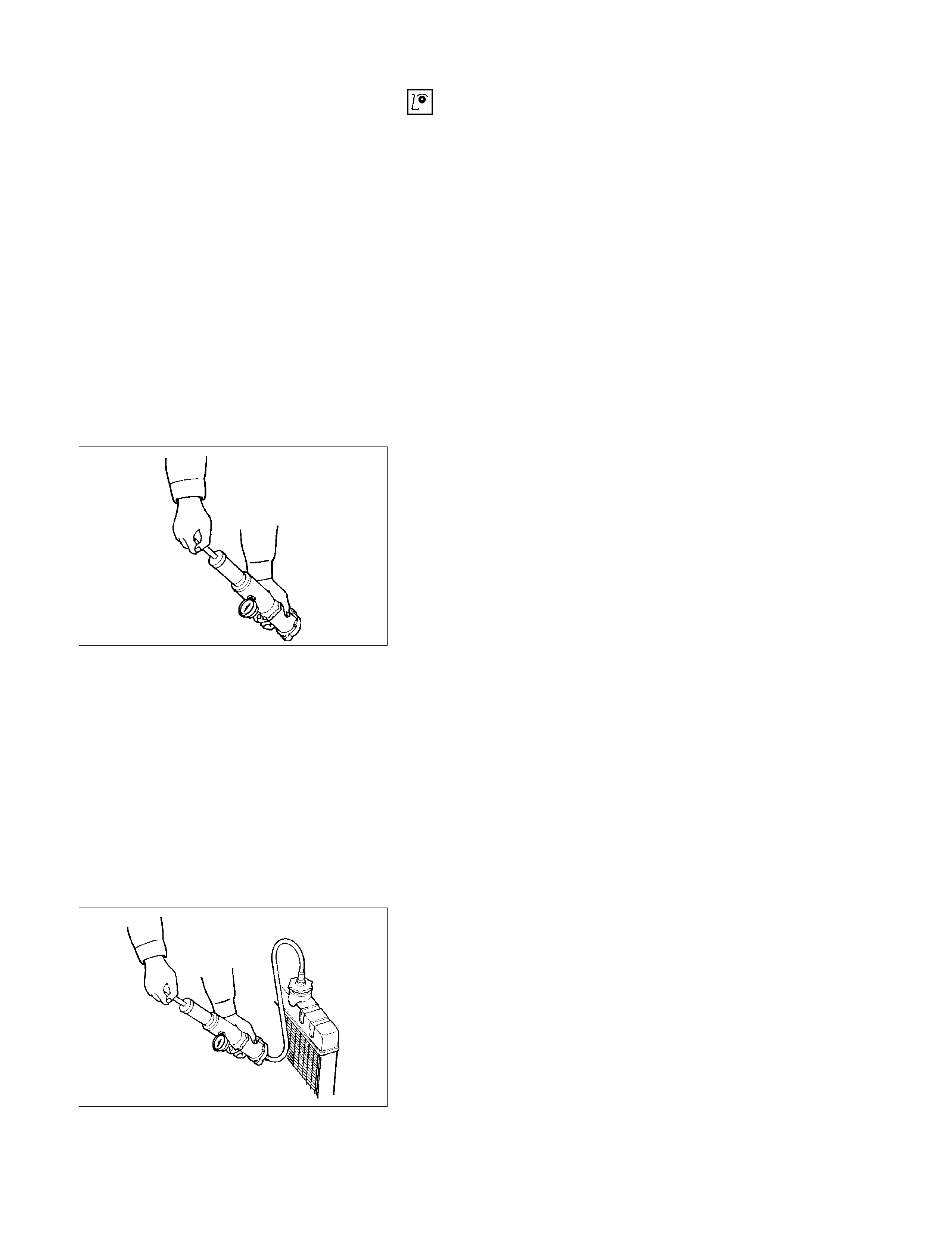
Radiator Cap
Measure the valve opening pressure of the pressurizing
valve with a radiator filler cap tester.
Replace the cap if the valve opening pressure is outside
the standard range.
Valve opening pressure
kPa (psi) 93.3 ∼ 122.7 (13.5 ∼17.8)
Cap tester: 5–8840–0277–0
Adapter: 5–8840–2603–0
Check the condition of the vacuum valve in the centre of
the valve seat side of the cap. If considerable rust or dirt is
found, or if the valve seat cannot be moved by hand,
clean or replace the cap.
110RS006
Valve opening vacuum
kPa (psi) 1.96 ∼ 4.91 (0.28 ∼ 0.71)
Radiator Core
1. A bent fin may result in reduced ventilation and
overheating may occur. All bent fins must be
straightened. Pay close attention to the base of the fin
when it is being straightened.
2. Remove all dust, insects, and other foreign material.
Flushing the Radiator
Thoroughly wash the inside of the radiator and the engine
coolant passages with cold water and mild detergent.
Remove all signs of scale and rust.
110RS005
Cooling System Leakage Check
Use a radiator cap tester to force air into the radiator
through the filler neck at the specified pressure of 196 kPa
(28.5 psi) with a cap tester:
• Leakage from the radiator
• Leakage from the coolant pump
• Leakage from the water hoses
• Check the rubber hoses for swelling.
Cap tester: 5–8840–0277–0
Adapter: 5–8840–2603–0
Installation
1. Install radiator assembly (9) with hose, taking care not
to damage the radiator core with a fan blade.
2. Support the radiator upper tank with the bracket (5)
and secure the radiator.
3. Connect reserve tank hose (6).
4. Install lower fan guide (3).
5. Connect radiator inlet hose and outlet hose (1) to the
engine.
RTW36BMH000101
6. Connect oil cooler hose to automatic transmission.
7. Connect battery ground cable.
RTW36BSH000101
8. Pour engine coolant up to filler neck of radiator, and
up to MAX mark of reserve tank.
Refer to Draining and Refilling Cooling System in this
Section.
FAN CLUTCH WITH COOLING FAN
INSPECTION AND REPAIR
Make necessary correction or parts replacement if wear, damage or any other abnormal condition are found through
inspection.
033R300001
Visually inspect for damage, leak (silicon grease) or other
abnormal conditions.
1. Inspection (on-vehicle)
1) Turn the fan clutch by hand when in a low
temperature condition before starting the engine, and
confirm that it can be turned readily.
2) Start the engine to warm it up until the temperature at
the fan clutch portion gets to around 80°C. Then stop
the engine and confirm that the fan clutch can be
turned with considerable effort (clutch torque) when
turned by hand.
If the fan clutch rotates more readily, however, this
indicates that the silicone grease is leaking internally.
Replace the fan clutch with a new one.
033RY00011
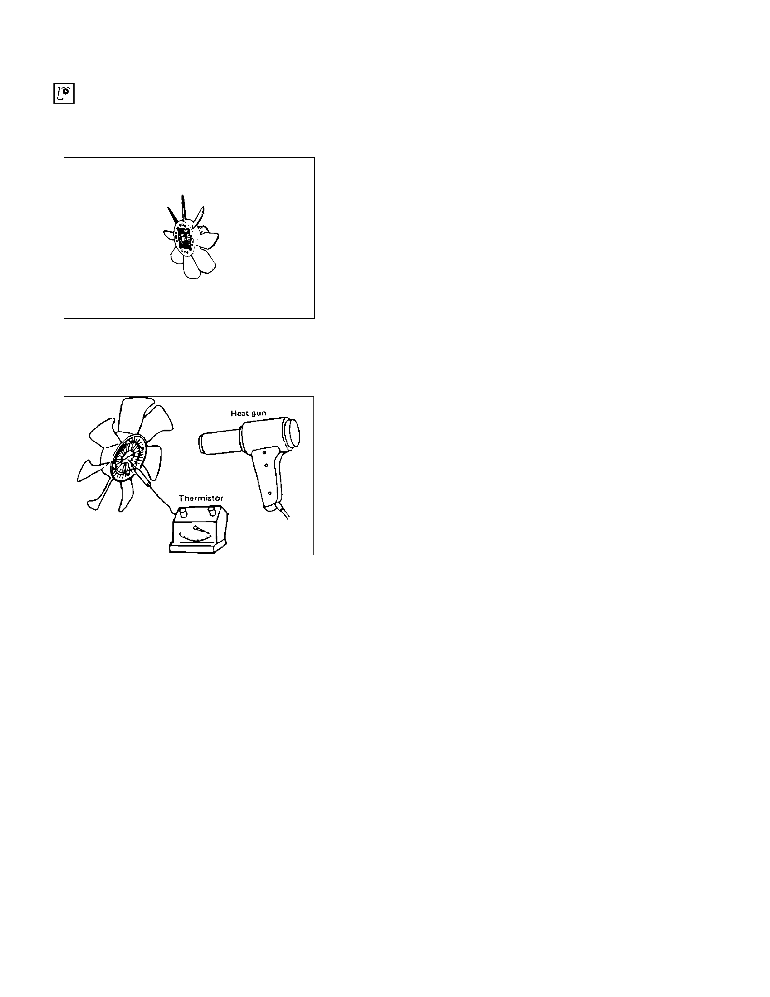
2. Inspection (in unit)
Warm up the bimetal of the fan clutch by using the heat
gun until the temperature gets to about 80°C when
measured with the thermistor. Then confirm that the fan
clutch can be turned with considerable effort (clutch
torque).
If the fan clutch rotates more readily at this time, this
indicates that the silicone grease is leaking internally.
Replace the fan clutch with a new one.