

MAIN DATA AND SPECIFICATIONS
Description
Item 60A 80A
Generator
Type
AC generator with IC regulator and vacuum pump
Hitachi LR160-503E Hitachi LR180-513B
Voltage V
Drive and rotation
Ground polarity
12
V-belt, clockwise viewed from the drive pulley
Negative
Maximum output A 60 80
Engine speed ratio to 1 1.788
Maximum speed rpm 11,000
Weight with vacuum pump kg (lb) 5.8 (12.8) 6.4 (14.1)
Vacuum Pump
Delivery volume cm3/rev
Exhaust Characteristic
Maximum vacuum
50
-66.7 kPa (-500 mm Hg) build up time 21 seconds or less at 1,000
rpm
7 seconds or less at 5,000 rpm
-90.7 kPa (-680 mmHg) or more
Starter Motor
Type
Solenoid controlled
Hitachi S13-555
12
2.3
8.76
300
Rated voltage V
Rated output kW
Load characteristics
Terminal voltage V
Load current A
Weight kg (Ib) 4.7 (10.4)
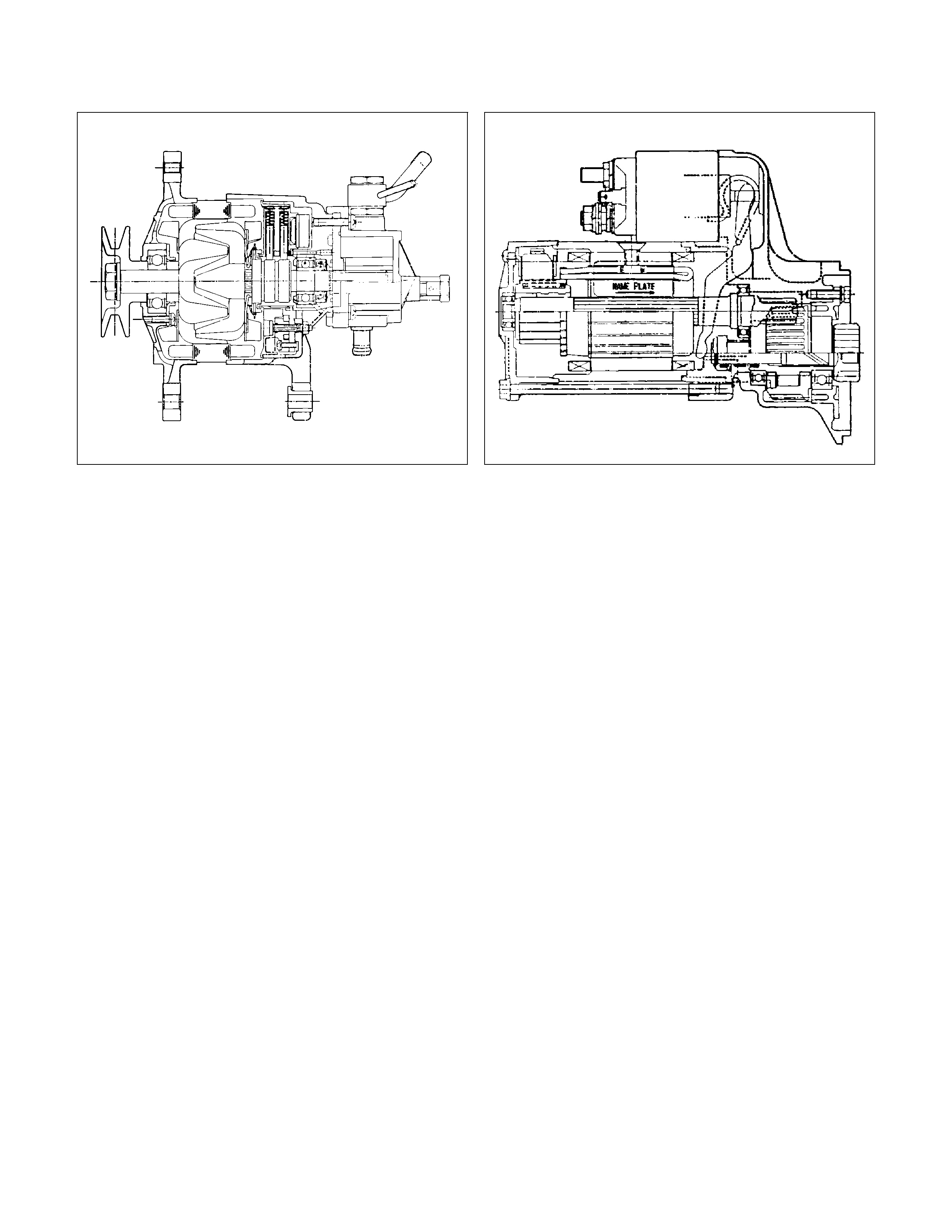
GENERAL DESCRIPTION
GENERATOR STARTER MOTOR
066L300004 065L300002
The basic charging system is the IC integral regulator charging system. The internal components are connected
electrically as shown in charging circuit diagram.
The generator features a solid state regulator that is mounted inside the generator. All regulator components are
enclosed into a solid mould, and this unit along with the brush holder assembly is attached to the slip ring end frame.
The generator voltage setting cannot be adjusted.
The starter motor circuit is composed of a 4-pole 4-brush type direct current series motor. The starter motor circuit
utilizes negative ground polarity.
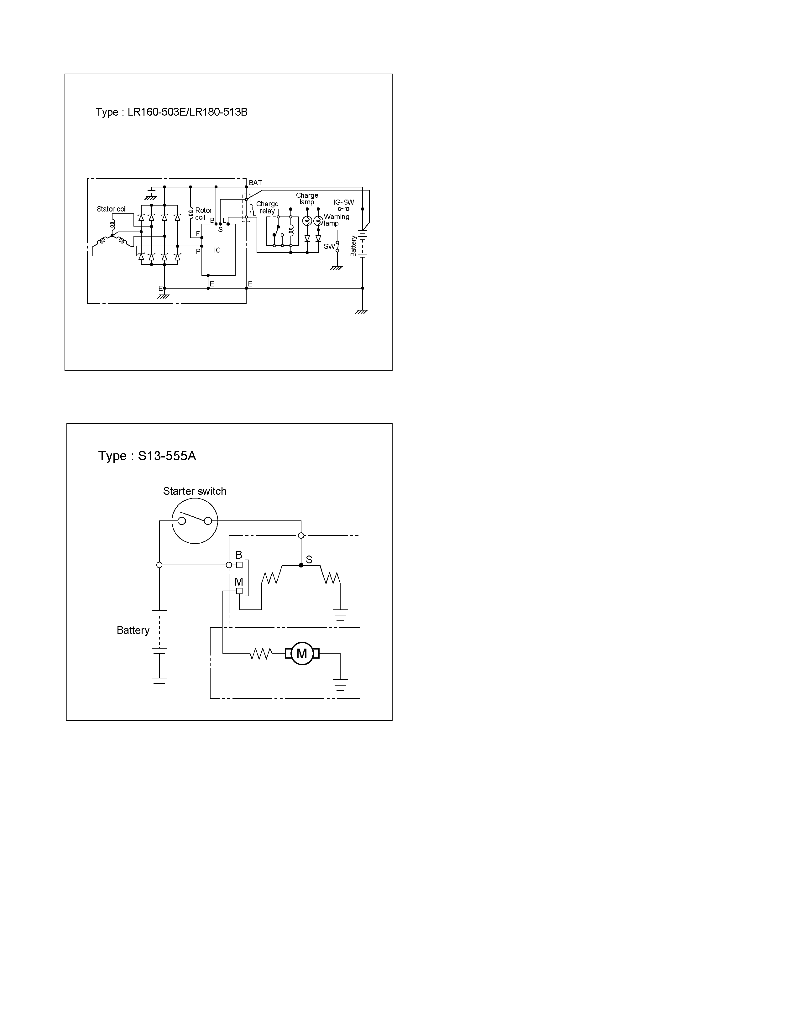
CHARGING CIRCUIT DIAGRAM
RTW46DSH005101
STARTING CIRCUIT DIAGRAM
RTW46DSH005501
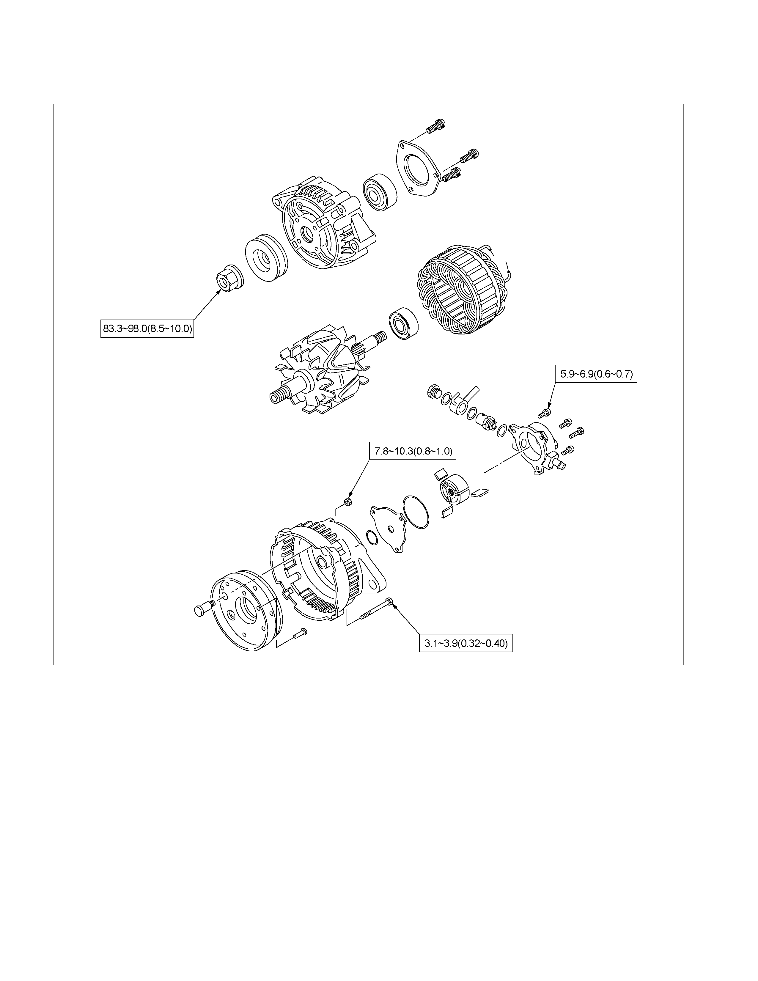
TORQUE SPECIFICATIONS
GENERATOR
Nm (kgm/Ib ft)
RTW46DLF000201
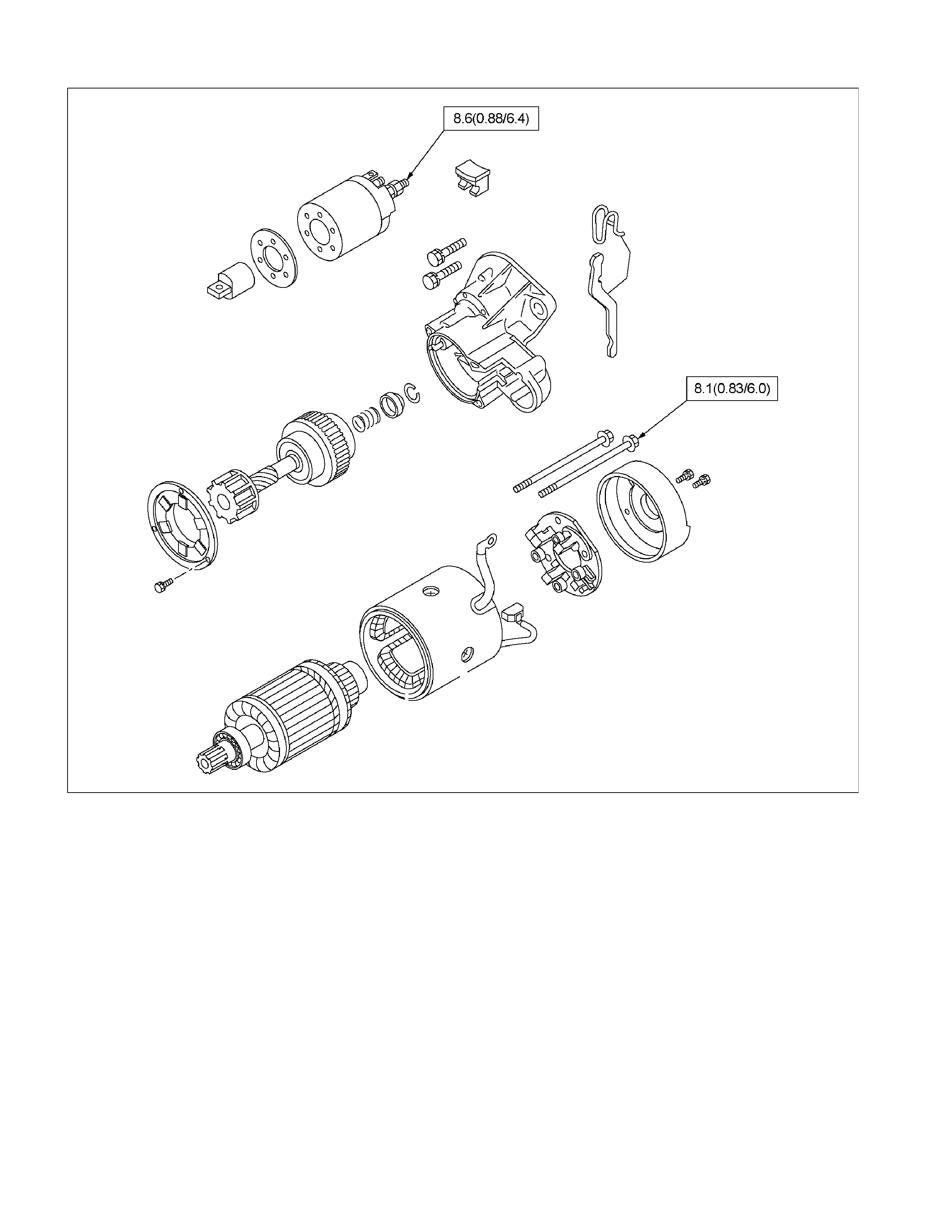
STARTER MOTOR
Nm (kgm/Ibft)
RTW46DLF000301
GENERATOR
Read this Section carefully before performing any removal and installation procedure. This Section gives you important
points as well as the order of operation. Be sure that you understand everything in this Section before you begin.
P1010002
Important Operations-Removal
Cooling Fan Belt
1. Disconnect the battery cables at the battery terminals.
2. Loosen and remove the fan belt adjusting plate bolts.
3. Remove the fan belt from the generator drive pulley.
Generator
1. Remove the vacuum pump hose.
2. Remove the generator bolt and the generator from the
bracket.
Important Operations-Installation
Follow the removal procedure in the reverse order to
perform the installation procedure. Pay careful attention to
the important points during the installation procedure.
Generator
1. Install the generator to the bracket.
2. Tighten the generator bolt to the specified torque.
3. Install the vacuum pump hose.
Generator Bolt Torque Nm (kgm/Ibft)
40 (4.1/30)
033RY00009
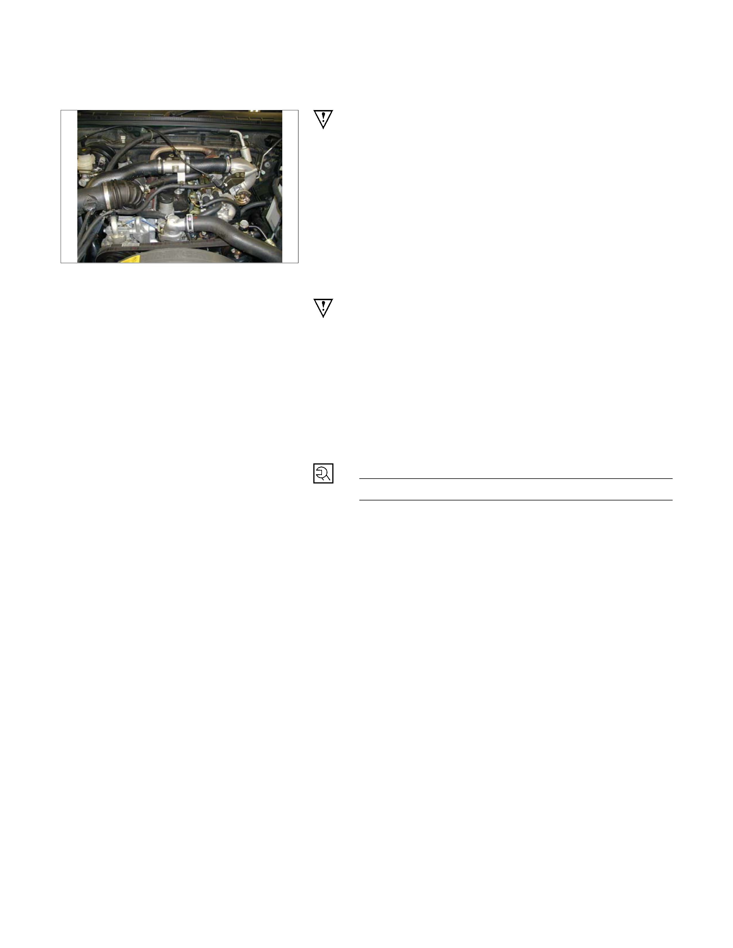
Cooling Fan Drive Belt
1. Hold the generator toward the engine.
2. Install the fan belt to the three pulleys.
1) Crankshaft pulley
2) Generator pulley
3) Cooling fan drive pulley
3. Adjust the fan belt tension
Fan belt tension is adjusted by moving the generator.
Depress the drive belt mid-portion with a 98 N (10
kg/22 Ib) force.
Cooling Fan Drive Belt Deflection mm (in)
New belt 4 - 7 (0.16 - 0.28)
Used belt 6 - 9 (0.24 - 0.35)
4. Tighten the adjusting plate bolts to the specified
torque.
Adjusting Plate Bolt N·m (kg·m/lb·ft)
19 (1.9/14)
Reconnect the battery cable to the battery after the completion
of work.

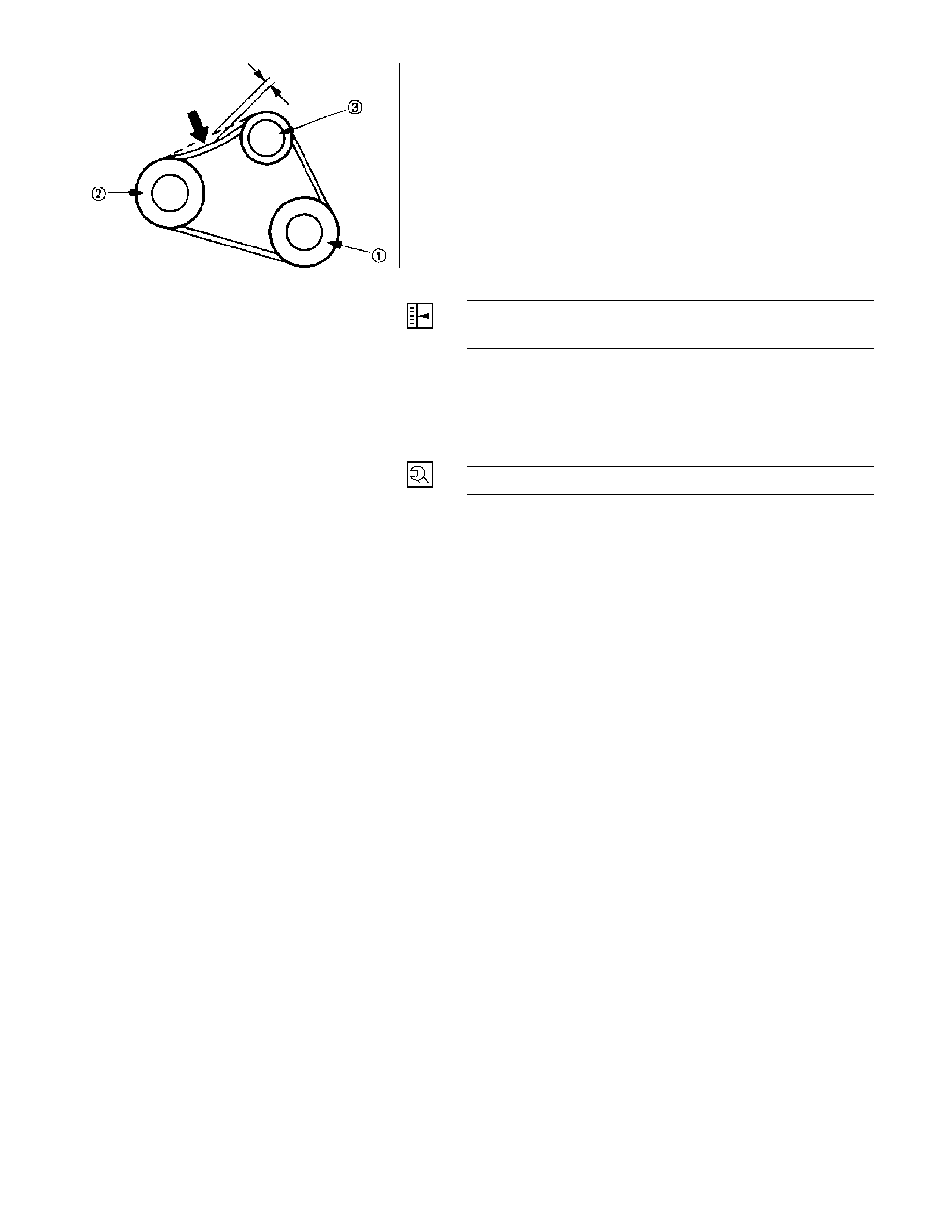
DISASSEMBLY
RTW46DLF000401
Disassembly Step
1. Vacuum pump
2. O-ring
3. Through bolt
4. B Terminal nut
5. Rear cover
6. Pulley
7. Rotor assembly
8. Front cover assembly
9. Rear rotor bearing
10. Rectifier assembly
11. Stator assembly
RTW46DSH000101
Important Operations
1. Vacuum Pump
1) Loosen the vacuum pump fixing screws.
2) Support the vacuum pump centre plate.
3) Carefully remove the vacuum pump.
2. O-ring
1) The O-ring must be renewed.
RTW46DSH000201
3. Through Bolt
1) Remove the M5 through bolt.
2) Separate the front and rear sides of the vacuum
pump.
3) Insert the tips of 2 flat-blade screwdrivers into the
space between the front cover and the stator core.
Remove the front cover and rotor together with the
rear cover and stator.
If removal is difficult, push the rear cover to the side and
lightly tap the end of the shaft with a plastic hammer to
loosen it.
• The front cover oil seal must be replaced with a new
one when the front cover is removed.
• Take care not to damage the stator core with the
screwdriver tips.
RTW46DSH000601
RTW46DSH002101
6. Pulley
1) Carefully clamp the rotor assembly in a vice.
2) Loosen the pulley nut.
3) Remove the pulley and the front cover from the rotor.
RTW46DSH000301
7. Rotor Assembly
1) Remove the rotor from front cover assembly.
2) Remove the front cover stator and rectifier.
RTW46DSH000701
8. Front Cover Assembly
1) Remove the front cover bearing retainer screws.
2) Remove the bearing.
RTW46DSH000801
9. Rear rotor bearing
• Re-use improper parts.
10. Rectifier
1) Disconnect the stator coil leads between each rectifier
by melting the solder connection.
Hold the lead wire between the solder and the rectifier
with a pair of long nose pliers.
This will prevent heat transfer and resultant damage to the
rectifier.
RTW46DSH000401
INSPECTION AND REPAIR
Make the necessary adjustments, repairs, and part replacement if excessive wear or damage is discovered during
inspection.
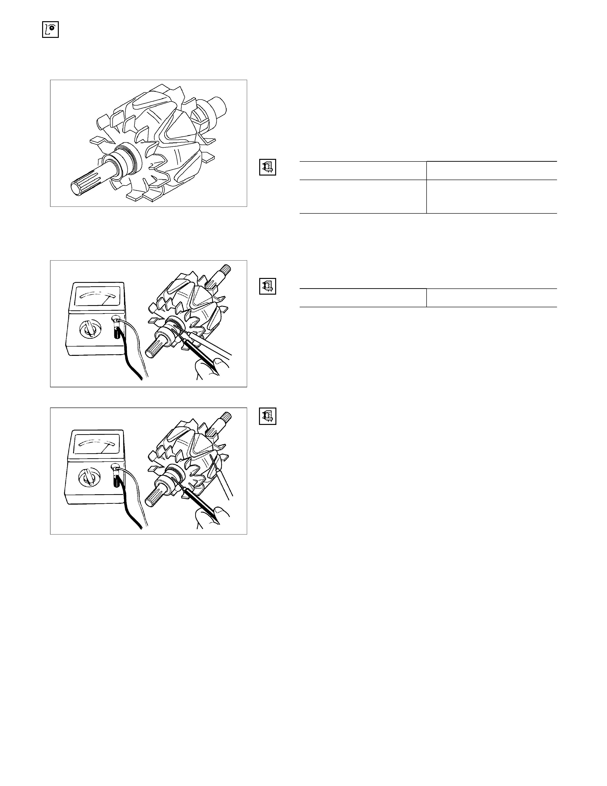
ROTOR ASSEMBLY
1. Inspect the slip ring faces for dirt and pitting.
Wipe away any dirt with a clean cloth soaked in
alcohol.
2. Measure the slip ring diameter.
Slip Ring Diameter mm (in)
Standard Limit
RTW06DSH000101
31.6 (1.245) 30.6 (1.183)
If the slip ring diameter is less than the specified limit, the
slip rings must be replaced.
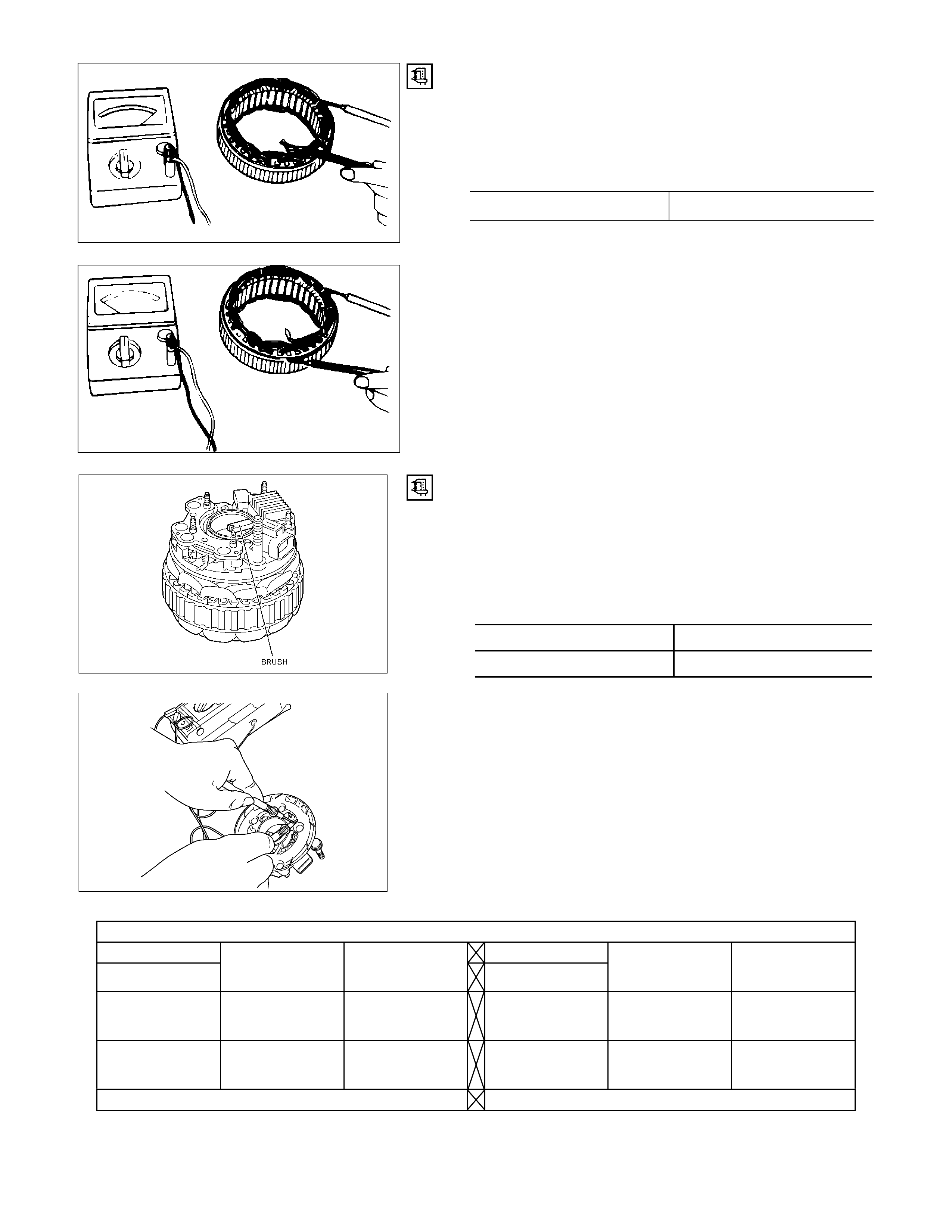
3. Measure the rotor coil resistance.
Rotor Coil Resistance at 20°C (68°F) ohms
Standard 3.8
RTW46DSH001001
RTW46DSH001101
4. Check for continuity between the slip rings and the
rotor core or shaft.
If there is continuity, the entire rotor assembly must be
replaced.
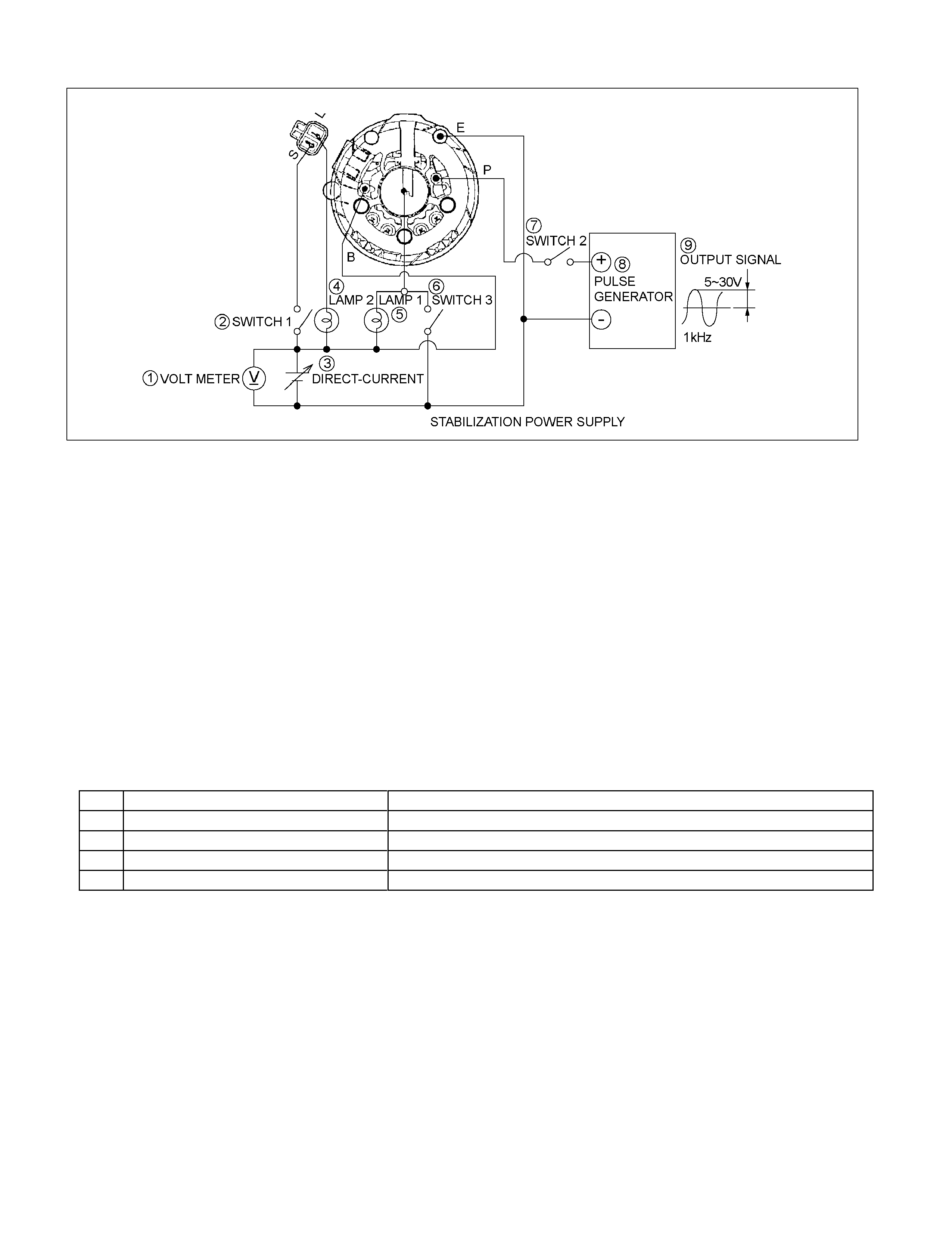
STATOR COIL ASSEMBLY
1. Check for continuity across the stator coils.
If there is no continuity, the stator coils must be
replaced.
Resistance Between The Terminal “N” and the Coil Ends
(Reference) ohms
Standard 0.1
066RY00022
2. Check for continuity between each stator coils and the
stator core.
If there is continuity, the stator coils must be replaced.
066RY00023
RTW46DSH004801
BRUSH
Measure the length of the brush. If abrasion has reduced
the brush length to less than 6.5 mm, the brush must be
replaced with a new one.
A wear line is inscribed in the brush. If the line is not
visible, the brush must be replaced.
Brush Length (Reference) mm (in)
Standard Limit
25 (1.0) 6.5 (0.25)
RTW46DSH001201
Rectifier
Tester wire
E BAT
U, V, and WN ⊕ ⊖ U, V, and WN ⊕ ⊖
⊕ ----- Conductivity ⊕ ----- No
conductivity
⊖ No
conductivity ----- ⊖ Conductivity -----
Negative side diode check Positive side diode check
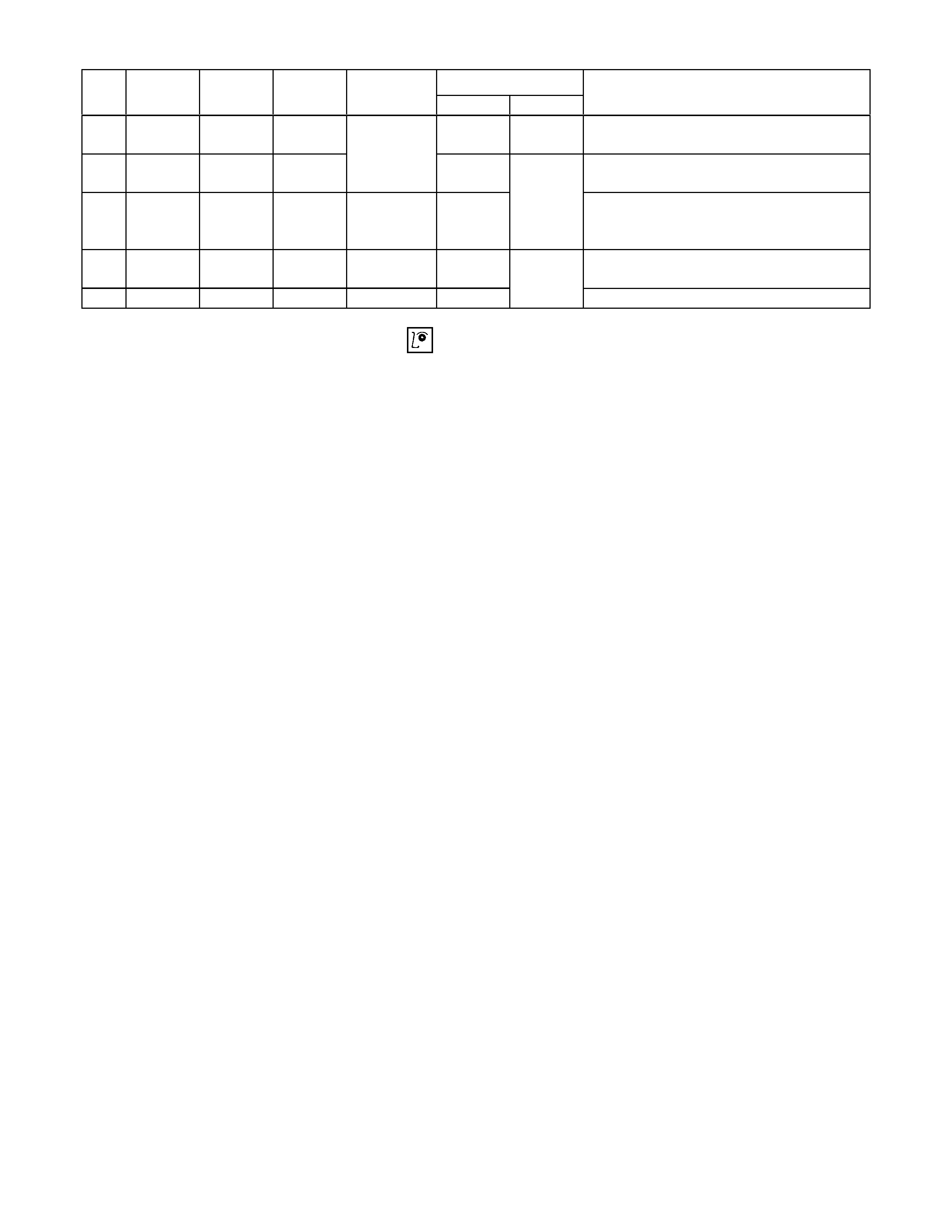
RECTIFIER ASSEMBLY
RTW46DSF000301
1. Voltmeter
2. Switch 1
3. DC regulated power supply
4. Lamp 2
5. Lamp 1
6. Switch 3
7. Switch 2
8. Pulse generator
9. Output signal
Test circuit
Refer to the judgment criteria shown in the Table below.
Carefully check Items 1~5. If all the items are OK, the IC
regulator is normal.
Circuit components
1 DC regulated power supply 0~20 volts variable with output of 1 ampere or more
2 Lamps (2) 12 volts, 1.4~3.4 watts
3 Switches (3) -----
4 DC voltmeter 0~30 volts, 0.5 grade
5 Pulse generator (Oscillator) 5~30 volt output at a frequency of 1kHz
Judgment criteria
Lamp condition
No. Switch
1 Switch
2 Switch
3 Voltmeter
reading Lamp 1 Lamp 2 Remarks
1 ON OFF OFF On
(dim) ON Initial excitation check
2 ON ON OFF 12V On or
flashing Full excitation check
3 ON ON OFF 16V Off or
on (dim)
OFF Lamp 1 off or dimly lit when the
voltmeter shows less than 12 volts or
16 volts
4 OFF ON OFF 12V On or
flashing Stator and brush separation check
5 ON ON ON 18V On ON Excess voltage check
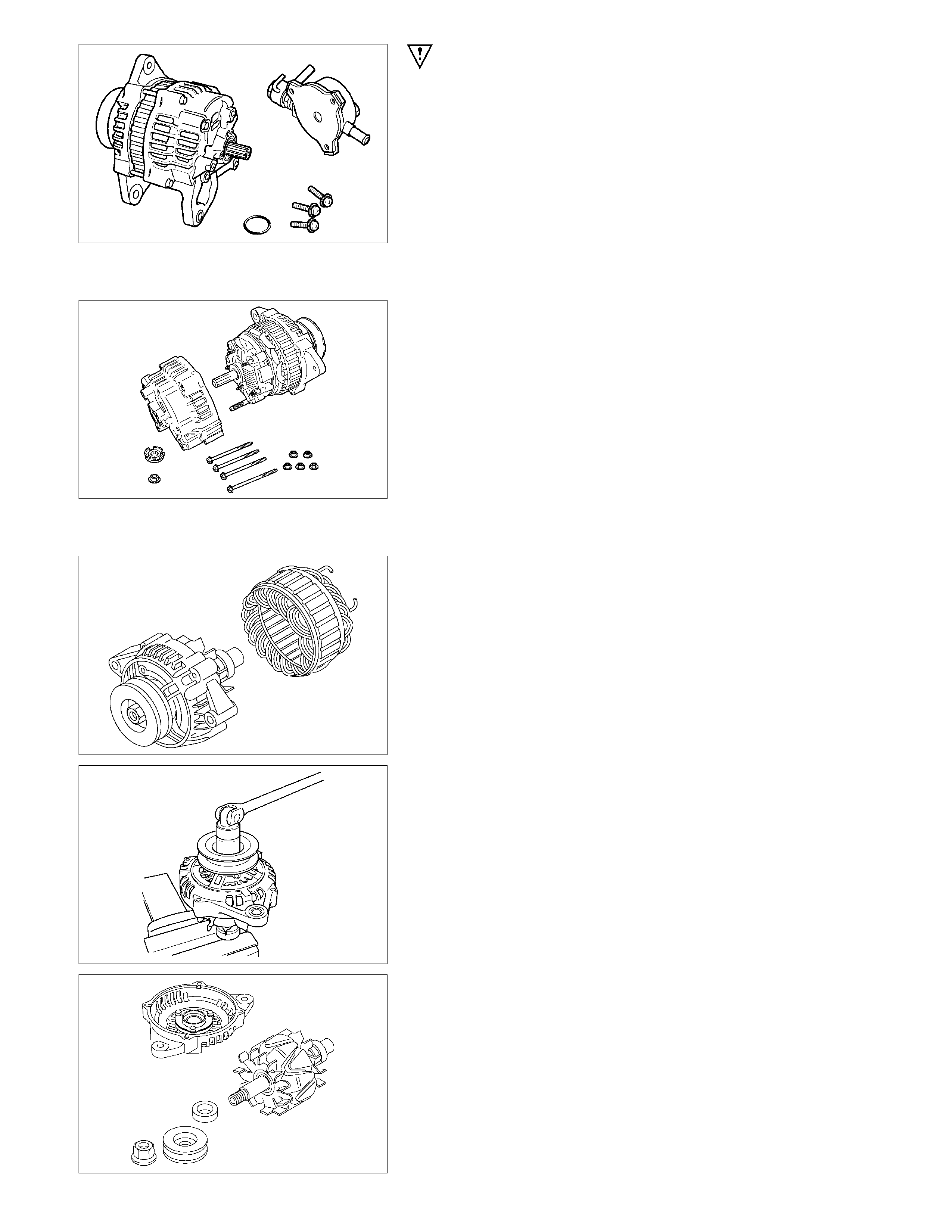
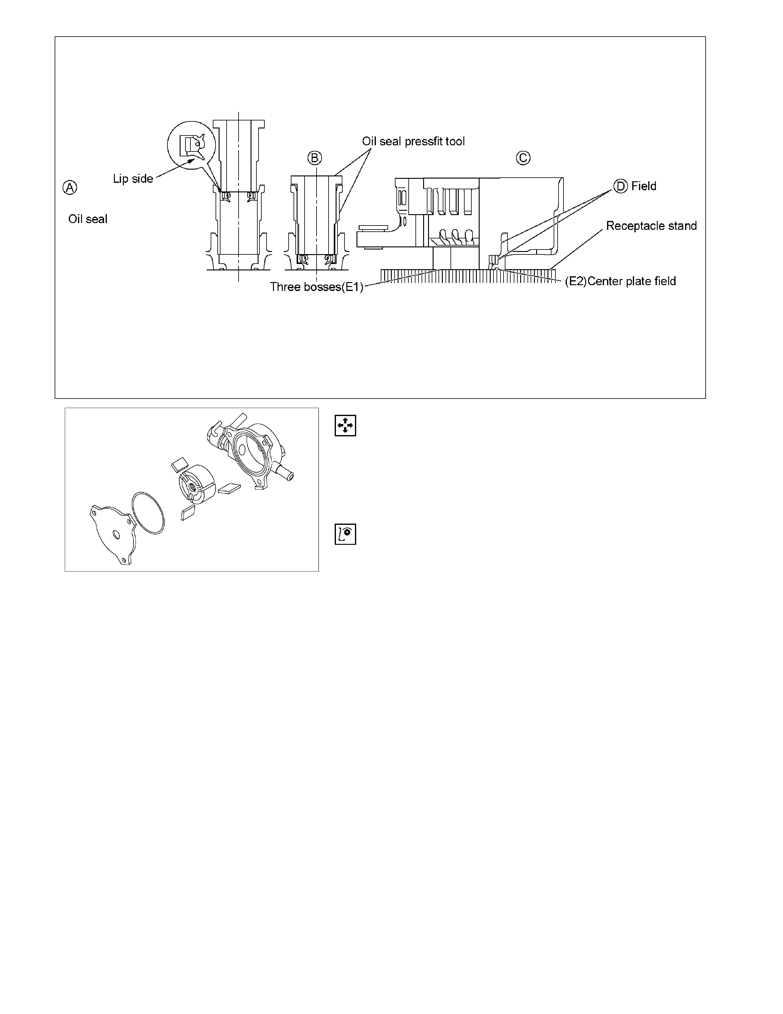
Oil seal
The oil seal must be replaced with a new one whenever
the alternator is disassembled.
Oil Seal Replacement
1. Push the old oil seal from the rear bracket outside
holes.
2. Use the insertion tool to press the new oil seal into
place. Follow the procedure shown in Figures A, B, C
and D.
Position the oil seal beneath the shaft and the
guide lip.
Position the cradle against the rear cover bosses
(3 points) so that the E1 and E2 surfaces fit into
the cradle. Take care not to damage the E1 and
E2 surfaces.
After completing the procedure, carefully check
the oil seal seating. Be absolutely sure that the
seal is evenly inserted (no warp) and level with the
surrounding surfaces.
CAUTION
• Be sure that no foreign material enters the
space between the oil seal and the rotor shaft
surfaces during the installation procedure.
• Take care not to damage the D surface.
• Under no circumstances may the original oil
seal be reused.
• The oil seal must be perfectly flat after being
pressed into place. If the oil seal is tilted, there
will be oil leakage.
RTW46DSF000101
RTW46DSH000901
Vacuum Pump
Vacuum Pump Disassembly
1. Remove the centre plate from the vacuum pump
housing.
2. Remove the vacuum pump rotor and the vanes from
the housing.
Inspection
Vacuum Pump Housing and Centre Plate
Inspect the vacuum pump housing and the centre plate for
excessive wear, abrasion, and scoring.
If any of these conditions are present, the vacuum pump
housing and centre plate must be replaced.
Vane
Inspect the vanes for excessive wear and damage.
Replace all four vanes if either of these conditions are
present.
Never replace only one vane.
Rotor
1. Inspect the rotor for excessive wear, abrasion, and
scoring.
Pay particular attention to the internal spline.
Replace the rotor if any of these conditions are
present.
2. Inspect the generator rotor shaft splines for backlash.
Replace the rotor if backlash is present.

RTW46DSH005201
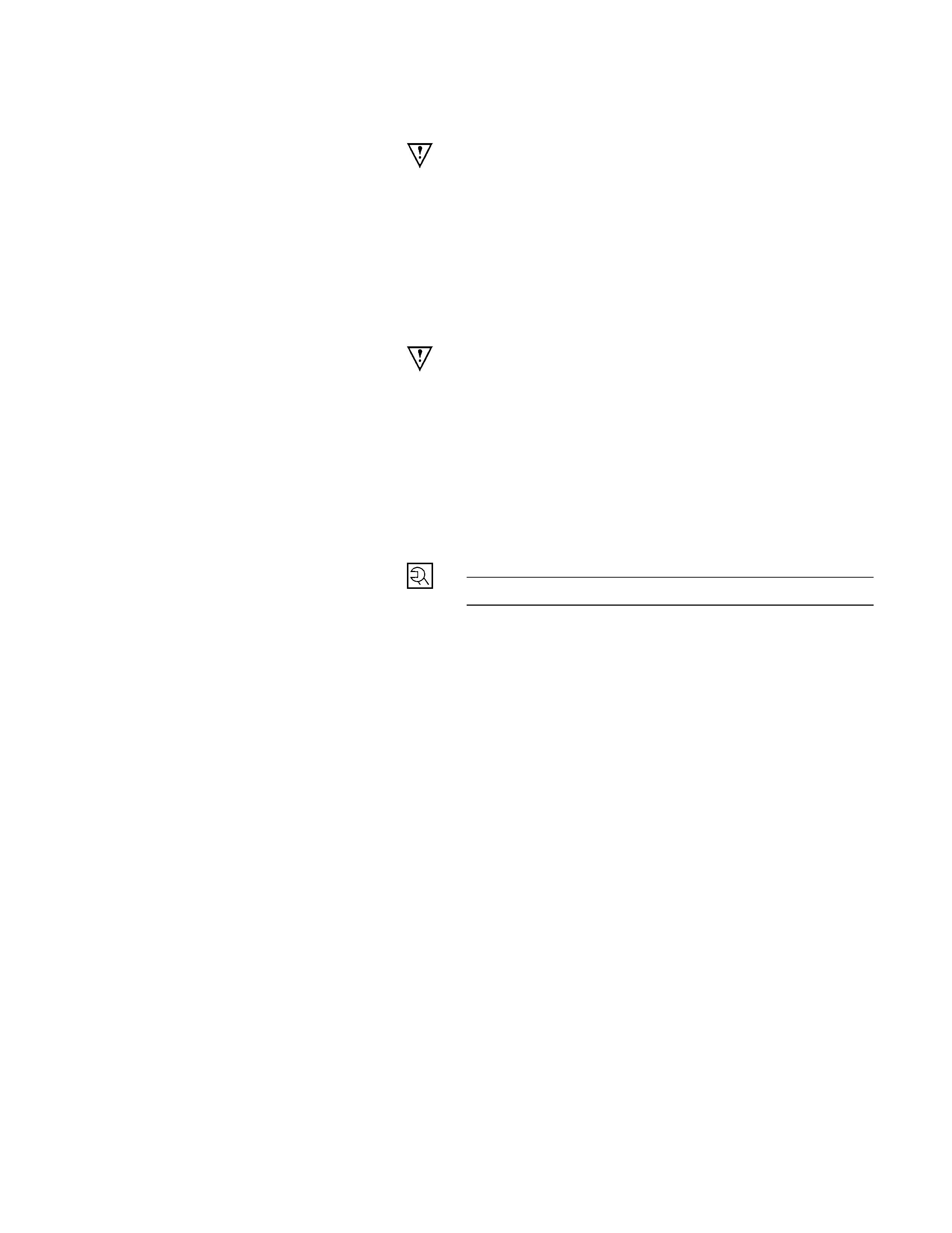
Check Valve
1. Carefully force the valve from the side as shown in the
illustration.
The valve must move smoothly.
If it does not, the check valve must be replaced.
2. Apply compressed air to the side as shown in the
illustration.
Air Pressure kPa (kg/cm2/psi)
98 - 490 (1-5/14 – 71)
3. Check for air leakage from the check valve.
If there is air leakage, the valve must be replaced.
RTW46DSH001801
Vacuum Pump Reassembly
1. Install the vanes to the rotor slits.
The rounded side of the vanes must be facing the
rotor housing.
RTW46DSH001901
2. Install the rotor with the concave side facing the
centre plate.
RTW46DSH002001
3. Install the centre plate to the rotor housing.
Be sure to use a new O-ring.
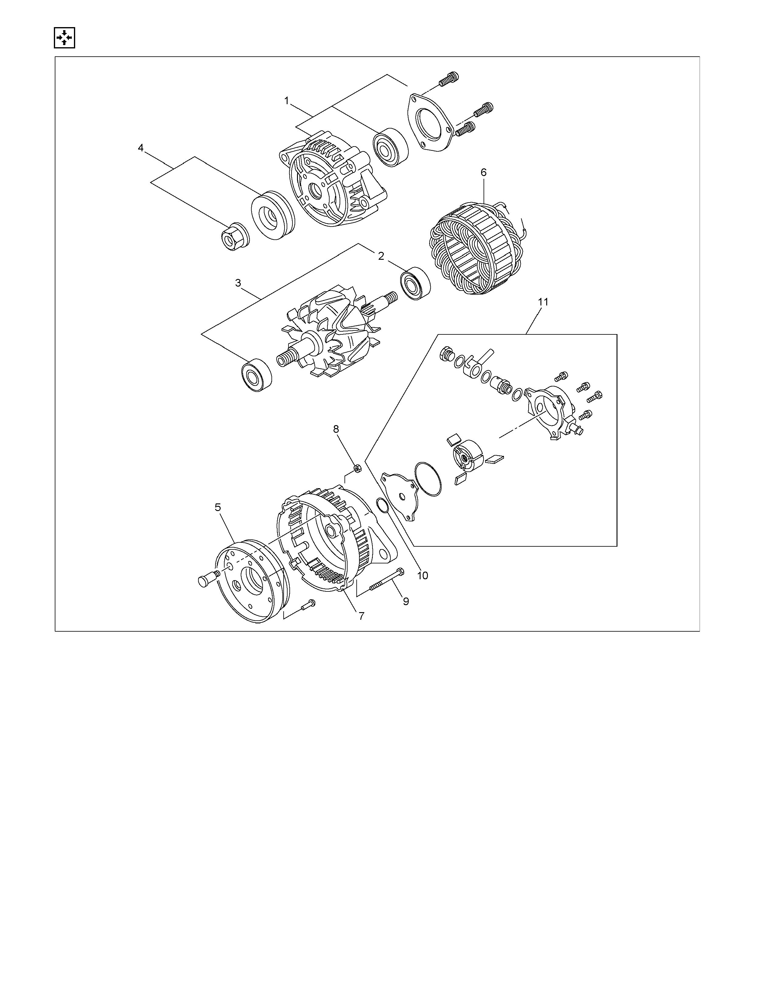
REASSEMBLY
RTW46DLF000501
Reassembly Step
1. Front cover
2. Rear rotor bearing
3. Rotor Assembly
4. Pulley
5. Rectifier Assembly
6. Stator Assembly
7. Rear cover
8. B Terminal nuts
9. Through bolt
10. O-ring
11. Vacuum pump
RTW46DSH000401
Important Operations
2. Rear rotor bearing
• Replace if the bearing condition is unsatisfactory.
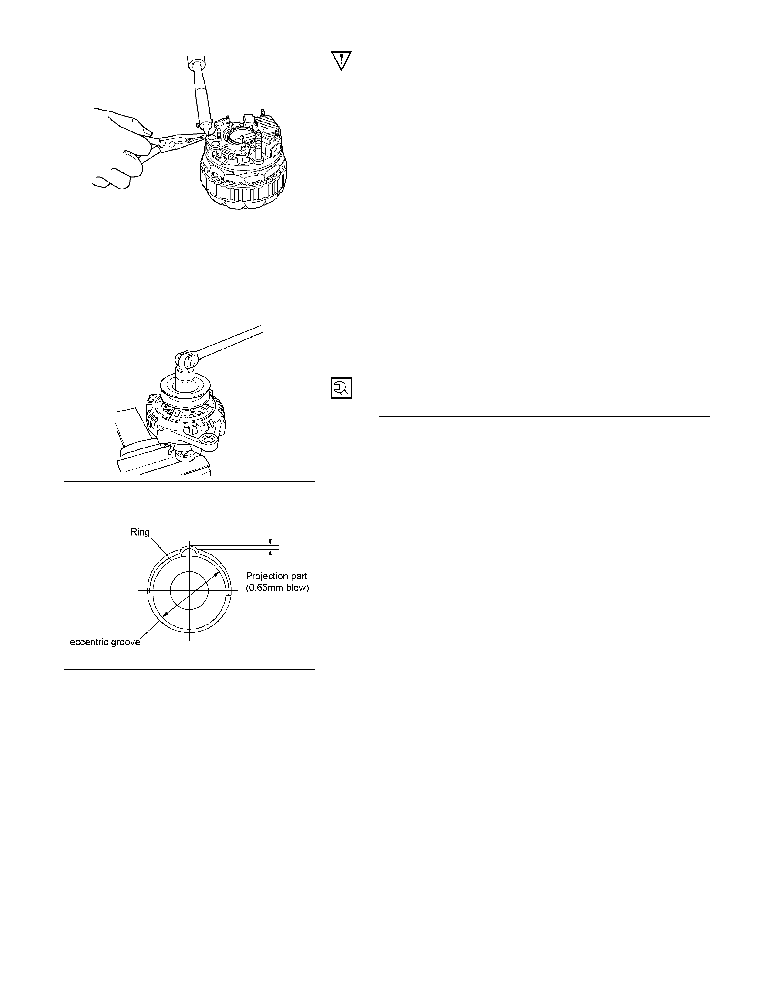
5. Rectifier
6. Stator
Use a pair of long-nose pliers to connect the stator coil
leads and the rectifier leads.
Finish the work as quickly as possible to prevent the
rectifier from heat transferred by the soldering.
RTW46DSH002101
3. Rotor Assembly
4. Pulley Assembly
Clamp the rotor in a vice and install the pulley nut.
Pulley Nut Torque N⋅m (kg⋅m/lb⋅ft)
83.3 ∼ 98.0 (8.5 ∼ 10.0/61 ∼ 72)
RTW46DSH004901
The rear ball bearing is pressed into the wheel eccentric
groove. The bearing ring projects from the groove.
During installation, rotate the bearing to the point of
minimum bearing ring projection.
Inspect the rear cover bearing box and replace it if it is
damaged.
RTW46DSH002201
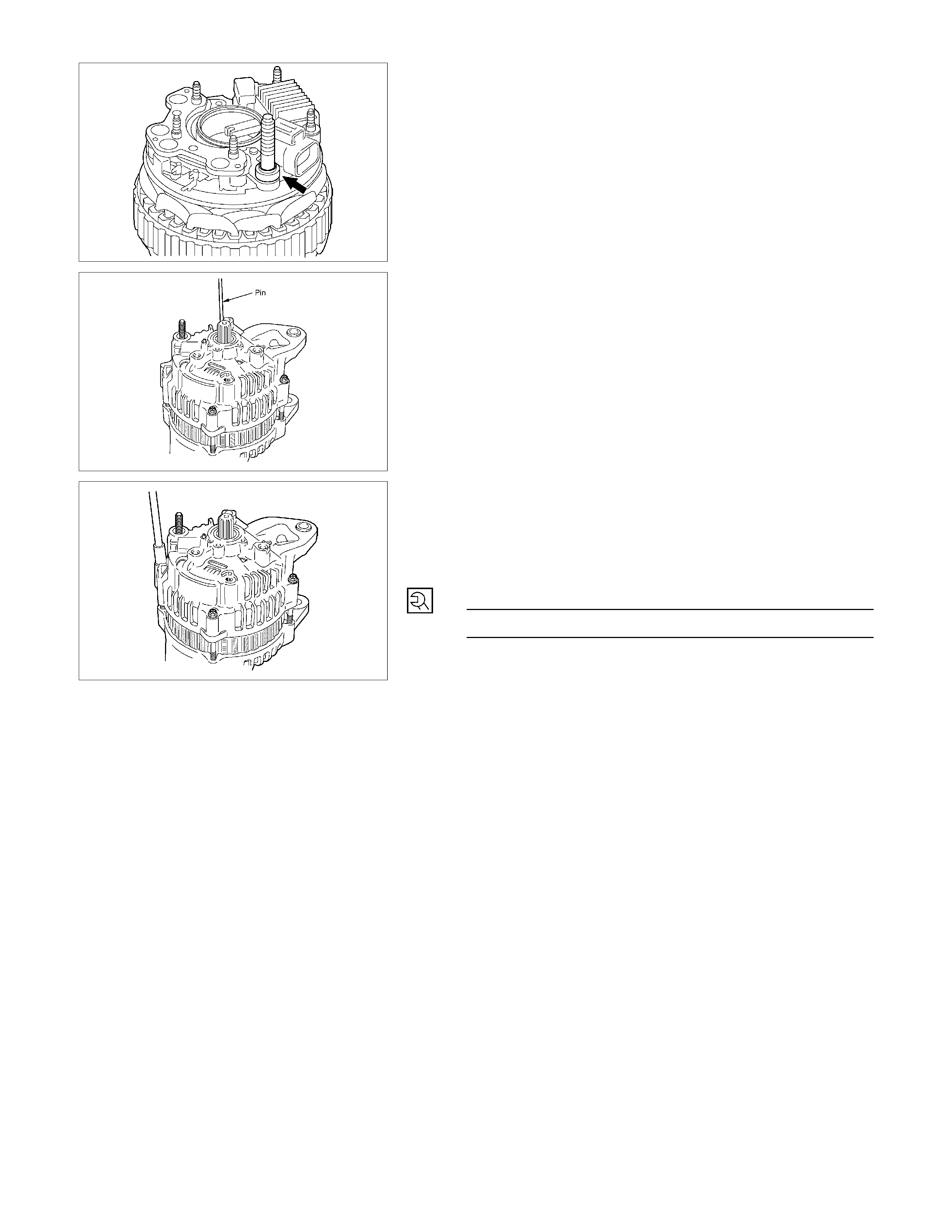
NOTE:
Be sure to attach the collar to the B terminal.
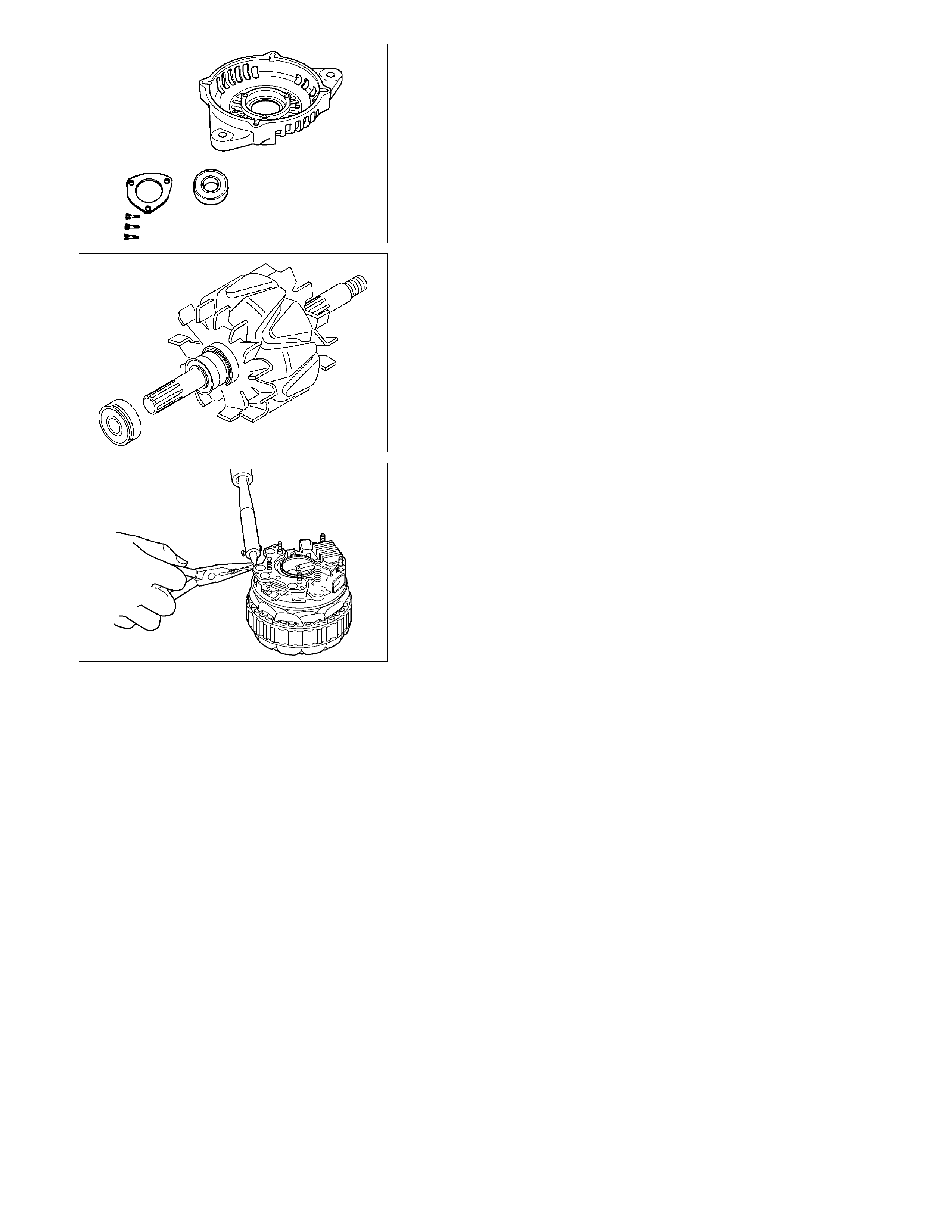
RTW46DSH005301
Insert the pin from the outside of the rear cover. Press the
brushes into the brush holder. Complete the assembly
procedure.
Remove the pin after completion of the assembly
procedure.
RTW06DSH000201
9. Through Bolt
1) Place a pilot bar into the through bolt hole to align the
front cover and the rear cover.
2) Install the through bolts and tighten them to the
specified torque.
Through Bolt Torque N⋅m (kg⋅m/lb⋅ft)
3.1 ∼ 3.9 (0.32 ∼ 0.41/2.6 ∼ 3.5)
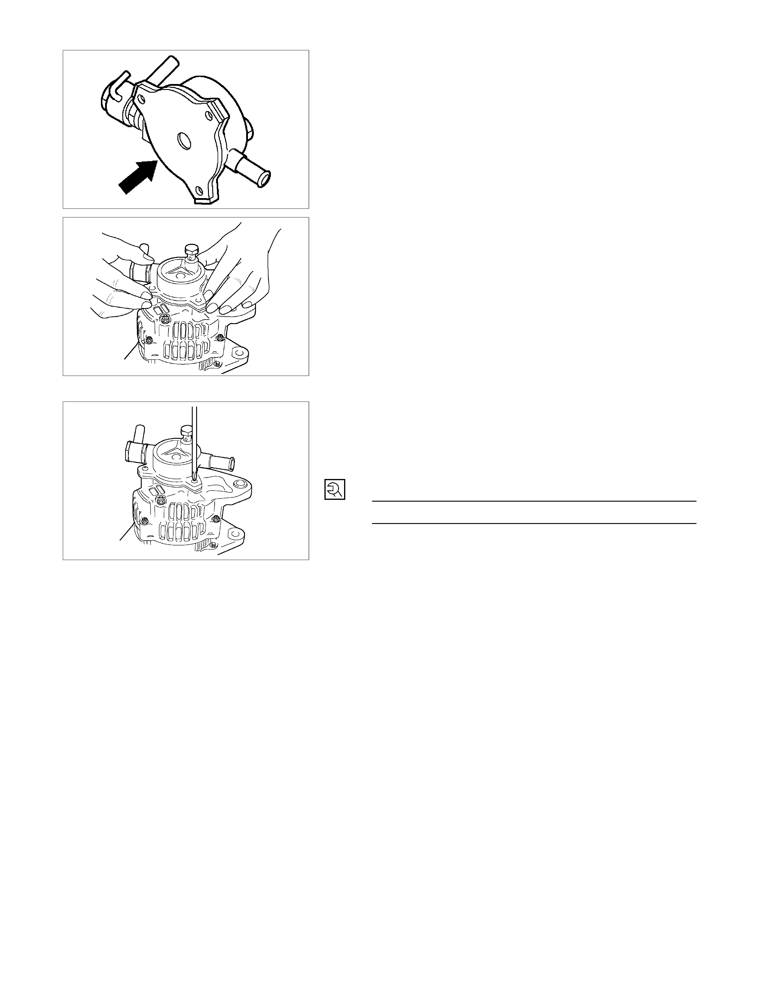
11. Vacuum Pump
To install the generator -
1) Note the direction of the arrow on the vacuum pump.
2) Look forward from the base of the arrow to locate the
3 generator fixing points.
3) Twist the fixing points down and to the left to align
them with the middle of the centre plate and the rotor.
RTW46DSH006101
Install vanes into slits in rotor.
The vanes should be installed with the chamfered side
facing outward.
RTW46DSH002401
Install the vacuum pump housing.
Make sure that the O-ring is not projecting beyond the
slots of the centre plate.
Take care so that no scratching takes place on the vane
resulted by contact with the housing.
RTW46DSH002501
Install the housing in the generator and fix it with the three
bolts.
Supply engine oil (5cc or so) from the oil port and check
that the generator pulley can be turned smoothly with your
hand.
Generator Housing Bolt Torque N⋅m (kg⋅m/lb⋅ft)
5.9 ∼ 6.9 (0.6 ∼ 0.7/5.2 ∼ 6.1)
STARTER MOTOR
Read this Section carefully before performing any removal and installation procedure. This Section gives you important
points as well as the order of operation. Be sure that you understand everything in this Section before you begin.
Important Operations - Removal
Starter Motor
1. Disconnect the ground cable and the battery cable at
the battery terminals.
2. Disconnect the cable at the terminal on the magnetic
switch.
3. Disconnect the battery cable from the starter motor
and the ground cable from the cylinder body.
4. Remove the starter motor from the engine.
Important Operations – Installation
The installation procedure is the reverse of the removal
procedure. Pay careful attention to the important points
during the installation procedure.
Starter Motor
1. Install the starter motor to the rear plate.
2. Tighten the starter motor bolts to the specified torque.
Starter Motor Bolt Torque N⋅m (kg⋅m/lb⋅ft)
85 (8.7/63)
3. Reconnect the battery cable at the starter motor and
the ground cable at the cylinder body.
4. Reconnect the battery cable and the ground cable at
the battery terminals.
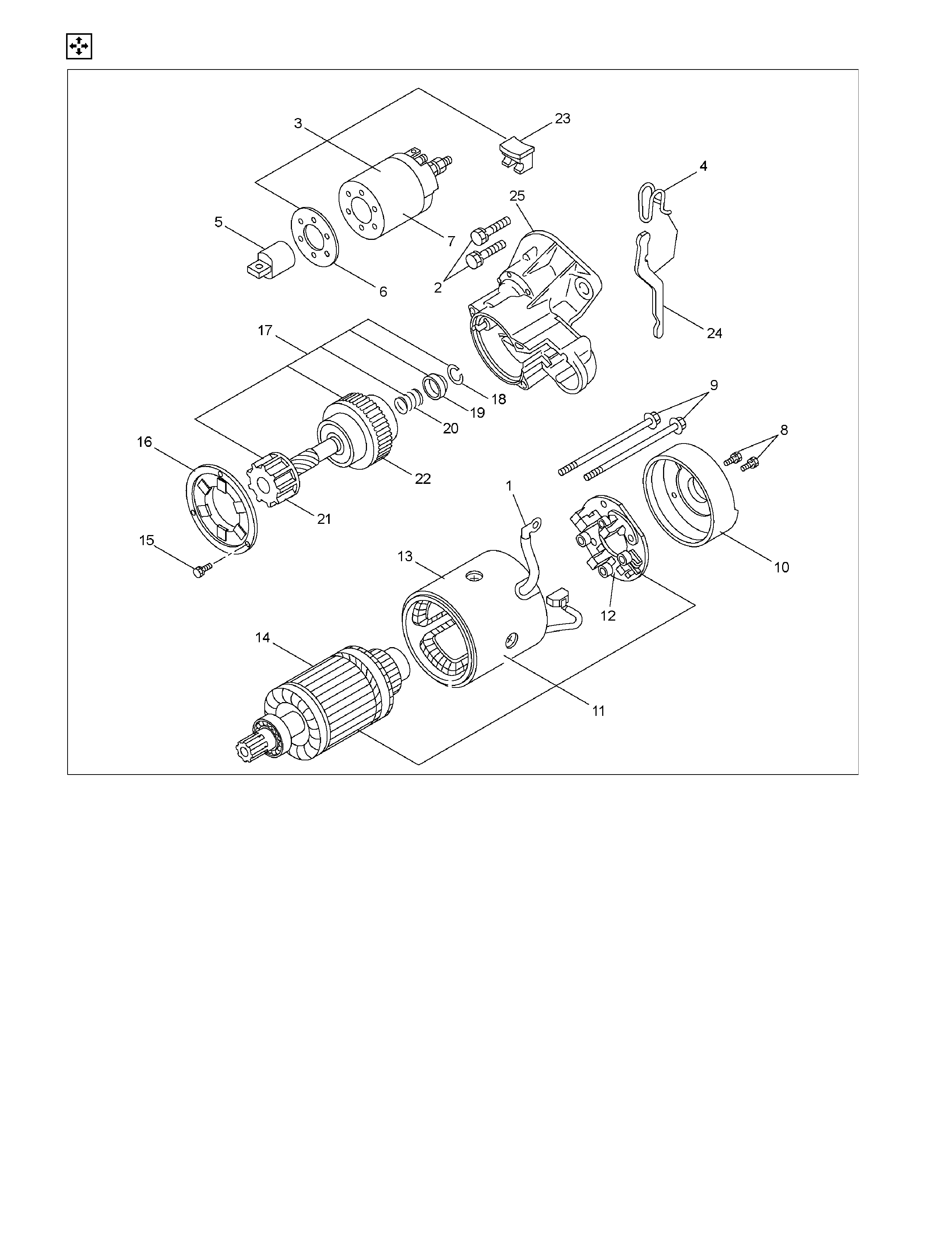
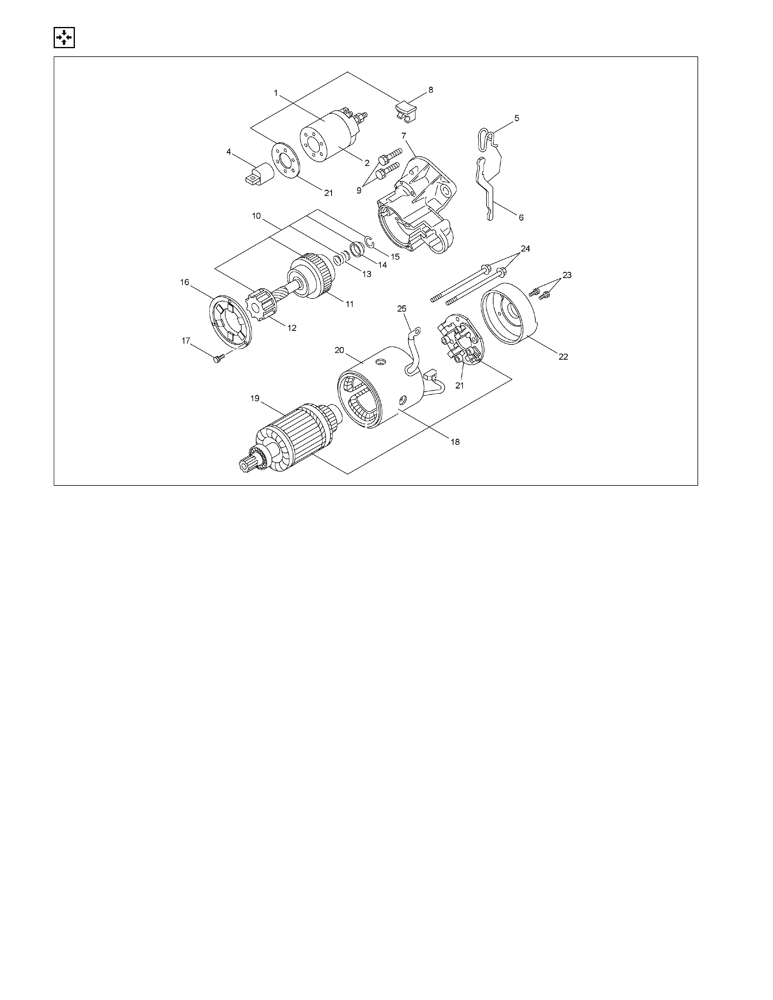
DISASSEMBLY
RTW460LF000201
Disassembly Step
1. Lead wire 14. Armature
2. Bolt 15. Bolt
3. Magnetic switch assembly 16. Bearing retainer
4. Torsion spring 17. Pinion assembly
5. Plunger 18. Pinion stopper clip
6. Dust cover 19. Pinion stopper
7. Magnetic switch 20. Return spring
8. Screw 21. Pinion shaft
9. Through bolt 22. Clutch
10. Rear cover 23. Dust cover
11. Motor assembly 24. Shift lever
12. Brush holder 25. Gear case
13. Yoke
RTW46DSH002601
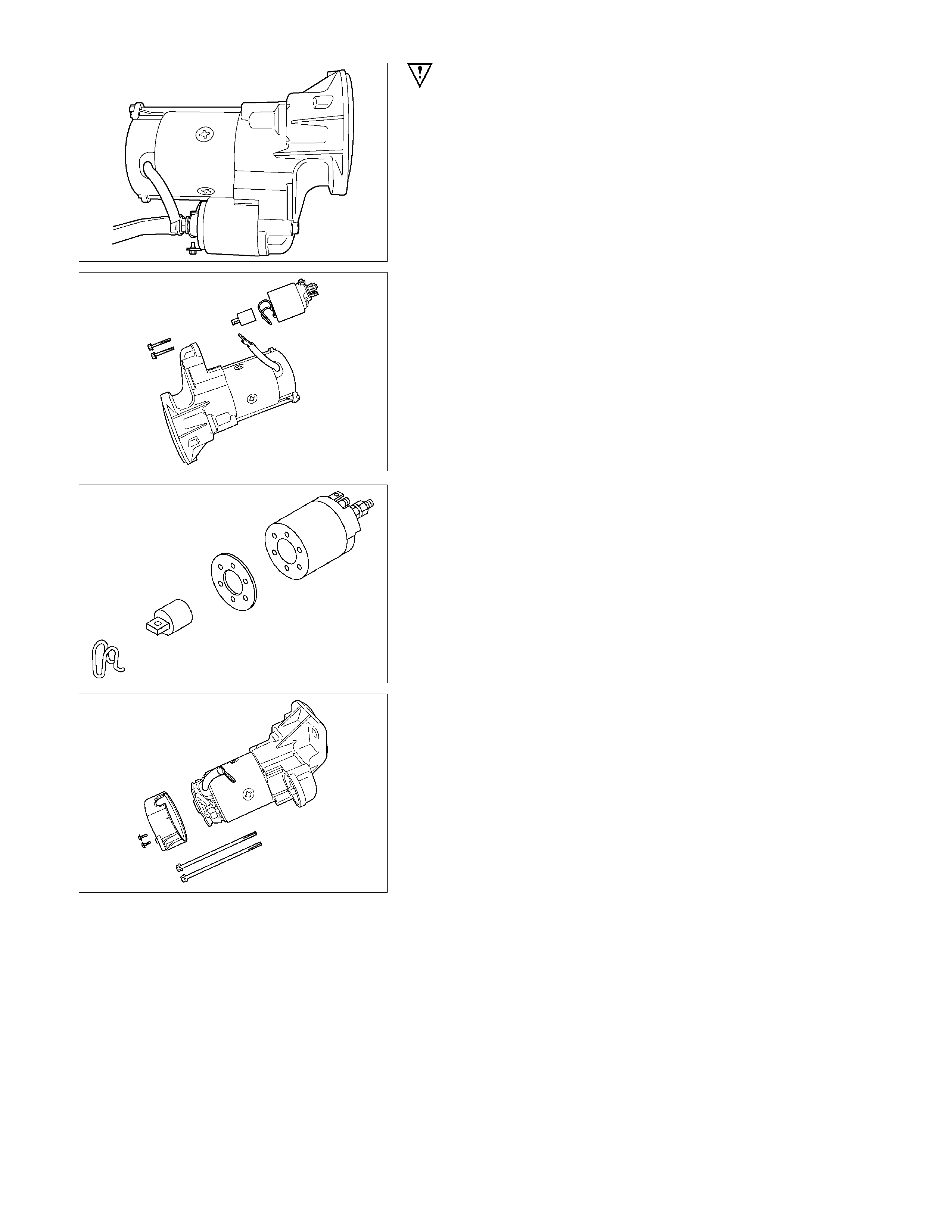
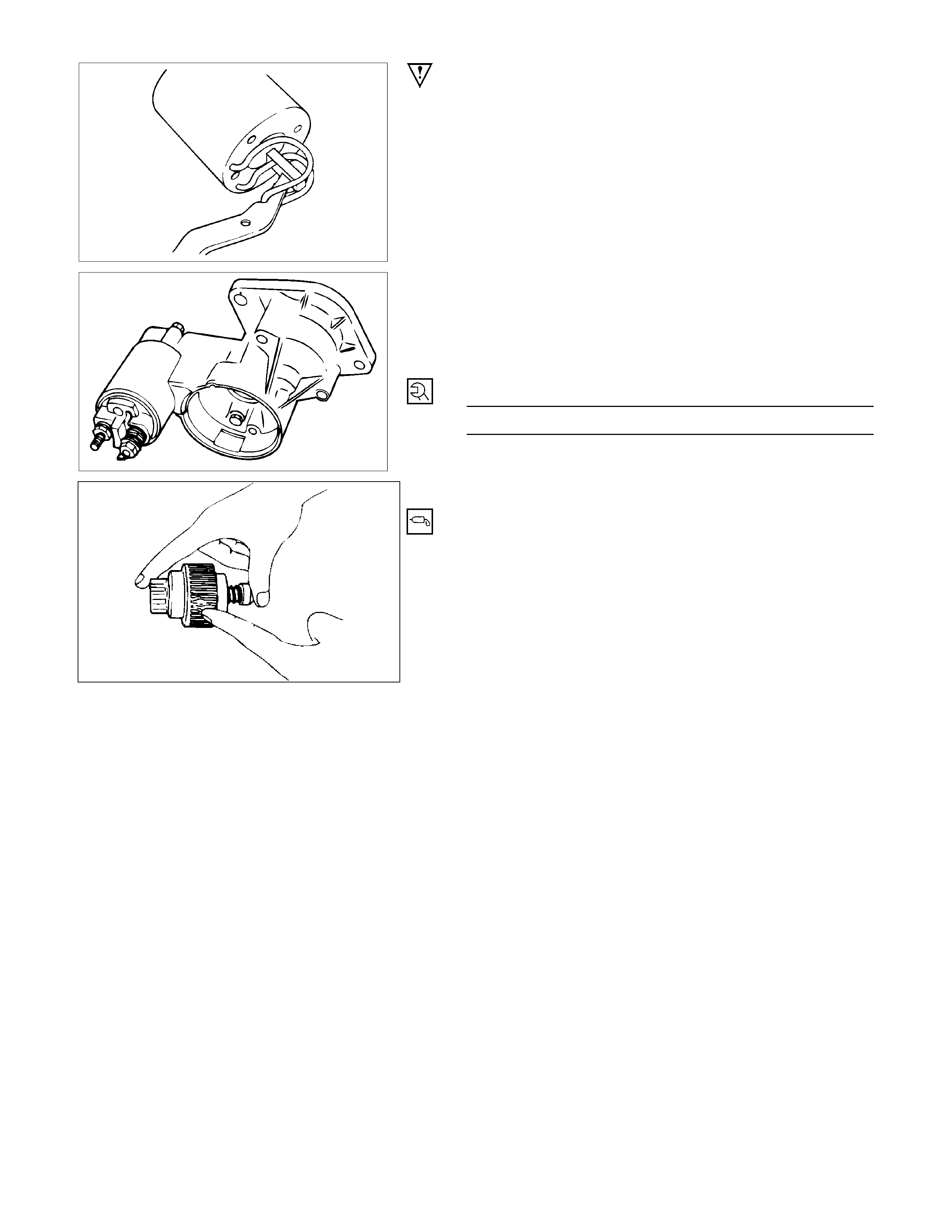
Important Operations
1. Lead Wire
Disconnect the lead wire at the magnetic switch.
RTW46DSH002701
3. Magnetic Switch Assembly
Remove the magnetic switch bolts, then remove the
switch from the shift lever.
RTW46DSH002801
Remove the torsion spring from the magnetic switch.
RTW46DSH002901
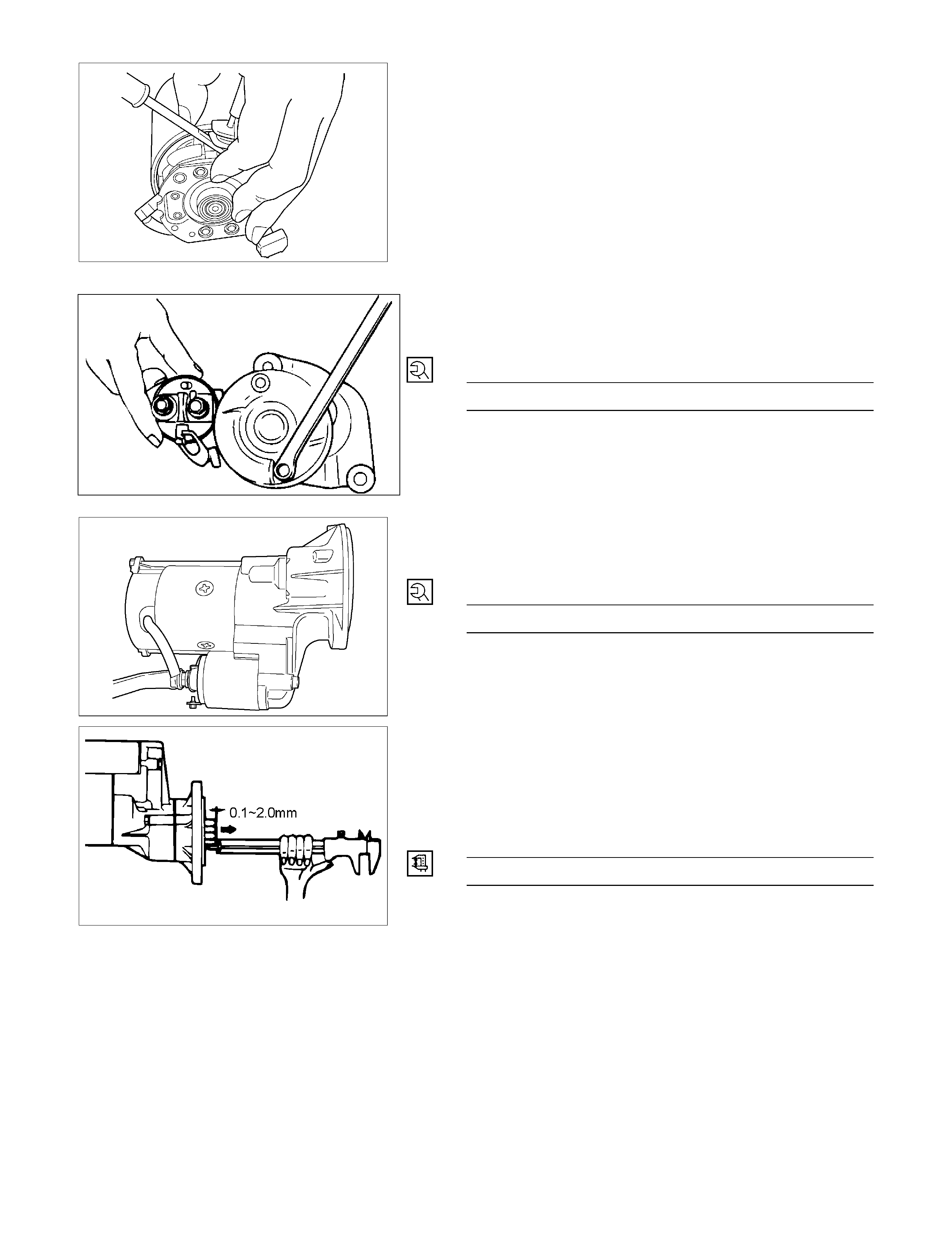
8. Screw
9. Through Bolt
10. Rear Cover
Remove the through bolts, then remove the rear cover.
RTW46DSH003001
11. Motor Assembly
Remove the four brushes from the brush holders.
RTW46DSH003101
Remove the yoke along with the armature and the brush
holder from the gear case.
Remove the brushes and commutator carefully, to avoid
contact with adjacent parts.
RTW46DSH003201
12. Brush Holder
13. Yoke
14. Armature
Remove the brush holder and pull out the armature
assembly free from the yoke.
RTW46DSH003301
16. Bearing Retainer
17. Pinion Assembly
23. Dust Cover
24. Shift Lever
25. Gear Case
1) Remove the bearing retainer.
2) Remove the pinion from the gear case.
RTW46DSH003401
3) Use a screwdriver to remove the stopper clip. Then
disassemble the pinion assembly.
INSPECTION AND REPAIR
Make the necessary adjustments, repairs, and part replacement if excessive wear or damage is discovered during
inspection.
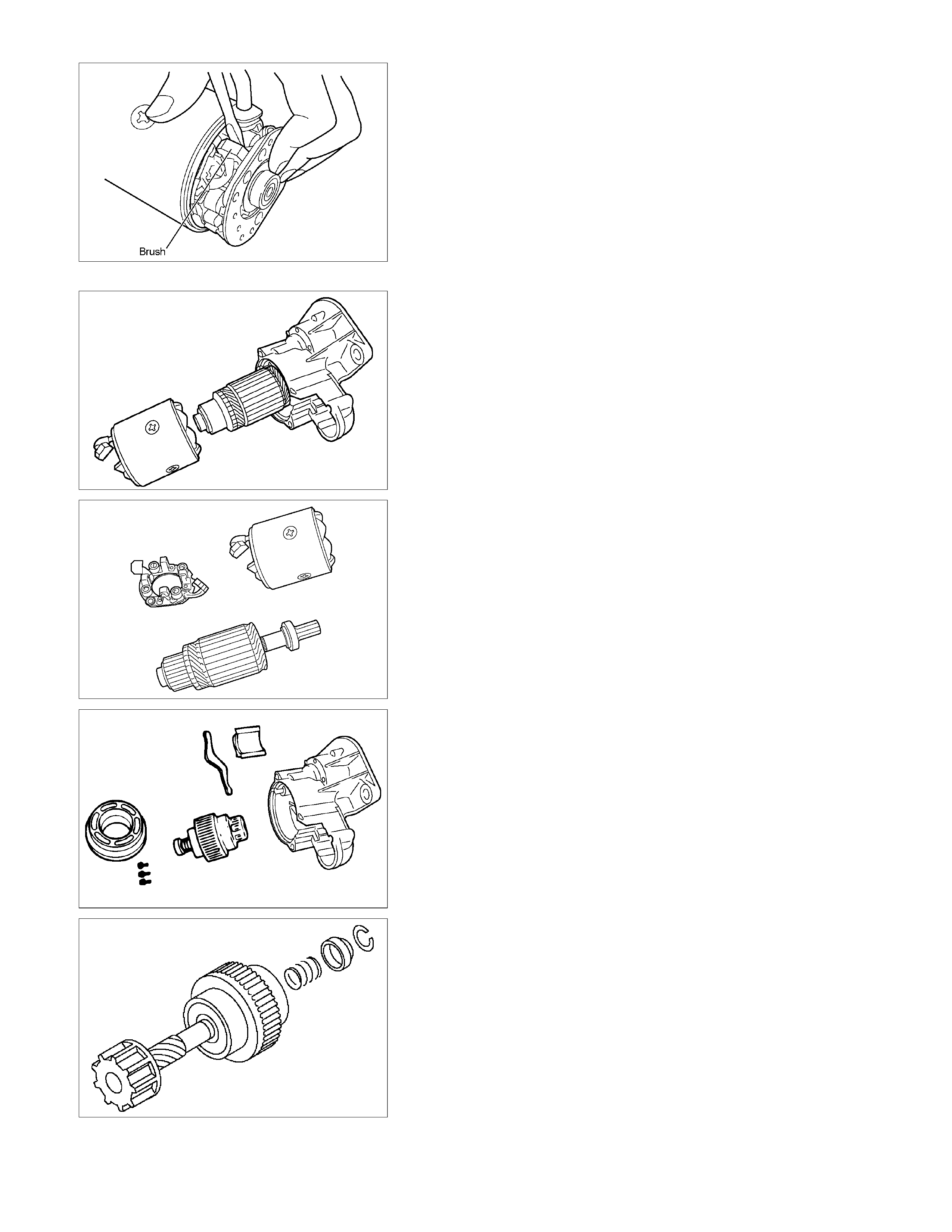
ARMATURE
1. Measure the commutator run-out.
Replace the commutator if the measured run-out
exceeds the specified limit.
Commutator Run-Out mm (in)
Standard Limit
0.05 (0.002) 0.2 (0.008)
RTW46DSH003501
2. Check the commutator mica segments for excessive
wear.
3. Measure the mica segment depth.
Mica Segment Depth mm (in)
Standard Limit
0.5 ∼ 0.8 (0.020 ∼ 0.030) 0.2 (0.008)
065RY00025
If the mica segment depth is less than the standard but
more than the limit, the commutator may be reground.
If the mica segment depth is less than the limit, the
commutator must be replaced.
4. Measure the commutator outside diameter.
Commutator Outside Diameter mm (in)
Standard Limit
36.5 (1.44) 35.5 (1.40)
If the measured outside diameter is less than the specified
limit, the commutator must be replaced.
065RY00026
RTW46DSH003601
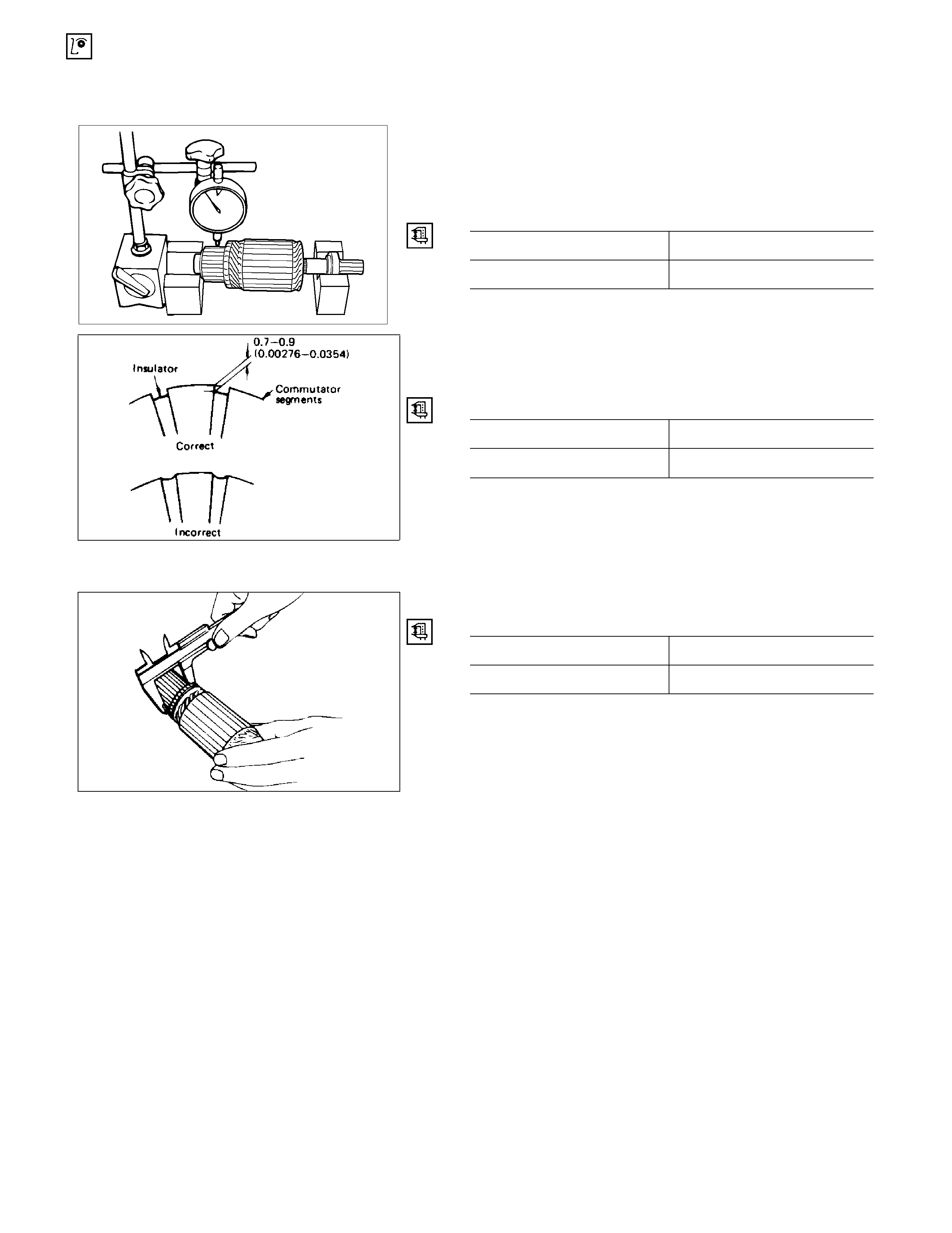
5. Use a circuit tester to check the armature for
grounding.
1) Hold one probe of the circuit tester against the
commutator segment.
2) Hold the other circuit tester probe against the
armature core.
If the circuit tester indicates continuity, the armature is
grounded and must be replaced.
RTW46DSH003701
6. Use the circuit tester to check the armature for
continuity.
1) Hold the circuit tester probes against two
commutator segments.
2) Repeat Step 1 at different segments of the
armature core.
There should be continuity between all segments of
the commutator.
If there is not, the armature must be replaced.
RTW46DSH003801
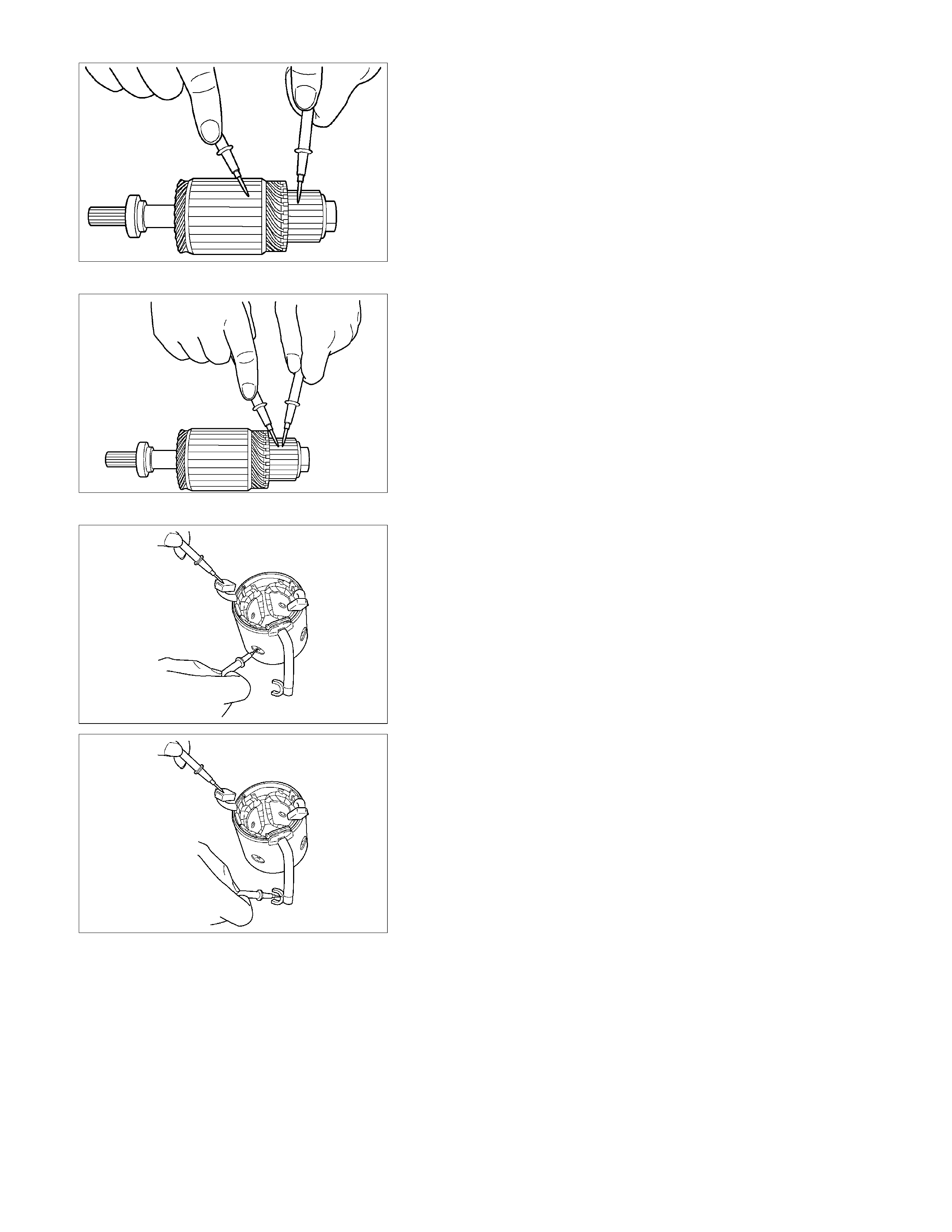
YOKE
1. Use a circuit tester to check the field winding ground.
1) Hold one circuit tester probe against the field
winding end or brush.
2) Hold the other circuit tester probe against the
bare surface of the yoke body.
There should be no continuity.
If there is continuity, the field coil is grounded, and
therefore the yoke must be replaced.
RTW46DSH003901
2. Use the circuit tester to check the field winding
continuity.
1) Hold one circuit tester probe against the “M”
terminal lead wire.
2) Hold the other circuit tester probe against the
field winding brush.
There should be continuity.
If there is no continuity, the yoke must be replaced.
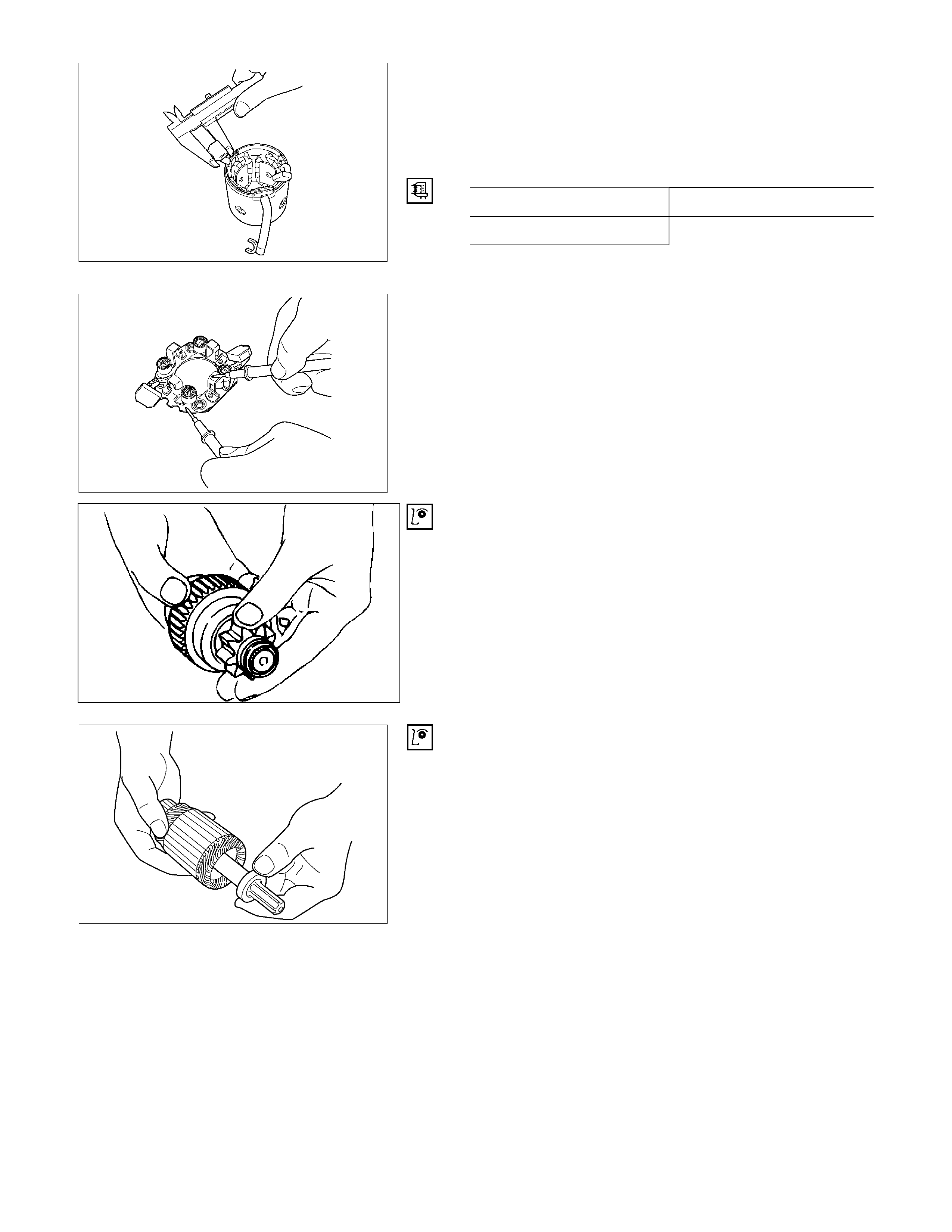
BRUSH AND BRUSH HOLDER
1. Use a vernier calliper to measure the brush length
(four brushes).
Replace the brushes as a set if one or more of the
brush lengths is less than the specified limit.
Brush Length mm (in)
Standard Limit
15 (0.59) 12 (0.47)
RTW46DSH004001
RTW46DSH004101
2. Use a circuit tester to check the brush holder
insulation.
Touch one probe to the holder plate and the other
probe to the positive brush holder.
There should be no continuity.
3. Inspect the brushes for excessive wear.
Replace parts as necessary.
OVERRUNNING CLUTCH
1. Inspect the overrunning clutch gear teeth for
excessive wear and damage.
Replace the overrunning clutch if necessary.
2. Rotate the pinion clockwise.
It should turn smoothly.
3. Try to rotate the pinion in the opposite direction.
The pinion should lock.
065RY00035
RTW46DSH004401
BEARING
Inspect the bearings for excessive wear and damage.
Replace the bearings if necessary.
REASSEMBLY
l
RTW46DLF000601
Reassembly Steps
1. Magnetic switch assembly 14. Pinion stopper
2. Magnetic switch 15. Pinion stopper clip
3. Dust cover 16. Bearing retainer
4. Plunger 17. Bolt
5. Torsion spring 18. Motor assembly
6. Shift lever
19. Armature
7. Gear case 20. Yoke
8. Dust cover 21. Brush holder
9. Bolt 22. Rear cover
10. Pinion assembly 23. Screw
11. Clutch 24. Through bolt
12. Pinion shaft 25. Lead wire
13. Return spring
RTW46DSH005601
Important Operations
1. Magnetic Switch Assembly
1) Attach the torsion spring to the holes in the magnetic
switch as illustrated.
2) Insert the shift lever into the plunger hole of the
magnetic switch.
RTW46DSH005701
7. Gear Case
3,8. Dust Cover
1) Install the magnetic switch assembly in the gear case.
2) Install the dust cover.
Dust Cover Bolt Torque N⋅m (kg⋅m/lb⋅ft)
8 (0.8/5.4)
10. Pinion Assembly
Apply a coat of grease to the reduction gear and install
the pinion assembly to the armature shaft.
065RY00041
RTW46DSH004501
21. Brush Holders
1) Install the brushes into the brush holder while raising
the spring end of the brush spring.
Take care not to damage the commutator face.
2) Install the brush holder while aligning the edges of the
yoke and the brush holder.
24. Through Bolt
Install the through bolts in the rear cover and tighten them
to the specified torque.
Through Bolt Torque N⋅m (kg⋅m/lb⋅ft)
8.1 (0.83/6.00)
065RY00044
RTW46DSH002601
25. Lead Wire
Connect the lead wire in the magnetic switch and tighten
the terminal nut to the specified torque.
Lead Wire Terminal Nut Torque N⋅m (kg⋅m/lb⋅ft)
8.6 (0.88/6.40)
RTW46DSH005801
Inspection After Assembly
Use a vernier calliper to measure the pinion shaft thrust
play.
The pinion shaft thrust play is equal to the pinion shaft
end and pinion stopper clearance.
Pinion Shaft Thrust Play mm (in)
0.1 – 2.0 (0.004 – 0.078)
MAGNETIC SWITCH
The following tests must be performed with the starter
motor fully assembled.
The yoke lead wire must be disconnected from the “M”
terminal.
To prevent coil burning, complete each test as quickly as
possible (within three to five seconds).
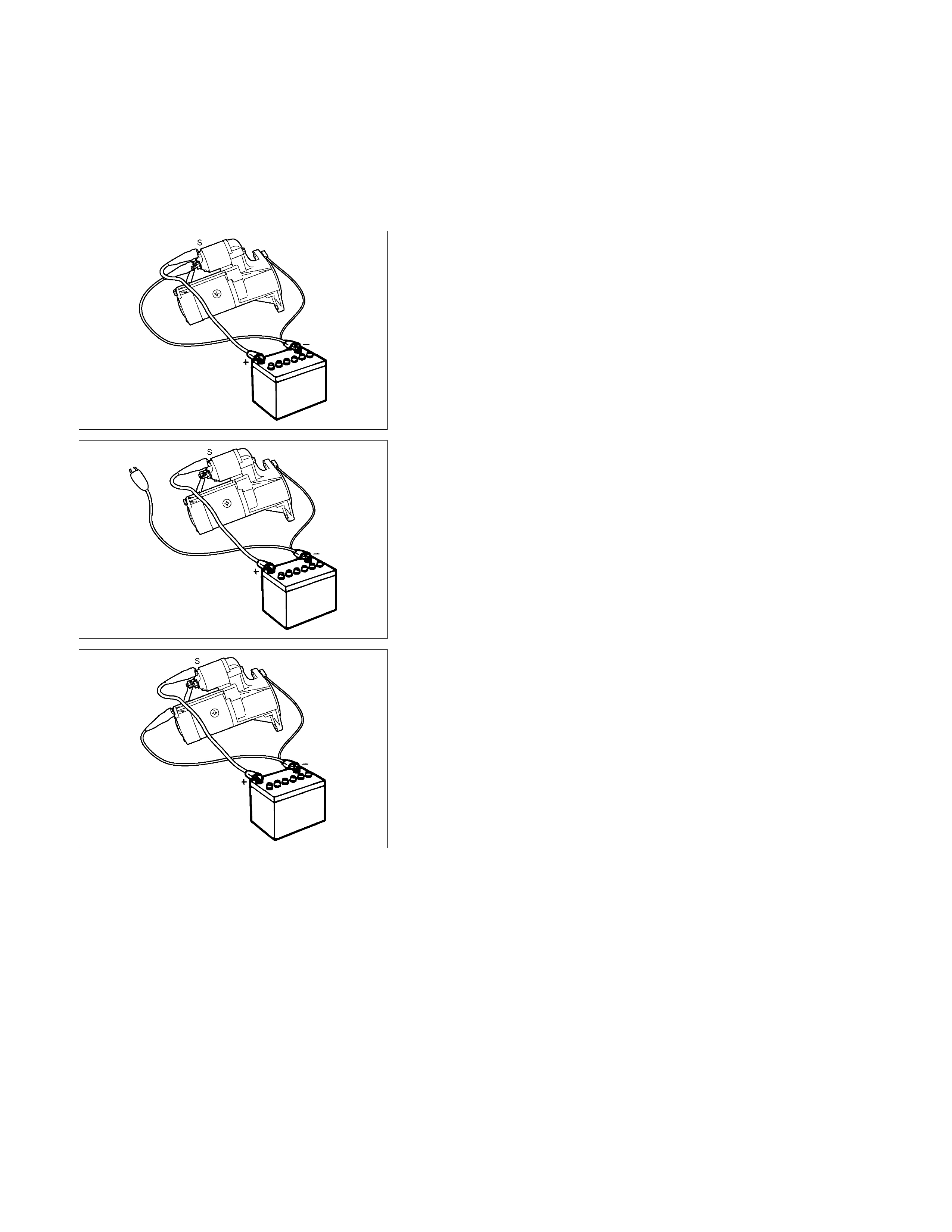
RTW46DSH004601
Temporarily connect the solenoid switch between the
clutch and the housing and run the following test.
Complete each test within three to five seconds.
1. Pull-in Test
Connect the battery negative terminal with the solenoid
switch body and the M terminal. When current is applied
to the S terminal from the battery positive terminal, the
pinion should flutter.
RTW46DSH005901
2. Hold-in Maintenance Test
Disconnect the lead at the M terminal. The pinion should
continue to flutter.
RTW46DSH004701
3. Return Test
Disconnect the battery positive lead at the S terminal.
The pinion should return to its home position.
PRE-HEATING SYSTEM
INSPECTION AND REPAIR
Make the necessary adjustments, repairs, and part replacement if excessive wear of damage is discovered during
inspection.
VISUAL CHECK
Check the main fuses and glow indicator for damage.
Replace the part(s) if required.
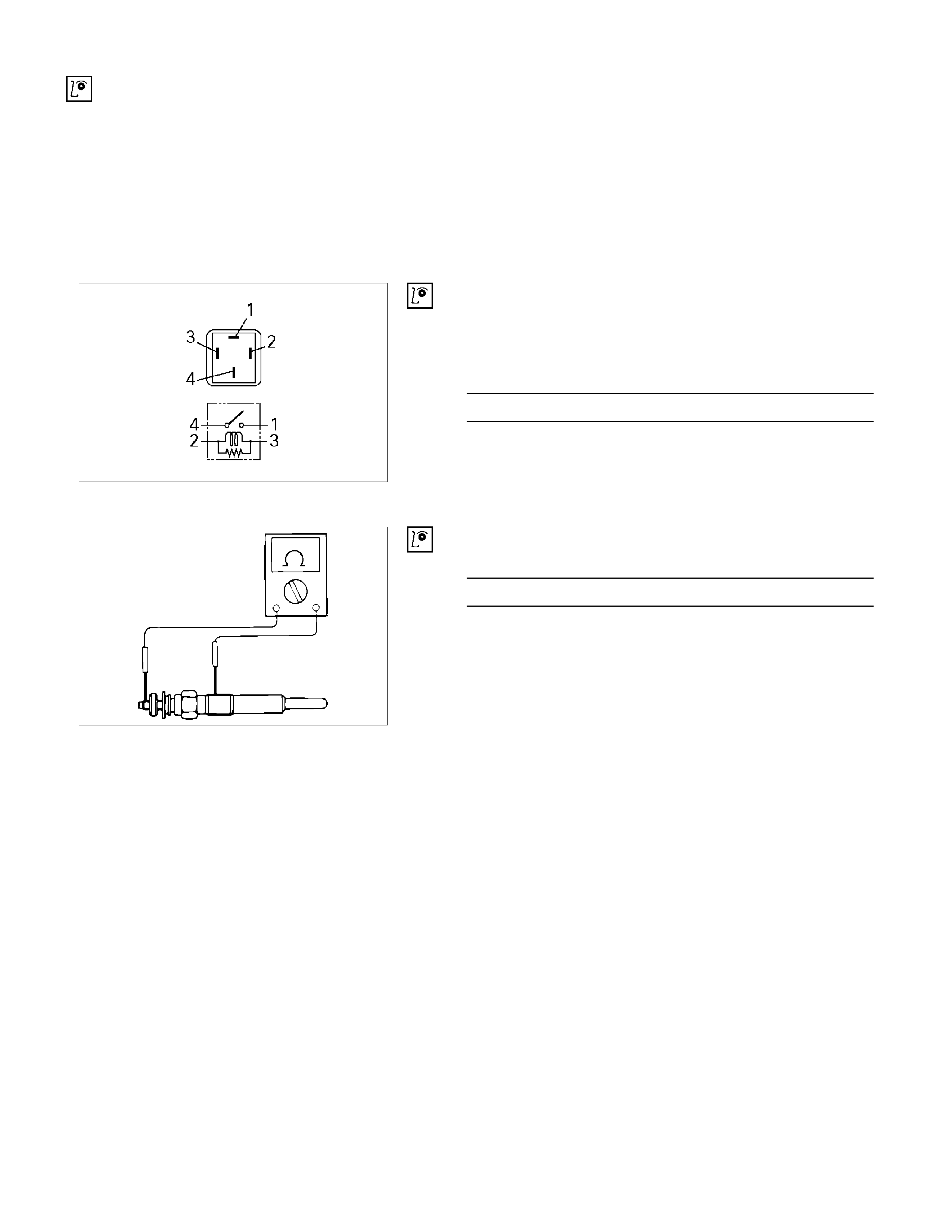
GLOW RELAY
The glow relay is located in the relay box in the engine
compartment.
825R300046
Use an ohmmeter to measure the resistance between
terminals No.2 and No.3.
If the measured value is outside the specified range, the
glow relay must be replaced.
Glow Relay Resistance Ohms
94 − 114
GLOW PLUG
LNW21KSH001401
Use a circuit tester to test the glow plugs for continuity.
Glow Plug Resistance (Reference) Ohms
Approximately 0.9