
SECTION 6E2 - ENGINE DRIVEABILITY AND EMISSIONS
ABBREVIATION CHARTS
COMPONENT LOCATOR
Engine Component Locator Table
ECM CIRCUIT DIAGRAM
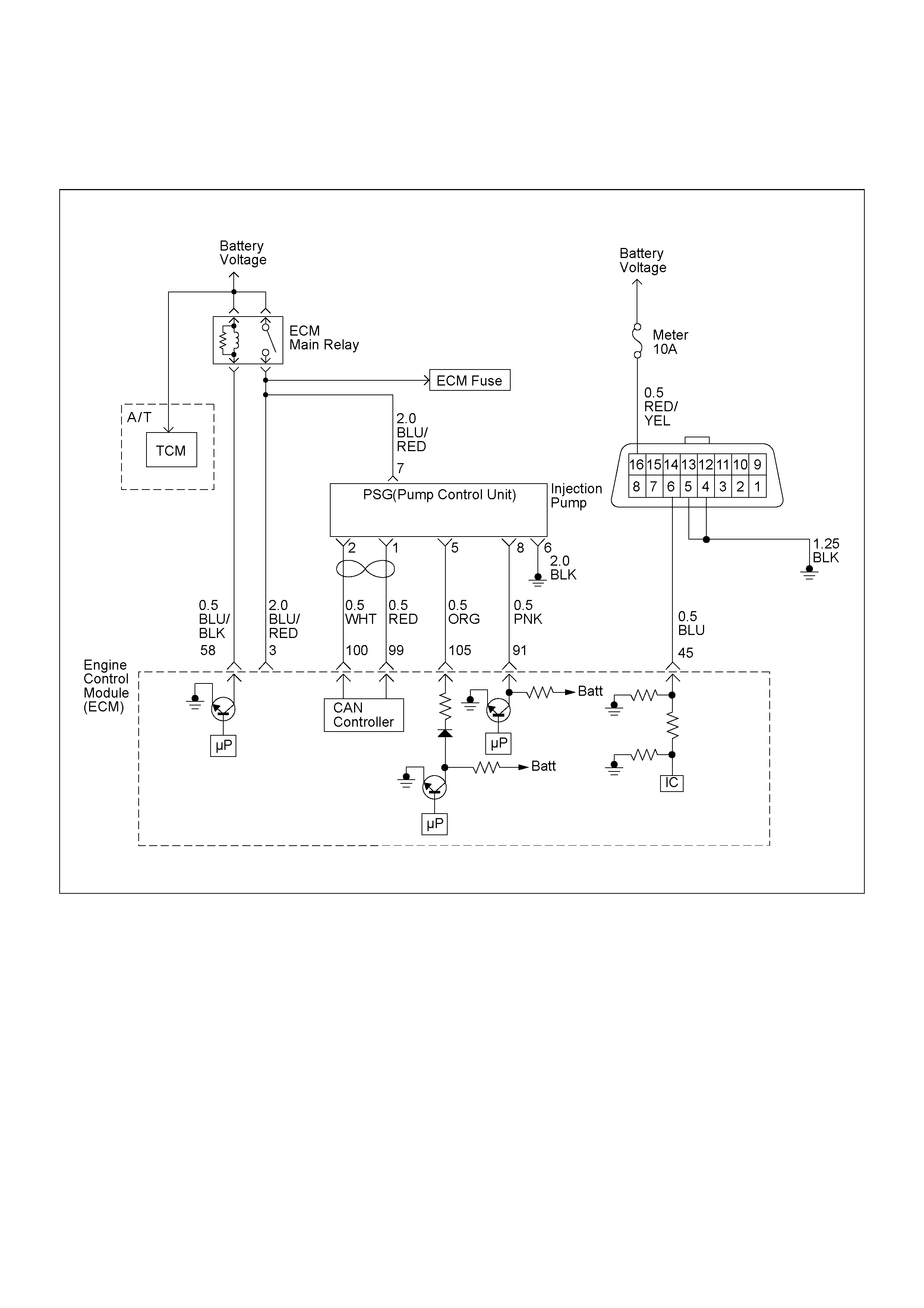
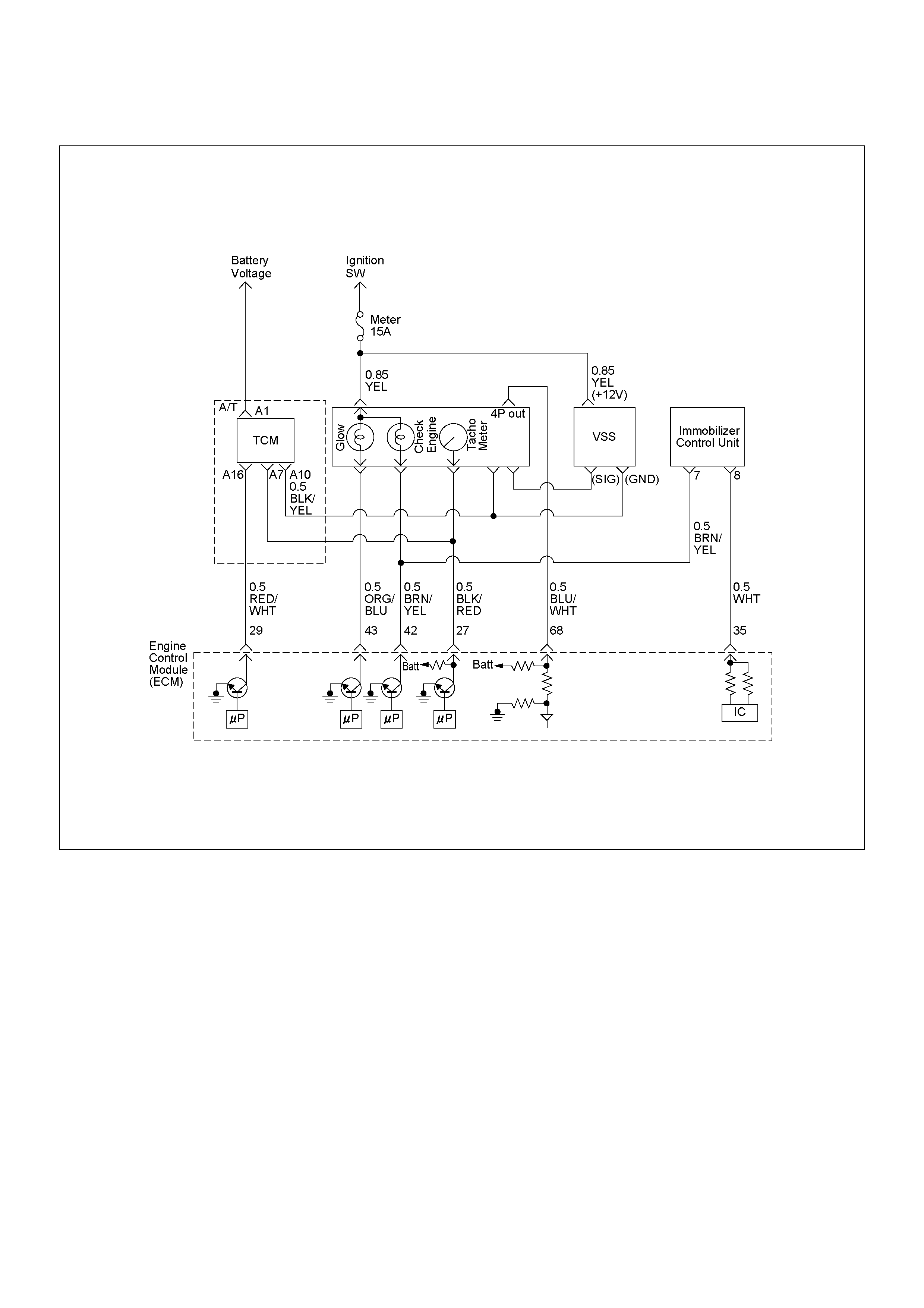
ECM CIRCUIT DIAGRAM (1/2)
ECM CIRCUIT DIAGRAM (2/2)
GROUND POINT
LOCATION
CABLE HARNESS & CONNECTOR LOCATION
PARTS LOCATION
CONNECTOR LIST
RELAY AND FUSE
RELAY AND FUSE BOX LOCATION
RELAY AND FUSE BOX LOCATION
FUSE AND RELAY LOCATION
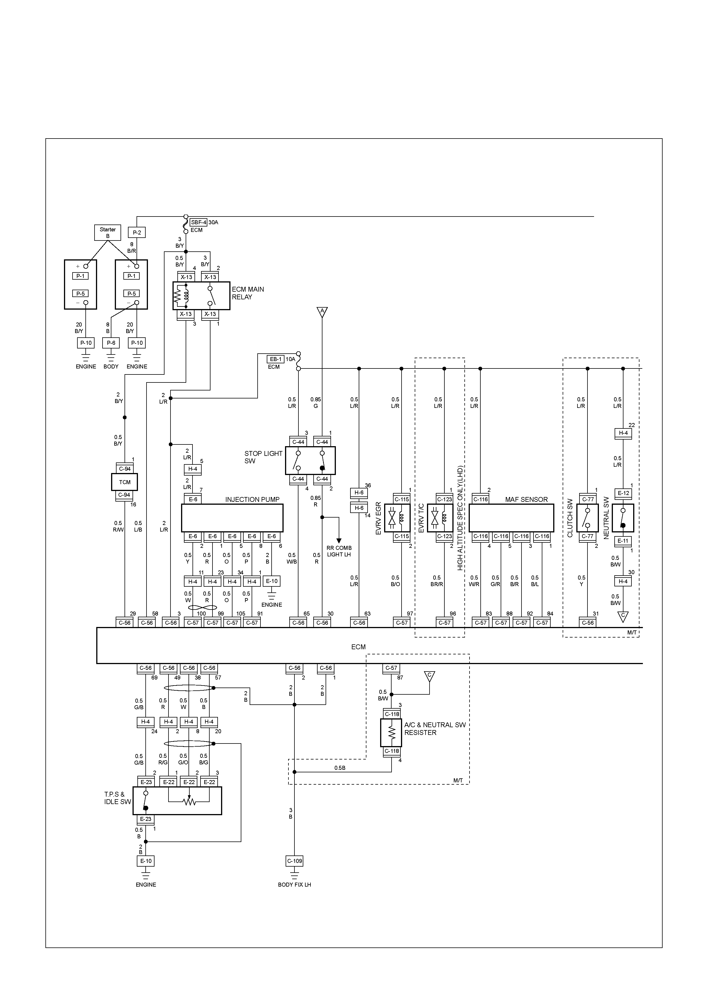
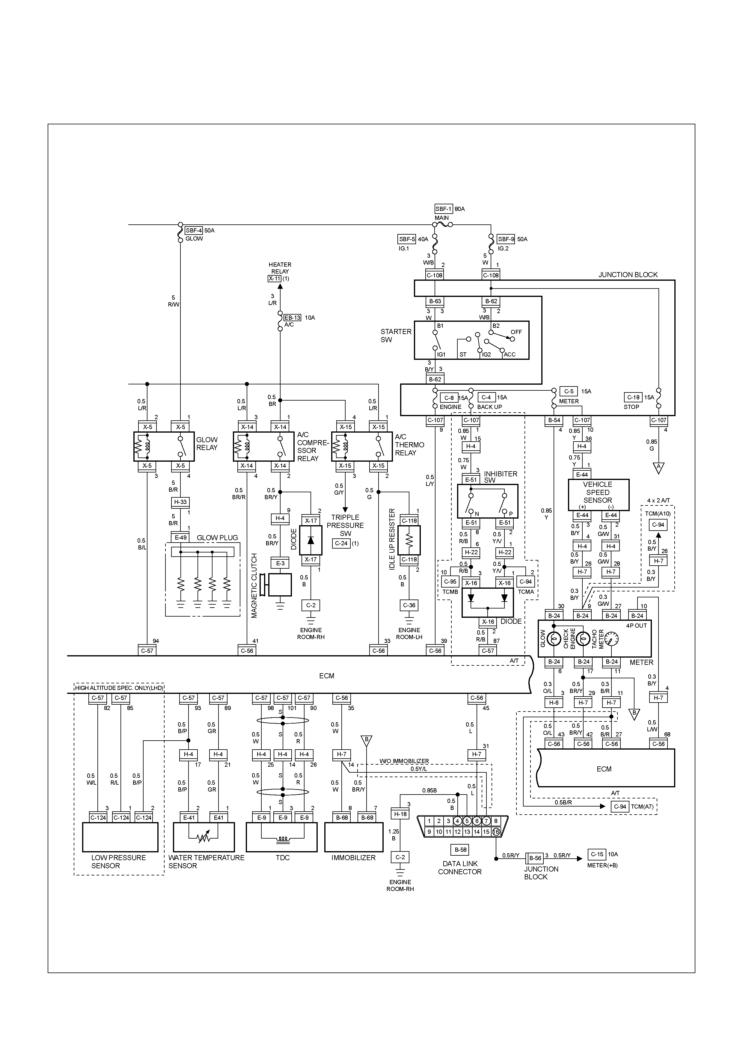
ECM WIRING DIAGRAM
ECM WIRING DIAGRAM (1/7)
ECM WIRING DIAGRAM (2/7)
ECM WIRING DIAGRAM (3/7)
ECM WIRING DIAGRAM (4/7)
ECM WIRING DIAGRAM (5/7)
ECM WIRING DIAGRAM (6/7)
ECM WIRING DIAGRAM (7/7)
ECM CONNECTOR PIN ASSIGNMENT
& OUTPUT SIGNAL
PSG CONNECTOR PIN ASSIGNMENT
& OUTPUT SIGNAL
GENERAL DESCRIPTION FOR ECM AND SENSORS
Engine Control Module (ECM)
Pump Control Unit (PSG) & Data Exchange
Between Control Module
Mass Air Flow (MAF) Sensor & Intake Air
Temperature (IAT) Sensor
Throttle Position Sensor (T PS)
Crankshaft Position (CKP) Sensor
Engine Coolant Temperature (ECT) Sensor
Vehicle Speed Sensor (VSS)
GENERAL DESCRIPTION FOR EGR
(EXHAUST GAS RE-CIRCULATION)
GENERAL DESCRIPTION FOR INJECTION PUMP
Outline
Cross-section View
Low Pressure Fuel Circuit
High Pressure Fuel Circuit
Pump Camshaft Speed Sensor
High Pressure Solenoid Valve
Timing Control Valve (TCV)
STRATEGY BASED DIAGNOSTICS
Overview
Diagnostic Thought Process
1. Verify the Complaint
2. Perform Preliminary Checks
3. Check Bulletins and Troubleshooting Hints
4. Perform Service Manual Diagnostic Checks
5a and 5b. Perform Service Manual
Diag nostic Procedures
5c. Technician Self Diagnoses
5d. Intermittent Diagnosis
5e. Vehicle Operates as Designed
6. Re-examine the complaint
7. Repair and Verify Fix
GENERAL SERVICE INFORMATION
Serviceability Issues
Visual/Physical Engine Compartment Inspection
Basic Knowledge of Tools Required
ON-BOARD DIAGNOSTIC (OBD)
On-Board Diagnostic (Self Diagnosis
System) Tests
The Diagnostic Executive
Verifying Vehicle Repair
Reading Flash Diagnostic Trouble Codes
Reading Diagnostic Trouble Codes
Using a Tech 2
History DTC
Diagnosis With Tech 2
TECH 2 OPERATING FLOW CHART (START UP)
Typical Scan Data & Definitions (Engine Data)
Miscellaneous Test
Plotting Snapshot Graph
Plotting Graph Flow Chart (Plotting graph
after obtaining vehicle information)
Flow Chart for Snaps hot Replay (Plotting G raph)
Snapshot Display With TIS2000
SERVICE PROGRAMMING SYSTEM (SPS)
ON-BOARD DIAGNOSTIC (OBD) SYSTEM CHECK
NO CHECK ENGINE LAMP (MIL)
CHECK ENGINE LAMP (MIL) “ON” STEADY
Techline
Techline
Techline
Techline
Techline
Techline

ECM DIAGNOSTIC TROUBLE CODES
DIAGNOSTIC TROUBLE CODE (DTC) P0100
(SYMPTOM CODE 7) (FLASH CODE 65) MASS
AIR FLOW (MAF) SENSOR VOLTAGE SUPPLY
CIRCUIT HIGH INPUT DIAGNOSTIC TROUBLE
CODE (DTC) P0100 (SYMPTOM CODE 9)
(FLASH CODE 65) MASS AIR FLOW (MAF)
SENSOR VOLTAGE SUPPLY CIRCUIT LOW
INPUT DIAGNOSTIC TROUBLE CODE (DTC)
P0100 (SYMPTOM CODE B) (FLASH CODE 65)
MASS AIR FLOW (MAF) SENSOR OUTPUT
CIRCUIT LOW INPUT DIAGNOSTIC TROUBLE
CODE (DTC) P0100 (SYMPTOM CODE C)
(FLASH CODE 65) MASS AIR FLOW (MAF)
SENSOR OUTPUT CIRCUIT HIGH INPUT
DIAGNOSTIC TROUBLE CODE (DTC) P0105
(SYMPTOM CODE 1) (FLASH CODE 34)
VACUUM PRESSURE SENSOR CIRCUIT HIGH
INPUT DIAGNOSTIC TROUBLE CODE (DTC)
P0105 (SYMPTOM CODE 2) (FLASH CODE 34)
VACUUM PRESSURE SENSOR CIRCUIT LOW
INPUT DIAGNOSTIC TROUBLE CODE (DTC)
P0105 (SYMPTOM CODE 7) (FLASH CODE 34)
VACUUM PRESSURE SENSOR VOLTAGE
SUPPLY CIRCUIT HIGH INPUT DIAGNOSTIC
TROUBLE CODE (DTC) P0105 (SYMPTOM
CODE 9) (FLASH CODE 34) VACUUM
PRESSURE SENSOR VOLTAGE SUPPLY
CIRCUIT LOW INPUT
DIAGNOSTIC TROUBLE CODE (DTC) P0110
(SYMPTOM CODE 1) (FLASH CODE 23)
INTAKE AIR TEMPERATURE (IAT) SENSOR
CIRCUIT HIGH INPUT DIAGNOSTIC TROUBLE
CODE (DTC) P0110 (SYMPTOM CODE 2)
(FLASH CODE 23) INTAKE AIR TEMPERATURE
(IAT) SENSOR CIRCUIT LOW INPUT
DIAGNOSTIC TROUBLE CODE (DTC) P0115
(SYMPTOM CODE 1) (FLASH CODE 14)
ENGINE COOLANT TEMPERATURE SENSOR
CIRCUIT HIGH INPUT DIAGNOSTIC TROUBLE
CODE (DTC) P0115 (SYMPTOM CODE 2)
(FLASH CODE 14) ENGINE COOLANT
TEMPERATURE SENSOR CIRCUIT LOW INPUT
DIAGNOSTIC TROUBLE CODE (DTC) P0180
(SYMPTOM CODE B) (FLASH CODE 15) FUEL
TEMPERATURE SENSOR CIRCUIT RANGE/
PERFORMANCE
DIAGNOSTIC TROUBLE CODE (DTC) P0215
(SYMPTOM CODE A) (FLASH CODE 52) FUEL
CUTOFF SOLENOID VALVE MALFUNCTION
DIAGNOSTIC TROUBLE CODE (DTC) P0215
(SYMPTOM CODE B) (FLASH CODE 52) FUEL
CUTOFF SOLENOID VALVE CIRCUIT HIGH
INPUT DIAGNOSTIC TROUBLE CODE (DTC)
P0215 (SYMPTOM CODE C) (FLASH CODE 52)
FUEL CUTOFF SOLENOID VALVE ALWAYS
ACTIVE DIAGNOSTIC TROUBLE CODE (DTC)
P0215 (SYMPTOM CODE D) (FLASH CODE 52)
FUEL CUTOFF SOLENOID VALVE
MALFUNCTION
DIAGNOSTIC TROUBLE CODE (DTC) P0216
(SYMPTOM CODE A) (FLASH CODE 54)
INJECTION TIMING CONTROL CIRCUIT
MALFUNCTION DIAGNOSTIC TROUBLE CODE
(DTC) P0216 (SYMPTOM CODE B) (FLASH
CODE 54) INJECTION TIMING CONTROL
CIRCUIT MALFUNCTION
DIAGNOSTIC TROUBLE CODE (DTC) P0243
(SYMPTOM CODE 3) (FLASH CODE 64)
TURBOCHARGER WASTEGATE SOLENOID
"A" RANGE/PERFORMANCE DIAGNOSTIC
TROUBLE CODE (DTC) P0243 (SYMPTOM
CODE 4) (FLASH CODE 64) TURBOCHARGER
WASTEGATE SOLENOID "A" LOW
DIAGNOSTIC TROUBLE CODE (DTC) P0243
(SYMPTOM CODE 5) (FLASH CODE 64)
TURBOCHARGER WASTEGATE SOLENOID
"A" RANGE/PERFORMANCE DIAGNOSTIC
TROUBLE CODE (DTC) P0243 (SYMPTOM
CODE 6) (FLASH CODE 64) TURBOCHARGER
WASTEGATE SOLENOID "A" MALFUNCTION
DIAGNOSTIC TROUBLE CODE (DTC) P0243
(SYMPTOM CODE 8) (FLASH CODE 64)
TURBOCHARGER WASTEGATE SOLENOID
"A" HIGH
DIAGNOSTIC TROUBLE CODE (DTC) P0251
(SYMPTOM CODE 6) (FLASH CODE 53)
INJECTION PUMP MALFUNCTION
DIAGNOSTIC TROUBLE CODE (DTC) P0251
(SYMPTOM CODE 7) (FLASH CODE 53)
INJECTION PUMP MALFUNCTION
DIAGNOSTIC TROUBLE CODE (DTC) P0251
(SYMPTOM CODE 9) (FLASH CODE 53)
INJECTION PUMP MALFUNCTION
DIAGNOSTIC TROUBLE CODE (DTC) P0251
(SYMPTOM CODE A) (FLASH CODE 53)
INJECTION PUMP MALFUNCTION
DIAGNOSTIC TROUBLE CODE (DTC) P0251
(SYMPTOM CODE B) (FLASH CODE 53)
INJECTION PUMP MALFUNCTION
DIAGNOSTIC TROUBLE CODE (DTC) P0251
(SYMPTOM CODE D) (FLASH CODE 53)
INJECTION PUMP MALFUNCTION
DIAGNOSTIC TROUBLE CODE (DTC) P0251
(SYMPTOM CODE E) (FLASH CODE 53)
INJECTION PUMP MALFUNCTION

DIAGNOSTIC TROUBLE CODE (DTC) P0335
(SYMPTOM CODE B) (FLASH CODE
43)CRANKSHAFT POSITION SENSOR CIRCUIT
MALFUNCTION DIAGNOSTIC TROUBLE CODE
(DTC) P0335 (SYMPTOM CODE D) (FLASH
CODE 43) CRANKSHAFT POSITION SENSOR
MALFUNCTION DIAGNOSTIC TROUBLE CODE
(DTC) P0335 (SYMPTOM CODE E) (FLASH
CODE 43) ENGINE SPEED INPUT CIRCUIT
RANGE/PERFORMANCE
DIAGNOSTIC TROUBLE CODE (DTC) P0380
(SYMPTOM CODE 4) (FLASH CODE 66) GLOW
RELAY CIRCUIT VOLTAGE LOW DIAGNOSTIC
TROUBLE CODE (DTC) P0380 (SYMPTOM
CODE 8) (FLASH CODE 66) GLOW RELAY
CIRCUIT VOLTAGE HIGH
DIAGNOSTIC TROUBLE CODE (DTC) P0381
(SUB CODE 4) (FLASH CODE 67) GLOW PLUG
INDICATOR CIRCUIT VOLTAGE LOW
DIAGNOSTIC TROUBLE CODE (DTC) P0381
(SUB CODE 8) (FLASH CODE 67) GLOW PLUG
INDICATOR CIRCUIT VOLTAGE HIGH
DIAGNOSTIC TROUBLE CODE (DTC) P0400
(SYMPTOM CODE 3) (FLASH CODE 32)
EXHAUST GAS RECIRCULATION FLOW
EXCESSIVE DETE CTED DIAGNOSTIC
TROUBLE CODE (DTC) P0400 (SYMPTOM
CODE 4) (FLASH CODE 32) EXHAUST GAS
RECIRCULATION CIRCUIT SHORT TO
GROUND OR OPEN CIRCUIT DIAGNOSTIC
TROUBLE CODE (DTC) P0400 (SYMPTOM
CODE 5) (FLASH CODE 32) EXHAUST GAS
RECIRCULATION FLOW INSUFFICIENT
DETECTED DIAGNOSTIC TROUBLE CODE
(DTC) P0400 (SYMPTOM CODE 8) (FLASH
CODE 32) EXHAUST GAS RECIRCULATION
CIRCUIT SHORT TO BATTERY
DIAGNOSTIC TROUBLE CODE (DTC) P0500
(SYMPTOM CODE 1) (FLASH CODE 24)
VEHICLE SPEED SENSOR CIRCUIT HIGH
INPUT DIAGNOSTIC TROUBLE CODE (DTC)
P0500 (SYMPTOM CODE A) (FLASH CODE 24)
VEHICLE SPEED SENSOR INPUT SIGNAL
FREQUENCY TOO HIGH DIAGNOSTIC
TROUBLE CODE (DTC) P0500 (SYMPTOM
CODE B) (FLASH CODE 24) VEHICLE SPEED
SENSOR INCORRECT SIGNAL
DIAGNOSTIC TROUBLE CODE (DTC) P0560
(SYMPTOM CODE 1) (FLASH CODE 35)
SYSTEM VOLTAGE TOO HIGH DIAGNOSTIC
TROUBLE CODE (DTC) P0560 (SYMPTOM
CODE 2) (FLASH CODE 35) SYSTEM VOLTAGE
TOO LOW DIAGNOSTIC TROUBLE CODE
(DTC) P0560 (SYMPTOM CODE A) (FLASH
CODE 35) SYSTEM VOLTAGE MALFUNCTION
DIAGNOSTIC TROUBLE CODE (DTC) P0561
(SYMPTOM CODE A) (FLASH CODE 18)
IGNITION SWITCH CIRCUIT MALFUNCTION
DIAGNOSTIC TROUBLE CODE (DTC) P0561
(SYMPTOM CODE B) (FLASH CODE 18)
IGNITION SWITCH CIRCUIT MALFUNCTION
DIAGNOSTIC TROUBLE CODE (DTC) P0602
CONTROL MODULE PROGRAMMING ERROR
DIAGNOSTIC TROUBLE CODE (DTC) P0606
(SYMPTOM CODE A) (FLASH CODE 28) ECU
MALFUNCTION DIAGNOSTIC TROUBLE CODE
(DTC) P0606 (SYMPTOM CODE B) (FLASH
CODE 28) ECU MALFUNCTION
DIAGNOSTIC TROUBLE CODE (DTC) P0645
(SYMPTOM CODE 4) (FLASH CODE 46) A/C
COMPRESSOR RELAY CIRCUIT VOLTAGE
LOW DIAGNOSTIC TROUBLE CODE (DTC)
P0645 (SYMPTOM CODE 8) (FLASH CODE 46)
A/C COMPRESSOR RELAY CIRCUIT VOLTAGE
HIGH
DIAGNOSTIC TROUBLE CODE (DTC) P0703
(SYMPTOM CODE A) (FLASH CODE 25)
BRAKE SWITCH CIRCUIT MALFUNCTION
DIAGNOSTIC TROUBLE CODE (DTC) P0703
(SYMPTOM CODE B) (FLASH CODE 25)
BRAKE SWITCH CIRCUIT MALFUNCTION
DIAGNOSTIC TROUBLE CODE (DTC) P0704
(SYMPTOM CODE 6) (FLASH CODE 57)
CLUTCH SWITCH INPUT CIRCUIT
MALFUNCTION
DIAGNOSTIC TROUBLE CODE (DTC) P1105
(SYMPTOM CODE 1) (FLASH CODE 86)
BAROMETRIC PRESSURE SENSOR CIRCUIT
HIGH INPUT DIAGNOSTIC TROUBLE CODE
(DTC) P1105 (SYMPTOM CODE 2) (FLASH
CODE 86) BAROMETRIC PRESSURE SENSOR
CIRCUIT LOW INPUT
DIAGNOSTIC TROUBLE CODE (DTC) P1120
(SYMPTOM CODE 1) (FLASH CODE 21) PEDAL/
THROTTLE POSITION SENSOR CIRCUIT HIGH
INPUT DIAGNOSTIC TROUBLE CODE (DTC)
P1120 (SYMPTOM CODE 7) (FLASH CODE 21)
PEDAL/THROTTLE POSITION SENSOR
VOLTAGE SUPPLY CIRCUIT HIGH INPUT
DIAGNOSTIC TROUBLE CODE (DTC) P1120
(SYMPTOM CODE 9) (FLASH CODE 21) PEDAL/
THROTTLE POSITION SENSOR VOLTAGE
SUPPLY CIRCUIT LOW INPUT DIAGNOSTIC
TROUBLE CODE (DTC) P1120 (SYMPTOM
CODE D) (FLASH CODE 21) PEDAL/THROTTLE
POSITION SENSOR BRAKE SWITCH ERROR
DIAGNOSTIC TROUBLE CODE (DTC) P1120
(SYMPTOM CODE E) (FLASH CODE 21)
PEDAL/THROTTLE POSITION SENSOR IDLE
POSITION SWITCH ERROR

DIAGNOSTIC TROUBLE CODE (DTC) P1173
(SYMPTOM CODE 3) (FLASH CODE 22) FUEL
REDUCTION CAUSED BY HIGH COOLANT
TEMPERATURE DIAGNOSTIC TROUBLE
CODE (DTC) P1173 (SYMPTOM CODE 7)
(FLASH CODE 22) FUEL REDUCTION CAUSED
BY HIGH FUEL TEMPERATURE DIAGNOSTIC
TROUBLE CODE (DTC) P1173 (SYMPTOM
CODE A) (FLASH CODE 22) FUEL REDUCTION
CAUSED BY LOW FUEL TEMPERATURE
DIAGNOSTIC TROUBLE CODE (DTC) P1335
(SYMPTOM CODE A) (FLASH CODE 43)
ENGINE SPEED OUTPUT CIRCUIT
MALFUNCTION
DIAGNOSTIC TROUBLE CODE (DTC) P1345
(SYMPTOM CODE A) (FLASH CODE 45)
CAMSHAFT SPEED MALFUNCTION
DIAGNOSTIC TROUBLE CODE (DTC) P1520
(SYMPTOM CODE A) (FLASH CODE 47)
NEUTRAL SWITCH ON ERROR DIAGNOSTIC
TROUBLE CODE (DTC) P1520 (SYMPTOM
CODE B) (FLASH CODE 47) NEUTRAL SWITCH
OFF ERROR
DIAGNOSTIC TROUBLE CODE (DTC) P1605
(SYMPTOM CODE C) (FLASH CODE 55) SEED
AND KEY FILE DESTROYED DIAGNOSTIC
TROUBLE CODE (DTC) P1605 (SYMPTOM
CODE D) (FLASH CODE 55) EEPROM DEFECT
DIAGNOSTIC TROUBLE CODE (DTC) P1605
(SYMPTOM CODE E) (FLASH CODE 55)
EEPROM DEFECT
DIAGNOSTIC TROUBLE CODE (DTC) P1610
(SYMPTOM CODE A) (FLASH CODE 56)
SECURITY KEY AND SECURITY CODE NOT
PROGRAMMED
DIAGNOSTIC TROUBLE CODE (DTC) P1611
(SYMPTOM CODE A) (FLASH CODE 56)
WRONG SECURITY CODE ENTERED
DIAGNOSTIC TROUBLE CODE (DTC) P1612
(SYMPTOM CODE A) (FLASH CODE 56)
IMMOBILIZER NO OR WRONG SIGNAL
DIAGNOSTIC TROUBLE CODE (DTC) P1613
(SYMPTOM CODE A) (FLASH CODE 56)
IMMOBILIZER NO OR WRONG SIGNAL
DIAGNOSTIC TROUBLE CODE (DTC) P1614
(SYMPTOM CODE A) (FLASH CODE 56)
WRONG TRANSPONDER KEY
DIAGNOSTIC TROUBLE CODE (DTC) P1625
(SYMPTOM CODE A) (FLASH CODE 76) ECM
MAIN RELAY SWITCHED OFF TOO EARLY
DIAGNOSTIC TROUBLE CODE (DTC) P1625
(SYMPTOM CODE B) (FLASH CODE 76) ECM
MAIN RELAY SWITCHED OFF TOO LATE
DIAGNOSTIC TROUBLE CODE (DTC) P1630
(SYMPTOM CODE A) (FLASH CODE 51) FUEL
INJECTION QUANTITY CIRCUIT
MALFUNCTION DIAGNOSTIC TROUBLE CODE
(DTC) P1630 (SYMPTOM CODE B) (FLASH
CODE 51) FUEL INJECTION QUANTITY
CIRCUIT MALFUNCTION
DIAGNOSTIC TROUBLE CODE (DTC) P1650
(SYMPTOM CODE A) (FLASH CODE 44) CAN
DEVICE OFFLINE DIAGNOSTIC TROUBLE
CODE (DTC) P1 650 (SYM PTO M CO DE B)
(FLASH CODE 44) CAN DEVICE HANG-UP
DIAGNOSTIC TROUBLE CODE (DTC) P1651
(SYMPTOM CODE A) (FLASH CODE 45) CAN
MALFUNCTION DIAGNOSTIC TROUBLE CODE
(DTC) P1651 (SYMPTOM CODE B) (FLASH
CODE 45) CAN RECEIVES ERROR
DIAGNOSTIC TROUBLE CODE (DTC) P1690
(SYMPTOM CODE 4) (FLASH CODE 77) CHECK
ENGINE LAMP (MIL) CIRCUIT VOLTAGE LOW
DIAGNOSTIC TROUBLE CODE (DTC) P1690
(SYMPTOM CODE 8) (FLASH CODE 77) CHECK
ENGINE LAMP (MIL) CIRCUIT VOLTAGE HIGH
SYMPTOM DIAGNOSIS
PRELIMINARY CHECKS
VISUAL/PHYSICAL CHECK
INTERMITTENT
ENGINE CRANKS BUT WILL NOT RUN
HARD START SYMPTOM
ROUGH, UNSTABLE, OR INCORRECT IDLE,
STALLING SYMPTOM
SURGES AND/OR CHUGS SYMPTOM
HESITATION, SAG, STUMBLE SYMPTOM
CUTS OUT, MISSES SYMPTOM
LACK OF POWER, SLUGGISH OR
SPONGY SYMPTOM
POOR FUEL ECONOMY S YMPTOM
EXCESSIVE WHITE SMOKE
EXCESSIVE BLACK SMOKE
ON-VEHICLE SERVICE PROC EDURE
ENGINE CONTROL MODULE (ECM)
CRANKSHAFT POSITION (CKP) SENSOR
ENGINE COOLANT TEMPERATURE
(ECT) SENSOR
MASS AIR FLOW (MAF) & INTAKE AIR
TEMPERATURE (IAT) SENSOR
THROTTLE POSITION SENSOR (TPS)
EGR EVRV (Electrical Vacuum Regulating Valve)
SPECIAL SERVICE TOOLS

ABBREVIATION CHARTS
Abbreviations Appellation
A/C Air conditioner
A/T Automati c transmi ssio n
ACC Accessory
BLK Black
BLU Blue
BRN Brown
CAN Controller Area Network
CEL Check engine lamp
CKP Crankshaft position sensor
DLC Data link connector
DTC Diagnosis trouble code
DVM Digital voltage meter
ECM Engine co ntr ol module
ECT Engine co olant tempera tur e
EEPROM Electrically erasable & programmable read only memory
EGR Exhaust gas recirculation
EVRV Electric vacuum regulating valve
GND Ground
GRY Gray
IAT Intake air temperature
IG Ignition
M/T Manual transmission
MAB High pressure solenoid valve cutoff (German abbreviation)
MAF Mass air flow
MIL Malfunction indicator lamp
OBD On-board diagnostic
ORN Orange
PNK Pink
RED Red
PSG Pump control unit (German abbreviation)
SW Switch
TCM Transmission control module
TCV Timing control valve
TDC Top dead center
TPS Throttle position sensor
VCC Voltage constunt control
VIO Violet
VSS Vehicle speed sensor
WHT White
YEL Yellow
COMPONENT LOCATOR
ENGINE COMPONENT LOCATOR TABLE
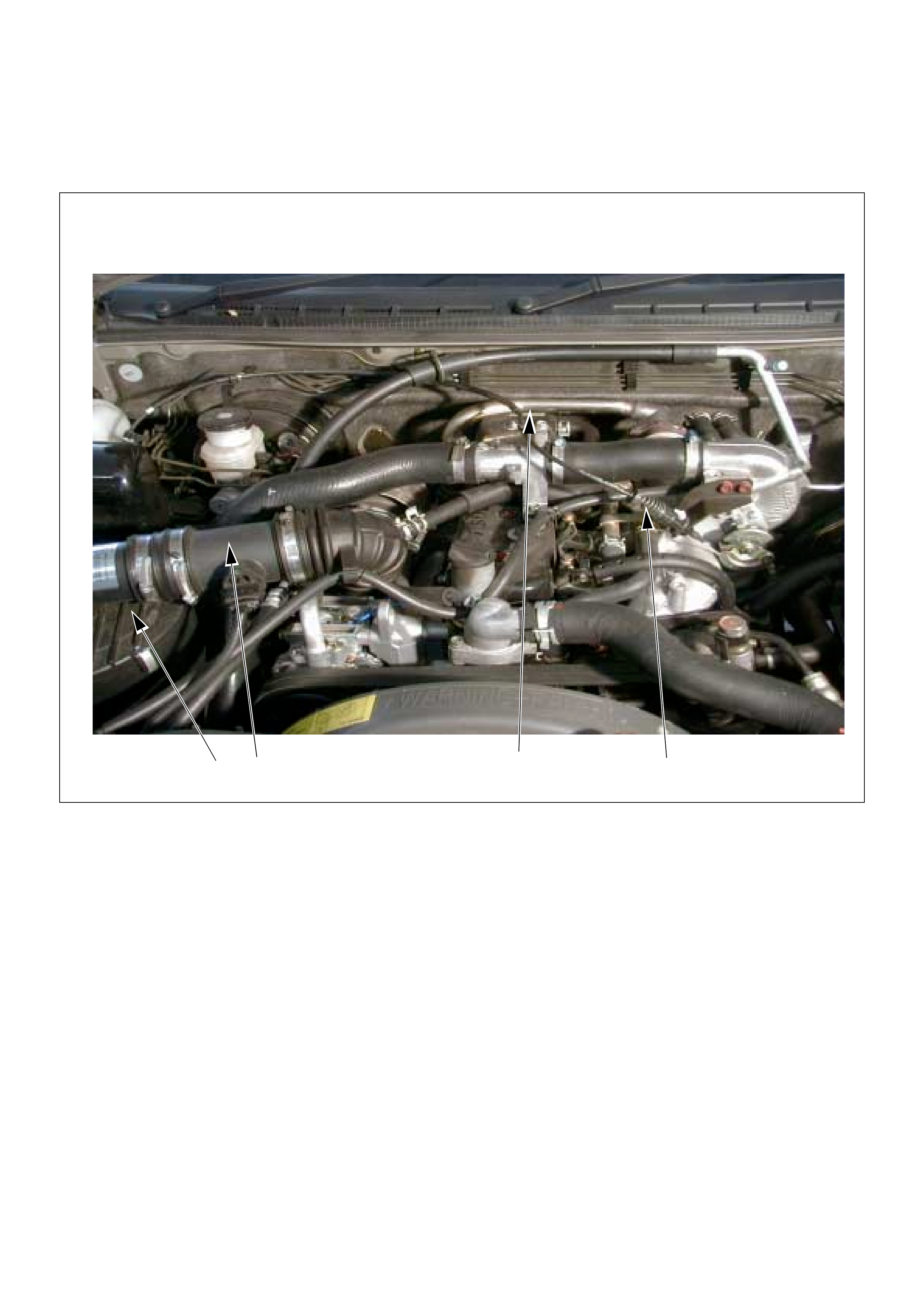
PNQO
(1) Mass Air Flow (MAF) & Intake Air Temperature
(IAT) Sensor Assembly
(2) Throttle Cable
(3) Air Cleaner Case
(4) EGR Pipe
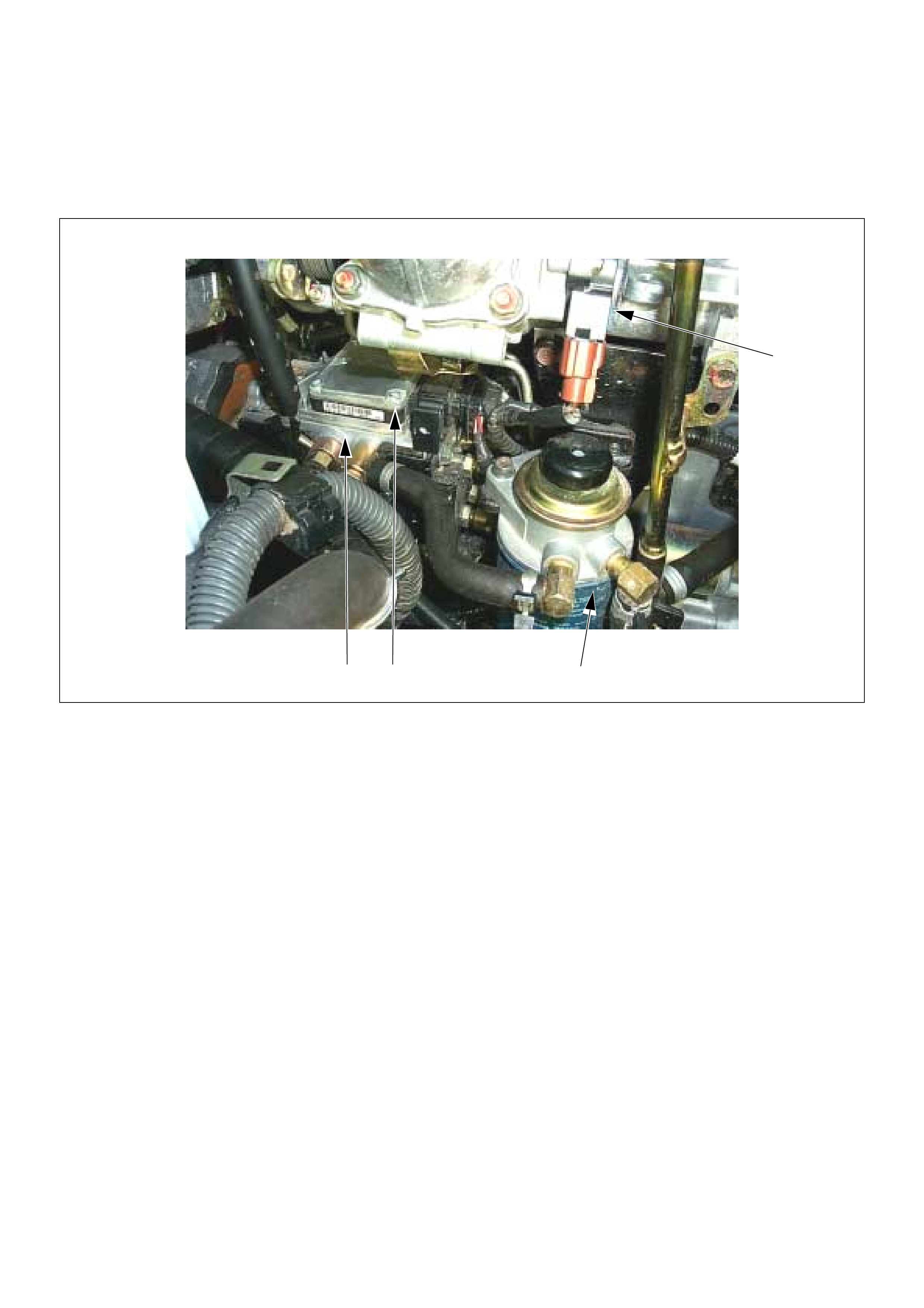
P O Q
N
(1) Throttle Position Sensor (TPS)
(2) Pump Control Unit (PSG) (3) Injection Pump Assembly
(4) Fuel Filter
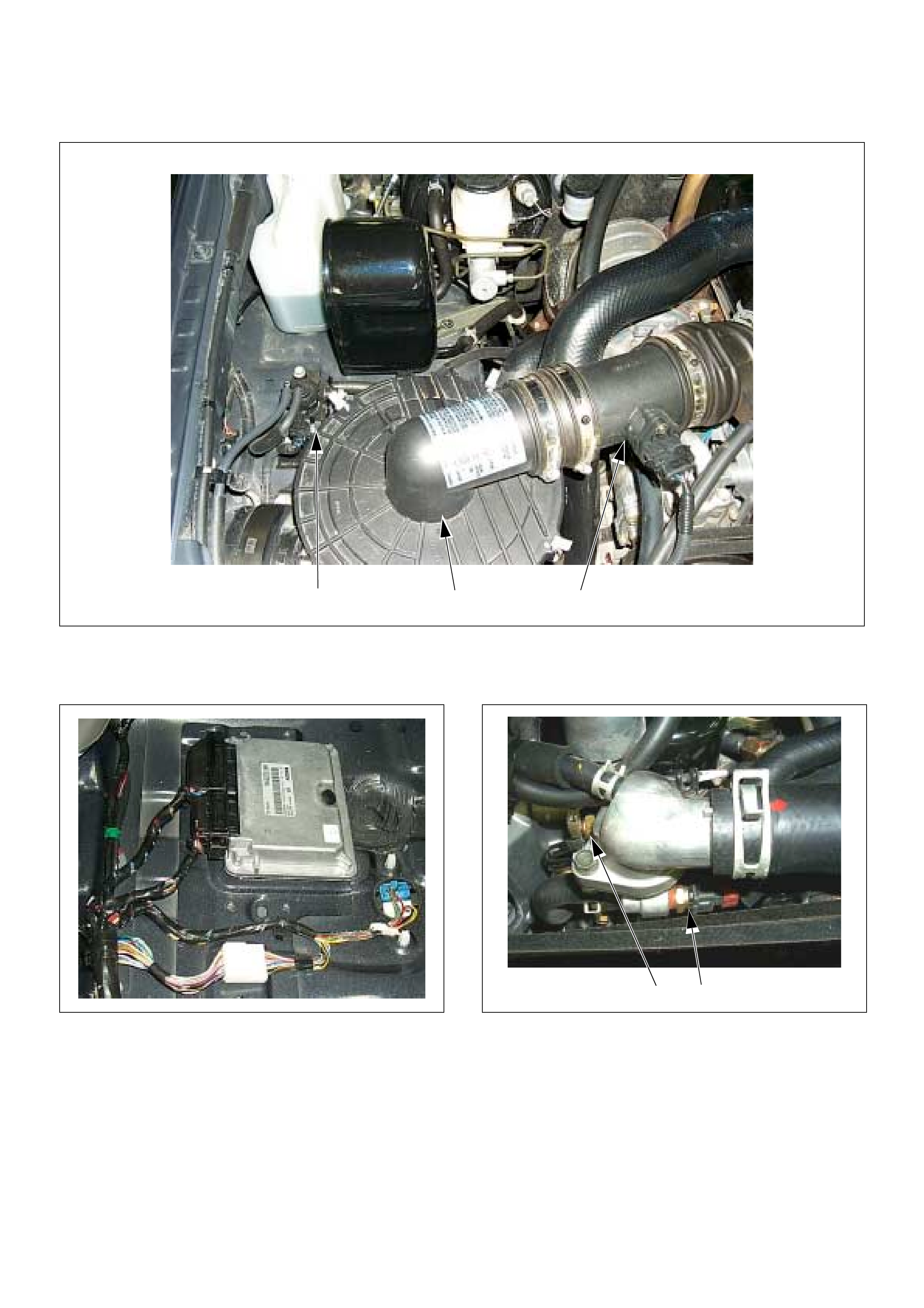
O NP
(1) Mass Air Flow (MAF) & Intake Air Temperature
(IAT) Sensor Assembly
(2) EGR EVRV
(3) Air Cleaner Case
(1) Engine Control Module (ECM) (1) Engine Coolant Temperature (ECT) Sensor
(2) Thermo Unit for Water Temperature Gauge
ON
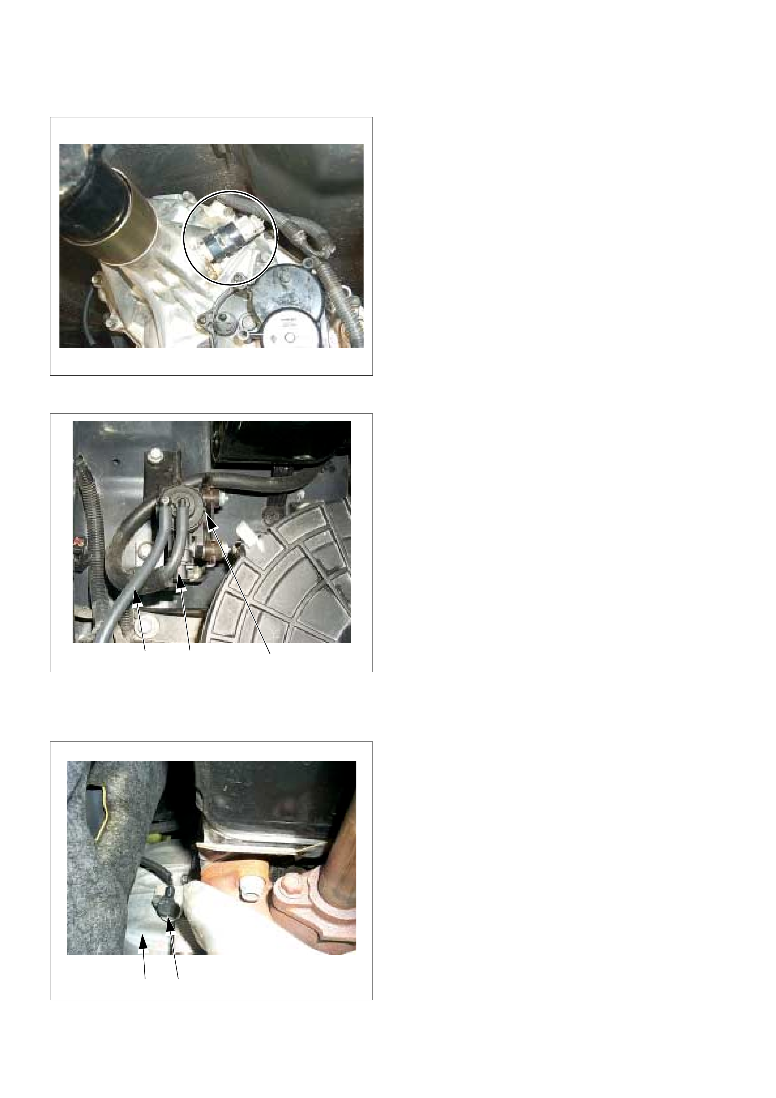
(1) Vehicle Speed Sensor (VSS)
(1) EGR EVRV
(2) To Vacuum Pump
(3) To EGR Valve
(1) Crankshaft Position (CKP) Sensor
(2) Clutch Housing
P O N
NO
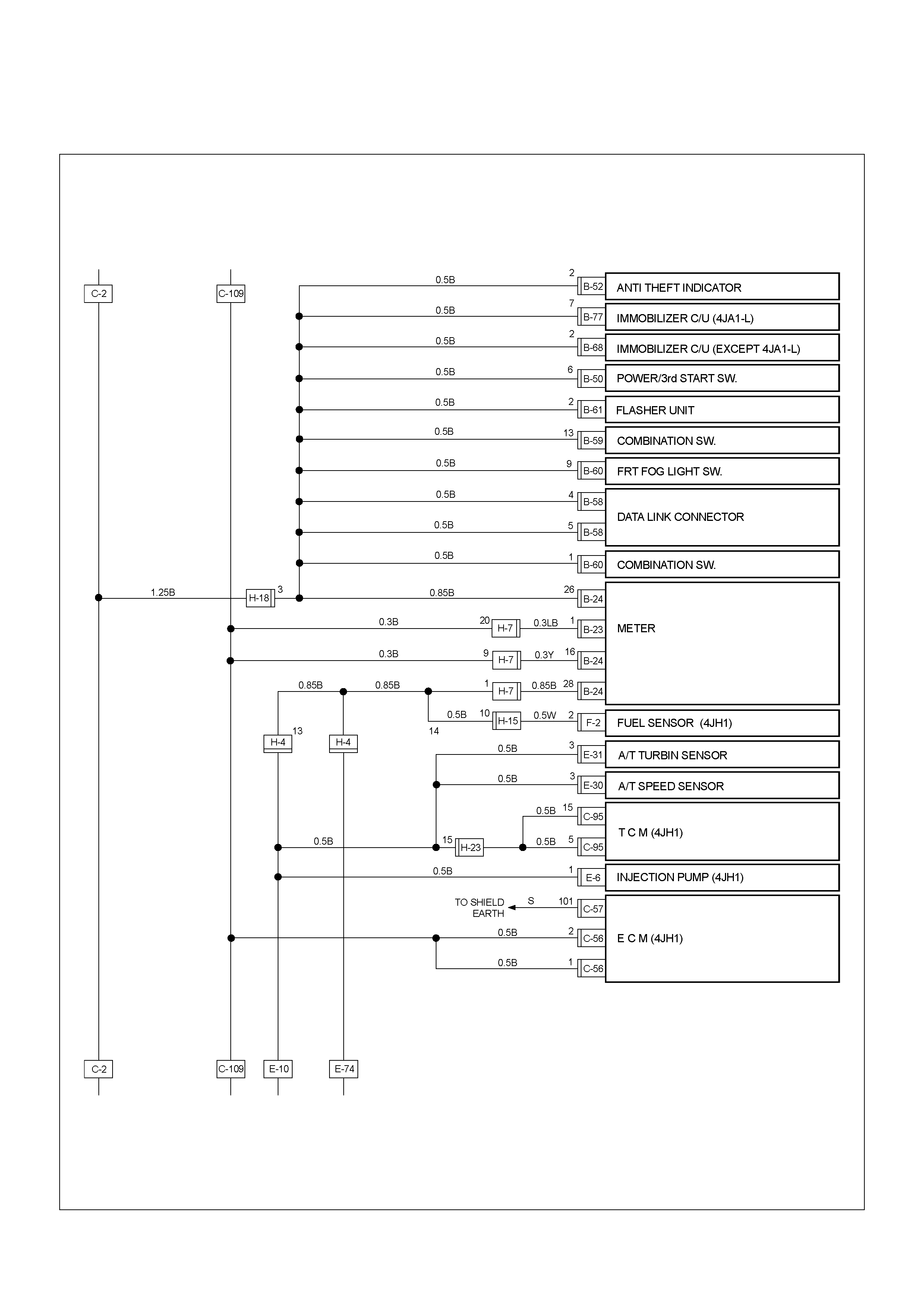
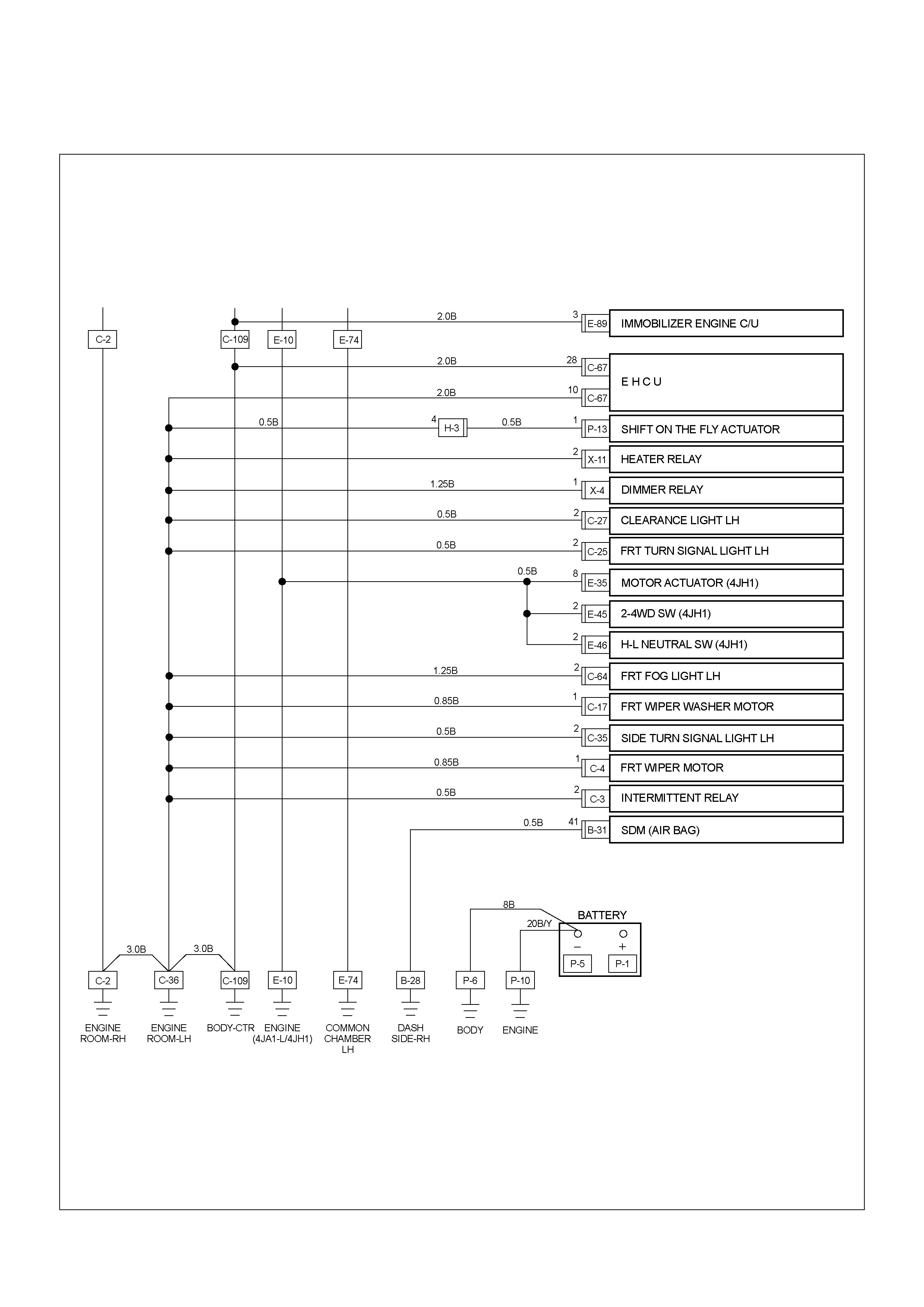
ECM CIRCUIT DIAGRAM
ECM CIRCUIT DIAGRAM (1/2)
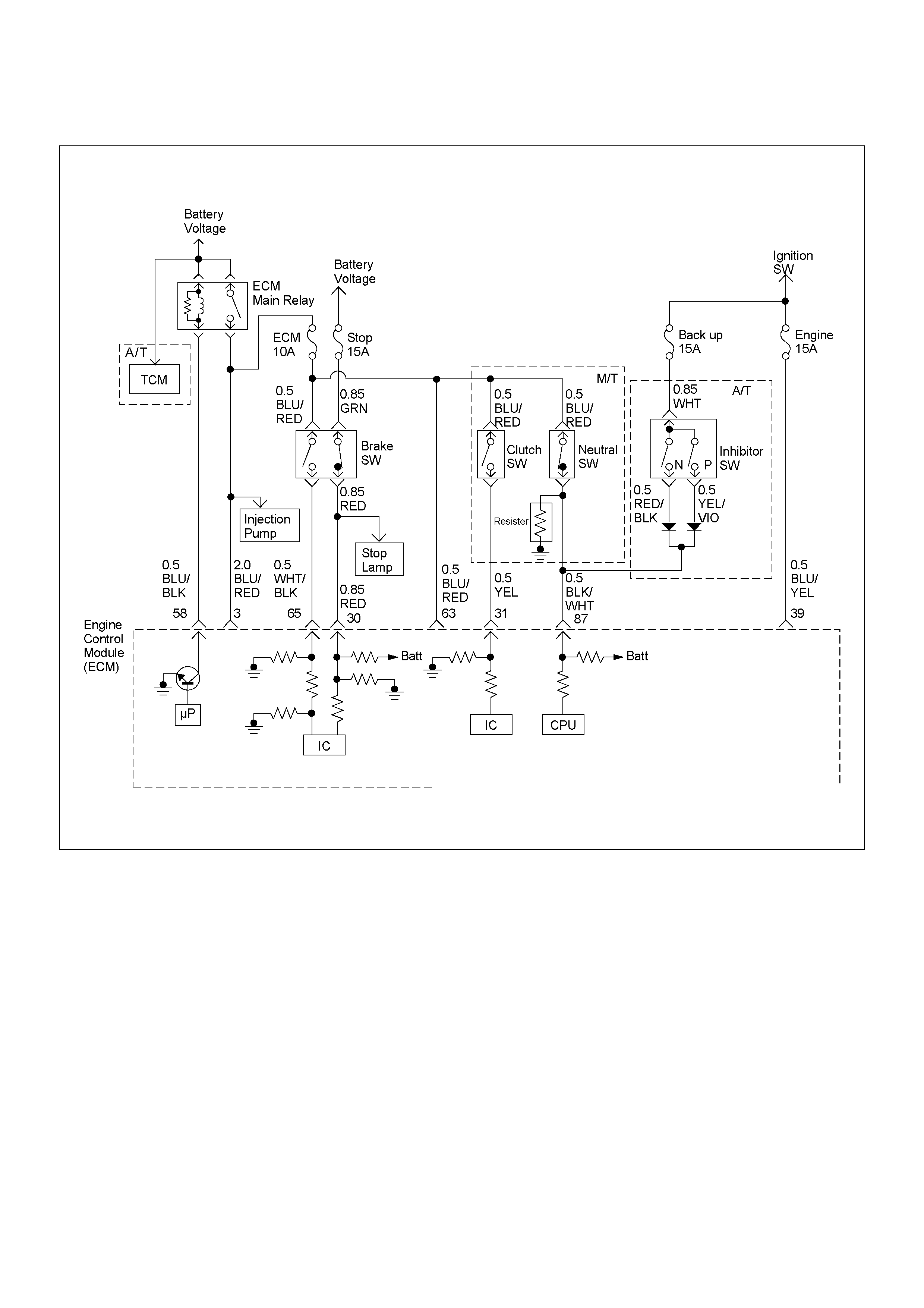
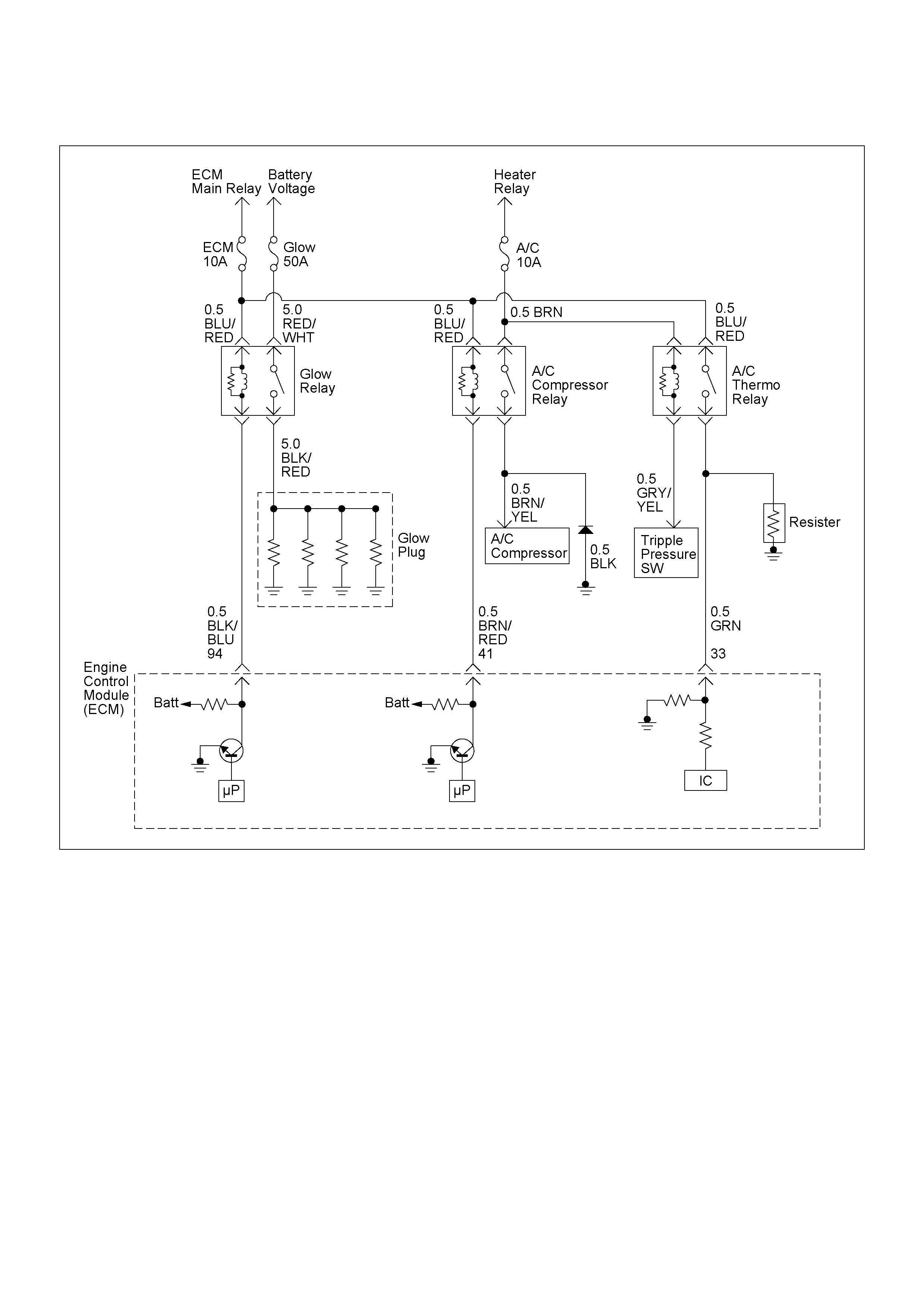
ECM CIRCUIT DIAGRAM (2/2)
GROUND POINT
GROUND POINT CHART (1/4)
GROUND POINT CHART (2/4)
GROUND POINT CHART (3/4)
GROUND POINT CHART (4/4)
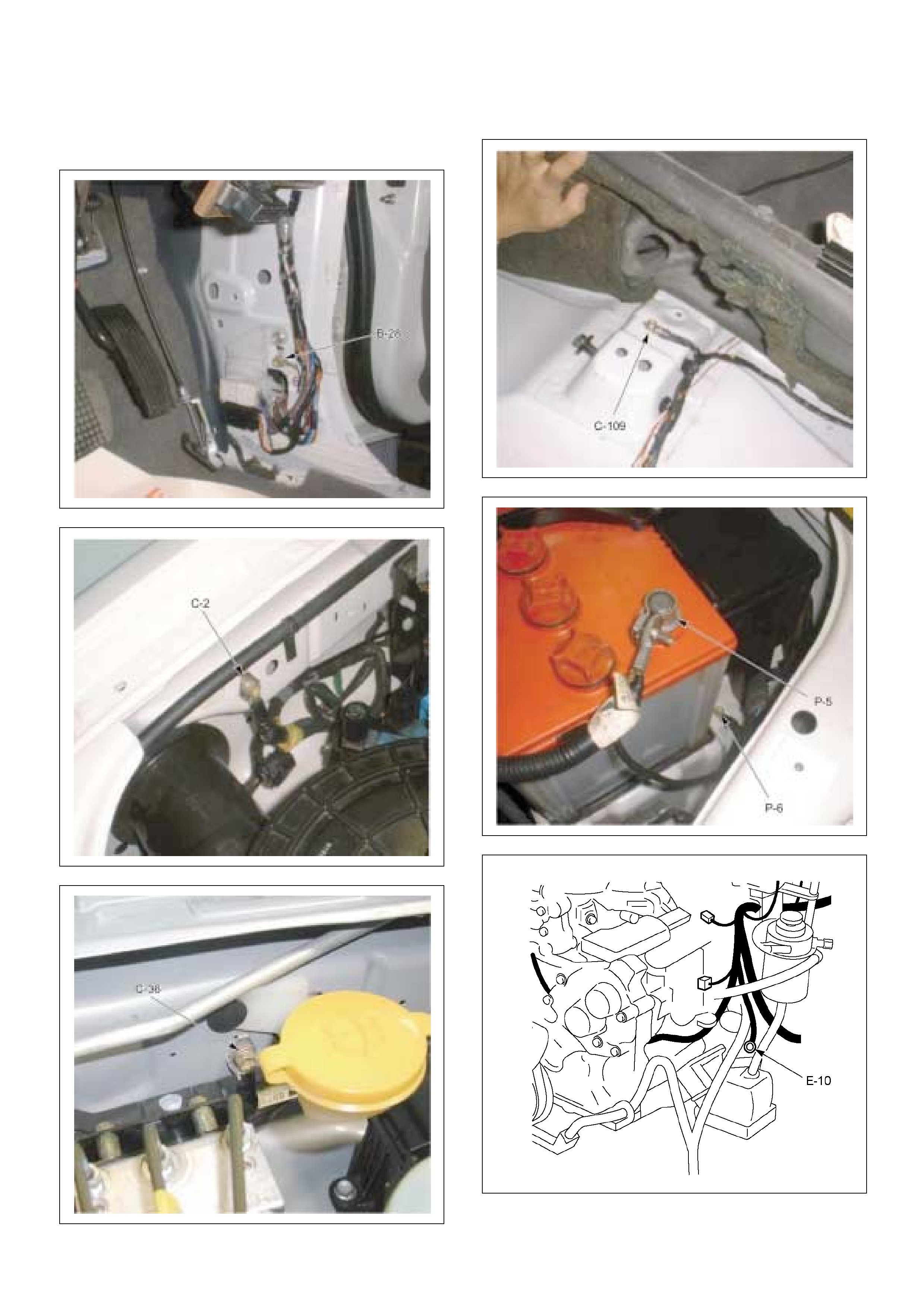
LOCATION
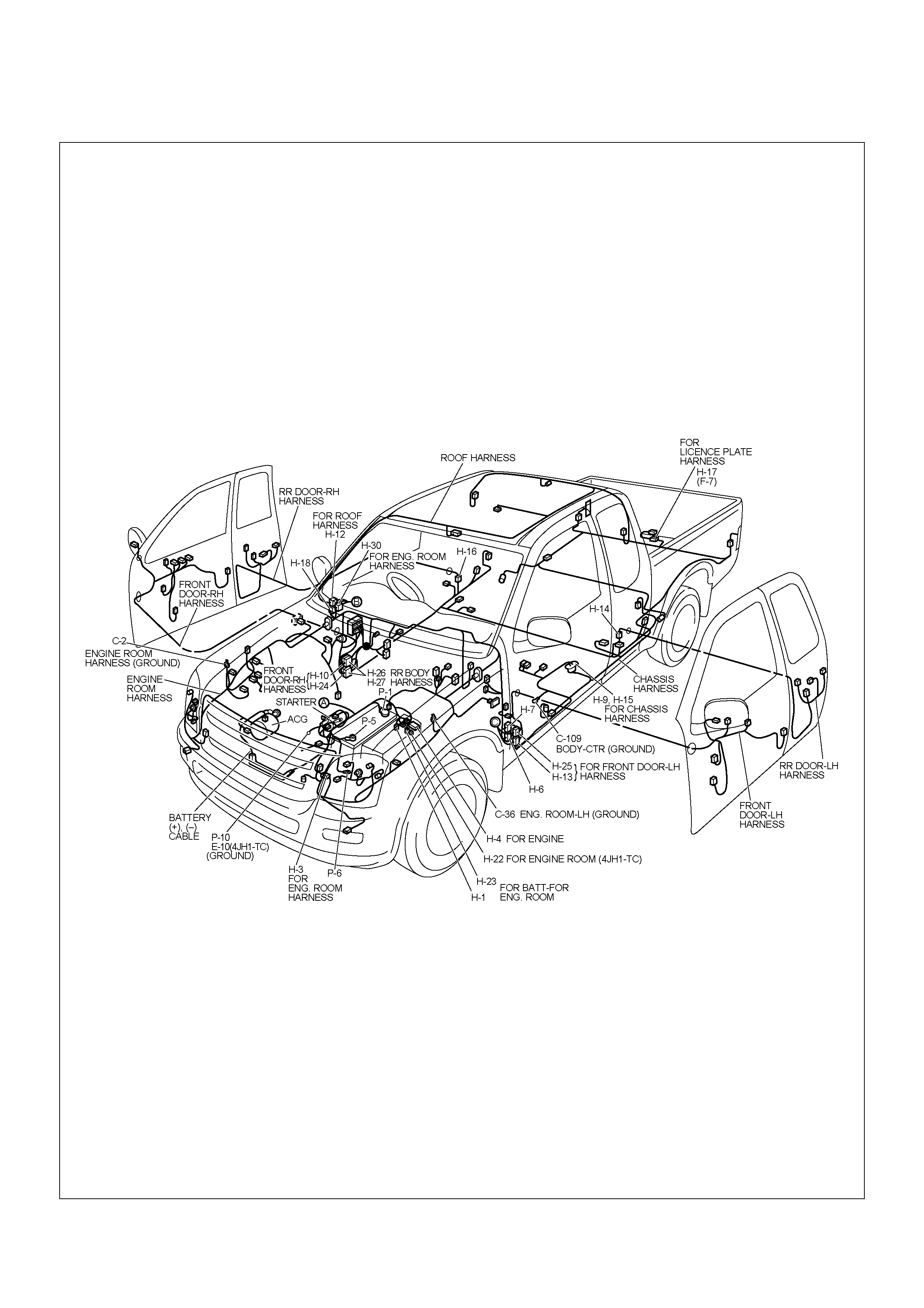
CABLE HARNESS & CONNECTOR LOCATION

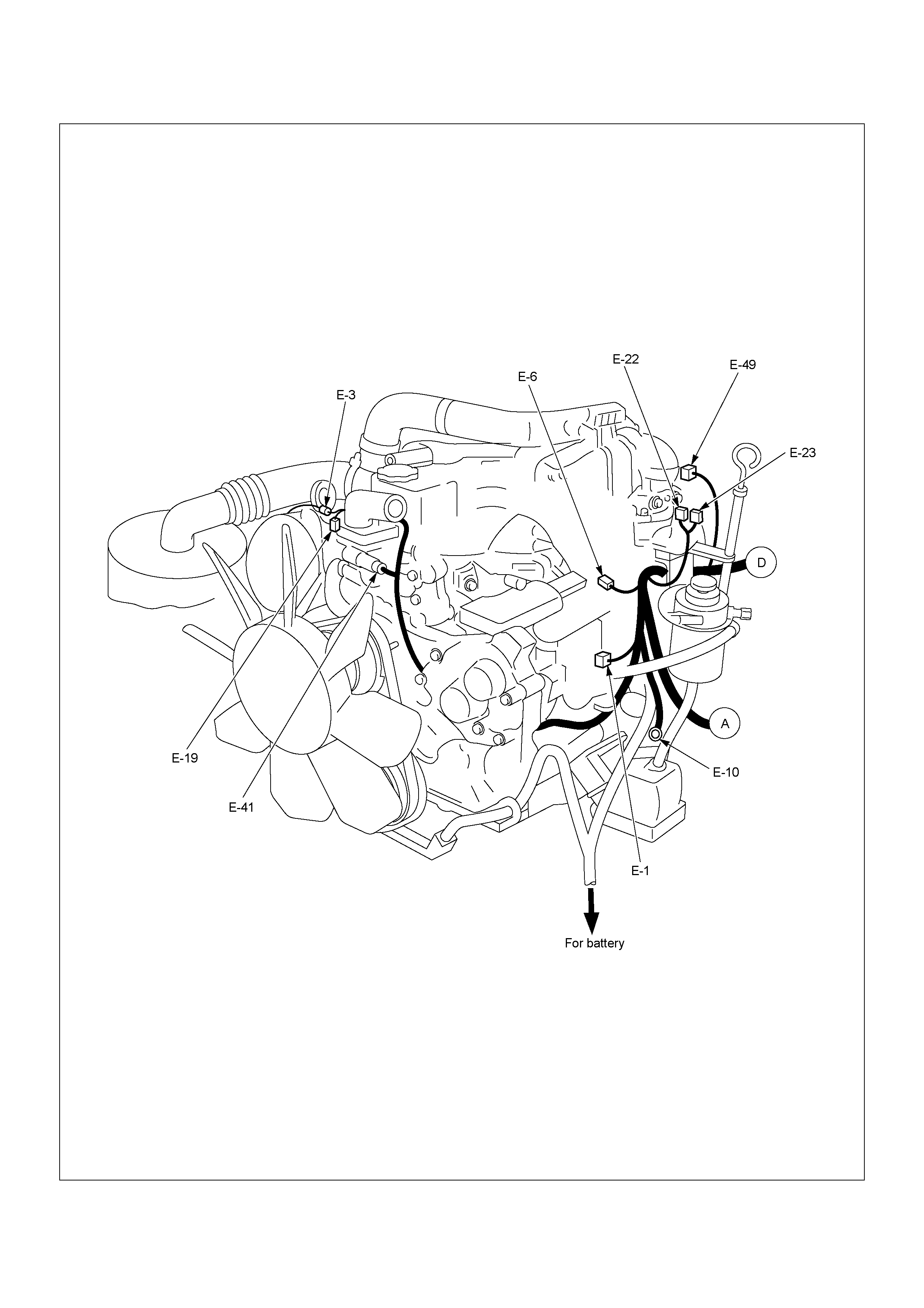
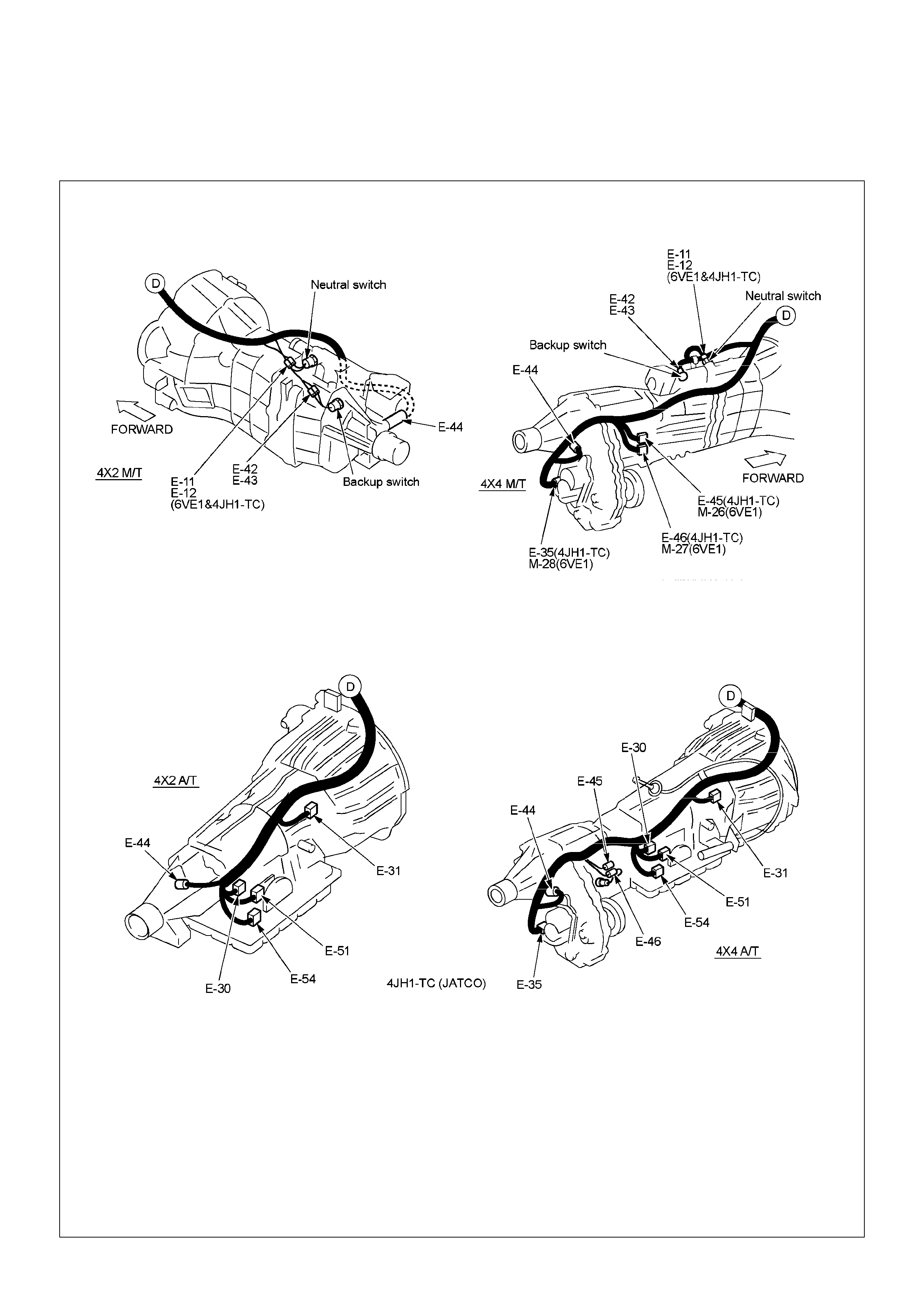
PARTS LOCATION
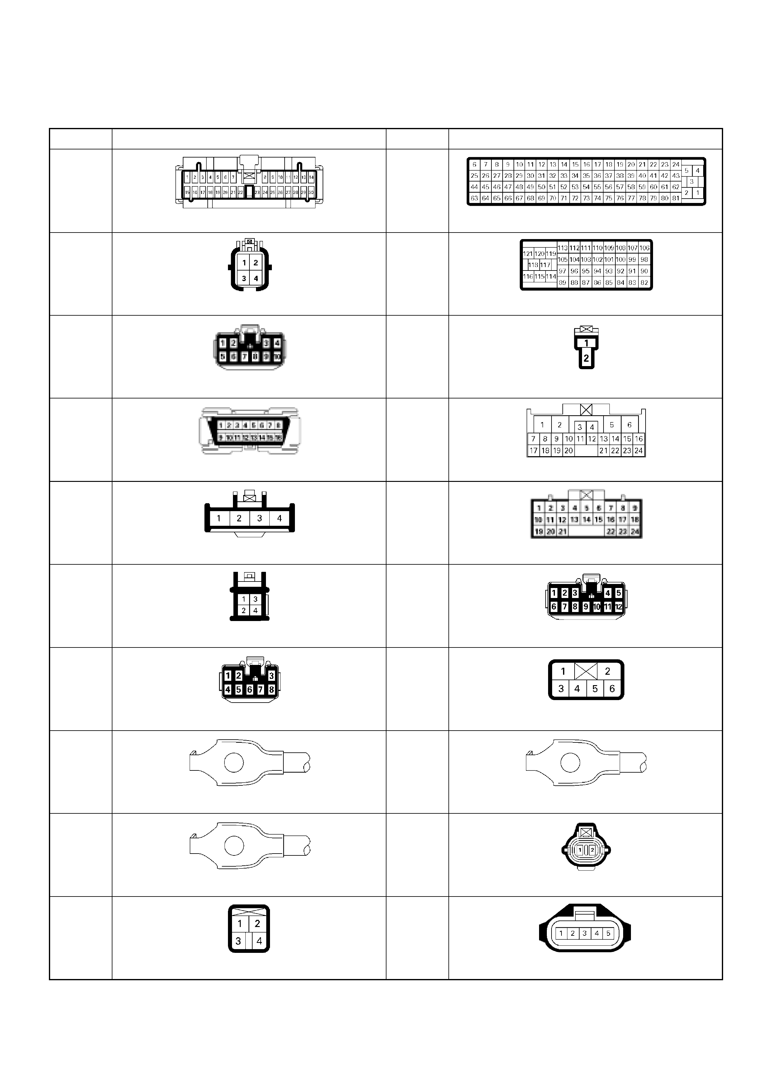
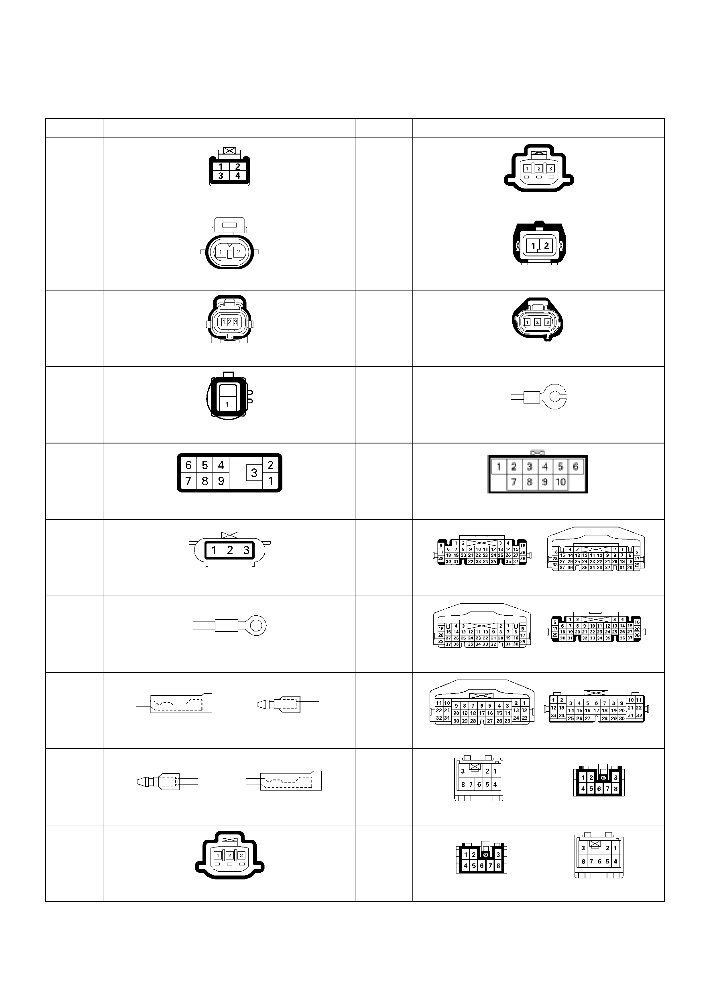
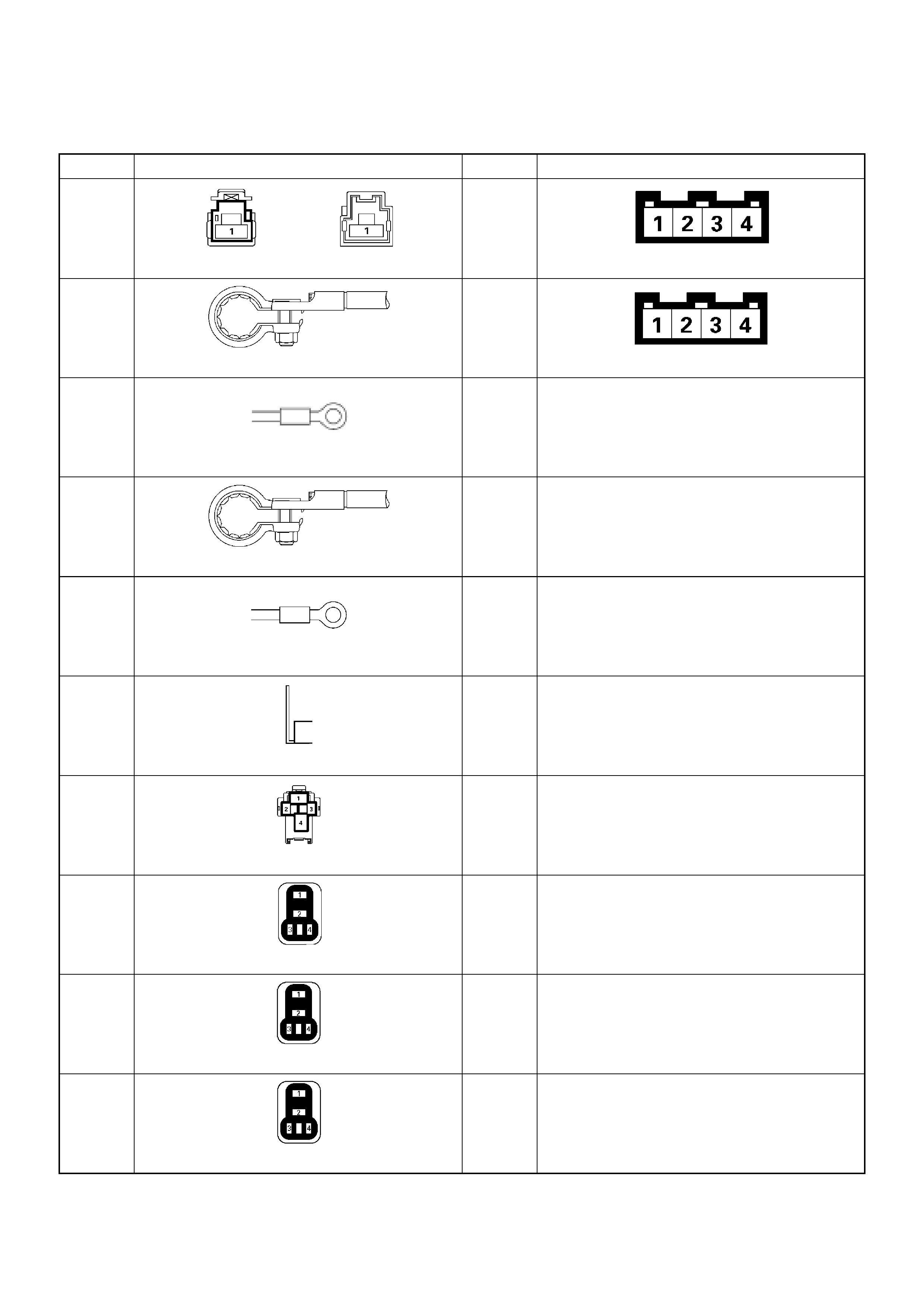
CONNECTOR LIST
No. Connector face No. Connector face
B-24
Green Meter-B
C-56
ECM-A
B-54
White J/B I2
C-57
ECM-B
B-56
White J/B I4
C-77
Clut ch swi t c h
B-58
Black Check connector
C-94
White TCM
B-62
White Ignition switch (IGSUB : G1)
C-95
White TCM
B-63
White Ignition switch (IGSUB : G2)
C-
White J/B E2
B-68
Immobilizer
C-
White J/B E1
C-2
Silver Engine room-RH ground
C-
Silver Body-LH ; ground
C-36
Silver Engine room-LH ; Ground
C-
Brown EVRV
C-44
White Stop lamp switch
C-
No. Connector face No. Connector face
C-
A/C Resister & Neutral switch
E-23
Gray Idle SW
C- E-41
Black Coolant temp sensor
C- E-44
Gray Vehi cle sp eed sensor
E-3
Black Magnetic clutch AC COMP
E-49
Gray Glow plug
E-6 E-51
Black Inhibiter switch
E-9 H-4
White Engine room ~ Mission
E-10
Silver Engine ground
H-6
White Engine room ~ INST
E-11
Natural
green Neutral switch
H-7
White Engine room ~ INST
E-12
Natural
green Neutral switch
H-18
White Engine room ~ INST
E-22
Brown TPS 1 main
H-22
White Engine ~ Engine room C
No. Connector face No. Connector face
H-33
Engine ~ Engine room
X-16
Black DIODE
P-1
Silver Battery (+)
X-17
Black DIODE
P-2
Silv er Relay & Fuse box
P-5
Silver Battery (-)
P-6
Silver Body earth (Gr oun d)
P-10
Silver Engine ground
X-5
Black Relay ; Glow
X-13
Black Relay ; ECM MAIN
X-14
Black Relay; A/C Compressor
X-15
Black Relay; Thermo
RELAY AND FUSE
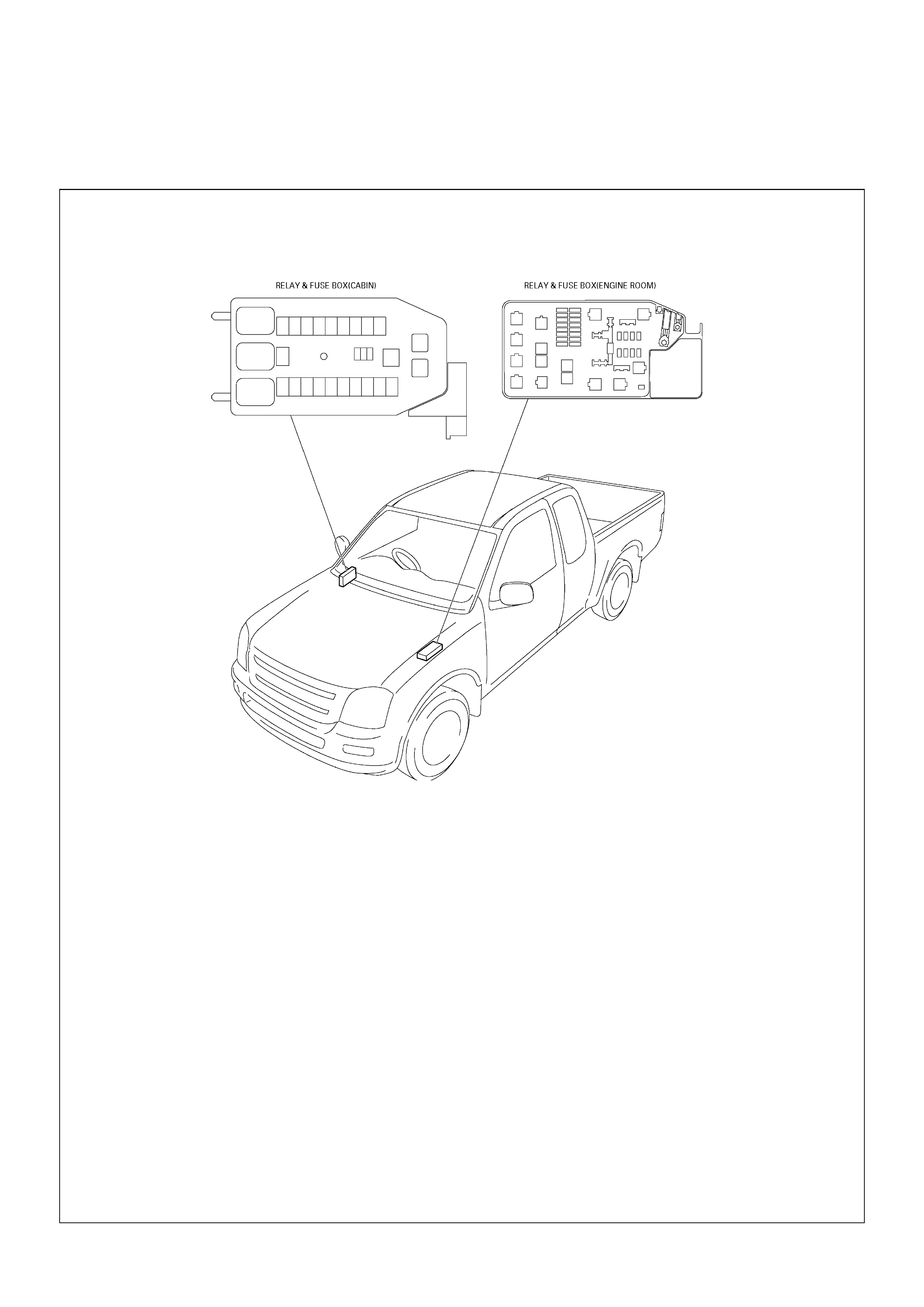
RELAY AND FUSE BOX LOCATION
RELAY AND FUSE BOX LOCATION
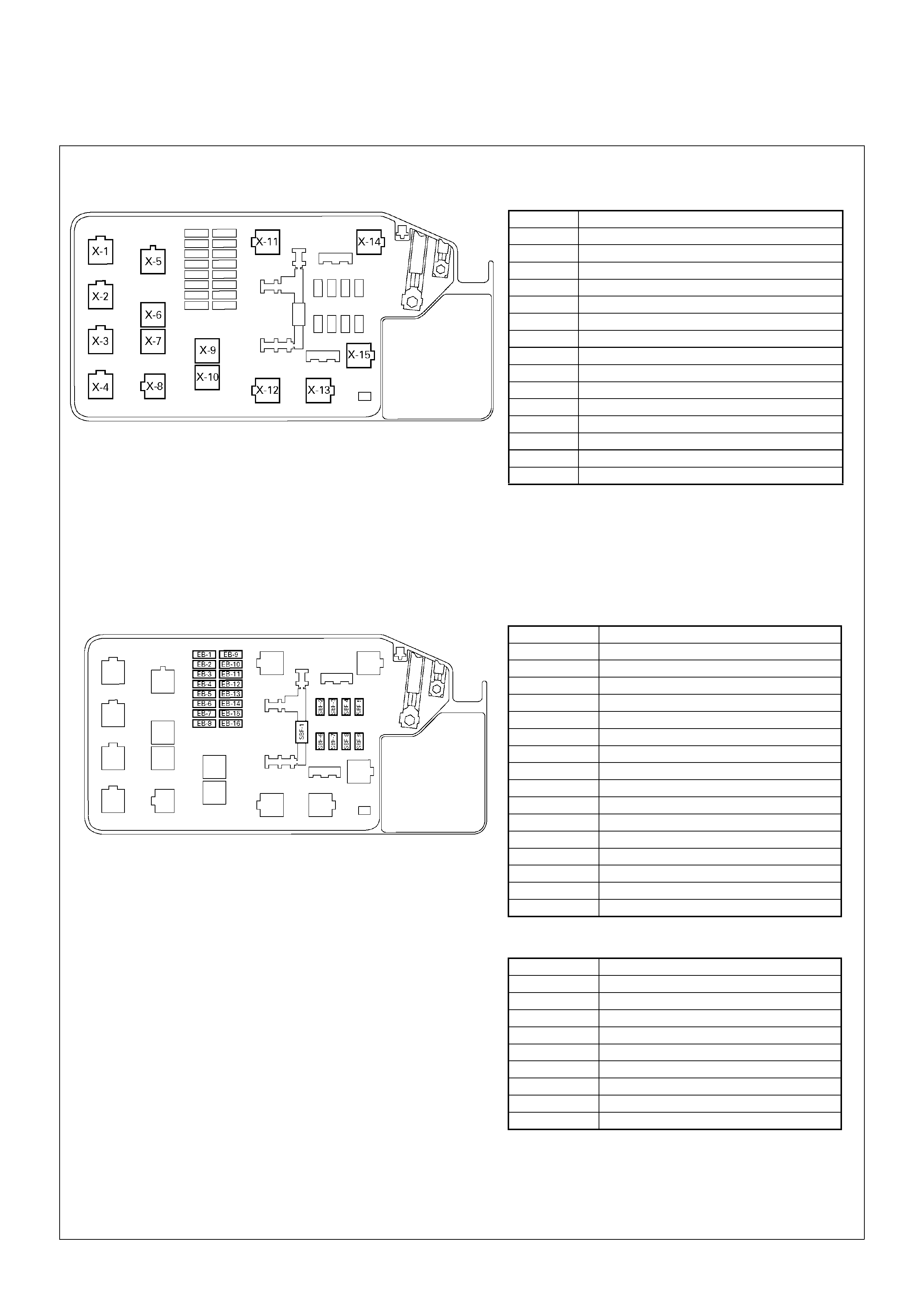
RELAY & FUSE BOX
RELAY
No. RELAY
X-1 RELAY; TAIL LIGHT
X-2 RELAY; FRT FOG LIGHT
X-3 RELAY; HO RN
X-4 RELAY; DI MMER
X-5 RELAY; GLOW
X-6 RELAY; COND, FAN
X-7 R ELAY; RR FO G
X-8 RELAY; STARTER
X-9 RELAY; HAZARD-RH
X-10 RELAY; HAZARD-LH
X-11 RELAY; HEATER
X-12 RELAY; HEAD LIGHT
X-13 RELAY; ECM MAIN
X-14 RELAY; A/C COMP
X-15 RELAY; THERMO
FUSE
SLOW BLOW FUSE
NO. FUSE
EB-1 10A ECM
EB-2 10A RR FOG
EB-3 15A FRT FOG
EB-4 —
EB-5 10A ILLUMI & TAIL-RH
EB-6 10A TAIL-LH
EB-7 10A H/LIGHT RH-LOW
EB-8 10A H/LIGHT LH-LOW
EB-9 10A TRA ILER
EB-10 10A AC G (S)
EB-11 10A H/LIGHT RH-HIGH
EB-12 10A H/LIGHT LH-HIGH
EB-13 10A A/C
EB-14 10A 4WD
EB-15 10A HORN
EB-16 10A HAZARD
NO. SLOW BLOW FUSE
SBF-1 80A MAIN
SBF-2 20A COND, FAN
SBF-3 50A GLOW
SBF-4 30A ECM
SBF-5 40A IG 1
SBF-6 40A ABS-1
SBF-7 30A ABS-2
SBF-8 30A BLOWER
SBF-9 50A IG 2
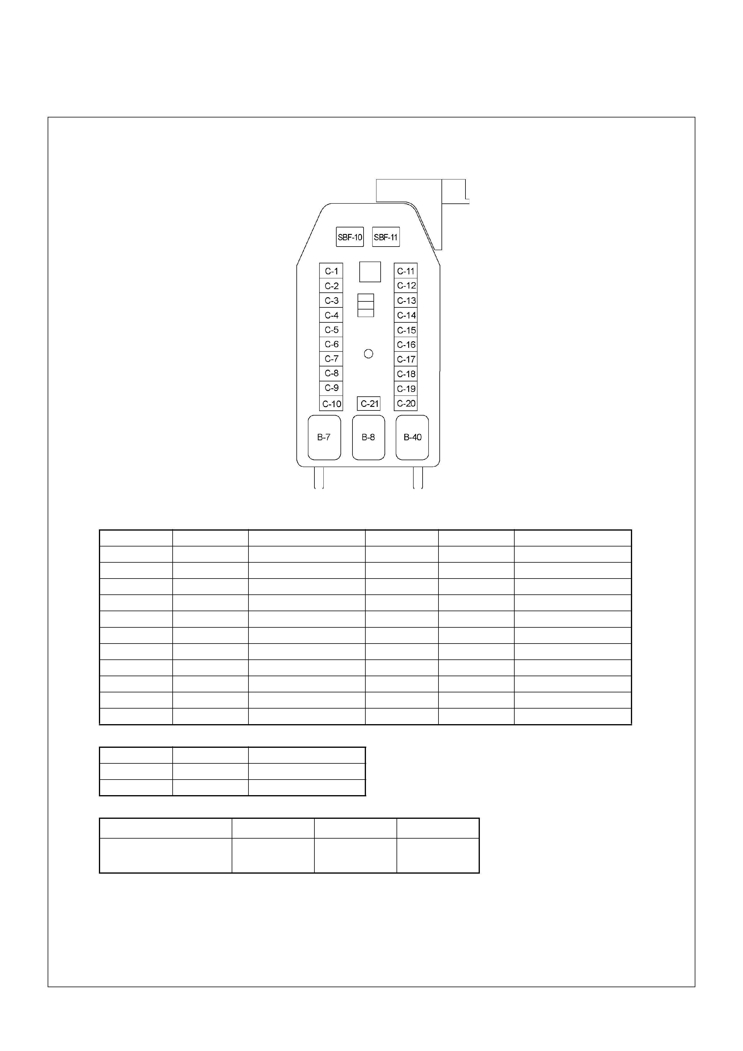
FUSE AND RELAY LOCATION
FUSE
SLOW BLOW FUS E
RELAY
No. Capacity Indication on label No. Capacity Indication on label
1— — 1215ACIGER
2 10A ABS 13 15A AUDIO (+B)
3 — — 14 20A DOOR LOCK
4 15A BACK UP 15 10A METER (+B)
5 15A METER 16 10A ROOM
6 10A TURN 17 10A ANTI THEFT
7 15A ELEC.IG 18 15A STOP
8 15A ENGINE 19 15A ACC SOCKET
9 20A FRT WIPER 20 10A STARTER
10 15A EGR 21 10A SRS
11 10A AUDIO
No. Capacity Indication on label
SBF-10 20A RR DEF
SBF-11 30A POWER WINDOW
Connector No. B-7 B-8 B-40
REAR
DEFOGGER POWER
WINDOW ACC
SOCKET
FUSE BOX
ECM WIRING DIAGRAM
ECM WIRING DIAGRAM (1/7)
ECM WIRING DIAGRAM (2/7)
ECM WIRING DIAGRAM (3/7)
ECM WIRING DIAGRAM (4/7)
ECM WIRING DIAGRAM (5/7)

ECM WIRING DIAGRAM (6/7)

ECM WIRING DIAGRAM (7/7)

ECM CONNECTOR PIN ASSIGNMENT & OUTPUT SIGNAL
View Looking Into ECM Case
Signal or Continuity Tester Position
Pin
No. B/
Box
No.
Pin Function Wire
Color Key SW
Off Key SW
On Engine
Idle Engine
2000rpm ECM
Connec-
tion
Ran
ge (+) (-)
1 1 ECM Ground BLK Continu-
ity with
ground
- - - Discon-
nect Ohm 1 GND
2 2 ECM Ground BLK Continu-
ity with
ground
- - - Discon-
nect Ohm 2 GND
3 3 Battery Power Sup-
ply BLU/
RED Less
than 1V 10-14V Connect DC V 3 GND
25 25 No Connection - - - - - - - - -
26 26 No Connection - - - - - - - - -
27 27 Engine Speed Output
(To Tacho Me ter) LGN - - Approx.
23Hz by
wave
form o r
approx.
6.3V
Approx.
67Hz by
wave
form or
approx.
6.8V
Connect AC V 27 GND
28 28 No Connection - - - - - - - - -
29 29 Throttle Position Sig-
nal To TCM (A16)
(AT Only)
- Approx. 140Hz by wave form (Idle:
Off dut y 1 0 % / WOT: Off duty 90%) - ---
30 30 Brake Switch 1 Sig-
nal GRN Less
than 1V Pedal is not stepped on: Less than
1V
Pedal is stepped on: 10-14V
Connect DC V 30 GND
31 31 Clutch Switch Signal
(MT Only) YEL Less
than 1V Pedal is not stepped on: 10-14V
Pedal is stepped on: Less than 1V Connect DC V 31 GND
32 32 No Connection - - - - - - - - -
33 33 A/C ON Signal Relay GRN/
YEL Less
than 1V A/C request switch is turned on: 10-
14V
A/C request switch is turned off:
Less than 1V
Connect DC V 33 GND
34 34 No Connection - - - - - - - - -
35 35 To Data Link Con-
nector No. 6 & Immo-
bilizer Control Unit
(ICU B8)
YEL--------

36 36 No Connection - - - - - - - - -
37 37 No Connection - - - - - - - - -
38 38 Throttle Position
Sensor (TPS) Out-
put Signal
GRN/
ORG Less
than 1V Less than 1V Approx.
0.5V Connect DC V 38 49
39 39 Key Switch Input Sig-
nal Via Engine Fuse WHT Less
than 1V 10-14V Connect DC V 39 GND
40 40 No Connection - - - - - - - - -
41 41 A/C Compresso r
Relay WHT/
GRN Less
than 1V 10-14V A/C comp. is oper-
ated: Less than 1V
A/C comp. is not oper-
ated: 10 - 14V
Connect DC V 41 GND
42 42 Check Engine Lamp GRN/
YEL Less
than 1V Lamp is turned on: Less than 1V
Lamp is turned off: 10-14V Connect DC V 42 GND
43 43 Glow Lamp ORG/
BLU Less
than 1V Lamp is turned on: Less than 1V
Lamp is turned off: 10-14V Connect DC V 43 GND
44 44 No Connection - - - - - - - - -
45 45 To Data Link Con-
nector No. 6 BLU Less
than 1V 10-14V Connect DC V 45 GND
46 46 No Connection - - - - - - - - -
47 47 No Connection - - - - - - - - -
48 48 No Connection - - - - - - - - -
49 49 Throttle Position
Sensor (TPS)
Ground
BLK/
GRN Idle:
Approx.
0.4K
ohm /
WOT:
Approx.
4.0K
ohm
- - - Discon-
nect Ohm 38 49
50 50 No Connection - - - - - - - - -
51 51 No Connection - - - - - - - - -
52 52 No Connection - - - - - - - - -
53 53 No Connection - - - - - - - - -
54 54 No Connection - - - - - - - - -
55 55 No Connection - - - - - - - - -
56 56 No Connection - - - - - - - - -
57 57 Throttle Position
Sensor (TPS) Power
Supply
RED/
GRN Less
than 1V Approx. 5V Connect DC V 57 49
58 58 ECM Relay BLU/
BLK 10-14V Less than 1V Connect DC V 58 GND
59 59 No Connection - - - - - - - - -
60 60 No Connection - - - - - - - - -
61 61 No Connection - - - - - - - - -
Signal or Continuity Tester Position
Pin
No. B/
Box
No.
Pin Function Wire
Color Key SW
Off Key SW
On Engine
Idle Engine
2000rpm ECM
Connec-
tion
Ran
ge (+) (-)

62 62 No Connection - - - - - - - - -
63 63 ECM Power Supply - Less
than 1V 10-14V - DC V 63 GND
64 64 No Connection - - - - - - - - -
65 65 Brake Switch 2 Sig-
nal WHT/
BLK Less
than 1V Pedal is not stepped on: 10-14V
Pedal is stepped on: Less than 1V Connect DC V 65 GND
66 66 No Connection - - - - - - - - -
67 67 No Connection - - - - - - - - -
68 68 Vehicle Speed Sen-
sor (VSS) YEL/
GRN - Approx. 14.5Hz by wave form or
approx. 6.0V at vehicle speed
20km/h
Connect AC V 68 GND
69 69 Idle Switch GRN/
BLK Less
than 1V Pedal is not stepped on: Less than
1V
Pedal is stepped on: Approx. 5V
Connect DC V 69 GND
70 70 No Connection - - - - - - - - -
71 71 No Connection - - - - - - - - -
72 72 No Connection - - - - - - - - -
73 73 No Connection - - - - - - - - -
74 74 No Connection - - - - - - - - -
75 75 No Connection - - - - - - - - -
76 76 No Connection - - - - - - - - -
77 77 No Connection - - - - - - - - -
78 78 No Connection - - - - - - - - -
79 79 No Connection - - - - - - - - -
80 80 No Connection - - - - - - - - -
81 81 No Connection - - - - - - - - -
82 82 Boost Pressure Sen-
sor (High Altitude
Spec . Only)
WHT/
BLU Less
than 1V Approx. 5V Connect DC V 82 93
83 83 Mass Air Flow (MAF)
Sensor Power Sup-
ply
WHT/
RED Less
than 1V Approx. 5V Connect DC V 83 92
84 84 Intake Air Tempera-
ture (IAT) Sensor
Signal
BLK/
BLU Less
than 1V 0 deg. C: Approx. 3.6V / 20 deg. C:
Approx. 2.6V / 40 deg. C: Approx.
1.7V / 60 deg. C: 1.1V / 80 deg. C:
0.7V
Connect DC V 84 92
85 85 Manifold Pressure
Sensor (High Altitude
Spec . Only)
RED/
BLU Less
than 1V - - - Connect DC V 85 93
86 86 No Connection - - - - - - - - -
87 87 Neut ral Switch BLK/
WHT Less
than 1V In neutral (A/T: P or N): Less than
1V
Other than neutral (A/T: other than
P or N): 10-14V
Connect DC V 87 GND
Signal or Continuity Tester Position
Pin
No. B/
Box
No.
Pin Function Wire
Color Key SW
Off Key SW
On Engine
Idle Engine
2000rpm ECM
Connec-
tion
Ran
ge (+) (-)

88 88 Mass Air Flow (MAF)
Sensor Signal GRN/
RED Less
than 1V Approx.
1V Approx.
1.8V Approx.
2.5V Connect DC V 88 92
89 89 Engine Coolant Tem-
perature (ECT) Sen-
sor Signal
GRY Less
than 1V 0 deg. C: Approx. 4.4V / 20 deg. C:
Approx. 3.8V / 40 deg. C: Approx.
2.9V / 60 deg. C: 2.1V / 80 deg. C:
1.4V
Connect DC V 89 93
90 90 CKP Sensor Signal RED - - Approx.
47Hz by
wave
form
Approx.
134Hz by
wave
form or
approx.
1.1V
Connect AC V 90 98
91 91 CKP Sensor Output
T o Pump Control Unit
(PSG) No . 8
PNK - - Approx.
47Hz by
wave
form
Approx.
134Hz by
wave
form or
approx.
0.7V
Connect AC V 91 GND
92 92 Mass Air Flow (MAF)
Sensor Ground BLK/
RED Continu-
ity with
ground
- - - Connect Ohm 92 GND
93 93 Engine Coolant Tem-
perature (ECT) Sen-
sor & Manifold
Pressure Sensor
Ground
BLK/
PNK Continu-
ity with
ground
- - - Connect Ohm 93 GND
94 94 Glow Relay BLK/
RED Less
than 1V Glow system is operated: Less than
1V
Glow system is not operated: 10 -
14V
Connect DC V 94 GND
95 95 No Connection - - - - - - - - -
96 96 T urbocharger W aste
gate Control EVRV BRW/
RED - - Wave form - ---
97 97 EGR EVRV BLK/
ORG - - Approx. 140Hz by
wave form when
EVRV is operated
- ---
98 98 CKP Sensor Ground WHT Continu-
ity with
ground
- - - Connect Ohm 98 GND
99 99 CAN (Controller Area
Netwo rk) to PSG
No.1
BLU--------
100 100 CAN (Controller Area
Netwo rk) to PSG
No.2
YEL--------
101 101 CKP Sens or Shield
Line BLK Continu-
ity with
ground
- - - Connect Ohm 101 GND
102 102 No Connection - - - - - - - - -
103 103 No Connection - - - - - - - - -
104 104 No Connection - - - - - - - - -
Signal or Continuity Tester Position
Pin
No. B/
Box
No.
Pin Function Wire
Color Key SW
Off Key SW
On Engine
Idle Engine
2000rpm ECM
Connec-
tion
Ran
ge (+) (-)

105 105 Solenoid Valve Shu t
Off (MAB) Output
Signal to PSG No.5
ORG - - - - - - - -
Signal or Continuity Tester Position
Pin
No. B/
Box
No.
Pin Function Wire
Color Key SW
Off Key SW
On Engine
Idle Engine
2000rpm ECM
Connec-
tion
Ran
ge (+) (-)

PSG CONNECTOR PIN ASSIGNMENT & OUTPUT SIGNAL
View Looking Into PSG Case
Signal or Continuity Tester Position
Pin
No. B/
Box
No.
Pin Function Wire
Color Key SW
Off Key SW
On Engine
Idle Engine
2000rp
m
ECM &
PSG Con-
nection
Rang
e(+) (-)
1 99 CAN (Controller Area
Network) to ECM
No.99
RED Continu-
ity
between
ECM &
PSG
---Discon-
nect Ohm 1 99
(ECM
)
2 100 CAN (Controller Area
Network) to ECM
No.100
WHT Continu-
ity
between
ECM &
PSG
---Discon-
nect Ohm 2 100
(ECM
)
3 - No Connect ion - ---- ----
4 - No Connect ion - ---- ----
5 105 Solenoid Valve Shut
Off (MAB) Output
Signal to ECM
No.105
ORG Continu-
ity
between
ECM &
PSG
---Discon-
nect Ohm 5 105
(ECM
)
6 - Ground BLK Continu-
ity with
ground
---Discon-
nect Ohm 6 GND
7 - Battery Power Sup-
ply BLU/
RED Less
than 1V 10-14V Discon-
nect Ohm 7 GND
8 91 CKP Sensor Output
ECM No.91 to Pump
Control Unit (PSG)
PNK Continu-
ity
between
ECM &
PSG
---Discon-
nect Ohm 8 91
(ECM
)
9 - No Connect ion - ---- ----
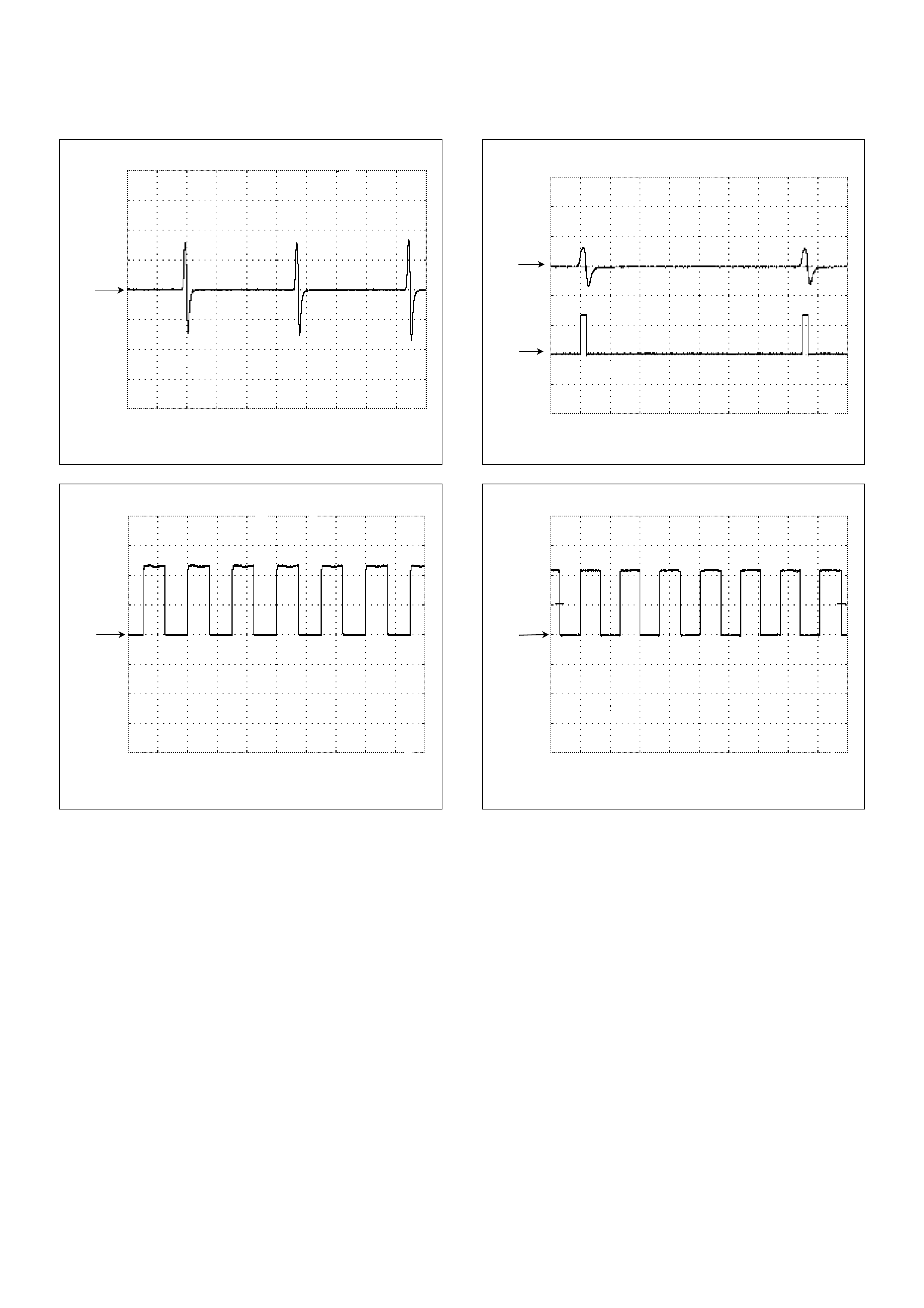
Crankshaft Position (CKP) Sensor Reference Wave Form
0V
Measurement Terminal: 90(+) 98(-)
Measurement Scale: 20V/div 2ms/div
Measurement Condition: Approximately 2000rpm
Engine Speed Output Signal Reference Wave Form
0V
Measurement Terminal: 27(+) GND(-)
Measurement Scale: 5V/div 10ms/div
M eas ur em ent C ond iti on: Approximately 2000r pm
Crank shaft Posit i on (CKP) Sens or & TDC Outpu t Signal
Reference Wave Form
CH1
0V
CH2
0V
Measurement Terminal: CH1: 90(+) / CH2: 91(+) GND(-)
Measurement Scale: CH1: 50V/div / CH2: 10V/div 1ms/div
Measurement Condition: Approximately 2000rpm
Vehicle Speed Sensor (VSS) Reference Wave Form
0V
Measurement Terminal: 68(+) GND(-)
Measurement Scale: 5V/div 50ms/div
M eas ur em ent C ond iti on: Approximately 20km/h
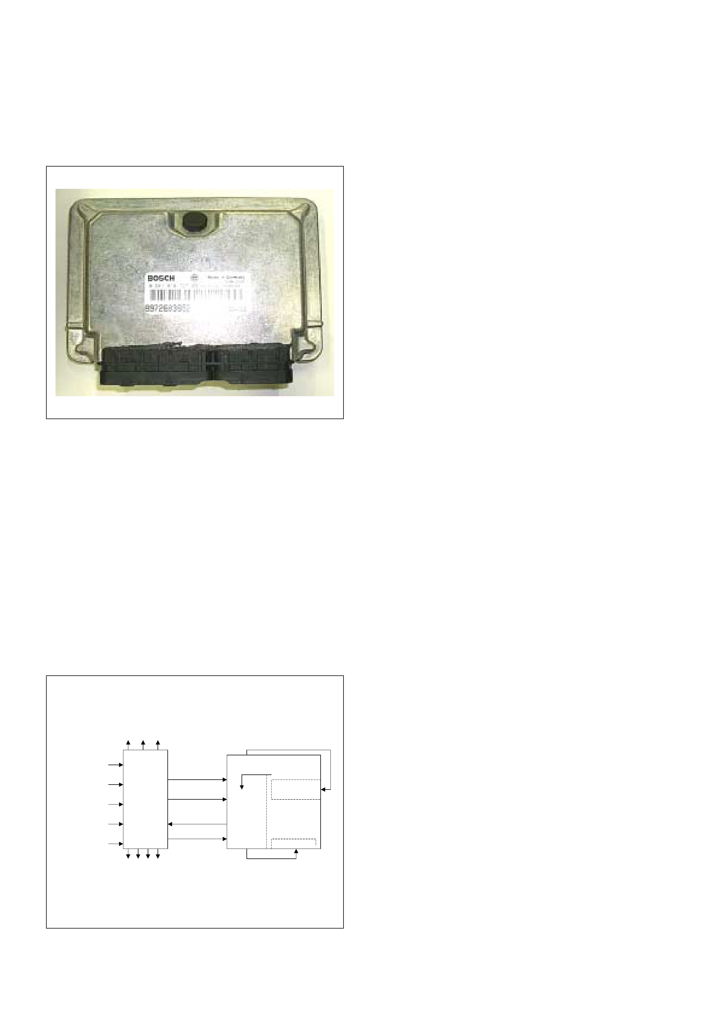
GENERAL DESCRIPTION FOR ECM AND SENSORS
Engine Control Module (ECM)
The engine control module (ECM) is located lower panel
just under the passenger's seat.
The fuel quantity and injection timing related functions
are controlled by the pump control unit (PSG).
The engine control module (ECM) performs the
following functions.
• Control of the exhaust gas re-circulation (EGR)
• Control of the quick on start (QOS) glow control
system
• Control of the A/C compressor
• Execution of the immobilizer function
Pump Control Unit (PSG) & Data Exchange
Between Control Module
The radial plunger distributor type injection pump uses
two control modules to execute full control of the engine
management system.
• Engine Control Module (ECM)
• Pump Control Unit (PSG) = Pumpen Steuer Great
(German)
The pump control unit (PSG) receives signals from the
sensors inside the pump to determine the cam ring
rotation angle, the pump speed and the fuel
temper atur e .
These values are then compared to the desired values
sent by the engine control module (ECM) such as the
desired injection timing and the desired fuel injection
quantity.
The engi ne control module ( ECM) processes al l engine
data and data regarding the surrounding environment
received from external sensors to perform any engine
side adjustments.
Maps for both are encoded in both control units. The
control units input circuit process sensor data.
A Microprocessor then determines the operating
conditions and calculates set values for optimum
running.
The interchange of data between the engine control
module (ECM) and the pump control unit (PSG) is
performed via a CAN-bus system. The abbreviation
CAN stands for Controller Area Network. Having two
separate control modules for the high pressure solenoid
valve prevents the discharge of any disturbing signals.
The information exchange between the two control
modules takes place via two means.
• Via analogue signal leads
• Via the CAN-bus
The analogue signal leads are used to exchange the
followi ng inf or mati on .
• Engine speed signal (ECM terminal 91)
• Pump Sp eed (ECM ter minal 105)
• Fuel Cutoff solenoid v alve signal ( MAB signa l) (ECM
terminal 105)
The engine speed signal is sent from the ECM to PSG
based on the input from the crank shaft position (CKP)
sensor.
The analogue CKP sensor signal is converted by the
ECM into a square wave signal.
The fuel cutoff solenoid valve signal is also referred to
as MAB signal.
MAB in this case, refers to the German abbreviation
Magnet ventil ABschaltung that stands for high pressure
solenoid valve cut off.
The MAB signal wire is used for two purposes.
-As a reference for the engine control module (ECM) for
the pump speed (back up for the CKP sensor).
-To turn Off the engine.
Self Diagnosis / Interface / Signal
To High Pressure Solenoid
Engine Speed
Injection Timing
Accelerator Pedal
Injection Quantity
Intake Air Tem perature
Response Signal
Mass Air Flow
Additional Signal
Others
Additional Operations To Timing Control Valve (TCV)
Engine
Control
Module
(ECM)
Cam Ring Rotational Angle
Fuel Temperature
High Pressure
Solenoid Valve
Pump
Control Fuel Injection
Unit (Mechanical)
(PSG)
Timing Device
The following signals are exchanged via the CAN-bus:
From ECM to PSG
• Desired injection quantity
• Desired injection timing
• Engi ne sp eed
From PSG to ECM
• Fuel temperature
• Pump speed
• Cylinder identifier
• Control pulse (actual injection quantity + actual
injection timing)
•PSG status
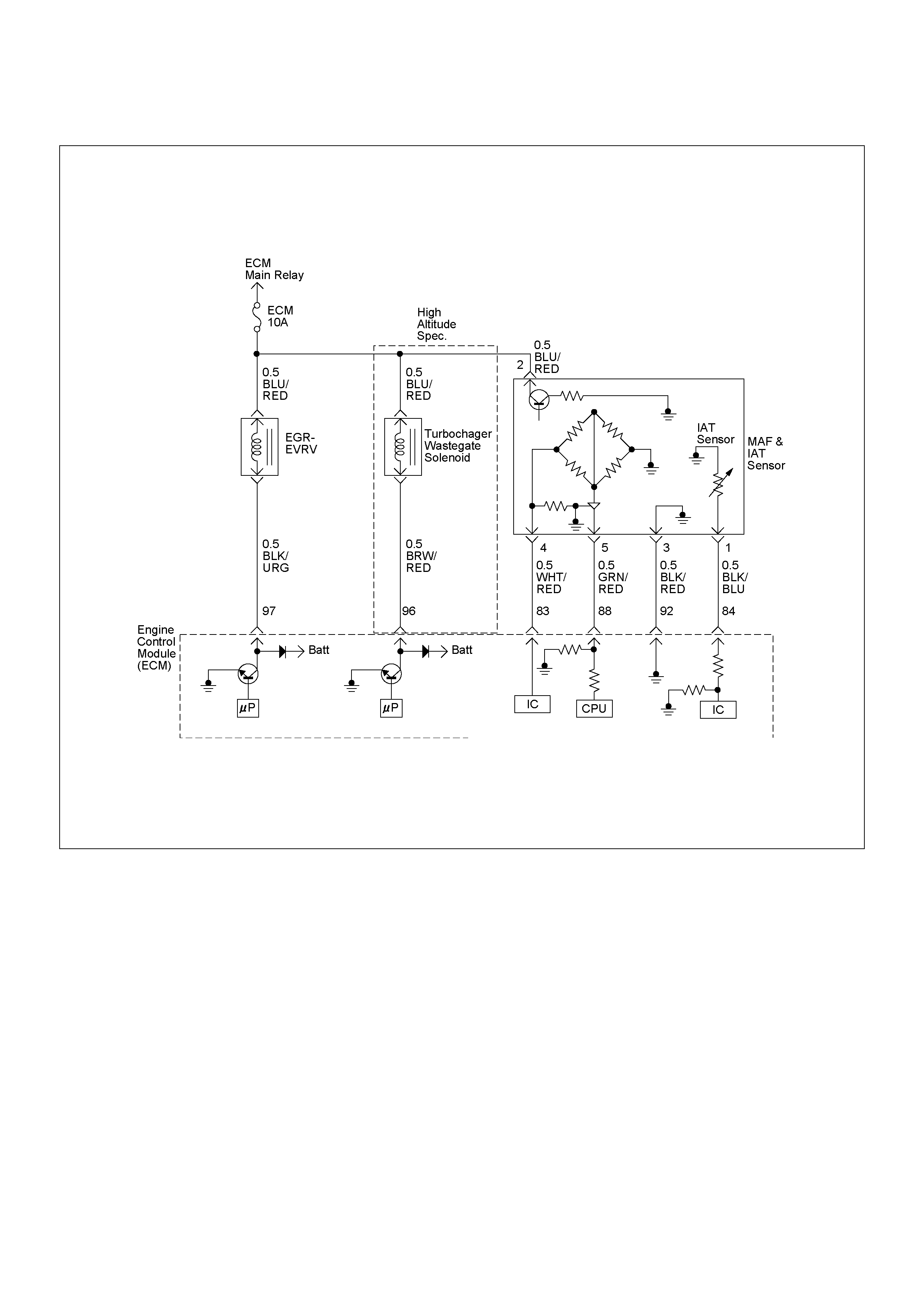
Mass Air Flow (MAF) Sensor & Intake Air
Temperature (IAT) Sensor
The mas s air flo w (MAF) sensor is part of the intake air
system.
It is fitted betw een the air clea ner and turb ocharge r and
measure the mass air flowing into the engine .
The mass air flow (MAF) sensor uses a hot film element
to determine the amount of air flowing into the engine.
The mass air flow (MAF) sensor assembly consist of a
mass air flow (MAF) sensor element and an intake air
temperature sensor that are both exposed to the air flow
to be measured.
The mass air flow (MAF) sensor element measures the
partial air mass through a measurement duct on the
sensor housing.
Using calibration, there is an extrapolation to t he entire
mass air flow to the engine.
The IAT sensor is a thermistor. A temperat ure changes
the resistance value. And it changes voltage. In other
words it measures a temperature value. Low air
temperature produces a high resistance.
The ECM supplies 5 volts signal to the IAT sensor
through resisters in the ECM and measures the voltage.
The signal voltage will be high when the air temperature
is cold, and it will be low when the air temperature is
hot.
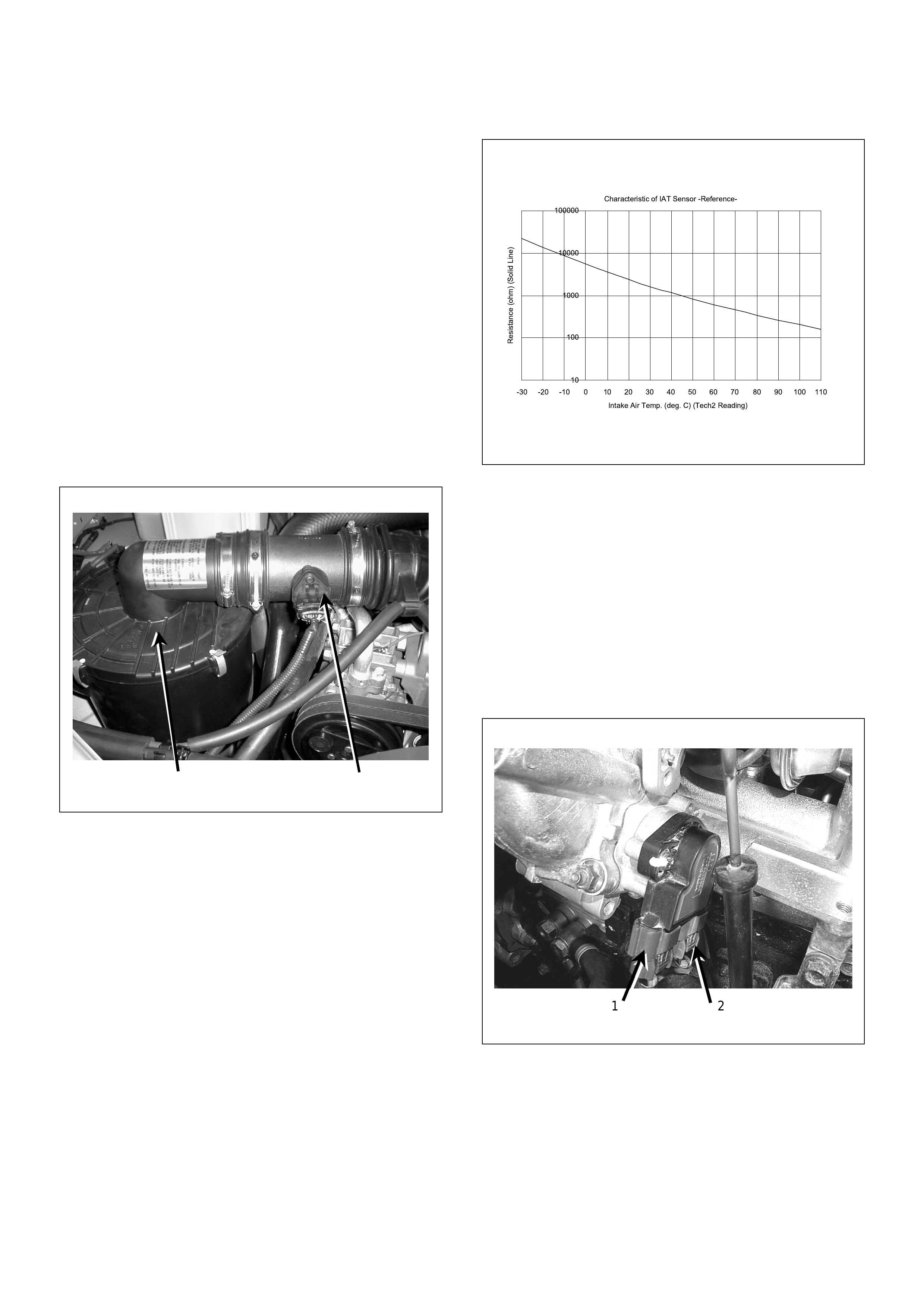
Throttle Position Sensor (TPS)
(1) Air Cleaner Case
(2) Mass Air Flow (MAF) & Intake Air Temperature
(IAT) Sensor
1 2
(1) Throttle Position Sensor (TPS)
(2) Idle Switch
Characteristic of IAT Sensor -Reference-
10
100
1000
10000
100000
-30 -20 -10 0 10 20 30 40 50 60 70 80 90 100 110
Intake Air Temp. (deg. C) (Tech2 Reading)
Resistance (ohm) (Solid Line)
1 2

The TPS is a potentiometer connected to throttle shaft
on the throttle body. It is installed to the main TPS and
idle switc h.
The engine control module (ECM) monitors the voltage
on the signal line and calculates throttle position. As the
throttle valve angle is changed when accelerator pedal
moved. The TPS signal also changed at a moved
throttle valve. As the throttle valve opens, the output
increases so that the output voltage should be high.
The engine control module (ECM) calculates fuel
delivery based on throttle valve angle.
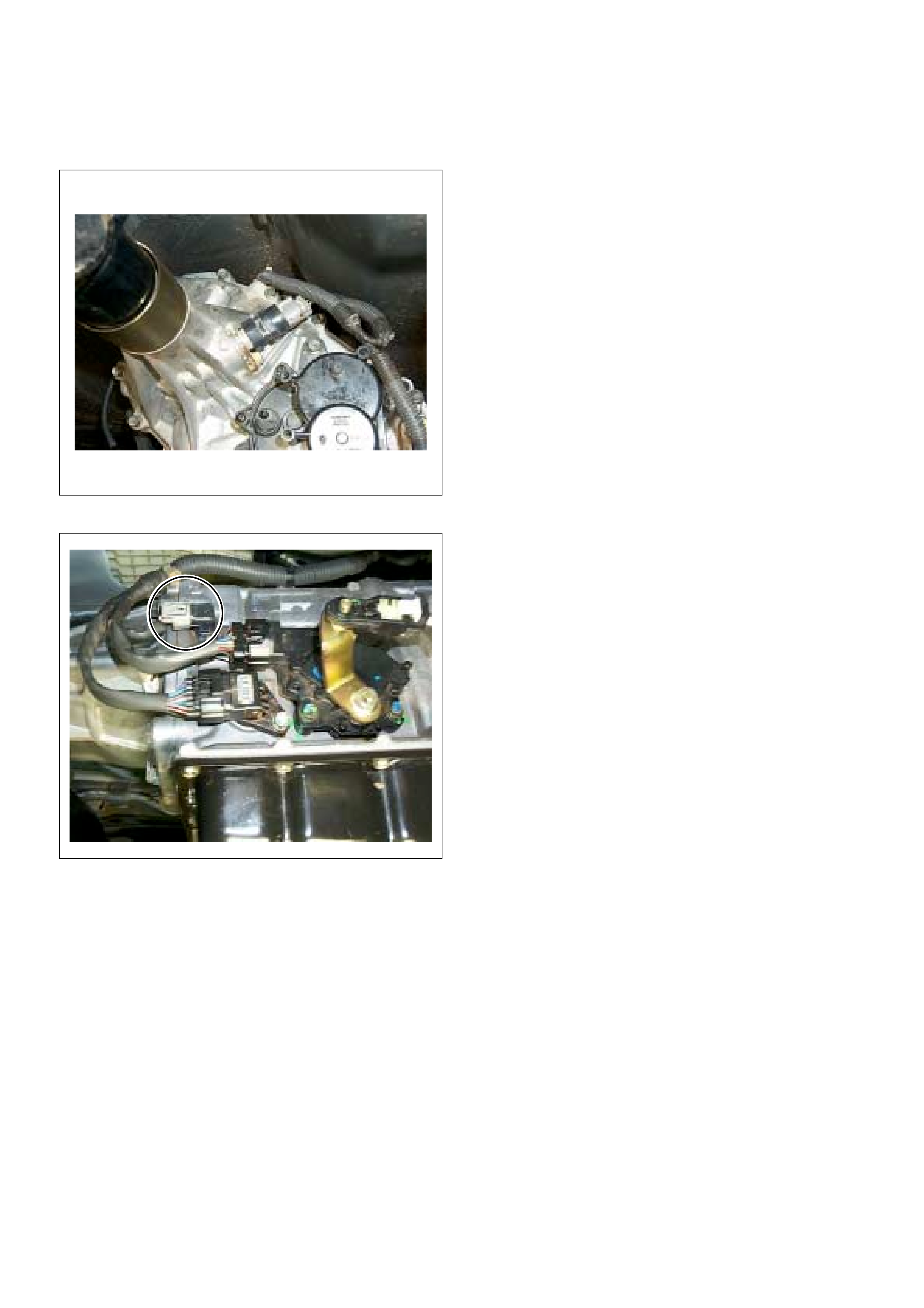
Crankshaft Position (CKP) Sensor
The CKP sensor is located on top of the flywheel
housing of the flywheel and fixed with a bolt.
The CKP sensor is of the magnet coil type. The
inductive pickup sensors four gaps in the flywheel
exciter ring and is used to determine the engine speed
and engine cylinder top dead center (TDC).
Engine Coolant Temperature (ECT) Sensor
The ECT sensor is a thermistor. Temperature changes
it’s resistance value, which therefore changes circuit
voltage. In other words it measures a temperature
value . It is installed on the coolant stream. Lo w coolant
temperature produces a high resistance.
The ECM supplies 5 volts signal to the ECT sensor
through resisters in the ECM and measures the voltage.
The signal voltage will be high when the engine
temperature is cold, and it will be low when the engine
temp eratur e is hot.
(1) Crankshaft Position (CKP) Sensor
(2) Fly wheel with sensor slot
Characteristic of TPS -Reference-
0
0.5
1
1.5
2
2.5
3
3.5
4
4.5
0 5 10 15 20 25 30 35 40 45 50 55 60 65 70 75 80 85 90 95 100
Pedal Position (%) (Tech2 Readin
g
Output Voltage (V)
1 2
(1) Engine Coolant Temperature (ECT) Sensor
(2) Thermo Unit for Water Temperature Gauge
NO
Characteristic of ECT Sensor -Reference-
10
100
1000
10000
100000
-30 -20 -10 0 10 20 30 40 50 60 70 80 90 100 110 120 130
Engine Coolant Temp (deg. C) (Tech2 Reading)
Resistance (ohm) (Solid Line)
Vehicle Speed Sensor (VSS)
M/T & A/T 4WD
A/T 2WD
The VSS is a magnet rotated by the transmission output
shaft. The VSS uses a hall elemen t. It interac ts with the
magnetic field treated by the r otating magnet. It outputs
a pulse signal. The 12 volts operating supply comes
from the meter fuse.
The engine control module (ECM) calculates the vehicle
speed by VSS.
On 2WD models fitt ed with automatic transmission, the
vehicle speed sensor signal is transmitted from the TCM
to the ECM via vehicle speed meter.
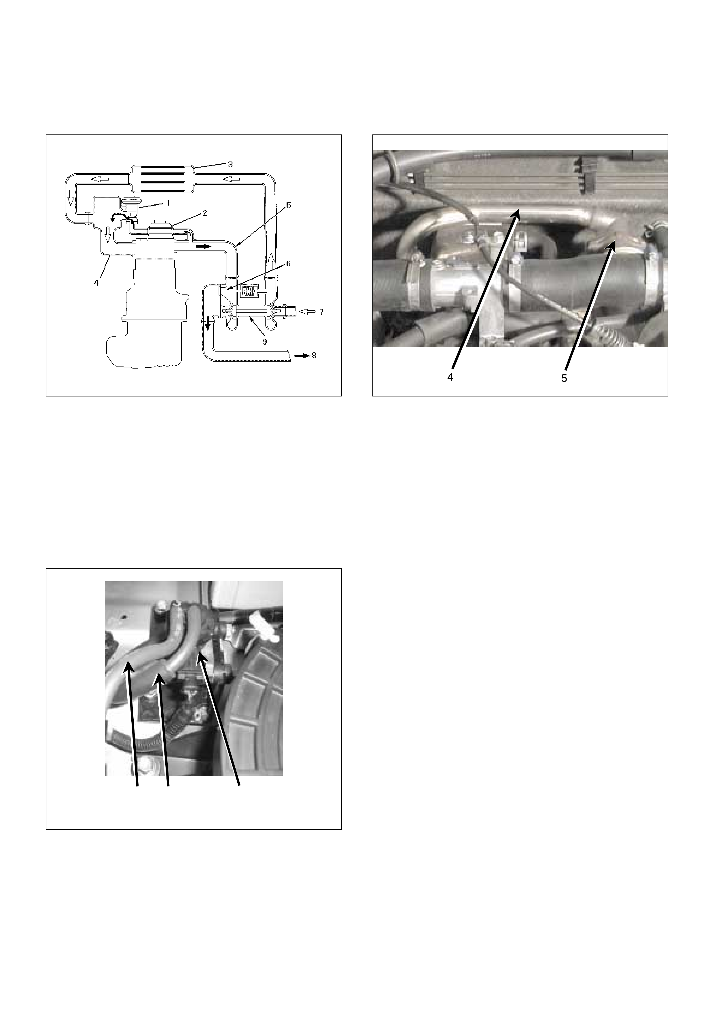
GENERAL DESCRIPTION FOR EGR (EXHAUST GAS RE-CIRCULATION)
The amount of EGR is controlled by EVRV (electrical
vacuu m regulati ng valve) via the engin e control mod ule
(ECM) command signal depends on the following
inputs.
• Engine speed
• Injection quantity
• Mass air flow
• Intake air temperature
• Coolant temperature
• Barometric pressure
(1) EGR Valve
(2) EGR Pipe
(3) Intercooler
(4) Intake Manifold
(5) Exhaust Manifold
(6) Waste Gate
(7) Fresh Ai r
(8) Exhaust Gas
(9) Turbocharger
123
(1) To EGR Valve
(2) From Vacuum Pump
(3) EGR EVRV
(4) EGR Valve
(5) EGR Pipe
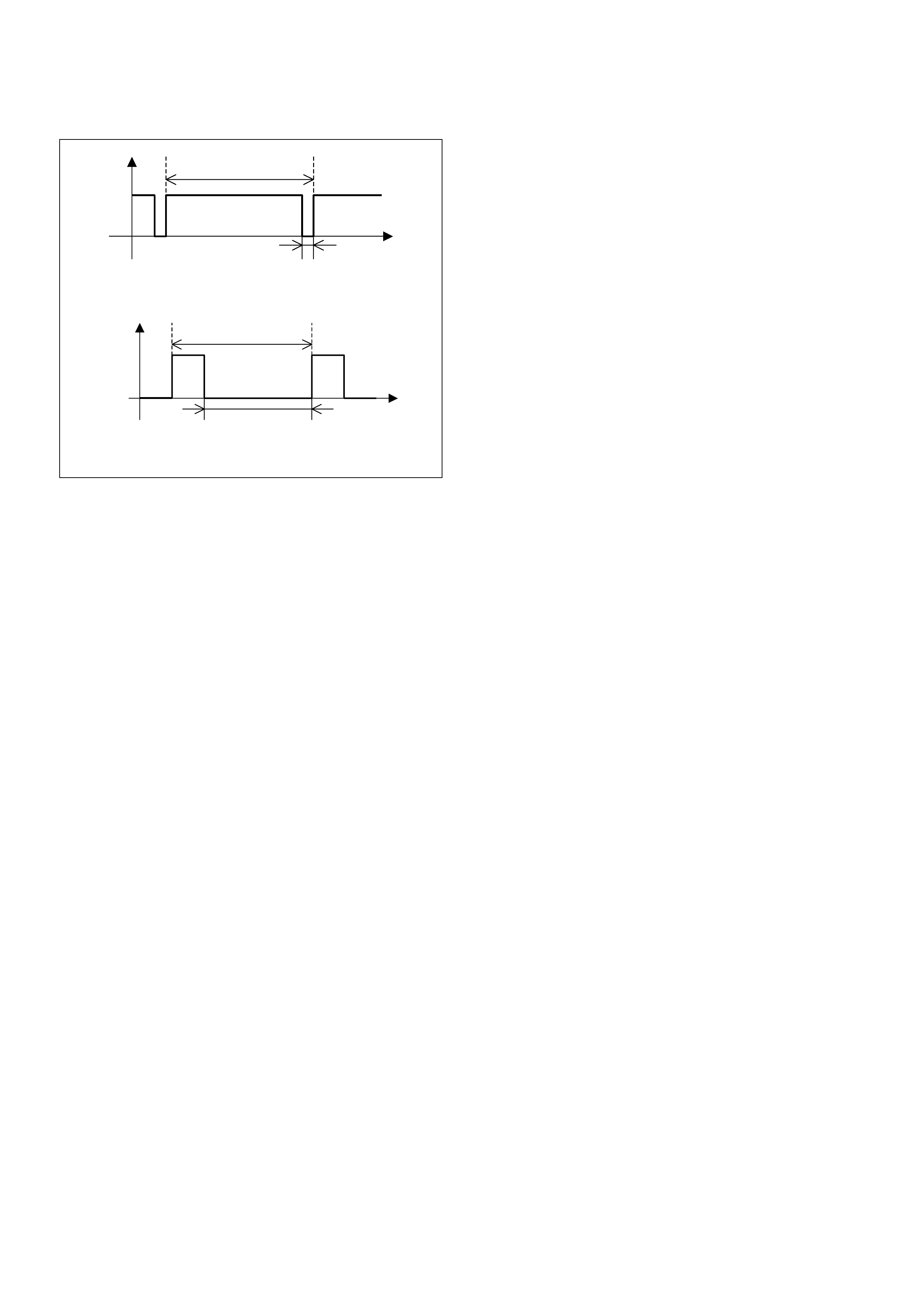
The EVRV is shaped to control vacuum applied to the
diaphragm chamber of the EGR valve based on duty
signal sent from the ECM. The duty ratio is the time that
the EVRV is opened during one EVRV operating cycle.
A duty ratio change of 90% to 10 % is EGR amount
control range.
7.1ms
Time
0.7ms
Off duty 10% =EGR Pul se Ratio 10%
7.1ms
Time
6.4ms
Off duty 90% =EGR Pu lse Ratio 90%
GENERAL DESCRIPTION FOR INJECTION PUMP
Outline
Instead of the previous face cam type, the radial plunger
distributor type injection pump utilizes a cam ring to
enable fuel injection at high-pressures, marking it
suitable for small, high-speed direct injection diesel
engines. T his pump was deve loped to prov ide the most
suitable fuel injection quantity and injection timing to
satisfy the demand for en gine reliabi lity, driveabi lity, lo w
smoke, low noise, high output and clear exhaust
emissions.
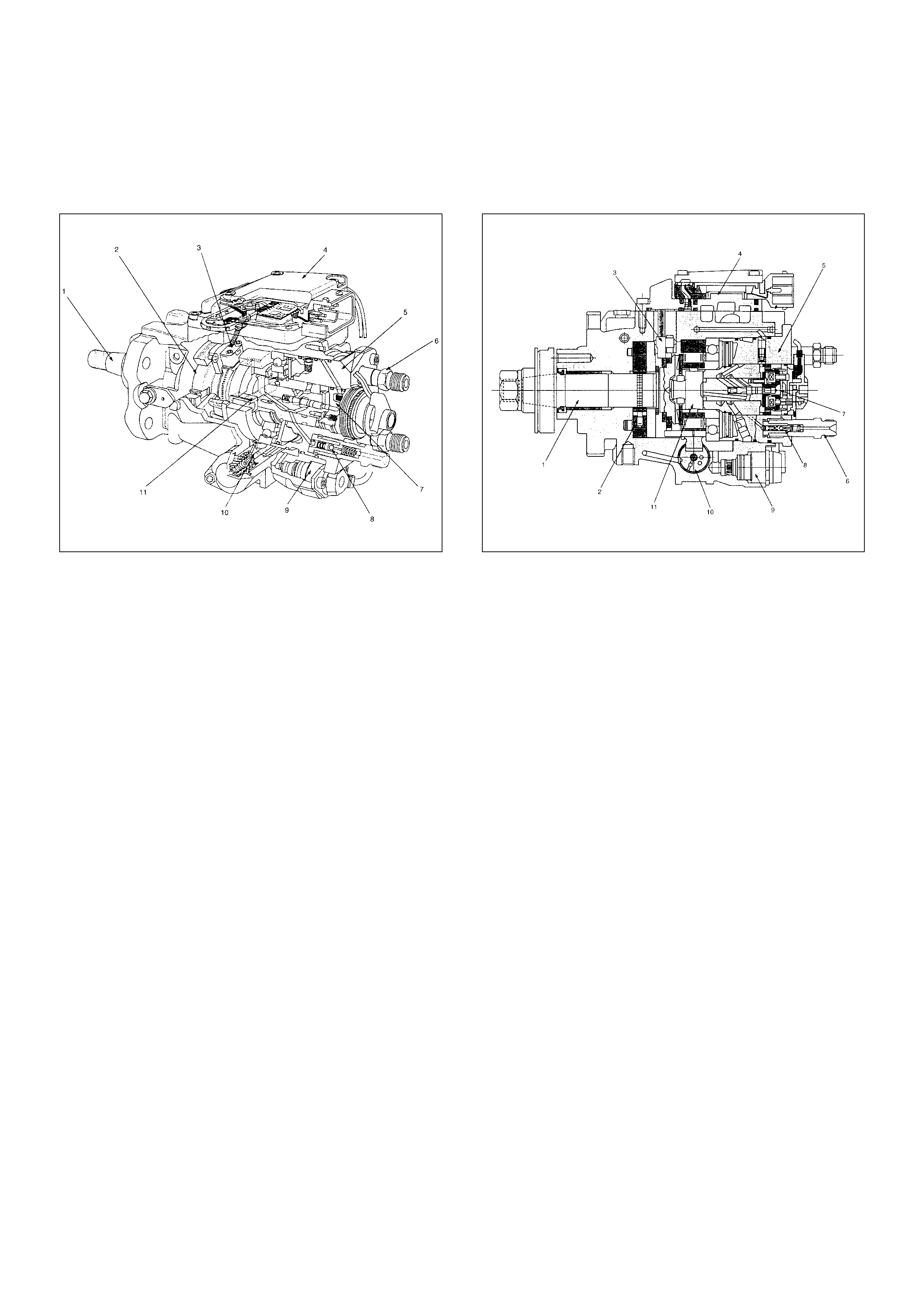
Cross-section View
(1) Drive Shaft
(2) Feed Pump
(3) Pump Camshaft Speed Sensor
(4) Pump Control Unit (PSG)
(5) Distributor Head
(6) Constant Pressure Valve (CPV) Holder
(7) High Pressure Solenoid Valve
(8) Constant Pressure Valve (CPV)
(9) Timing Control Valve (TCV)
(10) Timer
(11) Radial Plunger High Pressure Pump
(1) Dr iv e Sha ft
(2) Feed Pump
(3) Pump Camshaft Speed Sensor
(4) Pump Control Unit (PSG)
(5) Distributor Head
(6) Constant Pressure Valve (CPV) Holder
(7) High Pressure Solenoid Valve
(8) Constant Pressure Valve (CPV)
(9) Timing Control Valve (TCV)
(10) Timer
(11) Radial Plunger High Pressure Pump
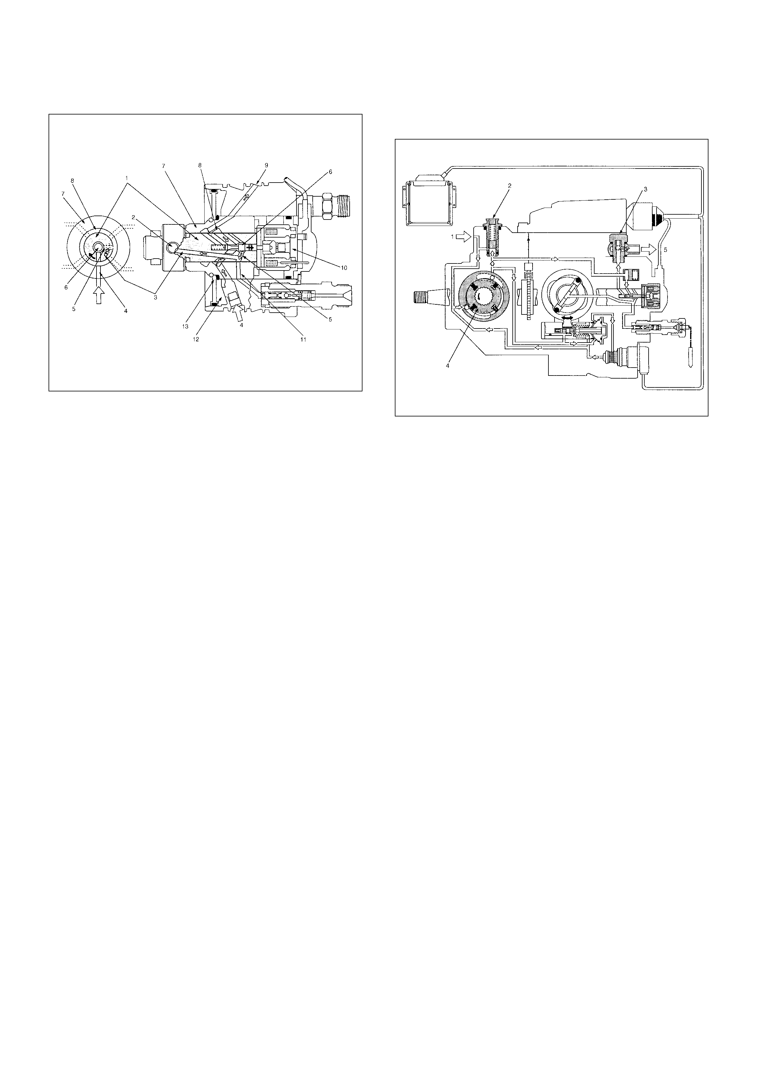
Low Pressure Fuel Circuit
The low pressure fuel circuit must supply sufficient fuel
to the high pressure fuel circuit. The main components
are the feed pump, the regulating valve and the
overflow valve.
(1) Rotor Shaft
(2) Radial Plunger
(3) Hi gh Pr ess ur e Passag e
(4) Low Pressure Inlet
(5) Distributor Slit
(6) Valv e Need le
(7) Barrel
(8) Annular Passage
(9) Fuel Return
(10) High Pressure Solenoid Valve
(11) Hi gh Pres s ure Outl et
(12) Diaphram Chamber
(13) Accumulator Diaphram
(1) Fuel Suction
(2) Regulating Valve
(3) Overflow Valve
(4) Feed Pump
(5) To Fuel Tank
High Pressure Fuel Circuit
In addition to a high pressure generating device, the
high pressure circuit also consists of fuel piping, and
devices to set the beginning of injection and fuel
injection quantity.
The main components are as follows.
• High pressure generation: Radial Plunger High
Pressure Pump
• Fuel distribution: Distributor Head
• Beginning of injection timing: Timing Device
• Prevention of secondary injection: Constant Pressure
Valve (CPV)
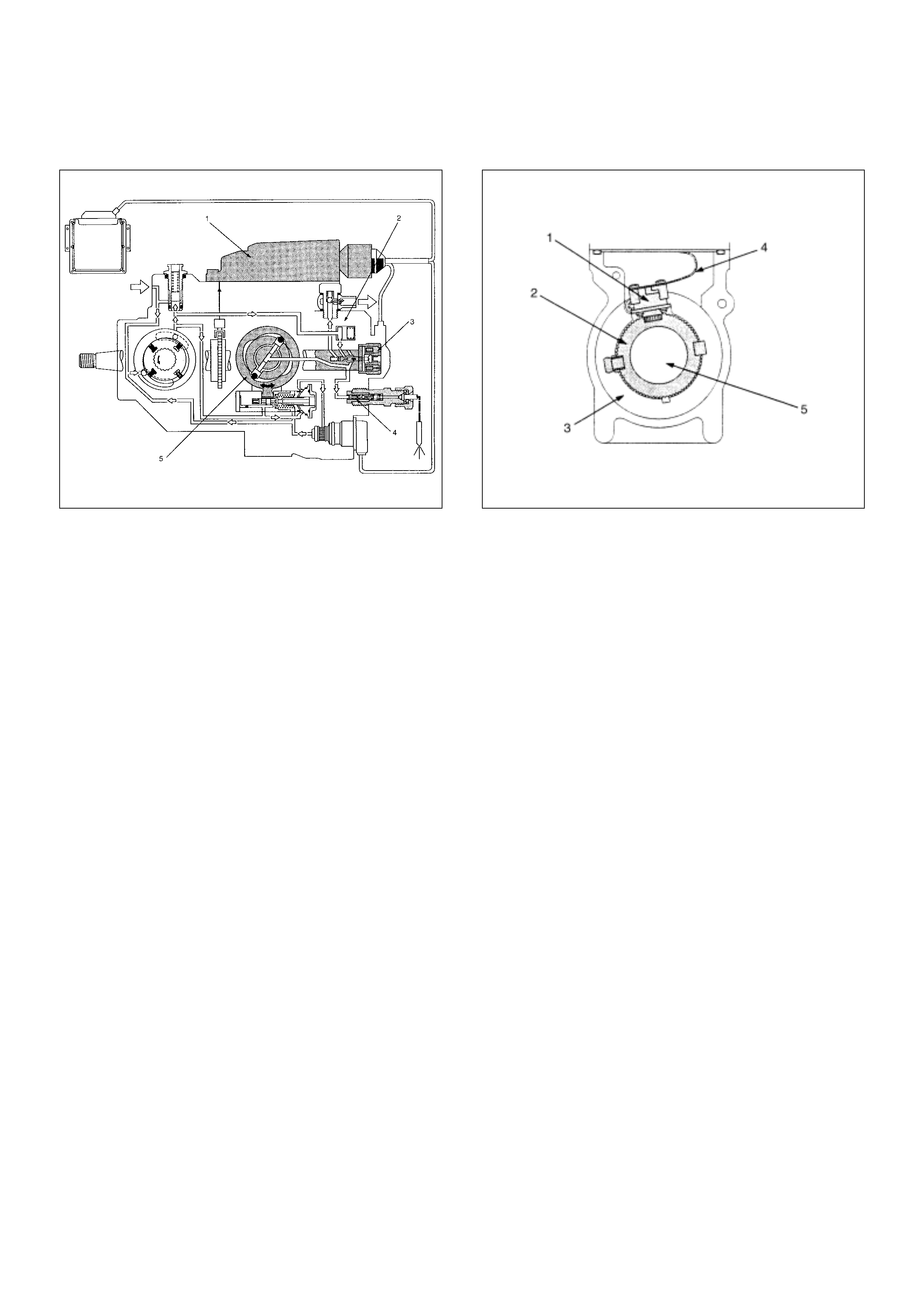
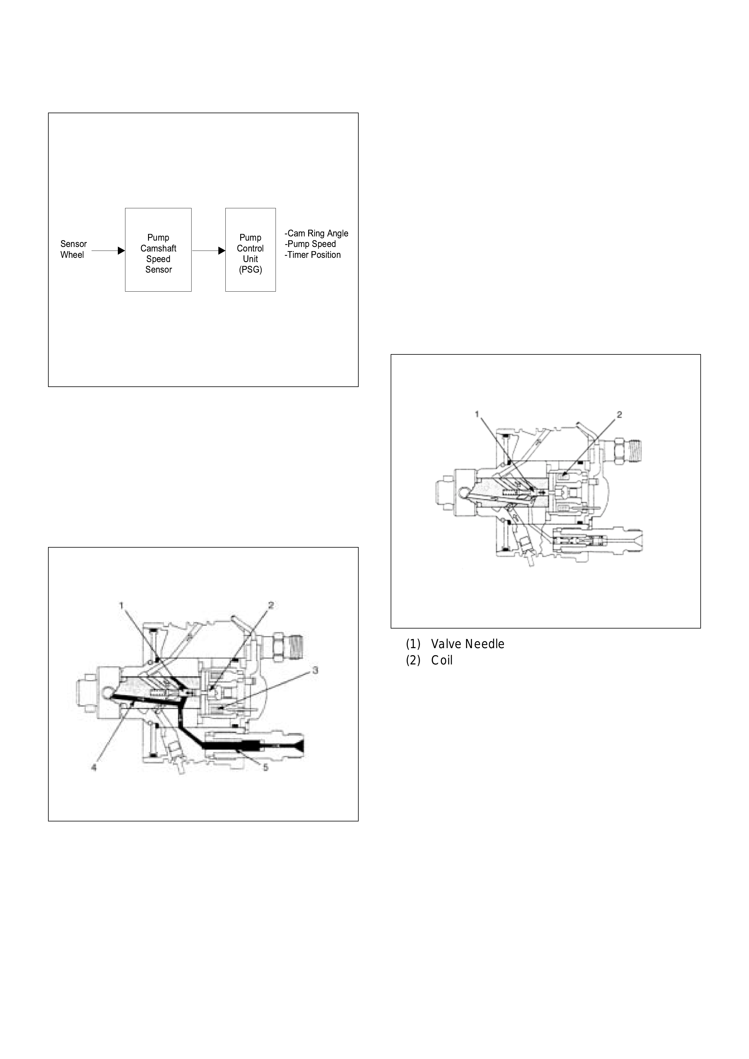
Pump Camshaft Speed Sensor
When the drive shaft rotates, the pump camshaft speed
sensor receives signal form the sensor wheel, and an
electric pulse is sent through the flexible connecting
harness to the pump control unit (PSG).
From these signals the pump control unit (PSG) can
determine the average pump speed and the momentary
pump speed.
The pump camshaft speed sensor is mounted to the
cam ring. Thus, the relationship between the cam ring
and the pump camshaft speed sensor signal is
constant.
The pump camshaft speed sensor signal is utilized for
the following purposes.
To determine the momentary angular position of the
cam ring.
To calculate the actual speed of the fuel injection pump.
To determine the actual timing plunger position.
(1) Pump Control Unit (PSG)
(2) Distributor Head
(3) High Pressure Solenoid Valve
(4) Constant Pressure Valve (CPV)
(5) Radial Plun ger High Pressure Pu mp
(1) Pump Camshaft Speed Sensor
(2) Sensor Wheel
(3) Pump Camshaft Speed Sensor Retaining Ring
(4) Flexible Connector Harness
(5) Dr iv e Sha ft
The pump c amshaft sensor signal has a too th gap, and
the crankshaft position (CKP) sensor on the flywheel
housing is used as a reference signal of engine top
dead cente r (TDC ) for the start tim ing of f uel deliv ery or
injection which is to be set.
High Pressure Solenoid Valve
Fuel injection quantity control is performed from the
beginning of pressure delivery at the beginning of cam
lift until the high pressure solenoid valve opens at the
end of pressure delivery.
This interval is called the pressure delivery interval.
Accor dingly, the inter val that the high press ure solen oid
valve is closed determines the fuel injection quantity
(high pr es sur e fu el supply end s when the high pr essure
solenoid valve opens).
When cu rren t from the pump cont rol uni t (PS G) flows to
the high pressure solenoid valve coil, the magnet
anchor (a movable iron core) pushes the valve needle,
toward the val ve seat.
When the valve seat is completely closed by the valve
needle, the way, of the fuel in the high pressure
passage to the low pressure circuit is closed.
The pressure of the fuel in the high pressure passage is
rapidly increased by radial plunger lift, and the high
press ure fuel is delivered through the co ns tant pressu re
valve (CPV) to the nozzle holder assembly and is
injected into the engine cylinder.
When the fuel injection quantity demanded by the
engine is reached, the current to the coil is cut and the
valve needle re-opens the valve seat.
As a result of this, a path is opened for the fuel in the
high pressure passage to the low pressure circuit and
the pressure decreases. With a decrease in injection
press ure the nozzl e cl oses and injecti on ends .
(1) Valv e Need le
(2) Magnet Anchor
(3) Coil
(4) Hi gh Pr ess ur e Passag e
-Cam Ring Angle
Sensor -Pump Speed
Wheel -Timer Position
Pump
Control
Unit
(PSG)
Pump
Camshaft
Speed
Sensor
(1) Valve Needle
(2) Coil
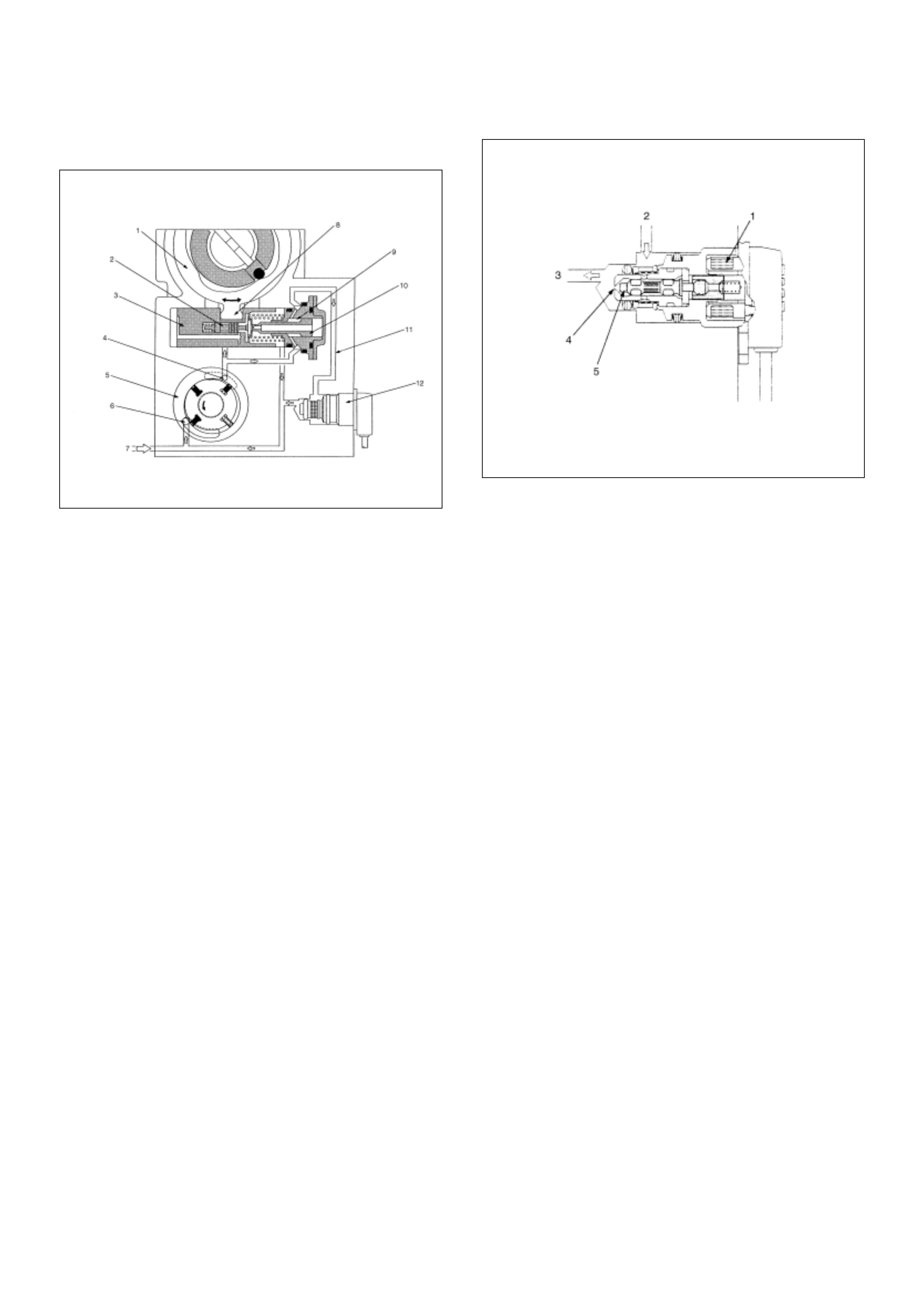
Timing Control Valve (TCV)
The pressure of the fuel fed from the feed pump is
adjusted in accordance with speed by the regulating
valve. This delivery pressure acts on the hydraulic
stopper's annular chamber as control pressure.
The chamber pressure of the annular chamber is
controlled by the timing control valve (TCV).
The timing plunger is connected to the cam ring by a
ball pin. Axial movement of the timing plunger is
transferred to the cam ring in the form of rotational
movement. Movement to th e right of the timing plunger
(to the spring side) advances injection timing.
When control current flows to the timing control valve
(TCV) coil, the valve need le opens and the fuel annul ar
chamber flows through the orifice to the feed pump inlet.
Consequently, the pressure of the annular chamber
decreases and the hydraulic stopper is moved to the
retard side.
The timing control valve (TCV) acts as a variable
throttl e, using the r apid opening and c losing (cyclin g) o f
the valve needle in the timing control valve (TCV).
At normal operation, the TCV controls the pressure
acting on the annular chamber so that the hydraulic
stopper cam move to any position, from the retard
position to the advance position. At this time, the duty
ratio is set by the pump control unit (PSG).
Duty ratio is the ratio of the time that the timing control
valve (TCV) is opened to one complete timing control
valve (TCV) operating cycle. A duty ratio change of
100% to 0% is an advance in injection timing. (The
VP44 displays an ON duty ratio.)
(1) Cam Ring
(2) Servo Valve
(3) Timer Piston
(4) Outlet
(5) Feed Pump
(6) Inlet
(7) Fuel Suction
(8) Ball Pin
(9) Annular Chamber
(10) Hydraulic S topper
(11) Return Passage
(12) Timing Control Valve (TCV)
(1) Coil
(2) From Ann ula r Chamber
(3) To Feed Pump
(4) Orifice
(5) Valve Needle
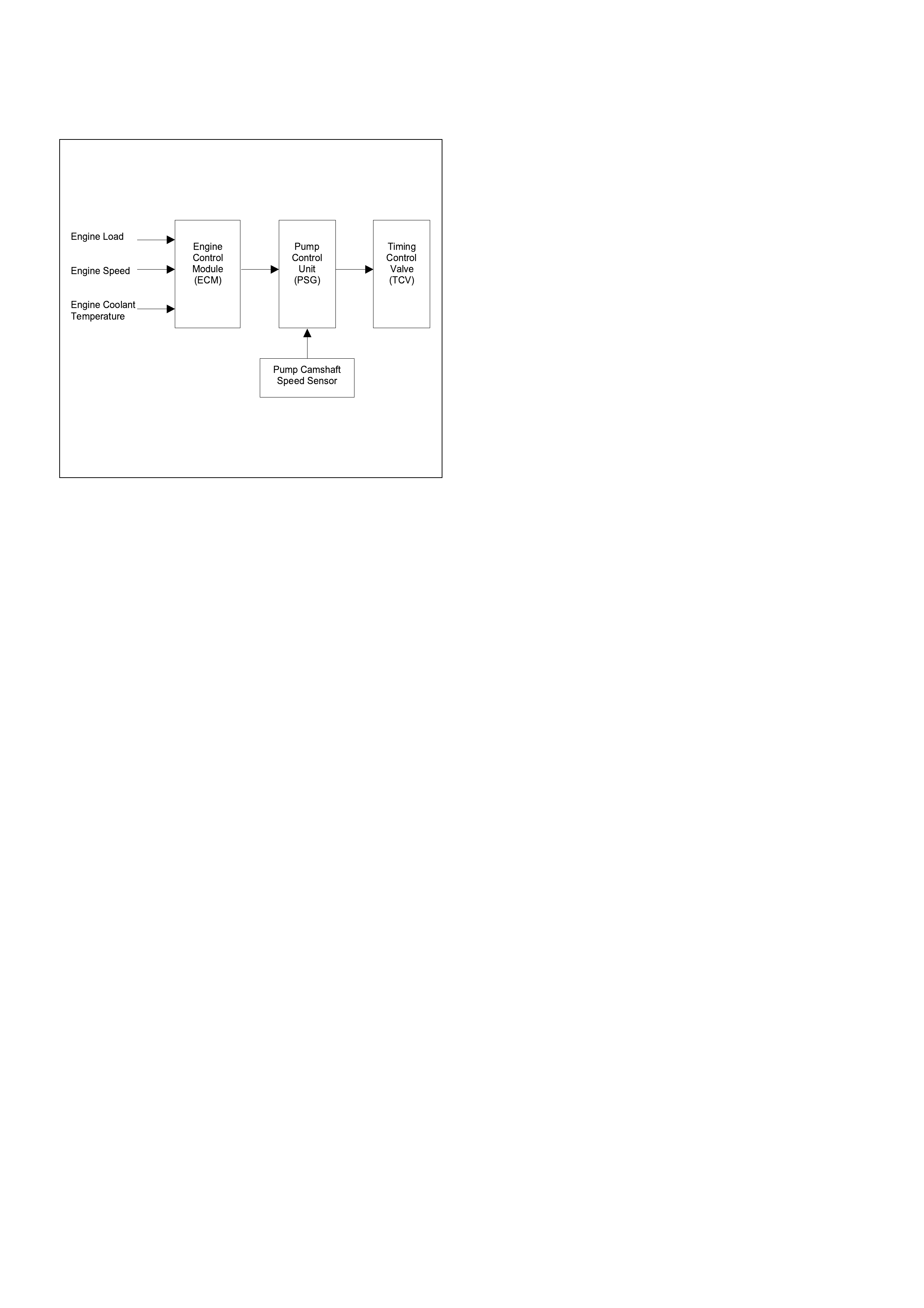
The engine control module (ECM) contains
characteristic maps of the start of injection,
corresponding to engine operating conditions (engine
load, engine speed and engine coolant temperature).
The pump control unit (PSG) is constantly comparing
the set start of injection timing and the actual start of
injection timing. If there is a difference, the timing
control valve (TCV) is controlled by the duty ratio. (The
actual start of injection timing is determined from the
pump camshaft speed sensor).
Engine Load
Engine Speed
Engine Coolant
Temperature
Engine
Control
Module
(ECM)
Pump
Control
Unit
(PSG)
Pump Camshaft
Speed Sensor
Timing
Control
Valve
(TCV)
STRATEGY BASED DIAGNOSTICS
Overview
As a re tail servic e t e ch ni ci an , y ou are part of th e Ho ld en
service team. The team goal is FIX IT RIGHT THE
FIRST TIME for the satisfa ction of every cust omer. You
are a very important member of the team as you
diagnose and repair customer vehicles.
You have maximum efficiency in diagnosis when you
have an effective, organized plan for your work.
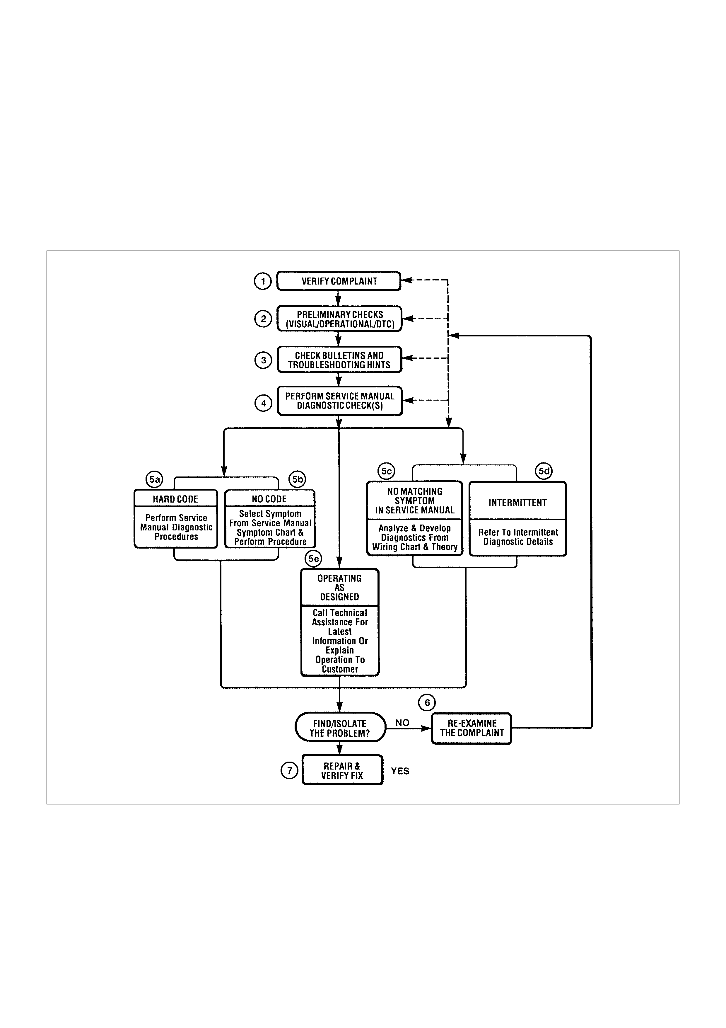
St rategy Based Diagnostic s (refer to Figu re 1) provid es
you with guidance as you create and follow a plan of
action for each specific diagnostic situation.
Strategy Based Diagnostics Chart

Diagnostic Thought Process
As you follow a diagnostic plan, every box on the
Strategy Based Diagnostics chart requires you to use
the diagnos tic though t process. Thi s method of think ing
optimize s your diagno si s in the followi ng ways:
• Improves your understanding and definition of the
customer complaint
• Sav es time by a vo iding tes tin g and/or replacing goo d
parts
• Allows you to look at the problem from different
perspectives
• Gui des you to deter mine what lev el of understand ing
about system operation is needed:
– Owner’s manual level
– Service manual level
– In-depth (engineering) level
1. Verify the Complaint
What you should do
To verify the custo mer complai nt, you need to know th e
correct (normal) operating behavior of the system and
verify that the customer complaint is a valid failure of the
system.
The following information will help you verify the
complaint:
• WHAT the vehicle model/options are
• WHAT aftermarket and dealer-installed accessories
exist
• WHAT related system(s) operate properly
• WHEN the problem occurs
• WHERE the problem occurs
• HOW the problem occurs
• HOW LONG the condition has existed (and if the
system ever worked correctly)
• HOW OFTEN the problem occurs
• Whether the severity of the problem has increased,
decreased or stayed the same
What resources you should use
Whenever possible, you should use the following
resources to assist you in verifying the complaint:
• Service manual Theory or Circuit Description
sections
• Service manual “System Performance Check”
• Owner manual operational description
• Technician experience
• Identical vehicle for comparison
• Circuit testing tools
• Vehicle road tests
• Complaint check sheet
• Contact with the customer
2. Perform Preliminary Checks
NOTE: An estimated 10 percent of successful vehicle
repairs are diagnosed with this step!
What you should do
You perform preliminary checks for several reasons:
• To detect if the cause of the complaint is VISUALLY
OBVIOUS
• To identify parts of the system that work correctly
• To accumulate enough data to correctly and
accurately search for a Holden Service Bulletin.
The initial checks may vary depending on the
compl exity of the system and may in clude the follow ing
actions:
• Operate the suspect system
• Make a visual inspection of harness routing and
accessible/visible power and ground circuits
• Check for blown fuses
• Make a visual inspection for separated connectors
• Make a visual inspection of connectors (includes
checking terminals for damage and tightness)
• Check for any DTCs stored by the on-board
computers
• Sense unusual noises, smells, vibrations or
movements
• Investigate the vehicle service history (call other
dealerships, if appropriate)
What resources you should use
Whenever appropriate, you should use the following
resources for assistance in performing preliminary
checks:
• Tech II or other technical equipment for viewing DTCs
• Service manual information:
– Component locations
– Harness routing
– Wiri ng sc hem ati cs
– Procedures for viewing DTCs
• Dealership service history file
• Veh ic le ro ad tes t
• Identical vehicle or system for comparison

3. Check Bulletins and Troub leshooting
Hints
NOTE: An estimated 30 percent of successful vehicle
repairs are diagnosed with this step!
What you should do
You should have enough information gained from
preliminary checks to accurately search for a bulletin
and other related service information. Some service
manual sections provide troubleshooting hints that
match symptoms with specific complaints.
What resources you should use
You should use the following resources for assistance in
checking for bulletins and troubleshooting hints:
• Printed bulletins
• Access Holden Bulletin(s).
• Videotapes
• Service manual
4. Perform Service Manual Diagnostic
Checks
What you should do
The “System Checks” in most service manual sections
and in most cells of section 8A (electrical) provide you
with:
• A systematic approach to narrowing down the
possible causes of a system fault
• Direction to specific diagnostic procedures in the
service manual
• Assistance to identify what systems work correctly
What resources you should use
Whenever possible, you should use the following
resources to perform service manual checks:
• Service manual
• Technical equipment (for viewing DTCs and
analyzing data)
• Digital multimeter and circuit testing tools
• Other tools as needed
5a and 5b. Perform Service Manual
Diagnostic Procedures
NOTE: An estimated 40 percent of successful vehicle
repairs are diagnosed with these steps!
What you should do
When directed by service manual diagnostic checks,
you must then carefully and accurately perform the
steps of diagnostic procedures to locate the fault related
to the customer complaint.
What resources you should use
Whenever appropriate, you should use the following
resources to perform service manual diagnostic
procedures:
• Service manual
• Technical equipment (for analyzing diagnostic data)
• Digital multimeter and circuit testing tools
• Essential and special tools
5c. Technician Self Diagnoses
When there is no DTC stored and no matching
symptom for the condition identified in the service
manual , you must begi n with a thorough understanding
of how the system(s) operates. Efficient use of the
service manual combined with you experience and a
good process of elimination will result in accurate
diagnosis of the condition.
What you should do
Step 1: Identify and understand the suspect
circuit(s)
Having completed steps 1 through 4 of the Strategy
Based Diagnostics chart, you should have enough
information to identify the system(s) or sub-system(s)
involved. Using the service manual, you should
determine and investigate the following circuit
characteristics:
• Electrical:
– How is the circuit powered (power distribution
charts and/or fuse block details)?
– How is the circuit grounded (ground distribution
charts)?
– How is the circuit controlled or sensed (theory of
operation):
– If it is a switched circuit, is it normally open or
normally closed?
– Is the power switched or is the ground
switched?
– Is it a variable resistance circuit (ECT sensor
or TP sensor, for example)?
– Is it a si gnal ge nerating devic e (MAF sens or of
VSS, for example)?
– Does it rely on some mechanical/vacuum
device to operate?

• Physical:
– Where are the circuit components (component
locators and wire harness routing diagrams):
– Are there areas where wires could be chafed
or pinched (brackets or frames)?
– Are there areas subjected to extreme
temperatures?
– Are there areas subjected to vibration or
movement (engine, transmission or
suspension)?
– Are the re areas ex posed to moisture, r oad salt
or other corrosives (battery acid, oil or other
fluids)?
– Are there common mounting areas with other
systems/components?
– Have previous repairs been performed to wiring,
connectors, components or mounting areas
(causing pinched wires between panels and
drivetrain or suspension components without
causing an immediate problem)?
– Does the vehicle have aftermarket or dealer-
installed equipment (radios, telephone, etc.)
Step 2: Isolate the problem
At this point, you should have a good idea of what could
cause th e presen t cond ition, as well a s cou ld not ca use
the condition. Actions to take include the following:
• Divide (and separate, where possible) the system or
circuit into smaller sections
• Confine the problem to a smaller area of the vehicle
(start with main harness connections while removing
panels and trim as necessary in order to eliminate
large vehicle sections from further investigation)
• For two or more circuits that do not share a common
power or ground, concentrate on areas where
harnesses are routed together or connectors are
shared (refer to the following hints)
Hints
Though the symptoms may vary, basic electrical failures
are generally caused by:
• Loose connections:
– Open/high resistance in terminals, splices,
connectors or grounds
• Incorrect connector/harness routing (usually in new
vehicles or after a repair has been made):
– Open/high resistance in terminals, splices,
connectors of grounds
• Corrosion and wire damage:
– Open/high resistance in terminals, splices,
connectors of grounds
• Component failure:
– Opens/short and high resistance in relays,
modules, switches or loads
• Aftermarket equipment affecting normal operation of
other systems
You may isolate circuits by:
• Unplugging connectors or removing a fuse to
separate one part of the circuit from another part
• Operating shared circuits and eliminating those that
function normally from the suspect circuit
• If only one component fails to operate, begin testing
at the component
• If a number of components do no operate, begin tests
at the area of commonality (such as power sources,
ground circuits, switches or major connectors)
What resources you should use
Whenever appropriate, you should use the following
resources to assist in the diagnostic process:
• Service manual
• Technical equipment (for data analysis)
• Experience
• Technical Assistance
• Circuit testing tools
5d. Intermittent Diagnosis
By definition, an intermittent problem is one that does
not occur continuously and will occur when certain
conditions are met. All these conditions, however, may
not be obvious or currently known. Generally,
intermittents are caused by:
• Faulty electrical connections and wiring
• Malfunctioning components (such as sticking relays,
solenoids, etc.)
• EMI/RFI (Electromagnetic/radio frequency
interference)
• Aftermarket equipment
Intermittent diagnosis requires careful analysis of
suspected systems to help prevent replacing good
parts. This m ay i nvolve using cr eativity a nd i ngenui ty to
interpret customer complaints and simulating all
exter nal and internal system conditi ons to duplicat e the
problem.
What you should do
Step 1: Acquire information
A thorough and comprehensive customer check sheet
is critical to intermittent problem diagnosis. You should
acquire this, since it will dictate the diagnostic starting
point. The vehicle service history file is another
source for accumulating information about the
complaint.

Step 2: Analyze the intermittent problem
Analyze the customer check sheet and service history
file to determine conditions relevant to the suspect
system(s).
Using service manual information, you must identify,
trace and locate all electrical circuits related to the
malfunctioning system(s). If there is more than one
system failure, you should identify, trace and locate
areas of commonality shared by the suspect circuits.
Step 3: Simulate the symptom and isolate the
problem
Simulate the symptom and isolate the system by
reprodu cing all possibl e conditions s uggested in Step 1
while monitoring suspected circuits/components/
systems to isolate the problem symptom. Begin with the
most logical circuit/component.
Isolate the circuit by dividing the suspect system into
simpler circuits. Next, confine the problem into a smaller
area of the system. Begin at the most logical point (or
point of easiest access) and thoroughly check the
isolated circuit for the fault, using basic circuit tests.
Hints
You can isolate a circuit by:
• Unplugging connectors or removing a fuse to
separate one part of the circuit from another
• If only component fails to operate, begin testing the
component
• If a number of co mpo nen ts do not operate , begi n tes t
at areas of commonality (such as power sources,
ground circuits, switches, main connectors or major
components)
• Substitute a known good part from the parts
department or the ve hic le syst em
• Try the suspect part in a known good vehicle
See Symptom Simulation Tests on the next page for
problem simulation procedures. Refer to service manual
sections 6E and 8A for information about intermittent
diagnosis. Follow procedures for basic circuit testing in
service manual section 8A.
What resources you should use
Whenever appropriate, you should use the following
resources to assist in the diagnostic process:
• Service manual
• Bulletins
• Digital multimeter (with a MIN/ MAX feature)
• Tech II and Tech II upload function
• Circuit testing tools (including connector kits/
harnes se s and jum per wires )
• Experience
• Intermittent problem solving simulation methods
• Customer complaint check sheet
Symptom Simulation Tests
1. Vibration
This method is useful when the customer complaint
analysis indicates that the problem occurs when the
vehicle/system undergoes some form of vibration.
For connectors and wire harness, slightly shake
vertically and horizontally. Inspect the connector joint
and body for damage. Also, tapping lightly along a
suspected circuit may be helpful.
For parts and sensors, apply slight vibration to the part
with a l ig ht tap of the fin ger whi le mo nit or ing the s yst em
for a malfunction.
2. Heat
This method is important when the complaint suggests
that th e problem occur s in a heat ed en vironm ent. App ly
moderate heat to the component with a hair drier or
similar tool while monitoring the system for a
malfunction.
CAUTION: Care must be take to avoid overheating
the compone nt.
3. Water and Moisture
This method may be used when the complaint suggests
that the malfunction occurs on a rainy day or under
conditions of high humidity . In this case, apply water in a
light spray on the vehicle to duplicate the problem.
CAUTION: Care must be take to avoid directly
exposing electrical connections to water.
4. Electrical loads
This method involves turning systems ON (such as the
blower, lights o r rear windo w defogger ) to crea te a load
on the vehicle electrical system at the same time you
are monitoring the suspect circuit/component.
5e. Vehicle Operates as Designed
This condition refers to instances where a system
operat ing as d esigned is perce ived to be unsatis factory
or undesirable. In general, this is due to:
• A lack of understanding by the customer
• A conflict between customer expectations and
vehicle design intent
• A system performance that is unacceptable to the
customer

What you should do
You can verify that a system is operating as designed
by:
• Reviewing service manual functional/diagnostic
checks
• Exa mining bul letins a nd other ser vice informati on for
supplementary information
• Co mpare sys tem oper a tio n to an identic al vehicl e
If the condition is due to a customer misunderstanding
or a con flict betwee n customer expec tation and system
operation, you should explain the system operation to
the custo mer.
If the complaint is due to a case of unsatisfactory
system performance, you should contact Technical
Assistance for the latest information.
What resources you should use
Whenever possible, you should use the following
resour ce s to fa cili tate the dia gno sti c proc es s:
• Vehicle service information (service manual, etc.)
• Holden field support
• Experience
• Identical vehicle or system for comparison
6. Re-examine the complaint
When you do not successfully find/isolate the problem
after executing a diagnostic path, you should re-
examine the com pl ain t.
What you should do
In this case, you will need to backtrack and review
information accumulated from step 1 through 4 of
Strategy Based Diagnostics. You also should repeat any
procedures that require additional attention.
A previous path may be eliminated from consideration
only if you are certain that all steps were executed as
directed. You must then select another diagnostic path
(step 5a, 5b, 5 c or 5d ) . If al l po ss i ble opti ons ha ve been
explored, you may call or seek Holden field support.
What resources you should use
Whenever possible, you should use the following
resour ce s to fa cili tate the dia gno sti c proc es s:
• Service manual
• Accumulated information form a previous diagnostic
path
• Service information and publications
• Holden field support
7. Repair and Verify Fix
What you should do
After you have located the cause of the problem, you
must execute a repair by following recommended
service manual procedures.
When the repair is completed, you should verify the fix
by performing the system checks under the conditions
listed in the customer c omplaint.
If applic able, you should ca rry out preven tive meas ures
to avoid a repeat complaint.
What resources you should use
Whenever possible, you should use the following
resources to facilitate the repair process:
• Electrical repair procedures
• Service manual information and publications

GENERAL SERVICE INFORMATION
Serviceability Issues
Non-OEM Parts
All of the OBD diagnostics have been calibrated to run
with OEM parts. Accordingly, if commercially sold
sensor or switch is installed, it makes a wrong diagnosis
and turns on the check engine lamp.
Aftermarket electronics, such as cellular phones,
stereos, and anti-theft devices, may radiate EMI into the
control system if they are improperly installed. This may
cause a false sensor reading and turn on the check
engine lamp.
Poor Vehicle Maintenance
The sens itivity of OBD dia gnostics will c ause the check
engine lamp to turn on if the vehicle is not maintained
properly. Restricted oil filters, fuel filters, and crankcase
deposits due to lack of oil changes or improper oil
viscosity can trigger actual vehicle faults that were not
previously monitored prior to OBD. Poor vehicle
maintenance can not be classified as a “non-vehicle
fault”, but with the sensitivity of OBD diagnostics,
vehicle maintenance schedules must be more closely
followed.
Related System Faults
Many of the OBD system diagnostics will not run if the
ECM detects a fault on a related system or component.
Visual/Phy sic al Engine Compartment
Inspection
Perform a careful visual and physical engine
compartment inspection when performing any
diagnostic procedure or diagnosing the cause of an
emission te st failure. This can often lea d to repairing a
problem without further steps. Use the following
guidelines when performing a visual/physical
inspection:
• Inspect all vacuum hoses for punches, cuts,
disconnects, and correct routing.
• Inspect hoses that are difficult to see behind other
components.
• Inspect all wires in the engine compartment for
proper connection s, burne d or chafed s pots, pinched
wires, contact with sharp edges or contact with hot
exhaust manifolds or pipes.
Basic Knowledge of Tools Required
NOTE: Lack of basic knowledge of this powertrain
when performing diagnostic procedures could result in
an incorrect diagnosis or damage to powertrain
components. Do not attempt to diagnose a powertrain
problem without this basic knowledge.
A basic understanding of hand tools is necessary to
effectively use this section of the Service Manual.
ON-BOARD DIAGNOSTIC (OBD)
On-Board Diagnostic (Self Diagnosis
System) Tests
A diagno stic test is a serie s of steps, the re sult of whi ch
is a pass or fail reported to the diagnostic executive.
When a diagnostic test reports a pass result, the
diagno sti c ex ec utive re co rd s the foll owi ng data:
• The diagnostic test has been completed since the
last ignition cycle.
• The diagnostic test has passed during the current
ignition cycl e.
• The fault identified by the diagnostic test is not
currently active.
When a diagnostic test reports a fail result, the
diagno sti c ex ec utive re co rd s the foll owi ng data:
• The diagnostic test has been completed since the
last ignition cycle.
• The fault identified by the diagnostic test is currently
active.
• The fault has been active during this ignition cycle.
• The operating conditions at the time of the failure.
The Diagnostic Exec utiv e
The Diagnostic Executive is a unique segment of
software which is designed to coo rdinate and prioritize
the diagn os tic proc edu re s as wel l as define the pro toc ol
for recording and displaying their results. The main
respo ns ib iliti es of the Di agn os tic Ex ecuti ve are li st ed as
follows:
• Commanding the check engine lamp on and off
• DTC logging and clearing
• Current status information on each diagnostic
Diagnostic Information
The diagnostic charts and functional checks are
desig ned to loc ate a faul ty c ircu it or c omp onen t th rough
a proce ss of logica l decis ions . The charts are prepared
with the requirement that the vehicle functioned
correc tly at the ti me of assembl y and that th ere are not
multiple faults present.
There is a continuous self-diagnosis on certain control
functions. This diagnostic capability is complemented
by the diagnostic procedures contained in this manual.
The language of communicating the source of the
malfunction is a system of diagnostic trouble codes.
When a malfunction is detected by the control module, a
diagnostic trouble code is set and the check engine
lamp is illuminated.
Techline
6E-60 RA – 4JH1-TC
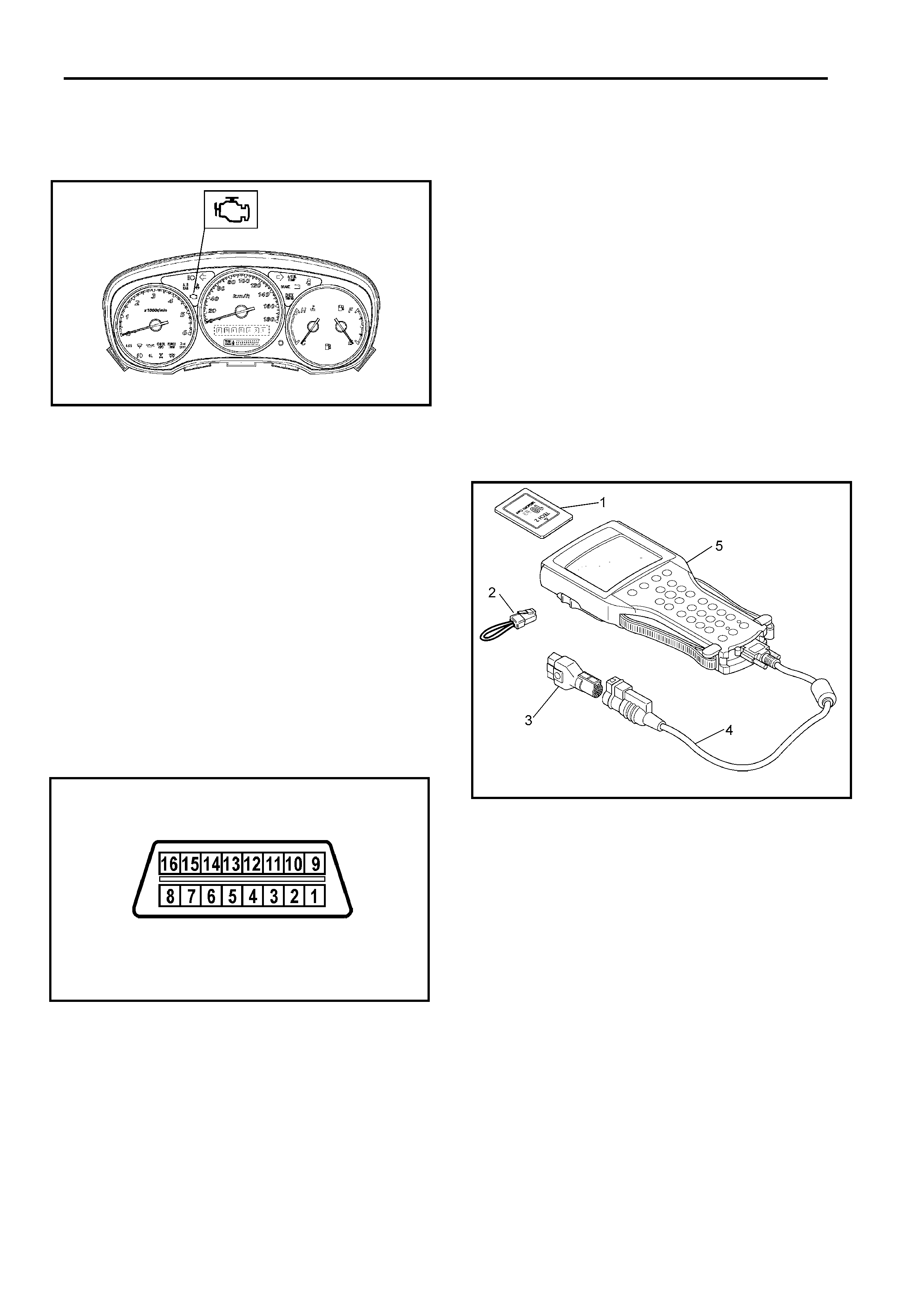
Malfunction Indicator Lamp
The malfunction indicator lamp (MIL) is located in the
instrument pane l cluste r. The MIL will di splay the follow ing
symbol when commanded ‘ON’.
The MIL indicate s that an emissio n relate d faul t ha s occurred
and vehicle service is required. The following is a list of the
modes of operation for the MIL:
• The MIL illuminates for about 2.6 seconds when the
ignition switch is turned ‘ON’, with the engine ‘OFF’. This is
a bulb test to ensu re th a t the MIL is able to illu mi nate .
• The MIL turns ’OFF’ after the engine is started, if a
diagnostic fault is n ot present.
• The MIL remains illuminated after the engine is started, i
f
the engine control module (ECM) detects a fault.
A
diagnostic trouble code (DTC) is stored any time the ECM
illuminate s the MIL due to an emi ssion re lated fau l t.
Data Link Connector (DLC)
The provision for communication with the control module is the
Data Link Connector (DLC). It is located behind the lower front
instrument pane l. The DLC is used to connect to a Tech2.
Some common uses of the Tech2 are listed below:
• Identify ing stored Diagno stic Trou ble Code s (D TCs).
• Clearing DTCs.
• Reading serial data.
• Connect the SAE 16/19 adap ter (3 ) to the da ta lin k
connector of the vehicle.
• Connect th e DLC ca ble (4) to th e Tech 2 (5).
• Connect the SAE 16/19 adap ter (3 ) to the da ta lin k
connector (DLC) of the vehicle.
Verifying Vehicle Repair
Verifica tion of ve hi cle rep ai r w ill be mo re comprehensive for
vehicles with OBD system diagnostic. Following a repair, the
technician shoul d pe rform the following steps:
1. Review and record the Fail Records for the DTC which
has been diagnosed .
2. Clear DTC(s).
3. Operate the vehicle within conditions noted in the Fail
Records.
4. Monitor the DTC status information for the specific DTC
which has been diagnosed until the diagnostic test
associated with that DTC runs.
Following these steps is very important in verifyin
g
repairs on OBD systems. Failure to follow these step
s
could result in unnecess ary repairs.
On-Board Diagnosis (Self-Diagnosis)
The Tech 2 Scan Tool
The Tech 2 scan tool is used to electrically diagnose and
check the vehicle electronic systems. The Tech 2 enhances
the diagnosis efficiency, even though the troubleshooting can
be done without the Tech 2.
1. Tech 2 Components:
• Tech 2 scan tool kit (No. 7000086), Tech 2 scan tool
(No. 7000057) a nd DLC cable (No . 3000095).
• SAE 16/19 adapter (No. 3000098) (3), RS232 loop
back connector (No. 3000112) (2) and PC MCIA card
(No. 3000117) (1).
Legend
(1) PCMCIA Card
(2) Loop Back Connector
(3) SAE 16/19 Pin Adaptor
(4) DLC Cable
(5) Tech 2 S ca n To ol
2. Connecting Tech 2 to the Vehicle:
• Check the ignition switch is turned OFF.
• Insert the PCMCIA card (1) in to th e Te ch 2 (5). Note
that the PCMCIA card must be installed in the slot
closest to the Tech 2 screen.
NOTE: Check that power is not supplied to the Tech 2
when installing or remo vin g the PCMC IA card.
• Turn th e igni ti on switch of the veh ic le to ON an d pres s
the "PWR" key of the Tech 2.
• Check the Tech 2 display.
Reading Flash Diagnostic Trouble Codes
The provision for communicating with the Engine Control
Module (ECM) is the Data Link Connector (DLC). The DLC is
located in the position shown next. It is used in the assembl
y
plant to receive information, checking that the engine is
operating properly before it leaves the plant.
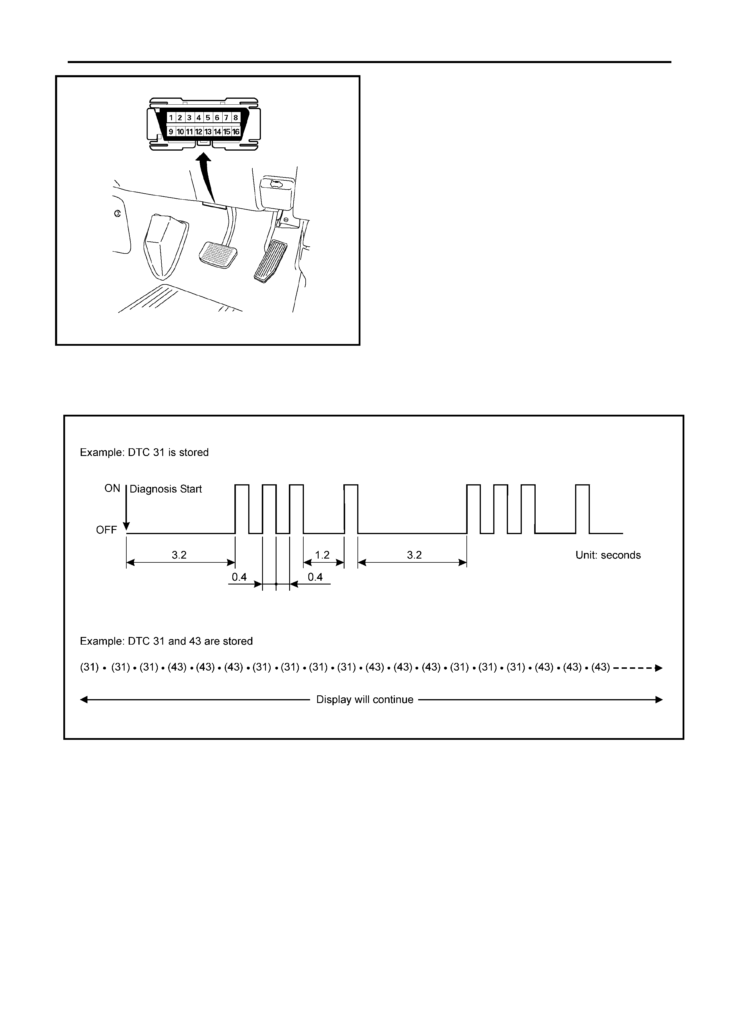
RA – 4JH1-TC 6E-61
The diagnostic trouble code(s) (DTCs) stored in the ECM
memory can be read either through a hand-held diagnosti
c
scanner plugged into the DLC or by counting the number o
f
flashes of the malfunction indicator lamp (MIL) when the
diagnostic test terminal of th e DLC is g ro unded .
The DLC terminal "6" (diagnostic request) is pulled "Low"
(grounded) by jumping to DLC terminal '4’ or ‘5’, which are
ground circui ts.
This will signal the ECM that you want to "flash" DTCs), if an
y
are present. Once terminals '4’ or ‘5’ and ‘6’ have been
connected, the ignition switch must be turned to the ‘ON’
position, with the engine not running .
The check eng ine lamp will indi cate a DTC three times if a DTC
is present. If more than one DTC has been stored in the ECM
memory, the DTC(s) will be displayed from the lowest to the
highest, with each DTC being disp layed three times.
Shown is the patt ern that a DTC ‘31’ ge nerates a nd the pattern
of events, when both a DTC ‘31’ and ‘43’ are stored in the
ECM.
The DTC display will continue as long as the DLC is shorted
and the ignition is in the ON position.
Reading Diagnostic Trouble Codes With Tech 2
The preferred method for reading diagnostic trouble code(s) is
to use a Tech2 scan tool. When reading DTC(s), follo
w
instructions supplied by the Tech 2 manufacturer.
Clearing Diagnostic Trouble Codes
To clear Diagnostic Trouble Codes (DTCs), use the Tech2
"clear DTCs" or "clear information" function. When clearing
DTCs follow instructions supplied by the Tech2 manufacturer.
Flash Code Displays
Diagnosis With Tech 2
If No Codes are Set:
• Refe r to Fl: Data D isplay and iden ti fy the ele ctri cal faul ts
that are not indicated by a troub le code .
• Re fe r to "SYMPTOM DIAGNOSIS".
If codes are set:
1. Record all tr oubl e co des dis pla yed b y Tec h 2 and c heck i
f
the codes are intermittent.
2. Clear the codes.
3. Road test the vehicle to reproduce the faulty status.
4. Check trouble codes again using the Tech 2.
5. If no codes is displayed by test driving, the fault is
intermittent. In this case, refer to "DIAGNOSIS AIDS".
6. If a code is present, refer to DTC Chart for diagnosis.
7. Check trouble codes again using the Tech 2.
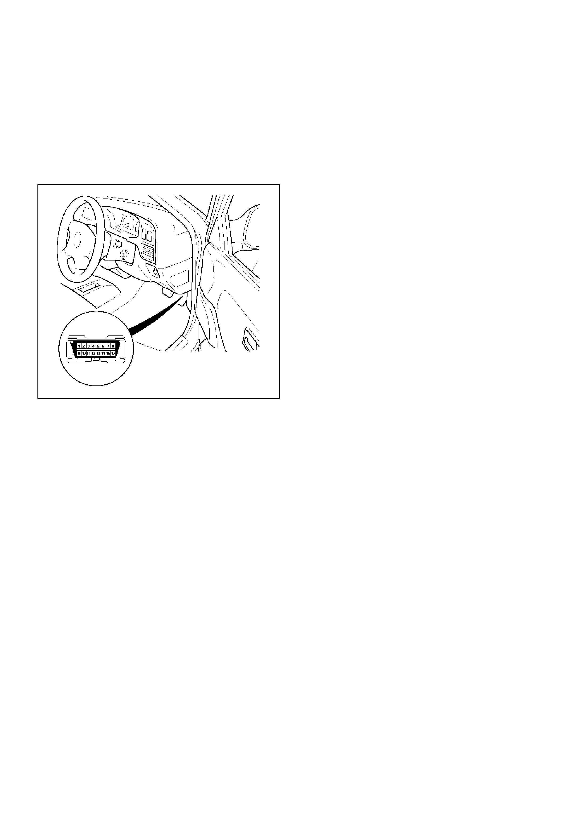
2. Tech 2 C onnectio n
• Check the key switch is turn OFF.
• Insert the PCMCIA card (1) into the Tech 2 (5).
• Connect the SAE 16/19 adapter (3) to the DLC
cable (4).
• Connect the DLC cable (4) to the Tech 2 (5).
• Connect the SAE 16/19 adapter (3) to the data
link connector of the vehicle.
• Turn the key switch of the vehicle ON and press
the “PWR” key of the Tech 2.
• Check the display of the Tech 2.
NOTE: Be sur e to check tha t the power is no t supplie d
to the Tech 2 when attaching or removing the PCMCIA
card.

TECH 2 OPERATING FLOW CHART (START UP)
Select “4JH1-TC Bosch” in Vehicle Identification menu and the following table is shown in the Tech 2 screen.
Press (ENTER) to Continue
Main Menu
F0: Diagnostic
F1: Service Programming System (SPS)
F2: View Capture Data
F3: Tool Opti o n
F4: Download/ Upload Help
Press "ENTER" key.
Vehicle Identification
(3) 2003
(2) 2002
(1) 2001
(Y) 2000
(X) 1999
(W) 1998
Select "F0: Diagnostic".
Select "(3) 2003" or later.
System Selection Menu
F0: Powertrain
F1: Chassis
F3: Body
Select "TF/UC)".
Vehicle Identification
4JH1-TC Bosch
4JA1-TC Bosc h
4JH1-T Denso
3.5L V6 6VE1 Hitachi
AW30-40LE
A/T JR405E
Select "F0: Powertrain".
Select "4JH1-TC Bosch".
Vehicle Identification
(UB) Trooper, Bighorn
(UE) Rodeo,/Amigo, Wizard/Mu
(TF/UC) LUV, Frontier, LAO-Rodeo
(TBR)
(N*) ELF, NPR, NQR

F0: Diagnostic Trouble Code
The pur pose of the “D iag nos ti c Trouble Cod es” m ode is
to display stored trouble code in the ECM.
When “Clear DTC Information” is selected, a “Clear
DTC Information”, warning screen appears.
This screen informs you that by cleaning DTC's “all
stored DTC information in the ECM will be erased”.
After clearing codes, confirm system operation by test
driving the vehicle.
Symptom Code:
This number or alphabet means identification of the
malfuncti on. Each DTC inclu des plural s ymptoms, s uch
as DTC P0100 has four kind s of symptom code (7), ( 9),
(B) and (C). DTC chart (check procedure) is separated
depending on the symptom code.
F1: Data Display
The purpose of the “Data Display” mode is to
continuously monitor data parameters.
The current actual values of all important sensors and
signals in the system are display through F1 mode.
See the “Typical Scan Data” section.
F2: Snapshot
“Snapsho t” allows you to focus on maki ng the condit ion
occur, rather than trying to view all of the data in
anticipation of the fault.
The snapshot will collect parameter information around
a trigger point that you select.
F3: Miscellaneous Test:
The purpose of “Miscellaneous Test” mode is to check
for correct operation of electronic system actuators.
F4: Programming (Factor y Use Only)
The pu rpose o f “Prog rammi ng” is to pr ogram VI N in the
ECM and lock the programmed data.
F0: Diagnostic Trouble Codes
F0: Read DTC Infor As Stored By ECU
F1: Clear DTC Information
F1: Data Display
F2: Snapshot
F3: Misc ell an eou s Test
F0: Lamps
F0: Glow Time Telltale Test
F1: Relays
F0: Glow Time Relay Test
F2: Solenoids
F0: EGR Solenoid Test
F3: Engine Speed (RPM) Control
F4: Program mi ng
F0: Program VIN
F1: Lock ECU
Read DTC Info As Stored By ECU
P0100 Present
(7) Mass Air Flow (MAF) Sensor
Voltage Supply Circuit High Input
DTC No.
Symptom Code

TYPICAL SCAN DATA & DEFINITIONS (ENGINE DATA)
Use the typi cal values table onl y after the On-Board Di agnostic Syst em check has b een completed , no DTC(s) were
noted, and you have determined that the On-Board Diagnostic are functioning properly.
Tech2 values from a properly running engine may be used for comparison with the engine you are diagnosing.
Condition : Vehicle s topp in g, en gin e r unn ing , ai r con ditioning off & after war m-up (Co ol ant te mpe ra tur e a pprox im ate ly
80 deg. C)

Tech 2 Parameter Units Idle 1500rpm 2000rpm Definition
1 Engine S peed rpm 675 - 725 1475 -
1525 1975 -
2025 The engine speed is measured by ECM from the CKP
sensor.
2 Vehicle Speed km/h / MPH 0 0 0 This displays vehicle speed. The vehicle speed is
measured by ECM from the vehicle speed sensor.
3 Pump Speed rpm 335 - 375 725 - 775 975 - 1025 This displays injection pu mp speed. The injection s peed is
measured by ECM from the pump cam sensor .
4 Accelerator Position
Sensor Signal % 0 3 - 5 5 - 7 Throttle position operating angle is measured by the ECM
from throttle position output voltage. This should display
0% at idle and 99 - 100% at full throttle.
5 Idle Switch Active/
Inactive 0V Active Active/
Inactive 0V Inactive 0V This displays operating status of the idle switch. This
should display "Active" until the accelerator pos ition nearly
4 - 5%.
6 Mass Air Flow
Sensor mg/strk 420 - 490 380 - 460 410 - 480 This displays calculated intake air volume f or one cylinder
stroke. The mass air flow is measured by ECM from the
MAF sensor output voltage.
7 Desired Mass Air
Flow mg/strk 430 - 470 380 - 420 410 - 470 This displays desired intake air volume for one cylinder
stroke. The desired mass air flow is calculated by ECM
depending on engine condition.
8 Barometric Pressur e hpa Depends
on altitude Depends
on altitude Depends
on altitude The barometric pressure is measured by ECM from the
sensor in the ECM. This data is changing by altitude.
9 Desired Injection
Quantity mg/stk 6 - 10 6 - 10 7 - 11 This displays desired value from the ECM. The ECM
compensates for fuel rate by throttle position and various
sensor signals.
10 Injection Quantity mg/stk 6 - 10 6 - 10 7 - 11 This displays calculated actual fuel quantity from the PSG.
The PSG receives desired injection quantity from the ECM.
And, it compensates actual injection depending on timer
position to determine duration of the high pressure
solenoid valve operation.
11 Desired Fuel Injection
Start deg. CA 1 - 3 2 - 4 3 - 5 This displays desired injection timing from the ECM. The
ECM compensates for fuel injection timing by throttle
position and various sensor signal.
12 Actual Injection Start deg. CA 1 - 3 2 - 4 3 - 5 This displays calculated actual injection timing based on
CKP signal and pump cam signal. The PSG controls TCV
duty ratio to meet desired injection timing from the ECM.
13 Coolant Temperature deg. C / deg.
F80 - 85 80 - 85 80 - 85 The ECT is measured by ECM from ECT sensor output
voltage. This data is changing by coolant temperature.
When the engine is normally warm upped, this data
displays approximately 80 deg. C.
14 Fuel Temperature deg. C / deg.
FDepends
on fuel
temp.
Depends
on fuel
temp.
Depends
on fuel
temp.
The FT is meas ured by PSG from FT sens or. This data is
changing by fuel temperature.
15 Intake Air
Temperature deg. C / deg.
FDepends
on ambient
temp.
Depends
on ambient
temp.
Depends
on ambient
temp.
The IAT is measured by ECM from IAT sensor output
voltage. This data is changing by intake air temperature.
16 Ignition Status On12V/
Off0V On 12V On 12V On 12V This displays the key switch status indicated by the ECM
with key switch signal. T his should display "Off 0V" at key
OFF and "On12V" at key ON.
17 Brake Switch 1 Active/
Inactive Inactive Inactive Inactive This displays operating status of the brake switch. This
should display "Active" when the brake pedal is stepped
on.
18 Brake Switch 2 Active/
Inactive Inactive Inactive Inactive This displays operating status of the brake switch. This
should display "Active" when the brake pedal is stepped
on.
19 Clutch Switch (M/T
Only) Active/
Inactive Inactive Inactive Inactive This displays operating status of the clutch switch. This
should display "Active" when the clutch pedal is stepped
on.
20 Neutral Switch On/Off On On On This displays operating status of the neutral switch. Th is
should display "On" when the gear position is neutral (M/T)
or P, N position (A/T).

Miscellaneous Test
The state of each circuit can be tested by using
miscellaneous test menus. Especially when DTC
cannot be detected, a faulty circuit can be diagnosed by
testing each circuit by means of these menus.
Even DTC has been detected, the circuit tests using
these menus could help discriminate between a
mechanical trouble and an electrical trouble.
Connect Tech 2 and select "Powertrain", "4JH1-TC
Bosch" & "Miscellaneous Test".
F0: Lamps
F0: Glow Time Telltale Test
When the Tech 2 is operated, "Glow Time Indicator
Lamp" is turned on or off.
The circuit is correct if the "Glow Time Indicator Lamp"
in the instrument panel is turned on or off in accordance
with this operation.
F1: Relays
F0: Glow Time Relay Test
When the Tech 2 is operated, glow relay turns ON or
OFF.
The circuit is correct if glow relay is operated in
accordance with this operation.
F2: Solenoids
F0: EGR Solenoid Test
When the Tech 2 is oper ated, control dut y ratio of EGR
EVRV changes to 5% to 95%.
The circuit is correct if glow relay is operated in
accordance with this operation.
21 A/C Information
Switch Active 12V/
Inactive 0V Inactive 0V Inactive 0V Inactive 0V This displays the air conditioner request signal. This
should display "Active 12V" when the air conditioner switch
is switched on.
22 Diagnostic Request Active 0V/
Inactive 12V Inactive
12V Inactive
12V Inactive
12V This displays the diagnostic request signal. This should
display "Inactive 12V" when the Tech 2 is connected.
23 System Voltage V 10 - 15 10 - 15 10 - 15 This displays the system voltage measured by the ECM at
ignition feed.
24 Main Relay Active/
Inactive Active Active Active This displays operating status for the ECM main relay. This
should display "Active" when the key switch is turned on
and while engine is running.
25 Glow Time Relay Active 0V/
Inactive12V Inactive
12V Inactive
12V Inactive
12V This displays operating status for the glow relay. This
should display "Inactive 12V" when the engine is warm
upped.
26 Check Engine Light On/Off Off Off Off This displays operating s tatus for the Check E ngine Lamp.
This should display "On" when the Check Engine Lamp is
turned on.
27 Glow Time Telltale On/Off Off Off Off This displays operating status for the glow indicator lamp.
This should display "On" when the glow lamp is turned on.
28 Desired Engine Idle
Speed rpm 700 700 700 The desired engine idle speed that the ECM commanding.
The ECM compensat es for various engine loads b ased on
engine coolant temperature.
29 A/C Request Ac tive 0V/
Inactive 12V Inactive
12V Inactive
12V Inactive
12V This displays operating status of the A/C compressor. This
should display "Active 0V" when the compressor relay is
operated.
30 Immobilizer Active/
Inactive Inactive Inactive Inactive This should display "Inactive" when the immobilizer is
correctly operated.
31 Immobilizer Signal Received/
Not
Received
Not
Received Not
Received Not
Received This should display "Not Received" when the immobilizer is
not activated.
32 Immobilizer Function
Programmed Yes/ No Yes Yes Yes This should display "Yes" when the imm obilizer is correctly
programmed.
33 EGR Pulse Ratio
(Exhaust Gas
Recirculation)
% 85 - 90 85 - 90 85 - 90 This displays the duty signal from the ECM to control the
EGR flow amount.
Tech 2 Parameter Units Idle 1500rpm 2000rpm Definition
EGR Solenoid Test
Desired Mass Air Flow 470 mg/strk
Mass Air Flow 450 mg/strk
Engine Speed 700 rpm
Exhaust Gas Recirculation 95%

• Press "Active" key.
Then, EVRV duty ratio increases to 95%
• Press "Inactive key".
EVRV duty ratio decreases to 5%
F3: Engine Speed (RPM) Control
When the Tech 2 is operated, "Desired Idle Speed"
increases 50rpm-by-50rpm up to 1200rpm.
The circuit is correct if engine speed is changed in
accordance with this operation.
• Press "Increase" key.
Then, Desired Idle speed is increases
50rpm-by-50rpm up to 1200rpm. Engine speed is
also
Engine Speed (RPM) Control
Engine Speed 850 rpm
Desired Idle Speed 850 rpm
Injection Quantity 7.5 mg/ strk
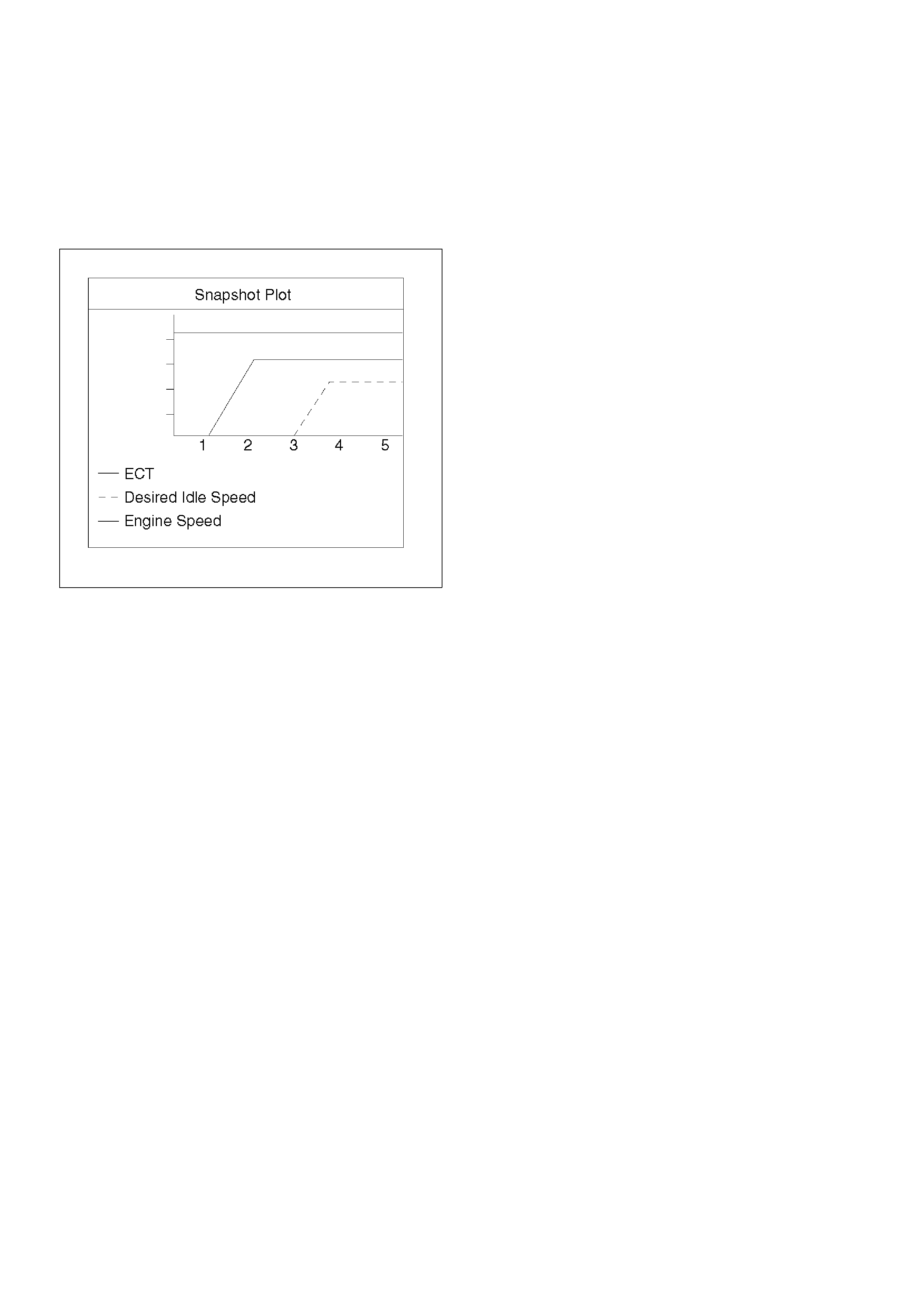
PLOT TING SN A PSHOT GR A P H
This test selects several necessary items from the data
list to plot graphs and makes data comparison on a long
term basis. It is an effective test particularly in emission
related evaluations.
For trouble diagnosis, you can collect graphic data
(snap shot) directly from the vehicle.
You can replay the snapshot data as needed. Therefore,
accura te diagno sis is possi ble, eve n though t he ve hicle
is not available.
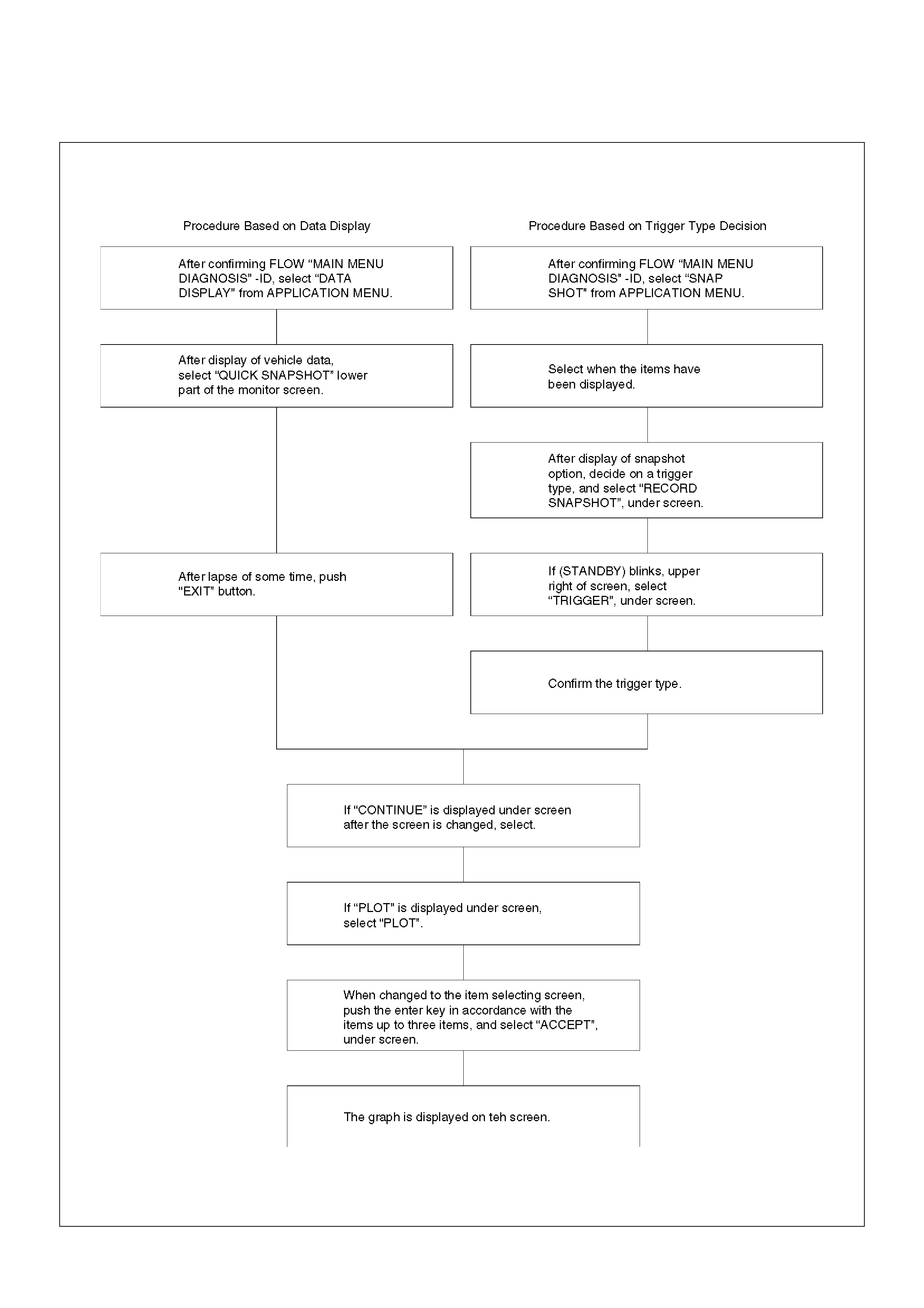
Plotting Graph Flow Chart (Plotting graph after obtaining vehicle information)

Flow Chart for Snapshot Replay (Plotting Graph)
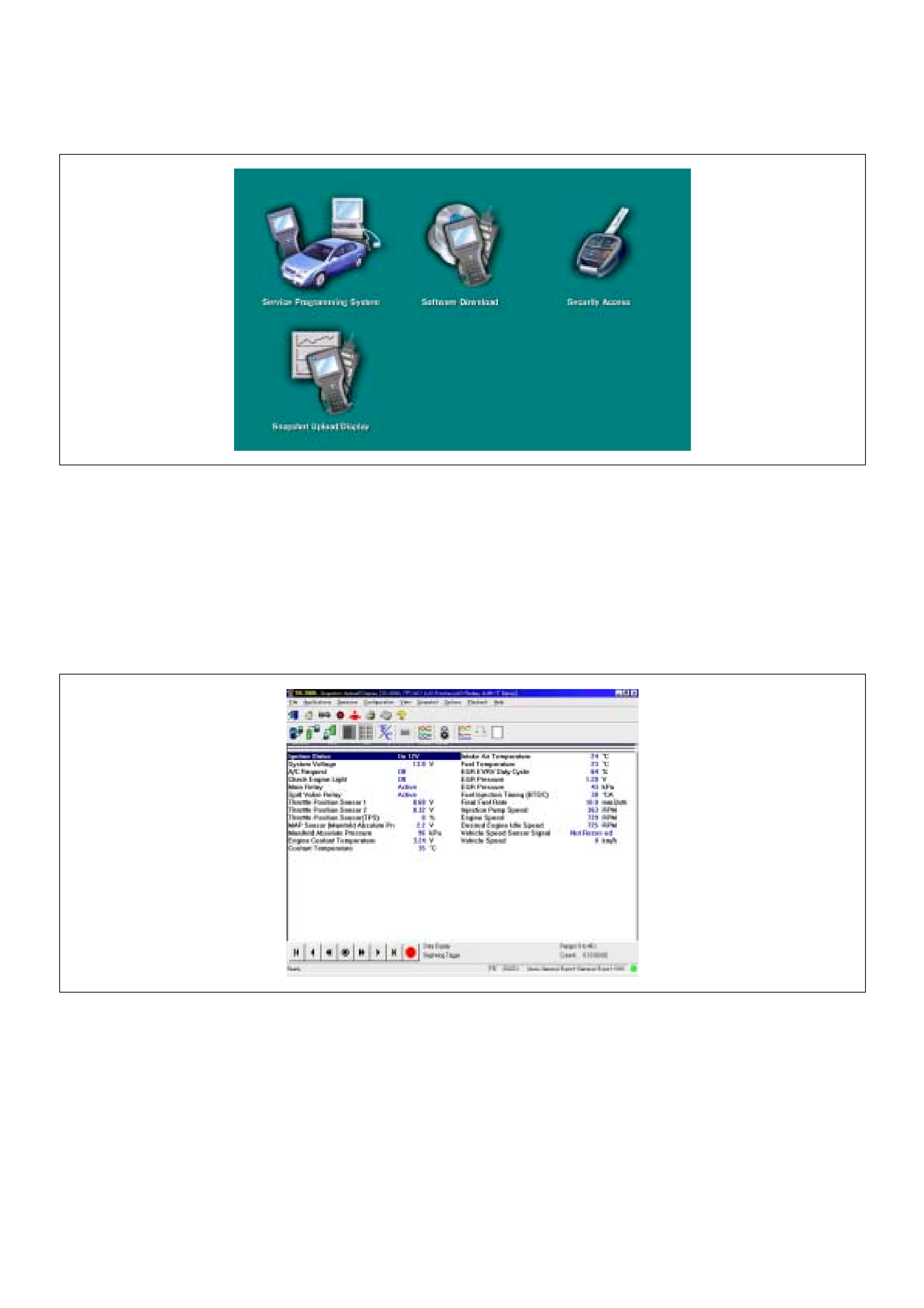
Snapshot Display With TIS2000
Procedures for transferring and displaying Tech2
snapshot data by using TIS2000 [Snapshot Upload]
function is described below.
Snapshot data can be displayed with [Snapshot Upload]
function included in TIS2000.
1. Record the snapshot data, in Tech2.
2. Transfer the snapshot data to PC.
By analyzing these data in various methods, trouble
conditions can be checked.
Snapshot data is displayed by executing the three steps
below shown:
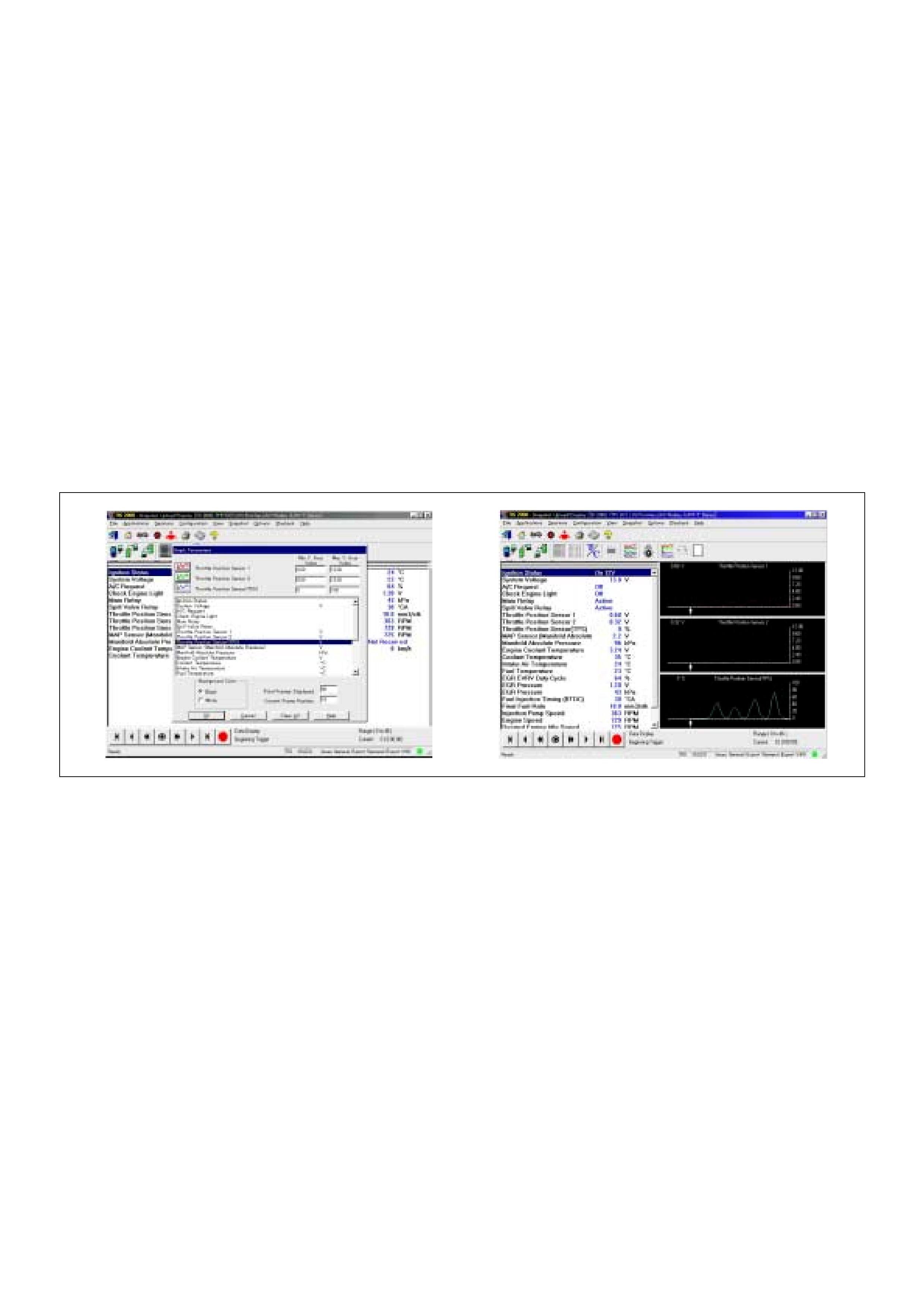
After recordin g the sn apshot in Tech2, trans fer the data
from Tech2 to PC by the below procedures.
1. Start TIS2000.
2. Select [Snapshot Upload] on the TIS2000 start
screen.
3. Select [Upload from trouble diagnosis tool (transfer
from diagnosis tester)] or click the corresponding
icon of th e tool bar.
4. Select Tech2, and transfer the recorded snapshot
information.
5. Select the transferred snapshot.
6. After ending transfer of the snapshot, data
parameter list is displayed on the screen.
3. Snapshot data is displayed with TIS2000
[Snapshot Upload] function.
Snapshot is stored in the PC hard disk or floppy disk,
and can be displayed any time.
Stored snapshot can be displayed by the below
procedures.
1. Start TIS2000.
2. Select [Snapshot Upload] on the TIS2000 start
screen.
3. Select [Open the existing files] or click the
corresponding icon of the tool bar.
4. Select the transferred snapshot.
5. Open the snapshot, to display the data parameter
list on the screen.
Graph display Values and graphs (Max. 3 graphs):
1. Click the icon for graph display. [Graph Parameter ]
window opens.
2. Click the first graph icon of the window upper part,
and select one parameter from the list of the window
lower part. Selec ted parameter is displa yed nest to
the graph icon. Graph division can be selected in
the field on the parameter right side.
3. Repeat the same procedures with the 2nd and 3rd
icons.
4. After selec ting all paramet ers to be displayed (Max .
3 parameters), click [OK] button.
5. Parameter selected is displayed in graph form on
the right of the data parameter on the screen.
6. Graph display can be moved with the navigation
icon.
7. For displaying another parameter by graph, click the
parameter of the list, drag the mouse to the d isplay
screen while pressing the mouse button and release
the mouse button. New parameter is displayed at
the position of the previous parameter. For
displaying the graph display screen in full size,
move the cursor upward on the screen. When the
cursor is changed to the magnifying glass form, click
the screen. Graph screen is displayed on the whole
screen.
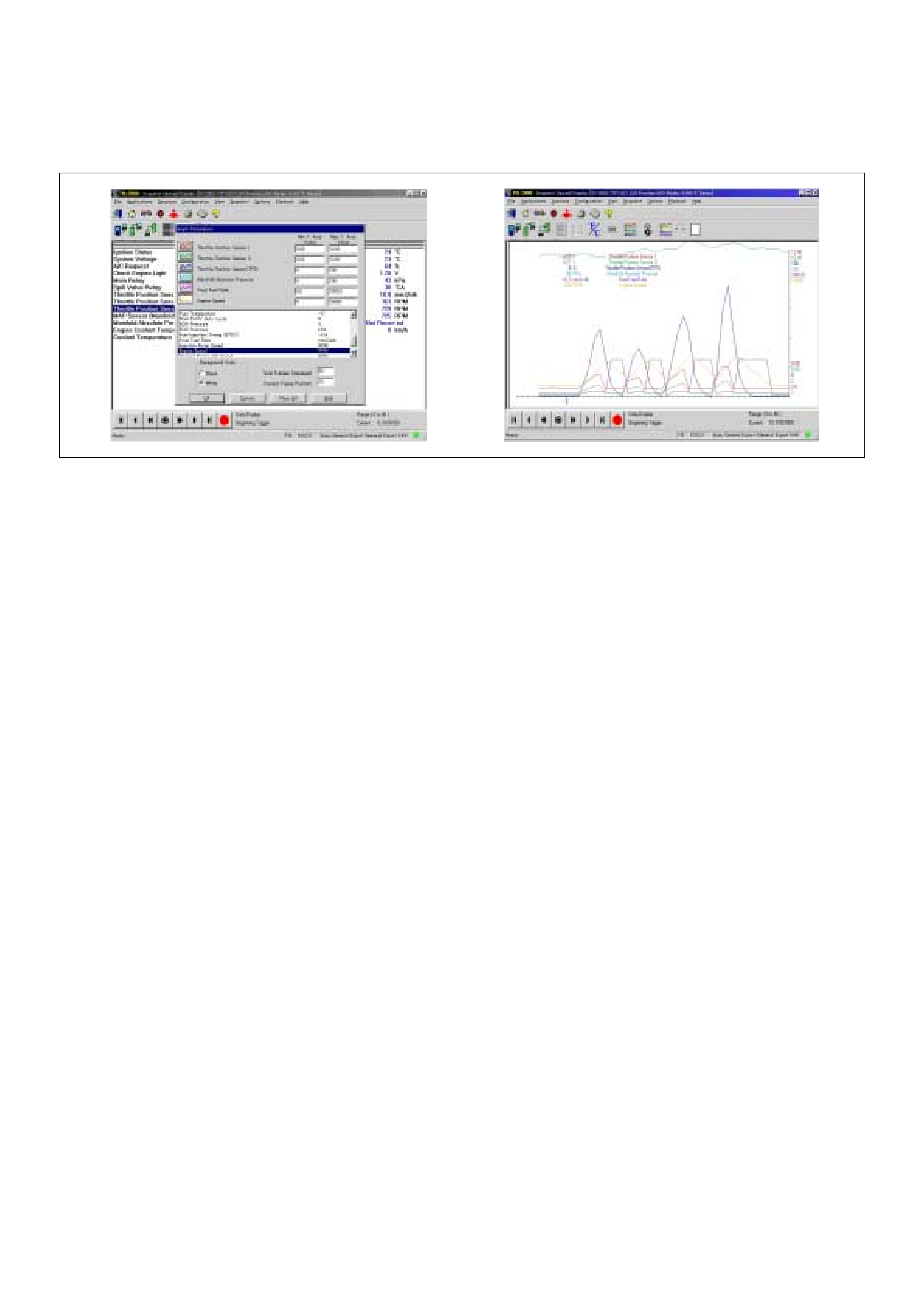
Display of graphs on one screen (Max. 6 graphs):
1. Click the 6 graph icon. [Graph Parameter] window
opens.
2. Click the graph icon, select the parameter to be
displayed from the list and change divisions
according to necessity.
3. Repeat the same procedures with the graph icons,
from the 2nd to 6th.
4. Click the [OK] button to display.
5. In thi s ca se , param eter s ar e d is pl aye d on ly i n gr ap h
form. All parameters are displayed in one graph.
6. The graph display screen can be moved with the
navigation icon.
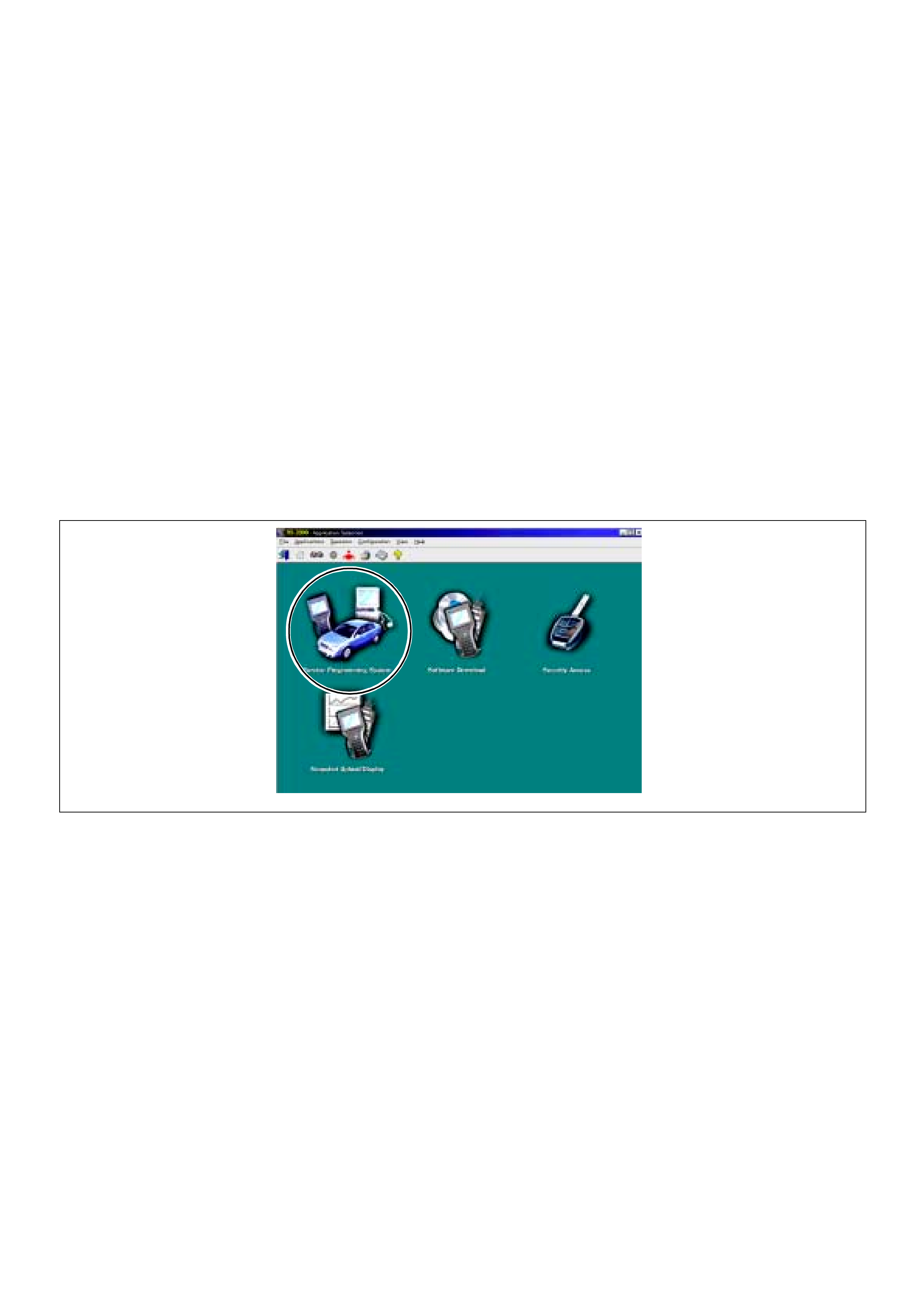
SERVICE PROGRAMMING SYSTEM (SPS)
The procedure to program the control unit by using the
Service Programming System (SPS) software contained
in TIS2000 is explained below.
NOTE:
• If the Engine Control Module (ECM) was
programmed, the Immobilizer System must be linked
to the ECM: Refer to section 11 “Immobilizer System-
ECM replacement” for the ECM/Immobilizer linking
procedure.
• Should Tech2 display "SPS Procedure was not
successful", engine will not start, but no DTCs are
present, low battery voltage or poor electrical
connections should be the primary suspects. Perform
the SPS procedure again after rectifying the fault/s.
IMPORTANT:
Perform the following checks before attempting to
program the control unit:
• The Tech2 PCMCIA card is programmed with The
latest software release.
• The latest release of TIS2000 is loaded on the PC.
• The vehicle battery is fully charged.
• The control unit to be programmed is connected
to the vehicle.
1. Preparations of TIS 2
Connect Tech 2 to P/C.
1. Check to see if Hardware Key is plugged into Port.
2. Activate TIS 2000 by P/C.
3. On the activating screen of TIS2000, choose
“Service Programming System”
4. On th e screen of “Diag nostic Te st er and Pro cessin g
Program Selection”, choose the one that will comply
with the following .
• Tech-2 in use
• New pr ogrammi ng by t he existi ng mod ule or ne w
programming by the replaced/new module.
• Fixing position of the control unit.
5. Upon completion of the selection, push the button of
“Next”.
2. Demand of Data
1. Connect Tech-2 to the vehicle. When activated by
turning on the power of Tech-2, push the “Enter”
switch.
2. Turn on the ignition switch (without starting the
engine)
3. In the main menu of Diagnostic Tester, push “F1:
Service Programming System (SPS)”.
4. Push “F0: Request Info” of Tech-2.
5. Where ve hic le data has been alr ea dy sa ve d in Tech
2, the existing data come on display. In this
instance, as Tech-2 starts asking whether to keep
the data or to continue obtaining anew data from the
control unit, choose either of them
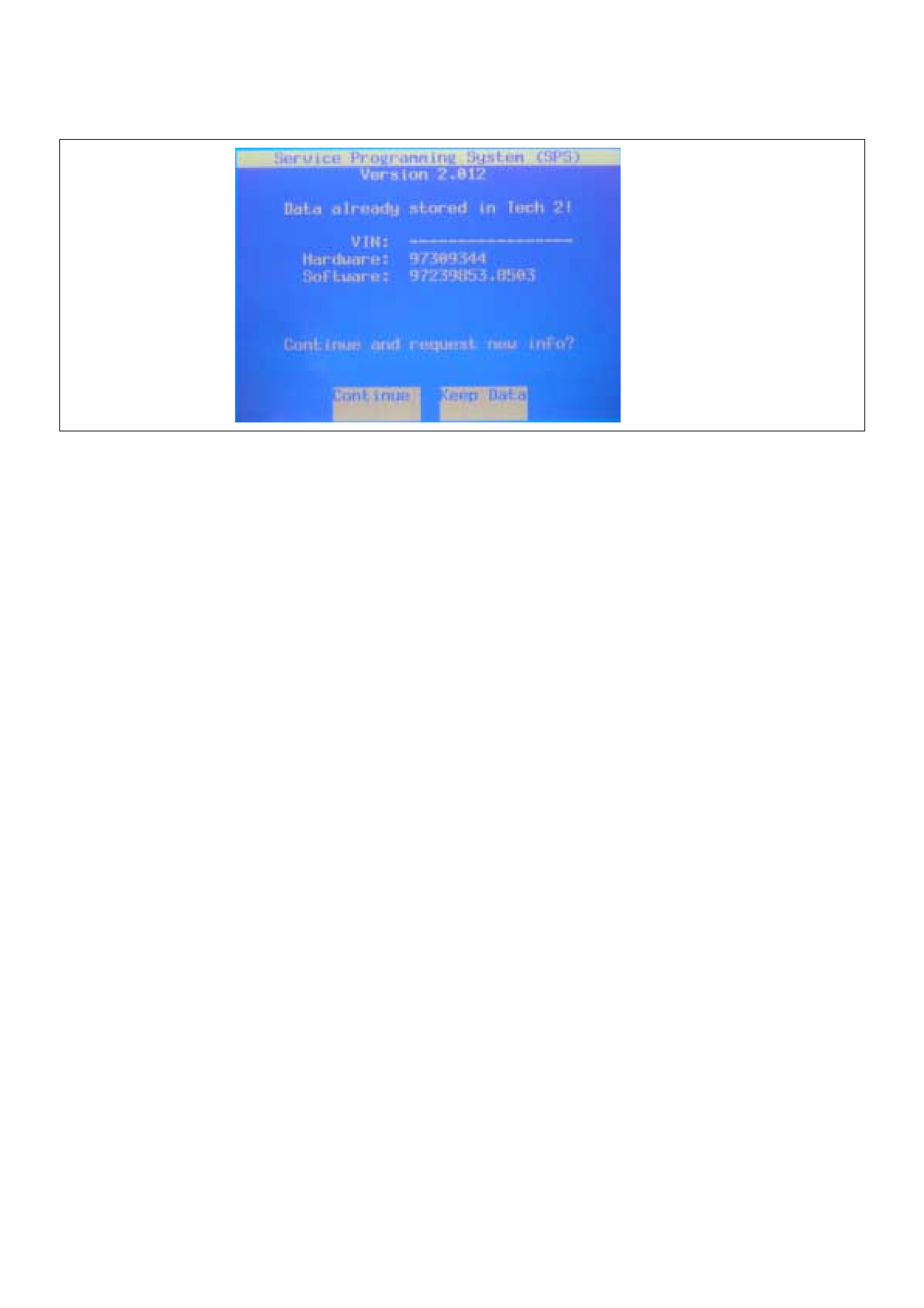
6. If you select “continue”, you have to select “Model
Year”, “Vehicle Type”.
7. After that. then push button and turn Ignition switch
tuned on, off, on following Tech-2 display. Tech-2
will read information from controller after this
procedure.
8. During obtaining information, Tech-2 is receiving
information from the control unit ECM and TCM (A/T
only) at the same time. With VIN not being
programm ed into the new contr ol unit at the time o f
shipment, "obtaining information" is not complete
(because the vehicle model, engine model and
model year are specified from VIN). For the
procedure get additional information on vehicles,
instruction will be provided in dialog form, when
TIS2000 is in operation.
9. Following instructions by Tech-2, push the “Exit”
switch of Tech-2, turn off the ignition of the vehicle
and turn off the power of Tech-2, thereby removing
from the vehicle.
3. Data Exchange
1. Conne ct Tech- 2 to P/C, turn on the power and cli ck
the “Next” button of P/C.
2. Check VIN of th e vehic le and choos e “Nex t”.
3. Select “System Type” for required control unit.
• Engine (Programming for ECM or PCM)
• Transmission (Programming for TCM)
4. When a lack of data is asked from among the
following menu, enter accordingly.
Select following Menu
• Model Year
• Model
• Engine type
• Tr ansmission type
• Destination code (vehicles for general export)*1
• Immobilizer
Etc.
* 1: How to read the destination code
Destination code can be read from ID Plate affixed on
vehicles, while on VIN plate the destination code is
described at the right-hand edge of Body Type line. In
the figure, the destination code can be read as "RR3"
(Australia).
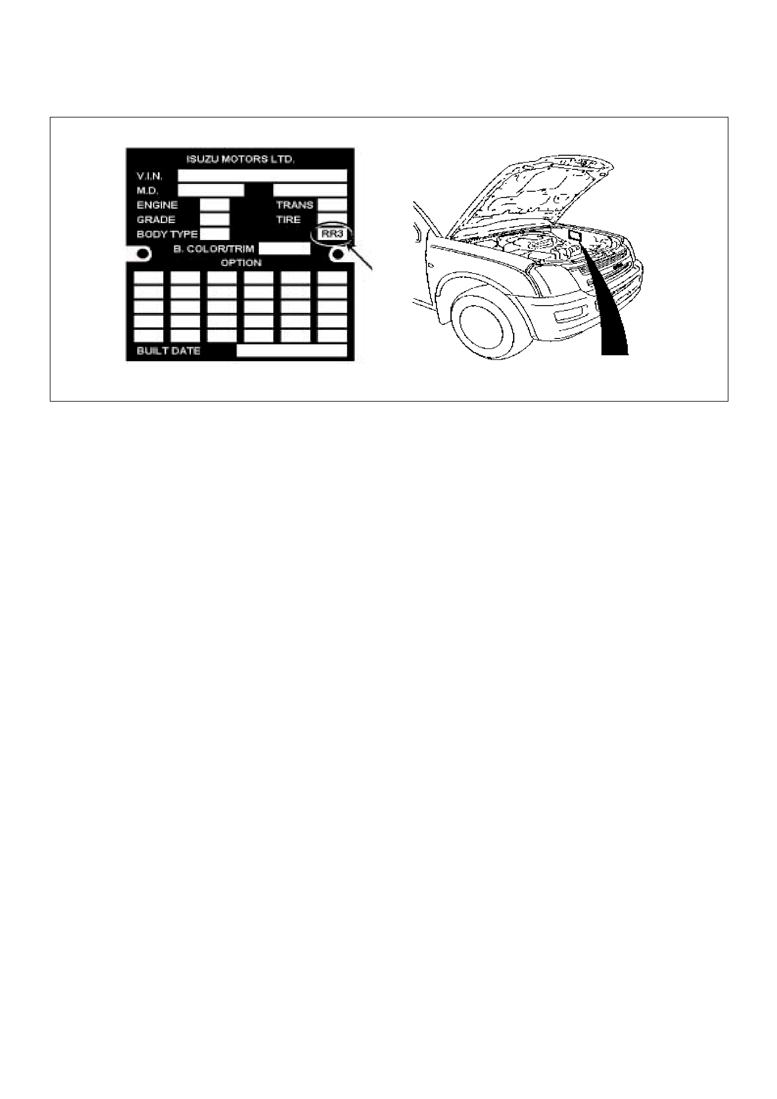
5. After choosing the data, click the “Next” button.
6. When all the necessary information is entered, the
“details” of software within the database that match
the entered data will appear for confirmation. Click
the “Program” switch and then download the new
software onto Tech-2.
7. “Data Transfer” comes on display. The progress of
downloading will be displayed on the screen in the
form of bar graph.
8. Upon finishing the data transfer, turn off the power
of Tech-2, removing from P/C.
4. Programming of EC M
1. Check to see if batteries are fully charged, while
ABS connectors shall be removed from the vehicle.
2. Connect Tech-2 to Vehicle Diagnostic Connectors.
3. Turn on the power of Tech-2 and the title screen
comes on display.
4. Turn on the ignition (without allowing the engine to
start)
5. On the title screen of Tech-2, push the “Enter”
button.
6. Choose “F1: Service Programming System” on the
main screen and then choose “Fl: Program ECU”.
7. While data is being transferred, “Programming in
Progress” will be displayed on the Tech-2 screen.
8. Upon finishing the data transfer, Tech-2 will display
“Reprogramming Was Successful”. Push the “Exit”
button to bring program to completion
9. Following “Procedure 2: Demand of Data”, try over
again “Information Obtaining” and check to confirm
if the data has been correctly re-loaded.
10. Upon finishing confirmation, turn off the ignition of
the vehicle and then turn off the power of Tech-2,
removing from the vehicle.
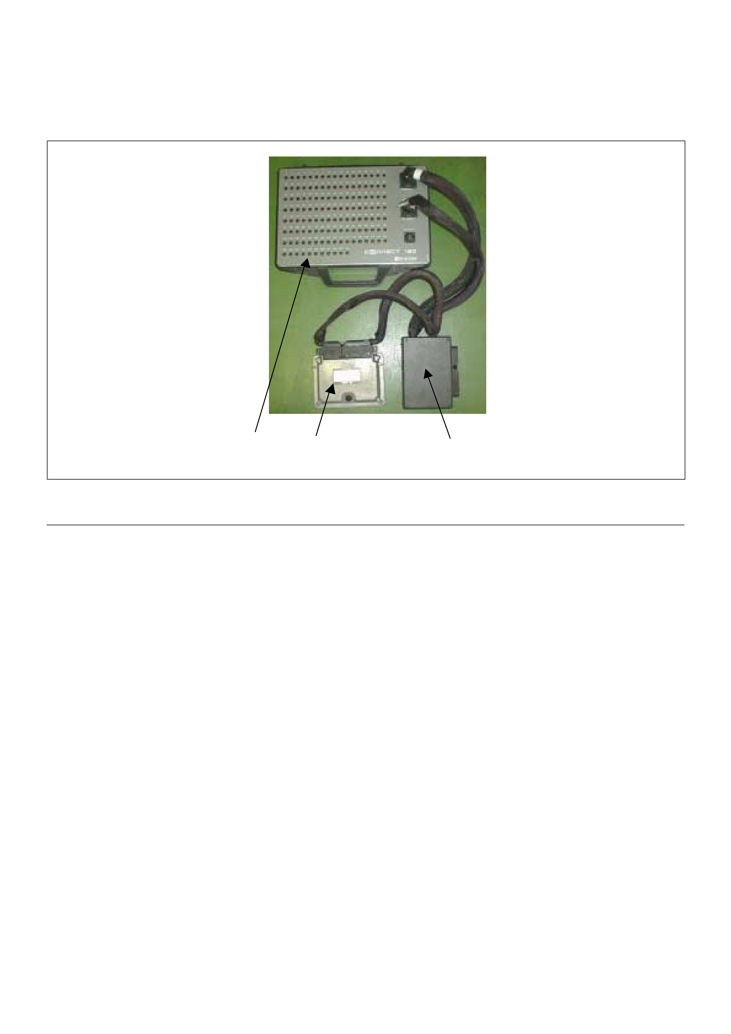
HOW TO USE BREAKER BOX
The engine control module (ECM) and other connectors
have water proo f connector and special termina l. Wa ter
proof terminal does not allow to use back prove. In
addition, the engine control module (ECM) special
terminal can not let regular digital voltage meter prove
to access, because terminal shape is very fine pin type.
In order to prevent damage of female terminal and
connector itself, the breaker box and adapter is the
most suitable special tool.
312
(1) Engine Control Module (ECM)
(2) Harness Adapter (3) Breaker Box
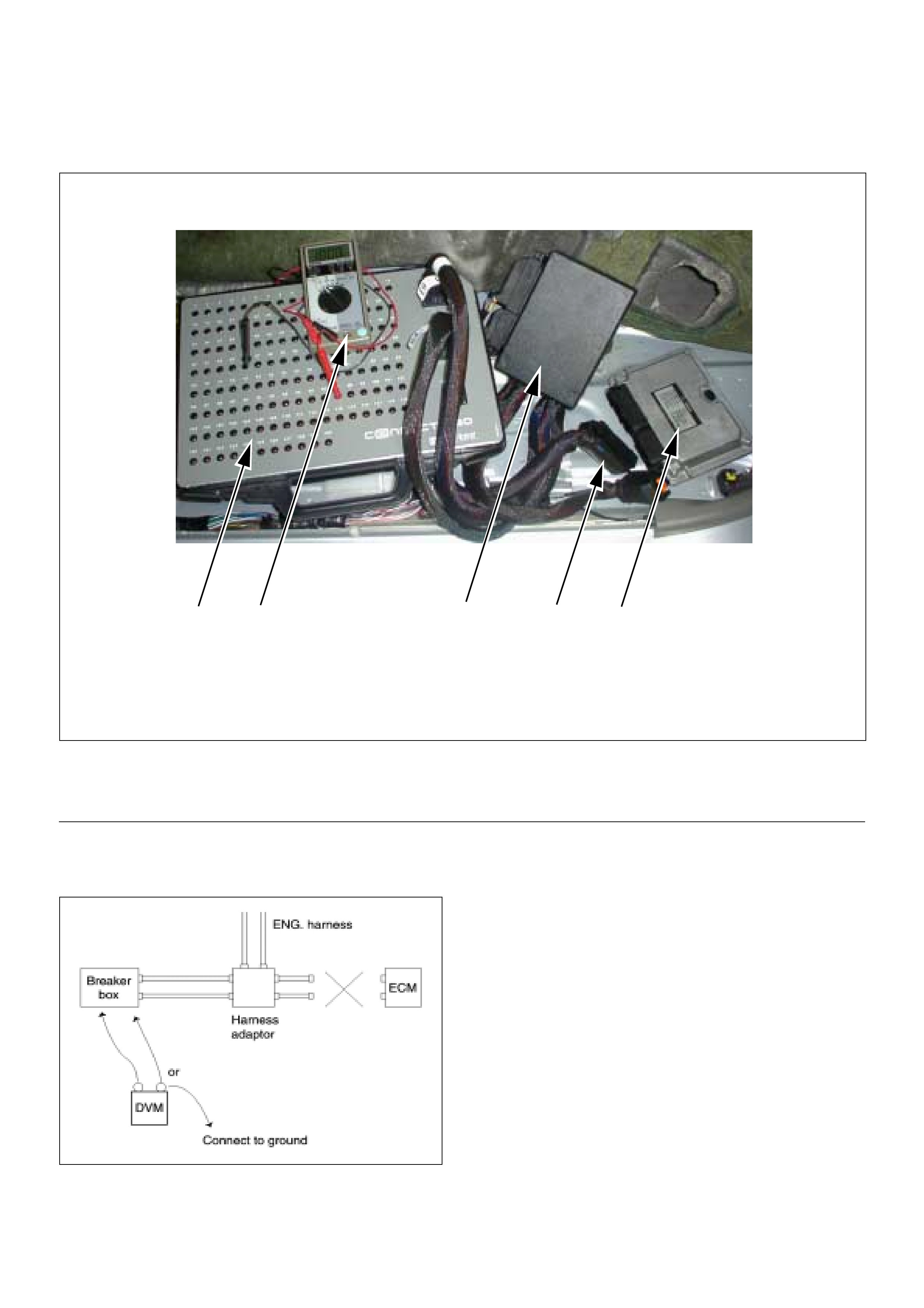
Breake r Box Connection Type A
Breake r box connect ion type A, c heck for “o pen circuit”
and “short to ground circuit”.
PQORN
(1) Engine Control Module (ECM)
(2) Harness Adapter
(3) Breaker Box
(4) Digital Voltage Meter
(5) ECM - Harness Adapter Disconnection
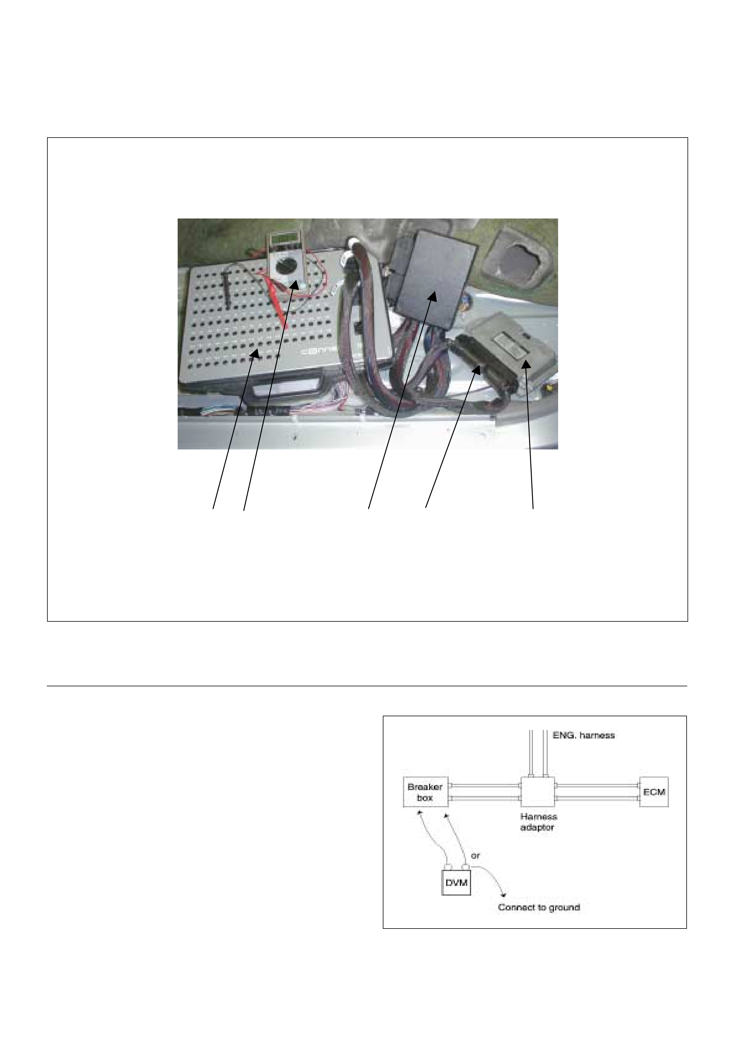
Breake r Box Connection Type B
Breaker box connection type B, check for “short to
power supply circuit” and “power, signal voltage check”
between the engine control module (ECM) and
electrical components.
1
23 45
(1) Engine Control Module (ECM)
(2) Harness Adapter
(3) Breaker Box
(4) Digital Voltage Meter
(5) ECM - Harness Adapter Connection
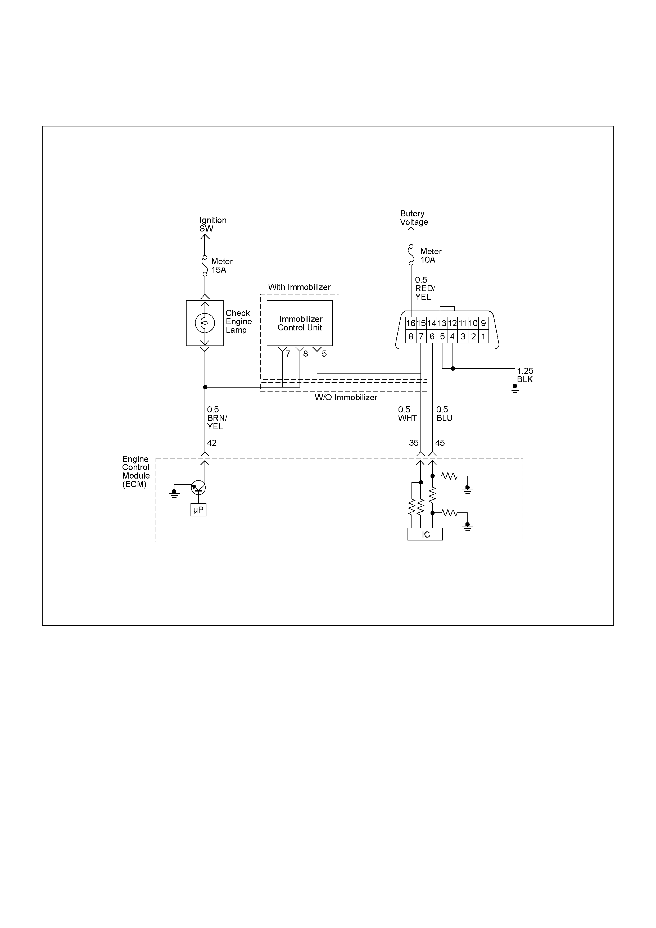
ON-BOARD DIAGNOSTIC (OBD) SYSTEM CHECK
Circuit Description
The on-board diagnostic system check is the starting
point for any driveability complaint diagnosis. Before
using this procedure, perform a careful visual/physical
check of the ECM and engine grounds for cleanliness
and tightness.
The on-board diagnostic system check is an organized
approach to identifying a problem created by an
electronic engine control system malfunction.
Diagnostic Aids
An intermittent may be caused by a poor connection,
rubbed-through wire insulation or a wire broken inside
the insulation. Check for poor connections or a
damaged harness. Inspect the ECM harness and
connector for improper mating, broken locks, improperly
formed or damaged terminals, poor terminal-to-wire
connection, and damaged harness.

Test Description
Number(s) below refer the step number(s) on the
Diagnosti c Chart:
1. The Ch eck Engine Lamp (MI L) should b e ON steady
with the ignition “On”, engine “Off”. If not, “No Check
Engine La mp (MIL) ” chart sho uld be us ed to iso late the
malfunction.
2. Checks the Class 2 data cir cuit and ensure s that the
ECM is able to transmit serial data.
3. This test ensures that the ECM is capable of
controlling the Check Engine Lamp (MIL) and the Check
Engine Lamp (MIL) driver circuit is not shorted to
ground circuit.
4. If the engine will not start, “Engine Cranks But Will
Not Run” chart should be used to diagnose the fault.
6. Th e Tech2 parameter s which is not within the typical
range m ay help to iso late the area wh ich is c ausing the
problem.
12. Th is v ehicle i s equ ipped with EC M wh ich ut ilizes an
electrically erasable programmable read only memory
(EEPROM).
On-Board Diagnostic (OBD) System Check
Step Action Value(s) Yes No
11. Ignition “On”, engine “Off”.
2. Check the “CHECK ENGINE” lamp (MIL).
Does the “CHECK ENGINE” lamp turn “On”? — Go to Step 2
Go to No
CHECK
ENGINE Lamp
21. Using the Tech 2, ignition “On” and engine “Off”.
2. Attempt to display “Data Display” with the Tech 2.
Does the Tech 2 display engine data? — Go to Step 3 Go to Step 7
31. Using the Tech 2, ignition “On” and engine “Off”.
2. Select the “Miscellaneous Test” and perform the
“Check Light” in “Lamps”.
3. Opera te the Tech 2 in ac cordanc e with the Tech 2
instructions.
Does the “CHECK ENGINE” lamp turn “Off”? — Go to Step 4
Go to CHECK
ENGINE LAMP
On Steady
4Attempt to start the engine.
Does the engine start and continue to “Run”? —Go to Step 5
Go to Engine
Cranks But Will
Not Run
51. Using the Tech 2, ignition “On” and engine “Off”.
2. Select the “Read DTC Info r As Stored B y ECU” in
“Diagnostic Trouble Code”.
3. Are any DTCs stored? — Go to DTC
Chart Go to Step 6
6Compare typical scan data values displayed on the
Tech 2 “Data Display”.
Are the displayed values within the range? —
Refer to
SYMPTOM
DIAGNOSIS
Refer to
TYPICAL
SCAN DATA
7Using the DVM and check the data link connector
power supply circuit.
1. Ignition “Off”, engine “Off”.
2. Check the circuit for open circuit.
Was the problem found?
—
Repair faulty
harness and
verify repair Go to Step 8
V
B-58 7
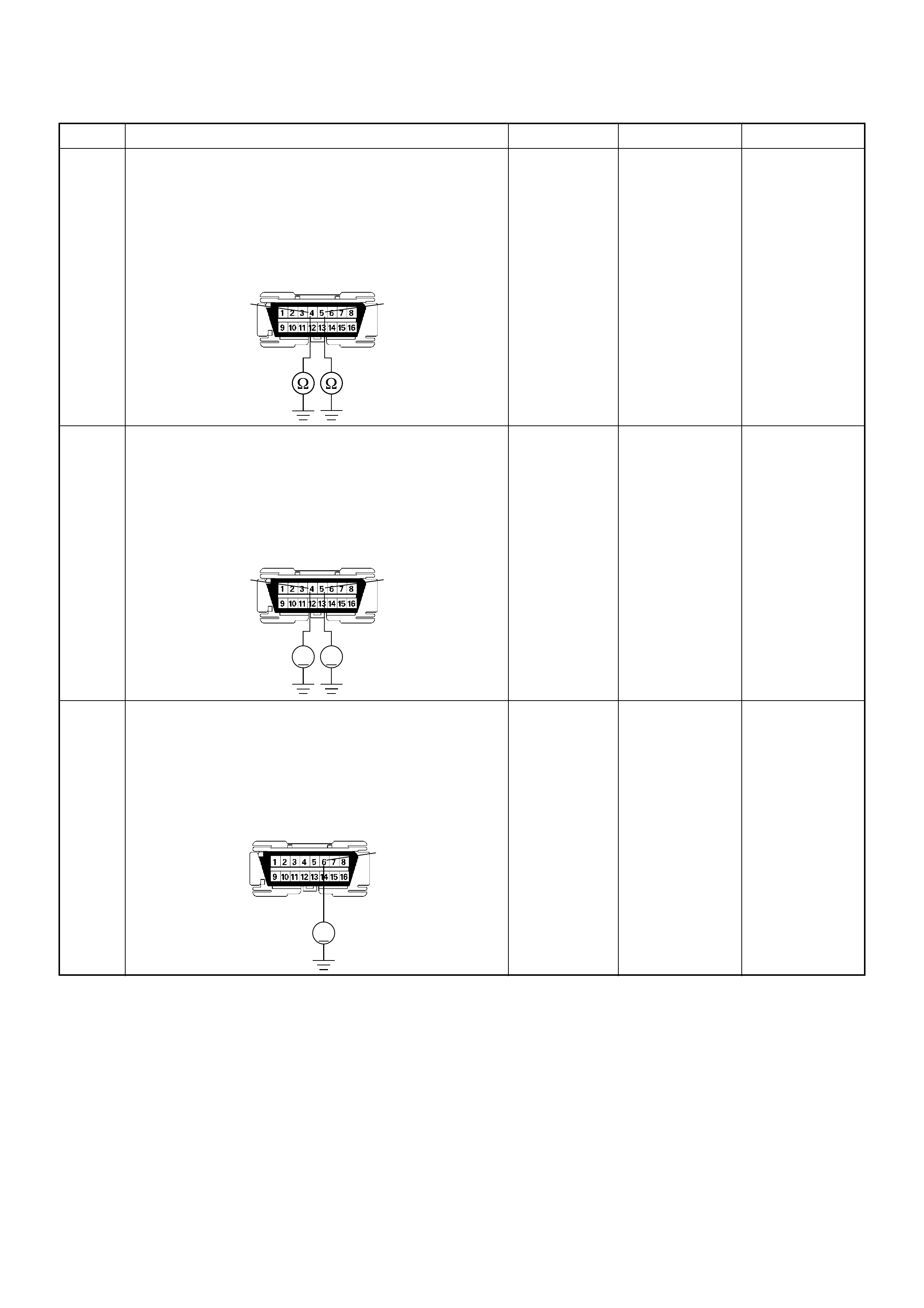
8Using the DVM and check the data link connector
grou nd circuit.
1. Ignition “Off”, engine “Off”.
2. Check the circuit for open circuit.
Was the problem found?
—
Repair faulty
harness and
verify repair Go to Step 9
9Using the DVM and check the data link connector
grou nd circuit.
1. Ignition “On”, engine “Off”.
2. Check the circuit for short to power supply circuit.
Was the DVM indicated specified value?
Less than 1V Go to Step 10
Repair faulty
harness and
verify repair
10 Using the DVM and check the data link connector
commun ic ati on circui t.
1. Ignition “On”, engine “Off”.
2. Check the circuit for short to power supply circuit.
Was the DVM indicated fixed battery voltage?
—
Repair faulty
harness and
verify repair Go to Step 11
Step Action Value(s) Yes No
54
B-58
VV
54
B-58
V
6
B-58
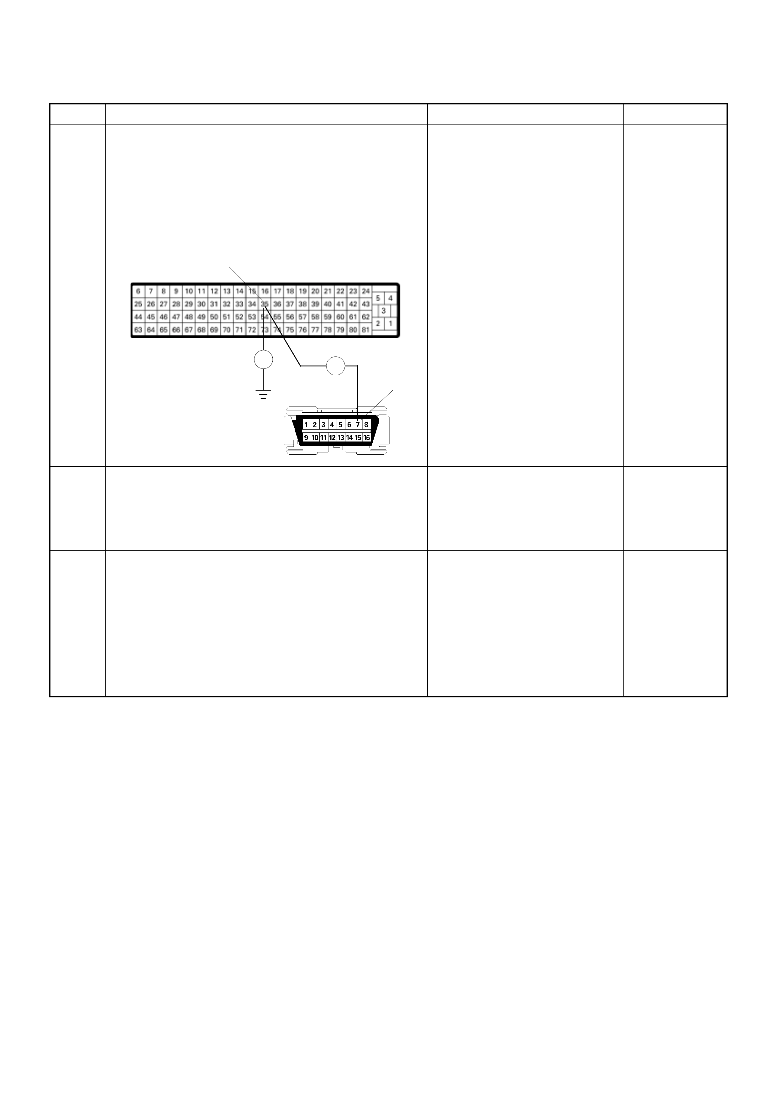
11
Using the DVM and check the data link connector
communication circuit.
1. Ignition “Off”, engine “Off”.
2. Disconnect the ECM connector.
3. Check the circuit for open or short to ground
circuit.
Was the problem found?
—
Repair faulty
harness and
verify repair Go to Step 12
12
Is the ECM programmed with the latest software
release?
If not, download the latest software to the ECM using
the “SPS (Service Programming System)”.
Was the problem solved? — Verify repair Go to Step 13
13
Replace the ECM.
Is the action complete?
IMPORTANT: The replacement ECM must be
programmed. Refer to section of the Service
Programming System (SPS) in this manual.
Foll owing ECM pr ogramming, the immobi lizer syst em
(if equipped) must be linked to the ECM. Refer to
section 11 “Immobilizer System-ECM replacement” for
the ECM/Immobilizer linking procedure. — Verify repair —
Step Action Value(s) Yes No
Ħ
Ħ
35 C-56
B-58
7

NO CHECK ENGINE LAMP (MIL)
Circuit Description
The check engine lamp should be illuminated and
steady fo r about fi ve seconds wi th the igni ti on “ O N” and
the engi ne stopp ed. Ignit ion feed vol tage is sup plied to
the check engine lamp bulb through the meter fuse.
The Engine Control Module (ECM) turns the check
engine lam p “ON” by groundin g the check engine lamp
driver circuit.
Diagnostic Aids
An intermittent check engine lamp may be cased by a
poor connection, rubbed-through wire insulation, or a
wire broken inside the insulation. Check for the
foll owi ng ite ms :
• Inspect the ECM harness and connections for
improper mating, broken locks, improperly formed or
damaged terminals, poor terminal-to-wire connection,
and damaged harness.
• If the engine runs OK, check for a faulty light bulb, an
open in the check engine lamp driver circuit, or an
open in the instrument cluster ignition feed.
• If the engine cranks but will not run, check for an
open ECM i gnition or batt ery feed, or a poor ECM to
engine ground.
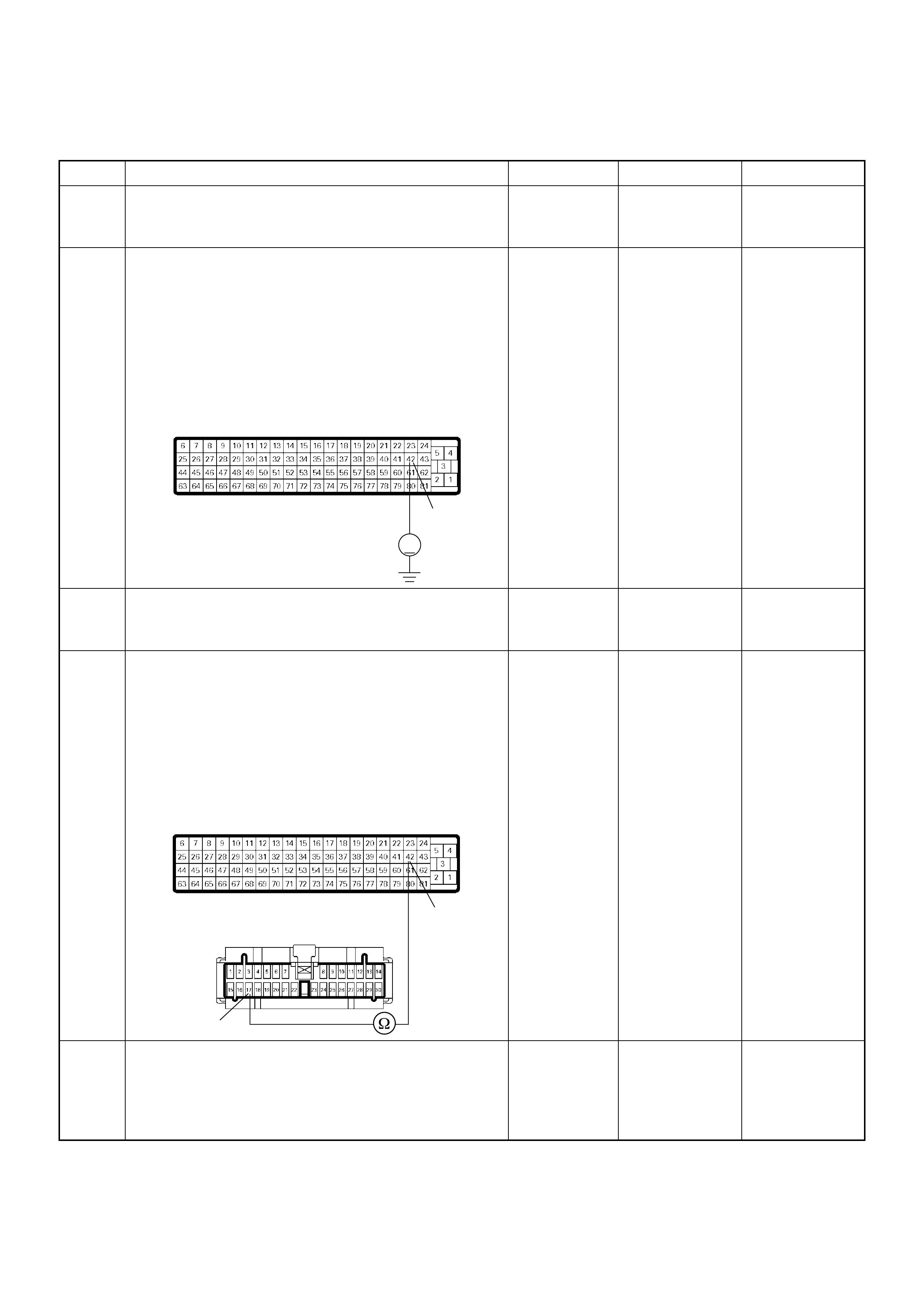
No Check Engine Lamp (MIL)
Step Action Value(s) Yes No
1 Chec k the meter fuse (15A).
If the fuse is burnt out, repair as necessary.
Was the problem found? — Verify repair Go to Step 2
2 Using the DVM and check the “CHECK ENGINE”
lamp circuit.
1. Ignition “Off”, engine “Off”.
2. Disconnect the ECM connector.
3. Ignition “On”.
4. Check the circuit for open circuit.
Was the DVM indicated specified value?
10-14.5V Go to Step 5 Go to Step 3
3 Check the “CHECK ENGINE” lamp bulb.
If the bulb is burnt out, repair as necessary.
Was the problem found? — Verify repair Go to Step 4
4 Using the DVM and check the “CHECK ENGINE”
lamp circuit.
1. Ignition “Off”, engine “Off”.
2. Disconnect the meter connector and ECM
connector.
3. Check the circuit for open circuit.
Was the problem found?
— Verify repair Go to Step 5
5 Is the ECM programmed with the latest software
release?
If not, downlo ad the latest software to the ECM using
the “SPS (Service Programming System)”.
Was the problem solved? — Verify repair Go to Step 6
V
42
C-56
42
17
B-24
C-56

6 Replace the ECM.
Is the action complete?
IMPORTANT: The replacement ECM must be
programmed. Refer to section of the Service
Programming System (SPS) in this manual.
Foll owing ECM pr ogramming, the immobi lizer syst em
(if equipped) must be linked to the ECM. Refer to
section 11 “Immobilizer System-ECM replacement” for
the ECM/Immobilizer linking procedure. — Verify repair —
Step Action Value(s) Yes No

CHECK ENGINE LAMP (MIL) “ON” STEADY
Circuit description
The check engine lamp should always be illuminated
and steady for about five seconds with ignition “ON” and
the engine stopped. Ignition feed voltage is supplied
directl y to the ch eck en gine lam p indic ator. The Engin e
Control Module (ECM) turns the check engine lamp
“ON” by grounding the check engine lamp driver circuit.
The check engine lamp should not remain “ON” with the
engine running and no DTC(s) set. A steady check
engine lamp with the engine running and no DTC(s)
suggests a short to ground in the check engine lamp
driver circuit.
Diagnostic Aids
An intermittent may be caused by a poor connection,
rubbed-through wire insulation, or a wire broken inside
the insulation. Check for the following items:
• Poor connection or damaged harness – Inspect the
ECM harness and connectors for improper mating,
broken locks, improperly formed or damaged
terminals, poor terminal-to-wire connection, and
damaged harness.
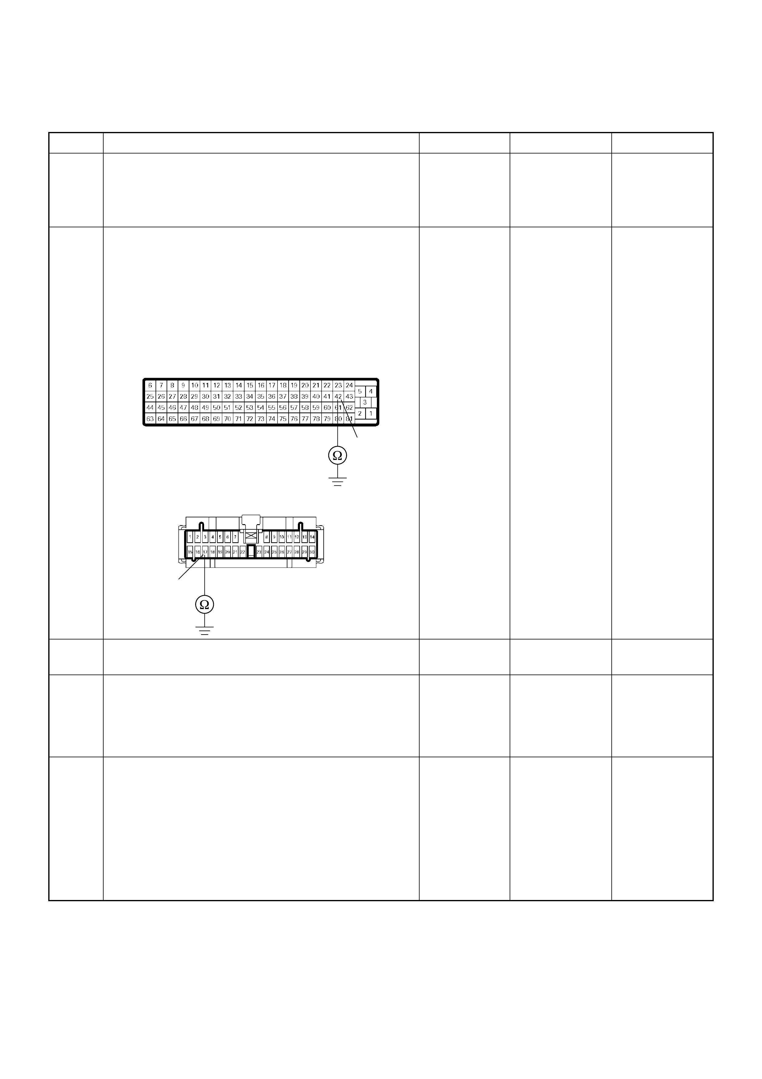
Check Engine Lamp (MIL) On Steady
Step Action Value(s) Yes No
1 1. Ignition “Off”, engine “Off”.
2. Disconnect the ECM connector.
3. Ignition “On”.
Was the “CHECK ENGINE” lamp turned on? — Go to Step 2 Go to Step 4
2 Using the DVM and check the “CHECK ENGINE”
lamp circuit.
1. Ignition “Off”, engine “Off”.
2. Disconnect the meter connector and ECM
connector.
3. Check the circuit for short to ground circuit.
Was the problem found?
— Verify repair Go to Step 3
3 Replace the meter assembly.
Is the action complete? — Verify repair —
4 Is the ECM programmed with the latest software
release?
If not, download the latest software to the ECM using
the “SPS (Service Programming System)”.
Was the problem solved? — Verify repair Go to Step 5
5 Replace the ECM.
Is the action complete?
IMPORTANT: The replacement ECM must be
programmed. Refer to section of the Service
Programming System (SPS) in this manual.
Following ECM programming, the immobilizer system
(if equipped) must be linked to the ECM. Refer to
section 11 “Immobilizer System-ECM replacement” for
the ECM/Immobilizer linking procedure. — Verify repair —
42
17
B-24
C-56

ECM DIAGNOSTIC TR OUBLE CODES
Flash
Code Code Symptom
Code MIL DTC Name DTC Setting Condition Fail-Safe (Back Up) Recovery Condition Related Failure Parts Related
ECM Pin
No.
Related
Multiple
DTC
65 P0100 7 ON Mass Air Flow (MAF) Sensor
Voltage Supply Circuit High
Input
MAF sensor power supply
voltage is more tha n 5. 2V. ECM uses mass air flow
1600mg/strk & EGR 10%
condit ions as subs titute.
MAF sensor power supply
voltage is below 5.2V. 1. Sensor power supply
circuit short to battery
voltage circuit.
2. MAF sensor malfunction.
3. ECM malfunction.
83 —
9 ON Mass Air Flow (MAF) Sensor
Voltage Supply Circuit Low
Input
MAF sensor power supply
voltage is below 4.6V. MAF sensor power supply
voltage is more tha n 4.6V. 1. Sensor power supply
circuit short to ground
ci r c u i t .
2. MAF sensor malfunction.
3. ECM malfunction.
83 —
B ON Mass Air Flow (MAF) Sensor
Output Circuit Low Inp ut 1. Engine speed is between
600rpm and 5000rpm.
2. MAF sensor output is
below -33.7mg/strk.
MAF sensor output is more
than -27.4mg/strk. 1. Sensor power supply
c i r c ui t o p e n c i r c u i t .
2. Sensor signal circuit
open or short to ground
cir cuit.
3. Sensor heater harness
o p e n c i r cuit.
4. Poor con nec tor
co n n e c t i o n.
5. MAF sensor malfunction.
6. ECM malfunction.
8 3 /
88 P0110(1)
C ON Mass Air Flow (MAF) Sensor
Output Circuit High Input 1. Engine speed is between
600rpm and 5000rpm.
2. MAF sensor output is
more than 1784mg/strk.
MAF sensor output is below
1784mg/strk. 1. Sensor signal circuit
short to voltage circuit.
2. Sensor ground circuit
open or short to voltage
cir cuit.
3. MAF sensor malfunction.
4. ECM malfunction.
88/
92 P0110(1)
34 P010 5 1 ON Va cuu m Pressure Sens or
Circuit High Input Vacuum sensor output
voltage is more tha n 4. 4V. 1. Fuel injection quantity is
reduced.
2. ECM use 615hpa
conditions for
turbocharger waste gate
control.
Vacuum sensor output
voltage is below 4.4V. 1. Sensor signal circuit
short to voltage circuit.
2. Sensor ground circuit
open or short to voltage
cir cuit.
3. Vacuum sensor
malfunction.
4. ECM malfunction.
85/
93 P0115(1)
2 ON Vacuum Pressure Sen sor
Circuit Low Input Vacuum sensor output
voltage is below 0.5V. Vacuum sensor output
voltage is more tha n 0.5V. 1. Sensor power supply
c i r c ui t o p e n c i r c u i t .
2. Sensor signal circuit
open or short to ground
cir cuit.
3. Poor con nec tor
co n n e c t i o n.
4. Vacuum sensor
malfunction.
5. ECM malfunction.
82/
85 —

34 P010 5 7 ON Va cuu m Pressure Sens or
Voltage Supply Circuit High
Input
Vacuu m sen sor power
supply voltage is more than
5.2V.
1. Fuel injection quantity is
reduced.
2. ECM use vacuum sensor
output voltage 5.0V
condition as substitute.
Vacuum sensor power
supply voltage is below 5.2V. 1. Sensor power supply
circuit short to battery
voltage circuit.
2. Vacuum sensor
malfunction.
3. ECM malfunction.
82 —
9 ON Vacuum Pressure Sen sor
Voltage Supply Circuit Low
Input
Vacuu m sen sor power
supply voltage is below 4.5V. Vacuum sensor power
supply voltage is more than
4.5V.
1. Sensor power supply
circuit short to ground
ci r c u i t .
2. Vacuum sensor
malfunction.
3. ECM malfunction.
82 —
23 P0110 1 ON Intake Air Temperature (IAT)
Sensor Circuit High Input IAT sensor output voltage is
more than 4.7V. ECM use 0 deg. C conditions
as substitute. IAT sensor output voltage is
below 4.7V. 1. Sensor signal circuit
open or short to voltage
ci r cui t.
2. Sensor ground circuit
open or short to voltage
cir cuit.
3. Poor con nec tor
connection
4. IAT sensor malfunction.
5. ECM malfunction.
8 4 /
92 P0100(B)/
P0100(C)
2 ON Intake Ai r Temperature (IAT)
Sensor Circuit Low Input IAT sensor output voltage is
below 0.3V. IAT sensor output voltage is
more than 0.3V. 1. Sensor signal circuit
short to ground circuit.
2. IAT sensor malfunction.
3. ECM malfunction.
84 —
14 P0115 1 ON Engine Coolant Temperature
(ECT) Sensor Circuit High
Input
ECT sensor output voltage is
more than 4.7V. 1. ECM uses fuel
temper atu re as
substitute.
2. ECM uses 60 deg. C
condition for injection
t i m i ng c o n t r o l .
3. ECM uses -15 deg. C
condition for glow time
control.
ECT sensor output voltage is
below 4.7V. 1. Sensor signal circuit
open or short to voltage
ci r cui t.
2. Sensor ground circuit
open or short to voltage
cir cuit.
3. Poor con nec tor
connection
4. ECT sensor malfunction.
5. ECM malfunction.
89/
93 P0105(1)
2 ON Engine Coolant Temperature
(ECT) Sensor Circuit Low
Input
ECT sensor output voltage is
below 0.3V. ECT sensor output voltage is
more than 0.3V. 1. Sensor signal circuit
short to ground circuit.
2. ECT sensor malfunction.
3. ECM malfunction.
89 —
15 P018 0 B ON Fuel Temper at ure Sen sor
Circuit Range/Performance FT sensor output is high
temperature (more than 150
deg. C) or low temperature
(below -40 deg. C).
The ECM uses 75 deg. C
condit ions as subs titute. FT sensor output is correct
temperature range between
150 deg. C and -40 deg. C.
1 . E C M m a l f u n c t i o n .
2. PSG (pump control unit)
malfunction. ——
Flash
Code Code Symptom
Code MIL DTC Name DTC Setting Condition Fail-Safe (Back Up) Recovery Condition Related Failure Parts Related
ECM Pin
No.
Related
Multiple
DTC

52 P0215 A ON Fuel Cutoff Solenoid Valve
Malfunction 1. Ignition key switch off.
2. Engine speed is below
1500rpm.
3. Vehicle speed is below
1.5 km/ h .
4. PSG (pump contro l unit)
recognizes MAB (fuel
cutoff solenoid valve)
signal from the ECM, but
the MAB could not
operate.
1. MAB (fuel cutoff solenoid
v a l v e) i s o p e r a t e d .
2. Desired injection quantity
becomes 0mg/strk.
No recovery until condition
match in the next ignition key
cycle.
1. PSG (pump control unit)
malfunction.
2. MAB (fuel cutoff solenoid
valve) malfunction.
——
B ON Fuel Cutoff Solenoid Valve
Circuit High Input ECM does not command
MAB (fuel cutoff solenoid
valve) signal to the PSG
(pump control unit), but PSG
det ected MAB signal line
circuit is high level.
Engine doe s not start. No recovery. 1. M A B (fuel cutoff solenoid
valve) signal circuit short
t o v o l t a g e c i r c u i t .
2. PSG (pump control unit)
malfunction.
105 —
C ON Fuel Cutoff Solenoid Valve
Always Active 1. Ignition key switch off.
2. Engine speed is below
1500rpm.
3. Vehicle speed is below
1.5 km/ h .
4. PSG (pump contro l unit)
does not recognize MAB
(fuel cutoff solenoid
valve) signal from the
ECM.
1. MAB (fuel cutoff solenoid
v a l v e) i s o p e r a t e d .
2. Desired injection quantity
becomes 0mg/strk.
No recovery until condition
match in the next ignition key
cycle.
1. MAB (fuel cutoff solenoid
valve) signal circuit open
or short to ground circuit.
2. PSG (pump control unit)
malfunction. 105 —
D ON Fuel Cutoff Solenoid Valve
Malfunction 1. Ignition key switch off.
2. CAN controller does not
operate Bus-off.
N o f ai l - s af e f u n c t i o n . 1 . E C M m a l f u n c t i o n .
2. PSG (pump control unit)
malfunction. ——
54 P0216 A ON Injection Timing Control
Circuit Malfunction 1. Engine speed is more
th a n 70 0 rpm .
2. Fuel injection quantity is
m o r e t h a n 4 m g / s t k .
3. Deviation of actual
injection timing and
desired injection timing is
more than +3 deg. CA or
-6 deg. CA for 8 seconds.
Fuel inject ion qua ntity is
reduced. Deviation of actual injection
timing an d desire d inj ect ion
timing is more than +3 deg.
CA or -6 deg. CA for 8
seconds.
1. Timing control valve
malfunction.
2 . Ti m e r p i s t o n s t i c k i n g .
3. Pump cam sha ft speed
sensor malfunction. ——
B ON Injection Timing Control
Circuit Malfunction 1. Engine speed is more
th a n 20 1 4rp m .
2. F l uctu at ion of actu al
injection timing is more
than +-5.2 deg. CA.
1. Engine speed is more
th a n 20 1 4rp m .
2. Fluctuation of actu al
injection timing is more
than +-5.2 deg. CA.
1. Insufficient air bleeding of
fuel line.
2 . F u e l f i l t e r c l o g g i n g .
3. Timing control valve
m a l f u n c t io n.
4. Pump cam sha ft speed
sensor malfunction.
——
Flash
Code Code Symptom
Code MIL DTC Name DTC Setting Condition Fail-Safe (Back Up) Recovery Condition Related Failure Parts Related
ECM Pin
No.
Related
Multiple
DTC

64 P0243 3 ON Turbocharger Wastegate
Solenoid "A" Range/
Performance
1. Intake air temperature is
between - 50 deg. C and
2 0 0 d e g . C .
2. Engine coolant
temper atu re i s betwe en -
50 deg. C and 150 deg.
C.
3. Barometric pressure is
between 0 hpa and
3500hpa.
4. Low vacuum pressure
condition. (Desired
vacuum pressure - actual
vacuum pressure is more
than 50hpa.)
1. Fuel injection quantity is
reduced.
2. EGR EVRV becomes
10% condition.
1. Engine speed is between
500rpm and 6000rpm.
2. Correct vacuum pressure
condition. (Desired
vacuum pressure - actual
vacuum pressur e is less
than 50hpa.)
1. Turbocharger wastegate
control EVRV
malfunction.
2. V acuum line is
obstructed.
3. Vacuum is leaking.
4. Vacuum pump
mal function.
5. Vacuum sensor
malfunction.
6. Turbocharger wastegate
v a l v e m a l fu n c t i o n .
7. ECM malfunction.
85/
96 —
4 ON Turboc harger Was tegate
Solenoid "A" Low Wastegate control EVRV
circuit open or short to
ground circuit.
1. Fuel injection quantity is
reduced.
2. EGR EVRV becomes
10% con dition.
3. Wastegate control EVRV
becomes 32% condition.
Wastegate control EVRV
circuit is correct condition. 1. Wastegate control EVRV
circuit ope n or sho rt to
g r o u n d ci rc uit.
2. Wastegate control EVRV
mal function.
3. ECM malfunction.
96 —
5 ON Turboc harger Was tegate
Solenoid "A" Range/
Performance
1. Intake air temperature is
between - 50 deg. C and
2 0 0 d e g . C .
2. Engine coolant
temper atu re i s betwe en -
50 deg. C and 150 deg.
C.
3. Barometric pressure is
between 0 hpa and
3500hpa.
4. High vacuum pressure
condition. (Desired
vacuum pressure - actual
vacuum pressure is less
than -50hpa.)
1. Fuel injection quantity is
reduced.
2. EGR EVRV becomes
10% condition.
1. Engine speed is between
500rpm and 6000rpm.
2. Correct vacuum pressure
condition. (Desired
vacuum pressure - actual
vacuum pressure is more
than -50hpa.)
1. Turbocharger wastegate
control EVRV
malfunction.
2. Vacuum regulating valve
malfunction.
3. Vacuum pump
mal function.
4. Vacuum sensor
malfunction.
5. ECM malfunction.
85/
96 —
6 ON Turboc harger Was tegate
Solenoid "A" Malfunction 1. Engine coolant
temper atu re i s betwe en -
50 deg. C and 150 deg.
C.
2. EGR control EVRV 0%
condit ion.
3. No DTC relating to MAF
sensor, vacuum sensor &
IAT sensor.
4. Large amount of mass air
flow. (= Incorrect boost
pressure condition)
(Desired mass air flow -
actual ma ss air flow is
less than -56mg/strk.)
1. Correct amount of mass
air flow. (= Correct boost
pressure condition)
(Desired mass air flow -
actual mass air flow is
more than -56mg/strk.)
1. Turbocharger wastegate
a c t u a t o r m al f u n c t i o n .
2. Vacuum line malfunction.
3. ECM malfunction.
——
Flash
Code Code Symptom
Code MIL DTC Name DTC Setting Condition Fail-Safe (Back Up) Recovery Condition Related Failure Parts Related
ECM Pin
No.
Related
Multiple
DTC

64 P0243 8 ON Turbocharger Wastegate
Solenoid "A" High Wastegate control EVRV
circuit short to voltage circuit. 1. Fuel injection quantity is
reduced.
2. EGR EVRV becomes
10% con dition.
3. Wastegate control EVRV
becomes 32% condition.
Wastegate control EVRV
circuit is correct condition. 1. Wastegate control EVRV
circuit short to voltage
ci r cui t.
2. Wastegate control EVRV
mal function.
3. ECM malfunction.
96 —
53 P0251 6 ON Injection Pump Malfunction 1. No pump camshaft
s p e e d s e n s o r e r r o r.
2. High pressure solenoid
valve control pulse width
does not match with
desired fuel injection
quantity .
1. MAB (fuel cutoff solenoid
v a l v e) i s o p e r a t e d .
2. Desired injection quantity
becomes 0mg/strk.
No recovery until condition
match in the next ignition key
cycle.
1. PSG (pump control unit)
malfunction.
2. Pump cam sha ft speed
sensor malfunction. ——
7 ON Injection Pump Malfunction 1. No pump camshaft
s p e e d s e n s o r e r r o r .
2 . N o C K P s e n s o r e r r o r.
3. Difference of engine
speed and doubled pump
camshaft speed is more
than 690rpm.
1. No pump camshaft
s p e e d s e n s o r er r o r.
2 . N o C K P s e ns o r e r r o r.
3. Difference of engine
speed and doubled pump
camshaft speed is below
690rpm.
No recovery until in the
next ignition key cycle.
1. Missing CKP sensor
pulses.
2. Electrical interference.
3. Magnetic interference.
4. PSG (pump control unit)
malfunction.
91 —
9 ON Injection Pump Malfunction No pump map programmed
in the PSG (pump control
unit) or PSG mal fun ctio n.
No recovery until condition
match in the next ignition key
cycle.
PSG (pump control unit)
malfunction. — —
A ON Injection Pump Malfunction EEPROM or A/D converter
malfunction in the PSG
(pump control unit).
Fuel inject ion qua ntity is
reduced. EEPROM or A/D converter
no malfunction in the PSG
(p ump c o ntr ol u n it ) .
No recovery until in the next
ignition key cycle.
PSG (pump control unit)
malfunction. ——
B ON Injection Pump Malfunction PSG (pump control unit)
recognized high pressure
solenoid valve drive circuit
error.
No fail-safe function. No re covery until condition
match in the next ignition key
cycle.
PSG (pump control unit)
malfunction. ——
D ON Injection Pump Malfunction PSG (pump cont rol unit)
could no t measure t he high
pressure solenoid valve drive
voltage.
PSG (pump control unit)
malfunction. ——
E ON Injection P ump Malfunction ECM coul d not accept PSG
(pump control unit) message. 1. MAB (fuel cutoff solenoid
v a l v e) i s o p e r a t e d .
2. Desired injection quantity
becomes 0mg/strk.
ECM accepts PSG (pump
control unit) message. 1. CAN high circuit open,
short to ground or short
to v o l ta g e c i r c ui t .
2. CAN low circuit open,
short to ground or short
t o v o l t a g e c i r c u i t .
3 . E C M m a l f u n c t i o n .
4. PSG (pump control unit)
malfunction.
99/
100 P1650(A)/
P1651(B)
Flash
Code Code Symptom
Code MIL DTC Name DTC Setting Condition Fail-Safe (Back Up) Recovery Condition Related Failure Parts Related
ECM Pin
No.
Related
Multiple
DTC

43 P0335 B ON Crankshaft Position Sensor
Circuit Malfunction 1. Engine speed is more
th a n 6 6 5r pm .
2. CKP sensor pulse width
error.
When pump ca mshaft speed
sensor is OK:
ECM uses doubled pump
camshaft speed as substitute
engine speed.
When pump ca mshaft speed
se n s o r i s no t O K :
1. MAB (fuel cutoff solenoid
v a l v e) i s o p e r a t e d .
2. Desired injection quantity
becomes 0mg/strk.
ECM detects correct CKP
pulse width. 1 . Du r i n g e n g i n e r u n :
1. CKP sensor harness
open circuit, short to
ground or short to
v o l t a g e c i r c u i t .
2. Poor con nec tor
co n n ec tio n .
3. CKP sensor malfunction.
4. Pulse sensing gap
incorrect.
5 . P u l s e r m a l f u n c t i on .
6. Electrical interference.
7. Magnetic interference.
8. ECM malfunction.
90/
98/
101 P1335 (A)
D ON Crankshaft Position Sensor
Circuit Malfunction 1. No pump camshaft
s p e e d s e n s o r er r o r.
2. "Crankshaft Position
Sensor Circuit
Malfunction (S ymptom
Code B)" is not stored.
3 . E n g i ne sp e e d i s 0 r p m .
4. Doubled pump camshaft
speed is more than
50rpm.
When pump ca mshaft speed
sensor is OK:
ECM uses doubled pump
camshaft speed as substitute
engine speed.
Other than pum p cam s ha ft
s p e e d s e n s o r i s O K :
Fuel inject ion qua ntity is
reduced.
1. Engine speed is more
than 0rpm.
2. Doub led pum p cam sha ft
speed is below 100rpm.
Du r i n g e n gine c r a n k :
1. CKP sensor harness
open circuit, short to
ground or short to
v o l t a g e c i r c u i t .
2. Poor con nec tor
co n n ec tio n .
3. CKP sensor malfunction.
4. Pulse sensing gap
incorrect.
5 . P u l s e r m a l f u n c t i on .
6. Electrical interference.
7. Magnetic interference.
8. ECM malfunction.
90/
98/
101 P1135 (A)
E ON E ng ine Speed Input Circui t
Range/Performance Engine spe ed i s more than
5700rpm. When intermittent
malfunction:
1. MAB (fuel cutoff solenoid
v a l v e) i s o p e r a t e d .
2. Desired injection quantity
b e c o m e s 0 m g / st r k .
When prel iminar y
malfunction:
ECM uses doubled pump
camshaft speed as substitute
engine speed.
Engine speed is below
5700rpm. 1. Engine over-running.
2. CKP sensor malfunction.
3 . P u l s e r m a l f u nc ti o n .
4. ECM malfunction. 9 0 /
98/
101 —
66 P0380 4 ON Glow Relay Circuit Voltage
Low Glow relay circuit open or
short to ground circuit. No fail-safe function. Glow relay circuit is correct
condition. 1. Glow relay circuit open or
short to ground circuit.
2. Glow relay malfunction.
3. ECM malfunction.
94 —
8 ON Glow Relay Circuit Voltage
High Glow relay circuit short to
voltage circuit. ECM malfunction. ——
Flash
Code Code Symptom
Code MIL DTC Name DTC Setting Condition Fail-Safe (Back Up) Recovery Condition Related Failure Parts Related
ECM Pin
No.
Related
Multiple
DTC

67 P0381 4 ON Glow Plug Indicator Circuit
Voltage Low Glow plug indicator circuit
open or short to ground
circuit.
No fail-safe function. Glow plug indicator circuit is
correct condition. 1. Glow plug indicator
circuit ope n or sho rt to
g r o u nd ci r c u i t .
2. Glow plug indicator lamp
mal function.
3. ECM malfunction.
43 —
8 ON Glow Plug Indicator Circuit
Voltage High Glow plug indicator circuit
short to voltage circuit. ECM malfunction. ——
32 P0400 3 ON Exhaust Gas Recirculation
Flow Excessive Detected 1. Intake air temperature is
between 15 deg. C and
1 0 0 d e g . C .
2. Engine coolant
temper atu re i s betwe en
35 deg. C and 100 deg.
C.
3. Barometric pressure is
between 850hpa and
1100hpa.
4. Small amount of mass air
flow. (Desired mass air
flow - mass air flow is
more than 150mg/strk)
Fuel inject ion qua ntity is
reduced. 1. Engine speed is between
1500rpm and 3200rpm .
2. In j ect ion qua ntity is
b e l o w o r 4 0 m g/ s t k .
3. Correct amount of mass
air flow.
1. EGR valve is stuck at
open pos iti o n.
2. EGR EVRV malfunction.
3 . A i r i n t a k e i s o b s t r u c t e d .
4. Air intake is leaking.
5. MAF sensor malfunction.
6. ECM malfunction. 88/
97 —
4 ON Exhaust Gas Recirculation
Circuit Short to Ground or
Open Circuit
EGR EVRV circuit open or
short to ground circuit. Fuel i nject ion qua ntity is
reduced and EGR EVRV
10% conditions as substitute.
EGR EVRV circuit is correct
condition. 1. EGR EVRV circuit ope n
or short to ground circuit.
2. EGR EVRV malfunction.
3. ECM malfunction.
97 —
5 ON Exhaust Gas Recirculation
Flow Insufficient Detected 1. Intake air temperature is
between 15 deg. C and
1 0 0 d e g . C .
2. Engine coolant
temper atu re i s betwe en
35 deg. C and 100 deg.
C.
3. Barometric pressure is
between 850hpa and
1100hpa.
4. Large mou nt of ma ss air
flow. (Desired mass air
flow - mass air flow is
below -150 mg/strk)
Fuel inject ion qua ntity is
reduced. 1. Engine speed is between
1500rpm and 3200rpm .
2. In j ect ion qua ntity is
b e l o w 4 0 m g/s t k .
3. Correct amount of mass
air flow.
1. EGR valve is stuck at
cl o se p o sit ion.
2. EGR valve operating
vacuum hose is clogged
o r d i s c o n n e c t e d .
3. EGR EVRV malfunction.
4. MAF sensor signal circuit
short to voltage circuit.
5. MAF sensor malfunction.
6. ECM malfunction.
88/
97 —
8 ON Exhaust Gas Recirculation
Circuit Short to Battery EGR EVRV circuit short to
voltage circuit. Fuel inject i on qua nt ity is
reduced & EGR EVRV 10%
condit ions as subs titute.
EGR EVRV circuit is correct
condition. 1. EGR EVRV circuit short
t o v o l ta g e c ir c u i t .
2. EGR EVRV malfunction.
3. ECM malfunction.
97 —
Flash
Code Code Symptom
Code MIL DTC Name DTC Setting Condition Fail-Safe (Back Up) Recovery Condition Related Failure Parts Related
ECM Pin
No.
Related
Multiple
DTC

24 P0500 1 ON
at
next
igniti
on
cycle
V eh icle S p eed S ensor Circu it
High Input Vehicle speed is more than
200km/h. ECM us es veh icle speed
5km/h condit ion as
substitute.
Vehicle speed is below
200km/h. 1. VSS signal circuit open,
short to ground or short
to v o l ta g e c i r c ui t .
2. VSS malfunction.
3. Speed meter
mal function.
4. TCM ma lfun c tio n (AT
2WD).
5. ECM malfunction.
68 —
A O N
at
next
igniti
on
cycle
Vehicle Speed Sensor Input
Signal Frequency Too High Input signal frequency is too
high. ECM uses vehicle speed
5km/h condit ion as
substitute.
Correct vehicle speed signal
frequency. 1. VSS malfunction.
2. Speed meter
m a l f u n c t io n.
3. Electrical interference.
4. Magnetic interference.
5. ECM malfunction.
68 —
B O N
at
next
igniti
on
cycle
Vehicle Speed Sensor
Incorrect Signal 1. Engine speed is more
th a n 360 0 rp m .
2. Fuel injection quantity is
m o r e t h a n 4 1 m g / s t r k .
3. Vehicle speed is below
1.5km/h.
Fuel inject ion qua ntity is
reduced. Vehicle speed is more than
1.5km/h. 1. VSS open circuit, short
to ground or short to
vo l ta g e.
2. Poor con nec tor
co n n ec tio n .
3. VSS malfunction.
4. Speed meter
mal function.
5. ECM malfunction.
68 —
35 P0560 1 OFF System Voltage Too High System voltage is more than
20V. ECM uses 9V conditions as
substitute. System voltage is below 20V. 1. Charge system
malfunction.
2. Battery jump start cable
misconnect.
3. ECM malfunction.
3/
39 —
2 OFF System Voltage Too Low System voltage i s below 7V. System voltage is more than
7V. 1. Battery power feed
harness open circuit or
short to ground circuit.
2. ECM ground harness
open or poor connection.
3. Poor con nec tor
connection.
4 . B a t t er y m a l f u n c t i on .
5. Ch ar ge syste m
mal function.
6. ECM malfunction.
3/
39 —
Flash
Code Code Symptom
Code MIL DTC Name DTC Setting Condition Fail-Safe (Back Up) Recovery Condition Related Failure Parts Related
ECM Pin
No.
Related
Multiple
DTC

35 P0560 A OFF System Voltage Malfunction System voltage of PSG
(pump control unit) is below
4.5V or more than 27V.
PSG uses default voltage as
substitute. System voltage of PSG is
between 4.5V and 27V. 1. Battery power feed
harness open circuit or
short to ground circuit.
2. PSG (pump control unit)
ground harness open or
p o o r c o n n e c t i o n .
3. Poor con nec tor
connection.
4 . B a t t e r y m a l f u n c t i o n .
5. Ch ar ge syste m
malfunction.
6. Battery jump start cable
misconnect.
7. PSG (pump control unit)
malfunction.
——
18 P0561 A OFF Ignition Switch Circuit
Malfunction The ECM recognized ignition
switch turn off signal during
ECM is activated.
ECM stops engine. No recovery until condition
match in the next ignition key
cycle.
1. Ignition switch circuit
open or short to ground
ci r cui t.
2. Poor con nec tor
connection.
3. Ignition switch
mal function.
4. ECM malfunction.
39 —
B OFF Ignition Switch Circuit
Malfunction Ignition switch circuit is
malfunction. 1. Ignition switch circuit
open or short to ground
ci r cui t.
2. Poor con nec tor
connection.
3. Ignition switch
mal function.
4. ECM malfunction.
39 —
- P0602 - Control Mod ule
Programming Error ECM memory area error. Engine control disabled. Memory are is OK. ECM is not programmed. ——
28 P0606 A ON ECU Malfunction Gate Array communication
error. 1. MAB (fuel cutoff solenoid
v a l v e) i s o p e r a t e d .
2. Desired injection quantity
becomes 0mg/strk.
No recovery. ECM malfunction.
——
B ON ECU Malfunction 1. Throttle position is below
1%.
2. Desired injection quantity
is more than 0mg/strk.
3. Engine speed is more
than 2000rpm.
MAB (fuel cutoff solenoid
va lv e ) i s o pe r a t e d . Desired injection quantity is
be l o w 0 m g / strk . 1 . E C M ma l f u n c t i o n .
2. PSG (pump control unit)
malfunction. ——
Flash
Code Code Symptom
Code MIL DTC Name DTC Setting Condition Fail-Safe (Back Up) Recovery Condition Related Failure Parts Related
ECM Pin
No.
Related
Multiple
DTC

46 P0645 4 ON A/C Compressor Relay
Circuit Voltage Low A/C compressor relay circuit
open or short to ground
circuit.
No fail-safe function. A/C compressor relay circuit
is correct condition. 1. A/C compr essor relay
circuit ope n or sho rt to
g r o u nd ci r c u i t .
2. Poor con nec tor
connection.
3. A /C compr esso r relay
mal function.
4. ECM malfunction.
41 —
8 ON A/C Compressor Relay
Circuit Voltage High A/C compressor relay circuit
short to voltage circuit. ECM malfunction. ——
25 P0703 A ON Brake Switch Circuit
Malfunction 1. Throttle position is more
than 0%.
2. Engine speed is more
t h a n o r 6 6 5 r p m .
3. Vehicle speed is more
th a n 0k m /h.
4. Brake switch 1 signal and
brake switch 2 signal are
differently inputted to the
ECM since the ignition
switch was turned on.
No fail-safe function. Brake switch 1 signal and
brake switch 2 signal are
correctly inputted to the
ECM.
1. B r ake switch 1 circu it
open, short to ground or
short to voltage circuit.
2. Poor con nec tor
connection.
3. B r ake swi tch 1
mal functio n.
4. ECM malfunction.
30 —
B ON Brake Switch Circuit
Malfunction 1. Throttle position is more
th a n 0% .
2. Engine speed is more
t h a n 6 6 5 r p m .
3. Vehicle speed is more
th a n 0 km/h .
4. Brake switch 1 signal and
brake switch 2 signal are
differently inputted to the
ECM.
1. B r ake switch 2 circu it
open or short to ground
ci r cui t.
2. Poor con nec tor
co n n e c t i o n.
3. B r ake swi tch 2
mal functio n.
4. ECM malfunction.
65 —
57 P0704 6 ON Clutch Switch Input Circuit
Malfunction Clutch signal does not
change between vehicle
speed 1.5km/h and 80km/h
since ignition switch was
tuned on.
No fail-safe function. Clutch signal correctly
changes. 1. Clutch switch circuit
open, short to ground or
short to voltage circuit.
2. Poor con nec tor
connection.
3. Clu tch switch
mal function.
4. ECM malfunction.
31 —
86 P1105 1 ON Barometric Pressure Sensor
Circuit High Input Barometric pressure sensor
output voltage is more than
4.4V.
ECM uses 1013hpa
condition as substitute. Barometric pressure sensor
output voltage is below 4.4V. ECM malfunction. ——
2 ON Barometric Pressure Sensor
Circuit Low Input Barometric pressure sensor
output voltage is below 1.5V. Barometric pressure sensor
output voltage is more than
1.5V.
ECM malfunction. ——
Flash
Code Code Symptom
Code MIL DTC Name DTC Setting Condition Fail-Safe (Back Up) Recovery Condition Related Failure Parts Related
ECM Pin
No.
Related
Multiple
DTC

21 P1120 1 ON Pedal/Throttle Position
Sensor Circuit High Input Throttle position sensor
output voltage is more than
4.5V.
ECM increases idle speed up
to 1400rpm. Throttle position sensor
output voltage is below 4.5V. 1. Sensor power supply
circuit short to voltage
cir cuit.
2. Sensor signal circuit
short to voltage circuit.
3. Sensor ground circuit
open or short to voltage
ci r cui t.
4. Poor con nec tor
connection.
5 . T P S m a l f u nc t i o n .
6. ECM malfunction.
3 8 /
49/
57 —
7 ON Pedal/Throttle Position
Sens or Voltage Supply
Circuit High Input
Throttle position sensor
power supply voltage is more
than 5.2V.
Throttle position sensor
power supply voltage is
below 5.2V.
1. Sensor power supply
circuit short to battery
voltage circuit.
2 . T P S m a l f u nc t i o n .
3. ECM malfunction.
57 —
9 ON Pedal/Throttle Position
Sens or Voltage Supply
Circuit Low Input
Throttle position sensor
power supply voltage is
below 4.6V.
Throttle position sensor
power supply voltage is more
than 4.6V.
1. Sensor power supply
circuit short to ground
ci r c u i t .
2. TP S ma l f u nctio n .
3. ECM malfunction.
57 —
D ON Pedal/Throttle Position
Sensor Brake Switch Error 1. Engine speed is more
than 1700rpm.
2. Vehicle speed is more
th a n 1. 5 km/h.
3. When bra ke pe dal is
depressed duri ng
accelerator pedal is
depres s in g .
Throttle position is more than
20% or brake pedal is
released (switch is inactive).
1. Th r ot t l e stic k i n g .
2. TPS incorrect adjusting.
3 . T P S m al f u n c t i o n .
4. B r ake switch
malfunction.
5. ECM malfunction.
30/
3 8 /
65 —
E ON Pedal/Throttle Position
Sensor Idle Position Switch
Error
1. Wh en idle switch is
turned off, throt tle
position sensor was
bel ow 0 . 35 % .
or
2. When idle switch is tuned
on, throttle position
sensor was more than
7.8%.
1. W h en thr ott le position
sensor is 100%, idle
switch turns off.
2. W h en thr ott le position
sensor is 0%, idle switch
turns on.
1 . T P S m al f u n c t i o n .
2. Idle switch malfunction.
3. ECM malfunction. 3 8/
69 —
22 P1173 3 OFF Fuel Reduction Caused By
High Coolant Temperature Excessive high engin e
coolant temperature is
detected.
No fail-safe functio n. Eng ine coo lant tempera tur e
is normal range. 1 . En g i n e o v e r h e at .
2. ECT sensor malfunction.
3. ECM malfunction. 89 —
7 OFF Fuel Reduction Caused By
High Fuel Temperature Fuel temperature is more
than 100 deg. C. PSG (pum p cont rol unit)
controls fuel injection
quantity based on engine
speed and fuel temperature.
Fuel temperature is below
100 deg. C. 1 . E C M m a l f u n c t i o n .
2. PSG (pump control unit)
malfunction. ——
A OFF Fuel Reduction Caused By
Low Fuel Temperature Exce ssive low fuel
temperature is detected. No fail-safe function. Fuel temperature is normal
range. 1 . E C M m a l f u n ct i o n .
2. PSG (pump control unit)
malfunction. ——
Flash
Code Code Symptom
Code MIL DTC Name DTC Setting Condition Fail-Safe (Back Up) Recovery Condition Related Failure Parts Related
ECM Pin
No.
Related
Multiple
DTC

43 P133 5 A ON Eng ine Speed Output Circui t
Malfunction The PSG (pump control unit)
is recognized defective
engine speed signal form the
ECM.
Fuel inject ion qua ntity is
reduced. Correct engine speed si gnal. 1. CKP sensor harness
open circuit, short to
ground or short to
v o l t a g e .
2. CKP sensor output
harness open circuit,
short to ground or short
to v olt ag e .
3. Poor con nec tor
co n n ec tio n .
4. CKP sensor malfunction.
5. Pulse sensing gap
incorrect.
6 . P u l s e r m a l f u n c t i on .
7. Electrical interference.
8. Magnetic interference.
9 . E C M m a l f u n c t i o n .
10. PSG (pump control unit)
malfunction.
90/
9 1 /
98/
101
P0335(B)/
P0335(D)
45 P1345 A ON Camshaft Speed Malfunction The PSG (pump control unit)
is recognized incorrect
camshaft speed signal.
No fail-safe function. Correct camshaft speed. 1. Pump camshaft speed
se n s o r m al fu nctio n .
2. Pulse sensing gap
incorrect.
3 . P u l s e r m a l f u n c t i on .
4. Electrical interference.
5. Magnetic interference.
6 . E C M m a l f u n c t i o n .
7. PSG (pump control unit)
malfunction.
——
47 P1520 A ON Neutral Switch ON Error Neutral switch signal is
inputted "On" three times
consecutively under driving
conditions.
No fail-safe function. Correct neutral switch signal
is inputted two times
consecutively under driving
conditions.
1. Neutral switch circuit
short to voltage circuit.
2. Neutral switch
mal function.
3. ECM malfunction.
87 —
B ON Neutral Switch OFF Error Neutral switch signal is
inputted "Off" three times
consecutively under driving
conditions.
1. Neutral switch circuit
open, short to ground
ci r cui t.
2. Poor con nec tor
connection.
3. Neutral switch
mal function.
4. ECM malfunction.
87 —
55 P1605 C ON Seed and Key File Destroyed Seed or key file in EEPROM
is destroyed. No fail-safe function. No recovery. ECM malfunction. ——
D ON EEPROM Defect Write and read from the
EEPROM are failed during
initialization of the ECM.
ECM uses default values
from the EPROM. Write and read from the
EEPROM are correct during
initialization of the ECM.
ECM malfunction. ——
Flash
Code Code Symptom
Code MIL DTC Name DTC Setting Condition Fail-Safe (Back Up) Recovery Condition Related Failure Parts Related
ECM Pin
No.
Related
Multiple
DTC

55 P1605 E ON EEPROM Defect EEPROM checksum does
not match with the read
check sum during
initialization of the ECM.
EEPROM checksum match
with the read check sum
during initialization of the
ECM.
ECM malfunction.
——
56 P1610 A - Security Key and Security
Code not Programmed Immobilizer functions are not
programmed in the ECM. 1 . E n g i n e d o e s n o t s t a r t .
2. Check engine lamp flash. No recovery. ECM malfunction. — B****
56 P1611 A - Wrong Security Code
Entered Received security code is not
correct. 1 . E n g i n e d o e s n o t s t a r t .
2. Check engine lamp flash. N o r e c o v e r y. 1 . EC M m a l f u n c t i o n .
2. Immobilizer control unit
mal functio n.
3. T ransponder key
malfunction.
— B****
56 P1612 A - Immobilizer No or Wrong
Signal Received challenge signal is
not correct or not recei ve d. 1 . E n g i n e d o e s n o t s t a r t .
2. Check engine lamp flash. No recovery. 1. ECM and immobilizer
control unit
communication circuit
open circuit, short to
ground circuit or short to
v o l t a g e c i r c u i t .
2 . E C M m al f u n ct io n .
3. Immobilizer control unit
mal functio n.
4. T ransponder key
malfunction.
2 7 /
35 B****
56 P1613 A - Immobilizer No or Wrong
Signal Received response signal is
not correct or not recei ve d. 1 . E n g i n e d o e s n o t s t a r t .
2. Check engine lamp flash. No recovery. 1. ECM and immobilizer
control unit
communication circuit
open circuit, short to
ground circuit or short to
v o l t a g e c i r c u i t .
2 . E C M m al f u n ct io n .
3. Immobilizer control unit
mal functio n.
4. T ransponder key
malfunction.
2 7 /
35 B****
56 P1614 A - Wrong Transponder Key Received response signal is
not correct from the
transponder key.
1 . E n g i n e d o e s n o t s t a r t .
2. Check engine lamp flash. N o r e c o v e r y. 1 . EC M m a l f u n c t i o n .
2. Immobilizer control unit
mal functio n.
3. T ransponder key
malfunction.
— B****
76 P1625 A OFF ECM Main Relay Switched
Off Too Early When ignition switch was
turned off, timing of the ECM
main relay turning off is too
early.
No fail-safe function. No re covery. ECM malfunction. 3/
58 —
B OFF ECM Main Relay Switched
Off Too Late When ignition switch was
turned off, timing of the ECM
main relay turning off is too
late or does not off.
No recovery. 1. ECM main relay
malfunction.
2. ECM malfunction. 3 /
58 —
51 P163 0 A ON Fuel Inje cti on Quant ity
Circuit Malfunction The PSG (pump control unit)
detects high pressure
solenoid valve control circuit
malfunction due to high
current.
Fuel inject ion qua ntity is
reduced. The PSG (pump control unit)
detects correct high pressure
solenoid valve control circuit.
PSG (pump control unit)
malfunction. ——
Flash
Code Code Symptom
Code MIL DTC Name DTC Setting Condition Fail-Safe (Back Up) Recovery Condition Related Failure Parts Related
ECM Pin
No.
Related
Multiple
DTC

B ON F uel Inje cti on Quant ity
Circuit Malfunction The PSG (pump control unit)
detects high pressure
solenoid valve control circuit
malfunction due to
continuous current.
1. MAB (fuel cutoff solenoid
v a l v e) i s o p e r a t e d .
2. Desired injection quantity
becomes 0mg/strk.
No recovery. PSG (pump control unit)
malfunction. ——
44 P1650 A ON CAN Device Offline CAN controller detects Bus-
off or canceling. MAB (fuel cutoff solenoid
va lv e ) i s o pe r a t e d . CAN controller detects
correct Bus signal. 1. CAN high circuit open,
short to ground or short
to v o l ta g e c i r c ui t .
2. CAN low circuit open,
short to ground or short
t o v o l ta g e c i r c u i t.
3. Poor con nec tor
connection.
4. Electrical interference.
5 . E C M m a l f u n c t i o n .
6. PSG (pump control unit)
malfunction.
99/
100 P1651(B)
B ON CAN Device Hang-up CAN controller does not
react under engine running. CAN controller reacts
correctly under engine
running.
1 . E C M m a l f u n c t i o n .
2. PSG (pump control unit)
malfunction. ——
45 P1651 A ON CAN Malfunction The PSG (pump control unit)
does not recognize CAN
signal from the CAN
controller.
1. MAB (fuel cutoff solenoid
v a l v e) i s o p e r a t e d .
2. Desired injection quantity
becomes 0mg/strk.
The PSG (pump control unit)
recognizes C AN signal from
the CAN controller.
1 . E C M m a l f u n c t i o n .
2. PSG (pump control unit)
malfunction. ——
B ON CAN Malfunction The ECM does not read CAN
signal from the PSG (pump
control unit).
The ECM reads CAN signal
from the PSG (pump control
unit).
1. CAN high circuit open,
short to ground or short
to voltage circuit.
2. CAN low circuit open,
short to ground or short
to voltage circuit.
3. Poor con nec tor
connection.
4. Electrical interference.
5. ECM malfunction.
6. PSG (pump control unit)
malfunction.
99/
100 P1650(A)
77 P1690 4 OFF Check Engine Lamp (MIL)
Circuit Voltage Low Check engin e lamp circuit
open or short to ground
circuit.
No fail-safe function. Check engine lamp circuit is
correct condition. 1. Check eng ine lamp
circuit ope n or sho rt to
g r o u nd ci r c u i t .
2. C h eck eng ine lamp
malfunction
3. ECM malfunction.
42 B****
8 OFF Check Engine Lamp (MIL)
Circuit Voltage High Check engine lamp circuit
short to voltage circuit. ECM malfunction. ——
Flash
Code Code Symptom
Code MIL DTC Name DTC Setting Condition Fail-Safe (Back Up) Recovery Condition Related Failure Parts Related
ECM Pin
No.
Related
Multiple
DTC

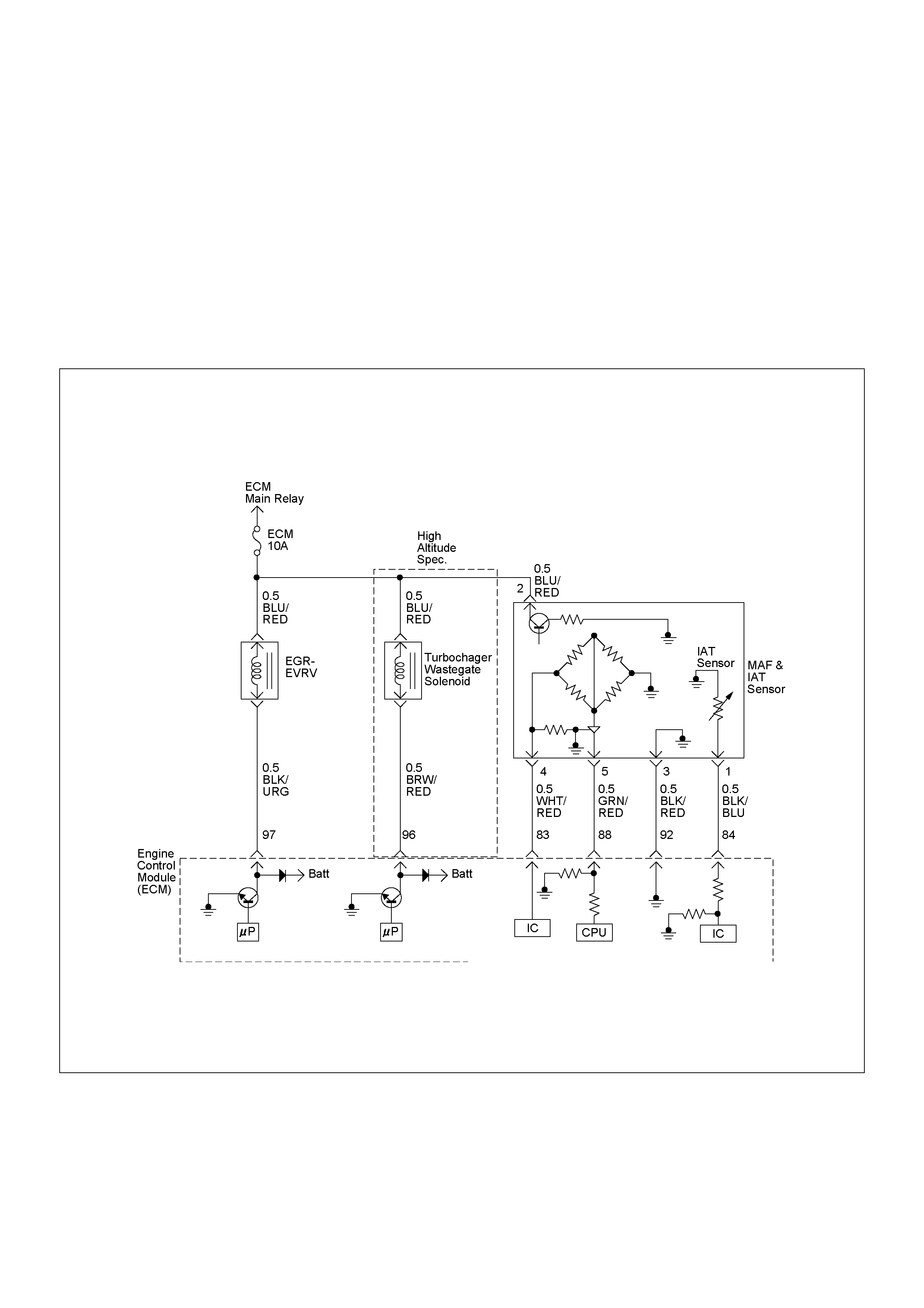
DIAGNOSTIC TROUBLE CODE (DTC) P0100 (SYM PTOM CODE 7)
(FLASH CODE 65) MASS AIR FLOW (MAF) SENSOR V OLTAGE
SUPPLY CIRCUIT HIGH INPUT
DIAGNOSTIC TROUBLE CODE (DTC) P0100 (SYM PTOM CODE 9)
(FLASH CODE 65) MASS AIR FLOW (MAF) SENSOR V OLTAGE
SUPPLY CIRCUIT LOW INPUT
DIAGNOSTIC TROUBLE CODE (DTC) P01 00 (SYMPTOM CODE B)
(FLASH CODE 65) MASS AIR FLOW (MAF) S EN SOR OUTPUT CIRCUIT LOW IN PUT
DIAGNOSTIC TROUBLE CODE (DTC) P01 00 (SYMPTOM CODE C)
(FLASH CODE 65) MASS AIR FLOW (MAF) SENSOR OUTPUT CIRCUIT HIGH INPUT

Condition for setting the DTC and action ta ken when the DTC sets
Circuit Description
The mas s air flo w (MAF) sensor is part of the intake air
system. It is fitted between the air cleaner and
turbocha rger a nd mea sure th e mas s air flowin g into the
engine.
The mass air flow (MAF) sensor element measures the
partial air mass through a measurement duct on the
sensor housing.
The ECM monitors the MAF sensor supply vol tage and
MAF sensor output voltage. The supply voltage is out of
range, DTC P0100 (Symptom Code 7) or P0100
(Symptom Code 9) will be stored. The output voltage
excessively high or low, DTC P0100 (Symptom Code B)
or P0100 (Symptom Code C) will be stored.
Diagnostic Aids
An intermittent may be caused by the following:
• Poor connections.
• Misrouted harness.
• Rubbed through wire insulation.
• Broken wire inside the insulation.
Check for the following conditions:
• Poor con nection at ECM-I nspect harness connectors
for backed out terminals, improper mating, broken
locks, improperly formed or damaged terminals, and
poor terminal to wire connection.
• Damaged harness-Inspect the wiring harness for
damage. If the harness appears to be OK, observe
the “Mass Air Flow” display on the Tech2 while
moving connectors and wiring harness related to the
sensor.
Flash
Code Code Symptom
Code MIL DTC Name DTC Setting Condition Fail-Safe (Back Up)
65 P0100 7 ON Mass Air Flow (MAF) Sensor
Voltage Supply Circuit High
Input
MAF sensor power supply
voltage is more than 5.2V. ECM uses mass air flow
1600mg/strk & EGR 10%
conditions as substitute.
9 ON Mass Air Flow (MAF) Sensor
Voltage Supply Circuit Low
Input
MAF sensor power supply
voltage is below 4.6V.
B ON Mass Air Flow (MAF) Sensor
Output Circuit Low Input 1. Engine speed is between
600rpm and 5000rpm.
2. MAF sensor output is
below -33.7mg/strk.
C ON Mass Air Flow (MAF) Sensor
Output Circuit High Input 1. Engine speed is between
600rpm and 5000rpm.
2. MAF sensor output is more
than 1784mg/strk.
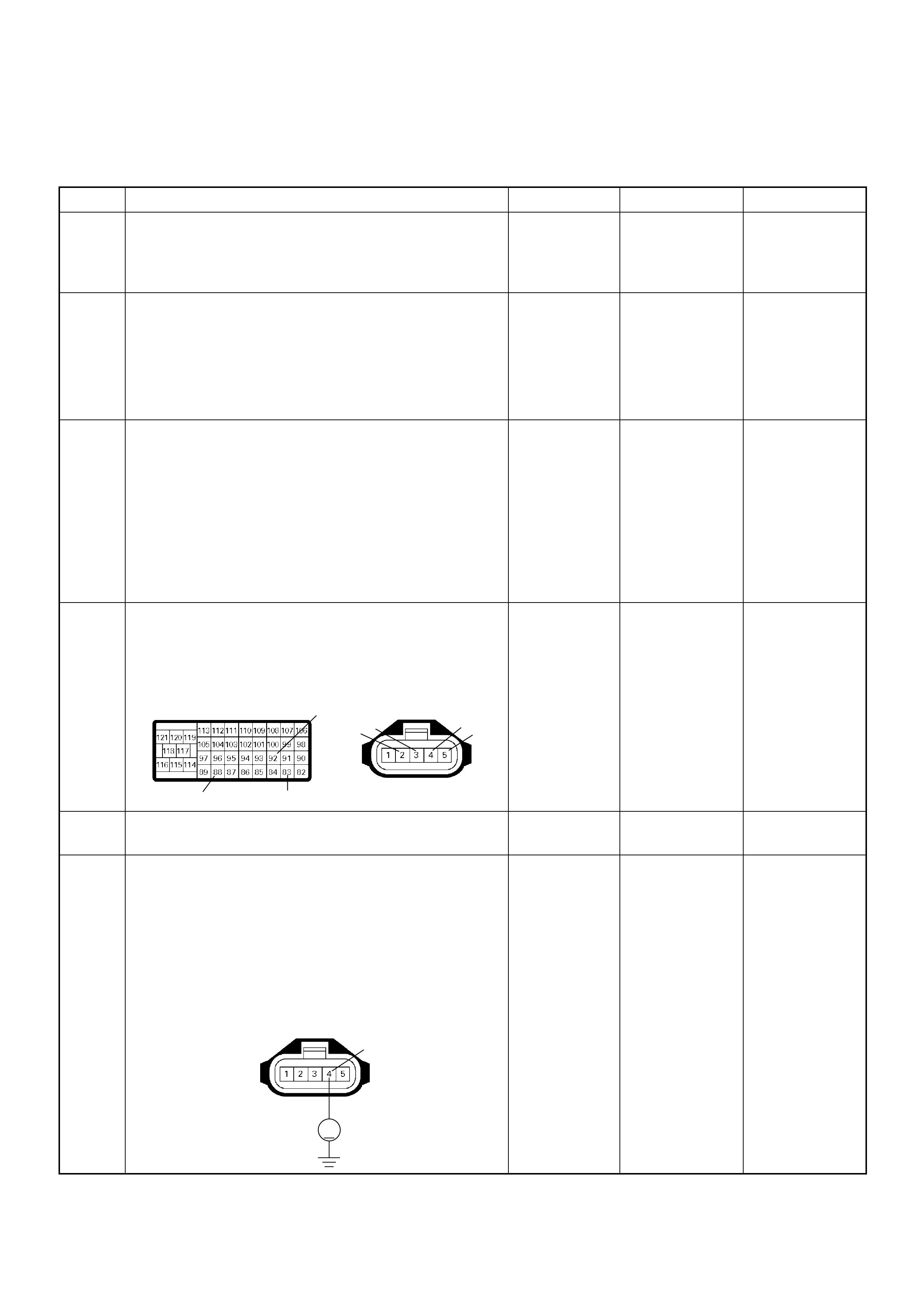
Diagnostic Trouble Code (DTC) P0100 (Symptom Code 7) (Flash Code 65)
Mass Air Flow (MAF) Sensor Voltage Supply Circuit High Input
Step Action Value(s) Yes No
1 Was the “On-Board Diagnostic (OBD) System Check”
performed?
—Go to Step 2
Go to On Board
Diagnostic
(OBD) System
Check
2 1. Connect the Tech 2.
2. Review and record the failure information.
3. Select “F0: Read DTC Infor As Stored By ECU” in
“F0: Diagnostic Trouble Codes”.
Is the DTC P0100 (Symptom Code 7) stored as
“Present Failure”? — Go to Step 3
Refer to
Diagnostic Aids
and Go to Step
3
3 1. Using the Tech 2, ignition “On” and engine “Off”.
2. Select “F1: Clear DTC Information” in “F0:
Diagnostic Trouble Codes” with the Tech 2 and
clear the DTC information.
3. Operate the vehicle and monitor the “F0: Read
DTC Infor As Stored By ECU” in the “F0:
Diagnostic Trouble Codes”.
Was the DT C P0 100 (Sy mpt om Code 7) stor e d i n th is
ignition cycle? — Go to Step 4
Refer to
Diagnostic Aids
and Go to Step
4
4 Check for poor/faulty connection at the MAF sensor or
ECM connector. If a poor/faulty connection is found,
repair as necessary.
Was the problem found?
— Verify repair Go to Step 5
5 Visual ly check the MA F se nso r.
Was the problem found? — Go to Step 11 Go to Step 6
6 Using the DVM and check the MAF sensor power
supply circuit.
1. Ignition “On”, engine “Off”.
2. Disconnect the MAF & IAT sensor connector.
3. Check the circuit for short to battery voltage
circuit.
Was the DVM indicated specified value?
Approximately
5.0V Go to Step 11
Less than 1V:
Go to Step 7
More than
specified value:
Go to Step 8
92
88 83
2345
C-116C-57(B)
V
4
C-116

7 Repair the open circuit between the ECM and MAF
sensor.
W as the problem solved?
— Verify repair Go to Step 8
8 Using the DVM and check the MAF sensor power
supply circuit.
1. Ignition “Off”, engine “Off”.
2. Disconnect the MAF & IAT sensor connector and
ECM connector.
3. Check the circuit for short to MAF sensor +12V
supply circuit.
Was the DVM indicated specified value?
No continuity Go to Step 10 Go to Step 9
9 Repair the circuit for short to MAF sensor +12V supply
circuit.
Is the action complete? — Verify repair —
10 Repair the short to bat tery voltage circu it between the
ECM and MAF se ns or.
W as the problem solved?
— Verify repair Go to Step 13
11 Substitute a known good MAF & IAT sensor assembly
and recheck.
W as the problem solved? — Go to Step 12 Go to S tep 13
12 Replace the MAF & IAT sensor assembly.
Is the action complete? — Verify repair —
13 Is the ECM programmed with the latest software
release?
If not, download the late st software to the ECM using
the “SPS (Service Programming System)”.
W as the problem solved? — Verify repair Go to Step 14
Step Action Value(s) Yes No
83 4
C-116C-57(B)
4
2
C-116
83 4
C-116C-57(B)

14 Replace the ECM.
Is the action complete?
IMPORTANT: The replacement ECM must be
programmed. Refer to section of the Service
Programming System (SPS) in this manual.
Foll owing ECM pr ogramming, the immobi lizer system
(if equipped) must be linked to the ECM. Refer to
section 11 “Immobilizer System-ECM replacement” for
the ECM/Immobilizer linking procedure. — Verify repair —
Step Action Value(s) Yes No
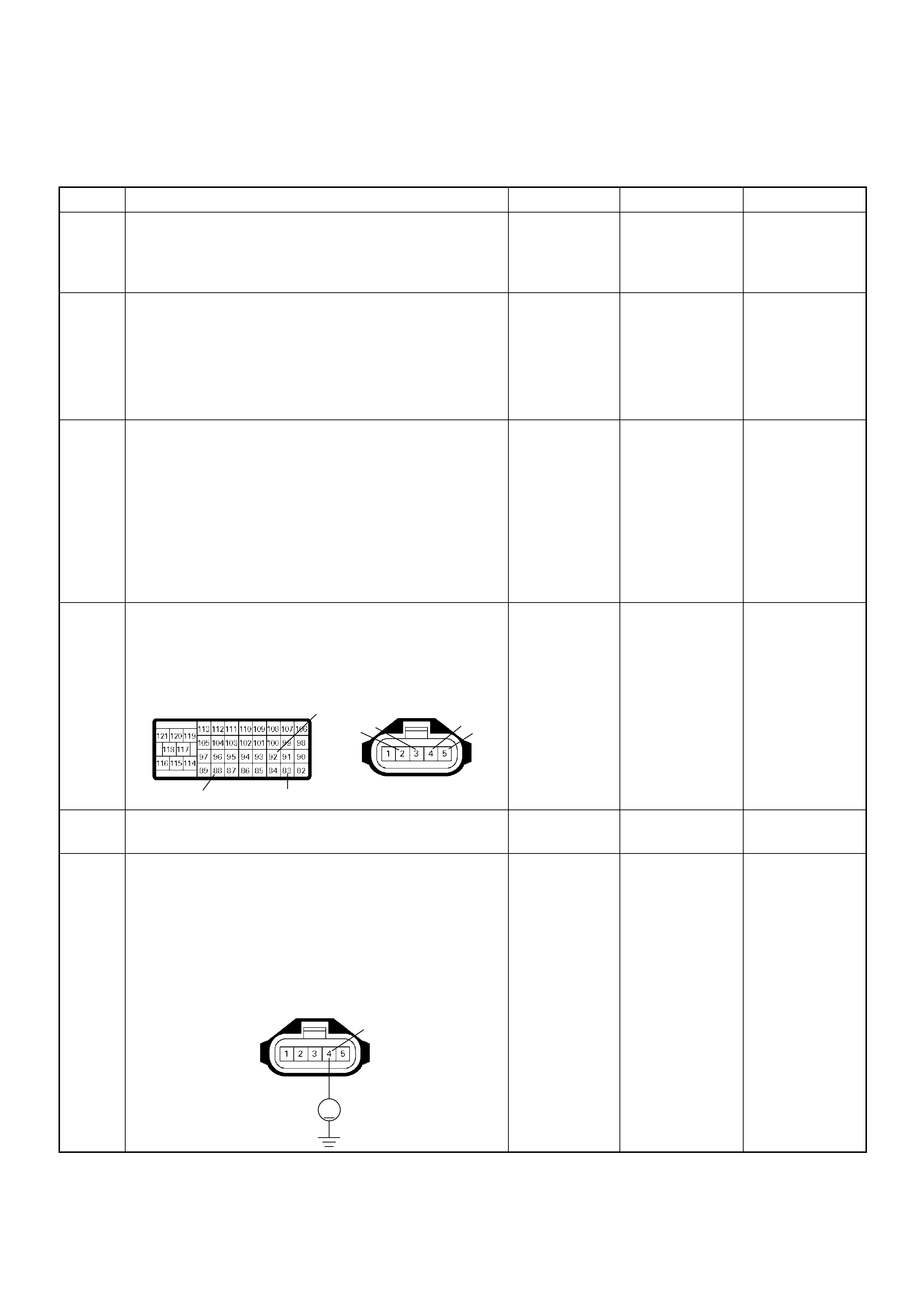
Diagnostic Trouble Code (DTC) P0100 (Symptom Code 9) (Flash Code 65)
Mass Air Flow (MAF) Sensor Voltage Supply Circuit Low Input
Step Action Value(s) Yes No
1 Was the “On-Board Diagnostic (OBD) System Check”
performed?
—Go to Step 2
Go to On Board
Diagnostic
(OBD) System
Check
2 1. Connect the Tech 2.
2. Review and record the failure information.
3. Select “F0: Read DTC I nfor As Stored By ECU” in
“F0: Diagnostic Trouble Codes”.
Is the DTC P0100 (Symptom Code 9) stored as
“Present Failure”? — Go to Step 3
Refer to
Diagnostic Aids
and Go to Step
3
3 1. Using the Tech 2, ignition “On” and engine “Off”.
2. Select “F1: Clear DTC Information” in “F0:
Diagnostic Trouble Codes” with the Tech 2 and
clear the DTC information.
3. Operate the vehicle and monitor the “F0: Read
DTC Infor As Stored By ECU” in the “F0:
Diagnostic Trouble Codes”.
Was the DT C P0 100 (Sy mpt om Code 9) stor e d i n th is
ignition cycle? — Go to Step 4
Refer to
Diagnostic Aids
and Go to Step
4
4 Check for poor/faulty connection at the MAF sensor or
ECM connector. If a poor/faulty connection is found,
repair as necessary.
Was the problem found?
— Verify repair Go to Step 5
5 Visual ly check the MA F se nso r.
Was the problem found? — Go to Step 10 Go to Step 6
6 Using the DVM and check the MAF sensor power
supply circuit.
1. Ignition “On”, engine “Off”.
2. Disconnect the MAF & IAT sensor connector.
3. Check the circuit for short to ground circuit.
Was the DVM indicated specified value?
Approximately
5.0V Go to Step 10 Go to Step 7
92
88 83
2345
C-116C-57(B)
V
4
C-116
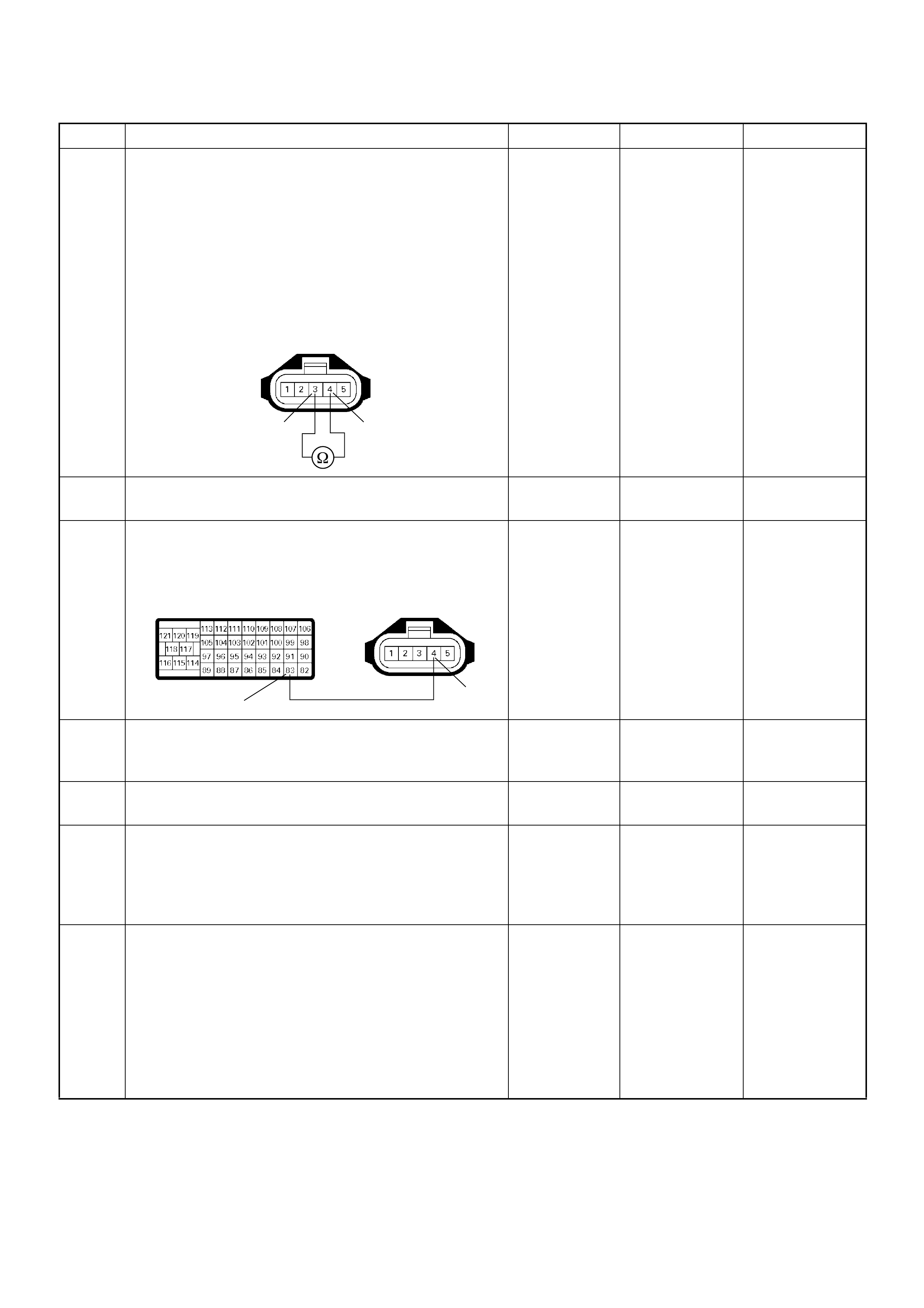
7 Using the DVM and check the MAF sensor power
supply circuit.
1. Ignition “Off”, engine “Off”.
2. Disconnect the MAF & IAT sensor connector and
ECM connector.
3. Check the circuit for short to MAF sensor ground
circuit.
Was the DVM indicated specified value?
No continuity Go to Step 9 Go to Step 8
8 Repair the circuit for short to MAF sensor ground.
Is the action complete? — Verify repair —
9 Repair the short to ground circuit between the ECM
and MAF sensor.
Was the problem solved?
— Verify repair Go to Step 12
10 Substitute a known good MAF & IAT sensor assembly
and recheck.
Was the problem solved? — Go to Step 11 Go to Step 12
11 Replace the MAF & IAT sensor assembly.
Is the action complete? — Verify repair —
12 Is the ECM programmed with the latest software
release?
If not, download the latest software to the ECM using
the “SPS (Service Programming System)”.
Was the problem solved? — Verify repair Go to Step 13
13 Replace the ECM.
Is the action complete?
IMPORTANT: The replacement ECM must be
programmed. Refer to section of the Service
Programming System (SPS) in this manual.
Foll owing ECM pr ogramming, the immobi lizer system
(if equipped) must be linked to the ECM. Refer to
section 11 “Immobilizer System-ECM replacement” for
the ECM/Immobilizer linking procedure. — Verify repair —
Step Action Value(s) Yes No
4
3
C-116
83 4
C-116C-57(B)
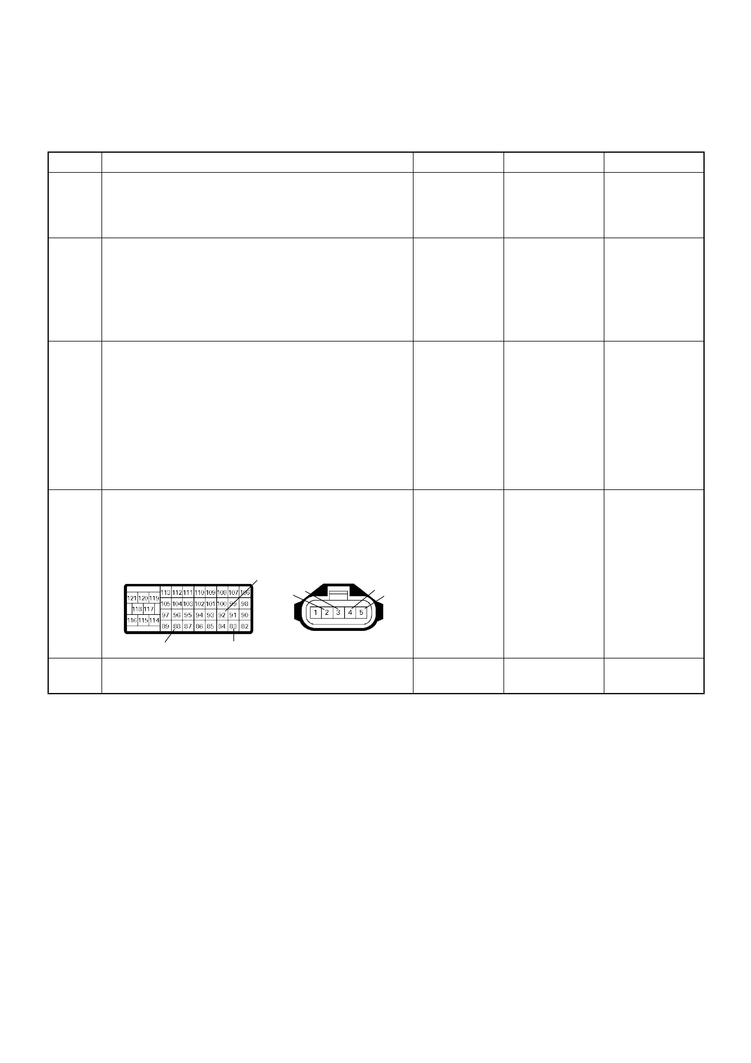
Diagnostic Trouble Code (DTC) P0100 (Symptom Code B) (Flash Code 65)
Mass Air Flow (MAF) Sensor Output Circuit Low Input
Step Action Value(s) Yes No
1 Was the “On-Board Diagnostic (OBD) System Check”
performed?
—Go to Step 2
Go to On Board
Diagnostic
(OBD) System
Check
2 1. Connect the Tech 2.
2. Review and record the failure information.
3. Select “F0: Read DTC I nfor As Stored By ECU” in
“F0: Diagnostic Trouble Codes”.
Is the DTC P0100 (Symptom Code B) stored as
“Present Failure”? — Go to Step 3
Refer to
Diagnostic Aids
and Go to Step
3
3 1. Using the Tech 2, ignition “On” and engine “Off”.
2. Select “F1: Clear DTC Information” in “F0:
Diagnostic Trouble Codes” with the Tech 2 and
clear the DTC information.
3. Operate the vehicle and monitor the “F0: Read
DTC Infor As Stored By ECU” in the “F0:
Diagnostic Trouble Codes”.
Was the DTC P0100 (Symptom Code B) stored in this
ignition cycle? — Go to Step 4
Refer to
Diagnostic Aids
and Go to Step
4
4 Check for poor/faulty connection at the MAF sensor or
ECM connector. If a poor/faulty connection is found,
repair as necessary.
Was the problem found?
— Verify repair Go to Step 5
5 Visual ly check the MA F se nso r.
Was the problem found? — Go to Step 11 Go to Step 6
92
88 83
2345
C-116C-57(B)
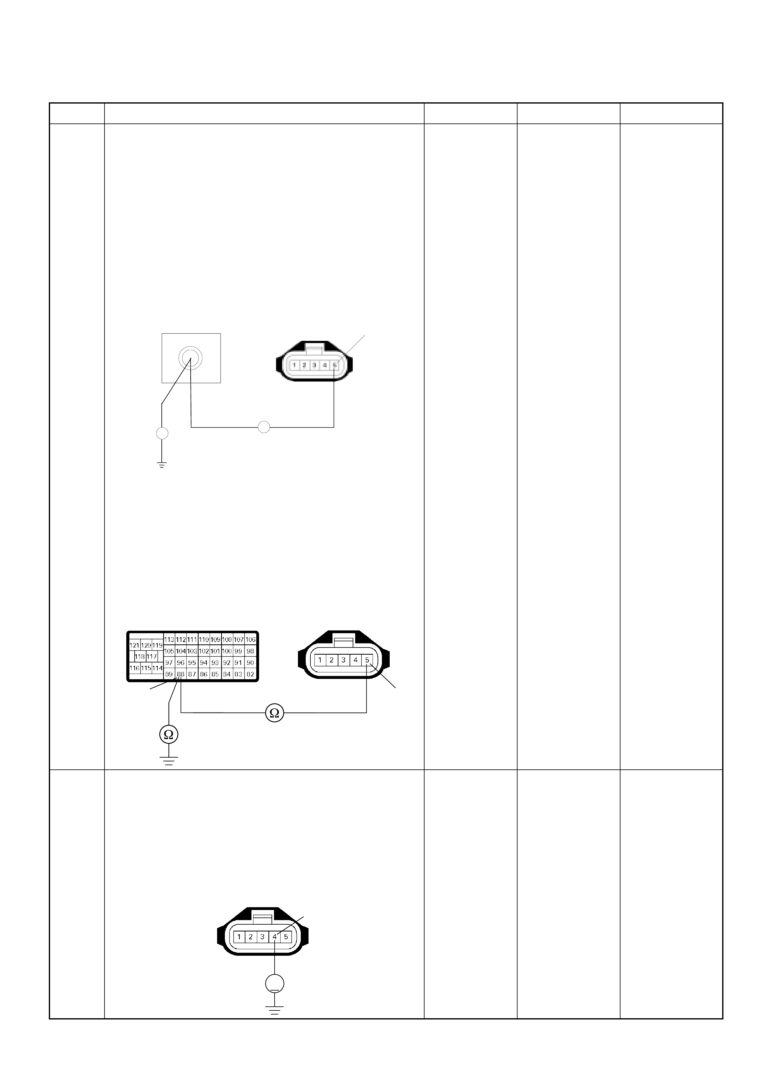
6 Using the DVM and check the MAF sensor signal
circuit.
Breaker box is available:
1. Ignition “Off”, engine “Off”.
2. Install the breaker box as type A. (ECM
disconnected) Ref. to HOW TO USE BREAKER
BOX
3. Disconnect the MAF & IAT sensor connector.
4. Check th e circuit f or open, short to sensor gr ound
or short to ground circuit.
Was the problem found?
Breaker box is not available:
1. Ignition “Off”, engine “Off”.
2. Disconnect the MAF & IAT sensor connector and
ECM connector.
3. Check th e circuit f or open, short to sensor gr ound
or short to ground circuit.
Was the problem found?
—
Repair faulty
harnes s and
verify repair Go to Step 7
7 Using the DVM and check the MAF sensor power
supply circuit.
1. Ignition “On”, engine “Off”.
2. Disconnect the MAF & IAT sensor connector.
3. Check the circuit for open circuit.
Was the DVM indicated specified value?
Approximately
5.0V Go to Step 9 Go to Step 8
Step Action Value(s) Yes No
C-116
88
Breaker Bo x 5
Ħ
Ħ
5
88
C-116
C-57(B)
V
4
C-116
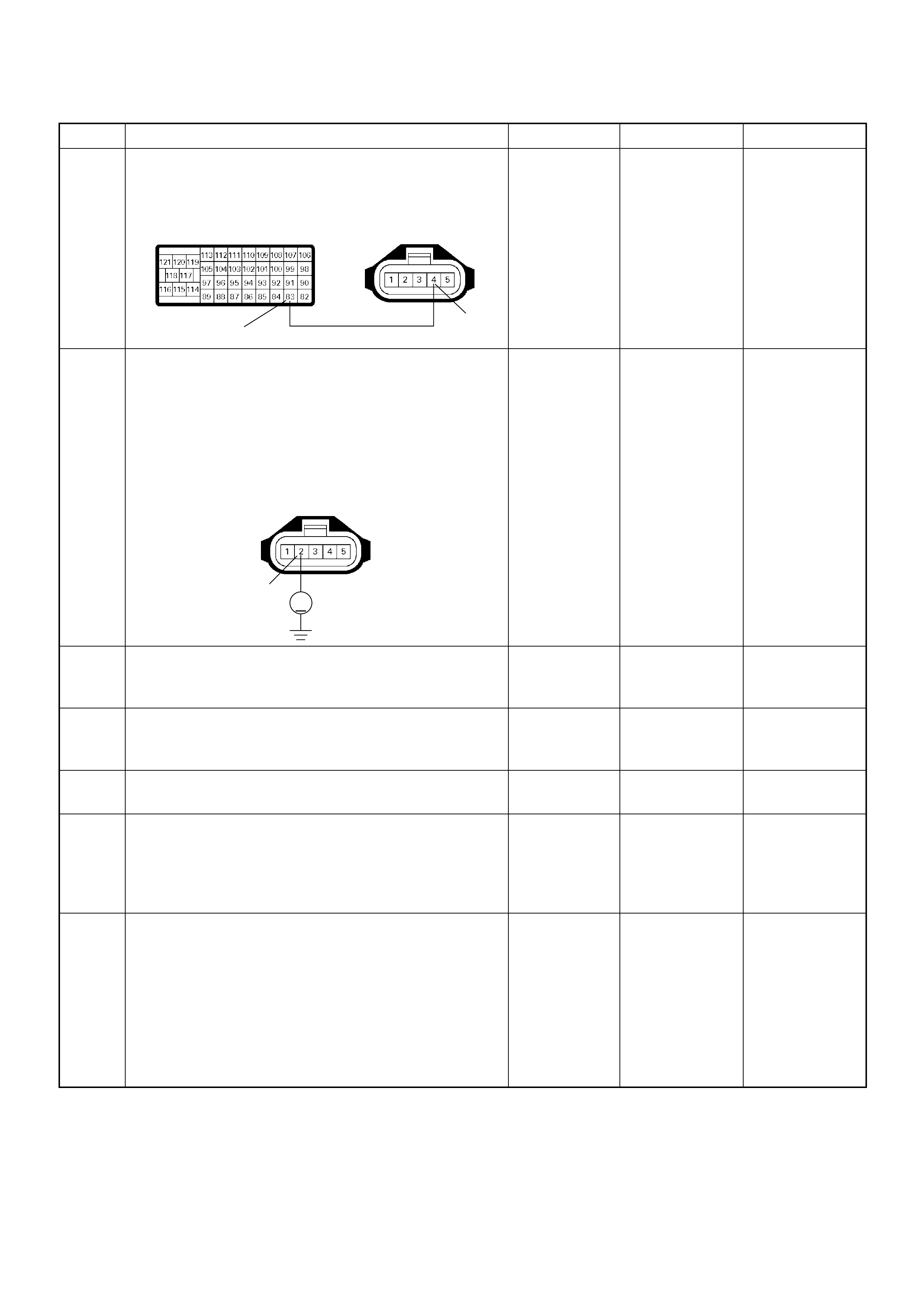
8 Repair the open circuit between the ECM and MAF
sensor.
Was the problem solved?
— Verify repair Go to Step 13
9 Using the DVM and check the MAF sensor +12V
supply circuit.
1. Ignition “On”, engine “Off”.
2. Disconnect the MAF & IAT sensor connector.
3. Check the circuit for open circuit.
Was the DVM indicated specified value?
10-14.5V Go to Step 11 Go to Step 10
10 Repair the open circuit between the ECM main relay
and MAF sensor.
Was the problem solved? — Verify repair Go to Step 11
11 Substitute a known good MAF & IAT sensor assembly
and recheck.
Was the problem solved? — Go to Step 12 Go to Step 13
12 Replace the MAF & IAT sensor assembly.
Is the action complete? — Verify repair —
13 Is the ECM programmed with the latest software
release?
If not, download the latest software to the ECM using
the “SPS (Service Programming System)”.
Was the problem solved? — Verify repair Go to Step 14
14 Replace the ECM.
Is the action complete?
IMPORTANT: The replacement ECM must be
programmed. Refer to section of the Service
Programming System (SPS) in this manual.
Foll owing ECM pr ogramming, the immobi lizer system
(if equipped) must be linked to the ECM. Refer to
section 11 “Immobilizer System-ECM replacement” for
the ECM/Immobilizer linking procedure. — Verify repair —
Step Action Value(s) Yes No
83 4
C-116C-57(B)
2
V
C-116

Diagnostic Trouble Code (DTC) P0100 (Symptom Code C) (Flash Code 65)
Mass Air Flow (MAF) Sensor Output Circuit High Input
Step Action Value(s) Yes No
1 Was the “On-Board Diagnostic (OBD) System Check”
performed?
—Go to Step 2
Go to On Board
Diagnostic
(OBD) System
Check
2 1. Connect the Tech 2.
2. Review and record the failure information.
3. Select “F0: Read DTC I nfor As Stored By ECU” in
“F0: Diagnostic Trouble Codes”.
Is the DTC P0100 (Symptom Code C) stored as
“Present Failure”? — Go to Step 3
Refer to
Diagnostic Aids
and Go to Step
3
3 1. Using the Tech 2, ignition “On” and engine “Off”.
2. Select “F1: Clear DTC Information” in “F0:
Diagnostic Trouble Codes” with the Tech 2 and
clear the DTC information.
3. Operate the vehicle and monitor the “F0: Read
DTC Infor As Stored By ECU” in the “F0:
Diagnostic Trouble Codes”.
Was the DTC P0100 (Symptom Code C) stored in this
ignition cycle? — Go to Step 4
Refer to
Diagnostic Aids
and Go to Step
4
4 Check for poor/faulty connection at the MAF sensor or
ECM connector. If a poor/faulty connection is found,
repair as necessary.
Was the problem found?
— Verify repair Go to Step 5
5 Visual ly check the MA F se nso r.
Was the problem found? — Go to Step 11 Go to Step 6
92
88 83
2345
C-116C-57(B)

6 Using the DVM and check the MAF sensor ground
circuit.
Breaker box is available:
1. Ignition “Off”, engine “Off”.
2. Install the breaker box as type A. (ECM
disconnected) Ref. to HOW TO USE BREAKER
BOX
3. Disconnect the MAF sensor connector.
4. Check the circuit for open circuit.
Was the problem found?
Breaker box is not available:
1. Ignition “Off”, engine “Off”.
2. Disconnect the MAF sensor connector and ECM
connector.
3. Check the circuit for open circuit.
Was the problem found?
—
Repair faulty
harnes s and
verify repair Go to Step 7
7 Using the DVM and check the MAF sensor ground
circuit.
1. Ignition “On”, engine “Off”.
2. Disconnect the MAF sensor connector .
3. Check the circuit for short to power supply circuit.
Was the DVM indicated specified value?
Less than 1V Go to Step 8
Repair faulty
harness and
verify repair
Step Action Value(s) Yes No
C-116
92
Breaker Box 3
Ħ
3
92
C-116
C-57
3
V
C-116

8 Using the DVM and check the MAF sensor signal
circuit.
1. Ignition “On”, engine “Off”.
2. Disconnect the MAF sensor connector.
3. Check the circuit for short to power supply circuit.
Was the DVM indicated specified value?
Less than 1V Go to Step 9
Repair faulty
harness and
verify repair
9 Substitute a known good MAF & IAT sensor assembly
and recheck.
Was the problem solved? — Go to Step 10 Go to Step 11
10 Replace the MAF & IAT sensor assembly.
Is the action complete? — Verify repair —
11 Is the ECM programmed with the latest software
release?
If not, download the latest software to the ECM using
the “SPS (Service Programming System)”.
Was the problem solved? — Verify repair Go to Step 12
12 Replace the ECM.
Is the action complete?
IMPORTANT: The replacement ECM must be
programmed. Refer to section of the Service
Programming System (SPS) in this manual.
Foll owing ECM pr ogramming, the immobi lizer system
(if equipped) must be linked to the ECM. Refer to
section 11 “Immobilizer System-ECM replacement” for
the ECM/Immobilizer linking procedure. — Verify repair —
Step Action Value(s) Yes No
5
V
C-116
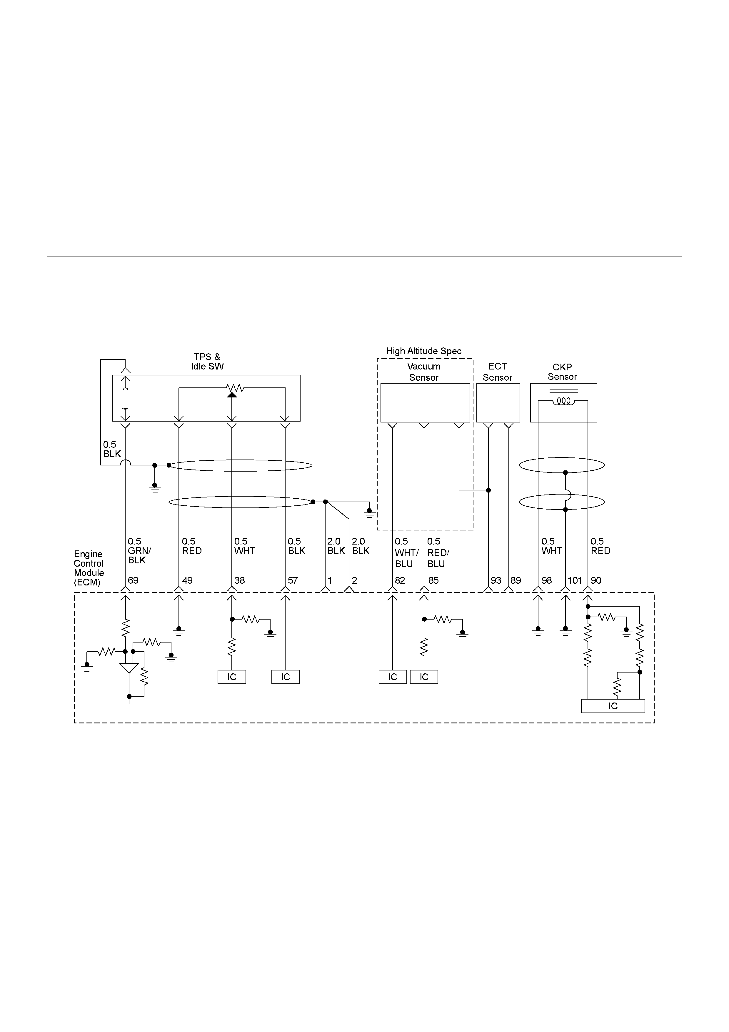
DIAGNOSTIC TROUBLE CODE (DTC) P0105 (SYMPTOM CODE 1) (FLASH CODE 34)
VACUUM PRESSURE SENSOR CIRCUIT HIGH INPUT
DIAGNOSTIC TROUBLE CODE (DTC) P0105 (SYMPTOM CODE 2) (FLASH CODE 34)
VACUUM PRESSURE SENSOR CIRCUIT LOW INPUT
DIAGNOSTIC TROUBLE CODE (DTC) P0105 (SYMPTOM CODE 7) (FLASH CODE 34)
VACUUM PRESSURE SENSOR VOLTAGE SUPPLY CIRCUIT HIGH INPUT
DIAGNOSTIC TROUBLE CODE (DTC) P0105 (SYMPTOM CODE 9) (FLASH CODE 34)
VACUUM PRE SSURE SENSOR VOLTAGE SUPPLY CIRCUIT LOW INPUT

Condition for setting the DTC and action ta ken when the DTC sets
Circuit description
The ECM monitors altitude from the barometric
pressure sensor. To apply specified vacuum pressure to
the turbocharger wastegate valve, ECM sends control
signal to the wastegate control solenoid depending on
altitude.
Then, apply vacuum pressure to the turbocharger
wastegate valve is monitored by the ECM form the
vacuum pressure sensor output signal. The ECM
controls wastegate control solenoid based on signal
from vacuum pressure sensor output.
The outpu t voltage ex cessi vely high o r low, DTC P010 5
(Symptom Co de 1) or P010 5 (Symp tom Cod e 2) w ill be
stored.
The supply voltage is out of range, DTC P0105
(Symptom Co de 7) or P010 5 (Symp tom Cod e 9) w ill be
stored.
Diagnostic Aids
An intermittent may be caused by the following:
• Poor connections.
• Misrouted harness.
• Rubbed through wire insulation.
• Broken wire inside insulation.
Check for the following conditions:
• Poor con nection at ECM-I nspect harness connectors
for backed out terminals, improper mating, broken
locks, improperly formed or damaged terminals, and
poor terminal to wire connection.
• Damaged harness-Inspect the wiring harness for
damage. If the harness appears to be OK, observe
the DTC P0105 display on the Tech 2 while moving
connectors and wiring harnesses. A change in the
display will indicate the location of the fault.
Flash
Code Code Symptom
Code MIL DTC Name DTC Setting Condition Fail-Safe (Back Up)
34 P0105 1 ON Vacuum Pressure Sens or
Circuit High Input Vacuum sensor output
voltage is more than 4.4V. 1. Fuel injection quantity is
reduced.
2. ECM use 615hpa
conditions for
turbocharger wast e gate
control.
2 ON Vacu u m Pres sure Sens or
Circuit Low Input Vacuum sensor output
voltage is below 0.5V.
7 ON Vacu u m Pres sure Sens or
Voltage Supply Circuit High
Input
Vacuum sensor power supply
voltage is more than 5.2V. 1. Fuel injection quantity is
reduced.
2. ECM use vacuum sensor
output voltage 5.0V
condition as substitute.
9 ON Vacu u m Pres sure Sens or
Voltage Supply Circuit Low
Input
Vacuum sensor power supply
voltage is below 4.5V.
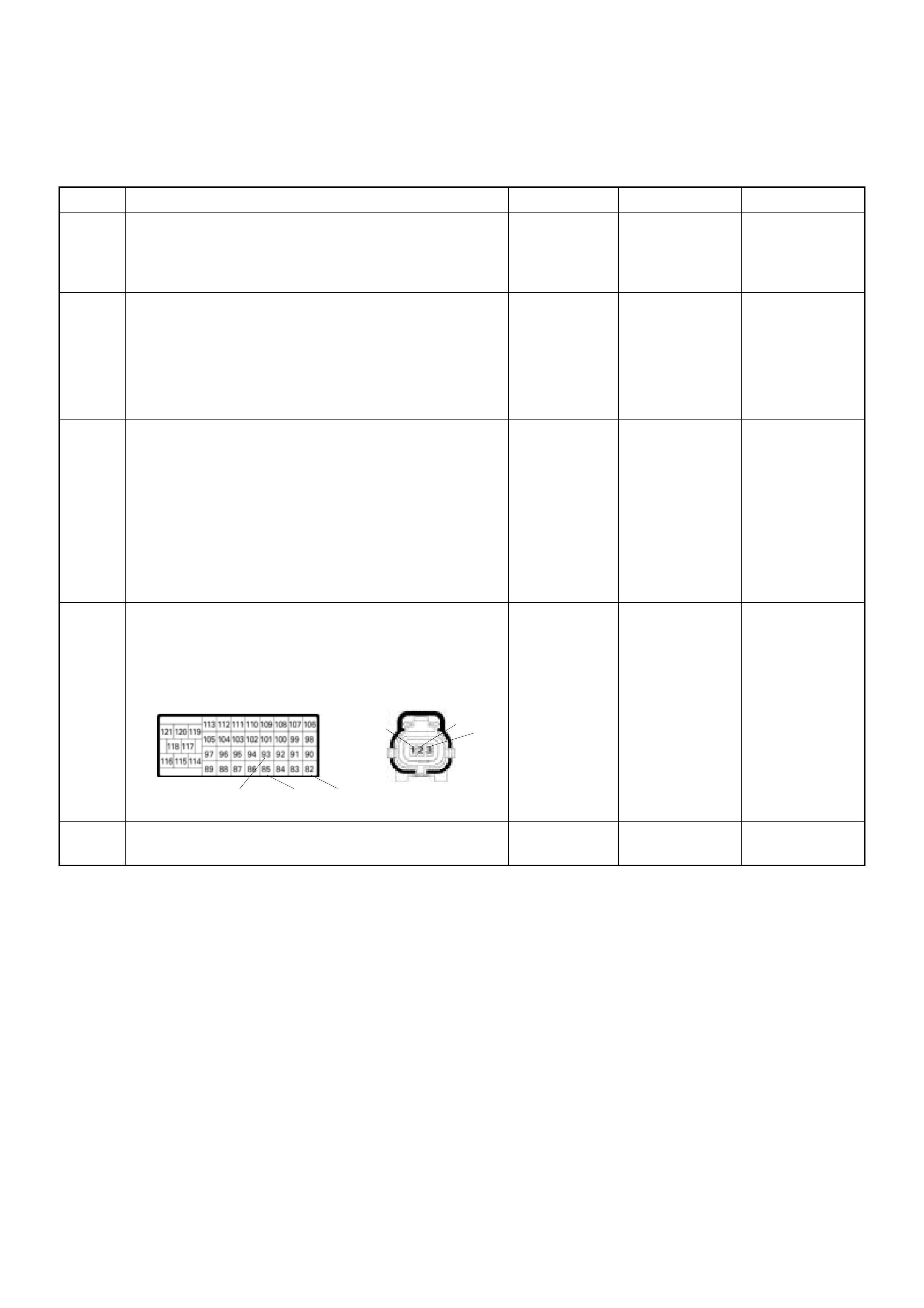
Diagnostic Trouble Code (DTC) P0105 (Symptom Code 1) (Flash Code 34)
Vacuum Pressure Sensor Circuit High Input
Step Action Value(s) Yes No
1 Was the "On-Board Diagnostic (OBD) System Check"
performed?
-Go to Step 2
Go to On Board
Diagnostic
(OBD) System
Check
2 1. Connect the T ech 2.
2. Revie w and record th e f ai lure in form atio n.
3. Select "F0: Rea d DTC Infor A s Stor ed By EC U" in
"F0: Diagnostic Trouble Codes".
Is the DTC P0105 (Symptom Code 1) stored as
"Present Failure"? - Go to Step 3
Refer to
Diagnostic Aids
and Go to Step
3
3 1 . Us in g th e Te ch 2 , ig n i t i o n "O n " a n d en g i n e " O ff " .
2. Select "F1: Clear DTC Information" in "F0:
Diagnostic Trouble Codes" with the Tech 2 and
clear the DTC information.
3. Operate the vehicle and monitor the "F0: Read
DTC Infor As Stored By ECU" in the "F0:
Diagnostic Trouble Codes".
Was the DT C P0 105 (Sy mpt om Code 1) stor e d i n th is
ignition cycle? - Go to Step 4
Refer to
Diagnostic Aids
and Go to Step
4
4 Check for poor/faulty connection at the vacuum
pressure sensor or ECM connector. If a poor/faulty
con necti on i s f o u n d , re pa i r a s n e c e s s a r y.
Was the problem found?
- Verify repair Go to Step 5
5 Visually check the vacuum sensor.
Was the problem found? - Go to Step 9 Go to Step 6
C-124
C-57
82
85
93
3
2
1
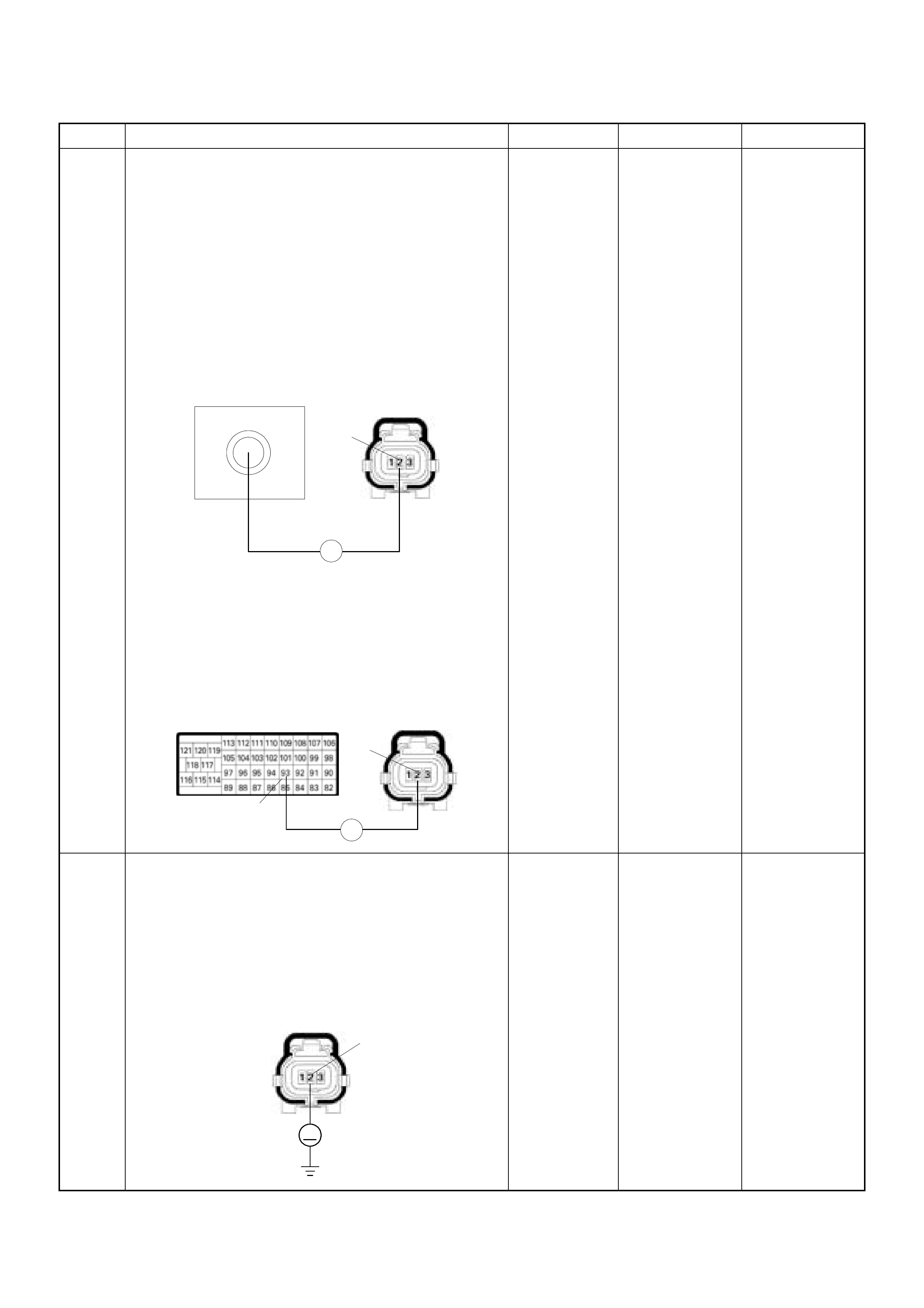
6 Using the DVM and check the vacuum pressure
sensor ground circuit .
Breaker box is available:
1. Ignition "Off", engine "Off".
2. Install the breaker box as type A. (ECM
disconnected) Ref. to HOW TO USE BREAKER
BOX
3. Disconnect the vacuum pressure sensor
connector.
4. Check the circuit for open circuit.
Was the problem found?
Breaker box is not available:
1. Ignition "Off", engine "Off".
2. Disconnect the vacuum pressure sensor
connector and ECM connector.
3. Check the circuit for open circuit.
Was the problem found?
-
Repair faulty
harness and
verify repair Go to Step 7
7 Using the DVM and check the vacuum pressure
sensor ground circuit .
1. Ignition "On", engine "Off".
2. Disconnect the vacuum pressure sensor
connector.
3 . C h e c k t h e c i r c u i t f o r s h o r t t o p o w e r s u p p l y c i r c u i t .
Was the DVM indicated specified value?
Less than 1V Go to Step 8
Repair faulty
harness and
verify repair
Step Action Value(s) Yes No
93
Breaker Box C-124
Ħ
2
C-57 C-124
Ħ
93
2
C-124
V
2

8 Using the DVM and check the vacuum pressure
sensor signal circuit.
1. Ignition "On", engine "Off".
2. Disconnect the vacuum pressure sensor
connector.
3 . C h e c k t h e c i r c u i t f o r s h o r t t o p o w e r s u p p l y c i r c u i t .
Was the DVM indicated specified value?
Less than 1V Go to Step 9
Repair faulty
harness and
verify repair
9 Substitute a known good vacuum pressure sensor
and recheck.
Was the problem solved? - Go to Step 10 Go to Step 11
10 Replace the vacuum pressure sensor.
Is the action complete? - Verify repair -
11 Is the ECM programmed with the latest software
release?
If not, download the latest software to the ECM using
the "SPS (Service Programming System)".
Was the problem solved? - Verify repair Go to Step 12
12 Replace the ECM.
Is the action complete?
IMPORTANT: The replacement ECM must be
programmed. Refer to section of the Service
P r o g r a m m i n g S y s t e m ( S PS ) i n t h i s m a n u a l .
Foll owing ECM pr ogramming, the immobi liser syst em
(if equipped) must be linked to the ECM. Refer to
section 11 "Immobilizer System-ECM replacement"
for the ECM/Immobilizer linking procedure. - Verify repair -
Step Action Value(s) Yes No
C-124
V
1

Diagnostic Trouble Code (DTC) P0105 (Symptom Code 2) (Flash Code 34)
Vacuum Pressure Sensor Circuit Low Input
Step Action Value(s) Yes No
1 Was the "On-Board Diagnostic (OBD) System Check"
performed?
-Go to Step 2
Go to On Board
Diagnostic
(OBD) System
Check
2 1. Connect the T ech 2.
2. Re vi ew and record th e fai lur e i nfor ma tion.
3. Sele ct "F0: Rea d DTC Info r As Stored By EC U" in
"F0: Diagnostic Trouble Codes".
Is the DTC P0105 (Symptom Code 2) stored as
"Present F ailure"? - Go to Step 3
Refer to
Diagnostic Aids
and Go to Step
3
3 1. Us in g t h e Te ch 2 , i g n i t i o n "O n " an d e n g i n e "O f f " .
2. Select "F1: Clear DTC Information" in "F0:
Diagnostic Trouble Codes" with the Tech 2 and
clear the DTC information.
3. Operate the vehicle and monitor the "F0: Read
DTC Infor As Stored By ECU" in the "F0:
Diagnostic Trouble Codes".
Was the DTC P0105 ( Symptom Code 2) s tor e d i n this
ignition cycle? - Go to Step 4
Refer to
Diagnostic Aids
and Go to Step
4
4 Check for poor/faulty connection at the vacuum
pressure sensor or ECM connector. If a poor/faulty
con ne c t i o n i s f o und , re pai r a s ne ce s s ar y.
Was the problem found?
- Verify repair Go to Step 5
5 Visually che ck the vacuum pre ss ur e s ensor.
Was the problem found? - Go to Step 9 Go to Step 6
C-124
C-57
82
85
93
3
2
1
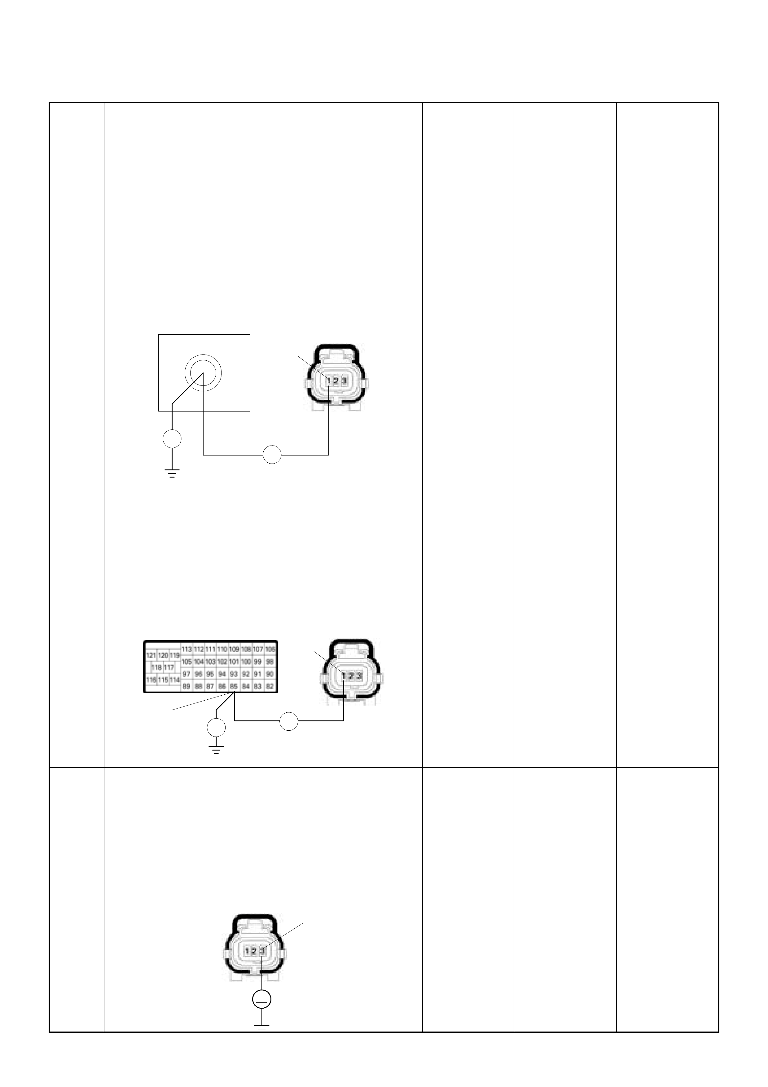
6 Using the DVM and check the vacuum pressure
sensor signal circuit.
Breaker box is available:
1. Ignition "Off", engine "Off".
2. Install the breaker box as type A. (ECM
disconnected) Ref. to HOW TO USE BREAKER
BOX
3. Disconnect the vacuum pressure sensor
connector.
4. Check th e circuit f or open, s hort to sens or ground
or short to ground circuit.
Was the problem found?
Breaker box is not available:
1. Ignition "Off", engine "Off".
2. Disconnect the vacuum pressure sensor
connector and ECM connector.
3. Check th e circuit f or open, s hort to sens or ground
or short to ground circuit.
Was the problem found?
-
Repair faulty
harness and
verify repair Go to Step 7
7 Using the DVM and check the vacuum pressure
sensor power supp ly circuit.
1. Ignition "On", engine "Off".
2. Disconnect the vacuum pressure sensor
connector.
3. Check the circuit for open circuit.
Was the DVM indicated specified value?
Approximately
5.0V Go to Step 9 Go to Step 8
85
Breaker Box C-124
Ħ
Ħ
1
C-57 C-124
Ħ
Ħ
85
1
C-124
V
3

8 Repair the open circuit between the ECM and vacuum
pressure sensor.
Was the problem solved?
- Verify repair Go to Step 11
9 Substitute a known good vacuum pressure sensor
assembly and recheck.
Was the problem solved? - Go to Step 10 Go to Step 11
10 Replace the vacuum sensor assembly.
Is the action complete? - Verify repair -
11 Is the ECM programmed with the latest software
release?
If not, download the latest software to the ECM using
the "SPS (Service Programming System)".
Was the problem solved? - Verify repair Go to Step 12
12 Replace the ECM.
Is the action complete?
IMPORTANT: The replacement ECM must be
programmed. Refer to section of the Service
P r o g r a m m i n g S y s t e m ( S PS ) i n t h i s m a n u a l .
Foll owing ECM pr ogramming, the immobi liser syst em
(if equipped) must be linked to the ECM. Refer to
section 11 "Immobilizer System-ECM replacement"
for the ECM/Immobilizer linking procedure. - Verify repair -
C-124 3
C-57
82

Diagnostic Trouble Code (DTC) P0105 (Symptom Code 7) (Flash Code 34)
Vacuum Pressure Sensor Voltage Supply Circuit High Input
Step Action Value(s) Yes No
1 Was the "On-Board Diagnostic (OBD) System Check"
performed?
-Go to Step 2
Go to On Board
Diagnostic
(OBD) System
Check
2 1. Connect the T ech 2.
2. Re vi ew and re co rd th e f ai lure i nfor ma tion.
3. Sele ct "F0: Rea d DTC Info r As Stored By EC U" in
"F0: Diagnostic Trouble Codes".
Is the DTC P0105 (Symptom Code 7) stored as
"Present Failure"? - Go to Step 3
Refer to
Diagnostic Aids
and Go to Step
3
3 1. Us in g t h e Te ch 2 , ig n i t io n " On " an d e n g i n e " O f f ".
2. Select "F1: Clear DTC Information" in "F0:
Diagnostic Trouble Codes" with the Tech 2 and
clear the DTC information.
3. Operate the vehicle and monitor the "F0: Read
DTC Infor As Stored By ECU" in the "F0:
Diagnostic Trouble Codes".
Was the DTC P0105 ( Symptom Code 7) s tor e d i n this
ignition cycle? - Go to Step 4
Refer to
Diagnostic Aids
and Go to Step
4
4 Check for poor/faulty connection at the vacuum
pressure sensor or ECM connector. If a poor/faulty
con ne c t i o n i s f o und , repa i r a s ne ce ss ary.
Was the problem found?
- Verify repair Go to Step 5
5 Visually che ck the vacuum pressure s en so r.
Was the problem found? - Go to Step 8 Go to Step 6
6 Using the DVM and check the vacuum pressure
sensor power supp ly circuit.
1. Ignition "On", engine "Off".
2. Disconnect the vacuum pressure sensor
connector.
3. Check the circuit for short to battery voltage
circuit.
Was the DVM indicated specified value?
Approximately
5.0V Go to Step 8 Go to Step 7
C-124
C-57
82
85
93
3
2
1
C-124
V
3

7 Repair the short to battery voltage circuit between the
E C M a n d v a c u u m p r e s s u r e s e n s o r.
Was the problem solved?
- Verify repair Go to Step 10
8 Substitute a known good vacuum pressure sensor
assembly and recheck.
Was the problem solved? - Go to Step 9 Go to Step 10
9 Replace the vacuum pressure sensor assembly.
Is the action complete? - Verify repair -
10 Is the ECM programmed with the latest software
release?
If not, download the latest software to the ECM using
the "SPS (Service Programming System)".
Was the problem solved? - Verify repair Go to Step 11
11 Replace the ECM.
Is the action complete?
IMPORTANT: The replacement ECM must be
programmed. Refer to section of the Service
P r o g r a m m i n g S y s t e m ( S PS ) i n t h i s m a n u a l .
Foll owing ECM pr ogramming, the immobi liser syst em
(if equipped) must be linked to the ECM. Refer to
section 11 "Immobilizer System-ECM replacement"
for the ECM/Immobilizer linking procedure. - Verify repair -
C-124 3
C-57
82
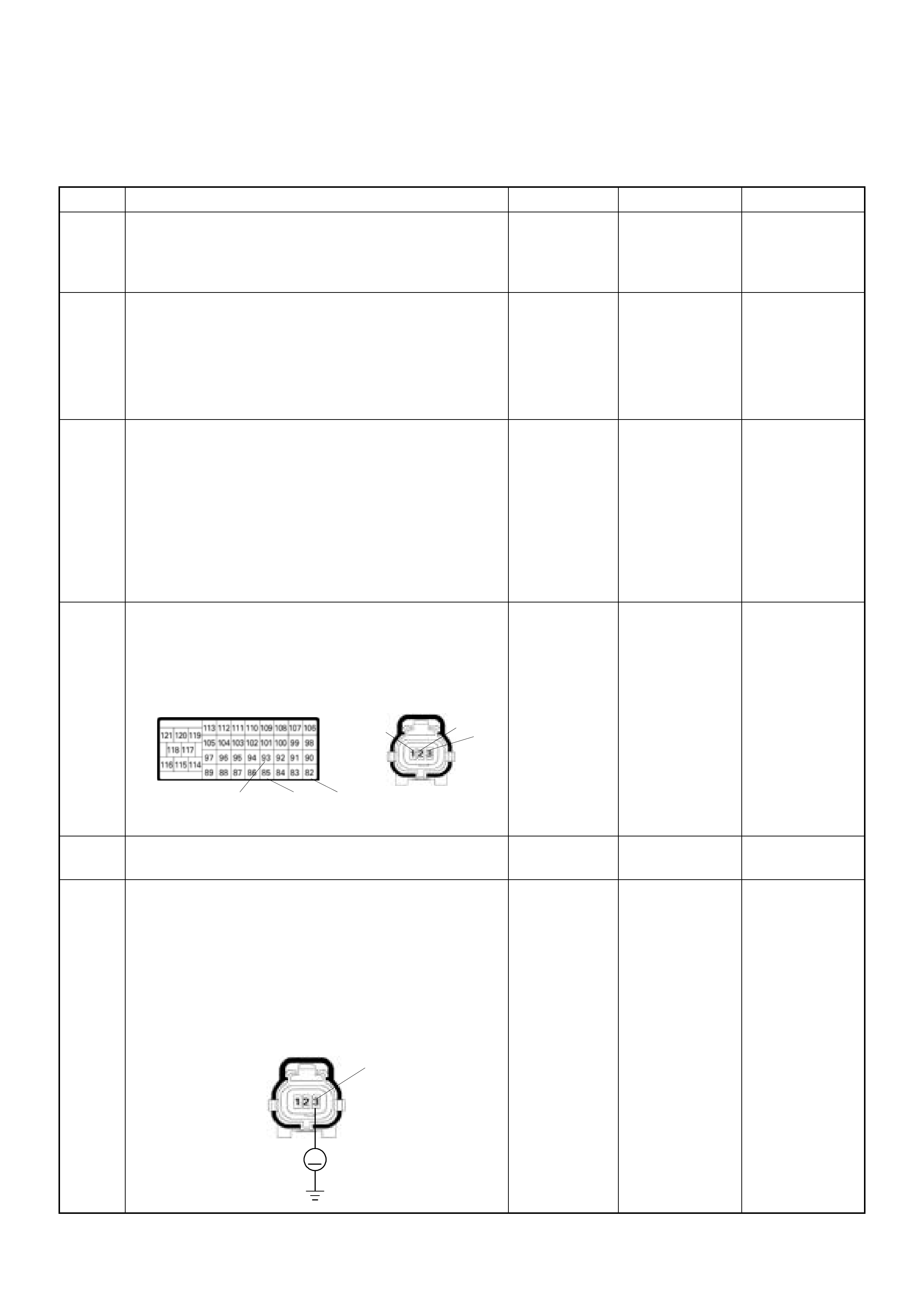
Diagnostic Trouble Code (DTC) P0105 (Symptom Code 9) (Flash Code 34)
Vacuum Pressure Sensor Voltage Supply Circuit Low Input
Step Action Value(s) Yes No
1 Was the "On-Board Diagnostic (OBD) System Check"
performed?
-Go to Step 2
Go to On Board
Diagnostic
(OBD) System
Check
2 1. Connect the T ech 2.
2. Re vi ew and re co rd th e f ai lure i nfor ma tion.
3. Sele ct "F0: Rea d DTC Info r As Stored By EC U" in
"F0: Diagnostic Trouble Codes".
Is the DTC P0105 (Symptom Code 9) stored as
"Present Failure"? - Go to Step 3
Refer to
Diagnostic Aids
and Go to Step
3
3 1. Us in g t h e Te ch 2 , ig n i t io n " On " an d e n g i n e " O f f ".
2. Select "F1: Clear DTC Information" in "F0:
Diagnostic Trouble Codes" with the Tech 2 and
clear the DTC information.
3. Operate the vehicle and monitor the "F0: Read
DTC Infor As Stored By ECU" in the "F0:
Diagnostic Trouble Codes".
Was the DTC P0105 ( Symptom Code 9) s tor e d i n this
ignition cycle? - Go to Step 4
Refer to
Diagnostic Aids
and Go to Step
4
4 Check for poor/faulty connection at the vacuum
pressure sensor or ECM connector. If a poor/faulty
con ne c t i o n i s f o und , repa i r a s ne ce ss ary.
Was the problem found?
- Verify repair Go to Step 5
5 Visually che ck the vacuum pressure s en so r.
Was the problem found? - Go to Step 10 Go to Step 6
6 Using the DVM and check the vacuum pressure
sensor power supp ly circuit.
1. Ignition "On", engine "Off".
2. Disconnect the vacuum pressure sensor
connector.
3. Check the circuit for short to ground circuit.
Was the DVM indicated specified value?
Approximately
5.0V Go to Step 10 Go to Step 7
C-124
C-57
82
85
93
3
2
1
C-124
V
3

7 Using the DVM and check the vacuum pressure
sensor power supply circuit.
1. Ignition "Off", engine "Off".
2. Disconnect the vacuum pressure sensor
c o n n e c t o r a n d E C M c o n n e c t o r.
3. Check the circuit for short to vacuum pessure
sensor ground circuit.
Was the DVM indicated specified value?
No continuity Go to Step 9 Go to Step 8
8 Repair the circuit for short to vacuum pressure sensor
ground.
Is the action complete? - Verify repair -
9 Repair the short to ground circuit between the vacuum
pressure sensor.
Was the problem solved? - Verify repair Go to Step 12
10 Substitute a known good MAF & IAT sensor assembly
and recheck.
Was the problem solved? - Go to Step 11 Go to Step 12
11 Replace the MAF & IAT sensor assembly.
Is the action complete? - Verify repair -
12 Is the ECM programmed with the latest software
release?
If not, download the latest software to the ECM using
the "SPS (Service Programming System)".
Was the problem solved? - Verify repair Go to Step 13
13 Replace the ECM.
Is the action complete?
IMPORTANT: The replacement ECM must be
programmed. Refer to section of the Service
P r o g r a m m i n g S y s t e m ( S PS ) i n t h i s m a n u a l .
Foll owing ECM pr ogramming, the immobi liser syst em
(if equipped) must be linked to the ECM. Refer to
section 11 "Immobilizer System-ECM replacement"
for the ECM/Immobilizer linking procedure. - Verify repair -
C-124 3
Ħ
2
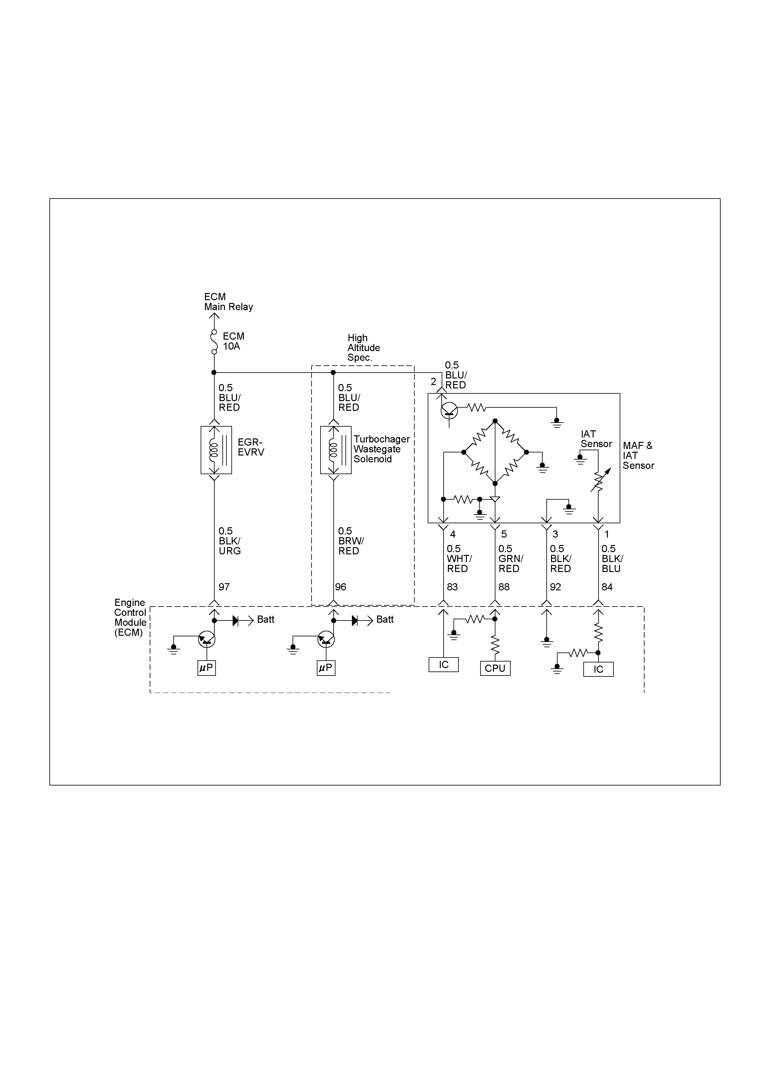
DIAGNOSTIC TROUBLE CODE (DTC) P0110 (SYMPTOM CODE 1)
(FLASH CODE 23) INTAKE AIR TEMPER ATURE (IAT) S ENSOR CIRCUIT HIGH INPUT
DIAGNOSTIC TROUBLE CODE (DTC) P0110 (SYMPTOM CODE 2)
(FLASH CODE 23) INTAKE AIR TEMPERATURE (IAT) SENSOR CIRCUIT LOW INPUT

Condition for setting the DTC and action ta ken when the DTC sets
Circuit Description
The IAT sensor is a thermistor. A tempe rature changes
the resistance value, which changes the voltage in the
circuit. In other words it measures a temperature value.
Low air temperature produces a high resistance.
The ECM supplies 5 volts signal to the IAT sensor
through resisters in the ECM and measures the voltage.
The signal voltage will be high when the air temperature
is cold, and it will be low when the air temperature is
hot.
The output vol tage excessiv ely high or lo w, DTC P0110
(Symptom Code 1) or P0110 (Symptom Code 2) will be
stored.
Diagnostic Aids
An intermittent may be caused by the following:
• Poor connections.
• Misrouted harness.
• Rubbed through wire insulation.
• Broken wire inside the insulation.
Check for the following conditions:
• Poor con nection at ECM -Inspect har ness connector s
for backed out terminals, improper mating, broken
locks, improperly formed or damaged terminals, and
poor terminal to wire connection.
• Damaged harness-Inspect the wiring harness for
damage. If the harness appears to be OK, observe
the “Intake Air Temperature” display on the Tech2
while moving connectors and wiring harness related
to the sensor.
Flash
Code Code Symptom
Code MIL DTC Name DTC Setting Condition Fail-Safe (Back Up)
23 P0110 1 ON Intake Air Temperature (IAT)
Sensor Circuit High Input IAT sensor output voltage is
more than 4.7V. ECM use deg.C conditions as
substitute.
2 ON Intake Air Temperature (IAT)
Sensor Circuit Low Input IAT sensor output voltage is
below 0.3V.
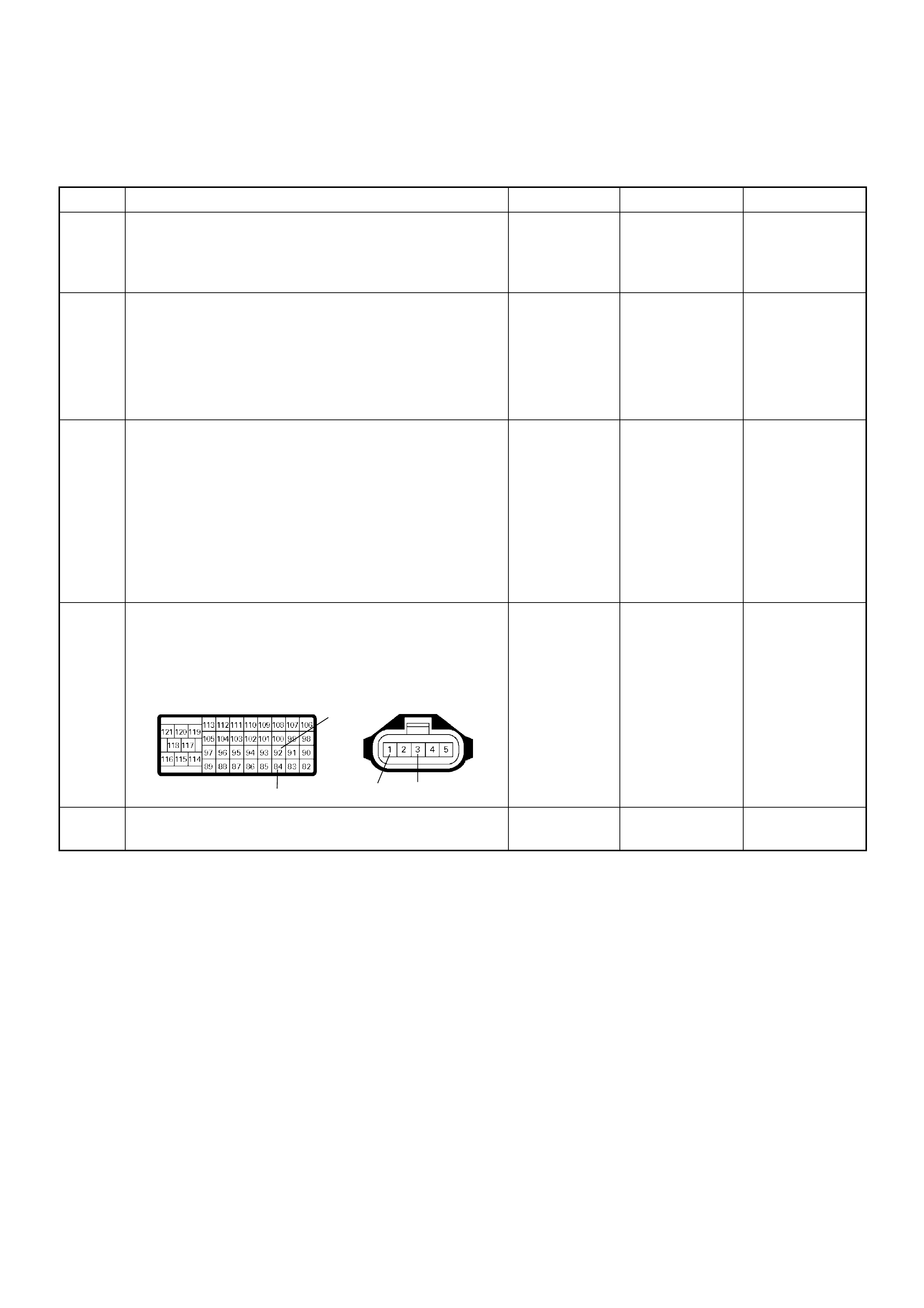
Diagnostic Trouble Code (DTC) P0110 (Symptom Code 1) (Flash Code 23)
Intake Air Temperature (IAT) Sensor Circuit High Input
Step Action Value(s) Yes No
1 Was the “On-Board Diagnostic (OBD) System Check”
performed?
—Go to Step 2
Go to On Board
Diagnostic
(OBD) System
Check
2 1. Connect the Tech 2.
2. Review and record the failure information.
3. Select “F0: Rea d DTC Infor As Stored By E CU” in
“F0: Diagnostic Trouble Codes”.
Is the DTC P0110 (Symptom Code 1) stored as
“Pres ent Fa ilure”? — Go to Step 3
Refer to
Diagnostic Aids
and Go to Step
3
3 1. Using the Tech 2, ignition “On” and engine “Off”.
2. Select “F1: Clear DTC Information” in “F0:
Diagnostic Trouble Codes” with the Tech 2 and
clear the DTC information.
3. Operate the vehicle and monitor the “F0: Read
DTC Infor As Stored By ECU” in the “F0:
Diagnostic Trouble Codes”.
Was the DTC P0 110 (Sym ptom Cod e 1) s tored i n this
ignition cycle? — Go to Step 4
Refer to
Diagnostic Aids
and Go to Step
4
4 Check for poor/faulty connection at the IAT sensor or
ECM connector. If a poor/faulty connection is found,
repair as necessary.
Was the problem found?
— Verify repair Go to Step 5
5 Visual ly check the IAT sensor.
Was the problem found? — Go to Step 12 Go to Step 6
92
84 13
C-116
C-57(B)
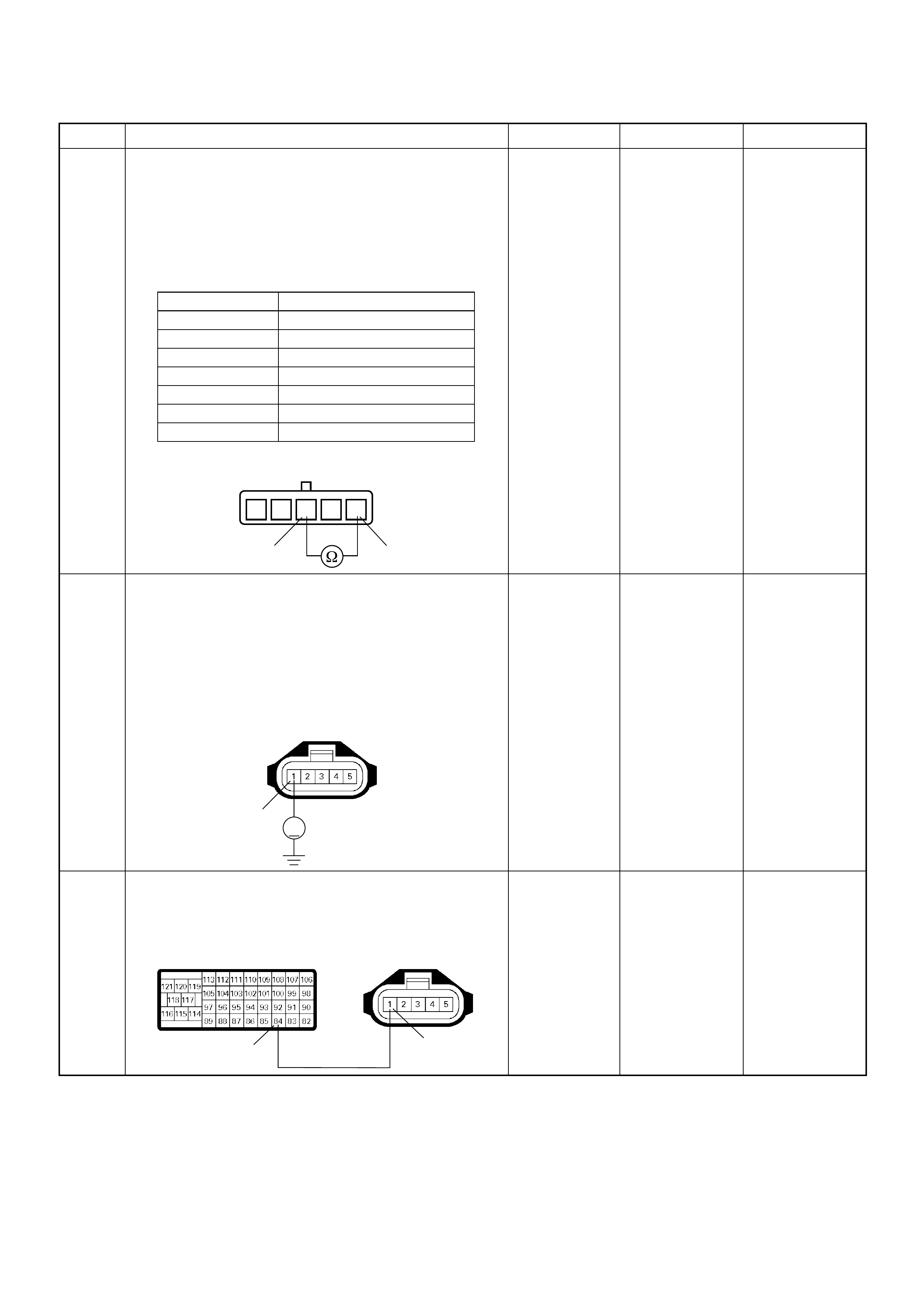
6 Using the DVM and check the IAT sensor.
1. Ignition “Off”, engine “Off”.
2. Disconnect MAF & IAT sensor connector.
3. Measure the resistance of IAT sensor.
Does the tester indicate standard resistance as shown
in the following table?
Standard
resistance Go t o Step 7 Go to Step 12
7 Using the DVM and check the IAT sensor signal
circuit.
1. Ignition “On”, engine “Off”.
2. Disconnect the MAF & IAT sensor connector.
3. Check the circuit for open circuit.
Was the DVM indicated specified value?
Approximately
5.0V Go to Step 10
Less than 1V:
Go to Step 8
More than
specified value:
Go to Step 9
8 Repair the open circuit between the ECM and IAT
sensor.
Was the problem solved?
— Verify repair Go to Step 14
Step Action Value(s) Yes No
Temperature (°C) Resistance (Ω) (Approximately)
-20 13660
0 5430
20 2433
40 1153
60 598
80 334
100 204
1235 4
13
IAT Sensor
1
V
C-116
1
84
C-116
C-57(B)
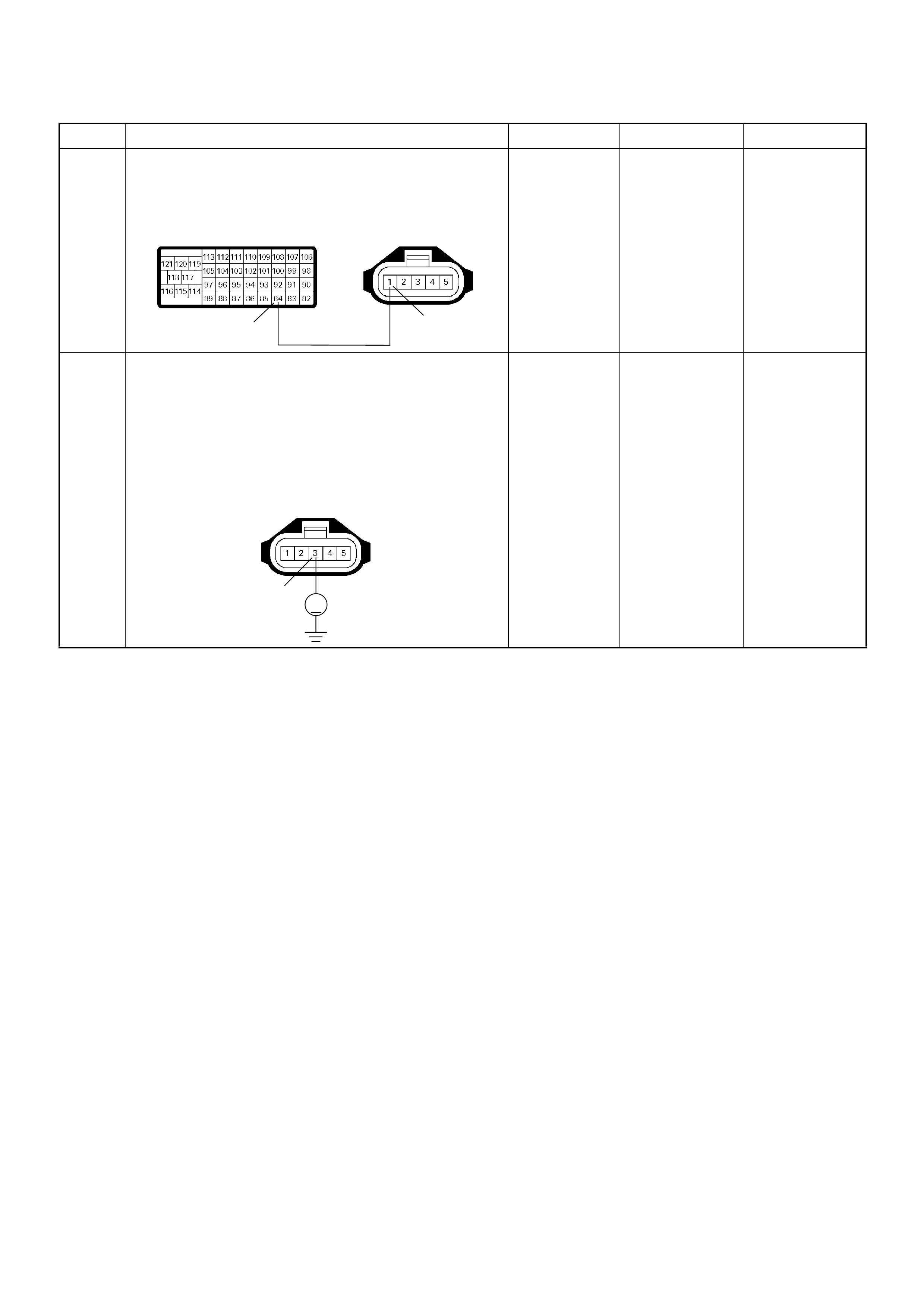
9 Repair the short to voltage circuit between the ECM
and IAT sensor.
Was the problem solved?
— Verify repair Go to Step 14
10 Using the DVM and check the IAT sensor ground
circuit.
1. Ignition “On”, engine “Off”.
2. Disconnect the MAF & IAT sensor connector.
3. Check the circuit for short to power supply circuit.
Was the DVM indicated specified value?
Less than 1V Go to Step 11
Repair faulty
harness and
verify repair
Step Action Value(s) Yes No
1
84
C-116
C-57(B)
3
V
C-116
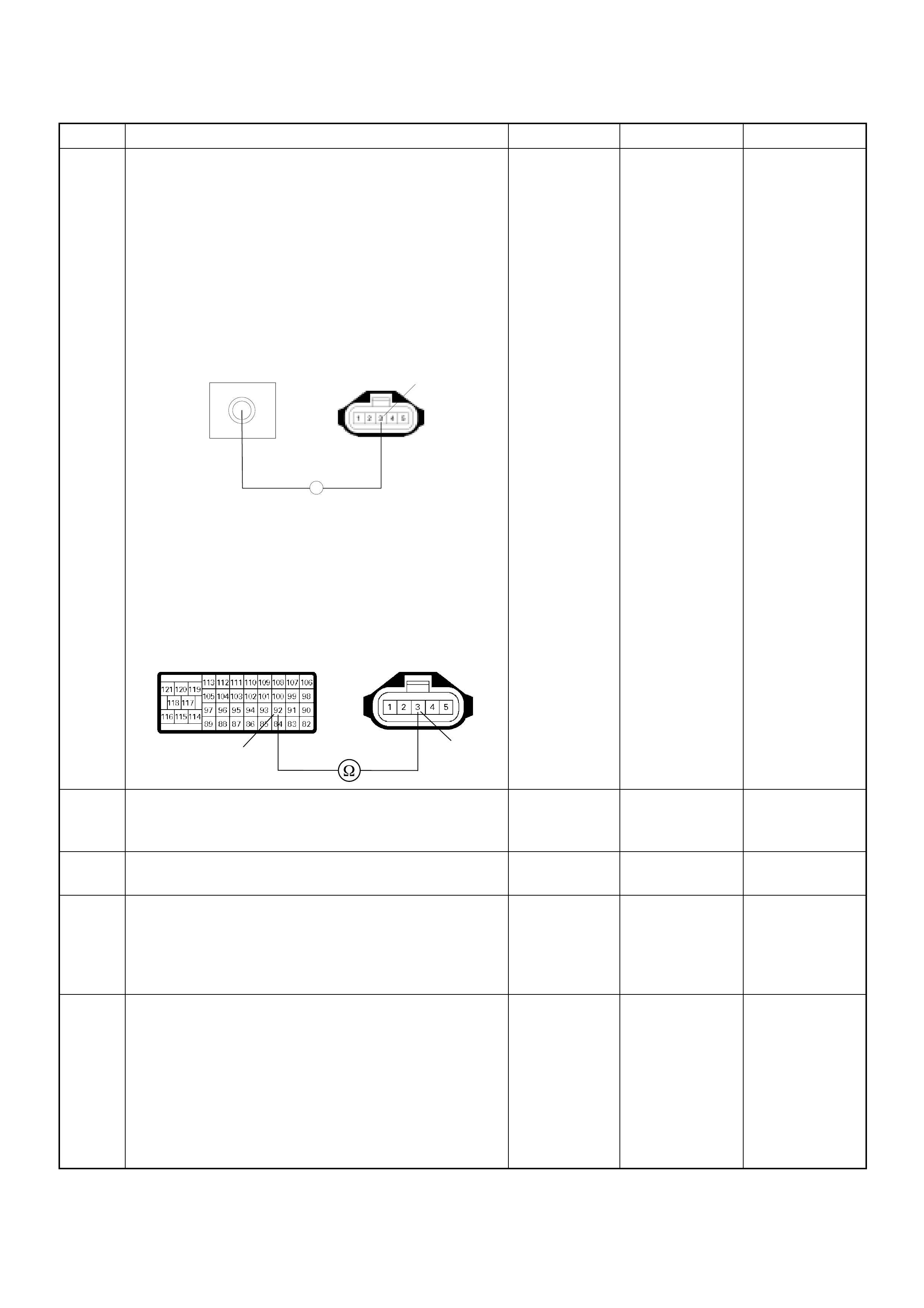
11 Using the DVM and check the IAT sensor ground
circuit.
Breaker box is available:
1. Ignition “Off”, engine “Off”.
2. Install the breaker box as type A. (ECM
disconnected) Ref. to HOW TO USE BREAKER
BOX
3. Disconnect the MAF & IAT sensor connector.
4. Check the circuit for open circuit.
Was the problem found?
Breaker box is not available:
1. Ignition “Off”, engine “Off”.
2. Disconnect the MAF & IAT sensor connector and
ECM connector.
3. Check the circuit for open circuit.
Was the problem found?
—
Repair faulty
harness and
verify repair Go to Step 14
12 Substitute a known good MAF & IAT sensor assembly
and recheck.
Was the problem solved? — Go to Step 13 Go to Step 14
13 Replace the MAF & IAT sensor assembly.
Is the action complete? — Verify repair —
14 Is the ECM programmed with the latest software
release?
If not, download the latest software to the ECM using
the “SPS (Service Programming System)”.
Was the problem solved? — Verify repair Go to Step 15
15 Replace the ECM.
Is the action complete?
IMPORTANT: The replacement ECM must be
programmed. Refer to section of the Service
Programming System (SPS) in this manual.
Foll owing ECM pr ogramming, the immobi lizer sys tem
(if equipped) must be linked to the ECM. Refer to
section 11 “Immobilizer System-ECM replacement” for
the ECM/Immobilizer linking procedure. — Verify repair —
Step Action Value(s) Yes No
C-116
92
Breaker Box 3
Ħ
3
92
C-116
C-57(B)

Diagnostic Trouble Code (DTC) P0110 (Symptom Code 2) (Flash Code 23)
Intake Air Temperature (IAT) Sensor Circuit Low Input
Step Action Value(s) Yes No
1 Was the “On-Board Diagnostic (OBD) System Check”
performed?
—Go to Step 2
Go to On Board
Diagnostic
(OBD) System
Check
2 1. Connect the Tech 2.
2. Review and record the failure information.
3. Select “F0: Rea d DTC Infor As Stored By E CU” in
“F0: Diagnostic Trouble Codes”.
Is the DTC P0110 (Symptom Code 2) stored as
“Pres ent Fa ilure”? — Go to Step 3
Refer to
Diagnostic Aids
and Go to Step
3
3 1. Using the Tech 2, ignition “On” and engine “Off”.
2. Select “F1: Clear DTC Information” in “F0:
Diagnostic Trouble Codes” with the Tech 2 and
clear the DTC information.
3. Operate the vehicle and monitor the “F0: Read
DTC Infor As Stored By ECU” in the “F0:
Diagnostic Trouble Codes”.
Was the DTC P0 110 (Sym ptom Cod e 2) s tored i n this
ignition cycle? — Go to Step 4
Refer to
Diagnostic Aids
and Go to Step
4
4 Check for poor/faulty connection at the IAT sensor or
ECM connector. If a poor/faulty connection is found,
repair as necessary.
Was the problem found?
— Verify repair Go to Step 5
5 Re move the MA F & IAT sensor as sembl y and vis ually
check.
Was the problem found? — Go to Step 8 Go to Step 6
92
84 13
C-116
C-57(B)
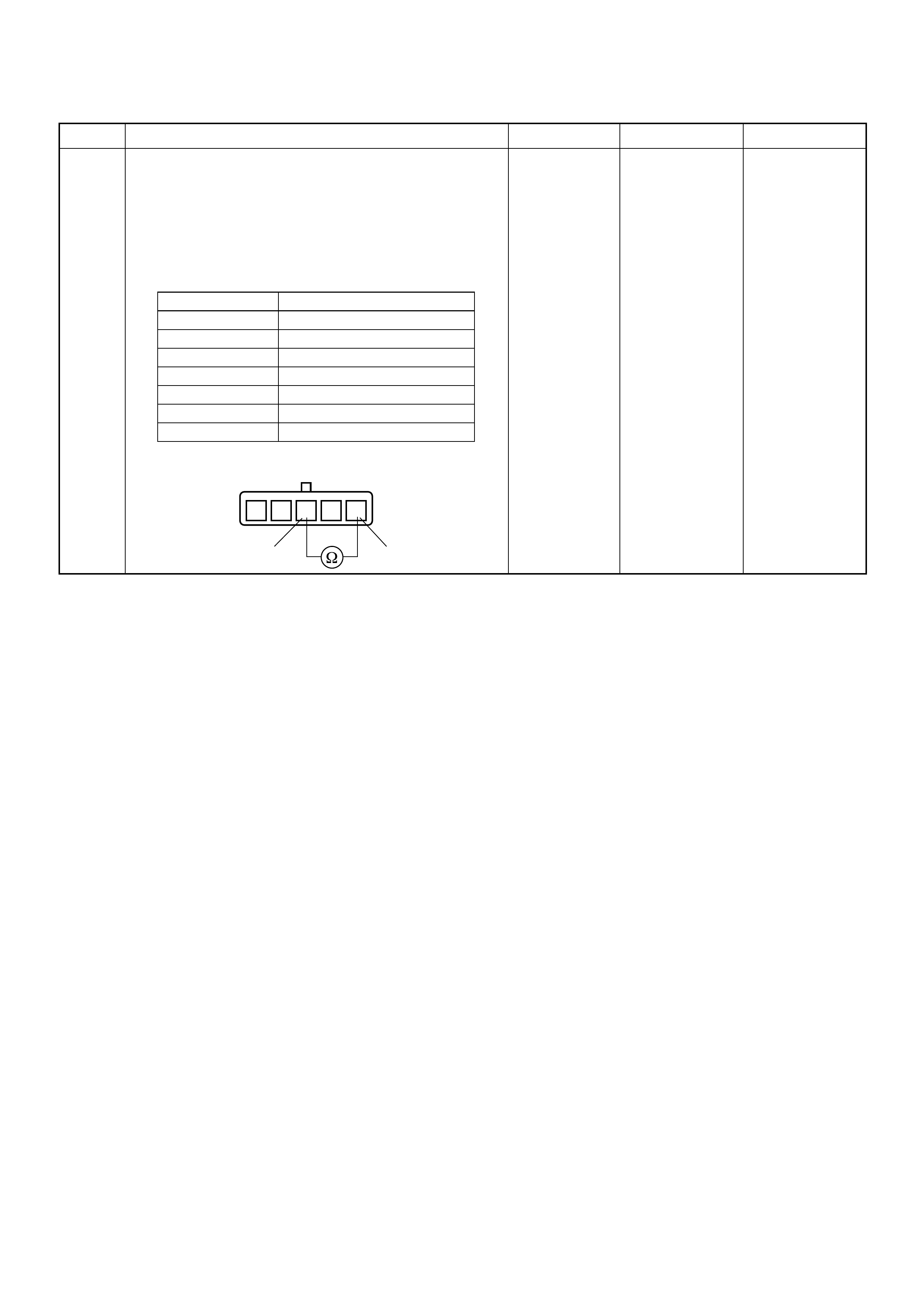
6 Using the DVM and check the IAT sensor.
1. Ignition “Off”, engine “Off”.
2. Disconnect MAF & IAT sensor connector.
3. Measure the resistance of IAT sensor.
Does the tester indicate standard resistance as shown
in the following table?
Standard
resistance Go t o Step 7 Go to Step 8
Step Action Value(s) Yes No
Temperature (°C) Resistance (Ω) (Approximately)
-20 13660
0 5430
20 2433
40 1153
60 598
80 334
100 204
1235 4
13
IAT Sensor
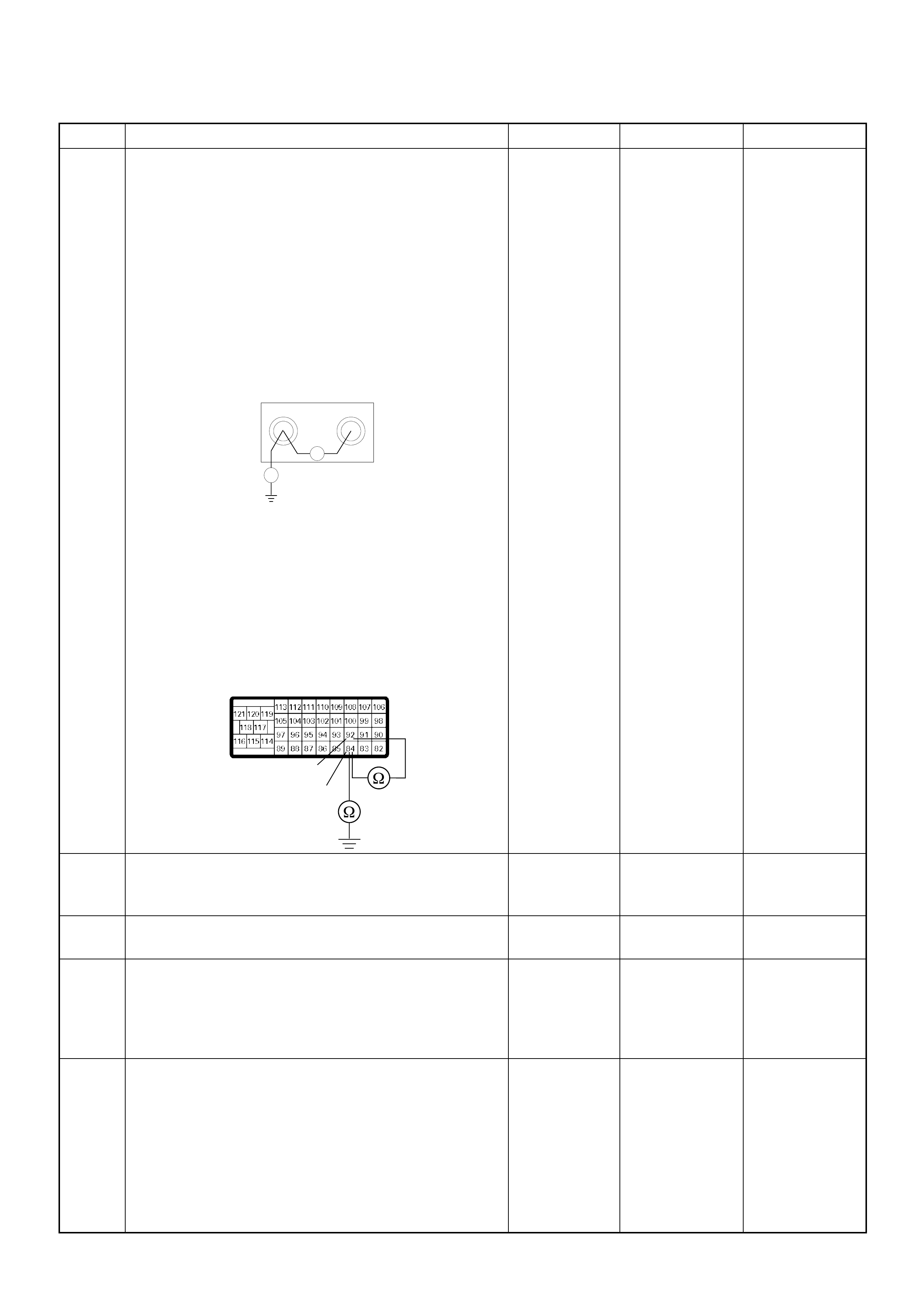
7 Using the DVM and check the IAT sensor signal
circuit.
Breaker box is available:
1. Ignition “Off”, engine “Off”.
2. Install the breaker box as type A. (ECM
disconnected) Ref. to HOW TO USE BREAKER
BOX
3. Disconnect the MAF & IAT sensor connector.
4. Check the circuit for short to sensor ground or
ground circuit.
Was the problem found?
Breaker box is not available:
1. Ignition “Off”, engine “Off”.
2. Disconnect the MAF & IAT sensor connector and
ECM connector.
3. Check the circuit for short to sensor ground or
ground circuit.
Was the problem found?
—
Repair faulty
harness and
verify repair Go to Step 10
8 Substitute a known good MAF & IAT sensor assembly
and recheck.
Was the problem solved? — Go to Step 9 Go to Step 10
9 Replace the MAF & IAT sensor assembly.
Is the action complete? — Verify repair —
10 Is the ECM programmed with the latest software
release?
If not, download the latest software to the ECM using
the “SPS (Service Programming System)”.
Was the problem solved? — Verify repair Go to Step 11
11 Replace the ECM.
Is the action complete?
IMPORTANT: The replacement ECM must be
programmed. Refer to section of the Service
Programming System (SPS) in this manual.
Foll owing ECM pr ogramming, the immobi lizer sys tem
(if equipped) must be linked to the ECM. Refer to
section 11 “Immobilizer System-ECM replacement” for
the ECM/Immobilizer linking procedure. — Verify repair —
Step Action Value(s) Yes No
84 92
Ħ
Breaker Box
Ħ
92
84
C-57(B)
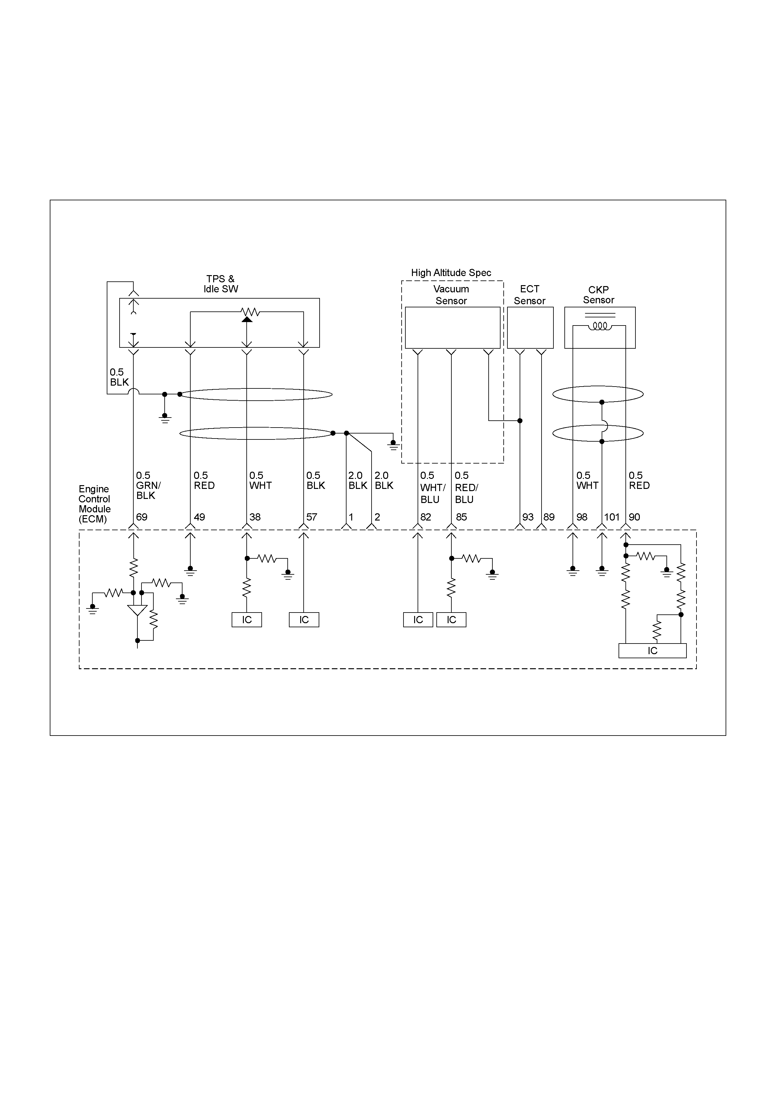
DIAGNOSTIC TROUBLE CODE (DTC) P0115 (SYMPTOM CODE 1)
(FLASH CODE 14) ENGINE COOLANT TEMPERATURE SENSOR CIRCUIT HIGH INPUT
DIAGNOSTIC TROUBLE CODE (DTC) P0115 (SYMPTOM CODE 2)
(FLASH CODE 14) ENGINE COOLANT TEMPERATURE SENSOR CIRCUIT LOW INPUT

Condition for setting the DTC and action ta ken when the DTC sets
Circuit Description
The ECT sensor is a thermistor . A temperature changes
the resistance value, which changes the voltage in the
circuit. In other words it measures a temperature value.
It is installed on the coolant stream. Low coolant
temperature produces a high resistance.
The ECM supplies 5 volts signal to the ECT sensor
through resisters in the ECM and measures the voltage.
The signal voltage will be high when the engine
temperature is cold, and it will be low when the engine
temperature is hot.
The output vol tage excessiv ely high or lo w, DTC P0115
(Symptom Code 1) or P0115 (Symptom Code 2) will be
stored.
Diagnostic Aids
An intermittent may be caused by the following:
• Poor connections.
• Misrouted harness.
• Rubbed through wire insulation.
• Broken wire inside the insulation.
Check for the following conditions:
• Poor con nection at ECM -Inspect har ness connector s
for backed out terminals, improper mating, broken
locks, improperly formed or damaged terminals, and
poor terminal to wire connection.
• Damaged harness-Inspect the wiring harness for
damage. If the harness appears to be OK, observe
the “Coolant Temperature” display on the Tech2
while moving connectors and wiring harness related
to the sensor.
Flash
Code Code Symptom
Code MIL DTC Name DTC Setting Condition Fail-Safe (Back Up)
14 P0115 1 ON E ngine Coolant Temperature
(ECT) Sensor Circuit High
Input
ECT sensor output voltage is
more than 4.7V. 1. ECM uses fuel temperature
as substitute.
2. ECM uses 60 deg.C
condition for injection timing
control.
3. ECM uses -25 deg.C
condition (4JA1-TC) or -15
deg.C condition (4JH1-TC)
for glow time control.
2 ON Engine Coolant Temperature
(ECT) Sensor Circuit Low
Input
ECT sensor output voltage is
below 0.3V.
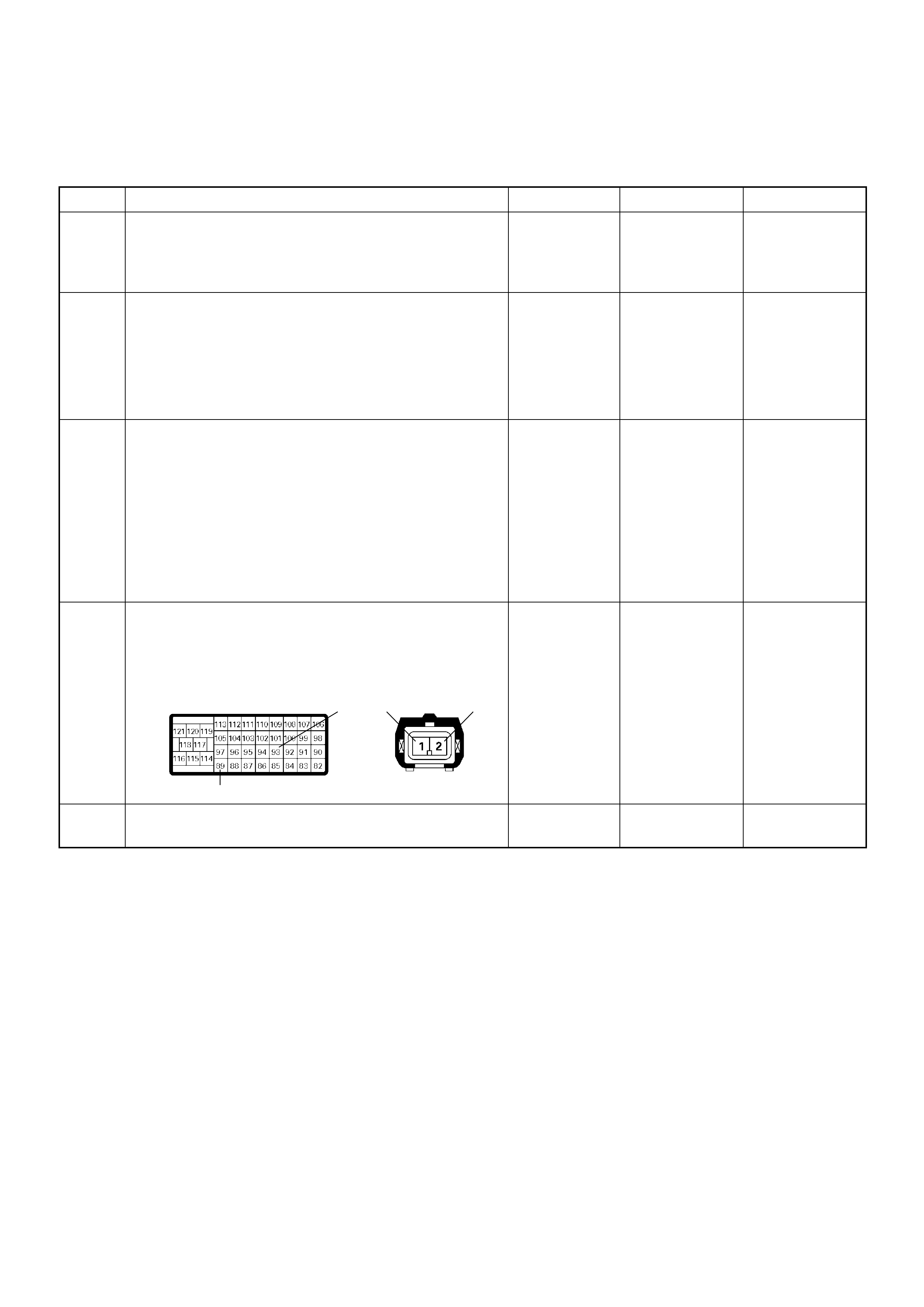
Diagnostic Trouble Code (DTC) P0115 (Symptom Code 1) (Flash Code 14)
Engine Coolant Temperature Sensor Circuit High Input
Step Action Value(s) Yes No
1 Was the “On-Board Diagnostic (OBD) System Check”
performed?
—Go to Step 2
Go to On Board
Diagnostic
(OBD) System
Check
2 1. Connect the Tech 2.
2. Review and record the failure information.
3. Select “F0: Rea d DTC Infor As Stored By E CU” in
“F0: Diagnostic Trouble Codes”.
Is the DTC P0115 (Symptom Code 1) stored as
“Pres ent Fa ilure”? — Go to Step 3
Refer to
Diagnostic Aids
and Go to Step
3
3 1. Using the Tech 2, ignition “On” and engine “Off”.
2. Select “F1: Clear DTC Information” in “F0:
Diagnostic Trouble Codes” with the Tech 2 and
clear the DTC information.
3. Operate the vehicle and monitor the “F0: Read
DTC Infor As Stored By ECU” in the “F0:
Diagnostic Trouble Codes”.
Was the DTC P0 115 (Sym ptom Cod e 1) s tored i n this
ignition cycle? — Go to Step 4
Refer to
Diagnostic Aids
and Go to Step
4
4 Check for poor/faulty connection at the ECT sensor or
ECM connector. If a poor/faulty connection is found,
repair as necessary.
Was the problem found?
— Verify repair Go to Step 5
5 Visual ly check the ECT sen so r.
Was the problem found? — Go to Step 12 Go to Step 6
93 21
89
E-41C-57(B)
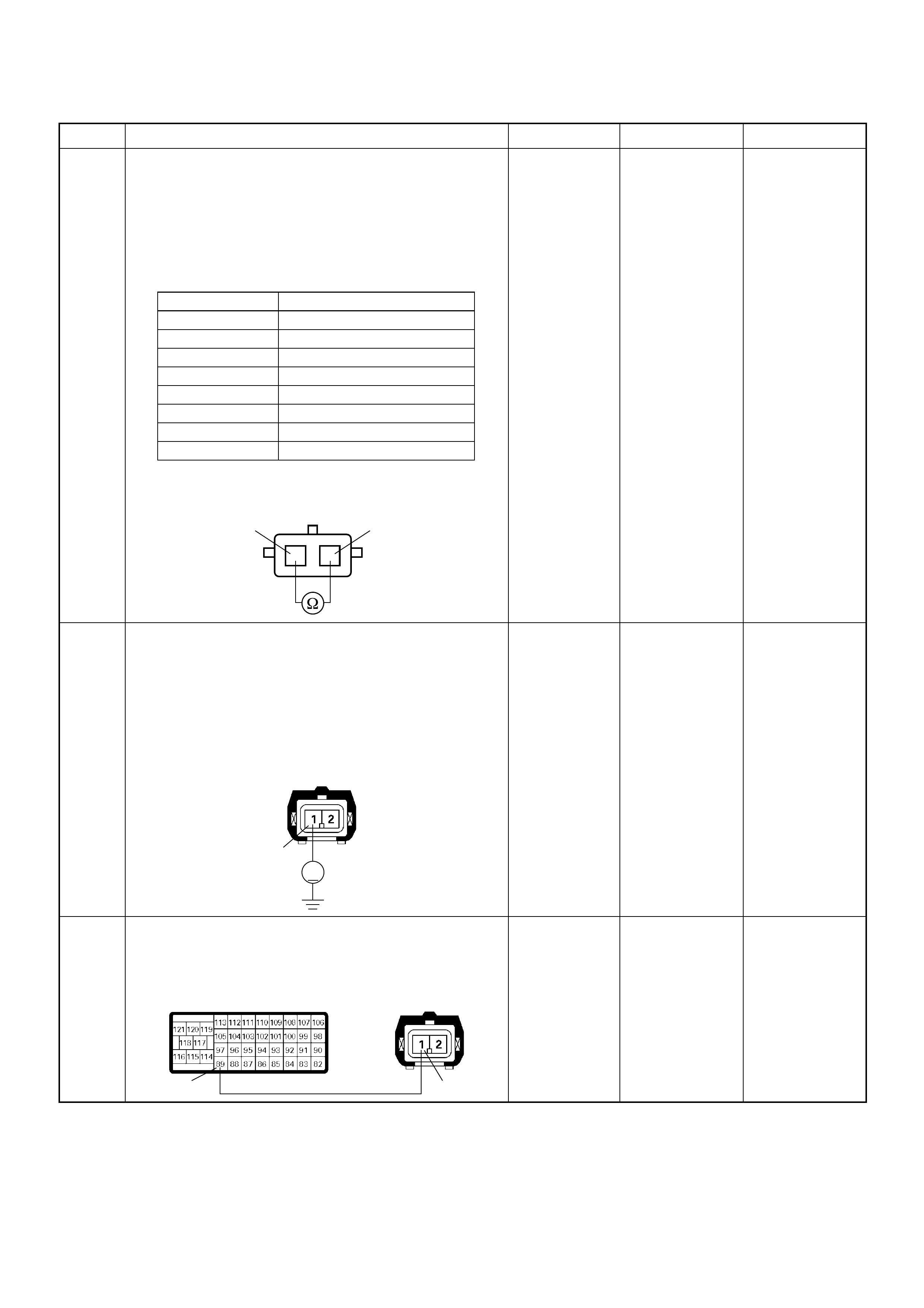
6 Using the DVM and check the ECT sensor.
1. Ignition “Off”, engine “Off”.
2. Disconnect ECT sensor connector.
3. Measure the resistance of ECT sensor.
Does the tester indicate standard resistance as shown
in the following table?
Standard
resistance Go t o Step 7 Go to Step 12
7 Using the DVM and check the ECT sensor signal
circuit.
1. Ignition “On”, engine “Off”.
2. Disconnect the ECT sensor connector.
3. Check the circuit for open circuit.
Was the DVM indicated specified value?
Approximately
5.0V Go to Step 10
Less than 1V:
Go to Step 8
More than
specified value:
Go to Step 9
8 Repair the open circuit between the ECM and ECT
sensor.
Was the problem solved?
— Verify repair Go to Step 14
Step Action Value(s) Yes No
Temperature (°C) Resistance (Ω) (Approximately)
-20 16100
0 5760
20 2370
40 1080
60 537
80 290
100 161
120 95
12
ECT Sensor 12
V
1
E-41
89 1
E-41C-57(B)
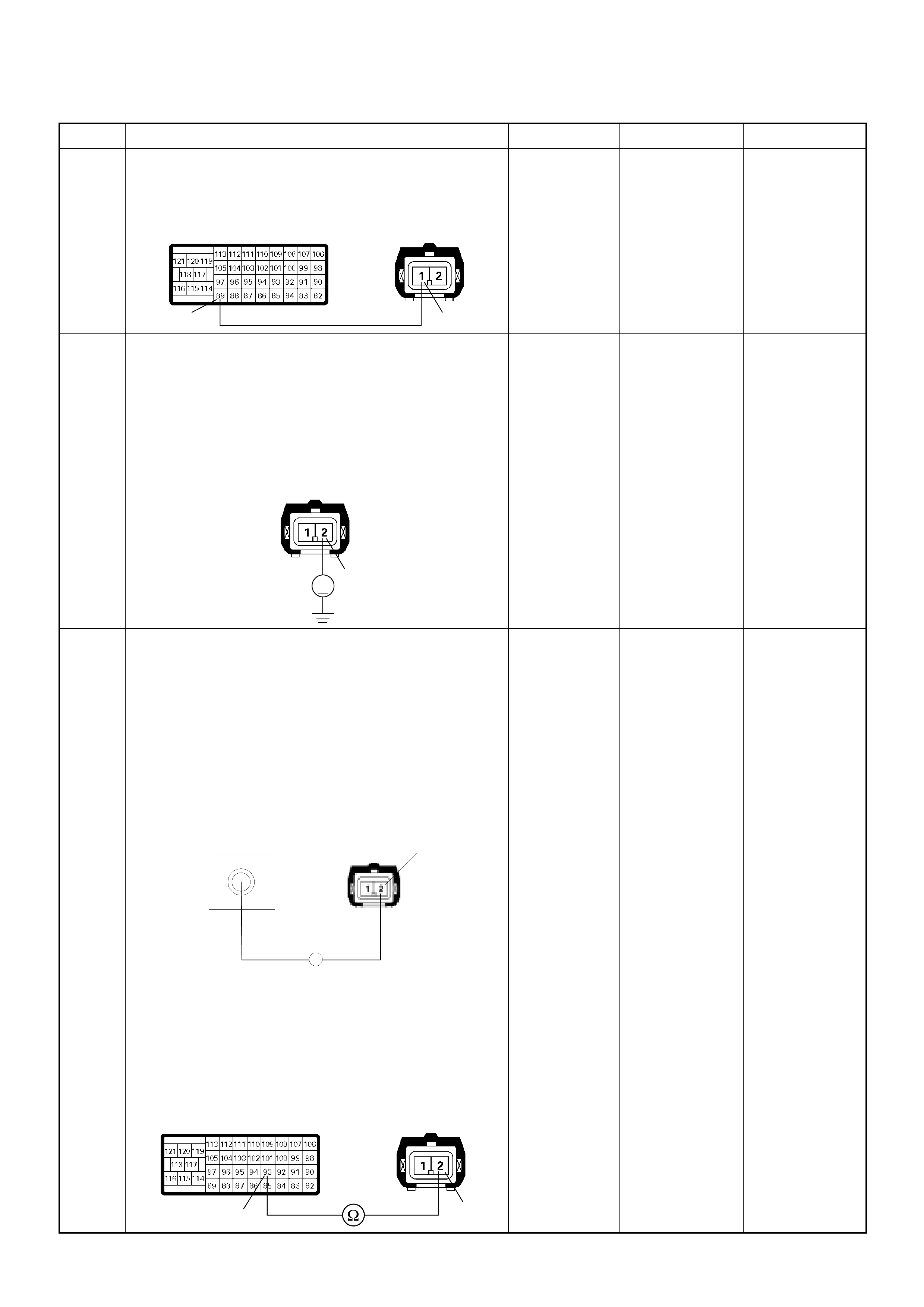
9 Repair the short to voltage circuit between the ECM
and ECT sensor .
Was the problem solved?
— Verify repair Go to Step 14
10 Using the DVM and check the ECT sensor ground
circuit.
1. Ignition “On”, engine “Off”.
2. Disconnect the ECT sensor connector.
3. Check the circuit for short to power supply circuit.
Was the DVM indicated specified value?
Less than 1V Go to Step 11
Repair faulty
harness and
verify repair
11 Using the DVM and check the ECT sensor ground
circuit.
Breaker box is available:
1. Ignition “Off”, engine “Off”.
2. Install the breaker box as type A. (ECM
disconnected) Ref. to HOW TO USE BREAKER
BOX
3. Disconnect the ECT sensor connector.
4. Check the circuit for open circuit.
Was the problem found?
Breaker box is not available:
1. Ignition “Off”, engine “Off”.
2. Disconnect the ECT sensor connector ECM
connector.
3. Check the circuit for open circuit.
Was the problem found?
—
Repair faulty
harn es s and
verify repair Go to Step 14
Step Action Value(s) Yes No
89 1
E-41C-57(B)
2
V
E-41
E-41
93
Breaker Box 2
Ħ
2
93
E-41
C-57

12 Substitute a known good ECT sensor assembly and
recheck.
Was the problem solved? — Go to Step 13 Go to Step 14
13 Replace the ECT sensor.
Is the action complete? — Verify repair —
14 Is the ECM programmed with the latest software
release?
If not, download the latest software to the ECM using
the “SPS (Service Programming System)”.
Was the problem solved? — Verify repair Go to Step 15
15 Replace the ECM.
Is the action complete?
IMPORTANT: The replacement ECM must be
programmed. Refer to section of the Service
Programming System (SPS) in this manual.
Foll owing ECM pr ogramming, the immobi lizer sys tem
(if equipped) must be linked to the ECM. Refer to
section 11 “Immobilizer System-ECM replacement” for
the ECM/Immobilizer linking procedure. — Verify repair —
Step Action Value(s) Yes No
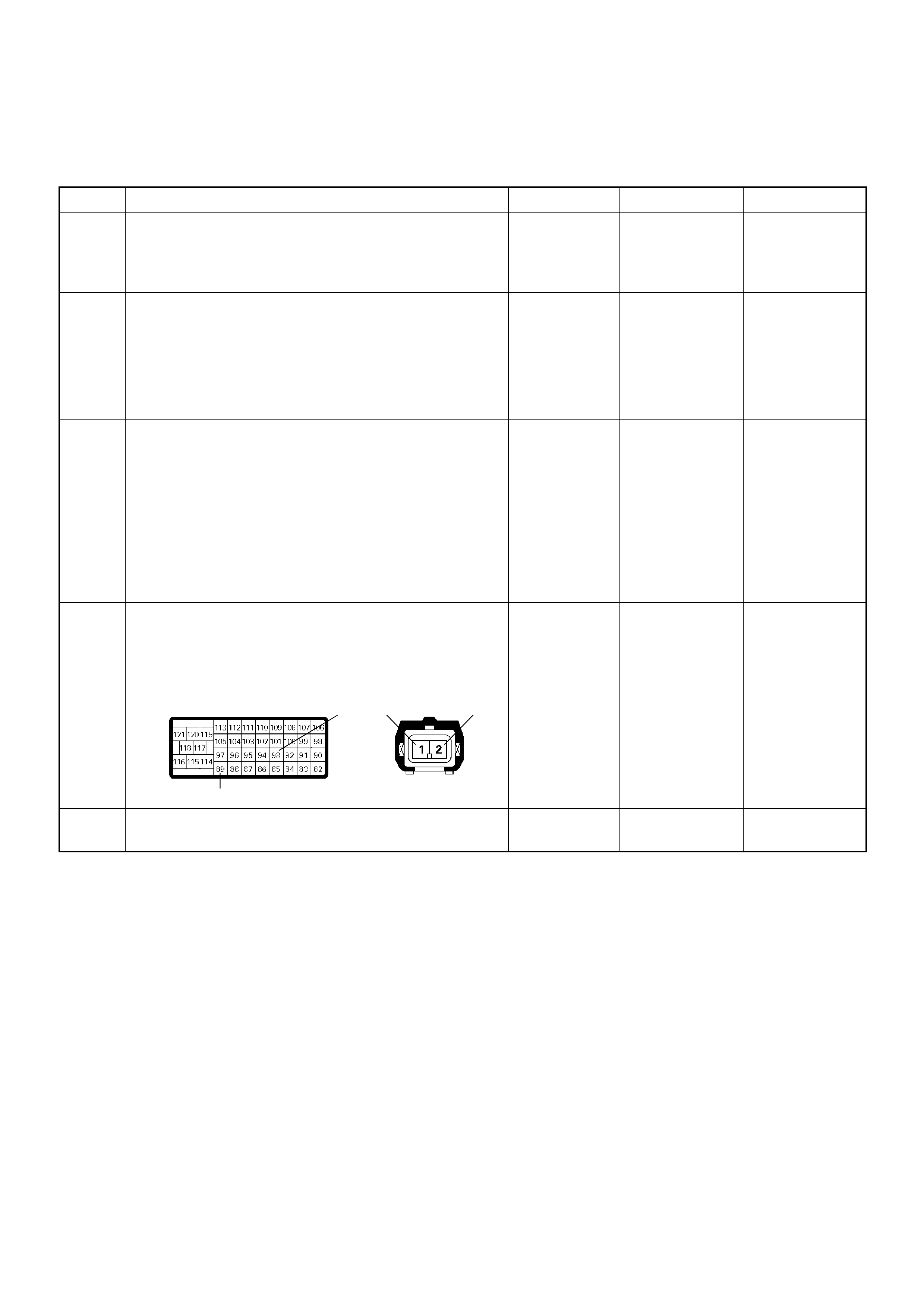
Diagnostic Trouble Code (DTC) P0115 (Symptom Code 2) (Flash Code 14)
Engine Coolant Temperature Sensor Circuit Low Input
Step Action Value(s) Yes No
1 Was the “On-Board Diagnostic (OBD) System Check”
performed?
—Go to Step 2
Go to On Board
Diagnostic
(OBD) System
Check
2 1. Connect the Tech 2.
2. Review and record the failure information.
3. Select “F0: Rea d DTC Infor As Stored By E CU” in
“F0: Diagnostic Trouble Codes”.
Is the DTC P0115 (Symptom Code 2) stored as
“Pres ent Fa ilure”? — Go to Step 3
Refer to
Diagnostic Aids
and Go to Step
3
3 1. Using the Tech 2, ignition “On” and engine “Off”.
2. Select “F1: Clear DTC Information” in “F0:
Diagnostic Trouble Codes” with the Tech 2 and
clear the DTC information.
3. Operate the vehicle and monitor the “F0: Read
DTC Infor As Stored By ECU” in the “F0:
Diagnostic Trouble Codes”.
Was the DTC P0 115 (Sym ptom Cod e 2) s tored i n this
ignition cycle? — Go to Step 4
Refer to
Diagnostic Aids
and Go to Step
4
4 Check for poor/faulty connection at the ECT sensor or
ECM connector. If a poor/faulty connection is found,
repair as necessary.
Was the problem found?
— Verify repair Go to Step 5
5 Visual ly check the ECT sen so r.
Was the problem found? — Go to Step 8 Go to Step 6
93 21
89
E-41C-57(B)
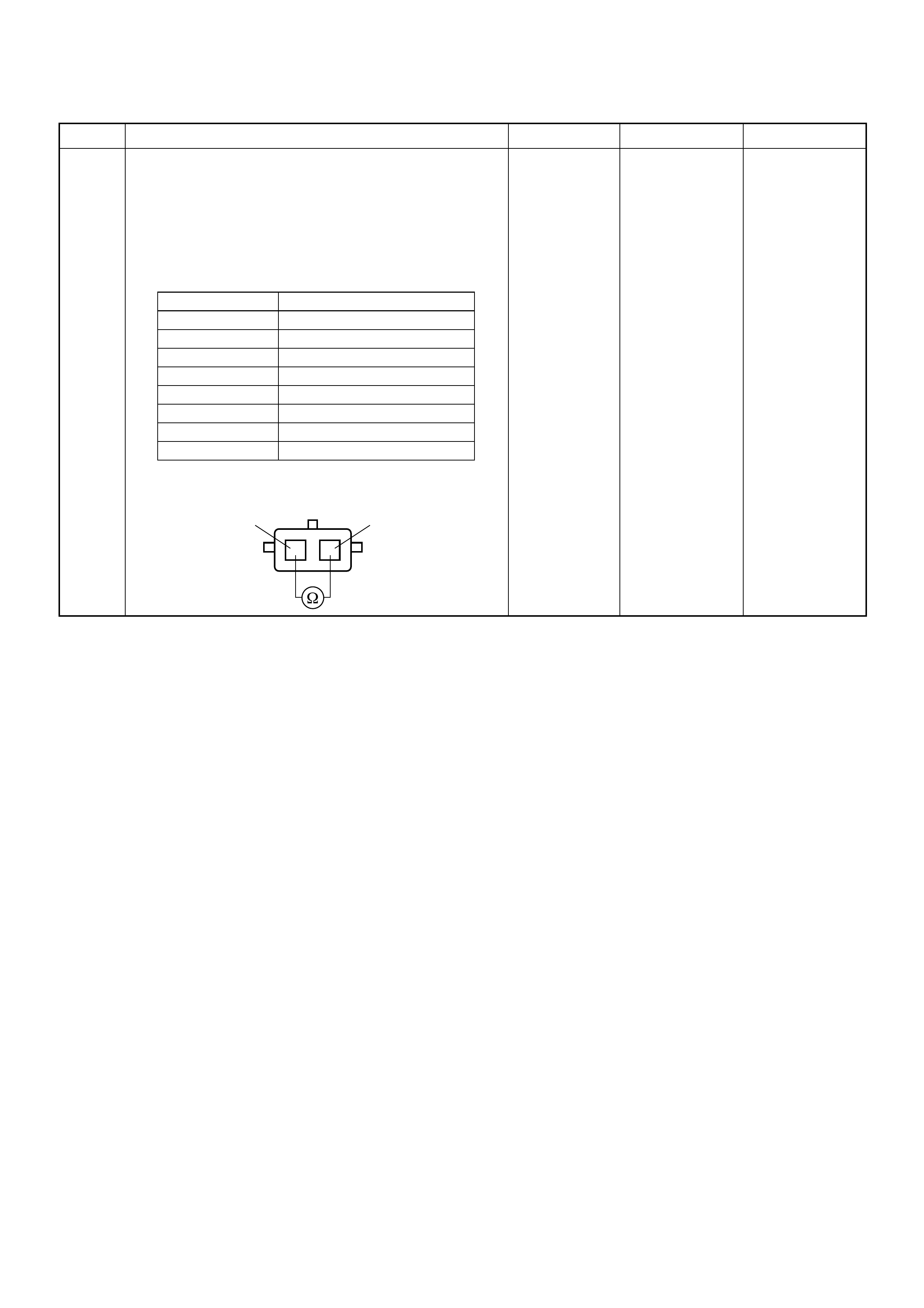
6 Using the DVM and check the ECT sensor.
1. Ignition “Off”, engine “Off”.
2. Disconnect ECT sensor connector.
3. Measure the resistance of ECT sensor.
Does the tester indicate standard resistance as shown
in the following table?
Standard
resistance Go t o Step 7 Go to Step 8
Step Action Value(s) Yes No
Temperature (°C) Resistance (Ω) (Approximately)
-20 16100
0 5760
20 2370
40 1080
60 537
80 290
100 161
120 95
12
ECT Sensor 12
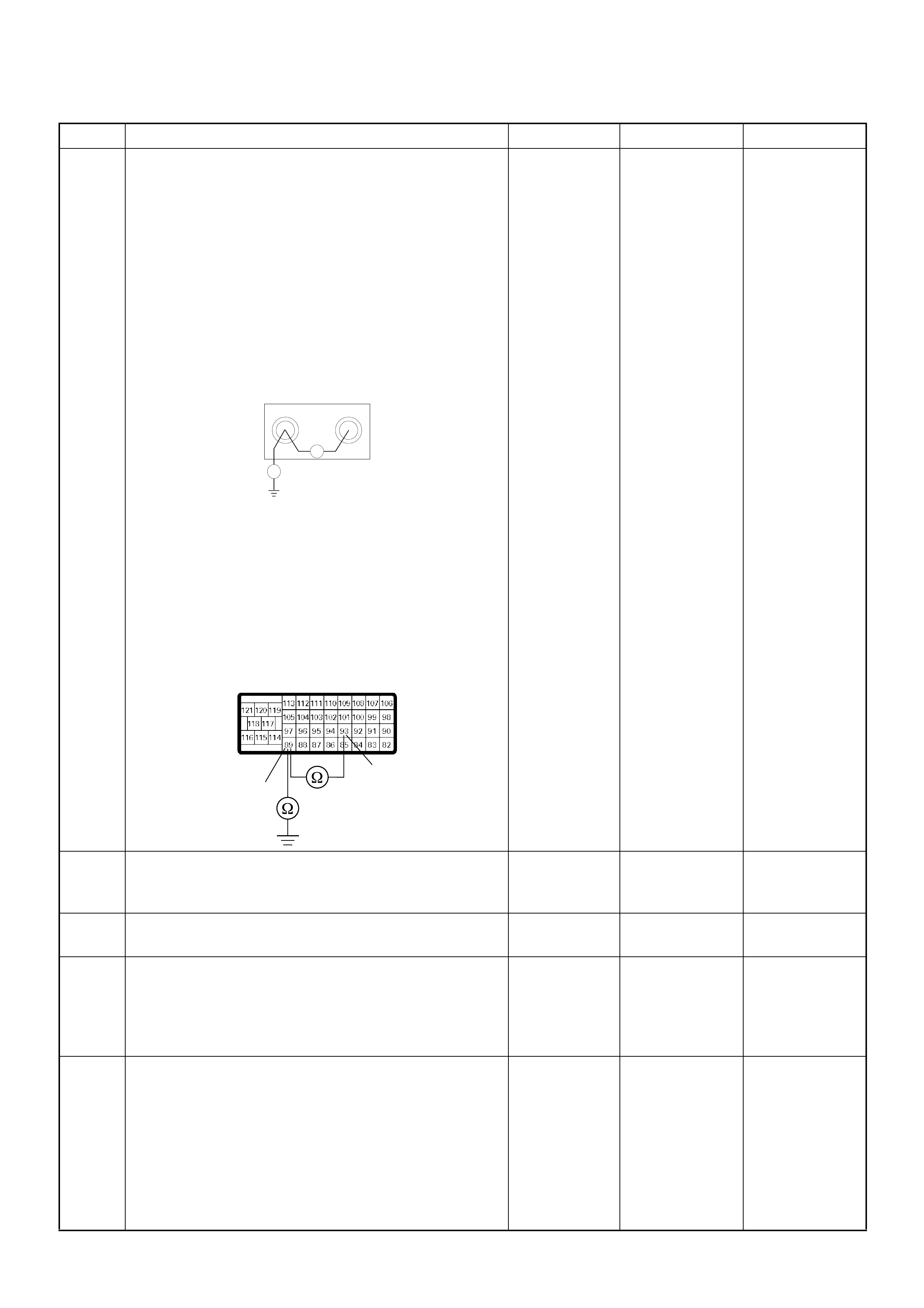
7 Using the DVM and check the ECT sensor signal
circuit.
Breaker box is available:
1. Ignition “Off”, engine “Off”.
2. Install the breaker box as type A. (ECM
disconnected) Ref. to HOW TO USE BREAKER
BOX
3. Disconnect the ECT sensor connector.
4. Check the circuit for short to sensor ground or
ground circuit.
Was the problem found?
Breaker box is not available:
1. Ignition “Off”, engine “Off”.
2. Disconnect the ECT sensor connector and ECM
connector.
3. Check the circuit for short to sensor ground or
ground circuit.
Was the problem found?
—
Repair faulty
harness and
verify repair Go to Step 10
8 Substitute a known good ECT sensor assembly and
recheck.
Was the problem solved? — Go to Step 9 Go to Step 10
9 Replace the ECT sensor.
Is the action complete? — Verify repair —
10 Is the ECM programmed with the latest software
release?
If not, download the latest software to the ECM using
the “SPS (Service Programming System)”.
Was the problem solved? — Verify repair Go to Step 11
11 Replace the ECM.
Is the action complete?
IMPORTANT: The replacement ECM must be
programmed. Refer to section of the Service
Programming System (SPS) in this manual.
Foll owing ECM pr ogramming, the immobi lizer sys tem
(if equipped) must be linked to the ECM. Refer to
section 11 “Immobilizer System-ECM replacement” for
the ECM/Immobilizer linking procedure. — Verify repair —
Step Action Value(s) Yes No
89 93
Ħ
Breaker Box
Ħ
93
89
C-57(B)
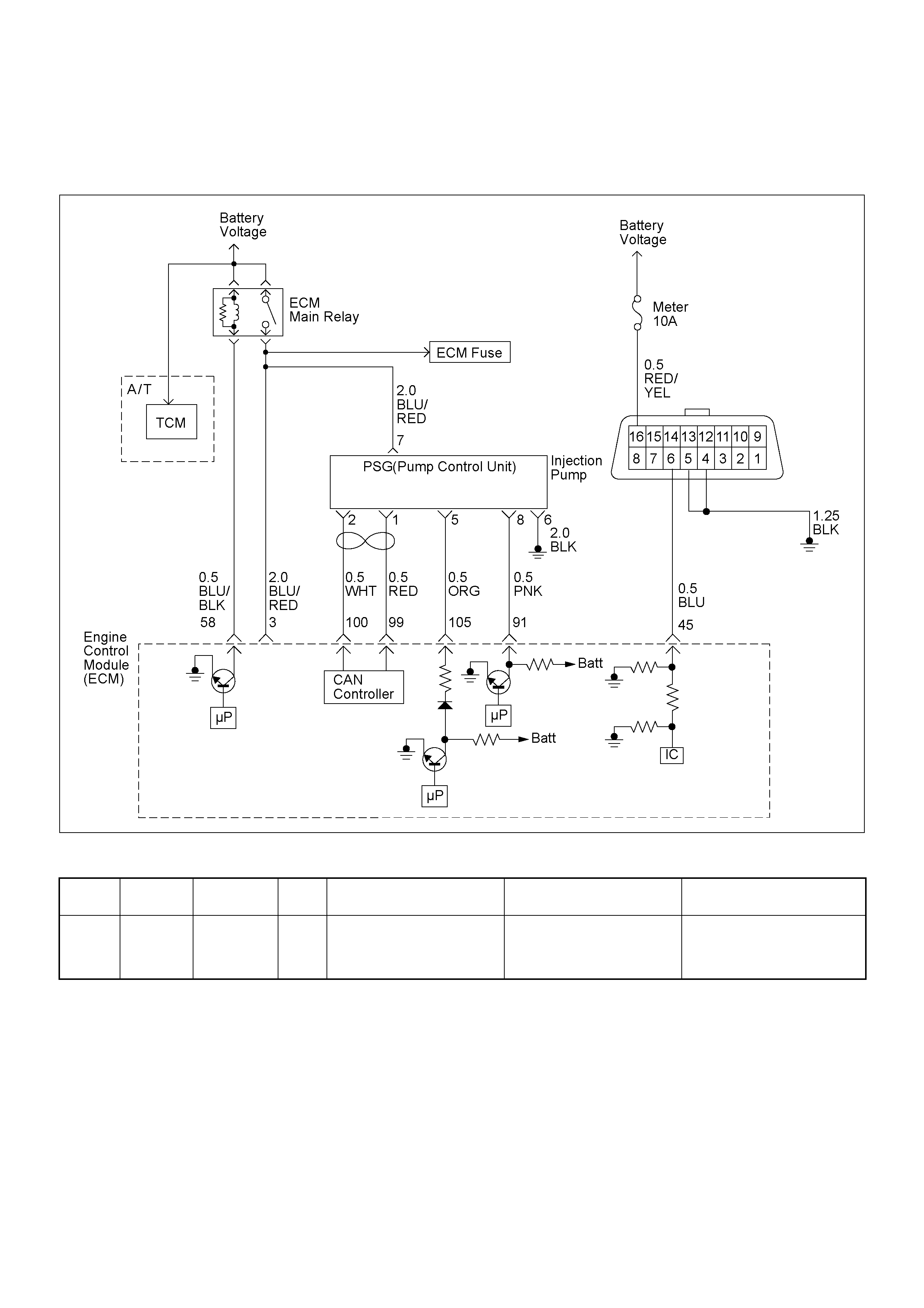
DIAGNOSTIC TROUBLE CODE (DTC) P01 80 (SYMPTOM CODE B)
(FLASH CODE 15) FUEL TEMPERAT URE SENSOR CIRCUIT RANGE/PERFORMANCE
Condition for setting the DTC and action ta ken when the DTC sets
Circuit Description
The fuel temp erature sensor is assembled in side of the
pump con t ro l uni t ( PS G). The si gnal of fu el temperat ur e
is sent via the CAN-bus from the PSG to ECM.
If the fuel temperature is excessively high or low
condition, DTC P0180 will be stored.
Diagnostic Aids
An intermittent may be caused by the following:
• Poor connections.
• Misrouted harness.
• Rubbed through wire insulation.
• Broken wire inside the insulation.
Check for the following conditions:
• Poor connection at ECM and PSG-Inspect harness
connectors for backed out terminals, improper
mating, broken locks, improperly formed or damaged
terminals, and poor terminal to wire connection.
• Damaged harness-Inspect the wiring harness for
damage. If the harness appears to be OK, observe
the “Fuel Temperature” display on the Tech2 while
moving c onnectors and wiring harness rela ted to the
sensor.
Flash
Code Code Symptom
Code MIL DTC Name DTC Setting Condition Fail-Safe (Back Up)
15 P0180 B ON Fuel Temperature Sensor
Circuit Range/Performance FT sensor output is high
temperature (mo re than
150deg.C) or low temperature
(below -40deg.C).
The ECM use 75deg.C
conditions as substitute.

Diagnostic Trouble Code (DTC) P0180 (Symptom Code B) (Flash Code 15) Fuel
Temperature Sensor Circuit Range/Performance
Step Action Value(s) Yes No
1 Was the “On-Board Diagnostic (OBD) System Check”
performed?
—Go to Step 2
Go to On Board
Diagnostic
(OBD) System
Check
2 1. Connect the Tech 2.
2. Review and record the failure information.
3. Select “F0: Read DTC Infor As Stored By ECU” in
“F0: Diagnostic Trouble Codes”.
Is the DTC P0180 (Symptom Code B) stored as
“Present Failure”? — Go to Step 3
Refer to
Diagnostic Aids
and Go to Step
3
3 1. Using the Tech 2, ignition “On” and engine “Off”.
2. Select “F1: Clear DTC Information” in “F0:
Diagnostic Trouble Codes” with the Tech 2 and
clear the DTC information.
3. Operate the vehicle and monitor the “F0: Read
DTC Infor As Stored By ECU” in the “F0:
Diagnostic Trouble Codes”.
Was the DTC P0180 (Symptom Code B) stored in this
ignition cycle? — Go to Step 4 Refer to
Diagnostic Aids
4 Is the ECM programmed with the latest software
release?
If not, download the latest software to the ECM using
the “SPS (Service Programming System)”.
Was the problem solved? — Verify repair Go to Step 5
5 Substitute a known good ECM and recheck.
Was the problem solved?
IMPORTANT: The replacement ECM must be
programmed. Refer to section of the Service
Programming System (SPS) in this manual.
Following ECM programming, the immobilizer system
(if equipped) must be linked to the ECM. Refer to
section 11 “Immobilizer System-ECM replacement” for
the ECM/Immobilizer linking procedure. —Go to Step 6 Go to Step 7
6 Replace the ECM.
Is the action complete?
IMPORTANT: The replacement ECM must be
programmed. Refer to section of the Service
Programming System (SPS) in this manual.
Foll owing ECM pr ogramming, the immobi lizer sys tem
(if equipped) must be linked to the ECM. Refer to
section 11 “Immobilizer System-ECM replacement” for
the ECM/Immobilizer linking procedure. — Verify repair —
7 Replace the injection pump assembly.
Is the action complete? — Verify repair —
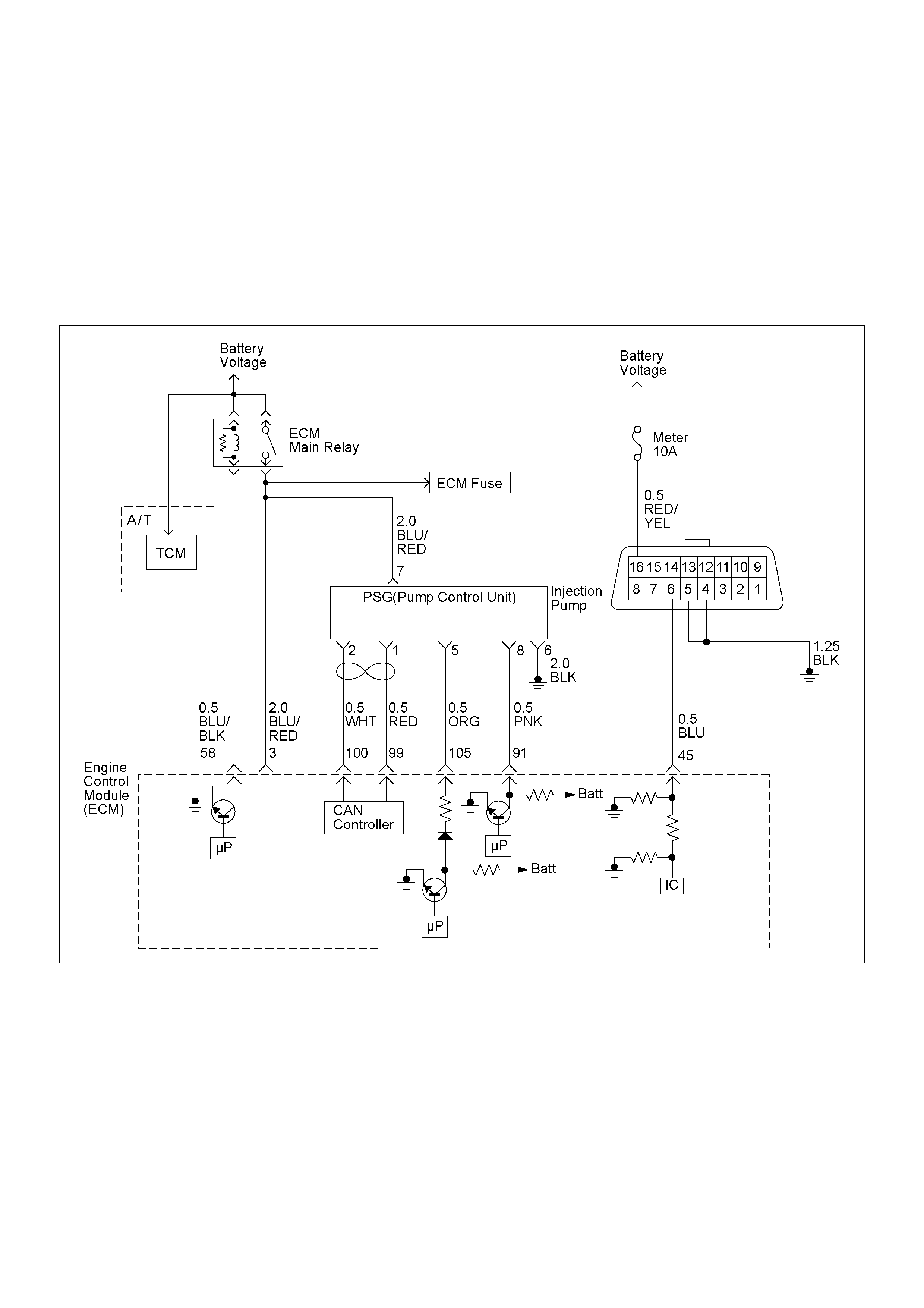
DIAGNOSTIC TROUBLE CODE (DTC) P02 15 (SYMPTOM CODE A)
(FLASH CODE 52) FUEL CUTOFF SOLEN OID VALVE MALFUNCTION
DIAGNOSTIC TROUBLE CODE (DTC) P02 15 (SYMPTOM CODE B)
(FLASH CODE 52) FUEL CUTOFF SOLENOID VALVE CIRCUIT HIGH INPUT
DIAGNOSTIC TROUBLE CODE (DTC) P02 15 (SYMPTOM CODE C)
(FLASH CODE 52) FUEL CUTOFF SOLENOID VALVE ALWAYS ACTIVE
DIAGNOSTIC TROUBLE CODE (DTC) P02 15 (SYMPTOM CODE D)
(FLASH CODE 52) FUEL CUTOFF SOLEN OID VALVE MALFUNCTION

Condition for setting the DTC and action ta ken when the DTC sets
Circuit Description
When the ignition switch is turned “Off”, the fuel
solenoid valve (MAB) signal is supplied from the ECM to
the PSG. This signal is the command for the PSG to
turn “Off” the engine.
If the MAB signal circuit is short to voltage circuit or
short to ground circuit, DTC P0215 (Symptom Co de B)
or P0215 (Symptom Code C) will be stored.
Diagnostic Aids
An intermittent may be caused by the following:
• Poor connections.
• Misrouted harness.
• Rubbed through wire insulation.
• Broken wire inside the insulation.
Check for the following conditions:
• Poor connection at ECM and PSG-Inspect harness
connectors for backed out terminals, improper
mating, broken locks, improperly formed or damaged
terminals, and poor terminal to wire connection.
Flash
Code Code Symptom
Code MIL DTC Name DTC Setting Condition Fail-Safe (Back Up)
52 P0215 A ON Fuel Cutof f Solenoid Valve
Malfunction 1. Ignition key switch off.
2. Engine speed is below
1500rpm.
3. Vehicle speed is below
1.5km/h.
4. PSG (pump control unit)
recognizes MAB (fuel cutoff
solenoid valve) signal from
the ECM, but the MAB
could not operate.
1. MAB (fuel cutoff solenoid
valve) is operated.
2. Desired injection quantity
becomes 0mg/strk.
B ON Fuel Cutoff Solenoid Valve
Circuit High Input ECM does not command
MAB (fuel cutoff solenoid
valve) signal to the PSG
(pump control unit), but PSG
detected MAB signal line
circuit is high level.
Engine does not start.
C ON Fuel Cutoff Solenoid Valve
Always Active 1. Ignition key switch off.
2. Engine speed is below
1500rpm.
3. Vehicle speed is below
1.5km/h.
4. PSG (pump control unit)
does not recognize MAB
(fuel cutoff solenoid valve)
signal from the ECM.
1. MAB (fuel cutoff solenoid
valve) is operated.
2. Desired injection quantity
becomes 0mg/strk.
D ON Fuel Cutoff Solenoid Valve
Malfunction 1. Ignition key switch off.
2. CAN controller does not
operate Bus-off.
No fail-safe function.

Diagnostic Trouble Code (DTC) P0215 (Symptom Code A) (Flash Code 52) Fuel
Cutoff Solenoid Valve Malfunction
Step Action Value(s) Yes No
1 Was the “On-Board Diagnostic (OBD) System Check”
performed?
—Go to Step 2
Go to On Board
Diagnostic
(OBD) System
Check
2 1. Connect the Tech 2.
2. Review and record the failure information.
3. Select “F0: Rea d DTC Infor As Stored By E CU” in
“F0: Diagnostic Trouble Codes”.
Is the DTC P0215 (Symptom Code A) stored as
“Pres ent Fa ilure”? — Go to Step 3
Refer to
Diagnostic Aids
and Go to Step
3
3 1. Using the Tech 2, ignition “On” and engine “Off”.
2. Select “F1: Clear DTC Information” in “F0:
Diagnostic Trouble Codes” with the Tech 2 and
clear the DTC information.
3. Operate the vehicle and monitor the “F0: Read
DTC Infor As Stored By ECU” in the “F0:
Diagnostic Trouble Codes”.
Was the DTC P0215 (Symptom Code A) stored in this
ignition cycle? — Go to Step 4 Refer to
Diagnostic Aids
4 Replace the injection pump assembly.
Is the action complete? — Verify repair —
Diagnostic Trouble Code (DTC) P0215 (Symptom Code B) (Flash Code 52) Fuel
Cutoff Solenoid Valve Circuit High Input
Step Action Value(s) Yes No
1 Was the “On-Board Diagnostic (OBD) System Check”
performed?
—Go to Step 2
Go to On Board
Diagnostic
(OBD) System
Check
2 1. Connect the Tech 2.
2. Review and record the failure information.
3. Select “F0: Rea d DTC Infor As Stored By E CU” in
“F0: Diagnostic Trouble Codes”.
Is the DTC P0215 (Symptom Code B) stored as
“Pres ent Fa ilure”? — Go to Step 3
Refer to
Diagnostic Aids
and Go to Step
3
3 1. Using the Tech 2, ignition “On” and engine “Off”.
2. Select “F1: Clear DTC Information” in “F0:
Diagnostic Trouble Codes” with the Tech 2 and
clear the DTC information.
3. Operate the vehicle and monitor the “F0: Read
DTC Infor As Stored By ECU” in the “F0:
Diagnostic Trouble Codes”.
Was the DTC P0215 (Symptom Code B) stored in this
ignition cycle? — Go to Step 4
Refer to
Diagnostic Aids
and Go to Step
4
4 Check for poor/faulty connection at the ECM or PSG
(pump control unit) connector. If a poor/faulty
connection is found, repair as necessary.
Was the problem found?
— Verify repair Go to Step 5
5 Visual ly chec k the PS G (p ump contr ol un it).
Was the problem found? — Go to Step 8 Go to Step 6
105 5E-6C-57
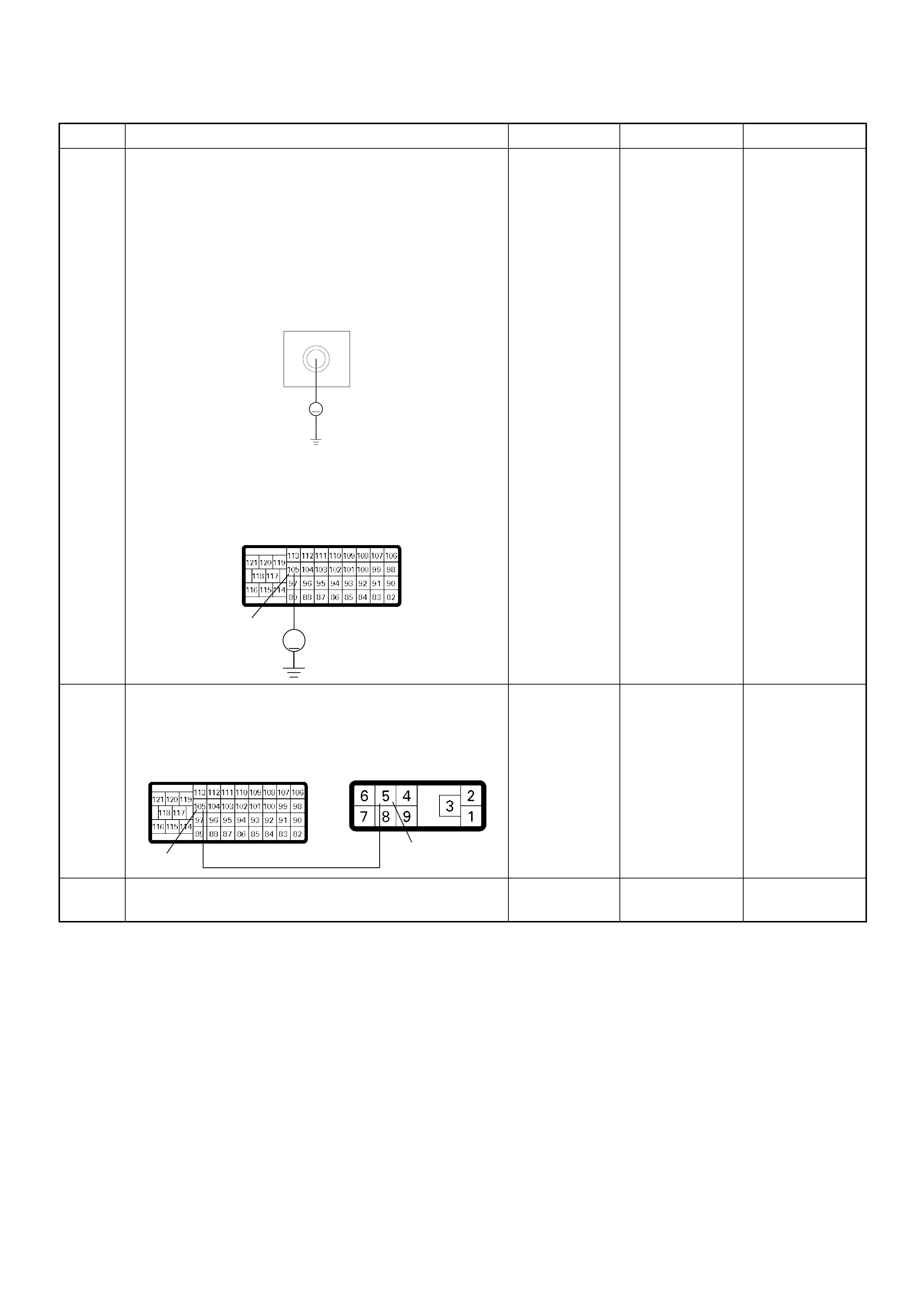
6 Using the DVM and check the MAB (fuel cutoff
solenoid valve) circuit.
Breaker box is available:
1. Ignition “Off”, engine “Off”.
2. Install the breaker box as type B. (ECM
connected) Ref. to HOW TO USE BREAKER BOX
3. Check the circuit for short to voltage circuit.
Was the DVM indicated specified value?
Breaker box is not available:
1. Check the circuit for short to voltage circuit.
Was the DVM indicated specified value?
Less than 1V Go to Step 8 Go to Step 7
7 Repair the short to voltage circuit between the ECM
and PSG (pump control unit).
Was the problem solved?
— Verify repair Go to Step 8
8 Replace the injection pump assembly.
Is the action complete? — Verify repair —
Step Action Value(s) Yes No
105
Breaker Box
V
V
105
C-57
105 5
E-6C-57
Diagnostic Trouble Code (DTC) P0215 (Symptom Code C) (Flash Code 52) Fuel
Cutoff Solenoid Valve Always Active
Step Action Value(s) Yes No
1 Was the “On-Board Diagnostic (OBD) System Check”
performed?
—Go to Step 2
Go to On Board
Diagnostic
(OBD) System
Check
2 1. Connect the Tech 2.
2. Review and record the failure information.
3. Select “F0: Rea d DTC Infor As Stored By E CU” in
“F0: Diagnostic Trouble Codes”.
Is the DTC P0215 (Symptom Code C) stored as
“Pres ent Fa ilure”? — Go to Step 3
Refer to
Diagnostic Aids
and Go to Step
3
3 1. Using the Tech 2, ignition “On” and engine “Off”.
2. Select “F1: Clear DTC Information” in “F0:
Diagnostic Trouble Codes” with the Tech 2 and
clear the DTC information.
3. Operate the vehicle and monitor the “F0: Read
DTC Infor As Stored By ECU” in the “F0:
Diagnostic Trouble Codes”.
Was the DTC P0215 (Symptom Code C) stored in this
ignition cycle? — Go to Step 4
Refer to
Diagnostic Aids
and Go to Step
4
4 Check for poor/faulty connection at the ECM or PSG
(pump control unit) connector. If a poor/faulty
connection is found, repair as necessary.
Was the problem found?
— Verify repair Go to Step 5
5 Visual ly chec k the PS G (p ump contr ol un it).
Was the problem found? — Go to Step 7 Go to Step 6
105 5E-6C-57
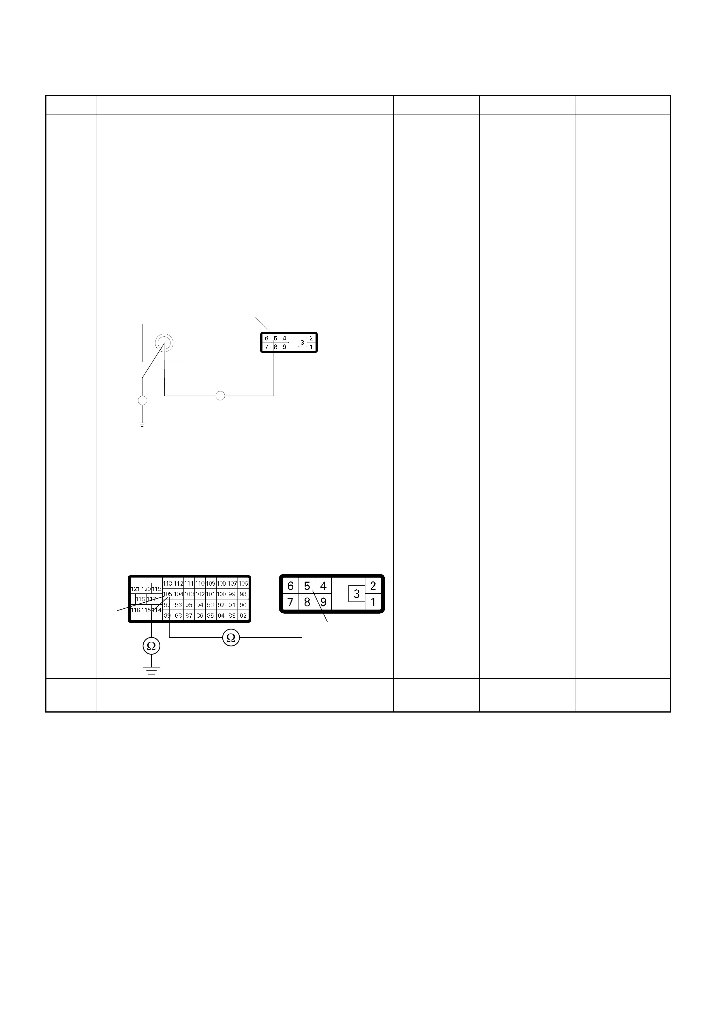
6 Using the DVM and check the MAB (fuel cutoff
solenoid valve) circuit.
Breaker box is available:
1. Ignition “Off”, engine “Off”.
2. Install the breaker box as type A. (ECM
disconnected) Ref. to HOW TO USE BREAKER
BOX
3. Disconnect the PSG (pump control unit)
connector.
4. Check the circuit for open or short to ground
circuit.
Was the problem found?
Breaker box is not available:
1. Ignition “Off”, engine “Off”.
2. Disconnect the PSG (pump control unit)
connector.
3. Check the circuit for open or short to ground
circuit.
Was the problem found?
—
Repair faulty
harn es s and
verify repair Go to Step 7
7 Replace the injection pump assembly.
Is the action complete? — Verify repair —
Step Action Value(s) Yes No
E-6
105
Breaker Box 5
Ħ
Ħ
5
105
E-6
C-57

Diagnostic Trouble Code (DTC) P0215 (Symptom Code D) (Flash Code 52) Fuel
Cutoff Solenoid Valve Malfunction
Step Action Value(s) Yes No
1 Was the “On-Board Diagnostic (OBD) System Check”
performed?
—Go to Step 2
Go to On Board
Diagnostic (OBD) System
Check
2 1. Connect the Tech 2.
2. Review and record the failure information.
3. Select “F0: Read DTC Infor As Stored By ECU” in
“F0: Diagnostic Trouble Codes”.
Is the DTC P0215 (Symptom Code D) stored as
“Present Failure”? — Go to Step 3
Refer to
Diagnostic Aids
and Go to Step
3
3 1. Using the Tech 2, ignition “On” and engine “Off”.
2. Select “F1: Clear DTC Information” in “F0:
Diagnostic Trouble Codes” with the Tech 2 and
clear the DTC information.
3. Operate the vehicle and monitor the “F0: Read
DTC Infor As Stored By ECU” in the “F0:
Diagnostic Trouble Codes”.
Was the DTC P0215 (Symptom Code D) stored in this
ignition cycle? — Go to Step 4 Refer to
Diagnostic Aids
4 Is the ECM programmed with the latest software
release?
If not, download the latest software to the ECM using
the “SPS (Service Programming System)”.
Was the problem solved? — Verify repair Go to Step 5
5 Substitute a known good ECM and recheck.
Was the problem solved?
IMPORTANT: The replacement ECM must be
programmed. Refer to section of the Service
Programming System (SPS) in this manual.
Following ECM programming, the immobilizer system
(if equipped) must be linked to the ECM. Refer to
section 11 “Immobilizer System-ECM replacement” for
the ECM/Immobilizer linking procedure. — Go to Step 6 Go to Step 7
6 Replace the ECM.
Is the action complete?
IMPORTANT: The replacement ECM must be
programmed. Refer to section of the Service
Programming System (SPS) in this manual.
Foll owing ECM pr ogramming, the immobi lizer sys tem
(if equipped) must be linked to the ECM. Refer to
section 11 “Immobilizer System-ECM replacement” for
the ECM/Immobilizer linking procedure. — Verify repair —
7 Replace the injection pump assembly.
Is the action complete? — Verify repair —
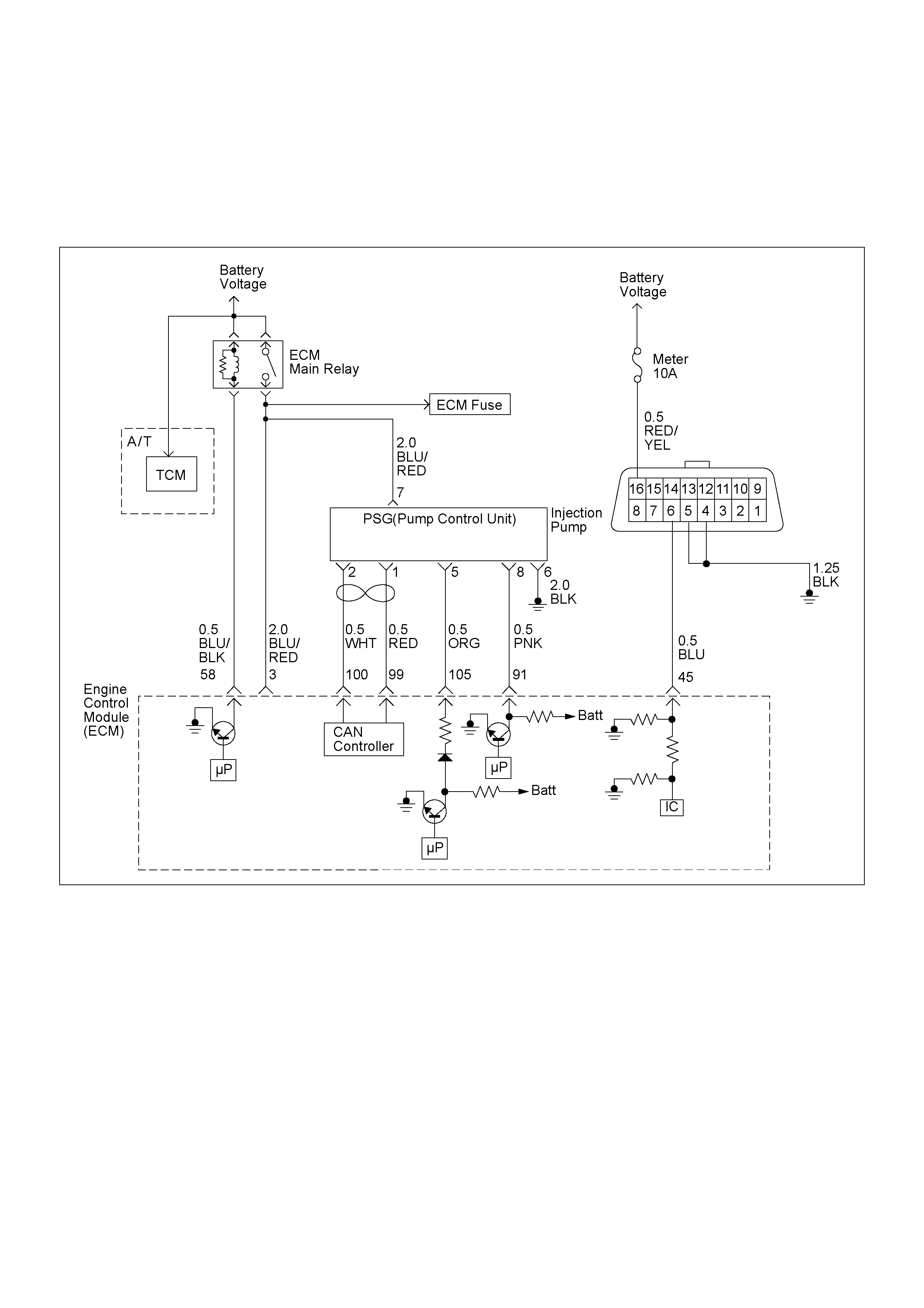
DIAGNOSTIC TROUBLE CODE (DTC) P0216 (SYMPTOM CODE A) (FLASH CODE 54)
INJECTION TIMING CONTROL CIRCUIT MALFUNCTION
DIAGNOSTIC TROUBLE CODE (DTC) P0216 (SYMPTOM CODE B) (FLASH CODE 54)
INJECTION TIMING CONTROL CIRCUIT MALFUNCTION

Condition for setting the DTC and action ta ken when the DTC sets
Circuit Description
The ECM is calculates an injection quantity and an
injection timing using the various sensors (crankshaft
position sensor, camshaft position sensor, engine
coolant temperature sensor, etc.). The timing control
valve (TCV) operation performs an injection timing
decision.
The TCV pe rf or ms as a v ar iab le th ro ttle, using the rapi d
opening and closing cycle of the valve needle in the
TCV.
The TCV is assembled in the injection pump. The signal
of desired injection timing and actual injection timing are
exchanged via the CAN-bus between the PSG and
ECM.
If the timer position is out of tolerance (deviation or
fluctuation), DTC P0216 will be stored.
Diagnostic Aids
An intermittent may be caused by the following:
• Poor connections.
• Misrouted harness.
• Rubbed through wire insulation.
• Broken wire inside the insulation.
• Insufficient air bleeding of fuel line.
• Low fuel quantity in the fuel tank.
Check for the following conditions:
• Insufficient air bleeding of fuel line inside, clogged
fuel filter or pinched fuel pipe/hose may cause the
DTC store or improper engine performance.
Air bleeding procedure:
1.Oper ate the primin g pump until str ong resi stance is
felt.
2.Wait 1 minute, and operate the priming pump until
strong resistance is felt.
3.Wait 1 minute, and operate the priming pump until
strong resistance is felt.
4.Turn the ignition switch to the "ON" position. Wait
until the glow indicator lamp turns off.
5.Turn the ignition switch to the "START" position
and crank the engine until it starts.
6.If the engine does not start, repeat S tep 3 - 5.
7.Allow the engine to idle for 3 minutes to bleed air
compl etely f orm th e fuel s ystem and ch eck fo r fuel
leakage.
• Poor connection at ECM and PSG-Inspect harness
connectors for backed out terminals, improper
mating, broken locks, improperly formed or damaged
terminals, and poor terminal to wire connection.
• Damaged harness-Inspect the wiring harness for
damage. If the harness appears to be OK, observe
the "Ac tua l In jec t i on Start" display on the Tech2 whi le
moving c onnectors and wiring harness rela ted to the
sensor.
Flash
Code Code Symptom
Code MIL DTC Name DTC Setting Condition Fail-Safe (Back Up)
54 P0216 A ON Injection Timing Control
Circuit Malfunction 1. Engine speed is more
than 700rpm.
2. Fuel injection quantity is
more than 4mg/stk.
3. Deviation of actual
injection timing and
desired injection timing is
more than +3 deg. CA or
-6 deg. CA for 8
seconds.
Fuel injection quantity is
reduced.
B ON Injection Timing Control
Circuit Malfunction 1. Engine speed is more
than 2014rpm.
2. Fluctuation of actual
injection timing is more
than +-5.2 deg. CA.

Diagnostic Trouble Code (DTC) P0216 (Symptom Code A) (Flash Code 54)
Injection Timing Control Circuit Malfunction
Diagnostic Trouble Code (DTC) P0216 (Symptom Code B) (Flash Code 54)
Injection Timing Control Circuit Malfunction
Step Action Value(s) Yes No
1 Was the "On-B oard Diagnos tic ( OBD ) Syste m Chec k"
performed?
-Go to
Step 2
Go to On Board
Diagnostic
(OBD) System
Check
2 1. Connect the T ech 2.
2. Re vi ew and record th e fai lur e i nf or ma tion .
3. Sele ct "F0: Rea d DTC Info r As Stored B y ECU" i n
"F0: Diagnostic Trouble Codes".
Is the DTC P0216 (Symptom Code A) or P0216
(Symp tom Code B) stored as "Present F ailure"? - Go to Step 3
Refer to
Diagnostic Aids
and Go to Step
3
3 1 . 1 U s i n g t h e Te c h 2 , i g n i t i o n " O n " a n d e n g i n e " O f f " .
2. Select "F1: Clear DTC Information" in "F0:
Diagnostic Trouble Codes" with the Tech 2 and
clear the DTC information.
3. Operate the vehicle and monitor the "F0: Read
DTC Infor As Stored By ECU" in the "F0:
Diagnostic Trouble Codes".
Was the DTC P0216 (Symptom Code A) or P0216
(Symptom Code B) stored in this ignition cycle? - Go to Step 4
Refer to
Diagnostic Aids
and Go to Step
4
4 Pe r f o r m t h e a i r b l e e d i n g i n t h e f u e l l i n e s u ffi ci e nt ly.
Air Bleeding Procedure:
1. Operate the priming pump until strong resistance
is felt .
2. Wait 1 mi nu te, a nd operate the pr im ing pum p un til
strong resistance is felt.
3. Once more wait, and operate the priming pump
until strong resistance is felt.
4. Turn the ignition switch to the "ON" positi on. Wait
until the glow indicator lamp turns off.
5. Turn the ignition switch to the "START" position
and crank the engine until it starts.
6. If the engine does not start, repeat Step 3 - 5.
7. Allow th e engine to idle for 3 minutes to bleed a ir
completely form the fuel system and check for fuel
leakage.
DTC Re-check:
1 . U s in g t h e Te ch 2 , i g n i t i o n "O n " an d e n g i n e "O f f " .
2. Select "F1: Clear DTC Information" in "F0:
Diagnostic Trouble Codes" with the Tech 2 and
clear the DTC information.
3. Operate the vehicle and monitor the "F0: Read
DTC Infor As Stored By ECU" in the "F0:
Diagnostic Trouble Codes".
Was the DTC P0216 (Symptom Code A) or P0216
(Symptom Code B) restored in this ignition cycle? - Go to Step 5 Verify repair
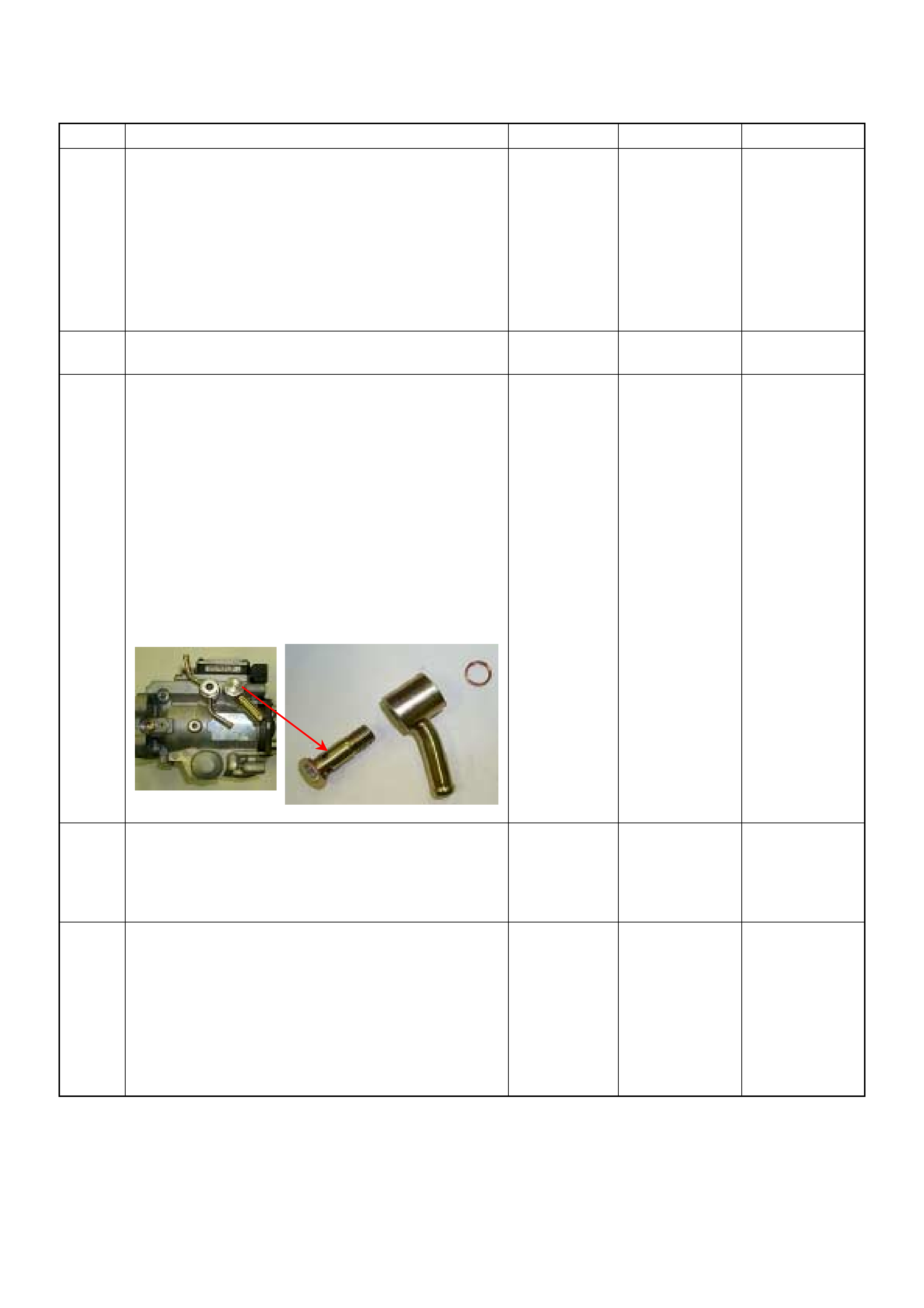
5 V i s u a l l y / p h y s i c a l l y i n s p e c t f o r t h e f o l l o w i n g c o n d i t i o n s .
• Restricted fuel supply system. Check for a pinched
fuel hose/pipe.
• Check for a condition that causes fuel waxing or
icing, such as the customer is using an incorrect
fuel type in winter season or water mixed with the
fuel.
If a problem is found, repair as necessary.
Was a problem found? - Verify repair Go to Step 6
6 Replace the fuel filter.
Was the problem solved? - Verify repair Go to Step 7
7 Remove the eye bolt with gauze filter from the
injection pump and check for the following conditions.
• Objects blocking at the gauze filter. Check for a
condition that causes contaminated fuel, such as
the customer is using an aftermarket fuel filter or
extended maintenance interval.
• Check for a condition that causes fuel waxing or
icing, such as the customer is using an incorrect
fuel type in winter season or water mixed with the
fuel.
If a problem is found, repair as necessary.
Was the problem found?
-
Replace the
eye bolt with
gauze filter and
verify repair Go to Step 8
8 Is the ECM programmed with the latest software
release? If
not, download the latest software to the ECM using
the "SPS (Service Programming System)".
Was the problem solved? - Verify repair Go to Step 9
9 S u b s t i t u t e a k n o w n g o o d E C M a n d r e c h e c k .
Was the problem solved?
IMPORTANT: The replacement ECM must be
programmed. Refer to section of the Service
P r o g r a m m i n g S y s t e m ( S PS ) i n t h i s m a n u a l .
Foll owing ECM pr ogramming, the immobi liser sys tem
(if equipped) must be linked to the ECM. Refer to
section 11 "Immobilizer System-ECM replacement"
for the ECM/Immobilizer linking procedure. - Go to Step 10 Go to Step 11
Step Action Value(s) Yes No

10 Replace the ECM.
Is the action complete?
IMPORTANT: The replacement ECM must be
programmed. Refer to section of the Service
P r o g r a m m i n g S y s t e m ( S PS ) i n t h i s m a n u a l .
Foll owing ECM pr ogramming, the immobi liser sys tem
(if equipped) must be linked to the ECM. Refer to
section 11 "Immobilizer System-ECM replacement"
for the ECM/Immobilizer linking procedure. - Verify repair -
11 Replace the injection pump assembly.
Is the action complete? - Verify repair -
Step Action Value(s) Yes No
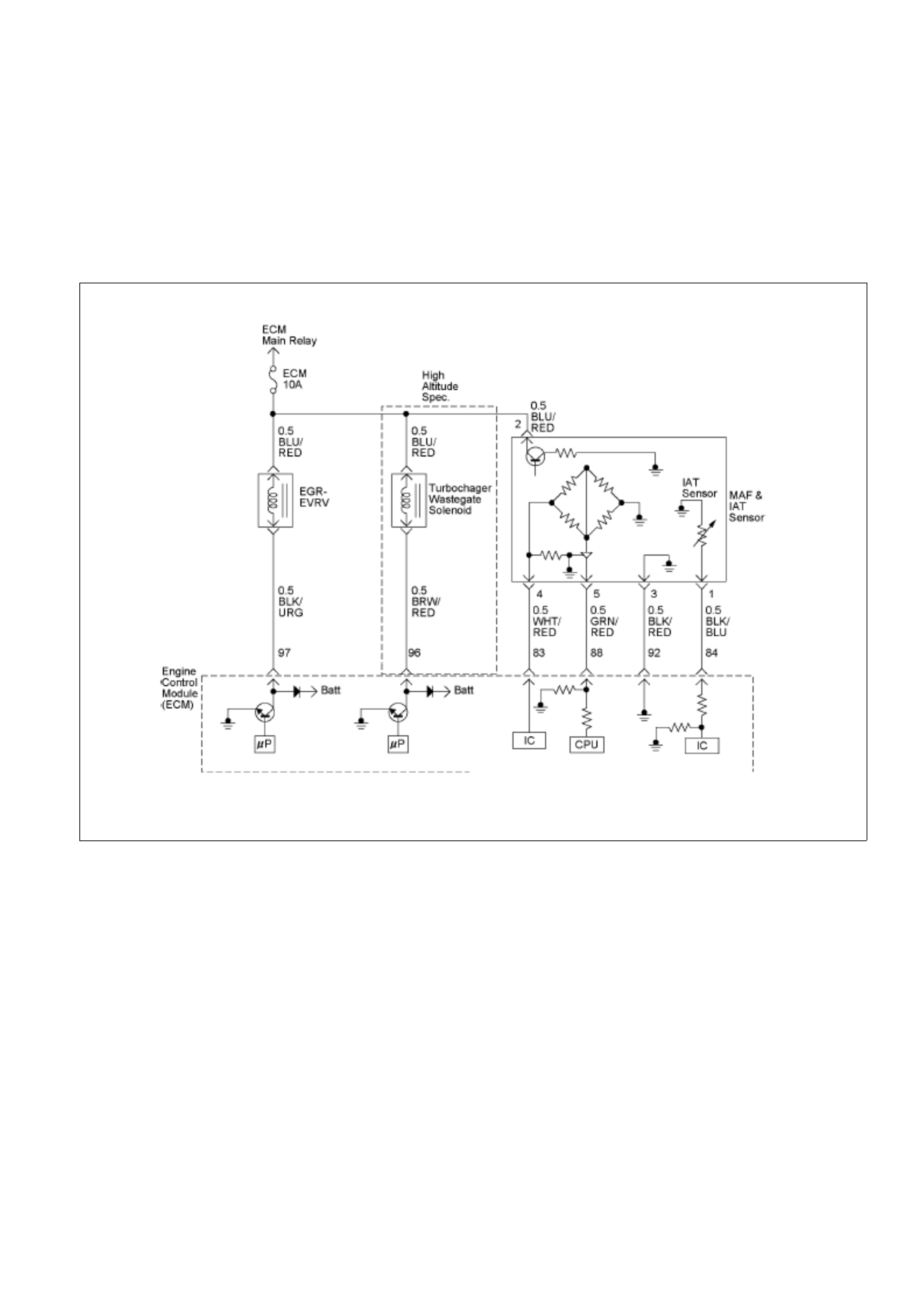
DIAGNOSTIC TROUBLE CODE (DTC) P0243 (SYMPTOM CODE 3) (FLASH CODE 64)
TURBOCHARGER WASTEGATE SOLENOID "A" RANGE/PERF ORM ANCE
DIAGNOSTIC TROUBLE CODE (DTC) P0243 (SYMPTOM CODE 4) (FLASH CODE 64)
TURBOCHARGER WASTEGATE SOLENOID "A" LOW
DIAGNOSTIC TROUBLE CODE (DTC) P0243 (SYMPTOM CODE 5) (FLASH CODE 64)
TURBOCHARGER WASTEGATE SOLENOID "A" RANGE/PERF ORM ANCE
DIAGNOSTIC TROUBLE CODE (DTC) P0243 (SYMPTOM CODE 6) (FLASH CODE 64)
TURBOCHARGER WASTEGATE SOLENOID "A" MALFUNCTION
DIAGNOSTIC TROUBLE CODE (DTC) P0243 (SYMPTOM CODE 8) (FLASH CODE 64)
TURBOCHARGER WASTEGATE SOLENOID "A" HIGH

Condition for setting the DTC and action taken when the DTC sets
Flash
Code Code Symptom
Code MIL DTC Name DTC Setting Condition Fail-Safe (Back Up)
3 ON Turbocharger Wastegate
Solenoid “A” Range/
Performance
1. Intake air temperature is
between –50 deg C and
200 deg C.
2. Engine coolant
temperature is between –
50 deg C and 150 deg C.
1. Fuel injection quantity is
reduced.
2. EGR EVRV becomes a
10% condition.
4 ON Turbocharger Wastegate
Solenoid “A” Low Wastegate control EVRV
circuit open or short to ground
circuit
1. Fuel injection quantity is
reduced.
2. EGR EVRV becomes a
10% condition.
3. Wastegate control EVRV
becomes a 32% condition.
5 ON Turbocharger Wastegate
Solenoid “A” Range/
Performance
1. Intake air temperature is
between –50 deg C and
200 deg C.
2. Engine coolant
temperature is between –
50 deg C and 150 deg C.
6 ON Turbocharger Wastegate
Solenoid “A” Malfunction 1. Engine coolant
temperature is between
–50 deg C and 150 deg
C.
2. EGR control EVRV is a
0% condition.
1. Fuel injection quantity is
reduced.
2. EGR EVRV becomes a
10% condition.
64 P0243
8 ON Turbocharger Wastegate
Solenoid “A” High Wastegate control EVRV
circuit short to voltage. 1. Fuel injection quantity is
reduced.
2. EGR EVRV becomes a
10% condition.
3. Wastegate control EVRV
becomes a 32% condition.
Circuit description
The ECM monitors altitude from the barometric pressure
sensor. To apply specified vacuum pressure to the
turbocharger wastegate valv e, ECM sends control signal to
the wastegate control solenoid depending on altitude.
Then, applied vacuum pressure to the turbocharger
wastegate valve is monitored b y the ECM from the vacu um
pressure sensor output signal. The ECM controls
wastegate control solenoid based on signal from vacuum
pressure sensor output.
If the vacuum pressure sensor detected vacuum pressure
is excessively low or high due to faulty vacuum line,
vacuum pump or turbocharger wastegate valve, DTC
P0243 (Symptom Code 3), P0243 (Symptom Code 5) or
P0243 (Symptom Code 6) will be stored.
If the wastegate control solenoid circuit is open or short to
ground circuit, DTC P0243 (Symptom Code 4) will be
stored.
If the wastegate control solenoid circuit is short to voltage
circuit, DTC P0243 (Symptom Code 8) will be stored.
Diagnostic Aids
An intermittent may be caused by the following:
• Poor connections.
• Misrouted harness.
• Rubbed through wire insulation.
• Broken wire inside insulation.
• Turbocharger wastegate valve sticking or broken.
• Misrouted vacuum hose.
• Faulty vacuum pump or regulating valve.
Check for the following conditions:
• Poor connection at ECM-Inspect harness connectors
for backed out terminals, improper mating, broken
locks, improperly formed or damaged terminals, and
poor terminal to wire connection.
• Damaged harness-Inspect the wiring harness for
damage. If the harness appear s to be OK, observe the
DTC P0243 display on the Tech 2 while moving
connectors and wiring harnesses. A change in the
display will indicate the location of the fault.

Diagnostic Trouble Code (DTC) P0243 (Symptom Code 3) (Flash Code 64)
Turbocharger Wastegate Solenoid "A" Range/Performance
Step Action Value(s) Yes No
1 Was the “On-Board Diagnostic (OBD) System Check”
performed? – Go to Step 2
Go to On Board
Diagnostic (OBD)
System Check
2 1 Connect the Tech 2.
2. Review and record the failure information.
3. Select "F0: Read DTC Infor As Stored By ECU" in
"F0: Diagnostic Trouble C odes".
Is the DTC P0243 (Symptom Code 3) stored as "Present
Failure"? – Go to Step 3
Refer to
Diagnostic Aids
and Go to Step 3
3 1 Using the Tech 2, ignition "On" and engine "Off".
2. Select "F1: Clear DT C Information" in "F0: Diagnostic
Trouble Codes" with the Tech 2 and clear the DTC
information.
3. Operate the vehicle and monitor the "F0: Read
DTC Infor As Stored By ECU" in the "F0:
Diagnostic Trouble Codes".
Was the DTC P0243 (Symptom Code 3) stored in this
ignition cycle? – Go to Step 4
Refer to
Diagnostic Aids
and Go to Step 4
4 Remove the vacuum hose & vacuum regulating valve
and check for the following conditions.
• Objects blocking the vacuum hose.
• Objects blocking the vacuum regul ating valve.
• Vacuum leaking at vacuum hose or vacuum
regulating valve.
• Objects blocking the wastegate solenoid valve.
If a problem is found, repair as necessary. Was the
problem found? – Verify repair Go to Step 5
5 Remove the vacuum pressure sensor and visually
check.
Was the problem found? – Go to Step 6 Go to Step 8
6 Substitute a known good vacuum pressure sensor and
recheck
Was the problem solved – Go to Step 7 Go to Step 8
7 Replace the vacuum press ure sensor.
Is the action complete? – Verify repair –
8 Using a DMM, check the wastegate control solenoid:
1 Ignition “On”, engine “Off”.
2 Disconnect the wastegate solenoid connector.
3. Measure the resistance of the wastegate control
solenoid coil.
Does the test indicate the specified resistance?
Approximately
32Ω at 20° C Go to Step 11 Go to Step 9
9 Substitute a known good wastegate control solenoid
and re-check.
Was the problem solved? – Go to Step 10 Go to Step 11
10 Replace the wastegate control solenoid.
Is the action complete? – Verify repair –

Step Action Value(s) Yes No
11 1 Using a pressure gauge, check the turbocharger
wastegate valve operation for a ruptured
diaphragm.
2 If a problem is found, repair as necessary.
Was a problem found? – Go to Step 12 Go to Step 13
12 Replace the turbocharger wastegate valve.
Is the action complete? – Verify repair –
13 Is the ECM programmed with the latest software
release?
If not, download the latest software to the ECM using
the “SPS (Service Programming System)”.
Was the problem solved? – Verify repair Go to Step 14
14 Replace the ECM.
Is the action complete?
IMPORTANT: The replacement ECM must be
programmed. Refer to the Service Programming
System (SPS) section, in this manual.
Following ECM programming, the immobiliser system(if
equipped) must be linked to the ECM. Refer to Section
11 “Immobiliser System – ECM Replacement” for the
ECM/Immobiliser linking procedure. – Verify repair –
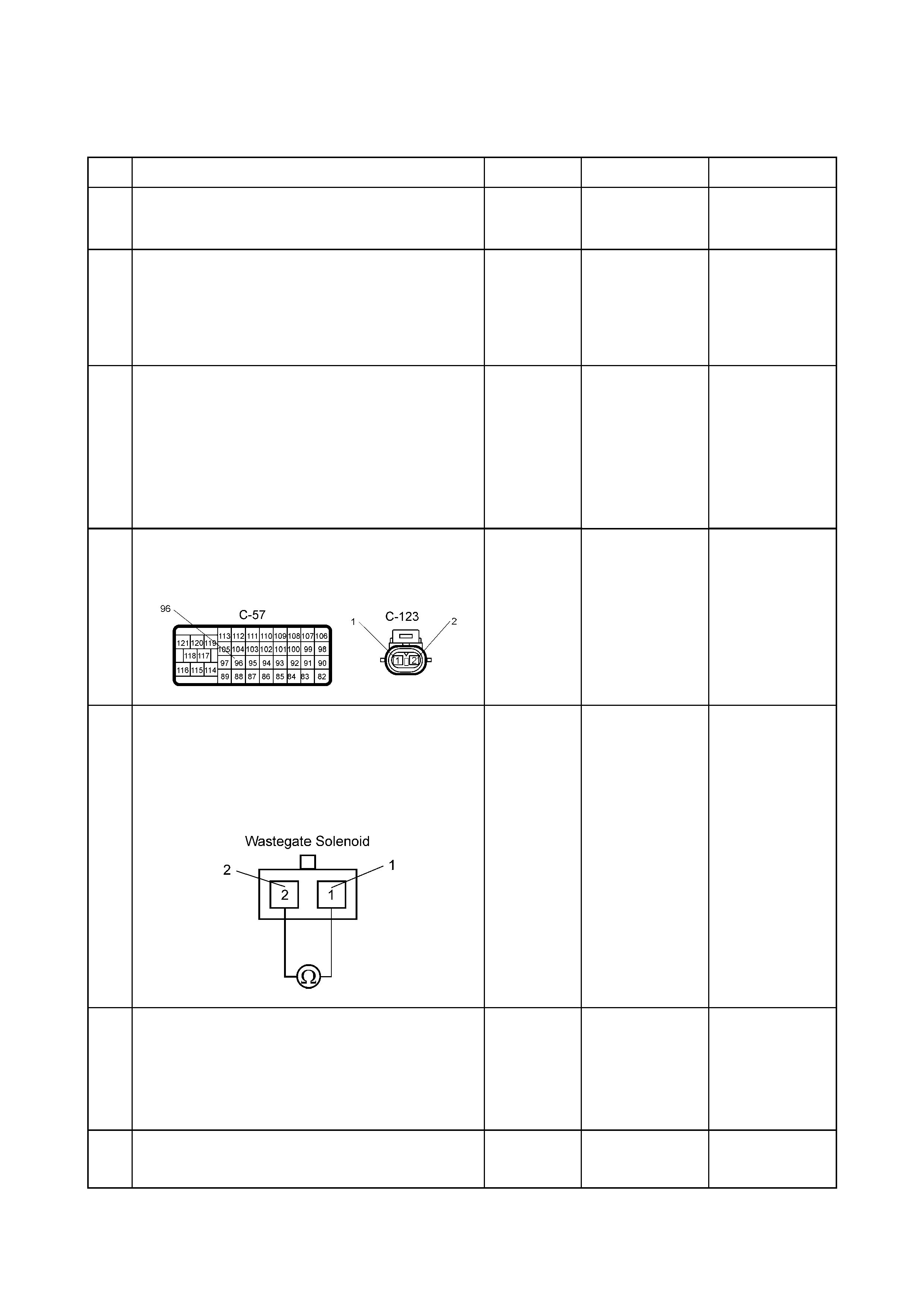
Diagnostic Trouble Code (DTC) P0243 (Symptom Code 4) (Flash Code 64)
Turbocharger Wastegate Solenoid "A" Low
Step Action Value(s) Yes No
1 W as the “On-Board Diagnostic (OBD) System Check”
performed? – Go to Step 2
Go to On Board
Diagnostic (OBD)
System Check
2 1 Connect the Tech 2.
2. Review and record the failure information.
3. Select “F0: Read DTC Infor As Stored By ECU” in
“F0: Diagnostic Trouble Codes”.
Is the DTC P0243 (Symptom Code 4) stored as
“Present Failure”? – Go to Step 3
Refer to
Diagnostic Aids
and Go to Step 3
3 1 Using the Tech 2, ignition "On" and engine "Off".
2. Select "F1: Clear DTC Information" in "F0:
Diagnostic Trouble Codes" with the Tech 2 and
clear the DTC information.
3. Operate the vehicle and monitor the "F0: Read
DTC Infor As Stored By ECU" in the "F0:
Diagnostic Trouble Codes".
Was the DTC P0243 (Symptom Code 4) stored in this
ignition cycle? – Go to Step 4
Refer to
Diagnostic Aids
and Go to Step 4
4 1 Check for p oor/fault y connections at the wastegate
control solenoid or ECM connector. If a poor/faulty
connection is found, repair as necessary.
Was the problem found and corrected?
– Verify repair Go to Step 5
5 Using a DMM, check the wastegate control solenoid:
1 Ignition “On”, engine “Off”.
2 Disconnect the wastegate solenoid connector.
3. Measure the resistance of the wastegate control
solenoid coil.
Does the test indicate the specified resistance?
Approximately
32Ω at 20° C Go to Step 11 Go to Step 9
6 Using a DMM, check the wastegate control solenoid
power supply circuit:
1 Ignition “On”, engine “Off”.
2 Disconnect the wastegate solenoid connector.
3. Check the circuit integrity.
Does the DMM indicate the specified value? 10 – 14.5 V Go to Step 8 Go to Step 7
7 Repair the open circuit between the ECM main relay
and wastegate control solenoid.
Is the action complete? – Verify repair –
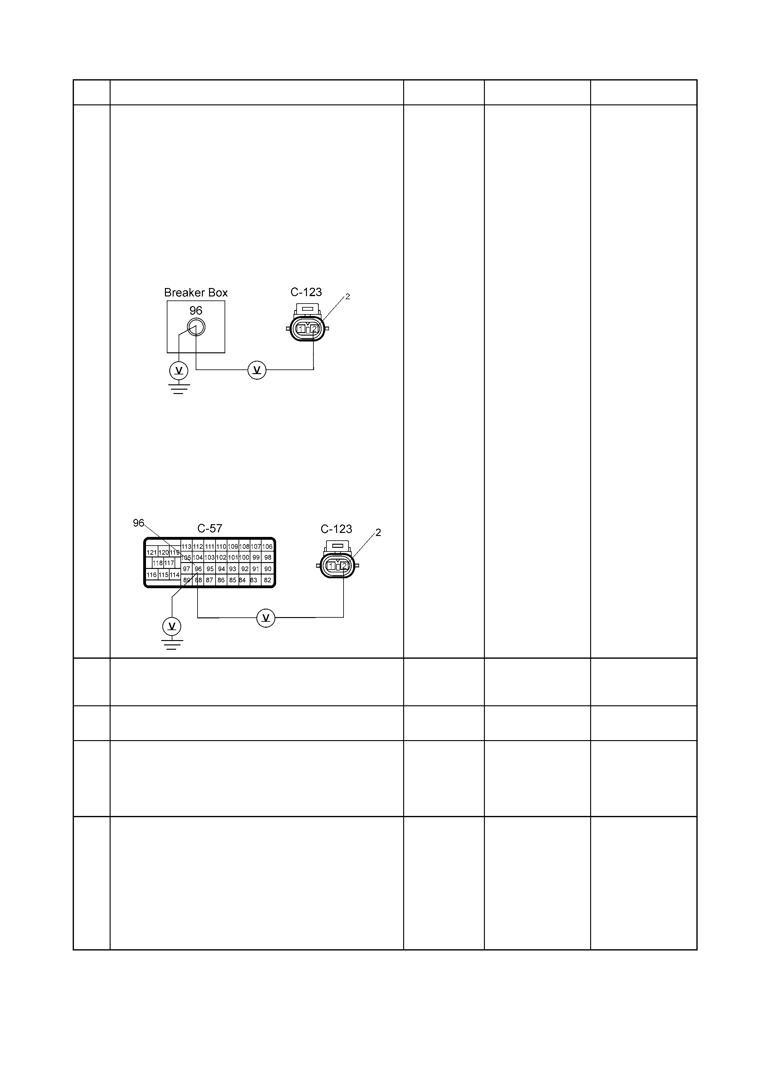
Step Action Value(s) Yes No
8 Using a DMM, check the wastegate control solenoid
circuit.
Breaker box is a vailable:
1 Ignition “On”, engine “Off”.
2 Install the breaker box as type “A”. (ECM
disconnected). Refer to ”How to Use Breaker Box”
in this Section.
3 Remove the wastegate control solenoid
connector.
4. Check the circuit for an open or short to ground.
Was the problem found?
Breaker box is not available:
1 Ignition “On”, engine “Off”.
2. Disconnect the ECM connector.
3. Disconnect the wastegate solenoid connecto r.
4. Using the DMM, check the circuit for a short to
ground or an open.
Was the problem found?
–
Repair faulty
harness and verify
repair Go to Step 11
9 Substitute a known good wastegate control solenoid
and re-check operation.
Was the problem solved? – Go to Step 10 Go to Step 11
10 Replace the wastegate control solenoid.
Is the action complete? – Verify repair –
11 Is the ECM programmed with the latest software
release?
If not, download the latest software to the ECM using
the “SPS (Service Programming System)”.
Was the problem solved? – Verify repair Go to Step 12
12 Replace the ECM.
Is the action complete?
IMPORTANT: The replacement ECM must be
programmed. Refer to the Service Programming
System (SPS) section, in this manual.
Following ECM programming, the immobiliser system(if
equipped) must be linked to the ECM. Refer to Section
11 “Immobiliser System – ECM Replacement” for the
ECM/Immobiliser linking procedure. – Verify repair –
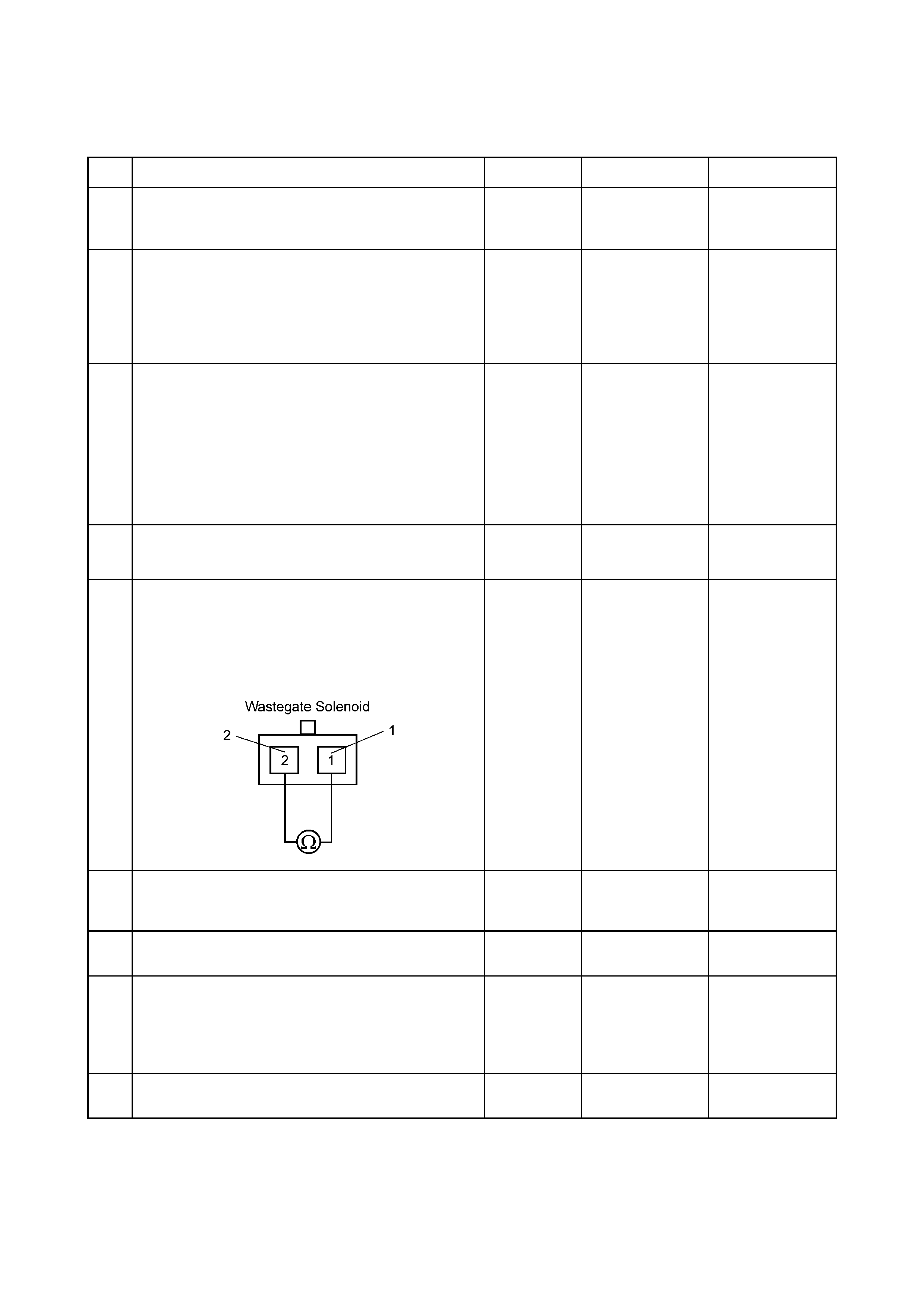
Diagnostic Trouble Code (DTC) P0243 (Symptom Code 5) (Flash Code 64)
Turbocharger Wastegate Solenoid "A" Range/Performance
Step Action Value(s) Yes No
1 W as the “On-Board Diagnostic (OBD) System Check”
performed? – Go to Step 2
Go to On Board
Diagnostic (OBD)
System Check
2 1 Connect the Tech 2.
2. Review and record the failure information.
3. Select “F0: Read DTC Infor As Stored By ECU” in
“F0: Diagnostic Trouble Codes”.
Is the DTC P0243 (Symptom Code 5) stored as
“Present Failure”? – Go to Step 3
Refer to
Diagnostic Aids
and Go to Step 3
3 1 Using Tech 2, with ignition "On" and engine "Off".
2. Select "F1: Clear DTC Information" in "F0:
Diagnostic Trouble Codes" with the Tech 2 and
clear the DTC information.
3. Operate the vehicle and monitor the "F0: Read
DTC Infor As Stored By ECU" in the "F0:
Diagnostic Trouble Codes".
Was the DTC P0243 (Symptom Code 5) stored in this
ignition cycle? – Go to Step 4
Refer to
Diagnostic Aids
and Go to Step 4
4 Visually check the vacuum regulating valve. If a
problem is found rectify as necessary.
Was the problem found and corrected? – Verify repair Go to Step 5
5 Using a DMM, check the wastegate control solenoid:
1 Ignition “On”, engine “Off”.
2 Disconnect the wastegate solenoid connector.
3. Measure the resistance of the wastegate control
solenoid coil.
Does the test indicate the specified resistance?
Approximately
32Ω at 20° C Go to Step 8 Go to Step 6
6 Substitute a known good wastegate control solenoid
and re-check.
Was the problem solved? – Go to Step 7 Go to Step 8
7 Replace the wastegate control solenoid.
Is the action complete? – Verify repair –
8 1 Using a pressure gauge, check the turbocharger
wastegate valve operation for a ruptured
diaphragm.
2 If a problem is found, repair as necessary.
Was a problem found? – Go to Step 9 Go to Step 10
9 Replace the turboch arger wastegate valve.
Is the action complete? – Verify repair –

Step Action Value(s) Yes No
10 Check for poor/faulty connection at the vacuum
pressure sensor or ECM connector. If a poor/faulty
connection is found, repair as necessary.
Was a problem found and corrected?
– Verify repair Go to Step 11
11 Visually check the vacuum pressure sensor.
Was a problem found? – Go to Step 13 Go to Step 12
12 Using a DMM, check the vacuum pressure sensor
signal circuit:
1 Ignition “On”, engine “Off”.
2 Disconnect the vacuum pressure sensor
connector.
3. Check the circuit for a short to power supply
circuit condition.
Does the DMM indicate the specified value?
Less than 1 V Go to Step 15
Repair faulty
harness and verify
repair.
13 Substitute a known good vacuum pressure sensor
assembly and re-check.
Was the problem resolved? – Go to Step 14 Go to Step 15
14 Replace the vacuum press ure sensor assembly.
Is the action complete? – Verify repair –
15 Is the ECM programmed with the latest software
release?
If not, download the latest software to the ECM using
the “SPS (Service Programming System)”.
Was the problem solved? – Verify repair Go to Step 16
16 Replace the ECM.
Is the action complete?
IMPORTANT: The replacement ECM must be
programmed. Refer to the Service Programming
System (SPS) section, in this manual.
Following ECM programming, the immobiliser
system(if equipped) must be linked to the ECM. Refer
to Section 11 “Immobiliser System – ECM
Replacement” for the ECM/Immobiliser linking
procedure. – Verify repair –
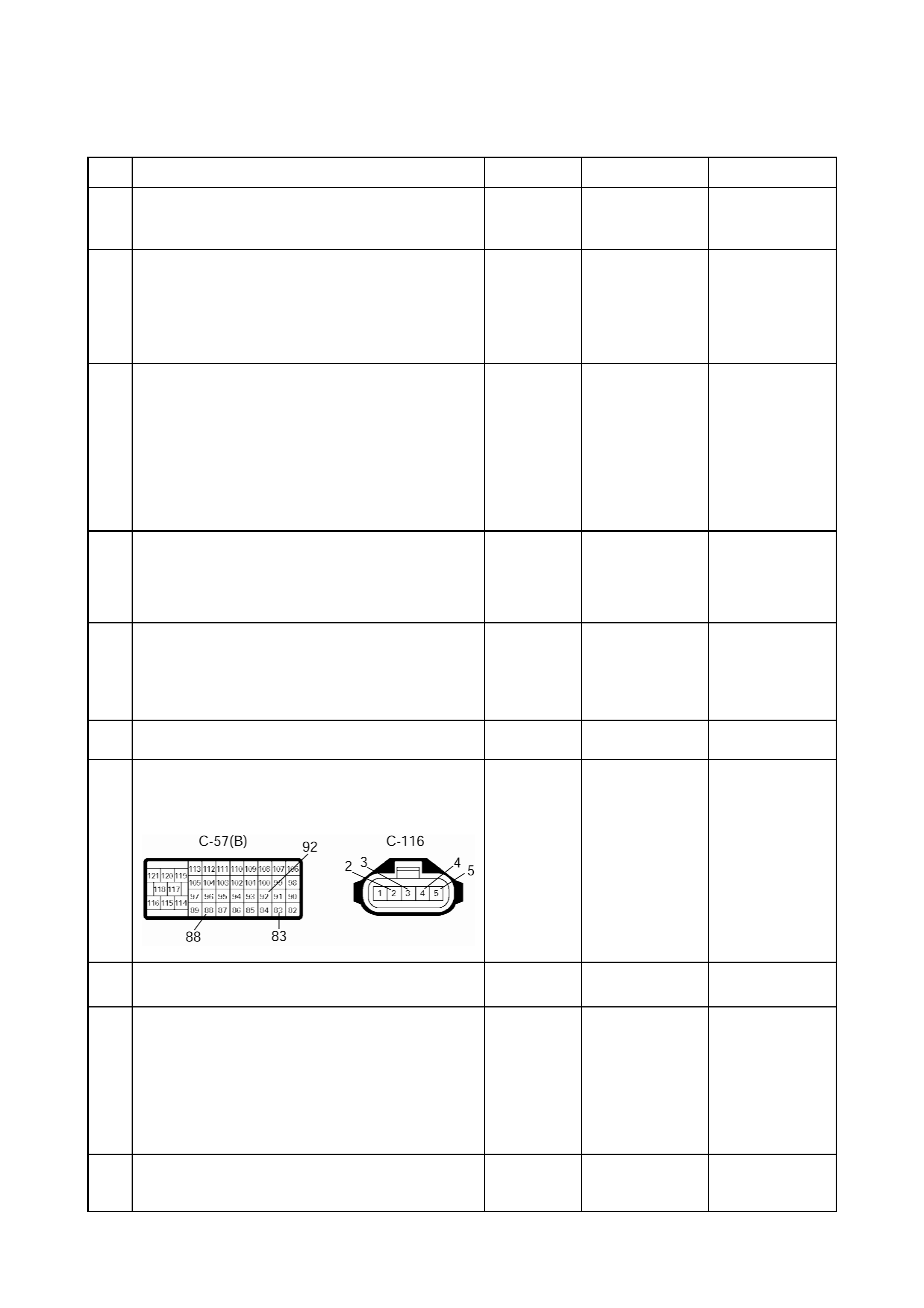
Diagnostic Trouble Code (DTC) P0243 (Symptom Code 6) (Flash Code 64)
Turbocharger Wastegate Solenoid "A" Malfunction
Step Action Value(s) Yes No
1 W as the “On-Board Diagnostic (OBD) System Check”
performed? – Go to Step 2
Go to On Board
Diagnostic (OBD)
System Check
2 1 Connect the Tech 2.
2. Review and record the failure information.
3. Select “F0: Read DT C Infor As Stored By ECU” in
“F0: Diagnostic Trouble Codes”.
Is the DTC P0243 (Symptom Code 6) stored as
“Present Failure”? – Go to Step 3
Refer to
Diagnostic Aids
and Go to Step 3
3 1 Using Tech 2, with ignition "On" and engine "Off".
2. Select "F1: Clear DTC Information" in "F0:
Diagnostic Trouble Codes" with the Tech 2 and
clear the DTC information.
3. Operate the vehicle and monitor the "F0: Read
DTC Infor As Stored By ECU" in the "F0:
Diagnostic Trouble Codes".
Was the DTC P0243 (S ymptom Code 5) stored in this
ignition cycle? – Go to Step 4
Refer to
Diagnostic Aids
and Go to Step 4
4 Visually check the turbocharger wastegate valve and
hose.
If the hose is clogged, disconnected or damaged, repair
as necessary.
Was the problem found and corrected? – Verify repair Go to Step 5
5 1 Using a pressure gauge, check the turbocharger
wastegate valve operation for a ruptured
diaphragm.
2 If a problem is found, repair as necessary.
Was a problem found? – Go to Step 6 Go to Step 7
6 Replace the turboch arger wastegate valve.
Is the action complete? – Verify repair –
7 Check for poor/faulty connection at the vacuum
pressure sensor or ECM connector. If a poor/faulty
connection is found, repair as necessary.
Was a problem found and corrected?
– Verify repair Go to Step 8
8 Visually check the MAF Sensor
Was a problem found? – Go to Step 10 Go to Step 9
9 Using a DMM, check the MAF sensor signal circuit:
1 Ignition “On”, engine “Off”.
2 Disconnect the MAF sensor connector.
3. Check the circuit for a short to power supply
condition.
Does the DMM indicate the specified value?
Less than 1 V Go to Step 12
Repair faulty
harness and verify
repair
10 Substitute a kno wn good MAF & IAT sensor assembly
and re-check.
Was the problem resolved? – Go to Step 11 Go to Step 12

11 Replace the MAF & IAT sensor assemb ly.
Is the action complete? – Verify repair –
12 Is the ECM programmed with the latest software
release?
If not, download the latest software to the ECM using
the “SPS (Service Programming System)”.
Was the problem solved? – Verify repair Go to Step 13
13 Replace the ECM.
Is the action complete?
IMPORTANT: The replacement ECM must be
programmed. Refer to the Service Programming
System (SPS) section, in this manual.
Following ECM programming, the immobiliser
system(if equipped) must be linked to the ECM. Refer
to Section 11 “Immobiliser System – ECM
Replacement” for the ECM/Immobiliser linking
procedure. – Verify repair –
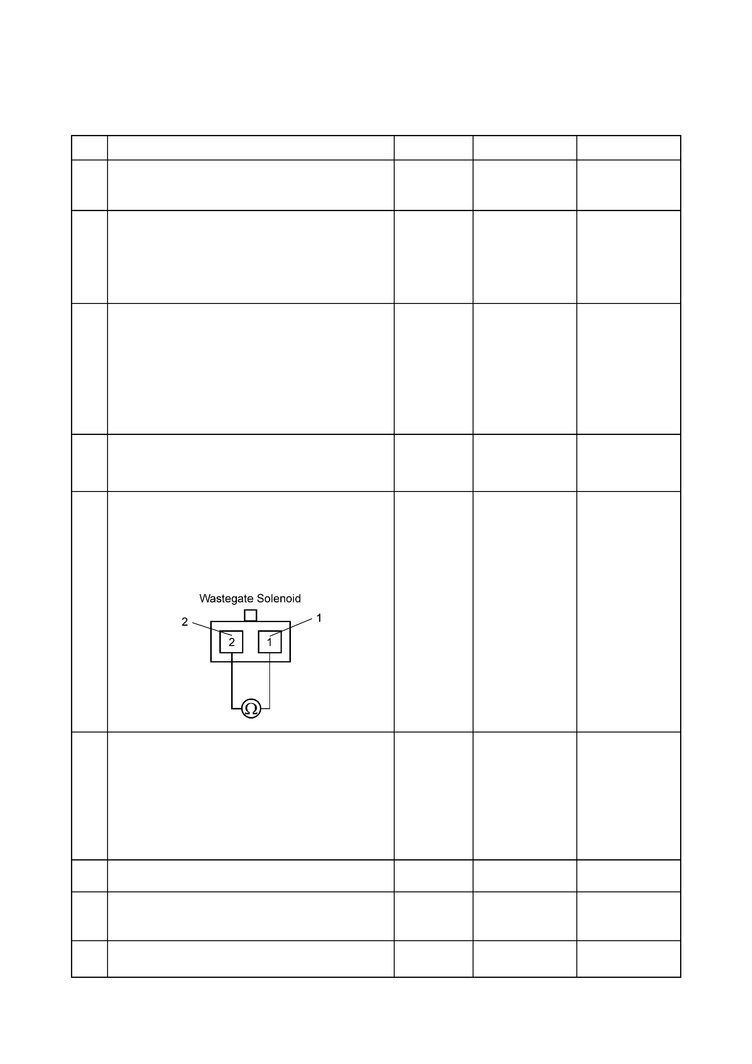
Diagnostic Trouble Code (DTC) P0243 (Symptom Code 8) (Flash Code 64)
Turbocharger Wastegate Solenoid "A" High
Step Action Value(s) Yes No
1 W as the “On-Board Diagnostic (OBD) System Check”
performed? – Go to Step 2
Go to On Board
Diagnostic (OBD)
System Check
2 1 Connect the Tech 2.
2. Review and record the failure information.
3. Select “F0: Read DT C Infor As Stored By ECU” in
“F0: Diagnostic Trouble Codes”.
Is the DTC P0243 (Symptom Code 8) stored as
“Present Failure”? – Go to Step 3
Refer to
Diagnostic Aids
and Go to Step 3
3 1. Using Tech 2, with ignition "On" and engine "Off".
2. Select "F1: Clear DTC Information" in "F0:
Diagnostic Trouble Codes" with the Tech 2 and
clear the DTC information.
3. Operate the vehicle and monitor the "F0: Read
DTC Infor As Stored By ECU" in the "F0:
Diagnostic Trouble Codes".
Was the DTC P0243 (Symptom Code 8) stored in this
ignition cycle? – Go to Step 4 Refer to
Diagnostic Aids
4 Check for poor/faulty connection at the wastegate
control solenoid or ECM connector. If a poor/faulty
connection is found, repair as necessary.
Was a problem found and corrected? – Verify repair Go to Step 5
5 Using a DMM, check the wastegate control solenoid:
1 Ignition “On”, engine “Off”.
2 Disconnect the wastegate solenoid connector.
3. Measure the resistance of the wastegate control
solenoid coil.
Does the test indicate the specified resistance?
Approximately
32Ω at 20° C Go to Step 6 Go to Step 8
6 Using a DMM, check the wastegate control solenoid
circuit:
1 Ignition “On”, engine “Off”.
2 Disconnect the wastegate control solenoid and
ECM connectors.
3. Check the circuit for a short to voltage condition.
Does the DMM indicate the specified value?
No continuity Go to Step 10 Go to Step 7
7 Repair the short to voltage co ndition.
Is the action complete? – Verify repair –
8 Substitute a known good wastegate control solenoid
and re-check operation.
Was the problem solved? – Go to Step 9 Go to Step 10
9 Replace the wastegate control solenoid.
Is the action complete? – Verify repair –

Step Action Value(s) Yes No
10 Is the ECM programmed with the latest software
release?
If not, download the latest software to the ECM using
the “SPS (Service Programming System)”.
Was the problem solved? – Verify repair Go to Step 11
11 Replace the ECM.
Is the action complete?
IMPORTANT: The replacement ECM must be
programmed. Refer to the Service Programming
System (SPS) section, in this manual.
Following ECM programming, the immobiliser
system(if equipped) must be linked to the ECM. Refer
to Section 11 “Immobiliser System – ECM
Replacement” for the ECM/Immobiliser linking
procedure. – Verify repair –
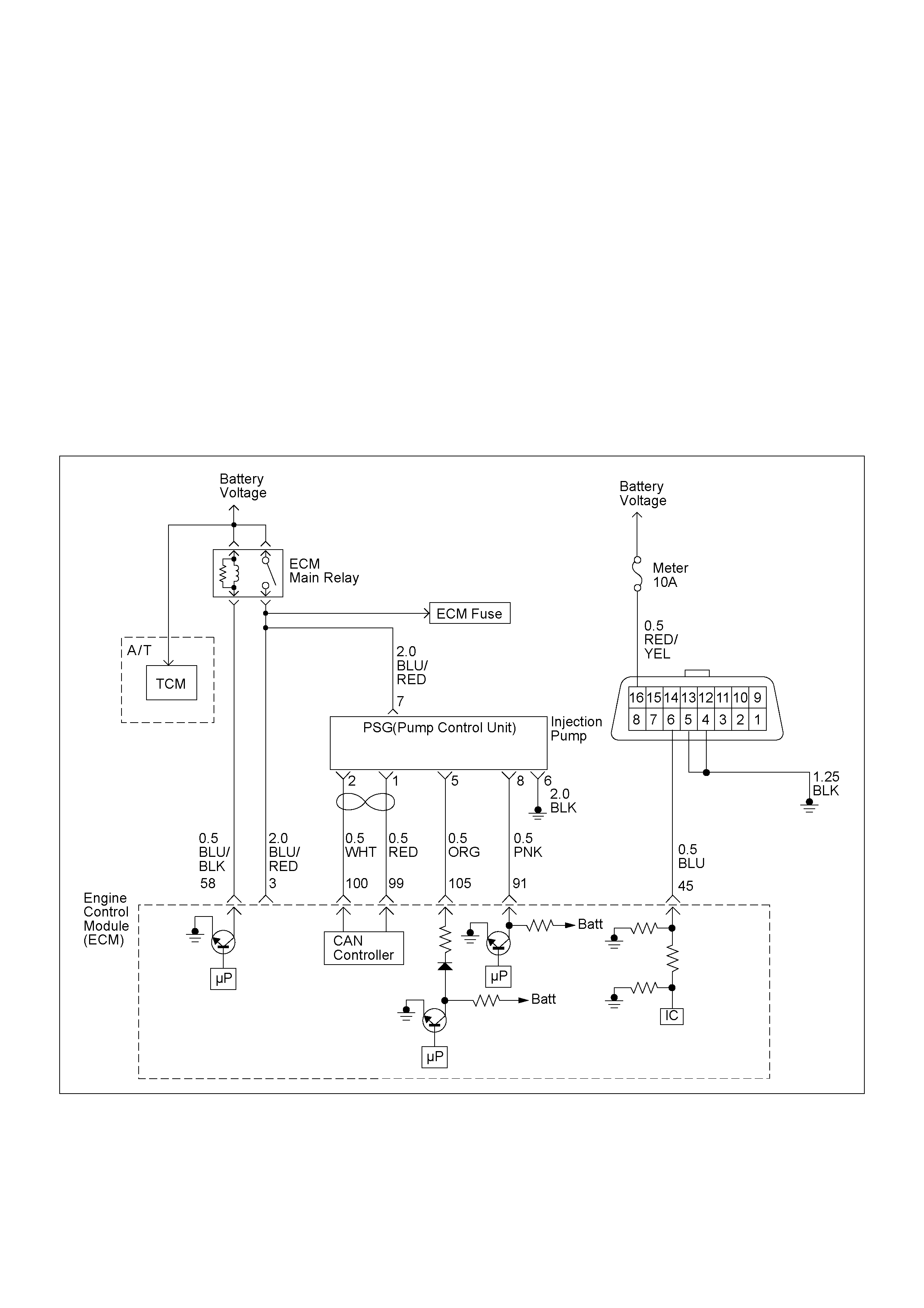
DIAGNOSTIC TROUBLE CODE (DTC) P0251 (SYM PTOM CODE 6)
(FLASH CODE 53) INJECTION PUMP MALFUNCTION
DIAGNOSTIC TROUBLE CODE (DTC) P0251 (SYM PTOM CODE 7)
(FLASH CODE 53) INJECTION PUMP MALFUNCTION
DIAGNOSTIC TROUBLE CODE (DTC) P0251 (SYM PTOM CODE 9)
(FLASH CODE 53) INJECTION PUMP MALFUNCTION
DIAGNOSTIC TROUBLE CODE (DTC) P02 51 (SYMPTOM CODE A)
(FLASH CODE 53) INJECTION PUMP MALFUNCTION
DIAGNOSTIC TROUBLE CODE (DTC) P02 51 (SYMPTOM CODE B)
(FLASH CODE 53) INJECTION PUMP MALFUNCTION
DIAGNOSTIC TROUBLE CODE (DTC) P02 51 (SYMPTOM CODE D)
(FLASH CODE 53) INJECTION PUMP MALFUNCTION
DIAGNOSTIC TROUBLE CODE (DTC) P0251 (SYMPTOM CODE E)
(FLASH CODE 53) INJECTION PUMP MALFUNCTION

Condition for setting the DTC and action ta ken when the DTC sets
Circuit Description
The ECM is calculates an injection quantity and an
injection timin g us ing t he v ar iou s s ens ors . And the P SG
control s the high pr essure solenoid valve depe nding on
programmed pump map data.
The signal of desired injection quantity and actual
injection quantity are exchanged via the CAN-bus
between the PSG and ECM.
If the relatio n of eng ine speed sign al and double d pum p
camshaft speed signal excessively large, DTC P0251
(Symptom Code 7) will be stored.
If the CAN high or low circuit is defected, DTC P0251
(Symptom Code E) will be stored.
Diagnostic Aids
An intermittent may be caused by the following:
• Poor connections.
• Misrouted harness.
• Rubbed through wire insulation.
• Broken wire inside the insulation.
Check for the following conditions:
• Poor connection at ECM and PSG-Inspect harness
connectors for backed out terminals, improper
mating, broken locks, improperly formed or damaged
terminals, and poor terminal to wire connection.
• Damaged harness-Inspect the wiring harness for
damage. If the harness appears to be OK, observe
the “Injection Quantity” display on the Tech2 while
moving c onnectors and wiring harn ess related to the
sensor.
Flash
Code Code Symptom
Code MIL DTC Name DTC Setting Condition Fail-Safe (Back Up)
53 P0251 6 ON Injection Pump Malfunction 1. No pump camshaft speed
sensor error.
2. High pressure solenoid
valve control pulse width
does not match with
desired fuel injection
quantity.
1. MAB (fuel cutoff solenoid
valve) is operated.
2. Desired injection quantity
becomes 0mg/strk.
7 ON Injection Pump Malfunction 1. No pump camshaft speed
sensor error.
2. No CKP sensor error.
3. Difference of engine speed
and doubled pump
camshaft speed is more
than 690 rpm.
9 ON Inj ection Pump Malfunction No pump map programmed in
the PSG (pump control unit)
or PSG malfunction.
A ON Inj ection Pump Malfunction EEPROM or A/D converter
malfunction in the PSG (pump
control unit).
Fuel injection quantity is
reduced.
B ON Inj ection Pump Malfunction PSG (pump control unit)
recognized high pressure
solenoid valve drive circuit
error.
No fail-safe function.
D ON Injection Pump Malfunction PSG (pump control unit) could
not measure the high
pressure solenoid valve drive
voltage.
E ON Injection Pump Malfunction ECM could not accept PSG
(pump control unit) message. 1. MAB (f uel cutoff solenoid
valve) is operated.
2. Desired injection quantity
becomes 0mg/strk.

Diagnostic Trouble Code (DTC) P0251 (Symptom Code 6) (Flash Code 53)
Injection Pump Malfunction
Step Action Value(s) Yes No
1 Was the “On-Board Diagnostic (OBD) System Check”
performed?
—Go to Step 2
Go to On Board
Diagnostic
(OBD) System
Check
2 1. Connect the Tech 2.
2. Review and record the failure information.
3. Select “F0: Rea d DTC Infor As Stored By ECU” in
“F0: Diagnostic Trouble Codes”.
Is the DTC P0251 (Symptom Code 6) stored as
“Pres ent Fa ilure”? — Go to Step 3
Refer to
Diagnostic Aids
and Go to Step
3
3 1. Using the Tech 2, ignition “On” and engine “Off”.
2. Select “F1: Clear DTC Information” in “F0:
Diagnostic Trouble Codes” with the Tech 2 and
clear the DTC information.
3. Operate the vehicle and monitor the “F0: Read
DTC Infor As Stored By ECU” in the “F0:
Diagnostic Trouble Codes”.
Was the DTC P0251 ( Sy mpt om Code 6) s tor e d i n this
ignition cycle? — Go to Step 4 Refer to
Diagnostic Aids
4 Replace the injection pump assembly.
Is the action complete? — Verify repair —
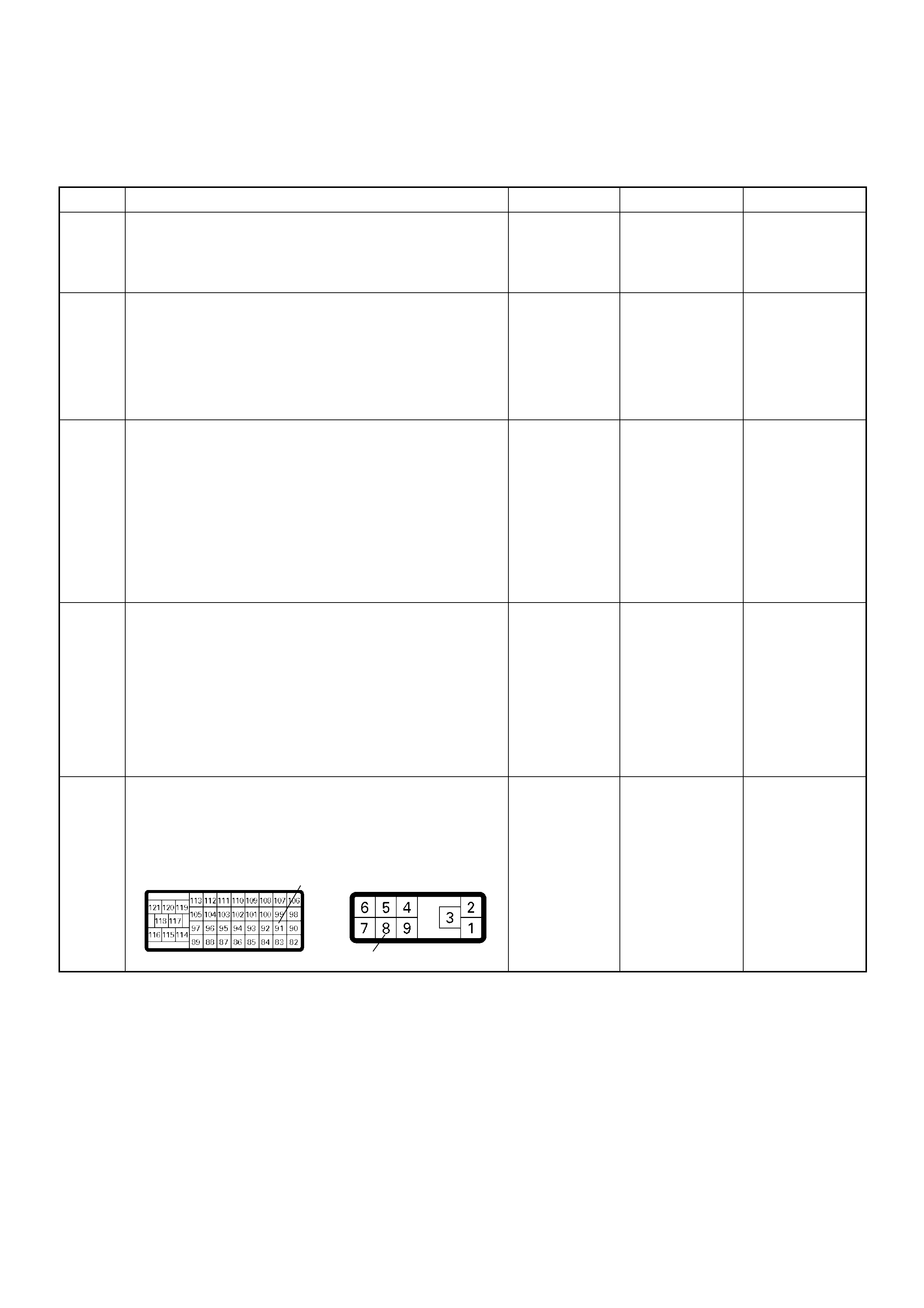
Diagnostic Trouble Code (DTC) P0251 (Symptom Code 7) (Flash Code 53)
Injection Pump Malfunction
Step Action Value(s) Yes No
1 Was the “On-Board Diagnostic (OBD) System Check”
performed?
—Go to Step 2
Go to On Board
Diagnostic
(OBD) System
Check
2 1. Connect the Tech 2.
2. Review and record the failure information.
3. Select “F0: Rea d DTC Infor As Stored By ECU” in
“F0: Diagnostic Trouble Codes”.
Is the DTC P0251 (Symptom Code 7) stored as
“Pres ent Fa ilure”? — Go to Step 3
Refer to
Diagnostic Aids
and Go to Step
3
3 1. Using the Tech 2, ignition “On” and engine “Off”.
2. Select “F1: Clear DTC Information” in “F0:
Diagnostic Trouble Codes” with the Tech 2 and
clear the DTC information.
3. Operate the vehicle and monitor the “F0: Read
DTC Infor As Stored By ECU” in the “F0:
Diagnostic Trouble Codes”.
Was the DTC P0251 ( Sy mpt om Code 7) s tor e d i n this
ignition cycle? — Go to Step 4
Refer to
Diagnostic Aids
and Go to Step
4
4 Was the DTC P0335 (Symptom Code B), P0335
(Symptom Code D) or P1335 (Symptom Code A)
stored at the same time ?
—
Go to DTC
Chart P0335
(Symptom
Code B)
(Symptom
Code D) or
P1335
(Symptom
Code A) Go to Step 5
5 Check for poor/faulty connection at the ECM or PSG
(pump control unit) connector. If a poor/faulty
connection is found, repair the faulty terminal.
Was the problem found?
— Verify repair Go to Step 6
91
8
C-57(B) E-6
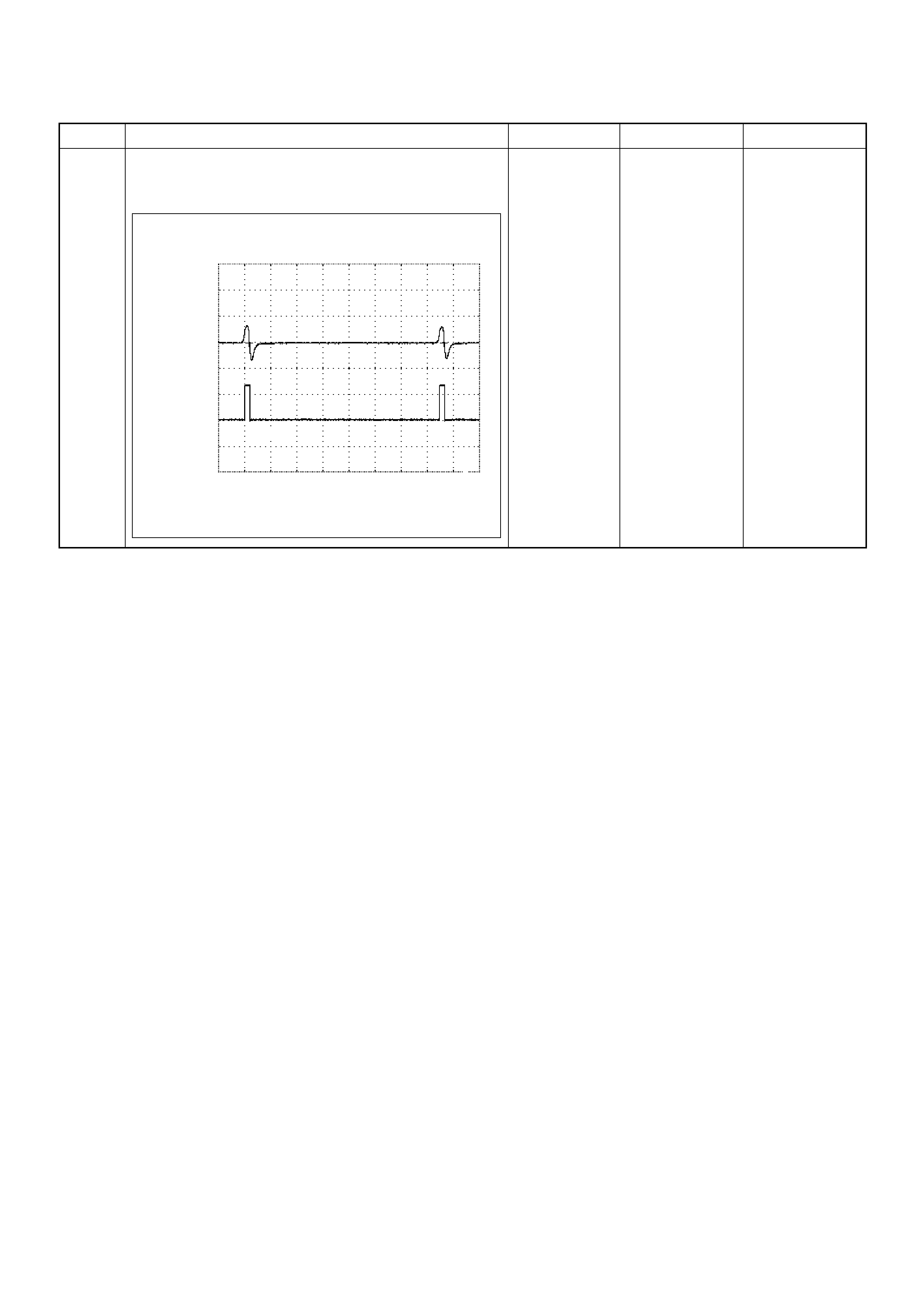
6 If an oscilloscope is available, monitor the CKP sensor
output signal. Does the oscilloscope indicate correct
wave form?
—Go to Step 13
Not available:
Go to Step 7
Fixed at low:
Go to Step 7
Fixed at High:
Go to Step 8
Step Action Value(s) Yes No
Crankshaft Position (CKP) Sensor & TDC Output Signal
Reference Wave Form
CH1
0V→
CH2
0V→
Measurement Terminal: CH1: 90(+) / CH2: 91(+) GND(-)
Measurement Scale: CH1: 50V/div / CH2: 10V/div 1ms/div
Measurement Condition: Approximately 2000rpm
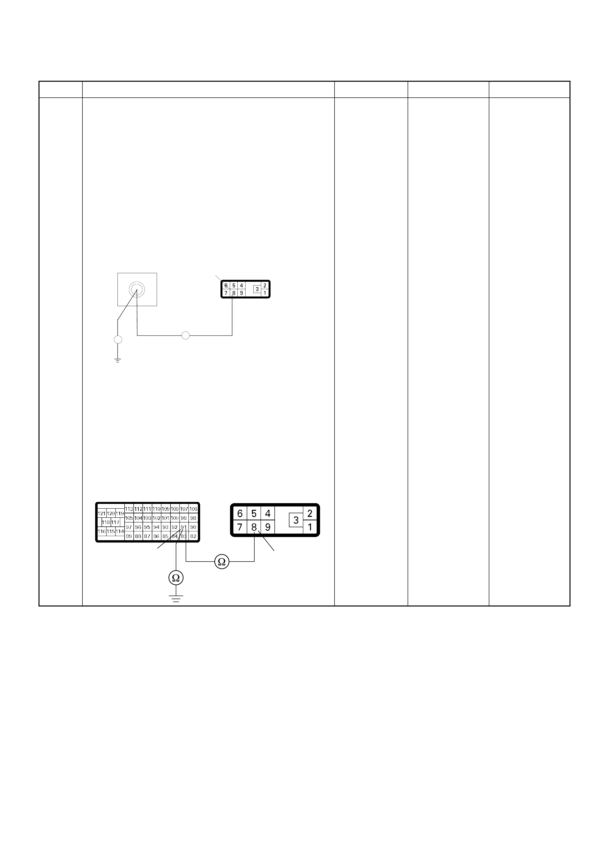
7 Using the DVM and check the CKP sensor output
circuit.
Breaker box is available:
1. Ignition “Off”, engine “Off”.
2. Install the breaker box as type A. (ECM
disconnected) Ref. to HOW TO USE BREAKER
BOX
3. Disconnect the PSG (pump control unit)
connector.
4. Check the circuit for open or short to ground
circuit.
Was the problem found?
Breaker box is not available:
1. Ignition “Off”, engine “Off”.
2. Disconnect the ECM connector.
3. Disconnect the PSG (pump control unit)
connector.
4. Check the circuit for open or short to ground
circuit.
Was the problem found?
—
Repair faulty
harn es s and
verify repair Go to Step 8
Step Action Value(s) Yes No
E-6
91
Breaker Box 8
Ħ
Ħ
91 8
C-57(B) E-6
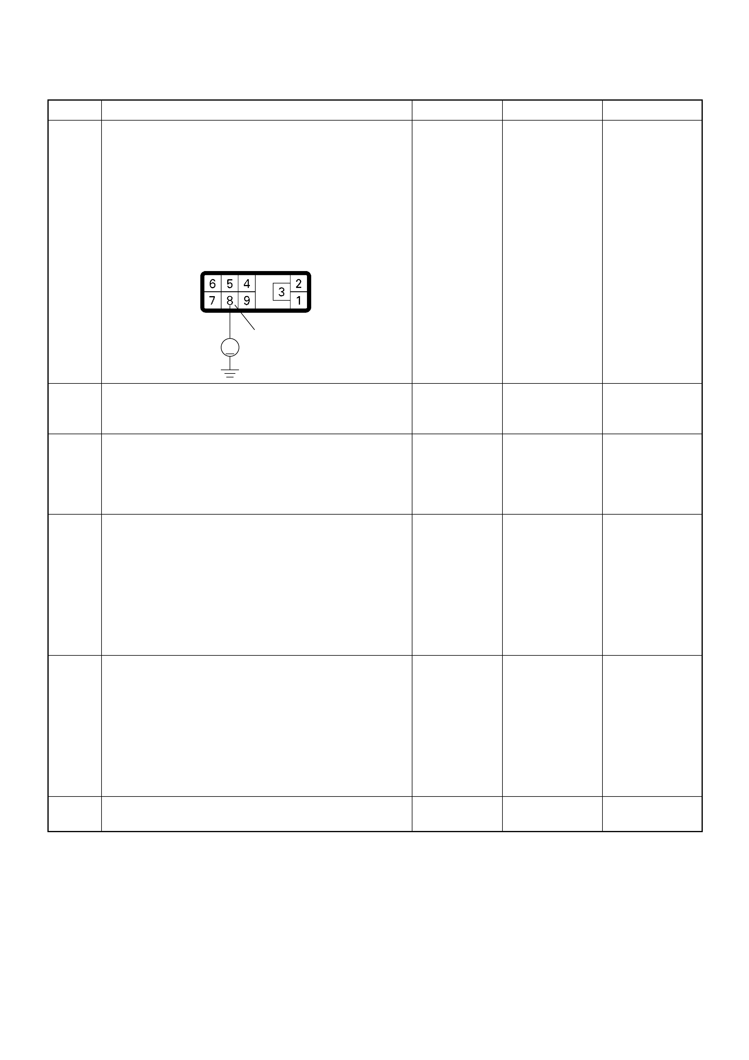
8 Using the DVM and check the CKP sensor output
circuit.
1. Ignition “On”, engine “Off”.
2. Disconnect the PSG (pump control unit)
connector.
3. Check the circuit for short to power supply circuit.
Was the DVM indicated specified value?
Less than 1V Go to Step 9
Repair faulty
harness and
verify repair
9 Check any accessory parts which may cause electric
interference or magnetic interference.
Was the problem found? —
Remove the
accessory parts
and verify repair Go to Step 10
10 Is the ECM programmed with the latest software
release?
If not, download the latest software to the ECM using
the “SPS (Service Programming System)”.
Was the problem solved? — Verify repair Go to Step 11
11 Substitute a known good ECM and recheck.
Was the problem solved?
IMPORTANT: The replacement ECM must be
programmed. Refer to section of the Service
Programming System (SPS) in this manual.
Following ECM programming, the immobilizer system
(if equipped) must be linked to the ECM. Refer to
section 11 “Immobilizer System-ECM replacement” for
the ECM/Immobilizer linking procedure. — Go to Step 12 Go to Step 13
12 Replace the ECM.
Is the action complete?
IMPORTANT: The replacement ECM must be
programmed. Refer to section of the Service
Programming System (SPS) in this manual.
Foll owing ECM pr ogramming, the immobi lizer syst em
(if equipped) must be linked to the ECM. Refer to
section 11 “Immobilizer System-ECM replacement” for
the ECM/Immobilizer linking procedure. — Verify repair —
13 Replace the injection pump assembly.
Is the action complete? — Verify repair —
Step Action Value(s) Yes No
8
V
E-6

Diagnostic Trouble Code (DTC) P0251 (Symptom Code 9) (Flash Code 53)
Injection Pump Malfunction
Step Action Value(s) Yes No
1 Was the “On-Board Diagnostic (OBD) System Check”
performed?
—Go to Step 2
Go to On Board
Diagnostic
(OBD) System
Check
2 1. Connect the Tech 2.
2. Review and record the failure information.
3. Select “F0: Rea d DTC Infor As Stored By ECU” in
“F0: Diagnostic Trouble Codes”.
Is the DTC P0251 (Symptom Code 9) stored as
“Pres ent Fa ilure”? — Go to Step 3
Refer to
Diagnostic Aids
and Go to Step
3
3 1. Using the Tech 2, ignition “On” and engine “Off”.
2. Select “F1: Clear DTC Information” in “F0:
Diagnostic Trouble Codes” with the Tech 2 and
clear the DTC information.
3. Operate the vehicle and monitor the “F0: Read
DTC Infor As Stored By ECU” in the “F0:
Diagnostic Trouble Codes”.
Was the DTC P0251 ( Sy mpt om Code 9) s tor e d i n this
ignition cycle? — Go to Step 4 Refer to
Diagnostic Aids
4 Replace the injection pump assembly.
Is the action complete? — Verify repair —

Diagnostic Trouble Code (DTC) P0251 (Symptom Code A) (Flash Code 53)
Injection Pump Malfunction
Step Action Value(s) Yes No
1 Was the “On-Board Diagnostic (OBD) System Check”
performed?
—Go to Step 2
Go to On Board
Diagnostic
(OBD) System
Check
2 1. Connect the Tech 2.
2. Review and record the failure information.
3. Select “F0: Rea d DTC Infor As Stored By ECU” in
“F0: Diagnostic Trouble Codes”.
Is the DTC P0251 (Symptom Code A) stored as
“Pres ent Fa ilure”? — Go to Step 3
Refer to
Diagnostic Aids
and Go to Step
3
3 1. Using the Tech 2, ignition “On” and engine “Off”.
2. Select “F1: Clear DTC Information” in “F0:
Diagnostic Trouble Codes” with the Tech 2 and
clear the DTC information.
3. Operate the vehicle and monitor the “F0: Read
DTC Infor As Stored By ECU” in the “F0:
Diagnostic Trouble Codes”.
Was the DTC P0251 (Symptom Code A) stored in this
ignition cycle? — Go to Step 4 Refer to
Diagnostic Aids
4 Replace the injection pump assembly.
Is the action complete? — Verify repair —

Diagnostic Trouble Code (DTC) P0251 (Symptom Code B) (Flash Code 53)
Injection Pump Malfunction
Step Action Value(s) Yes No
1 Was the “On-Board Diagnostic (OBD) System Check”
performed?
—Go to Step 2
Go to On Board
Diagnostic
(OBD) System
Check
2 1. Connect the Tech 2.
2. Review and record the failure information.
3. Select “F0: Rea d DTC Infor As Stored By ECU” in
“F0: Diagnostic Trouble Codes”.
Is the DTC P0251 (Symptom Code B) stored as
“Pres ent Fa ilure”? — Go to Step 3
Refer to
Diagnostic Aids
and Go to Step
3
3 1. Using the Tech 2, ignition “On” and engine “Off”.
2. Select “F1: Clear DTC Information” in “F0:
Diagnostic Trouble Codes” with the Tech 2 and
clear the DTC information.
3. Operate the vehicle and monitor the “F0: Read
DTC Infor As Stored By ECU” in the “F0:
Diagnostic Trouble Codes”.
Was the DTC P0251 (Symptom Code B) stored in this
ignition cycle? — Go to Step 4 Refer to
Diagnostic Aids
4 Replace the injection pump assembly.
Is the action complete? — Verify repair —

Diagnostic Trouble Code (DTC) P0251 (Symptom Code D) (Flash Code 53)
Injection Pump Malfunction
Step Action Value(s) Yes No
1 Was the “On-Board Diagnostic (OBD) System Check”
performed?
—Go to Step 2
Go to On Board
Diagnostic
(OBD) System
Check
2 1. Connect the Tech 2.
2. Review and record the failure information.
3. Select “F0: Rea d DTC Infor As Stored By ECU” in
“F0: Diagnostic Trouble Codes”.
Is the DTC P0251 (Symptom Code D) stored as
“Pres ent Fa ilure”? — Go to Step 3
Refer to
Diagnostic Aids
and Go to Step
3
3 1. Using the Tech 2, ignition “On” and engine “Off”.
2. Select “F1: Clear DTC Information” in “F0:
Diagnostic Trouble Codes” with the Tech 2 and
clear the DTC information.
3. Operate the vehicle and monitor the “F0: Read
DTC Infor As Stored By ECU” in the “F0:
Diagnostic Trouble Codes”.
Was the DTC P0251 (Symptom Code D) stored in this
ignition cycle? — Go to Step 4 Refer to
Diagnostic Aids
4 Replace the injection pump assembly.
Is the action complete? — Verify repair —

Diagnostic Trouble Code (DTC) P0251 (Symptom Code E) (Flash Code 53)
Injection Pump Malfunction
Step Action Value(s) Yes No
1 Was the “On-Board Diagnostic (OBD) System Check”
performed?
—Go to Step 2
Go to On Board
Diagnostic
(OBD) System
Check
2 1. Connect the Tech 2.
2. Review and record the failure information.
3. Select “F0: Read DTC Infor As Stored By ECU” in
“F0: Diagnostic Trouble Codes”.
Is the DTC P0251 (Symptom Code E) stored as
“Present Failure”? — Go to Step 3
Refer to
Diagnostic Aids
and Go to Step
3
3 1. Using the Tech 2, ignition “On” and engine “Off”.
2. Select “F1: Clear DTC Information” in “F0:
Diagnostic Trouble Codes” with the Tech 2 and
clear the DTC information.
3. Operate the vehicle and monitor the “F0: Read
DTC Infor As Stored By ECU” in the “F0:
Diagnostic Trouble Codes”.
Was the DTC P0251 (Symptom Code E) stored in this
ignition cycle? — Go to Step 4 Refer to
Diagnostic Aids
4 Was the DTC P1650 (Symptom Code A) or P1651
(Symptom Code B) stored at the same time?
—
Go to DTC
Chart P1650
(Symptom
Code A) Go to Step 5
5 Is the ECM programmed with the latest software
release?
If not, download the latest software to the ECM using
the “SPS (Service Programming System)”.
Was the problem solved? — Verify repair Go to Step 6
6 Substitute a known good ECM and recheck.
Was the problem solved?
IMPORTANT: The replacement ECM must be
programmed. Refer to section of the Service
Programming System (SPS) in this manual.
Foll owing ECM pr ogramming, the immobi lizer syst em
(if equipped) must be linked to the ECM. Refer to
section 11 “Immobilizer System-ECM replacement” for
the ECM/Immobilizer linking procedure. —Go to Step 7 Go to Step 8
7 Repla ce th e ECM.
Is the action complete?
IMPORTANT: The replacement ECM must be
programmed. Refer to section of the Service
Programming System (SPS) in this manual.
Foll owing ECM pr ogramming, the immobi lizer syst em
(if equipped) must be linked to the ECM. Refer to
section 11 “Immobilizer System-ECM replacement” for
the ECM/Immobilizer linking procedure. — Verify repair —
8 Replace the injection pump assembly.
Is the action complete? — Verify repair —
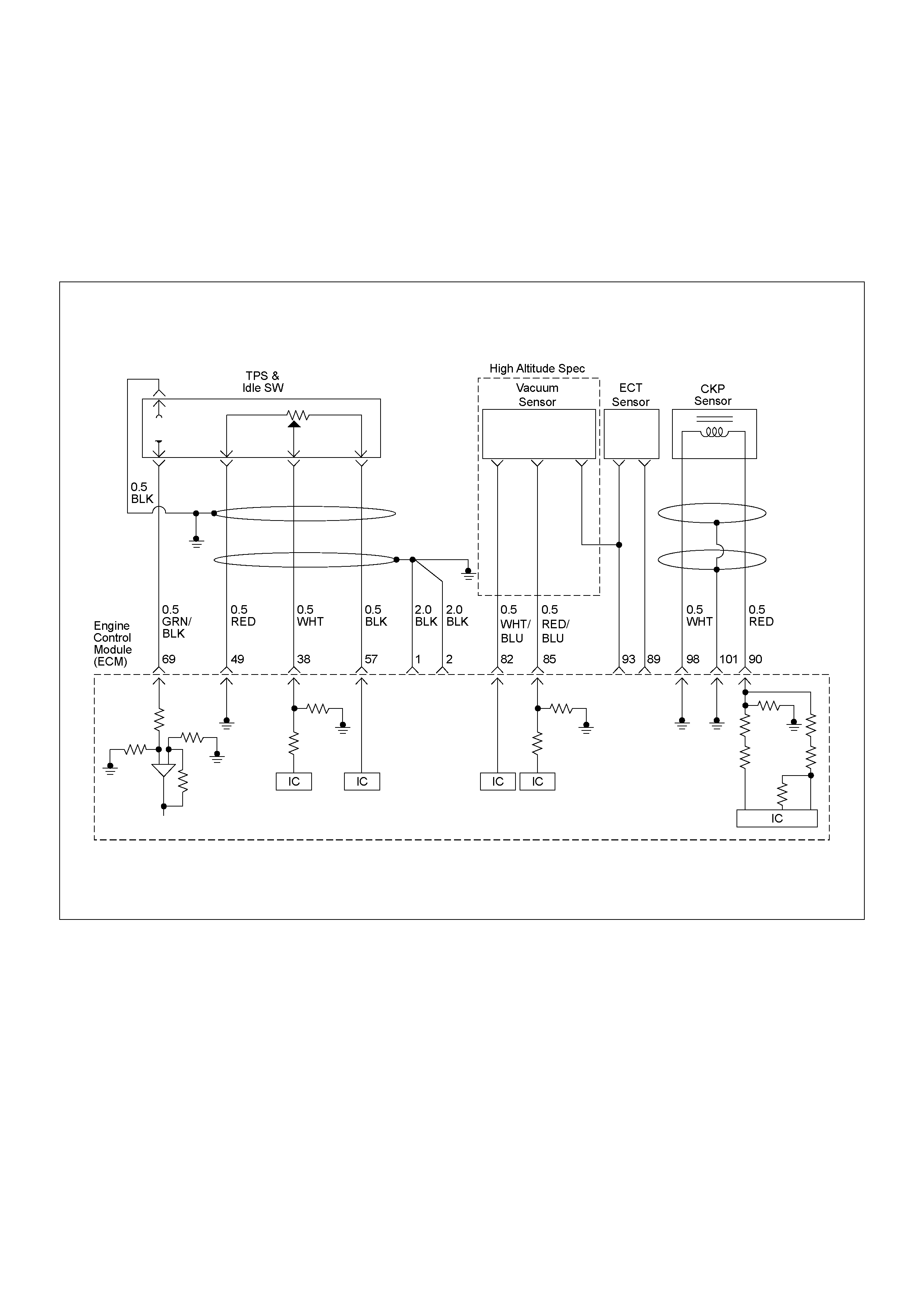
DIAGNOSTIC TROUBLE CODE (DTC) P03 35 (SYMPTOM CODE B)
(FLASH CODE 43)CRANKSHAFT POSITION SENSOR CIRCUIT MALFUNCTION
DIAGNOSTIC TROUBLE CODE (DTC) P03 35 (SYMPTOM CODE D)
(FLASH CODE 43) CRANKSHA FT POS ITION SENSOR MALFUNCTION
DIAGNOSTIC TROUBLE CODE (DTC) P0335 (SYMPTOM CODE E)
(FLASH CODE 43) ENGINE SPEED INPUT CIRCUIT RANGE/PERFORMANCE

Condition for setting the DTC and action ta ken when the DTC sets
Circuit Description
The CKP sensor is located on top of the flywheel
housing of the flywheel and fixed with a bolt. The CKP
sensor is of the magnet coil type. The inductive pickup
senses four gaps in the flywheel exciter ring and is used
to determine the engine speed and engine cylinder top
dead center.
If the CKP sensor harness or sensor malfunction is
detected during engine run, DTC P0335 (Symptom
Code B) is stored.
If the CKP sensor harness or sensor malfunction is
detected during engine cranking, DTC P0335
(Sympto m Code D) is stor ed.
If the CKP sensor signal frequency is excessively high
or engine ove r-r unning, DT C P0 335 (S ym pto m Code E)
is stored.
Diagnostic Aids
An intermittent may be caused by the following:
• Poor connections.
• Misrouted harness.
• Rubbed through wire insulation.
• Broken wire inside the insulation.
Check for the following conditions:
• Poor con nection at ECM -Inspect har ness connector s
for backed out terminals, improper mating, broken
locks, improperly formed or damaged terminals, and
poor terminal to wire connection.
• Damaged harness-Inspect the wiring harness for
damage. If the harness appears to be OK, observe
the “Engine Speed” display on the Tech2 while
moving c onnectors and wiring harn ess related to the
sensor.
Flash
Code Code Symptom
Code MIL DTC Name DTC Setting Condition Fail-Safe (Back Up)
43 P0335 B ON Crankshaft Position Sensor
Circuit Malfunction 1. Engine speed is more than
665rpm.
2. CKP sensor pulse width
error.
When pump camshaft speed
sensor is OK:
ECM uses doubled pump
camshaft speed as substitute
engine speed.
When pump camshaft speed
sensor is not OK:
1. MAB (fuel cutoff solenoid
valve) is operated.
2. Desired injection quantity
becomes 0mg/strk.
D ON Crankshaft Position Sensor
Circuit Malfunction 1. No pump camshaft speed
sensor error.
2. “Crankshaft Position
Sensor Circuit Malfunction
(Symptom Code B)” is not
stored.
3. Engine speed is 0rpm.
4. Doubled pump camshaft
speed is more than 50rpm.
When pump camshaft speed
sensor is OK:
ECM uses doubled pump
camshaft speed as substitute
engine speed.
Other than pump camshaft
speed sensor is OK:
Fuel injection quantity is
reduced.
E ON Engine Speed Input Circuit
Range/Performance En gine speed is more than
5700rpm. When intermittent malfunction:
1. MAB (fuel cutoff solenoid
valve) is operated.
2. Desired injection quantity
becomes 0mg/strk.
When preliminary malfunction:
ECM uses doubled pump
camshaft speed as substitute
engine speed.
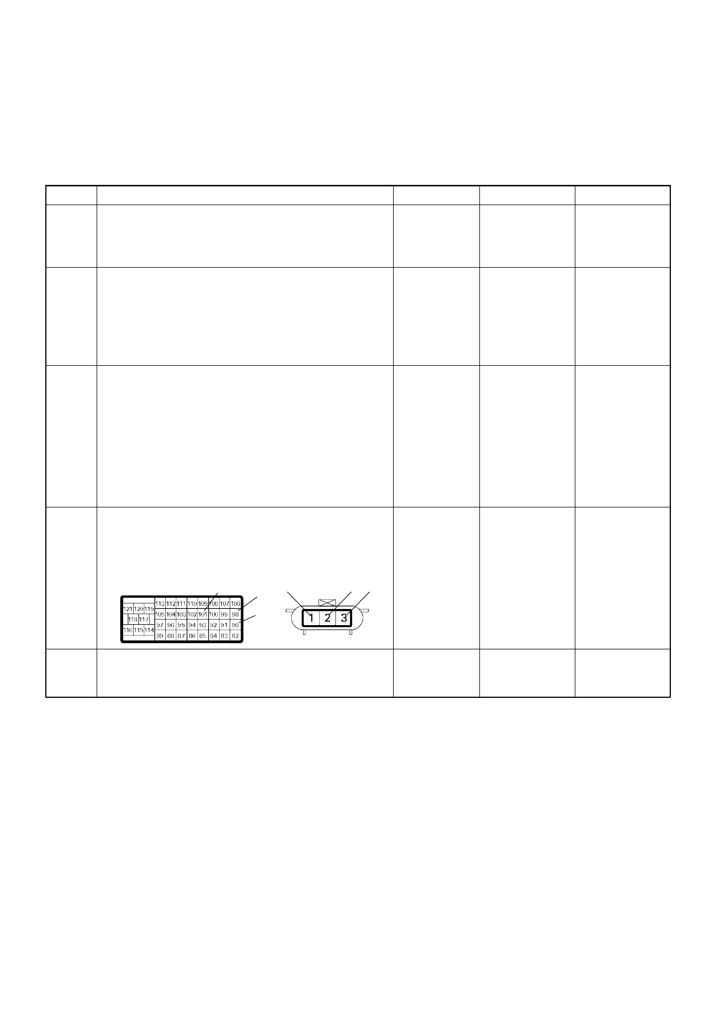
Diagnostic Trouble Code (DTC) P0335 (Symptom Code B) (Flash Code 43)
Crankshaft Position Sensor Circuit Malfunction
Diagnostic Trouble Code (DTC) P0335 (Symptom Code D) (Flash Code 43)
Crankshaft Position Sensor Malfunction
Step Action Value(s) Yes No
1 Was the “On-Board Diagnostic (OBD) System Check”
performed?
—Go to Step 2
Go to On Board
Diagnostic
(OBD) System
Check
2 1. Connect the Tech 2.
2. Review and record the failure information.
3. Select “F0: Rea d DTC Infor As Stored By ECU” in
“F0: Diagnostic Trouble Codes”.
Is the DTC P0335 (Symptom Code B) or P0335
(Symptom Code D) stored as “Present Failure”? — Go to Step 3
Refer to
Diagnostic Aids
and Go to Step
3
3 1. Using the Tech 2, ignition “On” and engine “Off”.
2. Select “F1: Clear DTC Information” in “F0:
Diagnostic Trouble Codes” with the Tech 2 and
clear the DTC information.
3. Operate the vehicle and monitor the “F0: Read
DTC Infor As Stored By ECU” in the “F0:
Diagnostic Trouble Codes”.
Was the DTC P0335 (Symptom Code B) or P0335
(Symptom Code D) stored in this ignition cycle? — Go to Step 4
Refer to
Diagnostic Aids
and Go to Step
4
4 Check for poor/faulty connection at the CKP sensor or
ECM connector. If a poor/faulty connection is found,
repair the faulty terminal.
Was the problem found?
— Verify repair Go to Step 5
5 Visually check the CKP sensor. If a faulty installation
is found, repair as necessary.
Was the problem found? — Verify repair Go to Step 6
101
90
98 2 31 E-9C-57(B)
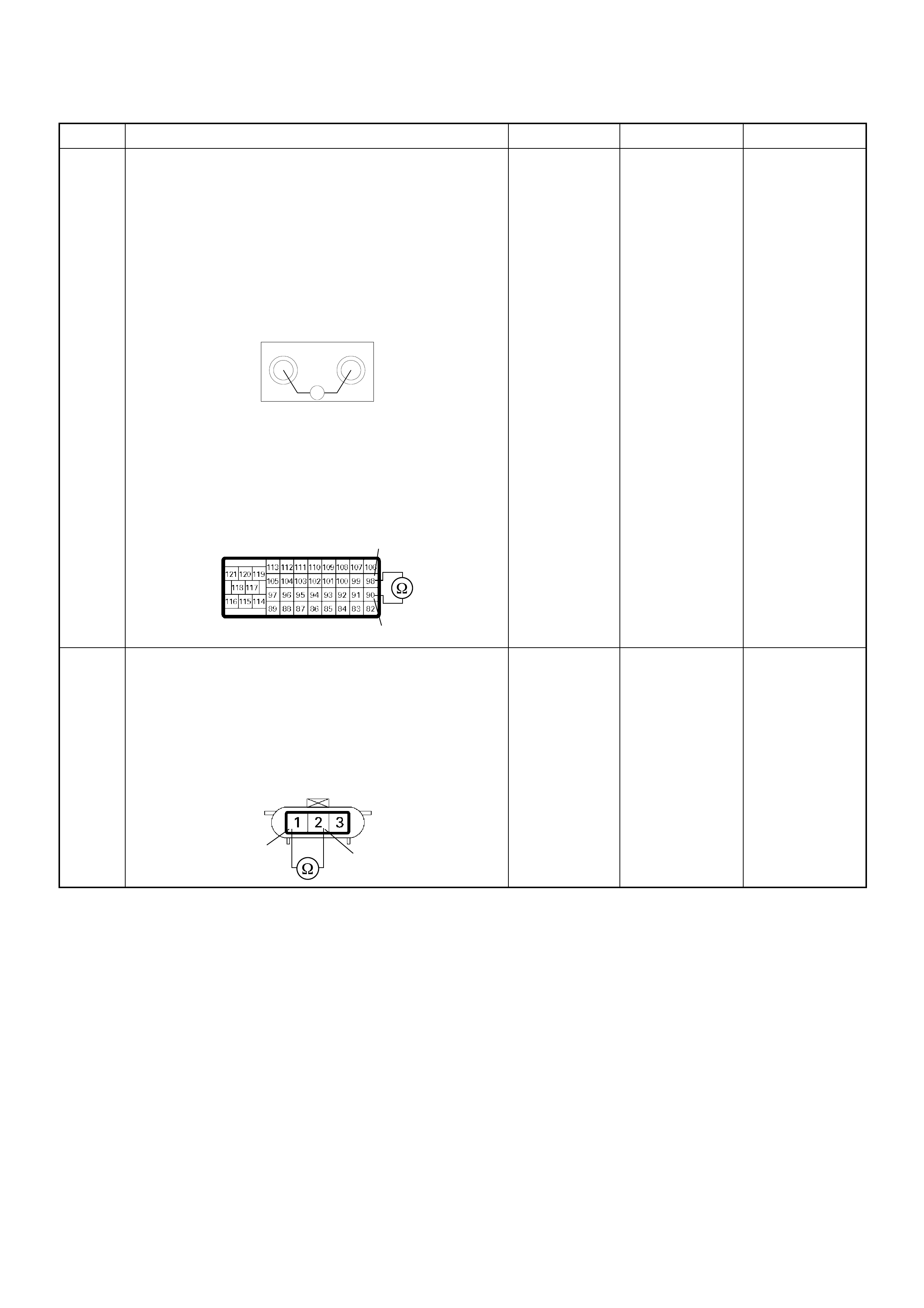
6 Using the DVM and check the CKP sensor circuit.
Breaker box is available:
1. Ignition “Off”, engine “Off”.
2. Install the breaker box as type A. (ECM
disconnected) Ref. to HOW TO USE BREAKER
BOX
3. Check the resistance of the CKP sensor.
Was the DVM indicated specified value?
Breaker box is not available:
1. Ignition “Off”, engine “Off”.
2. Disconnect the ECM connector.
3. Check the resistance of the CKP sensor.
Was the DVM indicated specified value?
Approximately
0.9kΩ at 20°C Go to Step 10 Go to Step 7
7 Using the DVM and check the CKP sensor circuit.
1. Ignition “Off”, engine “Off”.
2. Disconnect the CKP sensor connector.
3. Check the resistance of the CKP sensor.
Was the DVM indicated specified value?
Approximately
0.9kΩ at 20°C Go to Step 8 Go to Step 14
Step Action Value(s) Yes No
90 98
Ħ
Breaker Box
90
98
C-57(B)
12
E-9
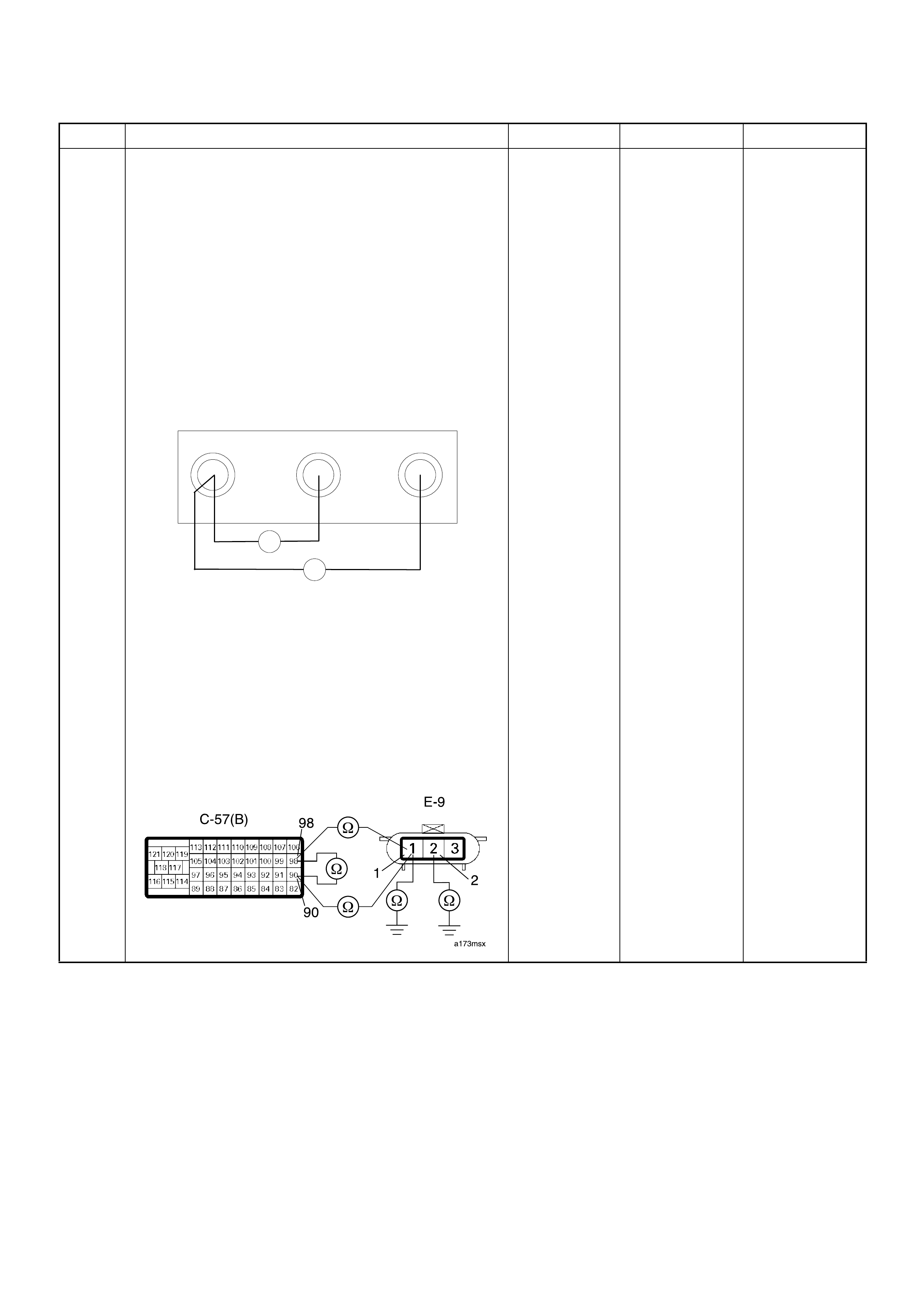
8 Using the DVM and check the CKP sensor circuit.
Breaker box is available:
1. Ignition “Off”, engine “Off”.
2. Install the breaker box as type A. (ECM
disconnected) Ref. to HOW TO USE BREAKER
BOX
3. Disconnect the CKP sensor connector.
4. Check the circuit for open , short to sens or wire or
short to ground circuit.
Was the problem found?
Breaker box is not available:
1. Ignition “Off”, engine “Off”.
2. Disconnect the ECM connector.
3. Disconnect the CKP sensor connector.
4. Check the circuit for open , short to sens or wire or
short to ground circuit.
Was the problem found?
—
Repair faulty
harn es s and
verify repair Go to Step 9
Step Action Value(s) Yes No
90 98
Breaker Bo x 101
Ħ
Ħ
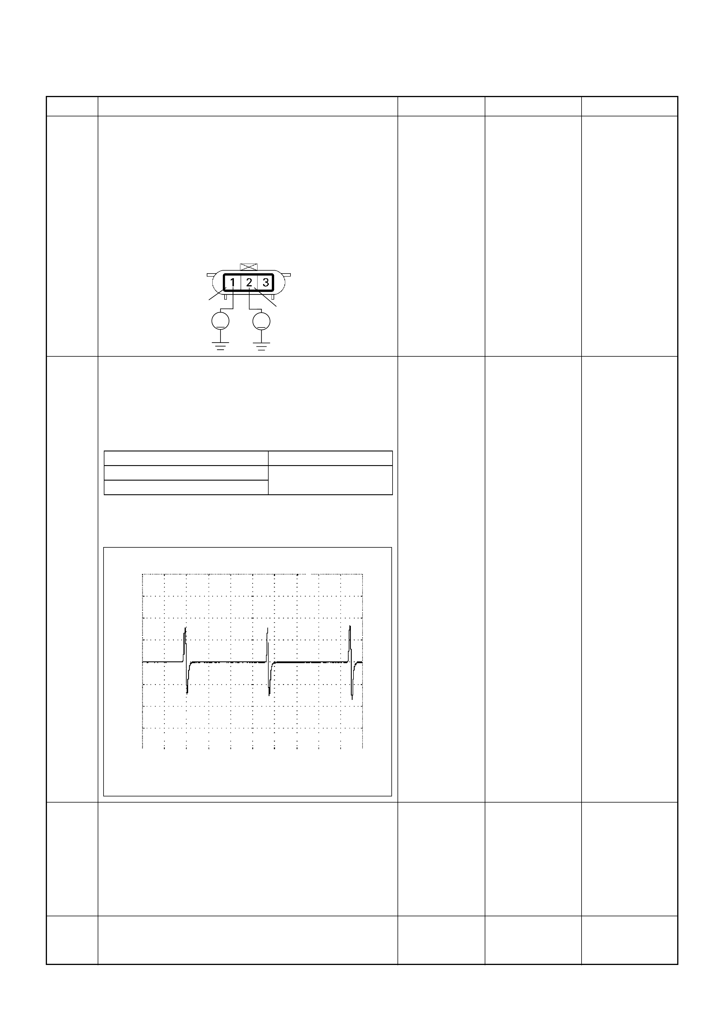
9 Using the DVM and check the CKP sensor circuit.
1. Ignition “On”, engine “Off”.
2. Disconnect the CKP sensor connector.
3. Check the circuit for short to power supply circuit.
If the DVM indicated out of specified value, repair
faulty harness and verify repair.
Is the action complete?
Less than 1V Verify repair —
10 Using the DVM and check the CKP sensor signal.
1. Ignition “On”, engine “On”.
2. Measure the CKP output voltage at the sensor
and ECM.
Does the tester indicate standard voltage?
If a osci lloscope i s availabl e, monitor the CKP sensor
signal. Does the oscilloscope indicate correct wave
form?
Go to Step 13 Go to Step 11
11 Remove the CKP sensor from the flywheel housing
and visually check.
Check for the following conditions.
• Obj ects sticki ng the CKP sensor.
• Objects sti cking the CKP sensor pu lser.
If a problem is found, repair as necessary.
Was the problem found? — Verify repair Go to Step 12
12 Check the CKP sensor shield wire for open or short
circuit.
Was the problem found? —
Repair faulty
harn es s and
verify repair Go to Step 13
Step Action Value(s) Yes No
12
VV
E-9
Measurement Point Voltage (V) (AC Range)
At CKP sensor terminal 2 & 1 Approximately 1.1 V at
2000rpm
At ECM C57 connector 90 & 98
Crankshaft Position (CKP) Sensor Reference Wave Form
0V→
Measurement Terminal: 90(+) 98(-)
Measurement Scale: 20V/div 2ms/div
Measurement Condition: Approximately 2000rpm

13 Check any accessory parts which may cause electric
interference or magnetic interference.
Was the problem found? —
Remove the
accessory parts
and verify repair Go to Step 14
14 Substitute a known good CKP sensor and recheck.
Was the problem solved? — Go to Step 15 Go to Step 16
15 Replace the CKP sensor.
Was the problem solved? — Verify repair Go to Step 16
16 Is the ECM programmed with the latest software
release?
If not, download the latest software to the ECM using
the “SPS (Service Programming System)”.
Was the problem solved? — Verify repair
Go to Step 17
17 Replace the ECM.
Is the action complete?
IMPORTANT: The replacement ECM must be
programmed. Refer to section of the Service
Programming System (SPS) in this manual.
Foll owing ECM pr ogramming, the immobi lizer sys tem
(if equipped) must be linked to the ECM. Refer to
section 11 “Immobilizer System-ECM replacement” for
the ECM/Immobilizer linking procedure. — Verify repair —
Step Action Value(s) Yes No
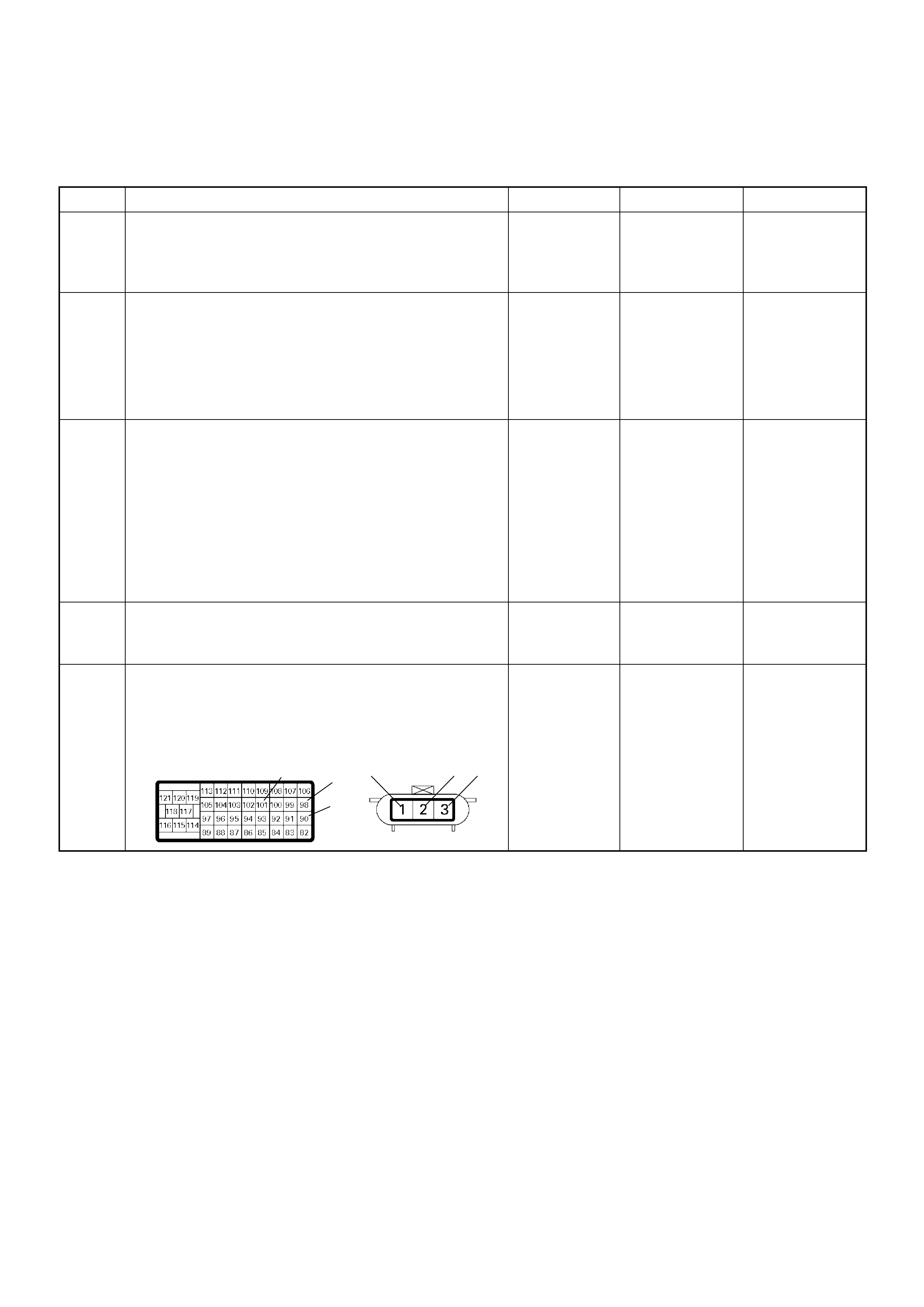
Diagnostic Trouble Code (DTC) P0335 (Symptom Code E) (Flash Code 43)
Engine Speed Input Circuit Range/Performance
Step Action Value(s) Yes No
1 Was the “On-Board Diagnostic (OBD) System Check”
performed?
—Go to Step 2
Go to On Board
Diagnostic
(OBD) System
Check
2 1. Connect the Tech 2.
2. Review and record the failure information.
3. Select “F0 : Read DTC I nfor A s Stored By E CU” in
“F0: Diagnostic Trouble Codes”.
Is the DTC P0335 (Symptom Code E) stored as
“Pres ent Fa ilure”? — Go to Step 3
Refer to
Diagnostic Aids
and Go to Step
3
3 1. Using the Tech 2, ignition “On” and engine “Off”.
2. Select “F1: Clear DTC Information” in “F0:
Diagnostic Trouble Codes” with the Tech 2 and
clear the DTC information.
3. Operate the vehicle and monitor the “F0: Read
DTC Infor As Stored By ECU” in the “F0:
Diagnostic Trouble Codes”.
Was the DTC P0335 (Symptom Code E) stored in this
ignition cycle? — Go to Step 4
Refer to
Diagnostic Aids
and Go to Step
4
4 Ask to the customer whether over-speed condition
such a s miss-gear shifting etc . has been expe rienced
or not. —
Expla in the
reason of DTC
to the customer Go to Step 5
5 Check for poor/faulty connection at the CKP sensor or
ECM connector. If a poor/faulty connection is found,
repair the faulty terminal.
Was the problem found?
— Verify repair Go to Step 6
101
90
98 2 31 E-9C-57(B)
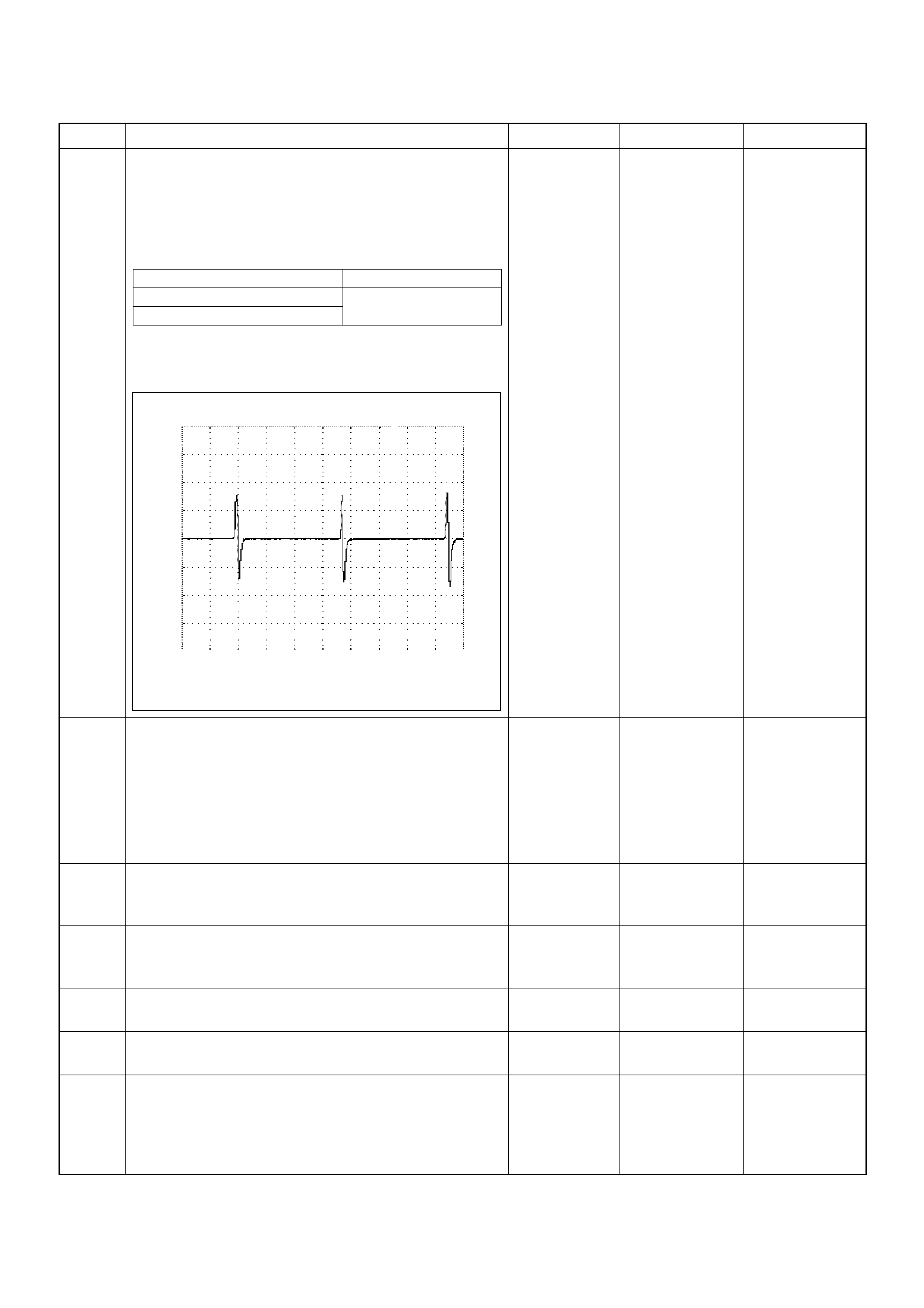
6 Using the DVM and check the CKP sensor signal.
1. Ignition “On”, engine “On”.
2. Measure the CKP output voltage at the sensor
and ECM.
Does the tester indicate standard voltage?
If a osci lloscope i s availabl e, monitor the CKP sensor
signal. Does the oscilloscope indicate correct wave
form?
Go to Step 9 Go to Step 7
7 Remove the CKP sensor from the flywheel housing
and visually check.
Check for the following conditions.
• Obj ects sticki ng the CKP sensor.
• Objects sti cking the CKP sensor pu lser.
If a problem is found, repair as necessary.
Was the problem found? — Verify repair Go to Step 8
8 Check the CKP sensor shield wire for open or short
circuit.
Was the problem found? —
Repair faulty
harn es s and
verify repair Go to Step 9
9 Check any accessory parts which may cause electric
interference or magnetic interference.
Was the problem found? —
Remove the
accessory parts
and verify repair Go to Step 10
10 Substitute a known good CKP sensor and recheck.
Was the problem solved? — Go to Step 11 Go to Step 12
11 Replace the CKP sensor.
Was the problem solved? — Verify repair Go to Step 12
12 Is the ECM programmed with the latest software
release?
If not, downlo ad the latest software to the ECM using
the “SPS (Service Programming System)”.
Was the problem solved? — Verify repair Go to Step 13
Step Action Value(s) Yes No
Measurement Point Voltage (V) (AC Range)
At CKP sensor terminal 2 & 1 Approximately 1.1 V at
2000rpm
At ECM C57 connector 90 & 98
Crankshaft Position (CKP) Sensor Reference Wave Form
0V→
Measurement Terminal: 90(+) 98(-)
Measurement Scale: 20V/div 2ms/div
Measurement Condition: Approximately 2000rpm

13 Replace the ECM.
Is the action complete?
IMPORTANT: The replacement ECM must be
programmed. Refer to section of the Service
Programming System (SPS) in this manual.
Foll owing ECM pr ogramming, the immobi lizer sys tem
(if equipped) must be linked to the ECM. Refer to
section 11 “Immobilizer System-ECM replacement” for
the ECM/Immobilizer linking procedure. — Verify repair —
Step Action Value(s) Yes No
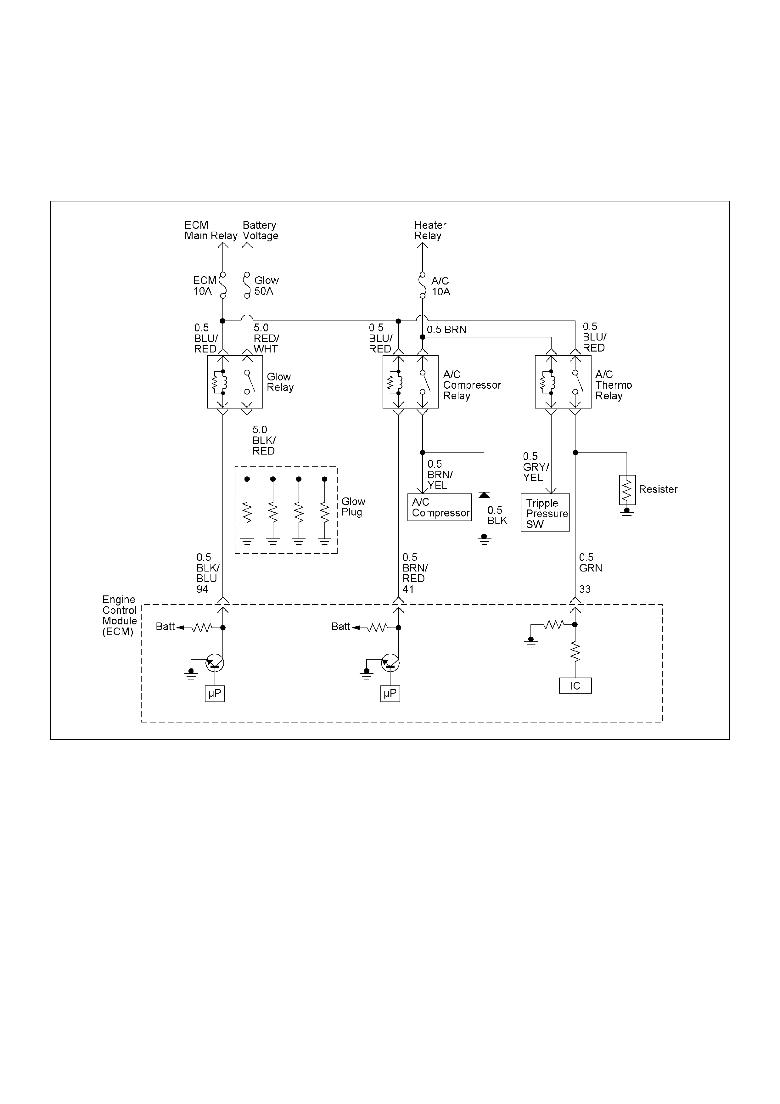
DIAGNOSTIC TROUBLE CODE (DTC) P0380 (SYM PTOM CODE 4)
(FLASH CODE 66) GLOW RELAY CIRCUIT VOLTAGE LOW
DIAGNOSTIC TROUBLE CODE (DTC) P0380 (SYM PTOM CODE 8)
(FLASH CODE 66) GLOW RELAY CIRCUIT VOLTAGE HIGH

Condition for setting the DTC and action ta ken when the DTC sets
Circuit Description
The voltage on the coil of the relay glow plug is supplied
by the relay engine control module (ECM) main. The
ECM swit ches gl ow rela y to ope ra te glow pl ug depe nds
on the coolant temperature.
In the after glow phase the lamp is not illuminated but
the glow plugs remain active for a certain period
depending on engine coolant temperature.
Diagnostic Aids
An intermittent may be caused by the following:
• Poor connections.
• Misrouted harness.
• Rubbed through wire insulation.
• Broken wire inside the insulation.
Check for the following conditions:
• Poor connection at ECM - Inspect harness
connectors for backed out terminals, improper
mating, broken locks, improperly formed or damaged
terminals, and poor terminal to wire connection.
• Damaged harness - Inspect the wiring harness for
damage. If the harness appears to be OK, observe
the DTC P0380 display on the Tech2 while moving
connectors and wiring harnesses. A change in the
display will indicate the location of the fault.
Flash
Code Code Symptom
Code MIL DTC Name DTC Setting Condition Fail-Safe (Back Up)
66 P0380 4 ON Glow Relay Circuit Voltage
Low Glow relay circuit open or
short to ground circuit. No fail-safe function.
8 ON Glow Relay Circuit V oltage
High Glow relay circuit short to
voltage circuit.
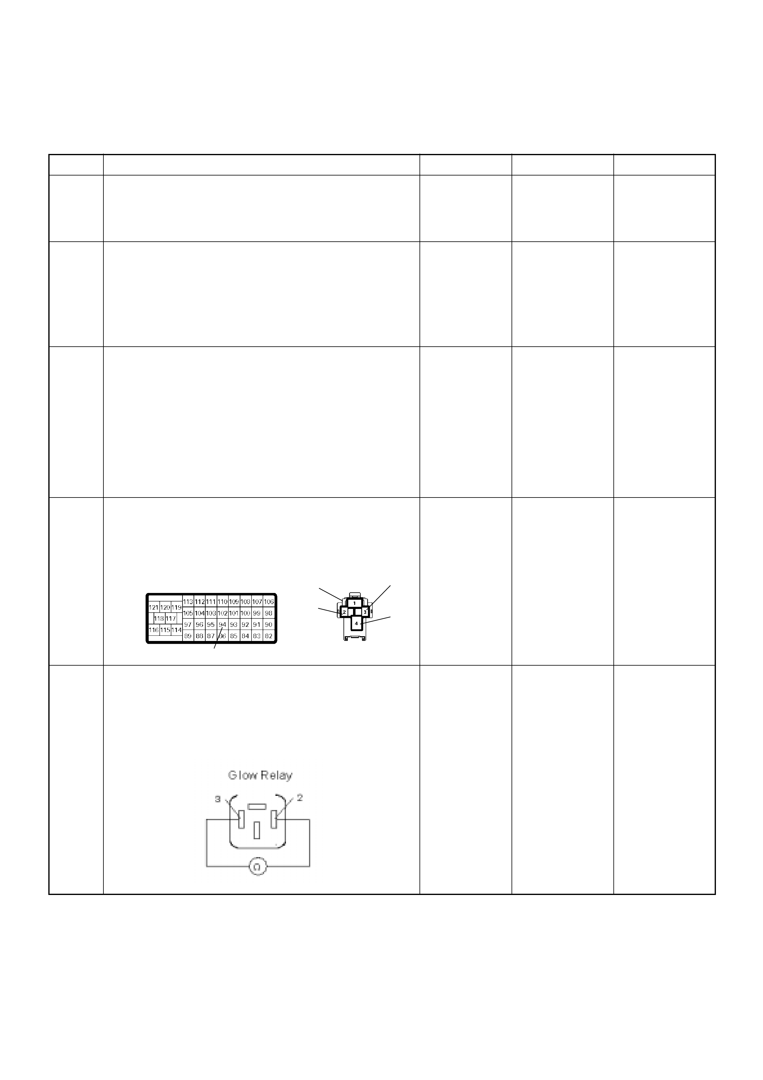
Diagnostic Trouble Code (DTC) P0380 (Symptom Code 4) (Flash Code 66)
Glow Relay Circuit Voltage Low
Step Action Value(s) Yes No
1 Was the “On-Board Diagnostic (OBD) System Check”
performed?
—Go to Step 2
Go to On Board
Diagnostic
(OBD) System
Check
2 1. Connect the Tech 2.
2. Review and record the failure information.
3. Select “F0 : Read DTC I nfor A s Stored By E CU” in
“F0: Diagnostic Trouble Codes”.
Is the DTC P0380 (Symptom Code 4) stored as
“Pres ent Fa ilure”? — Go to Step 3
Refer to
Diagnostic Aids
and Go to Step
3
3 1. Using the Tech 2, ignition “On” and engine “Off”.
2. Select “F1: Clear DTC Information” in “F0:
Diagnostic Trouble Codes” with the Tech 2 and
clear the DTC information.
3. Operate the vehicle and monitor the “F0: Read
DTC Infor As Stored By ECU” in the “F0:
Diagnostic Trouble Codes”.
Was the DTC P0380 ( Sy mpt om Code 4) st ored in th is
ignition cycle? — Go to Step 4
Refer to
Diagnostic Aids
and Go to Step
4
4 Check for poor/faulty connection at the glow relay or
ECM connector. If a poor/faulty connection is found,
repair as necessary.
Was the problem found?
— Verify repair Go to Step 5
5 Using the DVM and check the glow relay.
1. Ignition “Off”, engine “Off”.
2. Remove the glow relay from the relay box.
3. Check the relay coil.
Was the DVM indicated specified value?
Approximately
105ΩGo to Step 6
Replace glow
relay and verify
repair
94
3
4
2
1X-5C-57
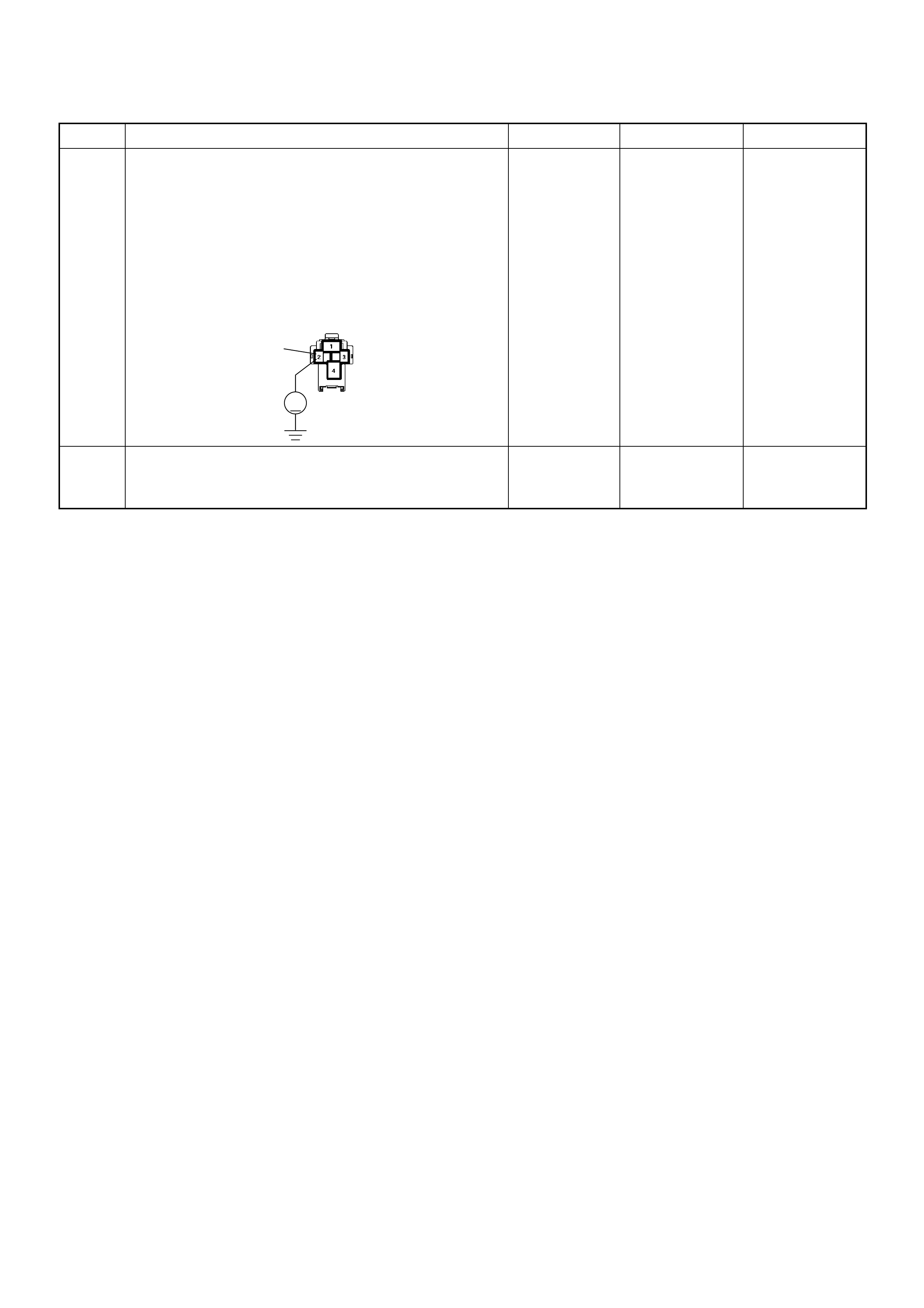
6 Using the DVM and check the glow relay power
supply circuit.
1. Ignition “On”, engine “Off”.
2. Remove the glow relay from the relay box.
3. Check the circuit for open or short to ground
circuit.
Was the DVM indicated specified value?
10-14.5V Go to Step 8 Go to Step 7
7 Repair the open or short to ground circuit between the
ECM main relay and glow relay.
Is the action complete? — Verify repair —
Step Action Value(s) Yes No
2
V
X-5
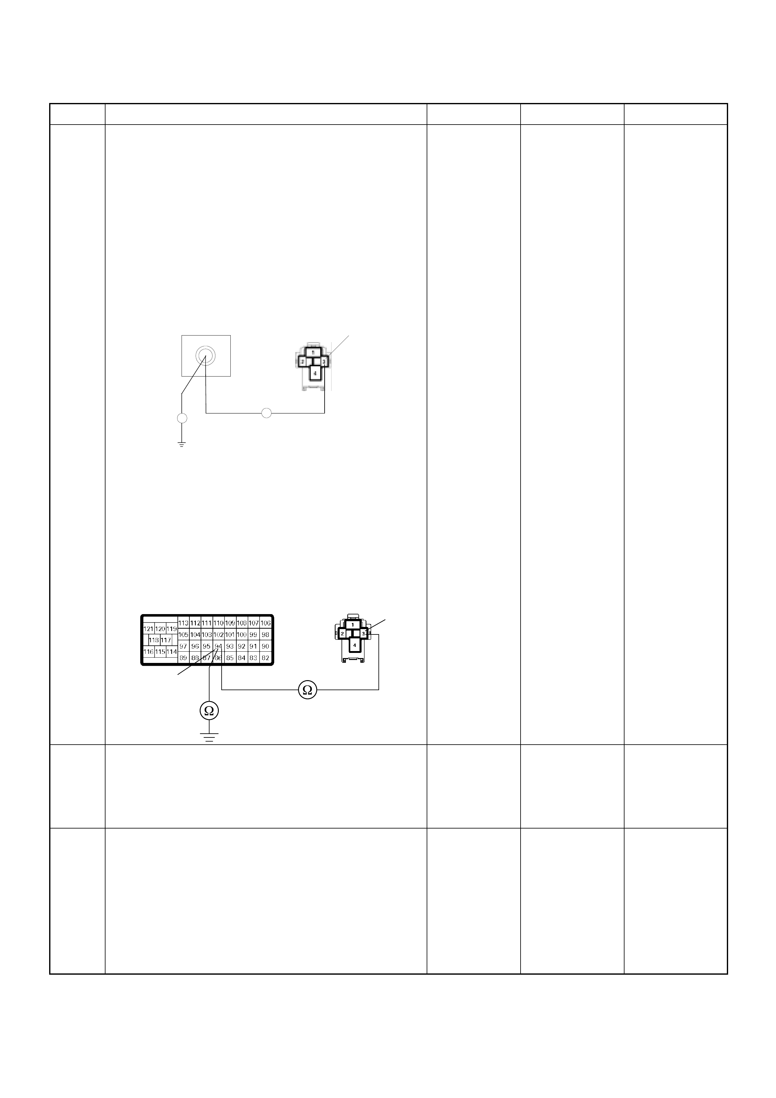
8 Using the DVM and check the glow relay ground
circuit.
Breaker box is available:
1. Ignition “Off”, engine “Off”.
2. Install the breaker box as type A. (ECM
disconnected) Ref. to HOW TO USE BREAKER
BOX
3. Remove the glow relay from the relay box.
4. Check the circuit for open or short to ground
circuit.
Was the problem found?
Breaker box is not available:
1. Ignition “Off”, engine “Off”.
2. Disconnect the ECM connector.
3. Remove the glow relay from the relay box.
4. Check the circuit for open or short to ground
circuit.
Was the problem found?
—
Repair faulty
harness and
verify repair Go to Step 9
9 Is the ECM programmed with the latest software
release?
If not, download the latest software to the ECM using
the “SPS (Service Programming System)”.
Was the problem solved? — Verify repair Go to Step 10
10 Replace the ECM.
Is the action complete?
IMPORTANT: The replacement ECM must be
programmed. Refer to section of the Service
Programming System (SPS) in this manual.
Foll owing ECM pr ogramming, the immobi lizer sys tem
(if equipped) must be linked to the ECM. Refer to
section 11 “Immobilizer System-ECM replacement” for
the ECM/Immobilizer linking procedure. — Verify repair —
Step Action Value(s) Yes No
X-5
94
Breaker Box 3
Ħ
Ħ
3
94
X-5C-57

Diagnostic Trouble Code (DTC) P0380 (Symptom Code 8) (Flash Code 66)
Glow Relay Circuit Voltage High
Step Action Value(s) Yes No
1 Was the “On-Board Diagnostic (OBD) System Check”
performed?
—Go to Step 2
Go to On Board
Diagnostic
(OBD) System
Check
2 1. Connect the Tech 2.
2. Review and record the failure information.
3. Select “F0: Read DTC Infor As Stored By ECU” in
“F0: Diagnostic Trouble Codes”.
Is the DTC P0380 (Symptom Code 8) stored as
“Present Failure”? — Go to Step 3
Refer to
Diagnostic Aids
and Go to Step
3
3 1. Using the Tech 2, ignition “On” and engine “Off”.
2. Select “F1: Clear DTC Information” in “F0:
Diagnostic Trouble Codes” with the Tech 2 and
clear the DTC information.
3. Operate the vehicle and monitor the “F0: Read
DTC Infor As Stored By ECU” in the “F0:
Diagnostic Trouble Codes”.
Was the DTC P0380 (Symptom Code 8) stored in this
ignition cycle? — Go to Step 4 Refer to
Diagnostic Aids
4 Is the ECM programmed with the latest software
release?
If not, download the latest software to the ECM using
the “SPS (Service Programming System)”.
Was the problem solved? — Verify repair Go to Step 5
5 Substitute a known good ECM and recheck.
Was the problem solved?
IMPORTANT: The replacement ECM must be
programmed. Refer to section of the Service
Programming System (SPS) in this manual.
Following ECM programming, the immobilizer system
(if equipped) must be linked to the ECM. Refer to
section 11 “Immobilizer System-ECM replacement” for
the ECM/Immobilizer linking procedure. —Go to Step 6 —
6 Replace the ECM.
Is the action complete?
IMPORTANT: The replacement ECM must be
programmed. Refer to section of the Service
Programming System (SPS) in this manual.
Foll owing ECM pr ogramming, the immobi lizer sys tem
(if equipped) must be linked to the ECM. Refer to
section 11 “Immobilizer System-ECM replacement” for
the ECM/Immobilizer linking procedure. — Verify repair —
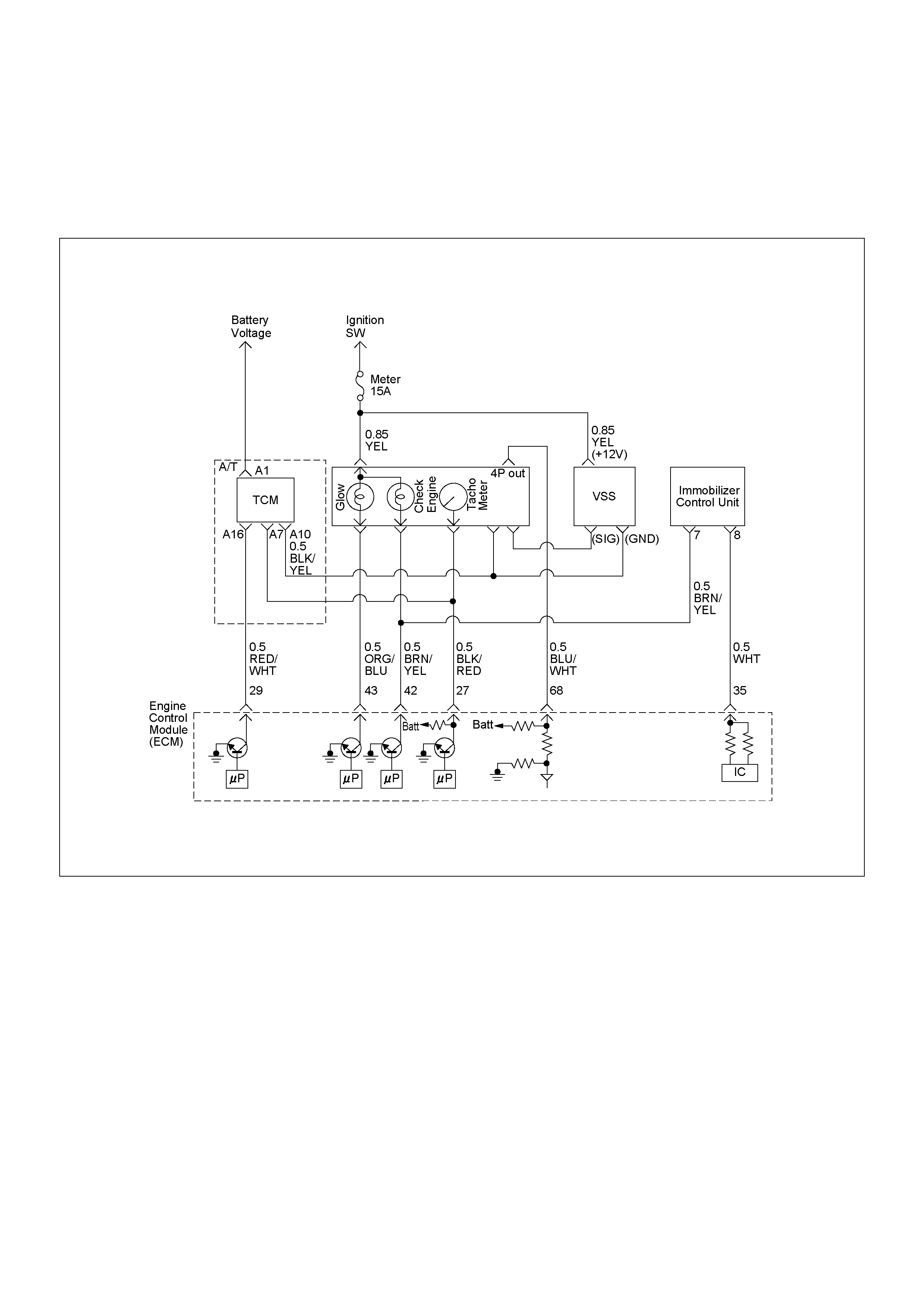
DIAGNOSTIC TROUBLE CODE (DTC) P0381 (SUB CODE 4) (FLASH CODE 67) GLOW PLUG
INDICATOR CIRCUIT VOLTAGE LOW
DIAGNOSTIC TROUBLE CODE (DTC) P0381 (SUB CODE 8) (FLASH CODE 67) GLOW PLUG
INDICATOR CIRCUIT VOLTAGE HIGH

Condition for setting the DTC and action ta ken when the DTC sets
Circuit Description
The function of th e glow time indicato r lamp is to info rm
the driver whether the glow system is activated.
When the lamp turned off, the engine can be started.
This does not imply that the glow plugs are no longer
activated.
In the after glow phase the lamp is not illuminated but
the glow plugs remain active for a certain period
depending on engine coolant temperature.
Diagnostic Aids
An intermittent may be caused by the following:
• Poor connections.
• Misrouted harness.
• Rubbed through wire insulation.
• Broken wire inside the insulation.
Check for the following conditions:
• Poor connection at ECM - Inspect harness
connectors for backed out terminals, improper
mating, broken locks, improperly formed or damaged
terminals, and poor terminal to wire connection.
• Damaged harness - Inspect the wiring harness for
damage. If the harness appears to be OK, observe
the DTC P0381 display on the Tech2 while moving
connectors and wiring harnesses. A change in the
display will indicate the location of the fault.
Flash
Code Code Symptom
Code MIL DTC Name DTC Setting Condition Fail-Safe (Back Up)
67 P0381 4 ON Glow Plug Indicator Circuit
Voltage Low Glow plug indicator circuit
open or short to ground
circuit.
No fail-safe function.
8 ON Glow Plug Indicator Circuit
Voltage High Glow plug indicator circuit
short to voltage circuit.
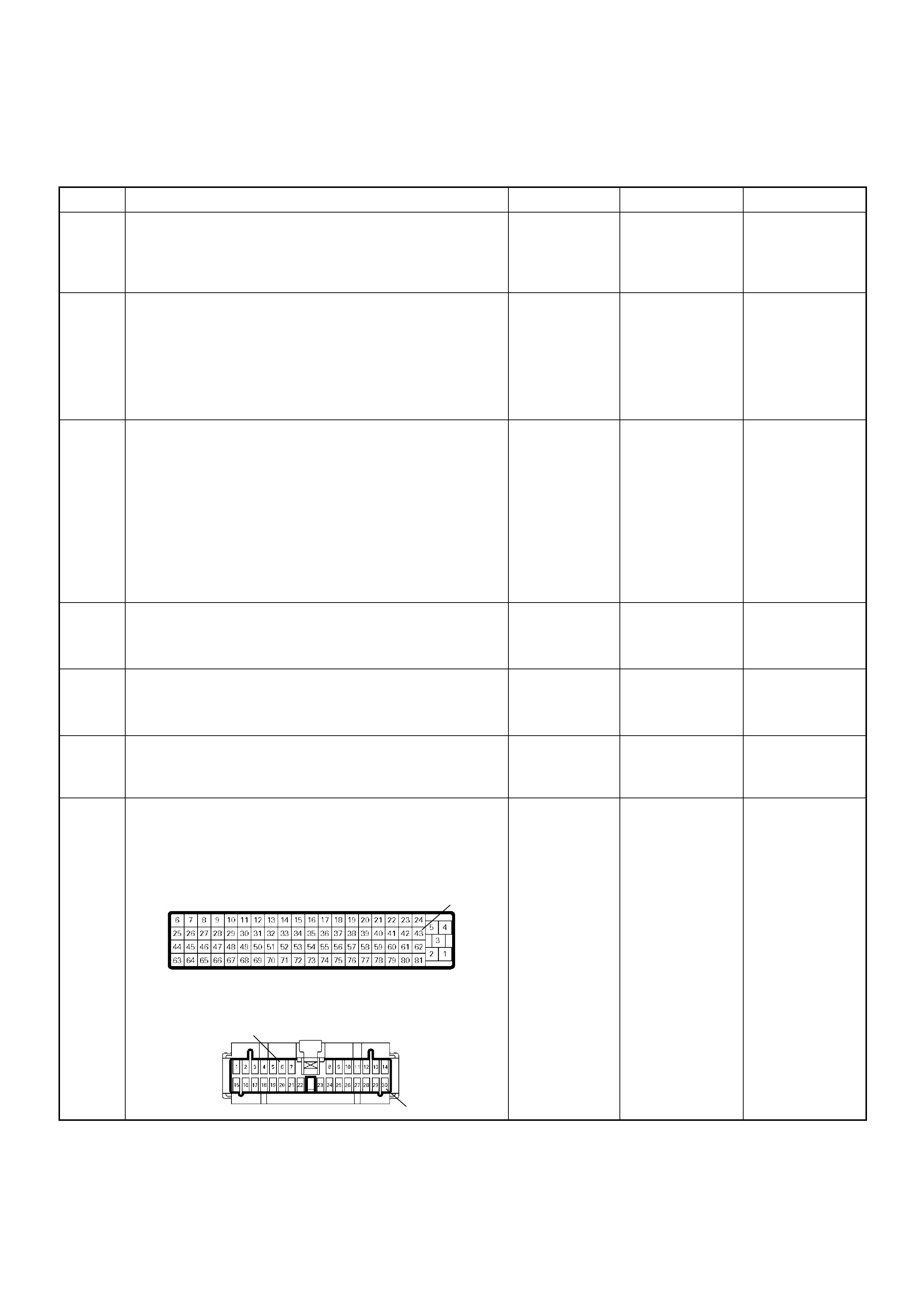
Diagnostic Trouble Code (DTC) P0381 (Symptom Code 4) (Flash Code 67)
Glow Plug Indicator Circuit Voltage Low
Step Action Value(s) Yes No
1 Was the “On-Board Diagnostic (OBD) System Check”
performed?
—Go to Step 2
Go to On Board
Diagnostic
(OBD) System
Check
2 1. Connect the Tech 2.
2. Review and record the failure information.
3. Select “F0 : Read DTC I nfor A s Stored By E CU” in
“F0: Diagnostic Trouble Codes”.
Is the DTC P0381 (Symptom Code 4) stored as
“Pres ent Fa ilure”? — Go to Step 3
Refer to
Diagnostic Aids
and Go to Step
3
3 1. Using the Tech 2, ignition “On” and engine “Off”.
2. Select “F1: Clear DTC Information” in “F0:
Diagnostic Trouble Codes” with the Tech 2 and
clear the DTC information.
3. Operate the vehicle and monitor the “F0: Read
DTC Infor As Stored By ECU” in the “F0:
Diagnostic Trouble Codes”.
Was the DTC P0381 ( Sy mpt om Code 4) st ored in th is
ignition cycle? — Go to Step 4
Refer to
Diagnostic Aids
and Go to Step
4
4 1. Ignitio n “On”, engi ne “Off”.
2. Check the glow plug indicator lamp.
Does the lamp turn “On”? — Go to Step 5 Go to Step 6
5 1. Ignitio n “On”, engi ne “Off”.
2. Check the glow plug indicator lamp.
Does the lamp turn “Off”? — Go to Step 9 Go to Step 7
6 Check the glow plug indicator lamp bulb.
If the bulb is burnt out, repair as necessary.
Was the problem found? — Verify repair Go to Step 7
7 Check for poor/faulty connection at the meter
connector and ECM connector. If a poor/faulty
connection is found, repair as necessary.
Was the problem found?
— Verify repair Go to Step 8
43
6
30
B-24
C-56
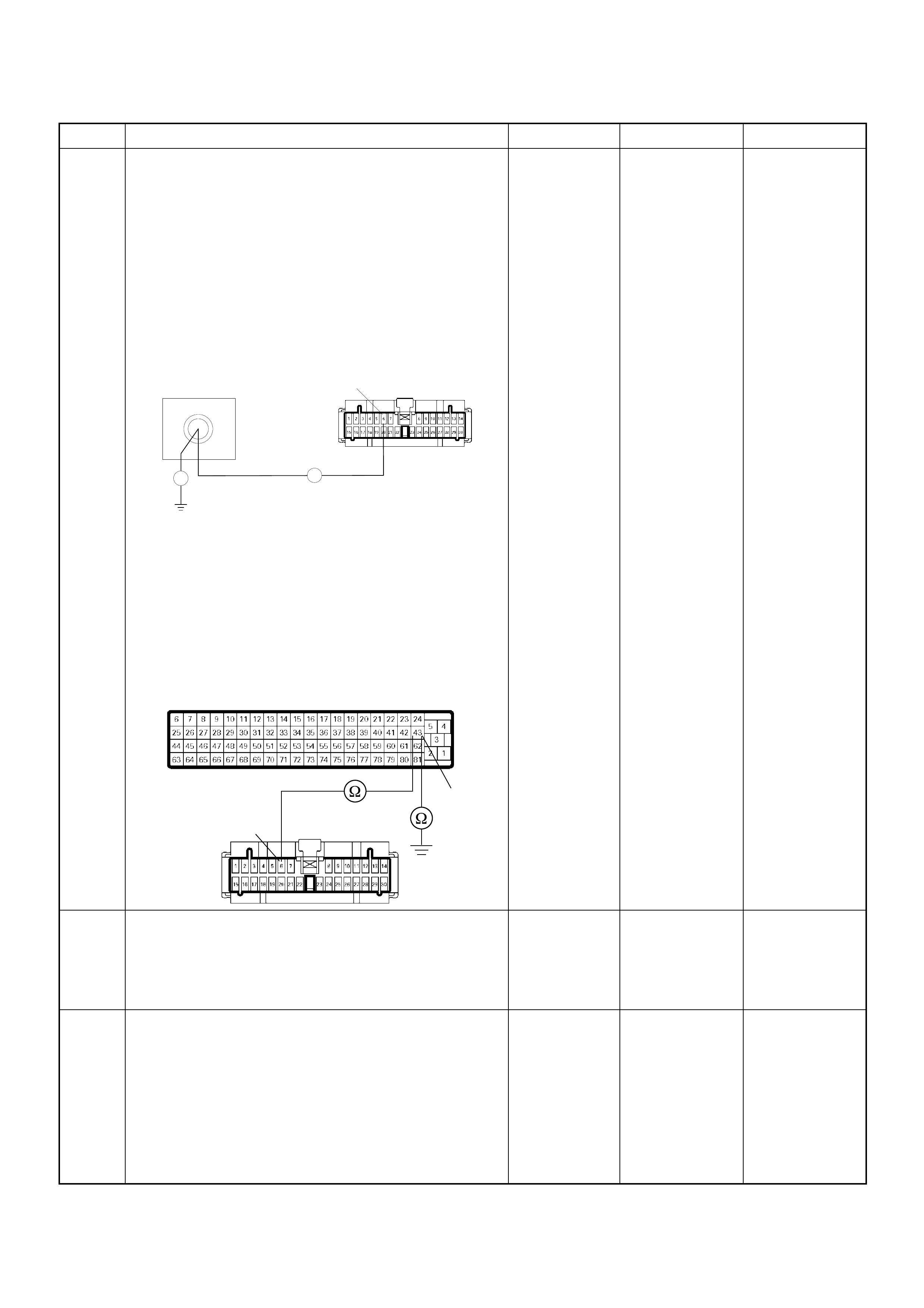
8 Using the DVM and check the glow time telltale circuit.
Breaker box is available:
1. Ignition “Off”, engine “Off”.
2. Install the breaker box as type A. (ECM
disconnected) Ref. to HOW TO USE BREAKER
BOX
3. Remove the meter connector.
4. Check the circuit for open or short to ground
circuit.
Was the problem found?
Breaker box is not available:
1. Ignition “Off”, engine “Off”.
2. Disconnect the ECM connector.
3. Remove the meter connector.
4. Check the circuit for open or short to ground
circuit.
Was the problem found?
—
Repair faulty
harness and
verify repair
Go to Step 9
9 Is the ECM programmed with the latest software
release?
If not, download the latest software to the ECM using
the “SPS (Service Programming System)”.
Was the problem solved? — Verify repair
Go to Step 10
10 Replace the ECM.
Is the action complete?
IMPORTANT: The replacement ECM must be
programmed. Refer to section of the Service
Programming System (SPS) in this manual.
Foll owing ECM pr ogramming, the immobi lizer sys tem
(if equipped) must be linked to the ECM. Refer to
section 11 “Immobilizer System-ECM replacement” for
the ECM/Immobilizer linking procedure. — Verify repair —
Step Action Value(s) Yes No
43
Breaker Box B-24
6
Ħ
Ħ
43
6B-24
C-56

Diagnostic Trouble Code (DTC) P0381 (Symptom Code 8) (Flash Code 67)
Glow Plug Indicator Circuit Voltage High
Step Action Value(s) Yes No
1 Was the “On-Board Diagnostic (OBD) System Check”
performed?
—Go to Step 2
Go to On Board
Diagnostic
(OBD) System
Check
2 1. Connect the Tech 2.
2. Review and record the failure information.
3. Select “F0: Read DTC Infor As Stored By ECU” in
“F0: Diagnostic Trouble Codes”.
Is the DTC P0381 (Symptom Code 8) stored as
“Present Failure”? — Go to Step 3
Refer to
Diagnostic Aids
and Go to Step
3
3 1. Using the Tech 2, ignition “On” and engine “Off”.
2. Select “F1: Clear DTC Information” in “F0:
Diagnostic Trouble Codes” with the Tech 2 and
clear the DTC information.
3. Operate the vehicle and monitor the “F0: Read
DTC Infor As Stored By ECU” in the “F0:
Diagnostic Trouble Codes”.
Was the DTC P0381 (Symptom Code 8) stored in this
ignition cycle? — Go to Step 4 Refer to
Diagnostic Aids
4 Is the ECM programmed with the latest software
release?
If not, download the latest software to the ECM using
the “SPS (Service Programming System)”.
Was the problem solved? — Verify repair Go to Step 5
5 Substitute a known good ECM and recheck.
Was the problem solved?
IMPORTANT: The replacement ECM must be
programmed. Refer to section of the Service
Programming System (SPS) in this manual.
Following ECM programming, the immobilizer system
(if equipped) must be linked to the ECM. Refer to
section 11 “Immobilizer System-ECM replacement” for
the ECM/Immobilizer linking procedure. —Go to Step 6 —
6 Replace the ECM.
Is the action complete?
IMPORTANT: The replacement ECM must be
programmed. Refer to section of the Service
Programming System (SPS) in this manual.
Foll owing ECM pr ogramming, the immobi lizer sys tem
(if equipped) must be linked to the ECM. Refer to
section 11 “Immobilizer System-ECM replacement” for
the ECM/Immobilizer linking procedure. — Verify repair —
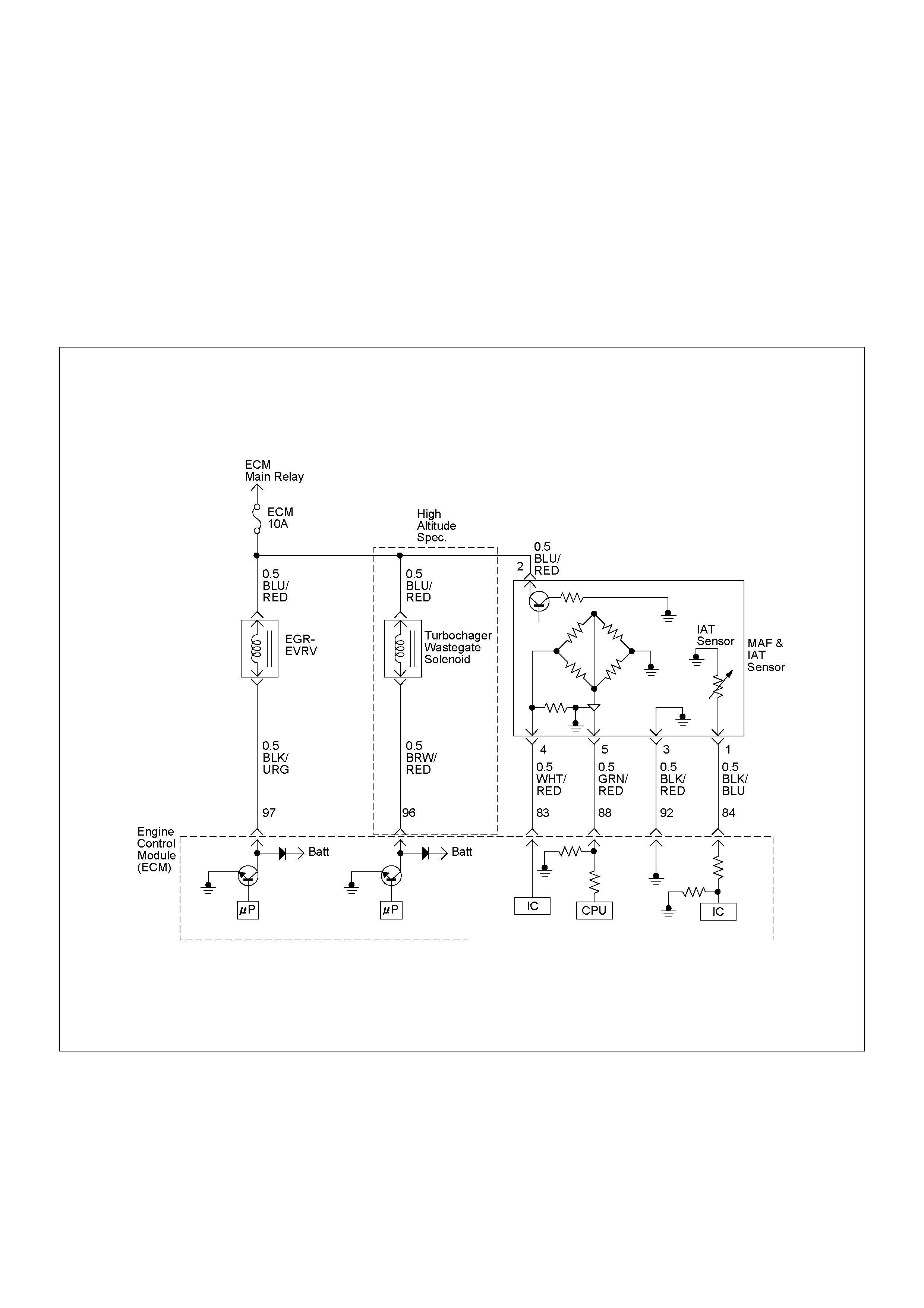
DIAGNOSTIC TROUBLE CODE (DTC) P0400 (SYM PTOM CODE 3)
(FLASH CODE 32) EXHAUS T GAS RECIRCULATION FLOW EXCESSIVE DETECTED
DIAGNOSTIC TROUBLE CODE (DTC) P0400 (SYM PTOM CODE 4)
(FLASH CODE 32) EXHAUS T GA S RECIRCULATION CIRCUIT SHORT TO GROUND OR
OPEN CIRCUIT
DIAGNOSTIC TROUBLE CODE (DTC) P0400 (SYM PTOM CODE 5)
(FLASH CODE 32) EXHAUS T GAS RECIRCULATION FLOW INSU FFICIENT DETECTED
DIAGNOSTIC TROUBLE CODE (DTC) P0400 (SYM PTOM CODE 8)
(FLASH CODE 32) EXHAUST GAS RECIRCULATION CIRCUIT SHORT TO BATTERY

Condition for setting the DTC and action taken when the DTC sets
Flash
Code Code Symptoms
Code MIL DTC Name DTC Setting Condition Fail-Safe (Back Up)
3 ON Exhaust Gas Recirculation
Excessive Flow Detected 1. Intake air temperature is
between 15 deg. C and
100 deg. C.
2. Engine coolant
temperature is between
35 deg. C and 100 deg.
C.
3. Barometric pressure is
between 85 kPa and 110
kPa.
4. Small amount of mass
air flow. (Desired mass
air flow - mass air flow is
more than 150 mg/strk.
Fuel injection quantity is
reduced.
4 ON Exhaust Gas Recirculation
Circuit Short to Ground or
Open Circuit.
EGR EVRV circuit open or
short to ground circuit. Fuel injection quantity is
reduced and EGR EVRV
10% conditions as
substitute.
5 ON Exhaust Gas Recirculation
Flow Insufficient Detected 1. Intake air temperature
is -between 15 deg. C
and 100 deg. C.
2. Engine coolant
temperature is between
35 deg. C and 100 deg.
C.
3. Barometric pressure is
between 85 kPa and
1100 kPa.
4. Large mount of mass
air flow. (Desired mass
air flow - mass air flow
is below 150 mg/strk).
Fuel injection quantity is
reduced.
32 P0400
8 ON Exhaust Gas Recirculation
Circuit Short to Battery EGR EVRV circuit short to
voltage circuit. Fuel injection quantity is
reduced and EGR EVRV
10% conditions as
substitute.
Circuit Description
The amount of EGR is controlled by EVRV (electrical
vacuum regula ti ng val ve) via the e ngine control module
(ECM) command signal depend s on the engine sp eed,
operating o f the accelerator pedal and engine coolant
temperature.
The EVRV is shaped to control vacuum applied to the
diaphragm chamber of the EGR valve based on du ty signal
sent from the ECM.
If the EGR valve is stu ck at open po siti on or close posi tio n,
DTC P0400 (Symptom Code 3) or DTC P0400 (Symptom
Code 5) i s stored.
If the EGR EVRV circui t is open or sh ort ground circuit, DTC
P0400 (Symptom Code 4) is stored.
If the EGR EVRV circuit is short to voltage circuit, DTC
P0400 (Symptom Code 8) is stored.
Diagnostic Aids
An intermittent may be caused by the following:
• Poor connections.
• Misrouted harne ss.
• Rubbed th rough w ire in sula ti on .
• Broken wire inside the insula tion .
• EGR valve sticking.
• Faulty inta ke air duct conn ection.
Check for the fo llow ing co ndition s:
• Poor connection at EC M-Inspect harne ss connector s for
backed out termin al s, improper ma ting , broken locks,
improperly formed or damage d termin al s, and poor
terminal to w ire connection .
Damaged harnes s-Inspect the w iring harne ss for dama ge. If
the harness appears to be OK, obse rve the DTC P0400
display on the Te ch 2 while moving connectors and wiring
harnesses. A change in the display will indicate th e loca tion
of the fault.

Diagnostic Trouble Code (DTC) P0400 (Symptom Code 3) (Flash Code 32)
Exhaust Gas Recirculation Flow Excessive Detected
Step Action Value(s) Yes No
1 Was the “On-Board Diagnostic (OBD) System Check”
performed?
—Go to Step 2
Go to On Board
Diagnostic
(OBD) System
Check
2 1. Connect the Tech 2.
2. Review and record the failure information.
3. Select “F0 : Read DTC I nfor A s Stored By E CU” in
“F0: Diagnostic Trouble Codes”.
Is the DTC P0400 (Symptom Code 3) stored as
“Pres ent Fa ilure”? — Go to Step 3
Refer to
Diagnostic Aids
and Go to Step
3
3 1. Using the Tech 2, ignition “On” and engine “Off”.
2. Select “F1: Clear DTC Information” in “F0:
Diagnostic Trouble Codes” with the Tech 2 and
clear the DTC information.
3. Operate the vehicle and monitor the “F0: Read
DTC Infor As Stored By ECU” in the “F0:
Diagnostic Trouble Codes”.
Was the DTC P0400 ( Sy mpt om Code 3) st ored in th is
ignition cycle? — Go to Step 4
Refer to
Diagnostic Aids
and Go to Step
4
4 Remove the MAF & IAT sensor assembly and check
for the following conditions.
• Objects blocking the air cleaner.
• Objects blocking the MAF sensor.
• Vacuum leaking at intake duct.
• Objects blocking the turbocharger.
If a problem is found, repair as necessary.
Was the problem found? — Verify repair Go to Step 5
5 Re move the MA F & IAT sensor as sembl y and vis ually
check.
Was the problem found? — Go to Step 6 Go to Step 8
6 Substitute a known good MAF & IAT sensor assembly
and re check.
Was the problem solved? — Go to Step 7 Go to Step 8
7 Replace the MAF & IAT sensor assembly.
Is the action complete? — Verify repair —
8 Using the DVM and check the EGR EVRV.
1. Ignition “Off”, engine “Off”.
2. Disconnect the EGR EVRV connector.
3. Measure the resistance of EGR EVRV solenoid
coil.
Does the tester indicate standard resistance?
Approximately
14Ω at 20°C Go to Step 11 Go to Step 9
12
EGR EVRV 12
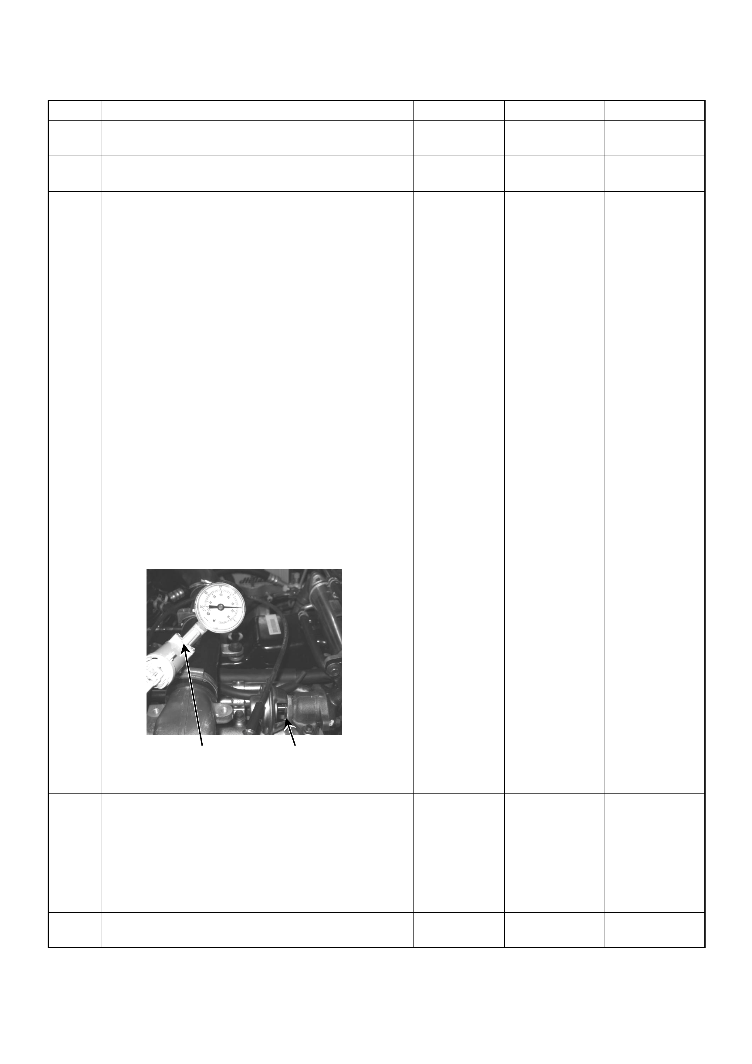
9 Substitute a known good EGR EVRV and recheck.
Was the problem solved? — Go to Step 10 Go to Step 11
10 Replace the EGR EVRV.
Is the action complete? — Verify repair —
11 Using the Tec h 2 or the v acuum pump a nd check th e
EGR valve operation for the following condition
through the small window.
• Restricted shaft movement. Check for objects
sticking the shaft, broken diaphragm or
exce ssive carbon depo sit.
Tech 2:
1. Using the Tech 2, ignition "On" and engine "On".
2. Select the "Miscellaneous Test" and perform the
"EGR Solenoid Test" in the "Solenoid".
3. Operate the Tech 2 in accordance with procedure.
• Solenoid 95%: EGR Valve Open
• Solenoid 5%: EGR Valve Close
Vacuum Pump:
1. Using the vacuum pump. Disconnect the original
vacuum hose and connect the hose to the EGR
valve.
2. Apply vacuum pressure.
• Vacuum Apply: EGR Valve Open
• Vacuum R elease: EGR Valv e Close
If a problem is found, repair as necessary.
Was the problem found? — Verify repair or
Go to Step 13 Go to Step 12
12 Inspect the EGR valve.
1. Remove the EGR valve from the engine.
2. Inspect the EGR valve whether pintle valve is
stuck or damage d.
If excessive carbon deposit is found, clean up the
EGR valve and inspect damage of the pintle and seat.
Was the problem found? — Verify repair or
Go to Step 13 Go to Step 14
13 Replace the EGR valve.
Is the action complete? — Verify repair —
Step Action Value(s) Yes No
Vacuum Pump Small Window

14 Is the ECM programmed with the latest software
release?
If not, download the latest software to the ECM using
the “SPS (Service Programming System)”.
Was the problem solved? — Verify repair Go to Step 15
15 Replace the ECM.
Is the action complete?
IMPORTANT: The replacement ECM must be
programmed. Refer to section of the Service
Programming System (SPS) in this manual.
Foll owing ECM pr ogramming, the immobi lizer sys tem
(if equipped) must be linked to the ECM. Refer to
section 11 “Immobilizer System-ECM replacement” for
the ECM/Immobilizer linking procedure. — Verify repair —
Step Action Value(s) Yes No
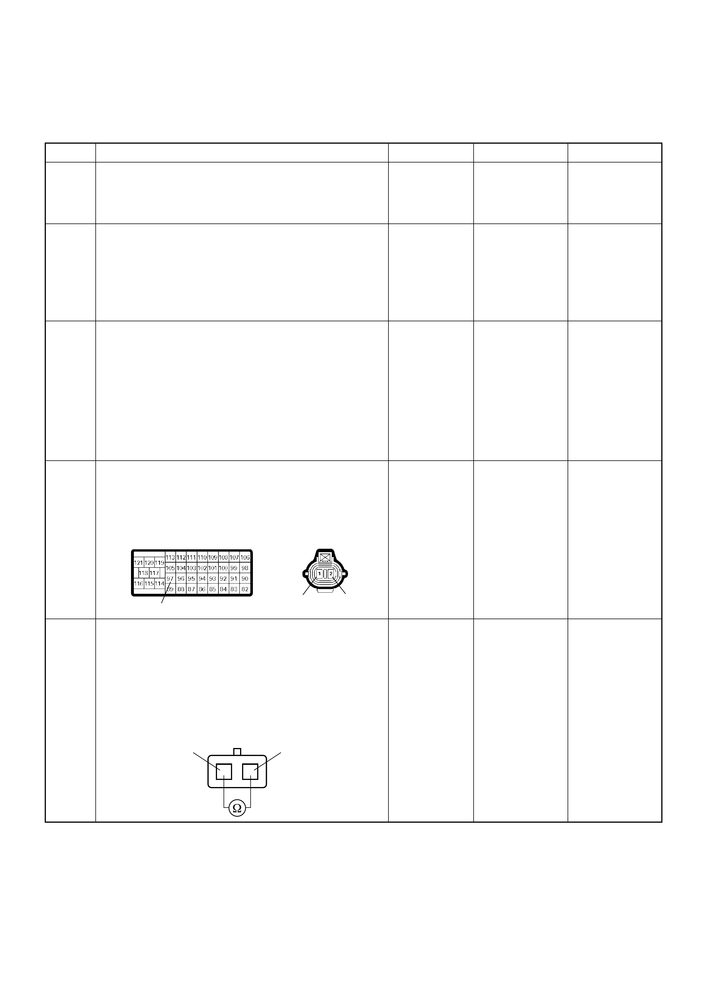
Diagnostic Trouble Code (DTC) P0400 (Symptom Code 4) (Flash Code 32)
Exhaust Gas Recirculation Circuit Short to Ground or Open Circuit
Step Action Value(s) Yes No
1 Was the “On-Board Diagnostic (OBD) System Check”
performed?
—Go to Step 2
Go to On Board
Diagnostic
(OBD) System
Check
2 1. Connect the Tech 2.
2. Review and record the failure information.
3. Select “F0 : Read DTC I nfor A s Stored By E CU” in
“F0: Diagnostic Trouble Codes”.
Is the DTC P0400 (Symptom Code 4) stored as
“Pres ent Fa ilure”? — Go to Step 3
Refer to
Diagnostic Aids
and Go to Step
3
3 1. Using the Tech 2, ignition “On” and engine “Off”.
2. Select “F1: Clear DTC Information” in “F0:
Diagnostic Trouble Codes” with the Tech 2 and
clear the DTC information.
3. Operate the vehicle and monitor the “F0: Read
DTC Infor As Stored By ECU” in the “F0:
Diagnostic Trouble Codes”.
Was the DTC P0400 ( Sy mpt om Code 4) st ored in th is
ignition cycle? — Go to Step 4
Refer to
Diagnostic Aids
and Go to Step
4
4 Ch eck for p oor/fa ulty c onnect ion at the EGR EVRV or
ECM connector. If a poor/faulty connection is found,
repair as necessary.
Was the problem found?
— Verify repair Go to Step 5
5 Using the DVM and check the EGR EVRV.
1. Ignition “Off”, engine “Off”.
2. Disconnect the EGR EVRV connector.
3. Measure the resistance of EGR EVRV solenoid
coil.
Does the tester indicate standard resistance?
Approximately
14Ω at 20°C Go to Step 6 Go to Step 9
97 12
C-115C-57
12
EGR EVRV 12
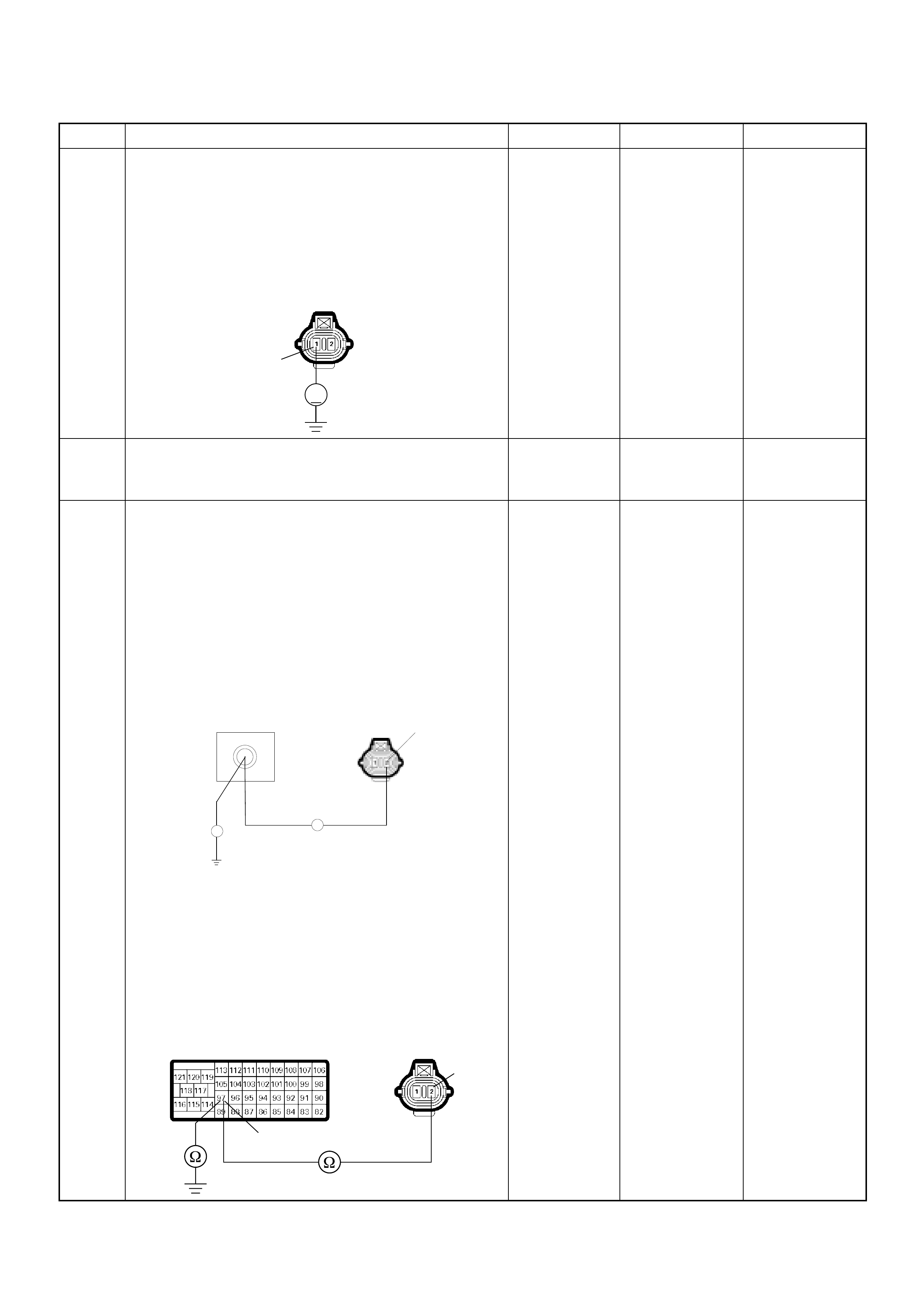
6 Using the DVM and check the EGR EVRV power
supply circuit.
1. Ignition “On”, engine “Off”.
2. Remove the EGR EVRV connector.
3. Check the circuit for open circuit.
Was the DVM indicated specified value?
10-14.5 V Go to Step 8 Go to Step 7
7 Repair the open circuit between the ECM main relay
and EGR EVR V.
Is the action complete? — Verify repair —
8 Using the DVM and check the EGR EVRV circuit.
Breaker box is available:
1. Ignition “Off”, engine “Off”.
2. Install the breaker box as type A. (ECM
disconnected) Ref. to HOW TO USE BREAKER
BOX
3. Remove the EGR EVRV connector.
4. Check the circuit for open or short to ground
circuit.
Was the problem found?
Breaker box is not available:
1. Ignition “Off”, engine “Off”.
2. Disconnect the ECM connector.
3. Remove the EGR EVRV connector.
4. Check the circuit for open or short to ground
circuit.
Was the problem found?
—
Repair faulty
harn es s and
verify repair Go to Step 11
Step Action Value(s) Yes No
V
1
C-115
C-115
97
Breaker Box 2
Ħ
Ħ
97
2
C-115C-57

9 Substitute a known good EGR EVRV and recheck.
Was the problem solved? — Go to Step 10 Go to Step 11
10 Replace the EGR EVRV.
Is the action complete? — Verify repair —
11 Is the ECM programmed with the latest software
release?
If not, download the latest software to the ECM using
the “SPS (Service Programming System)”.
Was the problem solved? — Verify repair Go to Step 12
12 Replace the ECM.
Is the action complete?
IMPORTANT: The replacement ECM must be
programmed. Refer to section of the Service
Programming System (SPS) in this manual.
Foll owing ECM pr ogramming, the immobi lizer sys tem
(if equipped) must be linked to the ECM. Refer to
section 11 “Immobilizer System-ECM replacement” for
the ECM/Immobilizer linking procedure. — Verify repair —
Step Action Value(s) Yes No

Diagnostic Trouble Code (DTC) P0400 (Symptom Code 5) (Flash Code 32)
Exhaust Gas Recirculation Flow Insufficient Detected
Step Action Value(s) Yes No
1 Was the “On-Board Diagnostic (OBD) System Check”
performed?
—Go to Step 2
Go to On Board
Diagnostic
(OBD) System
Check
2 1. Connect the Tech 2.
2. Review and record the failure information.
3. Select “F0 : Read DTC I nfor A s Stored By E CU” in
“F0: Diagnostic Trouble Codes”.
Is the DTC P0400 (Symptom Code 5) stored as
“Pres ent Fa ilure”? — Go to Step 3
Refer to
Diagnostic Aids
and Go to Step
3
3 1. Using the Tech 2, ignition “On” and engine “Off”.
2. Select “F1: Clear DTC Information” in “F0:
Diagnostic Trouble Codes” with the Tech 2 and
clear the DTC information.
3. Operate the vehicle and monitor the “F0: Read
DTC Infor As Stored By ECU” in the “F0:
Diagnostic Trouble Codes”.
Was the DTC P0400 ( Sy mpt om Code 5) st ored in th is
ignition cycle? — Go to Step 4
Refer to
Diagnostic Aids
and Go to Step
4
4 Visually check the EGR control vacuum hose.
If the hose is clogged or disconnected, repair as
necessary.
Was the problem found? — Verify repair Go to Step 5
5 Using the DVM and check the EGR EVRV.
1. Ignition “Off”, engine “Off”.
2. Disconnect the EGR EVRV connector.
3. Measure the resistance of EGR EVRV solenoid
coil.
Does the tester indicate standard resistance?
Approximately
14Ω at 20°C Go to Step 8 Go to Step 6
6 Substitute a known good EGR EVRV and recheck.
Was the problem solved? — Go to Step 7 Go to Step 8
7 Replace the EGR EVRV.
Is the action complete? — Verify repair —
12
EGR EVRV 12

8 Usi ng the Tech 2 o r the vacuu m pump and check the
EGR valve operation for the following condition
through the small window.
• Restricted shaft movement. Check for objects
sticking the shaft, broken diaphragm or
exce ssive carbon depo sit.
Tech 2:
3. Using the Tech 2, ignition "On" and engine "On".
4. Select the "Miscellaneous Test" and perform the
"EGR Solenoid Test" in the "Solenoid".
5. Operate the Tech 2 in accordance with procedure.
• Solenoid 95%: EGR Valve Open
• Solenoid 5%: EGR Valve Close
Vacuum Pump:
1. Using the vacuum pump. Disconnect the original
vacuum hose and connect the hose to the EGR
valve.
2. Apply vacuum pressure.
• Vacuum Apply: EGR Valve Open
• Vacuum R elease: EGR Valv e Close
If a problem is found, repair as necessary.
Was the problem found? — Verify repair or
Go to Step 10 Go to Step 9
9 Inspe ct the EGR valv e.
1. Remove the EGR valve from the engine.
2. Inspect the EGR valve whether pintle valve is
stuck or damage d.
If excessive carbon deposit is found, clean up the
EGR valve and inspect damage of the pintle and seat.
Was the problem found? — Verify repair or
Go to Step 10 Go to Step 11
10 Replace the EGR valve.
Is the action complete? — Verify repair -
Step Action Value(s) Yes No
Vacuum Pump Small Window
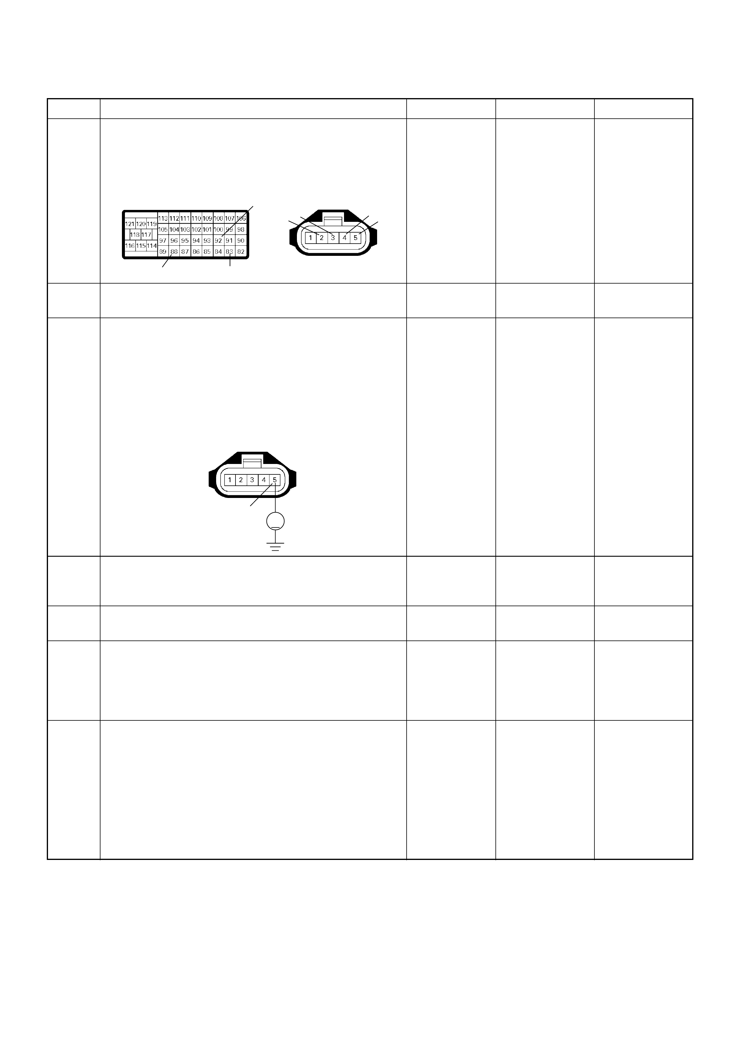
11 Check for poor/faulty connection at the MAF sensor or
ECM connector. If a poor/faulty connection is found,
repair as necessary.
Was the problem found?
— Verify repair
Go to Step 12
12 Visually check the MAF sensor.
Was the problem found? —
Go to Step 14 Go to Step 13
13 Using the DVM and check the MAF sensor signal
circuit.
1. Ignition “On”, engine “Off”.
2. Disconnect the MAF sensor connector.
3. Check the circuit for short to power supply circuit.
Was the DVM indicated specified value?
Less than 1V
Go to Step 16
Repair faulty
harness and
verify repair
14 Substitute a known good MAF & IAT sensor assembly
and recheck.
Was the problem solved? —
Go to Step 15 Go to Step 16
15 Replace the MAF & IAT sensor assembly.
Is the action complete? — Verify repair —
16 Is the ECM programmed with the latest software
release?
If not, download the latest software to the ECM using
the “SPS (Service Programming System)”.
Was the problem solved? — Verify repair
Go to Step 17
17 Replace the ECM.
Is the action complete?
IMPORTANT: The replacement ECM must be
programmed. Refer to section of the Service
Programming System (SPS) in this manual.
Foll owing ECM pr ogramming, the immobi lizer sys tem
(if equipped) must be linked to the ECM. Refer to
section 11 “Immobilizer System-ECM replacement” for
the ECM/Immobilizer linking procedure. — Verify repair —
Step Action Value(s) Yes No
92
88 83
2345
C-116C-57(B)
5
V
C-116
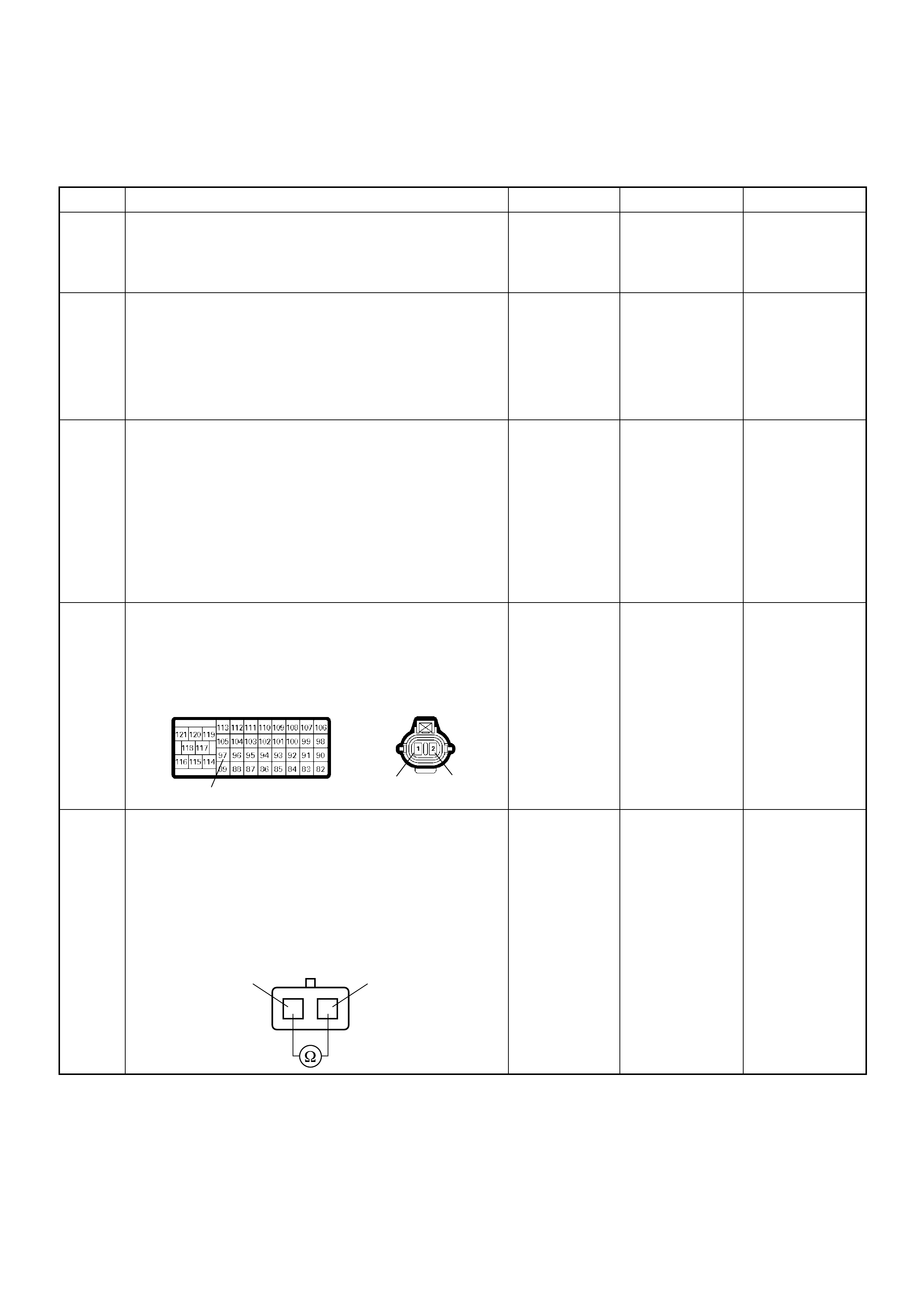
Diagnostic Trouble Code (DTC) P0400 (Symptom Code 8) (Flash Code 32)
Exhaust Gas Recirculation Circuit Short to Battery
Step Action Value(s) Yes No
1 Was the “On-Board Diagnostic (OBD) System Check”
performed?
—Go to Step 2
Go to On Board
Diagnostic
(OBD) System
Check
2 1. Connect the Tech 2.
2. Review and record the failure information.
3. Select “F0 : Read DTC I nfor A s Stored By E CU” in
“F0: Diagnostic Trouble Codes”.
Is the DTC P0400 (Symptom Code 8) stored as
“Pres ent Fa ilure”? — Go to Step 3
Refer to
Diagnostic Aids
and Go to Step
3
3 1. Using the Tech 2, ignition “On” and engine “Off”.
2. Select “F1: Clear DTC Information” in “F0:
Diagnostic Trouble Codes” with the Tech 2 and
clear the DTC information.
3. Operate the vehicle and monitor the “F0: Read
DTC Infor As Stored By ECU” in the “F0:
Diagnostic Trouble Codes”.
Was the DTC P0400 ( Sy mpt om Code 8) st ored in th is
ignition cycle? — Go to Step 4 Refer to
Diagnostic Aids
4 Ch eck for p oor/fa ulty c onnect ion at the EGR EVRV or
ECM connector. If a poor/faulty connection is found,
repair as necessary.
Was the problem found?
— Verify repair Go to Step 5
5 Using the DVM and check the EGR EVRV.
1. Ignition “Off”, engine “Off”.
2. Disconnect the EGR EVRV connector.
3. Measure the resistance of EGR EVRV solenoid
coil.
Does the tester indicate standard resistance?
Approximately
14Ω at 20°C Go to Step 6 Go to Step 8
97 12
C-115C-57
12
EGR EVRV 12

6 Using the DVM and check the EGR EVRV circuit.
1. Ignition “Off”, engine “Off”.
2. Remove the EGR EVRV connector and ECM
connector.
3. 3. Check the circuit for short to voltage circuit.
Was the DVM indicated specified value?
No continuity Go to Step 10 Go to Step 7
7 Repair the short to voltage circuit.
Is the action complete? — Verify repair —
8 Substitute a known good EGR EVRV and recheck.
Was the problem solved? — Go to Step 9 Go to Step 10
9 Replace the EGR EVRV.
Is the action complete? — Verify repair —
10 Is the ECM programmed with the latest software
release?
If not, download the latest software to the ECM using
the “SPS (Service Programming System)”.
Was the problem solved? — Verify repair Go to Step 11
11 Replace the ECM.
Is the action complete?
IMPORTANT: The replacement ECM must be
programmed. Refer to section of the Service
Programming System (SPS) in this manual.
Foll owing ECM pr ogramming, the immobi lizer sys tem
(if equipped) must be linked to the ECM. Refer to
section 11 “Immobilizer System-ECM replacement” for
the ECM/Immobilizer linking procedure. — Verify repair —
Step Action Value(s) Yes No
12
C-115
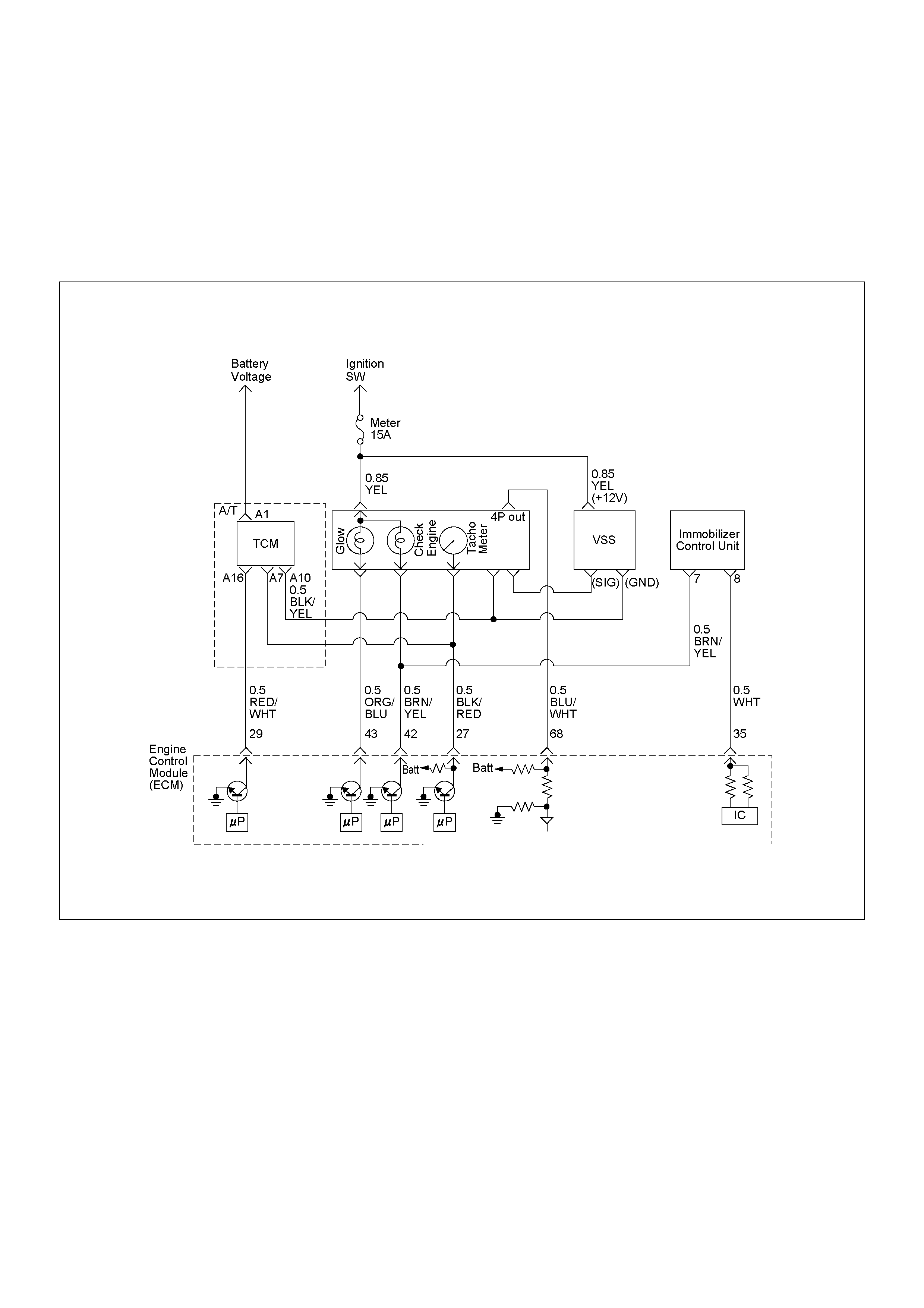
DIAGNOSTIC TROUBLE CODE (DTC) P0500 (SYM PTOM CODE 1)
(FLASH CODE 24) VEHICLE SP EED SENSOR CIRCUIT HIGH INPUT
DIAGNOSTIC TROUBLE CODE (DTC) P05 00 (SYMPTOM CODE A)
(FLASH CODE 24) VEHICLE SPE ED SENSOR INPUT SIGNAL FRE Q UENCY TOO HIGH
DIAGNOSTIC TROUBLE CODE (DTC) P05 00 (SYMPTOM CODE B)
(FLASH CODE 24) VEHICLE SPEED SENSOR INCORRECT SIGNAL

Condition for setting the DTC and action ta ken when the DTC sets
Circuit Description
The VSS is a magnet rotated by the transmission output
shaft. The VSS uses a hall element. It interacts with the
magnetic field treated by the rotating magnet. It out puts
pulse signal. The 12 volts operating supply from the
meter fuse.
The engine control module (ECM) calculates the vehicle
speed by VSS.
Diagnostic Aids
An intermittent may be caused by the following:
• Poor connections.
• Misrouted harness.
• Rubbed through wire insulation.
• Broken wire inside the insulation.
Check for the following conditions:
• Poor con nection at ECM -Inspect har ness connector s
for backed out terminals, improper mating, broken
locks, improperly formed or damaged terminals, and
poor terminal to wire connection.
• Damaged harness-Inspect the wiring harness for
damage. If the harness appears to be OK, observe
the DTC P0500 display on the Tech2 while moving
connectors and wiring harnesses. A change in the
display will indicate the location of the fault.
Flash
Code Code Symptom
Code MIL DTC Name DTC Setting Condition Fail-Safe (Back Up)
24 P0500 1 ON
at next
ignition
cycle
Vehicle Speed Sensor Circuit
High Input Vehicle speed is more than
200km/h. ECM uses vehicle speed 5km/
h condition as substitute.
AON
at next
ignition
cycle
Vehicle Speed Sensor Input
Signal Frequency Too High Input signal frequency is too
high. ECM uses vehicle speed 5km/
h condition as substitute.
BON
at next
ignition
cycle
Vehicle Speed Sensor
Incorrect Signal 1. Engine speed is more than
3600rpm.
2. Fuel injection quantity is
more than 41mg/strk.
3. Vehicle speed is below
1.5km/h.
Fuel injection quantity is
reduced.

Diagnostic Trouble Code (DTC) P0500 (Symptom Code 1) (Flash Code 24)
Vehicle Speed Sensor Circuit High Input
Step Action Value(s) Yes No
1 Was the “On-Board Diagnostic (OBD) System Check”
performed?
—Go to Step 2
Go to On Board
Diagnostic
(OBD) System
Check
2 1. Connect the Tech 2.
2. Review and record the failure information.
3. Select “F0 : Read DTC I nfor A s Stored By E CU” in
“F0: Diagnostic Trouble Codes”.
Is the DTC P0500 (Symptom Code 1) stored as
“Pres ent Fa ilure”? — Go to Step 3
Refer to
Diagnostic Aids
and Go to Step
3
3 1. Using the Tech 2, ignition “On” and engine “Off”.
2. Select “F1: Clear DTC Information” in “F0:
Diagnostic Trouble Codes” with the Tech 2 and
clear the DTC information.
3. Operate the vehicle and monitor the “F0: Read
DTC Infor As Stored By ECU” in the “F0:
Diagnostic Trouble Codes”.
Was the DTC P0500 ( Sy mpt om Code 1) st ored in th is
ignition cycle? — Go to Step 4
Refer to
Diagnostic Aids
and Go to Step
4
4 Perform test drive and check the speed meter.
Does the speed meter indicate correct vehicle speed. — Go to Step 5 Go to Step 6
5 Perform test drive and use the Tech 2.
Monitor the “Vehicle Speed” in the data display.
Does the Tech 2 indicate correct vehicle speed as
same as the speed meter indication in the instrument
panel? — G o to Step 15 Go to Step 7
6 Remove the VSS from the housing case and visually
check.
Was the problem found? — Go to Step 8 Go to Step 7
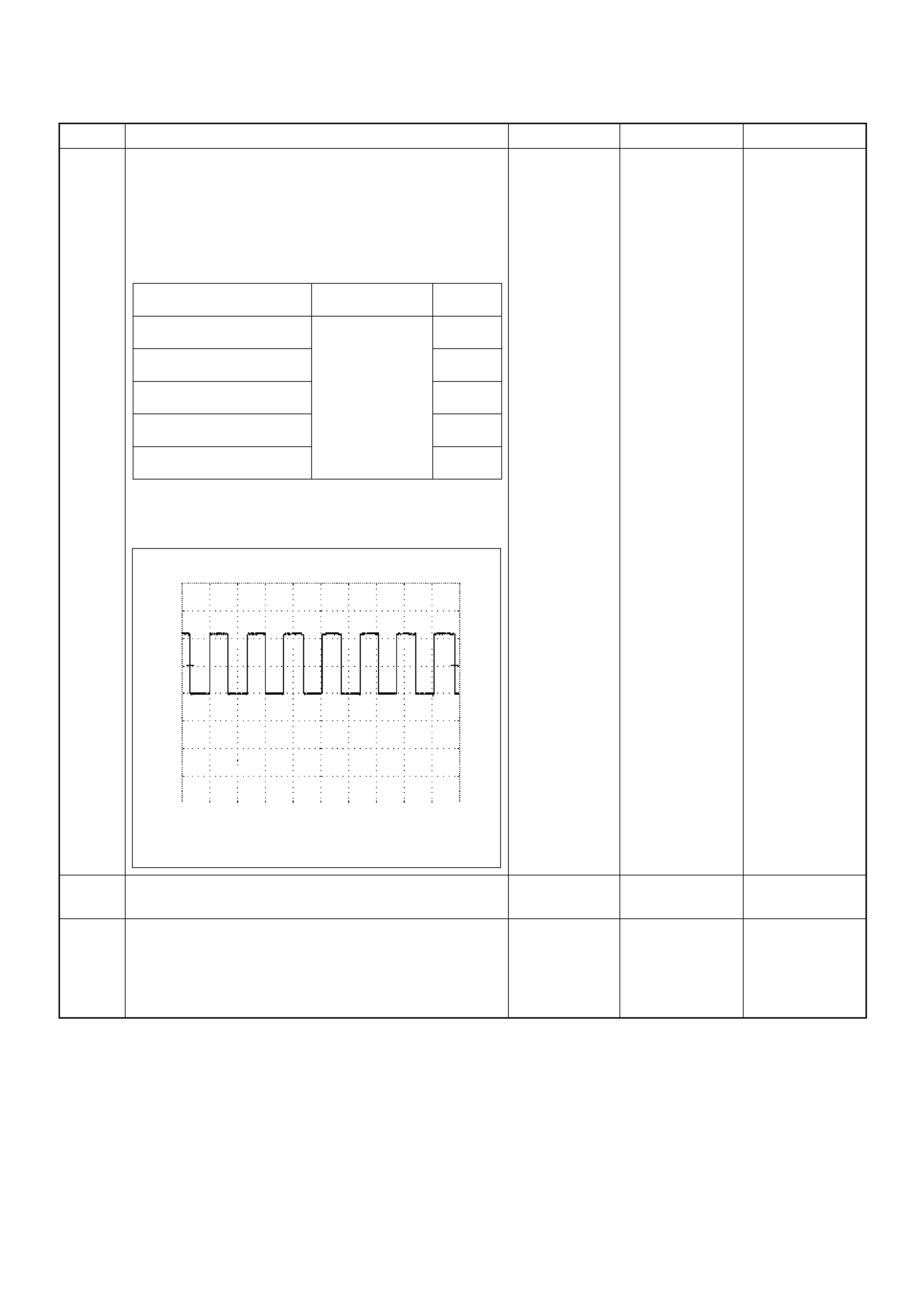
7 Using the DVM and check the VSS signal.
1. Ignition “On”, have an assistant rotate output shaft
by hand.
2. Measure the VSS output voltage at sensor, TCM
(A/T 2WD), meter and ECM.
Does the tester indicate specified value?
If a oscilloscope is available, monitor the VSS signal
at each connector connection. Does the oscilloscope
indicate correct wave form?
Refer to
Diagnostic Aids
and Go to Step
15
Refer to the
table in the
Action column
(in this step)
8 Replace the VSS.
Is the action complete? — Verify repair
9 Replace the TCM.
Is the action complete?
IMPORTANT: The replacement TCM must be
programmed. “SP S (S ervi ce P rogram min g Sy stem) is
necessary.” — Verify repair —
Step Action Value(s) Yes No
Measurement Position Voltage (V)
(AC Range) If No
Good
VSS terminal 3 & GND Fluctuates from 0.0
to 6.0 V Go to
Step 8
TCM C94 connector 10 &
GND (A/T 2WD) Go to
Step 9
Meter B24 connector 9 &
GND Go to
Step 10
Meter B24 connector 10 &
GND Go to
Step 12
ECM C56 connector 68 &
GND Go to
Step 13
Vehicle Speed Sensor (VSS) Reference Wave Form
0V→
Measurement Terminal: 68(+) GND(-)
Measurement Scale: 5V/div 50ms/div
Measurement Condition: Approximately 20km/h
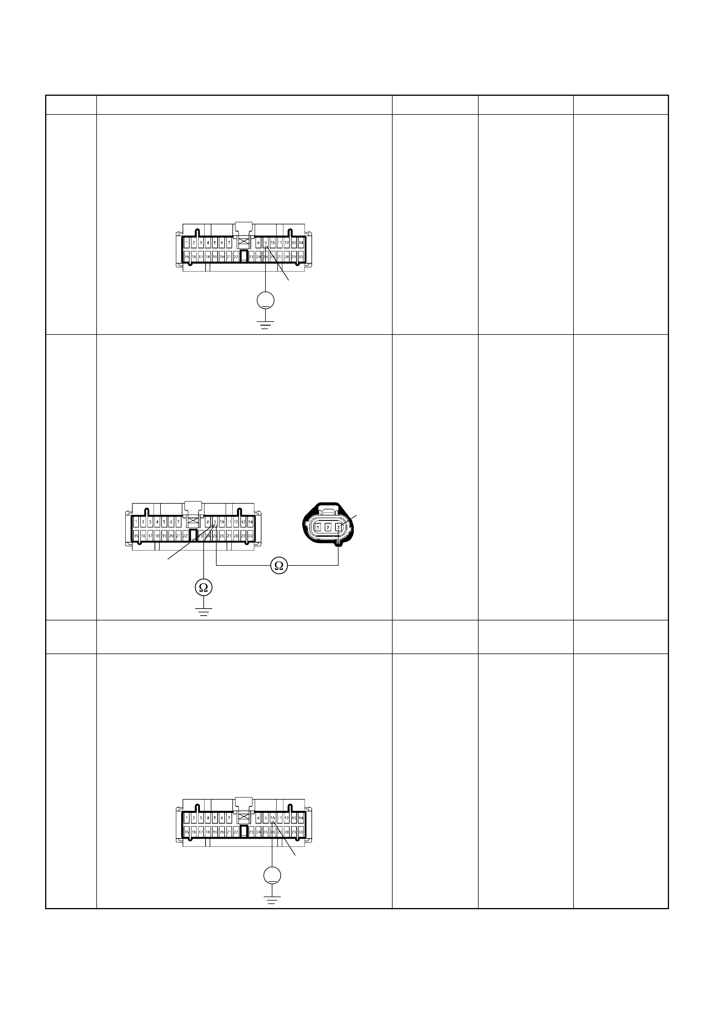
10 Using the DVM and check the VSS signal circuit.
1. Ignition “On”, engine “Off”.
2. Disconnect the meter connector.
3. Check the circuit for short to power supply circuit.
Was the DVM indicated specified value?
Less than 1V Go to Step 11
Repair faulty
harness and
verify repair
11 Using the DVM and check the VSS signal circuit.
1. Ignition “Off”, engine “Off”.
2. Disconnect the VSS connector and meter
connector.
3. Check the circuit for open or short to ground
circuit.
If a op en or short t o ground circ uit is fou nd, repair the
faulty harness and verify repair.
Is the action complete?
— Verify repair —
12 Replace the speed meter.
Is the action complete? — Verify repair —
13 Using the DVM and check the VSS signal circuit.
1. Ignition “Off”, engine “Off”.
2. Disconnect the meter connector and ECM
connector.
3. Ignition “On”.
4. Check the circuit for short to power supply circuit.
Was the DVM indicated specified value?
Less than 1V Go to Step 14
Repair faulty
harness and
verify repair
Step Action Value(s) Yes No
9
V
B-24
3
9
E-44
B-24
10
V
B-24

14 Using the DVM and check the VSS signal circuit.
Breaker box is available:
1. Ignition “Off”, engine “Off”.
2. Install the breaker box as type A. (ECM
disconnected) Ref. to HOW TO USE BREAKER
BOX
3. Disconnect the meter connector.
4. Check the circuit for open or shot to ground circuit.
Was the problem found?
Breaker box is not available:
1. Ignition “Off”, engine “Off”.
2. Disconnect the meter connector and ECM
connector.
3. Check the circuit for open or short to ground
circuit.
Was the problem found?
—
Repair faulty
harness and
verify repair Go to Step 15
15 Is the ECM programmed with the latest software
release?
If not, download the latest software to the ECM using
the “SPS (Service Programming System)”.
Was the problem solved? — Verify repair Go to Step 16
16 Replace the ECM.
Is the action complete?
IMPORTANT: The replacement ECM must be
programmed. Refer to section of the Service
Programming System (SPS) in this manual.
Foll owing ECM pr ogramming, the immobi lizer sys tem
(if equipped) must be linked to the ECM. Refer to
section 11 “Immobilizer System-ECM replacement” for
the ECM/Immobilizer linking procedure. — Verify repair —
Step Action Value(s) Yes No
68
Breaker Box B-24 10
Ħ
Ħ
68
10
B-24
C-56

Diagnostic Trouble Code (DTC) P0500 (Symptom Code A) (Flash Code 24)
Vehicle Speed Sensor Input Signal Frequency Too High
Step Action Value(s) Yes No
1 Was the “On-Board Diagnostic (OBD) System Check”
performed?
—Go to Step 2
Go to On Board
Diagnostic
(OBD) System
Check
2 1. Connect the Tech 2.
2. Review and record the failure information.
3. Select “F0 : Read DTC I nfor A s Stored By E CU” in
“F0: Diagnostic Trouble Codes”.
Is the DTC P0500 (Symptom Code A) stored as
“Pres ent Fa ilure”? — Go to Step 3
Refer to
Diagnostic Aids
and Go to Step
3
3 1. Using the Tech 2, ignition “On” and engine “Off”.
2. Select “F1: Clear DTC Information” in “F0:
Diagnostic Trouble Codes” with the Tech 2 and
clear the DTC information.
3. Operate the vehicle and monitor the “F0: Read
DTC Infor As Stored By ECU” in the “F0:
Diagnostic Trouble Codes”.
Was the DTC P0500 (Symptom Code A) stored in this
ignition cycle? — Go to Step 4
Refer to
Diagnostic Aids
and Go to Step
4
4 Perform test drive and check the speed meter.
Does the speed meter indicate correct vehicle speed. — Go to Step 5 Go to Step 6
5 Perform test drive and use the Tech 2.
Monitor the “Vehicle Speed” in the data display.
Does the Tech 2 indicate correct vehicle speed as
same as the speed meter indication in the instrument
panel? — G o to Step 10 Go to Step 7
6 Remove the VSS from the housing case and visually
check.
Was the problem found? — Go to Step 8 Go to Step 7
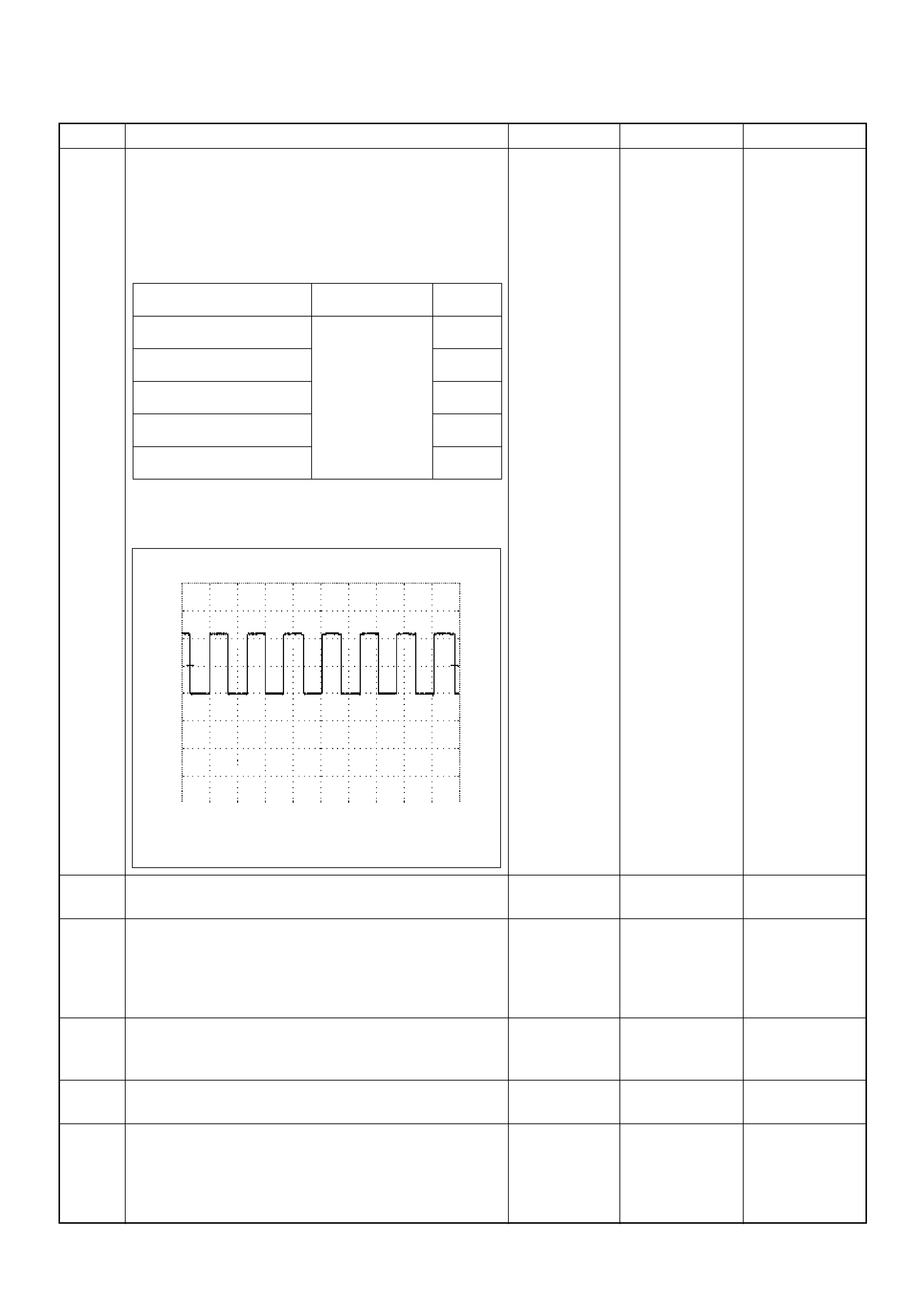
7 Using the DVM and check the VSS signal.
1. Ignition “On”, have an assistant rotate output shaft
by hand.
2. Measure the VSS output voltage at sensor, TCM
(A/T 2WD), meter and ECM.
Does the tester indicate specified value?
If a oscilloscope is available, monitor the VSS signal
at each connector connection. Does the oscilloscope
indicate correct wave form?
Refer to
Diagnostic Aids
and Go to Step
10
Refer the table
8 Replace the VSS.
Is the action complete? — Verify repair
9 Replace the TCM.
Is the action complete?
IMPORTANT: The replacement TCM must be
programmed. “SPS (Service Progr amming Sy st em)
is necessary.” — Verify repair —
10 Check any accessory parts which may cause electric
interference or magnetic interference.
Was the problem found? —
Remove the
accessory parts
and verify repair Go to Step 12
11 Replace the speed meter.
Is the action complete? — Verify repair —
12 Is the ECM programmed with the latest software
release?
If not, downlo ad the latest software to the ECM using
the “SPS (Service Programming System)”.
Was the problem solved? — Verify repair Go to Step 13
Step Action Value(s) Yes No
Measurement Position Voltage (V)
(AC Range) If No
Good
VSS terminal 3 & GND Fluctuates from 0.0
to 6.0 V Go to
Step 8
TCM terminal A10 & B5
(A/T 2WD) Go to
Step 9
Meter B24 connector 9 &
GND Go to
Step 10
Meter B24 connector 10 &
GND Go to
Step 11
ECM C56 connector 68 &
GND Go to
Step 10
Vehicle Speed Sensor (VSS) Reference Wave Form
0V→
Measurement Terminal: 68(+) GND(-)
Measurement Scale: 5V/div 50ms/div
Measurement Condition: Approximately 20km/h

13 Replace the ECM.
Is the action complete?
IMPORTANT: The replacement ECM must be
programmed. Refer to section of the Service
Programming System (SPS) in this manual.
Foll owing ECM pr ogramming, the immobi lizer sys tem
(if equipped) must be linked to the ECM. Refer to
section 11 “Immobilizer System-ECM replacement” for
the ECM/Immobilizer linking procedure. — Verify repair —
Step Action Value(s) Yes No
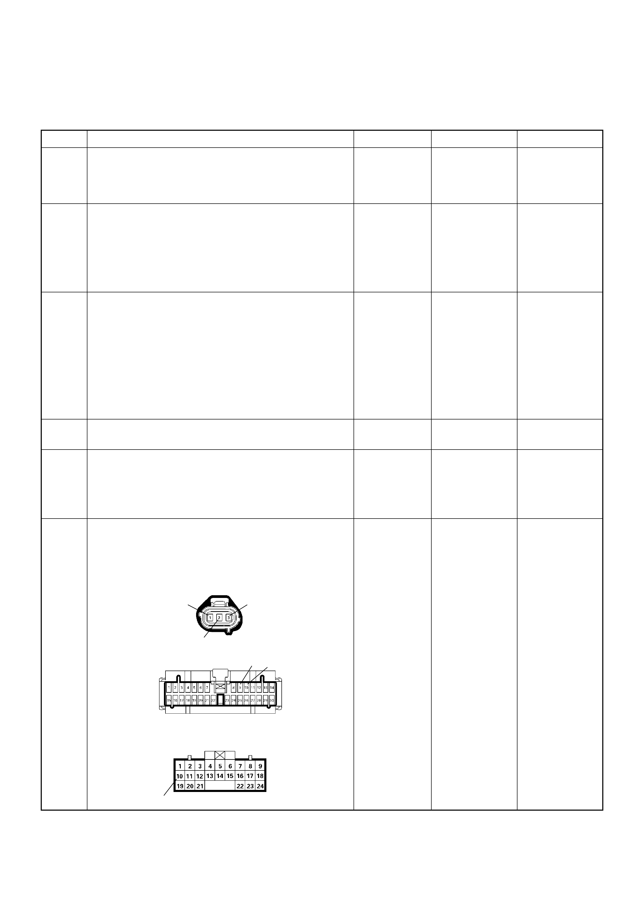
Diagnostic Trouble Code (DTC) P0500 (Symptom Code B) (Flash Code 24)
Vehicle Speed Sensor Incorrect Signal
Step Action Value(s) Yes No
1 Was the “On-Board Diagnostic (OBD) System Check”
performed?
—Go to Step 2
Go to On Board
Diagnostic
(OBD) System
Check
2 1. Connect the Tech 2.
2. Review and record the failure information.
3. Select “F0 : Read DTC I nfor A s Stored By E CU” in
“F0: Diagnostic Trouble Codes”.
Is the DTC P0500 (Symptom Code B) stored as
“Pres ent Fa ilure”? — Go to Step 3
Refer to
Diagnostic Aids
and Go to Step
3
3 1. Using the Tech 2, ignition “On” and engine “Off”.
2. Select “F1: Clear DTC Information” in “F0:
Diagnostic Trouble Codes” with the Tech 2 and
clear the DTC information.
3. Operate the vehicle and monitor the “F0: Read
DTC Infor As Stored By ECU” in the “F0:
Diagnostic Trouble Codes”.
Was the DTC P0500 (Symptom Code B) stored in this
ignition cycle? — Go to Step 4
Refer to
Diagnostic Aids
and Go to Step
4
4 Perform test drive and check the speed meter.
Does the speed meter indicate correct vehicle speed. — Go to Step 5 Go to Step 6
5 Perform test drive and use the Tech 2.
Monitor the “Vehicle Speed” in the data display.
Does the Tech 2 indicate correct vehicle speed as
same as the speed meter indication in the instrument
panel? — G o to Step 17 Go to Step 7
6 Ch eck for poor /faulty conn ection at the VSS, TCM (A /
T 2WD) and meter connectors. If a poor/faulty
connection is found, repair the faulty terminal.
Was the problem found?
— Verify repair Go to Step 8
13
2
910
10
B-24
C-94(10)
E-44
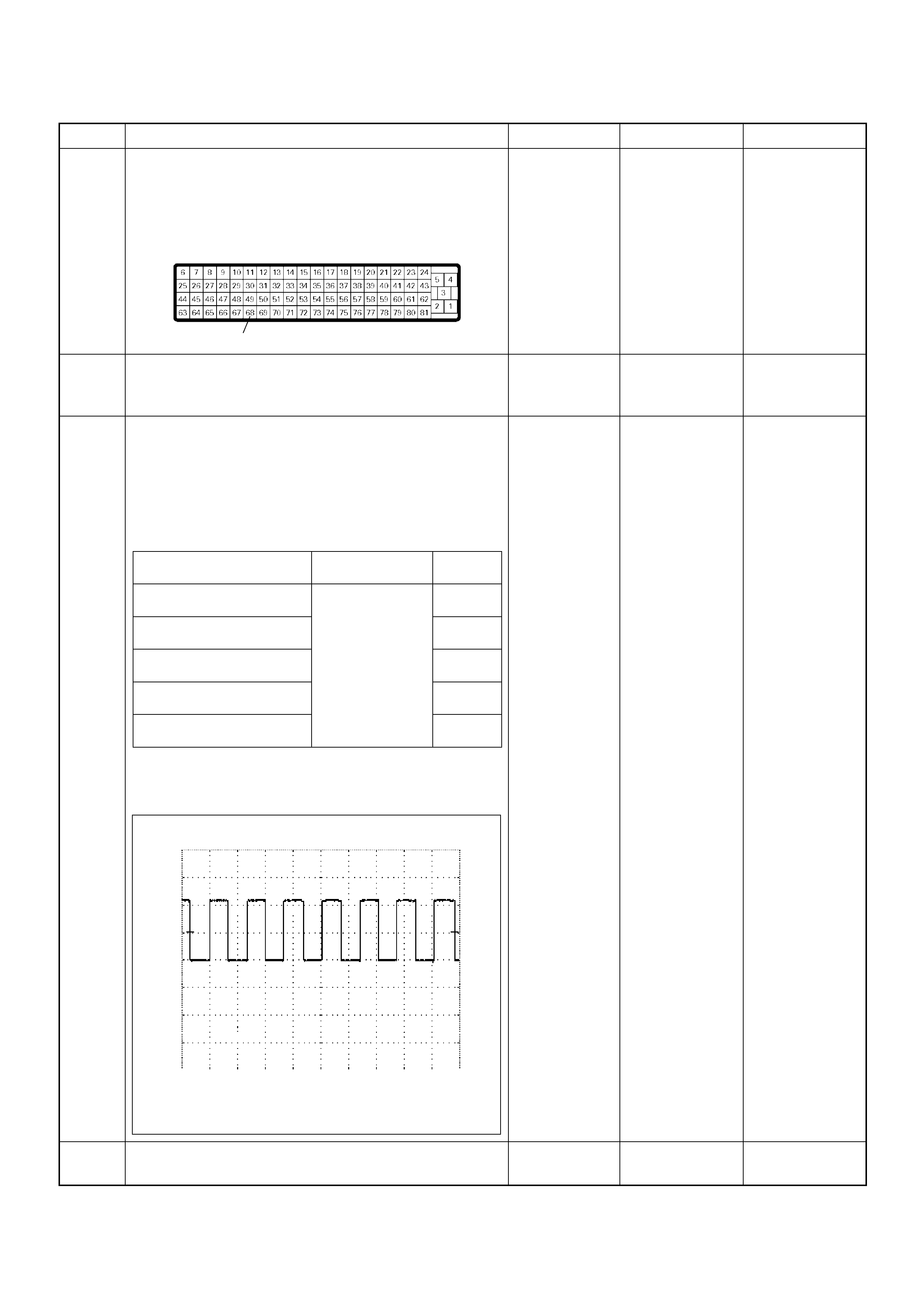
7 Check for poor/faulty connection at the ECM and
other connectors. If a poor/faulty connection is found,
repair the faulty terminal.
Was the problem found?
— Verify repair Go to Step 9
8 Remove the VSS from the housing case and visually
check.
Was the problem found? — Go to Step 10 Go to Step 9
9 Using the DVM and check the VSS signal.
1. Ignition “On”, have an as si s tant rotate output shaft
by hand.
2. Measure the VSS output voltage at sensor, TCM
(A /T 2WD) , meter and ECM.
Does the tester indicate specified value?
If a oscilloscope is available, monitor the VSS signal
at each connector connection. Does the oscilloscope
indicate correct wave form?
Refer to
Diagnostic Aids
and Go to Step
17 Refer the table
10 Replace the VSS.
Is the action complete? — Verify repair
Step Action Value(s) Yes No
68
C-56
Measurement Position Voltage (V)
(AC Range) If No
Good
VSS terminal 3 & GND Fluctuates from 0.0
to 6.0 V Go to
Step 10
TCM C94 connector 10 &
GND (A/T 2WD) Go to
Step 11
Meter B24 connector 9 &
GND Go to
Step 12
Meter B24 connector 10 &
GND Go to
Step 14
ECM C56 connector 68 &
GND Go to
Step 15
Vehicle Speed Sensor (VSS) Reference Wave Form
0V→
Measurement Terminal: 68(+) GND(-)
Measurement Scale: 5V/div 50ms/div
Measurement Condition: Approximately 20km/h
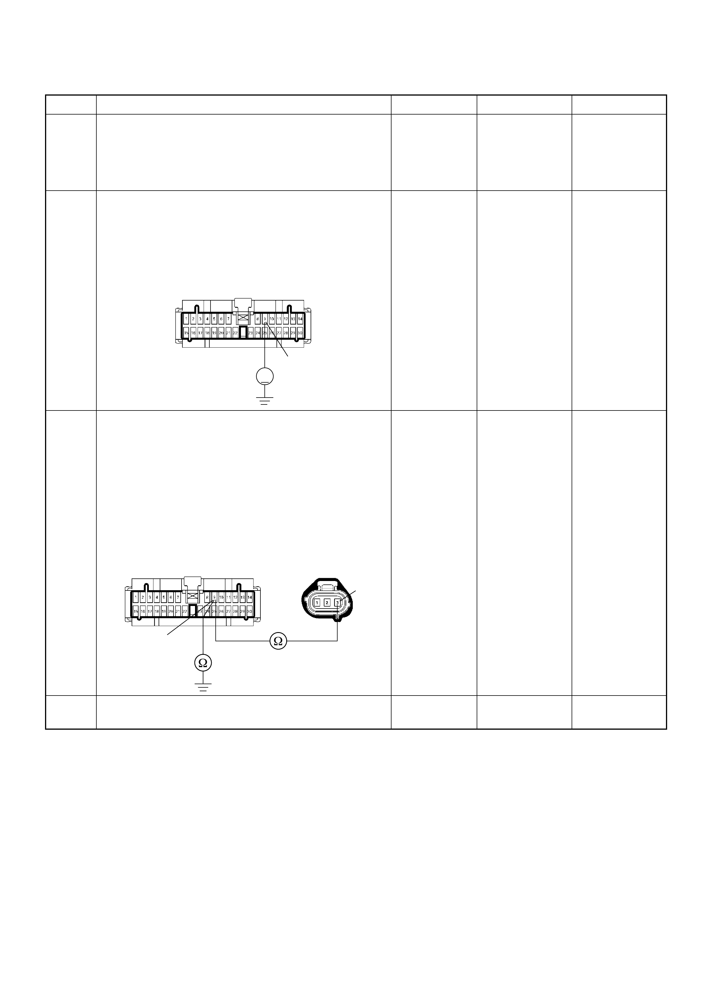
11 Replace the TCM.
Is the action complete?
IMPORTANT: The replacement TCM must be
programmed. “SPS (Service Programming System) is
necessary.” — Verify repair —
12 Using the DVM and check the VSS signal circuit.
1. Ignition “On”, engine “Off”.
2. Disconnect the meter connector.
3. Check the circuit for short to power supply circuit.
Was the DVM indicated specified value?
Less than 1V Go to Step 13
Repair faulty
harness and
verify repair
13 Using the DVM and check the VSS signal circuit.
1. Ignition “Off”, engine “Off”.
2. Disconnect the VSS connector and meter
connector.
3. Check the circuit for open or short to ground
circuit.
If a op en or short t o ground circ uit is fou nd, repair the
faulty harness and verify repair.
Is the action complete?
— Verify repair —
14 Replace the speed meter.
Is the action complete? — Verify repair —
Step Action Value(s) Yes No
9
V
B-24
3
9
E-44
B-24
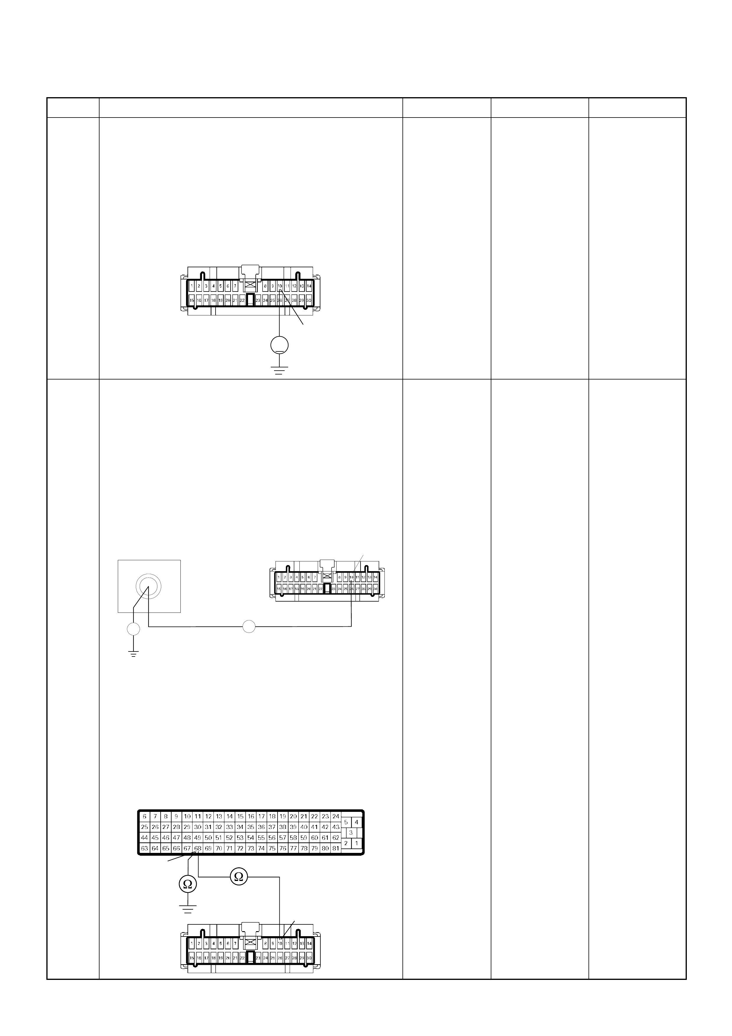
15 Using the DVM and check the VSS signal circuit.
1. Ignition “Off”, engine “Off”.
2. Disconnect the meter connector and ECM
connector.
3. Ignition “On”.
4. Check the circuit for short to power supply circuit.
Was the DVM indicated specified value?
Less than 1V Go to Step 16
Repair faulty
harness and
verify repair
16 Using the DVM and check the VSS signal circuit.
Breaker box is available:
1. Ignition “Off”, engine “Off”.
2. Install the breaker box as type A. (ECM
disconnected) Ref. to HOW TO USE BREAKER
BOX
3. Disconnect the meter connector.
4. Check the circuit for open or shot to ground circuit.
Was the problem found?
Breaker box is not available:
1. Ignition “Off”, engine “Off”.
2. Disconnect the meter connector and ECM
connector.
3. Check the circuit for open or short to ground
circuit.
Was the problem found?
—
Repair faulty
harn es s and
verify repair Go to Step 17
Step Action Value(s) Yes No
10
V
B-24
68
Breaker Box B-24 10
Ħ
Ħ
68
10
B-24
C-56

17 Is the ECM programmed with the latest software
release?
If not, download the latest software to the ECM using
the “SPS (Service Programming System)”.
Was the problem solved? — Verify repair Go to Step 18
18 Replace the ECM.
Is the action complete?
IMPORTANT: The replacement ECM must be
programmed. Refer to section of the Service
Programming System (SPS) in this manual.
Foll owing ECM pr ogramming, the immobi lizer sys tem
(if equipped) must be linked to the ECM. Refer to
section 11 “Immobilizer System-ECM replacement” for
the ECM/Immobilizer linking procedure. — Verify repair —
Step Action Value(s) Yes No
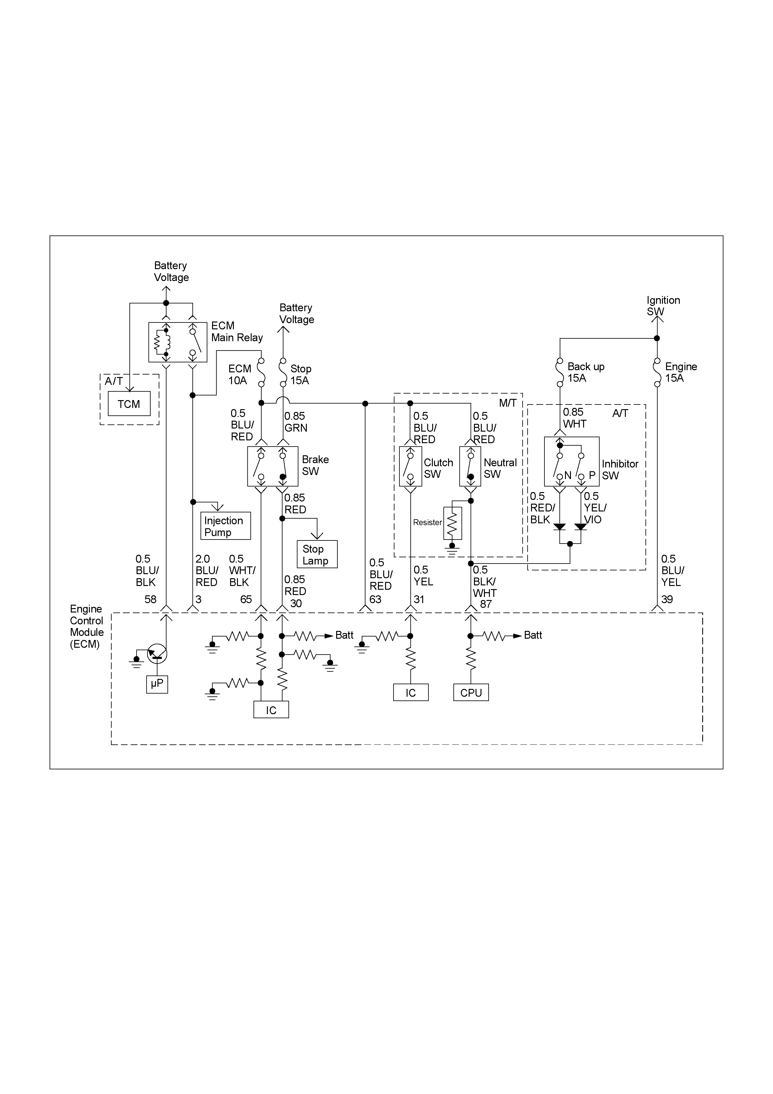
DIAGNOSTIC TROUBLE CODE (DTC) P0560 (SYM PTOM CODE 1)
(FLASH CODE 35) SYSTEM VOLTAGE TOO HIGH
DIAGNOSTIC TROUBLE CODE (DTC) P0560 (SYM PTOM CODE 2)
(FLASH CODE 35) SYSTEM VOLTAGE TOO LOW
DIAGNOSTIC TROUBLE CODE (DTC) P05 60 (SYMPTOM CODE A)
(FLASH CODE 35) SYSTEM VOLTAGE MALFUNCTION

Condition for setting the DTC and action ta ken when the DTC sets
Circuit Description
The ECM and PSG moni tors th e system vol tage on th e
ignition feed terminal to the ECM or PSG. The system
voltage to the ECM excessively high or low, DTC P0560
(Sympto m Code 1) or P 0560 ( Sympt om Cod e 2) w ill b e
stored. The system voltage to th e PSG excess ively high
or low, DTC P0560 (Symptom Code A) will be stored.
Diagnostic Aids
An intermittent may be caused by the following:
• Poor connections.
• Misrouted harness.
• Rubbed through wire insulation.
• Broken wire inside the insulation.
Check for the following conditions:
• Poor connection at ECM and PSG-Inspect harness
connectors for backed out terminals, improper
mating, broken locks, improperly formed or damaged
terminals, and poor terminal to wire connection.
• Damaged harness-Inspect the wiring harness for
damage. If the harness appears to be OK, observe
the “System Voltage” display on the Tech2 while
moving c onnectors and wiring harn ess related to the
sensor.
Flash
Code Code Symptom
Code MIL DTC Name DTC Setting Condition Fail-Safe (Back Up)
35 P0560 1 OFF Syst em Voltage Too High System voltage is more than
20V. ECM uses 9V conditions as
substitute.
2 O FF S yst em Voltage Too Low System voltage is below 7V.
A OFF S yst em Voltage Malfunction Sy stem voltage of PSG
(pump control unit) is below
4.5V or more than 27V.
PSG uses default voltage as
substitute.

Diagnostic Trouble Code (DTC) P0560 (Symptom Code 1) (Flash Code 35)
System Voltage Too High
Step Action Value(s) Yes No
1 Was the “On-Board Diagnostic (OBD) System Check”
performed?
—Go to Step 2
Go to On Board
Diagnostic
(OBD) System
Check
2 1. Connect the Tech 2.
2. Review and record the failure information.
3. Select “F0: Read DTC Infor As Stored By ECU” in
“F0: Diagnostic Trouble Codes”.
Is the DTC P0560 (Symptom Code 1) stored as
“Present Failure”? — Go to Step 3
Refer to
Diagnostic Aids
and Go to Step
3
3 1. Using the Tech 2, ignition “On” and engine “Off”.
2. Select “F1: Clear DTC Information” in “F0:
Diagnostic Trouble Codes” with the Tech 2 and
clear the DTC information.
3. Operate the vehicle and monitor the “F0: Read
DTC Infor As Stored By ECU” in the “F0:
Diagnostic Trouble Codes”.
Was the DTC P0560 (Symptom Code 1) stored in this
ignition cycle? — Go to Step 4
Refer to
Diagnostic Aids
and Go to Step
4
4 Was the battery jump start cable incorrectly
connecting? —Verify
procedure Go to Step 5
5 1. Using the Tech 2, ignition “On” and engine “On”.
2. Monitor the “System Voltage” in the data display.
3. Load the electrical system by turning on the
headlights, etc..
Does the Tech 2 indicate correct ignition voltage? 10 - 14.5V Go to Step 6
Check the
charging
system
6 Is the ECM programmed with the latest software
release?
If not, download the latest software to the ECM using
the “SPS (Service Programming System)”.
Was the problem solved? — Verify repair Go to Step 7
7 Replace the ECM.
Is the action complete?
IMPORTANT: The replacement ECM must be
programmed. Refer to section of the Service
Programming System (SPS) in this manual.
Foll owing ECM pr ogramming, the immobi lizer sys tem
(if equipped) must be linked to the ECM. Refer to
section 11 “Immobilizer System-ECM replacement” for
the ECM/Immobilizer linking procedure. — Verify repair —

Diagnostic Trouble Code (DTC) P0560 (Symptom Code 2) (Flash Code 35)
System Voltage Too Low
Step Action Value(s) Yes No
1 Was the “On-Board Diagnostic (OBD) System Check”
performed?
—Go to Step 2
Go to On Board
Diagnostic
(OBD) System
Check
2 1. Connect the Tech 2.
2. Review and record the failure information.
3. Select “F0 : Read DTC I nfor A s Stored By E CU” in
“F0: Diagnostic Trouble Codes”.
Is the DTC P0560 (Symptom Code 2) stored as
“Pres ent Fa ilure”? — Go to Step 3
Refer to
Diagnostic Aids
and Go to Step
3
3 1. Using the Tech 2, ignition “On” and engine “Off”.
2. Select “F1: Clear DTC Information” in “F0:
Diagnostic Trouble Codes” with the Tech 2 and
clear the DTC information.
3. Operate the vehicle and monitor the “F0: Read
DTC Infor As Stored By ECU” in the “F0:
Diagnostic Trouble Codes”.
Was the DTC P0560 ( Sy mpt om Code 2) st ored in th is
ignition cycle? — Go to Step 4
Refer to
Diagnostic Aids
and Go to Step
4
4 1. Using the Tech 2, ignition “On” and engine “On”.
2. Monitor the “System Voltage” in the data display.
3. Load the electrical system by turning on the
headlights, etc..
Does the Tech 2 indicate enough ignition voltage? 10 - 14.5V Go to Step 6 Go to Step 5
5 Using the DVM and check the battery voltage at the
battery terminal.
Does the tester indicate enough battery voltage?
10 - 14.5V Go to Step 6
Check the
charging
system, charge
or replace the
battery
6 Check for poor/faulty connection at the ECM
connector. If a poor/faulty connection is found, repair
as necessary.
Was the problem found?
— Verify repair Go to Step 7
3
21
56
C-56
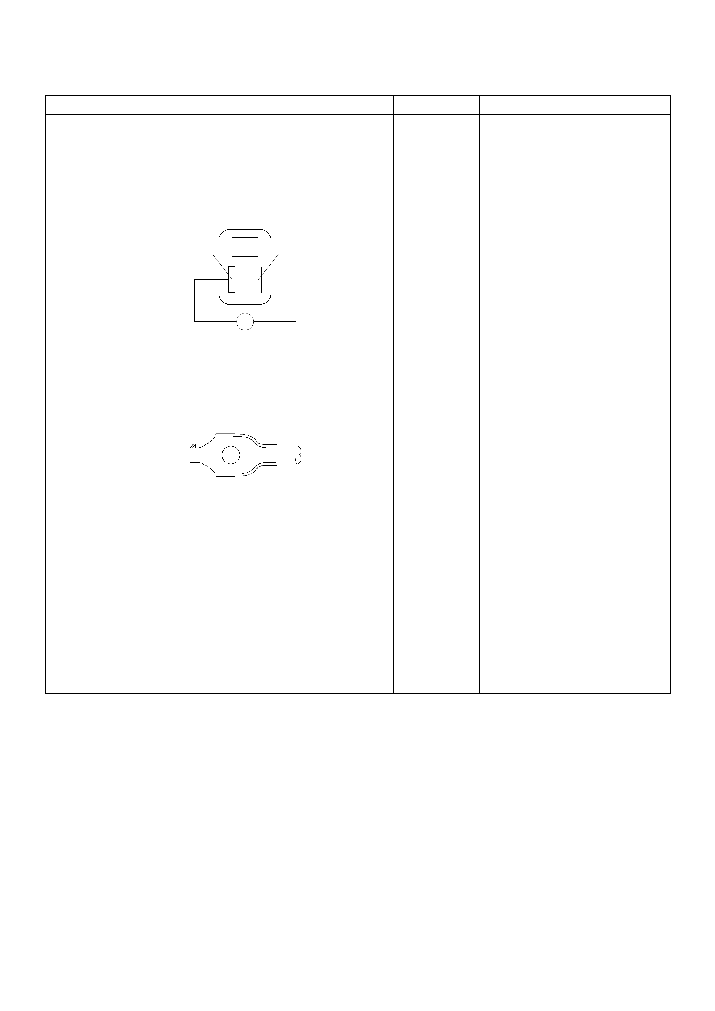
7 Using the DVM and check the ECM main relay.
1. Ignition “Off”, engine “Off”.
2. Remove the ECM main relay from the relay box.
3. Check the relay coil.
Was the DVM indicated specified value?
120-150Ω Go to Step 8
Replace ECM
main relay and
verify repair
8 Check for poor/faulty connection of the ECM ground
at the body. If a poor/faulty connection is found, repair
as necessary.
Was the problem found?
— Verify repair Go to Step 9
9 Is the ECM programmed with the latest software
release?
If not, download the latest software to the ECM using
the “SPS (Service Programming System)”.
Was the problem solved? — Verify repair Go to Step 10
10 Replace the ECM.
Is the action complete?
IMPORTANT: The replacement ECM must be
programmed. Refer to section of the Service
Programming System (SPS) in this manual.
Foll owing ECM pr ogramming, the immobi lizer sys tem
(if equipped) must be linked to the ECM. Refer to
section 11 “Immobilizer System-ECM replacement” for
the ECM/Immobilizer linking procedure. — Verify repair —
Step Action Value(s) Yes No
ECM Main Relay
3
4
2
1
Ħ
3
4
C-109
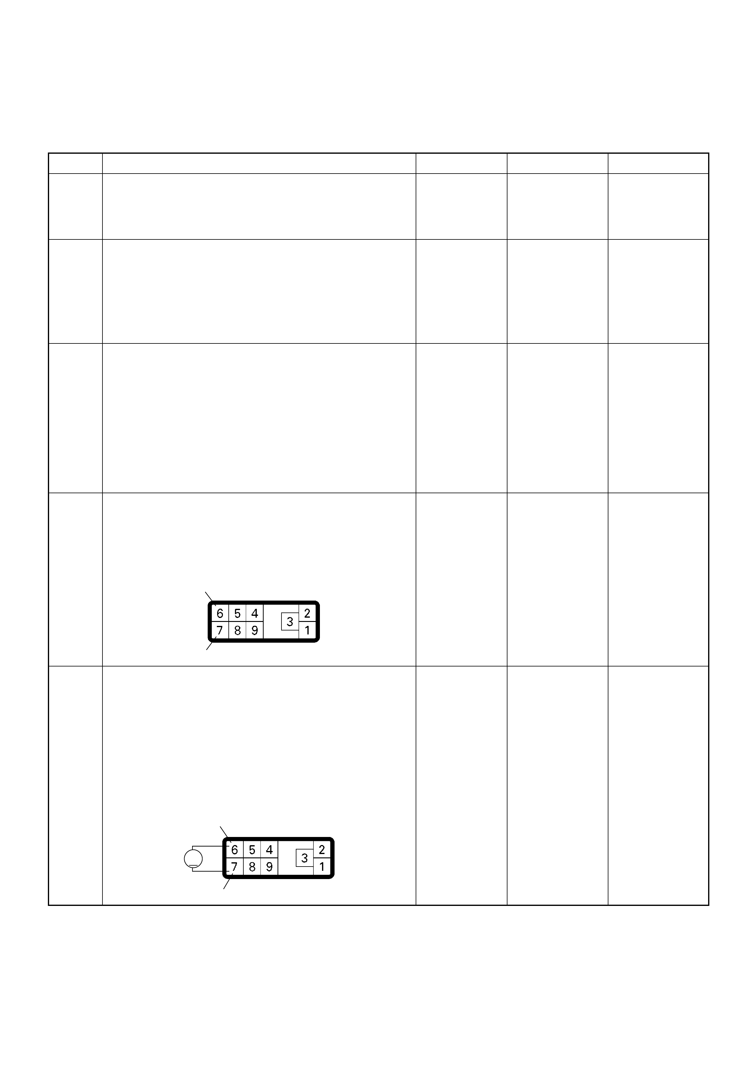
Diagnostic Trouble Code (DTC) P0560 (Symptom Code A) (Flash Code 35)
System Voltage Malfunction
Step Action Value(s) Yes No
1 Was the “On-Board Diagnostic (OBD) System Check”
performed?
—Go to Step 2
Go to On Board
Diagnostic
(OBD) System
Check
2 1. Connect the Tech 2.
2. Review and record the failure information.
3. Select “F0 : Read DTC I nfor A s Stored By E CU” in
“F0: Diagnostic Trouble Codes”.
Is the DTC P0560 (Symptom Code A) stored as
“Pres ent Fa ilure”? — Go to Step 3
Refer to
Diagnostic Aids
and Go to Step
3
3 1. Using the Tech 2, ignition “On” and engine “Off”.
2. Select “F1: Clear DTC Information” in “F0:
Diagnostic Trouble Codes” with the Tech 2 and
clear the DTC information.
3. Operate the vehicle and monitor the “F0: Read
DTC Infor As Stored By ECU” in the “F0:
Diagnostic Trouble Codes”.
Was the DTC P0560 (Symptom Code A) stored in this
ignition cycle? — Go to Step 4
Refer to
Diagnostic Aids
and Go to Step
4
4 Check for poor/faulty connection at the PSG (pump
control unit) connector. If a poor/faulty connection is
found, repair as necessary.
Was the problem found?
— Verify repair Go to Step 5
5 Using the DVM and check the PSG (pump control
unit) power supp ly circuit.
1. Ignition “On”, engine “Off”.
2. Disconnect the PSG (pump control unit)
connector.
3. Check the PSG (pump control unit) power supply
circuit.
Was the DVM indicated specified value?
10 - 14.5V Go to Step 7 Go to Step 6
6
7
E-6
6
7
V
E-6

6 Check for poor/faulty connection of the PSG (pump
control unit) ground at the cylinder body. If a poor/
faulty connecti on is found, re pair as necessa ry.
Was the problem found?
— Verify repair Go to Step 7
7 Replace the injection pump assembly.
Is the action complete? — Verify repair —
Step Action Value(s) Yes No
E-10
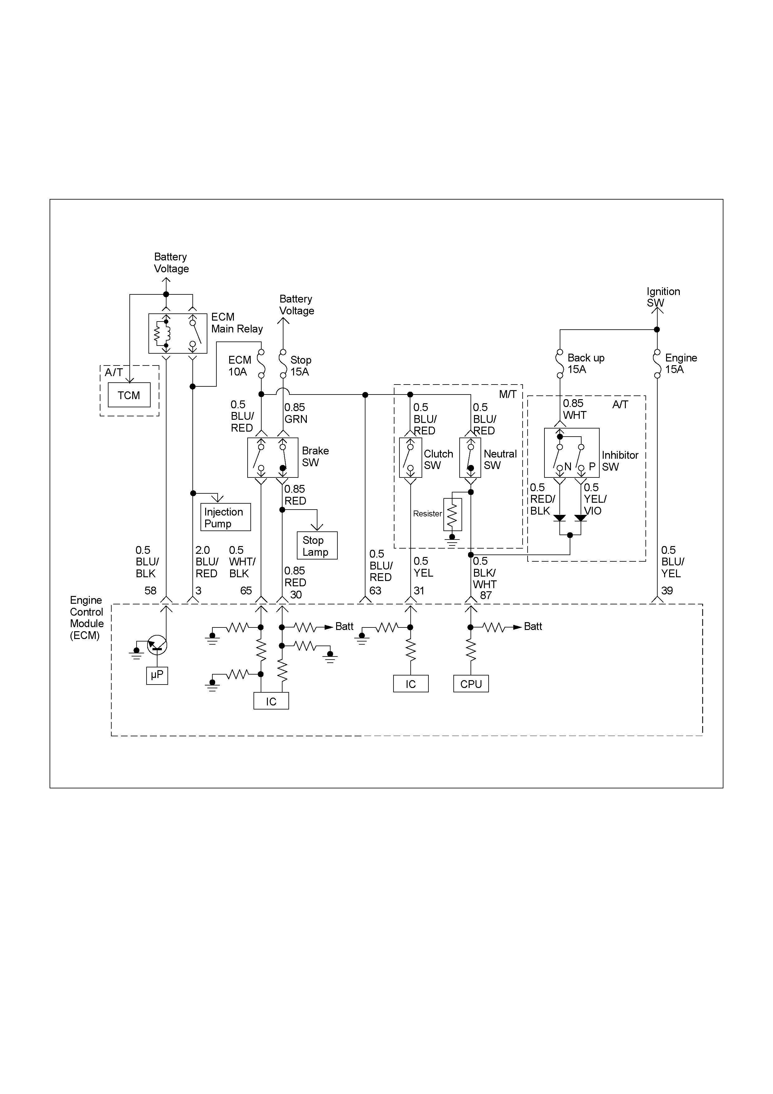
DIAGNOSTIC TROUBLE CODE (DTC) P05 61 (SYMPTOM CODE A)
(FLASH CODE 18) IGNITION SWITCH CIRCUIT MALFUNCTION
DIAGNOSTIC TROUBLE CODE (DTC) P05 61 (SYMPTOM CODE B)
(FLASH CODE 18) IGNITION SWITCH CIRCUIT MALFUNCTION

Condition for setting the DTC and action ta ken when the DTC sets
Circuit Description
The ECM monitors the ignition switch signal on the feed
terminal to the ECM. If the ignition switch signal
malfunctions, DTC P0561 (Symptom Code A) or DTC
P0561 (Symptom Code B) will be stored.
Diagnostic Aids
An intermittent may be caused by the following:
• Poor connections.
• Misrouted harness.
• Rubbed through wire insulation.
• Broken wire inside the insulation.
Check for the following conditions:
• Poor con nection at ECM -Inspect har ness connector s
for backed out terminals, improper mating, broken
locks, improperly formed or damaged terminals, and
poor terminal to wire connection.
• Damaged harness-Inspect the wiring harness for
damage. If the harness appears to be OK, observe
the “Ignition Status” display on the Tech2 while
moving c onnectors and wiring harn ess related to the
sensor.
Flash
Code Code Symptom
Code MIL DTC Name DTC Setting Condition Fail-Safe (Back Up)
18 P0561 A OFF Ignition Switch Circuit
Malfunction The ECM recognized ignition
switch turn off signal during
ECM is activated.
ECM stops engine.
B OFF Ignition Switch Circuit
Malfunction Ignition switch circuit is
malfunction.

Diagnostic Trouble Code (DTC) P0561 (Symptom Code A) (Flash Code 18)
Ignition Switch Circuit Malfunction
Diagnostic Trouble Code (DTC) P0561 (Symptom Code B) (Flash Code 18)
Ignition Switch Circuit Malfunction
Step Action Value(s) Yes No
1 Was the “On-Board Diagnostic (OBD) System Check”
performed?
—Go to Step 2
Go to On Board
Diagnostic
(OBD) System
Check
2 1. Connect the Tech 2.
2. Review and record the failure information.
3. Select “F0 : Read DTC I nfor A s Stored By E CU” in
“F0: Diagnostic Trouble Codes”.
Is the DTC P0561 (Symptom Code A) or P0561
(Symp tom Code B) stor ed as “Present Failure”? — Go to Step 3
Refer to
Diagnostic Aids
and Go to Step
3
3 1. Using the Tech 2, ignition “On” and engine “Off”.
2. Select “F1: Clear DTC Information” in “F0:
Diagnostic Trouble Codes” with the Tech 2 and
clear the DTC information.
3. Operate the vehicle and monitor the “F0: Read
DTC Infor As Stored By ECU” in the “F0:
Diagnostic Trouble Codes”.
Was the DTC P0561 (Symptom Code A) or P0561
(Symptom Code B)stored in this ignition cycle? — Go to Step 4
Refer to
Diagnostic Aids
and Go to Step
4
4 Ch eck the “Engi ne fus e (10 A)” .
If the fuse is burnt out, repair as necessary.
Was the problem found? — Verify repair Go to Step 5
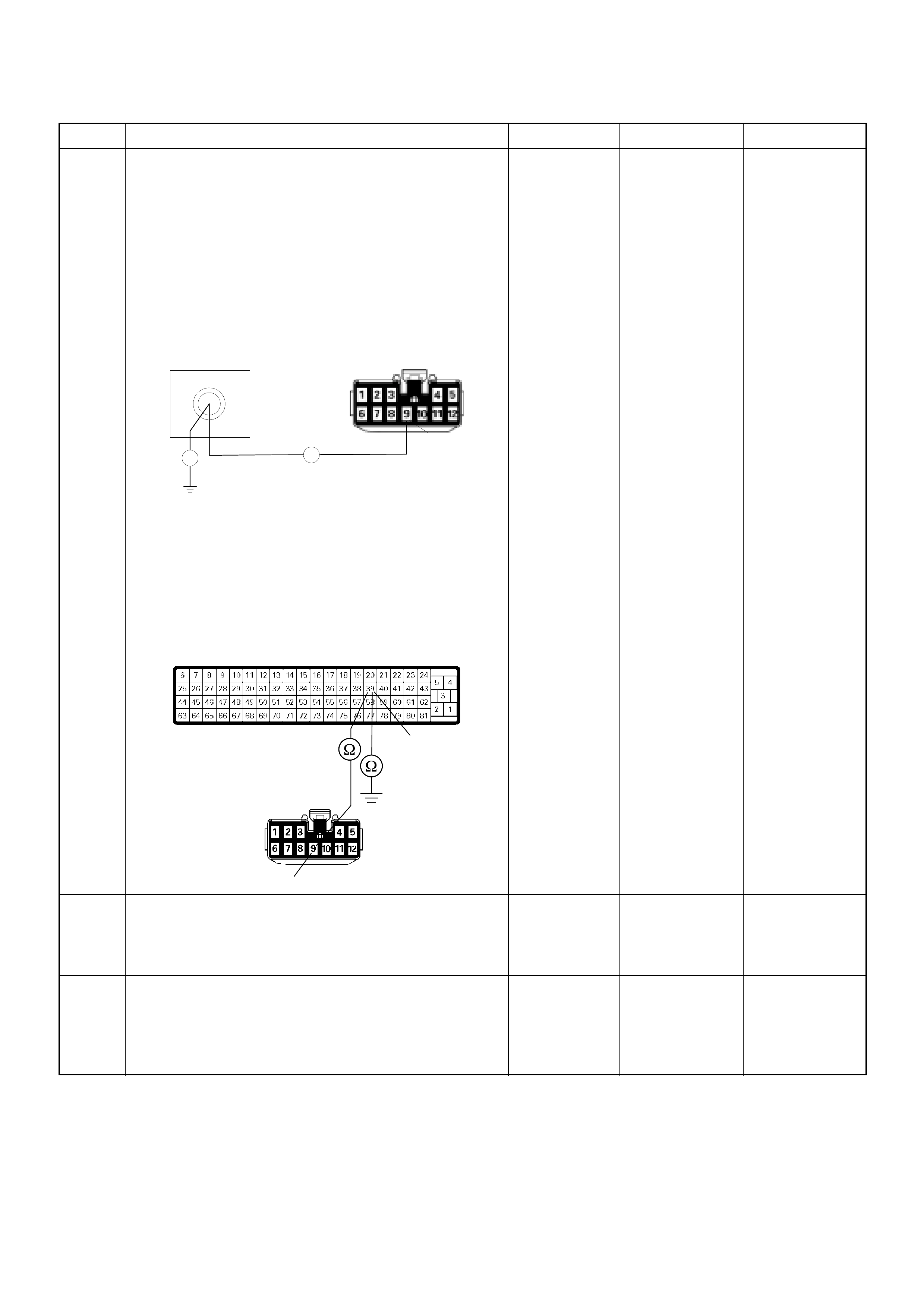
5 Using the DVM and check the ignition power feed
circuit.
Breaker box is available:
1. Ignition “Off”, engine “Off”.
2. Install the breaker box as type A. (ECM
disconnected)
3. Check the circuit for open or short to ground
circuit.
Was the problem found?
Breaker box is not available:
1. Ignition “Off”, engine “Off”.
2. Disconnect the ECM connector.
3. Check the circuit for open or short to ground
circuit.
Was the problem found?
—
Repair faulty
harn es s and
verify repair Go to Step 6
6 Check the ignition switch.
If a poor/faulty connection is found, repair as
necessary.
Was the problem found? — Verify repair Go to Step 7
7 Is the ECM programmed with the latest software
release?
If not, downlo ad the latest software to the ECM using
the “SPS (Service Programming System)”.
Was the problem solved? — Verify rep air Go to Step 8
Step Action Value(s) Yes No
39
Breaker Box
Ħ
Ħ
C-107
9
39
9
C-56
C-107

8 Replace the ECM.
Is the action complete?
IMPORTANT: The replacement ECM must be
programmed. Refer to section of the Service
Programming System (SPS) in this manual.
Foll owing ECM pr ogramming, the immobi lizer sys tem
(if equipped) must be linked to the ECM. Refer to
section 11 “Immobilizer System-ECM replacement” for
the ECM/Immobilizer linking procedure. — Verify repair —
Step Action Value(s) Yes No

DIAGNOSTIC TROUBLE CODE (DTC) P0602 CONTROL MODULE PROGRAMMING ERROR
Condition for setting the DTC and action taken when the DTC sets
Circuit Description & Diagnostic Aids
The replacement ECM must be programmed by the
Service Programming System (SPS), because the
service ECM is not programmed.
When the service ECM is used without SPS, DTC
P0602 will appear.
Diagnostic Trouble Code (DTC) P0602 Control Module Programming Error
Flash
Code Code Symptom
Code MIL DTC Name DTC Setting Condition Fail-Safe (Back Up)
- P0602 - - Control Module Programming
Error ECM memory area error. Engine control disabled.
Step Action Value(s) Yes No
1 Was the “On-Board Diagnostic (OBD) System Check”
performed?
—Go to Step 2
Go to On Board
Diagnostic
(OBD) System
Check
2 1. Connect the Tech 2.
2. Review and record the failure information.
3. Select “F0 : Read DTC I nfor A s Stored By E CU” in
“F0: Diagnostic Trouble Codes”.
Is the DTC P0602 stored as “Present Failure”? — Go to Step 3 Refer to
Diagnostic Aids
3 Download the latest software to the ECM using the
“SPS (Service Programming System)”.
Is the action complete? — Verify repair —

DIAGNOSTIC TROUBLE CODE (DTC) P06 06 (SYMPTOM CODE A)
(FLASH CODE 28) ECU MALFUNCTION
DIAGNOSTIC TROUBLE CODE (DTC) P06 06 (SYMPTOM CODE B)
(FLASH CODE 28) ECU MALFUNCTION
Condition for setting the DTC and action ta ken when the DTC sets
Circuit Description & Diagnostic Aids
If there is an internal ECM failure (IC, circuit, memory,
etc,), DTC P0606 (Symptom Code A) or P0606
(Symptom Code B) will be stored.
Flash
Code Code Symptom
Code MIL DTC Name DTC Setting Condition Fail-Safe (Back Up)
28 P0606 A ON ECM Malf unction Gate Array communication
error. 1. MAB (fuel cutoff solenoid
valve) is operated.
2. Desired injection quantity
becomes 0mg/strk.
B ON ECM Malfunction 1. Throttle position is below
1%.
2. Desired injection quantity is
more than 0mg/strk.
3. Engine speed is more than
2000rpm.
MAB (fuel cutoff solenoid
valve) is operated.

Diagnostic Trouble Code (DTC) P0606 (Symptom Code A) (Flash Code 28)
ECU Malfunction
Step Action Value(s) Yes No
1 Was the “On-Board Diagnostic (OBD) System Check”
performed?
—Go to Step 2
Go to On Board
Diagnostic
(OBD) System
Check
2 1. Connect the Tech 2.
2. Review and record the failure information.
3. Select “F0: Read DTC Infor As Stored By ECU” in
“F0: Diagnostic Trouble Codes”.
Is the DTC P0606 (Symptom Code A) stored as
“Present Failure”? — Go to Step 3
Refer to
Diagnostic Aids
and Go to Step
3
3 1. Using the Tech 2, ignition “On” and engine “Off”.
2. Select “F1: Clear DTC Information” in “F0:
Diagnostic Trouble Codes” with the Tech 2 and
clear the DTC information.
3. Operate the vehicle and monitor the “F0: Read
DTC Infor As Stored By ECU” in the “F0:
Diagnostic Trouble Codes”.
Was the DTC P0606 (Symptom Code A) stored in this
ignition cycle? — Go to Step 4 Refer to
Diagnostic Aids
4 Is the ECM programmed with the latest software
release?
If not, download the latest software to the ECM using
the “SPS (Service Programming System)”.
Was the problem solved? — Verify repair Go to Step 5
5 Replace the ECM.
Is the action complete?
IMPORTANT: The replacement ECM must be
programmed. Refer to section of the Service
Programming System (SPS) in this manual.
Foll owing ECM pr ogramming, the immobi lizer system
(if equipped) must be linked to the ECM. Refer to
section 11 “Immobilizer System-ECM replacement” for
the ECM/Immobilizer linking procedure. — Verify repair —

Diagnostic Trouble Code (DTC) P0606 (Symptom Code B) (Flash Code 28)
ECU Malfunction
Step Action Value(s) Yes No
1 Was the “On-Board Diagnostic (OBD) System Check”
performed?
—Go to Step 2
Go to On Board
Diagnostic
(OBD) System
Check
2 1. Connect the Tech 2.
2. Review and record the failure information.
3. Select “F0: Read DTC Infor As Stored By ECU” in
“F0: Diagnostic Trouble Codes”.
Is the DTC P0606 (Symptom Code B) stored as
“Present Failure”? — Go to Step 3
Refer to
Diagnostic Aids
and Go to Step
3
3 1. Using the Tech 2, ignition “On” and engine “Off”.
2. Select “F1: Clear DTC Information” in “F0:
Diagnostic Trouble Codes” with the Tech 2 and
clear the DTC information.
3. Operate the vehicle and monitor the “F0: Read
DTC Infor As Stored By ECU” in the “F0:
Diagnostic Trouble Codes”.
Was the DTC P0606 (Symptom Code B) stored in this
ignition cycle? — Go to Step 4 Refer to
Diagnostic Aids
4 Is the ECM programmed with the latest software
release?
If not, download the latest software to the ECM using
the “SPS (Service Programming System)”.
Was the problem solved? — Verify repair Go to Step 5
5 Substitute a known good ECM and recheck.
Was the problem solved?
IMPORTANT: The replacement ECM must be
programmed. Refer to section of the Service
Programming System (SPS) in this manual.
Following ECM programming, the immobilizer system
(if equipped) must be linked to the ECM. Refer to
section 11 “Immobilizer System-ECM replacement” for
the ECM/Immobilizer linking procedure. —Go to Step 6 Go to Step 7
6 Replace the ECM.
Is the action complete?
IMPORTANT: The replacement ECM must be
programmed. Refer to section of the Service
Programming System (SPS) in this manual.
Foll owing ECM pr ogramming, the immobi lizer system
(if equipped) must be linked to the ECM. Refer to
section 11 “Immobilizer System-ECM replacement” for
the ECM/Immobilizer linking procedure. — Verify repair —
7 Replace the injection pump assembly.
Is the action complete? — Verify repair —
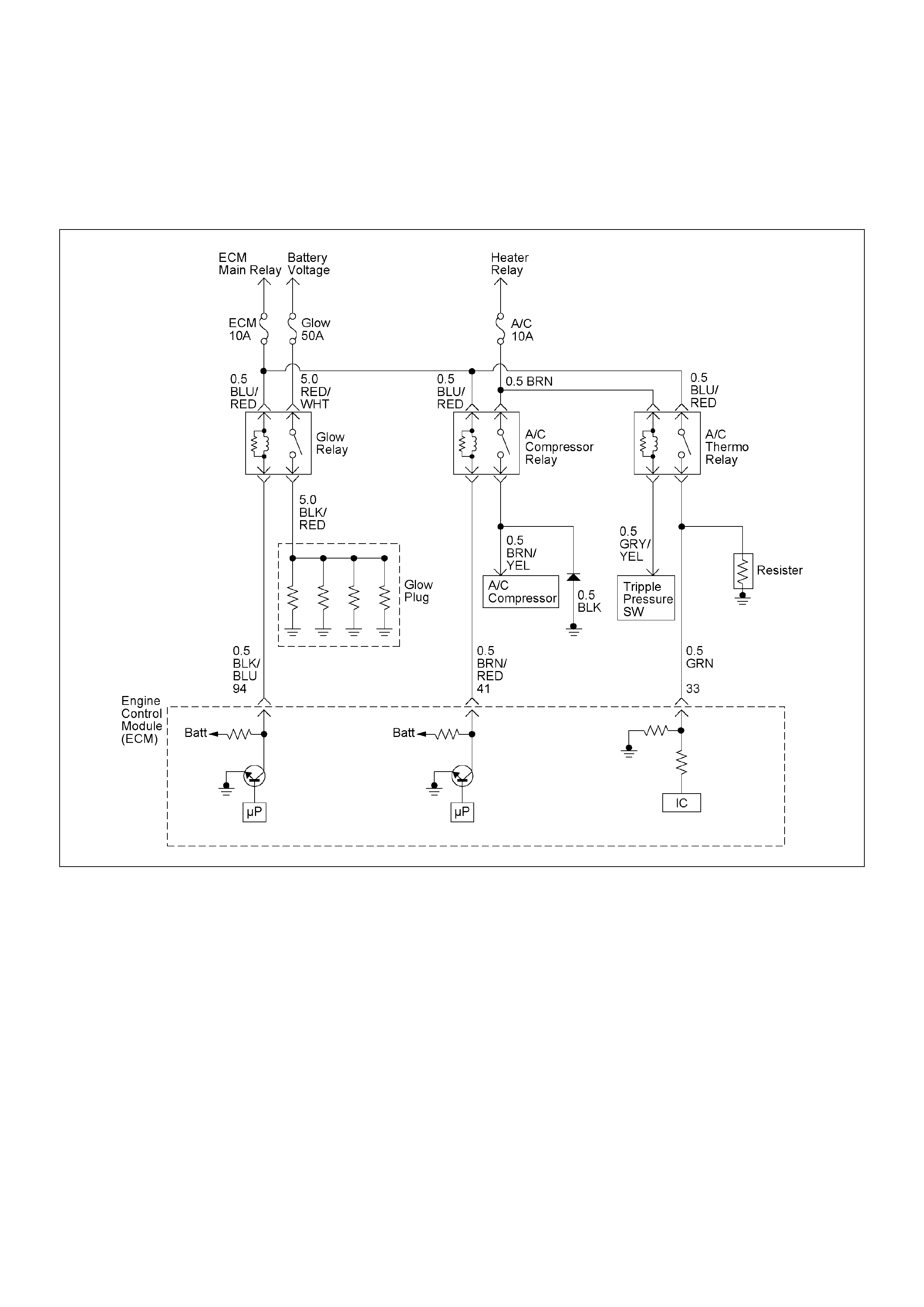
DIAGNOSTIC TROUBLE CODE (DTC) P0645 (SYM PTOM CODE 4)
(FLASH CODE 46) A/C COMPRESSOR RELAY CIRCUIT VOLTAGE LOW
DIAGNOSTIC TROUBLE CODE (DTC) P0645 (SYM PTOM CODE 8)
(FLASH CODE 46) A/C COMPRESSOR RELAY CIRCUIT VOLTA GE HIGH

Condition for setting the DTC and action ta ken when the DTC sets
Circuit Description
The voltage on the coil of the A/C compressor is
supplie d by the ECM main relay. The ECM sw itches A/
C compressor relay to operate A/C compressor
depends on the A/C request signal and certain setting
conditions.
Diagnostic Aids
An intermittent may be caused by the following:
• Poor connections.
• Misrouted harness.
• Rubbed through wire insulation.
• Broken wire inside the insulation.
Check for the following conditions:
• Poor con nection at ECM-I nspect harness connectors
for backed out terminals, improper mating, broken
locks, improperly formed or damaged terminals, and
poor terminal to wire connection.
• Damaged harness-Inspect the wiring harness for
damage. If the harness appears to be OK, observe
the DTC P0645 display on the Tech2 while moving
connectors and wiring harnesses.
Flash
Code Code Symptom
Code MIL DTC Name DTC Setting Condition Fail-Safe (Back Up)
46 P0645 4 ON A/C Compressor Relay Circuit
Voltage Low A/C compressor relay circuit
open or short to ground
circuit.
No fail-safe function.
8 ON A/C Compressor Relay Circuit
Voltage High A/C compressor relay circuit
short to voltage circuit.
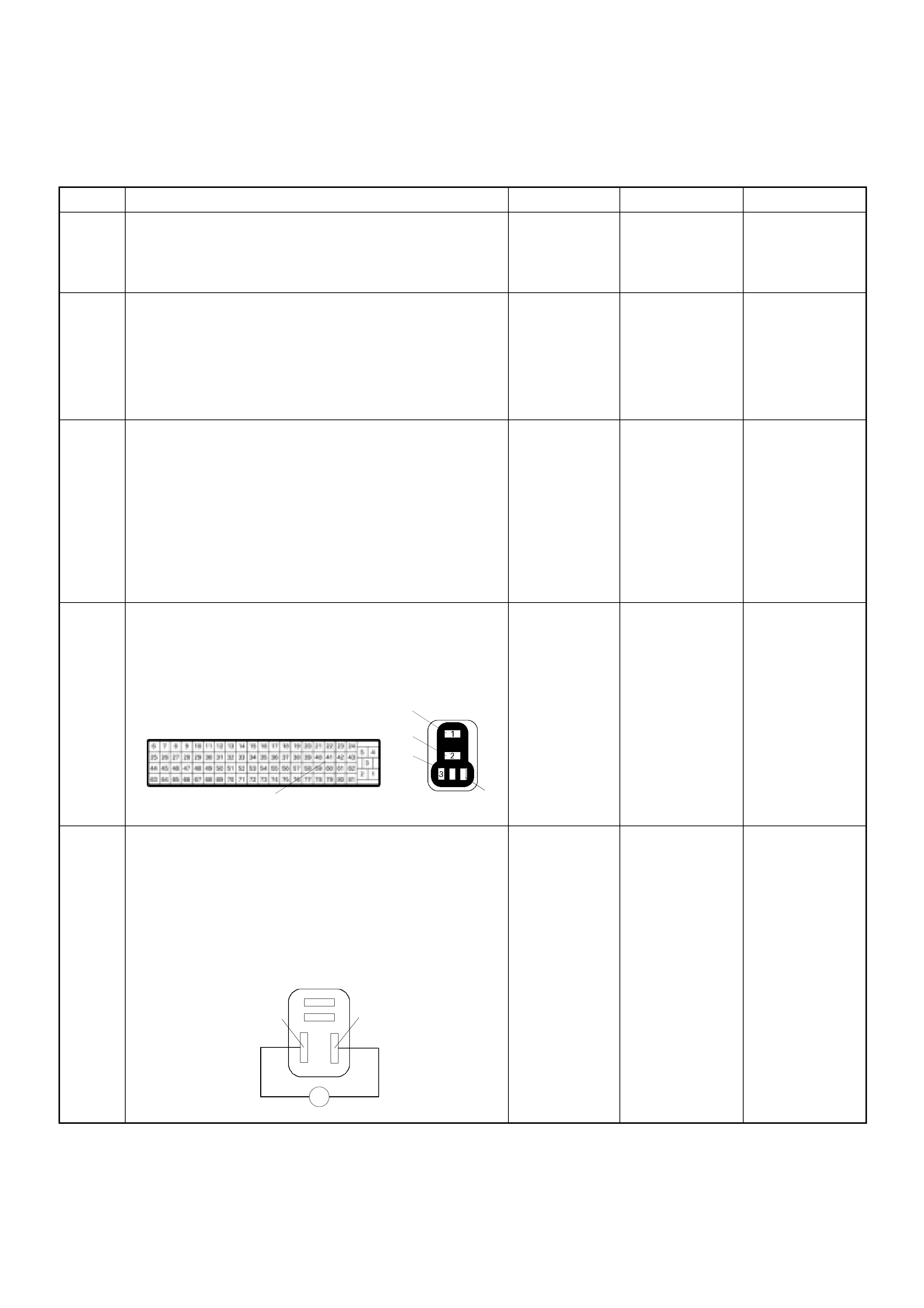
Diagnostic Trouble Code (DTC) P0645 (Symptom Code 4) (Flash Code 46) A/C
Compressor Relay Circuit Voltage Low
Step Action Value(s) Yes No
1 Was the “On-Board Diagnostic (OBD) System Check”
performed?
—Go to Step 2
Go to On Board
Diagnostic
(OBD) System
Check
2 1. Connect the Tech 2.
2. Review and record the failure information.
3. Select “F0: Read DTC I nfor As Stored By ECU” in
“F0: Diagnostic Trouble Codes”.
Is the DTC P0645 (Symptom Code 4) stored as
“Present Failure”? — Go to Step 3
Refer to
Diagnostic Aids
and Go to Step
3
3 1. Using the Tech 2, ignition “On” and engine “Off”.
2. Select “F1: Clear DTC Information” in “F0:
Diagnostic Trouble Codes” with the Tech 2 and
clear the DTC information.
3. Operate the vehicle and monitor the “F0: Read
DTC Infor As Stored By ECU” in the “F0:
Diagnostic Trouble Codes”.
Was the DT C P0 645 (Sy mpt om Code 4) stor e d i n th is
ignition cycle? — Go to Step 4
Refer to
Diagnostic Aids
and Go to Step
4
4 Check for poor/faulty connection at the A/C
compressor relay or ECM connector. If a poor/faulty
connection is found, repair as necessary.
Was the problem found?
— Verify repair Go to Step 5
5 Using the DVM and check the A/C compressor relay.
1. Ignition “Off”, engine “Off”.
2. Remove the A/C compressor relay from the relay
box.
3. Check the relay coil.
Was the DVM indicated specified value?
120-150ΩGo to Step 6
Replace A/C
compressor
relay and verify
repair
C-56 X-14
4
4
41
3
1
2
A/C Compressor Relay
3
4
2
1
Ħ
3
4
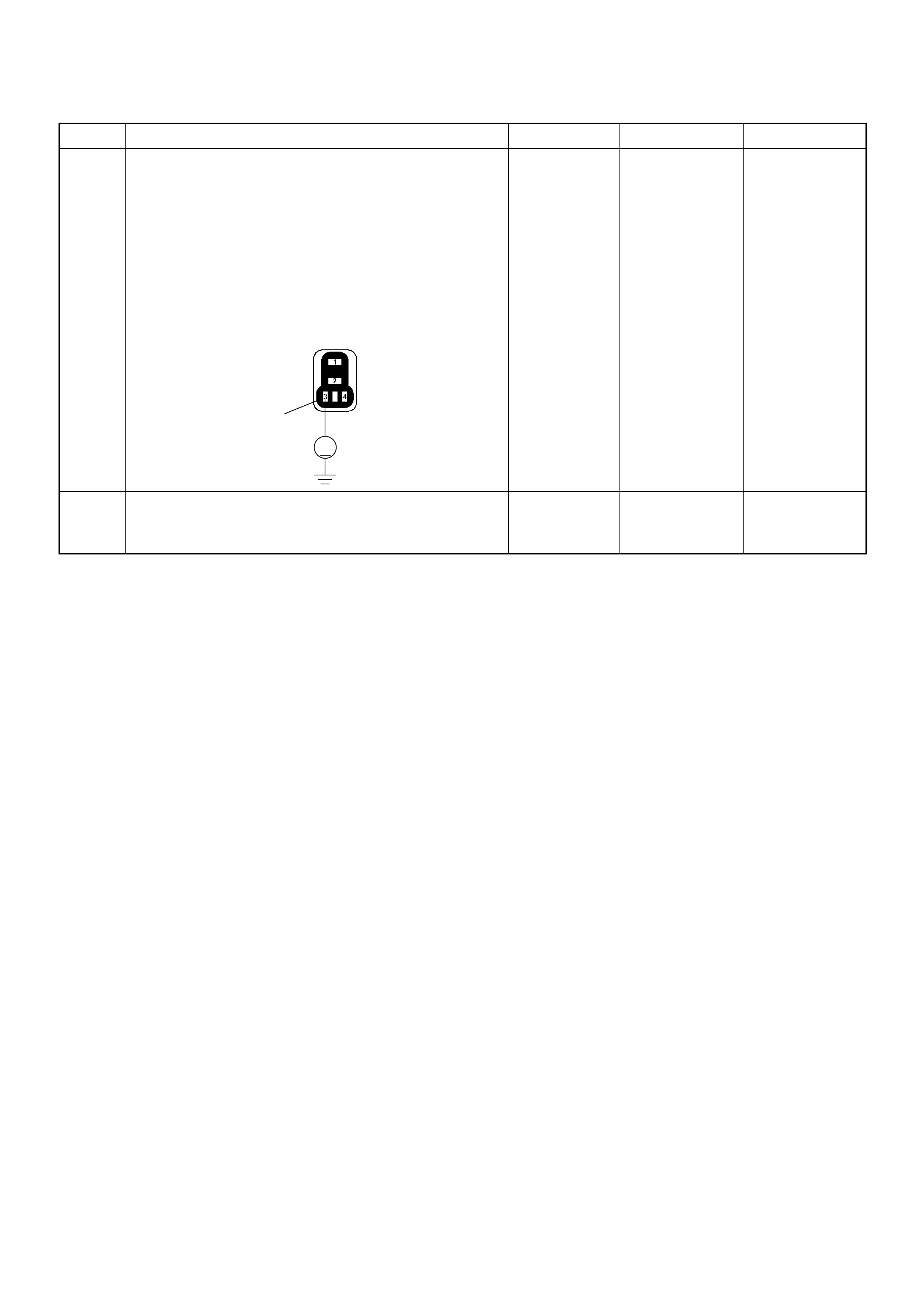
6 Using the DVM and check the A/C compressor relay
power supply circuit.
1. Ignition “On”, engine “Off”.
2. Remove the A/C compressor relay from the relay
box.
3. Check the circuit for open or short to ground
circuit.
Was the DVM indicated specified value?
10-14.5V Go to Step 8 Go to Step 7
7 Repair the open or short to ground circuit between the
ECM main relay and A/C compressor relay.
Is the action complete? — Verify repair —
Step Action Value(s) Yes No
3
V
X-14
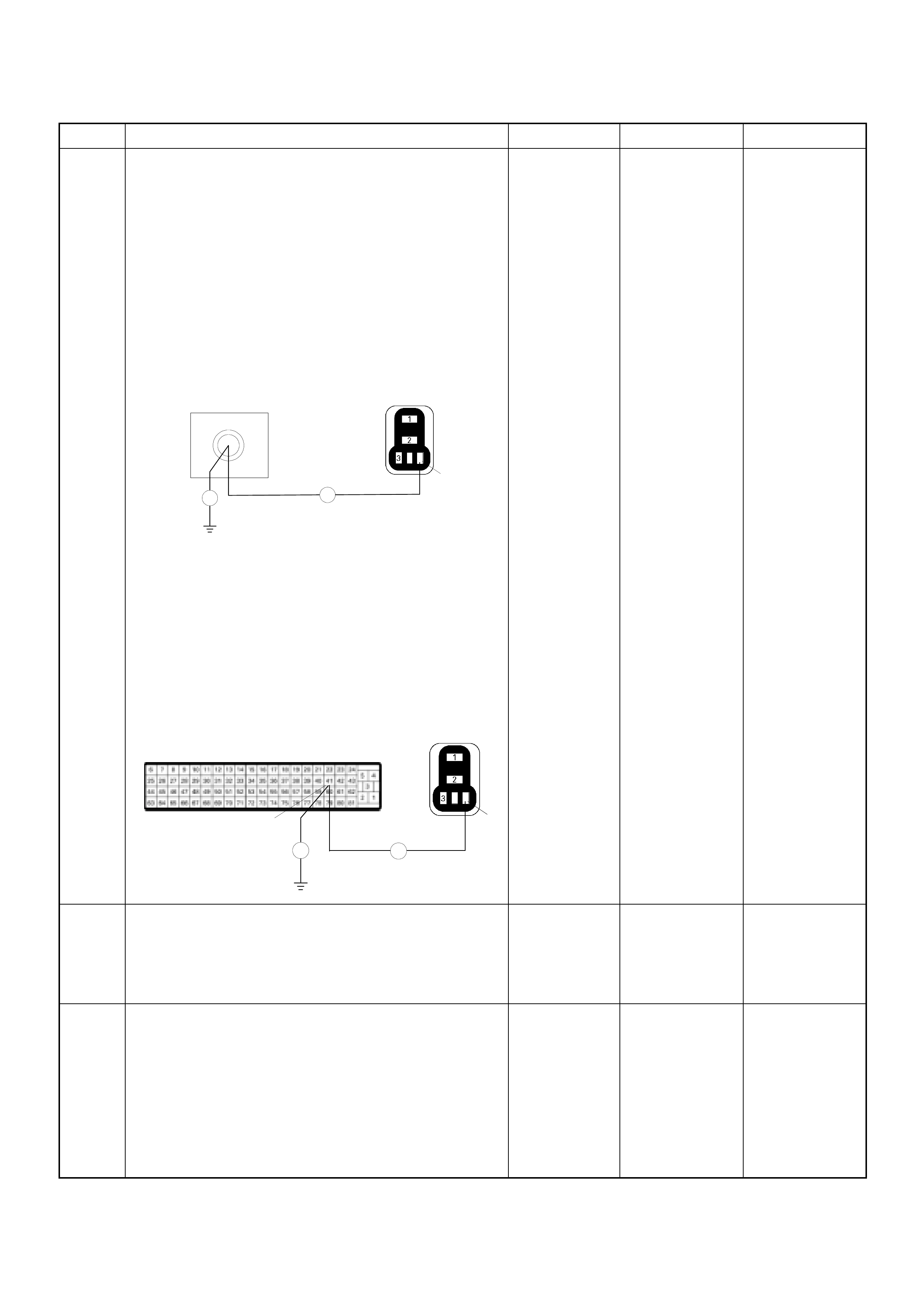
8 Using the DVM and check the A/C compressor relay
ground circuit.
Breaker box is available:
1. Ignition “Off”, engine “Off”.
2. Install the breaker box as type A. (ECM
disconnected)
3. Remove the A/C compressor relay from the relay
box.
4. Check the circuit for open or short to ground
circuit.
Was the problem found?
Breaker box is not available:
1. Ignition “Off”, engine “Off”.
2. Disconnect the ECM connector.
3. Remove the A/C compressor relay from the relay
box.
4. Check the circuit for open or short to ground
circuit.
Was the problem found?
—
Repair faulty
harness and
verify repair Go to Step 9
9 Is the ECM programmed with the latest software
release?
If not, download the latest software to the ECM using
the “SPS (Service Programming System)”.
Was the problem solved? — Verify repair Go to Step 10
10 Replace the ECM.
Is the action complete?
IMPORTANT: The replacement ECM must be
programmed. Refer to section of the Service
Programming System (SPS) in this manual.
Foll owing ECM pr ogramming, the immobi lizer system
(if equipped) must be linked to the ECM. Refer to
section 11 “Immobilizer System-ECM replacement” for
the ECM/Immobilizer linking procedure. — Verify repair —
Step Action Value(s) Yes No
X-14
4
41
Break e r Box
Ħ
Ħ 4
C-56 X-14
4
4
Ħ
Ħ
41

Diagnostic Trouble Code (DTC) P0645 (Symptom Code 8) (Flash Code 46) A/C
Compressor Relay Circuit Voltage High
Step Action Value(s) Yes No
1 Was the “On-Board Diagnostic (OBD) System Check”
performed?
—Go to Step 2
Go to On Board
Diagnostic
(OBD) System
Check
2 1. Connect the Tech 2.
2. Review and record the failure information.
3. Select “F0: Read DTC Infor As Stored By ECU” in
“F0: Diagnostic Trouble Codes”.
Is the DTC P0645 (Symptom Code 8) stored as
“Present Failure”? — Go to Step 3
Refer to
Diagnostic Aids
and Go to Step
3
3 1. Using the Tech 2, ignition “On” and engine “Off”.
2. Select “F1: Clear DTC Information” in “F0:
Diagnostic Trouble Codes” with the Tech 2 and
clear the DTC information.
3. Operate the vehicle and monitor the “F0: Read
DTC Infor As Stored By ECU” in the “F0:
Diagnostic Trouble Codes”.
Was the DTC P0645 (Symptom Code 8) stored in this
ignition cycle? — Go to Step 4 Refer to
Diagnostic Aids
4 Is the ECM programmed with the latest software
release?
If not, download the latest software to the ECM using
the “SPS (Service Programming System)”.
Was the problem solved? — Verify repair Go to Step 5
5 Substitute a known good ECM and recheck.
Was the problem solved?
IMPORTANT: The replacement ECM must be
programmed. Refer to section of the Service
Programming System (SPS) in this manual.
Following ECM programming, the immobilizer system
(if equipped) must be linked to the ECM. Refer to
section 11 “Immobilizer System-ECM replacement” for
the ECM/Immobilizer linking procedure. —Go to Step 6 —
6 Replace the ECM.
Is the action complete?
IMPORTANT: The replacement ECM must be
programmed. Refer to section of the Service
Programming System (SPS) in this manual.
Foll owing ECM pr ogramming, the immobi lizer system
(if equipped) must be linked to the ECM. Refer to
section 11 “Immobilizer System-ECM replacement” for
the ECM/Immobilizer linking procedure. — Verify repair —
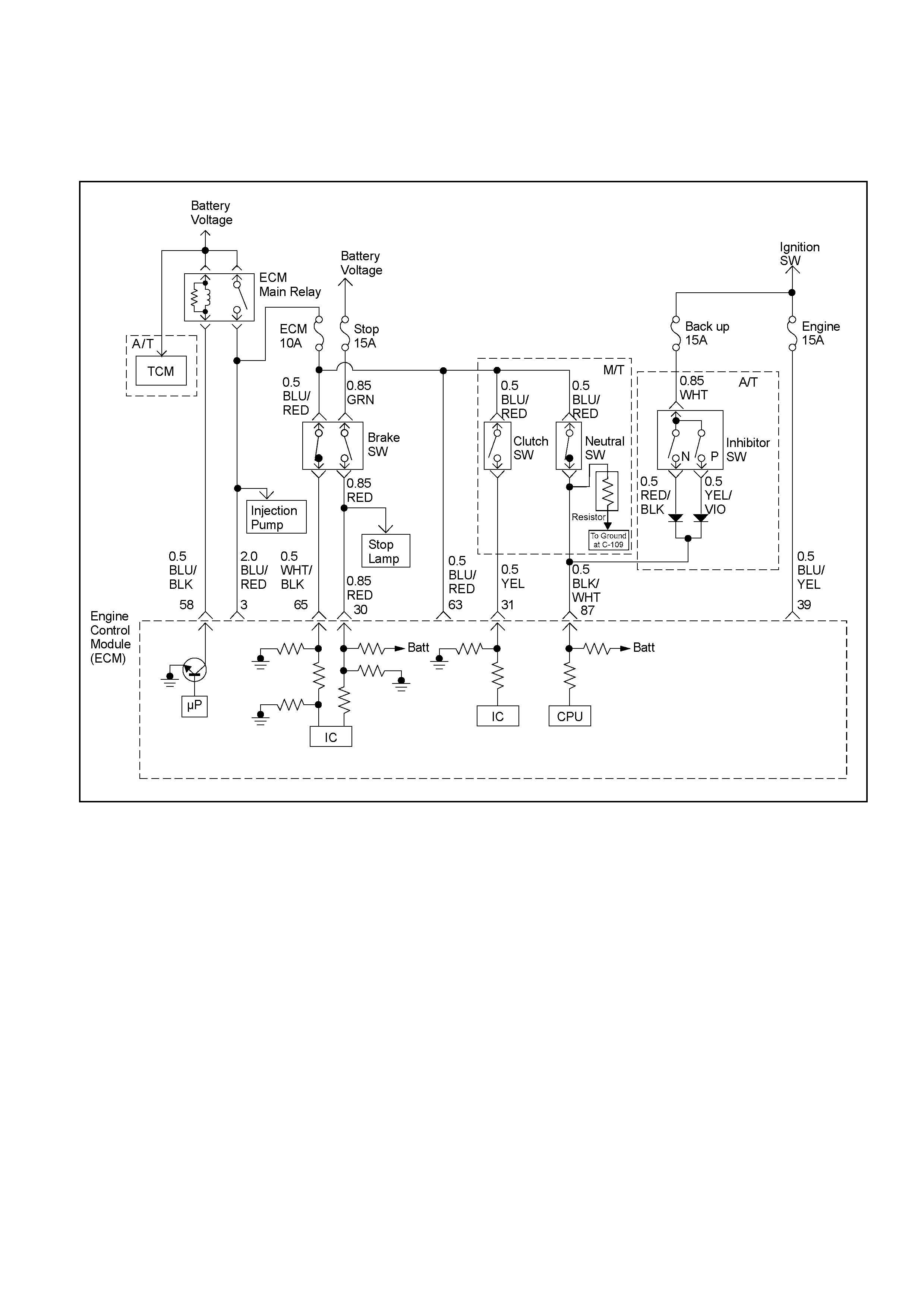
DIAGNOSTIC TROUBLE CODE (DTC) P0703 (SYMPTOM CODE A)
(FLASH CODE 25) BRAKE SWITCH CIRCUIT MALFUNCTION
DIAGNOSTIC TROUBLE CODE (DTC) P0703 (SYMPTOM CODE B)
(FLASH CODE 25) BRAKE SWITCH CIRCUIT MALFUNCTION
RTW46ELF001401-a

Condition for setting the DTC and action ta ken when the DTC sets
Circuit Description
The ECM monitors the brake switch signal on the feed
terminal to the ECM. If brake switch 1 or 2 circuit with
malfunction, DTC P0703 (Symptom Code A) or P0703
(Symptom Code B) will be stored.
Diagnostic Aids
An intermittent may be caused by the following:
• Poor connections.
• Misrouted harness.
• Rubbed through wire insulation.
• Broken wire inside the insulation.
Check for the following conditions:
• Poor con nection at ECM-I nspect harness connectors
for backed out terminals, improper mating, broken
locks, improperly formed or damaged terminals, and
poor terminal to wire connection.
• Damaged harness-Inspect the wiring harness for
damage. If the harness appears to be OK, observe
the “Br ake Sw itch 1 ” and “B rake Switch 2” disp lay on
the Tech2 while moving connectors and wiring
harness related to the sensor.
Flash
Code Code Symptom
Code MIL DTC Name DTC Setting Condition Fail-Safe (Back Up)
25 P0703 A ON Brake Switch Circuit
Malfunction 1. Throttle position is more
than 0%.
2. Engine speed is more than
665rpm.
3. V ehicle speed is more than
0km/h.
4. Brake switch 1 signal and
brake switch 2 signal are
differently inputted to the
ECM since the ignition
switch was turned on.
No fail-safe function.
B ON Brake Switch Circuit
Malfunction 1. Throttle position is more
than 0%.
2. Engine speed is more than
665 rpm.
3. V ehicle speed is more than
0km/h.
4. Brake switch 1 signal and
brake switch 2 signal are
differently inputted to the
ECM.
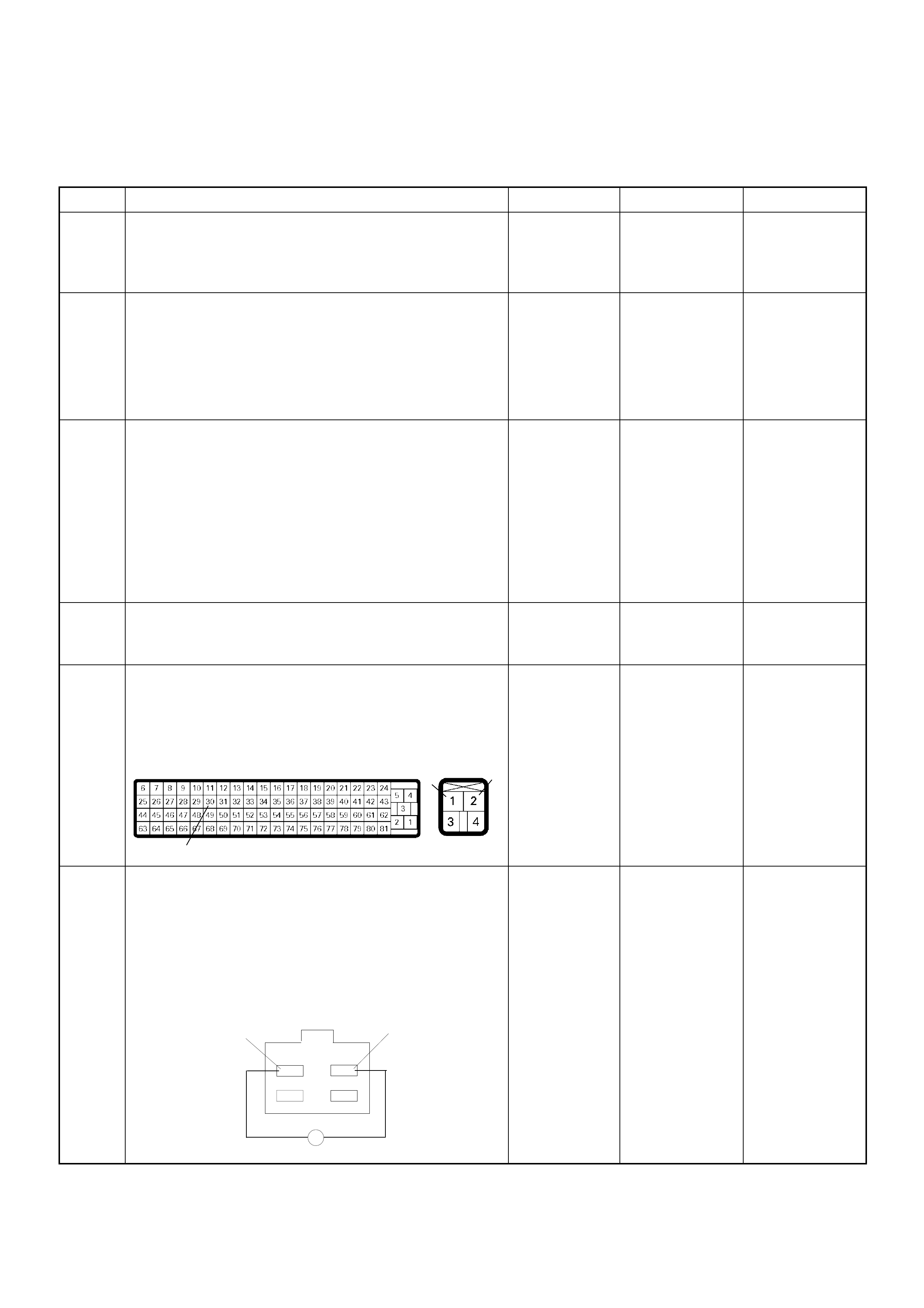
Diagnostic Trouble Code (DTC) P0703 (Symptom Code A) (Flash Code 25)
Brake Switch Circuit Malfunction
Step Action Value(s) Yes No
1 Was the “On-Board Diagnostic (OBD) System Check”
performed?
—Go to Step 2
Go to On Board
Diagnostic
(OBD) System
Check
2 1. Connect the Tech 2.
2. Review and record the failure information.
3. Select “F0: Read DTC I nfor As Stored By ECU” in
“F0: Diagnostic Trouble Codes”.
Is the DTC P0703 (Symptom Code A) stored as
“Present Failure”? — Go to Step 3
Refer to
Diagnostic Aids
and Go to Step
3
3 1. Using the Tech 2, ignition “On” and engine “Off”.
2. Select “F1: Clear DTC Information” in “F0:
Diagnostic Trouble Codes” with the Tech 2 and
clear the DTC information.
3. Operate the vehicle and monitor the “F0: Read
DTC Infor As Stored By ECU” in the “F0:
Diagnostic Trouble Codes”.
Was the DTC P0703 (Symptom Code A) stored in this
ignition cycle? — Go to Step 4
Refer to
Diagnostic Aids
and Go to Step
4
4 Check the “Stop Lamp fuse (15A)”.
If the fuse is burnt out, repair as necessary.
Was the problem found? — Verify repair Go to Step 5
5 Check for poor/faulty connection at the brake switch
or ECM connector. If a poor/faulty connection is
found, repair as necessary.
Was the problem found?
— Verify repair Go to Step 6
6 Using the DVM and check the brake switch 1.
1. Ignition “Off”, engine “Off”.
2. Remove the brake switch connector at the brake
pedal.
3. Check the brake switch 1.
Was the DVM indicated specified value?
Pedal is not
stepped on:
Continuity
Pedal stepped
on: No
continuity Go to Step 7
Replace pedal
switch and
verify repair
30
1
2
C-56 C-44
1
2
Ħ
Brake Switch

7 Using the DVM and check the brake switch 1 power
supply circuit.
1. Ignition “Off”, engine “Off”.
2. Remove the brake switch connector from the
brake switc h.
3. Check the circuit for open circuit.
Was the DVM indicated specified value?
10-14.5V Go to Step 9 Go to Step 8
8 Repair the open circuit between the “Stop Lamp fuse
(15A)” and brake switch 1.
Is the action complete? — Verify repair —
9 Using the DVM and check the brake switch 1 circuit.
Breaker box is available:
1. Ignition “Off”, engine “Off”.
2. Install the breaker box as type B. (ECM
connected) Ref. to HOW TO USE BREAKER BOX
3. Ignition “On”, engine “Off”.
4. Check the circuit for open or short to voltage
circuit.
Was the DVM indicated specified value?
Breaker box is not available:
1. Ignition “On”, engine “Off”.
2. Back probe the DVM to the brake switch 1 and
check the circuit for open or short to voltage
circuit.
Was the problem found?
Pedal is not
stepped on:
Less than 1V
Pedal stepped
on: 10-14.5V Go to Step 12
Fixed at 10-
14.5V: Go to
Step 10
Fixed at less
than 1V: Go to
Step 11
Step Action Value(s) Yes No
V
1
C-44
105
Breaker Box
V
V
2
C-44

10 Repair the short to voltage circuit between the brake
switch 1 connector and ECM.
Is the action complete?
— Verify repair —
11 Repair the open circuit between the brake switch 1
connector and ECM.
Is the action complete?
— Verify repair —
12 Is the ECM programmed with the latest software
release?
If not, download the latest software to the ECM using
the “SPS (Service Programming System)”.
Was the problem solved? — Verify repair Go to Step 13
13 Replace the ECM.
Is the action complete?
IMPORTANT: The replacement ECM must be
programmed. Refer to section of the Service
Programming System (SPS) in this manual.
Foll owing ECM pr ogramming, the immobi lizer system
(if equipped) must be linked to the ECM. Refer to
section 11 “Immobilizer System-ECM replacement” for
the ECM/Immobilizer linking procedure. — Verify repair —
Step Action Value(s) Yes No
2
30
C-56 C-44
2
30
C-56 C-44
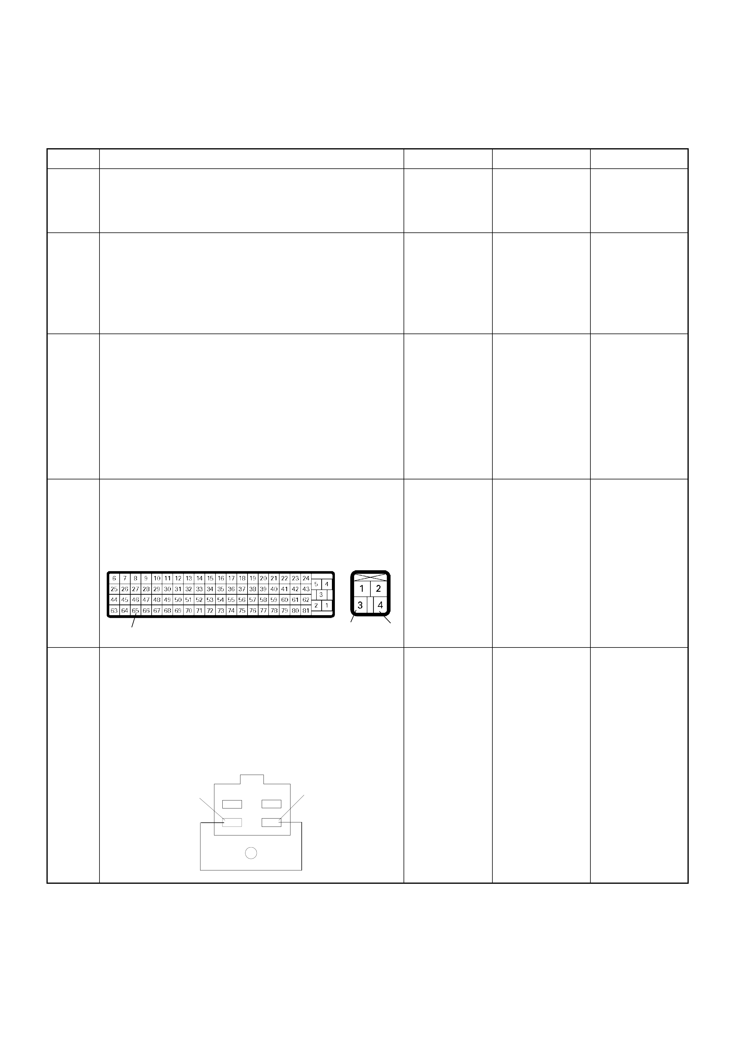
Diagnostic Trouble Code (DTC) P0703 (Symptom Code B) (Flash Code 25)
Brake Switch Circuit Malfunction
Step Action Value(s) Yes No
1 Was the “On-Board Diagnostic (OBD) System Check”
performed?
—Go to Step 2
Go to On Board
Diagnostic
(OBD) System
Check
2 1. Connect the Tech 2.
2. Review and record the failure information.
3. Select “F0: Read DTC I nfor As Stored By ECU” in
“F0: Diagnostic Trouble Codes”.
Is the DTC P0703 (Symptom Code B) stored as
“Present Failure”? — Go to Step 3
Refer to
Diagnostic Aids
and Go to Step
3
3 1. Using the Tech 2, ignition “On” and engine “Off”.
2. Select “F1: Clear DTC Information” in “F0:
Diagnostic Trouble Codes” with the Tech 2 and
clear the DTC information.
3. Operate the vehicle and monitor the “F0: Read
DTC Infor As Stored By ECU” in the “F0:
Diagnostic Trouble Codes”.
Was the DTC P0703 (Symptom Code B) stored in this
ignition cycle? — Go to Step 4
Refer to
Diagnostic Aids
and Go to Step
4
4 Check for poor/faulty connection at the brake switch
or ECM connector. If a poor/faulty connection is
found, repair as necessary.
Was the problem found?
— Verify repair Go to Step 5
5 Using the DVM and check the brake switch 2.
1. Ignition “Off”, engine “Off”.
2. Remove the brake switch connector at the brake
pedal.
3. Check the brake switch 2.
Was the DVM indicated specified value?
Pedal is not
stepped on:
No continuity
Pedal stepped
on: Continuity Go to Step 6
Replace pedal
switch and
verify repair
65
34
C-56 C-44
3
4
Ħ
Brake Swi tch
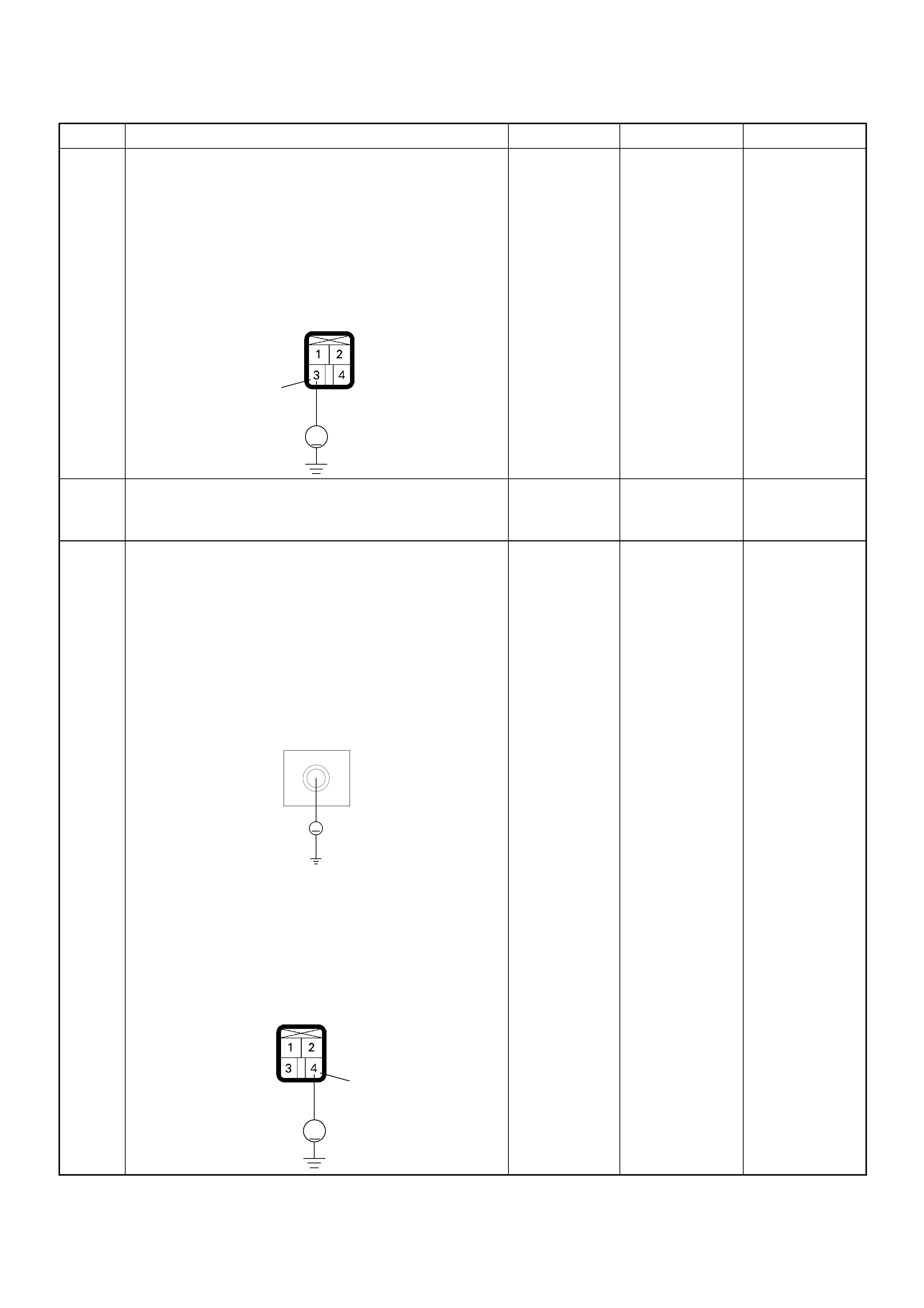
6 Using the DVM and check the brake switch 2 power
supply circuit.
1. Ignition “On”, engine “Off”.
2. Remove the brake switch connector from the
brake switc h.
3. Check the circuit for open circuit.
Was the DVM indicated specified value?
10-14.5V Go to Step 8 Go to Step 7
7 Re pair the ope n c irc uit bet ween the “ ECM fus e ( 1 0A)”
and brake switch 2.
Is the action complete? — Verify repair —
8 Using the DVM and check the brake switch 2 circuit.
Breaker box is available:
1. Ignition “Off”, engine “Off”.
2. Install the breaker box as type B. (ECM
connected)
3. Ignition “On”, engine “Off”.
4. Check the circuit for open or short to voltage
circuit.
Was the DVM indicated specified value?
Breaker box is not available:
1. Ignition “On”, engine “Off”.
2. Back probe the DVM to the brake switch 2 and
check the circuit for open or short to voltage
circuit.
Was the problem found?
Pedal is not
stepped on:
10-14.5V
Pedal stepped
on: Less than
1V Go to Step 11
Fixed at 10-
14.5V: Go to
Step 9
Fixed at less
than 1V: Go to
Step 10
Step Action Value(s) Yes No
V
3
C-44
65
Breaker Box
V
V
4
C-44
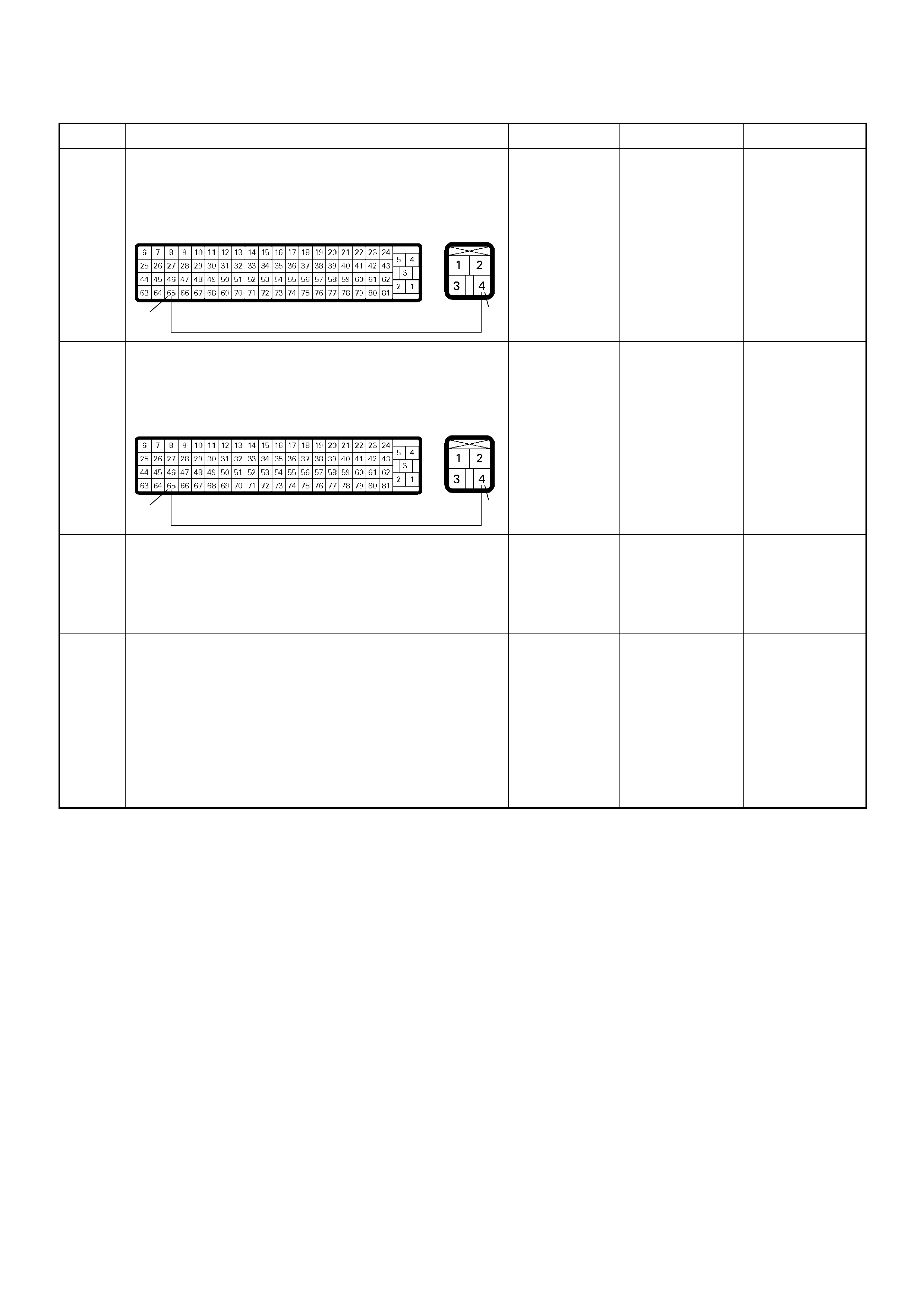
9 Repair the short to voltage circuit between the brake
switch 2 connector and ECM.
Is the action complete?
— Verify repair —
10 Repair the open circuit between the brake switch 2
connector and ECM.
Is the action complete?
— Verify repair —
11 Is the ECM programmed with the latest software
release?
If not, download the latest software to the ECM using
the “SPS (Service Programming System)”.
Was the problem solved? — Verify repair Go to Step 12
12 Replace the ECM.
Is the action complete?
IMPORTANT: The replacement ECM must be
programmed. Refer to section of the Service
Programming System (SPS) in this manual.
Foll owing ECM pr ogramming, the immobi lizer system
(if equipped) must be linked to the ECM. Refer to
section 11 “Immobilizer System-ECM replacement” for
the ECM/Immobilizer linking procedure. — Verify repair —
Step Action Value(s) Yes No
65 4
C-56 C-44
65 4
C-56 C-44
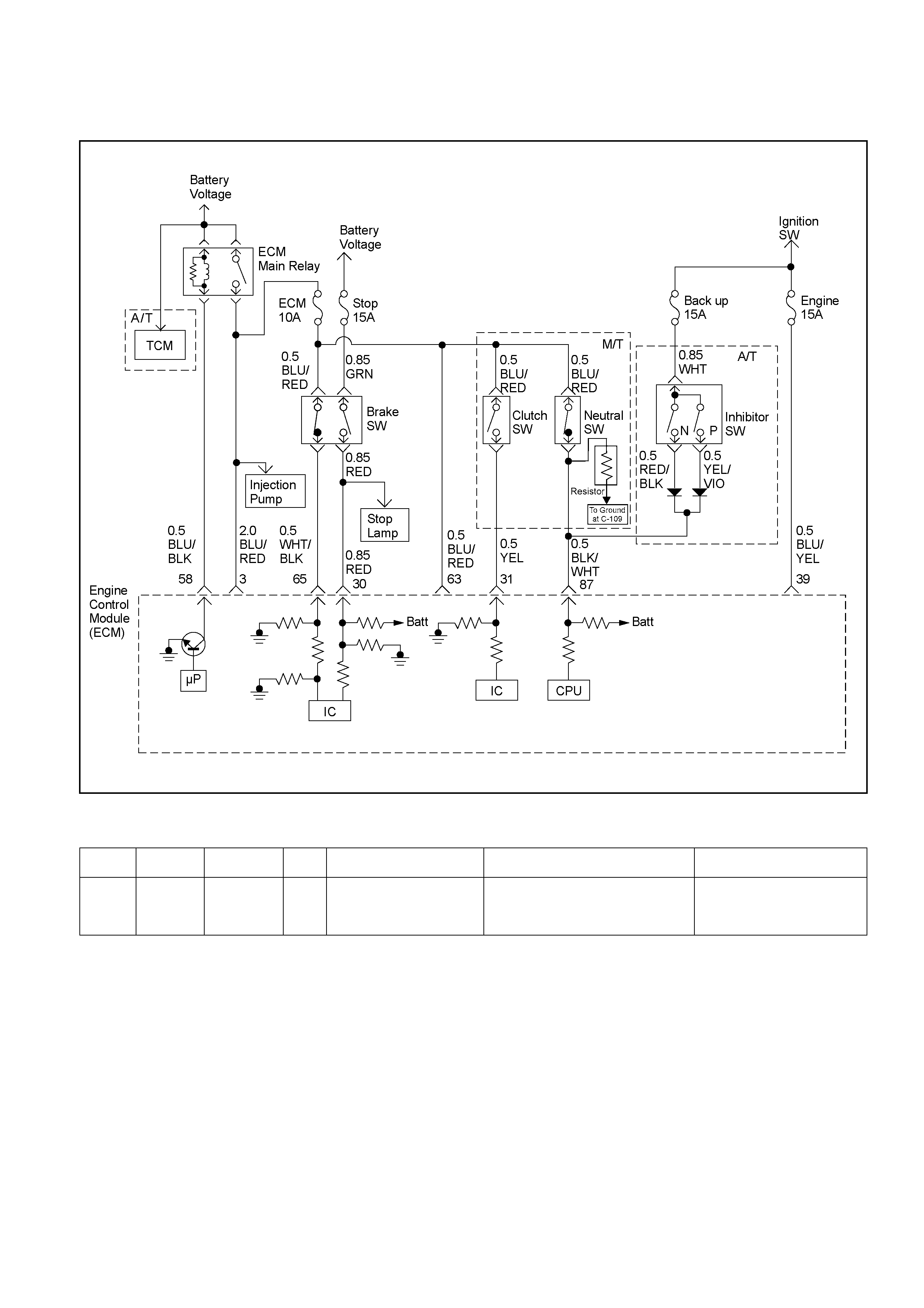
DIAGNOSTIC TROUBLE CODE (DTC) P0704 (SYMPTOM CODE 6)
(FLASH CODE 57) CLUTCH SWITCH CIRCUIT MALFUNCTION
RTW46ELF001401-a
Condition for setting the DTC and action taken when the DTC sets
Flash
Code Code Symptom
Code MIL DTC Name DTC Setting Condition Fail-Safe (Back Up)
57 P0704 6 ON Clutch Switch Circuit
Malfunction Clutch signal does not change
between vehicle speed 1.5 km/h
and 80 km/h since ignition switch
was turned on.
No fail-safe function.
Circuit Description
The ECM monitors the clutch switch signal on the feed
terminal to the ECM. If the clutch switch circuit with
malfunctions, a DTC P0704 (Symptom Code 6) will be
stored.
Diagnostic Aids
An intermittent may be caused by the following:
• Poor connections.
• Misrouted harness.
• Rubbed through wire insu lati on .
• Broken wire insi de the in sulation .
Check for the fo llow ing co ndition s:
• Poor connection at ECM-Inspect harness connectors fo r
backed out termin al s, improper ma ting , broken locks,
improperly formed or damage d termin al s, and poor
terminal to w ire connection .
• Damaged harness. Inspect the wiring ha rness for
damage. If the harn ess appea rs to be OK, obse rve the
"Clutch Sw itch" d isplay on Te ch 2 w hile moving
connectors and the wiring harness relate d to the sensor.
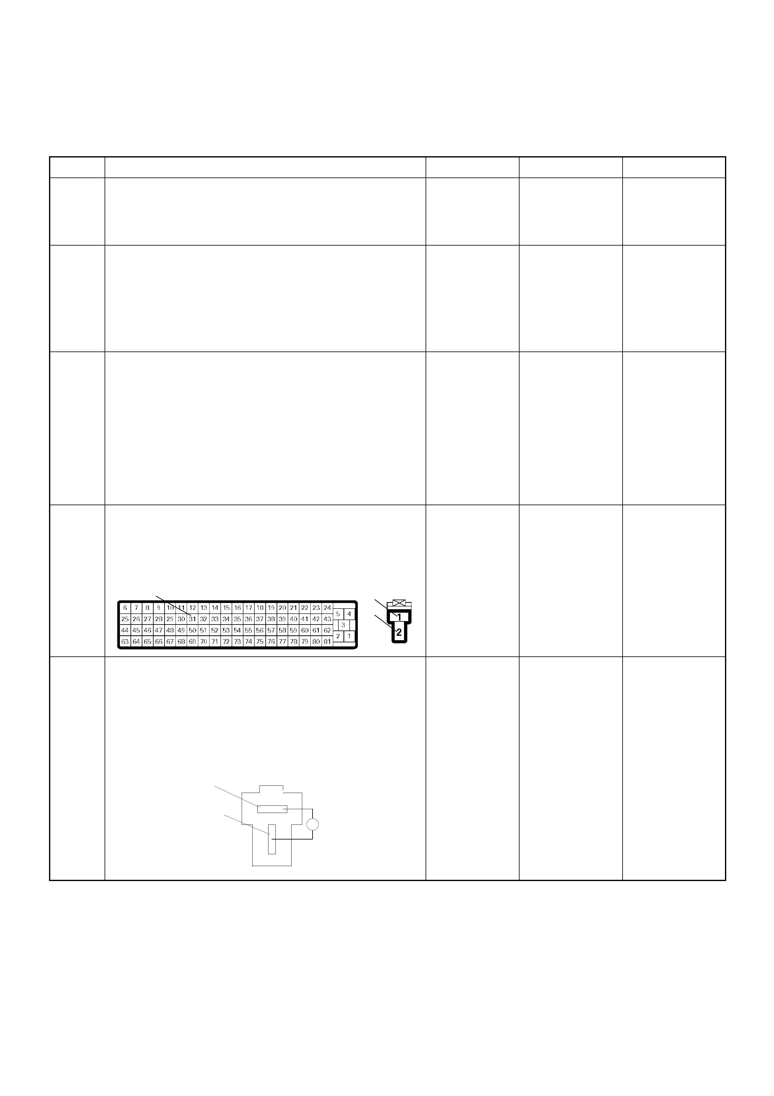
Diagnostic Trouble Code (DTC) P0704 (Symptom Code 6) (Flash Code 57)
Clutch Switch Input Circuit Malfunction
Step Action Value(s) Yes No
1 Was the “On-Board Diagnostic (OBD) System Check”
performed?
—Go to Step 2
Go to On Board
Diagnostic
(OBD) System
Check
2 1. Connect the Tech 2.
2. Review and record the failure information.
3. Select “F0: Read DTC I nfor As Stored By ECU” in
“F0: Diagnostic Trouble Codes”.
Is the DTC P0704 (Symptom Code 6) stored as
“Present Failure”? — Go to Step 3
Refer to
Diagnostic Aids
and Go to Step
3
3 1. Using the Tech 2, ignition “On” and engine “Off”.
2. Select “F1: Clear DTC Information” in “F0:
Diagnostic Trouble Codes” with the Tech 2 and
clear the DTC information.
3. Operate the vehicle and monitor the “F0: Read
DTC Infor As Stored By ECU” in the “F0:
Diagnostic Trouble Codes”.
Was the DT C P0 704 (Sy mpt om Code 6) stor e d i n th is
ignition cycle? — Go to Step 4
Refer to
Diagnostic Aids
and Go to Step
4
4 Check for poor/faulty connection at the clutch switch
or ECM connector. If a poor/faulty connection is
found, repair as necessary.
Was the problem found?
— Verify repair Go to Step 5
5 Using the DVM and check the clutch switch.
1. Ignition “Off”, engine “Off”.
2. Remove the clutch switch connector at the clutch
pedal.
3. Check the clutch switch.
Was the DVM indicated specified value?
Pedal is not
stepped on:
Continuity
Pedal stepped
on: No
continuity Go to Step 6
Replace pedal
switch and
verify repair
31
1
2
C-56 C-77
Clut ch Swi tch
1
2
Ħ
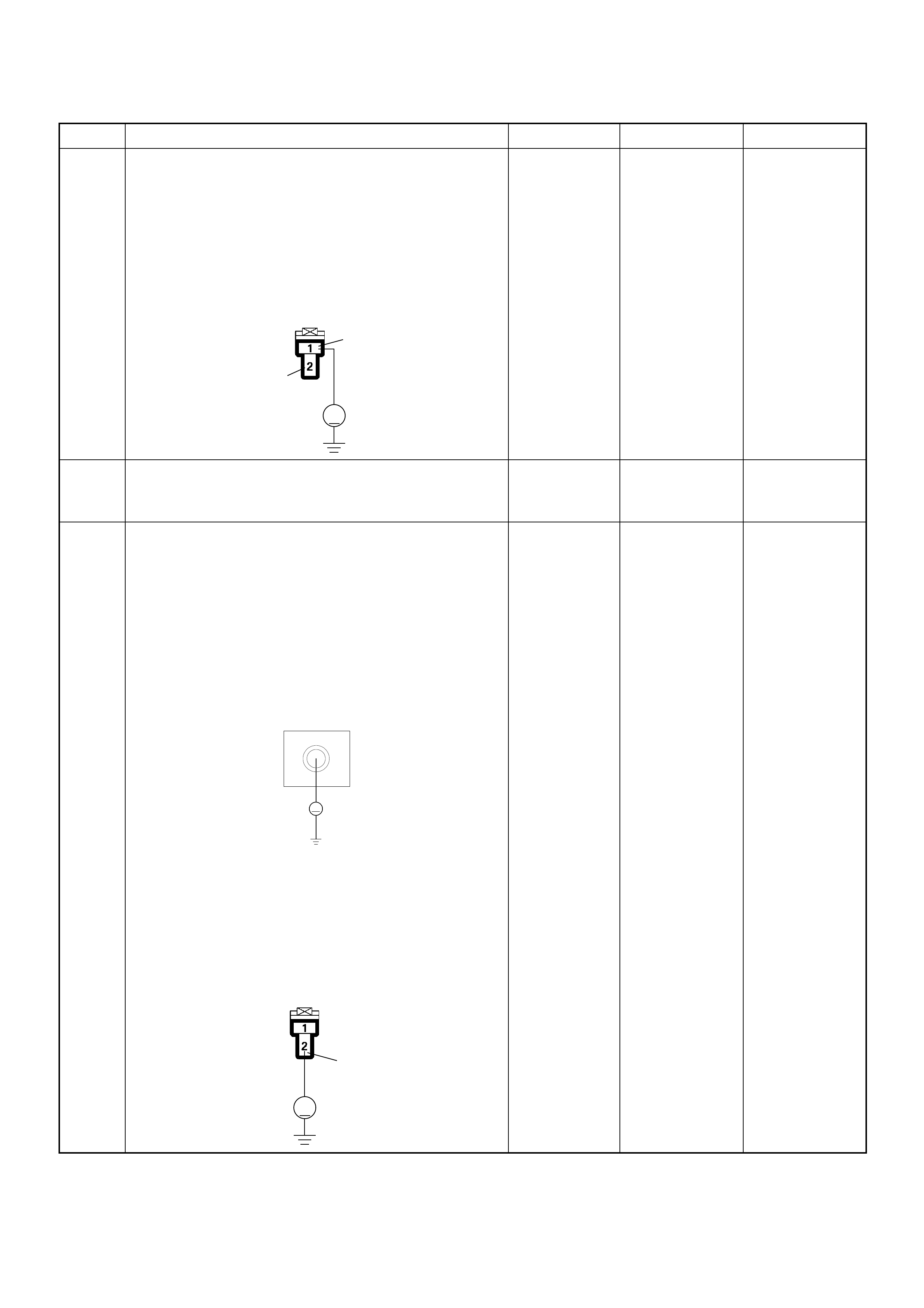
6 Using the DVM and check the clutch switch power
supply circuit.
1. Ignition “On”, engine “Off”.
2. Remove the clutch switch connector from the
clutch switch.
3. Check the circuit for open circuit.
Was the DVM indicated specified value?
10-14.5V Go to Step 8 Go to Step 7
7 Re pair the ope n c irc uit bet ween the “ ECM fus e ( 1 0A)”
and clu tch switch.
Is the action complete? — Verify repair —
8 Using the DVM and check the clutch switch circuit.
Breaker box is available:
1. Ignition “Off”, engine “Off”.
2. Install the breaker box as type B. (ECM
connected) Ref. to HOW TO USE BREAKER BOX
3. Ignition “On”, engine “Off”.
4. Check the circuit for open or short to voltage
circuit.
Was the DVM indicated specified value?
Breaker box is not available:
1. Ignition “On”, engine “Off”.
2. Back probe the DVM to the clutch switch and
check the circuit for open or short to voltage
circuit.
Was the problem found?
Pedal is not
stepped on:
10-14.5V
Pedal stepped
on: Less than
1V Go to Step 11
Fixed at 10-
14.5V: Go to
Step 9
Fixed at less
than 1V: Go to
Step 10
Step Action Value(s) Yes No
V
1
2
C-77
31
Breaker Box
V
V
2
C-77
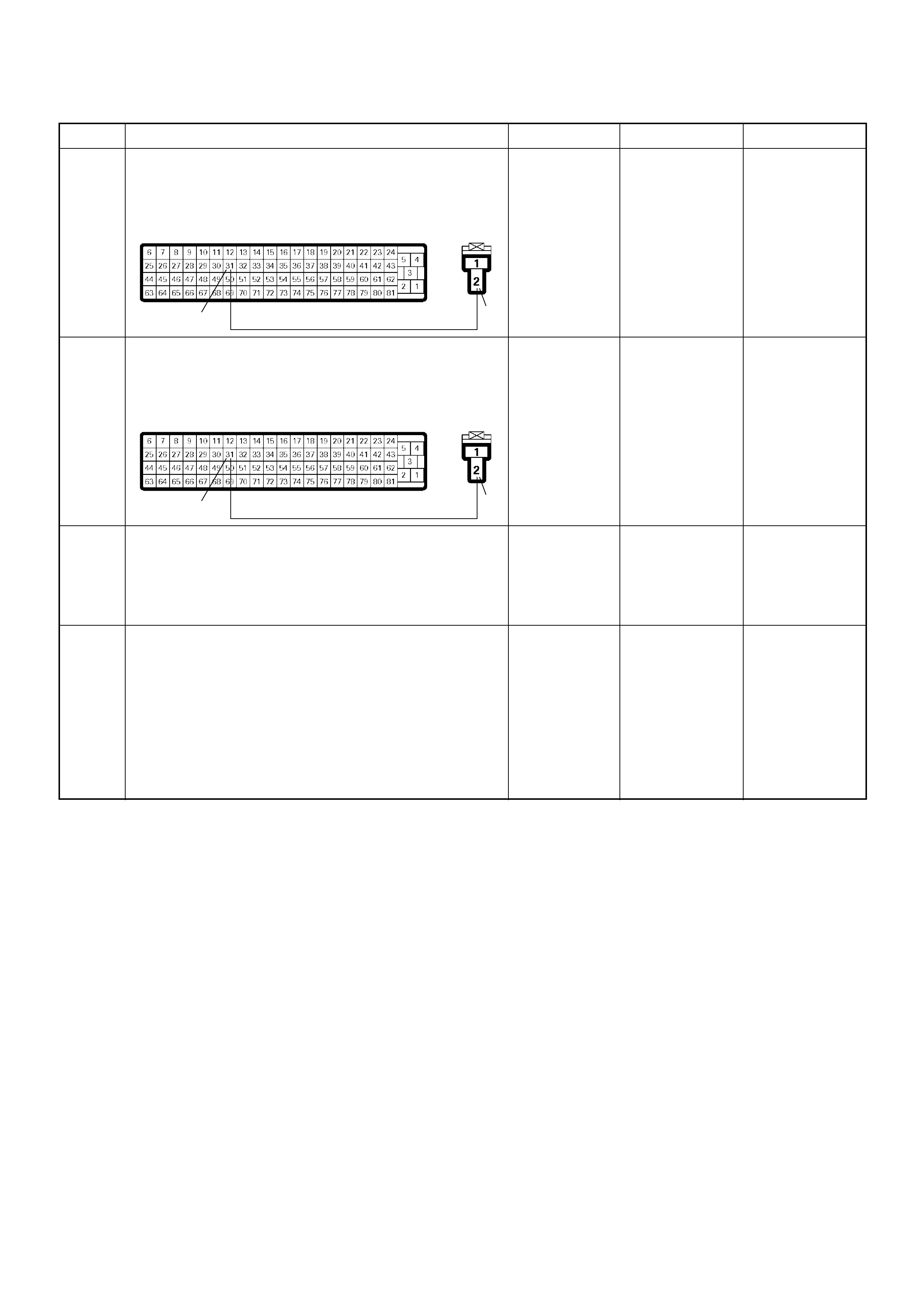
9 Repair the short to voltage circuit between the clutch
switch connector and ECM.
Is the action complete?
— Verify repair —
10 Repair the open circuit between the clutch switch
connector and ECM.
Is the action complete?
— Verify repair —
11 Is the ECM programmed with the latest software
release?
If not, download the latest software to the ECM using
the “SPS (Service Programming System)”.
Was the problem solved? — Verify repair Go to Step 12
12 Replace the ECM.
Is the action complete?
IMPORTANT: The replacement ECM must be
programmed. Refer to section of the Service
Programming System (SPS) in this manual.
Foll owing ECM pr ogramming, the immobi lizer system
(if equipped) must be linked to the ECM. Refer to
section 11 “Immobilizer System-ECM replacement” for
the ECM/Immobilizer linking procedure. — Verify repair —
Step Action Value(s) Yes No
31 2
C-56 C-77
31 2
C-56 C-77

DIAGNOSTIC TROUBLE CODE (DTC) P110 5 (SY MP TOM CODE 1)
(FLASH CODE 86 ) BAROMETRIC PRESSURE SENSOR CIRCUIT HIGH INPUT
DIAGNOSTIC TROUBLE CODE (DTC) P110 5 (SY MP TOM CODE 2)
(FLASH CODE 86) BAROMETRIC PRESSURE SENSOR CIRCUIT LOW INPUT
Condition for setting the DTC and action ta ken when the DTC sets
Circuit Description
The ECM monitors the barometric pressure signal at
inside of the ECM. If the sensor with malfunction, DTC
P11 05 (Symp tom Code 1) o r P1105 (Symptom Cod e 2)
will be stored.
Diagnostic Aids
If the DTC P1105 is stored, sensor or circuit of ECM
inside is failed.
Flash
Code Code Symptom
Code MIL DTC Name DTC Setting Condition Fail-Safe (Back Up)
86 P1105 1 ON Barometric Pressure Sens or
Circuit High Input Barometric press ure sensor
output voltage is more than
4.4V.
ECM uses 1013hpa condition
as sub stitute.
2 ON Barometric Pressure Sensor
Circuit Low Input Baromet ric press ure sensor
output voltage is below 1.5V.

Diagnostic Trouble Code (DTC) P1105 (Symptom Code 1) (Flash Code 86)
Barometric Pressure Sensor Circuit High Input
Diagnostic Trouble Code (DTC) P1105 (Symptom Code 2) (Flash Code 86)
Barometric Pressure Sensor Circuit Low Input
Step Action Value(s) Yes No
1 Was the “On-Board Diagnostic (OBD) System Check”
performed?
—Go to Step 2
Go to On Board
Diagnostic
(OBD) System
Check
2 1. Connect the Tech 2.
2. Review and record the failure information.
3. Select “F0: Read DTC Infor As Stored By ECU” in
“F0: Diagnostic Trouble Codes”.
Is the DTC P1105 (Symptom Code 1) or P1105
(Symptom Code 2) stored as “Present Failure”? — Go to Step 3
Refer to
Diagnostic Aids
and Go to Step
3
3 1. Using the Tech 2, ignition “On” and engine “Off”.
2. Select “F1: Clear DTC Information” in “F0:
Diagnostic Trouble Codes” with the Tech 2 and
clear the DTC information.
3. Operate the vehicle and monitor the “F0: Read
DTC Infor As Stored By ECU” in the “F0:
Diagnostic Trouble Codes”.
Was the DTC P1105 (Symptom Code 1) or P1105
(Symptom Code 2) stored in this ignition cycle? — Go to Step 4 Refer to
Diagnostic Aids
4 Is the ECM programmed with the latest software
release?
If not, download the latest software to the ECM using
the “SPS (Service Programming System)”.
Was the problem solved? — Verify repair Go to Step 5
5 Replace the ECM.
Is the action complete?
IMPORTANT: The replacement ECM must be
programmed. Refer to section of the Service
Programming System (SPS) in this manual.
Foll owing ECM pr ogramming, the immobi lizer system
(if equipped) must be linked to the ECM. Refer to
section 11 “Immobilizer System-ECM replacement” for
the ECM/Immobilizer linking procedure. — Verify repair —
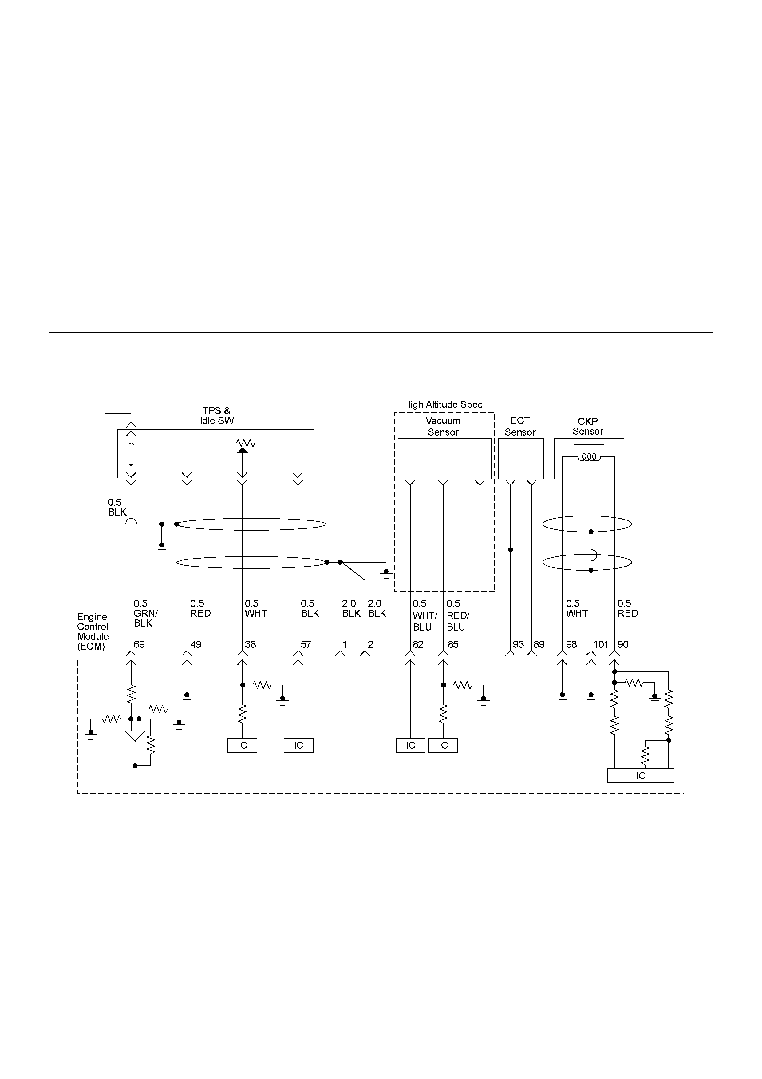
DIAGNOSTIC TROUBLE CODE (DTC) P112 0 (SY MP TOM CODE 1)
(FLASH CODE 21) PEDAL/THROTTLE POSITION SENSOR CIRCUIT HIGH INPUT
DIAGNOSTIC TROUBLE CODE (DTC) P112 0 (SY MP TOM CODE 7)
(FLASH CODE 21) PEDAL/THROTTLE POSITION SENSOR VOLTAGE SUPPLY CIRCUIT
HIGH INPUT
DIAGNOSTIC TROUBLE CODE (DTC) P112 0 (SY MP TOM CODE 9)
(FLASH CODE 21) PEDAL/THROTTLE POSITION SENSOR VOLTAGE SUPPLY CIRCUIT
LOW INPUT
DIAGNOSTIC TROUBLE CODE (DTC) P1120 (SYMPTOM CODE D)
(FLASH CODE 21) PEDAL/THROTTLE POSITION SENSOR BRAKE SWITCH ERROR
DIAGNOSTIC TROUBLE CODE (DTC) P1120 (SYMPTOM CODE E)
(FLASH CODE 21) PEDAL/THROTTLE POSITION SENSOR IDLE POSITION SWITCH ERROR

Condition for setting the DTC and action ta ken when the DTC sets
Circuit Description
The TPS is a potentiometer connected to throttle shaft
on the throttle body. It is installed to the main TPS and
idle switc h.
The engine control module (ECM) monitors the voltage
on the signal line and calculates throttle position. As the
throttle valve angle is changed when accelerator pedal
moved. The TPS signal also changed at a moved
throttle valve. As the throttle valve opens, the output
increases so that the output voltage should be high.
The ECM monitors the TPS supply voltage and TPS
output vo ltage. The supply vo ltage is out of range, DTC
P11 20 (Symp tom Code 7) o r P1120 (Symptom Cod e 9)
will be stored. The output voltage excessively high, DTC
P1120 (Symptom Code 1) will be stored.
If the brake pedal is depressed during accelerator pedal
is depressing, DTC P1120 (Symptom Code D) will be
stored.
If the relation of idle switch and TPS position are
incorrect, DTC P1120 (Symptom Code E) will be stored.
Diagnostic Aids
An intermittent may be caused by the following:
• Poor connections.
• Misrouted harness.
• Rubbed through wire insulation.
• Broken wire inside the insulation.
Check for the following conditions:
• Poor con nection at ECM-I nspect harness connectors
for backed out terminals, improper mating, broken
locks, improperly formed or damaged terminals, and
poor terminal to wire connection.
• Damaged harness-Inspect the wiring harness for
damage. If the harness appears to be OK, observe
the “Thrott le Po si ti on”, “I dle Sw it ch”, “Br ake Swi tc h 1”
and “Brake Switch 2” display on the Tech2 while
moving connectors and wiring harness related to the
sensor.
Flash
Code Code Symptom
Code MIL DTC Name DTC Setting Condition Fail-Safe (Back Up)
21 P1120 1 ON Pedal/Throttle Position
Sensor Circuit High Input Throttle position sensor
output voltage is more than
4.5V.
ECM increases idle speed up
to 1400rpm.
7 ON Pedal/Throttle Position
Sensor V oltage Supply Circuit
High Input
Throttle position sensor
power supply voltage is more
than 5.2V.
9 ON Pedal/Throttle Position
Sensor V oltage Supply Circuit
Low Input
Throttle position sensor
power supply voltage is below
4.6V.
D ON Pedal/Throttle Position
Sensor Brake Switch Error 1. Engine speed is more than
1700rpm.
2. V ehicle speed is more than
1.5km/h.
3. When brake pedal is
depressed during
accelerator pedal is
depressing.
E ON Pedal/Throttle Position
Sensor Idle Position Switch
Error
1. When idle switch is turned
off, throttle position sensor
was below 0.35%.
or
2. When idle switch is tuned
on, throttle position sensor
was more than 7.8%.
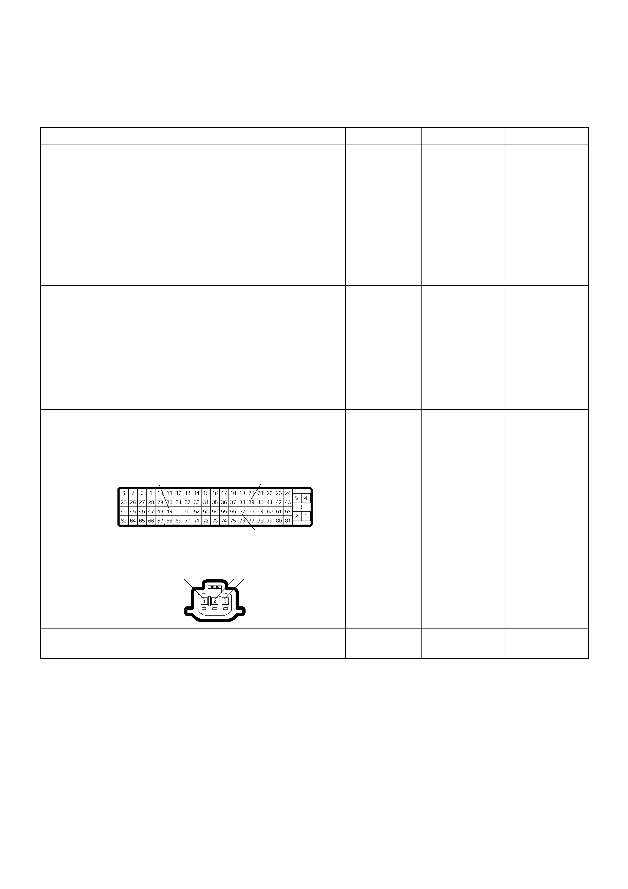
Diagnostic Trouble Code (DTC) P1120 (Symptom Code 1) (Flash Code 21)
Pedal/Throttle Position Sensor Circuit High Input
Step Action Value(s) Yes No
1 Was the “On-Board Diagnostic (OBD) System Check”
performed?
—Go to Step 2
Go to On Board
Diagnostic
(OBD) System
Check
2 1. Connect the Tech 2.
2. Review and record the failure information.
3. Select “F0: Read DTC I nfor As Stored By ECU” in
“F0: Diagnostic Trouble Codes”.
Is the DTC P1120 (Symptom Code 1) stored as
“Present Failure”? — Go to Step 3
Refer to
Diagnostic Aids
and Go to Step
3
3 1. Using the Tech 2, ignition “On” and engine “Off”.
2. Select “F1: Clear DTC Information” in “F0:
Diagnostic Trouble Codes” with the Tech 2 and
clear the DTC information.
3. Operate the vehicle and monitor the “F0: Read
DTC Infor As Stored By ECU” in the “F0:
Diagnostic Trouble Codes”.
Was the DT C P1120 (Sym ptom Code 1) s tored in th is
ignition cycle? — Go to Step 4
Refer to
Diagnostic Aids
and Go to Step
4
4 Check for poor/faulty connection at the TPS or ECM
connector. If a poor/faulty connection is found, repair
as necessary.
Was the problem found?
— Verify repair Go to Step 5
5 Visual ly check the TP S.
Was the problem found? — Go to Step 12 Go to Step 6
49 39
57
2 31
C-56
E-22
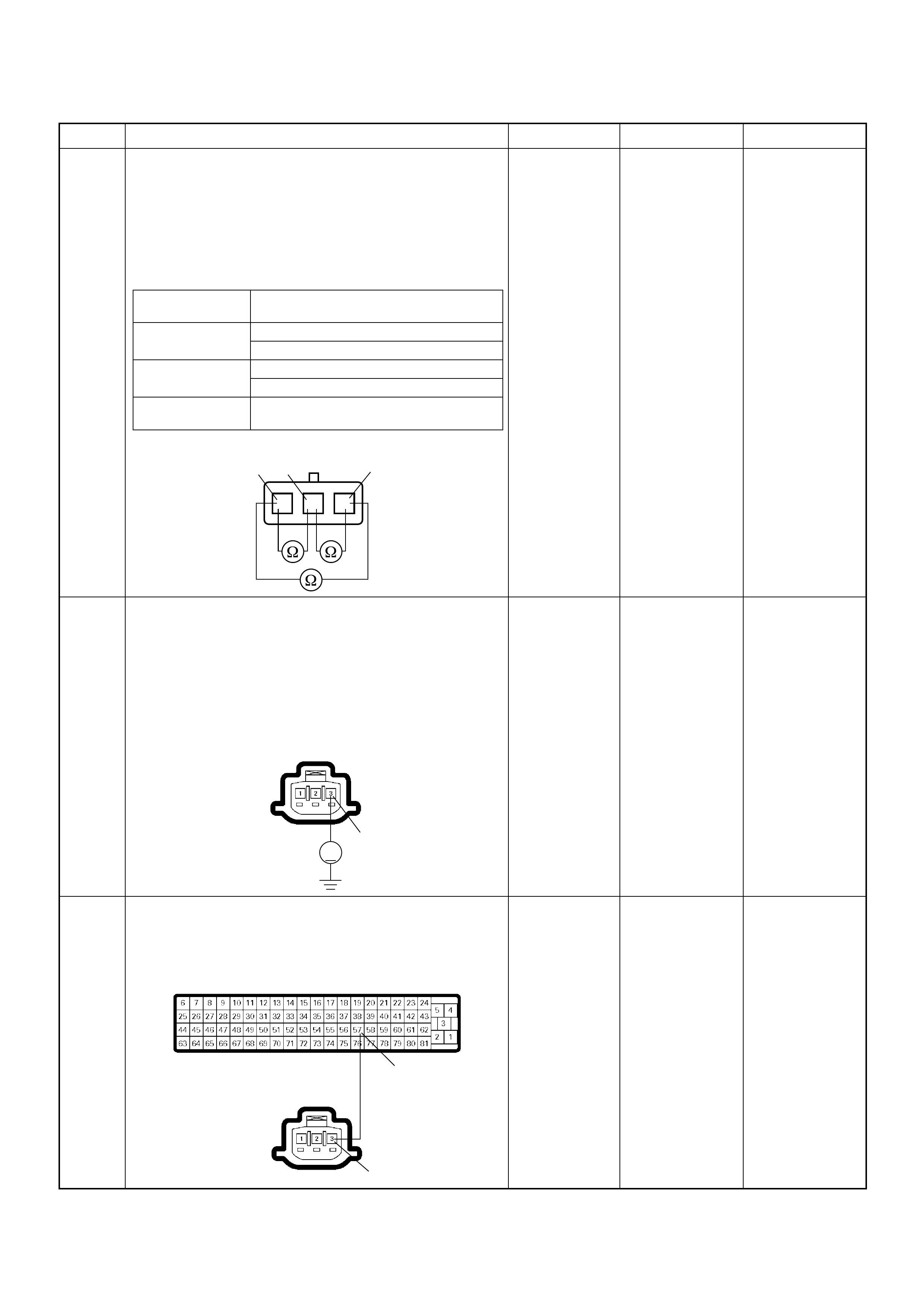
6 Using the DVM and check the TPS.
1. Ignition “Off”, engine “Off”.
2. Disconnect TPS connector.
3. Measure the resistance of TPS.
Does the tester indicate standard resistance as shown
in the following table?
Standard
resistance Go to Step 7 Go to S tep 12
7 Using the DVM and check the TPS power supply
circuit.
1. Ignition “On”, engine “Off”.
2. Disconnect the TPS connector.
3. Check the circuit for short to voltage circuit.
Was the DVM indicated specified value?
Approximately
5.0V Go to Step 9 Go to Step 8
8 Repair the short to voltage circuit between the ECM
and TPS.
W as the problem solved?
— Verify repair Go to Step 14
Step Action Value(s) Yes No
Measurement
Terminal Resistance (Ω)
1 - 2 Approximately 0.4kΩ at idle position
Approximately 4.0kΩ at WOT
2 - 3 Approximately 4.3kΩ at idle position
Approximately 0.8kΩ at WOT
1 - 3 Approximately 4.6kΩ at idle position &
WOT
TPS
123
1
2
3
V
3
E-22
57
3
C-56
E-22
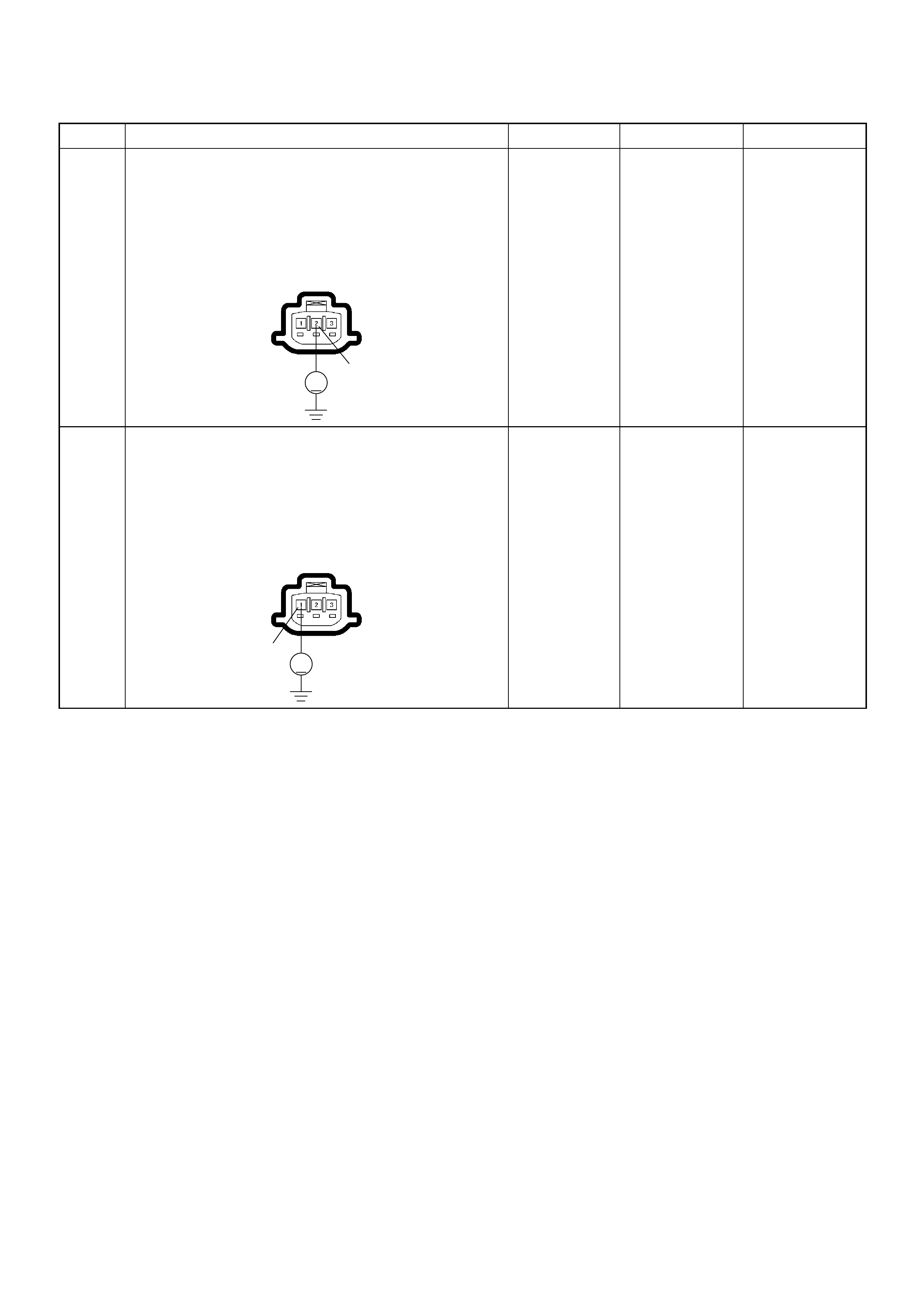
9 Using the DVM and check the TPS signal circuit.
1. Ignition “On”, engine “Off”.
2. Disconnect the TPS connector.
3. Check the circuit for short to power supply circuit.
Was the DVM indicated specified value?
Less than 1V Go to Step 10
Repair faulty
harness and
verify repair
10 Using the DVM and check the TPS ground circuit.
1. Ignition “On”, engine “Off”.
2. Disconnect the TPS connector .
3. Check the circuit for short to power supply circuit.
Was the DVM indicated specified value?
Less than 1V Go to Step 11
Repair faulty
harness and
verify repair
Step Action Value(s) Yes No
V
2
E-22
V
1
E-22
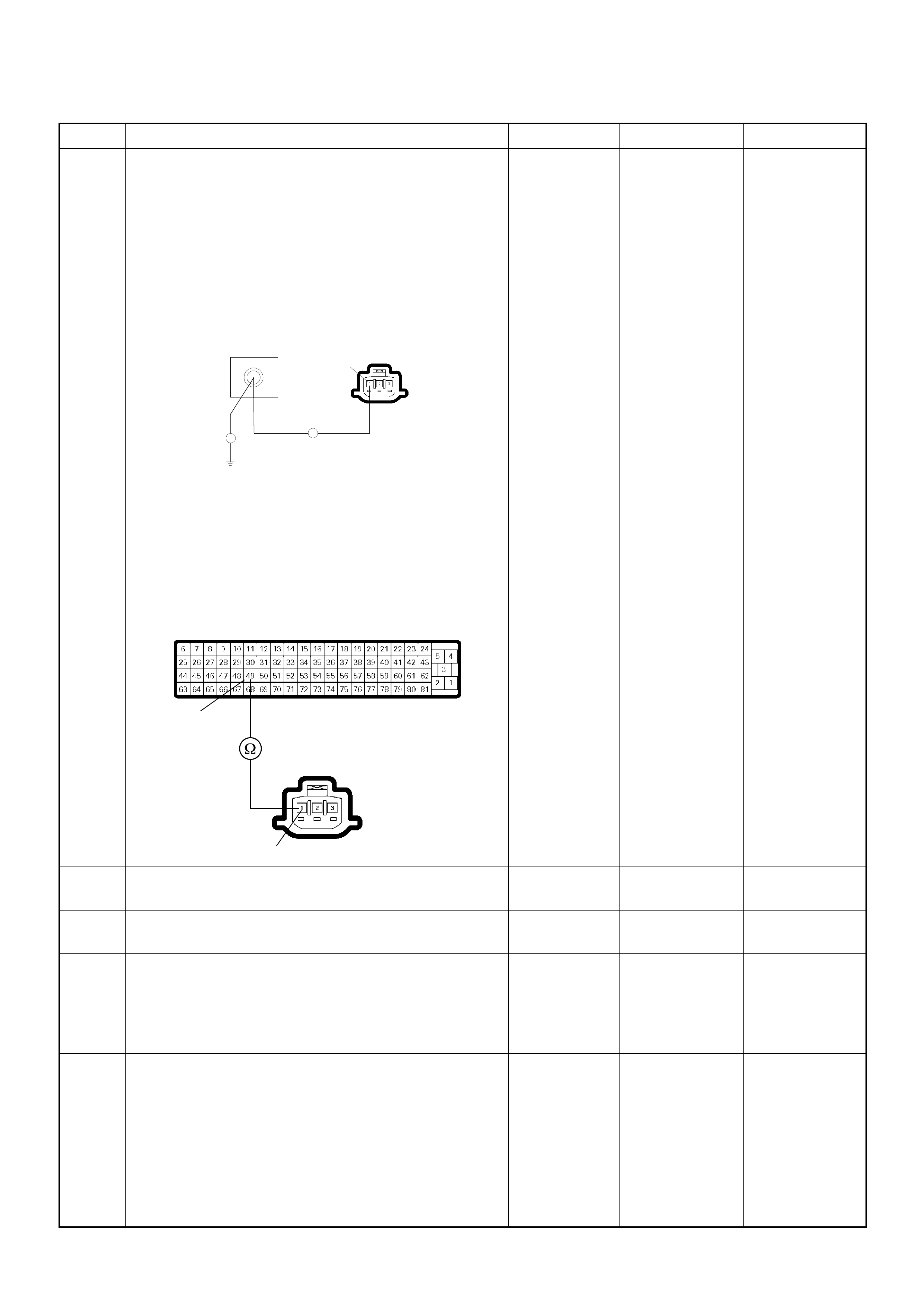
11 Using the DVM and check the TPS ground circuit.
Breaker box is available:
1. Ignition “Off”, engine “Off”.
2. Install the breaker box as type A. (ECM
disconnected) Ref. to HOW TO USE BREAKER
BOX
3. Disconnect the TPS connector.
4. Check the circuit for open circuit.
Was the problem found?
Breaker box is not available:
1. Ignition “Off”, engine “Off”.
2. Disconnect the TPS connector and ECM
connector.
3. Check the circuit for open circuit.
Was the problem found?
—
Repair faulty
harness and
verify repair Go to Step 14
12 Substitute a known good TPS and recheck.
Was the problem solved? — Go to Step 13 Go to Step 14
13 Replace the TPS.
Is the action complete? — Verify repair —
14 Is the ECM programmed with the latest software
release?
If not, download the latest software to the ECM using
the “SPS (Service Programming System)”.
Was the problem solved? — Verify repair Go to Step 15
15 Replace the ECM.
Is the action complete?
IMPORTANT: The replacement ECM must be
programmed. Refer to section of the Service
Programming System (SPS) in this manual.
Foll owing ECM pr ogramming, the immobi lizer system
(if equipped) must be linked to the ECM. Refer to
section 11 “Immobilizer System-ECM replacement” for
the ECM/Immobilizer linking procedure. — Verify repair —
Step Action Value(s) Yes No
E-22
49
Breaker Box
1
Ħ
Ħ
49
1
C-56
E-22

Diagnostic Trouble Code (DTC) P1120 (Symptom Code 7) (Flash Code 21)
Pedal/Throttle Position Sensor Voltage Supply Circuit High Input
Step Action Value(s) Yes No
1 Was the “On-Board Diagnostic (OBD) System Check”
performed?
—Go to Step 2
Go to On Board
Diagnostic
(OBD) System
Check
2 1. Connect the Tech 2.
2. Review and record the failure information.
3. Select “F0: Read DTC I nfor As Stored By ECU” in
“F0: Diagnostic Trouble Codes”.
Is the DTC P1120 (Symptom Code 7) stored as
“Present Failure”? — Go to Step 3
Refer to
Diagnostic Aids
and Go to Step
3
3 1. Using the Tech 2, ignition “On” and engine “Off”.
2. Select “F1: Clear DTC Information” in “F0:
Diagnostic Trouble Codes” with the Tech 2 and
clear the DTC information.
3. Operate the vehicle and monitor the “F0: Read
DTC Infor As Stored By ECU” in the “F0:
Diagnostic Trouble Codes”.
Was the DT C P1120 (Sym ptom Code 7) s tored in th is
ignition cycle? — Go to Step 4
Refer to
Diagnostic Aids
and Go to Step
4
4 Check for poor/faulty connection at the TPS or ECM
connector. If a poor/faulty connection is found, repair
as necessary.
Was the problem found?
— Verify repair Go to Step 5
5 Visual ly check the TP S.
Was the problem found? — Go to Step 8 Go to Step 6
49 39
57
2 31
C-56
E-22
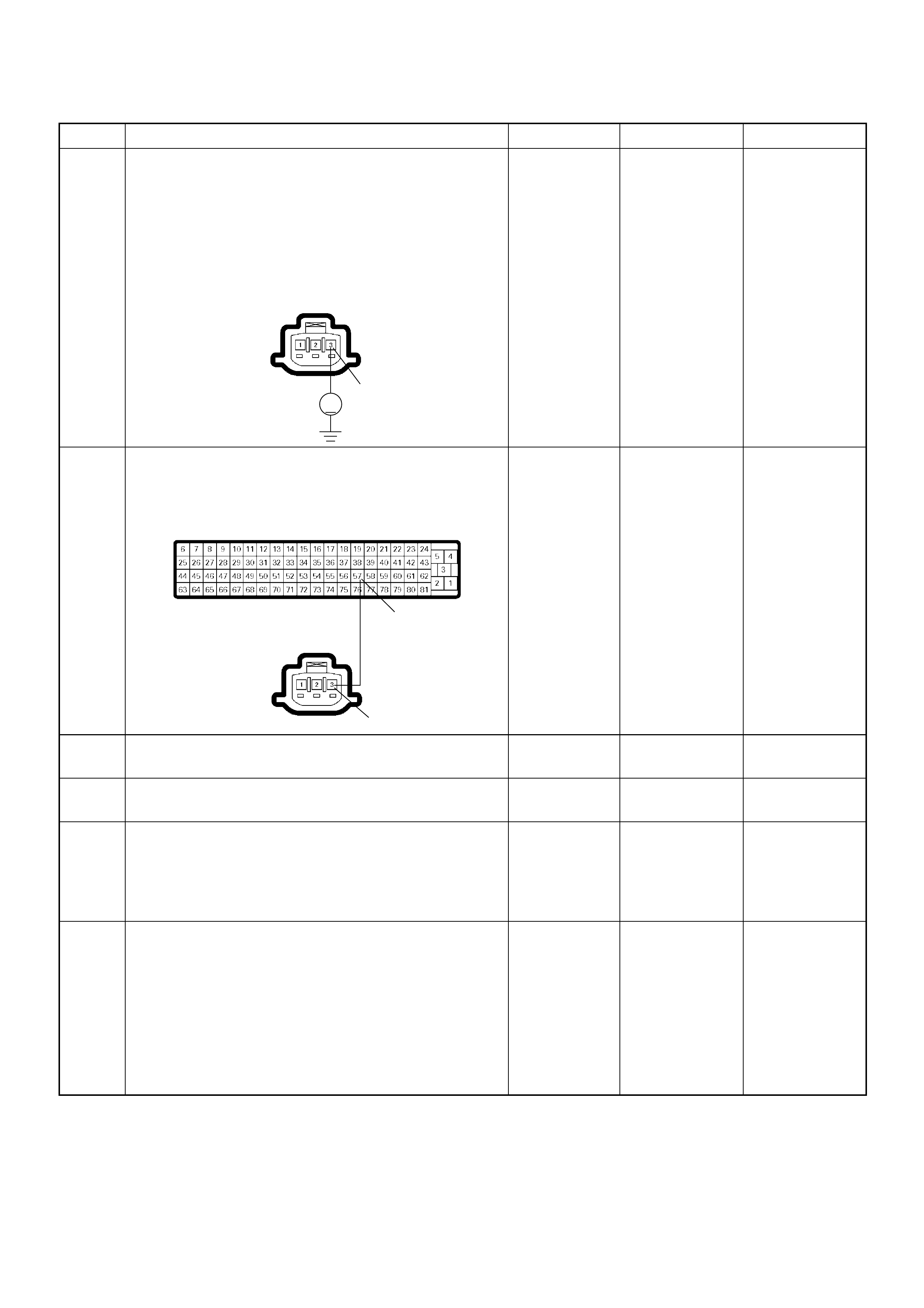
6 Using the DVM and check the TPS power supply
circuit.
1. Ignition “On”, engine “Off”.
2. Disconnect the TPS connector.
3. Check the circuit for short to ground circuit.
Was the DVM indicated specified value?
Approximately
5.0V Go to Step 12 Go to Step 7
7 Repair the short to battery voltage circuit between the
ECM and TPS.
Was the problem solved?
— Verify repair Go to Step 8
8 Substitute a known good TPS and recheck.
Was the problem solved? — Go to Step 9 Go to Step 10
9 Replace the TPS.
Is the action complete? — Verify repair —
10 Is the ECM programmed with the latest software
release?
If not, download the latest software to the ECM using
the “SPS (Service Programming System)”.
Was the problem solved? — Verify repair Go to Step 11
11 Replace the ECM.
Is the action complete?
IMPORTANT: The replacement ECM must be
programmed. Refer to section of the Service
Programming System (SPS) in this manual.
Foll owing ECM pr ogramming, the immobi lizer system
(if equipped) must be linked to the ECM. Refer to
section 11 “Immobilizer System-ECM replacement” for
the ECM/Immobilizer linking procedure. — Verify repair —
Step Action Value(s) Yes No
V
3
E-22
57
3
C-56
E-22

Diagnostic Trouble Code (DTC) P1120 (Symptom Code 9) (Flash Code 21)
Pedal/Throttle Position Sensor Voltage Supply Circuit Low Input
Step Action Value(s) Yes No
1 Was the “On-Board Diagnostic (OBD) System Check”
performed?
—Go to Step 2
Go to On Board
Diagnostic
(OBD) System
Check
2 1. Connect the Tech 2.
2. Review and record the failure information.
3. Select “F0: Read DTC I nfor As Stored By ECU” in
“F0: Diagnostic Trouble Codes”.
Is the DTC P1120 (Symptom Code 9) stored as
“Present Failure”? — Go to Step 3
Refer to
Diagnostic Aids
and Go to Step
3
3 1. Using the Tech 2, ignition “On” and engine “Off”.
2. Select “F1: Clear DTC Information” in “F0:
Diagnostic Trouble Codes” with the Tech 2 and
clear the DTC information.
3. Operate the vehicle and monitor the “F0: Read
DTC Infor As Stored By ECU” in the “F0:
Diagnostic Trouble Codes”.
Was the DT C P1120 (Sym ptom Code 9) s tored in th is
ignition cycle? — Go to Step 4
Refer to
Diagnostic Aids
and Go to Step
4
4 Check for poor/faulty connection at the TPS or ECM
connector. If a poor/faulty connection is found, repair
as necessary.
Was the problem found?
— Verify repair Go to Step 5
5 Visual ly check the TP S.
Was the problem found? — Go to Step 10 Go to Step 6
49 39
57
2 31
C-56
E-22
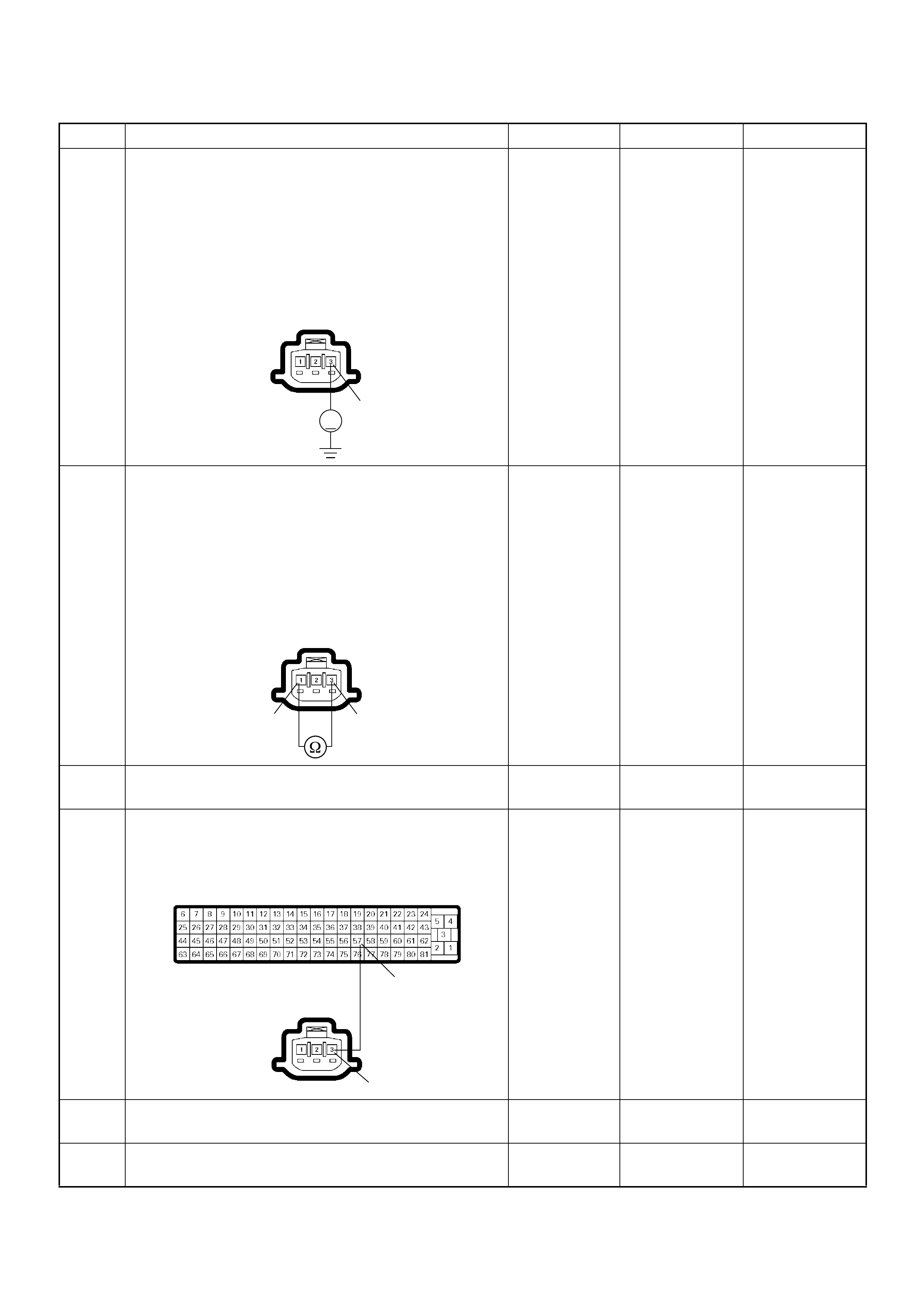
6 Using the DVM and check the TPS power supply
circuit.
1. Ignition “On”, engine “Off”.
2. Disconnect the TPS connector.
3. Check the circuit for short to battery voltage
circuit.
Was the DVM indicated specified value?
Approximately
5.0V Go to Step 10 Go to Step 7
7 Using the DVM and check the TPS power supply
circuit.
1. Ignition “Off”, engine “Off”.
2. Disconnect the TPS connector and ECM
connector.
3. Check the circuit for short to TPS ground circuit.
Was the DVM indicated specified value?
No continuity Go to Step 9 Go to Step 8
8 Re pair the circui t for sho rt to TPS groun d circ uit .
Is the action complete? — Verify repair —
9 Repair the short to ground circuit between the ECM
and TPS.
W as the problem solved?
— Verify repair Go to Step 12
10 Substitute a known good TPS and recheck.
Was the problem solved? — Go to Step 11 Go to Step 12
11 Replace the TPS.
Is the action complete? — Verify repair —
Step Action Value(s) Yes No
V
3
E-22
3
1
E-22
57
3
C-56
E-22

12 Is the ECM programmed with the latest software
release?
If not, download the latest software to the ECM using
the “SPS (Service Programming System)”.
Was the problem solved? — Verify repair Go to Step 13
13 Replace the ECM. Is the action complete?
IMPORTANT: The replacement ECM must be
programmed. Refer to section of the Service
Programming System (SPS) in this manual.
Foll owing ECM pr ogramming, the immobi lizer system
(if equipped) must be linked to the ECM. Refer to
section 11 “Immobilizer System-ECM replacement” for
the ECM/Immobilizer linking procedure. — Verify repair —
Step Action Value(s) Yes No

Diagnostic Trouble Code (DTC) P1120 (Symptom Code D) (Flash Code 21)
Pedal/Throttle Position Sensor Brake Switch Error
Step Action Value(s) Yes No
1 Was the “On-Board Diagnostic (OBD) System Check”
performed?
—Go to Step 2
Go to On Board
Diagnostic
(OBD) System
Check
2 1. Connect the Tech 2.
2. Review and record the failure information.
3. Select “F0: Read DTC I nfor As Stored By ECU” in
“F0: Diagnostic Trouble Codes”.
Is the DTC P1120 (Symptom Code D) stored as
“Present Failure”? — Go to Step 3
Refer to
Diagnostic Aids
and Go to Step
3
3 1. Using the Tech 2, ignition “On” and engine “Off”.
2. Select “F1: Clear DTC Information” in “F0:
Diagnostic Trouble Codes” with the Tech 2 and
clear the DTC information.
3. Operate the vehicle and monitor the “F0: Read
DTC Infor As Stored By ECU” in the “F0:
Diagnostic Trouble Codes”.
Was the DTC P1120 (Symptom Code D) stored in this
ignition cycle? — Go to Step 4
Refer to
Diagnostic Aids
and Go to Step
4
4 Visual ly check the TP S.
Check for the following conditions.
• Accelerator pedal sticking.
If a problem is found, repair as necessary.
W as the problem found? — Verify repair Go to Step 5
5 1. Using the Tech 2, ignition “On” and engine “Off”.
2. Monitor the “Throttle Position” in the data display.
Does the Tech 2 indicate correct “Throttle Position”
from 0% to 100% depending on accelerator pedal
operation? — Go to Step 7 Go to Step 6
6 1. Using the Tech 2, ignition “On” and engine “Off”.
2. Monitor the “Throttle Position” in the data display.
3. Adjust the TPS within 0% to 100%.
W as the problem solved? — Verify repair Go to Step 11
7 1. Using the Tech 2, ignition “On” and engine “Off”.
2. Monitor the “Brake Switch 1” and “Brake Switch 2”
in the data display.
Does the Tech 2 indicate “Inactive” when the brake
pedal was not stepped on? — Go to S tep 13 Go to Step 8
8 Adjust the brake switch.
Was the problem solved? — Verify repair Go to Step 9
9 Substitute a known good brake switch and recheck.
W as the problem solved? — Go to Step 10 Go to S tep 13
10 Replace the brake switch.
Is the action complete? — Verify repair —
11 Substitute a known good TPS and recheck.
W as the problem solved? — Go to Step 12 Go to S tep 13
12 Replace the TPS.
Is the action complete? — Verify repair —

13 Is the ECM programmed with the latest software
release?
If not, download the latest software to the ECM using
the “SPS (Service Programming System)”.
Was the problem solved? — Verify repair Go to Step 14
14 Replace the ECM.
Is the action complete?
IMPORTANT: The replacement ECM must be
programmed. Refer to section of the Service
Programming System (SPS) in this manual.
Foll owing ECM pr ogramming, the immobi lizer system
(if equipped) must be linked to the ECM. Refer to
section 11 “Immobilizer System-ECM replacement” for
the ECM/Immobilizer linking procedure. — Verify repair —
Step Action Value(s) Yes No

Diagnostic Trouble Code (DTC) P1120 (Symptom Code E) (Flash Code 21)
Pedal/Throttle Position Sensor Idle Position Switch Error
Step Action Value(s) Yes No
1 Was the “On-Board Diagnostic (OBD) System Check”
performed?
—Go to Step 2
Go to On Board
Diagnostic
(OBD) System
Check
2 1. Connect the Tech 2.
2. Review and record the failure information.
3. Select “F0: Read DTC I nfor As Stored By ECU” in
“F0: Diagnostic Trouble Codes”.
Is the DTC P1120 (Symptom Code E) stored as
“Present Failure”? — Go to Step 3
Refer to
Diagnostic Aids
and Go to Step
3
3 1. Using the Tech 2, ignition “On” and engine “Off”.
2. Select “F1: Clear DTC Information” in “F0:
Diagnostic Trouble Codes” with the Tech 2 and
clear the DTC information.
3. Operate the vehicle and monitor the “F0: Read
DTC Infor As Stored By ECU” in the “F0:
Diagnostic Trouble Codes”.
Was the DT C P1120 ( S ym ptom Cod e E) s tor ed in th is
ignition cycle? — Go to Step 4
Refer to
Diagnostic Aids
and Go to Step
4
4 Visual ly check the TP S.
Was the problem found? — Go to Step 8 Go to Step 5
5 1. Using the Tech 2, ignition “On” and engine “Off”.
2. Monitor the “Throttle Position” in the data display.
Does the Tech 2 indicate correct “Throttle Position”
from 0% to 100% depending on accelerator pedal
operation? — Go to Step 7 Go to Step 6
6 1. Using the Tech 2, ignition “On” and engine “Off”.
2. Monitor the “Throttle Position” in the data display.
3. Adjust the TPS within 0% to 100%.
Was the problem solved? — Verify repair Go to Step 8
7 1. Using the Tech 2, ignition “On” and engine “Off”.
2. Monitor the “Idle Switch” in the data display.
Does the Tech 2 indicate “Inactive” when the
accelerator pedal was stepped on? — Go to Step 10 Go to Step 8
8 Substitute a known good TPS and recheck.
Was the problem solved? — Go to Step 9 Go to Step 10
9 Replace the TPS.
Is the action complete? — Verify repair —
10 Is the ECM programmed with the latest software
release?
If not, download the late st software to the ECM using
the “SPS (Service Programming System)”.
W as the problem solved? — Verify repair Go to Step 11

11 Replace the ECM.
Is the action complete?
IMPORTANT: The replacement ECM must be
programmed. Refer to section of the Service
Programming System (SPS) in this manual.
Foll owing ECM pr ogramming, the immobi lizer system
(if equipped) must be linked to the ECM. Refer to
section 11 “Immobilizer System-ECM replacement” for
the ECM/Immobilizer linking procedure. — Verify repair —
Step Action Value(s) Yes No

DIAGNOSTIC TROUBLE CODE (DTC) P117 3 (SY MP TOM CODE 3)
(FLASH CODE 22) FUEL REDUCTION CAUSED BY HIGH COOLANT TEMPERATURE
DIAGNOSTIC TROUBLE CODE (DTC) P117 3 (SY MP TOM CODE 7)
(FLASH CODE 22) FUEL REDUCTION CAUSE D BY HIGH FUEL TEMPERATURE
DIAGNOSTIC TROUBLE CODE (DTC) P1173 (SYMPTOM CODE A)
(FLASH CODE 22) FUEL REDUCTION CAUSED BY LOW FUEL TEMPERATURE
Condition for setting the DTC and action ta ken when the DTC sets
Circuit Description
The engine coolant temperature (ECT) sensor is
installed on the coolant stream. High coolant
temperature produces a low resistance. The ECM
supplies 5 volts signal to the ECT sensor through
resisters in the ECM and measures the voltage. The
signal voltage will be low when the en gine temperature
is hot.
The fuel temp erature sensor is assembled insi de of the
pump con tro l uni t (PS G ). The si gna l of fu el tem per at ur e
is sent via the CAN-bus from the PSG to ECM.
If the engine coolant temperature is excessively high
condition, DTC P1173 (Symptom Code 3) will be stored.
If the fuel temperature is excessively high or low
condition, DTC P1173 (Symptom Code 7) or P1173
(Symptom Code A) will be stored.
Diagnostic Aids
An intermittent may be caused by the following:
• Poor connections.
• Misrouted harness.
• Rubbed through wire insulation.
• Broken wire inside the insulation.
Check for the following conditions:
• Poor connection at ECM and PSG-Inspect harness
connectors for backed out terminals, improper
mating, broken locks, improperly formed or damaged
terminals, and poor terminal to wire connection.
• Damaged harness-Inspect the wiring harness for
damage. If the harness appears to be OK, observe
the “Coolant Temperature” or “Fuel Temperature”
display on the Tech2 while moving connectors and
wiring harness related to the sensor.
Flash
Code Code Symptom
Code MIL DTC Name DTC Setting Condition Fail-Safe (Back Up)
22 P1173 3 OFF Fuel Reduction Caused By
High Coolant Temperature Excessive high engine
coolant temperature is
detected.
No fail-safe function.
7 OFF Fuel Reduction Caused By
High Fuel Temperature Fuel temperature is more than
100 deg. C. PSG (pump control unit)
controls fuel injection quantity
based on engine speed and
fuel temperature.
A OFF Fuel Reduction Caused By
Low Fuel Temperature Excessive low fuel
temperature is detected. No fail-safe function.

Diagnostic Trouble Code (DTC) P1173 (Symptom Code 3) (Flash Code 22) Fuel
Reduction Caused By High Coolant Temperature
Step Action Value(s) Yes No
1 Was the “On-Board Diagnostic (OBD) System Check”
performed?
—Go to Step 2
Go to On Board
Diagnostic
(OBD) System
Check
2 1. Connect the Tech 2.
2. Review and record the failure information.
3. Select “F0: Read DTC I nfor As Stored By ECU” in
“F0: Diagnostic Trouble Codes”.
Is the DTC P1173 (Symptom Code 3) stored as
“Present Failure”? — Go to Step 3
Refer to
Diagnostic Aids
and Go to Step
3
3 1. Using the Tech 2, ignition “On” and engine “Off”.
2. Select “F1: Clear DTC Information” in “F0:
Diagnostic Trouble Codes” with the Tech 2 and
clear the DTC information.
3. Operate the vehicle and monitor the “F0: Read
DTC Infor As Stored By ECU” in the “F0:
Diagnostic Trouble Codes”.
Was the DT C P1173 (Sym ptom Code 3) s tored in th is
ignition cycle? — Go to Step 4
Refer to
Diagnostic Aids
and Go to Step
4
4 Check the engine overheat condition.
Was the problem found?
—
Repair the
cause of
overheat and
verify repair Go to Step 5
5 1. Using the Tech 2, ignition “On” and engine “On”.
2. Monitor the “Coolant Temperature” in the data
display.
Does the Tech 2 indicate correct “Coolant
Temperature” depending on warm up time? — Go to Step 9 Go to Step 6
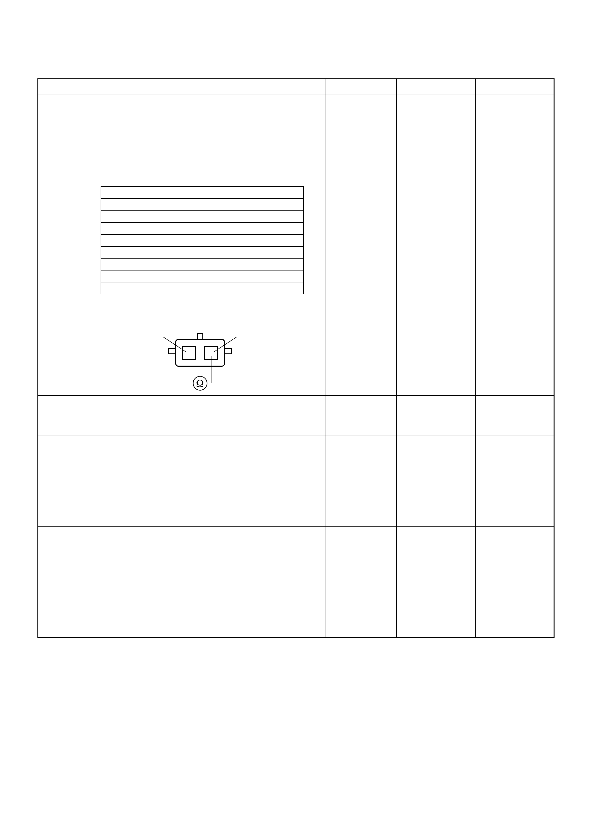
6 Using the DVM and check the ECT sensor.
1. Ignition “Off”, engine “Off”.
2. Disconnect ECT sensor connector.
3. Measure the resistance of ECT sensor.
Does the tester indicate standard resistance as shown
in the following table?
Standard
resistance Go to Step 9 Go to Step 7
7 Substitute a known good ECT sensor assembly and
recheck.
Was the problem solved? — Go to Step 8 Go to Step 9
8 Replace the ECT sensor.
Is the action complete? — Verify repair —
9 Is the ECM programmed with the latest software
release?
If not, download the latest software to the ECM using
the “SPS (Service Programming System)”.
Was the problem solved? — Verify repair Go to Step 10
10 Replace the ECM.
Is the action complete?
IMPORTANT: The replacement ECM must be
programmed. Refer to section of the Service
Programming System (SPS) in this manual.
Foll owing ECM pr ogramming, the immobi lizer system
(if equipped) must be linked to the ECM. Refer to
section 11 “Immobilizer System-ECM replacement” for
the ECM/Immobilizer linking procedure. — Verify repair —
Step Action Value(s) Yes No
Temperature (°C) Resistance (Ω) (Approximately)
-20 16100
0 5760
20 2370
40 1080
60 537
80 290
100 161
120 95
12
ECT Sensor 12

Diagnostic Trouble Code (DTC) P1173 (Symptom Code 7) (Flash Code 22) Fuel
Reduction Caused By High Fuel Temperature
Diagnostic Trouble Code (DTC) P1173 (Symptom Code A) (Flash Code 22) Fuel
Reduction Caused By Low Fuel Temperature
Step Action Value(s) Yes No
1 Was the “On-Board Diagnostic (OBD) System Check”
performed?
—Go to Step 2
Go to On Board
Diagnostic
(OBD) System
Check
2 1. Connect the Tech 2.
2. Review and record the failure information.
3. Select “F0: Read DTC I nfor As Stored By ECU” in
“F0: Diagnostic Trouble Codes”.
Is the DTC P1173 (Symptom Code 7) or P1173
(Symptom Code A) stored as “Present Failure”? — Go to Step 3
Refer to
Diagnostic Aids
and Go to Step
3
3 1. Using the Tech 2, ignition “On” and engine “Off”.
2. Select “F1: Clear DTC Information” in “F0:
Diagnostic Trouble Codes” with the Tech 2 and
clear the DTC information.
3. Operate the vehicle and monitor the “F0: Read
DTC Infor As Stored By ECU” in the “F0:
Diagnostic Trouble Codes”.
Was the DTC P1173 (Symptom Code 7) or P1173
(Symptom Code A) stored in this ignition cycle? — Go to Step 4 Refer to
Diagnostic Aids
4 Is the ECM programmed with the latest software
release?
If not, download the late st software to the ECM using
the “SPS (Service Programming System)”.
Was the problem solved? — Verify repair Go to Step 5
5 Substitute a known good ECM and recheck.
W as the problem solved?
IMPORTANT: The replacement ECM must be
programmed. Refer to section of the Service
Programming System (SPS) in this manual.
Foll owing ECM pr ogramming, the immobi lizer system
(if equipped) must be linked to the ECM. Refer to
section 11 “Immobilizer System-ECM replacement” for
the ECM/Immobilizer linking procedure. —Go to Step 6 Go to Step 7
6 Replace the ECM.
Is the action complete?
IMPORTANT: The replacement ECM must be
programmed. Refer to section of the Service
Programming System (SPS) in this manual.
Foll owing ECM pr ogramming, the immobi lizer system
(if equipped) must be linked to the ECM. Refer to
section 11 “Immobilizer System-ECM replacement” for
the ECM/Immobilizer linking procedure. — Verify repair —
7 Replace the injection pump assembly.
Is the action complete? — Verify repair —
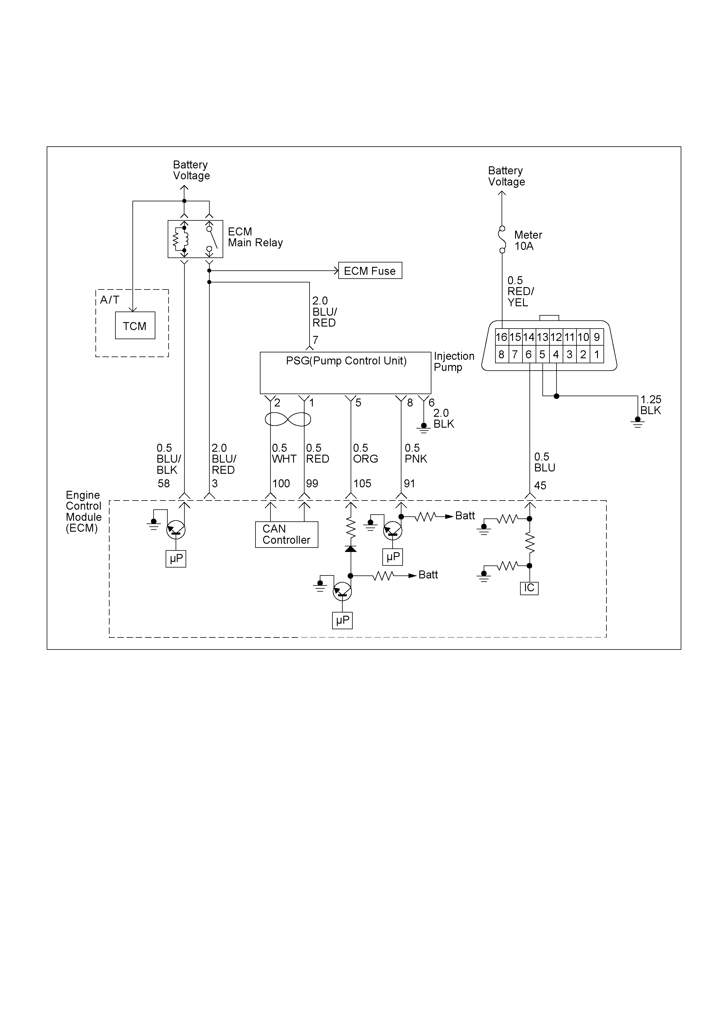
DIAGNOSTIC TROUBLE CODE (DTC) P13 35 (SYMPTOM CODE A)
(FLASH CODE 43) ENGINE SPEED OUTPUT CIRCUIT MALFUNCTION

Condition for setting the DTC and action ta ken when the DTC sets
Circuit Description
The CKP sensor is located on top of the flywheel
housing of the flywheel and fixed with a bolt. The CKP
sensor is of the magnet coil type. The inductive pickup
senses four gaps in the flywheel exciter ring and is used
to determine the engine speed and engine cylinder top
dead center.
The ECM converts sine wave signal to square wave
signal. And this signal is provided from the ECM to
pump control unit (PSG).
Diagnostic Aids
An intermittent may be caused by the following:
• Poor connections.
• Misrouted harness.
• Rubbed through wire insulation.
• Broken wire inside the insulation.
Check for the following conditions:
• Poor con nection at ECM-I nspect harness connectors
for backed out terminals, improper mating, broken
locks, improperly formed or damaged terminals, and
poor terminal to wire connection.
• Damaged harness-Inspect the wiring harness for
damage. If the harness appears to be OK, observe
the “Engine Speed” display on the Tech2 while
moving connectors and wiring harness related to the
sensor.
Flash
Code Code Symptom
Code MIL DTC Name DTC Setting Condition Fail-Safe (Back Up)
43 P1335 A ON Engine Speed Output Circuit
Malfunction The PSG (pump control unit)
detected defective engine
speed signal form the ECM.
Fuel injection quantity is
reduced.
Diagnostic Trouble Code (DTC) P1335 (Symptom Code A) (Flash Code 43)
Engine Speed Output Circuit Malfunction
Step Action Value(s) Yes No
1 Was the “On-Board Diagnostic (OBD) System Check”
performed?
—Go to Step 2
Go to On Board
Diagnostic
(OBD) System
Check
2 1. Connect the Tech 2.
2. Review and record the failure information.
3. Select “F0: Read DTC I nfor As Stored By ECU” in
“F0: Diagnostic Trouble Codes”.
Is the DTC P1335 (Symptom Code A) stored as
“Present Failure”? — Go to Step 3
Refer to
Diagnostic Aids
and Go to Step
3
3 1. Using the Tech 2, ignition “On” and engine “Off”.
2. Select “F1: Clear DTC Information” in “F0:
Diagnostic Trouble Codes” with the Tech 2 and
clear the DTC information.
3. Operate the vehicle and monitor the “F0: Read
DTC Infor As Stored By ECU” in the “F0:
Diagnostic Trouble Codes”.
Was the DTC P1335 (Symptom Code A) stored in this
ignition cycle? — Go to Step 4
Refer to
Diagnostic Aids
and Go to Step
4
4 Was the DTC P0335 (Symptom Code B) or P0335
(Symptom Code D) stored at the same time?
—
Go to DTC
Chart P0335
(Symptom
Code B)
(Symptom
Code C) Go to Step 5
5 Check for poor/faulty connection at the ECM or PSG
(pump control unit) connector. If a poor/faulty
connection is found, repair the faulty terminal.
Was the problem found?
— Verify repair Go to Step 6
91
8
C-57(B) E-6
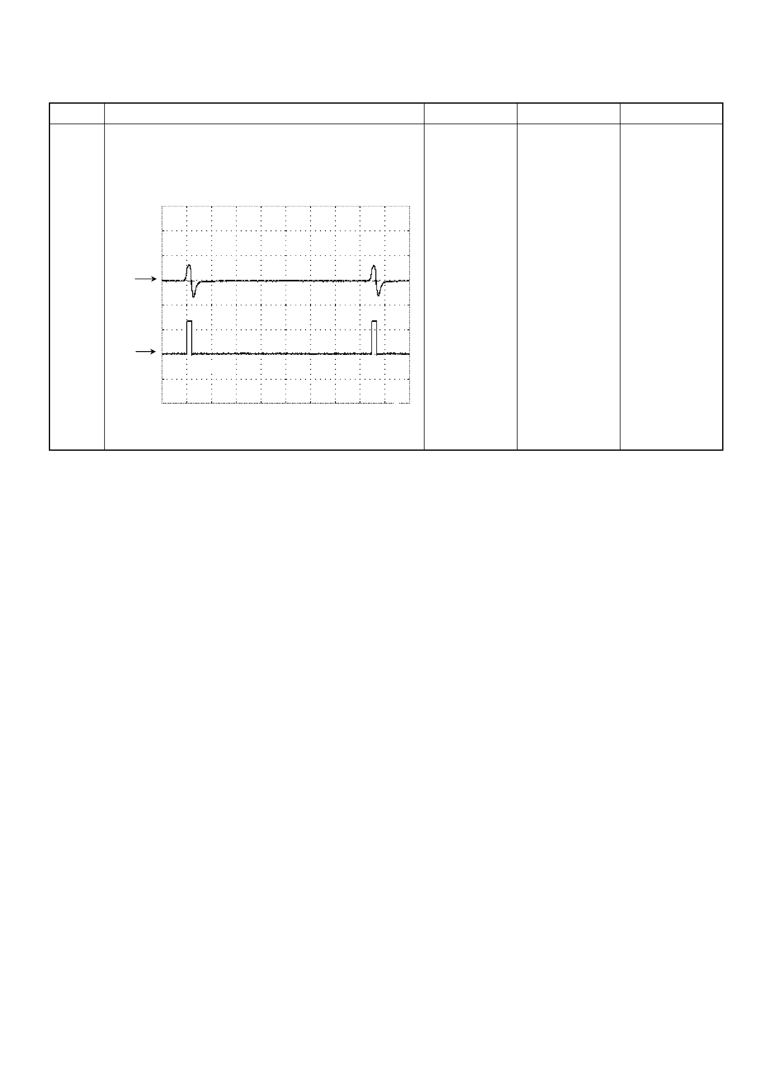
6 If a oscillosc ope is available, m onitor the CKP sensor
output signal. Does the oscilloscope indicate correct
wave form?
—Go to Step 13
Not available:
Go to Step 7
Fixed at low:
Go to Step 7
Fixed at High:
Go to Step 8
Step Action Value(s) Yes No
Crankshaft Position (CKP) Sensor & TDC Output Signal
Reference Wave Form
CH1
0V
CH2
0V
Measure ment Terminal: CH1: 90(+) / CH2: 91(+) GND( -)
Measurement Sc ale: CH1: 50V/div / CH2: 10V/div 1ms/div
Measurement Condition: Approximately 2000rpm
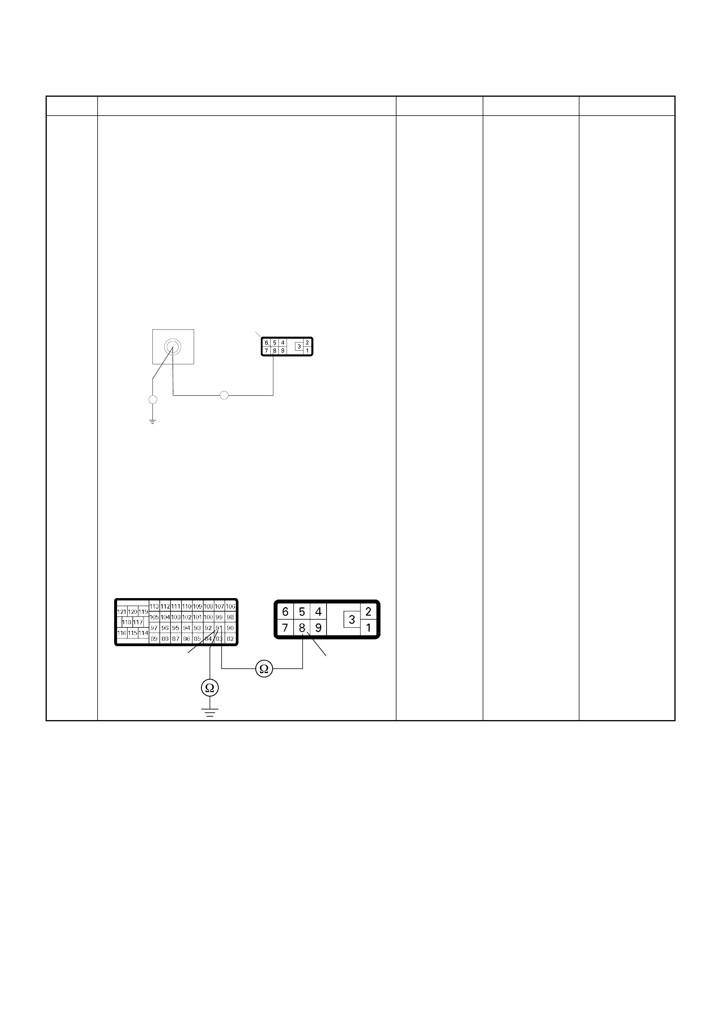
7 Using the DVM and check the CKP sensor output
circuit.
Breaker box is available:
1. Ignition “Off”, engine “Off”.
2. Install the breaker box as type A. (ECM
disconnected) Ref. to HOW TO USE BREAKER
BOX
3. Disconnect the PSG (pump control unit)
connector.
4. Check the circuit for open or short to ground
circuit.
Was the problem found?
Breaker box is not available:
1. Ignition “Off”, engine “Off”.
2. Disconnect the ECM connector.
3. Disconnect the PSG (pump control unit)
connector.
4. Check the circuit for open or short to ground
circuit.
Was the problem found?
—
Repair faulty
harnes s and
verify repair Go to Step 8
Step Action Value(s) Yes No
E-6
91
Breaker Box 8
Ħ
Ħ
91 8
C-57(B) E-6

8 Using the DVM and check the CKP sensor output
circuit.
1. Ignition “On”, engine “Off”.
2. Disconnect the PSG (pump control unit)
connector.
3. Check the circuit for short to power supply circuit.
Was the DVM indicated specified value?
Less than 1V Go to Step 9
Repair faulty
harness and
verify repair
9 Check any accessory parts which may cause electric
interference or magnetic interference.
Was the problem found? —
Remove the
accessory parts
and verify repair Go to Step 10
10 Is the ECM programmed with the latest software
release?
If not, download the latest software to the ECM using
the “SPS (Service Programming System)”.
Was the problem solved? — Verify repair Go to Step 11
11 Substitute a known good ECM and recheck.
Was the problem solved?
IMPORTANT: The replacement ECM must be
programmed. Refer to section of the Service
Programming System (SPS) in this manual.
Following ECM programming, the immobilizer system
(if equipped) must be linked to the ECM. Refer to
section 11 “Immobilizer System-ECM replacement” for
the ECM/Immobilizer linking procedure. —Go to Step 12 Go to Step 13
12 Replace the ECM.
Is the action complete?
IMPORTANT: The replacement ECM must be
programmed. Refer to section of the Service
Programming System (SPS) in this manual.
Foll owing ECM pr ogramming, the immobi lizer system
(if equipped) must be linked to the ECM. Refer to
section 11 “Immobilizer System-ECM replacement” for
the ECM/Immobilizer linking procedure. — Verify repair —
13 Replace the injection pump assembly.
Is the action complete? — Verify repair —
Step Action Value(s) Yes No
8
V
E-6
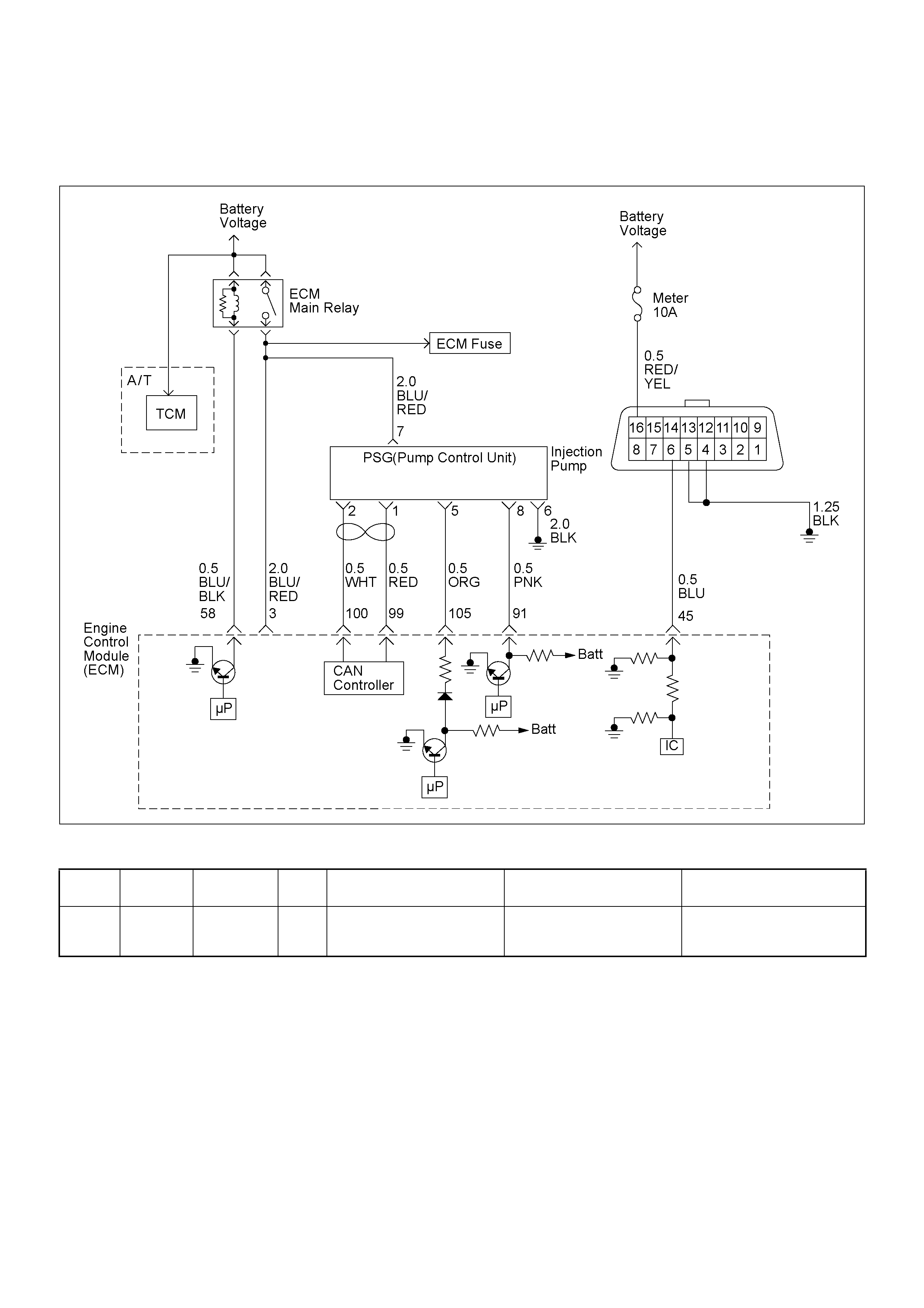
DIAGNOSTIC TROUBLE CODE (DTC) P13 45 (SYMPTOM CODE A)
(FLASH CODE 45) CAMSHAFT SPEED MALFUNCTION
Condition for setting the DTC and action ta ken when the DTC sets
Circuit Description
The pump camshaft sensor is a magnet with a coil. To
produce a signal, i t combine s with the puls er which is a
gear shaped device attached to the main shaft in the
pump.
The pump camshaft sensor is attached to the pump
control unit (PSG). The pum p camshaft speed signal is
sent via the CAN-bus from the PSG to ECM.
Diagnostic Aids
An intermittent may be caused by the following:
• Poor connections.
• Misrouted harness.
• Rubbed through wire insulation.
• Broken wire inside the insulation.
Check for the following conditions:
• Poor connection at ECM and PSG-Inspect harness
connectors for backed out terminals, improper
mating, broken locks, improperly formed or damaged
terminals, and poor terminal to wire connection.
• Damaged harness-Inspect the wiring harness for
damage. If the harness appears to be OK, observe
the “Pump Speed” display on the Tech2 while moving
connectors and wiring harnesses. A change in the
display will indicate the location of the fault.
Flash
Code Code Symptom
Code MIL DTC Name DTC Setting Condition Fail-Safe (Back Up)
45 P1345 A ON Camshaft Speed Malfunction The PSG (pump control unit)
is recognized incorrect
camshaft speed signal.
No fail-safe function.

Diagnostic Trouble Code (DTC) P1345 (Symptom Code A) (Flash Code 45)
Camshaft Speed Malfunction
Step Action Value(s) Yes No
1 Was the “On-Board Diagnostic (OBD) System Check”
performed?
—Go to Step 2
Go to On Board
Diagnostic
(OBD) System
Check
2 1. Connect the Tech 2.
2. Review and record the failure information.
3. Select “F0: Read DTC Infor As Stored By ECU” in
“F0: Diagnostic Trouble Codes”.
Is the DTC P1345 (Symptom Code A) stored as
“Present Failure”? — Go to Step 3
Refer to
Diagnostic Aids
and Go to Step
3
3 1. Using the Tech 2, ignition “On” and engine “Off”.
2. Select “F1: Clear DTC Information” in “F0:
Diagnostic Trouble Codes” with the Tech 2 and
clear the DTC information.
3. Operate the vehicle and monitor the “F0: Read
DTC Infor As Stored By ECU” in the “F0:
Diagnostic Trouble Codes”.
Was the DTC P1345 (Symptom Code A) stored in this
ignition cycle? — Go to Step 4
Refer to
Diagnostic Aids
and Go to Step
4
4 1. Using the Tech 2, ignition “On” and engine “Off”.
2. Monitor the “Pump Speed” in the data display.
Does the Tech 2 indicate correct “Pump Speed”
depending on engine speed? — Go to Step 6 Go to Step 5
5 Check any accessory parts which may cause electric
interference or magnetic interference.
Was the problem found? —
Remove the
accessory parts
and verify repair Go to Step 9
6 Is the ECM programmed with the latest software
release?
If not, download the latest software to the ECM using
the “SPS (Service Programming System)”.
Was the problem solved? — Verify repair Go to Step 7
7 Substitute a known good ECM and recheck.
Was the problem solved?
IMPORTANT: The replacement ECM must be
programmed. Refer to section of the Service
Programming System (SPS) in this manual.
Foll owing ECM pr ogramming, the immobi lizer system
(if equipped) must be linked to the ECM. Refer to
section 11 “Immobilizer System-ECM replacement” for
the ECM/Immobilizer linking procedure. —Go to Step 8 Go to Step 9
8 Replace the ECM.
Is the action complete?
IMPORTANT: The replacement ECM must be
programmed. Refer to section of the Service
Programming System (SPS) in this manual.
Foll owing ECM pr ogramming, the immobi lizer system
(if equipped) must be linked to the ECM. Refer to
section 11 “Immobilizer System-ECM replacement” for
the ECM/Immobilizer linking procedure. — Verify repair —
9 Replace the injection pump assembly.
Is the action complete? — Verify repair —
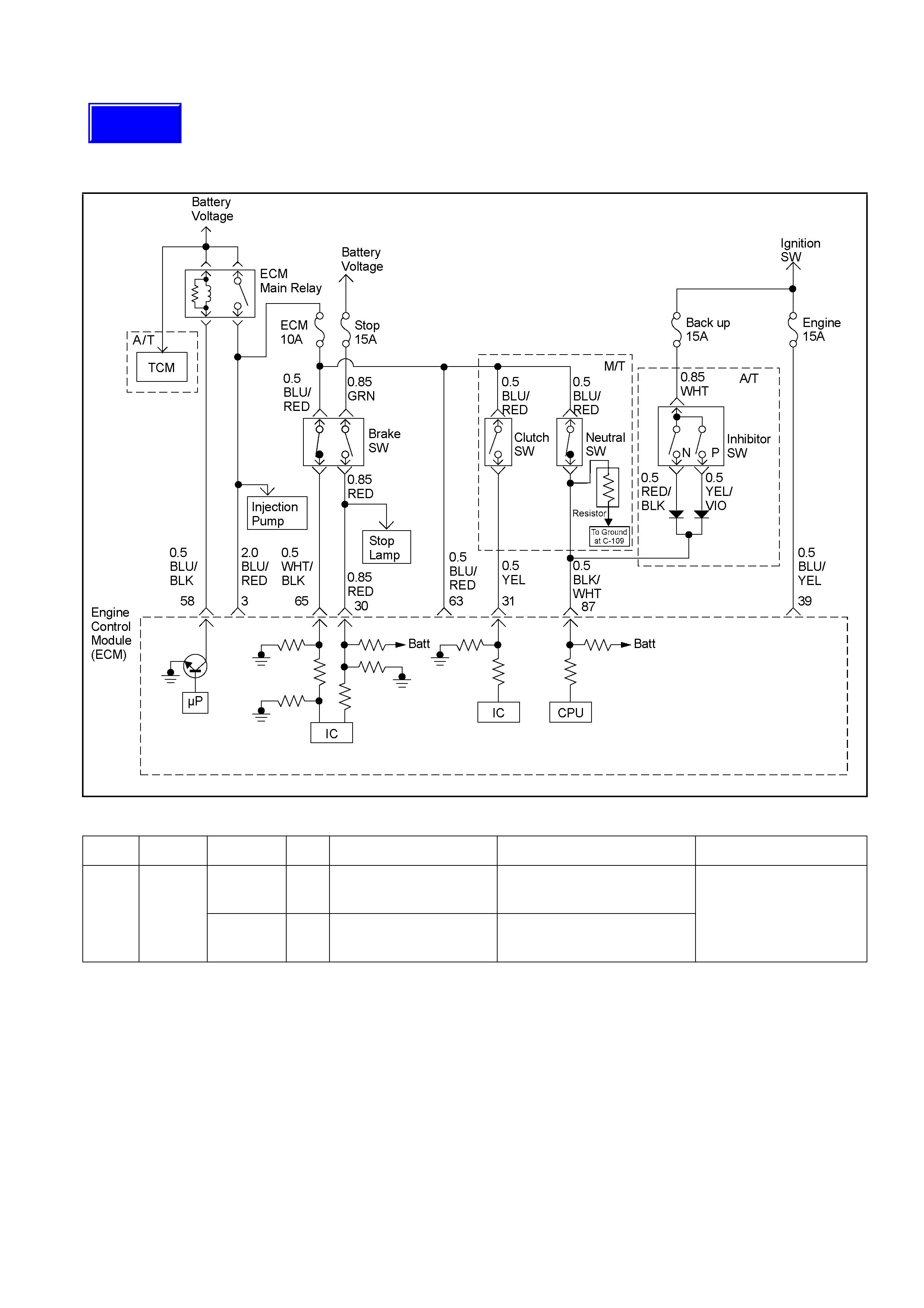
DIAGNOSTIC TROUBLE CODE (DTC) P1520 (SYMPTOM CODE A)
(FLASH CODE 47) NEUTRAL SWITCH ON ERROR
DIAGNOSTIC TROUBLE CODE (DTC) P1520 (SYMPTOM CODE B)
(FLASH CODE 47) NEUTRAL SWITCH OFF ERROR
RTW46ELF001401-a
Condition for setting the DTC and action taken when the DTC sets
Flash
Code Code Symptom
Code MIL DTC Name DTC Setting Condition Fail-Safe (Back Up)
A ON Neutral Switch ON Error Neutral switch signal is inputted
“On” three times consecutively
under driving conditions.
47 P1520
B ON Neutral Switch OFF Error Neutral switch signal is inputted
“Off” three times consecutively
under driving conditions.
No fail-safe function.
Techline

DTC P1520 (Symptom ‘A’ or ‘B’) may remain ‘Active’ after effecting repairs. This DTC is not erasable by using Tech 2. The
following ‘Clear Conditions’ are necessary to clear this DTC after repairs. Following this procedure, clear history DTC, using
Tech 2.
Code S ymptom
Code Transmission
Type Clear Conditions
M/T • Engine speed is higher than 1,500 rpm.
• Vehicle speed is higher than 64 km/h (40 mph)
• Neutral Switch is OFF (= Other than Neutral)
• Clutch switch is OFF (= Pedal is not depressed)
• Above conditions are met for 0.5 seconds.
AND
The above conditions must be met on the next two consecutive driving cycles. (A driving cycle
is; Ignition ON – Engine Run – Vehicle Run – Ignition OFF for 10 seconds.
A
A/T • Engine speed is higher than 1,500 rpm.
• Vehicle speed is higher than 80 km/h (50 mph)
• Neutral Switch is OFF (= Other than ‘N’ or ‘P’ range).
• Above conditions are met for 0.5 seconds.
AND
The above conditions must be met on the next two consecutive driving cycles. (A driving cycle
is; Ignition ON – Engine Run – Vehicle Run – Ignition OFF for 10 seconds).
P1520
B
M/T • Engine speed is higher than 665 rpm.
• Vehicle speed is lower than 2 km/h (3 mph)
• Neutral Switch is ON (= Neutral).
• Clutch Switch is OFF-ON-OFF (= Pedal is released after once being depressed).
• Above conditions are met for 0.5 seconds.
AND
The above conditions must be met on the next two consecutive driving cycles. (A driving cycle
is; Ignition ON – Engine Run – Ignition OFF for 10 seconds).
Circuit Description
The ECM monitors the neutral switch (A/T: N or P position
switch in inhib i tor sw itch) sign al on the feed termin al to th e
ECM. If the neutral switch malfunctions, a DTC P1520
(Symptom Code A) or P1520 (Sy mp tom Code B) will be
stored.
Diagnostic Aids
An intermittent may be caused by the follow ing:
• Poor connections.
• Misrouted harness.
• Rubbed through wire insu lati on .
• Broken wire insi de the in sulation .
Check fo r the fo llowing conditions:
• Poor connection at EC M-Inspect ha rness connecto rs for
backed out termin al s, improper ma ting , broken locks,
improperly formed or damage d termin al s, and poor
terminal to w ire connection .
• Damaged harnes s-Inspect the w iring harne ss for
damage. If the harn ess appea rs to be OK, obse rve the
“Neutral Switch” disp lay on the Tech 2 w hile moving
connectors and wiring harness rel a ted to the senso r.
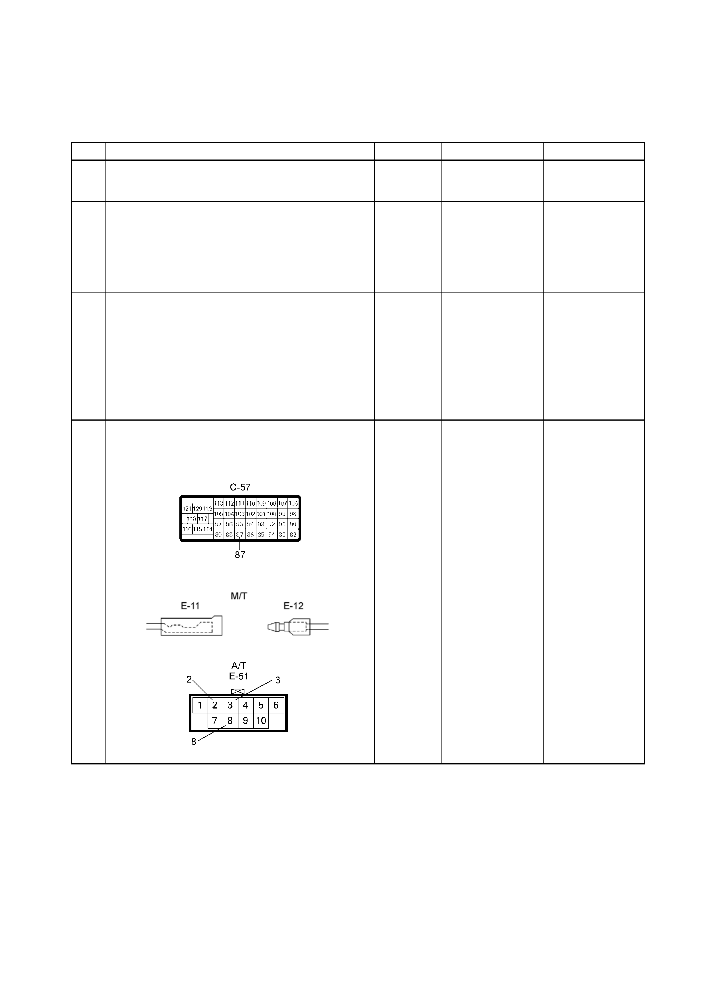
Diagnostic Trouble Code (DTC) P1520 (Symptom Code A) (Flash Code 47)
Neutral Switch ON Error
Diagnostic Trouble Code (DTC) P1520 (Symptom Code B) (Flash Code 47)
Neutral Switch OFF Error
Step Action Value(s) Yes No
1 Was the “On-Board Diagnostic (OBD) System Check”
performed? – Go to Step 2
Go to On-Board
Diagnostic (OBD)
System Check
2 Connect Tech 2.
Review and record the failure information.
Select “F0: Read DTC Infor As Stored By ECU” in “F0:
Diagnostic Trouble Codes”.
Is the DTC P1520 (Symptom Code A) or P1520
(Symptom Code B) stored as “Present Failure”? – Go to Step 3
Refer to Diagnostic
Aids and Go to
Step 3
3 Using Tech 2, ignition “On” and engi ne “Off”.
Select “F1: Clear DTC Information” in “F0: Diagnostic
Trouble Codes” with the Tech 2 and clear the DTC
information.
Operate the vehicle and monitor the “F0: Read DTC
Infor As Stored By ECU” in the “F0: Diagnostic Trouble
Codes”.
Was the DTC P1520 (Symptom Code A) or P1520
(Symptom Code B) stored in this ignition cycle? – Go to Step 4
Refer to Diagnostic
Aids and Go to
Step 4
4 Check for poor/faulty connection at the neutral switch
(inhibitor switch) or ECM connector. If a poor/faulty
connection is found, repa ir as necessary .
Was the problem found?
– Verify repair Go to Step 5

Step Action Value(s) Yes No
5 Using a DMM, check the neutral switch (or inhibitor
switch).
Ignition "Off", engine Off".
Remove the neutral switch connector (inhibitor switch
connector) from the switch.
Connect a DMM between the relevant terminals of the
neutral switch (or inhibitor switch).
Check the neutral s witch (or P/N range switch).
o
es the DMM indicate the specified val ue?
M/T
Neutral
(or P/N):
Continuity
Other than
Neutral
(or ‘P’/’N’):
No
Continuity Go to Step 6
Replace neutral
switch (or inhibitor
switch) and verify
repair
6 Using a DMM, check the neutral switch (or inhibitor
switch) power supply circ uit.
Ignition "On", engine "Off".
Remove the neutral switch (inhibitor switch)
connector from the switch.
Check the circuit for an open circuit.
o
es the DMM indicate the specified val ue?
V
E-12
M/T
V
3
E-51
A/T
10 – 14.5
volts Go to Step 8 Go to Step 7
7 Repair the open circuit between the “ECM fuse
(10A)” and neutral switch (or between the "Back-Up
fuse (15A)" and inhibitor switch).
Is the action complete? – Verify repair –
1236 5 4
7810 9
8
32
A/T
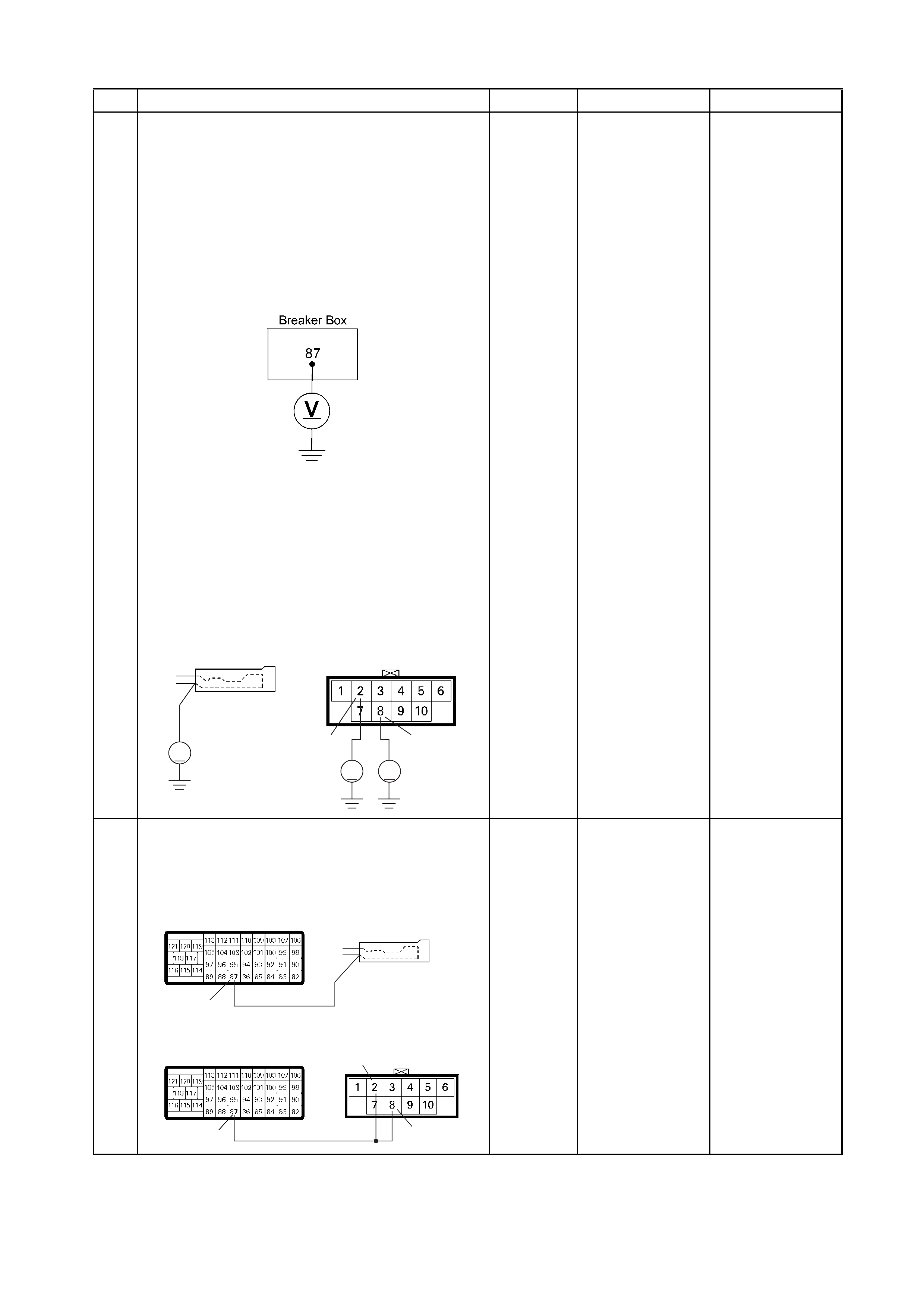
Step Action Value(s) Yes No
8 Using a DMM, check the neutral switch (or inhibitor
switch) circuit.
Breaker box is a vailable:
Ignition "Off", engine "Off".
Install the breaker box as type B. (ECM connected)
refer page 6C1-63, in this Section.
Ignition "On", engine "Off".
Check the circuit for open or short to voltage in the
circuit.
o
es the DVM indicate the specified val ue?
Breaker box is not available:
Reinstall the neutral switch harness connector to
the neutral switch (or inhibitor s witch).
Ignition "On", engine "Off".
Using a DMM, back probe the neutral switch (or
inhibitor switch) and check the circuit for an open
or short to voltage in the circuit.
a
s the DMM indicated specified value ?
V
82
V
V
E-11 E-51
M/T A/T
Neutral
(or P/N):
10 – 14.5
volts
Other than
Neutral
(or P/N):
Less than
1 volt Go to Step 11
Fixed at 10 – 14.5
volts: Go to Step 9.
Fixed at less than 1
volt: Go to Step 10.
9 Repair the short to voltage circuit between the
neutral switch connector (or inhibitor switch
connector) and ECM.
Is the action complete?
87
87 8
2
C-57
C-57
M/T
A/T
E-11
E-51
– Verify repair –
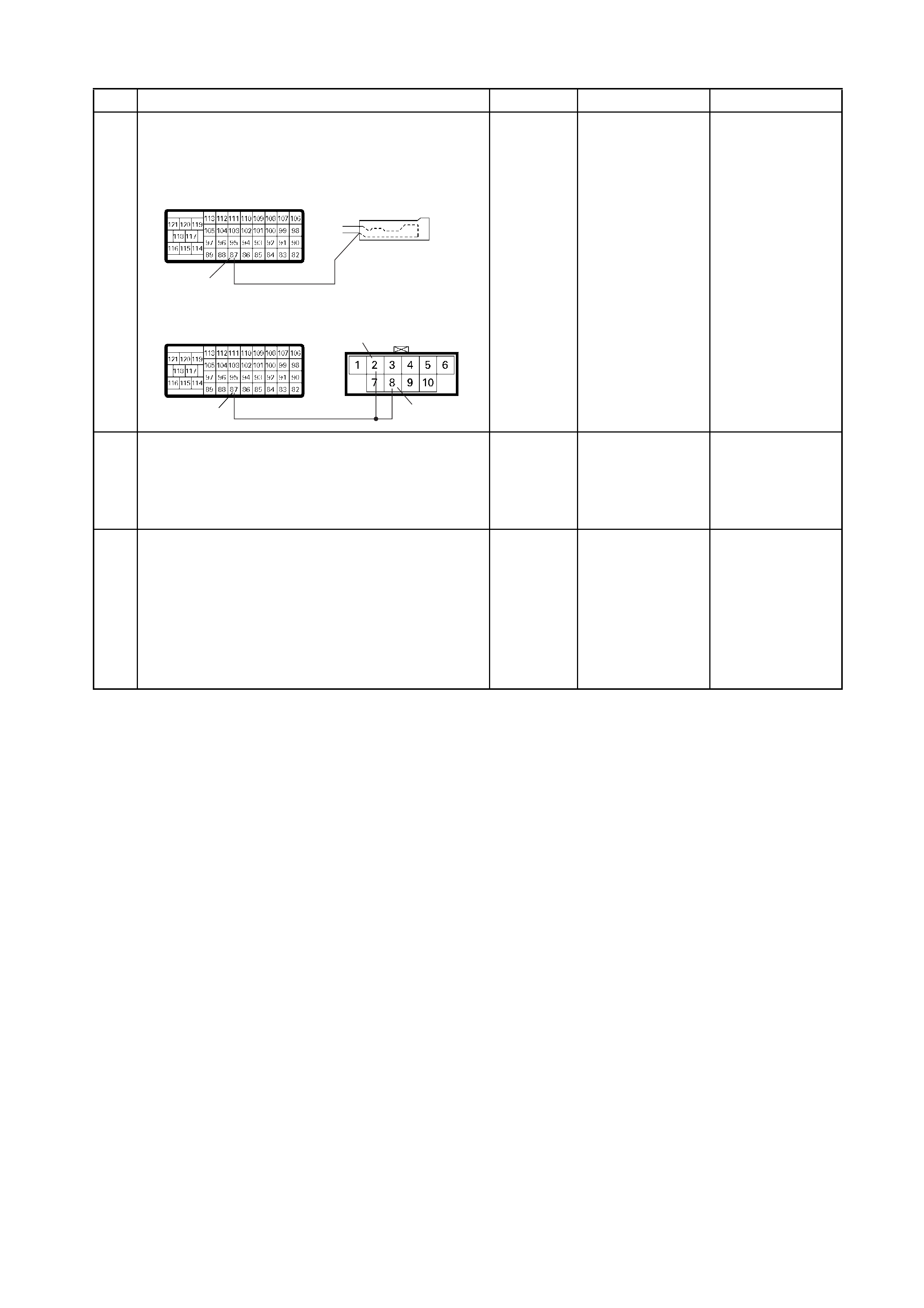
Step Action Value(s) Yes No
10 Repair the open circuit between the neutral switch
connector (or inhibito r sw itch con nec tor) and ECM.
Is the action complete?
87
87 8
2
C-57
C-57
M/T
A/T
E-11
E-51
– Verify repair –
11 Is the ECM programmed with the latest software
release?
If not, download the latest software to the ECM using the
"SPS (Service Programming Sy s tem )".
Was the problem solved? – Verify repair Go to Step 12
12 Replace the ECM.
Is the action complete?
IMPORTANT: The replacement ECM must be
programmed. Refer to section of the Service
Programming System (SPS) in this manual.
Following ECM programming, the immobiliser system (if
equipped) must be linked to the ECM. Refer to section
11 "Immobiliser System-ECM replacement" for the
ECM/Immobiliser l in king procedure. – Verify repair –

DIAGNOSTIC TROUBLE CODE (DTC) P16 05 (SYMPTOM CODE C)
(FLASH CODE 55) SEED AND KE Y FILE DESTROYED
DIAGNOSTIC TROUBLE CODE (DTC) P16 05 (SYMPTOM CODE D)
(FLASH CODE 55) EEPROM DEFE CT
DIAGNOSTIC TROUBLE CODE (DTC) P1605 (SYMPTOM CODE E)
(FLASH CODE 55) EEPROM DEFE CT
Condition for setting the DTC and action ta ken when the DTC sets
Circuit Description & Diagnostic Aids
The ECM used in this vehicle utilizes an electrically erasable & programmable read only memory (EEPROM). The
EEPROM contains program information and the calibrations required for engine and diagnostics operation.
If the ECM fails internally (IC, circuit, memory, etc,), DTC P1605 (Symptom Code C), P1605 (Symptom Code D) or
P1605 (Symptom Code E) will be stored.
Flash
Code Code Symptom
Code MIL DTC Name DTC Setting Condition Fail-Safe (Back Up)
55 P1605 C ON Seed and Key File Destroyed Seed or key file in EEPROM
is destroyed. No fail-safe function.
D ON EEPROM Defect Write and read from the
EEPROM are failed during
initialization of the ECM.
ECM uses default values from
the EPROM.
E ON EEPROM Defect EEPROM checksum does not
match with the read check
sum during initialization of the
ECM.

Diagnostic Trouble Code (DTC) P1605 (Symptom Code C) (Flash Code 55)
Seed and Key File Destroyed
Diagnostic Trouble Code (DTC) P1605 (Symptom Code D) (Flash Code 55)
EEPROM Defect
Diagnostic Trouble Code (DTC) P1605 (Symptom Code E) (Flash Code 55)
EEPROM Defect
Step Action Value(s) Yes No
1 Was the “On-Board Diagnostic (OBD) System Check”
performed?
—Go to Step 2
Go to On Board
Diagnostic
(OBD) System
Check
2 1. Connect the Tech 2.
2. Review and record the failure information.
3. Select “F0: Read DTC Infor As Stored By ECU” in
“F0: Diagnostic Trouble Codes”.
Is the DTC P1605 (Symptom Code C), P1605
(Symptom Code D) or P1605 (Symptom Code E)
stored as “Present Failure”? — Go to Step 3
Refer to
Diagnostic Aids
and Go to Step
3
3 1. Using the Tech 2, ignition “On” and engine “Off”.
2. Select “F1: Clear DTC Information” in “F0:
Diagnostic Trouble Codes” with the Tech 2 and
clear the DTC information.
3. Operate the vehicle and monitor the “F0: Read
DTC Infor As Stored By ECU” in the “F0:
Diagnostic Trouble Codes”.
Was the DTC P1605 (Symptom Code C), P1605
(Symptom Code D) or P1605 (Symptom Code E)
stored in this ignition cycle? — Go to Step 4 Refer to
Diagnostic Aids
4 Is the ECM programmed with the latest software
release?
If not, download the latest software to the ECM using
the “SPS (Service Programming System)”.
Was the problem solved? — Verify repair Go to Step 5
5 Replace the ECM.
Is the action complete?
IMPORTANT: The replacement ECM must be
programmed. Refer to section of the Service
Programming System (SPS) in this manual.
Foll owing ECM pr ogramming, the immobi lizer system
(if equipped) must be linked to the ECM. Refer to
section 11 “Immobilizer System-ECM replacement” for
the ECM/Immobilizer linking procedure. — Verify repair —

DIAGNOSTIC TROUBLE CODE (DTC) P16 10 (SYMPTOM CODE A)
(FLASH CODE 56) SECURITY KEY AND SECURITY CODE NOT PROGRAMME D
Condition for setting the DTC and action ta ken when the DTC sets
Circuit Description
The ECM decides that there is an abnormality in the
immobilizer control system. DTC P1610 (Symptom
Code A) i s recorded whe n immobil izer functio n was not
programmed in the ECM.
Diagnostic Aids
Check for the following conditions:
• Poor connection at ECM and immobilizer control unit-
Inspect harne ss con nectors for bac ked out termi nals,
improper mating, broken locks, improp erly formed or
damaged terminals, and poor terminal to wire
connection.
• Damaged harness-Inspect the wiring harness for
damage. If the harness appears to be OK, observe
the DTC P1610 display on the Tech2 while moving
connectors and wiring harnesses.
Flash
Code Code Symptom
Code MIL DTC Name DTC Setting Condition Fail-Safe (Back Up)
56 P1610 A - Security Key and Security
Code not Programmed Immobilizer functions are not
programmed in the ECM. 1. Engine does not start.
2. Check engine lamp flash.

Diagnostic Trouble Code (DTC) P1610 (Symptom Code A) (Flash Code 56)
Security Key and Security Code Not Programmed
Step Action Value(s) Yes No
1 Was the “On-Board Diagnostic (OBD) System Check”
performed?
—Go to Step 2
Go to On Board
Diagnostic
(OBD) System
Check
2 1. Connect the Tech 2.
2. Review and record the failure information.
3. Select “F0: Read DTC Infor As Stored By ECU” in
“F0: Diagnostic Trouble Codes”.
Is the DTC P1610 (Symptom Code A) stored as
“Present Failure”? — Go to Step 3
Refer to
Diagnostic Aids
and Go to Step
3
3 1. Using the Tech 2, ignition “On” and engine “Off”.
2. Select “F1: Clear DTC Information” in “F0:
Diagnostic Trouble Codes” with the Tech 2 and
clear the DTC information.
3. Operate the vehicle and monitor the “F0: Read
DTC Infor As Stored By ECU” in the “F0:
Diagnostic Trouble Codes”.
Was the DTC P1610 (Symptom Code A) stored in this
ignition cycle? — Go to Step 4
Refer to
Diagnostic Aids
and Go to Step
4
4 1. Using the Tech 2, ignition “On” and engine “Off”.
2. Select “Immobilizer” in the system selection menu
“Body”.
3. Select “Read DTC Info Ordered By Priority” in the
“Diagnostic Trouble Code”.
Was the any DTC's B0002 or B0009 stored in this
ignition cycle? —
Refer to
Section 11
IMMOBILISER
SYSTEM & Go
to DTC Chart
B0002 or
B0009 Go to Step 5
5 Is the ECM programmed with the latest software
release?
If not, download the latest software to the ECM using
the “SPS (Service Programming System)”.
Was the problem solved? — Verify repair Go to Step 6
6 Replace the ECM.
Is the action complete?
IMPORTANT: The replacement ECM must be
programmed. Refer to section of the Service
Programming System (SPS) in this manual.
Foll owing ECM pr ogramming, the immobi lizer system
(if equipped) must be linked to the ECM. Refer to
section 11 “Immobilizer System-ECM replacement” for
the ECM/Immobilizer linking procedure. — Verify repair —
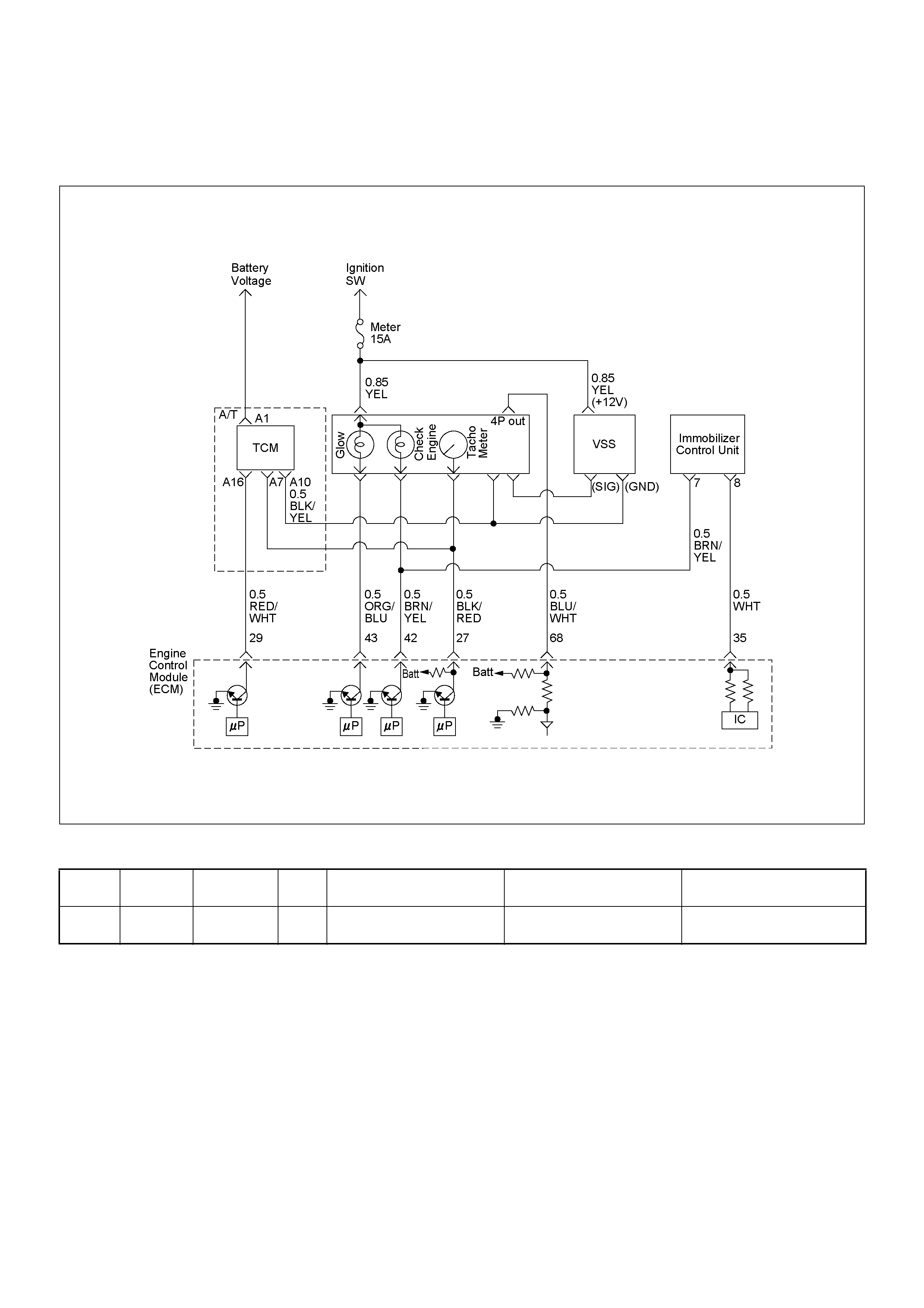
DIAGNOSTIC TROUBLE CODE (DTC) P1611 (SYMPTOM CODE A)
(FLASH CODE 56 ) WRONG SECURITY CODE ENTERED
Condition for setting the DTC and action ta ken when the DTC sets
Circuit Description
The ECM decides that there is an abnormality in the
immobilizer control system. DTC P1611 (Symptom
Code A) is recorded when received immobilizer security
code was not co rrec t.
Diagnostic Aids
Check for the following conditions:
• Poor connection at ECM and immobilizer control unit-
Inspect harne ss con nectors for bac ked out termi nals,
improper mating, broken locks, improp erly formed or
damaged terminals, and poor terminal to wire
connection.
• Damaged harness-Inspect the wiring harness for
damage. If the harness appears to be OK, observe
the DTC P1611 display on the Tech2 while moving
connectors and wiring harnesses.
Flash
Code Code Symptom
Code MIL DTC Name DTC Setting Condition Fail-Safe (Back Up)
56 P1611 A - Wrong Security Code Entered Received security code is not
correct. 1. Engine does not start.
2. Check engine lamp flash.

Diagnostic Trouble Code (DTC) P1611 (Symptom Code A) (Flash Code 56)
Wrong Security Code Entered
Step Action Value(s) Yes No
1 Was the “On-Board Diagnostic (OBD) System Check”
performed?
—Go to Step 2
Go to On Board
Diagnostic
(OBD) System
Check
2 1. Connect the Tech 2.
2. Review and record the failure information.
3. Select “F0: Read DTC Infor As Stored By ECU” in
“F0: Diagnostic Trouble Codes”.
Is the DTC P1611 (Symptom Code A) stored as
“Present Failure”? — Go to Step 3
Refer to
Diagnostic Aids
and Go to Step
3
3 1. Using the Tech 2, ignition “On” and engine “Off”.
2. Select “F1: Clear DTC Information” in “F0:
Diagnostic Trouble Codes” with the Tech 2 and
clear the DTC information.
3. Operate the vehicle and monitor the “F0: Read
DTC Infor As Stored By ECU” in the “F0:
Diagnostic Trouble Codes”.
Was the DTC P1611 (Symptom Code A) stored in this
ignition cycle? — Go to Step 4
Refer to
Diagnostic Aids
and Go to Step
4
4 1. Using the Tech 2, ignition “On” and engine “Off”.
2. Select “Immobilizer” in the system selection menu
“Body”.
3. Select “Read DTC Info Ordered By Priority” in the
“Diagnostic Trouble Code”.
Was the any DTC's B**** stored in this ignition cycle? —
Refer to
Section 11
IMMOBILISER
SYSTEM & Go
to DTC Chart
B**** Go to Step 5
5 Is the ECM programmed with the latest software
release?
If not, download the latest software to the ECM using
the “SPS (Service Programming System)”.
Was the problem solved? — Verify repair Go to Step 6
6 Replace the ECM.
Is the action complete?
IMPORTANT: The replacement ECM must be
programmed. Refer to section of the Service
Programming System (SPS) in this manual.
Foll owing ECM pr ogramming, the immobi lizer system
(if equipped) must be linked to the ECM. Refer to
section 11 “Immobilizer System-ECM replacement” for
the ECM/Immobilizer linking procedure. — Verify repair —

DIAGNOSTIC TROUBLE CODE (DTC) P16 12 (SYMPTOM CODE A)
(FLASH CODE 56) IMMOBILIZER NO OR WRONG SIGNAL
Condition for setting the DTC and action ta ken when the DTC sets
Circuit Description
The ECM decides that there is an abnormality in the
immobilizer control system. DTC P1612 (Symptom
Code A) is recorded when received immobilizer
challenge signal was not correct.
Diagnostic Aids
Check for the following conditions:
• Poor connection at ECM and immobilizer control unit-
Inspect harne ss con nectors for bac ked out termi nals,
improper mating, broken locks, improp erly formed or
damaged terminals, and poor terminal to wire
connection.
• Damaged harness-Inspect the wiring harness for
damage. If the harness appears to be OK, observe
the DTC P1612 display on the Tech2 while moving
connectors and wiring harnesses.
Flash
Code Code Symptom
Code MIL DTC Name DTC Setting Condition Fail-Safe (Back Up)
56 P1612 A - Imm obilizer No or Wrong
Signal Received challenge signal is
not correct or not received. 1. Engine does not start.
2. Check engine lamp flash.
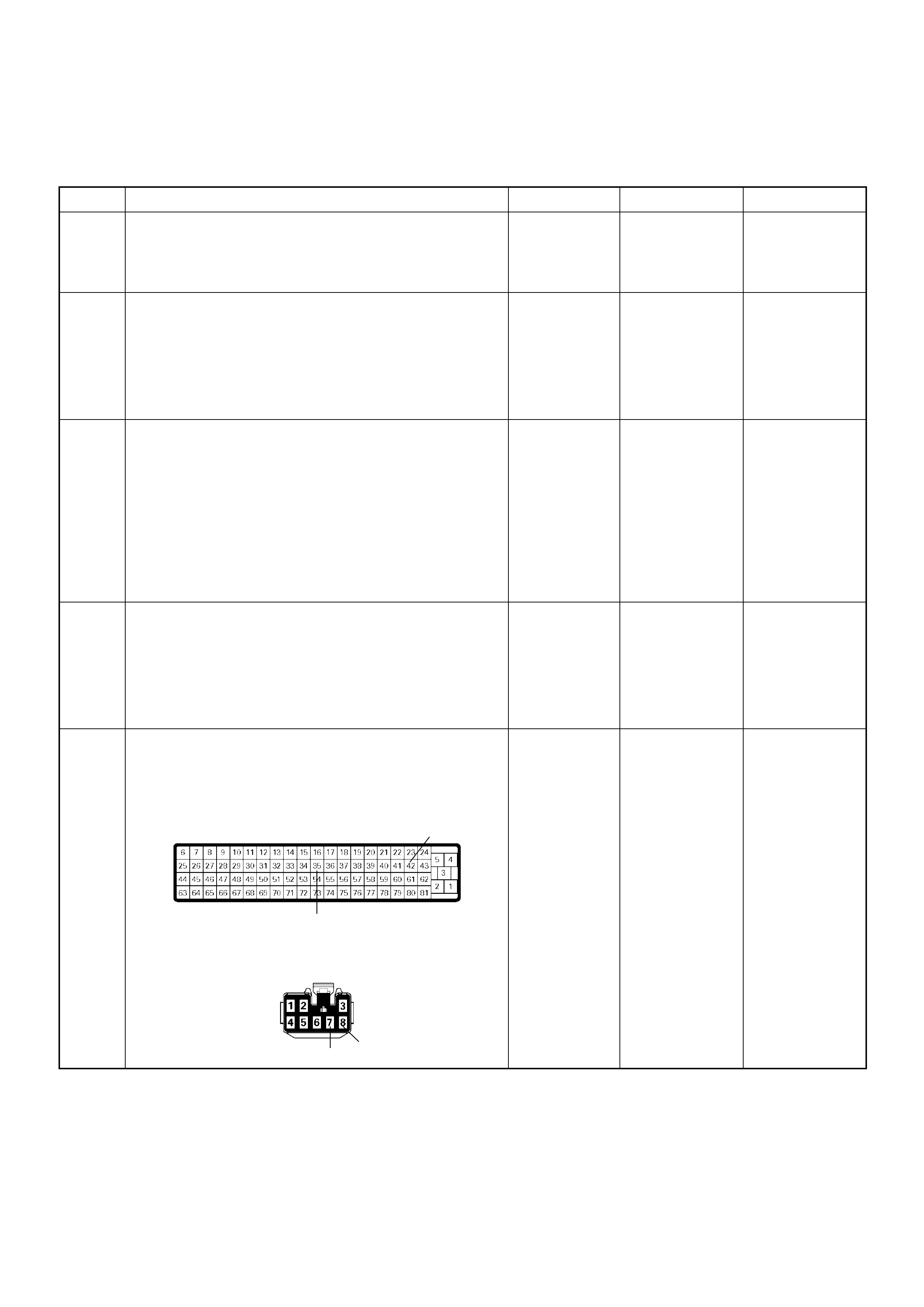
Diagnostic Trouble Code (DTC) P1612 (Symptom Code A) (Flash Code 56)
Immobilizer No or Wrong Signal
Step Action Value(s) Yes No
1 Was the “On-Board Diagnostic (OBD) System Check”
performed?
—Go to Step 2
Go to On Board
Diagnostic
(OBD) System
Check
2 1. Connect the Tech 2.
2. Review and record the failure information.
3. Select “F0: Read DTC I nfor As Stored By ECU” in
“F0: Diagnostic Trouble Codes”.
Is the DTC P1612 (Symptom Code A) stored as
“Present Failure”? — Go to Step 3
Refer to
Diagnostic Aids
and Go to Step
3
3 1. Using the Tech 2, ignition “On” and engine “Off”.
2. Select “F1: Clear DTC Information” in “F0:
Diagnostic Trouble Codes” with the Tech 2 and
clear the DTC information.
3. Operate the vehicle and monitor the “F0: Read
DTC Infor As Stored By ECU” in the “F0:
Diagnostic Trouble Codes”.
Was the DTC P1612 (Symptom Code A) stored in this
ignition cycle? — Go to Step 4
Refer to
Diagnostic Aids
and Go to Step
4
4 1. Using the Tech 2, ignition “On” and engine “Off”.
2. Select “Immobilizer” in the system selection menu
“Body”.
3. Sele ct “Read D TC Info Or dered B y Priority” in the
“Diagnositic Trouble Code”.
Was the DTC B0007 stored in this ignition cycle? —
Refer to
Section 11
IMMOBILISER
SYSTEM & Go
to DTC Chart
B0007 Go to Step 5
5 Check for poor/faulty connection at the immobilizer
control unit connector or ECM connector. If a poor/
faulty co nnec ti on is found, repair as neces sa ry.
Was the problem found?
— Verify repair Go to Step 6
42
35
78
C-56
B-68
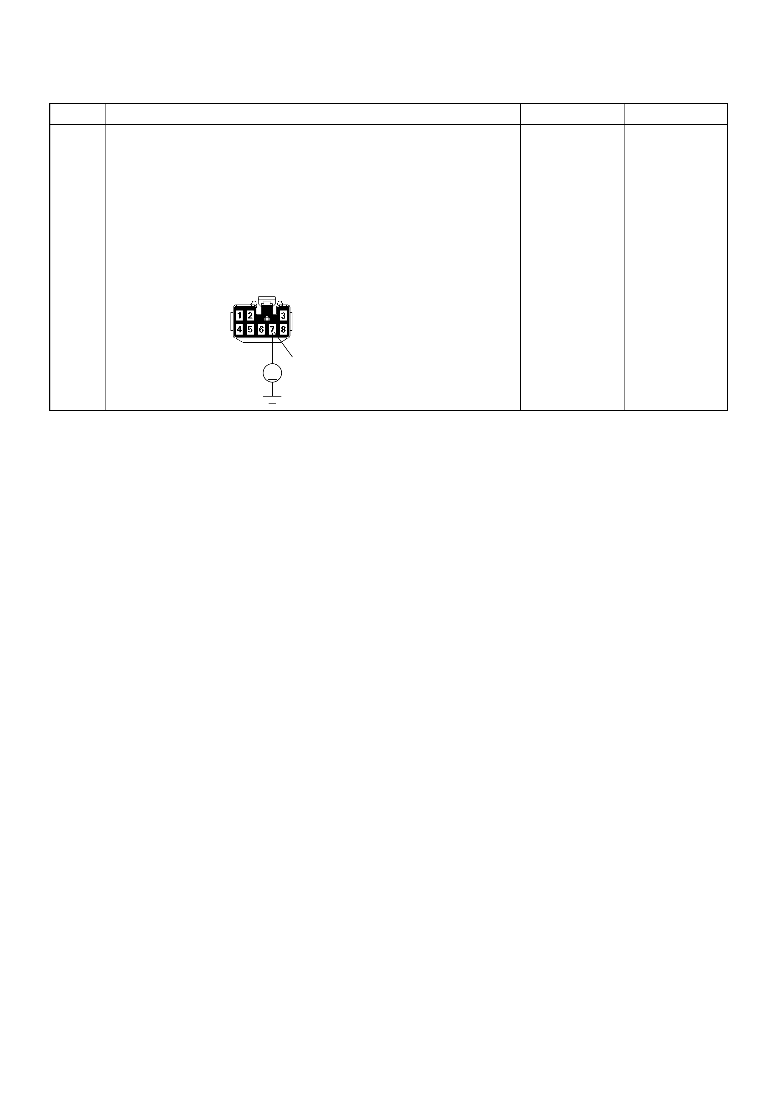
6 Using the DVM and check the “CHECK ENGINE”
lamp circuit.
1. Ignition “Off”, engine “Off”.
2. Disconnect the meter connector and immobilizer
control unit connector.
3. Ignition “On”.
4. Check the circuit for short to power supply circuit.
W as DVM indicated specified value?
Less than 1V Go to Step 7
Repair faulty
harness and
verify repair
Step Action Value(s) Yes No
7
V
B-68
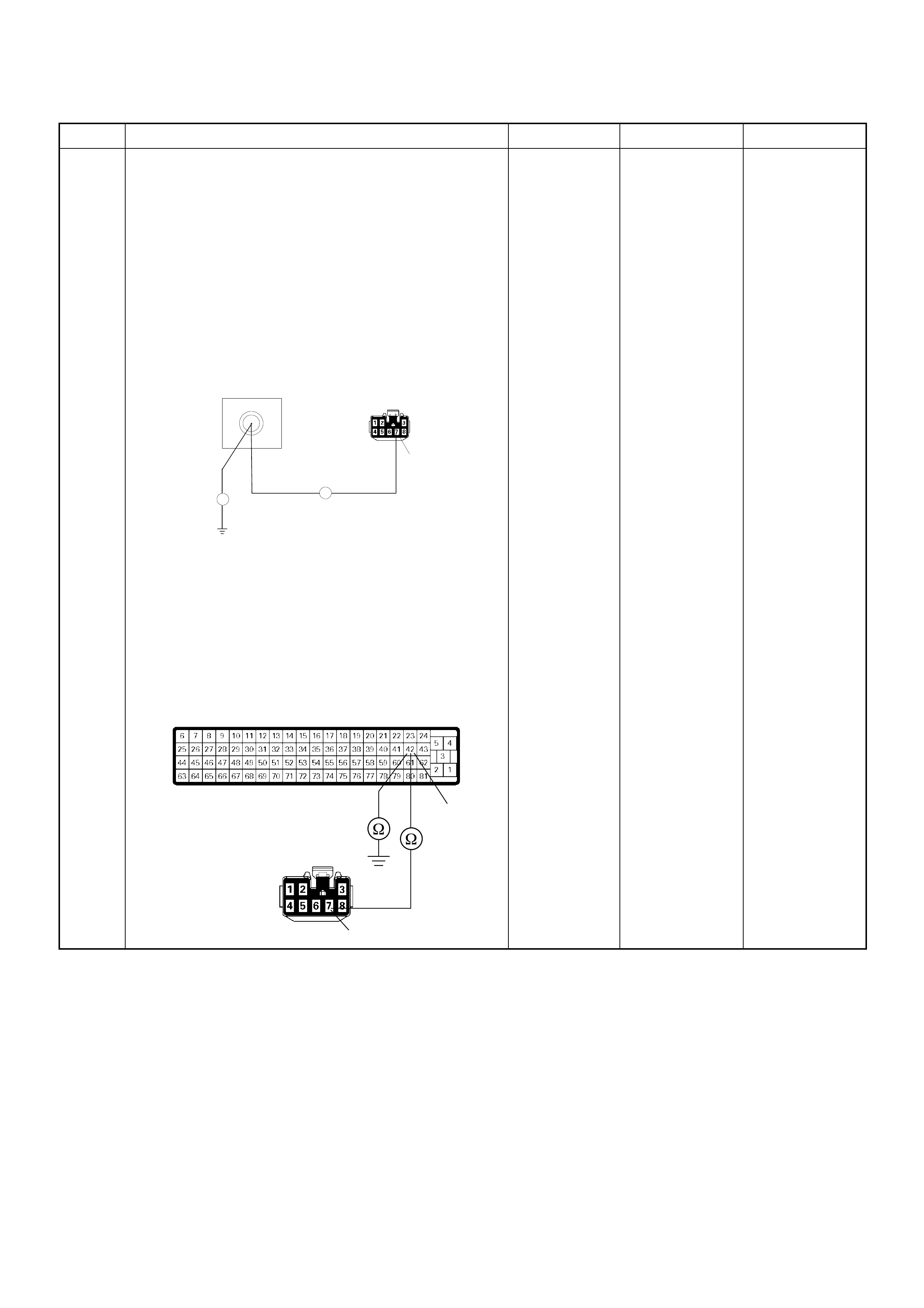
7 Using the DVM and check the “CHECK ENGINE”
lamp circuit.
Breaker box is available:
1. Ignition “Off”, engine “Off”.
2. Install the breaker box as type A. (ECM
disconnected) Ref. to HOW TO USE BREAKER
BOX
3. Disconnect the immobilizer control unit connector.
4. Check the circuit for open or short to ground
circuit.
Was the problem found?
Breaker box is not available:
1. Ignition “Off”, engine “Off”.
2. Disconnect the the immobilizer control unit
connector and ECM connector.
3. Check the circuit for open or short to ground
circuit.
Was the problem found?
—
Repair faulty
harnes s and
verify repair Go to Step 8
Step Action Value(s) Yes No
B-68
42
Breaker Box
7
Ħ
Ħ
42
7
C-56
B-68

8 Using the DVM and check the ECM and immobilizer
control unit communication circuit.
1. Ignition “Off”, engine “Off”.
2. Disconnect the immobilizer control unit connector.
3. Ignition “On”.
4. Check the circuit for short to power supply circuit.
Was the DVM indicated specified value?
Less than 1V Go to Step 9
Repair faulty
harness and
verify repair
9 Using the DVM and check the ECM and immobilizer
control unit communication circuit.
Breaker box is available:
1. Ignition “Off”, engine “Off”.
2. Install the breaker box as type A. (ECM
disconnected) Ref. to HOW TO USE BREAKER
BOX
3. Disconnect the immobilizer control unit connector.
4. Check the circuit for open or short to ground
circuit.
Was the problem found?
Breaker box is not available:
1. Ignition “Off”, engine “Off”.
2. Disconnect the the immobilizer control unit
connector and ECM connector.
3. Check the circuit for open or short to ground
circuit.
Was the problem found?
—
Repair faulty
harnes s and
verify repair Go to S tep 10
Step Action Value(s) Yes No
8
V
B-68
B-68
35
Breaker Box
8
Ħ
Ħ
35
8
C-56
B-68

10 Is the ECM programmed with the latest software
release?
If not, download the latest software to the ECM using
the “SPS (Service Programming System)”.
Was the problem solved? — Verify repair Go to Step 11
11 Replace the ECM.
Is the action complete?
IMPORTANT: The replacement ECM must be
programmed. Refer to section of the Service
Programming System (SPS) in this manual.
Foll owing ECM pr ogramming, the immobi lizer system
(if equipped) must be linked to the ECM. Refer to
section 11 “Immobilizer System-ECM replacement” for
the ECM/Immobilizer linking procedure. — Verify repair —
Step Action Value(s) Yes No

DIAGNOSTIC TROUBLE CODE (DTC) P16 13 (SYMPTOM CODE A)
(FLASH CODE 56) IMMOBILIZER NO OR WRONG SIGNAL
Condition for setting the DTC and action ta ken when the DTC sets
Circuit Description
The ECM decides that there is an abnormality in the
immobilizer control system. DTC P1613 (Symptom
Code A) is recorded when received immobilizer
response signal was not correct.
Diagnostic Aids
Check for the following conditions:
• Poor connection at ECM and immobilizer control unit-
Inspect harne ss con nectors for bac ked out termi nals,
improper mating, broken locks, improp erly formed or
damaged terminals, and poor terminal to wire
connection.
• Damaged harness-Inspect the wiring harness for
damage. If the harness appears to be OK, observe
the DTC P1613 display on the Tech2 while moving
connectors and wiring harnesses.
Flash
Code Code Symptom
Code MIL DTC Name DTC Setting Condition Fail-Safe (Back Up)
56 P1613 A - Imm obilizer No or Wrong
Signal Received response signal is
not correct or not received. 1. Engine does not start.
2. Check engine lamp flash.

Diagnostic Trouble Code (DTC) P1613 (Symptom Code A) (Flash Code 56)
Immobilizer No or Wrong Signal
Step Action Value(s) Yes No
1 Was the “On-Board Diagnostic (OBD) System Check”
performed?
—Go to Step 2
Go to On Board
Diagnostic
(OBD) System
Check
2 1. Connect the Tech 2.
2. Review and record the failure information.
3. Select “F0: Read DTC I nfor As Stored By ECU” in
“F0: Diagnostic Trouble Codes”.
Is the DTC P1613 (Symptom Code A) stored as
“Present Failure”? — Go to Step 3
Refer to
Diagnostic Aids
and Go to Step
3
3 1. Using the Tech 2, ignition “On” and engine “Off”.
2. Select “F1: Clear DTC Information” in “F0:
Diagnostic Trouble Codes” with the Tech 2 and
clear the DTC information.
3. Operate the vehicle and monitor the “F0: Read
DTC Infor As Stored By ECU” in the “F0:
Diagnostic Trouble Codes”.
Was the DTC P1613 (Symptom Code A) stored in this
ignition cycle? — Go to Step 4
Refer to
Diagnostic Aids
and Go to Step
4
4 1. Using the Tech 2, ignition “On” and engine “Off”.
2. Select “Immobilizer” in the system selection menu
“Body”.
3. Sele ct “Read D TC Info Or dered B y Priority” in the
“Diagnositic Trouble Code”.
Was the any DTC's B**** stored in this ignition cycle? —
Refer to
Section 11
IMMOBILISER
SYSTEM & Go
to DTC Chart
B**** Go to Step 5
5 Check for poor/faulty connection at the immobilizer
control unit connector or ECM connector. If a poor/
faulty co nnec ti on is found, repair as neces sa ry.
Was the problem found?
— Verify repair Go to Step 6
42
35
78
C-56
B-68

6 Using the DVM and check the “CHECK ENGINE”
lamp circuit.
1. Ignition “Off”, engine “Off”.
2. Disconnect the meter connector and immobilizer
control unit connector.
3. Ignition “On”.
4. Check the circuit for short to power supply circuit.
W as DVM indicated specified value?
Less than 1V Go to Step 7
Repair faulty
harness and
verify repair
Step Action Value(s) Yes No
7
V
B-68
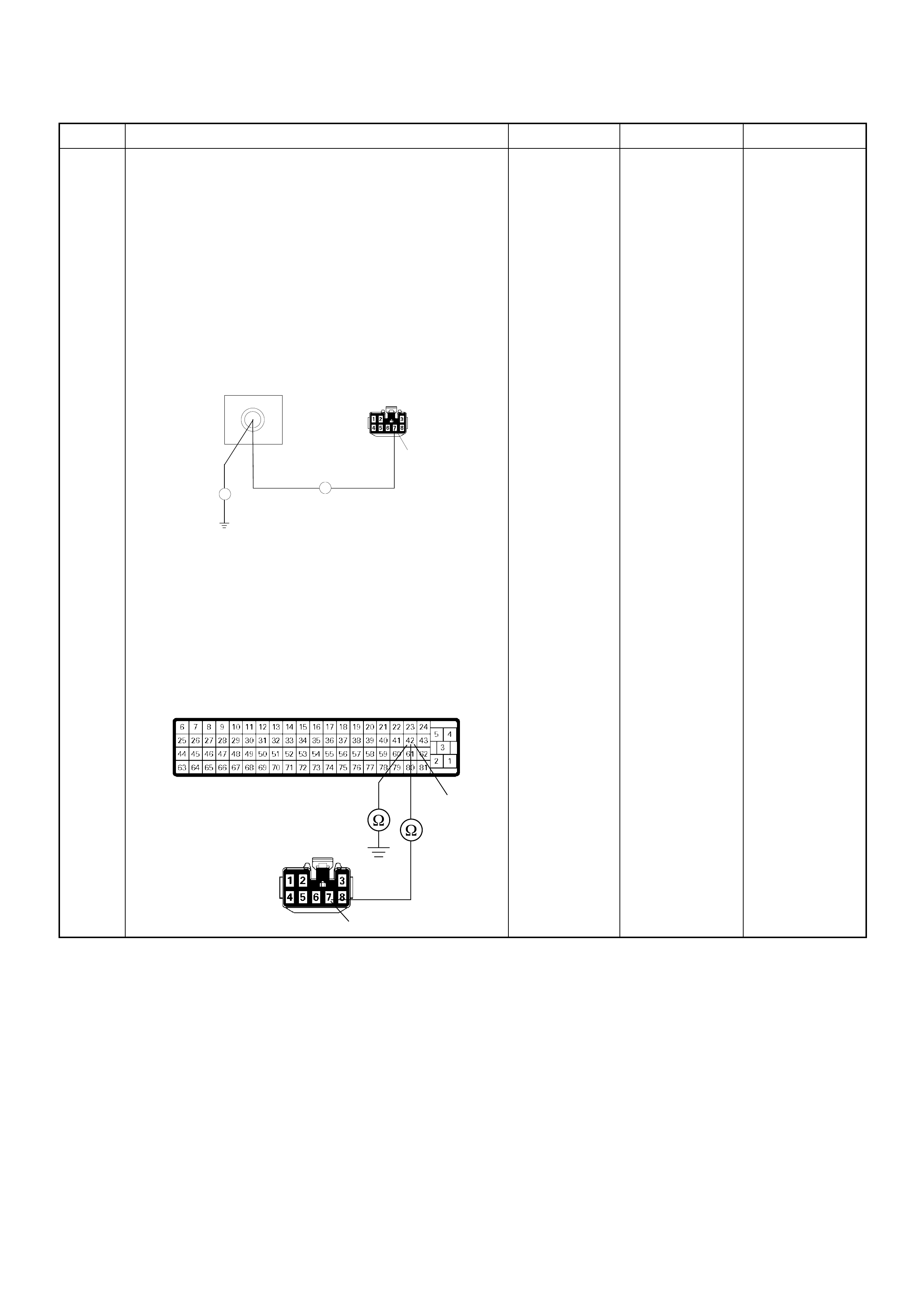
7 Using the DVM and check the “CHECK ENGINE”
lamp circuit.
Breaker box is available:
1. Ignition “Off”, engine “Off”.
2. Install the breaker box as type A. (ECM
disconnected) Ref. to HOW TO USE BREAKER
BOX
3. Disconnect the immobilizer control unit connector.
4. Check the circuit for open or short to ground
circuit.
Was the problem found?
Breaker box is not available:
1. Ignition “Off”, engine “Off”.
2. Disconnect the the immobilizer control unit
connector and ECM connector.
3. Check the circuit for open or short to ground
circuit.
Was the problem found?
—
Repair faulty
harnes s and
verify repair Go to Step 8
Step Action Value(s) Yes No
B-68
42
Breaker Box
7
Ħ
Ħ
42
7
C-56
B-68
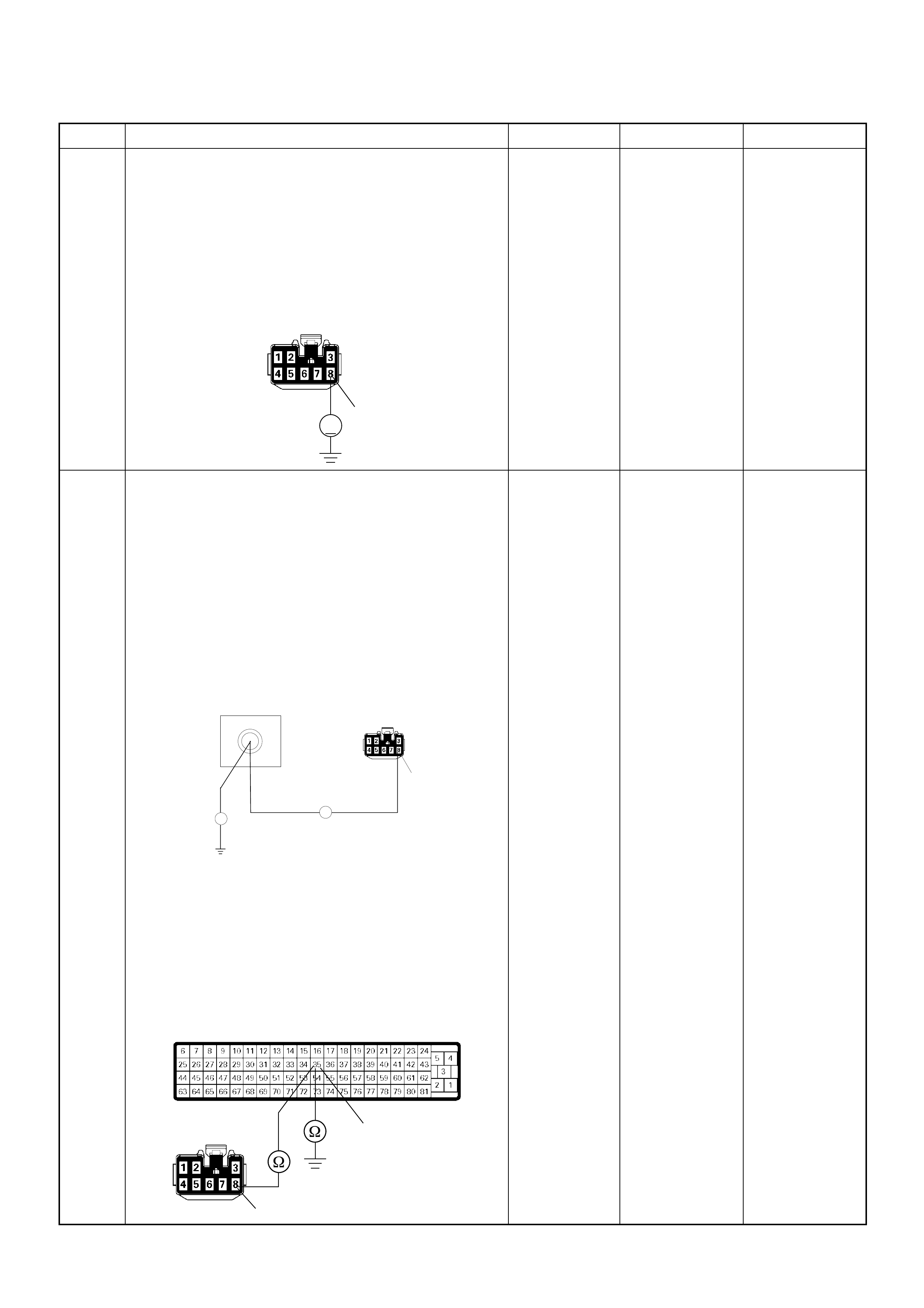
8 Using the DVM and check the ECM and immobilizer
control unit communication circuit.
1. Ignition “Off”, engine “Off”.
2. Disconnect the immobilizer control unit connector.
3. Ignition “On”.
4. Check the circuit for short to power supply circuit.
Was the DVM indicated specified value?
Less than 1V Go to Step 9
Repair faulty
harness and
verify repair
9 Using the DVM and check the ECM and immobilizer
control unit communication circuit.
Breaker box is available:
1. Ignition “Off”, engine “Off”.
2. Install the breaker box as type A. (ECM
disconnected) Ref. to HOW TO USE BREAKER
BOX
3. Disconnect the immobilizer control unit connector.
4. Check the circuit for open or short to ground
circuit.
Was the problem found?
Breaker box is not available:
1. Ignition “Off”, engine “Off”.
2. Disconnect the the immobilizer control unit
connector and ECM connector.
3. Check the circuit for open or short to ground
circuit.
Was the problem found?
—
Repair faulty
harnes s and
verify repair Go to S tep 10
Step Action Value(s) Yes No
8
V
B-68
B-68
35
Breaker Box
8
Ħ
Ħ
35
8
C-56
B-68

10 Is the ECM programmed with the latest software
release?
If not, download the latest software to the ECM using
the “SPS (Service Programming System)”.
Was the problem solved? — Verify repair Go to Step 11
11 Replace the ECM.
Is the action complete?
IMPORTANT: The replacement ECM must be
programmed. Refer to section of the Service
Programming System (SPS) in this manual.
Foll owing ECM pr ogramming, the immobi lizer system
(if equipped) must be linked to the ECM. Refer to
section 11 “Immobilizer System-ECM replacement” for
the ECM/Immobilizer linking procedure. — Verify repair —
Step Action Value(s) Yes No
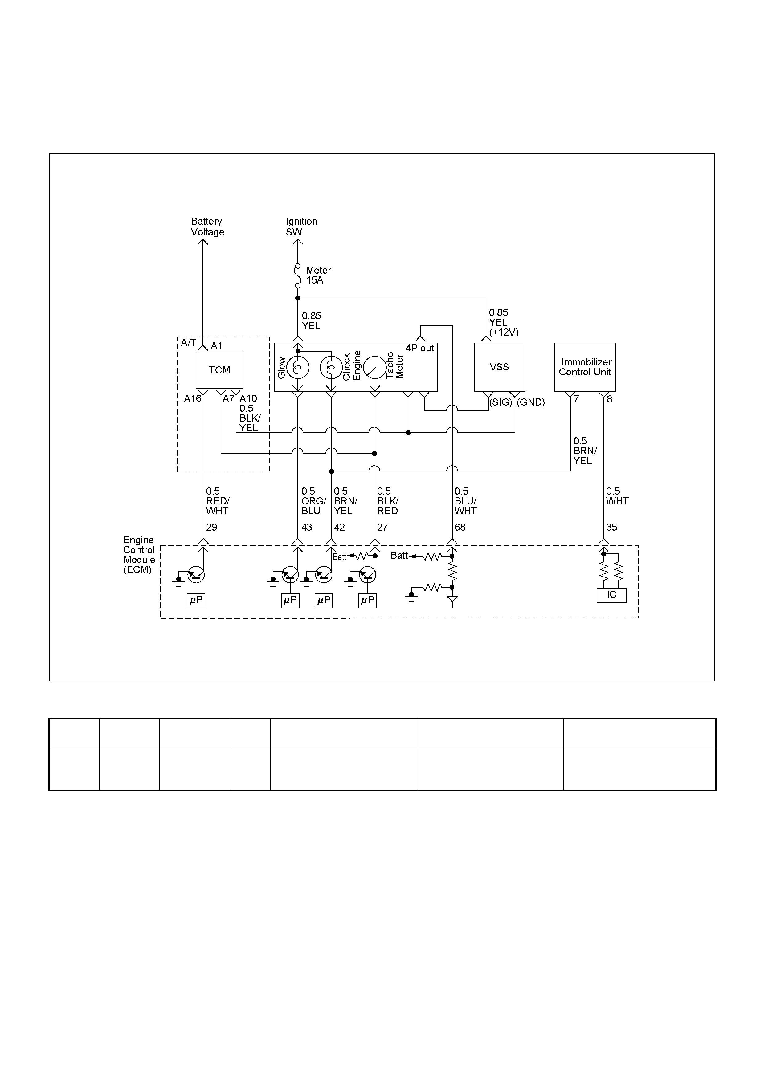
DIAGNOSTIC TROUBLE CODE (DTC) P16 14 (SYMPTOM CODE A)
(FLASH C ODE 56) WRON G TRANSPONDER KE Y
Condition for setting the DTC and action ta ken when the DTC sets
Circuit Description
The ECM decides that there is an abnormality in the
immobilizer control system. DTC P1614 (Symptom
Code A) is recorded when received immobilizer
response signal was not correct from the transponder
key.
Diagnostic Aids
Check for the following conditions:
• Poor connection at ECM and immobilizer control unit-
Inspect harne ss con nectors for bac ked out termi nals,
improper mating, broken locks, improp erly formed or
damaged terminals, and poor terminal to wire
connection.
• Damaged harness-Inspect the wiring harness for
damage. If the harness appears to be OK, observe
the DTC P1614 display on the Tech2 while moving
connectors and wiring harnesses.
Flash
Code Code Symptom
Code MIL DTC Name DTC Setting Condition Fail-Safe (Back Up)
56 P1614 A - Wrong Transponder Key Received response signal is
not correct from the
transponder key.
1. Engine does not start.
2. Check engine lamp flash.

Diagnostic Trouble Code (DTC) P1614 (Symptom Code A) (Flash Code 56)
Wrong Transponder Key
Step Action Value(s) Yes No
1 Was the “On-Board Diagnostic (OBD) System Check”
performed?
—Go to Step 2
Go to On Board
Diagnostic
(OBD) System
Check
2 1. Connect the Tech 2.
2. Review and record the failure information.
3. Select “F0: Read DTC Infor As Stored By ECU” in
“F0: Diagnostic Trouble Codes”.
Is the DTC P1614 (Symptom Code A) stored as
“Present Failure”? — Go to Step 3
Refer to
Diagnostic Aids
and Go to Step
3
3 1. Using the Tech 2, ignition “On” and engine “Off”.
2. Select “F1: Clear DTC Information” in “F0:
Diagnostic Trouble Codes” with the Tech 2 and
clear the DTC information.
3. Operate the vehicle and monitor the “F0: Read
DTC Infor As Stored By ECU” in the “F0:
Diagnostic Trouble Codes”.
Was the DTC P1614 (Symptom Code A) stored in this
ignition cycle? — Go to Step 4
Refer to
Diagnostic Aids
and Go to Step
4
4 1. Using the Tech 2, ignition “On” and engine “Off”.
2. Select “Immobilizer” in the system selection menu
“Body”.
3. Select “Read DTC Info Ordered By Priority” in the
“Diagnostic Trouble Code”.
Was the any DTC's B**** stored in this ignition cycle? —
Refer to
Section 11
IMMOBILISER
SYSTEM & Go
to DTC Chart
B**** Go to Step 5
5 Is the ECM programmed with the latest software
release?
If not, download the latest software to the ECM using
the “SPS (Service Programming System)”.
Was the problem solved? — Verify repair Go to Step 6
6 Replace the ECM.
Is the action complete?
IMPORTANT: The replacement ECM must e
programmed. Refer to section of the Service
Programming System (SPS) in this manual.
Foll owing ECM pr ogramming, the immobi lizer system
(if equipped) must be linked to the ECM. Refer to
section 11 “Immobilizer System-ECM replacement” for
the ECM/Immobilizer linking procedure. — Verify repair —

DIAGNOSTIC TROUBLE CODE (DTC) P16 25 (SYMPTOM CODE A)
(FLASH CODE 76) ECM MAIN RELAY SWITCHED OFF TOO EAR LY
DIAGNOSTIC TROUBLE CODE (DTC) P16 25 (SYMPTOM CODE B)
(FLASH CODE 76) ECM MAIN RELAY SWITCHED OFF TOO LATE

Condition for setting the DTC and action ta ken when the DTC sets
Circuit Description
The ECM switches ECM main relay to operate ECM
and other sensors or controller.
Diagnostic Aids
An intermittent may be caused by the following:
• Poor connections.
• Misrouted harness.
• Rubbed through wire insulation.
• Broken wire inside the insulation.
Check for the following conditions:
• Poor con nection at ECM-I nspect harness connectors
for backed out terminals, improper mating, broken
locks, improperly formed or damaged terminals, and
poor terminal to wire connection.
• Damaged harness-Inspect the wiring harness for
damage. If the harness appears to be OK, observe
the “Main Relay” display on the Tech2 while moving
connectors and wiring harnesses. A change in the
display will indicate the location of the fault.
Flash
Code Code Symptom
Code MIL DTC Name DTC Setting Condition Fail-Safe (Back Up)
76 P1625 A OFF ECM Main Relay Switched
Of f Too Ea rly When ignition switch was
turned off, timing of the ECM
main relay turning off is too
early.
No fail-safe function.
B OFF E CM Main Relay Switched
Off Too Late When ignition switch was
turned off, timing of the ECM
main relay turning off is too
late or does not turn off.

Diagnostic Trouble Code (DTC) P1625 (Symptom Code A) (Flash Code 76)
ECM Main Relay Switched Off Too Early
Step Action Value(s) Yes No
1 Was the “On-Board Diagnostic (OBD) System Check”
performed?
—Go to Step 2
Go to On Board
Diagnostic
(OBD) System
Check
2 1. Connect the Tech 2.
2. Review and record the failure information.
3. Select “F0: Read DTC Infor As Stored By ECU” in
“F0: Diagnostic Trouble Codes”.
Is the DTC P1625 (Symptom Code A) stored as
“Present Failure”? — Go to Step 3
Refer to
Diagnostic Aids
and Go to Step
3
3 1. Using the Tech 2, ignition “On” and engine “Off”.
2. Select “F1: Clear DTC Information” in “F0:
Diagnostic Trouble Codes” with the Tech 2 and
clear the DTC information.
3. Operate the vehicle and monitor the “F0: Read
DTC Infor As Stored By ECU” in the “F0:
Diagnostic Trouble Codes”.
Was the DTC P1625 (Symptom Code A) stored in this
ignition cycle? — Go to Step 4 Refer to
Diagnostic Aids
4 Is the ECM programmed with the latest software
release?
If not, download the latest software to the ECM using
the “SPS (Service Programming System)”.
Was the problem solved? — Verify repair Go to Step 5
5 Replace the ECM.
Is the action complete?
IMPORTANT: The replacement ECM must be
programmed. Refer to section of the Service
Programming System (SPS) in this manual.
Foll owing ECM pr ogramming, the immobi lizer system
(if equipped) must be linked to the ECM. Refer to
section 11 “Immobilizer System-ECM replacement” for
the ECM/Immobilizer linking procedure. — Verify repair —

Diagnostic Trouble Code (DTC) P1625 (Symptom Code B) (Flash Code 76)
ECM Main Relay Switched Off Too Late
Step Action Value(s) Yes No
1 Was the “On-Board Diagnostic (OBD) System Check”
performed?
—Go to Step 2
Go to On Board
Diagnostic
(OBD) System
Check
2 1. Connect the Tech 2.
2. Review and record the failure information.
3. Select “F0: Read DTC Infor As Stored By ECU” in
“F0: Diagnostic Trouble Codes”.
Is the DTC P1625 (Symptom Code B) stored as
“Present Failure”? — Go to Step 3
Refer to
Diagnostic Aids
and Go to Step
3
3 1. Using the Tech 2, ignition “On” and engine “Off”.
2. Select “F1: Clear DTC Information” in “F0:
Diagnostic Trouble Codes” with the Tech 2 and
clear the DTC information.
3. Operate the vehicle and monitor the “F0: Read
DTC Infor As Stored By ECU” in the “F0:
Diagnostic Trouble Codes”.
Was the DTC P1625 (Symptom Code B) stored in this
ignition cycle? — Go to Step 4 Refer to
Diagnostic Aids
4 Using the DVM and check the ECM main relay.
1. Ignition “Off”, engine “Off”.
2. Remove the ECM main relay from the relay box.
3. Check the relay switch.
Was the DVM indicated specified value?
No continuitly Go to Step 5
Replace ECM
main relay and
verify repair
5 Is the ECM programmed with the latest software
release?
If not, download the latest software to the ECM using
the “SPS (Service Programming System)”.
Was the problem solved? — Verify repair Go to Step 6
6 Replace the ECM.
Is the action complete?
IMPORTANT: The replacement ECM must be
programmed. Refer to section of the Service
Programming System (SPS) in this manual.
Foll owing ECM pr ogramming, the immobi lizer system
(if equipped) must be linked to the ECM. Refer to
section 11 “Immobilizer System-ECM replacement” for
the ECM/Immobilizer linking procedure. — Verify repair —
ECM Main Relay
1
2
Ħ
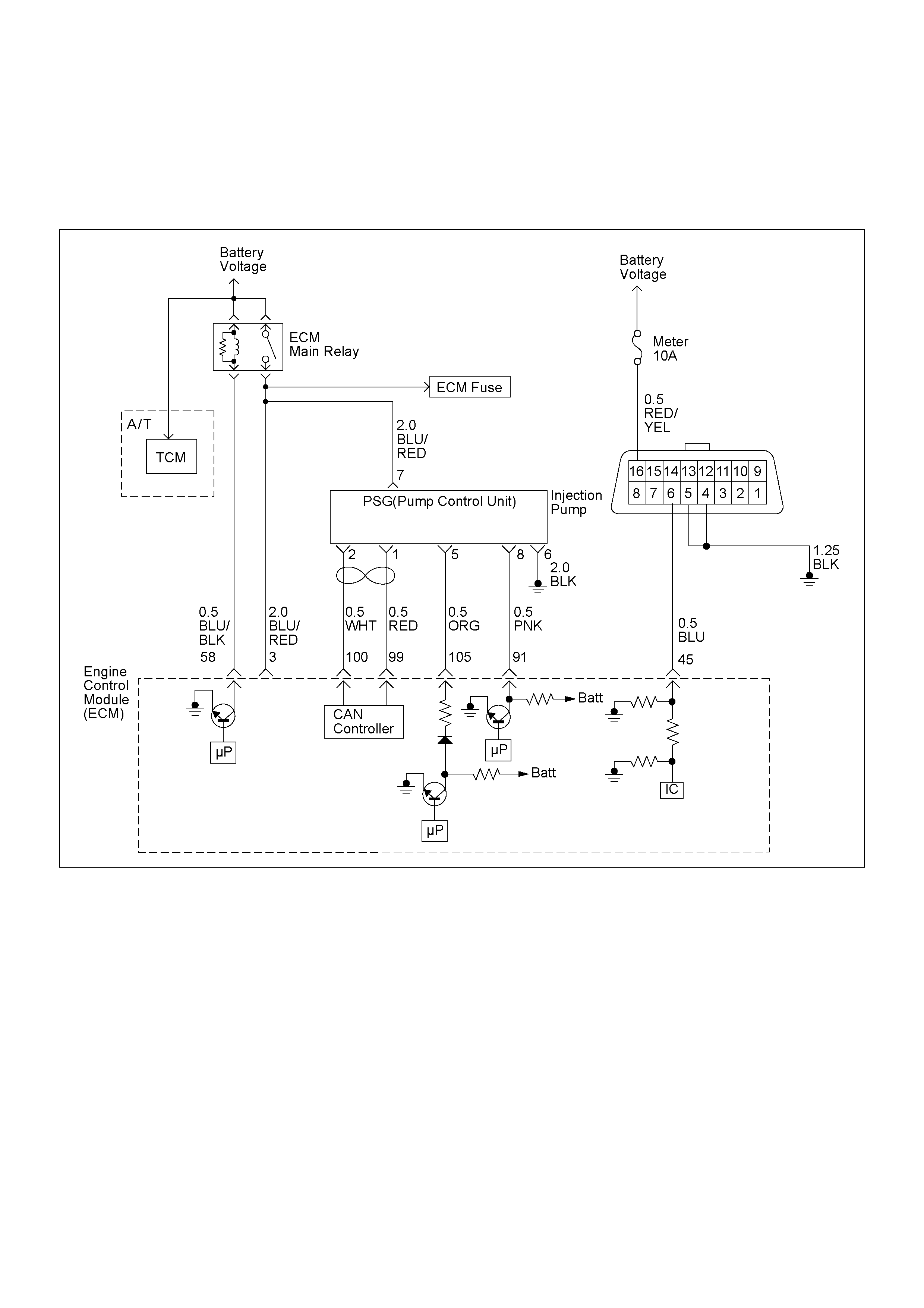
DIAGNOSTIC TROUBLE CODE (DTC) P16 30 (SYMPTOM CODE A)
(FLASH CODE 51) FUEL INJECTION QUANT ITY CIRCUIT MALFUNCTION
DIAGNOSTIC TROUBLE CODE (DTC) P16 30 (SYMPTOM CODE B)
(FLASH CODE 51) FUEL INJECTION QUANT ITY CIRCUIT MALFUNCTION

Condition for setting the DTC and action ta ken when the DTC sets
Circuit Description
The ECM calculates an injection quantity and injection
timing us ing the va riou s sensors . The PS G controls the
high pressure solenoid valve depending on
programmed pump map data.
Diagnostic Aids
An intermittent may be caused by the following:
• Poor connections.
• Misrouted harness.
• Rubbed through wire insulation.
• Broken wire inside the insulation.
Check for the following conditions:
• Poor connection at ECM and PSG-Inspect harness
connectors for backed out terminals, improper
mating, broken locks, improperly formed or damaged
terminals, and poor terminal to wire connection.
Flash
Code Code Symptom
Code MIL DTC Name DTC Setting Condition Fail-Safe (Back Up)
51 P1630 A ON Fuel Injection Quantity Circuit
Malfunction The PSG (pump control unit)
detects high pressure
solenoid valve control circuit
malfunction due to high
current.
Fuel injection quantity is
reduced.
B ON Fuel Injection Quantity Circuit
Malfunction The PSG (pump control unit)
detects high pressure
solenoid valve control circuit
malfunction due to continuous
current.
1. MAB (fuel cutoff solenoid
valve) is operated.
2. Desired injection quantity
becomes 0mg/strk.

Diagnostic Trouble Code (DTC) P1630 (Symptom Code A) (Flash Code 51) Fuel
Injection Quantity Circuit Malfunction
Diagnostic Trouble Code (DTC) P1630 (Symptom Code B) (Flash Code 51) Fuel
Injection Quantity Circuit Malfunction
Step Action Value(s) Yes No
1 Was the “On-Board Diagnostic (OBD) System Check”
performed?
—Go to
Step 2
Go to On Board
Diagnostic
(OBD) System
Check
2 1. Connect the Tech 2.
2. Review and record the failure information.
3. Select “F0: Rea d DTC Infor As Stored By E CU” in
“F0: Diagnostic Trouble Codes”.
Is the DTC P1630 (Symptom Code A) or P1630
(symptom Code B) stored as “Present Failure”? — Go to Step 3
Refer to
Diagnostic Aids
and Go to Step
3
3 1. Using the Tech 2, ignition “On” and engine “Off”.
2. Select “F1: Clear DTC Information” in “F0:
Diagnostic Trouble Codes” with the Tech 2 and
clear the DTC information.
3. Operate the vehicle and monitor the “F0: Read
DTC Infor As Stored By ECU” in the “F0:
Diagnostic Trouble Codes”.
Was the DTC P1630 (Symptom Code A) or P1630
(symptom Code B) stored in this ignition cycle? — Go to Step 4 Refer to
Diagnostic Aids
4 Replace the injection pump assembly.
Is the action complete? — Verify repair —

DIAGNOSTIC TROUBLE CODE (DTC) P16 50 (SYMPTOM CODE A)
(FLASH CODE 44) CAN DEVICE OFFLINE
DIAGNOSTIC TROUBLE CODE (DTC) P16 50 (SYMPTOM CODE B)
(FLASH CODE 44) CAN DEVICE HANG-UP

Condition for setting the DTC and action ta ken when the DTC sets
Circuit Description
The interchange of data between the engine control
module (ECM) and the pump control unit (PSG) is
performed via a CAN-bus system. The individual CAN-
bus systems are connected via two interfaces and can
exchange information and data. This allows control
modules that are connected to different CAN-bus
syste ms to communicate.
Diagnostic Aids
An intermittent may be caused by the following:
• Poor connections.
• Misrouted harness.
• Rubbed through wire insulation.
• Broken wire inside the insulation.
Check for the following conditions:
• Poor connection at ECM and PSG-Inspect harness
connectors for backed out terminals, improper
mating, broken locks, improperly formed or damaged
terminals, and poor terminal to wire connection.
• Damaged harness-Inspect the wiring harness for
damage. If the harness appears to be OK, observe
the DTC P1650 display on the Tech2 while moving
connectors and wiring harnesses.
Flash
Code Code Symptom
Code MIL DTC Name DTC Setting Condition Fail-Safe (Back Up)
44 P1650 A ON CAN Device Offline CAN controller detects Bus-
off or canceling. MAB (fuel cutoff solenoid
valve) is operated.
B ON CAN Device Hang-up CAN controller does not react
under engine running.
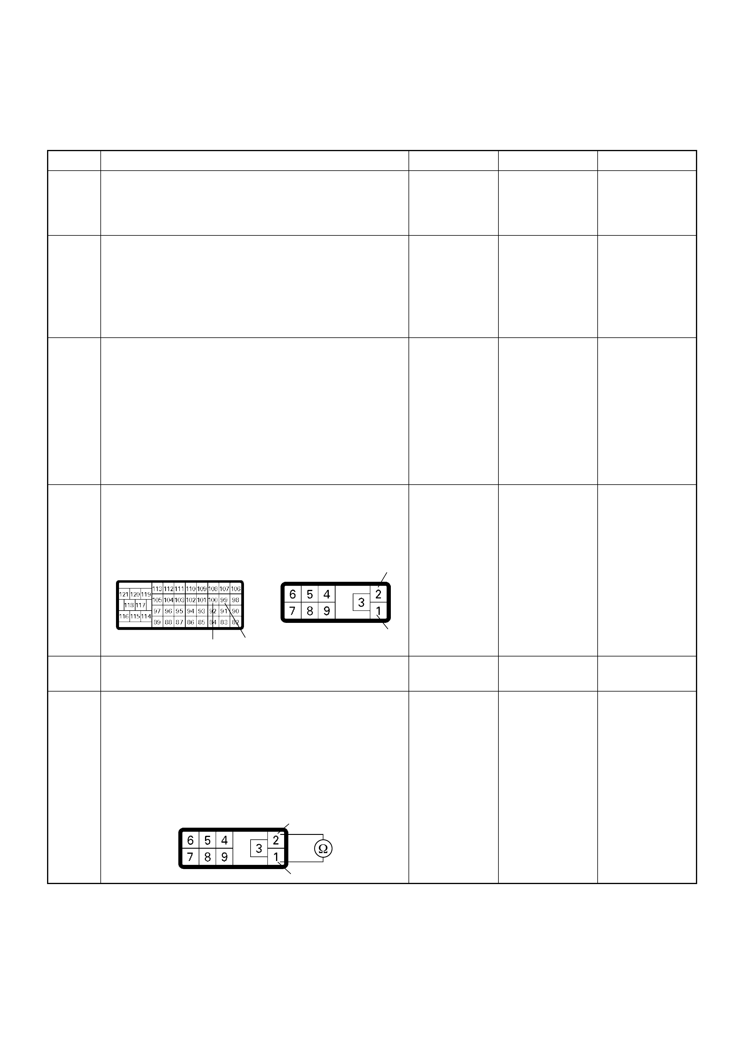
Diagnostic Trouble Code (DTC) P1650 (Symptom Code A) (Flash Code 44)
CAN Device Offline
Step Action Value(s) Yes No
1 Was the “On-Board Diagnostic (OBD) System Check”
performed?
—Go to
Step 2
Go to On Board
Diagnostic
(OBD) System
Check
2 1. Connect the Tech 2.
2. Review and record the failure information.
3. Select “F0: Rea d DTC Infor As Stored By E CU” in
“F0: Diagnostic Trouble Codes”.
Is the DTC P1650 (Symptom Code A) stored as
“Pres ent Fa ilure”? — Go to Step 3
Refer to
Diagnostic Aids
and Go to Step
3
3 1. Using the Tech 2, ignition “On” and engine “Off”.
2. Select “F1: Clear DTC Information” in “F0:
Diagnostic Trouble Codes” with the Tech 2 and
clear the DTC information.
3. Operate the vehicle and monitor the “F0: Read
DTC Infor As Stored By ECU” in the “F0:
Diagnostic Trouble Codes”.
Was the DTC P1650 (Symptom Code A) stored in this
ignition cycle? — Go to Step 4
Refer to
Diagnostic Aids
and Go to Step
4
4 Check for poor/faulty connection at the ECM or PSG
(pump control unit) connector. If a poor/faulty
connection is found, repair as necessary.
Was the problem found?
— Verify repair Go to Step 5
5 Visual ly chec k the PS G (p ump contr ol un it).
Was the problem found? — Go to Step 18 Go to Step 6
6 Using the DVM and check the CAN high circuit.
1. Ignition “Off”, engine “Off”.
2. Disconnect the ECM connector and PSG (pump
control unit) connector.
3. Check the circuit for short to CAN low circuit.
Was the DVM indicated specified value?
No continuity Go to Step 7
Repair faulty
harness and
verify repair
100 99 1
2
C-57 E-6
2
1
E-6

7 Using the DVM and check the CAN high circuit.
Breaker box is available:
1. Ignition “Off”, engine “Off”.
2. Install the breaker box as type A. (ECM
disconnected) Ref. to HOW TO USE BREAKER
BOX
3. Disconnect the PSG (pump control unit)
connector.
4. Check the circuit for open or short to ground
circuit.
Was the problem found?
Breaker box is not available:
1. Ignition “Off”, engine “Off”.
2. Disconnect the PSG (pump control unit)
connector.
3. Check the circuit for open or short to ground
circuit.
Was the problem found?
—
Repair faulty
harn es s and
verify repair Go to Step 8
Step Action Value(s) Yes No
E-6
100
Breaker Bo x 2
Ħ
Ħ
100 2
C-57 E-6
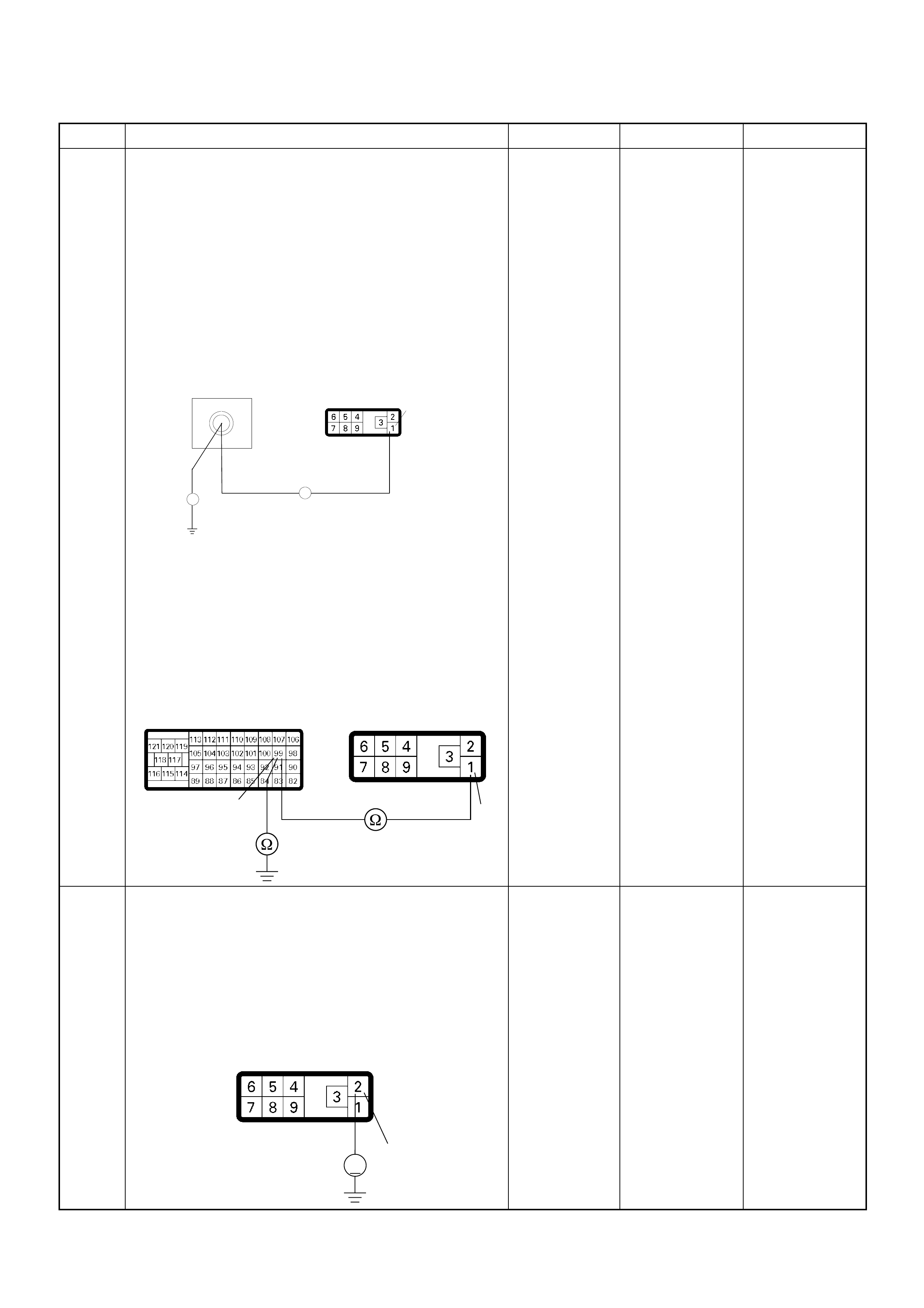
8 Using the DVM and check the CAN low circuit.
Breaker box is available:
1. Ignition “Off”, engine “Off”.
2. Install the breaker box as type A. (ECM
disconnected) Ref. to HOW TO USE BREAKER
BOX
3. Disconnect the PSG (pump control unit)
connector.
4. Check the circuit for open or short to ground
circuit.
Was the problem found?
Breaker box is not available:
1. Ignition “Off”, engine “Off”.
2. Disconnect the PSG (pump control unit)
connector.
3. Check the circuit for open or short to ground
circuit.
Was the problem found?
—
Repair faulty
harn es s and
verify repair Go to Step 9
9 Using the DVM and check the CAN high circuit.
1. Ignition “On”, engine “Off”.
2. Disconnect the PSG (pump control unit)
connector.
3. Check the circuit for short to power supply circuit.
Was the DVM indicated battery voltage or
approximately 5V?
—Go to Step 10 Go to Step 11
Step Action Value(s) Yes No
E-6
99
Breaker Box
1
Ħ
Ħ
99 1
C-57 E-6
2
V
E-6
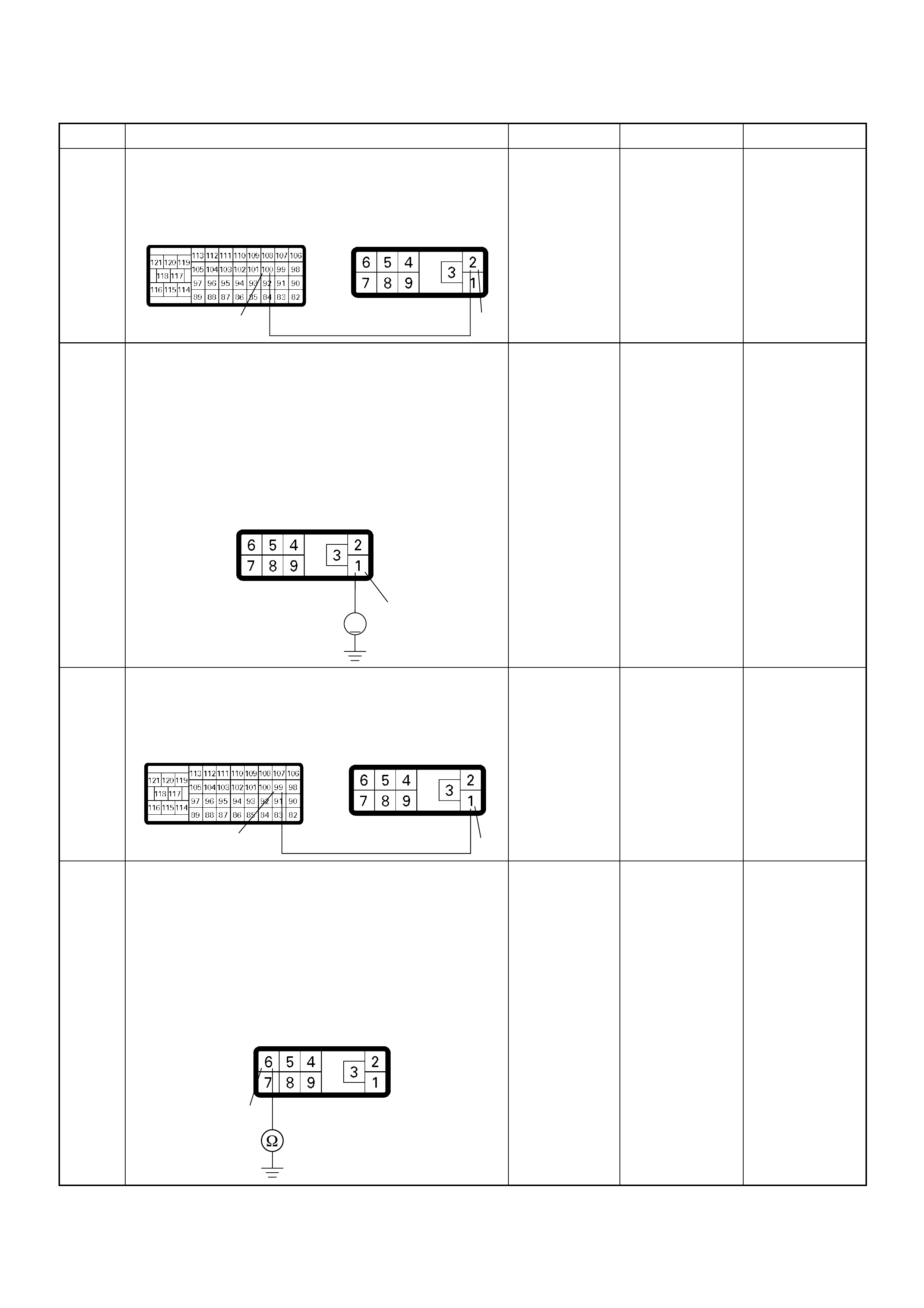
10 Repair the short to voltage circuit between the ECM
and PSG (pump control unit).
Is the action complete?
— Verify repair —
11 Using the DVM and check the CAN low circuit.
1. Ignition “On”, engine “Off”.
2. Disconnect the PSG (pump control unit)
connector.
3. Check the circuit for short to power supply circuit.
Was the DVM indicated battery voltage or
approximately 5V?
—Go to Step 12 Go to Step 13
12 Repair the short to voltage circuit between the ECM
and PSG (pump control unit).
Is the action complete?
— Verify repair —
13 Using the DVM and check the PSG (pump control
unit) ground circuit.
1. Ignition “Off”, engine “Off”.
2. Disconnect the PSG (pump control unit)
connector.
3. Check the circuit for open circuit.
Was the problem found?
—
Repair faulty
harn es s and
verify repair Go to Step 14
Step Action Value(s) Yes No
100 2
C-57 E-6
1
V
E-6
99 1
C-57 E-6
6
E-6

14 Check any accessory parts which may cause electric
interference.
Was the problem found? —
Remove the
accessory parts
and verify repair Go to Step 15
15 Is the ECM programmed with the latest software
release?
If not, download the latest software to the ECM using
the “SPS (Service Programming System)”.
Was the problem solved? — Verify repair Go to Step 16
16 Substitute a known good ECM and recheck.
Was the problem solved?
IMPORTANT: The replacement ECM must be
programmed. Refer to section of the Service
Programming System (SPS) in this manual.
Foll owing ECM pr ogramming, the immobi lizer sys tem
(if equipped) must be linked to the ECM. Refer to
section 11 “Immobilizer System-ECM replacement” for
the ECM/Immobilizer linking procedure. —Go to Step 17 Go to Step 18
17 Replace the ECM.
Is the action complete?
IMPORTANT: The replacement ECM must be
programmed. Refer to section of the Service
Programming System (SPS) in this manual.
Foll owing ECM pr ogramming, the immobi lizer sys tem
(if equipped) must be linked to the ECM. Refer to
section 11 “Immobilizer System-ECM replacement” for
the ECM/Immobilizer linking procedure. — Verify repair —
18 Replace the injection pump assembly.
Is the action complete? — Verify repair —
Step Action Value(s) Yes No

Diagnostic Trouble Code (DTC) P1650 (Symptom Code B) (Flash Code 44)
CAN Device Hang-up
Step Action Value(s) Yes No
1 Was the “On-Board Diagnostic (OBD) System Check”
performed?
—Go to
Step 2
Go to On Board
Diagnostic
(OBD) System
Check
2 1. Connect the Tech 2.
2. Review and record the failure information.
3. Select “F0: Read DTC Infor As Stored By ECU” in
“F0: Diagnostic Trouble Codes”.
Is the DTC P1650 (Symptom Code B) stored as
“Present Failure”? — Go to Step 3
Refer to
Diagnostic Aids
and Go to Step
3
3 1. Using the Tech 2, ignition “On” and engine “Off”.
2. Select “F1: Clear DTC Information” in “F0:
Diagnostic Trouble Codes” with the Tech 2 and
clear the DTC information.
3. Operate the vehicle and monitor the “F0: Read
DTC Infor As Stored By ECU” in the “F0:
Diagnostic Trouble Codes”.
Was the DTC P1650 (Symptom Code B) stored in this
ignition cycle? — Go to Step 4 Refer to
Diagnostic Aids
4 Is the ECM programmed with the latest software
release?
If not, download the latest software to the ECM using
the “SPS (Service Programming System)”.
Was the problem solved? — Verify repair Go to Step 5
5 Substitute a known good ECM and recheck.
Was the problem solved?
IMPORTANT: The replacement ECM must be
programmed. Refer to section of the Service
Programming System (SPS) in this manual.
Following ECM programming, the immobilizer system
(if equipped) must be linked to the ECM. Refer to
section 11 “Immobilizer System-ECM replacement” for
the ECM/Immobilizer linking procedure. —Go to Step 6 Go to Step 7
6 Replace the ECM.
Is the action complete?
IMPORTANT: The replacement ECM must be
programmed. Refer to section of the Service
Programming System (SPS) in this manual.
Foll owing ECM pr ogramming, the immobi lizer sys tem
(if equipped) must be linked to the ECM. Refer to
section 11 “Immobilizer System-ECM replacement” for
the ECM/Immobilizer linking procedure. — Verify repair —
7 Replace the injection pump assembly.
Is the action complete? — Verify repair —

DIAGNOSTIC TROUBLE CODE (DTC) P16 51 (SYMPTOM CODE A)
(FLASH CODE 45) CAN MALFUNCTION
DIAGNOSTIC TROUBLE CODE (DTC) P16 51 (SYMPTOM CODE B)
(FLASH CODE 45) CAN RECEIVES ERROR

Condition for setting the DTC and action ta ken when the DTC sets
Circuit Description
The interchange of data between the engine control
module (ECM) and the pump control unit (PSG) is
performed via a CAN-bus system. The individual CAN-
bus systems are connected via two interfaces and can
exchange information and data. This allows control
modules that are connected to different CAN-bus
syste ms to communicate.
Diagnostic Aids
An intermittent may be caused by the following:
• Poor connections.
• Misrouted harness.
• Rubbed through wire insulation.
• Broken wire inside the insulation.
Check for the following conditions:
• Poor connection at ECM and PSG-Inspect harness
connectors for backed out terminals, improper
mating, broken locks, improperly formed or damaged
terminals, and poor terminal to wire connection.
• Damaged harness-Inspect the wiring harness for
damage. If the harness appears to be OK, observe
the DTC P1651 display on the Tech2 while moving
connectors and wiring harnesses.
Flash
Code Code Symptom
Code MIL DTC Name DTC Setting Condition Fail-Safe (Back Up)
45 P1651 A ON CAN Malfunction The PSG (pump control unit)
does not recognize CAN
signal from the CAN
controller.
1. MAB (fuel cutoff solenoid
valve) is operated.
2. Desired injection quantity
becomes 0mg/strk.
B ON CAN Malfunction The ECM does not read CAN
signal from the PSG (pump
control unit).

Diagnostic Trouble Code (DTC) P1651 (Symptom Code A) (Flash Code 45)
CAN Malfunction
Step Action Value(s) Yes No
1 Was the “On-Board Diagnostic (OBD) System Check”
performed?
—Go to
Step 2
Go to On Board
Diagnostic
(OBD) System
Check
2 1. Connect the Tech 2.
2. Review and record the failure information.
3. Select “F0: Read DTC Infor As Stored By ECU” in
“F0: Diagnostic Trouble Codes”.
Is the DTC P1651 (Symptom Code A) stored as
“Present Failure”? — Go to Step 3
Refer to
Diagnostic Aids
and Go to Step
3
3 1. Using the Tech 2, ignition “On” and engine “Off”.
2. Select “F1: Clear DTC Information” in “F0:
Diagnostic Trouble Codes” with the Tech 2 and
clear the DTC information.
3. Operate the vehicle and monitor the “F0: Read
DTC Infor As Stored By ECU” in the “F0:
Diagnostic Trouble Codes”.
Was the DTC P1651 (Symptom Code A) stored in this
ignition cycle? — Go to Step 4 Refer to
Diagnostic Aids
4 Is the ECM programmed with the latest software
release?
If not, download the latest software to the ECM using
the “SPS (Service Programming System)”.
Was the problem solved? — Verify repair Go to Step 5
5 Substitute a known good ECM and recheck.
Was the problem solved?
IMPORTANT: The replacement ECM must be
programmed. Refer to section of the Service
Programming System (SPS) in this manual.
Following ECM programming, the immobilizer system
(if equipped) must be linked to the ECM. Refer to
section 11 “Immobilizer System-ECM replacement” for
the ECM/Immobilizer linking procedure. —Go to Step 6 Go to Step 7
6 Replace the ECM.
Is the action complete?
IMPORTANT: The replacement ECM must be
programmed. Refer to section of the Service
Programming System (SPS) in this manual.
Foll owing ECM pr ogramming, the immobi lizer sys tem
(if equipped) must be linked to the ECM. Refer to
section 11 “Immobilizer System-ECM replacement” for
the ECM/Immobilizer linking procedure. — Verify repair —
7 Replace the injection pump assembly.
Is the action complete? — Verify repair —
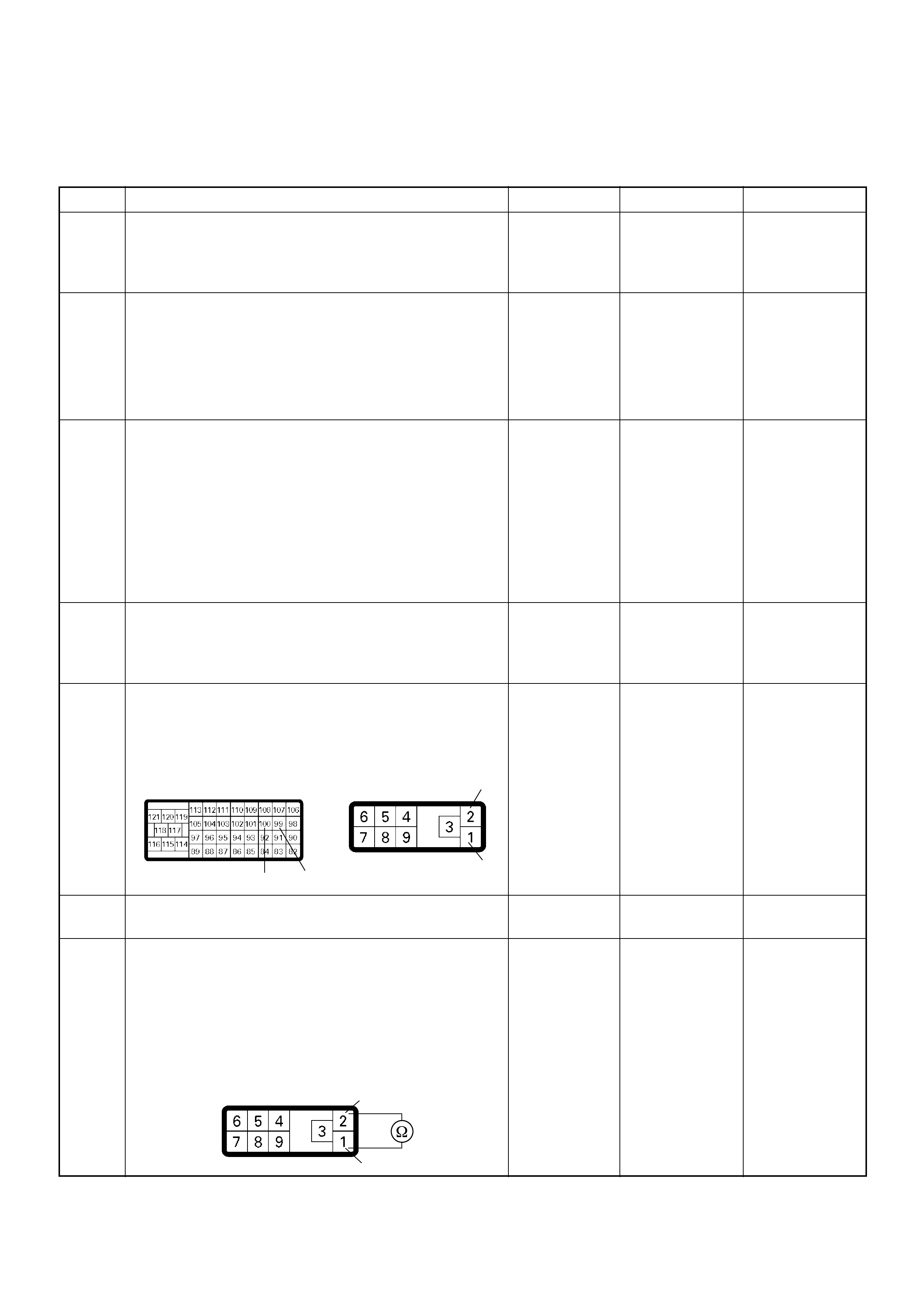
Diagnostic Trouble Code (DTC) P1651 (Symptom Code B) (Flash Code 45)
CAN Receives Error
Step Action Value(s) Yes No
1 Was the “On-Board Diagnostic (OBD) System Check”
performed?
—Go to
Step 2
Go to On Board
Diagnostic
(OBD) System
Check
2 1. Connect the Tech 2.
2. Review and record the failure information.
3. Select “F0: Rea d DTC Infor As Stored By E CU” in
“F0: Diagnostic Trouble Codes”.
Is the DTC P1651 (Symptom Code B) stored as
“Pres ent Fa ilure”? — Go to Step 3
Refer to
Diagnostic Aids
and Go to Step
3
3 1. Using the Tech 2, ignition “On” and engine “Off”.
2. Select “F1: Clear DTC Information” in “F0:
Diagnostic Trouble Codes” with the Tech 2 and
clear the DTC information.
3. Operate the vehicle and monitor the “F0: Read
DTC Infor As Stored By ECU” in the “F0:
Diagnostic Trouble Codes”.
Was the DTC P1651 (Symptom Code B) stored in this
ignition cycle? — Go to Step 4
Refer to
Diagnostic Aids
and Go to Step
4
4 Was the DTC P1 650 (Sympt om Code A ) sto re d a t th e
same time?
—
Go to DTC
Chart P1650
(Symptom
Code A) Go to Step 5
5 Check for poor/faulty connection at the ECM or PSG
(pump control unit) connector. If a poor/faulty
connection is found, repair as necessary.
Was the problem found?
— Verify repair Go to Step 6
6 Visual ly chec k the PS G (p ump contr ol un it).
Was the problem found? — Go to Step 19 Go to Step 7
7 Using the DVM and check the CAN high circuit.
1. Ignition “Off”, engine “Off”.
2. Disconnect the ECM connector and PSG (pump
control unit) connector.
3. Check the circuit for short to CAN low circuit.
Was the DVM indicated specified value?
No continuity Go to Step 8
Repair faulty
harness and
verify repair
100 99 1
2
C-57 E-6
2
1
E-6
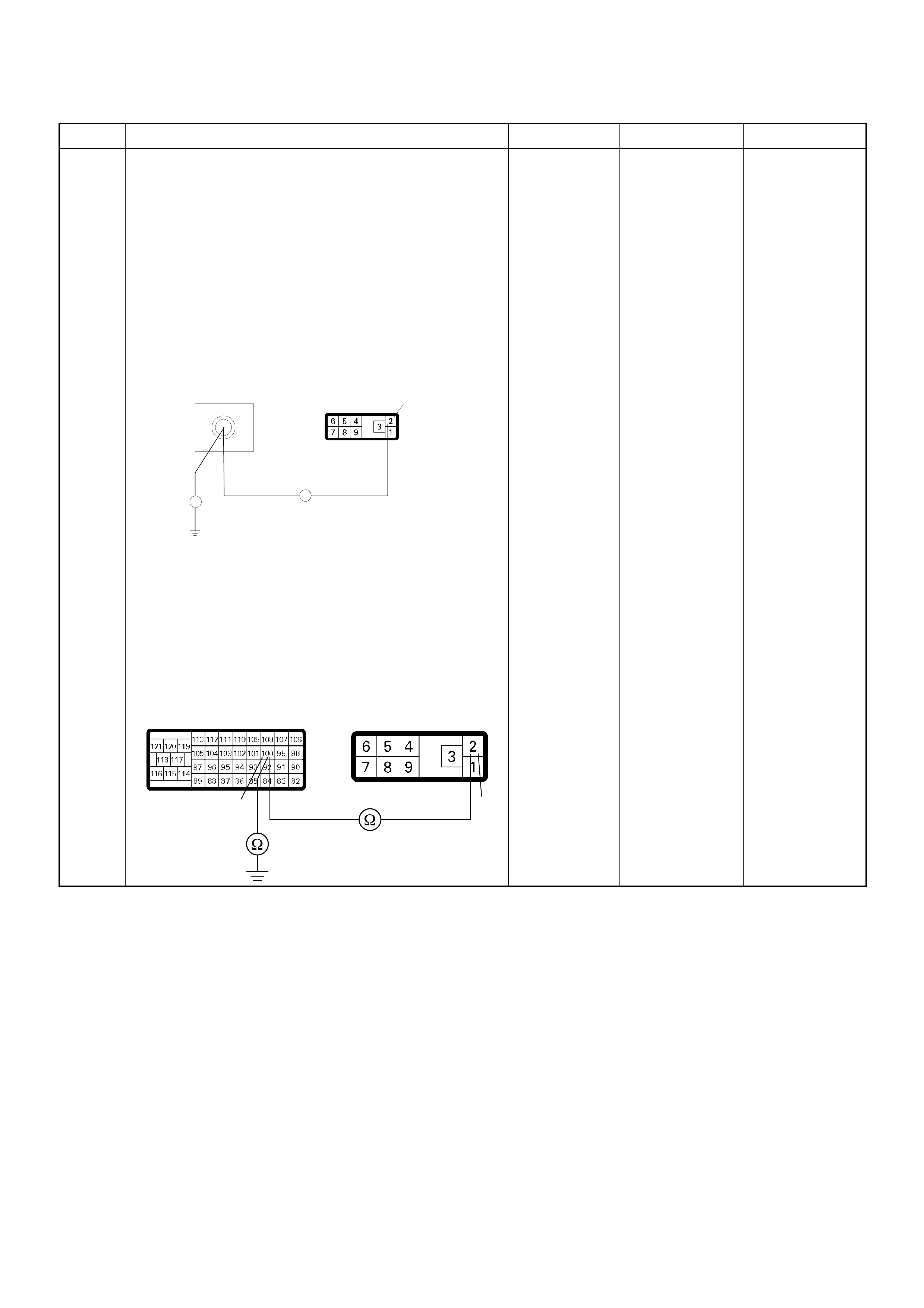
8 Using the DVM and check the CAN high circuit.
Breaker box is available:
1. Ignition “Off”, engine “Off”.
2. Install the breaker box as type A. (ECM
disconnected) Ref. to HOW TO USE BREAKER
BOX
3. Disconnect the PSG (pump control unit)
connector.
4. Check the circuit for open or short to ground
circuit.
Was the problem found?
Breaker box is not available:
1. Ignition “Off”, engine “Off”.
2. Disconnect the PSG (pump control unit)
connector.
3. Check the circuit for open or short to ground
circuit.
Was the problem found?
—
Repair faulty
harn es s and
verify repair Go to Step 9
Step Action Value(s) Yes No
E-6
100
Breaker Box 2
Ħ
Ħ
100 2
C-57 E-6
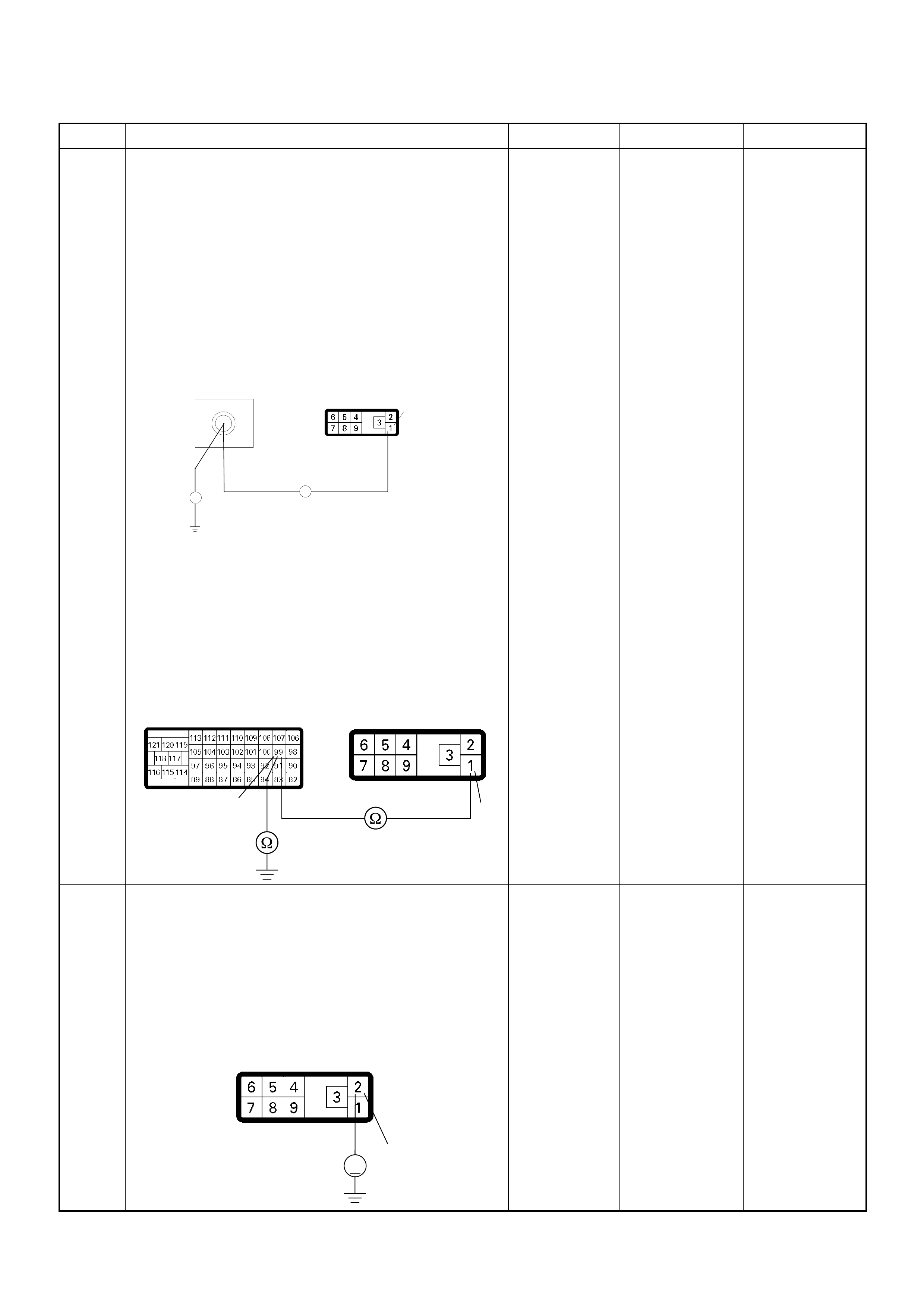
9 Using the DVM and check the CAN low circuit.
Breaker box is available:
1. Ignition “Off”, engine “Off”.
2. Install the breaker box as type A. (ECM
disconnected) Ref. to HOW TO USE BREAKER
BOX
3. Disconnect the PSG (pump control unit)
connector.
4. Check the circuit for open or short to ground
circuit.
Was the problem found?
Breaker box is not available:
1. Ignition “Off”, engine “Off”.
2. Disconnect the PSG (pump control unit)
connector.
3. Check the circuit for open or short to ground
circuit.
Was the problem found?
—
Repair faulty
harn es s and
verify repair Go to Step 10
10 Using the DVM and check the CAN high circuit.
1. Ignition “On”, engine “Off”.
2. Disconnect the PSG (pump control unit)
connector.
3. Check the circuit for short to power supply circuit.
Was the DVM indicated battery voltage or
approximately 5V?
— Go to Step 11 Go to Step 12
Step Action Value(s) Yes No
E-6
99
Breaker Box
1
Ħ
Ħ
99 1
C-57 E-6
2
V
E-6

11 Repair the short to voltage circuit between the ECM
and PSG (pump control unit).
Is the action complete?
— Verify repair —
12 Using the DVM and check the CAN low circuit.
1. Ignition “On”, engine “Off”.
2. Disconnect the PSG (pump control unit)
connector.
3. Check the circuit for short to power supply circuit.
Was the DVM indicated battery voltage or
approximately 5V?
—Go to Step 13 Go to Step 14
13 Repair the short to voltage circuit between the ECM
and PSG (pump control unit).
Is the action complete?
— Verify repair —
14 Using the DVM and check the PSG (pump control
unit) ground circuit.
1. Ignition “Off”, engine “Off”.
2. Disconnect the PSG (pump control unit)
connector.
3. Check the circuit for open circuit.
Was the problem found?
—
Repair faulty
harn es s and
verify repair Go to Step 15
Step Action Value(s) Yes No
100 2
C-57 E-6
1
V
E-6
99 1
C-57 E-6
6
E-6

15 Check any accessory parts which may cause electric
interference.
Was the problem found? —
Remove the
accessory parts
and verify repair Go to Step 16
16 Is the ECM programmed with the latest software
release?
If not, download the latest software to the ECM using
the “SPS (Service Programming System)”.
Was the problem solved? — Verify repair Go to Step 17
17 Substitute a known good ECM and recheck.
Was the problem solved?
IMPORTANT: The replacement ECM must be
programmed. Refer to section of the Service
Programming System (SPS) in this manual.
Foll owing ECM pr ogramming, the immobi lizer sys tem
(if equipped) must be linked to the ECM. Refer to
section 11 “Immobilizer System-ECM replacement” for
the ECM/Immobilizer linking procedure. —Go to Step 18 Go to Step 19
18 Replace the ECM.
Is the action complete?
IMPORTANT: The replacement ECM must be
programmed. Refer to section of the Service
Programming System (SPS) in this manual.
Foll owing ECM pr ogramming, the immobi lizer sys tem
(if equipped) must be linked to the ECM. Refer to
section 11 “Immobilizer System-ECM replacement” for
the ECM/Immobilizer linking procedure. — Verify repair —
19 Replace the injection pump assembly.
Is the action complete? — Verify repair —
Step Action Value(s) Yes No

DIAGNOSTIC TROUBLE CODE (DTC) P1690 (SYM PTOM CODE 4)
(FLASH CODE 77) CHECK ENGINE LAMP (MIL) CIRCUIT VOLTAGE LOW
DIAGNOSTIC TROUBLE CODE (DTC) P1690 (SYM PTOM CODE 8)
(FLASH CODE 77) CHECK ENGINE LAMP (MIL) CIRCUIT VOLTAGE HIGH

Condition for setting the DTC and action ta ken when the DTC sets
Circuit Description
The Check Engine Lamp (Malfunction Indicator Lamp
=MIL) should always be illuminated and steady with
ignition “On”. Ignition feed voltage is supplied to the
Check Engine Lamp bulb through the meter fuse. The
ECM turns the Check Engine Lamp “On” by grounding
the check engine lamp driver circuit for a certain time.
Diagnostic Aids
An intermittent may be caused by the following:
• Poor connections.
• Misrouted harness.
• Rubbed through wire insulation.
• Broken wire inside the insulation.
Check for the following conditions:
• Poor con nection at ECM -Inspect harnes s connector s
for backed out terminals, improper mating, broken
locks, improperly formed or damaged terminals, and
poor terminal to wire connection.
• Damaged harness-Inspect the wiring harness for
damage. If the harness appears to be OK, observe
the “Ch eck Engine La mp” disp lay on the Tec h2 while
moving connectors and wiring harnesses. A change
in the display will indicate the location of the fault.
Flash
Code Code Symptom
Code MIL DTC Name DTC Setting Condition Fail-Safe (Back Up)
77 P1690 4 OFF Check Engine Lamp (MIL)
Circuit Voltage Low Check engine lamp circuit
open or short to ground
circuit.
No fail-safe function.
8 OFF Check Engine Lamp (MIL)
Circuit Voltage High Check engine lamp circuit
short to ground circuit.

Diagnostic Trouble Code (DTC) P1690 (Symptom Code 4) (Flash Code 77)
Check Engine Lamp (MIL) Circuit Voltage Low
Step Action Value(s) Yes No
1 Was the “On-Board Diagnostic (OBD) System Check”
performed?
—Go to
Step 2
Go to On Board
Diagnostic
(OBD) System
Check
2 1. Connect the Tech 2.
2. Review and record the failure information.
3. Select “F0: Rea d DTC Infor As Stored By E CU” in
“F0: Diagnostic Trouble Codes”.
Is the DTC P1690 (Symptom Code 4) stored as
“Pres ent Fa ilure”? — Go to Step 3
Refer to
Diagnostic Aids
and Go to Step
3
3 1. Using the Tech 2, ignition “On” and engine “Off”.
2. Select “F1: Clear DTC Information” in “F0:
Diagnostic Trouble Codes” with the Tech 2 and
clear the DTC information.
3. Operate the vehicle and monitor the “F0: Read
DTC Infor As Stored By ECU” in the “F0:
Diagnostic Trouble Codes”.
Was the DTC P1690 ( Sy mpt om Code 4) s tor e d i n this
ignition cycle? — Go to Step 4
Refer to
Diagnostic Aids
and Go to Step
4
4 1. Ignitio n “On”, engine “Off”.
2. Check the “Check Engine” lamp.
Does the lamp turn “On”? — Go to Step 5 Go to Step 6
5 1. Ignitio n “On”, engine “Off”.
2. Check the “Check Engine” lamp.
Does the lamp turn “Off”? — Go to Step 9 Go to Step 7
6 Check the “C heck Engine” lamp bulb.
If the bulb is burnt out, repair as necessary.
Was the problem found? — V erify repair Go to Step 7
7 Check for poor/faulty connection at the meter
connector and ECM connector. If a poor/faulty
connection is found, repair as necessary.
Was the problem found?
— Verify repair Go to Step 8
42
17
C-56
B-24

8 Using the DVM and check the “Check Engine” lamp
circuit.
Breaker box is available:
1. Ignition “Off”, engine “Off”.
2. Install the breaker box as type A. (ECM
disconnected) Ref. to HOW TO USE BREAKER
BOX
3. Remove the meter connector.
4. Check the circuit for open or short to ground
circuit.
Was the problem found?
Breaker box is not available:
1. Ignition “Off”, engine “Off”.
2. Disconnect the ECM connector.
3. Remove the meter connector.
4. Check the circuit for open or short to ground
circuit.
Was the problem found?
—
Repair faulty
harn es s and
verify repair Go to Step 9
9 Is the ECM programmed with the latest software
release?
If not, download the late st software to the ECM using
the “SPS (Service Programming System)”.
Was the problem solved? — Verify repair Go to Step 10
Step Action Value(s) Yes No
42
Breaker Box B-24
17
Ħ
Ħ
42
17
C-56
B-24

10 Replace the ECM.
Is the action complete?
IMPORTANT: The replacement ECM must be
programmed. Refer to section of the Service
Programming System (SPS) in this manual.
Foll owing ECM pr ogramming, the immobi lizer sys tem
(if equipped) must be linked to the ECM. Refer to
section 11 “Immobilizer System-ECM replacement” for
the ECM/Immobilizer linking procedure. — Verify repair —
Step Action Value(s) Yes No

Diagnostic Trouble Code (DTC) P1690 (Symptom Code 8) (Flash Code 77)
Check Engine Lamp (MIL) Circuit Voltage High
Step Action Value(s) Yes No
1 Was the “On-Board Diagnostic (OBD) System Check”
performed?
—Go to
Step 2
Go to On Board
Diagnostic
(OBD) System
Check
2 1. Connect the Tech 2.
2. Review and record the failure information.
3. Select “F0: Read DTC Infor As Stored By ECU” in
“F0: Diagnostic Trouble Codes”.
Is the DTC P1690 (Symptom Code 8) stored as
“Present Failure”? — Go to Step 3
Refer to
Diagnostic Aids
and Go to Step
3
3 1. Using the Tech 2, ignition “On” and engine “Off”.
2. Select “F1: Clear DTC Information” in “F0:
Diagnostic Trouble Codes” with the Tech 2 and
clear the DTC information.
3. Operate the vehicle and monitor the “F0: Read
DTC Infor As Stored By ECU” in the “F0:
Diagnostic Trouble Codes”.
Was the DTC P1690 (Symptom Code 8) stored in this
ignition cycle? — Go to Step 4 Refer to
Diagnostic Aids
4 Is the ECM programmed with the latest software
release?
If not, download the latest software to the ECM using
the “SPS (Service Programming System)”.
Was the problem solved? — Verify repair Go to Step 5
5 Substitute a known good ECM and recheck.
Was the problem solved?
IMPORTANT: The replacement ECM must be
programmed. Refer to section of the Service
Programming System (SPS) in this manual.
Following ECM programming, the immobilizer system
(if equipped) must be linked to the ECM. Refer to
section 11 “Immobilizer System-ECM replacement” for
the ECM/Immobilizer linking procedure. —Go to Step 6 —
6 Replace the ECM.
Is the action complete?
IMPORTANT: The replacement ECM must be
programmed. Refer to section of the Service
Programming System (SPS) in this manual.
Foll owing ECM pr ogramming, the immobi lizer sys tem
(if equipped) must be linked to the ECM. Refer to
section 11 “Immobilizer System-ECM replacement” for
the ECM/Immobilizer linking procedure. — Verify repair —


SYMPTOM DIAGNOSIS
PRELIMINARY CHECKS
Before using this section, perform the “On-Board
Diagnostic (OBD) System Check” and verify all of the
following items:
• The engine control module (ECM) is operating
correctly.
• The check engine lamp, also known as the
malfunction indicator lamp (MIL), is operating
correctly.
• There are no Diagnostic Trouble Code(s) stored.
• Tech 2 data is within normal operating range. Refer
to Typical Scan Data Values.
• Verify the customer complaint and locate the correct
symptom in the table of contents. Perform the
procedure included in the symptom chart.
VISUAL/PHYSICAL CHECK
Several of the symptom procedures call for a careful
visual/physical check. This can lead to correcting a
problem without further checks and can save valuable
time. This check should include the following items:
• ECM grounds for cleanliness, tightness and proper
location.
• Vacuum hoses for splits, kinks, and proper
connection. Check thoroughly for any type of leak or
restriction.
• Air intake ducts for collapsed or damaged areas.
• Air leaks at throttle body mounting area, mass air flow
(MAF) sensor and intake manifold sealing surfaces.
• Wiring for proper connections, pinches and cuts.
INTERMITTENT
Important: An intermittent problem may or may not turn
on the check engine lamp (MIL) or store a Diagnostic
Trouble Code. Do NOT use the Diagnostic Trouble
Code (DTC) charts for intermittent problems.
The fault must be present to locate the problem.
Most intermittent problems are cased by faulty electrical
connections or wiring. Perform a careful visual/physical
check for the following conditions.
• Poor mating of the connector halves or a terminal not
fully seated in the connector (backed out).
• Improperly formed or damaged terminal.
• All connector terminals in the problem circuit should
be carefully checked for proper contact tension.
• Poor terminal-to-wire connection. This requires
removing the terminal form the connector body to
check.
• Check engine lamp (MIL) wire to ECM shorted to
ground.
• Poor ECM grounds. Refer to the ECM wiring
diagrams.
Road test the vehicle with a Digital Multimeter
connected to a suspected circuit. An abnormal voltage
when the malfunction occurs is a good indication that
there is a fault in the circuit being monitored.
Using Tech 2 to help detect intermittent conditions. The
Tech 2 have several features that can be used to
located an intermittent condition. Use the following
features to find intermittent faults:
To check for loss of diagnostic code memory,
disconnect the MAF sensor and idle the engine until the
check engine lamp (MIL) comes on. Diagnostic Trouble
Code P0100 should be stored and kept in memory
when the ignition is turned OFF.
If not, the ECM is faulty. When this test is completed,
make sure that you reconnect the MAF sensor, and
clear the Diagnostic Trouble Code P0100 from memory.
An intermittent check engine lamp (MIL) fault with no
stored Diagnostic Trouble Code may be caused by the
following:
• Check engine lamp (MIL) wire to ECM short to
ground.
• Poor ECM grounds. Refer to the ECM wiring
diagrams.
Check for improper installation of electrical options such
as light, cellular phones, etc. Check all wires from ECM
to the pump control unit (PSG) for poor connections.
Check for an open diode across the A/C compressor
clutch and check for other open diodes (refer to wiring
diagrams in Electrical Diagnosis).
If problem has not been found, refer to ECM connector
symptom tables.
• Check the “Broadcast Code” of the ECM, and
compare it with the latest Holden service bulletins
and/or Holden EEPROM reprogramming equipment
to determine if an update to the ECM's
reprogrammable memory has been released.
This identifies the contents of the reprogrammable
software and calibration contained in the ECM.
If the “Broadcast Code” is not the most current
available, it is advisable to reprogram the ECM's
EEPROM memory, which may either help identify a
hard-to find problem or may fix the problem.
The Service Programming System (SPS) will not allow
incorrect software programming or incorrect calibration
changes.
Techline
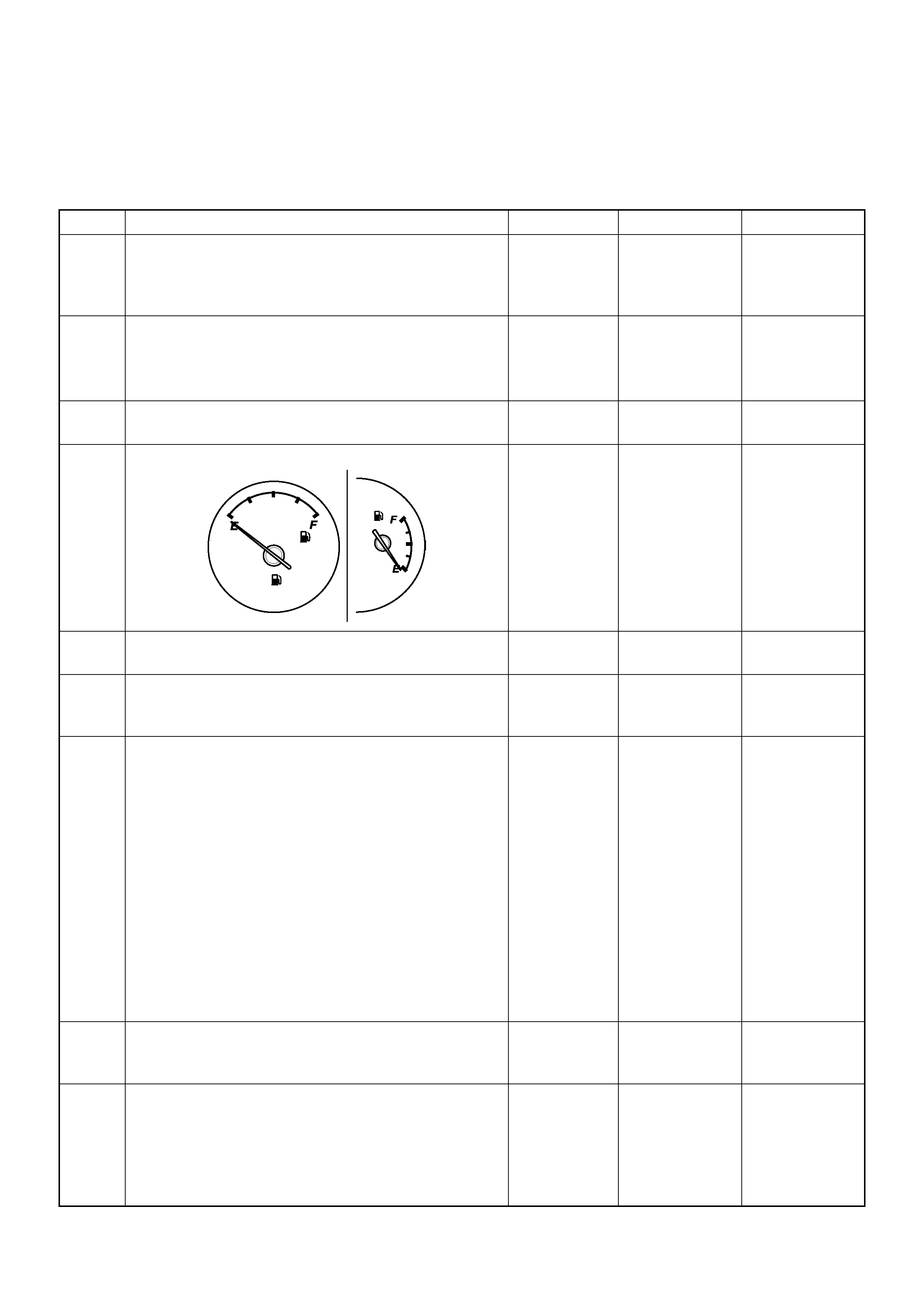
ENGINE CRANKS BUT WILL NOT RUN
DEFINITIONS: Engine cranks, but will not run. (The engine never start.)
NOTE: The vehicle with immobilizer system, this system may be activated. Check the immobilizer system diagnosis.
Step Action Value(s) Yes No
1 Was the “On-Board Diagnostic (OBD) System Check”
performed?
—Go to Step 2
Go to On Board
Diagnostic
(OBD) System
Check
2 1. Perform a bulletin search.
2. If a bulletin that addresses the symptom is found ,
correct the condition as instructed in the bulletin.
Was a bulletin found that addresses the symptom? — Verify repair Go to Step 3
3 Was a visually/physical check performed? —Go to Step 4 Go to Visual /
physical Check
4 Is the fuel amount enough?
—Go to Step 5 Add fuel to the
tank
5 Is the customer using the incorrect fuel type? Diesel fuel
only Replace with
diesel fuel Go to Step 6
6 Check the “ECM” fuse (10A) and “Engine” fuse (15A).
If the fuse is burnt out, repair as necessary.
W as the problem found? — Verify repair Go to Step 7
7 Visually/physically inspect for the following conditions.
• Restricted air intake system. Check for a restricted
air filter element, o r foreign ob jects blocking th e air
intake sy stem
• Che ck f or o bjects block ing or e xces sive d epo sits i n
the throttle bore and on the throttle plate
• Check for a condition that causes a large vacuum
leak, such as an incorrectly installed or faulty
crankc as e ven til ati on hose.
• Restricted air intake system at the turbocharger.
Check for objects blocking the turbocharger
compressor wheel or turbine shaft sticking.
If a problem is found, repair as necessary.
W as a problem found? — Verify repair Go to Step 8
8 Check the ECM & PSG grounds to verify that they are
clean and tight. Refer to the ECM wiring diagrams.
W as a problem found? — Verify repair Go to Step 9
9 1. Using the Tech 2, ignition “On” and engine “Off”.
2. Monitor the “Neutral Switch” in the data display.
Does the Tech 2 indicate correct “Neutral Switch”
status depending on any shift positions?
If a problem is found, repair as necessary.
W as the problem found? — Verify repair Go to Step 10

10 Remove the CKP sensor from the flywheel housing
and check for the following conditions.
• Objects sticking the CKP sensor.
• Objects sticking the CKP sensor pulser.
If a problem is found, repair as necessary.
W as the problem found? — Verify repair Go to Step 11
11 Check the CKP sensor harness for the following
conditions.
• Check for poor connector connection.
• Check for misrouted harness.
• Check for any accessory parts which may cause
electric interference.
If a problem is found, repair as necessary.
W as a problem found? — Verify repair Go to Step 12
12 Substitute a known good CKP sensor and recheck.
Was the problem solved? — Go to Step 13 Go to Step 14
13 Replace the CKP sensor.
Is the action complete? — Verify repair —
14 Check the exhaust system for a possible restriction.
• Damaged or collapsed pipes or catalytic converter.
• Internal muffler failur e.
If a problem is found, repair as necessary.
W as a problem found? — Verify repair Go to Step 16
15 Visually/physically inspect for the following conditions.
• Restric ted fuel supply s ystem. Che ck for a pinche d
fuel hose/pipe.
• Check for a condition that causes fuel waxing or
icing, such as the customer is using an incorrect
fuel type in winter season or water mixed with the
fuel.
If a problem is found, repair as necessary.
W as a problem found? — Verify repair Go to Step 17
16 Replace the fuel filter.
W as the problem solved? — Verify repair Go to Step 18
Step Action Value(s) Yes No
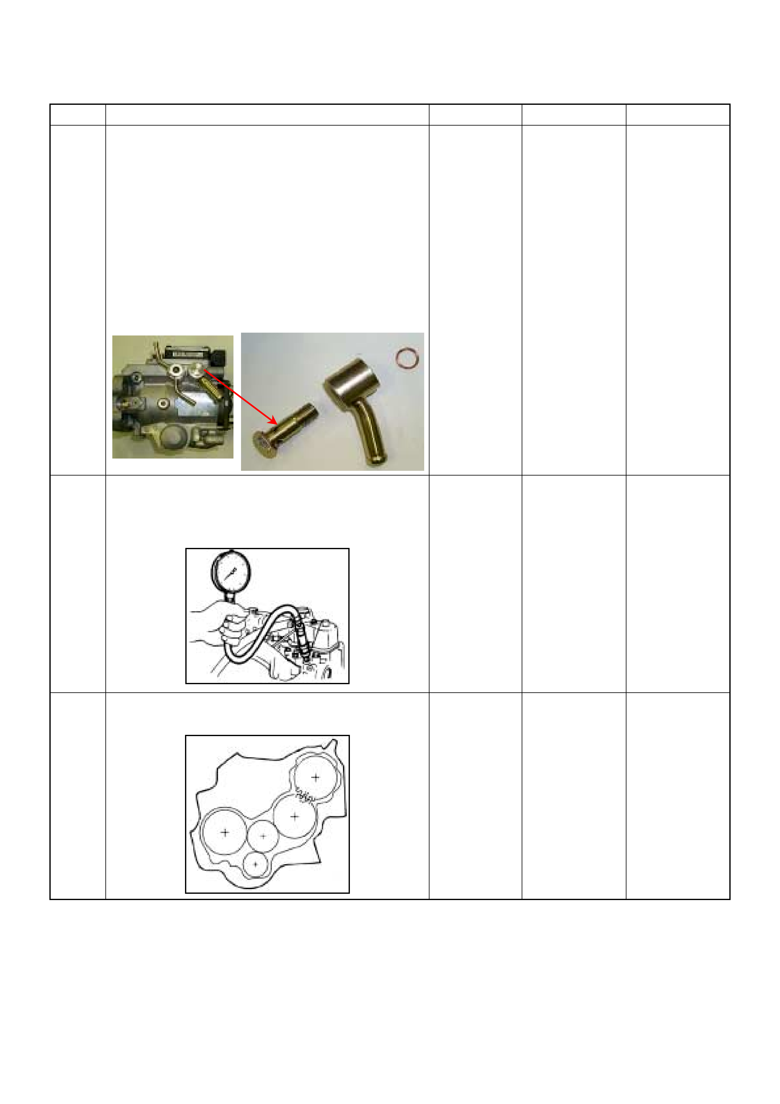
17 Remove the eye bolt with gauze filter from the
injection pump and check for the following conditions.
• Objects blocking at the gauze filter. Check for a
condition that causes contaminated fuel, such as
the customer is using an aftermarket fuel filter or
extended mai nte nan ce int er val.
• Check for a condition that causes fuel waxing or
icing, such as the customer is using an incorrect
fuel type in winter season or water mixed with the
fuel.
If a problem is found, repair as necessary.
Was the problem found?
—
Replace the
eye bolt with
gauze filter and
verify repair Go to Step 18
18 Check the engine compression pressure for each
cylinders.
If a problem is found, repair as necessary.
Was the problem found?
More than 2.1
Mpa (21.0 kg/
cm2) Verify repair Go to Step 19
19 If the injection pump was replaced, are the timing
gears or injection pump correctly installed?
—Go to Step 20 Repair as
necessary
Step Action Value(s) Yes No

20 1. Review all diagnostic procedures within this table.
2. If all procedures have been completed and no
malfunctions have been found, review/inspect the
following:
• Visual/physical inspection
• Tech 2 data
• All electrical connections within a suspected circuit
and/or system
Was a problem found? — Verify repair Go to Step 21
21 Is the ECM programmed with the latest software
release?
If not, download the latest software to the ECM using
the “SPS (Service Programming System)”.
Was the problem solved? — Verify repair Go to Step 22
22 Substitute a known good ECM and recheck.
Was the problem solved?
IMPORTANT: The replacement ECM must be
programmed. Refer to section of the Service
Programming System (SPS) in this manual.
Foll owing ECM pr ogramming, the immobi lizer system
(if equipped) must be linked to the ECM. Refer to
section 11 “Immobilizer System-ECM replacement” for
the ECM/Immobilizer linking procedure. — Go to Step 23 Go to Step 24
23 Replace the ECM.
Is the action complete?
IMPORTANT: The replacement ECM must be
programmed. Refer to section of the Service
Programming System (SPS) in this manual.
Foll owing ECM pr ogramming, the immobi lizer system
(if equipped) must be linked to the ECM. Refer to
section 11 “Immobilizer System-ECM replacement” for
the ECM/Immobilizer linking procedure. — Verify repair —
24 Replace the injection pump assembly.
Is the action complete? — Verify repair —
Step Action Value(s) Yes No

HARD START SYMPTOM
DEFINITIONS: Engine cranks, but does not start for a long time. Does eventually start, or may start and then
immediately stall.
Step Action Value(s) Yes No
1 Was the “On-Board Diagnostic (OBD) System Check”
performed?
—Go to Step 2
Go to On Board
Diagnostic
(OBD) System
Check
2 1. Perform a bulletin search.
2. If a bulletin that addresses the symptom is found ,
correct the condition as instructed in the bulletin.
Was a bulletin found that addresses the symptom? — Verify repair Go to Step 3
3 Was a visually/physical check performed? —Go to Step 4 Go to Visual /
physical Check
4 Is the customer using the incorrect fuel type? Diesel fuel
only Replace with
diesel fuel Go to Step 6
5 Visually/physically inspect for the following conditions.
• Restricted air intake system. Check for a restricted
air filter element, o r foreign ob jects blocking th e air
intake sy stem
• Che ck f or o bjects block ing or e xces sive d epo sits i n
the throttle bore and on the throttle plate
• Check for a condition that causes a large vacuum
leak, such as an incorrectly installed or faulty
crankc as e ven til ati on hose.
• Restricted air intake system at the turbocharger.
Check for objects blocking the turbocharger
compressor wheel or turbine shaft sticking.
If a problem is found, repair as necessary.
W as a problem found? — Verify repair Go to Step 6
6 Check the ECM & PSG grounds to verify that they are
clean and tight. Refer to the ECM wiring diagrams.
W as a problem found? — Verify repair Go to Step 7
7 1. Usin g th e Tech 2, d ispl ay the EC T s ensor an d I AT
sensor value.
2. Check the displayed value.
Does the Tech 2 indicate correct temperature
depending on engine condition?
If a problem is found, repair as necessary.
W as the problem found? — Verify repair Go to Step 8
8 1. Using the Tech 2, display the FT sensor value.
2. Check the displayed value.
Does the Tech 2 indicate correct temperature
depending on engine condition?
If a problem is found, repair as necessary.
Was the problem found? — Go to Step 20 Go to Step 9
9 1. Using the Tech 2, ignition “On”.
2. Monitor the “Glow Time Relay” in the data display.
Does the Tech 2 indicate correct “Glow Time Relay”
status depending on the time from ignition switch
“On”?
If a problem is found, repair as necessary.
Was the problem found? — Go to Step 20 Go to Step 10
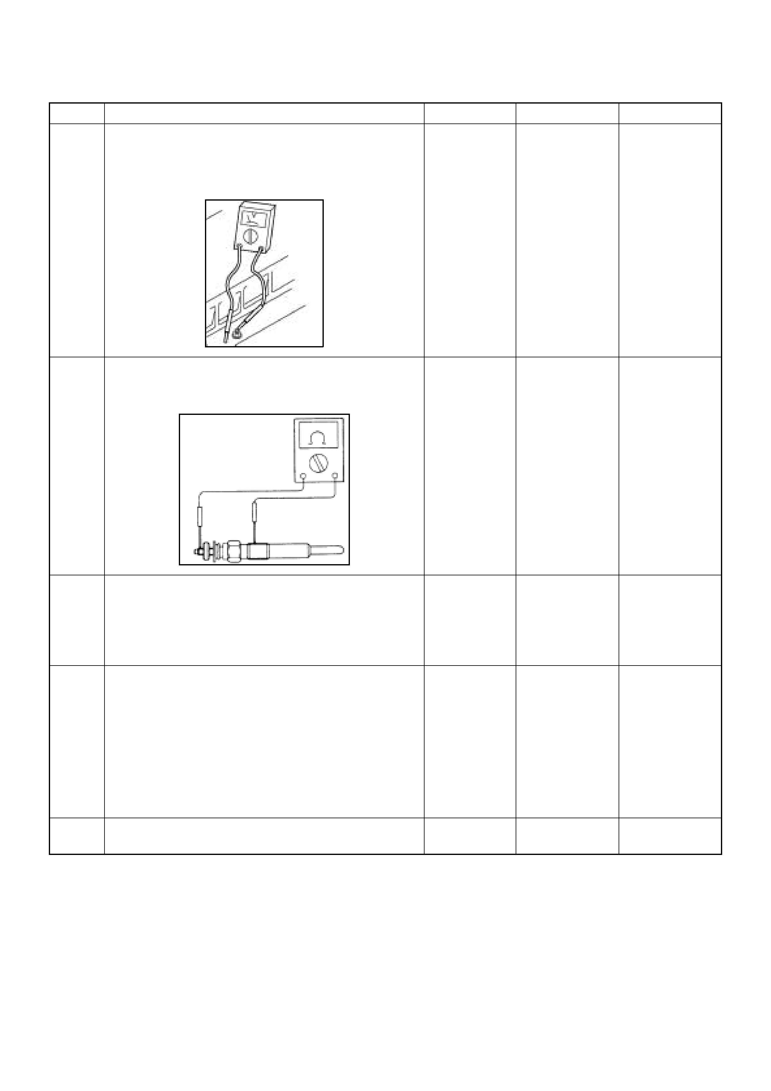
10 1. Using the Tech 2, ignition “On”.
2. Monitor the “Gl ow Time Rela y” in the data dis play
and then, does the supply voltage correctly supply
to the glow plug?
—Go to St ep 11
Repair voltage
supply circuit
and verify repair
11 Check the glow plugs for continuity.
If a problem is found, repair as necessary.
Was a problem found?
— Verify repair Go to Step 12
12 Check the exhaust system for a possible restriction.
• Damaged or collapsed pipes or catalytic converter.
• Internal muffler failur e.
If a problem is found, repair as necessary.
W as a problem found? — Verify repair Go to Step 13
13 Visually/physically inspect for the following conditions.
• Restric ted fuel supply s ystem. Che ck for a pinche d
fuel hose/pipe.
• Check for a condition that causes fuel waxing or
icing, such as the customer is using an incorrect
fuel type in winter season or water mixed with the
fuel.
If a problem is found, repair as necessary.
W as a problem found? — Verify repair Go to Step 14
14 Replace the fuel filter.
W as the problem solved? — Verify repair Go to Step 15
Step Action Value(s) Yes No
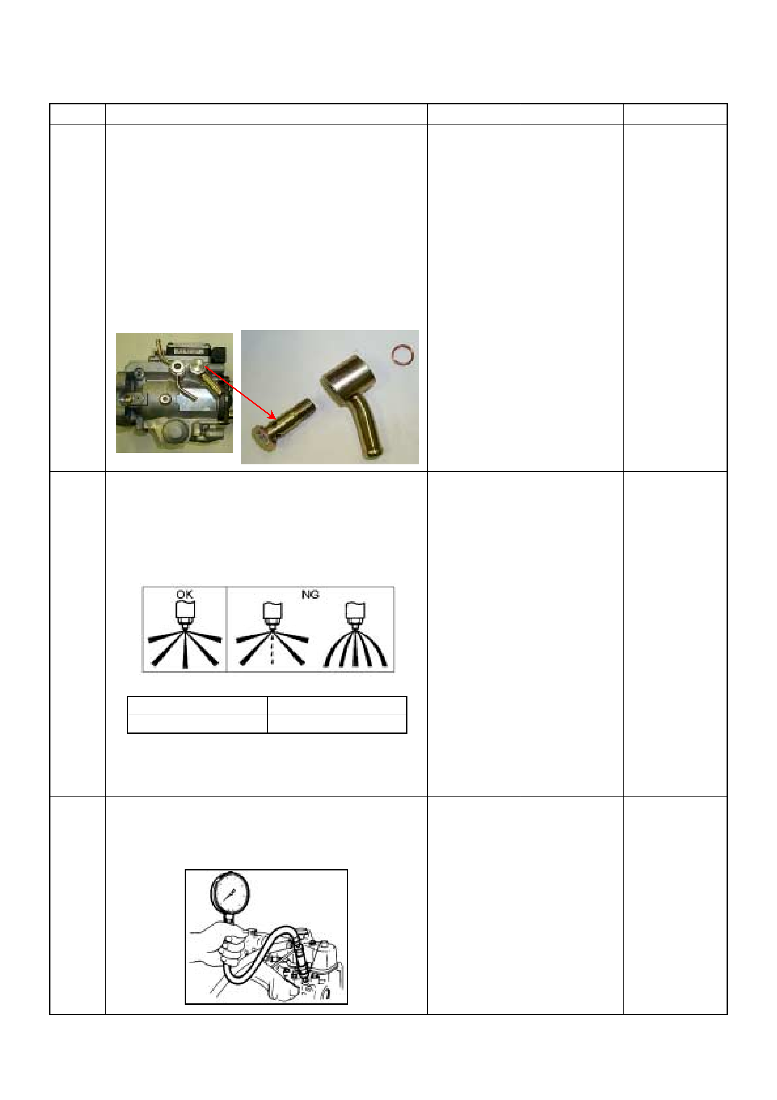
15 Remove the eye bolt with gauze filter from the
injection pump and check for the following conditions.
• Objects blocking at the gauze filter. Check for a
condition that causes contaminated fuel, such as
the customer is using an aftermarket fuel filter or
extended mai nte nan ce int er val.
• Check for a condition that causes fuel waxing or
icing, such as the customer is using an incorrect
fuel type in winter season or water mixed with the
fuel.
If a problem is found, repair as necessary.
Was the problem found?
—
Replace the
eye bolt with
gauze filter and
verify repair Go to Step 16
16 Remove the injection nozzles from the engine and
check for the following conditions.
• Improper spray condition.
• Operating pressure is incorrect.
If a problem is found, repair as necessary.
Was the problem found?
—
Replace the
injection nozzle
and verify repair Go to Step 17
17 Check the engine compression pressure for each
cylinders.
If a problem is found, repair as necessary.
Was the problem found?
More than 2.1
Mpa Verify repair Go to Step 18
Step Action Value(s) Yes No
1st Stage 2nd Stage
Approximately 19.5 Mpa Approximately 33.8 Mpa

18 Check the inlet/exhaust valve clearance for each
valves.
Are the valve clearances within the specified value?
0.4mm at cold
(In/Ex) Go to Step 19 Adjust and
verify repair
19 1. Review all diagnostic procedures within this table.
2. If all procedures have been completed and no
malfunctions have been found, review/inspect the
following:
• Visual/physical inspection
• Tech 2 data
• All electrical connections within a suspected circuit
and/or system
Was a problem found? — Verify repair Go to Step 20
20 Is the ECM programmed with the latest software
release?
If not, download the latest software to the ECM using
the “SPS (Service Programming System)”.
Was the problem solved? — Verify repair Go to Step 21
21 Substitute a known good ECM and recheck.
Was the problem solved?
IMPORTANT: The replacement ECM must be
programmed. Refer to section of the Service
Programming System (SPS) in this manual.
Following ECM programming, the immobilizer system
(if equipped) must be linked to the ECM. Refer to
section 11 “Immobilizer System-ECM replacement” for
the ECM/Immobilizer linking procedure. — Go to Step 22 Go to Step 23
22 Replace the ECM.
Is the action complete?
IMPORTANT: The replacement ECM must be
programmed. Refer to section of the Service
Programming System (SPS) in this manual.
Foll owing ECM pr ogramming, the immobi lizer system
(if equipped) must be linked to the ECM. Refer to
section 11 “Immobilizer System-ECM replacement” for
the ECM/Immobilizer linking procedure. — Verify repair —
23 Replace the injection pump assembly.
Is the action complete? — Verify repair —
Step Action Value(s) Yes No

ROUGH, UNSTABLE, OR INCORRECT IDLE, STALLING SYMPTOM
DEFINITIONS: Engine runs unevenly at idle. If severe,
the engine or vehicle may shake. Engine idle speed
may vary in RPM. Either condition may be severe
enough to stall the engine.
X
time
rpm
Rough Idle Stall
Step Action Value(s) Yes No
1 Was the “On-Board Diagnostic (OBD) System Check”
performed?
—Go to Step 2
Go to On Board
Diagnostic
(OBD) System
Check
2 1. Perform a bulletin search.
2. If a bulletin that addresses the symptom is found ,
correct the condition as instructed in the bulletin.
Was a bulletin found that addresses the symptom? — Verify repair Go to Step 3
3 Was a visually/physical check performed? —Go to Step 4 Go to Visual /
physical Check
4 Is the customer using the incorrect fuel type? Diesel fuel
only Replace with
diesel fuel Go to Step 5
5 1. Check for incorrect idle speed. Ensure that the
following conditions are present.
• Engine fully warm.
• Accessories are “OFF” .
2. Using a Tech 2, monitor “Desired Engine Idle
Speed” and “Engine Speed”.
Is the “Engine Speed” within the specified values?
Desired
Engine Idl e
Speed ± 25
rpm Go to Step 7 Go to Step 6
6 Visually/physically inspect for the following conditions.
• Restricted air intake system. Check for a restricted
air filter element, o r foreign ob jects blocking th e air
intake sy stem
• Che ck f or o bjects block ing or e xces sive d epo sits i n
the throttle bore and on the throttle plate
• Check for a condition that causes a large vacuum
leak, such as an incorrectly installed or faulty
crankc as e ven til ati on hose.
• Restricted air intake system at the turbocharger.
Check for objects blocking the turbocharger
compressor wheel or turbine shaft sticking.
If a problem is found, repair as necessary.
W as a problem found? — Verify repair Go to Step 7
7 Check the ECM & PSG grounds to verify that they are
clean and tight. Refer to the ECM wiring diagrams.
W as a problem found? — Verify repair Go to Step 8

8 1. Using the Tech 2, ignition “On” and engine “Off”.
2. Monitor the “Neutral Switch” in the data display.
Does the Tech 2 indicate correct “Neutral Switch”
status depending on any shift positions?
If a problem is found, repair as necessary.
W as the problem found? — Verify repair Go to Step 9
9 1. Using the Tech 2, ignition “On” and engine “Run”.
2. Monitor the “A/C Information Switch” in the data
display.
Does the Tech 2 indicate correct “A/C Information
Switch” status depend ing on A/C switc h posi tion?
If a problem is found, repair as necessary.
W as the problem found? — Verify repair Go to Step 10
10 1. Usin g th e Tech 2, d ispl ay the E CT s ens or an d IAT
sensor value.
2. Check the displayed value.
Does the Tech 2 indicate correct temperature
depending on engine condition?
If a problem is found, repair as necessary.
W as the problem found? — Verify repair Go to Step 11
11 1. Using the Tech 2, ignition “On” and engine “Run”.
2. Monitor the “Mass Air Flow” in the data display.
Does the Tech 2 indicate correct “Mass Air Flow”
depending on accelerator pedal operation? — Go to Step 16 Go to Step 12
12 Remove the MAF & IAT sensor assembly and check
for the following conditions.
• Objects blocking at the MAF sensor element.
If a problem is found, repair as necessary.
W as the problem found? — Verify repair Go to Step 13
13 Check the MAF sensor harness for the following
conditions.
• Check for poor connector connection.
• Check for misrouted harness.
• Check for any accessory parts which may cause
electric interference.
If a problem is found, repair as necessary.
W as a problem found? — Verify repair Go to Step 14
14 Substitute a known good MAF & IAT sensor assembly
and recheck.
Was the problem solved? — Go to Step 15 Go to Step 35
15 Replace the MAF & IAT sensor assembly.
Is the action complete? — Verify repair —
16 1. Using the Tech 2, ignition “On” and engine “Off”.
2. Monitor the “Pedal/Throttle Position” and “Idle
Switch” in the data display.
Does the Tech 2 indicate correct “Pedal/Throttle
Position” from 0% to 100% and correct “Idle Switch”
status depending on accelerator pedal operation? — Go to Step 21 Go to Step 17
Step Action Value(s) Yes No

17 1. Using the Tech 2, ignition “On” and engine “Off”.
2. Monitor the “Pedal/Throttle Position” and “Idle
Switch” in the data display.
3. Adjust the accelerator cable or TPS within 0% to
100%.
W as the problem solved? — Verify repair Go to Step 18
18 Check the TPS harness for the following conditions.
• Check for poor connector connection.
• Check for misrouted harness.
• Check for any accessory parts which may cause
electric interference.
If a problem is found, repair as necessary.
W as a problem found? — Verify repair Go to Step 19
19 Substitute a known good TPS and recheck.
Was the problem solved? — Go to Step 20 Go to Step 36
20 Replace the TPS.
Is the action complete? — Verify repair —
21 Remove the CKP sensor from the flywheel housing
and check for the following conditions.
• Objects sticking the CKP sensor.
• Objects sticking the CKP sensor pulser.
If a problem is found, repair as necessary.
W as the problem found? — Verify repair Go to Step 22
22 Check the CKP sensor harness for the following
conditions.
• Check for poor connector connection.
• Check for misrouted harness.
• Check for any accessory parts which may cause
electric interference.
If a problem is found, repair as necessary.
W as a problem found? — Verify repair Go to Step 23
23 Substitute a known good CKP sensor and recheck.
Was the problem solved? — Go to Step 24 Go to Step 25
24 Replace the CKP sensor.
Is the action complete? — Verify repair —
Step Action Value(s) Yes No
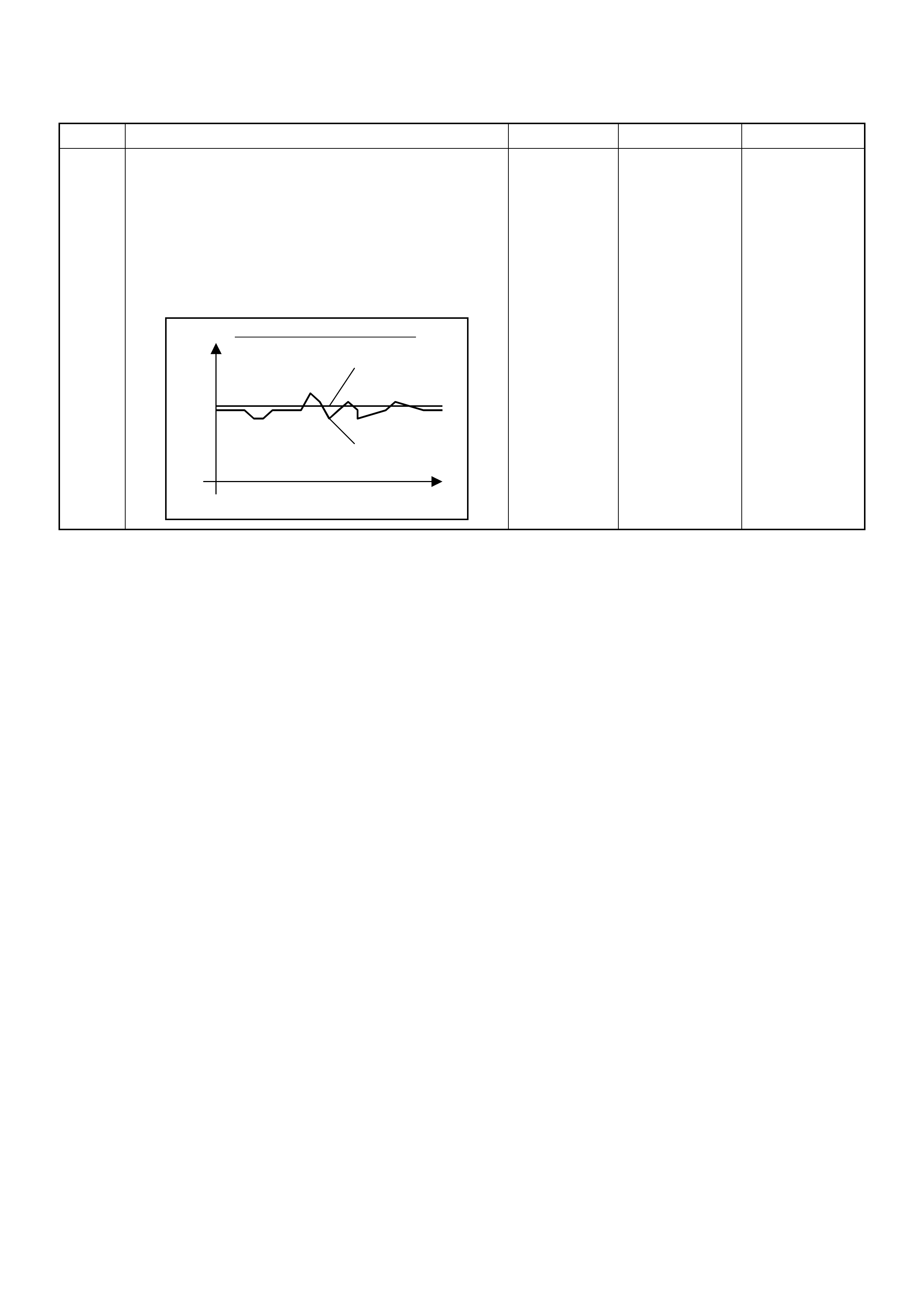
25 1. Using the Tech 2 and ignition “On” and engine
“Run”.
2. Monitor the following parameters in the data
display.
• “Desired Injection Quantity” & “Injection Quantity”
• “Desired Injection Start” & “Actual Injection Start”
Are the large gap or unstable parameter displayed
between “Desired” and “Actual”?
—Go to Step 29 Go to Step 26
Step Action Value(s) Yes No
When idling or part-throttle
High Desired
Low
Time
Actual

26 Using the Tec h 2 or the v acuum pump a nd check th e
EGR valve operation for the following condition
through the small window.
• Restricted shaft movement. Check for objects
sticking the shaft, broken diaphragm or
excessive carbon deposit.
Tech 2:
1. Using the Tech 2, ignition "On" and engine "On".
2. Select the "Miscellaneous Test" and perform the
"EGR Solenoid Test" in the "Solenoid".
3. Operate the Tech 2 in accordance with procedure.
• Solenoid 95%: EGR Valve Open
• Solenoid 5%: EGR Valve Close
Vacuum Pump:
1. Using the vacuum pump. Disconnect the original
vacuum hose and connect the hose to the EGR
valve.
2. Apply vacuum pressure.
• Vacuum Apply: EGR Valve Open
• Vacuum Release: EGR Valve C lose
If a problem is found, repair as necessary.
W as the problem found? — Verify repair Go to Step 27
27 Check the exhaust system for a possible restriction.
• Damaged or collapsed pipes or catalytic converter.
• Internal muffler failur e.
If a problem is found, repair as necessary.
W as a problem found? — Verify repair Go to Step 28
28 Visually/physically inspect for the following conditions.
• Restric ted fuel supply s ystem. Che ck for a pinche d
fuel hose/pipe.
• Check for a condition that causes fuel waxing or
icing, such as the customer is using an incorrect
fuel type in winter season or water mixed with the
fuel.
If a problem is found, repair as necessary.
W as a problem found? — Verify repair Go to Step 29
29 Replace the fuel filter.
W as the problem solved? — Verify repair Go to Step 30
Step Action Value(s) Yes No
Vacuum Pump Small Window
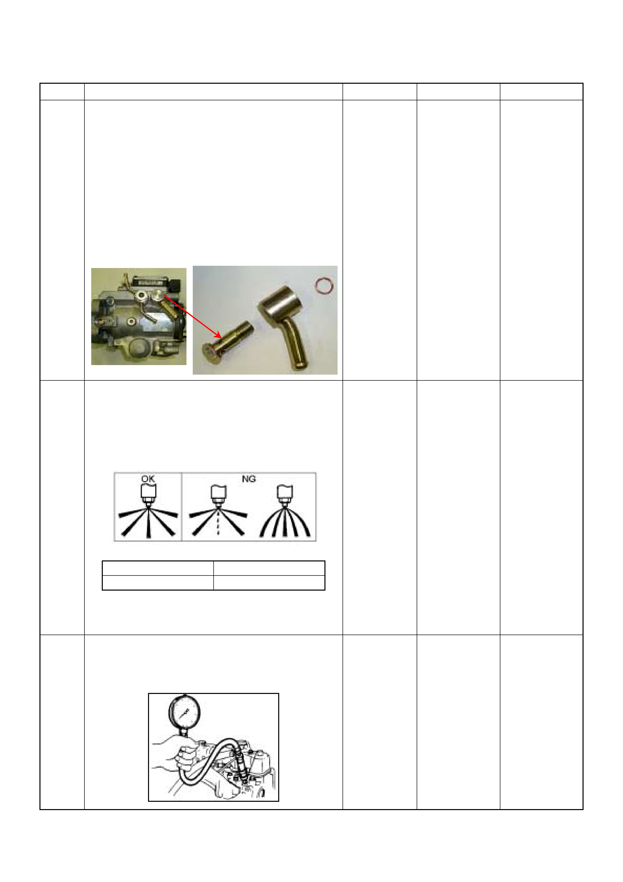
30 Remove the eye bolt with gauze filter from the
injection pump and check for the following conditions.
• Objects blocking at the gauze filter. Check for a
condition that causes contaminated fuel, such as
the customer is using an aftermarket fuel filter or
extended mai nte nan ce int er val.
• Check for a condition that causes fuel waxing or
icing, such as the customer is using an incorrect
fuel type in winter season or water mixed with the
fuel.
If a problem is found, repair as necessary.
Was the problem found?
—
Replace the
eye bolt with
gauze filter and
verify repair Go to Step 32
31 Remove the injection nozzles from the engine and
check for the following conditions.
• Improper spray condition.
• Operating pressure is incorrect.
If a problem is found, repair as necessary.
Was the problem found?
—
Replace the
injection nozzle
and verify repair Go to Step 32
32 Check the engine compression pressure for each
cylinders. Each cylinder must be evenly.
If a problem is found, repair as necessary.
Was the problem found?
More than 2.1
Mpa Verify repair Go to Step 33
Step Action Value(s) Yes No
1st Stage 2nd Stage
Approximately 19.5 Mpa Approximat ely 33.8 Mpa

33 Check the inlet/exhaust valve clearance for each
valves.
Are the valve clearances within the specified value?
0.4mm at cold
(In/Ex) Go to Step 34 Adjust and
verify repair
34 1. Review all diagnostic procedures within this table.
2. If all procedures have been completed and no
malfunctions have been found, review/inspect the
following:
• Visual/physical inspection
• Tech 2 data
• All electrical connections within a suspected circuit
and/or system
Was a problem found? — Verify repair Go to Step 35
35 Is the ECM programmed with the latest software
release?
If not, download the latest software to the ECM using
the “SPS (Service Programming System)”.
Was the problem solved? — Verify repair Go to Step 36
36 Substitute a known good ECM and recheck.
Was the problem solved?
IMPORTANT: The replacement ECM must be
programmed. Refer to section of the Service
Programming System (SPS) in this manual.
Following ECM programming, the immobilizer system
(if equipped) must be linked to the ECM. Refer to
section 11 “Immobilizer System-ECM replacement” for
the ECM/Immobilizer linking procedure. — Go to Step 37 Go to Step 38
37 Replace the ECM.
Is the action complete?
IMPORTANT: The replacement ECM must be
programmed. Refer to section of the Service
Programming System (SPS) in this manual.
Foll owing ECM pr ogramming, the immobi lizer system
(if equipped) must be linked to the ECM. Refer to
section 11 “Immobilizer System-ECM replacement” for
the ECM/Immobilizer linking procedure. — Verify repair —
38 Replace the injection pump assembly.
Is the action complete? — Verify repair —
Step Action Value(s) Yes No

SURGES AND/OR CHUGS SYMPTOM
DEFINITIONS: Engine power variation under steady
throttle or cruise. Feels like the vehicle speeds up and
slows down with no charge in the accelerator pedal.
time
rpm
Surge
Step Action Value(s) Yes No
1 Was the “On-Board Diagnostic (OBD) System Check”
performed?
—Go to Step 2
Go to On Board
Diagnostic
(OBD) System
Check
2 1. Perform a bulletin search.
2. If a bulletin that addresses the symptom is found ,
correct the condition as instructed in the bulletin.
Was a bulletin found that addresses the symptom? — Verify repair Go to Step 3
3 Was a visually/physical check performed? —Go to Step 4 Go to Visual /
physical Check
4 Is the customer using the incorrect fuel type? Diesel fuel
only Replace with
diesel fuel Go to Step 5
5 Visually/physically inspect for the following conditions.
• Restricted air intake system. Check for a restricted
air filter element, o r foreign ob jects blocking th e air
intake sy stem
• Che ck f or o bjects block ing or e xces sive d epo sits i n
the throttle bore and on the throttle plate
• Check for a condition that causes a large vacuum
leak, such as an incorrectly installed or faulty
crankc as e ven til ati on hose.
• Restricted air intake system at the turbocharger.
Check for objects blocking the turbocharger
compressor wheel or turbine shaft sticking.
If a problem is found, repair as necessary.
W as a problem found? — Verify repair Go to Step 6
6 Check the ECM & PSG grounds to verify that they are
clean and tight. Refer to the ECM wiring diagrams.
W as a problem found? — Verify repair Go to Step 7
7 1. Using the Tech 2, ignition “On” and engine “Run”.
2. Monitor the “A/C Information Switch” in the data
display.
Does the Tech 2 indicate correct “A/C Information
Switch” status depend ing on A/C switc h posi tion?
If a problem is found, repair as necessary.
W as the problem found? — Verify repair Go to Step 8

8 1. Usin g th e Tech 2, d ispl ay the EC T s ensor an d I AT
sensor value.
2. Check the displayed value.
Does the Tech 2 indicate correct temperature
depending on engine condition?
If a problem is found, repair as necessary.
W as the problem found? — Verify repair Go to Step 9
9 1. Using the Tech 2, ignition “On” and engine “Run”.
2. Monitor the “Mass Air Flow” in the data display.
Does the Tech 2 indicate correct “Mass Air Flow”
depending on accelerator pedal operation? — Go to Step 14 Go to Step 10
10 Remove the MAF & IAT sensor assembly and check
for the following conditions.
• Objects blocking at the MAF sensor element.
If a problem is found, repair as necessary.
W as the problem found? — Verify repair Go to Step 11
11 Check the MAF sensor harness for the following
conditions.
• Check for poor connector connection.
• Check for misrouted harness.
• Check for any accessory parts which may cause
electric interference.
If a problem is found, repair as necessary.
W as a problem found? — Verify repair Go to Step 12
12 Substitute a known good MAF & IAT sensor assembly
and recheck.
Was the problem solved? — Go to Step 13 Go to Step 29
13 Replace the MAF & IAT sensor assembly.
Is the action complete? — Verify repair —
14 1. Using the Tech 2, ignition “On” and engine “Off”.
2. Monitor the “Pedal/Throttle Position” and “Idle
Switch” in the data display.
Does the Tech 2 indicate correct “Pedal/Throttle
Position” from 0% to 100% and correct “Idle Switch”
status depending on accelerator pedal operation? — Go to Step 19 Go to Step 15
15 1. Using the Tech 2, ignition “On” and engine “Off”.
2. Monitor the “Pedal/Throttle Position” and “Idle
Switch” in the data display.
3. Adjust the accelerator cable or TPS within 0% to
100%.
W as the problem solved? — Verify repair Go to Step 16
16 Check the TPS harness for the following conditions.
• Check for poor connector connection.
• Check for misrouted harness.
• Check for any accessory parts which may cause
electric interference.
If a problem is found, repair as necessary.
W as a problem found? — Verify repair Go to Step 17
17 Substitute a known good TPS and recheck.
Was the problem solved? — Go to Step 18 Go to Step 29
18 Replace the TPS.
Is the action complete? — Verify repair —
Step Action Value(s) Yes No
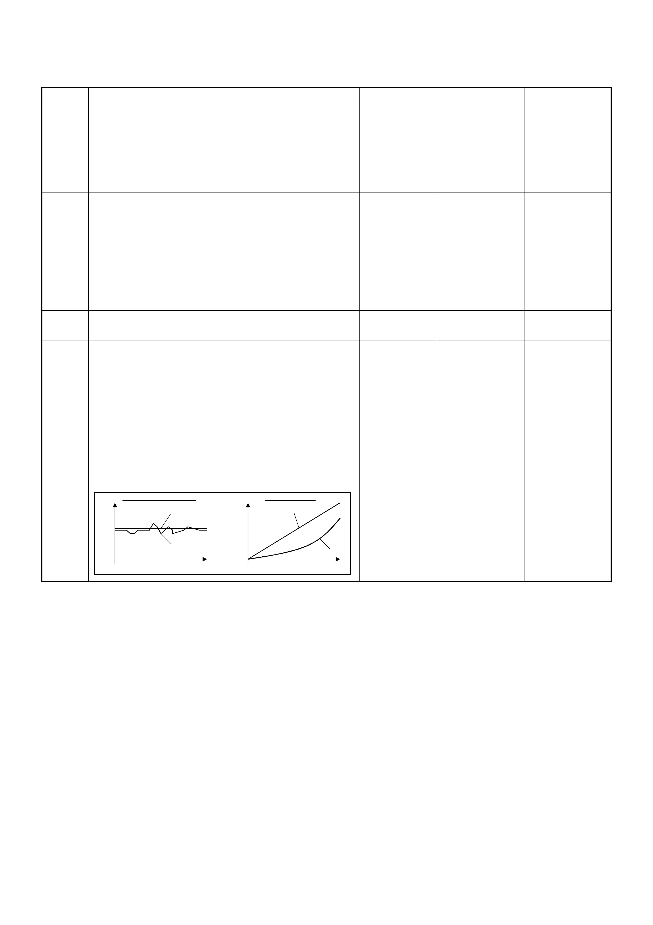
19 Remove the CKP sensor from the flywheel housing
and check for the following conditions.
• Objects sticking the CKP sensor.
• Objects sticking the CKP sensor pulser.
If a problem is found, repair as necessary.
W as the problem found? — Verify repair Go to Step 20
20 Check the CKP sensor harness for the following
conditions.
• Check for poor connector connection.
• Check for misrouted harness.
• Check for any accessory parts which may cause
electric interference.
If a problem is found, repair as necessary.
W as a problem found? — Verify repair Go to Step 21
21 Substitute a known good CKP sensor and recheck.
Was the problem solved? — Go to Step 22 Go to Step 23
22 Replace the CKP sensor.
Is the action complete? — Verify repair —
23 1. Using the Tech 2 and ignition “On” and engine
“Run”.
2. Monitor the following parameters in the data
display.
• “Desired Injection Quantity” & “Injection Quantity”
• “Desired Injection Start” & “Actual Injection Start”
Are the large gap or unstable parameter displayed
between “Desired” and “Actual”?
—Go to Step 25 Go to Step 24
Step Action Value(s) Yes No
When idling or part-throttle When accelerated
High Desired
Low
Time
Actual
High
Low
Desired
Actual
Time

24 Using the Tec h 2 or the v acuum pump a nd check th e
EGR valve operation for the following condition
through the small window.
• Restricted shaft movement. Check for objects
sticking the shaft, broken diaphragm or
excessive carbon deposit.
Tech 2:
1. Using the Tech 2, ignition "On" and engine "On".
2. Select the "Miscellaneous Test" and perform the
"EGR Solenoid Test" in the "Solenoid".
3. Operate the Tech 2 in accordance with procedure.
• Solenoid 95%: EGR Valve Open
• Solenoid 5%: EGR Valve Close
Vacuum Pump:
1. Using the vacuum pump. Disconnect the original
vacuum hose and connect the hose to the EGR
valve.
2. Apply vacuum pressure.
• Vacuum Apply: EGR Valve Open
• Vacuum Release: EGR Valve C lose
If a problem is found, repair as necessary.
W as the problem found? — Verify repair Go to Step 25
25 Visually/physically inspect for the following conditions.
• Restric ted fuel supply s ystem. Che ck for a pinche d
fuel hose/pipe.
• Check for a condition that causes fuel waxing or
icing, such as the customer is using an incorrect
fuel type in winter season or water mixed with the
fuel.
If a problem is found, repair as necessary.
W as a problem found? — Verify repair Go to Step 26
26 Replace the fuel filter.
W as the problem solved? — Verify repair Go to Step 27
Step Action Value(s) Yes No
Vacuum Pump Small Window
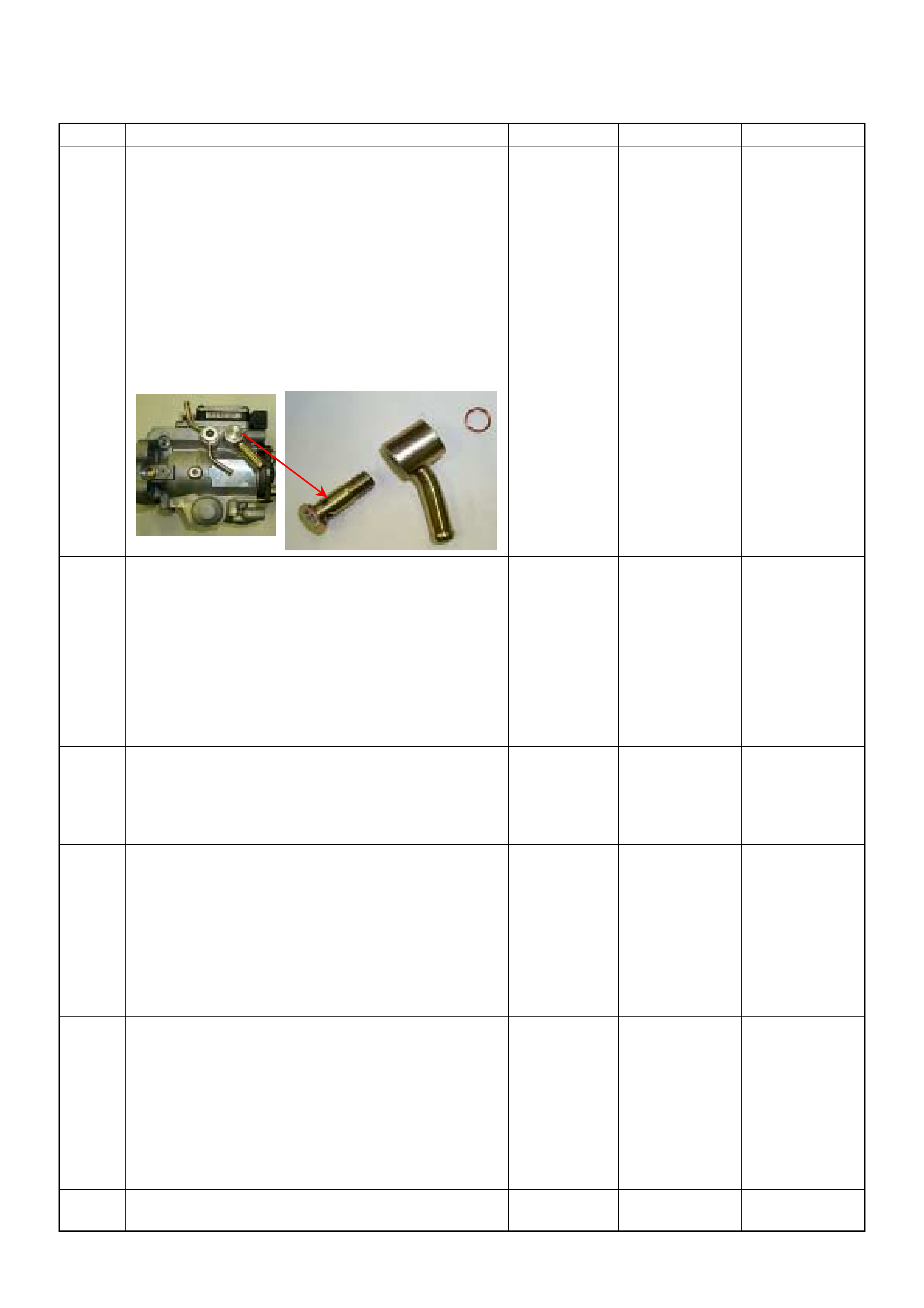
27 Remove the eye bolt with gauze filter from the
injection pump and check for the following conditions.
• Objects blocking at the gauze filter. Check for a
condition that causes contaminated fuel, such as
the customer is using an aftermarket fuel filter or
extended maintenance interval.
• Check for a condition that causes fuel waxing or
icing, such as the customer is using an incorrect
fuel type in winter season or water mixed with the
fuel.
If a problem is found, repair as necessary.
Was the problem found?
—
Replace the
eye bolt with
gauze filter and
verify repair Go to Step 28
28 1. Review all diagnostic procedures within this table.
2. If all procedures have been completed and no
malfunctions have been found, review/inspect the
following:
• Visual/physical inspection
• Tech 2 data
• All electrical connections within a suspected circuit
and/or system
Was a problem found? — Verify repair Go to Step 29
29 Is the ECM programmed with the latest software
release?
If not, download the latest software to the ECM using
the “SPS (Service Programming System)”.
Was the problem solved? — Verify repair Go to Step 30
30 Substitute a known good ECM and recheck.
Was the problem solved?
IMPORTANT: The replacement ECM must be
programmed. Refer to section of the Service
Programming System (SPS) in this manual.
Foll owing ECM pr ogramming, the immobi lizer system
(if equipped) must be linked to the ECM. Refer to
section 11 “Immobilizer System-ECM replacement” for
the ECM/Immobilizer linking procedure. — Go to Step 31 Go to Step 32
31 Replace the ECM.
Is the action complete?
IMPORTANT: The replacement ECM must be
programmed. Refer to section of the Service
Programming System (SPS) in this manual.
Foll owing ECM pr ogramming, the immobi lizer system
(if equipped) must be linked to the ECM. Refer to
section 11 “Immobilizer System-ECM replacement” for
the ECM/Immobilizer linking procedure. — Verify repair —
32 Replace the injection pump assembly.
Is the action complete? — Verify repair —
Step Action Value(s) Yes No

HESITATION, SAG, STUMBLE SYMPTOM
DEFINITIONS: Momentary lack of response as the
accelerator is pushed down. Can occur at any vehicle
speed. Usually most pronounced when first trying to
make the vehicle move, as from a stop sign. May cause
the engine to stall if severe enough.
time
rpm
Sug
Hesitation
Stumble
Step Action Value(s) Yes No
1 Was the “On-Board Diagnostic (OBD) System Check”
performed?
—Go to Step 2
Go to On Board
Diagnostic
(OBD) System
Check
2 1. Perform a bulletin search.
2. If a bulletin that addresses the symptom is found ,
correct the condition as instructed in the bulletin.
Was a bulletin found that addresses the symptom? — Verify repair Go to Step 3
3 Was a visually/physical check performed? —Go to Step 4 Go to Visual /
physical Check
4 Is the customer using the incorrect fuel type? Diesel fuel
only Replace with
diesel fuel Go to Step 5
5 Check the torque converter clutch (TCC) for proper
operation (if A/T model). If a problem is found, repair
as necessary.
W as a problem found? — Verify repair Go to Step 6
6 Visually/physically inspect for the following conditions.
• Restricted air intake system. Check for a restricted
air filter element, o r foreign ob jects blocking th e air
intake sy stem
• Che ck f or o bjects block ing or e xces sive d epo sits i n
the throttle bore and on the throttle plate
• Check for a condition that causes a large vacuum
leak, such as an incorrectly installed or faulty
crankc as e ven til ati on hose.
• Restricted air intake system at the turbocharger.
Check for objects blocking the turbocharger
compressor wheel or turbine shaft sticking.
If a problem is found, repair as necessary.
W as a problem found? — Verify repair Go to Step 7
7 Check the ECM & PSG grounds to verify that they are
clean and tight. Refer to the ECM wiring diagrams.
W as a problem found? — Verify repair Go to Step 8

8 1. Usin g th e Tech 2, d ispl ay the EC T s ensor an d I AT
sensor value.
2. Check the displayed value.
Does the Tech 2 indicate correct temperature
depending on engine condition?
If a problem is found, repair as necessary.
W as the problem found? — Verify repair Go to Step 9
9 1. Using the Tech 2, ignition “On” and engine “Run”.
2. Monitor the “Mass Air Flow” in the data display.
Does the Tech 2 indicate correct “Mass Air Flow”
depending on accelerator pedal operation? — Go to Step 14 Go to Step 10
10 Remove the MAF & IAT sensor assembly and check
for the following conditions.
• Objects blocking at the MAF sensor element.
If a problem is found, repair as necessary.
W as the problem found? — Verify repair Go to Step 11
11 Check the MAF sensor harness for the following
conditions.
• Check for poor connector connection.
• Check for misrouted harness.
• Check for any accessory parts which may cause
electric interference.
If a problem is found, repair as necessary.
W as a problem found? — Verify repair Go to Step 12
12 Substitute a known good MAF & IAT sensor assembly
and recheck.
Was the problem solved? — Go to Step 13 Go to Step 31
13 Replace the MAF & IAT sensor assembly.
Is the action complete? — Verify repair —
14 1. Using the Tech 2, ignition “On” and engine “Off”.
2. Monitor the “Pedal/Throttle Position” and “Idle
Switch” in the data display.
Does the Tech 2 indicate correct “Pedal/Throttle
Position” from 0% to 100% and correct “Idle Switch”
status depending on accelerator pedal operation? — Go to Step 19 Go to Step 15
15 1. Using the Tech 2, ignition “On” and engine “Off”.
2. Monitor the “Pedal/Throttle Position” and “Idle
Switch” in the data display.
3. Adjust the accelerator cable or TPS within 0% to
100%.
W as the problem solved? — Verify repair Go to Step 16
16 Check the TPS harness for the following conditions.
• Check for poor connector connection.
• Check for misrouted harness.
• Check for any accessory parts which may cause
electric interference.
If a problem is found, repair as necessary.
W as a problem found? — Verify repair Go to Step 17
17 Substitute a known good TPS and recheck.
Was the problem solved? — Go to Step 18 Go to Step 31
18 Replace the TPS.
Is the action complete? — Verify repair —
Step Action Value(s) Yes No

19 Remove the CKP sensor from the flywheel housing
and check for the following conditions.
• Objects sticking the CKP sensor.
• Objects sticking the CKP sensor pulser.
If a problem is found, repair as necessary.
W as the problem found? — Verify repair Go to Step 20
20 Check the CKP sensor harness for the following
conditions.
• Check for poor connector connection.
• Check for misrouted harness.
• Check for any accessory parts which may cause
electric interference.
If a problem is found, repair as necessary.
W as a problem found? — Verify repair Go to Step 21
21 Substitute a known good CKP sensor and recheck.
Was the problem solved? — Go to Step 22 Go to Step 23
22 Replace the CKP sensor.
Is the action complete? — Verify repair —
23 1. Using the Tech 2 and ignition “On” and engine
“Run”.
2. Monitor the following parameters in the data
display.
• “Desired Injection Quantity” & “Injection Quantity”
• “Desired Injection Start” & “Actual Injection Start”
Are the large gap or unstable parameter displayed
between “Desired” and “Actual”?
—Go to Step 27 Go to Step 24
Step Action Value(s) Yes No
When idling or part-throttle When accelerated
High Desired
Low
Time
Actual
High
Low
Desired
Actual
Time

24 Using the Tec h 2 or the v acuum pump a nd check th e
EGR valve operation for the following condition
through the small window.
• Restricted shaft movement. Check for objects
sticking the shaft, broken diaphragm or
excessive carbon deposit.
Tech 2:
1. Using the Tech 2, ignition "On" and engine "On".
2. Select the "Miscellaneous Test" and perform the
"EGR Solenoid Test" in the "Solenoid".
3. Operate the Tech 2 in accordance with procedure.
• Solenoid 95%: EGR Valve Open
• Solenoid 5%: EGR Valve Close
Vacuum Pump:
1. Using the vacuum pump. Disconnect the original
vacuum hose and connect the hose to the EGR
valve.
2. Apply vacuum pressure.
• Vacuum Apply: EGR Valve Open
• Vacuum Release: EGR Valve C lose
If a problem is found, repair as necessary.
W as the problem found? — Verify repair Go to Step 25
25 Check the exhaust system for a possible restriction.
• Damaged or collapsed pipes or catalytic converter.
• Internal muffler failur e.
If a problem is found, repair as necessary.
W as a problem found? — Verify repair Go to Step 26
26 Visually/physically inspect for the following conditions.
• Restric ted fuel supply s ystem. Che ck for a pinche d
fuel hose/pipe.
• Check for a condition that causes fuel waxing or
icing, such as the customer is using an incorrect
fuel type in winter season or water mixed with the
fuel.
If a problem is found, repair as necessary.
W as a problem found? — Verify repair Go to Step 27
27 Replace the fuel filter.
W as the problem solved? — Verify repair Go to Step 28
Step Action Value(s) Yes No
Vacuum Pump Small Window

28 Remove the eye bolt with gauze filter from the
injection pump and check for the following conditions.
• Objects blocking at the gauze filter. Check for a
condition that causes contaminated fuel, such as
the customer is using an aftermarket fuel filter or
extended maintenance interval.
• Check for a condition that causes fuel waxing or
icing, such as the customer is using an incorrect
fuel type in winter season or water mixed with the
fuel.
If a problem is found, repair as necessary.
Was the problem found?
—
Replace the
eye bolt with
gauze filter and
verify repair Go to Step 29
29 1. Review all diagnostic procedures within this table.
2. If all procedures have been completed and no
malfunctions have been found, review/inspect the
following:
• Visual/physical inspection
• Tech 2 data
• All electrical connections within a suspected circuit
and/or system
Was a problem found? — Verify repair Go to Step 30
30 Is the ECM programmed with the latest software
release?
If not, download the latest software to the ECM using
the “SPS (Service Programming System)”.
Was the problem solved? — Verify repair Go to Step 31
31 Substitute a known good ECM and recheck.
Was the problem solved?
IMPORTANT: The replacement ECM must be
programmed. Refer to section of the Service
Programming System (SPS) in this manual.
Foll owing ECM pr ogramming, the immobi lizer system
(if equipped) must be linked to the ECM. Refer to
section 11 “Immobilizer System-ECM replacement” for
the ECM/Immobilizer linking procedure. — Go to Step 32 Go to Step 33
32 Replace the ECM.
Is the action complete?
IMPORTANT: The replacement ECM must be
programmed. Refer to section of the Service
Programming System (SPS) in this manual.
Foll owing ECM pr ogramming, the immobi lizer system
(if equipped) must be linked to the ECM. Refer to
section 11 “Immobilizer System-ECM replacement” for
the ECM/Immobilizer linking procedure. — Verify repair —
33 Replace the injection pump assembly.
Is the action complete? — Verify repair —
Step Action Value(s) Yes No

CUTS OUT, MISSES SYMPTOM
DEFINITIONS: Steady pulsation or jerking that follows
engine speed; usually more pronounced as engine load
increases.
time
rpm
Step Action Value(s) Yes No
1 Was the “On-Board Diagnostic (OBD) System Check”
performed?
—Go to Step 2
Go to On Board
Diagnostic
(OBD) System
Check
2 1. Perform a bulletin search.
2. If a bulletin that addresses the symptom is found ,
correct the condition as instructed in the bulletin.
Was a bulletin found that addresses the symptom? — Verify repair Go to Step 3
3 Was a visually/physical check performed? —Go to Step 4 Go to Visual /
physical Check
4 Is the customer using the incorrect fuel type? Diesel fuel
only Replace with
diesel fuel Go to Step 5
5 Visually/physically inspect for the following conditions.
• Restricted air intake system. Check for a restricted
air filter element, o r foreign ob jects blocking th e air
intake sy stem
• Che ck f or o bjects block ing or e xces sive d epo sits i n
the throttle bore and on the throttle plate
• Check for a condition that causes a large vacuum
leak, such as an incorrectly installed or faulty
crankc as e ven til ati on hose.
• Restricted air intake system at the turbocharger.
Check for objects blocking the turbocharger
compressor
wheel or turbine shaft sticking.
If a problem is found, repair as necessary.
W as a problem found? — Verify repair Go to Step 6
6 Check the ECM & PSG grounds to verify that they are
clean and tight. Refer to the ECM wiring diagrams.
W as a problem found? — Verify repair Go to Step 7
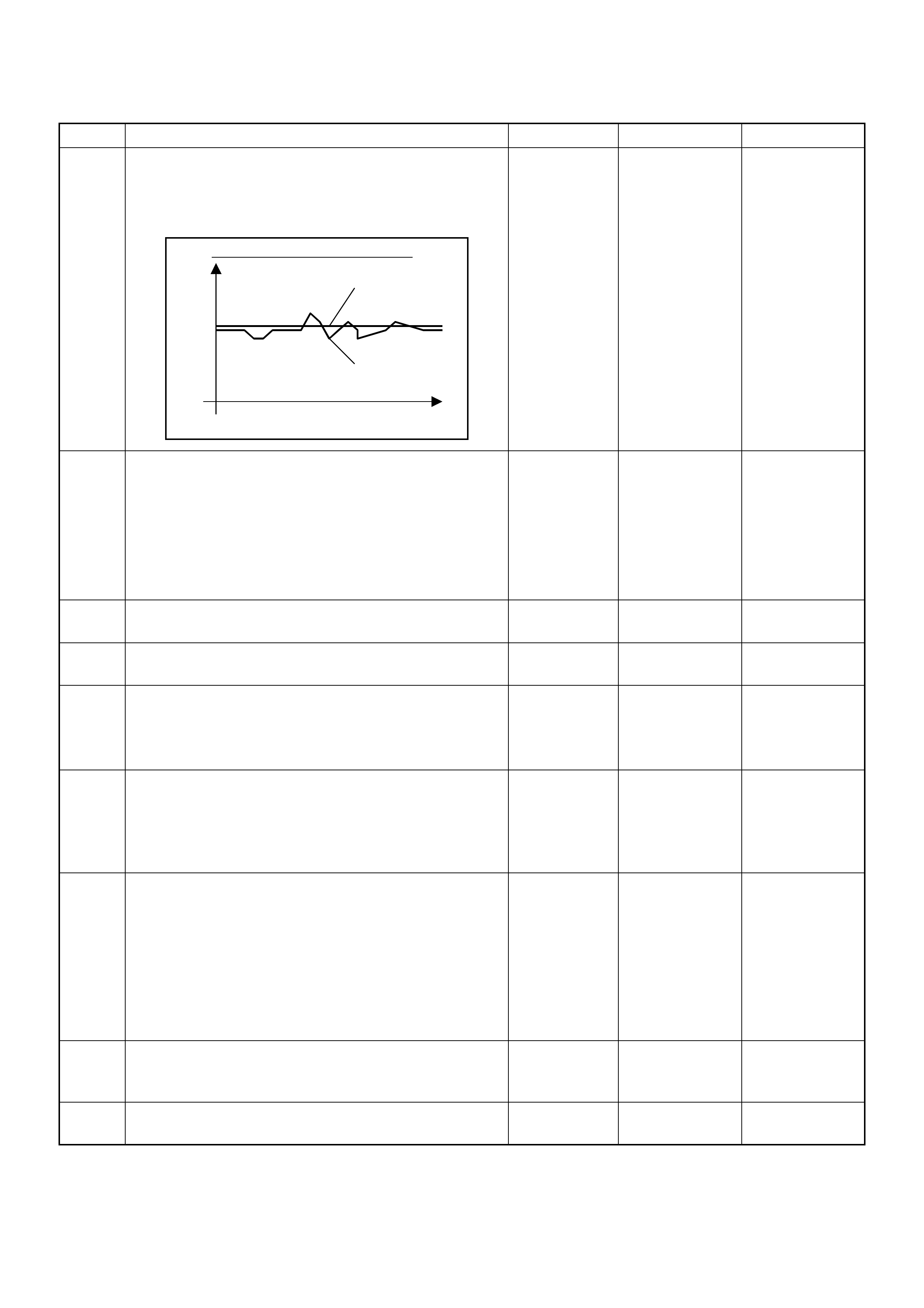
7 1. Using the Tech 2, perform test drive.
2. Monitor the “Vehicle Speed” in the data display.
Does the Tech 2 indicate correct “Vehicle Speed”
depending on driving speed?
—Go to Step 11 Go to Step 8
8 Check the VSS harness for the following conditions.
• Check for poor connector connection.
• Check for misrouted harness.
• Check for any accessory parts which may cause
electric interference.
If a problem is found, repair as necessary.
W as a problem found? — Verify repair Go to Step 9
9 Substitute a known good VSS and recheck.
Was the problem solved? — Go to Step 10 Go to Step 31
10 Replace the VSS assembly.
Is the action complete? — Verify repair —
11 1. Using the Tech 2, ignition “On” and engine “Run”.
2. Monitor the “Mass Air Flow” in the data display.
Does the Tech 2 indicate correct “Mass Air Flow”
depending on accelerator pedal operation? — Go to Step 16 Go to Step 12
12 Remove the MAF & IAT sensor assembly and check
for the following conditions.
• Objects blocking at the MAF sensor element.
If a problem is found, repair as necessary.
W as the problem found? — Verify repair Go to Step 13
13 Check the MAF sensor harness for the following
conditions.
• Check for poor connector connection.
• Check for misrouted harness.
• Check for any accessory parts which may cause
electric interference.
If a problem is found, repair as necessary.
W as a problem found? — Verify repair Go to Step 14
14 Substitute a known good MAF & IAT sensor assembly
and recheck.
Was the problem solved? — Go to Step 15 Go to Step 31
15 Replace the MAF & IAT sensor assembly.
Is the action complete? — Verify repair —
Step Action Value(s) Yes No
When constant vehicle speed
High Correct Speed
Low
Time
Unstable Data

16 1. Using the Tech 2, ignition “On” and engine “Off”.
2. Monitor the “Pedal/Throttle Position” and “Idle
Switch” in the data display.
Does the Tech 2 indicate correct “Pedal/Throttle
Position” from 0% to 100% and correct “Idle Switch”
status depending on accelerator pedal operation? — Go to Step 21 Go to Step 17
17 1. Using the Tech 2, ignition “On” and engine “Off”.
2. Monitor the “Pedal/Throttle Position” and “Idle
Switch” in the data display.
3. Adjust the accelerator cable or TPS within 0% to
100%.
W as the problem solved? — Verify repair Go to Step 18
18 Check the TPS harness for the following conditions.
• Check for poor connector connection.
• Check for misrouted harness.
• Check for any accessory parts which may cause
electric interference.
If a problem is found, repair as necessary.
W as a problem found? — Verify repair Go to Step 19
19 Substitute a known good TPS and recheck.
Was the problem solved? — Go to Step 20 Go to Step 31
20 Replace the TPS.
Is the action complete? — Verify repair —
21 Remove the CKP sensor from the flywheel housing
and check for the following conditions.
• Objects sticking the CKP sensor.
• Objects sticking the CKP sensor pulser.
If a problem is found, repair as necessary.
W as the problem found? — Verify repair Go to Step 22
22 Check the CKP sensor harness for the following
conditions.
• Check for poor connector connection.
• Check for misrouted harness.
• Check for any accessory parts which may cause
electric interference.
If a problem is found, repair as necessary.
W as a problem found? — Verify repair Go to Step 23
23 Substitute a known good CKP sensor and recheck.
Was the problem solved? — Go to Step 24 Go to Step 25
24 Replace the CKP sensor.
Is the action complete? — Verify repair —
Step Action Value(s) Yes No
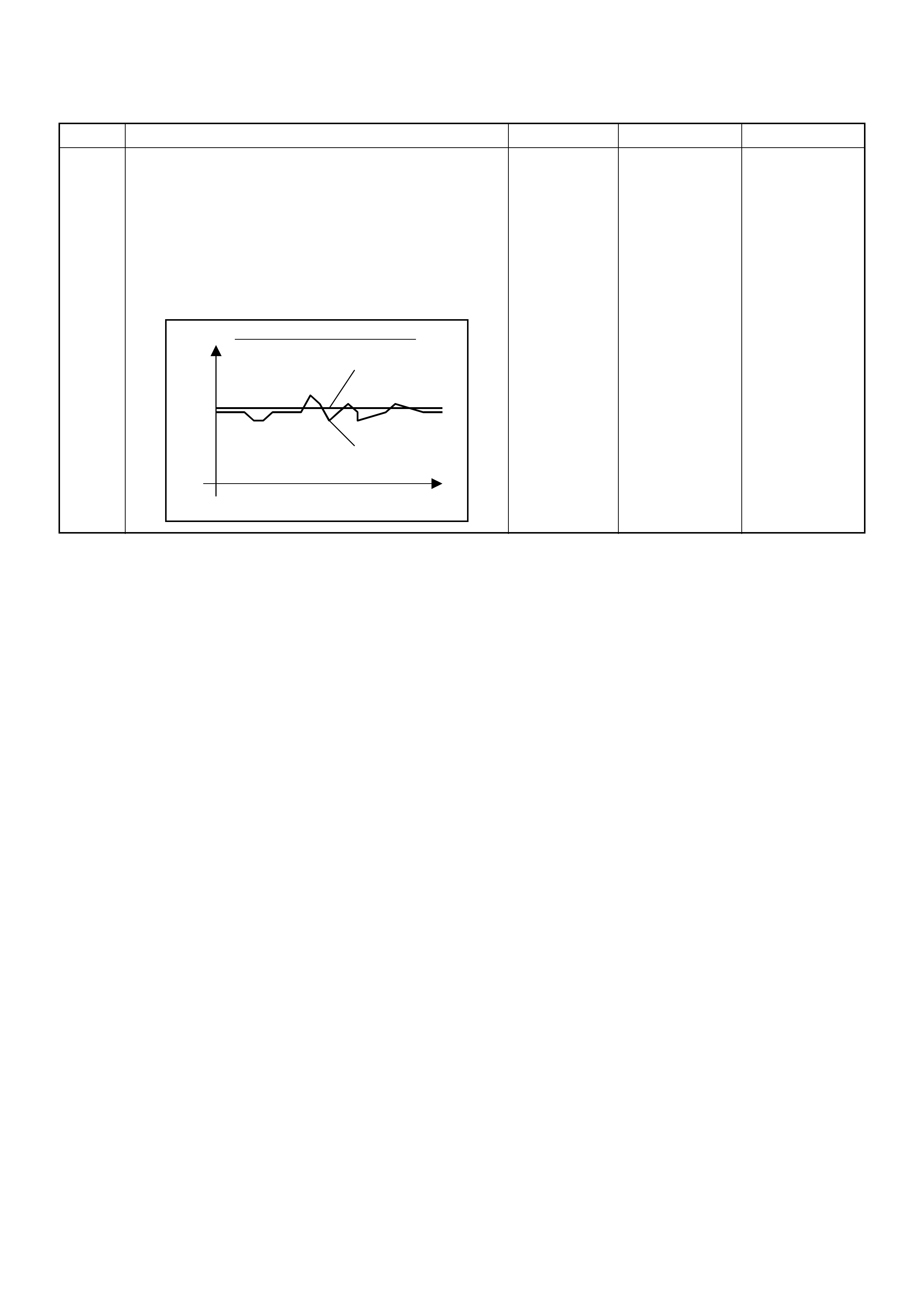
25 1. Using the Tech 2 and ignition “On” and engine
“Run”.
2. Monitor the following parameters in the data
display.
• “Desired Injection Quantity” & “Injection Quantity”
• “Desired Injection Start” & “Actual Injection Start”
Are the large gap or unstable parameter displayed
between “Desired” and “Actual”?
—Go to Step 29 Go to Step 26
Step Action Value(s) Yes No
When idling or part-throttle
High Desired
Low
Time
Actual

26 Using the Tec h 2 or the v acuum pump a nd check th e
EGR valve operation for the following condition
through the small window.
• Restricted shaft movement. Check for objects
sticking the shaft, broken diaphragm or
excessive carbon deposit.
Tech 2:
1. Using the Tech 2, ignition "On" and engine "On".
2. Select the "Miscellaneous Test" and perform the
"EGR Solenoid Test" in the "Solenoid".
3. Operate the Tech 2 in accordance with procedure.
• Solenoid 95%: EGR Valve Open
• Solenoid 5%: EGR Valve Close
Vacuum Pump:
1. Using the vacuum pump. Disconnect the original
vacuum hose and connect the hose to the EGR
valve.
2. Apply vacuum pressure.
• Vacuum Apply: EGR Valve Open
• Vacuum Release: EGR Valve C lose
If a problem is found, repair as necessary.
W as the problem found? — Verify repair Go to Step 27
27 Visually/physically inspect for the following conditions.
• Restric ted fuel supply s ystem. Che ck for a pinche d
fuel hose/pipe.
• Check for a condition that causes fuel waxing or
icing, such as the customer is using an incorrect
fuel type in winter season or water mixed with the
fuel.
If a problem is found, repair as necessary.
W as a problem found? — Verify repair Go to Step 28
28 Replace the fuel filter.
W as the problem solved? — Verify repair Go to Step 29
Step Action Value(s) Yes No
Vacuum Pump Small Window
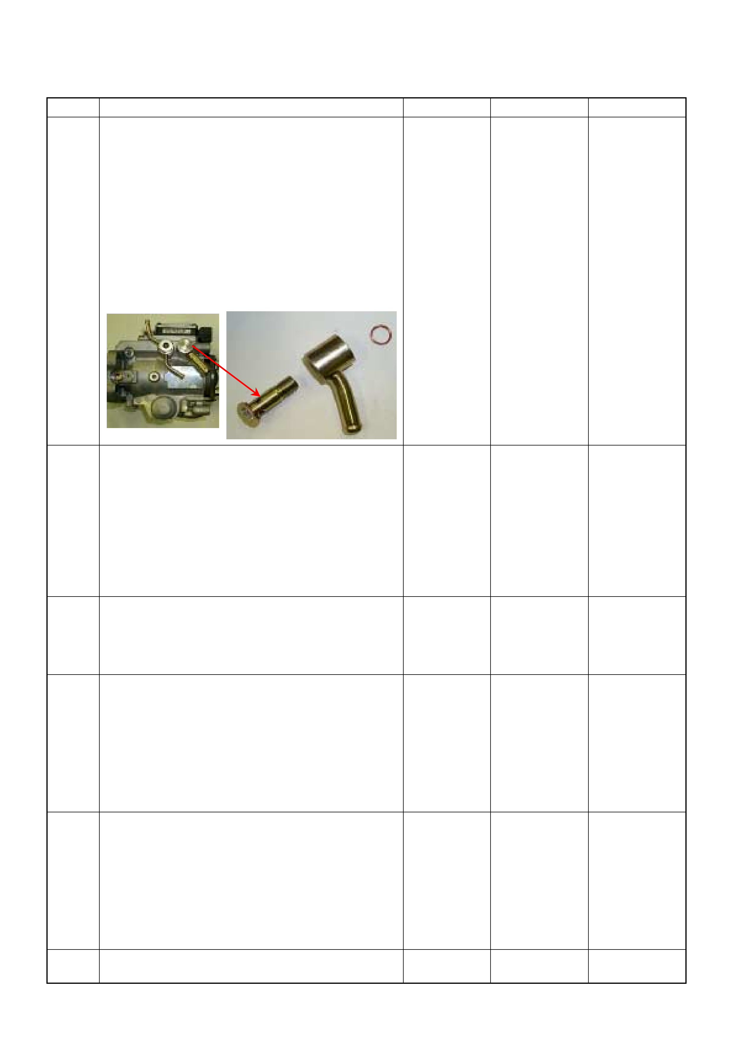
29 Remove the eye bolt with gauze filter from the
injection pump and check for the following conditions.
• Objects blocking at the gauze filter. Check for a
condition that causes contaminated fuel, such as
the customer is using an aftermarket fuel filter or
extended maintenance interval.
• Check for a condition that causes fuel waxing or
icing, such as the customer is using an incorrect
fuel type in winter season or water mixed with the
fuel.
If a problem is found, repair as necessary.
Was the problem found?
—
Replace the
eye bolt with
gauze filter and
verify repair Go to Step 30
30 1. Review all diagnostic procedures within this table.
2. If all procedures have been completed and no
malfunctions have been found, review/inspect the
following:
• Visual/physical inspection
• Tech 2 data
• All electrical connections within a suspected circuit
and/or system
Was a problem found? — Verify repair Go to Step 31
31 Is the ECM programmed with the latest software
release?
If not, download the latest software to the ECM using
the “SPS (Service Programming System)”.
Was the problem solved? — Verify repair Go to Step 32
32 Substitute a known good ECM and recheck.
Was the problem solved?
IMPORTANT: The replacement ECM must be
programmed. Refer to section of the Service
Programming System (SPS) in this manual.
Foll owing ECM pr ogramming, the immobi lizer system
(if equipped) must be linked to the ECM. Refer to
section 11 “Immobilizer System-ECM replacement” for
the ECM/Immobilizer linking procedure. — Go to Step 33 Go to Step 34
33 Replace the ECM.
Is the action complete?
IMPORTANT: The replacement ECM must be
programmed. Refer to section of the Service
Programming System (SPS) in this manual.
Foll owing ECM pr ogramming, the immobi lizer system
(if equipped) must be linked to the ECM. Refer to
section 11 “Immobilizer System-ECM replacement” for
the ECM/Immobilizer linking procedure. — Verify repair —
34 Replace the injection pump assembly.
Is the action complete? — Verify repair —
Step Action Value(s) Yes No

LACK OF POWER, SLUGGISH OR SPONGY SYMPTOM
DEFINITIONS: Engine delivers less than expected power. Attempting part-throttle acceleration results in little or no
increase in vehicle speed.
Step Action Value(s) Yes No
1 Was the “On-Board Diagnostic (OBD) System Check”
performed?
—Go to Step 2
Go to On Board
Diagnostic
(OBD) System
Check
2 1. Perform a bulletin search.
2. If a bulletin that addresses the symptom is found ,
correct the condition as instructed in the bulletin.
Was a bulletin found that addresses the symptom? — Verify repair Go to Step 3
3 Was a visually/physical check performed? —Go to Step 4 Go to Visual /
physical Check
4 Is the customer using the incorrect fuel type? Diesel fuel
only Replace with
diesel fuel Go to Step 5
5 Visually/physically inspect for the following conditions.
• Restricted air intake system. Check for a restricted
air filter element, o r foreign ob jects blocking th e air
intake sy stem
• Che ck f or o bjects block ing or e xces sive d epo sits i n
the throttle bore and on the throttle plate
• Check for a condition that causes a large vacuum
leak, such as an incorrectly installed or faulty
crankc as e ven til ati on hose.
• Restricted air intake system at the turbocharger.
Check for objects blocking the turbocharger
compressor wheel or turbine shaft sticking.
If a problem is found, repair as necessary.
W as a problem found? — Verify repair Go to Step 6
6 Check the ECM & PSG grounds to verify that they are
clean and tight. Refer to the ECM wiring diagrams.
W as a problem found? — Verify repair Go to Step 7
7 1. Usin g th e Tech 2, d ispl ay the EC T s ensor an d I AT
sensor value.
2. Check the displayed value.
Does the Tech 2 indicate correct temperature
depending on engine condition?
If a problem is found, repair as necessary.
W as the problem found? — Verify repair Go to Step 8
8 1. Using the Tech 2, display the FT sensor value.
2. Check the displayed value.
Does the Tech 2 indicate correct temperature
depending on engine condition?
If a problem is found, repair as necessary.
Was the problem found? — Go to Step 29 Go to Step 9
9 1. Using the Tech 2, ignition “On” and engine “Run”.
2. Monitor the “Mass Air Flow” in the data display.
Does the Tech 2 indicate correct “Mass Air Flow”
depending on accelerator pedal operation? — Go to Step 14 Go to Step 10

10 Remove the MAF & IAT sensor assembly and check
for the following conditions.
• Objects blocking at the MAF sensor element.
If a problem is found, repair as necessary.
W as the problem found? — Verify repair Go to Step 11
11 Check the MAF sensor harness for the following
conditions.
• Check for poor connector connection.
• Check for misrouted harness.
• Check for any accessory parts which may cause
electric interference.
If a problem is found, repair as necessary.
W as a problem found? — Verify repair Go to Step 12
12 Substitute a known good MAF & IAT sensor assembly
and recheck.
Was the problem solved? — Go to Step 13 Go to Step 29
13 Replace the MAF & IAT sensor assembly.
Is the action complete? — Verify repair —
14 1. Using the Tech 2, ignition “On” and engine “Off”.
2. Monitor the “Pedal/Throttle Position” and “Idle
Switch” in the data display.
Does the Tech 2 indicate correct “Pedal/Throttle
Position” from 0% to 100% and correct “Idle Switch”
status depending on accelerator pedal operation? — Go to Step 19 Go to Step 15
15 1. Using the Tech 2, ignition “On” and engine “Off”.
2. Monitor the “Pedal/Throttle Position” and “Idle
Switch” in the data display.
3. Adjust the accelerator cable or TPS within 0% to
100%.
W as the problem solved? — Verify repair Go to Step 16
16 Check the TPS harness for the following conditions.
• Check for poor connector connection.
• Check for misrouted harness.
• Check for any accessory parts which may cause
electric interference.
If a problem is found, repair as necessary.
W as a problem found? — Verify repair Go to Step 17
17 Substitute a known good TPS and recheck.
Was the problem solved? — Go to Step 18 Go to Step 30
18 Replace the TPS.
Is the action complete? — Verify repair —
Step Action Value(s) Yes No
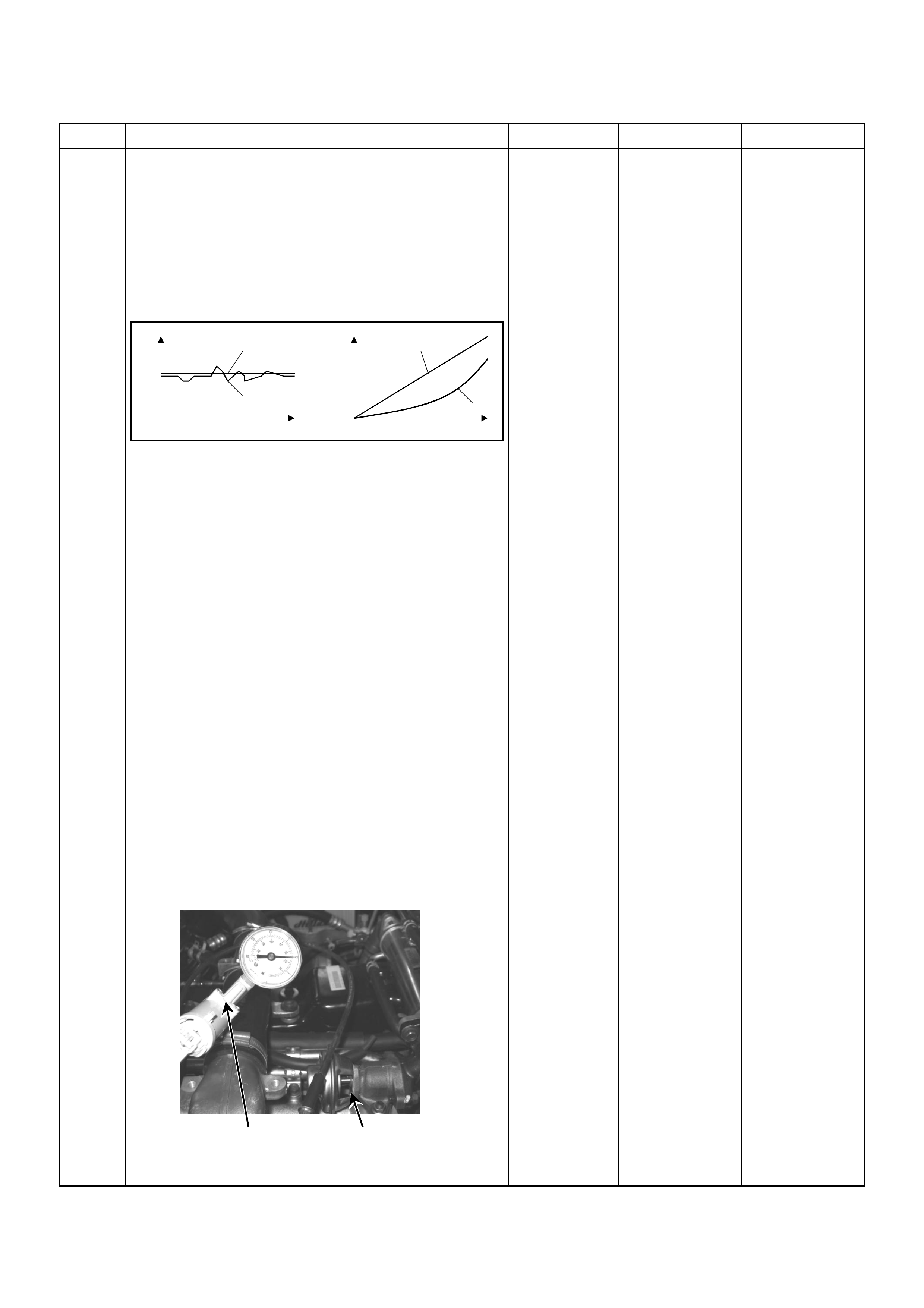
19 1. Using the Tech 2 and ignition “On” and engine
“Run”.
2. Monitor the following parameters in the data
display.
• “Desired Injection Quantity” & “Injection Quantity”
• “Desired Injection Start” & “Actual Injection Start”
Are the large gap or unstable parameter displayed
between “Desired” and “Actual”?
—Go to Step 22 Go to Step 20
20 Using the Tec h 2 or the v acuum pump a nd check th e
EGR valve operation for the following condition
through the small window.
ÅERestr ict sh af t mo ve men t . C heck f o r ob je ct s st i cki ng
the shaft, broken diaphragm or excessive carbon
deposit.
Tech 2:
1. Using the Tech 2, ignition "On" and engine "On".
2. Select the "Miscellaneous Test" and perform the
"EGR Solenoid Test" in the "Solenoid".
3. Operate the Tech 2 in accordance with procedure.
• Solenoid 95%: EGR Valve Open
• Solenoid 5%: EGR Valve Close
Vacuum Pump:
1. Using the vacuum pump. Disconnect the original
vacuum hose and connect the hose to the EGR
valve.
2. Apply vacuum pressure.
• Vacuum Apply: EGR Valve Open
• Vacuum Release: EGR Valve C lose
If a problem is found, repair as necessary.
W as the problem found? — Verify repair Go to Step 21
Step Action Value(s) Yes No
When idling or part-throttle When accelerated
High Desired
Low
Time
Actual
High
Low
Desired
Actual
Time
Vacuum Pump Small Window
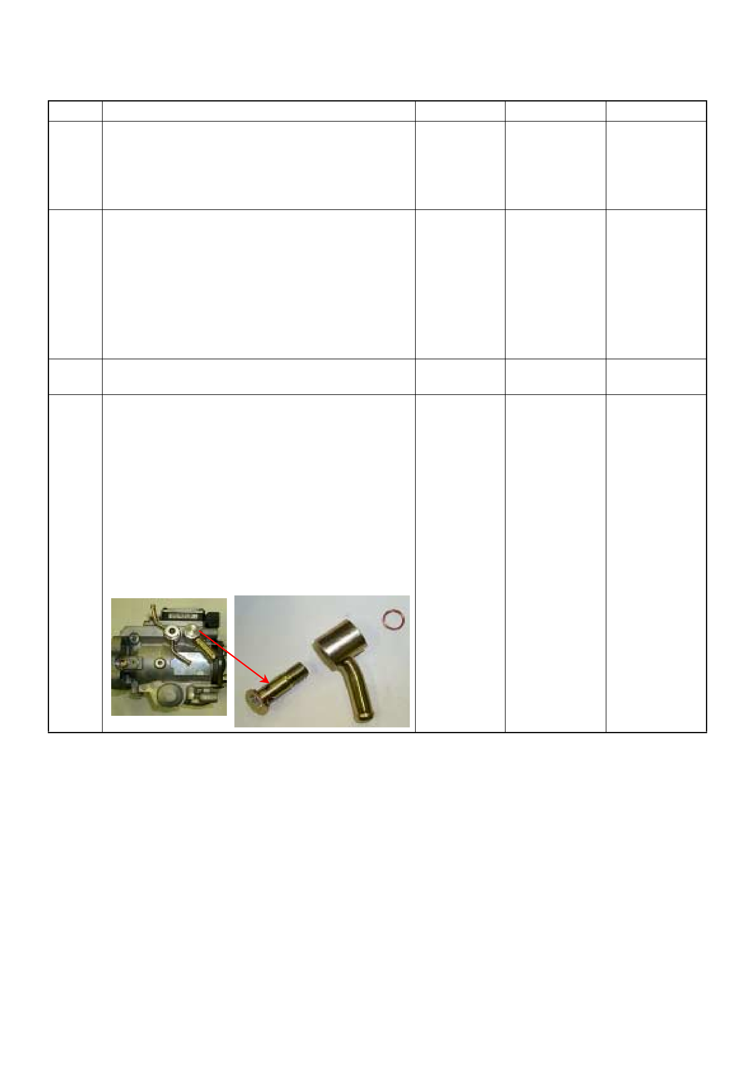
21 Check the exhaust system for a possible restriction.
• Damaged or collapsed pipes or catalytic converter.
• Internal muffler failur e.
If a problem is found, repair as necessary.
W as a problem found? — Verify repair Go to Step 22
22 Visually/physically inspect for the following conditions.
• Restric ted fuel supply s ystem. Che ck for a pinche d
fuel hose/pipe.
• Check for a condition that causes fuel waxing or
icing, such as the customer is using an incorrect
fuel type in winter season or water mixed with the
fuel.
If a problem is found, repair as necessary.
W as a problem found? — Verify repair Go to Step 23
23 Replace the fuel filter.
W as the problem solved? — Verify repair Go to Step 24
24 Remove the eye bolt with gauze filter from the
injection pump and check for the following conditions.
• Objects blocking at the gauze filter. Check for a
condition that causes contaminated fuel, such as
the customer is using an aftermarket fuel filter or
extended mai nte nan ce int er val.
• Check for a condition that causes fuel waxing or
icing, such as the customer is using an incorrect
fuel type in winter season or water mixed with the
fuel.
If a problem is found, repair as necessary.
Was the problem found?
—
Replace the
eye bolt with
gauze filter and
verify repair Go to Step 25
Step Action Value(s) Yes No
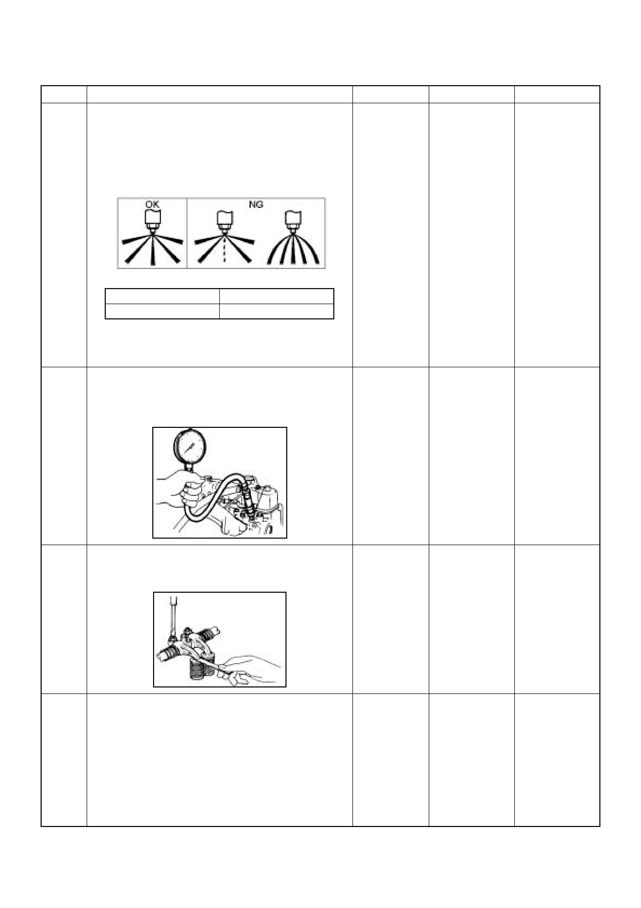
25 Remove the injection nozzles from the engine and
check for the following conditions.
• Improper spray condition.
• Operating pressure is incorrect.
If a problem is found, repair as necessary.
Was the problem found?
—
Replace the
injection nozzle
and verify repair Go to Step 26
26 Check the engine compression pressure for each
cylinders.
If a problem is found, repair as necessary.
Was the problem found?
More than 2.0
Mpa Verify repair Go to Step 27
27 Check the inlet/exhaust valve clearance for each
valves.
Are the valve clearances within the specified value?
0.4mm at cold
(In/Ex) Go to Step 28 Adjust and
verify repair
28 1. Review all diagnostic procedures within this table.
2. If all procedures have been completed and no
malfunctions have been found, review/inspect the
following:
• Visual/physical inspection
• Tech 2 data
• All electrical connections within a suspected circuit
and/or system
W as a problem found? — Verify repair Go to Step 29
Step Action Value(s) Yes No
1st Stage 2nd Stage
Approximately 19.5 Mpa Approxim ately 33.8 Mpa

29 Is the ECM programmed with the latest software
release?
If not, download the latest software to the ECM using
the “SPS (Service Programming System)”.
Was the problem solved? — Verify repair Go to Step 30
30 Substitute a known good ECM and recheck.
Was the problem solved?
IMPORTANT: The replacement ECM must be
programmed. Refer to section of the Service
Programming System (SPS) in this manual.
Foll owing ECM pr ogramming, the immobi lizer system
(if equipped) must be linked to the ECM. Refer to
section 11 “Immobilizer System-ECM replacement” for
the ECM/Immobilizer linking procedure. — Go to Step 31 Go to Step 32
31 Replace the ECM.
Is the action complete?
IMPORTANT: The replacement ECM must be
programmed. Refer to section of the Service
Programming System (SPS) in this manual.
Foll owing ECM pr ogramming, the immobi lizer system
(if equipped) must be linked to the ECM. Refer to
section 11 “Immobilizer System-ECM replacement” for
the ECM/Immobilizer linking procedure. — Verify repair —
32 Replace the injection pump assembly.
Is the action complete? — Verify repair —
Step Action Value(s) Yes No

POOR FUEL ECONOMY SYMPTOM
DEFINITIONS: Fuel economy, as measured by an actual road test, is noticeably lower than expected. Also, economy
is noticeably lower than it was on this vehicle at one time, as previously shown by an actual road test. (Larger than
standard tires will cause odometer readings to be incorrect, and that may cause fuel economy to appear poor when it
is actually normal.)
Step Action Value(s) Yes No
1 Was the “On-Board Diagnostic (OBD) System Check”
performed?
—Go to Step 2
Go to On Board
Diagnostic
(OBD) System
Check
2 1. Perform a bulletin search.
2. If a bulletin that addresses the symptom is found ,
correct the condition as instructed in the bulletin.
Was a bulletin found that addresses the symptom? — Verify repair Go to Step 3
3 Was a visually/physical check performed? —Go to Step 4 Go to Visual /
physical Check
4 Check owner's driving habits.
• Is the A/C “On” full time?
• Are tires at the correct pressure?
• Are excessively heavy loads being carried?
• Is acceleration too much, too often? — Go to Step 5 Go to Step 6
5 Review the items in Step 4 with the customer and
advise as necessary.
Is the action complete? — System OK —
6 Check for low engine coolant level.
W as a problem found? — Verify repair Go to Step 7
7 Check for inco rrect or faulty engine thermostat. Refer
to Engine Cooling.
W as a problem found? — Verify repair Go to Step 8
8 Check for proper calibration of the speedometer.
Does the s peed indicated on the speed mete r closely
match the vehicle speed displayed on the Tech 2? — Go to Step 10 Go to Step 9
9 Diagnose and repair the inaccurate speedometer
condition as necessary. Refer to Vehicle Speed
Sensor in Electrical Diagnosis. — Verify repair —
10 Check for proper calibration of the fuel gauge.
W as a problem found? — Verify repair Go to Step 11
11 Check the torque converter clutch (TCC) for proper
operation (if A/T model). If a problem is found, repair
as necessary.
W as a problem found? — Verify repair Go to Step 12
12 1. Using the Tech 2, ignition “On” and engine “Off”.
2. Monitor the “Neutral Switch” in the data display.
Does the Tech 2 indicate correct “Neutral Switch”
status depending on any shift positions?
If a problem is found, repair as necessary.
W as the problem found? — Verify repair Go to Step 13

13 1. Using the Tech 2, ignition “On” and engine “Run”.
2. Monitor the “A/C Information Switch” in the data
display.
Does the Tech 2 indicate correct “A/C Information
Switch” status depend ing on A/C switc h posi tion?
If a problem is found, repair as necessary.
W as the problem found? — Verify repair Go to Step 14
14 Visually/physically inspect for the following conditions.
• Restricted air intake system. Check for a restricted
air filter element, o r foreign ob jects blocking th e air
intake sy stem
• Che ck f or o bjects block ing or e xces sive d epo sits i n
the throttle bore and on the throttle plate
• Check for a condition that causes a large vacuum
leak, such as an incorrectly installed or faulty
crankc as e ven til ati on hose.
• Restricted air intake system at the turbocharger.
Check for objects blocking the turbocharger
compressor wheel or turbine shaft sticking.
If a problem is found, repair as necessary.
W as a problem found? — Verify repair Go to Step 15
15 1. Usin g th e Tech 2, d ispl ay the E CT s ens or an d IAT
sensor value.
2. Check the displayed value.
Does the Tech 2 indicate correct temperature
depending on engine condition?
If a problem is found, repair as necessary.
W as the problem found? — Verify repair Go to Step 16
16 1. Using the Tech 2, display the FT sensor value.
2. Check the displayed value.
Does the Tech 2 indicate correct temperature
depending on engine condition?
If a problem is found, repair as necessary.
Was the problem found? — Go to Step 31 Go to Step 17
17 1. Using the Tech 2, ignition “On” and engine “Run”.
2. Monitor the “Mass Air Flow” in the data display.
Does the Tech 2 indicate correct “Mass Air Flow”
depending on accelerator pedal operation? — Go to Step 22 Go to Step 18
18 Remove the MAF & IAT sensor assembly and check
for the following conditions.
• Objects blocking at the MAF sensor element.
If a problem is found, repair as necessary.
W as the problem found? — Verify repair Go to Step 19
19 Check the MAF sensor harness for the following
conditions.
• Check for poor connector connection.
• Check for misrouted harness.
• Check for any accessory parts which may cause
electric interference.
If a problem is found, repair as necessary.
W as a problem found? — Verify repair Go to Step 20
Step Action Value(s) Yes No
20 Substitute a known good MAF & IAT sensor assembly
and recheck.
Was the problem solved? — Go to Step 21 Go to Step 31
21 Replace the MAF & IAT sensor assembly.
Is the action complete? — Verify repair —
22 1. Using the Tech 2, ignition “On” and engine “Off”.
2. Monitor the “Pedal/Throttle Position” and “Idle
Switch” in the data display.
Does the Tech 2 indicate correct “Pedal/Throttle
Position” from 0% to 100% and correct “Idle Switch”
status depending on accelerator pedal operation? — Go to Step 27 Go to Step 23
23 1. Using the Tech 2, ignition “On” and engine “Off”.
2. Monitor the “Pedal/Throttle Position” and “Idle
Switch” in the data display.
3. Adjust the accelerator cable or TPS within 0% to
100%.
W as the problem solved? — Verify repair Go to Step 24
24 Check the TPS harness for the following conditions.
• Check for poor connector connection.
• Check for misrouted harness.
• Check for any accessory parts which may cause
electric interference.
If a problem is found, repair as necessary.
W as a problem found? — Verify repair Go to Step 25
25 Substitute a known good TPS and recheck.
Was the problem solved? — Go to Step 26 Go to Step 31
26 Replace the TPS.
Is the action complete? — Verify repair —
27 Remove the injection nozzles from the engine and
check for the following conditions.
• Improper spray condition.
• Operating pressure is incorrect.
If a problem is found, repair as necessary.
Was the problem found?
—
Replace the
injection nozzle
and verify repair Go to Step 28
Step Action Value(s) Yes No
1st Stage 2nd Stage
Approximately 19.5 Mpa Approximat ely 33.8 Mpa

28 Check the engine compression pressure for each
cylinders.
If a problem is found, repair as necessary.
Was the problem found?
More than 2.0
Mpa Verify repair Go to Step 29
29 Check the inlet/exhaust valve clearance for each
valves.
Are the valve clearances within the specified value?
0.4mm at cold
(In/Ex) Go to Step 30 Adjust and
verify repair
30 1. Review all diagnostic procedures within this table.
2. If all procedures have been completed and no
malfunctions have been found, review/inspect the
following:
• Visual/physical inspection
• Tech 2 data
• All electrical connections within a suspected circuit
and/or system
Was a problem found? — Verify repair Go to Step 31
31 Is the ECM programmed with the latest software
release?
If not, download the latest software to the ECM using
the “SPS (Service Programming System)”.
Was the problem solved? — Verify repair Go to Step 32
32 Substitute a known good ECM and recheck.
Was the problem solved?
IMPORTANT: The replacement ECM must be
programmed. Refer to section of the Service
Programming System (SPS) in this manual.
Foll owing ECM pr ogramming, the immobi lizer system
(if equipped) must be linked to the ECM. Refer to
section 11 “Immobilizer System-ECM replacement” for
the ECM/Immobilizer linking procedure. — Go to Step 33 Go to Step 34
Step Action Value(s) Yes No

33 Replace the ECM.
Is the action complete?
IMPORTANT: The replacement ECM must be
programmed. Refer to section of the Service
Programming System (SPS) in this manual.
Foll owing ECM pr ogramming, the immobi lizer system
(if equipped) must be linked to the ECM. Refer to
section 11 “Immobilizer System-ECM replacement” for
the ECM/Immobilizer linking procedure. — Verify repair —
34 Replace the injection pump assembly.
Is the action complete? — Verify repair —
Step Action Value(s) Yes No

EXCESSIVE WHITE SMOKE
Step Action Value(s) Yes No
1 Was the “On-Board Diagnostic (OBD) System Check”
performed?
—Go to Step 2
Go to On Board
Diagnostic
(OBD) System
Check
2 1. Perform a bulletin search.
2. If a bulletin that addresses the symptom is found ,
correct the condition as instructed in the bulletin.
Was a bulletin found that addresses the symptom? — Verify repair Go to Step 3
3 Was a visually/physical check performed? —Go to Step 4 Go to Visual /
physical Check
4 Is the customer using the incorrect fuel type? Diesel fuel
only Replace with
diesel fuel Go to Step 5
5 Check for engine coolant leaking into the combustion
chambers or through the gasket.
W as a problem found? — Verify repair Go to Step 6
6 Check the ECM & PSG grounds to verify that they are
clean and tight. Refer to the ECM wiring diagrams.
W as a problem found? — Verify repair Go to Step 7
7 1. Usin g th e Tech 2, d ispl ay the EC T s ensor an d I AT
sensor value.
2. Check the displayed value.
Does the Tech 2 indicate correct temperature
depending on engine condition?
If a problem is found, repair as necessary.
W as the problem found? — Verify repair Go to Step 8
8 1. Using the Tech 2, display the FT sensor value.
2. Check the displayed value.
Does the Tech 2 indicate correct temperature
depending on engine condition?
If a problem is found, repair as necessary.
Was the problem found? — Go to Step 30 Go to Step 9
9 1. Using the Tech 2, ignition “On” and engine “Run”.
2. Monitor the “Mass Air Flow” in the data display.
Does the Tech 2 indicate correct “Mass Air Flow”
depending on accelerator pedal operation? — Go to Step 14 Go to Step 10
10 Remove the MAF & IAT sensor assembly and check
for the following conditions.
• Objects blocking at the MAF sensor element.
If a problem is found, repair as necessary.
W as the problem found? — Verify repair Go to Step 11
11 Check the MAF sensor harness for the following
conditions.
• Check for poor connector connection.
• Check for misrouted harness.
• Check for any accessory parts which may cause
electric interference.
If a problem is found, repair as necessary.
W as a problem found? — Verify repair Go to Step 12
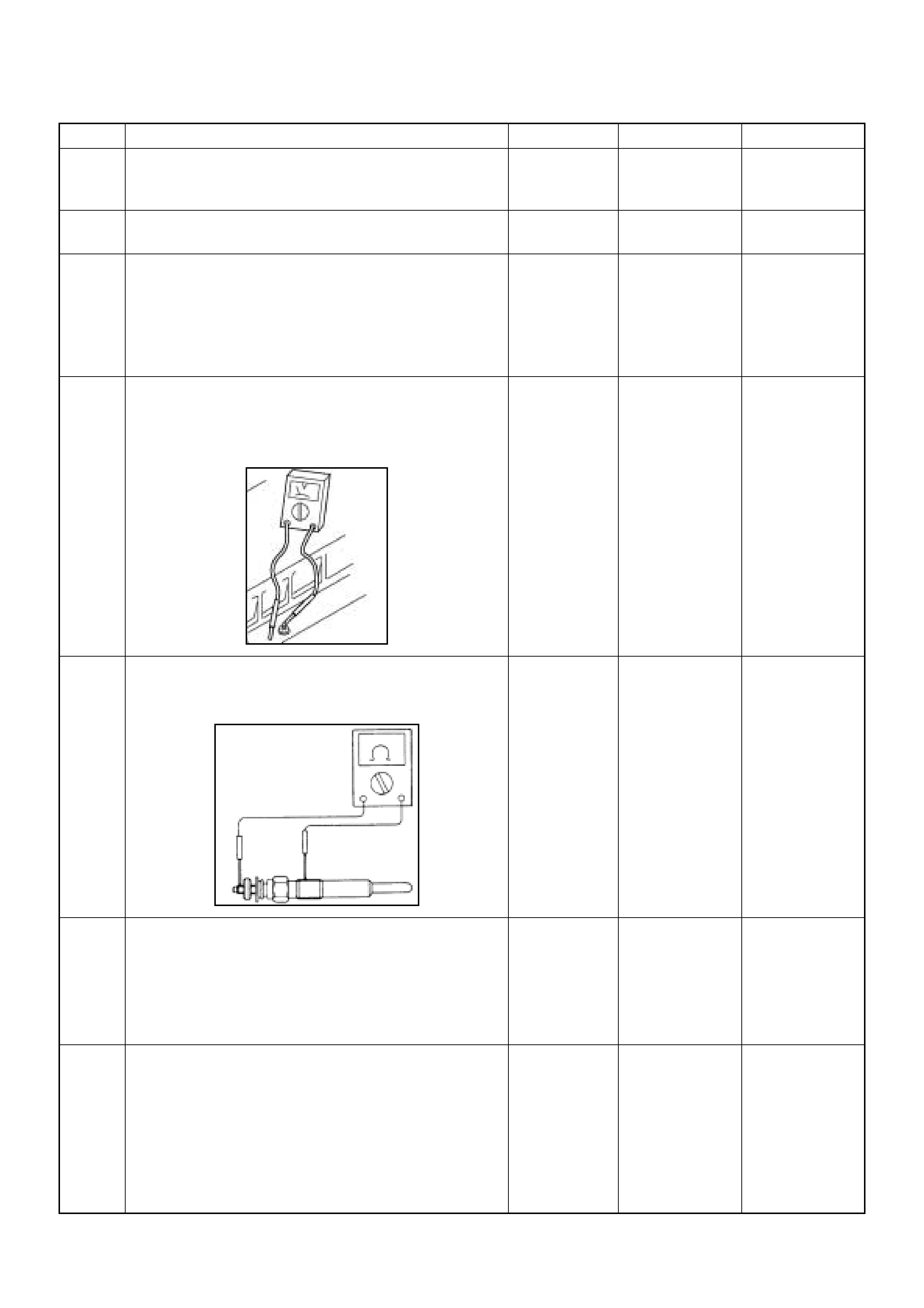
12 Substitute a known good MAF & IAT sensor assembly
and recheck.
Was the problem solved? — Go to Step 13 Go to Step 30
13 Replace the MAF & IAT sensor assembly.
Is the action complete? — Verify repair —
14 1. Using the Tech 2, ignition “On” and engine “Run”.
2. M onitor the “Glow Time Relay” in th e data display.
Does the Tech 2 indicate correct “Glow Time Relay”
status depending on the time from engine “Run”?
If a problem is found, repair as necessary.
Was the problem found? — Go to Step 30 Go to Step 15
15 1. Using the Tech 2, ignition “On” and engine “Run”.
2. Monitor the “Gl ow Time Rela y” in the data dis play
and then, does the supply voltage correctly supply
to the glow plug?
—Go to Step 16
Repair voltage
supply circuit
and verify repair
16 Check the glow plugs for continuity.
If a problem is found, repair as necessary.
Was a problem found?
— Verify repair Go to Step 17
17 Remove the CKP sensor from the flywheel housing
and check for the following conditions.
• Objects sticking the CKP sensor.
• Objects sticking the CKP sensor pulser.
If a problem is found, repair as necessary.
W as the problem found? — Verify repair Go to Step 18
18 Check the CKP sensor harness for the following
conditions.
• Check for poor connector connection.
• Check for misrouted harness.
• Check for any accessory parts which may cause
electric interference.
If a problem is found, repair as necessary.
Was a problem found? — Verify repair Go to Step 19
Step Action Value(s) Yes No
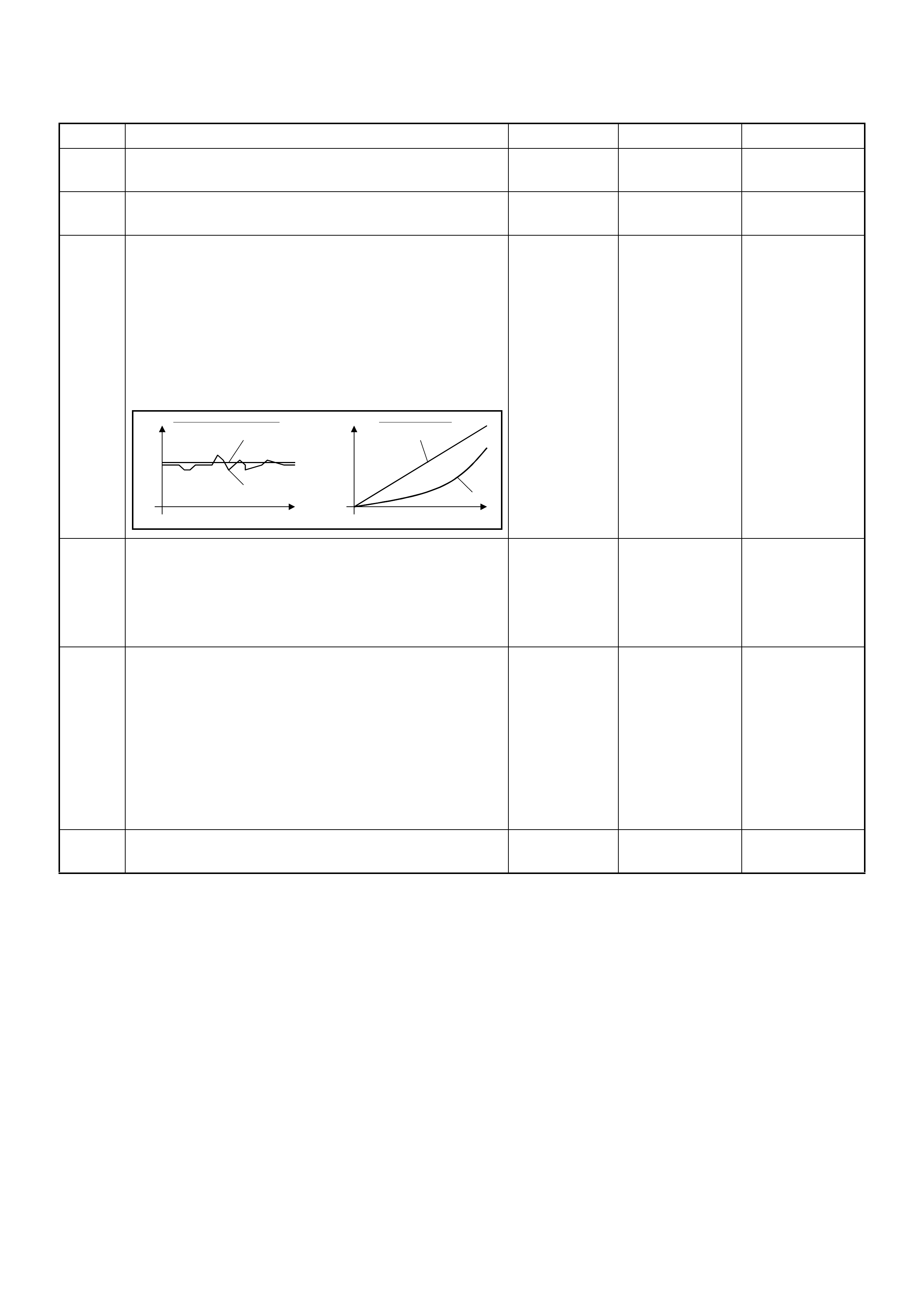
19 Substitute a known good CKP sensor and recheck.
Was the problem solved? — Go to Step 20 Go to Step 21
20 Replace the CKP sensor.
Is the action complete? — Verify repair —
21 1. Using the Tech 2 and ignition “On” and engine
“Run”.
2. Monitor the following parameters in the data
display.
• “Desired Injection Quantity” & “Injection Quantity”
• “Desired Injection Start” & “Actual Injection Start”
Are the large gap or unstable parameter displayed
between “Desired” and “Actual”?
—Go to Step 23 Go to Step 22
22 Check the exhaust system for a possible restriction.
• Damaged or collapsed pipes or catalytic converter.
• Internal muffler failur e.
If a problem is found, repair as necessary.
W as a problem found? — Verify repair Go to Step 23
23 Visually/physically inspect for the following conditions.
• Restric ted fuel supply s ystem. Che ck for a pinche d
fuel hose/pipe.
• Check for a condition that causes fuel waxing or
icing, such as the customer is using an incorrect
fuel type in winter season or water mixed with the
fuel.
If a problem is found, repair as necessary.
W as a problem found? — Verify repair Go to Step 24
24 Replace the fuel filter.
W as the problem solved? — Verify repair Go to Step 25
Step Action Value(s) Yes No
When idling or part-throttle When accelerated
High Desired
Low
Time
Actual
High
Low
Desired
Actual
Time
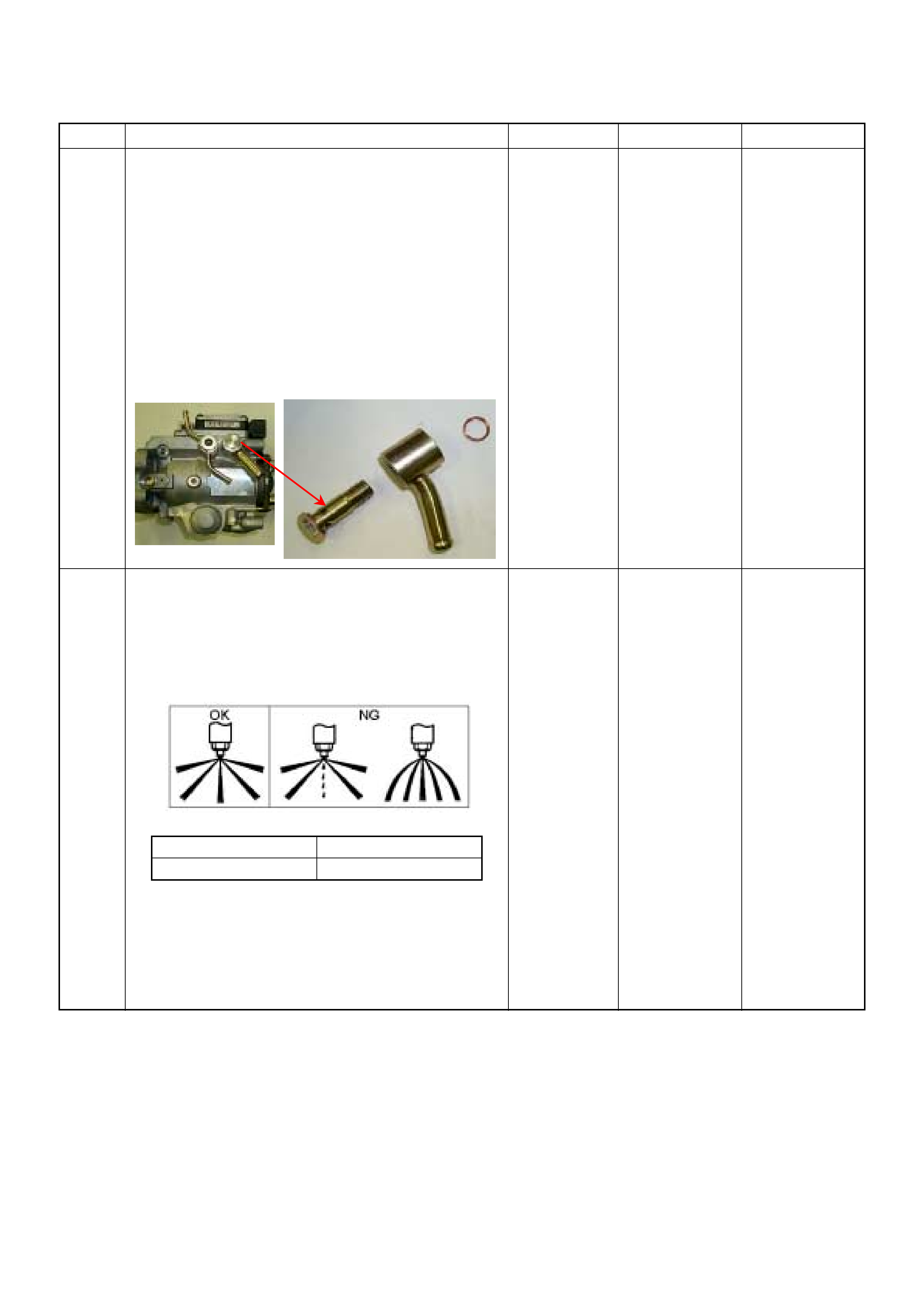
25 Remove the eye bolt with gauze filter from the
injection pump and check for the following conditions.
• Objects blocking at the gauze filter. Check for a
condition that causes contaminated fuel, such as
the customer is using an aftermarket fuel filter or
extended mai nte nan ce int er val.
• Check for a condition that causes fuel waxing or
icing, such as the customer is using an incorrect
fuel type in winter season or water mixed with the
fuel.
If a problem is found, repair as necessary.
Was the problem found?
—
Replace the
eye bolt with
gauze filter and
verify repair Go to Step 26
26 Remove the injection nozzles from the engine and
check for the following conditions.
• Improper spray condition.
• Operating pressure is incorrect.
If a problem is found, repair as necessary.
Was the problem found?
—
Replace the
injection nozzle
and verify repair Go to Step 27
Step Action Value(s) Yes No
1st Stage 2nd Stage
Approximately 19.5 Mpa Approximat ely 33.8 Mpa
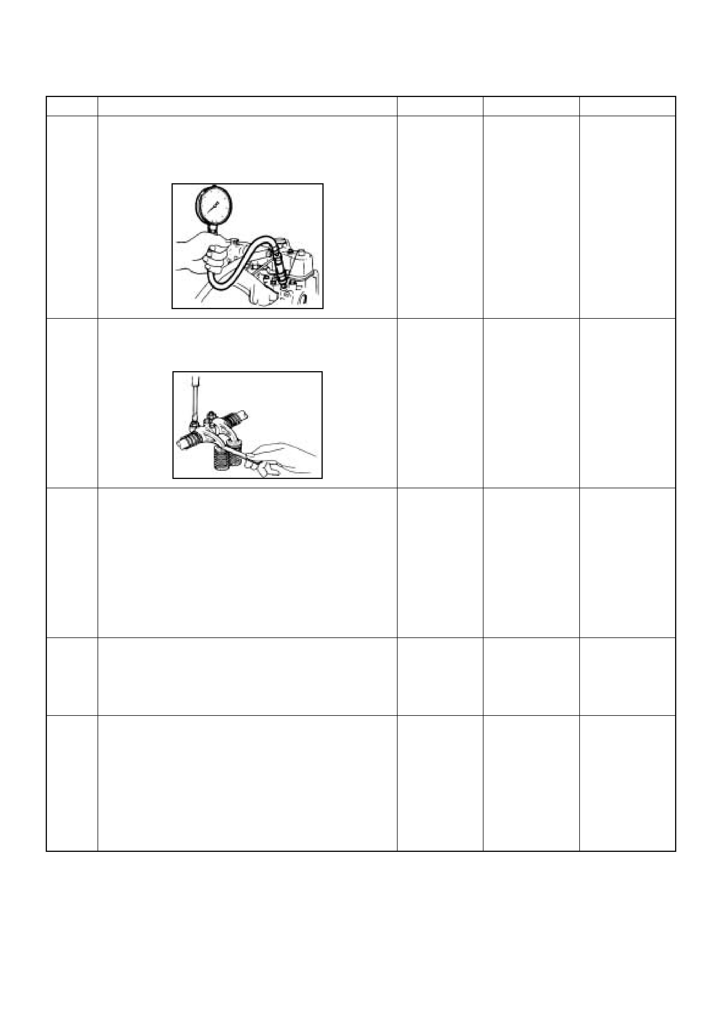
27 Check the engine compression pressure for each
cylinders.
If a problem is found, repair as necessary.
Was the problem found?
More than 20
Mpa Verify repair Go to Step 28
28 Check the inlet/exhaust valve clearance for each
valves.
Are the valve clearances within the specified value?
0.4mm at cold
(In/Ex) Go to Step 29 Adjust and
verify repair
29 1. Review all diagnostic procedures within this table.
2. If all procedures have been completed and no
malfunctions have been found, review/inspect the
following:
• Visual/physical inspection
• Tech 2 data
• All electrical connections within a suspected circuit
and/or system
Was a problem found? — Verify repair Go to Step 30
30 Is the ECM programmed with the latest software
release?
If not, download the latest software to the ECM using
the “SPS (Service Programming System)”.
Was the problem solved? — Verify repair Go to Step 31
31 Substitute a known good ECM and recheck.
Was the problem solved?
IMPORTANT: The replacement ECM must be
programmed. Refer to section of the Service
Programming System (SPS) in this manual.
Foll owing ECM pr ogramming, the immobi lizer system
(if equipped) must be linked to the ECM. Refer to
section 11 “Immobilizer System-ECM replacement” for
the ECM/Immobilizer linking procedure. — Go to Step 32 Go to Step 33
Step Action Value(s) Yes No

32 Replace the ECM.
Is the action complete?
IMPORTANT: The replacement ECM must be
programmed. Refer to section of the Service
Programming System (SPS) in this manual.
Foll owing ECM pr ogramming, the immobi lizer system
(if equipped) must be linked to the ECM. Refer to
section 11 “Immobilizer System-ECM replacement” for
the ECM/Immobilizer linking procedure. — Verify repair —
33 Replace the injection pump assembly.
Is the action complete? — Verify repair —
Step Action Value(s) Yes No

EXCESSIVE BLACK SMOKE
Step Action Value(s) Yes No
1 Was the “On-Board Diagnostic (OBD) System Check”
performed?
—Go to Step 2
Go to On Board
Diagnostic
(OBD) System
Check
2 1. Perform a bulletin search.
2. If a bulletin that addresses the symptom is found ,
correct the condition as instructed in the bulletin.
Was a bulletin found that addresses the symptom? — Verify repair Go to Step 3
3 Was a visually/physical check performed? —Go to Step 4 Go to Visual /
physical Check
4 Is the customer using the incorrect fuel type? Diesel fuel
only Replace with
diesel fuel Go to Step 5
5 Visually/physically inspect for the following conditions.
• Restricted air intake system. Check for a restricted
air filter element, o r foreign ob jects blocking th e air
intake sy stem
• Che ck f or o bjects block ing or e xces sive d epo sits i n
the throttle bore and on the throttle plate
• Check for a condition that causes a large vacuum
leak, such as an incorrectly installed or faulty
crankc as e ven til ati on hose.
• Restricted air intake system at the turbocharger.
Check for objects blocking the turbocharger
compressor wheel or turbine shaft sticking.
If a problem is found, repair as necessary.
W as a problem found? — Verify repair Go to Step 6
6 Check the ECM & PSG grounds to verify that they are
clean and tight. Refer to the ECM wiring diagrams.
W as a problem found? — Verify repair Go to Step 7
7 1. Usin g th e Tech 2, d ispl ay the EC T s ensor an d I AT
sensor value.
2. Check the displayed value.
Does the Tech 2 indicate correct temperature
depending on engine condition?
If a problem is found, repair as necessary.
W as the problem found? — Verify repair Go to Step 8
8 1. Using the Tech 2, display the FT sensor value.
2. Check the displayed value.
Does the Tech 2 indicate correct temperature
depending on engine condition?
If a problem is found, repair as necessary.
Was the problem found? — Go to Step 21 Go to Step 9
9 1. Using the Tech 2, ignition “On” and engine “Run”.
2. Monitor the “Mass Air Flow” in the data display.
Does the Tech 2 indicate correct “Mass Air Flow”
depending on accelerator pedal operation? — Go to Step 14 Go to Step 10
10 Remove the MAF & IAT sensor assembly and check
for the following conditions.
• Objects blocking at the MAF sensor element.
If a problem is found, repair as necessary.
W as the problem found? — Verify repair Go to Step 11
11 Check the MAF sensor harness for the following
conditions.
• Check for poor connector connection.
• Check for misrouted harness.
• Check for any accessory parts which may cause
electric interference.
If a problem is found, repair as necessary.
W as a problem found? — Verify repair Go to Step 12
12 Substitute a known good MAF & IAT sensor assembly
and recheck.
Was the problem solved? — Go to Step 13 Go to Step 21
13 Replace the MAF & IAT sensor assembly.
Is the action complete? — Verify repair —
14 1. Using the Tech 2 and ignition “On” and engine
“Run”.
2. Monitor the following parameters in the data
display.
• “Desired Injection Quantity” & “Injection Quantity”
• “Desired Injection Start” & “Actual Injection Start”
Are the large gap or unstable parameter displayed
between “Desired” and “Actual”?
—Go to Step 20 Go to Step 15
Step Action Value(s) Yes No
When idling or part-throttle When accelerated
High Desired
Low
Time
Actual
High
Low
Desired
Actual
Time
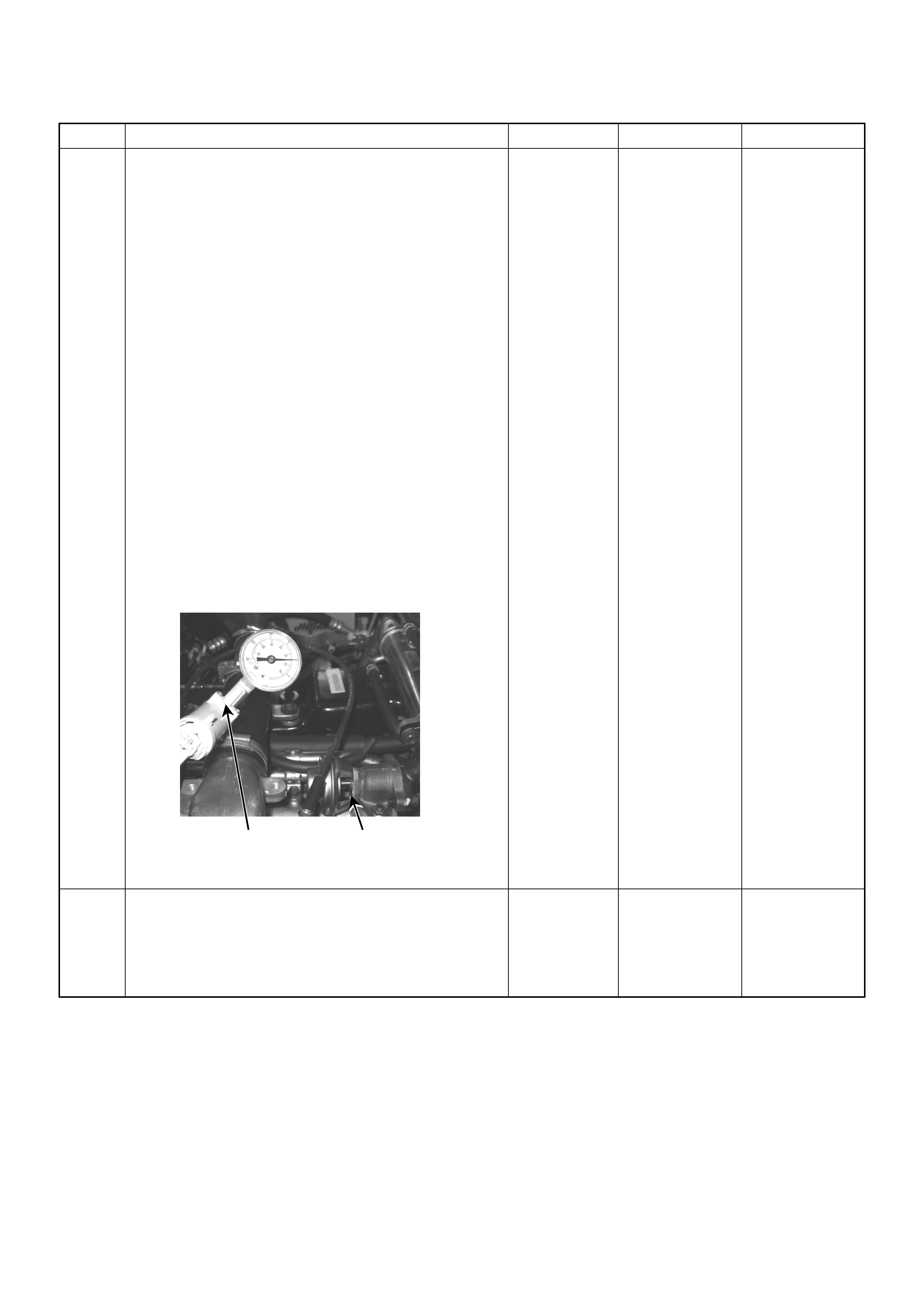
15 Using the Tec h 2 or the v acuum pump a nd check th e
EGR valve operation for the following condition
through the small window.
• Restricted shaft movement. Check for objects
sticking the shaft, broken diaphragm or
excessive carbon deposit.
Tech 2:
1. Using the Tech 2, ignition "On" and engine "On".
2. Select the "Miscellaneous Test" and perform the
"EGR Solenoid Test" in the "Solenoid".
3. Operate the Tech 2 in accordance with procedure.
• Solenoid 95%: EGR Valve Open
• Solenoid 5%: EGR Valve Close
Vacuum Pump:
1. Using the vacuum pump. Disconnect the original
vacuum hose and connect the hose to the EGR
valve.
2. Apply vacuum pressure.
• Vacuum Apply: EGR Valve Open
• Vacuum Release: EGR Valve C lose
If a problem is found, repair as necessary.
W as the problem found? — Verify repair Go to Step 16
16 Check the exhaust system for a possible restriction.
• Damaged or collapsed pipes or catalytic converter.
• Internal muffler failur e.
If a problem is found, repair as necessary.
W as a problem found? — Verify repair Go to Step 17
Step Action Value(s) Yes No
Vacuum Pump Small Window
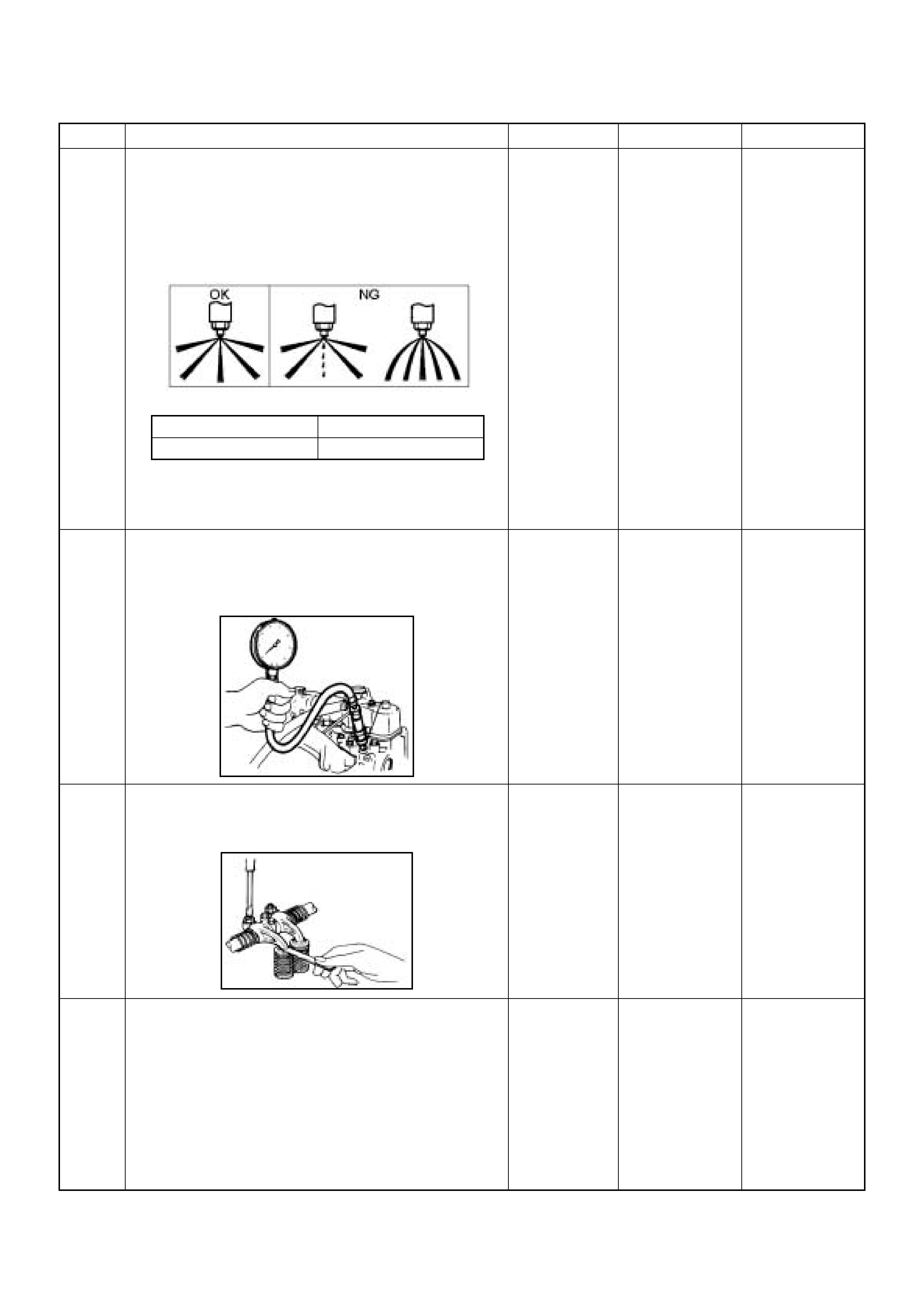
17 Remove the injection nozzles from the engine and
check for the following conditions.
• Improper spray condition.
• Operating pressure is incorrect.
If a problem is found, repair as necessary.
Was the problem found?
—
Replace the
injection nozzle
and verify repair Go to Step 18
18 Check the engine compression pressure for each
cylinders.
If a problem is found, repair as necessary.
Was the problem found?
More than 20
Mpa Verify repair Go to Step 19
19 Check the inlet/exhaust valve clearance for each
valves.
Are the valve clearances within the specified value?
0.4mm at cold
(In/Ex) Go to Step 20 Adjust and
verify repair
20 1. Review all diagnostic procedures within this table.
2. If all procedures have been completed and no
malfunctions have been found, review/inspect the
following:
• Visual/physical inspection
• Tech 2 data
• All electrical connections within a suspected circuit
and/or system
W as a problem found? — Verify repair Go to Step 21
Step Action Value(s) Yes No
1st Stage 2nd Stage
Approximately 19.5 Mpa Approximately 33.8 Mpa

21 Is the ECM programmed with the latest software
release?
If not, download the latest software to the ECM using
the “SPS (Service Programming System)”.
Was the problem solved? — Verify repair Go to Step 22
22 Substitute a known good ECM and recheck.
Was the problem solved?
IMPORTANT: The replacement ECM must be
programmed. Refer to section of the Service
Programming System (SPS) in this manual.
Foll owing ECM pr ogramming, the immobi lizer system
(if equipped) must be linked to the ECM. Refer to
section 11 “Immobilizer System-ECM replacement” for
the ECM/Immobilizer linking procedure. — Go to Step 24 Go to Step 23
23 Replace the ECM.
Is the action complete?
IMPORTANT: The replacement ECM must be
programmed. Refer to section of the Service
Programming System (SPS) in this manual.
Foll owing ECM pr ogramming, the immobi lizer system
(if equipped) must be linked to the ECM. Refer to
section 11 “Immobilizer System-ECM replacement” for
the ECM/Immobilizer linking procedure. — Verify repair —
24 Replace the injection pump assembly.
Is the action complete? — Verify repair —
Step Action Value(s) Yes No
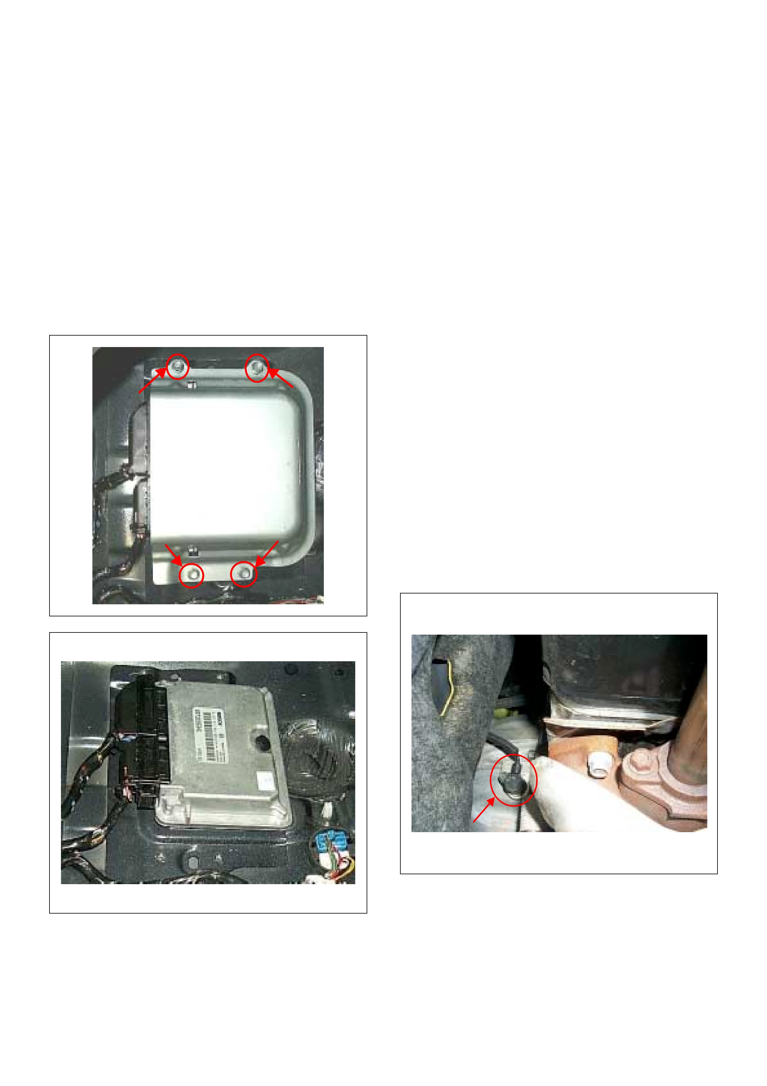
ON-VEHICLE SERVICE PROCEDURE
ENGINE CONTROL MODULE (ECM)
Location:
Under the left-hand side seat.
Removal Procedure
1. Disconnect the negative battery cable.
2. Remove the seat left-hand side.
3. Roll up the floor carpet.
4. Remove four bolts from the ECM cover.
5. Disconnect the two connectors from the ECM.
Installation Procedure
1. Connect the two connectors to the ECM.
2. Put on the ECM to the floor panel.
3. Tighten the ECM cover by four bolts with specified
tightening torque.
Tightening torque
• Bolts: 8.0 - 12.0 N·m (0.8 - 1.2 kgf·m)
4. Lay the floor carpet exactly.
5. Put on the seat to the floor panel and tighten with
specified tightening torque.
Tightening torque
• Bolts: 40.0 N·m (4.1 kgf·m)
6. Connect the negative battery cable.
NOTE: The replacement ECM must be programmed.
Refer to section of the Service Programming System
(SPS) in this manual.
Following ECM programming, the immobilizer system (if
equipped) must be linked to the ECM. Refer to section
11 “Immobilizer System-ECM replacement” for the
ECM /Imm obi li ze r linki ng proc edu re .
CRANKSHAFT PO SITION (CKP) SENSOR
Location:
Installed to the clutch housing.
Removal Procedure
1. Disconnect the negative battery cable.
2. Disconnect connector from the CKP sensor .
3. Loosen a bolt and r emov e the CKP se nsor from the
clutch housing.
Installation Procedure
1. Install the CKP sensor to the clutch housing.
2. Tighten CKP sensor by a bolt with specified
tighteni ng torque .
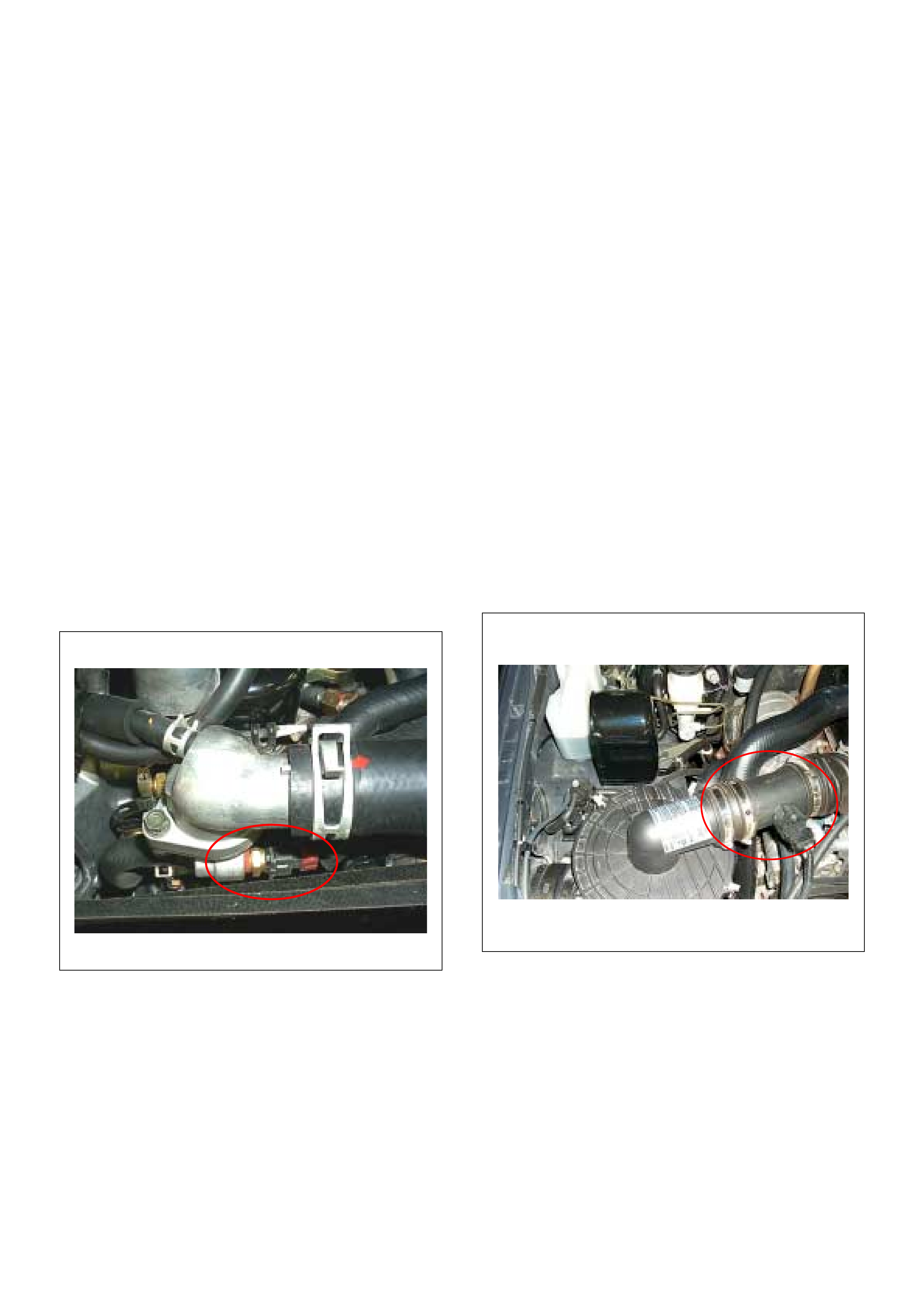
Tightening Torque
• Bolts: 8.0 - 12.0 N·m (0.8 - 1.2 kgf·m)
3. Connect a CKP sensor connector to the CKP
sensor.
4. Connect the negative battery cable.
NOTE: Verify any DTCs (diagnosis Trouble Code) are
not stored after replacement.
ENGINE COOLANT TEMPERATURE (ECT)
SENSOR
Location:
Installed to the thermostat housing.
NOTE: Cool down the engine befo re above pro cedures
are carried out.
Removal Procedure
1. Disconnect the negative battery cable.
2. Drain enough engine coolant so that the coolant
level will be below the ECT sensor.
3. Disconnect connector from the ECT sensor.
4. Loosen and remove the ECT sensor from the
thermostat housing.
Installation Procedure
1. Apply sealer to threads of screw at the ECT sensor.
2. Tighten the ECT sensor with specified tightening
torque.
Tightening Torque
• Bolt: 13N·m (1.3kgf·m)
3. Connect a ECT sensor connector to the ECT
sensor.
4. Fill the engine coolant.
5. Connect the negative battery cable.
NOTE: Verify any DTCs (diagnosis Trouble Code) are
not stored after replacement.
Verify no engine coolant leaking from the sensor
threads after replacement.
MASS AIR FLOW (MAF) & INTAKE AIR
TEMPERATURE (IAT) SENSOR
Location:
Installed to the intake duct housing.
Removal Procedure
1. Disconnect the negative battery cable.
2. Discon nect a MAF & IAT sens or conn ector fr om the
MAF & IAT sensor assembly.
3. Loosen th e clips and rem ove the MA F & IAT sensor
assembly from the intake duct housing.
Installation Procedure
1. Install the MAF & IAT sensor assembly into intake
air duct.
2. Tighten the clips.
3. Conne ct a MA F & IAT se nsor co nnecto r to the MAF
& IAT sensor assembly.
4. Connect the negative battery cable.
NOTE: Verify any DTCs (diagnosis Trouble Code) are
not stored after replacement.
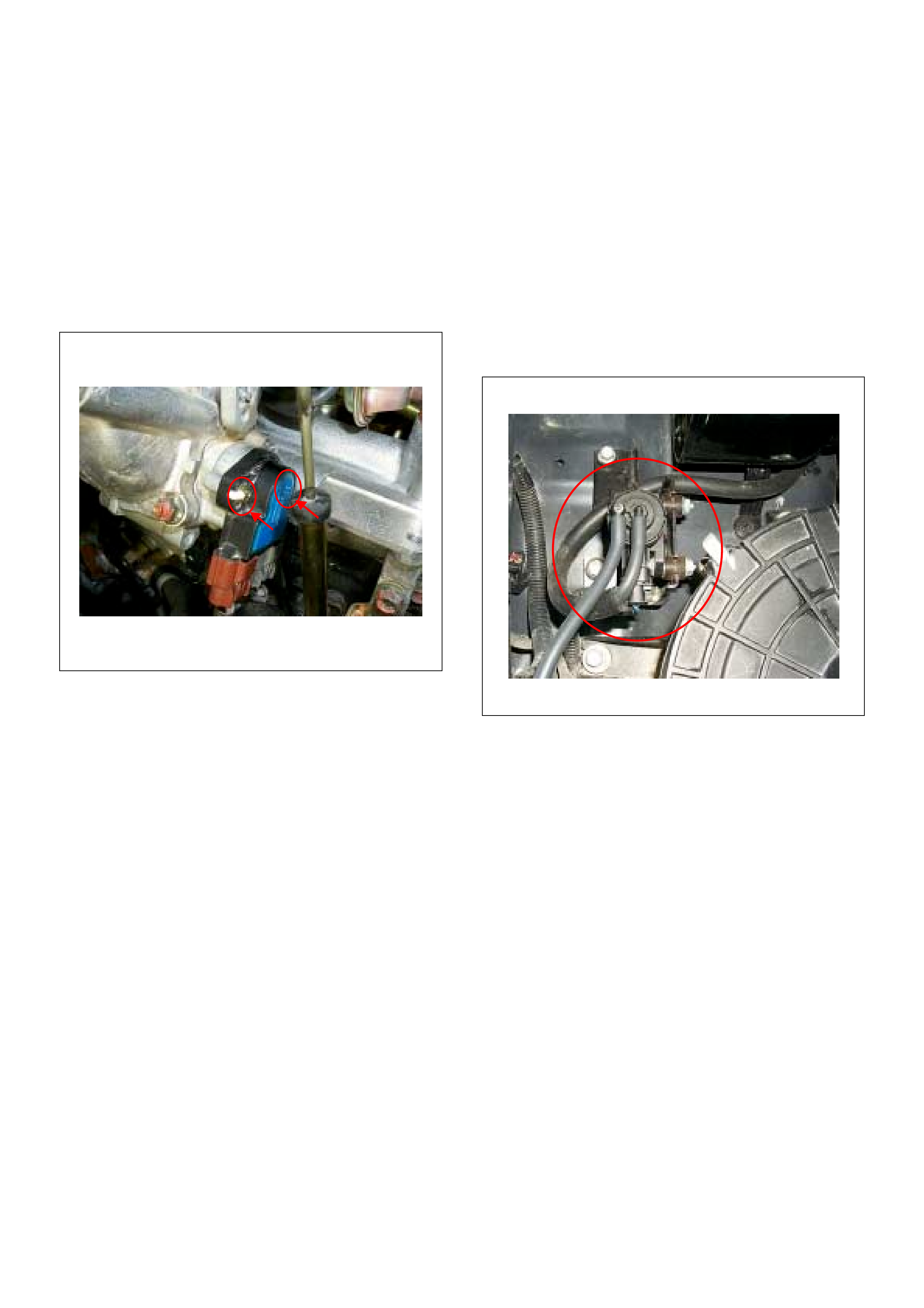
THROTTLE POSITION SENSOR (TPS)
Location:
Installed on the throttle body.
Removal Procedure
1. Disconnect the negative battery cable.
2. Disconnect the TPS connector.
3. Loosen two screws and remove TPS from the
throttle body.
Installation Procedure
1. Fit the TPS and temporarily tighten the two TPS
retaining screws.
2. Connect the TPS connectors to the TPS.
3. Connect the negative battery cable.
4. Connect the Tech2 to the vehicle.
5. Select “Data Display” with the Tech2.
6. Check the throttle position data and adjust the TPS
position, refer to Typical Scan Data & Definitions in
this manual.
7. Tight en the two screws.
NOTE: Verify no D TCs (Diagnostic Trouble Codes) are
stored after replacement.
EGR EVRV (Electrical Vacuum Regulating
Valve)
Location:
Back of the air cleaner case.
Removal Procedure
1. Disconenct the negative battery cable.
2. Disconnect the EVRV connector from the EVRV.
3. Disconnect the two hoses from the EVRV.
4. Loosen two bolts and remove the EVRV from the
bracket.
Installation Procedure
1. Tighten the purge solenoid by two bolts.
2. Connect the connector to the EVRV.
3. Connect the two hoses to the EVRV.
4. Connect the negative battery cable.
NOTE: Verify any DTCs (diagnosis Trouble Code) are
not stored after replacement.
Verify proper connection of the two hoses.
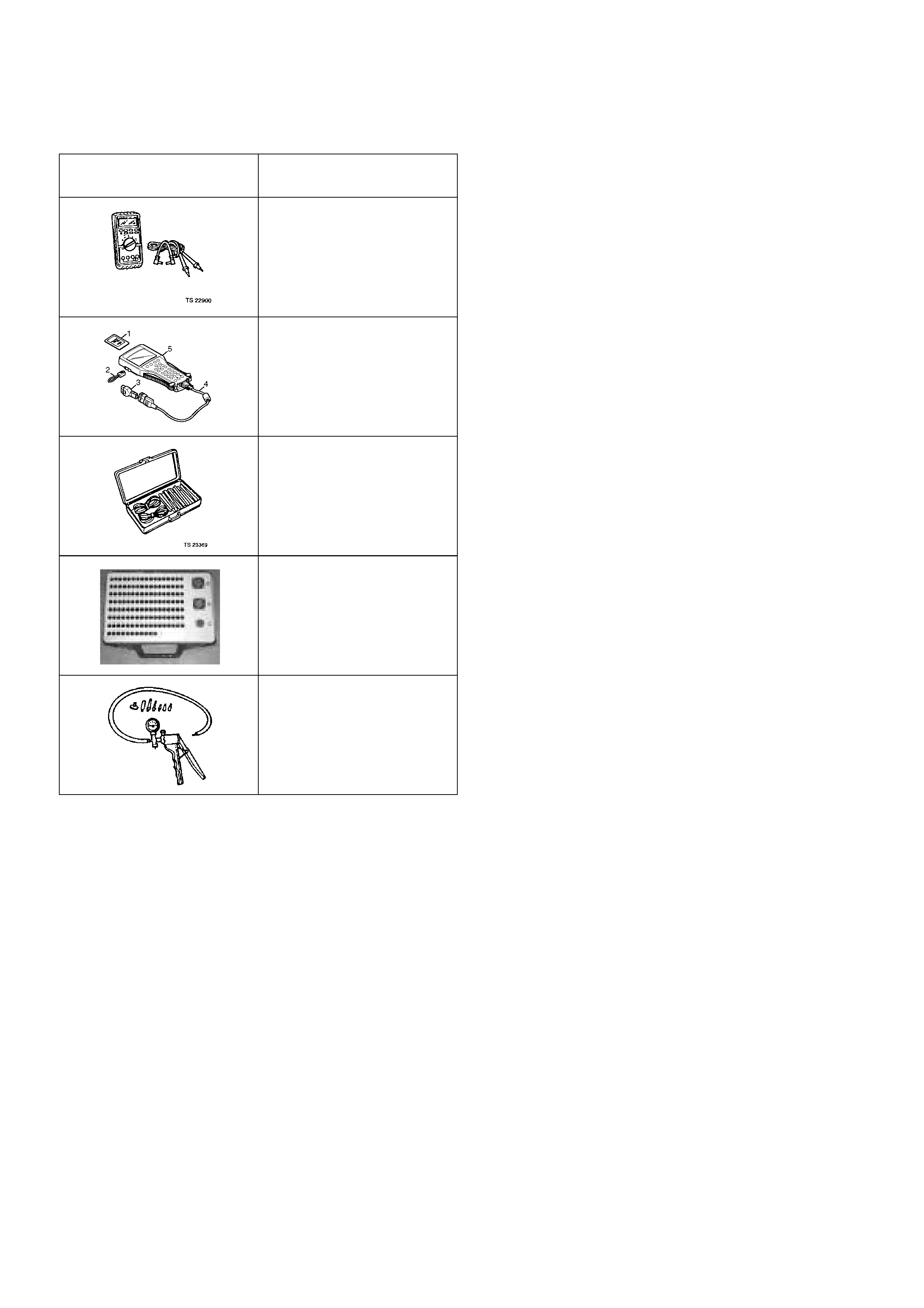
SPECIAL SERVICE TOOLS
ILLUSTRATION TOOL NO.
TOOL N AME
5-8840-0285-0
(J 39200)
High Impedance
Multimeter
(Digital Voltmeter -DVM)
(1) PCMCIA Card
(2) RS232 Loop Back
Connector
(3) SAE 16/19 Adapter
(4) DLC Cable
(5) TECH 2
5-8840-0385-0
(J 35616-A/BT-8637)
Connector Test Adapter Kit
Breaker Box
5-8840-0279-0
(J 23738-A)
Vacuum Pump with Gauge