
SECTION 6B - ENGINE COOLING (6VE1 3.5L)
Service Precaution
General Description
Diagnosis
Draining and Refilling Cooling System
Water Pump
Water Pump and Associated Parts
Removal
Inspection
Installation
Thermostat
Thermostat and Associated Parts
Removal
Inspection
Installation
Radiator
Radiator and Associated Parts
Removal
Inspection
Installation
Drive Belt and Cooling Fan
Drive Belt and Associated Parts
Inspection
Installation
Main Data and Specifications
General Specifications
Torque Specifications
Special Tools

Service Precaution
WARNING: THIS VEHICLE HAS A SUPPLEMENTAL
RESTRAINT SYSTEM (SRS). REFER TO THE SRS
COMPONENT AND WIRING LOCATION VIEW IN
ORDER TO DETERMINE WHETHER YOU ARE
PERFORMING SERVICE ON OR NEAR THE SRS
COMPONENTS OR THE SRS WIRING. WHEN YOU
ARE PERFORMING SERVICE ON OR NEAR THE
SRS COMPONENTS OR THE SRS WIRING, REFER
TO THE SRS SERVICE INFORMATION. FAILURE TO
FOLLOW WARNINGS COULD RESULT IN
POSSIBLE AIR BAG DEPLOYMENT, PERSONAL
INJURY, OR OTHERWISE UNNEEDED SRS SYSTEM
REPAIRS.
CAUTION: Always use the correct fastener in the
proper location. When you replace a fastener, use
ONLY the exact part number for that application.
HOLDEN will call out those fasteners that require a
replacement after removal. HOLDEN will also call
out the fasteners that require thread lockers or
thread sealant. UNLESS OTHERWISE SPECIFIED,
do not use supplemental coatings (Paints, greases,
or other corrosion inhibitors) on threaded fasteners
or fastener joint interfaces. Generally, such
coatings adversely affect the fastener torque and
the joint clamping force, and may damage the
fastener. When you install fasteners, use the
correct tightening sequence and specifications.
Following these instructions can help you avoid
damage to parts and systems.
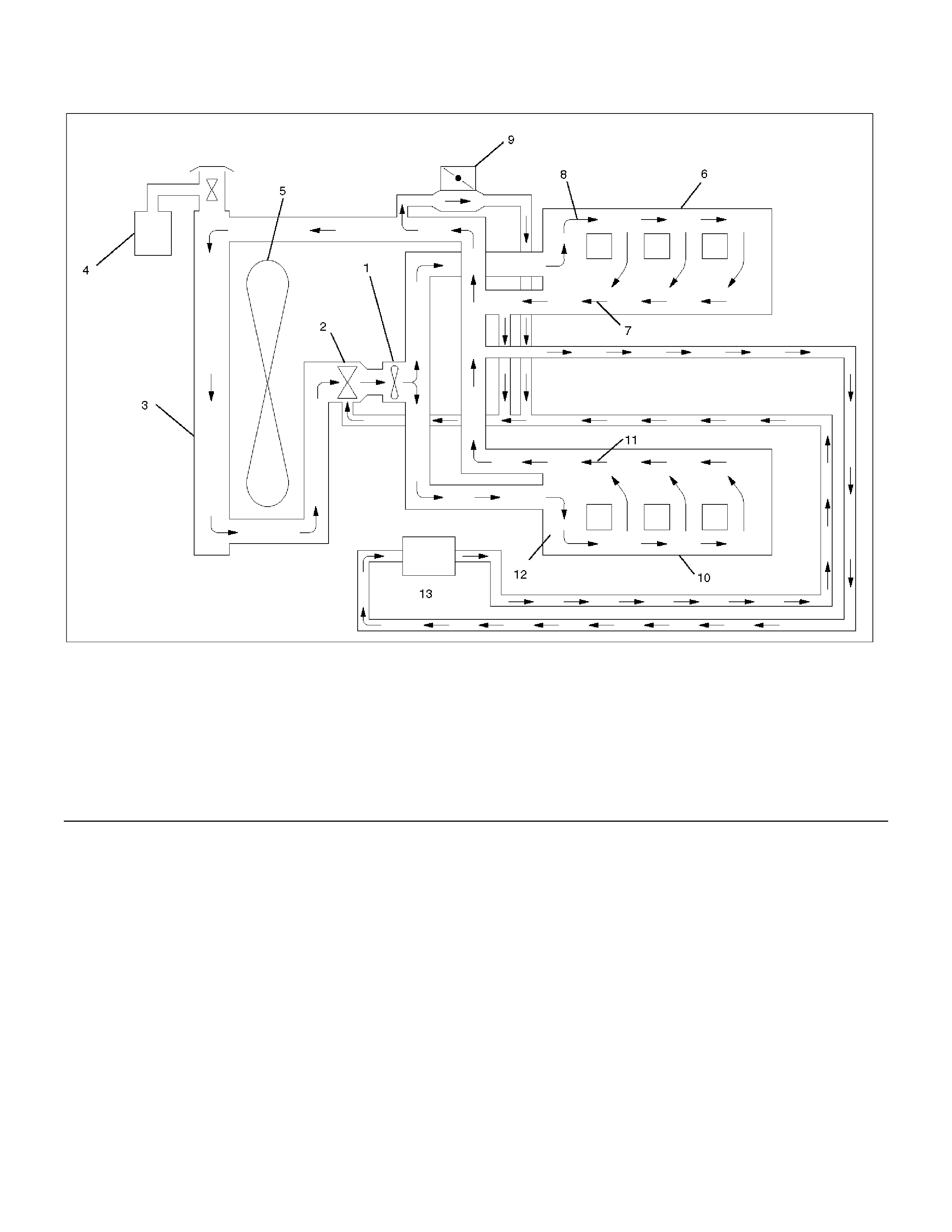
General Description
030RW001
Legend (7) Cylinder Head
(1) Water Pump (8) Right Bank
(2) Thermostat (9) Throttle Body
(3) Radiator (10) Cylinder Block
(4) Reserve Tank (11) Cylinder Head
(5) Cooling Fan (12) Left Bank
(6) Cylinder Block (13) Heater
The engine cooling system consists of the radiator, the
water pump, the cooling fan, and the thermostat.
To quickly increase cold engine coolant temperature for
smooth engine operation, the coolant is circulated by
the water pump and thermostat through the bypass
hose and back to the cylinder body.
At this stage the coolant does not circulate through the
radiator.
When the coolant temperature reaches a specified
value, the thermostat will begin to open and a gradually
increasing amount of coolant will circulate through the
radiator.
The thermostat will be fully open when the coolant
temperature reaches a specified value. All of the
coolant is now circulating through the radiator for
effective engine cooling.
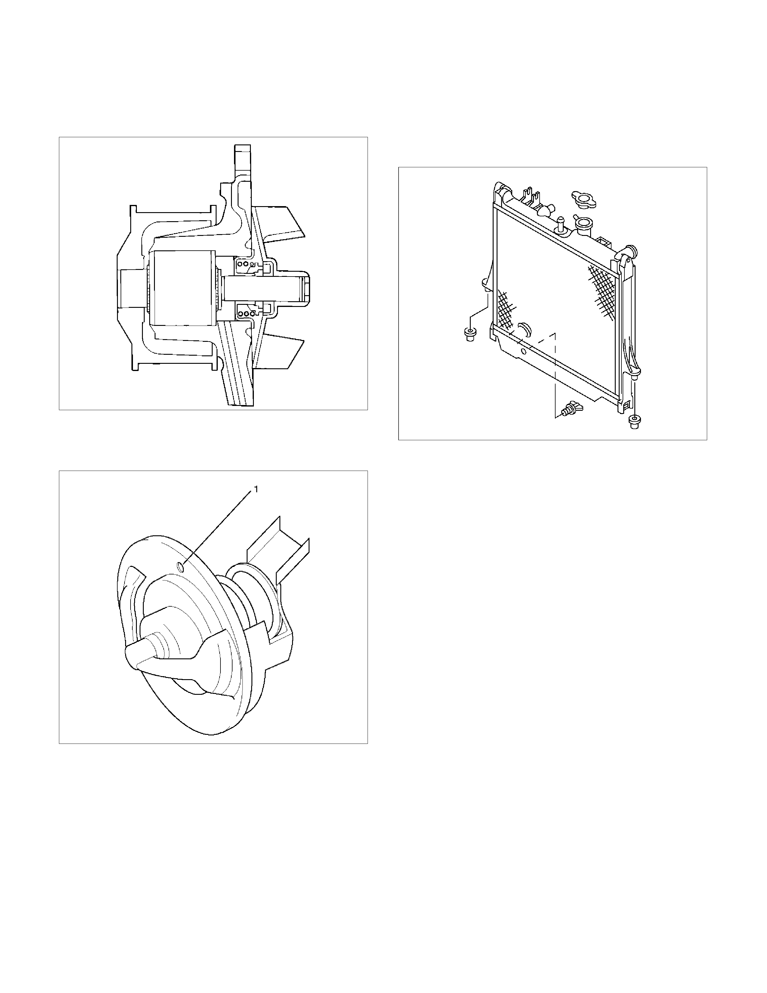
Water Pump
The engine coolant (EC) pump is a centrifugal impeller
type and is driven by a timing belt.
030RS001
Thermostat
The thermostat is a wax pellet type with an air hole (1)
and is installed in the thermostat housing.
031RW002
Radiator
The radiator is a tube type with corrugated fins. In order
to raise the boiling point of the coolant, the radiator is
fitted with a cap in which the valve is operated at 93.3
122.7 kPa (13.5 17.8 psi) pressure. (No oil cooler
is provided for M/T).
110RS001
Coolant Specification
To Holden Specification. Refer to Section 0B
Coolant Capacity
Automatic transmission: 11.0 litres
M
anual transmission: 11.2 litres

Diagnosis
Engine Cooling Trouble
Symptom Possible Cause Action
Engine overheating Low engine coolant level Replenish
Thermo meter unit faulty Replace
Faulty thermostat Replace
Faulty engine coolant temperature
sensor Replace
Clogged radiator Clean or replace
Faulty radiator cap Replace
Low engine oil level or use of
improper engine oil Replenish or change oil
Clogged exhaust system Replace faulty parts
Faulty throttle position sensor Replace throttle valve assembly
Open or shorted throttle position
sensor circuit Repair or replace
Damaged cylinder head gasket Replace
Engine overcooling Faulty thermostat Replace
Engine slow to warm–up Faulty thermostat Replace
Thermo unit faulty Replace
Draining and Refilling Cooling System
Before draining the cooling system, inspect the system
and perform any necessary service to ensure that it is
clean, does not leak and is in proper working order.
The engine coolant (EC) level should be between the
“MIN" and “MAX" lines of reserve tank when the engine
is cold. If low, check for leakage and add EC up to the
“MAX" line.
There should not be any excessive deposit of rust or
scales around the radiator cap or radiator filler hole,
and the EC should also be free from oil.
Replace the EC if excessively dirty.
WARNING: To avoid the danger of being burned, do
not remove the cap, hoses or drain plug while the
engine and radiator are still hot. Scalding fluid and
steam can be blown out under pressure.
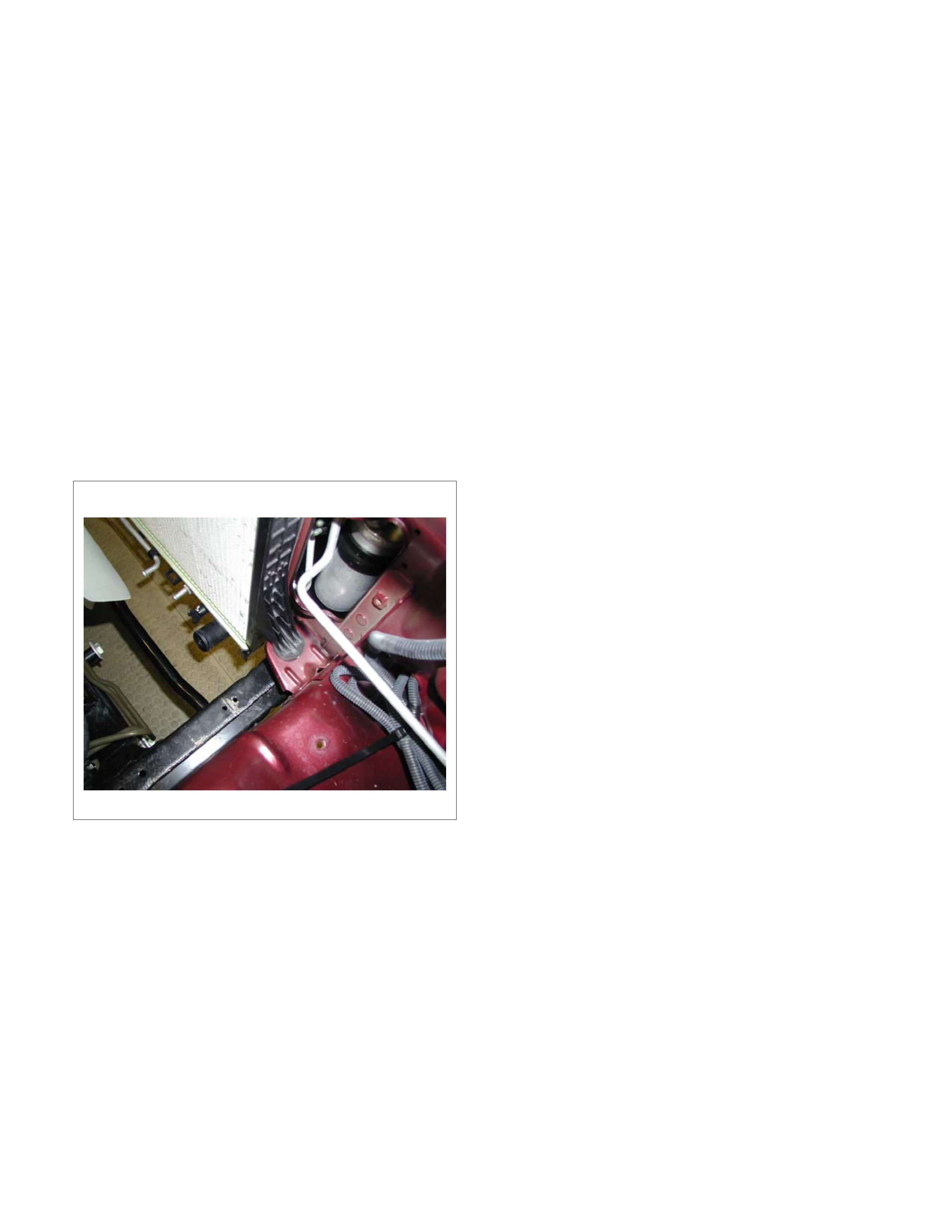
1. Place a suitable container beneath the vehicle and
completely drain the cooling system by opening the
drain plug at the bottom of the radiator.
P1010064
2. Remove the radiator cap.
3. Disconnect all hoses from the EC reserve tank and
remove the tank. Scrub and clean the inside of the
reserve tank with soap and water. Flush it well with
clean water, then drain it. Install the reserve tank
and hoses.
4. Refill the cooling system with coolant to Holden
Specification. Refer Section 0B.
Procedure for filling with coolant (in case of full change)
• Make sure that the engine is cool.
• Open radiator cap and pour coolant up to filler
neck.
• Pour coolant into reservoir tank up to “MAX" line.
• Tighten radiator cap and start the engine. After
idling for 2 to 3 minutes, stop the engine and
reopen radiator cap. If the water level is lower,
replenish.
WARNING: When the coolant is heated to a high
temperature, be sure not to loosen or remove the
radiator cap. Otherwise you might get scalded by
hot vapour or water. To open the radiator cap, put a
piece of thick cloth on the cap and loosen the cap
slowly to reduce the pressure when the coolant has
become cooler.
•
A
fter tightening radiator cap, warm up the engine at
about 2000 rpm. Set heater adjustment to the
highest temperature position, and allow the coolant
to circulate into the heater system.
• Allow the engine to reach operating temperature
and ensure the thermostat has opened.
• When the engine has cooled, carefully remove the
radiator capo and check filler neck for water level
and replenish if required. Should an extreme
shortage of coolant be found, check the cooling
system and reservoir tank hose for leakage.
• Pour coolant into the reservoir tank up to “MAX"
line.
Water Pump
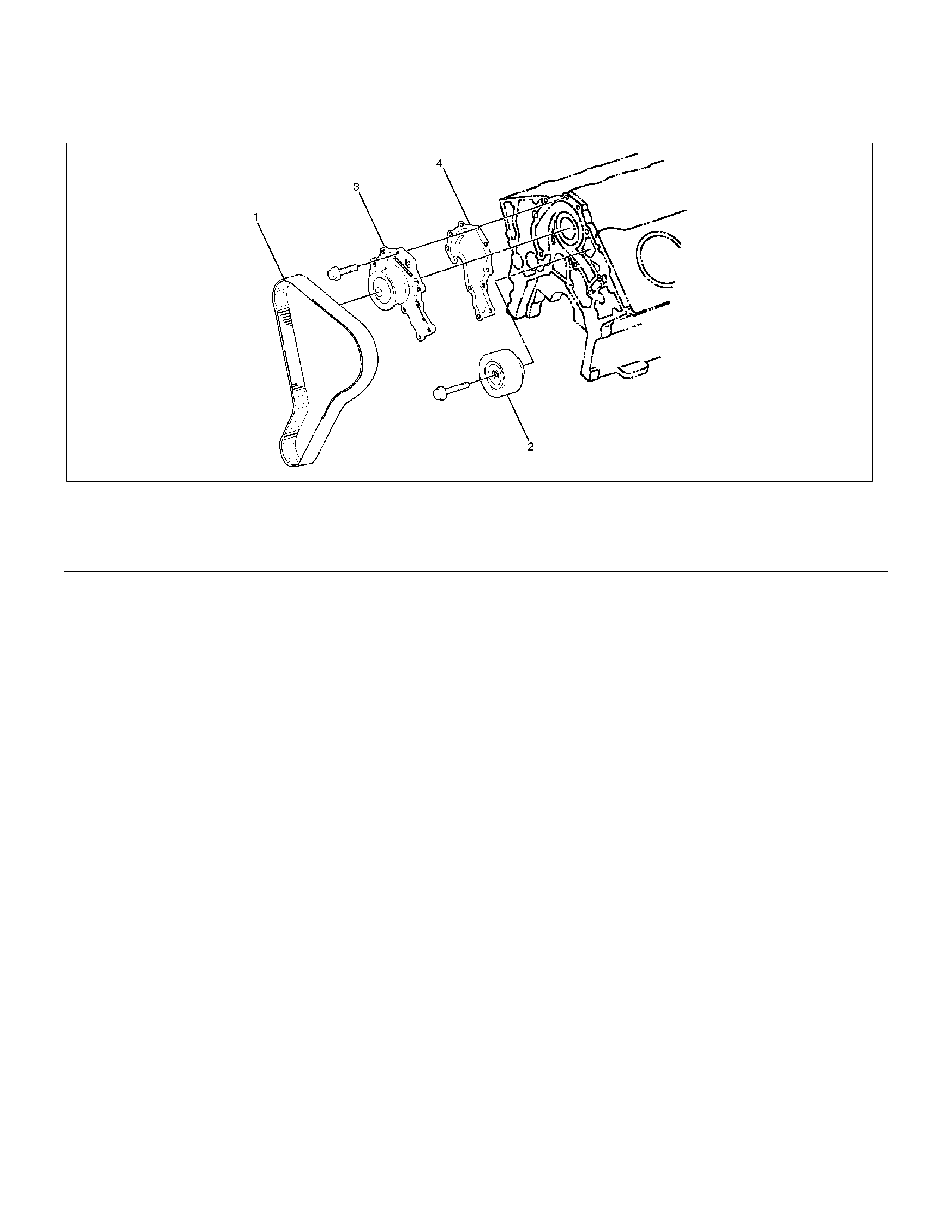
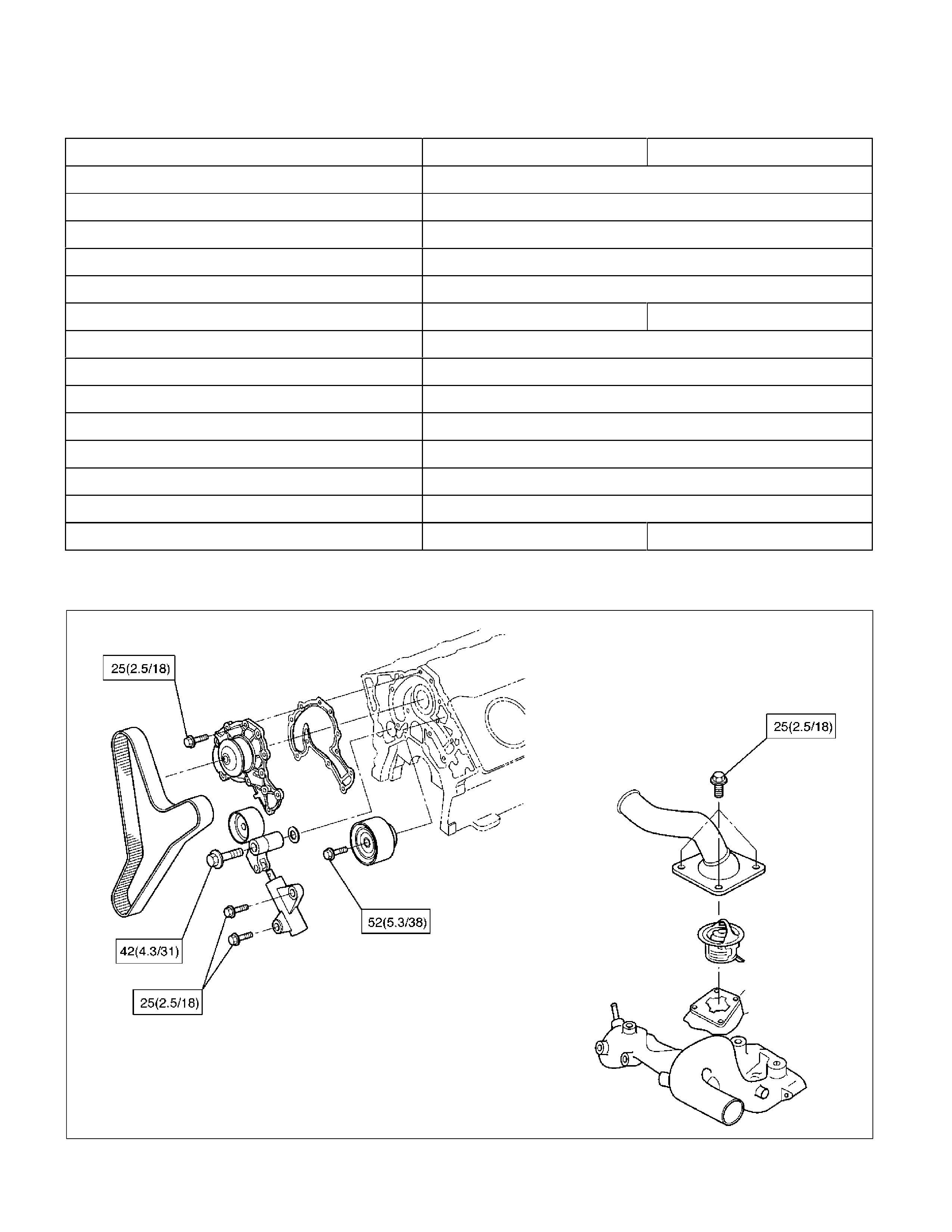
Water Pump and Associated Parts
030RS002
Legend
(1) Timing Belt (3) Water Pump Assembly
(2) Idle Pulley (4) Gasket
Removal
1. Disconnect the battery ground cable.
2. Drain coolant.
3. Radiator hose (on inlet pipe side).
4. Remove timing belt. Refer to “Timing Belt" in this
manual.
5. Remove Idle pulley.
6. Remove water pump assembly.
7. Remove gasket.
Inspection
Make necessary repair and parts replacement if
extreme wear or damage is found during inspection.
Should any of the following problems occur, the entire
water pump assembly must be replaced:
• Crack in the water pump body
• EC leakage from the seal unit
• Play or abnormal noise in the bearing
• Cracks or corrosion in the impeller.
Installation
1. Clean the mating surface of the block and water
pump.
2. Install a new gasket and reinstall the water pump
assembly, tighten bolts to the specified torque.
Torque: 25 N⋅m (2.5 kg⋅m/18 lb ft)
• Tightening order.
The tightening order is in the following
illustration.
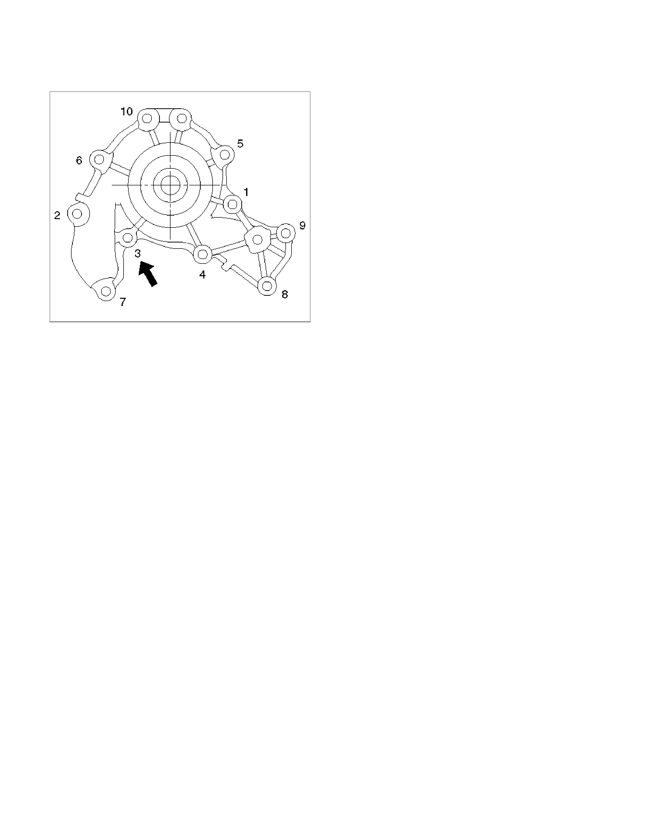
NOTE: To prevent oil leakage, apply LOCTITE 262 or
an equivalent, to the arrow marked fixing bolt thread.
030RW008
3. Idle pulley.
• Install idle pulley and tighten bolt to the
specified torque.
Torque: 52 N⋅m (5.3 kg⋅m/38 lb ft)
4. Timing belt.
• Install timing belt. Refer to “Timing Belt" in this
manual.
5. Connect radiator inlet hose and replenish EC.
6. Connect the battery ground cable.
Thermostat
Thermostat and Associated Parts
031RW001
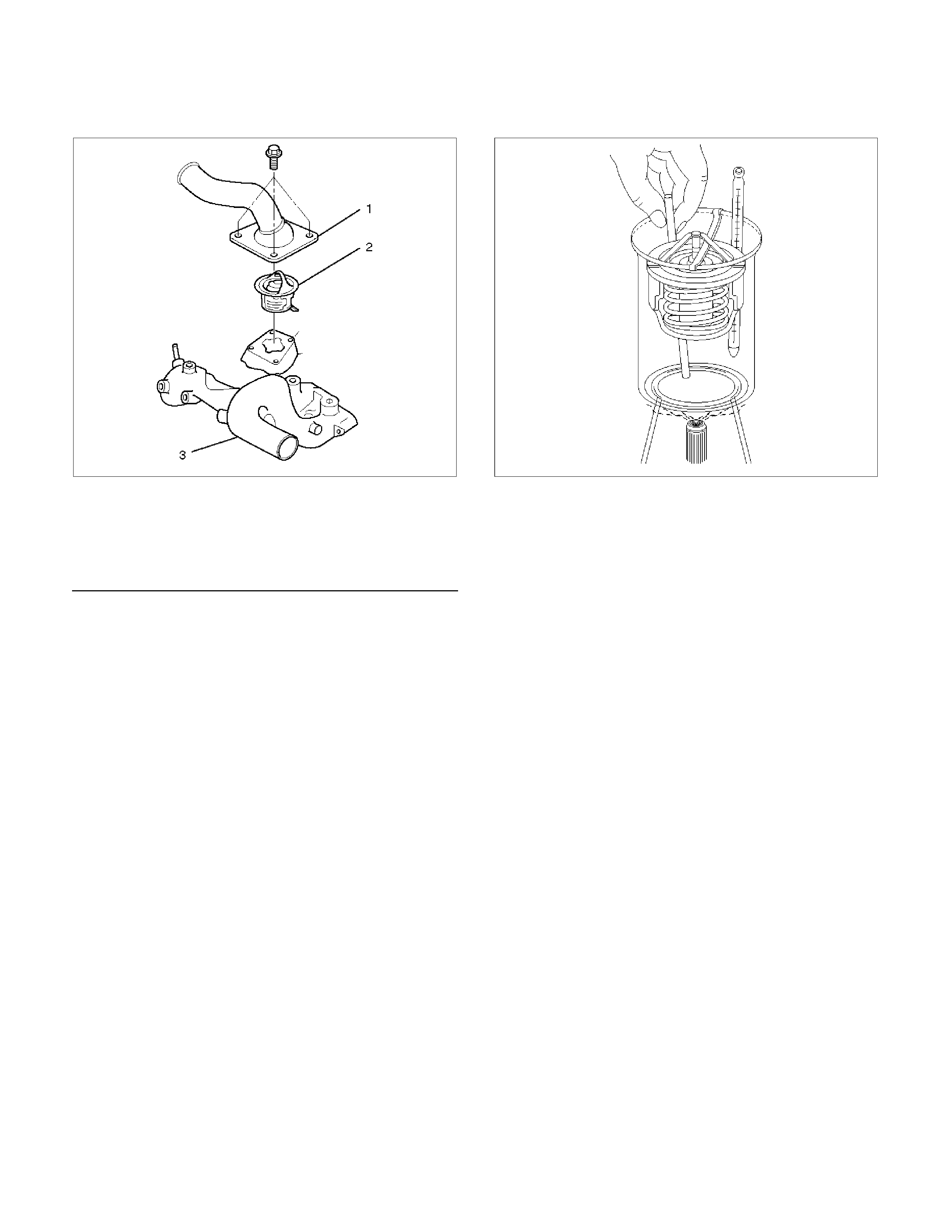
Legend
(1) Thermostat Housing
(2) Thermostat
(3) Outlet Pipe
Removal
1. Disconnect the battery ground cable.
2. Drain engine coolant from the radiator and engine.
3. Disconnect radiator hose from the inlet pipe.
4. Remove thermostat housing.
5. Remove thermostat (2).
Inspection
Suspend the thermostat in a water–filled container
using thin wire. Place a thermometer next to the
thermostat.
Do not directly heat the thermostat.
Gradually increase the water temperature. Stir the
water so that the entire water is same temperature.
031RS003
Confirm the temperature when the valve first begins to
open.
Valve opening temperature 74.5°C ∼ 78.5°C
(166.1°F ∼ 173.3°F)
Confirm the temperature when the valve is fully
opened.
Valve full open temperature and lift More than
8.5mm (0.33 in) at 90°C (194°F)
Replace if faulty.
Installation
1. Install thermostat into the outlet pipe (4) making
sure that the air hole is in the up position.
2. Install thermostat housing and tighten bolts to the
specified torque.
Torque: 25 N⋅m (2.5 kg⋅m/18 lb ft)
3. Install rubber hose.
4. Replenish engine coolant (EC).
5. Start engine and check for EC leakage.
Radiator
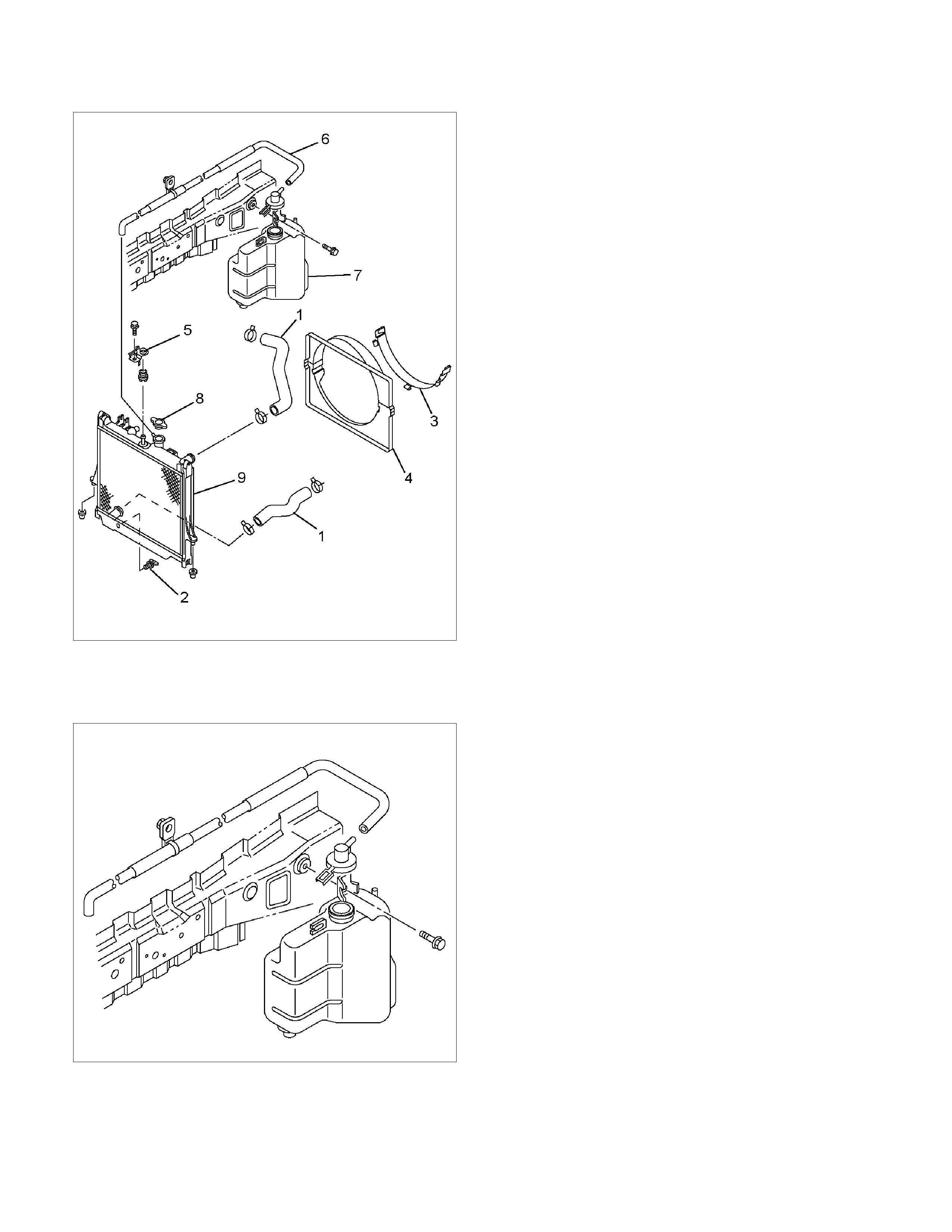
Radiator and Associated Parts
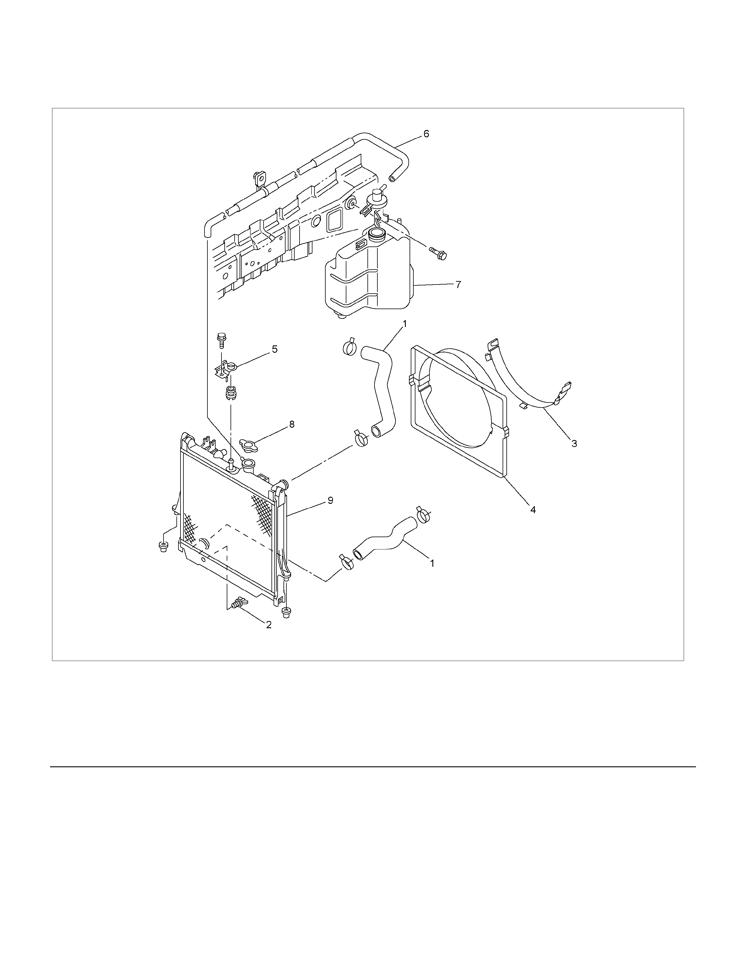
RTW36BLF000101
Legend (5) Bracket
(1) Radiator Hose (6) Reserve Tank Hose
(2) Drain Plug (7) Reserve Tank
(3) Fan Guide, Lower (8) Radiator Cap
(4) Fan Guide (9) Radiator Assembly
Removal
1. Disconnect the battery ground cable.
2. Loosen the drain plug to drain EC.
3. Disconnect oil cooler hoses for automatic
transmission (A/T), if fitted.
4. Disconnect radiator inlet hose and outlet hose
from the engine.
P1010064
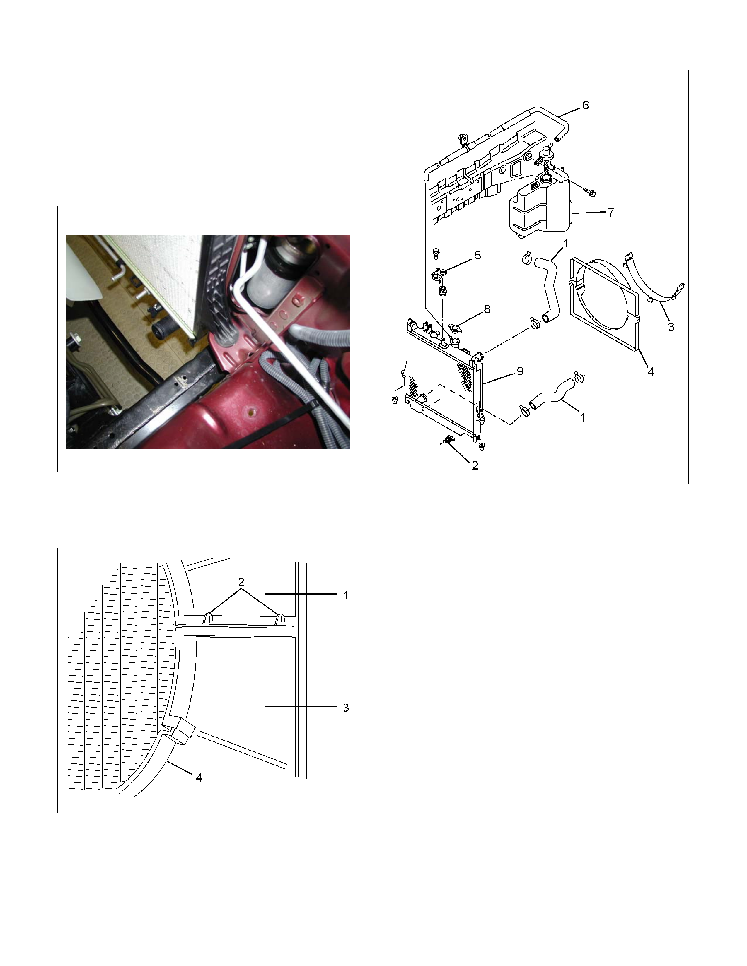
5. Remove fan guide (1), clips (2) on both sides and
the bottom lock, then remove lower fan guide (3)
with fan shroud (4).
RTW46BSH000101
6. Disconnect the reserve tank hose (6) from
radiator.
7. Remove bracket (5).
110RW004
8. Lift up and remove the radiator assembly, taking
care not to damage the radiator core with a fan
blade.
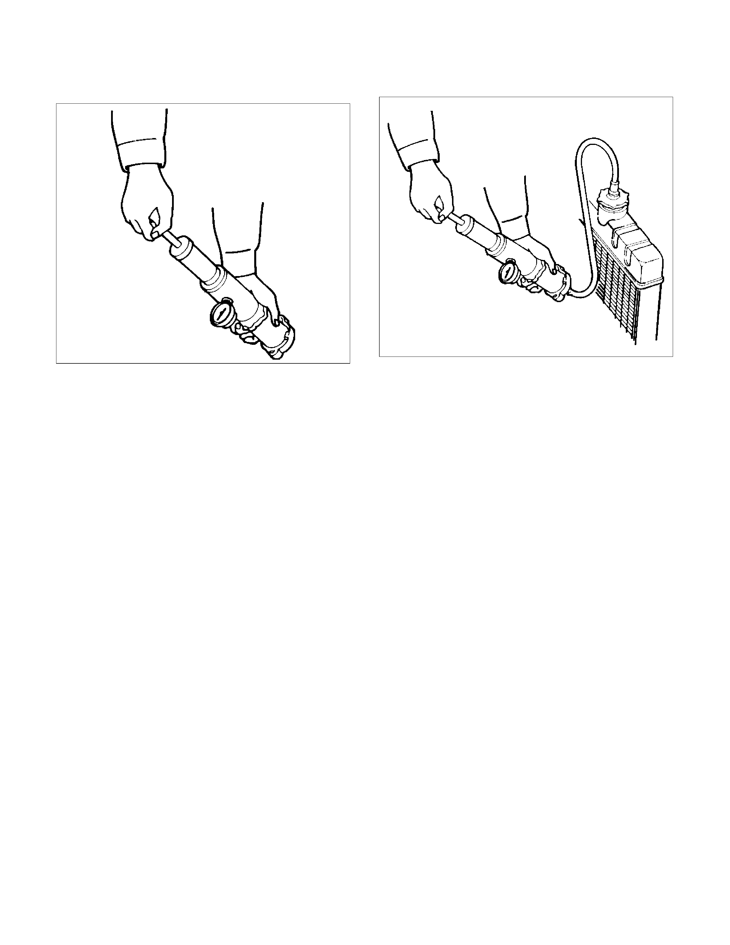
Inspection
Radiator Cap
Measure the valve opening pressure of the pressurizing
valve with a radiator cap tester.
Replace the cap if the valve opening pressure is
outside the standard range.
Valve opening pressure kPa (psi) 93.3 122.7
(13.5 17.8)
Cap tester: 5–8840–0277–0
Adapter: 5–8840–2603–0
Check the condition of the vacuum valve in the centre
of the valve seat side of the cap. If considerable rust or
dirt is found, or if the valve seat cannot be moved by
hand, clean or replace the cap.
Valve opening vacuum kPa (psi) 1.96 4.91 (0.28
0.71)
110RS006
Radiator Core
1. A bent fin may result in reduced ventilation and
overheating may occur. All bent fins must be
straightened. Pay close attention to the base of the
fin when it is being straightened.
2. Remove all dust, bugs and other foreign material.
Flushing the Radiator
Thoroughly wash the inside of the radiator and the
engine coolant passages with cold water and mild
detergent. Remove all signs of scale and rust.
Cooling System Leakage Check
Use a radiator cap tester to pressurize the radiator
through the filler neck at the specified pressure of 196
kPa (28.5 psi) and check the following:
• Leakage from the radiator
• Leakage from the coolant pump
• Leakage from the water hoses
• Check the rubber hoses for swelling.
Cap tester: 5–8840–0277–0
Adapter: 5–8840–2603–0
110RS005
Installation
1. Install radiator assembly (9) taking care not to
damage the radiator core with a fan blade.
2. Support the radiator upper tank with the bracket (5)
and secure the radiator.
3. Connect reserve tank hose (6).
4. Install lower fan guide (3).
5. Connect radiator inlet hose and outlet hose (1) to
the engine.
6. Connect oil cooler hose to automatic transmission.
RTW36BSH000101
7. Connect the battery ground cable.
8. Pour engine coolant up to filler neck of radiator, and
up to “MAX” mark of reserve tank.
RTW36BSH000101
Important operation (in case of 100% engine
coolant change) procedure for filling with engine
coolant.
Engine Coolant Change
1. To change engine coolant, make sure that the
engine is cool.
WARNING: When the coolant is heated to a high
temperature, be sure not to loosen or remove the
radiator cap. Otherwise you might get scalded by
hot vapour or water. To open the radiator cap, put a
piece of thick cloth on the cap and loosen the cap
slowly to reduce the pressure when the coolant has
become cooler.
2. Open radiator cap and drain the cooling system by
loosening the drain valve on the radiator and on the
cylinder body.
NOTE: For best result it is suggested that the engine
cooling system be flushed at least once a year. It is
advisable to flush the interior of the cooling system
including the radiator before using anti-freeze
(ethylene-glycol based) coolant.
Replace damaged rubber hoses as the engine
anti-freeze coolant is liable to leak out even minor
cracks.
HOLDEN recommends to use anti-freeze
(ethylen-glycol based) to HOLDEN specification or
equivalent, for the cooling system and not add any
inhibitors or additives. Refer Section 0B.
CAUTION: Failure to correctly fill the engine
cooling system in changing or topping up coolant
may sometimes cause the coolant to overflow from
the filler neck even before the engine and radiator
are completely full.
If the engine runs under this condition, shortage of
coolant may possibly result in engine overheating.
To avoid such trouble, the following precautions
should be taken in filling the system.
3. To refill engine coolant, pour coolant up to filler
neck using a filling hose which is smaller in outside
diameter of the filler neck. Otherwise air between
the filler neck and the filling hose will block entry,
preventing the system from completely filling up.
4. Keep a filling rate of 9 litres/min. or less. Filling over
this maximum rate may force air inside the engine
and radiator.
Also, the coolant overflow will increase, making it
difficult to determine whether or not the system is
completely full.
5. After filling the system, pull out the filling hose and
check to see if air trapped in the system is
dislodged and the coolant level goes down. Should
the coolant level go down, repeat topping-up until
there is no more drop in the coolant level.

6. After directly filling the radiator, fill the reservoir to
the maximum level.
7. Install and tighten radiator cap and start the engine.
After idling for 2 to 3 minutes, stop the engine and
reopen radiator cap. If the water level is lower,
replenish.
WARNING: When the coolant is heated to a high
temperature, be sure not to loosen or remove the
radiator cap. Otherwise you might get scalded by
hot vapour or water. To open the radiator cap, put a
piece of thick cloth on the cap and loosen the cap
slowly to reduce the pressure when the coolant has
become cooler.
8.
A
fter tightening radiator cap, warm up the engine at
about 2,000 rpm.
Set heater adjustment to the highest temperature
position, and allow the coolant to circulate into
heater system.
9. Allow the engine to reach operating temperature
and ensure the thermostat has opened.
10. When the engine has cooled, check filler neck for
water level and replenish if required. Should
extreme shortage of coolant be found, check the
coolant system and reservoir tank hose for leakage.
11. Fill the coolant in the reservoir tank up to “MAX"
line.
Drive Belt and Cooling Fan
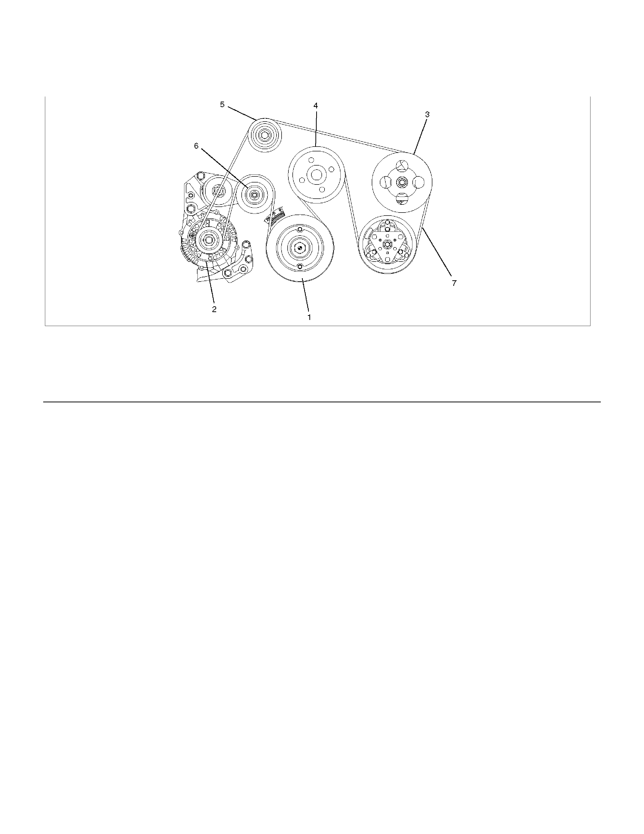
Drive Belt and Associated Parts
015RW005
Legend (4) Water Pump and Cooling Fan Pulley
(1) Crankshaft Pulley (5) Idle Pulley
(2) Generator (6) Tension Pulley
(3) Power Steering Pump (7) Drive Belt
Drive belt adjustment is not required as an automatic drive belt tensioner is fitted.
Inspection
Check drive belt for wear or damage, and replace with a new one as necessary.
Installation
Install cooling fan assembly and tighten bolts/nuts to the specified torque.
Torque : 25 N⋅m (2.5 kg⋅m/18 lb ft) for fan pulley and fan bracket.
Torque : 10 N⋅m (1.0 kg⋅m/7 lb ft) for fan and clutch assembly.
NOTE: A single serpentine accessory belt is used on all 6VE1 engines from MY1998. As a result, the direction of
rotation of the engine fan is opposite to that of the MY1992-97 6VD1 engine.
Therefore, installation of the incorrect fan may cause the cooling air to flow in the opposite direction, resulting in poor
air-conditioner performance and a rise in engine cooling temperature.
Main Data and Specifications
General Specifications
M/T A/T
Cooling system Engine coolant forced circulation
Radiator Tube type corrugated
Heat radiation capacity 81.4 kw (70.004 kcal/h)
Heat radiation area 9.42 m (0.875 ft)
Radiator front area 0.28 m (0.026 ft)
Radiator dry weight 5.0 kg (11.0 lb) 5.2 kg (11.4 lb)
Radiator cap valve opening pressure 93.3 122.7 kpa (13.5 17.8 psi)
Engine coolant pump Centrifugal impeller type
Delivery 300 (317) or more
Pump speed 5000 ± 50 rpm
Thermostat Wax pellet type with air hole
Valve opening temperature 74.5 78.5°C (166.1 173.3°F)
Engine coolant To Holden specification. Refer Section 0B.
Engine coolant total capacity 11.2 litres 11.0 litres
Torque Specifications N⋅m (kg⋅m/lb ft)
E06RW041
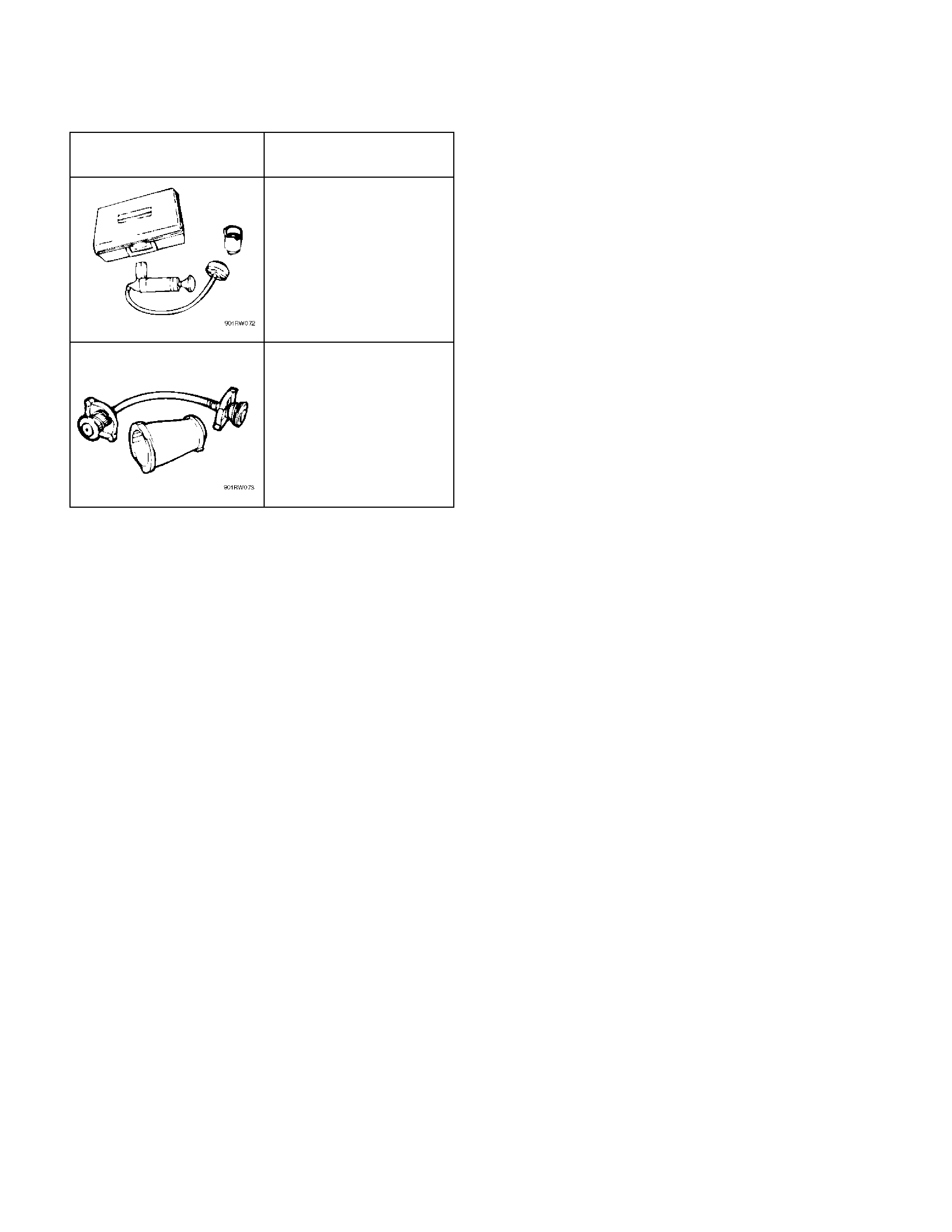
Special Tools
ILLUSTRATION PART NO.
PART NAME
5–8840–277–0
(J–24460–01)
Tester; radiator cap
5-8840-2603-0
(J–33984–A)
Adapter; radiator cap