
SECTION 6C - ENGINE FUEL (6VE1 3.5L)
Service Precautions
General Information
System Components
Fuel System Depressurizing
Procedure
Fuel Lines and Quick Connector Fittings
Description
Leak Test and Inspection
Removal
Inspection
Installation
Fuel Filter
Removal
Inspection
Installation
In-tank Fuel Filter
Fuel Pump Flow Test
Pressure Test
Fuel Tank
Fuel Tank and Associated Parts
Removal
Installation
Fuel Pump and Sender Assembly
Fuel Pump and Sender Assembly
Associated Parts
Removal
Installation
Fuel Pump Relay
General Description
Fuel Filler Neck
Removal
Installation
Fuel Filler Cap
General Description
Inspection
Main Data and Specifications
Torque Specifications
Special Tools

Service Precautions
Use extreme care when working on the fuel system and follow all safety precautions.
When working on the fuel system, disconnect the ground battery cable except for those tests where battery voltage is
required.
Always keep a dry chemical (Class B) fire extinguisher near the work area.
Replace all fuel lines and fittings with the same type of line and fitting as those removed.
Clean and inspect “O" rings carefully and replace if required.
Always depressurize the fuel line pressure before servicing any fuel system components.
Do not attempt any repairs on the fuel system until, all warnings and instructions, relating to that repair have been read
and ensure all notices and cautions are adhered to.
Do not allow any naked flames or sparks near the work area when working on the fuel system.
If draining of the fuel system is required, this should be done in a well ventilated area.
Protect the fuel lines and associated parts from thermal damage, spattering when welding.
General Information
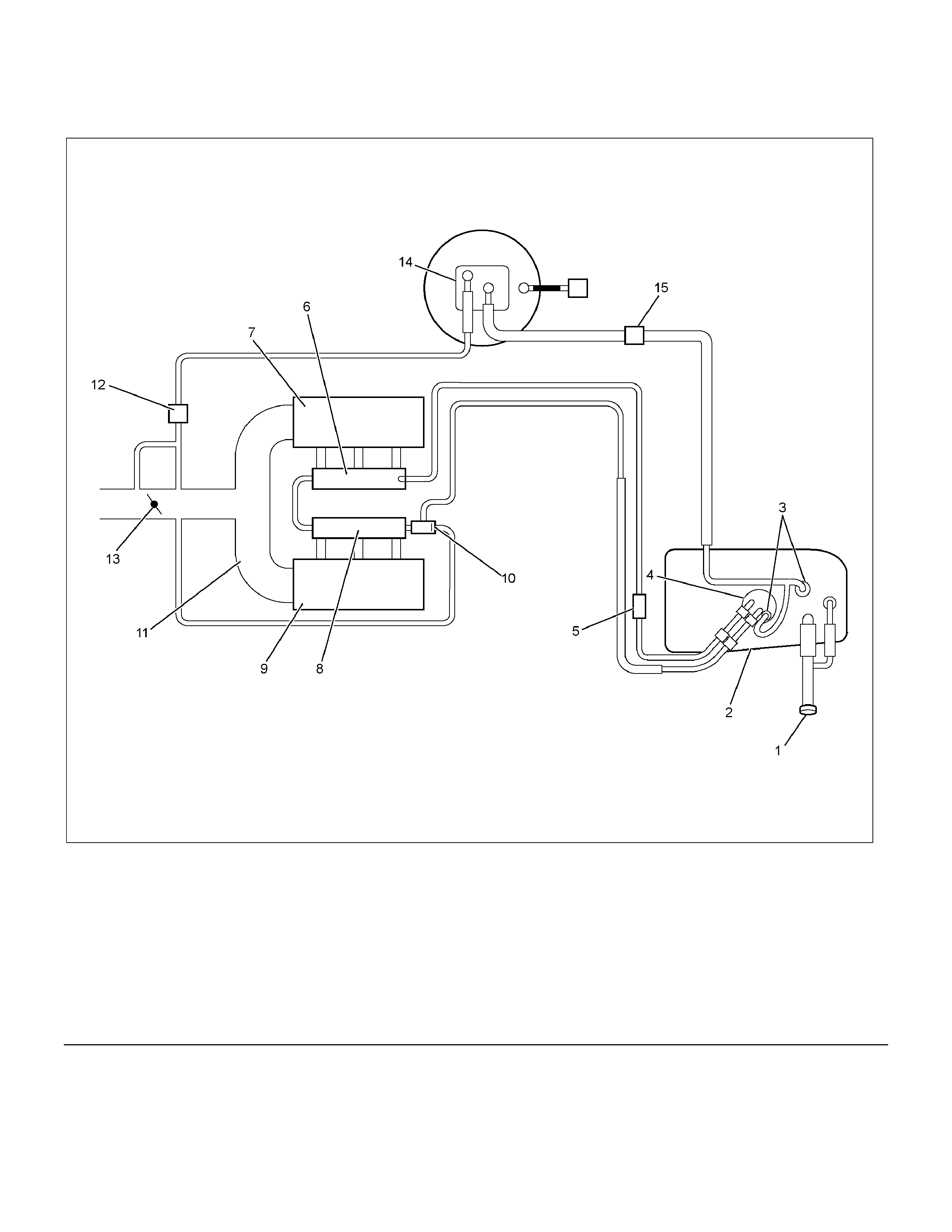
System Components
RTW36CLF000301
Legend (8) Left-hand Fuel Rail
(1) Fuel Filler Cap (9) Intake Air Left Bank
(2) Fuel Tank (10) Fuel Pressure Control Valve
(3) Rollover Valves (11) Common Chamber
(4) Fuel Pump and Sender Assembly (12) Duty Solenoid Valve
(5) Fuel Filter (13) Throttle Valve
(6) Right-hand Fuel Rail (14) Canister
(7) Intake Air Right Bank (15) Evaporative Control Valve

Fuel is injected into the engine by separate fuel injectors that are mounted in the intake manifold (common chamber).
Fuel is supplied to the injectors under pressure from the fuel tank through the fuel lines and a fuel rail, which is
attached to the top of the common chamber.
Fuel is circulated through the fuel rail continually while the engine is running. This removes air and vapours from the
fuel as well as keeping the fuel cool during hot conditions.
A fuel pressure control valve is installed on the fuel rail to maintain fuel line pressure across the injectors under all
operating conditions. Fuel pressure is accomplished by controlling the amount of fuel that is circulated back to the fuel
tank based on the demand of the engine.
See Section 6E Engine Driveability and Emission for more information and diagnosis.
The engine is fitted with a Manifold Atmospheric Pressure (MAP) sensor, which measures changes in the manifold
pressure, resulting from changes to the engine load and speed conditions. The sensor resistance will alter, which then
changes the MAP sensors voltage output.
The changing voltage is transformed into an electric signal and is sent to the Engine Control Module (ECM).
The ECM receives signals from the MAP sensor, intake air temperature sensor engine temperature and other sensors.
The ECM then determines an appropriate fuel injection pulse width (On Time) and sends the signal to the fuel injectors
to allow an appropriate air/fuel ratio.
Two interchangeable “O" rings are used on the fuel injector and must be replaced when the injectors are removed.
The Multiport Fuel Injection system utilizes an injection system where the injectors turn on at every crankshaft
revolution. The ECM controls the injector on time so that the correct amount of fuel is metered depending on driving
conditions.
All petrol engines are designed to use only unleaded petrol.
Unleaded petrol must be used for correct emission control system operation and its use will also minimize spark plug
fouling and extend engine oil life.
Using leaded petrol can damage the emission control system and could void the vehicle warranty.All vehicles are
equipped with an Evaporative Emission Control System. The purpose of the system is to minimize the escape of fuel
vapours to the atmosphere.

Fuel System Depressurizing
CAUTION: Depressurizing of the fuel system is required before any servicing to the fuel system that requires
the fuel lines to be disconnected.
Procedure
1. ,Remove the fuel cap slowly to release any build up of pressure in the fuel tank.
2. Remove the fuel pump fuse from the fuse box. Refer to Section 8A Electrical - Body & Chassis.
3. Crank the engine over for 15 seconds to relieve the pressure in the fuel lines.
NOTE: A small amount of residual pressure may remain in the system after this procedure has been performed. Use
care when servicing the fuel system.
Fuel Lines and Quick Connector Fittings
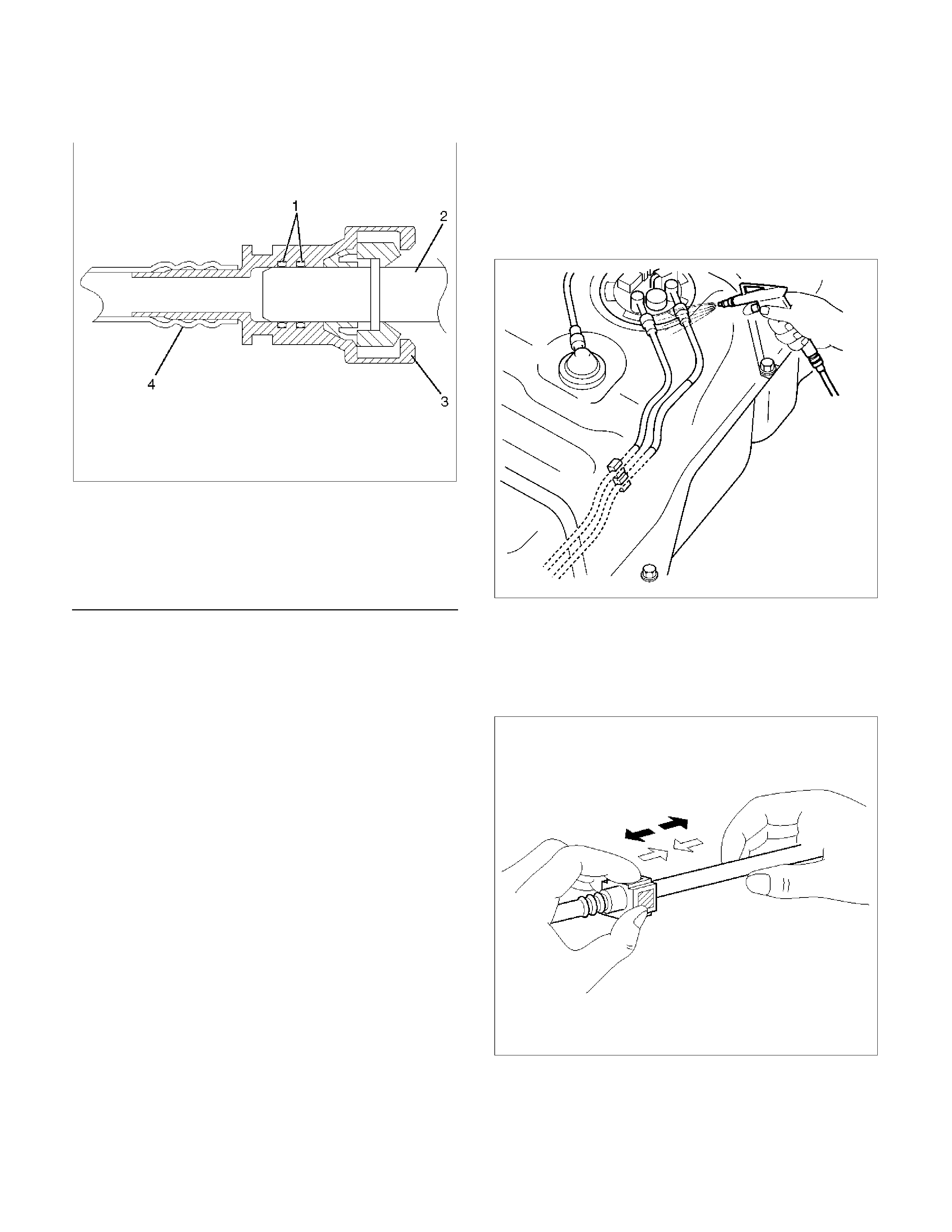
Description
140R100032
Legend
(1) O-ring
(2) Fuel line fuel line/ port
(3) Connector
(4) Plastic fuel line tube
CAUTION: Ensure all service precautions have
been observed prior to removing any connector
fittings.
Leak Test and Inspection
1. Turn the ignition key to the ON position and
ensure the pump runs for a short time by listening
for the pump start-up sound. The fuel pressure will
increase when the fuel pump is actuated.
2. Perform a preliminary check of the system by
inspecting the system for any leaks around the
connections and fittings.
3. Perform steps 2 and 3 several times.
4. If the preliminary check of the system produces no
leaks, start the engine and check the system
again for any signs of leaks around the
connections and lines.
Removal
1. Depressurize the fuel system, refer to
Fuel System Depressurizing in this Section.
2. Use compressed air to remove any dirt around the
fuel line quick connector fittings prior to
disconnecting the fittings.
141R100002
3. Hold the connector in one hand and depress the
square release button on the connector while
gently pulling the quick connector and the fuel
line/port apart with the other hand.
140R100037
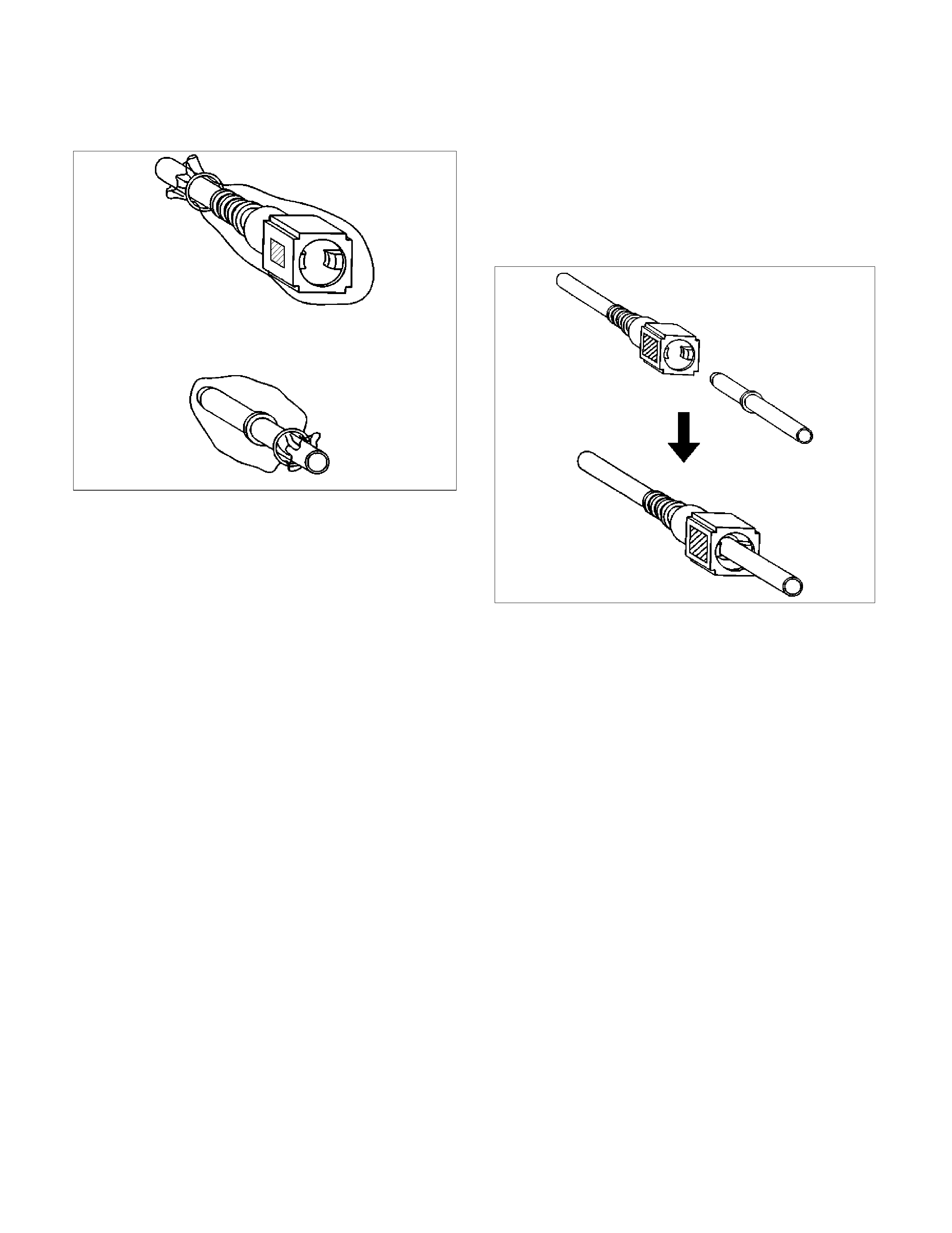
4. Cover the quick connectors to prevent dirt o
r
other foreign materials from entering the system.
140R100028
Inspection
1. Check the fuel line/port and quick connector fitting
for any scratches, rust, dents or cracks. Replace
the connector or the fuel line/port if found to be
defective.
2. Inspect the O-rings in the quick connector and
replace the connector or fuel line if found to be
defective.
Installation
1.
A
pply a small amount of engine oil or light oil to
the fuel line/port to assist in assembly of the
connector.
NOTE: Assembly of the fuel line/port and quick
connector should take place immediately after applying
the oil to prevent any dust from sticking to the surface,
which may cause the connector to leak.
140R100036
Fuel Filter
Removal
CAUTION: When a repair to the fuel system has
been completed, perform a leak test, refer to
Leak Test and Inspection.
1. Depressurize the fuel system, Refer to
Fuel System Depressurizing in this Section.
2. Disconnect the battery ground cable.
NOTE: Cover the opening of the filler neck to prevent
any dirt from entering.
CAUTION: A small amount of fuel will flow out of
the fuel lines and filter when disconnected.
3. Place a drain tray below the fuel filter and remove
the fuel line quick connectors on the inlet and
outlet side of the fuel filter.
NOTE: Refer to Fuel Lines and Quick Connector
Fittings in this section when performing any repairs.
NOTE: Cover the quick connector to prevent any dirt
from entering the system and any further fuel from
leaking.
4. Remove the fuel filter from the holder attached to
side cross-member.
Inspection
1. Replace the fuel filter if fuel leaks from the fuel
filter body or if the fuel filter body itself is
damaged.
2. Replace the fuel filter if it is clogged with dirt o
r
sediment or the filter shows signs of being
contaminated with water or other foreign
materials.
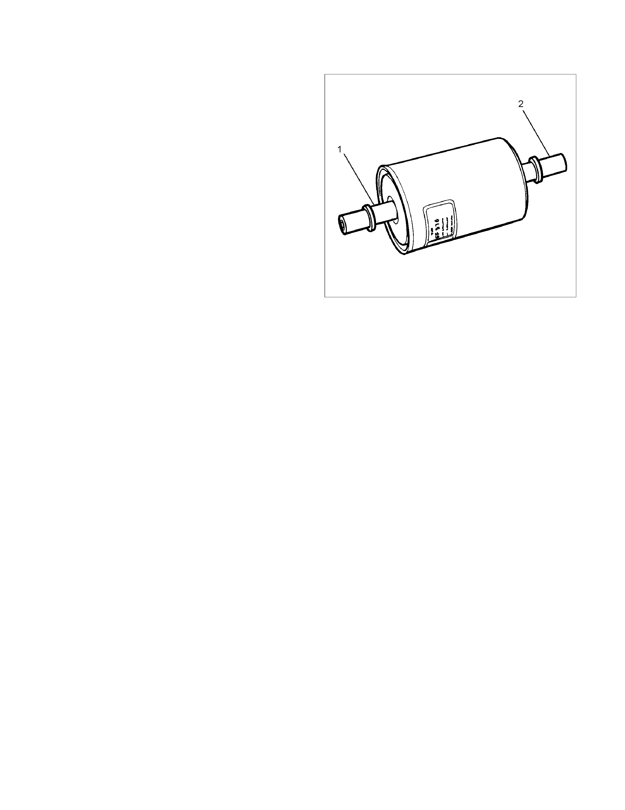
Installation
1. Install the fuel filter to the holder attached to side
cross-member.
NOTE: Ensure the direction of fuel filter outlet fuel
line/port (1) is facing the engine and the inlet
fuel line/port (2) is facing the fuel tank.
RTW36CSH000301
2. Connect the inlet and outlet fuel line quick
connectors to the fuel filter.
NOTE: Refer to Fuel Lines and Quick Connector
Fittings in this section.
3. Tighten the fuel filler cap until at least one click is
heard.
4. Connect the battery ground cable.
NOTE: After installation, perform a leak test, refer to
Leak Test and Inspection.
In–Tank Fuel Filter
The fuel pump assembly is fitted with a fuel filter, which
is located on the lower end of the fuel pick-up tube in
the fuel tank. This filter helps to prevent dirt from
entering the fuel system and stops water, unless the
filter is completely submerged in the water.
The filter is a self-cleaning type and does not require
scheduled maintenance. However, excess water and
dirt in the fuel tank can restrict the fuel supply to the
engine, resulting in poor engine performance or even
failure to start or run. In such a case, the fuel filter may
become blocked and allow dirt or water to enter the
system. If this occurs, the entire fuel system must be
thoroughly cleaned and the filters replaced.
Fuel Pump Flow Test
If a reduction of the fuel supply is suspected, perform
the following checks.
1. Ensure there is sufficient fuel in the tank.
2. With the engine running, check the fuel lines from
the fuel tank to the injectors for evidence o
f
leakage. Retighten, if the line or the connections
are loose. Also, check the fuel lines for restrictions
such as a squashed pipe or clogging.
3. Depressurize the fuel system, refer to Fuel
System Depressurizing in this Section.
4. Disconnect the fuel line at the fuel rail.
5. Connect a hose from the fuel line and place the
open end into a clean container
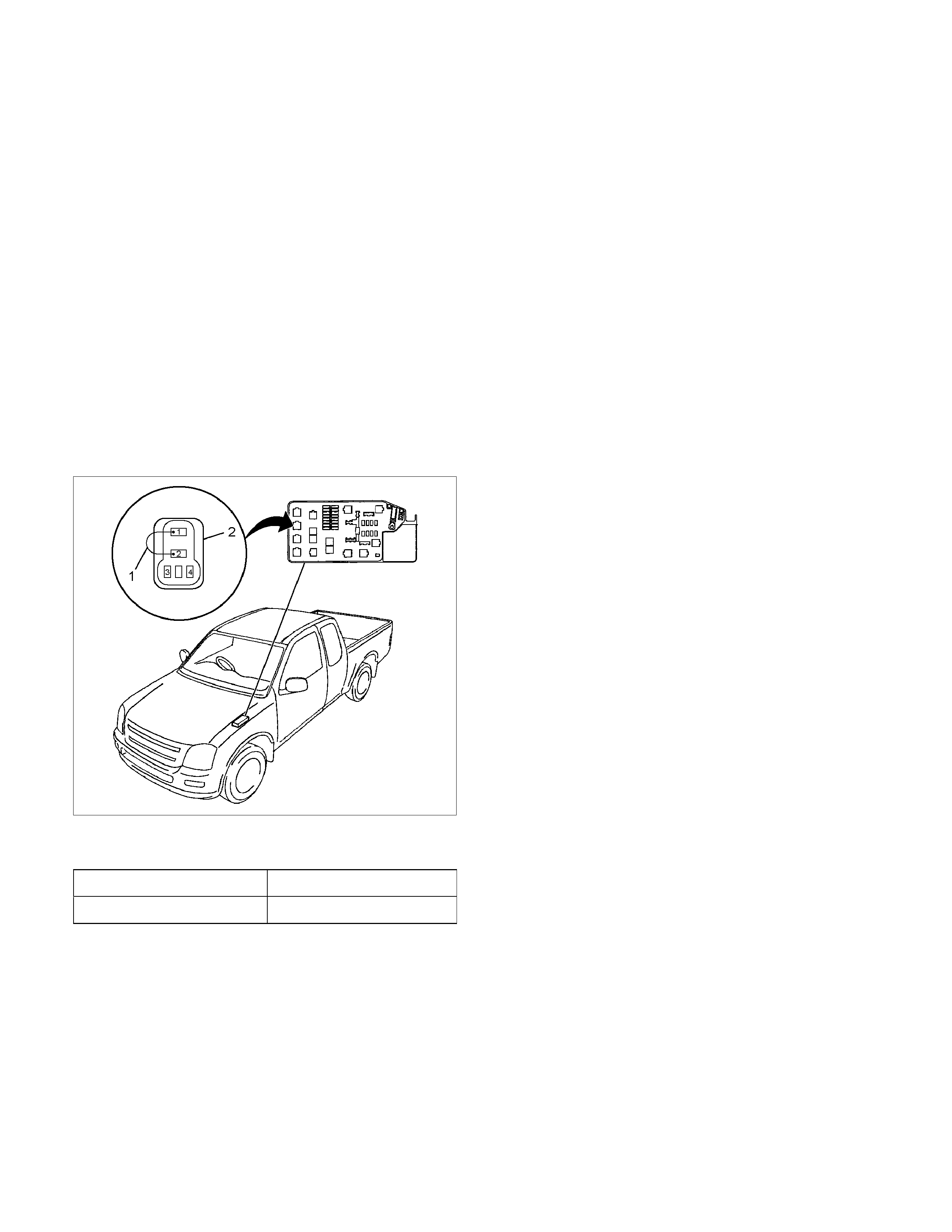
6. Connect the pump relay terminals (2) with a
jumper wire (1) as shown, then turn the ignition
ON to run the fuel pump and then check the fuel
pump flow rate.
RTW36CSH000201
CAUTION: Do not generate any sparks when
connecting the jumper wire.
Delivery Delivery
15 seconds 0.38 liters minimum
NOTE: If the fuel flow rate is below the minimum value,
conduct a pressure test.
Pressure test
To perform a pressure test on the fuel system, refer to
Section 6E Fuel Control System.
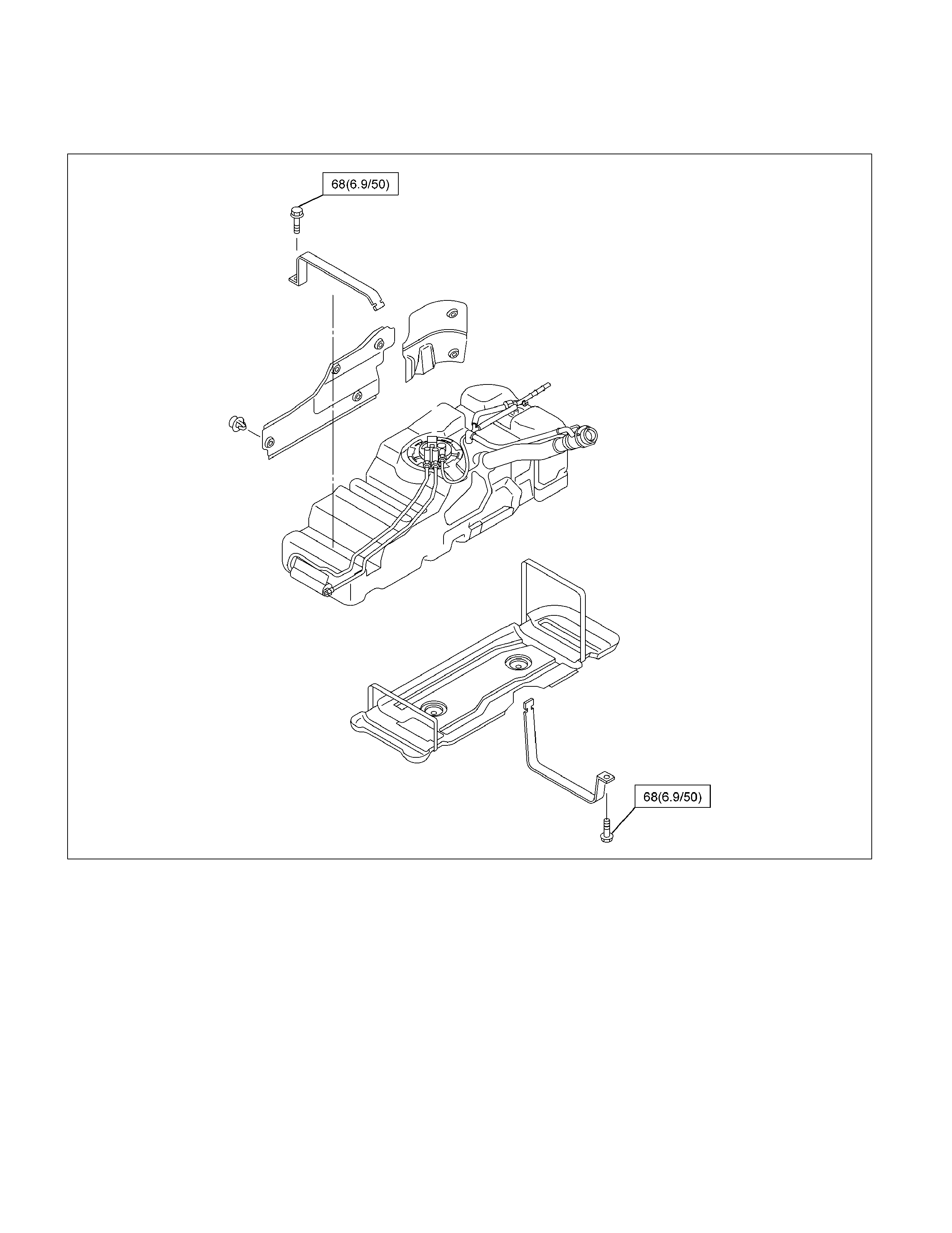
Fuel Tank
Fuel Tank and Associated Parts
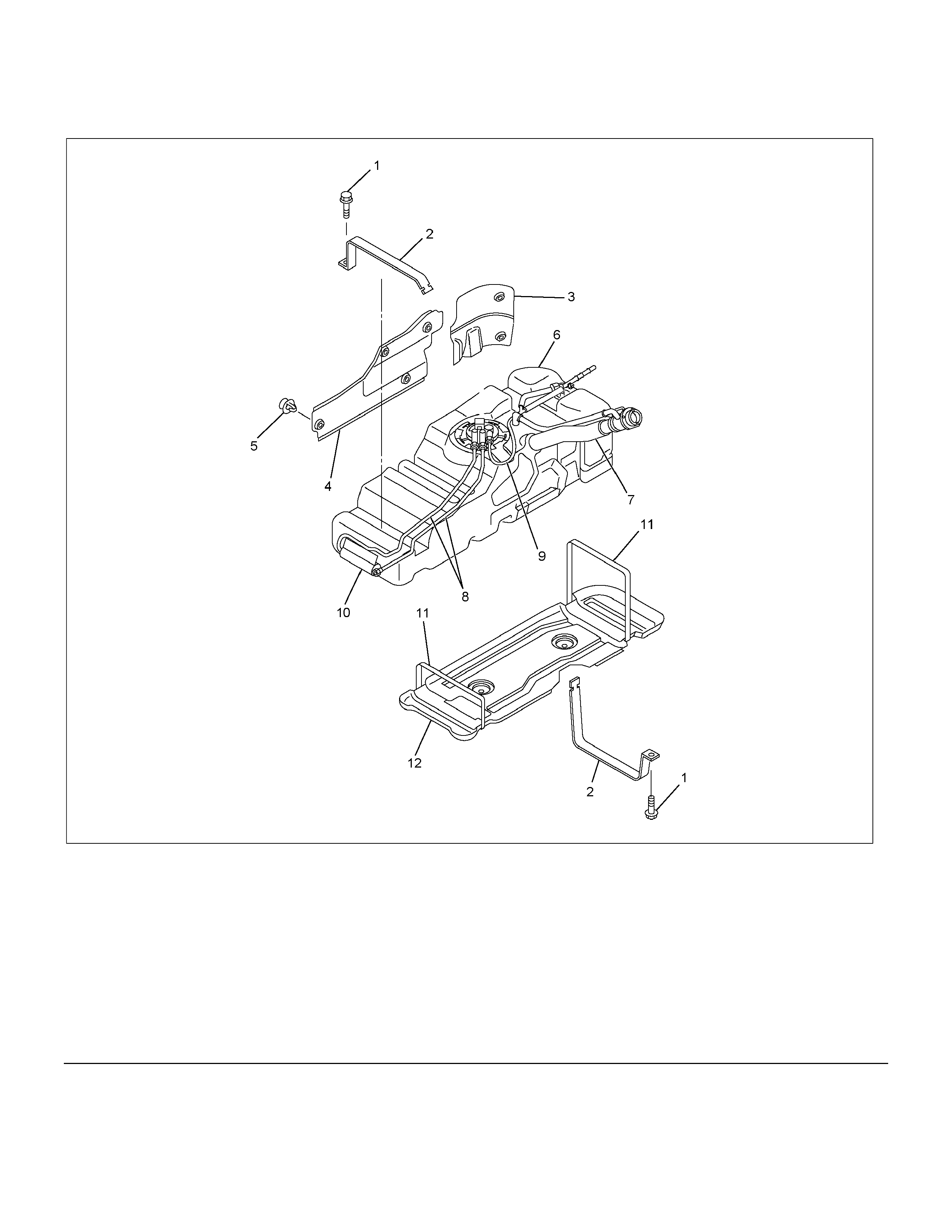
RTW46FLF000301
Legend
(1) Bolt; Fuel Tank Strap (7) Fuel Filler Hose
(2) Fuel Tank Strap (8)
(3)
(4) Rear Side Shield
Side Shield (9)
(10)
Fuel Line and Quick Connector
Evaporative Line and Quick Connector
Fuel Filter
(5) Retainer (11) Strap; Under Shield
(6) Fuel Tank (12) Under Shield

Removal
1. Disconnect the battery ground cable.
2. ,Loosen the fuel filler cap slowly to remove any build up of pressure in the fuel tank.
3. Depressurize the fuel system. Refer to Fuel System Depressurizing.
NOTE: Cover the opening of the filler neck to prevent any dust entering.
4. Jack up the vehicle and support the vehicle on safety stands.
5. Support the fuel tank from underneath the vehicle with a suitable lifter.
6. Remove the left-hand inner wheelhouse liner.
7. Remove the bolt fixing the filler neck to the body.
8. Remove the two side shields (3) and (4).
9. Disconnect the quick connector from the fuel lines (8) quick connector. Refer to Fuel Lines and Quick
Connector Fittings.
NOTE: Cover the quick connector to prevent any dust entering and fuel leaking.
10. Remove the bolt (1) fixing the lower tank strap (2).
11. Disconnect the fuel pump and sender assembly wiring harness connector on the fuel pump and remove the
wiring harness from the clip on the fuel tank.
12. Lower the fuel tank (6) from the vehicle.
NOTE: When lowering the fuel tank from the vehicle, ensure the wiring and fuel lines are free from interference with
the fuel tank.
Installation
Installation of the fuel tank is the reverse of the removal procedure noting the following:
1. Ensure the tank strap fixing bolts are tightened to the specified torque.
Torque: 68 N⋅m (6.9 kg⋅m/50 lb ft)
2. Tighten the filler cap until at least three clicks are heard.
3. Leak test the fuel system, refer to Leak Test and Inspection in this Section.
Fuel Pump and Sender Assembly
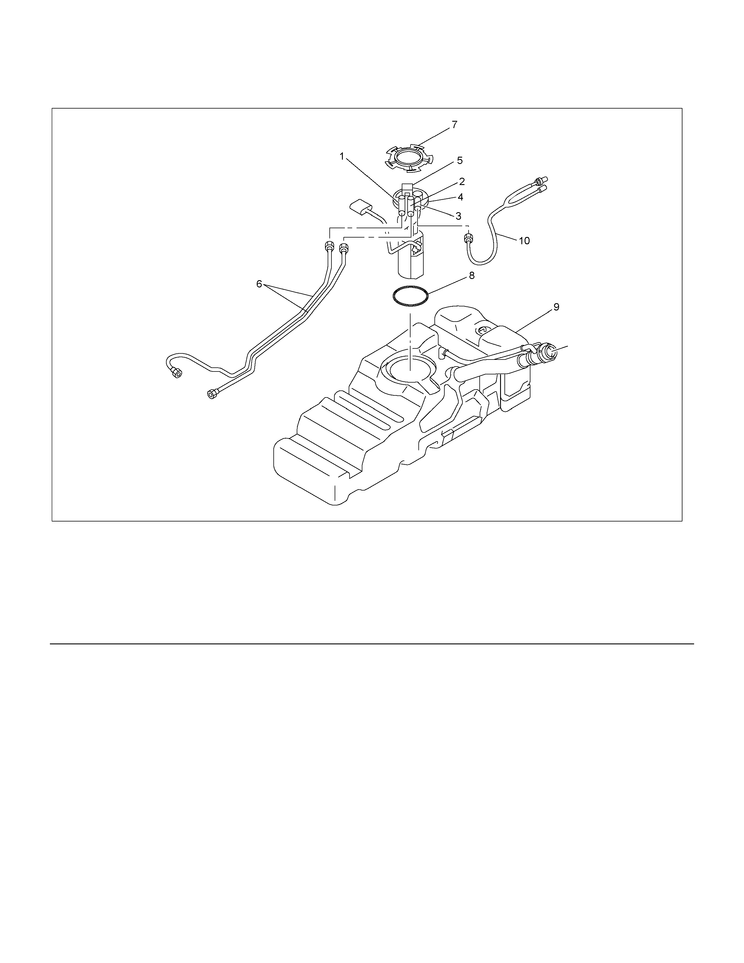
Fuel Pump and Sender Assembly Associated Parts
RTW46FMF000401
Legend
(1) Fuel Feed Port / Line (6) Fuel Line Quick Connector
(2) Fuel Return Port / Line (7) Retainer Ring (Fuel Pump Lock)
(3) Fuel Emission Port / Line (8) O-ring
(4) Fuel Pump and Sender Assembly (9) Fuel Tank Assembly
(5) Connector; Fuel Feed Pump & Sender (10) Evaporative Line Quick Connector
Removal
1. Remove the fuel tank assembly (9). Refer to
Fuel Tank Removal in this section.
2. Disconnect the fuel line quick connectors (6) and
(10).
3. Disconnect the fuel pump and sender assembly
wiring harness from the fuel pump and sende
r
assembly.
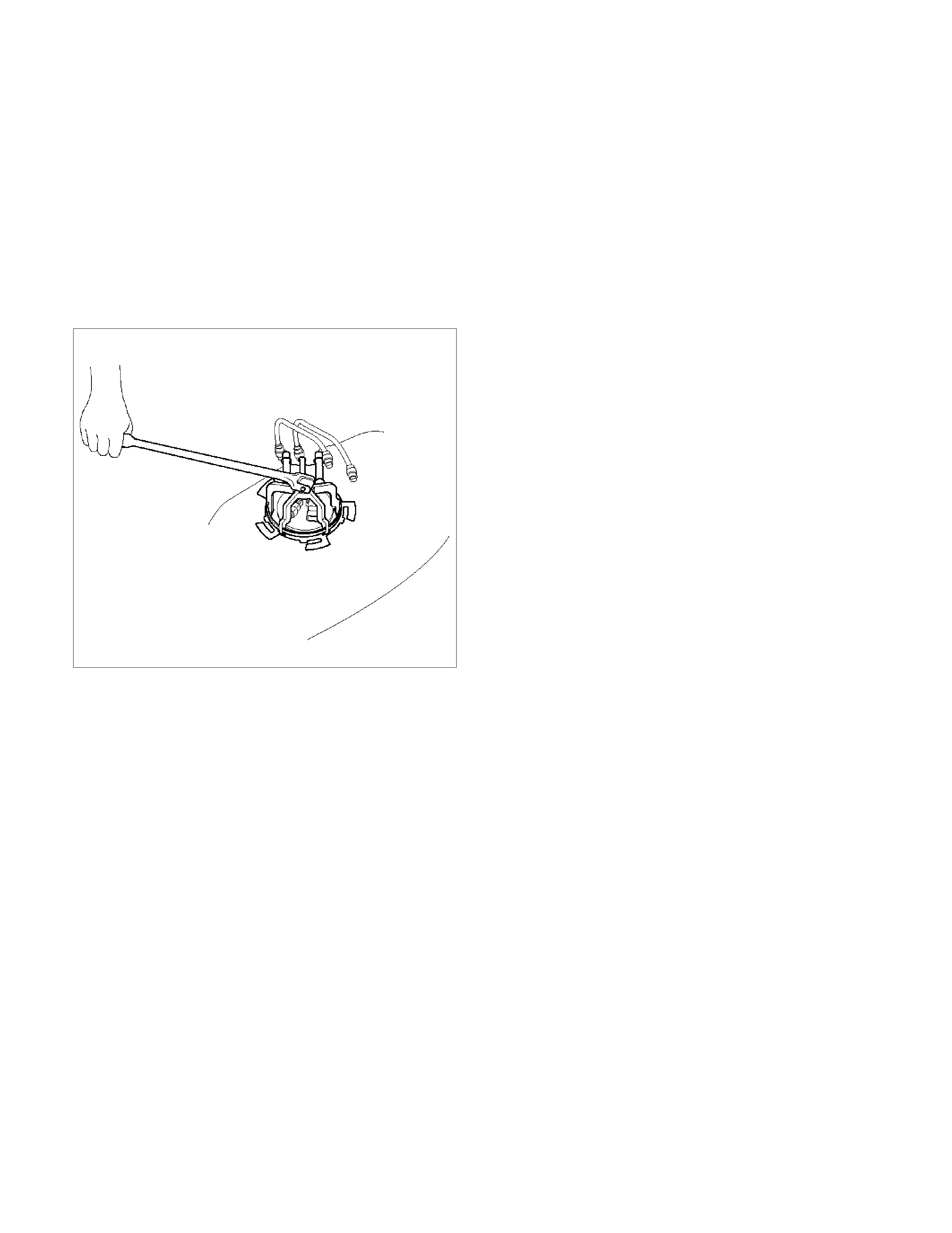
4. Remove the retainer ring (7) from the fuel tank
with the removal tool 5-8840-2602-0.
140R100035
5. Slowly, remove the fuel pump assembly from the
fuel tank taking care not to damage the float arm
for the fuel gauge.
NOTE: Cover the opening of the fuel tank to prevent
any dust entering the tank.
Installation
1. Clean the O-ring surface of the fuel tank and the
fuel pump.
2. Install a new fuel pump O-ring (8) over the flange
on the fuel pump.
NOTE: If the fuel pump O-ring comes into contact with
petrol, it will swell and cannot be installed.
3. Carefully, install the fuel pump (4) into the fuel
tank taking care not to damage the float arm fo
r
the fuel gauge sender.
4. Position the flange of the fuel pump to the mating
surface of the fuel tank and hold in position.
5. Slowly lock the retainer ring (7) to the fuel tank
with tool 5-8840-2602-0.
6. Install the fuel line quick connectors (6) and (10).
7. Install the fuel tank, refer to Fuel tank in this
Section.
8. Leak test the fuel system, refer to Leak Test and
Inspection in this Section.

Fuel Pump Relay
General Description
The fuel pump and sender assembly (FPSA) operation is controlled by the FPSA relay. When the ignition switch is
turned to the ON position, the FPSA relay operates the fuel pump for approximately 2 seconds.
When the ignition switch is turned to the START position, the Engine Control Module (ECM) receives the reference
pulse from the Ignition Control Module. The ECM will then operate the FPSA relay, supplying power to the FPSA.

Fuel Filler Neck
Removal
1. Remove the fuel tank. Refer to Fuel Tank in this section.
2. Using a marker pen or similar, place a reference mark at each joint of the fuel filler neck and hose to assist in the
reassembly process.
NOTE: Mark the joints of the fuel filler neck in the axial direction as well as the insertion depth of the joint.
3. Remove the clamps attaching the fuel tank breather hose to the filler neck and the fuel tank and remove the hose.
4. Remove the clamps attaching the fuel filler neck hose to the fuel tank and filler neck.
5. Remove the filler neck and hose by gently twisting and pulling them apart.
NOTE: Cover end of each hose and pipe to prevent any dust entering.
Installation
1. Installation of the fuel filler neck and hose is the reverse of the removal process noting the following:
• Align the marks made in step 2 of the removal process.
• Tighten all clamps to the specified torque.
Torque: 2.5 Nm (0.25 kgm/2 lb ft)
• Install the fuel tank. Refer to Fuel Tank in this section.
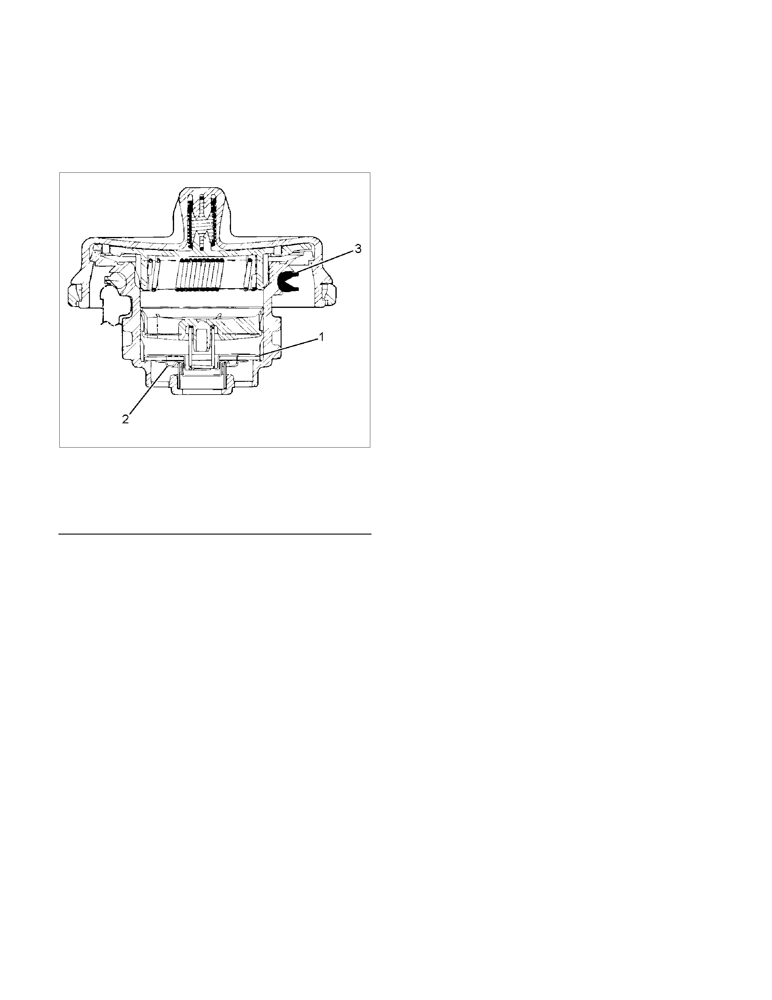
Fuel Filler Cap
General Description
Vacuum and pressure valves are built into the fuel filler
cap which regulate the pressure in the fuel tank and
prevent fuel tank damage.
RTW36CSH000401
Legend
(1) Pressure Valve
(2) Vacuum Valve
(3) Seal Ring
Inspection
Inspect the fuel filer cap and seal for any signs of
damage. Replace the fuel filler cap if found to be
defective.
CAUTION: A replacement fuel filler cap must be the
same type as the original. The fuel filler cap
pressure and vacuum valves are specific to a
particular application and must be replaced with
the same type or fuel system damage may occur.
Main Data and Specifications
Torque Specifications N⋅m (kg⋅m/lb ft)
RTW46FMF000601
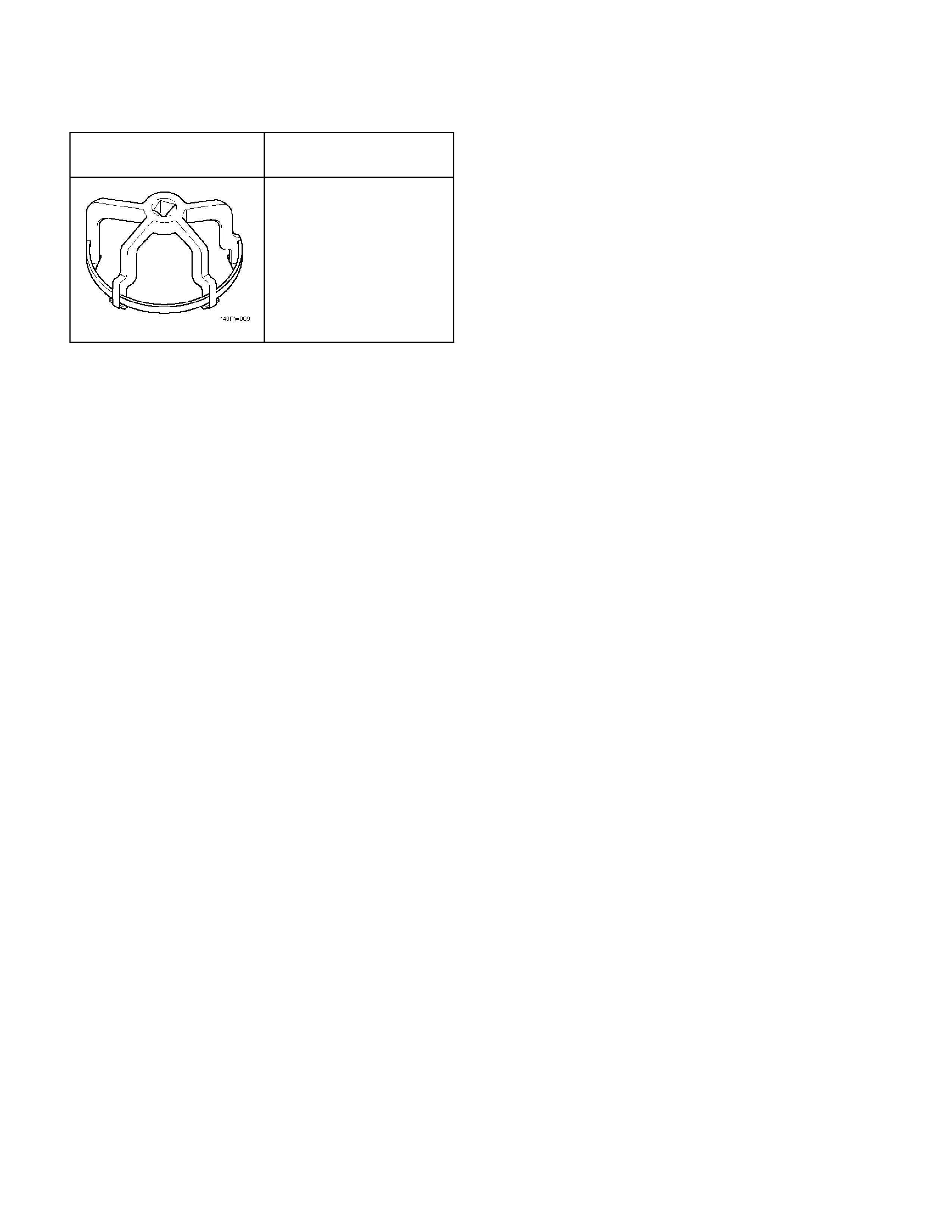
Special Tools
ILLUSTRATION PART NO.
PART NAME
5–8840–2602–0
(J–39765)
Remover; fuel pump
retainer