
SECTION 6D2 - IGNITION SYSTEM (6VE1 3.5L)
Service Precaution
General Description
Diagnosis
Ignition Coil
Removal
Inspection
Installation
Spark Plug
Inspection
Replacement Spark Plugs
Crankshaft Position Sensor
Removal
Installation
Main Data and Specifications
General Specifications
Torque Specifications

Service Precaution
WARNING: THIS VEHICLE HAS A SUPPLEMENTAL
RESTRAINT SYSTEM (SRS). REFER TO THE SRS
COMPONENT AND WIRING LOCATION VIEW IN
ORDER TO DETERMINE WHETHER YOU ARE
PERFORMING SERVICE ON OR NEAR THE SRS
COMPONENTS OR THE SRS WIRING. WHEN YOU
ARE PERFORMING SERVICE ON OR NEAR THE
SRS COMPONENTS OR THE SRS WIRING, REFER
TO THE SRS SERVICE INFORMATION. FAILURE TO
FOLLOW WARNINGS COULD RESULT IN
POSSIBLE AIR BAG DEPLOYMENT, PERSONAL
INJURY, OR OTHERWISE UNNEEDED SRS SYSTEM
REPAIRS.
CAUTION: Always use the correct fastener in the
proper location. When you replace a fastener, use
ONLY the exact part number for that application.
HOLDEN will call out those fasteners that require a
replacement after removal. HOLDEN will also call
out the fasteners that require thread lockers or
thread sealant. UNLESS OTHERWISE SPECIFIED,
do not use supplemental coatings (Paints, greases,
or other corrosion inhibitors) on threaded fasteners
or fastener joint interfaces. Generally, such
coatings adversely affect the fastener torque and
the joint clamping force, and may damage the
fastener. When you install fasteners, use the
correct tightening sequence and specifications.
Following these instructions can help you avoid
damage to parts and systems.

General Description
Ignition is done by the electronic ignition (El) that directly fires the spark plugs from ignition coils through spark plug
wires without using a distributor. A pair of ignition coils for the cylinders having different phases by 360° (No. 1 and No.
4, No. 2 and No. 5, No. 3 and No. 6) are fired simultaneously.
Since the cylinder on exhaust stroke requires less energy to fire its ignition plug, energy from the ignition coils can be
utilized to fire the mating cylinder on compression stroke. After additional 360° rotation, respective cylinder strokes are
reversed.
The EI consists of six ignition coils, crankshaft position sensor, engine control module (ECM) and other components.
The ignition coils are connected with the ECM.
The ECM turns on/off the primary circuit of ignition coils, and also it controls the ignition timing.
A notch in the timing disc on the crankshaft activates the crankshaft position sensor which then sends information such
as firing order and starting timing of each ignition coil to the ECM.
Further, the El employs ignition control (IC) to control similar to a distributor system.

Ignition Coil
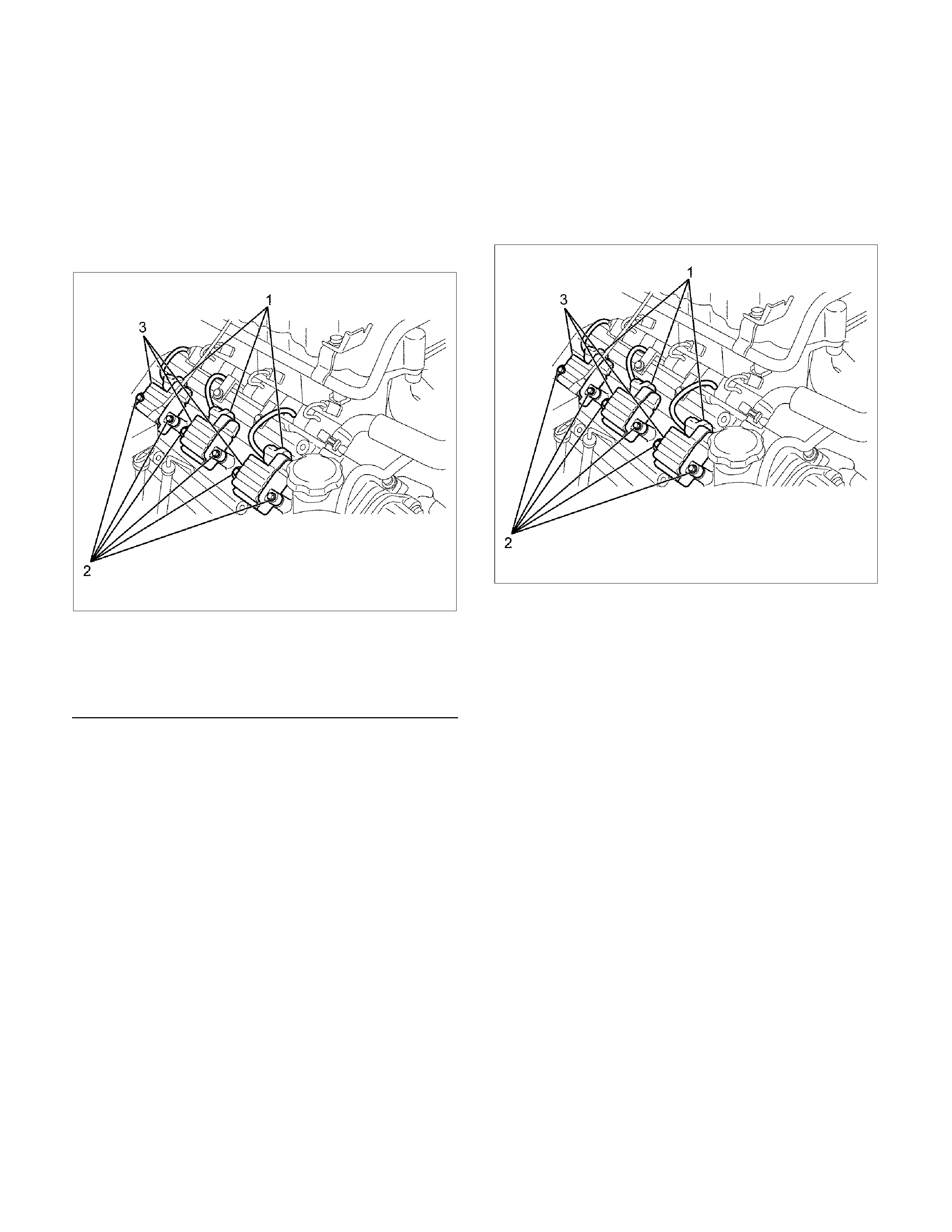
Removal
1. Disconnect the battery ground cable.
2. Ignition coil connector and ignition coil.
• Disconnect the connector from the ignition coil.
• Remove harness bracket bolt on the cylinder
head cover.
• Remove fixing bolts on the ignition coil.
RTW4Z0SH000101
Legend
(1) Ignition Coil Connector
(2) Bolt
(3) Ignition Coil Assembly
Inspection
Check the ignition coil assembly for insulation. Check
terminals for corrosion or damage, and replace as
necessary.
NOTE:
Due to the internal construction of the ignition coil unit,
it is impractical to perform primary and secondary
winding resistance tests with a multi-meter. A suspect
ignition coil unit should be substituted with a known
good unit when performing ignition system diagnosis.
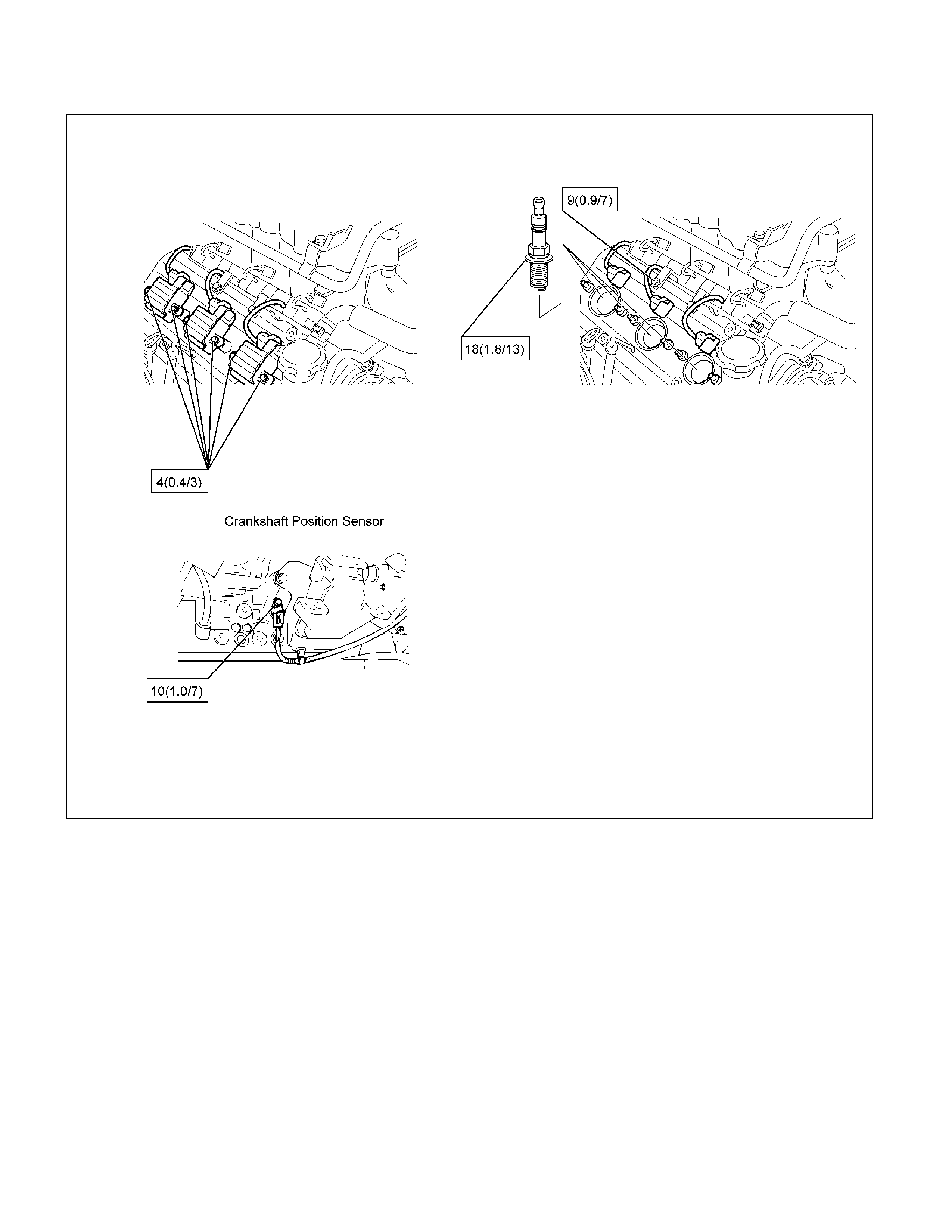
Installation
1. Install the ignition coil assembly (3).
Connect the ignition coil connector (1) to the
ignition coil (3), then tighten bolts (2) to the
specified torque.
Torque: 4 N⋅m (0.4 kg⋅m/3 lb ft)
RTW4Z0SH000101
2. Connect the battery ground cable.
Spark Plug
Inspection
Poor spark plug condition adversely affects engine
performance. Carefully inspect each spark plug
following the procedure outlined below.
1. Remove the spark plug.
2. Check the plug for dirt and other foreign material.
If the plug is extremely dirty, the fuel and electrical
systems must be checked.
3. If necessary, clean the spark plugs by placing them
in a spark plug cleaning machine for no more than
20 seconds.
4. Check the electrode and insulator for wear and/or
cracking. If there is significant wear or cracking, the
plug must be replaced.
5. Check the gasket for damage. Replace the gasket i
f
necessary.
6. Measure the insulation resistance with a 500-volt
megaohm meter. Replace the plug if the resistance
is less than the specified value.
Insulation resistance: 50 MΩ or more
011RS010
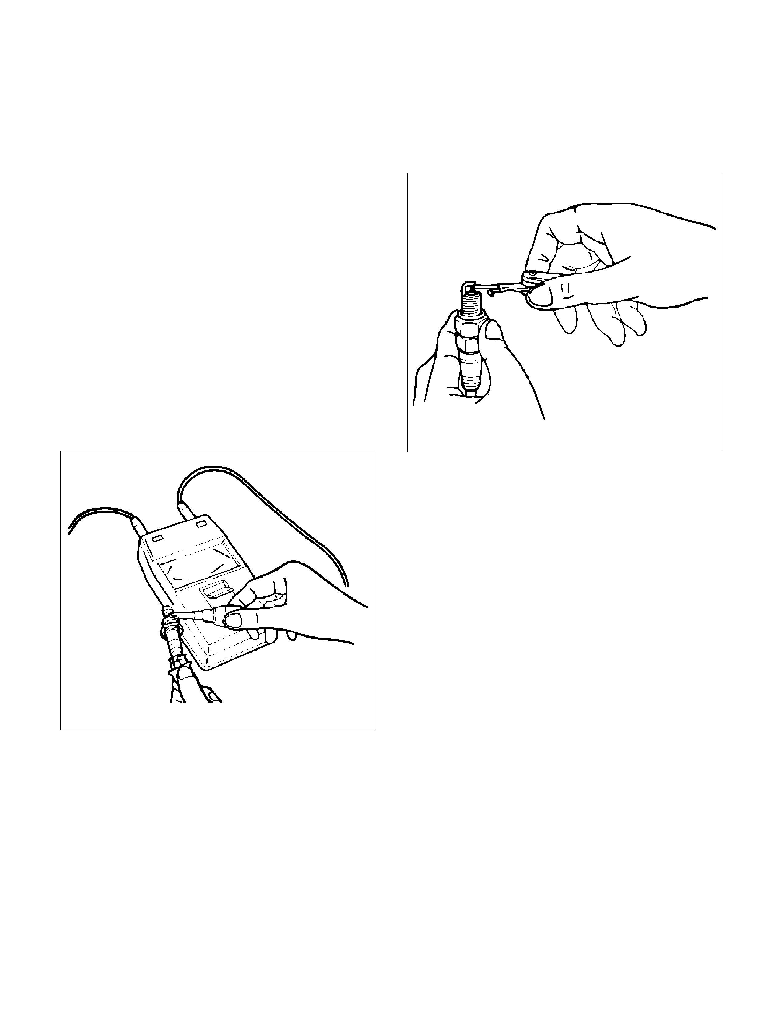
7. Check the spark plug gap. Replace the spark plug
if the gap is not as specified.
Standard: 1.0–1.1 mm (0.04–0.043 in)
Limit: 1.3 mm (0.05 in)
011RS011
• Do not attempt to adjust the gap of an old spark
plug. Replace the plug and adjust the gap of the
new plug if required.
• Take care not to damage the spark plug tip
during handling.
8. Tighten the spark plugs to the specified torque.
Torque: 18 N⋅m (1.8 kg⋅m/13 lb ft)
Replacement spark plugs
• Under normal conditions (no problem with the fuel
and/or electrical systems), use replacement spark
plugs with a low heat value (hot-type plug).
• If insulator and electrode scorching is significant,
use replacement spark plugs with a high heat value
(cold-type plug).
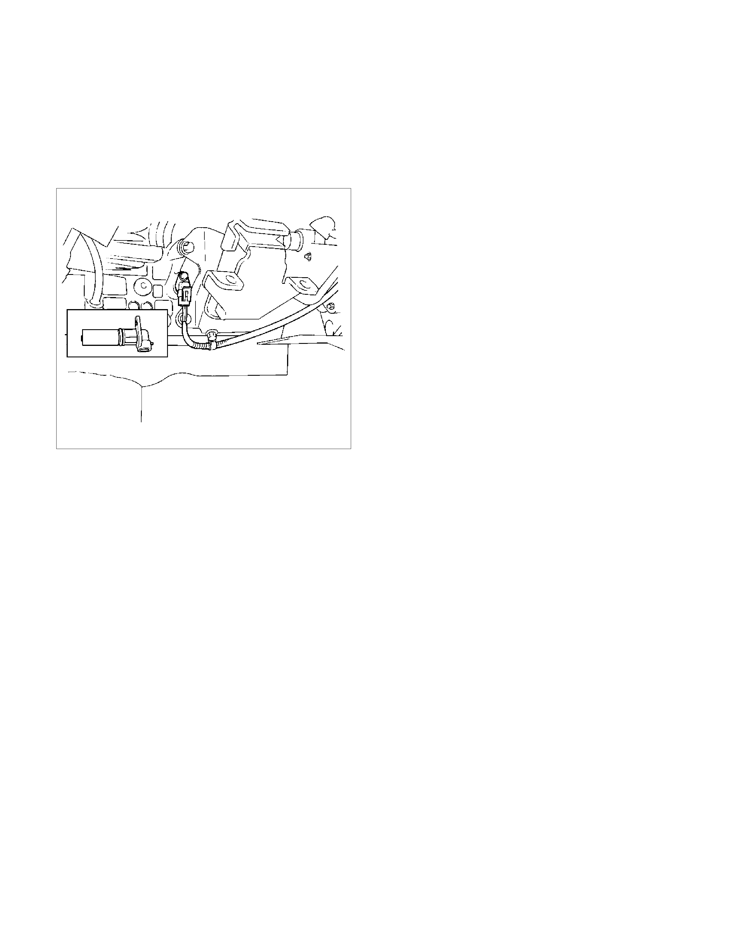
Crankshaft Position Sensor
Removal
1. Disconnect the battery ground cable
2. Disconnect the wiring connector from the
crankshaft position sensor.
3. Remove the crankshaft position sensor from the
cylinder block.
012RS008
Installation
1. Install the crankshaft position sensor into the
cylinder block.
Before installation, apply small amount of engine
oil to the O–ring.
Torque: 10 N⋅m (1.0 kg⋅m/7 lb ft)
2. Reconnect the wiring connector to the crankshaft
position sensor.

Main Data and Specifications
General Specifications
Ignition System
Ignition Form Electronic Ignition System (El system) with Crankshaft Position Sensor
Spark Plug
Type K16PR-P11
RC10PYP4
RK16PR11
Plug gap 1.0 mm (0.04 in) – 1.1 mm (0.043 in)
Torque 18 N⋅m (13 lb ft)
Torque Specifications N⋅m (kg⋅m/lb ft)
RTW460LF000101