
SECTION 6D3 - STARTING AND CHARGING
SYSTEM (6VE1 3.5L)
Service Precaution
Starting System
General Description
Diagnosis
Starter
Removal
Installation
Disassembled View
Disassembly
Inspection and Repair
Reassembly
Main Data and Specifications
General Specifications
Torque Specifications
Charging System
General Description
General On-Vehicle Inspection
Generator
Removal
Inspection
Installation
Disassembled View
Disassembly
Inspection and Repair
Reassembly
Bench Test
Main Data and Specifications

Service Precaution
WARNING: THIS VEHICLE HAS A SUPPLEMENTAL
RESTRAINT SYSTEM (SRS). REFER TO THE SRS
COMPONENT AND WIRING LOCATION VIEW IN
ORDER TO DETERMINE WHETHER YOU ARE
PERFORMING SERVICE ON OR NEAR THE SRS
COMPONENTS OR THE SRS WIRING. WHEN YOU
ARE PERFORMING SERVICE ON OR NEAR THE
SRS COMPONENTS OR THE SRS WIRING, REFER
TO THE SRS SERVICE INFORMATION. FAILURE TO
FOLLOW WARNINGS COULD RESULT IN
POSSIBLE AIR BAG DEPLOYMENT, PERSONAL
INJURY, OR OTHERWISE UNNEEDED SRS SYSTEM
REPAIRS.
CAUTION: Always use the correct fastener in the
proper location. When you replace a fastener, use
ONLY the exact part number for that application.
HOLDEN will call out those fasteners that require a
replacement after removal. HOLDEN will also call
out the fasteners that require thread lockers or
thread sealant. UNLESS OTHERWISE SPECIFIED,
do not use supplemental coatings (Paints, greases,
or other corrosion inhibitors) on threaded fasteners
or fastener joint interfaces. Generally, such
coatings adversely affect the fastener torque and
the joint clamping force, and may damage the
fastener. When you install fasteners, use the
correct tightening sequence and specifications.
Following these instructions can help you avoid
damage to parts and systems.

Starting System
General Description
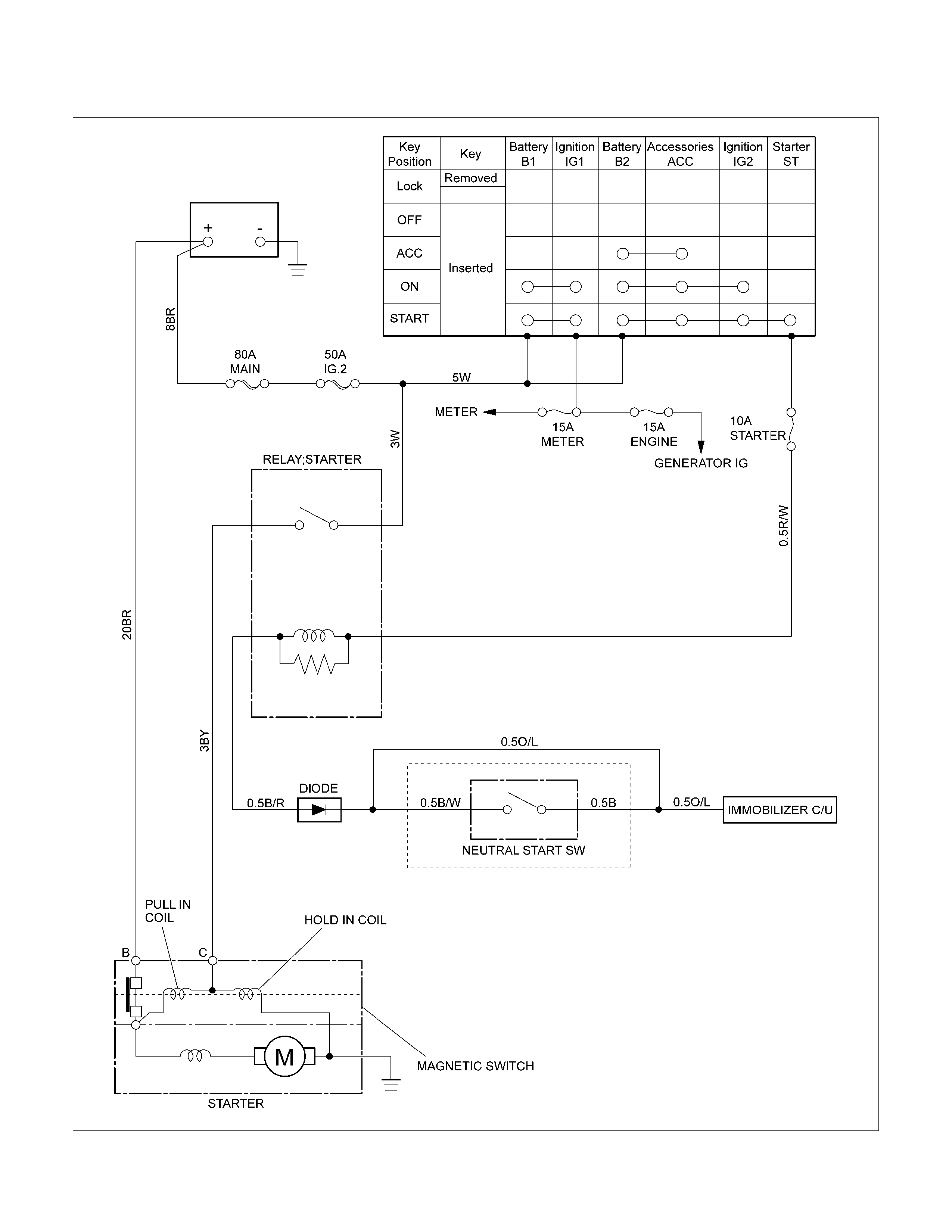
Cranking Circuit
The cranking system consists of a battery, starter motor, ignition (starter) switch, starter relay, etc. These main
components are connected by the starting system wiring harness.
Starter
The cranking system employs a magnetic type reduction starter in which the motor shaft is also used as a pinion
shaft. When the ignition switch is turned to the START position, the contacts of starter solenoid are closed, and the
armature rotates. At the same time, the plunger is attracted, and the pinion is pushed forward by the shift lever to
mesh with the ring gear. The ring gear then rotates to start the engine. When the engine speed is higher than the
pinion, the pinion idles, so that the armature is not driven.
When the engine starts and the ignition switch is returned to the ON position, the plunger returns, the pinion is
disengaged from the ring gear, and the armature stops rotation.
RTW46DXF000101
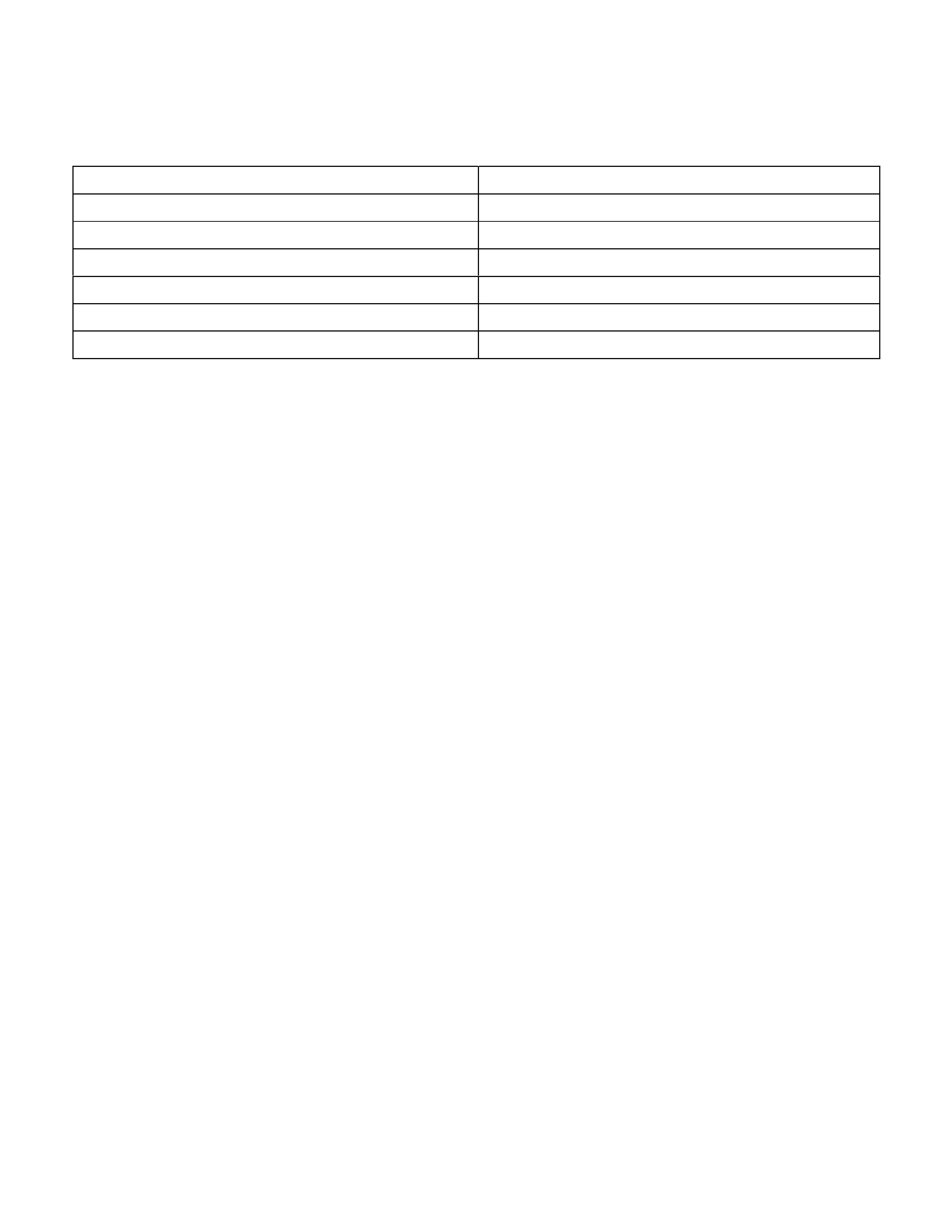
Diagnosis
Symptom Possible Cause Action
Starter does not run Charging failure Repair charging system
Battery failure Replace battery
Terminal connection failure Repair or replace terminal connector
and/or wiring harness
Starter switch failure Repair or replace starter switch
Starter failure Repair or replace starter
Starter
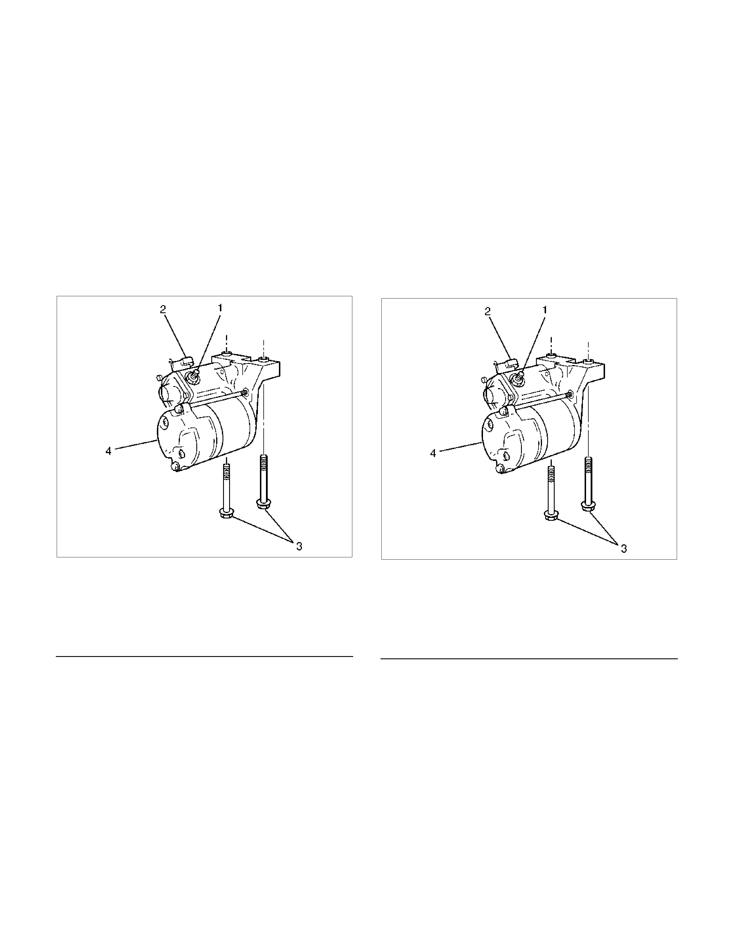
Removal
1. Disconnect the battery ground cable.
2. Disconnect left heated O2 sensor connector.
3. Remove exhaust front left pipe.
4. Remove dust cover.
5. Disconnect starter wiring connector from terminals
“30" and “50".
6. Remove starter assembly mounting bolts on inside
and outside.
7. Remove starter assembly toward the bottom of
engine.
065RY00050
Legend
(1) Terminal "30"
(2) Terminal "50"
(3) Fixing Bolts
(4) Starter Assembly
Installation
1. Install starter assembly.
2. Install mounting bolts and tighten bolts to specified
torque.
Torque: 40 N⋅m (4.1 kg⋅m/30 lb ft)
3. Reconnect the connectors to terminals “30" and
“50" and tighten Terminal “30" to specified torque.
Torque: 9 N⋅m (0.9 kg⋅m/7 lb ft)
4. Install dust cover.
065RY00050
Legend
(1) Terminal "30"
(2) Terminal "50"
(3) Fixing Bolts
(4) Starter Assembly
5. Install exhaust front left pipe and tighten bolts and
nuts to specified torque.
Stud Nut
Torque: 67 N⋅m (6.8 kg⋅m/49 lb ft)
Nut
Torque: 43 N⋅m (4.4 kg⋅m/32 lb ft)
6. Reconnect heated O2 sensor connector.
7. Reconnect the battery ground cable.
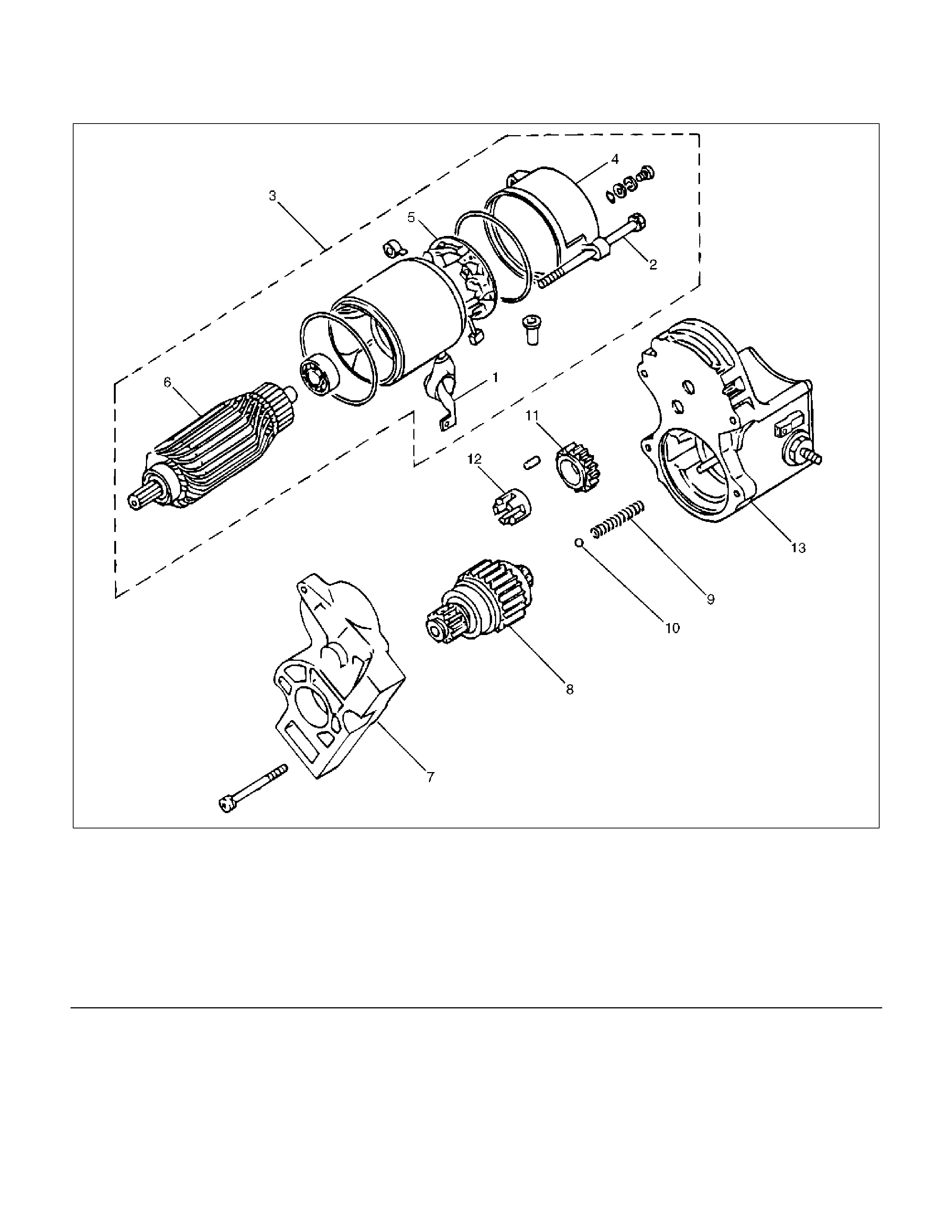
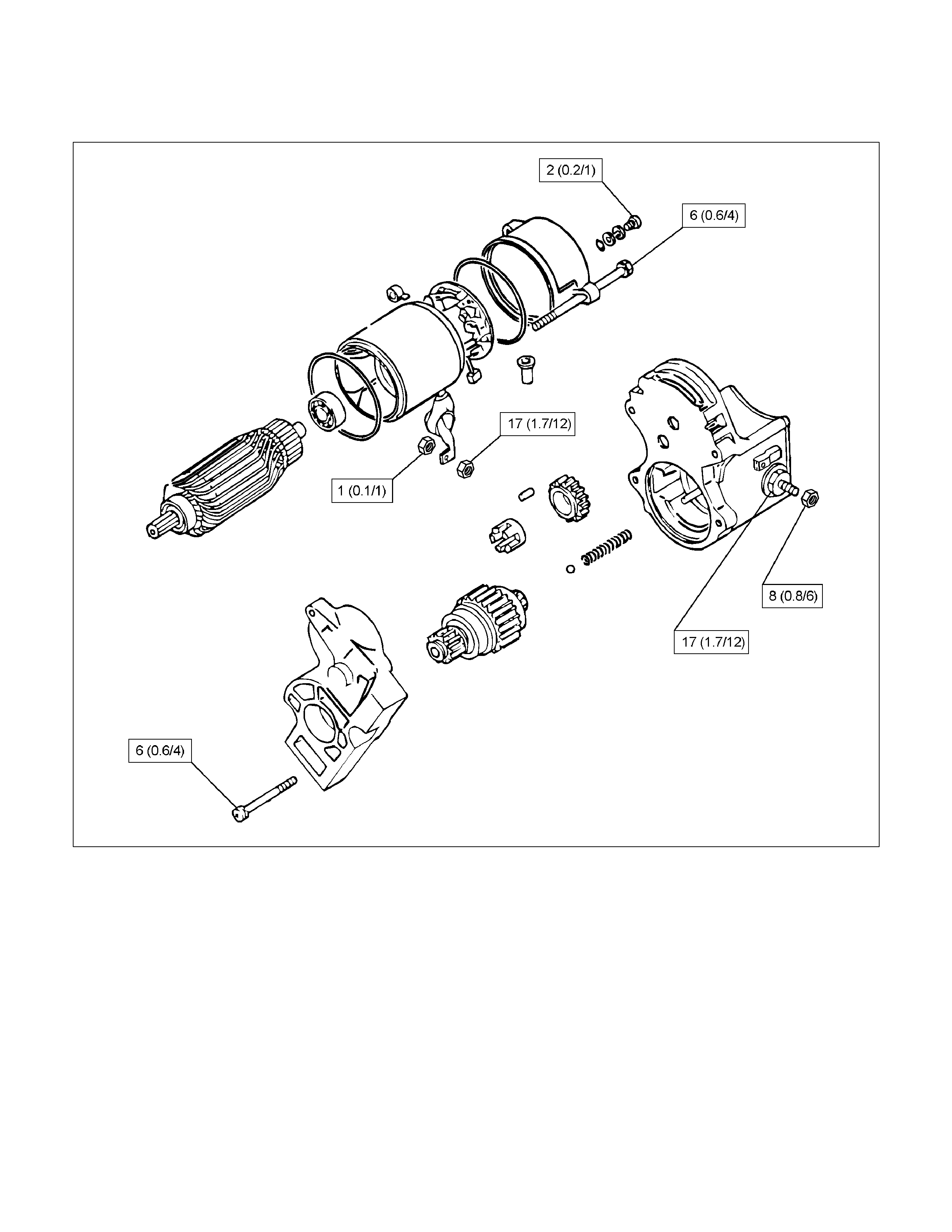
Disassembled View
065R100012
Legend (7) Housing
(1) Lead Wire (8) Over Running Clutch
(2) Through Bolt (9) Return Spring
(3) Yoke Assembly (10) Steel Ball
(4) Yoke Cover (11) Idle Pinion
(5) Brush and Brush Holder (12) Retainer
(6) Armature (13) Magnetic Switch (Solenoid)
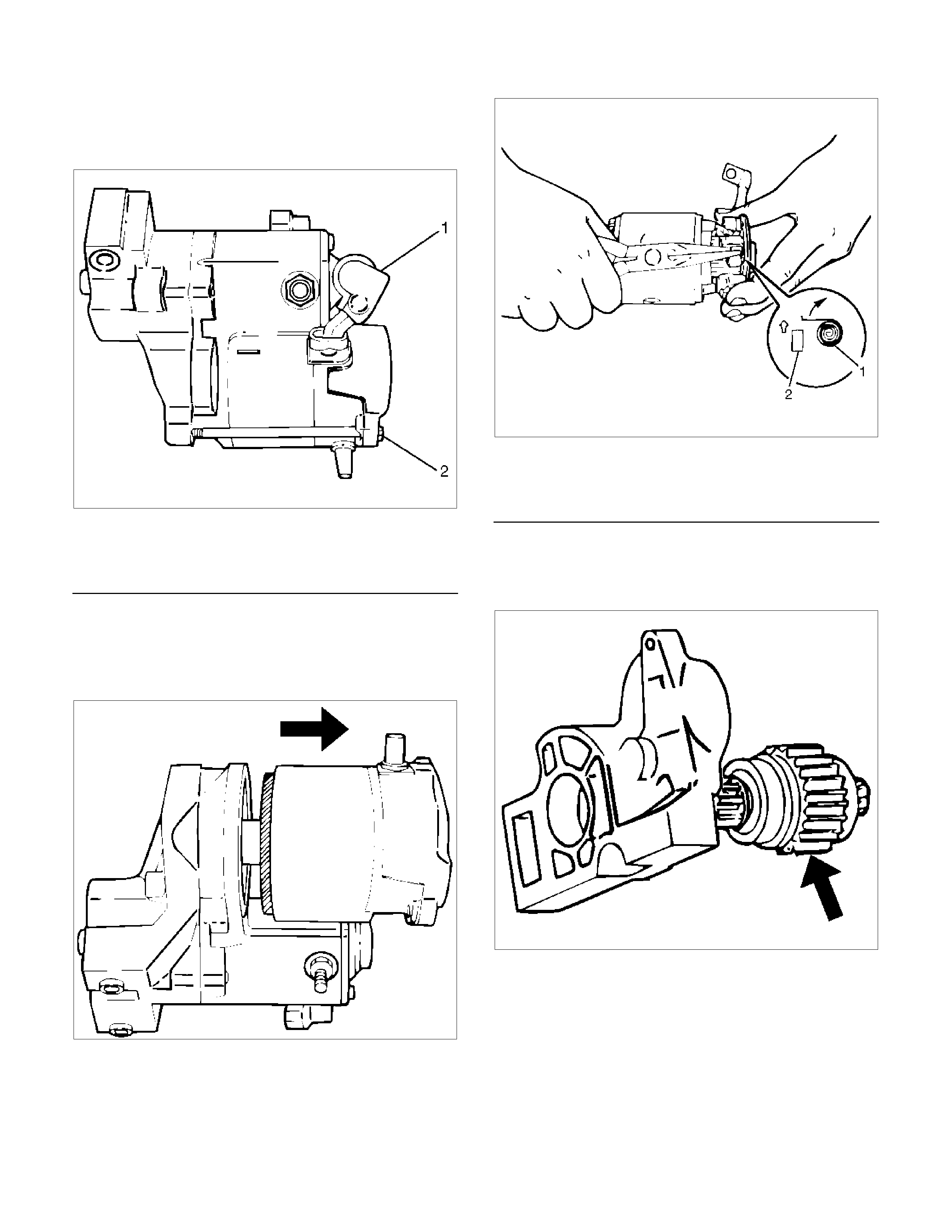
Disassembly
1. Remove the lead wire (1) from the magnetic switch.
2. Remove the through bolts (2).
065RY00053
Legend
(1) Lead Wire
(2) Through Bolt
3. Remove the yoke from the assembly.
4. Remove the yoke cover.
5. Use long nose pliers to remove the brush and brush
holder.
065RY00054
065RY00055
Legend
(1) Spring
(2) Brush
6. Remove the armature.
7. Remove the housing.
8. Remove the overrunning clutch from the housing.
065RY00056
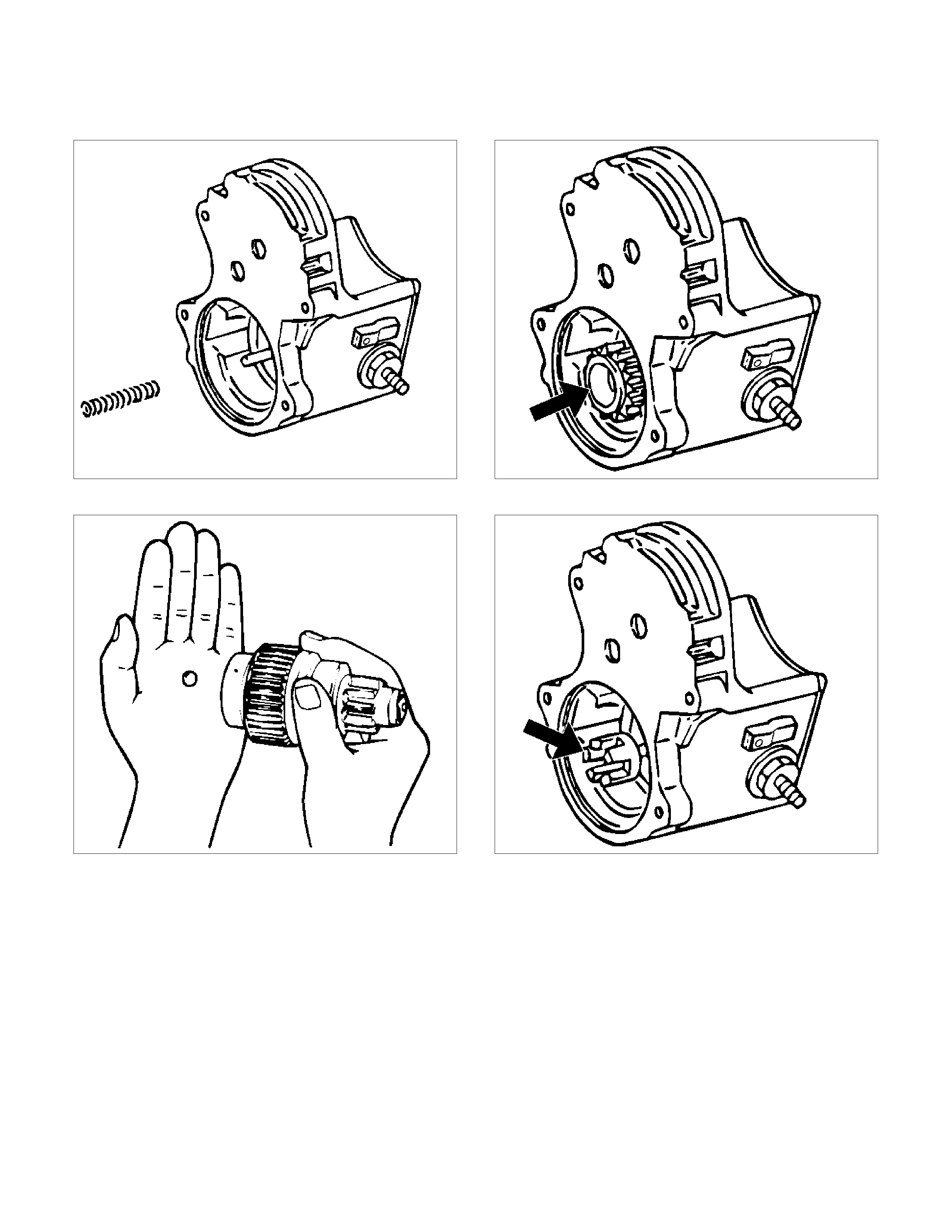
9. Remove the return spring from the magnetic switch.
065R100014
10. Remove the steel ball from the overrunning clutch.
065RY00058
11. Remove the idle pinion from the magnetic switch.
065R100015
12. Remove the retainer from the magnetic switch.
065R100016
13. Remove the magnetic switch.
Inspection and Repair
Repair or replace necessary parts if extreme wear or
damage is found during inspection.
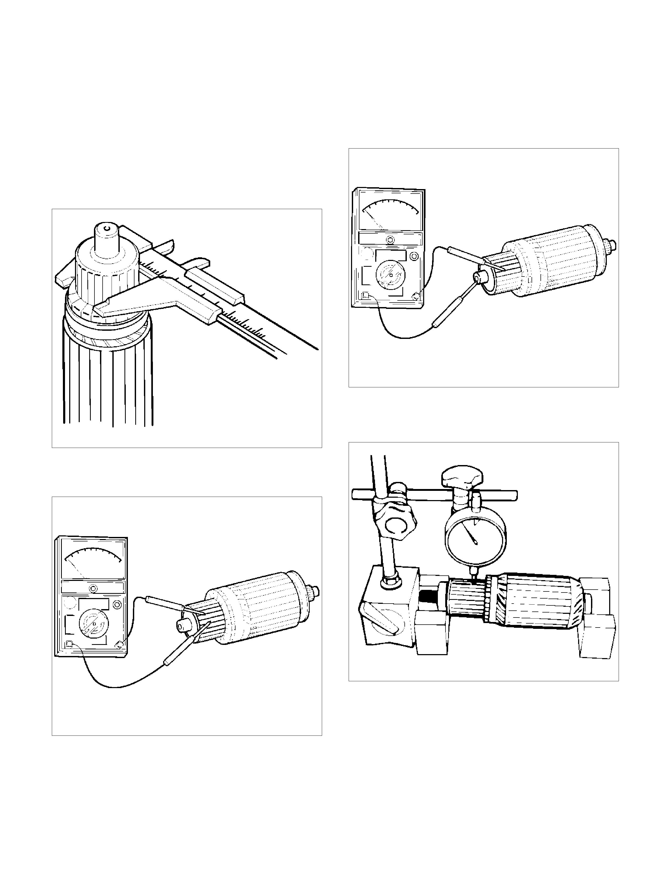
Armature
Measure the outer diameter of the commutator and
replace with a new one if it is out of the limit.
Standard: 30 mm (1.1811 in)
Limit: 29 mm (1.1417 in)
065RS014
Check for continuity between segment and segment on
the commutator. Replace commutator if there is no
continuity (i.e., open circuit).
065RS015
Check for continuity between commutator and shaft.
Also, check for continuity between commutator and
armature core, armature core and shaft. Replace
commutator if there is continuity (i.e., internally
grounded).
065RS016
Measure runout of the commutator with a dial gauge.
Repair or replace if it exceeds the limit.
Limit: 0.4 mm (0.0157 in)
065RY00061
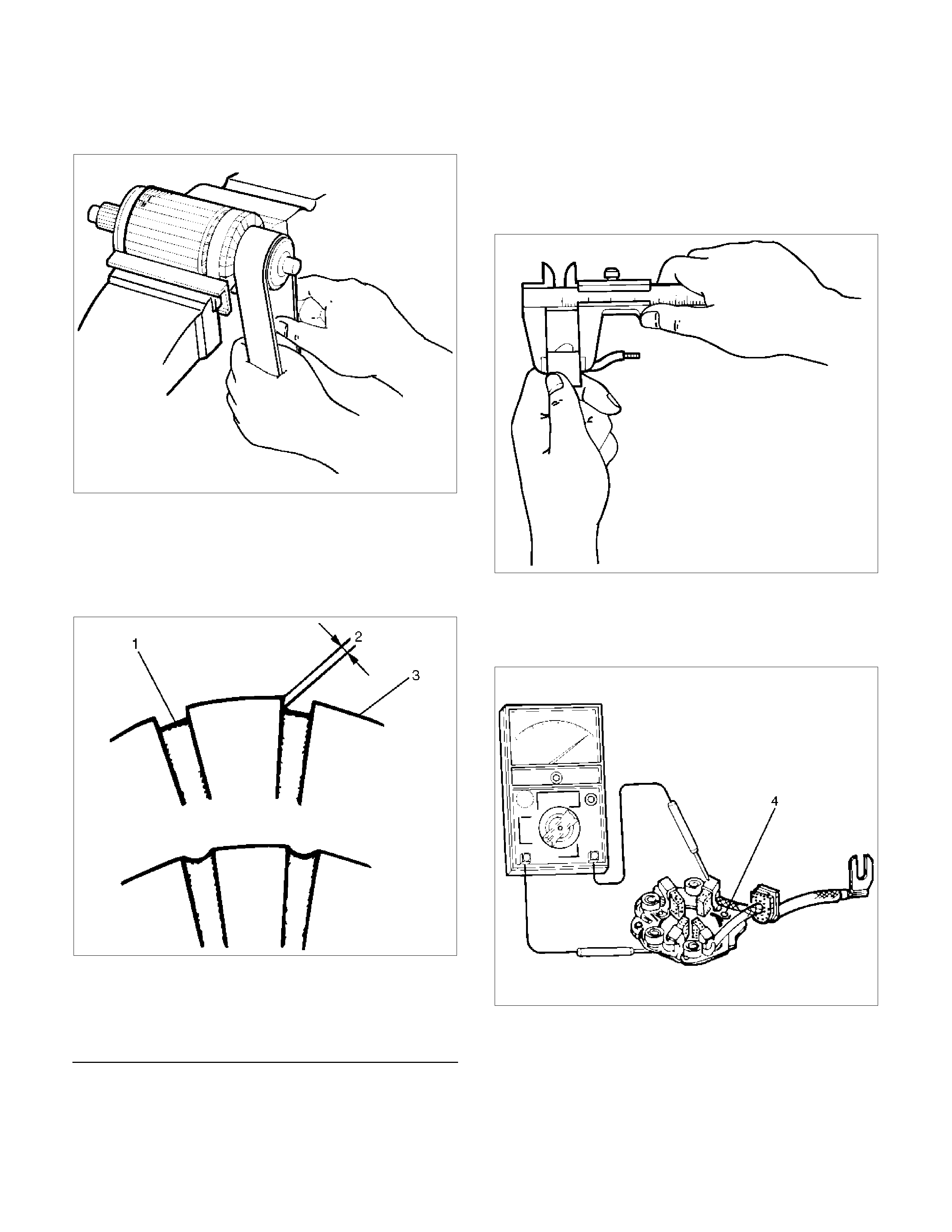
If rough, polish the commutator surface with #500 to
#600 sandpaper.
065RW012
Measure the depth of the insulator in the commutator.
Replace, if it is below the limit.
Standard: 0.45 mm to 0.75 mm (0.0177 in to
0.0295 in)
Limit: 0.2 mm (0.008 in)
065RY00070
Legend
(1) Insulator
(2) Depth of Insulator
(3) Commutator Segments
Brush
Measure the length of the brush.
Replace with a new one if it is below the limit.
Standard: 15 mm (0.5906 in)
Limit: 11 mm (0.43 in)
065RW014
Brush Holder
Check for continuity between brush holder (+) (4) and
base (–). Replace if there is continuity (i.e., insulation is
broken).
065RW015
Brush Spring
Use a spring balancer to measure the spring setting
force when removing the spring from the brush.
Standard: 17.65–23.54 N (38.9–51.9 lb)
Limit: 11.77 N (25.9 lb)
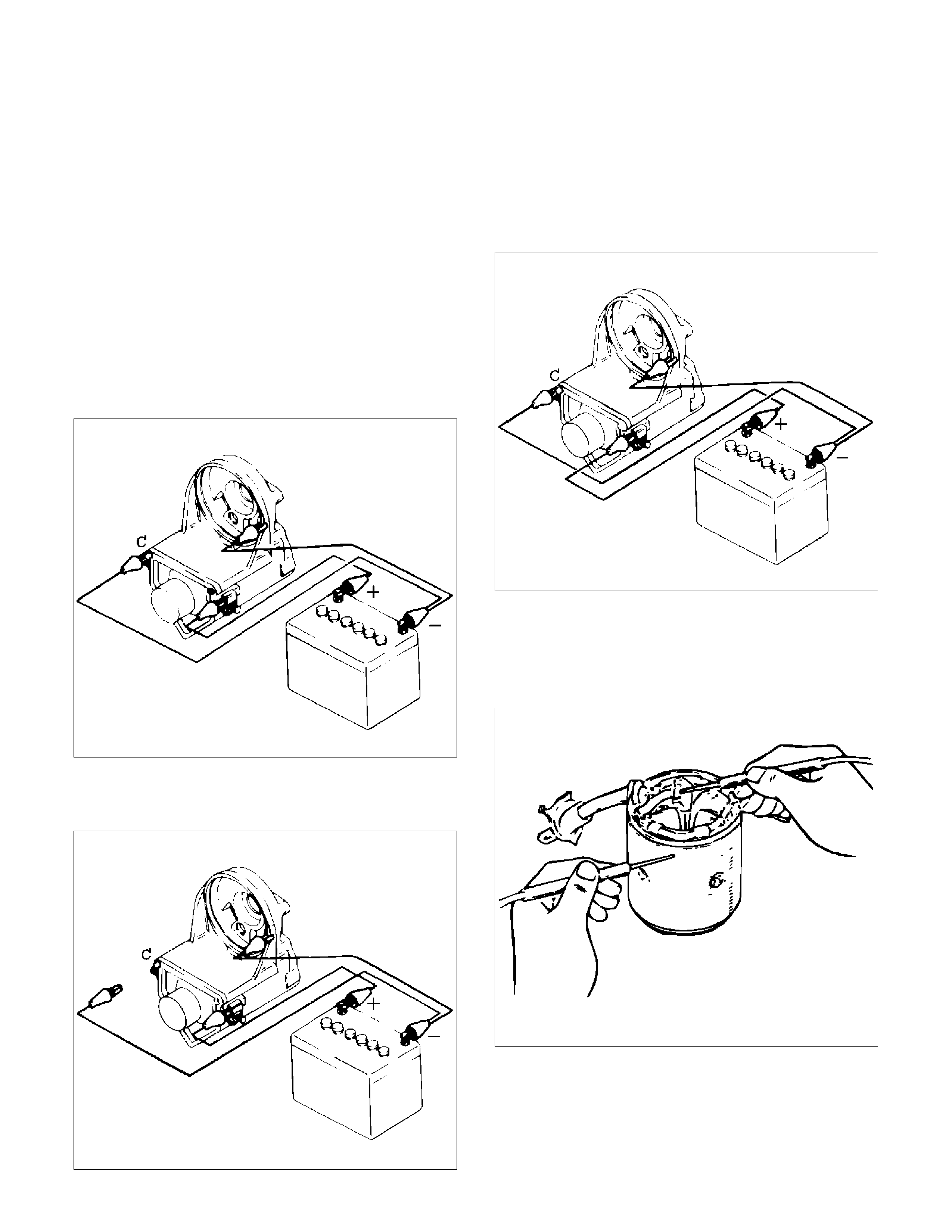
Magnetic Switch
Temporarily connect the magnetic switch between the
overrunning clutch and housing.
Perform the steps described below in 3 to 5 seconds.
1. Pull in test.
Connect the ground (-) to terminal “C” and magnetic
switch body.
Verify that the pinion pulls out when the battery (+)
pole is connected to terminal “50”.
065R100017
2. Hold in test.
Observe that the pinion stays when the lead wire is
disconnected from terminal “C”.
065R100018
3. Return test.
Connect the ground (-) to terminal “50” and
magnetic switch body.
Verify that the pinion pulls out when the battery (+)
pole is connected to terminal “C” and the pinion
pulls away when the lead wire is disconnected from
terminal “50”.
065R100019
Field Coil
1. Check for continuity between the end of the field
coil and yoke body.
Replace the field coil if there is continuity.
065RY00065
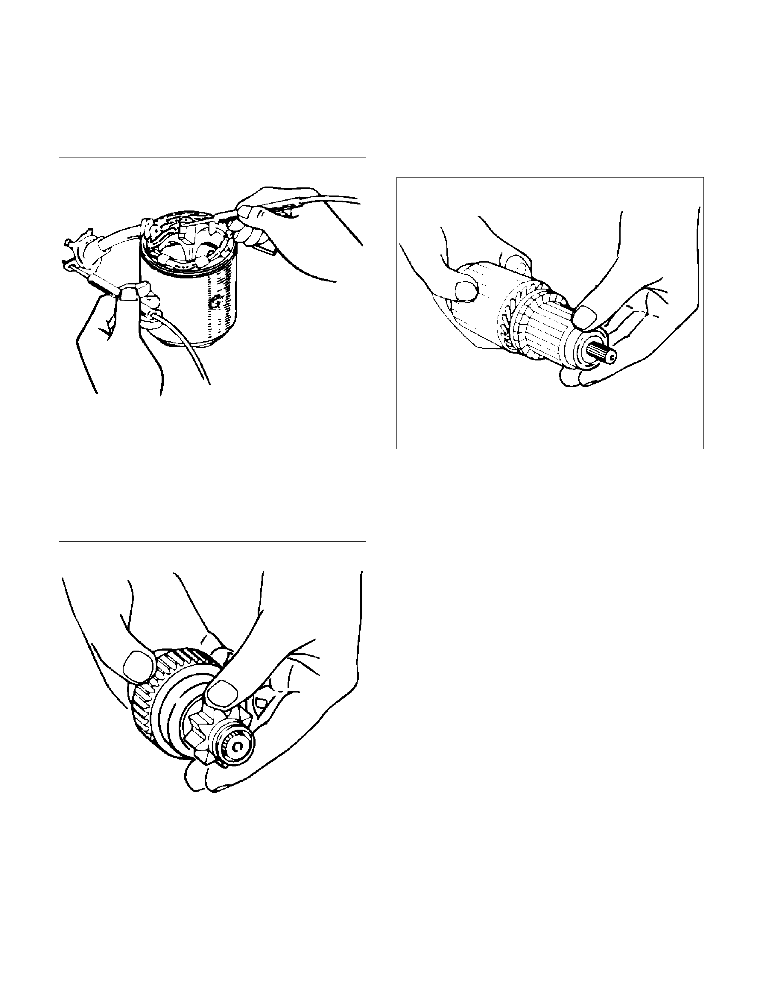
2. Check continuity between the lead wire of terminal
“C” and brush.
Replace the yoke assembly if there is no continuity.
065RY00066
Overrunning Clutch
1. Visually check for excessive wear or damage.
2. Test the pinion rotation, it must rotate smoothly
when rotated clockwise and it shouldn't rotate when
turned counter clockwise.
065RY00067
Bearing
1. Inspect excessive wear or damage.
Replace the bearing if an abnormal noise is heard
under normal operating condition.
065RY00068
Reassembly
To install, follow the removal steps in the reverse order,
noting the following points:
Grease application places
• Bearing in rear cover
• Gears in reduction gear
• Sliding portion of pinion
Main Data and Specifications
General Specifications
Model ADX4IH
Rating
Voltage 12 V
Output 1.4 Kw
Time 30 sec
Number of teeth of pinion 9
Rotating direction (as viewed from pinion) Clockwise
Weight (approx.) 3.8 kg (8.4 lb)
No–load characteristics
Voltage/current 11.5 V/90 A or less
Speed 3000 rpm or more
Load characteristics
Voltage/current 8.5 V/350 A or less
Torque 13.2 N m (1.35 kg m/9.77 lb in.) or more
Speed 1000 rpm or more
Locking characteristics
Voltage/current 2.4 V/500 A or less
Torque 11.8 N⋅m (1.2 kg⋅m/8.68 lb in) or more
Torque Specifications N⋅m (kg⋅m/lb ft)
RTW46DLF000101
Charging System
General Description
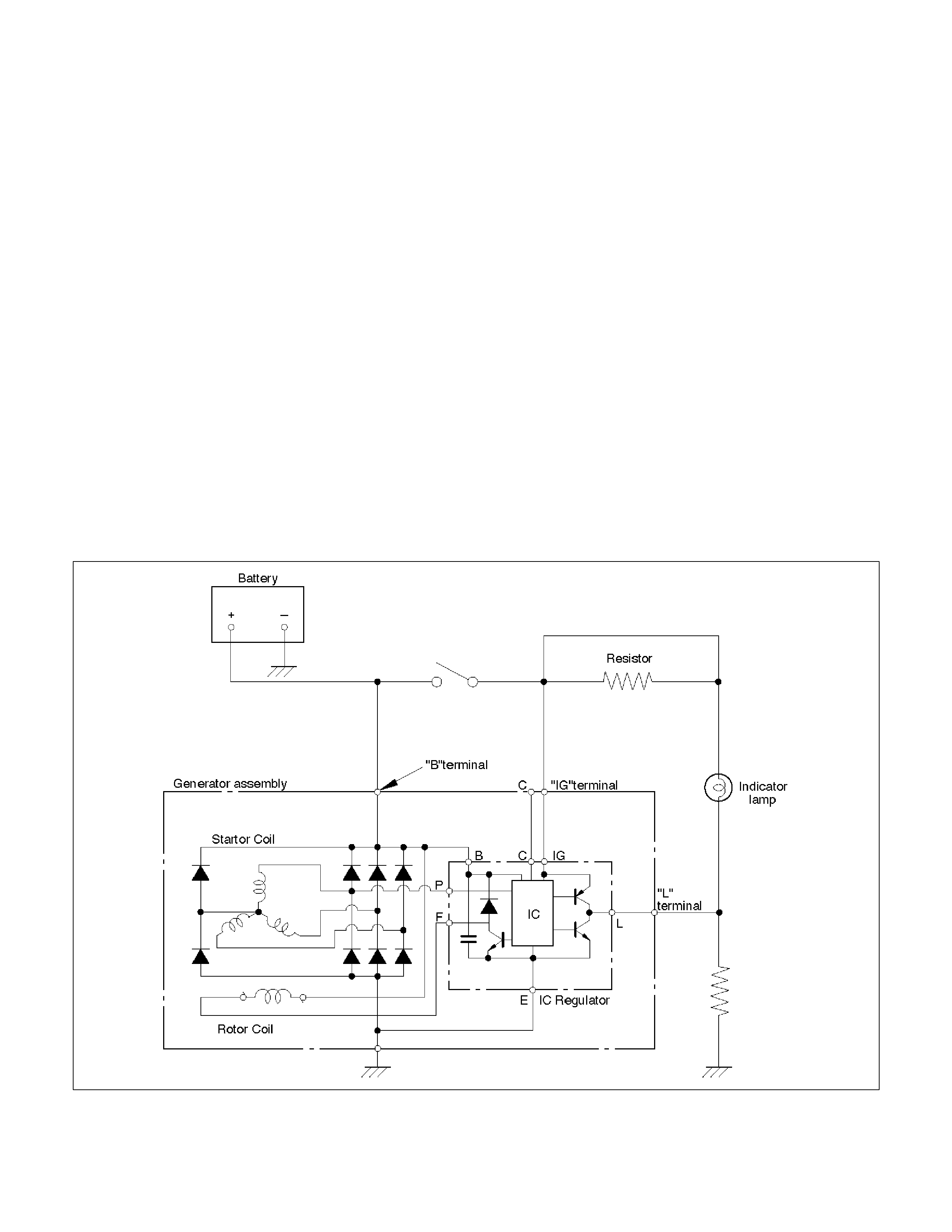
The IC integral regulator charging system and its main components are connected as shown in illustration.
The regulator is a solid state type and it is mounted along with the brush holder assembly inside the generator
installed on the rear end cover.
The generator does not require particular maintenance such as voltage adjustment.
The rectifier connected to the stator coil has eight diodes to transform AC voltage into DC voltage.
This DC voltage is connected to the output terminal of generator.
General On–Vehicle Inspection
The operating condition of charging system is indicated by the charge warning lamp. The warning lamp comes on
when the starter switch is turned to the “ON" position. The charging system operates normally if the lamp goes off
when the engine starts.
If the warning lamp shows abnormality or if undercharged or overcharged battery condition is suspected, perform
diagnosis by checking the charging system as follows:
1. Check visually the belt and wiring connector.
2. With the engine stopped, turn the ignition switch to the “ON" position and observe the warning lamp.
If lamp does not come on:
Disconnect the wiring connector from generator, and ground terminal “L" on connector side.
If lamp comes on: Repair or replace the generator.
F06RW009
Generator
Removal
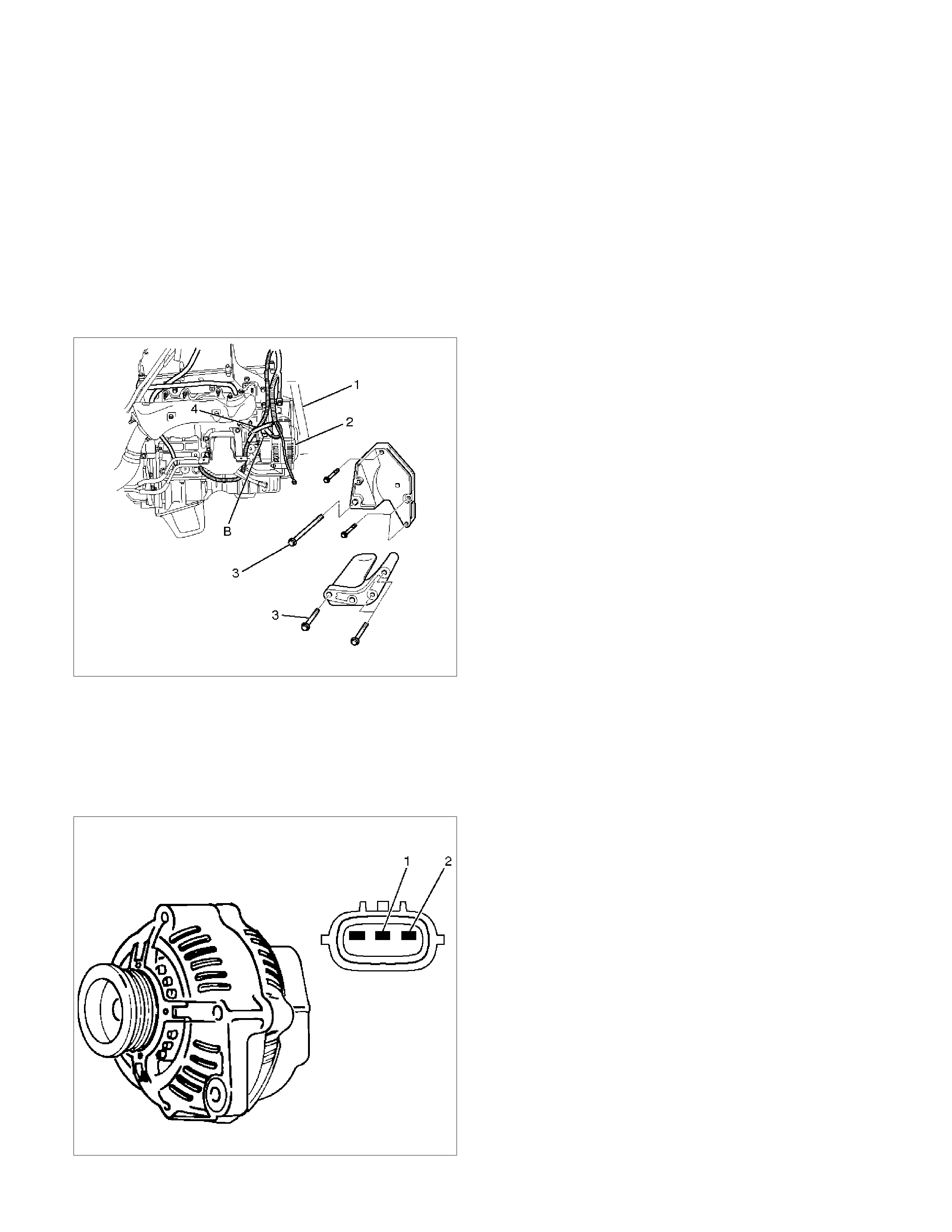
1. Disconnect the battery ground cable.
2. Move drive belt tensioner to one side using wrench
then remove drive belt (1).
3. Disconnect the wire from terminal “B" and
disconnect the connector (4).
4. Remove generator fixing bolt (3).
5. Remove generator assembly (2).
060RW002M
Inspection
1. Disconnect the wiring connector from the generator.
2. With the engine stopped, turn starter switch to the
“ON" position and connect a voltmeter between
connector terminal L (2) and ground or between
terminal IG (1) and ground.
066RW001
If voltage is not present, the line between battery
and connector is open circuit and will require repair.
3. Reconnect the wiring connector to the generator,
run the engine at middle speed, and turn off all
electrical devices other than engine.
4. Measure battery voltage. If it exceeds 16V, repair or
replace the generator.
5. Connect an ammeter to output terminal of
generator, and measure output current under load
by turning on the other electrical devices (eg.,
headlights). At this time, the voltage must not be
less than 13V.
Installation
1. Place generator assembly in the position to be
installed.
2. Install generator assembly and tighten the fixing
bolts to the specified torque.
Torque:
M10 bolt: 52 N⋅m (5.3 kg⋅m/38 lb ft)
M8 bolt: 25 N⋅m (2.5 kg⋅m/18 lb ft)
3. Connect wiring harness connector and connect wire
to terminal “B".
4. Move drive belt tensioner to one side using wrench,
then install drive belt to normal position.
5. Reconnect the battery ground cable.
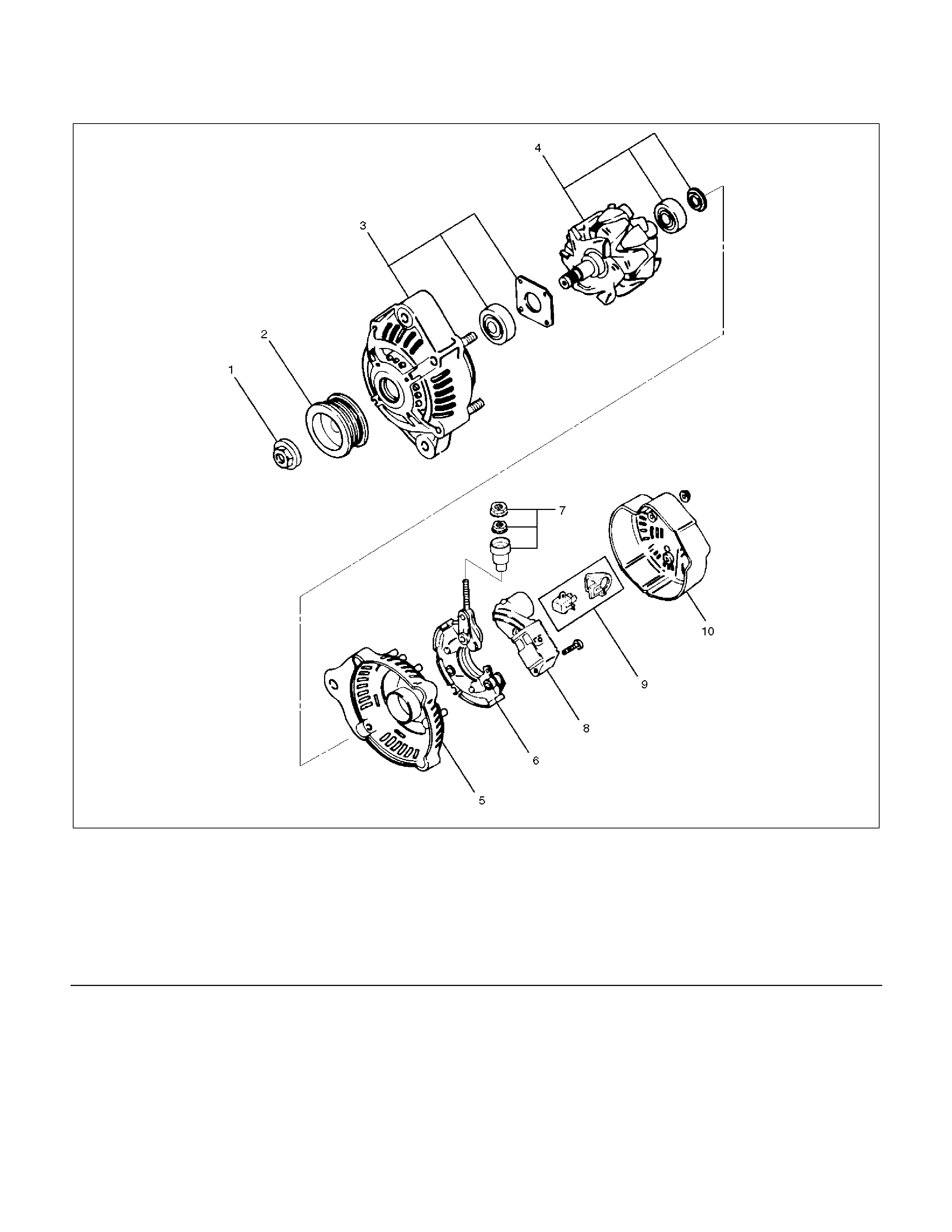
Disassembled View
066RW007
Legend (6) Rectifier
(1) Pulley Nut (7) Terminal Insulator and Nut
(2) Pulley (8) Regulator Assembly
(3) Front Cover Assembly (9) Brush Holder Assembly
(4) Rotor Assembly (10) Rear Cover
(5) Rear End Cover
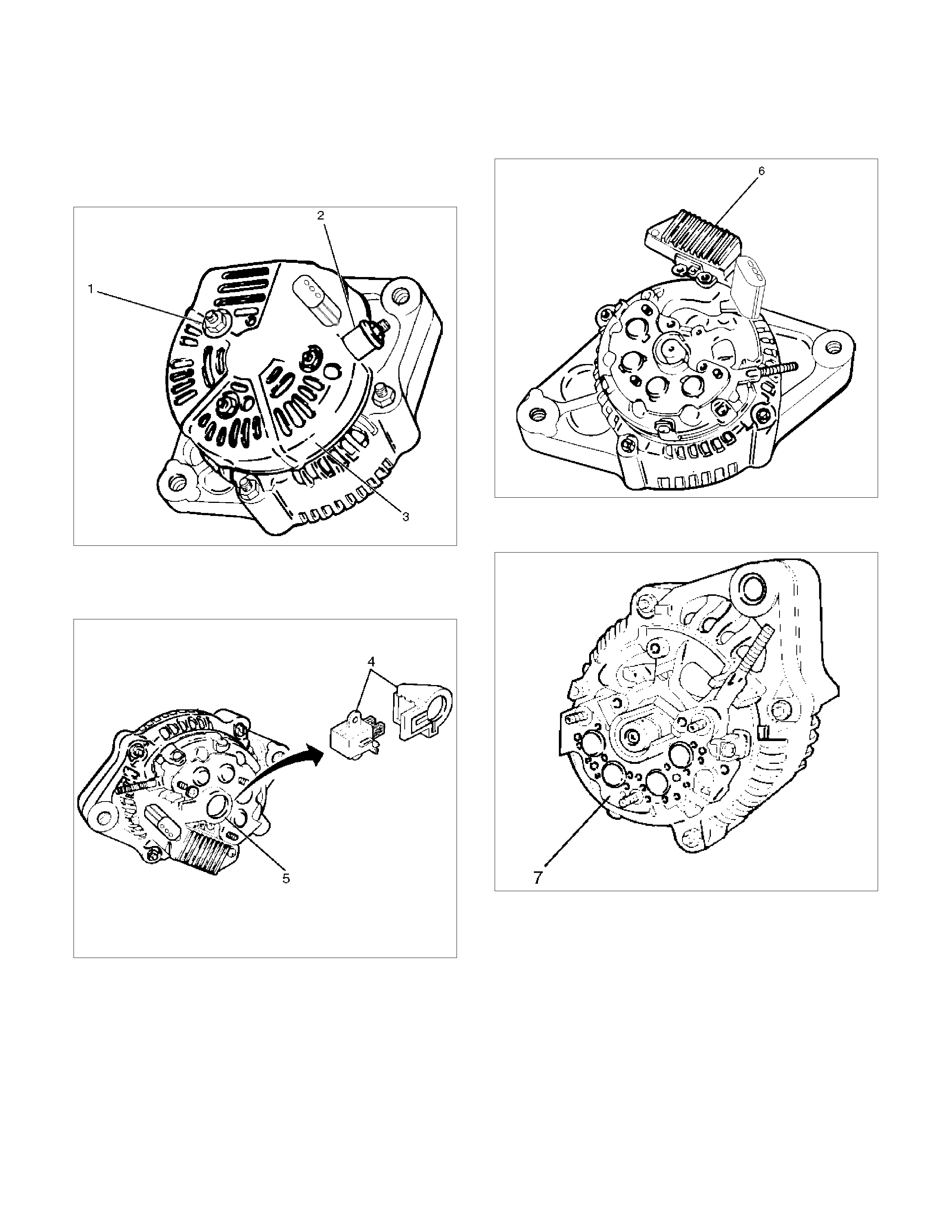
Disassembly
1. Remove terminal insulator and nut (2).
2. Remove three nuts (1) on the rear cover, then
remove the rear cover (3).
060RW005
3. Remove two screws that fix the brush holder (5)
and rectifier, then remove the brush holder
assembly (4).
060RW004
4. Remove three screws that fix the IC regulator, then
remove the IC regulator assembly (6).
060RW003
5. Remove the four screws that fix the rectifier (7) and
stator lead wires.
066RW004
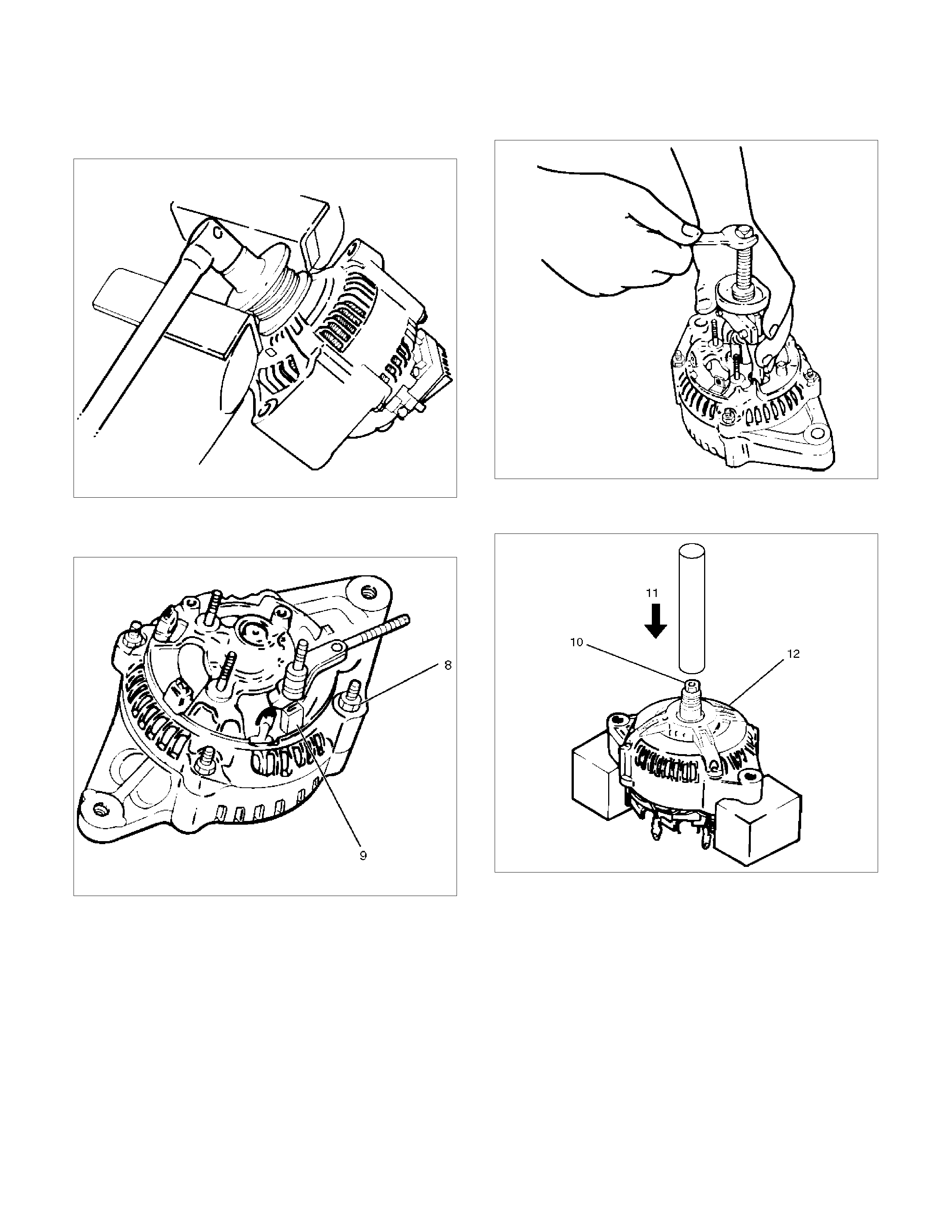
6. Secure the pulley directly in the vise between two
copper plates, and remove the nut and pulley.
066RS010
7. Remove the four nuts (8) that secure the front cover
assembly, rear end cover and an insulator (9).
066RW005
8. Use the puller to remove the rear end cover.
066RS012
9. Remove the rotor assembly (10) from the front
cover assembly (12) by using a bench press (11).
066RW006
Inspection and Repair
Repair or replace necessary parts if extreme wear or
damage is found during inspection.
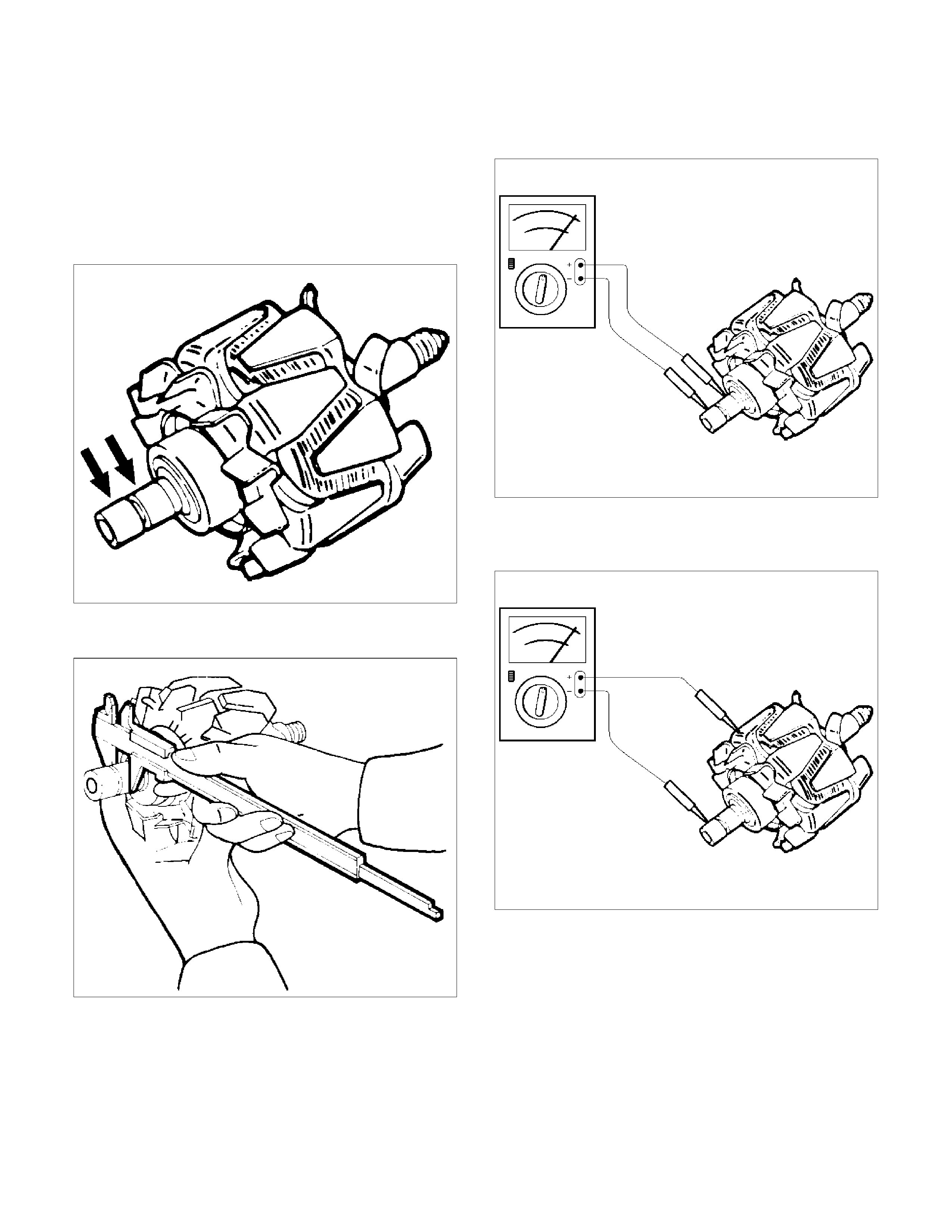
Rotor Assembly
1. Check the rotor slip ring surfaces for contamination
and roughness. If rough, polish with #500 to 600
sandpaper.
066RS014
2. Measure the slip ring diameter, and replace if it
exceeds the limit.
066RS015
3. Measure resistance between slip rings, and replace
the rotor assembly if there is no continuity.
066RS016
4. Measure resistance between slip ring and rotor
core.
If there is continuity, replace the rotor assembly.
066RS017
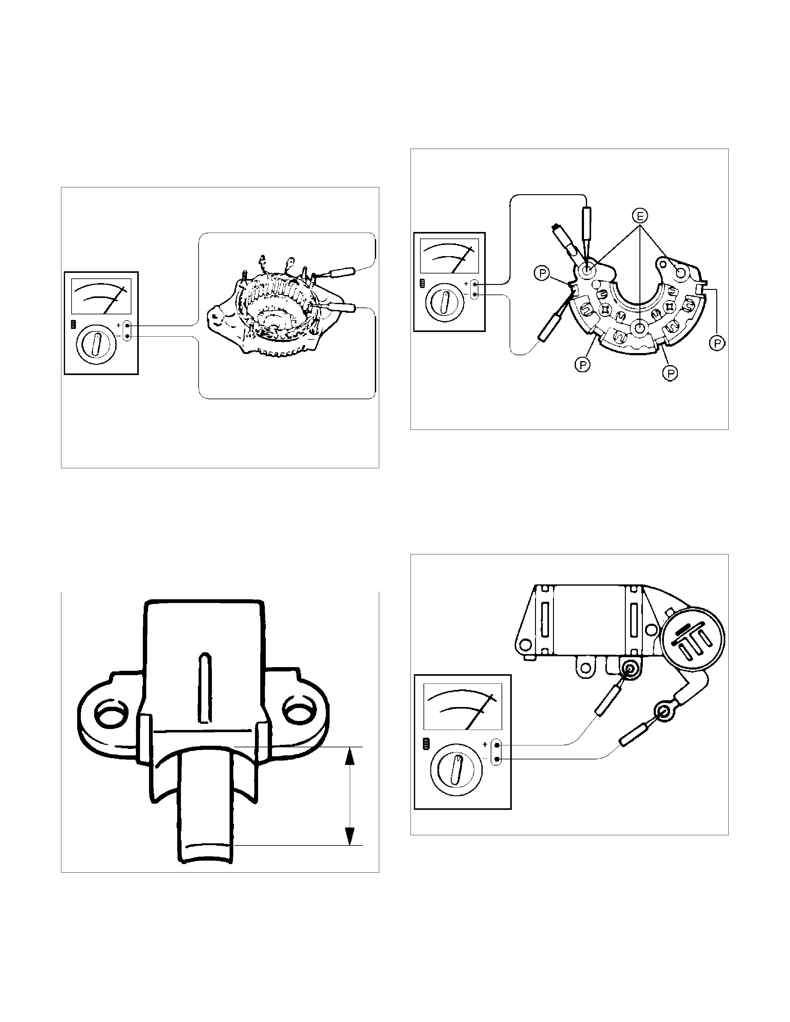
Stator Coil
1. Measure resistance between respective phases.
2. Measure insulation resistance between stator coil
and core with a mega–ohmmeter.
If less than standard, replace the coil.
066RS018
Brush
Measure the brush length.
If less than limit, replace the brush.
Standard: 10.mm (0.4134 in)
Limit: 8.4.mm (0.3307 in)
066RS019
Rectifier Assembly
Check for continuity across terminals “P" and “E" using
the 100W range of the multimeter.
066RW002
Change polarity, and make sure that there is continuity
in one direction, and not in the reverse direction. In
case of continuity in both directions, replace the rectifier
assembly.
IC Regulator Assembly
Check for continuity across terminals “B" and “F" using
the 100W range of the multimeter.
066RS021
Change polarity, and make sure that there is continuity
in one direction, and not in the reverse direction. In
case of continuity in both directions, replace the IC
regulator assembly.

Reassembly
To reassemble, follow the disassembly steps in the
reverse order, noting the following points:
1. Using a press with a socket wrench attached,
reassemble the rotor and the rear end cover
assembly into the front cover.
066RS022
2. Install pulley on the rotor.
Secure the pulley directly in the vise between two
copper plates, and tighten nut to the specified
torque.
Torque: 111 N⋅m (11.3 kg⋅m/82 lb ft)
066RS010
Bench Test
Conduct a bench test of the generator.
066RS023
Preparation
Remove generator from the vehicle (see “Generator
Removal").
1. Secure generator to the bench test equipment and
connect wires as follows:
Terminal “IG" for energization.
Terminal “L" for neutral (warning lamp).
Terminal “B" for output.
2. Conduct the generator characteristic test.
Characteristics of generator are shown in
illustration.
Repair or replace the generator if its outputs are
abnormal.
B06RW001
Main Data and Specifications
General Specifications
Part number 102211-1740
Model ACJV74
Rated voltage 12 V
Rated output 90 A
Rotating direction (as viewed from pulley) Clockwise
Pulley effective diameter 57.5 mm (2.26 in)
Weight 5.1 kg (11 lb)