
SECTION 6E - 3.5L ENGINE DRIVEABILITY AND
EMISSIONS
Abbreviation Charts
Component Locator
Engine Component Locator Table
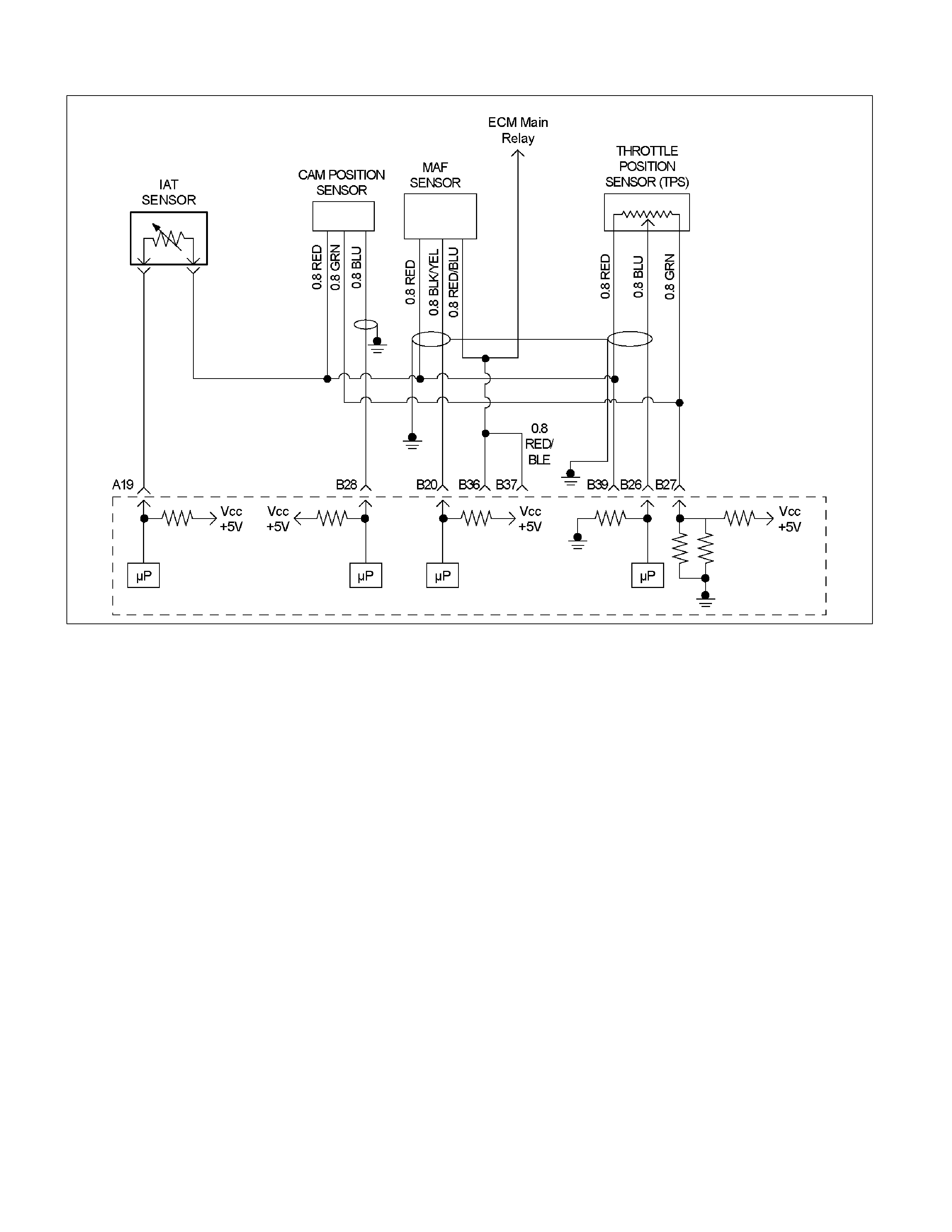
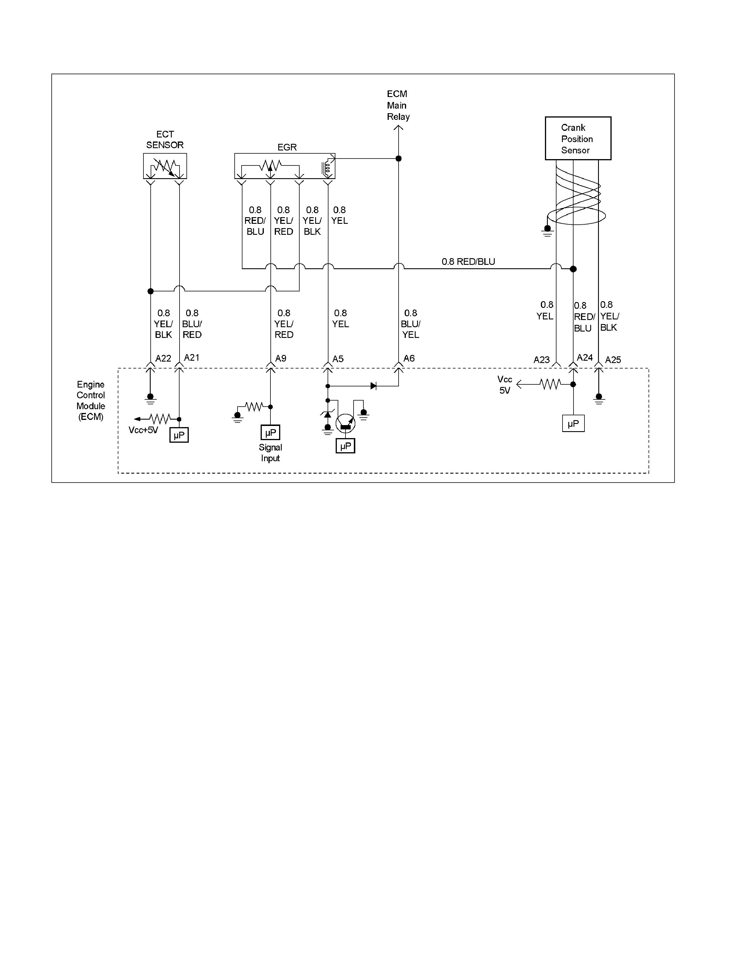
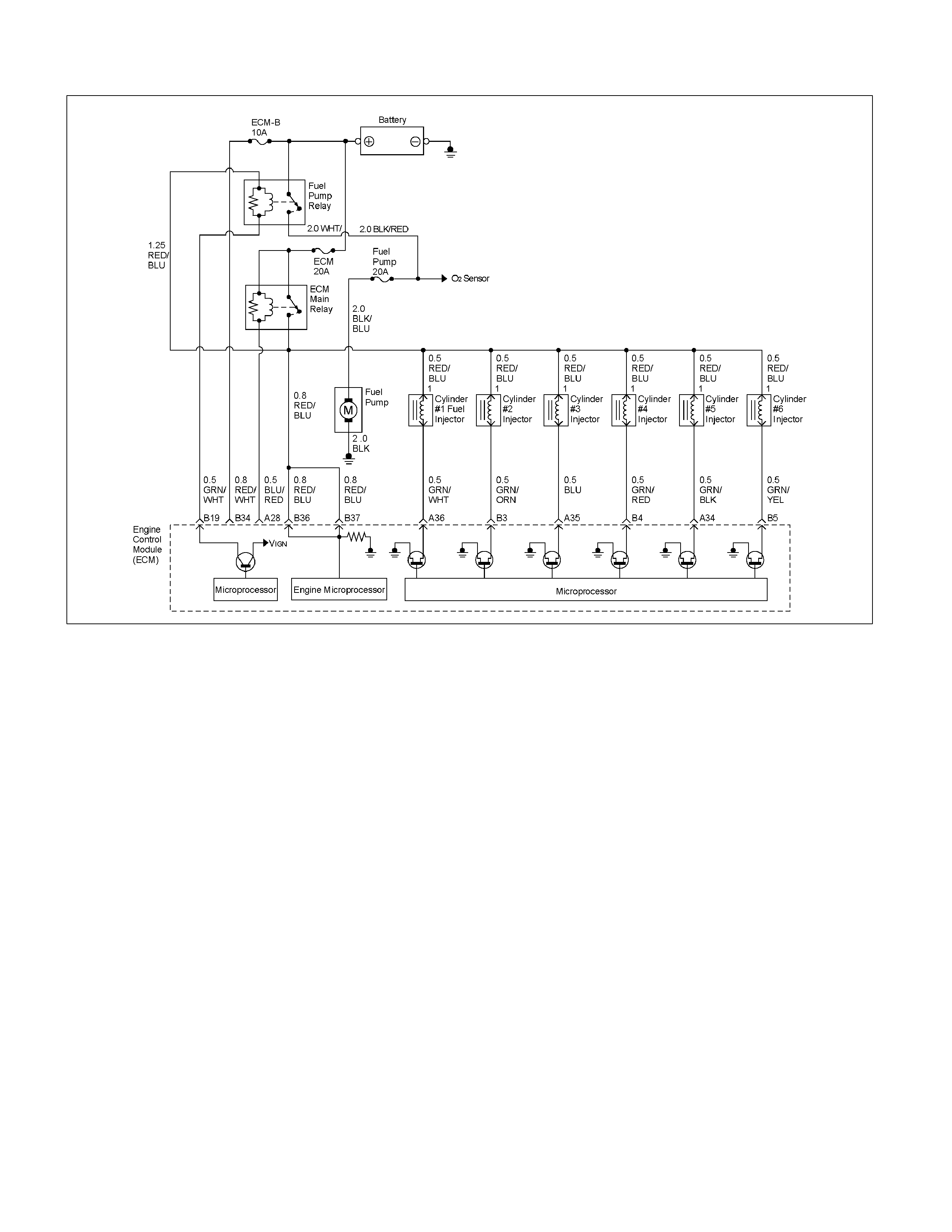
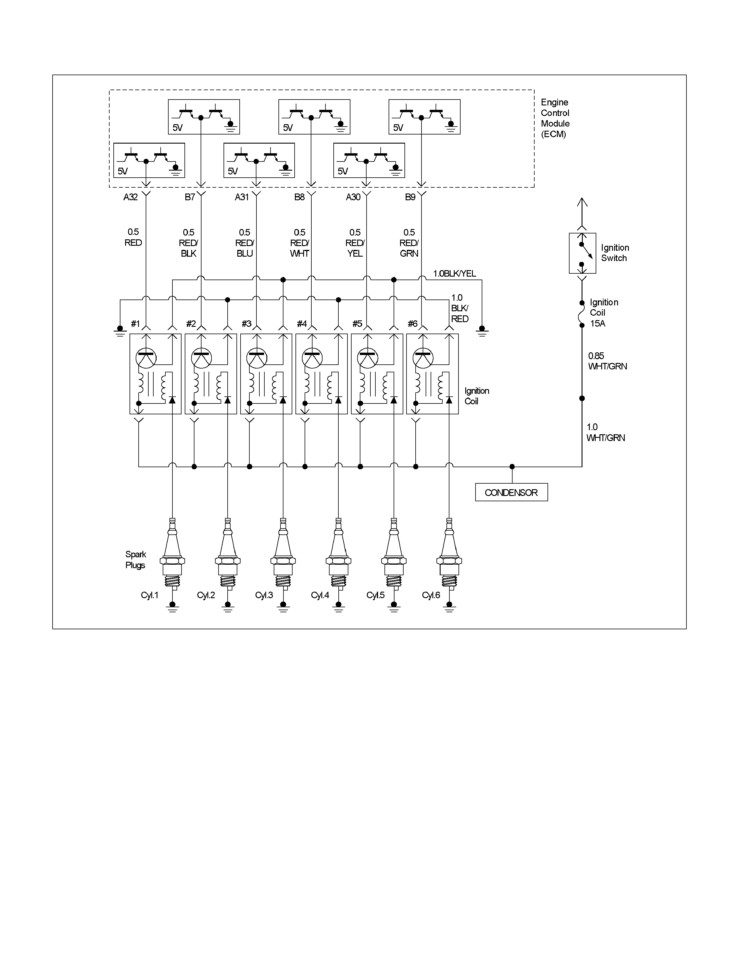
ECM Circuit Diagram
Ground Point Chart
Location
Cable Harness & Connector Location
Connector List
Relay And Fuse
Relay And Fuse Box Location
Fuse And Relay Location
ECM Wiring Diagram
ECM Connector Pin Assignment & Output Signal
General Description For ECM And Sensors
Engine Control Module (ECM)
Mass Air Flow (MAF) Sensor & Intake Air
Temperature (IAT) Sensor
Throttle Position Sensor (TPS)
Idle Air Control (IAC) Valve
Camshaft Position (CMP) Sensor
Crankshaft Position (CKP) Sensor
Engine Coolant Temperature (ECT) Sensor
Vehicle Speed Sensor (VSS)
Heated Oxygen (O2) Sensor
General Description For Fuel Metering
Acceleration Mode
Battery Voltage Correction Mode
Clear Flood Mode
Deceleration Mode
Fuel Cutoff Mode
Run Mode
Starting Mode
Fuel Metering System Components
Fuel Injector
Fuel Pressure Regulator
Fuel Rail
Fuel Pump Electrical Circuit
Camshaft Position (CMP) Sensor Signal
General Description For Electronic Ignition System
Ignition Coils & Control
Ignition Control ECM Output
Spark Plug
General Description For Evaporative Emission
System
EVAP Control System
Results of Incorrect Operation
General Descriprion For Exhaust Gas Recirculation
(EGR) System
Linear EGR Valve
Linear EGR valve Operation and Results of
Incorrect Operation
Strategy Based Diagnostics
Overview
Strategy Based Diagnostics Chart
Diagnostic Thought Process
1. Verify The Complaint
2. Perform Preliminary Checks
3. Check Bulletins And Troubleshooting Hints
4. Perform Service Manual Diagnostic Checks
5a And 5b. Perform Service Manual Diagnostic
Procedures
5c. Technician Self Diagnoses
5d. Intermittent Diagnosis
Symptom Simulation Tests
5e. Vehicle Operates As Designed
6. Re-Examine The Complaint
7. Repair And Verify Fix
General Service Information
Aftermarket Electrical and Vacuum Equipment
Electrostatic Discharge Damage
Maintenance Schedule
Visual/Physical Engine Compartment Inspection
Basic Knowledge Of Tools Required
Serial Data Communications
Class II Serial Data Communications
On-Board Diagnostic (OBD)
On-Board Diagnostic Tests
Comprehensive Component Monitor Diagnostic
Operation
Input Components
Output Components
Passive and Active Diagnostic Tests
Intrusive Diagnostic Tests
Warm-Up Cycle
Techline
Techline
Techline
Techline
Techline

The Diagnostic Executive
Diagnostic Information
Check Engine Lamp (MIL)
Extinguishing the MIL
Intermittent Check Engine Lamp
Data Link Connector (DLC)
Verifying Vehicle Repair
Reading Flash Diagnostic Trouble Codes
Reading Diagnostic Trouble Codes Using a
TECH 2
Clearing Diagnostic Trouble Codes
On-Board Diagnosis (Self-Diagnosis)
Tech 2 Connection
Diagnosis with TECH 2
Typical Scan Data & Definitions (Engine Data)
Typical Scan Data & Definitions (O2 Sensor Data)
Miscellaneous Test
Plotting Snapshot Graph
Plotting Graph Flow Chart (Plotting Graph After
Obtaining Vehicle Information)
Flow Chart For Snapshot Replay (Plotting
Graph)
Snapshot Display With TIS2000
Service Programming System (SPS)
How To Use Breaker Box
On-Board Diagnostic (OBD) System Check
No Check Engine Lamp (MIL)
Check Engine Lamp (MIL) "On" Steady
Fuel Injector Coil Test Proce dure And Fuel Injector
Balance Test Procedure
Fuel System Electrical Test
Fuel System Diagnosis
A/C System Circuit Diagnosis
ECM Diagnostic Trouble Codes (DTC)
Multiple DTC Sets Troubleshooting Aids
DTC P0101 (Flash Code 61) Mass Air Flow Sensor
Circuit Range/Performance
DTC P0102 (Flash Code 61) Mass Air Flow Sensor
Circuit Low Input
DTC P0103 (Flash Code 61) Mass Air Flow Sensor
Circuit High Input
DTC P0107 (Flash Code 33) Barometer Sensor
Voltage Low
DTC P0108 (Flash Code 33) Barometer Sensor
Voltege High
DTC P0112 (Flash Code 23) Intake Air Temperature
(IAT) Sensor Low Input
DTC P0113 (Flash Code 23) Intake Air Temperature
(IAT) Sensor High Input
DTC P0117 (Flash Code 14) Engine Coolant
Temperaturer (ECT) Sensor Low Input
DTC P0118 (Flash Code 14) Engine Coolant
Temperaturer (ECT) Sensor High Input
DTC P0121 (Flash Code 21) Throttle Position
Sensor (TPS) Circuit Range/Performance
DTC P0122 (Flash Code 21) Throttle Position
Sensor (TPS) Circuit Low Input
DTC P0123 (Flash Code 21) Throttle Position
Sensor (TPS) Cir cuit High Input
DTC P0131 (Flash Code 15) O2 Sensor Circuit Low
Voltage (Bank 1 Sensor 1)
DTC P0151 (Flash Code 15) O2 Sensorcircuit Low
Voltage (Bank 2 Sensor 1)
DTC P0132 (Flash Code 15) O2 Sensor Circuit High
Voltage (Bank 1 Sensor 1)
DTC P0152 (Flash Code 15) O2 Sensor Circuit High
Voltage (Bank 2 Sensor 1)
DTC P0134 (Flash Code 15) O2 Sensor Circuit No
Activity Detected (Bank 1 Sensor 1)
DTC P0154 (Flash Code 15) O2 Sensor Circuit No
Activity Detected (Bank 2 Sensor 1)
DTC P0171 (Flash Code 44) O2 Sensor System Too
Lean (Bank 1)
DTC P0174 (Flash Code 44) O2 Sensor System Too
Lean (Bank 2)
DTC P0172 (Flash Code 45) O2 Sensor System Too
Rich (Bank 1)
DTC P0175 (Flash Code 45) O2 Sensor System Too
Rich (Bank 2)
DTC P1171 (Flash Code 44) Fuel Supply System
Lean During Power Enrichment (Type A)
DTC P1172 (Flash Code 44) Fuel Supply System
Lean During Power Enrichment (Type B)
DTC P0201 (Flash Code 31) Injector 1 Control
Circuit
DTC P0202 (Flash Code 31) Injector 2 Control
Circuit
DTC P0203 (Flash Code 31) Injector 3 Control
Circuit
DTC P0204 (Flash Code 31) Injector 4 Control
Circuit
DTC P0205 (Flash Code 31) Injector 5 Control
Circuit
DTC P0206 (Flash Code 31) Injector 6 Control
Circuit
DTC P0336 (Flash Code 29) Crankshaft Position
Sensor Circuit Range/Performance (58x)
DTC P0337 (Flash Code 29) Crankshaft Position
Sensor Circuit No Signal (58x)
DTC P0341 (Flash Code 41) Camshaft Position
Sensor Circuit Range/Performance

DTC P0342 (Flash Code 41) Camshaft Position
Sensor Cir cuit No Signal
DTC P0351 (Flash Code 42) Ignition 1 Control
Circuit
DTC P0352 (Flash Code 42) Ignition 2 Control
Circuit
DTC P0353 (Flash Code 42) Ignition 3 Control
Circuit
DTC P0354 (Flash Code 42) Ignition 4 Control
Circuit
DTC P0355 (Flash Code 42) Ignition 5 Control
Circuit
DTC P0356 (Flash Code 42) Ignition 6 Control
Circuit
DTC P0404 (Flash Code 32) EGR Circuit
Range/Performance (Open Valve)
DTC P1404 (Flash Code 32) EGR Circuit
Range/Performance (Closed Valve)
DTC P0405 (Flash Code 32) EGR Circuit Low
DTC P0406 (Flash Code 32) EGR Circuit High
DTC P0444 Evap Purge Solenoid Valve Circuit Low
Voltage
DTC P0445 Evap Purge Solenoid Valve Circuit High
Voltage
DTC P0500 (Flash Code 24) Vehicle Speed Sensor
(VSS) Circuit Range/Performance
DTC P0562 (Flash Code 66) System Voltage Low
DTC P0563 (Flash Code 66) System Voltage High
DTC P0601 (Flash Code 51) Engine Control Module
(ECM) Memory Checksum
DTC P0602 Programming Error
DTC P1508 (Flash Code 22) Idle Air Control System
Low/Closed
DTC P1509 (Flash Code 22) Idle Air Control System
High/Open
DTC P1601 (Flash Code 65) Can Bus Off
DTC U2104 (Flash Code 67) Can Bus Reset Counter
Over-Run
DTC P1626 Immobiliser No Signal
DTC P1631 Immobiliser Wrong Signal
DTC P1648 Immobiliser Wrong Security Code
Entered
DTC P1649 Immobiliser Function Not Programmed
Symptom Diagnosis
Preliminary Checks
Visual/Physical Check
Intermittent
Engine Cranks But Will Not Run
Hard Start Symptom
Rough, Unstable, Or Incorrect Idle, Stalling
Symptom
Surges And/Or Chugs Symptom
Hesitation, Sa g, Stumble Symptom
Cuts Out, Misses Symptom
Lack Of Power, Sluggish Or Spongy Symptom
Detonation/Spark Knock Sy mptom
Poor Fuel Economy Symptom
Excessive Exhaust Emissions Or Odors
Symptom
Dieseling, Run-On Symptom
Backfire Symptom
On-Vehicle Service Procedure
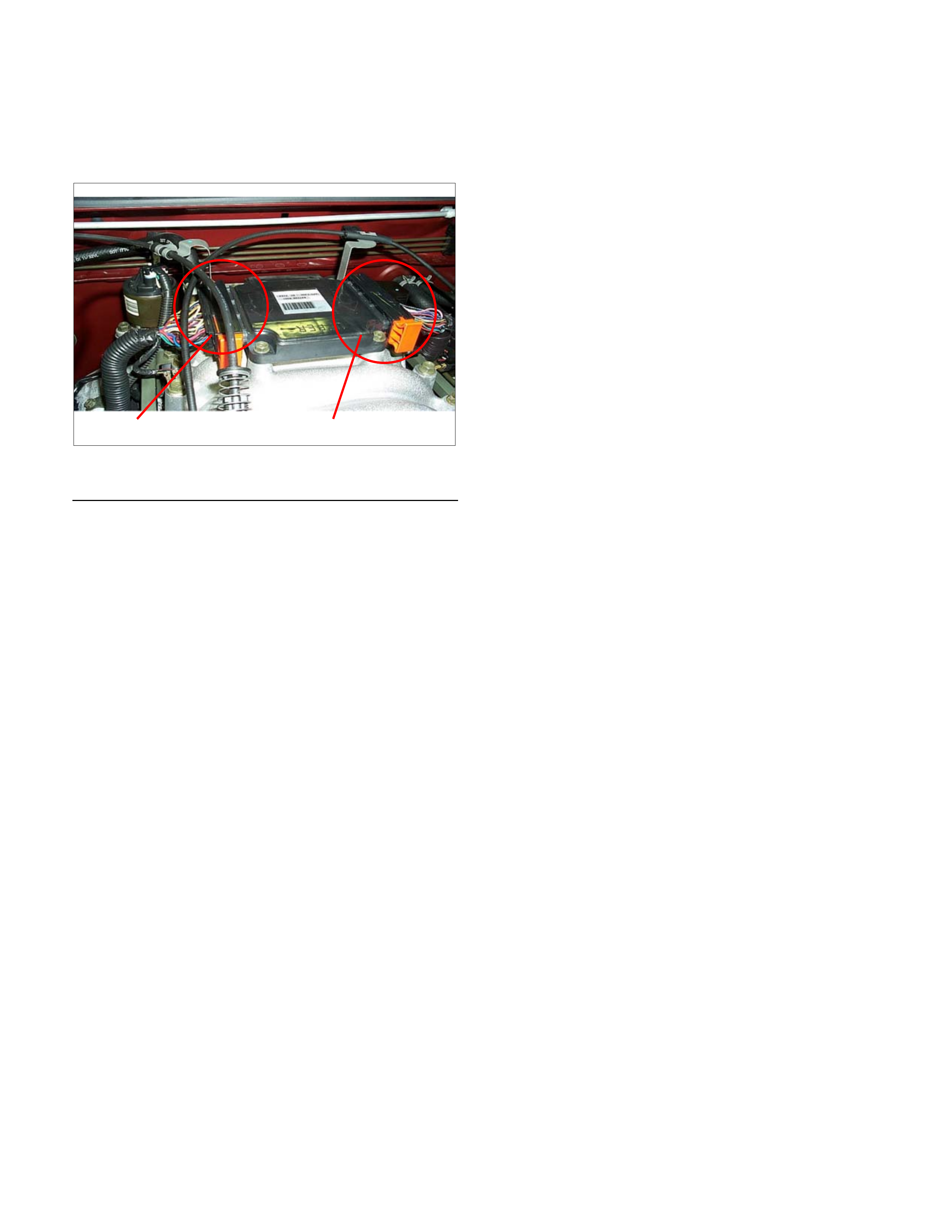
Engine Control Module (ECM)
Crankshaft Position (CKP) Sensor
Camshaft Position (CMP) Sensor
Engine Coolant Temperature (ECT) Sensor
Mass Air Flow (MAF) Sensor & Intake Air
Temperature (IAT) Sensor
Throttle Position Sensor (TPS)
Idle Air Control (IAC) Valve
Heated Oxygen Sensor (HO2s)
Evap Canister Purge Valve Solenoid
Fuel Pressure Relief
Fuel Rail Assembly
Fuel Injectors
Fuel Pressure Regulator
Ignition Coil
Spark Plugs
Special Tools

Abbreviation Charts
Abbreviations Appellation
A/C Air conditioner
A/T Automatic transmission
ACC Accessory
BLK Black
BLU Blue
BRN Brown
CAN Controller Ar ea Network
CEL Check eng ine lam p
CKP Crankshaft position
CMP Camshaft position
DLC Data link connector
DTC Diagnosis tr ouble code
DVM Digital volt age meter
ECM Engine contro l m odule
ECT Engine coolant t em per ature
EEPROM Electrically erasable & programmable r ead only memory
EGR Exhaust gas recalculat ion
GND Ground
GRY Gray
HO2S Heated Oxygen Sensor
IAT Intake air temperature
IAC Idle air control
IG Ignition
M/T Manual transmission
MAF Ma ss air fl ow
MIL Malfunction indicator lamp
OBD On-board diagnostic
ORN Orange
PNK Pink
PROM Progr ammable read only memor y
RED Red
SW Switch
TPS Thrott le posit ion sensor
TCM Transmission control module
VIO Violet
VSS Vehicle speed sensor
WHT White
WO T Wide open thr ottle
YEL Yellow
Component Locator
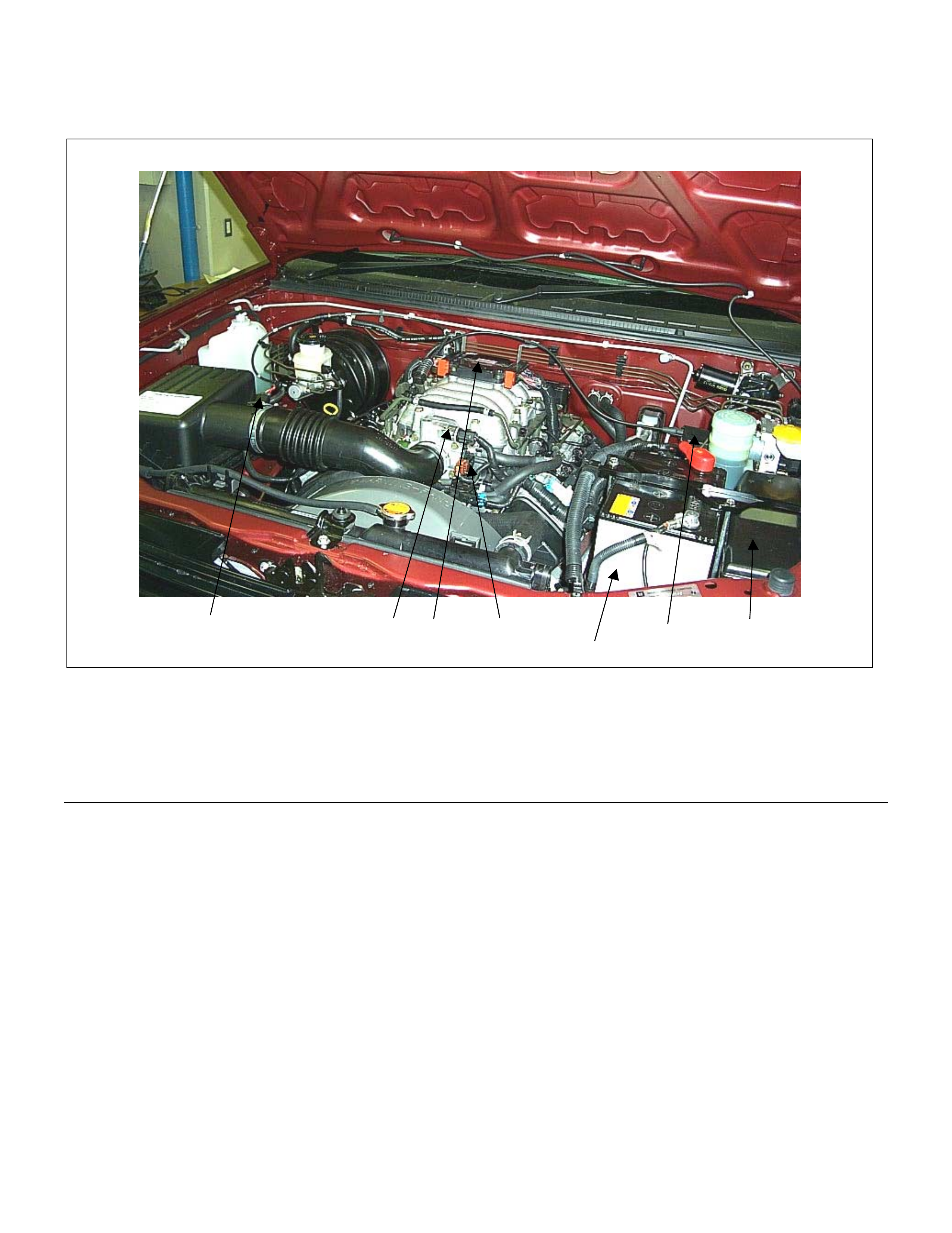
Engine Component Locator Table
7
465
32
1
Legend
(1) Engine Control Module (ECM)
(2) Throttle Position Sensor (TPS)
(3) Idle Air Control (IAC) Valve
(4) Battery
(5) Relay & Fuse Box
(6) Auto Cruise Actuator
(7) Mass Air Flow (MAF) & Intake Air Temperature
(IAT) Sensor Assembly
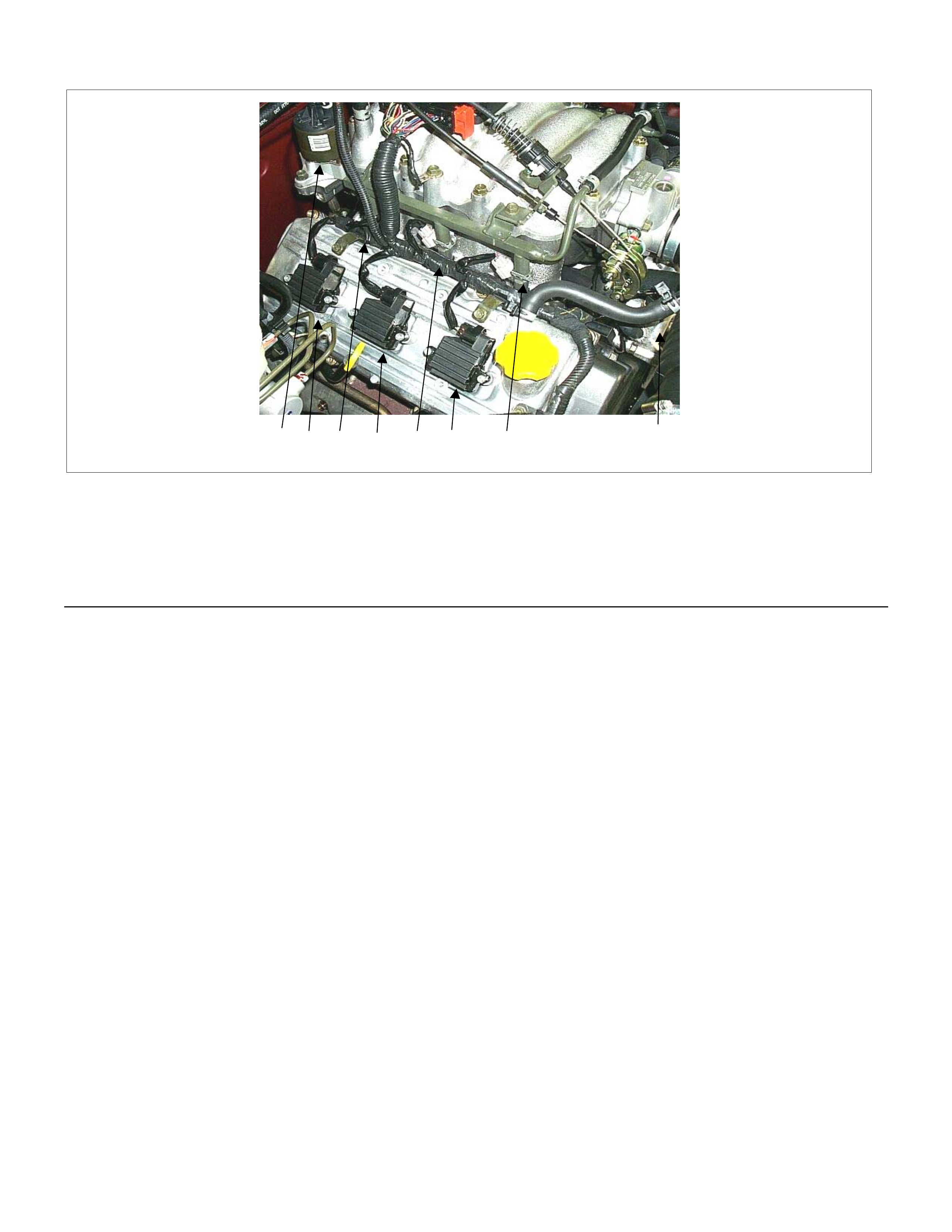
47362518
Legend
(1) Injector #1 Cy linder
(2) Injector #3 Cy linder
(3) Injector #5 Cy linder
(4) EGR Valve
(5) Ignition Coil #1 Cylinder
(6) Ignition Coil #3 Cylinder
(7) Ignition Coil #5 Cylinder
(8) Engine Coolant Temperature (ECT) Sensor
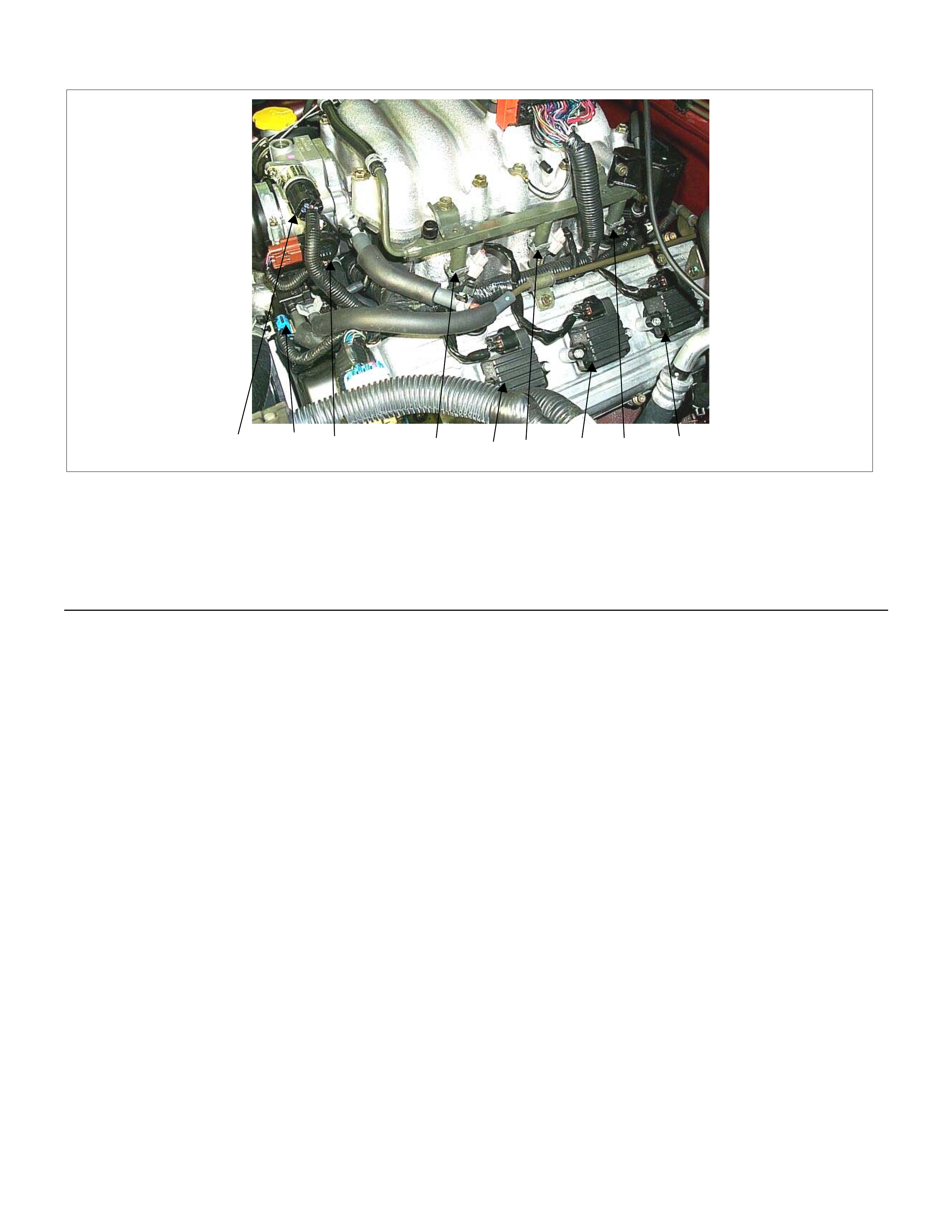
41623
78
5
9
Legend
(1) Injector #2 Cy linder
(2) Injector #4 Cy linder
(3) Injector #6 Cy linder
(4) Idle Air Control (IAC) Valve
(5) Throttle Position Sensor
(6) Ignition Coil #2 Cylinder
(7) Ignition Coil #4 Cylinder
(8) Ignition Coil #6 Cylinder
(9) Canister Purge Solenoid Valve
1
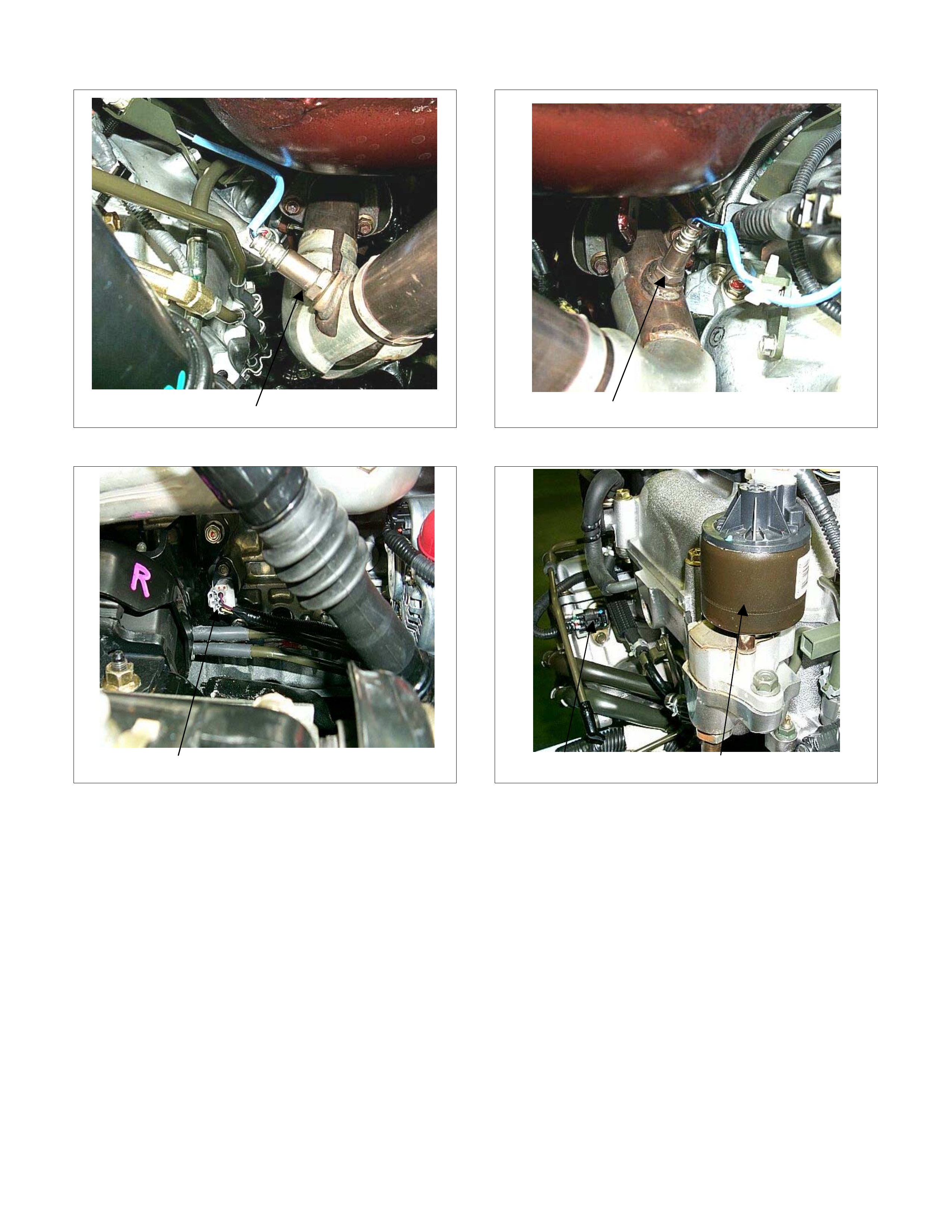
(1) Bank 1 Heated Oxygen Sensor (RH)
1
(1) Bank 2 Heated Oxygen Sensor (LH)
1
(1) Crankshaft Position (CKP) Sensor
12
(1) Camshaft Position Sensor (CMS)
(2) EGR Valve
1
(1) Canister
2
1
(1) Fuel Tank
(2) Fuel Pump
1
(1) Vehicle Speed Sensor (VSS)
1
(1) Po wer St eering Pressure Switch
ECM Circuit Diagram
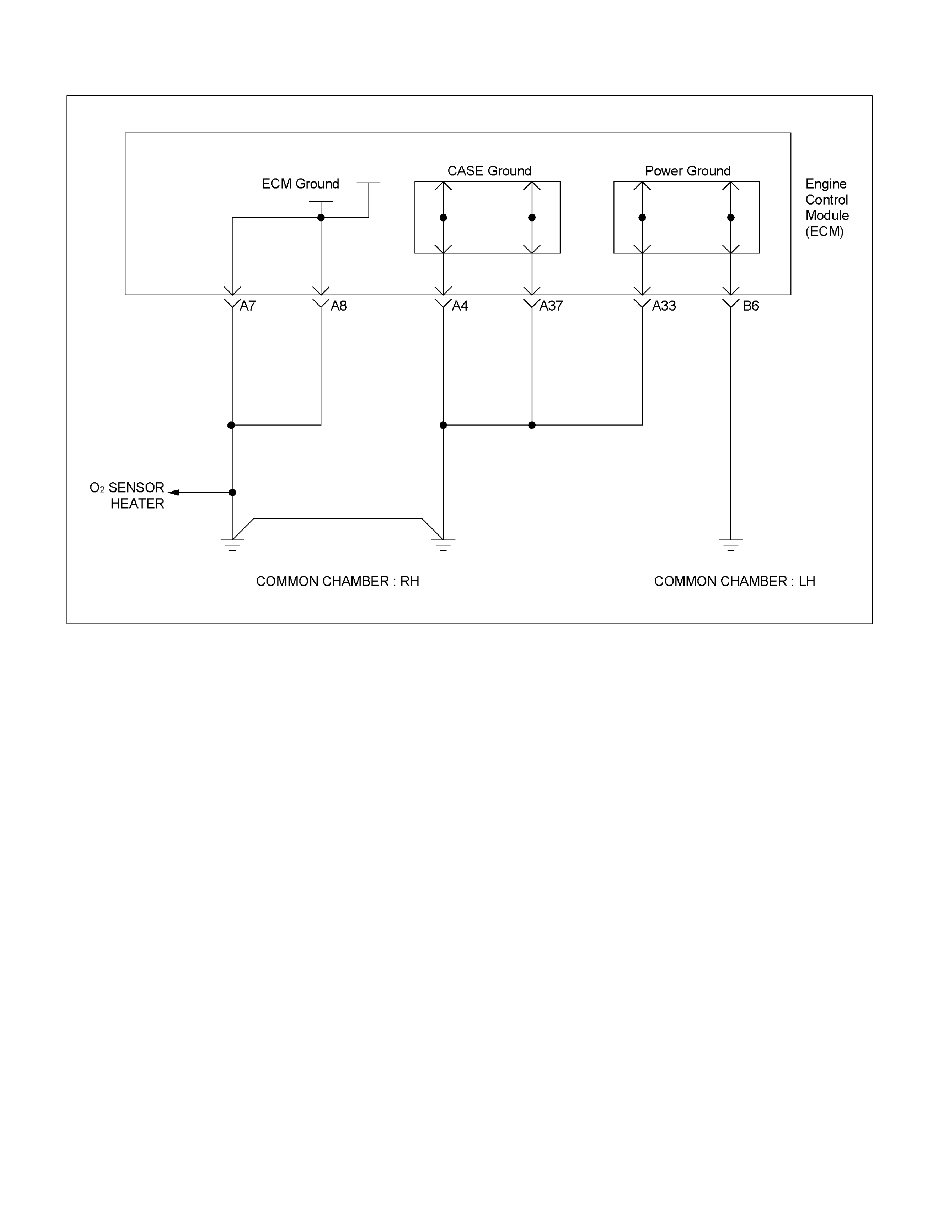
Ground Point Chart
Ground Point Chart (1/4)
RTW38DXF004501
Ground Point Chart (2/4)
RTW38DXF004401
Ground Point Chart (3/4)
RTW38DXF004001
Ground Point Chart (4/4)
RTW38DXF003901
Location
P−
−−
−5
P−
−−
−6
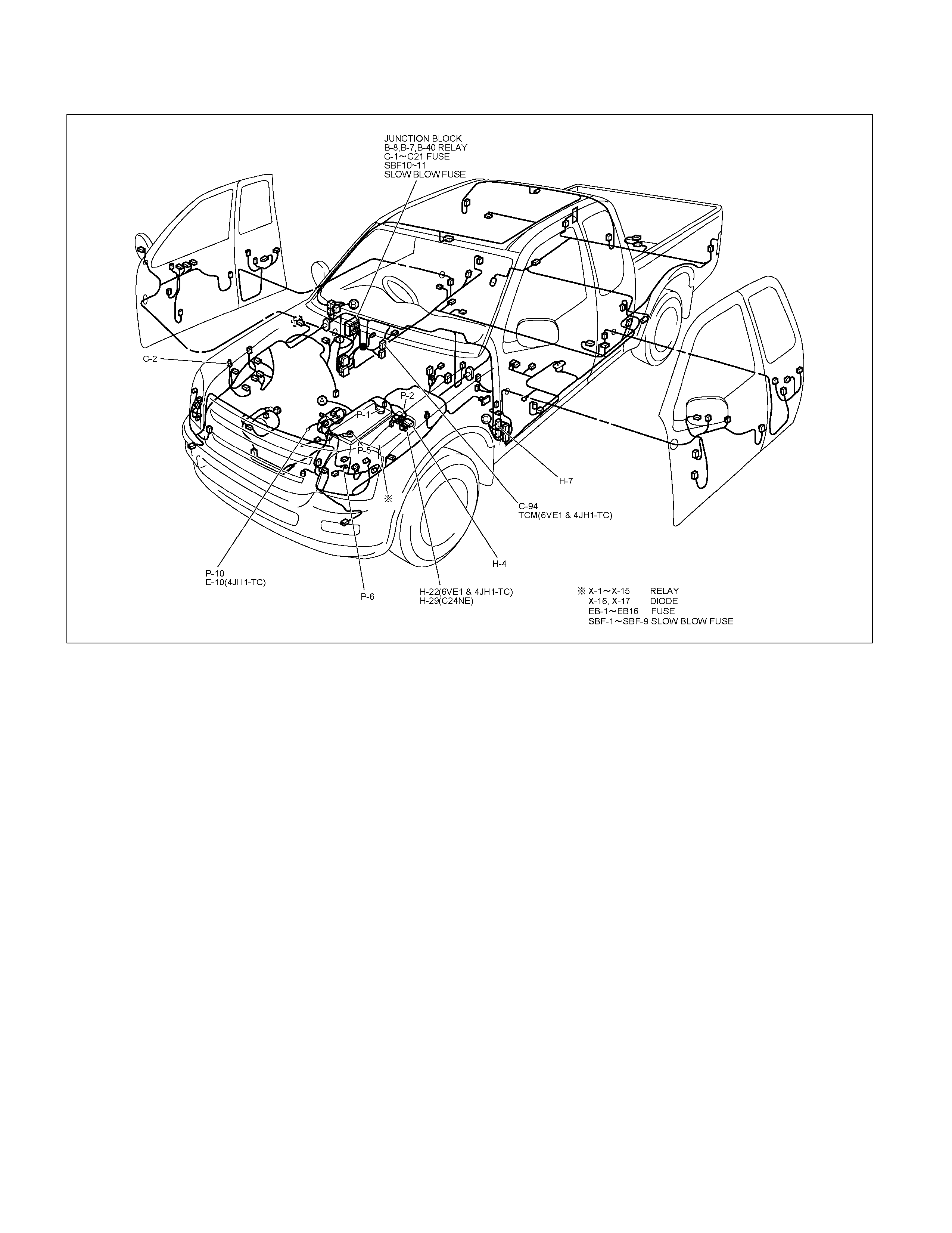
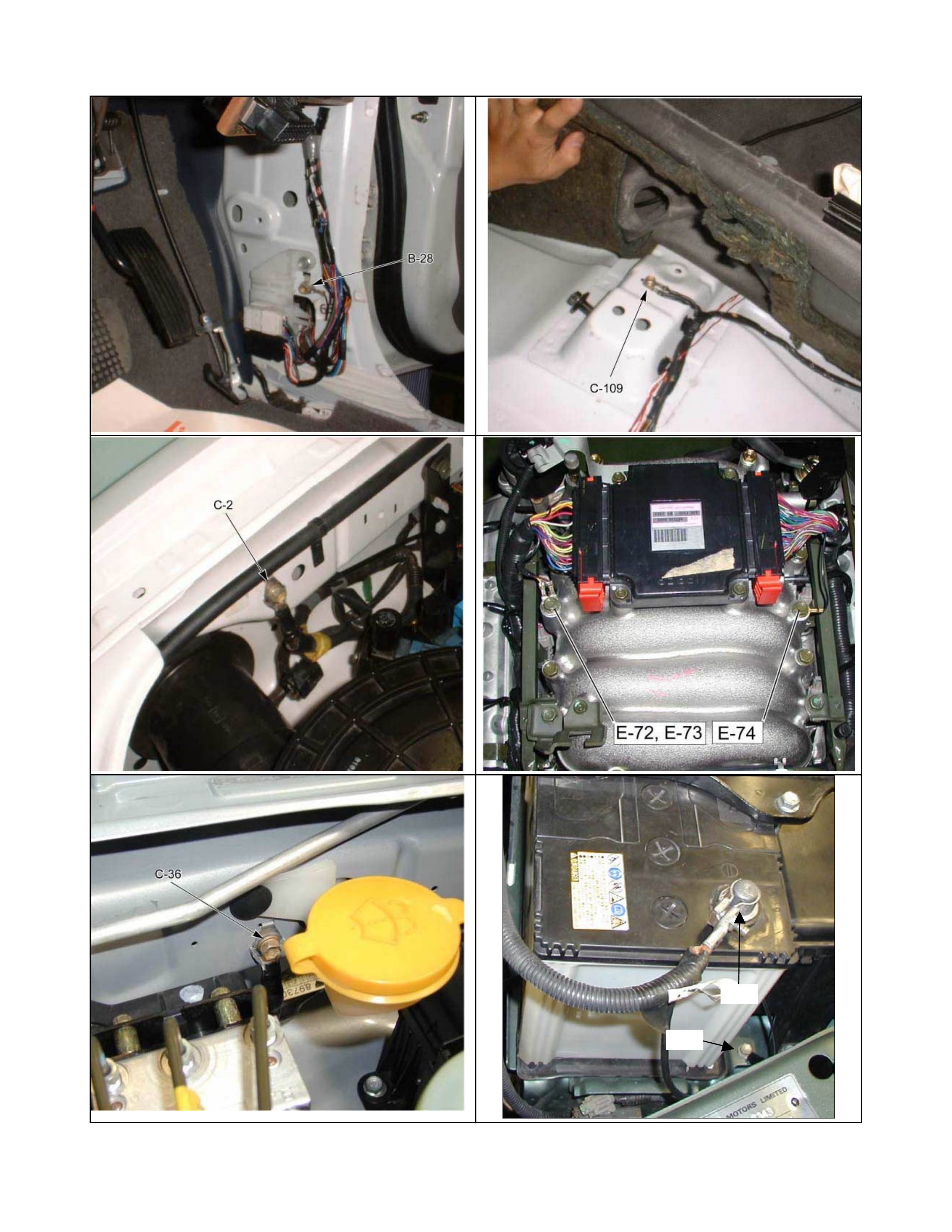
Cable Harness & Connector Location
RTW38DMF000301
810R300094
6VE1 Engine
RTW36ELF000301
Connector List
No. Connector face No. Connector face
B-24
Green
Meter-B
C-108
White
J/B E1
B-56
White
J/B I4
C-109
Silver
Body-LH ; ground
B-58
Black
Check connector
E-2
Magnetic clutch
B-62
White
Ignition switch (IGSUB : G1)
E-6
Fuel injector
B-63
White
Ignition switch (IGSUB : G2)
E-7
Fuel injector
B-68
Immobilizer
E-8
Fuel injector
C-2
Silver
Engine room-RH ground
E-9
Fuel injector
C-24
Triple pressure switch
E-51
Fuel injector
C-94
Gray
TCM-(A)
E-52
Fuel injector
C-107
White
J/B E2
E-53
Ignition coil
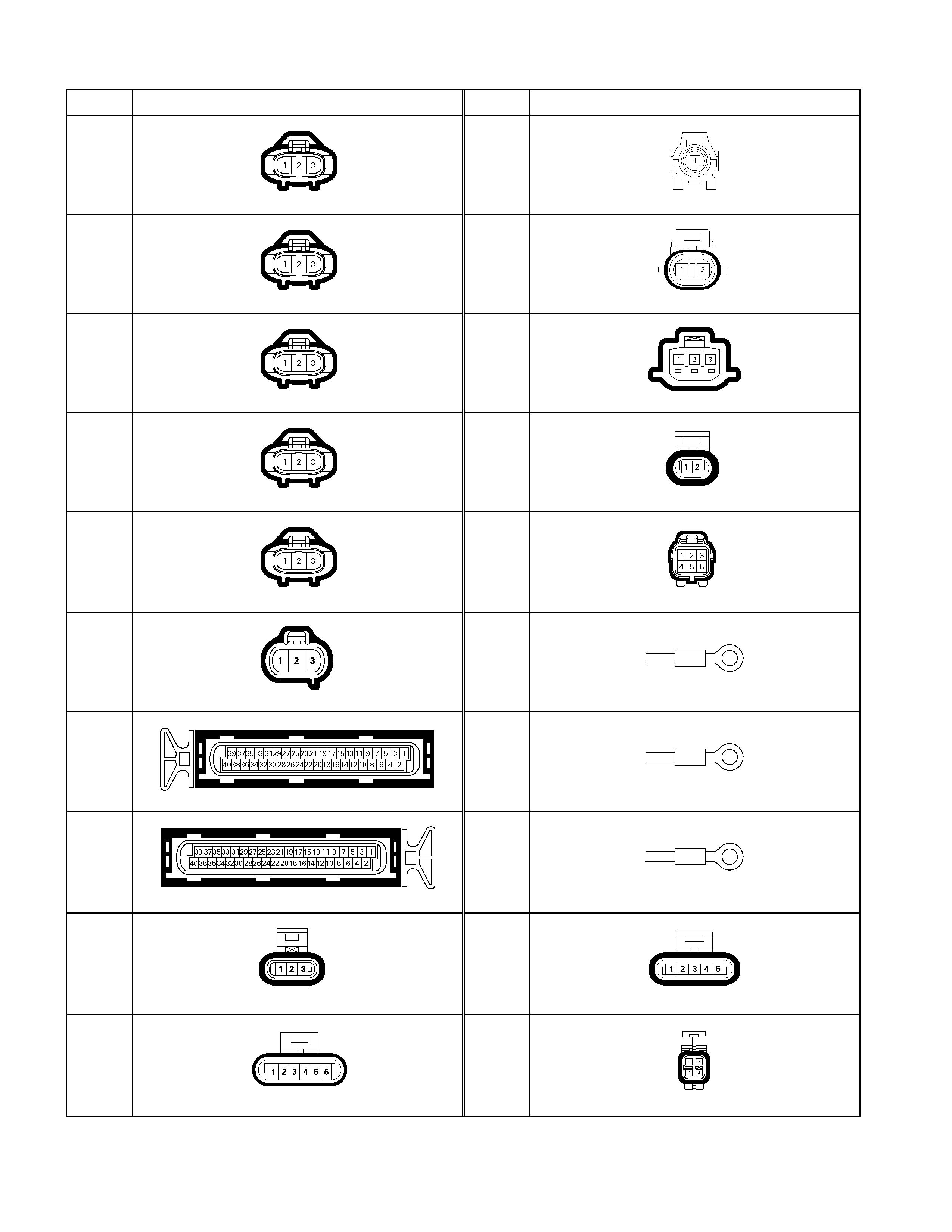
No. Connector face No. Connector face
E-54
Ignition coil
E-64
Oil pressure switch (P/STRG)
E-55
Ignition coil
E-66
Duty solenoid
E-56
Ignition coil
E-68
Throttle position sensor
E-57
Ignition coil
E-69
Temperature sensor
E-58
Ignition coil
E-70
IACV
E-59
Crank position sensor
E-72
Engine earth-A
E-60
ECM-A
E-73
Engine earth-A
E-61
ECM-B
E-74
Engine earth-B
E-62
Cam position sensor
E-76
EGR valve
E-63
MAF sensor
E-77
O2 sensor RH-Front
No. Connector face No. Connector face
E-78
O2 sensor LH-Front
P-1
Silver
Battery (+)
E-79
Neutral start switch
P-2
Silver
Relay & Fuse box
F-2
White
Fuel pump & sensor
P-5
Silver
Battery (-)
H-4
White
Engine ~ Engine room
P-8
White
ACG (L)
H-6
White
Engine room ~ INST
P-10
Silver
Engine ground
H-7
White
Engine room ~ INST
X-2
Black
Relay ; Front Fog lamp
H-9
Blue
Engine room ~ Chassis
X-13
Black
Relay ; ECM MAIN
H-18
White
Engine room ~ INST
X-14
Black
Relay ; A/C Compressor
H-22
White
Engine ~ Engine room C
X-15
Black
Relay ; Thermo
H-23
White
Engine ~ Engine room B
X-17
Black
DIODE

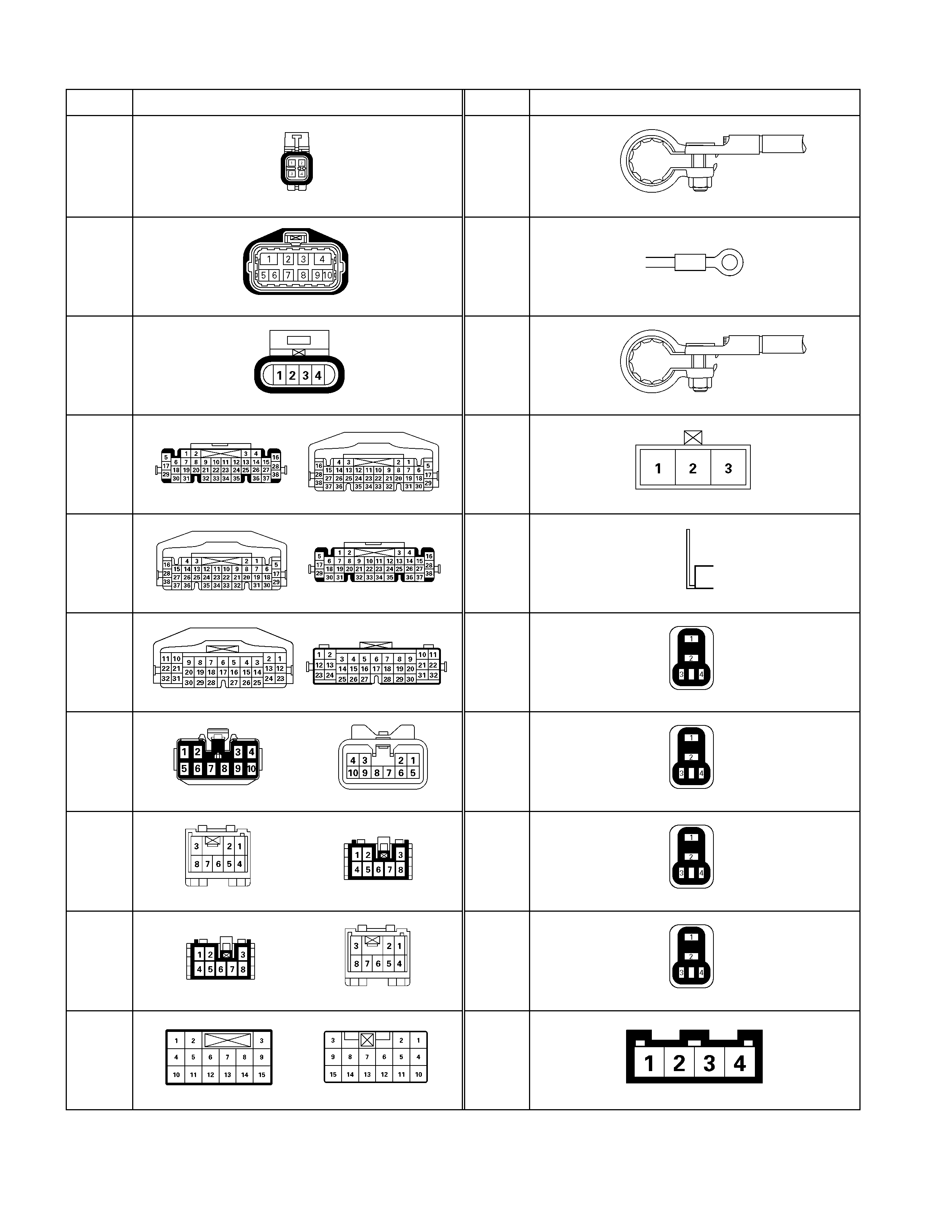
Relay And Fuse
Relay And Fuse Box Location
Relay And Fuse Box Location
RELAY & FUSE BOX
RELAY (6VE1)
NO. Relay name
X-1 RELAY; TAIL LIGHT
X-2 RELAY; FUEL PUMP
X-3 RELAY; HORN
X-4 RELAY; DIMMER
X-5 RELAY; FOG LIGHT
X-6 RELAY; STARTER
X-7 RELAY; COND, FAN
X-8 RELAY;
X-9 RELAY; HAZARD-RH
X-10 RELAY; HAZARD-LH
X-11 RELAY; HEATER
X-12 RELAY; HEAD LIGHT
X-13 RELAY; ECM MAIN
X-14 RELAY; A/C COMP
X-15 RELAY; THERMO
FUSE
ENGINE MODEL
FUSE NO. 6VE1
EB-1 20A ECM
EB-2 10A ECM (B)
EB-3 10A TCM
EB-4 15A FRT FOG
EB-5 10A ILLUMI
EB-6 10A TAIL
EB-7 10A H/LIGHT-RH
EB-8 10A H/LIGHT-LH
EB-9 10A O2 SENSOR
EB-10 20A FUEL PUMP
EB-11 \
EB-12 \
EB-13 10A A/C
EB-14 10A 4W D
EB-15 10A HORN
EB-16 10A H AZARD
SLOW BLOW FUSE
ENGINE MODEL
FUSE NO. 6VE1
SBF-1 100A MAIN
SBF-2 \
SBF-3 \
SBF-4 20A COND, FAN
SBF-5 40A IG 1
SBF-6 40A ABS-1
SBF-7 30A ABS-2
SBF-8 30A BLO WER
SBF-9 50A IG 2

Fuse And Relay Location
RTW36EMF000701
FUSE
NO. Capacity Indication on label NO. Capacity Indication on label
1 12 15A CIGER
2 10A ABS 13 15A AUDIO (+B)
3 14 20A DO OR LOCK
4 15A BACK UP 15 10A M ETER (+B)
5 15A M ETER 16 10A RO OM
6 10A TURN 17 10A ANTI THE FT
7 15A ELEC.IG 18 15A STOP
8 15A ENGINE 19 15A ACC SOCKET
9 20A FRT WIPER 20 10A STARTER
10 15A EGR 21 10A SRS
11 10A AUDIO
SLOW BLOW FUSE
NO. Capacity Indication on label
22 20A RR DEF
23 30A POW ER WINDOW
RELA Y
Connector No. B-7 B-8 B-40
6VE1 REAR DEFOGGER
POWER WINDOW ACC SOCKET
FUSE BOX
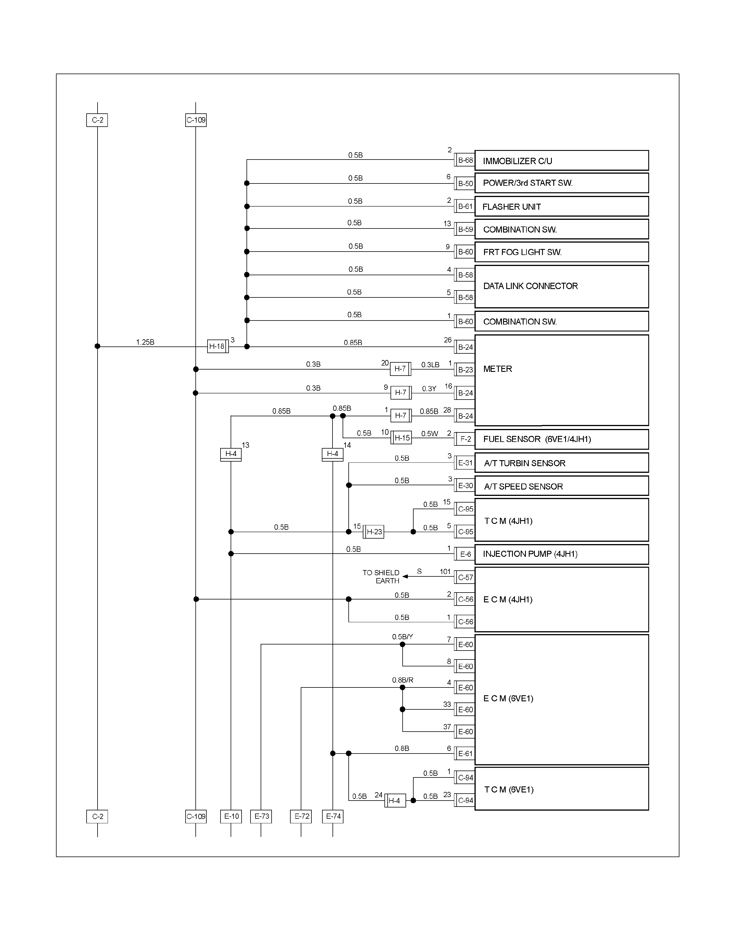
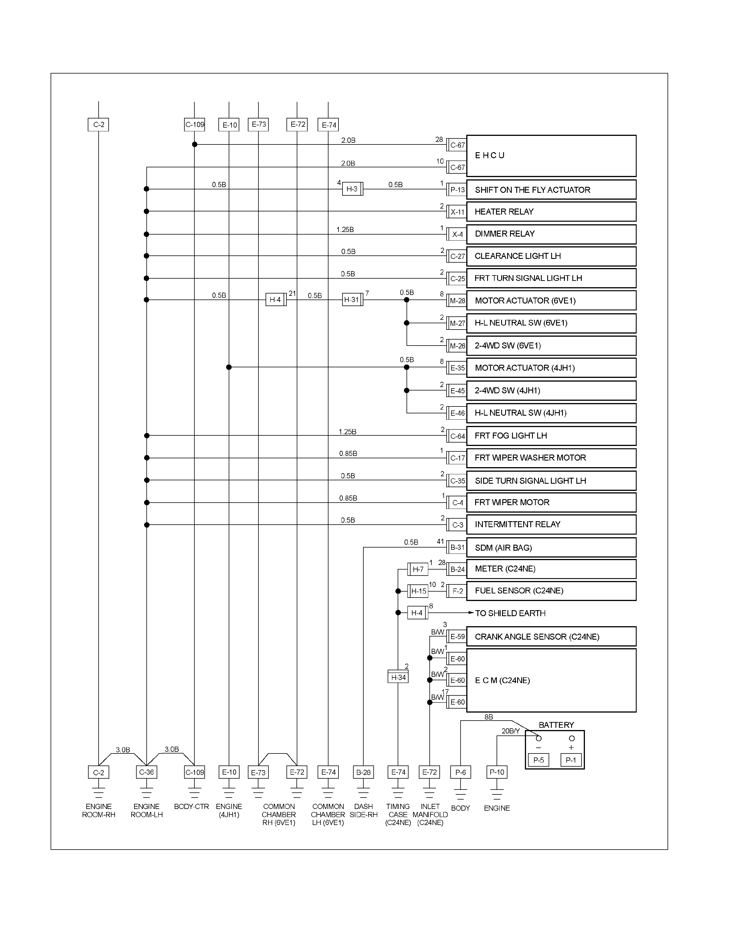
ECM Wiring Diagram
ECM Wiring Diagram (1/10)
RTW36EMF000301
ECM Wiring Diagram (2/10)
RTW36EMF000401
ECM Wiring Diagram (3/10)
RTW36EMF000501

ECM Wiring Diagram (4/10)
RTW36EMF000601
ECM Wiring Diagram (5/10)
RTW36EMF000901
ECM Wiring Diagram (6/10)
RTW36ELF000201
ECM Wiring Diagram (7/10)
RTW36EMF000201

ECM Wiring Diagram (8/10)
RTW36ELF000101

ECM Wiring Diagram (9/10)
RTW36EMF000101
ECM Wiring Diagram (10/10)
RTW36EMF000801
ECM Connector Pin Assignment & Output Signal
Connector A Port: View Looking Into ECM Case
Signal or Continuity Tester Position
Pin
No. B/Box
No. Pin Function Wire
Color Key SW
Off Key SW
On Engine
Idle Engine
2000rpm
ECM
Connection Range (+) (-)
A1 1
No
Connection - - - - - - - - -
A2 2
No
Connection - - - - - - - - -
A3 3
No
Connection - - - - - - - - -
A4 4
Ground
(Case) BLK/
RED Continuity
with ground - - - Disconnect Ω 4 GND
A5 5
EGR Valve
Solenoid
(Signal) YEL Less than
1V Battery voltage (DC V)
Wave form
or approx.
7V (AC V)
while EGR
is activated
Connect DC V/
AC V 5 GND
A6 6
ECM Main
Relay BLU/
YEL
Less than
1V / Battery
voltage
while
ECM main
relay is
activated
Battery voltage Connect DC V 6 GND
A7 7 Ground BLK/
YEL Continuity
with ground - - - Disconnect Ω 7 GND
A8 8 Ground BLK/
YEL Continuity
with ground - - - Disconnect Ω 8 GND
A9 9
EGR Valve
Position
(Output)
YEL/
RED
Approx.
1.3kΩ (9-
22)/ Approx.
5.2kΩ (9-
24)
- - - Disconnect Ω 9
22/
24
A10 10
CAN
(Controller
Area
Network)
High
RED Approx.
120Ω Wave form Disconnect Ω 10 11
A11 11
CAN
(Controller
Area
Network) Low
WHT - Wave form - - - -
A12 12
No
Connection - - - - - - - - -

Signal or Continuity Tester Position
Pin
No. B/Box
No. Pin Function Wire
Color Key SW
Off Key SW
On Engine
Idle Engine
2000rpm
ECM
Connection Range (+) (-)
A13 13
No
Connection - - - - - - - - -
A14 14
No
Connection - - - - - - - - -
A15 15
No
Connection - - - - - - - - -
A16 16
No
Connection - - - - - - - - -
A17 17
No
Connection - - - - - - - - -
A18 18
No
Connection - - - - - - - - -
A19 19
Intake Air
Temperature
(IAT) Sensor
YEL/
GRN Less than
1V Approx. 1.8V at IAT 30 Connect DC V 19 GND
A20 20
No
Connection - - - - - - - - -
A21 21
Engine
Coolant
Temperature
(ECT) Sensor
BLU/
RED Less than
1V Approx. 2.6V at ECT 80 Connect DC V 21 GND
A22 22
EGR Valve &
ECT Sensor
Ground
YEL/
BLK
Approx.
0.3KΩ at
ECT 80
(22-21) /
Approx.
5.4KΩ EGR
(22-24)
- - - Disconnect Ω 21/24 GND
A23 23
Crank
Position
(CKP) Sensor
(Output)
YEL - - Wave form
or approx.
2.3V
Wave form
or approx.
1.9V Connect AC V 23 GND
A24 24
Crank
Position
(CKP) Sensor
& EGR Valve
(Voltage
Supply)
RED/
BLU Less than
1V Approx. 5V Connect DC V 24 25
A25 25
Crank
Position
(CKP) Sensor
(Ground)
YEL/
BLK Continuity
with ground - - - Connect Ω 25 GND
A26 26
No
Connection - - - - - - - - -
A27 27
No
Connection - - - - - - - - -
Signal or Continuity Tester Position
Pin
No. B/Box
No. Pin Function Wire
Color Key SW
Off Key SW
On Engine
Idle Engine
2000rpm
ECM
Connection Range (+) (-)
A28 28
ECM Main
Relay BLU/
RED
Battery
voltage /
Less than
1V while
ECM main
relay is
activated
Less than 1V Connect DC V 28 GND
A29 29
No
Connection - - - - - - - - -
A30 30
No. 5 Ignition
Coil RED/
YEL - - Wave form - - - -
A31 31
No. 3 Ignition
Coil RED/
BLU - - Wave form - - - -
A32 32
No. 1 Ignition
Coil RED - - Wave form - - - -
A33 33
Ground
(Power) BLK/
RED Continuity
with ground - - - Disconnect Ω 33 GND
A34 34 No. 5 Injector GRN/
BLK Less than
1V Battery voltage Connect DC V 34 GND
A35 35 No. 3 Injector BLU Less than
1V Battery voltage Connect DC V 35 GND
A36 36 No. 1 Injector GRN/
WHT Less than
1V Battery voltage Connect DC V 36 GND
A37 37
Ground
(Case) BLK/
RED Continuity
with ground - - - Disconnect Ω 37 GND
A38 38
No
Connection - - - - - - - - -
A39 39
No
Connection - - - - - - - - -
A40 40
No
Connection - - - - - - - - -
Connector B Port: View Looking Into ECM Cace
Signal or Continuity Tester Position
Pin
No. B/Box
No. Pin Function Wire
Color Key SW Off Key SW On Engine Idle Engine
2000rpm ECM
Connection Range (+) (-)
B1 41
No
Connection - - - - - - - - -
B2 42
No
Connection - - - - - - - - -

Signal or Continuity Tester Position
Pin
No. B/Box
No. Pin Function Wire
Color Key SW Off Key SW On Engine Idle Engine
2000rpm ECM
Connection Range (+) (-)
B3 43 No. 2 Injector GRN/
ORG Less than
1V Battery voltage Connect DC V 43 GND
B4 44 No. 4 Injector GRN/
RED Less than
1V Battery voltage Connect DC V 44 GND
B5 45 No. 6 Injector GRN/
YEL Less than
1V Battery voltage Connect DC V 45 GND
B6 46
Ground
(Power) BLK Continuity
with ground - - - Disconnect Ω 46 GND
B7 47
No. 2 Ignition
Coil RED/
BLK - - Wave form Connect - - -
B8 48
No. 4 Ignition
Coil RED/
WHT - - Wave form Connect - - -
B9 49
No. 6 Ignition
Coil RED/
GRN - - Wave form Connect - - -
B10 50
No
Connection - - - - - - - - -
B11 51
A/C
Compressor
Relay
GRY/
RED Battery
voltage Battery voltage / Less than 1V while
A/C compressor is activated Connect DC V 51 GND
B12 52
Tacho Meter
Signal BLK/
RED - -
Approx.
40Hz by
wave form
or approx.
6.3V
Approx.
100Hz by
wave form
or approx.
6.3V
Connect AC V 52 GND
B13 53
Idle Air
Control Valve
(IACV) 1 BLU Less than
1V Less than 1V / Battery voltage Connect DC V 53 GND
B14 54
Idle Air
Control Valve
(IACV) 2
BLU/
WHT Less than
1V Less than 1V / Battery voltage Connect DC V 54 GND
B15 55
Canister
Purge
Solenoid
Valve
RED/
BLU Less than
1V Battery
voltage
Wave form/
battery
voltage
while
solenoid
valve is
not
activated
Battery
voltage
while
solenoid
valve is
not
activated
Connect DC V 55 GND
B16 56
Idle Air
Control Valve
(IACV) 3
BLU/
RED Less than
1V Less than 1V / Battery voltage Connect DC V 56 GND
B17 57
Idle Air
Control Valve
(IACV) 4
BLU/
BLK Less than
1V Less than 1V / Battery voltage Connect DC V 57 GND
B18 58
Check
Engine Lamp
(Immobilizer
Control Unit
Terminal B7)
BRN/
YEL Less than
1V Less than
1V Battery voltage while
lamp is turned off Connect DC V 58 GND

Signal or Continuity Tester Position
Pin
No. B/Box
No. Pin Function Wire
Color Key SW Off Key SW On Engine Idle Engine
2000rpm ECM
Connection Range (+) (-)
B19 59
Fuel Pump
Relay GRN/
WHT Less than
1V
Less than
1V / Battery
voltage
while
fuel pump is
activated
Battery voltage Conne ct DC V 59 GND
B20 60
Mass Air
Flow (MAF)
Sensor
BLK/
YEL Less than
1V Approx.
0.45V
Approx.
1.5V at 750
rpm Approx. 2V Connect DC V 60 GND
B21 61
Bank 1
Oxygen
Sensor PNK Less than
1V Approx.
0.4V 0.1 - 0.9V Connect DC V 61 62
B22 62
Bank 1
Oxygen
Sensor
(Ground)
BLU/
YEL Continuity
with ground - - - Connect Ω 62 GND
B23 63
Bank 2
Oxygen
Sensor RED Less than
1V Approx.
0.4V 0.1 - 0.9V Connect DC V 63 64
B24 64
Bank 2
Oxygen
Sensor
(Ground)
BLU/
BLK Continuity
with ground - - - Connect Ω 64 GND
B25 65
To Data Link
Connector
No.6
BLK/
GRN Less than
1V Approx. 5V Connect DC V 65 GND
B26 66
Throttle
Position
Sensor (TPS)
(Output)
BLU
Approx. 4.7KΩ at idle or
Approx. 1KΩ at WOT
(66-67)/Approx. 0.6KΩ at
idle or Approx. 4.3KΩ at
WOT (66-79)
- - Disconnect Ω 66
67 /
79
B27 67
TPS & Cam
Position
Sensor
(Supply)
GRN Less than
1V Approx. 5V Connect DC V 67 GND
B28 68
Camshaft
Angle Sensor
(Signal) BLU - -
Approx.
6.4Hz by
wave form
or 0.6 -
0.8V
Approx.
16.5Hz by
wave form
or 0.6 -
0.8V
Connect AC V 68 GND
B29 69
Inhibitor
Switch (AT
Only) BLK Less than
1V Less than 1V at P or N range / Battery
voltage at other than P or N range Connect DC V 69 GND
B30 70
Power
Steering
Pressure
Switch
GRN/
YEL Less than
1V
Less than 1V when switch is turned on
/
Battery voltage when switch is turned
off Connect DC V 70 GND
B31 71
Thermo
Relay GRN/
BLK Less than
1V Battery voltage when A/C request is
activated Connect DC V 71 GND

Signal or Continuity Tester Position
Pin
No. B/Box
No. Pin Function Wire
Color Key SW Off Key SW On Engine Idle Engine
2000rpm ECM
Connection Range (+) (-)
B32 72
Vehicle
Speed Signal
(Immobilizer
Control Unit
Terminal B8)
WHT Less than
1V - Approx. 14.0Hz by wave
form or approx. 4.0V at
20km/h Connect AC V 72 GND
B33 73
Ignition
Switch BLU/
YEL Less than
1V Battery voltage Connect DC V 73 GND
B34 74
Back Up
Power Supply RED/
WHT Battery voltage Connect DC V 74 GND
B35 75
No
Connection - - - - - - - - -
B36 76
ECM Main
Relay RED/
BLU
Less than
1V / Battery
voltage
while
ECM main
relay
is activated
Battery voltage Connect DC V 76 GND
B37 77
ECM Main
Relay RED/
BLU
Less than
1V / Battery
voltage
while
ECM main
relay
is activated
Battery voltage Connect DC V 77 GND
B38 78
To Data Link
Connect to
No. 2 GRN - - - - - - - -
B39 79
TPS, MAF,
IAT
& Camshaft
Angle Sensor
Ground
RED
Continuity
with
ground. /
Approx.
1.4KΩ
at IAT 30
- - - Disconnect Ω 79 19
B40 80
No
Connection - - - - - - - - -
GENERAL DESCRIPTION FOR ECM AND
SENSORS
Engine Control Module (ECM)
1 2
(1) A Port
(2) B Port
The engine control module (ECM) is located on the
common chamber. The ECM controls the following.
· Fuel metering system
· Ignition timing
· On-board diagnostics for powertrain functions.
The ECM constantly observes the information from
various sensors. The ECM controls the systems tha
t
affect vehicle performance. And it performs the
diagnostic function of the system.
The function can recognize operational problems, and
warn to the driver through the check engine lamp, and
store diagnostic trouble code (DTC). DTCs identify the
problem areas to aid the technician in marking repairs.
The input / output devices in the ECM include analog to
digital converts, signal buffers, counters and drivers.
The ECM controls most components with electronic
switches which complete a ground circuit when turned
on.
Inputs (Operating condition read):
· Battery voltage
· Electrical ignition
· Exhaust oxygen content
· Mass air flow
· Intake air temperature
· Engine coolant temperature
· Crankshaft position
· Camshaft position
· Throttle position
· Vehicle speed
· Power steering pressure
· Air conditioning request on or off
· EGR valve position
Outputs (Systems controlled):
· Ignition control
· Fuel control
· Idle air control
· Fuel pump
· EVAP canister purge
· Air conditioning
· Diagnostics functions
For vehicles with automatic transmission, the
interchange of data between the engine control module
(ECM) and the transmission control module (TCM) is
performed via a CAN-bus system.
The following signals are exchanged via the CAN-bus:
ECM to TCM:
· ECM CAN signal status
· Engine torque
· Coolant temperature
· Throttle position
· Engine speed
· A/C status
· CAN valid counter
TCM to ECM:
· Ignition timing retard request
· Garage shift status
· CAN valid counter
Mass Air Flow (MAF) Sensor & Intake Air
Temperature (IAT) Sensor
The MAF sensor is part of the intake air system.
It is fitted between the air cleaner & throttle body and
measure the mass air flowing into the engine.
The MAF sensor uses a hot wire element to determine
the amount of air flowing into the engine. (The wire
temperature reaches to 170 - 300°C)
The MAF sensor assembly consist of a MAF sensor
element and an intake air temperature sensor that are
both exposed to the air flow to be measured.
The MAF sensor element measures the partial air mass
through a measurement duct on the sensor housing.
Using calibration, there is an extrapolation to the entire
mass air flow to the engine.
The IAT sensor is a thermistor. A temperature changes
the resistance value. And it changes voltage. In other
words it measures a temperature value. Low air
temperature produces a high resistance.
The ECM supplies 5 volts signal to the IAT sensor
through resisters in the ECM and measures the voltage.
The signal voltage will be high when the air temperature
is cold, and it will be low when the air temperature is
hot. The ECM uses to this value
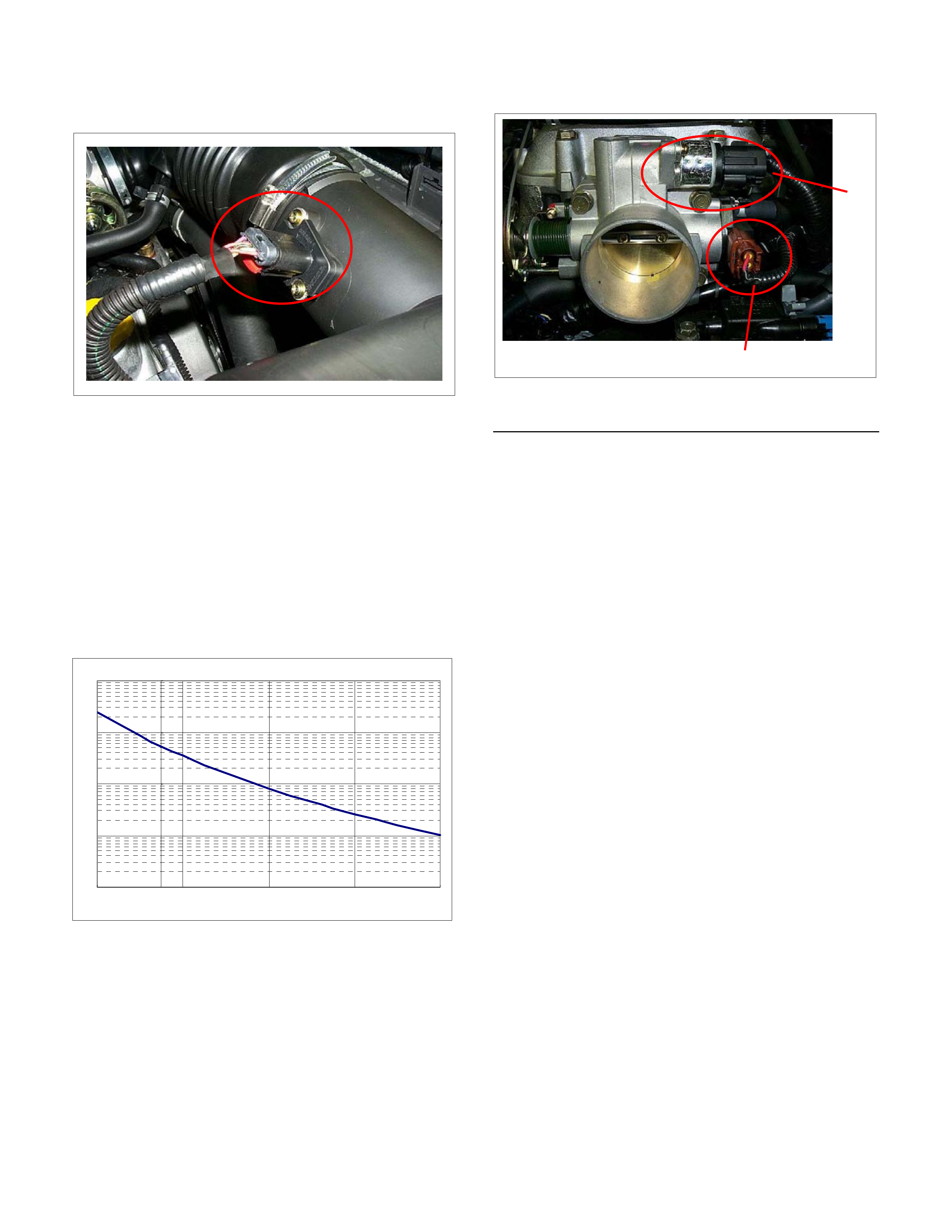
Throttle Position Sensor (TPS)
1
2
(1) Throttle Position Sensor (TPS)
(2) Idle Air Control Valve (IACValve)
The TPS is a potentiometer connected to throttle shaft
on the throttle body.
The engine control module (ECM) monitors the voltage
on the signal line and calculates throttle position. As the
throttle valve angle is changed when accelerator pedal
moved. The TPS signal also changed at a moved
throttle valve. As the throttle valve opens, the output
increases so that the output voltage should be high.
The throttle body has a throttle plate to control the
amount of air delivered to the engine. Vacuum ports
located behind the throttle plate provide the cacuum
signals needed by various components.
Engine coolant is directed through a coolant cavity in
the throttle body to warm the throttle valve and to
prevent icing.
Characteristic of IAT Sensor
10
100
1000
10000
100000
-30 10 50 90 130
Temperature (Ž
)
Resistance (Ω)
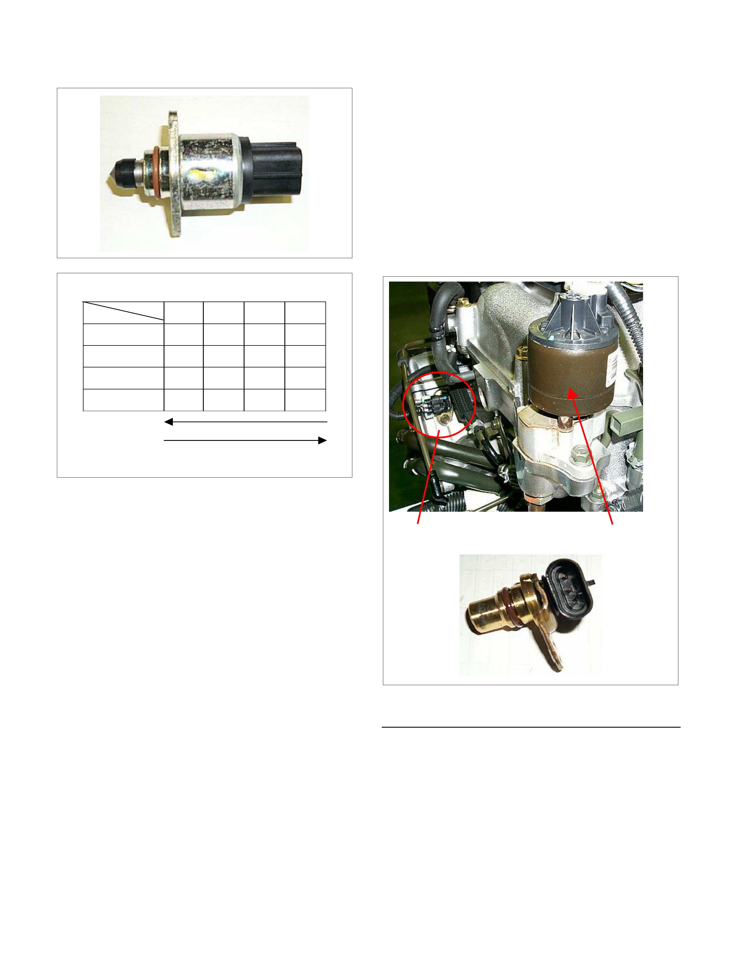
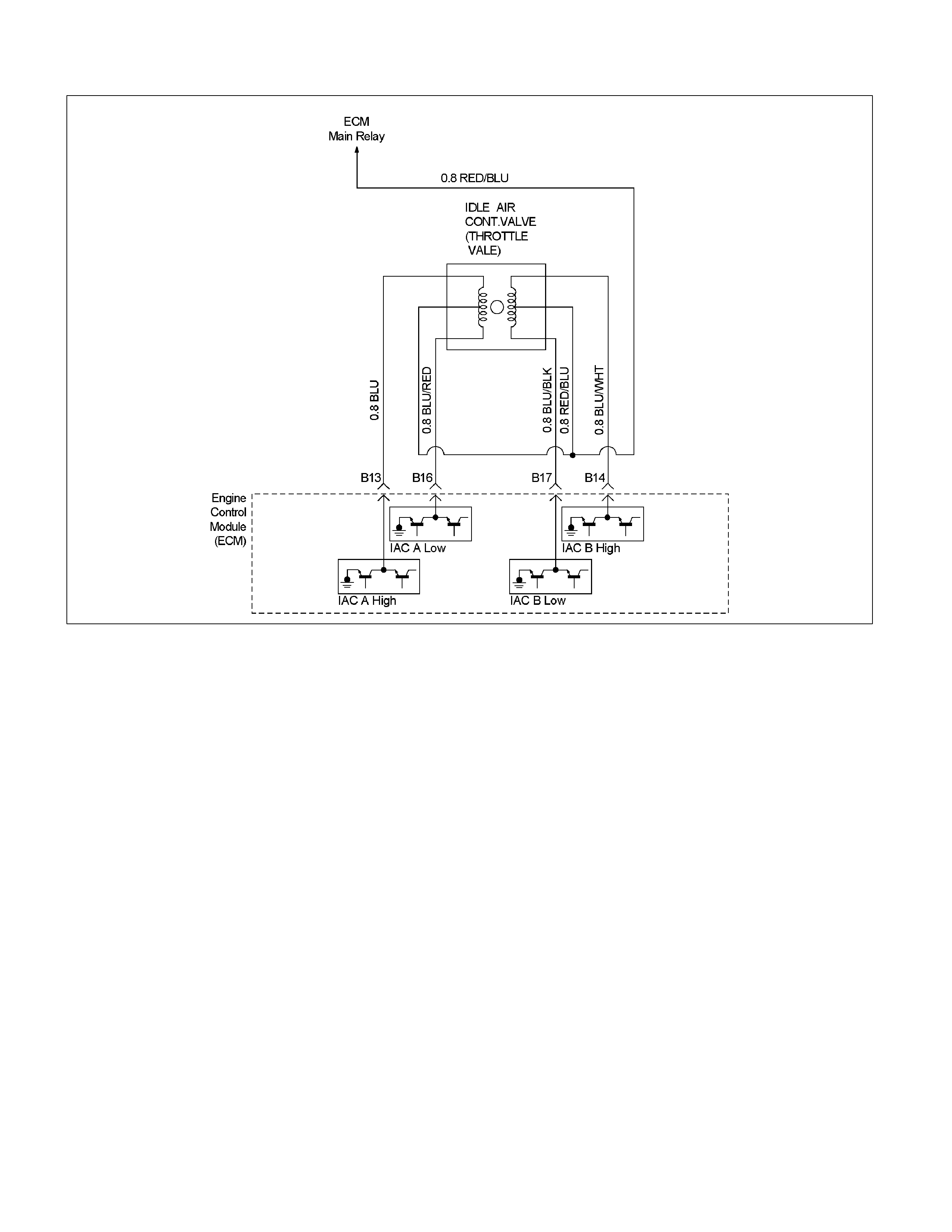
Idle Air Control (IAC) Valve
Step
Coil
ABCD
Coil A High
(ECM B13)
On On
Coil A Low
(ECM B16)
On On
Coil B High
(ECM B14)
On On
Coil B Low
(ECM B17)
On On
(IAC Valve Close Direction)
(IAC Valve Open Direction)
The idle air control valve (IAC) valve is two directional
and gives 2-way control. It has a stepping motor
capable of 256 steps, and also has 2 coils. With power
supply to the coils controlled steps by the engine control
module (ECM), the IAC valve's pintle is moved to adjust
idle speed, raising it for fast idle when cold or there is
extra load from the air conditioning or power steering.
By moving the pintle in (to decrease air flow) or out (to
increase air flow), a controlled amount of the air can
move around the throttle plate. If the engine speed is
too low, the engine control module (ECM) will retract the
IAC pintle, resulting in more air moving past the throttle
plate to increase the engine speed.
If the engine speed is too high, the engine control
module (ECM) will extend the IAC pintle, allowing less
air to move past the throttle plate, decreasing the
engine speed.
The IAC pintle valve moves in small step called counts.
During idle, the proper position of the IAC pintle is
calculated by the engine control module (ECM) based
on battery voltage, coolant temperature, engine load,
and engine speed.
If the engine speed drops below a specified value, and
the throttle plate is closed, the engine control module
(ECM) senses a near-stall condition. The engine control
module (ECM) will then calculate a new IAC pintle valve
position to prevent stalls.
If the IAC valve is disconnected and reconnected with
the engine running, the idle speed will be wrong. In this
case, the IAC must be reset. The IAC resets when the
key is cycled "On" then "Off". When servicing the IAC, it
should only be disconnected or connected with the
ignition "Off".
The position of the IAC pintle valve affects engine start-
up and the idle characteristic of the vehicle.
If the IAC pintle is fully open, too much air will be
allowed into the manifold. This results in high idle
speed, along with possible hard starting and lean
air/fuel ratio.
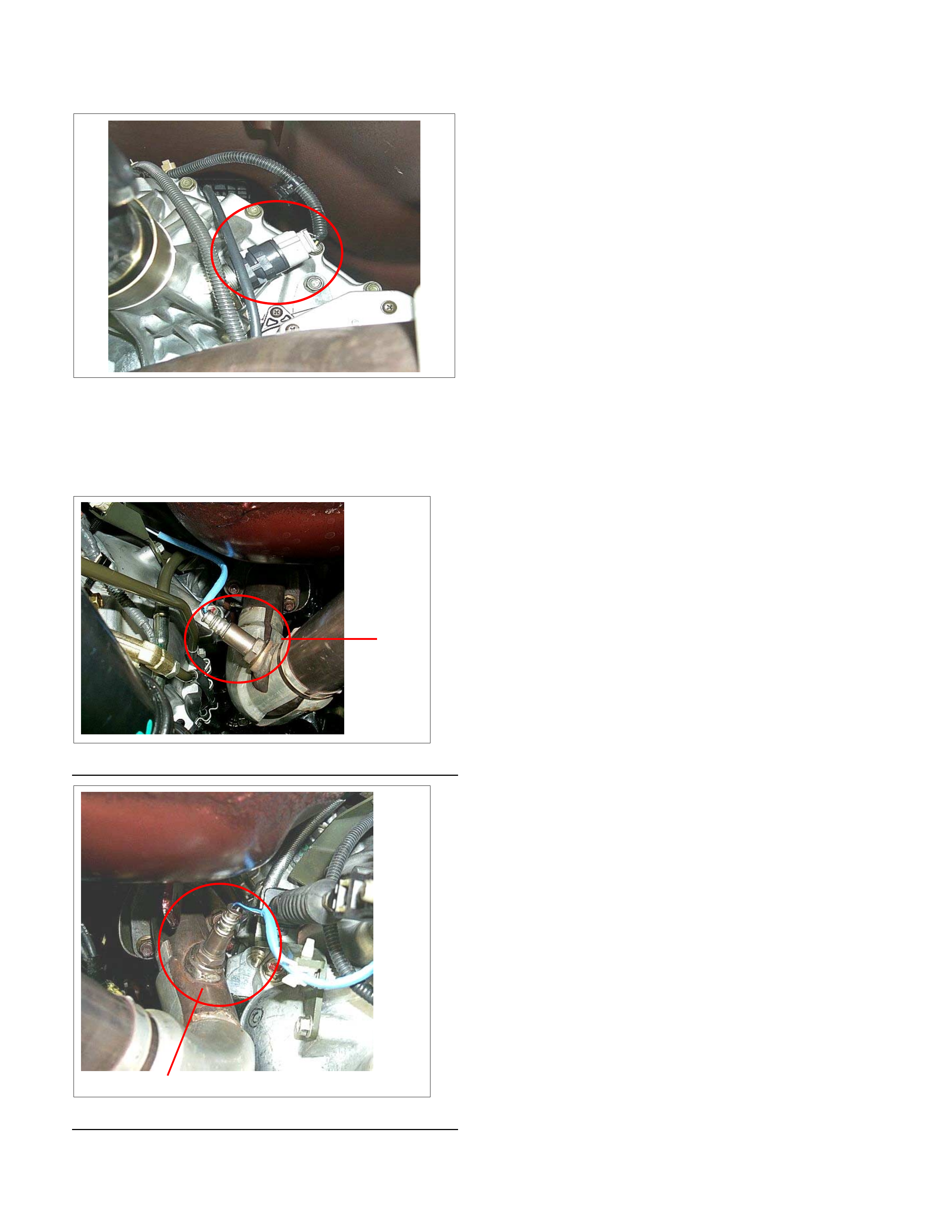
Camshaft P osition (CMP) Sensor
1 2
(1) Camshaft Position (CMP) Sensor
(2) EGR Valve
With the use of sequential multi-point fuel injection, a
hall element type camshaft position (CMP) is adopted to
provide information to be used in making decisions on
injection timing to each cylinder. It is mounted on the
rear of the left-hand cylinder head and sends signals to
the ECM.
The CMP signal is created as piston #1 is
approximately 25 deg. after top dead center on the
power stroke.
Crankshaft Position (CKP) Sensor
The crankshaft position (CKP) sensor, which sends a
signal necessary for deciding on injection timing to the
ECM, is mounted on the right-hand side of the cylinder
block.
The crankshaft has a 58 teeth press-fit timing disc, from
which the CKP sensor reads the position of the
crankshaft at all the times. It converts this to an
electrical signal, which it sends to the ECM.
Of the 58 teeth, 57 have a base with of 3°, and are
evenly spaced, but tooth No. 58 is 15° wide at its based
to serve as a timing mark, allowing the sensor to report
the standard crankshaft position.
Using the 58 X signals per rotation and the timing-mark
signal sent by the CKP sensor, the ECM is able to
accurately calculate engine speed and crank position.
Also, the position of each cylinder is precisely known by
the ECM from signals sent by the camshaft position
(CMP) sensor, so the sequential multi-point fuel
injection can be controlled with accuracy.
The 58 X signals are converted by the ECM into a
retangle wave signal. This converted signal is sent from
the ECM terminal B12 to the tachometer and transfer
control module terminal 15.
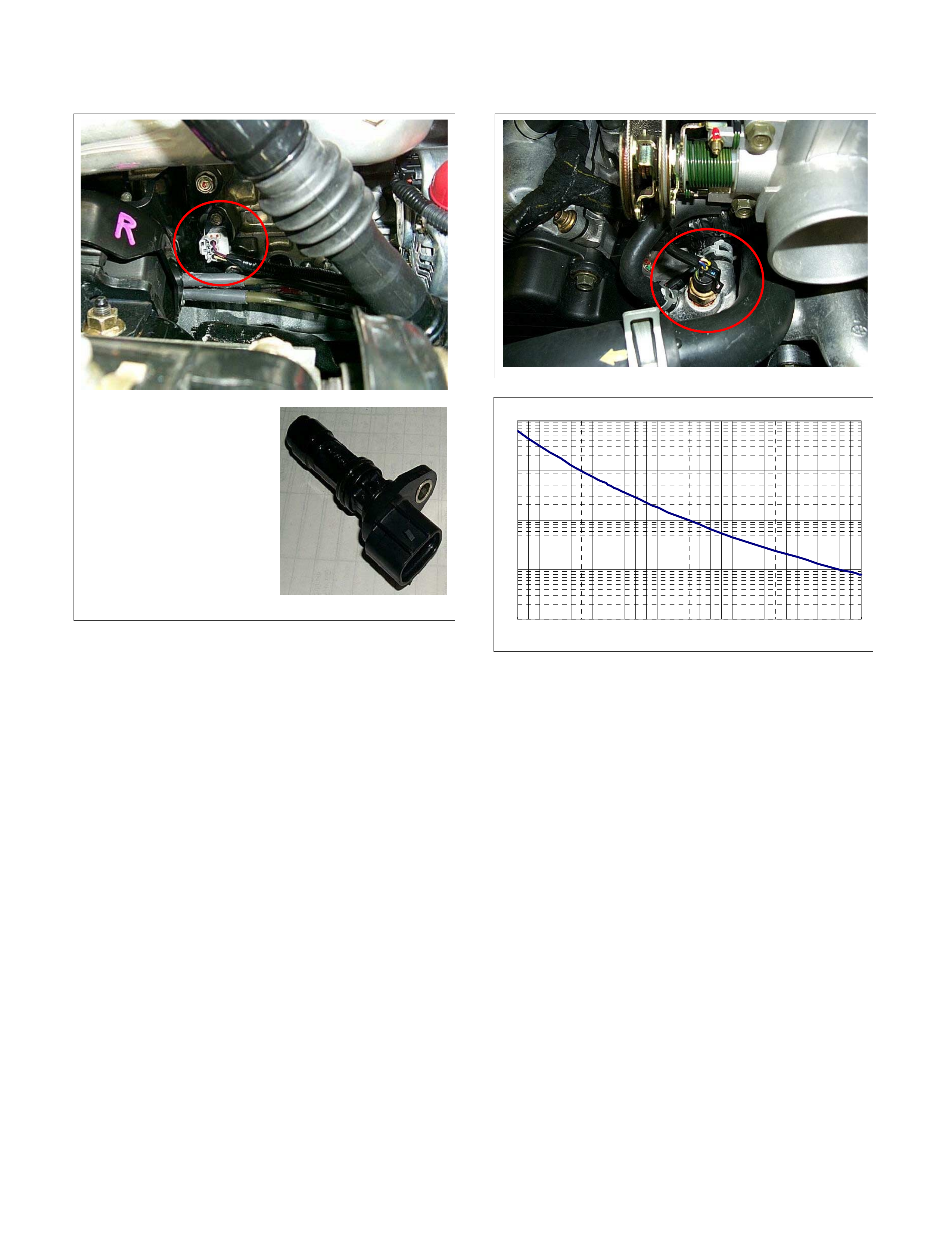
Engine Coolant Temperature (ECT) Sensor
The ECT sensor is a thermistor. A temperature
changes the resistance value. And it changes voltage.
In other words it measures a temperature value. It is
installed on the coolant stream. Low coolant
temperature produces a high resistance.
The ECM supplies 5 volts signal to the ECT sensor
through resisters in the ECM and measures the voltage.
The signal voltage will be high when the engine
temperature is cold, and it will be low when the engine
temperature is hot.
Characteristic of ECT Sensor
10
100
1000
10000
100000
-30 10 50 90 130
Temperature (Ž
)
Resistance (Ω)
Vehicle Speed Sensor (VSS)
The VSS is a magnet rotated by the transmission output
shaft. The VSS uses a hall element. It interacts with the
magnetic field treated by the rotating magnet. It outputs
pulse signal. The 12 volts operating supply from the
meter fuse.
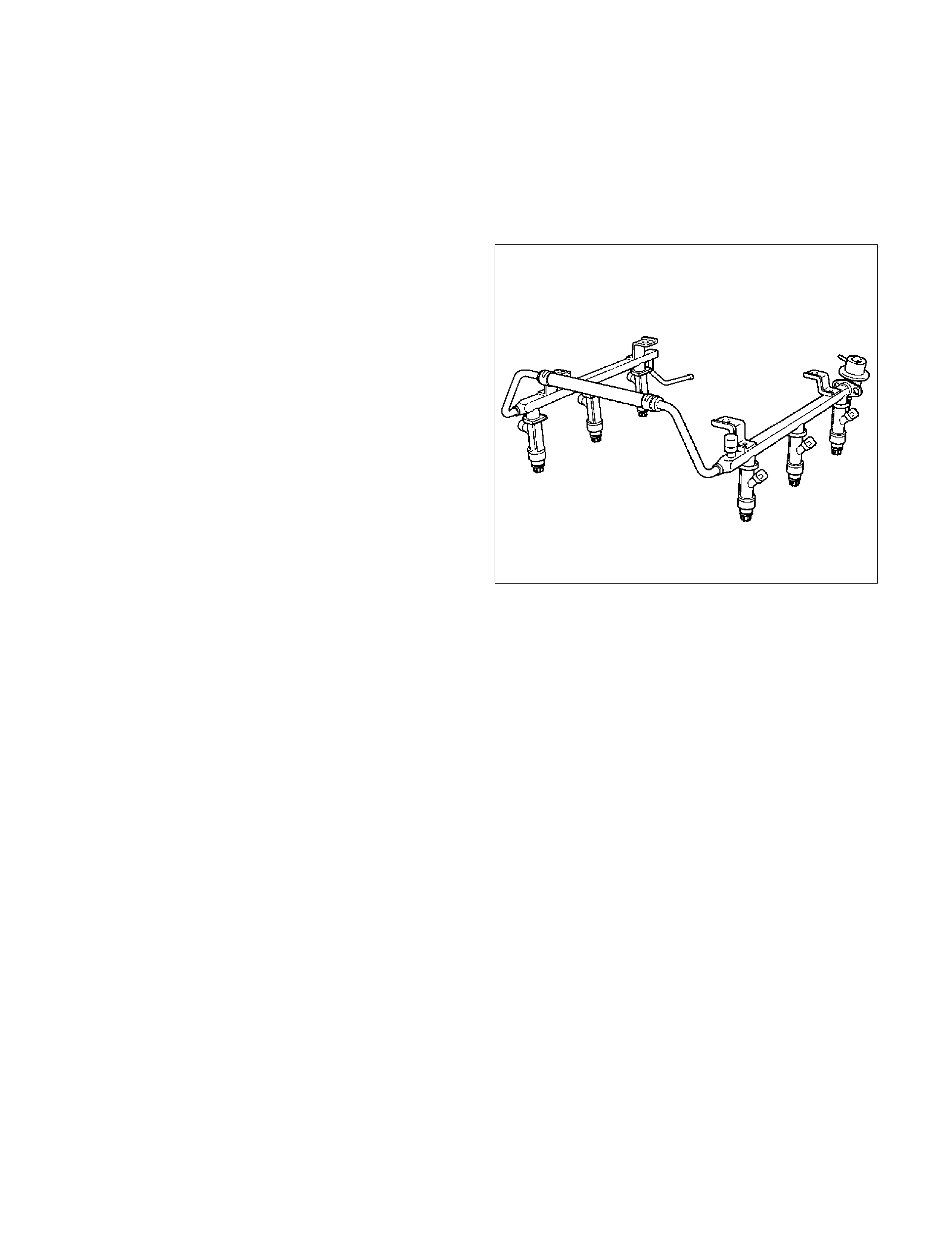
Heated Oxygen (O2) Sensor
1
(1) Bank 1 Heated Oxygen Sensor (RH)
1
(1) Bank 2 Heated Oxygen Sensor (LH)
Each oxygen sensor consists of a 4-wire low
temperature activated zirconia oxygen analyzer element
with heater for operating temperature of 315°C, and
there is one mounted on each exhaust pipe.
A constant 450millivolt is supplied by the ECM between
the two supply terminals, and oxygen concentration in
the exhaust gas is reported to the ECM as returned
signal voltage.
The oxygen present in the exhaust gas reacts with the
sensor to produce a voltage output. This voltage should
constantly fluctuate from approximately 100mV to
1000mV and the ECM calculates the pulse width
commanded for the injectors to produce the proper
combustion chamber mixture.
Low oxygen sensor output voltage is a lean mixture
which will result in a rich commanded to compensate.
High oxygen sensor output voltage is a rich mixture
which result in a lean commanded to compensate.
When the engine is first started the system is in "Open
Loop" operation. In "Open Loop", the ECM ignores the
signal from the oxygen sensors. When various
conditions (ECT, time from start, engine speed &
oxygen sensor output) are met, the system enters
"Closed Loop" operation. In "Closed Loop", the ECM
calculates the air fuel ratio based on the signal from the
oxygen sensors.
Heated oxygen sensors are used to minimize the
amount of time required for closed loop fuel control to
begin operation and allow accurate catalyst monitoring.
The oxygen sensor heater greatly decreases the
amount of time required for fuel control sensors to
become active.
Oxygen sensor heaters are required by catalyst monitor
and sensors to maintain a sufficiently high temperature
which allows accurate exhaust oxygen content readings
further away from the engine.

General Description For Fuel Metering
The fuel metering system starts with the fuel in the fuel
tank. An electric fuel pump, located in the fuel tank,
pumps fuel to the fuel rail through an in-line fuel filter.
The pump is designed to provide fuel at a pressure
above the pressure needed by the injectors.
A fuel pressure regulator in the fuel rail keeps fuel
available to the fuel injectors at a constant pressure.
A return line delivers unused fuel back to the fuel tank.
The basic function of the air/fuel metering system is to
control the air/fuel delivery to the engine. Fuel is
delivered to the engine by individual fuel injectors
mounted in the intake manifold.
The main control sensor is the heated oxygen sensor
located in the exhaust system. The heated oxygen
sensor reports to the ECM how much oxygen is in the
exhaust gas. The ECM changes the air/fuel ratio to the
engine by controlling the amount of time that fuel
injector is "On".
The best mixture to minimize exhaust emissions is 14.7
parts of air to 1 part of gasoline by weight, which allows
the catalytic converter to operate most efficiently.
Because of the constant measuring and adjusting of the
air/fuel ratio, the fuel injection system is called a "closed
loop" system.
The ECM monitors signals from several sensors in
order to determine the fuel needs of the engine. Fuel is
delivered under one of several conditions called
"mode". All modes are controlled by the ECM.
Acceleration Mode
The ECM provides extra fuel when it detects a rapid
increase in the throttle position and the air flow.
Battery Voltage Correction Mode
When battery voltage is low, the ECM will compensate
for the weak spark by increasing the following:
• The amount of fuel delivered.
• The idle RPM.
• Ignition dwell time.
Clear Flood Mode
Clear a flooded engine by pushing the accelerator pedal
down all the way. The ECM then de-energizes the fuel
injectors. The ECM holds the fuel injectors de-
energized as long as the throttle remains above 80%
and the engine speed is below 800 RPM. If the throttle
position becomes less than 80%, the ECM again begins
to pulse the injectors "ON" and "OFF," allowing fuel into
the cylinders.
Deceleration Mode
The ECM reduces the amount of fuel injected when it
detects a decrease in the throttle position and the air
flow. When deceleration is very fast, the ECM may cut
off fuel completely for short periods.
Engine Speed/Vehicle Speed/Fuel Disable Mode
The ECM monitors engine speed. It turns off the fuel
injectors when the engine speed increase above 6400
RPM. The fuel injectors are turned back on when
engine speed decreases below 6150 RPM.
Fuel Cutoff Mode
No fuel is delivered by the fuel injectors when the
ignition is "OFF." This prevents engine run-on. In
addition, the ECM suspends fuel delivery if no reference
pulses are detected (engine not running) to prevent
engine flooding.
Run Mode
The run mode has the following two conditions:
• Open loop
• Closed loop
When the engine is first started the system is in "open
loop" operation. In "open loop," the ECM ignores the
signal from the heated oxygen sensor (HO2S). It
calculates the air/fuel ratio based on inputs from the TP,
ECT, and MAF sensors.
The system remains in "open loop" until the following
conditions are met:
• The HO2S has a varying voltage output showing
that it is hot enough to operate properly (this
depends on temperature).
• The ECT has reached a specified temperature.
•
A
specific amount of time has elapsed since
starting the engine.
• Engine speed has been greater than a specified
RPM since start-up.
The specific values for the above conditions vary with
different engines and are stored in the programmable
read only memory (PROM). When these conditions are
met, the system enters "closed loop" operation. In
"closed loop," the ECM calculates the air/fuel ratio
(injector on-time) based on the signal from the HO2S.
This allows the air/fuel ratio to stay very close to 14.7:1.
Starting Mode
When the ignition is first turned "ON," the ECM
energizes the fuel pump relay for two seconds to allow
the fuel pump to build up pressure. The ECM then
checks the engine coolant temperature (ECT) sensor
and the throttle position sensor to determine the proper
air/fuel ratio for starting.
The ECM controls the amount of fuel delivered in the
starting mode by adjusting how long the fuel injectors
are energized by pulsing the injectors for very short
times.
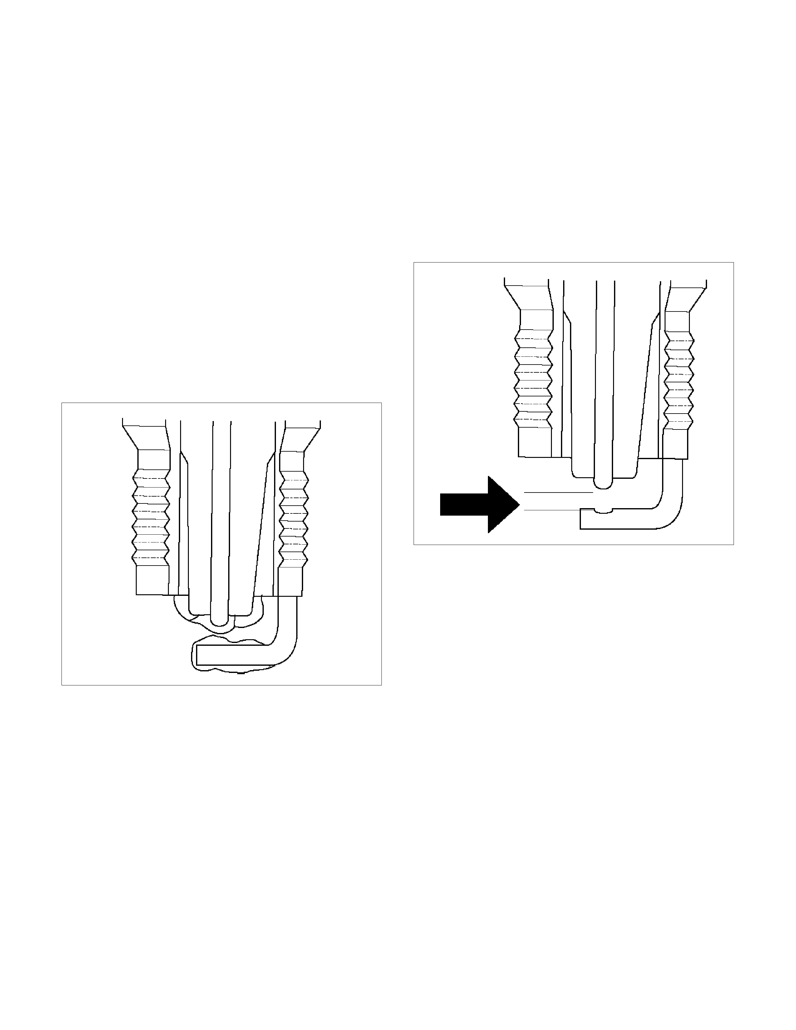
Fuel Metering System Components
The fuel metering system is made up of the following
parts.
• Fuel injector
• Throttle Body
• Fuel Rail
• Fuel Pressure regulator
• ECM
• Crankshaft position (CKP) sensor
• Camshaft position (CMP) sensor
• Idle air control valve
• Fuel pump
Fuel Injector
The sequential multi-port fuel injection fuel injector is a
solenoid operated device controlled by the ECM. The
ECM energizes the solenoid, which opens a valve to
allow fuel delivery.
The fuel is injected under pressure in a conical spray
pattern at the opening of the intake valve. Excess fuel
not used by the injectors passes through the fuel
pressure regulator before being returned to the fuel
tank.
Fuel Pressure Regulator
The fuel pressure regulator is a diaphragm-operated
relief valve mounted on the fuel rail with fuel pump
pressure on one side and manifold pressure on the
other side. The fuel pressure regulator maintains the
fuel pressure available to the injector at three times
barometric pressure adjusted for engine load. It may be
serviced separate.
If the pressure is too low, poor performance and a DTC
P0131, P0151, P0171, P0174, P1171 or P1174 will be
the result. If the pressure is too high, excessive odor
and/or a DTC P0132, P0152, P0172 or P0175 will be
the result. Refer to Fuel System Diagnosis for
information on diagnosing fuel pressure conditions.
Fuel Rail
The fuel rail is mounted to the top of the engine and
distributes fuel to the individual injectors. Fuel is
delivered to the fuel inlet tube of the fuel rail by the fuel
lines. The fuel goes through the fuel rail to the fuel
pressure regulator. The fuel pressure regulator
maintains a constant fuel pressure at the injectors.
Remaining fuel is then returned to the fuel tank.
055RV009
Fuel Pump Electrical Circuit
When the key is first turned "ON," the ECM energizes
the fuel pump relay for two seconds to build up the fuel
pressure quickly. If the engine is not started within two
seconds, the ECM shuts the fuel pump off and waits
until the engine is cranked. When the engine is cranked
and the 58 X crankshaft position signal has been
detected by the ECM, the ECM supplies 12 volts to the
fuel pump relay to energize the electric in-tank fuel
pump.
An inoperative fuel pump will cause a "no-start"
condition. A fuel pump which does not provide enough
pressure will result in poor performance.
Camshaft Position (CMP) Sensor Signal
The ECM uses this signal to determine the position of
the number 1 piston during its power stroke, allowing
the ECM to calculate true sequential multiport fuel
injection. Loss of this signal will set a DTC P0341. If the
CMP signal is lost while the engine is running, the fuel
injection system will shift to a calculated sequential fuel
injection based on the last fuel injection pulse, and the
engine will continue to run. The engine can be restarted
and will run in the calculated sequential mode as long
as the fault is present, with a 1-in-6 chance of being
correct.

General Description For Electronic Ignition System
Ignition Coils & Control
A separate coil-at-plug module is located at each spark
plug.
The coil-at-plug module is attached to the engine with
two screws. It is installed directly to the spark plug by an
electrical contact inside a rubber boot.
A three way connector provides 12 volts primary supply
from the ignition coil fuse, a ground switching trigger
line from the ECM, and ground.
The ignition control spark timing is the ECM's method of
controlling the spark advance and the ignition dwell.
The ignition control spark advance and the ignition dwell
are calculated by the ECM using the following inputs.
• Engine speed
• Crankshaft position (CKP) sensor
• Camshaft position (CMP) sensor
• Engine coolant temperature (ECT) sensor
• Throttle position sensor
• Park or neutral position switch
• Vehicle speed sensor
• ECM and ignition system supply voltage
Based on these sensor signal and engine load
information, the ECM sends 5V to each ignition coil
requiring ignition. This signal sets in the power
transistor of the ignition coil to establish a grounding
circuit for the primary coil, applying battery voltage to
the primary coil.
At the ignition timing, the ECM stops sending the 5V
signal voltage. Under this condition the power transistor
of the ignition coil is set off to cut the battery voltage to
the primary coil, thereby causing a magnetic field
generated in the primary coil to collapse.
On this moment a line of magnetic force flows to the
secondary coil, and when this magnetic line crosses the
coil, high voltage induced by the secondary ignition
circuit to flow through the spark plug to the ground.
Ignition Control ECM Output
The ECM provides a zero volt (actually about 100 mV to
200 mV) or a 5-volt output signal to the ignition control
(IC) module. Each spark plug has its own primary and
secondary coil module ("coil-at-plug") located at the
spark plug itself. When the ignition coil receives the
5-volt signal from the ECM, it provides a ground path for
the B+ supply to the primary side of the coil-at -plug
module. This energizes the primary coil and creates a
magnetic field in the coil-at-plug module. When the
ECM shuts off the 5-volt signal to the ignition control
module, the ground path for the primary coil is broken.
The magnetic field collapses and induces a high voltage
secondary impulse which fires the spark plug and
ignites the air/fuel mixture.
The circuit between the ECM and the ignition coil is
monitored for open circuits, shorts to voltage, and
shorts to ground. If the ECM detects one of these
events, it will set one of the following DTCs:
• P0351: Ignition coil Fault on Cylinder #1
• P0352: Ignition coil Fault on Cylinder #2
• P0353: Ignition coil Fault on Cylinder #3
• P0354: Ignition coil Fault on Cylinder #4
• P0355: Ignition coil Fault on Cylinder #5
• P0356: Ignition coil Fault on Cylinder #6
Spark Plug
A
lthough worn or dirty spark plugs may give satisfactory
operation at idling speed, they frequency fail at higher
engine speeds. Faulty spark plugs may cause poor fuel
economy, power loss, loss of speed, hard starting and
generally poor engine performance. Follow the
scheduled maintenance service recommendations to
ensure satisfactory spark plug performance. Refer to
Maintenance and Lubrica tion.
Normal spark plug operation will result in brown to
grayish-tan deposits appearing on the insulator portion
of the spark plug. A small amount of red-brown, yellow,
and white powdery material may also be present on the
insulator tip around the center electrode. These
deposits are normal combustion by-products of fuels
and lubricating oils with additives. Some electrode wear
will also occur. Engines which are not running properly
are often referred to as “misfiring." This means the
ignition spark is not igniting the air/fuel mixture at the
proper time.
Spark plugs may also misfire due to fouling, excessive
gap, or a cracked or broken insulator. If misfiring
occurs before the recommended replacement interval,
locate and correct the cause.
Carbon fouling of the spark plug is indicated by dry,
black carbon (soot) deposits on the portion of the spark
plug in the cylinder. Excessive idling and slow speeds
under light engine loads can keep the spark plug
temperatures so low that these deposits are not burned
off. Very rich fuel mixtures or poor ignition system
output may also be the cause. Refer to DTC P0172.
Oil fouling of the spark plug is indicated by wet oily
deposits on the portion of the spark plug in the cylinder,
usually with little electrode wear. This may be caused by
oil during break-in of new or newly overhauled engines.
Deposit fouling of the spark plug occurs when the
normal red-brown, yellow or white deposits of
combustion by products become sufficient to cause
misfiring. In some cases, these deposits may melt and
form a shiny glaze on the insulator around the center
electrode. If the fouling is found in only one or two
cylinders, valve stem clearances or intake valve seals
may be allowing excess lubricating oil to enter the
cylinder, particularly if the deposits are heavier on the
side of the spark plug facing the intake valve.
TS23995
Excessive gap means that the air space between the
center and the side electrodes at the bottom of the
spark plug is too wide for consistent firing. This may be
due to excessive wear of the electrode during use. A
check of the gap size and comparison to the gap
specified for the vehicle in Maintenance and Lubrication
will tell if the gap is too wide. A spark plug gap that is
too small may cause an unstable idle condition.
Excessive gap wear can be an indication of continuous
operation at high speeds or with engine loads, causing
the spark to run too hot. Another possible cause is an
excessively lean fuel mixture.
TS23992
Low or high spark plug installation torque or improper
seating can result in the spark plug running too hot and
can cause excessive center electrode wear. The plug
and the cylinder head seats must be in good contact for
proper heat transfer and spark plug cooling. Dirty or
damaged threads in the head or on the spark plug can
keep it from seating even though the proper torque is
applied. Once spark plugs are properly seated, tighten
them to the torque shown in the Specifications Table.
Low torque may result in poor contact of the seats due
to a loose spark plug. Over tightening may cause the
spark plug shell to be stretched and will result in poor
contact between the seats. In extreme cases, exhaust
blow-by and damage beyond simple gap wear may
occur.
Cracked or broken insulators may be the result of
improper installation, damage during spark plug heat
shock to the insulator material. Upper insulators can be
broken when a poorly fitting tool is used during
installation or removal, when the spark plug is hit from
the outside, or is dropped on a hard surface. Cracks in
the upper insulator may be inside the shell and not
visible. Also, the breakage may not cause problems
until oil or moisture penetrates the crack later.
TS2394
A broken or cracked lower insulator tip (around the
center electrode) may result from “heat shock" (spark
plug suddenly operating too hot).
TS23993
• "Heat shock" breakage in the lower insulator tip
generally occurs during several engine operating
conditions (high speeds or heavy loading) and ma
y
be caused by over-advanced timing or low grade
fuels. Heat shock refers to a rapid increase in the
tip temperature that causes the insulator material
to crack.
If there is any doubt about the serviceability of a spark
plug, replace it. Spark plugs with cracked or broken
insulators should always be replaced.

General Description For Evaporative Emission System
3 1
2
(1) Purge Solenoid Valve
(2) From Canistor to Purge Solenoid
(3) From Purge Solenoid to Intake
1
2
(1) Canistor
(2) Air Separator
The basic evaporative emission control system used on
the charcoal canister storage method. The method
transfers fuel vapor from the fuel tank to an activated
carbon (charcoal) storage devise to hold the vapors
when the vehicle is not operating.
The canister is located on the rear axle housing by the
frame cross-member.
When the engine is running, the fuel vapor is purged
from the carbon element by intake air flow and
consumed in the normal combustion process.
EVAP Control System
The evaporate emission canister purge is controlled by
a duty solenoid valve that allows manifold to purge the
canister when following operating conditions are met.
Purge solenoid valve operating condition at idle
condition:
• Engine speed is below 1000rpm.
• Vehicle speed is below 3km/h.
• Engine coolant temperature is more than 80°C.
• Intake air temperature is more than 10°C.
• In closed loop operation.
All above conditions are met for 4 seconds.
Purge solenoid valve operating condition at other than
idle condition:
• Engine speed is below 6375rpm.
• Vehicle speed is more than 14km/h.
• Engine coolant temperature is more than 60°C.
All above conditions are met for 4 seconds.
Results of Incorrect Operation
Poor idle, stalling and poor driveability can be caused
by:
• Inoperative purge solenoid.
• Damaged canister.
• Hoses split, cracked and/or not connected to the
proper tubes.
Evidence of fuel loss or fuel vapor odor can be caused
by:
• Liquid fuel leaking from fuel lines, or fuel pump.
• Cracked or damaged canister.
• Disconnected, misrouted, kinked, deteriorated or
damaged vapor hoses, or control hoses.
If the solenoid is always open, the canister can purge to
the intake manifold at all times. This can allow extra fuel
at idle or during warm-up, which can cause rough or
unstable idle, or too rich operation.
If the solenoid is always closed, the canister can
become over-loaded, resulting in fuel odor.
General Description For Exhaust Gas Recirculation (EGR) System
Linear EGR Valve
060R200237
Legend
(1) ECM
(2) Linear EGR Valve
(3) Throttle
(4) Exhaust Manifold
The exhaust gas re-circulation (EGR) system is used to
reduce emission levels of oxides of nitrogen (NOx).
NOx emission levels are caused by a high combustion
levels by decreasing the combustion temperature.
The EGR valve feeds small amount of exhaust gas
back into the combustion chamber. The fuel/air mixture
will be diluted and combustion temperatures reduced.
The ECM monitors the EGR actual position and adjusts
the pintle position accordingly.
Linear EGR valve Operation and Results of
Incorrect Operation
The linear EGR valve is designed to accurately supply
EGR to the engine independent of intake manifold
vacuum. The valve controls EGR flow from the exhaust
to the intake manifold through an orifice with a ECM
controlled pintle. During operation, the ECM controls
pintle position by monitoring the pintle position feedback
signal.
The feedback signal can be monitored with a Tech2 as
"EGR Valve (V)". "It should always be near the
commanded EGR position "Desired EGR Opening (V)".
The linear EGR valve is activated under the following
conditions:
• No DTC relating to the EGR.
• Engine speed is between 1200 and 4375rpm.
• Engine coolant temperature is between 20 and
100.
• Throttle position sensor output voltage is below
3V.
Too mach EGR flow at idle, cruise or cold operation
may cause any of the following conditions to occur:
• Engine stalls after a cold start.
• Engine stalls at idle after deceleration.
• Vehicle surges during cruise.
• Rough idle.
Too little or no EGR flow may allow combustion
temperatures to get too high. This could cause:
• Spark knock (detonation).
• Engine overheating.
• Emission test failure.
• Poor fuel economy.
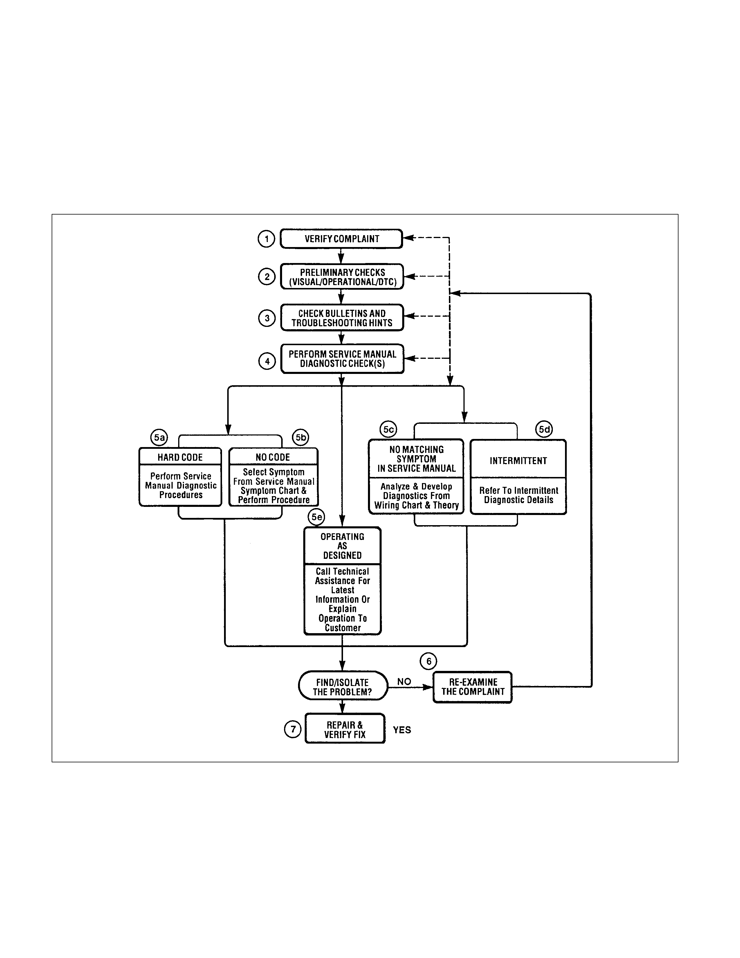
Strategy Based Diagnostics
Overview
As a retail service technician, you are part of the ISUZU
service team. The team goal is FIX IT RIGHT THE
FIRST TIME for the satisfaction of every customer. You
are a very important member of the team as you
diagnose and repair customer vehicles.
You have maximum efficiency in diagnosis when you
have an effective, organized plan for your work.
Strategy Based Diagnostics (refer to Figure 1) provides
you with guidance as you create and follow a plan of
action for each specific diagnostic situation.
Strategy Based Diagnostics Chart

Diagnostic Thought Process
As you follow a diagnostic plan, every box on the
Strategy Based Diagnostics chart requires you to use
the diagnostic thought process. This method of thinking
optimizes your diagnosis in the following ways:
• Improves your understanding and definition of the
customer complaint
• Saves time by avoiding testing and/or replacing
good parts
•
A
llows you to look at the problem from different
perspectives
• Guides you to determine what level o
f
understanding about system operation is needed:
− Owner’s manual level
− Service manual level
− In-depth (engineering) level
1. Verify the Complaint
What you should do
To verify the customer complaint, you need to know the
correct (normal) operating behavior of the system and
verify that the customer complaint is a valid failure of
the system.
The following information will help you verify the
complaint:
• WHAT the vehicle model/options are
• WHAT aftermarket and dealer-installed
accessories exist
• WHAT related system(s) operate properly
• WHEN the problem occurs
• WHERE the problem occurs
• HOW the problem occurs
• HOW LONG the condition has existed (and if the
system ever worked correctly)
• HOW OFTEN the problem occurs
• Whether the severity of the problem has
increased, decreased or stayed the same
What resources you should use
Whenever possible, you should use the following
resources to assist you in verifying the complaint:
Service manual Theory or Circuit Description
sections
• Service manual “System Performance Check”
• Owner manual operational description
• Technician experience
• Identical vehicle for comparison
• Circuit testing tools
• Vehicle road tests
• Complaint check sheet
• Contact with the customer
2. Perform Preliminary Checks
NOTE: An estimated 10 percent of successful
vehicle repairs are diagnosed with this step!
What you should do
You perform preliminary checks for several reasons:
• To detect if the cause of the complaint is
VISUALLY OBVIOUS
• To identify parts of the system that work correctly
• To accumulate enough data to correctly and
accurately search for a ISUZU Service Bulletin.
The initial checks may vary depending on the
complexity of the system and may include the following
actions:
• Operate the suspect system
• Make a visual inspection of harness routing and
accessible/visible power and ground circuits
• Check for blown fuses
• Make a visual inspection for separated connectors
• Make a visual inspection of connectors (includes
checking terminals for damage and tightness)
• Check for any DTCs stored by the on-board
computers
• Sense unusual noises, smells, vibrations or
movements
• Investigate the vehicle service history (call other
dealerships, if appropriate)
What resources you should use
Whenever appropriate, you should use the following
resources for assistance in performing preliminary
checks:
• Tech 2 or other technical equipment for viewing
DTCs
• Service manual information:
− Component locations
− Harness routing
− Wiring schematics
− Procedures for viewing DTCs
• Dealership service history file
• Vehicle road test
• Identical vehicle or system for comparison

3. Check Bulletins and Troubleshooting
Hints
NOTE: As estimated 30 percent of successful
vehicle repairs are diagnosed with this step!
What you should do
You should have enough information gained from
preliminary checks to accurately search for a bulletin
and other related service information. Some service
manual sections provide troubleshooting hints that
match symptoms with specific complaints.
What resources you should use
You should use the following resources for assistance
in checking for bulletins and troubleshooting hints:
• Printed bulletins
•
A
ccess ISUZU Bulletin Web site,
https://www.einet.isuzu.co.jp//
• Videotapes
• Service manual
4. Perform Service Manual Diagnostic
Checks
What you should do
The “System Checks” in most service manual sections
and in most cells of section 8A (electrical) provide you
with:
•
A
systematic approach to narrowing down the
possible causes of a system fault
• Direction to specific diagnostic procedures in the
service manual
• Assistance to identify what systems work correctly
What resources you should use
Whenever possible, you should use the following
resources to perform service manual checks:
• Service manual
• Technical equipment (for viewing DTCs and
analyzing data)
• Digital multimeter and circuit testing tools
• Other tools as needed
5a and 5b. Perform Service Manual
Diagnostic Procedures
NOTE: An estimated 40 percent of successful
vehicle repairs are diagnosed with these steps!
What you should do
When directed by service manual diagnostic checks,
you must then carefully and accurately perform the
steps of diagnostic procedures to locate the fault related
to the customer complaint.
What resources you should use
Whenever appropriate, you should use the following
resources to perform service manual diagnostic
procedures:
• Service manual
• Technical equipment (for analyzing diagnostic
data)
• Digital multimeter and circuit testing tools
• Essential and special tools
5c. Technician Self Diagnoses
When there is no DTC stored and no matching
symptom for the condition identified in the service
manual, you must begin with a thorough understanding
of how the system(s) operates. Efficient use of the
service manual combined with you experience and a
good process of elimination will result in accurate
diagnosis of the condition.
What you should do
Step 1: Identify and understand the suspect
circuit(s)
Having completed steps 1 through 4 of the Strategy
Based Diagnostics chart, you should have enough
information to identify the system(s) or sub-system(s)
involved. Using the service manual, you should
determine and investigate the following circuit
characteristics:
• Electrical:
− How is the circuit powered (power distribution
charts and/or fuse block details)?
− How is the circuit grounded (ground distribution
charts)?
− How is the circuit controlled or sensed (theor
y
of operation):
− If it is a switched circuit, is it normally open or
normally closed?
− Is the power switched or is the ground
switched?
− Is it a variable resistance circuit (ECT sensor
or TPS, for example)?
− Is it a signal generating device (MAF sensor
of VSS, for example)?
− Does it rely on some mechanical/vacuum
device to operate?

• Physical:
− Where are the circuit components (component
locators and wire harness routing diagrams):
−
A
re there areas where wires could be
chafed or pinched (brackets or frames)?
−
A
re there areas subjected to extreme
temperatures?
− Are there areas subjected to vibration o
r
movement (engine, transmission o
r
suspension)?
−
A
re there areas exposed to moisture, road
salt or other corrosives (battery acid, oil o
r
other fluids)?
−
A
re there common mounting areas with
other systems/components?
− Have previous repairs been performed to
wiring, connectors, components or mounting
areas (causing pinched wires between panels
and drivetrain or suspension components
without causing and immediate problem)?
− Does the vehicle have aftermarket or dealer-
installed equipment (radios, telephone, etc.)
Step 2: Isolate the problem
At this point, you should have a good idea of what could
cause the present condition, as well as could not cause
the condition. Actions to take include the following:
• Divide (and separate, where possible) the system
or circuit into smaller sections
• Confine the problem to a smaller area of the
vehicle (start with main harness connections while
removing panels and trim as necessary in order to
eliminate large vehicle sections from furthe
r
investigation)
• For two or more circuits that do not share a
common power or ground, concentrate on areas
where harnesses are routed together o
r
connectors are shared (refer to the following hints)
Hints
Though the symptoms may vary, basic electrical failures
are generally caused by:
• Loose connections:
− Open/high resistance in terminals, splices,
connectors or grounds
• Incorrect connector/harness routing (usually in
new vehicles or after a repair has been made):
− Open/high resistance in terminals, splices,
connectors of grounds
• Corrosion and wire damage:
− Open/high resistance in terminals, splices,
connectors of grounds
• Component failure:
− Opens/short and high resistance in relays,
modules, switches or loads
• Aftermarket equipment affecting normal operation
of other systems You may isolate circuits by:
• Unplugging connectors or removing a fuse to
separate one part of the circuit from another part
• Operating shared circuits and eliminating those
that function normally from the suspect circuit
• If only one component fails to operate, begin
testing at the component
• If a number of components do no operate, begin
tests at the area of commonality (such as power
sources, ground circuits, switches or major
connectors)
What resources you should use
Whenever appropriate, you should use the following
resources to assist in the diagnostic process:
• Service manual
• Technical equipment (for data analysis)
• Experience
• Technical Assistance
• Circuit testing tools
5d. Intermittent Diagnosis
By definition, an intermittent problem is one that does
not occur continuously and will occur when certain
conditions are met. All these conditions, however, may
not be obvious or currently known. Generally,
intermittents are caused by:
• Faulty electrical connections and wiring
• Malfunctioning components (such as sticking
relays, solenoids, etc.)
• EMI/RFI (Electromagnetic/radio frequenc
y
interference)
• Aftermarket equipment
Intermittent diagnosis requires careful analysis of
suspected systems to help prevent replacing good
parts. This may involve using creativity and ingenuity to
interpret customer complaints and simulating all
external and internal system conditions to duplicate the
problem.

What you should do
Step 1: Acquire information
A thorough and comprehensive customer check sheet
is critical to intermittent problem diagnosis. You should
require this, since it will dictate the diagnostic starting
point. The vehicle service history file is another
source for accumulating information about the
complaint.
Step 2: Analy ze the intermittent problem
Analyze the customer check sheet and service history
file to determine conditions relevant to the suspect
system(s).
Using service manual information, you must identify,
trace and locate all electrical circuits related to the
malfunctioning system(s). If there is more than one
system failure, you should identify, trace and locate
areas of commonality shared by the suspect circuits.
Step 3: Simulate the symptom and isolate the
problem
Simulate the symptom and isolate the system by
reproducing all possible conditions suggested in Step 1
while monitoring suspected circuits/components/
systems to isolate the problem symptom. Begin with the
most logical circuit/component.
Isolate the circuit by dividing the suspect system into
simpler circuits. Next, confine the problem into a smalle
r
area of the system. Begin at the most logical point (or
point of easiest access) and thoroughly check the
isolated circuit for the fault, using basic circuit tests.
Hints
You can isolate a circuit by:
• Unplugging connectors or removing a fuse to
separate one part of the circuit from another
• If only component fails to operate, begin testing
the component
• If a number of components do not operate, begin
test at areas of commonality (such as powe
r
sources, ground circuits, switches, main
connectors or major components)
• Substitute a known good part from the parts
department or the vehicle system
• Try the suspect part in a known good vehicle See
Symptom Simulation Tests on the next page fo
r
problem simulation procedures. Refer to service
manual Sections 6E and Sections 8A fo
r
information about intermittent diagnosis. Follo
w
procedures for basic circuit testing in service
manual Section 8A.
What resources you should use
Whenever appropriate, you should use the following
resources to assist in the diagnostic process:
• Service manual
• Bulletins
• Digital multimeter (with a MIN/MAX feature)
• Tech 2 and Tech 2 upload function
• Circuit testing tools (including connector
kits/harnesses and jumper wires)
• Experience
• Intermittent problem solving simulation methods
• Customer complaint check sheet
Symptom Simulation Tests
1. Vibration
This method is useful when the customer complaint
analysis indicates that the problem occurs when the
vehicle/system undergoes some form of vibration.
For connectors and wire harness, slightly shake
vertically and horizontally. Inspect the connector joint
and body for damage. Also, tapping lightly along a
suspected circuit may be helpful.
For parts and sensors, apply slight vibration to the part
with a light tap of the finger while monitoring the system
for a malfunction.
2. Heat
This method is important when the complaint suggests
that the problem occurs in a heated environment. Apply
moderate heat to the component with a hair drier or
similar tool while monitoring the system for a
malfunction.
CAUTION: Care must be take to avoid overheating
the component.
3. Water and Moisture
This method may be used when the complaint suggests
that the malfunction occurs on a rainy day or under
conditions of high humidity. In this case, apply water in
a light spray on the vehicle to duplicate the problem.
CAUTION: Care must be take to avoid directly
exposing electrical connections to water.
4. Electrical loads
This method involves turning systems ON (such as the
blower, lights or rear window defogger) to create a load
on the vehicle electrical system at the same time you
are monitoring the suspect circuit/component.

5e. Vehicle Operates as Designed
This condition refers to instances where a system
operating as designed is perceived to be unsatisfactory
or undesirable. In general, this is due to:
• A lack of understanding by the customer
•
A
conflict between customer expectations and
vehicle design intent
• A system performance that is unacceptable to the
customer
What you should do
You can verify that a system is operating as designed
by:
• Reviewing service manual functional/diagnostic
checks
• Examining bulletins and other service information
for supplementary information
• Compare system operation to an identical vehicle
If the condition is due to a customer misunderstanding
or a conflict between customer expectation and system
operation, you should explain the system operation to
the customer.
If the complaint is due to a case of unsatisfactory
system performance, you should contact Technical
Assistance for the latest information.
What resources you should use
Whenever possible, you should use the following
resources to facilitate the diagnostic process:
• Vehicle service information (service manual, etc.)
• ISUZU field support
• Experience
• Identical vehicle or system for comparison
6. Re-examine the complaint
When you do not successfully find/isolate the problem
after executing a diagnostic path, you should re-
examine the complaint.
What you should do
In this case, you will need to backtrack and review
information accumulated from step 1 through 4 of
Strategy Based Diagnostics. You also should repeat
any procedures that require additional attention.
A previous path may be eliminated from consideration
only if you are certain that all steps were executed as
directed. You must then select another diagnostic path
(step 5a, 5b, 5c or 5d). If all possible options have been
explored, you may call or seek ISUZU field support.
What resources you should use
Whenever possible, you should use the following
resources to facilitate the diagnostic process:
• Service manual
•
A
ccumulated information form a previous
diagnostic path
• Service information and publications
• ISUZU field support
7. Repair and Verify Fix
What you should do
After you have located the cause of the problem, you
must execute a repair by following recommended
service manual procedures.
When the repair is completed, you should verify the fix
by performing the system checks under the conditions
listed in the customer complaint.
If applicable, you should carry out preventive measures
to avoid a repeat complaint.
What resources you should use
Whenever possible, you should use the following
resources to facilitate the repair process:
• Electrical repair procedures
• Service manual information and publications

General Service Information
Aftermarket Electrical and Vacuum
Equipment
Aftermarket (add-on) electrical and vacuum equipment
is defined as any equipment which connects to the
vehicle's electrical or vacuum systems that is installed
on a vehicle after it leaves the factory. No allowances
have been made in the vehicle design for this type of
equipment.
NOTE: No add-on vacuum equipment should be
added to this vehicle.
NOTE: Add-on electrical equipment must only be
connected to the vehicle's electrical system at the
battery (power and ground).
Add-on electrical equipment, even when installed to
these guidelines, may still cause the powertrain system
to malfunction. This may also include equipment not
connected to the vehicle electrical system such as
portable telephones and radios. Therefore, the first
step in diagnosing any powertrain problem is to
eliminate all aftermarket electrical equipment from the
vehicle. After this is done, if the problem still exists, it
may be diagnosed in the normal manner.
Electrostatic Discharge Damage
Electronic components used in the ECM are often
designed to carry very low voltage. Electronic
components are susceptible to damage caused by
electrostatic discharge. Less than 100 volts of static
electricity can cause damage to some electronic
components. By comparison, it takes as much as 4000
volts for a person to feel even the zap of a static
discharge.
TS23793
There are several ways for a person to become
statically charged. The most common methods of
charging are by friction and induction.
•
A
n example of charging by friction is a person sliding
across a vehicle seat.
• Charge by induction occurs when a person with well
insulated shoes stands near a highly charged object
and momentary touches ground. Charges of the
same polarity are drained off leaving the person
highly charged with the opposite polarity. Static
charges can cause damage, therefore it is important
to use care when handling and testing electronic
components.
NOTE: To prevent possible electrostatic discharge
damage, follow these guidelines:
• Do not touch the ECM connector pins or soldered
components on the ECM circuit board.
• Do not open the replacement part package until
the part is ready to be installed.
• Before removing the part from the package,
ground the package to a known good ground on
the vehicle.
• If the part has been handled while sliding across
the seat, while sitting down from a standing
position, or while walking a distance, touch a
known good ground before installing the part.

Fuel Quality
Fuel quality is not a new issue for the automotive
industry, but its potential for turning on the MIL (“Check
Engine" lamp) with OBD systems is new.
Fuel additives such as “dry gas" and “octane
enhancers" may affect the performance of the fuel. The
Reed Vapor Pressure of the fuel can also create
problems in the fuel system, especially during the spring
and fall months when severe ambient temperature
swings occur. A high Reed Vapor Pressure could show
up as a Fuel Trim DTC due to excessive canister
loading. High vapor pressures generated in the fuel
tank can also affect the Evaporative Emission
diagnostic as well.
Using fuel with the wrong octane rating for your vehicle
may cause driveability problems. Many of the major
fuel companies advertise that using “premium" gasoline
will improve the performance of your vehicle. Most
premium fuels use alcohol to increase the octane rating
of the fuel. Although alcohol-enhanced fuels may raise
the octane rating, the fuel's ability to turn into vapor in
cold temperatures deteriorates. This may affect the
starting ability and cold driveability of the engine.
Low fuel levels can lead to fuel starvation, lean engine
operation, and eventually engine misfire.
Non-OEM Parts
All of the OBD diagnostics have been calibrated to run
with OEM parts.
Aftermarket electronics, such as cellular phones,
stereos, and anti-theft devices, may radiate EMI into the
control system if they are improperly installed. This ma
y
cause a false sensor reading and turn on the MIL
(“Check Engine" lamp).
Environment
Temporary environmental conditions, such as localized
flooding, will have an effect on the vehicle ignition
system. If the ignition system is rain-soaked, it can
temporarily cause engine misfire and turn on the MIL
(“Check Engine" lamp).
Vehicle Marshaling
The transportation of new vehicles from the assembly
plant to the dealership can involve as many as 60 key
cycles within 5Km miles of driving. This type of
operation contributes to the fuel fouling of the spark
plugs and will turn on the MIL (“Check Engine" lamp).
Poor Ve hicle Maintenance
The sensitivity of OBD diagnostics will cause the MIL
(“Check Engine" lamp) to turn on if the vehicle is not
maintained properly. Restricted air filters, fuel filters,
and crankcase deposits due to lack of oil changes or
improper oil viscosity can trigger actual vehicle faults
that were not previously monitored prior to OBD. Poor
vehicle maintenance can not be classified as a
“non-vehicle fault", but with the sensitivity of OBD
diagnostics, vehicle maintenance schedules must be
more closely followed.
Severe Vibration
The Misfire diagnostic measures small changes in the
rotational speed of the crankshaft. Severe driveline
vibrations in the vehicle, such as caused by an
excessive amount of mud on the wheels, can have the
same effect on crankshaft speed as misfire.
Related System Faults
Many of the OBD system diagnostics will not run if the
ECM detects a fault on a related system or component.
One example would be that if the ECM detected a
Misfire fault, the diagnostics on the catalytic converter
would be suspended until Misfire fault was repaired. If
the Misfire fault was severe enough, the catalytic
converter could be damaged due to overheating and
would never set a Catalyst DTC until the Misfire fault
was repaired and the Catalyst diagnostic was allowed to
run to completion. If this happens, the customer may
have to make two trips to the dealership in order to
repair the vehicle.
Maintenance Schedule
Refer to the Maintenance Schedule.
Visual/Physical Engine Compartment
Inspection
Perform a careful visual and physical engine
compartment inspection when performing any
diagnostic procedure or diagnosing the cause of an
emission test failure. This can often lead to repairing a
problem without further steps. Use the following
guidelines when performing a visual/physical inspection:
• Inspect all vacuum hoses for punches, cuts,
disconnects, and correct routing.
• Inspect hoses that are difficult to see behind other
components.
• Inspect all wires in the engine compartment for
proper connections, burned or chafed spots, pinched
wires, contact with sharp edges or contact with hot
exhaust manifolds or pipes.

Basic Knowledge of Tools Required
Lack of basic knowledge of this powertrain when
performing diagnostic procedures could result in an
incorrect diagnosis or damage to powertrain
components. Do not attempt to diagnose a powertrain
problem without this basic knowledge.
A basic understanding of hand tools is necessary to
effectively use this section of the Service Manual.
Serial Data Communications
Class II Serial Data Communications
This vehicle utilizes the “Class II" communication
system. Each bit of information can have one of two
lengths: long or short. This allows vehicle wiring to be
reduced by transmitting and receiving multiple signals
over a single wire. The messages carried on Class II
data streams are also prioritized. If two messages
attempt to establish communications on the data line at
the same time, only the message with higher priority will
continue. The device with the lower priority message
must wait. The most significant result of this regulation
is that it provides Tech 2 manufacturers with the
capability to access data from any make or model
vehicle that is sold.
The data displayed on the other Tech 2 will appear the
same, with some exceptions. Some scan tools will only
be able to display certain vehicle parameters as values
that are a coded representation of the true or actual
value. For more information on this system of coding,
refer to Decimal/Binary/Hexadecimal Conversions.
On this vehicle the Tech 2 displays the actual values for
vehicle parameters. It will not be necessary to perform
any conversions from coded values to actual values.
On-Board Diagnostic (OBD)
On-Board Diagnostic Tests
A diagnostic test is a series of steps, the result of which
is a pass or fail reported to the diagnostic executive.
When a diagnostic test reports a pass result, the
diagnostic executive records the following data:
• The diagnostic test has been completed since the
last ignition cycle.
• The diagnostic test has passed during the current
ignition cycle.
• The fault identified by the diagnostic test is not
currently active.
When a diagnostic test reports a fail result, the
diagnostic executive records the following data:
• The diagnostic test has been completed since the
last ignition cycle.
• The fault identified by the diagnostic test is currently
active.
• The fault has been active during this ignition cycle.
• The operating conditions at the time of the failure.
Remember, a fuel trim DTC may be triggered by a list of
vehicle faults. Make use of all information available
(other DTCs stored, rich or lean condition, etc.) when
diagnosing a fuel trim fault.
Comprehensive Component
Monitor Diagnostic Operation
Input Components
Input components are monitored for circuit continuity
and out-of-range values. This includes rationality
checking. Rationality checking refers to indicating a
fault when the signal from a sensor does not seem
reasonable, i.e.throttle position sensor that indicates
high throttle position at low engine loads. Input
components may include, but are not limited to the
following sensors:
• Vehicle Speed Sensor (VSS)
• Inlet Air Temperature (IAT) Sensor
• Crankshaft Position (CKP) Sensor
• Throttle Position Sensor (TPS)
• Engine Coolant Temperature (ECT) Sensor
• Camshaft Position (CMP) Sensor
• Barometer Sensor
• Mass Air Flow (MAF) Sensor
In addition to the circuit continuity and rationality check
the ECT sensor is monitored for its ability to achieve a
steady state temperature to enable closed loop fuel
control.
Output Components
Output components are diagnosed for proper response
to control module commands. Components where
functional monitoring is not feasible will be monitored for
circuit continuity and out-of-range values if applicable.
Output components to be monitored include, but are not
limited to, the following circuit:
• Idle Air Control (IAC) Valve
• Control module controlled EVAP Canister Purge
Valve
• Electronic Transmission controls
• A/C relays
• VSS output
• MIL control
Refer to ECM and Sensors in General Descriptions.

Passive and Active Diagnostic Tests
A passive test is a diagnostic test which simply monitors a
vehicle system or component. Conversely, an active test,
actually takes some sort of action when performing
diagnostic functions, often in response to a failed passive
test.
Intrusive Diagnostic Tests
This is any on -board test run by the Diagnostic Manage ment
System which may have an effect on vehicle performance or
emission le vels.
Warm-Up Cycle
A warm-up cycle means that the engine temperature must
reach a minimum of 70° C (160° F) and rise at least 22° C
(40° F) over the course of a trip.
The Diagnostic Executive
The Diagno stic Executive i s a unique segment of so ftware
which i s de signed to coordina te and prioritise the diagnostic
procedures as well as define the protocol for recording and
displaying their results. The main responsibilities of the
Diagnostic Executive are li sted as fol low s:
• Commanding the MIL ("Che ck Engi ne" la mp ) on and
off.
• DTC logging and clearing
• Freeze Frame data for the first emission related DTC
recorded.
• Current status information on each diagnostic.
The Diagno sti c Executive records DTCs and turns on the
MIL when emissio n-re la ted faul ts occur. It can also turn off
the MIL if the conditions cease which caused the DTC to
set.
Diagnostic Information
The diagnostic charts and functional checks are designed to
locate a faulty circuit or component through a process of
logical decisions. The charts are prepared with the
requirement tha t th e vehicl e fun cti oned co rre ctly at th e ti me
of assembly and that there are not multiple faults present.
There is a continuous self-diagnosis on certain control
functions. This diagnostic capability is complemented by the
diagnostic procedures co ntained in th is manua l. The
language of communi cating the sou rce of the malfunction is
a system of diagnostic tro uble codes. When a malfunction is
detected by the control mo dule, a diagnosti c trou ble co de is
set and the MIL (`Check Engine" lamp) is illuminated.
Check Engine Lamp (MIL)
The malfunction indicator lamp (MIL) is located in the
instrument pane l clus ter. The MIL will di splay the follow ing
symbol when commanded ‘ON’.
The MIL indicates that an emission related fault has
occurred and vehicle se rvice is required. The following is a
list of the modes of operation for the MIL:
• The MIL illuminates when the ignition switch is turned
‘ON’, with the engine ‘OFF’. This is a bulb test to ensure
that the MIL is able to illuminate.
• The MIL turns ’OFF’ after the engine is started, if a
diagnostic fault i s not present.
• The MIL rem ains illuminated aft er the engine is starte d,
if the engine control module (ECM) detects a fault. A
diagnostic trouble code (DTC) is stored any time the
ECM illuminates the MIL due to an emission related
fault.
Extinguishing the MIL
When the MIL is on, th e Diagno stic Execut ive w ill turn off
the MIL after three consecutive trips that a "test passed" has
been reporte d fo r the dia gno stic test tha t origina lly cau sed
the MIL to illuminate.
Although the MIL has been turned off, the DTC w ill remain in
the ECM me mory (bo th Free ze Fr ame and Failur e Reco rd s)
until forty (40) warm-up cycles after no faults have been
completed.
If the MIL was set by either a fuel trim or misfire-related
DTC, additional requ iremen ts must be met. In ad diti on to th e
requirements stated in the previous paragraph, these
requirements are as follows:
• The diagnostic tests that are passed must occur with
375 RPM of the RPM data stored at the time the last
test failed.
• Plus or minus ten (10) percent of the engine load that
was stored at the time the last test failed.
• Similar engine tempera ture condi tions (w armed up or
warming up ) as those stored at the time the last failed.
Meeting these requirements ensures that the fault which
turned on the MIL has been corrected.
The MIL ("Check Engine" lamp) is on the instrument panel
and has the follow ing fun ctions:
• It informs the driver that a fault that affects vehicle
emission le vels ha s occurred and tha t the vehicle
should be taken for se rvice as soon as possible .
• As a bulb and system check, the MIL will come "ON"
with the key "ON" and the engine not runn ing . When
the engine is sta rted , the MIL w ill turn "OFF."
• When the MIL remains "ON" while the engine is
running, or when a ma l function i s su spe cted due to a
driveability or emission s problem, a Pow ertrain On -
Board Diagnostic (OBD) Sy stem Check mu st be
performed. The procedures for these checks are given
in On-Board Diagnostic (OBD) System Check. These
checks will expose faul ts w hich may not be detected if
other diagnostics are perfo rmed fi rst.
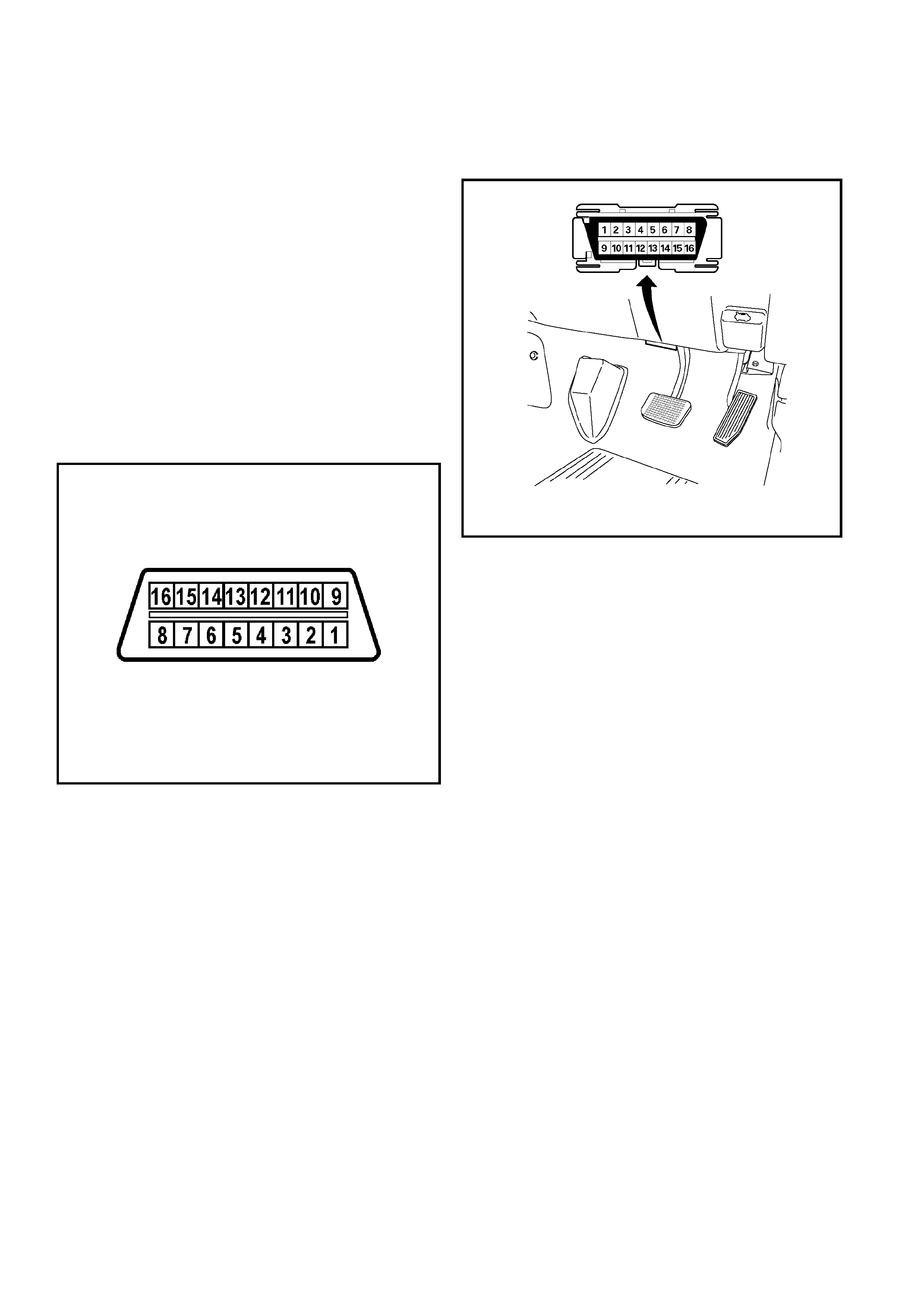
Intermittent Check Engine Lamp
In the case of an "intermittent" fault, the MIL ("Check
Engine" lamp ) may illuminate an d then (after three trips) go
"OFF". However, the correspond ing diagno stic trouble code
will be stored in the memo ry . When unexpected dia gnosti c
trouble codes appear, check for an in termi ttent mal function.
A diagnostic troub le cod e may rese t. Consult the .
"Diagnostic Aids" a s sociated with the diagnostic trouble
code. A physical inspection of the applicable sub-system
most often will resolve the problem.
Data Link Connector (DLC)
The provision for communicating with the control module is
the Data Lin k Conne ctor (DLC). Th e DLC is used to connect
to a Tech 2. Some common uses of the Tech 2 are listed
below:
• Identifying stored Diagno stic Trouble Codes (D TCs).
• Clearing DTCs.
• Performing out put control tests.
• Reading serial data .
Data Link Connector (DLC)
Verifying Vehicle Repair
Verification of vehicle repair will be more comprehensive for
vehicles with OBD system diagnostic. Following a repair, the
technician should perform the following steps:
1. Review and record the Fail Records and/or Free ze
Frame data for the DTC which has been diagnosed
(Freeze Frame data will only be stored for an A or B
type diagnostic and only if the MIL has been
requested).
2. Clear DTCs).
3. Operate the vehicle within conditions noted in the Fail
Records and/or Freeze Frame data.
4. Monitor the DTC status information for the specific DTC
which has been diagnosed until the diagnostic te st
associated with that DTC runs.
Following these steps are very important in verifying repairs
on OBD systems. Failure to fo llow the se step s could result
in unnecessary repairs
Reading Flash Diagnostic Trouble Codes
The provision for co mmuni cating w it the Engine Cont rol
Module (ECM) is the Da ta Lin k Connecto r (DLC), loca ted as
shown next.
It is used in the assembly plant to receive information, to
check that the engine is ope rati ng properly before i t lea ve s
the plant.
The diagnostic trouble code(s) (DTC(s) stored in the ECM
memory can be read eith er th rough a hand -held diagnosti c
scanner plugged in to th e DLC or by counting the numbe r of
flashes of the Check Engine Lamp MIL ) when the diagno stic
test terminal of the DLC is ground ed.
The DLC terminal ‘6’ (diagno stic request) is pulled ‘Low’
(grounded) by jumpering to DLC terminal ‘4’, which is a
ground wire.
This will signal the ECM that you want to "flash" DTC(s), if
any are present. On ce te rminals ‘4 ’ and ‘6’ have been
connected, the i gnition switch must be turned to the "ON"
position, with the engine not running . At th is poin t, the
"Check Engine" MIL shou ld flash DTC 12, th ree times
consecutively.
This would be the foll owing flash, sequence : "flash , pause ,
flash, flash, long pause, flash, pause, flash, flash. DTC 12
indicates th a t the ECM diagn ostic sy stem is opera ting.
If DTC 12 is not indicated, a problem is present within the
diagnostic sy stem itself, and should be addressed by
consulting the appropria te diagnostic chart in
DRIVEABILITY AND EMISSIONS. pause,
If DTC 12 is flashed and no other codes are stored in th e
ECM memory, then this code will continue to be fla shed .
However, if a DTC i s sto re d, then i t w ill then fla sh th a t DTC,
three times.
If more than one D TC has been stored in the ECM memory,
those DTC(s) will be flashed, from the lowest to the highest,
with each D TC being display ed th ree times.
Reading Diagnostic Trouble Codes Using
a TECH 2
The procedure for read ing diagnostic trou ble cod e(s) is to
use a Tech 2 diagnosti c san too l. When reading DTC( s),
follow instructions supplied by the Tech 2 manufacturer.
0.4 Sec 0.4 Sec
.
ON
OFF
3.2 Sec. 1.2 Sec. 3.2 Sec.
0.4 Sec 0.4 Sec
.
ON
OFF
3.2 Sec. 1.2 Sec. 3.2 Sec.
Self-diagnosis Start
Normal Code (12)
Trouble Code (32)
12 12 12 14 14 14 32 32 32
In case DTC 14 & 32 are stored
Clearing Diagnostic Trouble Codes
Important: Do not clear DTCs unless directed to do so
by the service information provided for each diagnostic
procedure. When DTCs are cleared, the Freeze Frame
and Failure Record data which may help diagnose an
intermittent fault will also be erased from memory.
If the fault that caused the DTC to be stored into
memory has been corrected, the Diagnostic Executive
will begin to count the “warm-up" cycles with no further
faults detected, the DTC will automatically be cleared
from the ECM memory.
To clear Diagnostic Trouble Codes (DTCs), use the
Tech 2 “clear DTCs" or “clear information" function.
When clearing DTCs follow instructions supplied by the
Tech 2 manufacturer.
When a Tech 2 is not available, DTCs can also be
cleared by disconnecting one of the following sources
for at least thirty (30) seconds.
To prevent system damage, the ignition key must be
“OFF" when disconnecting or reconnecting battery
power.
• The power source to the control module. Examples:
fuse, pigtail at battery ECM connectors etc.
• The negative battery cable. (Disconnecting the
negative battery cable will result in the loss of other
on-board memory data, such as preset radio tuning).
On-Board Diagnosis
(Self-Diagnosis)
1. The Engine Control Module (ECM) conducts a
self-test of most of the wiring and components in
the system each time the key is turned to ON, and
can detect faults in the system while the key is ON.
If a fault is detected, the ECM will store a trouble
code in memory and flash the CHECK ENGINE
indicator to alert the driver.
2. The Diagnostic Trouble Codes (DTC) can be
displayed by shorting together terminals and the
Data Link Connector (DLC) located below
Instrument Panel of drivers side.
The CHECK ENGINE indicator will flash DTC 12
three times, followed by any DTC.If several DTC are
stored, each DTC will be displayed three times. The
DTC will be displayed in numerical order. The DTC
display will continue as long as the DLC is shorted.
Some DTC can cause other DTC to be stored, It is
important to diagnose and repair the lowest
numbered DTC first before going on to the higher
numbered DTC.
Techline
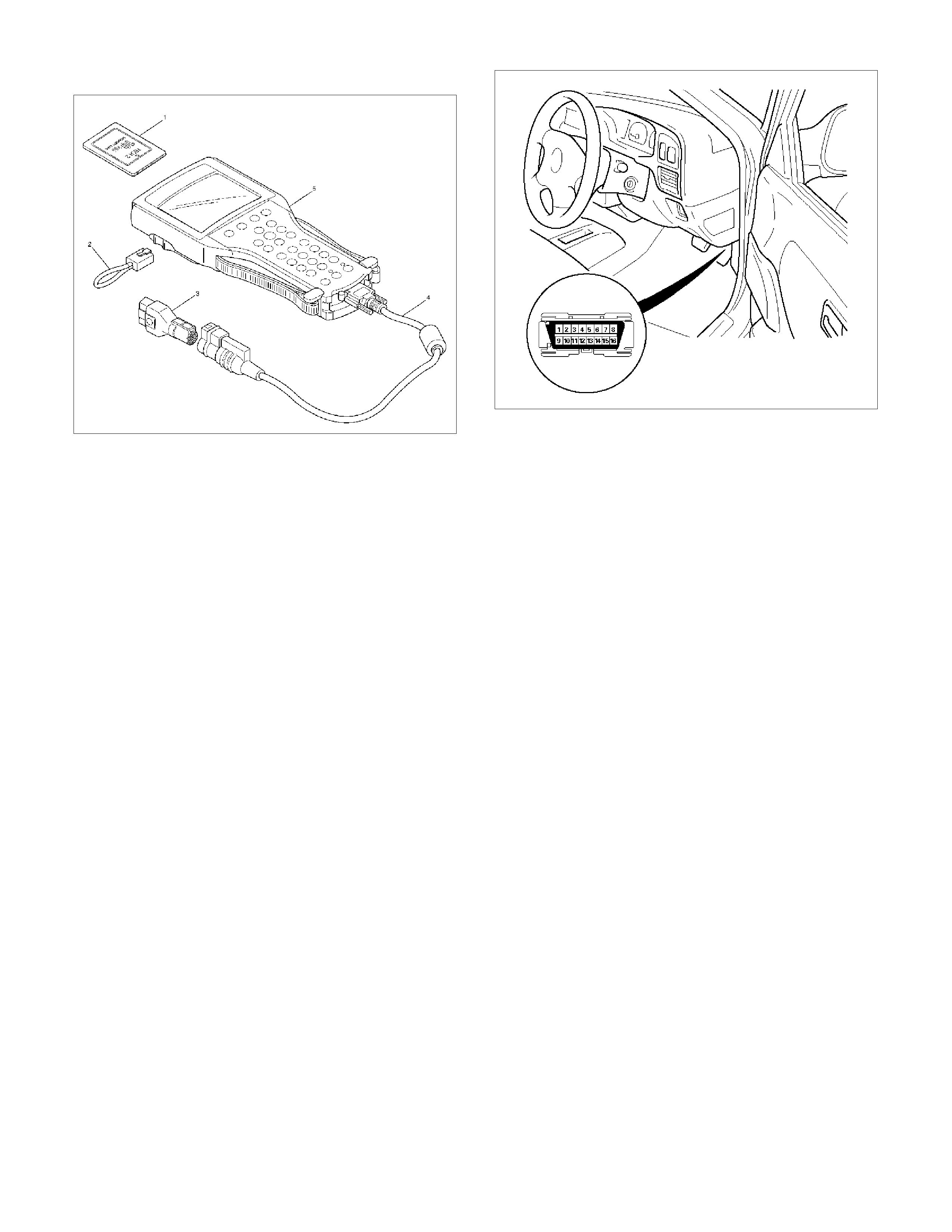
Tech 2 Connection
Tech 2 scan tool is used to electrically diagnose the
automatic transmission system and to check the
system. The Tech 2 enhances the diagnosis efficiency
though all the troubleshooting can be done without the
Te c h 2 .
1. Configuration of Tech 2
• Tech 2 scan tool kit (No. 7000086), Tech 2
scan tool (No. 7000057) and DLC cable (No.
3000095).
•SAE 16/19 adapter (No. 3000098) (3), RS232
loop back connector (No. 3000112) (2) and
PCMCIA card (No. 3000117) (1).
2. Tech 2 Connection
• Check the key switch is turn OFF.
• Insert the PCMCIA card (1) into the Tech 2 (5).
• Connect the SAE 16/19 adapter (3) to the DLC
• Turn the key switch of the vehicle ON and press
the “PWR” key of the Tech 2.
• Check the display of the Tech 2.
NOTE: Be sure to check that the power is not
supplied to the Tech 2 when attaching or removing
the PCMCIA card.
Diagnosis w ith TECH 2
If No Codes are Set
• Refer to F1: Data Display and identify the
electrical faults that are not indicated by trouble
code.
• Refer to "SYMPTOM DI AGNOSIS".
If Codes are Set
1. Record all trouble codes displayed by Tech 2 and
check id the codes are intermittent.
2. Clear the codes.
3. Drive the vehicle for a test to reproduce the fault
y
status.
4. Check trouble codes again using the Tech 2.
5. If no codes is displayed by test driving, the fault is
intermittent. In this case, refer to "DIAGNOSIS
AIDS".
6. If a code is present, refer to DTC Chart for
diagnosis.
7. Check trouble codes again using the Tech 2.
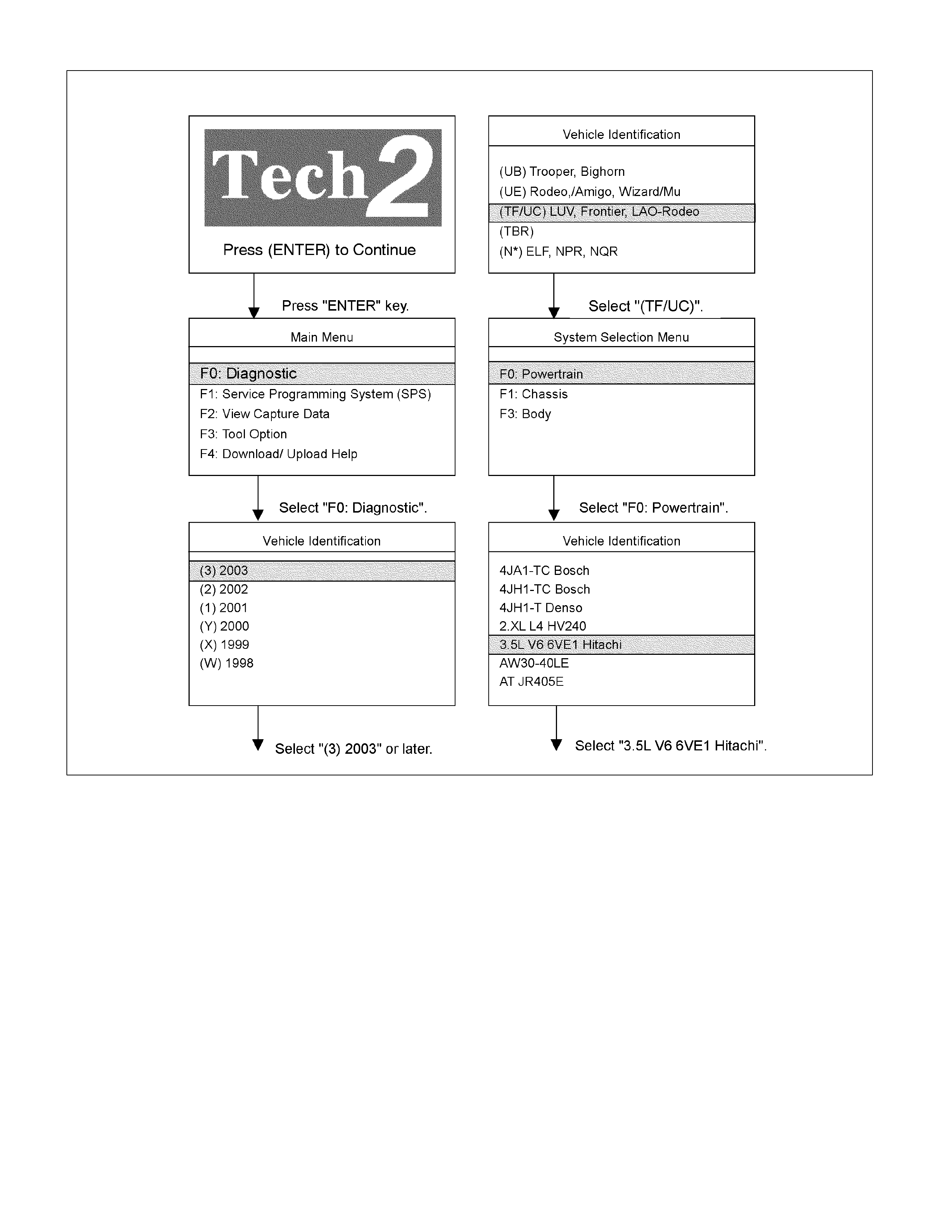
Select "3.5L V6 6VE1 Hitachi" in Vehicle Identification
menu and the following table is shown in the Tech 2
screen.

F0: Diagnostic Trouble Code
F0: Read DTC Infor By Priority
F1: Clear DTC Information
F2: DTC Information
F0: History
F1: MIL SVS or Message Requested
F2: Last Test Failed
F3: Test Failed Since Code Cleared
F4: Not Run Since Code Cleared
F5: Failed This Ignition
F3: Freeze Frame/Failure Record
F1: Data Display
F0: Engine Data
F1: O2 Sensor Data
F2: Snapshot
F3: Miscellaneous Test
F0: Lamps
F0: Malfunction Indicator Lamps
F1: Relays
F0: Fuel Pump Relay
F1: A/C Clutch Relay
F2: EVAP
F0: Purge Solenoid
F3: IAC System
F0: RPM Control
F1: IAC Control
F4: Fuel System
F0: Fuel Trim Reset
F4: System Information
F0: MIL/System Status
F0: Diagnostic Trouble Code
The purpose of the "Diagnostic Trouble Codes" mode is
to display stored trouble code in the
ECM.
When "Clear DTC Information" is selected, a "Clear
DTC Information", warning screen appears.
This screen informs you that by cleaning DTC's "all
stored DTC information in the ECM will be erased".
After clearing codes, confirm system operation by test
driving the vehicle.
Use the "DTC Information" mode to search for a
specific type of stored DTC information.
History
This selection will display only DTCs that are stored in
the ECM's history memory. It will not display Type B
DTCs that have not requested the MIL ("Check Engine
Lamp"). It will display all type A and B DTCs that
requested the MIL and have failed within the last 40
warm-up cycles. In addition, it will display all type C and
D DTCs that have failed within the last 40 warm-up
cycles.
MIL SVC or Message Request
This selection will display only DTCs that are requesting
the MIL. Type C and Type D DTCs cannot be displayed
using the MIL. Type C and D DTCs cannot be displayed
using this option.
This selection will report type B DTCs only after the MIL
has been requested.
Last Test Failed
This selection will display only DTCs that have failed the
last time the test run. The last test may have run during
a previous ignition cycle of a type A or type B DTC is
displayed. For type C and type D DTCs, the last failure
must have occurred during the current ignition cycle to
appear as last test fail.
Test Failed Since Code Cleared
The selection will display all active and history DTCs
that have reported a test failure since the last time
DTCs were cleared. DTCs that last failed more that 40
warm-up cycles before this option is selected will not be
displayed.
Failed This Ignition
This selection will display all DTCs that have failed
during the present ignition cycle.
Freeze Frame/Failure Record
This selection will display stored various vehicle
information at the moment an emission related fault
when the MIL ("Check Engine Lamp") is commanded
on.
The Freeze Frame data will not be erased unless the
associated history DTC is cleared.
F1: Data Display
The purpose of the "Data Display" mode is to
continuously monitor data parameters.
The current actual values of all important sensors and
signals in the system are display through F1 mode.
See the "Typical Scan Data" section.

F2: Snapshot
"Snapshot" allows you to focus on making the condition
occur, rather than trying to view all of the data in
anticipation of the fault.
The snapshot will collect parameter information around
a trigger point that you select.
F3: Miscellaneous Test:
The purpose of "Miscellaneous Test" mode is to check
for correct operation of electronic system actuators.
F4: System Information
The "MIL/System Status" informs number of stored
DTC.

Typical Scan Data & Definitions (Engine Data)
Use the typical values table only after the On-Board Diagnostic System check has been completed, no DTC(s) were noted, and you have determined that the On-Board
Diagnostic are functioning properly.
Tech2 values from a properly running engine may be used for comparison with the engine you are diagnosing.
Condition : Vehicle stopping, engine running, air conditioning off & after warm-up (Coolant temperature approximately 80°C)
Tech 2
Parameter Units Idle 2000rpm Definitions
1 Ignition Voltage V 10.5 − 14.5 10.5 − 14.5 This displays the system voltage measured by the ECM at ignition feed.
2 Engine Speed rpm 710 − 860 1950 − 2050 The actual engine speed is measured by ECM from the CKP sensor 58X signal.
3 Desired Idle
Speed rpm 750 − 770 750 − 770 The desired engine idle speed that the ECM commanding.
The ECM compensates for various engine loads.
4 Engine Coolant
Temperature °C or °F 80 − 90 (°C) 80 − 90 (°C) The ECT is measured by ECM from ECT sensor output voltage.
W hen the engine is normally warm upped, this data displays approximately 80 °C or
more.
5 Start Up ECT
(Engine Coolant
Temperature)
°C or °F Depends on
engine coolant
temp. at time of
start-up
Depends on
engine coolant
temp. at time of
start-up
Start-up ECT is measured by ECM from ECT sensor output voltage when engine is
started.
6 Intake Air
Temperature °C or °F Depends on
ambient temp. Depends on
ambient temp. The IAT is measured by ECM from IAT sensor output voltage.
This data is changing by intake air temperature.
7 Throttle Position % 0 4 − 6 Throttle position operating angle is measured by the ECM from throttle position
output voltage.
This should display 0% at idle and 99 − 100% at full throttle.
8 Throttle Position
Sensor V 0.4 − 0.7 0.6 − 0.8 The TPS output voltage is displayed.
This data is changing by accelerator operating angle.
9 Mass Air Flow g/s 5.0 − 8.0 13.0 − 16.0 This displays intake air amount.
The mass air flow is measured by ECM from the MAF sensor output voltage.
10 Air Fuel Ratio 14.7:1 14.7:1 This displays the ECM commanded value.
In closed loop, this should normally be displayed around 14.2:1 − 14.7:1.
11 Idle Air Control Steps 10 − 20 20 − 30 This displays the ECM commanded position of the idle air control valve pintle.
A
larger number means that more air is being commanded through the idle air
passage.
12 EGR Valve V 0.6 − 1.0 0.6 − 1.0 The EGR position sensor output voltage is displayed.
This data is changing by EGR valve solenoid operating position.
13 Desired EGR
Openring V 0 − 1.2 0 − 1.2 The ECM commanded EGR position sensor voltage is displayed.
A
ccording to the current position, ECM changes EGR valve solenoid operating
position to meet the desired position.
14 EGR Valve On
Duty % 0 60 − 80 This displays the duty signal from the ECM to control the EGR valve.
15 Engine Load % 2 − 7 8 − 15 This displays is calculated by the ECM form engine speed and MAF sensor reading.
Engine load should increase with an increase in engine speed or air flow amount.
16 B1 Fuel System
Status Open Loop/ Close
Loop Close Loop Close Loop
17 B2 Fuel System
Status Open Loop/ Close
Loop Close Loop Close Loop
When the engine is first started the system is in "Open Loop" operation.
In "Open Loop", the ECM ignores the signal from the oxygen sensors.
When various conditions (ECT, time from start, engine speed & oxygen sensor
output) are met, the system enters "Closed Loop" operation.
In "Closed Loop", the ECM calculates the air fuel ratio based on the signal from the
oxygen sensors.
18 Fuel Trim
Learned (Bank 1) Yes/No Yes Yes
19 Fuel Trim
Learned (Bank 2) Yes/No Yes Yes
When c onditions ar e appropr iate f or enabling long term f uel trim c or rec tions , f uel tr im
learn will display "Yes".
This indicates that the long term fuel trim is responding to the short term fuel trim.
If the f uel trim lean displays "No", then long term fuel trim will not re spond to c hanges
in short term fuel trim.
20 Injection Pulse
Bank 1 ms 2.0 − 4.0 2.0 − 4.0
21 Injection Pulse
Bank 2 ms 2.0 − 4.0 2.0 − 4.0
This displays the amount of time the ECM is commanding each injector On during
each engine cycle.
A
longer injector pulse width will cause more fuel to be delivered. Injector pulse width
should increase with increased engine load.
22 Spark Advance °CA 10 − 15 35 − 42 This displays the amount of spark advance being commanded by the ECM.

Tech 2
Parameter Units Idle 2000rpm Definitions
23 A/C Request (Air
Conditioning) On/Off Off Off This displays the air conditioner request s ignal. T his should dis play "On" when the air
conditioner switch is switched on.
24 A/C Clutch On/Off Off Off This displays whether the ECM has com manded the A/C compressor clutch "On" or
"Off".
25 EVAP Purge
Solenoid
(Evaporative
Emission)
% 50 − 80 0 This displays the duty signal from the ECM to control the canister purge solenoid
valve.
26 Fuel Trim Cell 49 − 52 13 − 17 This displays dependent on engine speed and MAF sensor reading.
A plot of engine speed versus MAF amount is divided into the cells.
Fuel trim cell indicates which cell is currently active.
27 Fuel Pump On/Off On On This displays operating status for the fuel pump main relay.
This should display "On" when the key switch is turned on and while engine is
running.
28 Deceleration Fuel
Cutoff Active/ Inactive Inactive Inactive The ECM will command the deceleration fuel mode when it detects a closed throttle
position while the vehicle is traveling.
While in decreasing fuel mode, the ECM will decrease the amount of fuel delivered
by entering open loop and decreasing the injector pulse width.
29 Power Enrichment Yes/No No No The ECM will command power enrichment mode "Yes" when a large increase in
throttle position and load is detected.
W hile in power enrichm ent mode, the ECM will increase the am ount of f uel delivered
by entering open loop and increasing the injector pulse width.
30 Vehicle Speed km/h or mph 0 0 This displays vehicle speed.
The vehicle speed is measured by ECM from the vehicle speed sensor.
31 Cam Signal Present/ Missing Present Present This displays input signal from the camshaft position sensor.
When the correct pulse is generated, signal is received.
32 PSP Switch
(Power Steering
Pressure)
Normal Pressure /
High Pressure Normal Pressure Normal Pressure This displays the power steering pressure signal.
This should display "High Pressure" when the steering is steered.
33 Torque Request
(Timing Retard) °CA 0 0
34 Security Code
Status Programmable/
Not
Programmable
Programmable Programmable This should display "Programmable" when the correct security code is programmed.
35 Immobiliser
Function
Programmed
Valid/ Invalid Valid Valid This should display "Valid" when the immobiliser is programmed.
36 Security Code Okay/ Not Okay Okay Okay This should display "Okay" when the correct security code is programmed.
37 Immobiliser
Sy stem Error / Not Error Not Erro r Not Error This should display "Not Error" when the immobiliser is normal.
38 Malfunction
Indicator Lamp On/Off Off Off This displays operating status for the Check Engine Lamp.
This should display "On" when the Check Engine Lamp is turned on.
39 Time From Start This displays the engine time elapsed since the engine was started.
If the engine is stopped, engine run time will be reset to 00:00:00

Typical Scan Data & Definitions (O2 Sensor Data)
Use the typical values table only after the On-Board Diagnostic System check has been completed, no DTC(s) were noted, and you have determined that the On-Board
Diagnostic are functioning properly.
Tech2 values from a properly running engine may be used for comparison with the engine you are diagnosing.
Condition : Vehicle stopping, engine running, air conditioning off & after warm-up (Coolant temperature approximately 80 °C)
Tech 2
Parameter Units Idle 2000rpm Definitions
1 Ignition Voltage V 10.5 − 14.5 10.5 − 14.5 This displays the system voltage measured by the ECM at ignition feed.
2 Engine Speed rpm 710 − 860 1950 − 2050 The actual engine speed is measured by ECM from the CKP sensor 58X signal.
3 Desired Idle
Speed rpm 750 − 770 750 − 770 The desired engine idle speed that the ECM commanding.
The ECM compensates for various engine loads.
4 Engine Coolant
Temperature °C or °F 80 − 90 (°C) 80 − 90 (°C) The ECT is measured by ECM from ECT sensor output voltage.
W hen the engine is normally warm upped, this data displays approximately 80 °C or
more.
5 Start Up ECT
(Engine Coolant
Temperature)
°C or °F Depends on
engine coolant
temp. at time of
start-up
Depends on
engine coolant
temp. at time of
start-up
Start-up ECT is measured by ECM from ECT sensor output voltage when engine is
started.
6 Throttle Position % 0 4 − 6 Throttle position operating angle is measured by the ECM from throttle position
output voltage.
This should display 0% at idle and 99 − 100% at full throttle.
7 Throttle Position
Sensor V 0.4 − 0.7 0.6 − 0.8 The TPS output voltage is displayed.
This data is changing by accelerator operating angle.
8 Mass Air Flow g/s 5.0 − 8.0 13.0 − 16.0 This displays intake air amount.
The mass air flow is measured by ECM from the MAF sensor output voltage.
9 Air Fuel Ratio 14.7:1 14.7:1 This displays the ECM commanded value. In closed loop, this should normally be
displayed around 14.2:1 − 14.7:1.
10 Engine Load % 2 − 7 8 − 15 This displays is calculated by the ECM form engine speed and MAF sensor reading.
Engine load should increase with an increase in engine speed or air flow amount.
11 B1 Fuel System
Status Open Loop/ Close
Loop Close Loop Close Loop
12 B2 Fuel System
Status Open Loop/ Close
Loop Close Loop Close Loop
When the engine is first started the system is in "Open Loop" operation.
In "Open Loop", the ECM ignores the signal from the oxygen sensors.
When various conditions (ECT, time from start, engine speed & oxygen sensor
output) are met, the system enters "Closed Loop" operation.
In "Closed Loop", the ECM calculates the air fuel ratio based on the signal from the
oxygen sensors.
13 B1S1 O2 Sensor
(Bank1 Sensor 1) mV 50 − 950 50 −950
14 B2S1 O2 Sensor
(Bank2 Sensor 1) mV 50 − 950 50 − 950
This displays the exhaust oxygen sensor output voltage.
Should fluctuate constantly within a range between 10mV (lean exhaust) and
1000mV (rich exhaust) while operating in closed loop.
15 B1 O2 Sensor
Ready (Bank 1) Yes/No Yes Yes
16 B2 O2 Sensor
Ready (Bank 2) Yes/No Yes Yes
This displays the status of the exhaust oxygen sensor.
This display will indicate "Yes" when the ECM detects a fluctuating oxygen sensor
output voltage sufficient to allow closed loop operation.
This will not occur unless the oxygen sensor is warmed up.
17 B1 Long Term
Fuel Trim (Bank
1)
% -10 − 20 -10 − 20
18 B2 Long Term
Fuel Trim (Bank
2)
% -10 − 20 -10 − 20
The long term fuel trim is delivered from the short term fuel term values and
represents a long term correction of fuel delivery for bank in question.
A value of 0% indicates that fuel delivery requires no compensation to maintain the
ECM commanded air fuel ratio.
A
negative value indicates that the fuel system is rich and fuel delivery is being
reduced (decreased injector pulse width).
A
positive value indicates that a lean condition exists and the ECM is com pensating
by add fuel (increased injector pulse width).
Because long term fuel trim tends to follow short term fuel trim, a value in the
negative range due to canister purge at idle should not be considered unusual.
Fuel trim values at maximum authority may indicate an excessively rich or lean
system.

Tech 2
Parameter Units Idle 2000rpm Definitions
19 B1 Short Term
Fuel Trim (Bank
1)
% -10 − 20 -10 − 20
20 B2 Short Term
Fuel Trim (Bank
2)
% -10 − 20 -10 − 20
The short term fuel trim to a bank r epresents a shor t term c orrection to the bank fuel
delivery by the ECM in response to the amount of time the bank fuel control oxygen
sensor voltage spends above or below the 450mV threshold.
If the oxygen sensor voltage has m ainly remained less than 450m V, indicating a lean
air/fuel, short term fuel trim will increase into the positive range above 0% and the
ECM will pass fuel.
If the oxygen sensor voltage stays mainly above the threshold, short term fuel trim
will decrease below 0% into the negative range while the ECM reduces fuel delivery
to compensate for the indicated rich condition.
Under certain conditions such as extended idle and high ambient temperatures,
canister purge may cause short term fuel trim to read in the negative range during
normal operation.
Fuel trim values at maximum authority may indicate an excessively rich or lean
system.
21 Fuel Trim Cell 49 − 52 13 − 17 This displays dependent on engine speed and MAF sensor reading.
A plot of engine speed versus MAF amount is divided into the cells.
Fuel trim cell indicates which cell is currently active.
22 Fuel Trim
Learned (Bank 1) Yes/No Yes Yes
23 Fuel Trim
Learned (Bank 2) Yes/No Yes Yes
When c onditions ar e appropr iate f or enabling long term f uel trim c or rec tions , f uel tr im
learn will display "Yes".
This indicates that the long term fuel trim is responding to the short term fuel trim.
If the f uel trim lean displays "No", then long term fuel trim will not re spond to c hanges
in short term fuel trim.
24 B1S1 Status
(Bank 1 Sensor 1) Rich / Lean Rich / Lean Rich / Lean
25 B2S1 Status
(Bank 2 Sensor 1) Rich / Lean Rich / Lean Rich / Lean
This displays dependent on the exhaust oxygen sensor output voltage.
Should fluctuate constantly "Rich" and "Lean" in closed loop.

Miscellaneous Test
The state of each circuit can be tested by using
miscellaneous test menus. Especially when DTC cannot
be detected, a faulty circuit can be diagnosed by testing
each circuit by means of these menus.
Even DTC has been detected, the circuit tests using
these menus could help discriminate between a
mechanical trouble and an electrical trouble.
Connect Tech 2 and select "Powertrain", "3.5L V6 6VE1
Hitachi" & "Miscellaneous Test".
F0: Lamps
F0: Malfunction Indicator Lamp
When the Tech 2 is operated, "Malfunction Indicator
Lamp (Check Engine Lamp)" is turned on or off.
The circuit is normal if the "Malfunction Indicator Lamp
(Check Engine Lamp)" in the instrument panel is turned
on or off in accordance with this operation.
F1: Relays
F0: Fuel Pump Relay
When the Tech 2 is operated, fuel pump relay signal
turns ON or OFF.
The circuit is normal if fuel pump sound is generated in
accordance with this operation when key switch is
turned ON.
"F1: A/C Clutch Relay"
When the Tech 2 is operated, A/C clutch relay signal
turns ON or OFF.
The circuit is normal if A/C compressor clutch is
energized in accordance with this operation when the
engine is running.
F2: EVAP
F0: Purge Solenoid
When the Tech 2 is operated, duty ratio of EVAP purge
solenoid is changed 10%-by-10%.
Purge Solenoid
Engine Speed 800 RPM
Desired Idle Speed 762 RPM
Engine Coolant Temperature 80 °C
Start Up ECT 50 °C
Intake Air Temperature 30 °C
Throttle Position 0 %
Throttle Position Sensor 0.49 V
EVAP Purge Solenoid 10 %
• Press "Increase" key.
Then, EVAP Purge Solenoid increases
10%-by-10%.
• Press "Quit" Key.
F3: IAC System
F0: RPM Control
When the Tech 2 is operated, "Desired Idle Speed"
increases 50rpm-by-50rpm up to 1550rpm.
The circuit is normal if engine speed is changed in
accordance with this operation.
RPM Control
Engine Speed 850 RPM
Desired Idle Speed 850 RPM
Engine Coolant Temperature 80 °C
Start Up ECT 50 °C
Intake Air Temperature 30 °C
Barometric Pressure 104 Kpa
Throttle Position 0 %
Desired Idle Speed 850 RPM
• Press "Increase" key.
Then, Desired Idle speed increases
50rpm-by-50rpm up to 1550rpm. Engine speed is
also changed by this operation.
• Press "Quit" Key.
F0: IAC Control
When the Tech 2 is operated, "Idle Air Control"
increases or decreases 10steps-by-10steps up to
160steps.
The circuit is normal if idle engine speed is changed in
accordance with this operation.
IAC Control
Engine Speed 875 RPM
Desired Idle Speed 762 RPM
Engine Coolant Temperature 80 Ž
Start Up ECT 50 Ž
Intake Air Temperature 30 Ž
Barometric Pressure 104 Kpa
Throttle Position 0 %
Idle Air Control 30 Steps
• Press "Increase" key.
Then, Idle Air Control increases 10steps-by-
10steps up to 160steps.
Engine speed is also changed by this operation.
• Press "Quit" Key.

F4: Fuel System
F0: Fuel Trim Reset
When the Tech 2 is operated, "Long Term Fuel Trim" is
reset to 0%.
Fuel Trim Reset
B1 Long Term Fuel Trim (Bank 1) 3 %
B2 Long Term Fuel Trim (Bank 2) 3 %
B1 Short Term Fuel Trim (Bank 1) −1 %
B2 Short Term Fuel Trim (Bank 2) −2 %
Fuel Trim Cell 53
Fuel Trim Learned (Bank 1) Yes
Fuel Trim Learned (Bank 2) Yes
B1S1 Status (Bank 1 Sensor 1) Lean
• Press "Reset" key.
Then, B1 & B2 Long Term Fuel Trim is reseted to
0%.
• Press "Quit" Key.

Plotting Snapshot Graph
This test selects several necessary items from the data
list to plot graphs and makes data comparison on a long
term basis. It is an effective test particularly in emission
related evaluations.
060RX037
For trouble diagnosis, you can collect graphic data
(snap shot) directly from the vehicle.
You can replay the snapshot data as needed.
Therefore, accurate diagnosis is possible, even though
the vehicle is not available.
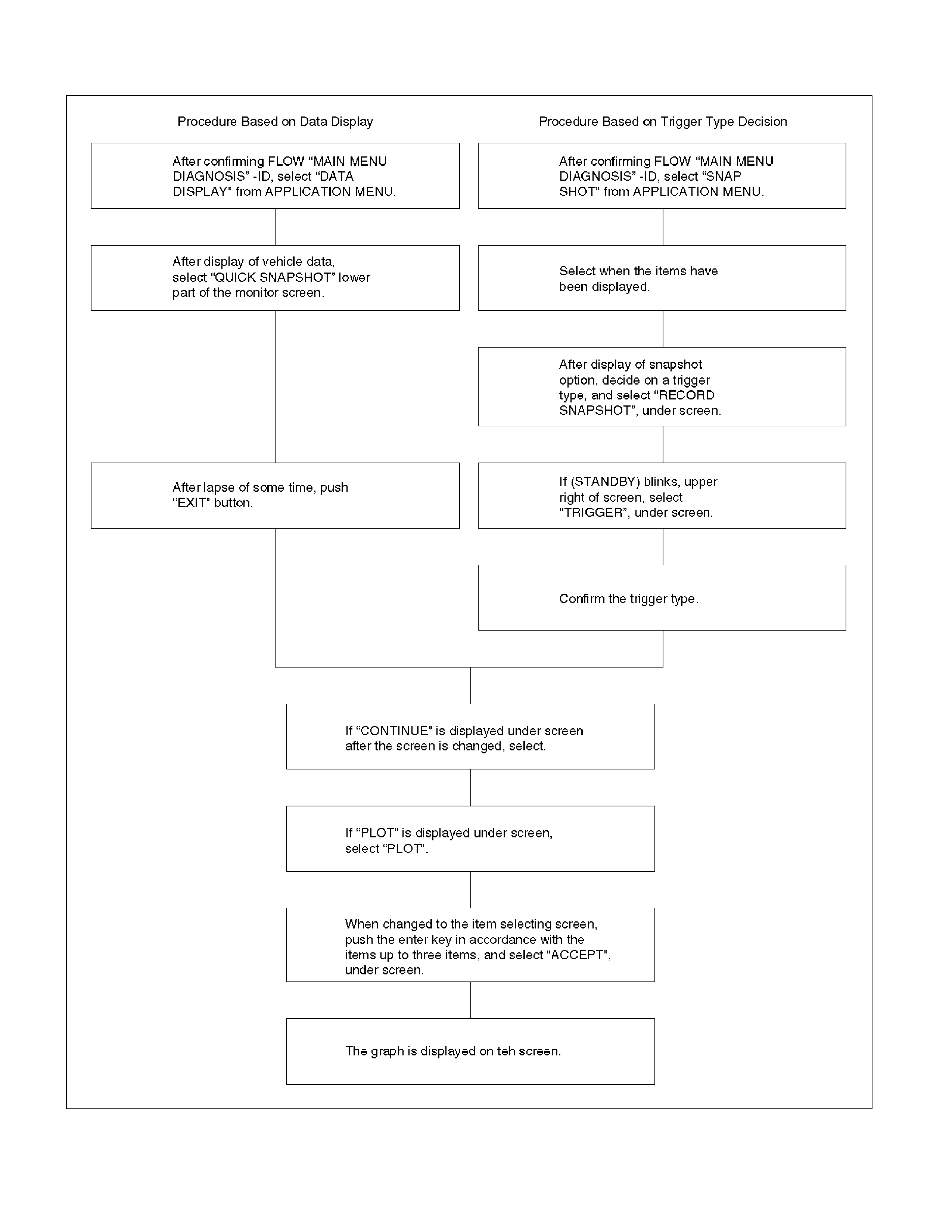
Plotting Graph Flow Chart (Plotting Graph After Obtaining Vehicle Information)
D06RY00167
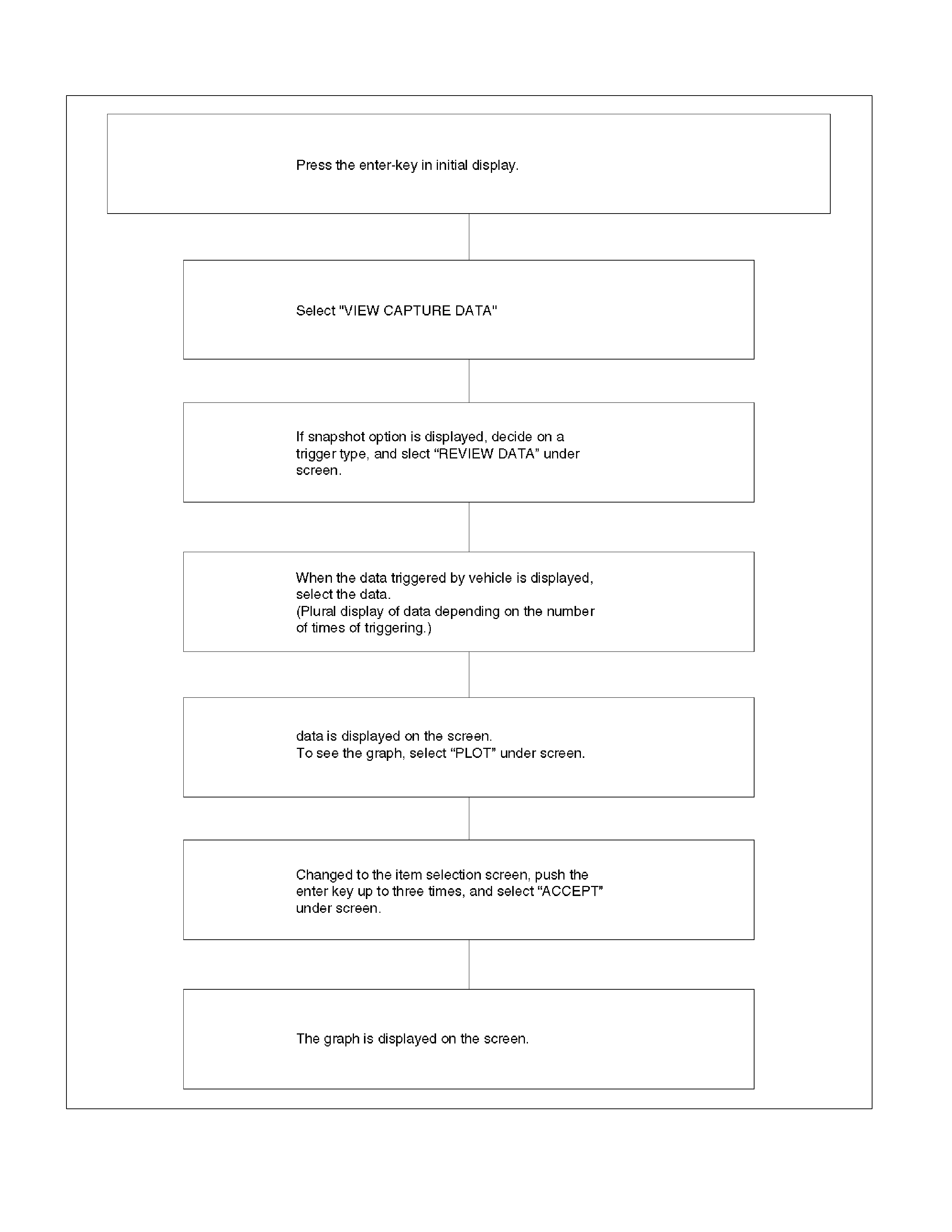
Flow Chart for Snapshot Replay (Plotting Graph)
060RX040
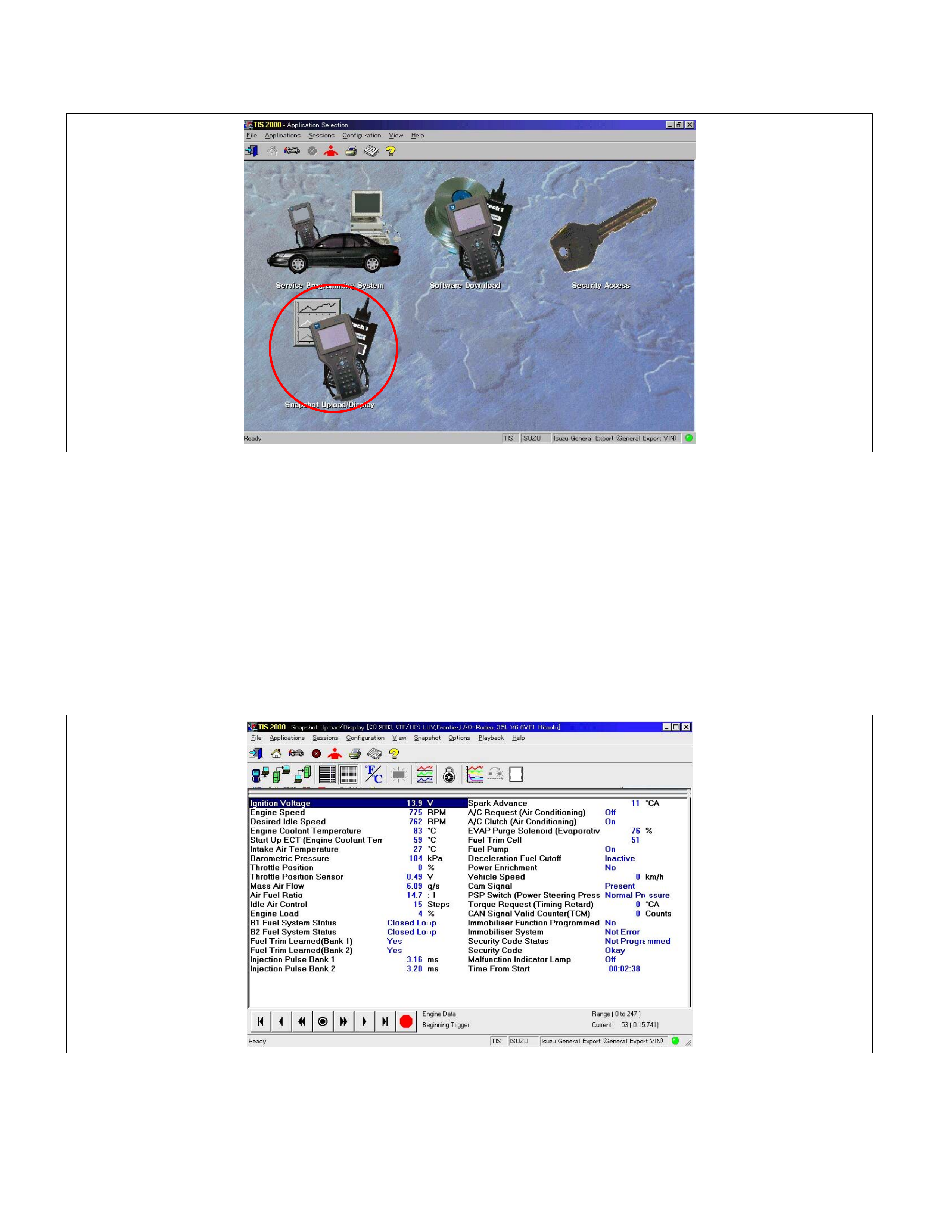
Snapshot Display With TIS2000
Procedures for transferring and displaying Tech2
snapshot data by using TIS2000 [Snapshot Upload]
function is described below.
Snapshot data can be displayed with [Snapshot Upload]
function included in TIS2000.
By analyzing these data in various methods, trouble
conditions can be checked.
Snapshot data is displayed by executing the three steps
below shown:
1. Record the snapshot data, in Tech2.
2. Transfer the snapshot data to PC.
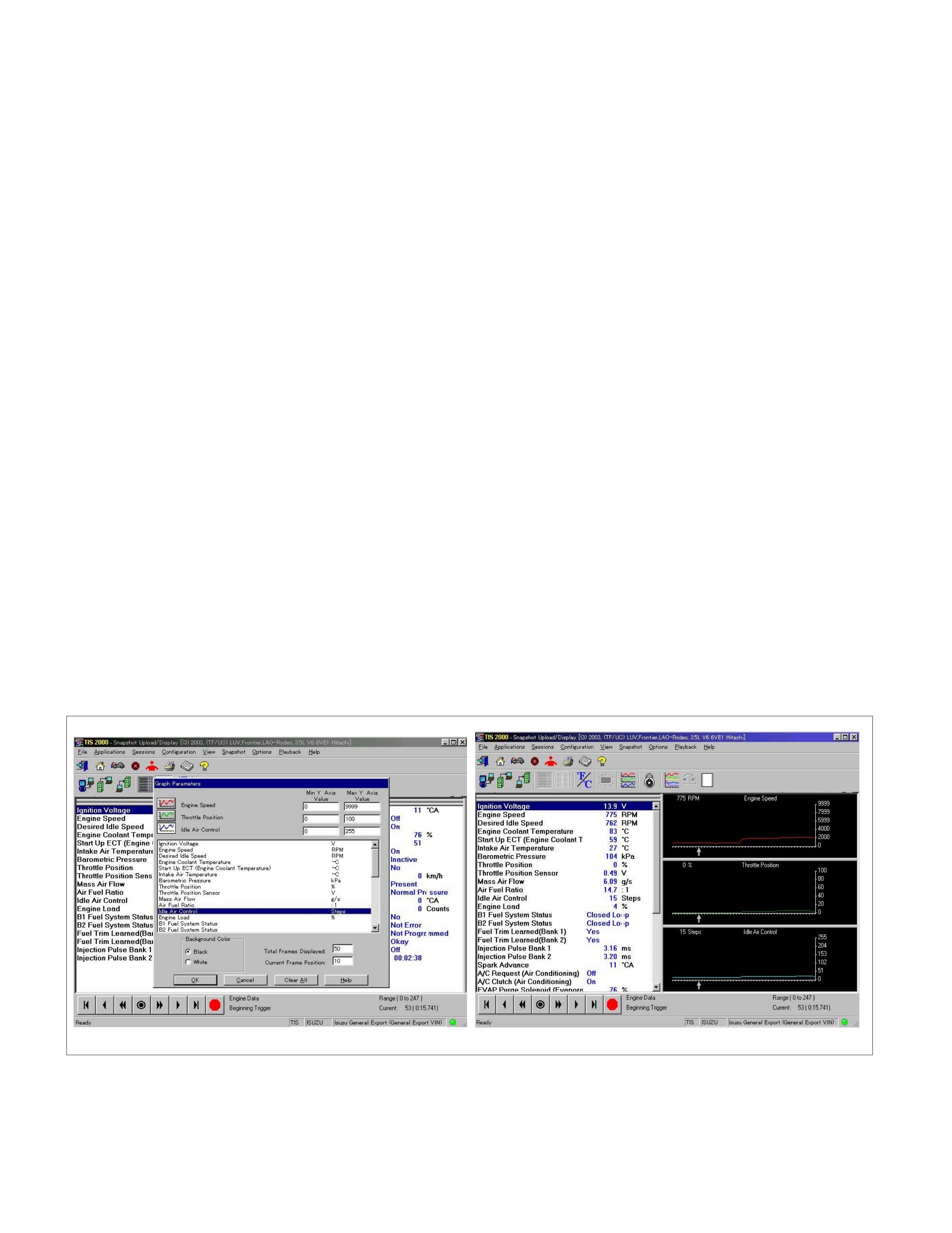
After recording the snapshot in Tech2, transfer the data
from Tech2 to PC by the below procedures.
1. Start TIS2000.
2. Select [Snapshot Upload] on the TIS2000 start
screen.
3. Select [Upload from trouble diagnosis tool (transfe
r
from diagnosis tester)] or click the corresponding
icon of the tool bar.
4. Select Tech2, and transfer the recorded snapshot
information.
5. Select the transferred snapshot.
6. After ending transfer of the snapshot, data
parameter list is displayed on the screen.
3. Snapshot data is displayed with TIS2000
[Snapshot Upload] function.
Snapshot is stored in the PC hard disk or floppy disk,
and can be displayed any time.
Stored snapshot can be displayed by the below
procedures.
1. Start TIS2000.
2. Select [Snapshot Upload] on the TIS2000 start
screen.
3. Select [Open the existing files] or click the
corresponding icon of the tool bar.
4. Select the transferred snapshot.
5. Open the snapshot, to display the data paramete
r
list on the screen.
Graph display Values a nd graphs (Max. 3 graphs):
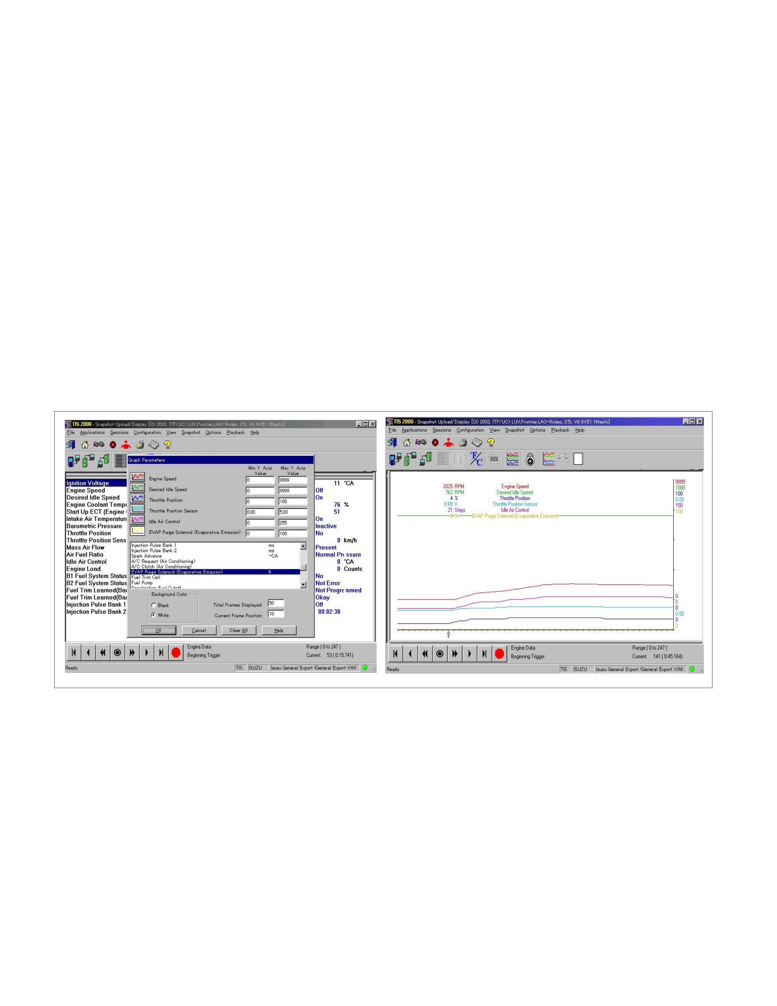
1. Click the icon for graph display. [Graph Parameter]
window opens.
2. Click the first graph icon of the window upper part,
and select one parameter from the list of the
window lower part. Selected parameter is
displayed nest to the graph icon. Graph division
can be selected in the field on the parameter right
side.
3. Repeat the same procedures with the 2nd and 3rd
icons.
4. After selecting all parameters to be displayed
(Max. 3 parameters), click [OK] button.
5. Parameter selected is displayed in graph form on
the right of the data parameter on the screen.
6. Graph display can be moved with the navigation
icon.
7. For displaying another parameter by graph, click
the parameter of the list, drug the mouse to the
display screen while pressing the mouse button
and release the mouse button. New parameter is
displayed at the position of the previous
parameter. For displaying the graph display screen
in full size, move the cursor upward on the screen.
When the cursor is changed to the magnifying
glass form, click the screen. Graph screen is
displayed on the whole screen.
Display of graphs on one screen (Max. 6 graphs):
1. Click the 6 graph icon. [Graph Parameter] windo
w
opens.
2. Click the graph icon, select the parameter to be
displayed from the list and change divisions
according to necessity.
3. Repeat the same procedures with the graph icons,
from the 2nd to 6th.
4. Click the [OK] button to display.
5. In this case, parameters are displayed only in
graph form. All parameters are displayed in one
graph.
6. The graph display screen can be moved with the
navigation icon.
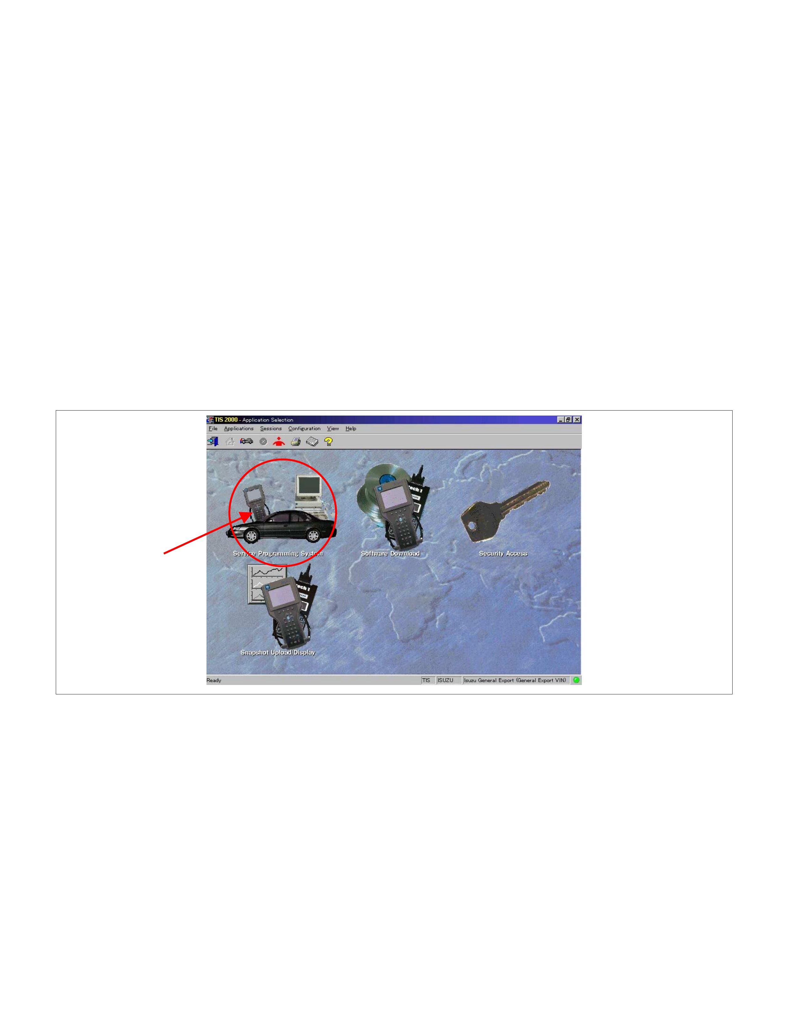
Service Programming System (SPS)
The procedure to program the control unit by using the
Service Programming System (SPS) software
contained in TIS2000 is explained below.
NOTE:
•
••
• If the Engine Control Module (ECM) was
programmed, the Immobiliser System must be
linked to the ECM: Refer to section 11
"Immobiliser System-ECM replacement" for the
ECM/Immobiliser linking procedure.
•
••
• Should T ech2 display "SPS Procedure w as not
successful", engine will not start, but no DT Cs
are present, low battery voltage or poo
r
electrical connections should be the primary
suspects. Perform the SPS procedure again
after rectifying the fault/s.
IMPORTANT:
Perform the following checks before attempting to
program the control unit:
•
••
• The Tech2 PCMCIA card is programmed with
the latest software release.
•
••
• The latest release of TIS2000 is loaded on the
PC.
•
••
• The vehicle battery is fully charged.
•
••
• The control unit to be programmed is
connected to the vehicle.
1. Preparations of TIS 2000
1. Connect Tech 2 to P/C.
2. Check to see if Hardware Key is plugged into Port.
3. Activate TIS 2000 by P/C.
4. On the activating screen of TIS2000, choose
"Service Programming System"
5. On the screen of "Diagnostic Tester and
Processing Program Selection", choose the one
that will comply with the following.
• Diagnostic tester in use
• New programming by the existing module or ne
w
programming by the replaced/new module.
• Fixing position of the control unit.
6. Upon completion of the selection, push the button
of "Continue".
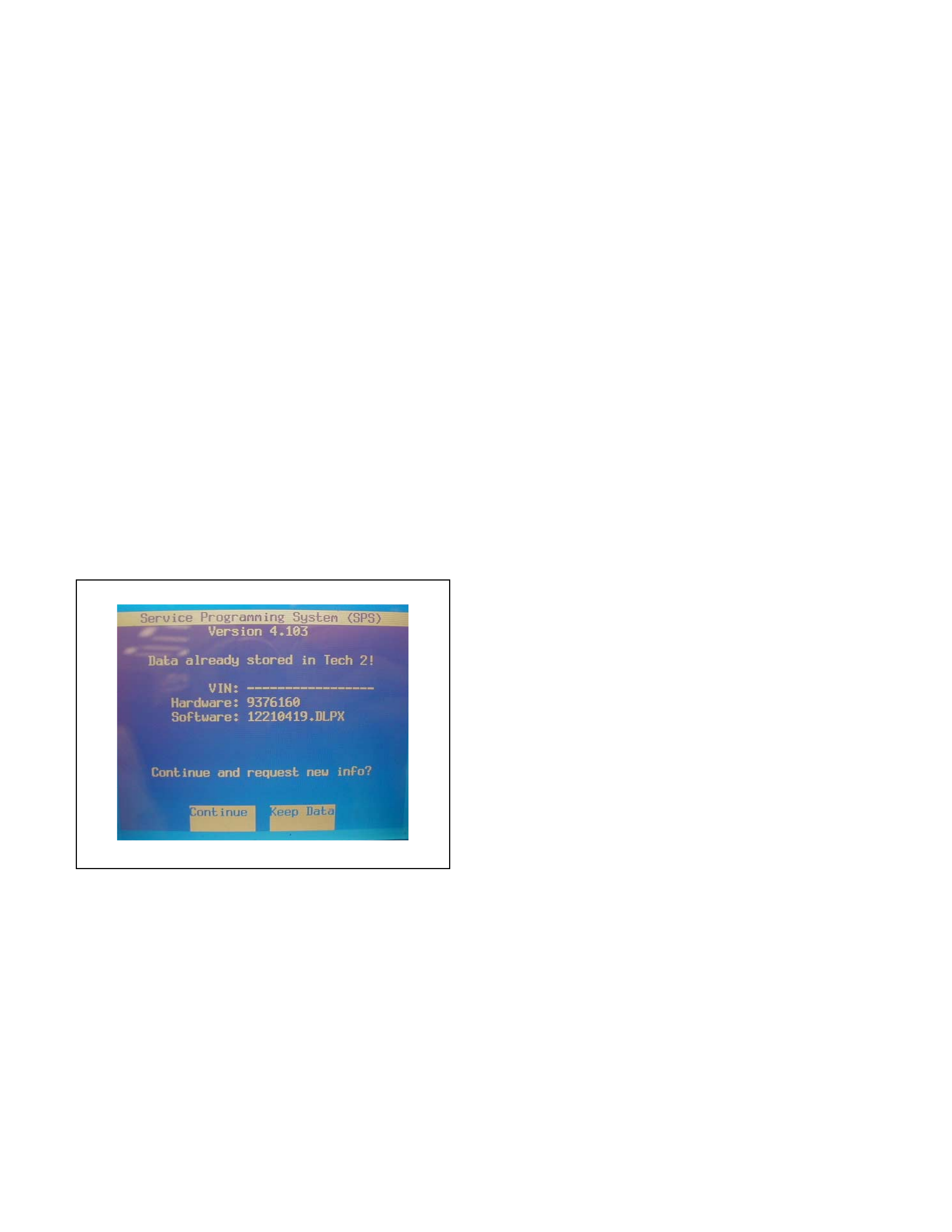
Requesting Data From The Vehicle
1. Connect TECH2 to the vehicle, turn on TECH 2 and
press “ENTER” at the start-up screen.
2. Turn the ignition ON
3. At the main menu screen, select F1: Service
Programming System (SPS)
4. Select F0: Request Info
5. Where existing data has already been saved in
TECH2, this data will be displayed. Choose whether
to keep the existing data, or to obtain new data from
the control unit.
6. If ‘continue’ is selected, select the correct Model
Year, Vehicle Type and Controller Type.
7. Follow the instructions on the TECH2 screen.
TECH2 will now obtain and display the requested data.
NOTE: If the control unit has been replaced, the VIN will
not be displayed. As the vehicle Model Year, Model
Type and Engine Type are specified from the VIN, the
correct VIN must be entered once TECH2 is connected
to TIS2000.
8. Press EXIT, turn the ignition OFF and then turn
TECH2 OFF.
Remove TECH2 from the vehicle.
Data Exchange
1. Connect TECH2 to the PC; ensuring the hardware
key is plugged into the correct PC port.
2. Turn TECH2 ON
3. Start the TIS2000 program
4. Select the Service Programming System
5. At the screen “Diagnostic Tester and Processing
Program Selection”, select:
• The diagnostic tester in use (TECH2)
• Whether programming an existing module or
programming a new module.
6. Click the NEXT button on the TIS2000 screen
7. Check the VIN displayed, if necessary enter the
correct vehicle VIN.
8. Click the NEXT button on the TIS2000 screen
9. Check the following information displayed:
• Model Year
• Model Type
• Engine Type
• Transmission Type
• Destination Code **
• Immobiliser
** The Destination Code can be read from the Body &
Option Plate affixed to the left side inner guard. Refer
to figure 3, which shows the Destination Code EK4
(General Export)
Note: Australian Destination Code is RR3
10. Click the NEXT button on the TIS2000 screen
11. If all the necessary information has been entered,
the “details” of the software within the TIS2000
Database that match the entered data will be
displayed for confirmation.
12. Click the PROGRAM button on the TIS2000 screen
to commence the software download to TECH2
13. “Data Transfer” will be displayed. The progress of
downloading will be displayed on the screen in the
form of a bar graph
14. When data transfer is complete, turn TECH2 OFF
and remove from the PC.
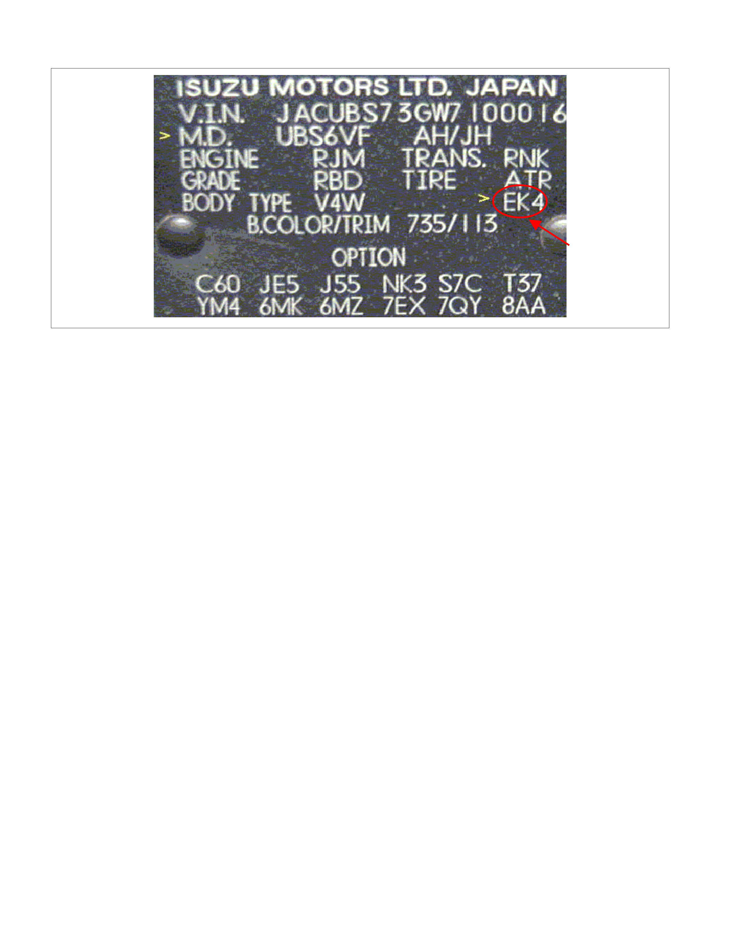
Programming the Control Unit
1. Ensure the vehicle battery is fully charged and, if
the vehicle is fitted with ABS, remove the
connectors from the ABS Control Unit
2. Connect TECH2 to the vehicle DLC,
3. Turn the ignition ON
4. Turn TECH 2 ON and press “ENTER” at the start-
up screen
5. At the main menu screen, select F1: Service
Programming System (SPS)
6. Select F1: Programming
7. While data is being transferred, “Downloading” will
be displayed on the TECH2 screen.
8. Upon completion of the data transfer, TECH2 will
display “Reprogramming Successful”
9. Press EXIT to bring programming to completion.
10. Perform “Requesting Data From The Vehicle”
Steps 1-4 and confirm the correct data has been
downloaded.
11. Press EXIT, turn TECH2 OFF and then turn the
ignition OFF.
12. Remove TECH2 from the vehicle.
NOTE:
• If the Engine Control Module (ECM) was
programmed, the Immobiliser System must be
linked to the ECM: Refer to Section 11- Engine
Immobiliser System - ECM Replaced for the
ECM/Immobiliser linking procedure
• Should TECH2 display “SPS Procedure was not
successful”, engine will not start, but no DTCs are
present, low battery voltage or poor electrical
connections should be the primary suspects.
Perform the SPS procedure again after rectifying
the fault/s.
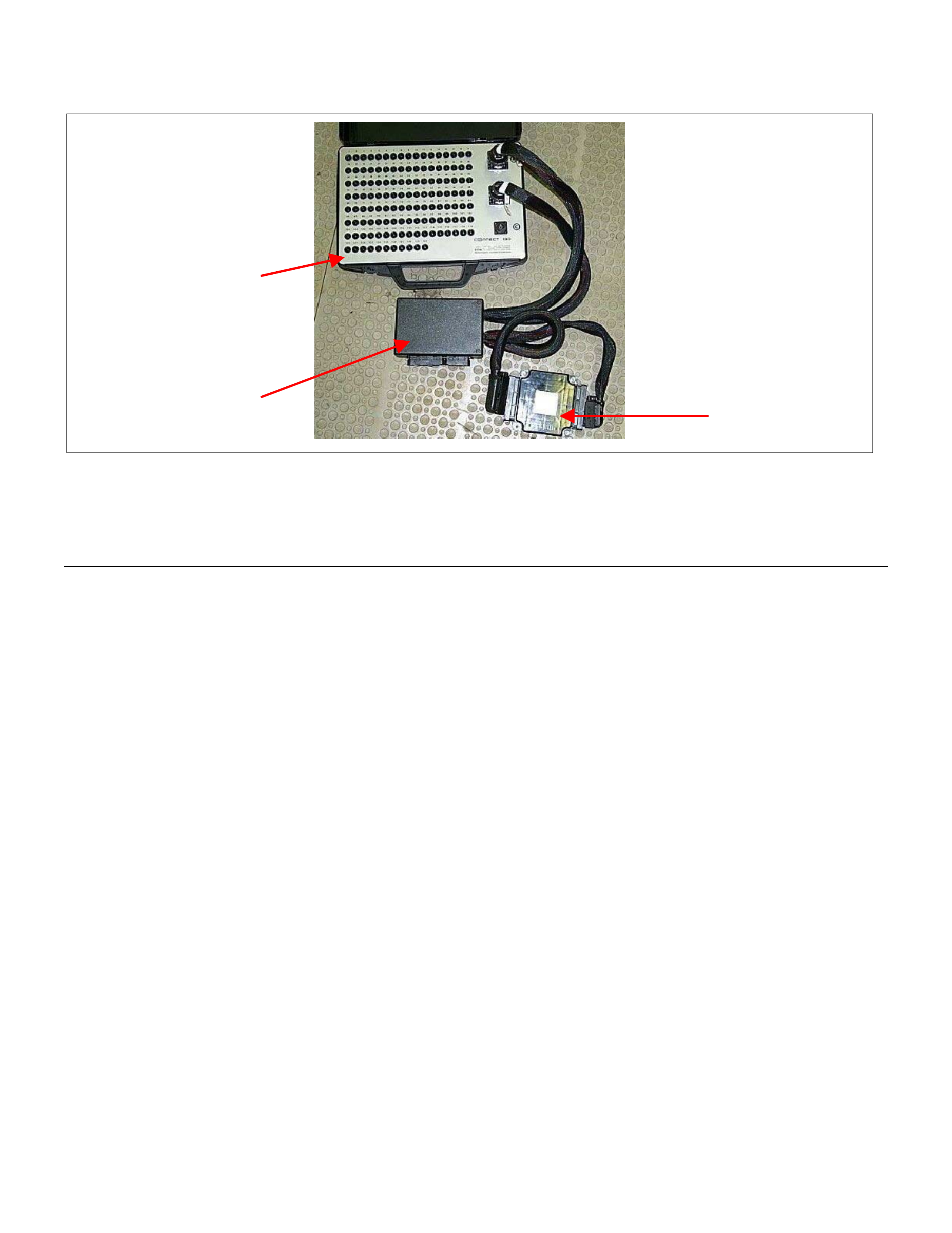
How To Use Breaker Box
3
2
1
Legend
(1) Engine Control Module (ECM)
(2) Harness Adapter
(3) Breaker Box
The engine control module (ECM) and other connectors
have water proof connector and special terminal. Water
proof terminal does not allow to use back prove. In
addition, the ECM special terminal can not let regular
digital voltage meter prove to access, because terminal
shape is very fin pin type.
In order to prevent damage of female terminal and
connector itself, the breaker box and adapter is the
most suitable special tool.
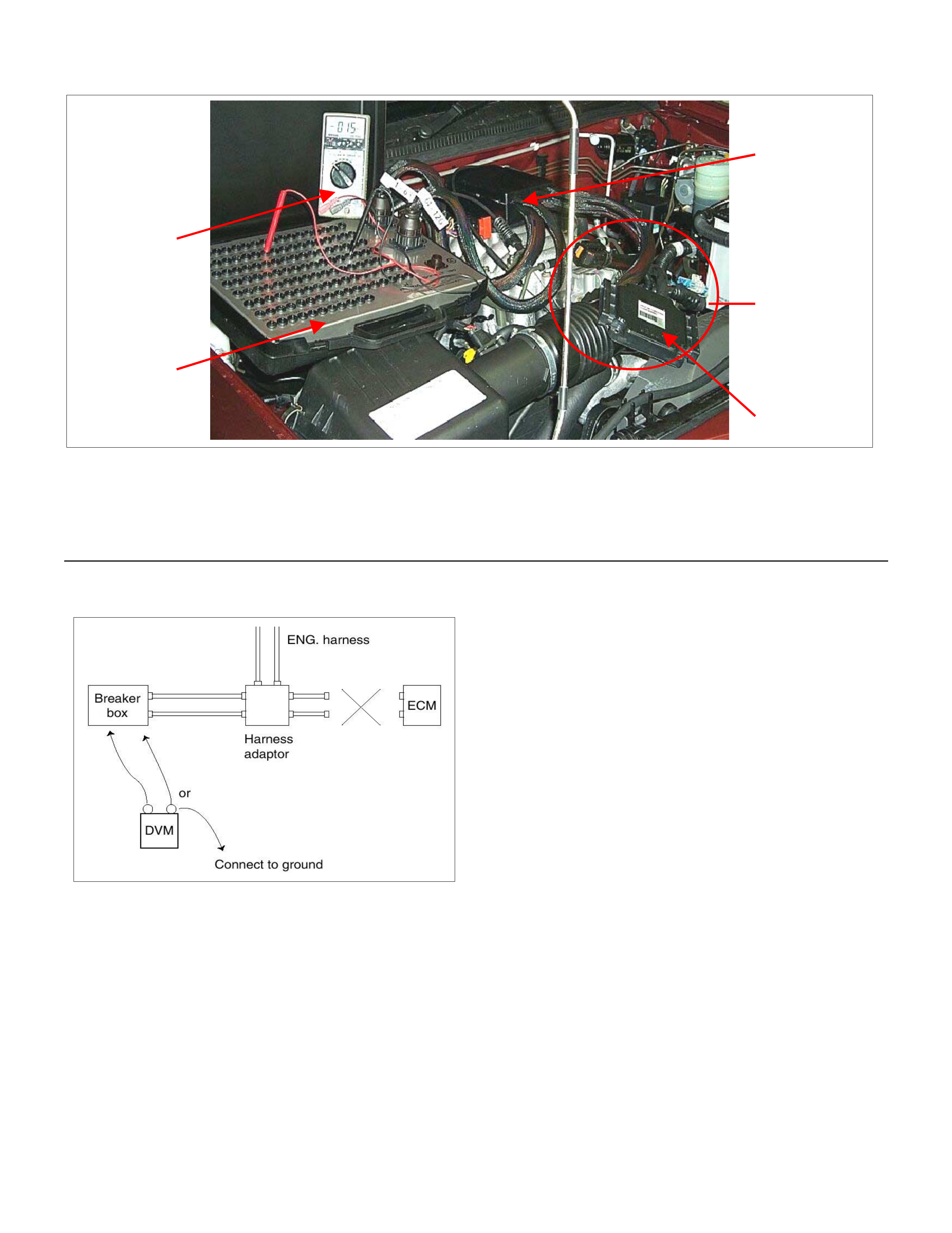
Breaker Box Connection Type A
1
5
2
3
4
Legend
(1) Engine Control Module (ECM)
(2) Harness Adapter
(3) Breaker Box
(4) Digital Voltage Meter
(5) ECM - Harness Adapter Disconnection
Breaker box connection type A, check for "open circuit"
and "short to ground circuit".
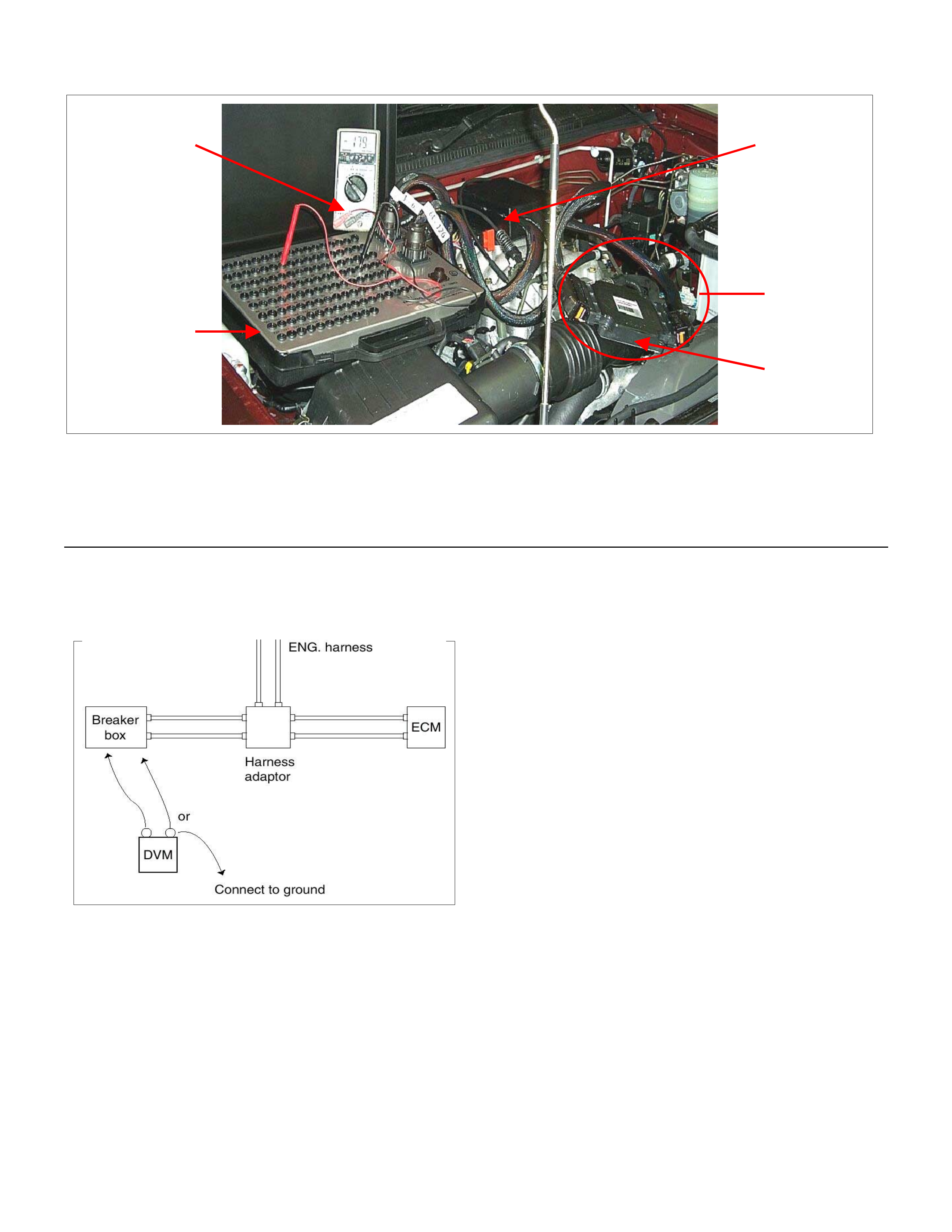
Breaker Box Connection Type B
2
5
1
4
3
Legend
(1) Engine Control Module (ECM)
(2) Harness Adapter
(3) Breaker Box
(4) Digital Voltage Meter
(5) ECM - Harness Adapter Connection
Breaker box connection type B, check for "short to
power supply circuit" and "power, signal voltage check"
between the engine control module (ECM) and
electrical components.
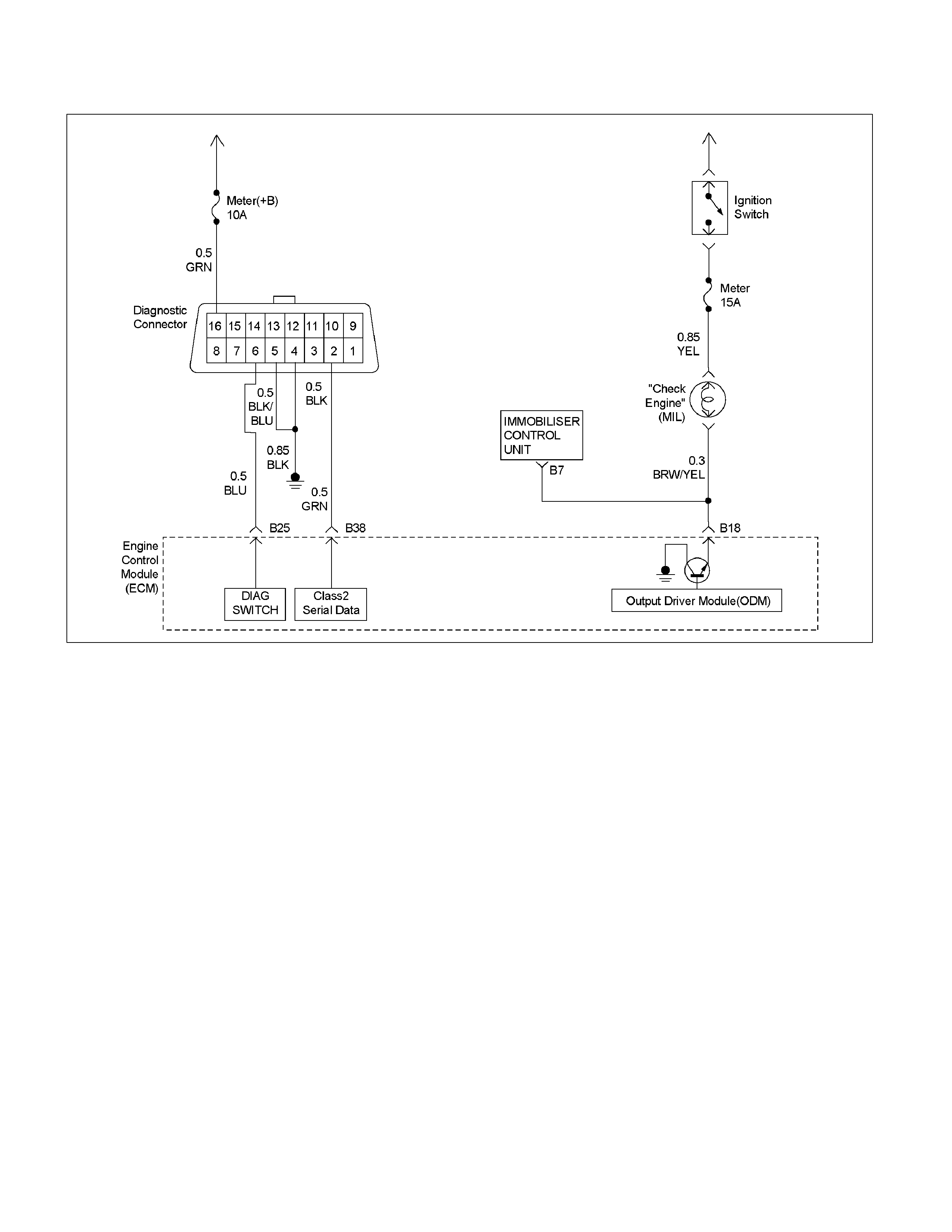
On-Board Diagnostic (OBD) System Check
RTW36EMF000301
Circuit Description
The on-board diagnostic system check is the starting
point for any driveability complaint diagnosis. Before
using this procedure, perform a careful visual/physical
check of the ECM and engine grounds for cleanliness
and tightness.
The on-board diagnostic system check is an organized
approach to identifying a problem created by an
electronic engine control system malfunction.
Diagnostic Aids
A poor connection, rubbed-through wire insulation or a
wire broken inside the insulation may cause an
intermittent. Check for poor connections or a damaged
harness. Inspect the ECM harness and connector for
improper mating, broken locks, improperly formed or
damaged terminals, poor terminal-to-wire connection,
and damaged harness.
Test Description
Number(s) below refer the step number(s) on the
Diagnostic Chart:
1. The Check Engine Lamp (MIL) should be ON
steady with the ignition "On", engine "Off". If not,
"No Check Engine Lamp (MIL)" chart should be
used to isolate the malfunction.
2. Checks the Class 2 data circuit and ensures that
the ECM is able to transmit serial data.
3. This test ensures that the ECM is capable o
f
controlling the Check Engine Lamp (MIL) and the
Check Engine Lamp (MIL) driver circuit is not
shorted to ground circuit.
4. If the engine will not start, "Engine Cranks But Will
Not Run" chart should be used to diagnose the
fault.
6. The Tech2 parameters, which are not within the
typical range, may help to isolate the area, which is
causing the problem.
12. This vehicle is equipped with ECM which utilizes
an electrically erasable programmable read onl
y
memory (EEPROM).
On-Board Diagnostic (OBD) System Check
Step Action Value (s) Yes No
1 1. Ignition "On", engine "Off".
2. Check the "CHECK ENGINE" lamp (MIL).
Does the "CHECK ENGINE" lamp turn "On"? - Go to Step 2
Go to No CHEC
K
ENGINE Lamp
2 1. Using the Tech 2, ignition "On" and engine "Off".
2. Attempt to display "Engine Data" with the Tech 2.
Does the Tech 2 display "Engine Data" and "O2
Sensor Data"? - Go to Step 3 Go to Step 7
3 1. Using the Tech 2, ignition "On" and engine "Off".
2. Select the "Miscellaneous Test" and perform the
"Malfunction Indicator Lamp" in "Lamps".
3. Operate the Tech 2 in accordance with the Tech 2
instructions.
Does the "CHECK ENGINE" lamp turn "Off"? - Go to Step 4
Go to CHECK
ENGINE LAMP
On Steady
4 Attempt to start the engine. Does the engine start and
continue to "Run"? - Go to Step 5
Go to Engine
Cranks But Will
Not Run
5 1. Using the Tech 2, ignition "On" and engine "Off".
2. Select the "Read DTC In for By Priority" in
"Diagnostic Trouble Code".
Are any DTCs stored? - Go to DTC Chart Go to Step 6
6 Compare typical scan data values displayed on the
Tech 2 "Engine Data" and "O2 Sensor Data".
Are the displayed values within the range? -
Refer to
SYMPTOM
DIAGNOSIS
Refer to
TYPICAL SCAN
DATA
7
Using the DVM and check the data link connector
power supply circuit.
1. Ignition "Off", engine "Off".
2. Check the circuit for open circuit.
Was the problem found?
V
16
B-58
-
Repair faulty
harness and
verify repair
Go to Step 8
Step Action Value (s) Yes No
8
Using the DVM and check the data link connector
ground circuit.
1. Ignition "Off", engine "Off".
2. Check the circuit for open circuit.
Was the problem found?
ĦĦ
54 B-58
-
Repair faulty
harness and
verify repair
Go to Step 9
9
Using the DVM and check the data link connector
ground circuit.
1. Ignition "On", engine "Off".
2. Check the circuit for short to power supply circuit.
Was the DVM indicated specified value?
54 B-58
VV
Less than 1V Go to Step 10
Repair faulty
harness and
verify repair
10
Using the DVM and check the data link connector
communication circuit.
1. Ignition "On", engine "Off".
2. Check the circuit for short to power supply circuit.
Was the DVM indicated battery voltage?
V
B-582
-
Repair faulty
harness and
verify repair
Go to Step 11
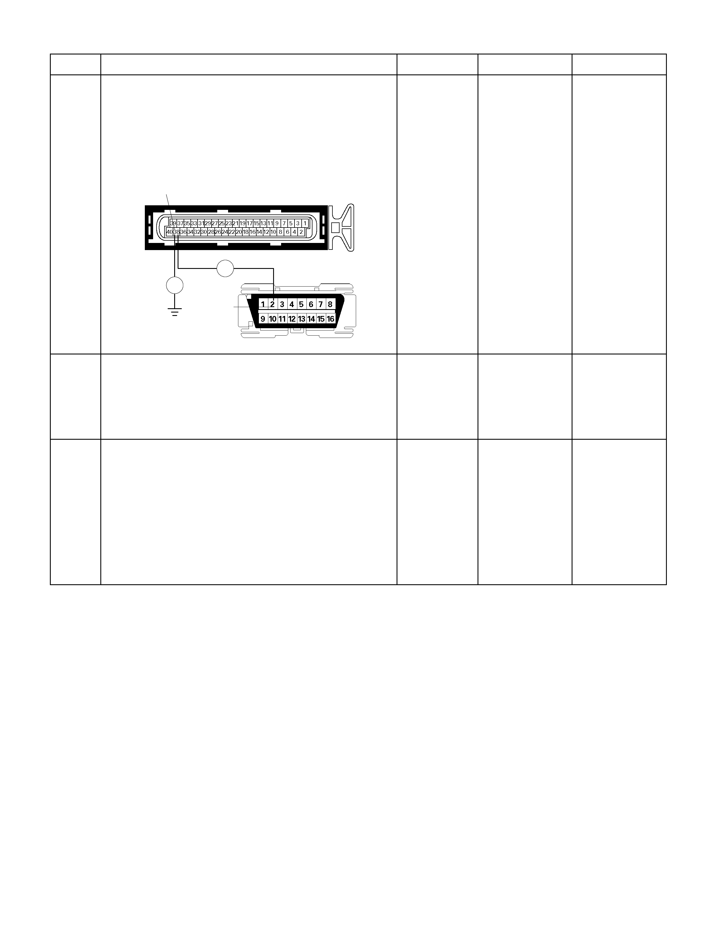
Step Action Value (s) Yes No
11
Using the DVM and check the data link connector
communication circuit.
1. Ignition "Off", engine "Off".
2. Disconnect the ECM connector.
3. Check the circuit for open or short to ground circuit.
Was the problem found?
Ħ
Ħ
38 E-61(B)
B-58
2
-
Repair faulty
harness and
verify repair
Go to Step 12
12 Is the ECM programmed with the latest software
release?
If not, download the latest software to the ECM using
the "SPS (Service Programming System)".
Was the problem solved? - Verify repair Go to step 13
13 Replace the ECM.
Is the action complete?
IMPORTANT: The replacement ECM must be
programmed. Refer to section of the Service
Programming System (SPS) in this manual. Following
ECM programming, the immobiliser system (if
equipped) must be linked to the ECM. Refer to section
11 “Immobiliser System-ECM replacement” for the
ECM/Immobiliser linking procedure. - Verify repair -
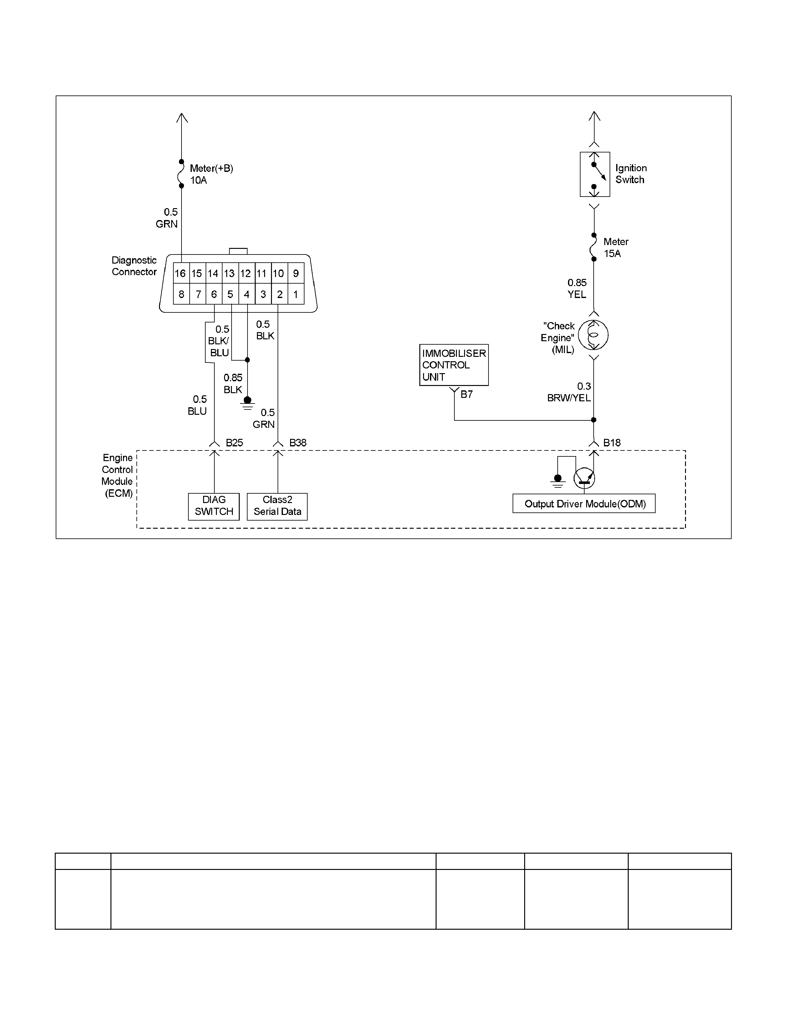
No Check Engine Lamp (MIL)
RTW36EMF000301
Circuit Description
The “Check Engine" lamp (MIL) should always be
illuminated and steady with the ignition “ON" and the
engine stopped. Ignition feed voltage is supplied to the
MIL bulb through the meter fuse. The Engine Control
Module (ECM) turns the MIL “ON" by grounding the MIL
driver circuit.
Diagnostic Aids
A poor connection, rubbed-through wire insulation, or a
wire broken inside the insulation may case an
intermittent MIL. Check for the following items:
• Inspect the ECM harness and connections for
improper mating, broken locks, improperly formed or
damaged terminals, poor terminal-to-wire connection,
and damaged harness.
• If the engine runs OK, check for a faulty light bulb, an
open in the MIL driver circuit, or an open in the
instrument cluster ignition feed.
• If the engine cranks but will not run, check for an
open ECM ignition or battery feed, or a poor ECM to
engine ground.
No Check Engine Lamp (MIL)
Step Action Value (s) Yes No
1 Check the meter fuse (15A). If the fuse is burnt out,
repair as necessary.
Was the problem found? - Verify repair Go to Step 2

Step Action Value (s) Yes No
2
Using the DVM and check the "CHECK ENGINE"
lamp circuit.
1. Ignition "Off", engine "Off".
2. Disconnect the ECM connector.
3. Ignition "On".
4. Check the circuit for open circuit.
Was the DVM indicated specified value?
V
E-61(B) 18
Battery voltage
Go to Step 5
Go to Step 3
3 Check the "CHECK ENGINE" lamp bulb. If the bulb is
burnt out, repair as necessary.
Was the problem found? - Verify repair Go to Step 4
4
Using the DVM and check the "CHECK ENGINE"
lamp circuit.
1. Ignition "Off", engine "Off".
2. Disconnect the meter connector and ECM
connector.
3. Check the circuit for open circuit.
Was the problem found?
Ħ
18
17
E-61(B)
B-24
-
Verify repair
Go to Step 5
5 Is the ECM programmed with the latest software
release?
If not, download the latest software to the ECM using
the "SPS (Service Programming System)".
Was the problem solved? - Verify repair Go to step 6
6 Replace the ECM.
Is the action complete?
IMPORTANT: The replacement ECM must be
programmed. Refer to section of the Service
Programming System (SPS) in this manual. Following
ECM programming, the immobiliser system (if
equipped) must be linked to the ECM. Refer to section
11 “Immobiliser System-ECM replacement” for the
ECM/Immobiliser linking procedure. - Verify repair -

Check Engine Lamp (MIL) “On" Steady
RTW36EMF000301
Circuit Description
The “Check Engine" lamp (MIL) should always be
illuminated and steady with ignition “ON" and the engine
stopped. Ignition feed voltage is supplied directly to the
MIL indicator. The Engine Control Module (ECM) turns
the MIL “ON" by grounding the MIL driver circuit.
The MIL should not remain “ON" with the engine
running and no DTC(s) set. A steady MIL with the
engine running and no DTC(s) suggests a short to
ground in the MIL driver circuit.
Diagnostic Aids
An intermittent may be caused by a poor connection,
rubbed–through wire insulation, or a wire broken inside
the insulation. Check for the following items:
• Poor connection or damaged harness – Inspect the
ECM harness and connectors for improper mating,
broken locks, improperly formed or damaged
terminals, poor terminal-to-wire connection, and
damaged harness.
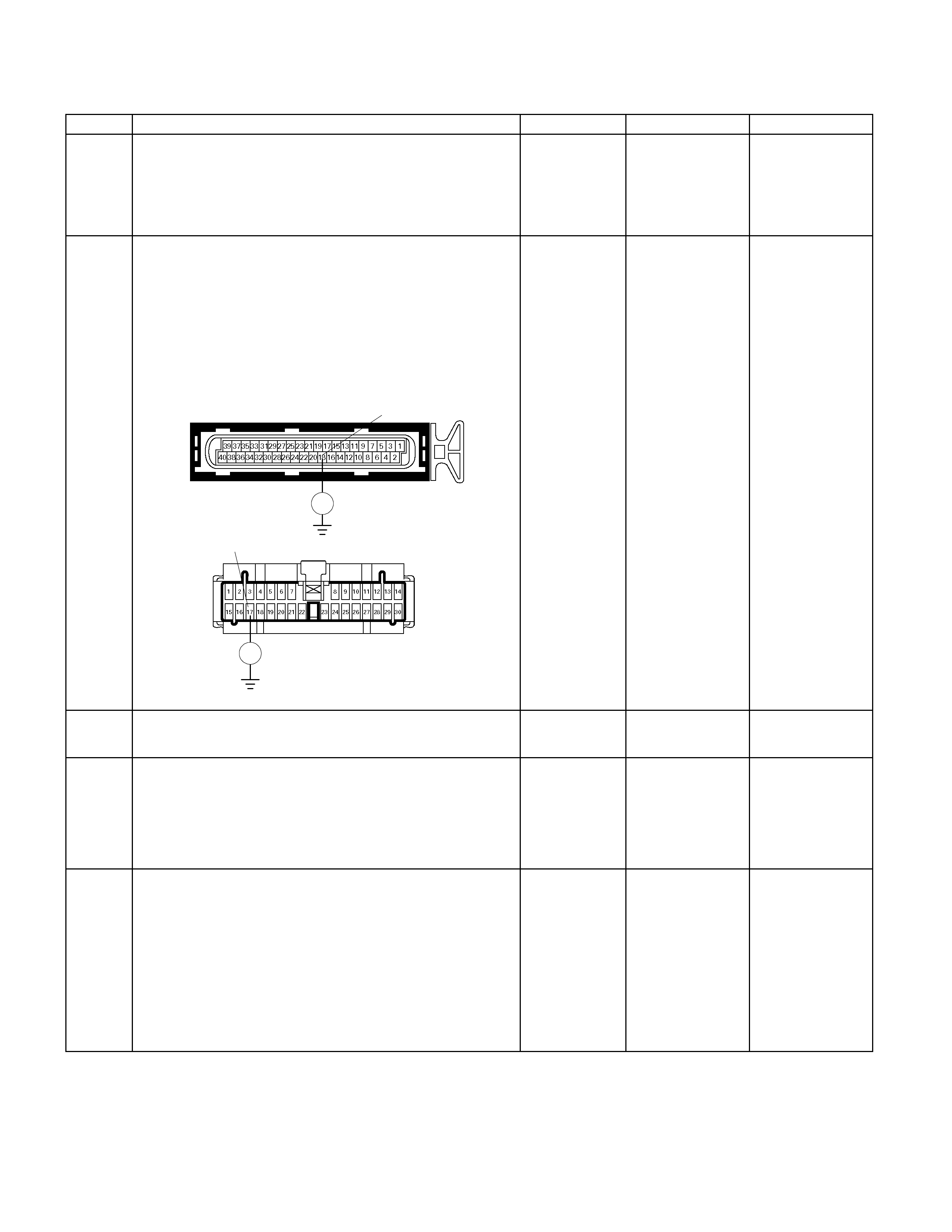
Check Engine Lamp (MIL) “ON" Steady
Step Action Value (s) Yes No
1 1. Ignition "Off", engine "Off".
2. Disconnect the ECM connector.
3. Ignition "On".
Was the "CHECK ENGINE" lamp turned on? - Go to Step 2 Go to Step 4
2 Using the DVM and check the "CHECK ENGINE"
lamp circuit.
1. Ignition "Off", engine "Off".
2. Disconnect the meter connector and ECM
connector.
3. Check the circuit for short to ground circuit.
Was the problem found?
Ħ
B-2417
Ħ
E-61(B) 18
- Verify repair Go to Step 3
3 Replace the meter assembly.
Is the action complete? - Verify repair -
4 Is the ECM programmed with the latest software
release?
If not, download the latest software to the ECM using
the "SPS (Service Programming System)".
Was the problem solved? - Verify repair Go to step 5
5 Replace the ECM.
Is the action complete?
IMPORTANT: The replacement ECM must be
programmed. Refer to section of the Service
Programming System (SPS) in this manual. Following
ECM programming, the immobiliser system (if
equipped) must be linked to the ECM. Refer to section
11 “Immobiliser System-ECM replacement” for the
ECM/Immobiliser linking procedure. - Verify repair -
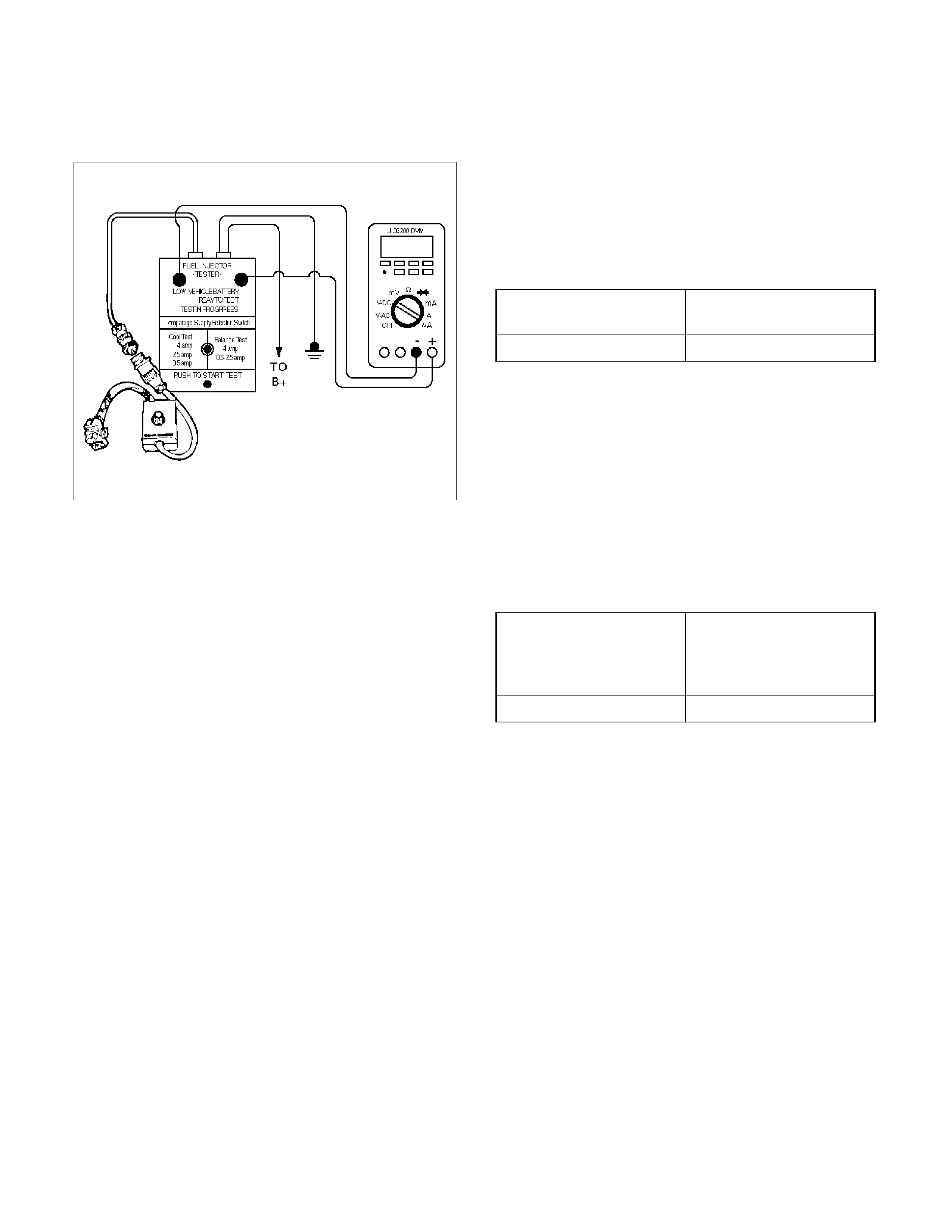
Fuel Injector Coil Test Procedure And Fuel Injector
Balance Test Procedure
Test Description
Number(s) below refer to the step number(s) on the
Diagnostic Chart:
2. Relieve the fuel pressure by connecting the 5–
8840–0378–0 Fuel Pressure Gauge to the fuel
pressure connection on the fuel rail.
CAUTION: In order to reduce the r isk of fire and
personal injury, wrap a shop towel around the fuel
pressure connection. The towel will absorb any fuel
leakage that occurs during the connection of the
fuel pressure gauge. Place the towel in an approved
container when the connection of the fuel pressure
gauge is complete.
Place the fuel pressure gauge bleed hose in an
approved gasoline container.
With the ignition switch “OFF," open the valve on
the fuel pressure gauge.
3. Record the lowest voltage displayed by the DVM
after the first second of the test. (During the first
second, voltage displayed by the DVM may be
inaccurate due to the initial current surge.)
Injector Specifications:
Resistance Ohms Voltage Specification at
10°C−35°C (50°F−95°F)
11.8 – 12.6 5.7 – 6.6
• The voltage displayed by the DVM should be within
the specified range.
• The voltage displayed by the DVM may increase
throughout the test as the fuel injector windings
warm and the resistance of the fuel injector
windings changes.
• An erratic voltage reading (large fluctuations in
voltage that do not stabilize) indicates an
intermittent connection within the fuel injector.
5. Injector Specifications:
Highest Acceptable
Voltage Reading
Above/Below 35°C/10°C
(95°F/50°F)
Acceptable Subtracted
Value
9.5 Volts 0.6 Volts
7. The Fuel Injector Balance Test portion of this chart
(Step 7 through Step 11) checks the mechanical
(fuel delivery) portion of the fuel injector. An engine
cool-down period of 10 minutes is necessary in
order to avoid irregular fuel pressure readings due
to “Hot Soak" fuel boiling.
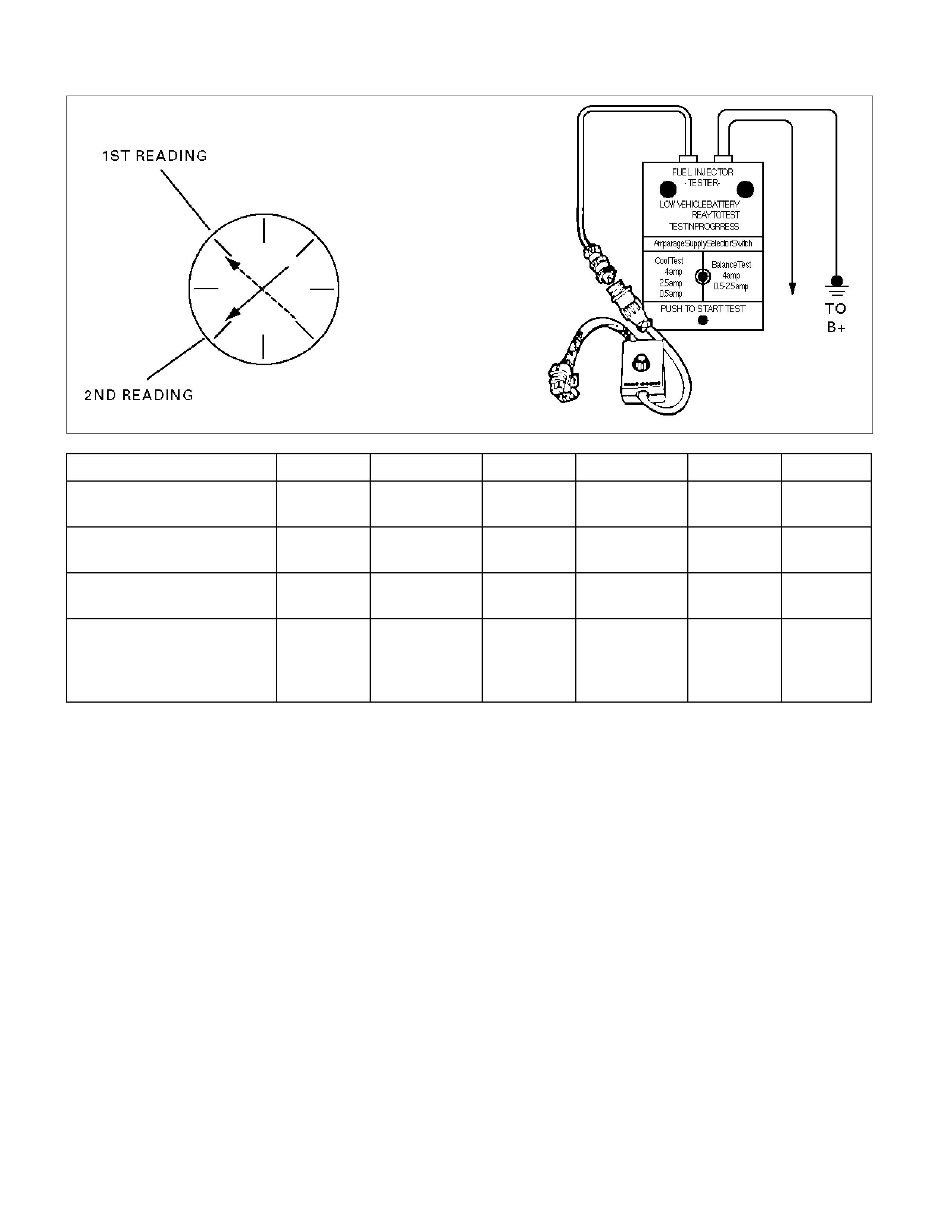
Injector Coil Test Procedure (Steps 1-6) and Injector Balance Test Procedure (Steps 7-11)
CYLINDER 1 2 3 4 5 6
1st Reading (1) 296 kPa
(43 psi)
296 kPa
(43 psi)
296 kPa
(43 psi)
296 kPa
(43 psi)
296 kPa
(43 psi)
296 kPa
(43 psi)
2nd Reading (2) 131 kPa
(19 psi)
117 kPa
(17 psi)
124 kPa
(18 psi)
145 kPa
(21 psi)
131 kPa
(19 psi)
130 kPa
(19 psi)
Amount of Drop
(1st Reading–2nd Reading)
165 kPa
(24 psi)
179 kPa
(26 psi)
172 kPa
(25 psi)
151 kPa
(22 psi)
165 kPa
(24 psi)
166 kPa
(24 psi)
Av.drop = 166 kpa/24 psi
±10 kpa/1.5 psi
= 156- 176 kPa or
22.5- 25.5 psi
OK Faulty, Rich
(Too Much
Fuel Drop)
OK Faulty, Lean
(Too Little
Fuel Drop)
OK OK
NOTE: These figures are examples only.

Injector Coil Test Procedure (Steps 1-6) and Injector Balance Test Procedure (Steps 7-11)
Step Action Value(s) YES NO
1 Was the “On-Board Diagnostic (OBD) System Check"
performed? — Go to Step 2 Go to OBD
System Check
2 1. Turn the engine “OFF."
In order to prevent flooding of a single cylinder and
possible engine damage, relieve the fuel pressure
before performing the fuel injector coil test procedure.
2. Relieve the fuel pressure. Refer to Test
Description Number 2.
3. Connect the 5–8840–2618–0 Fuel Injector Tester
to B+ and ground, and to the 5–8840–2635–0
Injector Switch Box.
4. Connect the injector switch box to the gray fuel
injector harness connector located at the rear of
the air cleaner assembly.
5. Set the amperage supply selector switch on the
fuel injector tester to the “Coil Test" 0.5 amp
position.
6. Connect the leads from the Digital Voltmeter
(DVM) to the injector tester. Refer to the
illustrations associated with the test description.
7. Set the DVM to the tenths scale (0.0).
8. Observe the engine coolant temperature.
Is the engine coolant temperature within the specified
values? 10°C (50°F) to
35°C (95°F) Go to Step 3 Go to Step 5
3 1. Set injector switch box injector #1.
2. Press the “Push to Start Test" button on the fuel
injector tester.
3. Observe the voltage reading on the DVM.
Important: The voltage reading may rise during the
test.
4. Record the lowest voltage observed after the first
second of the test.
5. Set the injector switch box to the next injector and
repeat steps 2, 3, and 4.
Did any fuel injector have an erratic voltage reading
(large fluctuations in voltage that did not stabilize) or a
voltage reading outside of the specified values? 5.7-6.6 V Go to Step 4 Go to Step 7
4 Replace the faulty fuel injector(s). Refer to Fuel
Injector.
Is the action complete? — Go to Step 7 —

Step Action Value(s) YES NO
5 1. Set injector switch box injector #1.
2. Press the “Push to Start Test" button on the fuel
injector tester.
3. Observe the voltage reading on the DVM.
Important: The voltage reading may rise during the
test.
4. Record the lowest voltage observed after the first
second of the test.
5. Set the injector switch box to the next injector and
repeat steps 2, 3, and 4.
Did any fuel injector have an erratic voltage reading
(large fluctuations in voltage that did not stabilize) or a
voltage reading above the specified value? 9.5 V Go to Step 4 Go to Step 6
6 1. Identify the highest voltage reading recorded (other
than those above 9.5 V).
2. Subtract the voltage reading of each injector from
the highest voltage selected in step 1. Repeat until
you have a subtracted value for each injector.
For any injector, is the subtracted Value in step 2
greater than the specified value? 0.6 V Go to Step 4 Go to Step 7
7 CAUTION: In order to reduce the risk of fire and
personal injury, wrap a shop towel around the fuel
pressure connection. The towel will absorb any
fuel leakage that occurs during the connection of
the fuel pressure gauge. Place the towel in an
approved container when the connection of the
fuel pressure gauge is complete.
1. Connect the 5–8840–0378–0 Fuel Pressure Gauge
to the fuel pressure test port.
2. Energize the fuel pump using the Tech 2.
3. Place the bleed hose of the fuel pressure gauge
into an approved gasoline container.
4. Bleed the air out of the fuel pressure gauge.
5. With the fuel pump running, observe the reading
on the fuel pressure gauge.
Is the fuel pressure within the specified values?
296 kpa-376
kpa
(43-55 psi) Go to Step 8
Go to Fuel
System
Diagnosis
8 Turn the fuel pump “OFF."
Does the fuel pressure remain constant? — Go to Step 9
Go to Fuel
System
Diagnosis

Step Action Value(s) YES NO
9 1. Connect the 5–8840–2618–0 Fuel Injector Tester
and 5–8840–2635–0 Injector Switch Box the fuel
injector harness connector.
2. Set the amperage supply selector switch on the
fuel injector tester to the “Balance Test" 0.5-2.5
amp position.
3. Using the Tech 2 turn the fuel pump “ON" then
“OFF" in order to pressurize the fuel system.
4. Record the fuel pressure indicated by the fuel
pressure gauge after the fuel pressure stabilizes.
This is the first pressure reading.
5. Energize the fuel injector by depressing the “Push
to Start Test" button on the fuel injector tester.
6. Record the fuel pressure indicated by the fuel
pressure gauge after the fuel pressure gauge
needle has stopped moving. This is the second
pressure reading.
7. Repeat steps 1 through 6 for each fuel injector.
8. Subtract the second pressure reading from the first
pressure reading for one fuel injector. The result
is the pressure drop value.
9. Obtain a pressure drop value for each fuel injector.
10. Add all of the individual pressure drop values.
This is the total pressure drop.
11. Divide the total pressure drop by the number of
fuel injectors. This is the average pressure drop.
Does any fuel injector have a pressure drop value that
is either higher than the average pressure drop or
lower than the average pressure drop by the specified
value? 10 kpa
(1.5 psi) Go to Step 10 Go to OBD
System Check
10 Re-test any fuel injector that does not meet the
specification. Refer to the procedure in step 11.
Do not repeat any portion of this test before running
the engine in order to prevent the engine from
flooding.
Does any fuel injector still have a pressure drop value
that is either higher than the average pressure drop or
lower than the average pressure drop by the specified
value? 10 kpa
(1.5 psi) Go to Step 11 Go to
Symptoms
11 Replace the faulty fuel injector(s). Refer to Fuel
Injector.
Is the action complete? — Verify repair —
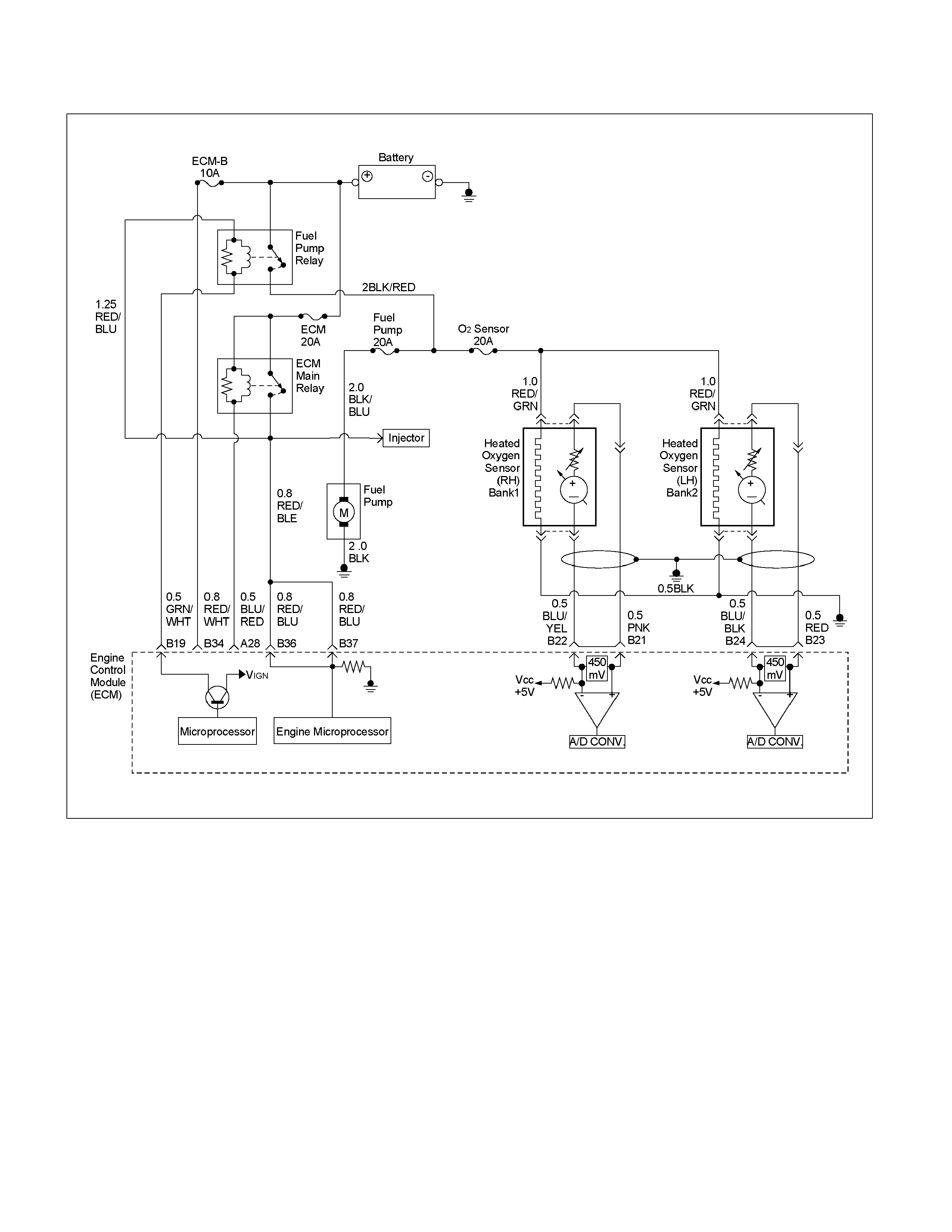
Fuel System Electrical Test
RTW36ELF000101
Circuit Description
When the ignition switch is first turned “ON," the Engine
Control Module (ECM) energizes the fuel pump relay
which applies power to the in-tank fuel pump. The fuel
pump relay will remain “ON" as long as the engine is
running or cranking and the ECM is receiving 58X
crankshaft position pulses. If no 58X crankshaft position
pulses are present, the ECM de-energizes the fuel
pump relay within 2 seconds after the ignition is turned
“ON" or the engine is stopped.
The fuel pump delivers fuel to the fuel rail and injectors,
then to the fuel pressure regulator. The fuel pressure
regulator controls fuel pressure by allowing excess fuel
to be returned to the fuel tank. With the engine stopped
and ignition “ON," the fuel pump can be turned “ON" by
using a command by the Tech 2.
Diagnostic Aids
An intermittent may be caused by a poor connection,
rubbed-through wire insulation, or a wire broken inside
the insulation. Check for the following items:
• Poor connection or damaged harness – Inspect the
ECM harness and connectors for improper mating,
broken locks, improperly formed or damaged
terminals, poor terminal-to-wire connection, and
damaged harness.
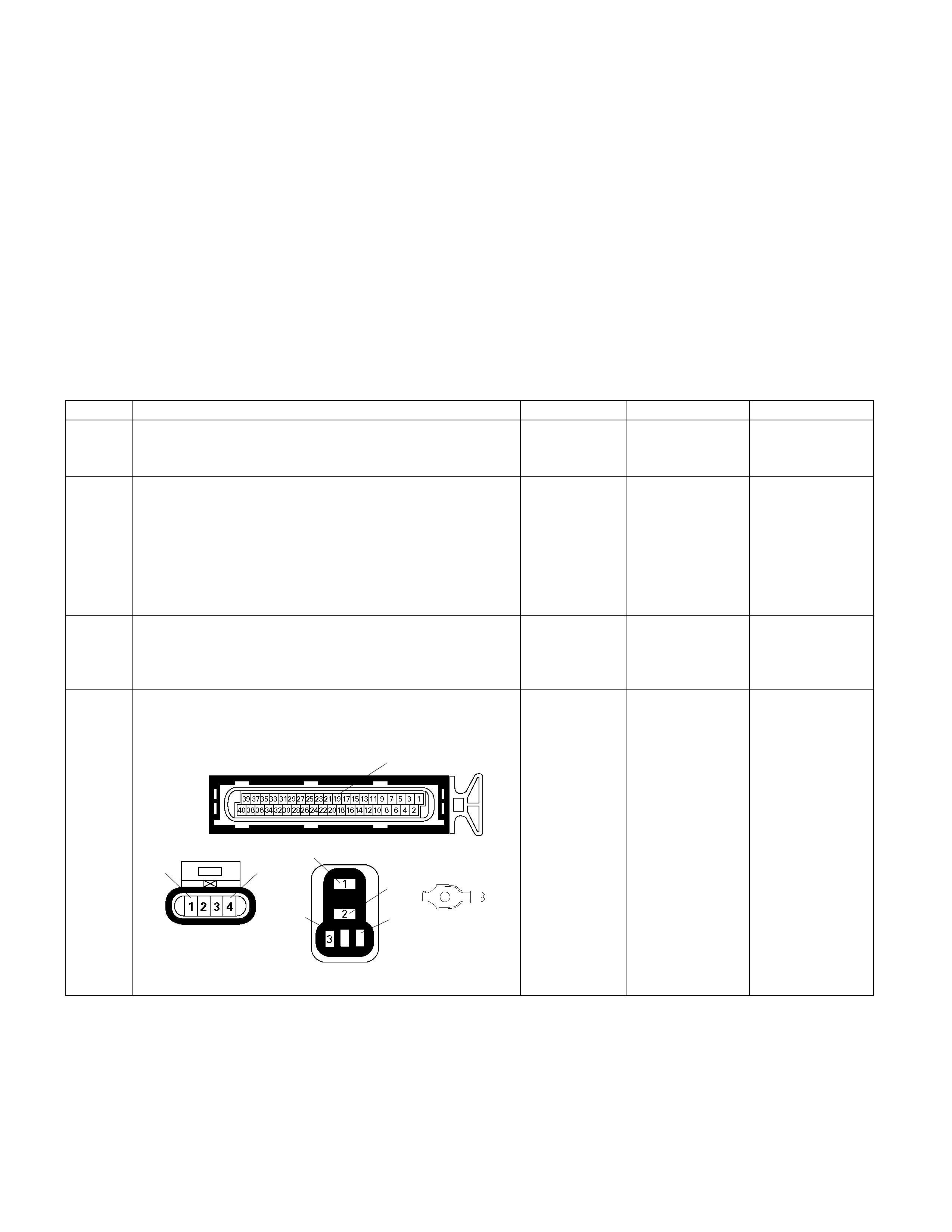
CAUTION: To reduce the risk of fire and personal
injury:
• It is necessary to relieve fuel system pressure
before connecting a fuel pressure gauge. Refer to
Fuel Pressure Relief Procedure, below.
• A small amount of fuel may be released when
disconnecting the fuel lines. Cover fuel line
fittings with a shop towel before disconnecting,
to catch any fuel that may leak out. Place the
towel in an approved container when the
disconnect is completed.
Fuel Pressure Relief Procedure
1. Remove the fuel cap.
2. Remove the fuel pump relay from the underhood
relay center.
3. Start the engine and allow it to stall.
4. Crank the engine for an additional 3 seconds.
Fuel Gauge Installation
1. Remove the fuel pressure fitting cap.
2. Install fuel gauge 5-8840-0378-0 to the fuel feed line
located in front of and above the right side valve
cover.
3. Reinstall the fuel pump relay.
Fuel System Electrical Test
Step Action Value (s) Yes No
1 Was the "On-Board Diagnostic (OBD) System Check"
performed? - Go to Step 2
Go to On Board
Diagnostic (OBD)
System Check
2 1. Using the Tech 2, ignition "On" and engine "On".
2. Select the "Miscellaneous Test" and perform the
"Fuel Pump Relay" in the "Relays".
3. Operate the Tech 2 in accordance with procedure.
Was the fuel pump operated, when the Tech 2 is
operated? - Test completed Go to Step 3
3 Check the "Fuel Pump" fuse (20A). If the fuse is burnt
out, repair as necessary.
Was the problem found? - Verify repair Go to Step 4
4 Check for poor/faulty connection at the fuel pump, fuel
pump relay or ECM connector. If a poor/faulty
connection is found, repair as necessary.
E-61(B)
X-2
4
F-2 C-109
19
1 4
4
1
3
2
Was the problem found? - Verify repair Go to Step 5
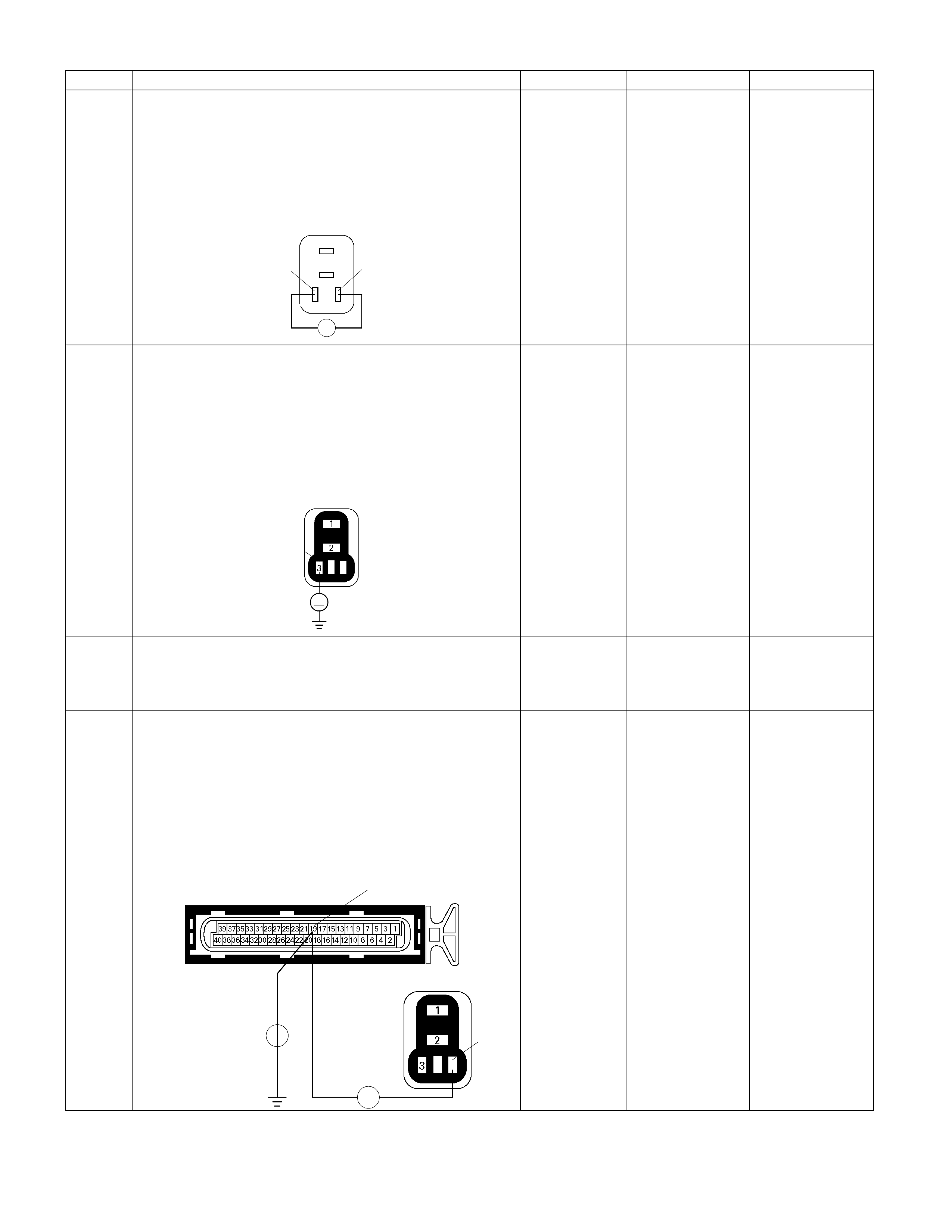
Step Action Value (s) Yes No
5 Using the DVM and check the fuel pump relay.
1. Ignition "Off", engine "Off".
2. Remove the fuel pump relay from the relay box.
3. Check the relay coil.
Was the DVM indicated specified value?
X-2
4
1
3
2
4
Ħ
3
4
Continuity Go to Step 6
Replace fuel
pump relay and
verify repair
6 Using the DVM and check the fuel pump relay power
supply circuit.
1. Ignition "On", engine "Off".
2. Remove the fuel pump relay from the relay box.
3. Check the circuit for open or short to ground circuit.
Was the DVM indicated specified value?
X-2
4
V
3
Battery voltage Go to Step 8 Go to Step 7
7 Repair the open or short to ground circuit between the
"ECM" fuse (15A) and fuel pump relay.
Is the action complete? - Verify repair -
8 Using the DVM and check the fuel pump relay ground
circuit.
1. Ignition "Off", engine "Off".
2. Disconnect the ECM connector.
3. Remove the fuel pump relay from the relay box.
4. Check the circuit for open or short to ground circuit.
Was the problem found?
E-61(B)
X-2
4
Ħ
Ħ
4
19
-
Repair faulty
harness and
verify repair Go to Step 9
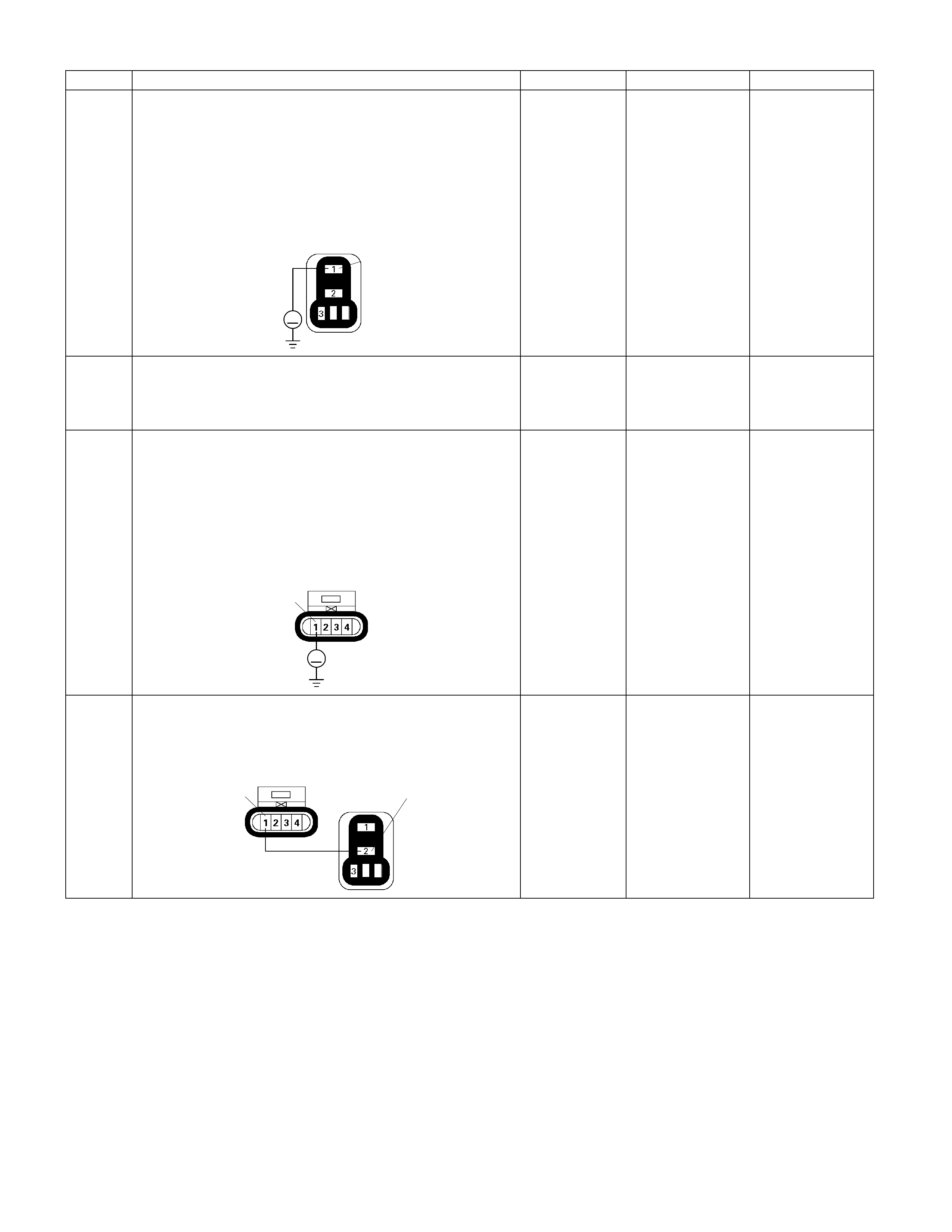
Step Action Value (s) Yes No
9 Using the DVM and check the fuel pump relay power
supply circuit.
1. Ignition "Off", engine "Off".
2. Remove the fuel pump relay from the relay box.
3. Check the circuit for open circuit.
Was the DVM indicated specified value?
X-2
4
V
1
Battery voltage Go to Step 11 Go to Step 10
10 Repair the open circuit between the fuel pump relay
and battery.
Is the action complete? - Verify repair -
11 Using the DVM and check the fuel pump power supply
circuit.
1. Ignition "On", engine "Off".
2. Disconnect the fuel pump connector.
3. Check the circuit for open or short to ground circuit.
Was the DVM indicated specified value?
F-2
1
V
Battery voltage Go to Step 13 Go to Step 12
12 Repair the open or short to ground circuit between the
fuel pump relay and fuel pump.
Is the action complete?
F-2
X-2
4
2
1
- Verify repair -
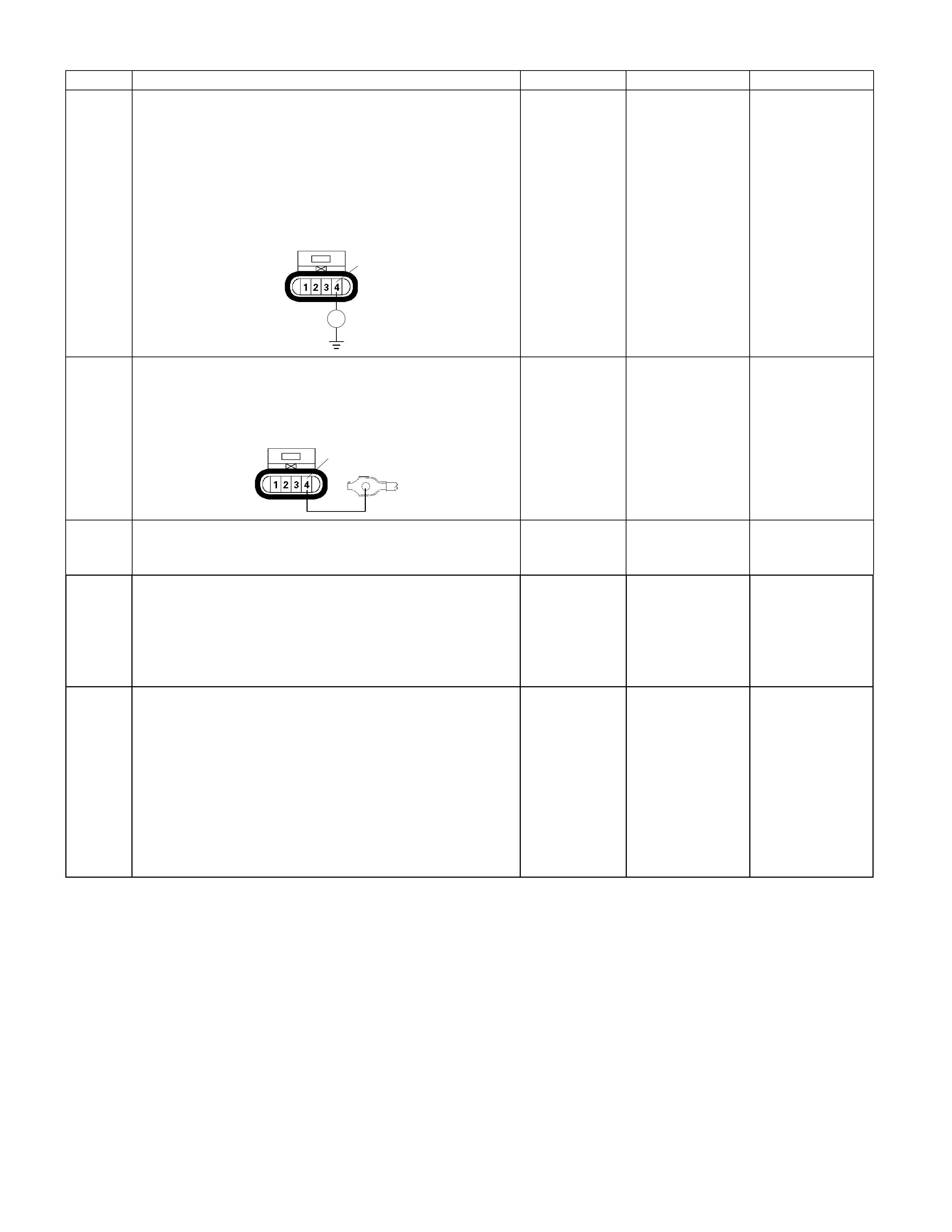
Step Action Value (s) Yes No
13 Using the DVM and check the fuel pump ground
circuit.
1. Ignition "Off", engine "Off".
2. Disconnect the fuel pump connector.
3. Check the circuit for open circuit.
Was the DVM indicated specified value?
F-2
Ħ
4
Continuity Go to Step 15 Go to Step 14
14 Repair the open circuit between the fuel pump and
body ground.
Is the action complete?
F-2
C-109
4
- Verify repair -
15 Replace the fuel pump.
Was the problem solved? - Verify repair Go to Step 16
16 Is the ECM programmed with the latest software
release?
If not, download the latest software to the ECM using
the "SPS (Service Programming System)".
Was the problem solved? - Verify repair Go to step 17
17 Replace the ECM.
Is the action complete?
IMPORTANT: The replacement ECM must be
programmed. Refer to section of the Service
Programming System (SPS) in this manual. Following
ECM programming, the immobiliser system (if
equipped) must be linked to the ECM. Refer to section
11 “Immobiliser System-ECM replacement” for the
ECM/Immobiliser linking procedure. - Verify repair -
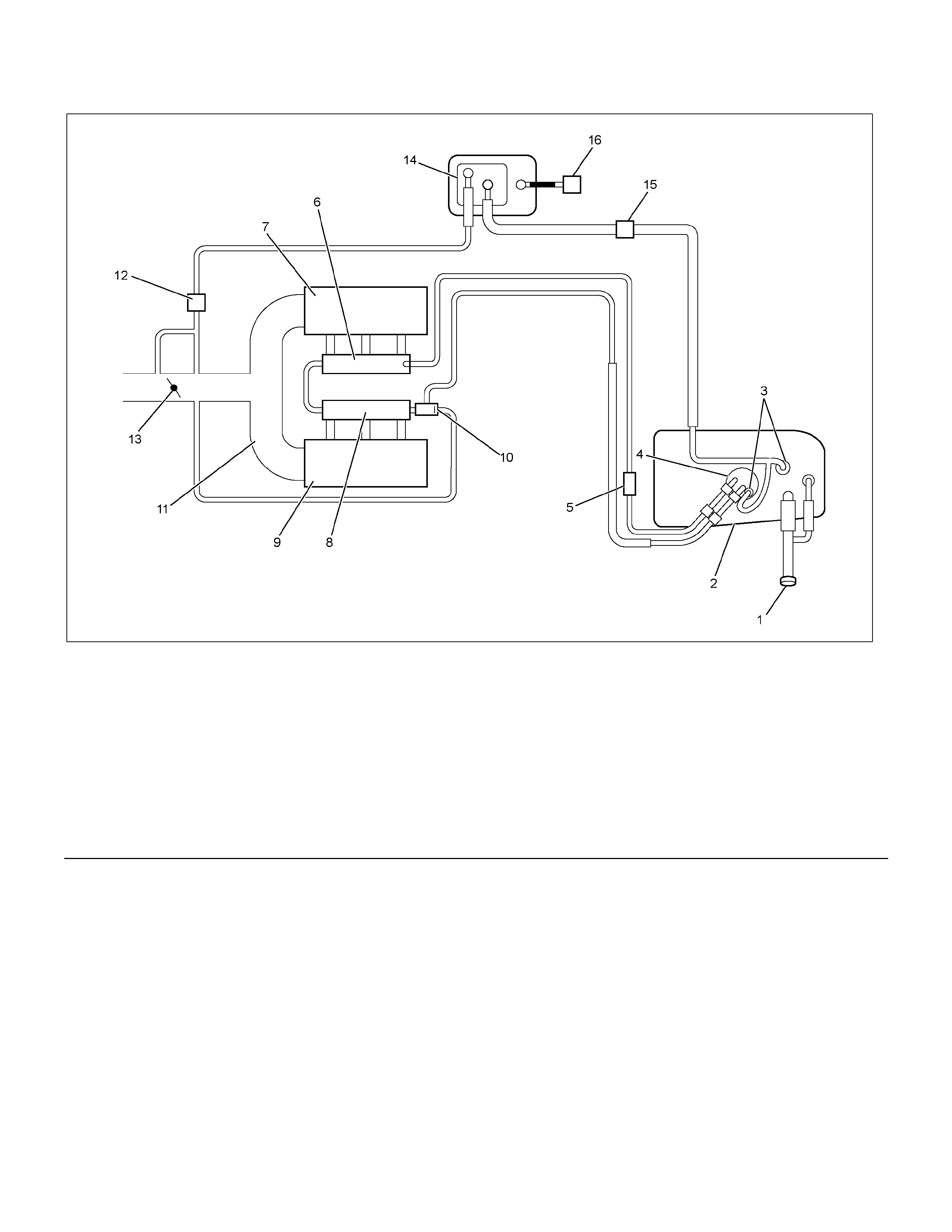
Fuel System Diagnosis
RTW36ELF000501
Legend
(1) Fuel Filler Cap
(2) Fuel Tank
(3) Rollove r Valve
(4) Fuel Pump Assembly
(5) Fuel Filter
(6) Fuel Rail Right
(7) Intake Air P ort Right Bank
(8) Fuel Rail Left
(9) Intake Air Port Left Bank
(10) Fuel Pressure Control Valve
(11) Common Chamber
(12) Duty Solenoid Valve
(13) Throttle Valve
(14) Canister
(15) Check Valve
(16) Air Separator

Circuit Description
When the ignition switch is turned “ON," the Engine
Control Module (ECM) will turn “ON" the in-tank fuel
pump. The in-tank fuel pump will remain “ON" as long
as the engine is cranking or running and the ECM is
receiving 58X crankshaft position pulses. If there are no
58X crankshaft position pulses, the ECM will turn the
in-tank fuel pump “OFF" 2 seconds after the ignition
switch is turned “ON" or 2 seconds after the engine
stops running.
The in-tank fuel pump is an electric pump within an
integral reservoir. The in-tank fuel pump supplies fuel
through an in-line fuel filter to the fuel rail assembly. The
fuel pump is designed to provide fuel at a pressure
above the pressure needed by the fuel injectors. A fuel
pressure regulator, attached to the fuel rail, keeps the
fuel available to the fuel injectors at a regulated
pressure. Unused fuel is returned to the fuel tank by a
separate fuel return line.
Test Description
Number(s) below refer to the step number(s) on the
Diagnostic Chart.
2. Connect the fuel pressure gauge to the fuel feed line
as shown in the fuel system illustration. Wrap a shop
towel around the fuel pressure connection in order to
absorb any fuel leakage that may occur when
installing the fuel pressure gauge. With the ignition
switch “ON" and the fuel pump running, the fuel
pressure indicated by the fuel pressure gauge
should be 333-376 kpa (3.4-3.8 kg/cm2 / 48-55 psi).
This pressure is controlled by the amount of
pressure the spring inside the fuel pressure regulator
can provide.
3. A fuel system that cannot maintain a constant fuel
pressure has a leak in one or more of the following
areas:
• The fuel pump check valve.
• The fuel pump flex line.
• The valve or valve seat within the fuel pressure
regulator.
• The fuel injector(s).
4. Fuel pressure that drops off during acceleration,
cruise, or hard cornering may case a lean condition.
A lean condition can cause a loss of power, surging,
or misfire. A lean condition can be diagnosed using
a Tech 1 Tech 2. If an extremely lean condition
occurs, the oxygen sensor(s) will stop toggling. The
oxygen sensor output voltage(s) will drop below 500
mV. Also, the fuel injector pulse width will increase.
Important: Make sure the fuel system is not operating
in the “Fuel Cut-Off Mode."
When the engine is at idle, the manifold pressure is
low (high vacuum). This low pressure (high vacuum)
is applied to the fuel pressure regulator diaphragm.
The low pressure (high vacuum) will offset the
pressure being applied to the fuel pressure regulator
diaphragm by the spring inside the fuel pressure
regulator. When this happens, the result is lower fuel
pressure. The fuel pressure at idle will vary slightly
as the barometric pressure changes, but the fuel
pressure at idle should always be less than the fuel
pressure noted in step 2 with the engine “OFF."
16.Check the spark plug associated with a particular
fuel injector for fouling or saturation in order to
determine if that particular fuel injector is leaking. If
checking the spark plug associated with a particular
fuel injector for fouling or saturation does not
determine that a particular fuel injector is leaking,
use the following procedure:
• Remove the fuel rail, but leave the fuel lines and
injectors connected to the fuel rail. Refer to Fuel
Rail Assembly in On-Vehicle Service.
• Lift the fuel rail just enough to leave the fuel
injector nozzles in the fuel injector ports.
CAUTION: In order to reduce the risk of fire and
personal injury that may result from fuel spraying
on the engine, verify that the fuel rail is positioned
over the fuel injector ports and verify that the fuel
injector retaining clips are intact.
• Pressurize the fuel system by connecting a 10
amp fused jumper between B+ and the fuel pump
relay connector.
• Visually and physically inspect the fuel injector
nozzles for leaks.
17. A rich condition may result from the fuel pressure
being above 376 kpa (55 psi). A rich condition may
cause a DTC P0132 or a DTC P0172 to set.
Driveability conditions associated with rich conditions
can include hard starting (followed by black smoke)
and a strong sulfur smell in the exhaust.
20.This test determines if the high fuel pressure is due
to a restricted fuel return line or if the high fuel
pressure is due to a faulty fuel pressure regulator.
21.A lean condition may result from fuel pressure below
333 kpa (48 psi). A lean condition may cause a DTC
P0131 or a DTC P0171 to set. Driveability conditions
associated with lean conditions can include hard
starting (when the engine is cold ), hesitation, poor
driveability, lack of power, surging , and misfiring.

22.Restricting the fuel return line causes the fuel
pressure to rise above the regulated fuel pressure.
Command the fuel pump “ON" with the Tech 2. The
fuel pressure should rise above 376 kpa (55 psi) as
the fuel return line becomes partially closed.
NOTE: Do not allow the fuel pressure to exceed 414
kpa (60 psi). Fuel pressure in excess of 414 kpa (60
psi) may damage the fuel pressure regulator.
CAUTION: To reduce the risk of fire and personal
injury:
• It is necessary to relieve fuel system pressure
before connecting a fuel pressure gauge. Refer to
Fuel Pressure Relief Procedure, below.
• A small amount of fuel may be released when
disconnecting the fuel lines. Cover fuel line
fittings with a shop towel before disconnecting,
to catch any fuel that may leak out. Place the
towel in an approved container when the
disconnect is completed.
Fuel Pressure Relief Procedure
1. Remove the fuel cap.
2. Remove the fuel pump relay from the underhood
relay center.
3. Start the engine and allow it to stall.
4. Crank the engine for an additional 3 seconds.
Fuel Gauge Installation
1. Remove the fuel pressure fitting cap.
2. Install fuel gauge 5-8840-0378-0 to the fuel supply
line located in front of and above the right side valve
cover.
3. Reinstall the fuel pump relay.

Fuel System Diagnosis
Step Action Value(s) YES NO
1 Was the “On-Board Diagnostic (OBD) System Check"
performed? — Go to
Step 2 Go to OBD
System Check
2 1. Turn the ignition “OFF."
2. Turn the air conditioning system “OFF."
3. Relieve fuel system pressure and install the fuel
pressure gauge.
Refer to 6E-114 FUEL GAUGE INSTALLATION
4. Turn the ignition “ON."
NOTE: The fuel pump will run for approximately 2
seconds. Use the Tech 2 to command the fuel
pump “ON".
5. Observe the fuel pressure indicated by the fuel
pressure gauge with the fuel pump running.
Is the fuel pressure within the specified limits? 290-376 kpa
(42-55 psi) Go to Step 3 Go to Step 17
3 The fuel pressure will drop when the fuel pump stops
running, then it should stabilize and remain constant.
Does the fuel pressure indicated by the fuel pressure
gauge remain constant? — Go to Step 4 Go to Step 12
4 1. When the vehicle is at normal operation
temperature, turn the ignition “ON" to build fuel
pressure and observe the measurement on the
gauge.
2. Start the engine and observe the fuel pressure
gauge.
Did the reading drop by the amount specified after the
engine was started? 21-105 kpa
(3-15 psi) Go to Step 5 Go to Step 9
5 Is fuel pressure dropping off during acceleration,
cruise, or hard cornering? — Go to Step 6 Check for
improper fuel
6 Visually and physically inspect the following items for
a restriction:
• The in-line fuel filter.
• The fuel feed line.
Was a restriction found? — Verify repair Go to Step 7
7 Remove the fuel tank and visually and physically
inspect the following items:
• The fuel pump strainer for a restriction.
• The fuel line for a leak.
• Verify that the correct fuel pump is in the vehicle.
Was a problem found in any of these areas? — Verify repair Go to Step 8
8 Replace the fuel pump.
Is the action complete? — Verify repair —

Step Action Value(s) YES NO
9 1. Disconnect the vacuum hose from the fuel
pressure regulator.
2. With the engine idling, apply 12-14 inches of
vacuum to the fuel pressure regulator.
Does the fuel pressure indicated by the fuel pressure
gauge drop by the amount specified? 21-105 kpa
(3-15 psi) Go to Step 10 Go to Step 11
10 Locate and repair the loss of vacuum to the fuel
pressure regulator.
Is the action complete? — Verify repair —
11 Replace the fuel pressure regulator.
Is the action complete? — Verify repair —
12 1. Run the fuel pump with the Tech 2.
2. After pressure has built up, turn off the pump and
clamp the supply hose shut with suitable locking
pliers.
Does the fuel pressure indicated by the fuel pressure
gauge remain constant? — Go to Step 13 Go to Step 15
13 Visually inspect the fuel supply line and repair any
leaks.
Was a problem found? — Verify repair Go to Step 14
14 Remove the fuel tank and inspect for leaky hose or
in-tank fuel line.
Was a problem found? — Verify repair Go to Step 8
15 1. If the pliers are still clamped to the fuel supply
hose, remove the locking pliers.
2. With suitable locking pliers, clamp the fuel return
line to prevent fuel from returning to the fuel tank.
3. Run the fuel pump with the Tech 2.
4. After pressure has built up, remove power to the
pump.
Does the fuel pressure indicated by the fuel pressure
gauge remain constant? — Go to Step 11 Go to Step 16
16 Locate and replace any leaking fuel injector(s).
Is the action complete? — Verify repair —
17 Is the fuel pressure indicated by the fuel pressure
gauge above the specified limit? 376 kpa (55
psi) Go to
Step 18 Go to Step 21

Step Action Value(s) YES NO
18 1. Relieve the fuel pressure. Refer to the Fuel
Pressure Relief.
2. Disconnect the fuel return line from the fuel rail.
3. Attach a length of flexible hose to the fuel rail
return outlet passage.
4. Place the open end of the flexible hose into an
approved gasoline container.
5. Run the fuel pump with the Tech 2.
6. Observe the fuel pressure indicated by the fuel
pressure gauge with the fuel pump running.
Is the fuel pressure within the specified limits? 290-376 kpa
(42-55 psi) Go to Step 19 Go to Step 20
19 Locate and correct the restriction in the fuel return
line.
Is the action complete? — Verify repair —
20 Visually and physically inspect the fuel rail outlet
passages for a restriction.
Was a restriction found? — Verify repair Go to Step 11
21 Is the fuel pressure indicated by the fuel pressure
gauge above the specified value? 0 kpa (0 psi) Go to Step 22 Go to Step 23
22 1. Command the fuel pump “ON" with the Tech 2.
2. Using suitable pliers which will not damage the fuel
hose, gradually apply pressure with the pliers to
pinch the flexible fuel return hose closed.
CAUTION: Do not let the fuel pressure exceed the
second specified value.
Does the fuel pressure indicated by the fuel pressure
gauge rise above the first specified value?
376 kpa (55
psi). 414 kpa
(60 psi). Go to Step 11 Go to Step 7
23 1. Command the fuel pump “ON" with the Tech 2.
2. Remove the fuel filler cap and listen for the sound
of the fuel pump running.
3. Turn the pump off.
Was the fuel pump running? — Go to Step 7
Go to Fuel
System
Electrical Test
Chart

A/ C System Circuit Diagnosis
RTW36EMF000101
Circuit Description
When air conditioning and blower fan are selected, and
if the system has a sufficient refrigerant charge, a
12-volt signal is supplied to the A/C request input of the
Engine Control Module (ECM). The A/C request signal
may be temporarily canceled during system operation
by the electronic thermostat in the evaporator case. The
electronic thermostat may intermittently remove the
control circuit ground for the A/C thermostat relay to
prevent the evaporator from forming ice. When the A/C
request signal is received by the ECM, the ECM
supplies a ground from the compressor clutch relay if
the engine operating conditions are within acceptable
ranges. With the A/C compressor relay energized,
voltage is supplied to the compressor clutch coil.
The ECM will enable the compressor clutch to engage
whenever A/C has been selected with the engine
running, unless any of the following conditions are
present:
• The A/C request switch is "Off".
• The engine speed is lower than 550rpm or greater
than 6375rpm.
• The engine coolant temperature is greater than
120.
Diagnostic Aids
To diagnose an the intermittent fault, check for the
following conditions:
• Poor connection at the ECM–Inspect connections for
backed-out terminals, improper mating, broken locks,
improperly formed or damaged terminals, and poor
terminal-to-wire connection.
• Damaged harness–Inspect the wiring harness for
damage. If the harness appears to OK, observe the
A/C clutch while moving connectors and wiring
harnesses related to the A/C. A sudden clutch
malfunction will indicate the source of the intermittent
fault.
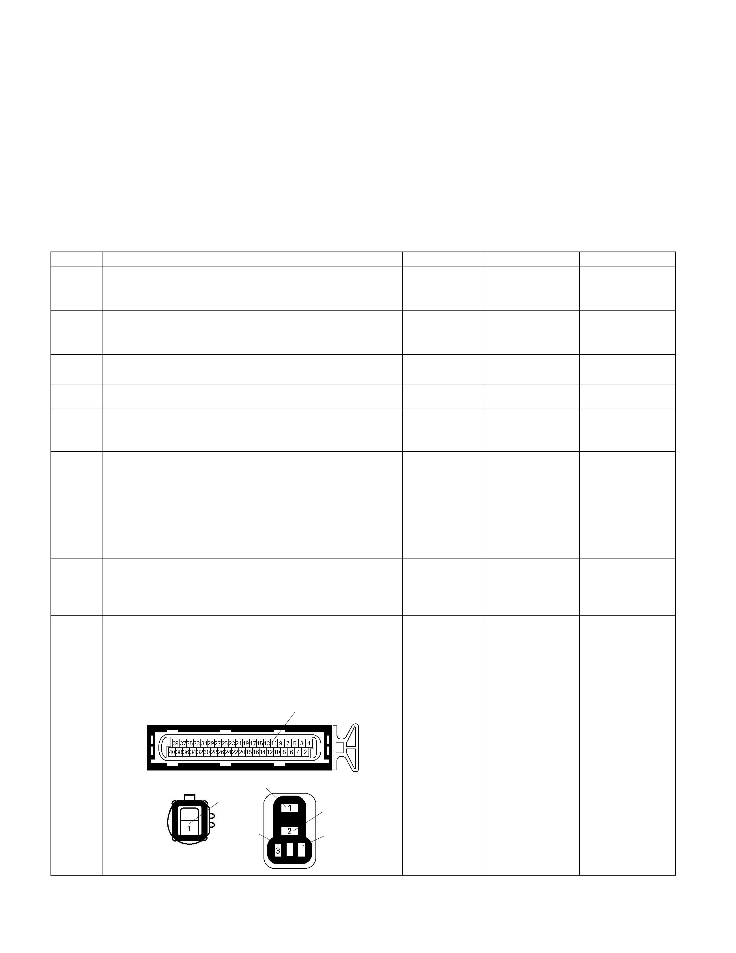
A/C Clutch Diagnosis
This chart should be used for diagnosing the electrical
portion of the A/C compressor clutch circuit. A Tech 2
will be used in diagnosing the system. The Tech 2 has
the ability to read the A/C request input to the ECM. The
Tech 2 can display when the ECM has commanded the
A/C clutch “ON." The Tech 2 should have the ability to
override the A/C request signal and energize the A/C
compressor relay.
A/C Clutch Control Circuit Diagnosis
Step Action Value (s) Yes No
1 Was the "On-Board Diagnostic (OBD) System Check"
performed? - Go to Step 2
Go to On Board
Diagnostic (OBD)
System Check
2 Are the A/C setting conditions met? - Go to Step 3
Set the setting
condition and Go
to Step 3
3 Is the A/C compressor worked properly? - Diagnosis
completed Go to Step 4
4 Does the blower motor operate? - Go to Step 6 Go to Step 5
5 Repair the blower motor circuit.
Is the action complete? - Verify repair -
6 1. Using the Tech 2, ignition "On" and engine "On".
2. Select the "Miscellaneous Test" and perform the
"A/C Clutch Relay" in the "Relays".
3. Operate the Tech 2 in accordance with procedure.
Was the A/C compressor magnet clutch engaged,
when the Tech 2 is operated? - Go to Step 15 Go to Step 7
7 Check the "A/C" fuse (10A). If the fuse is burnt out,
repair as necessary.
Was the problem found? - Verify repair Go to Step 8
8 Check for poor/faulty connection at the A/C
compressor, A/C compressor relay or ECM connector.
If a poor/faulty connection is found, repair as
necessary.
Was the problem found?
E-2 1X-14
44
1
3
2
E-61(B) 11
- Verify repair Go to Step 9
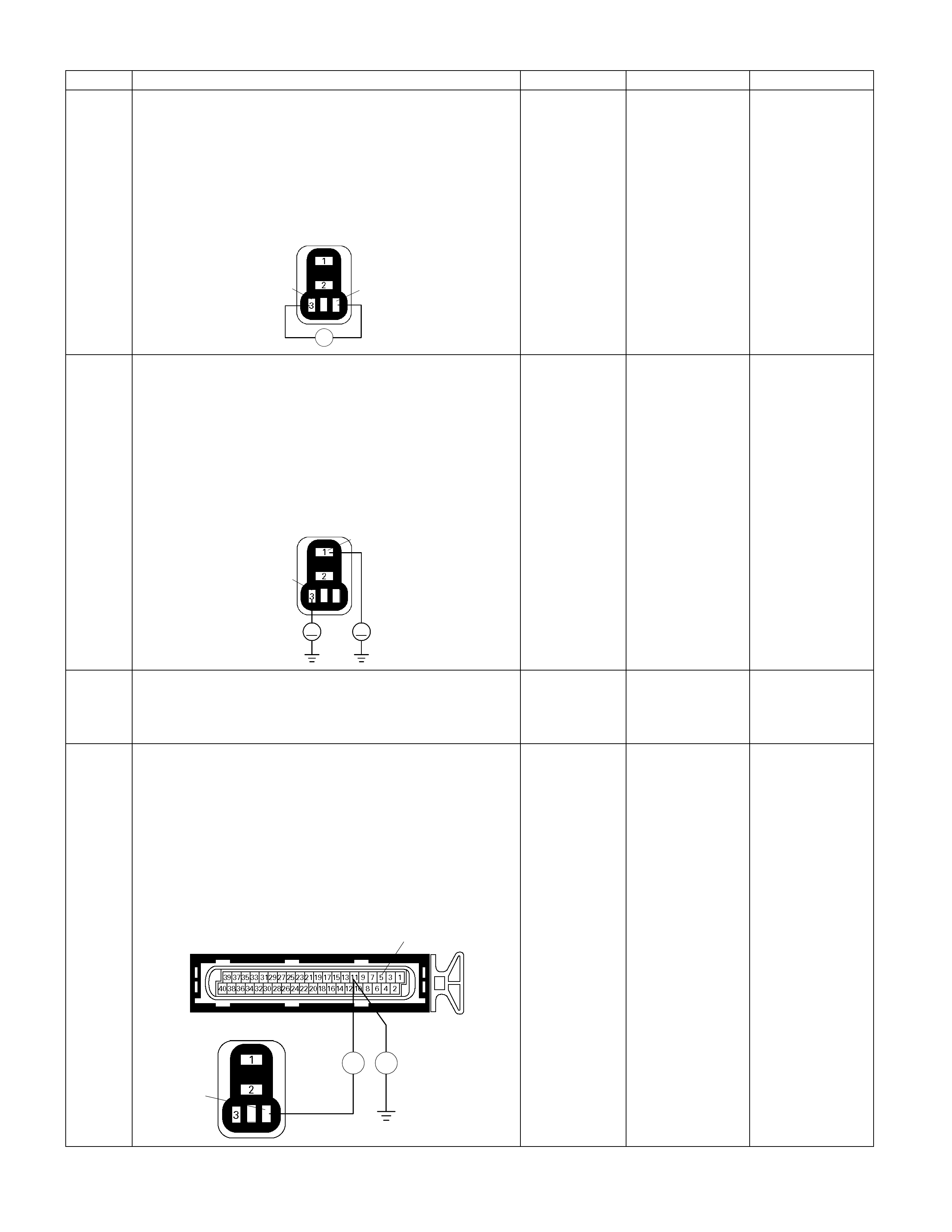
Step Action Value (s) Yes No
9
Using the DVM and check the A/C compressor relay.
1. Ignition "Off", engine "Off".
2. Remove the A/C compressor relay from the relay
box.
3. Check the relay coil.
Was the DVM indicated specified value?
X-14
44
3
Ħ
Continuity Go to Step 10
Replace A/C
compressor relay
and verify repair
10
Using the DVM and check the A/C compressor relay
power supply circuit.
1. Ignition "On", engine "Off".
2. Remove the A/C compressor relay from the relay
box.
3. Check the circuit for open or short to ground circuit.
Was the DVM indicated specified value?
X-14
4
1
3
V V
Battery voltage Go to Step 12 Go to Step 11
11 Repair the open or short to ground circuit between the
"A/C" fuse (10A) and A/C compressor relay .
Is the action complete? - Verify repair -
12
Using the DVM and check the A/C compressor relay
ground circuit.
1. Ignition "Off", engine "Off".
2. Disconnect the ECM connector.
3. Remove the A/C compressor relay from the relay
box.
4. Check the circuit for open or short to ground circuit.
Was the problem found?
E-61(B)
X-14
4
4
Ħ Ħ
11
-
Repair faulty
harness and
verify repair Go to Step 13
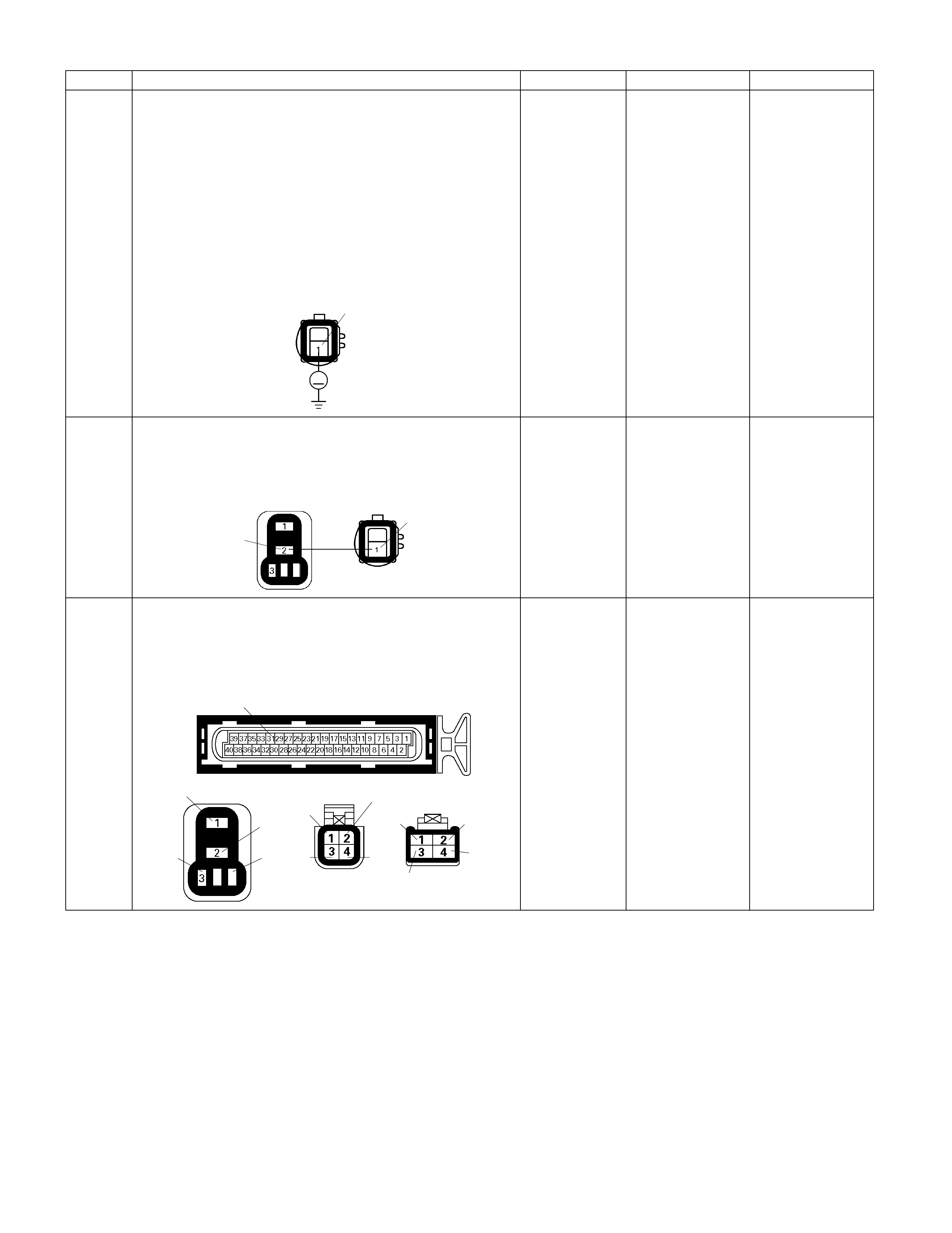
Step Action Value (s) Yes No
13
Using the DVM and check the A/C magnet clutch
power supply circuit.
1. Using the Tech 2, ignition "On" and engine "Off".
2. Select the "Miscellaneous Test" and perform the
"A/C Clutch Relay" in the "Relays".
3. Operate the Tech 2 in accordance with procedure.
4. Disconnect the A/C clutch connector. Check the
circuit for open or short to ground circuit.
Was the DVM indicated specified value?
E-2
V
1
Battery voltage Go to Step 27 Go to Step 14
14 Repair the open or short to ground circuit between the
A/C compressor relay and A/C magnet clutch.
Is the action complete? E-2
X-14
4
41
- Verify repair -
15 Check for poor/faulty connection at the thermo relay,
triple pressure switch, thermostat or ECM connector. If
a poor/faulty connection is found, repair as necessary.
Was the problem found?
E-61(B)
X-15
44
1
3
2
C-24 C-55
12
3 4
1
3
2
4
31
- Verify repair Go to Step 16
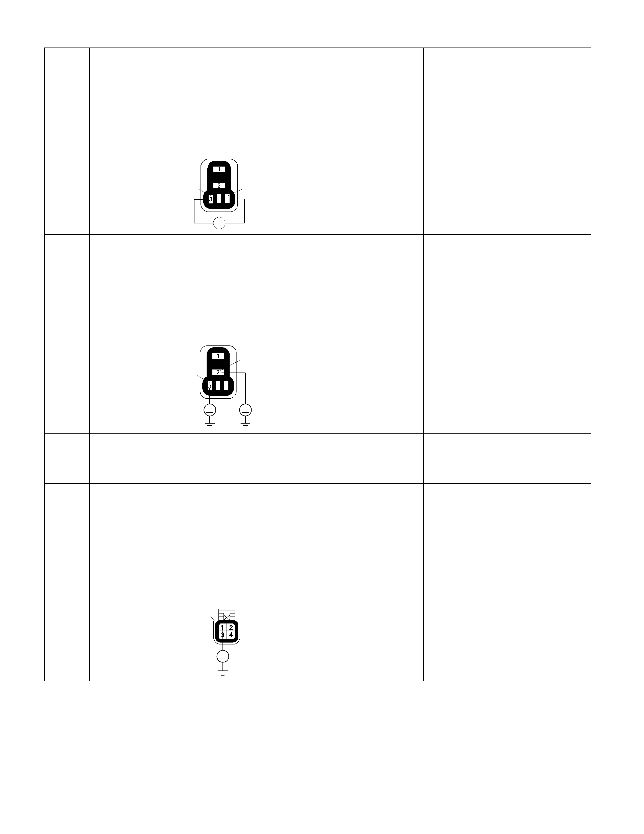
Step Action Value (s) Yes No
16
Using the DVM and check the thermo relay.
1. Ignition "Off", engine "Off".
2. Remove the thermo relay from the relay box.
3. Check the relay coil.
Was the DVM indicated specified value?
X-15
443
Ħ
Continuity Go to Step 17
Replace thermo
relay and verify
repair
17
Using the DVM and check the thermo relay pow er
supply circuit.
1. Ignition "On", engine "Off".
2. Remove the thermo relay from the relay box.
3. Check the circuit for open or short to ground circuit.
Was the DVM indicated specified value?
X-15
4
2
3
V V
Battery voltage Go to Step 19 Go to Step 18
18 Repair the open or short to ground circuit between the
"A/C" fuse (10A) and thermo relay.
Is the action complete? - Verify repair -
19
Using the DVM and check the triple pressure switch
circuit.
1. Ignition "On", engine "Off".
2. Turn "On" blower motor.
3. Disconnect the triple pressure switch connector.
4. Check the circuit for open or short to ground circuit.
Was the DVM indicated specified value?
C-24
V
1
Battery voltage Go to Step 21 Go to Step 20
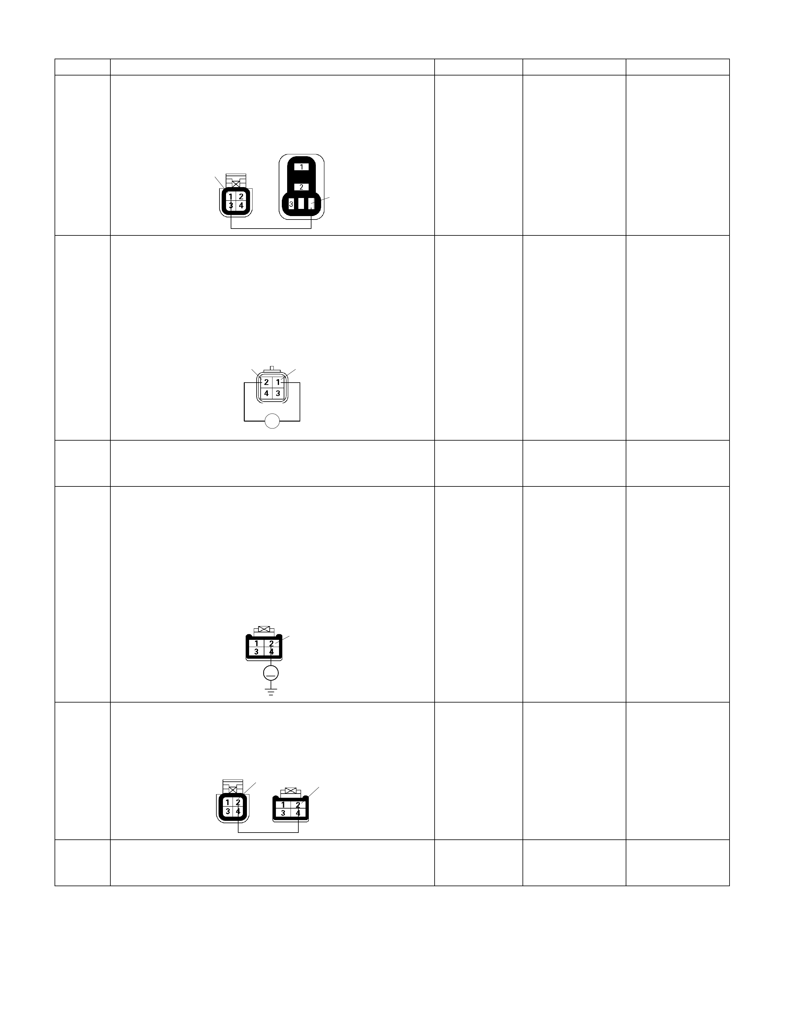
Step Action Value (s) Yes No
20 Repair the open or short to ground circuit between the
thermo relay and triple pressure switch.
Is the action complete?
C-24
X-15
44
1
- Verify repair -
21
Using the DVM and check the triple pressure switch.
1. Ignition "Off", engine "Off".
2. Disconnect the triple pressure switch connector.
3. Check the switch.
Was the switch closed?
Triple P r es s u r e
SW
Ħ
12
- Go to Step 23 Go to Step 22
22 Replace the triple pressure switch.
Is the action complete? - Verify repair -
23
Using the DVM and check the thermostat circuit.
1. Ignition "On", engine "Off".
2. Turn "On" blower motor.
3. Disconnect the triple pressure switch connector.
4. Check the circuit for open or short to ground circuit.
Was the DVM indicated specified value?
C-55
V
2
Battery voltage Go to Step 25 Go to Step 24
24 Repair the open or short to ground circuit between the
triple pressure switch and thermostat.
Is the action complete?
C-55
C-24 22
- Verify repair -
25 Replace the thermostat.
Is the action complete? - Verify repair -
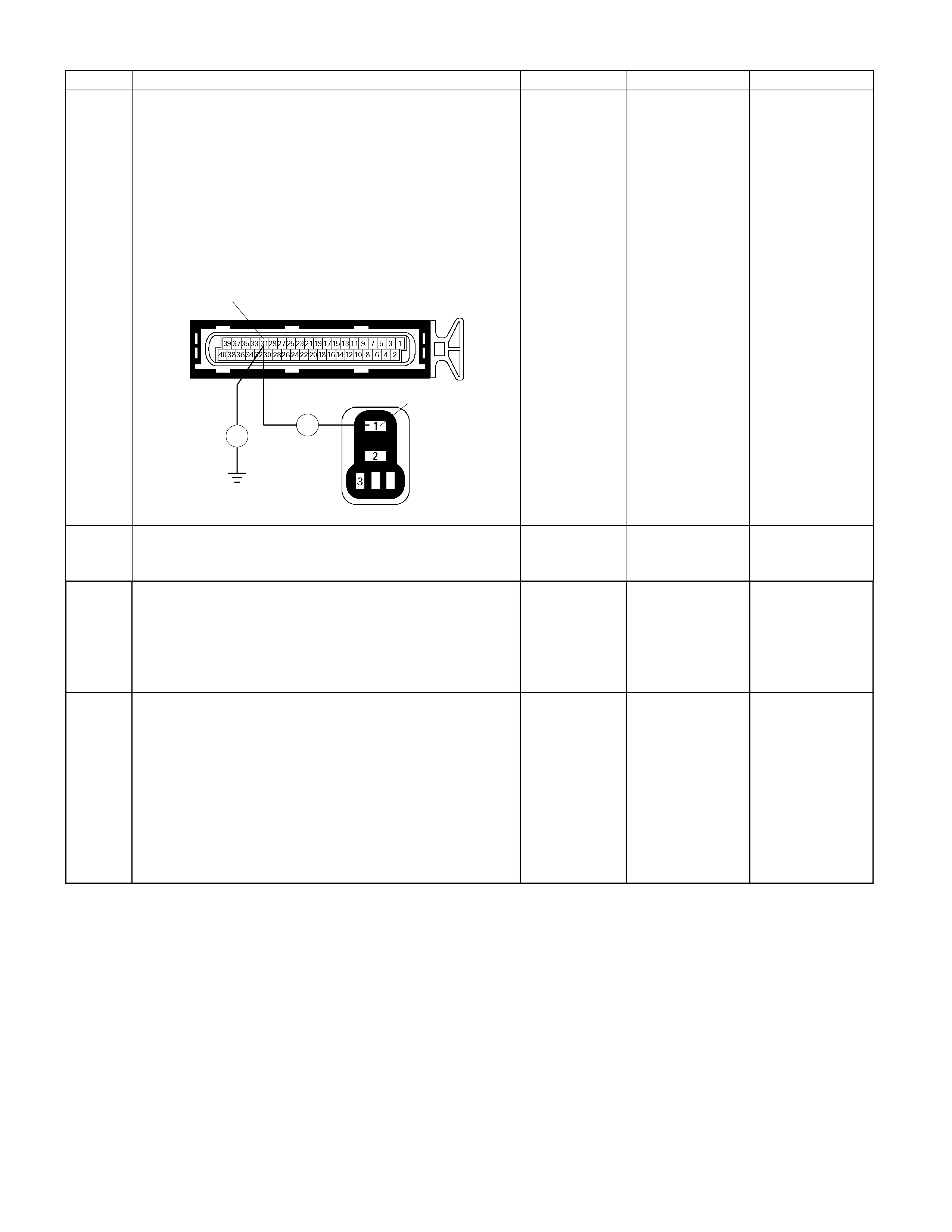
Step Action Value (s) Yes No
26
Using the DVM and check the thermo relay input
circuit.
1. Ignition "Off", engine "Off".
2. Disconnect the ECM connector.
3. Remove the thermo relay from the relay box.
4. Check the circuit for open or short to ground circuit.
Was the problem found?
E-61(B)
X-15
4
1
Ħ
Ħ
31
-
Repair faulty
harness and
verify repair Go to Step 28
27 Replace the A/C compressor.
Was the problem solved? - Verify repair
28 Is the ECM programmed with the latest software
release?
If not, download the latest software to the ECM using
the "SPS (Service Programming System)".
Was the problem solved? - Verify repair Go to step 29
29 Replace the ECM.
Is the action complete?
IMPORTANT: The replacement ECM must be
programmed. Refer to section of the Service
Programming System (SPS) in this manual. Following
ECM programming, the immobiliser system (if
equipped) must be linked to the ECM. Refer to section
11 “Immobiliser System-ECM replacement” for the
ECM/Immobiliser linking procedure. - Verify repair -

ECM Diagnostic Trouble Codes (DTC)
DTC Type A
• Emission related.
• Requests illumination of the MIL (Malfunction Indicator Lamp = Check Engine Lamp) of the first trip with a fail.
• Stores a history DTC on the first trip with a fail.
• Stores a freeze frame (If empty).
• Stores a fail record.
• Updates the fail record each time the diagnostic test fails.
DTC Type B
• Emission related.
• "Armed" after one trip with fail.
• "Disarmed" after one trip with a pass.
• Requests illumination of the MIL on the second consecutive trip with a fail."
• Store a history DTC on the second consecutive trip with a fail. (The DTC will be armed after the first fail.)
• Stores a freeze frame on the second consecutive trip with a fail (If empty ).
• Stores a fail record when the first test fails (not dependent on consecutive trip).
• Updates the fail record each time the diagnostic test fails.
DTC Type D
• Non emission related.
• Does not request illumination of any lamp.
• Stores a history DTC on the first trip with a fail.
• Does not store a freeze frame.
• Stores fail record when test fails.
• Updates the fail record each time the diagnostic test fails.

Flash
Code
Code Type DTC Name DTC Setting Condition Fail-Safe (Back Up) Recovery Condition Related Failure Parts Related
ECM Pin
No.
Related
Multiple
DTC
P0101 B Mass Air Flow Sensor Circuit
Range/Performance 1. No DTC relating to barometer sensor, TPS,
CMP sensor, CKP sensor and MAF sensor
(low input & high input).
2. Engine speed is between 2800rpm and
4500rpm.
3. Throttle position sensor output voltage is
between 1V and 3V.
4. Intake air temperature is between -14°C and
70°C.
5. Air flow amount below 0.04g/s (small air) or
more than 177g/s (large air). Above
conditions are met for 3 seconds.
No fail-safe function. Air flow amount is more than
0.04g/s or below 177g/s. 1. Air intake is obstructed.
2. Sensor signal circuit short to voltage circuit.
3. MAF sensor malfunction.
4. Electrical interference.
5. ECM malfunction.
B20/B39 -
P0102 A Mass Air Flow Sensor Circuit
Low Input MAF sensor output voltage is below 0.3V. MAF sensor output voltage is
more than 0.3V. 1. Sensor power supply circuit open circuit.
2. Sensor signal circuit open or short to ground
circuit.
3. Poor connector connection.
4. MAF sensor malfunction.
5. ECM malfunction.
B20 -
61
P0103 A Mass Air Flow Sensor Circuit
High Input MAF sensor output voltage is more than 4.9V.
The ECM uses default mass
air flow value based on IAC
valve position, throttle position,
barometer pressure and
engine speed.
MAF sensor output voltage is
below 4.9V. 1. Sensor signal circuit short to voltage circuit.
2. Sensor ground circuit open or short to voltage
circuit.
3. MAF sensor malfunction.
4. ECM malfunction.
B20/B39 P0113/
P0123/
P0341/
P0342
P0107 A Barometer Sensor Voltage
Low Barometer sensor output voltage is below 0.1V. Barometer sensor output
voltage is more than 0.1V. ECM malfunction. - - 33
P0108 A Barometer Sensor Voltage
High Barometer sensor output voltage is more than
5.1V.
The ECM use output voltage
4.8V condition as substitute. Barometer sensor output
voltage is below 5.1V. ECM malfunction. - -
P0112 A Intake Air Temperature Sensor
Low Input IAT sensor output voltage is below 0.08V. IAT sensor output voltage is
more than 0.08V. 1. Sensor signal circuit short to ground circuit.
2. IAT sensor malfunction.
3. ECM malfunction.
A19 - 23
P0113 A Intake Air Temperature Sensor
High Input IAT sensor output voltage is more than 4.9V.
The ECM use 40°C conditions
as substitute.
IAT sensor output voltage is
below 4.9V. 1. Sensor signal circuit open or short to voltage
circuit.
2. Sensor ground circuit open or short to voltage
circuit.
3. Poor connector connection
4. IAT sensor malfunction.
5. ECM malfunction.
A19/ B39 P0103/
P0123/
P0341/
P0342

Flash
Code
Code Type DTC Name DTC Setting Condition Fail-Safe (Back Up) Recovery Condition Related Failure Parts Related
ECM Pin
No.
Related
Multiple
DTC
P0117 A Engine Coolant Temperature
Sensor Low Input ECT sensor output voltage is below 0.08V. ECT sensor output voltage is
more than 0.08V. 1. Sensor signal circuit short to ground circuit.
2. ECT sensor malfunction.
3. ECM malfunction.
A21 - 14
P0118 A Engine Coolant Temperature
Sensor High Input ECT sensor output voltage is more than 4.8V.
The ECM uses default engine
coolant temperature value
based on start-up ECT and
time from start.
ECT sensor output voltage is
below 4.8V. 1. Sensor signal circuit open or short to voltage
circuit.
2. Sensor ground circuit open or short to voltage
circuit.
3. Poor connector connection
4. ECT sensor malfunction.
5. ECM malfunction.
A21/ A22 P0406
1. No DTC relating to barometer sensor, ECT
sensor, CMP sensor, CKP sensor, MAF
sensor and TPS (low input & high input).
2. Engine speed is more than 2000rpm.
3. Engine coolant temperature is more than
75°C.
4. TPS output voltage is between 0.24V and
0.26V. Above conditions are met for 3
seconds.OR
P0121 A Throttle Position Sensor
Range/Performance
1. No DTC relating to barometer sensor, ECT
sensor, CMP sensor, CKP sensor, MAF
sensor and TPS (low input & high input).
2. Engine speed is below 3200rpm.
3. Engine coolant temperature is more than
75°C.
4. TPS output voltage is between 4.54V and
4.56V. Above conditions are met for 3
seconds.
No fail-safe function. TPS output voltage is below
0.24V or more than 0.26V. OR
TPS output voltage is below
4.54V or more than 4.56V.
1. TPS malfunction.
2. Sensor signal circuit short to voltage circuit.
3. Electrical interference.
4. ECM malfunction.
B27/
B26/B39 -
P0122 A Throttle Position Sensor Low
Input TPS output voltage is below 0.24V. TPS output voltage is more
than 0.24V. 1. Sensor power supply circuit open or short to
ground circuit.
2. Sensor signal circuit open or short to ground
circuit.
3. Poor connector connection.
4. TPS malfunction. 5. ECM malfunction.
B27/ B26 P0336/
P0337 or
P0342
21
P0123 A Throttle Position Sensor High
Input TPS output voltage is more than 4.56V.
The ECM uses default throttle
position value based on mass
air flow and engine speed.
TPS output voltage is below
4.56V. 1. Sensor power supply circuit short to voltage
circuit.
2. Sensor signal circuit short to voltage circuit.
3. Sensor ground circuit open or short to voltage
circuit.
4. Poor connector connection.
5. TPS malfunction.
6. ECM malfunction.
B27/
B26/B39 P0103/
P0113/
P0341/
P0342

Flash
Code
Code Type DTC Name DTC Setting Condition Fail-Safe (Back Up) Recovery Condition Related Failure Parts Related
ECM Pin
No.
Related
Multiple
DTC
P0131 A O2 Sensor Circuit Low Voltage
(Bank 1 Sensor 1) B21/B22 P0171/
P1171/
P1172
P0151 A O2 Sensor Circuit Low Voltage
(Bank 2 Sensor 1)
1. No DTC relating to ECT sensor, CMP sensor,
CKP sensor, VSS, injector control circuit,
ignition control circuit and O2 sensor circuit no
activity (bank 1 & 2).
2. Engine speed is between 1000rpm and
4000rpm.
3. Engine coolant temperature is between 70°C
and 110°C.
4. Vehicle speed is between 0km/h and
120km/h.
5. Engine load is between 80 and 160. 6.
Throttle position fluctuation is below 0.28V.
7. O2 sensor bank 1 or bank 2 output voltage is
more than 400mV for 50 seconds.
"Open Loop" fuel control. O2 sensor bank 1 or bank 2
output voltage is below 400mV
for 50 seconds.
1. Sensor harness open or short to ground
circuit.
2. O2 sensor malfunction.
3. MAF sensor output is incorrect.
4. Air intake line malfunction.
5. AC valve malfunction.
6. Low fuel pressure.
7. njector malfunction.
8. ECM malfunction.
B23/ B24 P0174/
P1171/
P1172
P0132 A O2 Sensor Circuit High Voltage
(Bank 1 Sensor 1) B21/B22 P0172
P0152 A O2 Sensor Circuit High Voltage
(Bank 2 Sensor 1)
1. No DTC relating to ECT sensor, CMP sensor,
CKP sensor, VSS, injector control circuit,
ignition control circuit and O2 sensor circuit no
activity (bank 1 & 2).
2. Engine speed is between 1000rpm and
4000rpm.
3. Engine coolant temperature is between 70°C
and 110°C.
4. Vehicle speed is between 0km/h and
120km/h.
5. Engine load is between 80 and 160.
6. Throttle position fluctuation is below 0.28V.
7. O2 sensor bank 1 or bank 2 output voltage is
below 600mV for 50 seconds.
"Open Loop" fuel control. O2 sensor bank 1 or bank 2
output voltage is more than
600mV for 50 seconds.
1. Sensor harness open or short to ground
circuit.
2. O2 sensor malfunction.
3. MAF sensor output is incorrect.
4. Air intake line malfunction.
5. AC valve malfunction.
6. Low fuel pressure.
7. Injector malfunction.
8. EVAP purge solenoid valve malfunction.
9. Ignition system malfunction.
10. Spark plug malfunction.
11. ECM malfunction.
B23/ B24 P0175
P0134 A O2 Sensor Circuit No Activity
Detected (Bank 1 Sensor 1) B21/B22 -
15
P0154 A O2 Sensor Circuit No Activity
Detected (Bank 2 Sensor 1)
1.No DTC relating to MAF sensor, ECT sensor,
CMP sensor, CKP sensor, VSS, injector
control circuit and ignition control circuit.
2. Engine coolant temperature is more than
70°C.
3. Vehicle speed is more than 60km/h.
4. O2 sensor bank 1 or bank 2 output voltage is
between 350mV and 600mV.
"Open Loop" fuel control. O2 sensor bank 1 or bank 2
output voltage is below 0.35mV
consecutively. OR O2 sensor
bank 1 or bank 2 output
voltage is more than 600mV
consecutively.
1. O2 sensor malfunction.
2. ECM malfunction.
B23/ B24 -

Flash
Code
Code Type DTC Name DTC Setting Condition Fail-Safe (Back Up) Recovery Condition Related Failure Parts Related
ECM Pin
No.
Related
Multiple
DTC
P0171 B O2 Sensor System Too Lean
(Bank 1) - - 44
P0174 B O2 Sensor System Too Lean
(Bank 2)
1. No DTC relating to MAF sensor, IAT sensor,
ECT sensor, TPS, CMP sensor, CKP sensor,
VSS, injector control circuit, ignition control
circuit, O2 sensor circuit low voltage & high
voltage (bank 1 & 2) and O2 sensor circuit no
activity (bank 1 & 2).
2. Engine speed is more than 600rpm.
3. Intake air temperature is more than 50°C.
4. Engine coolant temperature is between 35°C
and 120°C.
5. Engine load is more than 20.
6. EVAP purge solenoid valve on-duty is below
100%. 7. Air-fuel ratio correction volume is
more than 150% for 20 seconds.
No fail-safe function. Air fuel ratio correction volume
is between 50% and 150% for
5 seconds.
1. Sensor harness open or short to ground
circuit.
2. O2 sensor malfunction.
3. MAF sensor output is incorrect.
4. Air intake line malfunction.
5. IAC valve malfunction.
6. Low fuel pressure.
7. Injector malfunction.
8. ECM malfunction.
- -
P0172 B O2 Sensor System Too Rich
(Bank 1) - - 45
P0175 B O2 Sensor System Too Rich
(Bank 2)
1. No DTC relating to MAF sensor, IAT sensor,
ECT sensor, TPS, CMP sensor, CKP sensor,
VSS, injector control circuit, ignition control
circuit, O2 sensor circuit low voltage & high
voltage (bank 1 & 2) and O2 sensor circuit no
activity (bank 1 & 2).
2. Engine speed is more than 600rpm.
3. Intake air temperature is more than 50°C.
4. Engine coolant temperature is between 35°C
and 120°C.
5. Engine load is more than 20.
6. EVAP purge solenoid valve on-duty is below
100%.
7. Air-fuel ratio correction volume is below 50%
for 20 seconds.
No fail-safe function. Air fuel ratio correction volume
is between 50% and 150% for
5 seconds.
1. Sensor harness open or short to ground
circuit.
2. O2 sensor malfunction.
3. MAF sensor output is incorrect.
4. Air intake line malfunction.
5. AC valve malfunction.
6. Low fuel pressure.
7. Injector malfunction.
8. EVAP purge solenoid valve malfunction.
9. Ignition system malfunction.
10. Spark plug malfunction.
11. ECM malfunction.
- -

Flash
Code
Code Type DTC Name DTC Setting Condition Fail-Safe (Back Up) Recovery Condition Related Failure Parts Related
ECM Pin
No.
Related
Multiple
DTC
P1171 D
Fuel Supply System Lean
During Power Enrichment
(Type A)
B21/B22/
B23/ B24 - 44
P1172 D
Fuel Supply System Lean
During Power Enrichment
(Type B)
1. No DTC relating to MAF sensor, IAT sensor,
ECT sensor, TPS, CMP sensor, CKP sensor,
VSS, injector control circuit, ignition control
circuit, O2 sensor circuit low voltage & high
voltage (bank 1 & 2) and O2 sensor circuit no
activity (bank 1 & 2).
2. Engine speed is between 1000rpm and
6000rpm.
3. Intake air temperature is below 70°C.
4. Engine coolant temperature is between 30°C
and 120°C.
5. Engine load is between 150 and 255.
6. Throttle position output is more than 2.22V
and fluctuation is below 0.28V.
7. Except fuel cut operation.
8. O2 sensor output voltage below 250mV for 10
seconds.
No fail-safe function.
O2 sensor output voltage is
more than 520mV for 5
seconds.
1. Sensor harness open or short to ground
circuit.
2. O2 sensor malfunction.
3. MAF sensor output is incorrect. 4. Air intake
line malfunction.
5. IAC valve malfunction.
6. Low fuel pressure.
7. Injector malfunction.
8. ECM malfunction.
B21/B22/
B23/ B24 -
P0201 A Injector 1 Control Circuit A36 -
P0202 A Injector 2 Control Circuit B3 -
P0203 A Injector 3 Control Circuit A35 -
P0204 A Injector 4 Control Circuit B4 -
P0205 A Injector 5 Control Circuit A34 -
31
P0206 A Injector 6 Control Circuit
1. No DTC relating to CMP sensor and CKP
sensor.
2. Under sequential injection.
3. Injection pulse is between 2.5ms and 7.5 ms.
4. Except fuel cut operation.
5. Engine speed is between 600rpm and
2000rpm.
6. 30 injection signals are not detected
consecutively.
No fail-safe function. 30 injection signals are
detected consecutively. 1. Injector harness open circuit, short to ground
or short to voltage.
2. Injector malfunction.
3. ECM malfunction.
B5 -

Flash
Code
Code Type DTC Name DTC Setting Condition Fail-Safe (Back Up) Recovery Condition Related Failure Parts Related
ECM Pin
No.
Related
Multiple
DTC
P0336 B Crankshaft Position Sensor
Circuit Range/Performance
(58X)
1. No DTC relating to CMP sensor.
2. Engine speed is below 2000rpm.
3. Extra or missing pulse is detected
consecutively.
1. CKP sensor harness open circuit, short to
ground or short to voltage.
2. Poor connector connection.
3. CKP sensor malfunction.
4. Pulse sensing gap incorrect.
5. Electrical interference.
6. Magnetic interference.
7. ECM malfunction.
A23/ A24/
A25 P0122/
P0337
29
P0337 B Crankshaft Position Sensor
Circuit No Signal (58X) 1. No DTC relating to CKP sensor.
2. Engine speed is below 2000rpm.
3. ncorrect pulse is detected consecutively.
No fail-safe function.
Correct pulse is detected
consecutively.
1. CKP sensor harness open circuit, short to
ground or short to voltage.
2. CMP sensor signal circuit short to ground
circuit.
3. TPS & CMP sensor power supply circuit short
to ground.
4. Poor connector connection.
5. CKP sensor malfunction.
6. Pulse sensing gap incorrect.
7. Electrical interference.
8. Magnetic interference.
9. ECM malfunction.
A23/ A24/
A25 P0112/
P0336
P0341 B Camshaft Position Sensor
Circuit Range/Performance 1. Engine speed below 2000rpm.
2. No crankshaft position sensor DTC P0336 or
P0337.
3. ncorrect pulse is detected consecutively.
1. CMP sensor harness open circuit, short to
ground or short to voltage.
2. Poor connector connection.
3. CMP sensor malfunction.
4. Pulse sensing gap incorrect.
5. Electrical interference.
6. Magnetic interference.
7. ECM malfunction.
B27/B28/
B39 P0103/
P0113/
P0123/
P0342
41
P0342 B Camshaft Position Sensor
Circuit No Signal 1. No DTC relating to CKP sensor.
2. Engine speed is below 2000rpm.
3. No pulse is detected consecutively.
Fuel cut is operated at high
engine speed.
Correct pulse is detected
consecutively.
1. CMP sensor harness open circuit, short to
ground or short to voltage.
2. Poor connector connection.
3. CMP sensor malfunction.
4. Pulse sensing gap incorrect.
5. Electrical interference.
6. Magnetic interference.
7. ECM malfunction.
B27/B28/
B39 P0103/
P0113/
P0123/
P0341 or
P0122

Flash
Code
Code Type DTC Name DTC Setting Condition Fail-Safe (Back Up) Recovery Condition Related Failure Parts Related
ECM Pin
No.
Related
Multiple
DTC
P0351 A Ignition 1 Control Circuit A32 -
P0352 A Ignition 2 Control Circuit B7 -
P0353 A Ignition 3 Control Circuit A31 -
P0354 A Ignition 4 Control Circuit B8 -
P0355 A Ignition 5 Control Circuit A30 -
42
P0356 A Ignition 6 Control Circuit
1. No DTC relating to CMP sensor and CKP
sensor.
2. Engine speed is between 250rpm and 850
rpm.
3. 10 ignition signals are not detected
consecutively.
Fuel cut is operated more than
2000rpm. 10 ignition signals are detected
consecutively. 1. Ignition coil harness open circuit, short to
ground or short to voltage.
2. Ignition coil malfunction.
3. ECM malfunction.
B9 -

Flash
Code
Code Type DTC Name DTC Setting Condition Fail-Safe (Back Up) Recovery Condition Related Failure Parts Related
ECM Pin
No.
Related
Multiple
DTC
P0404 B EGR Circuit
Range/Performance (Open
Valve)
1. Engine is stopping.
2. No DTC relating to ECT sensor, CKP sensor
and VSS.
3. Vehicle speed is below 4km/h.
4. Engine coolant temperature is more than
75°C.
5. EGR solenoid valve on-duty ratio is more than
100%.
6. EGR valve output monitoring signal high.
EGR valve output monitoring
signal low. 1. EGR solenoid harness short to voltage circuit.
2. EGR valve sticking.
3. ECM malfunction.
A5 -
P1404 B EGR Circuit
Range/Performance (Closed
Valve)
1. Engine is running.
2. Engine speed is below 4000rpm.
3. No DTC relating to CKP sensor.
4. EGR solenoid valve on-duty ratio is 0%.
5. EGR valve output monitoring signal low.
1. EGR operation is stopped.
2. EGR valve closed position
learning operation is
disabled.
3. EGR position feedback is
disabled.
EGR valve output monitoring
signal high. 1. EGR solenoid harness open circuit or short to
ground circuit.
2. EGR valve sticking.
3. ECM malfunction.
A5 -
P0405 B EGR Circuit Low 1. No DTC relating to EGR circuit
range/performance.
2. EGR solenoid valve on-duty ratio is more than
40%.
3. EGR position sensor output voltage is below
0.3V.
EGR position sensor output
voltage is more than 0.3V. 1. EGR position sensor power supply circuit
open or short to ground circuit.
2. EGR position sensor signal circuit open or
short to ground circuit.
3. Poor connector connection.
4. EGR valve malfunction.
5. ECM malfunction.
A9/ A24 -
P0406 B EGR Circuit High 1. No DTC relating to EGR circuit
range/performance.
2. EGR solenoid valve on-duty ratio is below
40%.
3. EGR position sensor output voltage is more
than 4.6V.
No fail-safe function.
EGR position sensor output
voltage is below 4.6V. 1. EGR position sensor power supply circuit
short to voltage circuit.
2. EGR position sensor signal circuit short to
voltage circuit.
3. EGR position sensor ground circuit open or
short to voltage circuit.
4. Poor connector connection.
5. EGR valve malfunction.
6. ECM malfunction.
A9/ A22/
A24 P0118
P0444 A EVAP Purge Solenoid Valve
Circuit Low Voltage 1. No DTC relating to CKP sensor and system
voltage.
2. Engine speed is below 4000rpm.
3. Purge solenoid valve on-duty ratio is below
48%.
4. Purge solenoid valve output monitoring signal
low.
Purge solenoid valve output
monitoring signal high. 1. Solenoid harness open circuit or short to
ground.
2. Solenoid malfunction.
3. ECM malfunction.
B15 -
32
P0445 A EVAP Purge Solenoid Valve
Circuit High Voltage 1. No DTC relating to CKP sensor and system
voltage.
2. Engine speed is below 4000rpm.
3. Purge solenoid valve on-duty ratio is more
than 50%.
4. Purge solenoid valve output monitoring signal
high.
No fail-safe function.
Purge solenoid valve output
monitoring signal low. 1. Solenoid harness short to voltage.
2. Solenoid malfunction.
3. ECM malfunction.
B15 -

Flash
Code
Code Type DTC Name DTC Setting Condition Fail-Safe (Back Up) Recovery Condition Related Failure Parts Related
ECM Pin
No.
Related
Multiple
DTC
24 P0500 B
Vehicle Speed Sensor Circuit
Range/Performance 1. Engine speed is below 5000rpm.
2. Under fuel cut operation.
3. Vehicle speed sensor output is below 1km/h.
Above conditions are met for 4 seconds.
The ECM use 10km/h
condition as substitute. Vehicle speed sensor output is
more than 2km/h. 1. Sensor harness open circuit, short to ground
circuit or short to voltage circuit.
2. Poor connector connection.
3. Electrical interference.
4. Magnetic interference.
5. VSS malfunction.
6. ECM malfunction.
B32 -
P0562 D
System Voltage Low Battery voltage is below 6V for more than 20
seconds. 1. Battery power feed harness open circuit or
short to ground circuit.
2. ECM ground harness open or poor
connection.
3. Poor connector connection.
4. Battery malfunction.
5. Charge system malfunction.
6. ECM malfunction.
- - 66
P0563 A System Voltage High Battery voltage is above 16V for more than 20
seconds.
No fail-safe function. Battery voltage is between 6V
and 16V.
1. Charge system malfunction.
2. Battery jump start cable misconnect.
3. ECM malfunction.
- -
51 P0601 A
Control Module Memory
Checksum ECM memory area error. Engine control disabled. Memory are is OK. 1. ECM malfunction. - -
- P0602 -
Programming Error ECM memory area error. Engine control disabled. Memory are is OK. 1. ECM is not programmed. - -

Flash
Code
Code Type DTC Name DTC Setting Condition Fail-Safe (Back Up) Recovery Condition Related Failure Parts Related
ECM Pin
No.
Related
Multiple
DTC
P1508 B Idle Air Control System
Low/Closed 1. No DTC relating to MAF sensor, IAT sensor,
ECT sensor, TPS, CMP sensor, CKP sensor,
VSS and system voltage.
2. Engine speed is between 675rpm and
6000rpm.
3. Engine coolant temperature is more than
75°C.
4. Intake air temperature is between -10°C and
80°C.
5. Vehicle is stopping.
6. Small amount of intake air through the idle air
control valve. (Idle air control valve is sticking
at close position.) Above conditions are met
for 2 seconds.
1. IAC valve harness open circuit, short to
ground circuit or short to voltage circuit.
2. Poor connector connection.
3. IAC valve malfunction.
4. IAC valve is sticking at close position.
5. ECM malfunction.
B13/ B14/
B16/ B17 - 22
P1509 B Idle Air Control System
High/Open 1. No DTC relating to MAF sensor, IAT sensor,
ECT sensor, TPS, CMP sensor, CKP sensor,
VSS and system voltage.
2. Engine speed is between 675rpm and
6000rpm.
3. Engine coolant temperature more than 75°C.
4. Intake air temperature is between -10°C and
80°C.
5. Vehicle is stopping.
6. Large amount of intake air through the idle air
control valve. (Idle air control valve is sticking
at open position.) Above conditions are met
for 2 seconds.
Fuel cut is operated at high idle
speed.
Correct amount of air intake
through the idle air control
valve. (Correct movement of
the idle air control valve.)
1. IAC valve harness open circuit, short to
ground circuit or short to voltage circuit.
2. Poor connector connection.
3. IAC valve malfunction.
4. IAC valve is sticking at open position.
5. ECM malfunction.
B13/ B14/
B16/ B17 -
65 P1601 D
CAN BUS Off CAN BUS off condition is detected consecutively. CAN BUS on condition is
detected consecutively for 2
seconds.
1. ECM and TCM communication circuit open,
short to ground or short to voltage.
2. Electrical interference.
3. ECM malfunction.
4. TCM malfunction.
A10/ A11 -
67 U2104 D
CAN BUS Reset Counter
Overrun 1. No DTC CAN BUS Off.
2. CAN valid counter does not change for 2
seconds.
Torque reduction control is
disable.
CAN valid counter changes
consecutively for 2 seconds. 1. ECM and TCM communication circuit open,
short to ground or short to voltage.
2. Electrical interference.
3. ECM malfunction.
4. TCM malfunction.
A10/ A11 P1767/
U2104 (AT)

Flash
Code
Code Type DTC Name DTC Setting Condition Fail-Safe (Back Up) Recovery Condition Related Failure Parts Related
ECM Pin
No.
Related
Multiple
DTC
P1626 -
Immobiliser No Signal No response from immobiliser control unit. 1. ECM and immobiliser control unit
communication circuit open circuit, short to
ground circuit or short to voltage circuit.
2. Electrical interference.
3. Magnetic interference.
4. ECM malfunction.
5. Immobiliser control unit malfunction.
6. Transponder key malfunction.
B18/ B32 B****
P1631 -
Immobiliser Wrong Signal Received response is not correct. 1. ECM malfunction.
2. Immobiliser control unit malfunction.
3. Transponder key malfunction.
- B****
P1648 -
Wrong Security Code Entered Received incorrect security code. 1. ECM malfunction.
2. Immobiliser control unit malfunction.
3. Transponder key malfunction.
- B****
-
P1649 -
Immobiliser Function Not
Programmed Immobiliser function is not programmed in the
ECM.
1. Engine does not start.
2. Check engine lamp flash.
No recovery
ECM malfunction. - B****
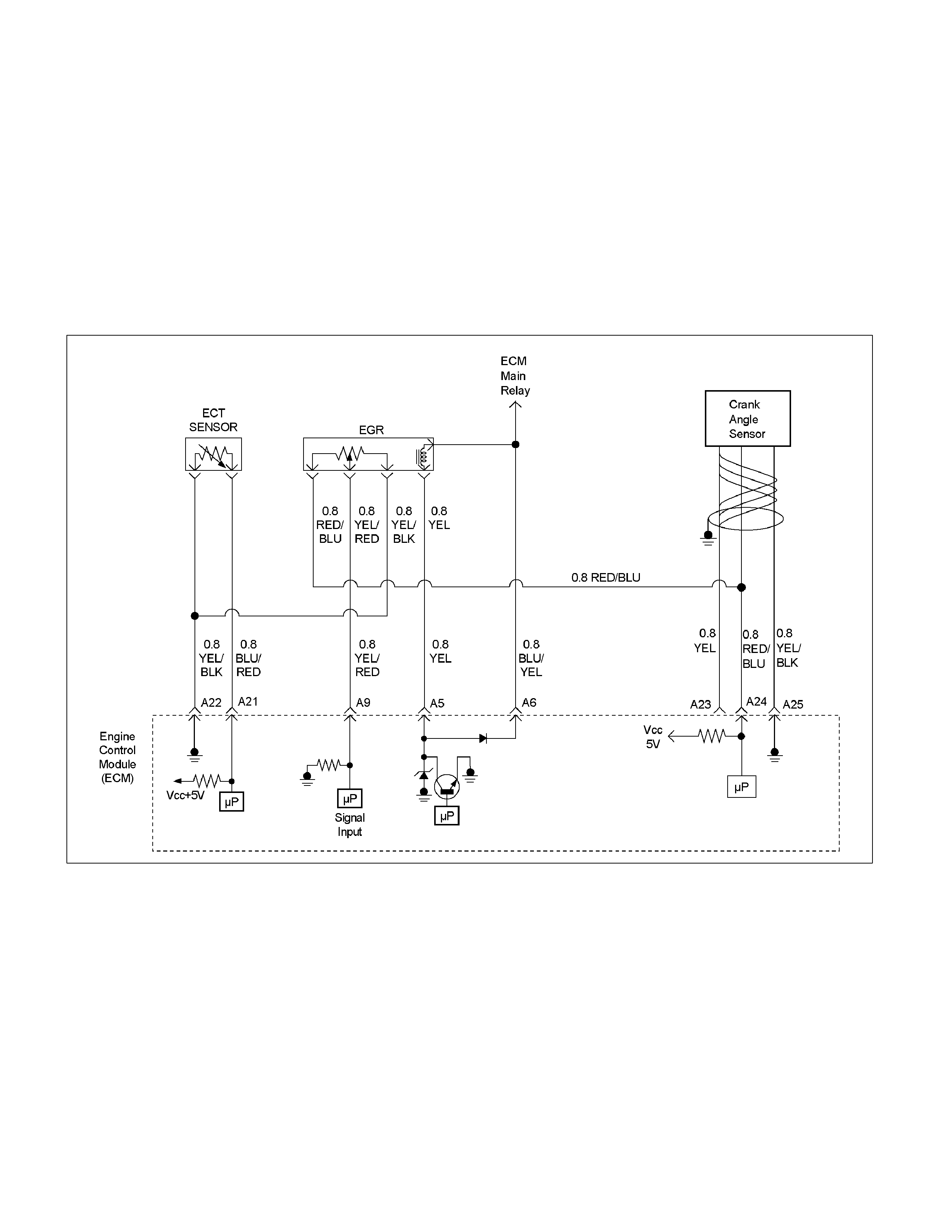
Multiple DTC Sets Troubleshooting Aids
An open or short to voltage circuit in the sensor ground circuit between the ECM terminal A22 and splice will cause one
or more of following DTCs to be set:
•
••
• P0406 (Flash Code 32): EGR Circuit High
•
••
• P0118 (Flash Code 14): Engine Coolant Temperature Sensor High Input
A short to ground circuit in the sensor power supply circuit between the ECM terminal A24 and splice will cause one or
more of following DTCs to be set:
•
••
• P0122 (Flash Code 21): Throttle Position Sensor Low Input
•
••
• P0336 (Flash Code 29): Crankshaft Position Sensor Circuit Range/Performance (58X)
•
••
• P0337 (Flash Code 29): Crankshaft Position Sensor Circuit No Signal (58X)
RTW36EMF000501
An open or short to voltage circuit in the sensor ground circuit between the ECM terminal B39 and splice will cause one
or more of following DTCs to be set:
•
••
• P0103 (Flash Code 61): Mass Air Flow Sensor Circuit High Input
•
••
• P0113 (Flash Code 23): Intake Air Temperature Sensor High Input
•
••
• P0123 (Flash Code 21): Throttle Position Sensor High Input
•
••
• P0341(Flash Code 41): Camshaft Position Sensor Circuit Range/Performance
•
••
• P0342 (Flash Code 41): Camshaft Position Sensor Circuit No Signal
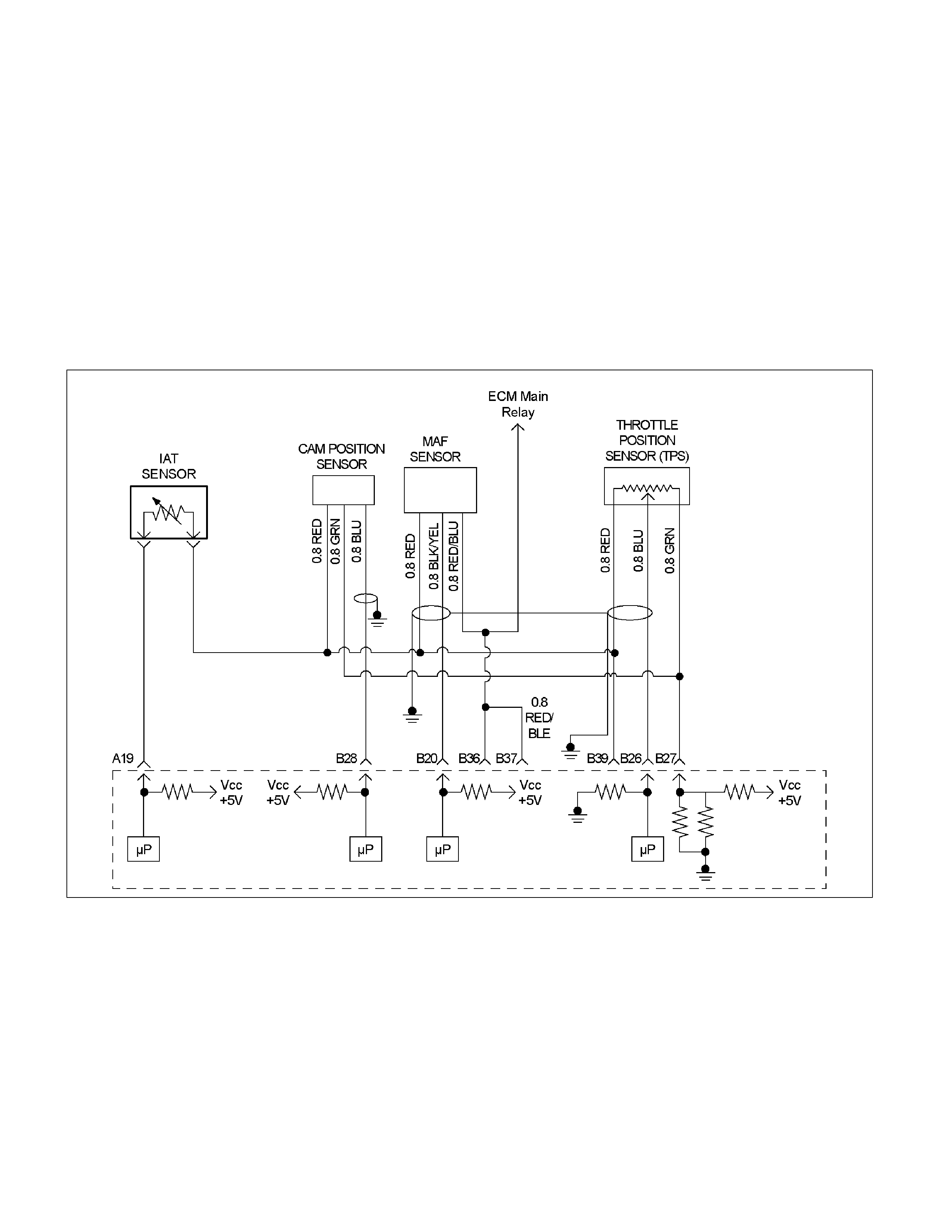
An open circuit in the sensor power supply circuit between the ECM terminal B27 and splice will cause one or more of
following DTCs to be set:
•
••
• P0122 (Flash Code 21): Throttle Position Sensor Low Input
•
••
• P0342 (Flash Code 41): Camshaft Position Sensor Circuit No Signal
A short to ground circuit in the sensor power supply circuit between the ECM terminal B27 and splice will cause one or
more of following DTCs to be set:
•
••
• P0122 (Flash Code 21): Throttle Position Sensor Low Input
•
••
• P0336 (Flash Code 29): Crankshaft Position Sensor Circuit Range/Performance (58X)
•
••
• P0337 (Flash Code 29): Crankshaft Position Sensor Circuit No Signal (58X)
A short to ground circuit in the sensor signal circuit between the ECM terminal B28 and sensor will cause one of
following DTC to be set:
•
••
• P0337 (Flash Code 29): Crankshaft Position Sensor Circuit No Signal (58X)
RTW36EMF000401
Too low fuel pressure (poor fuel) will cause one or more of following DTCs to be set.
•
••
• P0131 (Flash Code 15): O2 Sensor Circuit Low Voltage (Bank 1 Sensor 1)
•
••
• P0151 (Flash Code 15): O2 Sensor Circuit Low Voltage (Bank 2 Sensor 1)
•
••
• P0171 (Flash Code 44): O2 Sensor System Too Lean (Bank1)
•
••
• P0174 (Flash Code 44): O2 Sensor System Too Lean (Bank 2)
•
••
• P1171 (Flash Code 44): Fuel Supply System Lean During Power Enrichment (Type A)
•
••
• P1172 (Flash Code 44): Fuel Supply System Lean During Power Enrichment (Type B)
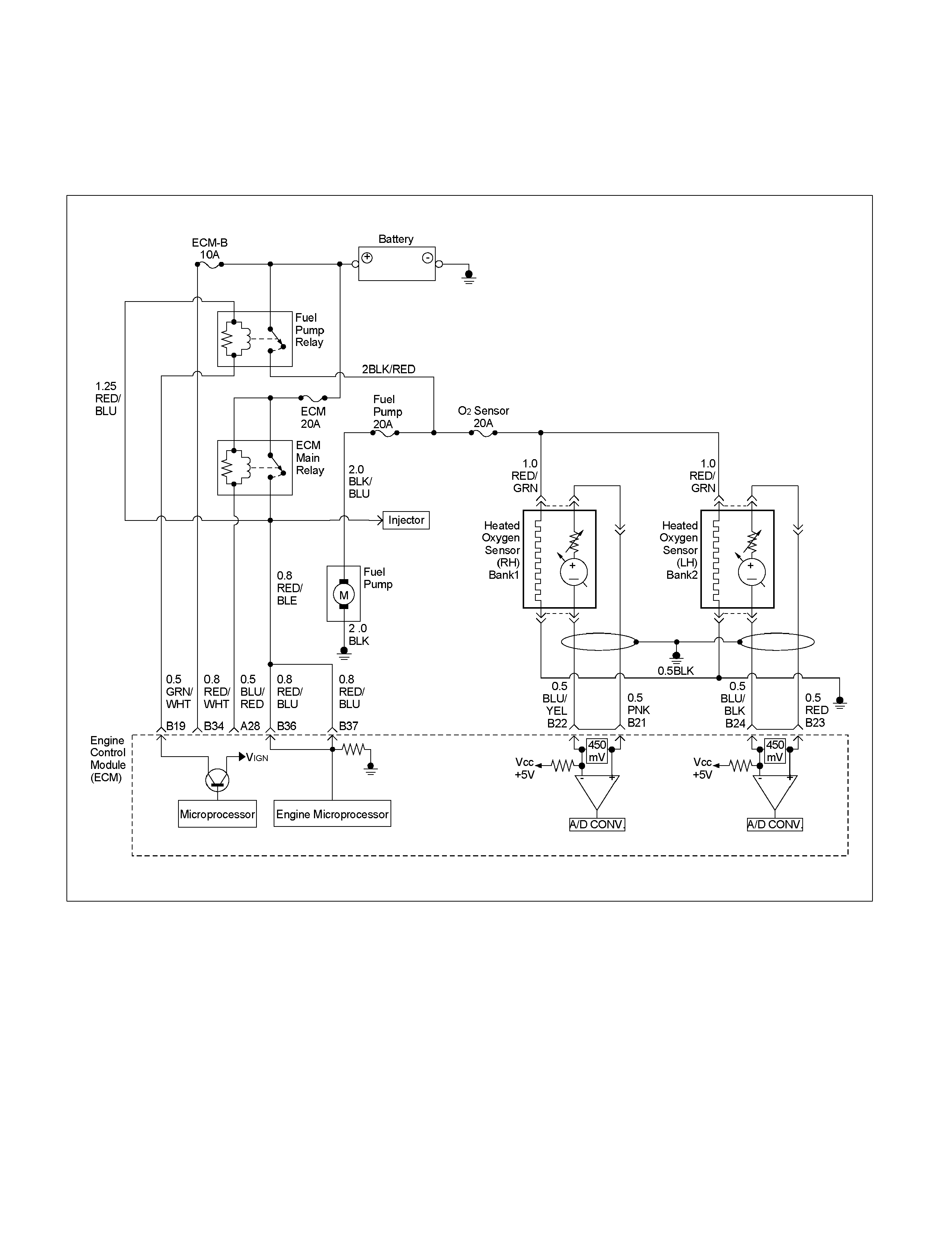
Too high fuel pressure (excessive fuel) will cause one or more of following DTCs to be set.
•
••
• P0132 (Flash Code 15): O2 Sensor Circuit High Voltage (Bank1 Sensor 1)
•
••
• P0152 (Flash Code 15): O2 Sensor Circuit High Voltage (Bank 2 Sensor 1)
•
••
• P0172 (Flash Code 45): O2 Sensor System Too Rich (Bank 1)
•
••
• P0175 (Flash Code 45): O2 Sensor System Too Rich (Bank 2)
RTW36ELF000101
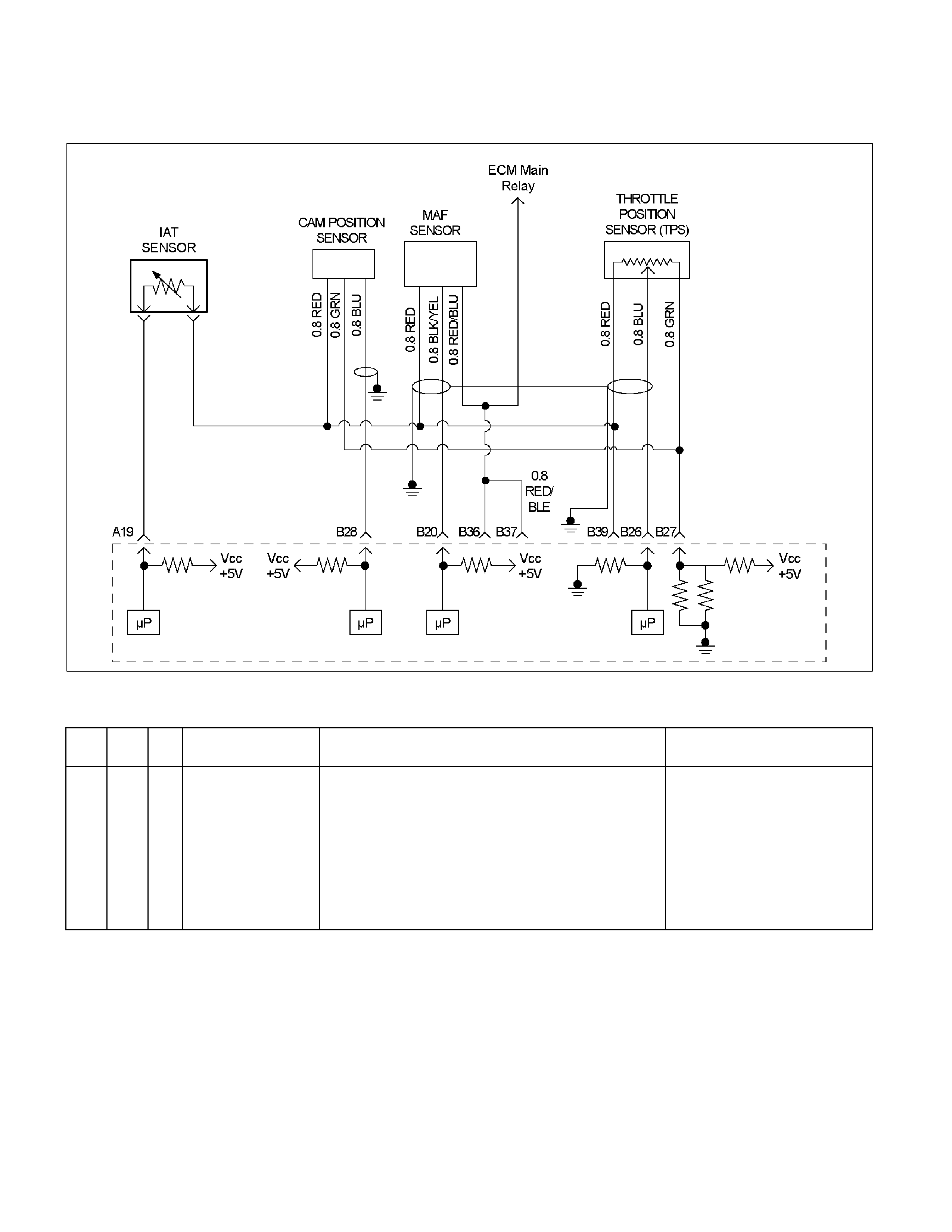
Diagnostic Trouble Code (DTC) P0101 (Flash Code 61) Mass Air Flow
Sensor Circuit Range/Performance
RTW36EMF000401
Condition For Setting The DTC and Action Taken When The DTC Sets
Flash
Code Code Type DTC Name DTC Setting Condition Fail-Safe (Back Up)
61 P0101 B Mass Air Flow Sensor
Circuit
Range/Performance
1. No DTC relating to barometer sensor, TPS, CMP sensor,
CKP sensor and MAF sensor (low input & hi gh i nput ).
2. Engine s peed i s between 2800rpm and 4500rpm .
3. Throttl e position sensor output volt age i s between 1V and
3V.
4. Intake air temperature is bet ween -14°C and 70°C.
5. Air f l ow am ount below 0.04g/s (small air) or more than
177g/s (large ai r).
Above condit i ons are met f or 3 seconds.
No fail-s afe functi on.

Circuit Description
The mass air flow (MAF) sensor measures the amount
of air which passes through it into the engine during a
given time. The Engine Control Module (ECM) uses the
mass air flow information to monitor engine operating
conditions for fuel delivery calculations. A large quantity
of air entering the engine indicates an acceleration or
high load situation, while a small quantity or air indicates
deceleration or idle.
The MAF sensor produces a frequency signal which
can be monitored using a Tech 2. The frequency will
vary within a range of around 4 to 7 g/s at idle to around
25 to 40 g/s at maximum engine load. DTC P0101 will
be set if the signal from the MAF sensor does not match
a predicted value based on throttle position and engine
RPM.
Diagnostic Aids
An intermittent may be caused by the following:
• Poor connections.
• Mis-routed harness.
• Rubbed through wire insulation.
• Broken wire inside the insulation.
Refer to Intermittents under service category
Symptoms.
Any un-metered air may cause this DTC to set. Check
for the following:
• The duct work at the MAF sensor for leaks.
• An engine vacuum leak.
• The PCV system for vacuum leaks.
• An incorrect PCV valve.
• The engine oil dip stick not fully seated.
• The engine oil fill cap loose or missing.
Diagnostic Trouble Code (DTC) P0101 (Flash Code 61) Mass A i r Flow Sensor Circuit Range/Performance
Step Action Value (s) Yes No
1 Was the "On-Board Diagnostic (OBD) System Check"
performed? - Go to Step 2
Go to On Board
Diagnostic (OBD)
System Check
2 1. Connect the Tech 2.
2. Review and record the failure information.
3. Select "F0: Read DTC Infor By Priority" in "F0:
Diagnostic Trouble Code".
Is the DTC P0101 stored as "Present Failure"? - Go to Step 3
Refer to
Diagnostic Aids
and Go to Step 3
3 1. Using the Tech2, ignition "On" and engine "Off".
2. Select "Clear DTC Information" with the Tech2 and
clear the DTC information.
3. Operate the vehicle and monitor the "F5: Failed
This Ignition" in "F2: DTC Information"
Was the DTC P0101 stored in this ignition cycle? - Go to Step 4
Refer to
Diagnostic Aids
and Go to Step 4
4 1. Using the Tech 2, ignition "On" and engine "On".
2. Monitor the "Mass Air Flow" in the data display.
Does the Tech 2 indicate correct "Mass Air Flow"
increase, when engine speed is increased?
- Go to Step 6 Go to Step 5
Step Action Value (s) Yes No
5 Remove the MAF & IAT sensor assembly and check
for the following conditions.
• Objects blocking the air cleaner.
• Objects blocking the MAF sensor.
• Objects blocking the throttle valve.
• Vacuum leaking at intake duct.
• Vacuum leaking at throttle body.
If a problem is found, repair as necessary.
Was the problem found? - Verify repair Go to Step 6
6 Check for poor/faulty connection at the MAF sensor or
ECM connector. If a poor/faulty connection is found,
repair as necessary.
Was the problem found?
39
20
E-61(B)
E-63
1
3
4
- Verify repair Go to Step 7
7 Remove the MAF & IAT sensor assembly and visually
check.
Was the problem found? - Go to Step 11 Go to Step 8
8
Using the DVM and check the MAF sensor signal
circuit.
1. Ignition "Off", engine "Off".
2. Disconnect the MAF sensor connector.
3. Ignition "On".
4. Check the circuit for short to power supply circuit.
Was the DVM indicated specified value?
V
4
E-63
Less than 1V
Go to Step 9
Repair faulty
harness and
verify repair

Step Action Value (s) Yes No
9 Check any accessory parts which may cause electric
interference. -
Remove the
accessory parts
and verify repair Go to Step 10
10 Check the shield wire for open or short circuit.
Was the problem found? - Verify repair Go to Step 11
11 Substitute a known good MAF & IAT sensor assembly
and recheck.
Was the problem solved? - Go to Step 12 Go to Step 13
12 Replace the MAF & IAT sensor assembly.
Is the action complete? - Verify repair
13 Is the ECM programmed with the latest software
release?
If not, download the latest software to the ECM using
the "SPS (Service Programming System)".
Was the problem solved? - Verify repair Go to step 14
14 Replace the ECM.
Is the action complete?
IMPORTANT: The replacement ECM must be
programmed. Refer to section of the Service
Programming System (SPS) in this manual. Following
ECM programming, the immobiliser system (if
equipped) must be linked to the ECM. Refer to section
11 “Immobiliser System-ECM replacement” for the
ECM/Immobiliser linking procedure. - Verify repair -
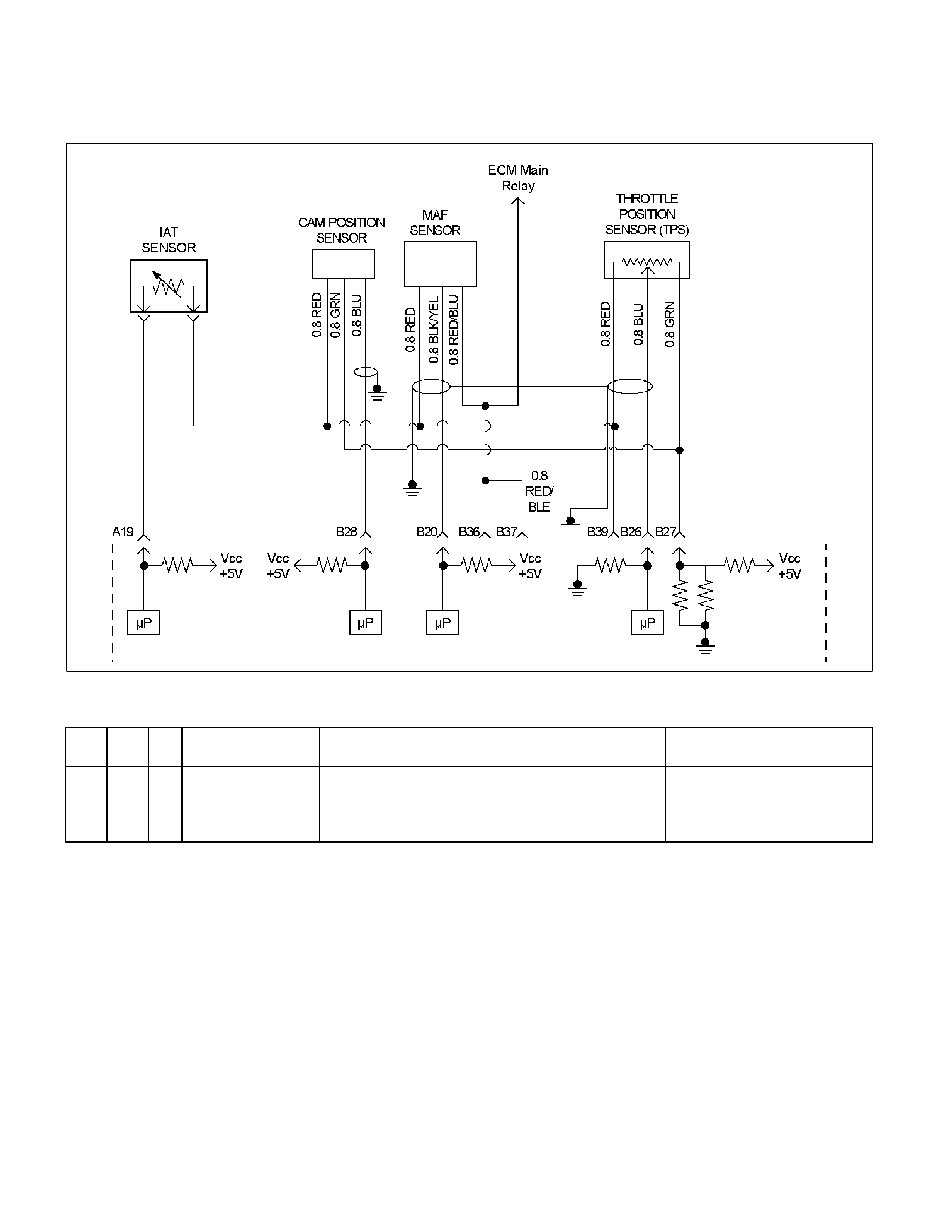
Diagnostic Trouble Code (DTC) P0102 (Flash Code 61) Mass Air Flow
Sensor Circuit Low Input
RTW36EMF000401
Condition For Setting The DTC and Action Taken When The DTC Sets
Flash
Code Code Ty pe DTC Name DTC Setting Condition Fail-Safe (Back Up)
61 P0102 A Mass Air Flow Sensor
Circuit Low Input MAF sens or output voltage is below 0.3V. The E CM uses default mass ai r f l ow
value based on IAC valve positi on,
throttl e position, barometer pres sure
and engine speed.
Circuit Description
The mass air flow (MAF) sensor measures the amount
of air which passes through it into the engine during a
given time. The Engine Control Module (ECM) uses the
mass air flow information to monitor engine operating
conditions for fuel delivery calculations. A large quantity
of air entering the engine indicates an acceleration or
high load situation, while a small quantity of air indicates
deceleration or idle.
The MAF sensor produces a frequency signal which
can be monitored using a Tech 2. The frequency will
vary within a range of around 4 to 7 g/s at idle to around
25 to 40 g/s at maximum engine load. DTC P0102 will
be set if the signal from the MAF sensor is below the
possible range of a normally operating MAF sensor.
.
Diagnostic Aids
Check for the following conditions:
• Poor connection at ECM – Inspect harness
connectors for backed-out terminals, improper
mating, broken locks, improperly formed or damaged
terminals, and poor terminal-to-wire connection.
• Misrouted harness – Inspect the MAF sensor
harness to ensure that it is not routed too close to
high voltage wires.
• Damaged harness – Inspect the wiring harness for
damage. If the harness appears to be OK, observe
the Tech 2 while moving connectors and wiring
harnesses related to the MAF sensor. A change in
the display will indicate the location of the fault.
If DTC P0102 cannot be duplicated, the information
included in the Failure Records data can be useful in
determining vehicle mileage since the DTC was last set
Diagnostic Trouble Code (DTC) P0102 (Flash Code 61) Mass Air Flow Sensor Circuit Low Input
Step Action Value (s) Yes No
1 Was the "On-Board Diagnostic (OBD) System Check"
performed? - Go to Step 2
Go to On Board
Diagnostic (OBD)
System Check
2 1. Connect the Tech 2.
2. Review and record the failure information.
3. Select "F0: Read DTC Infor By Priority" in "F0:
Diagnostic Trouble Code".
Is the DTC P0102 stored as "Present Failure"? - Go to Step 3
Refer to
Diagnostic Aids
and Go to Step 3
3 1. Using the Tech2, ignition "On" and engine "Off".
2. Select "Clear DTC Information" with the Tech2 and
clear the DTC information.
3. Operate the vehicle and monitor the "F5: Failed
This Ignition" in "F2: DTC Information"
Was the DTC P0102 stored in this ignition cycle? - Go to Step 4
Refer to
Diagnostic Aids
and Go to Step 4
4 Check for poor/faulty connection at the MAF sensor or
ECM connector. If a poor/faulty connection is found,
repair as necessary.
Was the problem found?
39
20
E-61(B)
E-63
1
3
4
- Verify repair Go to Step 5
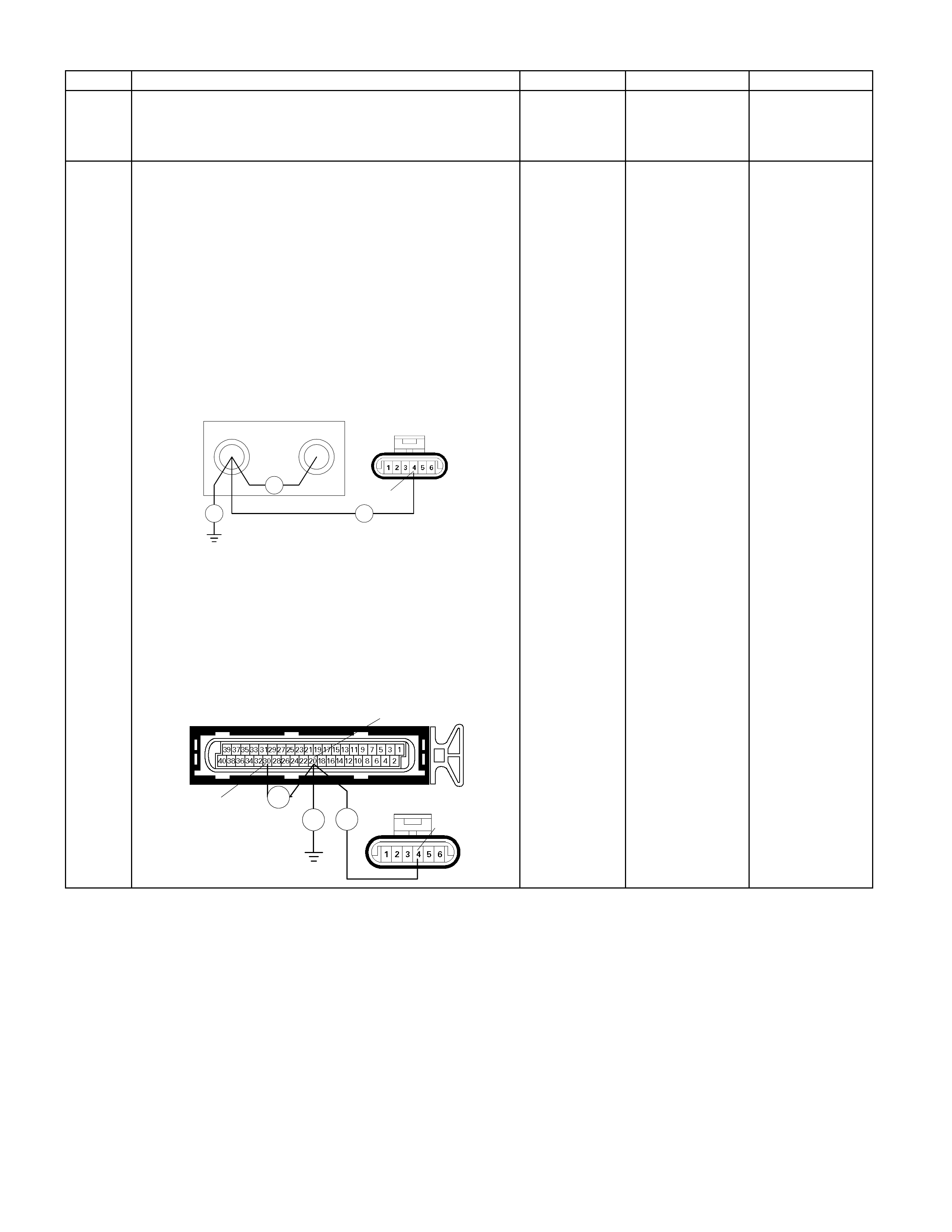
Step Action Value (s) Yes No
5 Remove the MAF & IAT sensor assembly and visually
check.
Was the problem found? - Go to Step 8 Go to Step 6
6
Using the DVM and check the MAF sensor signal
circuit.
Breaker box is available:
1. Ignition "Off", engine "Off".
2. Install the breaker box as type A (ECM
disconnected).
Refer to 6E-91 page.
3. Disconnect the MAF sensor connector.
4. Check the circuit for open, short to sensor ground
or short to ground circuit.
Was the problem found?
60 79
Ħ
Ħ
Breaker Box
4
E-63
Ħ
Breaker box is not available:
1. Ignition "Off", engine "Off".
2. Disconnect the MAF sensor connector and ECM
connector.
3. Check the circuit for open, short to sensor ground
or short to ground circuit.
Was the problem found?
E-61(B)
Ħ
Ħ Ħ E-63 4
20
30
-
Repair faulty
harness and
verify repair Go to Step 7
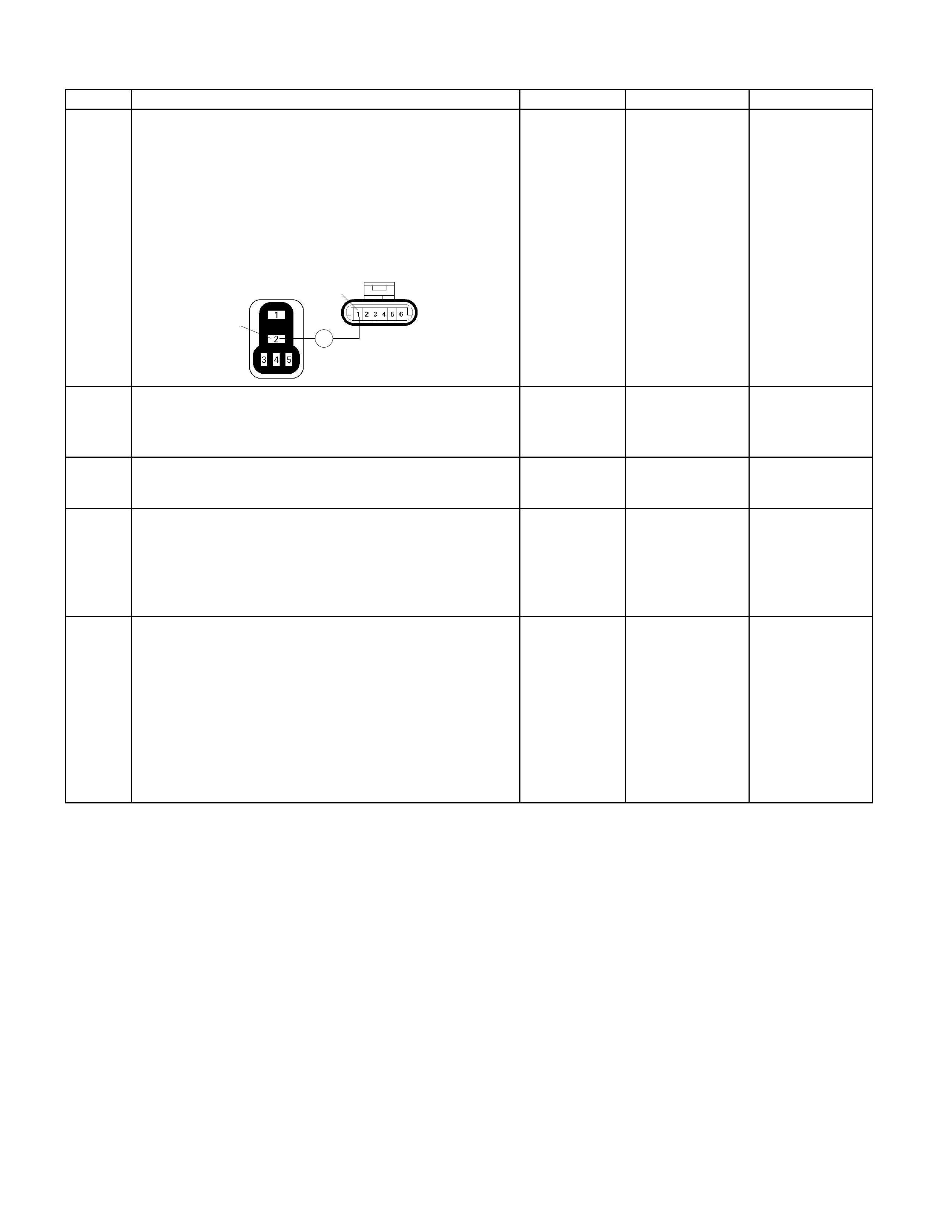
Step Action Value (s) Yes No
7
Using the DVM and check the MAF sensor power
supply circuit.
1. Ignition "Off", engine "Off".
2. Disconnect the MAF sensor connector and ECM
main relay.
3. Check the circuit for open circuit.
Was the problem found?
Ħ
X-13 E-63
2
1
-
Repair faulty
harness and
verify repair
Go to Step 8
8 Substitute a known good MAF & IAT sensor assembly
and recheck.
Was the problem solved? - Go to Step 9 Go to Step 10
9 Replace the MAF & IAT sensor assembly.
Is the action complete? - Verify repair -
10 Is the ECM programmed with the latest software
release?
If not, download the latest software to the ECM using
the "SPS (Service Programming System)".
Was the problem solved? - Verify repair Go to step 11
11 Replace the ECM.
Is the action complete?
IMPORTANT: The replacement ECM must be
programmed. Refer to section of the Service
Programming System (SPS) in this manual. Following
ECM programming, the immobiliser system (if
equipped) must be linked to the ECM. Refer to section
11 “Immobiliser System-ECM replacement” for the
ECM/Immobiliser linking procedure. - Verify repair -

Diagnostic Trouble Code (DTC) P0103 (Flash Code 61) Mass Air Flow
Sensor Circuit High Input
RTW36EMF000401
Condition For Setting The DTC and Action Taken When The DTC Sets
Flash
Code Code Type DTC Name DTC Setting Condition Fail-Safe (Back Up)
61 P0103 A Mass Air Flow Sens or
Circuit High Input MAF sensor output voltage is m ore than 4.9V. The ECM uses default mass air flow
value based on IAC valve positi on,
throttle position, barometer pressure
and engine speed.
Circuit Description
The mass air flow (MAF) sensor measures the amount
of air which passes through it into the engine during a
given time. The Engine Control Module (ECM) uses the
mass air flow information to monitor engine operating
conditions for fuel delivery calculations. A large quantity
of air entering the engine indicates an acceleration or
high load situation, while a small quantity of air indicates
deceleration or idle.
The MAF sensor produces a frequency signal which
can be monitored using a Tech 2. The frequency will
vary within a range of around 4 7 g/s at idle to around
25 to 40 g/s at maximum engine load. DTC P0103 will
be set if the signal from the MAF sensor is above the
possible range of a normally operating MAF sensor.
Diagnostic Aids
If DTC P0103 cannot be duplicated, the information
included in the Failure Records data can be useful in
determining vehicle mileage since the DTC was last set.
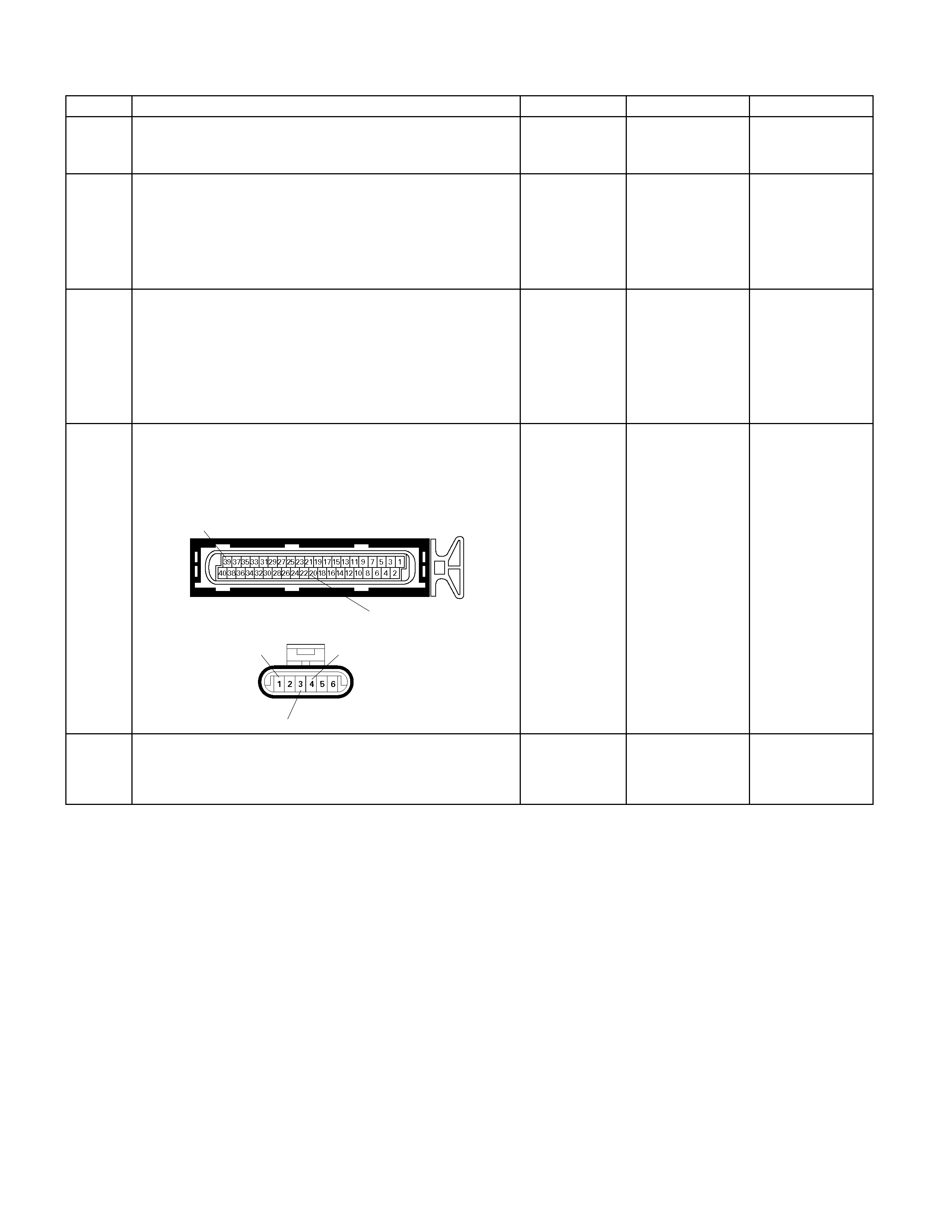
Diagnostic Trouble Code (DTC) P0103 (Flash Code 61) Mass Air Flow Sensor Circuit High Input
Step Action Value (s) Yes No
1 Was the "On-Board Diagnostic (OBD) System Check"
performed? - Go to Step 2
Go to On Board
Diagnostic (OBD)
System Check
2 1. Connect the Tech 2.
2. Review and record the failure information.
3. Select "F0: Read DTC Infor By Priority" in "F0:
Diagnostic Trouble Code".
Is the DTC P0103 stored as "Present Failure"? - Go to Step 3
Refer to
Diagnostic Aids
and Go to Step 3
3 1. Using the Tech2, ignition "On" and engine "Off".
2. Select "Clear DTC Information" with the Tech2 and
clear the DTC information.
3. Operate the vehicle and monitor the "F5: Failed
This Ignition" in "F2: DTC Information"
Was the DTC P0103 stored in this ignition cycle? - Go to Step 4
Refer to
Diagnostic Aids
and Go to Step 4
4 Check for poor/faulty connection at the MAF sensor or
ECM connector. If a poor/faulty connection is found,
repair as necessary.
Was the problem found?
39
20
E-61(B)
E-63
1
3
4
- Verify repair Go to Step 5
5 Remove the MAF & IAT sensor assembly and visually
check.
Was the problem found? - Go to Step 9 Go to Step 6
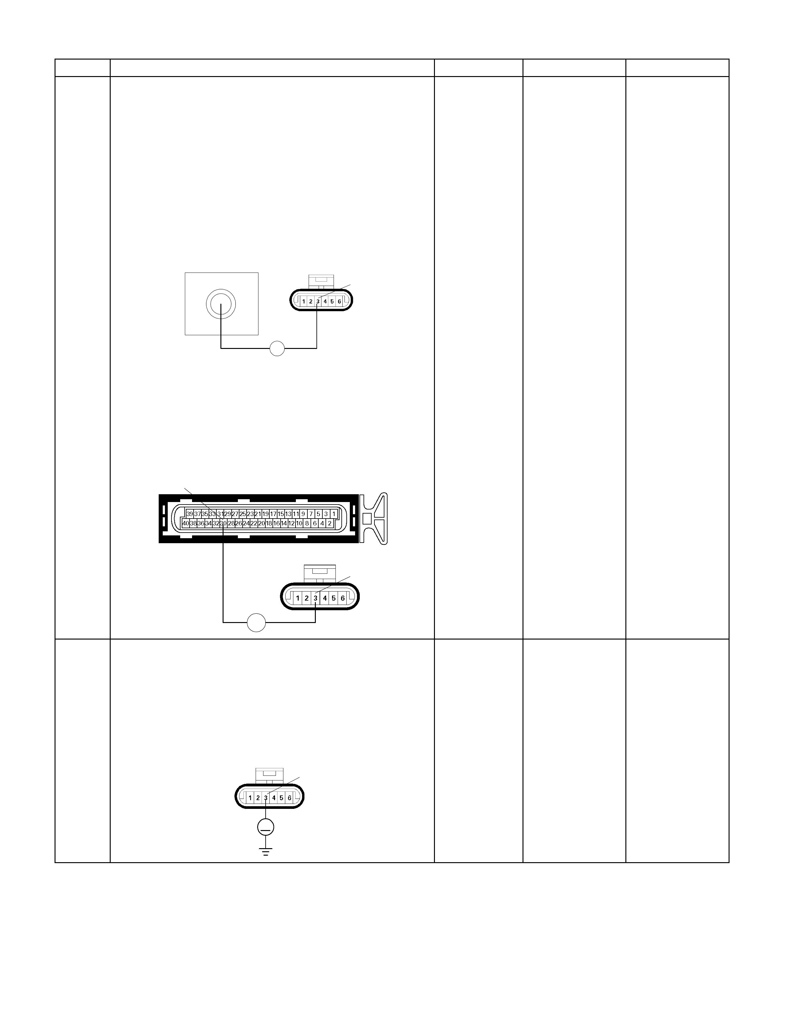
Step Action Value (s) Yes No
6
Using the DVM and check the MAF sensor ground
circuit.
Breaker box is available:
1. Ignition "Off", engine "Off".
2. Install the breaker box as type A (ECM
disconnected).
Refer to 6E-91 page.
3. Disconnect the MAF sensor connector.
4. Check the circuit for open circuit.
Was the problem found?
79
Breaker Box E-63
Ħ
3
Breaker box is not available:
1. Ignition "Off", engine "Off".
2. Disconnect the MAF sensor connector and ECM
connector.
3. Check the circuit for open circuit.
Was the problem found?
E-63
E-61(B)
Ħ
30
3
-
Repair faulty
harness and
verify repair
Go to Step 7
7
Using the DVM and check the MAF sensor ground
circuit.
1. Ignition "On", engine "Off".
2. Disconnect the MAF sensor connector .
3. Check the circuit for short to power supply circuit.
Was the DVM indicated specified value?
E-63
V
3
Less than 1V
Go to Step 8
Repair faulty
harness and
verify repair

Step Action Value (s) Yes No
8
Using the DVM and check the MAF sensor signal
circuit.
1. Ignition "On", engine "Off".
2. Disconnect the MAF sensor connector.
3. Check the circuit for short to power supply circuit.
Was the DVM indicated specified value?
E-63
V
4
Less than 1V
Go to Step 11
Repair faulty
harness and
verify repair
9 Substitute a known good MAF & IAT sensor assembly
and recheck.
Was the problem solved? - Go to Step 10 Go to Step 11
10 Replace the MAF & IAT sensor assembly.
Is the action complete? - Verify repair -
11 Is the ECM programmed with the latest software
release?
If not, download the latest software to the ECM using
the "SPS (Service Programming System)".
Was the problem solved? - Verify repair Go to step 12
12 Replace the ECM.
Is the action complete?
IMPORTANT: The replacement ECM must be
programmed. Refer to section of the Service
Programming System (SPS) in this manual. Following
ECM programming, the immobiliser system (if
equipped) must be linked to the ECM. Refer to section
11 “Immobiliser System-ECM replacement” for the
ECM/Immobiliser linking procedure. - Verify repair -

Diagnostic Trouble Code (DTC) P0107 (Flash Code 33)
Barometer Sensor Voltage Low
Diagnostic Trouble Code (DTC) P0108 (Flash Code 33)
Barometer Sensor Voltage High
Condition For Setting The DTC and Action Taken When The DTC Sets
Flash
Code Code Type DTC Name DTC Setting Condition Fail-Safe (Back Up)
33 P0107 A Barometer Sensor
Voltage Low Barometer sensor output voltage is bel ow 0.1V .
P0108 A Barometer Sensor
Voltage High Barometer s ensor output voltage is more than 5.1V.
The ECM use output voltage 4.8V
condition as subs titute.
Circuit Description
The ECM monitors the Barometer signals for voltages
outside the normal range of the Barometer sensor. If
the ECM detects a Barometer signal voltage that is
excessively low, DTC P0107 will be set.
If the ECM detects a Barometer signal voltage that is
excessively high, DTC P0108 will be set.
Diagnostic Aids
If DTC P0107 or P0108 cannot be duplicated, the
information included in the Failure Records data can be
useful in determining vehicle mileage since the DTC
was last set. If it is determined that the DTC occurs
intermittently, performing the DTC P0107 or P0108
Diagnostic Chart (Check procedure) may isolate the
cause of the fault.

Diagnostic Trouble Code (DTC) P0107 (Flash Code 33) Barometer Sensor Voltage Low
Diagnostic Trouble Code (DTC) P0108 (Flash Code 33) Barometer Sensor Voltage High
Step Action Value (s) Yes No
1 Was the "On-Board Diagnostic (OBD) System Check"
performed? - Go to Step 2
Go to On Board
Diagnostic (OBD)
System Check
2 1. Connect the Tech 2.
2. Review and record the failure information.
3. Select "F0: Read DTC Infor By Priority" in "F0:
Diagnostic Trouble Code".
Is the DTC P0107 or P0108 stored as "Present
Failure"? - Go to Step 3
Refer to
Diagnostic Aids
and Go to Step 3
3 1. Using the Tech2, ignition "On" and engine "Off".
2. Select "Clear DTC Information" with the Tech2 and
clear the DTC information.
3. Operate the vehicle and monitor the "F5: Failed
This Ignition" in "F2: DTC Information"
Was the DTC P0107 or P0108 stored in this ignition
cycle? - Go to Step 4 Refer to
Diagnostic Aids
4 Is the ECM programmed with the latest software
release?
If not, download the latest software to the ECM using
the "SPS (Service Programming System)".
Was the problem solved? - Verify repair Go to step 5
5 Replace the ECM.
Is the action complete?
IMPORTANT: The replacement ECM must be
programmed. Refer to section of the Service
Programming System (SPS) in this manual. Following
ECM programming, the immobiliser system (if
equipped) must be linked to the ECM. Refer to section
11 “Immobiliser System-ECM replacement” for the
ECM/Immobiliser linking procedure. - Verify repair -
Diagnostic Trouble Code (DTC) P0112 (Flash Code 23) Intake Air
Temperature (IAT) Sensor Low Input
RTW36EMF000401
Condition For Setting The DTC and Action Taken When The DTC Sets
Flash
Code Code Type DTC Name DTC Setting Condition Fail-Safe (Back Up)
23 P0112 A Intake Air Temperature
Sensor Low Input IAT sensor output voltage is below 0.08V. The ECM use 40°C conditions as
substitute.
Circuit Description
The intake air temperature (IAT) sensor is a thermistor
which measures the temperature of the air entering the
engine. The Engine Control Module (ECM) applies 5
volts through a pull-up resistor to the IAT sensor. When
the intake air is cold, the sensor resistance is high and
the ECM will monitor a high signal voltage on the IAT
signal circuit. If the intake air is warm, the sensor
resistance is lower, causing the ECM to monitor a lower
voltage. DTC P0112 will set when the ECM detects an
excessively low signal voltage on the intake air
temperature sensor signal circuit.
Diagnostic Aids
Check for the following conditions:
• Poor connection at ECM – Inspect harness
connectors for backed-out terminals, improper
mating, broken locks, improperly formed or damaged
terminals, and poor terminal-to-wire connection.
• Damaged harness – Inspect the wiring harness for
damage. If the harness appears to be OK, observe
the IAT display on the Tech 2 while moving
connectors and wiring harnesses related to the IAT
sensor. A change in the IAT display will indicate the
location of the fault.
If DTC P0112 cannot be duplicated, the information
included in the Failure Records data can be useful in
determining vehicle mileage since the DTC was last set.
Diagnostic Trouble Code (DTC) P0112 (Flash Code 23) Intake Air Temperature (IAT) Sensor Low Input
Step Action Value (s) Yes No
1 Was the "On-Board Diagnostic (OBD) System Check"
performed? - Go to Step 2
Go to On Board
Diagnostic (OBD)
System Check
2 1. Connect the Tech 2.
2. Review and record the failure information.
3. Select "F0: Read DTC Infor By Priority" in "F0:
Diagnostic Trouble Code".
Is the DTC P0112 stored as "Present Failure"? - Go to Step 3
Refer to
Diagnostic Aids
and Go to Step 3
3 1. Using the Tech2, ignition "On" and engine "Off".
2. Select "Clear DTC Information" with the Tech2 and
clear the DTC information.
3. Operate the vehicle and monitor the "F5: Failed
This Ignition" in "F2: DTC Information"
Was the DTC P0112 stored in this ignition cycle? - Go to Step 4
Refer to
Diagnostic Aids
and Go to Step 4
4 Check for poor/faulty connection at the IAT sensor or
ECM connector. If a poor/faulty connection is found,
repair as necessary.
Was the problem found?
E-60(A)
E-61(B)
E-63
19
39
6
5
- Verify repair Go to Step 5

Step Action Value (s) Yes No
5 Remove the MAF & IAT sensor assembly and visually
check.
Was the problem found? - Go to Step 8 Go to Step 6
6
Using the DVM and check the IAT sensor.
1. Ignition "Off", engine "Off".
2. Disconnect IAT sensor connector.
3. Measure the resistance of IAT sensor.
Does the tester indicate standard resistance as shown
in the following table?
MAF & IAT Sensor
5
6
Ħ
Temperature (°C) Resistance (Ω)
(Approximately)
-20 14210
0 5402
20 2343
40 1131
60 596
80 338
100 203 Standard
resistance Go to Step 7 Go to Step 8
Step Action Value (s) Yes No
7
Using the DVM and check the IAT sensor signal
circuit.
Breaker box is available:
1. Ignition "Off", engine "Off".
2. Install the breaker box as type A (ECM
disconnected).
Refer to 6E-91 page.
3. Disconnect the IAT sensor connector.
4. Check the circuit for short to sensor ground or
ground circuit.
Was the problem found?
19 79
Ħ
Breaker Box
Ħ
Breaker box is not available:
1. Ignition "Off", engine "Off".
2. Disconnect the IAT sensor connector.
3. Check the circuit for short to sensor ground or
ground circuit.
Was the problem found? E-60(A)
E-61(B)
Ħ
19
39
Ħ
-
Repair faulty
harness and
verify repair
Go to Step 10

Step Action Value (s) Yes No
8 Substitute a known good MAF & IAT sensor assembly
and recheck.
Was the problem solved? - Go to Step 9 Go to Step 10
9 Replace the MAF & IAT sensor assembly.
Is the action complete? - Verify repair -
10 Is the ECM programmed with the latest software
release?
If not, download the latest software to the ECM using
the "SPS (Service Programming System)".
Was the problem solved? - Verify repair Go to step 11
11 Replace the ECM.
Is the action complete?
IMPORTANT: The replacement ECM must be
programmed. Refer to section of the Service
Programming System (SPS) in this manual. Following
ECM programming, the immobiliser system (if
equipped) must be linked to the ECM. Refer to section
11 “Immobiliser System-ECM replacement” for the
ECM/Immobiliser linking procedure. - Verify repair -

Diagnostic Trouble Code (DTCP0113 (Flash Code 23) Intake Ai r
Temperature (IAT)Sensor High Input
RTW36EMF000401
Condition For Setting The DTC and Action Taken When The DTC Sets
Flash
Code Code Type DTC Name DTC Setting Condition Fail-Safe (Back Up)
23 P0113 A Intake Air Temperature
Sensor High Input IAT sensor output voltage is more than 4.9V . The ECM use 40°C conditions as
substitute.
Circuit Description
The intake air temperature (IAT) sensor is a thermistor
which measures the temperature of the air entering the
engine. The Engine Control Module (ECM) applies 5
volts through a pull-up resistor to the IAT sensor. When
the intake air is cold, the sensor resistance is high and
the ECM will monitor a high signal voltage on the IAT
signal circuit. If the intake air is warm, the sensor
resistance is lower causing the ECM to monitor a lower
voltage. DTC P0113 will set when the ECM detects an
excessively high signal voltage on the intake air
temperature sensor signal circuit.
Diagnostic Aids
Check for the following conditions:
• Poor connection at ECM – Inspect harness
connectors for backed-out terminals, improper
mating, broken locks, improperly formed or damaged
terminals, and poor terminal-to-wire connection.
• Damaged harness – Inspect the wiring harness for
damage. If the harness appears to be OK, observe
the IAT display on the Tech 2 while moving
connectors and wiring harnesses related to the IAT
sensor. A change in the IAT display will indicate the
location of the fault.
If DTC P0113 cannot be duplicated, the information
included in the Failure Records data can be useful in
determining vehicle mileage since the DTC was last set.

Diagnostic Trouble Code (DTC) P0113 (Flash Code 23) Intake Air Temperature (IAT) Sensor High Input
Step Action Value (s) Yes No
1 Was the "On-Board Diagnostic (OBD) System Check"
performed? - Go to Step 2
Go to On Board
Diagnostic (OBD)
System Check
2 1. Connect the Tech 2.
2. Review and record the failure information.
3. Select "F0: Read DTC Infor By Priority" in "F0:
Diagnostic Trouble Code".
Is the DTC P0113 stored as "Present Failure"? - Go to Step 3
Refer to
Diagnostic Aids
and Go to Step 3
3 1. Using the Tech2, ignition "On" and engine "Off".
2. Select "Clear DTC Information" with the Tech2 and
clear the DTC information.
3. Operate the vehicle and monitor the "F5: Failed
This Ignition" in "F2: DTC Information"
Was the DTC P0113 stored in this ignition cycle? - Go to Step 4
Refer to
Diagnostic Aids
and Go to Step 4
Step Action Value (s) Yes No
4 Check for poor/faulty connection at the IAT sensor or
ECM connector. If a poor/faulty connection is found,
repair as necessary.
Was the problem found?
E-60(A)
E-61(B)
E-63
19
39
6
5
- Verify repair Go to Step 5
5 Visually check the IAT sensor.
Was the problem found? - Go to Step 12 Go to Step 6
6
Using the DVM and check the IAT sensor.
1. Ignition "Off", engine "Off".
2. Disconnect IAT sensor connector.
3. Measure the resistance of IAT sensor.
Does the tester indicate standard resistance as shown
in the following table?
MAF & IAT Sensor
5
6
Ħ
Temperature (°C) Resistance (Ω)
(Approximately)
-20 14210
0 5402
20 2343
40 1131
60 596
80 338
100 203
Standard
resistance
Go to Step 7
Go to Step 12
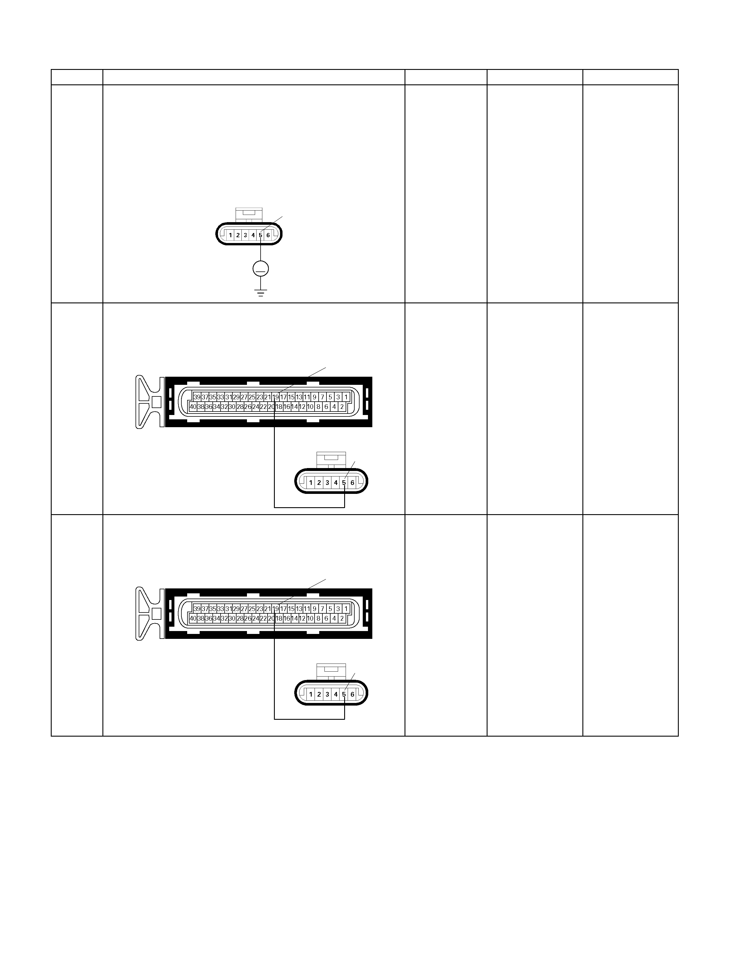
Step Action Value (s) Yes No
7
Using the DVM and check the IAT sensor signal
circuit.
1. Ignition "On", engine "Off".
2. Disconnect the IAT sensor connector.
3. Check the circuit for open circuit.
Was the DVM indicated specified value?
E-63
V
5
A
pproximately
5.0V
Go to Step 10
Less than 1V:
Go to Step 8
More than
specified value:
Go to Step 9
8 Repair the open circuit between the ECM and IAT
sensor.
Was the problem solved? E-60(A)
E-63 5
19
- Verify repair Go to Step 14
9 Repair the short to voltage circuit between the ECM
and IAT sensor.
Was the problem solved? E-60(A)
E-63 5
19
- Verify repair Go to Step 14
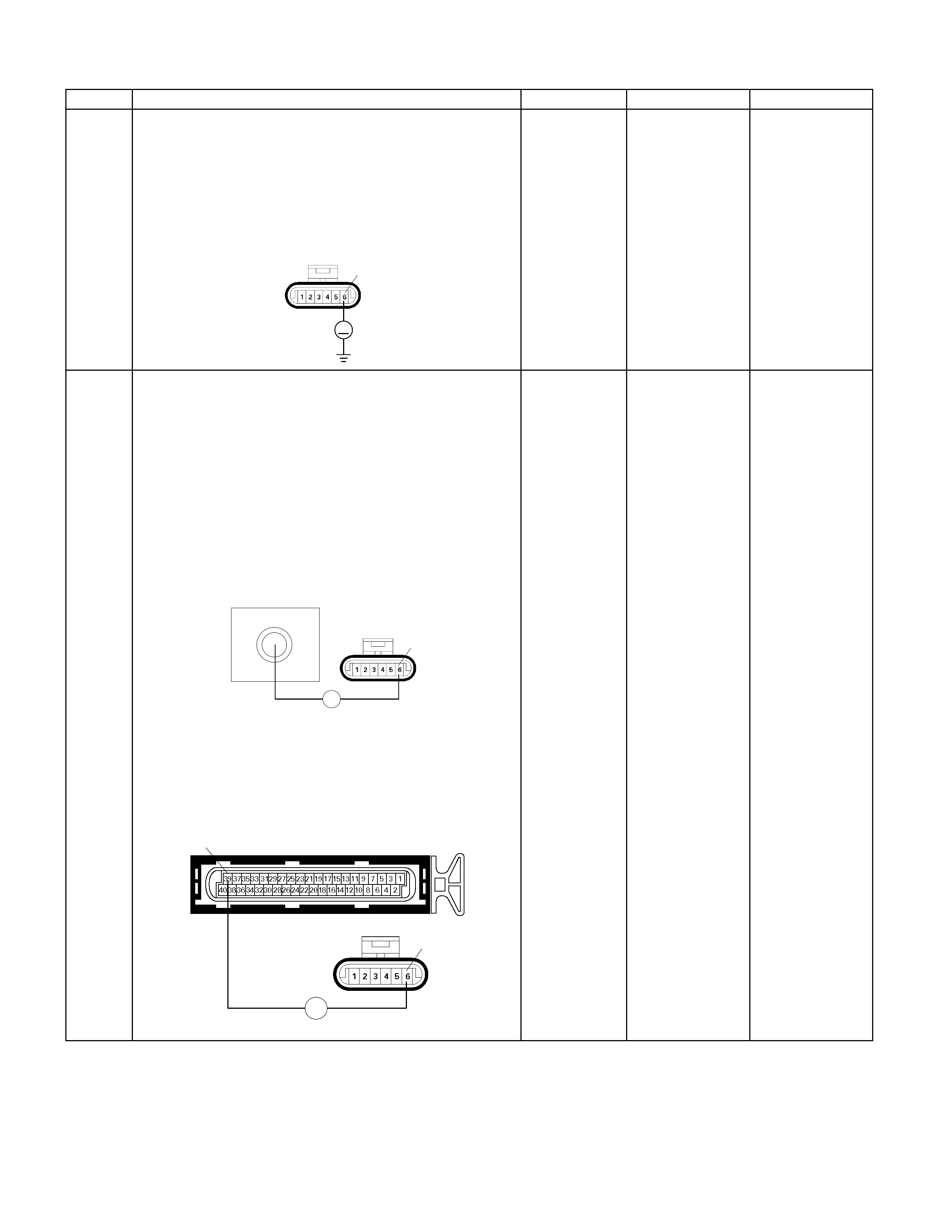
Step Action Value (s) Yes No
10
Using the DVM and check the IAT sensor ground
circuit.
1. Ignition "On", engine "Off".
2. Disconnect the IAT sensor connector.
3. Check the circuit for short to power supply circuit.
Was the DVM indicated specified value?
E-63
V
6
Less than 1V
Go to Step 11
Repair faulty
harness and
verify repair
11
Using the DVM and check the IAT sensor ground
circuit.
Breaker box is available:
1. Ignition "Off", engine "Off".
2. Install the breaker box as type A (ECM
disconnected).
Refer to 6E-91 page.
3. Disconnect the IAT sensor connector.
4. Check the circuit for open circuit.
Was the problem found?
79
Breaker Box
E-63
Ħ
6
Breaker box is not available:
1. Ignition "Off", engine "Off".
2. Disconnect the IAT sensor connector.
3. Check the circuit for open circuit.
Was the problem found?
E-61(B)
E-63
Ħ
6
39
-
Repair faulty
harness and
verify repair Go to Step 14

Step Action Value (s) Yes No
12 Substitute a known good MAF & IAT sensor assembly
and recheck.
Was the problem solved? - Go to Step 13 Go to Step 14
13 Replace the MAF & IAT sensor assembly.
Is the action complete? - Verify repair -
14 Is the ECM programmed with the latest software
release?
If not, download the latest software to the ECM using
the "SPS (Service Programming System)".
Was the problem solved? - Verify repair Go to step 15
15 Replace the ECM.
Is the action complete?
IMPORTANT: The replacement ECM must be
programmed. Refer to section of the Service
Programming System (SPS) in this manual. Following
ECM programming, the immobiliser system (if
equipped) must be linked to the ECM. Refer to section
11 “Immobiliser System-ECM replacement” for the
ECM/Immobiliser linking procedure. - Verify repair -
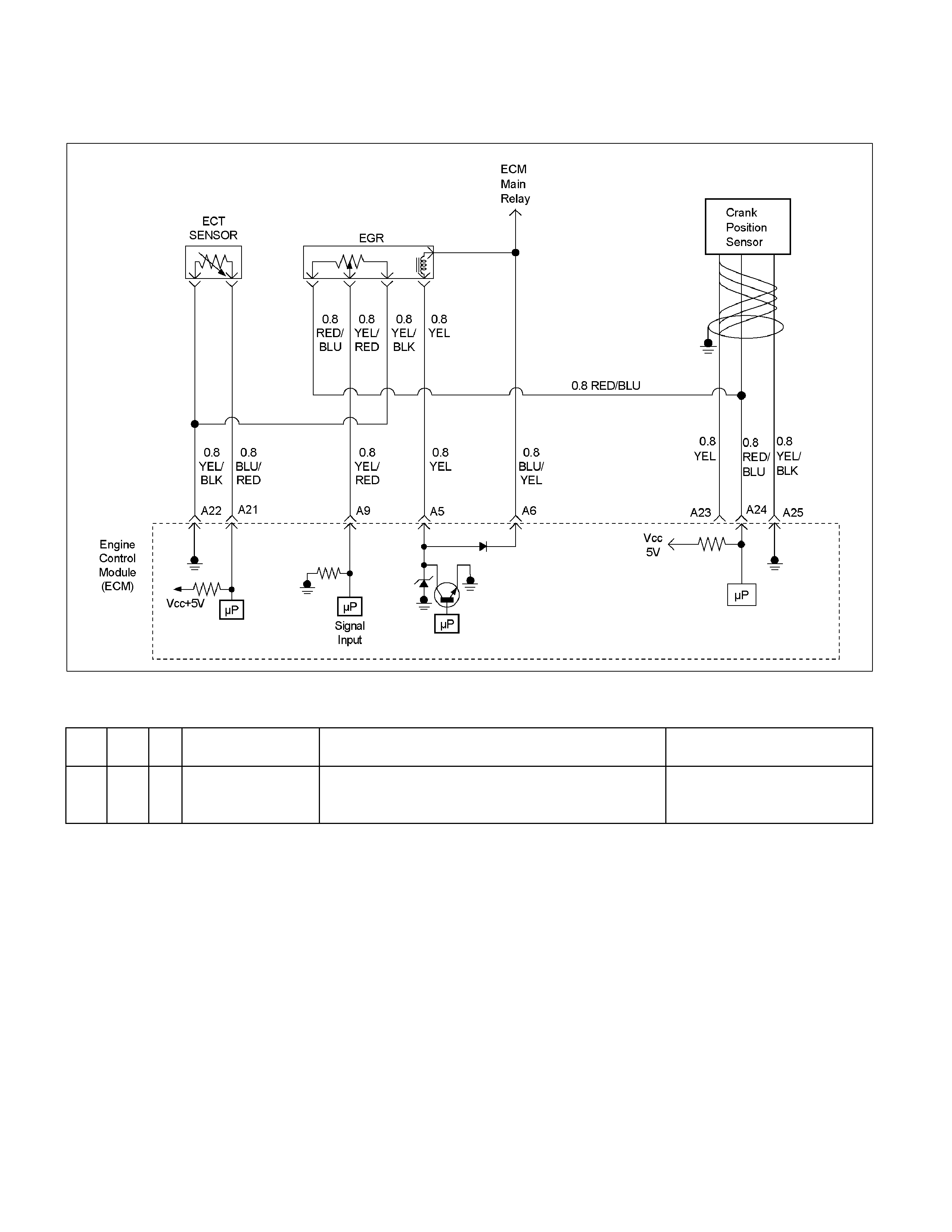
Diagnostic Trouble Code (DTC) P0117 (Flash Code 14) Engine
Coolant Temperature (ECT) Sensor Low Input
RTW36EMF000501
Condition For Setting The DTC and Action Taken When The DTC Sets
Flash
Code Code Type DTC Name DTC Setting Condition Fail-Safe (Back Up)
14 P0117 A Engine Coolant
Temperature Sensor
Low Input
ECT sensor output voltage i s below 0.08V. The ECM uses default engine
coolant temperat ure val ue based on
start -up E CT and time f rom start.
Circuit Description
The engine coolant temperature (ECT) sensor is a
thermistor mounted on a coolant crossover pipe at the
rear of the engine. The Engine Control Module (ECM)
applies a voltage (about 5 volts) through a pull-up
resistor to the ECT signal circuit. When the engine
coolant is cold, the sensor (thermistor) resistance is
high, therefore the ECM will measure a high signal
voltage. As the engine coolant warms, the sensor
resistance becomes lower, and the ECT signal voltage
measured at the ECM drops. With a fully warmed-up
engine, the ECT signal voltage should measure about
1.5 to 2.0 volts.
Diagnostic Aids
Check for the following conditions:
• Poor connection at ECM – Inspect harness
connectors for backed-out terminals, improper
mating, broken locks, improperly formed or damaged
terminals, and poor terminal-to-wire connection.
• Damaged harness – Inspect the wiring harness for
damage. If the harness appears to be OK, observe
the ECT display on the Tech 2 while moving
connectors and wiring harnesses related to the ECT
sensor. A change in the ECT display will indicate the
location of the fault.
If DTC P0117 cannot be duplicated, the information
included in the Failure Records data can be useful in
determining vehicle mileage since the DTC was last set.
If it is determined that the DTC occurs intermittently.
Diagnostic Trouble Code (DTC) P0117 (Flash Code 14) Engine Coolant Temperature (ECT) Sensor Low Input
Step Action Value (s) Yes No
1 Was the "On-Board Diagnostic (OBD) System Check"
performed? - Go to Step 2
Go to On Board
Diagnostic (OBD)
System Check
2 1. Connect the Tech 2.
2. Review and record the failure information.
3. Select "F0: Read DTC Infor By Priority" in "F0:
Diagnostic Trouble Code".
Is the DTC P0117 stored as "Present Failure"? - Go to Step 3
Refer to
Diagnostic Aids
and Go to Step 3
3 1. Using the Tech2, ignition "On" and engine "Off".
2. Select "Clear DTC Information" with the Tech2 and
clear the DTC information.
3. Operate the vehicle and monitor the "F5: Failed
This Ignition" in "F2: DTC Information"
Was the DTC P0117 stored in this ignition cycle? - Go to Step 4
Refer to
Diagnostic Aids
and Go to Step 4
4 Check for poor/faulty connection at the ECT sensor or
ECM connector. If a poor/faulty connection is found,
repair as necessary.
Was the problem found?
E-69
E-60(A) 21
22
12
- Verify repair Go to Step 5
5 Visually check the ECT sensor.
Was the problem found? - Go to Step 8 Go to Step 6
6
Using the DVM and check the ECT sensor.
1. Ignition "Off", engine "Off".
2. Disconnect ECT sensor connector.
3. Measure the resistance of ECT sensor.
Does the tester indicate standard resistance as shown
in the following table?
ECT Sensor
Ħ
12
Temperature (°C) Resistance (Ω)
(Approximately)
-20 32040
0 9788
20 3516
40 1439
60 656
80 327
100 175
Standard
resistance
Go to Step 7
Go to Step 8
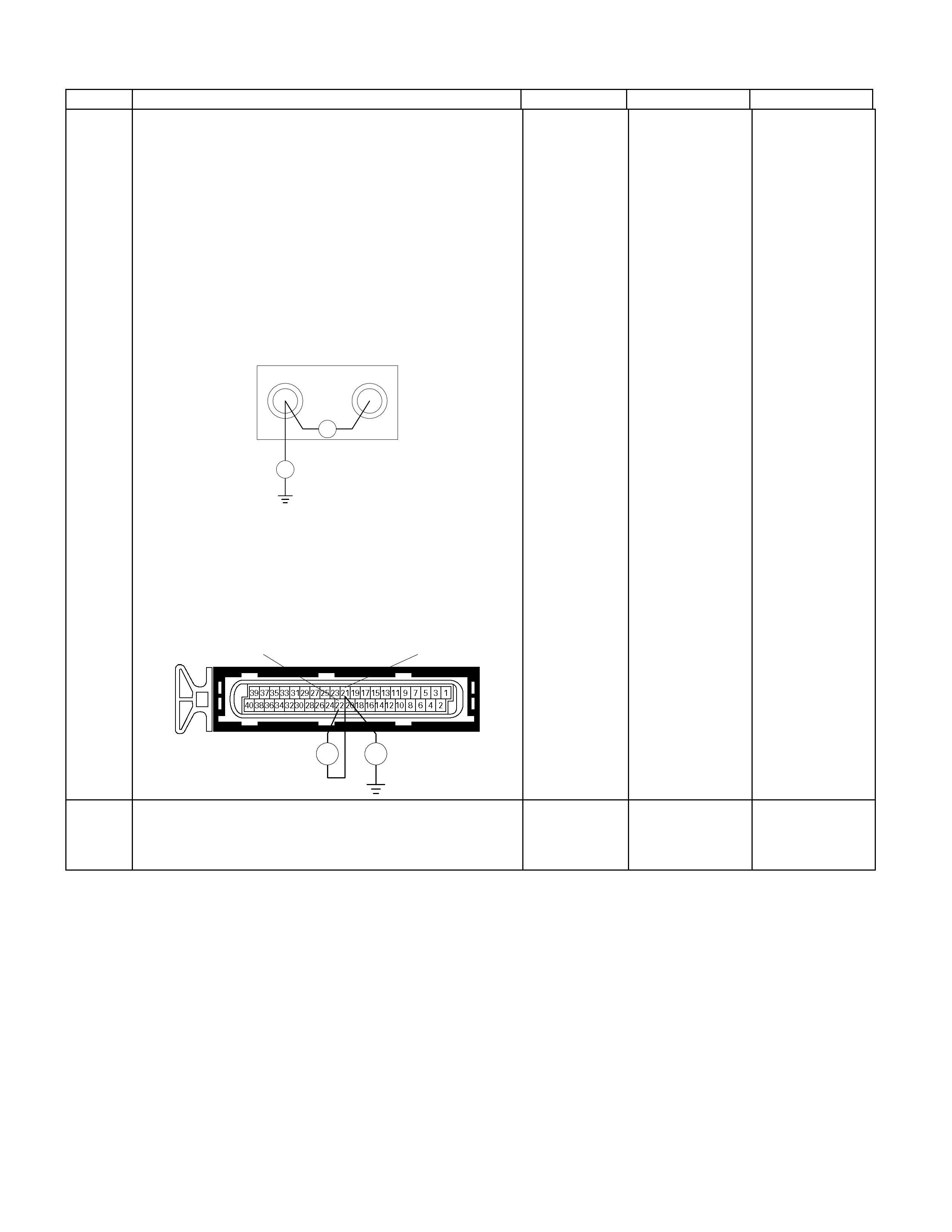
Step Action Value (s) Yes No
7
Using the DVM and check the ECT sensor signal
circuit.
Breaker box is available:
1. Ignition "Off", engine "Off".
2. Install the breaker box as type A (ECM
disconnected).
Refer to 6E-91 page.
3. Disconnect the ECT sensor connector.
4. Check the circuit for short to sensor ground or
ground circuit.
Was the problem found?
21 22
Ħ
Breaker Box
Ħ
Breaker box is not available:
1. Ignition "Off", engine "Off".
2. Disconnect the ECT sensor connector.
3. Check the circuit for short to sensor ground or
ground circuit.
Was the problem found? E-60(A)
Ħ Ħ
2122
-
Repair faulty
harness and
verify repair
Go to Step 10
8 Substitute a known good ECT sensor assembly and
recheck.
Was the problem solved? - Go to Step 9 Go to Step 10

Step Action Value (s) Yes No
9 Replace the ECT sensor.
Is the action complete? - Verify repair -
10 Is the ECM programmed with the latest software
release?
If not, download the latest software to the ECM using
the "SPS (Service Programming System)".
Was the problem solved? - Verify repair Go to step 11
11 Replace the ECM.
Is the action complete?
IMPORTANT: The replacement ECM must be
programmed. Refer to section of the Service
Programming System (SPS) in this manual. Following
ECM programming, the immobiliser system (if
equipped) must be linked to the ECM. Refer to section
11 “Immobiliser System-ECM replacement” for the
ECM/Immobiliser linking procedure. - Verify repair -

Diagnostic Trouble Code (DTC) P0118 (Flash Code 14)
Engine Coolant Temperature (ECT) Sensor High Input
RTW36EMF000501
Condition For Setting The DTC and Action Taken When The DTC Sets
Flash
Code Code Type DTC Name DTC Setting Condition Fail-Safe (Back Up)
14 P0118 A Engine Coolant
Temperature Sensor
High Input
ECT sensor output voltage is more than 4.8V. The ECM uses default engine
coolant temperature value based on
start-up ECT and time from start.
Circuit Description
The engine coolant temperature (ECT) sensor is a
thermistor mounted in on a coolant crossover pipe at
the rear of the engine. The Engine Control Module
(ECM) applies a voltage (about 5 volts) through a
pull-up resistor to the ECT signal circuit. When the
engine coolant is cold, the sensor (thermistor)
resistance is high, therefore the ECM will measure a
high signal voltage. As the engine coolant warms, the
sensor resistance becomes less, and the ECT signal
voltage measured at the ECM drops. With a fully
warmed-up engine, the ECT signal voltage should
measure about 1.5 to 2.0 volts.
Diagnostic Aids
Check for the following conditions:
• Poor connection at ECM – Inspect harness
connectors for backed-out terminals, improper
mating, broken locks, improperly formed or damaged
terminals, and poor terminal-to-wire connection.
• Damaged harness – Inspect the wiring harness for
damage. If the harness appears to be OK, observe
the ECT display on the Tech 2 while moving
connectors and wiring harnesses related to the ECT
sensor. A change in the ECT display will indicate the
location of the fault.
If DTC P0118 cannot be duplicated, the information
included in the Failure Records data can be useful in
determining vehicle mileage since the DTC was last
set.
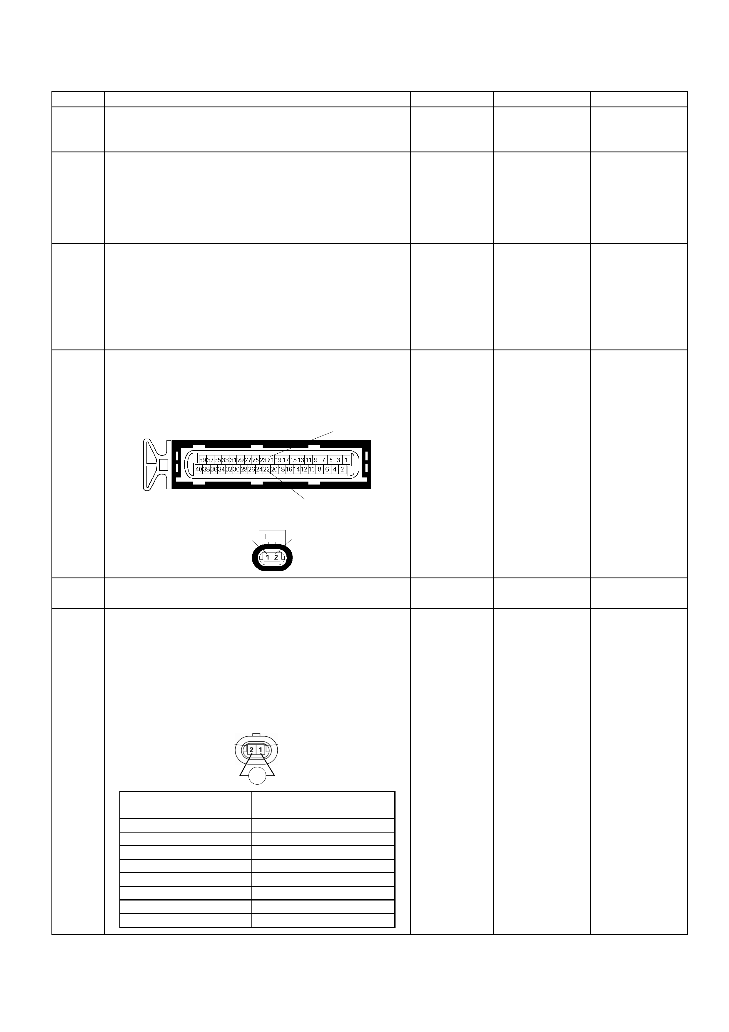
Diagnostic Trouble Code (DTC) P0118 (Flash Code 14) Engine Coolant
Temperature (ECT) Sensor High Input
Step Action Value (s) Yes No
1 Was the "On-Board Diagnostic (OBD) System Check"
performed? - Go to Step 2
Go to On Board
Diagnostic (OBD)
System Check
2 1. Connect the Tech 2.
2. Review and record the failure information.
3. Select "F0: Read DTC Infor By Priority" in "F0:
Diagnostic Trouble Code".
Is the DTC P0118 stored as "Present Failure"? - Go to Step 3
Refer to
Diagnostic Ai ds
and Go to Step 3
3 1. Using the Tech2, ignition "On" and engine "Off".
2. Select "C lear DTC Inf ormation" with the T ech2 and
clear the DTC information.
3. Operate the vehicle and monitor the "F5: Failed
This Ignition" in "F2: DTC Information"
Was the DTC P0118 stored in this ignition cycle? - Go to Step 4
Refer to
Diagnostic Ai ds
and Go to Step 4
4 Check for poor/fault y connec tion at the ECT sens or or
ECM connector. If a poor/faulty connection is found,
repair as necess ary.
Was the problem found?
E-69
E-60(A) 21
22
12
- Verify repair Go to Step 5
5 Visually check the ECT sensor. Was the problem
found? - Go to Step 12 Go to Step 6
6
Using the DVM and check the ECT sensor.
1. Ignition "Off", engine "Off".
2. Disconnect ECT sensor connector.
3. Measure the resistance of ECT sensor.
Does the tes ter in dic at e s ta ndard r es istanc e as s h o wn
in the following table?
ECT Sensor
Ħ
12
Temperature (°C) Resistance (Ω)
(Approximately)
-20 32040
0 9788
20 3516
40 1439
60 656
80 327
100 175
120 100
Standard
resistance
Go to Step 7
Go to Step 12
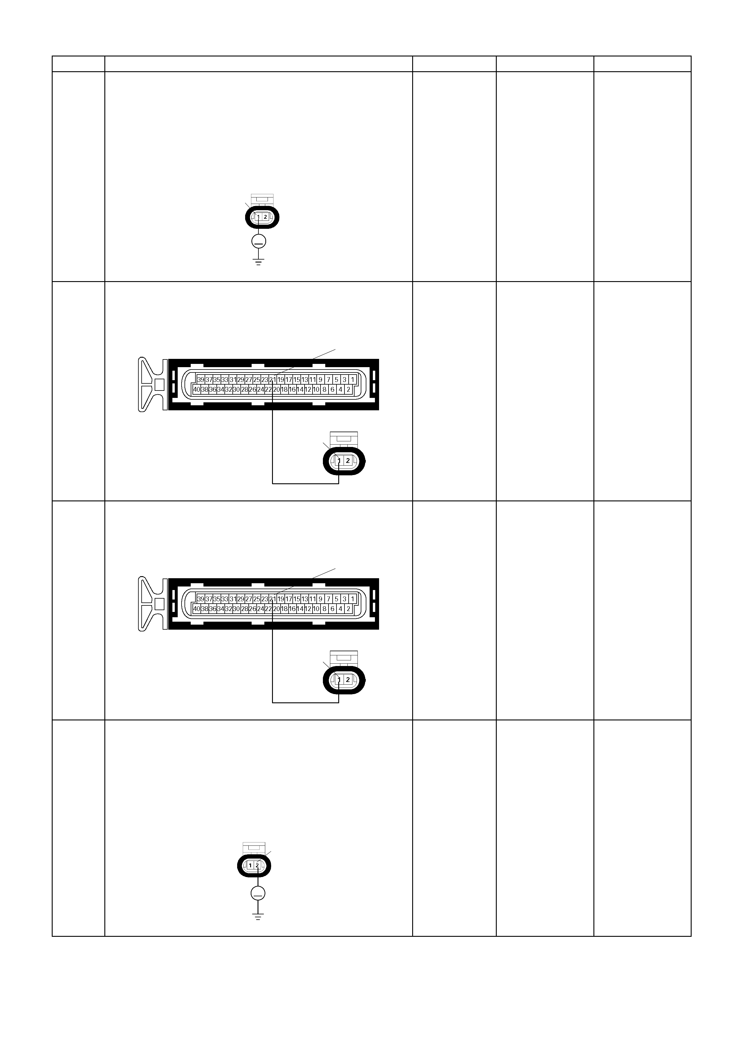
Step Action Value (s) Yes No
7
Using the DVM and check the ECT sensor signal
circuit.
1. Ignition "On", engine "Off".
2. Disconnec t the ECT sens or connec tor .
3. Check the circuit for open circuit.
Was the DVM indicated specified value?
E-69
V
1
A
pproximately
5.0V
Go to Step 10
Less than 1V:
Go to Step 8
More than
specif ied value:
Go to Step 9
8 Repair the open circuit between the ECM and ECT
sensor.
Was the problem solved? E-60(A)
E-69
21
1
- Verify repair Go to Step 14
9 Repair the short to voltage circuit between the ECM
and ECT sensor .
Was the problem solved? E-60(A)
E-69
21
1
- Verify repair Go to Step 14
10
Using the DVM and check the ECT sensor ground
circuit.
1. Ignition "On", engine "Off".
2. Disconnec t the ECT sens or connector .
3. Check the circuit for short to power supply circuit.
Was the DVM indicated specified value?
E-69
V
2
Less than 1V
Go to Step 11
Repair faulty
harness and
verify repair

Step Action Value (s) Yes No
11
Using the DVM and check the ECT sensor ground
circuit.
Breaker box is available:
1. Ignition "Off", engine "Off".
2. Install the breaker box as type A (ECM
disconnected)
Refer to 6E-91 page.
3. Disconnec t the ECT sens or connector .
4. Check the circuit for open circuit.
Was the problem found?
22
Breaker Box
E-69
Ħ
2
Breaker box is not available:
1. Ignition "Off", engine "Off".
2. Disconnec t the ECT sens or connector .
3. Check the circuit for open circuit.
Was the problem found? E-60(A)
E-69
Ħ
2
22
-
Repair faulty
harness and
verify repair
Go to Step 14
12 Substitute a known good ECT sensor assembly and
recheck.
Was the problem solved? - Go to Step 13 Go to Step 14
13 Replace the ECT sensor.
Is the action complete? - Verify repair -
14 Is the ECM programmed with the latest software
release?
If not, download the latest software to the ECM using
the "SPS (Service Programming System)".
Was the problem solved? - Verify repai r Go to step 15
15 Replace the ECM.
Is the action complete?
IMPORTANT: The replacement ECM must be
programmed. Refer to section of the Service
Programming System (SPS) in this m anual. Following
ECM programming, the immobiliser system (if
equipped) must be l inked to the ECM. Ref er to s ec ti o n
11 “Immobiliser System-ECM replacement” for the
ECM/Immobiliser linking procedure. - Verify repair -
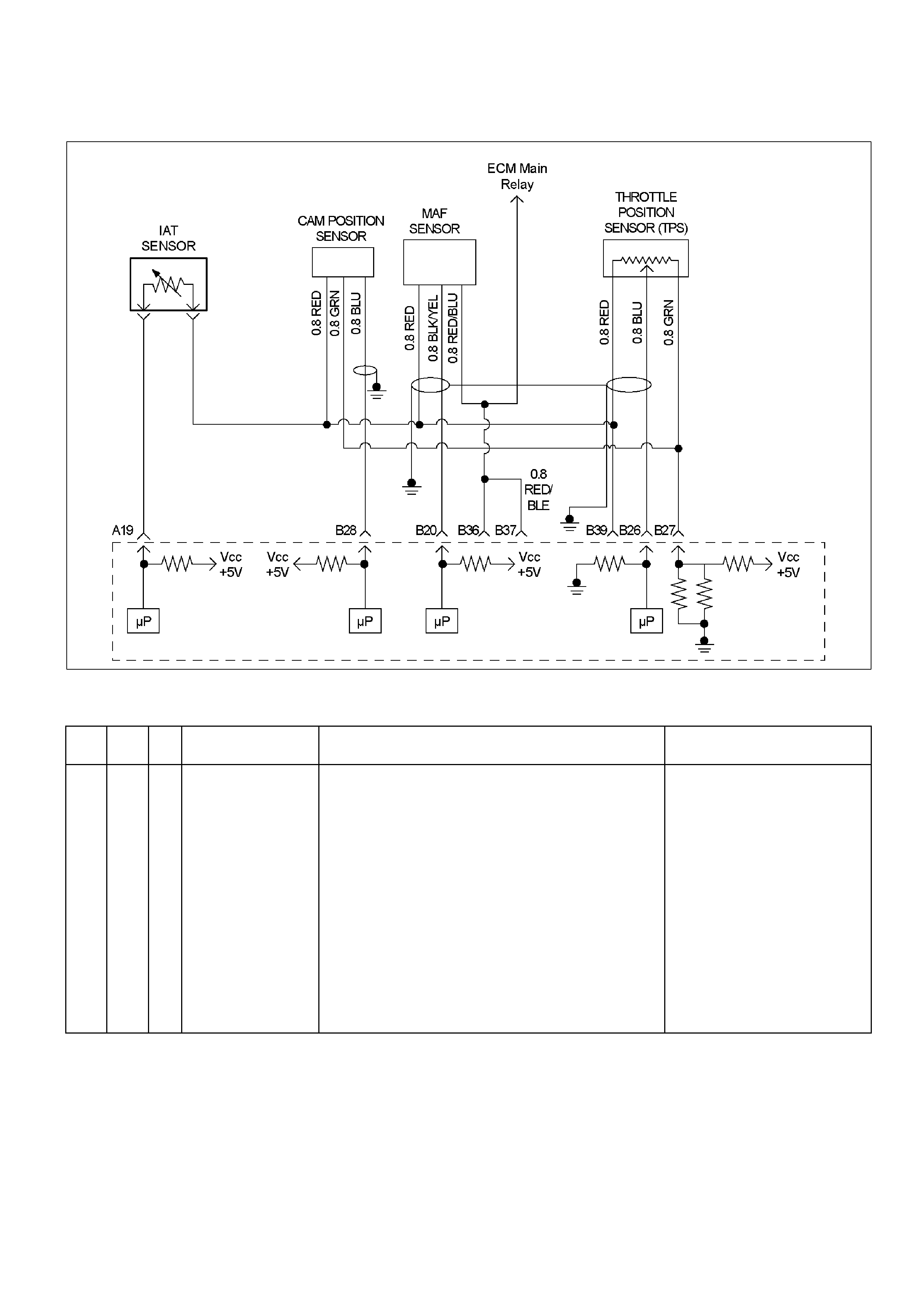
Diagnostic Trouble Code (DTC) P0121 (Flash Code 21) Throttle
Position Sensor (TPS) Circuit Range/Performance
RTW36EMF000401
Condition For Setting The DTC and Action Taken When The DTC Sets
Flash
Code Code Type DTC Name DTC Setti n g Co ndition Fai l-Safe (Back Up)
21
P0121
A
Throttle Position
Sensor
Range/Performance
1. No DTC relating to barometer sensor, ECT sensor, CMP
sensor, CKP sensor, MAF sensor and TPS (low input &
high input).
2. E ngi ne speed is m ore than 2000rpm.
3. Engine coolant temperature is more than 75°C.
4. TP S output voltage is between 0.24V and 0.26V.
Above conditions are met for 3 seconds.
OR
1. No DTC relating to barometer sensor, ECT sensor, CMP
sensor, CKP sensor, MAF sensor and TPS (low input &
high input).
2. E ngi ne speed is bel ow 3200rpm.
3. Engine coolant temperature is more than 75°C.
4. TP S output voltage is between 4.54V and 4.56V.
Above conditions are met for 3 seconds.
No fail-s afe funct i on.

Circuit Description
The TPS circuit provides a voltage signal that changes
relativ e to thrott le bl ade an gle. T he sign al vo lta ge wil l
vary from about 0.6 volts at closed throttle to about 4.5
volts at wide open throttle (WOT).
The TPS signal is one of the most important inputs
used by the Engine Control Module (ECM) for fuel
control and many of the ECM-controlled outputs. The
ECM monitors throttle position and compares actual
throttle position from the TPS to a predicted TPS value
calculated from engine speed. If the ECM detects an
out-of-range condition, DTC P0121 will set.
Diagnostic Aids
Check for the following conditions:
• Poor connection at ECM – Inspect harness
connectors for backed-out terminals, improper
mating, broken locks improperly formed or damaged
terminals, and poor terminal-to-wire connection.
• Damaged harness – Inspect the wiring harness for
damage. If the harness appears to be OK, observe
the ECT display on the Tech 2 while moving
connectors and wiring harnesses related to the
sensor. A change in the display will indicate the
location of the fault.
If DTC P0121 cannot be duplicated, the information
included in the Failure Records data can be useful in
determining vehicle mileage since the DTC was last
set.
Diagnostic Trouble Code (DTC) P0121 (Flash Code 21) Throttle Position
Sensor (TPS) Circuit Range/Performance
Step Action Value (s) Yes No
1 Was the "On-Board Diagnostic (OBD) System Check"
performed? - Go to Step 2
Go to On Board
Diagnostic (OBD)
System Check
2 1. Connect the Tech 2.
2. Review and record the failure information.
3. Select "F0: Read DTC Infor By Priority" in "F0:
Diagnostic Trouble Code".
Is the DTC P0121 stored as "Present Failure"? - Go to Step 3
Refer to
Diagnostic Ai ds
and Go to Step 3
3 1. Using the Tech2, ignition "On" and engine "Off".
2. Select "Clear DTC Information" with the Tech2 and
clear the DTC information.
3. Operate the vehicle and monitor the "F5: Failed
This Ignition" in "F2: DTC Information"
Was the DTC P0121 stored in this ignition cy cle? - Go to Step 4
Refer to
Diagnostic Ai ds
and Go to Step 4
4
1. Using the Tech 2, ignition "On" and engine "Off".
2. Monitor t he "T hr ottle Pos i ti on" in the dat a dis pl a y.
Does the Tech 2 indicate correct "Throttle Position"
from 0% to 100% depending on accelerator pedal
operation? - Go to Step 6 Go to Step 5
5 1. Using the Tech 2, ignition "On" and engine "Off
2. Monitor t he "T hr ottle Pos i ti on" in the dat a dis pl a y.
3. Adjust the TPS within 0% to 100%.
Was the problem solved? - Verify repair Go to Step 12
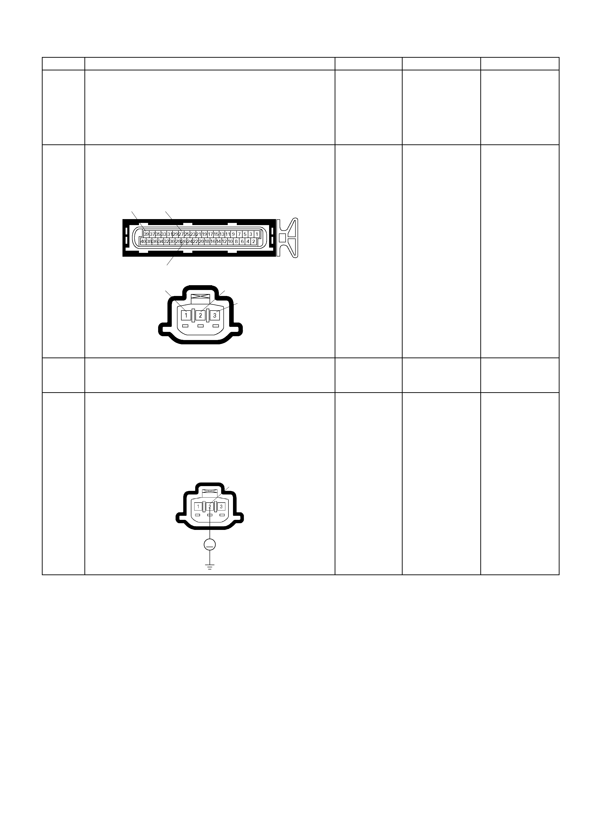
Step Action Value (s) Yes No
6 Check for the following conditions.
• Objects blocking the throttle valve.
• Vacuum leaking at throttle body.
If a problem is found, repair as necessary.
Was the problem found? - Verify repair Go to Step 7
7 Check for poor/faulty connection at the TPS or ECM
connector. If a poor/faulty connection is found, repair
the faulty terminal.
Was the problem found?
E-61(B)
26
2739
E-68
1 2 3
- Veri fy repair Go to Step 8
8 Visually check the TPS.
Was the problem found? - Go to Step 12 Go to Step 9
9
Using the DVM and check the TPS signal circuit.
1. Ignition "On", engine "Off".
2. Disconnect the TPS connector.
3. Check the circuit for short to power supply circuit.
Was the DVM indicated specified value?
E-68 2
V
Less than 1V
Go to Step 10
Repair faulty
harness and
verify repair

Step Action Value (s) Yes No
10 Check any accessory parts which may cause electric
interference.
Was the problem found? -
Remove the
accessory parts
and verify repair Go to Step 11
11 Check the shield wire for open or short circuit.
Was the problem found? - V erify repair Go to Step 12
12 Substitute a known good TPS and recheck.
Was the problem solved? - Go to Step 13 Go to Step 14
13 Replace the TPS.
Is the action complete? - Verify repair -
14 Is the ECM programmed with the latest software
release?
If not, download the latest software to the ECM using
the "SPS (Service Programming System)".
Was the problem solved? - Verify repair Go to step 15
15 Replace the ECM.
Is the action complete?
IMPORTANT: The replacement ECM must be
programmed. Refer to section of the Service
Programming System (SPS) in this manual. Following
ECM programming, the immobiliser system (if
equipped) m ust be l ink ed to th e ECM. Refer to sect io n
11 “Immobiliser System-ECM replacement” for the
ECM/Immobiliser linking procedure. - Verify repair -
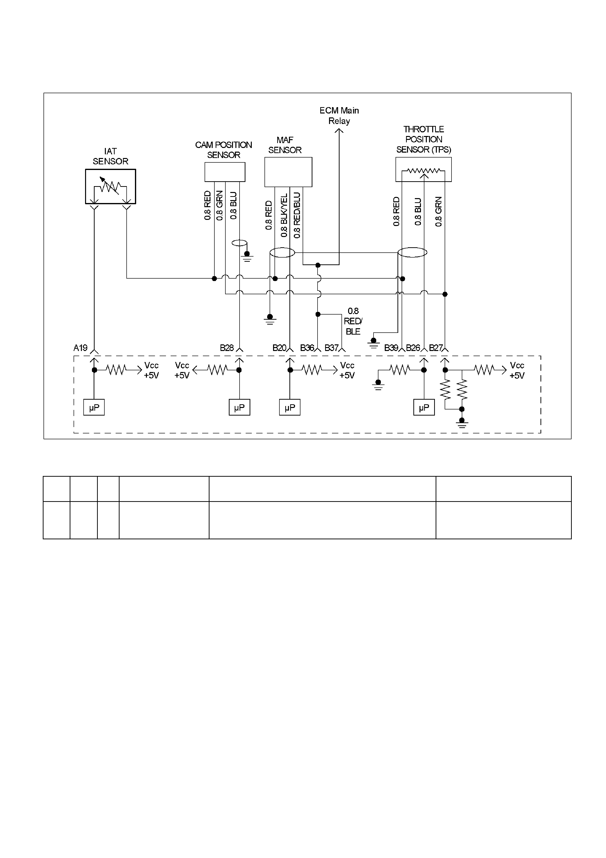
Diagnostic Trouble Code (DTC) P0122 (Flash Code 21) Throttle
Position Sensor Circuit Low Input
RTW36EMF000401
Condition For Setting The DTC and Action Taken When The DTC Sets
Flash
Code Code Type DTC Name DTC Setting Condition Fail-Safe (Back Up)
21 P0122 A Throttle Position
Sensor Low Input TPS output voltage is below 0.24V. The ECM uses default throttle
positi on value bas ed on mass air
flow and engine speed.
Circuit Description
The TPS circuit provides a voltage signal that changes
relativ e to thrott le bl ade an gle. The signal vo lta ge wil l
vary from below 0.6 volts at closed throttle to about 4.5
volts at wide open throttle (WOT).
The TPS signal is used by the Engine Control Module
(ECM) for fuel control and many of the ECM-controlled
outputs.
Diagnostic Aids
Check for the following conditions:
• Poor co nnec t ion at ECM – Ins pec t harnes s
connectors for backed-out terminals, improper
mating, broken locks, improperly formed or damaged
terminals, and poor terminal-to-wire connection.
• Damaged harness – Inspect the wiring harness for
damage. If the harness appears to be OK, observe
the throttle position display on the Tech 2 while
moving connectors and wiring harnesses related to
the TPS. A change in the display will indicate the
location of the fault.
If DTC P0122 cannot be duplicated, the information
included in the Failure Records data can be useful in
determining vehicle mileage since the DTC was last
set.
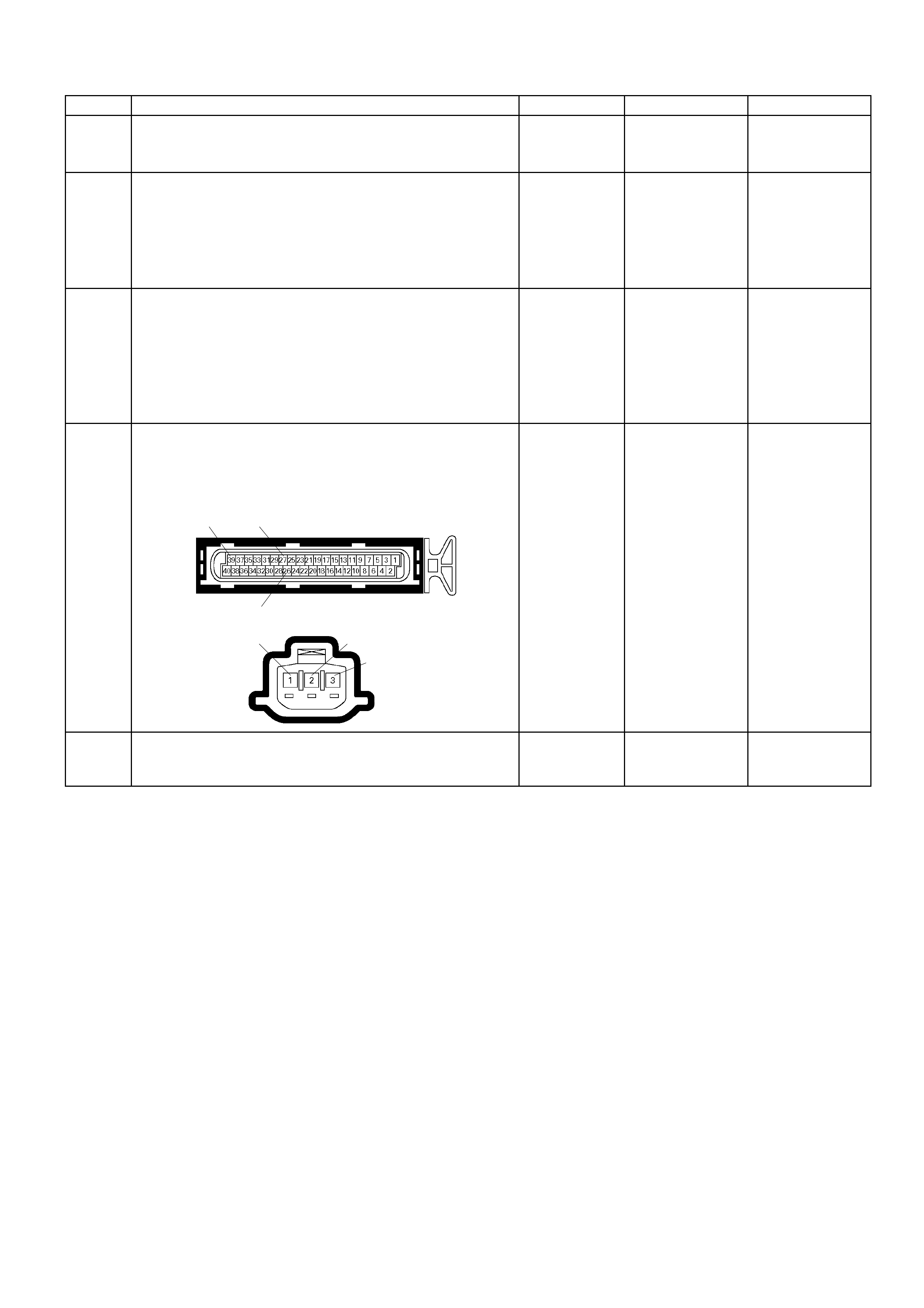
Diagnostic Trouble Code (DTC) P0122 (Flash Code 21) Throttle Position Sensor Circuit Low Input
Step Action Value (s) Yes No
1 W as the "On-Boar d Diagno stic (OBD) S ystem Check "
performed? - Go to Step 2
Go to On Board
Diagnostic (OBD)
System Check
2 1. Connect the Tech 2.
2. Review and record the failure information.
3. Select "F0: Read DTC Infor By Priority" in "F0:
Diagnostic Trouble Code".
Is the DTC P0122 stored as "Present Failure"? - Go to Step 3
Refer to
Diagnostic Ai ds
and Go to Step 3
3 1. Using the Tech2, ignition "On" and engine "Off".
2. Selec t "Clear DT C Infor mation " with the T ech2 a nd
clear the DTC information.
3. Operate the vehicle and monitor the "F5: Failed
This Ignition" in "F2: DTC Information"
Was the DTC P0122 stored in this ignition cy cle? - Go to Step 4
Refer to
Diagnostic Ai ds
and Go to Step 4
4 Check for poor/faulty connection at the TPS or ECM
connector. If a poor/faulty connection is found, repair
as necessary.
Was the problem found?
E-61(B)
26
2739
E-68
1 2 3
- Verify repair Go to Step 5
5 Visually check the TPS.
Was the problem found? - Go to Step 10 Go to Step 6
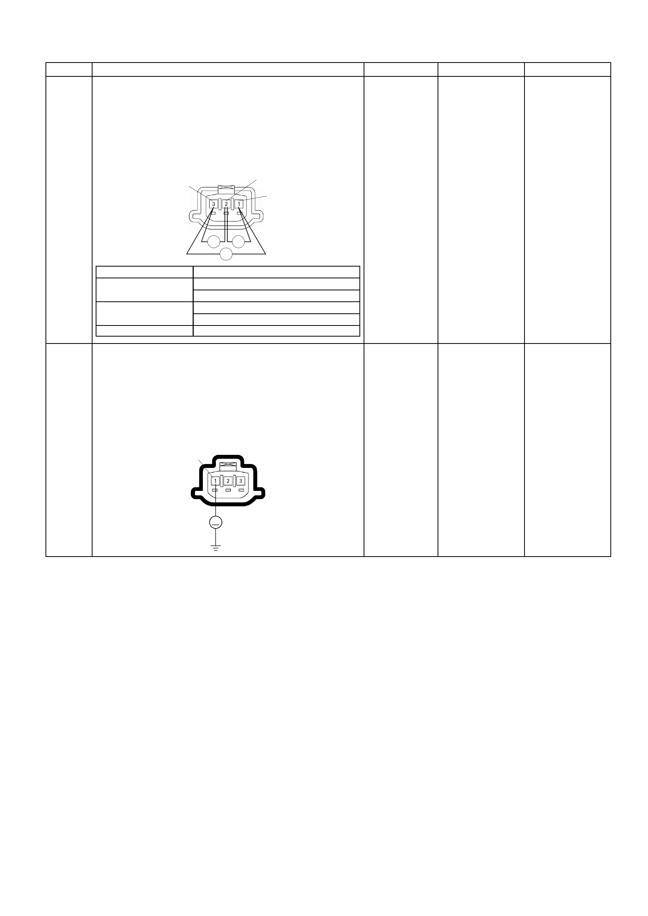
Step Action Value (s) Yes No
6 Using the DVM and check the TPS.
1. Ignition "Off", engine "Off".
2. Disconnect TPS connector.
3. Measure the r es istanc e of TPS.
Does the tes ter in dic ate sta ndard r es is t anc e as shown
in the following table?
TPS
Ħ Ħ
Ħ
1
2
3
Measurement Terminal Resistance (Ħ
)
1 - 2 Approxim ately 4. 7kĦ
at id le pos itio n
Appr oximatel y 1.0k Ħ
at WOT
2 Р3 A ppr oximately 0.6kĦ
at id le pos itio n
Appr oximatel y 4.3k Ħ
at WOT
1 – 3 A ppr oximatel y 5.0k at i dl e posit i on & WOT
Standard
resistance
Go to Step 7
Go to Step 10
7
Using the DVM and check the TPS power supply
circuit.
1. Ignition "On", engine "Off".
2. Disconnect the TPS connector.
3. Check the circuit for open or short to ground circuit.
Was the DVM indicated specified value?
E-68
1
V
A
pproximately
5.0V
Go to Step 9
Go to Step 8
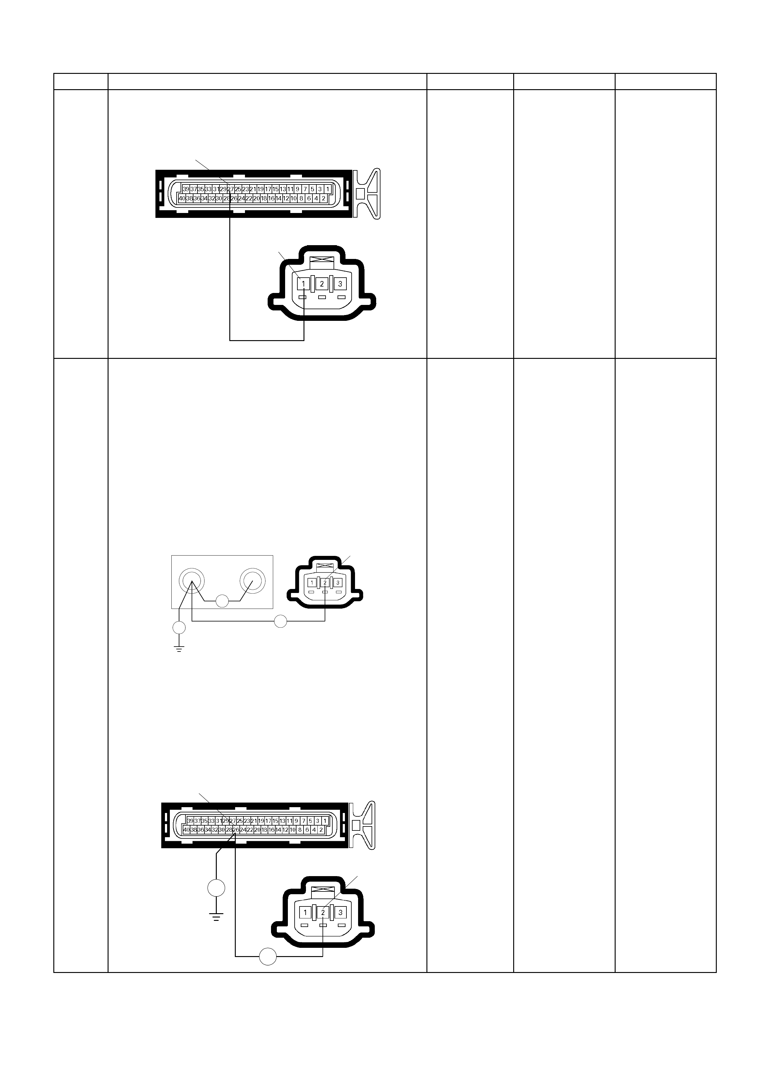
Step Action Value (s) Yes No
8 Repa ir the o pen or shor t to ground c ircui t between t he
ECM and TPS.
Was the problem solved?
E-68
1
E-61(B)
27
- Verify repair Go to Step 12
9
Using the DVM and check the TPS signal circuit.
Breaker box is available:
1. Ignition "Off", engine "Off".
2. Install the breaker box as type A (ECM
disconnected).
Refer to 6E-91 page.
3. Disconnect TPS connector.
4. Check the circuit for open, short to sensor ground
or short to ground circuit.
Was the problem found?
66 79
Ħ
Breaker Box E-68
Ħ
Ħ
2
Breaker box is not available:
1. Ignition "Off", engine "Off".
2. Disconnect the TPS connector and ECM
connector.
3. Check the circuit for open, short to sensor ground
or short to ground circuit.
Was the problem found?
E-61(B)
E-68 2
Ħ
Ħ
26
-
Repair faulty
harness and
verify repair
Go to Step 12

Step Action Value (s) Yes No
10 Substitute a known good TPS and recheck.
Was the problem solved? - Go to Step 11 Go to Step 12
11 Replace the TPS.
Is the action complete? - Verify repair -
12 Is the ECM programmed with the latest software
release?
If not, download the latest software to the ECM using
the "SPS (Service Programming System)".
Was the problem solved? - Verify repair Go to step 13
13 Replace the ECM.
Is the action complete?
IMPORTANT: The replacement ECM must be
programmed. Refer to section of the Service
Program ming S ys tem (SPS) in this manual. Fo llowing
ECM programming, the immobiliser system (if
equipped) must be linked to the ECM. Refer to sec tio n
11 “Immobiliser System-ECM replacement” for the
ECM/Immobiliser linking procedure. - Verify repair -

Diagnostic Trouble Code (DTC) P0123 (Flash Code 21) Throttle
Position Sensor Circuit High Input
RTW36EMF000401
Condition For Setting The DTC and Action Taken When The DTC Sets
Flash
Code Code Type DTC Name DTC Setting Condition Fail-Safe (Back Up)
21 P0123 A Throttle Position
Sensor High Input TPS output voltage is more than 4.56V. The ECM uses default throttle
positi on value bas ed on mass air
flow and engine speed.
Circuit Description
The TPS circuit provides a voltage signal that changes
relativ e to thrott le bl ade an gle. T he signal voltage will
vary from about 0.6 volts at closed throttle to about 4.5
volts at wide open throttle (WOT).
The TPS signal is one of the most important inputs
used by the Engine Control Module (ECM) for fuel
control and m an y of the ECM-c ontr ol le d outputs .
Diagnostic Aids
Check for the following conditions:
• Poor connection at ECM – Inspect harness
connectors for backed-out terminals, improper
mating, broken locks, improperly formed or damaged
terminals, and poor terminal-to-wire connection.
• Damaged harness – Inspect the wiring harness for
damage. If the harness appears to be OK, observe
the TPS display on the Tech 2 while moving
connectors and wiring harnesses related to the TP
sensor. A change in the display will indicate the
location of the fault.
• Faulty TPS – With the ignition key “ON," engine
“OFF," observe the TPS display on the Tech 2 while
slowly depressing the accelerator to wide open
throttle. If a voltage over 4.88 volts is seen at any
point in normal accelerator travel, replace the TPS.
If DTC P0123 cannot be duplicated, the information
included in the Failure Records data can be useful in
determining vehicle mileage since the DTC was last
set.
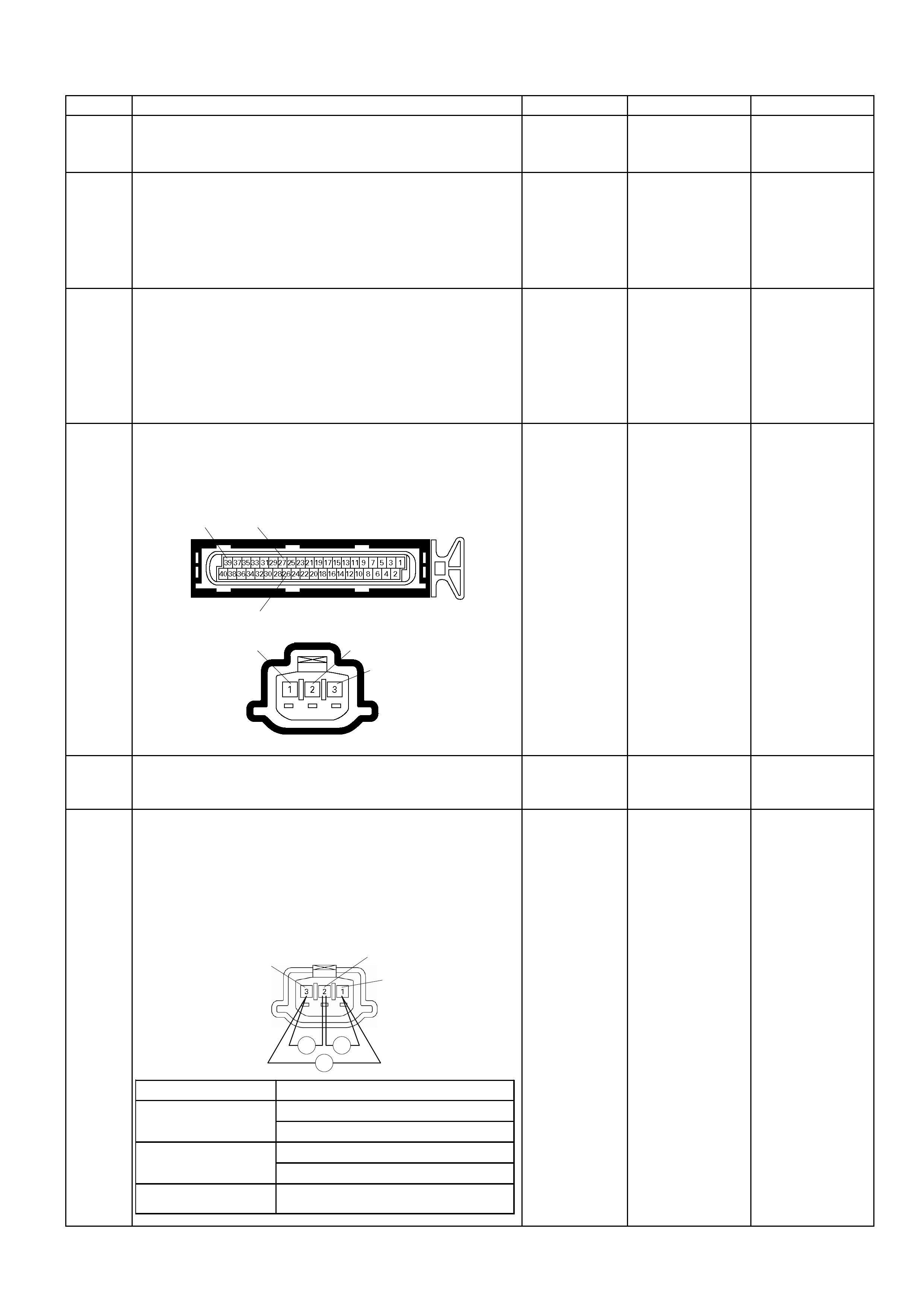
Diagnostic Trouble Code (DTC) P0123 (Flash Code 21) Throttle Position Sensor Circuit High Input
Step Action Value (s) Yes No
1 Was the "On-Board Diagnostic (OBD) System Check"
performed? - Go to Step 2
Go to On Board
Diagnostic (OBD)
System Check
2 1. Connect the Tech 2.
2. Review and record the failure information.
3. Select "F0: Read DTC Infor By Priority" in "F0:
Diagnostic Trouble Code".
Is the DTC P0123 stored as "Present Failure"? - Go to Step 3
Refer to
Diagnostic Ai ds
and Go to Step 3
3 1. Using the Tech2, ignition "On" and engine "Off".
2. Select "Clear DTC Information" with the Tech2 and
clear the DTC information.
3. Operate the vehicle and monitor the "F5: Failed
This Ignition" in "F2: DTC Information"
Was the DTC P0123 stored in this ignition cycle? - Go to Step 4
Refer to
Diagnostic Ai ds
and Go to Step 4
4 Check for poor/faulty connection at the TPS or ECM
connector. If a poor/faulty connection is found, repair
as necessary.
Was the problem found?
E-61(B)
26
2739
E-68
1 2 3
- Verify repair Go to Step 5
5 Visually check the TPS.
Was the problem found? - Go to Step 12 Go to Step 6
6
Using the DVM and check the TPS.
1. Ignition "Off", engine "Off".
2. Disconnect TPS connector.
3. Measure the resistance of TPS.
Does the tes ter indic ate sta ndard resist ance as s hown
in the following table?
TPS
Ħ Ħ
Ħ
1
2
3
Measurement Terminal Resi stance (Ω)
1 - 2 Approxim ately 4.7kΩ at idle position
Approximatel y 1.0kΩ at WOT
2 – 3 Approximately 0. 6kΩ at idle position
Approximatel y 4.3kΩ at WOT
1 – 3 Approximately 5. 0k at idle posi tion &
WOT
Standard
resistance
Go to Step 7
Go to Step 12
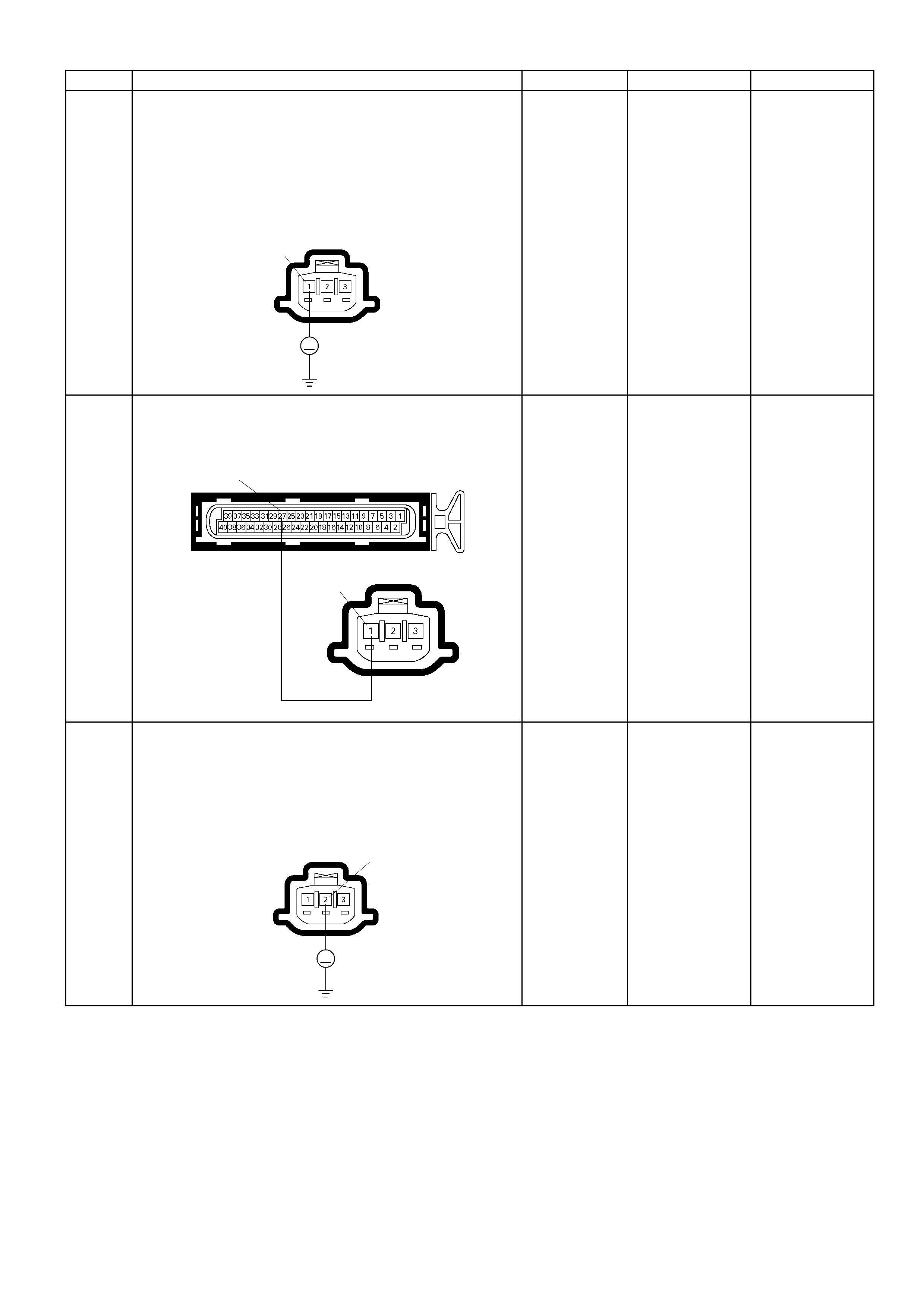
Step Action Value (s) Yes No
7
Using the DVM and check the TPS power supply
circuit.
1. Ignition "On", engine "Off".
2. Disconnect the TPS connector.
3. Check the circuit for short to voltage circuit.
Was the DVM indicated specified value?
E-68
1
V
A
pproximately
5.0V
Go to Step 9
Go to Step 8
8 Repair the short to voltage circuit between the ECM
and TPS.
Was the problem solved?
E-68
1
E-61(B)
27
- Verify repair Go to Step 14
9
Using the DVM and check the TPS signal circuit.
1. Ignition "On", engine "Off".
2. Disconnect the TPS connector.
3. Check the circuit for short to power supply circuit.
Was the DVM indicated specified value?
E-68
V
2
Less than 1V
Go to Step 10
Repair faulty
harness and
verify repair
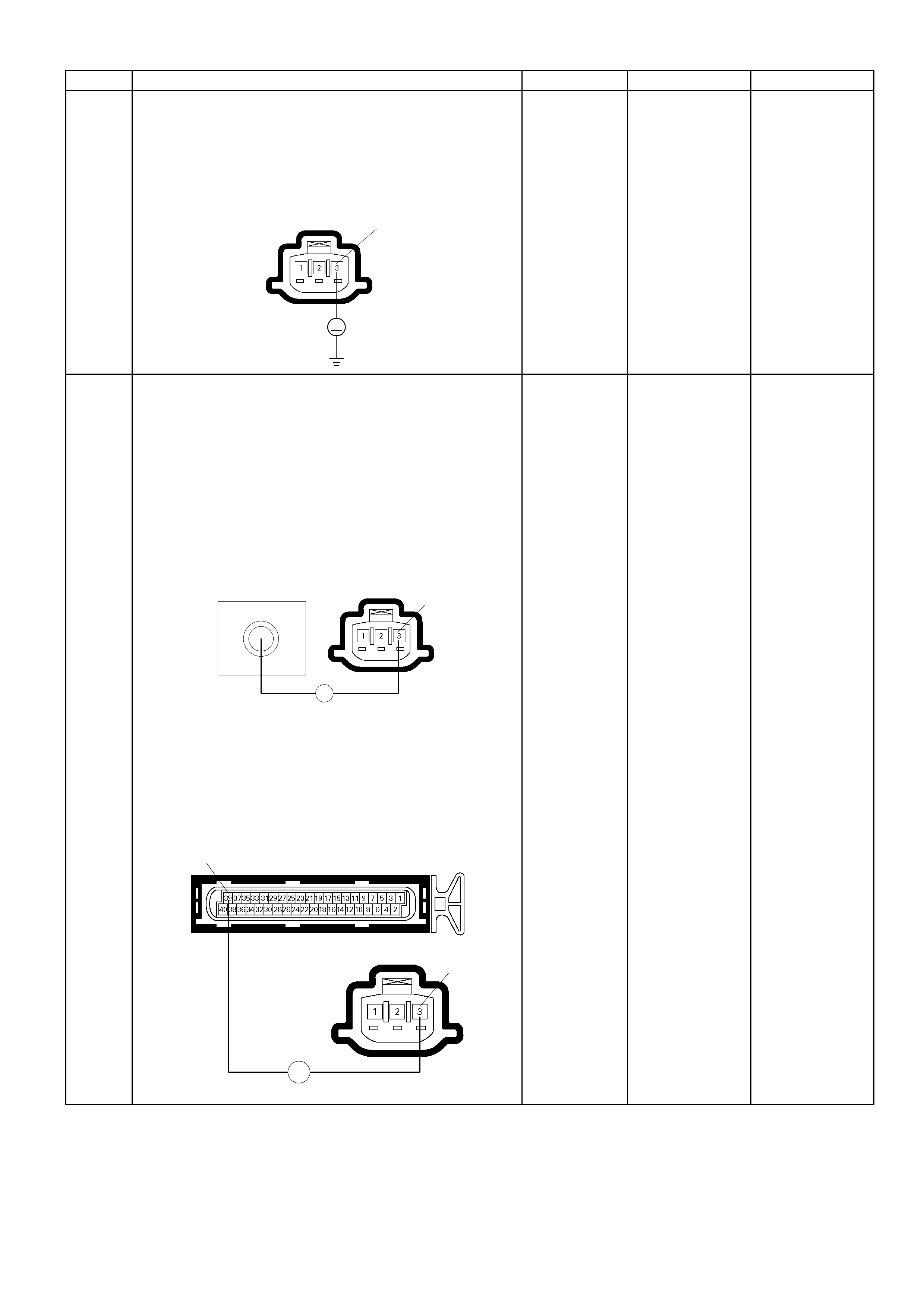
Step Action Value (s) Yes No
10
Using the DVM and check the TPS ground circuit.
1. Ignition "On", engine "Off".
2. Disconnect the TPS connector .
3. Check the circuit for short to power supply circuit.
Was the DVM indicated specified value?
E-68
V
3
Less than 1V
Go to Step 11
Repair faulty
harness and
verify repair
11
Using the DVM and check the TPS ground circuit.
Breaker box is available:
1. Ignition "Off", engine "Off".
2. Install the breaker box as type A. (ECM
disconnected).
Refer to 6E-91 page.
3. Disconnect the TPS connector.
4. Check the circuit for open circuit.
Was the problem found? E-68 3
79
Breaker Box
Ħ
Breaker box is not available:
1. Ignition "Off", engine "Off".
2. Disconnect the TPS connector and ECM connector.
3. Check the circuit for open circuit.
Was the problem found?
E-61(B)
E-68 3
Ħ
39
-
Repair faulty
harness and
verify repair Go to Step 14

Step Action Value (s) Yes No
12 Substitute a known good TPS and recheck.
Was the problem solved? - Go to Step 13 Go to Step 14
13 Replace the TPS.
Is the action complete? - Verify repair -
14 Is the ECM programmed with the latest software
release?
If not, download the latest software to the ECM using
the "SPS (Service Programming System)".
Was the problem solved? - Veri fy repair Go to step 1 5
15 Replace the ECM.
Is the action complete?
IMPORTANT: The replacement ECM must be
programmed. Refer to section of the Service
Programming System (SPS) in this manual. Following
ECM programming, the immobiliser system (if
equipped) m ust be l inked t o th e ECM. Refer to sect io n
11 “Immobiliser System-ECM replacement” for the
ECM/Immobiliser linking procedure. - Verify repair -
Diagnostic Trouble Code (DTC) P0131 (Flash Code 15) O2 Sensor
Circuit Low Voltage (Bank 1 Sensor 1)
Diagnostic Trouble Code (DTC) P0151 (Flash Code 15) O2 Sensor
Circuit Low Voltage (Bank 2 Sensor 1)
RTW36ELF000101
Condition For Setting The DTC and Action Taken When The DTC Sets
Flash
Code Code Type DTC Name DTC Setting Condition Fail-Safe (Back Up)
P0131 A O2 Sensor Circuit Low
Voltage (Bank 1 Sensor
1)
15
P0151 A O2 Sensor Circuit Low
Voltage (Bank 2 Sensor
1)
1. No DTC relating to ECT sensor, CMP sensor, CKP sensor,
VSS, inject or cont rol ci rcuit, i gnit i on cont rol circuit and O2
sensor circuit no act i vity (bank 1 & 2).
2. Engine speed is between 1000rpm and 4000rpm.
3. Engine coolant temperat ure is between 70°C and 110°C.
4. Vehicle speed is between 0km/h and 120km/h.
5. Engine load is between 80 and 160.
6. Throttle position fluct uat i on is below 0.28V.
7. O2 sensor bank 1 or bank 2 output voltage is more than
400mV for 50 seconds.
"Open Loop" fuel control.

Circuit Description
The Engine Control Module (ECM) supplies a bias
voltage of about 450 mV between the heated oxygen
sensor (HO2S) signal high and signal low circuits. The
ECM constantly monitors the HO2S signal during
“closed loop" operation and compensates for a rich or
lean condition by decreasing or increasing injector
pulse width as necessary. If HO2S voltage remains
excessively low for an extended period of time, DTC
P0131 or P0151 will be set.
Diagnostic Aids
Check for the following conditions:
• Heated oxygen sensor wiring – The sensor pigtail
may be routed incorrectly and contacting the exhaust
system.
• Poor ECM to engine bloc k grounds.
• F uel pr ess ur e – The syste m will go lean if press ure is
too low. The ECM can compensate for some
decrease. However, If fuel pressure is too low, a
DTC P0131 or P0151 may be set. Refer to
Fuel System Diagnosis.
• Lean injector(s) – Perform “Injector Balance Test."
• Exhaust leaks – An exhaust leak may cause outside
air to be pulled into the exhaust gas stream past the
HO2S, causing the system to appear lean. Check for
exhaust leaks that may cause a false lean condition
to be indicated.
• MAF sensor – The system can go lean if the MAF
sensor sign al ind ic ates an eng ine air f lo w
measurement that is not correct. Disconnect the
MAF sensor to see if the lean condition is corrected.
If so, replace the MAF sensor.
• Fuel contamination – Water, even in small amounts,
can be delivered to the fuel injectors. The water can
cause a lean exhaust to be indicated. Excessive
alcohol in the fuel can also cause this condition.
Refer to Fuel System Diagnosis for the procedure
to check for fuel contamination.
• If none of the above conditions are present, replace
the affected HO2S.
Diagnostic Trouble Code (DTC) P0131 (Flash Code 15) O2 Sensor Circuit Low Volta ge (Bank 1 Sensor 1)
Diagnostic Trouble Code (DTC) P0151 (Flash Code 15) O2 Sensor Circuit Low Volta ge (Bank 2 Sensor 1)
Step Action Value (s) Yes No
1 Was the "On-Board Diagnostic (OBD) System Check"
performed? - Go to Step 2
Go to On Board
Diagnostic (OBD)
System Check
2 1. Connect the Tech 2.
2. Review and record the failure information.
3. Select "F0: Read DTC Infor By Priority" in "F0:
Diagnostic Trouble Code".
Is the DTC P0131 or P0151 stored as "Present
Failure"? - Go to Step 3
Refer to
Diagnostic Ai ds
and Go to Step 3
3 1. Using the Tech2, ignition "On" and engine "Off".
2. Select "Clear DTC I nformation " with the T ech2 and
clear the DTC information.
3. Operate the vehicle and monitor the "F5: Failed
This Ignition" in "F2: DTC Information"
Was the DTC P0131 or P0151 stored in this ignition
cycle? - Go to Step 4
Refer to
Diagnostic Ai ds
and Go to Step 4
Step Action Value (s) Yes No
4 Check for poor/faulty connection at the O2 sensor or
ECM connector. If a poor/faulty connection is found,
repair as neces sary.
Was the problem found?
E-77/E-78
4
3
12
E-61(B) 21
24 22
23
- Verify repair Go to Step 5
5
Using the DVM an d c hec k the O2 s ens or cir c uit f or the
affected bank.
1. Ignition "On", engine "Off".
2. Disconnect the O2 sensor connector for the
affected bank.
3. Check the circuit for open, short to heater ground
or ground circuit.
Was the DVM indicated specified value?
E-77/E-78
BANK1/BANK2
V
2
4
Approximatly
450mV
Go to Step 7
Go to Step 6
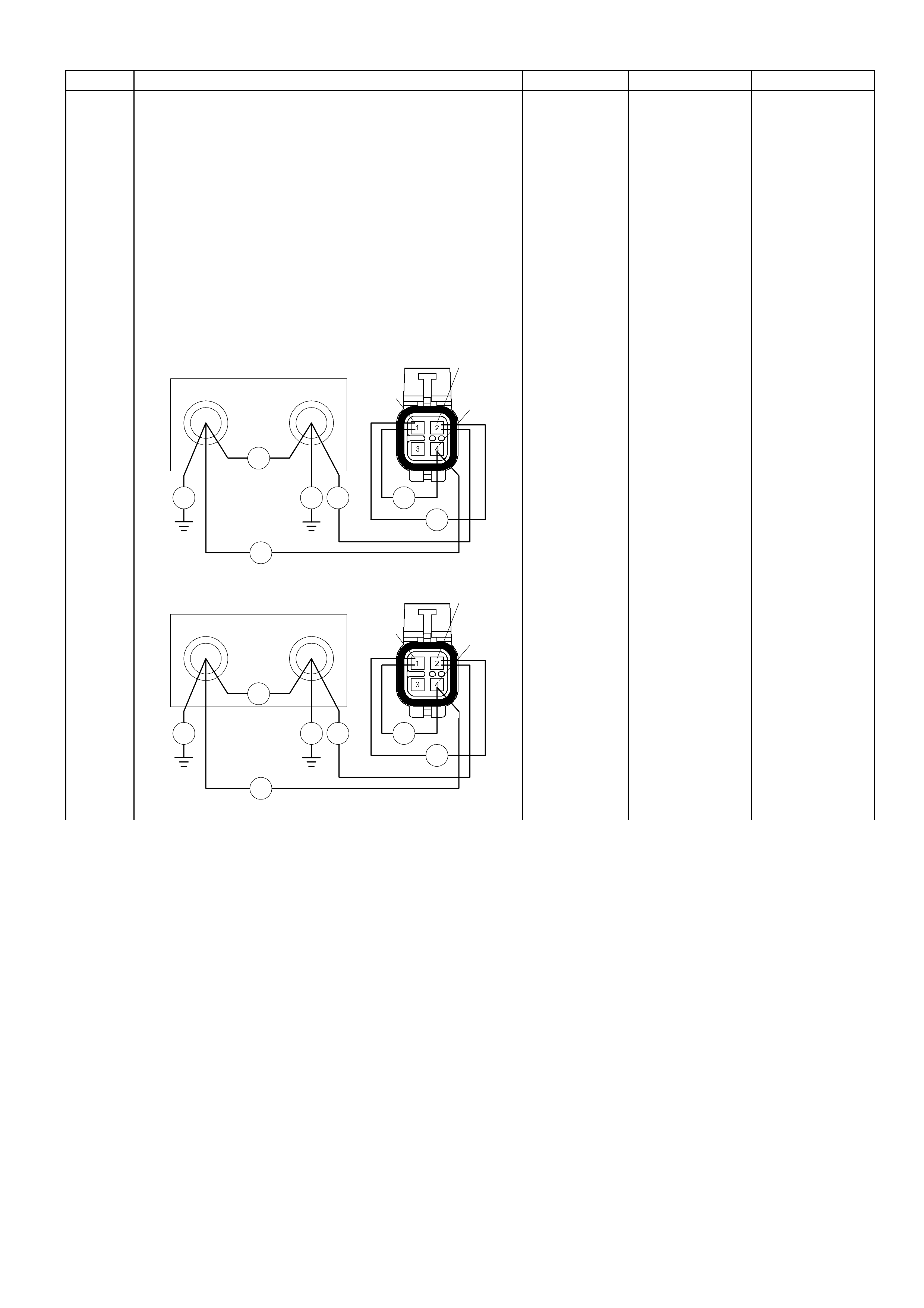
Step Action Value (s) Yes No
6 Using the DVM an d c hec k the O2 s ens or c ir c uit f or the
affected bank.
Breaker box is available:
1. Ignition "Off", engine "Off".
2. Install the breaker box as type A (ECM
disconnected).
Refer to 6E-91 page.
3. Disconnect the O2 sensor for the affected bank.
4. Check the circuit for open, short to heater ground
or short to ground circuit.
Was the problem found?
61 62
Ħ
Breaker Box E-77
Ħ
Ħ
Ħ
Ħ
ĦĦ
1
2
4
BANK1
63 64
Ħ
Breaker Box
Ħ
Ħ
ĦĦ
BANK2 E-78
Ħ
Ħ
1
2
4
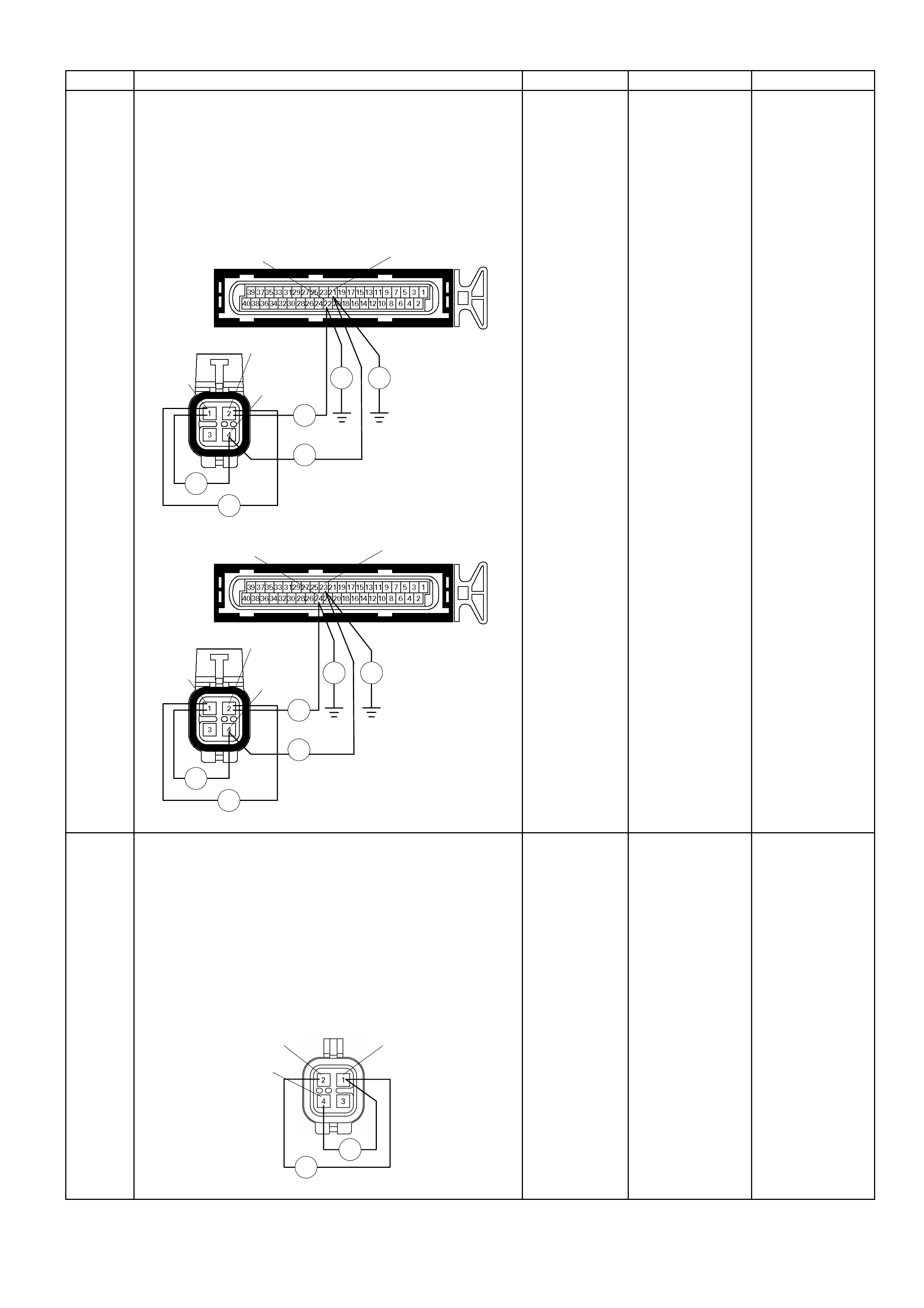
Step Action Value (s) Yes No
Breaker box is not available:
1. Ignition "Off", engine "Off".
2. Disconnect the O2 sensor connector for the
affected bank and ECM connector.
3. Check the circuit for open, short to heater ground
or short to ground circuit.
Was the problem found?
E-77
Ħ
Ħ
1
2
4
E-61(B)
Ħ Ħ
Ħ
Ħ
21
22
BANK1
E-78
Ħ
Ħ
1
2
4
E-61(B)
Ħ Ħ
Ħ
Ħ
23
24
BANK2
-
Repair faulty
harness and
verify repair Go to Step 15
7
Using the DVM an d c hec k the O2 s ens or cir c uit f or the
affected bank.
1. Ignition "Off", engine "Off".
2. Disconnect the O2 sensor connector for the
affected bank.
3. Check the circuit for short to heater ground circuit.
Was the DVM indicated specified value?
O2 Sensor
BANK1/BANK2
Ħ
Ħ
12
4
No continuity
Go to Step 9
Go to Step 8

Step Action Value (s) Yes No
8 Repair the short to heater ground circuit.
Was the problem found? - Verify repair Go to Step 15
9 1. Using the Tech 2, ignition "On" and engine "On".
2. Monitor the "Mass Air Flow" in the data display.
Does the Tech 2 indicate correct "Mass Air Flow"
increase, when engine speed is increased?
- Go to Step 11 Go to Step 10
10 Remove the MAF & IAT sensor assembly and check
for the following conditions.
• Objects blocking the air cleaner.
• Objects blocking the MAF sensor.
• Objects blocking the throttle valve.
• Vacuum leaking at intake duct.
• Vacuum leaking at throttle body.
If a problem is found, repair as necessary.
Was the problem found? - Verify repair
Refer to DTC
P0101 and Go to
Step 11
11 1. Using the Tech 2, ignition "On" and engine "On".
2. Select the "Miscellaneous Test" and perform the
"IAC Control" in the "IAC System".
3. Operate the Tech 2 in accrodance with procedure.
Was the engine speed changed, when the IAC Valve
is operating step by step? - Go to Step 13 Go to Step 12
12 Check for the following conditions.
• Objects blocking the IAC Valve.
• Objects blocking the throttle valve.
• Vacuum leaking at throttle body.
If a problem is found, repair as necessary.
Was the problem found? - Verify repair
Refer to DTC
P1508/P1509
and Go to Step
13

Step Action Value (s) Yes No
13 Check for injector for the affected bank.
Refer to "Injector Coil Test & Injector Balance Test
Procedure"
Was the injector operation correct? - Go to Step 14
Reefer to Injector
Coil Test &
Injecotr Balance
Test Procedure
14 Check for fuel pressure.
Refer to "F u el Sy st em Di ag nos is".
Was the fuel pressure correct? - Go to Step 15
Refer to Fuel
System
Diagnosis
15 Replace the O2 sensor for the affected bank.
Was the problem solved? - Verify repair Go to Step 16
16 Is the ECM programmed with the latest software
release?
If not, download the latest software to the ECM using
the "SPS (Service Programming System)".
Was the problem solved? - Verify repair Go to step 17
17 Replace the ECM.
Is the action complete?
IMPORTANT: The replacement ECM must be
programmed. Refer to section of the Service
Programming S ystem (SPS) in this manual. Following
ECM programming, the immobiliser system (if
equipped) m ust be link ed to the ECM. Ref er to s ection
11 “Immobiliser System-ECM replacement” for the
ECM/Immobiliser linking procedure. - Verify repair -
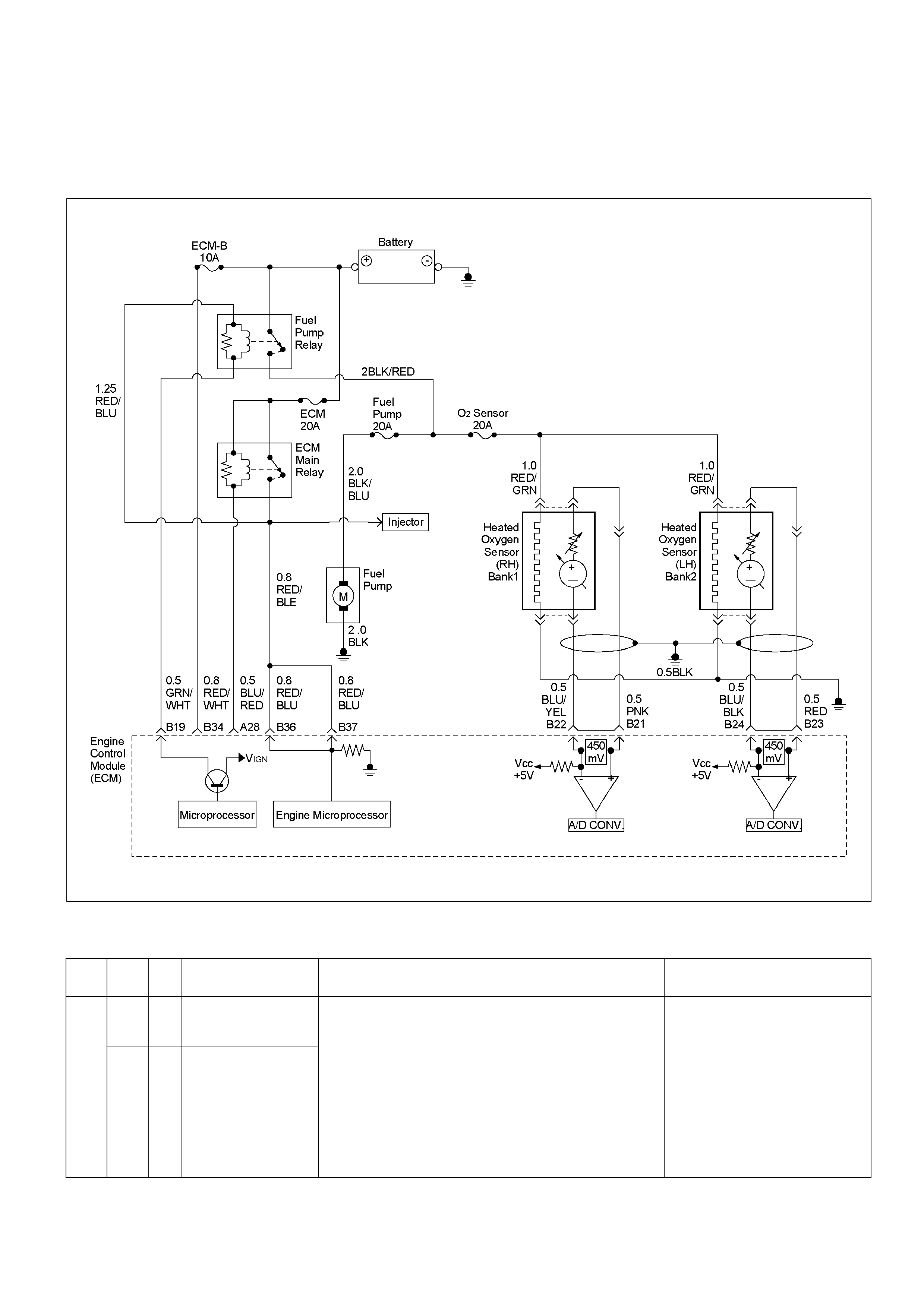
Diagnostic Trouble Code (DTC) P0132 (F lash Code 15) O2 Sensor
Circuit High Voltage (Bank 1 Sensor 1)
Diagnostic Trouble Code (DTC) P0152 (F lash Code 15) O2 Sensor
Circuit High Voltage (Bank 2 Sensor 1)
RTW36ELF000101
Condition For Setting The DTC and Action Taken When The DTC Sets
Flash
Code Code Type DTC Name DTC Setting Condition Fail-Safe (Back Up)
P0132 A O2 S ensor Ci rcuit High
Voltage (Bank 1 Sensor
1)
15
P0152 A O2 S ensor Ci rcuit High
Voltage (Bank 2 Sensor
1)
1. No DTC relating to ECT sensor, CMP sensor, CKP sensor,
VSS, inject or cont rol ci rcuit, i gnit i on cont rol circuit and O2
sensor circuit no act i vity (bank 1 & 2).
2. E ngi ne speed is bet ween 1000rpm and 4000rpm.
3. Engine coolant temperature is between 70 and 110.
4. V ehi cle speed is between 0km/h and 120km/h.
5. E ngi ne l oad is between 80 and 160.
6. Throt tle position fluctuation is below 0.28V.
7. O2 s ensor bank 1 or bank 2 output voltage is below 600mV
for 50 seconds.
"Open Loop" fuel control.

Circuit Description
The Engine Control Module (ECM) supplies a bias
voltage of about 450 mV between the heated oxygen
sensor (HO2S) signal high and signal low circuits. The
ECM constantly monitors the HO2S signal during
“closed loop" operation and compensates for a rich or
lean condition by decreasing or increasing injector
pulse width as nec es sary. If the HO2S volta ge remains
excessively high for an extended period of time, DTC
P0132 or P0152 wi ll be set .
Diagnostic Aids
Check the following items:
• Fuel pressure – The system will go rich if pressure is
too high. The ECM can compensate for some
increase. However, if fuel pressure is too high, a
DTC P0132 or P0152 may be set. Refer to
Fuel System Diagnosis.
• Perform “Injector Balance Test" – Refer to
Fuel System Diagnosis.
• Check the canister for fuel saturation – If full of fuel,
check canister control and hoses.
• MAF sensor –The system can go rich if MAF sensor
signal indicates an engine airflow measurement that
is not correct. Disconnect the MAF sensor to see it
the rich condition is corrected. If so, replace the MAF
sensor.
• Check for a leak in the fuel pressure regulator
diaphragm by checking the vacuum line to the
regulator for the presence of fuel. There should be
no fuel in the vacuum line.
• An inter mittent thrott le pos it ion se ns or output will
cause the system to go rich due to a false indication
of the engine accelerating.
• Shorted Heated Oxygen Sensor (HO2S) –If the
HO2S is internally shorted, the HO2 S vo ltag e
displayed on the Tech 2 will be over 1 volt. Try
disconnecting the affected HO2S with the key “ON,"
engine “OFF." If the displayed HO2S voltage
changes from over 1000 mV to around 450 mV,
replace the HO2S . Silic on c ontamination of the
HO2S can also cause a high HO2S voltage to be
indicated. This condition is indicated by a powdery
white deposit on the portion of the HO2S exposed to
the exhaust stream. If contamination is noticed,
replace the af f ec ted HO2S.
• O pen HO2 S Signa l C irc uit or Fault y HO2S–A poor
connection or open in the HO2S signal circuit can
cause the DTC to set during deceleration fuel mode.
An HO2S which is faulty and not allowing a full
voltage swing between the rich and lean thresholds
can also cause this condition. Operate the vehicle by
monitoring the HO2S voltage with a Tech 2. If the
HO2S voltag e is lim ited within a range bet ween 300
mV to 600 mV, check the HO2S signal circuit wiring
and associated terminal conditions.
• If none of the above conditions are present, replace
the affected HO2S.
Diagnostic Trouble Code (DTC) P0132 (Flash Code 15) O2 Sensor Circuit High Voltage (Bank 1 Sensor 1)
Diagnostic Trouble Code (DTC) P0152 (Flash Code 15) O2 Sensor Circuit High Voltage (Bank 2 Sensor 1)
Step Action Value (s) Yes No
1 Was the "On-Board Diagnostic (OBD) System Check"
performed? - Go to Step 2
Go to On Board
Diagnostic (OBD)
System Check
2 1. Connect the Tech 2.
2. Review and record the failure information.
3. Select "F0: Read DTC Infor By Priority" in "F0:
Diagnostic Trouble Code".
Is the DTC P0132 or P0152 stored as "Present
Failure"? - Go to Step 3
Refer to
Diagnostic Ai ds
and Go to Step 3
3 1. Using the Tech2, ignition "On" and engine "Off".
2. Select "Clear DTC I nformation " with the T ech2 and
clear the DTC information.
3. Operate the vehicle and monitor the "F5: Failed
This Ignition" in "F2: DTC Information"
Was the DTC P0132 or P0152 stored in this ignition
cycle? - Go to Step 4
Refer to
Diagnostic Ai ds
and Go to Step 4
Step Action Value (s) Yes No
4 Check for poor/faulty connection at the O2 sensor or
ECM connector.
If a poor/faulty connection is found, repair as
necessary.
Was the problem found?
E-77/E-78
4
3
12
E-61(B) 21
24 22
23
- Verify repair Go to Step 5
5
Using the DVM an d c hec k the O2 s ens or cir c uit f or the
affected bank.
1. Ignition "On", engine "Off".
2. Disconnect the O2 sensor connector for the
affected bank.
3. Check the circuit for open, short to heater ground
or ground circuit.
Was the DVM indicated specified value?
E-77/E-78
BANK1/BANK2
V
2
4
Approximatly
450mV
Go to Step 7
Go to Step 6
6
Using the DVM an d c hec k the O 2 s ens or c ir cuit for the
affected bank.
1. Ignition "On", engine "Off".
2. Disconnect the O2 sensor connector for the
affected cylinder.
3. Check the circuit for short to power supply circuit.
Was the DVM indicated specifed value?
E-77/E-78
BANK1/BANK2
V V
2
4
Less than 1V
Go to Step 15
Repair faulty
harness and
verify repair
Step Action Value (s) Yes No
7
Using the DVM an d c hec k the O2 s ens or c ir c uit f or the
affected bank.
1. Ignition "Off", engine "Off".
2. Disconnect the O2 sensor connector for the
affected bank.
3. Check the circuit for short to heater power supply
circuit.
Was the DVM indicated specified value?
O2 Sensor
BANK1/BANK2
Ħ
Ħ
3
2
4
No continuity
Go to Step 9
Go to Step 8
8 Repair the short to heater power supply circuit.
Was the problem found? - Verify repair Go to Step 15
9 1. Using the Tech 2, ignition "On" and engine "On".
2. Monitor the "Mass Air Flow" in the data display.
Does the Tech 2 indicate correct "Mass Air Flow"
increase, when engine speed is increased?
- Go to Step 11 Go to Step 10
10 Remove the MAF & IAT sensor assembly and check
for the following conditions.
• -Objects blocking the air cleaner.
• Objects blocking the MAF sensor.
• Objects blocking the throttle valve.
• Vacuum leaking at intake duct.
• Vacuum leaking at throttle body.
If a problem is found, repair as necessary.
Was the problem found? - Verify repair
Refer to DTC
P0101 and Go to
Step 11
11 1. Using the Tech 2, ignition "On" and engine "On".
2. Select the "Miscellaneous Test" and perform the
"IAC Control" in the "IAC System".
3. Operate the Tech 2 in accrodance with procedure.
Was the engine speed changed, when the IAC Valve
is operating step by step?
- Go to Step 13 Go to Step 12

Step Action Value (s) Yes No
12 Check for the following conditions.
• Objects blocking the IAC Valve.
• Objects blocking the throttle valve.
• Vacuum leaking at throttle body.
If a problem is found, repair as necessary.
Was the problem found? - Verify repair
Refer to DTC
P1508/P1509
and Go to Step
13
13 Check for injector for the affected bank.
Refer to "Injector Coil Test & Injector Balance Test
Procedure".
Was the injector operation correct? - Go to Step 14
Reefer to Injector
Coil Test &
Injector Balance
Test Procedure
14 Check for fuel pressure.
Refer to "F u el Sy s tem Di ag nos is".
Was the fue l pressure correct? - Go to Step 15
Refer to Fuel
System
Diagnosis
15 Replace the O2 sensor for the affected bank.
Was the problem solved? - Verify repair Go to Step 16
16 Is the ECM programmed with the latest software
rele ase?
If not, download the latest software to the ECM using
the "SPS (Service Programming System)".
Was the problem solved? - Verify repair Go to step 17
17 Replace the ECM.
Is the action complete?
IMPORTANT: The replacement ECM must be
programmed. Refer to section of the Service
Programming S ystem (SPS) in this manual. Following
ECM programming, the immobiliser system (if
equipped) m ust be link ed to the ECM. Ref er to s ection
11 “Immobiliser System-ECM replacement” for the
ECM/Immobiliser linking procedure. - Verify repair -

Diagnostic Trouble Code (DTC) P0134 (Flash Code 15) O2 Sensor
Circuit No Activity Detected (Bank 1 Sensor 1)
Diagnostic Trouble Code (DTC) P0154 (Flash Code 15) O2 Sensor
Circuit No Activity Detected (Bank 2 Sensor 1)
RTW36ELF000101
Condition For Setting The DTC and Action Taken When The DTC Sets
Flash
Code Code Type DTC Name DTC Setting Condition Fail-Safe (Back Up)
P0134 A O2 Sensor Circuit No
Activity Detected (Bank
1 Sensor 1)
15
P0154 A O2 Sensor Circuit No
Activity Detected (Bank
2 Sensor 1)
1. No DTC relating to MAF sensor, ECT sensor, CMP sensor,
CKP sensor, VSS, injector control circuit and ignition
control circuit.
2. Engine coolant temperat ure is more than 70°C.
3. Vehicle speed is more than 60km/h.
4. O2 sensor bank 1 or bank 2 output voltage is between
350mV and 600mV.
"Open Loop" fuel control.

Circuit Description
• The Engine Control Module (ECM) supplies a bias
voltage of about 450 mV between the heated oxygen
sensor (HO2S) high and low circuits. The ECM
constantly monitors the HO2S signal during “closed
loop" operation and compensates for a rich or lean
condition by decreasing or increasing injector pulse
width as necessary. If the Bank 1 HO2S 1 voltage
remains at or near the 450 mV bias for an extended
period of time, DTC P0134 or P0154 will be set,
indicating an open sensor signal or sensor low
circuit.
Diagnostic Aids
Check for the following conditions:
• Poor connection or damaged harness – Inspect the
harness connectors for backed-out terminals,
improper mating, broken locks, improperly formed or
damaged terminals, poor terminal-to-wire
connecti on, and dam aged harnes s .
• Faulty HO2S heater or heater circuit – With the
ignition “ON," engine “OFF," after a cool down
period, the HO2S 1 voltage displayed on the Tech 2
is normally 455-460 mV. A reading over 1000 mV
indicates a signal line shorted to voltage. A reading
under 5 mV indicates a signal line shorted to ground
or signal lines shorted together. Disconnect the
HO2S and connect a test light between the HO2S
ignition feed and heater ground circuits. If the test
light does not light for 2 seconds when the ignition is
turned on, repair the open ignition feed or sensor
ground circuit as necessary. If the test light lights and
the HO2S signal and low circuits are OK, replace the
HO2S.
• Intermittent test – With the Ignition “ON," monitor the
HO2S signa l vo ltag e whil e moving the wiring harn es s
and related connectors. If the fault is induced, the
HO2S signal voltage will change. This may help
isolate the location of the malfunction.
Diagnostic Trouble Code (DTC) P0134 (Flash Code 15) O2 Sensor Circuit No Activity Detected
(Bank 1 Sensor 1)
Diagnostic Trouble Code (DTC) P0154 (Flash Code 15) O2 Sensor Circuit No Activity Detected
(Bank 2 Sensor 1)
Step Action Value (s) Yes No
1 Was the "On-Board Diagnostic (OBD) System Check"
performed? - Go to Step 2
Go to On Board
Diagnostic (OBD)
System Check
2 1. Connect the Tech 2.
2. Review and record the failure information.
3. Select "F0: Read DTC Infor By Priority" in "F0:
Diagnostic Trouble Code".
Is the DTC P0134 or P0154 stored as "Present
Failure"? - Go to Step 3
Refer to
Diagnostic Ai ds
and Go to Step 3
3 1. Using the Tech2, ignition "On" and engine "Off".
2. Selec t "Clear DT C Inform ation" with the T ech2 and
clear the DTC information.
3. Operate the vehicle and monitor the "F5: Failed
This Ignition" in " F2: DTC Information"
Was the DTC P0134 or P0154 stored in this ignition
cycle? - Go to Step 4
Refer to
Diagnostic Ai ds
and Go to Step 4
Step Action Value (s) Yes No
4 Check for poor/faulty connection at the O2 sensor or
ECM connector. If a poor/faulty connection is found,
repair as necessary.
Was the problem found?
E-77/E-78
4
3
12
E-61(B) 21
24 22
23
- Verify repair Go to Step 5
5
Using the DVM and check the O2 sensor circuit for
the affected bank.
1. Ignition "On", engine "Off".
2. Disconnect the O2 sensor connector for the
affected bank.
3. Check the circuit for open, short to heater ground
or ground circuit.
Was the DVM indicated specified value?
E-77/E-78
BANK1/BANK2
V
2
4
Approximatly
450mV
Go to Step 6
Go to Step 12
6
Using the DVM and check the O2 sensor heater
power supply circuit for the affected bank.
1. Ignition "On", engine "Off".
2. Disconnect the O2 sensor connector for the
affected cylinder.
3. Check the circuit for open circuit.
Was the DVM indicated specified value?
E-77/E-78
BANK1/BANK2
V
1
3
Batter y volta ge
Go to Step 9
Go to Step 7
7 Repair the o pen or short to ground c ircui t between t he
fuel pum p rela y and O2 se nsor hea ter for the aff ected
cylinder.
Was the problem found? - Verify repair Go to Step 8
Step Action Value (s) Yes No
8 Repair the op en circuit betw een the O2 sensor heat er
and engine ground for the affected cylinder.
Was the problem found? - Verify repair Go to Step 9
9
Using the DVM and check the O2 sensor heater
circuit for the affected bank.
1. Ignition "Off", engine "Off".
2. Disconnect the O2 sensor connector for the
affected bank.
3. Check the circuit for short circuit.
Was the tester indicated specified value?
O2 Sensor
BANK1/BANK2
Ħ
1
3
Approximatly
16.5Ω at 20°C
Go to Step 12
Approximataly
0Ω: Go to Step
10
No continuitly:
Go to Step 11
10 Repair the s hort circuit bet ween the O2 sensor heater
power supply and ground circ uit.
Is the action complete? - Verify repair -
11 Replace the O2 sensor for the affected bank.
Was the problem solved? - Verify repair Go to Step 12
12 Is the ECM programmed with the latest software
release?
If not, download the latest software to the ECM using
the "SPS (Service Programming System)".
Was the problem solved? - Verify repair Go to step 13
13 Replace the ECM.
Is the action complete?
IMPORTANT: The replacement ECM must be
programmed. Refer to section of the Service
Program ming S ys tem ( SPS) in this manual. Foll owing
ECM programming, the immobiliser system (if
equipped) must be linked to the ECM. Refer to sec tio n
11 “Immobiliser System-ECM replacement” for the
ECM/Immobiliser linking procedure. - Verify repair -

Diagnostic Trouble Code (DTC) P0171 (Flash Code 44) O2 Sensor
System Too Lean (Bank 1)
Diagnostic Trouble Code (DTC) P0174 (Flash Code 44) O2 Sensor
System Too Lean (Bank 2)
RTW36ELF000101
Condition For Setting The DTC and Action Taken When The DTC Sets
Flash
Code Code Type DTC Name DTC Setting Condition Fail-Safe (Back Up)
P0171 B O2 S ensor S ystem Too
Lean (Bank 1)
44
P0174 B O2 S ensor S ystem Too
Lean (Bank 2)
1. No DTC relating to MAF sensor, IAT sensor, ECT sensor,
TPS, CMP sens o r , CKP sens o r , VSS, in jector control
circuit, i gniti on cont rol ci rcuit, O2 sensor ci rcuit low voltage
& high voltage (bank 1 & 2) and O2 sensor circuit no
activit y (bank 1 & 2).
2. Engine speed is more than 600rpm.
3. Intake air temperature is more than 50°C.
4. Engine coolant temperat ure is between 35°C and 120°C.
5. Engine load is more than 20.
6. EVAP purge solenoid valve on-duty is bel ow 100%.
7. Air-fuel ratio correc tion volume is more than 150%
for 20 seconds.
No fail-s afe funct i on.

Circuit Description
To provide the best possible combination of driveability,
fuel economy , and emission control, a “closed loop"
air/fuel metering system is used. While in “closed loop,"
the Engine Control Module (ECM) monitors the HO2S
signals and adjusts fuel delivery based upon the HO2S
signal voltages. A change made to fuel delivery will be
indicated by the long and short term fuel trim values
which can be monitored with a Tech 2. Ideal fuel trim
values are around 0%; if the HO2S signals are
indicating a lean condition the ECM will add fuel,
resulting in fuel trim values above 0%. If a rich condition
is detected, the fue l trim values will be belo w 0%,
indicating that the ECM is reducing the amount of fuel
delivered. If an excessively lean condition is detected,
the ECM will set DTC P0171 or P0174.
The ECM's maximum authority to control long term fuel
trim allows a range between –15% (automatic
transmission) or –12% (manual transmission) and
+20%. The ECM monitors fuel trim under various
engine speed/load fuel trim cells before determining the
status the fuel trim diagnostic.
Diagnostic Aids
Check for the following conditions:
• Poor co nnec t ion at ECM – Ins pect harn es s
connectors for backed-out terminals, improper
mating, broken locks, improperly formed or damaged
terminals, and poor terminal-to-wire connection.
• Damaged harness – Inspect the wiring harness for
damage. If the harness appears to be OK, observe
the HO2S display on the Tech 2 while moving
connectors and wiring harnesses related to the
engine harness. A change in the display will indicate
the location of the fault.
Diagnostic Trouble Code (DTC) P0171 (Flash Code 44) O2 Sensor System Too Lean (Bank 1)
Diagnostic Trouble Code (DTC) P0174 (Flash Code 44) O2 Sensor System Too Lean (Bank 2)
Step Action Value (s) Yes No
1 Was the "On-Board Diagnostic (OBD) System Check"
performed? - Go to Step 2
Go to On Board
Diagnostic (OBD)
System Check
2 1. Connect the Tech 2.
2. Review and record the failure information.
3. Select "F0: Read DTC Infor By Priority" in "F0:
Diagnostic Trouble Code".
Is the DTC P0171 or P0174 stored as "Present
Failure"? - Go to Step 3
Refer to
Diagnostic Ai ds
and Go to Step 3
3 1. Using the Tech2, ignition "On" and engine "Off".
2. Select "Clear DTC Information" with the Tech2 and
clear the DTC information.
3. Operate the vehicle and monitor the "F5: Failed
This Ignition" in "F2: DTC Information"
Was the DTC P0171 or P0174 stored in this ignition
cycle? - Go to Step 4
Refer to
Diagnostic Ai ds
and Go to Step 4

Step Action Value (s) Yes No
4 1. Using the Tech 2, ignition "On" and engine "On".
2. Monitor the "Mass Air Flow" in the data display.
Does the Tech 2 indicate correct "Mass Air Flow"
increase, when engine speed is increased?
- Go to Step 6 Go to Step 5
5 Remove the MAF & IAT sensor assembly and check
for the following conditions.
• Objects blocking the air cleaner.
• Objects blocking the MAF sensor.
• Objects blocking the throttle valve.
• Vacuum leaking at intake duct.
• Vacuum leaking at throttle body.
If a problem is found, repair as necessary.
Was the problem found? - Verify repair
Refer to DTC
P0101 and Go to
Step 6
6 1. Using the Tech 2, ignition "On" and engine "Off".
2. Monitor the "Throttle Posi ti on" in the data displa y.
Does the Tech 2 indicate correct "Throttle Position"
from 0% to 100% depending on accelerator pedal
operation? - Go to Step 8 Go to Step 7
7 1. Using the Tech 2, ignition "On" and engine "Off".
2. Monitor the "Throttle Posi ti on" in the data displa y.
3. Adjust the TPS within 0% to 100%.
Was the action complete? - Verify repair -
8 Check for the following conditions.
• Objects blocking the throttle valve.
• Vacuum leaking at throttle body.
If a problem is found, repair as necessary.
Was the problem found? - Verify repair
Refer to DTC
P0121 and Go to
Step 9
9 1. Using the Tech 2, ignition "On" and engine "On".
2. Select the "Miscellaneous Test" and perform the
"IAC Control" in the "IAC System".
3. Operate the Tech 2 in accrodance with procedure.
Was the engine speed changed, when the IAC Valve
is operating step by step? - Go to Step 11 Go to Step 10

Step Action Value (s) Yes No
10 Check for the following conditions.
• Objects blocking the IAC Valve.
• Objects blocking the throttle valve.
• Vacuum leaking at throttle body.
If a problem is found, repair as necessary.
Was the problem found? - Verify repair
Refer to DTC
P1508/P1509
and Go to Step
11
11 Check for injector for the affected bank.
Refer to "Injector Coil Test & Injector Balance Test
Procedure".
Was the injector operation correct? - Go to Step 12
Reefer to Injector
Coil Test &
Injecotr Balance
Test Procedure
12 Check for fuel pressure.
Refer to "F u el Sy st em Di ag nos is".
Was the fuel pressure correct? - Go to Step 13
Refer to Fuel
System
Diagnosis
13 Replace the O2 sensor for the affected bank.
Was the problem solved? - Verify repair Go to Step 14
14 Is the ECM programmed with the latest software
release?
If not, download the latest software to the ECM using
the "SPS (Service Programming System)".
Was the problem solved? - Veri fy repair Go to step 15
15 Replace the ECM.
Is the action complete?
IMPORTANT: The replacement ECM must be
programmed. Refer to section of the Service
Programming System (SPS) in this manual. Following
ECM programming, the immobiliser system (if
equipped) m ust be l inked t o th e ECM. Refer to sect io n
11 “Immobiliser System-ECM replacement” for the
ECM/Immobiliser linking procedure. - Verify repair -
Diagnostic Trouble Code (DTC) P0172 (Flash Code 45) O2 Sensor
System Too Rich (Bank 1)
Diagnostic Trouble Code (DTC) P0175 (Flash Code 44) O2 Sensor
System Too Rich (Bank 2)
RTW36ELF000101
Condition For Setting The DTC and Action Taken When The DTC Sets
Flash
Code Code Type DTC Name DTC Setting Condition Fail-Safe (Back Up)
P0172 B O2 S ensor System Too
Rich (Bank 1)
45
P0175 B O2 S ensor System Too
Rich (Bank 2)
1. No DTC relating to MAF sensor, IAT sensor, ECT sensor,
TPS, CMP sens o r , CKP sens o r , VSS, in jector control
circuit, i gniti on cont rol ci rcuit, O2 sensor ci rcuit low voltage
& high voltage (bank 1 & 2) and O2 sensor circuit no
activit y (bank 1 & 2).
2. Engine speed is more than 600rpm.
3. Intake air temperature is more than 50°C.
4. Engine coolant temperat ure is between 35°C and 120°C.
5. Engine load is more than 20.
6. EVAP purge solenoid valve on-duty is bel ow 100%.
7. Air-fuel ratio correc tion volume is below 50% for 20
seconds.
No fail-safe function.

Circuit Description
To provide the best possible combination of driveability,
fuel economy , and emission control, a “closed loop"
air/fuel metering system is used. While in “closed loop,"
the Engine Control Module (ECM) monitors the heated
oxygen sensors (HO2S) signals and adjusts fuel
delivery based upon the HO2S signal voltages. A
change made to fuel delivery will be indicated by the
long and short term fuel trim values which can be
monitored with a Tech 2. Ideal fuel trim values are
around 0%; if the HO2S signals are indicating a lean
condition the ECM will add fuel, resulting in fuel trim
values above 0%. If a rich condition is detected, the fuel
trim values will be below 0%, indicating that the ECM is
reducing the amount of fuel delivered. If an excessively
rich condition is detected on Bank 1, the ECM will set
DTC P0172 or P0175.
The ECM's maximum authority to control long term fuel
trim allows a range between –15% (automatic
transmission) or –12 (manual transmission) and +20%.
The ECM's maximum authority to control short term fuel
trim allows a range between –11% and +20%. The
ECM monitors fuel trim under various engine
speed/load fuel trim cells before determining the status
of the fuel trim diagnostic.
Diagnostic Aids
Check for the following conditions:
• Poor co nnec t ion at ECM – Ins pect harn es s
connectors for backed-out terminals, improper
mating, broken locks, improperly formed or damaged
terminals, and poor terminal-to-wire connection.
• Damaged harness – Inspect the wiring harness for
damage. If the harness appears to be OK, observe
the HO2S display on the Tech 2 while moving
connectors and wiring harnesses related to the
engine harness. A change in the display will indicate
the location of the fault.
Diagnostic Trouble Code (DTC) P0172 (Flash Code 45) O2 Sensor System Too Rich (Bank 1)
Diagnostic Trouble Code (DTC) P0175 (Flash Code 44) O2 Sensor System Too Rich (Bank 2)
Step Action Value (s) Yes No
1 Was the "On-Board Diagnostic (OBD) System Check"
performed? - Go to Step 2
Go to On Board
Diagnostic (OBD)
System Check
2 1. Connect the Tech 2.
2. Review and record the failure information.
3. Select "F0: Read DTC Infor By Priority" in "F0:
Diagnostic Trouble Code".
Is the DTC P0172 or P0175 stored as "Present
Failure"? - Go to Step 3
Refer to
Diagnostic Ai ds
and Go to Step 3
3 1. Using the Tech2, ignition "On" and engine "Off".
2. Select "Clear DTC Information" with the Tech2 and
clear the DTC information.
3. Operate the vehicle and monitor the "F5: Failed
This Ignition" in "F2: DTC Information"
Was the DTC P0172 or P0175 stored in this ignition
cycle? - Go to Step 4
Refer to
Diagnostic Ai ds
and Go to Step 4

Step Action Value (s) Yes No
4 1. Using the Tech 2, ignition "On" and engine "On".
2. Monitor the "Mass Air Flow" in the data display.
Does the Tech 2 indicate correct "Mass Air Flow"
increase, when engine speed is increased?
- Go to Step 6 Go to Step 5
5 Remove the MAF & IAT sensor assembly and check
for the following conditions.
• Objects blocking the air cleaner.
• Objects blocking the MAF sensor.
• Objects blocking the throttle valve.
• Vacuum leaking at intake duct.
• Vacuum leaking at throttle body.
If a problem is found, repair as necessary.
Was the problem found? - Verify repair
Refer to DTC
P0101 and Go to
Step 6
6 1. Using the Tech 2, ignition "On" and engine "Off".
2. Monitor the "Throttle Posi ti on" in the data displa y.
Does the Tech 2 indicate correct "Throttle Position"
from 0% to 100% depending on accelerator pedal
operation? - Go to Step 8 Go to Step 7
7 1. Using the Tech 2, ignition "On" and engine "Off".
2. Monitor the "Throttle Posi ti on" in the data displa y.
3. Adjust the TPS within 0% to 100%.
Is the action complete? - Verify repair -
8 Check for the following conditions.
• Objects blocking the throttle valve.
• Vacuum leaking at throttle body.
If a problem is found, repair as necessary.
Was the problem found? - Verify repair
Refer to DTC
P0121 and Go to
Step 9
9
1. Using the Tech 2, ignition "On" and engine "On".
2. Select the "Miscellaneous Test" and perform the
"IAC Control" in the "IAC System".
3. Operate the Tech 2 in accrodance with procedure.
Was the engine speed changed, when the IAC Valve
is operating step by step?
-
Go to Step 11
Go to Step 10
10 Check for the following conditions.
• Objects blocking the IAC Valve.
• Objects blocking the throttle valve.
• Vacuum leaking at throttle body.
If a problem is found, repair as necessary.
Was the problem found? - Verify repair
Refer to DTC
P1508/P1509
and Go to Step
11

Step Action Value (s) Yes No
11 Check for injector for the affected bank.
Refer to "Injector Coil Test & Injector Balance Test
Procedure".
Was the injector operation correct? - Go to Step 12
Reefer to Injector
Coil Test &
Injecotr Balance
Test Procedure
12 Check for fuel pressure.
Refer to "F u el Sy st em Di ag nos is".
Was the fuel pressure correct? - Go to Step 13
Refer to Fuel
System
Diagnosis
13 Replace the O2 sensor for the affected bank.
Was the problem solved? - Verify repair Go to Step 14
14 Is the ECM programmed with the latest software
release?
If not, download the latest software to the ECM using
the "SPS (Service Programming System)".
Was the problem solved? - Verify repair Go to step 15
15 Replace the ECM.
Is the action complete?
IMPORTANT: The replacement ECM must be
programmed. Refer to section of the Service
Programming System (SPS) in this manual. Following
ECM programming, the immobiliser system (if
equipped) m ust be l inked t o th e ECM. Refer to sect io n
11 “Immobiliser System-ECM replacement” for the
ECM/Immobiliser linking procedure. - Verify repair -

Diagnostic Trouble Code (DTC) P1171 (Flash Code 44) Fuel Supply
System Lean During Power Enrichment (T ype A)
Diagnostic Trouble Code (DTC) P1172 (Flash Code 44) Fuel Supply
System Lean During Power Enrichment (T ype B)
RTW36ELF000101
Condition For Setting The DTC and Action Taken When The DTC Sets
Flash
Code Code Type DTC Name DTC Setting Condition Fail-Safe (Back Up)
P1171 D Fuel Supply System
Lean During Power
Enrichment (Type A)
44
P1172 D Fuel Supply System
Lean During Power
Enrichment (Type B)
1. No DTC relating to MAF sensor, IAT sensor, ECT sensor,
TPS, CMP sens o r , CKP sens o r , VSS, in jector control
circuit, i gniti on cont rol ci rcuit, O2 sensor ci rcuit low voltage
& high voltage (bank 1 & 2) and O2 sensor circuit no
activit y (bank 1 & 2).
2. Engine speed is between 1000rpm and 6000rpm.
3. Intake air temperature is below 70°C.
4. Engine coolant temperat ure is between 30°C and 120°C.
5. Engine load is between 150 and 255.
6. Throttle position out put is more than 2.22V and fluctuat i on
is below 0.28V.
7. Except fuel cut operation.
8. O2 sensor output voltage below 250mV for 10 seconds.
No fail-s afe funct i on.

Circuit Description
The engine control module (ECM) internal circuitry can
identify if the vehicle fuel system is capable of
supplying adequate amounts of fuel during heavy
acceleration (power enrichment). The ECM monitors
the voltage of the oxygen sensor during power
enrichment. When a power enrichment mode of
operation is requested during “closed loop" operation
(by heavy acceleration), the ECM will provide more fuel
to the engine. Under these conditions the ECM should
detect a “rich" condition (high oxygen sensor voltage). If
this “rich" exhaust is not detected at this time, a DTC
P1171 or P1172 will set. A plugged fuel filter, restricted
fuel line, restricted in-tank filter or defective fuel pump
can prevent adequate amouts of fuel from being
supplied during power enrichment mode.
Diagnostic Aids
• A restricted fuel filter or fuel line, restricted in-tank
filter, or a defective fuel pomp may supply adequate
amounts of fuel at idle, but may not be able to supply
enough fuel during heavy acceleration.
• Water or alcohol in the fuel may cause low HO2S
voltage during acceleration.
• Check for faulty or plugged fuel injector(s).
• Check for low fuel.
Diagnostic Trouble Code (DTC) P1171 (Flash Code 44) Fuel Supply System Lean
During Power Enrichment (Type A)
Diagnostic Trouble Code (DTC) P1172 (Flash Code 44) Fuel Supply System Lean
During Power Enrichment (Type B)
Step Action Value (s) Yes No
1 W as the "On-Board D iagnostic (OBD) System Check"
performed? - Go to Step 2
Go to On Board
Diagnostic (OBD)
System Check
2 1. Connect the Tech 2.
2. Review and record the failure information.
3. Select "F0: Read DTC Infor By Priority" in "F0:
Diagnostic Trouble Code".
Is the DTC P1171 or P1172 stored as "Present
Failure"? - Go to Step 3
Refer to
Diagnostic Ai ds
and Go to Step 3
3 1. Using the Tech2, ignition "On" and engine "Off".
2. Selec t "Clear DTC Inf ormation" with the Te ch2 and
clear the DTC information.
3. Operate the vehicle and monitor the "F5: Failed
This Ignition" in "F2: DTC Information"
Was the DTC P1171 or P1172 stored in this ignition
cycle? - Go to Step 4
Refer to
Diagnostic Ai ds
and Go to Step 4
4 1. Using the Tech 2, ignition "On" and engine "On".
2. Monitor the "Mass Air Flow" in the data display.
Does the Tech 2 indicate correct "Mass Air Flow"
increase, when engine speed is increased?
- Go to Step 6 Go to Step 5
5 Remove the MAF & IAT sensor assembly and check
for the following conditions.
• Objects blocking the air cleaner.
• Objects blocking the MAF sensor.
• Objects blocking the throttle valve.
• Vacuum leaking at intake duct.
• Vacuum leaking at throttle body.
If a problem is found, repair as necessary.
Was the problem found? - Verify repair
Refer to DTC
P0101 and Go to
Step 6

Step Action Value (s) Yes No
6 1. Using the Tech 2, ignition "On" and engine "Off".
2. Monitor the "Throttle Posi ti on" in the data displa y.
Does the Tech 2 indicate correct "Throttle Position"
from 0% to 100% depending on accelerator pedal
operation? - Go to Step 8 Go to Step 7
7 1. Using the Tech 2, ignition "On" and engine "Off".
2. Monitor the "Throttle Posi ti on" in the data displa y.
3. Adjust the TPS within 0% to 100%.
Is the action complete? - Verify repair -
8 Check for the following conditions.
• Objects blocking the throttle valve.
• Vacuum leaking at throttle body.
If a problem is found, repair as necessary.
Was the problem found? - Verify repair
Refer to DTC
P0121 and Go to
Step 9
9
1. Using the Tech 2, ignition "On" and engine "On".
2. Select the "Miscellaneous Test" and perform the
"IAC Control" in the "IAC System".
3. Operate the Tech 2 in accrodance with procedure.
Was the engine speed changed, when the IAC Valve
is operating step by step?
-
Go to Step 10
Go to Step 10
10 Check for the following conditions.
• Objects blocking the IAC Valve.
• Objects blocking the throttle valve.
• Vacuum leaking at throttle body.
If a problem is found, repair as necessary.
Was the problem found? - Verify repair
Refer to DTC
P1508/P1509
and Go to Step
11
11 Check for injector for the affected bank.
Refer to "Injector Coil Test & Injector Balance Test
Procedure".
Was the injector operation correct? - Go to Step 12
Reefer to Injector
Coil Test &
Injector Balance
Test Procedure
12 Check for fuel pressure.
Refer to "F u el Sy st em Di ag nos is".
Was the fuel pressure correct? - Go to Step 13
Refer to Fuel
System
Diagnosis
13 Replace the O2 sensor for the affected bank.
Was the problem solved? - Verify repair Go to Step 14
14 Is the ECM programmed with the latest software
release?
If not, download the latest software to the ECM using
the "SPS (Service Programming System)".
Was the problem solved? - Verify repair Go to step 15
15 Replace the ECM.
Is the action complete?
IMPORTANT: The replacement ECM must be
programmed. Refer to section of the Service
Program ming System (SPS) in this m anual. Followi ng
ECM programming, the immobiliser system (if
equipped) must be linked to the ECM. Refer to section
11 “Immobiliser System-ECM replacement” for the
ECM/Immobiliser linking procedure. - Verify repair -
Diagnostic Trouble Code (DTC) P0201 (Flash Code 31)
Injector 1 Control Circuit
Diagnostic Trouble Code (DTC) P0202 (Flash Code 31)
Injector 2 Control Circuit
Diagnostic Trouble Code (DTC) P0203 (Flash Code 31)
Injector 3 Control Circuit
Diagnostic Trouble Code (DTC) P0204 (Flash Code 31)
Injector 4 Control Circuit
Diagnostic Trouble Code (DTC) P0205 (Flash Code 31)
Injector 5 Control Circuit
Diagnostic Trouble Code (DTC) P0206 (Flash Code 31)
Injector 6 Control Circuit
RTW36EMF000901
Condition For Setting The DTC and Action Taken When The DTC Sets
Flash
Code Code Type DTC Name DTC Setting Condition Fail-Safe (Back Up)
P0201 A Inj ector 1 Control Circuit
P0202 A Inj ector 2 Control Circuit
P0203 A Inj ector 3 Control Circuit
P0204 A Inj ector 4 Control Circuit
P0205 A Inj ector 5 Control Circuit
31
P0206 A Inj ector 6 Control Circuit
1. No DTC relating to CMP sensor and CKP sensor.
2. Under sequential i nject i on.
3. Injection pulse is between 2.5ms and 7.5 ms.
4. Except fuel cut operation.
5. Engine speed is between 600rpm and 2000rpm.
6. 30 injection signals are not det ected consecutively.
No fail-safe function.

Circuit Description
The Engine Control Module ECM has six individual
injector driver circuits. Each controls an injector. When
a driver circuit is grounded by the (ECM), the injector is
activated. The ECM monitors the current in each driver
circuit. The voltage on each driver is monitored to
detect a fault. If the voltage is not what the ECM
expects to monitor on the circuit, a DTC is set. This
DTC is also set if an injector driver is shorted to voltage
or if there is an open circuit.
Diagnostic Aids
An injector driver circuit that is open or shorted to
voltage will cause a DTC P0201, P0202, P0203,
P0204, P0205 or P0206 to set. It will also cause a
misfire due to an inoperative injector. A misfire DTC will
also be set indicating which cylinder is inoperative.
Long term and short term fuel trims that are excessively
high or low are a good indication that an injector is
faulty.
Use Fuel Injector Coil Test Procedure to check for
fault y injector s .
Diagnostic Trouble Code (DTC) P0201 (Flash Code 31) Injector 1 Control Circuit
Diagnostic Trouble Code (DTC) P0202 (Flash Code 31) Injector 2 Control Circuit
Diagnostic Trouble Code (DTC) P0203 (Flash Code 31) Injector 3 Control Circuit
Diagnostic Trouble Code (DTC) P0204 (Flash Code 31) Injector 4 Control Circuit
Diagnostic Trouble Code (DTC) P0205 (Flash Code 31) Injector 5 Control Circuit
Diagnostic Trouble Code (DTC) P0206 (Flash Code 31) Injector 6 Control Circuit
Step Action Value (s) Yes No
1 W as the "On- Board Diagn ostic (OBD) System Chec k"
performed? - Go to Step 2
Go to On Board
Diagnostic (OBD)
System Check
2 1. Connect the Tech 2.
2. Review and record the failure information.
3. Select "F0: Read DTC Infor By Priority" in "F0:
Diagnostic Trouble Code".
Is the DTC P0201, P0202, P0203, P0204, P0205 or
P0206 stored as "Present Failure"? - Go to Step 3
Refer to
Diagnostic Ai ds
and Go to Step 3
3 1. Using the Tech2, ignition "On" and engine "Off".
2. Select "Clear DT C Inform ation" with the T ech2 and
clear the DTC information.
3. Operate the vehicle and monitor the "F5: Failed
This Ignition" in "F2: DTC Information"
Was the DTC P0201, P0202, P0203, P0204, P0205
or P0206 stored in this ignition cycle? - Go to Step 4
Refer to
Diagnostic Ai ds
and Go to Step 4
Step Action Value (s) Yes No
4 Check for poor/faulty connection at the injector or
ECM connector. If a poor/faulty connection is found,
repair as necess ary.
Was the problem found?
E-61(B)
4
5 3
E-60(A)
35
3436
E-6/E-7/E-8/E-9/
E-51/E-52
12
- Verify repair Go to Step 5
5 Visually check the injector for affected cylinder.
Was the problem found? - Go to Step 11 Go to Step 6
6
Using the DVM and check the injector coil.
1. Ignition "Off", engine "Off".
2. Disconnect injector connector for the affected
cylinder.
3. Measure the resistance of injector coil.
Does the tester indicate standard resistance?
Injector
Ħ
1
2
A
pproximately
15Ω at 20°C
Go to Step 7
Go to Step 11
Step Action Value (s) Yes No
7
Using the DVM and check the injector power supply
circuit.
1. Ignition "On", engine "Off".
2. Disconnect the injector connector for the affected
cylinder.
3. Check the circuit for open circuit.
Was the DVM indicated specified value?
E-6/E-7/E-8/E-9/
E-51/E-52
V
1
Batter y volta ge
Go to Step 9
Go to Step 8
8 Repair the o pen or short to ground c ircui t between t he
ECM main relay and injector for the affected cylinder.
Is the action complete? - Verify repair -
9 Using the DVM and check the injector signal circuit.
Breaker box is available:
1. Ignition "Off", engine "Off".
2. Install the breaker box as type A (ECM
disconnected).
Refer to 6E-91 page.
3. Disconnect the injector connector for the affected
cylinder.
4. Check the circuit for open or short to ground circuit.
Was the problem found?
36
Breaker Box
Ħ
E-6
Ħ
No.1 Cylinder
43
Breaker Box
Ħ
E-7
Ħ
No.2 Cylinder
Step Action Value (s) Yes No
35
Breaker Box
Ħ
E-8
Ħ
No.3 Cylinder
44
Breaker Box
Ħ
E-9
Ħ
No.4 Cylinder
34
Breaker Box
Ħ
E-51
Ħ
No.5 Cylinder
45
Breaker Box
Ħ
E-52
Ħ
No.6 Cylinder
Breaker box is not available:
1. Ignition "Off", engine "Off".
2. Disconnect the injector connector for the affected
cylinder and ECM connector.
3. Check the circuit for open or short to ground circuit.
Was the problem found?
E-60(A)
E-6
Ħ
Ħ
36
2
No.1 Cylinder
E-61(B)
E-7
Ħ
Ħ
2
3
No.2 Cylinder
Step Action Value (s) Yes No
E-60(A)
E-8
Ħ
Ħ
2
35
No.3 Cylinder
E-61(B)
E-9
Ħ
Ħ
2
4
No.4 Cylinder
E-60(A)
E-51
Ħ
Ħ
2
34
No.5 Cylinder
E-61(B)
E-52
Ħ
Ħ
2
5
No.6 Cylinder
-
Repair faulty
harness and
verify repair Go to Step 10

Step Action Value (s) Yes No
10 Using the DVM and check the injector signal circuit.
1. Ignition "On", engine "Off".
2. Disconnect the injector connector for the affected
cylinder.
3. Check the circuit for short to battery voltage circuit.
Was the DVM indicated battery voltage?
E-6/E-7/E-8/E-9/
E-51/E-52
V
2
-
Repair faulty
harness and
verify repair Go to Step 12
11 Replace the injector for the affected cylinder.
Was the problem solved? - Verify repair Go to Step 12
12 Is the ECM programmed with the latest software
release?
If not, download the latest software to the ECM using
the "SPS (Service Programming System)".
Was the problem solved? - Verify repair Go to step 13
13 Replace the ECM.
Is the action complete?
IMPORTANT: The replacement ECM must be
programmed. Refer to section of the Service
Program ming S ystem (SPS) in this m anual. Follo wing
ECM programming, the immobiliser system (if
equipped) must be linked to the ECM. Ref er to s ec tio n
11 “Immobiliser System-ECM replacement” for the
ECM/Immobiliser linking procedure. - Verify repair -
Diagnostic Trouble Code (DTC) P0336 (Flash Code 29) Crankshaft
Position Sensor Circuit Range/Performance (58x)
Diagnostic Trouble Code (DTC) P0337 (Flash Code 29) Crankshaft
Position Sensor Circuit No Signal (58x)
RTW36EMF000501
Condition For Setting The DTC and Action Taken When The DTC Sets
Flash Code Code Type DTC Name DTC Setting Condition Fail-Safe (Back Up)
P0336 B Crankshaft Position Sensor Circuit
Range/Perform ance (58X) 1. No DTC relating to CMP sensor.
2. Engine speed is below 2000rpm.
3. Extra or missing pulse is detected c onsecutively.
29
P0337 B Crankshaft Position Sensor Circuit
No Signal (58X) 1. No DTC relating to CKP sensor.
2. Engine speed is below 2000rpm.
3. Incorrect puls e is detect ed consecutively.
No fail-safe function.
Circuit Description
The CKP reference signal is produced by the
crankshaft position (CKP) sensor. During one
crankshaft revolution, crankshaft pulses will be
produced. The Engine Control Module (ECM) uses the
CKP reference signal to calculate engine RPM and
crankshaft position. The ECM constantly monitors the
number of pulses on the CKP reference circuit and
compares them to the number of camshaft position
(CMP) signal pulses being received. If the ECM
receives an incorrect number of pulses on the CKP
reference circuit, DTC P0336 will set.
Diagnostic Aids
An intermittent may be caused by a poor connection,
rubbed–through wire insulation or a wire broken inside
the insulation. Chec k for:
• Poor connection – Inspect the ECM harness and
connectors for improper mating, broken locks,
improperly formed or damaged terminals, and poor
terminal-to-wire connection.
• Damaged harness – Inspect the wiring harness for
damage.
Reviewing the Failure Re cords vehicle mileage since
the diagnostic test last failed may help determine how
often the condition that caused the DTC to be set
occurs. Th is may assist in diagnosing the condition.

Diagnostic Trouble Code (DTC) P0336 (Flash Code 29) Crankshaft Position Sensor Circuit
Range/Performance (58X)
Diagnostic Trouble Code (DTC) P0337 (Flash Code 29) Crankshaft Position Sensor Circuit No Signal (58X)
Step Action Value (s) Yes No
1 Was the "On-Board Di agnostic (OBD) System Check"
performed? - Go to Step 2
Go to On Board
Diagnostic (OBD)
System Check
2 1. Connect the Tech 2.
2. Review and record the failure information.
3. Select "F0: Read DTC Infor By Priority" in "F0:
Diagnostic Trouble Code".
Is the DTC P0336 or P0337 stored as "Present
Failure"? - Go to Step 3
Refer to
Diagnostic Ai ds
and Go to Step 3
3 1. Using the Tech2, ignition "On" and engine "Off".
2. Select "C lear DTC Inf ormation" with th e Tech2 and
clear the DTC information.
3. Operate the vehicle and monitor the "F5: Failed
This Ignition" in " F2: DTC Information"
Was the DTC P0336 or P0337 stored in this ignition
cycle? - Go to Step 4
Refer to
Diagnostic Ai ds
and Go to Step 4
4 Check any accessory parts which may cause electric
interference or magnetic interference.
Was the problem found? -
Remove the
accessory parts
and verify repair Go to Step 5
5 Attempt to start the engine.
Does the engine start and continue to "Run"? - Go to Step 6 Go to Step 7
Step Action Value (s) Yes No
6
Using the DVM and check the CKP sensor signal.
1. Ignition "On", engine "On".
2. Measure t he CKP output voltage at the se nsor and
ECM.
Does the tester indicate standard voltage?
Measurement Point Volt age (V) (AC Range)
At CKP sensor terminal 3 & GND
At ECM E60 connector A23 & GND
Approximatel y 1.9 V at
2000rpm
If a oscilloscope is available, monitor the CKP sensor
signal.
Doe s the oscilloscope indicate correct wave form?
Crankshaft Position Sensor Reference Wave Form
Measurement Terminal: A23 (+) A25 (-)
Measurement Scale: 2. 0V/div 5.0ms / div
Measurement Condi tion: Engine speed at 2000rpm
Go to Step 17 Go to Step 7
7 Check f or poor /faulty conn ection at th e C KP sens or or
ECM connector. If a poor/faulty connection is found,
repair the faulty terminal.
Was the problem found? E-60(A) 23
24
25
E-59
3
2
1
- Verify repair Go to Step 8

Step Action Value (s) Yes No
8 Remove the CKP sensor from the cylinder block and
vi sually check.
Check for the following conditions.
• Objects sticking the CKP sensor.
• Objects sticking the CKP sensor pluser.
• Gear missing the CKP sensor pluser.
Was the problem found? - Verify repai r Go to Ste p 9
9
Using the DVM and check the CKP sensor power
supply circuit.
1. Ignition "On", engine "Off".
2. Disconnec t the CK P sensor connector.
3. Check the circuit for ope n, short to ground or short
to battery voltage circuit.
Was the DVM indicated specified value?
E-59
V
1
A
pproximately
5.0V
Go to Step 12
Less than 1V:
Go to Step 10
More than
specif ied value:
Go to Step 11
10 Repair th e open or s hort t o groun d circ uit be twee n the
ECM and CKP sensor.
Was the problem solved? E-60(A)
E-59
24 1
- Verify repair Go to Step 21
Step Action Value (s) Yes No
11 Repair the short to battery voltag e circuit between th e
ECM and CKP sensor.
Was the problem solved? E-60(A)
E-59
24 1
- Verify repair Go to Step 21
12 Using the DVM and check the CKP sensor signal
circuit.
Breaker box is available:
1. Ignition "Off", engine "Off".
2. Install the breaker box as type A (ECM
disconnected).
Refer to 6E-91 page.
3. Disconnec t the CK P sensor connector.
4. Check the circuit for open, short to sensor ground
or short to ground circuit.
Was the problem found?
23 25
Ħ
Breaker Box E-59
ĦĦ
3
Step Action Value (s) Yes No
Breaker box is not available:
1. Ignition "Off", engine "Off".
2. Disconnect the CKP sensor connector and ECM
connector.
3. Check the circuit for open, short to sensor ground
or short to ground circuit.
Was the problem found?
E-60(A)
E-59
Ħ
25 23
3
-
Repair faulty
harness and
verify repair Go to Step 13
13
Using the DVM and check the CKP sensor signal
circuit.
1. Ignition "On", engine "Off".
2. Disconnec t the CK P sensor connector.
3. Check the circuit for short to power supply circuit.
Was the DVM indicated specified value?
E-59
V
3
Less than 1V
Go to Step 14
Repair faulty
harness and
verify repair
Step Action Value (s) Yes No
14
Using the DVM and check the CKP sensor ground
circuit.
Breaker box is available:
1. Ignition "Off", engine "Off".
2. Install the breaker box as type A (ECM
disconnected).
Refer to 6E-9 1 page.
3. Disconnect CKP sensor connector.
4. Check the circuit for open circuit.
Was the problem found?
25
Break er Box E-59
Ħ
2
Breaker box is not available:
1. Ignition "Off", engine "Off".
2. Disconnect the CKP sensor connector and ECM
connector.
3. Check the circuit for open circuit.
Was the problem found? E-60(A)
E-59
Ħ
2
25
-
Repair faulty
harness and
verify repair
Go to Step 15
15
Using the DVM and check the CKP ground circuit.
1. Ignition "On", engine "Off".
2. Disconnect the CKP sensor connector .
3. Check the circuit for short to power supply circuit.
Was the DVM indicated specified value?
E-59
V
2
Less than 1V
Go to Step 21
Repair faulty
harness and
verify repair
16 Check the CKP sensor shield wire for open or short
circuit.
Was the problem found? - Verify repair Go to Step 17
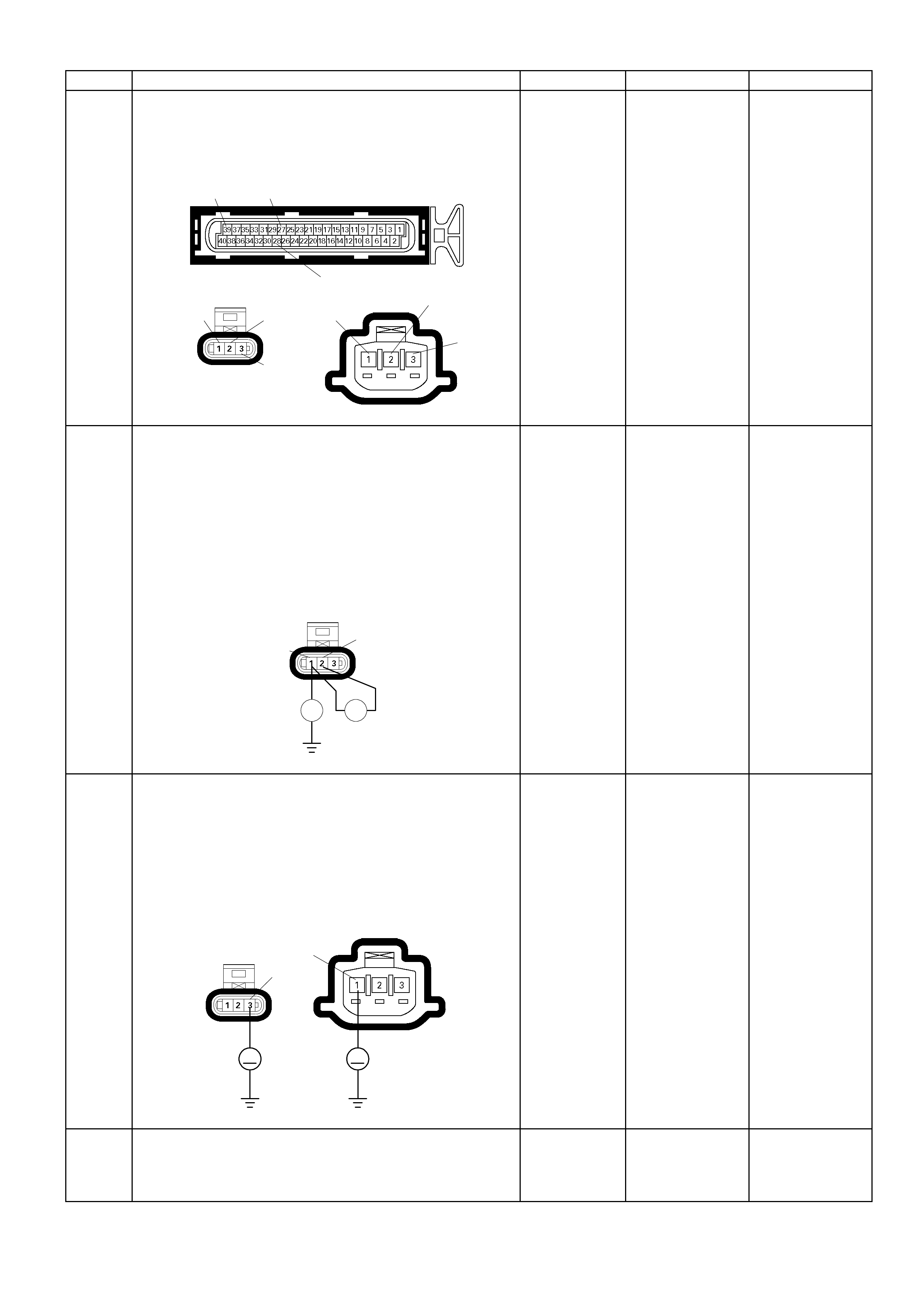
Step Action Value (s) Yes No
17 Check for poor/faulty connection at the TPS, CMP
sensor or ECM connector. If a poor/faulty connection
is found, repair the faulty terminal.
Was the problem found?
E-61(B)
E-62 E-68
39
1 2
3
12
3
27
28
- Verify repair Go to Step 18
18
Using the DVM and check the CMP sensor signal
circuit.
1. Ignition "Off", engine "Off".
2. Disconnect the CMP sensor connector and ECM
connector.
3. Check the circuit for short to sensor ground or short
to ground circuit.
Was the problem found?
E-62
Ħ Ħ
12
-
Repair faulty
harness and
verify repair
Go to Step 19
19
Using the DVM and check the TPS or CMP sensor
power supply circuit.
1. Ignition "On", engine "Off".
2. Disconnect the TPS or CMP sensor connector.
3. Check the circuit for open or short to ground circuit.
Was the DVM indicated specified value?
E-62
E-68
V V
31
A
pproximately
5.0V
Go to Step 23
Go to Step 20
20 Repair the short to ground circuit between the ECM
and TPS or CMP sensor.
Was the problem solved? - Verify repair Go to Step 23

Step Action Value (s) Yes No
21 Substitute a known good CKP sensor and recheck.
Was the problem solved? - Go to Step 21 Go to Step 23
22 Replace the CKP sensor.
Was the problem solved? - Verify repair Go to Step 23
23 Is the ECM programmed with the latest software
release?
If not, download the latest software to the ECM using
the "SPS (Service Programming System)".
Was the problem solved? - Verify repair Go to step 24
24 Replace the ECM.
Is the action complete?
IMPORTANT: The replacement ECM must be
programmed. Refer to section of the Service
Programming System (SPS) in this m anual. Following
ECM programming, the immobiliser system (if
equipped) must be l inked to the ECM. Ref er to s ect i o n
11 “Immobiliser System-ECM replacement” for the
ECM/Immobiliser linking procedure. - Verify repair -
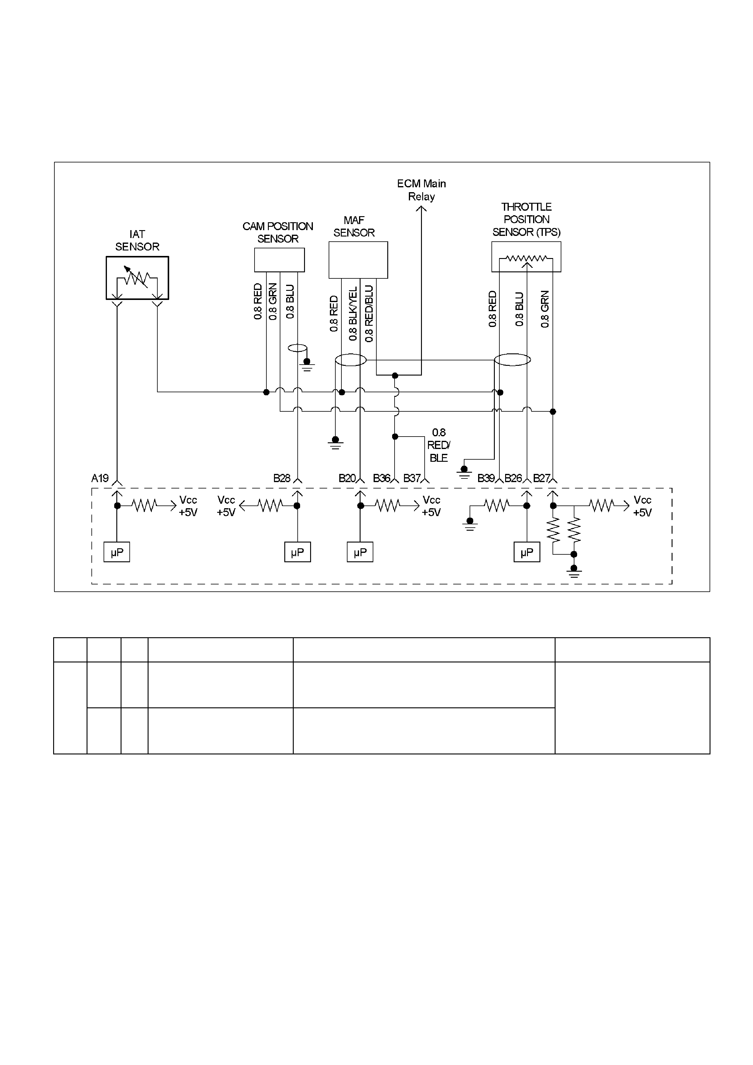
Diagnostic Trou ble Code (DTC) P0341(Fl ash Co de 41) Camsha f t
Position Sensor Circuit Range/Performance
Diagnostic Trouble Code (DTC) P0342 (Flash Code 41) Camshaft
Position Sensor Circuit No Signal
RTW36EMF000401
Condition For Setting The DTC and Action Taken When The DTC Sets
Flash
Code Code Type DTC Name DTC Setting Condition Fail-Safe (Back Up)
P0341 B Camshaft Position Sensor
Circuit Range/Performance 1. Engine speed below 2000rpm.
2. No crankshaft position sensor DTC P0336 or P0337.
3. Incorrect puls e is detect ed consecutively.
41
P0342 B Camshaft Position Sensor
Circuit No Signal 1. No DTC relating to CKP sensor.
2. Engine speed is below 2000rpm.
3. No pulse is detected consecutivel y.
Fuel cut is operated at high
engine speed.
Circuit Description
If the ECM receives an incorrect number of pulses on
the CMP reference circuit, DTC P0341 will set.
If the ECM does not receive pulses on the CMP
reference circuit, DTC P0342 will set.
Diagnostic Aids
An intermittent may be caused by a poor connection,
rubbed–through wire insulation or a wire broken inside
the insulation. Chec k for:
• Poor connection — Inspect the ECM harness and
connectors for improper mating, broken locks,
improperly formed or damaged terminals, and poor
terminal-to-wire connection.
• Damaged harness — Inspect the wiring harness for
damage.
Reviewing the Failure Records vehicle mileage since
the diagnostic test last failed may help determine how
often the condition that caused the DTC to be set
occurs. This may assist in diagnosing the condition.
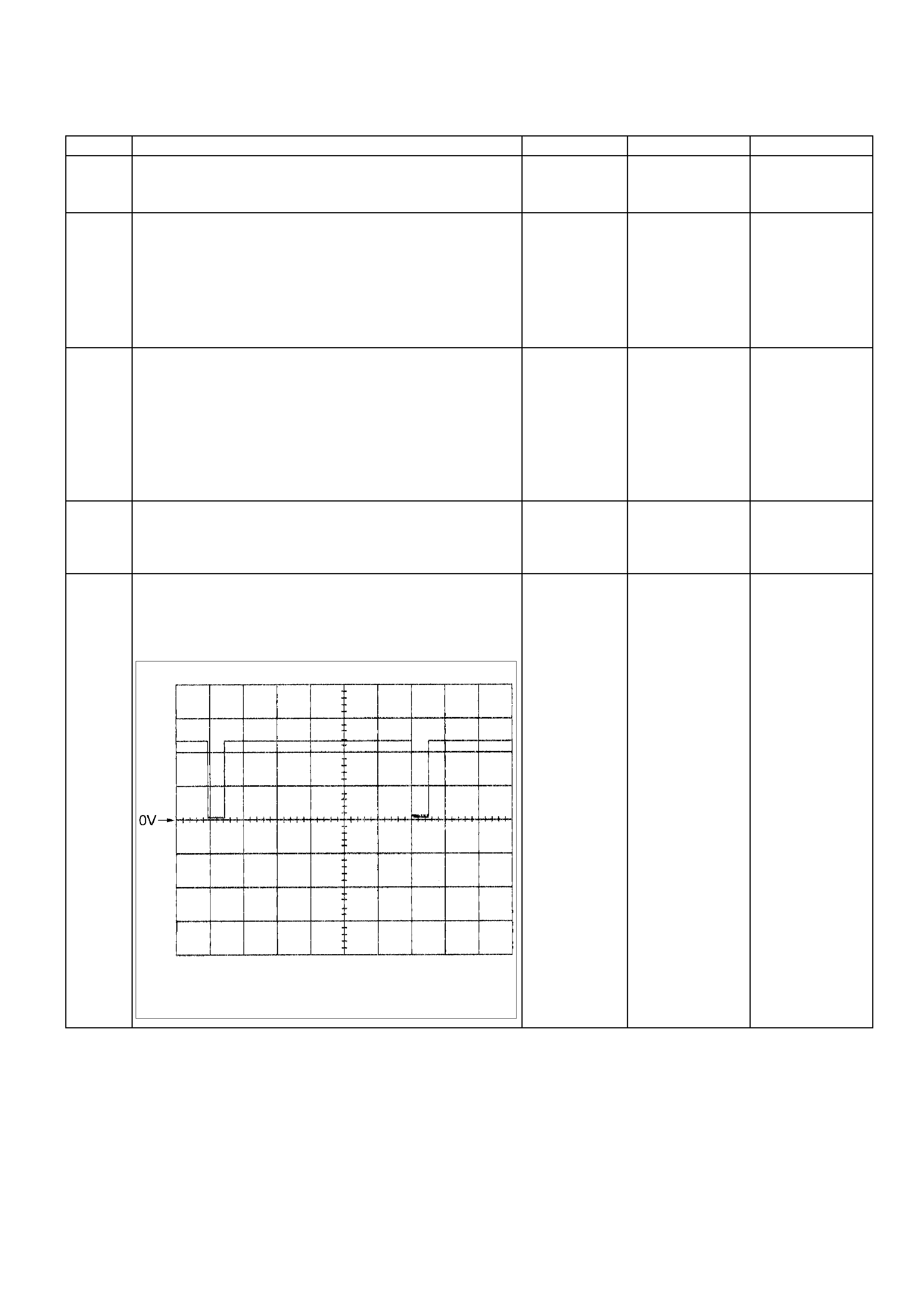
Diagnostic Trouble Code (DTC) P0341(Flash Code 41) Camshaft Position Sensor Circuit
Range/Performance
Diagnostic Trouble Code (DTC) P0342 (Flash Code 41) Camshaft Position Sensor Circuit No Signal
Step Action Value (s) Yes No
1 Was the "On-Board Diagnostic (OBD) System Check"
performed? - Go to Step 2
Go to On Board
Diagnostic (OBD)
System Check
2 1. Connect the Tech 2.
2. Review and record the failure information.
3. Select "F0: Read DTC Infor By Priority" in "F0:
Diagnostic Trouble Code".
Is the DTC P0341 or P0342 stored as "Present
Failure"? - Go to Step 3
Refer to
Diagnostic Ai ds
and Go to Step 3
3 1. Using the Tech2, ignition "On" and engine "Off".
2. Select "Clear DTC Information" with the Tech2 and
clear the DTC information.
3. Operate the vehicle and monitor the "F5: Failed
This Ignition" in "F2: DTC Information"
Was the DTC P0341 or P0342 stored in this ignition
cycle? - Go to Step 4
Refer to
Diagnostic Ai ds
and Go to Step 4
4 Check any accessory parts which may cause electric
interference or magnetic interference.
Was the problem found? -
Remove the
accessory parts
and verify repair Go to Step 5
5
If a oscilloscope is available, monitor the CMP sensor
signal. Does the oscilloscope indicate correct wave
form?
Camshaf t Position Sensor Referenc e Wave Form
Measurement T erminal: B28 (+) B39 (-)
Measurement Scale: 2. 0V/div 10ms/ di v
Measurement Condi tion: Engine speed at 2000rpm
Refer to
Diagnostic Ai ds
and Go to Step
17
Not available:
Go to Step 6
Fixed at low:
Go to Step 6
Fixed at High:
Go to Step 12
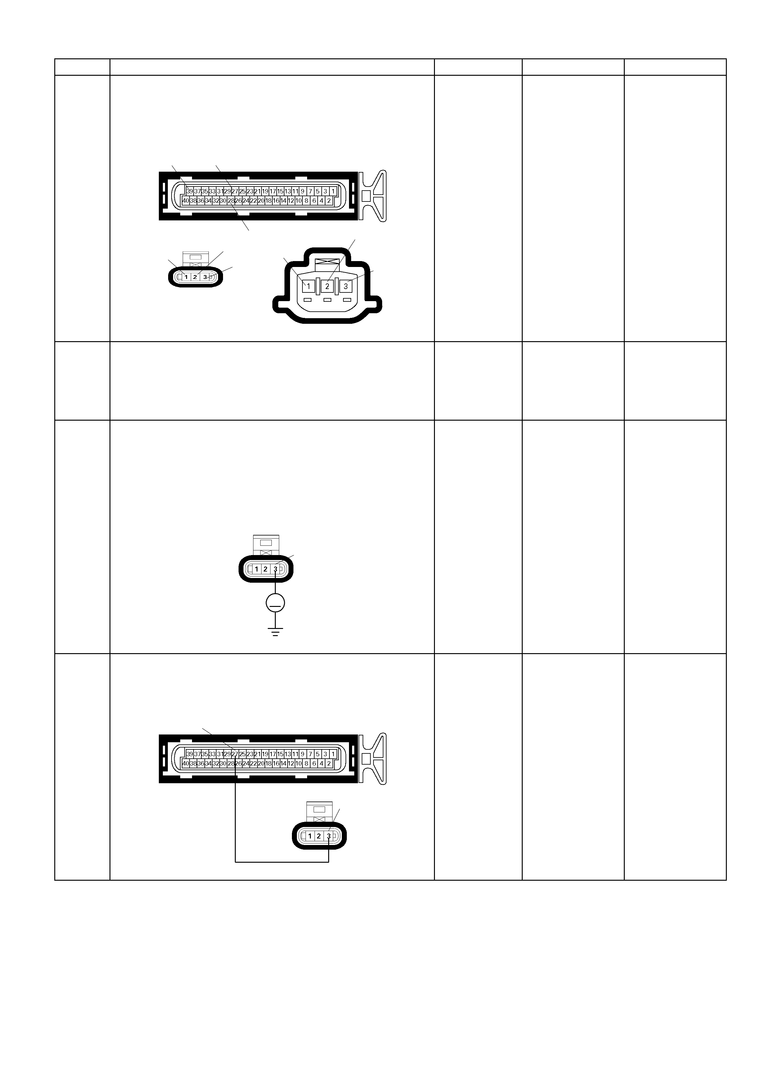
Step Action Value (s) Yes No
6 Check for poor/faulty connection at the TPS, CMP
sensor or ECM connector. If a poor/faulty connection
is found, repair the faulty terminal.
Was the problem found?
E-61(B)
39 27
28 E-68
12
3
E-62
123
- Verify repair Go to Ste p 7
7 Remove the CMP sensor from the cylinder head and
vi sually check.
• Objects sticking the CMP sensor.
Was the problem found? - Verify repair Go to Step 8
8 1. Ignition "On", engine "Off".
2. Disconnec t the CM P senso r connector .
3. Check the circuit for open, short to ground or short
to battery voltage circuit.
Was the DVM indicated specified value?
E-62
V
3
A
pproximately
5.0V Go to Step 11
Less than 1V:
Go to Step 9
More than
specif ied value:
Go to Step 10
9 Repair the open, short to sensor gorund or short to
ground circuit between the ECM and CMP sensor.
Was the problem solved?
E-61(B)
E-62
27
3
- Verify repair Go to Step 15
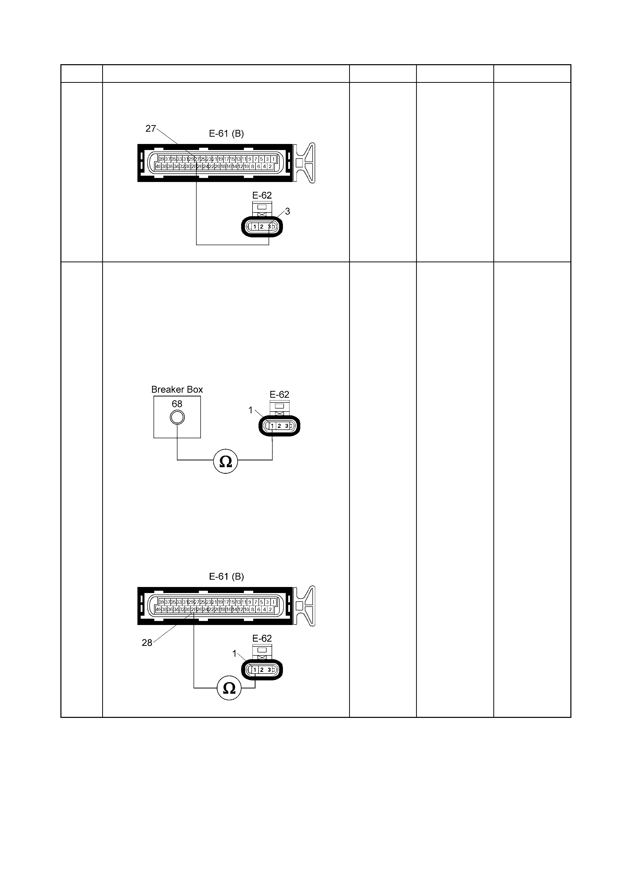
Step Action Value(s) Yes No
10 Rep air the short to battery voltage circuit bet ween the
ECM and CMP sensor.
Was the problem solved?
– Verif y repair Go to Step 15
11 Using the DM M, check the CMP sensor signal circuit.
Breaker box is a vailable:
1. Ignition "Off", engine "Off".
2. Install the breaker bo x as type A (ECM
disconnected).
Refer to page 6E-86.
3. Disconnect th e CMP sensor connector.
4. Check the circ uit for open circuit.
Was the problem found?
Breaker box is not available:
1. Ignition ‘OFF ’, engine ‘OFF’.
2. Disconnect th e wiring harness connectors from
the CMP sensor and the ECM.
3. Check the circ uit for open circuit.
Was the problem found?
–
Repair faulty
harness and
verify repair Go to Step 12
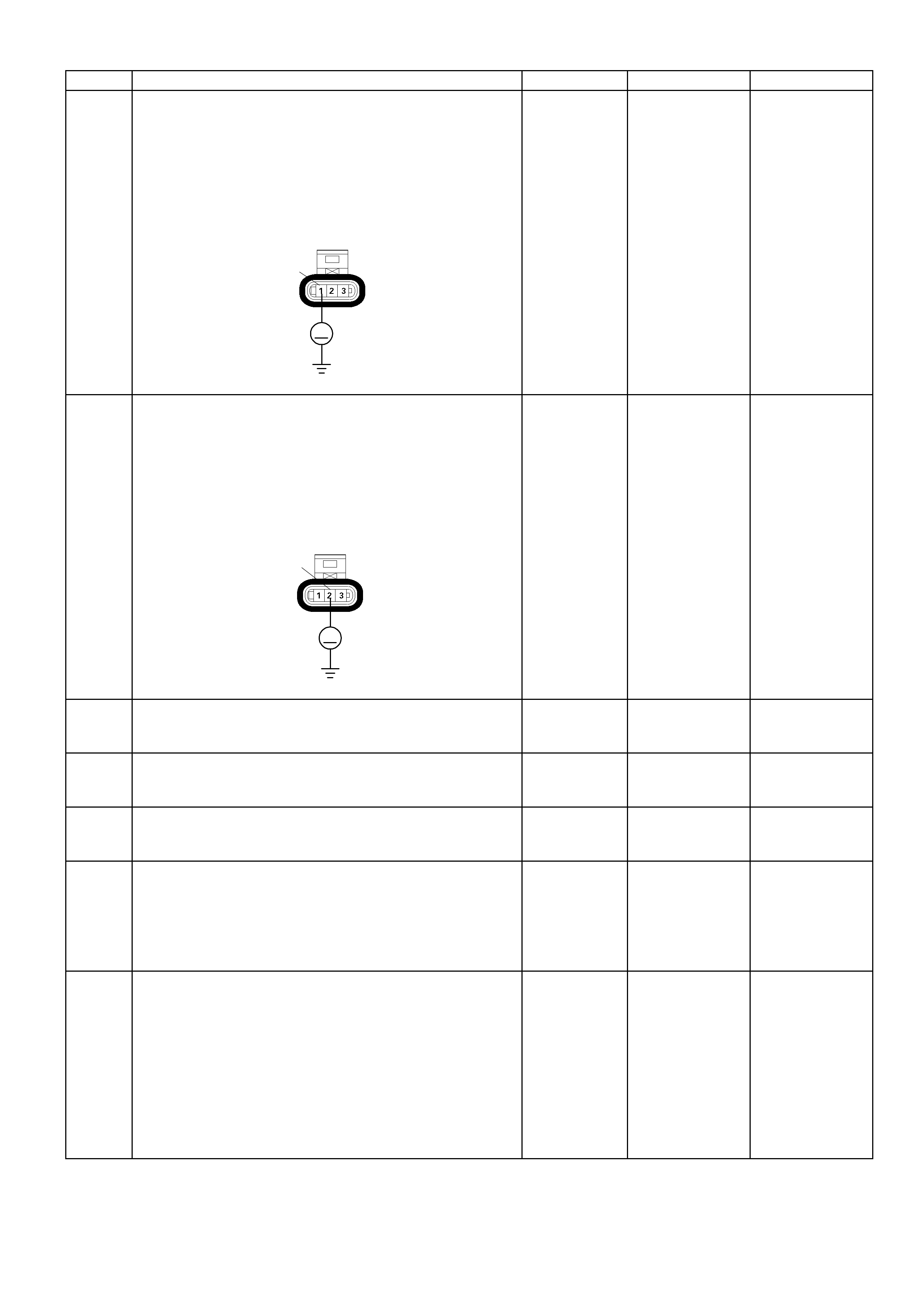
Step Action Value (s) Yes No
12
Using the DVM and check the CMP sensor signal
circuit.
1. Ignition "On", engine "Off".
2. Disconnec t the CM P senso r connector .
3. Check the circuit for short to power supply circuit.
Was the DVM indicated specified value?
E-62
V
1
Less than 1V
Go to Step 13
Repair faulty
harness and
verify repair
13
Using the DVM and check the CMP sensor ground
circuit.
1. Ignition "On", engine "Off".
2. Disconnect the CMP sensor connector .
3. Check the circuit for short to power supply circuit.
Was the DVM indicated specified value?
E-62
V
2
Less than 1V
Go to Step 14
Repair faulty
harness and
verify repair
14 Check the shield wire for open or short circuit.
Was the problem found? - Verify repair Go to Step 15
15 Substitute a known good CMP sensor and recheck.
Was the problem solved? - Go to Step 16 Go to Step 17
16 Replace the CMP sensor.
Was the problem solved? - Verify repair Go to Step 17
17 Is the ECM programmed with the latest software
release?
If not, download the latest software to the ECM using
the "SPS (Service Programming System)".
Was the problem solved? - Verify repai r Go to step 18
18 Replace the ECM.
Is the action complete?
IMPORTANT: The replacement ECM must be
programmed. Refer to section of the Service
Programming System (SPS) in this manual. Following
ECM programming, the immobiliser system (if
equipped) m ust be l ink ed to th e ECM. Refer to sect io n
11 “Immobiliser System-ECM replacement” for the
ECM/Immobiliser linking procedure. - Verify repair -
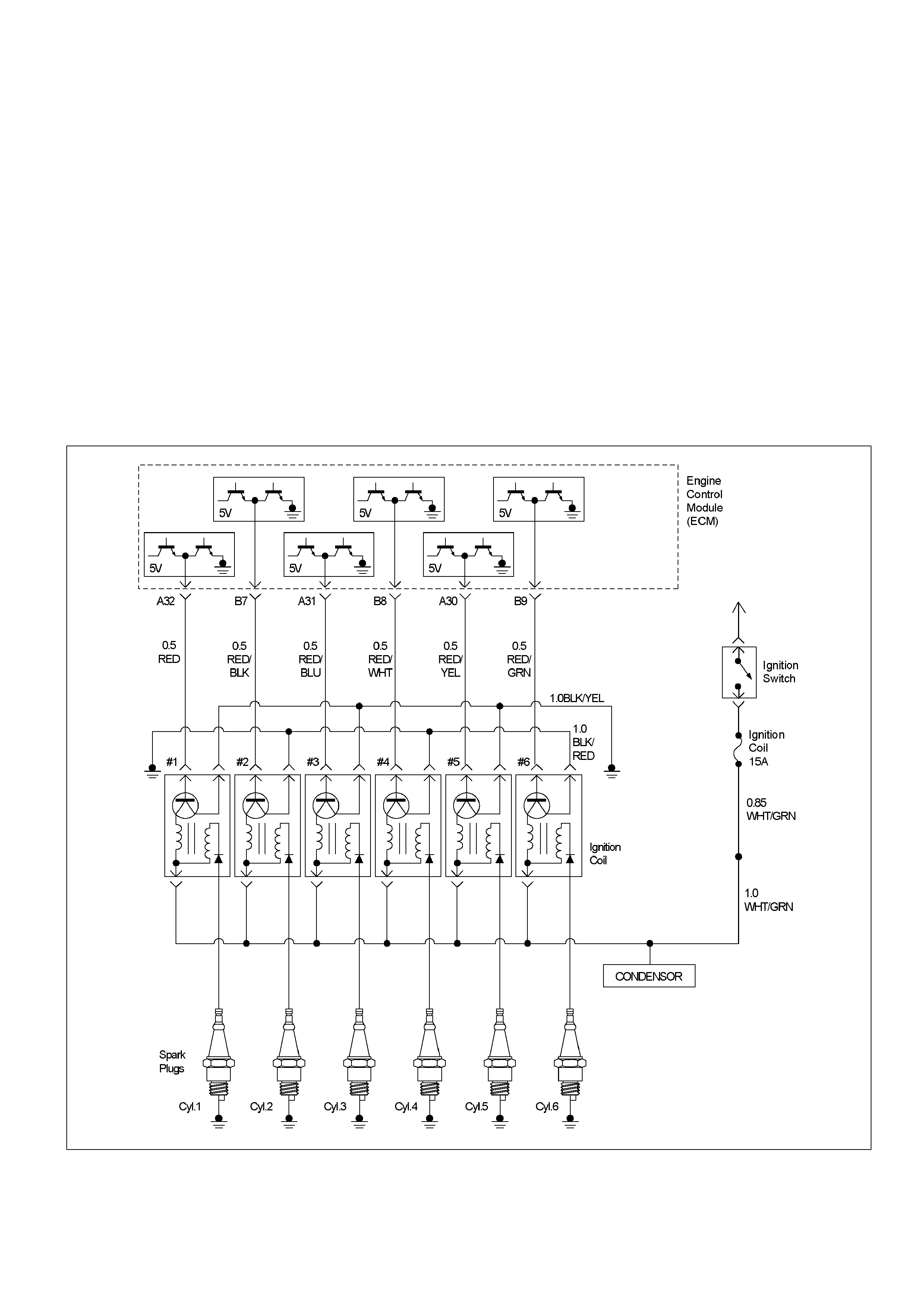
Diagnostic Trouble Code (DTC) P0351 (Flash Code 42)
Ignition 1 Control Circuit
Diagnostic Trouble Code (DTC) P0352 (Flash Code 42)
Ignition 2 Control Circuit
Diagnostic Trouble Code (DTC) P0353 (Flash Code 42)
Ignition 3 Control Circuit
Diagnostic Trouble Code (DTC) P0354 (Flash Code 42)
Ignition 4 Control Circuit
Diagnostic Trouble Code (DTC) P0355 (Flash Code 42)
Ignition 5 Control Circuit
Diagnostic Trouble Code (DTC) P0356 (Flash Code 42)
Ignition 6 Control Circuit
RTW36ELF000201

Condition For Setting The DTC and Action Taken When The DTC Sets
Flash
Code Code Type DTC Name DTC Setting Condition Fail-Safe (Back Up)
P0351 A Ignition 1 Control
Circuit
P0352 A Ignition 2 Control
Circuit
P0353 A Ignition 3 Control
Circuit
P0354 A Ignition 4 Control
Circuit
P0355 A Ignition 5 Control
Circuit
42
P0356 A Ignition 6 Control
Circuit
1. No DTC relating to CMP sensor and CKP sensor.
2. Engine speed is between 250rpm and 850 rpm.
3. 10 ignition signals are not detected consecutively.
Fuel cut is operated more than
2000rpm.
Circuit Description
The Engine Control Module's (ECM) control circuit 1
provides a zero-volt or a 5-volt output signal to the
ignition coil. The normal voltage on the circuit is zero
volts. When the ignition coil receives the 5-volt signal
from the ECM, it provides a ground path for the B+
supply to the primary side of the number 1 ignition coil.
When the ECM shuts off the 5 volts to the ignition coil,
the ignition coil turns “OFF." This causes the ignition
coil primary magnetic field to collapse, producing a
voltage in the secondary coil which fires the spark plug.
The circuit between the ECM and ignition coil is
monitored for an open circuit, short to voltage, and
short to ground. When the ECM detects a problem on
ignition control circuit, it will set a DTC P0351, P0352,
P0353, P0354, P0355 or P0356.
Diagnostic Aids
Check for the following conditions:
• Poor connection at ECM – Inspect the harness
connectors for backed-out terminals, improper
mating, broken locks, improperly formed or damaged
terminals, and poor terminal-to-wire connections.
• Damaged harness – Inspect the wiring harness for
damage. If the harness appears to be OK, observe
the Tech 2 display related to DTC P0351 or P0352,
P0353, P0354, P0355 or P0356 wh ile m oving the
connector and wiring related to the ignition system. A
change in the display will indicate the location of the
fault.
Reviewing the Failure Records vehicle mileage since
the diagnostic test last failed may help determine how
often the condition that caused the DTC to be set
occurs. This may assist in diagnosing the condition.
Diagnostic Trouble Code (DTC) P0351 (Flash Code 42) Ignition 1 Control Circuit
Diagnostic Trouble Code (DTC) P0352 (Flash Code 42) Ignition 2 Control Circuit
Diagnostic Trouble Code (DTC) P0353 (Flash Code 42) Ignition 3 Control Circuit
Diagnostic Trouble Code (DTC) P0354 (Flash Code 42) Ignition 4 Control Circuit
Diagnostic Trouble Code (DTC) P0355 (Flash Code 42) Ignition 5 Control Circuit
Diagnostic Trouble Code (DTC) P0356 (Flash Code 42) Ignition 6 Control Circuit
Step Action Value (s) Yes No
1 W as the "On- Board D iagnostic (OBD) Syst em Check "
performed? - Go to Step 2
Go to On Board
Diagnostic (OBD)
System Check
2 1. Connect the Tech 2.
2. Review and record the failure information.
3. Select "F0: Read DTC Infor By Priority" in "F0:
Diagnostic Trouble Code".
Is the DTC P0351, P0352, P0353, P0354, P0355 or
P0356 stored as "Present Failure"? - Go to Step 3
Refer to
Diagnostic Ai ds
and Go to Step 3
3 1. Using the Tech2, ignition "On" and engine "Off".
2. Select "Cl ear DTC Inform ation" with the T ech2 and
clear the DTC information.
3. Operate the vehicle and monitor the "F5: Failed
This Ignition" in "F2: DTC Information"
Was the DTC DTC P0351, P0352, P0353, P0354,
P0355 or P0356 stored in this ignition cycle? - Go to Step 4
Refer to
Diagnostic Ai ds
and Go to Step 4
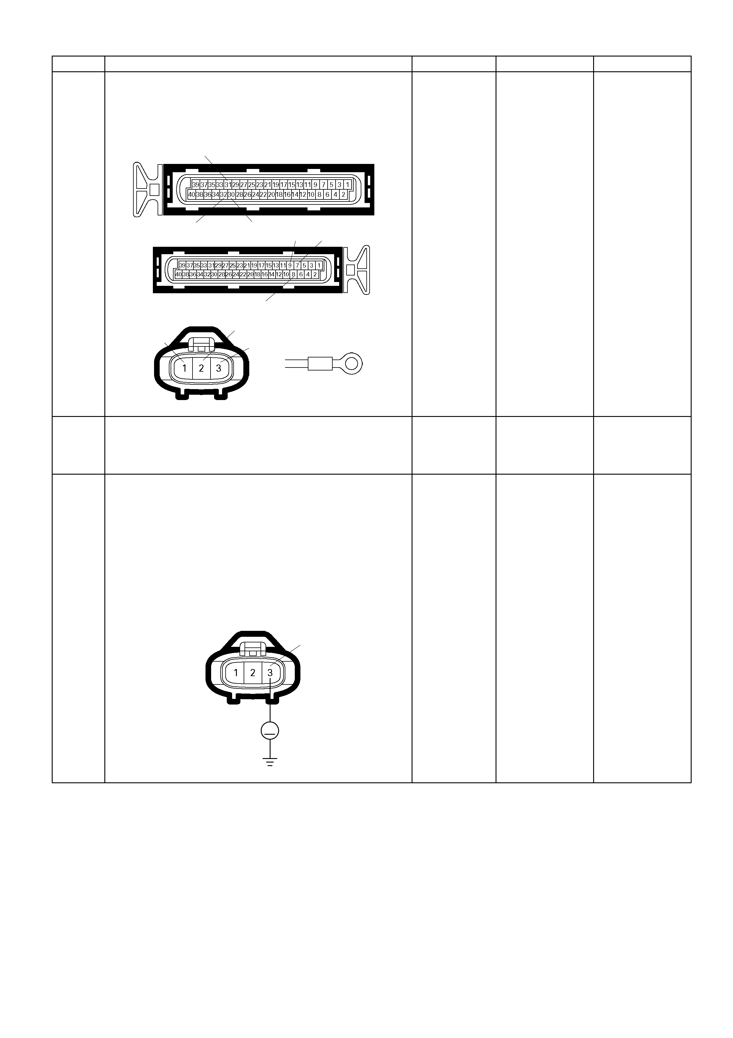
Step Action Value (s) Yes No
4 Check for poor/fault y connection at the ignition coil or
ECM connector. If a poor/faulty connection is found,
repair as neces s ar y.
Was the problem found? E-60(A)
E-61(B)
E-53/E-54/E-55/
E-56/E-57/E-58
E-73/E-74
31
32 30
8
9 7
123
- Verify repair Go to Step 5
5 Visually check the ignition coil for the affected
cylinder.
Was the problem found? - Go to Step 12 Go to Step 6
6
Using the DVM and check the ignition coil signal
circuit for the affected cylinder.
1. Ignition "On", engine "Off".
2. Disconnect the ignition coil connector for the
affected cylinder.
3. Check the circuit for short to battery voltage circuit.
Was the DVM indicated battery voltage?
E-53/E-54/E-55/
E-56/E-57/E-58
V
3
-
Repair faulty
harness and
verify repair
Go to Step 7
Step Action Value (s) Yes No
7
Using the DVM and check the ignition coil signal
circuit for the affected cylinder.
Breaker box is available:
1. Ignition "Off", engine "Off".
2. Install the breaker box as type A (ECM
disconnected).
Refer to 6E-91 page.
3. Disconnect the ignition coil connector for the
affected cylinder.
4. Check the circuit for open or short to ground circuit.
Was the problem found?
32
Breake r Box
No.1 Cylinder
Ħ
E-53
Ħ
3
47
Breake r Box
No.2 Cylinder
Ħ
E-54
Ħ
3
31
Breake r Box
No.3 Cylinder
Ħ
E-55
Ħ
3
48
Breaker Box
No.4 Cylinder
Ħ
E-56
Ħ
3
30
Breaker Box
No.5 Cylinder
Ħ
E-57
Ħ
3
Step Action Value (s) Yes No
49
Breaker Box
No.6 Cylinder
Ħ
E-58
Ħ
3
Breaker box is not available:
1. Ignition "Off", engine "Off".
2. Disconnect the ignition coil connector for the
affected cylinder and ECM connector.
3. Check the circuit for open or short to ground circuit.
Was the problem found?
E-60(A)
E-53
3
Ħ
Ħ
32
No.1 Cy li n der
E-60(A)
E-54
3
7
Ħ
Ħ
No.2 Cylinder
E-60(A)
E-55
3
Ħ
Ħ
31
No.3 Cylinder
Step Action Value (s) Yes No
E-60(A)
E-56
3
8
Ħ
Ħ
No.4 Cylinder
E-60(A)
E-57
3
Ħ
Ħ
30
No.5 Cylinder
E-60(A)
E-58
3
9
Ħ
Ħ
No.6 Cylinder
-
Repair faulty
harness and
verify repair Go to Step 8
8
Using the DVM and check the ignition coil power
supply circuit.
1. Ignition "On", engine "Off".
2. Disconnect the ignition coil connector for the
affected cylinder.
3. Check the circuit for open circuit.
Was the DVM indicated specified value?
E-53/E-54/E-55/
E-56/E-57/E-58
V
2
Battery volta ge
Go to Step 10
Go to Step 9
Step Action Value (s) Yes No
9 Repair the o pen or s hort to ground circ uit bet ween the
"IGN. COIL" (15A) and ignition coil for the affected
cylinder.
Is the action complete? - Verify repair -
10
Using the DVM and check the ignition coil ground
circuit for the affected cylinder.
1. Ignition "On", engine "Off".
2. Disconnect the ignition coil connector for the
affected cylinder.
3. Check the circuit for short to power supply circuit.
Was the DVM indicated specified value?
E-53/E-54/E-55/
E-56/E-57/E-58
V
1
Less than 1V
Go to Step 11
Repair faulty
harness and
verify repair
11 Using the DVM and check the ignition coil ground
circuit.
1. Ignition "Off", engine "Off".
2. Disconnect the ignition coil connector for the
affected cylinder and ECM connector.
3. Check the circuit for open circuit.
Was the problem found?
E-53/E-54/E-55/
E-56/E-57/E-58
1
Ħ
-
Repair faulty
harness and
verify repair Go to Step 12
12 Replace the ignition coil for the affected cylinder.
Was the problem solved? - Verify repair Go to Step 13
13 Is the ECM programmed with the latest software
release?
If not, download the latest software to the ECM using
the "SPS (Service Programming System)".
Was the problem solved? - Verify repair Go to step 14
14 Replace the ECM.
Is the action complete?
IMPORTANT: The replacement ECM must be
programmed. Refer to section of the Service
Program ming System (SPS) i n this m anual. Follo wing
ECM programming, the immobiliser system (if
equipped) must be linked to the ECM. R efer to sec tio n
11 “Immobiliser System-ECM replacement” for the
ECM/Immobiliser linking procedure. - Verify repair -
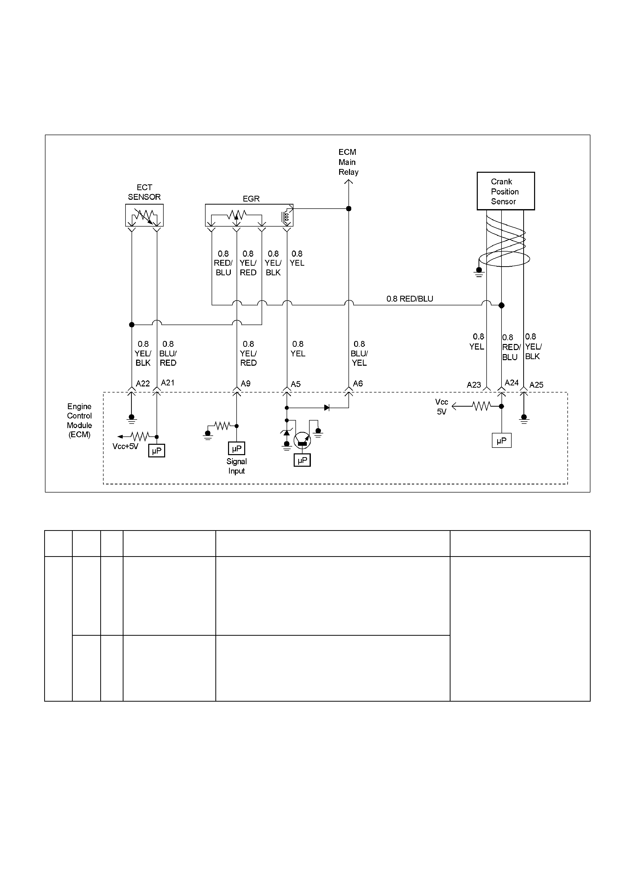
Diagnostic Trouble Code (DTC) P0404 (Flash Code 32) EGR Circuit
Range/Perfomance (Open Valve)
Diagnostic Trouble Code (DTC) P1404 (Flash Code 32) EGR Circuit
Range/Perfomance (Closed Val ve)
RTW36EMF000501
Condition For Setting The DTC and Action Taken When The DTC Sets
Flash
Code Code Type DTC Name DTC Setting Condition Fail-Safe (Back Up)
P0404 B EGR Circuit
Range/Performance
(Open Valve)
1. Engine is stopping.
2. No DTC relating to ECT sensor, CKP sensor and VSS.
3. Vehicle speed is below 4km/h.
4. Engine coolant temperat ure is more than 75°C.
5. EGR solenoid valve on-duty ratio is more than 100%.
6. EGR valve output monitoring signal high.
32
P1404 B EGR Circuit
Range/Performance
(Closed Val ve)
1. Engine is running.
2. Engine speed is below 4000rpm.
3. No DTC relating to CKP sensor.
4. EGR solenoid valve on-dut y rat io is 0%.
5. EGR valve output monitoring signal low.
1. EGR operat i on is stopped.
2. EGR valve closed position
learning operation is dis abl ed.
3. EGR position feedback is
disabled.

Circuit Description
The engine control module (ECM) monitors the EGR
valve pintle position input to ensure that the valve
responds properly to commands from the PCM, and to
detect a fault if pintle position is different
fromcommanded position.
Diagnostic Aids
Check for the following conditions:
• Excessive carbon deposit on EGR valve shaft
maycause EGR stuck open or unsmooth operation.
Those carbon deposit may occur by unusual
portoperation. Clean up carbon may make
smoothfunction of EGR valve.
• Poor connection or damaged harness −Inspect
thewiring harness for damage. If the harness
appears to be OK, observe the EGR actual position
display on the Tech 2 while moving connectors and
wiring harnesses related to EGR valve. A change in
the displa y will indic at e the loc at ion of the fault.
Diagnostic Trouble Code (DTC) P0404 (Flash Code 32) Egr Circuit Range/Perfomance (Open Valve)
Diagnostic Trouble Code (DTC) P1404 (Flash Code 32) Egr Circuit Range/Perfomance (Closed Valve)
Step Action Value (s) Yes No
1 W as the "On-Boar d Di agno stic (OBD) S ystem Chec k "
performed? - Go to Step 2
Go to On Board
Diagnostic (OBD)
System Check
2 1. Connect the Tech 2.
2. Review and record the failure information.
3. Select "F0: Read DTC Infor By Priority" in "F0:
Diagnostic Trouble Code".
Is the DTC P0404 or P1404 stored as "Present
Failure"? - Go to Step 3
Refer to
Diagnostic Ai ds
and Go to Step 3
3 1. Using the Tech2, ignition "On" and engine "Off".
2. Sel ect "C lear DT C Inf orm ation" with the T ech2 and
clear the DTC information.
3. Operate the vehicle and monitor the "F5: Failed
This Ignition" in "F2: DTC Information"
Was the DTC P0404 or P1404 stored in this ignition
cycle? - Go to Step 4
Refer to
Diagnostic Ai ds
and Go to Step 4
4 Check for poor/faulty connection at the EGR valve or
ECM connector. If a poor/faulty connection is found,
repair as necessary.
Was the problem found? E-60(A)
E-76
5
51
- Verify repair Go to Step 5
Step Action Value (s) Yes No
5
Using the DVM and check the EGR valve.
1. Ignition "Off", engine "Off".
2. Disconnec t EG R va lv e con nector .
3. Measure the resistance of EGR valve solenoid coil.
Does the tester indicate standard resistance?
EGR Valve
Ħ
15
Apporoximatel
y 8.3 Ω at 20°C
Go to Step 6
Go to Step 11
6
Inspect the EGR valve.
1. Remove the EGR valve from the engine.
2. Inspect the EG R v al ve whether there is any carbon
deposit on shaft.
If excessive carbon deposit is found, clean up the
EGR valve and inspect damage of the pintle and seat.
Was the problem found?
-
Verify repair or
Go to Step 11
Go to Step 7
7
Using the DVM and check the EGR valve solenoid
power supply circuit.
1. Ignition "On", engine "Off".
2. Disconnec t the EG R va lv e connec tor .
3. Check the circuit for open circuit.
Was the DVM indicated specified value?
E-76
V
5
Batter y volta ge
Go to Step 9
Go to Step 8
8 Repair the open or short to ground circuit between the
ECM main relay and EGR valve.
Is the action complete? - Verify repair -
Step Action Value (s) Yes No
9
Using the DVM and check the EGR valve solenoid
signal circuit.
Breaker box is available:
1. Ignition "Off", engine "Off".
2. Install the breaker box as type A (ECM
disconnected).
Refer to 6E-91 page.
3. Disconnec t EG R va lv e connec tor .
4. Check the circuit for open, short to sensor ground
or short to ground circuit.
Was the problem found?
522
Ħ
Breaker Box
E-76
Ħ
Ħ
1
Breaker box is not available:
1. Ignition "Off", engine "Off".
2. Disconnect the EGR valve connector and ECM
connector.
3. Check the circuit for open, short to sensor ground
or short to ground circuit.
Was the problem found? E-60(A)
Ħ
Ħ
E-76
Ħ
22 5
1
-
Repair faulty
harness and
verify repair
Go to Step 10
10
Using the DVM and check the EGR valve solenoid
signal circuit.
1. Ignition "Off", engine "Off".
2. Disconnec t the EG R va lv e connec tor .
3. Check the circuit for short to battery voltage circuit.
Was the DVM indicated battery voltage?
E-76
V
1
-
Repair faulty
harness and
verify repair
Go to Step 11

Step Action Value (s) Yes No
11 Substitute a known good EGR valve and recheck.
Was the problem solved? - Go to Step 12 Go to Step 13
12 Replace the EGR valve.
Was the problem solved? - Verify repair Go to Step 13
13 Is the ECM programmed with the latest software
release?
If not, download the latest software to the ECM using
the "SPS (Service Programming System)".
Was the problem solved? - Verify repair Go to step 14
14 Replace the ECM.
Is the action complete?
IMPORTANT: The replacement ECM must be
programmed. Refer to section of the Service
Program m ing S ystem (SPS) in this m anual. Fol lowin g
ECM programming, the immobiliser system (if
equipped) must be linked to the ECM. Refer to
section 11 “Immobiliser System-ECM
replacement” for the ECM/Immobiliser linking
procedure. - Verify repair -

Diagnostic Trouble Code (DTC) P0405 (Flash Code 32)
EGR Circuit Low
RTW36EMF000501
Condition For Setting The DTC and Action Taken When The DTC Sets
Flash
Code Code Type DTC Name DTC Setting Condition Fail-Safe (Back Up)
32 P0405 B EG R Ci rcuit Low 1. No DTC relati ng to EGR circuit range/perf ormance.
2. EGR solenoid valve on-duty ratio is more than 40%.
3. EGR position sensor out put voltage i s below 0.3V.
No fail-safe function.
Circuit Description
The engine control module (ECM) monitors the EGR
valve pintle position input to ensure that the valve
responds properly to command from the ECM. If
current pintle position voltage indicates less than 0.3 V
the ECM will set DTC P0405.
Diagnostic Aids
Check for the following conditions:
• Poor connection or damaged harness – Inspect the
wiring harness for damage. If the harness appears to
be OK, observe the EGR actual position display on
the Tech 2 while moving connectors and wiring
harnesses related to EGR valve. A change in the
display will indicate the location of the fault.
Diagnostic Trouble Code (DTC) P0405 (Flash Code 32) Egr Circuit Low
Step Action Value (s) Yes No
1 W as the "On- Board Diagn ostic (O BD) System Check"
performed? - Go to Step 2
Go to On Board
Diagnostic (OBD)
System Check
2 1. Connect the Tech 2.
2. Review and record the failure information.
3. Select "F0: Read DTC Infor By Priority" in "F0:
Diagnostic Trouble Code".
Is the DTC P0405 stored as "Present Failure"? - Go to Step 3
Refer to
Diagnostic Ai ds
and Go to Step 3
3 1. Using the Tech2, ignition "On" and engine "Off".
2. Selec t "Clear DT C Inform ation" with the T ech2 and
clear the DTC information.
3. Operate the vehicle and monitor the "F5: Failed
This Ignition" in "F2: DTC Information"
Was the DTC P0405 stored in this ignition cy cle? - Go to Step 4
Refer to
Diagnostic Ai ds
and Go to Step 4
4 Check for poor/faulty connection at the EGR valve or
ECM connector. If a poor/faulty connection is found,
repair as necessary.
Was the problem found?
E-60(A)
E-76
9
24
234
22
- Verify repair Go to Step 5
5 Visually check the EGR valve.
Was the problem found? - Go to Step 10 Go to Step 6
6
Using the DVM and check the EGR valve position
sensor.
1. Ignition "Off", engine "Off".
2. Disconnec t EG R va lv e con nector .
3. Measure the resistance of EGR valve position
sensor.
Does the tes ter in dic at e s t a ndard r es is t anc e as s ho wn
in the following table?
EGR Valve
Ħ Ħ
EGR Valve
Ħ
4
2
34 2
Measurement Terminal Resi stance (Ω)
2 – 3 Approximately 1.1k Ω
3 – 4 Approximately 4.5k Ω
2 - 4 Approximately 4.7kΩ
Standard
resistance
Go to Step 7
Go to Step 10
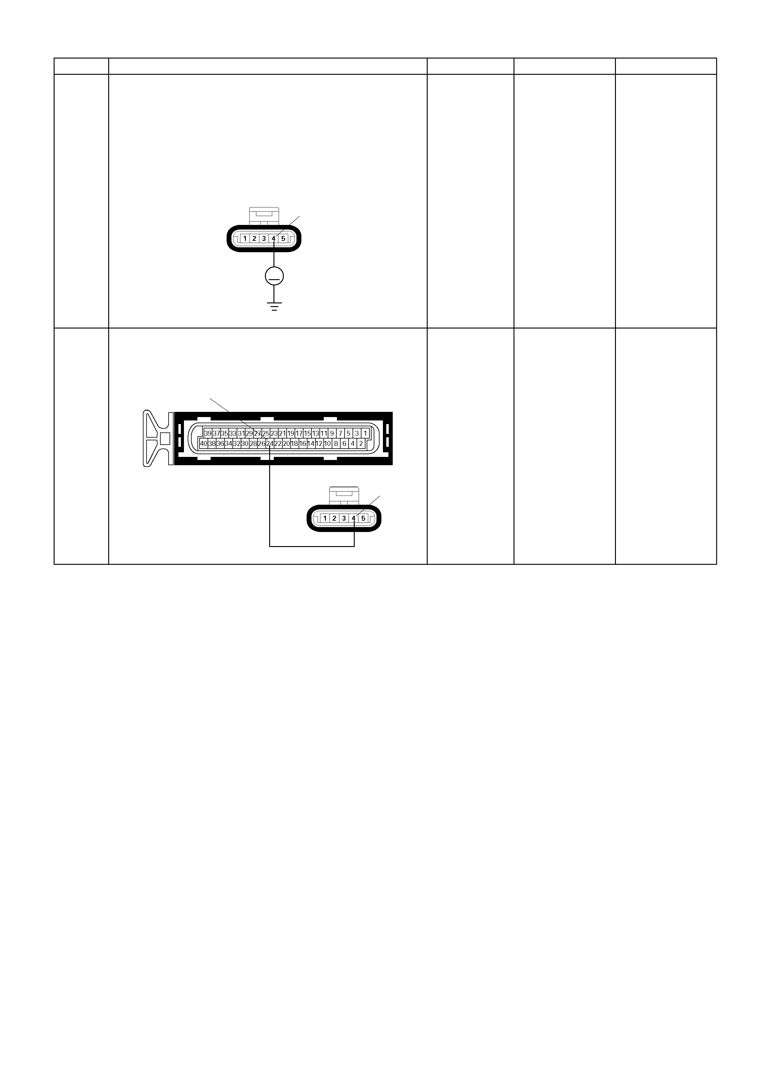
Step Action Value (s) Yes No
7
Using the DVM and check the EGR valve position
sensor power supply circuit.
1. Ignition "On", engine "Off".
2. Disconnec t the EG R va lv e connec tor .
3. Check the circuit for open or short to ground circuit.
Was the DVM indicated specified value?
E-76
V
4
Approximately
5.0V
Go to Step 9
Go to Step 8
8 Repair the o pen or short to ground c ircui t between t he
ECM and EGR valve position sensor circuit.
Was the problem solved?
E-76 4
E-60(A)
24
- Verify repair Go to Step 12
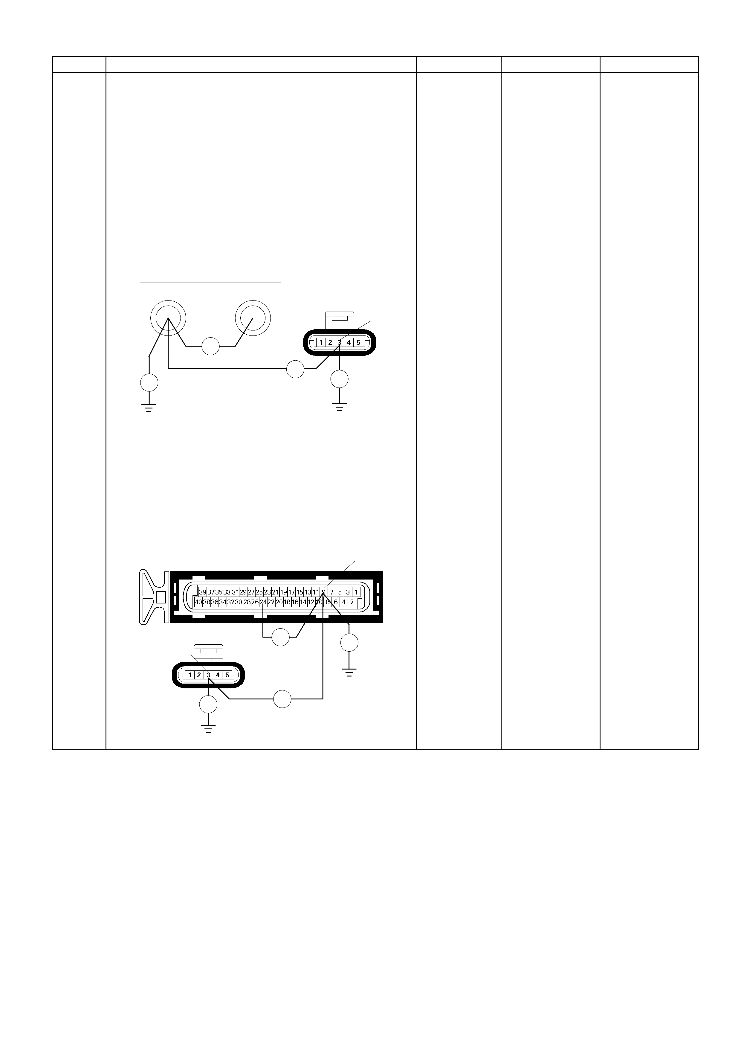
Step Action Value (s) Yes No
9
Using the DVM and check the EGR valve position
sensor signal circuit.
Breaker box is available:
1. Ignition "Off", engine "Off".
2. Install the breaker box as type A (ECM
disconnected).
Refer to 6E-91 page.
3. Disconnec t EG R va lv e connec tor .
4. Check the circuit for open, short to sensor ground
or short to ground circuit.
Was the problem found?
E-76
Ħ Ħ
3
922
Ħ
Breaker Box
Ħ
Breaker box is not available:
1. Ignition "Off", engine "Off".
2. Disconnect the EGR valve connector and ECM
connector.
3. Check the circuit for open, short to sensor ground
or short to ground circuit.
Was the problem found?
E-76
3
E-60(A) 9
Ħ Ħ
Ħ Ħ
-
Repair faulty
harness and
verify repair
Go to Step 10

Step Action Value (s) Yes No
10 Substitute a known good EGR valve and recheck.
Was the problem solved? - Go to Step 11 Go to Step 12
11 Replace the EGR valve.
Is the action complete? - Verify repair -
12 Is the ECM programmed with the latest software
release?
If not, download the latest software to the ECM using
the "SPS (Service Programming System)".
Was the problem solved? - Verify repair Go to step 13
13 Replace the ECM.
Is the action complete?
IMPORTANT: The replacement ECM must be
programmed. Refer to section of the Service
Program ming S ys tem (SPS) in this manual. Foll owing
ECM programming, the immobiliser system (if
equipped) must be linked to the ECM. Refer to sec tio n
11 “Immobiliser System-ECM replacement” for the
ECM/Immobiliser linking procedure. - Verify repair -
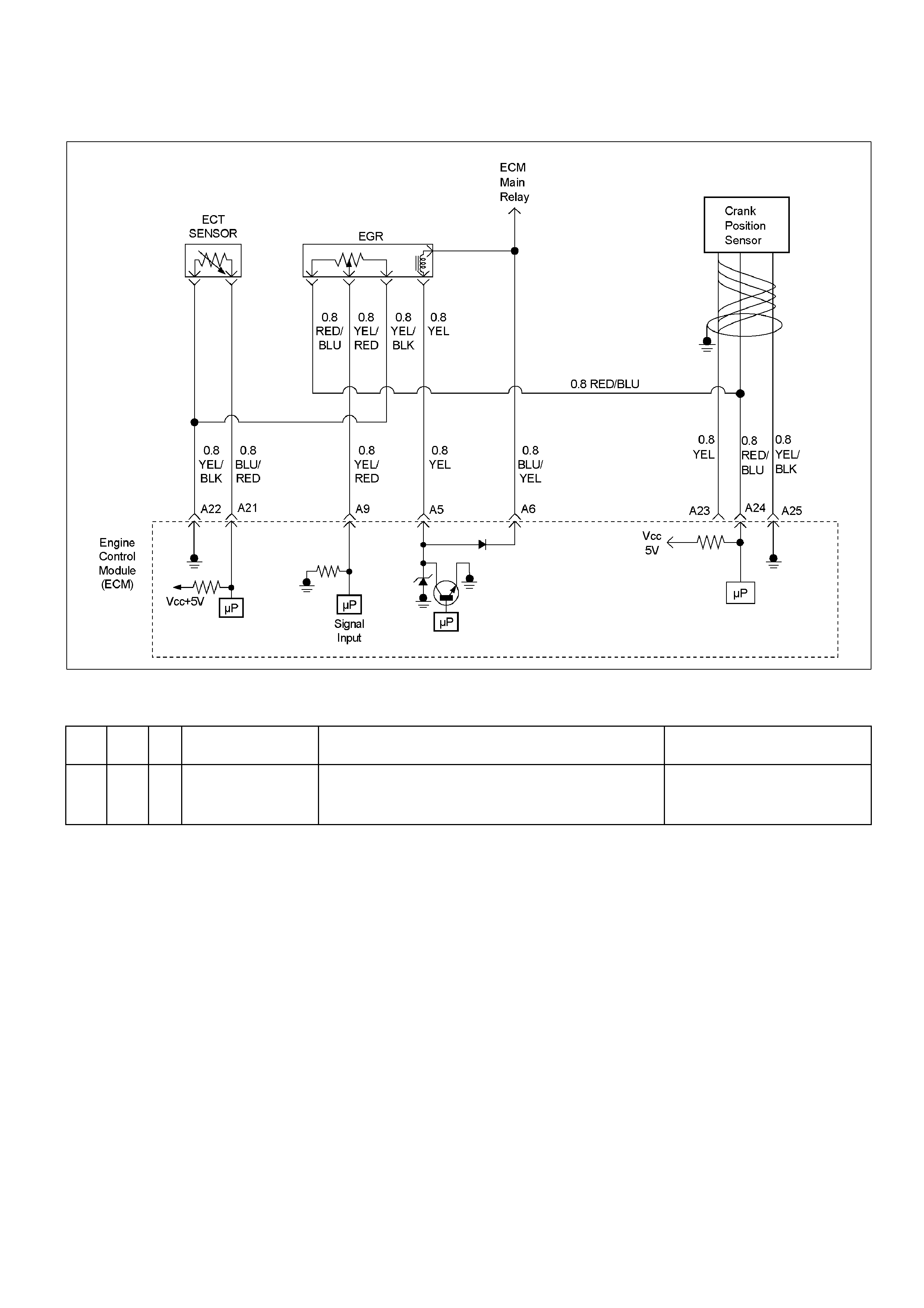
Diagnostic Trouble Code (DTC) P0406 (Flash Code 32)
EGR Circuit High
RTW36EMF000501
Condition For Setting The DTC and Action Taken When The DTC Sets
Flash
Code Code Type DTC Name DTC Setting Condition Fail-Safe (Back Up)
32 P0406 B EG R Ci rcuit Hi gh 1. No DTC relati ng to EGR circuit range/perf ormance.
2. EGR solenoid valve on-duty ratio is below 40%.
3. EGR position sensor out put voltage i s more than 4. 6V.
No fail-safe function.
Circuit Description
The engine control module (ECM) monitors the EGR
valve pintle position input to ensure that the valve
responds properly to command from the ECM. If
current pintle position voltage indicates more than 4.6 V
the ECM will set DTC P0406.
Diagnostic Aids
Check for the following conditions:
• Poor connection or damaged harness – Inspect the
wiring harness for damage. If the harness appears to
be OK, observe the EGR actual position display on
the Tech 2 while moving connectors and wiring
harnesses related to EGR valve. A change in the
display will indicate the location of the fault.
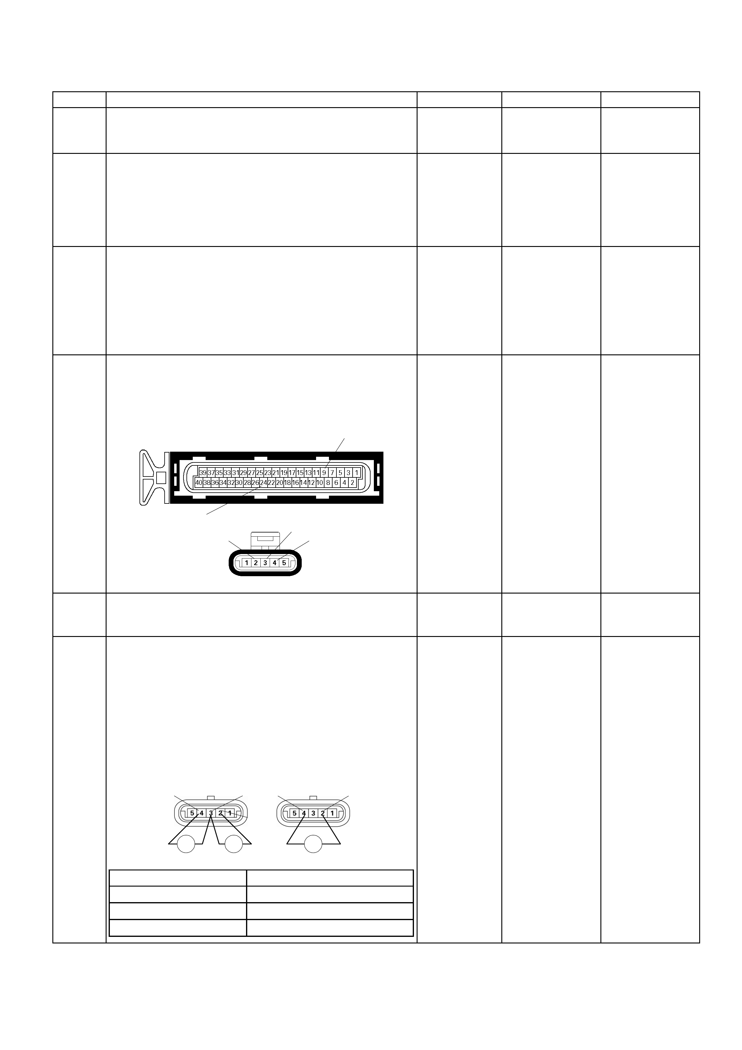
Diagnostic Trouble Code (DTC) P0406 (Flash Code 32) Egr Circuit High
Step Action Value (s) Yes No
1 W as the "On- Board Diagn ostic (O BD) System Check"
performed? - Go to Step 2
Go to On Board
Diagnostic (OBD)
System Check
2 1. Connect the Tech 2.
2. Review and record the failure information.
3. Select "F0: Read DTC Infor By Priority" in "F0:
Diagnostic Trouble Code".
Is the DTC P0406 stored as "Present Failure"? - Go to Step 3
Refer to
Diagnostic Ai ds
and Go to Step 3
3 1. Using the Tech2, ignition "On" and engine "Off".
2. Selec t "Clear DT C Inform ation" with the T ech2 and
clear the DTC information.
3. Operate the vehicle and monitor the "F5: Failed
This Ignition" in "F2: DTC Information"
Was the DTC P0406 stored in this ignition cycle? - Go to Step 4
Refer to
Diagnostic Ai ds
and Go to Step 4
4 Check for poor/faulty connection at the EGR valve or
ECM connector. If a poor/faulty connection is found,
repair as neces sary.
Was the problem found?
E-60(A)
E-76
9
24
234
- Verify repair Go to Step 5
5 Visually check the EGR valve.
Was the problem found? - Go to Step 12 Go to Step 6
6
Using the DVM and check the EGR valve position
sensor.
1. Ignition "Off", engine "Off".
2. Disconnec t EG R va lv e connec tor .
3. Measure the resistance of EGR valve position
sensor.
Does the tes ter in dic at e s ta ndar d r es istance as s ho wn
in the following table?
EGR Valve
Ħ Ħ
EGR Valve
Ħ
4
2
34 2
Measurement Terminal Resi stance (Ω)
2 – 3 Approximately 1.1k Ω
3 – 4 Approximately 4.5k Ω
2 - 4 Approximately 4.7kΩ
Standard
resistance
Go to Step 7
Go to Step 12
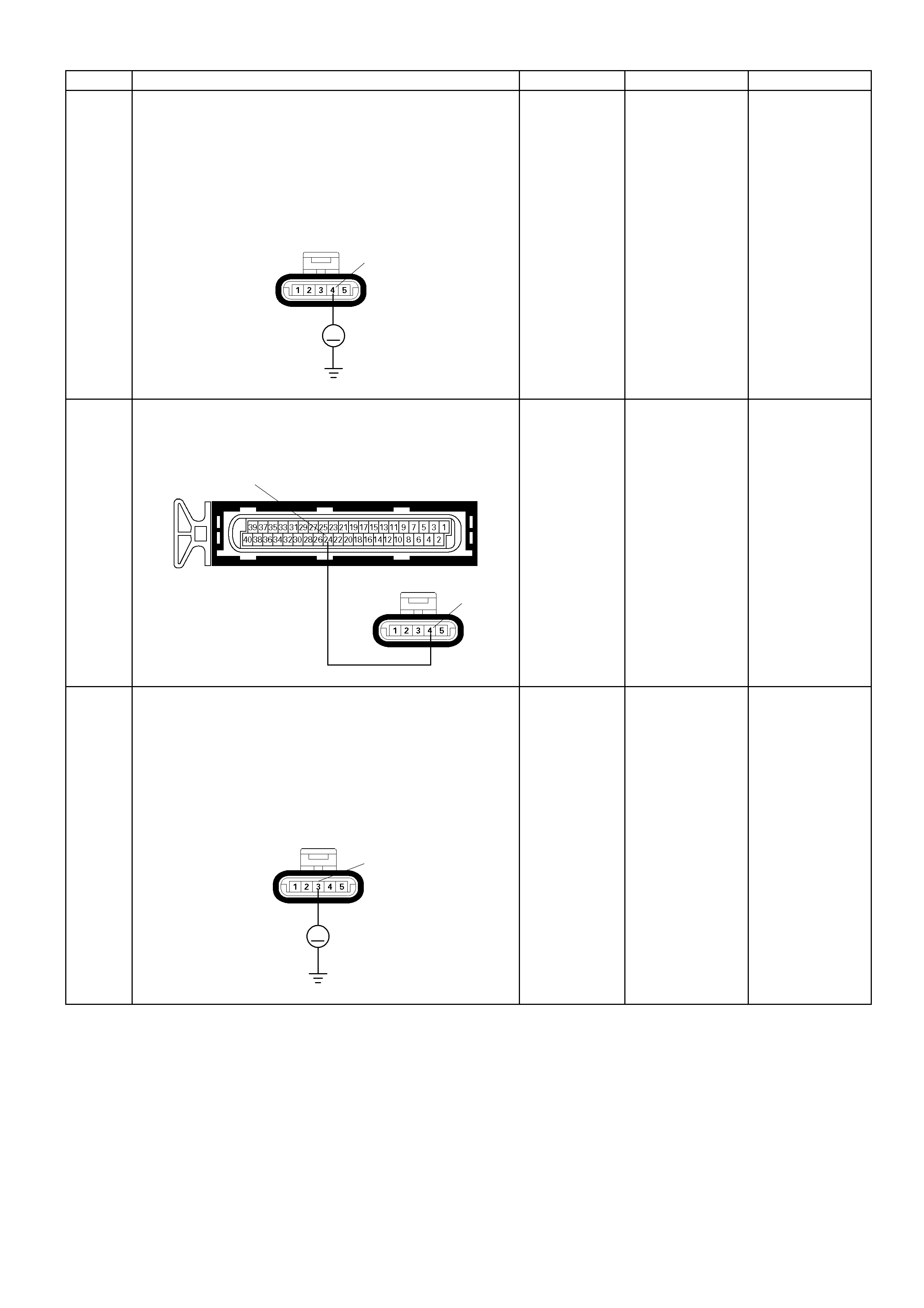
Step Action Value (s) Yes No
7
Using the DVM and check the EGR position sensor
power supply circuit.
1. Ignition "On", engine "Off".
2. Disconnec t the EG R va lv e connec tor .
3. Check the circuit for short to voltage circuit.
Was the DVM indicated specified value?
E-76
V
4
A
pproximately
5.0V
Go to Step 9
Go to Step 8
8 Repair the short to voltage circuit between the ECM
and EGR valve.
Was the problem solved?
E-76 4
E-60(A)
24
- Verify repair Go to Step 14
9 Using the DVM and check the EGR position sensor
signal circuit.
1. Ignition "On", engine "Off".
2. Disconnec t the EG R va lv e connec tor .
3. Check the circuit for short to power supply circuit.
Was the DVM indicated specified value?
E-76
V
3
Less than 1V
Go to Step 10
Repair faulty
harness and
verify repair
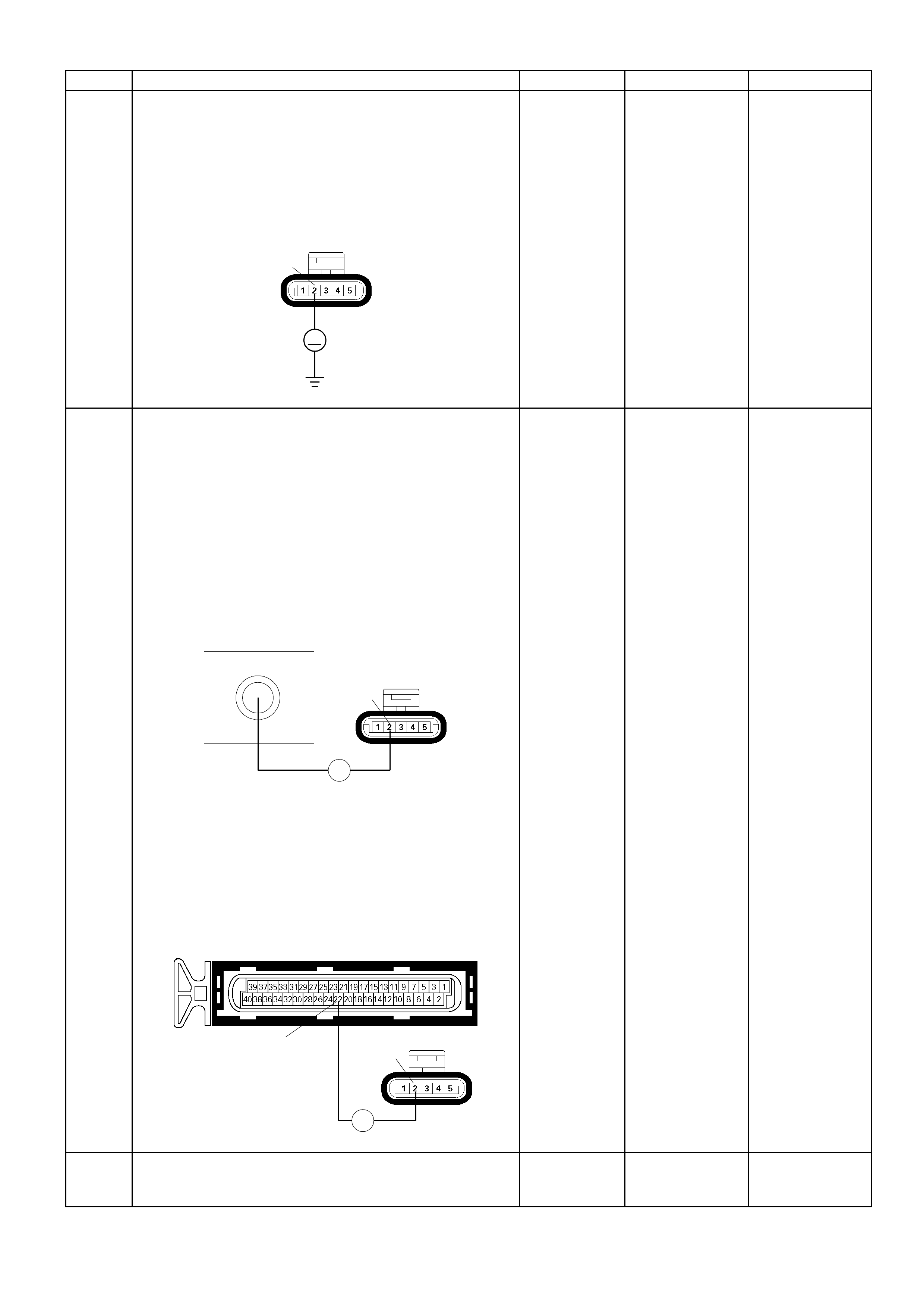
Step Action Value (s) Yes No
10
Using the DVM and check the EGR position sensor
ground circuit.
1. Ignition "On", engine "Off".
2. Disconnec t the EG R va lv e connec tor .
3. Check the circuit for short to power supply circuit.
Was the DVM indicated specified value?
E-76
V
2
Less than 1V
Go to Step 11
Repair faulty
harness and
verify repair
11
Using the DVM and check the EGR position sensor
ground circuit.
Breaker box is available:
1. Ignition "Off", engine "Off".
2. Install the breaker box as type A (ECM
disconnected).
Refer to 6E-91 page.
3. Disconnec t the EG R va lv e connec tor .
4. Check the circuit for open circuit.
Was the problem found?
22
Breaker Box
E-76
Ħ
2
Breaker box is not available:
1. Ignition "Off", engine "Off".
2. Disconnect the EGR valve connector and ECM
connector.
3. Check the circuit for open circuit.
Was the problem found? E-60(A)
E-76
Ħ
2
22
-
Repair faulty
harness and
verify repair
Go to Step 12
12 Substitute a known good EGR valve and recheck.
Was the problem solved? - Go to Step 13 Go to Step 14

Step Action Value (s) Yes No
13 Replace the EGR valve.
Is the action complete? - Verify repair -
14 Is the ECM programmed with the latest software
release?
If not, download the latest software to the ECM using
the "SPS (Service Programming System)".
Was the problem solved? - Verify repair Go to step 15
15 Replace the ECM.
Is the action complete?
IMPORTANT: The replacement ECM must be
programmed. Refer to section of the Service
Program ming S ys tem (SPS) in this manual. Fo llowing
ECM programming, the immobiliser system (if
equipped) must be linked to the ECM. Refer to sec tio n
11 “Immobiliser System-ECM replacement” for the
ECM/Immobiliser linking procedure. - Verify repair -
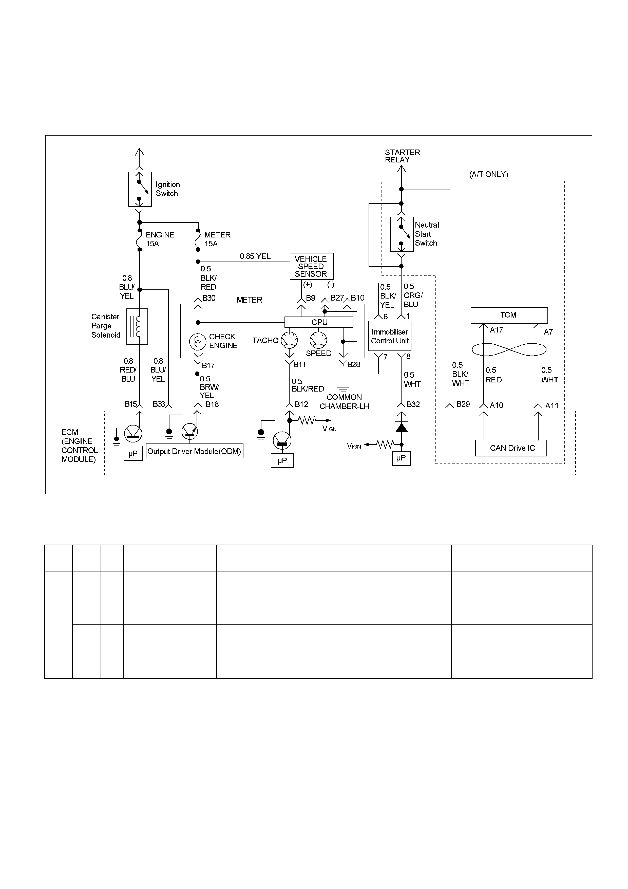
Diagnostic Trouble Code (DTC) P0444 Evap Purge Solenoid
Valve Circuit Low Voltage
Diagnostic Trouble Code (DTC) P0445 Evap Purge Solenoid
Valve Circuit High Voltage
RTW36EMF000601
Condition For Setting The DTC and A ction Taken When The DTC Sets
Flash
Code Code Type DTC Name DTC Setting Condition Fail-Safe (Back Up)
P0444 A EVAP Purge Solenoid
Valve Circuit Low
Voltage
1. No DTC relating to CKP sensor and system voltage.
2. Engine speed is below 4000rpm.
3. Purge solenoid valve on-duty ratio is below 48%.
4. Purge solenoid valve output monitoring signal low.
No fail-safe function.
−
P0445 A EVAP Purge Solenoid
Valve Circ uit Hi gh
Voltage
1. No DTC relating to CKP sensor and system voltage.
2. Engine speed is below 4000rpm.
3. Purge solenoid valve on-duty ratio is more than 50%.
4. Purge solenoid valve output monitoring si gnal hi gh.
No fail-safe function.

Circuit Description
The canister purge solenoid valve is controlled by the
Engine Train Control Module (ECM).
At an appropriate time, the EVAP canister purge
solenoid is “ON," allowing engine vacuum to draw a
small vacuum on the entire evaporative emissions
system.
Diagnostic Aids
An intermittent may be caused by the following:
• Poor connections.
• Mis routed harness.
• Rubbed through wire insulation.
• Broken wire inside the insulation.
Check for the following conditions:
• Poor connection at ECM-Inspect harness connectors
for backed out terminals, improper mating, broken
locks, improperly formed or damaged terminals, and
poor terminal to wire connection.
• Damaged harness-Inspect the wiring harness for
damage. If the harness appears to be OK, observe
the EVAP purge solenoid display on the Tech 2 while
moving connectors and wiring harnesses related to
the sensor.
A change in the display will indicate the location of
the fault. If DTC P0444 or P0445 cannot be
duplicated, the information included in the Failure
Records data can be us ef ul in determined vehicl e
mileage since the DTC was last set.
If it is determined that the DTC occurs intermittently,
performing the DTC P0444 or P0445 Diagnostic
Chart may isolate the cause of the fault.
Diagnostic Trouble Code (DTC) P0444 Evap Purge Solenoid Valve Circuit Low Voltage
Diagnostic Trouble Code (DTC) P0445 Evap Purge Solenoid Valve Circuit High Voltage
Step Action Value (s) Yes No
1 W as the "On- Board Diagn ostic (OBD) System Chec k"
performed? - Go to Step 2
Go to On Board
Diagnostic (OBD)
System Check
2 1. Connect the Tech 2.
2. Review and record the failure information.
3. Select "F0: Read DTC Infor By Priority" in "F0:
Diagnostic Trouble Code".
Is the DTC P0444 or P0445 stored as "Present
Failure"? - Go to Step 3
Refer to
Diagnostic Ai ds
and Go to Step 3
3 1. Using the Tech2, ignition "On" and engine "Off".
2. Select "Clear DT C Inform ation" with the T ech2 and
clear the DTC information.
3. Operate the vehicle and monitor the "F5: Failed
This Ignition" in "F2: DTC Information"
Was the DTC P0444 or P0445 stored in this ignition
cycle? - Go to Step 4
Refer to
Diagnostic Ai ds
and Go to Step 4
4 Check for poor/f aulty connec tion at the pur ge soleno id
valve or ECM conn ector. If a poor /faulty co nnection is
found, repair as necessary.
Was the problem found?
E-61(B)
E-66
21
15
- Verify repair Go to Step 5
Step Action Value (s) Yes No
5
Using the DVM and check the purge solenoid valve.
1. Ignition "Off", engine "Off".
2. Disconnec t pur g e sol eno id va lv e conn ector .
3. Measure the resistance of purge solenoid valve
coil.
Does the tester indicate standard resistance?
25 - 30Ω at
20°C
Go to Step 6
Go to Step 9
6
Using the DVM and check the purge solenoid valve
power supply circuit.
1. Ignition "On", engine "Off".
2. Disconnec t the pur g e solenoid valve con nec tor.
3. Check the circuit for open circuit.
Was the DVM indicated specified value?
E-66
V
2
Battery voltage
Go to Step 8
Go to Step 7
7 Repair the o pen or short to ground c ircui t between t he
"Engine" fuse (15A) and purge solenoid valve.
Is the action complete? - Verify repair -
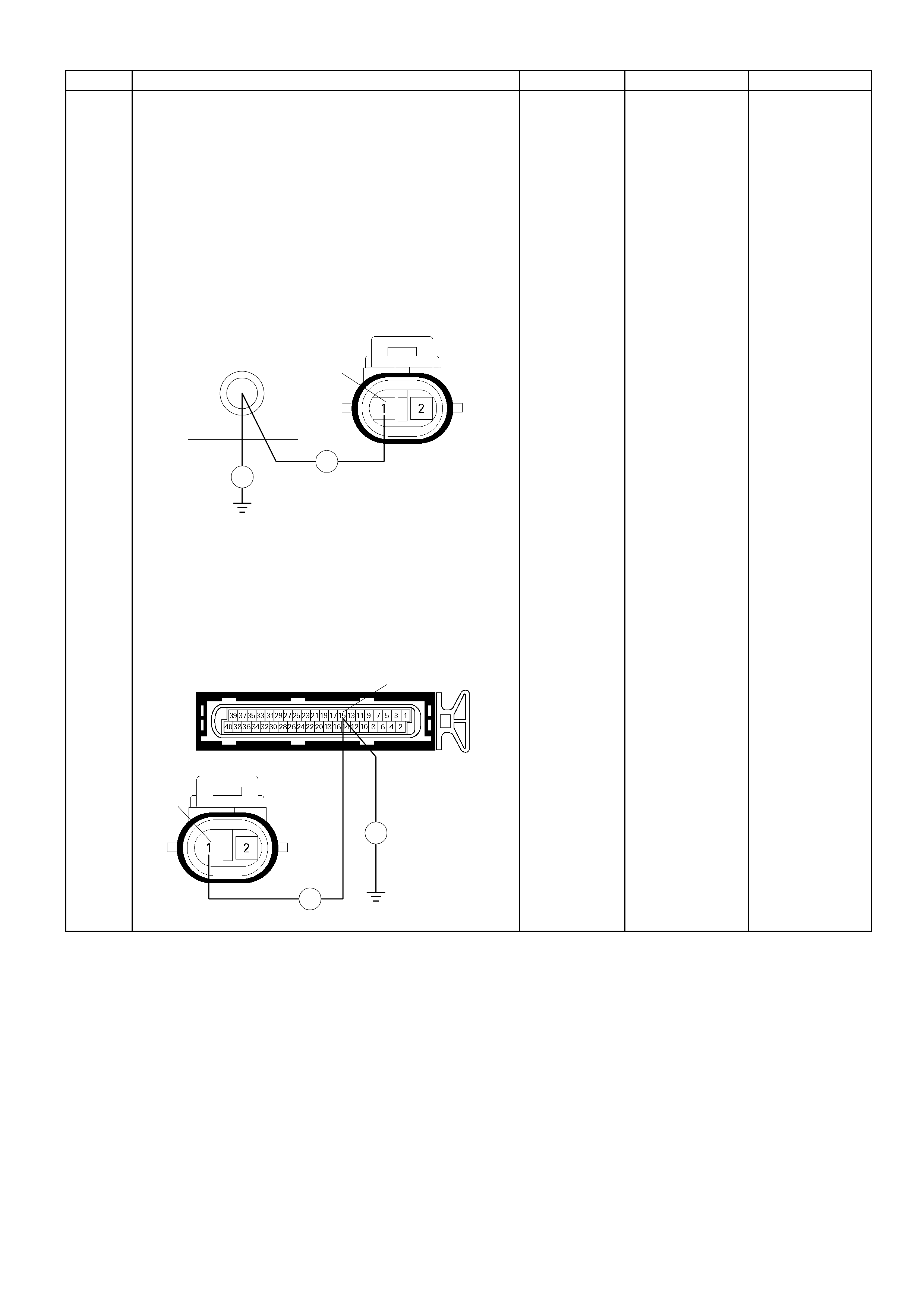
Step Action Value (s) Yes No
8
Using the DVM and check the purge solenoid valve
solenoid sig nal circuit.
Breaker box is available:
1. Ignition "Off", engine "Off".
2. Install the breaker box as type A (ECM
disconnected).
Refer to 6E-91 page.
3. Disconnec t the pur g e solenoid valve con nec tor.
4. Check the circuit for open or short to ground circuit.
Was the problem found?
55
Breaker Box E-66
Ħ
Ħ
1
Breaker box is not available:
1. Ignition "Off", engine "Off".
2. Disconnec t the purge s o le n oid valve c onn ec tor a nd
ECM connector.
3. Check the circuit for open or short to ground circuit.
Was the problem found?
E-61(B)
E-66
Ħ
Ħ
1
15
-
Repair faulty
harness and
verify repair
Go to Step 9

Step Action Value (s) Yes No
9
Using the DVM and check the purge solenoid valve
signal circuit.
1. Ignition "On", engine "Off".
2. Disconnec t the pur g e solenoid valve con nec tor.
3. Check the circuit for short to battery voltage circuit.
Was the DVM indicated battery voltage?
E-66
V
1
-
Repair faulty
harness and
verify repair
Go to Step 10
10 Substitute a known good purge solenoid valve and
recheck.
Was the problem solved? - Go to Step 11 Go to Step 12
11 Replace the purge solenoid valve.
Was the problem solved? - Verify repair Go to Step 12
12 Is the ECM programmed with the latest software
release?
If not, download the latest software to the ECM using
the "SPS (Service Programming System)".
Was the problem solved? - Verify repair Go to step 13
13 Replace the ECM.
Is the action complete?
IMPORTANT: The replacement ECM must be
programmed. Refer to section of the Service
Program ming S ys tem (SPS) in this manual. Fo llowing
ECM programming, the immobiliser system (if
equipped) must be linked to the ECM. Refer to sec tio n
11 “Immobiliser System-ECM replacement” for the
ECM/Immobiliser linking procedure. - Verify repair -
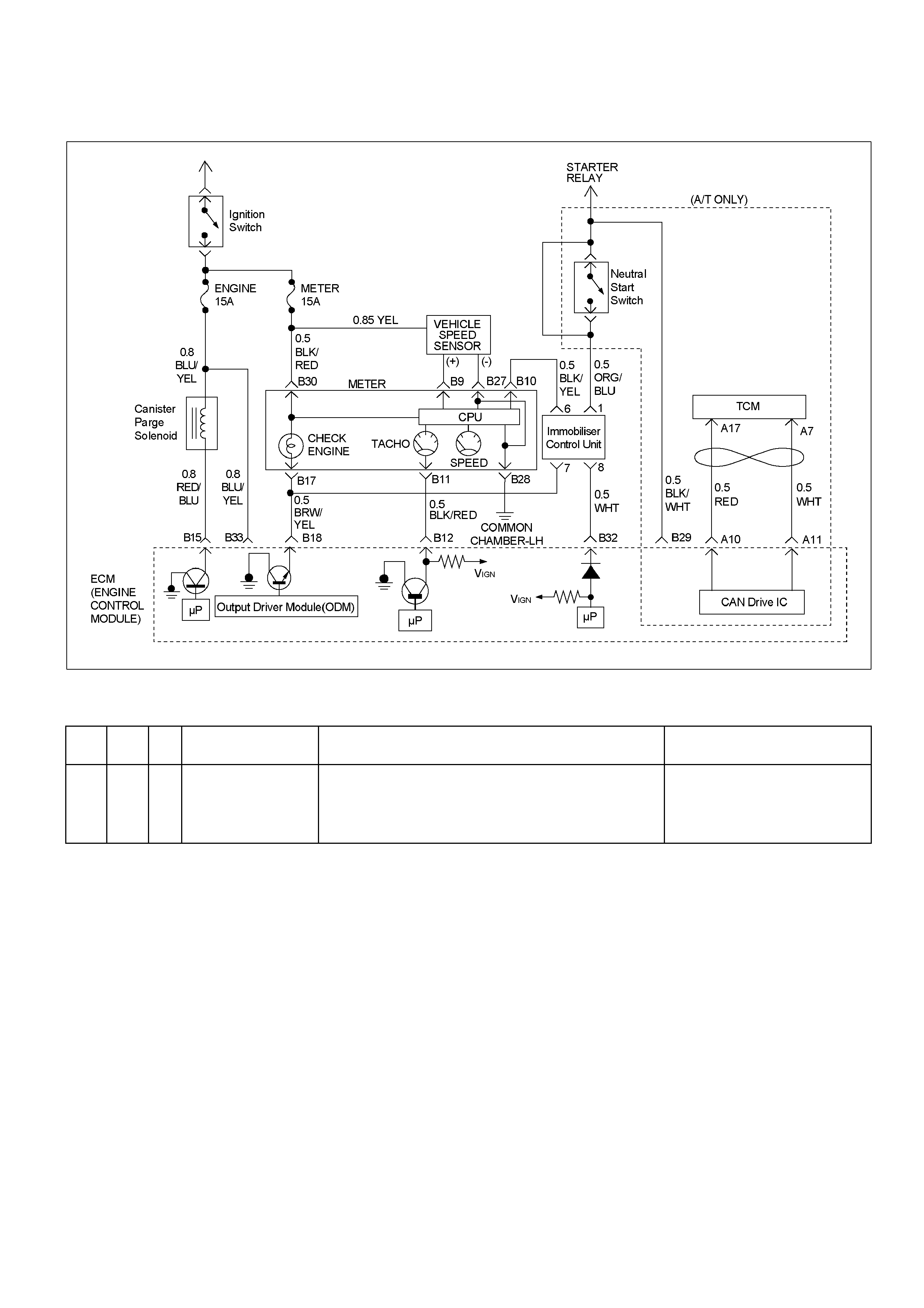
Diagnostic Trouble Code (DTC) P0500 (Flash Code 24) Vehicle
Speed Sensor (VSS) Circuit Range/Performance
RTW36EMF000601
Condition For Setting The DTC and A ction Taken When The DTC Sets
Flash
Code Code Type DTC Name DTC Setting Condition Fai l -Safe (Back Up)
24 P0500 B Vehicle Speed Sensor
Circuit
Range/Performance
1. Engine speed is below 5000rpm.
2. Under fuel cut operati on.
3. Vehicle speed sensor output is below 1km/h.
Above conditions are m et for 4 seconds.
The ECM use 10km/h condition as
substitute.
Circuit Description
The vehicle speed sensor has a magnet rotated by the
transmission output shaft. Attached to the sensor is a
hall effect circuit the interacts with the magnetic field
treated by the rotating magnet. A 12-volt operating
supply for the speed sensor hall circuit is supplied from
the meter fuse. The VSS pulses to ground the 9-volt
signal sent from the Engine Control Module (ECM) on
the reference circuit. The ECM interprets vehicle speed
by the number of pulses to ground per second on the
reference circuit.
Diagnostic Aids
An intermittent may be caused by a poor connection,
rubbed–through wire insulation or a wire broken inside
the insulation. Chec k for:
• Poor connection — Inspect the ECM harness and
connectors for improper mating, broken locks,
improperly formed or damaged terminals, and poor
terminal-to-wire connection.
• Damaged harness — Inspect the wiring harness for
damage.

Diagnostic Trouble Code (DTC) P0500 (Flash Code 24) Vehicle Speed Sensor (VSS)
Circuit Range/Performance
Step Action Value (s) Yes No
1 Was the "On-Board Diagnostic (OBD) System Check"
performed?
- Go to Step 2
Go to On Board
Diagnostic
(OBD) System
Check
2 1. Connect the Tech 2.
2. Review and record the failure information.
3. Select "F0: Read DTC Infor By Priority" in "F0:
Diagnostic Trouble Code".
Is the DTC P0500 stored as "Present Failure"? - Go to Step 3
Refer to
Diagnostic Ai ds
and Go to Step 3
3 1. Using the Tech2, ignition "On" and engine "Off".
2. Select "Clear DTC Information" with the Tech2 and
clear the DTC information.
3. Operate the vehicle and monitor the "F5: Failed
This Ignition" in "F2: DTC Information"
Was the DTC P0500 stored in this ignition cy cle? - Go to Step 4
Refer to
Diagnostic Ai ds
and Go to Step 4
4 Check any accessory parts which may cause electric
interference or magnetic interference.
Was the problem found? -
Remove the
accessory parts
and verify repair Go to Step 5
5 Perform test drive and check the speed meter.
Does the speed meter indicate correct vehicle speed. - Go to Step 6 Go to Step 7
6 Perform test drive and use the Tech 2.
Monitor the "Vehicle Speed" in the data display.
Does the Tech 2 indicate correct vehicle speed as
same as the speed meter indication in the instrument
panel? - Go to Step 25 Go to Step 8
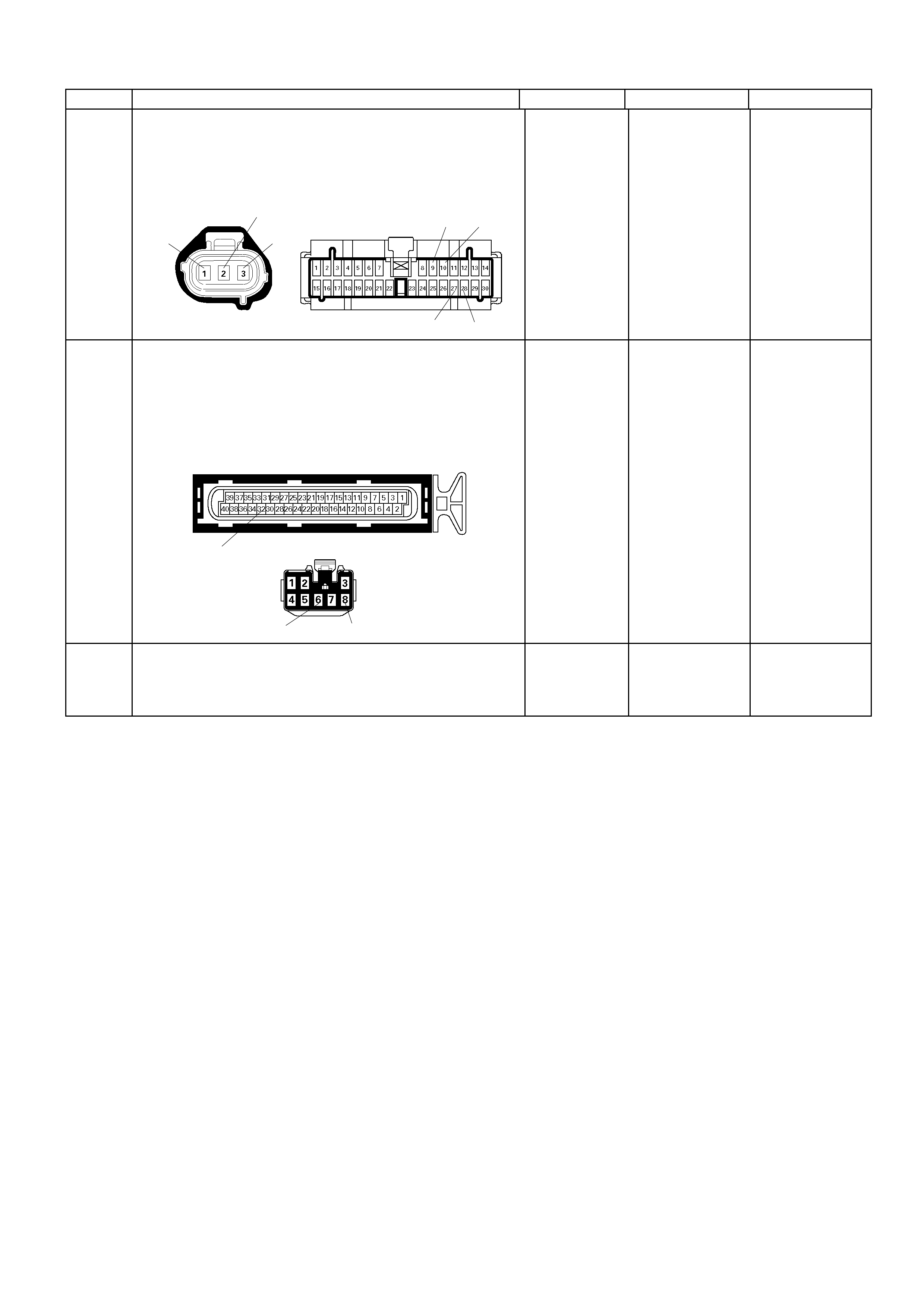
Step Action Value (s) Yes No
7 Check f or poor/fault y connection at the VSS and meter
connectors. If a poor/faulty connection is found, repair
the faulty terminal.
Was the problem found?
B-24
E-44 109
27 28
1
2
3
- Verify repair Go to Step 9
8 Check for poor/faulty connection at the immobiliser
control u nit (if equ ipped) , ECM and other con nector s. I f
a poor/faulty connection is found, repair the faulty
terminal.
Was the problem found?
B-68
68
E-61(B)
32
- Verify repair Go to Step 10
9 Remove the VSS from the housing case and visually
check.
Was the problem found? - Go to Step 23 Go to Step 10
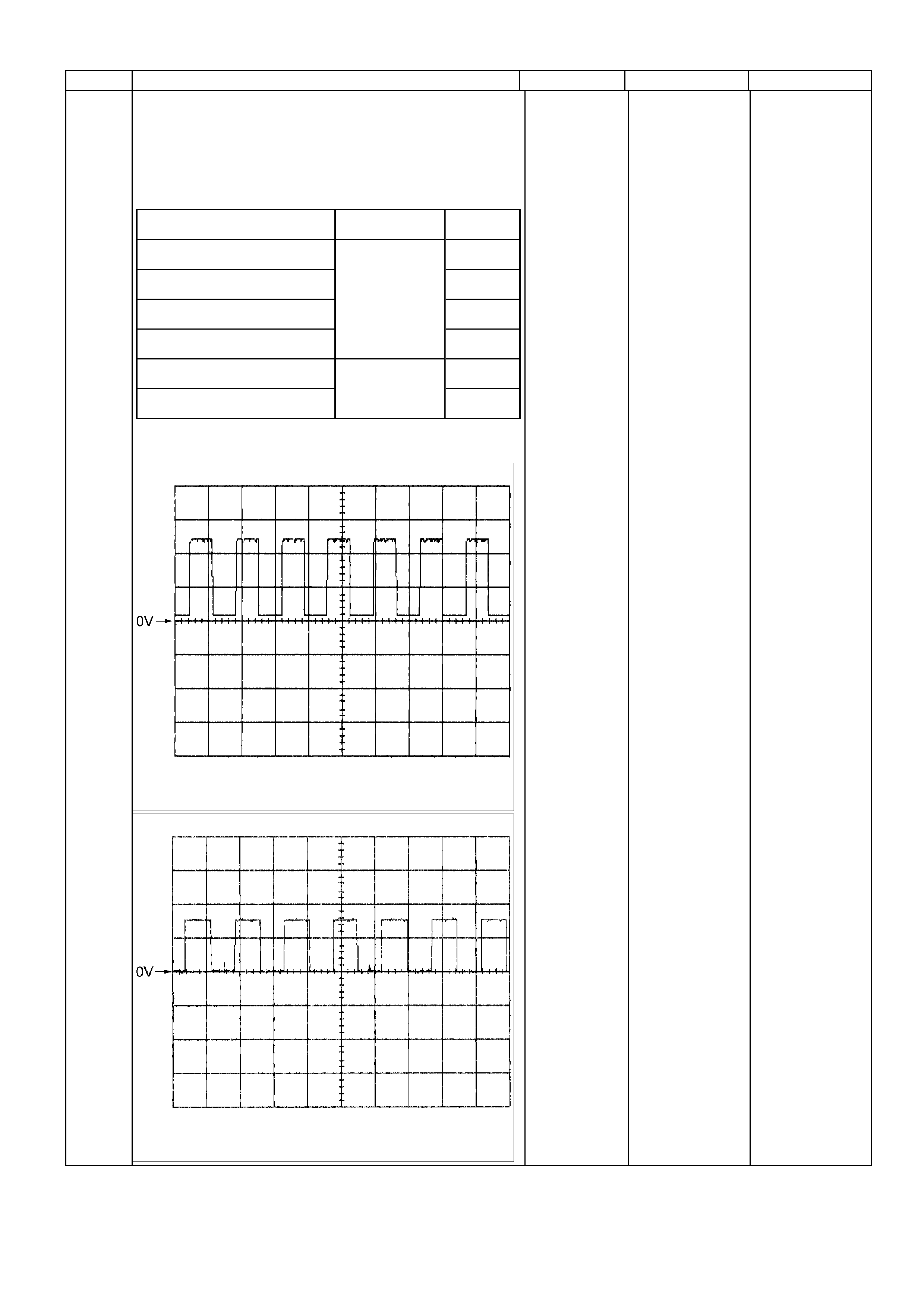
Step Action Value (s) Yes No
10
Using the DVM and check the VSS signal.
1. Ignition "On", vehicle "Run (lift up)".
2. Measure the VSS output voltage at sensor, meter,
immobiliser control unit (if equipped) and ECM.
Does the tester indicate specified value?
Measurement Position V ol t age (V)
(AC Range) If No Good
VSS terminal 3 & GND Go to
Step 11
Meter B24 connec tor 9 & GND Go to
Step 15
Meter B24 connec tor 10 & GND Go to
Step 17
Immobiliser control unit B68
connect or 6 & GND
Approximately
6.0 V at 20km/h
Go to
Step 18
Immobiliser control unit B68
connect or 8 & GND Go to
Step 20
ECM B61 connec t or 32 & GND
Approximately
4.0 V at 20km/h Go to
Step 21
If a oscilloscope is available, monitor the VSS signal.
Does the oscilloscope indicate correct wave form?
Vehicl e S peed Sensor Reference Wave Form
Measurement Scale: 5V /div 50m s/div
Measurement Condi tion: Vehicle speed 20km/h
Measurement Terminal: A t Vehicle Speed Sensor
Vehicl e S peed Sensor Reference Wave Form
Measurement Scale: 5V /div 50m s/div
Measurement Condi tion: Vehicle speed 20km/h
Measurement Terminal: At Engine Control Module
-
Refer to
Diagnostic Ai ds
and Go to Step
25
Refer the table
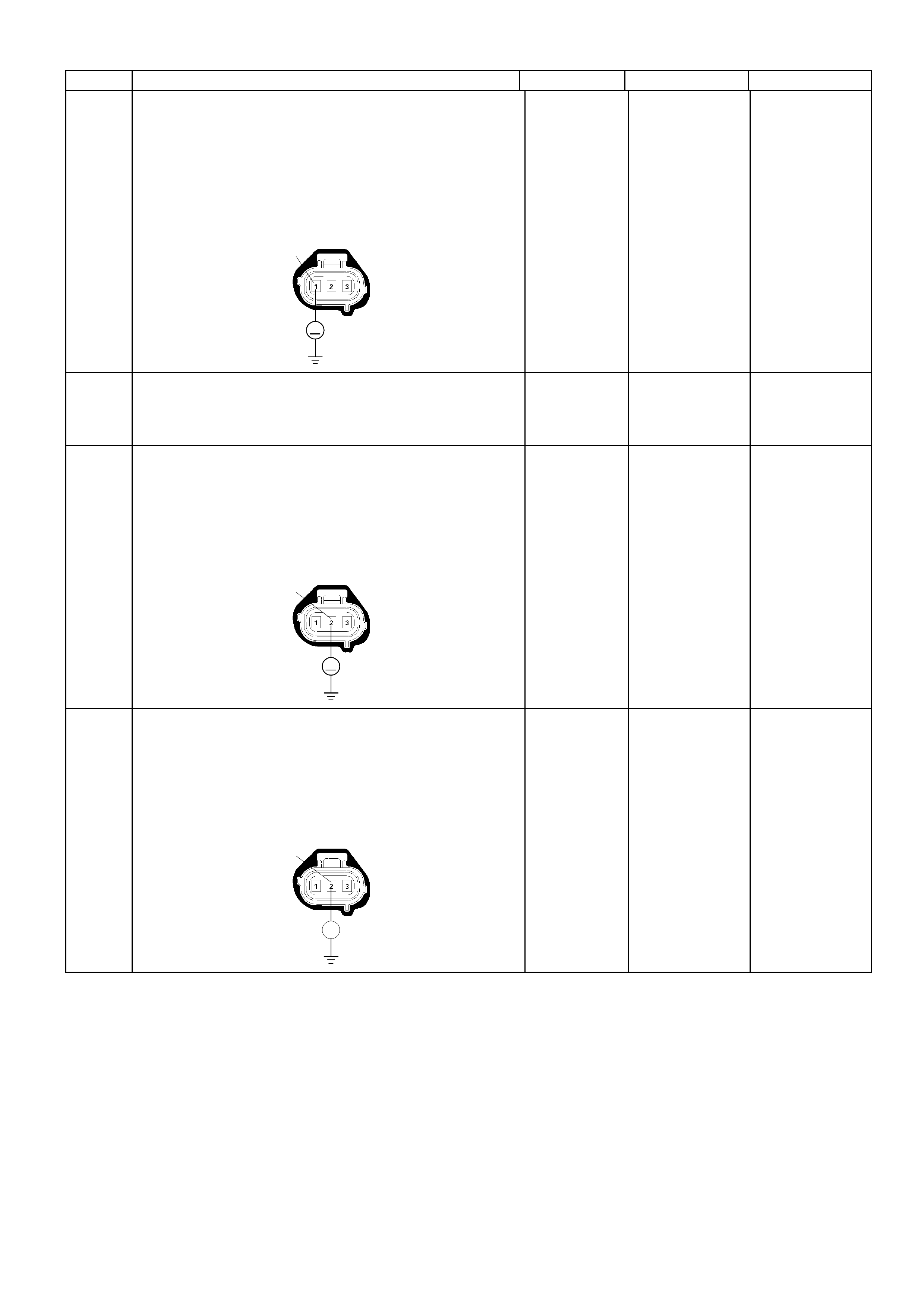
Step Action Value (s) Yes No
11
Using the DVM and check the VSS power supply
circuit.
1. Ignition "On", engine "Off".
2. Disconnec t the V SS co nne c tor.
3. Check the circuit for open or short to ground circuit.
Was the DVM indicated specified value?
E-44
V
1
Battery
voltage
Go to Step 13
Go to Step 12
12 Repair the open circuit between the VSS and meter
fuse.
Is the action complete? - Verify repair -
13
Using the DVM and check the VSS ground circuit.
1. Ignition "On", engine "Off".
2. Disconnec t the V SS co nne c tor.
3. Check the circuit for short to power supply circuit.
Was the DVM indicated specified value?
E-44
V
2
Less than 1V Go to Step 14
Repair faulty
harness and
verify repair
14
Using the DVM and check the VSS ground circuit.
1. Ignition "Off", engine "Off".
2. Disconnec t the V SS co nne c tor.
3. Check the circuit for open circuit.
Was the problem found? E-44
2
Ħ
-
Repair faulty
harness and
verify repair Go to Step 23
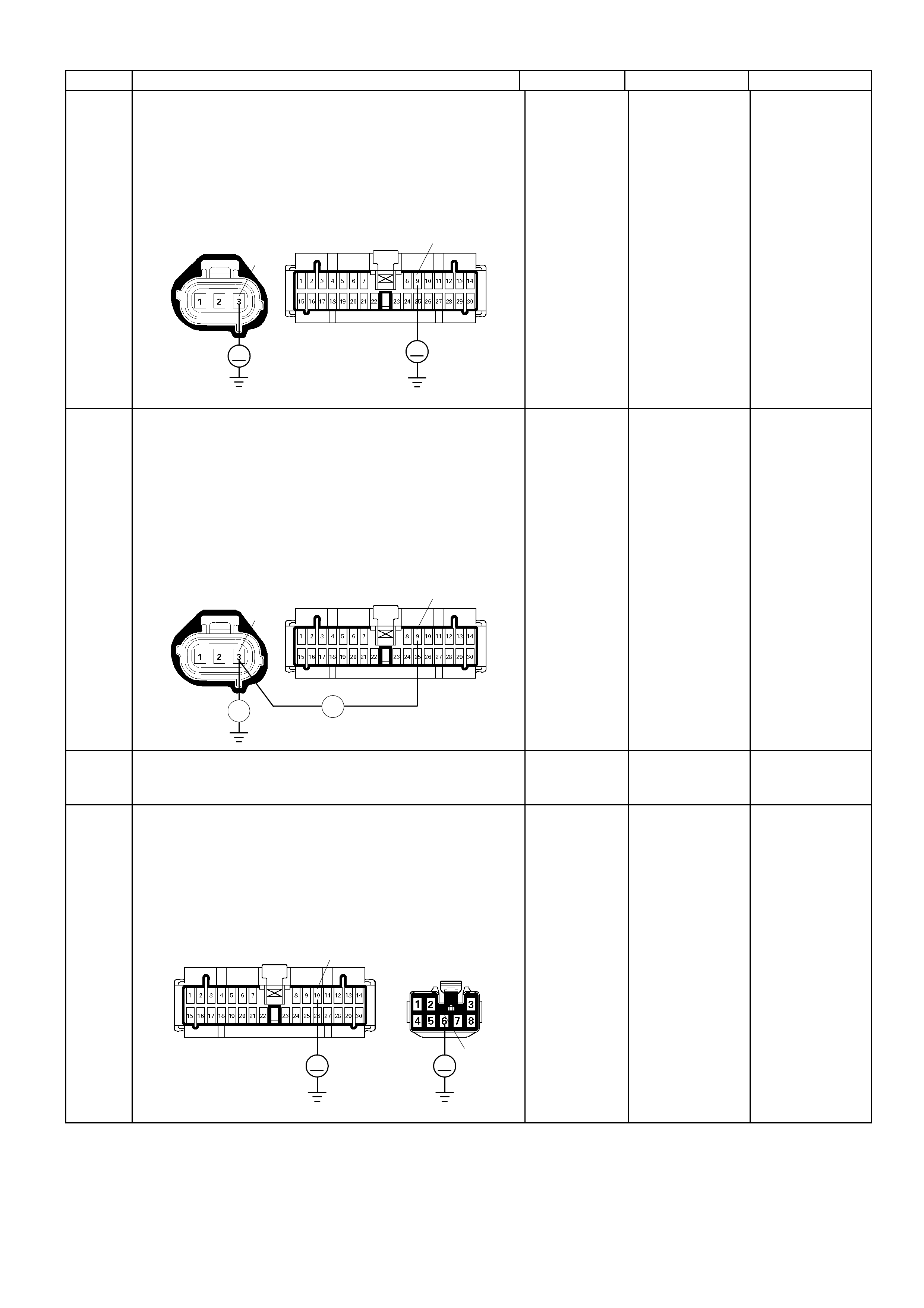
Step Action Value (s) Yes No
15
Using the DVM and check the VSS signal circuit.
1. Ignition "On", engine "Off".
2. Disconnect the VSS connector and meter
connector.
3. Check the circuit for short to power supply circuit.
Was the DVM indicated specified value?
E-44 3B-24
V
9
V
Less than 1V
Go to Step 16
Repair faulty
harness and
verify repair
16
Using the DVM and check the VSS signal circuit.
1. Ignition "Off", engine "Off".
2. Disconnect the VSS connector and meter
connector.
3. Check the c ircuit for open or s hort to groun d circuit.
If a open or short to ground circuit is found, repair
the fault y harnes s and verify repair.
Is the action complete?
E-44 3
Ħ
B-24 9
Ħ
-
Veri fy repair
-
17 Replace the speed meter.
Is the action complete? - Verify repair -
18
Using the DVM and check the VSS signal circuit.
1. Ignition "On", engine "Off".
2. Disconnect the meter connector and immobiliser
control unit connector (if equipped).
3. Check the circuit for short to power supply circuit.
Was the DVM indicated specified value?
B-24 B-68
V V
10
6
Less than 1V
Go to Step 19
Repair faulty
harness and
verify repair
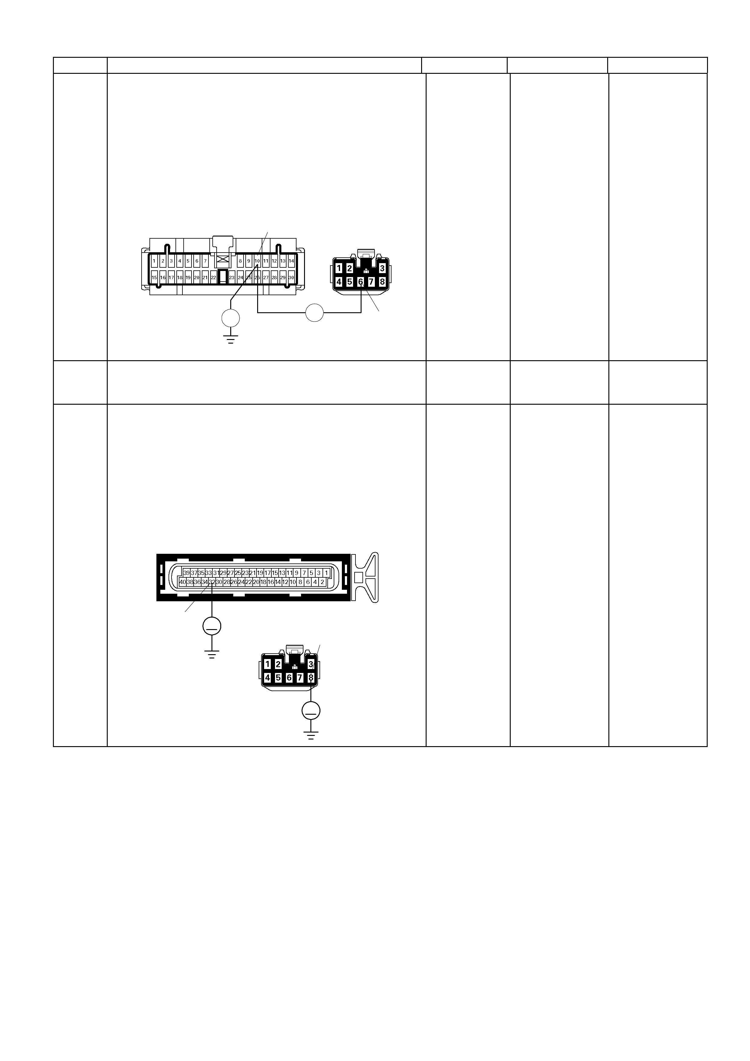
Step Action Value (s) Yes No
19
Using the DVM and check the VSS signal circuit.
1. Ignition "Off", engine "Off".
2. Disconnect the meter connector and immobiliser
control unit connector (if equipped).
3. Check the circuit for open or short to ground circuit.
If a open or short to ground circuit is found, repair the
fault y harness and ver ify repair.
Is the action complete?
B-24 B-68
10
6
Ħ Ħ
-
Veri fy repair
-
20 Replace the immobiliser control unit (if equipped).
Is the action complete? - Verify repair -
21
Using the DVM and check the VSS signal circuit.
1. Ignition "Off", engine "Off".
2. Disconnect th e immobilis er control uni t connector (if
equipped) and ECM connector.
3. Ignition "On".
4. Check the circuit for short to power supply circuit.
Was the DVM indicated specified value?
B-68
V
8
E-61(B)
V
32
Less than 1V
Go to Step 22
Repair faulty
harness and
verify repair
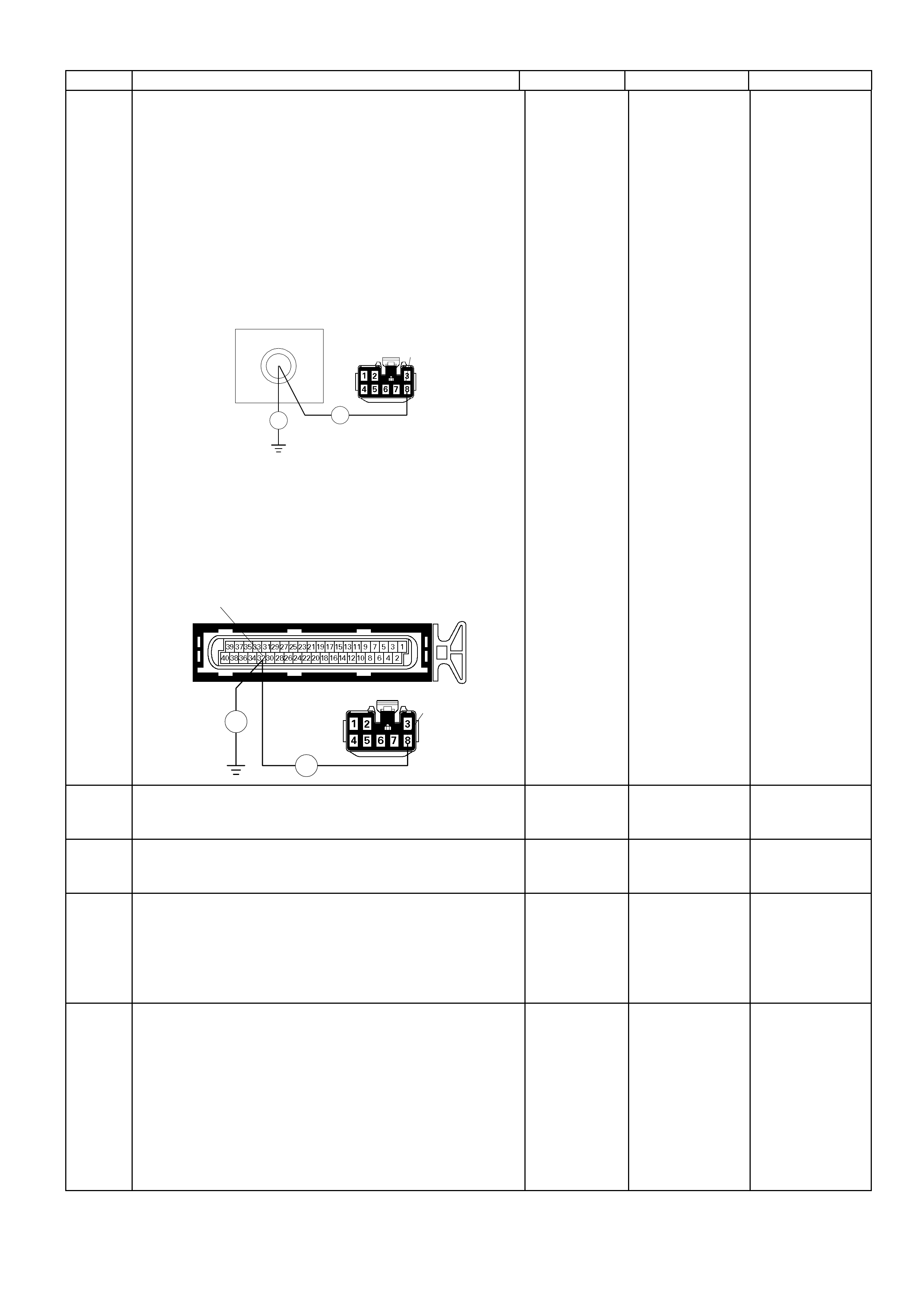
Step Action Value (s) Yes No
22
Using the DVM and check the VSS signal circuit.
Breaker box is available:
1. Ignition "Off", engine "Off".
2. Install the breaker box as type A (ECM
disconnected).
Refer to 6E-91 page.
3. Disconnect th e immobilis er control uni t connector (if
equipped).
4. Check the circuit for open or shot to ground circuit.
Was the problem found?
72
Breaker Box
Ħ
B-68
Ħ
8
Breaker box is not available:
1. Ignition "Off", engine "Off".
2. Disconnect th e immobilis er control uni t connector (if
equipped) and ECM connector.
3. Check the circuit for open or short to ground circuit.
Was the problem found?
E-61(B)
B-68
Ħ
Ħ
32
8
-
Repair faulty
harness and
verify repair
Go to Step 25
23 Substitute a known good VSS and recheck.
Was the problem solved? - Go to Step 24 Go to Step 25
24 Replace the VSS.
Was the problem solved? - Verify repair Go to Step 25
25 Is the ECM programmed with the latest software
release?
If not, download the latest software to the ECM using
the "SPS (Service Programming System)".
Was the problem solved? - Veri fy repair Go to step 26
26 Replace the ECM.
Is the action complete?
IMPORTANT: The replacement ECM must be
programmed. Refer to section of the Service
Programming System (SPS) in this manual. Following
ECM programming, the immobiliser system (if
equipped) must be l inked to the ECM. Ref er to section
11 “Immobiliser System-ECM replacement” for the
ECM/Immobiliser linking procedure. - Verify repair -

Diagnostic Trouble Code (DTC) P0562 (Flash Code 66) System
Voltage Low
Condition For Setting The DTC and A ction Taken When The DTC Sets
Flash
Code Code Type DTC Name DTC Setting Condition Fail-Safe (Back Up)
66 P0562 D Syst em Voltage Low Battery voltage is below 6V for more than 20 seconds. No fail -safe function.
Circuit Description
The engine control module (ECM) monitors the system
voltage on the ignition feed terminals to the ECM. A
system voltage DTC will set whenever the voltage is
above a calibr at ed value.
Diagnostic Aids
If the DTC sets when an accessory is operated, check
for a poor connection or defective accessory.
Diagnostic Trouble Code (DTC) P0562 (Flash Code 66) System Voltage Low
Step Action Value (s) Yes No
1 W as the "On- Board Diagn ostic (O BD) System Check"
performed? - Go to Step 2
Go to On Board
Diagnostic (OBD)
System Check
2 1. Connect the Tech 2.
2. Review and record the failure information.
3. Select "F0: Read DTC Infor By Priority" in "F0:
Diagnostic Trouble Code".
Is the DTC P0562 stored as "Present Failure"? - Go to Step 3
Refer to
Diagnostic Ai ds
and Go to Step 3
3 1. Using the Tech2, ignition "On" and engine "Off".
2. Selec t "Clear DT C Infor mation " with the T ech2 a nd
clear the DTC information.
3. Operate the vehicle and monitor the "F5: Failed
This Ignition" in "F2: DTC Information"
Was the DTC P0562 stored in this ignition cy cle? - Go to Step 4
Refer to
Diagnostic Ai ds
and Go to Step 4
4 1. Using the Tech 2, ignition "On" and engine "On".
2. Monitor the "Ignition Voltage" in the data display.
3. Load the electrical system by turning on the
headlights , etc ..
Does the Tech 2 indicate enough ignition voltage? 10 - 14V Go to Step 6 Go to Step 5
5 Using the DVM and check the battery voltage at the
battery terminal.
Does the tester indicate enough battery voltage? 10 - 14V Go to Step 6
Check the
charging system,
charge or replace
the battery
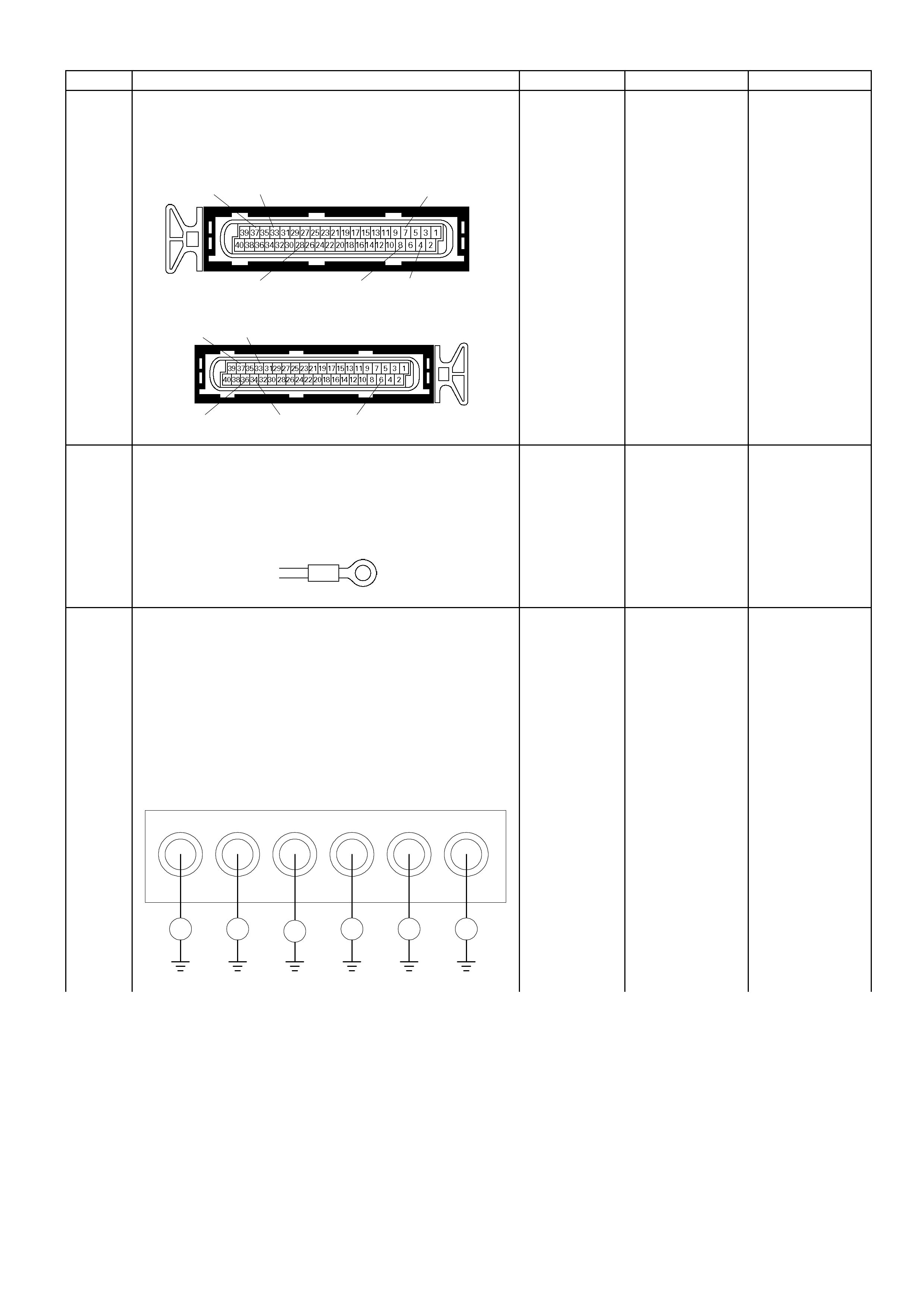
Step Action Value (s) Yes No
6 Check for poor/faulty connection at the ECM
connector. If a poor/faulty connection is found, repair
as necessary.
Was the problem found? E-60(A)37 33 7
28 84
E-61(B)
37 33
36 34 6
- Verify repair Go to Step 7
7 Check for poor/faulty connection of the ECM ground
at the common chamber right and left. If a poor/faulty
connection is found, repair as necessary.
Was the problem found?
E-72/E-73/E-74
- Verify repair Go to Step 8
8 Using the DVM and check the ECM ground circuit.
Breaker box is available:
1. Ignition "Off", engine "Off".
2. Install the breaker box as type A (ECM
disconnected).
Refer to 6E-91 page.
3. Check the circuit for open circuit.
Was the problem found?
7Breaker Box 4637338
Ħ ĦĦĦ
Ħ
Ħ
4
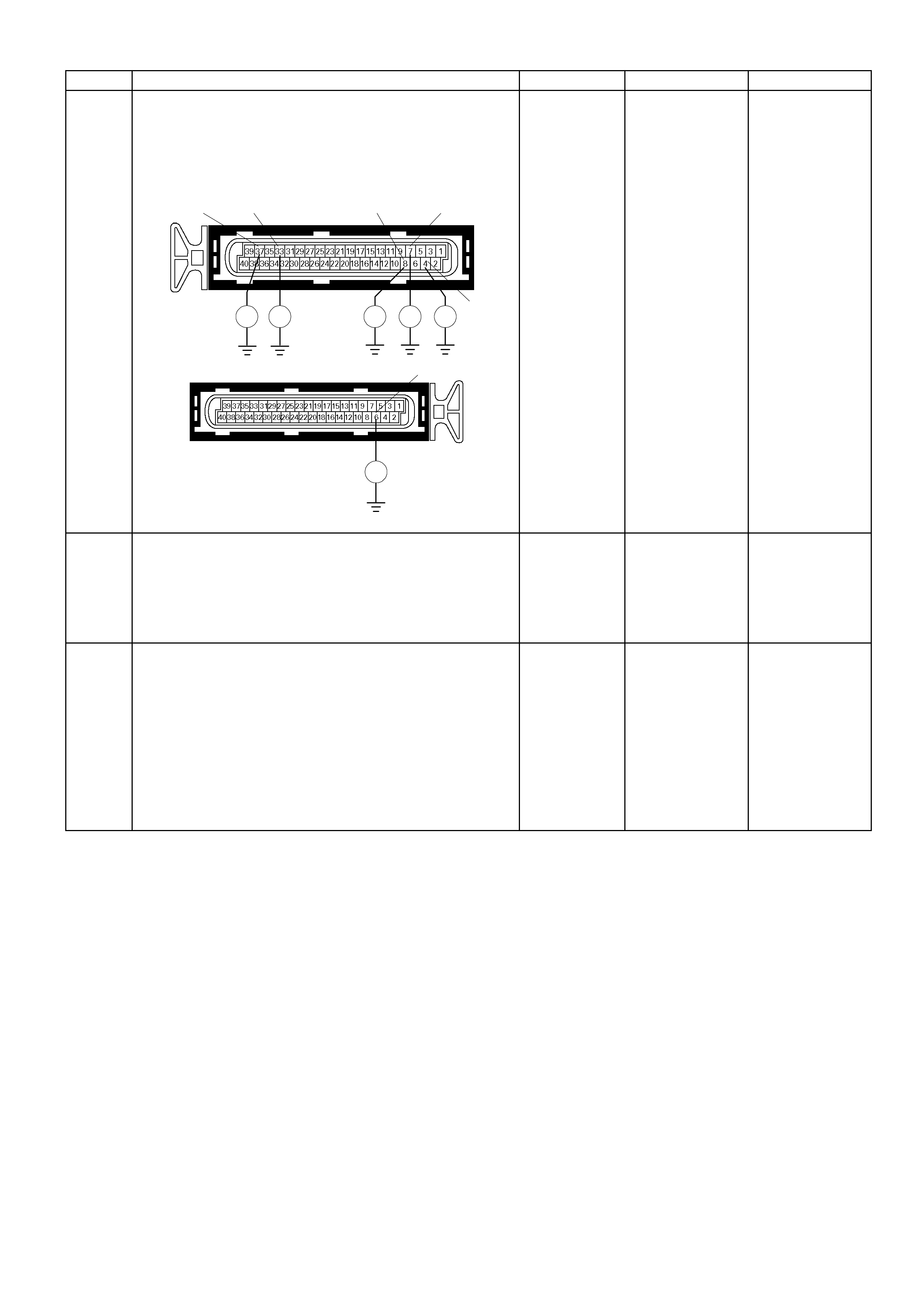
Step Action Value (s) Yes No
Breaker box is not available:
1. Ignition "Off", engine "Off".
2. Disconnec t the EC M conn e c tor.
3. Check the circuit for open circuit.
Was the problem found?
E-60(A)
Ħ Ħ Ħ Ħ Ħ
37 33 8 7
4
E-61(B)
Ħ
6
-
Repair faulty
harness and
verify repai r
Go to Step 9
9 Is the ECM programmed with the latest software
release?
If not, download the latest software to the ECM using
the "SPS (Service Programming System)".
Was the problem solved? - Verify repair Go to step 10
10 Replace the ECM.
Is the action complete?
IMPORTANT: The replacement ECM must be
programmed. Refer to section of the Service
Program ming S ys tem (SPS) in this manual. Fo llowing
ECM programming, the immobiliser system (if
equipped) must be linked to the ECM. Refer to sec tio n
11 “Immobiliser System-ECM replacement” for the
ECM/Immobiliser linking procedure. - Verify repair -

Diagnostic Trouble Code (DTC) P0563 (Flash Code 66)
System Voltage High
Condition For Setting The DTC and A ction Taken When The DTC Sets
Flash
Code Code Type DTC Name DTC Setting Condition Fail-Safe (Back Up)
66 P0563 A Sys tem Voltage High Batt ery volt age is above 16V f or more than 20 seconds. No fail-safe functi on.
Circuit Description
The engine control module (ECM) monitors the system
voltage on the ignition feed terminals to the ECM. A
system voltage DTC will set whenever the voltage is
above a calibr at ed va lue .
Diagnostic Aids
If the DTC sets when an accessory is operated, check
for a poor connection or defective accessory.
Diagnostic Trouble Code (DTC) P0563 (Flash Code 66) System Voltage High
Step Action Value (s) Yes No
1 Was the "On-Board Diagnostic (OBD) System Check"
performed?
- Go to Step 2
Go to On Boar
d
Diagnostic
(OBD) System
Check
2 1. Connect the Tech 2.
2. Review and record the failure information.
3. Select "F0: Read DTC Infor By Priority" in "F0:
Diagnostic Trouble Code".
Is the DTC P0563 stored as "Present Failure"? - Go to Step 3
Refer to
Diagnostic Ai ds
and Go to Step
3
3 1. Using the Tech2, ignition "On" and engine "Off".
2. Select "Clear DTC Information" with the Tech2 and
clear the DTC information.
3. Operate the vehicle and monitor the "F5: Failed This
Ignition" in "F 2: DT C Information"
Was the DTC P0563 stored in this ignition cycle? - Go to Step 4
Refer to
Diagnostic Ai ds
and Go to Step
4
4 1. Using the Tech 2, ignition "On" and engine "On".
2. Monitor the "Ignition Voltage" in the data display.
3. Load the electrical system by turning on the
headlights , etc ..
Does the Tech 2 indicate correct ignition voltage? 10 - 14V Go to Step 5
Check the
charging
system and Go
to Step 5
5 Is the battery jamp start cable incorrectly connecting? - Verify
procedure Go to Step 6
6 Is the ECM programmed with the latest software
release?
If not, download the latest software to the ECM using the
"SPS (Service Programming System)".
Was the problem solved? - Verify repair Go to step 7
7 Replace the ECM.
Is the action complete?
IMPORTANT: The replacement ECM must be
programmed. Refer to section of the Service
Programming System (SPS) in this manual. Following
ECM progr amming, the im mobiliser system ( if equipped)
must be linked to the ECM. Refer to section 11
“Immobiliser System-ECM replacement” for the
ECM/Immobiliser linking procedure. - Verify repair -

Diagnostic Trouble Code (DTC) P0601 (Flash Code 51) Engine
Control Module (ECM) Memory Checksum
Condition For Setting The DTC and A ction Taken When The DTC Sets
Flash
Code Code Type DTC Name DTC Setting Condition Fail-Safe (Back Up)
51 P0601 A Control Module
Memory Check sum ECM memory area error. Engine control disabl ed.
Circuit Description
The engine control module (ECM) used in this vehicle
utilizes an electrically erasable programmable read-only
memory (EEPROM). The EEPROM contains program
information and the calibrations required for engine,
transmission, and engine diagnostics operation.
Unlike the PROM used in past applications, the
EEPROM is not replaceable.
Diagnostic Aids
• DTC P0601 indicates that the contents of the
EEPROM have changed since the ECM was
programmed. The only possible repair is ECM
replacement.
Diagnostic Trouble Code (DTC) P0601 (Flash Code 51) Engine Control Module (ECM) Memory Checksum
Step Action Value (s) Yes No
1 W as the "On- Board Diagn ostic (OBD) System Chec k"
performed? - Go to Step 2
Go to On Board
Diagnostic (OBD)
System Check
2 1. Connect the Tech 2.
2. Review and record the failure information.
3. Select "F0: Read DTC Infor By Priority" in "F0:
Diagnostic Trouble Code".
Is the DTC P0601 stored as "Present Failure"? - Go to Step 3
Refer to
Diagnostic Ai ds
and Go to Step 3
3 1. Using the Tech2, ignition "On" and engine "Off".
2. Select "Clear DT C Inform ation" with the T ech2 and
clear the DTC information.
3. Operate the vehicle and monitor the "F5: Failed
This Ignition" in "F2: DTC Information"
Was the DTC P0601 stored in this ignition cycle? - Go to Step 4 Refer to
Diagnostic Ai ds
4 Is the ECM programmed with the latest software
release?
If not, download the latest software to the ECM using
the "SPS (Service Programming System)".
Was the problem solved? - Verify repair Go to step 5
5 Replace the ECM.
Is the action complete?
IMPORTANT: The replacement ECM must be
programmed. Refer to section of the Service
Program ming S ys tem ( SPS) in this m anual. Foll owing
ECM programming, the immobiliser system (if
equipped) must be linked to the ECM. Refer to sec tio n
11 “Immobiliser System-ECM replacement” for the
ECM/Immobiliser linking procedure. - Verify repair -

Diagnostic Trouble Code (DTC) P0602 Programming Error
Condition For Setting The DTC and A ction Taken When The DTC Sets
Flash
Code Code Type DTC Name DTC Setting Condition Fail-Safe (Back Up)
51 P0602 - Programming Error ECM memory area error. Engine control disabled.
Circuit Description
The engine control module (ECM) used in this vehicle
utilizes an electrically erasable programmable read-only
memory (EEPROM). The EEPROM contains program
information and the calibrations required for engine,
transmission, and engine diagnostics operation.
Unlike the PROM used in past applications, the
EEPROM is not replaceable.
Diagnostic Aids
Check for following conditions.
• When reprogramming operation is stopped under
Service Programming System (SPS), DTC P0602
will be set.
• When non programmed ECM (service ECM) is used
without Ser vice Pr ogr am ming System (SPS), DTC
P0602 will be set.
Diagnostic Trouble Code (DTC) P0602 Programming Error
Step Action Value (s) Yes No
1 W as the "On- Board Diagn ostic (O BD) System Chec k"
performed? - Go to Step 2
Go to On Board
Diagnostic (OBD)
System Check
2 1. Connect the Tech 2.
2. Review and record the failure information.
3. Select "F0: Read DTC Infor By Priority" in "F0:
Diagnostic Trouble Code".
Is the DTC P0602 stored as "Present Failure"? - Go to Step 3 Refer to
Diagnostic Ai ds
3 Download the latest software to the ECM. "SPS
(Service Programming Sy stem) is neces sa ry."
Is the action complete? - Verify repair -
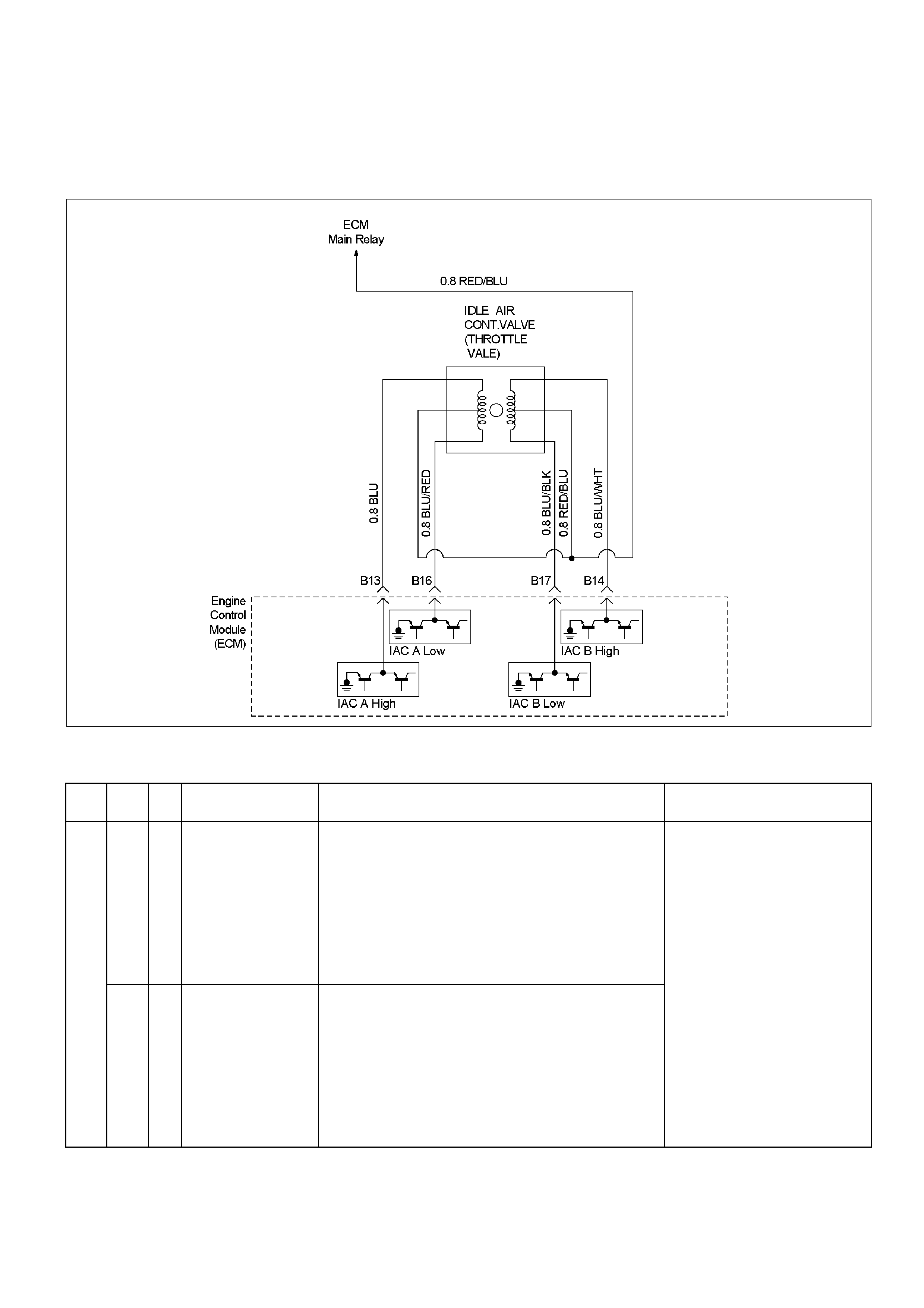
Diagnostic Trouble Code (DTC) P1508 (Flash Code 22)
Idle Air Control System Low/ Closed
Diagnostic Trouble Code (DTC) P1509 (Flash Code 22)
Idle Air Con trol S ystem High/Open
RTW36EMF000201
Condition For Setting The DTC and A ction Taken When The DTC Sets
Flash
Code Code Type DTC Name DTC Setting Condition Fail-Safe (Back Up)
P1508 B Idl e Air Control System
Low/Closed 1. No DTC relating to MAF sensor, IAT sensor, ECT sensor,
TPS, CMP sensor, CKP sensor, VSS and system voltage.
2. Engine speed is between 675rpm and 6000rpm.
3. Engine coolant temperat ure is more than 75°C.
4. Intake air temperature is between -10°C and 80°C.
5. Vehicle is stopping.
6. Small amount of intake air through the idle air control
valve. (Idle ai r control valve is sticking at close position.)
Above conditions are met for 2 seconds.
22
P1509 B Idl e Air Control System
High/Open 1. No DTC relating to MAF sensor, IAT sensor, ECT sensor,
TPS, CMP sensor, CKP sensor, VSS and system voltage.
2. Engine speed is between 675rpm and 6000rpm.
3. Engine coolant temperat ure more than 75°C.
4. Intake air temperature is between -10°C and 80°C.
5. Vehicle is stopping.
6. Large amount of intake air through the idle air control
valve. (Idle ai r cont rol valve is st icki ng at open position. )
Above conditions are met for 2 seconds.
Fuel cut is operated at high idle
speed.

Circuit Description
The engine control module (ECM) controls engine idle
speed by adjusting the position of the idle air control
(IAC) motor pintle. The IAC is a bi-directional stepper
motor driven by two coils. The ECM applies current to
the IAC coils in steps (counts) to extend the IAC pintle
into a passage in the throttle body to decrease air flow.
The ECM reverses the current to retract the pintle,
increasing air flow. This method allows highly accurate
control of idle speed and quick response to changes in
engine load. If the ECM detects a condition where too
low of an idle speed is present and the ECM is unable
to adjust idle speed by increasing the IAC counts, DTC
P1508 or P1509 will set, indicating a problem with the
idle control system.
Diagnostic Aids
Check for the following conditions:
• Poor connection at ECM or IAC motor – Inspect
harness connectors for backed-out terminals,
improper mating, broken locks, improperly formed or
damaged terminals, and poor terminal-to-wire
connection.
• Damaged harness – Inspect the wiring for damage.
• Restricted air intake system – Check for a possible
collapsed air intake duct, restricted air filter element,
or foreign objects blocking the air intake system.
Diagnostic Trouble Code (DTC) P1508 (Flash Code 22) Idle Air Control System Low/Closed
Diagnostic Trouble Code (DTC) P1509 (Flash Code 22) Idle Air Control System High/Open
Step Action Value (s) Yes No
1 W as the "On- Board Diagno stic (OBD) System Check"
performed? - Go to Step 2
Go to On Board
Diagnostic (OBD)
System Check
2 1. Connect the Tech 2.
2. Review and record the failure information.
3. Select "F0: Read DTC Infor By Priority" in "F0:
Diagnostic Trouble Code".
Is the DTC P1508 or P1509 stored as "Present
Failure"? - Go to Step 3
Refer to
Diagnostic Ai ds
and Go to Step 3
3 1. Using the Tech2, ignition "On" and engine "Off".
2. Select "Clear DTC Inform ation" with the T ech2 and
clear the DTC information.
3. Operate the vehicle and monitor the "F5: Failed
This Ignition" in "F2: DTC Information"
Was the DTC P1508 or P1509 stored in this ignition
cycle? - Go to Step 4
Refer to
Diagnostic Ai ds
and Go to Step 4
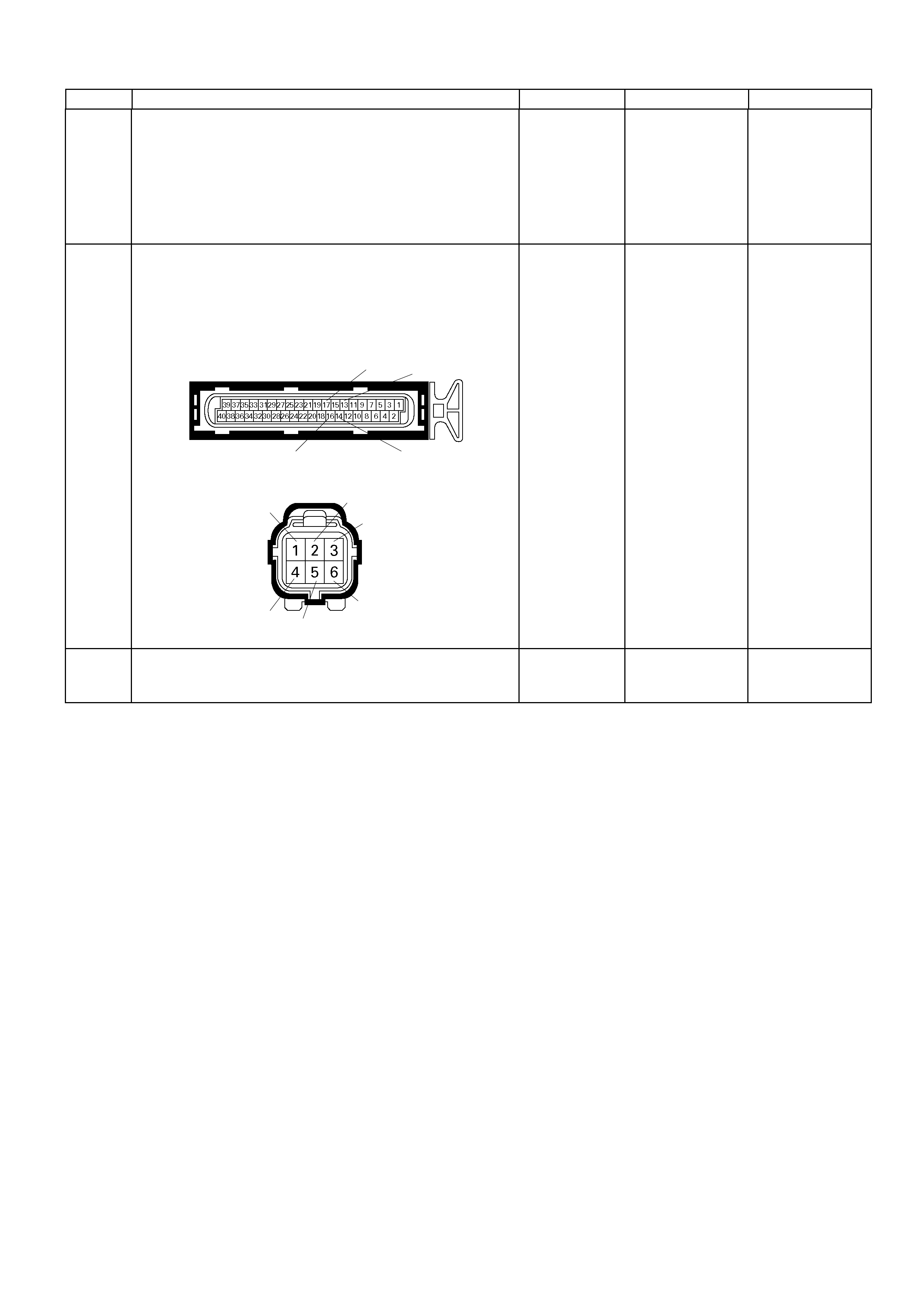
Step Action Value (s) Yes No
4 Check for the following conditions.
• Objects blocking the Idle Air Control (IAC) Valve.
• Objects blocking the throttle valve.
• Vacuum leaking at throttle body.
If a problem is found, repair as necessary.
Was the problem found? - Verify repair Go to Step 5
5 Check for poor/faulty connection at the IAC Valve or
ECM connector.
If a poor/faulty connection is found, repair the faulty
terminal.
Was the problem found?
E-61(B) 13
14
17
16
E-70
456
3
2
1
- Verify repair Go to Step 6
6 Remove the IAC Valve and visually check.
Was the problem found? - Go to Step 12 Go to Step 7
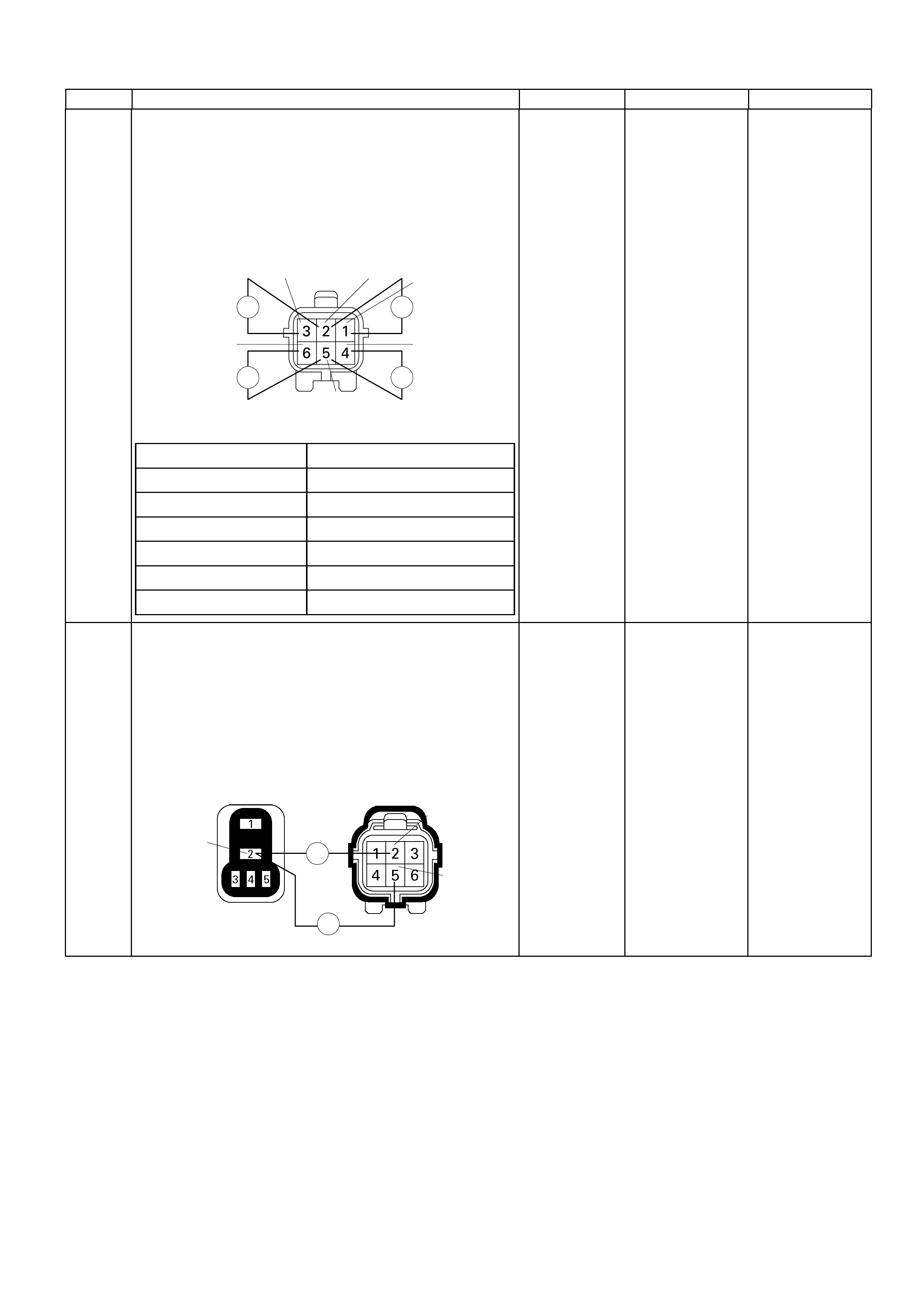
Step Action Value (s) Yes No
7
Using the DVM and check the IAC Valve coil at IAC
Valve.
1. Ignition "Off", engine "Off".
2. Disconnec t the IAC Val ve c onnec t or .
3. Check the coil resistance.
Does the tes ter i nd icate s ta ndar d r es istance as s ho wn
in the following table?
IAC Valve
ĦĦ
Ħ Ħ
21
3
4
5
6
Measurement Terminal Resi stance (Ω)
1 - 2 Approximately 50Ω
2 - 3 Approxim ately 50Ω
1 – 3 Approximately 100Ω
4 - 5 Approximately 50Ω
5 - 6 Approximately 50Ω
4 - 6 Approxim ately 100Ω
-
Go to Step 8
Go to Step 12
8
Using the DVM and check the IAC Valve power
supply circuit.
1. Ignition "Off", engine "Off".
2. Disconnect the IAC Valve connector and ECM
main relay
3. Check the circuit for open circuit.
Was the problem found?
X-13 E-70
Ħ
Ħ
2
2
5
-
Repair faulty
harness and
verify repair
Go to Step 9
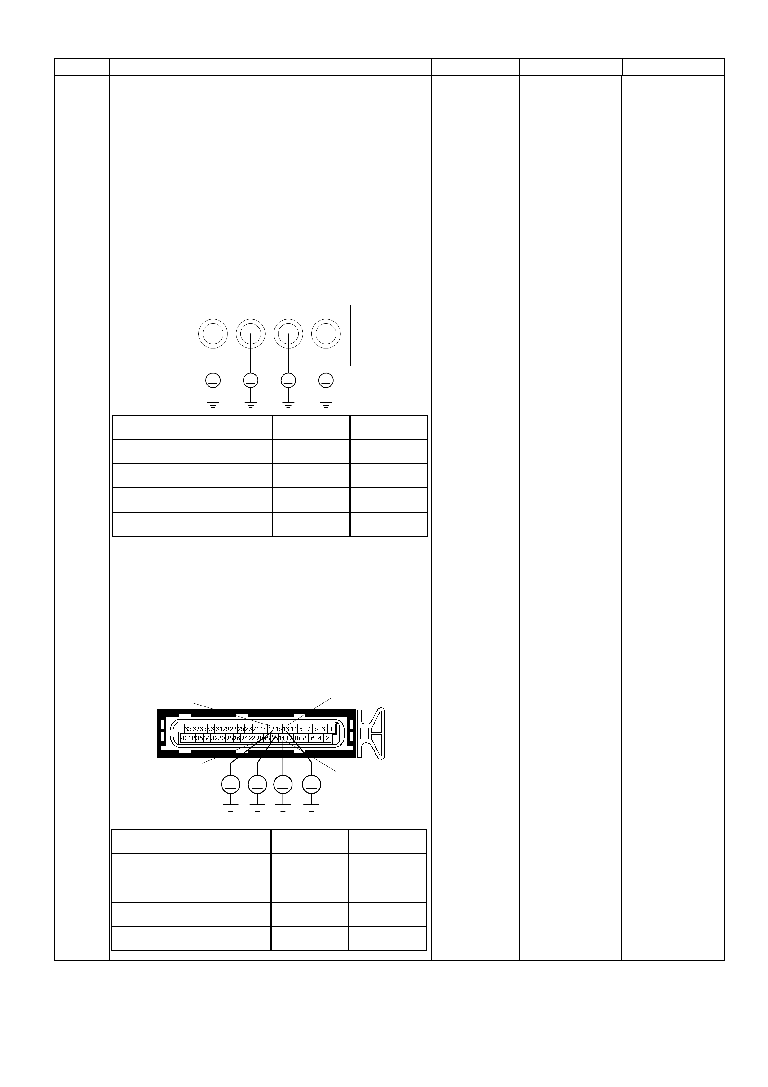
Step Action Value (s) Yes No
9
Using the DVM and check the IAC Valve circuit.
Breaker box is available:
1. Ignition "Off", engine "Off".
2. Install the breaker box as type B. (ECM
connection)
3. Using the Tech 2, ignition "On" and engine "Off".
4. Select the "Miscellaneous Test" and perform the
"IAC Control" in the "IAC System".
5. Operate the Tech 2 in accrodance with procedure.
Does the DVM indicate correct characteristic as
shown in the following table, when the IAC Valve is
operating step by step?
53 54
Breaker Box 5756
V V V V
Measurement Point IACV steps at
0, 20, 40, c
160 IACV steps at
10, 30, 50, c
150
Coil A High (Breaker Box 53 & GND) Less than 1V Battery voltage
Coil A Low (Breaker Box 56 & GND) Battery voltage Less than 1V
Coil B High (Breaker Box 54 & GND) Less than 1V Battery voltage
Coil B Low (Breaker Box 57 & GND) Battery voltage Less than 1V
Breaker box is not available:
1. Using the Tech 2, ignition "On" and engine "Off".
2. Select the "Miscellaneous Test" and perform the
"IAC Control" in the "IAC System".
3. Operate the T ech 2 in acc ordanc e with pr oc ed ur e.
Does the DVM indicate correct characteristic as
shown in the following table, when the IAC Valve is
operating step by step?
E-61(B)
V V V V
17
16 14
13
Measurement Point IACV steps at
0, 20, 40, c
160 IACV steps at
10, 30, 50, c
150
Coil A High (ECM E61 conn ector 13 & GND) Less than 1V Battery voltage
Coil A Low (ECM E61 connector 16 & GND) Battery voltage Less than 1V
Coil B High (ECM E61 connector 14 & GND) Less than 1V Battery voltage
Coil B Low (ECM E61 connector 17 & GND) Battery voltage Less than 1V
- Go to Step 14
Fixed at less than
1V: Go to Step
10
Fixed at battery
voltage: Go to
Step 11
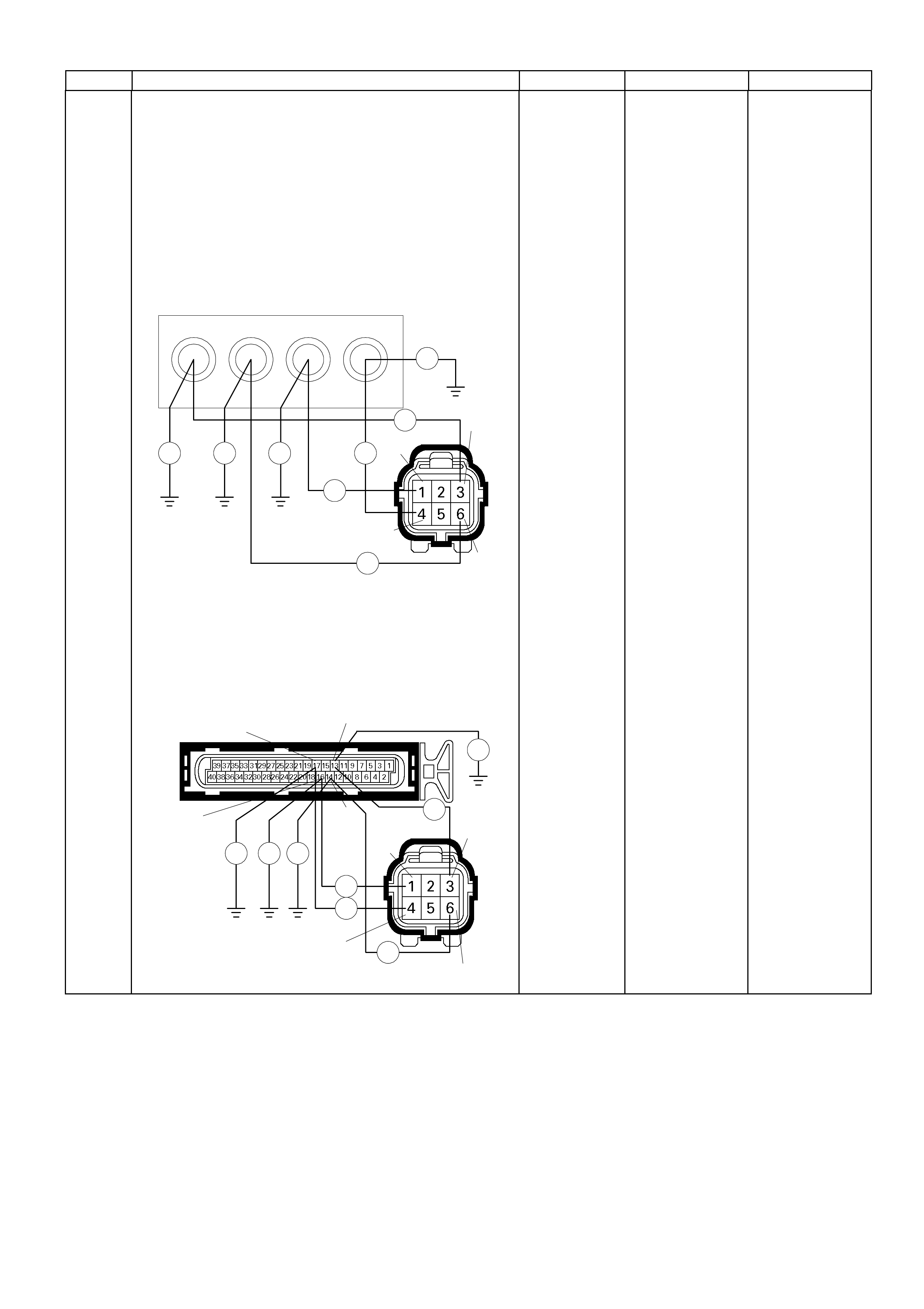
Step Action Value (s) Yes No
10
Using the DVM and check the IAC Valve circuit.
Breaker box is available:
1. Ignition "Off", engine "Off".
2. Install the breaker box as type A (ECM
disconnected).
Refer to 6E-91 page.
3. Disconnec t the IAC Val ve c onnec t or .
4. Check the circuit for open or short to ground circuit.
Was the problem found?
53 54
Breaker Box 5756
E-70
Ħ
Ħ
Ħ
Ħ
Ħ
Ħ Ħ Ħ 1
4
3
6
Breaker box is not available:
1. Ignition "Off", engine "Off".
2. Disconnec t the IAC Val ve c onnec t or .
3. Check the circuit for open or short to ground circuit.
Was the problem found?
E-61(B)
E-70
Ħ
Ħ
Ħ
Ħ
Ħ
ĦĦĦ
13
17
16
13
6
4
14
-
Repair faulty
harness and
verify repair Go to Step 14

Step Action Value (s) Yes No
11
Using the DVM and check the IAC Valve circuit.
1. Ignition "On", engine "Off".
2. Disconnec t the IAC Val ve c onnector.
3. Check the circuit for short to power supply circuit.
Was the DVM indicate voltage?
E-70
V V V V
1
436
-
Repair faulty
harness and
verify repair
Go to Step 14
12 Substitute a known good IAC Valve and recheck.
Was the problem solved? - Go to Step 13 Go to Step 14
13 Replace the IAC Valve.
Was the problem solved? - Verify repair Go to Step 14
14 Is the ECM programmed with the latest software
release?
If not, download the latest software to the ECM using
the "SPS (Service Programming System)".
Was the problem solved? - Verify repair Go to step 15
15 Replace the ECM.
Is the action complete?
IMPORTANT: The replacement ECM must be
programmed. Refer to section of the Service
Program ming System (SPS) i n this m anual. Follow ing
ECM programming, the immobiliser system (if
equipped) must be linked to the ECM. R efer to sec tio n
11 “Immobiliser System-ECM replacement” for the
ECM/Immobiliser linking procedure. - Verify repai r -
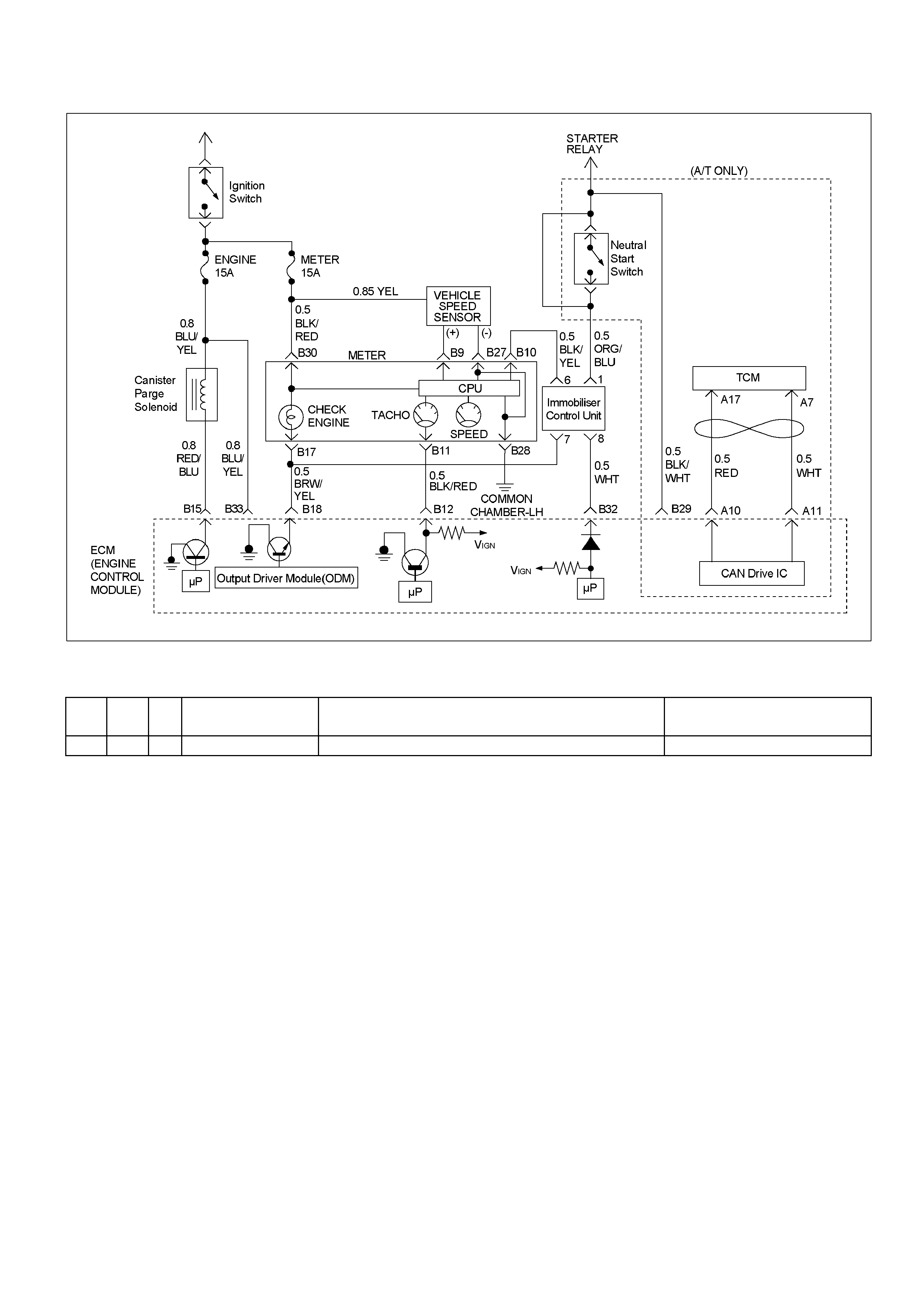
Diagnostic Trouble Code (DTC) P1601 (Flash Code 65) Can Bus Off
RTW36EMF000601
Condition For Setting The DTC and A ction Taken When The DTC Sets
Flash
Code Code Type DTC Name DTC Setting Condition Fail-Safe (Back Up)
65 P1601 D CAN BUS Off CAN B US off conditi on is detect ed consecutively. Torque reduction control is disable.
Circuit Description
The engine control system in 6VE1 uses high speed
CAN bus system. The individual CAN bus systems are
connected via two interfaces and can exchange
information and data. This allows control modules that
are connected to different CAN bus systems to
communicate. Engine control modules (ECM) in the
vehicle that require cont inuous, rapid communication
are connected to the high speed CAN bus. The engine
is continuously notified of the current engine load
status. Since the ECM has to react immediately to load
status changes, rapid communication is required
between the ECM and the automatic transmission
control module. The high speed CAN bus in the 6VE1
is designed as a two-wire CAN bus (twisted pair). The
wires are shielded and twisted. The engine rate is 500K
band.
Diagnostic Aids
• Inspect the wiring for poor electrical connection at
the ECM. Look for possible bent, backed out,
deformed or damaged terminals. Check for weak
terminal tension as well. Also check for a chafed wire
that could short to bare metal or other wiring. Inspect
for a broken wire inside the insulation.
• When diagnosing for a possible intermittent short or
open condition, move the wiring harness while
observing test equipment for a change.
• Inspect the wiring for EMI (Erectro-M agnetic
Interference). Check that all wires are properly
routed away from coil, and generator. Also check for
improperly installed electrical options. When this test
is performed, turn “OFF" on electronic autoparts
switches to improperly for a noise preventing.

Diagnostic Trouble Code (DTC) P1601 (Flash Code 65) CAN Bus Off
Step Action Value (s) Yes No
1 W as the "On- Board Diagn ostic (O BD) System Check"
performed? - Go to Step 2
Go to On Board
Diagnostic (OBD)
System Check
2 1. Connect the Tech 2.
2. Review and record the failure information.
3. Select "F0: Read DTC Infor By Priority" in "F0:
Diagnostic Trouble Code".
Is the DTC P1601 stored as "Present Failure"? - Go to Step 3
Refer to
Diagnostic Ai ds
and Go to Step 3
3 1. Using the Tech2, ignition "On" and engine "Off".
2. Selec t "Clear DT C Inform ation" with the T ech2 and
clear the DTC information.
3. Operate the vehicle and monitor the "F5: Failed
This Ignition" in "F2: DTC Information"
Was the DTC P1601 stored in this ignition cy cle? - Go to Step 4
Refer to
Diagnostic Ai ds
and Go to Step 4
4 Check any accessory parts which may cause electric
interference.
Was the problem found? -
Remove the
accessory parts
and verify repair Go to Step 5
5 1. Using the Tech 2, ignition "On" and engine "Off".
2. Select "AW30-40LE" in the system selection menu
"Powertrain".
3. Select "Read DTC Info Ordered By Priority" in the
"Diagnositic Trouble Code".
Was the any DTC's P**** or U**** stored in this
ignition cycle? -
Refer to
"Automatic
Transmission
Workshop
Manual" & Go to
DTC Chart P****
or U**** Go to Step 6
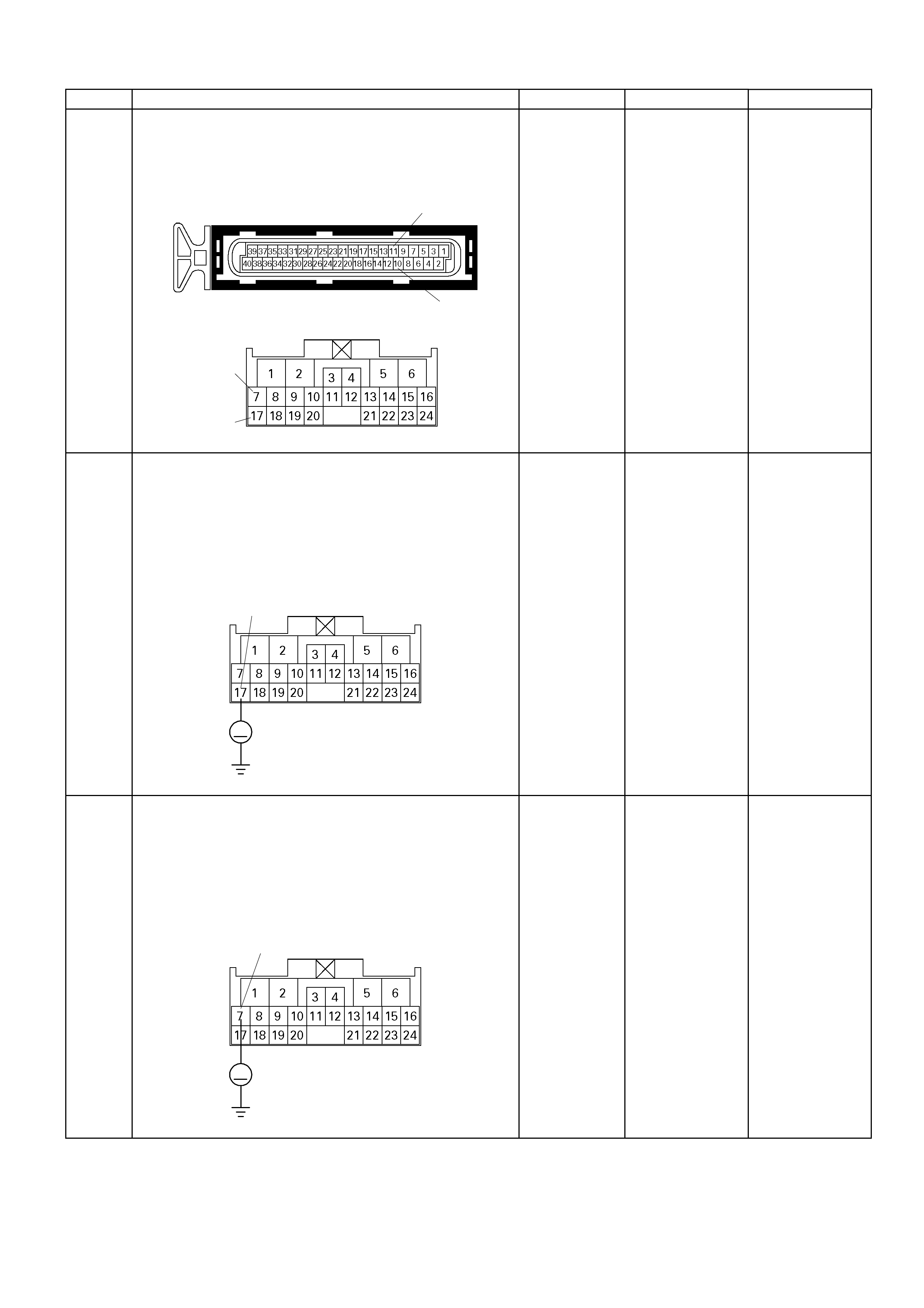
Step Action Value (s) Yes No
6 Check for poor/faulty connection at the TCM or ECM
connector. If a poor/faulty connection is found, repair
as necessary.
Was the problem found? E-60(A) 11
10
C- 94
7
17
- Verify repair Go to Step 7
7
Using the DVM and check the CAN BUS high circuit.
1. Ignition "Off", engine "Off".
2. Disconnect the TCM connector.
3. Ignition "On".
4. Check the circuit for short to power supply circuit.
Was the problem found?
C- 94
V
17
-
Repair faulty
harness and
verify repair
Go to Step 8
8
Using the DVM and check the CAN BUS low circuit.
1. Ignition "Off", engine "Off".
2. Disconnect the TCM connector.
3. Ignition "On".
4. Check the circuit for short to power supply circuit.
Was the problem found?
C- 94
V
7
-
Repair faulty
harness and
verify repair
Go to Step 9
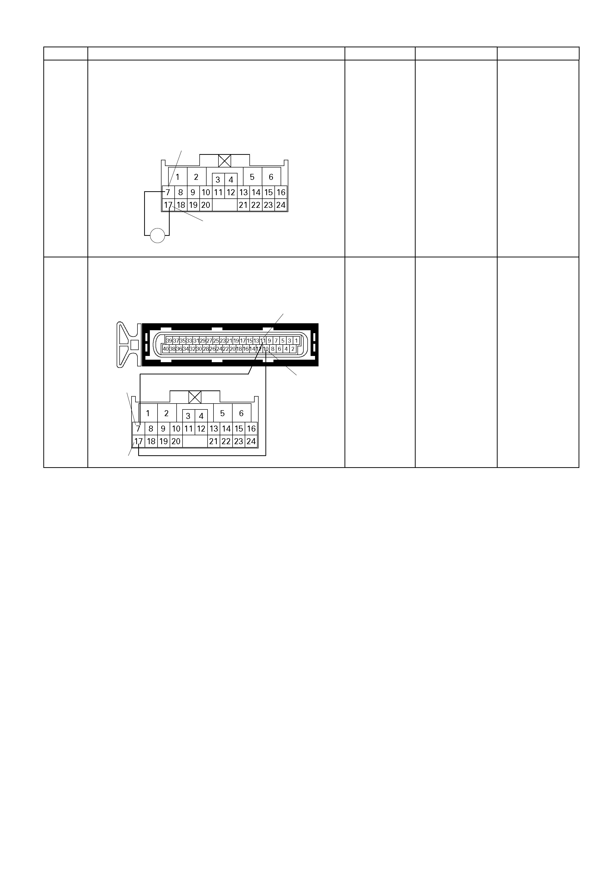
Step Action Value (s) Yes No
9
Using the DVM and check the ECM CAN BUS circuit.
1. Ignition "Off", engine "Off".
2. Disconnect TCM connector.
3. Measure the r es istanc e of ECM CAN BUS circui t.
Does the tester indicate standard resistance?
C-94
7
Ħ
17
A
pproximately
120Ω
Go to Step 14
Close to 0Ω:
Go to Step 10
No resistance:
Go to Step 11
10 Repair the open circuit between the ECM CAN BUS
high and low circuit.
Was the problem solved?
E-60(A)
C-94
7
17
11
10
- Verify repair Go to Step 15
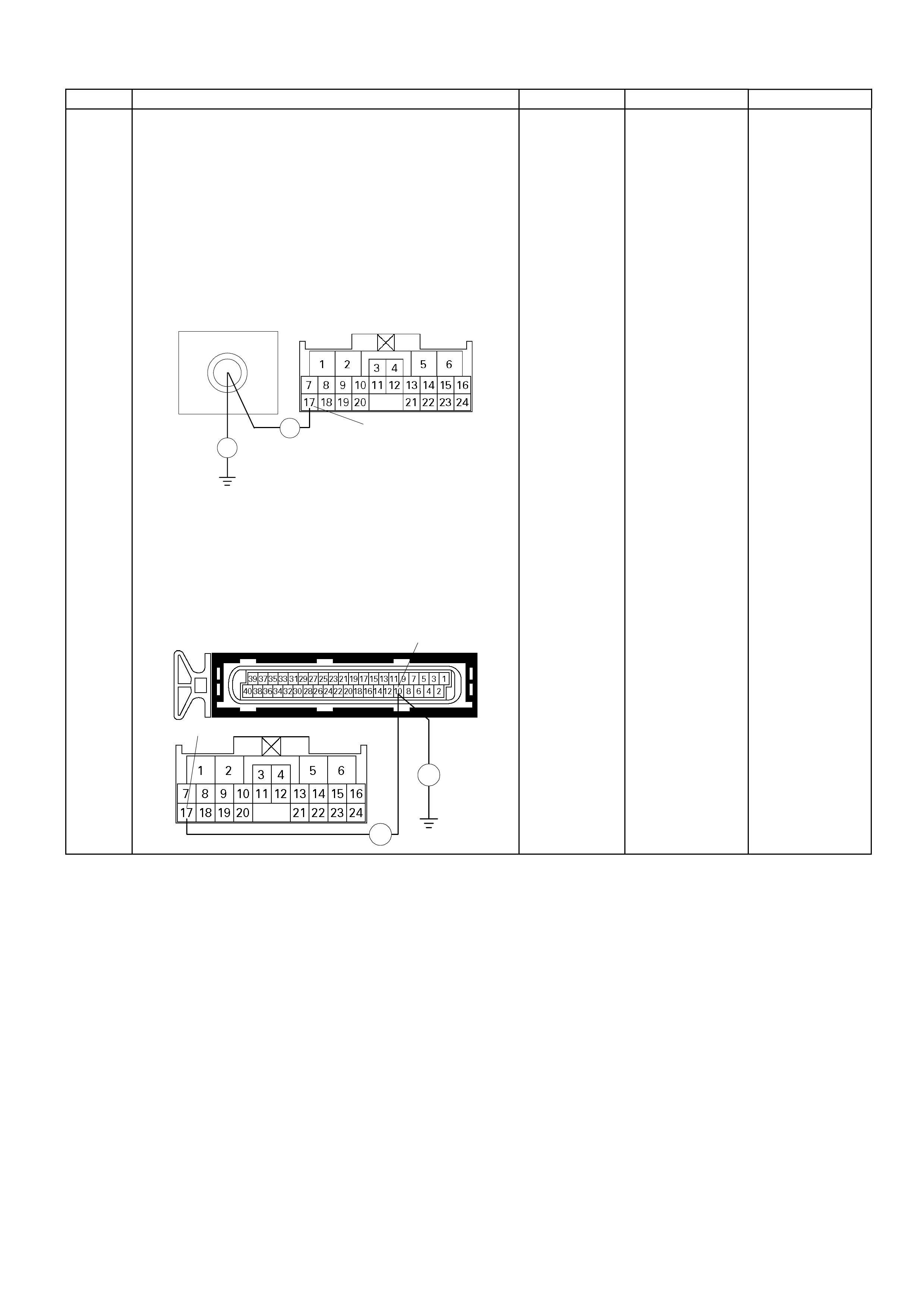
Step Action Value (s) Yes No
11
Using the DVM and check the CAN BUS high circuit.
Breaker box is available:
1. Ignition "Off", engine "Off".
2. Install the breaker box as type A (ECM
disconnected).
Refer to 6E-91 page.
3. Disconnect the TCM connector.
4. Check the circuit for open or short to ground circuit.
Was the problem found?
10
Breaker Box C- 94
Ħ
Ħ 17
Breaker box is not available:
1. Ignition "Off", engine "Off".
2. Disconnect the TCM connector and ECM
connector.
3. Check the circuit for open or short to ground circuit.
Was the problem found? E-60(A)
C- 94
Ħ
Ħ
17
10
-
Repair faulty
harness and
verify repair Go to Step 12
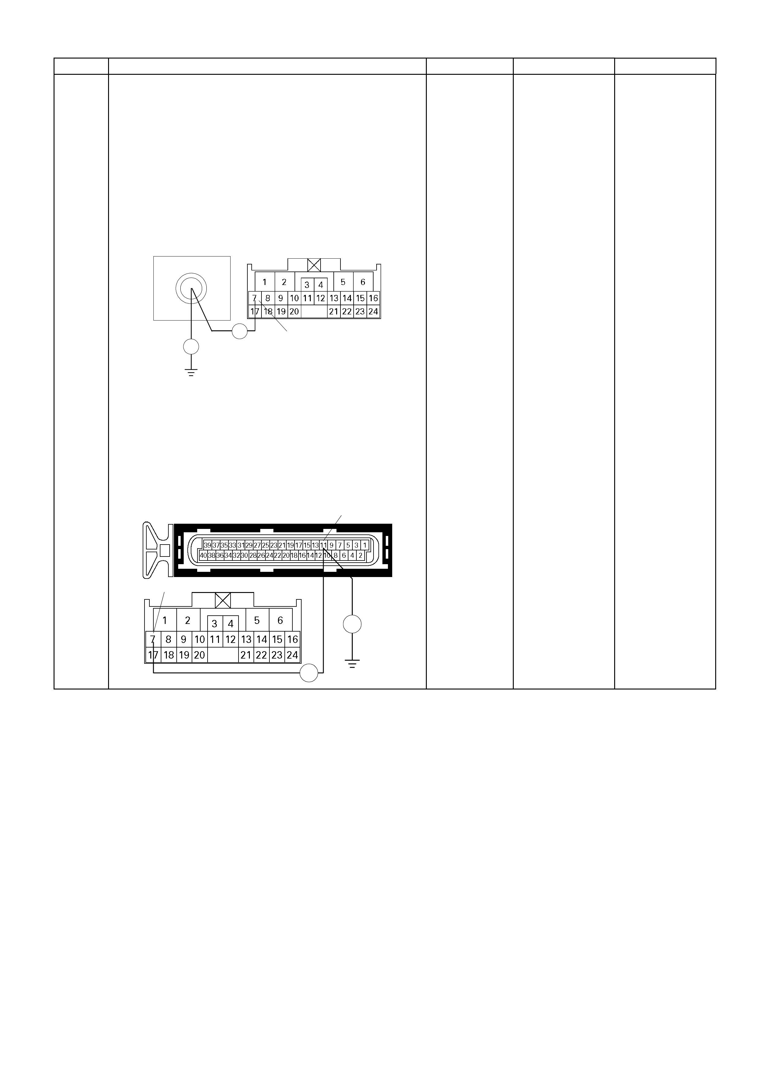
Step Action Value (s) Yes No
12 Using the DVM and check the CAN BUS low circuit.
Breaker box is available:
1. Ignition "Off", engine "Off".
2. Install the breaker box as type A (ECM
disconnected).
Refer to 6E-91 page.
3. Disconnect the TCM connector.
4. Check the circuit for open or short to ground circuit.
Was the problem found?
11
Breaker Box C- 94
Ħ
Ħ 7
Breaker box is not available:
1. Ignition "Off", engine "Off".
2. Disconnect the TCM connector and ECM
connector.
3. Check the circuit for open or short to ground circuit.
Was the problem found? E-60(A)
C- 94
Ħ
Ħ
7
11
-
Repair faulty
harness and
verify repair
Go to Step 13

Step Action Value (s) Yes No
13 Is the ECM or TCM programmed with the latest
software rele ase?
If not, download the latest software to the ECM or
TCM using the "SPS (Service Programming
System)".
Was the problem solved? - Verify repair Go to Step 14
14 Replace the TCM.
Was the problem solved?
IMPORTANT: The replacement TCM must be
programmed. "SPS (Service Programming System)
and is necessary." - Verify rep air Go to step 15
15 Replace the ECM.
Is the action complete?
IMPORTANT: The replacement ECM must be
programmed. Refer to section of the Service
Program ming System (SPS) in t his manual. F ollowin g
ECM programming, the immobiliser system (if
equipped) must be linked to the ECM. Ref er to s ect io n
11 “Immobiliser System-ECM replacement” for the
ECM/Immobiliser linking procedure. - Verify repair -
Diagnostic Trouble Code (DTC) U2104 (Flash Code 67) Can Bus
Reset Counter Over-Run
RTW36EMF000601
Condition For Setting The DTC and A ction Taken When The DTC Sets
Flash
Code Code Type DTC Name DTC Setting Condition Fail-Safe (Back Up)
67 U2104 D CAN BUS Reset
Counter Overrun 1. No DTC CAN BUS Off.
2. CAN valid counter does not change for 2 seconds . Torque reducti on cont rol is disable.
Circuit Description
The engine control system in 6VE1 uses high speed
CAN bus system. The individual CAN bus systems are
connected via two interfaces and can exchange
information and data. This allows control modules that
are connected to different CAN bus systems to
communicate. Engine control modules (ECM) in the
vehicle that require continuous, rapid communication
are connected to the high speed CAN bus. The engine
is continuously notified of the current engine load
status. Since the ECM has to react immediately to load
status changes, rapid communication is required
between the ECM and the automatic transmission
control module. The high speed CAN bus in the 6VE1
is designed as a two-wire CAN bus (twisted pair). The
wires are shielded and twisted. The engine rate is 500K
band.
Diagnostic Aids
• Inspect the wiring for poor electrical connection at
the ECM. Look for possible bent, backed out,
deformed or damaged terminals. Check for weak
terminal tension as well. Also check for a chafed wire
that could short to bare metal or other wiring. Inspect
for a broken wire inside the insulation.
• When diagnosing for a possible intermittent short or
open condition, move the wiring harness while
observing test equipment for a change.
• Inspect the wiring for EMI (Erectro-Magnetic
Interference). Check that all wires are properly
routed away from coil, and generator. Also check for
improperly installed electrical options. When this test
is performed, turn “OFF" on electronic auto parts
switches to improperly for a noise preventing.

Diagnostic Trouble Code (DTC) U2104 (Flash Code 67) CAN Bus Reset Counter Over-Run
Step Action Value (s) Yes No
1 W as the "On- Board Diagn ostic (O BD) System Check"
performed? - Go to Step 2
Go to On Board
Diagnostic (OBD)
System Check
2 1. Connect the Tech 2.
2. Review and record the failure information.
3. Select "F0: Read DTC Infor By Priority" in "F0:
Diagnostic Trouble Code".
Is the DTC U2104 stored as "Present Failure"? - Go to Step 3
Refer to
Diagnostic Ai ds
and Go to Step 3
3 1. Using the Tech2, ignition "On" and engine "Off".
2. Selec t "Clear DT C Infor mation " with the T ech2 a nd
clear the DTC information.
3. Operate the vehicle and monitor the "F5: Failed
This Ignition" in "F2: DTC Information"
Was the DTC U2104 stored in this ignition cycle? - Go to Step 4
Refer to
Diagnostic Ai ds
and Go to Step 4
4 1. Using the Tech 2, ignition "On" and engine "Off".
2. Select "AW30-40LE" in the system selection menu
"Powertrain".
3. Select "Read DTC Info Ordered By Priority" in the
"Diagnositic Trouble Code".
Was the any DTC's P**** or U**** stored in this
ignition cycle? -
Refer to
"Automatic
Transmission
Workshop
Manual" & Go to
DTC Chart P****
or U**** Go to Step 5
5 Check any accessory parts which may cause electric
interference.
Was the problem found? -
Remove the
accessory parts
and verify repair Go to Step 6

Step Action Value (s) Yes No
6 Check for poor/faulty connection at the TCM or ECM
connector. If a poor/faulty connection is found, repair
as necessary.
Was the problem found? E-60(A) 11
10
C- 94
7
17
- Verify repair Go to Step 7
7
Using the DVM and check the CAN BUS high circuit.
1. Ignition "Off", engine "Off".
2. Disconnect the TCM connector.
3. Ignition "On".
4. Check the circuit for short to power supply circuit.
Was the problem found?
C- 94
V
17
-
Repair faulty
harness and
verify repair
Go to Step 8
8
Using the DVM and check the CAN BUS low circuit.
1. Ignition "Off", engine "Off".
2. Disconnect the TCM connector.
3. Ignition "On".
4. Check the circuit for short to power supply circuit.
Was the problem found?
C- 94
V
7
-
Repair faulty
harness and
verify repair
Go to Step 9

Step Action Value (s) Yes No
9
Using the DVM and check the ECM CAN BUS circuit.
1. Ignition "Off", engine "Off".
2. Disconnect TCM connector.
3. Measure the r es ist ance of ECM CAN BUS circui t.
Does the tester indicate standard resistance?
C-94
7
Ħ
17
A
pproximately
120Ω
Go to Step 14
Close to 0Ω: Go
to Step 10
No resistance:
Go to Step 11
10 Repair the open circuit between the ECM CAN BUS
high and low circuit.
Was the problem solved?
E-60(A)
C-94
7
17
11
10
- Verify repair Go to Step 15
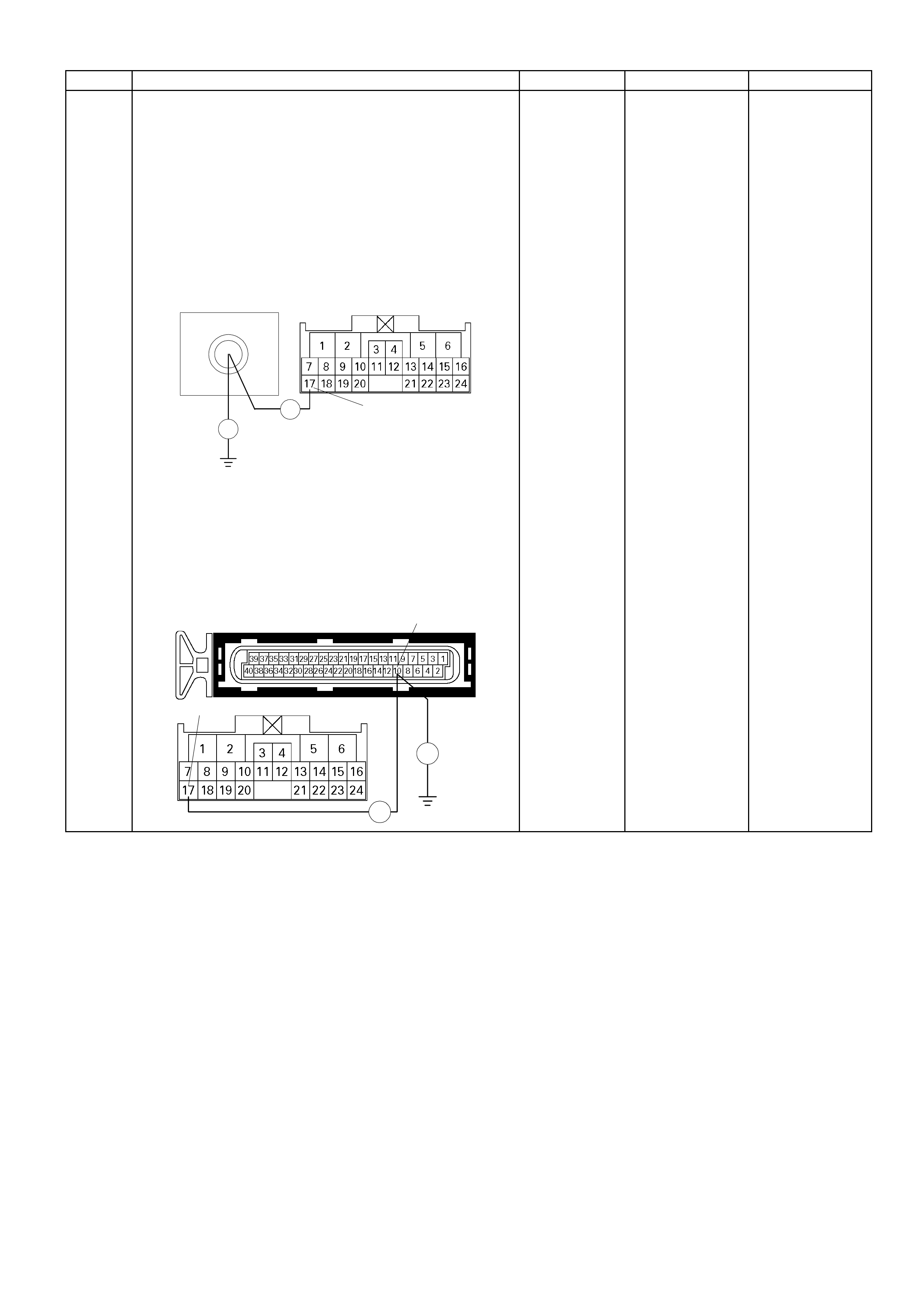
Step Action Value (s) Yes No
11
Using the DVM and check the CAN BUS high circuit.
Breaker box is available:
1. Ignition "Off", engine "Off".
2. Install the breaker box as type A (ECM
disconnected).
Refer to 6E-91 page.
3. Disconnect the TCM connector.
4. Check the circuit for open or short to ground circuit.
Was the problem found?
10
Break e r Box C-94
Ħ
Ħ 17
Breaker box is not available:
1. Ignition "Off", engine "Off".
2. Disconnect the TCM connector and ECM
connector.
3. Check the circuit for open or short to ground circuit.
Was the problem found? E-60(A)
C- 94
Ħ
Ħ
17
10
-
Repair faulty
harness and
verify repair
Go to Step 12
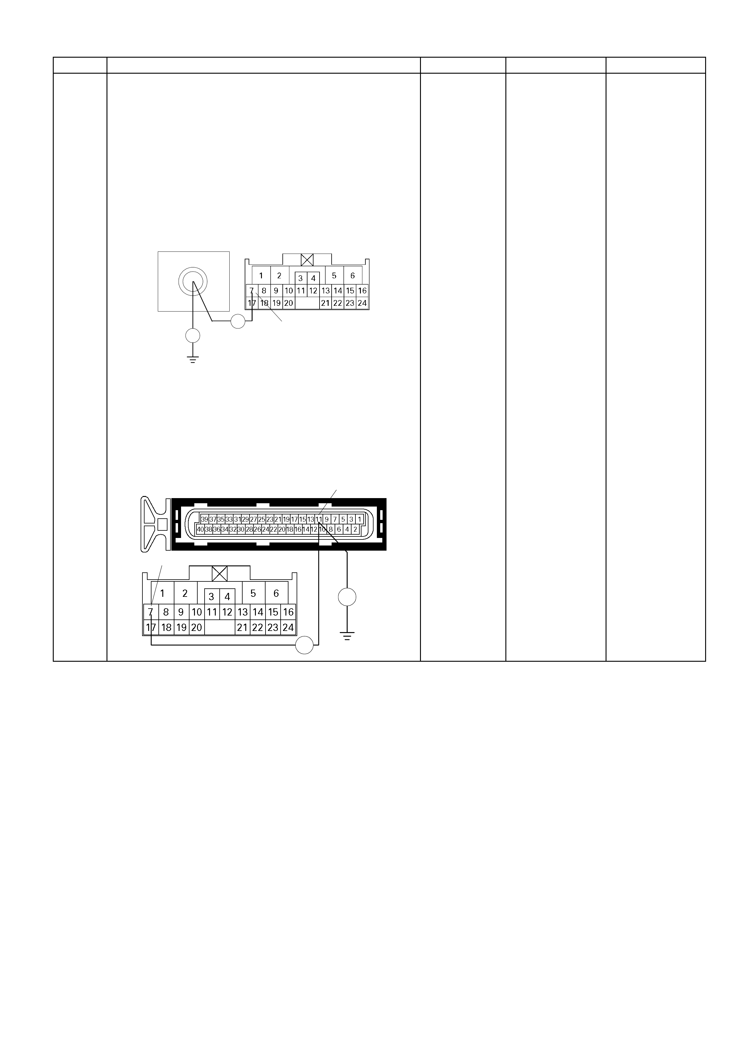
Step Action Value (s) Yes No
12
Using the DVM and check the CAN BUS low circuit.
Breaker box is available:
1. Ignition "Off", engine "Off".
2. Install the breaker box as type A (ECM
disconnected).
Refer to 6E-91 page.
3. Disconnect the TCM connector.
4. Check the circuit for open or short to ground circuit.
Was the problem found?
11
Break er Box C- 94
Ħ
Ħ 7
Breaker box is not available:
1. Ignition "Off", engine "Off".
2. Disconnect the TCM connector and ECM
connector.
3. Check the circuit for open or short to ground circuit.
Was the problem found? E-60(A)
C- 94
Ħ
Ħ
7
11
-
Repair faulty
harness and
verify repair
Go to Step 13

Step Action Value (s) Yes No
13 Is the ECM or TCM programmed with the latest
software release?
If not, download the latest software to the ECM or
TCM using the "SPS (Service Programming
System)".
Was the problem solved? - Verify repair Go to step 14
14 Replace the TCM.
Was the problem solved?
IMPORTANT: The replacement TCM must be
programmed. "SPS (Service Programming System)
and is necessary." - Verify repair Go to Step 15
15 Replace the ECM.
Is the action complete?
IMPORTANT: The replacement ECM must be
programmed. Refer to section of the Service
Programming System (SPS) in this m anual. Following
ECM programming, the immobiliser system (if
equipped) must be l inked to the ECM. Ref er to s ec ti o n
11 “Immobiliser System-ECM replacement” for the
ECM/Immobiliser linking procedure. - Veri fy repair -

Diagnostic Trouble Code (DTC) P1626 Immobiliser No Signal
RTW36EMF000601
Condition For Setting The DTC and A ction Taken When The DTC Sets
Flash
Code Code Type DTC Name DTC Setting Condition Fail-Safe (Back Up)
67 P1626 - Immobiliser No Signal No res ponse from immobiliser control unit. 1. Engine does not start.
2. Check engine lamp flash.
Circuit Description
The Engine Control Module (ECM) decides whether
that is an abnom ality in the imm obilis er contro l s ystem.
DTC P1626 is recorded by the ECM when no response
from immobliser.
Diagnostic Aids
Check for the following conditions:
• Poor connection at Engine Control Module (ECM)
and immobiliser inspect harness connectors for
backed out terminals, improper mating, broken
lock s, improperl y for med or dam aged terminals, and
poor terminal to wire connection.
• Damaged harness-inspect the wiring harness for
damage, if the harness appears to be OK,
disconnect the ECM and immobiliser, turn the
ignition "ON" and observe a voltmeter connected to
the suspect driver circuit at the ECM and
immobiliser harness connector while moving
connectors and wiring harnesses relates to the
Check Engine Lamp (MIL). A change in voltage will
indicate the location of the fault.
Diagnostic Trouble Code (DTC) P1626 Immobiliser No Signal
Step Action Value (s) Yes No
1 W as the "On- Board Diagn ostic (O BD) System Check"
performed? - Go to Step 2
Go to On Board
Diagnostic (OBD)
System Check
2 1. Connect the Tech 2.
2. Review and record the failure information.
3. Select "F0: Read DTC Infor By Priority" in "F0:
Diagnostic Trouble Code".
Is the DTC P1626 stored as "Present Failure"? - Go to Step 3
Refer to
Diagnostic Ai ds
and Go to Step 3
3 1. Using the Tech2, ignition "On" and engine "Off".
2. Selec t "Clear DT C Infor mation " with the T ech2 a nd
clear the DTC information.
3. Operate the vehicle and monitor the "F5: Failed
This Ignition" in "F2: DTC Information"
Was the DTC P1626 stored in this ignition cy cle? - Go to Step 4
Refer to
Diagnostic Ai ds
and Go to Step 4
4 Check any accessory parts which may cause electric
interference.
Was the problem found? -
Remove the
accessory parts
and verify repair Go to Step 5
5 1. Using the Tech 2, ignition "On" and engine "Off".
2. Select "Immobiliser" in the system selection menu
"Body".
3. Select "Read DTC Info Ordered By Priority" in the
"Diagnositic Trouble Code".
Was the any DTC's B**** stored in this ignition cycle? -
Refer to
"Immobiliser
Workshop
Manual" & Go to
DTC Chart B**** Go to Step 6
6 Check for poor/faulty connection at the immobiliser
control unit connector or ECM connector. If a
poor/faulty connection is found, repair as necessary.
Was the problem found?
E-61(B)
B-68
32 18
78
- Verify repair Go to Step 7
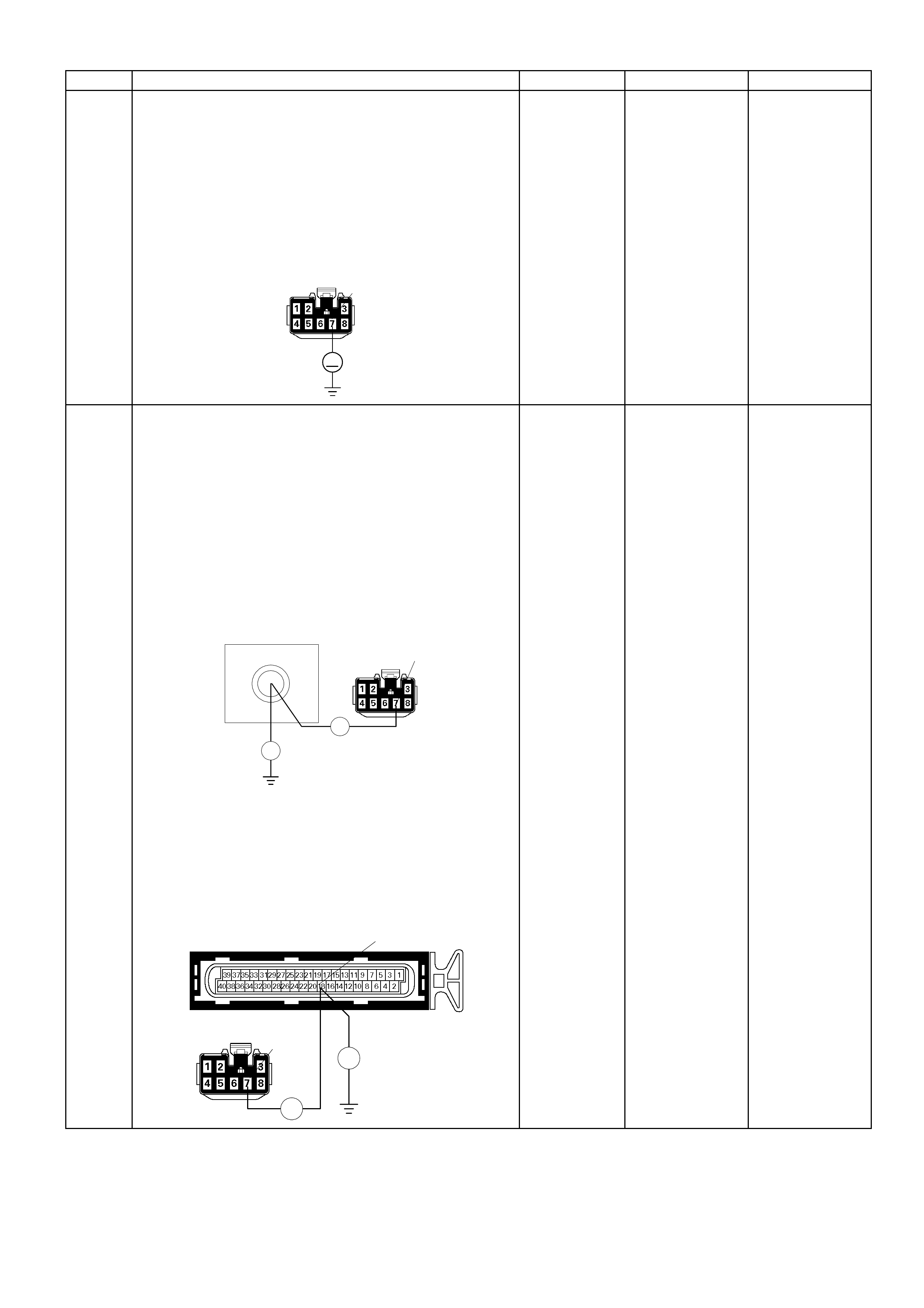
Step Action Value (s) Yes No
7
Using the DVM and check the "CHECK ENGINE"
lamp circuit.
1. Ignition "Off", engine "Off".
2. Disconnect the meter connector and immobiliser
control un it connec tor .
3. Ignition "On".
4. Check the circuit for short to power supply circuit.
Was the problem found?
B-68 7
V
-
Repair faulty
harness and
verify repai r
Go to Step 8
8
Using the DVM and check the "CHECK ENGINE"
lamp circuit.
Breaker box is available:
1. Ignition "Off", engine "Off".
2. Install the breaker box as type A (ECM
disconnected).
Refer to 6E-91 page.
3. Disconnec t the im mobiliser contr ol un it con nec tor.
4. Check the circuit for open or short to ground circuit.
Was the problem found?
58
Breaker Box
Ħ
B-68
Ħ
7
Breaker box is not available:
1. Ignition "Off", engine "Off".
2. Disconnect the immobiliser control unit connector
and ECM connec tor.
3. Check the circuit for open or short to ground circuit.
Was the problem found?
E-61(B)
B-68
Ħ
Ħ
7
18
-
Repair faulty
harness and
verify repai r
Go to Step 9
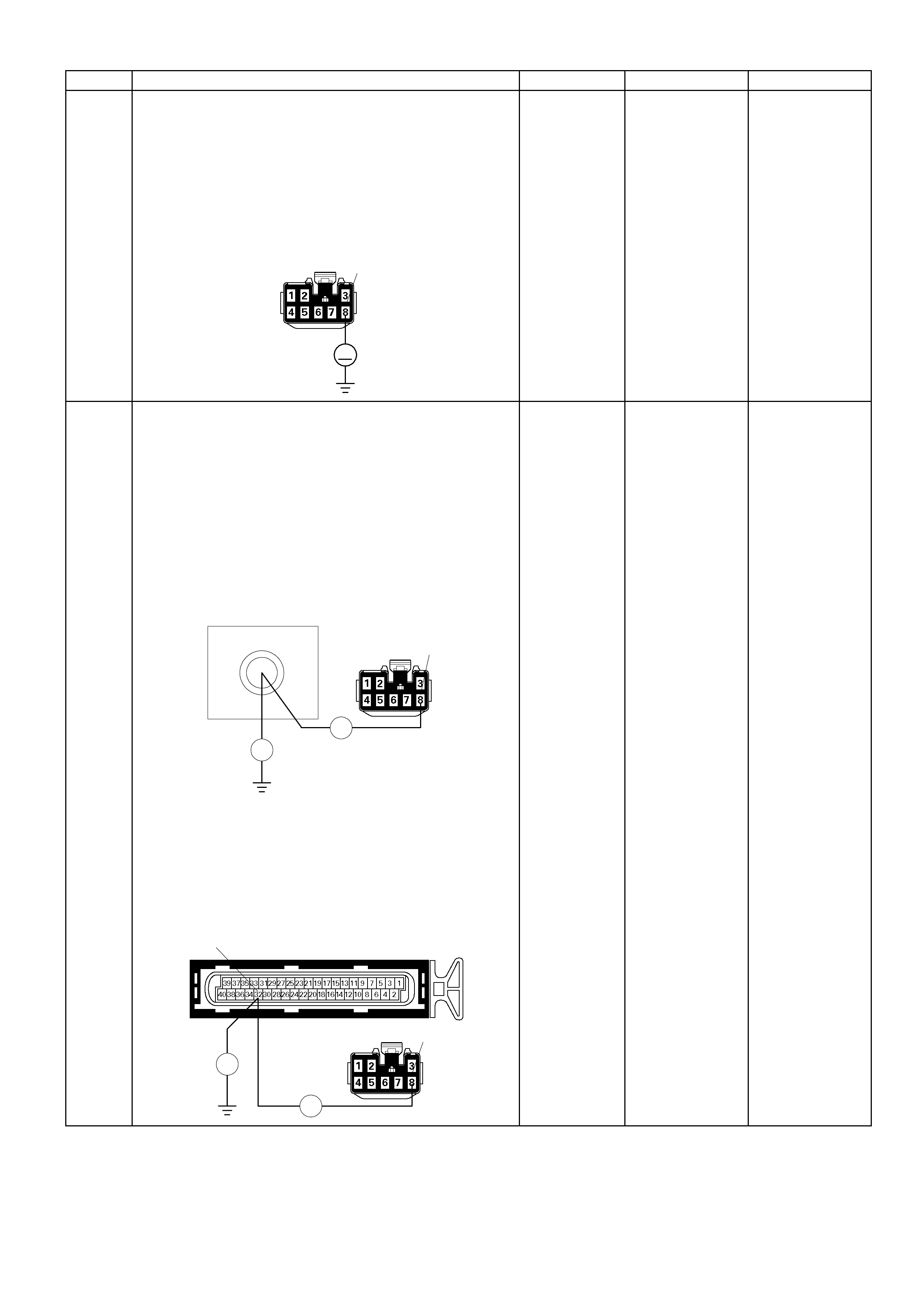
Step Action Value (s) Yes No
9
Using the DVM and check the VSS signal circuit.
1. Ignition "Off", engine "Off".
2. Disconnect the immobiliser control unit connector
and ECM connec tor.
3. Ignition "On".
4. Check the circuit for short to power supply circuit.
Was the problem found?
B-68 8
V
-
Repair faulty
harness and
verify repair
Go to Step 10
10
Using the DVM and check the VSS signal circuit.
Breaker box is available:
1. Ignition "Off", engine "Off".
2. Install the breaker box as type A (ECM
disconnected).
Refer to 6E-91 page.
3. Disconnec t the im mobiliser c ontr ol un it con nec tor .
4. Check the circuit for open or shot to ground circuit.
Was the problem found?
72
Breaker Box
Ħ
B-68
Ħ
8
Breaker box is not available:
1. Ignition "Off", engine "Off".
2. Disconnect the immobiliser control unit connector
and ECM connec tor.
3. Check the circuit for open or short to ground circuit.
Was the problem found?
B-68 8
E-61(B)
Ħ
Ħ
32
-
Repair faulty
harness and
verify repair
Go to Srtep 11

Step Action Value (s) Yes No
11 Is the ECM programmed with the latest software
release?
If not, download the latest software to the ECM using
the "SPS (Service Programming System)".
Was the problem solved? - Verify repai r Go to step 12
12 Replace the ECM.
Is the action complete?
IMPORTANT: The replacement ECM must be
programmed. Refer to section of the Service
Program ming System (SPS) in th is manual. F ollowin g
ECM programming, the immobiliser system (if
equipped) must be linked to the ECM. Refer to sec tion
11 “Immobiliser System-ECM replacement” for the
ECM/Immobiliser linking procedure. - Ve rify repair -
Diagnostic Trouble Code (DTC) P1631 Immobiliser Wrong Signal
RTW36EMF000601
Condition For Setting The DTC and A ction Taken When The DTC Sets
Flash
Code Code Type DTC Name DTC Setting Condition Fail-Safe (Back Up)
67 P1631 - Immobiliser Wrong
Signal Received response is not correct. 1. Engine does not start.
2. Check engine lamp fl ash.
Circuit Description
The ECM decides whet her that is an abnor malit y in the
immobiliser control system. DTC P1631 is recorded by
the ECM when receive d res pons e was not correc t.
Diagnostic Aids
Check for the following conditions:
• Poor connection at Engine Control Module (ECM)
and immobiliser inspect harness connectors for
backed out terminals, improper mating, broken
lock s, improperl y for med or dam aged terminals , and
poor terminal to wire connection.
• Damaged harness-inspect the wiring harness for
damage, if the harness appears to be OK,
disconnect the ECM and immobiliser, turn the
ignition "ON" and observe a voltmeter connected to
the suspect driver circuit at the ECM and
immobiliser harness connector while moving
connectors and wiring harnesses relates to the
Check Engine Lamp (MIL). A change in voltage will
indicate the location of the fault .

Diagnostic Trouble Code (DTC) P1631 Immobiliser Wrong Signal
Step Action Value (s) Yes No
1 W as the "On- Board Diagn ostic ( OBD) System Check"
performed? - Go to Step 2
Go to On Board
Diagnostic (OBD)
System Check
2 1. Connect the Tech 2.
2. Review and record the failure information.
3. Select "F0: Read DTC Infor By Priority" in "F0:
Diagnostic Trouble Code".
Is the DTC P1631 stored as "Present Failure"? - Go to Step 3
Refer to
Diagnostic Ai ds
and Go to Step 3
3 1. Using the Tech2, ignition "On" and engine "Off".
2. Selec t "Clear DTC Infor mation " with th e Tech2 a nd
clear the DTC information.
3. Operate the vehicle and monitor the "F5: Failed
This Ignition" in "F2: DTC Information"
Was the DTC P1631 stored in this ignition cycle? - Go to Step 4
Refer to
Diagnostic Ai ds
and Go to Step 4
4 1. Using the Tech 2, ignition "On" and engine "Off".
2. Select "Immobiliser" in the system selection menu
"Body".
3. Select "Read DTC Info Ordered By Priority" in the
"Diagnositic Trouble Code".
Was the any DTC's B**** stored in this ignition cycle? -
Refer to
"Immobiliser
Workshop
Manual" & Go to
DTC Chart B**** Go to Step 5
5 Is the ECM programmed with the latest software
release?
If not, download the latest software to the ECM using
the "SPS (Service Programming System)".
Was the problem solved? - Verify repai r Go to step 6
6 Replace the ECM.
Is the action complete?
IMPORTANT: The replacement ECM must be
programmed. Refer to section of the Service
Program ming System (SPS) in this m anual. Followin g
ECM programming, the immobiliser system (if
equipped) must be linked to the ECM. Refer to sec tio n
11 “Immobiliser System-ECM replacement” for the
ECM/Immobiliser linking procedure. - Ve rify repair -
Diagnostic Trouble Code (DTC) P1648 Wrong Security Code Entered
RTW36EMF000601
Condition For Setting The DTC and Action Taken When The DTC Sets
Flash
Code Code Type DTC Name DTC Setting Condition Fail-Safe (Back Up)
67 P1648 - Wrong Security Code
Entered Received i ncorrect security code. 1. Engine does not start.
2. Check engi ne l amp flas h.
Circuit Description
The ECM decides whether that is an abnormality in the
immobiliser control system. DTC P1648 is recorded by
the ECM when received security code was not correct.
Diagnostic Aids
Check for the following conditions:
• Poor connection at Engine Control Module (ECM)
and immobiliser inspect harness connectors for
backed out terminals, improper mating, broken
locks, improperly formed or damaged terminals, and
poor terminal to wire connection.
• Damaged harness-inspect the wiring harness for
damage, if the harness appears to be OK,
disconnect the ECM and immobiliser, turn the
ignition "ON" and observe a voltmeter connected to
the suspect driver circuit at the ECM and immobiliser
harness connector while moving connectors and
wiring harnesses relates to the Check Engine Lamp
(MIL). A change in voltage will indicate the location
of the fault.

Diagnostic Trouble Code (DTC) P1648 Wrong Security Code Entered
Step Action Value (s) Yes No
1 Was the "On-Board Diagnostic (OBD) System Check"
performed? - Go to Step 2
Go to On Board
Diagnostic (OBD)
System Check
2 1. Connect the Tech 2.
2. Review and record the failure information.
3. Select "F0: Read DTC Infor By Priority" in "F0:
Diagnostic Trouble Code".
Is the DTC P1648 stored as "Present Failure"? - Go to Step 3
Refer to
Diagnostic Aids
and Go to Step 3
3 1. Using the Tech2, ignition "On" and engine "Off".
2. Select "Clear DTC Information" with the Tech2 and
clear the DTC information.
3. Operate the vehicle and monitor the "F5: Failed
This Ignition" in "F2: DTC Information"
Was the DTC P1648 stored in this ignition cycle? - Go to Step 4
Refer to
Diagnostic Aids
and Go to Step 4
4 1. Using the Tech 2, ignition "On" and engine "Off".
2. Select "Immobiliser" in the system selection menu
"Body".
3. Select "Read DTC Info Ordered By Priority" in the
"Diagnositic Trouble Code".
Was the any DTC's B**** stored in this ignition cycle? -
Refer to
"Immobiliser
Workshop
Manual" & Go to
DTC Chart B**** Go to Step 5
5 Is the ECM programmed with the latest software
release?
If not, download the latest software to the ECM using
the "SPS (Service Programming System)".
Was the problem solved? - Verify repair Go to step 6
6 Replace the ECM.
Is the action complete?
IMPORTANT: The replacement ECM must be
programmed. Refer to section of the Service
Programming System (SPS) in this manual. Following
ECM programming, the immobiliser system (if
equipped) must be linked to the ECM. Refer to section
11 “Immobiliser System-ECM replacement” for the
ECM/Immobiliser linking procedure. - Verify repair -
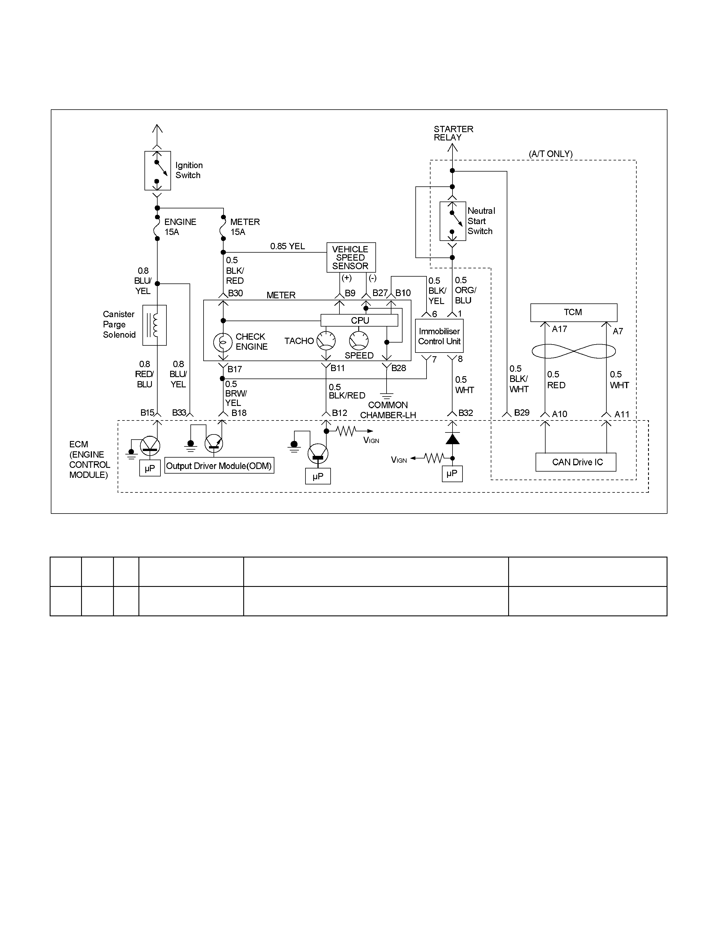
Diagnostic Trouble Code (DTC) P1649 Immobiliser
Function Not Programmed
RTW36EMF000601
Condition For Setting The DTC and Action Taken When The DTC Sets
Flash
Code Code Type DTC Name DTC Setting Condi ti on Fail -Safe (Back Up)
67 P1649 - Immobiliser Function
Not Programmed Im mobiliser function is not programmed in the ECM. 1. Engine does not start.
2. Check engi ne l amp flas h.
Circuit Description
The ECM decides whether that is an abnormality in the
immobiliser control system. DTC P1649 is recorded by
the ECM when immobiliser function was not
programmed in the ECM.
Diagnostic Aids
Check for the following conditions:
• Poor connection at Engine Control Module (ECM)
and immobiliser inspect harness connectors for
backed out terminals, improper mating, broken
locks, improperly formed or damaged terminals, and
poor terminal to wire connection.
• Damaged harness-inspect the wiring harness for
damage, if the harness appears to be OK,
disconnect the ECM and immobilizer, turn the
ignition "ON" and observe a voltmeter connected to
the suspect driver circuit at the ECM and immobilizer
harness connector while moving connectors and
wiring harnesses relates to the Check Engine Lamp
(MIL). A change in voltage will indicate the location
of the fault.

Diagnostic Trouble Code (DTC) P1649 Immobiliser Function Not Programmed
Step Action Value (s) Yes No
1 Was the "On-Board Diagnostic (OBD) System Check"
performed? - Go to Step 2
Go to On Board
Diagnostic (OBD)
System Check
2 1. Connect the Tech 2.
2. Review and record the failure information.
3. Select "F0: Read DTC Infor By Priority" in "F0:
Diagnostic Trouble Code".
Is the DTC P1649 stored as "Present Failure"? - Go to Step 3
Refer to
Diagnostic Aids
and Go to Step 3
3 1. Using the Tech2, ignition "On" and engine "Off".
2. Select "Clear DTC Information" with the Tech2 and
clear the DTC information.
3. Operate the vehicle and monitor the "F5: Failed
This Ignition" in "F2: DTC Information"
Was the DTC P1649 stored in this ignition cycle? - Go to Step 4
Refer to
Diagnostic Aids
and Go to Step 4
4 1. Using the Tech 2, ignition "On" and engine "Off".
2. Select "Immobiliser" in the system selection menu
"Body".
3. Select "Read DTC Info Ordered By Priority" in the
"Diagnositic Trouble Code".
Was the any DTC's B**** stored in this ignition cycle? -
Refer to
"Immobiliser
Workshop
Manual" & Go to
DTC Chart B**** Go to Step 5
5 Is the ECM programmed with the latest software
release?
If not, download the latest software to the ECM using
the "SPS (Service Programming System)".
Was the problem solved? - Verify repair Go to step 6
6 Replace the ECM.
Is the action complete?
IMPORTANT: The replacement ECM must be
programmed. Refer to section of the Service
Programming System (SPS) in this manual. Following
ECM programming, the immobiliser system (if
equipped) must be linked to the ECM. Refer to section
11 “Immobiliser System-ECM replacement” for the
ECM/Immobiliser linking procedure. - Verify repair -

Symptom Diagnosis
Preliminary Checks
Before using this section, perform the "On-Board
Diagnostic (OBD) System Check" and verify all of the
following items:
• The engine control module (ECM) and check engine
lamp (MIL=malfunction indicator lamp) are operating
correctly.
• There are no Diagnostic Trouble Code(s) stored.
• Tech 2 data is within normal operating range. Refer
to Typical Scan Data Values.
• Verify the customer complaint and locate the correct
symptom in the table of contents. Perform the
procedure included in the symptom chart.
Visual/Physical Check
Several of the symptom procedures call for a careful
visual/physical check. This can lead to correcting a
problem without further checks and can save valuable
time. This check should include the following items:
• ECM grounds for cleanliness, tightness and proper
location.
• Vacuum hoses for splits, kinks, and proper
connection. Check thoroughly for any type of leak or
restriction.
• Air intake ducts for collapsed or damaged areas.
• Air leaks at throttle body mounting area, manifold
absolute pressure (MAP) sensor and intake manifold
sealing surfaces.
• Ignition wires for cracking, harness, and carbon
tracking.
• Wiring for proper connections, pinches and cuts.
Intermittent
Important: An intermittent problem may or may not turn
on the check engine lamp (MIL=malfunction indicator
lamp) or store a Diagnostic Trouble Code. Do NOT use
the Diagnostic Trouble Code (DTC) charts for
intermittent problems.
The fault must be present to locate the problem.
Most intermittent problems are cased by faulty electrical
connections or wiring. Perform a careful visual/physical
check for the following conditions.
• Poor mating of the connector halves or a terminal
not fully seated in the connector (backed out).
• Improperly formed or damaged terminal.
• All connector terminals in the problem circuit should
be carefully checked for proper contact tension.
• Poor terminal-to-wire connection. This requires
removing the terminal form the connector body to
check.
• Ignition coils shorted to ground and arcing at ignition
wires or plugs.
• Check engine lamp (MIL=malfunction indicator lamp)
wire to ECM shorted to ground.
• Poor ECM grounds. Refer to the ECM wiring
diagrams.
Road test the vehicle with a Digital Multimeter
connected to a suspected circuit. An abnormal voltage
when the malfunction occurs is a good indication that
there is a fault in the circuit being monitored.
Using Tech 2 to help detect intermittent conditions. The
Tech 2 have several features that can be used to
located an intermittent condition. Use the following
features to find intermittent faults:
To check for loss of diagnostic code memory,
disconnect the mass air flow (MAF) sensor and idle the
engine until the check engine lamp (MIL=malfunction
indicator lamp) comes on. Diagnostic Trouble Code
P0102 should be stored and kept in memory when the
ignition is turned OFF.
If not, the ECM is faulty. When this test is completed,
make sure that you clear the Diagnostic Trouble Code
P0102 from memory.
An intermittent check engine lamp (MIL=malfunction
indicator lamp) with no stored Diagnostic Trouble Code
may be caused by the following:
• Ignition coil shorted to ground and arcing at ignition
wires or plugs.
• Check engine lamp (MIL=malfunction indicator lamp)
wire to ECM short to ground.
• Poor ECM grounds. Refer to the ECM wiring
diagrams.
Check for improper installation of electrical options such
as light, cellular phones, etc. Check all wires from ECM
to the ignition control module for poor connections.
Check for an open diode across the A/C compressor
clutch and check for other open diodes (refer to wiring
diagrams in Electrical Diagnosis).
Techline

If problem has not been found, refer to ECM connector
symptom tables.
• Check the "Broadcast Code" of the ECM, and
compare it with the latest Isuzu service bulletins
and/or Isuzu EEPROM reprogramming equipment to
determine if an update to the ECM's
reprogrammable memory has been released.
To check the "Broadcast Code", connect the Tech 2,
then look for "ID info." then select "Broadcast Code".
This should display a 4 character code, such as "8501"
(example only).
This identifies the contents of the reprogrammable
software and calibration contained in the ECM.
If the "Broadcast Code" is not the most current
available, it is advisable to reprogram the ECM's
EEPROM memory, which may either help identify a
hard-to find problem or may fix the problem.
The Service Programming System (SPS) will not allow
incorrect software programming or incorrect calibration
changes.
Engine Cranks But Will Not Run
DEFINITIONS: Engine cranks, but will not run. (The
engine never start.)
NOTE: The replacement ECM must be programmed.
Refer to section of the Service Programming
System (SPS) in this manual. Following ECM
programming, the immobiliser system (if equipped)
must be linked to the ECM. Refer to section 11
"Immobiliser System-ECM replacement" for the
ECM/Immobiliser linking procedure.
Should Tech2 display "SPS Procedure was not
successful", engine will not start, but no DTCs are
present, low battery voltage or poor electrical
connections should be the primary
suspects.Perform the SPS procedure again after
rectifying the fault/s.
NOTE: The vehicle with immobiliser system, this
system may be activated. Check the immobiliser
system diagnosis.
Step Action Value (s) Yes No
1 Was the "On-Board Diagnostic (OBD) System Check"
performed? - Go to Step 2
Go to On Board
Diagnostic (OBD)
System Check
2 1. Perform a bulletin search.
2. If a bulletin that addresses the symptom is found,
correct the condition as instructed in the bulletin.
Was a bulletin found that addresses the symptom? - Verify repair Go to Step 3
3 Was a visually/physical check performed? - Go to Step 4 Go to Visual /
physical Check
4 Check the "Meter" fuse (15A), "Engine" fuse (15A),
"IGN Coil" fuse (15A) and "Fuel Pump" fuse (20A). If
the fuse is burnt out, repair as necessary.
Was the problem found? - Verify repair Go to Step 5

Step Action Value (s) Yes No
5 Check the ECM grounds to verify that they are clean
and tight. Refer to the ECM wiring diagrams.
Was a problem found? - Verify repair Go to Step 6
6 Check the fuel quality.
Is the customer using proper fuel? - Go to Step 7 Replace fuel
7 Visually/phy sically inspect for the following conditions:
• Restrict air intake system. Check for a restricted air
filter element, or foreign objects blocking the air
intake system.
• Check for objects blocking the IAC passage or
throttle bore, excessive deposits in the throttle bore
and on the throttle plate.
• Check for a condition that causes a large vacuum
leak, such as an incorrectly installed or faulty
crankcase ventilation hose/brake booster hose.
Was a problem found? - Verify repair Go to Step 8
8 1. Using a Tech 2, display the IAC value.
2. Check for a faulty, plugged, or sticking IAC
operation.
Was the problem found? - Verify repair Go to Step 9
9 Check the CKP sensor signal or installation condition.
Refer to DTC P0336 "Crankshaft Position Sensor
Circuit Range/Performance" and DTC P0337
"Crankshaft Position Sensor Circuit No Signal".
Was a problem found? - Verify repair Go to Step 10
10 Check for proper ignition voltage output with the spark
tester.
Was a problem found? - Verify repair Go to Step 11
11 1. Remove the spark plugs and check for gas or oil
fouling cracks, wear, improper gap, burned
electrodes, heavy deposits, or improper heat
range.
2. If spark plugs are fouled, the cause of fouling must
be determined before replacing the spark plugs.
Was a problem found? - Verify repair Go to Step 12
12 Check the fuel pressure. Refer to Fuel System
Diagnosis.
Was a problem found? - Verify repair Go to Step 13
13 Perform the procedure in Fuel System Pressure Test
to determine if there is a problem with fuel delivery.
Was a problem found? - Verify repair Go to Step 14
14 Visually/physically check the vacuum hose for splits,
kinks and proper connections and routing.
Was a problem found? - Verify repair Go to Step 15
15 Check the exhaust system for a possible restriction:
• Damaged or collapsed pipes.
• Internal muffler failure.
Was a problem found? - Verify repair Go to Step 16

Step Action Value (s) Yes No
16 Check for the following engine mechanical problems
(refer to Engine Mechanical section):
• Low compression.
• Leaking cylinder head gaskets.
• Worn camshaft.
• Camshaft drive belt slipped or stripped.
Was a problem found? - Verify repair Go to Step 17
17 1. Review all diagnostic procedures within this table.
2. If all procedures have been completed and no
malfunctions have been found, review/inspect the
following:
• Visual/physical inspection.
• Tech 2 data.
• All electrical connections within a suspected circuit
and/or system.
Was a problem found? - Verify repair Go to Step 18
18 Is the ECM programmed with the latest software
release?
If not, download the latest software to the ECM using
the "SPS (Service Programming System)".
Was the problem solved? - Verify repair Go to step 19
19 Replace the ECM.
Is the action complete?
IMPORTANT: The replacement ECM must be
programmed. Refer to section of the Service
Programming System (SPS) in this manual. Following
ECM programming, the immobiliser system (if
equipped) must be linked to the ECM. Refer to section
11 “Immobiliser System-ECM replacement” for the
ECM/Immobiliser linking procedure. - Verify repair -

Hard Start Symptom
DEFINITIONS: Engine cranks, but does not start for a
long time. Does eventually start, or may start and then
immediately stall.
Step Action Value (s) Yes No
1 Was the "On-Board Diagnostic (OBD) System Check"
performed? - Go to Step 2
Go to On Board
Diagnostic (OBD)
System Check
2 1. Perform a bulletin search.
2. If a bulletin that addresses the symptom is found,
correct the condition as instructed in the bulletin.
Was a bulletin found that addresses the symptom? - Verify repair Go to Step 3
3 Was a visually /physical check performed? - Go to Step 4 Go to Visual /
physical Check
4 1. Using a Tech 2, display the ECT sensor and IAT
sensor value.
2. Check the specified value or wire.
Was the problem found? - Verify repair Go to Step 5
5 Check the ECM grounds to verify that they are clean
and tight. Refer to the ECM wiring diagrams.
Was a problem found? - Verify repair Go to Step 6
6 Visually/physically inspect for the following conditions:
• Restrict air intake system. Check for a restricted air
filter element, or foreign objects blocking the air
intake system.
• Check for objects blocking the IAC passage or
throttle bore, excessive deposits in the throttle bore
and on the throttle plate.
• Check for a condition that causes a large vacuum
leak, such as an incorrectly installed or faulty
crankcase ventilation hose/brake booster hose.
Was a problem found? - Verify repair Go to Step 7
7 1. Using a Tech 2, display the IAC value.
2. Check for a faulty, plugged, or sticking IAC
operation.
Was the problem found? - Verify repair Go to Step 8
8 Check the CKP sensor signal or installation condition.
Refer to DTC P0336 "Crankshaft Position Sensor
Circuit Range/Performance" and DTC P0337
"Crankshaft Position Sensor Circuit No Signal".
Was a problem found? - Verify repair Go to Step 9
9 Check for proper ignition voltage output with a spark
tester.
Was the problem found? - Verify repair Go to Step 10
Techline

Step Action Value (s) Yes No
10 1. Remove the spark plugs and check for gas or oil
fouling cracks, wear, improper gap, burned
electrodes, heavy deposits, or improper heat
range.
2. If spark plugs are fouled, the cause of fouling must
be determined before replacing the spark plugs.
Was a problem found? - Verify repair Go to Step 11
11 Check for water or alcohol contaminated fuel.
Was a problem found? - Verify repair Go to Step 12
12 Perform the procedure in Fuel System Pressure Test
to determine if there is a problem with fuel delivery.
Was a problem found? - Verify repair Go to Step 13
13 1. Check the injector connectors.
2. If any of the connectors are connected at an
improper cylinder, connect as necessary.
Was a problem found? - Verify repair Go to Step 14
14 Check for the following engine mechanical problems
(refer to Engine Mechanical section):
• Low compression.
• Leaking cylinder head gaskets.
• Worn camshaft.
• Camshaft drive belt slipped or stripped.
Was a problem found? - Verify repair Go to Step 15
15 1. Review all diagnostic procedures within this table.
2. If all procedures have been completed and no
malfunctions have been found, review/inspect the
following:
• Visual/physical inspection.
• Tech 2 data.
• All electrical connections within a suspected circuit
and/or system.
Was a problem found? - Verify repair Go to Step 16
16 Is the ECM programmed with the latest software
release?
If not, download the latest software to the ECM using
the "SPS (Service Programming System)".
Was the problem solved? - Verify repair Go to step 17
17 Replace the ECM.
Is the action complete?
IMPORTANT: The replacement ECM must be
programmed. Refer to section of the Service
Programming System (SPS) in this manual. Following
ECM programming, the immobiliser system (if
equipped) must be linked to the ECM. Refer to section
11 “Immobiliser System-ECM replacement” for the
ECM/Immobiliser linking procedure. - Verify repair -

Rough, Unstable, Or Incorrect Idle, Stalling Symptom
DEFINITIONS: Engine runs unevenly at idle. If severe,
the engine or vehicle may shake. Engine idle speed
may vary in RPM. Either condition may be severe
enough to stall the engine.
X
time
rpm
Rough Idle Stall
Step Action Value (s) Yes No
1 Was the "On-Board Diagnostic (OBD) System Check"
performed? - Go to Step 2
Go to On Board
Diagnostic (OBD)
System Check
2 1. Perform a bulletin search.
2. If a bulletin that addresses the symptom is found,
correct the condition as instructed in the bulletin.
Was a bulletin found that addresses the symptom? - Verify repair Go to Step 3
3 Was a visually /physical check performed? - Go to Step 4 Go to Visual /
physical Check
4 1. Check for incorrect idle speed. Ensure that the
following conditions are present.
• Engine fully warm.
• Accessories are OFF. 2. Using a Tech 2, monitor
IAC position.
Is the IAC position within the specified values? 10 - 20 Steps Go to Step 6 Go to Step 5
5 Visually/physically inspect for the following conditions:
• Restrict air intake system. Check for a restricted air
filter element, or foreign objects blocking the air
intake system.
• Check for objects blocking the IAC passage or
throttle bore, excessive deposits in the throttle bore
and on the throttle plate.
• Check for a condition that causes a large vacuum
leak, such as an incorrectly installed or faulty
crankcase ventilation hose/brake booster hose.
Was a problem found? - Verify repair Go to Step 6
6 1. Using a Tech 2, display the ECT sensor and IAT
sensor value.
2. Check the specified value or wire.
Was the problem found? - Verify repair Go to Step 7

Step Action Value (s) Yes No
7 1. Using the Tech 2, ignition "On" and engine "On".
2. Monitor the "Mass Air Flow" in the data display.
Does the Tech 2 indicate correct "Mass Air Flow" as
shown in the following graph, when engine speed is
increasing little by little?
MAF Sensor Output Characteristic (Reference)
0
10
20
30
40
50
60
750 1000 1250 1500 1750 2000 2250 2500 2750 3000 3250 3500 3750 4000 4250 4500 4750 5000
Tec h2 Readi ng Engine Speed (rpm )
Tech2 Reading MAF (g/s)
- Go to Step 9 Go to Step 8
8 Remove the MAF & IAT sensor assembly and check
for the following conditions.
• Objects blocking the air cleaner.
• Objects blocking the MAF sensor.
• Objects blocking the throttle valve.
• Vacuum leaking at intake duct.
• Vacuum leaking at throttle body.
If a problem is found, repair as necessary.
Was the problem found? - Verify repair
Refer to DTC
P0101 and Go to
Step 9
9 1. Using the Tech 2, ignition "On" and engine "Off".
2. Monitor the "Throttle Position" in the data display.
Does the Tech 2 indicate correct "Throttle Position"
from 0% to 100% depending on accelerator pedal
operation? - Go to Step 11 Go to Step 10
10 1. Using the Tech 2, ignition "On" and engine "Off".
2. Monitor the "Throttle Position" in the data display.
3. Adjust the accelerator cable or TPS within 0% to
100%.
Is the action complete? - Verify repair -
11 Check for the following conditions.
• Objects blocking the throttle valve.
• Vacuum leaking at throttle body.
If a problem is found, repair as necessary.
Was the problem found? - Verify repair Go to Step 12

Step Action Value (s) Yes No
12 Check the fuel control Heated Oxygen Sensor
(HO2S). When monitored on the Tech 2, the HO2S
should respond quickly to different throttle positions. If
it doesn't check for silicon or other contaminates from
fuel or use of improper sealant. The sensors may have
a white powdery coating. Silicon contamination sends
a rich exhaust signal which causes the ECM to
command and excessively lean air/fuel mixture.
Was a problem found? - Verify repair Go to Step 13
13 Check the fuel pressure. Refer to Fuel System
Diagnosis.
Was a problem found? - Verify repair Go to Step 14
14 Perform the procedure in Fuel System Pressure Test
to determine if there is a problem with fuel delivery.
Was a problem found? - Verify repair Go to Step 15
15 Monitor "B1S1 (Bank 1 Sensor 1) Status" and "B2S1
(Bank 2 Sensor 1) Status" on the Tech 2.
Is the "B1S1 (Bank 1 Sensor 1) Status" or "B2S1
(Bank 2 Sensor 1) Status" in the rich condition? - Go to Step 16 Go to Step 17
16 Check items that can cause the engine to run rich.
Refer to DTC P0172 "O2 Sensor System Too Rich
(Bank 1)" or DTC P0175 "O2 Sensor System Too Rich
(Bank 2)".
Was a problem found? - Verify repair Go to Step 18
17 Check items that can cause the engine to run lean.
Refer to DTC P0171 "O2 Sensor System Too Lean
(Bank 1)" or DTC P0174 "O2 Sensor System Tool
Lean (Bank 2)".
Was a problem found? - Verify repair Go to Step 18
18 Check for proper ignition voltage output with the spark
tester.
Was a problem found? - Verify repair Go to Step 19
19 Check the ignition coils for cracks or carbon tracking.
If a problem is found, repair as necessary.
Was a problem found? - Verify repair Go to Step 20
20 1. Remove the spark plugs and check for gas or oil
fouling cracks, wear, improper gap, burned
electrodes, heavy deposits, or improper heat range.
2. If spark plugs are fouled, the cause of fouling must
be determined before replacing the spark plugs.
Was a problem found? - Verify repair Go to Step 21
21 1. Check the injector connectors.
2. If any of the connectors are connected at an
improper cylinder, connect as necessary.
Was a problem found? - Verify repair Go to Step 22
22 Check the ECM grounds to verify that they are clean
and tight. Refer to the ECM wiring diagrams.
Was a problem found? - Verify repair Go to Step 23

Step Action Value (s) Yes No
23 1. Check for faulty engine mounts.
2. If a problem is found, repair as necessary.
Was a problem found? - Verify repair Go to Step 24
24 Check for the following engine mechanical problems
(refer to Engine Mechanical section):
• Low compression.
• Leaking cylinder head gaskets.
• Worn camshaft.
• Sticking or leaking valves. -Valve timing.
• Broken valve springs.
• Camshaft drive belt slipped or stripped.
Was a problem found? - Verify repair Go to Step 25
25 1. Review all diagnostic procedures within this table.
2. If all procedures have been completed and no
malfunctions have been found, review/inspect the
following:
• Visual/physical inspection.
• Tech 2 data.
• All electrical connections within a suspected circuit
and/or system.
Was a problem found? - Verify repair Go to Step 26
26 Is the ECM programmed with the latest software
release?
If not, download the latest software to the ECM using
the "SPS (Service Programming System)".
Was the problem solved? - Verify repair Go to step 27
27 Replace the ECM.
Is the action complete?
IMPORTANT: The replacement ECM must be
programmed. Refer to section of the Service
Programming System (SPS) in this manual. Following
ECM programming, the immobiliser system (if
equipped) must be linked to the ECM. Refer to section
11 “Immobiliser System-ECM replacement” for the
ECM/Immobiliser linking procedure. - Verify repair -
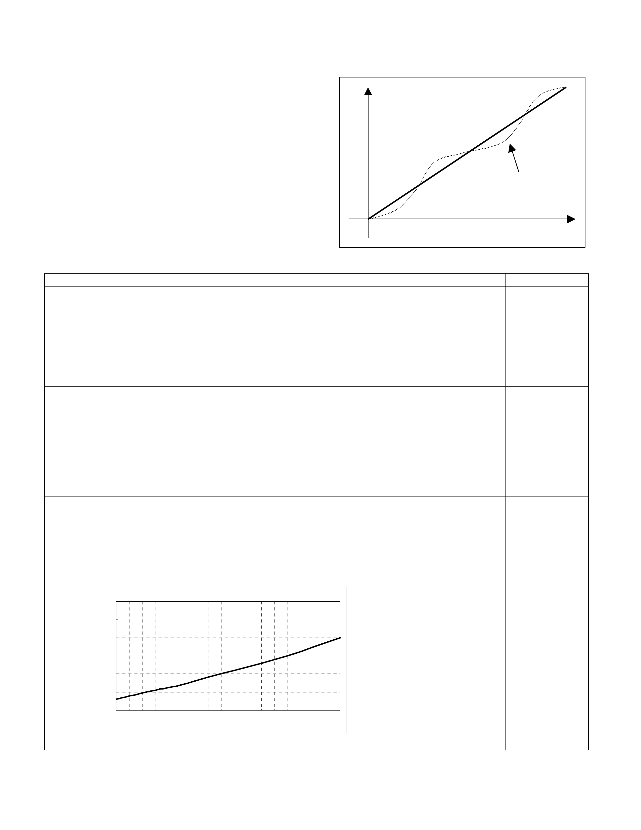
Surges And/Or Chugs Symptom
DEFINITIONS: Engine power variation under steady
throttle or cruise. Feels like the vehicle speeds up and
slows down with no charge in the accelerator pedal.
time
rpm
Surge
Step Action Value (s) Yes No
1 Was the "On-Board Diagnostic (OBD) System Check"
performed? - Go to Step 2
Go to On Board
Diagnostic (OBD)
System Check
2 1. Perform a bulletin search.
2. If a bulletin that addresses the symptom is found,
correct the condition as instructed in the bulletin.
Was a bulletin found that addresses the symptom? - Verify repair Go to Step 3
3 Was a visually /physical check performed? - Go to Step 4 Go to Visual /
physical Check
4 Be sure that the driver understands transmission
torque converter clutch and A/C compressor operation
as explained in the owner's manual. Inform the
customer how the torque converter clutch (TCC) (if
A/T model) and the A/C clutch operate.
Is the customer experiencing a normal condition? - System OK Go to Step 5
5 1. Using the Tech 2, ignition "On" and engine "On".
2. Monitor the "Mass Air Flow" in the data display.
Does the Tech 2 indicate correct "Mass Air Flow" as
shown in the following graph, when engine speed is
increasing little by little?
MA F Sensor Output Characteristic (Reference)
0
10
20
30
40
50
60
750 1000 1250 1500 1750 2000 2250 2500 2750 3000 3250 3500 3750 4000 4250 4500 4750 5000
Tec h2 Reading Engine Speed (rpm)
Tec h2 Readi ng M AF (g/s)
- Go to Step 7 Go to Step 6

Step Action Value (s) Yes No
6 Remove the MAF & IAT sensor assembly and check
for the following conditions.
• Objects blocking the air cleaner.
• Objects blocking the MAF sensor.
• Objects blocking the throttle valve.
• Vacuum leaking at intake duct.
• Vacuum leaking at throttle body.
If a problem is found, repair as necessary.
Was the problem found? - Verify repair
Refer to DTC
P0101 and Go to
Step 7
7 1. Using the Tech 2, ignition "On" and engine "Off".
2. Monitor the "Throttle Position" in the data display.
Does the Tech 2 indicate correct "Throttle Position"
from 0% to 100% depending on accelerator pedal
operation?
- Go to Step 9 Go to Step 8
8 1. Using the Tech 2, ignition "On" and engine "Off".
2. Monitor the "Throttle Position" in the data display.
3. Adjust the accelerator cable or TPS within 0% to
100%.
Is the action complete? - Verify repair -
9 Check for the following conditions.
• Objects blocking the throttle valve.
• Vacuum leaking at throttle body.
If a problem is found, repair as necessary.
Was the problem found? - Verify repair Go to Step 10
10 Check the fuel control Heated Oxygen Sensor
(HO2S). When monitored on the Tech 2, the HO2S
should respond quickly to different throttle positions. If
it doesn't check for silicon or other contaminates from
fuel or use of improper sealant. The sensors may have
a white powdery coating. Silicon contamination sends
a rich exhaust signal which causes the ECM to
command and excessively lean air/fuel mixture.
Was a problem found? - Verify repair Go to Step 11
11 Check the fuel pressure. Refer to Fuel System
Diagnosis.
Was a problem found? - Verify repair Go to Step 12
12 Monitor "B1S1 (Bank 1 Sensor 1) Status" and "B2S1
(Bank 2 Sensor 1) Status" on the Tech 2.
Is the "B1S1 (Bank 1 Sensor 1) Status" or "B2S1
(Bank 2 Sensor 1) Status" in the rich condition? - Go to Step 13 Go to Step 14

Step Action Value (s) Yes No
13 Check items that can cause the engine to run rich.
Refer to DTC P0172 "O2 Sensor System Too Rich
(Bank 1)" or DTC P0175 "O2 Sensor System Too Rich
(Bank 2)".
Was a problem found? - Verify repair Go to Step 15
14 Check items that can cause the engine to run lean.
Refer to DTC P0171 "O2 Sensor System Too Lean
(Bank 1)" or DTC P0174 "O2 Sensor System Tool
Lean (Bank 2)".
Was a problem found? - Verify repair Go to Step 15
15 Check for proper ignition voltage output with the spark
tester.
Was a problem found? - Verify repair Go to Step 16
16 Check the ignition coils for cracks or carbon tracking.
If a problem is found, repair as necessary.
Was a problem found? - Verify repair Go to Step 17
17 1. Remove the spark plugs and check for gas or oil
fouling cracks, wear, improper gap, burned
electrodes, heavy deposits, or improper heat range.
2. If spark plugs are fouled, the cause of fouling must
be determined before replacing the spark plugs.
Was a problem found? - Verify repair Go to Step 18
18 1. Check the injector connectors.
2. If any of the connectors are connected at an
improper cylinder, connect as necessary.
Was a problem found? - Verify repair Go to Step 19
19 Check the ECM grounds to verify that they are clean
and tight. Refer to the ECM wiring diagrams.
Was a problem found? - Verify repair Go to Step 20
20 Visually/physically check the vacuum hose for splits,
kinks and proper connections and routing.
Was a problem found? - Verify repair Go to Step 21

Step Action Value (s) Yes No
21 Check the exhaust system for a possible restriction:
• Damaged or collapsed pipes.
• Internal muffler failure.
Was a problem found? - Verify repair Go to Step 22
22 1. Review all diagnostic procedures within this table.
2. If all procedures have been completed and no
malfunctions have been found, review/inspect the
following:
• Visual/physical inspection.
• Tech 2 data.
• All electrical connections within a suspected circuit
and/or system.
Was a problem found? - Verify repair Go to Step 23
23 Is the ECM programmed with the latest software
release?
If not, download the latest software to the ECM using
the "SPS (Service Programming System)".
Was the problem solved? - Verify repair Go to step 24
24 Replace the ECM.
Is the action complete?
IMPORTANT: The replacement ECM must be
programmed. Refer to section of the Service
Programming System (SPS) in this manual. Following
ECM programming, the immobiliser system (if
equipped) must be linked to the ECM. Refer to section
11 “Immobiliser System-ECM replacement” for the
ECM/Immobiliser linking procedure. - Verify repair -

Hesitation, Sag, Stumble Symptom
DEFINITIONS: Momentary lack of response as the
accelerator is pushed down. Can occur at any vehicle
speed. Usually most pronounced when first trying to
make the vehicle move, as from a stop sign. May cause
the engine to stall if severe enough.
time
rpm
Sug
Hesitation
Stumble
Step Action Value (s) Yes No
1 Was the "On-Board Diagnostic (OBD) System Check"
performed? - Go to Step 2
Go to On Board
Diagnostic (OBD)
System Check
2 1. Perform a bulletin search.
2. If a bulletin that addresses the symptom is found,
correct the condition as instructed in the bulletin.
Was a bulletin found that addresses the symptom? - Verify repair Go to Step 3
3 Was a visually/physical check performed? - Go to Step 4 Go to Visual /
physical Check.
4 Check the fuel quality.
Is the customer using improper fuel or degraded fuel? - Replace fuel Go to Step 5
5 1. Using the Tech 2, ignition "On" and engine "On".
2. Monitor the "Mass Air Flow" in the data display.
Does the Tech 2 indicate correct "Mass Air Flow" as
shown in the following graph, when engine speed is
increasing little by little?
MAF Sensor Output Characteristic (Reference)
0
10
20
30
40
50
60
750 1000 1250 1500 1750 2000 2250 2500 2750 3000 3250 3500 3750 4000 4250 4500 4750 5000
Tec h2 Readi ng Engine Speed (rpm )
Tec h2 Readi ng M AF (g/s)
- Go to Step 7 Go to Step 6

Step Action Value (s) Yes No
6 Remove the MAF & IAT sensor assembly and check
for the following conditions.
• Objects blocking the air cleaner.
• Objects blocking the MAF sensor.
• Objects blocking the throttle valve.
• Vacuum leaking at intake duct.
• Vacuum leaking at throttle body.
If a problem is found, repair as necessary.
Was the problem found? - Verify repair
Refer to DTC
P0101 and Go to
Step 7
7 1. Using the Tech 2, ignition "On" and engine "Off".
2. Monitor the "Throttle Position" in the data display.
Does the Tech 2 indicate correct "Throttle Position"
from 0% to 100% depending on accelerator pedal
operation?
- Go to Step 9 Go to Step 8
8 1. Using the Tech 2, ignition "On" and engine "Off".
2. Monitor the "Throttle Position" in the data display.
3. Adjust the accelerator cable or TPS within 0% to
100%.
Is the action complete? - Verify repair -
9 Check for the following conditions.
• Objects blocking the throttle valve.
• Vacuum leaking at throttle body.
If a problem is found, repair as necessary.
Was the problem found? - Verify repair Go to Step 10
10 Check the fuel control Heated Oxygen Sensor
(HO2S). When monitored on the Tech 2, the HO2S
should respond quickly to different throttle positions. If
it doesn't check for silicon or other contaminates from
fuel or use of improper sealant. The sensors may have
a white powdery coating. Silicon contamination sends
a rich exhaust signal which causes the ECM to
command and excessively lean air/fuel mixture.
Was a problem found? - Verify repair Go to Step 11
11 Check the fuel pressure. Refer to Fuel System
Diagnosis. Was a problem found? - Verify repair Go to Step 12

Step Action Value (s) Yes No
12 Monitor "B1S1 (Bank 1 Sensor 1) Status" and "B2S1
(Bank 2 Sensor 1) Status" on the Tech 2.
Is the "B1S1 (Bank 1 Sensor 1) Status" or "B2S1
(Bank 2 Sensor 1) Status" in the rich condition? - Go to Step 13 Go to Step 14
13 Check items that can cause the engine to run rich.
Refer to DTC P0172 "O2 Sensor System Too Rich
(Bank 1)" or DTC P0175 "O2 Sensor System Too Rich
(Bank 2)".
Was a problem found? - Verify repair Go to Step 15
14 Check items that can cause the engine to run lean.
Refer to DTC P0171 "O2 Sensor System Too Lean
(Bank 1)" or DTC P0174 "O2 Sensor System Tool
Lean (Bank 2)".
Was a problem found? - Verify repair Go to Step 15
15 Check for proper ignition voltage output with the spark
tester.
Was a problem found? - Verify repair Go to Step 16
16 Check the ignition coils for cracks or carbon tracking.
If a problem is found, repair as necessary.
Was a problem found? - Verify repair Go to Step 17
17 1. Remove the spark plugs and check for gas or oil
fouling cracks, wear, improper gap, burned
electrodes, heavy deposits, or improper heat
range.
2. If spark plugs are fouled, the cause of fouling must
be determined before replacing the spark plugs.
Was a problem found? - Verify repair Go to Step 18
18 1. Check the injector connectors.
2. If any of the connectors are connected at an
improper cylinder, connect as necessary.
Was a problem found? - Verify repair Go to Step 19

Step Action Value (s) Yes No
19 Check the ECM grounds to verify that they are clean
and tight. Refer to the ECM wiring diagrams.
Was a problem found? - Verify repair Go to Step 20
20 Visually/physically check the vacuum hose for splits,
kinks and proper connections and routing.
Was a problem found? - Verify repair Go to Step 21
21 Check the exhaust system for a possible restriction:
• Damaged or collapsed pipes.
• Internal muffler failure.
Was a problem found? - Verify repair Go to Step 22
22 1. Review all diagnostic procedures within this table.
2. If all procedures have been completed and no
malfunctions have been found, review/inspect the
following:
• Visual/physical inspection.
• Tech 2 data.
• All electrical connections within a suspected circuit
and/or system.
Was a problem found? - Verify repair Go to Step 23
23 Is the ECM programmed with the latest software
release?
If not, download the latest software to the ECM using
the "SPS (Service Programming System)".
Was the problem solved? - Verify repair Go to step 24
24 Replace the ECM.
Is the action complete?
IMPORTANT: The replacement ECM must be
programmed. Refer to section of the Service
Programming System (SPS) in this manual. Following
ECM programming, the immobiliser system (if
equipped) must be linked to the ECM. Refer to section
11 “Immobiliser System-ECM replacement” for the
ECM/Immobiliser linking procedure. - Verify repair -

Cuts Out, Misses Symptom
DEFINITIONS: Steady pulsation or jerking that follows
engine speed; usually more pronounced as engine load
increases.
time
rpm
Step Action Value (s) Yes No
1 Was the "On-Board Diagnostic (OBD) System Check"
performed? - Go to Step 2
Go to On Board
Diagnostic (OBD)
System Check
2 1. Perform a bulletin search.
2. If a bulletin that addresses the symptom is found,
correct the condition as instructed in the bulletin.
Was a bulletin found that addresses the symptom? - Verify repair Go to Step 3
3 Was a visually /physical check performed? - Go to Step 4 Go to Visual /
physical Check.
4 Check the ECM grounds to verify that they are clean
and tight. Refer to the ECM wiring diagrams.
Was a problem found? - Verify repair Go to Step 5
7 Check the CKP sensor signal or installation condition.
Refer to DTC P0336 "Crankshaft Position Sensor
Circuit Range/Performance" and DTC P0337
"Crankshaft Position Sensor Circuit No Signal".
Was a problem found? - Verify repair Go to Step 8
8 Monitor "B1S1 (Bank 1 Sensor 1) Status" and "B2S1
(Bank 2 Sensor 1) Status" on the Tech 2.
Is the "B1S1 (Bank 1 Sensor 1) Status" or "B2S1
(Bank 2 Sensor 1) Status" in the rich condition? - Go to Step 9 Go to Step 10
9 Check items that can cause the engine to run rich.
Refer to DTC P0172 "O2 Sensor System Too Rich
(Bank 1)" or DTC P0175 "O2 Sensor System Too Rich
(Bank 2)".
Was a problem found? - Verify repair Go to Step 11
10 Check items that can cause the engine to run lean.
Refer to DTC P0171 "O2 Sensor System Too Lean
(Bank 1)" or DTC P0174 "O2 Sensor System Tool
Lean (Bank 2)".
Was a problem found? - Verify repair Go to Step 11

Step Action Value (s) Yes No
11 1. Using the Tech 2, ignition "On" and engine "Off".
2. Monitor the "Throttle Position" in the data display.
Does the Tech 2 indicate correct "Throttle Position"
from 0% to 100% depending on accelerator pedal
operation? - Go to Step 13 Go to Step 12
12 1. Using the Tech 2, ignition "On" and engine "Off".
2. Monitor the "Throttle Position" in the data display.
3. Adjust the accelerator cable or TPS within 0% to
100%.
Is the action complete? - Verify repair -
13 Check for the following conditions.
• Objects blocking the throttle valve.
• Vacuum leaking at throttle body.
If a problem is found, repair as necessary.
Was the problem found? - Verify repair Go to Step 14
14 Visually/physically inspect for the following conditions:
• Restrict air intake system. Check for a restricted air
filter element, or foreign objects blocking the air
intake system.
• Check for objects blocking the IAC passage or
throttle bore, excessive deposits in the throttle bore
and on the throttle plate.
• Check for a condition that causes a large vacuum
leak, such as an incorrectly installed or faulty
crankcase ventilation hose/brake booster hose.
Was a problem found? - Verify repair Go to Step 15
15 Perform the Injector Coil/Balance Test.
Was a problem found. - Verify repair Go to Step 16
16 1. Check for fuel in the pressure regulator vacuum
hose.
2. If fuel is present, replace the fuel pressure regulator
assembly.
Was a problem found? - Verify repair Go to Step 17
17 Check for proper ignition voltage output with the spark
tester.
Was a problem found? - Verify repair Go to Step 18
18 1. Remove the spark plugs and check for gas or oil
fouling cracks, wear, improper gap, burned
electrodes, heavy deposits, or improper heat
range.
2. If spark plugs are fouled, the cause of fouling must
be determined before replacing the spark plugs.
Was a problem found? - Verify repair Go to Step 19

Step Action Value (s) Yes No
19 Check for the following engine mechanical problems
(refer to Engine Mechanical Section):
• Low compression. -Leaking cylinder head gaskets.
• Worn camshaft. -Sticking or leaking valves.
• Valve timing. -Broken valve springs.
• Camshaft drive belt slipped or stripped.
Was a problem found? - Verify repair Go to Step 20
20 1. Check for faulty engine mounts.
2. If a problem is found, repair as necessary.
Was a problem found? - Verify repair Go to Step 21
21 1. Review all diagnostic procedures within this table.
2. If all procedures have been completed and no
malfunctions have been found, review/inspect the
following:
• Visual/physical inspection.
• Tech 2 data.
• All electrical connections within a suspected circuit
and/or system.
Was a problem found? - Verify repair Go to Step 22
22 Is the ECM programmed with the latest software
release?
If not, download the latest software to the ECM using
the "SPS (Service Programming System)".
Was the problem solved? - Verify repair Go to step 23
23 Replace the ECM.
Is the action complete?
IMPORTANT: The replacement ECM must be
programmed. Refer to section of the Service
Programming System (SPS) in this manual. Following
ECM programming, the immobiliser sy stem (if
equipped) must be linked to the ECM. Refer to section
11 “Immobiliser System-ECM replacement” for the
ECM/Immobiliser linking procedure. - Verify repair -

Lack Of Pow e r, Sluggish Or Spongy Symptom
DEFINITIONS: Engine delivers less than expected
power. Attempting part-throttle acceleration results in
little or no increase in vehicle speed.
Step Action Value (s) Yes No
1 Was the "On-Board Diagnostic (OBD) System Check"
performed?
- Go to Step 2
Go to
On Board
Diagnostic
(OBD) System
Check
2 1. Perform a bulletin search.
2. If a bulletin that addresses the symptom is found, correct
the condition as instructed in the bulletin.
Was a bulletin found that addresses the symptom? - Verify repair Go to Step 3
3 Was a visually /physical check performed?
- Go to Step 4
Go to Visual /
physical
Check.
4 1. Remove and check the air filter element for dirt or
restrictions.
2. Replace the air filter element if necessary.
Was a repair required? - Verify repair Go to Step 5
5 Check the fuel quality.
Is the customer using improper fuel or degraded fuel? - Replace fuel Go to Step 6
6 1. Using the Tech 2, ignition "On" and engine "On".
2. Monitor the "Mass Air Flow" in the data display.
Does the Tech 2 indicate correct "Mass Air Flow" as shown in
the following graph, when engine speed is increasing little by
little?
MAF Sensor Output Characteristic (R eference)
0
10
20
30
40
50
60
750 1000 1250 1500 1750 2000 2250 2500 2750 3000 3250 3500 3750 4000 4250 4500 4750 5000
Tech2 Reading Engine Speed (rpm)
Tech2 Reading MAF (g/s)
- Go to Step 8 Go to Step 7

Step Action Value (s) Yes No
7 Remove the MAF & IAT sensor assembly and check for the
following conditions.
• Objects blocking the air cleaner.
• Objects blocking the MAF sensor.
• Objects blocking the throttle valve.
• Vacuum leaking at intake duct.
• Vacuum leaking at throttle body.
If a problem is found, repair as necessary.
Was the problem found? - Verify repair
Refer to DTC
P0101 and Go
to Step 8
8 1. Using the Tech 2, ignition "On" and engine "Off".
2. Monitor the "Throttle Position" in the data display.
Does the Tech 2 indicate correct "Throttle Position" from 0%
to 100% depending on accelerator pedal operation? - Go to Step 10 Go to Step 9
9 1. Using the Tech 2, ignition "On" and engine "Off".
2. Monitor the "Throttle Position" in the data display.
3. Adjust the accelerator cable or TPS within 0% to 100%.
Is the action complete? - Verify repair -
10 Check for the following conditions.
• Objects blocking the throttle valve.
• Vacuum leaking at throttle body.
If a problem is found, repair as necessary.
Was the problem found? - Verify repair Go to Step 11
11 Check the fuel control Heated Oxygen Sensor (HO2S). When
monitored on the Tech 2, the HO2S should respond quickly to
different throttle positions. If it doesn't check for silicon or other
contaminates from fuel or use of improper sealant. The
sensors may have a white powdery coating. Silicon
contamination sends a rich exhaust signal which causes the
ECM to command and excessively lean air/fuel mixture.
Was a problem found? - Verify repair Go to Step 12
12 Check the fuel pressure. Refer to Fuel System Diagnosis.
Was a problem found? - Verify repair Go to Step 13
13 Monitor "B1S1 (Bank 1 Sensor 1) Status" and "B2S1 (Bank 2
Sensor 1) Status" on the Tech 2.
Is the "B1S1 (Bank 1 Sensor 1) Status" or "B2S1 (Bank 2
Sensor 1) Status" in the rich condition? - Go to Step 14 Go to Step 15

Step Action Value (s) Yes No
14 Check items that can cause the engine to run rich. Refer to
DTC P0172 "O2 Sensor System Too Rich (Bank 1)" or DTC
P0175 "O2 Sensor System Too Rich (Bank 2)".
Was a problem found? - Verify repair Go to Step 16
15 Check items that can cause the engine to run lean. Refer to
DTC P0171 "O2 Sensor System Too Lean (Bank 1)" or DTC
P0174 "O2 Sensor System Tool Lean (Bank 2)".
Was a problem found? - Verify repair Go to Step 16
16 Check for proper ignition voltage output with the spark tester.
Was a problem found? - Verify repair Go to Step 17
17 Check the ignition coils for cracks or carbon tracking. If a
problem is found, repair as necessary.
Was a problem found? - Verify repair Go to Step 18
18 1. Remove the spark plugs and check for gas or oil fouling
cracks, wear, improper gap, burned electrodes, heavy
deposits, or improper heat range.
2. If spark plugs are fouled, the cause of fouling must be
determined before replacing the spark plugs.
Was a problem found? - Verify repair Go to Step 19
19 Visually/physically check the vacuum hose for splits, kinks and
proper connections and routing.
Was a problem found? - Verify repair Go to Step 20
20 Check the exhaust system for a possible restriction:
• Damaged or collapsed pipes.
• Internal muffler failure.
Was a problem found? - Verify repair Go to Step 21

Step Action Value (s) Yes No
21 Check the torque converter clutch (TCC) for proper operation
(if A/T model). If a problem is found, repair as necessary.
Was a problem found? - Verify repair Go to Step 22
22 Check for the following engine mechanical problems (refer to
Engine Mechanical Section):
• Low compression.
• Leaking cylinder head gaskets.
• Worn camshaft.
• Sticking or leaking valves.
• Valve timing.
• Broken valve springs.
• Camshaft drive belt slipped or stripped.
Was a problem found? - Verify repair Go to Step 23
23 1. Review all diagnostic procedures within this table.
2. If all procedures have been completed and no malfunctions
have been found, review/inspect the following:
• Visual/physical inspection.
• Tech 2 data.
• All electrical connections within a suspected circuit and/or
system.
Was a problem found? - Verify repair Go to Step 24
24 Is the ECM programmed with the latest software release?
If not, download the latest software to the ECM using the
"SPS (Service Programming System)".
Was the problem solved? - Verify repair Go to step 25
25 Replace the ECM.
Is the action complete?
IMPORTANT: The replacement ECM must be programmed.
Refer to section of the Service Programming System (SPS) in
this manual. Following ECM programming, the immobiliser
system (if equipped) must be linked to the ECM. Refer to
section 11 “Immobiliser System-ECM replacement” for the
ECM/Immobiliser linking procedure. - Verify repair -

Detonation/Spark Knock Symptom
DEFINITIONS: A mild to sever ping, usually worse
under acceleration. The engine makes a shape metallic
knocking sound that changes with throttle opening.
Prolonged detonation may lead to complete engine
failure.
Step Action Value (s) Yes No
1 Was the "On-Board Diagnostic (OBD) System Check"
performed? - Go to Step 2
Go to On Board
Diagnostic (OBD)
System Check
2 1. Perform a bulletin search.
2. If a bulletin that addresses the symptom is found,
correct the condition as instructed in the bulletin.
Was a bulletin found that addresses the symptom? - Verify repair Go to Step 3
3 Was a visually /physical check performed? - Go to Step 4 Go to Visual /
physical Check.
4 1. If Tech 2 readings are normal (refer to Typical Scan
Data Values) and there are no engine mechanical
faults, fill the fuel tank with a known quality
gasoline.
2. Re-evaluate the vehicle performance.
Is detonation present? - Go to Step 5 Verify repair
5 Check for obvious overheating problems:
• Low engine coolant.
• Restricted air flow to radiator.
• Incorrect coolant solution.
If a problem is found, repair as necessary.
Was a problem found? - Verify repair Go to Step 6
6 1. Using a Tech 2, display the ECT sensor and IAT
sensor value.
2. Check the specified value or wire.
Was the problem found? - Verify repair Go to Step 7

Step Action Value (s) Yes No
7 1. Using the Tech 2, ignition "On" and engine "On".
2. Monitor the "Mass Air Flow" in the data display.
Does the Tech 2 indicate correct "Mass Air Flow" as
shown in the following graph, when engine speed is
increasing little by little?
MA F Sensor Output Characteri stic (Reference)
0
10
20
30
40
50
60
750 1000 1250 1500 1750 2000 2250 2500 2750 3000 3250 3500 3750 4000 4250 4500 4750 5000
Tec h2 Readi ng Engine Speed (rpm)
Tech2 Reading MAF (g/s)
- Go to Step 9 Go to Step 8
8 Remove the MAF & IAT sensor assembly and check
for the following conditions.
• Objects blocking the air cleaner.
• Objects blocking the MAF sensor.
• Objects blocking the throttle valve.
• Vacuum leaking at intake duct.
• Vacuum leaking at throttle body.
If a problem is found, repair as necessary.
Was the problem found? - Verify repair
Refer to DTC
P0101 and Go to
Step 9
9 1. Using the Tech 2, ignition "On" and engine "Off".
2. Monitor the "Throttle Position" in the data display.
Does the Tech 2 indicate correct "Throttle Position"
from 0% to 100% depending on accelerator pedal
operation?
- Go to Step 11 Go to Step 10
10 1. Using the Tech 2, ignition "On" and engine "Off".
2. Monitor the "Throttle Position" in the data display.
3. Adjust the accelerator cable or TPS within 0% to
100%.
Is the action complete? - Verify repair -
11 Check the fuel control Heated Oxygen Sensor
(HO2S). When monitored on the Tech 2, the HO2S
should respond quickly to different throttle positions. If
it doesn't check for silicon or other contaminates from
fuel or use of improper sealant. The sensors may have
a white powdery coating. Silicon contamination sends
a rich exhaust signal which causes the ECM to
command and excessively lean air/fuel mixture.
Was a problem found? - Verify repair Go to Step 12

Step Action Value (s) Yes No
12 Check the fuel pressure. Refer to Fuel System
Diagnosis.
Was a problem found? - Verify repair Go to Step 13
13 Monitor "B1S1 (Bank 1 Sensor 1) Status" and "B2S1
(Bank 2 Sensor 1) Status" on the Tech 2.
Is the "B1S1 (Bank 1 Sensor 1) Status" or "B2S1
(Bank 2 Sensor 1) Status" in the lean condition? - Go to Step 14 Go to Step 15
14 Check items that can cause the engine to run lean.
Refer to DTC P0171 "O2 Sensor System Too Lean
(Bank 1)" or DTC P0174 "O2 Sensor System Tool
Lean (Bank 2)".
Was a problem found? - Verify repair Go to Step 15
15 Check spark plugs for proper heat range.
Were incorrect spark plugs installed? - Verify repair Go to Step 16
16 1. Remove excessive carbon buildup with a top
engine cleaner.
2. Re-evaluate vehicle performance.
Is detonation still present? - Verify repair Go to Step 17
17 Check for an engine mechanical problem. Perform a
cylinder compression check. Refer to Engine
Mechanical.
Was a problem found? - Verify repair Go to Step 18
18 1. Review all diagnostic procedures within this table.
2. If all procedures have been completed and no
malfunctions have been found, review/inspect the
following:
• Visual/physical inspection.
• Tech 2 data.
• All electrical connections within a suspected circuit
and/or system.
Was a problem found? - Verify repair Go to Step 19
19 Is the ECM programmed with the latest software
release?
If not, download the latest software to the ECM using
the "SPS (Service Programming System)".
Was the problem solved? - Verify repair Go to step 19
20 Replace the ECM.
Is the action complete?
IMPORTANT: The replacement ECM must be
programmed. Refer to section of the Service
Programming System (SPS) in this manual. Following
ECM programming, the immobiliser sy stem (if
equipped) must be linked to the ECM. Refer to section
11 “Immobiliser System-ECM replacement” for the
ECM/Immobiliser linking procedure. - Verify repair -

Poor Fuel Economy Symptom
DEFINITIONS: Fuel economy, as measured by an
actual road test, is noticeably lower than expected. Also,
economy is noticeably lower than it was on this vehicle
at one time, as previousl shown by an actual road test.
(Larger than standard tires will cause odometer
readings to be incorrect, and that may cause fuel
economy to appear poor when it is actually normal.)
Step Action Value (s) Yes No
1 Was the "On-Board Diagnostic (OBD) System Check"
performed? - Go to Step 2
Go to On Board
Diagnostic (OBD)
System Check
2 1. Perform a bulletin search.
2. If a bulletin that addresses the symptom is found,
correct the condition as instructed in the bulletin.
Was a bulletin found that addresses the symptom? - Verify repair Go to Step 3
3 Was a visually /physical check performed? - Go to Step 4 Go to Visual /
physical Check.
4 Check owner's driving habits.
• Is the A/C On full time (defroster mode On)?
• Are tires at the correct pressure?
• Are excessively heavy loads being carried?
• Is acceleration too much, too often? - Go to Step 5 Go to Step 6
5 Review the items in Step 4 with the customer and
advise as necessary.
Is the action complete? - System OK -
6 Visually/phy sically check: Vacuum hoses for splits,
kinks, and improper connections.
Was a problem found? - Verify repair Go to Step 7
7 Check for low engine coolant level.
Was a problem found? - Verify repair Go to Step 8
8 Check for incorrect or faulty engine thermostat. Refer
to Engine Cooling.
Was a problem found? - Verify repair Go to Step 9
9 Remove and check the air filter element for dirt or for
restrictions.
Was a problem found? - Verify repair Go to Step 10
10 Check the torque converter clutch (TCC) for proper
operation (if A/T model). If a problem is found, repair
as necessary.
Was a problem found? - Verify repair Go to Step 11
11 1. Using a Tech 2, display the ECT sensor and IAT
sensor value.
2. Check the specified value or wire.
Was the problem found? - Verify repair Go to Step 12

Step Action Value (s) Yes No
12 1. Remove the spark plugs and check for gas or oil
fouling cracks, wear, improper gap, burned
electrodes, heavy deposits, or improper heat
range.
2. If spark plugs are fouled, the cause of fouling must
be determined before replacing the spark plugs.
Was a problem found? - Verify repair Go to Step 13
13 Check for proper calibration of the speedometer.
Does the speed indicated on the speed meter closely
match the vehicle speed displayed on the Tech 2? - Go to Step 15 Go to Step 14
14 Diagnose and repair the inaccurate speedometer
condition as necessary. Refer to Vehicle Speed
Sensor in Electrical Diagnosis. - Verify repair -
15 Check for proper calibration of the fuel gauge.
Was a problem found? - Verify repair Go to Step 16
16 Check for the following engine mechanical problems
(refer to Engine Mechanical):
• Low compression.
• Worn camshaft.
• Sticking or leaking valves.
• Valve timing.
Was a problem found? - Verify repair Go to Step 17
17 1. Review all diagnostic procedures within this table.
2. If all procedures have been completed and no
malfunctions have been found, review/inspect the
following:
• Visual/physical inspection.
• Tech 2 data.
• All electrical connections within a suspected circuit
and/or system.
Was a problem found? - Verify repair Go to Step 18
18 Is the ECM programmed with the latest software
release?
If not, download the latest software to the ECM using
the "SPS (Service Programming System)".
Was the problem solved? - Verify repair Go to step 19
19 Replace the ECM.
Is the action complete?
IMPORTANT: The replacement ECM must be
programmed. Refer to section of the Service
Programming System (SPS) in this manual. Following
ECM programming, the immobiliser sy stem (if
equipped) must be linked to the ECM. Refer to section
11 “Immobiliser System-ECM replacement” for the
ECM/Immobiliser linking procedure. - Verify repair -

Excessive Exhaust Emissions Or Odors Symptom
DEFINITIONS: Vehicle fails an emission test. There is
excessive "rotten egg" smell. (Excessive odors do not
necessarily indica te excessive emissions.)
Step Action Value (s) Yes No
1 Was the "On-Board Diagnostic (OBD) System Check"
performed? - Go to Step 2
Go to On Board
Diagnostic (OBD)
System Check
2 1. Perform a bulletin search.
2. If a bulletin that addresses the symptom is found,
correct the condition as instructed in the bulletin.
Was a bulletin found that addresses the symptom? - Verify repair Go to Step 3
3 Was a visually /physical check performed? - Go to Step 4 Go to Visual /
physical Check.
4 Is the customer continual accelerated On/Off in cold
condition? - System OK Go to Step 5
5 Is the customer used lead fuel? - Replace to
Unlead fuel Go to Step 6
6 Check for vacuum leaks (vacuum lines, intake
manifold, throttle body, etc.)
Were any vacuum leaks found? - Verify repair & Go
to Step 17 Go to Step 7
7 1. Check fuel cap for proper installation.
2. Secure the fuel cap if necessary.
Was a problem found? - Verify repair & Go
to Step 17 Go to Step 8
8 Check the fuel pressure. Refer to Fuel System
Pressure Test.
Was a problem found? - Verify repair & Go
to Step 17 Go to Step 9
9 1. Check for faulty , plugged or incorrectly installed
PCV valve.
2. Verify that the PCV system is not plugged.
Was a problem found? - Verify repair & Go
to Step 17 Go to Step 10
10 Check the injector connectors, if any of the injectors
are connected an incorrect cylinder, correct as
necessary.
Was a problem found? - Verify repair & Go
to Step 17 Go to Step 11
11 Perform the Injector Coil/Balance Test.
Was a problem found? - Verify repair & Go
to Step 17 Go to Step 12
12 Check for a problem with the engine cooling system.
Was a problem found? - Verify repair & Go
to Step 17 Go to Step 13

Step Action Value (s) Yes No
13 Check EVAP canister for fuel loading. Refer to
Evaporative Emission Control System.
Was a problem found? - Verify repair & Go
to Step 17 Go to Step 14
14 Check the EVAP purge solenoid valve operation.
Is the valve operated normally? - Verify repair & Go
to Step 17 Verify repair & Go
to Step 15
15 Check the exhaust system for a possible restriction:
• Damaged or collapsed pipes.
• Internal catalytic converter failure.
Was a problem found? - Verify repair & Go
to Step 17 Go to Step 16
16 1. Remove excessive carbon buildup with a top
engine cleaner. Refer to the instructions on the top
engine cleaner can.
2. Perform the exhaust emission test.
Does the vehicle pass the test? - System OK Go to Step 18
17 Perform the exhaust emission test.
Does the vehicle pass the test? - System OK Go to Step 18
18 Check the fuel control Heated Oxygen Sensor
(HO2S). When monitored on the Tech 2, the HO2S
should respond quickly to different throttle positions. If
it doesn't check for silicon or other contaminates from
fuel or use of improper sealant. The sensors may have
a white powdery coating. Silicon contamination sends
a rich exhaust signal which causes the ECM to
command and excessively lean air/fuel mixture.
Was a problem found? - Verify repair Go to Step 19
19 Monitor "B1S1 (Bank 1 Sensor 1) Status" and "B2S1
(Bank 2 Sensor 1) Status" on the Tech 2.
Is the "B1S1 (Bank 1 Sensor 1) Status" or "B2S1
(Bank 2 Sensor 1) Status" in the rich condition? - Go to Step 20 Go to Step 21
20 Check items that can cause the engine to run rich.
Refer to DTC P0172 "O2 Sensor System Too Rich
(Bank 1)" or DTC P0175 "O2 Sensor System Too Rich
(Bank 2)".
Was a problem found? - Verify repair Go to Step 22
21 Check items that can cause the engine to run lean.
Refer to DTC P0171 "O2 Sensor System Too Lean
(Bank 1)" or DTC P0174 "O2 Sensor System Tool
Lean (Bank 2)".
Was a problem found? - Verify repair Go to Step 22

Step Action Value (s) Yes No
22 Check for the following engine mechanical problems
(refer to Engine Mechanical):
• Low compression.
• Leaking cylinder head gaskets.
• Worn camshaft. -Sticking or leaking valves.
• Valve timing. -Broken valve springs.
Was a problem found? - Verify repair Go to Step 23
23 1. Review all diagnostic procedures within this table.
2. If all procedures have been completed and no
malfunctions have been found, review/inspect the
following:
• Visual/physical inspection.
• Tech 2 data.
• All electrical connections within a suspected circuit
and/or system.
Was a problem found? - Verify repair Go to Step 24
24 Is the ECM programmed with the latest software
release?
If not, download the latest software to the ECM using
the "SPS (Service Programming System)".
Was the problem solved? - Verify repair Go to step 25
25 Replace the ECM.
Is the action complete?
IMPORTANT: The replacement ECM must be
programmed. Refer to section of the Service
Programming System (SPS) in this manual. Following
ECM programming, the immobiliser sy stem (if
equipped) must be linked to the ECM. Refer to section
11 “Immobiliser System-ECM replacement” for the
ECM/Immobiliser linking procedure. - Verify repair -

Dieseling, Run-On Symptom
DEFINITIONS: Engine continues to run after key is
turned OFF, but runs very rough. If engine runs
smoothly, check the ignition switch and adjustment.
Step Action Value (s) Yes No
1 Was the "On-Board Diagnostic (OBD) System Check"
performed? - Go to Step 2
Go to On Board
Diagnostic (OBD)
System Check
2 1. Perform a bulletin search.
2. If a bulletin that addresses the symptom is found,
correct the condition as instructed in the bulletin.
Was a bulletin found that addresses the symptom? - Verify repair Go to Step 3
3 Was a visually /physical check performed? - Go to Step 4 Go to Visual /
physical Check.
4 Check for a short between voltage circuit and the
ignition feed circuit.
Was a problem found? - Verify repair Go to Step 5
5 Check the fuel leaking from injector. Perform the
Injector Coil/Balance Test.
Was a problem found? - Verify repair Go to Step 6
6 1. Review all diagnostic procedures within this table.
2. If all procedures have been completed and no
malfunctions have been found, review/inspect the
following:
• Visual/physical inspection.
• Tech 2 data.
• All electrical connections within a suspected circuit
and/or system.
Was a problem found? - Verify repair Go to Step 7
7 Is the ECM programmed with the latest software
release?
If not, download the latest software to the ECM using
the "SPS (Service Programming System)".
Was the problem solved? - Verify repair Go to step 8
8 Replace the ECM.
Is the action complete?
IMPORTANT: The replacement ECM must be
programmed. Refer to section of the Service
Programming System (SPS) in this manual. Following
ECM programming, the immobiliser sy stem (if
equipped) must be linked to the ECM. Refer to section
11 “Immobiliser System-ECM replacement” for the
ECM/Immobiliser linking procedure. - Verify repair -

Backfire Symptom
DEFINITIONS: Fuel ignites in the intake manifold, or in
the exhaust system, making a loud popping noise.
Step Action Value (s) Yes No
1 Was the "On-Board Diagnostic (OBD) System Check"
performed? - Go to Step 2
Go to On Board
Diagnostic (OBD)
System Check
2 1. Perform a bulletin search.
2. If a bulletin that addresses the symptom is found,
correct the condition as instructed in the bulletin.
Was a bulletin found that addresses the symptom? - Verify repair Go to Step 3
3 Was a visually /physical check performed? - Go to Step 4 Go to Visual /
physical Check.
4 Check for proper ignition voltage output with the spark
tester.
Was a problem found? - Verify repair Go to Step 5
5 Check the ignition coils for cracks or carbon tracking.
If a problem is found, repair as necessary.
Was a problem found? - Verify repair Go to Step 6
6 1. Remove the spark plugs and check for gas or oil
fouling cracks, wear, improper gap, burned
electrodes, heavy deposits, or improper heat
range.
2. If spark plugs are fouled, the cause of fouling must
be determined before replacing the spark plugs.
Was a problem found? - Verify repair Go to Step 7
7 Check the fuel pressure. Refer to Fuel System
Pressure Test.
Was a problem found? - Verify repair Go to Step 8
8 Refer to Fuel System Diagnosis to determine if there
is a problem with fuel delivery.
Was a problem found? - Verify repair Go to Step 9
9 Check the CKP sensor signal, shield wire, or
installation condition. Refer to DTC P0336 "Crankshaft
Position Sensor Circuit Range/Performance" and DTC
P0337 "Crankshaft Position Sensor Circuit No Signal".
Was a problem found? - Verify repair Go to Step 10
10 Check for the following engine mechanical problems
(refer to Engine Mechanical):
• Low compression.
• Leaking cylinder head gaskets.
• Worn camshaft.
• Sticking or leaking valves.
• Valve timing.
• Broken valve springs.
• Camshaft drive belt slipped or stripped.
Was a problem found? - Verify repair Go to Step 11

Step Action Value (s) Yes No
11 Check the intake and exhaust manifold for casting
flash. Refer to Engine Mechanical.
Was a problem found? - Verify repair Go to Step 12
12 1. Review all diagnostic procedures within this table.
2. If all procedures have been completed and no
malfunctions have been found, review/inspect the
following:
• Visual/physical inspection.
• Tech 2 data.
• All electrical connections within a suspected circuit
and/or system.
Was a problem found? - Verify repair Go to Step 13
13 Is the ECM programmed with the latest software
release?
If not, download the latest software to the ECM using
the "SPS (Service Programming System)".
Was the problem solved? - Verify repair Go to step 14
14 Replace the ECM.
Is the action complete?
IMPORTANT: The replacement ECM must be
programmed. Refer to section of the Service
Programming System (SPS) in this manual. Following
ECM programming, the immobiliser sy stem (if
equipped) must be linked to the ECM. Refer to section
11 “Immobiliser System-ECM replacement” for the
ECM/Immobiliser linking procedure. - Verify repair -
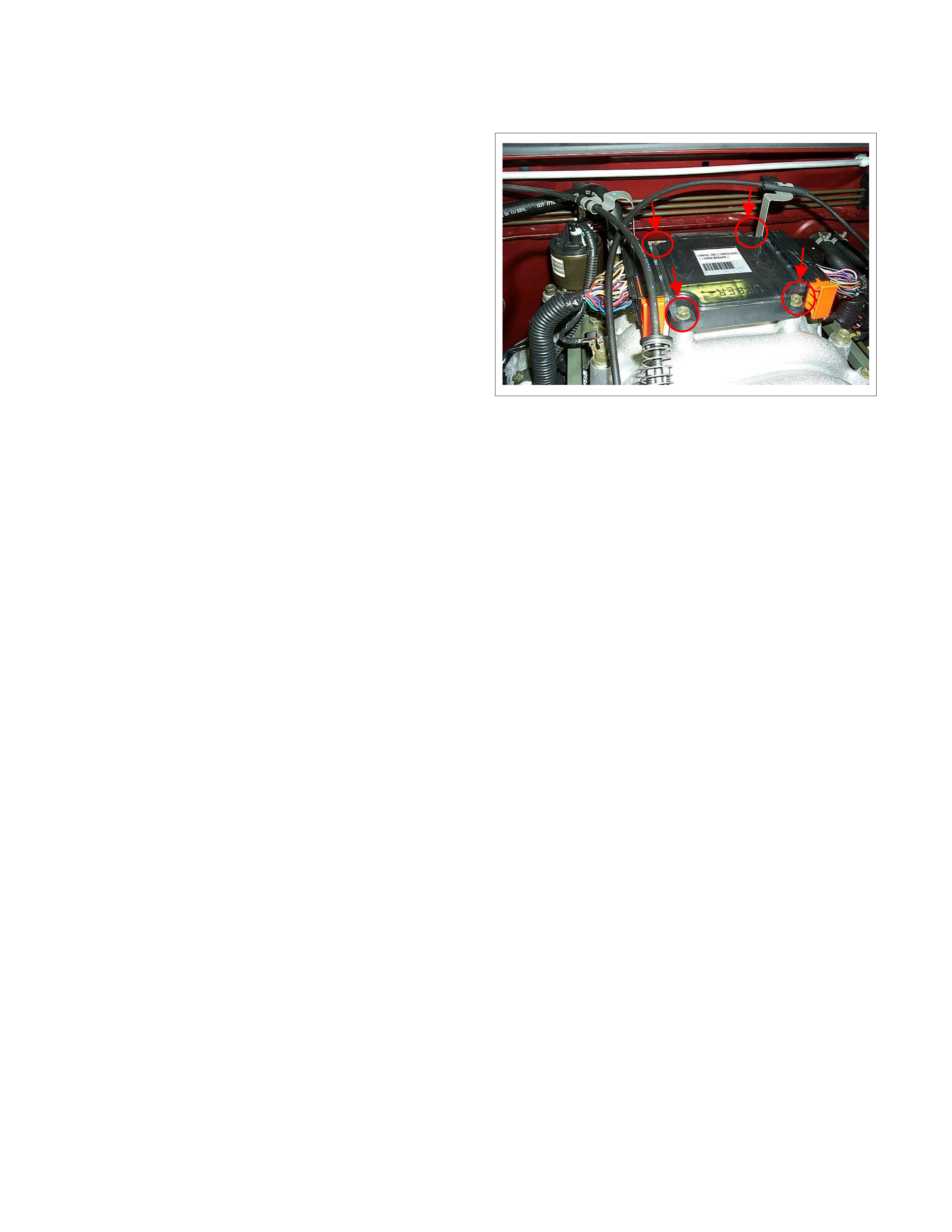
On-Vehicle Service Procedure
Engine Control Module (ECM)
NOTE:
To prevent possible electrostatic discharge
damage, follow these guidelines:
• Do not touch the control module connector pins
or soldere d components on the control module
circuit board.
• Do not open the replacement part package until
the par is ready to be installed.
• Before removing the part from the package,
ground the package to a known good ground on
the vehicle.
• If the part has been handled while sliding across
the seat, or while sitting down from a standing
position, or while walking a distance, touch a
known good ground before installing the part.
NOTE:
To prevent internal ECM damage, the ignition must
be in the "OFF" position in order to disconnect or
reconnect power to the ECM (for example: battery
cable, ECM pigtail, ECM fuse, jumper cables, etc.).
NOTE:
When replacing the production ECM with a service
ECM, it is important to transfer the broadcast code
and production ECM number to the service ECM
label. This will allow positive identification of ECM
parts throughout the service life of the vehicl e.
Location
On the common chamber.
Removal Procedure
1. Disconnect the negative battery cable.
2. Disconnect the two connectors from the ECM.
3. Remove four bolts.
4. Remove the ECM from common chamber.
Installation Procedure
1. Put on the ECM on the common chamber.
2. Tighten the ECM by four bolts.
3. Connect the two connectors to the ECM.
4. Connect the negative battery cable.
NOTE:
The replacement ECM must be programmed.
Service Programming System (SPS) and
immobiliser programming (if equipped) is/are
necessary. In case "SPS procedure does not
succeed" or "engine does not run but No DTC after
SPS", low vehicle battery voltage or disconnected
electrical connector (e.g. poor connection of data
link connector) are supposed. Perform the SPS
procedure once again by correct conditions. The
programming ECM will be recovered normally.
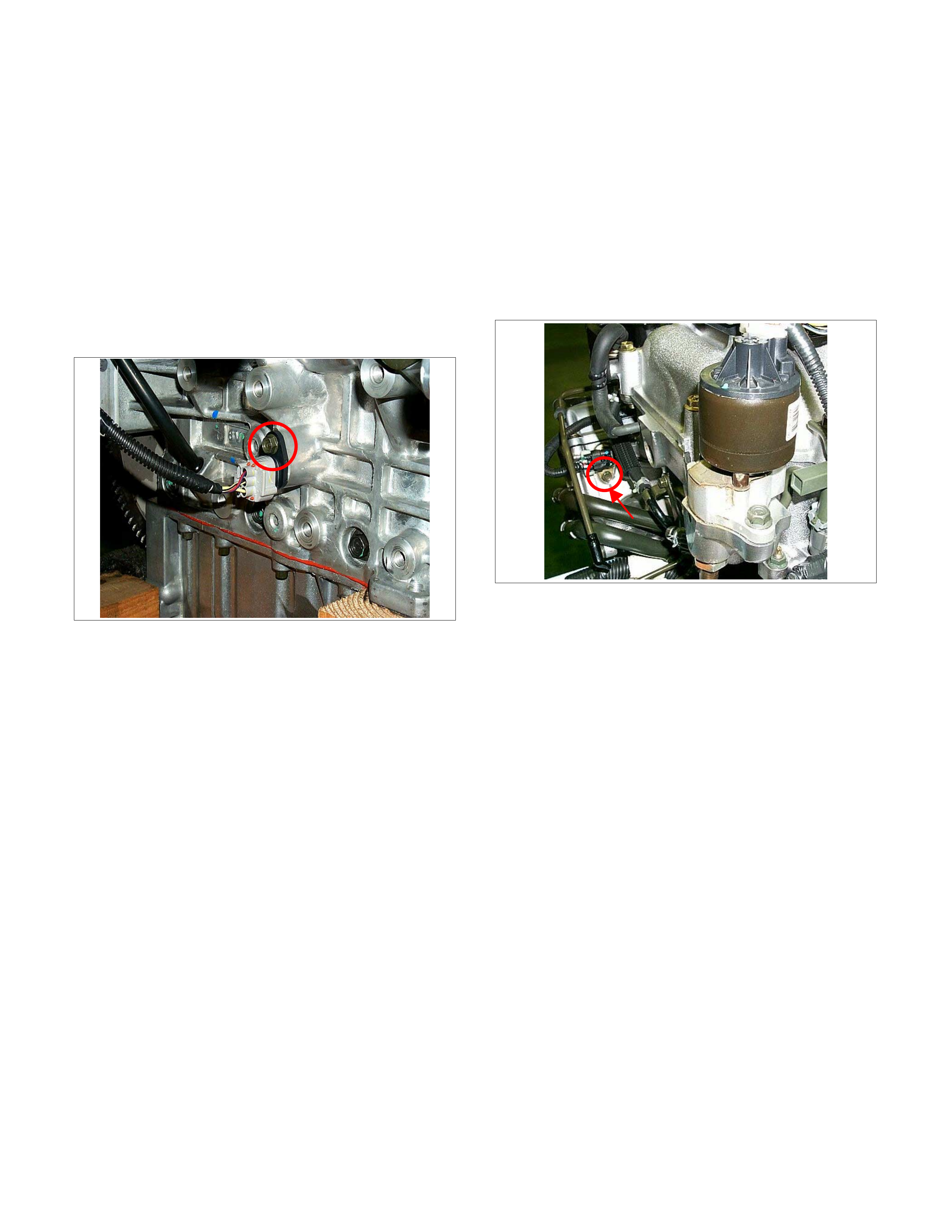
Crankshaft Position (CKP) Sensor
Location
Right-hand side of the cylinder block.
Removal Procedure
1. Disconnect the negative battery cable.
2. Disconnect connector from the CKP sensor.
3. Loosen a bolt and remove the CKP sensor from
the cylinder block.
NOTE:
Use caution to avoid any hot oil that might drip out.
Installation Procedure
1. Install the CKP sensor to the cylinder block.
Before installation, apply small amount of engine
oil to the O-ring.
2. Tighten CKP sensor by a bolt with specified
tightening torque.
Tightening Torque
Bolt: 10N⋅
⋅⋅⋅m (1.0kgf⋅
⋅⋅⋅m).
3. Connect a sensor connector to the CKP sensor.
4. Connect the negative battery cable.
NOTE:
Verify any DTCs (diagnosis Trouble Code) are not
stored after replacement.
Camshaft P osition (CMP) Sensor
Location
The rear of right bank of the cylinder head.
Removal Procedure
1. Disconnect the negative battery cable.
2. Disconnect connector from the CMP sensor.
3. Loosen a bolt and remove the CMP sensor from
the cylinder head.
Installation Procedure
1. Install the CMP sensor to the cylinder head.
Before installation, apply small amount of engine
oil to the O-ring.
2. Tighten CMP sensor by a bolt with specified
tightening torque.
Tightening Torque
Bolt: 10N⋅
⋅⋅⋅m (1.0kgf⋅
⋅⋅⋅m)
3. Connect a sensor connector to the CMP sensor.
4. Connect the negative battery cable.
NOTE:
Verify any DTCs (diagnosis Trouble Code) are not
stored after replacement.
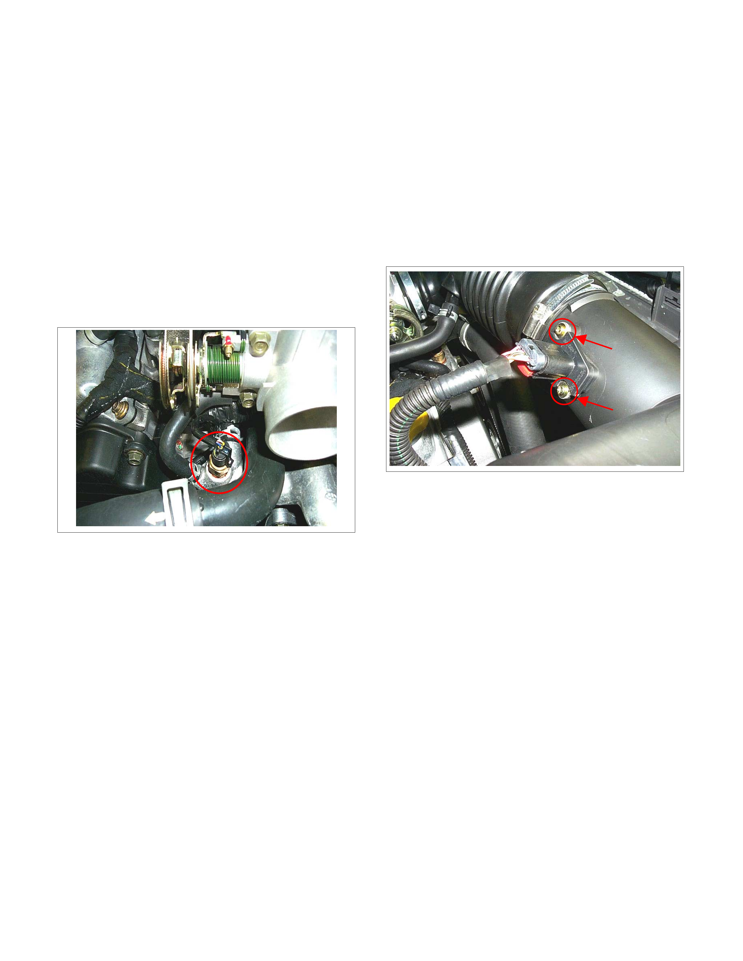
Engine Coolant Temperature (ECT) Sensor
Location
Installed to the thermostat housing.
Removal Procedure
1. Disconnect the negative battery cable.
2. Drain enough engine coolant so that the coolant
level will be below the ECT sensor.
3. Disconnect connector from the ECT sensor.
4. Loosen and remove the ECT sensor from the
thermostat housing.
NOTE:
Cool down the engine before above procedures are
carried out.
Installation Procedure
1.
A
pply sealer to threads of screw at the ECT
sensor.
2. Tighten the ECT sensor with specified tightening
torque.
Tightening Torque
13N⋅
⋅⋅⋅m (1.3kgf⋅
⋅⋅⋅m)
3. Connect a ECT sensor connector to the ECT
sensor.
4. Fill the engine coolant.
5. Connect the negative battery cable.
NOTE:
Verify any DTCs (diagnosis Trouble Code) are not
stored after replacement.
Verify no engine coolant leaking from the sensor
threads after replacement.
Mass Air Flow (MAF) Sensor & Intake Air
Temperature (IAT) Sensor
Location
Installed to the intake duct housing.
Removal Procedure
1. Disconnect the negative battery cable.
2. Disconnect a MAF & IAT sensor connector from
the MAF & IAT sensor.
3. Loosen two screws and remove the MAF & IAT
sensor from the intake duct.
Installation Procedure
1. Install the MAF & IAT sensor into intake air duct.
2. Tighten MAF & IAT sensor by two screws.
3. Connect a sensor connector to the MAF & IAT
sensor.
4. Connect the negative battery cable.
NOTE:
Verify any DTCs (diagnosis Trouble Code) are not
stored after replacement.
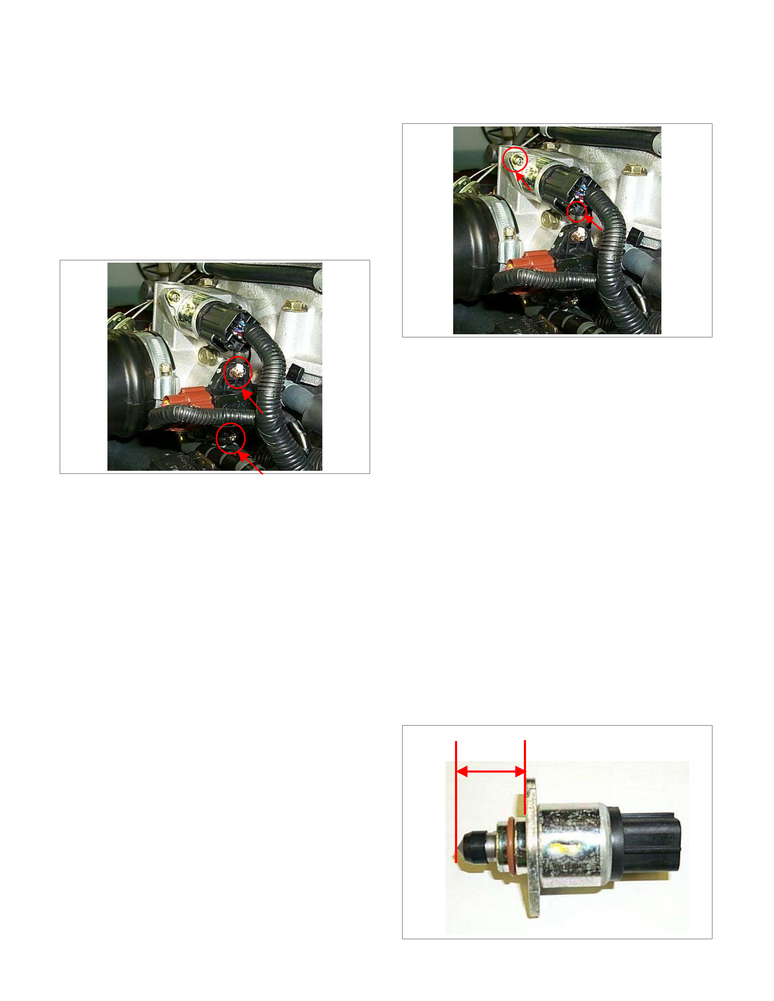
Throttle Position Sensor (TPS)
Location
Installed on the throttle body.
Removal Procedure
1. Disconnect the negative battery cable.
2. Disconnect the TPS connector.
3. Loosen two screws and remove TPS from the
throttle body.
Installation Procedure
1. Temporary tighten the TPS by two screws.
2. Connect a TPS connectors to the TPS.
3. Connect the Tech2 to the vehicle.
4. Connect the negative battery cable.
5. Select "Data Display" with the Tech2.
7. Check the throttle position data and adjust the TPS
position.
8. Tighten two screws.
NOTE:
Verify any DTCs (diagnosis Trouble Code) are not
stored after replacement.
Idle Air Control (IAC) Valve
Location
Installed on the throttle body.
Removal Procedure
1. Disconnect the negative battery cable.
2. Disconnect the IAC valve connector.
3. Loosen two screws and remove IAC valve from
the throttle body.
Cleaning and Inspection
1. Clean the IAC valve O-ring sealing surface, pintle
valve seat and air passage.
2. Us e carbur etor cleaner and a parts cleaning brus h
to remove carbon deposit.
Do not use a cleaner that contain methyl ethyl
ketone. This is an extremely strong solvent and not
necessary for this type of deposit.
3. Shiny spots on the pintle are normal and do not
indicate misalignment or a bent pintle shaft.
4. Inspect the IAC valve O-ring for cuts, cracks or
distortion.
Measurement
In order to install a new IAC valve, messier the distance
between the tip of the pintle and the mounting flange. If
that measurement is 28mm (1.1in.) or less, the valve
need no adjustment. If the measurement is greater than
28mm (1.1in.), apply finger pressure and retract the
valve. The force required to retract the pintle on a new
valve will not damage the valve, shaft, or pintle.
28mm(1.1in.)
or less
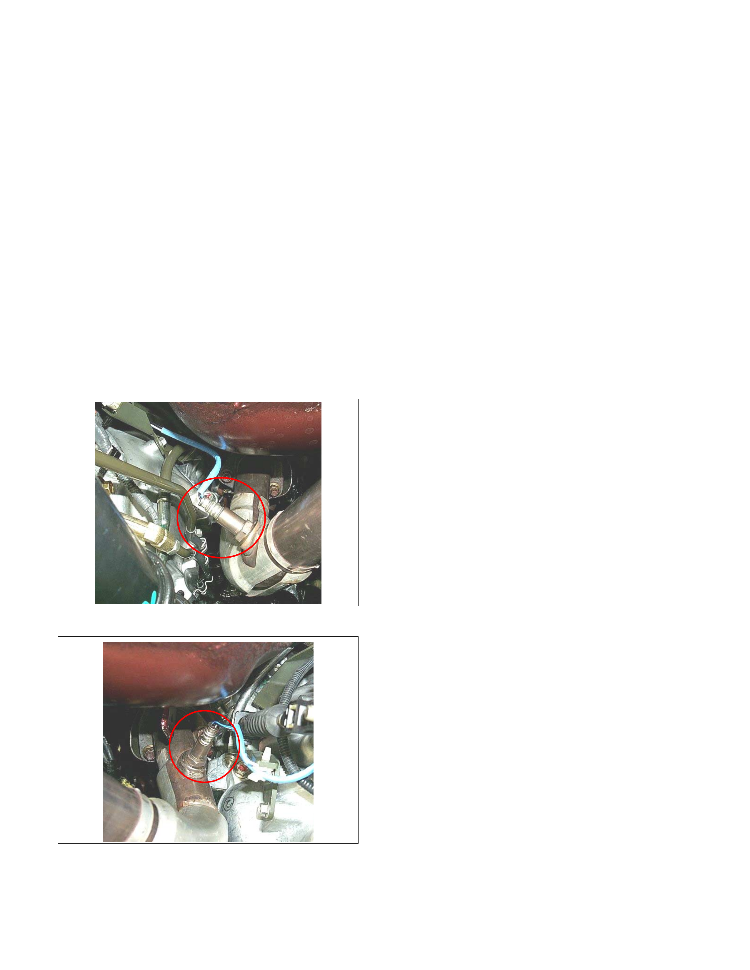
Installation Procedure
1. Tighten the IAC valve by two screws.
2. Connect a IAC valve connector to the IAC valve.
3. Connect the negative battery cable.
NOTE:
Verify any DTCs (diagnosis Trouble Code) are not
stored after replacement.
Heated Oxygen Sensor (HO2S)
Location
Installed on the exhaust pipe for each bank.
Removal Procedure
1. Disconnect the negative battery cable.
2. Disconnect the O2 sensor connector.
3. Loosen and remove the O2 sensor from the
exhaust pipe.
Bank 1 Heated Oxygen Sensor (Right bank)
Bank 2 Heated Oxygen Sensor (Left bank)
Inspection
• Inspect the louvered end of the sensor for grease,
dirt, excessive carbon build up or other
contamination.
• A special anti-seize compound is used on the O2
sensor threads. This compound consists of glass
breads suspended in a liquid graphite solution.
T he graphite burns away with engine heat, but the
glass breads will remain, marking the sensor
easier to remove.
• New or service sensors will already have the
compound applied to the threads. If a sensor is
removed and is to be reinstalled for any reason,
the threads must have anti-seize compound
applied.
Installation Procedure
1. Install the O2 sensor to the exhaust pipe.
Apply anti-seize compound or the equivalent to the
threads of the oxygen sensor, if necessary.
2. Tighten the O2 sensor with specified tightening
torque.
Tightening Torque
Bolt: 42N⋅
⋅⋅⋅m (4.3kgf⋅
⋅⋅⋅m)
3. Connect a sensor connector to the O2 sensor.
4. Connect the negative battery cable.
NOTE:
Verify any DTCs (diagnosis Trouble Code) are not
stored after replacement.
Verify no exhaust gas leaking from the sensor
threads after replacement.
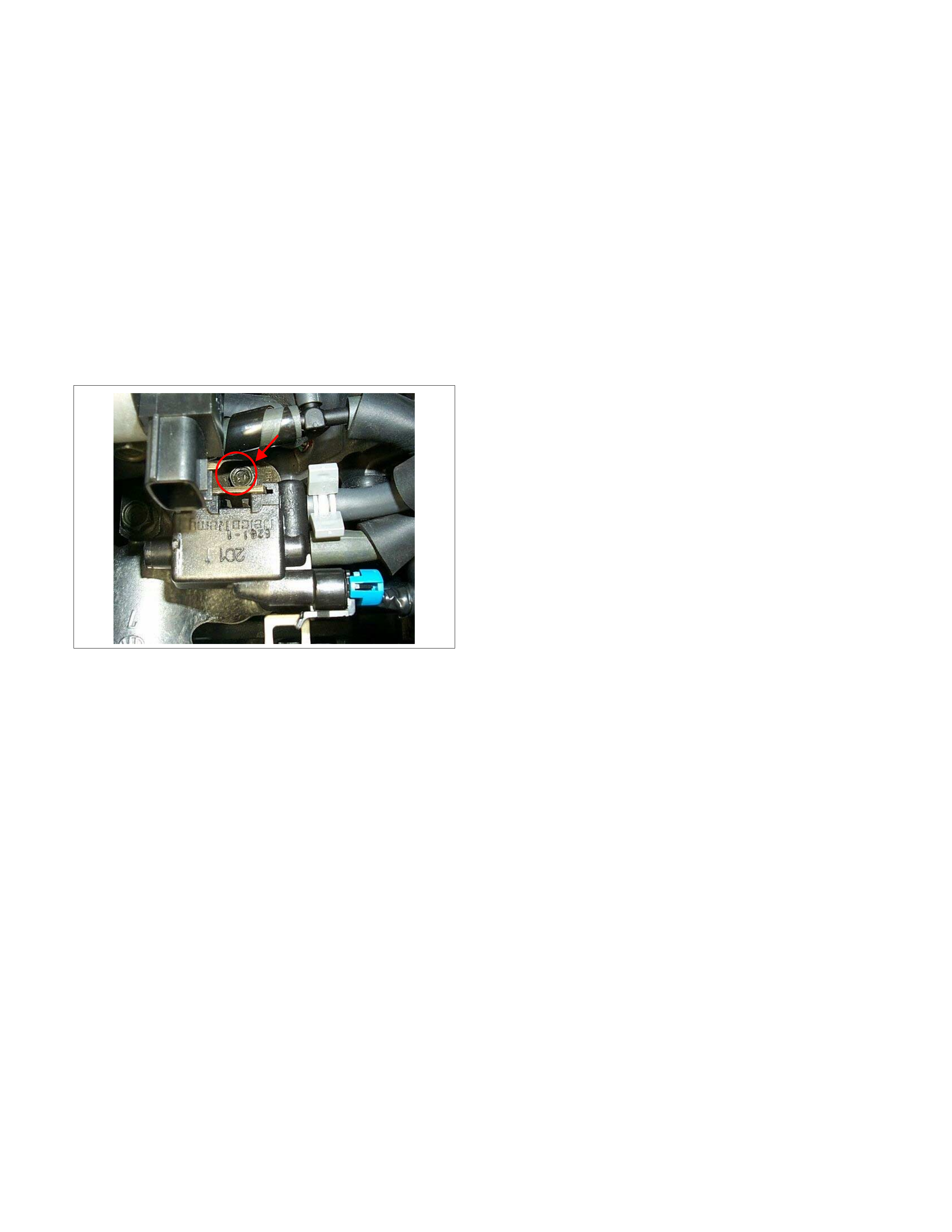
Evap Canister Purge Valve Solenoid
Location
On the intake manifold.
Removal Procedure
1. Disconenct the negative battery cable.
2. Disconnect a purge solenoid connector from the
purge solenoid.
3. Disconnect two hoses from the purge solenoid
valve.
4. Loosen a bolt and remove the purge solenoid from
the intake manifold.
Installation Procedure
1. Put on the purge solenoid on the intake manifold.
2. Tighten the purge solenoid by a bolt.
3. Connect a connector to the purge solenoid.
4. Connect two hoses to the purge solenoid valve.
5. Connect the negative battery cable.
NOTE:
Verify any DTCs (diagnosis Trouble Code) are not
stored after replacement.
Verify proper connection of two hoses.
Fuel Pressure Relief
Caution:
To reduce the risk of the fire and personal injury, it
is necessary to relive the fuel system pressure
before servicing the fuel system components.
Caution:
After relieving the fuel system pressure, a small
amount of fuel may be released when servicing fuel
lines or connections. Reduce the chance of
personal injury by covering the fuel line fitting with
a short towel before disconnecting the fittings. The
towel will absorb any fuel that may leak out. When
the disconnect is completed, place the towel in an
approved container.
1. Remove the fuel filler cap.
2. Remove the fuel pump relay.
3. Start the engine and allow it to stall.
3. Crank the engine for about 30 seconds.
4. Disconnect the negative battery cable.
Fuel Rail Assembly
Removal Procedure
NOTE:
• Do not attempt to remove the fuel inlet fitting on
the fuel rail. It is staked in place. Removing the
fuel inlet fitting will result in damage to the fuel
rail or the internal O-ring seal.
• Use care when removing the fuel rail assembly in
order to prevent damage to the injector electrical
connector terminals and the injector spray tips.
• Fittings should be capped and holes plugged
during servicing to prevent dirt and other
contaminants from entering open lines and
passages.
Important: Before removal, the fuel rail assembly may
be cleaned with a spray type engine cleaner. Follow the
spray package instructions. Do not immerse the fuel
rails in liquid cleaning solvent.
1. Depressurize the fuel system. Refer to
Fuel Pressure Relief Procedure in this Section.
2. Disconnect the negative battery cable.
3. Remove the engine cover.
4. Disconnect the accelerator pedal cable from throttle
body and cable bracket.
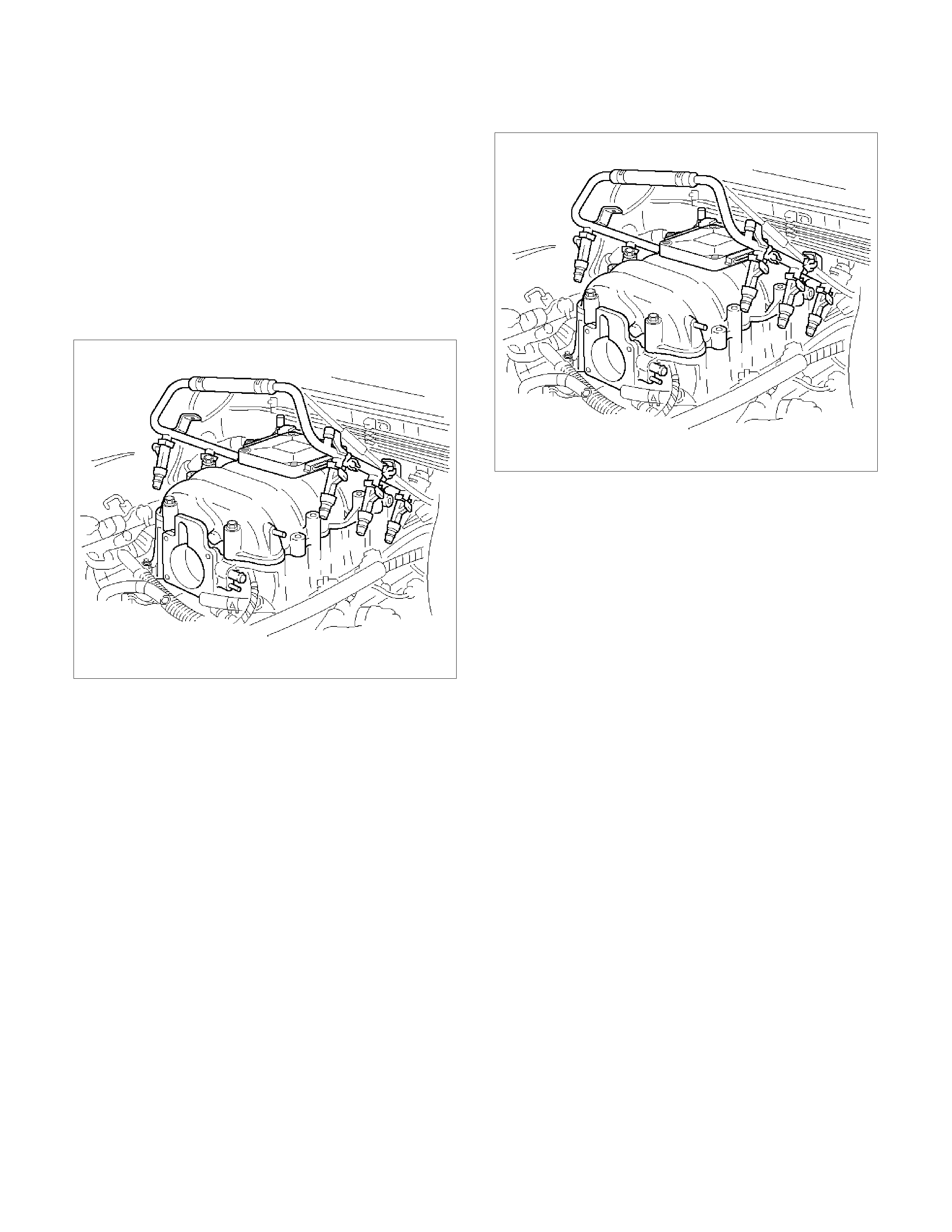
5. Disconnect the connectors from, solenoid valve,
sensing valve.
6. Disconnect the vacuum hose on canister VSV and
positive crankcase ventilation hose.
7. Remove the common chamber Refer to the
common chamber in Engine Mechanical.
1. Lift up carefully on the fuel injectors. Do not
separate the fuel injectors from the fuel rail.
2. If an injector becomes separated from the fuel
rail, the infector O-ring seals and the retainer
clip must be replaced.
3. Drain residual fuel into an approved container.
060RW044
8. If removal of the fuel pressure regulator is
necessary, refer to Fuel Pressure Regulator.
9. If removal of the fuel injectors is necessary , refer to
Fuel Injectors.
Installation Procedure
1. If the fuel injectors were removed, install them.
Refer to Fuel Injectors.
2. If the fuel pressure regulator was removed, install
it. Refer to Fuel Pressure Regulator.
3. Install the common chamber. Refer to
common chamber in engine Mechanical.
060RW044
4. Connect the vacuum hose on Canister VSV and
positive crankcase ventilation hose.
5. Connect the connectors to, solenoid valve.
6. Connect the accelerator pedal cable to throttle
body and cable bracket.
7. Install the engine cover.
8. Connect the negative battery cable.
9. Crank the engine until it starts. Cranking the
engine may take longer than usual due to trapped
air in the fuel rail and in the injectors.
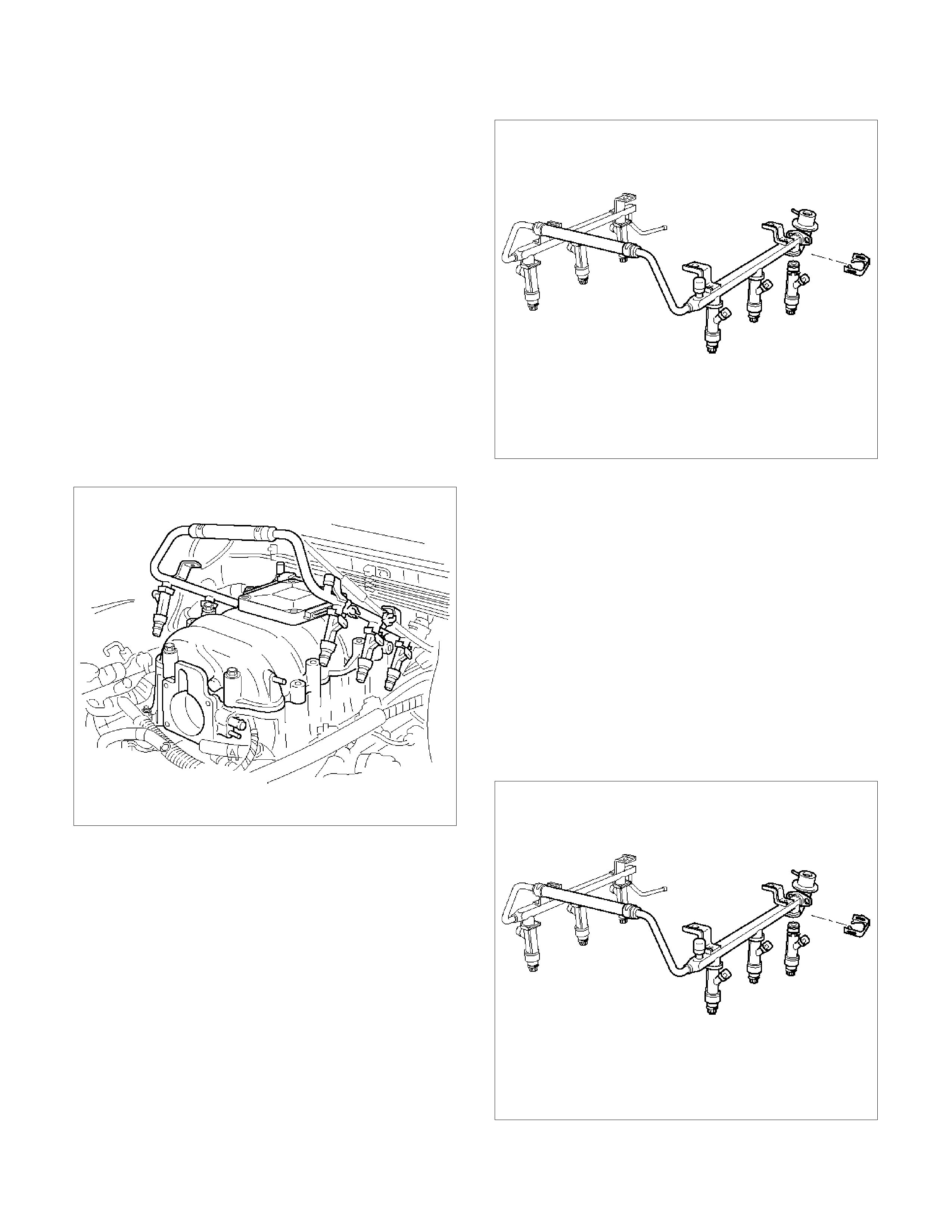
Fuel Injectors
Removal Procedure
NOTE: If the fuel injectors are leaking, the engine oil
may be contaminated with fuel. Check the oil for
signs of contamination and change the oil and the
filter if necessary.
NOTE: Use care in removing the fuel injectors in
order to prevent damage to the fuel injector
electrical connector pins or the fuel injector
nozzles. The fuel injector is an electrical component
and should not be immersed in any type of cleaner
as this may damage the fuel injector.
Important: Fuel injectors are serviced as a complete
assembly only.
1. Disconnect the negative battery cable.
2. Remove the upper intake manifold. Refer to
Common Chamber in Engine Mechanical..
3. Remove the fuel rail. Refer to Fuel Rail.
060RW044
4. Remove the injector retainer clip.
F06RW017
5. Remove the fuel injector assembly.
6. Remove the O-ring from the fuel injector.
7. Remove the O-ring backup from the fuel injector .
Inspection Procedure
1. Inspect the O-rings for cracks or leaks.
2. Replace worn or damaged O-rings.
3. Lubricate the new O-rings with engine oil before
installation.
Installation Procedure
1. Install the O-ring backup on the fuel injector.
2. Install the new O-ring on the fuel injector.
3. Install the fuel injector on the fuel rail.
F06RW017
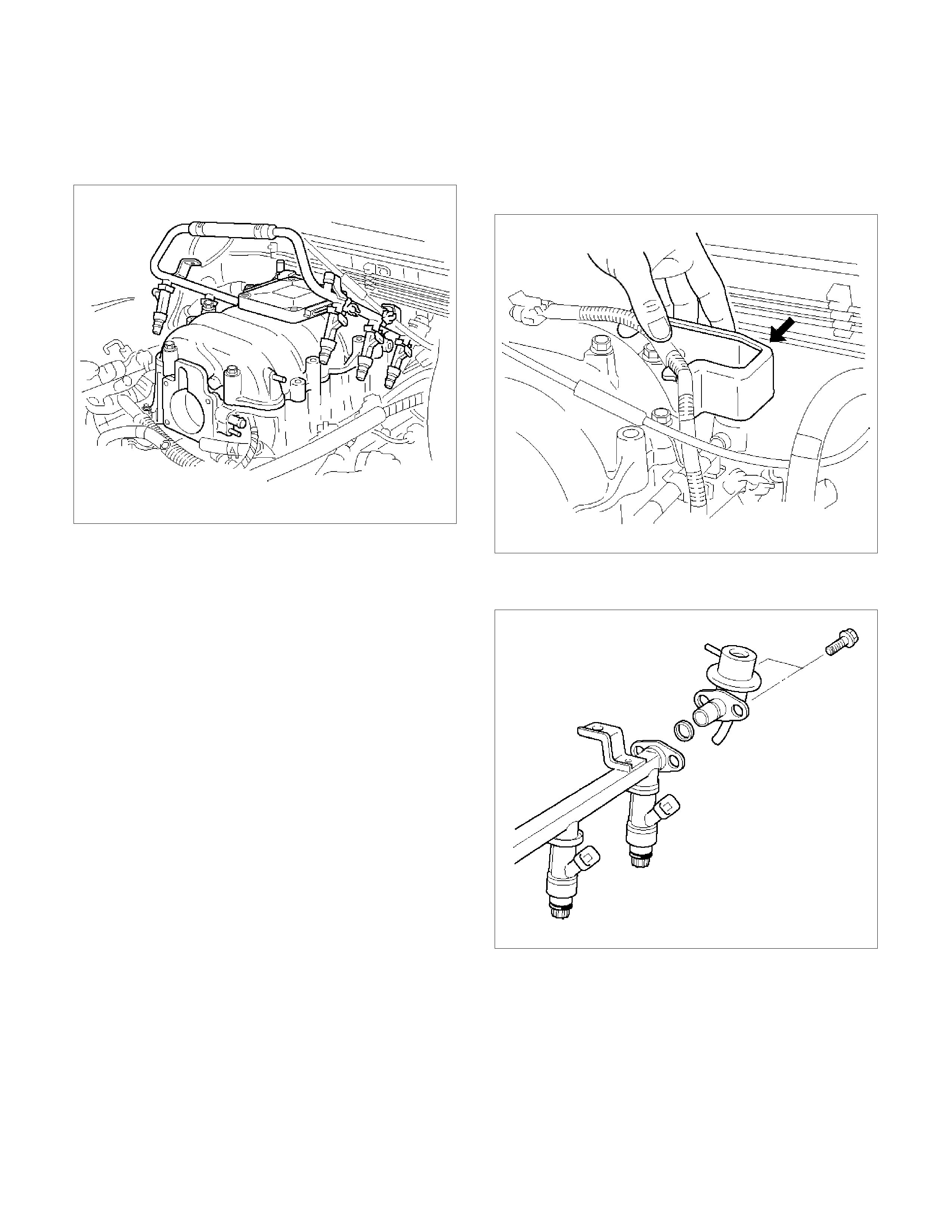
4. Use new fuel injector retainer clips to retain the fuel
injector to the fuel rail.
5. Coat the end of the fuel injector with engine oil.
6. Install the fuel rail. Refer to Fuel Rail.
060RW044
7. Install the upper intake manifold. Refer to
Common Chamber in Engine Mechanical.
8. Install the engine cover.
9. Connect the negative battery cable.
Fuel Pressure Regulator
Removal Procedure
CAUTION: To reduce the risk of fire and personal
injury, it is necessary to relieve the fuel system
pressure before servicing the fuel system
components.
CAUTION: After relieving the system pressure, a
small amount of fuel may be released when
servicing fuel lines or connections. Reduce the
chance of personal injury by covering the fuel line
fittings with a shop towel before disconnecting the
fittings. The towels will absorb any fuel that may
leak out. When the disconnect is completed, place
the towel in an approved container.
NOTE: Compressed air must never be used to test
or clean a fuel pressure regulator, as damage to the
fuel pressure regulator may result.
NOTE: To prevent damage to the fuel pressure
regulator, do not immerse the pressure regulator in
solvent.
1. Depressurize the fuel system. Refer to Fuel
Pressure Relief Procedure.
2. Disconnect the negative battery cable.
3. Remove the fuel pump relay. Refer to Fuel Pump
Relay.
4. Remove the pressure regulator hose from the fuel
pressure regulator.
5. Remove the two bolts from the protector that
secures the common chamber.
060RW066
6. Remove the fuel pressure regulator attaching
screw.
060RW116
7. Remove the fuel pressure regulator from the fuel
rail.
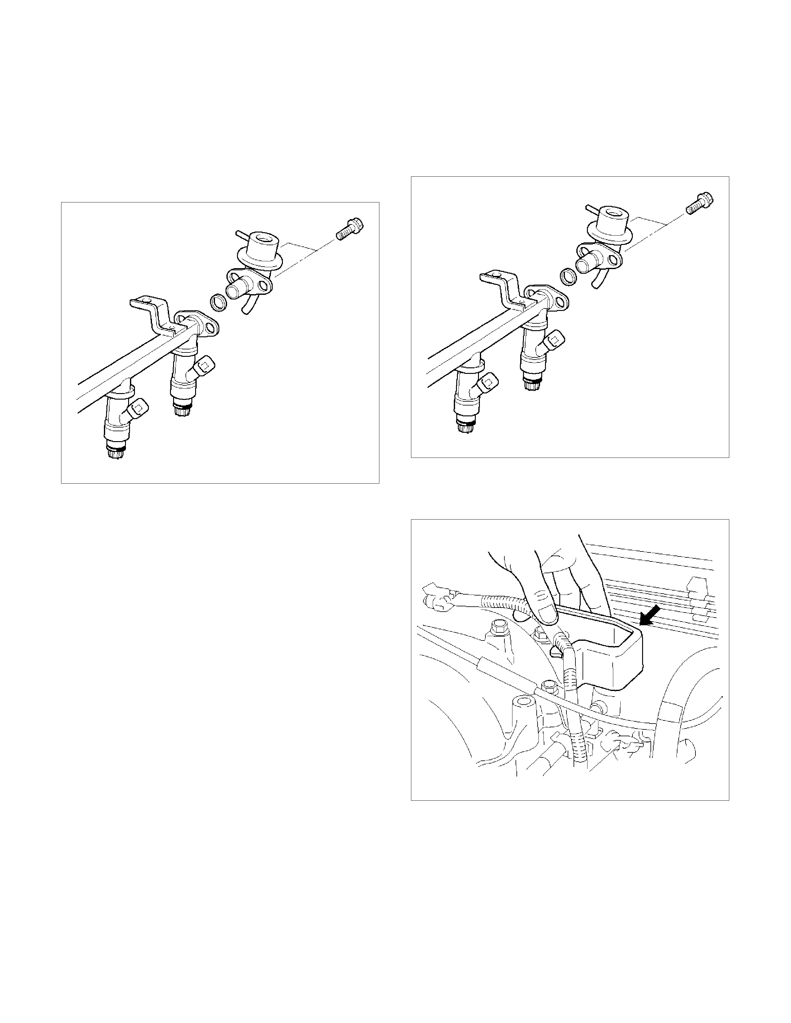
Disassembly Procedure
1. Remove the O-ring from the fuel pressure regulator.
2. Remove the fuel return line from the fuel pressure
regulator.
3. Remove the O-ring from the fuel return line.
• The O-ring may be left inside the fuel pressure
regulator instead of on the fuel return line.
060RW116
Assembly Procedure
1. Install a new O-ring on the fuel return line.
2. Install the fuel return line on the fuel pressure
regulator.
Do not over-tighten the swivel nut on the fuel pressure
regulator. The fuel pressure regulator can be damaged
and fuel may leak if the swivel nut is over-tightened.
3. Tighten the swivel nut.
4. Install a new O-ring on the fuel pressure regulator.
Installation Procedure
1. Install the fuel pressure regulator attaching screw.
Tighten
• Tighten the fuel pressure regulator attaching screw
to 3 N⋅m (0.3 kg⋅m/26 lb in.).
060RW116
2. Install the fuel pressure regulator on the fuel rail.
3. Install the two bolts to the protector that secures
the common chamber.
060RW066
4. Install the pressure regulator hose to the fuel
pressure regulator.
5. Install the fuel pump relay. Refer to Fuel Pump
Relay.
6. Connect the negative battery cable.
7. Crank the engine until it starts. Cranking the engine
may take longer than usual due to trapped air in the
fuel lines.
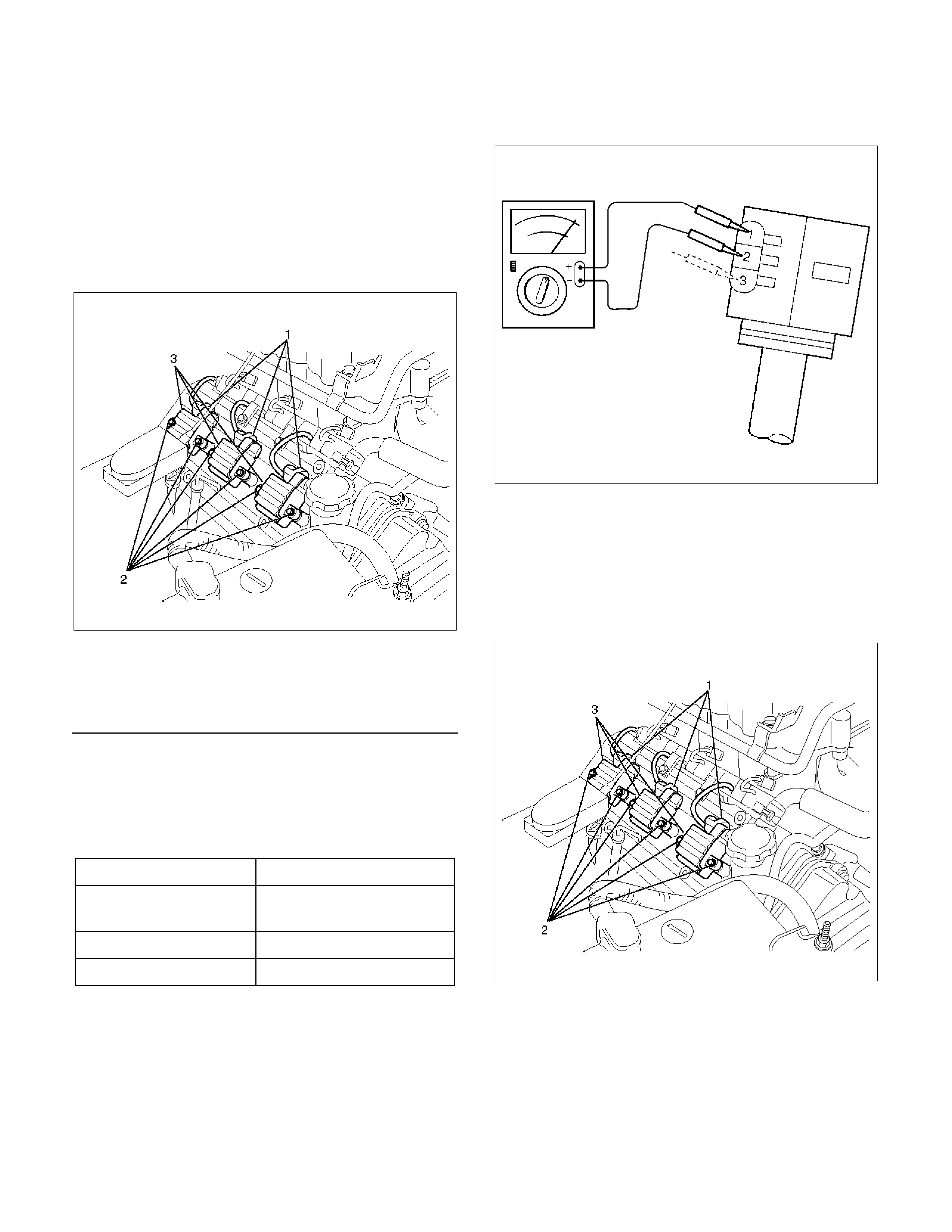
Ignition Coil
Removal Procedure
1. Disconnect battery ground cable.
2. Ignition coil connector and ignition coil.
• Disconnect three connector from ignition coil.
• Remove harness bracket bolt on cylinder head
cover.
• Remove fixing bolts on ignition coil.
060RW001
Legend
(1) Ignition Coil Connector
(2) Bolt
(3) Ignition Coil Assembly
Inspection Procedure
Check the ignition coil assembly for insulation. Check
terminals for corrosion or damage, and replace as
necessary.
Measuring resistance of ignition coil assembly.
Terminal No. Limit
1 to 2 Without 0 ohm or infinity
maximum ohm.
1 to 3 Same as above
2 to 3 Same as above
Measure resistance of ignition coil assembly, and
replace the ignition coil assembly if its value exceeds
the standard.
060RW006
Installation Procedure
1. Install the ignition coil assembly (3).
Connect ignition coil connector (1) and ignition coil
(3), then tighten bolt (2) to the specified torque.
Torque: 4 N⋅
⋅⋅⋅m (0.4 kg⋅
⋅⋅⋅m/35 lb in)
060RW001
2. Connect battery ground cable.
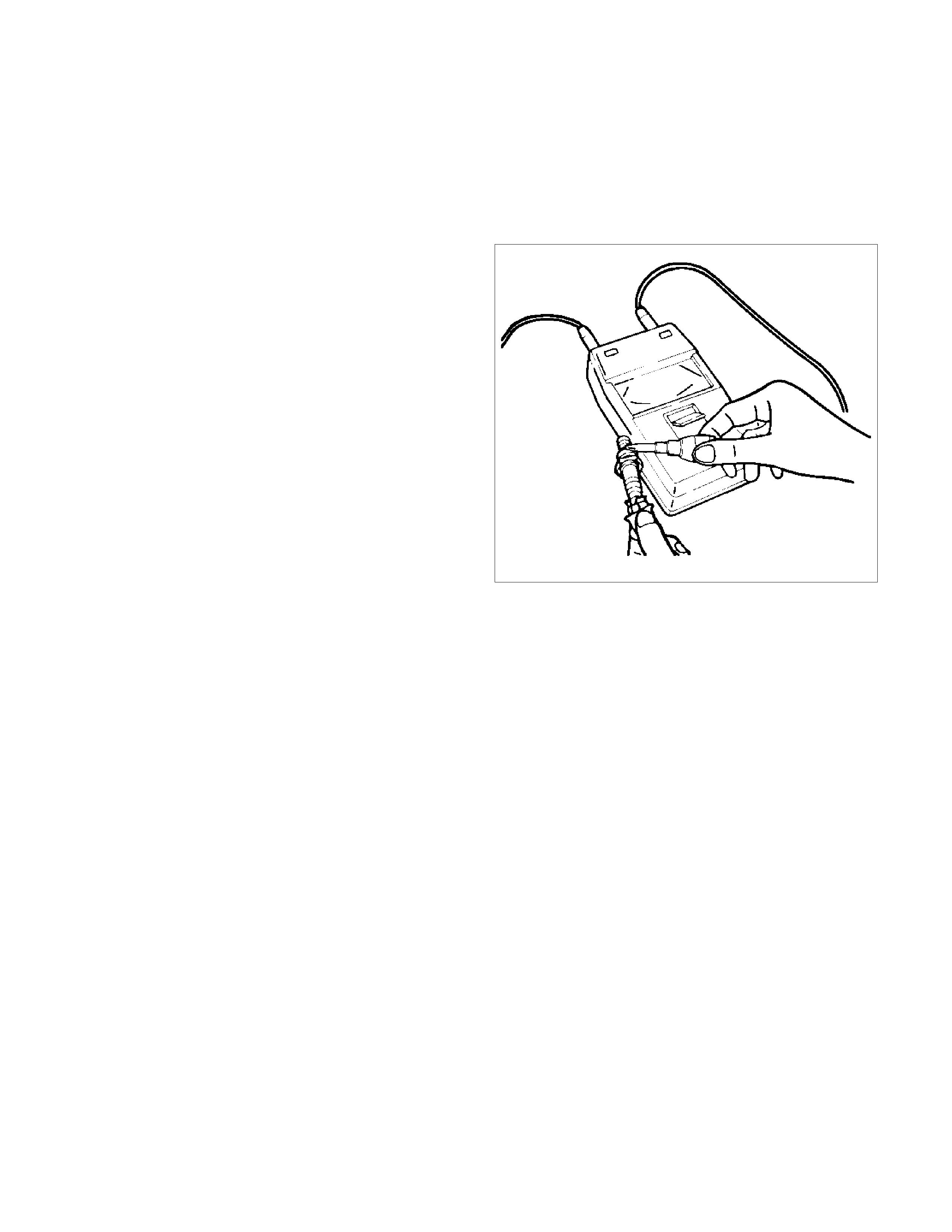
Spark Plugs
Removal Procedure
1. Remove spark plugs.
Inspection Procedure
The spark plug affects entire engine performance and
therefore its inspection is very important.
• Check electrode and insulator for presence of
cracks, and replace if any.
• Check electrode for wear, and replace if necessary.
• Check gasket for damage, and replace if necessary.
• Measure insulation resistance with an ohmmeter,
and replace if faulty.
• Adjust spark plug gap to 1.0 mm (0.04 in) 1.1
mm (0.043 in).
• Check fuel and electrical systems if spark plug is
extremely dirty.
• Use spark plugs having low heat value (hot type
plug) if fuel and electrical systems are normal.
• Use spark plugs having high heat value (cold type
plug) if insulator and electrode are extremely
burned.
Sooty Spark Plugs
Much deposit of carbon or oil on the electrode and
insulator of spark plug reduces the engine performance.
Possible causes:
• Too rich mixture
• Presence of oil in combustion chamber
• Incorrectly adjusted spark plug gap
Burning Elec trodes
This fault is characterized by scorched or heavily
oxidized electrode or blistered insulator nose.
Possible causes:
• Too lean mixture
• Improper heat value
Measuring Insulation Resistance
• Measure insulation resistance using a 500 volt
megaohm meter.
• Replace spark plugs if measured value is out of
standard.
Insulation resistance: 50 MΩ
ΩΩ
Ω or more
011RS010
Cleaning Spark Plugs
• Clean spark plugs with a spark plug cleaner.
• Raise the ground electrode to an angle of 45 to 60
degrees. If electrode is wet, dry it before cleaning.
• After spark plug is thoroughly cleaned, check
insulator for presence of cracks.
• Clean threads and metal body with a wire brush.
• File the electrode tip if electrode is extremely worn.
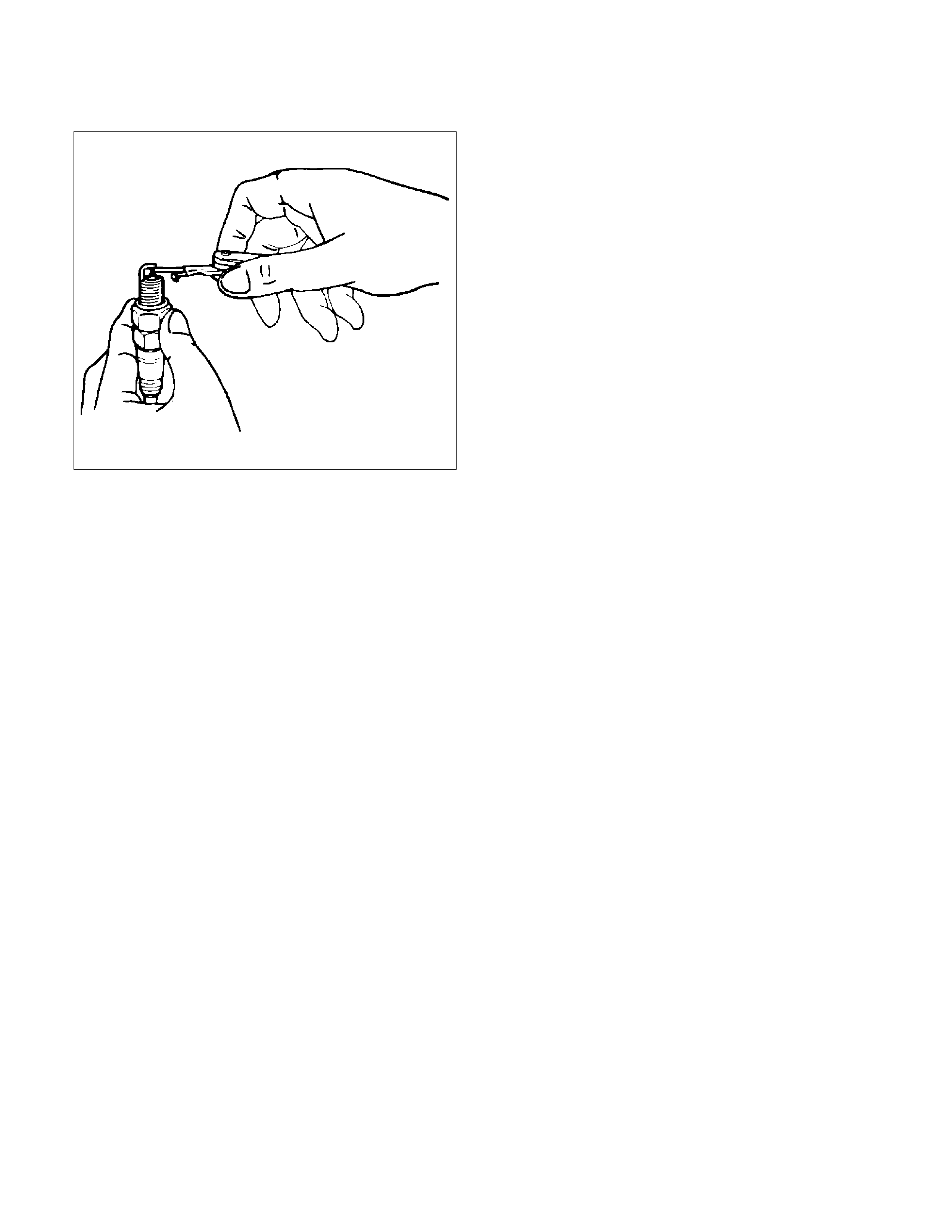
• Bend the ground electrode to adjust the spark plug
gap.
011RS011
Installation Procedure
1. Spark plugs
• Tighten spark plugs to the specified torque.
Torque: 18 N⋅
⋅⋅⋅m (1.8 kg⋅
⋅⋅⋅m/13 lb ft)
Special Tools
ILLUSTRATION PART NO.PART NAME ILLUSTRATION PART NO.PART NAME
5–8840–0285–0
(J 39200)
High Impedance
Multimeter (Digital
Voltmeter – DVM)
Breaker Box
(1) PCMCIA Card
(2) RS232 Loop Back
Connector
(3) SAE 16/19 Adapter
(4) DLC Cable
(5) TECH 2
5–8840–2618–0
Fuel Injector Tester
5–8840–0385–0
(J 35616-A/BT-8637)
Connector Test Adapter
Kit
5–8840–0378–0
(J 34730-E)
Port Fuel Injection
Diagnostic Kit
5–8840–2635–0
(J 39021-90)
Injector Switch Box
5–8840–0383–0
(J 26792/BT-7220-1)
Spark Tester