
SECTION 6D3 - STARTING AND CHARGING SYSTEM
Starting System
General Description
Service Precaution
Diagnosis
Starter
Removal
Installation
Disassembled View
Inspection and Repair
Characteristic Test
Charging System
General Description
General On-Vehicle Inspection
Generator
Removal
Inspection
Installation
Diagnosis
Disassembly
Clean
Inspection
Reassembly
Inspection
Technical Data
Starting System
General Description
Cranking Circuit
The cranking system consists of a battery, starter, starter
switch, starter relay, etc. These main components are
connected.
Starter
The cranking system employs a magnetic type reduction
starter in which the motor shaft is also used as a pinion shaft.
When the starter switch is turned on, the contacts of magnetic
switch are closed, and the armature rotates. At the same time,
the plunger is attracted, and the pinion is pushed forward by
the shift lever to mesh with the ring gear.
Then, the ring gear runs to start the engine. When the engine
starts and the starter switch is turned off, the plunger returns,
the pinion is disengaged from the ring gear, and the armature
stops rotation. When the engine speed is higher than the
pinion, the pinion idles, so that the armature is not driven.
Service Precaution
CAUTION:
Always use the correct fastener in the proper location.
When you replace a fastener, use ONLY the exact part
number for that application. Holden will call out those
fasteners that require a replacement after removal. Holden
will also call out the fasteners that require thread lockers
or thread sealant. UNLESS OTHERWISE SPECIFIED, do
not use supplemental coatings (Paints, greases, or other
corrosion inhibitors) on threaded fasteners or fastener
joint interfaces. Generally, such coatings adversely affect
the fastener torque and the joint clamping force, and may
damage the fastener. When you install fasteners, use the
correct tightening sequence and specifications. Following
these instructions can help you avoid damage to parts and
systems.
Diagnosis
Condition Possible cause Correction
Starter does not run Charging failure Repair charging system
Battery Failure Replace Battery
Terminal connection failure Repair or replace terminal connector
and/or wiring harness
Starter switch failure Repair or replace starter switch
Starter failure Repair or replace starter
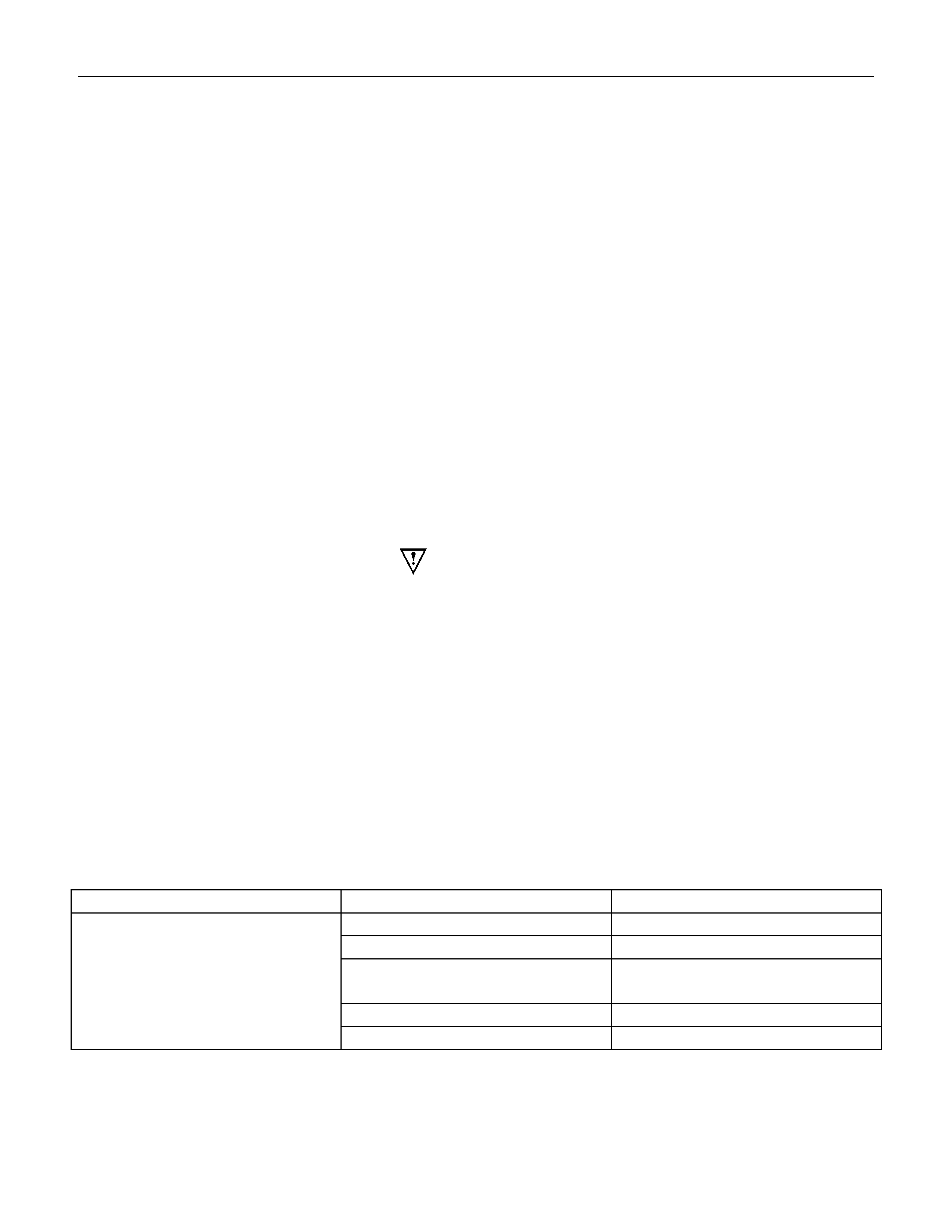
Starter
Removal
1.Remove the battery ground cable.
2.Remove harness connectors (1) and (2).
3.Remove bolts from starter.
Installation
1.Install starter assembly.
2. Install mounting bolts and tighten bolts to specified torque.
Torque: 51 N⋅
⋅⋅⋅m (5.2 kgf⋅
⋅⋅⋅m)
3. Connect harness.
4. Reconnect the battery ground cable.
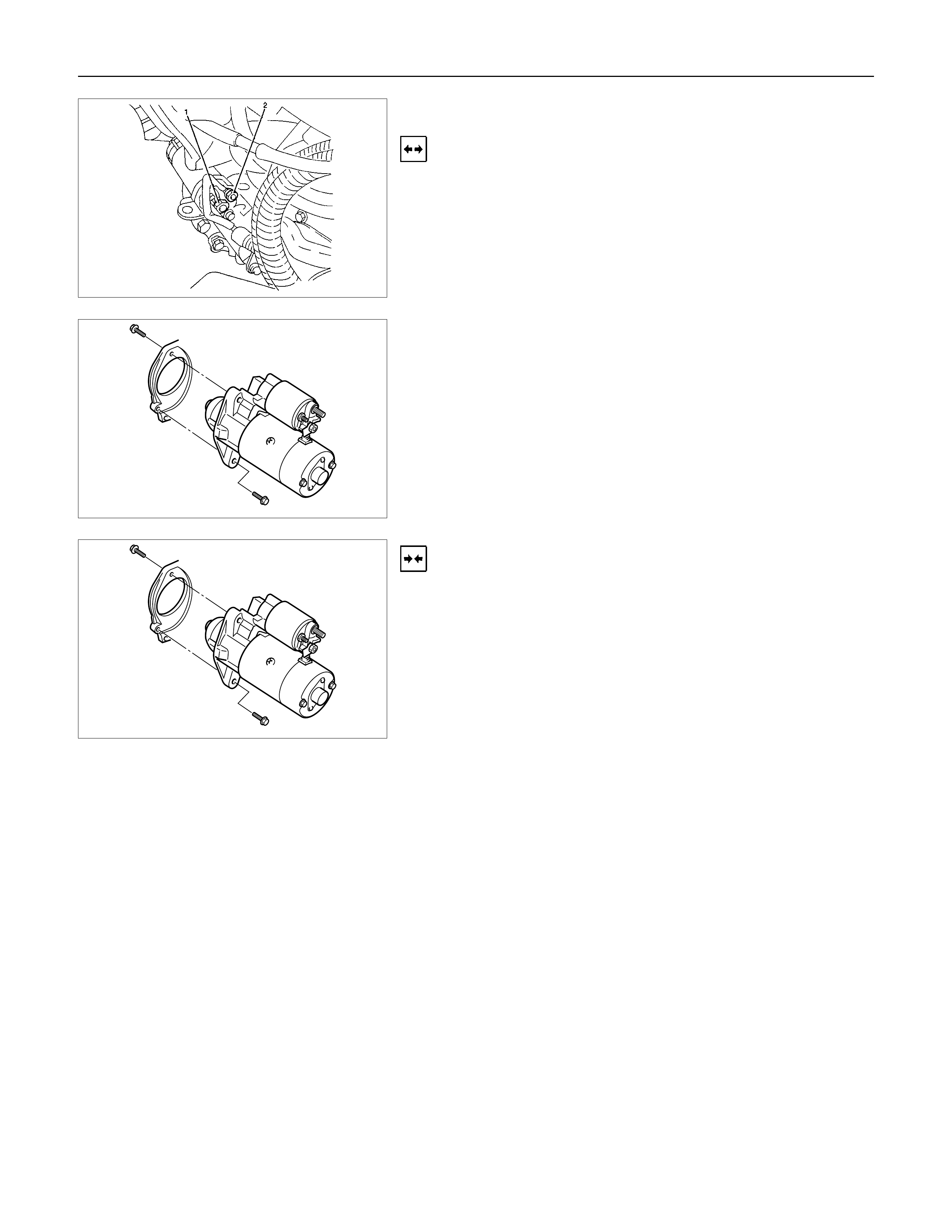
Disassembled View
Legend
1 Bolt
2 Magnetic Switch
3 Gear Case
4 Piston
5 Piston Shaft
6 Center Bracket
7 Armature
8 Yoke Assembly
9 Brush and Brush Holder
10 Washer
11 Rear Cover
12 Through Bolt
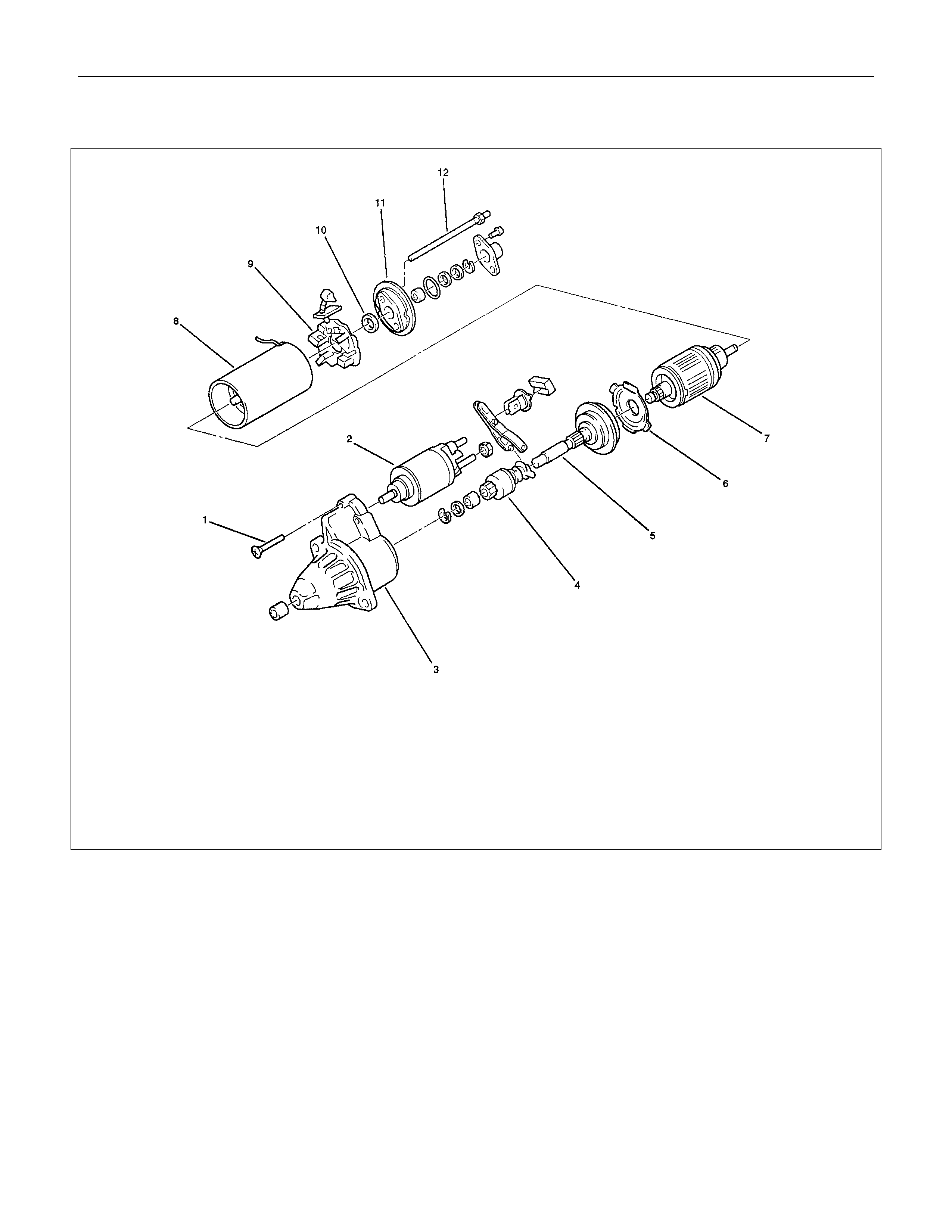
Inspection and Repair
Repair or replace necessary parts if extreme wear or damage
is found during inspection.
Armature
Check for continuity between commutator and segment.
Replace commutator if there is no continuity (i.e.,
disconnected).
Check for continuity between commutator and shaft.
Also, check for continuity between commutator and armature
core, armature core and shaft. Replace commutator if there is
continuity (i.e., internally grounded).
Brush
Measure the length of brush.
Replace with a new one, if it is below the limit.
Brush Holder
Check for continuity between brush holder (+) (4) and base (-).
Replace, if there is continuity (i.e., insulation is broken).
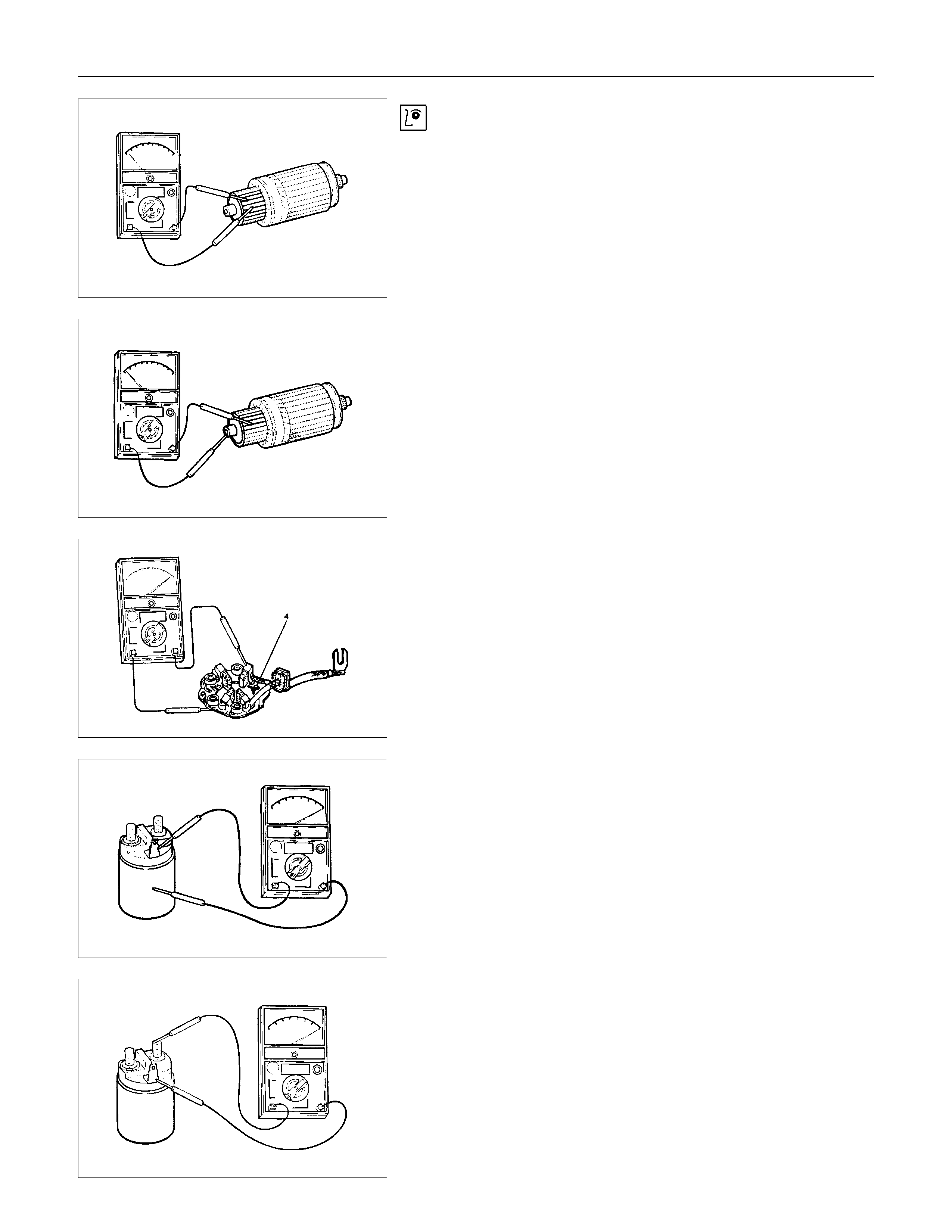
Magnetic Switch
Check for continuity of shunt coil between terminals S and M.
Replace, if there is no continuity (i.e., coil is disconnected).
Continuity of Series Coil
Check for continuity between terminals S and M.
Replace, if there is no continuity (i.e., coil is disconnected).
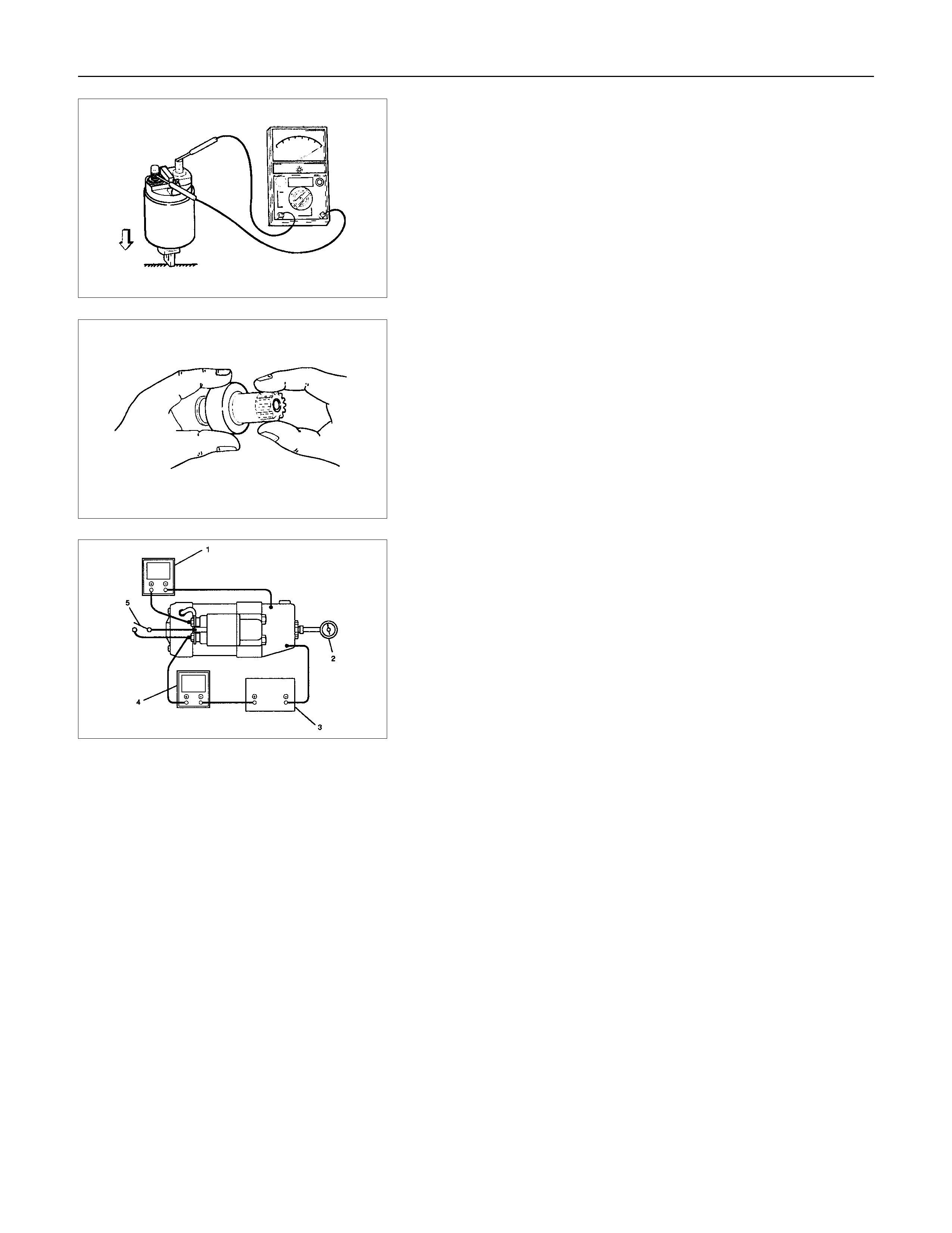
Continuity of Contacts
With the plunger faced downward, push down the magnetic
switch. In this state, check for continuity between terminals B
and M. Replace, if there is no continuity (i.e., contacts are
faulty).
Pinion
Check if the pinion rotates smoothly in drive direction by hand,
or if it is locked when it is rotated in reverse. If not, replace the
pinion.
Characteristic Test
For easily confirming the characteristics, conduct the noload
test as follows:
Rating as short as 30 seconds requires rapid testing.
Fix the starter on the test bench, and wire as shown in
illustration. When the switch is closed, the current flows and
the starter runs under no load. At this time, measure current,
voltage and speed to check if they satisfy the standard.
Legend
1 Volt Meter
2 Revolution Indicator
3 Battery
4 Ammeter
5 Switch
Charging System
General Description
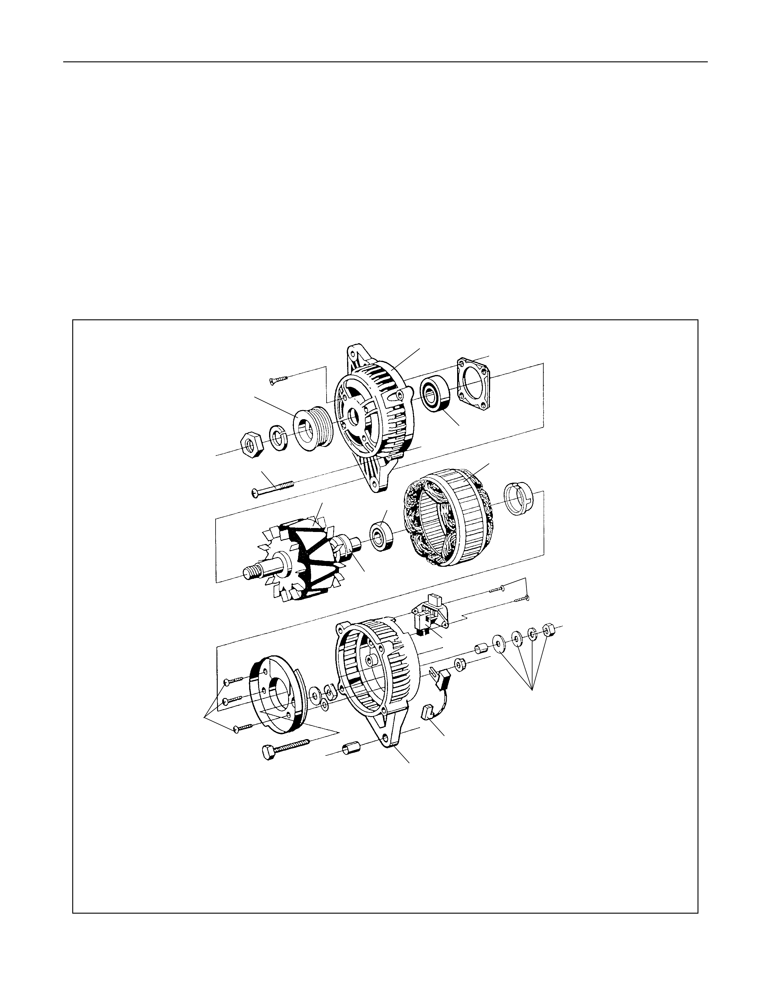
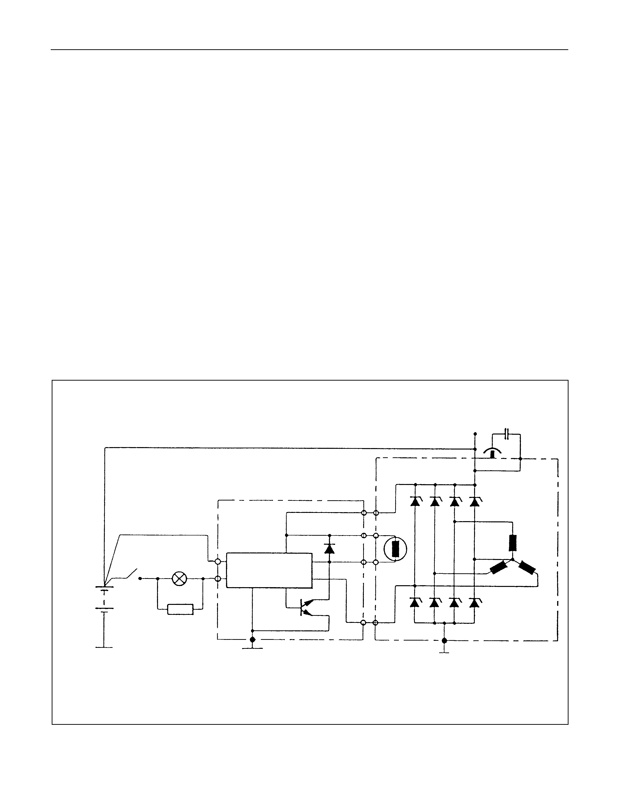
The charging system is an IC integral regulator charging
system and its main components are connected as shown in
illustration.
The regulator is a solid state type and it is mounted along with
the brush holder assembly inside the generator installed on the
rear end cover.
The generator does not require particular maintenance such as
voltage adjustment. The rectifier connected to the stator coil
has eight diodes to transform AC voltage into DC voltage.
This DC voltage is connected to the output terminal of
generator.
Legend
1 Startor assembly
2 Housing
3 Slipring
4 Screws (2)
5 Regulator
6.Bolt (4)
7 Rectifier assembly
8 Retaining assembly
9 B+ terminal nut and washer
10 Pulley
11 Rotor assembly
12 Ball bearing
2
11
12
2
8
5
4
3
1
11
7
6
10
9
General On-Vehicle Inspection
The operating condition of charging system is indicated by the
charge warning lamp. The warning lamp comes on when the
starter switch is turned to "ON" position. The charging system
operates normally if the lamp goes off when the engine starts.
If the warning lamp shows abnormality or if undercharged or
overcharged battery condition is suspected, perform diagnosis
by checking the charging system as follows:
1.Check visually the belt and wiring connector.
2.With the engine stopped, turn the stator switch to "ON"
position and observe the warning lamp.
If lamp does not come on:
Disconnect wiring connector from generator, and ground
the terminal "L" on connector side.
If lamp comes on:
Repair or replace the generator.
Generator
Removal
1.Disconnect battery ground cable.
2.Move drive belt tensioner to loose side using wrench then
remove drive belt.
3.Disconnect terminal "B" wiring connector and connector.
4.Remove generator assembly.
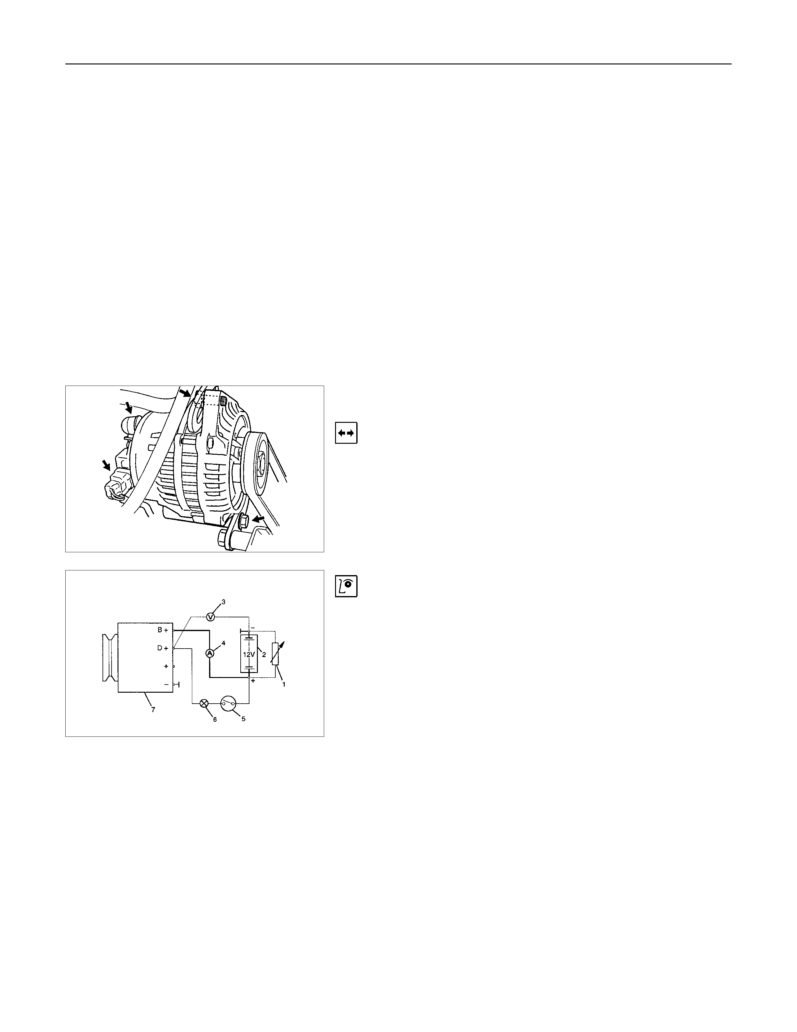
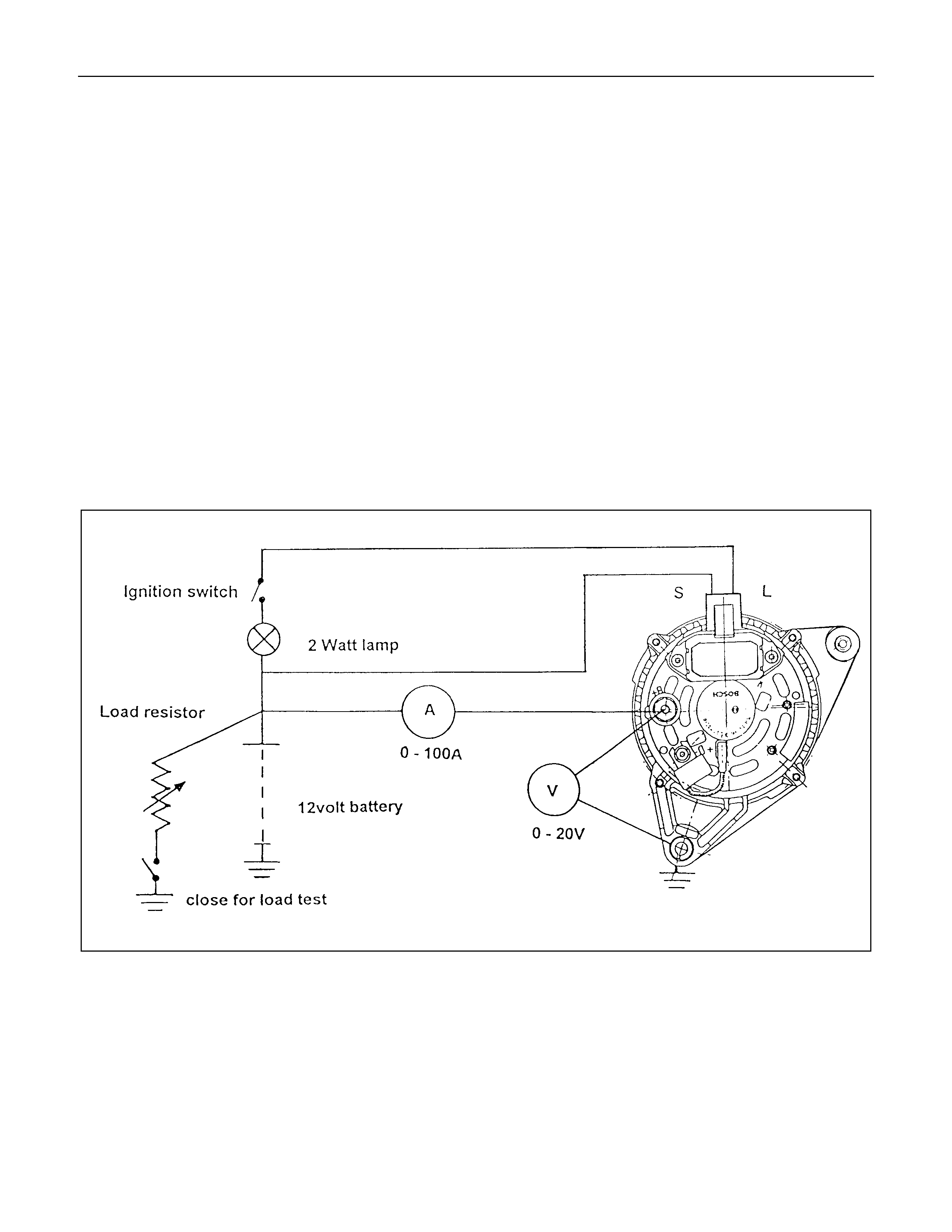
Generator Power and Circuit Diagram Inspection
Legend
1 Load resistor, set parallel to battery
2 Battery
3 Voltmeter
4 Ammeter
5 Ignition Lock
6 Charge Telltale
7 Generator
1. Disconnect battery.
2. Close off connecting cable from alternator terminal "B+".
3. Set ammeter (measuring range 100A) in disconnected line.
4. Connect controllable load resistor to battery terminal.
5. Set resistor in front of connection to "O"; connect first to
battery, then to resistor.
6. Connect tachometer.
7. Connect oscilloscope according to manufacturer's
instructions.
8. Connect battery.
9. Start engine and read off resulting current at various engine
speeds.
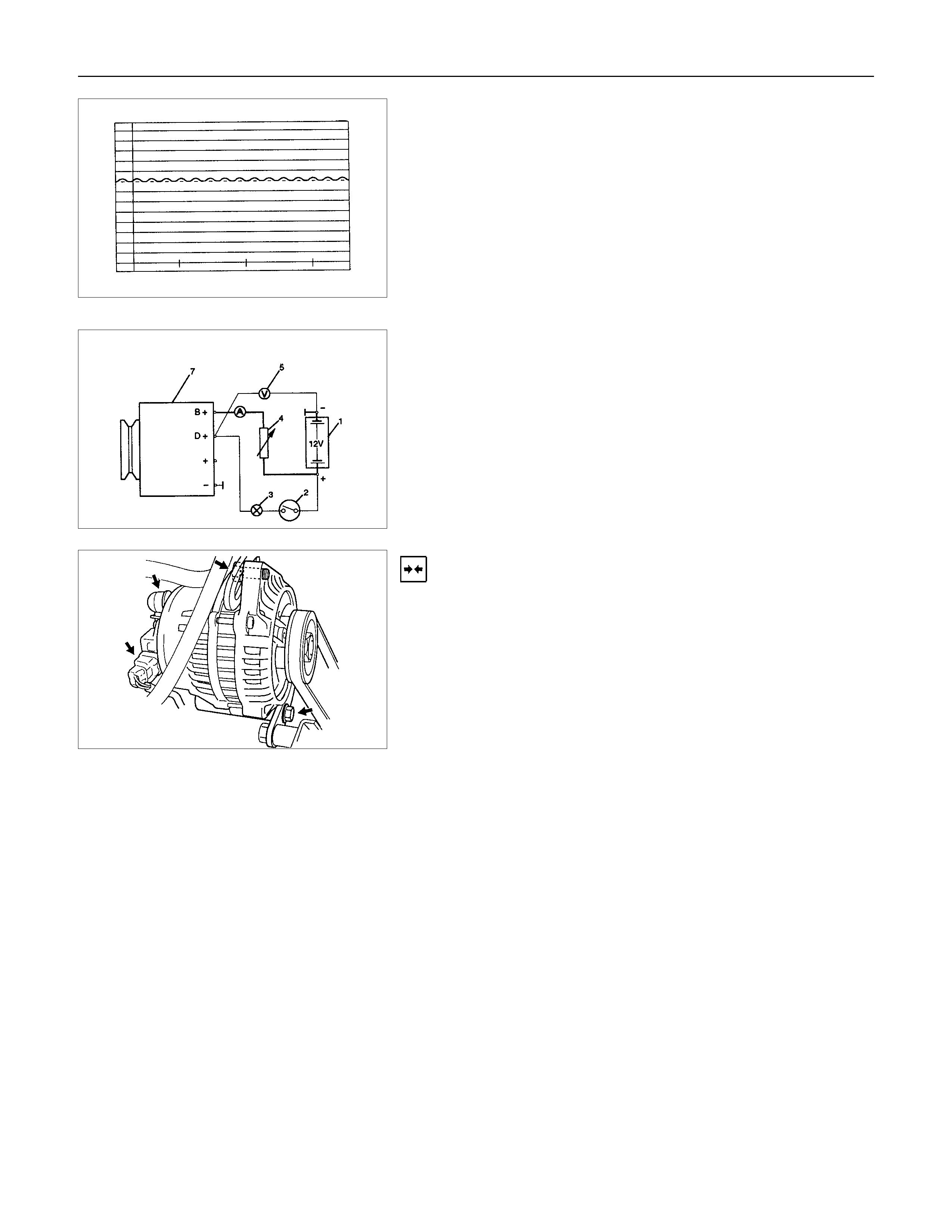
Generator Power
1. Adjust load resistor, if the required load currents are not
attained.
2. The shape of the voltage curves on oscilloscope curve
should be regular.
3. Test value: 5 to 7A.
4. If the required minimum current intensity is not attained, or if
the oscilloscope picture shows variations, the alternator
should be overhauled.
Regulated Voltage Circuit Diagram Legend
1 Battery
2 Ignition Lock
3 Charge Telltale
4 Resistor, for attainment of load current with the battery set in
series
5 Voltmeter
6 Ammeter
7 Generator
Installation
1. Install generator assembly and bring generator assembly to
the position to be installed.
2. Install generator assembly and tighten to the specified
torque.
Torque:
Long bolt: 35 N⋅
⋅⋅⋅m (3.6 kgf⋅
⋅⋅⋅m)
Short bolt: 20 N⋅
⋅⋅⋅m (2.0 kgf⋅
⋅⋅⋅m)
3. Connect wiring harness connector.
4. Move drive belt tensioner to loose side using a wrench, then
install drive belt to normal position.
5. Reconnect battery ground cable.
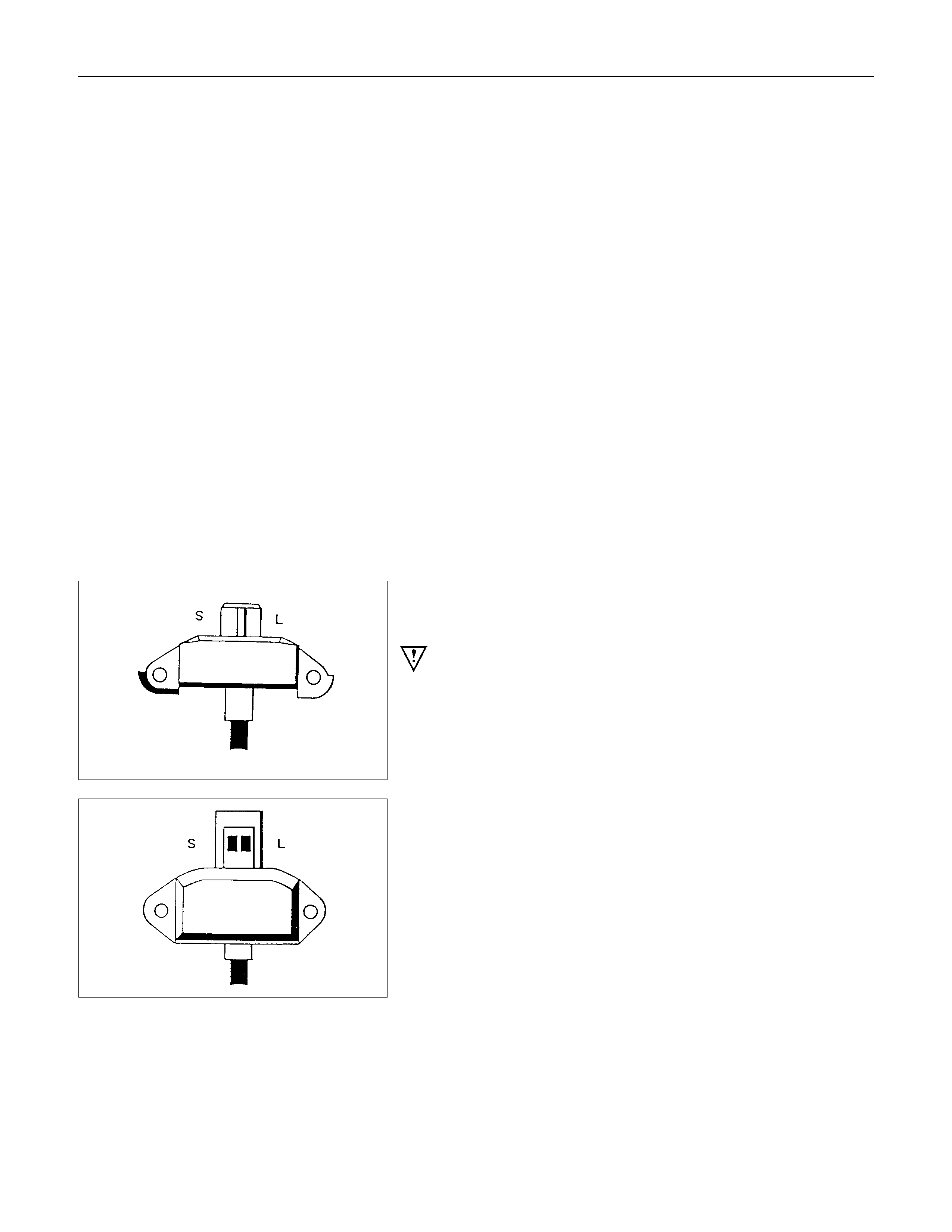
The generator has four external connections; the "B+" lead to
battery positive, "L" lead to the warning lamp circuit(max. 2
watts), "S" lead to battery positive terminal for battery sensing
and an earth connection.
Explanation of type inscripiton
Example:KC-A--> 14V 50-90A.
K = Code for Stator OD(126mm OD).
C = Compact Generator.
A = Ausland (countries other than Germany)
> = Direction of rotation(clockwise).
14V = Generator Operating Voltage.
50A = Stabilised output at 25 C at 1800 RPM./13.5
Volts.
90A = Stabilised output at 25 C at 1800 RPM./13.5
Volts.
Generator Connetions.
B+ : Battery Main Connection (battery positive)
S : Battery Sense Connection(battery positive)
L : Waring lamp(via warning lamp to Ignition switch)
BATT.SENSE
REGULATOR ASSEMBLY
HYBR10
ALTERNATOR ASSEMBLY
12V BATT.
1GN.SW.
300a*
WARN.LAMP
1.2 WATT
L
S
8+
SUPPRESSOR
CAPACITOR
0.5µf
NOTE: * RESISTOR IS RECOMMENDED TO
ENSURE THAT THE GENERATOR
REMAINS FUNCTIONAL IN CASE OF
WARNING LAMP FAILURE

Warning
Do not reverse S and L connections as this will destroy the
warning lamp circuit of the regulator.
Ensure good electrical contact beween generator earth and
battery negative,
Operation
With the Iginiton switch turnded "ON", current is supplied via
the warning lamp to the "L" terminal of the regulator. Base
current is fed to T15 causing it to turn on, current then flows
from B+ through the rotor winding via the regulator brushes
and the collector emitter junction of T15 to earth completing the
circuit. The current in the rotor causes a magnetic field
between adjacent poles to be created, this field is rotated and
cuts the windings of the stator at right angles inducing a
voltage into them.
As the speed is increased this induced voltage increases and
results in curent being rectified in the 3 phase diode bridge and
supplied as DC to the B+ output and hence to the battery.
When the voltage at the B+ terminal of the battery reaches
around 14.2 volts, this voltage is monitored by the "S" lead and
turns the regulator Hybrid base current to T15 OFF removing
rotor current, resulting in a decrease in output voltage to below
the regulating voltage, T15 base current turns ON and the
whole cycle is repeated very rapidly.
D38 protects T15 and the regulator against the back voltage
developed across the rotor winding when T15 turns OFF.
The new generated EP regulators incorporate current limiting in
the warning lamp circuit.
Backup Regulation
The EP regulator will limit the output voltage to a safe level
should either the main B+ cable or the battery sense wire
become decoupled, the output voltage will be slightly above the
normal setting(1-3 volts).
Start up phase
When the Iginition switch is turned on and the engine is not
running, the current to the rotor is reduced by switching it on
and off at a 50% duty cycle, the frequency is approximately 4
KHz and may be audible at times.
This is quite normal, once the engine is started normal
regulation commences.
Warning lamp failure
Should the warning lamp fail, the generator will self excite by
deriving a small current from the phase connecion allowing the
voltage to build up to regulating level.
Note: no filed current will flow when the engine is cranking.

Diagnosis
The EP regulator incorporates diagnostics which will illuminate
the warning lamp as a result of fault conditions in the generator
and external circuitry.
These conditions include:
1.An open circuit in the regulator battery sensing wire (S
Terninal)
2.An open circuit or excessive voltage drop in the B+ cable.
3.An open circuit in the generator phase connection.
4.Overcharging of the battery.
5.Regulator output stage short circuit.
6.Open circuit rotor.
The regulator compares the voltage at B+ with the voltage at
the "S" terminal connceted to battery positive. If the voltage
differential exceeds a predetermined threshold, the regulator
will operate in backup mode to limit the output voltage to a safe
level. The warning lamp; will remain illuminated as along as
these conditions prevail.
Sources of high resistance which will trigger the warning lamp
are:
a.Poor contact in wiring harness connectors.
b.Poor contact between rectifier and regulator.
c.High resistance in fusible link assembly.
Caution:
When bench testing the generator it is important that the
warning lamp wattage of 2 watts is not exceeded.
Reversal of the "S" and "L" on the regulator will damage
the regulator.
The correct plug for the regulator is a 9 122 067 011 for the
Bosch tye and for the Shinagawa connector the number is
X02FW.
See appendix 1 for daignostic matrix.
Before testing or disassembling the generator please observe
the following points.
1. When testing the diodes with AC type testers the RMS.
Vlotage output must not exceed 12.0 volts, it is
recommended that the stator should be disconnected
during this test.
2. Where zener power diodes are used, the breakdown
voltage should be tested to ensure all diodes have the same
zener voltage.
3. Insulation tests on the rotor and stator should use a voltage
not exceeding 110v for a series test lamp. The rectifier
must be disconnected from the stator prior to testing.
4. When carrying out repairs to the charging system always
disconnected the battery negative first, and reconnect it last.

5.During current output tests please make sure that the
ammeter is securely connceted into the charge circuit.
6.Some battery powered timing lights can produce high
transient voltages when connected or disconnected. Only
disconnect or connect timing lights when the engine is
switched off.
7.Make sure the warning lamp circuit is functioning normally
before commencing tests.
8.Battery isolation switches must only be operated when the
engine is stopped.
9.To protect the charging system when using 240 volt
chargers it is recommeneded that the battery is
disconnected whilst charging.
10.Due to the very low resistance value of the stator winding it
may not be possible to obtain accurate readings without
special equipment.
11.12 volts must never be connected to the "L" terminal of the
regulator as this will damage the lamp driver circuit.
12.No loads apart from the warning lamp can be connected to
the "L" termainal. The "W" terminal is provided for this
purpose.
Disassembly
1. Mark the relative positions of the end housings in relation to
the stator assembly to aid reassembly. Use a permanent
marking pen do not use centre punched as this can cause
misalignmnet of the housings.
2. Remove the EP regulator from the slipring end housing by
removing the two screws. Tilt the regulator slightly from the
plug connection until the regulator clears the housing, then
lift clear.
3. Remove the four through bolts.
4. Carefully remove the stator assembly along with the slipring
end housing taking care not to put strain on the stator wires.
5. To disconnect the stator from the rectifier assembly, grasp
the stator wires close to the wire loop with a pair of long
nosed pliers, heat the joint with a soldering iron, when the
point becomes plastic apply a slight twisting motion to the
wires, then pull upwards to release the wires. Remove the
stator.
This procedure opens the wire loop to release the stator
connections easily.
6. To remove the rectifier remove the three retaining screw
and the B+ terminal nut and washers.
Note: the B+ bolt and the positive heatsink retaining screw are
fitted with mica insulating washers.
These must be discarded and replaced with new washers and
heatsink compound.

7. To remove the pulley, mount an 8mm Allen key in the vice
with the short end upwards, place a 24mm ring spanner on
the puley nut, position the internal hexagon of the rotor shaft
onto the Allen ken, loosen the nut and remove the pulley.
Note: the pulley has an integral boss which locks up against
the bearing,
therefore no thrust collar is provided.
8. Removing the rotor assembly. Remove the four retaining
screws from the drive end housing, withdraw the rotor
complete with the bearing.
Note: the rotor must not be pressed from the drive end housing
using a press as the bearing retaining plate and drive end
housing will be damaged or distorted. Parts removed in this
way must be replaced if the integrity of the generator is to be
maintained.
9. Remove the drive end bearing from the rotor shaft using a
chuck type puler, take care not to distort the fan assembly
during this process.
10.Remove the slipring end bearing using the same meghod
as in 9.
Clean
Thoroughly clean all components except the rotor and stator
with an approved cleaning agent. Ensure that all traced of oil
and dirt are removed. If an abrasive cleaner is used to remove
scale and paint from the housings take care not to abrade the
bearing and mounting spigot surfaces. The rotor and stator
must be cleaned with compressed air only, the use of solvents
could cause damage to the insulating materials.
Inspection
1. Rectifier assembly
The following test equipment is required.
The recitifier assembly is not repairable and must be replaced
if a faulty diode is detected during inspection.
(a) Adiode tester where the DC output at the test probes does
not exceed 14 volts or in the case of AC testers 12 volts
RMS. This is to ensue that when inspection rectifiers fitted
with zener power diodes the forward and reverse checks
are completer and are not masked by the diode turning on
due to the zener breakdown voltage.
(b) A zenere diode tester with a DC output in excess of 30
volts, the tester should also incorporate internal current
limiting set to 5 Ma. to prevent high currents during
inspection.
(c) Diodes can be destroyed during service due to high
temperature and overload, open circuits are usually a result
of excessive voltage.
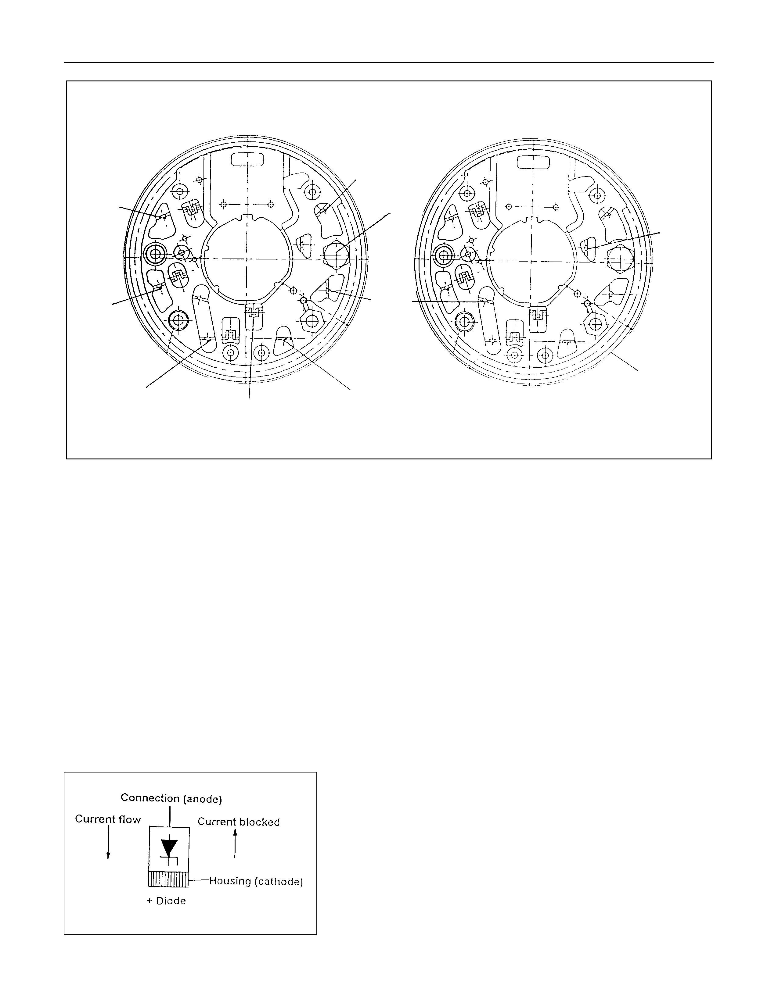
Positive heatsink
8 diode6 diode
H
G
Negative heatsink
C
B
AStarpoint F
E
B+Bolt
D
Diode connections
Stator connection
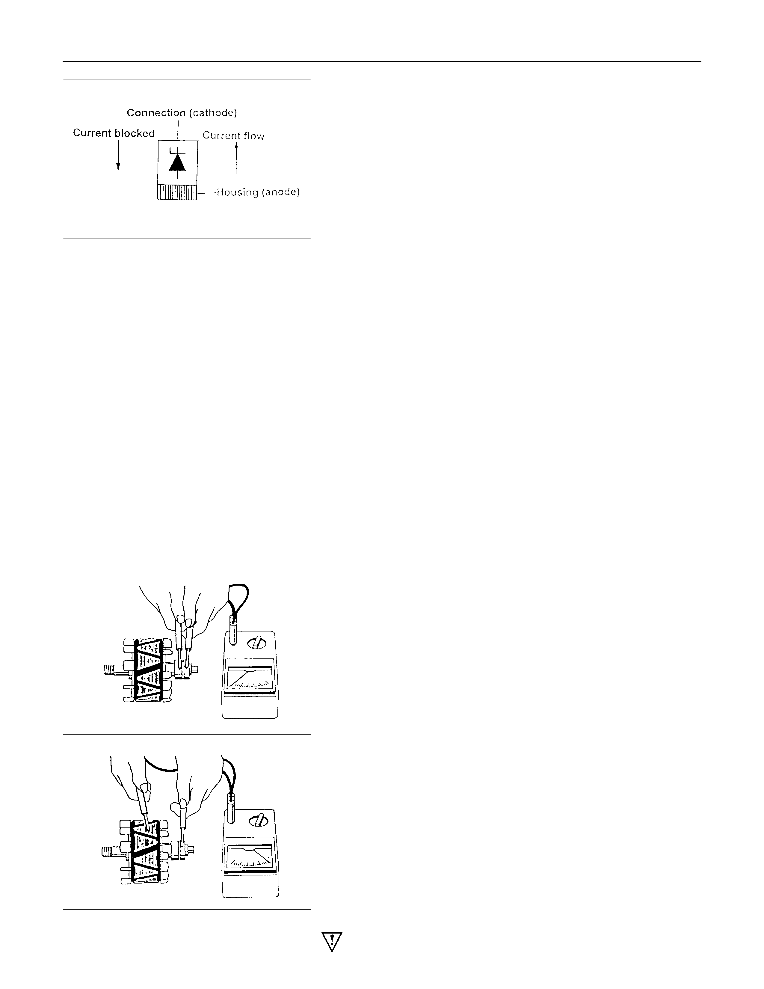
1.1 Power Diodes.
Apply the negative test probe of the diode tester or a
multimeter with a diode test feature to the positive heatsink and
the positive probe alternatevely to A,B,C, a low resistance
reading, or the forward voltage drop across the diode shoud be
obtained. Reverse the test probes, a high resistance reading or
a higher reverse voltage should be obtained.
Now connect the positive test probe to the negative heatsink
and the negative alternatively to D,E,F, a low resistance or
forward voltage drop across the diode should be obtained.
Reverse the test probes, a high resistance reading or a higher
reverse voltage should be obtained.
For 8 diode rectifier plates tests for G and H should be
included. When the reverse voltage test is done the applied
voltage should be less than 14 volts DC or 12 volts RMS for
AC testers.
1.2 Zener Diode
The basic tests in 1.1 should be undertaken first before the
diode zener voltage is tested. Diodes are grouped together
according to their zener voltag i.e. all diodes within a rectifier
must have the same zener voltage.
Connect the test probes as for the reverese test listed above
i.e. reverse biased apply the test voltage form the zener diode
tester (current limited to 5ma) and read to zener breakdown
voltage this should be a steady reading and not increase with
increased voltage from the tester.
Readings for Zener diode groups 011 to 042
Zener voltage at
5Ma.
Positive
diode
Negative
diode
Fordward
current Rating
17.8v-19.2v 011 012 25A
18.8v-20.2v 013 014 25A
19.8v-21.2v 015 016 25A
20.8v-22.2v 017 018 25A
21.8v-23.2v 019 020 25A
22.8v-24.2v 021 022 25A
17.8v-19.2v 031 032 35A
18.8v-20.2v 033 034 35A
19.8v-21.2v 035 036 35A
20.8v-22.2v 037 038 35A
21.8v-23.2v 039 040 35A
22.8v-24.2v 041 042 35A
Note: Diode number is stamped on the rear of the diode.
2. Stator
Inspect the stator insulation resistance to ground with an
insuation tester or a series test lamp up to 110 volts.
The insulation resistance must be greater than 1 megohm.
The winding reisistance is measured between phases using a
low reading ohmmeter designed for this purpose, the values
are given at the rear of this instruction.
3. Rotor
Inspect the rotor for insulation resistance to ground using an
insulation tester or a series test lamp up to 110 volts.
The insulation resistance must be grater than 1 megohm.
Measure the rotor resistance between the sliprings using an
ohmmeter or apply 12 volts across the sliprings and measure
the rotor current flow, then divide 12 by the measured current,
the results is the rotor resistance in ohms. values are given at
the rear of this instruction.
If the sliprings are worn or out of round they must be re-
machined to a minimum diameter or 26.7 mm and should have
a runout not exceeding 0.060mm. If the slipring is below these
limits it must be replaced with a new one.
Warning; extreme care must be exercised when machining
the slipring as it is possible for the turning tool to foul the fan.
4. Replacing the brushes (inbuilt regulator)
Check the brushes for length, this is measured from the brush
holder to the end of the brush along it's centre line. Also
inspect for any sideways wear. If worn replace both brushes.
The minimum length is 3.8mm. Inspect the brush springs for
signs of corrosion or loss of tension or uneven tension.
Replacing the brushes, using a soldering iron apply heat to the
soldered joints on the rear of the brush holder of the regulator,
using a small lever prise up the retaining tabs to release the
brush lead and spring. Thread the new brush lead up the
brush holder along with the spring, pull the lead through the
tabs until the brush is protruding 12mm from the holder.
Bend down the tabs and solder the brush lead taking care not
to allow the solder to run up the lead which will reduce
flexibility. Use 60/40 resin cored solder.
5. Ball bearing
Please note the bearings used in this KCA generator are a high
tolerance type, only fully sealed bearings of the same
specification are to be used as replacements. It is
recommended that the bearings be replaced during the
reconditioning process to restore the unit to original
specification.
6. Regulator
The regulator can only be tested when fitted into an altenator.
Warning: do not reverse"S" and "L" connections or put 12
volt supply to "L" terminal, this connection must not be
used as a supply source other than to supply the
requirements of the warning lamp 2(watts).
Such action will destroy the regulator warning lamp
circuit.
For test voltages refer to Generator output testing section.
See also additional information on regulator function earlier in
this instruction.

Reassembly
Generator
(a) Press new bearing onto slipring end of the rotor taking care
to aplly the force to the bearing inner race only, otherwise
the bearing will be noisy and it's life will be shortened.
(b) Fit a new bearing to the drive end housing, fit the bearing
plate, and four retaining screws, press the rotor into the
bearing, using a support tool to take the thrust against the
bearing inner.
The support is fitted from the pulley side of the bearing. In
this way the thrust is not taken by the drive end housing.
(c) To fit pulley, mount an 8mm Allen key in the vice with the
short end upwards, place a 24mm ring spanner on the shaft
nut, position the internal hexagon of the rotor shaft onto the
Allen key, tighten the nut to the required torque(See torque
chart)
(d) Inspect the bearing support ring for signs of damage, if in
doubt replace the ring by pressing it into the housing by
hand, do not use excessive force.
(e) To refit the rectifier, fit new mica washers to the positive
heatsink B+ bolt and retaining screw each washer must
have heatsink compound applied to both surfaces before
fitting.
Fit the three retaining screws to the rectifier then install into
slipring end housing. Tighten the B+ bolt to the reuired
torque.
(f) To refit the stator, make sure the spigot surface are clean
and free from damage, fit the stator into the slipring end
housing noting the correct lead connection positioning. Fit
the stator leads into the wire loops in the recrifier. Using a
pair of pliers squeeze the loop to retain the stator lead prior
to soldering. Repeat for each lead in turn, solder the leads
into position using 60/40 resin cored solder. Make sure the
leads will be clear of the internal fan when the rotor is
assmebled into the stator.
(g) Carefully install the rotor into the stator/slipring end housing
assembly, noting the alignment of the housings and through
bolt holes. Fit the through bolts making sure the stator is
seated correctly, tighten the through bolts to the correct
torque setting (uneven torque can produce magnetic noise
levels above normal).
(h) Fitting the regulator. Compress the brushes into the brush
holder by hand, slip the regulator through the opening in the
rear of the slipring end housing until the brushes come in
contact with the slipring. Press the regulator towards the
slipring until the holes are aligned then fit the retaining
screws and tighten.

Inspection
Generator
Before any in field testing can be undertaken it is important that
the battery's conditions is established and the terminals are
clean and tight.
Check the condition of the generator drive belt and ensure that
it is adjusted in accordance with the engine manufacturer's
recommnedations.
Battery conditions:
Note: This assessment may be difficult with maintenance free
assemblies.
Test the specific gravity of the individual cells the readings
should be within 10 points of each other, it is recommended
that the average SG should be 1.260 or higher.
A load test should be carried out to determine the ability of the
battery to supply and accept current. This is a good indicator
as to the general condition of the battery.
A load equal to the normal starting current should be placed
across the battery, the duration of this load test should not
exceed 10 seconds, during this time the terminal voltage
across the battery should not drop below 9.6 volts. Observe
each cell for signs of excessive gas liberation, usuall an
indication of cell failure.
If the battery test is clear proceed with the Generator tests as
follows.
Care should be taken when making the following connections.
It is recommended that the battery negative terminal be
disconnected before the test meters are connected, and
reconnecting the negative terminal when the meters are
inserted into the circuit under test. The warning lamp in the D+
circuit should not exceed 2 watts.
Regulating voltage test on the vehicle.
Connect a voltmeter to the generator, the positive lead to the
B+ terminal and the nagative lead to the generator casing.
Select the voltage range to suit the system, i.e. 20v for 12 volt
sysytems or 40v for 24 volt systems. Connect an ammeter in
series with the main output cable from the B+ terminal on the
generator, the range selected must be capable of reading the
maximum output from the generator.
Note the voltmeter reading before starting the engine. This
reading should increase when the engine is running indicating
generator output, start the engine and increase the engine
speed until the generator is running at 4000 rpm, switch on
vehicle loads of 5-10 A is indcated on the ammeter, the
voltmeter shoud read 14.0-14.2 v for a 12 volt system, for a 24
volt system the readings should be 5-10 A and 27.7-28.5 volts.
Load regulation test
Increase the engine speed until the generator is running at
6000 rpm, increase the load to 90% of full output a decrease in
the regulating voltage should not exceed 0.50 volts for 12 v
and 0.70 v for 24 v regulators of the readings obtained in the
previous test. If so, the regulator is defective.
Generator output test at full load
Increase engine speed until the altenator is running at 6000
rpm, switch on electrical loads until the generator voltage drops
to 13.5 volts for 12 v systems and 26 volts for 24 v systems, full
outut should be obtained under these conditions. It may be
necessary to adjust engine speed to maintain altenator speed.
If sufficient electrical loads are not available a carbon pile
resistance can be connected across the battery and adjusted
until maximum output is obtained.
Keep the time for this test to a minimum to avoid undue
heating and high engine speeds.

Technical Data
(mm)
Brush wear - Minimum Length 3.8
Sliprings - Minimum Diameter 26.7
Sliprings - Trueness <0.06
Pole claws - Trueness <0.05(93.25±0.05)
Torque
N.m(kgf⋅m)
Pulley retaining nut 54-68(5.5-6.9)
Capacitor retaining screw 2.7-3.8(0.3-0.4)
Capacitor whiz nut 1.5-2.2(0.1-0.2)
B+ terminal nut M8 7.5-8.5(0.8-0.9)
B+ terminal rectifier nut 6.0-7.5(0.6-0.8)
Regulator retaining screw 1.6-2.3(0.1-0.2)
Rectifier retaining screw 1.6-2.3(0.1-0.2)
Bearing retaining plate screw 2.1-3.0(0.2-0.3)
Through bolt 3.8-5.5(0.4-0.6)
Winding resistance(between phases)
(Ω)
Stator Rotor
70 Amp generator 0.086+10% 2.6±0.13
85 Amp generator 0.058+10% 2.6±0.13
90 Amp generator 0.056+10% 2.6±0.13
Warning lamp fault indication
Fault running Generator not
running Ignition ON
Generator
Iginiton ON
Generator out cable
O/C
ON ON
Battery "S" cable O/C ON ON
Battery overcharged ON ON
Positive diode short OFF ON
Negative diode short ON ON
Positive diode open ON OFF
Negative diode open ON OFF
Phase voltage sensing ON ON
cable open circuit
Power transistor
shorted
ON ON
Warnign lamp driver
O/C
OFF OFF
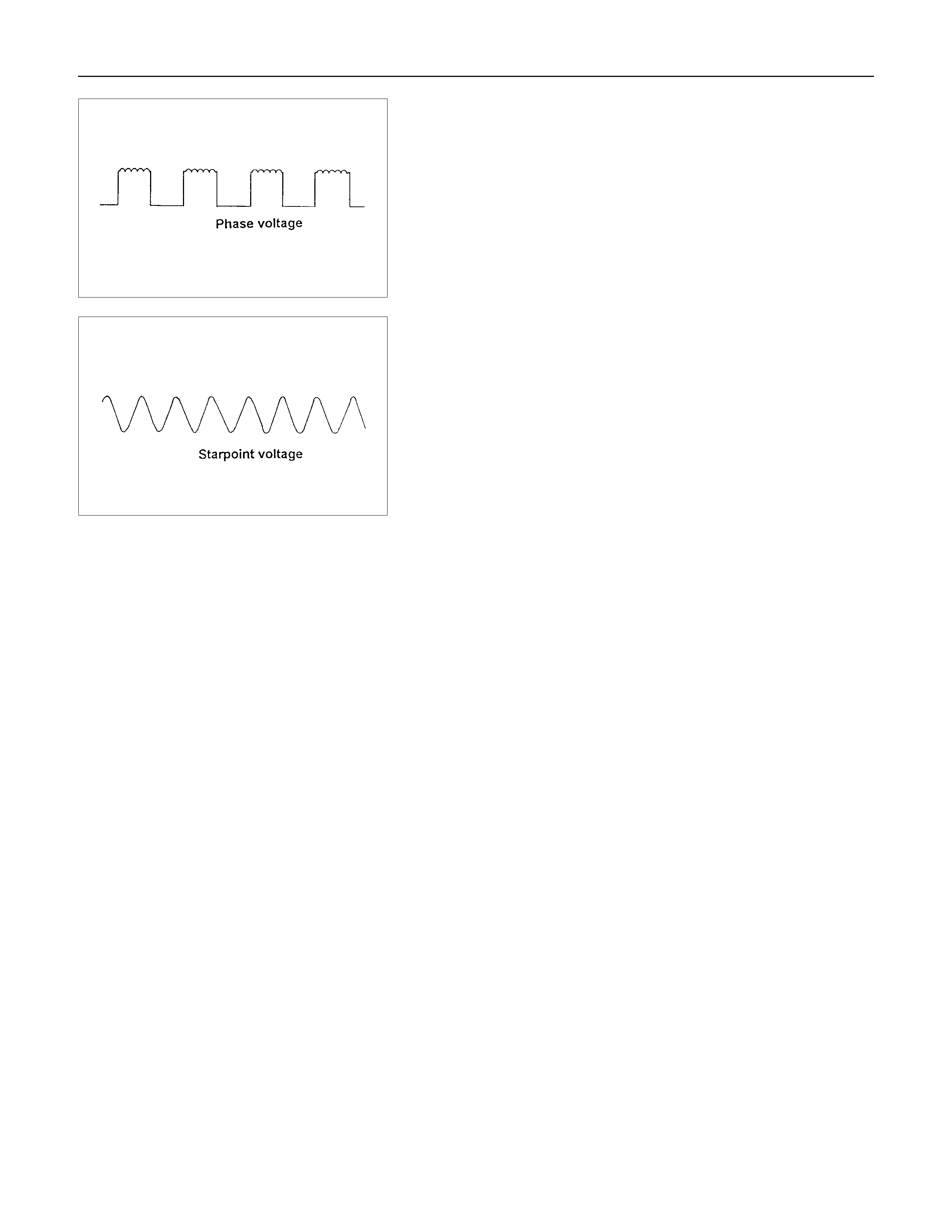
Output wave forms for phase and startpoint connections.
Note; the average of these two waveforms are identical from
no load to 100% output of rated load.
Voltage phase = Voltage startpoint
6.9v@ rated output 7.2v@ Zero output
Note: The phase frequency is one third of the startpoint
frequency.