
SECTION 0A - GENERAL INFORMATION
General Repair Instructions
Notes on The Format of this Manual
Identification
Chassis Number
Holden I.D. Plate
Compliance Plate
Body & Option Plate
Vehicle Identification Plate
Lifting Instructions
Lifting Points And Supportable Point-Locations
Lifting Point; Front
Supportable Point; Front
Lifting Point; Rear
Supportable Point; Rear
Techline
Techline
Techline
Techline
Techline
Techline
Techline
Techline
Techline

General Repair Instructions
1. Park the vehicle on level ground and chock the front or rear wheels before lifting the vehicle.
2. Raise the vehicle with a jack set against the axle or the frame.
3. Support the vehicle on chassis stands.
4. Use covers on the vehicle body, seats, and floor to prevent damage and/or contamination.
5. Disconnect the grounding cable from the battery before performing service operations.
This will prevent cable damage or burning due to a short circuit.
6. Handle brake fluid and antifreeze solution with great care.
Spilling these liquids on painted surfaces will damage the paint.
7. The use of the proper tool(s) and special tool(s) where specified is essential to efficient, reliable, and safe service
operations.
8. Always use genuine HOLDEN replacement parts.
9. Discard used cotter pins, gaskets, O-rings, oil seals, lock washers, and self-locking nuts at disassembly.
Normal function of these parts cannot be guaranteed if they are reused.
10. Prepare new cotter pins, gaskets, O-rings, oil seals, lock washers, and self-locking nuts for installation.
11. Keep the disassembled parts neatly in groups.
This will facilitate smooth and correct reassembly.
12. Keep fixing nuts and bolts separate.
Fixing nuts and bolts vary in hardness and design according to installation position.
13. Clean all parts before inspection or reassembly.
14. Clean the oil ports and other openings with compressed air to make certain that they are free from dirt and
obstructions.
15. Lubricate the rotating and sliding faces of all moving parts with oil or grease before installation.
16. Use the recommended liquid gasket to prevent leakage.
17. Carefully observe all nut and bolt torque specifications.
18. When removing or replacing parts that require refrigerant to the discharged from the Air conditioning system, be
sure to use the Vehicle Refrigerant Recovery and Recycling Equipment (VRRRE) to recover and recycle R134a, to
promote the movement for the protection of the ozone layer covering the earth.
19. Check and recheck your work. No service operation is complete until you have done this.
Notes On The Format Of This Manual
1. Find the applicable Section by referring to the index at the front of the Workshop Manual binder.
2. The following technical service information is included in this Section:
• Identification
• Maintenance schedules
• Recommended Iubricants
• Recommended fuels
• Oil viscosity charts
3. Individual Sections of this Workshop Manual are divided into the following categories:
• Main data and specifications
• Torque specifications
• Recommended liquid gasket
• Loctite application procedure
• Servicing
• Removal and installation
• Disassembly
• Inspection and repair
• Reassembly
• Troubleshooting
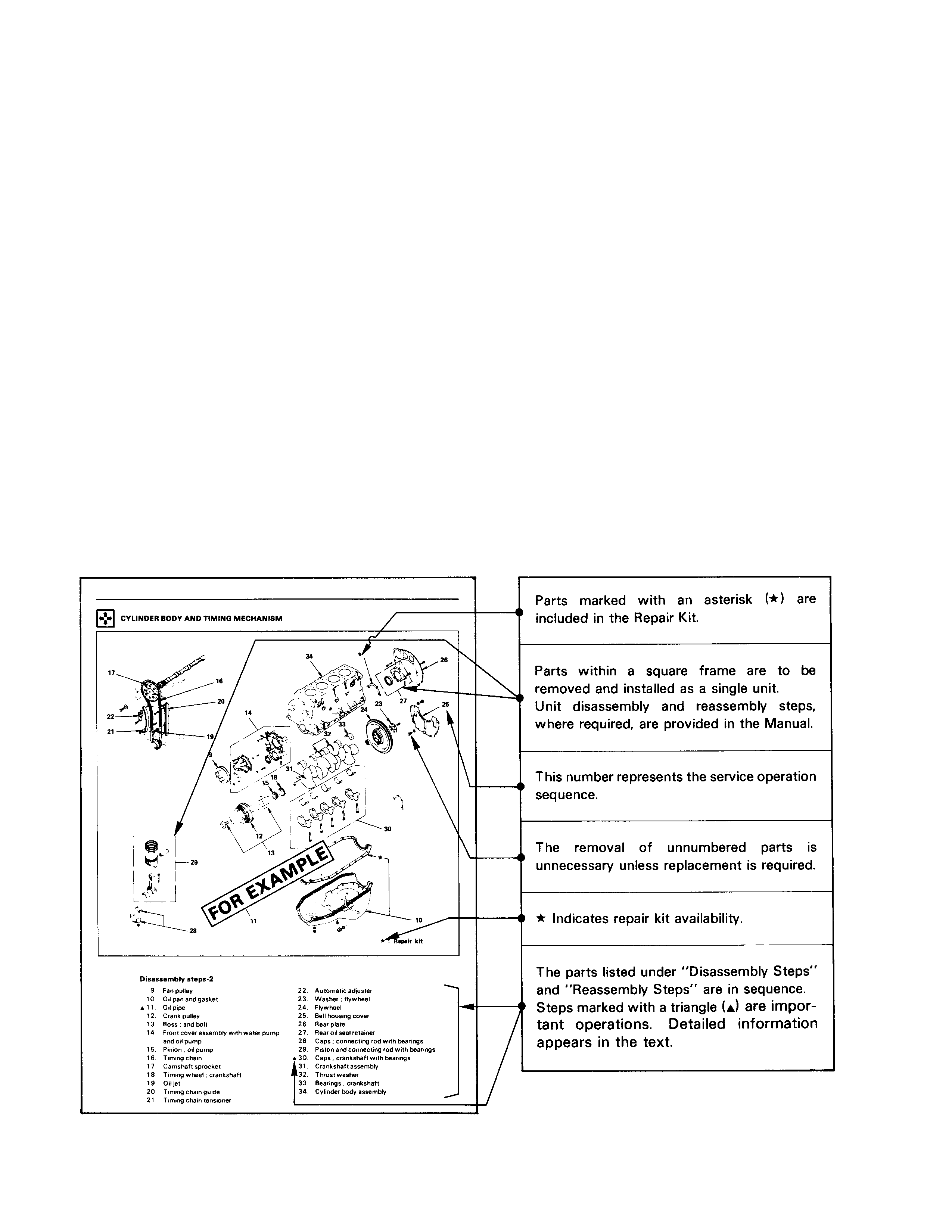
4. Each "Major Components" page of this Workshop Manual has an exploded view of the applicable area.
A brief explanation of the notation used follows:
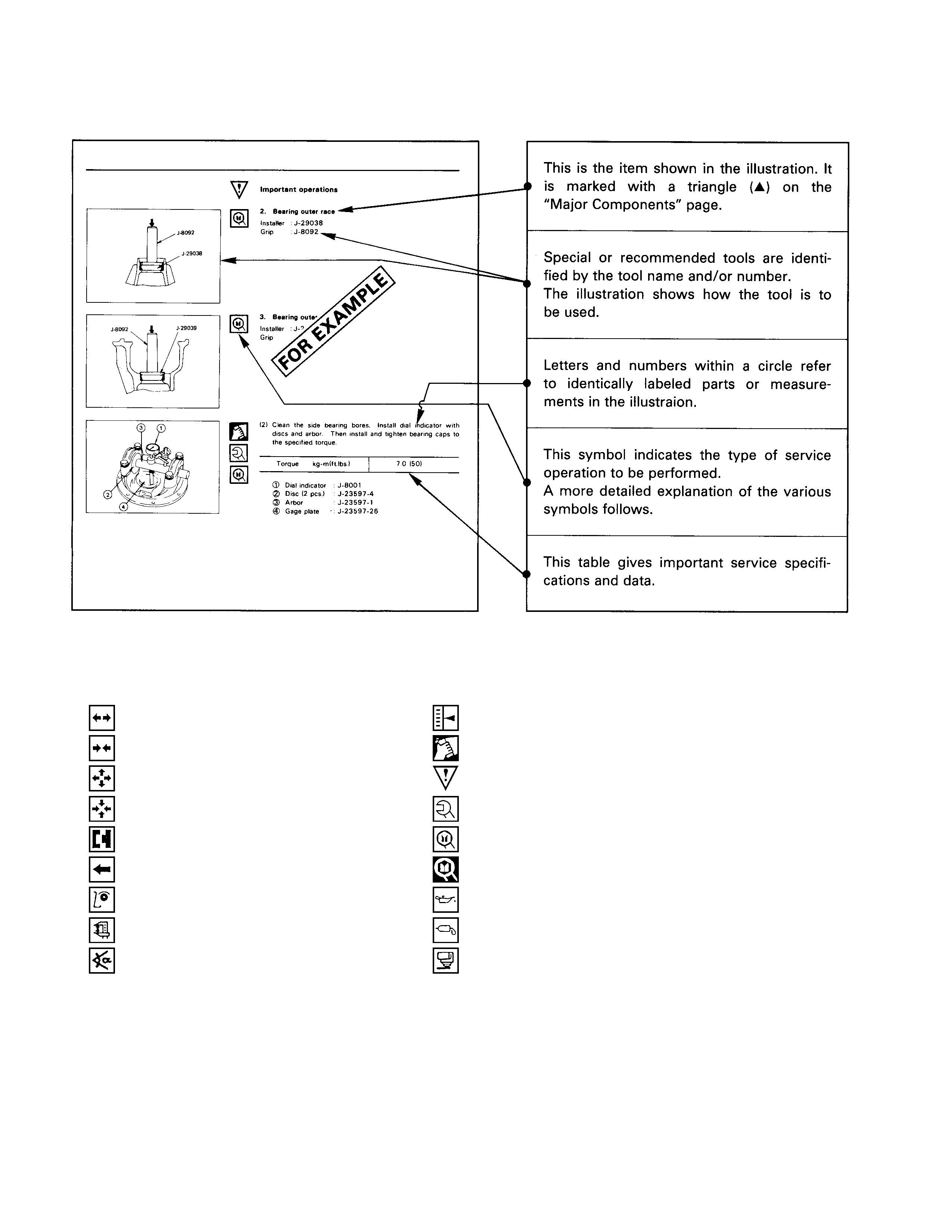
5. Below is a sample of the Workshop Manual text following the " Major Components " page.
A brief explanation of the notation used follows:
6. The following symbols appear throughout the Workshop Manual.
They tell you at a glance the type of service operation to perform.
........Removal ........Adjustment
........Installation ........Cleaning
........Disassembly ........Important operation requiring extra care
........Reassembly ........Specified torque
........Alignment ........ISUZU special tool(s) required or recommended
........Directional indication ........Other special tool(s) required or recommended
........Inspection ........Lubrication (Oil)
........Measurement ........Lubrication (Grease)
........Torque Angle Method ........Liquid gasket application

7. Measurement criteria are defined by the terms "standard" and "limit".
A measurement falling within the "standard" range indicates that the applicable part or parts are serviceable.
"Limit" is an absolute value.
A measurement falling outside the "limit" indicates that the applicable part or parts must be repaired or replaced.
8. Components are parts are listed in the singular form throughout the Workshop Manual.
9. The following directional criteria are used throughout the Workshop Manual:
Front:
The cooling fan side of the engine.
Right:
The right-hand side of the engine viewed from the flywheel.
Left:
The left-hand side of the engine viewed from the flywheel.
Rear:
The flywheel side of the engine.
Cylinder numbers are counted from the front of the engine towards the rear.
The engine's rotation is clockwise viewed from the front of the engine.
Identification
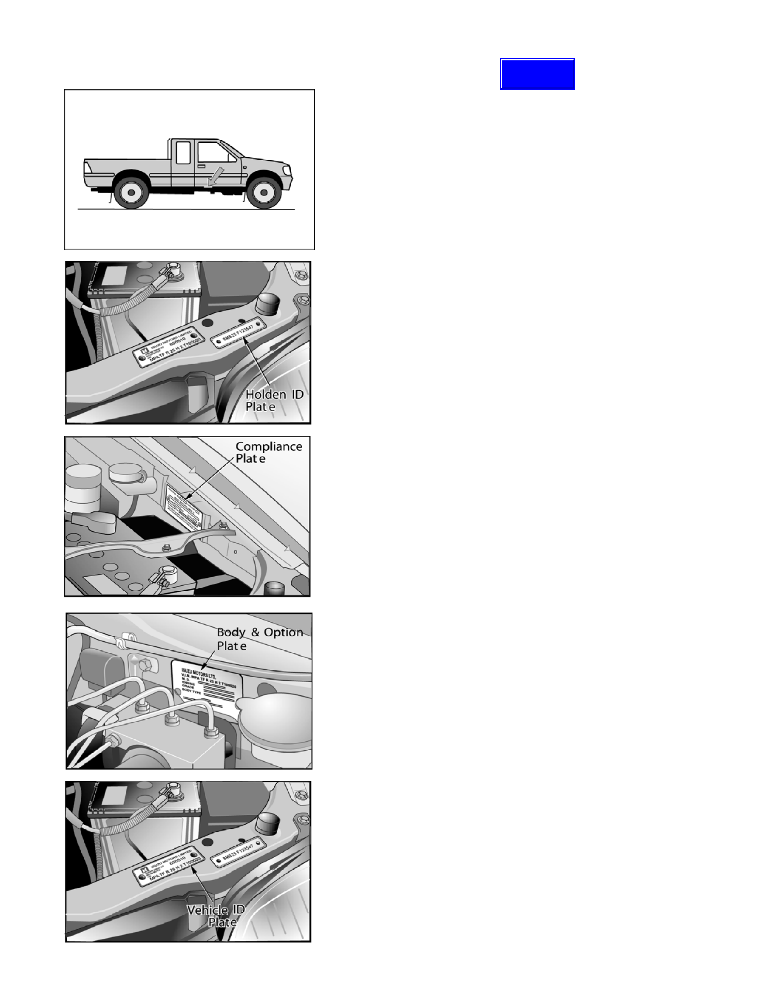
Chassis Number
The chassis number is stamped on the right-hand side of the
chassis side member under the right door.
Holden I.D. Plate
Riveted to the radiator support panel, adjacent to the LH
headlamp.
Used for warranty identification, road-side assistance
identification etc
Compliance Plate
Riveted to the LH inner guard.
Displays approval numbers, category, manufacturer’s name,
model name and code, Gross Vehicle Mass (GVM), seating
capacity, build date and V.I.N.
Body & Option Plate
Riveted to the LH inner guard.
Displays V.I.N., vehicle option codes and the country code
Vehicle Identification Plate
Riveted to the radiator support panel, adjacent to the LH
headlamp.
Displays the V.I.N. and the engine serial number
Techline
Lifting Instructions
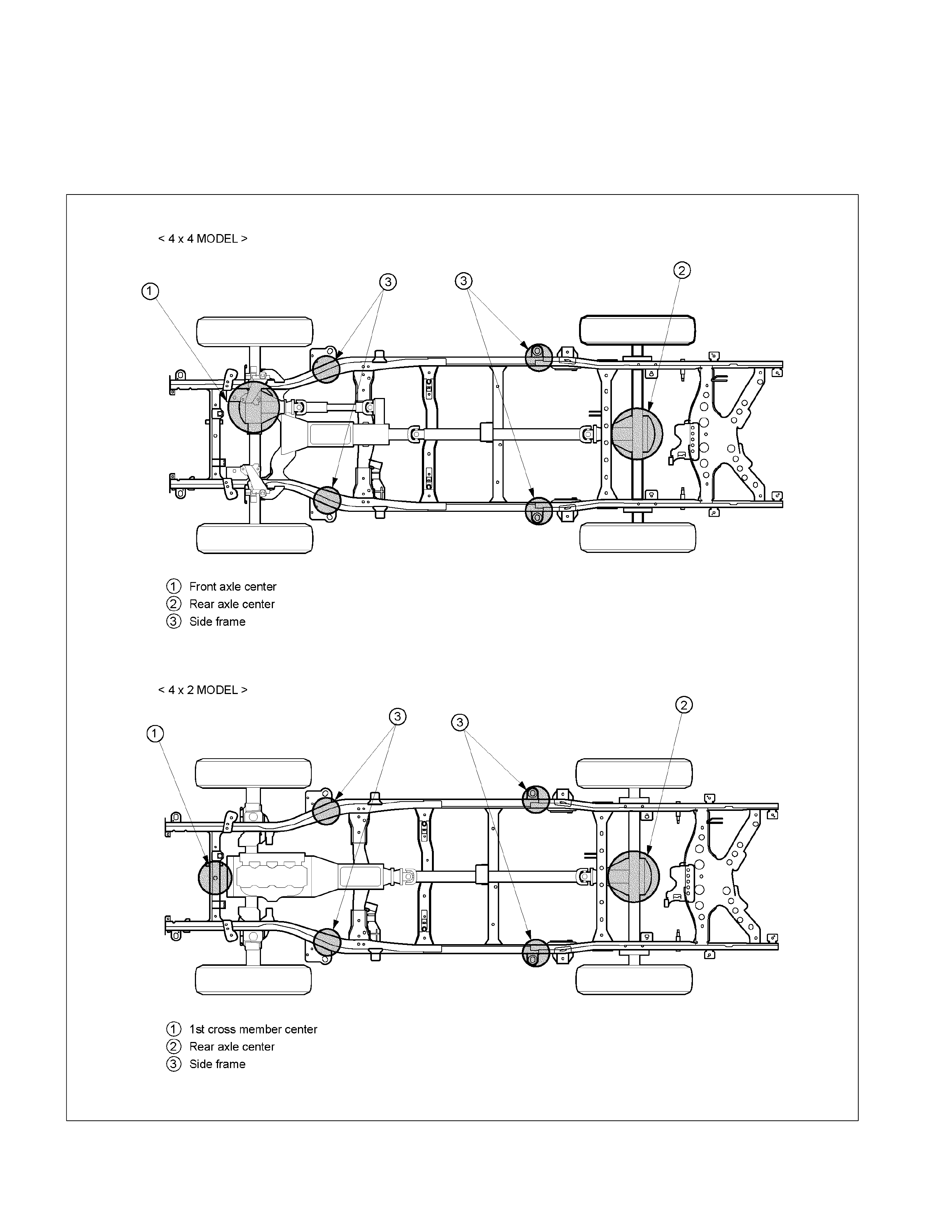
If a lifting device other than the original jack is used, it is most important that the device be applied only to the correct
lifting points. (See the illustration.) Raising the vehicle from any other point may result in serious damage.
Lifting Points and Supportable Point-Locations
RTW30AXF000101
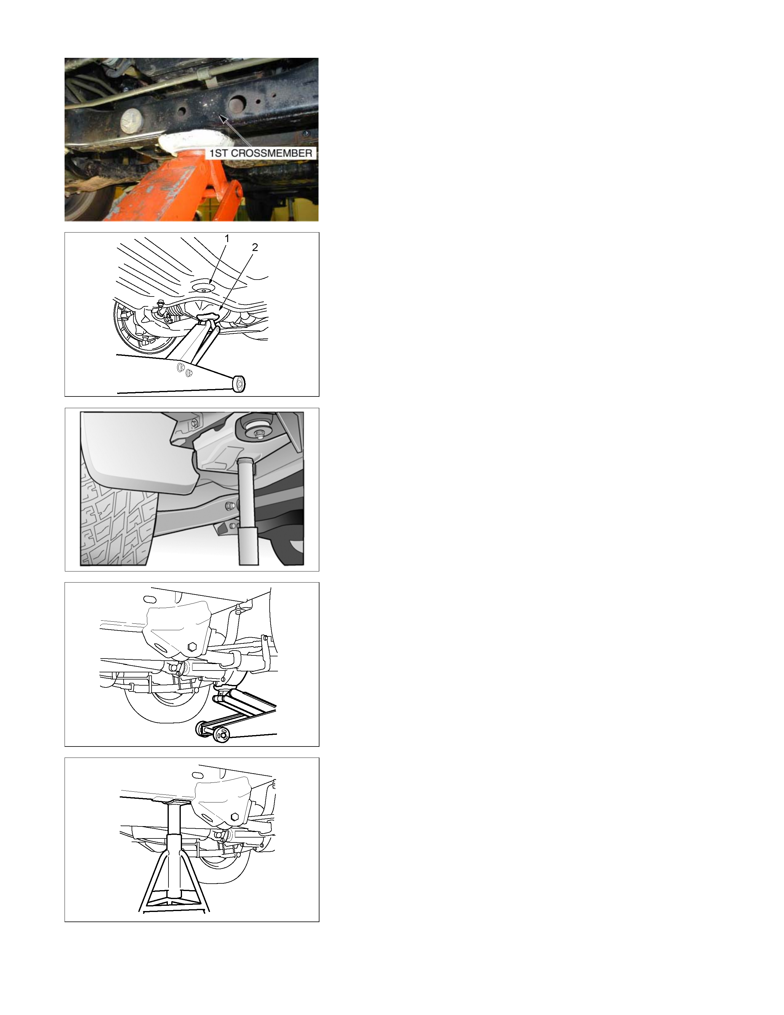
Lifting Point; Front
4×2 Model
• When using floor jack, lift the center of 1st cross member.
RTW30ASH000301
4×4 Model
• When using floor jack, lift the under surface of skid plate (1)
(set the circle depression shape, shown on left picture) o
r
lift the center of front axle case (2).
RTU4Z0SH007901
Supportable Point; Front
• Position the chassis stands at the bottom of the frame side
member, backward of front wheel.
RTW30ASH000101
Lifting Point; Rear
• When using floor jack, lift the center of rear axle case.
RTW30ASH000201
Supportable Point; Rear
• Position the chassis stands at the bottom of the frame side
member, forward of the rear wheel.