
SECTION 1 - HEATER AND AIR CONDITIONING
General Description
Main Data and Specifications
Heater Unit
Removal and Installation
Disassembly and Reassembly
Duct
Removal and Installation
Disassembly and Reassembly
Blower Unit Assembly
Removal and Installation
Disassembly and Reassembly
Defroster Nozzle and Vent Duct
Removal and Installation
Control Lever Assembly
Removal and Installation
Control Panel Illumination Bulb
Removal and Installation
Inspection and Repair
Troubleshooting
Techline
Techline
Techline
Techline
Techline
Techline
Techline
General Description
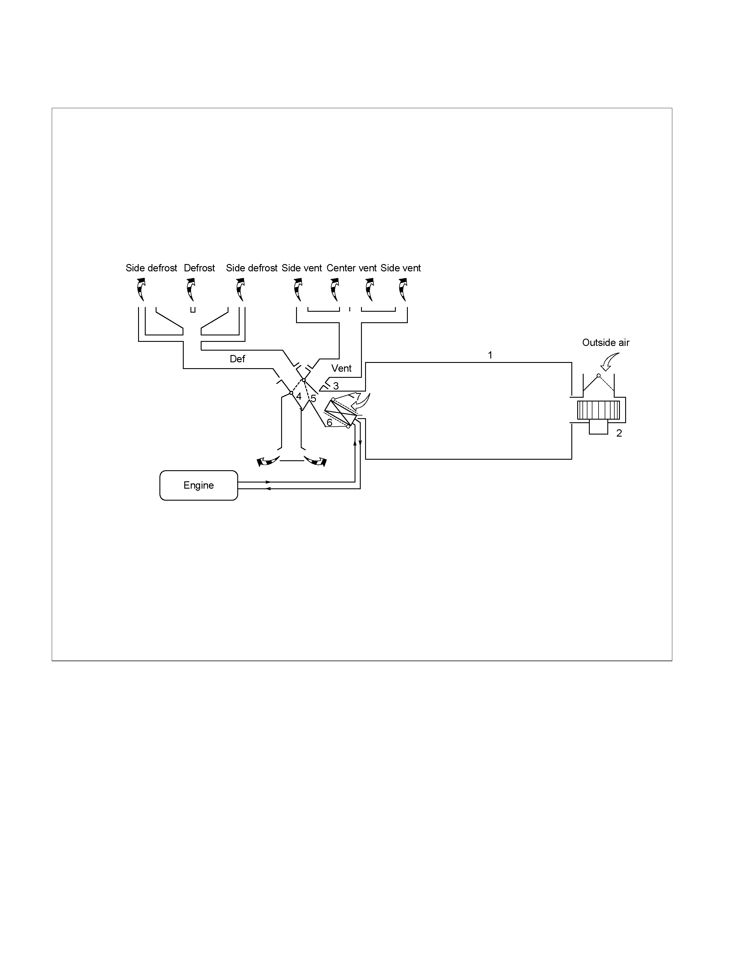
Heater Air Flow Diagram
RTW310LF001201
1. Heater Duct 4. Mode (DEF/FOOT) control door
2. Blower Unit 5. Mode (VENT) control door
3. Heater Unit 6. Heater Core
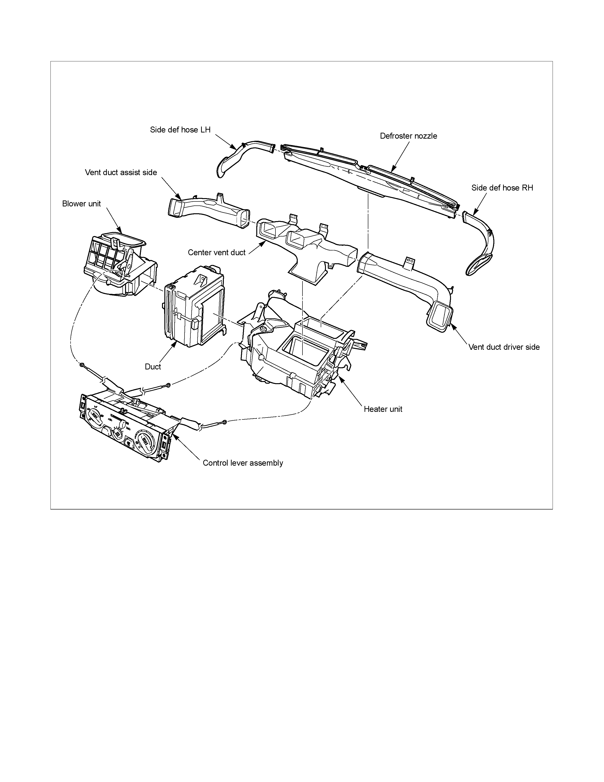
Unit (Interior Components)
RTW410LF000801

Wiring Diagram (4JH1-TC)
RTW38DXF000701
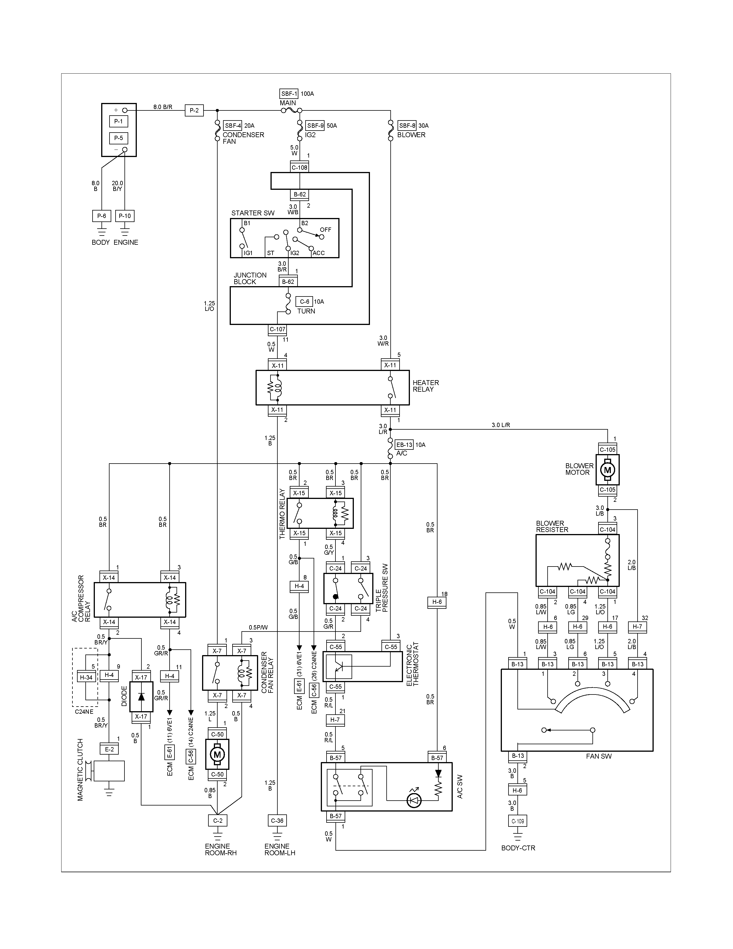
Wiring Diagram (6VE1, C24SE)
RTW38DXF000601
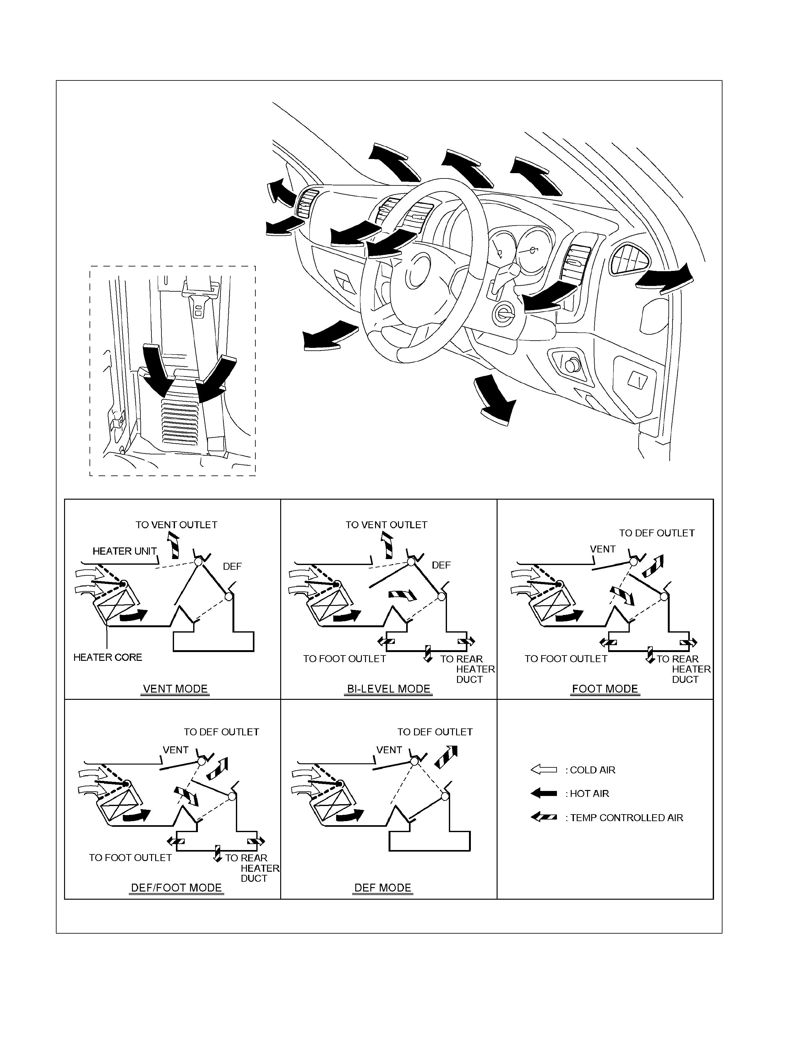
Ventilation
RTW310XF000101
Main Data And Specifications
HEATING UNIT
Type Reheat air mix
Core dimension mm (in.) (L×H×W) 180 (7.09) × 182.3 (7.18) × 27 (1.06)
Capacity 4200 kcal/hr (300m3/hr)
BLOWER UNIT
Type Sirocco fan type
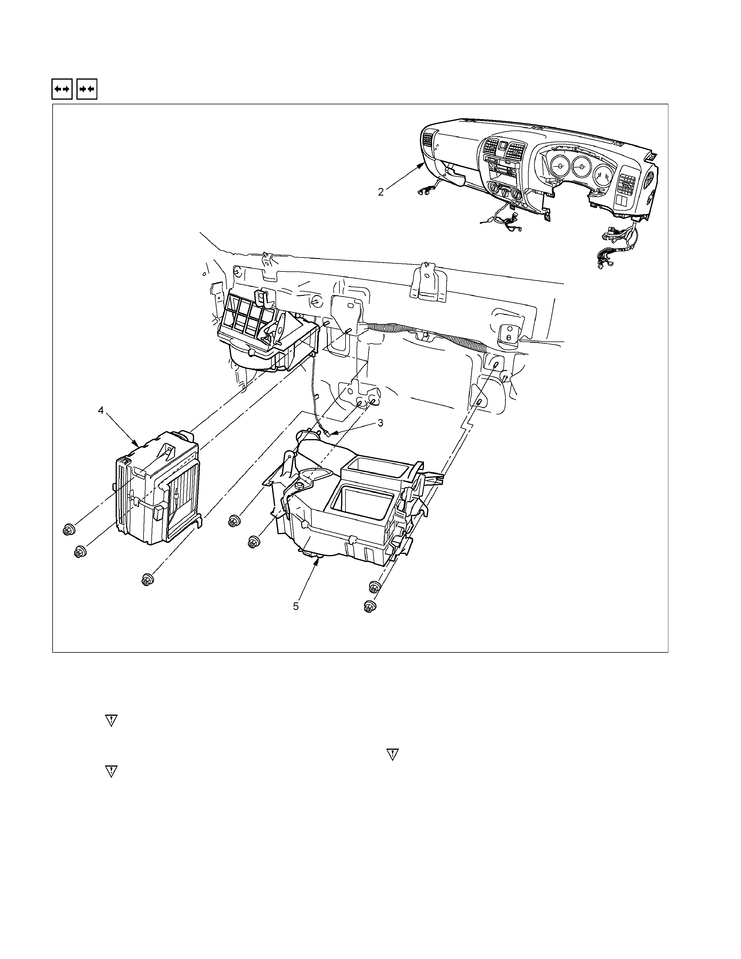
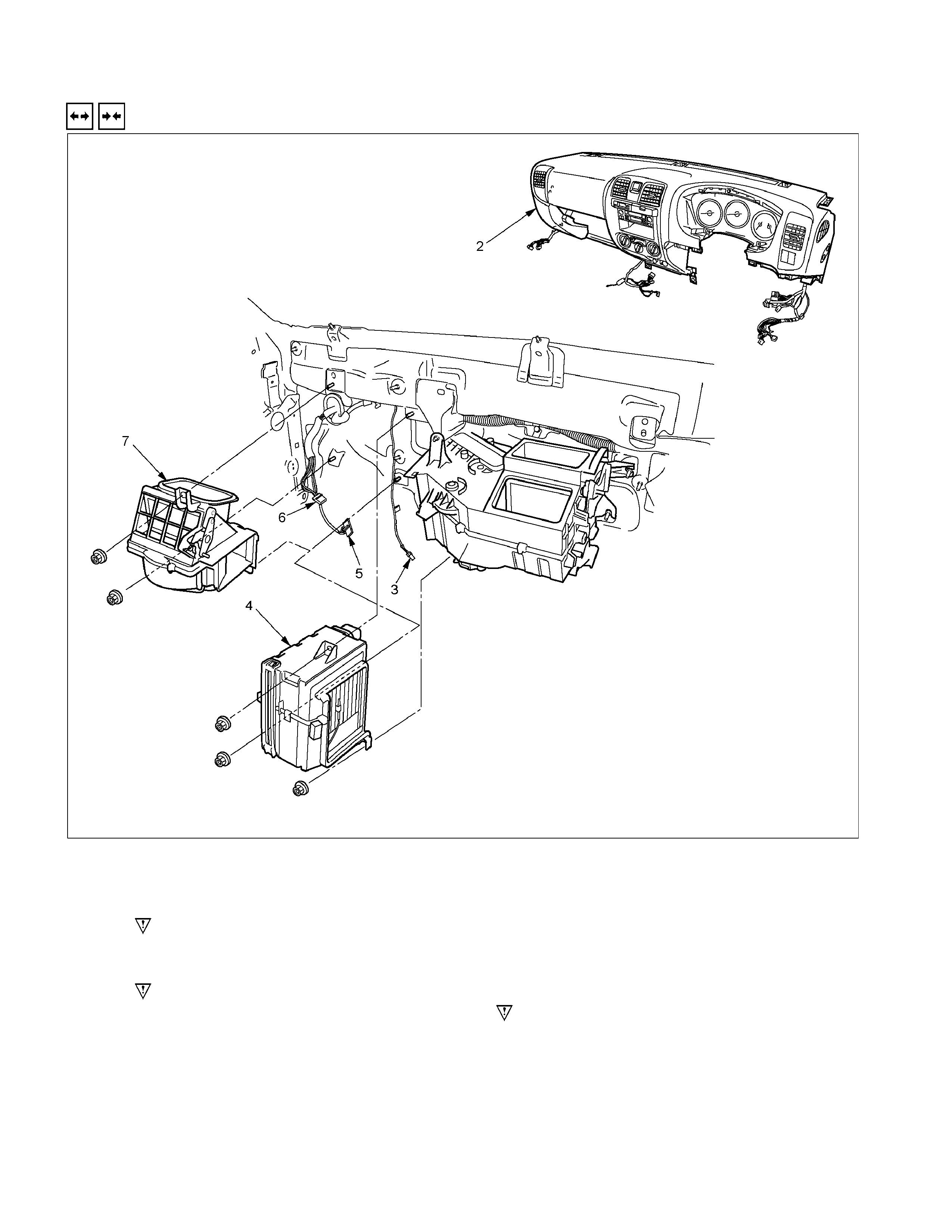
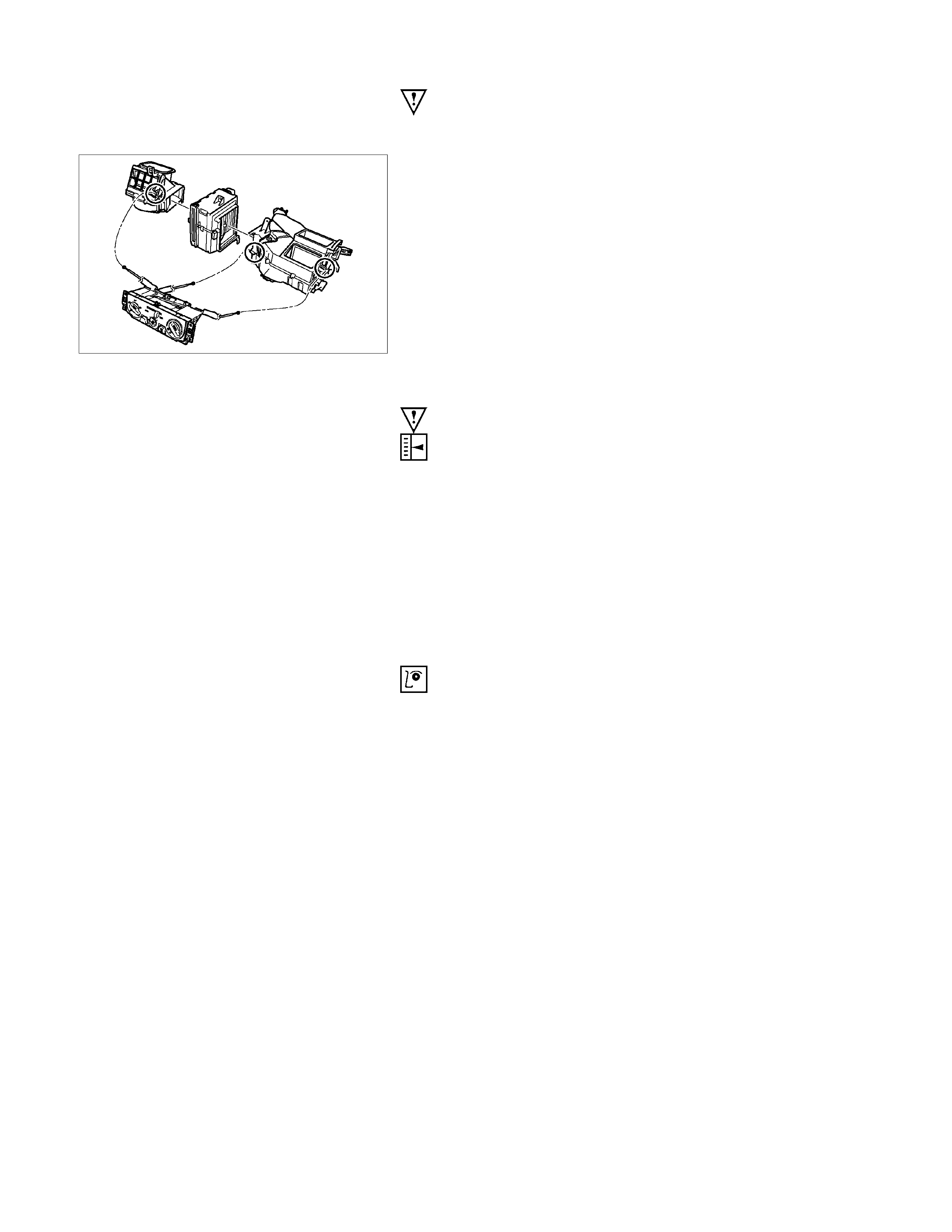
Heater Unit
Removal And Installation
RTW310LF000501-X
Removal Steps
1. Control cable
2. Instrument panel assembly and cross
beam
3. Electronic thermostat connector
4. Evaporator or Duct
5. Heater unit
Installation steps
5. Heater unit
4. Evaporator or Duct
3. Electronic thermostat connector
2. Instrument panel assembly and cross
beam
1. Control cable

Important Operations – Removal
2. Instrument Panel Assembly and Cross Beam.
Refer to INSTRUMENT PANEL in CAB section.
4. Evaporator or Duct
Refer to “DUCT” in this section.
Important Operation - Installation
2. Instrument Panel Assembly and Cross Beam
Adjust the heater control cables.
Refer to "CONTROL LEVER ASSEMBLY" in this section.
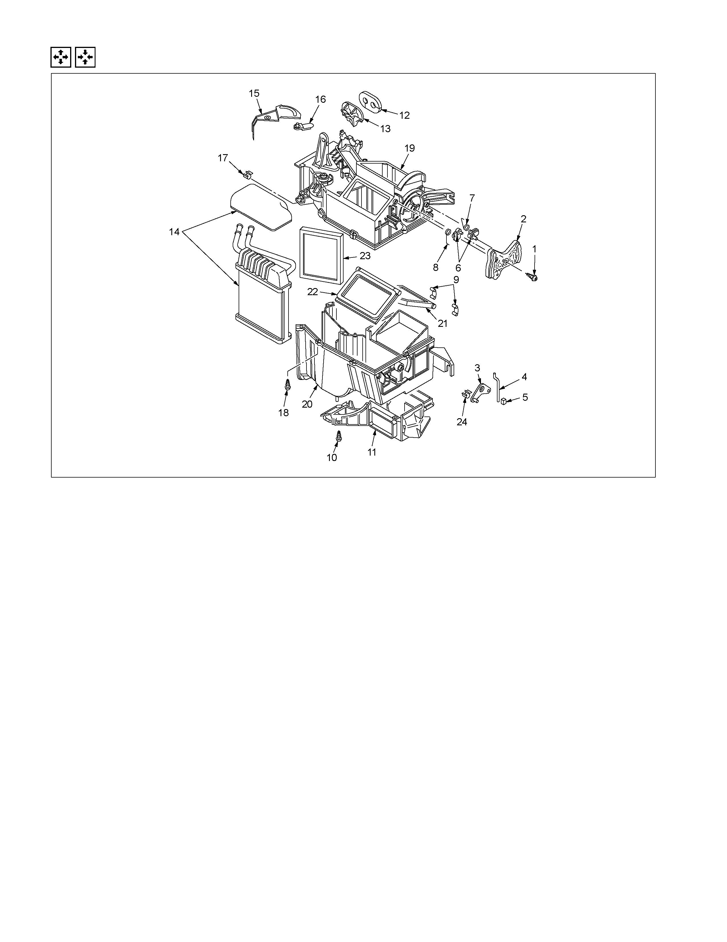
Disassembly And Reassembly
RTW310LF001401
Disassembly Steps
1. Attaching screw
2. Main link-side
3. Sub link-side
4. Mode rod
5. Holder rod
6. Mode lever
7. DEF/FOOT-spring
8. VENT-spring
9. Heater box clip
10. Attaching screws
11. Foot duct
12. H/Pipes seal
13. Heater core clamp
14. Heater core
15. Mix lever (2)
16. Mix lever (1)
17. Control cable clamp
18. Attaching screws
19. Upper case
20. Lower case
21. DEF/FOOT door
22. VENT door
23. Mix door
24. Control cable clamp
Reassembly Steps
24. Control cable clamp
23. Mix door
22. VENT door
21. DEF/FOOT door
20. Lower case
19. Upper case
18 Attaching screws
17. Control cable clamp
16. Mix lever (1)
15. Mix lever (2)
14. Heater core
13. Heater core clamp
12. H/Pipes seal
11. Foot duct
10. Attaching screws
9. Heater box clip
8. VENT-spring
7. DEF/FOOT-spring
6. Mode lever
5. Holder rod
4. Mode rod
3. Sub link-side
2. Main link-side
1. Attaching screw
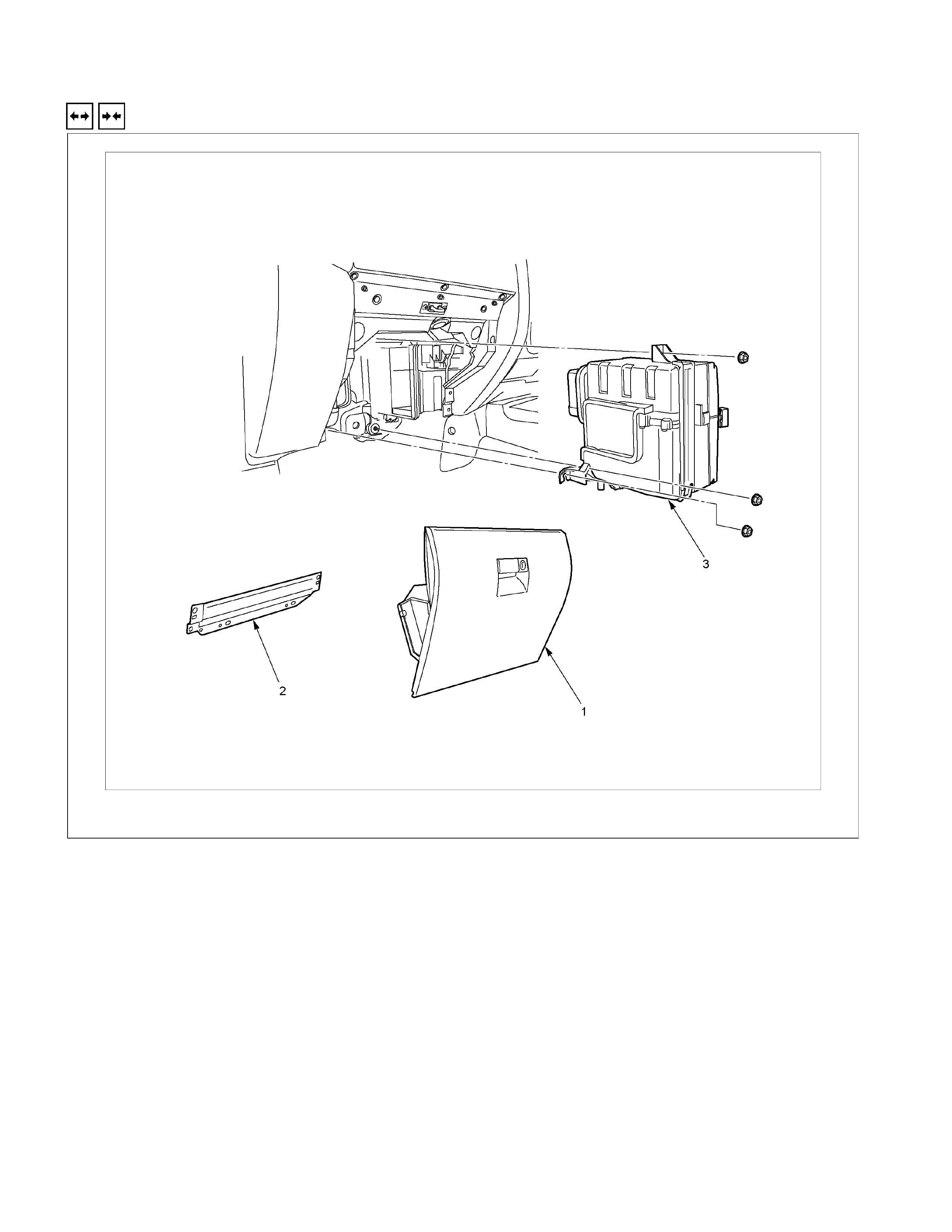
Duct
Removal And Installation
RTW310LF001601
Removal Steps
1. Glove box
2. Passenger lower bracket
3. Evaporator or Duct assembly
Installation Steps
3. Evaporator or Duct assembly
2. Passenger lower bracket
1. Glove box
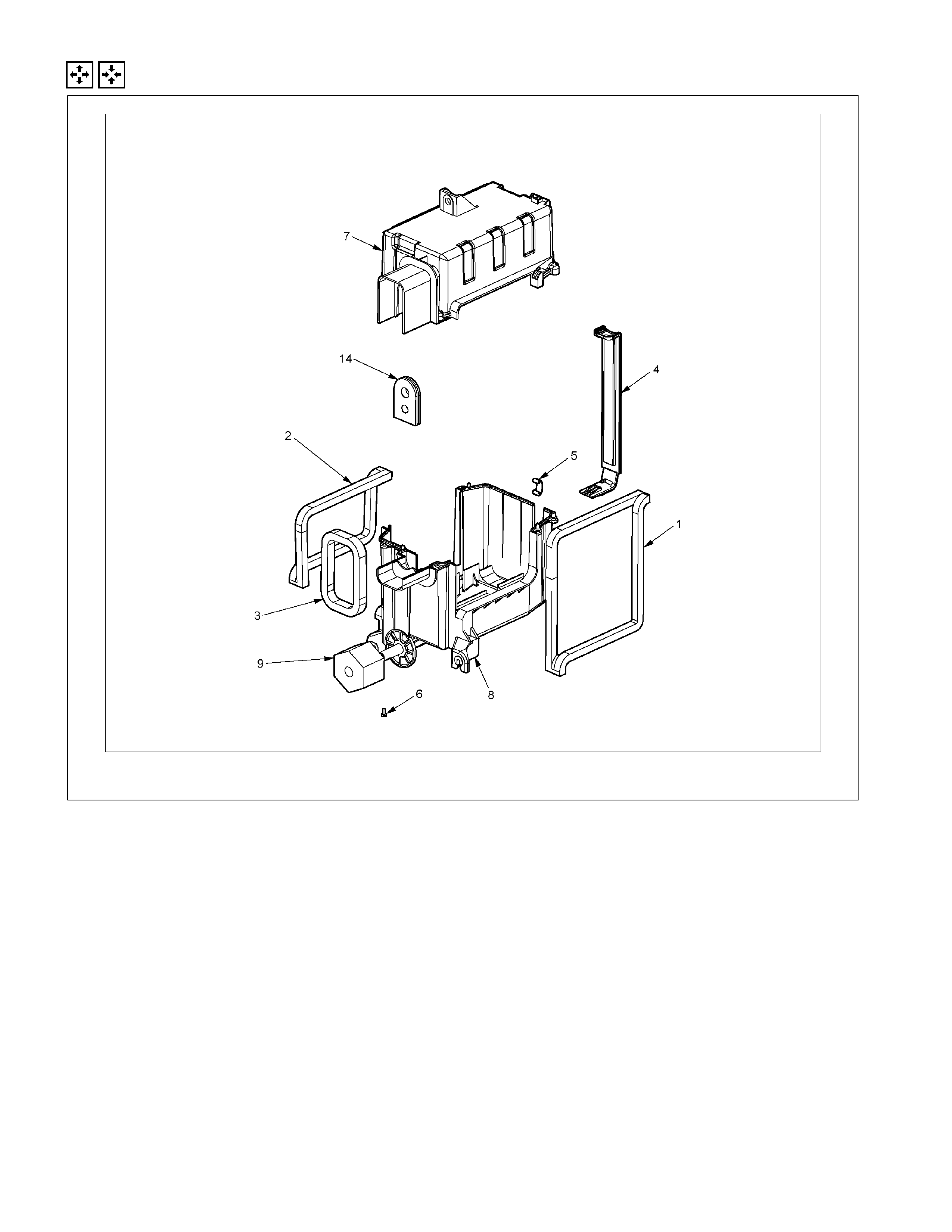
Disassembly And Reassembly
RTW310LF001501
Disassembly Steps
1. Packing cooler outlet
2. Packing cooler inlet
3. Seal fod cooler
4. Filter cover assembly
5. Clip heater
6. Attaching screws
7. Case : cooler upper
8. Case : cooler lower
9. Packing drain
Reassembly Steps
9. Packing drain
8. Case : cooler lower
7. Case : cooler upper
6. Attaching screws
5. Clip heater
4. Filter cover assembly
3. Seal fod cooler
2. Packing cooler inlet
1. Packing cooler outlet
Blower Unit Assembly
Removal And Installation
873R300002-X
Removal Steps
1. Control cable
2. Instrument panel assembly and cross
beam
3. Electronic thermostat connector
4. Evaporator or duct
5. Resistor connector
6. Blower motor connector
7. Blower unit assembly
Installation Steps
7. Blower unit assembly
6. Blower motor connector
5. Resistor connector
4. Evaporator or duct
3. Electronic thermostat connector
2. Instrument panel assembly and cross
1. Control
beam cable

Important Operation - Installation
2. Instrument Panel Assembly and Cross Beam
Refer to “INSTRUMENT PANEL” in CAB section.
4. Evaporator or Duct
Refer to “DUCT” in this section.
Important Operation - Installation
2. Instrument Panel Assembly and Cross Beam
Adjust the heater control cables.
Refer to “CONTROL LEVER ASSEMBLY” in this section.
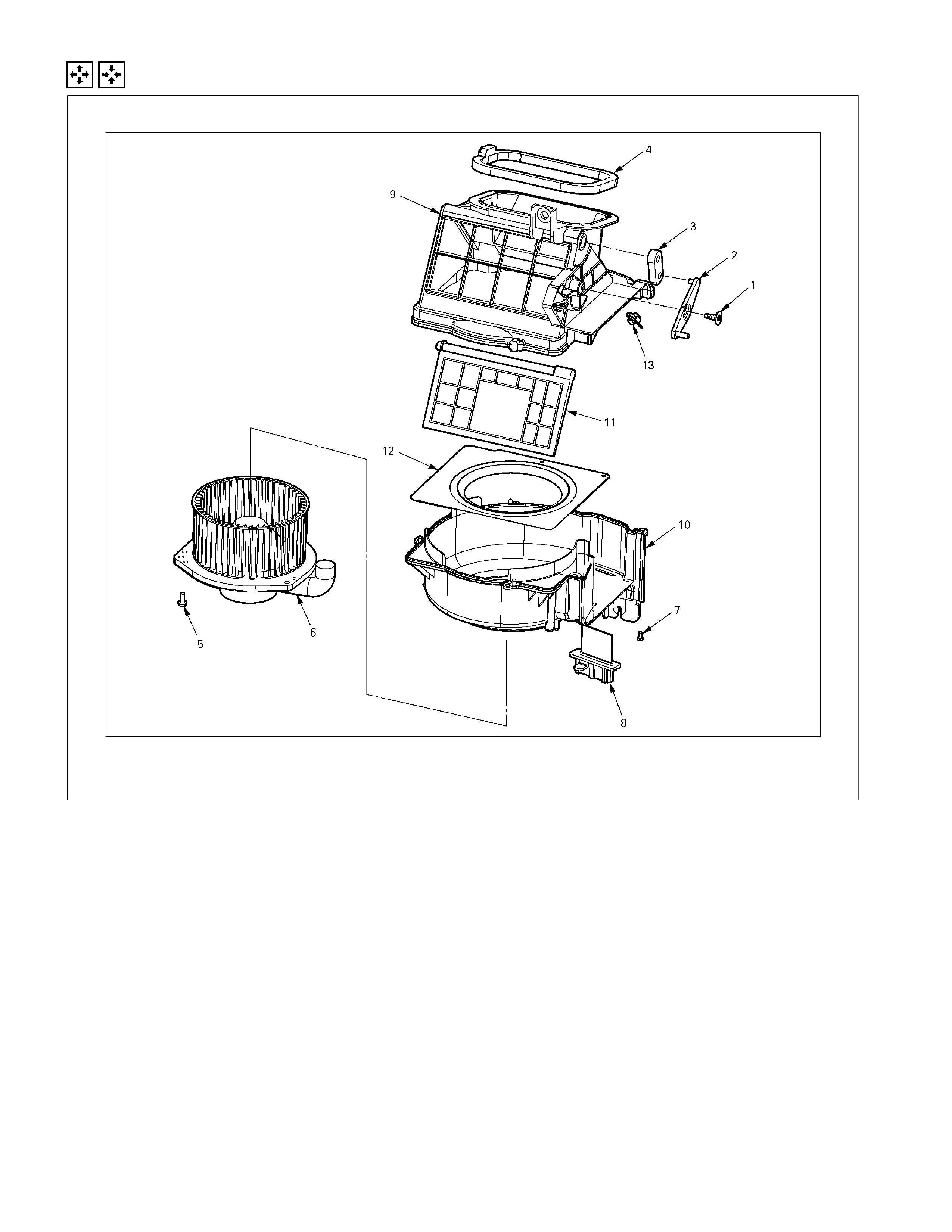
Disassembly And Reassembly
Disassembly Steps
1. Attaching screw
2. Intake link
3. Intake lever
4. Intake packing
5. Attaching screws
6. Blower motor assembly
7. Attaching screw
8. Flat resistor
9. Upper case
10. Lower case
11. Mode door
12. Bell mouth
13. Control cable clamp
Reassembly Steps
13. Control cable clamp
12. Bell mouth
11. Mode door
10. Lower case
9. Upper case
8. Flat resistor
7. Attaching screw
6. Blower motor assembly
5. Attaching screws
4. Intake packing
3. Intake lever
2. Intake link
1. Attaching screw
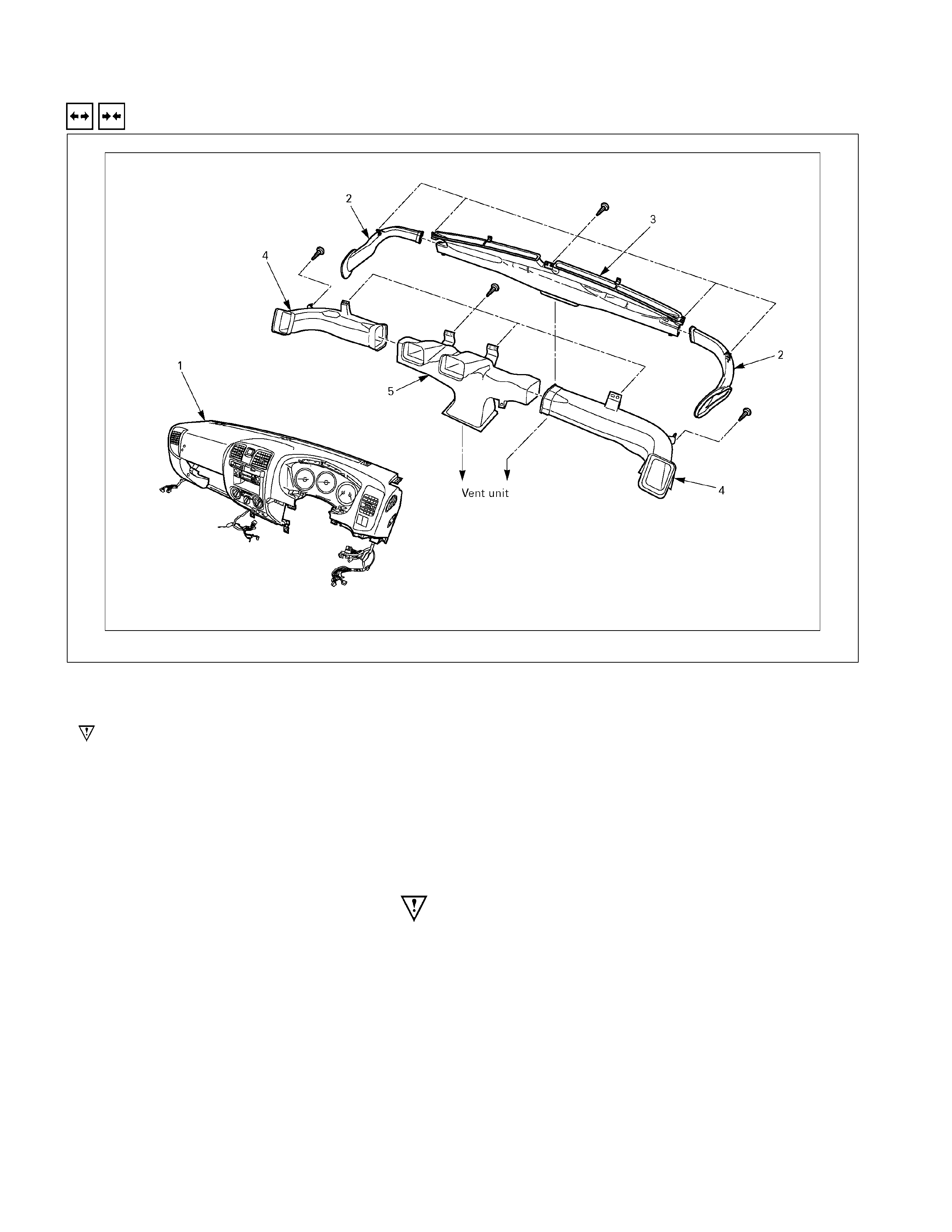
Defroster Nozzle And Vent Duct
Removal And Installation
Removal Steps
1. Instrument panel assembly and cross
beam
2. Side def hose R/LH
3. Defroster nozzle
4. Vent duct driver side and passenger
side
5. Center vent duct
Installation Steps
5. Center vent duct
4. Vent duct driver side and passenger side
3. Defroster nozzle
2. Side def hose R/LH
1. Instrument panel assembly and cross beam
Important Operation - Removal
1. Instrument Panel Assembly and Cross Beam
Refer to “INSTRUMENT PANEL” in CAB section.

Control Lever Assembly
Removal And Installation
RTW310MF000601
Removal Steps
1. Glove box
2. Instrument panel driver lower cover
3. Ash tray
4. Control cables
5. Center cluster
6. Attaching screw
7. A/C switch connector
8. Fan switch connector
9. Control lever assembly
Installation Steps
9. Control lever assembly
8. Fan switch connector
7. A/C switch connector
6. Attaching screw
5. Center cluster
4. Control cables
3. Ash tray
2. Instrument panel driver lower cover
1. Glove box
Techline
Important Operation - Removal
2. Instrument Panel Driver Lower Cover
Refer to “INSTRUMENT PANEL” in CAB section.
RTW310SH000101
4. Control Cables
Disconnect control cables at each unit side.
5. Center Cluster
Refer to “INSTRUMENT PANEL” in CAB section.
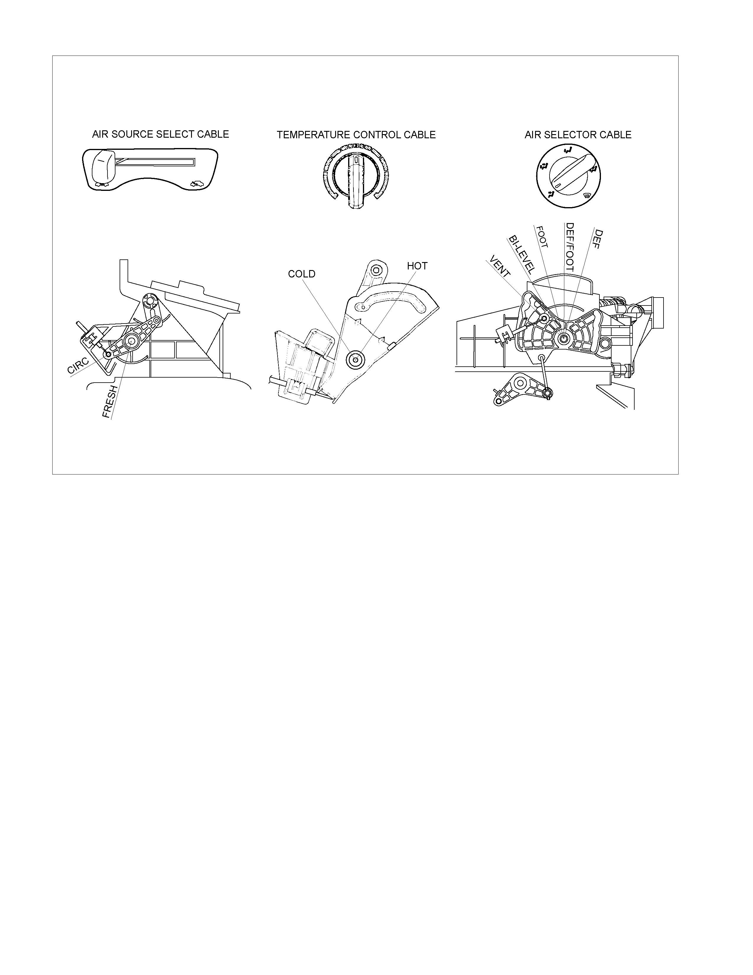
Important Operation - Installation
9. Control Lever Assembly
Air source control cable
1) Slide the control lever to the left (“CIRC” position).
2) Connect the control cable at the "CIRC" position of the link
unit of blower assembly and fix it with the clip.
Temperature control cable
1) Turn the control knob to the right (“FULL HOT” position).
2) Connect the control cable at the “FULL HOT” position o
f
the mix lever of the heater unit and fix it with the clip.
Air select control cable
1) Turn the control knob to the left (“VENT” position).
2) Connect the control cable at the “VENT” position of the
mode control link of the heater unit and fix it with the clip.
4. Control Cables
Check control cable operation
RTW410MF000201
Control Panel Illumination Bulb
Removal And Installation
This illustration is based on RHD model
RTW410MF000601
Removal Steps
1. Control lever assembly
2. Illumination bulb
Installation Steps
2. Illumination bulb
1. Control lever assembly
Important Operation - Removal
1. Control lever assembly
Refer to “CONTROL LEVER ASSEMBLY” in this section.
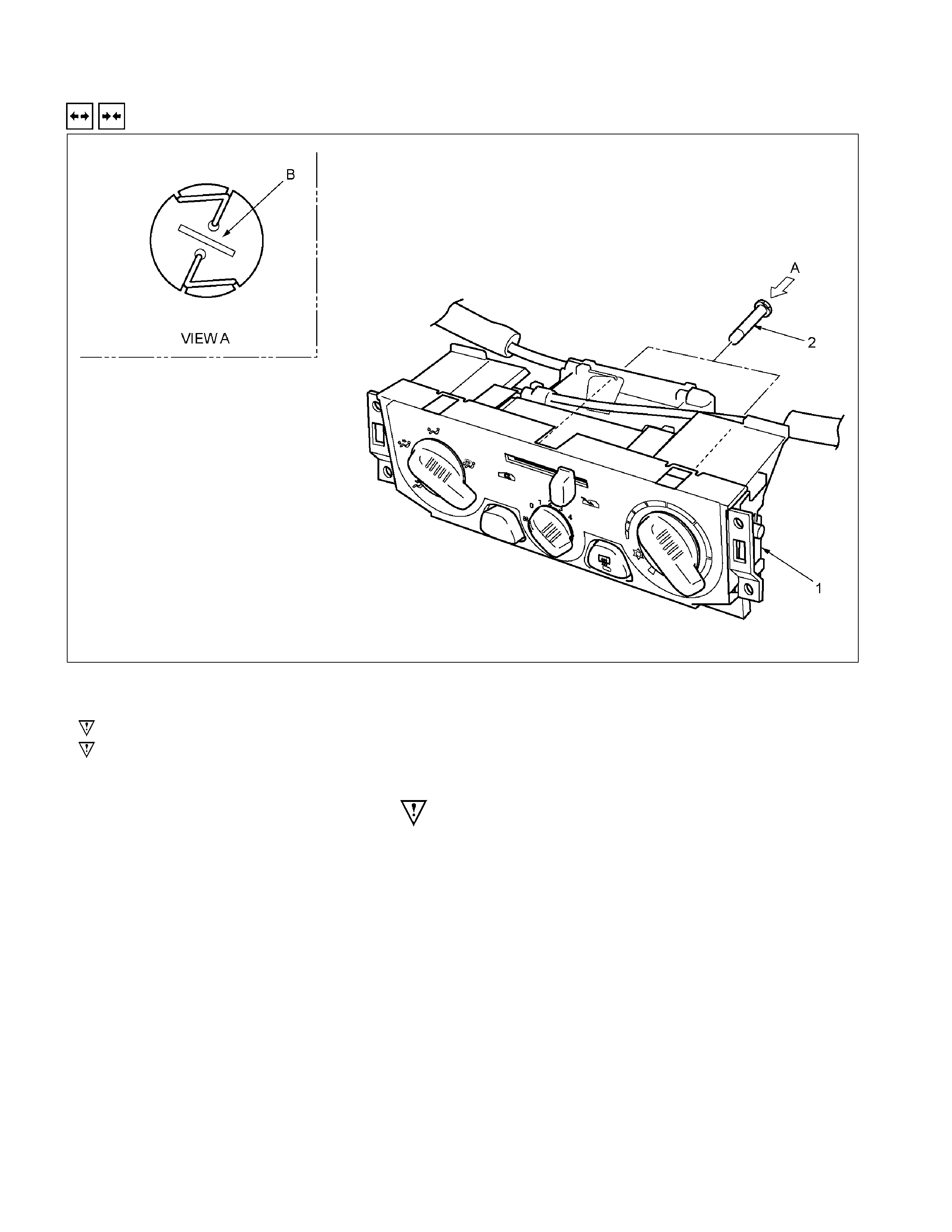
2. Illumination Bulb
To remove the illumination bulb, insert an ordinary screwdriver
into the slot (B) at the back of the bulb. Turn the bulb
counterclockwise and pull it free.
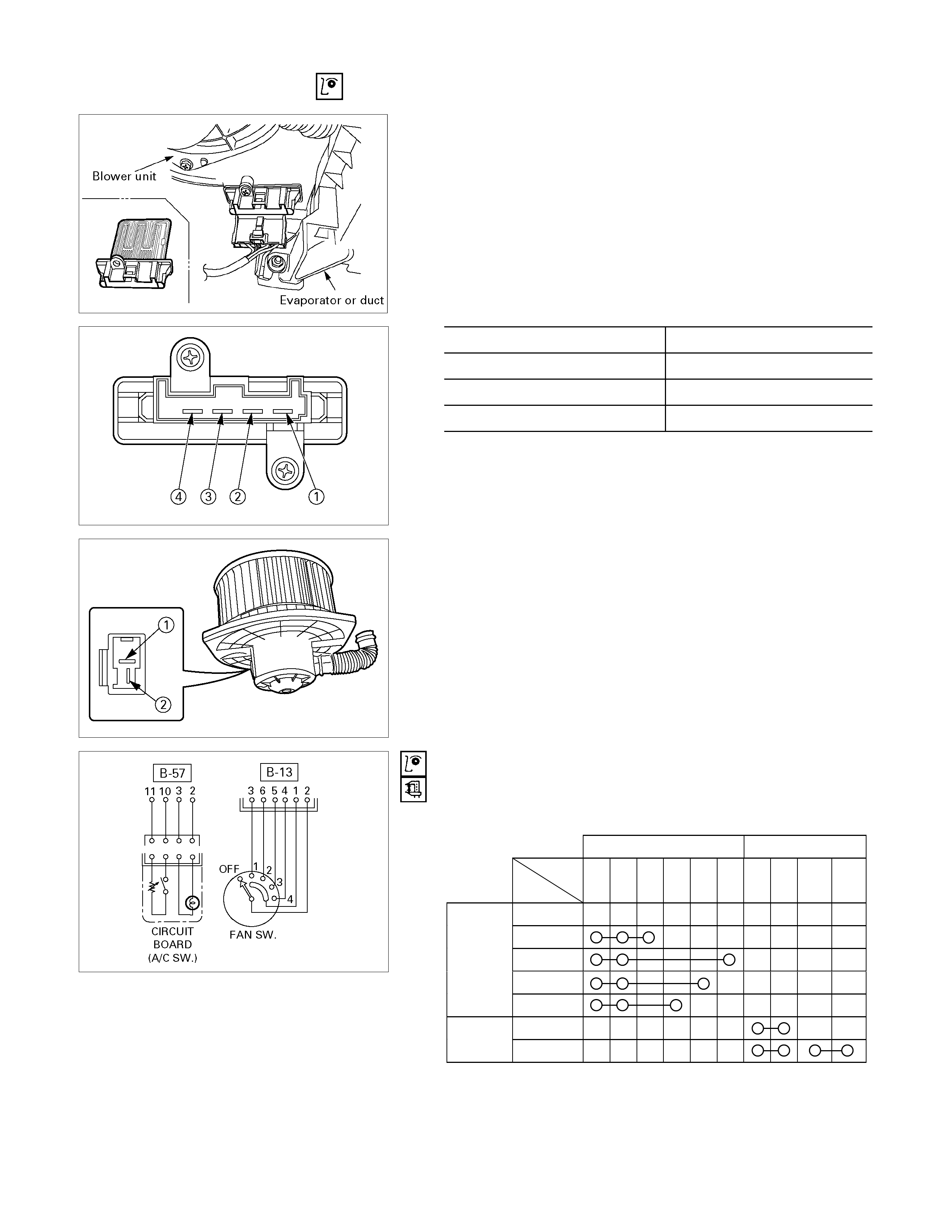
Inspection And Repair
840R300005-X
Resistor
As for air-conditioning model, fixed on left (RHD) / right (LHD)
side of the evaporator unit.
As for heater only model, fixed on left (RHD) / right (LHD) side
of the duct placed between blower unit and heater unit.
Replace the resistor with a new on if the coil is found to be
open or if the resistance value deviates from the specified
range.
Terminal Resistance
3 – 2 1.99 Ω
3 – 4 0.9 Ω
3 – 1 0.17 Ω
Blower motor
Check blower motor for smooth rotation.
Connect the battery positive terminal to the No.1 terminal of
the blower motor and negative to the No.2.
Be sure to check to see if the blower motor operates correctly.
D08R300070
Fan switch and Circuit board
Check for continuity between fan switch and A/C switch side
connector terminals.
B-13 B-57
Terminal
No.
SW.
position 1 2 3 4 5 6 2 3 10 11
OFF
1
2
3
(FAN SW.)
4
OFF
CIRCUIT
BOARD
(A/C SW.) ON
825r300045
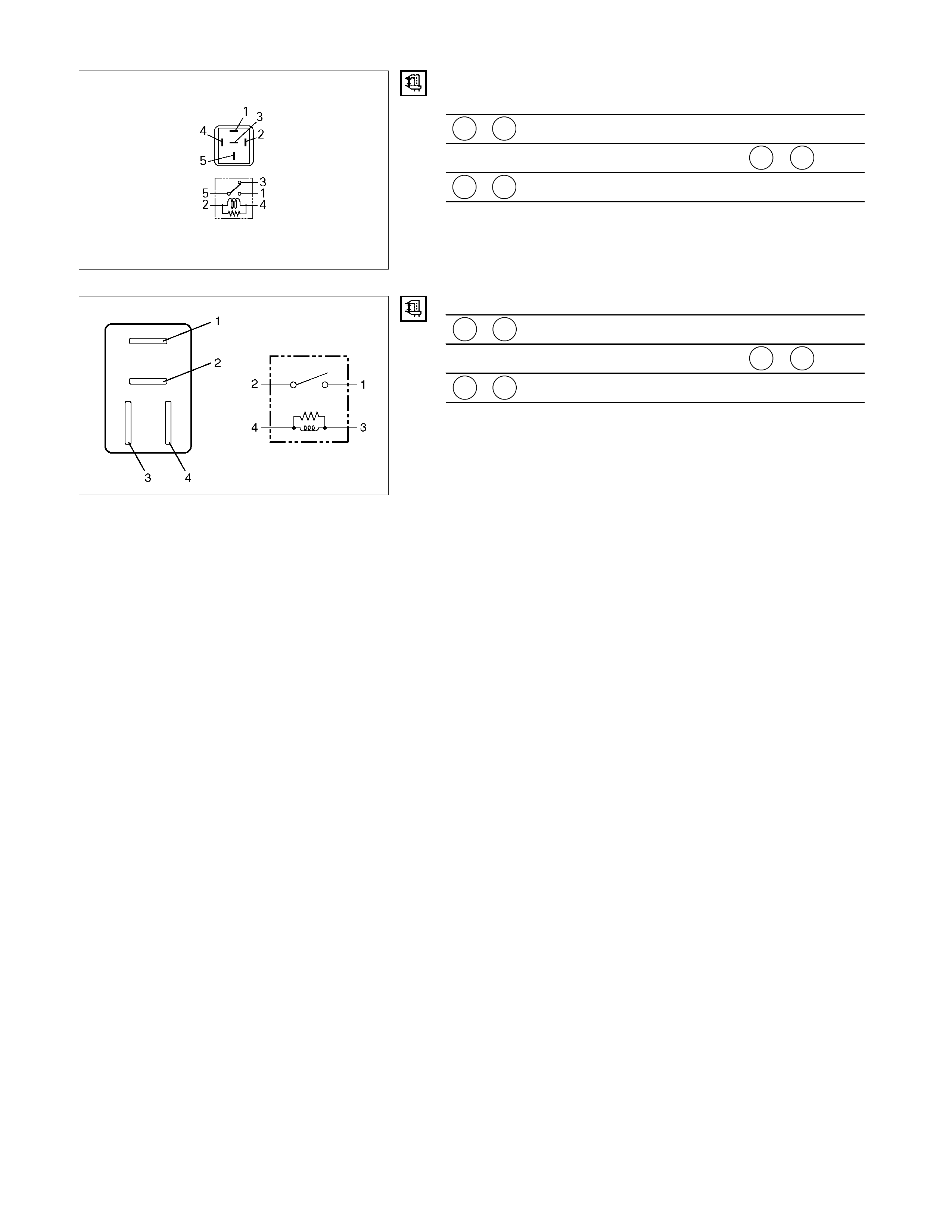
Heater and thermo switch relay.
Check for continuity between the relay terminals.
1 - 5 ⋅⋅⋅⋅⋅ No continuity
(When battery voltage is applied between 2 - 4 )
1 - 5 ⋅⋅⋅⋅⋅ Continuity
825r300023
Check for continuity between the relay terminals.
1 - 2 ⋅⋅⋅⋅⋅ No continuity
(When battery voltage is applied between 3 - 4 )
1 - 2 ⋅⋅⋅⋅⋅ Continuity
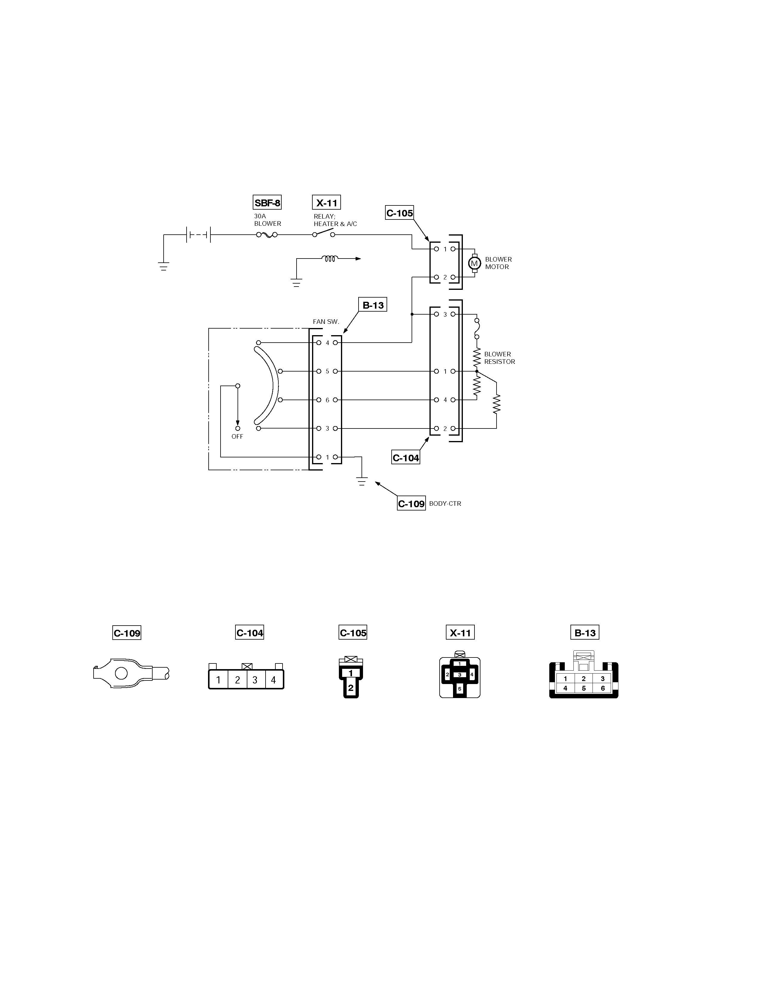
TROUBLESHOOTING
FAN CONTROL KNOB (FAN SWITCH)
Current flows to the blower motor through the Heater & A/C relay (X-11) to activate the rotation of the blower motor by
turning “ON” the fan control knob (fan switch). Blower motor speed is controlled in stages by the resistor, by operating
the switch from “LOW” to “HIGH.”
D08R300046-X2

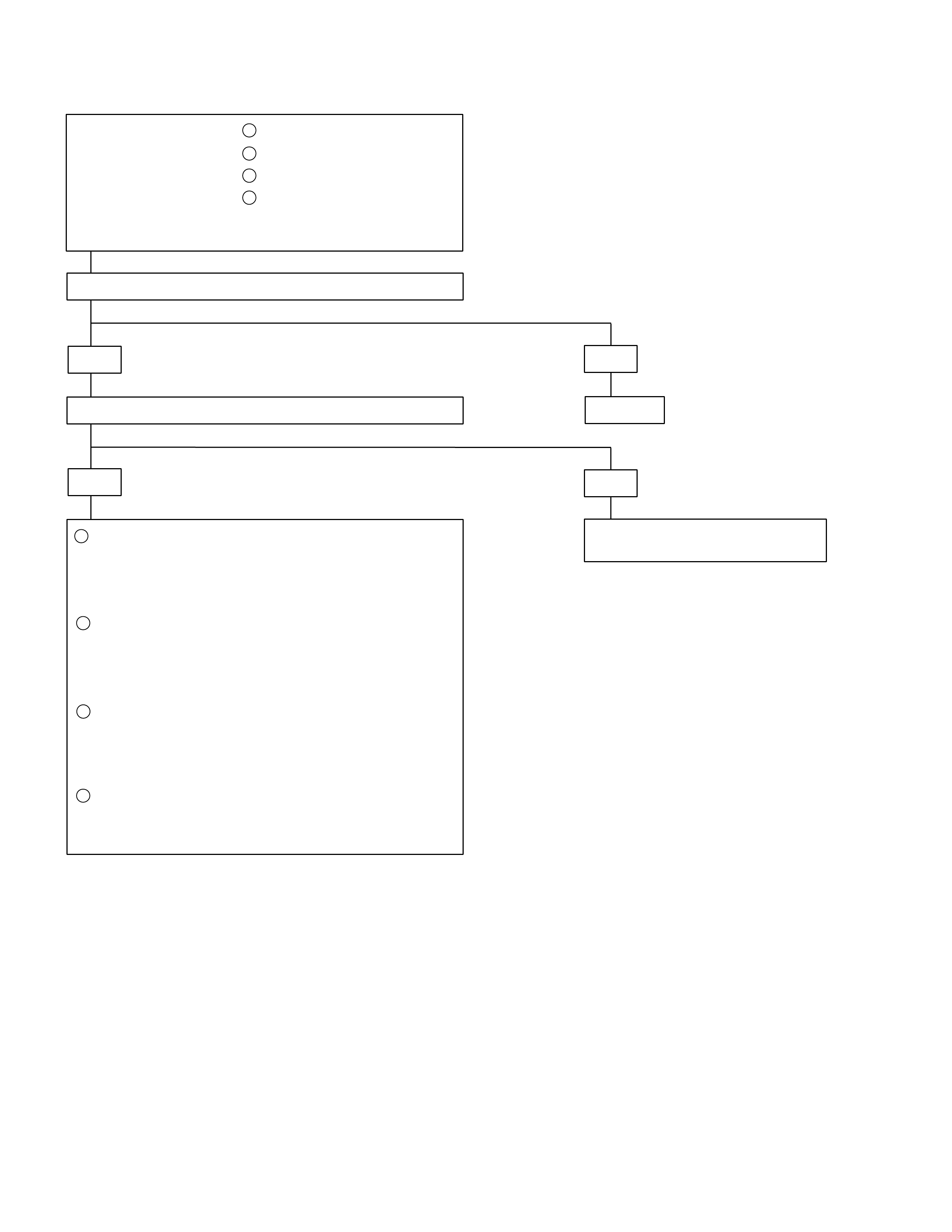
BLOWER MOTOR DOES NOT RUN
Re
p
lace
YES
• Is No.SBF-8 (30A) slow blow fuse OK?
• Is heater & A/C relay (X -11) OK?
YES
• Is resistor OK?
YES
• Is fan control knob (Fan switch) OK?
YES
YES
• Check to see if battery voltage is present at
chassis side conne ct or t ermina l No.C10 5-1 is there a
battery voltage?
• Turn the ignition swit ch "O N" (Engine is running)
• Fan control knob (Fan switch) "ON"
• Is blower motor OK?
YES
Poor ground or open circuit either betw een chassis
side connector terminal No.C105-2 and No.C104-3
or No.B13-1 and body ground No.C-109.
NO
Re
p
lace
NO
Re
p
lace
NO
NO
Replace control lever
assembly
Re
p
lace
NO
NO
Open circuit betw een
No.SBF-8 (30A) slow blow
fuse and No.C105-1.
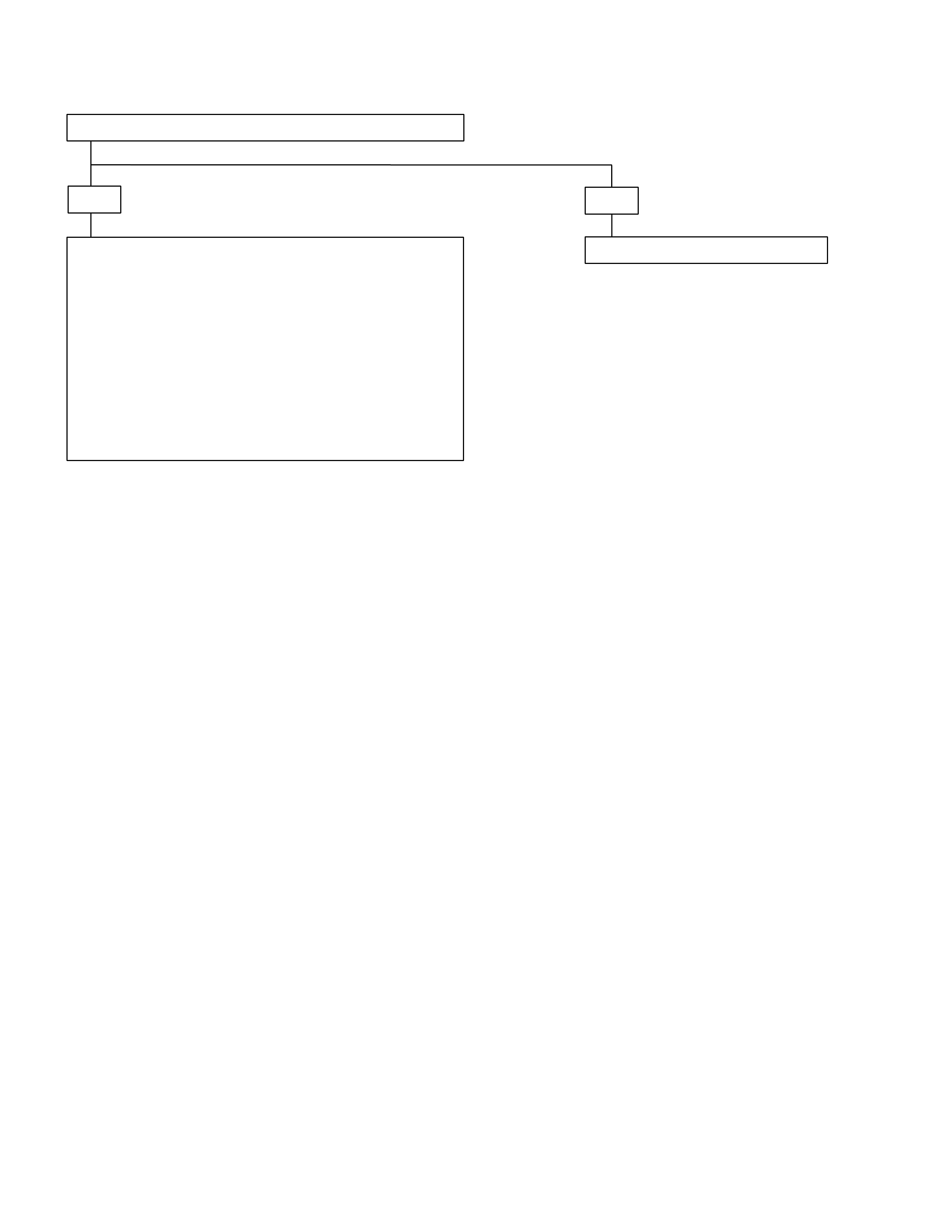
BLOWER MOTOR DOES NOT RUN IN CERTAIN POSITION
A
1:
(
Low
)
Blower motor does not B 2:
(
Medium Low
)
Position
run at C 3:
(
Medium Hi
)
D 4:
(
Hi
g
h
)
* Checkin
g
is
p
erformed onl
y
when in the malfunct ion
mode.
• Is resist or OK?
YES
• Is fan control knob
(
Fan switch
)
OK?
YES
Condition:
• O
p
en circuit between chassis side connect o
r
terminal No. C104-2 and No. B13-3
B Condition :
• O
p
en circuit between chassis side connect o
r
terminal No. C104-4 and No. B13-6
C Condition:
• O
p
en circuit between chassis side connect o
r
terminal No. C104-1 and No. B13-5
D Condition:
• O
p
en circuit between chassis side connect o
r
terminal No. C105-2 a nd No. B13-4
Re
p
lace
NO
NO
Replace control leve
r
assembly
A
BLOWER MOTOR DOES NOT STOP AT “OFF” POSITION
• Is fan control knob (Fan switch) OK?
YES
Short circuit between chassis side connector terminal
• No. C105-2 and No. C104-3
(or)
• No. C105-2 and No. B13-4
(or)
• No. C104-1 and No. B13-5
(or)
• No. C104-4 and No. B13-6
(or)
• No. C104-2 and No. B13-3
NO
Replace control lever assembly