
SECTION 11A
IMMOBILIZER SYSTEM
Service Precaution
General Description
What Happens Without Proper Transponder
Operation?
No Proper Transponder Is Available, What
Should Be Done For The System?
Caution To The Operation
Summary Of Operation
What Your Organization Should Provide For
Your Customer
• Car Pass
• Security Code Management
• Essential Tool (Scan Tool : Tech-2)
Circuit Diagram
Parts Location
Immobilizer Control Unit (ICU); For Electronic
Control Engine (6VE1, C24SE, 4JH1-TC,
4JA1-TC)
Pin-outs; For Electronic Control Engine
(6VE1, C24SE, 4JH1-TC, 4JA1-TC)
Immobilizer Control Unit (ICU); Mechanical
Control Engine (4JA1-T)
Immobilizer Coil (Antenna)
Transponder (Key)
Check Engine Lamp
Engine Control Module (ECM)
Car Pass Card
Loss Of Car Pass Card
Instructions On Filling Out The Form
"Data Request, Car Pass"
Important Instructions
lmportant Information On Programming
Security Code
Entering A Code
Transponder (Key)
Important
Tech-2 Scan Tool
Tech-2 Features
Getting Started
Operating Procedure
Menu
DTC
Clear DTC Information
Tech-2 Data Display
Check Vehicle Identification Number (VIN)
Reset Immobilizer (Reset Immobilizer
Control Unit)
Reset Engine Control Module (Reset ECM)
Erase Transponder Key
Programming Immobilizer Function
Programming ICU
Programming ECM
Programming ICU and ECM
Transponder Program
Data List
Diagnostic Procedure
Clearing Diagnostic Trouble Codes
Verifying Vehicle Repair
Diagnostic Aids
Check The Condition For System Parts
Check The Electro-Magnetic Interference (EMI)
Check The Other Items
Diagnostic Trouble Code (DTC) List
Immobilizer System Check
No Immobilizer Warning Lamp
Check Immobilizer Warning Lamp On Steady
B0001 Replace Electronic Control Unit (ECU)
(Immobilizer Fault)
B0002 Immobilizer Not Programmed
B0003 Transponder Key Problem
B0004 Immobilizer Coil Circuit (Antenna Coil Fault)
B0005 Communication Line W Voltage Low
B0006 Communication Line W Voltage High
B0007 No Engine Request Received
B0008 Wrong Transponder Key
B0009 No Transponder Key Programmed
B0010 Unknown Transponder Key
B0011 Transponder Key Problem
(Only 4JA1-T Engine)

B0012 Wrong Transponder Key
(Only 4JA1-T Engine)
B0013 Immobilizer Not Programmed
(Only 4JA1-T Engine)
B0014 No Transponder Key Programmed
(Only 4JA1-T Engine)
B0015 Frequency Signal Low
(Only 4JA1-T Engine)
B0016 Frequency Signal High
(Only 4JA1-T Engine)
B0023 Immobilizer Coil Circuit (Antenna Coil Fault)
(Only 4JA1-T Engine)
B0024 Wrong Transponder Key
(Only 4JA1-T Engne)
B0055 EEPROM Error
Special Tools

Service Precaution
WARNING:
THIS VEHICLE HAS A SUPPLEMENTAL
RESTRAINT SYSTEM (SRS). REFER TO THE SRS
COMPONENT AND WIRING LOCATION VIEW IN
ORDER TO DETERMINE WHETHER YOU ARE
PERFORMING SERVICE ON OR NEAR THE SRS
COMPONENTS OR THE SRS WIRING. WHEN YOU
ARE PERFORMING SERVICE ON OR NEAR THE
SRS COMPONENTS OR THE SRS WIRING, REFER
TO THE SRS SERVICE INFORMATION. FAILURE TO
FOLLOW WARNINGS COULD RESULT IN
POSSIBLE AIR BAG DEPLOYMENT, PERSONAL
INJURY, OR OTHERWISE UNNEEDED SRS SYSTEM
REPAIRS.
CAUTION:
A
lways use the correct fastener in the prope
r
location. When you replace a fastener, use ONL
Y
the exact part number for that application. ISUZU
will call out those fasteners that require a
replacement after removal. ISUZU will also call out
the fasteners that require thread lockers or thread
sealant. UNLESS OTHERWISE SPECIFIED, do not
use supplemental coatings (Paints, greases, o
r
other corrosion inhibitors) on threaded fasteners o
r
fastener joint interfaces. Generally, such coatings
adversely affect the fastener torque and the joint
clamping force, and may damage the fastener.
When you install fasteners, use the correct
tightening sequence and specifications. Following
these instructions can help you avoid damage to
parts and systems.
General Description
The immobilizer system consists of the four majo
r
components which are Engine Control Module (ECM),
Immobilizer Control Unit (lCU), transponder, and scan
tool (Tech-2).
This system can be activated by a correctly programmed
transponder and starter switch is set to OFF.
This system can be deactivated by a correctl
y
programmed transponder key connected with a correctl
y
programmed ECM and a correctly programmed lCU.
While the system is on :
The starter cut off relay deactivates function of starter,
and the fuel injector power source is deactivated also.
• Check Engine lamp is flashing.
• Warning buzzer is operating.
(With antitheft system)
• Gasoline Engine (6VE1, C24SE)
LTW3BALF000101
Diesel Engine With ECM (4JH1-TC/4JA1-TC)
LTW3BALF000201
Diesel Engine With Engine Immobilizer Unit (4JA1-T Mechanical Control Engine)
RAW4B0LF000101

What happens without proper transponder
operation?
One of the function of transponder is to deactivate o
r
activate starter function. lf the proper transponder is not
used, starter cannot be operated. Because starter relay
stays off, cranking engine is not possible.
After the starter relay is activated, transponder signal
triggers to let lCU calculate by transponder address
signal and immobilizer algorithm.
When the result matches with necessary condition, it
makes injector power source be activated.
If transponder does not send correct signal, lCU and
ECM do not activate injector system on.
Therefore the vehicle cannot be operated.
No proper transponder is available, what
should be done for the system?
When any proper transponder is not available, a new
transponder should be programmed. Up to 5
transponders can be provided with a scan tool (Tech-2)
and by proper procedure.
In addition to the absence of proper transponder, it may
happen particular secret code to the particular vehicle
is missing. ln this case, the secret code must be
provided by your organization.
Otherwise transponder cannot be programmed in any
way.
lf the essential for a scan tool (Tech-2) for programming
and proper software for Tech-2 are not available, there
is no permanent way to fix system. Temporary replace
with new ECM, new ICU and new transponder without
any secret code can make the system be deactivated,
but it does not last long. Such a replacement does not
solve any condition. Even after replacement, the
system is activated automatically in short time and then
no operation of the vehicle can be made in any way.
Tech-2 should be provided in your organization.
Caution to the operation
lf an attempt is made to start the engine while the
immobilizer system is activated, the check engine lamp
flashes and the engine will not start.
Summary of operation
Switch on: Set the ignition and starter switch to OFF.
(Activate)
Switch off: Set the ignition and starter switch to ON by
using the transponder key. (Deactivate)
What your organization should provide for
your customer
• Car Pass
For a new owner, your dealership must hand Car Pass
card, which has identification numbers of new owner's
vehicle immobilizer system. This information is very
important in case of repair or lost of transponder.
The followings are necessary items provided by you
r
responsibility.
1) Car pass with identification for a new owner
2) Blank car pass card when it is for reissue
3) Instruction to dealers how to use car pass card
• Security code management
Your organization must keep security codes for all
vehicles as confidential data. Once the security codes
are lost, anybody who have the security code can
access immobilizer system. Your organization has
responsibility of any missing vehicles caused by stolen
security code.
• Essential tool (Scan tool : Tech-2)
Your dealership must have Tech-2, and Tech-2
updated software for immobilizer system.
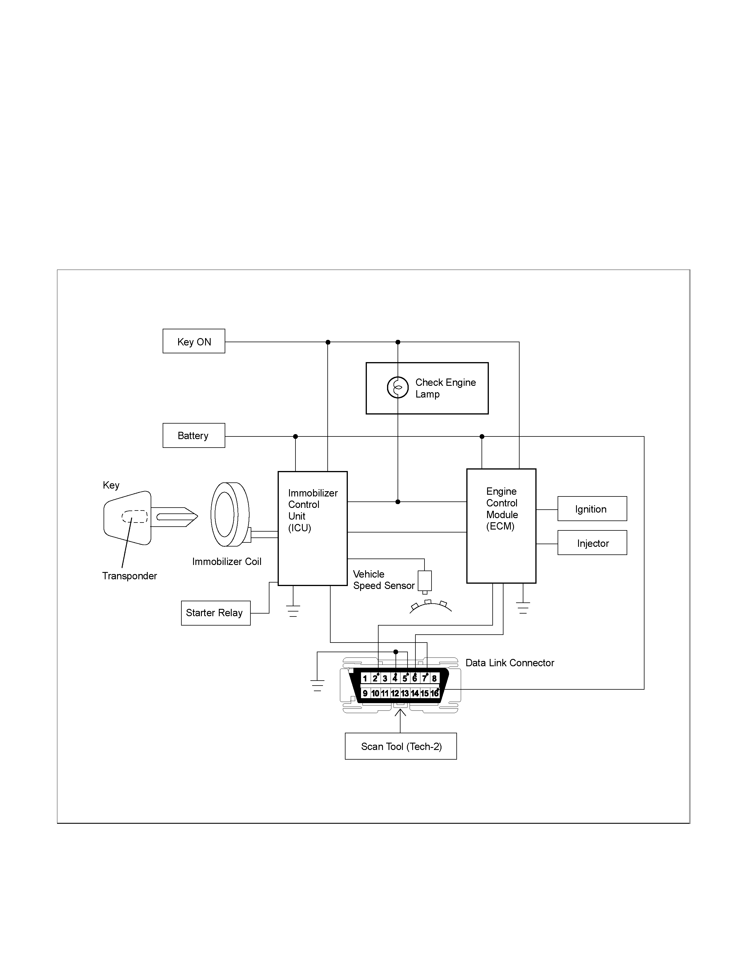
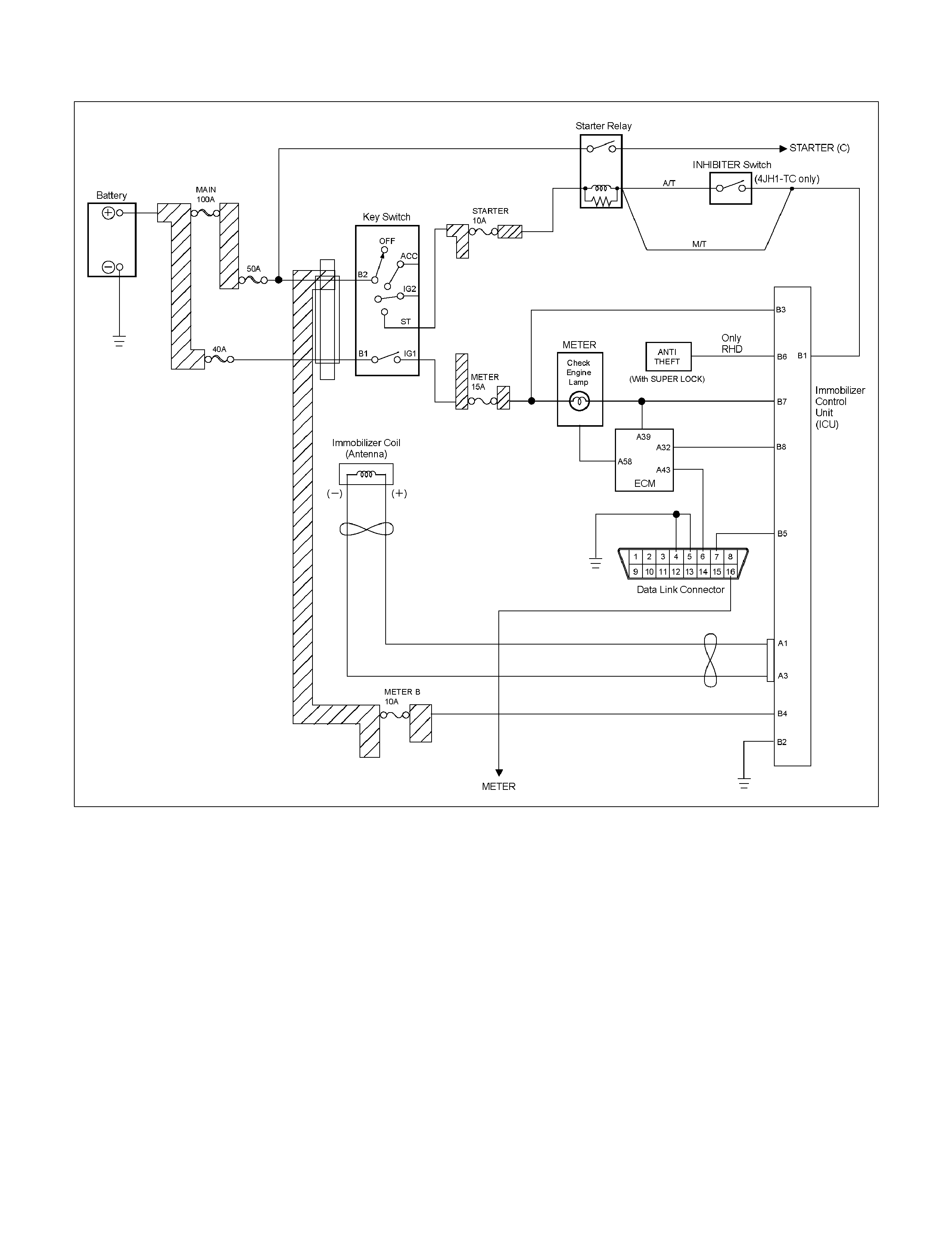
Circuit Diagram
• Gasoline Engine (6VE1, C24SE)
RAW4B0LF000601
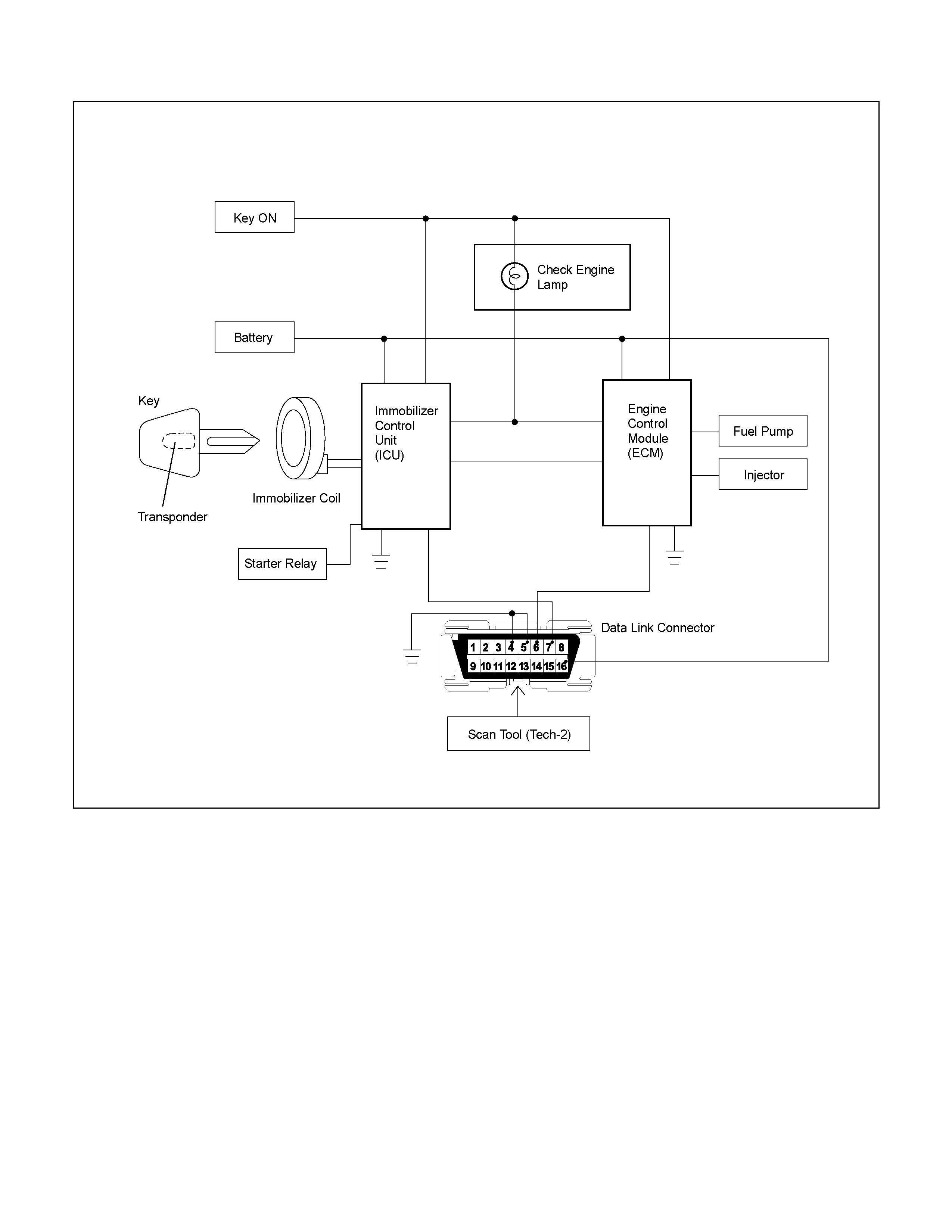
Diesel Engine With ECM (4JH1-TC/4JA1-TC)
RTW4B0LF000101
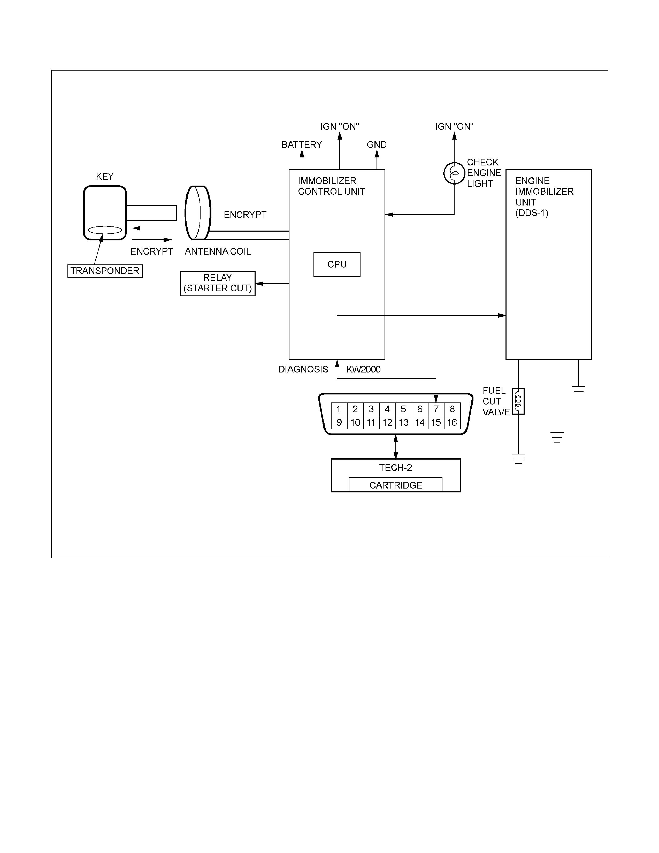
Diesel Engine With Engine Immobilizer Unit (4JA1-T Mechanical Control Engine)
RAW4B0LF000401
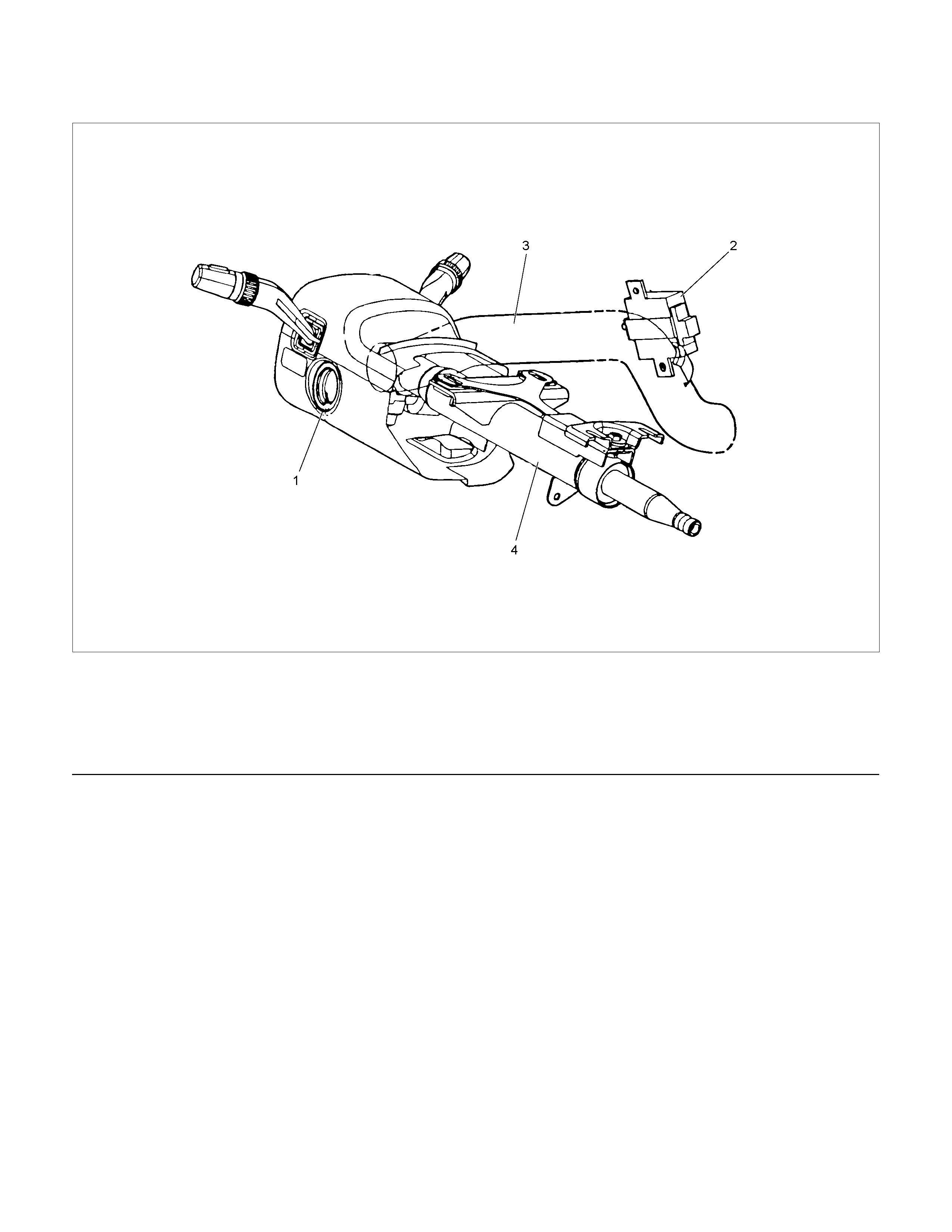
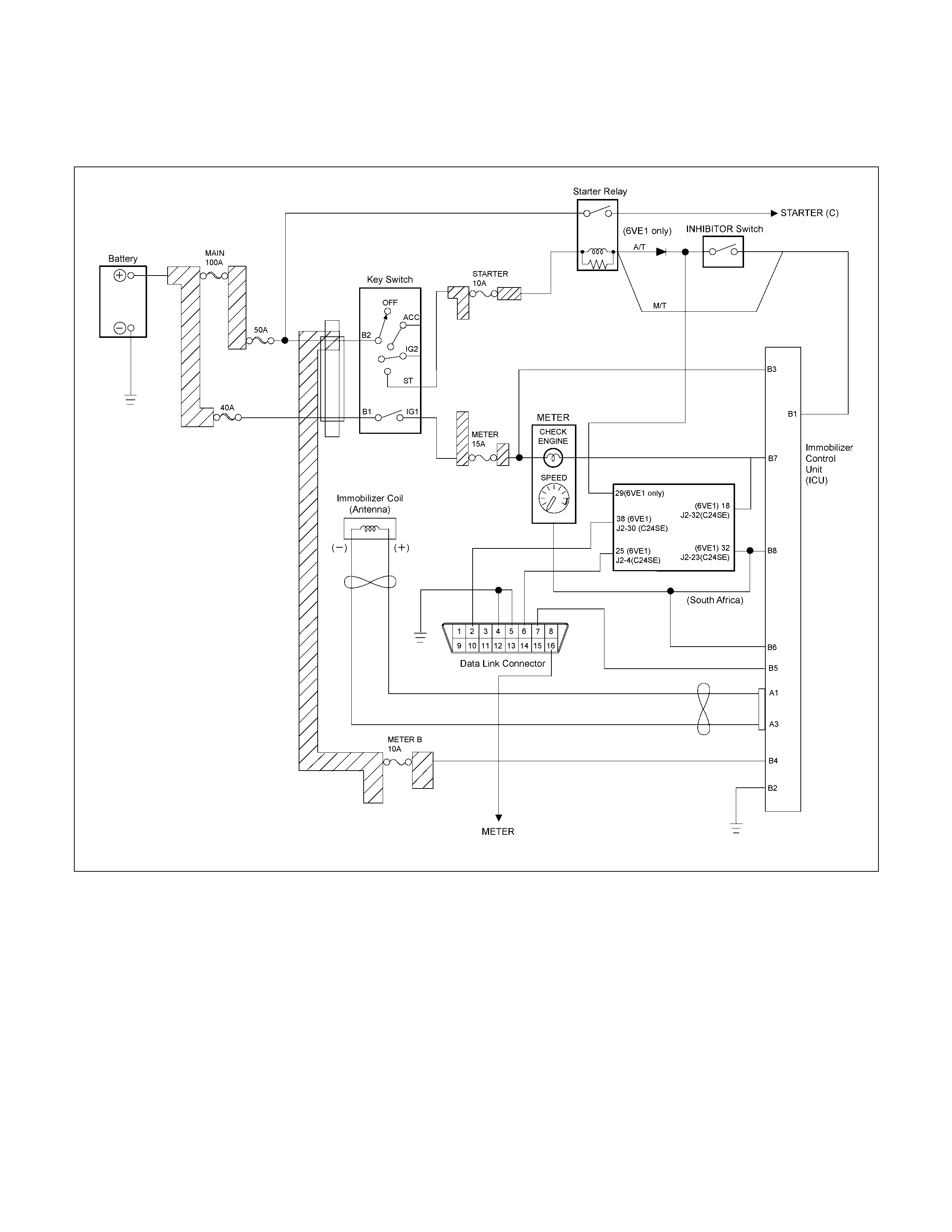
Parts Location
LTW3BAMF000101
Legend
(1) Immobilizer Coil
(2) Immobilizer Control Unit (ICU)
(3) Cross Beam
(4) Steering Shaft

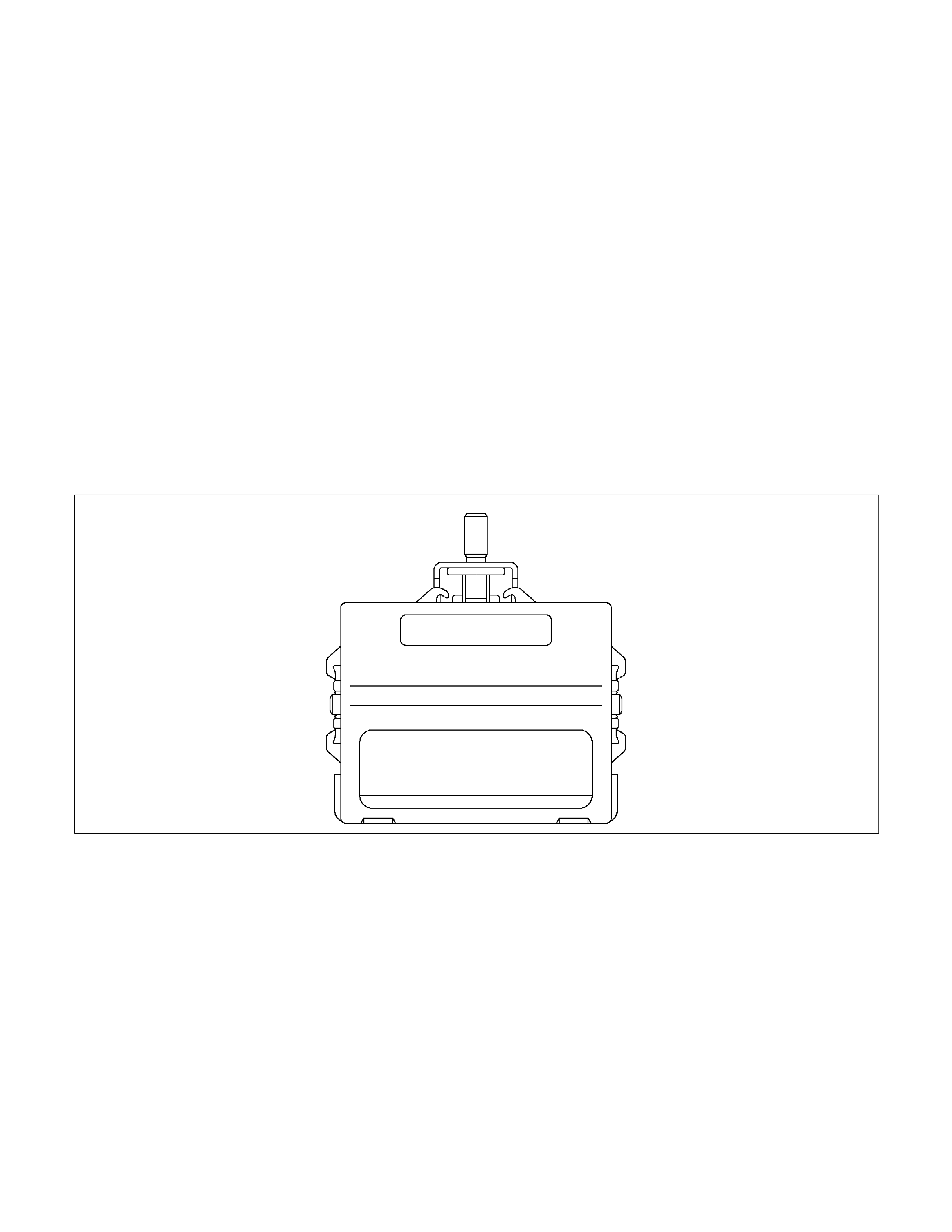
Immobilizer control unit (ICU); For
Electronic Control Engine (6VE1,
C24SE, 4JH1-TC, 4JA1-TC)
Immobilizer control unit (ICU) permits engine starting,
when the security code which compares the security
code registered into the transponder (key) and the
security code registered into ICU, and is similarly
registered into ICU and engine control unit (ECM) is
compared and it is judged that it is normal. When the
code registered into the key is unusual, and when not
recognizing a security code, ICU does not permit
starting of engine.
RUW38HSF000101
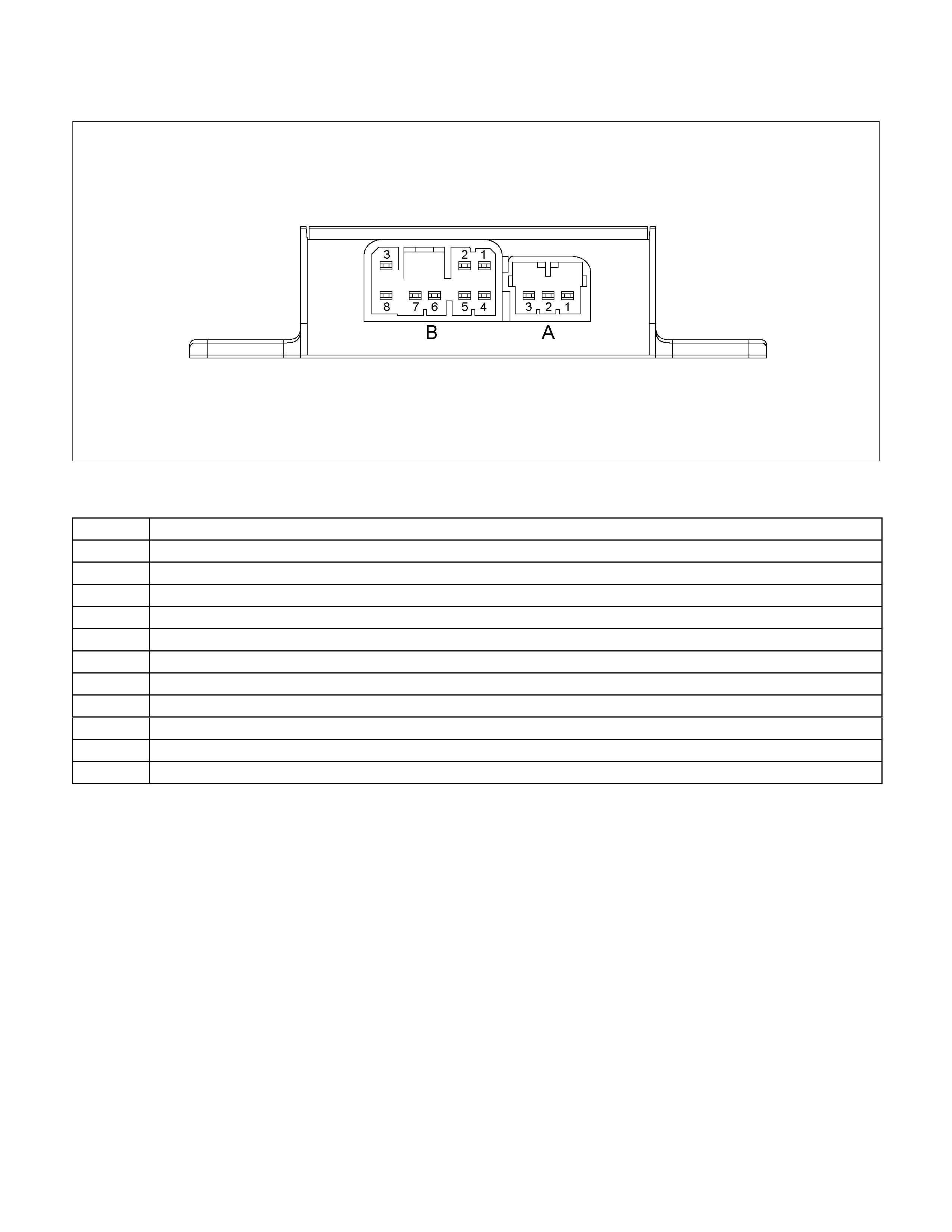
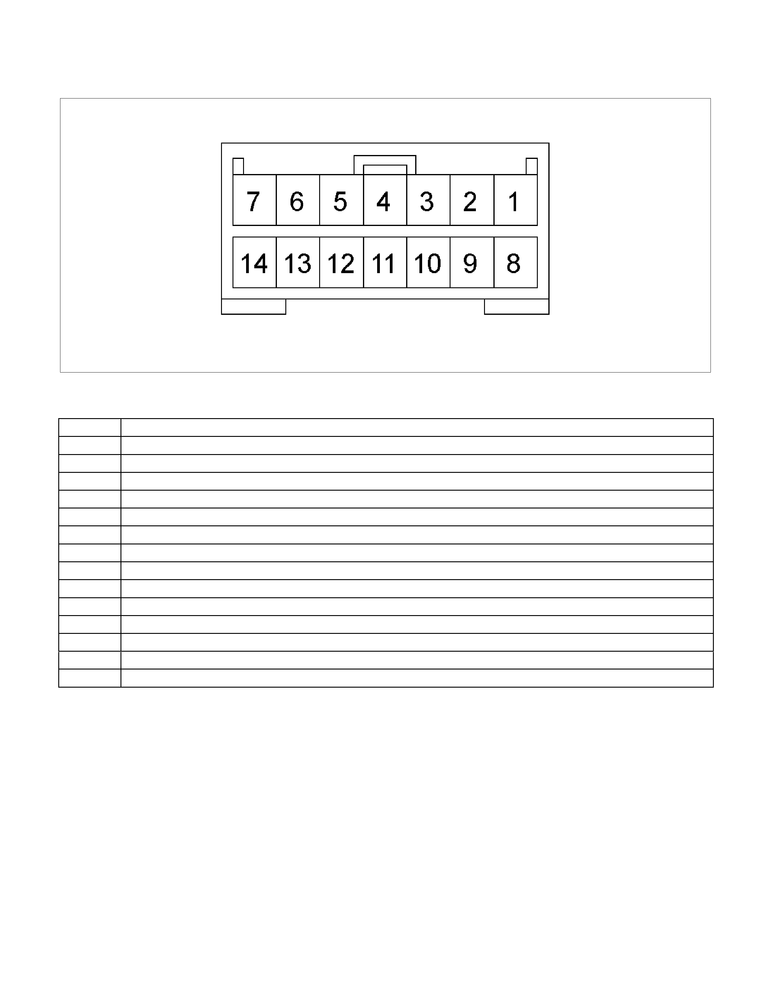
Pin-outs; For Electronic Control Engine (6VE1, C24SE, 4JH1-TC, 4JA1-TC)
RUW38HSF000201
No. Pin Function
A-1 Antenna coil positive
A-2 ⎯
A-3 Antenna coil negative
B-1 Starter Relay (6VE1, C24SE Engine) / Immobilizer Relay (4JH1-TC/4JA1-TC Engine)
B-2 Ground
B-3 Voltage from ignition switch ON
B-4 Back up voltage supply
B-5 To Tech-2
B-6 Vehicle speed sensor (6VE1, C24SE Engine) / Not used (4JH1-TC/4JA1-TC Engine)
B-7 Communication: carry on line from ECM to ICU (Check engine lamp)
B-8 Communication: carry on line from ICU to ECM (Communication line W)
Immobilizer control unit (ICU);
Mechanical Control Engine (4JA1-T)
Immobilizer control unit (ICU) permits engine starting,
when the security code which compares the security
code registered into the transponder (key) and the
security code registered into ICU, and is similarly
registered into ICU and engine immobilizer unit (DDS-
1) is compared and it is judged that it is normal. When
the code registered into the key is unusual, and when
not recognizing a security code, engine immobilizer unit
does not permit starting of engine by the fuel cut valve
on the fuel pump.
The engine immobilizer unit is located with fuel cut
valve on fuel pump 4JA1-T engine.
The immobilizer control unit decides whether there is
an abnormality the security code based on the engine
immobilizer unit security code.
When the problem found, the engine immobilizer unit
stops fuel supply by the fuel cut valve.
RAW4B0SF000101
Pin-outs
RUW48HSF000201
No. Pin Function
1 Back up voltage supply
2 Voltage from ignition switch ON
3 Lamp
4 ⎯
5 ⎯
6 Antenna coil positive
7 Ground
8 Engine immobilizer unit
9 To Tech2
10 ⎯
11
⎯
12 ⎯
13 Antenna coil negative
14 Starter cut relay

Immobilizer coil (Antenna)
Immobilizer coil is install in order that ICU may check
the security code memorized by the transponder (key).
RUW38HSH000301
Transponder (Key)
Transponder is installed in the inside of a key.
Transponder has memorized the security code of a
immobilizer system.
LTW3BASH000101
Legend
(1) Transponder (Key)
Check engine lamp
Check engine lamp displays failure or a system
operation of a immobilizer system by flash of a lamp.
RTW56ESH001601
Engine control module (ECM)
ECM will stop engine, if it communicates with ICU and
abnormalities are detected by a key and the
immobilizer system.
LTW3BASH000301
Legend
(1) ECM (6VE1 engine)
(2) ECM (C24SE engine)
(3) ECM (4JH1-TC, 4JA1-TC engine)
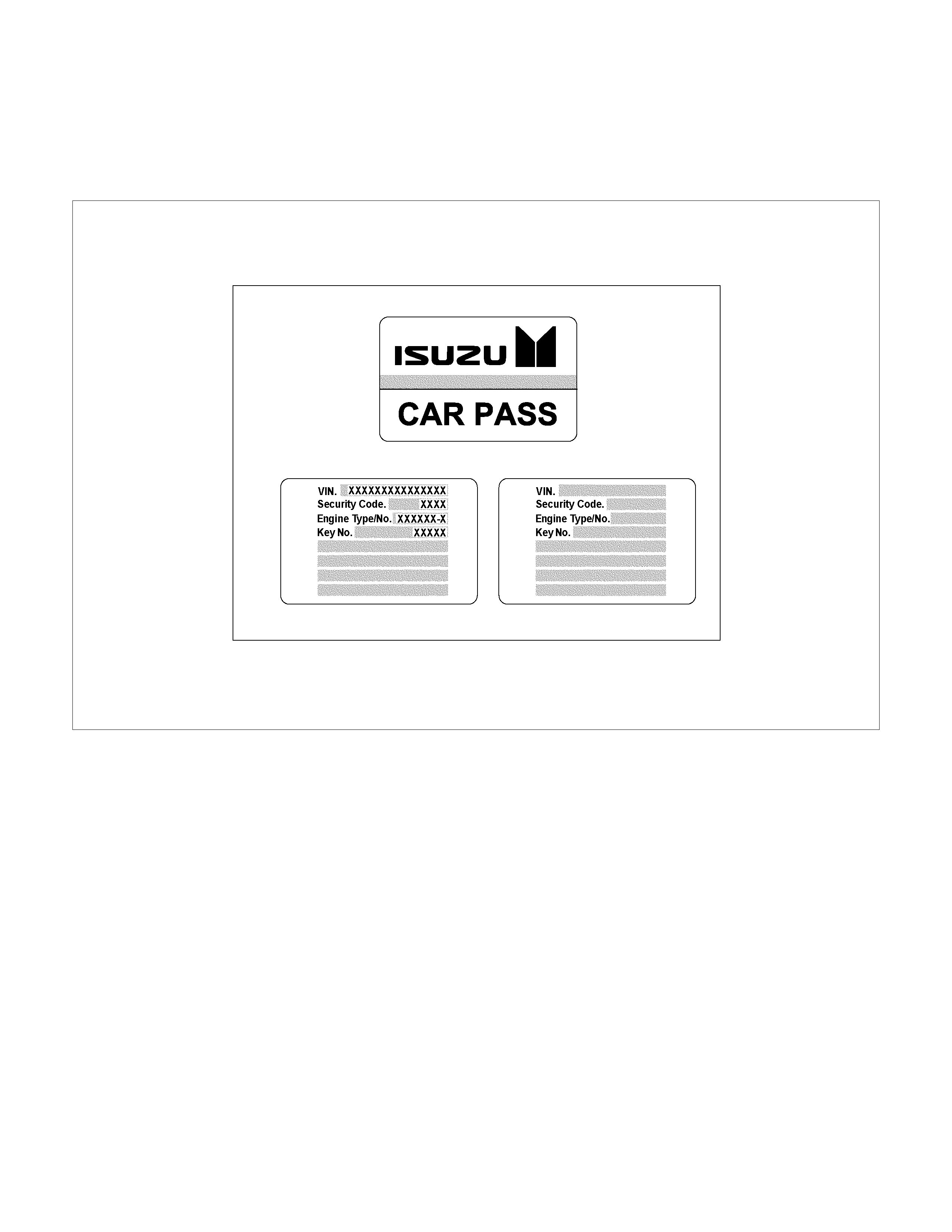
Car Pass Card
Issue of a car pass card is based on distributer. A ca
r
pass card is issued to the customer on delivery of the
vehicle along with the other papers.
RUW38HMF000201
Notes:
This car pass card is an important document and must
be treated with the same care as the vehicle papers.
It must not be kept in the vehicle. The customer must
present the car pass card for operations involving the
immobilizer or the engine control unit.
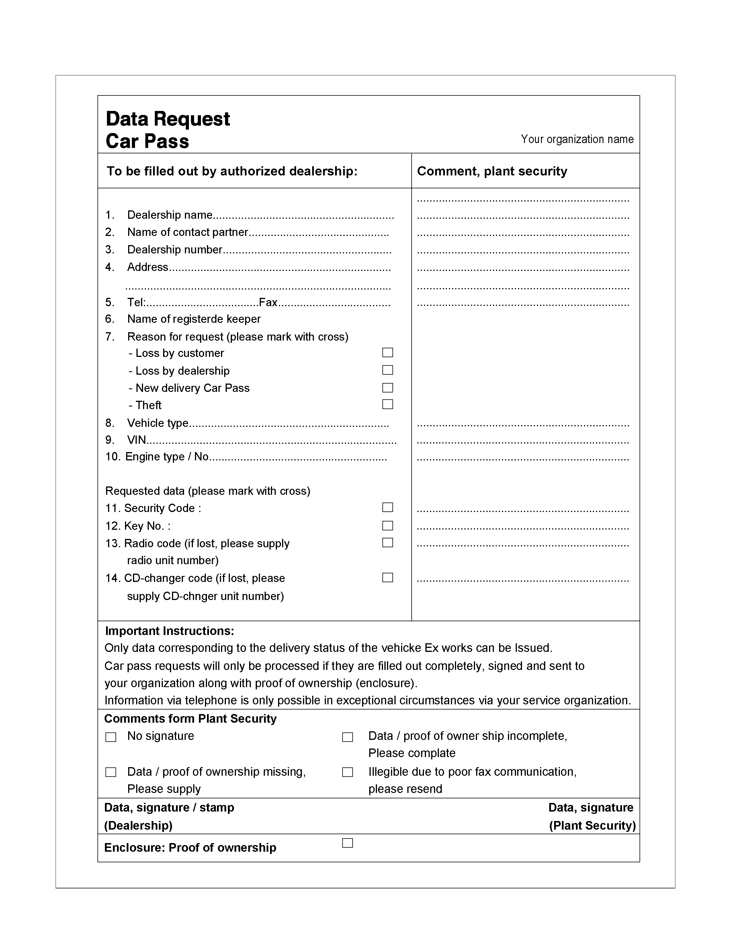
Loss of car pass card
If the car pass card is lost, the data can be requested
from your proper organization name. This request will
only be processed if accompanied by the enclosed
form and proof of ownership. Once the data is received,
it can be entered in a blank car pass and given to the
customer.
The unused car pass should be destroyed.
Instructions on Filling Out the form "Data
request, car pass"
To be provided by the dealership.
The data requested under items 1-10 must be provided
completely, including the authorized dealership
number, the vehicle Identification number (VIN) and
engine type/number (Engine type/No).
Mark missing data / desired data with a cross:
• Security code (for diagnosis and programming with
Tech-2)
• Mechanical key Number
Complete the form by entering the data and
signature/authorized dealership stamp and send it
along with proof of ownership (Vehicle lD or invoice) to
address provided in the form. The requested data will
be sent by Fax to the dealership that made the request
after your organization has confirmed that the info is
corrected.

Important Instructions
Only data corresponding to the delivery status of the
vehicle can be issued. Car pass data requests will only
be processed if the first column is filled out completely.
Signed and sent to your organization along with proo
f
of
ownership.
Information via telephone is only possible in exceptional
circumstances via your service organization.
A
s for the delivery of new vehicles, the customer must
be informed about all features of the car pass that are
relevant to vehicle security, for example, that the ca
r
pass card should be kept in a safe place(not in the
vehicle) and should be presented when an authorized
your organization name workshop is visited, The exact
phrasing can be found in the relevant Owner's Manual.
RUW38HXF000201

lmportant information on Programming
Security code
The security code protects the immobilizer control unit
against unauthorized programming and data access
from Tech-2. The security code consists of a 4 digit
code number and is programmed into the immobilize
r
control unit and Engine Control Module (ECM).
New control units are not programmed with a security
code.
If the control units are replaced, the security code
entered in the car pass, transponder lD, etc.
Must be programmed into the new control unit with
Tech-2.
The security code can only be programmed with Tech-
2 once and must therefore be performed with great
care.
Once programmed, the security code cannot be
overwritten. An already used immobilizer can be reused
in a different car by initializing the immobilizer. Afte
r
that you can program the security code again. Fo
r
initializing command you need the current security
code.
If the immobilizer control unit is returned, always
enclosed the security code that is allocated to that
control unit. If this is not done, we can not process the
case and the warranty will not be recognized.
Entering a code
If the Tech-2 display requests that the
• security code
• mechanical key number
• Vehicle Identification No.
be entered, process as follows;
To input a digit you need to use the up and down
buttons of the Tech-2. By using the numeric buttons the
according digit will be displayed at the current position
and the cursor will move to the next position.
For letters you need to use the up and down buttons o
f
the Tech-2. The up and down key might be used fo
r
digits as well. By using the up and down buttons the
displayed digit or letter will be increased or decreased.
To move to the next position you need to use the move-
to-right-button.
With the two buttons, move-to-right and move-to-left
you can select the position of number you want to
change.
This will allow you to correct a wrong number.
A
fter the number is completed you need to press the
Enter button to accept the number. Correction is now
no longer possible.
Use the OKAY soft key to program the number and the
NOT OKAY soft key to abort the programming.
Transponder (Key)
• If a transponder key is lost:
If a transponder key is lost, all transponder keys in the
immobilizer control system must be erased.
Transponder keys can be ordered via the "Your prope
r
organization name such as part and accessory
department" as previously by providing the mechanical
key number.
The mechanical key number is provided on the ca
r
pass card.
Thereafter, existing and new transponder keys are
programmed consecutively using Tech-2. The vehicle
can then no longer be started using lost key.
• 5 transponder keys can be provided:
Each transponder has different Identifications. If a
customer wants more than 2 transponder keys,
maximum 5 transponder keys can be provided by
additional programming by Tech-2.
• lf a new ignition key w ith different mechanical ke
y
number needs to be installed:
If installation of an ignition lock with a different
mechanism key number is necessary (an ignition lock
which belongs to the mechanical key number has to be
ordered first), all transponder keys must first be erased
and the two transponder keys which belong to the
ignition lock that is now installed must be programmed.
The new mechanical key number must be programmed
now into the immobilizer. The mechanical key numbe
r
in the car pass is to be changed as well.
Important
A
fter successful programming, the engine control can
only be used for vehicles with immobilizer and
transponder.
Faults that occur in connection with the immobilize
r
control unit are recognized by the engine control unit
and as long as "IMMOBILOZER" is not programmed,
are indicated by a flashing of the check engine lamp.
If the immobilizer and engine control unit are replaced
at the same time, the immobilizer control unit must be
programmed first before the "IMMOBILIZER" function in
the engine control unit can be activated.
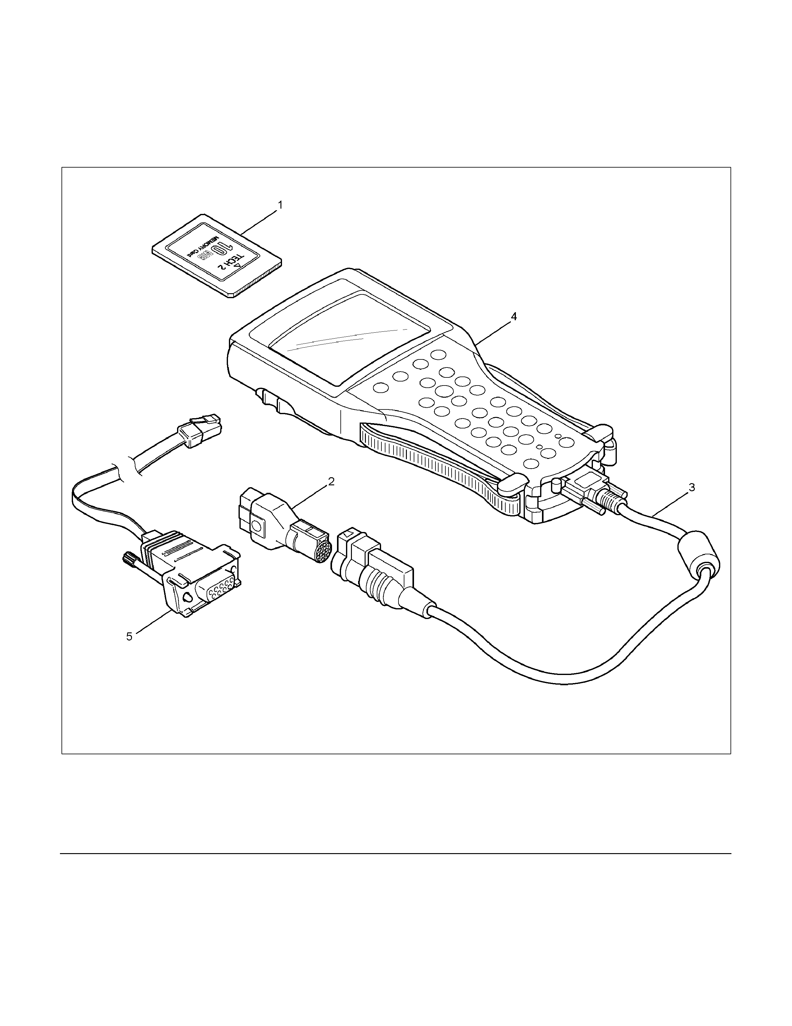
Tech 2 Scan Tool
Isuzu dealer service departments are recommended to
use Tech 2. Please refer to Tech 2 scan tool use
r
guide.
LTW3BALF000501-X
Legend
(1) PCMCIA Card
(2) SAE 16/19 Adaptor
(3) DLC Cable
(4) Tech-2
(5) RS232C Cable
Tech-2 Features
1. Tech-2 is a 12volt system. Do not apply 24 volts.
2.
A
fter connecting and/or installing the vehicle
communication interface (VCI) module, PCMCI
A
card and data link connector (DLC) to the Tech-2,
connect the tool to the vehicle DLC.
3. Make sure the Tech-2 is OFF when removing o
r
installing the PCMCIA card.
4. The Tech-2 has the capability of two or three
snapshots.
5. The PCMCIA card is sensitive to magnetism and
static electricity, so care should be taken in the
handling of the card.
6. The Tech-2 can not plot a graph when replaying a
snapshot.
7. Always return to the Main Menu by pressing the
EXIT key several times before shutting down.
8. To clear diagnostic trouble codes (DTCs), open
Application Menu and press "Clear DTC ".
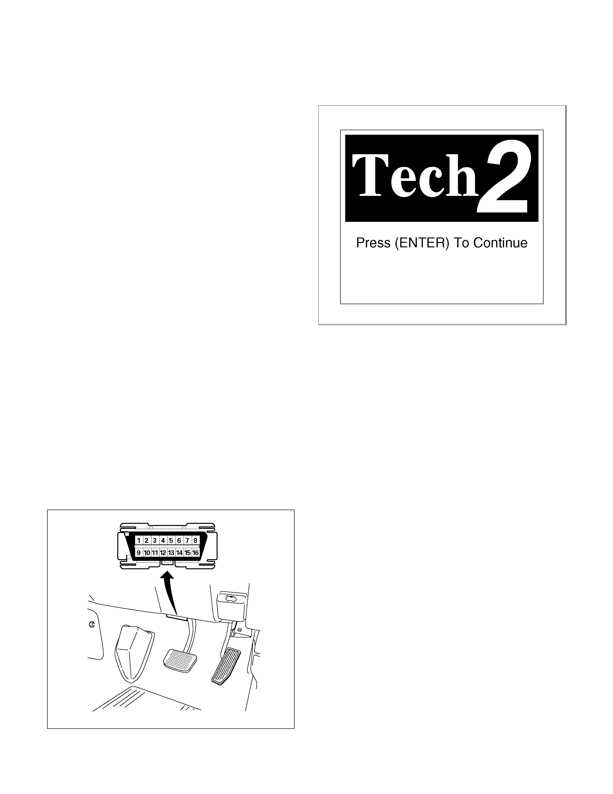
Getting Started
Before operating the Isuzu PCMCIA card with the Tech
2, the following steps must be performed:
1. The Isuzu System PCMCIA card inserts into the
Tech 2.
2. Connect the SAE 16/19 adapter to the DLC cable.
3. Connect the DLC cable to the Tech 2.
4. Mark sure the vehicle ignition is off.
5. Connect the Tech 2 SAE 16/19 adapter to the
vehicle DLC.
• RHD (For example)
060R300015
6. Tune on the vehicle ignition (key) switch.
7. Power the Tech-2 ON and verify the Tech-2 powe
r
up display.
060RW009
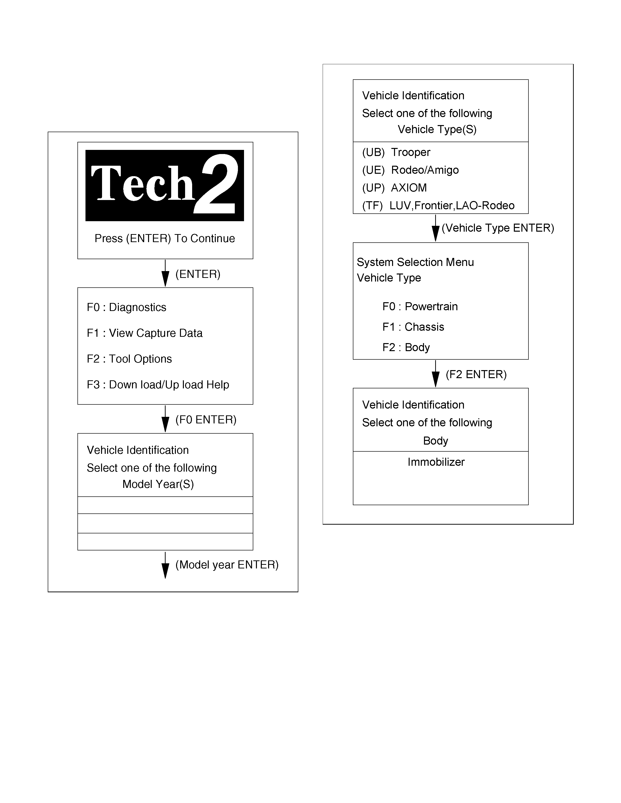
Operating Procedure
The power up screen is displayed when you power up
the tester with the Isuzu systems PCMCIA card.
Follow the operating procedure below.
060R100102
LTW3BALH000101

Menu
The following table shows which functions are used fo
r
the available equipment versions.
F0: D iagnostic Trouble C odes
F0: R ead D TC Info O rdered B y P riority
F1: R e a d D T C In fo A s S to re d B y E C U
F2: C le a r D T C In fo rm a tion
F1: D ata D isplay
F2: Snap S hot
F3: A dditional Function
F0: R ead EC U Identification
F1: R eset Im m obilizer
F2: R eset Engine C ontrol M odule
F3: Erase Transponder-K eys
F4: Programming
F0: P ro g ra m Im m o b ilizer Function
F1: P rogram Transponder-K eys
NOTE: Before going to programming process, Tech-2
indicates instruction as follows.
060R200289
DTC
On OBD has two options available in the Tech 2 DTC
mode to display the enhanced information available.
• Read DTC Info Ordered By Priority
• Read DTC Info As Stored By ECU
Clear DTC Information
To clear Diagnostic Trouble Codes (DTCs), use the
diagnostic scan tool "clear DTC information" function.
Tech-2 Data Display
Use the Tech 2 Data Values only after the On-Board
Diagnostic System Check has been completed, no
DTC(s) were noted, and you have determined that the
on-board diagnostics are functioning properly.
The Tech 2 data values represent values that would be
seen on a normally-immobilizer system.
Check Vehicle Identification Number (VIN)
1. Select "Body" and "Immobilizer".
2. Select "Additional Function" and "Read ECU
Identification".
3. Shows up VIN on tech-2 display.
Reset Immobilizer (Reset Immobilizer
Control Unit)
1. Select "Body" and "Immobilizer".
2. Select "Additional Function" and "Reset
Immobilizer".
3. Enter the security code and press Confirm.
4. Reset Immobilizer screen shows up with warning.
See the following screen.
060R200279
5. When reset is completed, the following screen
shows up.
060R200278
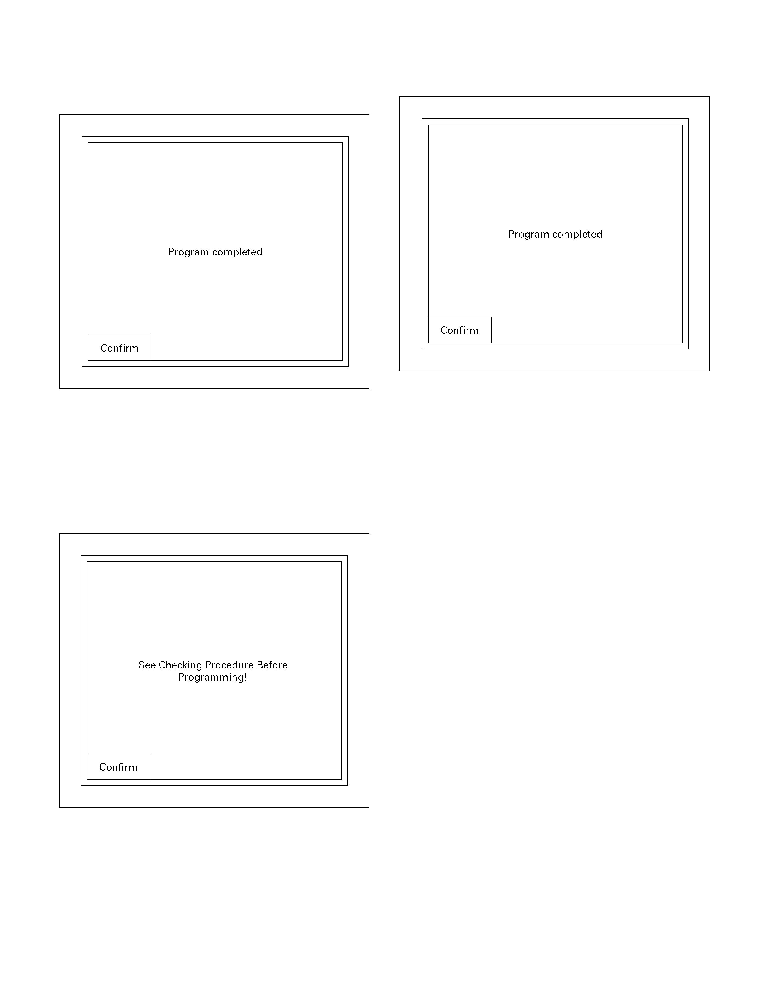
Reset Engine Control Module (Reset ECM)
1. Select "Body" and "Immobilizer".
2. Select "Additional Function" and "Reset Engine
Control Module".
3. The following screen shows up.
060R200289
4. Confirm the following screen shows up.
5. Input the security code, then press the soft key o
f
"Not Okay" or "Okay".
6. The following screen shows up.
7. Programming is completed.
060R200278
8. When the procedure is completed waits 10
seconds and then turn the Key on.
The fail lamp begins to flash.
9. Turn the ignition on, then engine dose not run.
10. Reset is completed.
Erase Transponder Key
1. Select "Body" and "Immobilizer".
2. Select "Additional Function” and "Erase
Transponder-Keys".
3. See immobilizer status on Tech-2 screen and type
security code. If the status dose not allow the
programming, only immobilizer status is displayed.
4. See illustration of caution.

• CAUTION
060R200286
• Erase
060R200285
4. See programming result on display.
Programming Immobilizer Function
Caution:
1) Do not replace ICU and ECM at the same time
2) Change ICU at first or ECM and other one
change follows.
1. Select "Body" and "immobilizer".
2. Select "Programming" on Tech-2 display.
3. Check the display, then press the "Confirm" key.
LTW3BASH000401
4. Install the "Hardware Key" on PC.
5. Connect RS232 cable to the PC and Tech2.
6. Turn on the PC, then start software "TIS 2000".
7. Select "Security Access" in the TIS 2000 screen.
8. Select "Next" in the TIS 2000 screen and wait a
few seconds.
9. When programming is enabled (Approved), then
press "close" in the TIS 2000 screen.
(Finish the "TIS 2000" operation.)
10. Select "Program Immobilizer Function" on Tech-2
display.
11. The following screen shows up.
060R200289
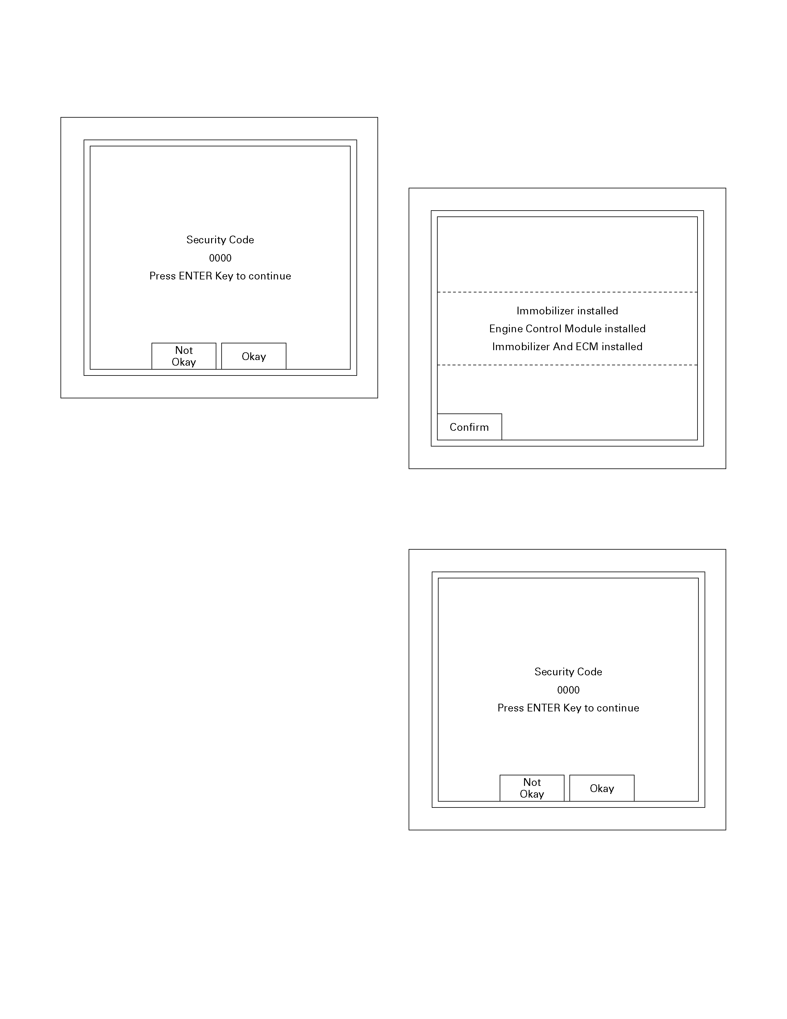
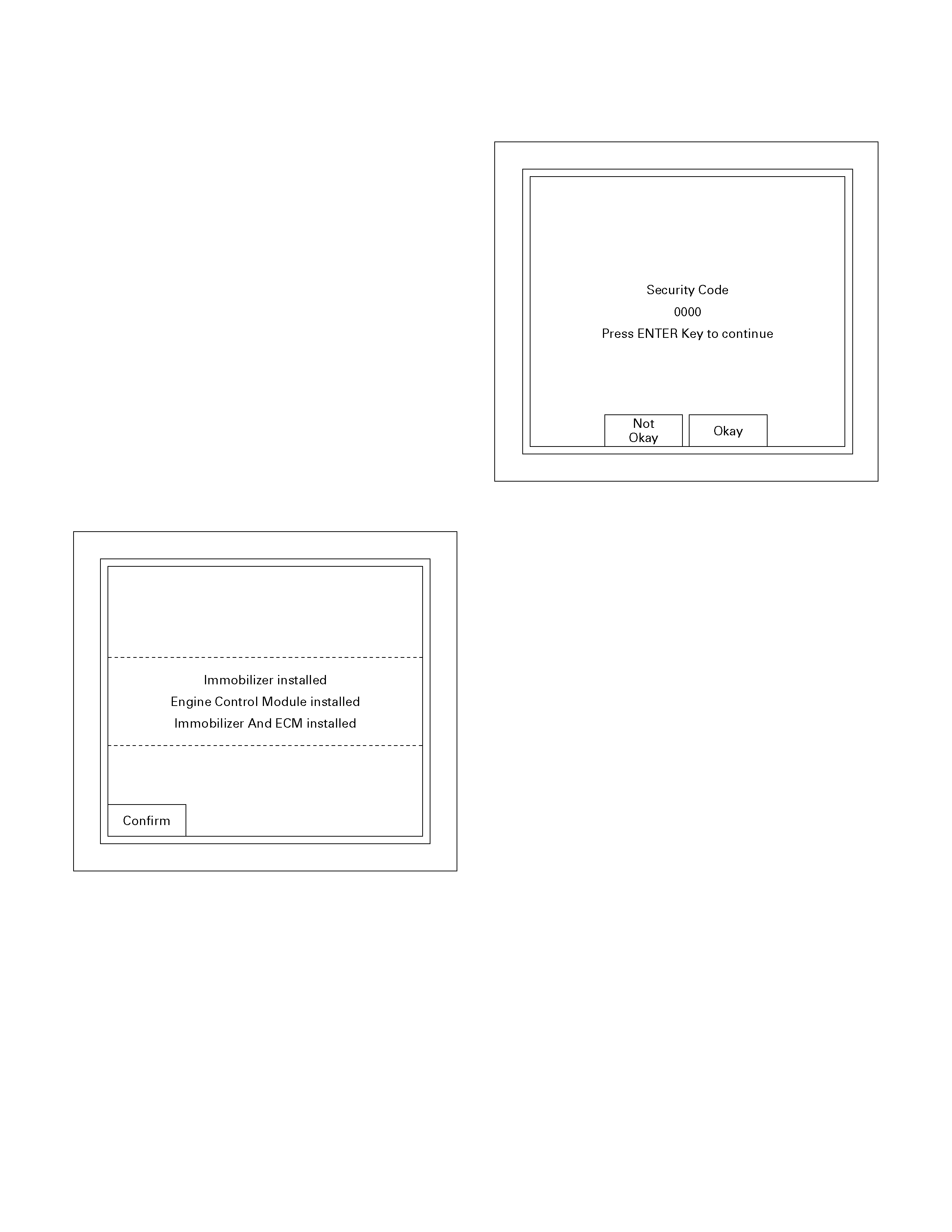
12. Confirm the following screen shows up.
13. Input the security code, then press the soft key o
f
"Not Okay" or "Okay".
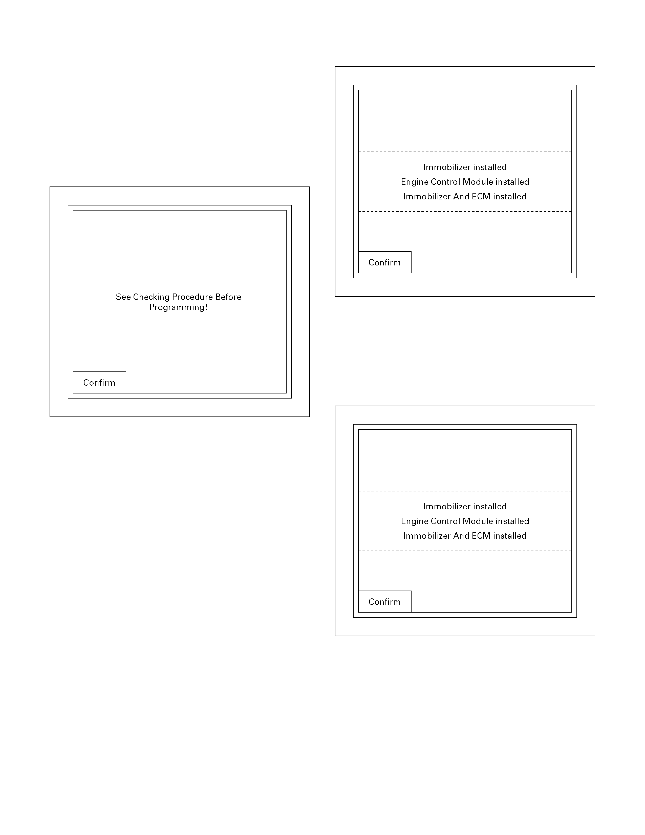
14. Select the engine type then, press "Enter" key.
15. Input a program option, by moving the cursor on
the selection, then press "Enter" key.
• Programming ICU
• Programming ECM
• Programming ICU and ECM
060R200283
Programming ICU
1. Follow Programming Immobilizer Function steps 1
through 14.
2. Input a program option, by moving the cursor on
the selection, then pres "Enter" key.
060R200283
3. Enter the security code.
4. Input the security code, then press the soft key o
f
"Okay" or "Not Okay".
060R200284
5. Enter VIN.
6. Enter Mechanical key number.
7. Turn ON ignition.
8. Select an engine system.
9. See the programming result.
Tech-2 displays the result of programming as the
following.
Follow those instructions
• Selected Programming is not possible due to
wrong System Status!
• Immobilizer Not Programmed!
• Immobilizer Already Programmed!
• ECM Not Programmed!
• ECM Already Programmed!
10. Transponder key must be reprogrammed,
because all transponder information is erased.
When ICU is programmed. See Transponde
r
programming.
Programming ECM
1. Follow Programming Immobilizer Function steps 1
through 14.
2. Input a program option, by moving the cursor on
the selection, then pres "Enter" key.
060R200283
3. Enter the security code.
4. Input the security code, then press the soft key o
f
"Okay" or "Not Okay".
060R200284
5. Turn on the Ignition.
6. Select an Engine system.
7. See the display of programming result.
Tech-2 displays the result of programming as the
following.
Follow those instructions
• Selected Programming is not possible due to
wrong System Status!
• Immobilizer Not Programmed!
• Immobilizer Already Programmed!
• ECM Not Programmed!
• ECM Already Programmed!
8. Transponder key must be reprogrammed,
because all transponder information is erased.
When ICU is programmed. See Transponde
r
programming.
Programming ICU and ECM
1. Follow Programming Immobilizer Function steps 1
through 14.
2. Input a program option, by moving the cursor on
the selection, then press "Enter" key.
060R200283
3. Enter the security code.
4. Input the security code, then press the soft key o
f
"Okay" or "Not Okay".
060R200284
5. Input the security code.
6. Enter VIN.
7. Enter Key No.
8. Select an engine system.
See programming result display and follow
instructions of the display.
9. Transponder key must be reprogrammed,
because all transponder information on ICU is
erased when ICU is programmed. See
Transponder programming.
10. Follow Programming ECM steps 2 through 8.
Transponder Program
1. Select "Body" and "Immobilizer".
2. Select "Programming" and "Program
Transponder-Keys".
(Follow Programming Immobilizer Function steps
1 through 14.)
3. See immobilizer status on Tech-2 screen, and
enter security code. If the status does not allow
the programming, only immobilizer status is
displayed.
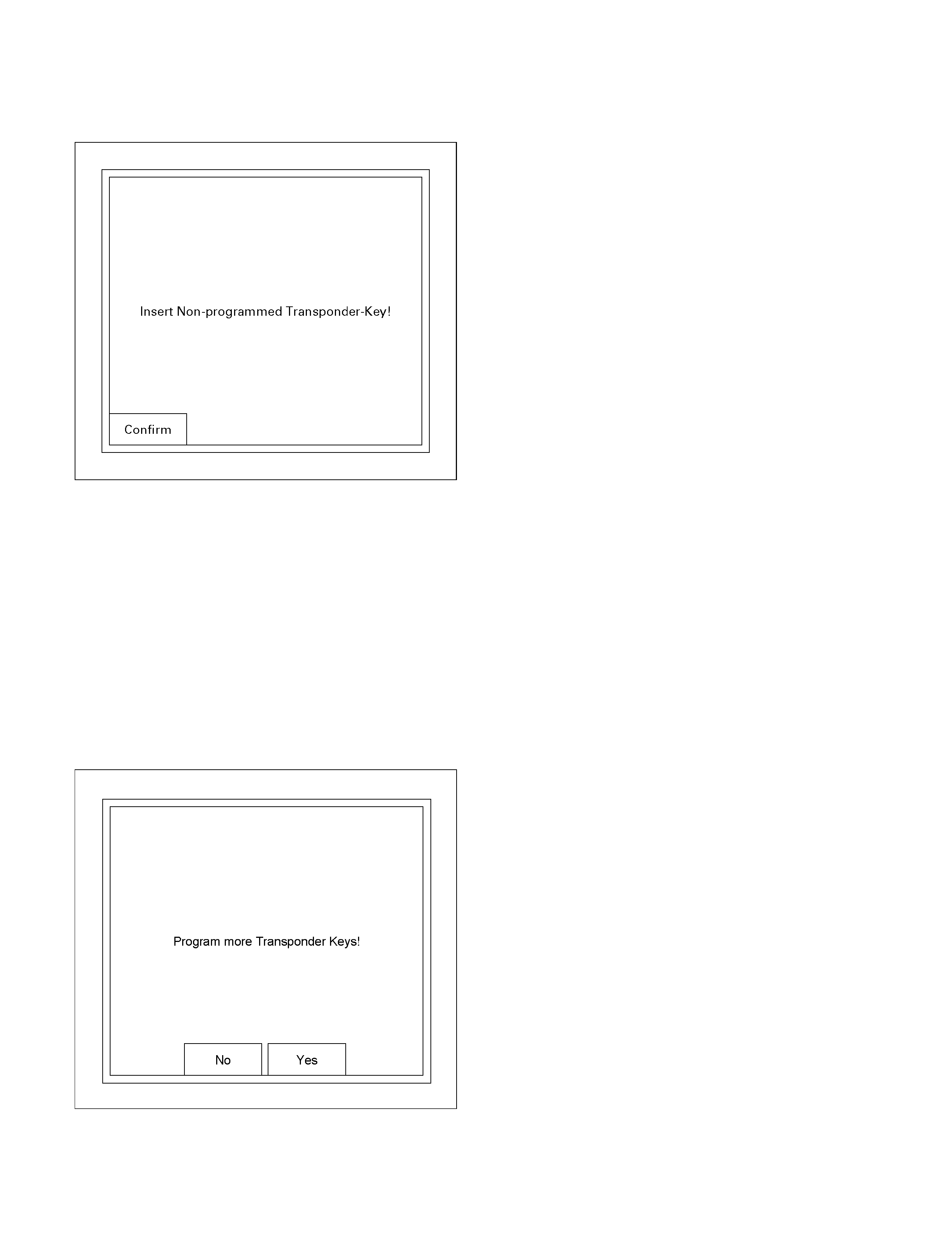
4. Insert Non-programmed Transponder-key and
press soft key of "Confirm".
060R200288
5. "Turn On ignition key", is displayed if the ignition is
off.
6. The transponder status is displayed if the status
does not allow the programming.
7. When programming starts "Programming
Transponder - key!" is displayed.
8. Turn off Ignition key.
9. Turn On Ignition key.
10. If the programming was not successful, the
transponder status is only displayed.
11. To program more illustration press soft key.
RUW38SH000601
12. See programming result.

Data List
No. Strings Note
1 Ignition Status On 12V /Off 0V
2 Transponder-Key Transp. Key # The number of the key currently
programmed
3 Transponder Status Correct/Incorrect TP-Key
4 Transponder-Key 1 Status Programmed / Not Programmed
5 Transponder-Key 2 Status Programmed / Not Programmed
6 Transponder-Key 3 Status Programmed / Not Programmed
7 Transponder-Key 4 Status Programmed / Not Programmed
8 Transponder-Key 5 Status Programmed / Not Programmed
9 Immobilizer signal Transmitted / Not Transmitted
10 Engine Request Received / Not Received
11 Vehicle Speed Output Veh. Speed signal
12 Immobilizer Relay Active 0V / Inactive 12V
13 Security Wait Time Active / Inactive

Diagnostic Procedure
• Once the cause of DTC is repaired or gone,
engine can be operated normally, and present
DTC becomes history code.
• History code is canceled by no repeat failure on
25 consequence ignition key on afterward.
• History code cannot be canceled by battery
connector disconnected.
Clearing Diagnostic Trouble Codes
IMPORTANT: Do not clear DTCs unless directed to do
so by the service information provided for each
diagnostic procedure. When DTCs are cleared, the
Failure Record data which may help diagnose an
intermittent fault will also be erased from memory.
Verifying Vehicle Repair
Verification of vehicle repair will be more
comprehensive for vehicles with immobilizer system
diagnostic. Following a repair, the technician should
perform the following steps:
1. Review and record the Fail Records for the DTC
which has been diagnosed.
2. Clear DTC(s).
3. Operate the vehicle within conditions noted in the
Fail Records.
4. Monitor the DTC status information for the DTC
which has been diagnosed until the diagnostic test
associated with that DTC runs.
Following these steps are very important in verifying
repairs on immobilizer systems. Failure to follow these
steps could result in unnecessary repairs.
Diagnostic Aids
Check The Condition For System Parts.
• Installation condition, poor connection, damage,
system parts malfunction. Harness, Fuse, Relay,
Immobilizer coil (antenna), Key, Meter,
Immobilizer control unit (ICU), Engine control
module (ECM).
NOTE: Breakage of immobilizer fuse does not operate
immobilizer system. Check engine lamp flashes at this
time.
Check The Electro-Magnetic Interference (EMI)
• Location of vehicle check
Move the vehicle to a new location and perform
the check again.
• Non-OEM Parts.
Switch is "OFF" or remove the Non-OEM parts
and perform the check again.
• Other
Remove the accessory and another key from key.
Check The Other Items.
• Battery voltage is low.
• Immobilizer programming functions.
Must be programmed immobilizer system.
• Registration for security code, immobilizer control
unit parts number.
• Key switch operation.
Immobilizer system may detect a history DTC by
the timing of ON-OFF of a key switch.
• Active the immobilizer system.
• Keyless entry system is malfunction.
• Anti theft system is malfunction.

Diagnostic Trouble Code (DTC) List With ECM
• Immobilizer Control Unit (ICU)
DTC Description Note
B0001 REPLACE ELECTRONIC CONTROL UNIT
(ECU) (IMMOBILIZER FAULT) This error code appears if a RAM /ROM Error was
detected or the EEPROM is defect.
B0002 IMMOBILIZER NOT PROGRAMMED Immobilizer control unit is not programmed.
B0003 TRANSPONDER KEY PROBLEM ・Reading of Transponder information failed with ignition
on transponder has a fault.
・Hardware fault in reading circuit.
B0004 IMMOBILIZER COIL CIRCUIT (ANTENN
A
COIL FAULT) Immobilizer coil has a fault.
B0005 COMMUNICATION LINE W VOLTAGE LOW Short circuit to ground or open circuit.
B0006 COMMUNICATION LINE W VOLTAGE HIGH Short circuit to 12V.
B0007 NO ENGINE REQUEST RECEIVED No ECM Challenge.
B0008 WRONG TRANSPONDER KEY Incorrect security code response received.
B0009 NO TRANSPONDER KEY PROGRAMMED Transponder security code table empty
B0010 UNKNOWN TRANSPONDER KEY Transponder security code not valid.
• Engine Control Module (ECM: Gasoline Engine {6VE1, C24SE})
DTC Description Note
P1626 No Response From Immobilizer Refer to Engine Control system section
P1631 Received Response Was Not Correct Refer to Engine Control system section
P1648 Received Incorrect Security Code Refer to Engine Control system section
P1649 Security Code & Security Key Not
Programmed Refer to Engine Control system section
• Engine Control Module (ECM: Diesel Engine {4JH1-TC, 4JA1-TC})
DTC Description Note
P1610 Seeds and Key File Destroyed Refer to Engine Control system section
P1611 Wrong Security Code Entered Refer to Engine Control system section
P1612/
P1613 Immobilizer No or Wrong Signal Refer to Engine Control system section
P1649 Wrong Transponder Key Refer to Engine Control system section

Diagnostic Trouble Code (DTC) list with Engine Immobilizer Unit (4JA1-T Diesel Engine)
• Engine Immobilizer Unit
Code
(DTC) Description Detecting Condition
B0011 TRANSPONDER KEY PROBLEM Transponder code unsuccessfully read 5 consecutive
time. (No completely read in 500ms transponder code)
B0012 WRONG TRANSPONDER KEY Immobilizer program no executed.
B0013 IMMOBILIZER NOT PROGRAMMED Processing program no executed.
B0014 NO TRANSPONDER KEY PROGRAMMED Processing to save the transponder key in the control unit
not Executed.
B0015 FREQUENCY SIGNAL Lo Lo level (less than 2.5) input during the Hi level was being
output to the communication line.
B0016 FREQUENCY SIGNAL Hi (Diesel) Hi level (more than 2.5v) input during the Lo level was
being output to the communication line.
B0023 ANTENNA COIL OPEN Antenna coil not connected.
B0024 WRONG TRANSPONDER RESPONSE Transponder response signal with challenge is wrong.
B0055 EEPROM ERROR Write and read cannot be correctly made to and from the
EEPROM in the control unit.

IMMOBILIZER SYSTEM CHECK
Step Action Value(s) Yes No
1 1. Key position is "ON," engine "OFF."
2. Observe the check engine lamp.
Note: When a key switch is turned ON, check engine
lamp will turn on and a check engine lamp will be
turned off after a few seconds.
Is the check engine lamp "ON"?
⎯ Go to Step 2 Go to "No
Immobilizer
warning lamp"
2 1. Key position is "ON," engine "OFF."
2. Observe the check engine lamp.
Note: When a key switch is turned ON, check engine
lamp will turn on and a check engine lamp will be
turned off after a few seconds.
Is the check engine lamp "OFF"?
(Check engine lamp does not flash)
⎯ Go to Step 3 Go to
"Immobilizer
warning lamp on
steady"
3 1. Key position is "OFF."
2. Install a scan tool.
3. Key position is "ON."
4. Attempt to display immobilizer data with the scan
tool.
Does the scan tool display immobilizer data?
⎯ Go to Step 9 Go to Step 4
4 1. Key position is "OFF," disconnect the immobilizer
control unit (ICU).
2. Check the DLC (Data Link Connector) circuit for
an open, short to ground, or short to voltage.
Also, check the DLC ignition feed circuit for an
open or short to ground and the DLC ground
circuit for an open.
Was a problem found?
⎯ Go to Step 5 Go to Step 6
5 Repair or replace the DLC (Data Link Connector)
circuit.
Was the action complete?
⎯ Go to Step 3 ⎯
6 1. Check the ICU circuit for an open, short to
ground, or short to voltage. Also, check the ICU
ignition feed circuit for an open or short to ground
and the ICU ground circuit for an open.
2. If a problem is found, repair as necessary.
Was a problem found?
⎯ Go to Step 7 Go to Step 8
7 Repair or replace the ICU ignition feed and ground
circuits.
Was the action complete?
⎯ Go to Step 3 ⎯
8 Replace the immobilizer control unit (ICU).
IMPORTANT: The replacement ICU must be
programmed the immobilizer data by the scan tool.
Was the action complete?
⎯ Go to Step 3 ⎯
9 Select "Display DTCs" with the scan tool.
Are any DTCs stored?
⎯ Go to Step 10 Go to Step 13

Step Action Value(s) Yes No
10 Review and record for scan tool Failure Records data
and DTCs.
Was the action complete?
⎯ Go to Step 11 ⎯
11 Following the DTC is stored.
Are there DTC B0001 or B0055 stored? Go to applicable
DTC table after
Go to Step 12
Go to Step 12
12 Clear the DTCs by "Clear the Information "with scan
tool.
Did the DTCs Cleared?
⎯ Go to Step 12 ⎯
13 Select "Display DTCs" with the scan tool.
Are any DTCs stored?
⎯ Go to applicable
DTC table Go to Step 14
14 1. Key position is "ON," engine "OFF."
2. Observe the check engine lamp.
Note: If a key switch is turned ON, check engine
lamp will turn on and a check engine lamp will be
turned off after a few seconds.
Is the check engine lamp "flash"?
⎯ Go to Step 15 Go to Step 20
15 Check the engine control system.
If a problem is found, repair as necessary.
(Refer to section 6E: system check and DTCs)
IMPORTANT: The replacement ECM must be
programmed the immobilizer data by scan tool.
(Except 4JA1-L Engine)
Was the action complete?
⎯ Go to Step 16 ⎯
16 Check the key.
Is a key peculiar to a vehicle?
⎯ Go to Step 18 Go to Step 17
17 Change into a peculiar key.
IMPORTANT: If replace the key, after replace lock
cylinders, perform the following below the items.
• Replace the keys and key cylinders.
• Program the immobilizer system.
(Refer to "Important information on Programming")
Was the action complete?
⎯ Go to Step 18 ⎯
18 Check the immobilizer programming functions.
• Immobilizer control unit (ICU).
• Engine control module (ECM).
• Transponder (Key).
If a problem is found, repair as necessary.
(Refer to "Important information on Programming")
Was the action complete?
⎯ Go to Step 19 ⎯
19 Operate the DTCs by "Clear the Information" with
scan tool.
Was the action complete?
⎯ Go to Step 20 ⎯
20 Attempt to start the engine.
Did the engine start?
⎯ System OK Refer to
Diagnostic Aids

NO IMMOBILIZER WARNING LAMP
Step Action Value(s) Yes No
1 Check the meter fuse for the instrument cluster
ignition feed circuit.
Is the fuse normal?
⎯ Go to Step 3 Go to Step 2
2 Replace the fuse.
Is the action complete?
⎯ Verify repair
Go to Step 3
⎯
3 1. Key position is "OFF".
2. Disconnect the meter.
3. Disconnect the engine control module (ECM).
4. Check the circuit between meter and ECM for an
open, short to round, or short to voltage.
Also, check the meter circuit for an open or short to
ground and the DLC ground circuit for an open.
Was a problem found?
⎯ Go to Step 4 Go to Step 5
4 Repair or replace the meter circuit.
Was the action complete?
⎯ Go to Step 5 ⎯
5 1. Key position is "ON," engine "OFF."
2. Observe the check engine lamp.
Is the check engine lamp "ON"?
⎯ Go to Step 6 Go to Step 7
6 Repair or replace the meter.
Was the action complete?
⎯ Go to Step 7 ⎯
7 1. Key position is "OFF".
2. Check the check engine lamp bulb.
Is the check engine lamp bulb normal?
⎯ Go to Step 9 Go to Step 8
8 Replace the check engine lamp bulb.
Is the action complete?
⎯ Verify repair
Go to Step 9
⎯
9 1. Key position is "OFF".
2. Connect the meter.
3. Connect the engine control module (ECM).
4. Key position is "ON".
5. Observe the check engine lamp.
Note: If a key switch is turned ON, check engine lamp
will turn on and a check engine lamp will be turned off
after a few seconds.
Is the check engine lamp "ON"?
⎯ Verify repair Go to Step 10
10 Replace the engine control module (ECM).
IMPORTANT: The replacement ICU must be
programmed the immobilizer data by scan tool.
Was the action complete?
⎯ Verify repair ⎯

CHECK IMMOBILIZER WARNING LAMP ON STEADY
Step Action Value(s) Yes No
1 1. Key position is "OFF".
2. Disconnect the immobilizer control unit (ICU).
3. Disconnect the engine control module (ECM).
4. Key position is "ON," engine "OFF."
5. Observe the check engine lamp.
Is the check engine lamp "ON"?
⎯ Go to Step 2 Go to Step 5
2 1. Key position is "OFF".
2. Disconnect the meter.
3. Key position is "ON," engine "OFF."
4. Observe the check engine lamp.
Is the check engine lamp "ON"?
⎯ Go to Step 3 Go to Step 4
3 Repair or replace the meter.
Was the action complete?
⎯ Verify repair
Go to Step 5
⎯
4 Repair or replace the meter circuit.
(Between meter and ICU/ECM)
Was the action complete?
⎯ Verify repair
Go to Step 5
⎯
5 Check the immobilizer control unit (ICU) circuit.
1. Ignition "OFF," disconnect the ICU.
2. Check the ICU circuit for an open, short to ground,
or short to voltage.
Also, check the ICU ignition feed circuit for an open or
short to ground and the ICU ground circuit for an
open.
Was a problem found?
⎯ Go to Step 6 Go to Step 7
6 Repair or replace the immobilizer unit (ICU) circuit.
Was the action complete?
⎯ Verify repair
Go to Step 7
⎯
7 1. Key position is "OFF".
2. Connect the meter.
3. Connect the immobilizer control unit (ICU).
4. Connect the engine control module (ECM).
5. Key position is "ON".
6. Observe the check engine lamp.
Is the check engine lamp "ON"?
⎯ Verify repair Refer to
Diagnostic Aids

B0001 REPLACE ELECTRONIC CONTROL UNIT (ECU) (IMMOBILIZER FAULT)
Step Action Value(s) Yes No
1 Was the "Immobilizer System Check" performed? ⎯ Go to Step 2 Go to Immobilize
r
System Check
2 Recheck the DTC.
1. Key position is “OFF”.
2. Install the scan tool on vehicle.
3. Key position is “ON”.
4. Check the DTC on scan tool.
Is DTC B0001 stored?
⎯ Go to Step 3 Refer to
Diagnostic Aids
3 Check the immobilizer control unit (ICU) circuit.
1. Ignition "OFF," disconnect the ICU.
2. Check the ICU circuit for an open, short to ground,
or short to voltage.
Also, check the ICU ignition feed circuit for an open or
short to ground and the ICU ground circuit for an
open.
Was a problem found?
⎯ Go to Step 4 Go to Step 5
4 Repair or replace the immobilizer unit (ICU) circuit.
Was the action complete?
⎯ Verify repair ⎯
5 Replace the immobilizer control unit (ICU).
IMPORTANT: The replacement ICU must be
programmed the security data by scan tool.
Was the action complete?
⎯ Verify repair ⎯

B0002 IMMOBILIZER NOT PROGRAMMED
Step Action Value(s) Yes No
1 Was the "Immobilizer System Check" performed? ⎯ Go to Step 2 Go to Immobilizer
System Check
2 Check the immobilizer programming functions.
• Immobilizer control unit (ICU).
If a problem is found, repair as necessary.
(Refer to "Important information on Programming")
Was the action complete?
⎯ Go to Step 3 Go to Step 5
3 Recheck the DTC.
1. Key position is “OFF” and keep the position for
more than 30 seconds.
2. Key position is “ON”.
3. Check the DTC on scan tool.
Is DTC B0002 stored?
⎯ Go to Step 4 Verify repair
4 Replace the immobilizer control unit (ICU).
IMPORTANT: The replacement ICU must be
programmed the security data by scan tool.
Was the action complete?
⎯ Verify repair ⎯
5 Check the immobilizer programming functions.
• Engine control module (ECM).
• Immobilizer control unit (ICU).
If a problem is found, repair as necessary.
(Refer to "Important information on Programming")
Was the action complete?
⎯ Verify repair Go to Step 6
6 Replace the key and lock cylinder assembly and
immobilizer system (ICU and ECM).
IMPORTANT:
• ICU and ECM are not replacing simultaneously.
• After replace lock cylinders, perform the
following below the items.
• Program the immobilizer system.
(Refer to "Important information on Programming")
Was the action complete?
⎯ Verify repair ⎯

B0003 TRANSPONDER KEY PROBLEM
Step Action Value(s) Yes No
1 Was the "Immobilizer System Check" performed? ⎯ Go to Step 2 Go to Immobilizer
System Check
2 Check the key.
Is a key peculiar to a vehicle?
⎯ Go to Step 3 Refer to
Diagnostic Aids
3 Check the immobilizer programming functions.
• All transponder (Key).
If a problem is found, repair as necessary.
(Refer to "Important information on Programming")
Was the action complete?
⎯ Go to Step 4 Go to Step 5
4 Recheck the DTC.
1. Key position is “OFF” and keep the position for
more than 30 seconds.
2. Key position is “ON”.
3. Check the DTC on scan tool.
Is DTC B0003 stored?
⎯ Go to Step 5 Verify repair
5 Recheck the DTC.
1. Non-OEM parts switch is "OFF" or remove the Non-
OEM parts.
2. Remove the accessory and another key from key.
3. Move the vehicle to a new location.
4. Key position is “OFF” and keep the position for
more than 30 seconds.
5. Key position is “ON”.
6. Check the DTC on scan tool.
Is DTC B0003 stored?
⎯ Go to Step 6 Verify repair
6 Check the immobilizer coil (antenna) circuit.
1. Key position is “OFF”.
2. Disconnect the immobilizer control unit (ICU).
(immobilizer coil circuit : 3 pin connector)
3. Check the immobilizer coil circuit for an open, short
to ground, or short to voltage.
Also, check the ICU ignition feed circuit for an open or
short to ground and the ICU ground circuit for an open.
Was a problem found?
⎯ Go to Step 7 Go to Step 8
7 Repair or replace the immobilizer coil (antenna) circuit.
Was the action complete?
⎯ Verify repair ⎯
8 Recheck the DTC.
1. Key position is “OFF” and keep the position for
more than 30 seconds.
2. Key position is “ON”.
3. Check the DTC on scan tool.
Is DTC B0003 stored?
⎯ Go to Step 9 Verify repair
9 Replace the immobilizer control unit (ICU).
IMPORTANT: The replacement ICU must be
programmed the security data by scan tool.
Was the action complete?
⎯ Go to Step 10 ⎯

Step Action Value(s) Yes No
10 Check the immobilizer programming functions.
• Immobilizer control unit (ICU).
• All transponder (Key).
If a problem is found, repair as necessary.
(Refer to "Important information on Programming")
Was the action complete?
⎯ Go to Step 11 ⎯
11 Recheck the DTC.
1. Key position is “OFF” and keep the position for
more than 30 seconds.
2. Key position is “ON”.
3. Check the DTC on scan tool.
Is DTC B0003 stored?
⎯ Go to Step 12 Verify repair
12 Replace the transponder (Key).
IMPORTANT: The replacement transponder (key)
must be programmed the security data by scan tool.
Was the action complete?
⎯ Verify repair ⎯

B0004 IMMOBILIZER COIL CIRCUIT (ANTENNA COIL FAULT)
Step Action Value(s) Yes No
1 Was the "Immobilizer System Check" performed? ⎯ Go to Step 2 Go to Immobilize
r
System Check
2 Check the immobilizer coil (antenna) circuit.
1. Key position is “OFF”.
2. Disconnect the immobilizer control unit (ICU).
(immobilizer coil circuit : 3 pin connector)
3. Check the immobilizer coil circuit for an open,
short to ground, or short to voltage.
Also, check the ICU ignition feed circuit for an open or
short to ground and the ICU ground circuit for an
open.
Was a problem found?
⎯ Go to Step 3 Go to Step 4
3 Repair or replace the immobilizer coil (antenna).
Was the action complete?
⎯ Verify repair ⎯
4 Recheck the DTC.
1. Key position is “OFF” and keep the position for
more than 30 seconds.
2. Key position is “ON”.
3. Check the DTC on scan tool.
Is DTC B0004 stored?
⎯ Go to Step 5 Verify repair
5 Replace the immobilizer control unit (ICU).
IMPORTANT: The replacement ICU must be
programmed the security data by scan tool.
Was the action complete?
⎯ Verify repair ⎯

B0005 COMMUNICATION LINE ‘W’ VOLTAGE LOW
Step Action Value(s) Yes No
1 Was the "Immobilizer System Check" performed? ⎯ Go to Step 2 Go to Immobilize
r
System Check
2 Recheck the DTC.
1. Key position is “OFF”.
2. Install the scan tool on vehicle.
3. Key position is “ON”.
4. Check the DTC on scan tool.
Is DTC B0005 stored?
⎯ Go to Step 3 Refer to
Diagnostic Aids
3 Check the immobilizer communication W line circuit.
1. Key position is “OFF”.
2. Disconnect the immobilizer control unit (ICU).
3. Disconnect the engine control module (ECM).
4. Check the immobilizer communication W line
circuit for an open, short to ground, or short to
voltage.
Also, check the ICU and ECM ignition feed circuits for
an open or short to ground and the ICU and ECM
ground circuit for an open.
Was a problem found?
⎯ Go to Step 4 Go to Step 5
4 Repair or replace the immobilizer communication W
line circuit.
Was the action complete?
⎯ Verify repair ⎯
5 Replace the immobilizer control unit (ICU).
IMPORTANT: The replacement ICU must be
programmed the security data by scan tool.
Was the action complete?
⎯ Verify repair ⎯

B0006 COMMUNICATION LINE ‘W’ VOLTAGE HIGH
Step Action Value(s) Yes No
1 Was the "Immobilizer System Check" performed? ⎯ Go to Step 2 Go to Immobilize
r
System Check
2 Recheck the DTC.
1. Key position is “OFF”.
2. Install the scan tool on vehicle.
3. Key position is “ON”.
4. Check the DTC on scan tool.
Is DTC B0006 stored?
⎯ Go to Step 3 Refer to
Diagnostic Aids
3 Check the immobilizer communication W line circuit.
1. Key position is “OFF”.
2. Disconnect the immobilizer control unit (ICU).
3. Disconnect the engine control module (ECM).
4. Check the immobilizer communication W line
circuit for an open, short to ground, or short to
voltage.
Also, check the ICU and ECM ignition feed circuits for
an open or short to ground and the ICU and ECM
ground circuit for an open.
Was a problem found?
⎯ Go to Step 4 Go to Step 5
4 Repair or replace the immobilizer communication W
line circuit.
Was the action complete?
⎯ Verify repair ⎯
5 Replace the immobilizer control unit (ICU).
IMPORTANT: The replacement ICU must be
programmed the security data by scan tool.
Was the action complete?
⎯ Verify repair ⎯

B0007 NO ENGINE REQUEST RECEIVED
Step Action Value(s) Yes No
1 Was the "Immobilizer System Check" performed? ⎯ Go to Step 2 Go to Immobilize
r
System Check
2 Recheck the DTC on ICU.
1. Key position is “OFF”.
2. Install the scan tool on vehicle.
3. Key position is “ON”.
4. Check the DTC on scan tool.
Is DTC B0007 stored?
⎯ Go to Step 3 Refer to
Diagnostic Aids
3 Check the immobilizer communication line circuit.
1. Key position is “OFF”.
2. Disconnect the immobilizer control unit (ICU).
3. Disconnect the engine control module (ECM).
4. Check the immobilizer communication line circuit
for an open, short to ground, or short to voltage.
Also, check the ICU and ECM ignition feed circuits for
an open or short to ground and the ICU and ECM
ground circuit for an open.
Was a problem found?
⎯ Go to Step 4 Go to Step 5
4 Repair or replace the immobilizer communication line
circuit.
Was the action complete?
⎯ Verify repair ⎯
5 Recheck the DTC on ICU.
1. Key position is “OFF” and keep the position for
more than 30 seconds.
2. Key position is “ON”.
3. Check the DTC on scan tool.
Is DTC B0007 stored?
⎯ Go to Step 6 Verify repair
6 Recheck the DTC on ECM.
1. Key position is “OFF” and keep the position for
more than 30 seconds.
2. Key position is “ON”.
3. Check the DTC on scan tool.
Are below DTCs stored?
P1649 (6VE1, C24SE) , P1611/P1614 (4JH1-TC,
4JA1-TC)
⎯ Go to Step 7 Go to Step 9
7 Perform the immobilizer programming functions.
(Refer to "Important information on Programming")
• Engine control module (ECM).
Was the action complete?
⎯ Go to Step 8 Go to Step 11
8 Recheck the DTC on ECM.
1. Key position is “OFF” and keep the position for
more than 30 seconds.
2. Key position is “ON”.
3. Check the DTC on scan tool.
Are below DTCs stored?
P1649 (6VE1, C24SE) , P1611/P1614 (4JH1-TC,
4JA1-TC)
⎯ Go to Step 11 Go to Step 12

Step Action Value(s) Yes No
9 Check the immobilizer programming functions.
• Engine control module (ECM).
If a problem is found, repair as necessary.
(Refer to "Important information on Programming")
Was the action complete?
⎯ Go to Step 10 Go to Step 11
10 Recheck the DTC on ECM.
1. Key position is “OFF” and keep the position for
more than 30 seconds.
2. Key position is “ON”.
3. Check the DTC on scan tool.
Are below DTCs stored?
P1649 (6VE1, C24SE), P1611/P1614 (4JH1-TC,
4JA1-TC)
⎯ Go to Step 11 Go to Step 12
11 Replace the engine control module (ECM).
IMPORTANT: The replacement ECM must be
programmed the security data by scan tool.
Was the action complete?
⎯ Go to Step 12 ⎯
12 Recheck the DTC on ECM.
1. Key position is “OFF” and keep the position for
more than 30 seconds.
2. Key position is “ON”.
3. Check the DTC on scan tool.
Are below DTCs stored?
P1626 (6VE1, C24SE), P1612/P1613 (4JH1-TC,
4JA1-TC)
⎯ Go to Step 13 Go to Step 2
13 Replace the immobilizer control unit (ICU).
IMPORTANT: The replacement ICU must be
programmed the security data by scan tool.
Was the action complete?
⎯ Verify repair ⎯

B0008 WRONG TRANSPONDER KEY
Step Action Value(s) Yes No
1 Was the "Immobilizer System Check" performed? ⎯ Go to Step 2 Go to Immobilize
r
System Check
2 Check the key.
Is a key peculiar to a vehicle?
⎯ Go to Step 3 Refer to
Diagnostic Aids
3 Check the immobilizer programming functions.
• Transponder (Key).
Was a problem found?
⎯ Go to Step 4 Go to Step 5
4 Perform the immobilizer programming functions.
• Transponder (Key).
(Refer to "Important information on Programming")
Was the action complete?
⎯ Go to Step 5 ⎯
5 Recheck the DTC.
1. Key position is “OFF” and keep the position for
more than 30 seconds.
2. Key position is “ON”.
3. Check the DTC on scan tool.
Is DTC B0008 stored?
⎯ Go to Step 6 Verify repair
6 Replace the transponder (Key).
IMPORTANT: The replacement transponder (key)
must be programmed the security data by scan tool.
Was the action complete?
⎯ Go to Step 7 ⎯
7 Recheck the DTC.
1. Key position is “OFF” and keep the position for
more than 30 seconds.
2. Key position is “ON”.
3. Check the DTC on scan tool.
Is DTC B0008 stored?
⎯ Go to Step 8 Verify repair
8 Replace the immobilizer control unit (ICU).
IMPORTANT: The replacement ICU must be
programmed the security data by scan tool.
Was the action complete?
⎯ Verify repair ⎯

B0009 NO TRANSPONDER KEY PROGRAMMED
Step Action Value(s) Yes No
1 Was the "Immobilizer System Check" performed? ⎯ Go to Step 2 Go to Immobilize
r
System Check
2 Check the key.
Is a key peculiar to a vehicle?
⎯ Go to Step 3 Refer to
Diagnostic Aids
3 Check the immobilizer programming functions.
• Transponder (Key).
Was a problem found?
⎯ Go to Step 4 Go to Step 5
4 Perform the immobilizer programming functions.
• Transponder (Key).
(Refer to "Important information on Programming")
Was the action complete?
⎯ Go to Step 5 ⎯
5 Recheck the DTC.
1. Key position is “OFF” and keep the position for
more than 30 seconds.
2. Key position is “ON”.
3. Check the DTC on scan tool.
Is DTC B0009 stored?
⎯ Go to Step 6 Verify repair
6 Replace the transponder (Key).
IMPORTANT: The replacement transponder (key)
must be programmed the security data by scan tool.
Was the action complete?
⎯ Go to Step 7 ⎯
7 Recheck the DTC.
1. Key position is “OFF” and keep the position for
more than 30 seconds.
2. Key position is “ON”.
3. Check the DTC on scan tool.
Is DTC B0009 stored?
⎯ Go to Step 8 Verify repair
8 Replace the immobilizer control unit (ICU).
IMPORTANT: The replacement ICU must be
programmed the security data by scan tool.
Was the action complete?
⎯ Verify repair ⎯

B0010 UNKNOWN TRANSPONDER KEY
Step Action Value(s) Yes No
1 Was the "Immobilizer System Check" performed? ⎯ Go to Step 2 Go to Immobilize
r
System Check
2 Check the key.
Is a key peculiar to a vehicle?
⎯ Go to Step 3 Refer to
Diagnostic Aids
3 Check the immobilizer programming functions.
• Transponder (Key).
Was a problem found?
⎯ Go to Step 4 Go to Step 5
4 Perform the immobilizer programming functions.
• Transponder (Key).
(Refer to "Important information on Programming")
Was the action complete?
⎯ Go to Step 5 ⎯
5 Recheck the DTC.
1. Key position is “OFF” and keep the position for
more than 30 seconds.
2. Key position is “ON”.
3. Check the DTC on scan tool.
Is DTC B0010 stored?
⎯ Go to Step 6 Verify repair
6 Replace the transponder (Key).
IMPORTANT: The replacement transponder (key)
must be programmed the security data by scan tool.
Was the action complete?
⎯ Go to Step 7 ⎯
7 Recheck the DTC.
1. Key position is “OFF” and keep the position for
more than 30 seconds.
2. Key position is “ON”.
3. Check the DTC on scan tool.
Is DTC B0010 stored?
⎯ Go to Step 8 Verify repair
8 Replace the immobilizer control unit (ICU).
IMPORTANT: The replacement ICU must be
programmed the security data by scan tool.
Was the action complete?
⎯ Verify repair ⎯

B0011 TRANSPONDER KEY PROBLEM (Only 4JA1-T Engine)
Step Action Value(s) Yes No
1 Was the "Immobilizer System Check" performed? ⎯ Go to Step 2 Go to Immobilizer
System Check
2 Check the key.
Is a key peculiar to a vehicle?
⎯ Go to Step 3 Refer to
Diagnostic Aids
3 Check the immobilizer programming functions.
• All transponder (Key).
If a problem is found, repair as necessary.
(Refer to "Important information on Programming")
Was the action complete?
⎯ Go to Step 4 Go to Step 5
4 Recheck the DTC.
1. Key position is “OFF” and keep the position for more
than 30 seconds.
2. Key position is “ON”.
3. Check the DTC on scan tool.
Is DTC B0011 stored?
⎯ Go to Step 5 Verify repair
5 Recheck the DTC.
1. Non-OEM parts switch is "OFF" or remove the Non-
OEM parts.
2. Remove the accessory and another key from key.
3. Move the vehicle to a new location.
4. Key position is “OFF” and keep the position for more
than 30 seconds.
5. Key position is “ON”.
6. Check the DTC on scan tool.
Is DTC B0011 stored?
⎯ Go to Step 6 Verify repair
6 Check the immobilizer coil (antenna) circuit.
1. Key position is “OFF”.
2. Disconnect the immobilizer control unit (ICU).
(immobilizer coil circuit : 3 pin connector)
3. Check the immobilizer coil circuit for an open, short
to ground, or short to voltage.
Also, check the ICU ignition feed circuit for an open or
short to ground and the ICU ground circuit for an open.
Was a problem found?
⎯ Go to Step 7 Go to Step 8
7 Repair or replace the immobilizer coil (antenna) circuit.
Was the action complete?
⎯ Verify repair ⎯
8 Recheck the DTC.
1. Key position is “OFF” and keep the position for more
than 30 seconds.
2. Key position is “ON”.
3. Check the DTC on scan tool.
Is DTC B0011 stored?
⎯ Go to Step 9 Verify repair
9 Replace the immobilizer control unit (ICU).
IMPORTANT: The replacement ICU must be
programmed the security data by scan tool.
Was the action complete?
⎯ Go to Step 10 ⎯

Step Action Value(s) Yes No
10 Check the immobilizer programming functions.
• Immobilizer control unit (ICU).
• All transponder (Key).
If a problem is found, repair as necessary.
(Refer to "Important information on Programming")
Was the action complete?
⎯ Go to Step 11 ⎯
11 Recheck the DTC.
1. Key position is “OFF” and keep the position for more
than 30 seconds.
2. Key position is “ON”.
3. Check the DTC on scan tool.
Is DTC B0011 stored?
⎯ Go to Step 12 Verify repair
12 Replace the transponder (Key).
IMPORTANT: The replacement transponder (key)
must be programmed the security data by scan tool.
Was the action complete?
⎯ Verify repair ⎯

B0012 WRONG TRANSPONDER KEY (Only 4JA1-T Engine)
Step Action Value(s) Yes No
1 Was the "Immobilizer System Check" performed? ⎯ Go to Step 2 Go to Immobilize
r
System Check
2 Check the key.
Is a key peculiar to a vehicle?
⎯ Go to Step 3 Refer to
Diagnostic Aids
3 Check the immobilizer programming functions.
• Transponder (Key).
Was a problem found?
⎯ Go to Step 4 Go to Step 5
4 Perform the immobilizer programming functions.
• Transponder (Key).
(Refer to "Important information on Programming")
Was the action complete?
⎯ Go to Step 5 ⎯
5 Recheck the DTC.
1. Key position is “OFF” and keep the position for
more than 30 seconds.
2. Key position is “ON”.
3. Check the DTC on scan tool.
Is DTC B0012 stored?
⎯ Go to Step 6 Verify repair
6 Replace the transponder (Key).
IMPORTANT: The replacement transponder (key)
must be programmed the security data by scan tool.
Was the action complete?
⎯ Go to Step 7 ⎯
7 Recheck the DTC.
1. Key position is “OFF” and keep the position for
more than 30 seconds.
2. Key position is “ON”.
3. Check the DTC on scan tool.
Is DTC B0012 stored?
⎯ Go to Step 8 Verify repair
8 Replace the immobilizer control unit (ICU).
IMPORTANT: The replacement ICU must be
programmed the security data by scan tool.
Was the action complete?
⎯ Verify repair ⎯

B0013 IMMOBILIZER NOT PROGRAMMED (Only 4JA1-T Engine)
Step Action Value(s) Yes No
1 Was the "Immobilizer System Check" performed? ⎯ Go to Step 2 Go to Immobilizer
System Check
2 Check the immobilizer programming functions.
• Immobilizer control unit (ICU).
If a problem is found, repair as necessary.
(Refer to "Important information on Programming")
Was the action complete?
⎯ Go to Step 3 Go to Step 5
3 Recheck the DTC.
1. Key position is “OFF” and keep the position for
more than 30 seconds.
2. Key position is “ON”.
3. Check the DTC on scan tool.
Is DTC B0013 stored?
⎯ Go to Step 4 Verify repair
4 Replace the immobilizer control unit (ICU).
IMPORTANT: The replacement ICU must be
programmed the security data by scan tool.
Was the action complete?
⎯ Verify repair ⎯
5 Check the immobilizer programming functions.
• Engine control immobilizer unit.
• Immobilizer control unit (ICU).
If a problem is found, repair as necessary.
(Refer to "Important information on Programming")
Was the action complete?
⎯ Verify repair Go to Step 6
6 Replace the key and lock cylinder assembly and
immobilizer system (ICU and Engine immobilizer
unit).
IMPORTANT:
• ICU and Engine immobilizer unit are not
replacing simultaneously.
• After replace lock cylinders, perform the
following below the items.
• Program the immobilizer system.
(Refer to "Important information on Programming")
Was the action complete?
⎯ Verify repair ⎯

B0014 NO TRANSPONDER KEY PROGRAMMED (Only 4JA1-T Engine)
Step Action Value(s) Yes No
1 Was the "Immobilizer System Check" performed? ⎯ Go to Step 2 Go to Immobilize
r
System Check
2 Check the key.
Is a key peculiar to a vehicle?
⎯ Go to Step 3 Refer to
Diagnostic Aids
3 Check the immobilizer programming functions.
• Transponder (Key).
Was a problem found?
⎯ Go to Step 4 Go to Step 5
4 Perform the immobilizer programming functions.
• Transponder (Key).
(Refer to "Important information on Programming")
Was the action complete?
⎯ Go to Step 5 ⎯
5 Recheck the DTC.
1. Key position is “OFF” and keep the position for
more than 30 seconds.
2. Key position is “ON”.
3. Check the DTC on scan tool.
Is DTC B0014 stored?
⎯ Go to Step 6 Verify repair
6 Replace the transponder (Key).
IMPORTANT: The replacement transponder (key)
must be programmed the security data by scan tool.
Was the action complete?
⎯ Go to Step 7 ⎯
7 Recheck the DTC.
1. Key position is “OFF” and keep the position for
more than 30 seconds.
2. Key position is “ON”.
3. Check the DTC on scan tool.
Is DTC B0014 stored?
⎯ Go to Step 8 Verify repair
8 Replace the immobilizer control unit (ICU).
IMPORTANT: The replacement ICU must be
programmed the security data by scan tool.
Was the action complete?
⎯ Verify repair ⎯

B0015 FREQUENCY SIGNAL LOW (Only 4JA1-T Engine)
Step Action Value(s) Yes No
1 Was the "Immobilizer System Check" performed? ⎯ Go to Step 2 Go to Immobilize
r
System Check
2 Recheck the DTC.
1. Key position is “OFF”.
2. Install the scan tool on vehicle.
3. Key position is “ON”.
4. Check the DTC on scan tool.
Is DTC B0015 stored?
⎯ Go to Step 3 Refer to
Diagnostic Aids
3 Check the immobilizer communication W line circuit.
1. Key position is “OFF”.
2. Disconnect the immobilizer control unit (ICU).
3. Disconnect the Engine immobilizer unit.
4. Check the immobilizer communication W line
circuit for an open, short to ground, or short to
voltage.
Also, check the ICU and Engine immobilizer unit
ignition feed circuits for an open or short to ground
and the ICU and Engine immobilizer unit ground
circuit for an open.
Was a problem found?
⎯ Go to Step 4 Go to Step 5
4 Repair or replace the immobilizer communication W
line circuit.
Was the action complete?
⎯ Verify repair ⎯
5 Replace the immobilizer control unit (ICU).
IMPORTANT: The replacement ICU must be
programmed the security data by scan tool.
Was the action complete?
⎯ Verify repair ⎯

B0016 FREQUENCY SIGNAL HIGH (Only 4JA1-L Engine)
Step Action Value(s) Yes No
1 Was the "Immobilizer System Check" performed? ⎯ Go to Step 2 Go to Immobilizer
System Check
2 Recheck the DTC.
1. Key position is “OFF”.
2. Install the scan tool on vehicle.
3. Key position is “ON”.
4. Check the DTC on scan tool.
Is DTC B0016 stored?
⎯ Go to Step 3 Refer to
Diagnostic Aids
3 Check the immobilizer communication W line circuit.
1. Key position is “OFF”.
2. Disconnect the immobilizer control unit (ICU).
3. Disconnect the engine control module (Engine
immobilizer unit).
4. Check the immobilizer communication W line
circuit for an open, short to ground, or short to
voltage.
Also, check the ICU and Engine immobilizer unit
ignition feed circuits for an open or short to ground
and the ICU and Engine immobilizer unit ground
circuit for an open.
Was a problem found?
⎯ Go to Step 4 Go to Step 5
4 Repair or replace the immobilizer communication W
line circuit.
Was the action complete?
⎯ Verify repair ⎯
5 Replace the immobilizer control unit (ICU).
IMPORTANT: The replacement ICU must be
programmed the security data by scan tool.
Was the action complete?
⎯ Verify repair ⎯

B0023 IMMOBILIZER COIL CIRCUIT (ANTENNA COIL FAULT)
(Only 4JA1-T Engine)
Step Action Value(s) Yes No
1 Was the "Immobilizer System Check" performed? ⎯ Go to Step 2 Go to Immobilize
r
System Check
2 Check the immobilizer coil (antenna) circuit.
1. Key position is “OFF”.
2. Disconnect the immobilizer control unit (ICU).
(immobilizer coil circuit : 3 pin connector)
3. Check the immobilizer coil circuit for an open,
short to ground, or short to voltage.
Also, check the ICU ignition feed circuit for an open or
short to ground and the ICU ground circuit for an
open.
Was a problem found?
⎯ Go to Step 3 Go to Step 4
3 Repair or replace the immobilizer coil (antenna).
Was the action complete?
⎯ Verify repair ⎯
4 Recheck the DTC.
1. Key position is “OFF” and keep the position for
more than 30 seconds.
2. Key position is “ON”.
3. Check the DTC on scan tool.
Is DTC B0023 stored?
⎯ Go to Step 5 Verify repair
5 Replace the immobilizer control unit (ICU).
IMPORTANT: The replacement ICU must be
programmed the security data by scan tool.
Was the action complete?
⎯ Verify repair ⎯

B0024 WRONG TRANSPONDER KEY (Only 4JA1-T Engine)
Step Action Value(s) Yes No
1 Was the "Immobilizer System Check" performed? ⎯ Go to Step 2 Go to Immobilize
r
System Check
2 Check the key.
Is a key peculiar to a vehicle?
⎯ Go to Step 3 Refer to
Diagnostic Aids
3 Check the immobilizer programming functions.
• Transponder (Key).
Was a problem found?
⎯ Go to Step 4 Go to Step 5
4 Perform the immobilizer programming functions.
• Transponder (Key).
(Refer to "Important information on Programming")
Was the action complete?
⎯ Go to Step 5 ⎯
5 Recheck the DTC.
1. Key position is “OFF” and keep the position for
more than 30 seconds.
2. Key position is “ON”.
3. Check the DTC on scan tool.
Is DTC B0024 stored?
⎯ Go to Step 6 Verify repair
6 Replace the transponder (Key).
IMPORTANT: The replacement transponder (key)
must be programmed the security data by scan tool.
Was the action complete?
⎯ Go to Step 7 ⎯
7 Recheck the DTC.
1. Key position is “OFF” and keep the position for
more than 30 seconds.
2. Key position is “ON”.
3. Check the DTC on scan tool.
Is DTC B0024 stored?
⎯ Go to Step 8 Verify repair
8 Replace the immobilizer control unit (ICU).
IMPORTANT: The replacement ICU must be
programmed the security data by scan tool.
Was the action complete?
⎯ Verify repair ⎯

B0055 EEPROM ERROR
Step Action Value(s) Yes No
1 Was the "Immobilizer System Check" performed? ⎯ Go to Step 2 Go to Immobilize
r
System Check
2 Recheck the DTC.
1. Key position is “OFF”.
2. Install the scan tool on vehicle.
3. Key position is “ON”.
4. Check the DTC on scan tool.
Is DTC B0055 stored?
⎯ Go to Step 3 Refer to
Diagnostic Aids
3 Check the immobilizer control unit (ICU) circuit.
1. Ignition "OFF," disconnect the ICU.
2. Check the ICU circuit for an open, short to ground,
or short to voltage.
Also, check the ICU ignition feed circuit for an open or
short to ground and the ICU ground circuit for an
open.
Was a problem found?
⎯ Go to Step 4 Go to Step 5
4 Repair or replace the immobilizer unit (ICU) circuit.
Was the action complete?
⎯ Verify repair ⎯
5 Replace the immobilizer control unit (ICU).
IMPORTANT: The replacement ICU must be
programmed the security data by scan tool.
Was the action complete?
⎯ Verify repair ⎯
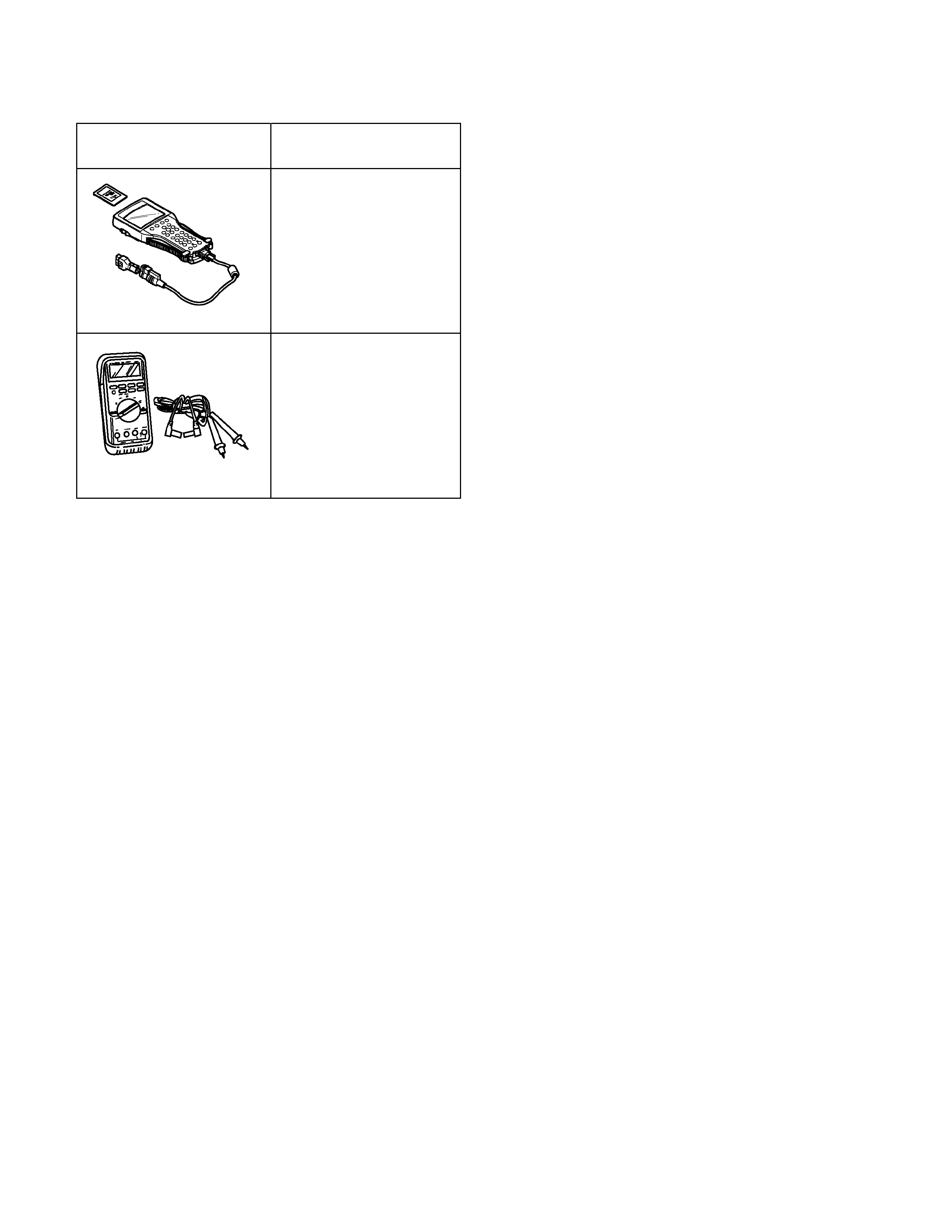
Special Tools
ILLUSTRATION PART NO.
PART NAME
Tech-2
Scan Tool
5-8840-0366-0
Digital Multi Meter