
SECTION 11 - IMMOBILISER SYSTEM
Service Precaution
General Description
What Happens Without Correct
Transponder Key Operation?
No Correct Transponder Is Available ,
What Should Be Done For The System?
Without The Security Code The Transponder
Key Cannot Be Programmed
Caution
Summary Of Operation
Circuit Diagram
Parts Location
Immobiliser Control Unit (ICU)
Pin-Outs
Immobiliser Coil (Antenna)
Transponder (Key)
Immobiliser War ning Lamp
Engine Control Module (ECM)
Important Information On Programming
Security Code
Entering The Security Code
Transponder (Key)
Important
Tech2 Scan Tool
Tech2 Features
Getting Started
Operating Procedure
Menu
DTC
Clear DTC Information
Tech2 Data Display
Check Vehicle Identification Number (VIN)
Reset Immobiliser (Reset Immobiliser
Control Unit)
Reset Engine Control Module (Reset ECM)
Erase Transponder Key
Programming Immobiliser Function
Programming ICU
Programming ECM
Programming ICU And ECM
Transponder Program
Data List
Diagnostic Procedure
Clearing Diagnostic Trouble Codes
Verifying Vehicle Repair
Diagnostic Aids
Check The Condition For System Parts
Check The Electro-Magnetic Interference (EMI)
Check The Other Items
Check The Operation
Diagnostic Trouble Code (DTC) List
Immobiliser System Check
No Check Engine Lamp
Check Engine Lamp On Steady
B8001 Replace Electronic Control Unit
(ECU) (Immobiliser Fault)
B8002 Immobiliser Not Programmed
B8003 Transponder Key Problem
B8004 Immobiliser Coil Circuit (Antenna Coil Fault)
B8005 Communication Line W Voltage Low
B8006 Communication Line W Voltage High
B8007 No Engine Request Received
B8008 Wrong Transponder Key
B8009 No Transponder Key Programmed
B8010 Unknown Transponder Key
Special Tool
Techline

Service Precaution
WARNING: THIS VEHICLE HAS A SUPPLEMENTAL RESTRA INT SYSTEM (SRS). REFER TO THE SRS
COMPONENT AND WIRING LOCATION VIEW IN ORDER TO DETERMINE WHETHER YOU ARE PERFORMING
SERVICE ON OR NEAR THE SRS COMPONENTS OR THE SRS WIRING. WHEN YOU A RE PERFORMING
SERVICE ON OR NEAR THE SRS COMPONENTS OR THE SRS WIRING, REFER TO THE SRS SERVICE
INFORMATION. FAILURE TO FOLLOW WARNINGS COULD RESULT IN POSSIBLE AIR BAG DEPLOYMENT,
PERSONAL INJURY, OR OTHERWISE UNNEEDED SRS SYSTEM REPAIRS.
CAUTION: Always use the correct fastener in the proper location. When you replace a fastener, use ONLY the
exact part number for that application. HOLDEN will call out those fasteners that require a replacement after
removal. HOLDEN will also call out the fasteners that require thread lockers or thread sealant. UNLESS
OTHERWISE SPECIFIED, do not use supplemental coatings (Paints, greases, or other corrosion inhibitors) on
threaded fasteners or fastener joint interfaces. Generally, such coatings adversely affect the fastener torque
and the joint clamping force, and may damage the fastener. When you install fasteners, use the correct
tightening sequence and specifications. Following these instructions can help you avoid damage to parts and
systems.
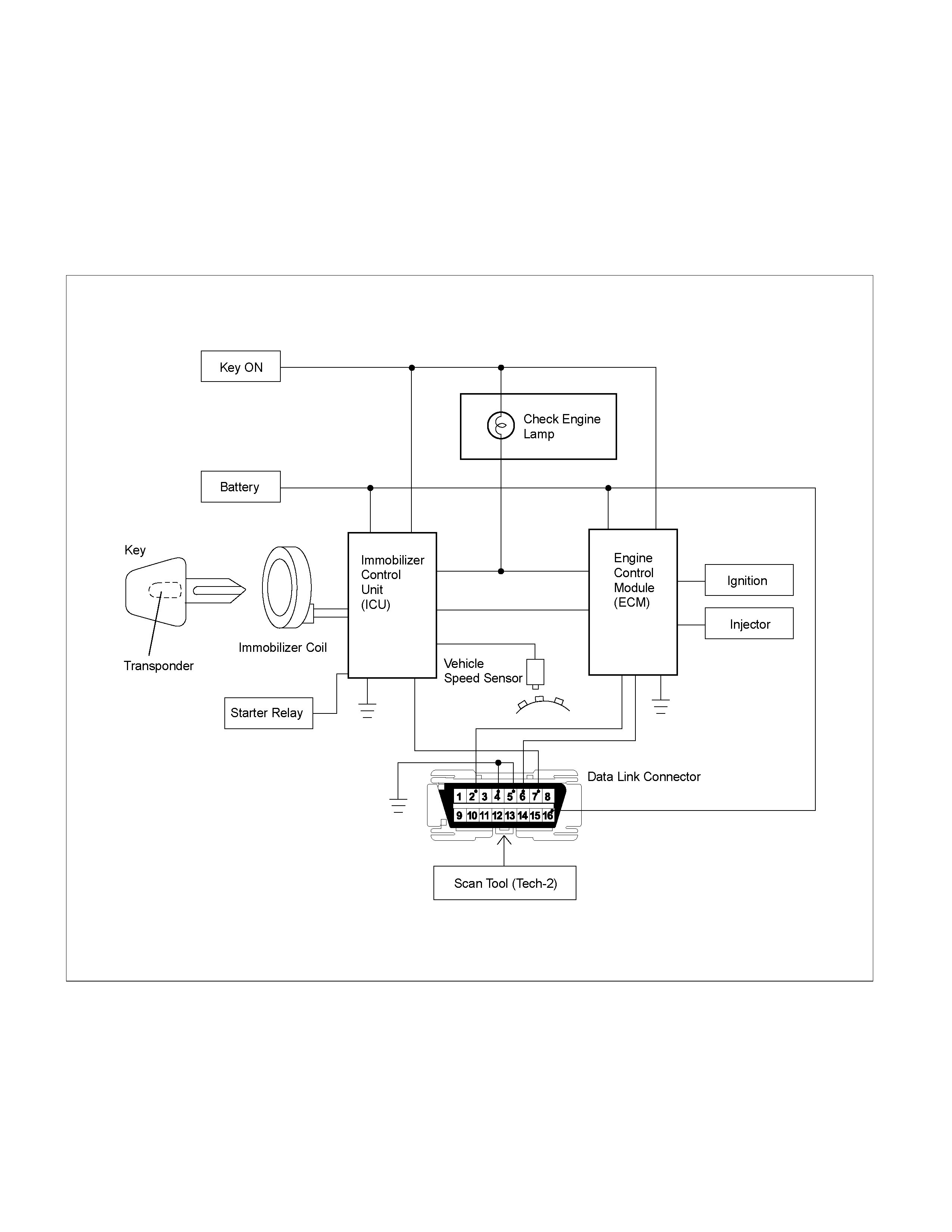
General Description
The Engine Immobiliser system is designed to provide “Drive-away” protection by electronically disabling the fuel and
starter systems. It is a passive system requiring no action on the part of the driver other than removing the ignition key
from the switch.
When the system is active :
The ICU disables the starter function, and the ECU disables the fuel injector function.
•
••
• Petrol Engine (6VE1, C24SE)
LTW3BALF000101
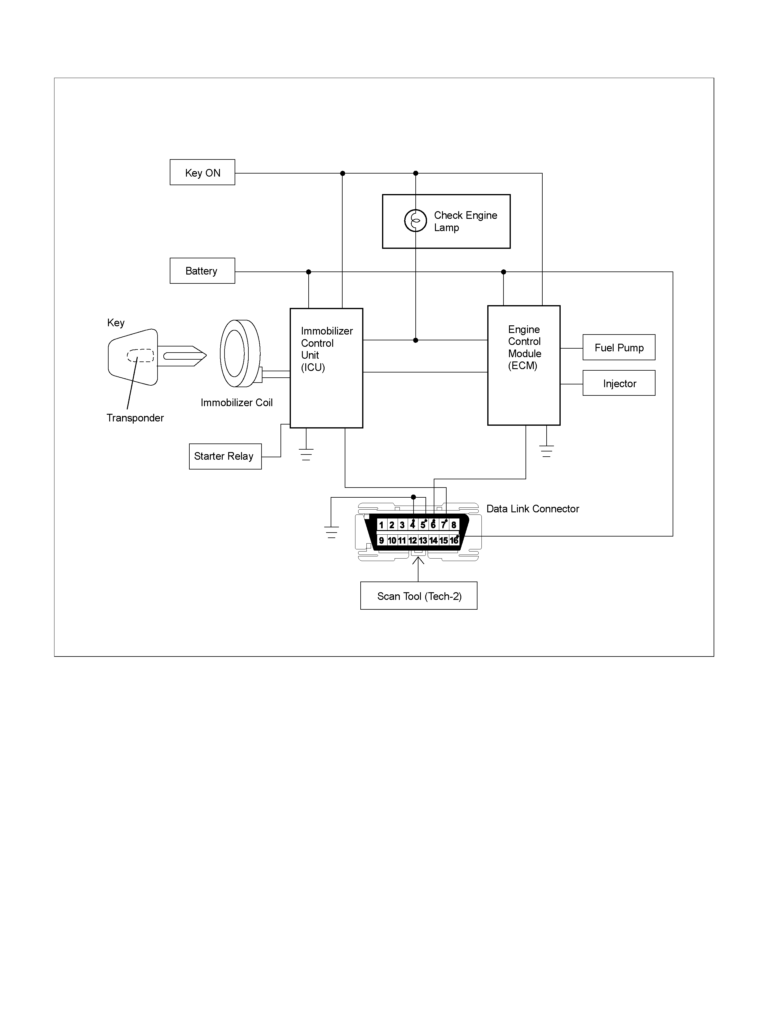
Diesel Engine (4JH1-TC)
LTW3BALF000201
What Happens Without Correct Transponder Key Operation?
One of the functions of the transponder key is to activate or deactivate the starter motor function. lf the correct
transponder key is not used, the starter relay cannot be energised and cranking the engine is not possible.
When the starter relay is activated, the transponder signal triggers to the lCU to calculate the transponder address
signal and immobiliser algorithm.
When the result matches with the ECM’s internal calculation, the injector power source will be activated.
If lCU fails to send the correct calculated result to the ECM, the engine may crank, but the injector system will not be
activated, resulting in a “crank, but no start” condition.

No Correct Transponder Is Available, What Should Be Done For The System?
When the correct transponder is not available, a new transponder should be programmed. Up to 5 transponders can be
programmed into the ICU with a scan tool (TECH2).
When programming a transponder key to the Immobiliser system the security code must be obtained through the
Holden Vehicle Security Information Request process. Refer to Retailer Letter 09/01?
Without The Security Code The Transponder Key Cannot Be Programmed
lf the scan tool (TECH2) and correct software are not available, there is no permanent way to repair the system.
Temporarily replacing with a new ECM, new ICU and new transponder without any security code MAY deactivate the
system, but only for a very short time. Such a replacement does not resolve any condition.
Caution
lf an attempt is made to start the engine while the immobiliser system is activated, the CHECK ENGINE lamp will flash,
the engine will not start a one or more DTC’s will be logged in both the ICU and the ECM.
Summary Of Operation
Ignition Switch OFF: System is active. Vehicle cannot be started
Ignition Switch ON: System is inactive and the vehicle can be started.
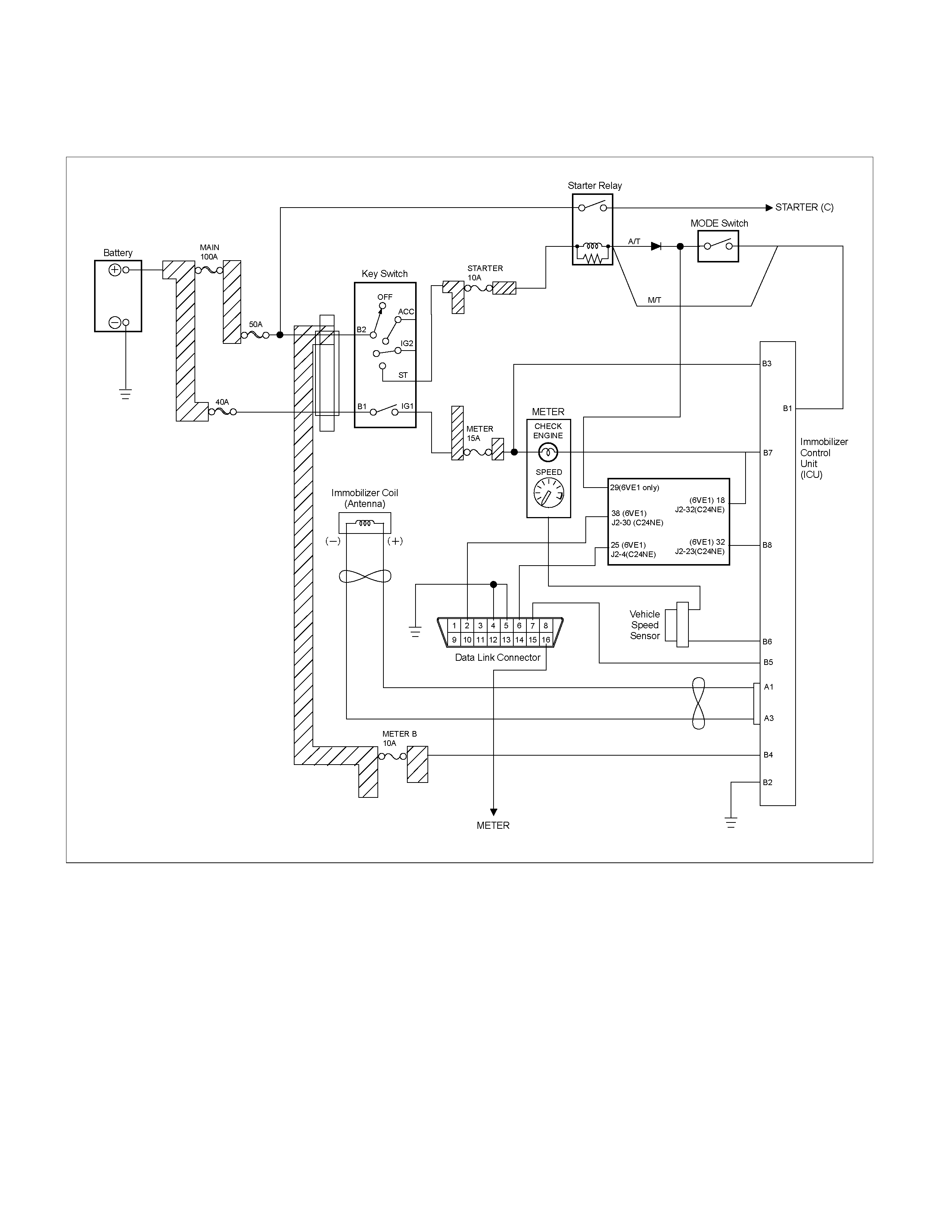
Circuit Diagram
•
••
• Petrol Engine (6VE1, C24SE)
LTW3BALF000301
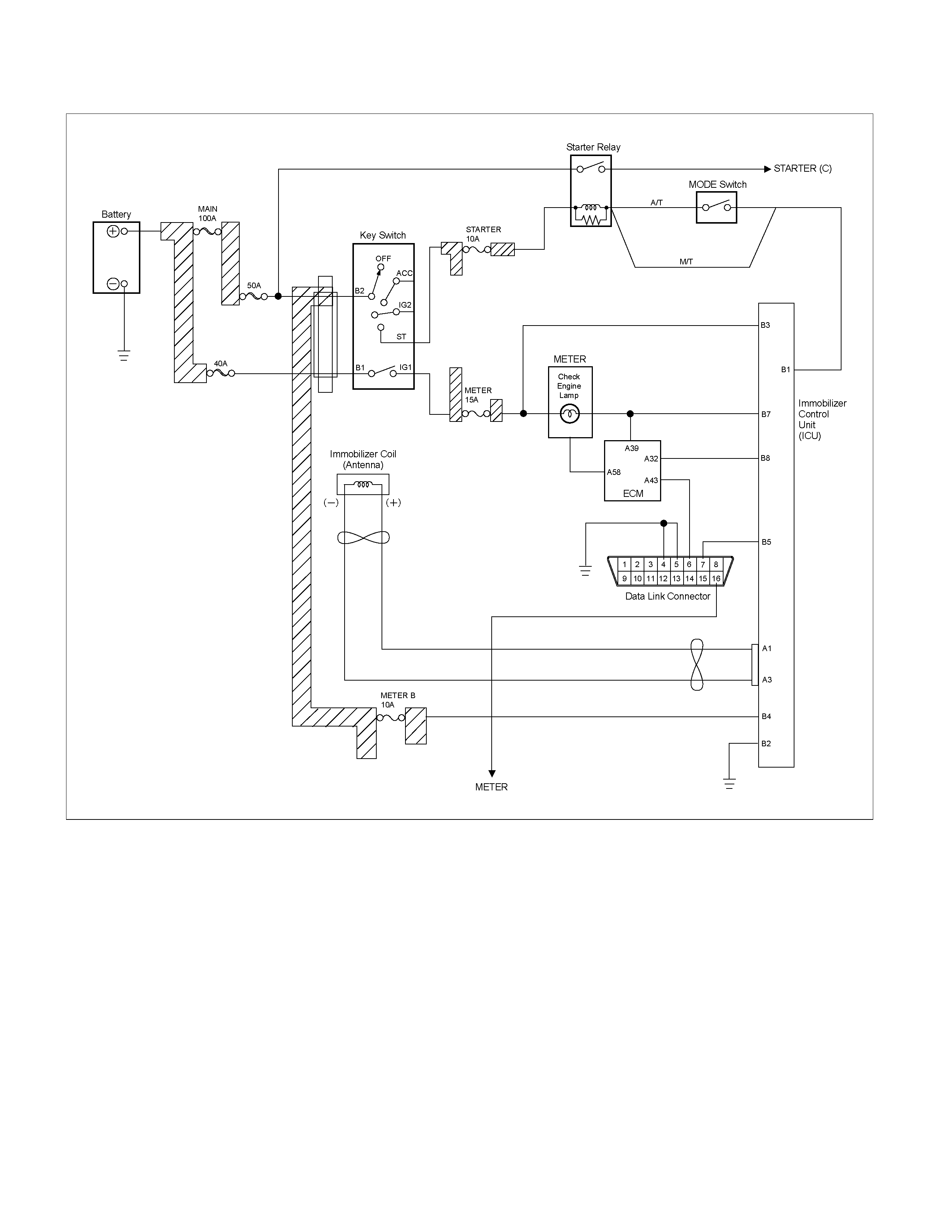
Diesel Engine (4JH1-TC)
LTW3BALF000401
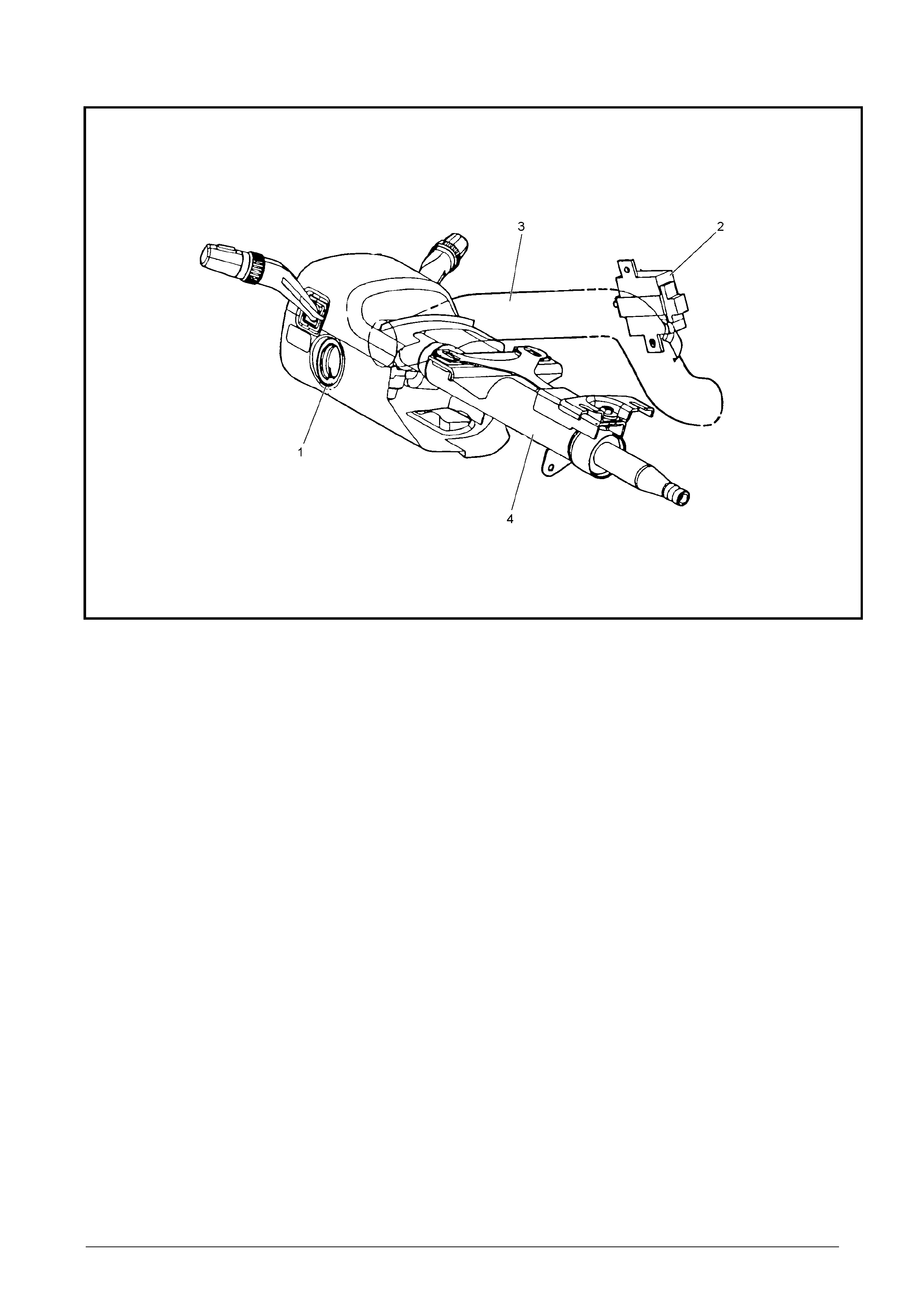
Parts Location
LTW3BAMF000101
Legend
(1) Immobiliser Coil
(2) Immobiliser Control Unit (ICU) (3) Cross Beam
(4) Steering Shaft

Immobiliser Control Unit (ICU)
When the ignition is turned ON, a complex process of data transfer takes place between the transponder key, the
Immobiliser Control Unit (ICU) and the Engine Control Unit (ECU).
If any transmitted data is incorrect or missing, the ICU prevents starter relay operation.
Should it be necessary to remove the ICU from the vehicle, the ICU MUST be “reset” with TECH2 prior to removal.
Due to the complex nature of the coded signals transmitted between the transponder key and the ICU, it is
recommended that the transponder keys be replaced when the ICU is replaced.
RUW38HSF000101
Pin-Outs
RUW38HSF000201

No. Pin Function
A-1 Antenna coil positive
A-2
A-3 Antenna coil negat ive
B-1 Starte r Relay (6VE1, C24SE Engine) / I mmobiliser Relay (4JH1- TC Engine)
B-2 Ground
B-3 Voltage from ignition switch ON
B-4 Back up voltag e supply
B-5 To TECH2
B-6 Vehicle speed sensor (6VE1, C24SE Engine) / Not used (4JH1-TC Engine)
B-7 Communicat ion: fr om ECM to I CU (CHECK ENGINE lam p )
B-8 Communication: from ICU to ECM (Comm unicat ion line W)
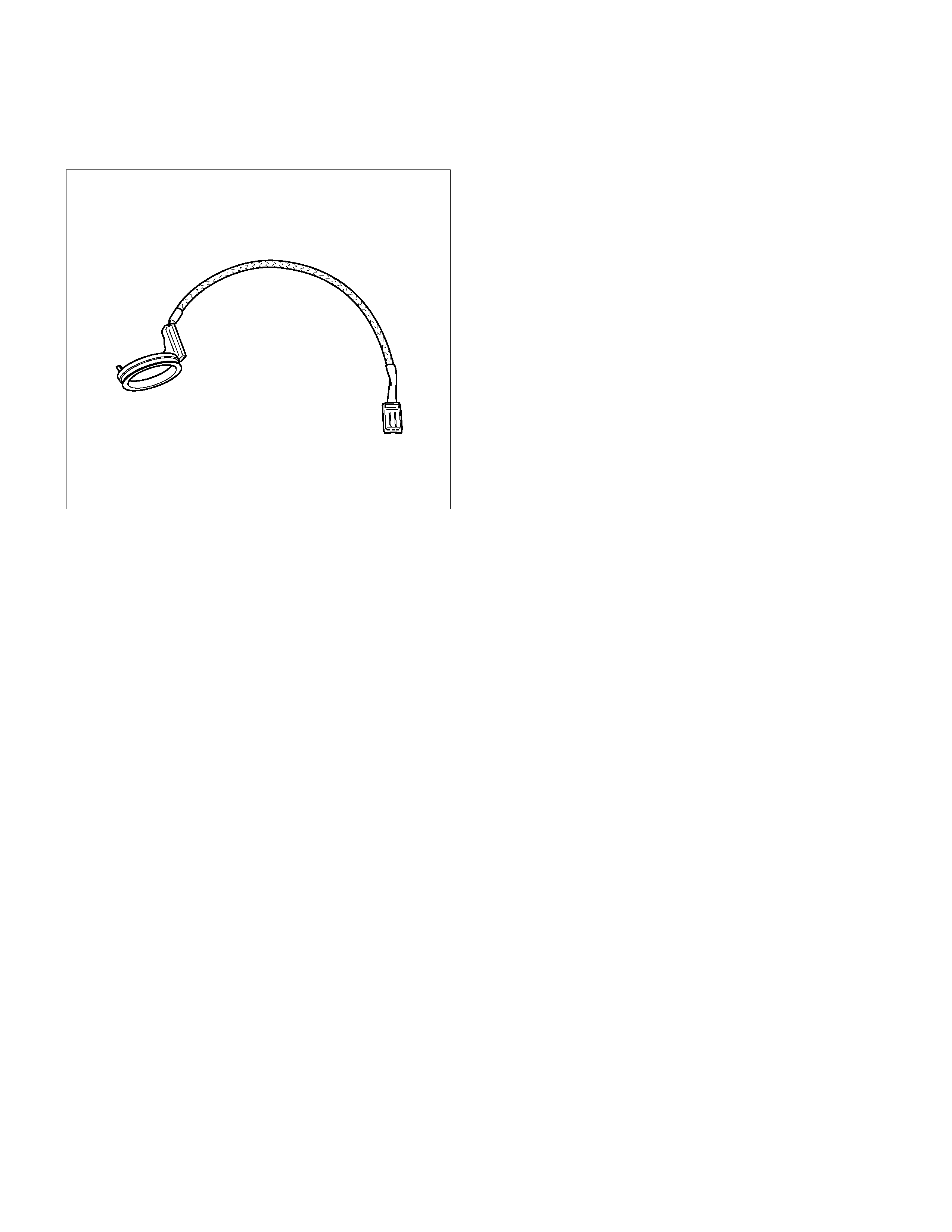
Immobiliser Coil (Antenna)
Surrounding the ignition lock is a dipole antenna, which is connected to the ICU by a wiring harness. A non-contact
radio frequency is to transfer information between the transponder key and the ICU via the antenna.
RUW38HSH000301
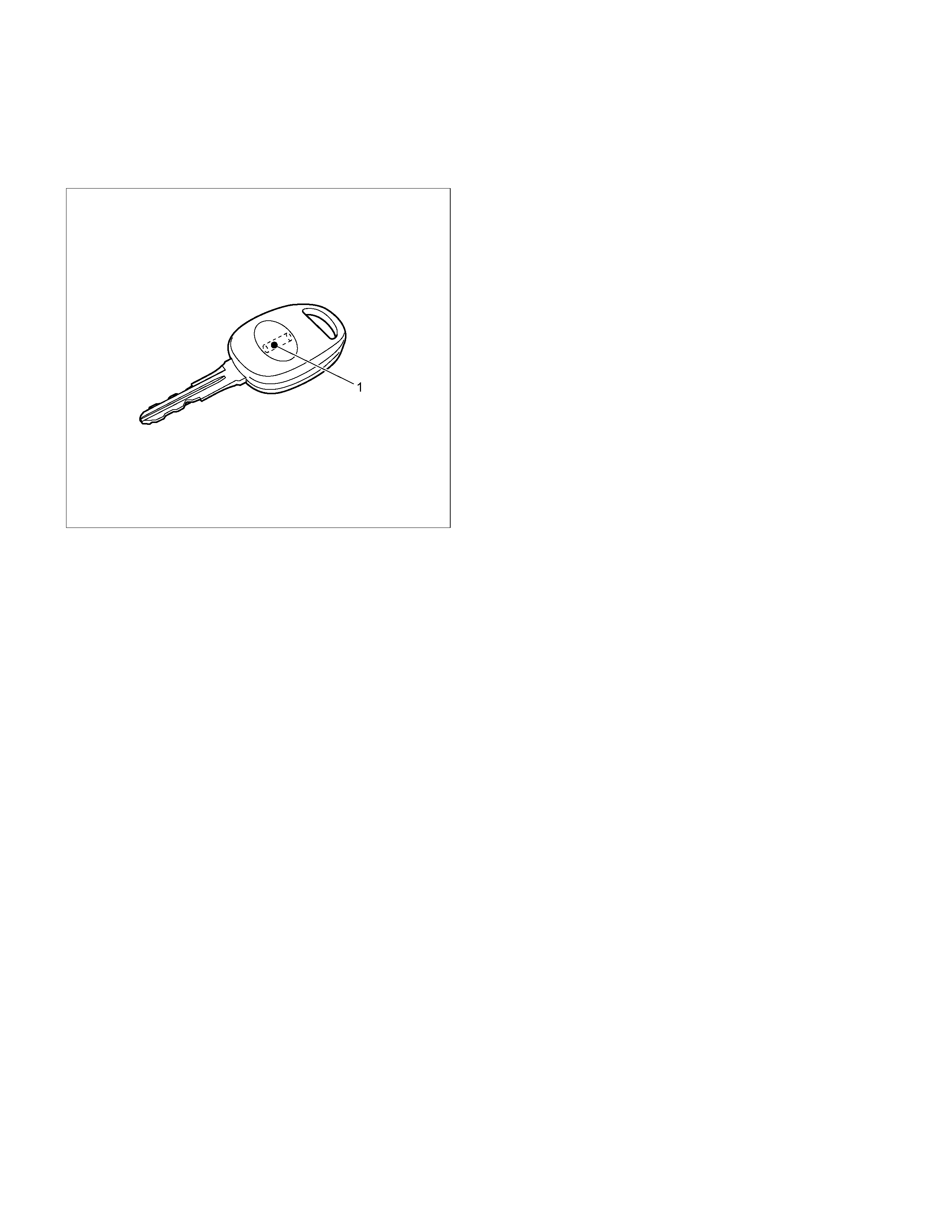
Transponder (Key)
The system uses a conventional mechanical-cut ignition key containing a miniature transponder embedded in the
plastic handle. The transponder circuit in the key does not require batteries – the ICU supplying a high frequency AC
voltage signal to the coil antenna provides the operating signal.
LTW3BASH000101
Legend
(1) Transponder (Key)
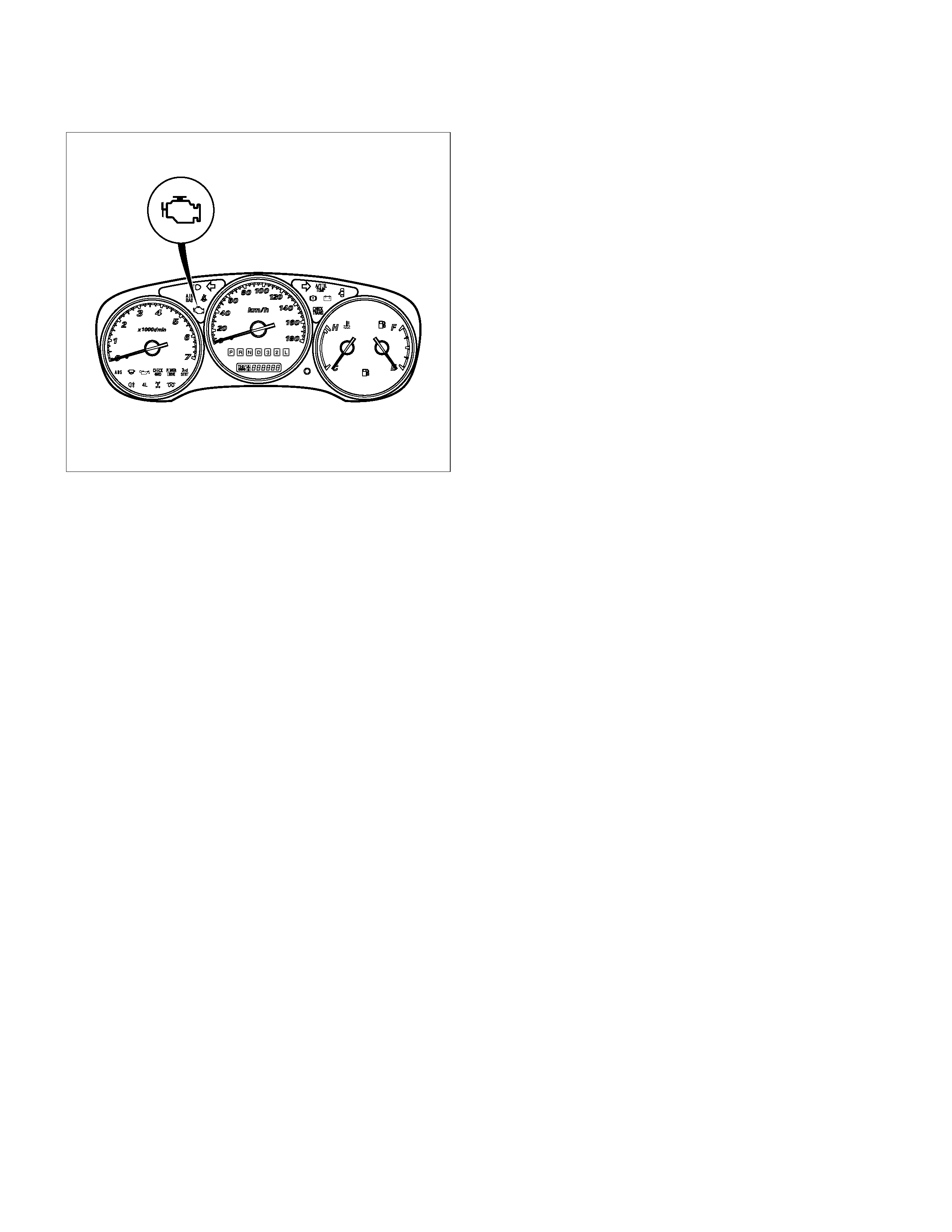
Check Engine Lamp
CHECK ENGINE lamp displays immobiliser system malfunction by rapid flashing of the CHECK ENGINE lamp.
LTW3BASH000201
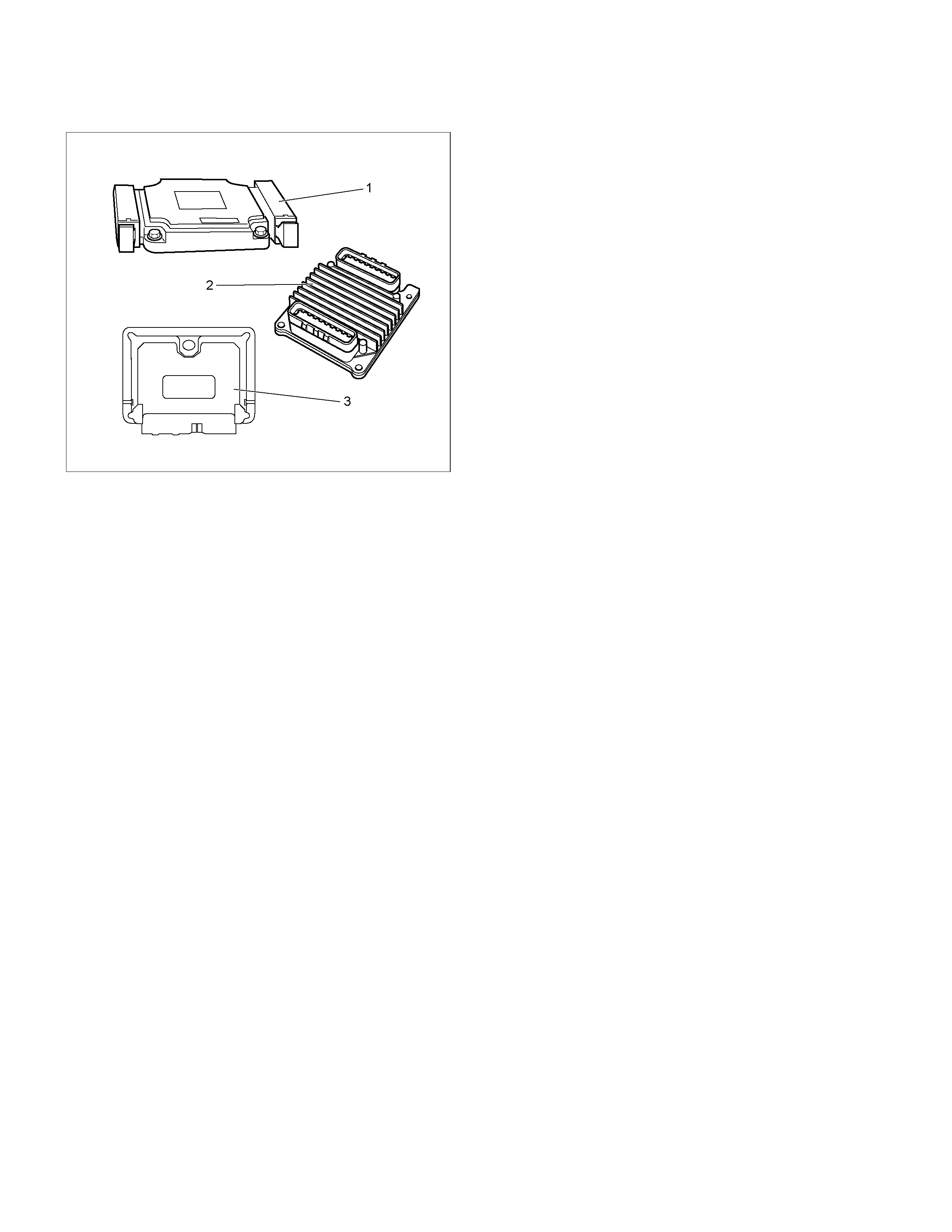
Engine Control Module (ECM)
If the transponder key rolling code does not match that calculated by the ECM, the ECU will not enable the fuel sy stem.
LTW3BASH000301
Legend
(1) ECM (6VE1 engine)
(2) ECM (C24SE engine)
(3) ECM (4JH1-TC engine) RUW38HXF000201

Important Information on Programming
Security Code
The security code protects the immobiliser control unit
against unauthorized programming and data access
from TECH2. The security code consists of a 4-digit
code number and is programmed into the Immobiliser
Control Unit and Engine Control Module (ECM).
New control units are not programmed with a security
code.
If the control units are replaced, the security code must
be programmed into the new control unit with TECH2.
The security code can only be programmed with TECH2
once and must therefore be entered with great care.
Once programmed, the security code cannot be
overwritten.
An already used immobiliser can be reused in a
different vehicle by ‘resetting’ the immobiliser. After that
you can program the security code again. For the reset
command, you require the current security code.
Should it be necessary to remove the ICU from the
vehicle, the ICU MUST be “reset” with TECH2 prior to
removal.
If the immobiliser control unit is returned (e.g. warranty
cases), always enclosed the security code that is
allocated to that control unit.
Entering The Security Code
If the TECH2 display requests the
• Security code
• Mechanical key number
• Vehicle Identification Number
proceed as follows:
To input a digit you need to use the up and down
buttons of the TECH2. By using the numeric buttons the
according digit will be displayed at the current position
and the cursor will move to the next position.
To enter letters you need to use the up and down
buttons of the TECH2. The up and down keys can also
be used for digits. By using the up and down buttons the
displayed digit or letter will be increased or decreased.
To move to the next position you need to use the move-
to-right-button.
With the two buttons, move-to-right and move-to-left
you can select the position of number you want to
change.
This will allow you to correct a wrong number.
After the number is completed you need to press the
Enter button to accept the number.
NOTE:
Correction is no longer possible after pressing
ENTER.
Use the OKAY soft key to program the number and the
NOT OKAY soft key to abort the programming.
Transponder (Key)
•
••
• If a transponder key is lost:
If a transponder key is lost, all transponder keys in the
immobiliser control system must be erased.
Thereafter, existing and new transponder keys are
programmed consecutively using TECH2. The vehicle
can then no longer be started using lost key.
•
••
• 5 transponder keys can be provided:
Each transponder has different Identifications. If a
customer wants more than 2 transponder keys,
additional programming by TECH2 can provide
maximum 5 transponder keys.
•
••
• lf a new ignition key with different mechanical key
number needs to be installed:
If installation of an ignition lock with a different
mechanism key number is necessary (an ignition lock
which belongs to the mechanical key number has to be
ordered first), all transponder keys must first be erased
and the two transponder keys, w hich belong to the
ignition lock that is now installed, must be programmed.
The new mechanical key number must be programmed
now into the immobiliser. The mechanical key number
in the car pass is to be changed as well.
Important
After successful programming, the engine control can
only be used for vehicles with immobiliser and
transponder.
Faults that occur in connection with the immobiliser
control unit are recognized by the engine control unit
and as long as "IMMOBILISER" is not programmed, are
indicated by a flashing of the CHECK ENGINE lamp.
NOTE:
If the immobiliser and e ngine control unit are
replaced at the same time, the IMMOBILISER
CONTROL UNIT MUST BE PROGRAMMED FIRST
before the "IMMOBILISER" function in the engine
control unit can be activated.
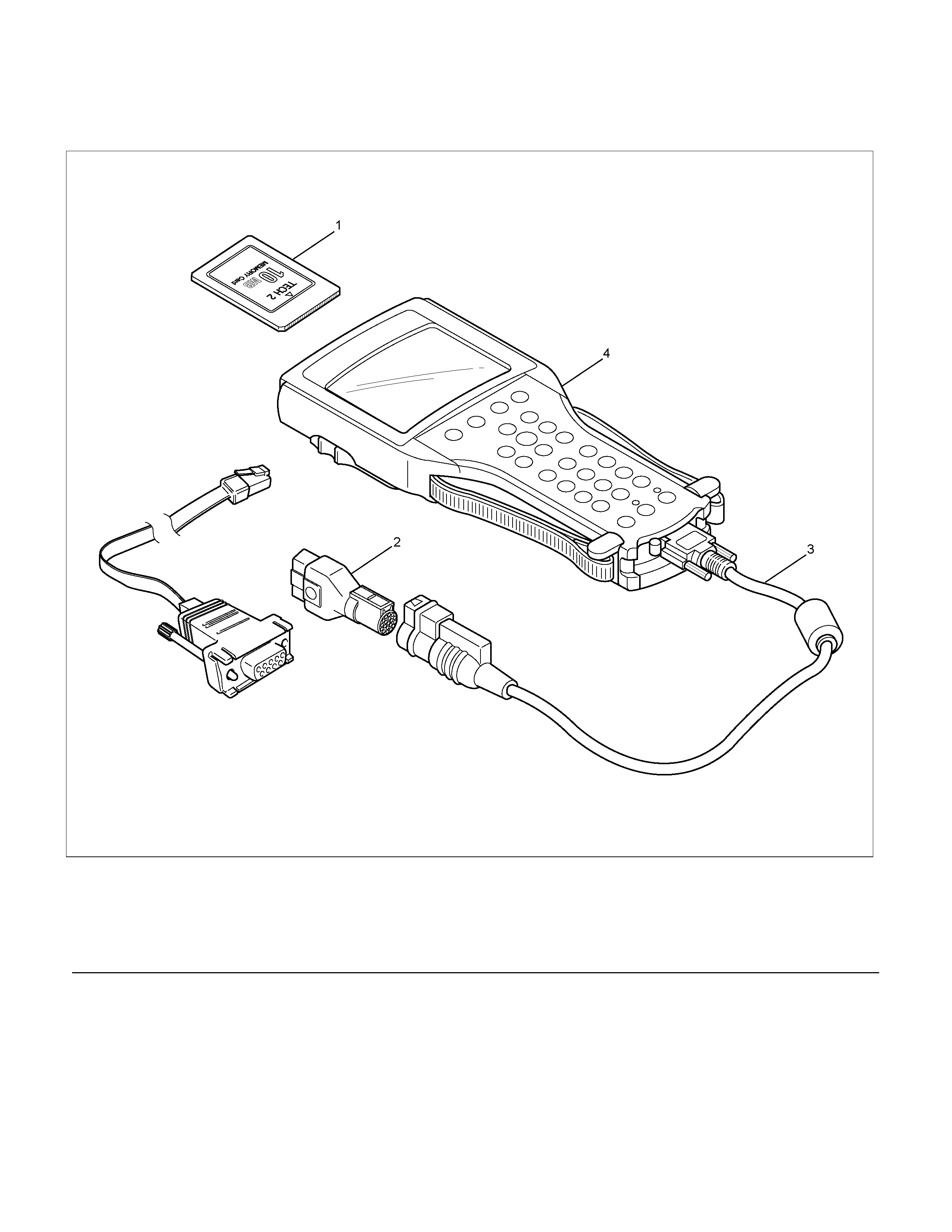
Tech 2 Scan Tool
TECH2 is the preferred tool for both programming and diagnosis of the Engine Immobiliser system.
LTW3BALF000501
Legend
(1) PCMCIA Card
(2) SAE 16/19 Adaptor
(3) DLC Cable
(4) TECH2
(5) RS232C Cable
TECH 2 Features
1. TECH2 is a 12volt system. Do not apply 24 volts.
2.
A
fter connecting and/or installing the vehicle
communication interface (VCI) module, PCMCI
A
card and data link connector (DLC) to the T ECH2,
connect the tool to the vehicle DLC.
3. Make sure the TECH2 is OFF when removing o
r
installing the PCMCIA card.
4. The TECH2 has the capability of two snapshots.
5. The PCMCIA card is sensitive to magnetism and
static electricity, so care should be taken in the
handling of the card.
6. The TECH2 cannot plot a graph when replaying a
snapshot.
7.
A
lways return to the Main Menu by pressing the
EXIT key several times before shutting down.
8. To clear diagnostic trouble codes (DTCs), open
Application Menu and press "Clear DTC ".
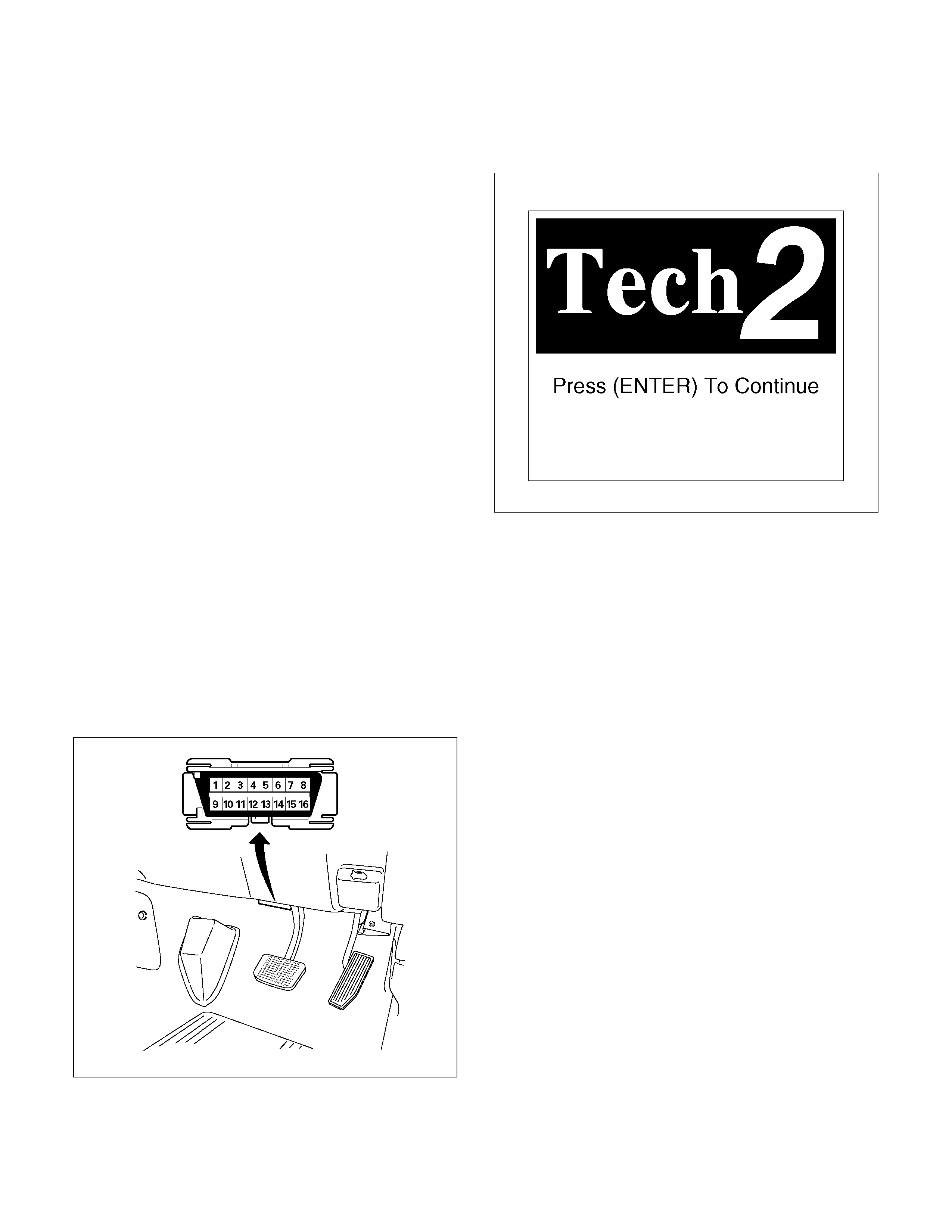
Getting Started
Before operating the Isuzu PCMCIA card with the Tech
2, the following steps must be performed:
1. The Isuzu System PCMCIA card inserts into the
Tech 2.
2. Connect the SAE 16/19 adapter to the DLC cable.
3. Connect the DLC cable to the Tech 2.
4. Mark sure the vehicle ignition is off.
5. Connect the Tech 2 SAE 16/19 adapter to the
vehicle DLC.
060R300015
6. Tune on the vehicle ignition (key) switch.
7. Power the TECH2 ON and verify the TECH2
power up display.
060RW009
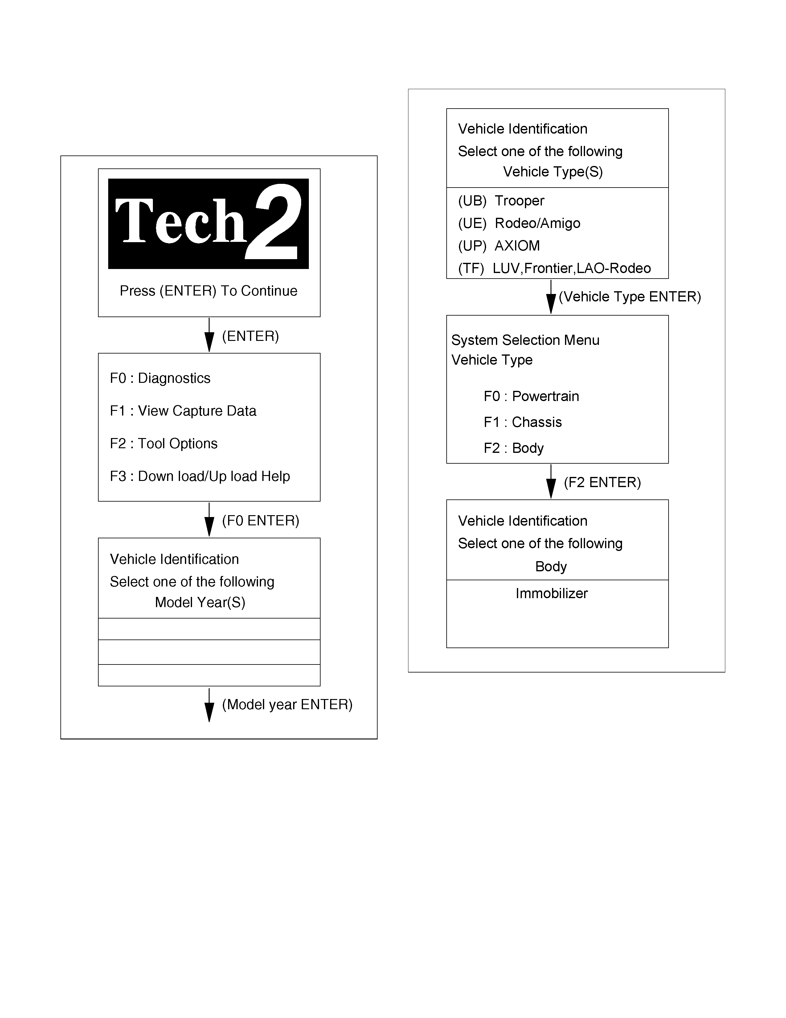
Operating Procedure
The power up screen is displayed when you power up
the tester with the Isuzu systems PCMCIA card.
Follow the operating procedure below.
060R100102
LTW3BALH000101

Menu
The following table shows which functions are used for
the available equipment versions.
F0: Diagnost ic Trouble Codes
F0: Read DTC I n fo O r dered By Priority
F1: Read DTC Inf o As Stored By ECU
F2: Clear DTC Information
F1: Data Display
F2: Snap Shot
F3: Additional Function
F0: Read ECU Ident ification
F1: Reset I m m obilizer
F2: Reset Eng ine Cont rol Module
F3: Erase Transponder-Keys
F4: Programming
F0: Prog ram Im mobilizer Function
F1: Prog r am Transponder- Keys
NOTE: Before going to programming process, TECH2
indicates instruction as follows.
060R200289
DTC
On OBD has two options available in the Tech 2 DTC
mode to display the enhanced information available.
• Read DTC Info Ordered By Priority
• Read DTC Info As Stored By ECU
Clear DTC Information
To clear Diagnostic Trouble Codes (DTCs), use the
diagnostic scan tool "clear DTC information" function.
TECH2 Data Dis play
Use the Tech 2 Data Values only after the On-Board
Diagnostic System Check has been completed, no
DTC(s) were noted, and you have determined that the
on-board diagnostics are functioning properly.
The Tech 2 data values represent values that would be
seen on a normally-immobiliser system.
Check Vehicle Identification Number (VIN)
1. Select "Body" and "Immobiliser".
2. Select "Additional Function" and "Read ECU
Identification".
3. Shows up VIN on TECH2 display.
Reset Immobiliser (Reset Immobiliser
Control Unit)
1. Select "Body" and "Immobiliser".
2. Select "Additional Function" and "Reset
Immobiliser".
3. Enter the security code and press Confirm.
4. Reset Immobiliser screen shows up with warning.
See the following screen.
060R200279

5. When reset is completed, the following screen
shows up.
060R200278
Reset Engine Control Module (Reset ECM)
1. Select "Body" and "Immobiliser".
2. Select "Additional Function" and "Reset Engine
Control Module".
3. The following screen shows up.
060R200289
4. Confirm the following screen shows up.
5. Input the security code, then press the soft key o
f
"Not Okay" or "Okay".
6. The following screen shows up.
7. Programming is completed.
060R200278
8. When the procedure is completed waits 10
seconds and then turn the Key on.
The fail lamp begins to flash.
9. Turn the ignition on, then engine dose not run.
4. Reset is completed.
Erase Transponder Key
1.Select "Body" and "Immobiliser".
2.Select "Additional Function” and "Erase
Transponder-Keys".
3.See immobiliser status on TECH2 screen and type
security code. If the status does not allow the
programming, only immobiliser status is displayed.
4.See illustration of caution.
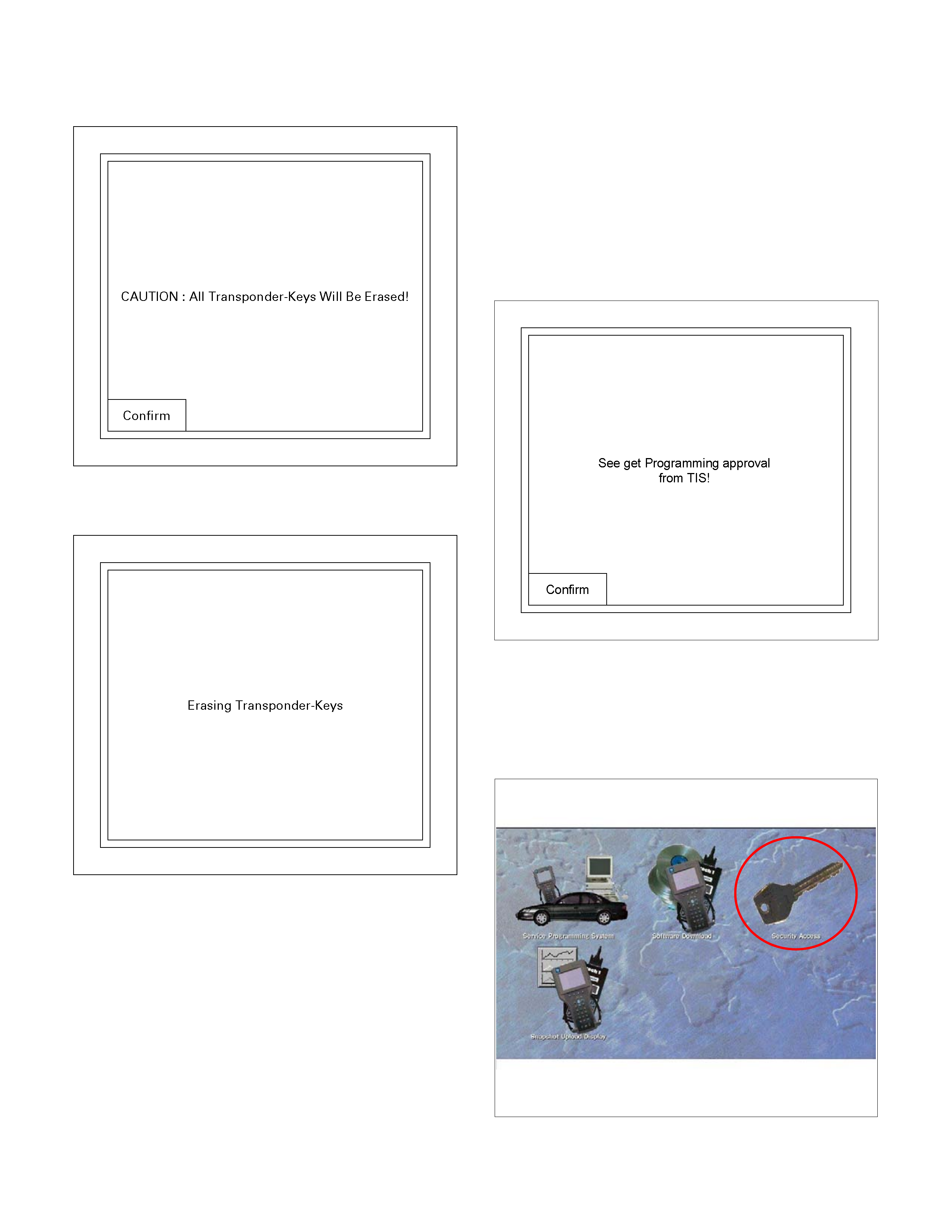
•
••
• CAUTION
060R200286
•
••
• Erase
060R200285
4. See programming result on display.
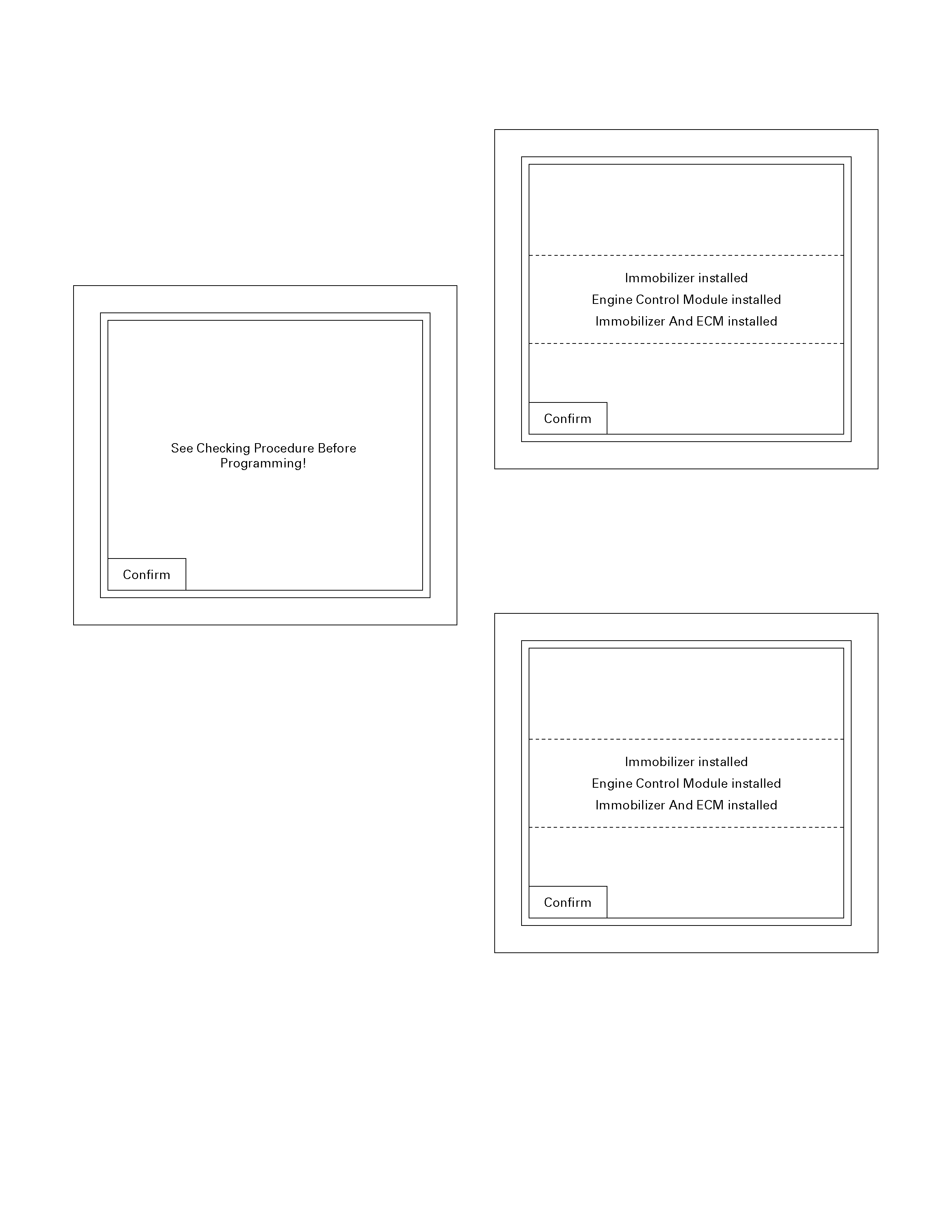
Programming Immobiliser Function
Caution:
1) Do not replace ICU and ECM at the same time
2) Change ICU at first or ECM and other one
change follows.
1. Select "Body" and "immobiliser".
2. Select "Programming" on TECH2 display.
3. Check the display, then press the "Confirm" key.
LTW3BASH000401
4. Install the "Hardware Key" on PC.
5. Connect RS232 cable to the PC and Tech2.
6. Turn on the PC, then start software "TIS 2000".
7. Select "Security Access" in the TIS 2000 screen.
8. Select "Next" in the TIS 2000 screen and wait a
few seconds.
9. When programming is enabled (Approved), then
press "close" in the TIS 2000 screen.
(Finish the "TIS 2000" operation.)
10. Select "Program Immobiliser Function" on TECH2
display.
11. The following screen shows up.
060R200289
12. Confirm the following screen shows up.
13. Input the security code, then press the soft key o
f
"Not Okay" or "Okay".
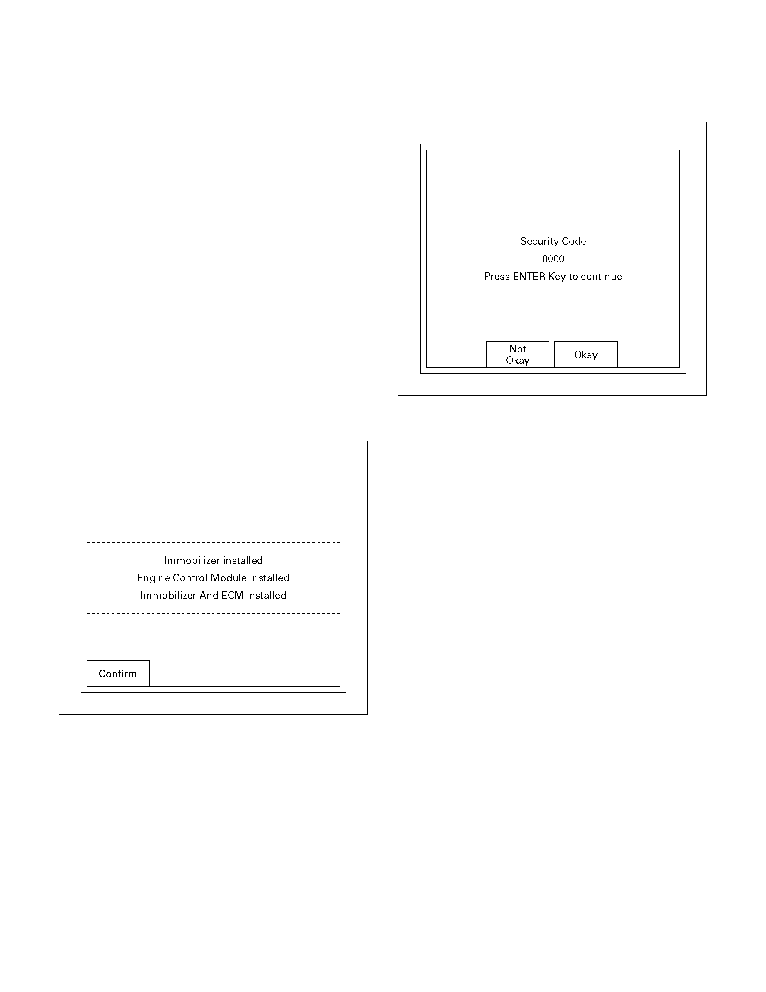
14. Select the engine type then, press "Enter" key.
15. Input a program option, by moving the cursor on
the selection, then press "Enter" key.
• Programming ICU
• Programming ECM
• Programming ICU and ECM
• Programming ICU and ECM
060R200283
Programming ICU
1. Follow Programming Immobiliser Function steps 1
through 14.
2. Input a program option, by moving the cursor on
the selection, then pres "Enter" key.
060R200283
3. Enter the security code.
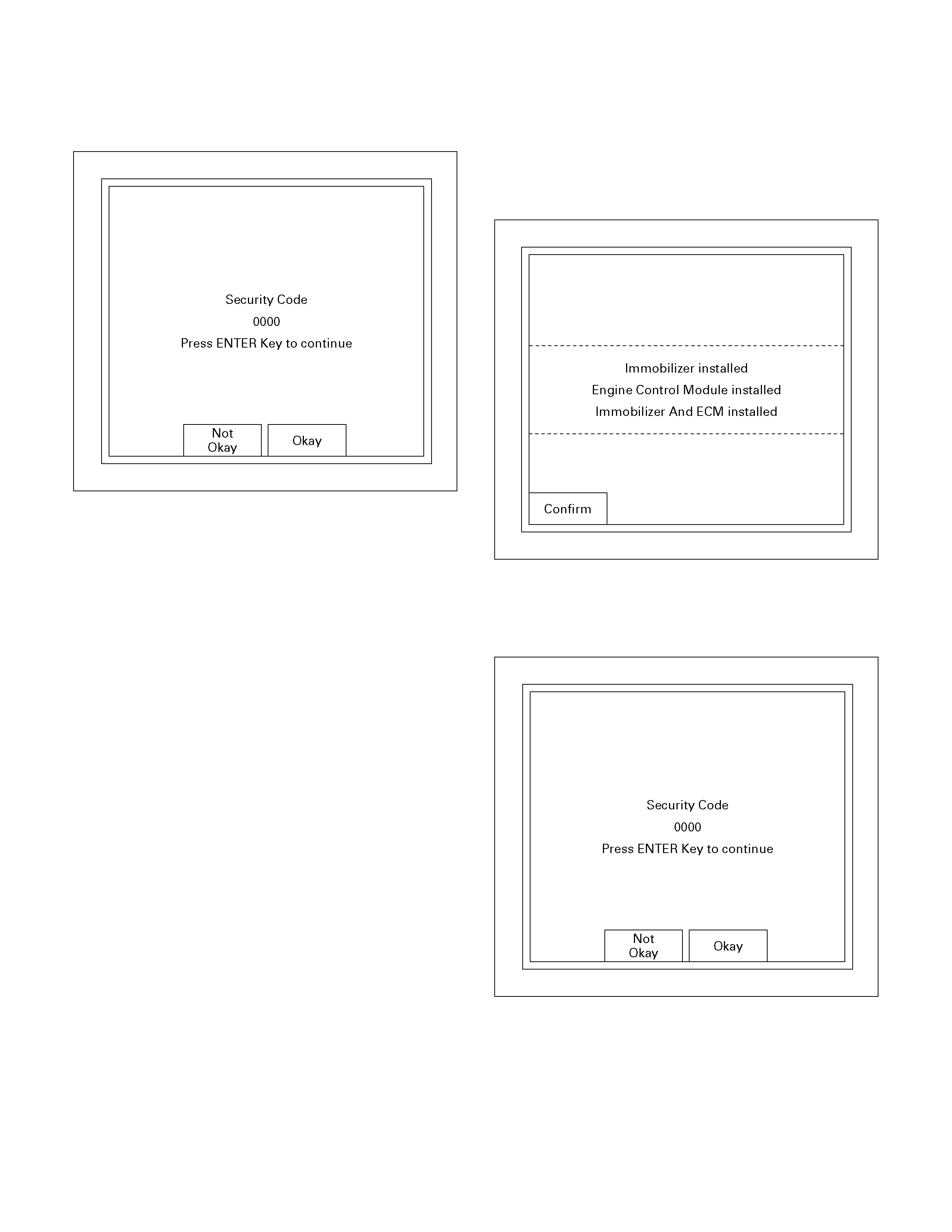
4. Input the security c ode, then press the soft key o
f
"Okay" or "Not Okay".
060R200284
5. Enter VIN.
6. Enter Mechanical key number.
7. Turn ON ignition.
8. Select an engine system.
9. See the programming result.
TECH2 displays the result of programming as the
following.
Follow those instructions
• Selected Programming is not possible due to
wrong System Status!
• Immobiliser Not Programmed!
• Immobiliser Already Programmed!
• ECM Not Programmed!
• ECM Already Programmed!
10. Transponder key must be reprogrammed,
because all transponder information is erased.
When ICU is programmed. See Transponde
r
programming.
Programming ECM
1. Follow Programming Immobiliser Function steps 1
through 14.
2. Input a program option, by moving the cursor on
the selection, then pres "Enter" key.
060R200283
3. Enter the security code.
4. Input the security code, then press the soft key o
f
"Okay" or "Not Okay".
060R200284
5. Turn on the Ignition.
6. Select an Engine system.
7. See the display of programming result.
TECH2 displays the result of programming as the
following.
Follow those instructions
• Selected Programming is not possible due to
wrong System Status!
• Immobiliser Not Programmed!
• Immobiliser Already Programmed!
• ECM Not Programmed!
• ECM Already Programmed!
8. Transponder key must be reprogrammed,
because all transponder information is erased.
When ICU is programmed. See Transponde
r
programming.
Programming ICU And ECM
1. Follow Programming Immobiliser Function steps 1
through 14.
2. Input a program option, by moving the cursor on
the selection, then pres "Enter" key.
060R200283
3. Enter the security code.
4. Input the security code, then press the soft key o
f
"Okay" or "Not Okay".
060R200284
5. Input the security code.
6. Enter VIN.
7. Enter Key No.
8. Select an engine system.
See programming result display and follow
instructions of the display.
9. Transponder key must be reprogrammed,
because all transponder information on ICU is
erased when ICU is programmed. See
Transponder programming.
10. Follow Programming ECM steps 2 through 8.
Transponder Program
1. Select "Body" and "Immobiliser".
2. Select "Programm ing" and "Pr ogram Trans ponder -
Key s".
(Follow Programming Immobiliser Function steps 1
through 14.)
3. See immobiliser status on TECH2 screen, and
enter security code. If the status does not allow the
programming, only immobiliser status is displayed.
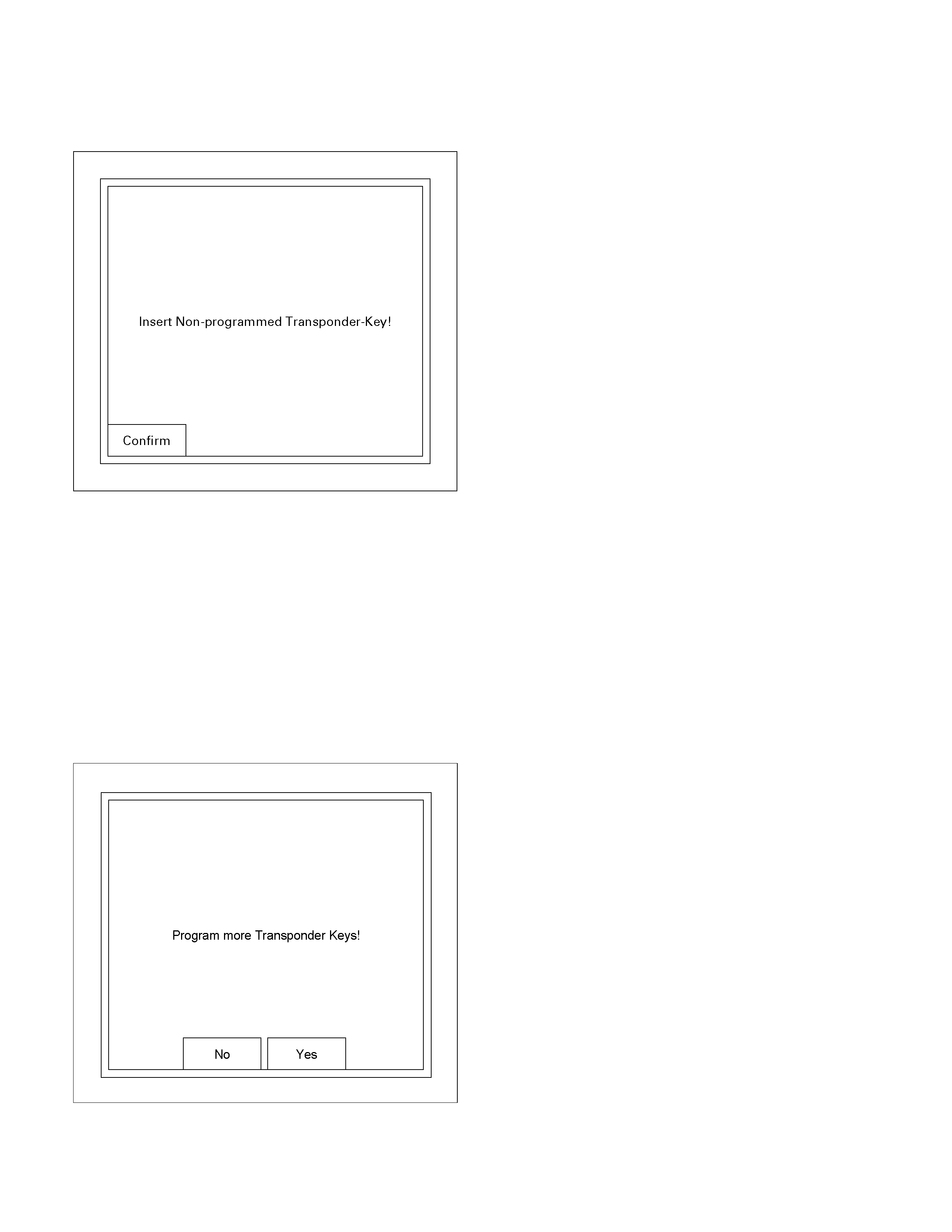
4. Insert Non-programmed Transponder-key and
press soft key of "Confirm".
060R200288
5. "T urn On ignition k ey", is displayed if the ignition is
off.
6. The transponder status is displayed if the status
does not allow the programming.
7. When programming starts "Programming
Transponder - key!" is displayed.
8. Turn off Ignition key.
9. Turn On Ignition key.
10. If the programming was not successful, the
transponder status is only display ed.
11. To program more illustration press soft key.
RUW38SH000601
12. See programming result.

Data List
No. Strings Note
1 Ignit ion St atus On 12V /Off 0V
2 Transponder - Key Transp. Key # Number of the k eys curr ently
programmed
3 Transponder Status Correct/Incorrect TP-Key
4 Transponder - Key 1 Status Progr am m ed / Not Programm ed
5 Transponder - Key 2 Status Progr am m ed / Not Programm ed
6 Transponder - Key 3 Status Progr am m ed / Not Programm ed
7 Transponder - Key 4 Status Progr am m ed / Not Programm ed
8 Transponder - Key 5 Status Progr am m ed / Not Programm ed
9 Immobiliser signal Transm it t ed / Not Transmitt ed
10 Engine Request Received / Not Received
11 Vehicle Speed Output Veh. Speed signal
12 Immobiliser Relay Active 0V / Inactive 12V
13 Security Wait Time Active / Inactive

Diagnostic Procedure
• Once the cause of DTC is repaired, the engine can be operated normally, and present DTC becomes history code.
• History code is cancelled by no repeat failure on 25 subsequent ignition key cycles.
• History code cannot be cancelled by disconnecting the battery.

Clearing Diagnostic Trouble Codes
IMPORTANT: Do not clear DTCs unless directed to do so by the service information provided for each diagnostic
procedure. When DTCs are cleared, the Failure Record data which may help diagnose an intermittent fault will also be
erased from memory.

Verifying Vehicle Repair
Verification of vehicle repair will be more comprehensive for vehicles with immobiliser system diagnostic. Following a
repair, the technician should perform the following steps:
1. Review and record the Fail Records for the DTC that has been retrieved.
2. Clear DTC(s).
3. Operate the vehicle within conditions noted in the Fail Records.
4. Monitor the DTC status information for the DTC that has been retrieved until the diagnostic test associated with
that DTC runs.
Following these steps precisely is important to verifying repairs on immobiliser systems. Failure to follow these steps
could result in unnecessary repairs.

Diagnostic Aids
Check The Condition For System Parts.
• Installation condition, poor connection, dam age, system parts malfunc tion. Harness, Fuse, Relay, Imm obiliser coil
(antenna), Key, Meter, Immobiliser control unit (ICU), Engine control module (ECM).
NOTE: Failure of immobiliser fuse will not disable immobiliser system. The CHECK ENGINE lamp flashes to indicate
the engine will not start.
Check The Electro-Magnetic Interference (EMI)
• Location of vehicle check
Move the vehicle to a new location and perform the check again.
• Non-OEM Parts.
Switch "OFF" or remove the Non-OEM parts and perform the check again.
• Other
Remove the accessory and another key from key.
Check The Other Items.
• Battery voltage is low.
• Immobiliser programming functions.
Must be programmed immobiliser system.
• Registration for security code, immobiliser control unit parts number.
• Key switch operation.
Immobiliser system may detect a history DTC by the timing of ON-OFF of a key switch.
• Active the immobiliser system.
• Keyless entry system is malfunction.
• Anti theft system is malfunction.
Check The Operation
Check the operation "Lock / unlock" by using transmitter (key) on the vehicle.

Diagnostic Trouble Code (DTC) List
•
••
• Immobiliser Control Unit (ICU)
DTC Description Note
B8001 REPLACE ELECTRONIC CONTROL UNIT
(ECU) (IMMOBILISER FAULT) This error code appears if a RAM /ROM Error was
detected or the EEPROM is defect.
B8002 IMMOBILISER NOT PROGRAMMED Immobiliser control unit is not programmed.
B8003 TRANSPONDER KEY PROBLEM Reading of Transponder information failed with ignition
on transponder has a fault.
Hardware fault in reading circuit.
B8004 IMMOBILISER COIL CIRCUIT (ANTENNA
COIL FAULT) Immobiliser coil has a fault.
B8005 COMMUNICATION LINE W VOLTAGE LOW Short circuit to ground or open circuit.
B8006 COMMUNICATION LINE W VOLTAGE HIGH Short circuit to 12V.
B8007 NO ENGINE REQUEST RECEIVED No ECM Challenge.
B8008 WRONG TRANSPONDER KEY Incorrect security code response received.
B8009 NO TRANSPONDER KEY PROGRAMMED Transponder security code table empty
B8010 UNKNOWN TRANSPONDER KEY Transponder security code not valid.
•
••
• Engine Control Module (ECM: Petrol Engine {6VE1, C24SE})
DTC Description Note
P1626 No Response From Immobiliser Refer to Engine Control system section
P1631 Received Response Was Not Correct Refer to Engine Control system section
P1648 Received Incorrect Security Code Refer to Engine Control system section
P1649 Security Code & Security Key Not
Programmed Refer to Engine Control system section
•
••
• Engine Control Module (ECM: Diesel Engine {4JH1-TC})
DTC Description Note
P1610 Seeds and Key File Destroyed Refer to Engine Control system section
P1611 Wrong Security Code Entered Refer to Engine Control system section
P1612/
P1613 Immobiliser No or Wrong Signal Refer to Engine Control system section
P1649 Wrong Transponder Key Refer to Engine Control system section

Immobiliser System Check
Step Action Yes No
1 1. Key position “ON”, engine “OFF”.
2. Observe the CHECK ENGINE lamp.
Note: When the ignition key is turned “ON”, the CHECK ENGINE
lamp will illuminate and stay “ON” for C24SE / 6VE1 engines,
while the lamp will illuminate and stay on for about 2.6 seconds
for the 4JH1-TC engine.
Is the CHECK ENGINE lamp “ON”? Go to Step 3 Go to Step 2
2
1 Key position “ON”, engine “OFF”.
2. Observe the CHECK ENGINE lamp.
Note: When the ignition key is turned “ON”, the CHECK ENGINE
lamp will illuminate and stay “ON” for C24SE / 6VE1 engines,
while the lamp will illuminate and stay on for about 2.6 seconds
for the 4JH1-TC engine.
Is the CHECK ENGINE lamp “OFF”? (CHECK ENGINE lamp does
not flash). Go Step 3
Go to “CHECK
ENGINE lamp on
steady”
3
1. Key position is “OFF”.
2. Install scan tool.
3. Key position is “ON”.
4. Attempt to display immobiliser data with the scan tool.
Does the scab tool display immobiliser data? Go to Step 9 Go to Step 4
4
1. With key position “OFF”, disconnect the immobil iser co ntrol unit
(ICU).
2. Check the DLC (Data Link Connector) circuit for an open, short
to ground or short to voltage. Also, check the DLC ignition feed
circuit for an open or short to ground and the DLC ground circuit
for an open.
Was a problem found? Go to Step 5 Go to Step 6
5 1. Repair or replace the DLC (Data Link Connector) circuit.
Was the action complete? Go to Step 3 —
6
1. Check the ICU circuit for an open, short to ground or short to
voltage. Also, check the ICU ignition feed circuit for an open or
short to ground and the ICU ground circuit for an open.
2. If a problem is found, repair as necessar y.
Was a problem found and corr ected? Go to Step 7 Go to Step 8
7 1. Repair or replace the ICU ignition feed and ground circuits.
Was the action complete? Go to Step 3 —
8
1. Replace the Immobiliser Control Unit (ICU).
IMPORTANT: The replacement ICU must be programmed with the
immobiliser data, using the scan tool.
Was the action complete? Go to Step 3 —
9 1. Select “Display DTCs” on the scan tool.
Are any DTCs stored? Go to Step 10 Go to Step 13
10 1. Review and re cord the scan tool Failure Rec ords data and
DTCs.
Was the action complete? Go to Step 11 —
11 If DTC/s are displayed, is one of them B8001?
Go to applicable
DTC table, then;
Go to Step 12 Go to Step 12
12 1 Use the scan tool to clear stored DTCs.
Did the DTCs clear? System OK —

Step Action Value(s) Yes No
13 Select "Display DTCs" with the scan tool.
Are any DTCs stored? Go to applicable
DTC table Go to Step 14
14 1. Key position is "ON," engine "OFF."
2. Observe the CHECK ENGINE lamp.
Note: When the key switch is turned ON, the CHECK
ENGINE lamp should illuminate and then go out after a few
seconds.
Does the CHECK ENGINE l amp "flash"? Go to Step 15 Go to Step 20
15 Check the engine control system.
If a problem is found, repair as necessary. (Refer to section
6E: system check and DTCs)
IMPORTANT: The replacement ECM must be programmed
with the immobiliser data by scan tool.
Was the action complete? Go to Step 16
16 Check the key.
Is the key type correct for the vehicle? Go to Step 18 Go to Step 17
17 Replace with correct key type.
IMPORTANT: when replacing the key, program the
immobiliser system. (Refer to "Important information on
Programming")
Was the action complete? Go to Step 18
18 Check the immobiliser programming functions.
• Immobiliser control unit (ICU).
• Engine control module (ECM).
• Transponder (Key).
If a problem is found, repair as necessary. (Refer to
"Important information on Programming")
Was the action complete? Go to Step 19
19 Operate the DTCs by "Clear the Information " with the scan
tool.
Was the action complete? Go to Step 20
20 Attempt to start the engine.
Did the engine start? System OK Refer to Diagnostic
Aids

No Check Engine Lamp
Step Action Value(s) Yes No
1 Check the meter fuse for the instrument cluster
ignition feed circuit.
Is the fuse normal? Go to Step 3 Go to Step 2
2 Replace the fuse.
Is the action complete? Verify repair Go to
Step 3
3 1. Key position is "OFF".
2. Disconnect the meter.
3. Disconnect the engine control module (ECM).
4. Check the circuit between meter and ECM for an open,
short to round, or short to voltage. Also, check the meter
circuit for an open or short to ground and the DLC ground
circuit for an open.
Was a problem found? Go to Step 4 Go to Step 5
4 Repair or replace the meter circuit.
Was the action complete? Go to Step 5
5 1. Key position is "ON," engine "OFF."
2. Observe the CHECK ENGINE lamp.
Is the CHECK ENGINE lamp "ON"? Go to Step 6 Go to Step 7
6 Repair or replace the meter.
Was the action complete? Go to Step 7
7 1. Key position is "OFF".
2. Check the CHECK ENGINE lamp bulb.
Is the CHECK ENGINE lamp bulb normal? Go to Step 9 Go to Step 8
8 Replace the check engine lamp bulb.
Is the action complete? Verify repair Go to
Step 9
9 1. Key position is "OFF".
2. Connect the meter.
3. Connect the engine control module (ECM).
4. Key position is "ON".
5. Observe the check engine lamp.
Note: If a key switch is turned ON, check engine lamp will
turn on and a check engine lamp will be turned off after a few
seconds.
Is the check engine lamp "ON"? Verify repair Go to Step 10
10 Replace the engine control module (ECM).
IMPORTANT: The replacement ICU must be programmed
with the immobiliser data by scan tool.
Was the action complete? Verify repair

Check Engine Lamp On Steady
Step Action Value(s) Yes No
1 1. Key position is "OFF".
2. Disconnect the immobiliser control unit (ICU).
3. Disconnect the engine control module (ECM).
4. Key position is "ON," engine "OFF."
5. Observe the CHECK ENGINE lamp .
Is the CHECK ENGINE lamp "ON"? Go to Step 2 Go to Step 5
2 1. Key position is "OFF".
2. Disconnect the meter.
3. Key position is "ON," engine "OFF."
4. Observe the CHECK ENGINE lamp.
Is the CHECK ENGINE lamp "ON"? Go to Step 3 Go to Step 4
3 Repair or replace the meter.
Was the action complete? Verify repair Go to
Step 5
4 Repair or replace the meter circuit.
(Between meter and ICU/ECM )
Was the action complete? Verify repair Go to
Step 5
5 Check the immobiliser control unit (ICU) circuit.
1. Ignition "OFF," disconnect the ICU.
2. Check the ICU circuit for an open, short to ground, or short
to voltage. Also, check the ICU ignition feed circuit for an
open or short to ground and the ICU ground circuit for an
open.
Was a problem found? Go to Step 6 Go to Step 7
6 Repair or replace the immobiliser unit (ICU) circuit.
Was the action complete? Verify repair Go to
Step 7
7 1. Key position is "OFF".
2. Connect the meter.
3. Connect the immobiliser control unit (ICU).
4. Connect the engine control module (ECM).
5. Key position is "ON".
6. Observe the CHECK ENGINE lamp .
Is the CHECK ENGINE lamp "ON"? Verify repair Refer to Diagnostic
Aids

B8001 Replace Electronic Control Unit (ECU) (Immobiliser Fault)
Step Action Value(s) Yes No
1 Was the "Immobiliser System Check" performed? Go to Step 2 Go to Immobiliser
System Check
2 Recheck the DTC.
1. Key position is “OFF”.
2. Install the scan tool on vehicle.
3. Key position is “ON”.
4. Check the DTC on scan tool.
Is DTC B8001 stored? Go to Step 3 Refer to
Diagnostic Aids
3 Check the immobiliser control unit (ICU) circuit.
1. Ignition "OFF," disconnect the ICU.
2. Check the ICU circuit for an open, short to ground, or short
to voltage. Also, check the ICU ignition feed circuit for an
open or short to ground and the ICU ground circuit for an
open.
Was a problem found? Go to Step 4 Go to Step 5
4 Repair or replace the immobiliser unit (ICU) circuit.
Was the action complete? Verify repair
5 Replace the immobiliser control unit (ICU).
IMPORTANT: The replacement ICU must be programmed
with the security data by scan tool.
Was the action complete? Verify repair

B8002 Immobiliser Not Programmed
Step Action Value(s) Yes No
1 Was the "Immobiliser System Check" performed? Go to Step 2 Go to Immobiliser
System Check
2 Check the immobiliser programming functions.
• Immobiliser control unit (ICU).
If a problem is found, repair as necessary. (Refer to
"Important information on Programming")
Was the action complete? Go to Step 3 Go to Step 5
3 Recheck the DTC.
1. Key position is “OFF” and keep the position for more
than 30 seconds.
2. Key position is “ON”.
3. Check the DTC on scan tool.
Is DTC B8002 stored? Go to Step 4 Verify repair
4 Replace the immobiliser control unit (ICU).
IMPORTANT: The replacement ICU must be
programmed the security data by scan tool.
Was the action complete? Verify repair
5 Check the immobiliser programming functions.
• Engine control module (ECM).
• Immobiliser control unit (ICU).
If a problem is found, repair as necessary.
(Refer to "Important information on Programming")
Was the action complete? Verify repair Go to Step 6
6 Replace the key and lock cylinder assembly and
immobiliser system (ICU and ECM).
IMPORTANT:
• ICU and ECM are not replaced simultaneously.
• After replacing the components, perform the following
below the items.
• Program the immobiliser system.
(Refer to "Important information on Programming")
Was the action complete? Verify repair

B8003 Transponder Key Problem
Step Action Value(s) Yes No
1 Was the "Immobiliser System Check" performed? Go to Step 2 Go to Immobiliser
System Check
2 Check the key.
Is a key peculiar to a vehicle? Go to Step 3 Refer to
Diagnostic Aids
3 Check the immobiliser programming functions.
• All transponder (Key).
If a problem is found, repair as necessary. (Refer to "Important
information on Programming")
Was the action complete? Go to Step 4 Go to Step 5
4 Recheck the DTC.
1. Key position is “OFF” and keep the position for more than
30 seconds.
2. Key position is “ON”.
3. Check the DTC on scan tool.
Is DTC B8003 stored? Go to Step 5 Verify repair
5 Recheck the DTC.
1. Non-OEM parts switch is "OFF" or remove the Non-OEM
parts.
2. Remove the accessory and another key from key.
3. Move the vehicle to a new location.
4. Key position is “OFF” and keep the position for more than
30 seconds.
5. Key position is “ON”.
6. Check the DTC on scan tool.
Is DTC B8003 stored? Go to Step 6 Verify repair
6 Check the immobiliser coil (antenna) circuit.
1. Key position is “OFF”.
2. Disconnect the immobiliser control unit (ICU). 3 pin
connector
3. Check the immobiliser coil circuit for an open, short to
ground, or short to voltage. Also, check the ICU ignition
feed circuit for an open or short to ground and the ICU
ground circuit for an open.
Was a problem found? Go to Step 7 Go to Step 8
7 Repair or replace the immobiliser coil (antenna) circuit.
Was the action complete? Verify repair
8 Recheck the DTC.
1. Key position is “OFF” and keep the position formore than 30
seconds.
2. Key position is “ON”.
3. Check the DTC on scan tool.
Is DTC B8003 stored? Go to Step 9 Verify repair

Step Action Value(s) Yes No
9 Replace the immobiliser control unit (ICU).
IMPORTANT: The replacement ICU must be programmed with
the security data by scan tool.
Was the action complete? Go to Step 10
10 Check the immobiliser programming functions.
• Immobiliser control unit (ICU).
• All transponder (Key).
If a problem is found, repair as necessary. (Refer to "Important
information on Programming")
Was the action complete? Go to Step 11
11 Recheck the DTC.
1. Key position is “OFF” and keep the position for more than
30 seconds.
2. Key position is “ON”.
3. Check the DTC on scan tool.
Is DTC B8003 stored? Go to Step 12 Verify repair
12 Replace the transponder (Key).
IMPORTANT: The replacement transponder (key) must be
programmed the security data by scan tool.
Was the action complete? Verify repair

B8004 Immobiliser Coil Circuit (Antenna Coil Fault)
Step Action Value(s) Yes No
1 Was the "Immobiliser System Check" performed? Go to Step 2 Go to Immobiliser
System Check
2 Check the immobiliser coil (antenna) circuit.
1. Key position is “OFF”.
2. Disconnect the immobiliser control unit (ICU). (immobiliser
coil circuit : 3 pin connector)
3. Check the immobiliser coil circuit for an open, short to
ground, or short to voltage. Also, check the ICU ignition feed
circuit for an open or short to ground and the ICU ground
circuit for an open.
Was a problem found? Go to Step 3 Go to Step 4
3 Repair or replace the immobiliser coil (antenna) .
Was the action complete? Verify repair
4 Recheck the DTC.
1. Key position is “OFF” and keep the position for more than
30 seconds.
2. Key position is “ON”.
3. Check the DTC on scan tool.
Is DTC B8004 stored? Go to Step 5 Verify repair
5 Replace the immobiliser control unit (ICU).
IMPORTANT: The replacement ICU must be programmed
the security data by scan tool.
Was the action complete? Verify repair

B8005 Communication Line W Voltage Low
Step Action Value(s) Yes No
1 Was the "Immobiliser System Check" performed? Go to Step 2 Go to Immobiliser
System Check
2 Recheck the DTC.
1. Key position is “OFF”.
2. Install the scan tool on vehicle.
3. Key position is “ON”.
4. Check the DTC on scan tool.
Is DTC B8005 stored? Go to Step 3 Refer to Diagnostic
Aids
3 Check the immobiliser communication W line circuit.
1. Key position is “OFF”.
2. Disconnect the immobiliser control unit (ICU).
3. Disconnect the engine control module (ECM).
4. Check the immobiliser communication W line circuit for an
open, short to ground, or short to voltage. Also, check the
ICU and ECM ignition feed circuits for an open or short to
ground and the ICU and ECM ground circuit for an open.
Was a problem found? Go to Step 4 Go to Step 5
4 Repair or replace the immobiliser communication W line
circuit.
Was the action complete? Verify repair
5 Replace the immobiliser control unit (ICU).
IMPORTANT: The replacement ICU must be programmed
with the security data by scan tool.
Was the action complete? Verify repair

B8006 Communication Line W Voltage High
Step Action Value(s) Yes No
1 Was the "Immobiliser System Check" performed? Go to Step 2 Go to Immobiliser
System Check
2 Recheck the DTC.
1. Key position is “OFF”.
2. Install the scan tool on vehicle.
3. Key position is “ON”.
4. Check the DTC on scan tool.
Is DTC B8006 stored? Go to Step 3 Refer to
Diagnostic Aids
3 Check the immobiliser communication W line circuit.
1. Key position is “OFF”.
2. Disconnect the immobiliser control unit (ICU).
3. Disconnect the engine control module (ECM).
4. Check the immobiliser communication W line circuit for an
open, short to ground, or short to voltage. Also, check the
ICU and ECM ignition feed circuits for an open or short to
ground and the ICU and ECM ground circuit for an open.
Was a problem found? Go to Step 4 Go to Step 5
4 Repair or replace the immobiliser communication W line
circuit.
Was the action complete? Verify repair
5 Replace the immobiliser control unit (ICU).
IMPORTANT: The replacement ICU must be programmed
with the security data by scan tool.
Was the action complete? Verify repair

B8007 No Engine Request Received
Step Action Value(s) Yes No
1 Was the "Immobiliser System Check" performed? Go to Step 2 Go to Immobiliser
System Check
2 Recheck the DTC on ICU.
1. Key position is “OFF”.
2. Install the scan tool on vehicle.
3. Key position is “ON”.
4. Check the DTC on scan tool.
Is DTC B8007 stored? Go to Step 3 Refer to
Diagnostic Aids
3 Check the immobiliser communication line circuit.
1. Key position is “OFF”.
2. Disconnect the immobiliser control unit (ICU).
3. Disconnect the engine control module (ECM).
4. Check the immobiliser communication line circuit for an
open, short to ground, or short to voltage. Also, check the
ICU and ECM ignition feed circuits for an open or short to
ground and the ICU and ECM ground circuit for an open.
Was a problem found? Go to Step 4 Go to Step 5
4 Repair or replace the immobiliser communication line circuit.
Was the action complete? Verify repair
5 Recheck the DTC on ICU.
1. Key position is “OFF” and keep the position for more than
30 seconds.
2. Key position is “ON”.
3. Check the DTC on scan tool.
Is DTC B8007 stored? Go to Step 6 Verify repair
6 Recheck the DTC on ECM.
1. Key position is “OFF” and keep the position for more than
30 seconds.
2. Key position is “ON”.
3. Check the DTC on scan tool.
Are below DTCs stored?
P1649 (6VE1, C24SE), P1611/P1614 (4JH1-TC) Go to Step 7 Go to Step 9
7 Perform the immobiliser programming functions.
(Refer to "Important information on Programming")
• Engine control module (ECM).
Was the action complete? Go to Step 8 Go to Step 11

Step Action Value(s) Yes No
8 Recheck the DTC on ECM.
1. Key position is “OFF” and keep the position for more than
30 seconds.
2. Key position is “ON”.
3. Check the DTC on scan tool.
Are below DTCs stored?
P1649 (6VE1, C24SE) , P1611/P1614 (4JH1-TC) Go to Step 11 Go to Step 12
9 Check the immobiliser programming functions.
• Engine control module (ECM).
If a problem is found, repair as necessary.
(Refer to "Important information on Programming")
Was the action complete? Go to Step 10 Go to Step 11
10 Recheck the DTC on ECM.
1. Key position is “OFF” and keep the position for more than
30 seconds.
2. Key position is “ON”.
3. Check the DTC on scan tool.
Are below DTCs stored?
P1649 (6VE1, C24SE), P1611/P1614 (4JH1-TC) Go to Step 11 Go to Step 12
11 Replace the engine control module (ECM).
IMPORTANT: The replacement ECM must be programmed
with the security data by scan tool.
Was the action complete? Go to Step 12
12 Recheck the DTC on ECM.
1. Key position is “OFF” and keep the position for more than
30 seconds.
2. Key position is “ON”.
3. Check the DTC on scan tool.
Are below DTCs stored?
P1626 (6VE1, C24SE), P1612/P1613 (4JH1-TC) Go to Step 13 Go to Step 2
13 Replace the immobiliser control unit (ICU).
IMPORTANT: The replacement ICU must be programmed
with the security data by scan tool.
Was the action complete? Verify repair

B8008 Wrong Transponder Key
Step Action Value(s) Yes No
1 Was the "Immobiliser System Check" performed? Go to Step 2 Go to Immobiliser
System Check
2 Check the key.
Is a key peculiar to a vehicle? Go to Step 3 Refer to
Diagnostic Aids
3 Check the immobiliser programming functions. - Transponder
(Key).
Was a problem found? Go to Step 4 Go to Step 5
4 Perform the immobiliser programming functions. -
Transponder (Key).
(Refer to "Important information on Programming")
Was the action complete? Go to Step 5
5 Recheck the DTC.
1. Key position is “OFF” and keep the position for more than
30 seconds.
2. Key position is “ON”.
3. Check the DTC on scan tool.
Is DTC B8008 stored? Go to Step 6 Verify repair
6 Replace the transponder (Key).
IMPORTANT: The replacement transponder (key)
must be programmed the security data by scan tool.
Was the action complete? Go to Step 7
7 Recheck the DTC.
1. Key position is "OFF" and keep the position for more than
30 seconds.
2. Key position is "ON".
3. Check the DTC on scan tool.
Is DTC B8008 stored? Go to Step 8 Verify repair
8 Replace the immobiliser control unit (ICU).
IMPORTANT: The replacement ICU must be programmed
with the security data by scan tool.
Was the action complete? Verify repair

B8009 No Transponder Key Programmed
Step Action Value(s) Yes No
1 Was the "Immobiliser System Check" performed? Go to Step 2 Go to Immobiliser
System Check
2 Check the key.
Is a key peculiar to a vehicle? Go to Step 3 Refer to
Diagnostic Aids
3 Check the immobiliser programming functions. - Transponder
(Key).
Was a problem found? Go to Step 4 Go to Step 5
4 Perform the immobiliser programming functions. -
Transponder (Key).
(Refer to "Important information on Programming")
Was the action complete? Go to Step 5
5 Recheck the DTC.
1. Key position is “OFF” and keep the position for more than
30 seconds.
2. Key position is “ON”.
3. Check the DTC on scan tool.
Is DTC B8009 stored? Go to Step 6 Verify repair
6 Replace the transponder (Key).
IMPORTANT: The replacement transponder (key) must be
programmed with the security data by scan tool.
Was the action complete? Go to Step 7
7 Recheck the DTC.
1. Key position is “OFF” and keep the position for more than
30 seconds.
2. Key position is “ON”..
3. Check the DTC on scan tool.
Is DTC B8009 stored? Go to Step 8 Verify repair
8 Replace the immobiliser control unit (ICU).
IMPORTANT: The replacement ICU must be programmed
with the security data by scan tool.
Was the action complete? Verify repair

B8010 Unknown Transponder Key
Step Action Value(s) Yes No
1 Was the "Immobiliser System Check" performed? Go to Step 2 Go to Immobiliser
System Check
2 Check the key.
Is a key peculiar to a vehicle? Go to Step 3 Refer to
Diagnostic Aids
3 Check the immobiliser programming functions. - Transponder
(Key).
Was a problem found? Go to Step 4 Go to Step 5
4 Perform the immobiliser programming functions. -
Transponder (Key).
(Refer to "Important information on Programming")
Was the action complete? Go to Step 5
5 Recheck the DTC.
1. Key position is “OFF” and keep the position for more than
30 seconds.
2. Key position is “ON”..
3. Check the DTC on scan tool.
Is DTC B8010 stored? Go to Step 6 Verify repair
6 Replace the transponder (Key).
IMPORTANT: The replacement transponder (key) must be
programmed with the security data by scan tool.
Was the action complete? Go to Step 7
7 Recheck the DTC.
1. Key position is “OFF” and keep the position for more than
30 seconds.
2. Key position is “ON”..
3. Check the DTC on scan tool.
Is DTC B8010 stored? Go to Step 8 Verify repair
8 Replace the immobiliser control unit (ICU).
IMPORTANT: The replacement ICU must be programmed
with the security data by scan tool.
Was the action complete? Verify repair
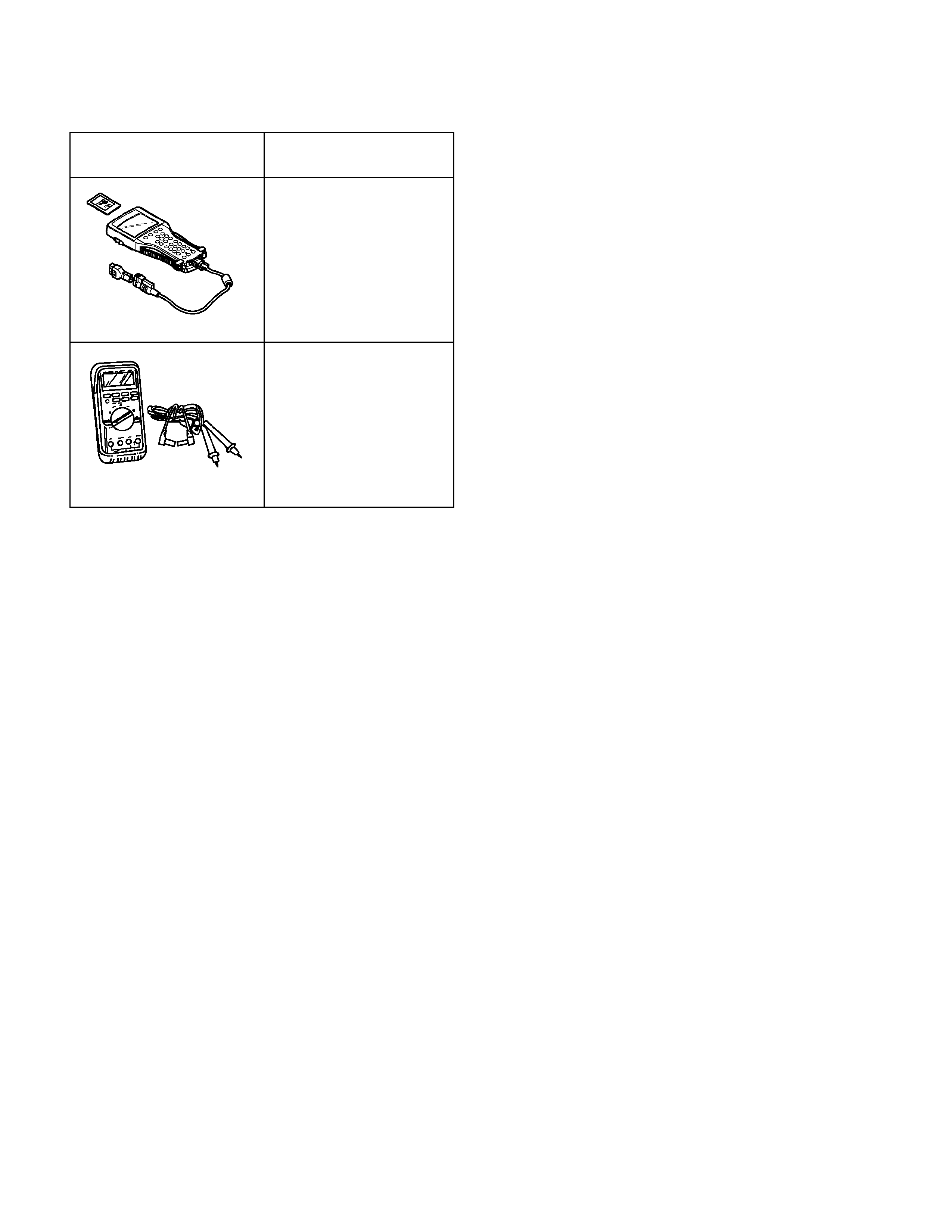
Special Tools
ILLUSTRATION PART NO.
PART NAME
TECH2
Scan Tool
5-8840-0366-0
Digital Multi Meter