
Immobiliser System – HFV6 Page 6E1–1
Page 6E1–1
Section 11A-1
Immobiliser System – HFV6
ATTENTION
Before performing any service operation or other procedure described in this Section, refer to 1.1 Warning
Caution and Notes for correct workshop practices with regard to safety and / or property damage.
1 General Information ...............................................................................................................................3
1.1 Warning Caution and Notes.................................................................................................................................. 3
Definition of WARNING, CAUTION and NOTE Statements................................................................................. 3
WARNING defined............................................................................................................................................. 3
CAUTION defined .............................................................................................................................................. 3
NOTE defined..................................................................................................................................................... 3
2 Component Location .............................................................................................................................4
2.1 Engine Compartment............................................................................................................................................. 4
2.2 Interior .................................................................................................................................................................... 5
3 Component Description.........................................................................................................................6
3.1 Immobiliser Control Unit....................................................................................................................................... 6
3.2 Powertrain Interface Module................................................................................................................................. 7
3.3 Engine Control Module.......................................................................................................................................... 8
4 Diagnostics.............................................................................................................................................9
4.1 Diagnostic General Descriptions.......................................................................................................................... 9
Diagnostic Trouble Code (DTC) Tables ............................................................................................................... 9
Multiple DTCs..................................................................................................................................................... 9
Diagnostic Trouble Codes (DTCs)........................................................................................................................ 9
Status of DTCs................................................................................................................................................... 9
Conditions for Clearing DTCs............................................................................................................................. 9
Tech 2 ICU Diagnostic Tests............................................................................................................................... 10
Tech 2 Limitations............................................................................................................................................ 10
Tech 2 Intermittent Fault Tests......................................................................................................................... 10
5 Wiring Diagram and Harness Connector...........................................................................................11
5.1 Wiring Diagram .................................................................................................................................................... 11
5.2 Harness Connector.............................................................................................................................................. 12
Immobiliser Control Unit Connector – B70........................................................................................................ 12
Pin Description................................................................................................................................................. 12
Immobiliser Control Unit Connector – B78........................................................................................................ 12
Pin Description................................................................................................................................................. 12
6 Diagnostics Starting Point ..................................................................................................................13
6.1 Diagnostic Requirements, Precautions and Preliminary Checks.................................................................... 13
Basic Knowledge Required................................................................................................................................. 13
Basic Diagnostic Tools Required....................................................................................................................... 13
Diagnostic Precautions....................................................................................................................................... 13
Preliminary Checks.............................................................................................................................................. 14
Diagnostic Aids.................................................................................................................................................... 14
Check the condition for system parts. .............................................................................................................. 14
Check the Electro Magnetic Interference (EMI)................................................................................................ 14

Immobiliser System – HFV6 Page 6E1–2
Page 6E1–2
Check the other items. ..................................................................................................................................... 14
Check the operation......................................................................................................................................... 14
6.2 Diagnostic Trouble Codes................................................................................................................................... 15
Immobiliser Control Unit (ICU)............................................................................................................................ 15
6.3 Immobiliser System and Warning Lamp Check................................................................................................ 16
Immobiliser System Check ................................................................................................................................. 16
No Immobiliser Warning Lamp........................................................................................................................... 18
Immobiliser Warning Lamp On Steady.............................................................................................................. 19
7 Intermittent Fault Conditions..............................................................................................................20
7.1 Intermittent Conditions Diagnostic Table.......................................................................................................... 20
Description........................................................................................................................................................... 20
Diagnostic Table.................................................................................................................................................. 20
8 DTC Tables............................................................................................................................................22
8.1 B0001 Replace Electronic Control Unit (Immobiliser Fault)............................................................................. 22
8.2 B0002 Immobiliser Not Programmed ................................................................................................................. 23
8.3 B0003 Transponder Key Problem....................................................................................................................... 24
8.4 B0004 Immobiliser Coil Circuit (Antenna Coil Fault) ........................................................................................ 26
8.5 B0005 Communication Line W Voltage Low...................................................................................................... 27
8.6 B0006 Communication Line W Voltage High..................................................................................................... 28
8.7 B0007 No Engine Request Received.................................................................................................................. 29
8.8 B0008 Wrong Transponder Key.......................................................................................................................... 31
8.9 B0009 No Transponder Key Programmed......................................................................................................... 32
8.10 B0010 Unknown Transponder Key..................................................................................................................... 33
8.11 B0055 EEPROM Error.......................................................................................................................................... 34
9 Immobiliser Security and Programming............................................................................................35
9.1 Security and Programming Information ............................................................................................................ 35
Car Pass Card ...................................................................................................................................................... 35
lmportant information on Programming............................................................................................................ 35
Security code ................................................................................................................................................... 35
Entering a code................................................................................................................................................ 35
Transponder (Key) ........................................................................................................................................... 36
9.2 Immobiliser Control Unit Reset Procedure........................................................................................................ 37
9.3 Immobiliser Link to ECM / PIM............................................................................................................................ 38
10 Immobiliser V6 – Tech 2 Functions....................................................................................................39
10.1 Introduction.......................................................................................................................................................... 39
10.2 Tech 2 Functions ................................................................................................................................................. 40
F0: Diagnostic Trouble Codes............................................................................................................................ 40
F1: Data Display................................................................................................................................................... 40
F2: Snapshot Options.......................................................................................................................................... 40
F3: Additional Functions..................................................................................................................................... 40
F4: Programming................................................................................................................................................. 40
10.3 Immobiliser V6 Data List ..................................................................................................................................... 41
Data Display ......................................................................................................................................................... 41
11 Special Tools ........................................................................................................................................42

Immobiliser System – HFV6 Page 6E1–3
Page 6E1–3
1 General Information
For Information not contained in this section, refer to Section 11A Immobiliser.
1.1 Warning Caution and Notes
This Section contains various W A RNINGS, CAUTIONS and NOTE statements that you must observe carefully to reduce
the risk of death or injury during service, repair procedures or vehicle operation. Incorrect service or repair procedures
may damage the vehicle or cause operational faults. WARNINGS, CAUTION and NOTE statements are not exhaustive.
GM HOLDEN LTD can not possibly warn of all the potentially hazardous consequences of failure to follow these
instructions.
Definition of WARNING, CAUTION and NOTE Statements
Diagnosis and repair proce dures in this Section contain both general and specific WARNING, CAUTION and NOTE
statements. GM HOLDEN LTD is dedicated to the presentation of service information that helps the technician to
diagnose and repair the systems necessary for proper operation of the vehicle. C ertain procedures may present a hazard
to the technician if they are not followed in the recommended manner. WA RNING, CAUTION and NOTE statements are
designed to help prevent thes e hazards from occurring, but not all hazards can be foreseen.
WARNING defined
A WARNING statement immediately precedes an operatin g procedure or maintenance practice which, if not correctly
followed, could result in death or injury. A WARNING statement alerts yo u to take necessary action or not to take a
prohibited action. If a WARNING statement is ignored, the following consequences may occur:
• Death or injury to the technician or other personnel working on the vehicle,
• Death or injury to other people in or near the workplace area, and / or
• Death or injury to the driver / or passenger(s) of the vehicle or other people, if the vehicle has been improperly
repaired.
CAUTION defined
A CAUTION statement immediately precedes an operating procedure or maintenance practice which, if not correctly
followed, could result in damage to or destru c tion of equipment, or corruption of data. If a CAUTION statement is
ignored, the following consequences may occur:
• Damage to the vehicle,
• Unnecessary vehicle repairs or component replacement,
• Faulty operation or performance of any system or component being repaired,
• Damage to any system or components which depend on the proper operation of the system or component being
repaired,
• Faulty operation or performance of any systems or components which depend on the pro per operation or
performance of the system or component under repair,
• Damage to fasteners, basic tools or special tools and / or
• Leakage of coolant, lubricant or other vital fluids.
NOTE defined
A NOTE statement immediately precedes or follows an operating procedure, maintenance practice or condition that
requires highlighting. A NOTE statement also emphasises necessary characteristics of a diagnostic or repair procedure.
A NOTE statement is designed to:
• Clarify a procedure,
• Present additional information for accomplishing a procedure,
• Give insight into the reasons for performing a procedure in the recommended manner, and / or
• Present information that gives the technician the ben efit of past experience in accomplishing a procedure with
greater ease.
Immobiliser System – HFV6 Page 6E1–4
Page 6E1–4
2 Component Location
2.1 Engine Compartment
Legend
1 Engine Control Module 2 Powertrain Interface Module
Figure 11A-1 – 1
Immobiliser System – HFV6 Page 6E1–5
Page 6E1–5
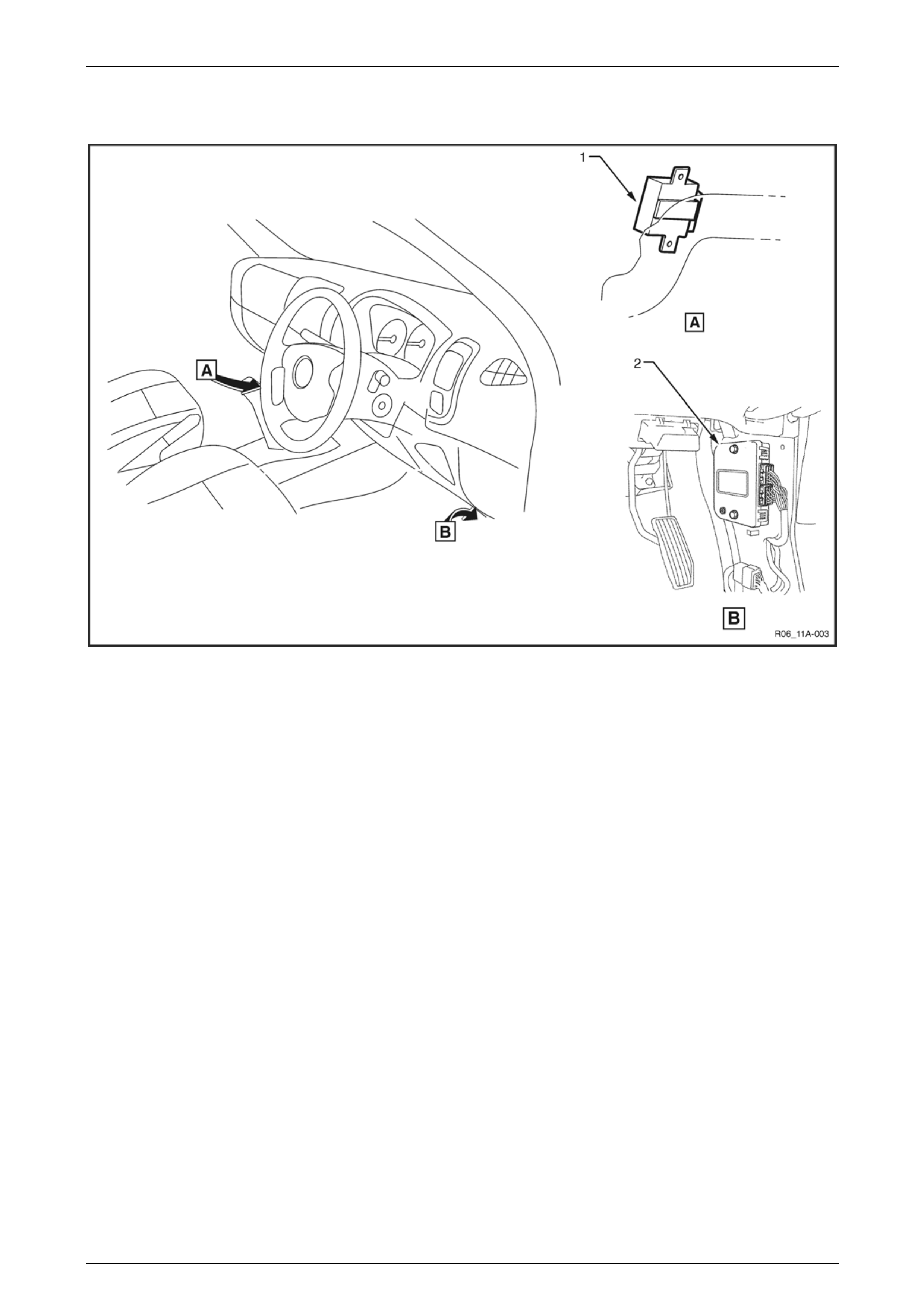
2.2 Interior
Figure 11A-1 – 2
Legend
1 Immobiliser Control Unit 2 Powertrain Interface Module
Immobiliser System – HFV6 Page 6E1–6
Page 6E1–6
3 Component Description
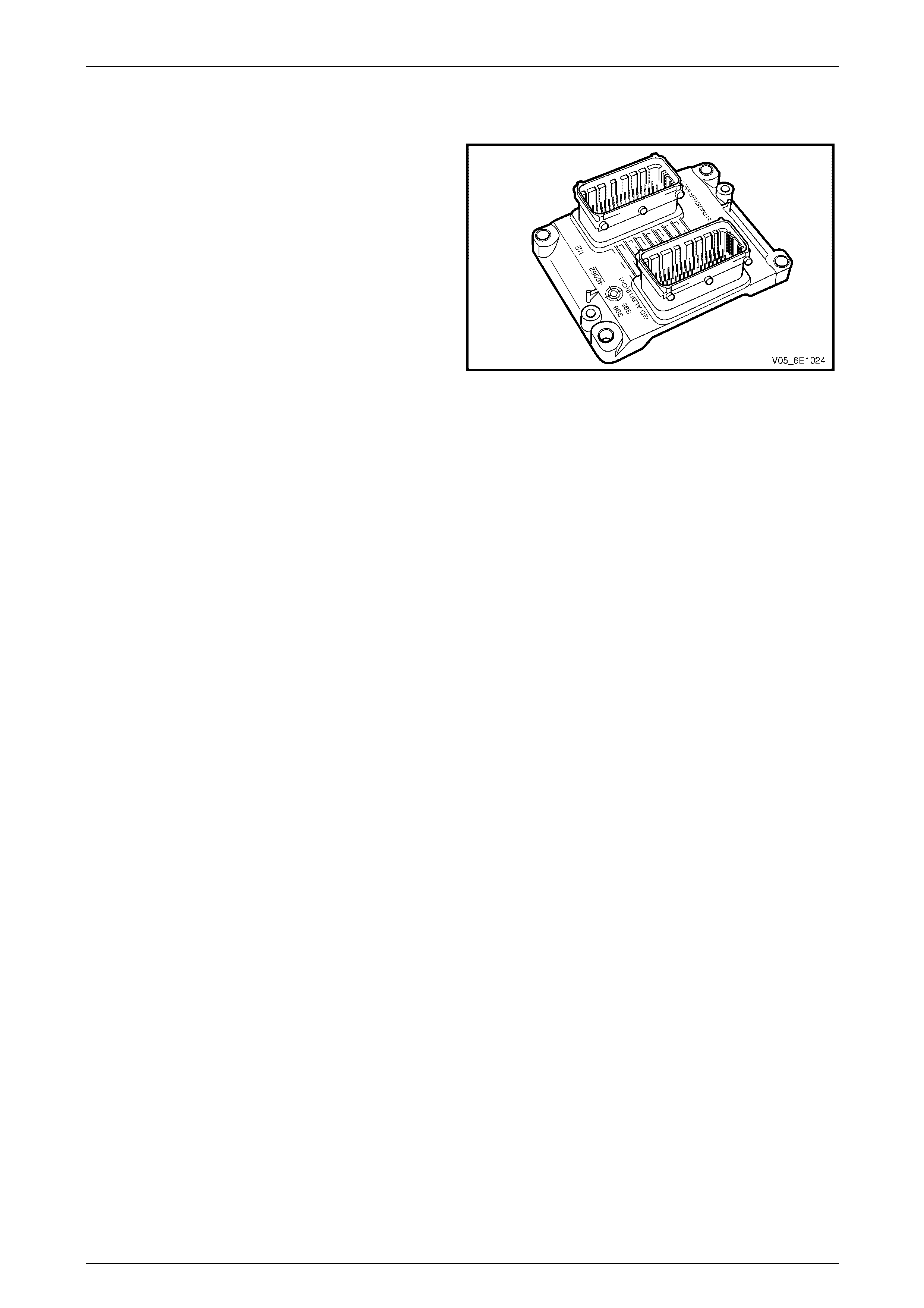
3.1 Immobiliser Control Unit
The immobiliser control unit (ICU) is mounted to the left of
the steering column.
The ICU in conjunction with the po wertrain in terface module
(PIM) and engine control module (ECM) immobilises the
engine. The ICU communicates with the ECM via the PIM.
For further information on immobiliser system operati on,
refer to Section 11A Immobiliser System.
Figure 11A-1 – 3

Immobiliser System – HFV6 Page 6E1–7
Page 6E1–7
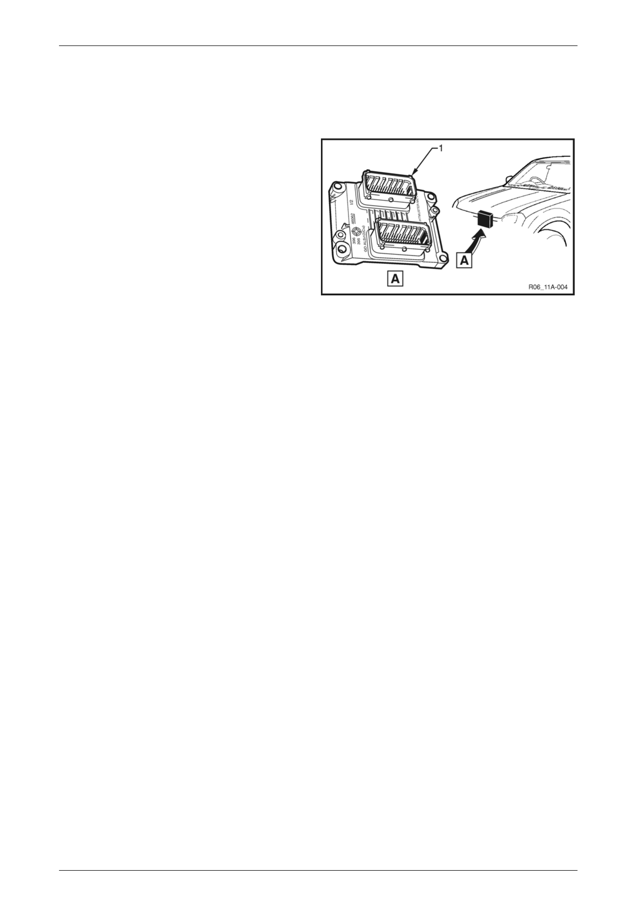
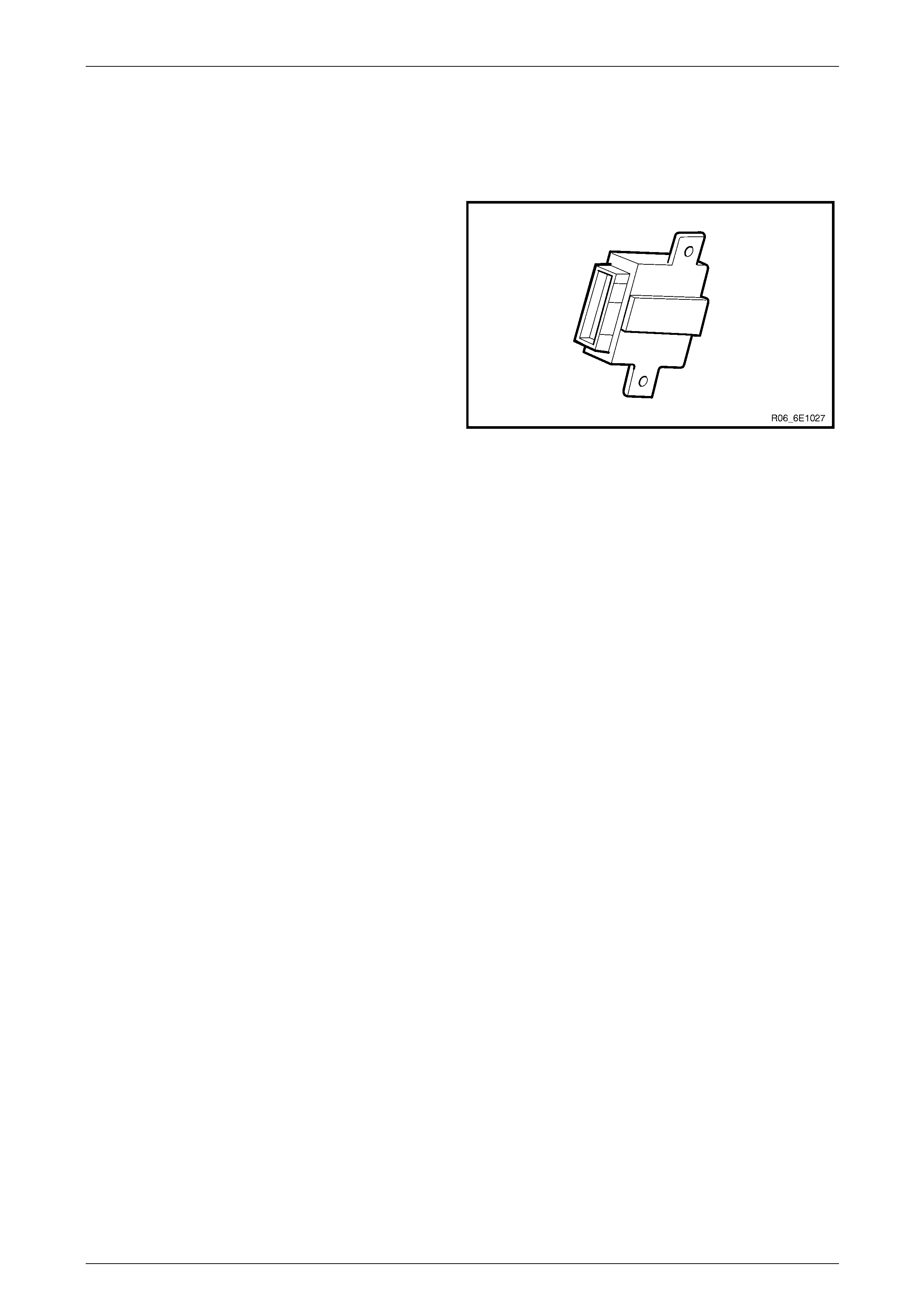
3.2 Powertrain Interface Module
The powertrain interface module (PIM) is located behind the
right-hand lower hinge pillar trim.
Figure 11A-1 – 4
The PIM performs the following functions:
• The PIM acts as the communication gateway between the GM LAN communications proto col and keyword 2000
protocol.
• The PIM converts analogue si gnals from the cruise control switches into digital serial data.
• The PIM upon inputs received from the engi ne control module (ECM), transmission control module (TCM) and
immobiliser control unit (ICU) controls the operation of the following instruments and warning lamps. Refer to
Section 6E1-1 Powertrain Interface Module – V6 for further information on the powertrain interface module.
Immobiliser System – HFV6 Page 6E1–8
Page 6E1–8
3.3 Engine Control Module
The ECM is located at the right front of the engine
assembly.
The ECM communicates directly with the transmission
control module (TCM) and PIM via the serial data network.
The ECM is also an integral part of the vehicle security
system.
Figure 11A-1 – 5

Immobiliser System – HFV6 Page 6E1–9
Page 6E1–9
4 Diagnostics
4.1 Diagnostic General Descriptions
The immobiliser control un it (ICU) diagnostic procedure is organised in a logical structure that begins with the Diagnostic
System Check. The Diagnostic System Check directs the diagnostic proce dure to the logical steps or appropriate
diagnostic table required to diagnose an immobiliser fau lt cond ition.
The diagnostic tables locate a faulty circuit or component through a logical based process of elimination. Correct use of
the diagnostic tables is essential to reduce di agnostic time and to prevent misdiagnosis.
In addition, the Diagnostic System Check provides the following information:
• identification of the ICU,
• condition of the diagnostic circuit, and
• identification and status of the DTCs if present.
Diagnostic Trouble Code (DTC) Tables
The diagnostic procedure is directed to a diagnostic trouble code (DTC) table if there are DTCs currently stored in the
ICU.
The diagnostic tables are designed to locate a faulty circuit or component through a logic al based process of elimination.
The diagnostic tables are developed with the following assumptions:
• the vehicle functioned correctly at the time of assembly,
• there are no multiple faults, and
• the problem currently exists.
Multiple DTCs
When performing a DTC check and there are multiple DT Cs, the diag nostic process must begin with the most likely DT C
that may trigger other DTCs.
Knowledge of the ICU and Tech 2 limitations are important to reduce diagn ostic time and to prevent misdiagnosis. Refer
to 6.1 Diagnostic Requirements, Precautions and Preliminary Checks.
Diagnostic Trouble Codes (DTCs)
When the ignition s witch is turned on, the ICU performs an internal integrity check that detects and isolates any interna l
faults. The PIM also monitors the serial data bus for messages from the po wertrain interface module. If a fault is detected
by the PIM, it will log a Diagnostic Trouble Code (DTC) that represents the fault detected. The DTCs stored in the PIM
may be accessed using Tech 2.
Status of DTCs
The ICU designates the DTCs logged into a Current or History DTC.
Current DTCs
If the fault condition that triggers the DTC is present during the last ICU self test, that DT C will be designated as a current
DTC.
History
DTCs
If the fault condition that triggers the DTC is not present during the last ICU self test, that DTC will be designated as a
history DTC.
Conditions for Clearing DTCs
• If there is no DTC logged in the current ICU self test, the current DTC will be cleared.
• If there is no DTC logged after 100 consecutive drive cycles, the history DTC will be cleared.

Immobiliser System – HFV6 Page 6E1–10
Page 6E1–10
Tech 2 ICU Diagnostic Tests
Tech 2 Limitations
Some DTCs trigger other DTCs to set, which causes Tech 2 to display multiple DTCs. In those situations, Tech 2 may
display more DT Cs than is neede d to rectify a fault.
When Tech 2 displays an o utp ut function, it displays only the command given by the ICU. If a connector is disconnected,
that fault will not register in the ICU output function. Tech 2 does not verify the command action.
The service technician must understand t he system being diagnosed as well as the correct use and limitations of Tech 2
to be able to perform diagnostic procedures efficiently and successfully.
Tech 2 Intermittent Fault Tests
The following are lists of Tech 2 diagnostic tests that may be used to diagnose intermittent faults:
• Wiggle test the suspected ICU wiring harne ss and connector while observing Tech 2 operating paramet ers of the
circuit being tested. If Tech 2 read-out fluctuates during this procedure, check the wiring harness circuit for loose
connection.
• Road test the vehicle in conditions that trigger the intermittent fault while an assistant observes the suspected Tech
2 operating parameter data.
• Capture and store data in the Snapshot mode when the fault occurs. The stored data may be repl ayed at a slower
rate to aid in diagnostics. Refer to Tech 2 User Instructions for more infor mation o n the Snapshot function.
• Operate suspected components to test their operation using Tech 2 Output Control Data.
Immobiliser System – HFV6 Page 6E1–11
Page 6E1–11
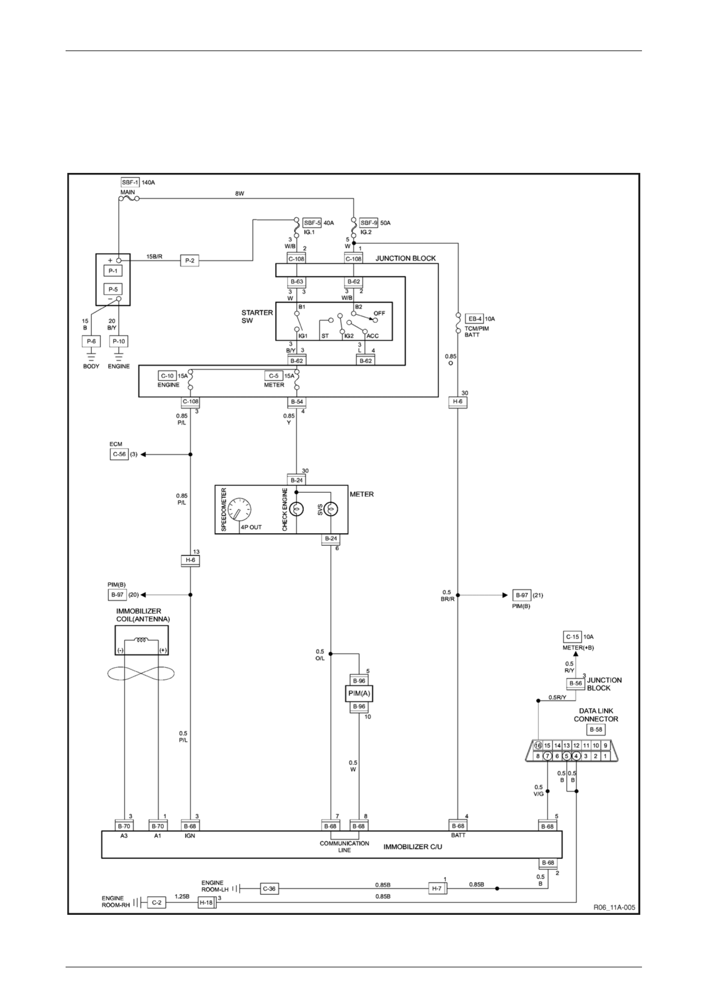
5 Wiring Diagram and Harness
Connector
5.1 Wiring Diagram
Figure 11A-1 – 6
Immobiliser System – HFV6 Page 6E1–12
Page 6E1–12
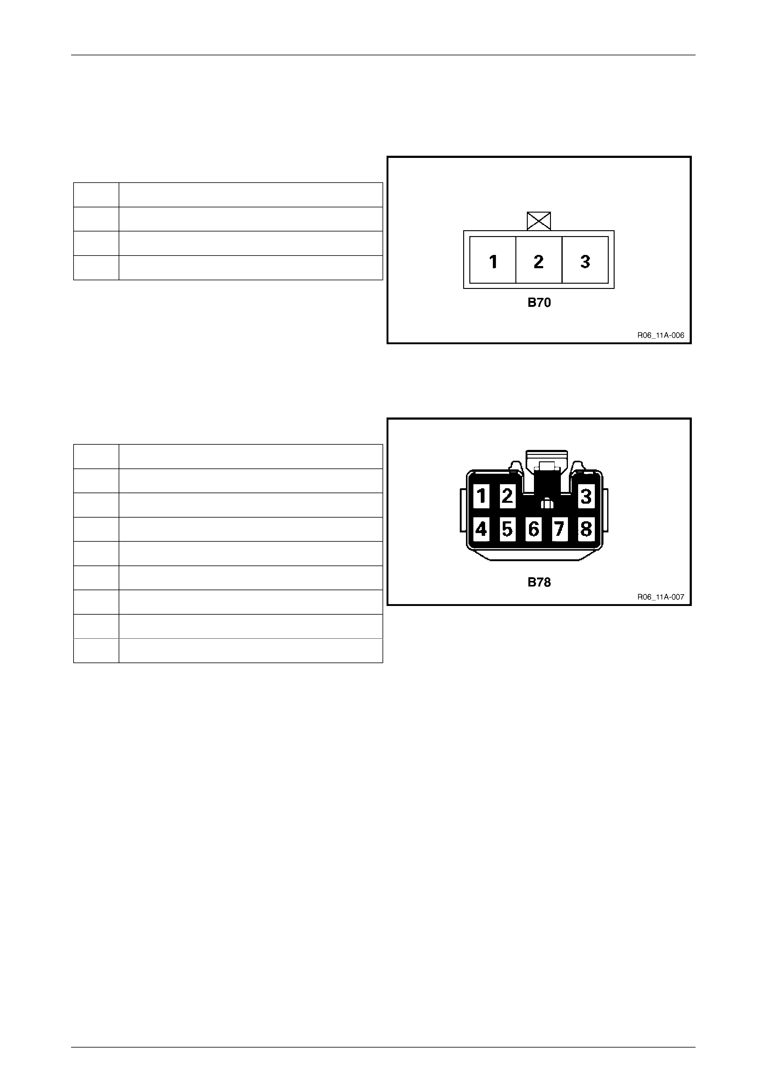
5.2 Harness Connector
Immobiliser Control Unit Connector – B70
Pin Description
Pin Function
1 Antenna coil positive
2 Not Connected
3 Antenna coil negative
Figure 11A-1 – 7
Immobiliser Control Unit Connector – B78
Pin Description
Pin Function
1 Not Connected
2 Ground
3 Ignition Supply Voltage
4 12 V Uninterrupted Supply Voltage
5 To Tech 2
6 Not Connected
7 Communication
8 Communication
Figure 11A-1 – 8

Immobiliser System – HFV6 Page 6E1–13
Page 6E1–13
6 Diagnostics Starting Point
6.1 Diagnostic Requirements, Precautions
and Preliminary Checks
Basic Knowledge Required
A lack of basic understanding of electronics,
electrical wiring circuits and use of electrical
circuit testing tools when performing the ICU
diagnostic procedures could result in
incorrect diagnostic results or damage to
components.
In addition, understanding of the Engine Management System is essential to prevent misdiagnosis an d component
damage. Refer to Section 6C1-1 Engine Ma nagement – V6 – General Information.
Basic Diagnostic Tools Required
Use of incorrect electrical circuit diagnostic
tools when performing the ICU diagnostic
procedures could result in incorrect
diagnostic results or damage to components.
The following electrical circuit testing tools are required to perform the diagnostic procedu r es detailed in this Section:
• Tech 2.
• Test lamp, refer to Section 8A Electrical - Body and Chassis for further information.
• Digital multimeter with 10 MΩ impedance, refer to Section 8A Electrical - Body and Chass is for further information.
• Connector test adapter kit Tool No. J35616-A.
Diagnostic Precautions
• Use only the test equipment specified in the diagnostic tables. Other test equipment may either give incorrect
results or damage serviceable components.
• Do not clear any DTCs unless instructed.
• The fault must be present when using the DTC Diagnostic T ables. Otherwise, misdiagnosis or replacement of
serviceable parts may occur.
• Always use connector adapters such as those contained in connector test adapter kit Tool No. J35616-A to prevent
connector terminal damage.
• Thorough inspection of the wiring circuits and connectors listed in the diagnostic procedures must be performed,
otherwise misdiagnosis may occur.
• Inspect the electrical circuitry or connector terminals that are suspected to be causing the compl aint for the
following conditions:
• backed-out connector terminals,
• improper wiring connector mating,
• broken wiring connector locks,
• damaged connector terminals, and
• physical damage to the wiring harness.
• Before replacing a component, inspect its connector terminal for corrosion or deformation that may cause the fault
condition.

Immobiliser System – HFV6 Page 6E1–14
Page 6E1–14
Preliminary Checks
The ICU preliminar y check examines easily accessible components which may cause probl ems with the ICU. This visual
and physical inspection proc edure may quickly identify the fault condition and eliminate the need for additional diagnosis.
• Refer to Service Techlines for releva nt information regarding the fault condition.
• Ensure the battery is fully charged.
• Check the battery connections for corrosion or a loose terminal.
• Perform a visual and physical inspection of the following:
• ICU component wiring harness and terminals for proper connections, pinches or cuts, and
• ICU wiring harness routing which may be positioned very close to a high voltage or high current devices such
as aftermarket audio systems.
NOTE
High voltage or high current devices may induce
electrical noise on a circuit, which can interfere
with normal circuit operation.
• The ICU is sensitive to Electro Magnetic Interference (EMI). Check for incorrect aftermarket theft deterrent
devices, lights or mobile phon e installations if an intermittent malfunction is suspected.
Diagnostic Aids
Check the condition for system parts.
• Installation condition, poor connection, damage, system parts malfunction. Harness, Fuse, Relay, Immobiliser coil
(antenna), Key, Meter, immobiliser control unit (ICU), Engine control module (ECM).
NOTE
Breakage of immobiliser fuse does not operate
immobiliser system. SVS flashes at this time.
Check the Electro Magnetic Interference (EMI)
• Location of vehicle check.
Move the vehicle to a new location and p erfo rm the check again.
• Non-OEM Parts.
Switch is "OFF" or remove the Non-OEM parts and perform the check a ga in .
• Other.
Remove the accessory and an other key from key.
Check the other items.
• Battery voltage is low.
• Immobiliser programming func tions.
Must be programmed immobiliser system.
• Registration for security code, immobiliser control unit parts number.
• Key switch operation.
Immobiliser system may detect a history DTC by the timing of ON-OFF of a key switch.
• Active the immobiliser system.
• Keyless entry system is malfunction.
• Anti theft system is malfunction.
Check the operation
• Check the operation "Lock / unlock" by using transmitter (key) on the vehicle.

Immobiliser System – HFV6 Page 6E1–15
Page 6E1–15
6.2 Diagnostic Trouble Codes
Immobiliser Control Unit (ICU)
DTC Description Note
B0001 Replace electronic control unit (ECU)
(immobiliser fault) This error code appears if a RAM / ROM Error was
detected or the EEPROM is defect.
B0002 immobiliser not prog rammed Immobiliser control unit is not programm ed.
B0003 Transponder key problem ・Reading of Transponder information failed with ignition
on transponder has a fault.
・Hardware fault in reading circuit.
B0004 Immobiliser coil circuit (antenna coil fault) Immobiliser coil has a fault.
B0005 Communication line w voltage low Short circuit to ground or open circuit.
B0006 Communication line w voltage high Short circuit to 12V.
B0007 No engine request received No PIM Challenge.
B0008 Wrong transponder key Incorrect security code response received.
B0009 No transponder key programmed Transponder security code table empty.
B0010 Unknown transponder key Transponder security code not valid.

Immobiliser System – HFV6 Page 6E1–16
Page 6E1–16
6.3 Immobiliser System and Warning Lamp
Check
Immobiliser System Check
Step Action Value(s) Yes No
1 1. Key position is "ON," engine "OFF."
2. Observe the service vehicle soon (SVS) lamp.
Note: When a key switch is turned ON, SVS lamp will
turn on and a SVS lamp will be turned off after a few
seconds.
Is the SVS "ON"?
⎯ Go to Step 2 Go to
No Immobiliser
Warning Lamp
2 1. Key position is "ON," engine "OFF."
2. Observe the SVS.
Note: When a key switch is turned ON, SVS will turn
on and a SVS will be turned off after a few seco nds.
Is the SVS "OFF"?
( SVS does not flash)
⎯ Go to Step 3 Go to
Immobiliser
Warning Lamp
On Steady
3 1. Key position is "OFF."
2. Install a scan tool.
3. Key position is "ON."
4. Attempt to display immobiliser data with the scan
tool.
Does the scan tool display immobiliser data?
⎯ Go to Step 9 Go to Step 4
4 1. Key position is "OFF," disconnect the immobiliser
control unit (ICU).
2. Check the data link connector (DLC) circuit for an
open, short to ground, or short to voltage.
Also, check the DLC ignition feed circuit for an
open or short to ground and the DLC ground
circuit for an open.
Was a problem found?
⎯ Go to Step 5 Go to Step 6
5 Repair or replace the data link connector (DLC)
circuit.
Was the action complete?
⎯ Go to Step 3 ⎯
6 1. Check the ICU circuit for an open, short to ground,
or short to voltage. Also, check the ICU ignition
feed circuit for an open or short to ground and the
ICU ground circuit for an open.
2. If a problem is found, repair as necessary.
Was a problem found?
⎯ Go to Step 7 Go to Step 8
7 Repair or replace the ICU ignition feed and ground
circuits.
Was the action complete?
⎯ Go to Step 3 ⎯
8 Replace the immobiliser control u nit (ICU).
IMPORTANT: The replacement ICU must be
programmed the immobiliser data by the scan tool.
Was the action complete?
⎯ Go to Step 3 ⎯
9 Select "Display DTCs" with the scan tool.
Are any DTCs stored?
⎯ Go to Step 10 Go to Step 13

Immobiliser System – HFV6 Page 6E1–17
Page 6E1–17
Step Action Value(s) Yes No
10 Review and record for scan tool Failure Records data
and DTCs.
Was the action complete?
⎯ Go to Step 11 ⎯
11 Following the DTC is stored.
Are there DTC B0001 or B0055 stored? Go to applicable
DTC table after
Go to Step 12
Go to Step 12
12 Clear the DTCs by "Clear the Information "with scan
tool.
Did the DTCs Cleared?
⎯ Go to Step 12 ⎯
13 Select "Display DTCs" with the scan tool.
Are any DTCs stored?
⎯ Go to applicable
DTC table Go to Step 14
14 1. Key position is "ON," engine "OFF."
2. Observe the SVS.
Note: If a key switch is turned ON, SVS will turn on
and a SVS will be turned off after a few seconds.
Is the SVS "flash"?
⎯ Go to Step 15 Go to Step 20
15 Check the powertrain interface module and engine
control syst em.
If a problem is found, repair as necessary.
IMPORTANT: The replacement ECM or PIM must be
programmed the immobiliser data by scan tool.
Was the action complete?
⎯ Go to Step 16 ⎯
16 Check the key.
Is a key peculiar to a vehicle?
⎯ Go to Step 18 Go to Step 17
17 Change into a peculiar key.
IMPORTANT: If replace the key, after replace lock
cylinders, perform the following below the items.
• Replace the keys and key cylinders.
• Program the immobiliser system.
(Refer to "Important information on Programming")
Was the action complete?
⎯ Go to Step 18 ⎯
18 Check the immobiliser programming functions.
• Immobiliser control unit (ICU).
• Powertrain Interface Module (PIM).
• Engine control module (ECM).
• Transponder (Key).
If a problem is found, repair as necessary.
(Refer to "Important Information on Programming")
Was the action complete?
⎯ Go to Step 19 ⎯
19 Operate the DTCs by "Clear the Information" with
scan tool.
Was the action complete?
⎯ Go to Step 20 ⎯
20 Attempt to start the engine .
Did the engine start?
⎯ System OK Refer to
Diagnostic Aids

Immobiliser System – HFV6 Page 6E1–18
Page 6E1–18
No Immobiliser Warning Lamp
Step Action Value(s) Yes No
1 Check the meter fuse for the instrument cluster
ignition feed circuit.
Is the fuse normal?
⎯ Go to Step 3 Go to Step 2
2 Replace the fuse.
Is the action complete?
⎯ Verify repair
Go to Step 3
⎯
3 1. Key position is "OFF".
2. Disconnect the meter.
3. Disconnect the powertrain interface module (PIM)
and immobiliser control unit.
4. Check the circuit between meter and PIM and
meter and ICU and meter for an open, short to
ground, or short to voltage.
Also, check the meter circuit for an open or short to
ground and the DLC ground circuit for an open.
Was a problem found?
⎯ Go to Step 4 Go to Step 5
4 Repair or replace the m eter circuit.
Was the action complete?
⎯ Go to Step 5 ⎯
5 1. Key position is "ON," engine "OFF."
2. Observe the SVS.
Is the SVS "ON"?
⎯ Go to Step 6 Go to Step 7
6 Repair or replace the m eter.
Was the action complete?
⎯ Go to Step 7 ⎯
7 1. Key position is "OFF".
2. Check the SVS bulb.
Is the SVS bulb normal?
⎯ Go to Step 9 Go to Step 8
8 Replace the SVS bulb.
Is the action complete?
⎯ Verify repair
Go to Step 9
⎯
9 1. Key position is "OFF".
2. Connect the meter.
3. Connect the PIM and ICU).
4. Key position is "ON".
5. Observe the SVS.
Note: If a key switch is turned ON, SVS will turn on
and a SVS will be turned off after a few seconds.
Is the SVS "ON"?
⎯ Verify repair Go to Step 10
10 Replace the powertrain interface modul e (PIM).
IMPORTANT: The replacement PIM must be
programmed the immobiliser data by scan tool.
Was the action complete?
⎯ Verify repair ⎯

Immobiliser System – HFV6 Page 6E1–19
Page 6E1–19
Immobiliser Warning Lamp On Steady
Step Action Value(s) Yes No
1 1. Key position is "OFF".
2. Disconnect the immobiliser control unit (ICU).
3. Disconnect the powertrain interface module (PIM).
4. Key position is "ON," engine "OFF."
5. Observe the SVS.
Is the SVS "ON"?
⎯ Go to Step 2 Go to Step 5
2 1. Key position is "OFF".
2. Disconnect the meter.
3. Key position is "ON," engine "OFF."
4. Observe the SVS.
Is the SVS "ON"?
⎯ Go to Step 3 Go to Step 4
3 Repair or replace the m eter.
Was the action complete?
⎯ Verify repair
Go to Step 5
⎯
4 Repair or replace the m eter circuit.
(Between meter and ICU/PIM)
Was the action complete?
⎯ Verify repair
Go to Step 5
⎯
5 Check the immobiliser control unit (ICU) circuit.
1. Ignition "OFF," disconnect the ICU.
2. Check the ICU circuit for an open, short to ground,
or short to voltage.
Also, check the ICU ignition feed circuit for an open or
short to ground and the ICU ground circuit for an
open.
Was a problem found?
⎯ Go to Step 6 Go to Step 7
6 Repair or replace the immobiliser control unit (ICU)
circuit.
Was the action complete?
⎯ Verify repair
Go to Step 7
⎯
7 1. Key position is "OFF".
2. Connect the meter.
3. Connect the immobiliser control unit (ICU).
4. Connect the engine control module (PIM).
5. Key position is "ON".
6. Observe the SVS.
Is the SVS "ON"?
⎯ Verify repair Refer to
Diagnostic Aids

Immobiliser System – HFV6 Page 6E1–20
Page 6E1–20
7 Intermittent Fault Conditions
7.1 Intermittent Conditions Diagnostic Table
Description
A fault condition is intermittent if one of the following conditions exists:
• The fault condition is not al ways present.
• The fault condition cannot be presently duplicated.
• There is no current DTC but a History DTC is stored.
Diagnostic Table
Checks Actions
Preliminary • Perform the Preliminary Chec ks, refe r to 6.1 Diagnostic Re quirements,
Precautions and Preliminary Checks.
• Gather information from the customer regarding the conditions that trigger the
intermittent fault such as:
• At what engine or ambient temperature range do es the fault occur?
• Does the fault occur when operating aftermarket electrical equi pment inside
the vehicle?
• Does the fault occur on rough roads or in wet road conditions?
Harness / Connector Install Tech 2 and perform the Tech 2 Intermittent Fault Tests. Refer to
4.1 Diagnostic General Descriptions for information on Tech 2 ECU diagnostic tests.
Warning Indicator The following conditions may cause an intermittent service vehicle soon (SVS) Lamp
fault with no DTC listed:
• Electro Magnetic Interference (EMI) caused b y a faulty relay, ECM controlled
solenoid, switch or other external source.
• Incorrect installation of aftermarket electrical equipment such as the following:
• mobile phones,
• theft deterrent alarms,
• lights, or
• radio equipment.
• Loose ICU or PIM ground connections.

Immobiliser System – HFV6 Page 6E1–21
Page 6E1–21
Checks Actions
Temperature Related The Tech 2 Freeze Frame / Failure Records or Snapshot data may be used if applica ble
to the fault condition. Refer to 4.1 Diagnostic General Descriptions for information on
Tech 2 ECU diagnostic tests.
• If the intermittent fault is heat related, review the Tech 2 data in relationshi p to the
following:
• high ambient temperature,
• underhood / engine generate d heat,
• circuit generated heat due to a poor electrical connection or high electrical
load, and
• higher than normal load conditions (towing, etc.).
• If the intermittent fault is related to cold ambient or engine temperature, review the
Tech 2 data in relationship to the following:
• low ambient temperature, and
• the fault condition that occurs only on a cold start situation.
Additional Tests • Check for incorrect installation of aftermarket electrical equipment such as the
following:
• mobile phones,
• theft deterrent alarms,
• lights, or
• radio equipment.
• Check for Electro Magnetic Interference (EMI) caused b y a faulty relay, ECM
controlled solenoid or switch. The fault is triggered when the relay or solenoid is
activated.
• Check the A/C compressor clutch and some rela ys that contain a clamping diode
or resistor for an open circuit.
• Check the generator for a faulty rectifier bridge that may allow A/C noise into the
ICU or PIM electrical circuit.
When all diagno sis an d repairs are completed, check the engine management system for correct operation.

Immobiliser System – HFV6 Page 6E1–22
Page 6E1–22
8 DTC Tables
8.1 B0001 Replace Electronic Control Unit
(Immobiliser Fault)
Step Action Value(s) Yes No
1 Was the “Immobiliser System and Warning Lamp
Check” perfor med?
⎯ Go to Step 2 Go to
Immobiliser
System Check
2 Recheck the DT C.
1. Key position is “OFF”.
2. Install the scan tool on vehicle.
3. Key position is “ON”.
4. Check the DTC on scan tool.
Is DTC B0001 stored?
⎯ Go to Step 3 Refer to
Diagnostic Aids
3 Check the immobiliser control unit (ICU) circuit.
1. Ignition "OFF," disconnect the ICU.
2. Check the ICU circuit for an open, short to ground,
or short to voltage.
Also, check the ICU ignition feed circuit for an open or
short to ground and the ICU ground circuit for an
open.
Was a problem found?
⎯ Go to Step 4 Go to Step 5
4 Repair or replace the immobiliser control unit (ICU)
circuit.
Was the action complete?
⎯ Verify repair ⎯
5 Replace the immobiliser c ontrol unit (ICU).
IMPORTANT: The replacement ICU must be
programmed the security data by scan tool.
Was the action complete?
⎯ Verify repair ⎯

Immobiliser System – HFV6 Page 6E1–23
Page 6E1–23
8.2 B0002 Immobiliser Not Programmed
Step Action Value(s) Yes No
1 Was the “Immobiliser System and Warning Lamp
Check” perfor med? ⎯ Go to Step 2 Go to
Immobiliser
System Chec k
2 Check the immobiliser programming functions.
• Immobiliser control unit (ICU).
If a problem is found, repair as necessary.
(Refer to "Important information on Programming")
Was the action complete?
⎯ Go to Step 3 Go to Step 5
3 Recheck the DT C.
1. Key position is “OFF” and keep the position for
more than 30 seconds.
2. Key position is “ON”.
3. Check the DTC on scan tool.
Is DTC B0002 stored?
⎯ Go to Step 4 Verify repair
4 Replace the immobiliser c ontrol unit (ICU).
IMPORTANT: The replacement ICU must be
programmed the security data by scan tool.
Was the action complete?
⎯ Verify repair ⎯
5 Check the immobiliser programming functions.
• Powertrain interface module.
• Engine control module (ECM).
• Immobiliser control unit (ICU).
If a problem is found, repair as necessary.
(Refer to "Important information on Programming")
Was the action complete?
⎯ Verify repair Go to Step 6
6 Replace the key and lock cylinder assembly and
immobiliser system (ICU and ECM).
IMPORTANT:
• ICU, PIM and ECM are not replacing
simultaneously.
• After replace lock cylinders, perform the
following below the items.
• Program the immobiliser system.
(Refer to "Important information on Programming")
Was the action complete?
⎯ Verify repair ⎯

Immobiliser System – HFV6 Page 6E1–24
Page 6E1–24
8.3 B0003 Transponder Key Problem
Step Action Value(s) Yes No
1 Was the “Immobiliser System and Warning Lamp
Check” perfor med?
⎯ Go to Step 2 Go to
Immobiliser
System Chec k
2 Check the key.
Is a key peculiar to a vehicle?
⎯ Go to Step 3 Refer to
Diagnostic Aids
3 Check the immobiliser programming functions.
• All transponder (Key).
If a problem is found, repair as necessary.
(Refer to "Important Information on Programming")
Was the action complete?
⎯ Go to Step 4 Go to Step 5
4 Recheck the DT C.
1. Key position is “OFF” and keep the position for more
than 30 seconds.
2. Key position is “ON”.
3. Check the DTC on scan tool.
Is DTC B0003 stored?
⎯ Go to Step 5 Verify repair
5 Recheck the DT C.
1. Non-OEM parts switch is "OFF" or remove the Non-
OEM parts.
2. Remove the accessory and another key from key.
3. Move the vehicle to a new location.
4. Key position is “OFF” and keep the position for more
than 30 seconds.
5. Key position is “ON”.
6. Check the DTC on scan tool.
Is DTC B0003 stored?
⎯ Go to Step 6 Verify repair
6 Check the immobiliser coil (antenna) circuit.
1. Key position is “OFF”.
2. Disconnect the immobiliser control unit (ICU).
(immobiliser coil circuit : 3 pin connector)
3. Check the immobiliser coil circuit for an open, short
to ground, or short to voltage.
Also, check the ICU ignition feed circuit for an open or
short to ground and the ICU ground circuit for an open.
Was a problem found?
⎯ Go to Step 7 Go to Step 8
7 Repair or replace the immobiliser coil (antenna) circuit.
Was the action complete?
⎯ Verify repair ⎯
8 Recheck the DT C.
1. Key position is “OFF” and keep the position for more
than 30 seconds.
2. Key position is “ON”.
3. Check the DTC on scan tool.
Is DTC B0003 stored?
⎯ Go to Step 9 Verify repair
9 Replace the immobiliser c ontrol unit (ICU).
IMPORTANT: The replacement ICU must be
programmed the security data by scan tool.
Was the action complete?
⎯ Go to Step 10 ⎯

Immobiliser System – HFV6 Page 6E1–25
Page 6E1–25
Step Action Value(s) Yes No
10 Check the immobiliser programming functions.
• Immobiliser control unit (ICU).
• All transponder (Key).
If a problem is found, repair as necessary.
(Refer to "Important information on Programming")
Was the action complete?
⎯ Go to Step 11 ⎯
11 Recheck the DTC.
1. Key position is “OFF” and keep the position for more
than 30 seconds.
2. Key position is “ON”.
3. Check the DTC on scan tool.
Is DTC B0003 stored?
⎯ Go to Step 12 Verify repair
12 Replace the transponder (Key).
IMPORTANT: The replacement transponder (key)
must be programmed the security data b y scan tool.
Was the action complete?
⎯ Verify repair ⎯

Immobiliser System – HFV6 Page 6E1–26
Page 6E1–26
8.4 B0004 Immobiliser Coil Circuit (Antenna
Coil Fault)
Step Action Value(s) Yes No
1 Was the “Immobiliser System and Warning Lamp
Check” perfor med?
⎯ Go to Step 2 Go to
Immobiliser
System Chec k
2 Check the immobiliser coil (antenna) circuit.
1. Key position is “OFF”.
2. Disconnect the immobiliser control unit (ICU).
(immobiliser coil circuit : 3 pin connector)
3. Check the immobiliser coil circuit for an open,
short to ground, or short to voltage.
Also, check the ICU ignition feed circuit for an open or
short to ground and the ICU ground circuit for an
open.
Was a problem found?
⎯ Go to Step 3 Go to Step 4
3 Repair or replace the immobiliser coil (antenna).
Was the action complete?
⎯ Verify repair ⎯
4 Recheck the DT C.
1. Key position is “OFF” and keep the position for
more than 30 seconds.
2. Key position is “ON”.
3. Check the DTC on scan tool.
Is DTC B0004 stored?
⎯ Go to Step 5 Verify repair
5 Replace the immobiliser c ontrol unit (ICU).
IMPORTANT: The replacement ICU must be
programmed the security data by scan tool.
Was the action complete?
⎯ Verify repair ⎯

Immobiliser System – HFV6 Page 6E1–27
Page 6E1–27
8.5 B0005 Communication Line W Voltage
Low
Step Action Value(s) Yes No
1 Was the “Immobiliser System and Warning Lamp
Check” perfor med?
⎯ Go to Step 2 Go to
Immobiliser
System Chec k
2 Recheck the DT C.
1. Key position is “OFF”.
2. Install the scan tool on vehicle.
3. Key position is “ON”.
4. Check the DTC on scan tool.
Is DTC B0005 stored?
⎯ Go to Step 3 Refer to
Diagnostic Aids
3 Check the immobiliser communication W line circuit.
1. Key position is “OFF”.
2. Disconnect the immobiliser control unit (ICU).
3. Disconnect the powertrain interface module (PIM).
4. Check the immobiliser communication W line
circuit for an open, short to ground, or short to
voltage.
Also, check the ICU and PIM ignition feed circuits for
an open or short to ground and the ICU and PIM
ground circuit for an ope n.
Was a problem found?
⎯ Go to Step 4 Go to Step 5
4 Repair or replace the immobiliser communication W
line circuit.
Was the action complete?
⎯ Verify repair ⎯
5 Replace the immobiliser c ontrol unit (ICU).
IMPORTANT: The replacement ICU must be
programmed the security data by scan tool.
Was the action complete?
⎯ Verify repair ⎯

Immobiliser System – HFV6 Page 6E1–28
Page 6E1–28
8.6 B0006 Communication Line W Voltage
High
Step Action Value(s) Yes No
1 Was the “Immobiliser System and Warning Lamp
Check” perfor med?
⎯ Go to Step 2 Go to
Immobiliser
System Chec k
2 Recheck the DT C.
1. Key position is “OFF”.
2. Install the scan tool on vehicle.
3. Key position is “ON”.
4. Check the DTC on scan tool.
Is DTC B0006 stored?
⎯ Go to Step 3 Refer to
Diagnostic Aidss
3 Check the immobiliser communication W line circuit.
1. Key position is “OFF”.
2. Disconnect the immobiliser control unit (ICU).
3. Disconnect the powertrain interface module (PIM).
4. Check the immobiliser communication W line
circuit for an open, short to ground, or short to
voltage.
Also, check the ICU and PIM ignition feed circuits for
an open or short to ground and the ICU and PIM
ground circuit for an ope n.
Was a problem found?
⎯ Go to Step 4 Go to Step 5
4 Repair or replace the immobiliser communication W
line circuit.
Was the action complete?
⎯ Verify repair ⎯
5 Replace the immobiliser c ontrol unit (ICU).
IMPORTANT: The replacement ICU must be
programmed the security data by scan tool.
Was the action complete?
⎯ Verify repair ⎯

Immobiliser System – HFV6 Page 6E1–29
Page 6E1–29
8.7 B0007 No Engine Request Received
Step Action Value(s) Yes No
1 Was the “Immobiliser System and Warning Lamp
Check” perfor med?
⎯ Go to Step 2 Go to
Immobiliser
System Chec k
2 Recheck the DTC on ICU.
1. Key position is “OFF”.
2. Install the scan tool on vehicle.
3. Key position is “ON”.
4. Check the DTC on scan tool.
Is DTC B0007 stored?
⎯ Go to Step 3 Refer to
Diagnostic Aids
3 Check the immobiliser communication line circuit.
1. Key position is “OFF”.
2. Disconnect the immobiliser control unit (ICU).
3. Disconnect the powertrain interface module (PIM).
4. Check the immobiliser communication line circuit
for an open, short to ground, or short to voltage.
Also, check the ICU and PIM ignition feed circuits for
an open or short to ground and the ICU and PIM
ground circuit for an ope n.
Was a problem found?
⎯ Go to Step 4 Go to Step 5
4 Repair or replace the immobiliser communication line
circuit.
Was the action complete?
⎯ Verify repair ⎯
5 Recheck the DTC on ICU.
1. Key position is “OFF” and keep the position for
more than 30 seconds.
2. Key position is “ON”.
3. Check the DTC on scan tool.
Is DTC B0007 stored?
⎯ Go to Step 6 Verify repair
6 Recheck the DTC on PIM.
1. Key position is “OFF” and keep the position for
more than 30 seconds.
2. Key position is “ON”.
3. Check the DTC on scan tool.
Are below DTCs stored?
B3902 or P0633
⎯ Go to Step 7 Go to Step 9
7 Perform the immobiliser programming functions.
(Refer to "Important information on Programming")
• Powertrain Interface Module (PIM).
Was the action complete?
⎯ Go to Step 8 Go to Step 11
8 Recheck the DTC on PIM.
1. Key position is “OFF” and keep the position for
more than 30 seconds.
2. Key position is “ON”.
3. Check the DTC on scan tool.
Are below DTCs stored?
B3902 or P0633
⎯ Go to Step 11 Go to Step 12

Immobiliser System – HFV6 Page 6E1–30
Page 6E1–30
Step Action Value(s) Yes No
9 Check the immobiliser programming functions.
• Powertrain Interface Module (PIM).
If a problem is found, repair as necessary.
(Refer to "Important information on Programming")
Was the action complete?
⎯ Go to Step 10 Go to Step 11
10 Recheck the DTC on PIM.
1. Key position is “OFF” and keep the position for
more than 30 seconds.
2. Key position is “ON”.
3. Check the DTC on scan tool.
Are below DTCs stored?
B3902 or P0633
⎯ Go to Step 11 Go to Step 12
11 Replace the powertrain interface module (PIM).
IMPORTANT: The replacement PIM must be
programmed the security data by scan tool.
Was the action complete?
⎯ Go to Step 12 ⎯
12 Recheck the DTC on PIM.
1. Key position is “OFF” and keep the position for
more than 30 seconds.
2. Key position is “ON”.
3. Check the DTC on scan tool.
Are below DTCs stored?
B3902 or P0633
⎯ Go to Step 13 Go to Step 2
13 Replace the immobiliser c ontrol unit (ICU).
IMPORTANT: The replacement ICU must be
programmed the security data by scan tool.
Was the action complete?
⎯ Verify repair ⎯

Immobiliser System – HFV6 Page 6E1–31
Page 6E1–31
8.8 B0008 Wrong Transponder Key
Step Action Value(s) Yes No
1 Was the “Immobiliser System and Warning Lamp
Check” perfor med?
⎯ Go to Step 2 Go to
Immobiliser
System Chec k
2 Check the key.
Is a key peculiar to a vehicle?
⎯ Go to Step 3 Refer to
Diagnostic Aids
3 Check the immobiliser programming functions.
• Transponder (Key).
Was a problem found?
⎯ Go to Step 4 Go to Step 5
4 Perform the immobiliser programming functions.
• Transponder (Key).
(Refer to "Important information on Programming")
Was the action complete?
⎯ Go to Step 5 ⎯
5 Recheck the DT C.
1. Key position is “OFF” and keep the position for
more than 30 seconds.
2. Key position is “ON”.
3. Check the DTC on scan tool.
Is DTC B0008 stored?
⎯ Go to Step 6 Verify repair
6 Replace the transpond er (Key).
IMPORTANT: The replacement transponder (key)
must be programmed the security data b y scan tool.
Was the action complete?
⎯ Go to Step 7 ⎯
7 Recheck the DT C.
1. Key position is “OFF” and keep the position for
more than 30 seconds.
2. Key position is “ON”.
3. Check the DTC on scan tool.
Is DTC B0008 stored?
⎯ Go to Step 8 Verify repair
8 Replace the immobiliser c ontrol unit (ICU).
IMPORTANT: The replacement ICU must be
programmed the security data by scan tool.
Was the action complete?
⎯ Verify repair ⎯

Immobiliser System – HFV6 Page 6E1–32
Page 6E1–32
8.9 B0009 No Transponder Key Programmed
Step Action Value(s) Yes No
1 Was the “Immobiliser System and Warning Lamp
Check” perfor med?
⎯ Go to Step 2 Go to
Immobiliser
System Chec k
2 Check the key.
Is a key peculiar to a vehicle?
⎯ Go to Step 3 Refer to
Diagnostic Aids
3 Check the immobiliser programming functions.
• Transponder (Key).
Was a problem found?
⎯ Go to Step 4 Go to Step 5
4 Perform the immobiliser programming functions.
• Transponder (Key).
(Refer to "Important information on Programming")
Was the action complete?
⎯ Go to Step 5 ⎯
5 Recheck the DT C.
1. Key position is “OFF” and keep the position for
more than 30 seconds.
2. Key position is “ON”.
3. Check the DTC on scan tool.
Is DTC B0009 stored?
⎯ Go to Step 6 Verify repair
6 Replace the transpond er (Key).
IMPORTANT: The replacement transponder (key)
must be programmed the security data b y scan tool.
Was the action complete?
⎯ Go to Step 7 ⎯
7 Recheck the DT C.
1. Key position is “OFF” and keep the position for
more than 30 seconds.
2. Key position is “ON”.
3. Check the DTC on scan tool.
Is DTC B0009 stored?
⎯ Go to Step 8 Verify repair
8 Replace the immobiliser c ontrol unit (ICU).
IMPORTANT: The replacement ICU must be
programmed the security data by scan tool.
Was the action complete?
⎯ Verify repair ⎯

Immobiliser System – HFV6 Page 6E1–33
Page 6E1–33
8.10 B0010 Unknown Transponder Key
Step Action Value(s) Yes No
1 Was the “Immobiliser System and Warning Lamp
Check” perfor med?
⎯ Go to Step 2 Go to
Immobiliser
System Chec k
2 Check the key.
Is a key peculiar to a vehicle?
⎯ Go to Step 3 Refer to
Diagnostic Aids
3 Check the immobiliser programming functions.
• Transponder (Key).
Was a problem found?
⎯ Go to Step 4 Go to Step 5
4 Perform the immobiliser programming functions.
• Transponder (Key).
(Refer to "Important Information on Programming")
Was the action complete?
⎯ Go to Step 5 ⎯
5 Recheck the DT C.
1. Key position is “OFF” and keep the position for
more than 30 seconds.
2. Key position is “ON”.
3. Check the DTC on scan tool.
Is DTC B0010 stored?
⎯ Go to Step 6 Verify repair
6 Replace the transpond er (Key).
IMPORTANT: The replacement transponder (key)
must be programmed the security data b y scan tool.
Was the action complete?
⎯ Go to Step 7 ⎯
7 Recheck the DT C.
1. Key position is “OFF” and keep the position for
more than 30 seconds.
2. Key position is “ON”.
3. Check the DTC on scan tool.
Is DTC B0010 stored?
⎯ Go to Step 8 Verify repair
8 Replace the immobiliser c ontrol unit (ICU).
IMPORTANT: The replacement ICU must be
programmed the security data by scan tool.
Was the action complete?
⎯ Verify repair ⎯

Immobiliser System – HFV6 Page 6E1–34
Page 6E1–34
8.11 B0055 EEPROM Error
Step Action Value(s) Yes No
1 Was the “Immobiliser System and Warning Lamp
Check” perfor med?
⎯ Go to Step 2 Go to
Immobiliser
System Chec k
2 Recheck the DT C.
1. Key position is “OFF”.
2. Install the scan tool on vehicle.
3. Key position is “ON”.
4. Check the DTC on scan tool.
Is DTC B0055 stored?
⎯ Go to Step 3 Refer to
Diagnostic Aids
3 Check the immobiliser control unit (ICU) circuit.
1. Ignition "OFF," disconnect the ICU.
2. Check the ICU circuit for an open, short to ground,
or short to voltage.
Also, check the ICU ignition feed circuit for an open or
short to ground and the ICU ground circuit for an
open.
Was a problem found?
⎯ Go to Step 4 Go to Step 5
4 Repair or replace the immobiliser unit (ICU) circuit.
Was the action complete?
⎯ Verify repair ⎯
5 Replace the immobiliser c ontrol unit (ICU).
IMPORTANT: The replacement ICU must be
programmed the security data by scan tool.
Was the action complete?
⎯ Verify repair ⎯

Immobiliser System – HFV6 Page 6E1–35
Page 6E1–35
9 Immobiliser Security and
Programmi ng
9.1 Security and Programming Information
Car Pass Card
When performing certain immobiliser programming functions using Tech 2, you may be prompted to enter a four digit
Security Code. This informati on is found on the vehicle security card issued with the vehicle when new. If the card is
unavailable, contact the GM Holden Technical Assistance (TAS) centre to obtain the relevant Security Code.
lmportant information on Programming
Security code
The security code protects the immobilizer co ntrol unit against unauthorized programming and data access from Tech-2.
The security code consists of a 4 digit code number and is programmed into the immobilizer control unit and engine
control module (ECM).
New control units are not programmed with a security code.
If the control units are replaced, the security code entered on the car pass card, transponder l D etc, must be
programmed into the new control unit with Tech-2.
The security code can only be programmed with Tech-2 once and must therefore be performed with great care.
Once programmed, the security code cannot be overwritten. An already used immobilizer can be reused in a different car
by initializing the immobilizer. After that you can program the security code again. F or initializing command you need the
current security code.
If the immobilizer control unit is returned, al ways enclose the security code that is allocated to that control unit. If this is
not done, we can not process the case and the warranty will not be recognized.
Entering a code
If the Tech-2 display requests that the
• security code,
• mechanical key number, and the
• Vehicle Identification No.
to be entered, process as follo ws;
To input a digit you need to use the up and down buttons of the Tech-2. By using the numeric buttons the accordin g digit
will be displayed at the current position and the cursor will move to the next position.
For letters you need to use the up and do wn buttons of the Tech-2. The up and down key might be used for digits as
well. By using the up and do wn buttons the displa yed digit or letter will be increased or decreased.
To move to the next position you need to use the move-to-right-button.
With the two buttons, move-to-right and move-to-left you can select the position of numb er you want to change.
This will allow you to correct a wrong number.
After the number is completed you need to press the Enter b utton to accept the number. Correction is now no longer
possible.
Use the OKAY soft key to program the number and the NOT OKAY soft key to abort the programming.
NOTE: If an incorrect code is entered, the ICU will go into a security wait time stage. This wait time stage will prevent any
further attempts to enter the security code until the wait time has elapsed.
Should a second incorrect se curity code be entered after the initial wait time has elapsed, the ICU will go into a second
wait time stage. The wait time will increase each time an incorrect code is entered. When the correct code is entered the
wait time will reset back to its original value of 10 seconds. The ignition switch must be in the ON position with the battery
connected during the wait time period.

Immobiliser System – HFV6 Page 6E1–36
Page 6E1–36
The wait time stages are as follows:
• Stage 1 = 10 seconds.
• Stage 2 = 10 seconds.
• Stage 3 = 10 minutes.
• Stage 4 = 20 minutes.
• Stage 5 = 40 minutes.
• Stage 5 = 80 minutes.
Transponder (Key)
If a transponder key is lost:
If a transponder key is lost, all transponder keys in the immobilizer control system must be erased. Transponder keys
can be ordered via the "Your proper organizat ion name such as part and accessory department" as previously by
providing the mechanical key number.
The mechanical key number is provided on the car pass card.
Thereafter, existing and new transponder keys are programmed consecutiv ely using Tech-2. The vehicle can then no
longer be started using lost key.
5 transponder keys can be provided:
Each transponder has different Identifications. If a customer wants more than 2 transponder keys, maximum 5
transponder keys can be prov ided by additional programming b y Tech-2.
If installation of an ignition lock with a different mechanism key number is necessary (an ignition lock which belongs to
the mechanical key number has to be ordered first), all transponder keys must first be erased and the two transponder
keys which belong to the ignition lock that is now installed must be programmed.
The new mechanical key number must be programmed no w into the immobilizer. The mechanical ke y number in the car
pass is to be changed as well.
Important:
After successful programming, the engine control can only be used for vehicles with immobilizer and transponder.
Faults that occur in connection with the immobilizer control unit are recog nized by the engine control unit and as l on g as
"IMMOBILOZER" is not programmed, are indicated by a flashing of the check engin e lamp.
If the immobilizer and engine control u nit are replaced at the same time, the immobilizer control unit must be
programmed first before the "IMMOBILIZ ER" function in the engine control unit can be activated.

Immobiliser System – HFV6 Page 6E1–37
Page 6E1–37
9.2 Immobiliser Control Unit Reset
Procedure
Do not perform the reset procedure within
sixty seconds of turning the ignition switch
on. Failure to comply may result in the PIM
failing to reset.
When an immobiliser control unit (ICU) has been installed into a vehicle, it is security linked to the powertrain interface
module (PIM) and engine control module (ECM). Once this linking has been performed, the ICU cannot be installe d in
any other vehicle, unless the security linking between the PIM and the ECM has been reset using th e following
procedure:
1 Prior to resetting the PIM, obtain the Security Code. For further information, refer to Car Pass Card.
2 Connect Tech 2 to the data link connector (DLC) and turn the ignition switch on.
3 On Tech 2 select: Body / Immobiliser / Additional Functions / Reset Immobiliser.
NOTE
When Tech 2 requests programming approval,
obtain TIS approval.
NOTE
If a Tech 2 screen displ a ying Security Wait Time
Active, Please Wait! appears after selecting the
Reset Immobiliser option, an incorrect security
code has been previously entered. Refer to
9.1 Security and Programming Information for
further information.
4 When Tech 2 displays See Checking Proced ure before Programming, press the Confirm soft key.
5 When Tech 2 displays Enter Security Code, enter the security code, press the Enter key and then the Okay soft
key.
The engine will not start after the ICU has
been reset.
5 When Tech 2 displays Warning: Engine Will Not Start After Reset, press the Confirm soft key.
Do not turn the ignition switch off within 60
seconds of performing the ICU reset
procedure. Failure to co mply may result in th e
ICU failing to reset.
6 When Tech 2 displays Turn Ignition Off, turn the ignition switch off.
7 When Tech 2 displays Turn Ignition On, turn the ignition switch on.
8 When Tech 2 displays Erasing Completed Successfully, press the Confirm soft key.

Immobiliser System – HFV6 Page 6E1–38
Page 6E1–38
9.3 Immobiliser Link to ECM / PIM
Do not perform the Immobiliser Link to ECM /
PIM procedure within sixty seconds of turning
the ignition switch on. Failure to comply may
result in the ICU failing to link.
When the immobiliser control unit (ICU) has been replaced, it is necessary to security link the ICU, powertrain interface
module (PIM) and engine control module (ECM) before the vehicle will start.
NOTE
The following procedure is for an ICU
replacement only. If the ECM, and or PIM has
also been replaced, select the appropriate
options when prompted.
1 Prior to performing the linking proce dure, obtain the security code. For further information, refer to Car Pass Card.
2 Connect Tech 2 to the data link connector (DLC).
3 On Tech 2 select: Body / Immobiliser / Programming / Immobiliser Link to ECM.
4 When Tech 2 displays Immobiliser Replaced, press the Yes soft key.
5 When Tech 2 displays PIM or ECM Replaced?, press the No soft key.
NOTE
When Tech 2 requests programming approval,
obtain TIS approval.
6 When Tech 2 displays Enter Security Code, enter the security code and press the Enter key and then the Okay
soft key.
7 When Tech 2 displays Confirm Security Code, re-enter the security code, press the Enter key and then the Okay
soft key.
8 When Tech 2 displays Enter Vehicle Identification Number (VIN), enter the vehic les VIN and then press the
Enter key
9 When Tech 2 displays Turn Ignition Off, turn the ignition switch off.
10 When Tech 2 displays Insert Non Programmed Transponder-Key, press the Confirm soft key.
11 When Tech 2 displays Turn Ignition On, turn the ignition switch on.
12 When Tech 2 displays Turn Ignition Off, turn the ignition switch off.
NOTE
Using Tech 2, turn the ignition switch on and off
when prompted.
13 When Tech 2 displays Program More Transponder Keys, press the Yes soft key if another transponder key is to
be programmed, or press the No soft key.
14 When Tech 2 displays Turn Ignition On, turn the ignition switch on and press the Confirm soft key to return to the
Tech 2 Immobiliser screen.

Immobiliser System – HFV6 Page 6E1–39
Page 6E1–39
10 Immobiliser V6 – Tech 2
Functions
10.1 Introduction
Do not use a Tech 2 that displays faulty data;
have the Tech 2 repaired. The use of a faulty
Tech 2 can result in misdiagnosis and the
unnecessary repl acement of parts.
From the Main Menu, having selected Diagnostics / 2006 / RA Rodeo / Body / Immobiliser, the Tech 2 functions for
the Immobiliser Interface, include:
F0: Diagnostic Trouble Codes
F1: Data Display
F2: Snapshot
F3: Additional Functions
F4: Programming.

Immobiliser System – HFV6 Page 6E1–40
Page 6E1–40
10.2 Tech 2 Functions
F0: Diagnostic Trouble Codes
When this test mode is initiated, DTCs stored b y the ICU can be displayed or cleared. When entered, there are three
additional modes for selection:
F0: Read DTC Info Ordered By Priority
F1: Read DTC Info As Stored By ECU
F2: Clear DTC Information
F1: Data Display
Use the Tech 2 Data List under the following conditions:
• The Diagnostic System Check – V6 Engine has been completed.
• The On-board Diagnostics are function ing correctly.
• No DTCs are present.
F2: Snapshot Options
In this test mode, Tech 2 captures data before and after a snapshot triggering event that may or may not set a DTC.
Trigger Type : Manual Trigger
F0: Manual Trigger
F1: Any Code
F2: Single Code
Trigger Point : Centre
F4: Beginning
F5: Centre
F6: End
F3: Additional Functions
When this selection is made from the Tech 2 screen, an additional choice is provided:
F0: Read ECU Identification
F1: Reset Immobiliser
F2: Erase Transponder-Keys
F4: Programming
Within this selection, there are two programming selections available:
F0: Immobiliser Link To ECM/PIM
F1: Program Transponder-Keys

Immobiliser System – HFV6 Page 6E1–41
Page 6E1–41
10.3 Immobiliser V6 Data List
Data Display
Tech 2 Display Units Displayed Switch On Switch Off
Ignition Status On 12V / Off 0V On 12V Off 0V
Transponder-Key Transp. Key 1 / Invalid Transp. Key 1 Invalid
Transponder Status Correct TP-Key / Invalid Correct TP-Key Invalid
Transponder-Key 1 Status Programmed Programmed Programmed
Transponder-Key 2 Status Not
Programmed Not
Programmed Not
Programmed
Transponder-Key 3 Status Not
Programmed Not
Programmed Not
Programmed
Transponder-Key 4 Status Not
Programmed Not
Programmed Not
Programmed
Transponder-Key 5 Status Not
Programmed Not
Programmed Not
Programmed
Immobiliser Signal Transmitted / Not
Transmitted Transmitted Not
Transmitted
Engine Request Received / Not Received Received Not Received
Vehicle Speed Output Veh.
Speedsignal Veh.
Speedsignal Veh.
Speedsignal
Immobiliser Relay Active 0V / Inactive 12V Active 0V Inactive 12V
Security Wait Time Inactive Inactive Inactive
Immobiliser System – HFV6 Page 6E1–42
Page 6E1–42
11 Special Tools
Tool Number Illustration Description Tool Classification
3588
Digital Multimeter
Also Previously released as J 39200 or
equivalent.
NOTE: The instrument must have 10
mega ohms impedanc e and be
capable of reading frequencies.
Mandatory
J35616
Connector Test Adaptor Kit
Used when carrying out electric al
diagnostic circuit checks.
Desirable
70000861
Tech 2 Diagnostic Scan Tool
Previously released.
Mandatory
N/A
Technical Information System (TIS)
CD ROM
Available to Authorised Dealers.
Mandatory