
SECTION 2B - SHEET METAL
This section includes items of front-end sheet metal that are attached by bolts, screws or clips and related accessory
components.
Anticorrosion materials have been applied to the interior surfaces of some metal panels to provide rust resistance.
When servicing these panes, areas on which this material has been disturbed, should be properly recoated with
service-type anticorrosion material.
Engine Hood Assembly
Engine Hood Lock
Front Fender Panel
Radiator Grille
Rear Body
Body Mounting
Body Dimension
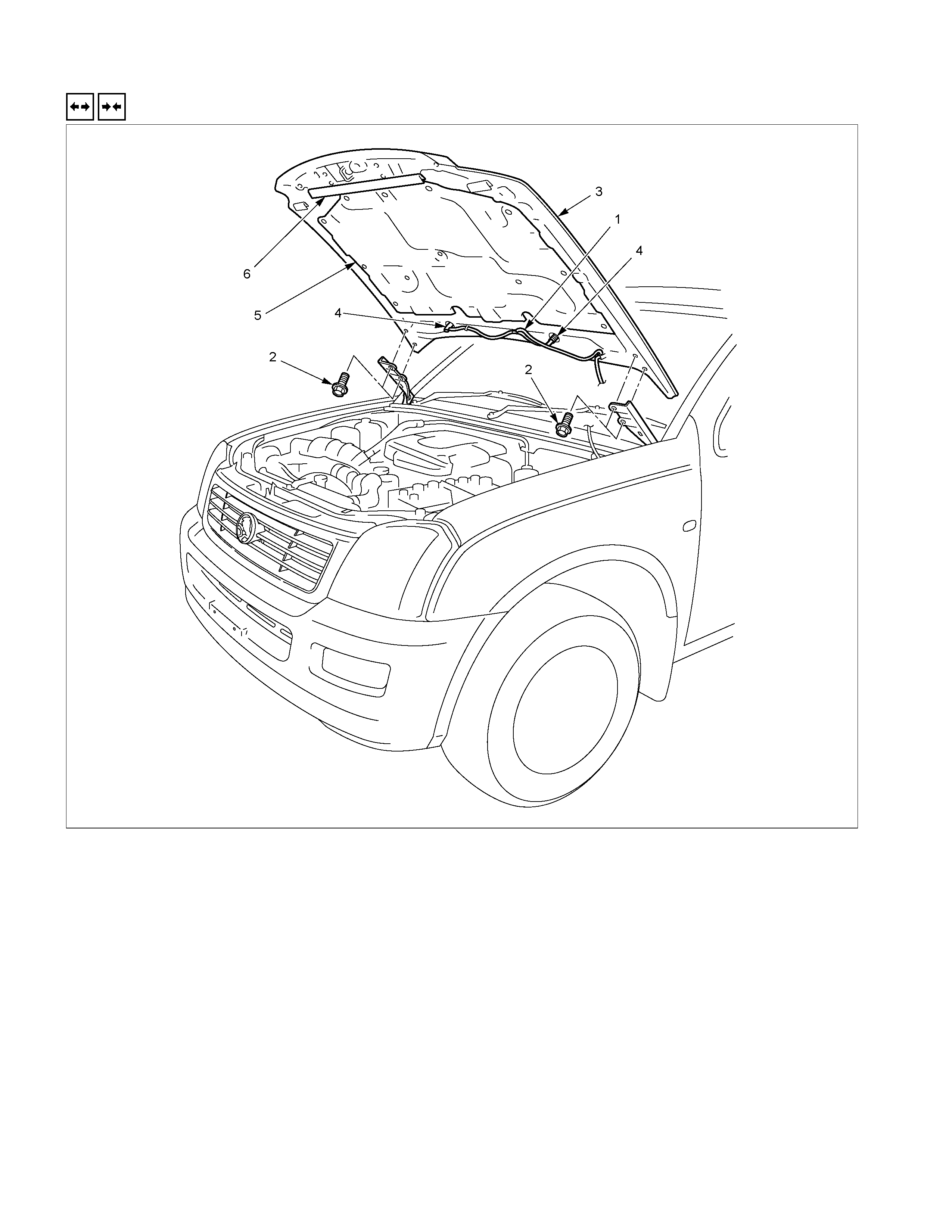
ENGINE HOOD ASSEMBLY
REMOVAL AND INSTALLATION
RTW2BLF000101
Removal Steps Installation Steps
▲ 1. Washer nozzle tube 6. Hood seal
▲ 2. Hood hinge bolts 5. Hood insulator
3. Engine hood 4. Washer nozzle
4. Washer nozzle ▲ 3. Engine hood
5. Hood insulator (Die. Eng. Only) ▲ 2. Hood hinge bolts
6. Hood seal 1. Washer nozzle tube
Important Operations - Removal
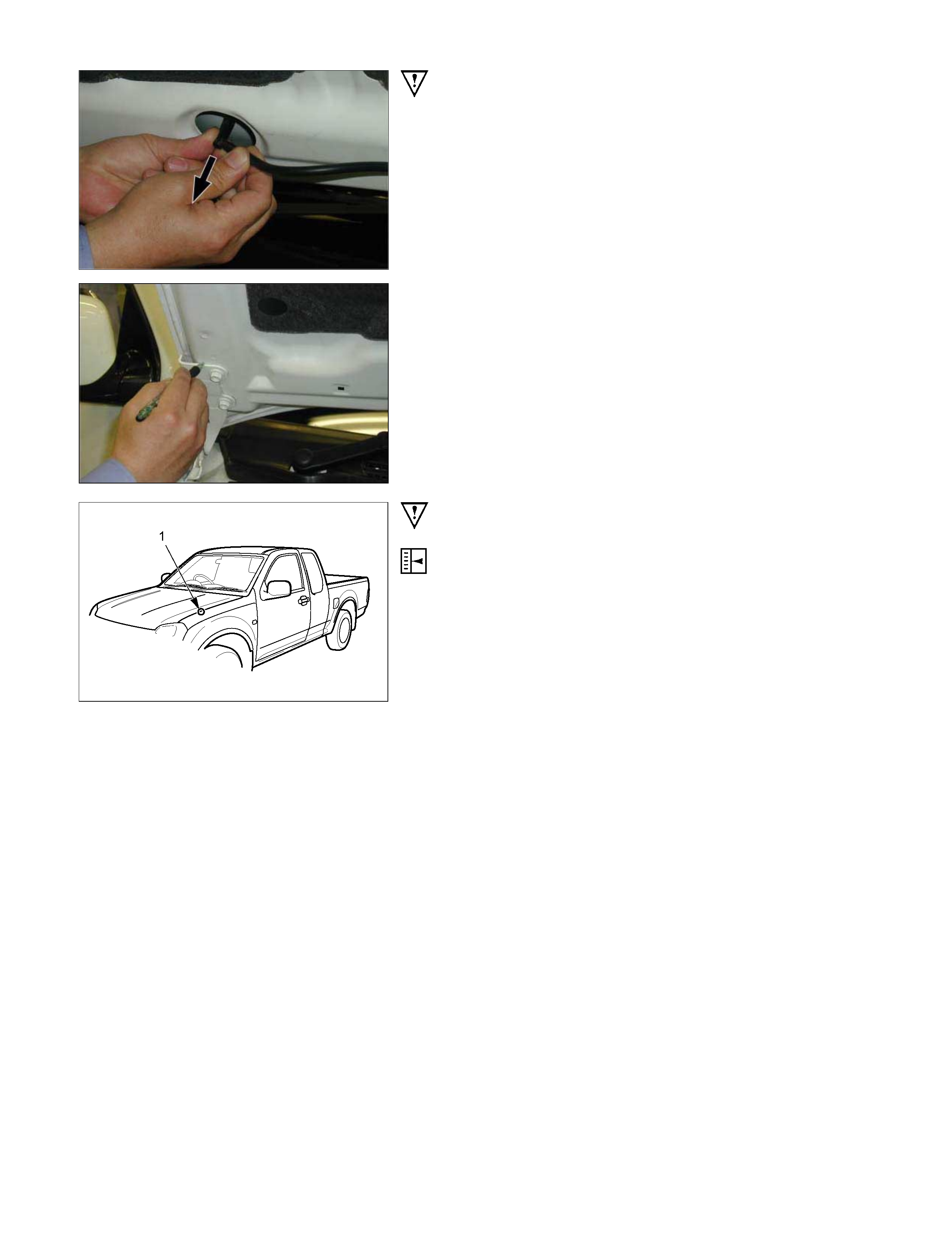
1. Washer Nozzle Tube
1) Open the hood.
2) Support the hood.
3) Remove the windshield washer nozzle tube.
2. Hood Hinge Bolts
• Before removing the hinges from the engine hood, scribe a
mark showing location of the hinges to facilitate installation in
the original position.
RTW32BSH000101
Important Operations - Installation
3. Engine Hood
• Check the engine hood and fender. (1)
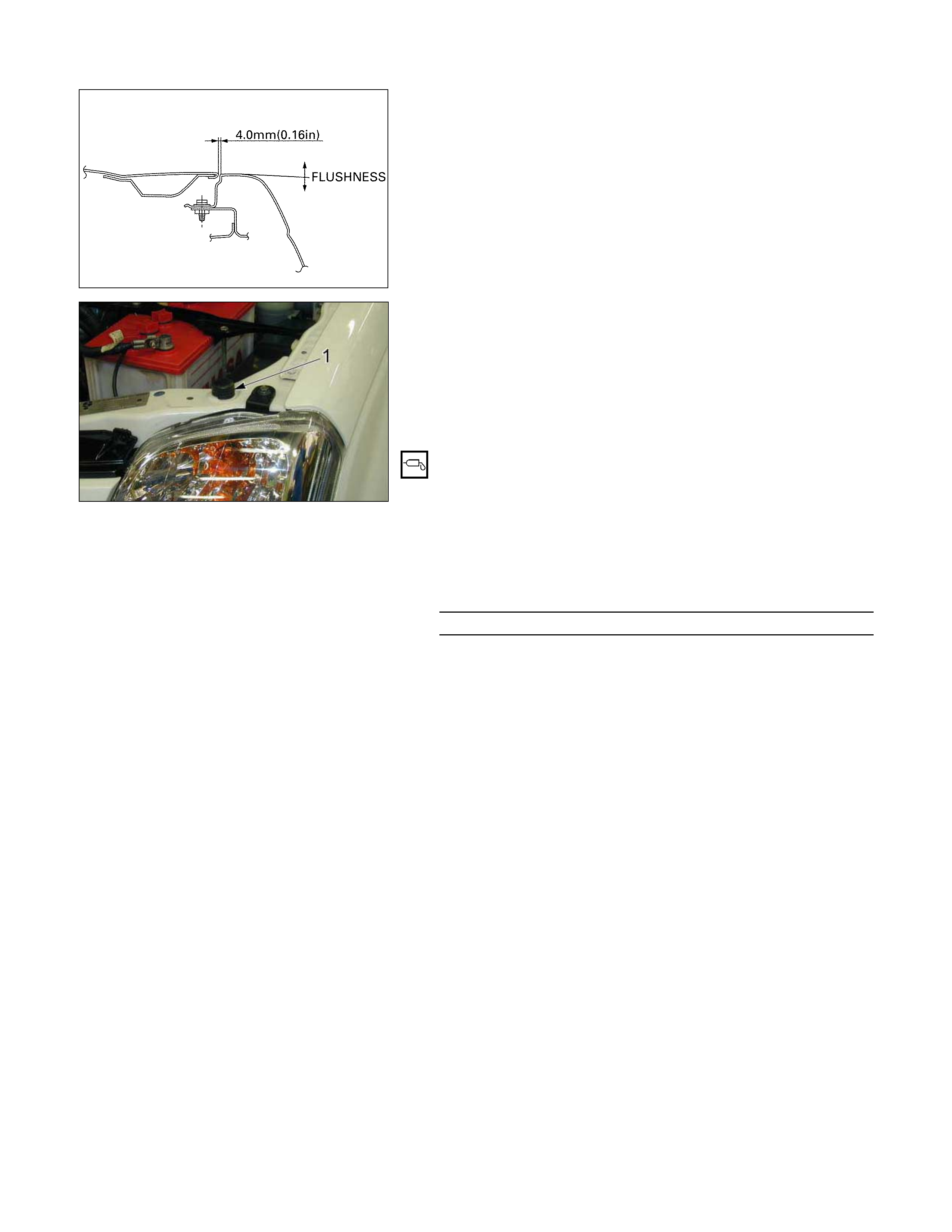
• Clearance : 4.0 mm (0.16 in)
• Height (step) : Flushness
• Adjust clearance with the hinges on the engine hood.
• Adjust height (step) with the hood rests (1).
Engine Hood Striker
• Apply a light coat of grease to the striker.
2. Hood Hinge Bolts
• Tighten the engine hood hinge fixing bolts to the specified
torque.
Torque N⋅m(kgf⋅m/lb⋅in)
10 (1.0 / 87)
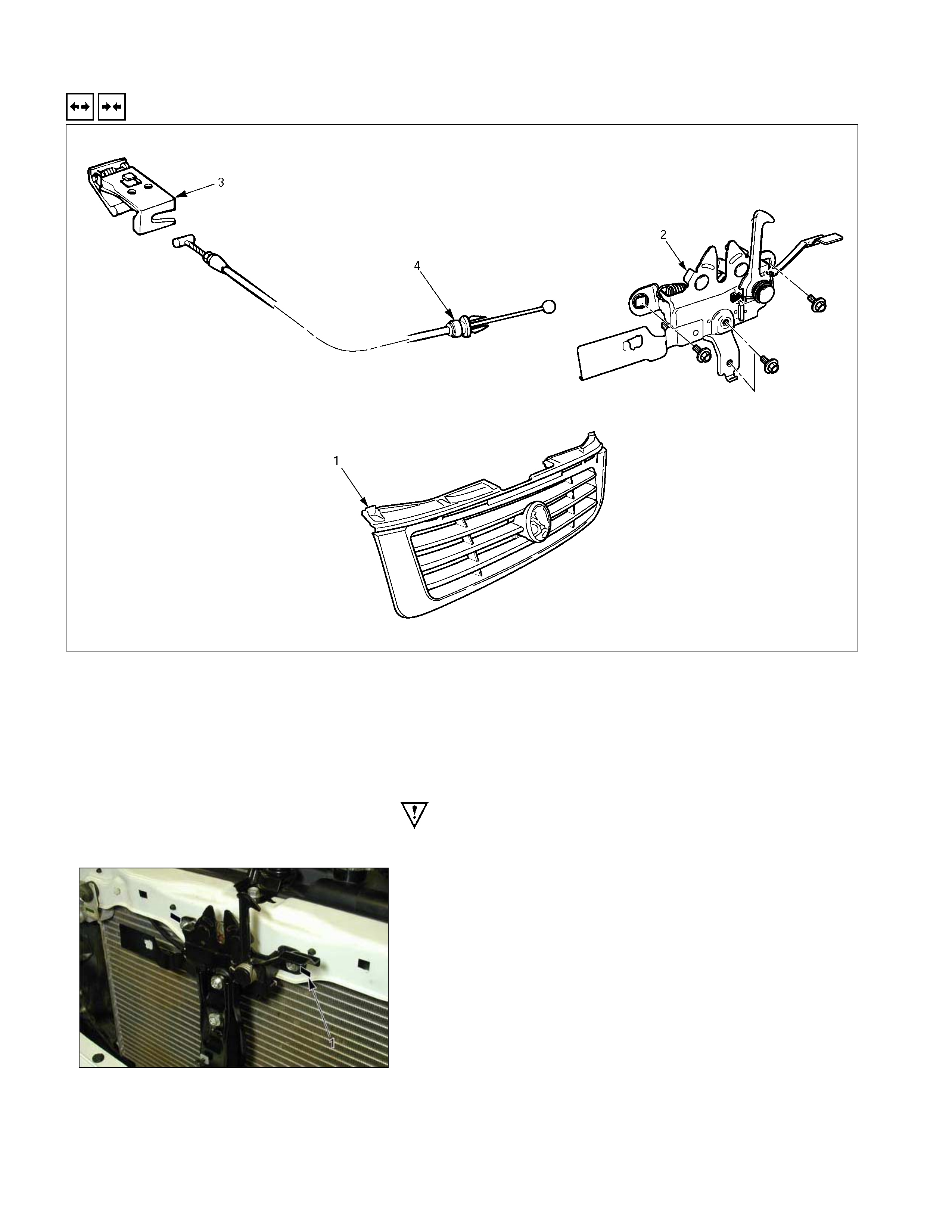
ENGINE HOOD LOCK
REMOVAL AND INSTALLATION
RTW32BMF000101
Removal Steps Installation Steps
▲ 1. Radiator grille ▲ 4. Control cable
▲ 2. Engine food lock assembly 3. Hood lock control lever
3. Hood lock control lever ▲ 2. Engine food lock assembly
▲ 4. Control cable 1. Radiator grille
Important Operations - Removal
1. Radiator Grille
Refer to the Radiator Grille in this section.
2. Engine Hood Lock Assembly
Apply setting marks (1) to the hood lock assembly and the
body prior to removal.
4. Control Cable
Pull out the control cable toward the passenger compartment.
Important Operations - Installation
4. Control Cable
Reroute the control cable to its original position, and check and
see if the lock assembly and control lever work normally.
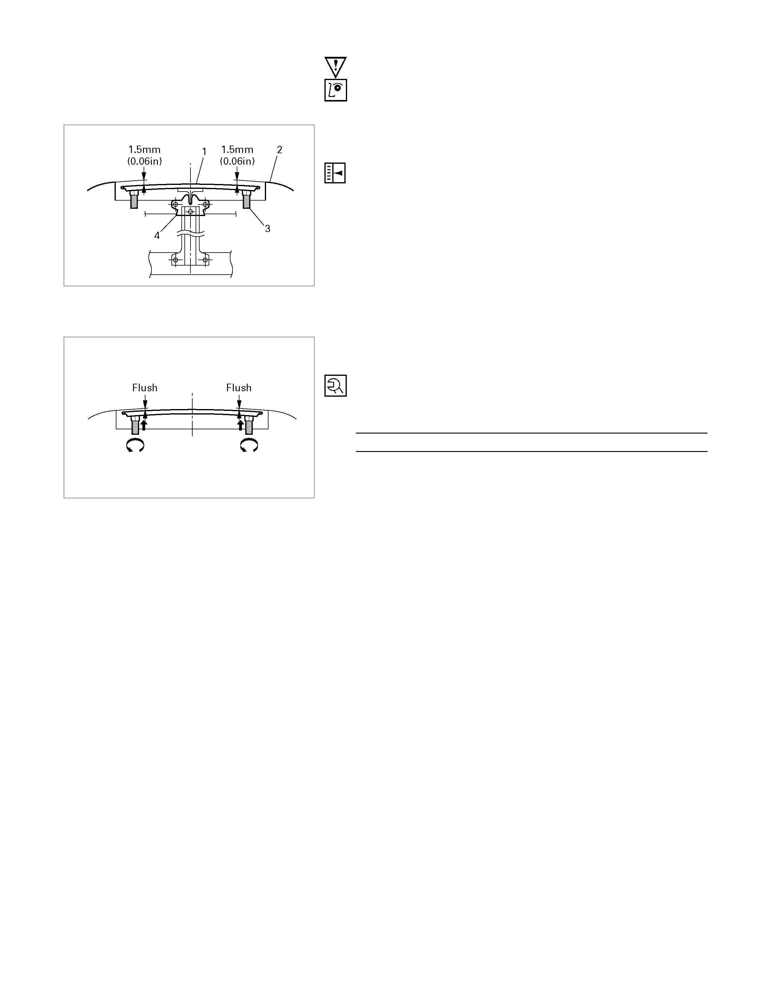
2. Engine Hood Lock Assembly
Adjustment
1) Install the engine hood lock assembly (4) and temporaril
y
tighten the bolts securing it.
2) Close the hood.
3) Position the hood so that the stepped portion between the
hood (1) and the fender (2) is precisely 1.5 mm (0.06 in)
high.
4) Final tighten the bolts securing the engine hood lock
assembly.
5) Turn the buffers (3) counterclockwise until the stepped
portion between the hood and the fender disappears.
6) Tighten the hood lock assembly fixing bolts to the specified
torque.
Torque N⋅m(kgf⋅m/lb⋅in)
10 (1.0 / 87)
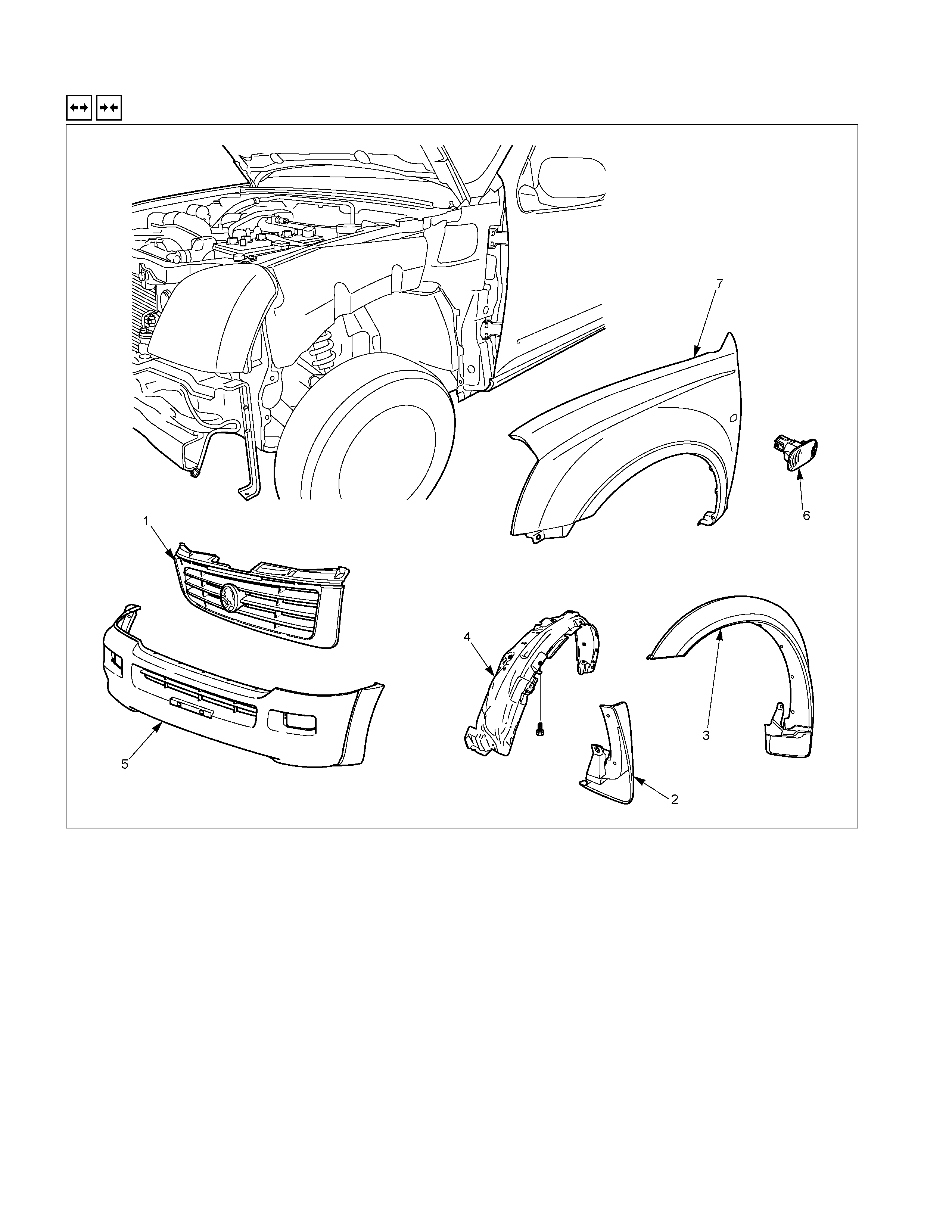
FRONT FENDER PANEL
REMOVAL AND INSTALLATION
RTW32BLF000201
Removal Steps Installation Steps
▲ 1. Radiator grille ▲ 7. Front fender panel
2. Mud guard (W/O Front wheel extention) 6. Side turn signal light
3. Front wheel extention (W/ Front wheel
extention) 5. Front bumper facia
▲ 4. Inner liner 4. Inner liner
▲ 5. Front bumper facia 3. Front wheel extention (W/ Front wheel
extention)
6. Side turn signal light 2. Mud guard (W/O Front wheel extention)
▲ 7. Front fender panel 1. Radiator grille
Important Opera tion - Installation
7. Front Fender Panel
1) Tighten the front fender panel fixing bolts to the
specified torque.
Torque N⋅m(kgf⋅m/lb⋅in)
10 (1.0 / 87)
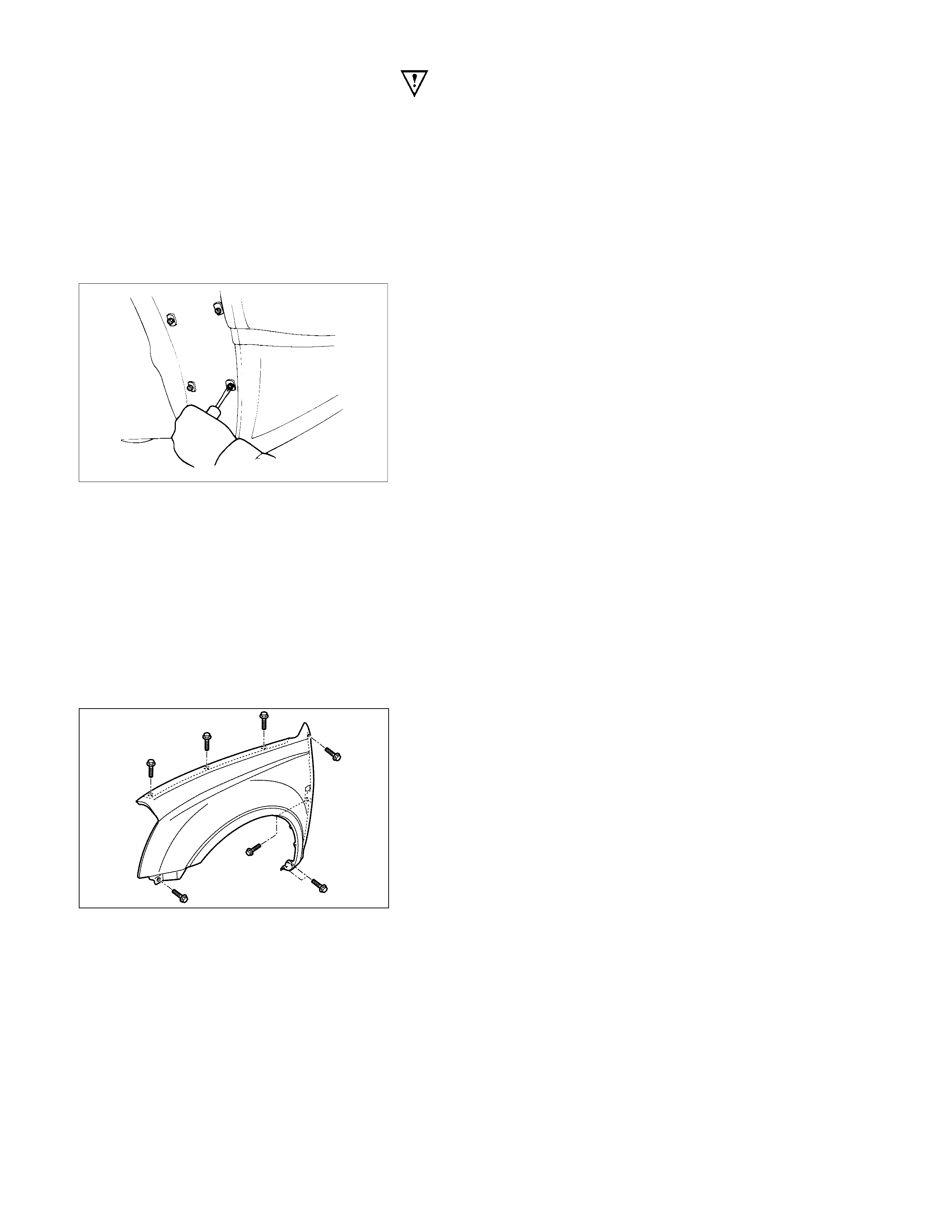
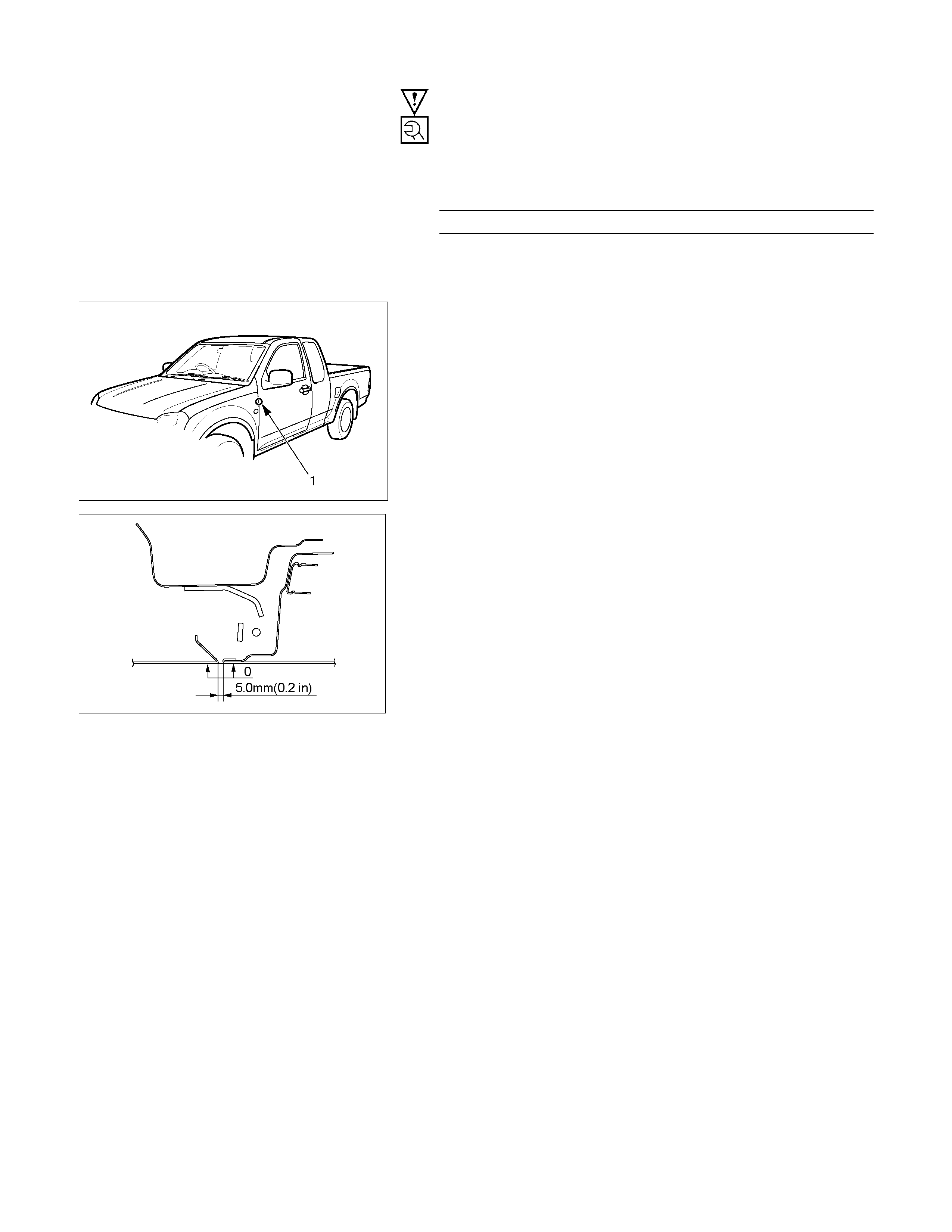
RTW32BSH000201
2) Check the fender and front door (1).
• Clearance : 5.0 mm (0.2 in)
• Height (step) : Flushness
RTW32BSH000301
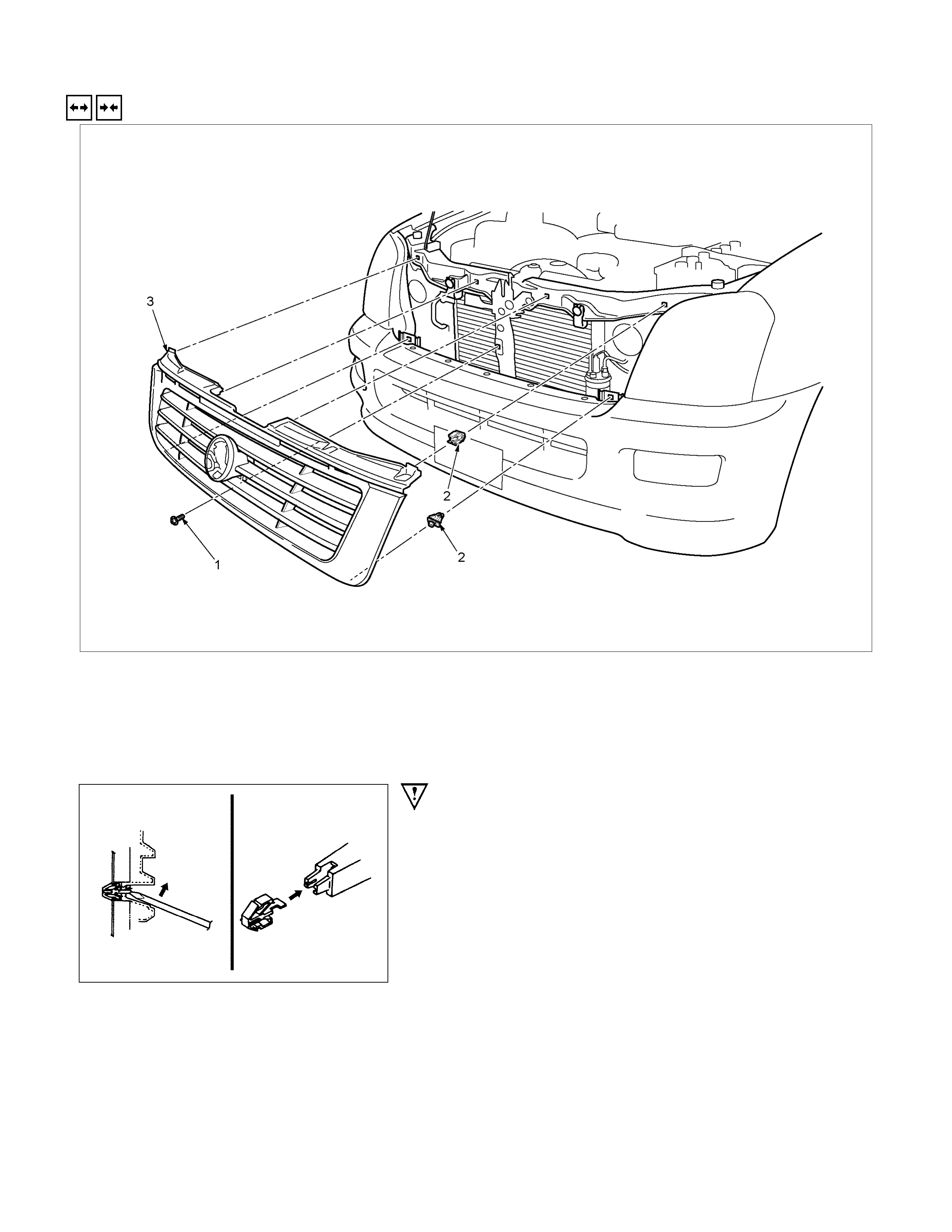
RADIATOR GRILLE
REMOVAL AND INSTALLATION
RTW32AMF000101
Removal Steps Installation Steps
1. Screw 3. Radiator grille
▲ 2. Clip 2. Clip
3. Radiator grille 1. Screw
Important Operation - Removal
2. Clip
• Use a screwdriver to release the 4 clips at the top of the
radiator grille.
• Pull the grille together with the 2 bottom clips from the
vehicle.
REAR BODY
REMOVAL AND INSTALLATION
RTW32MF000301
Removal Steps Installation Steps
1. Battery ground cable 7. Rear body assembly
2. Rear combination lamp & license lamp
harness connector ▲ 6. Bolt; frame to rear body
3. Rear wheel house extension panel 5. Fuel filler pipe and evaporator hose
4. Fuel filler door release cable assembly 4. Fuel filler door release cable assembly
▲ 5. Fuel filler pipe and evaporator hose 3. Rear wheel house extension panel
6. Bolt; frame to rear body 2. Rear combination lamp & license lamp
connector
▲ 7. Rear body assembly 1. Battery ground cable
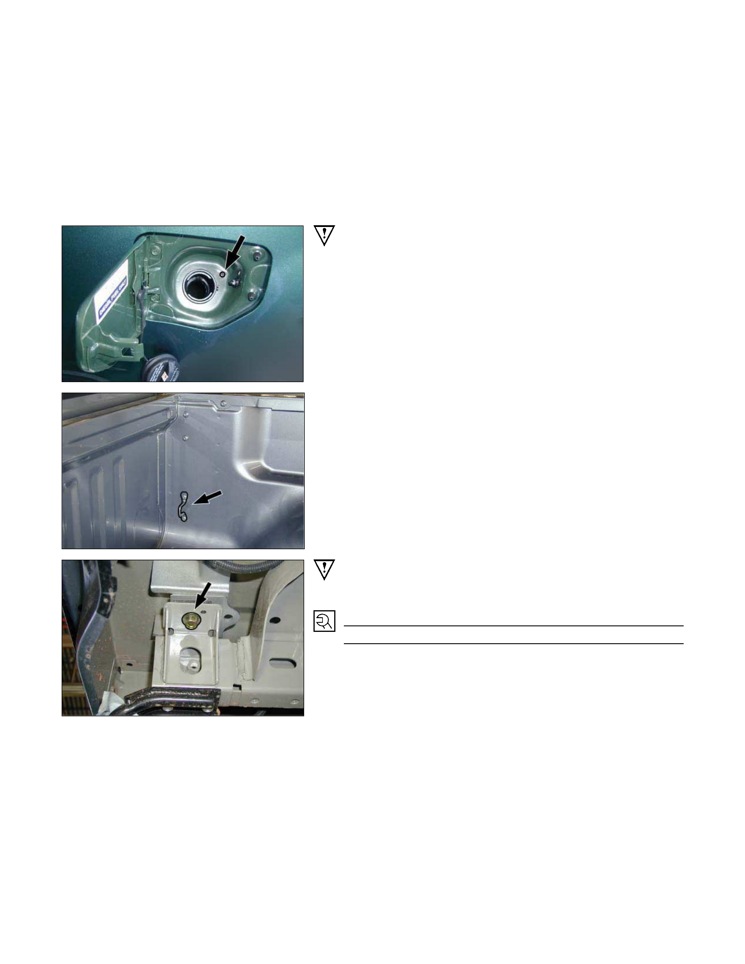
NOTE:
The rear body must be empty before removal.
Important Operations - Removal
4. Fuel Filler Pipe and Evaporator Hose
7. Rear Body Assembly
Attach lifting wires to the rear body hooks and raise the rear
body.
Note:
In lifting up rear body, take care not to dash it against cab
body.
Important Operation – Installation
6. Bolt; Frame to Body
Torque N⋅m(kgf⋅m/lb⋅ft)
54 (5.5 / 40)
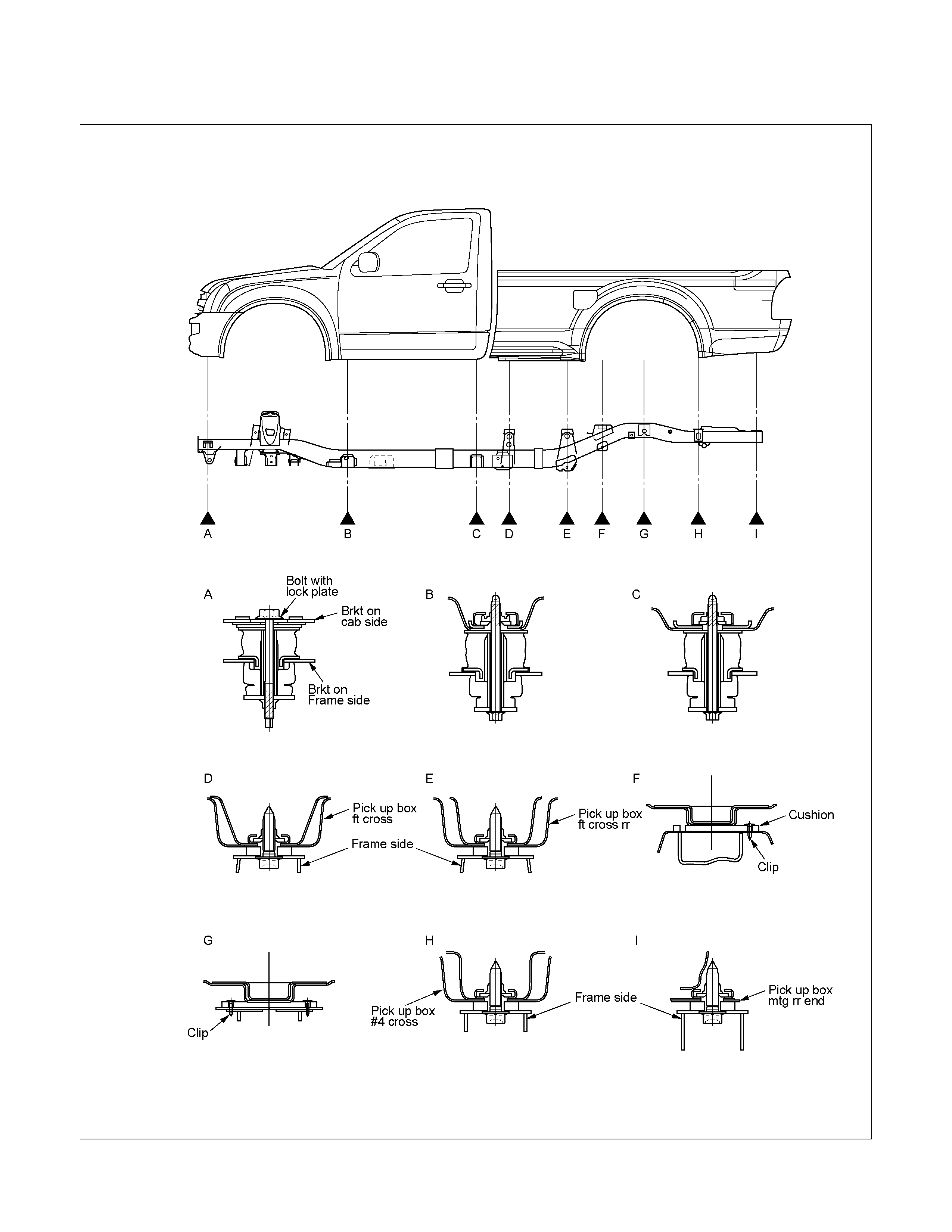
BODY MOUNTING
REGULAR CAB Model
RTW32BXF000101
Important Operations – Installation
Bolt : A
Torque N⋅m(kgf⋅m/lb⋅ft)
50 (5.1 / 37)
Bolt : B,C
Torque N⋅m(kgf⋅m/lb⋅ft)
72 (7.3 / 53)
Bolt : D,E,H,I
Torque N⋅m(kgf⋅m/lb⋅ft)
54 (5.5 / 40)
NOTE :
Discard used the mounting bolts D,E,H,I shown in the
figure and install new one.
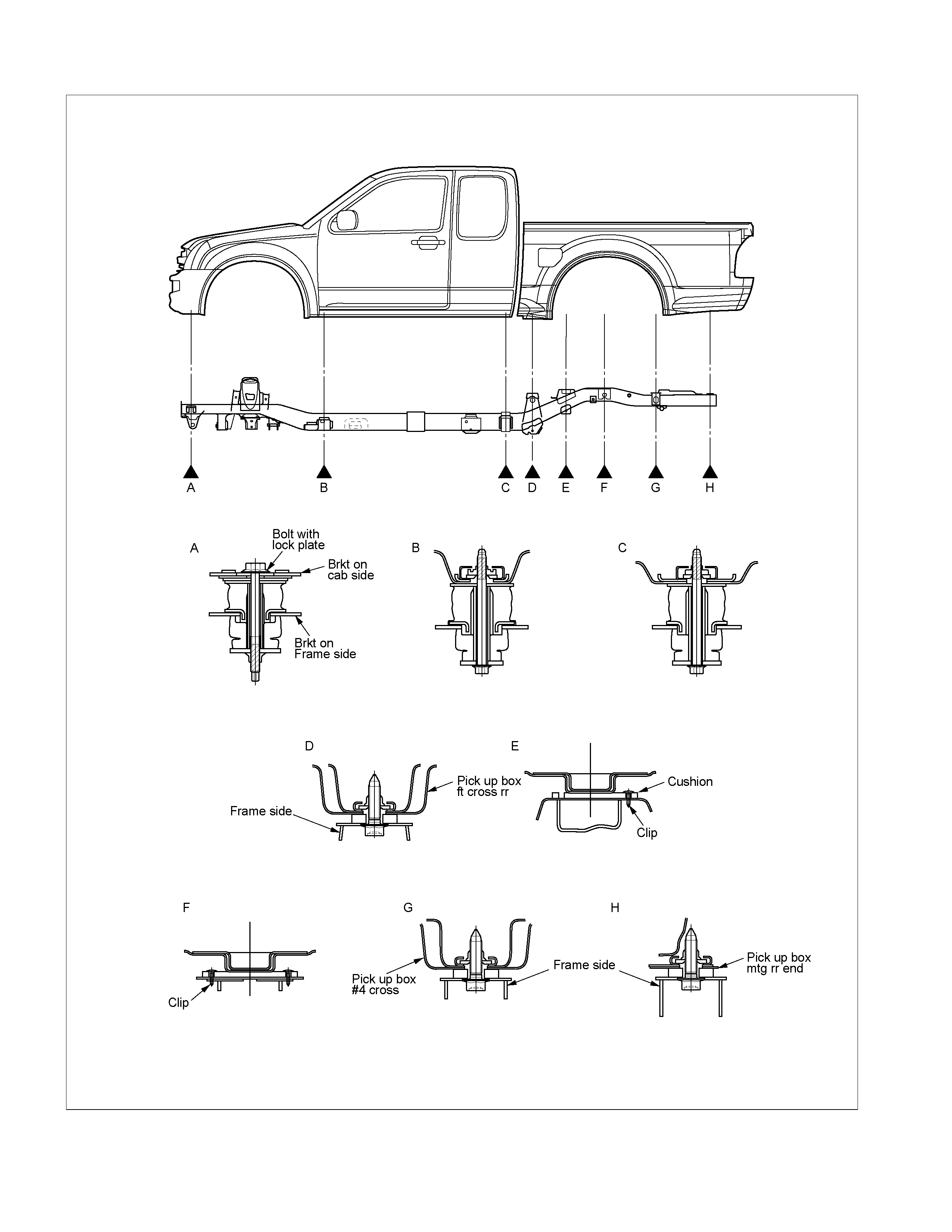
EXTEND CAB Model
RTW32BXF000201

Important Operations – Installation
Bolt : A
Torque N⋅m(kgf⋅m/lb⋅ft)
50 (5.1 / 37)
Bolt : B,C
Torque N⋅m(kgf⋅m/lb⋅ft)
72 (7.3 / 53)
Bolt : D,G,H
Torque N⋅m(kgf⋅m/lb⋅ft)
54 (5.5 / 40)
NOTE :
Discard used the mounting bolts D,G,H shown in the
figure and install new one.
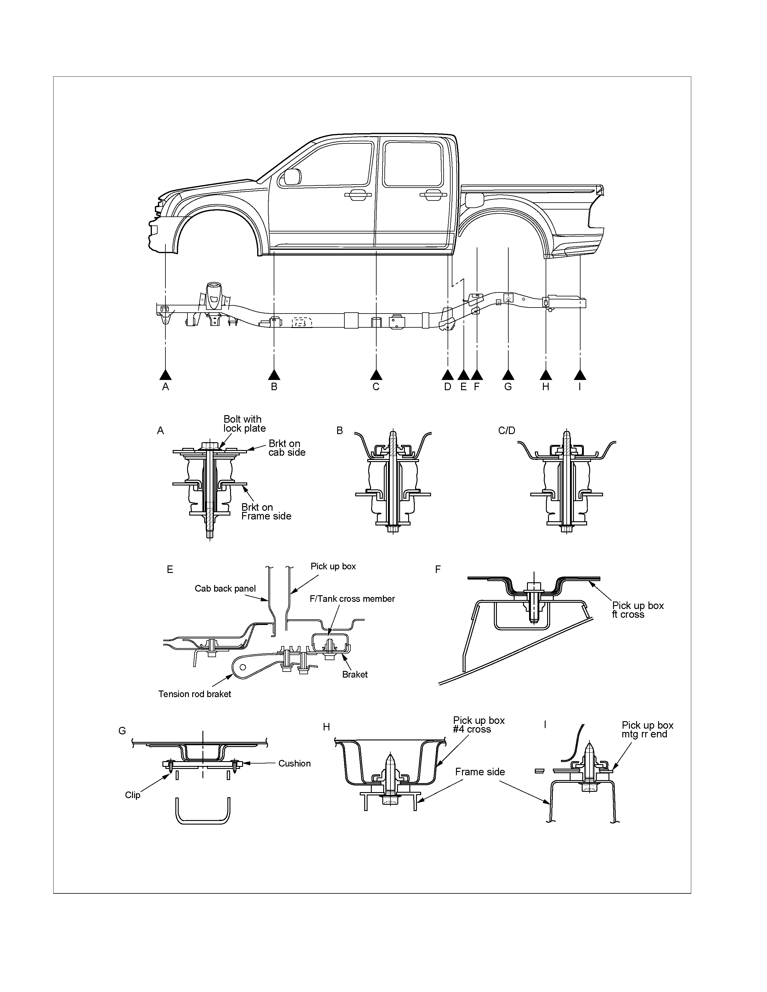
CREW CAB Model
RTW32BXF000301
Important Operations – Installation
Bolt : A
Torque N⋅m(kgf⋅m/lb⋅ft)
50 (5.1 / 37)
Bolt : B,C/D
Torque N⋅m(kgf⋅m/lb⋅ft)
72 (7.3 / 53)
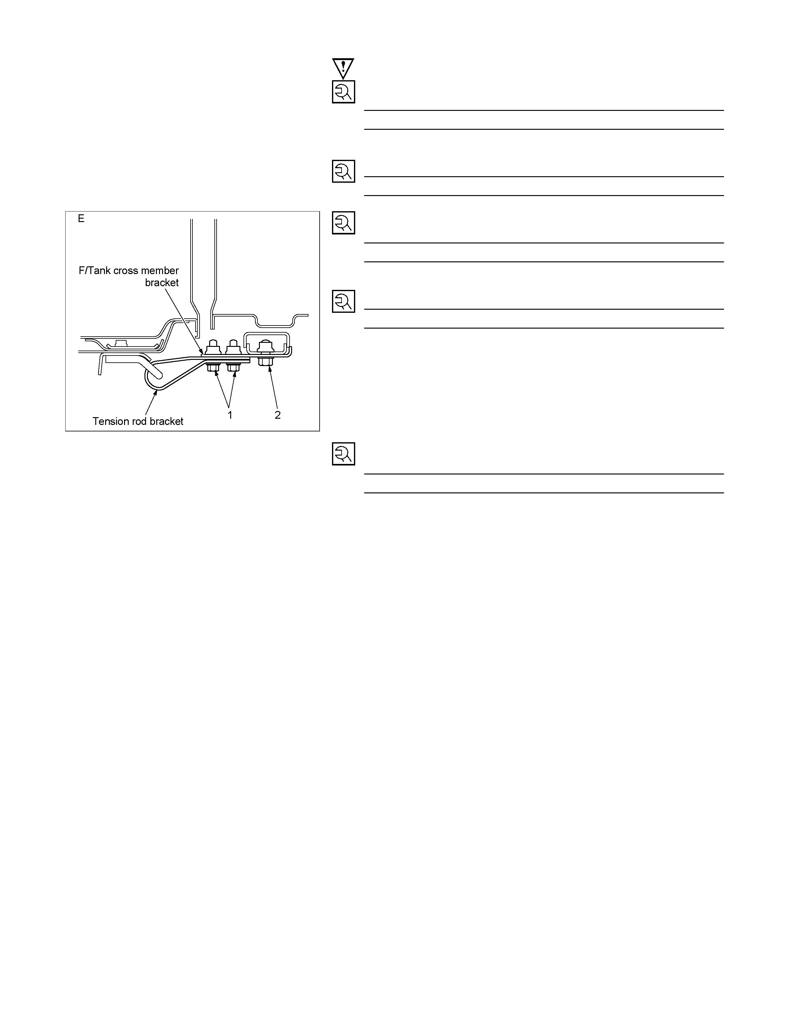
RTW32BSH000401
Bolt : E-1
Torque N⋅m(kgf⋅m/lb⋅ft)
116 (11.8 / 85)
Bolt : E-2
Torque N⋅m(kgf⋅m/lb⋅ft)
168 (17.1 / 124)
Bolt : F,H,I
Torque N⋅m(kgf⋅m/lb⋅ft)
54 (5.5 / 40)
NOTE :
Discard used the mounting bolts G,H shown in the figure
and install new one.
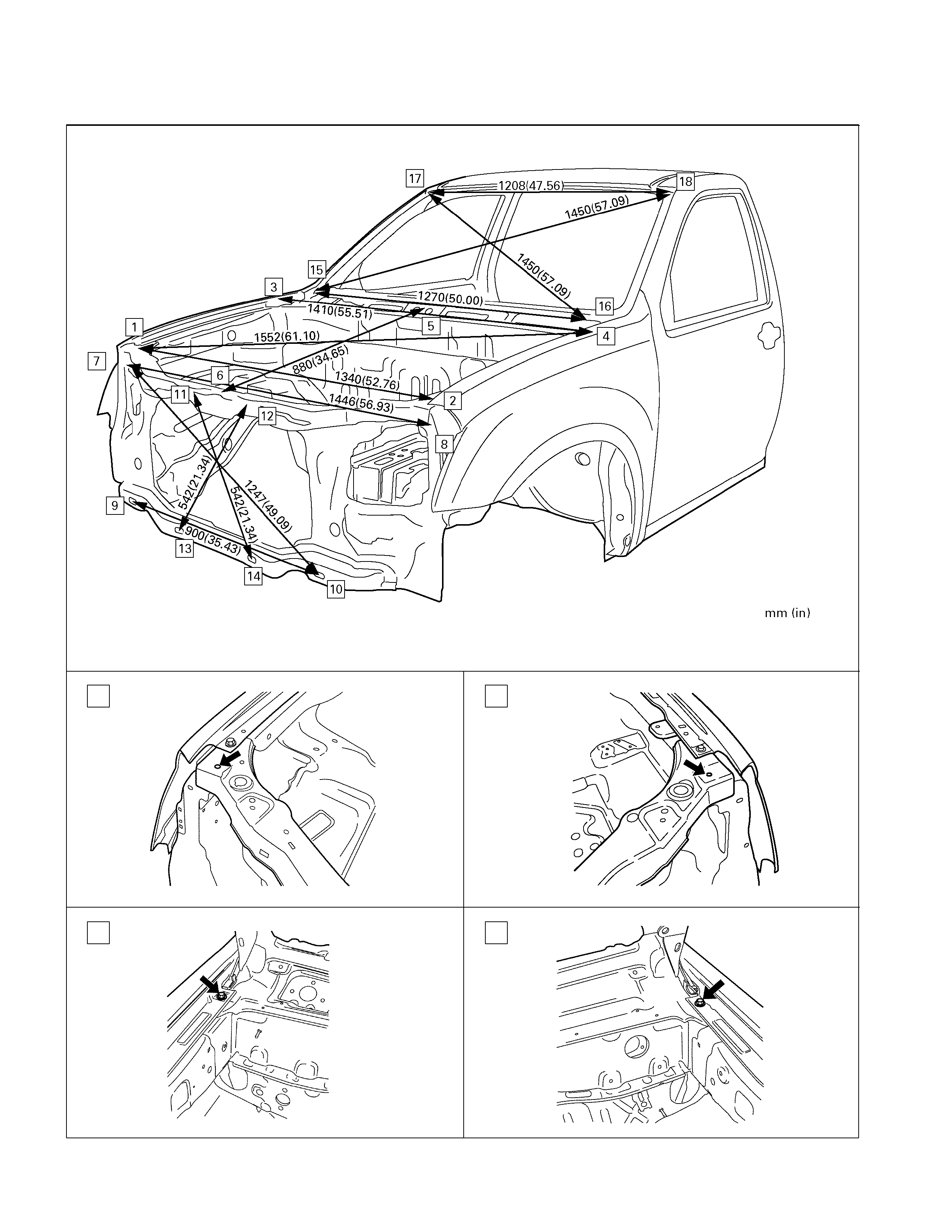
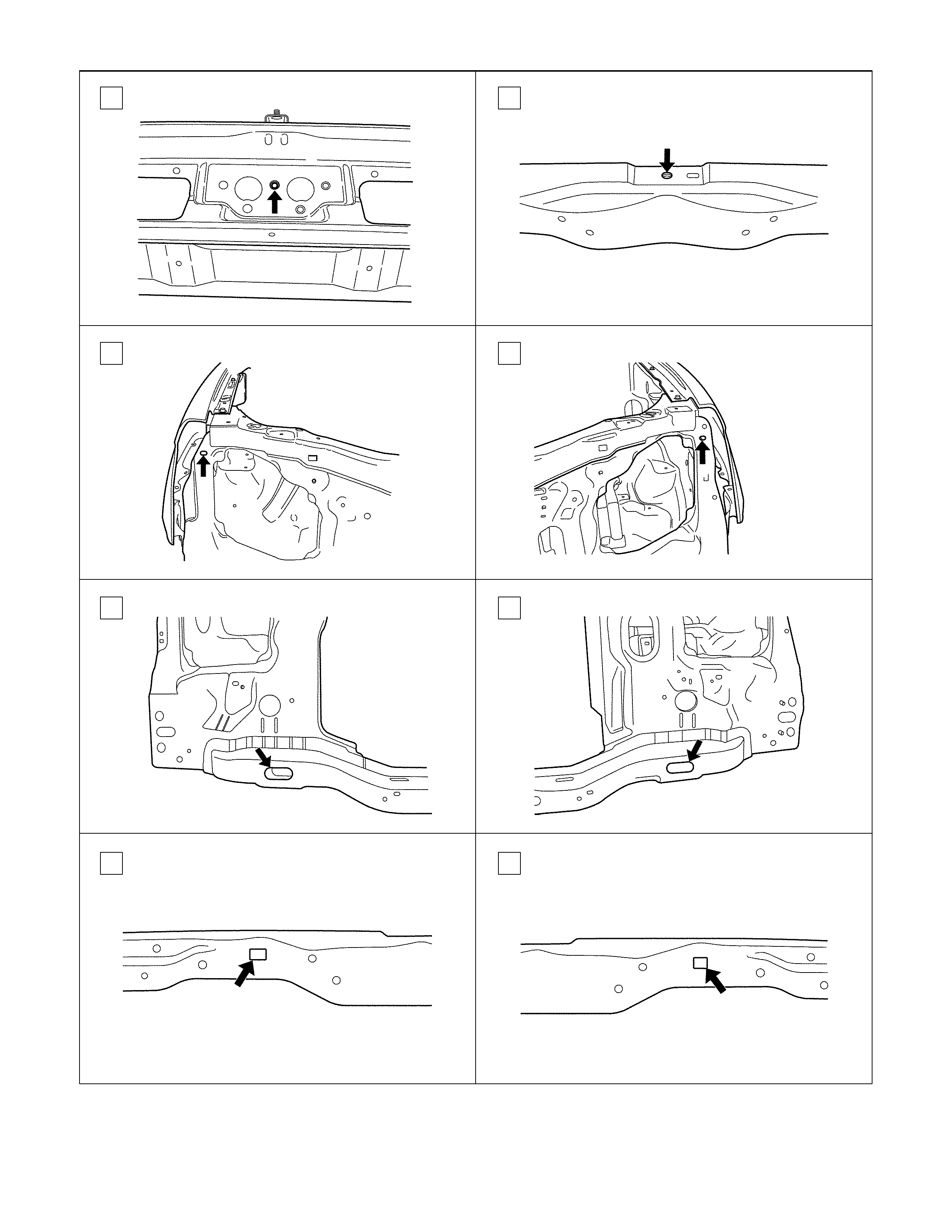
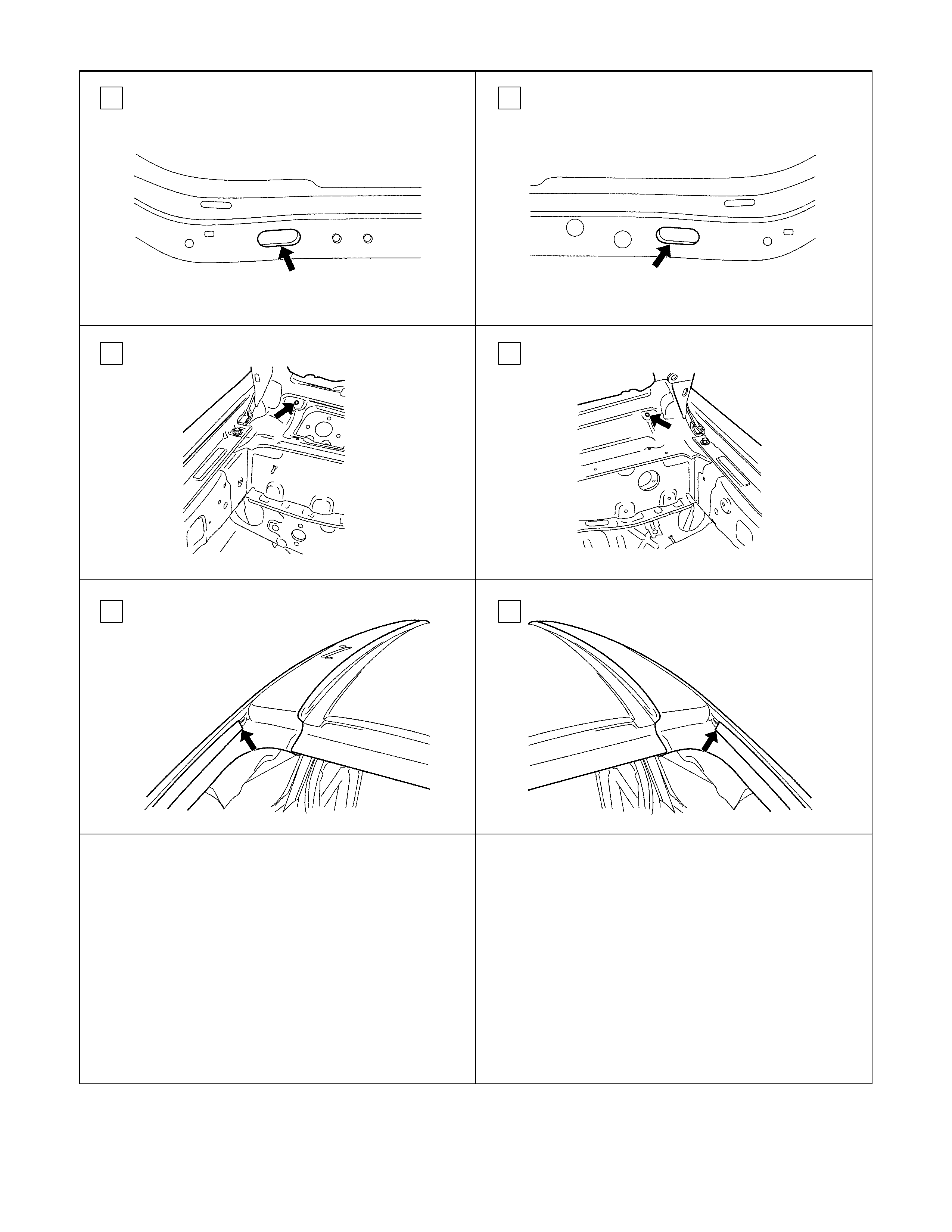
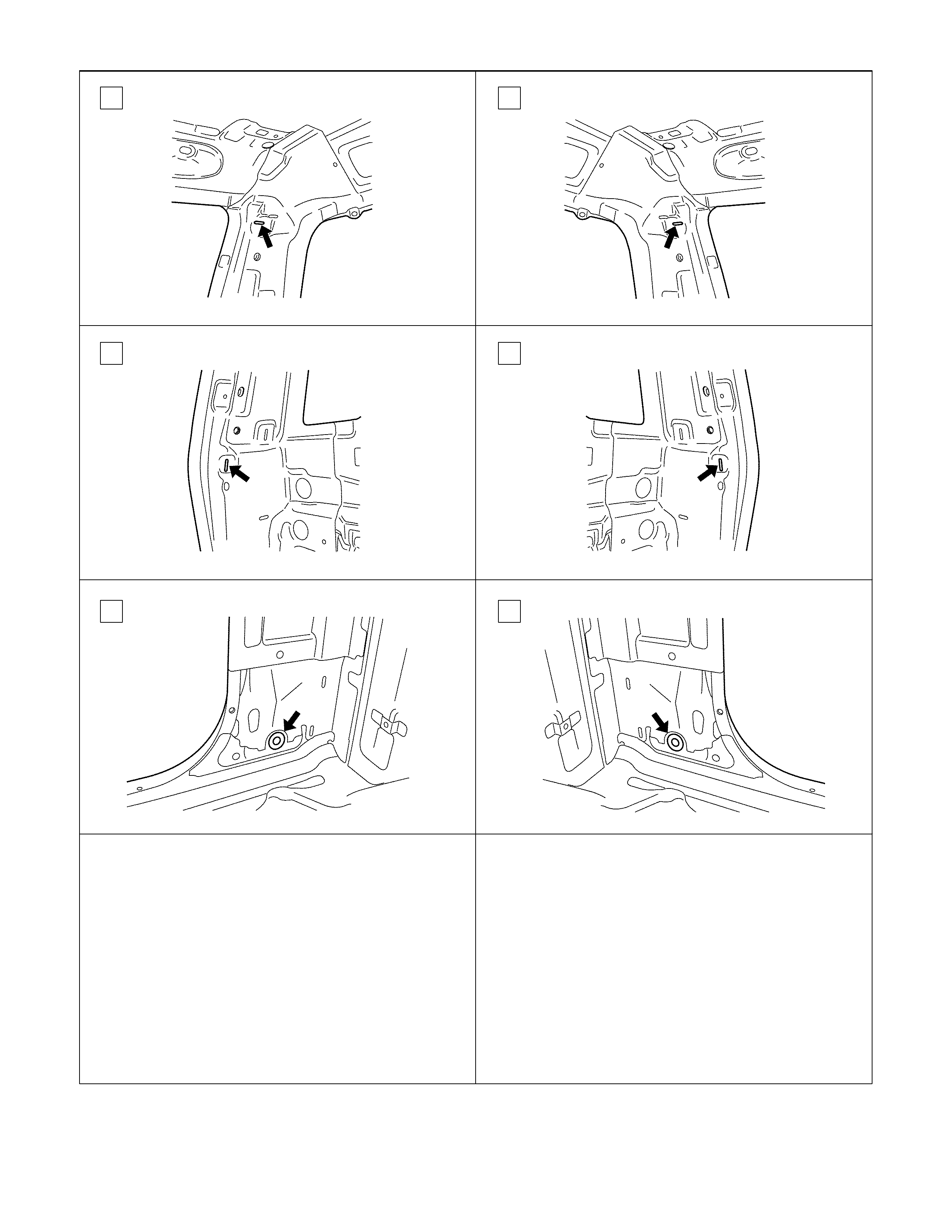
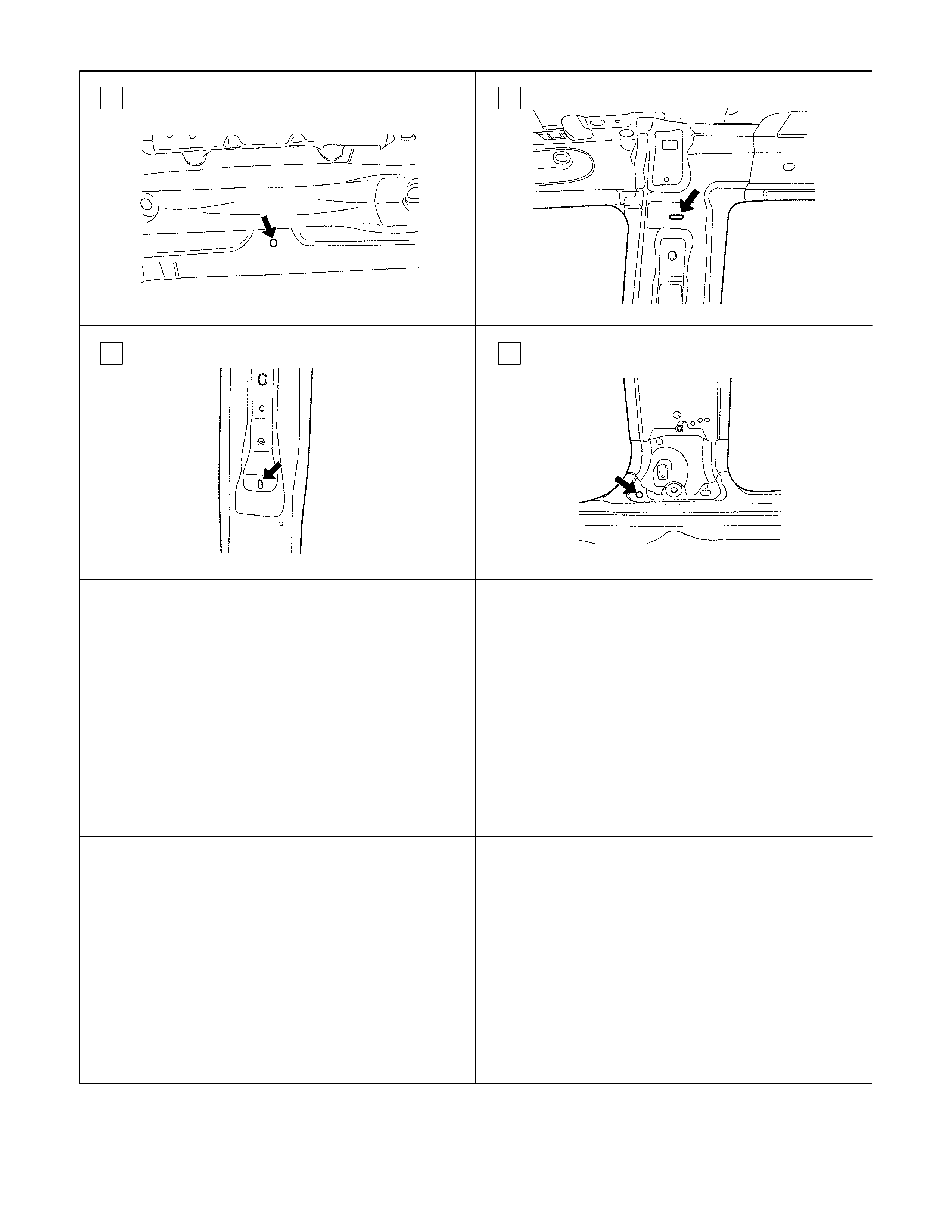
BODY DIMENSION
FRONT SECTION
1 2
3 4
5 6
7 8
9 10
11 12
13 14
15 16
17 18
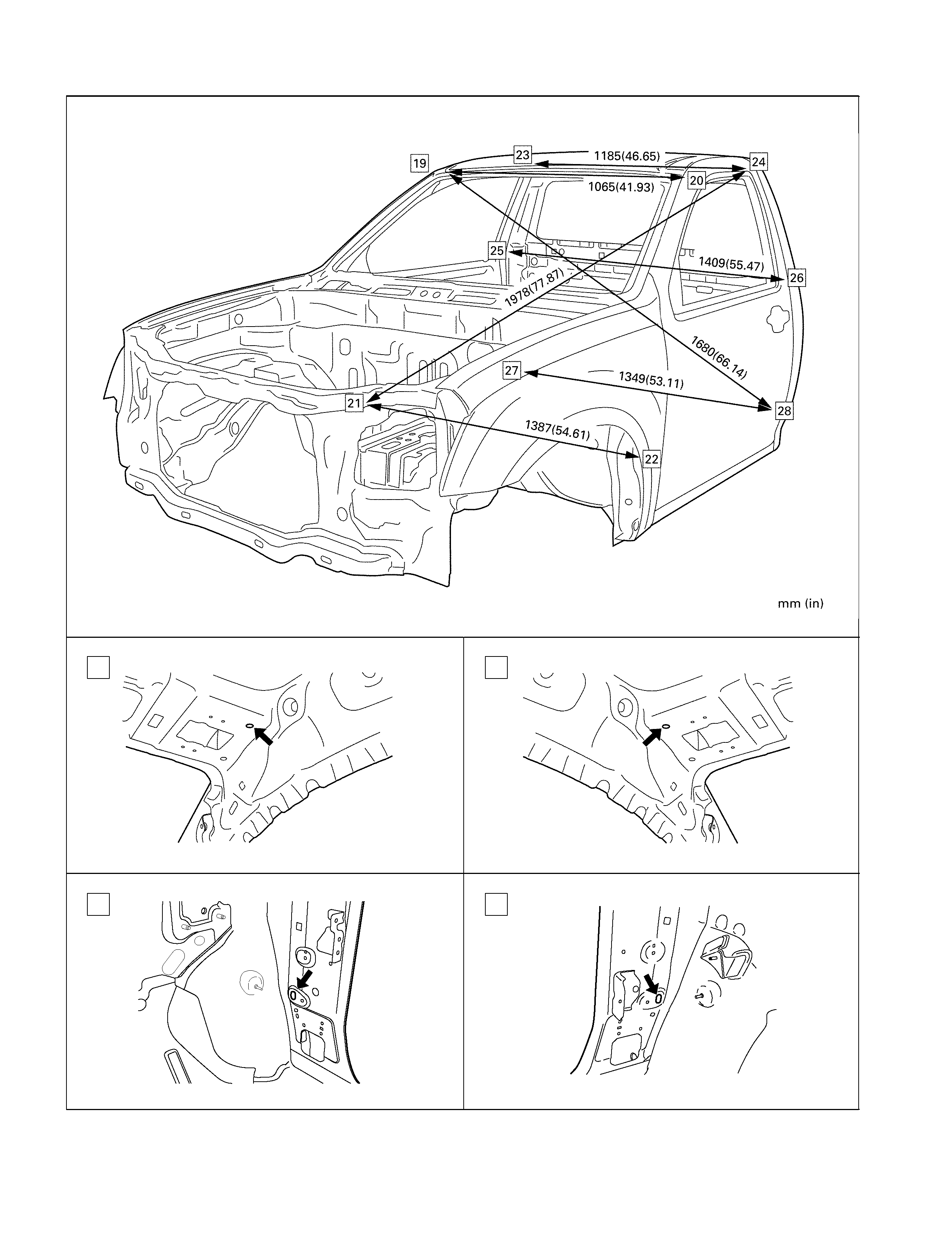
ROOM SECTION (REGULAR CAB)
19 20
21 22
23 24
25 26
27 28
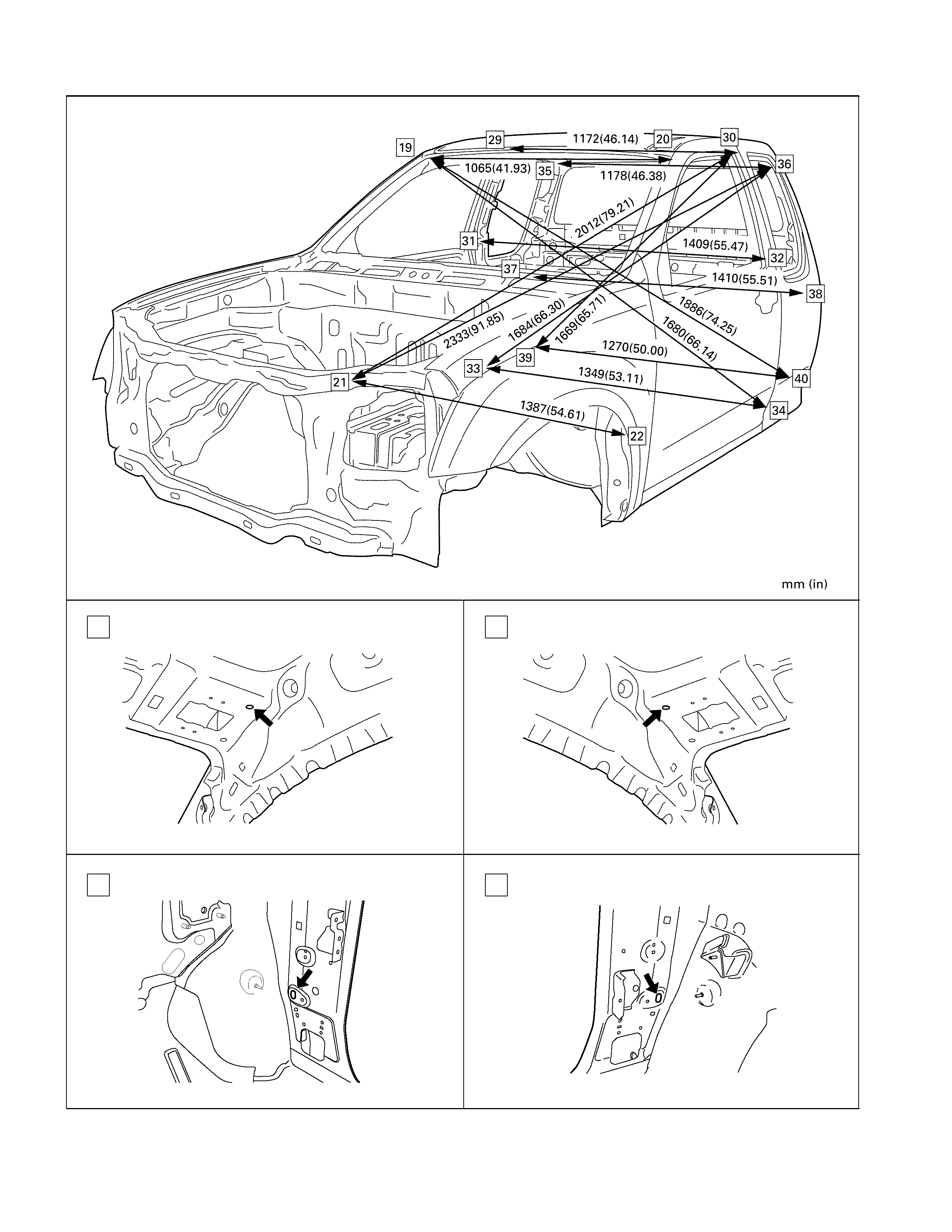
ROOM SECTION (EXTEND CAB)
19 20
21 22
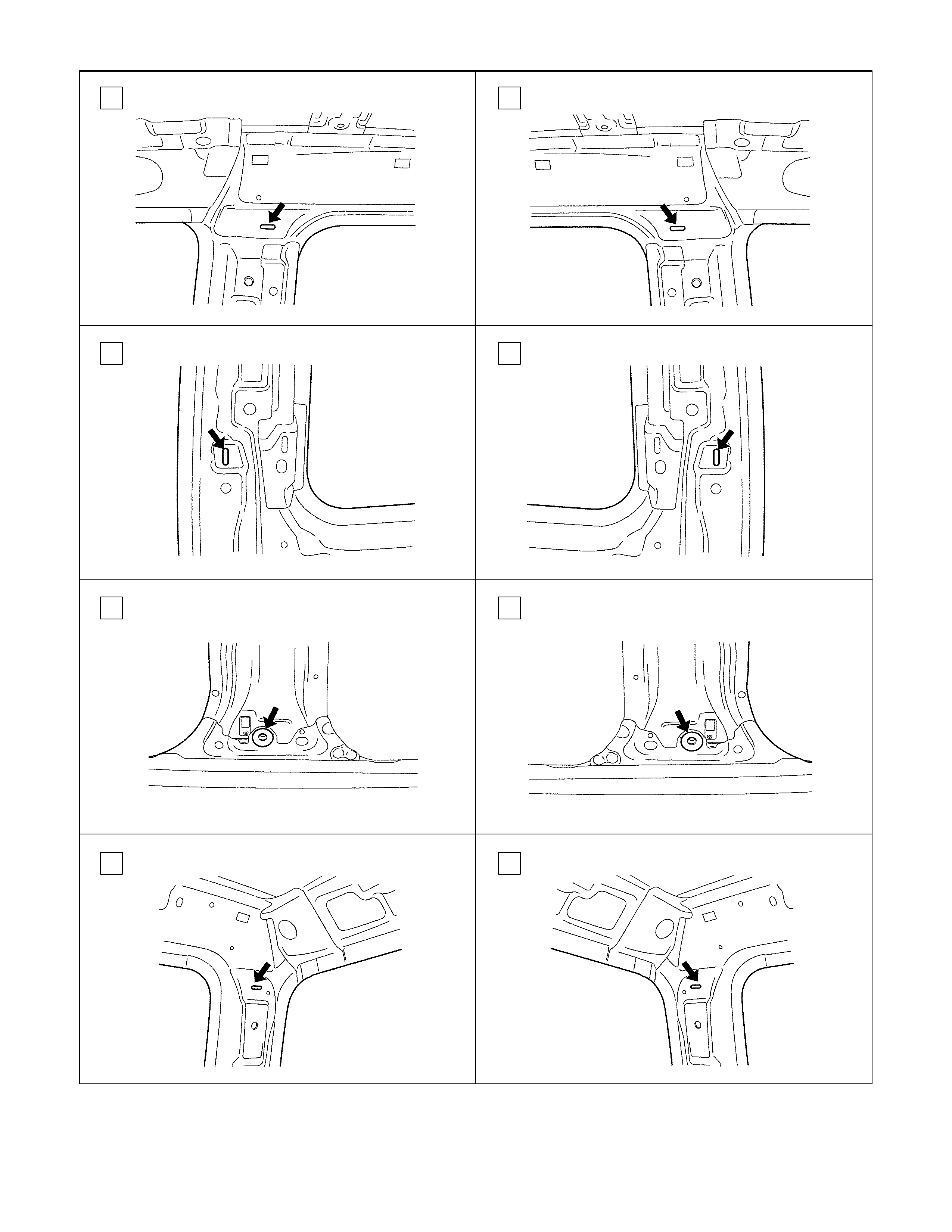
29 30
31 32
33 34
35 36
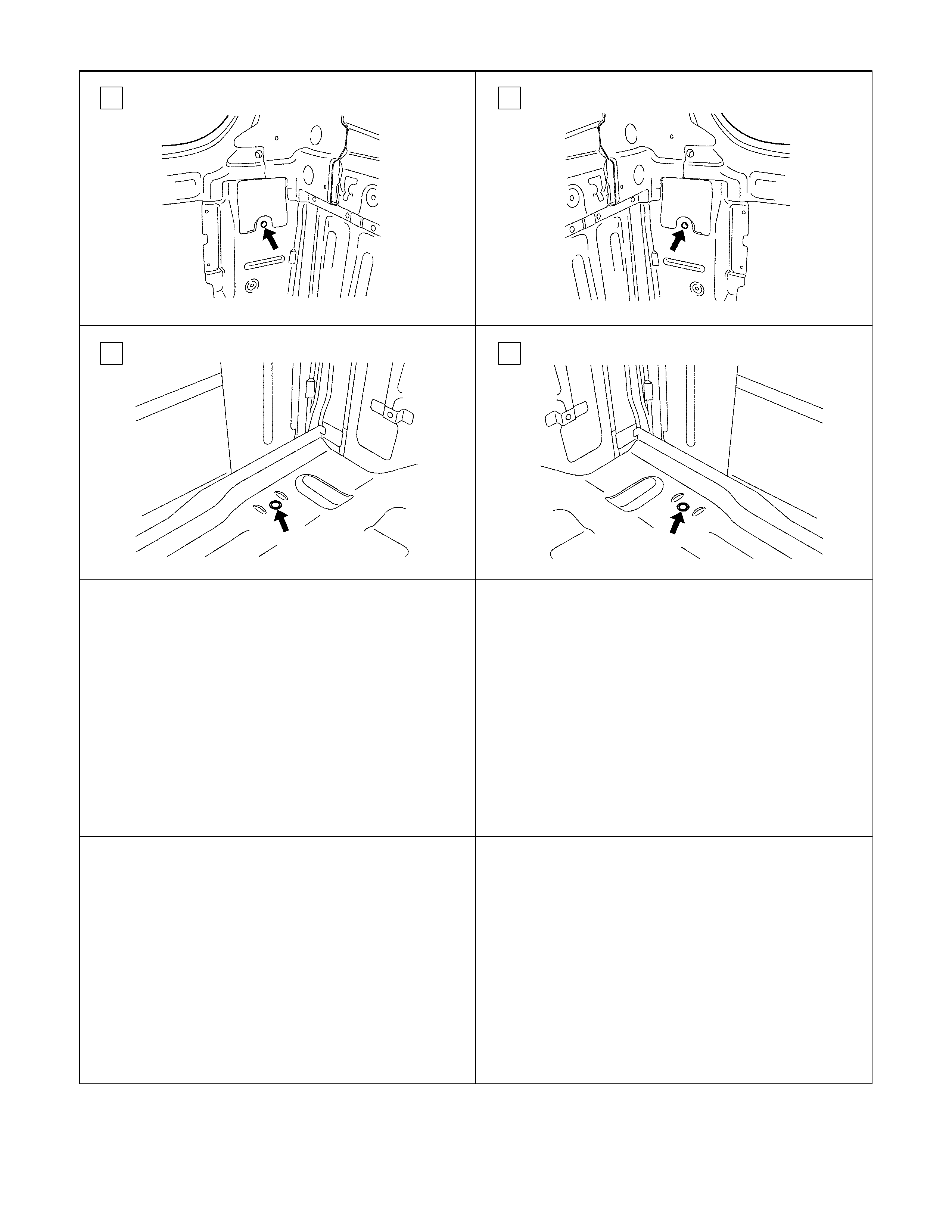
37 38
39 40
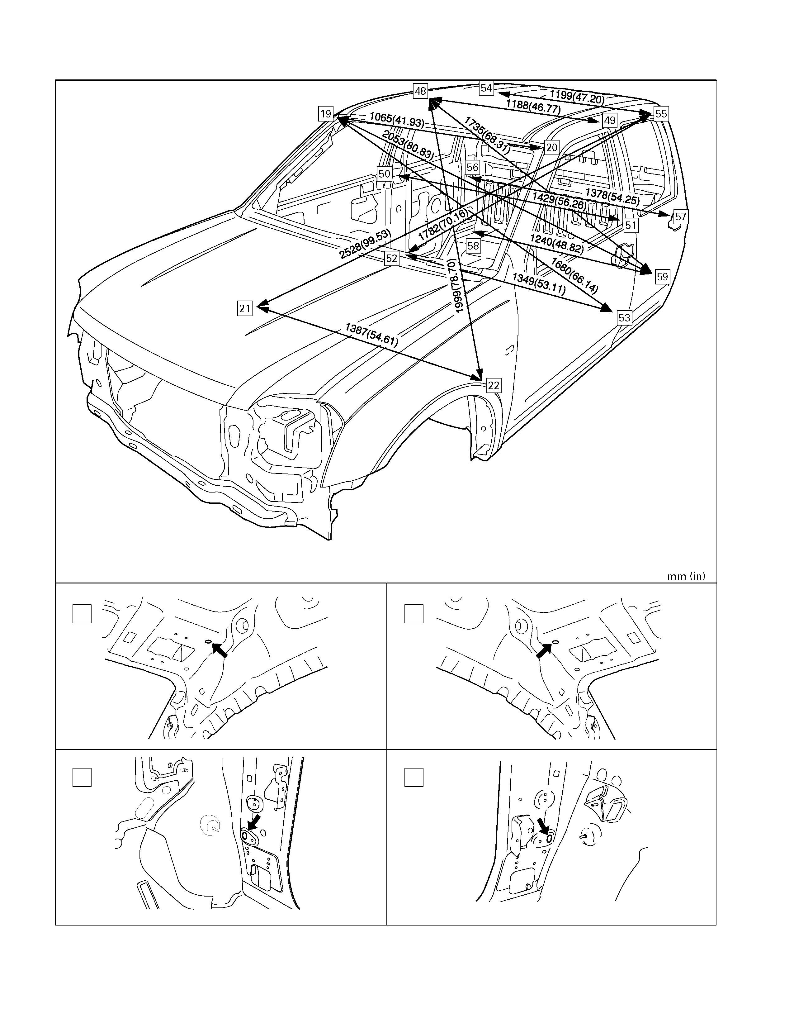
ROOM SECTION (CREW CAB)
19 20
21 22
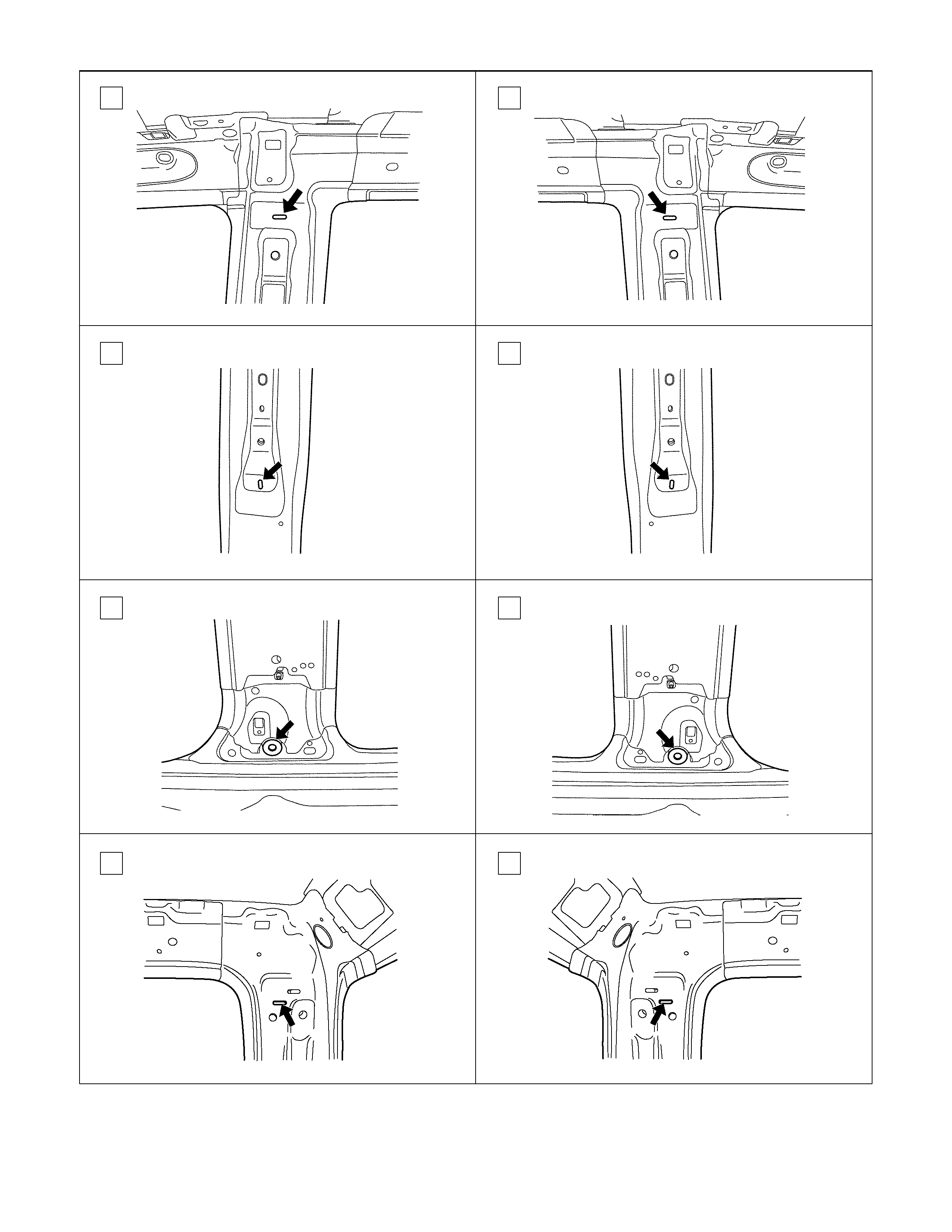
48 49
50 51
52 53
54 55
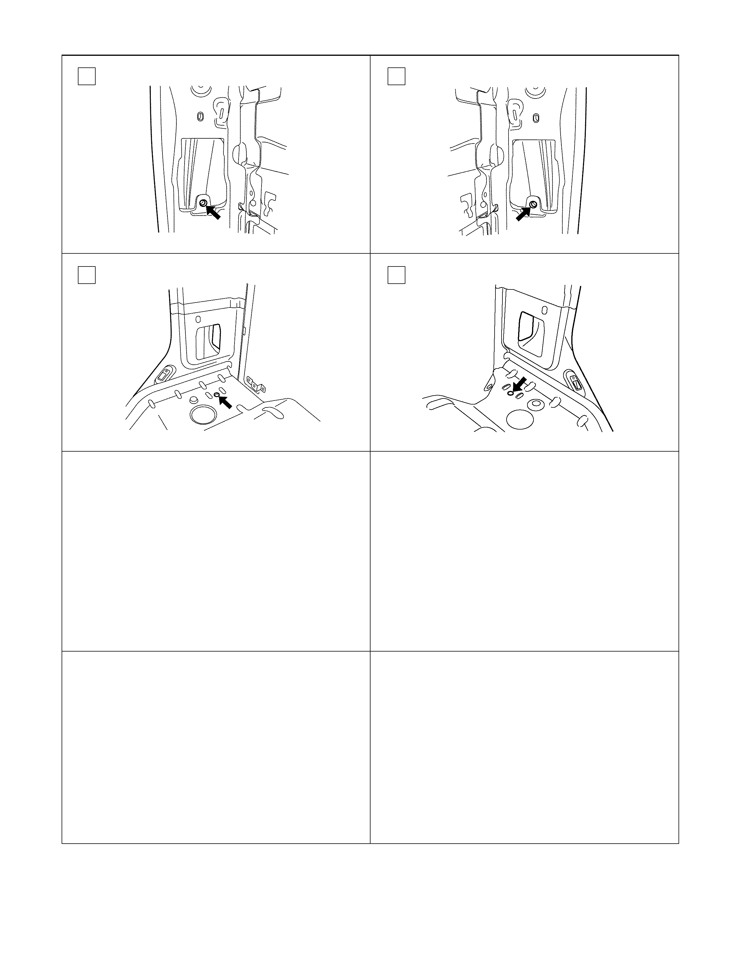
56 57
58 59
SIDE BODY SECTION (REGULAR CAB)
41 42
43 44
45 23
25 46
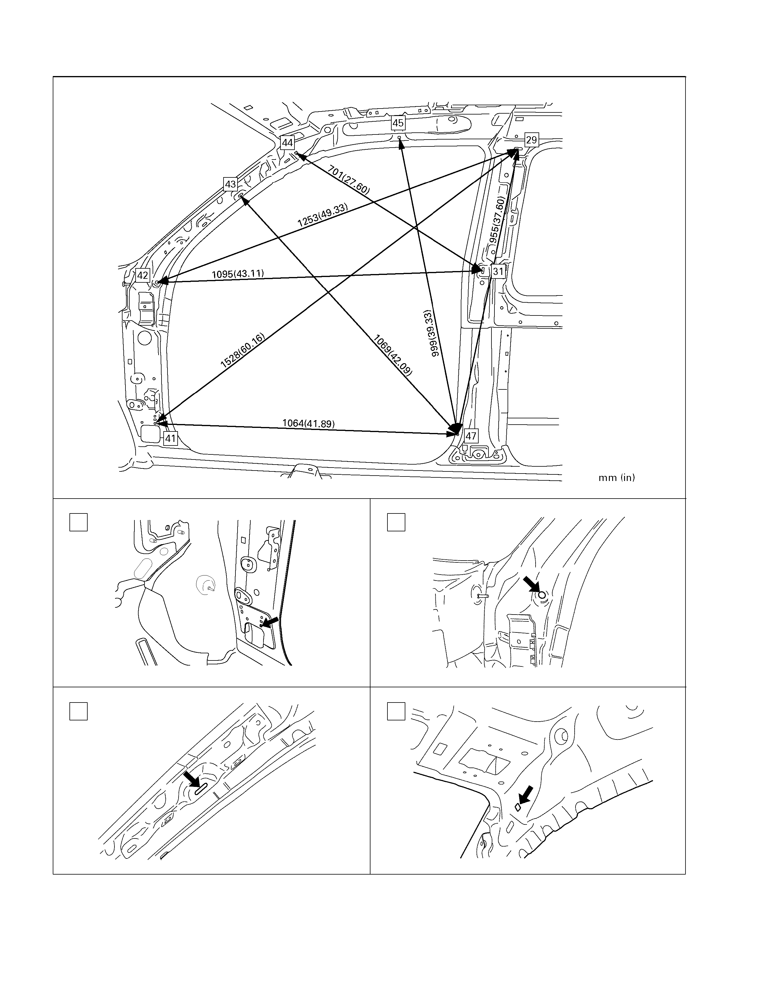
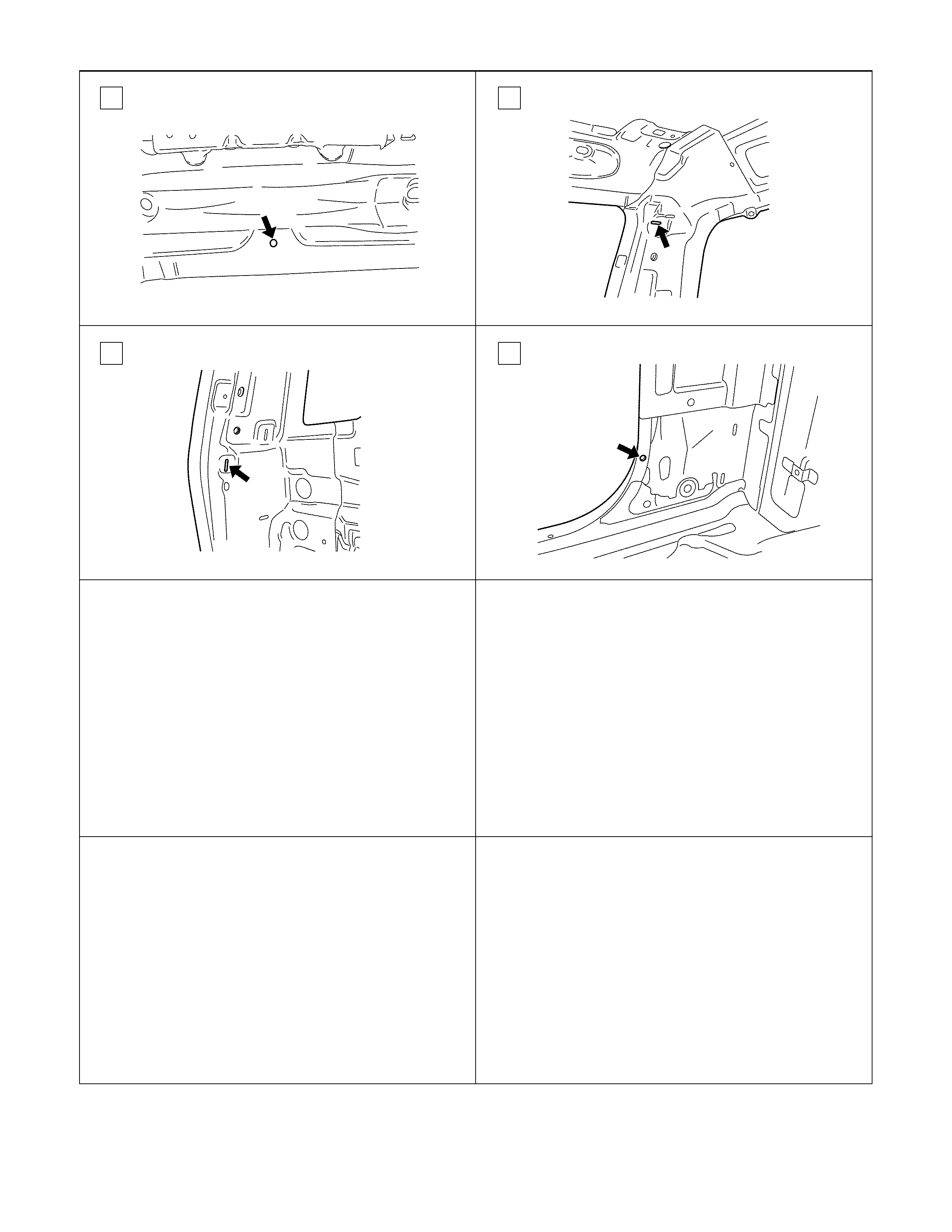
SIDE BODY SECTION (EXTEND CAB)
41 42
43 44
45 29
31 47
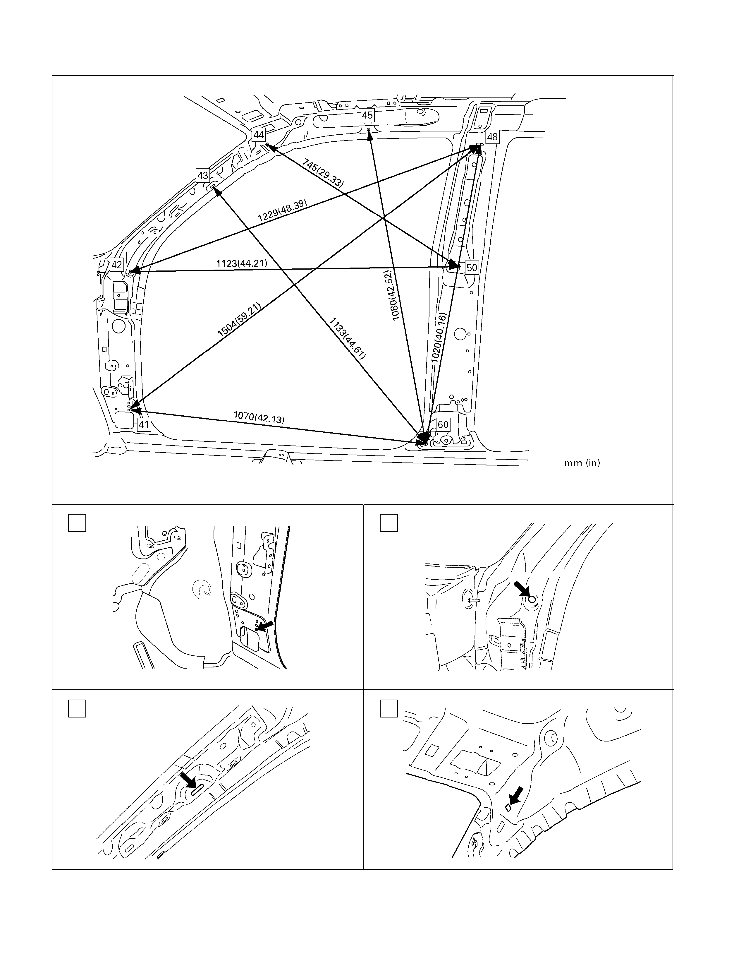
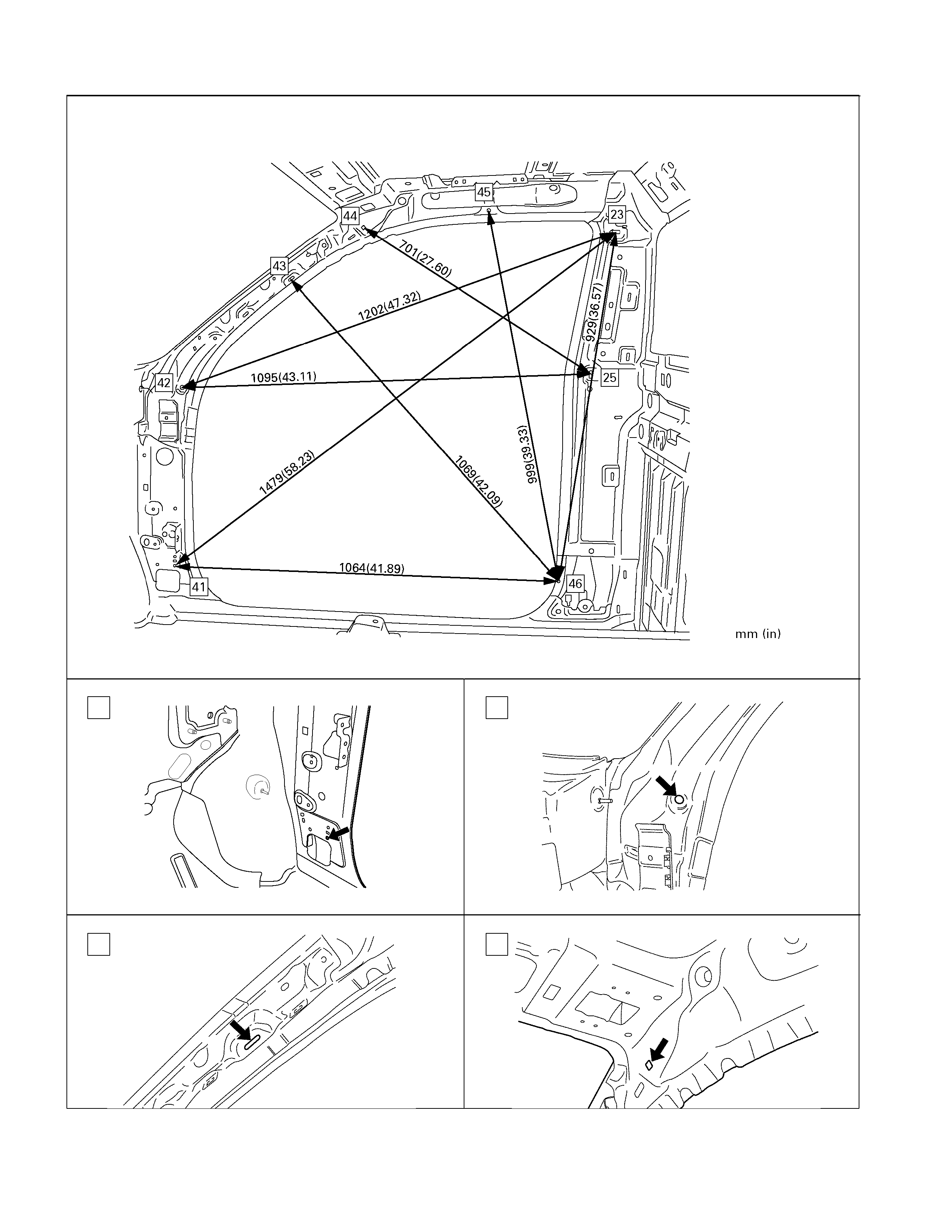
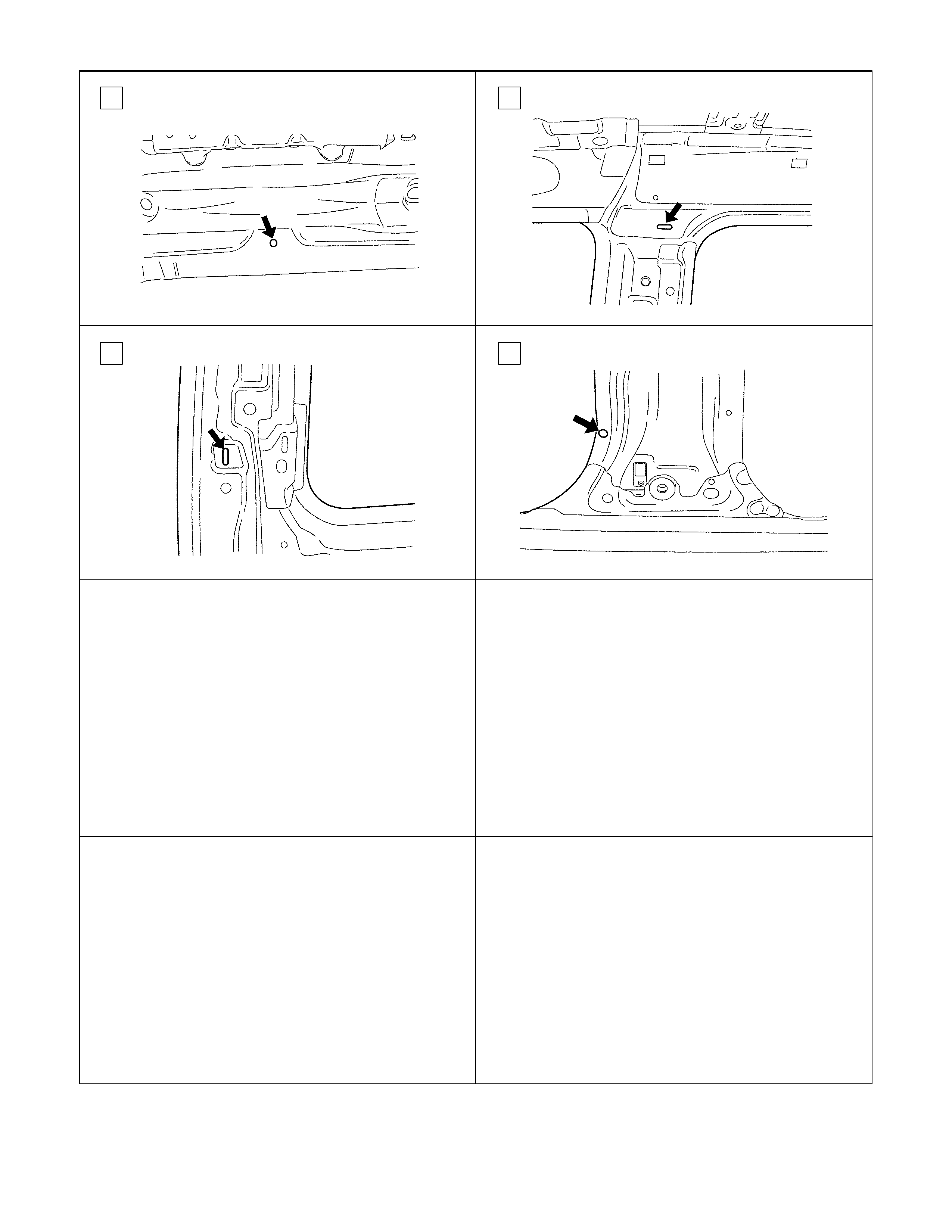
SIDE BODY SECTION; FRONT SIDE (CREW CAB)
41 42
43 44
45 48
50 60
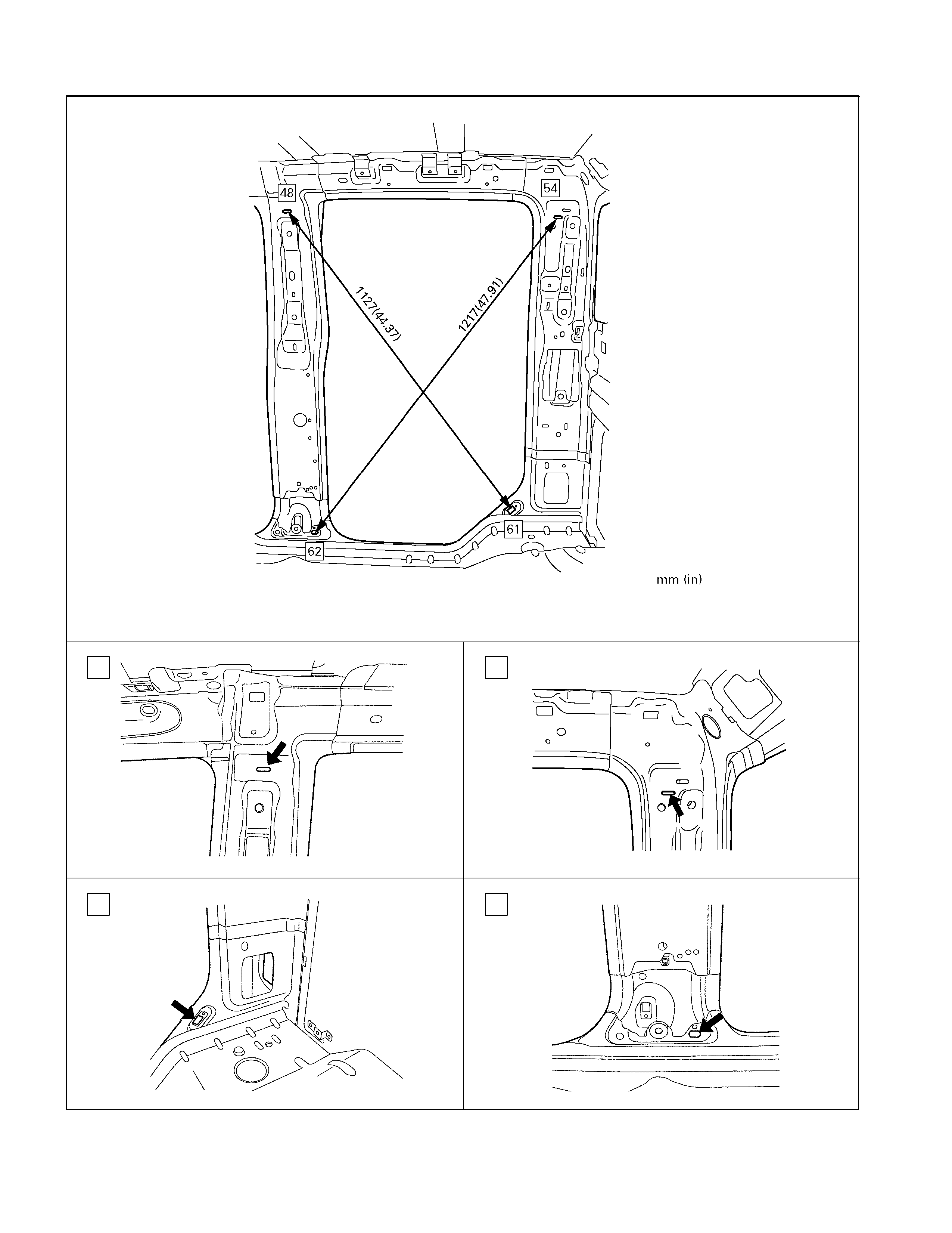
SIDE BODY SECTION; REAR SIDE (CREW CAB)
48 54
61 62